La spécialité de formation : un « signal » de compétences spécifiques et générales
Upload
khangminh22Category
view
2download
0
UNIVERSITE PIERRE ET MARIE CURIE, Paris VI
HABILITATION A DIRIGER DES RECHERCHESSpécialité •chimie analytique, radiochimieMémoire présenté par Micheline DRAYE
SYSTEMES DE SEPARATION POUR L'INDUSTRIE NUCLEAIRE
DE L'ELABORATION DU SYSTEME A SA VALIDATION EN
MILIEU RADIOACTIF
Soutenance prévue le 28 mai 2004
Jury
Pr. Gérard Coté, Ecole Nationale Supérieure de Chimie de Paris, ParisPr. Jacques Foos, Conservatoire National des Arts et Métiers, Paris
Pr. Marc Lemaire, Université Claude Bernard Lyon I, VilleurbannePr. Pierre Létellier, Université Paris VI, Paris
Pr. Kenneth Nash, Washington State Unïversïty, Pullman WA, USAPr. Christian Pétrîer, Université de Savoie, Le Bourget du-Lac
Pr, Eric Simoni, Université Paris XI, Orsay
UNIVERSITE PIERRE ET MARIE CURIE, Paris VI
HABILITATION A DIRIGER DES RECHERCHES
Spécialité : chimie analytique, radiochimieMémoire présenté par Micheline DRAYE
SYSTEMES DE SEPARATION POUR L'INDUSTRIE NUCLEAIRE
DE L'ELABORATION DU SYSTEME A SA VALIDATION EN
MILIEU RADIOACTIF
Soutenance prévue le 28 mai 2004
Jury
Pr. Gérard Cote, Ecole Nationale Supérieure de Chimie de Paris. ParisPr. Jacques Foos, Conservatoire National des Arts et Métiers, Paris
Pr. Marc Lemaire, Université Claude Bernard Lyon I, VilleurbannePr. Pierre Létellier, Université Paris VT, Paris
Pr. Kenneth Nash, Washington State University, Pullman WA. USAPr. Christian Pétrier, Université de Savoie. Le Bourget du-Lac
Pr. Eric Simoni. Université Paris XI, Orsay

Habilitation à diriger des recherches - 2& mai 2004 Micheline PPAY6
Pour Julie et Théo
Ma plusprofonde amitié à Lydie, Nathalie et Christine.

Habilitation àdiriger des recherches - Z» mai Z0Q4 Micheline PPAYC
Remerciements
Je remercie pour leur accueil et leur soutien. Madame Danièle Olivier, directeur de l'EcoleNationale Supérieure de Chimie de Paris, et Monsieur Daniel Lincot, Directeur du Laboratoired'Electrochimie et de Chimie Analytique de l'ENSCP.
Je remercie Monsieur Eric Simoni et Monsieur Pierre Toulhoat pour l'intérêt qu'ils ont portéàmes travaux en acceptant d'en être rapporteurs.
Iwish to express my sincerest thanks to Sir Kenneth Nash who volunteered time from itsbusyschedule to review thisdocument, although written in the language ofMolière.
Je tiens à exprimer ma profonde reconnaissance àMonsieur Marc Lemaire pour l'enthousiasme etla curiosité scientifique qu'il a su me transmettre, les précieux conseils qu'il m'a toujoursprodigués, et l'honneur qu'il me fait d'accepter departiciper à cejury.
AMonsieur Jacques Foos, je tiens à exprimer toute magratitude pour le« l'asile expérimental»qu'il m'assure depuis 6 ans, pour la confiance qu'il m'a accordée en me donnant l'opportunité dedispenser ses cours de radiochimie et de physique nucléaire, etpour accepter de participer àcejury.
Je remercie Monsieur Pierre Létellier et Monsieur Christian Pétrierpourl'honneur et le plaisirqu'ils me font de participer à ce jury.
Monsieur Gérard Cote m'a accueillie dans son équipe. Je le remercie pour la confiance qu'il m'aaccordée et pourson constant soutien.
Je remercie tout spécialement Kenneth Czerwinski, Alain Favre-réguillon et tous les étudiantscités dans ce mémoire, sans lesquels ces travaux n'auraientpu être réalisés. J'aiprisbeaucoup deplaisir àpartager ces sujets de recherches aveceux.
Je remercie MichelFromon, Joël Lelièvre et tous les enseignants avec lesquelsj'ai transmis etbeaucoup acquis.
Enfin, je ne voudrais pas terminer cettepage sans remercier tous lesmembres des Laboratoiresde Catalyse et Synthèse Organique de l'UCBL, de Chimie Organique du CNAM, des SciencesNucléaires du CNAM, duLECA de l'ENSCP, de Chimie Moléculaire et Environnement du Bourgetde Lac, et l'Actinides Research group du Nuclear Engineering Department du MIT, que j'aicôtoyéspendant cesquelques années et sans lesquels mon travail n'auraitpas étéaussi riche tanthumainement quescientifiquement.

Habilitation à diriger des recherches - Z$ mai Z004 Micheline PPAYC
Résumé
L'imagination est plus importante que le savoir.A. Einstein

Mes travaux de recherches concernent l'aval du cycle électronucléaire et visent à concevoir,
créer, évaluer et/ou améliorer divers systèmes de séparation envisageables pour le traitement
des combustibles nucléaires usés. L'éventail des voies explorées est large, de l'extraction liquide-
liquide, aux procédés membranaires, en passant par l'extraction solide-liquide. Au-delà de la mise
au point des divers concepts pour la séparation des radionucléides ciblés, les systèmes élaborés
ont été étudiés à travers leur efficacité ainsi que leur stabilité chimique et radiochimique, car
pour utiliser un matériau dans l'industrie nucléaire, il faut connaître, en particulier, la dose
d'irradiation précise au-delà de laquelle il a perdu ses qualités essentielles. A titre d'exemple,
après avoir mis en évidence les potentialités du DCH18C6 pour le développement d'un nouveau
procédé de retraitement des combustibles nucléaires usés, nous avons identifié la structure de
ses produits de dégradation à l'aide de nombreuses techniques d'analyse (IRTF, RMN, CG-Sbk et
diffraction de rayons X). Compte tenu des précautions croissantes prises par les industriels du
nucléaire, il nous a semblé nécessaire d'aller plus loin dans nos investigations. Les extractants
modernes étant définis moléculairement ainsi que dans leur stéréochimie, il nous a fallu
déterminer la stéréochimie des produits de radiolyse du DCH18C6. Malgré la puissance des
techniques d'analyse structurale utilisées et précédemment citées, il nous a été nécessaire, pour
confirmer les fragments proposés, d'en synthétiser chacune des structures possibles. Cette
synthèse nous a permis d'évaluer l'intervention des produits de dégradation lors d'une éventuelle
utilisation industrielle du DCH18C6 et de conclure que les propriétés d'extraction et la
remarquable stabilité en milieux acide et radioactif du DCH18C6, en font un solide candidat pour
le retraitement des combustibles nucléaires usés. Nous avons suivi la même démarche pour les
résines phormophénoliques, que nous avons en plus synthétisées. Puis, c'est dans un souci de
protection de l'homme et de l'environnement que nous avons cherché à éliminer les solvants
organiques volatiles classiquement utilisés dans l'extraction par solvant et que nous avons axé la
suite nos recherches vers des technologies non polluantes basées sur l'emploi de systèmes
micellaires en extraction liquide-liquide, ou de membranes de nanofiltration.
Pour diversifier les techniques d'analyse disponibles et développer des approches scientifiques
plus pertinentes, certains des travaux décrits ont été menés dans le cadre de collaborations
nationales et/ou internationales, bans ce contexte, l'étude de la stabilité de la résine poly(4-
vinylpyridine) (P4VP) nous a permis d'établir une collaboration scientifique avec l'Institut de
Physique Nucléaire de Lyon pour l'utilisation d'une technique fine d'analyse de surface, la
spectrométrie de masse à temps de vol d'ions secondaires induits par un faisceau d'ions primaires
lourds multichargés accélérés (TOF-PDMS), qui, à cette occasion, a trouvé sa première utilisation

pour le suivi des modifications structurales d'un matériau organique, soumis à des contraintes detype photoniques.
Finalement, le projet de recherches décrit propose l'étude des mécanismes fondamentaux du
vieillissement de matériaux organiques sous stress chimique, thermique et radiochimique et deson application à l'industrie nucléaire. Acet égard, le programme prévoit de mettre en évidence
et d'interpréter des mécanismes fondamentaux de dégradation, en développant ou en appliquantdes techniques et des méthodes d'analyse. Il permettra d'acquérir des informations sur le
matériau dégradé, sur la nature, la composition et la structure de ses composés « métabolites ».
Il nécessitera d'aborder des domaines de connaissance très variés, et son aspect pluridisciplinairem'amènera à faire appel à des techniques classiques pour l'analyse de matériaux organiques etd'autres encore peu exploitées pour ce type de matériaux. Le projet de recherches que jepropose relevant d'une approche pluridisciplinaire, il sera réalisé dans le cadre de collaborations
aussi bien internes au laboratoire que nationales et internationales. Ma problématique derecherches, physico-chimie de la dégradation de systèmes organiques sous stress chimique,thermique et radiolytique, permettra aussi de développer à terme une base de données pourl'industrie nucléaire. Des méthodologies dérivées pourront alors être transposées à pratiquementtous les secteurs industriels.

Habilitation à diriger des recherches - ZB mai Z004 Micheline PPAYC
Abstract
Imagination is more important than knowledge.A. Einstein

My research deals with the end of the electronuclear cycle and aims to design, create, assess
and/or improve various séparation Systems for spent nuclear fuel reprocessing. The range of
roads explored is large from liquid-liquid extraction, tp membrane processes, through solid-liquid
extraction. Beyond the development of various concepts for targeted radionuclides séparation,
the Systems efficiency and stability were studied. Evaluation of irradiation dose on séparations
was examined based on the needs of the nuclear industry. As an example, after highlighting the
great potential of DCH18C6 for the development of a new nuclear fuel reprocessing process, we
determined the structure of its dégradation products using a suite of analytical techniques
(FTIR, NMR, C6-MS and X-ray diffraction). Considering the increasing précautions taken by the
nuclear industry, we deem it necessary to expand our investigations into organic stereochemistry
of extracting ligands. We determined the stereochemistry of the DCH18C6 radiolysis products.
Despite the capacity of the structural analytical techniques used and previously quoted, we
synthesized each possible structure to assess ail the proposed fragments. Thèse synthèses
allowed us to evaluate the dégradation products interférence during potential DCH18C6
industrial use and to conclude that its great extraction capabilities and its remarkable chemical
and radiochemical stability make the DCH18C6 a reliable candidate for the spent nuclear fuel
reprocessing.
To vary the available analytical techniques and to develop more relevant scientific approaches,
some of the described work was conducted as a part of national and/or international
collaborations. In this context, the study of the poly(4-vinylpyridine) (P4VP) resin stability in
radioactive médium allowed us to establish a scientific collaboration with the « Nuclear Physic
Institute of Lyon » for the use of a surface analysis fine technique, the Time of Flight-Particle
Induced Desorption Mass Spectrometry (TOF-PDMS). This was its first use for the analysis of
structural modifications of an organic material subjected to photonic type stress.
The described research project illustrâtes the importance of examining and understanding the
fundamental mechanisms of the ageing of organic materials under chemical, radiochemical and
thermal stress, and its application to the nuclear industry. To this respect, the research program
plans to bring to the fore and to explain fundamental mechanisms of dégradation by developing
and using analytical techniques and methods. It will enable to obtain informations concerning the
degradated material, the nature, the composition, the structure of its "metabolite" compounds
and data critical from modeling. It will require approaching various area of knowledge; its
interdisciplinary aspect will pull my radiochemistry and séparations based research into novel
expérimental areas as well as introduce others to the subject of radiochemistry and the nuclear

fuel cycle. The research project I propose being dépendent of amultidisciplinary approach, it willbe carried out in the framework of collaborations. Thèse collaborations will be internai to the
laboratory as well as national and international. The results from my research area, physico-chemistry of organic Systems under chemical, thermal and radiolytical stress, will not onlypositively impact the scientific community by will also hâve important applications to the nuclearindustry.
Habilitation à diriger des recherches - ZB mai Z004 Micheline OPAYC
Curriculum Vitae
Ca a débuté comme ça.Moi, j'avais jamais rien dit. Rien.
Céline

Habilitation àdiriger des recherches - ZB mai ZQQ4 Micheline DPAYC
Micheline DRAYENée le 11 janvier 1965 - deux enfants - nationalité françaiseEcole Nationale Supérieure de Chimie de ParisLaboratoire d'Electrochimie et de Chimie AnalytiqueGroupe Procédés de Séparation et RadiochimieH 11, rue Pierre et Marie Curie, 75005 Paris@ bureau : 01-44-07-10-32, personnel : 01-42-06-34-97, Fax : 01-44-27-67-50Email : [email protected]
Docteur en Chimie Analytique(Université Claude Bernard de LYON)
Titres universitaires et diplômes1994 Doctorat de Chimie Analytique de l'Université Claude Bernard (Lyon 1),
mention très honorable.
1991 Diplôme d'Etudes Approfondies en Chimie Analytique de l'Université ClaudeBernard (Lyon 1), mention AB.
Expériences professionnelles2001 Maître de Conférences titulaire à l'école Nationale Supérieure de Chimie de
Paris.
1998-2001 Maître de Conférences stagiaire à l'Ecole Nationale Supérieure de Chimie deParis.
1997-1998 Visiting Scientist au "Department of Nuclear Engineering, ActinidesResearch Group" du "Massachusetts Institute of Technology", Cambridge,USA, (Pr. K. R. Czerwinski).
1995-1997 Stage de Post-doctorat au Laboratoire de Sciences Nucléaires du CNAM,Paris, (Pr. J. Foos), financement CEA.
1991-1994 Stage de thèse en Chimie Analytique au Laboratoire de Catalyse etSynthèse Organique de l'université Claude Bernard, Lyon 1, (Pr. M. Lemaire),et au Service Laboratoires àe la COGEMA Marcoule, Financement CIFRE.
1990-1991 Stage de DEA en Chimie Analytique au Laboratoire de Catalyse et SynthèseOrganique de l'université Claude Bernard, Lyon 1, (Pr. M. Lemaire),financement COGEMA.
1990 Stage de Maîtrise au Laboratoire de Catalyse et de Synthèse Organique del'université Claude Bernard, Lyon 1, (Pr. M. Lemaire), financement COGEMA,et au Service laboratoires'de la COGEMA Marcoule.
Distinction
1991 Prix de la Société Française à l'Energie Nucléaire (SFEN - ESSONES)
Activités et responsabilités administrativesDepuis 2002 Membre d'un jury de concours d'ingénieur de recherches au CNAM, Paris.Depuis 1998 Chargé de mission pour les Etats Unis, échanges internationaux, ENSCP.Depuis 1998 Membre de jury de 2° et de 3° année à l'ENSCP, et de Maîtrise à l'Université
Pierre et Marie Curie (Paris VI).

Habilitation àdiriger des recherches - ZB mai ZOo4 Micheline PPAY6
Collaborations nationales
Depuis 2003 Collaboration scientifique avec l'Université de Savoie, Laboratoire de ChimieMoléculaire de l'Environnement, Ecole Supérieure d'Ingénieurs de Chambéry,73376 Le Bourget du Lac Cedex, France -Dr. Emmanuel Naffrechoux, Pr.Christian Pétrier.
Depuis 2002 Participation au groupe de travail GT 32 de la CETAMA (commissiond'établissement des méthodes d'analyse) sur la thématique "Spéciationanalytique et bases de données thermodynamiques" pour l'environnement etles milieux biologiques.
Depuis 1998 Groupe de travail PRACTTS puis PARIS (physico-chimie des actinides etautres radioéléments ensolution et aux interfaces).
Depuis 1991 Collaboration scientifique avec le Conservatoire National des Arts et Métiers,Laboratoires de chimie organique et des Sciences Nucléaires, 2, rue Conté,75003 Paris, France -Pr. Alain Guy, Pr. Jacques Foos.
Collaborations internationales
Depuis 2003 Membre d'un comité d'experts, auprès de Duke Cogema Stone AWebster,ayant pour mission de proposer au NRC (Nuclear Regulatory Commission) unprogramme de recherches axé sur la fiabilité du procédé PUREX, pour laconstruction d'une usine de retraitement du plutonium militaire et d'une usinede fabrication de combustibles tAOX aux Etats Unis.
Depuis 2003 Collaboration scientifique avec PUniversity of Nevada-Las Vegas" (UNLV),Department of Chemistry, Actinides Research Group,4505 Maryland Parkway,BOX 4003, Las Vegas, NV, 89154/4003, USA -Pr. Kenneth R. Czerwinski
1997 - 2003 Collaboration scientifique avec le Massachusetts Institute of Technology(MIT), Department of Nuclear Engineering, Actinides Research Group, 77Massachusetts Avenue, Cambridge MA 02139, USA -Pr. Kenneth R.Czerwinski.
2000 - 2001 Membre d'un comité d'experts au "National Research CounaT de la "NationalAcademy of Sciences", USA (http://www.nas.edu) ayant pour objectif deproposer à Tenvironmental Management Science Program" du "United StatesDepartment of Energy" (DOE) un plan de développement d'un programme àlong terme visant à résoudre les problèmes de gestion des déchetsradioactifs à haute activité des sites du DOE.
Depuis 1998 Collaboration scientifique avec l'Université Technologique de Poznan, Institutde Chimie Technologique et de Génie des Procédés, Poznan, Pologne - Pr. JanSzymanowski
Contrats de recherches avec l'industrie
2002 - 2003 Contrat EDF-CNRS, Etude de l'adsorption des sulfates et autres espècessoufrées sur les tubes de générateurs de vapeur de centrales à réacteur àeau sous pression.
2001-2002 Contraf EDF-CNRS, Etude de l'évolution de l'efficacité des résineséchangeuses d'ions des Centres Nucléaires de Production Electrique (CNPE)en fonction des caractéristiques des eff luents qui y circulent.

Habilitation à diriger des recherches - ZB mai Z004 Micheline DPAYC
Production scientifique
LECTEURS amis, moins amis, ennemis, critiquesNe me jugez point de sitôt!...
Attendez un petit peu la suite!...Céline

Habilitation àdiriger des recherches - ZB mai Z004 Micheline PPAY5
PUBLICATIONS
1 Cloud point extraction for sélective removal of Gd(III) and La(III) with 8-hydroxyquinoline, M. Draye, A. Favre-Reguillon, G. LeBuzit, S. Thomas, A. Guy, G. Cote, J.Foos, Sep. Sci. Technol (souspresse).
2. Cloud point extraction: an alternative to traditional liquid-liquid extraction forlanthanides (III) séparation, A. Favre-Réguillon, M. Draye, S. Thomas, G. Lebuzit, J.Foos, G. Cote, A. Guy, Talanta (souspresse).
3. Removal of Uranium from Sea Water by Nanofiltration, A. Favre-Réguillon, M. Draye, G.LeBuzit, J. Foos, M. Lemaire, A. Guy, Ind. Eng. Chem. Res.42(23), 5900-5904 (2003).
4. Détermination of lanthanum(III) and europium(III) - lactate interaction constants bycapillary electrophoresis for environmental applications, S. Bortolus, A. Varenne, M.Draye, K. Czerwinski, G. Cote, P. Gareil, Ars Separatoria Acta 2(0-0) (2003)
5. Correction of inner filter effect in mirror coating cells for trace level fluorescencemeasurements, Bernard Fanget, O. Devos, M. Draye, Anal. Chem. 75(11), 2790-2795(2003).
6. Removal of 243Am with phenolic based Resins, M. Draye, A. Favre-Réguillon, D. Wruck, A.Guy, J. Foos, K. Czerwinski. Sep. Sci. Technol. 36 (5â6), 899-909(2001).
7. An ESR study of y-irradiated P4VP polymers. Dose-effect relationships, M. Draye, A.Favre-Réguillon, J. Foos, A. Guy, Chem. Lett, 710-711 (2000)
.8. Removal of bisphenol Afrom aqueous streams by micellar extraction and ultrafiltration,R. Urbanski, M. Draye, G. Cote, J. Szymanowski, Solvent Extr. Ion Exch., 18(3), 533-550(2000)
9. Sélective Séparation of Lanthanides with Phenolic Resins: Extraction behavior andThermal Stability, M. Draye, A. Favre-Reguillon, J. Foos, A. Guy, M. Lemaire, K.Czerwinski. Sep. Sci. Technol, 35(8), 1117-1132(2000)
10. Sélective extraction of Pd from acidic nitrate solutions with thiamacrocyclesdinonylnaphtalenesulfonic acid Systems, M. Draye, A. Favre-Reguillon, G. LeBuzit, J.Foos, M. Lemaire, A. Guy, J. Radioanal. Nucl. Chem., letters, 220 (1), 105 (1997).
11.ARecovery Process of Strontium from Acidic Nuclear Waste Streams. M. Draye, G. LeBuzit, M. Lemaire, B. Leclere, P. Doutreluingne, J. Foos, A. Guy. Sep. Sci. Technol, 32 (10),1725 (1997).
12.Gamma-ray induced modifications of the chemical structure of an ion exchange resin. M.Draye, B. Nsouli, H. Allali, M. Lemaire, J.P. Thomas. Polym. Degrad. Stab. 56,157 (1997).
13. Radiochemical Stability of Dicyclohexano-18-Crown-6 Ether (DCH18C6) and its Use in aRecovery Process of Strontium from Acidic Nuclear Waste Stream, M. Draye, A. Favre-Reguillon, J. Foos, A. Guy, M. Lemaire. Radiochim. Acta. 78,105 (1997).
14.Energy déposition and fragments production resulting from gamma-ray or ion beamirradiation of an ion exchange resin. B. Nsouli, M. Draye, H. Allali, M. Lemaire, J.P.Thomas. Int. J. ofMass. Spectrom. IonProcesses. 154,179-191 (1996).
15. Radiochemical stability of the dicyclohexano-18-couronne-6 ether (DCH18C6): Synthesisand tests in radioactive médium of the DCH18C6 radiolytic products. M. Draye, A. Favre-Reguillon, R. Chomel, R. Faure, A. Guy, J. Foos, M. Lemaire. Chim Bull Soc Fr, 133, 183(1996).
16.Lipophilic polythiamacrocycles as palladium extracting agents. V. Guyon, A. Guy, J. Foos,M. Lemaire, M. Draye. Tetrahedron, 51,4065 (1995).
Habilitation àdiriger des recherches - ZB mai Zoo4 Micheline PPAY6
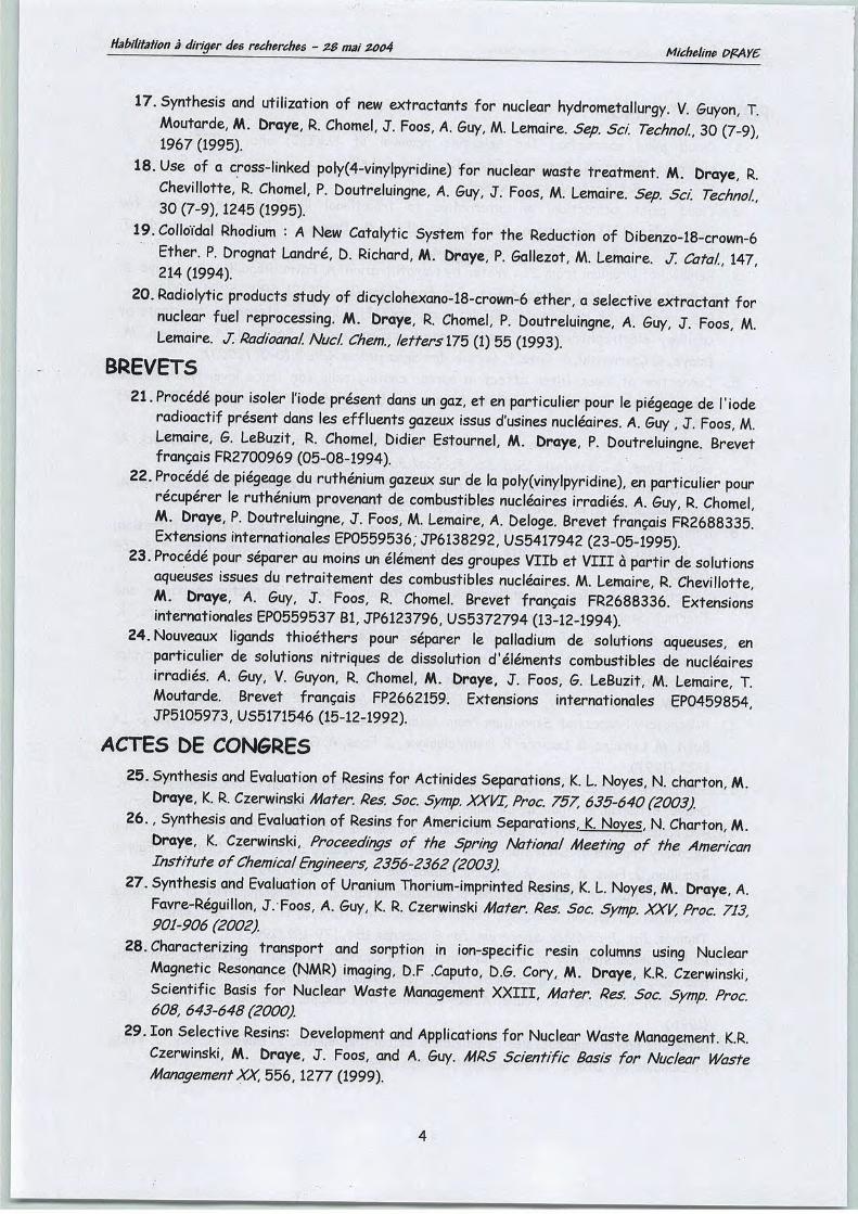
17. Synthesis and utilization of new extractants for nuclear hydrometallurgy. V. Guyon, T.Moutarde, M. Draye, R. Chomel, J. Foos, A. Guy, M. Lemaire. Sep. Sci Technol. 30 (7-9)1967 (1995).
18. Use of a cross-linked poly(4-vinylpyridine) for nuclear waste treatment. M. Draye, R.Chevillotte, R. Chomel, P. Doutreluingne, A. Guy, J. Foos, M. Lemaire. Sep. Sci Technol.30 (7-9), 1245 (1995).
19. Colloïdal Rhodium : A New Catalytic System for the Réduction of Dibenzo-18-crown-6Ether. P. Drognat Landré, D. Richard, M. Draye, P. Gallezot, M. Lemaire J. Catal. 147214 (1994).
20. Radiolytic products study of dicyclohexano-18-crown-6 ether, a sélective extractant fornuclear fuel reprocessing. M. Draye, R. Chomel, P. Doutreluingne, A. Guy, J. Foos, M.Lemaire. J. Radioanal. Nucl. Chem., letters 175 (1) 55 (1993).
BREVETS
21. Procédé pour isoler l'iode présent dans un gaz, et en particulier pour le piégeage de l'ioderadioactif présent dans les effluents gazeux issus d'usines nucléaires. A. Guy , J. Foos, M.Lemaire, G. LeBuzit, R. Chomel, Didier Estournel, M. Draye, P. Doutreluingne. Brevetfrançais FR2700969 (05-08-1994).
22. Procédé de piégeage du ruthénium gazeux sur de la poly(vinylpyridine), en particulier pourrécupérer le ruthénium provenant de combustibles nucléaires irradiés. A. Guy, R. Chomel,M. Draye, P. Doutreluingne, J. Foos, M. Lemaire, A. Déloge. Brevet français FR2688335.Extensions internationales EP0559536, JP6138292, US5417942 (23-05-1995).
23. Procédé pour séparer au moins un élément des groupes Vllb et VIII à partir de solutionsaqueuses issues du retraitement des combustibles nucléaires. M. Lemaire, R. Chevillotte,M. Draye, A. Guy, J. Foos, R. Chomel. Brevet français FR2688336. Extensionsinternationales EP0559537 Bl, JP6123796, US5372794 (13-12-1994).
24. Nouveaux ligands thioéthers pour sêçtarer le palladium de solutions aqueuses, enparticulier de solutions nitriques de dissolution d'éléments combustibles de nucléairesirradiés. A. Guy, V. Guyon, R. Chomel, M. Draye, J. Foos, G. LeBuzit, M. Lemaire, T.Moutarde. Brevet français FP2662159. Extensions internationales EP0459854JP5105973, US5171546 (15-12-1992).
ACTES DE CONGRES
25. Synthesis and Evaluation of Resins for Actinides Séparations, K. L. Noyés, N. charton, M.Draye, K. R. Czerwinski Mater. Res. Soc. Symp. XXVI, Proc. 757, 635-640(2003)
26., Synthesis and Evaluation of Resins for Americium Séparations, K. Noves. N. Charton, M.Draye, K. Czerwinski, Proceedings of the Spring National Meeting of the AmericanInstitute ofChemical Engineers, 2356-2362 (2003)
21. Synthesis and Evaluation of Uranium Thorium-imprinted Resins, K. L. Noyés, M. Draye, A.Favre-Réguillon, J. Foos, A. Guy, K. R. Czerwinski Mater. Res. Soc. Symp. XXV, Proc 713901-906 (2002)
28.Characterizing transport and sorption in ion-specific resin columns using NuclearMagnetic Résonance (NMR) imaging, D.F .Caputo, D.G. Cory, M. Draye, K.R. Czerwinski,Scientific Basis for Nuclear Waste Management XXIII, Mater. Res. Soc. Symp. Proc608,643-648(2000)
29. Ion Sélective Resins: Development and Applications for Nuclear Waste Management. K.R.Czerwinski, M. Draye, J. Foos, and A. Guy. MRS Scientific Basis for Nuclear WasteManagement XX, 556,1277 (1999).

Habilitation àdiriger des recherches - ZB mai ZQQ4 Micheline PPAY6
30. Hafnium Hydroxide Complexation and Solubility: The Impact of Hydrolysis Reactions onthe Disposition of Weapons-Grade Plutonium. G. Cerefice, M. Draye, K. Noyés, and K.R.Czerwinski. MRS Scientific Basis for Nuclear Waste Management XX. Volume 556, 1025(1999).
31. Ion spécifie resins for nuclear waste : Europium studies, K. Czerwinski, M. Draye, A.Favre-Reguillon, J. Foos, A.Guy. Book of abstracts, 216+h ACS National Meeting, Boston,August 23-27 (1998).
32. Ion Sélective Resins: Development and Applications for Nuclear Waste Management, K. R.Czerwinski, M. Draye, A. Favre-Reguillon, J. Foos, A. Guy, Proceedings of the MRS'98Conférence, (1998).
33. Environmental Behavior of Hafnium for the Disposai of Weapons-Grade Plutonium, G.Cerefice, M. Draye, K. L. Noyés, K. Czerwinski. Proceedings of waste Management'98Conférence (1998).
34. Chelating Ion-Exchange Resins for the Compétitive Sorption of Lanthanum and Europium,M. Draye, A. Favre-Reguillon, J. Foos, A. Guy, K. Czerwinski. Proceedings of wasteManagement '98Conférence (1998).
35. Competititve sorption of Lanthanum and Europium by Phenolic Resins containing 8-Hydroxyquinoline, M. Draye, A. Favre-Reguillon, J. Foos, A. Guy, K. Czerwinski.Proceedings of International Symposium on Radiation Safety Management'97, 423(1997).
OUVRAGE COLLECTIF AVEC COMITE DE LECTURE
36.Research Needs for High-Level Waste stored in thanks and bins at U.S. Department ofEnergy Sites. Environmental Management Science Program. M. Corradini, D. Campbell, M.Draye, C. Drummond, III, P. Hayward, L. Hobbs, E. Lahoda, R. Rogers, B. Sternberg, E.Zebroski. Ed. National Academy Press,Washington D.C. (2001).
RAPPORTS SCIENTIFIQUES A DIFFUSION RESTREINTE37. S. Legeai, M Draye, G. Cote, Etude de l'adsorption de sulfates et autres espèces
soufrées sur les tubes de générateurs de vapeur des centrales à réacteur à eau souspression. LECA-EDF, rapport du 2003
38.B. Maurel, M. Draye, G. Cote, E. Moleiro, Etude de l'évolution de l'efficacité des résineséchangeuses d'ions des CNPE en fonction des caractéristiques des effluents qui ycirculent. LECA-EDF, E 57 302 / RNE 971 ; T44 L42, rapport du 30 novembre 2002.
39. B. Maurel, M. Draye, G. Cote, E. Moleiro, Etude de l'évolution de l'efficacité des résineséchangeuses d'ions des CNPE en fonction des caractéristiques des effluents qui ycirculent. LECA-EDF, E 57 302 / RNE 971 ; T 44 L42, rapport du 30 août 2002.
40. G. S. Cerefice, M. Draye, K. L. Noyés, K.R. Czerwinski, Determining ComplexationParameters for Hafnium, Lanthanides and Plutonium for Use in Assessing PlutoniumDisposition Options. Reporting Period: 15 august 1998 - 28 February 1999. MIT-LLNLReport 1999
41.G.S. Cerefice, M. Draye, K.L. Noyés, and K.R. Czerwinski: "Determining ComplexationParameters for Hafnium, Lanthanides, and Plutonium for Use in Assessing PlutoniumDisposition Options, Reporting Period: 16 January 1998- 14 August 1998. MIT-LLNLReport 1998.

Habilitation àdiriger des recherches - ZB mai Z004 Micheline PPAY6
42. G.S. Cerefice, M. Draye, K.L. Noyés, and K.R. Czerwinski: "Determining ComplexationParameters for Hafnium, Lanthanides, and Plutonium for Use in Assessing PlutoniumDisposition Options, Reporting Period: 21 August 1997- 15 January 1998. MIT-LLNLReport 1998.
THESE ET MEMOIRE DIPLOMANT
43. M. Draye, Etude de la stabilité de ligands organiques utilisables pour le retraitement descombustibles nucléaires usés. Thèse, 12/09/1994, Université Claude Bernard Lyon 1.
44. M. Draye, Synthèse et caractérisation de nouveaux ligands utilisables pour leretraitement des combustibles nucléaires usés. DEA, juin 1991, Université ClaudeBernard, Lyon 1.
COMMUNICATIONS ORALES
45.13th Symposium on Séparations Science and Technology for Energy Applications, 27-30octobre 2003, Gatlinburg TN, USA. " Cloud Point Extraction: An Alternative totraditional Liquid-Liquid Extraction for Lanthanides Extraction " A. Favre-Réguillon,M. Draye. G. LeBuzit, S. Thomas, J. Foos, G. Cote, A. Guy.
46.13+h Symposium on Séparations Science and Technology for Energy Applications, 27-30octobre 2003, Gatlinburg TN, USA. "Sélective Rejection of dissolved Uranium Carbonatefrom Seewafer using Crossflow Filtration Technology" A. Favre-Réauillon. A. Sorin,M. Draye, G. LeBuzit, J. Foos, A. Guy, M. Lemaire.
47. Spring National Meeting of the American Institute of Chemical Engineers, 30 mars-3Avril 2003, New Orléans LA, USA, Synthesis and Evaluation of Resins for AmericiumSéparations, K. Noyés. N. Charton, M. Draye, K. Czerwinski.
48. Eurochem 2002, Société Française de Chimie, 8-11 juillet 2002, Toulouse, France. "CloudPoint Extraction: An Alternative to traditional Liquid-Liquid Extraction for LanthanidesExtraction", A. Favre-Réauillon. M. Draye, A. Guy, G. Cote, J. Foos.
49.XVIIth International Symposium on Physico-Chemical Methods of the Mixturesséparation "Ars Separatoria 2002", 17-20 juin 2002, Borowno, Pologne. "CapillaryElectrophoresis Humic Acid Fingerprints: Influence of sample médium and SéparationElectrolyte Conditions", S. Bortolus. S. Descroix, F. Robert, A. Varenne, M. Draye, G.Cote, P. Gareil.
50. American Nuclear Society 2002 Annual Meeting, 09-13 juin 2002, Hollywood FL, USA."Selectivity Batch Studies of Thorium- Uranyl-Imprinted Resins", K. L. Noves. M. Draye,K. R. Czerwinski.
51.Materials Research Society Symposium, 26-30 novembre 2001, Boston MA, USA."Synthesis and Evaluation of Uranium Thorium-imprinted Resins", K. L. Noves. M. Draye,A. Favre-Réguillon, J. Foos, A. Guy, K. R. Czerwinski.
52.11* Symposium on Séparations Science and Technology for Energy Applications, 17-21octobre 1999, Gatlinburg TN, USA. "Removal of 243Am with phenolic based Resins", tLDraye, A. Favre-Réguillon, D. Wruck, A. Guy, J. Foos, K. Czerwinski.
53. Material Research Society Fall Meeting, 30 novembre-4 décembre 1998, Boston MA,USA. "Hafnium hydroxide complexation and Solubility", G. Cerefice. M. Draye, K. Noyés,K. Czerwinski.
Habilitation àdiriger des recherches - ZB mai zoo4 Micheline PPAY6
54.Matériel Research Society Fall Meeting, 30 novembre-4 décembre 1998, Boston MA,USA. "Ion sélective Resins: Development and Applications for Nuclear WasteAAnnagement". K. R. Czerwinski, M. Draye.
55. 216th American Chemical Society Meeting, 26-30 septembre 1998, Boston MA, USA. "IonSpécifie of Nuclear Waste: Europium Studies", K. R. Czerwinski, M. Draye, A. Favre-Réguillon, J. Foos, A. Guy.
56. Waste Management'98 Conférence, 4-8 mars 1998, Tucson AT, USA. "Behavior ofHafnium as a neutron poison for the geological Disposai of Plutonium", G. Cerefice, M.Draye, K. L. Noyés, K. Czerwinski.
57. International Symposium on Radiation Safety Management, 6-7 novembre 1997, KoreaElectric Power Research Institute Taejon, Corée. "Compétitive Sorption of Lanthanumand Europium by Phenolic Resins Containing 8-hydroxiquinoline" M. Draye, K. Czerwinski.
58. Journée de Chimie organique, 26 mai 1994, Lyon, France. "Structural Identification andSynthesis of the radiolytic products of the DCH18C6". M. Draye, A. Favre-Réguillon, M.Lemaire.
59. 8th Symposium on Séparation Science and Technology for Energy Applications, 24-28octobre 1993, Gatlinburg Tennessee, USA. "Use ofa Crosslinked Poly(4-vinylpyridine) forNuclear Waste Treatment". M. Drave. R. Chevillotte, R. Chomel, A. Guy, J. Foos, M.Lemaire.
COMMUNICATIONS PAR AFFICHES
60. Assemblée annuelle du GDR Practis, 7-8 février 2002, Villeneuve-lès-Avignon, France."Use of capillary electrophoresis for the détermination of métal ion-humic substancesinteraction and évaluation of their mobility", S. Bortolus, A. Varenne, M. Draye, K.Czerwinski, G. Cote, P. Gareil.
61. 4e colloque organisé sous l'égide du groupe français de l'IHSS, novembre 2001, ENSILTechnopole Limoges, France. "Use of capillary electrophoresis for the détermination ofmétal ion-humic substances interaction and évaluation of their mobility", S. Bortolus, A.Marenne, M. Draye, K. Czerwinski, G. Cote, P. Gareil.
62.International Meetings on Radiation Processing, 26-30 septembre 2000, Avignon, France."An ESR Study of y-Irradiated P4VP Polymers: Dose-Effect Relationships", M. Draye, A.Favre-Réguillon, J. Foos, A. Guy.
63. Waste Management'98 Conférence, 4-8 marsl998, Tucson AZ, USA. "Chelating Ion-Exchange Resins for the Compétitive Sorption of Lanthanum and Europium" M. Draye, A.Favre-Réguillon, J. Foos, A. Guy, K. Czerwinski.
64.4th international Conférence on nuclear and radiochemistry, 8-13 september 1996, StMalo, France. Radiochemical Stability of Dicyclohexano-18-Crown-6 Ether (DCH18C6) andits Use in a Recovery Process of Strontium from Acidic Nuclear Waste Stream, M.Draye, A. Favre-Reguillon, J. Foos, A. Guy, M. Lemaire.
65.Société Française de Chimie 1994, Lyon, 26-30 septembre 1994. "Suivi de l'incidence desrayonnements ysur une poly(4-vinylpyridine) par TOF-PDMS". M. Draye, B. NSouli, H.Allali, M. Lemaire, J.-P. Thomas.
66. Société Française de Chimie 1994, Lyon, 26-30 septembre 1994. "Identificationstructurale et synthèse des produits de radiolyse du DCH18C6". M. Draye, A. Favre-Réguillon, M. Lemaire.
67.8th Symposium on Séparation Science and Technology for Energy Applications, 24-28

Habilitation àdiriger des recherches - ZB mai Z004 Micheline DPAY6
octobre 1993, Gatlinburg Tennessee, USA. " Synthesis and utilization of new extractantsfor nuclear hydrometallurgy. V. Guyon, T. Moutarde, M. Draye, R. Chomel, J. Foos, A.Guy, M. Lemaire.
68.10èmes Journées Françaises de Spectrometrie de Masse, Paris, 21-23 septembre 1993."Caractérisation des modifications consécutives à l'irradiation y de la poly(4-vinylpyridine) au moyen de la technique PDMS". B. NSouli, M. Draye, H. Allali, M. Lemaire,J.-P. Thomas.
69.ioen.es journées Françaises de Spectrometrie de Masse, Paris, 21-23 septembre 1993."Spectrometrie par temps de vol et désorption spontanée - Application à lacaractérisation de la poly(4-vinylpyridine)". B. NSouli, M. Draye, H. Allali, B. Lagrange, M.Lemaire, J.-P. Thomas.
70. Carrefours de la Fondation Rhône-Alpes Futur, Lyon, 16 novembre 1993. "Synthèse etutilisation de nouveaux extractants utilisables pour le retraitement des effluentsnucléaires". M. Draye, V. Guyon, R. Chomel, T. Moutarde, A. Guy, J. Foos, M. Lemaire.
71. Journées de Chimie Organique de la Société Française de Chimie, Palaiseau, 9-11septembre 1992. "Réduction chimio- et stéréosélective du DB18C6 en cis-syn-cisDCH18C6". P. Drognat Landré, M. Draye, M. Lemaire, D. Richard, P. Gallezot.

Habilitation à diriger des recherches - ZB mai ZOOA Micheline PFAYC
Activités d'encadrement et d'enseignement
Qui ne continue pas d'apprendrene mérite pas d'enseigner.
6. Bachelard

Habilitation àdiriger des recherches - ZB mai ZQ04 Micheline PPAYC
Activités d'encadrement (co-direction G. Cote)
Travaux de DEA
Stéphane Hautin (2000, Chimie Analytique)Travaux de thèse de doctorat (taux d'encadrement 50%)Audrey-Flore Nogmsik, doctorat de chimie analytique de l'Université de Paris VI (2002 - )Sophie Bortolus, doctorat de chimie analytique de l'Université de Paris VI (2000 - 2003)Autres
Nils De Jonc et (stage de microthèse, ENSCP 2004),Bouchta El Montaser (stage de master, ENSCP 2004)Sylvie Thomas (stage de microthèse ENSCP 2003)Sophie Legeai (stage de post-doctorat 2002 - 2003)Hélène Banchieri (stage de microthèse ENSCP 2002)Brigitte Maurel (stage de post-doctorat 2001 - 2002)Alice Huyn, Mienanzambi LOUMOUAMOU et Caroline Neveu (stages de BTS 2000)Jean-Baptiste Bertin et Camille Lana (stage demicrothèse ENSCP 2000)Lidwine Abiade et Pascale Padre (stages de microthèse ENSCP 1999)
Activités d'encadrement (co-direction K. Czerwinski)Travaux de Master (taux d'encadrement 50%)Jonathan Plaue, Master de "Science,MIT 2003 (Boston, USA)Marc Vial, Master de 'Material Science and Chemistry', MIT 2002 (Boston, USA)Travaux de thèse de doctorat (taux d'encadrement 50%)Karen Noyés, thèse de'Nuclear Chemical Engineering' MIT 2000 - 2003 (Boston, USA)Autres
Mathieu Salanne (stage de 2°année ENSCP), MIT 2003 (Boston, USA)Thomas Granier (stage de microthèse ENSCP), MIT 1999 (Boston, USA)Jurys de thèse de doctoratKaren Noyés, membre du jury de thèse de 'Nuclear Chemical Engineering', 30 mai 2003, MIT(Boston, USA)Virginia Cunan, membre du jury de thèse 'Nuclear Chemical Engineering', 30 mai 2003, MIT(Boston, USA)
Activités d'enseignementJ'ai débuté mes activités d'enseignement au « Department of Nuclear Engineering » du
« Massachusetts Institute of Technology » où j'ai assuré pendant deux ans, en temps que« lecturer », l'enseignement, aux étudiants de 3ème cycle, du cours 'Nuclear waste management".
Actuellement, j'effectue mes activités d'enseignement à l'Ecole Nationale Supérieure de Chimiede Paris. Elles s'adressent à des élèves ingénieurs de lère année et de 2ème année (2ème cycle). Lesdifférentes valeurs dans lesquelles j'enseigne sont : Radiochimie et Physique Nucléaire,Electrochimie, Chimie des Milieux Réactionnels Complexes, et Chimie Physique. Mon serviced'enseignement est réparti entre ces différences activités : 10 heures de cours de radiochimieet physique nucléaire, 10 heures de TD d'Electrochimie, 6 heures de TD de Chimie des MilieuxRéactionnels Complexes et 135 heures de TP de Chimie Physique pour un volume horaire total de192 HED.J'interviens également lors de cycles de formation continue et de formation professionnelle oùj'enseigne les Méthodes Physico-Chimiques d'Analyse.

Habilitation à diriger des recherches - ZB mai Z004 Micheline PPAY6
Activités de recherches (1991-2004)
Celui qui trouve sans chercher est celuiqui a longtemps cherché sans trouver.
G. Bachelard
Habilitation àdiriger des recherches - ZB mai ZQ04 Micheline PFAY6
Orientation généraleDepuis mon stage de DEA, mes activités de recherches sont centrées sur la chimie et la
physico-chimie des procédés de séparation ainsi que la chimie des solutions avec, comme champsd'application, l'aval du cycle électronucléaire et la protection de l'environnement. Elles présententun aspect multidisciplinaire depuis la conception d'un nouveau système de séparation -de la
synthèse du vecteur d'extraction à la mise en oeuvre du procédé- jusqu'à l'étude de faisabilité et
de vieillissement du systèmedans ses conditions réelles d'utilisation.
Cadre actuel des recherches
J'ai été recrutée le 1er septembre 1998 sur un poste de maître de conférences dans le
groupe 'Procédés de Séparation &Radiochimie dirigé par le professeur Gérard Cote. Ce groupe a
été créé au sein du Laboratoire d'Electrochimie et de Chimie Analytique de l'ENSCP (UMR 7575)
dans le cadre d'un projet formation-recherche, visant à renforcer l'enseignement de la
radiochimie en France. En effet, suite à une réflexion menée au niveau national, il est apparu
nécessaire de renforcer l'enseignement de cette discipline. C'est dans ce contexte, et pour
répondre à ce besoin, que le ministère de l'Education Nationale, de la Recherche et de la
Technologie (MENRT) a confié à l'Ecole Nationale Supérieure de Chimie de Paris, en partenariat
avec l'Ecole Européenne de Chimie, des Polymères et des Matériaux de Strasbourg, la missiomde
mettre en place un pôle enseignement-recherche « Chimie et Radiochimie à l'Aval du Cycle
Electronucléaire ».
10

Habilitation àdiriger des recherches - ZB mai Z004 Micheline PFAYC
TABLE DES MATIERES
Introduction générale 12
1-L'extraction liquide-liquide pour l'industrie nucléaire 15
1.1-Le dicyclohexano-18-couronne-6 17
1.2-Nouveaux milieux, nouveaux solvants 21
1.2.1-Extraction liquide/liquide en systèmes biphasés aqueux-aqueux formulés àl'aide de polymères hydrosolubles 21
1.2.2-Séparation par point de trouble 23
1.2.2.1-Le phénomène de point de trouble et son origine 25
1.2.2.2-Utilisation du phénomène de point trouble pour la séparationgadolinium/lanthane 26
2-L'extraction solide-liquide pour l'industrie nucléaire 29
2.1-La poly(4-vinylpyridine) 30
2.2-Les résines formophénoliques 33
2.2.1-Développement de résines catéchol et résorcinol formaldehyde 34
2.2.2-Développement de résines formophénoliques 8-hydroxyquinoléine 35
3-Les techniques membranaires 38
Bibliographie 55
Publications
n
——

Habilitation à diriger des recherches - ZB mai Z004 Micheline PFAYC
Introduction générale
Ce sont les exigences d'un développement économique sûr et durable qui, aujourd'hui, fixent les
enjeux en matière énergétique. La demande mondiale en énergie augmente constamment et
devrait doubler d'ici 2050. Continuer à produire de l'énergie dans les conditions actuelles pose
trois problèmes majeurs ; à long terme, le risque d'épuisement en quelques générations des
ressources fossiles ; à moyen terme, les incertitudes sur les cours des hydrocarbures qui pèsent
sur l'économie et les risques de rupture d'approvisionnement ; enfin, la nécessité de lutter dès à
présent contre le réchauffement climatique lié à la consommation de combustibles fossiles. Ce
n'est donc pas par hasard que les grands pays consommateurs d'énergie électrique ont inscrit le
développement de l'énergie nucléaire en position stratégique dans leurs perspectives
énergétiques. Le nucléaire est une source d'énergie mature et les réacteurs actuellement sur le
marché sont des modèles performants et en continuel développement de leur compétitivité
économique, de leur sûreté, et de leur durabilité, par la minimisation des déchets radioactifs,
l'utilisation optimale des ressources naturelles en combustible et la résistance à la prolifération.
Dans ce contexte, pour un développement de l'énergie nucléaire, il faut pouvoir maîtriser et
gérer l'impact sanitaire et environnemental des activités qui lui sont liées. Les déchets
radioactifs, produits en faible quantité, sont traités et stockés dans les meilleures conditions de
sûreté pour l'homme et pour l'environnement. Les exigences dans ce domaine sont fortes et de
nombreux travaux de recherches visent à étudier et développer des solutions techniques
efficaces et sûres pour encore réduire la quantité et la nocivité des déchets radioactifs, pour les
conditionner et pour les entreposer ou les stocker en profondeur. Les recherches dans ce
domaine s'inscrivent dans le cadre d'une loi, la loi Bataille, adoptée le 30 décembre 1991, et qui
définit trois axes de recherches pour la gestion des déchets radioactifs à vie longue. En 2006, le
gouvernement et le parlement pourront alors se prononcer sur un ensemble de solutions
scientifiques et techniques concernant la minimisation de la quantité et de la toxicité des
déchets par la séparation et la transmutation, le conditionnement et l'entreposage de longue
durée, et enfin le stockage géologique profond.
La France est aujourd'hui en situation d'indépendance pratiquement totale pour sa production
d'électricité avec le nucléaire et l'hydraulique. Au cœur de la production électrique d'origine
nucléaire figure l'uranium. Avant et après son passage dans le réacteur, l'uranium fait l'objet d'un
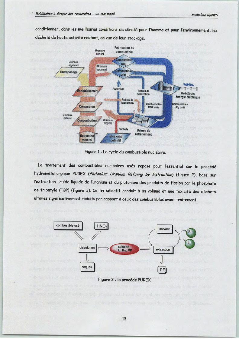
certain nombre d'opérations et de transformations qui constituent « le cycle du combustible»
(figure 1), dont une étape est le retraitement. Le retraitement consiste à récupérer, dans les
combustibles usés, les matières énergétiques réutilisables - uranium et plutonium - et à
12
Habilitation à diriger des recherches - ZB mai Z004 Micheline PPAYC
conditionner, dans les meilleures conditions de sûreté pour l'homme et pour l'environnement, les
déchetsde haute activité restant, envue de leur stockage.
Uranium
J$jHMfft
UanhMPsMmSêti «la«M'tastlisfe
r î-îftèadatm
éfKi^iéiisetrlçp»
âïlitÉê».
Figure 1 : Le cycle du combustible nucléaire.
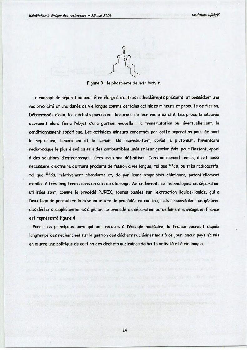
Le traitement des combustibles nucléaires usés repose pour l'essentiel sur le procédéhydrométallurgique PUREX (Plutonium Uranium Refining by Extraction) (figure 2), basé sur
l'extraction liquide-liquide de l'uranium et du plutonium des produits de fission par le phosphatede tributyle (TBP) (figure 3). Ce tri sélectif conduit à un volume et une toxicité des déchets
ultimes significativement réduits par rapportà ceux des combustibles avant traitement.
combustible usé HNO,
dissolution I s c=$
v
Figure 2 : le procédé PUREX
13
Habilitation à diriger des recherches - ZB mai Z004 Micheline PPAYC
Figure 3 : le phosphate de n-tributyle.
Le concept de séparation peut être élargi à d'autres radioéléments présents, et possédant une
radiotoxicité et une durée de vie longue comme certains actinides mineurs et produits de fission.
Débarrassés d'eux, les déchets perdraient beaucoup de leur radiotoxicité. Les produits séparés
devraient alors faire l'objet d'une gestion nouvelle : la transmutation ou, éventuellement, le
conditionnement spécifique. Les actinides mineurs concernés par cette séparation poussée sont
le neptunium, l'américium et le curium. Ils représentent, après le plutonium, l'inventaire
radiotoxique le plus élevé au sein des combustibles usés et leur gestion fait, pour l'instant, appel
à des solutions d'entreposages sûres mais non définitives. Dans un second temps, il est aussi
nécessaire d'extraire certains produits de fission à vie longue, tel que 135Cs, ou très radioactifs,
tel que 137Cs, relativement abondants et, de par leurs propriétés chimiques, potentiellement
mobiles à très long terme dans un site de stockage. Actuellement, les technologies de séparation
utilisées sont, comme le procédé PUREX, toutes basées sur l'extraction liquide-liquide, qui a
l'avantage de permettre la mise en oeuvre de procédés en continu, mais l'inconvénient de générer
des déchets supplémentaires à gérer. Le procédé de séparation actuellement envisagé en France
est représenté figure 4.
Parmi les principaux pays qui ont recours à l'énergie nucléaire, la France poursuit depuis
longtemps des recherches sur la gestion des déchets nucléaires mais à ce jour, aucun pays n'a mis
en oeuvre une politique de gestion des déchets nucléaires de haute activité et à vie longue.
14

Habilitation à diriger des recherches - ZB mai Zoo4
Combustiblw
U Pu
ilPUREX J_U£Lj.
NpTe
Produits de fission
et actinides mineurs '
Cs
I Actinides et^lanthanides J
Produits
de fission
Am *Cm
AÙIAMEX
CALIXARENELanthanides
Produits
de fission
Micheline PPAYB
Stockage
Figure 4 : schéma de séparationpoussée Français.PUREX- Plutonium Uranium Refining by Extraction, procédé hydrométallurgique de séparation de
^uranium et du plutonium du combustible usés - ÙIAMEX. DIAMide Extractant, procédé de séparation del'ensemble lanthanides et actinides mineurs des produits de fission - SANEX: Séparation des ActiNidesparExtraction ou Sélective ActiNides Extraction, procédé de séparation des actinides et des lanthanides,CALIXARENES: Séparation du césium des produits defission par des calixarènes.
1-L'extraction liquide-liquide pour l'industrie nucléaire
La stratégie du programme de recherches menée en France par le CEA pour la séparation desradionucléides à vie longue consiste à articuler les recherches en complément de la stratégieindustrielle actuelle du retraitement du combustible usé et à tirer parti des potentialités duprocédé PUREX. La voie d'exploration principale pour la séparation des radionucléides àvie longueest celle de l'extraction liquide-liquide, extraction sélective à partir de la solution aqueuse danslaquelle a été solubilisé l'ensemble des composants du combustible usé. Ce choix découle de
plusieurs considérations. Tout d'abord le procédé PUREX de traitement du combustible usé,actuellement mis en œuvre pour la récupération de Uet de Pu est un procédé de ce type. Parailleurs, la séparation des radionucléides à vie longue ne prend tout son sens qu'en complémentd'une stratégie homologue àcelle de la séparation U-Pu. Il apparaît donc pertinent de se placeren aval de cette étape essentielle pour de nouveaux objectifs de séparations complémentaires.Ensuite, la relative proximité de l'échéance privilégie naturellement les procédés dont la maturitéindustrielle est éprouvée, ce qui est le cas des procédés hydrométallurgiques. Enfin le retourd'expérience de la mise en œuvre du procédé PUREX dans les unités de COÔEMA à la Haguedémontre la capacité de tels procédés àprocurer des performances de séparation remarquablesen ce qui concerne la quantitativité et la sélectivité de la récupération des éléments d'intérêt et
15

Habilitation àdiriger des recherches - ZB mai ZQQ4 Micheline PFAYC
aproduire de faibles quantités de déchets technologiques associés. C'est là un atout considérableau regard des principaux critères d'évaluation pour une séparation poussée des radionucléides.
La récupération de Am et de Cm est aujourd'hui envisagée en trois étapes. La première étapedes séparations, le procédé DIAMEX, a pour objectif de séparer, à l'aide de molécules de lafamille des diamines (figure 5), le mélange des ions An(III) et Ln(III) du reste des déchets,
soient les 2/3 des produits de fission.
C8H17^N
Figure 5 : Struture du N,N'-diheptyl-N,N'-dimethyl(octyloxyethyl) malonamide
La seconde étape, le procédé SANEX, a pour but la séparation des deux groupes d'ions An(III)
et Ln(III), par extraction sélective des An(III), constituants mineurs du mélange, à l'aide de
molécules de la famille des bis-triazinyl-pyridines (figure 6). Les conditions requises pour aboutir
à la sélectivité sont plus « pointues » que celles de l'étape précédente, mais le fait d'opérer en
milieu épuré du reste des produits de fission rend possible le choix de conditions chimiques
favorables à la séparation.
R^N
Figure 6 : : Formule générale des 2,6-bis-(l,2,4-triazine-3-yle)-pyridine (BTP)R = H ou alkyle
Enfin, la récupération de Cs est envisagée grâce à la mise en œuvre du procédé CALIXARENES
qui a pour but d'extraire le césium directement des solutions de produits de fission issues du
procédé PUREX à l'aide de molécules de la famille des calixarènes-couronnes (figure 7). Ces
molécules, hautement sélectives et extrêmement résistantes, sont capables de piéger le césium
parmi les innombrables espèces chimiques, en particulier les alcalins, présentes dans des
solutions contenant de l'acide nitrique en concentration élevée.
16

Habilitation àdiriger des recherches - ZB mai Z004 Micheline PPAY6
Figure 7 : structure du benzo couronne 6-calixarène-benzo-couronne 6.
Les résultats obtenus à ce jour augurent très favorablement de la possibilité de réunir à
l'horizon 2006 les éléments scientifiques et techniques nécessaires à l'évaluation des conditions
de la mise en œuvre industrielle de la stratégie précédemment décrite.
1.1 -Le dicyclohexano-18-couronne-6
Le procédé PUREX, aujourd'hui le plus efficace, présente néanmoins un certain nombre de
limitations essentiellement liées à la radiolyse du solvant, le phosphate de tributyle (TBP), quisous l'effet des rayonnements ionisants, se dégrade en sous-produits gazeux et liquides. Parmi
ceux-ci, les plus gênants sont les acides mono- et dibutylphosphoriques (H2MBP et HDBP) quiinterviennent dans le procédé et en abaissent considérablement les performances, par formation
de produits insolubles et de complexes avec les produits de fission et de matières fissilessolubles en phase organique[l].
La recherche de nouveaux matériaux, utilisables pour le retraitement des combustibles
nucléaires usés et le traitement des effluents radioactifs, impose comme critères de sélection
une bonne capacité d'extraction, une grande sélectivité, mais aussi une excellente stabilité
radiochimique, propriété inhérente à tout développement industriel.
Un grand nombre d'études a été consacré à la recherche de nouveaux extractants, tout aussi
efficaces mais chimiquement et radiochimiquement plus stables que le TBP. L'utilisation des outils
de la chimie supramoléculaire[2] ont mis en évidence les potentialités des éthers couronnes en
hydrométallurgie[3], et en particulier du dicyclohexano-18-couronne-6 (DCH18C6) (figure 8), quis'est révélé le plus apte au développement d'un nouveau procédé de retraitement des
combustibles nucléaires usés. En effet, des travaux ont montré l'efficacité de l'isomère cis-syn-cis du DCH18C6 pour séparer sélectivement PuIV de Uw et des produits de fission sans le
17
Habilitation à diriger des recherches - ZB mai Z0û4 Micheline PPAY6
changement devalence nécessaire avec le TBP lors du procédé PUREX[4]. Dans ce contexte, nous
avons développé un nouveau système faisant intervenir le DCH18C6 pour la concentration
sélective du strontium contenu dans des solutions acides hautement chargées en sodium[5,6].
a:o
a:o
Figure 8 : Le dicyclohexano-18-couronne-6 (DCH18C6) cis-syn-cis et cis-anti-cis
Néanmoins, pour utiliser un matériau dans l'industrie nucléaire, il faut connaître avec précision
la dose d'irradiation au-delà de laquelle il a perdu ses qualités essentielles. Avec une approche
analogue à l'industrie pharmaceutique qui, avant de mettre un médicament sur le marché,
identifie avec précision ses métabolites et étudie, individuellement, leur activité sur l'organisme
humain, nous avons étudié la possibilité d'utiliser le DCH18C6 à l'échelle industrielle.
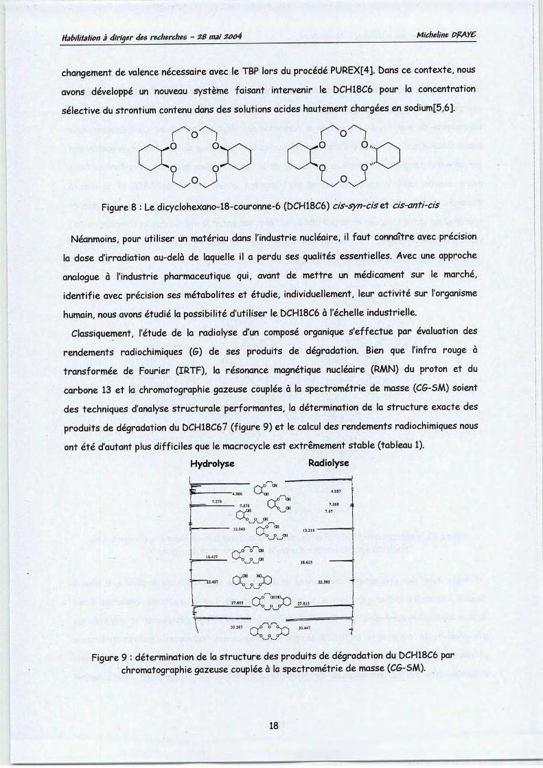
Classiquement, l'étude de la radiolyse d'un composé organique s'effectue par évaluation des
rendements radiochimiques (G) de ses produits de dégradation. Bien que l'infra rouge à
transformée de Fourier (IRTF), la résonance magnétique nucléaire (RMN) du proton et du
carbone 13 et la chromatographie gazeuse couplée à la spectrometrie de masse (CG-SM) soient
des techniques d'analyse structurale performantes, la détermination de la structure exacte des
produits de dégradation du DCH18C67 (figure 9)et le calcul des rendements radiochimiques nous
ont été d'autant plus difficiles que lemacrocycle est extrêmement stable (tableau 1).
Hydrolyse Radiolyse
F=j 7.24.308 ""^Sha° 4.957
7.368 :
7.67
12.218
18.623
22.593r
27.815
30.447
•
a,o ai
o CH
c
a:O O CH
^S> 0
a° °
aCH «VNo o JJ
\ t \ t
o o o^J
30.267 s~*JO O
a:::o
o,
o1
Figure 9 : détermination de la structure des produits dedégradation du DCH18C6 parchromatographie gazeuse couplée à la spectrometrie de masse (CG-SAA).
18

Habilitation à diriger des recherches - ZB mai Z004 Micheline PPAY6
Les solutions de dissolution de combustibles nucléaires usés étant fortement acides, nous
avons également identifié les produits d'hydrolyse du DCH18C6 en effectuant une étude
systématique de l'influence de l'acidité et de celle de la concentration en uranium sur la
dégradation du macrocycle à l'aide de la technique des plans d'expériences. Curieusement, nousavons observé que la présence d'uranium défavorise la dégradation du macrocycle, probablementpar un effet template de l'uranium, en faveur de la recombinaison des fragments formés. Nous
avons ensuite isolé le complexe formé par l'isomère cis-syn-cis du DCH18C6 et le nitrate
d'uranyle et l'avons analysé par diffraction de rayons X(figure 10). Il n'y a pas de liaison decoordination entre l'uranium et le DCH18C6 ; l'interaction entre le macrocycle et l'uranium sefait
via des liaisons hydrogène mettant en œuvre d'une part les deux molécules d'eau du complexe etd'autrepart les atomes d'oxygène du macrocycle.
O : OxygenC : CarbonN : NitrogenU : UraniumOW :H20
Figure 10 : représentation ORTEP de la structure du complexe de l'isomère cis-syn-cis duDCH18C6 avec le nitrated'uranyle par diffraction de rayons X.
Compte tenu des précautions croissantes prises par les industriels du nucléaire, il nous a
semblé nécessaire d'aller plus loin dans nos investigations. Les extractants modernes étant
définis moléculairement ainsi que dans leur stéréochimie, il a fallu déterminer la stéréochimie
des produits de radiolyse du DCH18C6. Malgré la puissance des techniques d'analyse structuraleutilisées et précédemment citées, il nous a été nécessaire, pour confirmer les fragmentsproposés, d'en synthétiser chacune des structures possibles. Cette synthèse nous a permis
19
Habilitation à diriger des recherches - ZB mai Z0Q4 Micheline PFAYC
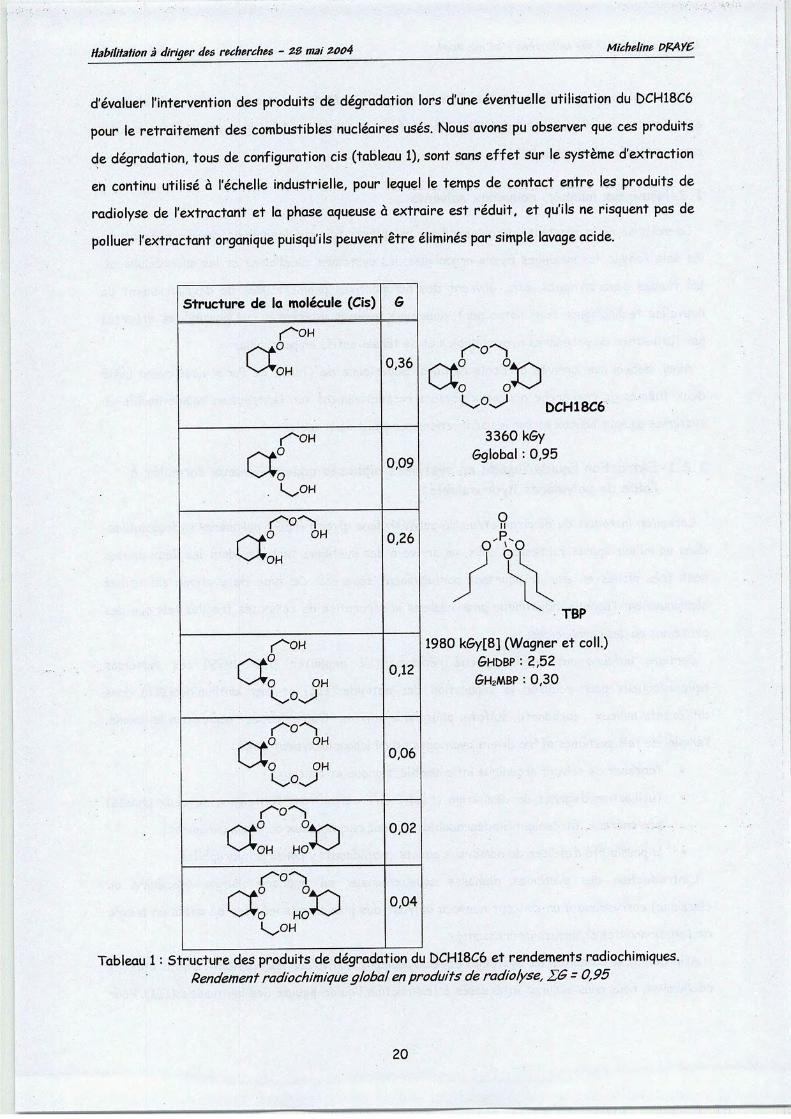
d'évaluer l'intervention des produits de dégradation lors d'une éventuelle utilisation du DCH18C6
pour le retraitement des combustibles nucléaires usés. Nous avons pu observer que ces produitsde dégradation, tous de configuration cis (tableau 1), sont sans effet sur le système d'extraction
en continu utilisé à l'échelle industrielle, pour lequel le temps de contact entre les produits de
radiolyse de l'extractant et la phase aqueuse à extraire est réduit, et qu'ils ne risquent pas de
polluer l'extractant organique puisqu'ils peuvent êtreéliminés par simple lavage acide.
r-o^
a: :ook>©>^ DCH18C6
3360 k<5y(Sglobal : 0,95
TBP
1980 kGy[8] (Wagner et coll.)GHùBP : 2,52
GH2MBP : 0,30
Structure de la molécule (Cis) G
r^oH
^*OH0,36
r^OH
a: 0,09
>NiO OH
^^OH0,26
r^oH
a0—'•O OHk.o^J
0,12
^aO OH^•O OH
0,06
et0 °ooX^OH HO^-^
0,02
<T°"o\Ao HO*^
Is^OH
0,04
Tableau 1: Structure des produits de dégradation du DCH18C6 et rendements radiochimiques.Rendement radiochimiqueglobal enproduits deradiolyse, ZG - 0,95
20

Habilitation àdiriger des recherches - ZB mai ZOo4 Micheline PPAY6
Ce travail nous a permis de conclure que les propriétés d'extraction et la remarquable stabilitéen milieux acide et radioactif du DCH18C6, en font un solide candidat pour le retraitement descombustibles nucléaires usés[9].
1.2-Nouveaux milieux, nouveaux solvants
La maîtrise de la réactivité dans les milieux complexes tels que les milieux aqueux concentrés,les sels fondus, les mélanges hydro-organiques, les systèmes micellaires et les microémulsions,les fluides supercritiques, etc., ouvrent des perspectives prometteuses de développement denouvelles technologies. Pour notre part, nous nous sommes intéressés aux possibilités offertespar l'utilisation de polymères hydrosolubles et de tensio-actifs en particulier.
Ainsi, depuis mon arrivée à l'Ecole National Supérieure de Chimie de Paris, nous avons initié
deux thèmes de recherche nouveaux portant respectivement sur l'extraction liquide-liquide ensystèmes aqueux/aqueux et sur les séparations par point de trouble.
1.2.1-Extraction liquide/liquide en systèmes biphasés aqueux-aqueux formulés àl'aide de polymères hydrosolubles.
Lorsqu'on introduit du dextran et/ou du poly(éthylène glycol) -PES : polymères hydrosolubles-dans un milieu aqueux fortement salin, on arrive à des systèmes biphasés dont les deux phasessont très riches en eau et pourtant parfaitement séparées. Ce type de système est utiliséclassiquement l'échelle industrielle pour réaliser la séparation de composés fragiles tels que desprotéines ou des aminoacides.
Certains auteurs ont aussi cherché récemment à exploiter (1992-1999) ces systèmesaqueux/aqueux pour réaliser la séparation des actinides(III) et des lanthanides(III) dansdifférents milieux : carbonate, sulfate, phosphate, nitrate. Outre l'aspect séparation lui-même,l'emploi de tels systèmes offre divers avantages parmi lesquels on peut citer :
• l'absence de solvant organique inflammable, toxique et coûteux;
• l'utilisation d'agents de démixtion (c'est-à-dire permettant l'obtention de deux phases)peu onéreux, facilement biodégradables et donc respectueux de l'environnement;
• la possibilité d'utiliser de nombreux agents complexants ycompris hydrophilesL'introduction des systèmes diphasés aqueux/aqueux en hydrométallurgie (nucléaire ou
classique) correspond à un concept nouveau offrant des possibilités inédites de mises en œuvrede fonctionnalités chimiques intéressantes.
Afin de mieux connaître les systèmes aqueux/aqueux et d'évaluer les possibilités qu'ils offrentréellement, nous nous sommes intéressés à l'extraction liquide-liquide des lanthanides(III). Pour
21

Habilitation à diriger des recherches - ZB mai Z004 Micheline PFAYC
essayer de surmonter la difficulté sur laquelle ont buté les rares auteurs qui se sont penchés sur
la séparation actinides(III)/lanthanides(III) en milieux diphasés aqueux/aqueux, nous avons
choisi d'utiliser les ions ferricyanure Fe(CN)63" comme vecteur d'extraction. Ce choix tient au
fait que les ions forment des complexes LnFe(CN)6 avec les lanthanides(III), même en milieu
très acide (nousavons opéré en deçà de la limite de précipitation de LnFe(CN)6).
Les résultats obtenus montrent qu'il n'est pas facile de formuler des systèmes diphasés
aqueux/aqueux en milieu acide nitrique (0,5-1 M) avec des polymères hydrosolubles classiques
comme le PEG et le dextran, mais une fois le système formulé, l'extraction des lanthanides(III)
peut être réalisée. Par ailleurs, sur le plan de la physico-chimie, nous avons observé que le
partage des lanthanides(III) suit une loi de comportement aussi simple que dans les systèmes
diphasés aqueux/organiques classiques. Par exemple, la Figure 11 montre que les points
expérimentaux représentatifs du coefficient de distribution de l'europium(III) entre une phase
aqueuse riche en PEô-1000 (notée <&2) et une phase aqueuse riche en dextran (notée 4>i) peuvent
être linéarisés selon l'équation [1] établie de manière classique en tenant compte des équilibres
de complexation et de partage [2] et [3] :
J^ = 1 J_
4, K£uPÏu[Ee(CNt\^ ^Eul+Fe{CN\r o EuFe{CN\ [2]
EuFe{CN\ o EuFe{CN\ [3]
avec *> - ^EuF<CN^ et K ^<™W1 *[fi/% IFeiCNf^ ^-\.EuFe{CN\\
Ces premiers résultats sont importants car, même s'il reste de nombreux problèmes pour
formuler des systèmes diphasés aqueux/aqueux en milieux acides, ils constituent un premier pas
vers la définition de systèmes totalement nouveaux pour réaliser la séparation de groupe
actinides(III)/lanthanides(III) dans les conditions de la séparation poussée. Dans la suite de ce
travail, il est prévu de rechercher des polymères hydrosolubles mieux adaptés que le PEG (divers
PEG ont été testés) et le dextran, et d'utiliser des molécules polyazotés comme vecteur
d'extraction.
22

Habilitation à diriger des recherches - ZB mai Z004
•ê
25 50
1/ [Fe(CN)6-]dextran(M-l)
Micheline PPAYC
125
Figure 11 :droite 1/DEu en fonction de 1/[Fe(CN)36~]dextran)dans le cas du partage de Eu(III) entre une phase aqueuse riche
en PEG-1000 et unephaseaqueuse riche en dextran.
1.2.2-Séparation par point de trouble
Les tensio-actifs sont capables de s'agréger pour former des agglomérats de la taille de
colloïdes, considérés comme des micelles (figure 12). Au cours de leur formation, les micelles de
tensio-actif ont la capacité de piéger de nombreuses substances hydrophobes, les isolant ainsi dureste de la solution.
Groupe hydrophile
Chaîne hydrophobe
Figure 12 : Représentation schématique d'une micelle.
La solubilité de tensio-actifs non ioniques ou zwitterioniques en solution aqueuse est fortementdiminuée au delà d'une température bien définie, la température de point de trouble (TCP). Enfixant la température de la solution au delà de la température TCP/ la solution demixte en une
23

Habilitation à diriger des recherches - ZB mai Zûo4 Micheline PPAY6
phase riche en tensio-actif et une phase pauvre en tensio-actif[10,11], qui se trouve alors à une
concentration proche de la concentration micellaire critique (CMC) (figure 13).
tensio-actif en
solution dans l'eatKÇF 1 'point trouble
\J •zm CTI
solution homogène solution turbide
j-jkp phase richeen tensio-actif
phase pauvreen tensio-actif
phase richeen tensio-actif
Figure 13 : démixtion d'une solution de tensio-actif non ionique ou zwitterioniquepar phénomène de point de trouble.
L'extraction par point de trouble est donc le résultat de la séparation d'un soluté entre les deux
phases aqueuses,l'une riche et l'autre pauvre en tensio-actif, en fonction de son affinité pour le
tensio-actif.
Le point de trouble, qui est un phénomène réversible, a été utilisé pour la séparation de divers
solutés. Dans la plupart des applications, l'extraction par point de trouble est utilisée pour la
séparation et/ou la préconcentration de molécules d'intérêt biologique[10,ll], comme étape
préalable au dosage d'analytes[12,13,14] ou la récupération de polluants d'effluents
industriels[15,16]. L'extraction par point de trouble, en absence d'agent chélatant, est une
technique efficace pour la récupération d'ions métalliques[17,18] ; Un agent chélatant peut
extraire sélectivement ces ions, par formation de complexes hydrophobes solubles dans la
solution micellaire de tensio-actif. Depuis les premiers travaux de Watanabe et al. [19] sur
l'extraction du nickel et du zinc, un grand nombre de ligands ont été utilisés pour la récupération
d'ions métalliques[20,21,22]. L'extraction par point de trouble du Cr3* avec des dérivés de la
8-hydroxyquinoléine a été décrite dans la littérature[12,22].
24
•

Habilitation àdiriger des recherches - ZB mai zoo4 Micheline PPAY6
1.2.2.1-Le phénomène de point de trouble et son origine
Le point trouble est défini comme la température au-delà de laquelle un tensio-actif non ioniqueou zwitterionique demixte, et se sépare en une phase aqueuse riche en tensio-actif et une phaseaqueuse diluée, dont la concentration en tensio-actif est proche de la CMC[23]
L'extraction par point de trouble offre une alternative potentielle à l'extraction liquide-liquidetraditionnelle. Cependant, par rapport à l'extraction liquide-liquide classique, l'extraction parpoint de trouble est un concept nouveau qui est encore loin de sa maturité que ce soit en termede développement ou d'applications.
Les forces à l'origine du phénomène de point de trouble ne sont pas clairement connues. La
séparation entre les phases riche et pauvre en tensio-actif résulte d'un équilibre délicat entreles forces attractives et répulsives soluté-soluté, et les interactions solvant-soluté. De plusl'entropie qui tend à favoriser la solubilité des micelles dans l'eau s'oppose à l'enthalpie quifavorise la séparation des micelles de l'eau[10].
Au moins deux interprétations peuvent être données au phénomène de point de trouble, faisant
intervenirsoient les liaisons hydrogène, soient les liaisons de Van der Waals.
Abasse température, les micelles de tensio-actif du milieu aqueux sont entourées de molécules
d'eau. Des liaisons hydrogène se créent entre l'eau et la partie hydrophile du tensio-actif. Et
lorsque la température est portée au-delà de la température de point de trouble, les
groupements hydrophiles des molécules de tensio-actif se déshydratent par rupture des liaisons
hydrogène. Le tensio-actif devient insoluble dans l'eau et les molécules de tensio-actif se
regroupent en agrégats de plus en plus gros. La solution se trouble et les phases se séparent pardifférence de densité[15,23,24].
Des calculs ont été effectués et montrent que les composés polyéthylène glycol (PEG) ou lesmicelles de surfactants polyéthoxylés existent à la fois sous forme polaire et apolaire. La chaînepolyéthoxylée peut être considérée comme un enchaînement de dipôles, chacun interagissantavec les molécules d'eau qui l'entourent. La forme polaire, dominante aux basses températures,devient apolaire et insoluble dans l'eau au-dessus d'une température critique, la température depoint de trouble[25].
Un grand nombre d'études ont été menées concernant la température de point de trouble etles différents paramètres qui peuvent la modifier. En effet, la température à laquelle s'effectuela séparation de phases est contrôlée par la composition du système aqueux : concentration entensio-actif, structure du tensio-actif, présence et nature de sels inorganiques, de composésorganiques ou d'un second tensio-actif dans le milieu[10,26].
25

Habilitation à diriger des recherches - ZB mai ZQ04 Micheline PFAY6
1.2.2.2-Utilisation du phénomène de point trouble pour la séparationgadoliniutn/lanthane
L'extraction par point de trouble est, dans son concept, une technique simple que nous avons
mise en œuvre, dans lasuite de nos travaux, pour séparer le gadolinium du lanthane à partir d'une
solution aqueuse de tensio-actif, le TRITON X-114, et d'un ligand approprié, la
8-hydroxyquinoléine.
La température, le temps d'équilibre, le pH de la solution, la nature et la quantité de ligand
utilisé, ont été étudiés comme facteurs déterminants pour l'efficacité et la sélectivité de
l'extraction.
Les complexes des lanthanides avec la 8-hydroxyquinoléine sont caractérisés par une grande
stabilité thermodynamique (Log p2= 16.21 et log p2= 17.21 pour La3+ et Gd3+ respectivement, à
T=30°C, en présence de [NaCl04] =0,3M et dans le dioxane à 50% v/v[27]) et une constante de
formation Ln3+-8-hydroxiquinolinate dix fois plus élevée pour le gadolinium que pour le lanthane.
Cette différence a été mise à profit pour l'extraction par point de trouble et nous a permis de
bénéficier d'un système très efficient pour la séparation intragroupe des lanthanides (III).
L'extraction par point de trouble des lanthanides avec la 8-hydroxyquinoléine a donc été réalisée
à l'aide de solutions de tensio-actif non ionique à 1% en poids dans une solution neutre (pH ~ 5.5).
De nombreux tensio-actifs non ioniques ont été testés : des alcools polyoxyéthylés comme le
Simulsol OX1006L et le Simulsol NW900, le polyoxyethylène sorbitan monooléate Tween 80 et
l'alkylphénol polyéthoxylé Triton X-114. Les structures chimiques du simulsol NW900 et du triton
X114sont données figure 14.
Hp^O-Figure 14 : Le simulsol NW900 et le triton X114
Dans la solution micellaire constituée par des tensio-actifs non ioniques tels que le Simulsol
OX1006L, le Simulsol NW900 ou le Tween 80, dont la partie lipophilique est aliphatique, le
complexe formé par la 8-hydroxyquinoléine avec les lanthanides est insoluble et précipite. Par
contre, le Triton X-114, avec la structure aromatique de sa partie lipophilique, solubiliseà la fois
la 8-hydroxyquinoléine et ses complexes avec les lanthanides en formant des structures
microscopiquement ordonnées dans la micelle.
En outre, le système étudié présente un certain nombre d'avantages en terme
d'expérimentation puisque la température de point de trouble du Triton X-114 se situant autour
26

Habilitation à diriger des recherches - ZB mai Z004 Micheline PPAY&
la température ambiante (23-25°C), la température de travail a été fixée à 60°C. Ainsi, la phase
riche en surfactant de par sa densité élevée, permet une récupération plus aisée de la phase
aqueuse, moins dense, par simple aspiration.
L'extraction par point de trouble du lanthane(III) et du gadolinium(III) par la
8-hydroxyquinoléine a été évaluée en termes d'efficacité d'extraction E. 3+, de coefficient de
distribution £>3+, de sélectivité S,ed^-jur et de facteur de concentration CF, 3+ définis commeu?-
suit :
e^=£Lz£LxmQ
4„- =
^Gd^JLr?*
c,
V
Gds-
'Lt,"
fv^\Vprs J
-c- _ Masse totale de Ln3+ dans la phase riche en tensio-actif {C, xVj)-{Cf *Vf)ifl3+ Masse totale de Ln3+ dans la phase aqueuse [Cf x\/f)
où C/ est la concentration initiale en mol L"1 de cation métallique dans la solution micellaire, Cf
est la concentration en mol L"1 de cation métallique dans la phase aqueuse après extraction parpoint de trouble, V, est le volume en mL de solution micellaire, Vf est le volume en mL de phase
aqueuse extraction par point trouble et Vprs est le volume en mL de phase riche en tensio-actif
après extraction par point de trouble.
"Joo « Km 2b--Q3O
4= ?n -C
oa. .
«> 1b-•o
(!)
r> 10-m
>d) "
a. "
Em
5:
0 - ' 1 . 1 | 1 1 i ! | '"i "T-ri - t—!—i—i—i—[—i—i 1—i—f
4 6 8
[8-hydroxyquinoline], mM
10
Figure 15 : variation de la température de point de trouble en fonction de laconcentration en 8-hydroxyquinoléine.
27

Habilitation à diriger des recherches - ZB mai ZQ04 Micheline PPAYC
Nous avons vérifié (Figure 15) que la température de point de trouble diminue linéairementavec la concentration en 8-hydroxyquinoléine en deçà d'une concentration de 7 mmol L"1,concentration àpartir de laquelle la température de point de trouble ne varie plus.
Nous avons ensuite étudié l'influence du rapport molaire 8-hydroxyquinoléine-lanthanide(III)
sur l'efficacité de l'extraction et sur sa sélectivité. La figure 16 montre qu'en l'absence d'agent
chélatant, l'extraction est inférieure à 10%, à la fois pour le lanthane et pour le gadolinium. Bienque sélective en faveur du gadolinium, l'extraction reste faible pour des rapports molaires8-hydroxyquinoléine-lanthanide(III) de 2 à 4. En augmentant le rapport molaire8-hydroxyquinoléine-lanthanide(III) de 6 à 14, l'efficacité d'extraction du gadolinium augmenteplus rapidement que celle du lanthane, donnant lieu à d'excellentes valeurs de sélectivité enfaveur dugadolinium (tableau 2).
100
^80o
'+-oa
x
T3
a
60
oû-
04
• UffCI)
• êd(in)
4 6 8 10 12[8-hydroxyquinoléine]/[Ln(III)]
14
Figure 16 : Influence du rapport molaire agent chélatant-lanthanide(III) sur l'efficacitéd'extraction et la sélectivité pour l'extraction du Gd3+ vis-à-vis du La3+. [La(N03)3] =[Gd(N03)3] =0,36mM ;pH =5,5; 1% Triton X-114 en poids ; température d'équilibrede 60°Cet temps d'équilibre de lh.
Pour des rapports molaires 8-hydroxyquinoléine-lanthanides(III) élevés (tableau 2), descoefficients de distribution supérieurs à 15 pour le lanthane et à 300 pour le gadolinium sont
observés, donnant lieu à des sélectivités supérieures à 10 en faveur du gadolinium. Pour un
rapport molaire 8-hydroxyquinoléine-lanthanides(III) de 14, une sélectivité supérieure à 30, dugadolinium vis-à-vis du lanthane est observée, pour un facteur de concentration du gadoliniumsupérieur à57. L'efficacité de l'extraction est fortement influencée par la nature du tensio-actifnon ionique et celle du rapport molaire 8-hydroxyquinoléine-lanthanides(III).
28
———

Habilitation à diriger des recherches - ZB mai Z004Micheline PPAY6
Rapport molaire 8-hydroxyquinoline/ , I " :Ln3+ bla *&^ SGd37La3+ Sed3+/La3+0 1,1±0,3 5,9+0,3 n.d. 5,4+1,42 1*7*0,3 6,9±0,3 n.d. 4,0+0 84 2,2±0,3 13,2±0,4 5,8 6,0+0,96 5,3+0,3 32,6+0,6 6,6 6,1+0,58 11,3±0,4 100±1,0 8,9 8,8+0,310 18,9±0,5 394±4,0 20,9 20,8+0,612 38,1±0, 1059+10,0 28,6 27,'8+0,'6
-M . 63,8+0,9 2067+20 32,4 324+06A, ^(N03)3] =[6d(N03)3] =0,36mM ;pH =5,5; 1% Triton X-114 en poids ;température d'équilibre de 60°C :tempsdéquilibre de lh ;volume de phase micellaire=45 mL ;volume de phase riche en surfactant après point trouble=l,5 mL
Tableau 2: Influence du rapport molaire agent chélatant-lanthanide(III) sur l'efficacité et lasélectivité pour l'extraction du Gd3t vis-à-vis du La et le facteur de concentration.
Au cours de ces travaux, nous avons développé un nouveau procédé d'extraction liquide-liquidesans solvant organique basé sur le concept de point de trouble pour la séparation delanthanides[28].
Ces premiers résultats définissent un système totalement nouveau pour la séparation delanthanides(III). Nous poursuivons actuellement ce travail par des manipulations en milieuradioactif dans l'Actinides Research Group du Massachusetts Institute of Technology, afind'évaluer les possibilités d'utiliser un tel système pour la séparation actinidesmineurs/lanthanides et de déterminer son efficacité pour l'extraction sélective des actinides.
2-L'extraction solide-liquide pour l'industrie nucléaire
Parmi les méthodes séparatives disponibles, l'extraction solide-liquide offre les bases desschémas de séparations les plus pratiques. Du point de vue de la gestion des déchets radioactifs,l'un des avantages majeurs que présente l'extraction solide - liquide réside en sa capacité àséparer les radioéléments tout en produisant un volume minimal d'effluent décontaminé et adaptéàun stockage direct. Des études ont mis en évidence l'utilisation de matrices minérales[29] qui,malheureusement, constituent in fine un déchet supplémentaire. Par opposition, les résinesorganiques ne comportant que des atomes de carbone (C), d'hydrogène (H), d'oxygène (O) etd'azote (N) (principe CHON) sont totalement incinérables et constitueront, par conséquent, unvolume final de déchets radioactifs réduit.
L'échange d'ions peut être défini comme un échange réversible d'ions entre une phase solide etune phase liquide. Les résines échangeuses d'ions organiques ont été décrites pour la premièrefois en 1935 [30]. Il s'agissait de la découverte des propriétés d'échange d'ions d'une résinephénol - formaldehyde.
29

Habilitation àdiriger des recherches - ZB mai ZQ04 Micheline PPAYC
les principales exigences requises pour ces matériaux sont une bonne capacité d'échange, unebonne sélectivité, un minimum de perte dans les effluents, et dans le cas de l'industrie nucléaire,une bonne stabilité vis à vis des rayonnements ionisants. La sélectivité d'une résine pour un ion
par rapport à un autre dépend principalement de la nature du groupement fonctionnel de larésine. Elle est aussi dépendante de la composition de la solution, du taux de gonflement de larésine et de la nature du squelette du polymère. Ces différents facteurs influent également la
cinétique de complexation et le taux d'échange de la résine.
2.1-La poly(4-vinylpyridine)
De par les propriétés acido-basiques et complexantes de ses noyaux pyridine, la poly(4-vinylpyridine) (P4VP) est une résine organique qui présente un vaste domaine d'application. Enparticulier, la P4VP est particulièrement efficace en ce qui concerne la récupération des cationslourds et des métaux de transitions1]. Nous avons démontré les potentialités de la P4VP en ce
qui concerne la récupération d'émetteurs a tels que 241Am, le plutonium total et 244Cm àl'état detraces et d'émetteurs B,y. tels que, 125Sb, 60Co, et 144(Ce et Pr) et 106Ru[32,33,34], qui constitue
90% de la radioactivité résiduelle après les coprécipitations actuellement nécessaires à
l'élimination de la majeure partie des radioéléments présents à l'état de trace dans les effluentsliquides. Nous avons également montré l'efficacité de la P4VP pour la récupération de l'iodegazeux[35]. Suite à ces résultats encourageants et dans l'optique d'utiliser cette résine pour letraitements d'effluents radioactifs liquides et gazeux, nous avons étudié la stabilité de la poly(4-
vinylpyridine) (P4VP) (Figure 17).
Figure 17 : La poly(4-vinylpyridine)
L'étude de l'action des rayonnements ionisants sur un polymère est très délicate de par lacomplexité des mécanismes de dégradation potentiellement mis en jeu. Cette difficulté estd'autant plus grande que le polymère est stable. En raison de sa grande stabilité, la P4VP s'estavérée un matériau très difficile à caractériser par les techniques classiques d'analysesl'infrarouge à transformée de Fourier (IRTF), l'UV-visible (UV-Vis.), l'analyse thermo-gravimétrique (ATG), l'analyse mécanique dynamique (DMA), la résonance paramagnétiqueélectronique (RPE) et la spectroscopie d'émission atomique à plasma induit haute fréquence à
30
—
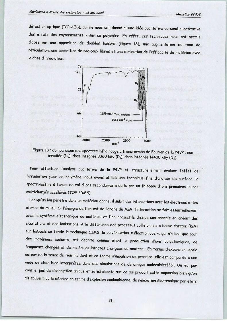
Habilitation à diriger des recherches - ZB mai Z004Micheline PPAY6
détection optique (ICP-AES), qui ne nous ont donné qu'une idée qualitative ou semi-quantitativedes effets des rayonnements ysur ce polymère. En effet, ces techniques nous ont permisd'observer une apparition de doubles liaisons (figure 18), une augmentation du taux deréticulation, une apparition de radicaux libres et une diminution de l'efficacité du matériau avecla dose d'irradiation.
60
3000
1690 cm'1 vc=Ccoojugll&
1654cm"1 Vcc
2500 2000cm
1500
Figure 18 :Comparaison des spectres infra rouge à transformée de Fourier de la P4VP :nonirradiée (D0), dose intégrée 3360 kGy (Di), dose intégrée 14400 kGy (D2).
Pour effectuer l'analyse qualitative de la P4VP et structurellement évaluer l'effet del'irradiation ysur ce polymère, nous avons utilisé une technique fine d'analyse de surface, laspectrometrie à temps de vol d'ions secondaires induits par un faisceau d'ions primaires lourdsmultichargés accélérés (TOF-PDMS).
Lorsqu'un ion pénètre dans un matériau donné, il subit des interactions avec les électrons et lesatomes du milieu. Si l'énergie de l'ion est de l'ordre du MeV, l'interaction se fait essentiellementavec le système électronique du matériau et l'ion projectile dissipe son énergie en créant desexcitations et des ionisations. Ala différence des processus collisionnels à basse énergie (keV)sur lesquels se fonde la technique SIMS, la pulvérisation «électronique», qui n'a lieu que pourdes matériaux isolants, est décrite comme étant la production d'ions polyatomiques, defragments chargés et de molécules intactes chargées ou neutres; En terme d'expansion localeautour de la trace de l'ion incident et en terme d'impulsion de pression, elle est comparée àuneonde de choc bien interprétée dans des simulations de dynamique moléculaire[36]. On n'a, parcontre, pas de description unique et satisfaisante sur ce qui produit cette expansion bien qu'onait souvent pu la décrire en terme d'explosion coulombienne, de relaxation électronique par états
31
Habilitation à diriger des recherches - ZB mai Z004 Micheline PPAYC
excités répulsifs ou excitation par électron secondaire de faible énergie. R. D. Mac Farlane[37] a
été le premier à analyser par spectrometrie de masse à temps de vol les ions secondaires émis à
partir de films isolants organiques, sous le bombardement d'ions lourds rapides (1 MeV/u)
produits lors de la fission spontanée de l'isotope 252 du californium. L'émission ionique
secondaire était supposée due à un micro plasma créé au voisinage de la trace des ion primaires
dans le matériau étudié, donnant ainsi naissance au sigle PDMS pour « Plasma Désorption Mass
Spectrometry ». Mais la validité d'une telle interprétation étant critiquable au regard de
nombreuses théories, le sigle PDMS a été attribué depuis à « Particle Induced Désorption Mass
Spectrometry ». Avec des rendements proches de 100%, la technique PDMS est considérée
comme non destructive puisque la fraction de surface concernée par la pulvérisation est
négligeable. En effet, les flux incidents requis sont très faibles (inférieurs à 103 ions s"1) par
rapport à ceux que nécessite une technique comme le SIMS (Secondary Emission Ion Mass
Spectrometry) statique (109 à 1010 s ions s"1 cm"2) et plus particulièrement le SIMS dynamique
(1013 à 1016 ions s1 cm"2).
L'émission ionique secondaire sous bombardement d'ions lourds rapides (MeV) nous a fourni des
informations nouvelles sur la structure moléculaire du matériau à travers l'analyse en
spectrometrie de masse des espèces émises. Plus intéressant, le phénomène de pulvérisation
"électronique" sur lequel est basée la technique (TOF-PDMS) s'est montré sensible aux
modifications de la structure du matériau analysé en fonction de la dose d'irradiation. Le
mécanisme cohérent de formation de radicaux et de doubles liaisons résultant de scissions de
liaisons et de recombinaisons, que nous avons finalement proposé, a pu être étayé par les
techniques d'analyses classiques précédemment citées (figure 19). L'irradiation y d'un matériau
organique réticulé avec le divinylbenzène conduit à la formation de deux types de radicaux
constitués d'oligomères de résine intacte et d'oligomère de résine modifiée. La figure 4 résume
les cas les plus représentatifs du mécanisme de dégradation de la poly(4-vnylpyridine). Les
radicaux comprenant un pont DVB sont notés Rc, les radicaux oligomères de résine intacte
résultant d'une scission benzylique sont notés Ri, les oligomères de résine modifiée par la perte
d'une pyridine et la formation d'une double liaison sont notés R2, et les fragments pyridiniques
sont notés R3.
Toutes les analyses convergent vers les mêmes conclusions : les rayonnements y produisent des
radicaux au sein de la P4VP, qui se recombinent en fonction de la dose d'irradiation. Néanmoins, la
P4VP est un matériau extrêmement stable en milieu acide et radioactif[38,[39]
32

Habilitation à diriger des recherches - ZB mai Z004 Micheline PPAYG
Figure 19 : mécanisme de dégradation de la poly(4-vinylpyridine) sous irradiation y.A: scission pyridinique, B: scission vinylique
2.2-Les résines formophénoliques
Les résines échangeuses d'ions contenant des groupements phénoliques présentent une
spécificité particulièrement élevée pour le césium et le strontium contenus dans les effluents
radioactifs [40,41,42]. Dans la théorie HSAB (Hard-Soft and Acid-Base), les cations trivalents
des lanthanides et des actinides présentent une forte acidité de Lewis et sont considérés comme
des acides durs ; ils interagissent donc préférentiellement avec les atomes donneurs durs ou
bases dures telles que l'oxygène, et la liaison est principalement de nature ionique. Les actinides
étant des acides un peu moins durs que les lanthanides, puisque leurs électrons 5f sont plus
délocalisés que les électrons 4f des lanthanides, l'interaction avec des ligands plus mous,contenant des atomes donneurs mous tels que l'azote, devait permettre une discrimination entre
les deux séries.
33
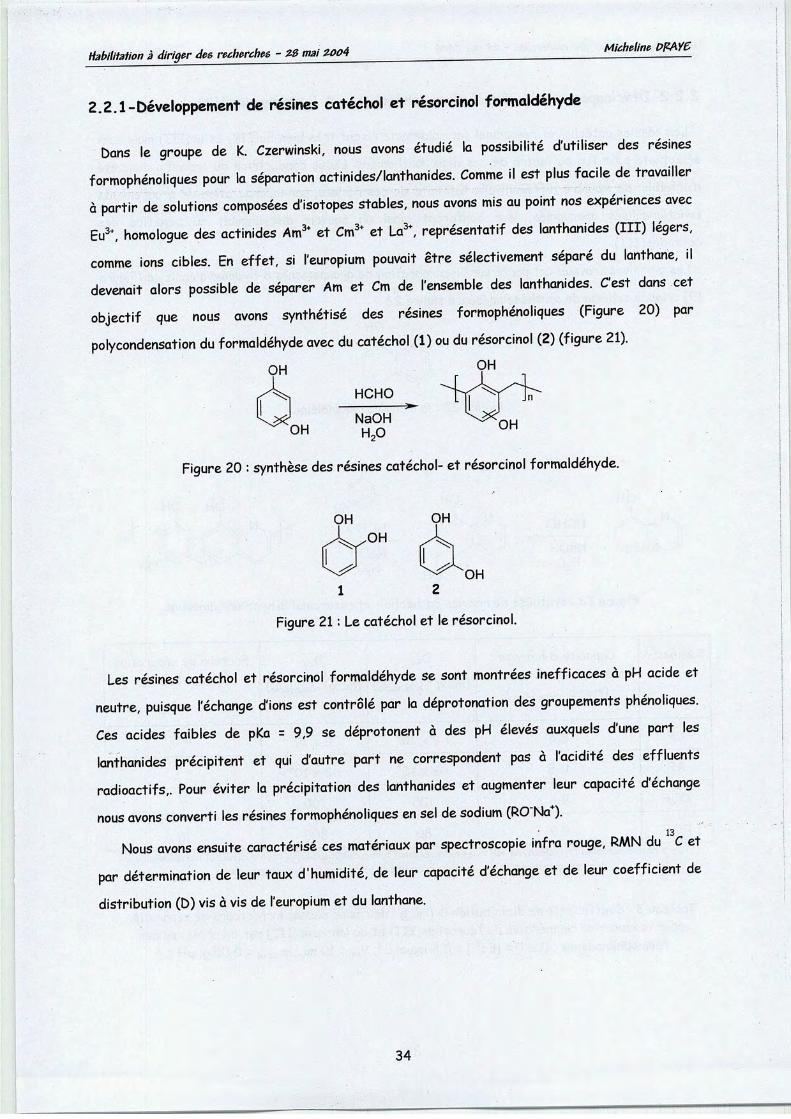
Habilitation àdiriger des recherches - ZB mai ZOo4 Micheline PPAYC
2.2.1-Développement de résines catéchol et résorcinol formaldehyde
Dans le groupe de K. Czerwinski, nous avons étudié la possibilité d'utiliser des résinesformophénoliques pour la séparation actinides/lanthanides. Comme il est plus facile de travailleràpartir de solutions composées d'isotopes stables, nous avons mis au point nos expériences avecEu3+, homologue des actinides Am3+ et Cm3+ et La3\ représentatif des lanthanides (III) légers,comme ions cibles. En effet, si l'europium pouvait être sélectivement séparé du lanthane, ildevenait alors possible de séparer Am et Cm de l'ensemble des lanthanides. C'est dans cetobjectif que nous avons synthétisé des résines formophénoliques (Figure 20) parpolycondensation du formaldehyde avec du catéchol (1) ou du résorcinol (2) (figure 21).
OH OH
HCHO
NaOH ^nMOH u 0 0Hi2v
Figure 20 : synthèse des résines catéchol- et résorcinol formaldehyde.
1
Figure 21 : Le catéchol et lerésorcinol.
Les résines catéchol et résorcinol formaldehyde se sont montrées inefficaces à pH acide et
neutre, puisque l'échange d'ions est contrôlé par la déprotonation des groupements phénoliques.Ces acides faibles de pKa = 9,9 se déprotonent à des pH élevés auxquels d'une part leslanthanides précipitent et qui d'autre part ne correspondent pas à l'acidité des effluentsradioactifs,. Pour éviter la précipitation des lanthanides et augmenter leur capacité d'échange
nous avons converti les résines formophénoliques en sel desodium (RO"Na+).13
Nous avons ensuite caractérisé ces matériaux par spectroscopie infra rouge, RMN du Cet
par détermination de leur taux d'humidité, de leur capacité d'échange et de leur coefficient dedistribution (D) vis à vis de l'europium et du lanthane.
34

Habilitation à diriger des recherches - ZB mai Z004Micheline PPAY6
2.2.2-Développement de résines formophénoliques 8-hydroxyquinoléine
Les résines catéchol et résorcinol formaldehyde fixent très bien Eu(III) et La(III) mais sanssélectivité pour l'un ou l'autre de ces deux lanthanides. L'idée conductrice du travail a donc étéd'affaiblir de manière différentielle l'affinité de ces résines, par incorporation de groupementsfonctionnalisés appropriés, leur conférant ainsi un pouvoir discriminant au bénéfice desactinides(III).
Les premiers travaux ont porté sur l'incorporation de groupements 8-hydroxyquinoléine (Figure19) selon le schéma de synthèse présenté figure 22.
OH
HCHO
NaOH
H20
Figure 22 : la 8-hydroxyquinoléine.
OH
OH
HCHO
NaOHH20
Figure 23 :synthèse de résines cathéchol- et résorcinol 8-hydroxyquinoleine.
Résines^
CF
RF
CQF
RQF
Capacitéd'échangevis-à-vis des ions Na+
(meqg'Vésine sèche)
8,6
11,5
9,6
9,9
DLa
(mL g résine sèche)
>2 x 10⁶
>2 x 10⁶
100
80
'Eu
(mL g résine sèche)
>2 x 10⁶
>2 x 10⁶
700
800
Facteur de séparation(SEu/Lçr Deu/Du,)
10
(*) CF =résine catéchol formaldehyde; RF =résine résorcinol formaldehyde; CQF =résine catéchol formaldehyde 8-nydroxyqumoleine; RQF =résine résorcinol formaldehyde 8-hydroxyquinoléine
Tableau 3:Coefficients de distribution D(mL g"1 de résine sèche) et facteurs de séparationpour Iextraction compétitive de l'europium(III) et du lanthane(III) par diverses résines
formophénoliques ; [La3*] =[Eu3*] =2,5 mmol L"1; Vsol =10 mL; mrési„e =0,05 g; pH =4
35
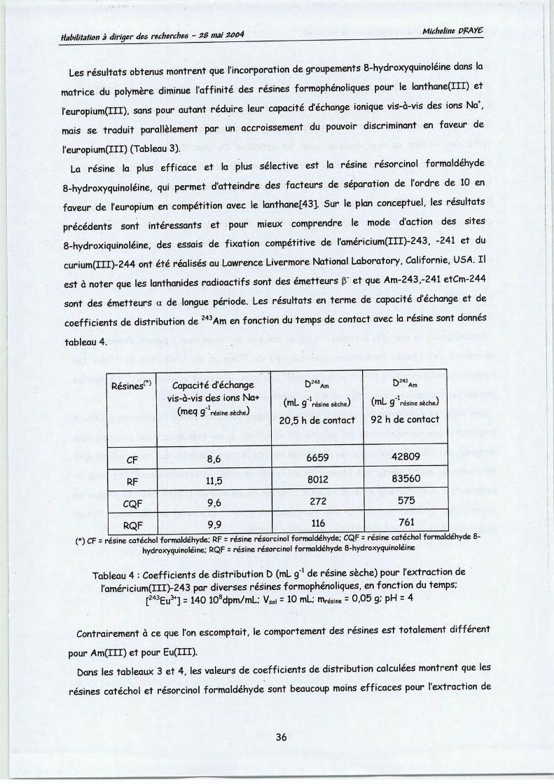
Habilitation à diriger des recherches - ZB mai ZQ04 Micheline PPAYC
Les résultats obtenus montrent que l'incorporation de groupements 8-hydroxyquinoléine dans lamatrice du polymère diminue l'affinité des résines formophénoliques pour le lanthane(III) etl'europium(III), sans pour autant réduire leur capacité d'échange ionique vis-à-vis des ions Na+,mais se traduit parallèlement par un accroissement du pouvoir discriminant en faveur del'europium(III) (Tableau 3).
La résine la plus efficace et la plus sélective est la résine résorcinol formaldehyde8-hydroxyquinoléine, qui permet d'atteindre des facteurs de séparation de l'ordre de 10 enfaveur de l'europium en compétition avec le lanthane[43]. Sur le plan conceptuel, les résultatsprécédents sont intéressants et pour mieux comprendre le mode d'action des sites8-hydroxiquinoléine, des essais de fixation compétitive de l'américium(III)-243, -241 et ducurium(III)-244 ont été réalisés au Lawrence Livermore National Laboratory, Californie, USA. Ilest à noter que les lanthanides radioactifs sont des émetteurs p" et que Am-243,-241 etCm-244sont des émetteurs a de longue période. Les résultats en terme de capacité d'échange et decoefficients de distribution de 243Am en fonction du temps de contact avec la résine sont donnés
tableau 4.
nRésines'
CF
RF
CQF
RQF
Capacitéd'échangevis-à-vis des ions Na+
(meq g résine sècheJ
8,6
11,5
9,6
9,9
O Am
(mL g résine sèchej
20,5 h de contact
6659
8012
272
116
O Am
(mL g résine sèchej
92 h de contact
42809
83560
575
761
(*) CF =résine catéchol formaldehyde; RF =résine résorcinol formaldehyde; CQF =résine catéchol formaldehyde 8-hydroxyquinoléine; RQF =résine résorcinol formaldehyde 8-hydroxyquinoléine
Tableau 4 : Coefficients de distribution D(mL g"1 de résine sèche) pour l'extraction deraméricium(III)-243 par diverses résines formophénoliques, en fonction du temps;
[243Eu3+] =140 108dpm/mL; Vso, =10 mL; résine =0,05 g; pH =4
Contrairement à ce que l'on escomptait, le comportement des résines est totalement différent
pour Am(III) et pour Eu(III).
Dans les tableaux 3 et 4, les valeurs de coefficients de distribution calculées montrent que les
résines catéchol et résorcinol formaldehyde sont beaucoup moins efficaces pour l'extraction de
36

Habilitation àdiriger des recherches - ZB mai zoo4 Micheline PPAY6
Am(III) (tableau 4) que pour l'extraction de Eu(III) (tableau 3). Par contre, des valeurscomparables de coefficients de distribution sont obtenues pour l'extraction de Am(III) et deEu(III) par les résines à base de 8-hydroxyquinoléine. Cette observation confirmerait ainsi uneacidité un peu moins dure pour les actinides que pour les lanthanides, et ainsi, une tendance moinsforte aux liaisons de type ioniques pour les actinides. De plus, l'influence du groupementphénolate des résines à base de 8-hydroxyquinoléines n'étant pas d'égale importance pour leslanthanides et les actinides, la résine résorcinol 8-hydroxyquinoléine est la plus efficace pourl'extraction de Eu(III) (tableau 3) alors que la résine catéchol 8-hydroxyquinoléine est la plusefficace pour l'extraction de Am(III) (tableau 4). Ces résultats laissent penser que l'interactiondes actinides avec des ligands contenant des atomes donneurs mous tels que l'azote du cyclepyridinique, devrait permettre une discrimination entre les deux séries, actinides/lanthanides.
Bien que leur vitesse d'extraction soit plus faible pour l'extraction de Am(III) que pour cellede Eu(III), les résines formophénoliques sont des matériaux adéquats pour l'extraction deAm(III) contenu dans des solutions aqueuses à pH 4.
Parallèlement, le suivi des activités a et pen fonction du temps nous a permis d'observer unesélectivité des résines formophénoliques vis-à-vis de 243Am et de 239Np, fils de 243Am. Lesrésines formophénoliques 8-hydroxyquinoléines sont plus sélectives vis-à-vis de 239Np que lesrésines formophénoliques qui, elles, sont plus sélectives vis-à-vis de 243Am[44].
Des tests de résistance des résines formophénoliques fonctionnalisées 8-hydroxyquinoléine àl'exposition aux rayonnements yont ensuite été effectués. Il est ainsi apparu que pour une doseintégrée de 200 kGy, les capacités d'échange de ces résines (vis-à-vis des ions sodium) sontdiminuées de moitié tandis que l'apparition de fonctions acide carboxylique peut être mise enévidence par spectroscopie en infra rouge à transformée de Fourier (figure 24). Les travaux encours visent à déterminer l'effet des rayonnements y sur l'affinité et la sélectivité de cesrésines vis-à-vis des actinides(III) et des lanthanides(III).
37

Habilitation à diriger des recherches - ZB mai ZQ04
Fonctions acide 1739 cm-icarboxylique 1720emJ/
Chelatees1705 cm
1688 cnr1*
2000 1800 1600
Longueur d'onde (cm-1)
1400
Micheline PPAY6
Figure 2' : Comparaison desspectres infra rouge à transformée de Fourier de la P4VP :non irradiée (Do), dose intégrée 200 kGy (Di)
3-Les techniques membranaires
Le développement industriel des techniques à membranes ne date que des années 1960 pour les
dialyses et 1970 pour les techniques de solvo-transfert. Ce sont les techniques de dialyse qui se
sont développées les premières et c'est seulement avec l'apparition et le développement des
membranes asymétriques que les techniques de solvo-transfert (osmose inverse, ultrafiltration...)
ont finalement pu se développer de façon beaucoup plus rapide que les techniques de dialyse. Les
techniques séparatives à membranes se sont considérablement développées depuis quelques
années. Grâce à de nouveaux matériaux, les membranes sont de plus en plus performantes et
gagnent progressivement les domaines réservés de la séparation par extraction liquide-liquide,
par évaporation, par centrifugation, par échange d'ions ou traitement chimique et précipitation.
Les techniques séparatives à membranes assurent la filtration de particules solides, de
macromolécules telles que les polymères, les protéines ou les colloïdes, et même de petites
molécules comme les sels, dans des conditions souvent moins coûteuses, plus économes en énergie
et moins polluantes. Longtemps les membranes ne furent qu'organiques. La première génération -
celle des dérivés de la cellulose - a été remplacée par celle des polymères de type poly-(amide),
poly-(acrylonitrile), poly-(sulfone) ou polymère fluoré. La grande diversité des matériaux et leur
meilleure résistance aux agents basiques, acides et organiques ont engendré un développement
considérable de leur domaine d'application. Puis, au début des années 80, l'arrivée sur le marché
de membranes minérales a été saluée comme l'avènement d'une troisième génération, précédant
celle des membranes organo-minérales.
38

Habilitation à diriger des recherches - 2$ mai Z004 Micheline PŒAY6
Dans le domaine du nucléaire, l'usine de séparation isotopique d'EURODIF pour l'enrichissement
isotopique de l'hexafluorure d'uranium par diffusion gazeuse a nécessité la fabrication de plus de
cent vingt millions de membranes, représentant plus de quatre millions de mètres carrés de
surface diffusante. De même, un procédé de traitement d'effluents de laverie de linge
faiblement contaminés en radioéléments tels que le cobalt, le césium ou l'argent a été mis au
point avec TECHNICATOME. Des travaux ont montré les potentialités de la nanofiltration
assistée de la complexation pour la récupération sélective du césium[45] et nous avons vérifié la
composition et la stabilité radiolytique des membranes composites organiques sélectionnées. Des
applications ont également été développées dans le domaine du traitement d'effluents industriels
pour la régénération d'huiles usagées, le traitement de liqueurs papetières bisulfitiques ou le
recyclage de matériaux toxiques d'effluents de galvanoplastie. La technologie des membranes est
largement utilisée pour la production d'eau d'irrigation ou d'eau potable à partir d'eau saumâtre
ou d'eau marine[46]. En effet, l'eau est la première ressource visée de l'eau de mer. Et pour faire
face à leur manque en eau douce, certains pays comme l'Espagne ont mis en place des installations
de dessalement de l'eau de mer fonctionnant par osmose inverse. Mais si l'ultrafiltration est une
technique bien adaptée à la séparation et la concentration de substances colloïdales contenues
dans l'eau de mer[47], la nanofiltration, qui occupe une position intermédiaire entre les deux
techniques précédemment citées, permet la séparation de cations monovalents de cations
multivalents[48]. En effet, en osmose inverse, la membrane n'est perméable qu'au solvant. La
sélectivité est d'origine chimique et le transfert des solutés se fait par solubilisation-diffusion.
Alors qu'en ultrafiltration, la sélectivité entre solutés est d'origine essentiellement physique et
leur transfert se fait par convection mécanique. Pour ce qui est de la nanofiltration, la
sélectivité, qui est liée et au coefficient de partage et au coefficient de transfert, est d'origine
à la fois chimique et physique. En jouant sur les conditions opératoires, il est alors possible defavoriser le transfert chimique par rapport au transfert physique ou réciproquement.
3.1-Récupération de l'uranium de l'eau de mer par nanofiltration
L'eau de mer contient 3,3 ug/L d'uranium[49,50,51] ; compte tenu du volume océanique de 1,37
10Z1 L, le contenu uranifère total des océans est évalué à 4,5 milliards de tonnes. Nous avons donc
considéré la nanofiltration comme une technique potentiellement applicable à la concentrationdirecte de l'uranium contenu dans l'eau de mer.
L'objectif de cette étude a été d'estimer les avantages apportés par la nanofiltration et de
proposer un procédé pour laconcentration sélective de l'uranium contenu dans l'eau de mer.
39

Habilitation à diriger des recherches - ZB mai ZQ04 Micheline PPAYC
Nous avons tout d'abord évalué les capacités de diverses membranes à retenir l'uranium enprésence de concentrations élevées en chlorure de sodium. Après avoir sélectionné la meilleurecandidate, nous l'avons testée pour la filtration d'eaux de mer simulées contenant en plus del'uranium, du calcium et du sodium. Ces premiers essais nous ont permis de sélectionner lamembrane la plus appropriée à la séparation de cations monovalents de cations multivalents. Nousavons ensuite choisi la membrane montrant le coefficient de rétention le plus élevé pour l'uranium
et la plus grande sélectivité pour l'uranium vis-à-vis des alcalins et des alcalino-terreux, pour latester sur des eauxde mer dopée et non dopéeen uranium.
Nous avons réalisé nos essais sur le pilote de laboratoire Osmonics® Sepa représentéfigure 25. La solution d'alimentation est pompée du réservoir d'alimentation vers le module defiltration à une vitesse de 0,3 m s1, tangentiellement à la surface de la membrane. Lesexpériences sont thermostatées à 20 ±1°C et les paramètres hydrauliques sont contrôlés pardes valves et des manomètres.
Pour la caractérisation des coefficients de rétention des membranes, la valve 12 est ouverte
et la solution.d'alimentation est maintenue à une composition constante pendant les expériences
en recyclant totalement perméat et rétentat. Pour les opérations de concentration de l'uranium,la valve 13 est ouverte et le perméat est collecté dans le réservoir 11 alors que le rétentat est
remis en circulation.
Figure 25: diagramme du montage de filtration utilisé au laboratoire.1 : réservoir d'alimentation, 2 : pH mètre, 3 : échangeur de chaleur, 4 : pompe, 5 : module defiltration Osmonics® Sepa, 6: membrane, 7': manomètre, 8: valve de contrôle du débit durétentat, 9 : débitmètre du rétentat, 10: débitmètre du perméat, 11 : réservoir du perméat,12 et 13 : valves.
40

Habilitation à diriger des recherches - ZB mai Z004Micheline PPAYC
Le dosage des cations dans l'eau de mer simulée est effectué par ICP-OES (spectromètresimultané CCD Vista Varian) alors qu'il est effectué par ICP-MS (spectromètre UltraMass700Varian) dans l'eau de mer naturelle.
Dans l'eau de mer, les particules d'uranium restent dissoutes sous la forme d'ion uranyle [I/O** )plus ou moins complexé à 98% en composés carbonates et à 2% en composés hydroxylés. Lalittérature concernant les équilibres mis en jeu dans les systèmes uranium-carbonate est trèsriche[52, 53]. En effet, les systèmes uranium (Vl)-carbonate, généralement assez compliqués,sont constitués de différents complexes ioniques en équilibre rapide à la fois les uns avec les
autres, et avec l'ion aquo ou des espèces hydrolysées. Pour une faible concentration en ion
uranyle et lorsque cette concentration n'excède pas la concentration en carbonate, les espècesmonomère de carbonate d'uranyle U02(C03), U02(C03)22- et U02(C03)34" devraient dominer au
delà de pH 5. Le diagramme que nous avons construit figure 26 à l'aide du logitiel CHESS[54]montre que les espèces dominantes dans une solution contenant lxlO"5 mol L"1 d'U022+ et 2xl0"3
mol L"1 de (C032-, HC03) àpH 8.3 sont U02(C03)34" et U02(C03)22-. Le complexe neutre U02(C03)domine le système à pH 5, mais à pH 8,3 de l'eau de mer, U02(C03)34- et U02(C03)22- sont lesespèces majoritaires.
i.
_ao
Êc.o
'+-uoL.
u_
pH
Figure 26 : Diagramme de spéciation de l'uranium(vT) en fonction de pH pour [CO32"]=2xl0-3 Met[NaCI]=llg/L,T=25°C:
l°9/W"), =-10.3146, logK^^) =-0.6634,'^•W- =-5-2073, logKm)m£ =-3.7467, logfc•[OOMcoifi - -9.4302
41

Habilitation à diriger des recherches - ZB mai Z004 Micheline PPAYC
La technique de nanofiltration a la particularité de séparer les sels selon leur taille, mais aussi
selon leur valence, laissant ainsi prévoir, des coefficients de rétention élevés pour les espèces de
l'U(VI).
L'uranium est présent dans l'eau de mer à son degré d'oxydation le plus élevé (+6); étant
données les fortes concentrations de carbonates que renferme l'eau de mer, c'est l'anion
tricarbonato uranylate (U02(C03)34") qui y prédomine. Il n'y a néanmoins aucune preuve
expérimentale de cet anion dans le milieu naturel, du fait de sa très faible concentration. La
structure de l'anion tricarbonato uranylate (U02(C03)34~) a été étudiée[55]. Dans le plan
équatorial, le rayon du complexe est de 4,85 A, ce qui le classe parmi les ions les plus gros de
l'eau de mer.
Etant données sa taille et sa charge élevées, la nanofiltration semble être une technique de
choix pour la concentration de l'uranium (VI), et dans une étude antérieure, des complexes
carbonates de l'uranium ont été extrait d'une eau potable avec des rendements de 90% pour les
deux principaux complexes carbonates négativement chargés de Puranium[56].
Nous avons nanofiltré des solutions de carbonate d'U(VT) contenant 0 à 11 g L"1 de chlorure de
sodium et nous avons testé l'efficacité de quatre membranes de seuil de coupure 8'000D (G50),
3'500D (G20), 2'500D (G10) et 150-300D (5DL) que nous avons évaluée par leur coefficient de
rétention (Eq. 5).
R(%) =(l-Cp/Cf)xlQQ [5]
La variation du pourcentage de rétention de l'uranium en fonction de la concentration en sodium
est représentée figure 27, pour quatre membranes différentes. En accord avec la théorie
d'exclusion de Donnan, le pourcentage de rétention de l'uranium diminue avec l'augmentation de la
concentration en sodium.
4 6 8 10
Concentration en Na (g/L)
-5DL
-S10
-S20
v -650A
12
Figure 27 : variation de la rétention de l'uranium enfonction de la concentration ensodium.
42

Habilitation à diriger des recherches - ZB mai zoo4 Micheline PPAYC
Pour les membranes 5DL, G20 et G10, les pourcentages de rétention de l'uranium restent
néanmoins élevés, et supérieurs à 70% pour une concentration en chlorure de sodium
représentative de celle de l'eau de mer. Ces trois dernières membranes ont donc été
sélectionnées pour la suite de l'étude et testée avec une eau de mer simulée contenant, outre les
sels d'uranium et de sodium, du chlorure de calcium (Figure 28).
100 -t u
^s
80 -
60 -
U
Caeo
'+-c
6)H-
c
wU
•o
>*-M-
40 -
20 -
X
0-Na Ca
CaNa mm Na
620 010 5DL
Figure 28 : Sélectivité des membranes G20, G10 et 5DLvis-à-vis du sodium, du calcium et de l'uranium.
La figure 28 montre que la membrane G10 est la plus sélective pour la rétention de l'uranium
vis-à-vis du sodium et du calcium et c'est cette membrane que nous avons utilisée dans la suite de
notre étude.
Si l'on considère la très faible concentration d'uranium dans l'eau de mer, comparativement à
celles d'éléments majeurs tels que le sodium, le potassium, le magnésium et le calcium, la
spectroscopie d'émission atomique à plasma induit haute fréquence (ICP-OES) n'est pas une
technique suffisamment sensible pour son dosage direct. Une séparation des éléments de la
matrice et une préconcentration de l'uranium sont donc préconisées avant le dosage de l'uranium.
De nombreux travaux décrivent des méthodes de séparation et/ou de préconcentration telles
que la co-précipitation[57], l'adsorption sur des résines chélatantes[58], l'extraction en phasesolide[59] et l'extraction par solvant[60] pour l'analyse de l'eau de mer. Toutes ces techniques
présentent néanmoins un certain nombre d'inconvénients liés au large volume d'échantillon
nécessaire à l'analyse et à la lenteur de la pré-concentration. Nous avons donc introduit dans l'eau
de mer la quantité minimale de sel d'U(VT) permettant une analyse par ICP-OES de la solution
d'alimentation durant l'expérience de nanofiltration. Les résultats obtenus avec cette eau de mer
dopée sont identiques à ceux obtenus avec l'eau de mer synthétique. En effet, que l'eau
43

Habilitation a diriger des recherches - ZB mai Zûo4 Micheline PPAYC
nanofiltrée soit de l'eau de mer synthétique ou de l'eau de mer dopée l'uranium, le sodium et le
calcium ont le même (Figure 29).
16-
14 •
12
u 10
—i—
0.0
-î 1 r
_o o'
o—o-So o—'
Na
U
-Ca
—r-
0.2
/I
-A—a'
-o—a a—a • d-o-dd
0.4 0.6 0.8
Rapport volumique nanofiltré [l-(Vf/V()]
1.0
14
12
10
3"
-6
4 §
-2
Figure 29 : Variation de la concentration en uranium, en sodium et en calciumEn fonction du rapport volumique nanofiltré.
La figure 29 montre que les concentration en sodium et en calcium ne sont pas affectées par le
procédé denanofiltration alors que la concentration en U(VI) est multipliée par un facteur 7.
Ces résultats nous ont encouragé à étudier la concentration de l'uranium à partir d'eau de mer
naturelle, et l'analyse élémentaire des échantillons prélevés a été effectuée par spectroscopie
d'émission atomique à plasma induit haute fréquence couplé à la spectrometrie de masse
(ICP-MS).
Le dosage de la concentration en uranium total dans l'eau de mer et la détermination de son
rapport isotopique 234u/238U sont décrits dans la littérature[61]. La spectroscopie d'émission
atomique à plasma induit haute fréquence couplé à la spectrometrie de masse (ICP-MS), associée
à une étape de pré-concentration des ions de la matrice[59,62] ou de co-précipitation[57], est la
technique la plus communément utilisée. Dans notre étude, nous avons dosé l'uranium directement
dans l'eau de mer, sans étape préalable, et nous avons obtenu la valeur de 3,66 (-ig L". La
concentration en uranium dans le rétentat a ensuite été mesurée et sur la figure 30 le rapport
des concentrations en uranium dans le rétentat et dans la solution source est représenté en
fonction du rapport volumique nanofiltré.
44

Habilitation à diriger des recherches - ZB mai Zoo4
14
12
10-
4-
-, , p
_o—o—o-
-Na
-U
-Ca
-A—A"
d—q u d—a—•• a—d d a-D-aû
0.0 0.2 0.4 0.6 0.8 1.0
Rapportvolumique nanofiltré [1-(V /V)]
~r > r—
0.4 0.6
Micheline PPAY6
14
12
10
8 «
Figure 30 : Rapport des concentrations en uranium dans le rétentat et dansla solution source en fonction du rapport volumique nanofiltré
Comme prévu, l'uranium se concentre quelle que soit son origine, eau mer dopée en uranium
([U] =2,38 mg L"1) ou eau de mer naturelle ([U] =3,66 Mg L"1), selon une loi exponentielle àpartied'un rapport volumique nanofiltré de 0,6.
Finalement, les concentrations en ions majeurs ont été mesurées pour un rapport volumiquenanofiltré de 0,96 et les résultats obtenus sont consignés dans le tableau 5.
Cations Concentration Concentration Facteur demajeurs initiale finale concentration
Na 12200 mg/L 13600 mg/L 1,1Mg 1420 mg/L 1800 mg/L 1,3Ca 430 mg/L 565 mg/L 1,3K 350 mg/L 413 mg/L 1,2
Sr 7,4 mg/L 9,8 mg/L 1,3Li 0,3 mg/L 0,26 mg/L 0,9
Mo 0,1 mg/L 0,12 mg/L 1,2Ba 0,014 mg/L 0,14 mg/L 10,0U 3,66 ug/L 31,12 ug/L 8,5
Tableau 5 :Concentrations en cations majeurs mesurées dans de l'eau de mer naturelle parspectrometrie d'émission atomique par plasma induit haute fréquence couplée
à la spectrometrie de masse. Facteurs de concentration correspondants.
Les cinq cations les plus abondants dans l'eau de mer Na+, Mg2+, Caz\ K+ et Sr2+, qui sont les cinqcations les plus abondants dans l'eau de mer et dont les concentrations sont jusqu'à 3 106 fois
45
Habilitation àdiriger des recherches - ZB mai ZQQ4 Micheline PPAYC
supérieures àcelle de l'uranium, sont très faiblement concentrés par le procédé de nanofiltration(facteurs de concentration inférieurs à 1,4). Seuls le barium et l'uranium présentent des facteurs
de concentration élevés, de 10 et de 8,5 respectivement qui peuvent être expliqués par les
propriétés de la membrane de nanofiltration. En effet, les mécanismes de séparation sontnormalement décrits en termes d'effets de charge et/ou de taille[63], et l'action « tamis » de la
membrane associée aux interactions électrostatiques à sa surface expliquent la rétention
d'espèces aussi volumineuses et aussi chargées que celles de U(VI). Ainsi, la rétention de Ba +n'est pas surprenante puisque cecation est le plus lourd des alcalino-terreux.
Ces résultats prouvent néanmoins qu'il est possible de concentrer sélectivement des micro
concentrations d'uranium contenu dans de l'eau de mer chargée en une multitude d'autres cations,
jusqu'à 106 fois plus concentrés, à l'aide d'une membrane de nanofiltration sans porter préjudice àl'environnement. A l'échelle industrielle, ce procédé n'est pas techniquement viable en l'état
actuel et pourrait être amélioré en associant, après l'étape de nanofiltration, des lits fluidisés
dont l'efficacité serait ainsi augmentée par l'augmentation de la concentration en uranium dans la
solution d'alimentation. Il est bien entendu qu'une application industrielle de ce procédé
nécessiterait une évaluation de la rentabilité du procédé, et optimisation des coûts de
construction de l'installation et de l'usinede production.
46

Habilitation à diriger des recherches - ZB mai Z004 Micheline PFAY6
Projet de recherche
Soyez réalistes : demandez l'impossible.Che Guevara

Habilitation àdiriger des recherches - ZB mai Z0û4 Micheline PPAYC
Etude des mécanismes fondamentaux de vieillissement dematériaux organiques sous stress chimique, thermique et
radiochimique. Application à l'industrie nucléaire.
• Introduction
Contexte
La chimie du vieillissement de matériaux organiques se rapporte à l'étude du comportement
chimique et physique de matériaux, isolés ou en solution, soumis à divers stress. Elle a pourobjectif de mettre en évidence et d'interpréter des mécanismes fondamentaux de dégradation,en développant ou en appliquant des techniques et des méthodes d'analyse. Elle permet aussi
d'acquérir des informations sur le matériau dégradé et sur la nature, la composition et lastructure de ses composés « métabolites ». Son étude nécessite d'aborder des domaines de
connaissance très variés, et son aspect pluridisciplinaire m'amènera à faire appel à des
techniques classiques pour l'analyse de matériaux organiques et d'autres encore peu exploitées
pour ce type de matériaux.
• Objectifs scientifiques
Ce projet a pour objectif l'étude de l'effet de stress chimique, thermique et radiolytique sur
des molécules organiques et tout particulièrement sur les polymères.
La plupart des molécules organiques sont solubilisables, c'est pourquoi l'étude de leur
dégradation dispose d'un large panel de techniques d'analyse comme, par exemple, lesspectrométries infra-rouge à transformée de Fourier, d'absorption moléculaire UV-Visible, de
résonance magnétique nucléaire et de masse.... Par contre, la plupart des polymères organiques
industriels sont insolubles et souvent infusibles, et sont plus difficiles à analyser à l'aide des
techniques d'analyses classiques, qui pour la plupart, mettent en oeuvre l'une de ces propriétés.
L'étude qualitative et quantitative de leur dégradation, de son mécanisme et des produits de
dégradations générés est alors délicate ; celle-ci sera au cœur de mon projet de recherche et
constituera un réel challenge scientifique, tant au niveau fondamental qu'appliqué.
• Panorama des mécanismes de dégradation de matériaux organiques
- Compréhension des stress thermique et chimique
La stabilité de polymères de type résines fonctionnalisées est fonction de la nature de leur
squelette, mais aussi de leur fonctionnalité. Par exemple, les résines cationiques comportant desgroupements sulfoniques sont thermiquement plus stables que les résines anioniques. En effet,sous le seul effet de la température, les résines cationiques perdent leur groupement sulfonique,
mais la désulfonation n'atteint des rendements significatifs qu'à partir d'une température de
47

Habilitation à diriger des recherches - ZB mai ZOo4 Micheline PPAY6
120°C [64], alors que la dégradation du squelette du polymère nécessite des températures
supérieures à 350°C (pyrolyse).
Sous l'effet de la température et en milieu basique, le benzyltriméthylammonium se
transforme majoritairement en benzylalcool, et en une faible fraction de dibenzyléther issu de la
déshydratation du benzylalcool [65]. Cette réaction se produit en milieu alcalin, et de façon
notable qu'à partir de 50°C (figure 31).
OH-.
N(CH3)3
H,Q
Figure 31 : Mécanisme de dégradation thermique d'un motif
benzyltriméthylammonium en milieu basique.
Une étude portant sur la dégradation hydrothermique de résines cationiques et anioniques
fortes de type polystyrène-divinylbenzène [66] montre que l'effet de la température est visible
dès 95°C et peut aller jusqu'à la dégradation complète de la résine pour des températures
inférieures à 250°C. Une analyse par spectroscopie infra-rouge montre par ailleurs que cette
dégradation hydrothermique passe par l'oxydation de certaines liaisons C-C en fonctions C-O-C,
en fonctions C-O, puis en COz lorsque la température augmente. Les spectres infra-rougeobtenus dans ce cas sont alors identiques à ceux obtenus dans le cas d'une radiolyse. Les agents
oxydants sont également susceptibles d'endommager les résines [67]. Dès les années cinquante,
des études ont montré que des conditions très oxydantes peuvent conduire à une déréticulation
du polymère [68]. Dans le cas de résines comportant des groupements sulfoniques, si l'oxydationse prolonge, le nombre, la taille et le poids moléculaire des fragments produits augmentent, et les
sulfates libérés deviennent corrosifs lorsqu'ils peuvent se réduire en sulfure [69]. La stabilité
vis-à-vis de l'oxydation dépend fortement de la réticulation du polymère ; ainsi les résines de
48
Habilitation à diriger des recherches - ZB mai ZQ04 Micheline PPAY6
type gel sont relativement sensibles aux agents oxydants, alors que les résines de typemacroporeux, fortement réticulées, sont plus résistantes [70]. D'autre part, des travaux ontmontré que la décomposition par H202 d'une résine de type polystyrène-co-divinylbenzènecomportant des groupements sulfoniques est catalysée par le fer qu'elle piège selon unmécanisme de type Haber-Weiss; cet effet catalyseur est également observé avec le cuivre,alors que le nickel et le zinc sont catalytiquement inactifs[71,72]. Une étude montre que l'effetconjugué de H202, de l'acidité et de la concentration en fer (Fe2+ ou Fe3+) peut rapidementconduire à une dissolution totale d'une résine comportant des groupements
sulfoniques/polystyrène-co-divinylbenzène. Selon les conditions expérimentales, la résine estdissoute en solution aqueuse par des intermédiaires réactifs issus de la décomposition catalysée
par le fer de l'eau oxygénée à la surface de la résine [73].
Compréhension du stress radiolytique
La radiolyse et les changements chimiques des échangeurs d'ions organiques dépendent à la foisde facteurs relatifs à la résine elle-même comme la composition chimique, la forme ionique dans
laquelle la résine est exposée aux radiations, son pourcentage d'humidité, son degré deréticulation. Cette radiolyse dépend aussi de facteurs concernant la source d'irradiation, son
débit de dose et l'environnement de la résine pendant l'irradiation. Exposés aux rayonnements
ionisants, les échangeurs d'anions se dégradent généralement plus facilement que les échangeurs
de cations à l'exception des résines dérivées de pyridines qui présentent une stabilité
particulièrement élevée. L'effet des groupes aromatiques observé dans tous les systèmesorganiques est retrouvé pour les résines synthétiques, et les échangeurs d'ions comprenant desgroupements aromatiques sont plus résistants que leurs analogues purement aliphatiques. Les
polymères styrèniques réticulés au divinylbenzène et irradiés en présence d'eau sous forme acideou basique peuvent être classés dans l'ordre de stabilité suivant : échangeurs d'anions
pyridiniques >échangeurs de cations à noyaux de fonctionnalisation sulfonique et carboxylique >bases faibles échangeuses d'anions de type primaire, secondaire ou tertiaire > bases fortes
échangeuses d'anions du type ammonium quaternaire [74]. La dégradation d'une résine se traduitpar des modifications de ses propriétés physico-chimiques, telles que sa couleur, sa densité, sonpoids moléculaire, son élasticité, sa porosité, sa solubilité, sa capacité d'échange, ses propriétésélectriques et mécaniques [74,75,76]. Pour déterminer l'effet d'un stress tel que celui desrayonnements ionisants sur un matériau, il est possible d'utiliser différentes techniques d'analyseen fonction de ses propriétés, même si ce matériau est infusible, insoluble et isolant ; Dans ce
contexte, la technique TOF-PDMS (HSF-SIMS) s'est avérée une méthode très puissante pour la
49
——

Habilitation à diriger des recherches - ZB mai ZOo4Micheline PPAYB
caractérisation structurale d'une résine poly(4-vinylpyridine) et pour le suivi de l'effet de sonirradiation par des rayonnements y(figure 32) [38]. D'autre part, les analyses IRTF, UV, RPE, TGet DMA effectuées ont pu confirmer les résultats obtenus à l'aide de la TOF-PDMS. D'une façongénérale, les rayonnements y favorisent la formation de doubles liaisons sur la chaîne dupolymère et produisent des radicaux qui serecombinent en fonction de la dose d'irradiation
Figure3 2:mécanisme de dégradation de la poly(4-vinylpyridine) sous irradiation y.A: scission pyridinique, B: scission vinylique.
En résumé, les études menées sur le vieillissement de résines sous stress chimique, thermiqueou radiolytique ne donnent q'une description qualitative des effets d'un stress sur le matériaumais pas de leurs effets conjugués. D'autre part, très peu d'auteurs se sont intéressés à la
structure des «composés métabolites » produits et à leur évolution en fonction de l'intensité dustress.
50
——

Habilitation à diriger des recherches - ZB mai Z004 Micheline PPAYC
m Description du projet de recherches
Méthodologie
L'étude que je propose concerne la physico-chimie de la dégradation de matériaux organiques
sous stress chimique, thermique et radiolytique. L'approche consiste à utiliser de façon
systématique les techniques éprouvées dans la caractérisation de molécules organiques et de
polymères, et d'autres encore peu exploitées pour ces matériaux, comme par exemple les
techniques utilisant des faisceaux d'ions (TOF-PDMS,...) (Figure 33). Ces dernières, en plus de
leurs qualités analytiques, offrent la possibilité d'initier, in-situ, des modifications dans des
conditions rigoureusement contrôlées, par des faisceaux de même nature que ceux permettant la
caractérisation.
STRESS THERMIQUE
STRESS RADIOLYTIQUE | STRESS CHIMIQUE
I /POLYMERE
\Endommagements créés par le stress
Description et évolution des espèces produitesEtude de vieillissement du matériau
IRTF, UV, RMN, RPE ( ATG, DMA)
Dosage Chimique [Etude du dépôt d'énergie]
METHODES NUCLEAIRES DANALYSE
^TOF-PDMSy:
Figure 33 : Etude des mécanismes fondamentaux du vieillissement de polymères sousstressthermique, chimiqueet radiolytique.
Cette analyse fine de la matière que permettra la TOF-PDMS, couplée à des caractérisations
qualitatives et semi-quantitatives classiques d'infrarouge à transformée de Fourier, de
spectroscopie d'absorption moléculaire UV-Visible, de résonance magnétique nucléaire y compris
en phasesolide ou en gel,de résonance paramagnétique électronique, de spectroscopie mécanique
comme l'analyse mécanique dynamique, d'analyse thermogravimétrique et de dosages chimiques,
permettra à la fois d'étudier le matériau mais aussi ses « composés métabolites ». Une synthèse
51

Habilitation à diriger des recherches - ZB mai Z004 Micheline PFAYB
d' « authentiques » des composés principaux devra être envisagée pour évaluer l'impact de cette
dégradation sur les procédés utilisant des résines.
Apports visés de l'étude
Sur le plan fondamental, je souhaite apporter notamment des éclaircissements sur les
paramètres structuraux qui conditionnent les mécanismes de dégradation en passant, dans le cas
du stress radiolytique des polymères, par la compréhension plus générale des mécanismes de
dépôt d'énergie dans ce type particulier de matériaux. Je pourrai alors dégager des lois
concernant les relations entre structure moléculaire et/ou polymérique, et effet des
rayonnements. Cette approche me permettra de proposer une échelle de stabilité des matériaux
en fonction de leur structure (type de monomère, taille des billes, taux de réticulation) et descontraintes imposées.
Sur le plan appliqué, il s'agira d'établir des critères pour lechoix de matériaux enfonction de
l'environnement de leur utilisation et descontraintes auxquelles ils seront soumis. Trois domaines
d'application touchant directement mes activités peuvent être cités : (1) l'amont et l'aval du cycleélectronucléaire, (2) les circuits d'épuration des centres de production électronucléaires et/ou
les résines d'enrobage de déchets radioactifs ainsi que (3) les matériaux utilisés pour la conquêtespatiale et pour l'aéronautique.
• Place du projet aux niveaux national et international
L'approche que je propose fait appel à des techniques d'analyse encore peu utilisées pourl'analyse de matériaux organiques. D'autre part, l'étude de la physico-chimie de la dégradation dematériaux organiques sous stress chimique, thermique et radiolytique est un thème encore très
peu abordé actuellement en raison de la complexité des mécanismes de dégradation qui peuvent
être mis en jeu, et de la grande stabilité de certains matériaux à étudier. Pourtant, un stress
radiolytique peut profondément altérer la structure moléculaire et les propriétésmacroscopiques d'une (macro)molécule. Par exemple, la dose d'irradiation suffisante pourmodifier les propriétés d'un polymère organique est, dans la plupart des cas, considérablement
plus faible que celle requise pour créer un changement significatif dans un verre, une céramiqueou un métal.
D'autre part, un grand nombre de matériaux organiques a été développé pour des applicationsen milieu «stressant ». Sans une parfaite connaissance de leur stabilité, ils peuvent mettre enéchec un procédé, pourtant prometteur du point de vue de l'application, par suite de leur faiblestabilité ou d'interférences notables de certains de leurs «métabolites » avec le procédé. Enpratique, pour développer des matériaux, il est souhaitable de développer simultanément des
52
—————

Habilitation àdiriger des recherches - ZB mai ZQ04 Micheline PPAYC
outils pour évaluer leur stabilité et orienter leur synthèse de façon efficace. L'enjeu est d'autant
plus important si l'on considère l'intérêt que les gouvernements français, anglais, japonais et
américainsconcèdent actuellement au traitement des déchets radioactifs.
Ainsi, c'est aussi face au constat de la nécessité d'une parfaite accréditation de leur
technologie et d'une meilleure maîtrise de leurs divers procédés par les communautés
scientifiques nationale et internationale du nucléaire que j'ai élaboré ceprojet derecherches.
• Environnement scientifique du projet et collaborations possibles
Le projet que je propose relève d'une approche pluridisciplinaire. Mon programme de
recherches s'articulera à la frontière des sciences analytiques avec la chimie des matériaux, la
chimie organique et les procédés.
Au niveau du laboratoire, il trouvera naturellement sa place dans différents pôles de
recherches, au sein du groupe « Procédés de Séparation et Radiochimie (Pr. Gérard Cote) auquel
j'appartiens, en explorant un axe nouveau et complémentaire. Des interactions seront également
envisageables avec le groupe « Modélisation des Systèmes Complexes » (Pr. Carlo Adamo), dont le
thème est prioritaire dans le cadre des projets de l'ENSCP. D'autre part, ce projet de recherche
s'intégrera parfaitement dans l'étude de la réactivité chimique et des interactions
rayonnement/matière de matériaux organiques pour le photovoltaïque du groupe « Films et
Interfaces » (Dr. D. Lincot et Dr. J. F. Guillemoles).
Mes travaux seront également réalisés dans le cadre de collaborations scientifiques dont j'ai
déjà pu bénéficier dans le passé [38,77,44]. Pour ce qui est des techniques d'analyse éprouvées
dans la caractérisation (macro)molécules organiques, je pourrai bénéficier du potentiel du
laboratoire de catalyse et synthèse organique de l'Université Claude Bernard de Lyon (UMR5622
- Pr. Marc Lemaire) et de celui du laboratoire de chimie moléculaire et environnement de
l'Université de Savoie (Pr Christian Pétrier). Quand aux méthodes utilisant les faisceaux d'ions,
elles mettront à contribution l'expertise du Dr. Jean-Paul Thomas, directeur du groupe de
recherches Bombardement Ionique et Analyse de Surface (BIAS) de l'Institut de Physique
Nucléaire de Lyon (IN2P3), et du potentiel de l'institut « Libanese Atomic Energy Commission »
du CNRS Libanais (Dr. Bilal Nsouli, directeur). Les manipulations nécessitant l'utilisation de
radionucléides et les techniques d'analyse associées à leur détection seront effectuées dans
I' « Actinides Research Group » du « Harry Reid Center for Environmental Studies » de
l'Université du Nevada Las Vegas (UNLV) (Pr. Kenneth Czerwinski, Dr. Antonny Hetchanova).
53
"

Habilitation àdiriger des recherches - ZB mai Z004 Micheline PPAYG
- Objectifs au niveau de la formation des étudiants
Al'Ecole Nationale Supérieure de Chimie de Paris et dans le cadre de la création d'un pôleenseignement-recherche « Chimie et Radiochimie à l'Aval du Cycle Electronucléaire » , le Pr.
Gérard Cote, responsable de mon groupe, est à l'origine de la création du « Secteur Nucléaire »
et d'un master « Nucléaire » qui vient d'être approuvé par le ministère. Ces deux modules
d'enseignement ont pour objectif de former des étudiants de haut niveau (national etinternational) dans ce secteur d'activité. La chimie du vieillissement de matériaux exposés auxradiations ionisantes, et en particulier la chimie du vieillissement de composés organiques sousstress chimique, thermique et radiolytique sera un thème incontournable pour l'industrie engénéral.
Débouchés industriels potentiels
Dans le cadre du programme dénommé par le CEA «séparations poussées » de l'axe 1de la loi
du 30 décembre 1991, qui vise à séparer sélectivement les radioéléments, les ligands organiquesproposés sont généralement d'une efficacité remarquable mais souvent d "une stabilité tout à fait
relative et malconnue dans les conditions de leur utilisation. Pourtant, leur stabilité peutremettre en question tout le procédé dont ils sont à l'origine (exemples du TPTZ et du
cyanex-301). Dans ce contexte, une approche analogue à celle de l'industrie pharmaceutique, quiavant de mettre un médicament sur le marché, identifie précisément tous ses métabolites et
étudie, individuellement, leur activité sur l'organisme humain, permettrait à la fois de proposerdes systèmes efficaces et adaptés à leur environnement, mais aussi d'apporter des éléments decompréhension aux mécanismes dedégradation mis en jeu.
D'autre part, une étude que j'ai réalisée, dans le cadre du partenariat entre EDF (groupeChimie Corrosion des Renardières) et le LECA, sur l'évolution de l'efficacité des résines
échangeuses d'ions des Centres Nucléaires de Production d'Electricité (CNPE) en fonction des
conditions d'exploitation a clairement montré l'impact du vieillissement des résines échangeusesd'ions sur la qualité de l'épuration. En effet, les conditions d'utilisation des résines échangeusesd'ions dans les CNPE peuvent être pénalisantes pour leur durée de vie et leur efficacité
puisqu'elles sont soumises à des variations importantes des conditions physico-chimiques dufluide primaire -telles que le pH, les conditions d'oxydo-réduction et la température- dans unenvironnement radiolysant, puisqu'elles s'enrichissent au cours du temps en ions dont certains
sont radioactifs (essentiellement émetteurs gamma). L'ensemble de ces contraintes présente àterme le risque de dégrader les polymères et de perturber le procédé d'épuration.
Contrairement aux autres secteurs industriels, l'industrie nucléaire, après avoir été parmi les
54

Habilitation àdiriger des recherches - ZB mai Z0Q4 Micheline PFAY6
premières industries àdévelopper la culture de la sûreté comme l'industrie aéronautique, conduitdepuis plusieurs décennies celle du «déchet », de l'amont à l'aval de chaque procédé utilisé. Maproblématique de recherches, physico-chimie de la dégradation de systèmes organiques sousstress chimique, thermique et radiolytique, permettra de développer à terme une base dedonnées pour l'industrie nucléaire. Néanmoins, des méthodologies dérivées pourront êtretransposées à pratiquement tous les secteurs industriels.
55

Habilitation à diriger des recherches - ZB mai Z004 Micheline PPAYB

Habilitation à diriger des recherches - ZB mai ZQ04 Micheline PPAY6
[1] C. Lamouroux, Contribution et complémentarité des techniques de spectrometrie de masse à
l'étude des molécules complexantes issues de la dégradation radiolytique du tributyle phosphate,
thèse de doctorat de l'université de Paris VI, 2000.
[2] B. Dietrich, P. Viout, J. M. Lehn dans : Aspects de la chimie des composés macrocycliques,
InterEditions/Editions du CNRS Paris (1991).
[3] M. Draye, A. Favre-Reguillon, J. Foos, A. Guy, M. Lemaire. Radiochim. Acta, 78,105 (1997).
[4] M. Lemaire, A. Guy, R. Chomel, J. Foos, J. Chem. Soc, Chem. Commun., 1152 (1991).
[5] M. Draye, G. Le Buzit, M. Lemaire, B. Leclere, P. Doutreluingne, J. Foos, A. Guy. Radiochem.
Acta, 78,105 (1997).
[6]M. Lemaire, B. Leclere, P. Doutreluingne, J. Foos, A. Guy. Sep. Sci. Technol, 32 (10), 1725
(1997).
[7] M. Draye, R. Chomel, P. Doutreluingne, A. Guy, J. Foos, M. Lemaire. J. Radioanal. Nucl. Chem.,
letters 175 (1)55 (1993).
[8] W. W. Schulz, J. D. Navratil, A. E. Talbot dans : Science and Technology of Tributyl
Phosphate, CRC Press, Inc., 1, 238 (1984).
[9] M. Draye, A. Favre -Reguillon, R. Chomel, R. Faure, A. Guy, J. Foos, M. Lemaire. Bull. Soc.
Chim. Fr.. 133,183 (1996).
[10] W. L. Hinze and E. Pramauro, Crit. Rev. Anal. Chem., 24,133 (1993).
[11]<F. H. Quina and W. L. Hinze, Ind. Eng. Chem. Res., 38, 4150 (1999).
[12] E. K. Paleologos, C. D. Stalikas, S. M. Tzouwara-Karayanni and M. I. Karayannis, Anal. Chim.
Acta, 436, 49 (2001).
[13] M. Fernando Silva, L. Fernandez, R. A. Oisina and D. Stacchiola, Anal. Chim. Acta, 342, 229
(1997).
[14] M. F. Silva, L. P. Fernandez and R. A. Oisina, Analyst, 123,1803 (1998).
[15] K. Materna, I. Milosz, I. Miesiac, G. Cote and J. Szymanowski, Environ. Sci. Technol., 35,
2341, (2001),.
[16] G. Komaromy-Hiller and R. von Wandruszka, Talanta, 42, 83 (1995).
[17] M. O. Luconi, M. Fernando Silva, R. A. Oisina and L. P. Fernandez, Talanta, 51,123 (2000).
[18] S. Akita, M. Rovira, A. M. Sastre and H. Takeuchi, Sep. Sci. Technol., 33, 2159 (1998).
[19] H. Watanabe and H. Tanaka, Talanta, 25, 585 (1978).
[20] D. L. Giokas, E. K. Paleologos, P. G. Veltsistas and M. I. Karayannis, Talanta, 56,415 (2002).
[21] J. Chen and K. C. Teo, Anal. Chim. Acta, 450, 215 (2001).
56

Habilitation àdiriger des recherches - ZB mai Z004 Micheline PPAYC
[22] C. Wang, D. F. Martin and B. B. Martin, J. Environ. Sci. Health, Part A, A34, 705 (1999).[23] C. D. Stalika, Trends Anal. Sci., 21, 343 (2002).
[24] J. G. Huddleston; H. D. Willauer; S. T. Griffin; R. D. Rogers, Ind. Eng. Chem. Res., 38, 2523(1999).
[25] Samii, A., Karlstro'm, G, Lindman, B., Langmuir, 7, 653 (1990).
[26] E. Lins de Barros Neto, J.P. Canselier, J. Corn. Esp. ùeter, 28, 433 (1998).
[27] R. D. Gupta, G. S. Manku, A. N. Bhat, B. D. Jain, Aust. J. Chem., 23,1387 (1970).
[28] A. Favre-Réguillon, Draye M., S. Thomas, G. Lebuzit, J. Foos, G. Cote, A. Guy, Talanta (souspresse).
[29] R. Cahill, B. Shpeizer, G. Z. Peng, LBortun, A. Clearfield in: "Séparation of f éléments"éd. K.L. Nash, G. R, Choppin, Plénum Press NY, 165-176 (1995).
[30] B. A. Adams, E. L. Holmes, J. Soc. Chem. Ind., 54,1 (1935).
[31] A. Sugii, N. Ogawa, Y. Linuma, H. Yanamura, Talanta, 28, 551 (1981).
[32] M. Draye, R. Chevillotte, R. Chomel, P. Doutreluingne, A. Guy, J. Foos, M. Lemaire. Sep. Sci.Technol., 30 (7-9), 1245 (1995).
[33] M. Lemaire, R. Chevillotte, M. Draye, A. Guy, J. Foos, R. Chomel. Brevet françaisFR2688336. Extensions internationales EP0559537 Bl, JP6123796, US5372794 (13-12-1994)[34]A. Guy, V. Guyon, R. Chomel, M. Draye. J. Foos, G. LeBuzit, M. Lemaire, T. Moutarde. Brevet
français FP2662159. Extensions internationales EP0459854, JP5105973, US5171546(15-12-1992).
[35] A. Guy, J. Foos, M. Lemaire, G. LeBuzit, R. Chomel, Didier Estournel, M. Draye, P.Doutreluingne. Brevet français FR2700969 (05-08-1994)
[36] R. E. Jonhson, B. U. R. Sundqvist, A. Hedin, D. Fenyo, Phys. Rev., B40, 49 (1989).[37] R. D. Mac Farlane, D. F. Torgeson, Sience, 91, 929 (1976).
[38]. M. Draye, B. Nsouli, H. Allali, M. Lemaire, J.P. Thomas. Polym. Degrad. Stab. 56,157 (1997).[39] B. Nsouli, M. Draye, H. Allali, M. Lemaire, J.P. Thomas. Int. J. of Mass. Spectrom. IonProcesses. 154,179 (1996).
[40].S. K. Samanta, M. Ramaswamy, B. M. Misra, Sep. Sci. Technol, 27(2), 255 (1992).[41].S. K. Samanta, M. Ramaswamy, B. M. Misra, Radiochim. Acta, 57, 201 (1992).
[42].M. Draye, A. Favre-Réguillon, J. Foos, A. Guy, K. R. Czerwinski, Proceedings of WasteManagement '98Conférence (1997).
[43] M. Draye, A. Favre-Reguillon, J. Foos, A. Guy, M. Lemaire, K. Czerwinski. Sep. Sci. Technol.,35(8), 1117(2000).
57
———• . . IL.-
Habilitation àdiriger des recherches - ZB mai ZQ04 Micheline PPAYC
[44] M. Draye, A. Favre-Réguillon, D. Wruck, A. Guy, J. Foos, K. Czerwinski. Sep. Sci. Technol., 36
(546). 899 (2001).
[45] E. Gaubert, H. Barnier, L. nicod, A. Favre-Réguillon, J. Foos, A. Guy, C. Bardot, M. Lemaire,
Sep. Sci. Technol. 32(14), 2309 (1997).
[46] A. M. Hassan; M. A. K. Al-Sofi; A. S. Al-Amoudi; A. T. M. Jamaluddin; A. M. Farooque; A.
Rowaili; A. G. I. Dalvi; N. M. Kither; G. M. Mustafa; I. A. R. Al-Tisan, Desalination, 35,118 (1998).
[47] A. Teuler; K. Glucina; J. M. Laine, desalination, 89,125 (1999).
[48] C. O. Anne; D. Trebouet; P. Jaouen; F. Quemeneur, besalination, 67,140 (2001).
[49] OECD Uranium 1999, Ressources, Production and ùemand, OECD Nuclear Energy Agency and
the International Atomic Energy Agency; Paris, 2000
[50] K. Schwochau, Top. Curr. Chem., 91,124, (1984).
[51] T. Yabutani, S. Ji, F. Mouri, H. Sawatari, A. Itoh, K. Chiba, H. Haraguchi, Bull. Chem. Soc.
Jpn, 14,122, (1999).
[52] D. L. Clark; D. E. Hobart; M. P. Neu, Chem. Rev., 25, 95 (1995).
[53] I. Grenthe; J. Fuger; R. J. M. Konings; R. Lemire, J. A. Muller, B.; C. Nguyen-Trung; H.
Wanner Chemical Thermodynamics of Uranium, North-Holland; Amsterdam (1992).
[54] J. van der Lee JCHESS 2.O. École Nationale Supérieure des Mines de Paris ,35 rue Saint
Honoré , 77305 Fontainebleau Cedex, France (2002)
[55]R. Graziani; G. Bombieri; E. Forsellini, J. Chem. Soc, ùa/ton Trans., 2059 (1972).
[56] O. Raff, R. D. Wilken, Ùesalination, 122,147 (1999).
[57] C. L. Chou; J. D. Moffatt, Fresenius' J. Anal. Chem., 368, 59 (2000).
[58] T. Yabutani; F. Mouri; A. Itoh; H. Haraguchi, Anal. Sci., 17, 399 (2001).
[59] E. R. Unsworth; J. M. Cook; S. J., Anal. Chim. Acta, 442,141 (2001).
[60] S. K. Babu; D. Satyanarayana; U. Muralikrishna, Indien J. Mar. Sci., 10,16 (1981).
[61] D. Delanghe; E. Bard; Marine Chem., 80, 79 (2002).
[62] T. Yabutani; K. Chiba; H. Haraguchi, Bull. Chem. Soc. Jpn., 74, 31 (2001).
[63] J. Schaep; B. Van Der Bruggen; C. Vandecasteele; D. Wilms, Sep. Purifie. Technol., 14, 155
(1998).
[64] G.R. Hall, J.T. Klaschka, A. Nellestyn, M. Streat, Proceedings on International Conférence on
Chemical engineering and Unit processes, 16-18 July 1969, London, UK (1970).
[65] B. Bauer, H. Strathmann, F. Effenberger, ùesalination, 125 (1990).
[66] R. Fernandez-Prini, P. Schulman, J. Appl. Polym. Sci., 29, 341 (1984).
58
Habilitation à diriger des recherches - ZB mai Zoo4 Micheline PPAYG
[67] Dowex ion échange resins , Practicalguidelines, Dow Chemical Company éd. 2000.
[68] B. A. Soldano, J. Phys. Chem., 50, 456 (1954).
[69] D. H. Freeman, L. Xun, ACS Symposium Séries, 245, 355 (1984).
[70] B. Hoffman, S. Tsuzuki, International Conférence BNES on Water Chemistry in NuclearReactors Systems Proceedings, 22-26 April 2002, Avignon, France (2002).
[71] W. Wood, J. Phys. Chem., 61, 832 (1957).
[72] K. Maeda, K. Kinoshita, Y. Goto, K. Ogasawara, K. Hirabayashi, Y. Shiozawa, Water Chemistry
of Nuclear Reactor Systems 8, International BNES Conférence proceedings, Bornemouth, UK,22-26/10/2000, 471 (2000).
[73] N. E. Bibler, E. G. Orebaugh, Ind. Eng. Chem. Prod. Res.Ùev., 15(2), 136 (1976).
[74] K. K. S. Pillay : The effects of ionizing radiations on synthetic organic ion exchangers, J.Radioanal. Nucl. Chem., 97(1), 135 (1986).
[75] T. Ichikawa, Z. Hagiwara, J. Nucl. Sci. Technol., 10(12), 746 (1973).
[76] F. S. Marsh, Los Alamos NationalLaboratory Report LA-11912, California, USA #990).
[77] A. Favre-Réguillon, M. Draye, G. LeBuzit, J. Foos, M. Lemaire, A. Guy, Ind. Eng. Chem. Res.,
42(23) 5900(2003); B. Fanget, O. Devos, M. Draye, Anal. Chem. 75(11) 2790(2003)
59

Habilitation à diriger des recherches - ZB mai ZOo4 Micheline PPAY€
Publications Sélectionnées

«ifllts Available online at www.sciencedirect.com
'"«Q1 TalantaELSEVIER Talanta xxx (2004) xxx-xxx
www.elsevier.com/locate/talanta
Short communication
10
11
12
Cloudpoint extraction: an alternative to traditional liquid-liquidextraction for lanthanides(III) séparation
Alain Favre-Réguillon2, Micheline Drayeb'*, Gérard Lebuzit3, Sylvie Thomasb,Jacques Foosa, Gérard Coteb, Alain Guya
a Conservatoire National des Arts et Métiers, Laboratoires de Chimie Organique& et desSciences Nucléaires (CNRSESA 7084), 292 rue St Martin. 75003 Paris, France
bEcoleNationale Supérieure de Chimie deParis, Laboratoire d'Electrochimie et de Chimie Analytique (CNRS UMR 7575),U rue P. et M. Curie, 75231 Paris Cedex 05, France
Received 18My 2003; received in revisedform 14November 2003;accepted18December 2003
13 Abstract
14 Cloud pointextraction (CPE) was used to extract andseparate lanthanum(III) and gadolinium(in) nitrate from an aqueous solution. The15 methodology used isbasedontheformation of lanthanide(III)-8-hydroxyquinoline (8-HQ) complexes soluble ina micellar phaseofnon-ionic16 surfactant. The lanthanide(ïïT) complexesare then extractedinto the surfactant-rich phase at a température abovethecloud point température17 (CPT). Thestructure ofthenon-ionic surfactant, andthe chelating agent-metal molarratioare identified as factors determining theextraction18 efficiency andselectivity. In an aqueous solution containing equimolar concentrations of La(IÏÏ) andGd(III), extraction efficiency forGd(Hl)19 can reach 96% witha Gd(III)/La(III) selectivityhigher than 30 usingTritonX-114. Under those conditions, a Gd(III)decontamination factor20 of 50 is obtained.
21 © 2003 Publishedby Elsevier B.V.
22 Keywords: Cloud point extraction; Liquid-liquid extraction; Lanthanide(IIl)
23 1. Introduction
24 Liquid-liquid extraction is widely used in the hydromet-25 allurgy of base and stratégie metals, and especially for the26 spent nuclear fuel reprocessing [1]. However, this technique27 exhibits important restrictions and drawbacks related to the28 use of expensive, toxic and inflammable organic diluents.29 Furthermore, due to the dilution in the organic phases, the30 mass action of the extractants is decreased compared to that31 potentially available form the pure compounds. This phe-32 nomenon is exemplified in the solventless extraction concept33 that consists in using a classical extradant without any dilu-34 ent. Indeed, the extradant is first dispersed in the aqueous35 phase by sonication and left to settle after reaction with the36 métal cation to be extracted. For instance, 87% of nickel(II)37 (1.4 x 10"-3 M initial concentration) is removed form 1M38 sulfuric acid with bis(2-ethylhexyl) phosphorodithioic acid39 for a extractant/metal molar ratio of 10, whereas only 10%
* Corresponding author. Fax: +33-14427-6750.E-mail address: [email protected] (M. Draye).
1 0039-9140/$ - see front matter © 2003 Published by Elsevier B.V.2 doi:10.1016/j.talanta.2003.12.033
of nickel is removed when the extractant is used in solu- 40
tion in kérosène with a phase volume ratio of 1, ail the 41other conditions being identical [1], In spite of its interest, 42the solventless extraction concept encounters both the diffi- 43culty ofhomogenously dispersing the extractant in the aque- 44ous phase and the one of efficiently collecting the organics 45droplets ofoily métal complexes and extractant in excess. As 46a resuit, new séparation methods based on innovative con- 47cepts are currently being developed [2]. An interesting al- 48tentative to traditional liquid-liquid solvent extraction is the 49use of aqueous polymeric solutions as environmentally safe 50liquid-liquid extraction média [3]. Many formulations for 51such Systems are known, referred to as micellar extraction 52(ME) [4], aqueous biphasic Systems (ABS) [5] and cloud 53point extraction (CPE) [6,7]. 54
Surface-active agents can aggregate in aqueous solution to 55form colloidal-sized clusters referred to as micelles. During 56their formation the surfactant micelles hâve proved to entrap 57several hydrophobic substances, isolating them from the bulk 58solution. The solubility of non-ionic or zwitterionic surfac- 59tants in aqueous solution is dramatically depressed above a 60
TAL 7023 1-4
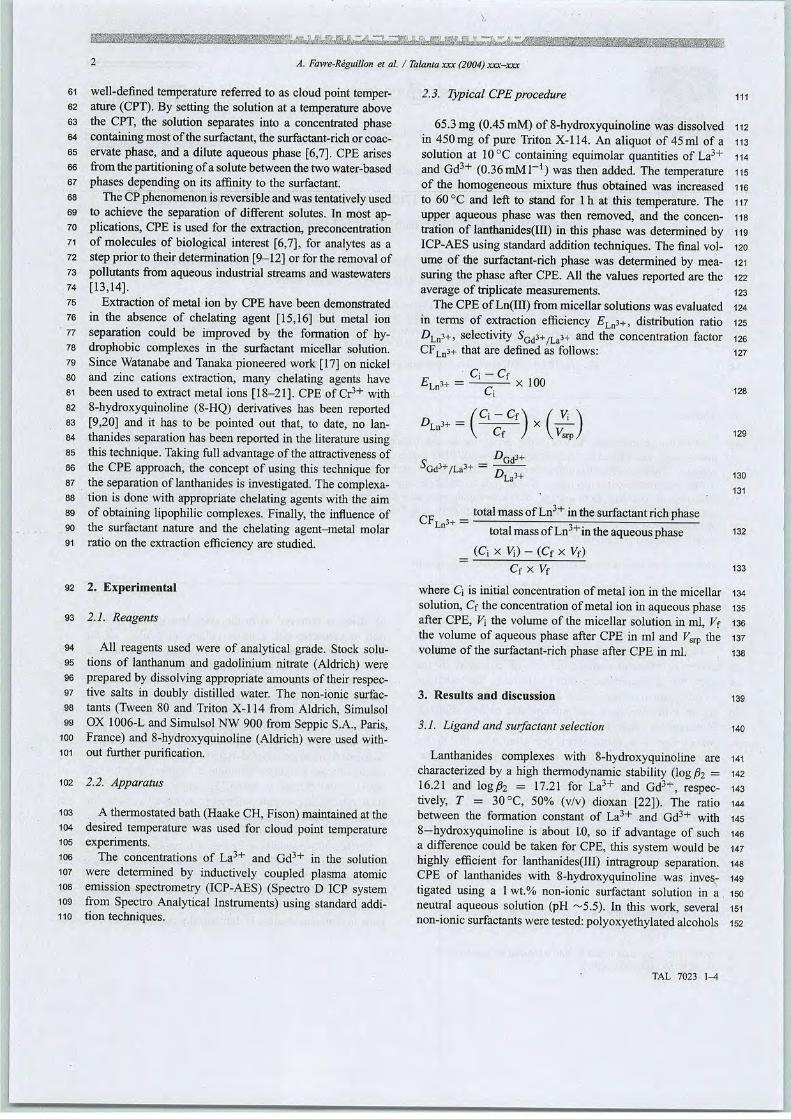
A. Favre-Réguillon et al. / Talanta xxx (2004)xxx-xxx
61
62
63
64
65
66
67
70
71
72
73
74
75
76
77
78
79
80
81
82
83
84
85
86
87
88
89
90
91
well-defined température referred to as cloud point température (CPT). By settingthe solutionat a température abovethe CPT, the solution séparâtes into a concentrated phasecontaining most ofthe surfactant, the surfactant-rich or coac-ervate phase, and a dilute aqueous phase [6,7]. CPE arisesfrom the partitioning ofa soluté between the two water-basedphases depending on its affinity to the surfactant.
The CPphenomenon isréversible and was tentatively usedto achieve the séparation of différent solutés. In most applications, CPE is used for the extraction, preconcentrationof molécules of biological interest [6,7], for analytes as astep prior to their détermination[9-12] or for the removal ofpollutants from aqueous industrial streams and wastewaters[13,14].
Extraction of métal ion by CPE hâve been demonstratedin the absence of chelating agent [15,16] but métal ionséparation could be improved by the formation of hy-drophobic complexes in the surfactant micellar solution.Since Watanabe and Tanaka pioneered work [17] on nickeland zinc cations extraction, many chelating agents hâvebeen used to extract métal ions [18-21]. CPE of Cr3+ with8-hydroxyquinoline (8-HQ) derivatives has been reported[9,20] and it has to be pointed out that, to date, no lanthanides séparation has beenreported in the literature usingthis technique. Takingfull advantageof the attractiveness ofthe CPE approach, the concept of using this technique forthe séparation of lanthanides is investigated. Thecomplexation is done with appropriate chelatingagentswith the aimof obtaining lipophilic complexes. Finally, the influence ofthe surfactant nature and the chelating agent-metal molarratio on the extraction efficiency are studied.
92 2. Expérimental
93 2.1. Reagents
94 Ail reagents used were of analytical grade. Stock solu-95 tions of lanthanum and gadolinium nitrate (Aldrich) were96 preparedby dissolving appropriate amounts of theirrespec-97 tive salts in doubly distilled water. The non-ionic surfac-98 tants (Tween 80 and Triton X-l 14 from Aldrich, Simulsol99 OX 1006-L and Simulsol NW 900 from Seppic S.A., Paris,
100 France) and 8-hydroxyquinoline (Aldrich) were used wifh-101 out further purification.
102 2.2. Apparatus
103
104
105
106
107
108
109
110
A thermostated bafh (Haake CH, Fison) maintainedat thedesired température was used for cloud point températureexperiments.
The concentrations of La3+ and Gd3+ in the solutionwere determined by inductively coupled plasma atomicémission spectrometry (ICP-AES) (Spectro D ICP Systemfrom Spectro Analytical Instruments) using standard addition techniques.
2.3. Typical CPEprocédure m
65.3 mg (0.45 mM) of 8-hydroxyquinoline was dissolved 112in 450mg of pure Triton X-114. An aliquot of 45ml of a 113solution at 10°C containing equimolar quantities of La3+ 114and Gd3+ (0.36 mMl""1) was then added. The température 115of the homogeneous mixture thus obtained was increased neto 60°C and left to stand for 1h at this température. The 117upper aqueous phase was then removed, and the concen- 118tration of lanthanides(III) in this phase was determined by 119ICP-AES usingstandard addition techniques. The final vol- 120urne of the surfactant-rich phase was determined by mea- 121suring the phase after CPE. Ail the values reported are the 122average of triplicate measurements. 123
The CPE ofLn(III) from micellar solutions was evaluated 124in terms of extraction efficiency £Ln3+, distribution ratio 125DLn3+, selectivity S'Gd3+/La3+ and the concentration factor 126CFLn3+ that are defined as follows: 127
E-i„i+Q-Cf
x 100
£]>
^Gd^/La
CFLn'+ =
Cf
DGà3+
h mD ïa3+
total mass ofLn3+ inthe surfactant rich phasetotal mass ofLn3+in theaqueous phase
(Q x V0 - (Cf x Vf)
Cf X Vf
where Q is initial concentration of métal ion in the micellar 134solution, Cf the concentration of métal ion in aqueous phase 135after CPE, V\ the volume of the micellar solution in ml, Vf 136the volume of aqueous phase after CPE in ml and Vstp the 137volume of the surfactant-rich phase after CPE in ml. 138
128
129
130
131
132
133
3. Results and discussion 139
3.1. Ligand and surfactantsélection 140
Lanthanides complexes with 8-hydroxyquinoline are 141characterized by a high thermodynamic stability (logft = 14216.21 and logft = 17.21 for La3+ and Gd3+, respec- 143tively, T = 30°C, 50% (v/v) dioxan [22]). The ratio 144between the formation constant of La3+ and Gd3+ with 1458-hydroxyquinoline is about 1.0, so if advantage of such 146a différence could be taken for CPE, this System would be 147highly efficient for lanthanides(ïïl) intragroup séparation. 148CPE of lanthanides with 8-hydroxyquinoline was inves- 149tigated using a 1 wt.% non-ionic surfactant solution in a 150neutral aqueous solution (pH ~5.5). In this work, several 151non-ionic surfactants were tested: polyoxyefhylated alcohols 152
TAL 7023 l^t

A. Favre-Réguillon et al. / Talanta xxx(2004) xxx-xxx
153 like Simulsol0X1006L and SimulsolNW900,polyoxyethy-154 lene sorbitan monooleate Tween 80 and polyethoxylated155 alkylphenol like Triton X-114.156 When working with the non-ionic surfactants Simulsol157 OX1006L, NW900 or Tween 80 which lipophilic part is158 aliphatic, 8-hydroxyquinoline is sparingly soluble in the159 initial micellar solution. Eurthermore, their lanthanides160 complexes precipitate in themicellar solution. Ontheoppo-161 site, 8-hydroxyquinoline and its lanthanides complexes are162 soluble in the micellar solution of Triton X-l 14. A possible163 explanation is that the solubilisation behavior of themicel-164 lar system formed with Triton X-114 arises from the aro-165 matic structure of the lipophilic part of Triton X-l 14. The166 solubilisation of 8-hydroxyquinoline, and the lanthanides167 complexes formed with, is directly related to the existence168 of microscopically ordered structures of aromatic nucleus169 in the micelle. The CP of the studied System with Triton170 X-114 is near room température, offering advantages in171 terms of expérimental procédure since the settling temper-172 ature was 60 °C. Furthermore, the surfactant-rich phase is173 the heaviest, allowing an easier workup: the upper aqueous174 phase could be removed by suction.
175 3.2. Influence of 8-hydroxyquinoline on CPof 1 wt.%176 Triton X-114 solutions
177
178
179
180
181
182
183
184
185
186
The effect of expérimental variables on CP and CPEparameters has beenpreviously studied [11,13]. The cloudpoint of a given non-ionic surfactant can be altered (ei-ther increased or decreased) by the présence of additives.In particular, the addition of polar organic compoundslike phénols depresses the cloud point [23]. The effect of8-hydroxyquinoline on couldpoint température wasstudied(Fig. 1).
Fig. 1 shows the effect of 8-hydroxyquinoline's concentration on CPE température. For 0-8mmoll_1 of
'4
o•—' ??
-î
20
0Q.
F 18
0)H
16c
o14
-a
o 12
O
10
—I 1 1 1 1 1 1 1 1 110 2 4 6 8 10
8-Hydroxyquinoline concentration (mM)
Fig. 1. Cloud Point Température (°C) vs. 8-hydroxyquinoline concentration (mM).
100 •
90
I 4°50 30x
UJ 20
10
0
I lLaJ*
VZZZàGA3'
U
in ï^\
m
i Si
i
!rI
'A0 2 4 6 8 10 12 14
[8-hydroxyquinoline] / [Ln(lll)] ratio
Fig. 2. Effect of 8-hydroxyquinoline/lanthanide(HI) molar ratio onextraction efficiency, [La(N03)3] = [Gd(N03)3] = 0.36mM; pH 5.5; 1wt.%Triton X-114; équilibration température 60C'C; équilibration time lh.
8-hydroxyquinoline, CPE température linearly decreasesfrom 26 to 10 °C where a plateau is reached.
3.3. Effect of8-hydroxyquinoline/lanthanide(III) molarratio on extraction efficiency
187
188
189
190
Fig. 2 shows results obtained for the CPE of lanthanides with Triton X-114 as surfactant with increasing8-hydroxyquinoline concentration after 1h at 60°C. Itshould be noted that contact time could be significantlyreduced by centrifugation.
In the absence of chelating agent a low extraction, in-ferior to 10%, of La3+ and Gd3+ is observed. The lowGd3+/La3+ selectivity observed could be explained bythe différence of hydration enthalpy between lanthanumand gadolinium [24]. At pH 5.5, when increasing the8-hydroxyquinolme/lanthanide(III) molar ratio from 2 to14, extraction efficiency increases faster for Gd3+ than forLa3+ which is in accordance with the stability constantsleading to a high distribution coefficient and selectivity forGd3+ (Table 1).
Table 1
Effect of 8-hydroxyquinoline/lanthanides ratio on distribution coefficientand Gd3+/La3+ selectivity
8-HQ/Ln(llI) %» Dafi* SGd3+/L!1-,+molar ratio
0 1.1 ± 0.3 5.9 ± 0.3 5.4 ± 1.4
2 1.7 ± 0.3 6.9 ± 0.3 4.0 ± 0.8
4 2.2 ± 0.3 13.2 ± 0.4 6.0 ± 0.9
6 5.3 ± 0.3 32.6 ± 0.6 6.1 ± 0.5
8 11.3 ± 0.4 100 ± 1 8.8 ± 0.3
10 18.9 ± 0.5 394 ±4 20.8 ± 0.6
12 38.1 ± 0.7 1059 ± 10 27.8 ± 0.6
14 63.8 é 0.9 2067 ± 20 32.4 ± 0.6
[La(N03)3] = [Gd(N03)3] = 0.36mM; pH 5.5; 1wt.% Triton X-114;équilibration température 60°C; équilibration time lh; volume of themicellarphase45ml;volumeof the surfactant-rich phase afterCPE 1.2ml.
TAL 7023 1-4
———i
191
192
193
194
195
196
197
198
199
200
201
202
203
204
205
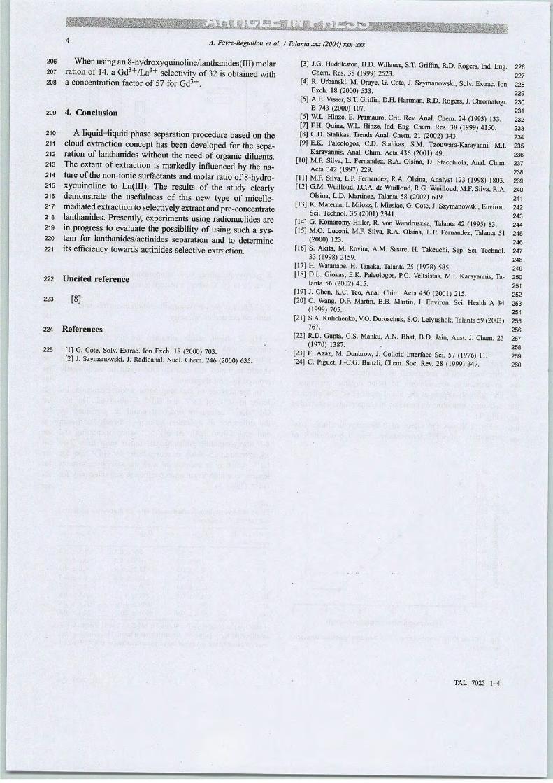
A. Favre-Réguillon et al. / Talanta xxx (2004) xxx-xxx
206 When using an8-hydroxyquinoline/lanthanides(III) molar207 ration of 14, a Gd3+/La3+ selectivity of32 isobtained with208 a concentration factor of 57 for Gd3+.
209 4. Conclusion
210
211
212
213
214
215
216
217
218
219
220
221
A liquid-Hquid phase séparation procédure based on thecloud extraction concept has been developed for the séparation of lanthanides without the need of organic diluents.The extent of extraction is markedly infiuenced by the nature ofthe non-ionic surfactants and molar ratio of8-hydroxyquinoline to Ln(III). The results of the study clearlydemonstrate the usefulness of this new type of micelle-mediated extraction toselectively extract and pre-concentratelanthanides. Presently, experiments using radionuclides arein progress to evaluate the possibility ofusing such a System for lanthanides/actinides séparation and to détermineits efficiency towards actinides sélective extraction.
222 Uncited référence
223 [8].
224 Références
225 [1] G. Cote, Solv. Extrac: ton Excîi. 18 (2000) 703.[2] J. Szymanowski, J. Radioanal. Nucl. Chem. 246 (2000) 635.
[3] J.G. Huddleston, H.D. Willauer, S.T. Griffin, R.D. Rogers, Ind. Eng.Chem. Res. 38 (1999) 2523.
[4] R. Urbanski, M. Draye, G. Cote, J. Szymanowski, Solv. Extrac IonExch. 18 (2000) 533.
[5] A.E. Visser, S.T. Griffin, D.H. Hartman, R.D. Rogers, J. ChromatogrB 743 (2000) 107.
[6] W.L. Hinze, E. Pramauro, Crit. Rev. Anal. Chem. 24 (1993) 133.[7] EH. Quina, W.L. Hinze, Ind. Eng. Chem. Res. 38 (1999) 4150.[8] CD. Stalikas, Trends Anal. Chem. 21 (2002) 343.[9] E.K. Paleologos, CD. Stalikas, S.M. Tzouwara-Karayanni, Mi.
Karayannis, Anal. Chim. Acta 436 (2001) 49.[10] M.F. Silva, L. Fernandez, R.A. Oisina, D. Stacchiola, Anal. Chim
Acta 342 (1997) 229.[11] M.F. Silva, L.P. Fernandez, R.A. Oisina, Analyst 123 (1998) 1803.[12] G.M. Wuilloud, J.C.A. de Wuilloud, R.G. Wuilloud, M.F. Silva, R.A.
Oisina, L.D. Martinez, Talanta 58 (2002) 619.[13] K.Materna, I. Milosz, I. Miesiac, G.Cote, J. Szymanowski, Environ.
Sci. Technol. 35 (2001) 2341.[14] G. Komaromy-Hiller, R. von Wandruszka, Talanta 42 (1995) 83.[15] M.O. Luconi, M.F. Silva, R.A. Oisina, L.P. Fernandez, Talanta 51
(2000) 123.
[16] S. Akita, M. Rovira, A.M. Sastre, H. Takeuchi, Sep. Sci. Technol.33 (1998) 2159.
[17] H. Watanabe, H. Tanaka, Talanta 25 (1978) 585.[18] D.L. Giokas, E.K. Paleologos, P.G. Veltsistas, M.I. Karayannis, Ta
lanta 56 (2002) 415.
[19] J. Chen, K.C. Teo, Anal. Chim. Acta 450 (2001) 215.[20] C. Wang, D.F. Martin, B.B. Martin, J. Environ. Sci. Health A 34
(1999) 705.
[21] S.A. Kulichenko, V.O. Doroschuk, S.O. Lelyushok, Talanta 59 (2003)767.
[22] R.D. Gupta, G.S. Manku, A.N. Bhat, B.D. Jain, Aust. J Chem 23(1970) 1387.
[23] E. Azaz, M. Donbrow, J. Colloid Interface Sci. 57 (1976) 11.[24] C. Piguet, J.-C.G. Bunzli, Chem. Soc. Rev. 28 (1999) 347.
TAL 7023 1-4
226
227
228
229
230
231
232
233
234
235
236
237
238
239
240
241
242
243
244
245
246
247
248
249
250
251
252
253
254
255
256
257
258
259
260
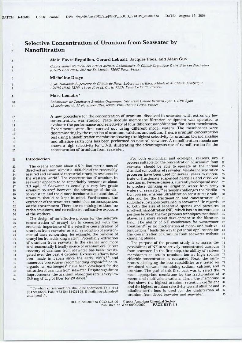
iolOb06 USER: cmh69 DIV: @xyv04/datal/CLS_pj/GRP_ie/JOB_i21/DIV_lc030157a DATE: August 15. 2003
10
il
12
13
14
15
16
17
18
19
20
21
22
23
24
25
26
27
28
29
30
31
32
33
34
35
3G
37
38
39
40
41
42
43
44
45
40
47
48
49
50
Sélective Concentration of Uranium from Seawater byNanofiltration
Alain Favre-Reguillon, Gérard Lebuzit, Jacques Foos, and Alain GuyConservatoire National des Arts et Métiers. Laboratoires de Chimie Organique & des Sciences Nucléaires(CNRS ESA 7084), 202 rue St. Martin. 75003 Paris. France
Micheline Draye
Ecole Nationale Supérieure de Chimie de Paris. Laboratoire d'Electrochimie et de Chimie Analytique(CNRS UMR 7575). U rue P. et M. Curie. 75231 Paris Cedex05. France
Marc Lemaire*
Laboratoire de Catalyse et SynthèseOrganique. Université Claude Bernard Lyon 1. CPELyon,43 boulevard du 11 Novembre 1918. 69622 Villeurbanne Cedex. France
A new procédure for the concentration of uranium, dissolved in seawater with extremely lowconcentration, was studied. Plate module membrane filtration equipment was operated toevaluate the performance and selectivity offour différent nanofiltrationflat sheet membranes.Experiments were first carried out using différent model waters. The membranes werediscriminating by the rejectionofuranium, calcium, and sodium.Then, a uranium concentrationtest usinga nanofiltration membrane showing the highestselectivity for uranium towardalkalineand alkaline-earth ions has been performed on natural seawater. A nanofiltration membraneshows a high selectivity for U(VI), illustrating the advantageous use of nanofiltration for theconcentration of uranium from seawater.
Introduction
The océans contain about 4.5 billion metric tons ofdissolved uranium, almost a 1000-fold of the reasonablyassured and estimated terrestrial uranium resources inthe western world.1 The concentration of uranium inseawater appears to be remarkably constant at about3.3 fig/L.1"3 Seawater is actually a very low gradeuranium source;1 however, the advantage of the dissolved state and the almost inexhaustible quantities ofuranium should be kept in mind. Furthermore, theextraction of the seawater uranium has no conséquenceson the environment. There are no mining residues, noradon émissions, and no collective radioactive exposureof the workers.
The design of an effective process for the sélectiveconcentration of uranyl ion is connected with theéconomie importance of the sélective concentration ofuranium from seawater as well as adoption of environ-mental lavvs concerning. for example, the removal ofuranyl ion from drinking water4). Potentially, extractionof uranium from seawater is the cleaner and moreenvironmentally friendly source of uranium ore. Directrecovery of uranium from seawater has been investi-gated over the past 4 décades. Extensive efforts hâvebeen made in Japan since the early 1960s,2-5 andmimerons procédures recommending organic6-8 or in-organic ion exchangers" hâve been developed for theextraction of uranium from seawater. Despite significantimprovements, the uranium adsorption rate is very low(0.9 mg of U/g of fiber for 20 days).7
* To vvhoni correspondance should bc addressed. Tel.: +33(0)472448209. Fax: +33 (0)4724314 08. E-mail: marc.lerhaire®univ-lyonl.lï.
For both economical and ecological reasons, anyprocess suitable for the concentration of uranium fromseawater should be able to operate at the normalchemical composition of seawater. Membrane séparationprocesses hâve been used for several years to concen-trate or fractionate suspended particles and dissolvedsubstances. Reverse osmosis, currently widespread usedto produce drinking or irrigation water from brinywaters or seawater,10 seriously challenges the distillation process, whereas ultrafiltration constitutes a valu-able aid for the fractionation and concentration ofcolloidal substances contained in seawater.1 ' In regardsto both the size of separated species and pressuresinvolved, nanofiltration (NF). which has an intermediateposition between the two previous techniques mentionedabove, is a more récent development in the filtrationfield. The ability of NF membranes for wastewatertreatment12 or for fractionation of mono- and multiva-lent cations13 leads the way to potential applications forthe concentration of uranium from seavvater withoutchanging phases.
The purpose of the présent study is to assess thepossibilités of NF in selectively concentrated uraniumfrom seavvater. In the first step, the ability of variousmembranes to retain uranium ion at high sodiumchloride concentration is evaluated. Next, the membranes displaying the best capabilities are tested onsimulated seawater containing sodium, calcium, anduranium. The goal of this first part was to sélect themost appropriate membrane for the fractionation ofmono- and multivalent cations. Then, the membranethat shows the highest uranium rétention coefficientand the highest uranium selectivitytoward alkaline andalkaline-earth ions is used for the diafiltration ofuranium from doped seavvater and seawater.
10.102 l/io030157a CCC: $25.00 C xxxx American Chemical SocietyPubiishccl on Web 00/00/0000 PAGE EST: 4.8
51
52
53
54
55
50
57
58
59
60
61
02
03
04
05
Cfi
67
68
09
70
71
72
73
74
75
76
77
78
79
80
81
82
83
84
85
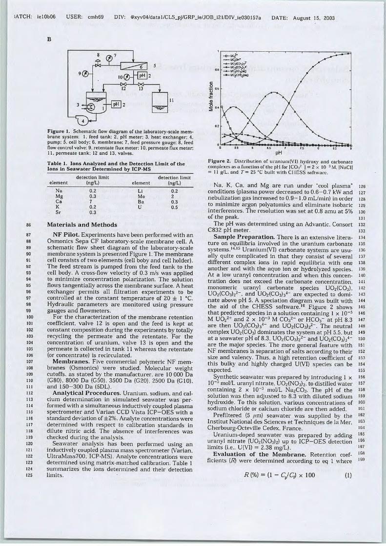
1ATCH: ielOb06 USER: cmh69 DIV: @xyv04/datal/CLS_pj/GRP_ie/JOB_i21/DIV_ie030157a DATE: August 15, 2003
B
3:fe"ifS2
Figure 1. Schematic flow diagram of the laboratory-scale membrane System: 1, feed tank; 2. pH meter; 3, heat exchanger; 4,pump: 5, cell body; 6, membrane; 7, feed pressure gauge; 8, feedflow control valve: 9, retentate flux meter; 10, permeate flux meter;11, permeate tank; 12 and 13, valves.
Table 1. Ions Analyzed and the Détection Lirait of theIons in Seawater Determined by ICP-MS
détection limit
élément (ng/L)
Na 0.2
Mg 0.3
Ca 7
K 0.2
Sr 0.3
détection limit
élément (ng/L)
Li 0.2
Mo 2
Ba 0.3
U 0.5
86 Materials and Methods
87 NF Pilot. Experiments hâve been performed with an88 Osmonics Sepa CF laboratory-scale membrane cell. A89 schematic flow sheet dicigram of the laboratory-scale90 membrane System is presented Figure 1.The membrane91 cell consists of two éléments (cell boby and cell holder).92 The feed stream is pumped from the feed tank to the93 cell body. A cross-flow velocity of 0.3 m/s was applied94 to minimize concentration polarization. The solution95 flows tangentially across the membrane surface. A heat96 exchanger permits ail filtration experiments to be97 controlled at the constant température of 20 ± 1 °C.98 Hydraulic parameters are monitored using pressure99 gauges and flowmeters.ioo For the characterization of the membrane rétention101 coefficient, valve 12 is open and the feed is kept at102 constant composition during the experiments by totally103 recycling the permeate and the retentate. For the104 concentration of uranium, valve 13 is open and the105 permeate is collected in tank 11 whereas the retentate106 (or concentrate) is recirculated.107 Membranes. Five commercial polymeric NF raem-108 branes (Osmonics) were studied. Molecular vveight109 cutoffs. as stated by the manufacturer, are 10 000 Dano (G80), 8000 Da (G50). 3500 Da (G20). 2500 Da (G10),m and 150-300 Da (5DL).112 Analytical Procédures. Uranium, sodium, and cal-U3 cium détermination in simulated seavvater was per-114 formed with a siriïultaneous inductively coupled plasma115 spectrometer and Varian CCD Vista ICP-OES with a116 standard déviation of ±2%. Analyte concentrations were117 determined with respect to calibration standards in118 dilute nitric acid. The absence of interférences was119 checked during the analysis.120 Seawater analysis has been performed using an121 inductively coupled plasma mass spectrometer (Varian,122 UltraMass700, ICP-MS). Analyte concentrations were123 determined using matrix-matched calibration. Table 1124 summarizes the ions determined and their détection125 limits.
Figure 2. Distribution of uranium(Vl) hydroxy and carbonatecomplexes as a fonction of the pli for |CO:i2 ] = 2 x 10 ''' M, |NaCl]= 11 g/L. and T= 25 °C built with C11ESS software.
Na, K, Ca, and Mg are run under "cool plasma"conditions (plasma power decreased to 0.6-0.7 kW andnebulization gas increased to 0.9-1.0 mL/min) in orderto minimize argon polyatomics and eliminate isobaricinterférences. The resolution was set at 0.8 amu at 5%of the peak.
The pH was determined using an Advantic, ConsortC832 pH meter.
Sample Préparation. There is an extensive litera-ture on equilibria involved in the uranium carbonateSystems.1415 Uranium(VI) carbonate Systems are usu-ally quite complicated in that they consist of severaldifférent complex ions in rapid equilibria with oneanother and with the aquo ion or hydrolyzed species.At a low uranyl concentration and when this concentration does not exceed the carbonate concentration,monomeric uranyl carbonate species U02(COj),U02(C03)22-, and U02(C03)34- are expected to domi-nate above pH 5. A spéciation diagram was built withthe aid of the CHESS software.16 Figure 2 showsthat predicted species in a solution containing 1 x 10⁻⁵M U022+ and 2 x 10~3 M CO32- or HCOr at pH 8.3are then U02(C03)34- and U02(C03)22-. The neutralcomplex U02(C03) dominâtes the System at pH 5.5, butat a seawater pH of 8.3, U02(C03)2„2- and U02(CO: \.A-
are the major species. The more gênerai feature withNF membranes is séparation of salts according to theirsize and valency. Thus, a high rétention coefficient ofthis bulky and highly charged U(VI) species can beexpected.
Synthetic seavvaterwas prepared by introducing 1 x10~5 mol/L uranyl nitrate, U02(N03)2. to distilled watercontaining 2 x 10_:i mol/L Na2CO:i. The pH of thesolution was then adjusted to 8.3 with diluted sodiumhydroxide. To this solution, various concentrations ofsodium chloride or calcium chloride are then added.
Prefiltered (5 /mi) seavvater was supplied by theInstitut National des Sciences et Techniques de la Mer,Cherbourg-Octeville Cedex. France.
Uranium-doped seawater was prepared by addinguranyl nitrate (U02(NO:i)2) up to ICP-OES détectionlimits (Le., U(VI) = 2.38 mg/L).
Evaluation of the Membrane. Rétention coefficients [R] were determined according to eq 1 where
R (%) = (1 - CJQ x 100 (D
126
127
128
129
130
131
132
133
134
135
13G
137
138
139
140
141
142
143
144
145
146
147
148
149
150
151
152
153
154
155
156
157
158
159
160
101
162
103
164
165
166
167
168
109

Iel0b06 USER: cmh69 DIV: @xyv04/datal/CLS_pJ/GRP_ie/JOB_i21/DIV_ie030157a DATE: August 15, 2003
0,10
10.06
0,002
AP (bar)
Figure 3. Dependence of the volume water flux on the transmembrane pressure for NF membranes.
170 Cv and Q are the concentrations in mol/L ofmétal ionsni in the permeate and feed.
172 Results and Discussion
173 Prior to the détermination of transport-séparation174 properties of the membrane, the dependence of the175 volumetric water flux on the transmembrane pressure176 was determined with deionized water. In the case of ail177 five membranes, a pressure increase from 1 to 3 bar178 leads to a linear volumetric water flux increase. Figure179 3 shows the volume water flux dependence on the180 transmembrane pressure for différent NF membranes.181 The results on the transmembrane pressure influence182 on the volumetric water flux suggest that the G10 to183. 5DL membranes are the most compact membranes184 whereas the G80 and G50 membranes hâve the most185 open structure. The five membranes show anyway a186 linear variation of their water flux volume versus187 transmembrane pressure.188 Rétention Coefficient of U(VI) with Simulated189 Seawater. Uranium occurs in seawater in its highest190 oxidation state (+6). Owing to the seavvater carbonate191 content, uranium predominantly exists in this natural192 environment as tricarbonato uranylate anion193 |U02(C03)34-|. Hovvever, there is no expérimental evi-194 dence for the présence of bulky ion in natural seavvater195 due to its extremely low concentration. The structure196 of the tricarbonato uranylate anion |U02(C03)34_] has197 been studied.17 In the equatorial plane, the radius of198 the complex ion amounts to 4.85 A; it is thus one ofthe199 largest inorganic ions existing in seavvater.2 In a previ-200 ous study, uranium carbonate complexes hâve been201 removed from drinking water by NF with rejection202 yields above 90% for the two major negatively charged203 uranyl carbonate complexes.4204 Uranium(VI) carbonate solutions with a sodium chlo-205 ride concentration ranging from 0 to 11 g/L were used206 as feed solutions: the membrane performance was207 measured in terms of the uranium rétention coefficient.208 The measurements for ail modules were performed in209 stable and identical conditions. The variation of the210 uranium rejection percentage as a function of the feed211 concentration for the différent membranes is shown in212 Figure 4. In accordance with the Donnan exclusion213 theory. the uraniumrejection percentage decreases with214 . increasing NaCl concentrations for ail of the five mem-215 branes.18 Predictably, the highest cutoff membranes216 exhibit the lowest soluté rejection for the same concen-
100:;~-0 O O
£RO-
z>
aTf 60-ll=
8 40-O
r
?n
0-
4 6
Na(fl/L)
10 12
Figure 4. Dependence of the observed uranium rétention coefficient as a function of the sodium concentration in the feed.Conditions: T= 20 °C, AP= 3 bar. pH 8.3. |U022 | = 1 x 10 5mol/L, |COi2 + HCQ3] = 2 x 10 3 mol/L, |NaCl| = 0-11 g/L.
100
80-
g 60
40 -
20
Na Ca
G20
NaCa
mi
G10
U
5DL
Figure 5. Rétentioncoefficient ofsodium, calcium, and uraniumas a function of the operating membrane. Expérimental conditions: 7"= 20 °C, AP= 3 bar. pli 8.3. |U022-] = 1 x 10 5mol/L,|COiz + HCO-t| = 2 x 10⁻³ mol/L. |NaCl] = 11 g/L. |CaCl2| =lg/L.
tration. For the G50 membrane, uranium rejectionstarts decreasing at a 1 g/L NaCl concentration whileG20 and G10 membrane rétention coefficients are kepthigh. The uranium rejection of the 5DL membrane iskept almost constant. For a seawater sodium chlorideconcentration, three membranes (5DL, G10, and G20)hâve a U(VI) rétention coefficient of greater than 70%.
In viewof their goodperformance, the 5DL,G10,andG20 membranes were then further evaluated.
Rétention Coefficient of Na, Ca, and U(VI) withSimulated Seawater. The selected membranes werethen evaluated with simulated seawater containing. inaddition to sodium and uranium salts, calcium chloride,and the results are shown in Figure 5. In the présenceof 1g/L calcium chloride, the U(VI) rétention coefficientdecreases to 50% for the G20 membrane. For G10 and5DL membranes, no significant decrease of the U(VI)rétention coefficient is noticed but U(VI)/Ca2+ selectivityof the 5DL membrane is dramatically low. Under thoseconditions, the G10 membrane shows a high rétentioncoefficient for U(VI) and a low rétention coefficient forsodium and calcium, leading to high U(VI)/Ca2+ andU(VI)/Na+ selectivities.
Rétention Coefficient of Uranium from Seawater. Because the seawater uranium concentration isvery low compared to those ofmajor éléments such asNa+, K+, Mg2+, and Ca2+. inductively coupled plasmaatomic émission spectroscopy is not sensitive enough foi-direct uranium détermination. The séparation of matrixéléments and preconcentration of uranium should beperformed prior touranium détermination. Séparation
217
218
219
220
221
222
223
224
225
226
227
228
229
230
231
232
233
234
235
236
237
238
239
240
241
242
243
244
245
246
247

1ATCH: iel0b06 USER: cmh69 DIV: @xyv04/datal/CLS_pj/GRP_ie/JOB_i21/DIV_ie030157a DATE: August 15, 2003
248
249
250
251
252
253
254
255
256
257
258
259
260
261
262
263
264
265
266
267
268
269
270
271
272
273
274
275
276
277
278
279
280
281
282
283
284
285
286
287
288
289
290
291
292
293
294
0.2 0.4 0.6 0.8 1.0
Nanofiltrated Volume Ratio (V/V)
Figure 6. Concentration of Na', Ca2 . and U(VI) as a functionof the nanofiltcrcd volume ratio. Expérimental conditions: pre-filtercd seawater. |U02(N03)2| =1x10 •"' mol/L, T= 20 "C, AP =3 bar, G10 membrane, pli 8.3.
and/or preconcentration methods such as coprecipita-tion,19 chelating resin adsorption.20solid-phase extraction,21 and solvent extraction22 hâve been widely em-ployed for seawater analysis. However, thèse techniquesshow as main drawbacks large sample volumes andlengthy preconcentration times. Because of this, weintroduced into the seawater the minimum of U(VI) saitallowing an ICP-OES analysis of the feed compositionduring the expérience duration.
In comparison to experiments with synthetic solutions, a similar behavior for uranium, sodium, andcalcium is observed when U(VI)-doped seawater wasnanofiltered with the G10 NF membrane (Figure 6). Theconcentrations of calcium and sodium in the feed arenot affected by the NF process, although the concentration of U(VI) was 7-fold raised.
The results obtained for the U(VI)-doped seawaterprompted us to study the concentration of U(VI) fromseawater in real samples. The total concentration ofuranium présent in seawater was determined byICP-MS.
The précise détermination of the uranium concentration and 234Tj/23.8Tj ratio in seawater has been describedearlier.23 The most commonly used techniques are ICP-MS coupled with matrix ion preconcentration21-24 orcoprecipitation.111 In our work. the concentration of UfVI)was directly determined by ICP-MS. A value of 3.66/(g/Lof uranium was obtained. The concentration of uraniumin the retentate was then determined as a function ofthe nanofiltered volume ratio, and the results aredisplayed in Figure 7.
As expected, the increase of the U(VI) concentrationin the retentate is exponential, and the behavior ofU(VI) is the same in both seawater (3.66 ,ttg/L) anddoped seavvater (2.38 mg/L). The concentrations of themajor seavvater métal ions were determined before andafter NF experiments for a nanofiltered volume ratioof0.96 (Table 2).
The five métal ions Na+. Mg2+, Ca2+, K+, and Sr2+.that occur at concentrations down to 1 g/L are onlyslightly concentrated by the NF process (concentrationfactor inferior to 1.4). Among the analyzed ions, onlyBa2+ and U(VI) are concentrated, and they show concentration factors of 10 and 8.5, respectively. The highfactor of concentration observed for U(VI) and Ba2+ canbe explained by the NF membrane propertiès. Indeed,the séparation mechanism is normally described in
B? 6>
S 5
I "3
0,0 0,2 0,4 0.6 0,8
Nanofiltrated Volume Ratio (V/V)1.0
Figure 7. Concentration of U(VI) in the retentate versus initialconcentration of UfVI) in the feed as a function of the nanofilteredvolume ratio. Expérimental conditions: prefiltered seawater. T=20 "C. AP = 3 bar, G10 membrane, pH 8.3.
Table 2. Concentration of the Major Seawater MétalIons before and after NF with the G10 Membrane for aNanofiltered Volume Ratio of 0.96 Determined byICP-MS and Related Concentration Factors
élément
Na
Mg.Ca
K
Sr
Li
Mo
Ba
U
sMgfl.
initial concn
(mg/L)
12200
1420
430
350
7.4
0.3
0.1
0.014
3.66a
final concn
(mg/L)
13600
1800
565
413
9.8
0.26
0.12
0.14
31.12*
concn
factor
1.1
1.3
1.3
1.2
1.3
0.9
1.2
10.0
8.5
terms of charge and/or size effects.25 As expected, a 295sieving mechanism and electrostatic interaction are 296responsible for the rétention of the bulky and highly 297charged U(VI) species. Rejection of Ba2+ would hâve 298been possible to predict because Ba2+ is the heaviest 299alkaline-earth ion. Thèse encouraging results highlight 300the great capabilities of NF for the sélective extraction 301of UfVI) from seawater. 302
Conclusion 303
Because of the weak uranium content of the sea (3.6 304/(g/L), the recovery of this élément is difficult. The 305objective of this study was to show the potentialities of 300the NF to selectively concentrate the seawater uranium. 307The variation of the rejection uranium percentage as a 308function of the feed composition was studied for five 309différent organic NF membranes. The best efficiency 310was obtained with the Osmonics G10 membrane. With 311this membrane, seavvater uranium can be selectively 312nanofiltered and then concentrated by a 8.5 factor. The 313concentration factor for the major métal ions dissolved 314in seavvater was less than 1.5. Ail of thèse results do 315not presently allow an economically viable process for 316the sélective recovery of seavvater uranium. However, 317its weak environmental impact as well as its high 318suitability in terms of process engineering make the 319membrane technology a very promising candidate for 320the sélective concentration of seawater uranium. A 321process combining the use of the membrane process in 322
5ATCH: ielObOG USER: cmhGO DIV: feyv04/dalal/CLS_pj/CRP_ie/JOB_i21/DlV_ic030157a DATE: August 15. 2003
PAGE EST: 4.8
323 association with fluidized sorbent beds seems to be324 advantageous becausean increase of the concentration325 of uranium in the feed allows an increase of the uranium320 absorption rate on adsorbent. It should be emphasized327 that the mostimportant factor contributing to the total328 recovery cost is the pîantconstruction cost, and the scale329 of the plant could be reduced by the development of a330 new process having a greater absorption rateB or kinet-331 ics.
332 Acknowledgment
We thank Y. Abdelnour from Varian France for thedétermination of the ion concentration in seawater byICP-MSand J.-L. Nigon. Cogema, 2 rue P. Dautier, BP4, 78140Vélizy Cedex, France, for the discussionsaboutof the Japanese publications and patents.
Literature Cited
(1) OECD. Uranium 1999. Resources. Production andDemand,OECD Nuclear Energy Agency and the International AtomicEnergy Agency: Paris. 2000.
(2) Schwochau. K. Extraction of metals from sea water. Top.Cuir. Chem. 1984. 124. 91.
(3) Yabutani. T.; Ji, S.: Mouri. F.; Sawatari. M.: Itoh. A.: Chiba.K.;Haraguchi. 11. Multiclcment détermination of trace clémentsin coastal seavvater by inductively coupled plasma mass spectrometrywithaidofchelating resinpreconcentration. Bull. Chem. Soc.Jpn. 1999. 72. 2253.
(4) Raff. O.: Wilken. R.-D. Removalof dissolved uranium bynanofiltration. Dcsalination 1999. 122. 147.
(5) Kanno. M. Présent status of study on extraction of uraniumfrom sea water. J. Nucl. Sci. Technol. 1984. 21, 1.
(6) Kobukc. Y.; Tabushi. L: Aoki. T.; Kamaishi. T.: 1lagiwara.I. Composite fiber adsorbent for rapid uptake of uranyl fromseawater. Ind. Eng. Chem. Res. 1988. 27. 1461.
(7) Kawai.T.: Saito. K.;Sugita. K.: Katakai. A.: Seko. N.;Sugo.T.: Kanno. J.-L: Kawakami. T. Comparison of amidoxime adsor-bentsprepared bycografting methacrylic acid and 2-hydroxyethylmethacrylate with acrylonitrilc ontopolyethylene. Ind. Eng. Chem.Res. 2000. 39. 2910.
(8) Hascgawa. S.: Seko. N.:Tabata. K.:Tamada. M.: Katakai.A.; Kasai. N.: Watanabc, T.: Kawabata. Y.: Nawata, Y.: Sugo. T.Construction and installation of the expérimental marine cquipment for recovery of rare metals in seawater. Department ofMaterial Development.Japan Atomic Energy Research Institute.JAERI-Tcch: 2001: p 1.
(9) Ooi. K.: Ashida. K.: Katoh. S.: Sugasaka. K. Rate ofuranium adsorption on hydrous titanium(IV) oxide granulatedwith poiyacrylic hydrazide. J. Nucl. Sci. Technol. 1987. 24. 315.
(10) Hassan. A. M.: Al-Sofi. M. A. K.: Al-Amoudi. A. S.:Jamaluddin. A. T. M.: Farooquc. A. M.: Rowaili. A.: Dalvi. A. G.L: Kither. N. M.: Mustafa. G. M.; Al-Tisan. I. A. R. A new approachto membrane and thermal seawater dcsalination processcs usingnanofiltration membranes (Part 1). Dcsalination 1998. 118. 35.
333
334
335
336
337
338
339
340
341
342
343
344
345
346
347
348
349
350
351
352
353
354
355
356
357
358
359
360
301
362
303
364
365
306
367
368
369
370
371
372
373
374
(11) Teulcr. A.; Glucina. K.: Laine. .1. M. Assessment of UFprctreatmcnt prior RG membranes for seawater dcsalination.Dcsalination 1999. 125. 89.
(12) Van der Bruggen. B.: De Vreese. L; Vandecasteele, C.Water réclamation in the textile industry: nanofiltration of dyebaths for vvool dyeing, Ind, Eng. Chem. Res, 2001. 40. 3973.
(13) Anne. C. 6.; f rebouct. D.: .laotien. P.: Quemeneur. F.Nanofiltration of seawater: fractionation of mono- and multi-valent cations. Dcsalination 2001. 140. 67.
(14) Clark. D. L.: I lobart. D. E.: Ncu. M. P. ActinicleCarbonateComplexes and Their Importance in Actinicle EnvironmentalChemistry. Chem. Rev. 1995. 95. 25.
(15) Grcnthe. L; Fuger. J.; Konings, R. J. M.: Lemirc. J. R.;Muller, B. A.: Nguyen-Trung. C: VVanncr. H. Chemical Thermo-dynamics of Uranium: North-1 lolland: Amsterdam. The Nether-hmds. 1992.
(16) van der Lee. J. JCHESS 2.0. Ecole Nationale Supérieuredes Mines de Paris: Fontainebleau Cedex. France. 2002.
. (17) Graziani. R.; Bombieri. G.: Forsellini. E. Crystal structureof tetraammonium uranyl tricarbonato. J. Chem. Soc. Daltonfrans. 1972. 2059.
(18) Schaep. .1.: Vander Bruggen. B.;Vandecasteele. C; Wilms,D. Chemistry for the protection of the environment. Rétentionmechanisms in nanofiltration: Plénum Press: New York. 1998:Vol. 3.
(19) Chou, C. L.: Moffact. .1. D. A simple coprecipitationinductively coupled plasma mass spectrometrie method for thedétermination of uranium in seawater. Fresenius'J. Anal. Chem.2000, 368. 59.
(20) Yabutani. T.: Mouri. F.: Itoh. A.; I laraguchi, 11. Multicle-ment monitoring for dissolved and acid-solublcconcentrations oftrace metals in surface seavvater along the ferry track betweenOsaka and Okinawa as investigated by ICP-MS. Anal. Sci. 2001,17, 399.
(21) Unsworth. E. R.: Cook.J. M.: llill. S. J. Détermination ofuranium and thorium in natural waters with a high matrixconcentration using solid-phasc extraction inductively coupledplasma mass spectrometry. Anal. Cliim. Acta 2001. 442. 141.
(22) Babu. S. K.: Satyéinarayana. D.; Muralikrishna. U.Photometric estimation of uranium in sea water based on extraction. Indian J. Mar. Sci. 1981. W. 16.
(23) Delanghe.D.;Bard. E.: I lamelin. B. NewTIMSconstraintson the uranium-238 and uranium-234 in seawaters from the mainocéan basins and the Mediterrancan Sea. Mac Chem. 2002. 80.79.
(24) Yabutani. T.; Chiba. K.: Haraguchi. H. Multielementdétermination of trace cléments in seawater by inductively coupledplasma mass spectrometry after tiuidem preconcentration withcoopération of chelating resin adsorption and lanthanum coprecipitation. Bull. Chem. Soc. Jpn. 2001. 74. 31.
(25) Schaep, .1.: Van Der Bruggen. B.: Vandecasteele, C:Wilms. D. Influence of ion size and charge in nanofiltration. Sep.Purif. Technol. 1998. 14. 155.
375
376
377
378
379
380
381
382
383
384
385
386
387
388
389
390
391
392
393
394
395
396
397
398
399
400
401
402
403
404
405
406
407
408
409
410
411
412
413
414
415
416
417
418
419
420
421
422
423
424
425
420
427
Received for review February 18. 2003 428Rcviscd manuscript received July 16, 2003 429
Acceptée! July 23, 2003 430
IE030157A 431
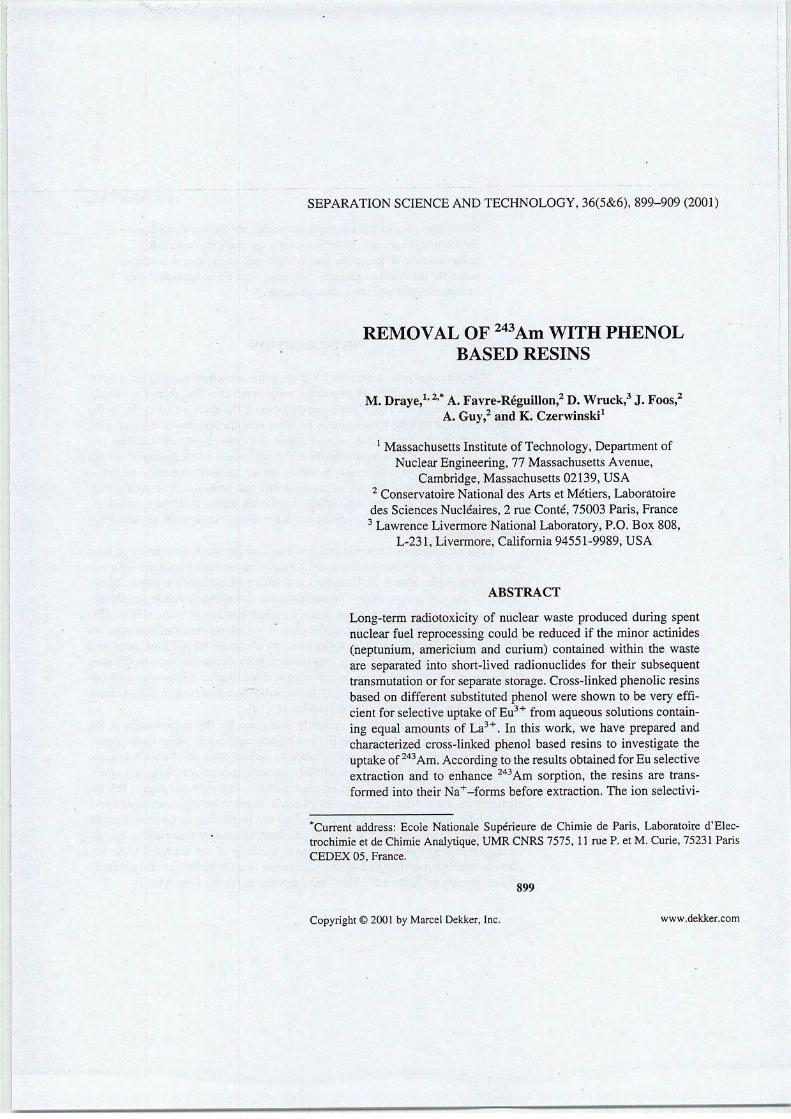
SEPARATION SCIENCE AND TECHNOLOGY, 36(5&6), 899-909 (2001)
REMOVAL OF 243Am WITH PHENOLBASED RESINS
M. Draye,1-2* A. Favre-Réguillon,2 D.Wruck,3 J. Foos,2A. Guy,2 and K. Czerwinski1
1Massachusetts Institute of Technology, Department ofNuclear Engineering, 77 Massachusetts Avenue,
Cambridge, Massachusetts 02139, USA2 Conservatoire National des Arts et Métiers, Laboratoiredes Sciences Nucléaires, 2 rue Conté, 75003 Paris, France3Lawrence Livermore National Laboratory, P.O. Box 808,
L-231, Livermore, California 94551-9989, USA
ABSTRACT
Long-term radiotoxicity of nuclear waste produced during spentnuclear fuel reprocessing could be reduced if the minor actinides(neptunium, americium and curium) contained within the wasteare separated into short-lived radionuclides for their subséquenttransmutation or for separate storage. Cross-linked phenolic resinsbased on différent substituted phénol were shown to be very efficient for sélective uptake of Eu3+ from aqueous solutions containing equal amounts of La3+. In this work, we hâve prepared andcharacterized cross-linked phénol based resins to investigate theuptake of 243Am. According to theresults obtained forEusélectiveextraction and to enhance 243Am sorption, the resins are trans-formed into their Na+-forms before extraction. The ion selectivi-
"Current address: Ecole Nationale Supérieure de Chimie de Paris, Laboratoire d'Electrochimie et de Chimie Analytique, UMR CNRS 7575, 11 rue P. et M. Curie, 75231 ParisCEDEX 05, France.
899
Copyright © 2001 by Marcel Dekker, Inc. www.dekker.com

900 DRÀYËËTÀL.
ties of the cross-linked phénol basedresinsare then compared as afunctionof the identity of the ion-exchangephenolicmatrix. Radiation stability of the resins was studied and each resin was mea-suredfor the effect of ionizing radiations withFTIR spectroscopy,moisture regain and ion exchange capacity.
INTRODUCTION
The actinides pose a long-term hazard to the biosphère making their isolation from the environment an important public concern. The séparation of actinidesfrom the radioactive waste generated during the nuclear fuel cycle for theseparate storage of long-lived minora emitting actinides (neptunium, americiumand curium), or their subséquent transmutation into short-lived radionuclides is apromising strategy for theimprovement of theradioactive waste management [1].For such a strategy, it is necessary to define minor actinide séparation methods.The group séparation is still one of the most difficult processes. For trivalent actinides Am3+ and Cm3+, the main obstacle is the séparation from the lanthanides,which are présent in major quantities and hâve similar ionic radii [2] and elec-tronic structures.
The séparations of actinide ions are based on the small différences in theirionic radii across the séries and/or in the stronger interaction of actinides with softdonor ligands like S or N [3,4]. Indeed, soft donor extractants are known to en-hance Ln/An group séparations, presumably due to enhanced stability of the actinide extractant complexes (metal-ligand covalent bondingor steric effects) [5].
Organic ligands containing acidic phénolor carboxyl functional groupsareknown to complexradionuclides undera varietyof conditions[6-9].An improvedprocess for the séparation of thèseions requires both size-selective complexationand a ligand with the optimum mix of hard and soft donors. Numerous methodsbased on liquid-liquid extraction [10-12] or solid-liquid extraction [13,14] hâvebeen described for effecting this séparation [15,16].
The DIAMEX process is currently evaluated for the coextraction of thechemically similarminoractinide(III) and lanthanide(HI) ions usinghydrophobicmalonamides from the highly acidic raffinate issuing from the PUREX process[17]. To achieve the final americium(ÏÏI) séparation from scrubbing solutions,there is a need to develop anotherefficient process. In a previous paper [18], wedemonstrated that phenolic resins are effective in the sélective removal of Eu3+from acidic aqueous médium. By combining the formaldehyde condensation ofthe phenolic compound with 8-hydroxyquinoline, an attempt was made to exploitan expected small increase in covalency in bonding of the actinides [19], Weshowedthat incorporation of 8-hydroxyquinoline into the phenolicmatrix inducesan intragroup séparation La3+/Eu3+ with séparation factors from 6 to 10.
REMOVAL OF 243Am 901
The présentarticle deals with the Am3+ uptakebehavior of synthetic poly-mers prepared from monomers containing phenolic groups. The effect of intro-ducing 8-hydroxyquinoline into the molecular matrix was studied. The stability ofthe resins was then determined.
EXPERIMENTAL PROCEDURE
Chemicals And Reagents
Résorcinol, catéchol, 8-hydroxyquinoline and formaldehyde (37% aqueoussolution) were obtained from Aldrich and used without further purification. Thestock solutions of europium were prepared by dissolving the Eu nitrate hexahy-drate sait from Aldrich in deionized water.
Synthesis of the Resins
The resins were synthesized by alkaline polycondensation of formaldehydewith phenolic compounds according to références [18,9].
Phénol based resins. A phenolic compound (0.2 M) in 150 mL of 2 Nsodium hydroxide was cooled to 0°C; 40 mL of formaldehyde (0.5 M) were thenslowly added, keeping the solution at 0°C. The mixture was stirred 1 h at this température, left overnight at room température and then kept at 100°C in an air ovenfor curing for 4 days.
Phénol 8-hydroxyquinoline based resins. Formaldehyde (40 mL, 0.5 M)was added to a suspension of 8-hydroxyquinoline (29 g, 0.2 M) in 150 mL of 1.5N sodium hydroxide. When a deep red solution was obtained, a solution of phenolic compound (0.2 M) in 150 mL of 1.5 N sodium hydroxide was added, fol-lowed by 40 mL of formaldehyde (0.5 M). The solution was stirred overnight atroom température and then kept at 100°C in an air oven for curing for 4 days.
After curing, the resins were crushed, sieved to -80+200 ASTN mesh sizeparticles, washed and conditioned by subjecting them to two 1N HC1/0.1 N NaOHcycles. The resins were finally converted into acid form and washed thoroughlywith water until neutral.
Préparationof the 243Am Stock Solution
Am was separated from U, Np and Pu by anion exchange chromatographyand assayed bya spectroscopy. The total a activity was 91% of243Am and 9% of241Am + 244Cm. On a mole basis, this is 243Am / (243Am+241Am+244Cm) =
—
902 DRAYE ET AL.
99.7%. Am hydroxide was precipitatedand redissolved in order to prépare an initial solution of pH 4 and ionic strengh (NaCl) of about 0.01 M.
Convertion of the Resins into their Na+-Form
0.05 g of resin into H+-form was shaken for 2 hours with 10 mL of 1MNaOH. The resin was then filtered and washed with water until neutral.
Analytical Section
FTIR Spectroscopy. FTIR spectra were recorded on a 1600 Perkin-Elmerspectrophotometer. The measurements were done using KBr pellets in the range4000-400 cm"1.
ICP-AES Measurements. Eu and La concentrations were determined byinductively coupled plasma - atomic émission spectrometry (ICP-AES) with astandarddéviationof ± 2%.The System used for this workwas the SpectroD System from Spectro Analytical Instruments.
Activity Measurements by a-Spectrometry and (3-Countmg. The alphaspectrometer used to détermine the Am and Cm isotopic composition consisted ofa Tennelec 257 alpha spectrometer and a Nucleus PC-based MCA System. Totalalpha and beta measurements were carried out by liquid scintillationspectrometry(liquid scintillationcounting : LSC) with a Packard InstrumentCompany 2500 TRliquid scintillation analyser. The instrument was normalized using a NIST-trace-able background, H-3 and C-14 standards from Packard Instrument Company.
Characterization of the Resins
Moisture Regain. Moisture regain was determined by heating 0.1 g of resinin an air oven at 100°C for 24 hours. The weight loss gave the percentage of water in the resin.
Ion-Exchange Capacity. For determining the total ion-exchange capacity,0.25 g ofresin inH+ form, ofknown moisture content, was equilibrated overnightwith 50 mL of 0.1N NaOH solution containing 5% NaCl. The amount of NaOHconsumed in the H+—ôNa+ exchange was determined bytitrating theremainingNaOH in the supernatant with 0.1M HCI solution.
Europium Uptake
Eu3+ sorption was performed according to a standard procédure previouslydescribed [10] in order to get comparable results between various resins. Batch ex-

REMOVAL OF 243Am 903
traction was performedat room température. A known amount of resin was equilibrated for 20 hours with a solution of Eu sait. After séparation, the concentrationof non sorbed Eu3+ in solution was determined by ICP-AES. The standard déviation was determined from six independent ion-exchange experiments. The distribution coefficient (D (mL/g(dry))) was calculatedas follows:
Ct-C/\w/y
where C,- and C/are the initial and final concentrations of métal ion in solution, Vis the volume of the equilibrated solution (mL) and m is the weight of dry resin(g). The pH of the solutions was determined before extraction.
Americium Uptake
A weighted quantity (~ 0.1 g) of resin was placed in a plastic tube andstirred for 20 hours with 10 mL of Am stock solution. After stirring the resin wasallowed to settle in the plastic tube for 1/2 hour for the first assay. A second assaywas made after 72 h. Liquid Scintillation Samples of the experiment were takenby pipetting 50 pi of the supernatant and placed into 18 mL of Ecolite scintillation fluid. For each resin two samples, corresponding to 20.5 h and 92 h of contact time, were then counted on the Packard spectrometer.
Irradiation of the Resins
Plugged glass containers filled with ~ 0.5 g of phenolic based resins wereail gamma irradiated in the spent fuel pool of the Massachusetts Institute of Technology's nuclear reactor. The position of the samplesfrom the bottom of the spentfuel rack was evaluated and the value of the highest gamma flux in the spent fuelpool was determined tobe475.6 Gyh"1. Theabsorbed dose was determined aftercalibration to be 200 kGy. After irradiation, the resins were characterized againfor their moisture regain and ion-exchange capacity.
RESULTS AND DISCUSSION
Condensation polymer of résorcinol (RF), catéchol (CF) and copolymer ofrésorcinol and 8- hydroxyquinoline (RQF), catéchol and 8- hydroxyquinoline(CQF) (Figure 1) were evaluated at pH 4.

904 DRAYE ET AL.
(b) (c)
Figure 1. Formo phenolic resins were synthesized with catéchol (a) (CF), résorcinol (b)(RF) and copolymerswere synthesizedwithcatéchol (a) and 8-hydroxyquinoline(c) (CQF)or with résorcinol (b) and 8-hydroxyquinoline (c) (RQF).
Europium Uptake
At pH 4, CF and RF resins in their H+-form are inefficient for Eu sorption, whereas introduction of 8- hydroxyquinoline in the bulk of the polymerclearly induces an extraction (Table 1). Indeed, at pH 4, no H+—»zEu3+ exchange occurs.
Phenolicresinscontainthe weaklyacidicphenolic—OHgroup (pKa = 9.9)as the functional groupresponsiblefor ion exchange.It is expectedthat complètemanifestation of their ion-exchange properties will be possible only when the —OH groups are ionized to the maximum extent, i.e., at high pH where précipitation of the lanthanides occurs [20]. To avoid précipitation of Eu3+ and still en-hance its sorption, it is necessary to transform the resins into their Na+-formbefore extraction. Though the resins in Na+-form show high affinity for Eu3+, amarked decrease in the compound's ability to extract Eu3+ is observed as 8-hydroxyquinoline group is introduced into the matrix of the polymers.The decreasefrom the parent resins CF and RF is significant, decreasing by several orders ofmagnitude. Nevertheless, the 8-hydroxyquinoline based resins are most efficientin their Na+-form than in their H+-form.
Table1. Ion-Exchange Capacity and Eu Distribution Coefficients for Substituted Phenol-formaldehyde Resins in their H+-Form and their Na-t—Form. Q Eu3+ = 0.005 M, V =10 mL, pH = 4, m = 0.05 g, T (Shaking) = 20 h
Resin
CF
RF
CQF
RQF
Ion-ExchangeCapacity (meq/g(dry))
8.6
11.5
9.6
9.9
D (mL/g(dry))H+-form
D (mL/g(dry))Na+-form
0 6450000
0 946000
12.6 216
17.8 411

REMOVAL OF243Am 905
Americium Uptake
The resins were then applied for the sorption of243Am. The distribution coefficients were determined for CF, RF and the 8-hydroxyquinoline derivatives atpH 4. The results obtained after 20.5 h and 92 h of contact time are summarizedin Table 2.
The resins behave differently with Am3+ than with Eu3+. It can beseen bycomparing the results in Table 1to those in Table 2that D(Am3+) is significantlylower for the CF and RF resins that one could expect from Eu3+ experiments.Comparable D(Eu3+) and D(Am3+) are observed for the CQF and RQF resinsprobably because of the similar affinity ofEu3+ and Am3+ for N-donor extractants. But, influence of the phenolic compound in the 8-hydroxiquinoline basedresins is différent for Eu3+ than for Am3+. For Eu3+, distribution coefficient withRQF resin is superior to theone obtained with CQF resin when it is theoppositefor Am3+. Although the kinetics ofthe extraction isslower for Am3+, the abilityof the resins to removeAm3+ from pH 4 solutions is clearlybroughtto the fore.
The alpha and beta activities in the aqueous solutions were measured beforeand afterextraction-and the (3-to-a?activity ratios were determined. Table 3 liststhe p-to-a?activity ratios obtained after 20.5 h and after 92ofcontact time beforesampling and counting.
Table 3 shows that in ail cases the (3-to-a?activity ratio in the solution islarger after 92h than at 20.5 h of contact. In addition, the CFand RF resins showthe highest affinity for 243Am, and for thèse resins, 0-to-a?activity ratios aregreater than one after 92 hof contact. An explanation for thèse results is that 239Npdaughters of 243Am bound to the resin are being released back into the solutionwhile the resin continue to extract 243Am from the solution. In opposition, CQFand RQF resins kept in 239Np. Such behavior suggests that theCFand RF resinsshow anaffinity for243Am(III) over 239Np while 8-hydroxyquinoline based resinsshow a 239Np affinity
Table 2. 243Am DistributionCoefficientD of243 Am Extracted by Sub-stituted Phenol-Formaldehyde Resins in their Na+-Form astheFunction ofTime. Stock Solution 243Am Activity = 1.40 108 dpm / mL, V = 10mL,pH = 4, m = 0.05
243Am D (mL/g(dry)) . 243Am D (mL/g(dry))Resin contact time = 20.5 h contact time = 92 h
CF 6659 42809
RF 8012 83560
CQF 272 575
RQF 116 761
mmmmmm

906 DRAYE ET AL.
Table 3. (â-to-cx Activity Ratios of theSolution After 243Am Extraction bySubstituted Phenol-Formaldehyde Resins in their Na+-Form
Resin
CF
RF
CQFRQF
p-to-a activity ratiocontact time = 20.5 h
0.98
0.96
0.43
0.36
(3-to-tx activity ratioContact time = 92 h
2.6
5.7
0.67
0.69
Radiation Stability of the Resins
Gamma irradiation of ion-exchange resins used for radioactive effluentsprocessing may lead to prejudicial modifications of the molecular structure andmacroscopic properties. Phénol formaldehyde polycondensates are known to bequite stable to irradiation by gamma radiation [21,22]. The effects of gammaradiation to phénol based resins were studied by comparing moisture regain, ion-exchange capacity (Table 4)andbyFTIR spectra before and after irradiation (Figure 2). The maximumintegrated dose was 200 kGy.
The moisture regain is not significantly affected whereas ion-exchange ca-pacities are decreased (Table 4). This decrease canbe ascribed to a crosslinkingor an oxidative dégradation of the polymermatrix. Globally, the pattern and theintensities of the FTIR vibration bands remain very similar beforeand after irradiation. Figure 2 illustrâtes how the spectrum changes for RQFresin upon sub-mitting the resin to gamma ray.
Similar features are observed for irradiated RF, CF and CQF resins. Afterirradiation, four absorption bands occurat 1738,1720,1702 and 1686 cm"1 are observed, corresponding to carbonyl stretching vibrations of chelated carboxylicacid functions [23]. Nevertheless, the absorption bands intensity is fairly small,confirmingthe well-known stability of the phenolicpolycondensates.
Table 4. Ion-Exchange Capacity and Moisture Regain of IrradiatedResins
Moisture Regain Ion-ExchangeResin (%wt/wt) Capacity (meq/g,dry))
CF 20 6.8
RF 33 7.5
CQF 16 5.5
RQF 14 5.8

REMOVAL OF 243Am
Chelated 1739 cm-icarboxylic acid
functions 1720cm
1705 cm"1
1688 cm
2000 1800 1600
Wavenumber(cm-1)
Figure 2. FTIRspectra of theRFresins before andafterirradiation.
CONCLUSION
The purpose ofthis paper was to develop an improved process for 243Am removal. Polymers prepared from simple phenolic monomers were found to hâvehigh affinities for Eu(III) and Am(III) ofpH 4 solutions. AtpH 4, CQF and RQF8-hydroxyquinoline based resins intheir H+-form are efficient for Eu extraction,whereas CF and RF parent resins need to be transformed ito their Na+-form toshow a high affinity for Euextraction. CFand RFresins show a Am(III) versusNp(V) selectivity while 8-hydroxyquinoline based resins show an affinity towardNp(V).
The effects of gamma radiations to phénol based resins were studied bycomparing moisture regain, ion-exchange capacity and by FTIR spectra beforeand after irradiation. The maximum integrated dose was 200 kGy. The ion-exchange capacities are by half decreased and low intensity absorption bands ofchelated carboxilic acid functions are observed.
907
unirradiated
20Mrad
1400

908 DRAYE ET AL.
ACKNOWLEDGMENTS
The authors are grateful to P. LaFond for irradiation of the resins.
REFERENCES
1. C. Madic, FAct. Chim. (R), 22-26 (1997).2. R. D. Shannon, Acta Cryst., A32, 751-767 ( 1976).3. C. Musikas, in Actinides/Lanthanides Séparations (G. R. Choppin, J. D.
Navratil, W.W. Schulz, Eds), World Scientific Press, Singapor, 1985.4. G. LeMarois, R. Fitoussi, C. Cuillerdier in Actinides Séparations, ACS
Symposium Séries, Vol. 117 (J. D. Navratil, W. W. Schulz, Eds), AmericanChemical Society, Washington D. C, 1980.
5. G. Modolo, R. Odoj, Solvent Extr. Ion Exch., 17, 33 (199).6. E. L. Cooper, M. K. Hass, and J. F. Mattie, Appl. Radiât, lsot. 46, 1159
(1995).
7. C. G. Pippin, J. C. Sullivan, D. Meisel, G. R. Choppin, Radiochim. Acta. 57,177 (1992).
8. G. R. Choppin, Radiochim. Acta. 32, 43, 1983.9. N. Dumont,A. Favre-Réguillon, B. Dunjic, M. Lemaire, Sep. Sci. Technol.,
31(7), 1001-1010(1996).10. A. Favre-Reguillon, B. Dunjic, N. Dumont, M. Lemaire, J. Inclusion and
Molecular Recongnition. 32(4), 477-484 (1998).11. J. Rais, S. Tachimori, Sep, Sci. Technol., 29(10), 1347-1365 (1994).12. L. Nigond, N. Condamines, P. Y. Cordier, J. Livet, C. Madic, C.
Cuillerdier, M. J. Hudson, C. Musikas, Sep. Sci. Technol. 30(7-9), 2075-2099 (1995).
13. L. K. Felker, D. E. Benker, F. R. Chattin, R. G. Stacy, Sep. Sci. Technol.30(7-9), 1769-1778(1995).
14. F. Arnaud-Neu, S. Cremin, S. Harris, M. A. Me Kervey, M. J. Schwing-Weill, P. Schwinte, A. Walker, J. Chem. Soc, Dalton Transaction, 329-334(1997).
15. K. L. Nash. Solvent Extr. Ion Exch., 11 (4), 729-767 (1995).16. K. L. Nash, G. R. Choppin "Séparation of f éléments" éd. K. L. Nash, G. R.
Choppin, Plénum Press NY (1995).17. P. B. Iveson, M. G. B. Drew, M. J. Hudson, C. Madic, J. Chem. Soc, Dal
ton Trans., 3601 (1999).
18. M. Draye, A. Favre-Réguillon, J. Foos, A. Guy, K. R. Czerwinski, Sep. Sci.Technol, in press.
19. G. R. Choppin, Radiochim. Acta, 32,43 (1983).

REMOVAL OF 243Am 909
20. L. D. Pettit, K. J. Powell, Stability Constants Database, IUPAC and Académie Software, (1993-1999).
21. K. K. S. Pillay, J. Radioanal. Nucl.Chem., 102,247 (1986).22. S. K. Samanta, M. Ramaswamy, B. M. Misra, Sep. Sci. Technol., 27, 255
(1992).23. L. J. Bellamy, The Infra-red Spectraof ComplexMolécules, Chapman and
HalLLondon, 1(3) (1975).
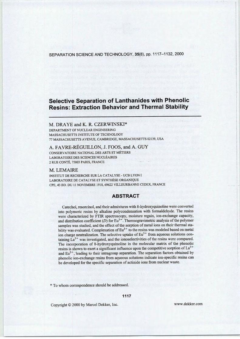
SEPARATION SCIENCE AND TECHNOLOGY, 35(8), pp. 1117-1132, 2000
Sélective Séparation of Lanthanides with PhenolicResins: Extraction Behavior and Thermal Stability
M. DRAYE and K. R. CZERWINSKI*DEPARTMENT OF NUCLEAR ENGINEERING
MASSACHUSETTS INSTITUTE OF TECHNOLOGY
77 MASSACHUSETTS AVENUE, CAMBRIDGE, MASSACHUSETTS 02139, USA
A. FAVRE-RÉGUILLON, J. FOOS, and A. GUYCONSERVATOIRE NATIONAL DESARTSET MÉTIERSLABORATOIREDES SCIENCESNUCLÉAIRES
2 RUECONTÉ, 75003 PARIS, FRANCE
M. LEMAIREINSTITUT DE RECHERCHE SUR LA CATALYSE - UCB LYON I
LABORATOIRE DE CATALYSE ET SYNTHÈSE ORGANIQUECPE,43 BD.DU 11 NOVEMBRE 1918, 69622 VILLEURBANNE CEDEX, FRANCE
ABSTRACT
Catéchol,résorcinol, andtheiradmixtureswith 8-hydroxyquinoline were convertedinto polymeric resins by alkaline polycondensation with formaldehyde. The resinswere characterized by FTIR spectroscopy, moisture regain, ion-exchange capacity,and distribution coefficient (D)for Eu3+. Thermogravimetric analysis of the polymersamples wasstudied, andthe effectof the sorption of métal ionson their thermal stability was evaluated. Complexation ofEu3+ tothe resins was modeled based onmétalion charge neutralization. The sélective uptake ofEu3+ from aqueous solutions containing La3+ was investigated, andthe ionoselectivities of theresins were compared.The incorporation of 8-hydroxyquinoline in the molecular matrix of the phenolicresins isshown to exert a significant influence upon the compétitive sorption ofLa3+and Eu3+,Teading to their intragroup séparation. The séparation factors obtained byphenolic ion-exchange resins from aqueous solutions indicate ion-specific resins canbe developed for the spécifie séparation of actinide ions from nuclear waste.
* To whom correspondence should be addressed.
1117
Copyright ©2000 byMarcel Dekker, Inc. www.dekker.com
——
1118 DRAYE ET AL.
INTRODUCTION
One of themost critical aspects of thenuclear waste-disposal problem con-cerns safe long-term storage. Society and the environment need protectionfrom thehazards associated with radioactive waste. The waste products con-tain a variety of radioactive éléments, including long-lived a-emitting actinides that require anextended period of storage. Long-term radiotoxicity ofnuclear waste produced during spent nuclear fuel reprocessing canbereducedif the minor actinides (Np, Am, and Cm) contained within the wastes are sep-arated for their subséquent transmutation into short-lived radionuclides or forseparate storage. For such a strategy, it is necessary to defme minor actinideséparationmethods. For trivalentactinidesAm3+ and Cm3+, the main obstacle is séparation from the lanthanides which hâve similar ionic radii (1) andelectronic structures (2).
The séparations of the actinides ions are based on the small différences intheir ionic radiiacross the séries and/orin the stronger interaction of actinideswith soft donor ligands like S, Cl, or N (3, 4). Organic ligands containingacidic phénol or carboxyl functional groups are known to complex radionuclides under a variety of conditions (5-8). Such organic ligands can form re-markably stable complexes, compete with inorganic ligands, affect the oxida-tion and réduction of the actinides, and alter the behavior of the actinides. Animproved process for the séparation of thèse ions requires both size-selectivecomplexation and a ligand with the optimum mix ofhard and soft donors. Nu-merous methods basedon liquid-liquidextraction (9-11) or solid-liquid extraction (12, 13) hâve been described foreffecting this séparation (14, 15).
From the waste management point of view, the most attractive feature ofsolid-liquid extraction is its ability to partition radioactive éléments into twoseparate components and produce decontaminated effluent suitable for directdisposai. Many studies hâve pointed out thatthe use of a minerai matrix (16)constitutes anadditional waste. Incontrast, organic resins, and especially phenolic resins, can bedestroyed with nitric acid, eliminating the need to disposeof the solid separately.
Ion-exchange resins containing phenolic groups are known to possess ex-ceptionally high affinity for Cs+ and Sr2+ in aqueous radioactive solution(8-19), and their stability to radiolysis has been shown (18). Séparation procédures employing ion-exchange resins are frequently made more sélective bythe addition of complexing agents during sorption or elution. Although themost stable and sélective complexes often involve chelating compounds,some of thèse, because of size and solubility characteristics, are not suitablefor the usual ion-exchange techniques. To avoidthèsedifficulties and still takeadvantage of the selectivity of chelating agents, some resins hâve been synthesized which incorporate the chelating compound in the structure of theresin itself. Resins made from 8-hydroxyquinoline and phenolic compounds
Marcel Dekker, Inc.270 Madison Avenue, New York, New York 10016

SEPARATION OF LANTHANIDES WITH PHENOLIC RESINS 1119
containboth weakly acidic and weakly basic groups. The properties of thèseresins are expected to be applicable to élément séparations for actinide-con-taining waste. To test this hypothesis, initial experiments are performed withEu3+ and La3+. The trivalent lanthanide Eu3+ is suitably homologous for thetrivalent actinides Am3+ and Cm3+ (20). If a selectivity is achieved betweenEu3+ and La3+, further experiments examining the séparation of Am3+ orCm3+ from lanthanides can be performed with a degree of confidence.
The présent article examines Eu3+ uptake behavior by synthetic polymersprepared from monomers containing phenolic groups. The influence of 8-hydroxyquinoline introduction in the molecular matrix on intragroup séparationis studied. The complexation constants of the resins are then determined, andthe thermal behavior of the synthesized resins is studied by thermogravimetryunder hélium atmosphère.
EXPERIMENTAL
Materials
Chemicals and Reagents. Phénol, résorcinol, catéchol, 8-hydroxyquinoline, and formaldehyde (37% aqueous solution) were obtained fromAldrich and used without further purification. The Eu and La nitrate hexahy-drate salts used were from Aldrich.
Resins Synthesis. The resins were synthesized by alkaline polycon-densation offormaldehyde with phenolic compounds according to Refs. 8 and19. After curing, the resins were crushed, sieved to from 75 to 180 |xm sizeparticle, washed, and conditioned by subjecting them to two 1 N HCl/0.1 NNaOH cycles. Theresinswere finally convertedto acid form and washedthor-oughly with water until neutral.
Resins Conversion to Na+-Form. 0.05 g of H+-form resin wasshaken for 2 hours with 10 mL of 1 M NaOH. The resin was then filtered andwashed with water until neutral.
Analytical Section
FTIR Spectroscopy. FTIR spectra were recorded on a 1600 Perkin-Elmer spectrophotometer. The measurements were in the 4000-400 cm-1range with samples in KBr.
Thermal Analysis. Thermogravimetric (TG) measurements were performed under hélium atmosphère with a DuPont Instruments TGA 2950 instrument. Resin samples (5-15 mg) were weighted into the thermobalance,and the weight loss was determined as a function of the température from 30to 500°C witha heating rateof 10°C-min-1.
Marcel Dekker, Inc.
270 Madison Avenue, New York, New York 10016
3o
D
o
a
Se

1120 DRAYE ET AL.
Resins Characterization
Moisture Regain. This was determined by heating 0.1 g of resin in anair oven at 100°C for 24 hours, the weight lossgiving thepercentage of waterin the resin.
Ion-Exchange Capacity. For détermination of total ion-exchange capacity, 0.25 g of resin in the H+ form of known moisture regain was equilibrated overnight with 50 mL of 0.1 N NaOH solution containing 5% NaCl.The amountof NaOH consumed in the H+-»Na+ exchange was determinedby titrating the remaining NaOH in the supematant with 0.1 M HC1 solution.
Solid-Liquid Extraction
Asa measure of theresin'saffinity forEu3+ and fora comparison betweenvarious resins, a standard procédure was followed for the measurement ofdistribution coefficients, D (mL/g(dry)). Batch extraction was performed at roomtempérature. A known weight of resin was equilibrated 20 hours with métalion solution. The supematant was then removed and the concentration ofmétal ions in the solution was determined by inductively coupled plasmaatomic émission spectrometry (ICP-AES) (Spectro D ICP System from Spectro Analytical Instruments). Thedistribution coefficient (D)wascalculated byusing the formula
D =Cf
V
m(1)
where Q and Cf are the initial and final concentrations of métal ion in solution, respectively, Vis the volume of the équilibration solution in millilitersand m is the weight in grams of dry resin. The standard déviation was determined from six independent ion-exchange experiments.
RESULTS AND DISCUSSION
The sixresins were synthesized withphénol (a), catéchol (b),résorcinol (c),and 8-hydroxyquinoline (d) (Fig. 1, Table 1). Alkaline polycondensation offormaldehyde with phenolic compound gives an infusible, insoluble, amor-
OH
O coOH
FIG. 1 Phénol (a), catéchol (b), résorcinol (c), and 8-hydroxyquinoline (d)moleeuleM<«cEi.DEKKER, iNC.270 Madison Avenue, New York, New York 10016
—

SEPARATION OF LANTHANIDES WITH PHENOLIC RESINS 1121
TABLE 1
Resins Examined
Resin Symbol
Phénol formaldehydeCatéchol formaldehydeRésorcinol formaldehydePhénol 8-hydroxyquinoline formaldehydeCatéchol 8-hydroxyquinoline formaldehydeRésorcinol 8-hydroxyquinoline formaldehyde
PF
CF
RF
PQFCQFRQF
phous, crosslinked polymer. By assuming complète crosslinking, the repeat-ing unit insuch apolymer isgiven by the following expression (18):
(C6H3-„)(OH)„(CH2)1.5 (2)
where n = 1 for phénol andn = 2 for catéchol and résorcinol. If ail the OHgroups are accessible in the polymer, the theoretically expected H+->Na+ion-exchange capacity inalkaline solution would be8.9 meq/g for phénol and15.6 meq/g for the two dihydroxybenzene resins. The results ofthecharacterization of the resins are presented in Table 2.
The ion-exchange capacities for the catéchol and résorcinol formaldehyderesins are lower than the theoretical capacities but they are higher (17) thanand comparable (8) with those of the literature. The ion-exchange capacitiesobtained for the resins made from 8-hydroxyquinoline and a phenolic compound are comparable with those obtained for the catéchol and résorcinolresins.
Europium Sorption—H+ Form Resins
Many ion-exchange materials based on phenol-formaldehyde condensation polymers hâve been described in the literature together with détails of
TABLE 2
Moisture Regain andIon-Exchange Capacities forPhenolic Resins
Moisture regain Ion-exchange capacity
Resin (%wt/wt) (meq/g(dry))
CF 20 8.6
RF 40 11.5
PQF 10 5.9
CQF 20 9.6
RQF 19 9.9Marcel Dekker, Inc.
270 Madison Avenue, New York, New York 10016
mmm
Is©
m
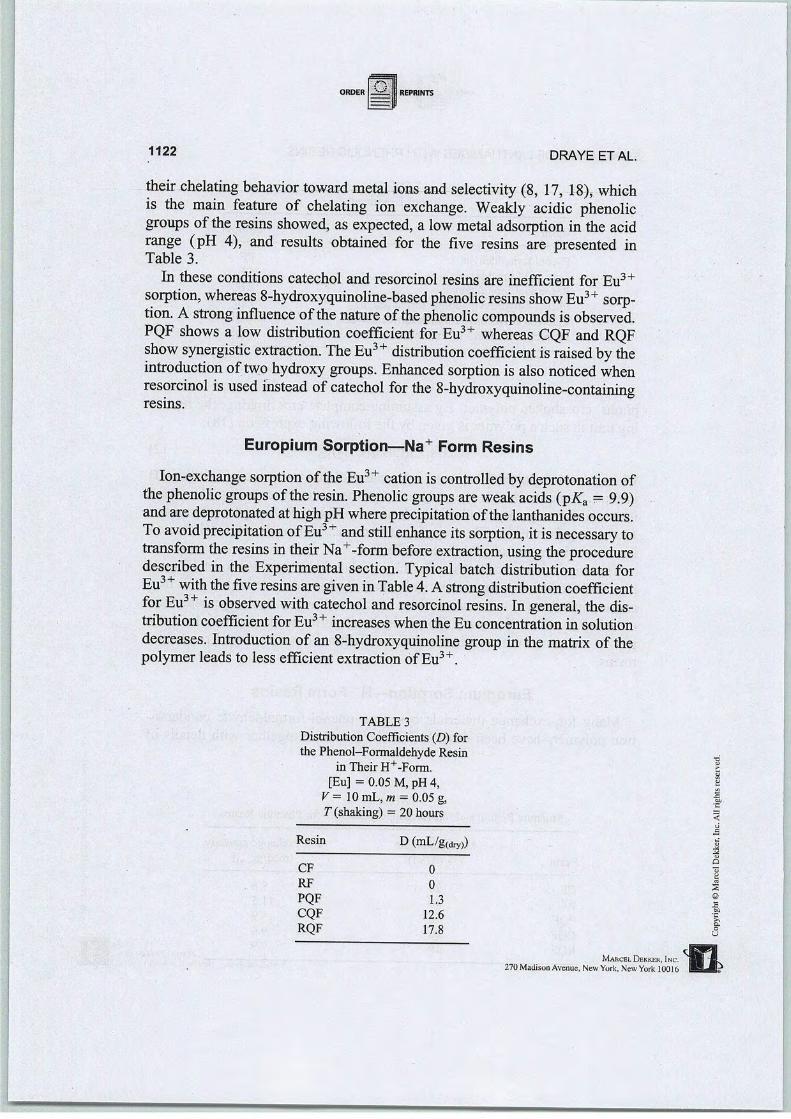
1122 DRAYE ET AL.
their chelating behavior toward métal ions and selectivity (8, 17, 18), whichis the main feature of chelating ion exchange. Weakly acidic phenolicgroups of the resins showed, as expected, a low métal adsorption in the acidrange (pH 4), and results obtained for the five resins are presented inTable 3.
In thèse conditions catéchol and résorcinol resins are inefficient for Eu3+sorption, whereas 8-hydroxyquinoline-based phenolic resins show Eu3+ sorption. A strong influence of the nature ofthe phenolic compounds isobserved.PQF shows a low distribution coefficient for Eu3+ whereas CQF and RQFshow synergistic extraction. The Eu3+ distribution coefficient israised by theintroduction of two hydroxy groups. Enhanced sorption is also noticed whenrésorcinol is used instead ofcatéchol for the 8-hydroxyquinoline-containingresins.
Europium Sorption—Na+ Form Resins
Ion-exchange sorption ofthe Eu3+ cation iscontrolled by deprotonation ofthe phenolic groups ofthe resin. Phenolic groups are weak acids (pKa = 9.9)andaredeprotonated athighpH where précipitation of the lanthanides occurs.To avoid précipitation ofEu3+ and still enhance its sorption, itis necessary totransform the resins in their Na+-form before extraction, using the procéduredescribed in the Expérimental section. Typical batch distribution data forEu3+ with the five resins are given in Table 4. Astrong distribution coefficientfor Eu3+ is observed with catéchol and résorcinol resins. In gênerai, the distributioncoefficient for Eu3+ increases whenthe Eu concentration in solutiondecreases. Introduction of an 8-hydroxyquinoline group in the matrix of thepolymer leads to less efficient extraction ofEu3+.
TABLE 3
DistributionCoefficients (D) forthe Phenol-Formaldehyde Resin
in Their H+-Form.[Eu] = 0.05 M, pH 4,
V= 10 mL, m = 0.05 g,7,(shaking) = 20 hours
Resin D (mL/g(dry))s
1
CF 0o
RF 0
PQF 1.3 ©
CQF 12.6_B/J
RQF 17.8a,o
U
Marcel Di-kkek, Inc.270 Madison Avenue, New York,New York 10016

SEPARATION OF LANTHANIDES WITH PHENOLIC RESINS
TABLE 4
Distribution Coefficients D and Amount of Eu Extracted by SubstitutedPhenol-Formaldehyde Resin in their Na+-Form, forVarious Concentrations of
Eu. V= 10mL, pH 4, m = 0.05 g, 7(shaking) = 20 hours
1123
D Eu extracted
Resin QEu (M) (mL/g(dry)) (mmol/grdrçr))
CF 0.005 6,450,000 1.35
CF 0.010 415 1.43
CF 0.025 134 1.73
CF 0.050 64 1.72
RF 0.005 946,000 1.86
RF 0.010 824 1.93
RF 0.025 134 2.01
RF 0.050 50 1.95
PQF 0.005 157 0.50
PQF 0.010 37 0.28
PQF 0.025 21 0.43
PQF 0.050 5 0.23
CQF 0.005 216 0.63
CQF 0.010 122 0.77
CQF 0.025 32 0.72
CQF 0.050 50 2.14
RQF 0.005 411 0.84
RQF 0.010 151 0.94
RQF 0.025 25 0.59
RQF 0.050 42 1.98
Lanthanum-Europium Compétitive Extraction—Na+ FormResins
The initial studies showed a strong influence of 8-hydroxyquinoline on theion-exchange capacity ofphenolic resins. Theinfluence of thischelating compound onion-exchange selectivity was then examined, yielding lower distribution coefficients for resins with the same phenolic-based functional groups.Thèse results were used in evaluating compétitive extraction between La andEu.
Using the results obtained for Eu3+ extraction, the resins were converted totheir Na+-form before the extraction experiments. Europium and La extraction is expected to be somewhat slow, and kinetic experiments were performed. The resulting distribution coefficients for La and Eu with the différent resins as a function oftime are presented in Fig. 2 and Table 5. The resultswere used to evaluate the rate of métal ion sorption to the examined resins.
Marcel Dekker, Inc.
270 Madison Avenue, New York, New York 10016
3ai
Q
u
s
©
^

1124
400
"V \Eu'RQF Eu) CQF
Eu, PQF
La> CC*F I „ nneI La, RQF La» pQF
* É É
DRAYE ET AL.
| i i i |—i—i—i—[—î—i—î—j—i—r
20 40 60 80T (hours)
-r—r—t—r—j-
100 120
FIG. 2 Europium-lanthanum distribution coefficient profiles for the phenol-catechol-and resorcinol-8-hydroxyquinoline formaldehyde resins as a function of the time.
[La] = [Eu] = 0.0025 mol-L-1, pH4, V= 10 mL, m= 0.05 g.
For each collection time presented in Table 5, the concentration ofmétal ionbound to the resin (Q - Cf) was evaluated with Eq. (1). If presented graphi-cally, the shape of the saturation curve is the same as Fig. 2. To evaluate therate of métal ion sorption to resin, the concentration of métal bound to resin([M - Res]) as a function of time is fit to
[M - Res] = A + B exp(-kT) (3)
TABLE 5
KineticDatafor CompétitionExperiment for Eu and La with DifférentResins.The Distribution Coefficients forEuand Lawith CQF, PQF, and RQF Are Presented
Time S.
(hours) DEu, CQF DLa, CQF DEu, PQF DLa, PQF, DEu, RQF £>La, RQF <
0 0 73.4 0 0 0 642 156 65 75 25 196 56 14 265.1 62 130 30 314.5 495.3 328.4 57.4 150 32 362 45
w
S
8 359 48.5 161 33 377 37.7©
24 378.8 48.5 180 35.4 393 37.8 •a
120 378.8 48.5 180 35.4 393 37.8o
U
Marcel Dekker, ïnc. WL270 Madison Avenue, New York, New-York10016 MËJÊtf

REPRINTS
SEPARATION OF LANTHANIDES WITH PHENOLIC RESINS 1125
TABLE 6
Evaluated Rates (kin hour"1) for the Sorption ofEu3+ and La3+ to the Examined Resins at pH 4
Resin
CQFPQFRQF
3 +Eu
0.54 ± 0.02
0.44 ± 0.02
0.69 ± 0.02
LaJ
0.20 ± 0.05
0.66 ± 0.07
0.23 ± 0.04
where A and B are constants for the conditions examined, T is the time inhours, and k is the rate in hour-1. The resulting values for kare presented inTable 6. The Eu3+ sorption rates are greater for the dihydroxy-based resins,while La3+ sorption is faster for PQF resin. The minimum rate from the measured values is 0.20 h-1 for La3+ sorption to CQF resin. From this value, amixing time of20 hours was chosen. This will resuit in ==99% ofthe equilib-rium concentration being reached in the kinetically slowest case.
After extraction with the catéchol and the résorcinol formaldehyde resins,the concentrationsofLa3+ and Eu3+ in the aqueous solution are too low to bemeasured byICP-AES. Their distribution coefficients are very high and theirselectivity can not be determined with accuracy. Incorporation of 8-hydroxyquinoline in the polymeric matrix strongly reduces the distribution coefficient of La3+ and Eu3+, butresults in sélective extraction of Eu3+. The phénol-, catéchol-, and resorcinol-8-hydroxyquinoline-formaldehyde resinssorbed Eu3+ with a Eu3+/La3+ séparation factor of 6.2, 6.9, and 9.9 respec-tively (Table 7). Thèse results are similar to séparation factors obtained from
TABLE 7
Distribution Coefficients D (mL/g(dry)) and Séparation Factors for the Compétitive Extractionof Lanthanum and Europiumby Phenolic Resins. StandardDéviation ±5.
[La] = [Eu] 4 0.0025 mol-L"1, V= 10 mL, pH 4, m=0.05 g, r(shaking) = 20 hours. TheSéparation Factors Obtained from the Kinetic Experiments at24 Hours Are Also Presented
Phenolic
resin
CF
RF
PQFCQFRQF
Séparation factor Eu/LaDistribution coefficient (mL/g(dry))
La
>2,000,000>2,000,000
64
98
82
Eu 20 hours
>2,000,000 ~1
>2,000,000 ~1
400 6.2
672 6.9
816 9.9
Kinetic experiments(24 hours)
5.1
7.8
10
*Marcel Dekker, Inc.
270 Madison Avenue, New York, New York 10016
——•
s©
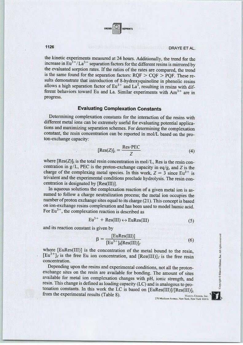
1126 DRAYE ET AL.
the kinetic experiments measured at 24hours. Additionally, the trend for theincrease in Eu3+/ La3+séparation factors for the différent resins is mirrored bythe evaluated sorption rates. If the ratios of the rates are compared, the trendis the same found for the séparation factors: RQF > CQF > PQF. Thèse results demonstrate that introduction of 8-hydroxyquinoline in phenolic resinsallows a high séparation factor of Eu3+ and La3, resulting in resins with différent behaviors toward Eu and La. Similar experiments with Am3+ are inprogress.
Evaluating Complexation Constants
Determining complexation constants for the interaction of the resins withdifférent métal ions can be extremely useful for evaluating potential applications and maximizing séparation schemes. For determining the complexationconstant, the resin concentration can be reported in mol/L based on the pro-ton-exchange capacity:
[Res(Z)]t =Res-PEC
Z(4)
where [Res(Z)]t is the totalresinconcentration in mol/L, Res is the resin concentration in g/L, PEC is the proton-exchange capacity in eq/g, and Z is thecharge of the complexing métal species. In this work, Z = 3 since Eutrivalent and the expérimental conditions preclude hydrolysis. The resin concentration is designated by [Res(III)].
In aqueous solutions the complexation reaction of a given métal ion is as-sumed to follow a charge neutralization process; the métal ion occupies thenumber ofproton exchange sites equal to its charge (21). This concept isbasedon ion-exchange resins complexation and has been used to model humic acid.ForEu3+, thecomplexation reaction is described as
3 +
Eu3+ + Res(III) <-> EuRes(III)
and its reaction constant is givenby
[EuRes(IH)]0 =
[Eu3+MRes(III)]f
1S
(5)
(6)
where [EuRes(III)] is the concentration of the métal bound to the resin,[Eu3+]f is the free Eu ion concentration, and [Res(III)]f is the free resinconcentration.
Depending upon the resins and expérimental conditions, not ail the proton-exchange sites on the resin are available for bonding. The amount of sitesavailable for métal ion complexation changes with pH, ionic strength, andresin. This change is defined as loading capacity (LC) and is analogous to protonation constants. In this work the LC is based on [EuRes(III)]/[Res(III)]tfrom theexpérimental results (Table 8). m^d™, .«,
270 Madison Avenue, New York, New York 10016
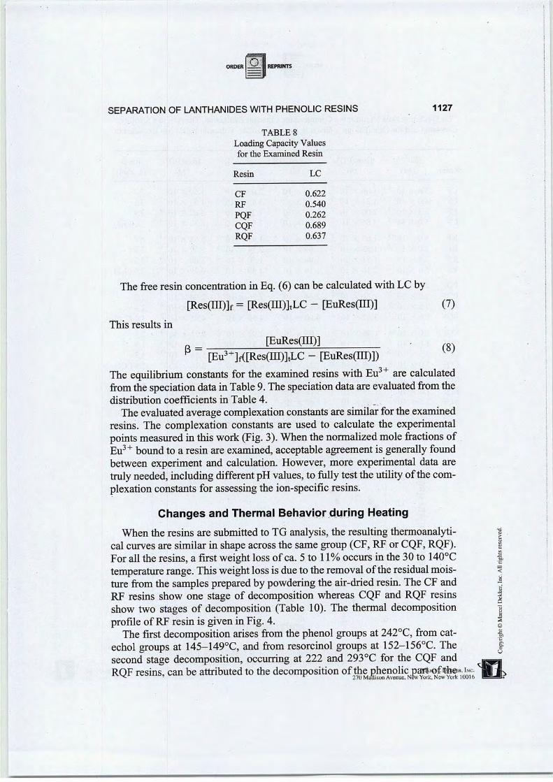
SEPARATION OF LANTHANIDES WITH PHENOLIC RESINS
TABLE 8
Loading Capacity Valuesfor the Examined Resin
Resin LC
CF 0.622
RF 0.540
PQF 0.262
CQF 0.689
RQF 0.637
1127
The free resin concentration in Eq. (6) can be calculated with LC by
[Res(III)]f = [Res(III)]tLC - [EuRes(III)] (7)
This results in
P[EuRes(III)]
[Eu3+M[Res(III)]tLC - [EuRes(III)])
The equilibrium constants for the examined resins with Eu3+ are calculatedfrom thespéciation datain Table 9.Thespéciation dataare evaluated from thedistribution coefficients in Table 4.
The evaluated average complexationconstants are similar for the examinedresins. The complexation constants are used to calculate the expérimentalpoints measured in this work(Fig. 3).When the normalized mole fractions ofEu3+ bound to a resin are examined, acceptable agreement is generally foundbetween experiment and calculation. However, more expérimental data aretrulyneeded, including différent pH values, to fully test theutility of thecomplexation constants for assessing the ion-specific resins.
Changes and Thermal Behavior during Heating
When the resins are submitted to TG analysis, the resulting thermoanalyti-cal curves are similar in shape across the same group (CF, RF or CQF, RQF).For ail the resins, a first weight loss of ca. 5 to 11% occurs in the 30 to 140°Ctempérature range. Thisweight lossis dueto theremoval of theresidual moisture from the samples preparedby powdering the air-dried resin. The CF andRF resins show one stage of décomposition whereas CQF and RQF resinsshow two stages of décomposition (Table 10). The thermal décompositionprofile of RF resin is given in Fig. 4.
The first décompositionarises from the phénol groups at 242°C, from catéchol groups at 145-149°C, and from résorcinol groups at 152-156°C. Thesecond stage décomposition, occurring at 222 and 293°C for the CQF andRQF resins, can be attributed to the décomposition of the phenolic pa*t»<rf'%©*. î
^. • -, - - " * 270 Madison Avenue, New York, New York 101
(8)
•^——*—
3
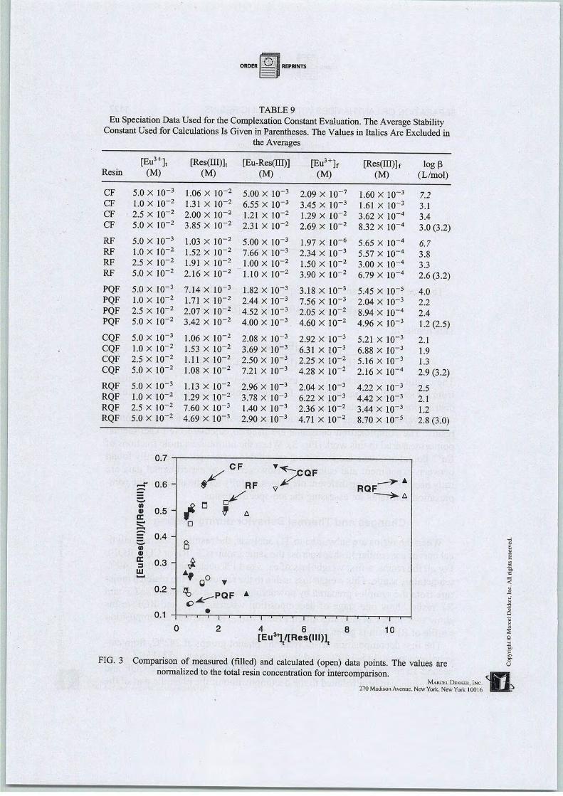
TABLE 9
Eu Spéciation Data Used for the Complexation Constant Evaluation. The Average StabilityConstant Used forCalculations Is Given inParenthèses. The Values in Italics Are Excluded in
the Averages
[Eu3+]t [Res(III)]t [Eu-Res(III)] [Eu3+]f [Res(ÏÏT)]f log (3Resin (M) (M) (M) (M) (M) (L/mol)
CF 5.0 X 10"3 1.06 X 10"2 5.00 X 10"3 2.09 X 10"7 1.60 X lO"3 7.2CF 1.0 X lO"2 1.31 X lO"2 6.55 X 10"3 3.45 X 10"3 1.61 X 10"3 3.1CF 2.5 X lO"2 2.00 X lO-2 1.21 X lO-2 1.29 X 10"2 3.62 X 10"4 3.4CF 5.0 X 10"2 3.85 X lO-2 2.31 X lO-2 2.69 X lO"2 8.32 X 10~4 3.0 (3.2)
RF 5.0 X lO-3 1.03 X lO-2 5.00 X 10"3 1.97 X 10"6 5.65 X 10"4 6.7RF LO X 10"2 1.52 X lO-2 7.66 X lO-3 2.34 X 10⁻³ 5.57 X 10~4 3.8RF 2.5 X lO"2 1.91 X 10"2 1.00 X lO"2 1.50 X lO-2 3.00 X 10~4 3.3RF 5.0 X 10"2 2.16 X 10"2 1.10 X 10~2 3.90 X 10"2 6.79 X 10~4 2.6 (3.2)
PQF 5.0 X lO"3 7.14 X lO"3 1.82 X 10~3 3.18 X lO-3 5.45 X 10~5 4.0PQF 1.0 X lO"2 1.71 X lO-2 2.44 X lO-3 7.56 X lO"3 2.04 X lO-3 2.2PQF 2.5 X lO"2 2.07 X lO"2 4.52 X 10"3 2.05 X lO"2 8.94 X lO"4 2.4PQF 5.0 X lO"2 3.42 X lO"2 4.00 X lO-3 4.60 X 10"2 4.96 X 10"3 1.2(2.5)
CQF 5.0 X 10"3 1.06 X 10"2 2.08 X lO"3 2.92 X lO-3 5.21 X lO-3 2.1CQF 1.0 X lO-2 1.53 X lO"2 3.69 X lO-3 6.31 X 10⁻³ 6.88 X lO"3 1.9CQF 2.5 X lO"2 1.11 X 10"2 2.50 X lO"3 2.25 X lO-2 5.16 X 10"3 1.3CQF 5.0 X lO-2 1.08 X lO-2 7.21 X lO-3 4.28 X 10"2 2.16 X 10"4 2.9 (3.2)
RQF 5.0 X lO"3 1.13 X lO"2 2.96 X lO-3 2.04 X 10"3 4.22 X 10"3 2.5RQF LO X lO-2 1.29 X lO"2 3.78 X lO"3 6.22 X lO"3 4.42 X lO-3 2.1RQF 2.5 X lO-2 7.60 X lO"3 1.40 X lO"3 2.36 X 10"2 3.44 X 10"3 1.2RQF 5.0 X lO"2 4.69 X lO"3 2.90 X lO"3 4.71 X lO"2 8.70 X lO"5 2.8 (3.0)
fl 7\J.i
s? °-6 ~ * RF X ,. >- ARQF
=
D
S
« 0.5 - A
= 0.4 -
(O0)
8
% 0.3- *1U AM
f 0° T0.2 -
m
A
0.1 -
(
1,1)1
) 2 4
l i i > i
6 8
:, ' ' i >
10[Eu31/[Res(lll)l
FIG. 3 Comparison of measured (filled) and calculated (open) data points. The values arenormalized to thetotal resin concentration for intercomparison.
Marcel Dekker, Inc.270 Madison Avenue, New York, New York 10016

SEPARATION OF LANTHANIDES WITH PHENOLIC RESINS
TABLE 10
Phenomenological Dataon the Thermal Décomposition of the Phenolic Resins
1129
Resin 7i (°C) T2 (°C) Weight loss at 500°C (%
PF 241.62 —
CF 148.84 —
RF 152.19 —
CQF 145.48 221.53
RQF 155.54 292.51
17
40
32
30
24
8-hydroxyquinoline groups. For a température of 500°C, the weight loss isfrom 17 to 40%, depending on the resin.
Thermogravimetrîc Studies of the Polymer-MetalComplexes
Thermal analysis of the polymer complexes can reveal the change in thethermal stability inducedby introduction of métal ions in the polymermatrix(22-24). The thermal stability varieswiththe métal ionandthe structure of thepolymer-metal complex (23). This part of the study is concerned with thethermal décomposition behavior of Eu3+ complexes of the phenolic resins.The phenomenological data of the thermal décomposition of various Systemsare given in Table 11.
65
t—!—î—i—r~
i ' i i I . i . i L
100 200 300 400
Température (°C)
FIG. 4 TG curve of RF resin.
500
Marcel Dekker, Inc.
270 Madison Avenue. New York, New York 10016

1130 DRAYE ET AL.
TABLE 11
Phenomenological Dataon theThermal Décomposition of theMétal Complexes of PhenolicResins
Resin complex Tx (°C) T2 (°C) T3 (°C) T4(°C) Weight loss at 500°C (%)
PF-Eu 243.42 _ 18CF-Eu 172.31 445.06 — — 29RF-Eu 193.55 457.36 — — 32
CQF-Eu 163.37 290.80 361.22 431.65 25
RQF-Eu 172.31 300.00 361.22 451.77 26
Thecomplexation of the métal ion increases the stability of the resin. Thisis similar to theresults forthepolychelates from 8-quinolyl acrylate (25). Thestabilities are in theorderPF-Eu > RF-Eu > CF-Eu > RQF-Eu > CQF-Eu.The first weight loss of 5 to 8% that occurs below 140°C is attributed to thedésorption ofadsorbed/coordinated water molécules. Inthe température rangeof 30 to 500°C, the PF-Eupolymer complex dégrades in one stage whereasthe CF-Euand RF-Eupolymers dégrade in two stages. A four-stage décomposition is seen for CQF-Eu and RQF-Eu. The PF-Eucomplex décompose at243°C. For CF-Eu and RF-Eu complexes, the first-stage décomposition iswithin 149-152°C whereas the second-stage décomposition occurs in the445-457°C température range. For CQF-Eu and RQF-Eu complexes, thefirst-stage décomposition is within 163-172°C. A second-stage décomposition occurs in the 291-300°C température range. The third-stage décomposition at 360°C may be due to the décomposition of the coordinated hydroxyquinoline groups. The last stage décomposition occurs in the 432-452°Ctempérature range. The CQF-Eu and RQF-Eu complexes hâve weaker thermal stabilities compared to the other complexes. The dégradation températures for the complexes are greater than for the polymeric ligand, indicatingthat stability is gained oncomplexation with the métal ions. The greater stability ofthe métal complexes isprobably due to the formation ofstable ring-structured métal complexes.
CONCLUSION
Thèse investigations on complexation behavior of phenolic polymersdemonstratethat phenolic resins are effective in the sélectiveremovalof Eu3+from an acidic aqueous médium. Conversion of the resins in their Na+ formmarkedly enhanced Eu3+ sorption. The incorporation of8-hydroxyquinolineinto the phenolic matrix produces important changes in the compétitive sorption ofLa3+ and Eu3+. Compared with résorcinol and catéchol formaldehyde
Marcel Dekker, Inc.270 Madison Avenue, New York, New York 10016
<
1Q

SEPARATION OF LANTHANIDES WITH PHENOLIC RESINS 1131
resins, the phenolic 8-hydroxyqumoline-based resins show low distributioncoefficients for Eu3+ sorption, but they show a selectivity between La3+ andEu3+. The selectivity ofcompétitive Eu3+/ La3+ sorption is found tobe influ-enced bytheidentity ofthe ion-exchange phenolic matrix. The séparation factors obtained for PQF, CQF, andRQFresins are SVQF = 6.2, SCqf = 6.9, and5RQF = 9.9. Evaluated complexation constants showed acceptable agreementbetween experiment and calculation. However, further effort is needed to determined the utility of the complexation model and the evaluated terms. Phenomenological analyses of the thermal décomposition of the différent resinsreveal that the thermal stabilities of the polymers vary significantly by complexation with a métal ion. Thethermal stabilities of the métal complexes arehigher than the uncomplexed resins.
ACKNOWLEDGMENTS
The authors thank Pr. B. Chabert (Laboratory ofPlastic materials and Bio-materials study, Lyon University) for providing the TG facility, and Drs. N.Zydowicz and O. Gainfor helping with TG experiments.
REFERENCES
1. R. D. Shannon, Acta Cryst., A32, 751-767 (1976).2. C. Madic, Act. Chim. (R), pp. 22-26 (1997).3. C. Musikas, in Actinides/Lanthanides Séparations (G. R. Choppin, J. D. Navratil, and W.
W. Schulz, Eds.), World Scientific Press, Singapore, 1985.4. G. LeMarois, R. Fitoussi, and C. Cuillerdier, in Actinides Séparations (ACS Symposium
Séries, Vol. 117, J. D. Navratil and W. W. Schulz, Eds.), American Chemical Society,Washington, DC, 1980.
5. E. L. Cooper,M. K. Hass, and J. F. Mattie,Appl. Radiât. Isot., 46, 1159 (1995).6. C. G. Pippin, J. C. Sullivan, D. Meisel, and G. R. Choppin, Radiochim. Acta, 57, 177
(1992).7. G. R. Choppin, Ibid., 32,43 (1983).8. N. Dumont, A. Favre-Réguillon, B. Dunjic, and M. Lemaire, Sep. Sci. Technol., 31(1),
1001-1010(1996).9. A. Favre-Réguillon, B. Dunjic, N. Dumont, andM. Lemaire,J. Ind. Phenom. Mol. Recog.
Chem., In Press.10. J. Rais and S. Tachimori, Sep.Sci. Technol., 29(10), 1347-1365 (1994).11. L. Nigond, N. Condamines, P. Y. Cordier, J. Livet, C. Madic, C. Cuillerdier, M. J. Hud
son, and C. Musikas, Ibid., 30(1-9), 2075-2099 (1995).12. L. K. Felker, D. E. Benker, F. R. Chattin, and R. G. Stacy, Ibid., 30(1-9), 1769-1778
(1995).13. F. Arnaud-Neum S. Cremin, S. Harris, M. A. McKervey, M. J. Schwing-Weill, P.
Schwinte, and A. Walker,J. Chem. Soc, Dalton Trans., pp. 329-334 (1997).14. K. L. Nash, Solv. Extr. Ion Exch., 11(4), 729-767 (1995).15. K. L. Nash and G. R. Choppin, in Séparation ofEléments (K. L. Nashand G. R. Choppin,
Eds.), Plénum Press, New York, NY, 1995.Marcel Dekker, Inc.
270 Madison Avenue, New York, New York 10016
—-

1132 DRAYE ET AL.
16.
17.
18.
19.
20.
21.
22.
23.
24.
25.
R. Cahill, B. Shpeizer, G. Z.Peng, L. Bortum, and A. Clearfield, inSéparation ofEléments(K. L. Nash and G. R. Choppin, Eds.), Plénum Press, New York, NY, 1995, pp. 165-176.S. K. Samanta, M. Ramaswamy, and B. M. Misra, Sep. Sci. Technol, 27(2), 255-267(1992).
S. K. Samanta, M. Ramaswamy, and B. M. Misra, Radiochim. Acta, 57,201-205 (1992).M. Draye, A. Favre-Réguillon, J. Foos, A. Guy, and K. R. Czerwinski, Proceedings ofWaste Management '98 Conférence, WM Symposia, Inc., Tucson, Arizona, 1998.G. T. Seaborg, Radiochim. Acta, 61, 115-122 (1993).J. I. Kim and K. R. Czerwinski, Ibid., 73,5 (1996).M. A. Diab, A. Z. El-Sonbati, A. El-Sanabari, and F. I. Taha, Polym. Degrad. Stab., 24,51-58(1989).B. Mathew, P. M. Madhusudanan, and V. N. R. Pillai, Thermochim. Acta, 205, 271-282(1992).
B.Mathew andS. Jacob, Polym. Degrad. Stab., 54, 107-111 (1996).A.Z. El-Sonbati andM.A. Diab., Ibid., 22,295-302 (1988).
Received by editorJune 8, 1998Revision received October 1999
Marcel Dekker, Inc.270 MadisonAvenue, New York, New York 10016

710 Chemistry Letters 2000
An ESR Study ofy-Irradiated P4VP Polymers : Dose-Effect Relationships
M. Draye,* A. Favre-Réguillon,f J. Foos,+ and A. Guy1'Ecole Nationale Supérieure de Chimie de Paris, Laboratoire dElectrochimie etde Chimie Analytique,
11 rue P. et M. Curie, 75005 Paris1Conservatoire National des Arts et Métiers, Laboratoire de Chimie Organique, ESA CNRS 7084
292, rue St Martin, 75003 Paris, France^Conservatoire National des Arts et Métiers, Laboratoire des Sciences Nucléaires,
2 rue Conté, 75003 Paris, France
(Received February 10, 2000; CL-000144)
The behavior of poly(vinylpyridine) with a gamma raysource has beenstudied. In the présentwork, samples were irradiated in air with a 60Co or 137Cs gamma cell source (absorbeddose 10Gy to 14400 kGy). Ail testedsamples show well definedESR signais whose amplitude increases with time. The behaviorat room température and dose-effect relationships were investi-gated.
Irradiation has a wide range of applications such as polymer-ization,1 grafting of polymers,2 decontamination or sterilization ofgoods,3 or disposable equipment for hospital and médical use.4There is needs for methods which could discriminate betweenirradiated and non-irradiated goods. The method should be accu-rate, reproducible, quick and easy to perform. In practice, it has •been proveddifficult to fulfill ail thèse requirements simultane-ously.3
The methods which hâve been the most extensively studiedand which hâve the greatest scope of application include thermoluminescence (TL),5 methods monitoring the formation of long-chain volatile hydrocarbons and 2-alkylcyclobutanones6 andElectron Spin Résonance (ESR) spectroscopy.7 However, itappeared from preliminary measurements onfoodstuffs and polymers, that the stability of radiation-induced radicals is often low.This low stability is attributed to the highmoisture content, or tothe fast recombination of small reactive radicals with others, giv-ing rise to a stable low molecular weight product. It means thatthose methods can not be used for identification of irradiatedgoods as such.
Because of energy-transfer processes, radiation inducedchemistry is not completely random. Energy can migrate overshort distances, selectively causing relatively weak chemicalbonds tobreak, orbecoming trapped by certain functional groupssuch as aromatic rings, that undergo efficient non-reactive decayto theground state. Forreasons discussed elsewhere, the présenceof an aromatic ring andeven more of a hetero aromatic ring8'9 inthe poly(vinylpyridine) exerts a strongly stabilizing influence onthe yieldof radiation-induced cross-linking or scission.
In the présent work, production of stable long-lived radicalcenterin poly(vinylpyridine) generated by gamma ray radiationis studied by ESR. Dose effect relationships and decay areinvestigated whereas nature of the radicals, produced within thepolymer, was studied by time-of-flight particle induced désorptionmass spectrometry (TOF-PDMS) in previous papers.'0-"
In a first set of measurements the cross-linked poly(4-vinylpyridine) (P4VP) samples12 were irradiated in the148-14400kGy absorbed dose range with a l37Cs y source at a
dose rate of 20 kGy h-1 and storedin air at room conditions.13 Ina second set of measurements, the P4VP samples14 were irradiated in the 10-100 Gy absorbeddose range with a 60Co source at adose rate of 1.06 kGy h"1, and stored in air at room conditions15.Figure 1 shows the ESR signal16 of a cross-linked P4VP samplefora 148 kGy integrated dose. Thesignal is typical for free radicals, both in the g value and in microwave power dependence.But, a unique value of 2.005 for the g factor was determinedwhich did not allow to distinguish the kind of radicals in the bulkof the polymer. This signal is also présent in the un-irradiatedsamples at a much lower intensity.
30000
20000
10000
•S 0
I£ -10000-
-20000-
-30000-
3250 3300 3350 3400
Magnetic Field / G
3450
Figure 1. ESRsignal of a cross-linked P4VPsample for a 148kGy integrated dosewitha VARIAN E Linespectrometer at amodulation frequency of 100 kHz, microwave frequency 9.3
GHz, mass of polymer= 30 mg.
Figure 2 shows the ESR spectra of a linear P4VP samplefor a 100Gy integrated dose. While the integrated doseis 1500times lower than previously, the signal remains as intense andwell defined.
In both cases, ESR spectroscopy gives unambiguousresults concerning the existence of paramagnetic centers. Thenumber of spins can be found by double intégration of thederivative curve and comparison with a VARIAN standardsample. By this way, we determined the number of spins pergram of polymer as a function of the integrated dose.
Figure 3 shows the variation of numbers of spins per gramof resinas a function of the integrated dosein the 0-14400 kGyrange. The zéro integrated dose signal shows a non negligibleconcentration of spins, corresponding to the free radicals produced during polymerization. For an integrated dose of 10000kGy a plateau is reached, indicating some possible intramolecu-lar reactions, such as cross-linking.
Copyright© 2000 The Chemical Societyof Japan

Chemistry Letters 2000
3250 3300 3350 3400
Magnetic Field / G
3450
Figure 2. ESR spectra ofa linear P4VP sample for a 100 Gyintegrated with a BRUKER ESP300E spectrometer at amodulation frequency of 100 kHz, microwave frequency 9.4GHz, massof polymer= 50mg.
1E+15
5000 10000 15000
IntegratedDose/ Gy
Figure 3. Number of spin per g of cross-linked P4VP as thefunction of the integrateddose.
The intensity of the ESR signais of cross-linked P4VP wasfound tobealmost constant afterseveral months in air. In addition, the time dependence of the ESR signal amplitude for a10000 kGy integrated dose sample did not show any appréciable variation.
Although we find a polymer, which shows a stable andstrong corrélation between integrated dose and ESR signal from500 to 10000 Gy, we were interested in the potential of suchmaterials with lower integrated dose. Linear P4VP shows well-defined ESR spectrum that could allow us to study lower integrated doses.
Linear P4VP shows a strong dependence of the number ofspin per gram of resin as a function of the integrated dose(Figure 4). With such polymer one could détermine the integrated doses that are common tovarious goods.3
1.2E+I5 -r
20 40 60 80
Integrated Dose/ Gy
Figure 4. Number of spin/g of the linear P4VP as the functionof the integrated dose.
711
Unlike cross-linked P4VP, the intensity of the ESR spectraof linear P4VP decreases at room température. The radical'sconcentration decreases linearly with the time and after 20 daysin air at room température, the number ofspin per gram is byhalf decreased while after 40 days the signais fall to the back-ground. The timedecrease of the free radicals concentration inthe linear P4VP samples makes this material inadéquate for itsstraight out application as a dosimeter.
The results obtained in the présent investigation confirmthat the ESR technique is a valuable tool for studying thebehavior of polymeric materials under irradiation. Moreover,the time évolution inairof radicals produced in thecross-linkedsamples tested in this work suggests a possible application ofthis material as a dosimeter. In fact the possibility of keepinginformation and non destructive readings for a long time shouldallow the use of cross-linked P4VP samples as a permanentrecord of delivered dose values.
The search for an improvement to dosimeter has barelybegun and cross-linked PVP appears to be at least as good as l-a-alanine in high dose range17. Our research efforts are cur-rently focused on the synthesis of poly substituted vinyl pyri-dine inorder to improve the radicals stability.
The authors wish to thank M. Espagnan of COGEMA-Marcoule and the Centre d'Etude du Bouchet, DGA/CTA forperforming the gamma-irradiations. We also wish to thankBernard Morin of Laboratoire Réactivité de Surface, UMRCNRS 7609, for the ESR measurements.
Références and Notes1
10
11
14
15
16
17
X. Xu, Z. Zhang, M. Zhang, J. Polym. Sci. Part A, Polym. Chem36,257(1998).H. A. EI-Boohy, G. Badr, J. Radioanal. Nucl. Chem., 230 121(1998).
C. H. McMurray, M. F. Patterson, E. M. Stewart, Chem/nrf.,1998,435.
W. Skiens, Radiât. Phys. Chem., 15,47 (1980).T. Kron, A. Smith, and K. Hyodo, Aust. Phys. Eng. Sci 19 225(1996). .•.':.'.. 'J. T. Môrsel in "Lipids Analysis in Oils and Fats," éd. R. J.Hamilton, Chapman &Hall, (1998), Chap. 7, "Chromatographyof food irradiated markers"American Society for Testing and Materials, Standard E 1607-64,"Standard pratice for use ofthe alanine-EPR dosimetry system"W. Parkinson, C. Bopp, D. Binder, and J. White. J. Ph\s Chem69,828(1965). " "H. Kang, O. Saito, and M. Dole, J. Am. Chem. Soc, 89 1980(1967).
M. Draye, B. Nsouli, H. Hallali, M. Lemaire, and J. P ThomasPolym. Degrad. Stab., 56, 157(1997).B. Nsouli, M. Draye, H. Allali, M. Lemaire, and J. P.Thomas, Int.J. Mass Spectrom. Ion Processes, 154, 179 (1996).The P4VP resin, cross-linked with 2% divinylbenzène, was sup-plied by Reilly Industries Inc. Indianapolis, Indiana.The absorbed doses were determined after calibration to be 148480, 3360, 7200 and 14400 kGy.Linear P4VP was synthesized by heterophase anionic polymeriza-tion of 4-vinylpyridine with butylithium in toluène; P. P.Spiegelman, G. Parravano, J, Polym. Sci. Part A, 2, 2245 (1964).Theabsorbed doses were determined aftercalibration to be 10 2550, 75 and 100Gy.Polymer was introduced in quartz sample holder. The measurements were carried out in air at room température. DPPH wasused as a field marker.
P. N. Keizer, J. R. Morton, K. F. Preston, J. Chem. Soc, FaradayTrans., 87, 3147(1991).
SEPARATION SCIENCE AND TECHNOLOGY, 32(10), pp. 1725-1737, 1997
A Recovery Process of Strontium from Acidic NuclearWaste Streams
M. DRAYE,* G. LE BUZIT, J. FOOS, and A. GUYLABORATOIRE DES SCIENCES NUCLÉAIRES DU CNAM2 RUE CONTÉ, 75003 PARIS, FRANCE
B. LECLERE and P. DOUTRELUINGNESERVICE LABORATOIRES COGEMA
ETABLISSEMENT DE LA HAGUE
BP508, 50105 CHERBOURG CEDEX, FRANCE
M. LEMAIRE*INSTITUT DE RECHERCHE SUR LA CATALYSE (CNRS)
LABORATOIRE DE CATALYSE ET SYNTHÈSE ORGANIQUECPE, 43, BOULEVARD DU 11 NOVEMBRE 1918, 69622 VILLEURBANNE CEDEX, FRANCE
ABSTRACT
A process combining liquid-liquid extraction with ion exchange for strontiumtraces removalin the présence ofan excess of sodiumconcentrationsis described.In this continuous process, strontium is extracted from acidic (0.9 M) solutionusing a substoichiometric amount ofdicyclohexano-18-crown-6 (0.1 M in CHC13).Extracted strontium is readily stripped from an organic phase with water andconcentrated onto an ion exchanger. This process allows a high strontium decon-tamination factor (250) with a very important extraction factor (5000).
INTRODUCTION
Large volumes of liquid wastes are generated during spent nuclear fuelreprocessing. Weakly radioactive, thèseeffluents impose a complex treat-ment composed of several stepsof coprécipitations withvarious chemicalreagents [Ba(N03)2, Fe(N03)2, • • •] before releasing, andalthough satis-
* To whom correspondence should be addressed.
1725
Copyright © 1997 by Marcel Dekker, Inc.
*•"'

1726 DRAYE ET AL.
factory at the levé! of the rejection norms presently enforced, the methodprésents many disadvantages. The method is not very sélective; it générâtes important amounts of low activity solid wastes and requires a significant volume of chemical reagents before disposai can occur. Because ofboth the assumed high cost of waste immobilization and disposai, andthe increasing concern toward protection of the environment (2), a moreeffective process to minimize the volume of waste is désirable. Amongthe radioactive éléments présent as traces in the liquid wastes (Table 1),^Sr, which has chemical properties close to those of calcium, is knownfor its harmful biological effects on bone cells. Nevertheless 90Sr, becauseof the heat it générâtes, should be of value as a reliable source of thermalenergy for use in radioisotopic thermal electric generators (3) and couldhâve significant bénéficiai applications.
Recently, solvent extraction and ion-exchange processes for strontiumisolation from alkaline and weak or strong acid waste solutions hâve beendeveloped. The use of dicyclohexano-18-crown-6 (DCH18C6), a very stable crown ether (4, 5), and its dimethyl and dw-butyl derivatives for theremoval of Sr from acidic média is well documented in the literature(6-11). Many studies hâve focused on improvement of the efficiency ofcrown ethers by using différent solvents and/or additives (12-15). Ion-exchange processes employing inorganic ion exchangers such as anti-monic acid for sorbing 90Sr from strong (0.5 to 7 M HN03) acid wastesolutions hâve been extensively studied (16). On the other hand, the useof organic ion exchangers containing functional groups for the séparationof métal ions has been reported (17-19) only from basic solutions. Manyprocesses hâve been described for the removal of strontium from acidicor basic solutions. Without exception, however, thèse processes involvestrontium concentrations from 70 (20) to 500 (13) times higher than thèseof the effluents we describe.
TABLE 1
Composition of the Effluents Produced by Ail the Industrial Wholes of the Spent NuclearFuel Reprocessing Plant of COGEMA La Hague (before treatment)
Elément Na Zn Mg Fe Ca K Al
Concentration 1870 80 50(mg-L"1)
Elément Cr Ru Cs Pu Sr Sb Pb
Concentration 0.60 0.50 0.35 ' 0.13 6 x 10~3 2 x 10~4 <0 10(mg-L-1)

STRONTIUM FROM ACIDIC NUCLEAR WASTE STREAMS 1727
The aim of this paper is to report a new continuous process combiningliquid-liquid extraction with ion exchange for strontium trace removal inthe présence of an excess of sodium. The association of thèse two techniques allows a high strontium decontamination factor and a very important extraction factor (l).
The coextraction of metalsprésent in liquidwaste by solventextractionwhich utilizes DCH18C6 as the Sr extractant has been studied. As reported by Horwitz et al. (21), the distributions ratios measured with 0.2M DtBuDCH18C6 in 1-octanol were lower than 1 for ail éléments exceptstrontium.
EXPERIMENTAL
Strontium Extraction Procédure
Chemicals and Reagents. Ail reagents were purchased commer-cially and used as received. The mixture of DCH18C6 isomers was sup-plied by Fluka, and the DCH18C6 isomers were separated according toa procédure previously reported (22). DUOLITE ARG 9652 resin (18-40mesh, sulfonate form) was purchased from Rohm & Haas Industries. Onegram ofresin contains 1.2 meq ofstrong acid exchange sites (S03H). Thesimulated aqueous wastes were prepared by dissolving salts of sodiumand strontium nitrates in nitric acid. The composition of the syntheticwaste used in this study is shown in Table 2.
Liquid-Liquid Procédure. Equal volumes (3 mL) ofsimulated aqueous waste and organic DCH18C6 in the chosen solvent were shaken for15 minutes in sealed tubes. The two phases were separated by centrifuga-tion, andthestrontium was then stripped from theorganic phase by back-extraction to an aqueous receiving phase (3 mL of distilled water).
Ion-Exchange Study
Batch Procédure. The kinetics of Sr extraction were studied by shak-ing 1 mL of resin with 5 mL of a 0.9 M nitric acid solution containing0.545 x 10-3g-L-' ofSr and 4.18 g-L~' of Na. After 1 to 18 hours of
Ion
TABLE 2
Chemical Composition of the Synthetic Effluents
H+ NO3 Na+ Sr2 +
Concentration (mol-L-1) 0.9 1 0.1 2.68x10"

1758 DRAYE ET AL.
shaking, the solution was filtered and theconcentration ofSr in theaqueous phase was measured to détermine the distribution coefficient D.
Column Procédure. The desired volume of resin, 6 mL, was col-lected in a glass tube (/z/<j> = 12). Sr fixation was performed by passingthe effluent through the column at a flow rate of 0.17 L-h~'. Strontiumwas then eluted with 5 M HN03.
Distribution Ratios
Liquid-Liquid Study. Distribution ratios of Sr and Na were determined radiometrically. The isotopes used were 8sSr (65 d) and 22Na (2.6y). 514 keV -y-energy was used for 85Sr détermination, 511 keV 7-energywas used for 22Na détermination in the absence of 85Sr, and 1274 keV22Na 7-energy was used for 22Na détermination in the présence of 85Sr.
Ion-Exchange Study. Distribution ratios of Sr were measured bothradiometrically using the 514 keV -y-energy of 85Sr (65 d) and by atomicabsorption spectrometry. Distribution ratios of Na were measured byatomic absorption spectrometry.
Analytical Section
Measurements of the Activity by y-Ray Spectrometry. TheINTERTECHNIQUE IN 1200 equipment was composed of a high-puritysemiconductor Ge detector type, a preamplifïer, an amplifier, a coder, ananalyzer, and computer treatment. The concentrations of Sr and Na weremeasured with a standard déviation of ± 5%.
Atomic Absorption Spectrometry Measurements. The concentrations of Na and Sr were determined by atomic absorption spectrometryusing a Perkin-Elmer 5100 spectrometer (air-acetylene flame). In the caseof Sr for which the amounts for analysis were extremely small, we hadto use electrothermal atomization (furnace-AAS). Analyses were typicallyreproductible to within ±5%.
RESULTS AND DISCUSSION
Liquid-Liquid Extraction of Strontium
The nature of the solvent, the stereochemical configuration of theDCH18C6 isomer, and the extractant concentration were used to studythe removal of strontium traces in the présence of excess sodium.
The distribution ratio of each métal in the liquid-liquid distribution,representing the ratio of the total analytical concentration of a métal inthe extract (regardless of its chemical form) to its total analytical concentration in the other phase, was expressed as

STRONTIUM FROM ACIDIC NUCLEAR WASTE STREAMS 1729
D = [M]/[M]
and calculated from the expérimental data, where [M] and [M] were thetotal métal concentrations in the organic and aqueous phases, respec-tively.
The séparation factor, representing the ratio of the respective distribution ratios of the two extractible metals measured under the same conditions, was calculated as follows:
«m,.m, = DmJDm2
Extraction Step
Choice of the Solvent. The nature of the solvent used can affectthe extraction selectivity (23-25). The sélection of an appropriate solventrequires that certain factors be taken into considération: the solvent musthâve an acceptable density, its water solubility must be low, and its phasedisengagement from mixtures withnitricacid mustbe rapid. The partitionof DCH18C6 between water and various solvents was measured in theprésence of potassium picrate by the Frensdorffs method (26), and thepercentage of DCH18C6 loss was expressed by
where [L] and [L] indicate the concentrations of DCH18C6in the aqueousand organic phases, respectively.
Amongail the solvents tested, only those resulting in a macrocycle lossbelow 7% were selected. The influence of 26 solvents on Sr selectivity ofextraction was studied in an attempt to correlate strontium extractionwith the physicochemical properties of the solvents (dipole moment p.,dielectric constant e, and Hildebrand parameter 8). Table 3 summarizedthe distribution ratios obtained as a function of the solvent used and ofits physicochemical properties. Four classes of solvent were selectedforthe study: chlorinated hydrocarbons, alcohols, carboxylic acids, and aro-matics.
It is interesting to note that chlorinated solvents give the highest Srdistribution ratios and the best séparation factors. DCH18C6 is less effective for Sr extraction whèn diluted in primary or secondary alcohols, butthere appears to be no corrélation between the number of carbons of thealiphatic chain, theclass ofthealcohol, andtheSrefficiency ofextraction.The same conclusions can be drawn regarding the D and a values obtainedwhen DCH18C6 is diluted in carboxylic acids.

1 /JUDRAYE ET AL.
TABLE 3Comparison of Strontium Distribution Ratios in Various Solvents, T = 25°C, DCH18C6
= 0.1 mol-L -', Initial HN03 = 0.9 mol-L"1
Solvent p% £»Sr DNa "Sr.Na v P-" 8e
Chloroform 0.05 25.00 £0.01 £2500 4.81 '3.84 • 9.16Dichloromethane 0.08 26.00 0.02 1300 9.08 5.17 9.881,2-Dichloroethane 0.35 14.00 0.03 467 10.65 6.20 9.861,1,1-Trichloroethane 1.80 0.17 =£0.01 17 7.53 5.20 8.301-Chloropentane 6.20 0.02 =£0.01 £2 6.60 1.94 8.33
1-Pentanol 1.05 2.25 0.11 20 13.90 5.94 10.901-Heptanol 1.50 0.87 0.07 12 11.55 3.07 10.501-Octanol 2.00 0.6 0.05 12 10.34 5.81 10.301-DecanoI 2.90 0.35 0.04 9 8.10 8.602-Octanol 3.50 0.34 0.03 11 8.17 5.54 7.902-Ethylhexanol 2.00 0.47 0.02 24 4.41 _ 9.85Cyclohexanôl 1.65 2.30 0.15 15 15.00 6.20 11.40
Pentanoic acid 0.16 2.53 0.11 23 2.66 1.12 8.50Hexanoic acid 0.22 1.08 0.03 36 2.63 1.13 8.51Heptanoic acid 0.29 0.64 0.02 32 2.60 1.14 8.53Octanoic acid 0.40 0.37 =£0.01 £37 2.45 1.15 8.562-Ethylhexanoic acid 0.55 0.18 =£0.01 £18 2.40 1.13 8.10
Benzène 1.30 0.21 =£0.01 £21 2.28 0.00 9.16Chlorobenzene 0.84 1.25 =£0.01 >125 5.71 5.14 9.67Bromobenzene 0.88 1.24 =£0.01 £124 5.40 5.17 9.87Iodobenzene 1.30 0.93 =£0.01 £93 4.63 4.64 10.13Toluène 0.05 0.05 =50.01 £5 8.93 1.43 8.93Nitrobenzene 0.70 6.00 0.05 120 13.44 10.40Benzonitrile 0.70 11.00 0.12 92 2.33 13.51 10.701,2-Dichlorobenzene 0.90 1.05 =£0.01 >105 35.74 7.57 10.041,2,4-Trichlorobenzene 2.30 0.36 =£0.01 £36 24.20 13.50 12.38
" Electric dipole moment.* Dipole moment.r Hildebrand function (27, 28).
Aromatics are more effective solvents than alcohols and carboxylicacids, which are in turn less effective diluents than alcohols.
The solvent effect on both Sr efficiency and selectivity of extraction isnot well understood and cannot be rationalized on the basis ofits polarity(ix and e)or its H-bonding ability (ô). In gênerai, however, the best resultsare obtained with chlorinated solvents and especially with chloroformfor which the required strontium distribution ratios and selectivity areobserved. Inorder to test the potential value ofour methodology, chloro-
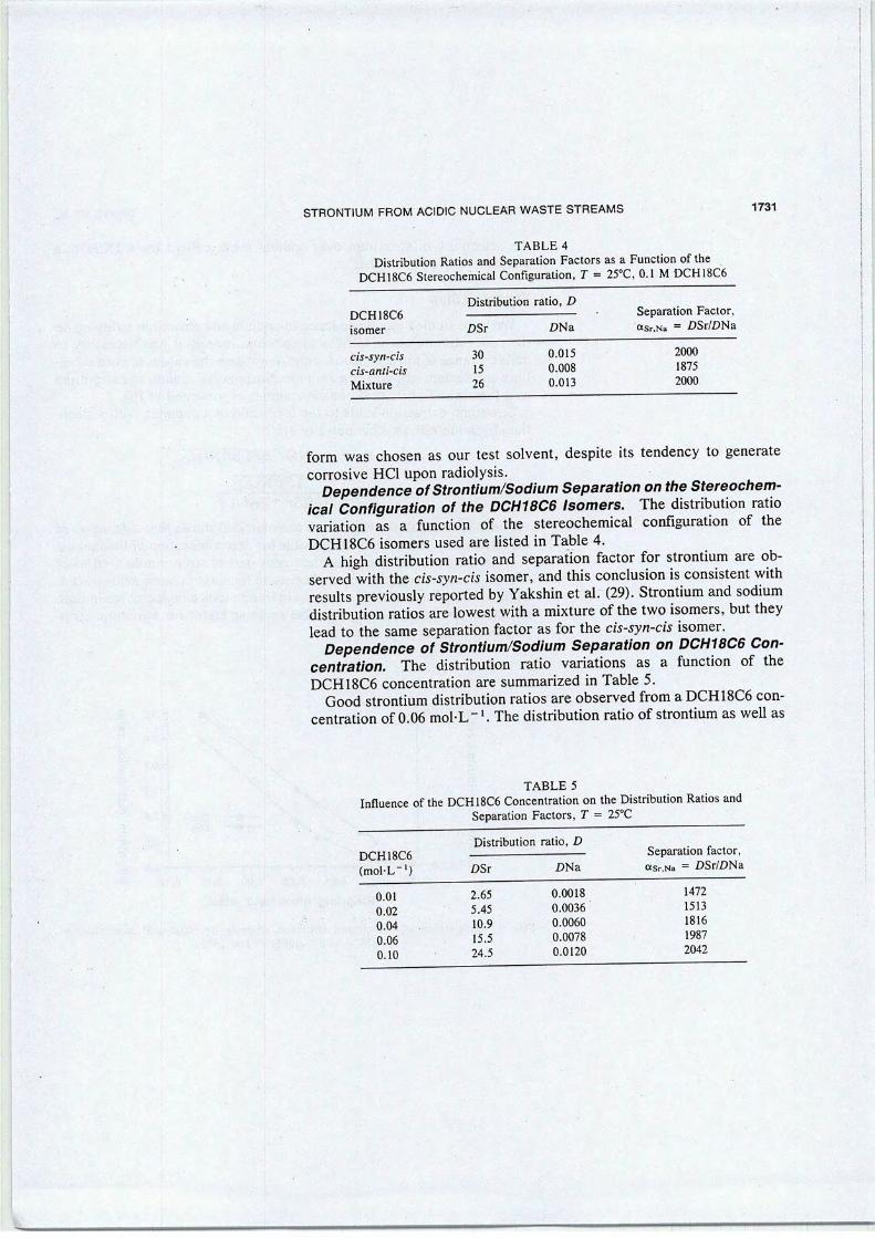
STRONTIUM FROM ACIDIC NUCLEAR WASTE STREAMS 1731
TABLE 4
Distribution Ratios and Séparation Factors as a Function of theDCH18C6 Stereochemical Configuration, T = 25°C, 0.1 M DCH18C6
DCH18C6
isomer
Distribution ratio, DSéparation Factor,asr.Na = 2>Sr/£>NaDSr Z)Na
cis-syn-ciscis-anti-cis
Mixture
30
15
26
0.015
0.008
0.013
2000
1875
2000
form was chosen as our test solvent, despite its tendency to generatecorrosive HC1 upon radiolysis.
Dependence ofStrontium/Sodium Séparation on the Stereochemical Configuration of the DCH18C6 Isomers. The distribution ratiovariation as a function of the stereochemical configuration of theDCH18C6 isomers used are listed in Table 4.
A high distribution ratio and séparation factor for strontium are observed with the cis-syn-cis isomer, and this conclusion is consistent withresults previously reported by Yakshin et al. (29). Strontium and sodiumdistribution ratios are lowest with a mixture of the two isomers, but theylead to the same séparation factor as for the cis-syn-cis isomer.
Dependence of Strontium/Sodium Séparation on DCH18C6 Concentration. The distribution ratio variations as a function of theDCH18C6 concentration are summarized in Table 5.
Good strontium distribution ratios are observed from a DCH18C6 concentration of 0.06 mol-L-1. The distribution ratio of strontium as well as
TABLE 5
Influence of the DCH18C6 Concentration on the Distribution Ratios andSéparation Factors, T = 25°C
Distribution ratio, DDCH18C6 Separation factor,
(mol-L"1) DSr £>Na «Sr.Na = CSr/DNa
0.01 2.65 0.0018 1472
0.02 5.45 0.0036 1513
0.04 10.9 0.0060 1816
0.06 15.5 0.0078 1987
0.10 24.5 0.0120 2042
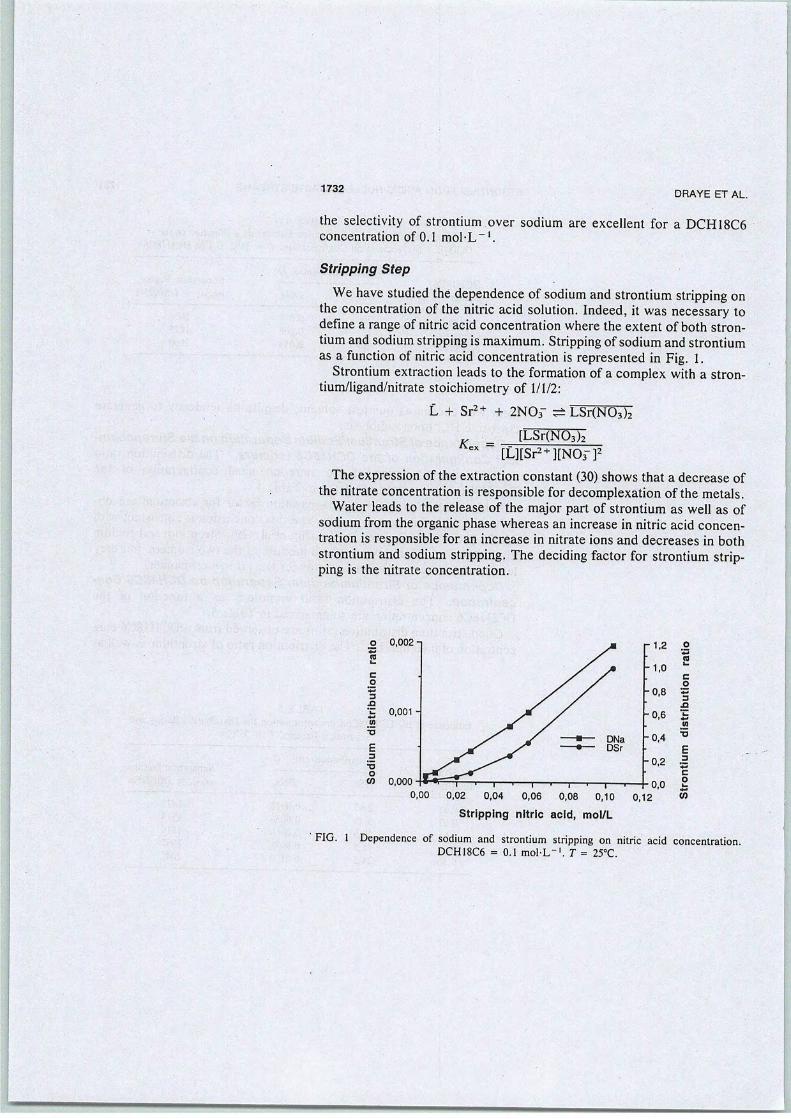
1732DRAYE ET AL.
the selectivity of strontium over sodium are excellent for a DCH18C6concentration of O.l mol-L"1.
Stripping Step
We hâve studied the dependence of sodium and strontium stripping onthe concentration of the nitric acid solution. Indeed, it was necessary todefine a range of nitric acid concentration where the extent of both strontium and sodiumstrippingis maximum. Strippingof sodium and strontiumas a function of nitric acid concentration is represented in Fig. 1.
Strontium extraction leads to the formation of a complex with a stron-tium/ligand/nitrate stoichiometry of 1/1/2:
3J3
0,002 n
L + Sr2+ + 2NOr çè LSr(N03)2
KB[LSr(N03)2
[L][Sr2+][N03-]2
The expression of the extraction constant (30) shows that a decrease ofthe nitrate concentration is responsible for decomplexation of the metals.
Water leads to the release of the major part of strontium as well as ofsodium from the organic phase whereas an increase in nitric acid concentration is responsible for an increase in nitrate ions and decreases in bothstrontium and sodium stripping. The deciding factor for strontium stripping is the nitrate concentration.
.2
-C 0,001
'•B
E3
Otn
3SX
0,000
0,00 0,02 0,04 0,06 0,08 0,10
Stripping nitric acid, mol/L
0,12
m
TÎ
E3
CO
55
FIG. 1 Dependence of sodium and strontium stripping on nitric acid concentration.DCH18C6 = 0.1 mol-L"1. T = 25°C.

STRONTIUM FROM ACIDIC NUCLEAR WASTE STREAMS 1733
Solid-Liquid Concentration of Strontium
Duolite ARC-9652 is a sulfonic acid cation-exchange macroporousresin.
Batch Concentration of Strontium
The distribution coefficients D were calculated as follows:
Cf m
where Ctand C{ = concentrations of strontium before and after concentration onto the resin
V = volume of solution (mL)m = mass of resin (g)
Sorption kinetics of Sr concentration on the DUOLITE ARC-9652 from0.9 mol-L-' nitric acid containing sodium nitrate hâve been studied, andthe results are shown in Fig. 2.
Theextent of strontium concentration increasesrapidly andappreciablyup to 2 hours of shaking, at which time a plateau is reached. Maximumdistribution ratios of 147 mL/g(dry) and of 5 mL/g(dry) are obtained after18 hours of shakingfor the strontium and the sodium, respectively.
£ 150-
^ 125-E :
coefficient, 0tn0
cO
'•= 25"3
SX
S c 2
1 11111111 111 11111 111
4 6 8 10 12
Time of shaking, h
14 16 18
FIG. 2 Kinetic of concentration of traces of strontium onto the DUOLITE ARC-9652 inthe présence of 4.18 g-L-'of sodium. HN03 = 0.9 mol-L"1.
•—«•—

1734 DRAYE ET AL.
In light of thèse results, removal of traces of strontium from 0.9 Mnitric solution containing an excess of sodium can be achieved using theDUOLITE ARC-9652 resin.
Evaluation of a Continuous Process ofExtraction-Stripping-Concentration of Strontium
The number of theoretical stages of extraction was calculated usingthe "Kremser formula" (31a,b). In Fig. 3 a strontium stripping facility isproposed as a function of the concentrations for the nuclear waste streamsstudied.
The pilot installation requires a 3-stage extraction reactor and a 3-stagestripping reactor. The strontium is continuously concentrated onto an ion-exchange resin. Extraction of more than 99% of the strontium in threestages needs a DCH18C6 concentration of 0.022 M.
A pH-adjusted synthetic effluent (pH 0.46) with a flow rate of 0.17 L-h" 'was added at the first stage and the extraction solvent was introduced at
A B C
Fi =0.17
11 1 r E ,
». - ,-••]•-,
mm
mËÊMîf\ 10 -3 il
k»A A1 »> 1 C
».
».
»•
a - -2 • •
».».
a ». -3--
EFFLUENT, 30 LHNO3 0.9 mol L-'
Na+ O.lmolL-l
Sr2+ 2.68 10-6 mol L-'
F2 = 0.33 ,l F3 = 0.17 A
DCH18C6, 0.022 mol L-'CHCI3, 0.5L
'r
RAFFENATE WATER, 0.4 L
A Extraction B Stripping C Concentration
FIG. 3 Pilot installation for strontium extraction and recovery. F, = Effluent flow rate(L-h"1). F2 = Organic phase flow rate (L-h-'). F, = Sr stripping flow rate (L-h-1).<•
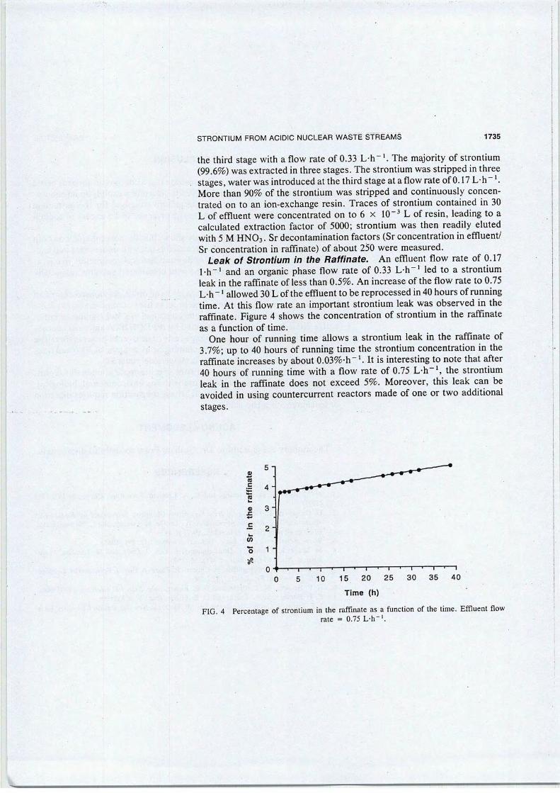
STRONTIUM FROM ACIDIC NUCLEAR WASTE STREAMS 1735
the third stage with a flow rate of 0.33 L-h- '. The majority of strontium(99.6%) was extracted in threestages. The strontium was stripped inthreestages, water was introduced atthe third stage ataflow rate of0.17 L-h~ '.More than 90% of the strontium was stripped and continuously concentrated on to an ion-exchange resin. Traces of strontium contained in 30L of effluent were concentrated on to 6 x 10~3 L of resin, leading to acalculated extraction factor of 5000; strontium was then readily elutedwith 5 M HN03. Sr decontamination factors (Sr concentration in effluent/Sr concentration in raffinate) of about 250 were measured.
Leak of Strontium in the Raffinate. An effluent flow rate of 0.17l-h-1 and an organic phase flow rate of 0.33 L-h-1 led to a strontiumleak in the raffinate of less than 0.5%. An increase of the flow rate to 0.75L-h~ ' allowed 30L of the effluent to be reprocessed in 40 hours of runningtime. At this flow rate an important strontium leak was observed in theraffinate. Figure 4 shows the concentration of strontium in the raffinateas a function of time.
One hour of running time allows a strontium leak in the raffinate of3.7%; up to 40 hours of running time the strontium concentration in theraffinate increases by about 0.03%-h"1. It is interesting to note that after40 hours of running time with a flow rate of 0.75 L-h-1, the strontiumleak in the raffinate does not exceed 5%. Moreover, this leak can beavoided in using countercurrent reactors made of one or two additionalstages.
0)5-
ta
4-
•
3"
c2"
tn •
o 1 "
5^
o- »—i—|— • i i 1 1
C) 5 10 15 20 25 30 35 40
Time (h)
FIG 4 Percentage of strontium in the raffinate as a function of the time. Effluent flowrate = 0.75 L-h'1.
"mm ——

1736 DRAYE ET AL.
CONCLUSION
The results presented hère demonstrate that a continuous process basedonliquid-liquid extraction (DCH18C6 inchloroform)/solid-liquid concentration (ion exchanger) provides an effective method for the extractionand recovery of strontium traces in the présence of an excess of sodiumfrom nitric acid média.
The liquid-liquidextraction study showsthat the solvent effecton bothSr efficiency and selectivity of extraction is not well understood and can-not be rationalized on the basis ofphysicochemical parameters like p., e,or ô. The best results are obtained with chlorinated solvents, especiallywith chloroform.
This process has several advantages over other previously describedstrontium extraction methods. The process uses commercially availablereagents and works easily. Strontium contained ina 30-L sample of radioactive effluent is selectivelyextracted by the DCH18C6 and then concentrated onto 6 mL of an ion-exchange resin. Theoverall process thereforereduces the volume of material containing Sr by a factor of 5000 and fixesthis soluble specie onto an organic incinerable material.
Although we hâve described only one spécifie application inthis report,the process should be suitable for use with any environmental, biological!geological, or nuclear waste sample whose préparation requires digestionor leaching with nitric acid.
ACKNOWLEDGMENT
The authors are grateful to Dr. Graham Feast for helpful discussions.
REFERENCES
1. N. M. Rice, H. M. N. Irving, and M. A. Léonard, Pure Appl. Chem., 65(11) 2373(1993)
2. G. Grossi and L. Cecille, in New Séparation Chemistry Techniques for RadioactiveWaste and Other Spécifie Applications (L. Cecille, M. Casarci, and L. Pietrelli, Eds.),Elsevier Applied Science, London, 1991, p. 11.
3. W. W. Schulz and L. A. Bray, Sep. Sci. Technol., 22, 191 (1987).4. M. Draye, R. Chomel, P. Doutreluingne, A. Guy, J. Foos, and M. Lemaire. J. Ra-
dioanal. Nucl. Chem., Lett., 175(1), 55 (1993).5. M. Draye, A. Favre-Réguillon, R. Chomel, R. Faure, A. Guy, J. Foos, and M Lemaire
Bull. Soc. Chim. Fr., 133(2), 183 (1996).6. E. P. Horwitz, M. L. Dietz, and D. E. Fisher, Solv. Extr. Ion Exch., S, 199 (1990).7. E. P. Horwitz, M. L. Dietz, and D. E. Fisher, Ibid., 8, 557 (1990).8. J. F. Dozol, J. Casas i Garcia, and A. M. Sastre. in New Séparation Chemistry Tech-

STRONTIUM FROM ACIDIC NUCLEAR WASTE STREAMS 1737
niques for Radioactive Waste andother Spécifie Applications (L. Cecille, M. Casarci,and L. Pietrelli, Eds.), Elsevier Applied Science, London, 1991, p. 173.
9. J. F. Dozol, J. Casas, and A. Sastre, J. Membr. Sci., 82, 237 (1993).10. J. F. Dozol, J. Casas, and A. Sastre, Sep. Sci. Technol., 28(11&12), 2007 (1993).11. J. F. Dozol, J. Casas, and A. Sastre, Ibid., 29(15), 1999 (1994).12. W. J. McDowell, Sep. Sci. Technol., 23, 1251 (1988).13. E. P. Horwitz, M. L. Dietz, and D. E. Fisher, Solv. Extr. Ion Exch., 9(1), 1 (1991).14. G. J. Lumetta, M. J. Wagner, and E. O. Jones, Sep. Sci. Technol., 30, 1087 (1995).15. M. L. Dietz, E. P. Horwitz, and R. D. Rogers, Solv. Extr. Ion Exch., 13(1), 1 (1995).16. L. H. Baetsle, D. Van Deyck, and D. Huys, /. Inorg. Nucl. Chem., 27, 683 (1965).17. M. A. Ebra, R. M. Wallace, D. D. Walker, and, R. A. Wille, Sci. Basis Nucl. Waste
Manage., 6, 633 (1982).18. S. K. Samanta and M. Ramaswamy, Radiochim. Acta, 57, 201 (1992).19. N. Dumont, A. Favre-Réguillon, B. Dunjic, and M. Lemaire, Sep. Sci. Technol.,31(1),
1001 (1996).20. D. J. Wood, T. J. Tranter, and T. A. Todd, Solv. Extr. Ion Exch., 13(5), 829 (1995).21. E. P. Horwitz, M. L. Dietz, and D. E. Fisher, Ibid., 9(1), 1 (1991).22. V. Guyon, P. DrognatLandré, A. Guy, J. Foos, and M. Lemaire, Chem. Lett., p. 723
(1992).23. E. Blasius, W. Klein, and U. Schôn, J. Radioanal. Nucl. Chem., Articles, 89(2), 389
(1985).24. M. L. Dietz, E. P. Horwitz, and D. E. Fisher, Solv. Extr. Ion Exch., 8, 199 (1990).25. M. L. Dietz, E. P. Horwitz, and D. E. Fisher, Ibid., 8(4&5), 557 (1990).26. H. K. Frensdorff, J. Am. Chem. Soc, 93(19), 4684 (1971).27. M. Chastrette, M. Rajzmann, M. Chanon, and K. F. Purceil, Ibid., 107(\), 1 (1985).28. C. Reichardt, in Solvents and Solvent Effects in Organic Chemistry, VCH Weinheim,
New York, NY, 1988, pp. 408-410.29. V. V. Yakshin, B. F. Myasoedov, O. M. Vilkova, A. M. Tuzova, A. T. Fedorova,
and I. M. Radionova, Radiokhimiya, 31, 67 (1989).30. Y. Takeda, Top. Curr. Chem. 121, 1 (1984)31. (a) A. Kremser, Natl. Pet. News, 22(21),42 (1930). (b) R. Treybal, in Chemical Engi-
neers' Handbook (R. H. Perry and C. H. Chilton, Eds.), McGraw-Hill, New York,NY, 1973, Chap. 15-19.
Received by editor June 13, 1996Revision received November 1996
PII: S014 1-3 9 10(96)00176-0
Polymer Dégradation and Stability 56 (1997) 157-167© 1997 Elsevier Science Limited
Printed in Northern Ireland. Ail rights reserved0141-3910/97/S17.00
Gamma-ray-induced modifications of thechemical structure of an ion exchange resin
M. Draye," B. Nsouli,5 H. Allali,* M. Lemaire" & J.-P. Thomas"*"Institut de Recherches sur la Catalyse, Laboratoire de Catalyse et Synthèse Organique, CPE-ESCIL,Université Claude Bernard Lyon I, 43 bd du 11 Novembre 1918, 69622 Villeurbanne Cedex, France
hInstitut de Physique Nucléaire (et IN2P3), Université Claude Bernard Lyon I, 43 bd du 11 Novembre 1918,69622 Villeurbanne Cedex, France
(Received 17 June 1996; accepted 11 July 1996)
Gamma-ray irradiation of ion exchange resins used for processing nucleareffluent may lead to considérable modifications of the molecular structure andmacroscopic properties. In the présent study, crosslinked poly(4-vinylpyridine)(P4VP), irradiated by a 137Cs y-source up to an integrated dose of 14400kGy,has been investigated. The particle-induced desorption-mass spectrometry(PDMS) technique is able to detect the radiation-induced structural dégradation of such an infusible and insoluble material. From the results of PDMS, acohérent description of the production of spécifie radical fragments andmodified chains is proposed. Both the nature of thèse fragments as' well astheir formation, as a function of the dose of irradiation, correlate with resultsof électron paramagnetic résonance spectrometry and Fourier transforminfrared spectroscopy, and with thermogravimetric and dynamical mechanicalanalysis. In addition, analysis of the soluble and insoluble fractions helps todiscriminate between différent possible processes. In particular, it is shownthat the loss of pyridine fragments correlates well with chemical measurementslike the loss of protonatable sites. © 1997 Elsevier Science Limited
1 INTRODUCTION
The acid-base and loading properties of itspyridine group hâve stimulated the use ofpoly(4-vinylpyridine) (P4VP) resin in variousapplications such as a chemical reagent,1 acatalyst2 or catalyst support,3 an extractant fororganic pollutants4 and for the sélective isolationof a host of dissolved metals.5 Among thèseapplications, there is particular interest in itsadsorbing properties towards radionucléides fromliquid wastes of low or médium activity.6,7 Theon-going effects of radiation-induced ageing onthe properties and performances of suchmaterials hâve been a topic of considérableinterest. It has been shown that, among thesynthetic resins, those of the vinylpyridine typeare more résistant towards ionizing radiation.s Achemical évaluation of the stability of suchcrosslinked materials has already been under--
* To wham correspondence should be addressed.
taken,9,10 but a detailed investigation of thestructural modifications induced by gammaradiation has still to be performed before anyindustrial technique aimed at nuclear wastereprocessing can be considered.
As part of such a programmé is the study ofthe radiochemical stability of P4VP irradiatedwith a dose of up to 14400kGy, and this work isaimed at obtaining an insight into the modification of both molecular structure and macroscopicproperties. For such an infusible and insolublematerial most of the commonly used techniquesfor polymer characterization [infrared spectroscopy (IR), ultraviolet spectrophotometry (UV),nuclear magnetic résonance spectrocopy (NMR),électron paramagnetic résonance spectrometry(EPR), électron spectroscopy for chemicalanalysis (ESCA), etc.] give limited or uncorre-lated results. In a fortheoming paper" wedemonstrate that négative ion émission under ionbeam impact can be sensitive to the chemicalmodifications induced in such a material by
157

158 M. Draye et al.
y-irradiation, provided that the primary ions areused in the MeV instead of the keV régime. Thusparticle-induced desorption-mass spectrometry(PDMS)—or, adopting the terminology proposedby Sundqvist,12 HSF-SIMS—has been widelyused in this study to give a cohérent descriptionof thèse modifications that is in agreement withresults of other techniques such as EPR, IR,thermogravimetric analysis (TGA) and dynami-cal mechanical analysis (DMA).
2 EXPERIMENTAL
2.1 Materials
The crosslinked (2% with divinylbenzène) P4VPresin used in this study was supplied by ReillyIndustries Inc., Indianapolis, IN, USA. Thematerial was a fine, white, insoluble and infusiblepowder, with a spécifie area of ~0.5 m2g_1. It hasthe chemical structure sketched in Fig. 1.
2.2 Gamma irradiation
Plugged glass containers filled with 1.8 g of P4VPwere exposed to various irradiation doses of a137Cs y-source. The doses absorbed were determined by calibration to be 148, 480, 3360, 7200and 14 400 kGy at a dose rate of 20 kGy h-1.
2.3 Sample préparation
2.3.1 General procédurePellets of thickness 1 mm were made bycompressing (at 2 tonne cm-2) 0.1g of thepowder into a stainless steel cylinder of 8 mminternai diameter.
2.3.2 Extraction of the soluble partThe soluble part of the irradiated samples wasobtained by shaking 0.15 g of the P4VP powder
Fig. 1. Molecular structure of the P4VP resin crosslinkedwith 2°o divinylbenzène.
with 2 cm"3 ethanol for 15 min. After filtration,the resin in the filter was dried and weighed. Thevalue obtained was then compared with thatresulting from evaporation to dryness of theorganic phase. For the most soluble samples(high irradiation doses) good agreement wasfound from such a comparison. The percentageof soluble part was expressed according to thefollowing expression:
%=fc^xl00M,
where M-, and M( are the weights of the driedresin before and after extraction.
2.3.3 Spin-coating dépositionIn order to détermine the polymer amount ofthèse solutions of différent concentrations, thinfilms were prepared by spin-coating dépositionon aluminized Mylar backings. However, asexplained later in the text, such solutions hâve tobe subjected to a given number of dilutions. Thusthe films were made from assays of 10 p\. For atypical area of deposit around 2.5 cm2 the largestthickness value never exceeded 5 /xg cm"2.
2.4 Instrumentation
2.4.1 FTIR spectraFourier transform infrared (FTIR) spectra wererecorded on a Perkin-Elmer 1720X spectrometerfrom P4VP pellets (1% in KBr).
2.4.2 EPR spectraThe EPR spectra were recorded, at roomtempérature, on a Varian E Line électronparamagnetic résonance spectrometer, at amagnetic modulation frequency of 100 kHz. Thequartz EPR cells contained 30 mg of resinpowder. The spin concentrations were obtainedby comparison of the expérimental spectra with acalibrated Varian pitch sample EPR spectrumcontaining a definite number of spins.
2.4.3 Thermal analysisThermogravimetric (TG) measurements wereperformed on a DuPont Instruments TGA 2950apparatus, under hélium atmosphère. Amounts
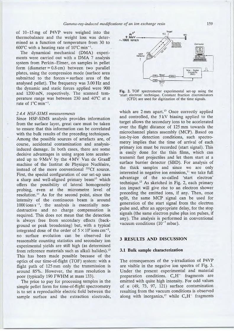
Gamma-ray-induced modifications of an ion exchange resin 159
of 10-15 mg of P4VP were weighed into thethermobalance and the weight loss was determined as a function of température from 30 to600°C with a heating rate of 10°C min"1.
The dynamical mechanical (DMA) experiments were carried out with a DMA 7 analysisSystem from Perkin-Elmer, on samples in pelletform (diameter = 0.8 cm) between two parallelplates, using the compression mode (surface areasubmitted to the forces = surface area of the
analysed pellet). The frequency was 3.00 Hz andthe dynamic and static forces applied were 900and 1200 mN, respectively. The scanned température range was between 230 and 40°C at arate of lôCmih"1.
2.4.4 HSF-SIMS measurements
Since HSF-SIMS analysis provides informationfrom the surface layer, great care must be takento ensure that this information can be correlated
with the bulk results of the preceding techniques.Among the possible sources of artefacts are, ofcourse, accidentai contamination and analysis-.induced damage. In both cases, there are somedécisive advantages in using argon ions acceler-ated up to 9MeV by the 4MV Van de Graaffmachine of the Institut de Physique Nucléaire,instead of the more conventional 252Cf source.
First, the spécial configuration of our set-up usesa sharp and well-aligned primary beam13 whichoffers the possibility of latéral homogeneityprobing, even at the micromètre level ofresolution.14 As for the second point, since theintensity of the continuous beam is around1000 ions s-1, the analysis is essentially non-destructive and no charge compensation isrequired. This does not mean that the détectionis always free from secondary effects (back-ground or peak broadening) but, with a typicalintegrated dose of the order of 5 x 10⁹ ions cm-2,no surface évolution can be observed for
reasonable counting statistics and secondary ionexpérimental yields are still high (as determinedfrom référence materials such as alkali halides).13This has been made possible because of theoptics of our time-of-flight (TOF) system: with aflight path of 125 mm only the transmission isaround 85%. However, the mass resolution ispoor (typically 190 FWHM at mass 133).
The price to pay for processing samples in thesimple pellet form for time-of-flight spectrometryis to set a reproducible electric field between thesample surface and the extraction électrode,
Ar°9 MeV ,
~1000 ions/s
Fig. 2. TOF spectrometer expérimental set-up using the'start électron' technique. Constant fraction discriminators
(CFD) are used for digitization of the time signais.
which are 2 mm apart.13 Once correctly appliedand controlled, the 5 kV biasing applied to thetarget allows the secondary ions to be acceleratedover the flight distance of 125 mm towards themicrochannel plates assembly (MCP). Based onion-by-ion détection conditions, such spectrometry implies that the time of arrivai of eachprimary ion must be recorded (start signal). Thisis easily done for the thin films, which cantransmit fast projectiles and let them start at asurface barrier detector (SBD). For analysis ofthe thick samples and since we are onlyinterested in négative ion émission,1 ' we take fulladvantage of the so-called 'start électron'technique.13 As sketched in Fig. 2, each primaryion impact will give rise to an électron showerpreceding the emitted ions, if any. Then, oncesplit, the same MCP signal can be used forgénération of the start signal from the électronpuise and, after an appropriate delay, for the stopsignais (the same électron puise plus ion puises, ifany). The analysis is performed in conventionalvacuum conditions (10~7 mbar).
3 RESULTS AND DISCUSSION
3.1 Bulk sample characterization
The conséquences of the y-irradiation of P4VPare visible in the négative ion spectra of Fig. 3.Under the présent expérimental and materialpréparation conditions. C„H~ fragments areemitted with quite high intensity. For odd valuesof. n (49, 73, 97, 121) surface contaminationresulting from the vacuum conditions is observedalong with inorganics,15 while C„H" fragments
•

160 M. Draye et al.
2.43
1.62
0.81
0
2.25
o
U1.50
0.75
41
> "W \J V
300
78
146
158
•ÂÂ
400 500
Channels a (TOF)
Fig. 3. Négative ion mass spectra: (a) from an unirradiatedP4VP pellet sample; (b) from an irradiated sample with anintegrated dose of 148 kGy. Characteristic ions areunderlined, new ions following y-ray irradiation are circled,
contaminants or C„H~ fragments bear a * label.
(a)
600
with even values of n corne from multifragmenta-tion of the polymer backbone and also do notreflect its chemical structure. Four peaks hâvebeen selected and will be considered as
characteristic of the material. From the unir
radiated material they correspond to masses at41, 78, 146 and 158 Da. Of course, the ionémission itself is just a conséquence of a localizedenergy déposition inducing scissions along thechains, as-formed or modified fragments beingsusceptible to escape in a more or less stablecharged form. Thus the increase in intensity ofthe characteristic peaks observed for the smallesty dose [148 kGy, Fig. 3(b)] is a strong indicationthat the pre-formation of some fragmentsfacilitâtes ion émission. Finally, the émission ofnew peaks at higher masses (183-184, 197 and211 Da) has to be explained by the productionunder y-irradiation of fragments not formedunder ion bombardment. As sketched in Fig. 4,the randomly distributed scissions induced by theinteraction with y-rays could lead to fragments ormodified chains from which the ion émission
under primary ion interaction is easier, since oneof the simultaneous processes needed is no
longer required. As an extrême example, mass158, which is produced from two pyridinicscissions (A + A) plus a benzylic scission (B), ismore easily emitted from A + B . or A + Ascissions from a modified chain or a fragment. Asfor the ions appearing only after y-irradiation, assketched in Fig. 5, their production from amodified chain only requires a B scission insteadof the B + B scissions that are never observed on
the unirradiated material. On the other hand, thefragment of mass 211 when formed under ionbombardment is preferentially ionised and leadsto [M + H]+ ion émission.11 Formed - undery-irradiation, it can be responsible for productionof the associated ions. More détails on thèse
processes are given in Réf. 11.Ail thèse tentative interprétations require the
formation of stable free radicals as well as the
formation of double bonds, single or conjugated.In addition, this production should correlate withyield variation of the associated ions as a functionof the integrated dose. For the characteristic ions,such a variation is shown in Fig. 6.
Concerning the radicals, EPR spectrometrygives unambiguous results concerning the existence of paramagnetic centres. Since we aredealing with an amorphous polymer, the absenceof hyperfine structure cannot be attributed to thedelocalized single électrons of ethylenic and/oraromatic free radicals.16 Quantitatively, thevariation of the number of spins per g of resin asa function of the integrated dose is shown in Fig.7. Such a curve, which averages the contributionof the différent free radicals, is comparable to thevariation of the related individual ions (Fig. 6).This is a first support of our interprétation of theformation of various entities.
As far as double bond formation is concerned,some lack of sensitivity (already evoked for suchtype of samples) has prevented the détection ofany significant modification of IR spectra belowthe irradiation dose of 3360 kGy. As shown inFig. 8, the présence of well-defined peaks at 1690and 1654 cm"1 can be attributed to the stretchingvibration mode of aliphatic, double and conjugated double bonds, respectively.17 The increase inintensity of thèse two bands with integrated doseis qualitatively observed. also in agreement withour interprétation. Particularly interesting is theseemingly steeper increase of intensity of theband corresponding to conjugated OC bonds,when increasing the integrated dose. This is inagreement with the yield variation of fragments

Gamma-ray-induced modifications of an ion exchange resin 161
N N N N
Yray = B2
N N "n'
+ e
•2Ha Beam = A, +A2
Fig. 4. Proposed mechanisms for émission of the characteristic négative fragments from A and B scissions induced by-y-irradiation.
of mass 158 and 146 (Fig. 6) and would favour,among their mechanisms of formation proposedin Fig. 5, the one involving A scissions fromy-irradiation.11 Finally, although the sampleswere not irradiated in vacuum, no oxidation hasbeen detected from thèse spectra (absence ofCO, RC02H and RCOzR, bands). It must be
noted, however, that the containers were closedduring irradiation, and that the pyridine groupsof the crosslinked P4VP are highly résistant tooxidizing and reducing agents.18
The évolution of thèse y-induced modifications, either observed from the yield of spécifieions or from the concentration of paramagnetic
mm^mm
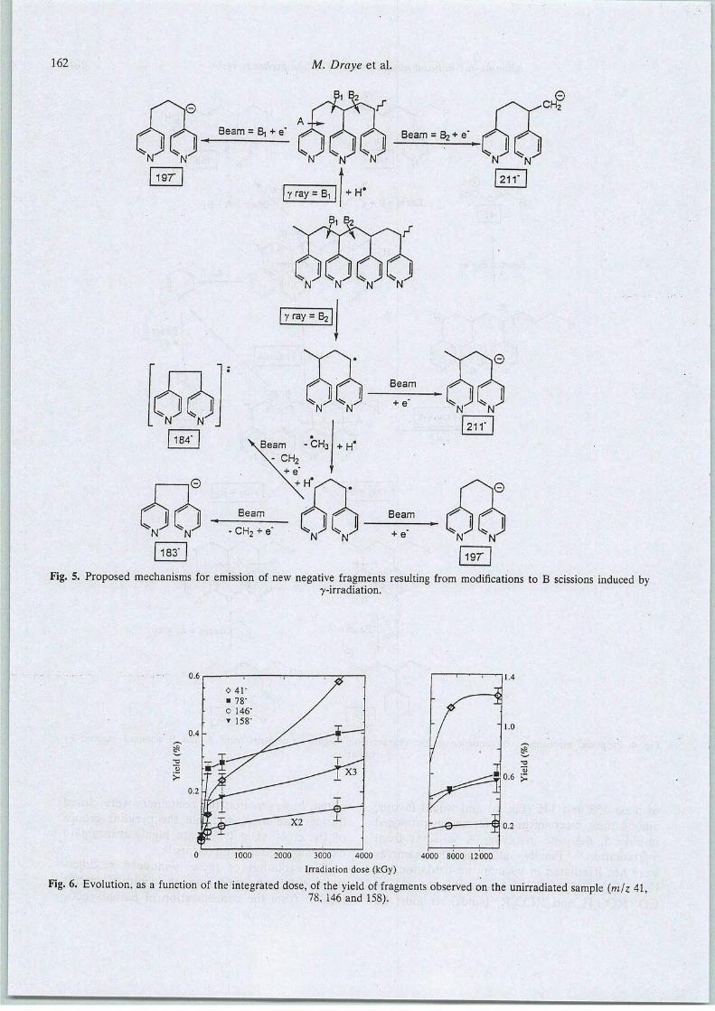
162
Beam = R, + e'
N' "N'
197"
N N N N
y ray = B2
Fig. 5. Proposed mechanisms for émission of new négative fragments resulting from modifications to B scissions induced byy-irradiation.
0 41"
• 78"
0 146"
• 158"
/
0.4- ~^r~-
fP^ ^-TX3 '
0.2 •J/X---""""—ri
-
X2
0 1000 2000 3000 4000 4000 8000 12000
Irradiation dose (kGy)
Fig. 6. Evolution, as a function of the integrated dose, of the yield offragments observed on the unirradiated sample (mjz 4178, 146 and 158). '

Gamma-ray-induced modifications of an ion exchange resin
0.15
163
5000 10000 15000
Irradiation dose (kGy)
Fig. 7. Evolution, as a function of the integrated dose, ofthe number of spins per g of P4VP resin.
centres, is charactererized by an almost linearincrease in the low-dose région (<500kGy),foUowed by a more or less marked saturationrégime. The occurrence of- recombination processes taking place once a given concentration offragments or modified chains is reached, issuspected. This would explain why the émissionof new ions following low-dose irradiation
2S
aiai
on
78
72
66-
60
3000
a : 0 kGyb : 3360 kGyc : 14400 kGy
1690 cm' vc = cConjugated !
1654 cm' vc - c—
2500 2000 1500
Wave Number (cm")Fig. 8. FTIR spectra of the P4VP resin: (a) unirradiated: (b)irradiated with 3360 kGy integrated dose; (c) irradiated with
14 400 kGy integrated dose.
0.09
0.03
1000 2000 3000
Irradiation dose (kGy)
4000
Fig. 9. Evolution, as a function of the integrated dose, ofthe yield of fragments resulting from modifications induced
by y-irradiation (m/z 183-184, 197 and 211).
exhibits a marked decrease and then disappears(Fig. 9) while the spécifie ion émission tends toslow down. A good approach to investigatingsuch bulk modifications is to perform TGA in aninert atmosphère. The variation of weight loss asa function of température is shown for variousintegrated doses in Fig. 10. No significantdéviation from the unirradiated case is found
until the 3360 kGy integrated dose, when anoticeable amount of dry tar and a decrease ofthe dégradation température are observed. Sincethis last parameter is related to early désorptionof the fragments formed under irradiation, it isnot surprising to observe a further évolution
100
80
2 60
- 40
20
OkGy
3360 kGy
7200 kGy
14400 kGy
100 200 300
Température (°C)
Fig. 10. Relative residual weight as a function oftempérature for P4VP samples at différent integrated doses.
400

164 M. Draye et al.
limited to some change of the slope. Moreover, itis particularly interesting to note that the amountof dry tar reaches a value of 50% for a 25%crosslinked unirradiated resin. Thus its con-
tinuous increase up to a value of 18% is typical ofa continuous increase of crosslinking proeesses asa function of integrated dose.
Another powerful technique for assessing theexistence of crosslinking under y-irradiation andits évolution as a function of integrated dose isdynamical mechanical analysis, by which the glasstransition température (Tg) can be deduced fromthe variation of tan 5, S being the loss angle. Ascan be seen from Fig. 11, the data hâve beenobtained with decreasing températures; thisremoves the possibility of artefacts due the initialprésence of a significant amount of water in thesamples, as observed in the low-temperaturerégion of the previous thermograms (Fig. 10).The main resuit is an important (around 40°C)increase in Tg for the largest dose together with asignificant decrease of the chain mobility fromthe decrease of tan 8. For the lowest dose
(148 kGy) the observed decrease is not assignificant because of the reproducibility of themeasurements for such a sintered material, andone has to be cautious when observing anincrease of Tg since undesirable crosslinkingprocesses can develop when starting at such ahigh température (230°C).
3.2 Analysis of the soluble fraction
The previous results obtained from the différenttechniques clearly establish the formation ofstable free radicals within the irradiated material,
2.0
1.8 - •0 kGy
1.6 _ ^ a 148 kGy
1.4 -
\ • 14400 kGy
_ 1-2<c
= 1.0n
H 0.8
- (
0.6 - /
0.4 - Il
0.2
01
-1/
• ' • '• • / ' l70 180 190 200 210 220
Température (°C)
Fig. 11. Dynamical mechanical analysis: variation of tan S asa function of annealing température.
as well as the development of crosslinkingprocesses, as a function of the integrated dose.Starting with such a resin initially crosslinkedwith divinylbenzène (DVB) implies the formation of two types of radical. Summarized in Fig.12 are the most illustrative cases. While the
radicals incorporating one DVB bridge aredenoted Rc, the others can be intact oligomersresulting from a benzylic scission (denoted R,),or modified by the loss of a pyridine and thecréation of double bonds (denoted R2) or ofsimple fragments like the pyridine unit (denotedR,). Then, recombinations leading to Rc-Rc orRc-R, fragments will be responsible for a higherdensity of crosslinking, while Ri-R, fragmentslead to intact or modified oligomers of longerchains. The free radicals, as well as this lastcategory of fragments, must be soluble in organicpolar solvents.
Indeed, the variation of the quantity of solublematerial extracted by ethanol is remarkablycomparable to the EPR data variation, as shownin Fig. 13. From such solutions where theconcentration increases as a function of inte
grated dose, HSF-SIMS analysis can help indiscriminating -the relative abundance of theindividual fragments. This requires the préparation of spin-coating targets for which the amountof deposited material is proportional to theconcentration. Then, if the thickness of thesamples is maintained below the depth of originof the secondary ion émission and if a linearcorrespondence between ion yield and samplethickness can be established, the variation of theamount of a given species can be obtained. Sucha procédure has been described in détail in Réf.11. As observed in Fig. 14, from the yieldvariation of the ions of mass 41 and 78, thecorresponding fragments are extracted in thesame proportions as free radicals are formed.The différence with what is observed from the
bulk, is that the ion yield of the mass 41 isproportionally smaller. This gives some crédit tothe various origins (free radicals or modifiedchains) of thèse smallest fragments. Moreover,from the HSF-SIMS analysis of the insolubleresidue one can détermine what has been lost.
For the highest dose (14 400 kGy), where theeffect is expected to be the most important, theyield is reduced by a factor of 5.0 and 2.6 formasses 78 and 41, respectively. By comparison,the émission of ions of mass 146 and 158 is onlyreduced by a factor of 1.6 and 1.2, respectively.
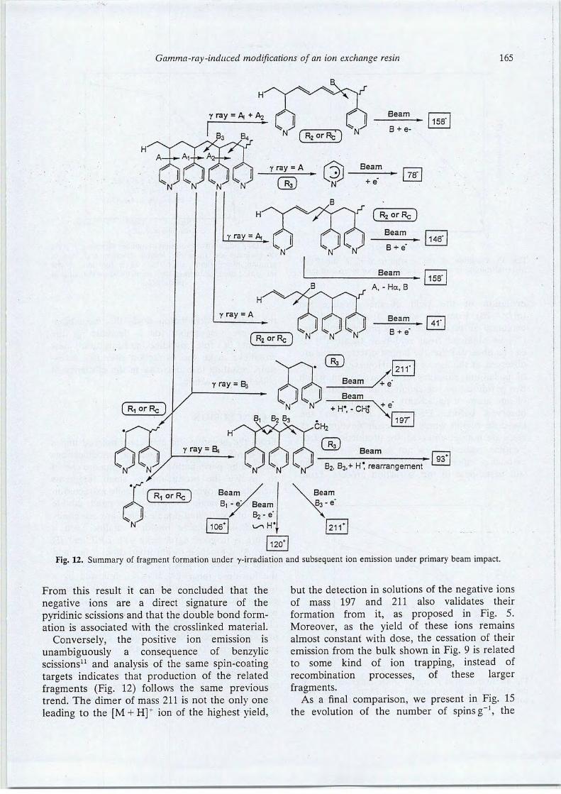
Gamma-ray-induced modifications of an ion exchange resin 165
158'
y ray = A78"
*N N N N
y ray = B3
( R2 or Rç )
(R2orRc) ^N N N
Beam
Beam
N" "N' +H-,-CH3*\e
B + e"
211"
'+e
197"
Beam93*
"N' N N N NB2, B3,+ H* rearrangement
f R! or Rc ) BeamB, -eX Beam
B2 - e
Fig. 12. Summary of fragment formation under -y-irradiation and subséquent ion émission under primary beam impact.
From this resuit it can be concluded that the
négative ions are a direct signature of thepyridinic scissions and that the double bond formation is associated with the crosslinked material.
Conversely, the positive ion émission isunambiguously a conséquence of benzylicscissions11 and analysis of the same spin-coatingtargets indicates that production of the relatedfragments (Fig. 12) follows the same previoustrend. The dimer of mass 211 is not the only oneleading to the [M + H]+ ion of the highest yield,
but the détection in solutions of the négative ionsof mass 197 and 211 also validâtes theirformation from it, as proposed in Fig. 5.Moreover, as the yield of thèse ions remainsalmost constant with dose, the cessation of theirémission from the bulk shown in Fig. 9 is relatedto some kind of ion trapping, instead ofrecombination processes, of thèse largerfragments.
As a final comparison, we présent in Fig. 15the évolution of the number of spins g-1, the
——

166 M. Draye et al.
2 8
5000 10000
Irradiation dose (kGy)15000
Fig. 13. Variation of the weight fraction of the P4VPmaterial soluble in ethanol, as a function of integrated dose.
évolution of the yield of the pyridine ion(m/z =78) from the soluble fraction and theévolution of the relative loss of protonatable sites(%, as obtained from acid-base titration10). Itcan be observed that the largest discrepancies areobserved at the lowest doses. However, in termsof palladium efficiency of extraction (in whichtwo pyridine sites are required for the extractionof one atom of palladium), no significant loss isobserved before 3360kGy.10 Then, for thelow-dose région where the recombination processes are not yet observed, the production of freepyridine radicals does not seriously affect theextraction efficiency because free pyridines canstill participate in the extraction process. From
5000 10000
Irradiation dose (kGy)15000
Fig. 14. Evolution, as a function of the integrated dose, ofthe yield of ions of mass 41 and 78 from thin filmscorresponding to the resulting concentration of soluble
material.
• Nb. of spin/g of resino Yield (m/z = 78)A Protonable site loss (%)
5000 10000
Irradiation dose (kGy)
_L15000
Fig. 15. Comparative évolution of numberof spins g"', yieldof pyridine ion from the soluble fraction and loss ofprotonatable pyridine sites (%), as a function of theintegrated dose. Data hâve been normalized on the value at
14 400 kGy.
the 3360 kGy irradiation dose, the recombina-tions are responsible for a decrease in theamount of free pyridine radicals and newcrosslinks make the extraction sites less accessible, resulting in a decrease in the efficiency ofpalladium extraction.
4 CONCLUSION
From the négative ion émission observed underHSF-SIMS conditions, chemical modificationsinduced by y-irradiation of P4VP resin are shownto involve the production of small fragmentsincluding the pyridine radical, easily extracted inthe soluble fraction. On the other hand, doublebonds or conjugated double bonds are essentiallyformed on insoluble modified chains. Such apicture is in good agreement with EPR and IRdata. As a function of absorbed dose, a fast andlinear increase of this production is observed inthe low-dose range (<150kGy), followed by amuch slqwer variation. Larger fragments (dimersor trimers) are also found in the soluble fractionbut the corresponding ion émission from the bulkdisappears above 150 kGy. The recombinationprocesses responsible for thèse changes aresupported by TGA and DMA measurements,where irradiation-induced crosslinking processesare qualitatively shown to increase up to asaturation level. Finally, as the productionvariation of the pyridine fragments is comparableto that of the loss of protonatable sites, one may
Gamma-ray-induced modifications of an ion exchange resin 167
interpret the excellent stability of the extractionefficiency of the material as being due to theprésence of pyridine fragments left undestroyed.
ACKNOWLEDGEMENTS
The dedicated assistance of the accelerator crew
of the Institut de Physique Nucléaire, M. Ferrariand A. Gardon, and of M. Espagnan fromCOGEMA-Marcoule who performed the y-irradiations, are gratefully acknowledged. M. D.and M. L. are grateful to R. Chomel fromCOGEMA-Marcoule for his support to the work.
REFERENCES
1. Cardillo, G., Orena, M., Sandri, S. & Tomassini, C,Chem. Ind., 16 (1983) 643.
2. Hilnig, S., Lucke, E. & Brenninger, W., Org. Syn. Coll.,5 (1973) 808.
3. Chanda, M., O'Driscoll, K. F. & Rempel, G. L. J., J.Mol. CataL, 7 (1980) 389.
4. Kawabara, N., Yoshida, S. & Tanigawa, N., Ind. Eng.Chem. Prod. Res. Dev., 20 (1980) 386.
5. Sugii, M., Ogawa, N., Linuma, Y. & Yamamura, H.,Talanta, 28 (1981) 551.
6. Draye, M., Chevillotte, R., Chomel, R., Doutreluingne,P., Guy, A., Foos, J. & Lemaire, M., Sep. Sci. Technol.,
307-9 (1995) 1245.7. Lemaire, M., Chevillotte, R., Draye, M., Guy, A., Foos,
J. and Chomel, R., French Patent 9 202, 1992.8. Gangwer, T. E., Godstein, M. and Pillay, K. K. S.,
Radiation Effects on Ion Exchange Materials, BNL-50781. Brookhaven National Laboratory, Upton, NY,1977.
9. Marsh, S. F., The Effects of In Situ Alpha ParticleIrradiations on Six Strong-Base Anion ExchangeResins, LA-12055, UC-731. Los Alamos NationalLaboratory, Los Alamos, NM, 1991.
10. Draye, M., Ph. D. Dissertation (unpublished),Université Lyon I, Villeurbanne, France, 1994.
11. Nsouli, B., Draye, M., Allali, H., Lemaire, M. andThomas, J.-P., Int. J.'Mass Spectr. Ion Proc, 154 (1996)179.
12. Sundqvist, B. U. R., Sputtering by Particle Bombardment III, éd. P. Behrisch and K. Wittmaack. Springer,Berlin, 1991, p. 257.
13. Allali, H., Nsouli, B. & Thomas, J.-P., Int. J. MassSpectr. Ion Proc, 127 (1993) 111.
14. Thomas, J.-P., Oladipo, A. A. & Fallavier, M., Nucl.Instrum. Meth. Phys. Res., B42 (1989) 127.
15. Allali, H., Nsouli, B., Thomas, J.-P., Szymczack, W. &Wittmaack, K., Nucl. Instrum. Meth. Phys. Res., B90(1994) 501.
16. Chipara, M. L, Ifrim, A., Grecu, V. V., Toscan, M. L,Popescu-Pogrion, N., Ionescu, A., Chipara, M. D. &Reyes Romero, J., Polym. Degrad. Stab., 43 (1989) 165.
17. Bellamy, L. J., The Infrared Spectra of ComplexMolécules, Vol. 1. Chapman and Hall Publishers,London and New York, 1975.
18. Reilly Chemicals, A New Family of CrosslinkedPoly(vinylpyridine), Métal Recovery, Reillex reports 2,3, 4 and 5. 1990. Bruxelles, Belgium.
—»——.

International Journal o!
ELSEVIER International Journal ofMass Spectrometry and Ion Processes 154 (1996) 179-191Mass Spectrometry
and Ion Processes
Energy déposition and fragments production resulting fromgamma-ray or ion beam irradiation of an ion exchange resin
B. Nsoulia, M. Drayeb, H. Allalf, M. Lemaireb, J.-P. Thomas*'*^Institut de Physique Nucléaire (etIN2P3), Université Claude Bernard Lyon I, 43, Bd. du 11 novembre 1918,
69622 Villeurbanne Cedex, FranceInstitut de Recherches sur la Catalyse, Laboratoire de Catalyse et Synthèse Organique, Université Claude Bernard Lyon I,
43, Bb. du 11 novembre 1918, 69622 Villeurbanne Cedex, France
Received 5 January 1996; accepted in final form 6 April 1996
Abstract
The extraction efficiency ofionexchange resins aimed at the reprocessing ofnuclear effluents isstrongly dépendent ongamma-ray induced modifications of theirchemical structure. Apoly(4-vinylpyridine) resin, or P4VP, hasbeen subjectedto gamma irradiation using a 137Cs source (Ey = 662 keV) and we hâve attempted to characterize its structuralmodifications using TOF-SIMS techniques based on low (keV) and high (MeV) primary ion beam énergies. Thèseanalytical techniques arebasedon the formationof fragments resulting respectively fromatomicand electronic collisionsof heavy ions. As a resuit, the différences in natureand relative intensity of the emitted secondary ions, as well as thevariation oftheir intensity asa function of theabsorbed dose ofgamma rays (upto 14400 kGy), can beinterpreted fromdifférent types of bond breaking. While gamma-ray absorption results in benzylic or pyridinic scissions, MeV ionbombardment mayinduce simultaneous (andclose) pyridinic-pyridinic or pyridinic-benzylic scissions, or both.Accord-ingly, the technique is very sensitive to the présence of fragments preformed under gamma irradiation. This is notobserved with keV bombardment which may destroy the pyridine nucleus. The SIMS analysis of the soluble fractionof theirradiated material (free radicals andfragments) andofthe remaining material confirms the proposed fragmentation paths leading to positive and négative ion émission. Such results fuUy support the important finding that thèsegamma-ray induced modifications are only observed from négative émission under MeV ion bombardment.
Keywords: Gamma-ray irradiation; Ion beam irradiation; Ion exchange resin; Time of flight
1. Introduction
Because of its particular "résistance" toionizing radiations [1], there has been in récentyears great interest in the use of the poly(4-vinylpyridine) resin (P4VP) in nuclear wastereprocessing programs [2]. This property hasbeen recently quantified in terms of variation of
* Corresponding author.
spécifie physico-chemical characteristics suchas number of protonatable sites, quantity ofextracted Pd, etc. as a function of thegamma-ray dosedelivered froma 137Cs source[3]. On the other hand, various analytical techniques hâve been used for the characterizationof the chemical structure modifications and a
cohérent picture of the observed évolutions hasgreatly benefited from the plasma désorption
0168-1176/96/$15.00 © 1996 Elsevier Science B.V. Ail rights reservedPII S0168-1176(96)04381-9
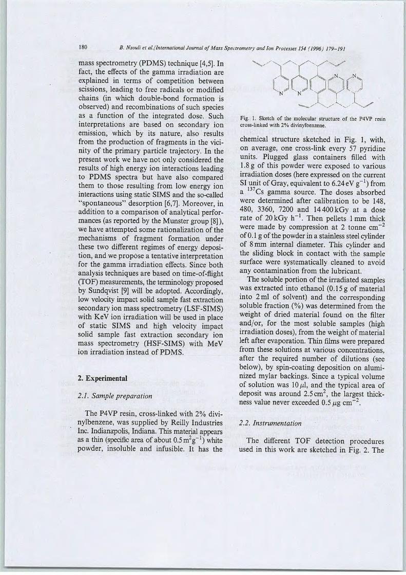
180 B. Nsouli et al./International Journal of Mass Spectrometry and Ion Processes 154 (1996) 179-191
mass spectrometry (PDMS) technique [4,5]. Infact, the effects of the gamma irradiation areexplained in terms of compétition betweenscissions, leading to free radicals or modifiedchains (in whieh double-bond formation isobserved) and recombinations of such speciesas a function of the integrated dose. Suchinterprétations are based on secondary ionémission, which by its nature, also resultsfrom the production of fragments in the vici-nity of the primary particle trajectory. In theprésent work we hâve not only considered theresults of high energy ion interactions leadingto PDMS spectra but hâve also comparedthem to those resulting from low energy ioninteractions using static SIMS and the so-called"spontaneous" désorption [6,7]. Moreover, inaddition to a comparison of analytical performances (as reported by the Munster group [8] ),we hâve attempted some rationalization of themechanisms of fragment formation underthèse two différent régimes of energy déposition, and we propose a tentative interprétationfor the gamma irradiation effects. Since bothanalysis techniques are based on time-of-flight(TOF) measurements, the terminology proposedby Sundqvist [9] will be adopted. Accordingly,low velocity impact solid sample fast extractionsecondary ion mass spectrometry (LSF-SIMS)with KeV ion irradiation will be used in placeof static SIMS and high velocity impactsolid sample fast extraction secondary ionmass spectrometry (HSF-SIMS) with MeVion irradiation instead of PDMS.
2. Expérimental
2.1. Sample préparation
The P4VP resin, cross-linked with 2% divinylbenzène, was supplied by Reilly IndustriesInc. Indianapolis, Indiana. This material appearsasa thin (spécifie area of about 0.5 m2g-1) whitepowder, insoluble and infusible. It has the
Fig. 1. Sketch of the molecular structure of the P4VP resincross-linked with 2% divinylbenzène.
chemical structure sketched in Fig. 1, with,on average, one cross-link every 57 pyridineunits. Plugged glass containers filled with1.8g of this powder were exposed to variousirradiation doses (hère expressed on the currentSIunit ofGray, équivalent to 6.24eV g-1) froma Cs gamma source. The doses absorbedwere determined after calibration to be 148,480, 3360, 7200 and 14400 kGy at a doserate of 20 kGy h-1. Then pellets 1mm thickwere made by compression at 2 tonne cm-2of 0.1g of the powder in a stainlesssteelcylinderof 8 mm internai diameter. This cylinder andthe sliding block in contact with the samplesurface were systematically cleaned to avoidany contamination from the lubricant.
The solubleportion of the irradiated sampleswas extracted into ethanol (0.15 g of materialinto 2ml of solvent) and the correspondingsoluble fraction (%) was determined from theweight of dried material found on the filterand/or, for the most soluble samples (highirradiation doses), from the weight of materialleft after evaporation. Thin films were preparedfrom thèse solutions at various concentrations,after the required number of dilutions (seebelow), by spin-coating déposition on alumi-nized mylar backings. Since a typical volumeof solution was 10pi, and the typical area ofdeposit was around 2.5 cm2, the largest thickness value never exceeded 0.5 pg cm""2.
2.2. Instrumentation
The différent TOF détection procéduresused in this work are sketched in Fig. 2. The
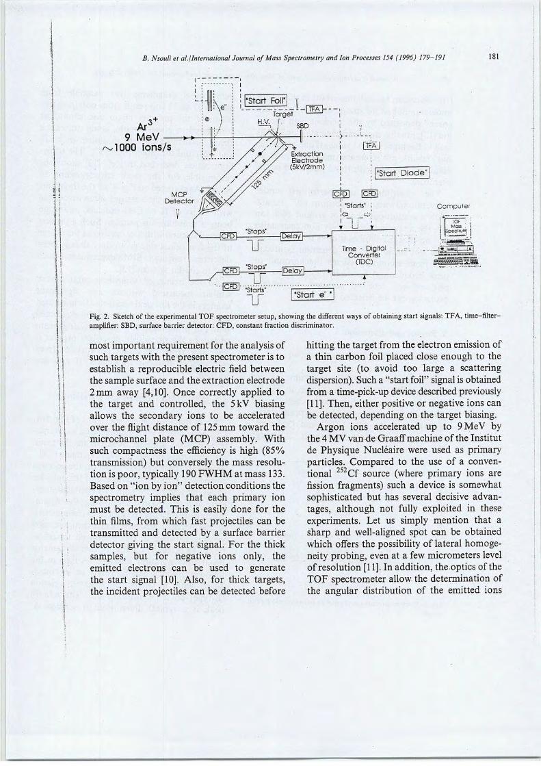
I 'SI
B. Nsouli et al./International Journal ofMass Spectrometry and Ion Processes 154 (1996) 179-191 181
Ar°9 MeV
/^ÎOOO ions/s
TFÂ>-
ExtractionElectrode
(5kV/2mm)"Start Diode"
EFDl ICFD1
Computer1 "Starts" :
i TT ;,
Time - DigitalConverter
(TDC)
k
•••IgfdH Starts""Start e" "
Fig. 2. Sketch of the expérimental TOF spectrometer setup, showing the différent ways of obtaining start signais:TFA, time-filter-amplifier: SBD, surface barrier detector: CFD, constant fraction discriminator.
most important requirement for the analysis ofsuch targets with the présent spectrometer is toestablish a reproducible electric field betweenthe sample surface and the extraction électrode2 mm away [4,10]. Once correctly applied tothe target and controlled, the 5kV biasingallows the secondary ions to be acceleratedover the flight distance of 125 mm toward themicrochannel plate (MCP) assembly. Withsuch compactness the efficiency is high (85%transmission) but conversely the mass resolution is poor, typically 190 FWHM at mass 133.Based on "ion by ion" détection conditions thespectrometry implies that each primary ionmust be detected. This is easily done for thethin films, from which fast projectiles can betransmitted and detected by a surface barrierdetector giving the start signal. For the thicksamples, but for négative ions only, theemitted électrons can be used to generatethe start signal [10]. Also, for thick targets,the incident projectiles can be detected before
hitting the target from the électron émission ofa thin carbon foil placed close enough to thetarget site (to avoid too large a scatteringdispersion). Such a "start foil" signal is obtainedfrom a time-pick-up devicedescribed previously[11]. Then, either positive or négative ions canbe detected, depending on the target biasing.
Argon ions accelerated up to 9 MeV bythe 4 MV vande Graaff machine of the Institut
de Physique Nucléaire were used as primaryparticles. Compared to the use of a conventional 252Cf source (where primary ions arefission fragments) such a device is somewhatsophisticated but has several décisive advan-tages, although not fully exploited in thèseexperiments. Let us simply mention that asharp and well-aligned spot can be obtainedwhich offers the possibility of latéral homoge-neity probing, even at a few micrometers levelof resolution [11]. In addition, the.optics of theTOF spectrometer allow the détermination ofthe angular distribution of the emitted ions
«—••»—

182B. Nsouli et al./International Journal ofMass Spectrometry and Ion Processes 154 (1996) 179-191
[10] which can be very important in the futureunderstanding of thespatial distribution of theenergy deposited by the incident high energyion [12]. Finally, thèse expérimental conditionslead to the highest yield values if one comparesour results on référence materials such asalkali halides [10] with those published in theliterature.
The experiments are performed underconventional vacuum conditions (10" mbar).With a continuous beam of around 1000 ions-1, the analysis is essentially non-destructiveand no charge compensation is required. Thisdoes not mean that the détection is alwaysfree from secondary effects (background orpeak broadening) but with typically 5 x 10primary ions received per cm , no surfaceévolution can be detected.
3. Results and discussion
3.1. HSF-SIMS: positive ion émission
The positive PDMS spectrum of anuntreated P4VP sample is shown in Fig. 3.The most intense peak corresponds to theprotonated monomer while the peaks corresponding to the [2M +H]+ and [3M +H]+ions are much less important. Although
150 300 450
Channelsa(TOF)
Fig. 3. Positive ion mass spectrum ofan untreated P4VP pelletsample.
600
many other fragments (for example frommasses 27 to 73Da) resuit from polyfragmen-tation of the polymer chain and cannot beconsidered as characteristic, some others areclearly associated with the monomer {mjz 118and 120) and the dimer (m/z 197). The tropy-lium cation described in Réf. [13] should beresponsible for the peak corresponding tom/z 93. As sketched onFig. 4,ailthefragmentsresuit from benzylic scissions often associatedwith a loss of H or CH3 radicals, ionizationbeing a simultaneous process. Such a processof bond scissionwith localization of the chargeat the functional side-group has already beendescribed from static SIMS experiments whichlead to similar spectra [13].
Ail the irradiated samples exhibit a verysimilar spectrum, without any significantchanges inthe ion yield whatever the integrateddose. Thus it can be provisionally concludedthat the probability for the analyzing beamto induce the previously described process isthe same from the intact network or from7-irradiation-induced fragments, if any areformed.
3.2. HSF-SIMS: négative ion émission
From the négative ion spectrum of Fig. 5(a)only four peaks will be considered as characteristic of the material. Apart from the usualcontaminants (m/z 49, 73, 97,121), many C„Hfragments (bearing the * label on the spectra)corne from multifragmentation of the polymerbackbone and do not reflect its chemical structure. As discussed in the following, the remain-ing fragments can be considered as characteristicof the polymer structure since their émissionyield is sensitive to the 7-induced modifications. As sketched on Fig. 6, thèse fragmentsresuit from pyridinic scissions (A-type in thefollowing) which can be single or in coïncidence with a vinylic or benzylic scission(B-type) on a neighboring site. The m/z 78peak is a typical illustration of scission A.

S '•
B. Nsouli et al./International Journal of MassSpectrometry andIon Processes 154 (1996) 179-191 183
B-i. ^2 &3 j-
r^ ri ri
B2
N N N
+ CH3, cyclization
Fig. 4. Proposedmechanisms of positive fragment formation under ion beamirradiation.
Simultaneous scissions A + B involve the production of double bonds, leading to m/z 41,when occurring near a chain end or to m/z146 when occurring within a chain. Even conjugated double bonds could be producedthrough A + A + B processes (m/z 158). Thepoor mass resolution of our System cannotbe exclusively responsible for the width ofthèse last two peaks. A doublet can be sus-pected at m/z 146-148 or even resolved at m/z158-162 (see Fig. 5(c)): thèse doublets include
peaks that are interpreted are the capture of anadditional H instead of the release of an Haatom and double bond formation.
In sharp contrast to what is observed withpositive émission,the effects of gamma irradiation are well detected. It can be qualitativelyobserved that even at the lowest integrateddose of 148kGy, there is a noticeable increasein the intensity of the characteristic peaks ofthe original material (especially m/z 41 and 78;Fig. 5(b)), being more pronounced for the
^^mm •••••

184B. Nsouli et al./International Journal of Mass Spectrometry and Ion Processes 154 (1996) 179-191
2.43
XI.5* a
1.62p
0.81
-S? 2.25(D
• i-H
.1 1.50
Oo
2 0.75
^1X1.5149 El
§ 0O 5.25
O
3.50
1.75
IMjto,
200
¥
w
731 . EU97
121
fc
wMïUw.
EQ X3
u . lii!62N ;* r*-/.
\L0JI W_"T.)
r~(197'!
<21Ï!
,VV*J*v*
300 400 500 600
Channelsa(TOF)
Fig. 5. Négative ion mass spectra: (a) from an untreated P4VPpellet sample; (b) from an irradiated sample with an integrateddose of 148 kGy; (c) from an irradiated sample with an integrated dose of 14 400 kGy. Characteristic ions appear in blacksquares, new ions following gamma-ray irradiation are circled,contaminants orC„H' fragments are marked with an astensk.
largest dose of 14400 kGy (Fig. 5(c)). In addition, new fragments are detected at low dosesof irradiation, corresponding to m/z 183-184,197 and 211 (circled on the spectrum of Fig.5(b)). Since the gamma-ray interactions arerandomly distributed within the material,simultaneous scissions are not expected fromthis process and only single A or B scissionshâve to be considered. Then, if the proposedmechanisms ofionformation sketched inFig. 6are relevant, it will be easier for the primarybeam to produce such secondaries from
Fig. 6. Proposed mechanisms of the characteristic négative ionformation under ion beam irradiation.
fragments resulting from A scissions inducedby the gamma irradiation. As the simplestexample, if the pyridine radical is preformed,the corresponding négative ion will onlyrequire an électron capture to be emitted.Also, as sketched in Fig. 7, the final émissionof the ions at m/z 146 and 158 will be easierfrom fragments resulting from either A or Bscissions; in the first case the analyzing beam

B. Nsouli et al./International Journal of Mass Spectrometry and Ion Processes 154 (1996) 179-191 185
N N N N
ïray = B, Yray = B2
Beam = A
Fig. 7. Proposed mechanisms for the émission ofthe négative ions ofm/z 146 and 158, from Aand Bscissions induced by gammairradiation.
must interact with modified chains, in the such as those represented in Fig. 8. Thesecond with dinner or trimer free-radical production of such ions from a modifiedfragments. • chain only requires a B scission instead of
As far as new fragments are observed, the simultaneous B+B scissions never observedgamma irradiation must produce new entities from the unirradiated material. On the other
—

186 B. Nsouli et al.jInternational Journal ofMass Spectrometry and Ion Processes 154 (1996) 179-191
§2.
Fig. 8. Proposed mechanisms for the émission of new négative ions resulting from Bscissions induced by gamma irradiation.
hand, it has been previously shown that thefragment of mass 211, when formed underion bombardment, is preferentially ionizedand leads to [M+ H]+ ion émission. If preformed under gamma irradiation it could beresponsible for the production of the relatedions. Of course, when a benzylic scissionoccurs, the resulting modified chain is thecounterpart of the production of the dimerand trimer radicals sketched in Fig. 7.
The yield variationof ail thèse fragments asa function of the integrated dose is given inFig. 9. It can be observed that the smallestdose is responsible for the steepest increase.However, for increasing doses, the yields of
the fragments already observed in the unirradiated sample tend to saturate while the émissionof the new fragments exhibits a fast decreaseand vanishes. Such behavior has been interpreted in terms of radical recombinations [5]above a given concentration of fragments ormodified chains, also leading to a decrease inthe mobility of the charged fragments. Thesomewhat différent behavior of the m/z 41fragment can be related not only to the factthat, being the smallest, it has the greatestmobility but also to the fact it results fromscissions occurring at chain ends. As anextrême conséquence, the ions correspondingto the largestfragments resulting fromgamma

B. Nsouli etal.j'International Journal of Mass Spectrometry and Ion Processes 154 (1996) 179-191 187
0 1000 2000 3000 4000 4000 8000 12000
Irradiation Dose (kGy)0.15
"S
0.09
0.03
0 1000 2000 3000 4000
Irradiation Dose (kGy)
Fig. 9. Evolution, as a function of the integrated dose, of theyield of the fragments: (a) observed on the unirradiatedsample(m/z 41, 78, 146and 158); (b) resulting from gamma-irradiationinduced modifications (m/z 183, 184, 197, 211).
irradiation hâve a lower mobility and theirémission is then strongly affected by therecombination processes.
3.3. Studyofthe soluble andinsoluble fractionsof the irradiatedmaterial
From the free radicals formed under gamma•irradiations as well as their recombinationproducts, those leading to linear fragmentswill be extracted with ethanol. Indeed, thereis an increasing quantity of soluble materialas a function of the dose of irradiation andsuch a variation is in good agreement withthe corresponding variation of the number ofspins per gram measured by électron paramagnetic résonance spectroscopy (EPR) [5]. As thesimplest way to déterminesuch a variation fora particular species in the solution, one can
3
o
aiai
B+
i—i
I
U
I
8_-*- ~ t
/
6 : /
/
4 il a •-•:/ b -c--
•
b-
i
2 ^
n
-
0 50 100 150 200 250 300
Concentration (|ig/cm3 )Fig. 10. Variation oftheyield ofthemolecular ion [M+ H]+ asa function of the concentration for: (a) non-cross-linked P4VPsolution; (b) 2% cross-linked P4VP, irradiated at the highestdose (14400kGy). Eacji data point corresponds to a 10/ilassay spin-coated target.
still use the HSF-SIMS technique applied todeposits taken from solutions containing aknown amount of extracted material. However, the thickness of such deposits must besmaller than the émission depth of the emittedions, i.e. within a range where the yield varieslinearly with the layer coverage, as illustratedin Fig. 10. There the [M + H]+ émission yieldhas been measured from spin-coated targetscorresponding to increasing soluble fractionconcentrations of (a) a non-cross-linked resinor (b) a 2% cross-linked material irradiatedwith the largest dose. The first case corresponds to the présence of the longest chainsin the solution, while the second correspondsto thehighest soluble fraction withmuchsmallerfragments. Indeed, the steeper slope is foundwhen large chains are présent, presumablyleading to a better coverage. For the curvecorresponding to the largest integrated dose,the concentration required for being below

188 B. Nsouliet al./International Journal of Mass Spectrometry andIon Processes 154 (1996) 179-191
a-D
jS
<
Soi-* fraction
O (Mf
V M=
10000
Irradiated Dose (kGy)
/*
15000
Fig. 11. Variation, as a function of the integrated dose, of theyield of the positive ions[M+ H]+ and thoseof masses 93 and120, as obtained from thin filmscorresponding to the resultingconcentration of soluble material. Also plotted are thecorresponding values of the soluble fraction (%). Ail data arenormalized to the value at 14400kGy.
2
5000 10000
Irradiation Dose (kGy)
15000
Fig. 12. Variation, as a function of the integrated dose, of theyield of the négative ions of mass 41 and 78 as obtained fromthin films corresponding to the resultingconcentration of soluble material.
-2the saturation value (around 50 pg cm- in theprésent example) sets the number of dilutionsone has to perform on each solution corresponding to a given dose of irradiation.From the spin-coated targets so realized, thevariation in yield of a given ion will refiectthe extracted proportion ofthe related species.
Then, as shown in Fig. 11, the analysis ofsuch targets leads to a yield variation of themain positive ions as a function of the irradiation dose very similar to the variation ofthe soluble fraction. Since the positive ionémission has been found insensitive to fragment formation when performed from thebulk sample, the présent variation must beinterpreted as a simple proportionality to theamount of extracted material whether it is afragment or an unmodified chain. This indi-cates that a positive ion is formed with almostthe same probability from a B scission andsimultaneous ionization of the fragmentformed, as from a simple ionization on thesame fragment preformed by 7 irradiation(see Fig. 4).
For the émission of négative ions, the yieldvariation will refiect the amount of freeradicals from which they can be produced(as proposed in Fig. 7). Then, as observed inFig. 12, the yields ofthe ions of m/z 41 and 78remain similar whatever the integrated gammadose, in contrast to what was observed forthe bulk samples (Fig. 9). According to theproposed mechanisms sketched in Fig. 7,both A and B gamma-induced scissions willfavor production of free radicals leadingto the émission of the m/z 78 ion (pyridinefragment directly from A scissions or largerfragments resulting from B scissions). On theother hand, compared to the bulk situation, Ascissions leading to modified but insolublechains will not contribute to the émission ofthe m/z 41 ion, thus explaining the- réductionof this émission relative to those of the pyridine ion. The émission of the other ionspreviously observed from the bulk is strongly

B. Nsouli et al./International Journal ofMass Spectrometry and Ion Processes 154 (1996) 179-191 189
so3-
5000
HS04-
3000
CN-1000
0Ijitlilllllilill.'illili.i.vlillir'";1'"'-1 ••iUil,lil„»iiiLl<uj! o
20
5000t-
•4
t/3 3000 • 5
O
O 1000
o' il L
5
10 .22
MiMiilhjMdiiUiiiiijll.Uiiirjjii,it,iJ
m/z
Fig. 13. LSF-SIMS négative ion mass spectra from (a) untreated P4VP pellet sample, (b) irradiated (and contaminated) sample with anintegrated dose of148 kGy, and (c) irradiated sample with an integrated dose of14 400 kGy.
reduced (m/z 158 ishardly detected).However,the fragments corresponding to the dimer areclearly identified in the solutions from thepeaks at m/z 197 and 211, and, in contrastto the bulk situation, the émission does not van-ish when increasing the ion dose. From themechanism proposed in Fig. 8, one may inferthat the free radicals responsible for the émission can be extracted (i.e. they do not recombine). Consequently, it can be concluded thatthe extinction of the émission from the bulkresults from some trapping of the ions insteadof a recombination of the radicals produced.
The analysis of the remaining material oncethe extraction has been performed must confirmthe previous findings. For the most favourablecase ofthe highest dose (14 400 kGy), the residue
was dried and the resulting pellet analyzed.The yield réduction for the most significantpeaks atm/z 78,41,146 and 158 isrespectively5.0, 2.6, 1.6 and 1.2. Thèse numbers are onlyindicative since they resuit from a singleexperiment, but thequalitative trend is specta-cular. As expected, the m/z 78 ion is moreeasily formed from the extracted fragmentswhile the m/z 41 ion can be formed eitherfrom fragments or from modified end chains.Asfar asm/z 146 and 158 are concerned, thereis a clear indication that the related ionsare formed from insoluble modified chains(Fig. 7). Accordingly, the dimer and trimerfragments formed by B scissions will moreeasily give rise to positive (Fig. 4) thannégative ions.
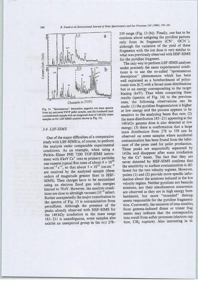
190B. Nsouli et al./International Journal ofMass Spectrometry and Ion Processes 154 (1996) 179-191
339 range (Fig. 13 (b)). Finally, one has to becautious about assigning the pyridine patternonly from its fragments (CN~, OCN ),although the variation of the yield of thèsefragments with the ion dose is very similar towhat was previously observed with HSF-SIMSfor the pyridine fragment.
The only way toperforai LSF-SIMS analysesunder precisely the same expérimental conditions is to use the so-called "spontaneousdésorption" phenomenon which has beenwell explained as a bombardment of polya-tomic ions [6,7] with a broad mass distributionsbut at an energy corresponding to the targetbiasing (keV). Thus when comparing thèseresults (spectra of Fig. 14) to the previousones, the following observations can bemade: (1) the pyridine fragmentation is higherat low energy and the process appears to besensitive to the analyzing beam flux rate; (2)the massdistribution 183-211 appearing at the148 kGy gamma dose is also detected at lowenergy; (3) there is confirmation that a largemass distribution from 278 to 339 can beobserved on some samples where accidentaicontamination has beenfound from the lubri-cant of the press used for pellet production.Thèse peaks are sequentially separated by14Da and disappear after some irradiationby the Cs+ beam. The fact that they arenever detected by HSF-SIMS confirais thatthe sensitivity to surface contamination is différent for the two velocity régimes. However,points (1) and (2) provide more spécifie information about the scissions induced in the lowvelocity régime. Neither pyridinic nor benzylicscissions, nor their simultaneous occurrence,are observed as they are in high energy bombardment, but more "extended" damageseems responsible for the pyridine fragmentation. Conversely, theémission ofions resultingfrom gamma-induced dimer or trimer fragments may indicate that the correspondraiions resuit from softer processes (électron capfure, CH2 rupture). Also interesting in th
Channels a (TOF)
Fig. 14. "Spontaneous" désorption négative ion mass spectrafrom (a) untreated P4VP pellet sample, and (b) irradiated (andcontaminated) sample with an integrated dose of148 kGy (samesamples as for LSF-SIMS analysis shown inFig. 13).
3.4. LSF-SIMS
One ofthe major difficulties ofa comparativestudy with LSF-SIMS is, ofcourse, toperforaithe analysis under comparable expérimentalconditions. As an example, when using aPerkin-Elmer PHI 7200 TOF-SIMS instrumentwith8keV Cs+ ions as primary particlesone expects typical flux rates ofabout 4x10ion cm
-2-2s-1, so that about 5x 10¹² ion cm
are received by the analyzed sample (threeorders of magnitude greater than in HSF-SIMS). Then charges hâve to be neutralizedusing an électron flood gun with énergieslimited to 70 eV. However, the analysis conditions areclose to ultrahigh vacuum (10~ mbar).Rather unexpectedly the major contribution tothe spectra of Fig. 13 is contamination frompersulfates. Although the présence of thepeaks -already observed with HSF-SIMS forthe 148 kGy irradiation in the mass range183-211 is unambiguous, some samples alsoexhibit an unexpected group in the m/z 278-

B. Nsouli et al./International Journal of Mass Spectrometry and Ion Processes 154 (1996) 179-191 191
"spontaneous" désorption process is the unex-pected présence of the m/z 211 ion in the unirradiated sample (Fig. 14(a)).One has to notethat such a spectrum results from a fairly longacquisition time and consequently the primaryion dose is somewhat high (around 2 x 10¹⁰ioncm-2). Then, an effect similar to gammairradiation could be evoked, while underLSF-SIMS conditions, where the dose rate istypically five orders of magnitude higher, thesputtering effect is dominant.
4. Conclusion
From the SIMS analysis ofthe bulk samplesand the soluble and insoluble fractions resulting from gamma irradiation, a cohérentpicture of the formation of fragments canbe obtained for différent energy dépositionprocesses. One particular aspect of fast(MeV) ion interactions with the P4VP networkis the possibility of inducing simultaneouspyridinic-pyridinic, or benzylic-pyridinic scissions or both. Subsequently, any single scission initiated by the gamma irradiation leadsto preformed fragments from which the ionémission is easier under MeV bombardment.
However, this is spécifie to négative ion formation. Since positive ion émission only requiresbenzylic scissions the phenomenon takes placeeither on intact or on prefragmented material.The occurrence of such simultaneous scissionsis much less with low energy (keV) ions, thusexplaining the lack of sensitivity of LSF-SIMSto gamma-induced preformed fragments. As anoticeable exception, dimers or larger fragments can be detected at low doses (as forMeV primary ions), but the related ion émissionis strongly reduced when increasing the dose.
Acknowledgements
The dedicated assistance of the accelerator
crew ofthe Institut de Physique Nucléaire, M.Ferrari and A. Gardon and of M. Espagnanfrom COGEMA-Marcoule who performedthe gamma irradiations, is gratefully acknowl-edged.Two of us (M.D. and M.L.) are gratefultoR. Chomel from COGEMA-Marcoule forhis support of the work.
Références
[I] T.E. Gangwer, M. Godstein and K.K.K.S. Pillay, Radiationeffectson ion exchangematerials, Report BNL-50781, Broo-khaven National Laboratory, Upton, NY, 1977,p. 88.
[2] M. Lemaire, R. Chevillote, R. Chomel, P. Doutreluingne,A. Guy,J. Foos and R. Chomel, FrenchPatent,9,202, 516,1992.
[3] M. Draye, R. Chevillote, R. Chomel, P. Doutreluingne, A.Guy, J. Foos and M. Lemaire,Sep. Sci. Technol. 30(7-9)(1995) 1245.
[4] B. Nsouli, Ph.D. Dissertation (unpublished), UniversitéClaude Bernard Lyon I, 1995.
[5] M. Draye, B. Nsouli, H. Allali, M. Lemaire and J.-P.Thomas, Polym. Dégradation and Stability, submittedfor publication.
[6] H. Allali, O. Debré, B. Lagrange, B. Nsouli,A.A.Oladipoand J.-P. Thomas, Nucl. Instrum. Methods Phys. Res. B,108 (1996) 163.
[7] M. Benguerba, S.DéliaNegraand Y. LeBeyec, Proc.39thASMS Conférence on Mass Spectrometry and AlliedTopics, Nashville, TN, 1991, p. 500.
[8] H. Feld, A. Leute, R. Zurmûhlen and A. Benninghoven,Anal. Chem., 63 (1991) 903.
[9] B.U.R. Sundqvist, in R. Behrisch and K. Wittmaack(Eds.), Sputtering by Particle Bombardment III,Springer-Verlag, Berlin, 1991, p. 257.
[10] H. Allali, B. Nsouli and J.-P. Thomas, Int. J. MassSpectron. Ion Processes, 127 (1993) 111.
[II] J.-P. Thomas, A.A. Oladipo and M. Fallavier, Nucl.Instrum. Methods Phys. Res. B, 42 (1989) 127.
[12] R.M. Papaléo, G. Brinkmalm, D. Fenyô, J. Eriksson,H.-F. Kammer, P. Demirev, P. Hakansson and B.U.R.Sundqvist, Nucl. Instrum. Methods Phys. Res. B, 91(1994) 667.
[13] K.J. Hook, T.J. Hook,J.H. Wandas and J.S.Gardella, Jr.,Appl. Surface Sci., 44 (1990) 29.
wmmm

Bull Soc Chim Fr (1996) 133, 183-197© Elsevier, Paris
Radiochemical stabilityofthe dicyclohexano-18-crown-6 ether (DCH18C6):
synthesis and tests in radioactive médiumof the DCH18C6 radiolytic products
Micheline Draye1-2*, Alain Favre-Réguillon1, Rodolph Chomel2, René Faure3,Alain Guy4, Jacques Foos4, Marc Lemaire1*
1 Institut de recherches sur la catalyse (CNRS), Laboratoire de catalyse et synthèse organique,UCBL, ESCIL, 43, boulevard du ll-Novembre-1918, 69622 Villeurbanne cedex;
2 Service laboratoire COGEMA, Établissement de Marcoule, BP 170, 30206 Bagnols-sur-Cèze cedex;3 Laboratoire de chimie analytique II, LICAS, UCBL, 43, boulevard du ll-Novembre-1918, 69622 Villeurbanne Cedex;
4 Laboratoire des sciences nucléaires du CNAM, 292, rue Saint-Martin, 75141 Paris cedex 03, France.
(Received 24 October 1995; accepted 12 January 1996)
Summary — The cis-syn-cis isomer of the dicyclohexano-18-crown-6 ether (DCH18C6) was subjected to hydrolysis andradiolysis with a 137Cs gamma source, at différent doses of irradiation. The cis-syn-cis DCH18C6 radiolytic productspreviously identified [1], were synthesized in their différent configurations. Thèse radiolytic products, ail of cis configuration,were tested on aqueous synthetic solutions of spent nuclear fuels. Experiments in radioactive médium showed that, undercontinuous extraction conditions, the cis-syn-cis DCH18C6 radiolytic products cannot perturb a reprocessing process usmgthe DCH18C6 as sélective extractant. Good prospects for the application of DCH18C6 to spent nuclear fuel reprocessingwere therefore demonstrated. An X-ray crystallographic study of the DCH18C6 cis-sj/n-cis-isomer with uranyl nitrate wasinvestigated.
spent nuclear fuel reprocessing / DCH18C6 radiochemical stability / radiolytic product synthesis / crown ether
Résumé — Stabilité radiochimique du dicyclohexano-18-couronne-6 éther (DCH18C6): synthèse et tests en milieuradioactif des produits de radiolyse du DCH18C6. L'isomère cis-syn-cisdu dicyclohexano-18-couronne-6 ether (DGHlSCb)aété hydrolyse et radiolyse avec les rayonnements gamma d'une source de 13rCs, àdifférentes doses dirradiation. Les produitsde radiolyse du DCH18C6 cis-syn-cis, identifiés auparavant [1], ont été synthétisés dans leurs différentes configurationsrelatives Ces produits de radiolyse, tous de configuration cis, ont été testés dans des solutions aqueuses synthétiques^ deretraitement de combustibles nucléaires usés. Les essais en milieu radioactif ont montré que, dans les conditions dun systèmed'extraction en continu, les produits de radiolyse du DCH18C6 cis-syn-cis ne peuvent pas perturber un procède de retraitementutilisant leDCH18C6 comme extractant sélectif. Ainsi, de bonnes perspectives pour l'application du DCH18C6 au retraitement^des combustibles nucléaires usés a été démontré. Un cristal du DCH18C6 cis-syn-cis avec le nitrate d'uranyle a ete examineen cristallographie de rayons X.retraitement des combustibles nucléaires usés / stabilité radiochimique du DCH18C6 / synthèse de produit deradiolyse / éther couronne
Introduction
In some industrialized countries, nuclear energy contribution has reached impressive levels. Uranium figuresat the heart of nuclear production of electricity. Beforeand after its transit through the reactor, uranium un-dergoes many opérations and chemical transformationswhich constitute the 'fuel cycle'. One step of the 'fuelcycle' is the reprocessing. The reprocessing consists ofrecovering, in the spent fuels, the reusable energetic materials (uranium and plutonium) and conditioning, to
* Correspondence and reprirtts
the best conditions of safety for man and the environ-ment, the ultimate wastes with a view to their disposai.At their arrivai at the reprocessing plant, the spentfuels are stored for two to three years in a pool, awaitingthe natural decrease of their activity. Once taken outof the pool, the fuel assemblages are sheared and thenuclear material is dissolved in nitric acid. Extractionwith organic solvent permits the chemical séparation ofuranium, plutonium and fission products. Uranium isconcentrated in nitrate form whereas plutonium is conditioned under its oxide form, and thèse are then reused
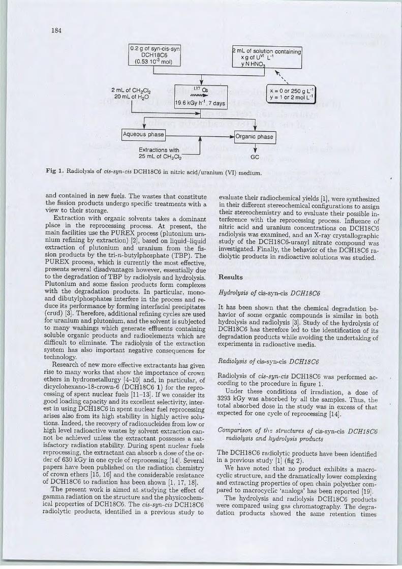
184
0.2 g of syn-cis-synDCH18C6
(0.53 1Q-3mol)
2 mL of CH2CI220 mL of H20
'•"Cs
h-1
2 mL of solution containingxgofUvl L"1yNHNO,
l >v
19.6kGy h"1.7 days
x = 0 or 250 g L"1y = 1 or 2 mol L"1
Aqueous phase
Extractions with25 mL of CH2CI2~
Organic phase
TGC
Fig 1. Radiolysis of cis-syn-cis DCH18C6 in nitric acid/uranium (VI) médium.
and contained in new fuels. The wastes that constitutethe fission products undergo spécifie treatments with aview to their storage.
Extraction with organic solvents takes a dominantplace in the reprocessing process. At présent, themain facilities use the PUREX process (plutonium uranium refining by extraction) [2], based on liquid-liquidextraction of plutonium and uranium from the fission products by the tri-n-butylphosphate (TBP). ThePUREX process, which is currently the most effective,présents several disadvantages however, essentially dueto the dégradationofTBP by radiolysis and hydrolysis.Plutonium and some fission products form complexeswith the dégradation products. In particular, mono-and dibutylphosphates interfère in the process and reduce its performance by forming interfacial précipitâtes(crtid) [3]. Therefore, additional refining cycles are usedfor uranium and plutonium,and the solvent is subjectedto many washings which generate effluents containingsoluble organic products and radioéléments which aredifficult to eliminate. The radiolysis of the extractionSystem has also important négative conséquences fortechnology.
Research of new more effective extractants has givenrise to many works that show the importance of crownethers in hydrometallurgy [4-10] and, in particular, ofdicyclohexano-18-crown-6 (DCH18C6 1) for the reprocessing of spent nuclear fuels [11-13]. If we consider itsgood loading capacity and its excellentselectivity, interest in using DCH18C6 in spent nuclear fuel reprocessingarises also from its high stability in highly active solutions. Indeed, the recovery of radionucléides from low orhigh level radioactive wastes by solvent extraction cannot be achieved unless the extractant possesses a sat-isfactory radiation stability. During spent nuclear fuelsreprocessing, the extractant can absorb a dose ofthe order of 630 kGy in one cycle of reprocessing [14]. Severalpapers hâve been published on the radiation chemistryof crown ethers [15, 16] and the considérable résistanceof DCH18C6 to radiation has been shown [1, 17, 18].
The présent work is aimed at studying the effect ofgamma radiation on the structure and the physicochemical properties of DCH18C6. The cis-syn-cis DCH18C6radiolytic products, identified in a previous study to
evaluate their radiochemical yields [1], were synthesizedin their différent stereochemical configurations to assigntheir stereochemistry and to evaluate their possible interférence with the reprocessing process. Influence ofnitric acid and uranium concentrations on DCH18C6radiolysis was examined, and an X-ray crystallographicstudy of the DCH18C6-uranyl nitrate compound wasinvestigated. Finally, the behavior of the DCH18C6 radiolytic products in radioactive solutions was studied.
Results
Hydrolysis of cis-syn-cis DCH18C6
It has been shown that the chemical dégradation behavior of some organic compounds is similar in bothhydrolysis and radiolysis [3]. Study ofthe hydrolysis ofDCH18C6 has therefore led to the identification of itsdégradation products while avoiding the undertaking ofexperiments in radioactive média.
Radiolysis of cis-syn-cis DCH18C6
Radiolysis of cis-syn-cis DCH18C6 was performed according to the procédure in figure 1.
Under thèse conditions of irradiation, a dose of3293 kGy was absorbed by ail the samples. Thus, thetotal absorbed dose in the study was in excess of thatexpected for one cycle of reprocessing [14].
Comparison of ths structures of cis-syn-cis DCH18C6radiolysis and hydrolysis products
The DCH18C6 radiolytic products hâve been identifiedin a previous study [1] (fig 2).
We hâve noted that no product exhibits a macro-cyclic structure, and the dramatically lower complexingand extracting properties of open chain polyether compared to macrocyclic 'analogs' has been reported [19].
The hydrolysis and radiolysis DCH18C6 productswere compared using gas chromatography. The dégradation products showed the same rétention times

Fig 2. Structure of the DCH18C6 radiolytic products.
L
7.28-
4.90 - -
: Y.58 -
185
12.04- -5-- •- 12.22
18.44 • •-- 6 --- 18.62
r22.44 7. 22.59
H 27.69 27.81
30.27 30.44
HYDROLYSIS RADIOLYSIS
Fig 3. Comparison of radiolysis and hydrolysis chromatograms.
0,5
1 0,41
o 0,3-Ia
•g 0,2-o
t5
S. 0,1-
0,0
U(Doncent
• 2
ration = 250 g/L
:H•%,
D 40 5• 6• rm b
1 JkàiïM-È1 2
Nitric Acid Concentration (M)
0,0
1 2Nitric Acid Concentration (M)
Fig 4. Acidity dependence of the DCH18C6 radiolysis in the présence and absence of uranium.
(fig 3); the DCH18C6 radiolysis products are qualita-tively identical with the DCH18C6 hydrolysis products.'Quantitatively, products of low mass are more abun-dant in the case of hydrolysis, whereas products of highmass are more abundant in the case of radiolysis. Indeed, protonation of the macrocycle sites starts a chaindégradation reaction to give low mass products, but radiolysis, the most immédiate phenomenum, essentiallyfavors the high mass compounds.
Influence of acidity on the hydrolysis of cis-syn-cisDCH18C6, in the présence and absence of uranium
In the absence of uranium, an increase in acidity leadsto an increase in DCH18C6 radiolysis. The présence of
uranium in the DCH18C6 solution decreases, or slowsdown, radiolysis of DCH18C6, but this phenomenum isnot indépendant of nitric acid concentration. Figure 4shows the correlated action of nitric acid and uraniumconcentrations.
In the case of a high concentration of uranium, an increase in acidity from 1 to 2 M stabilizes the DCH18C6-uranyl nitrate compound and decreases the action of the7 radiation; compound 8, the least fragmented product,was given in the highest yield. On the other hand, inthe absence of uranium, an increase of the acidity from1 to 2 M has no influence on the macrocycle dégradation. The radiochemical yields were higher than inthe présence of uranium but the dégradation was only

186
governed by irradiation.The highest radiochemical yieldwas obtained for the most fragmented compound 2.
A structural analysis ofthe cis-syn-cis DCH18C6-uranylnitrate compound
cis-syn-cis DCH18C6 is more stable to radiolysis inthe présence of uranium. Indeed, the présence of uranium disadvantaged macrocycle hydrolysis and radiolysis. This phenomenum was ascribable to the templateeffect of uranium that favors fragment recombination.Evidence for the structure of the DCHl8C6-uranyl nitrate compound was obtained from a single X-ray analysis.An ORTEP view of the cis-syn-cis DCH18C6-uranylnitrate is shown in figure 5.
O : OxygenC : Carbon
N : NilragenU : UraniumOW : H20
Fig 5. ORTEP drawing of the cis-syn-cis DCH18C6-uranylnitrate compound.
Uranyl nitrate is bonded to the macrocycle via twowater molécules. The uniqueness of the structure doesnot resuit from the présence of water molécules betweenthe uranium atom and the macrocycle [20-22] but fromtheir side-by-side arrangement, and in the non-linearposition of the nitrate molécules in relation to uraniumoxide. The ORTEP drawing of the asymmetric unitclearly shows that there is no bond between the uraniumand the DCH18C6. Interaction between the macrocycleand the uranium complex is probably realized via hydrogen bonds between the two water molécules and theoxygen atoms of the macrocycle. Thus, ail the oxygenatoms of the macrocycle are affected by the hydrogenbonds within a single unit [(U02)(N03)2(H20)2]. Thesix contacts assigned as being hydrogen bonds are sum-marized in table I.
Synthesis of DCH18C6 radiolysis products
In order to test their influence on spent nuclear fuelreprocessing, the DCH18C6 radiolytic products weresynthesized.
Table I. Hydrogen bonding distances (Â).
OW1...04
OW1...02
OW1...03
2.68
2.75
3.02
OW2.. .01'OW2.. .05'OW2.. .06'
2.60
2.78
2.87
Symmetry code; (i) 1 - x, 1/2 + y, l/(-z).
• Stereochemistry of the compounds synthesizedUpon réduction, dibenzo-18-crown-6 ether (DB18C6)can yield up to five stereoisomers of DCH18C6. Theionoselective properties of thèse stereoisomers dépendon their stereochemical configuration. For example, ithas been shown that the selectivity of the isolation ofplutonium is much higher when using the cis-syn-cis-isomerofthe macrocycle [5]. We therefore had to détermine the stereochemical configurations of the DCH18C6radiolytic products in order to establish their complex-ing properties. However it is difficult, if not possible,to identify the stereochemical configurations with theusual techniques of analysis. Hydrolysis and radiolysisare expected to lead to dégradation products with rétention ofconfiguration. So, in order to confirm this, weun-dertook synthesis of the DCH18C6 radiolytic productsin their différent stereochemical configurations (fig 6),without séparation of the possible enantiomers.
Synthesis of l,2-bis(2-hydroxyethoxy)cyclohexane 3
Dialkylation of catéchol with 2-chloroethanol in aqueous sodium hydroxide afforded the l,2-bis(2-hydroxy-ethoxy)benzène 9 in 99% yield. The hydrogénationof aromatic compounds is well documented in theliterature and heterogeneous catalysis has been themost thoroughly studied method. The réduction of 9was first run according to the method described by •Pedersen using Ru on alumina [23]. However, hydrogénation of phénol ether molécules leads to the formation of a hydrogenolysis by-product, the amount ofwhich dépends on the température of the reaction andthe nature ofthe catalystinvolved [24]. The phasetrans-fer method of réduction previously described [25] givesrise to complète conversion, but the reaction mixtureis difficult to purify due to the présence of trioctyl-amine, used as surfactant. With the Rh/C catalyst, theconversion is complète but the chimioselectivity variesfrom 63 to 95% as a function of the solvent polarity(CHCI3 < C1(CH2)2C1 < MeOH).
Finally, the réduction ofthe l,2-bis(2-hydroxyethoxy)-benzene 9 to l,2-bis(2-hydroxyethoxy)cyclohexane 3was performed by using the Rh/SrTi03 catalyst [26],under constant conditionsof température and pressure.The synthesis is summarized in figure 7.
Synthesis of 2-(2-hydroxyethoxy)cyclohexanol cis 2
Using another base and solvent, alkylation of catécholafforded mono- and dialkylated aromatic derivatives[27]. The monoalkylated aromatic derivative 10 was obtained in 30% yield, after simple silicagel chrornatogra-phy. Then, réduction ofcompound 10 using Rh/SrTi03catalyst led to the 2-(2-hydroxyethoxy)cyclohexanolcis 2 in 98% yield (fig 8).

a7e
OH H
X)Fig 6. Potential stereochemical configurations of the DCH18C6 dégradation products.
CK OH1
u NaOH, H20" Ar (99%)
Fig 7. Synthesis of l,2-bis(2-hydroxyethoxy)cyclohexane 3.
10
cr oh
u K2C03, AcétoneAr
3% Rh-SrTi03, H2
CHCI3/MeOH (1/1)1 atm., r. t., (98%)
Fig 8. Synthesis of 2-(2-hydroxyethoxy)cyclohexanol cis 2.
3% Rh-SrTi03, H2i
CHCI3/MeOH (1/1)1 atm., r. t., (98%)
187

188
Synthesis of 2-(2-hydroxyethoxy)cyclohexanol trans 2
The previously described method, involving theRh/SrTi03 catalyst for the réduction ofaromatic rings[26], preferentially yields the compound in the cisconfiguration. Conversely, epoxide opening in acidicmédium is known to be directed to the trans configuration. This strategy, developed by Ikeda et al [28]for the synthesis of the cyclohexanol substituted at the2-position, gives rise to a mixture of products which aredifficult to purify. Direct treatment of the cyclohexene-oxide (7-oxabicyclo[4.1.0]heptane) with ethyleneglycolin the présence of catalytic sulfuric acid [29] led to the2-(hydroxyethoxy)cyclohexanol trans 2 (fig 9).
HO OH
H2S04 cat.(42%)
~cr^^''OH
2
Fig 9. Synthesis of 2-(2-hydroxyethoxy)cyclohexanoltrans 2.
Synthesis of the l,2-bis(5-hydroxy-3-oxapentyloxy)-cyclohexane cis 6
The l,2-bis(5-hydroxy-3-oxapentyloxy)cyclohexane inthe cis configuration was readily obtained by quantitative réduction [26] of l,2-bis(5-hydroxy-3-oxapentyl-oxy)benzene 11, synthesized from the catéchol according to the method previously described for compound
11
HcP°^h >y.K2C03, acétone
Ar
3% Rh-SrTi03, H2)
CHCI3/MeOH (1/1)1 atm., r. t., (97%)
3 (fig 10). The dialkylated aromatic derivative 11 wasreduced, affording the expected compound 6.
Synthesis of 2-(5-hydroxy-3-oxapentyloxy)cyclohexanolcis 4
Quantitative réduction of the 2-(5-hydroxy-3-oxa-pentyloxy)phenol 12, arising as a secondary productof the dialkylated derivative synthesis, afforded the2-(5-hydroxy-3-oxapentyloxy)cyclohexanol 7 in the cisconfiguration (fig 11).
Synthesis of 2-(5-hydroxy-3-oxapentyloxy)cyclohexanolcis 4
2-(5-Hydroxy-3-oxapentyloxy)cyclohexanol trans 4 wasobtained in 43% yield using previously describedmethodology (fig 12).
Synthesis of l-(5-hydroxy-3-oxapentyloxy)-2-(2-hydroxyethoxy)cyclohexane cis 5
l-(5-Hydroxy-3-oxapentyloxy)-2-(2-hydroxyethoxy)-cyclohexane cis 5 was obtained in two steps. Alkyl-ation of 2-(5-hydroxy-3-oxapentyloxy)phenol 12 by2-chloroethanol led to l-(5-hydroxy-3-oxapentyloxy)-2-(hydroxyethoxy)benzène 13 in 31% yield. Réductionof compound 13 with the Rh/SrTi03 catalyst then gavethe desired product 5 in 97% yield (fig 13).
Synthesis of 2,2'-[3-oxapentane-l,5-diylbis(oxy)diyl]-dicyclohexanol cis 7a, 7b
The reaction conditions of Pedersen [23] for the directsynthesis of the cyclohexanols 7a and 7b cis lead to
+ 12(25%)
11 (55%)
Fig 10. Synthesis of l,2-bis(5-hydroxy-3-oxapentyloxy)cyclohexane cis 6.
3% Rh-SrTi03, H2
CHCI3/MeOH (1/1) l\/JN.,1 atm., r. t., (98%) 7
rrOH
Fig 11. Synthesis of 2-bis(5-hydroxy-3-oxa-pentyloxy)cyclohexanol cis 4.

a mixture which is difficult to purify. We now reporta more convenient and simple method using guaia-col as starting material (fig 14). The key step of thesynthesis is the deprotection of the phenoxy groupswith trimethylsilyl iodide, by sélective breaking of themethyl-oxygen bonds.
H2SQ4 cat. \/\(43%) OH
Fig 12. Synthesis of 2-(5-hydroxy-3-oxapentyloxy)cyclo-hexahol trans 4.
Addition of bis(2-chloroethyl)ether to guaiacol afforded the aromatic dimethylated derivative 14 in60% yield after recrystallization from ether. Deprotection of compound 14 with trimethylsilyl iodide inchloroform [30] led to the 2,2'-[3-oxapentane-l,5-diyl-bis(oxy)diyl]bis-phenol 15 after recrystallization fromether, in 97% yield. Rh/SrTi03 was inactive in theprésence of the compound 15, the complexing properties of which inhibit the réduction reaction. So aromatic
3% Rh-SrTi03, H2w~
CHCI3/MeOH (1/1)1 atm., r. t., (97%) 5
189
derivative 15 was reduced by Rh/C catalyzed reaction.In this case, a total conversion was obtained, but theselectivity was a function of the polarity of the solvent used during the réduction (table II). Attemptedincrease of the catalyst concentration led to significanthydrogenolysis. The diastereoisomers crud was purifiedby thin layer chromatography.
Table II. Selectivity percentage as a function of solventpolarity.
Solvent
Dipolar momentp (10-3 G m)Selectivity in 7, (%)
CHCk Cl(CH2)2Cl MeOH
3.8
39
5.2
56
5.7
60
Synthesis of 2,2''-[3-oxapentane-l,5-diylbis(oxy)diyl]dicyclohexanol trans 7c, 7d, 7e
Synthesis ofthe stereoisomers 7c, 7d, 7e, has been previously described [31]. We report a one-step procédurewhich leads to a mixture of the three stereoisomers.
Fig 13. Synthesis of l-(5-hydroxy-3-oxapentyloxy)-2-(2-hydroxyethoxy)cyclohexane cis 5.
/^^CH3\^\,H NaOH, H20
(60%)
„.%^JCH3 H3CO^„ ^ (CH3)3SJ, /CHC,3
(97%)
10% Rh/C, H2
MeOH, 50 atm., (30%)
r^Y0" HCS
7a cis-syn-cis
H HO...
7b cis-anti-cis
Fig 14. Synthesis of 2,2'-[3-oxapentane-l,5-diylbis(oxy)diyl]dicyclohexanol cis 7a and 7b.
<^mmm
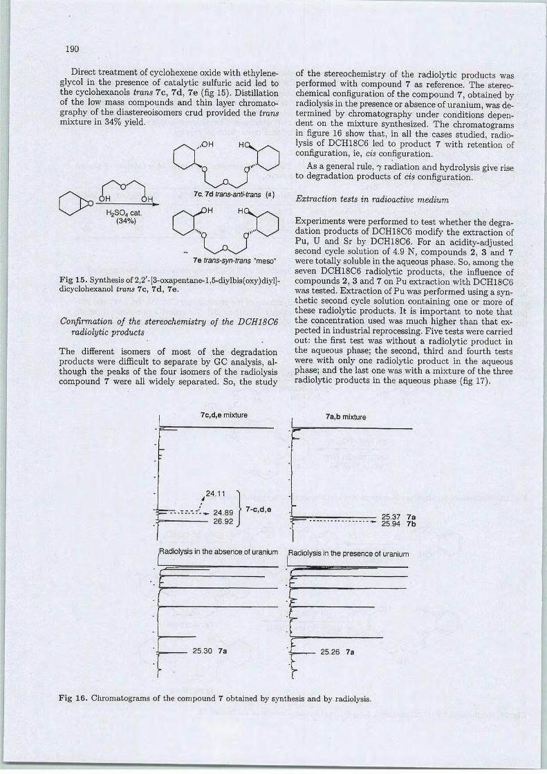
190
Direct treatment of cyclohexene oxide with ethylene-glycol in the présence of catalytic sulfuric acid led tothe cyclohexanols trans 7c, 7d, 7e (fig 15). Distillationof the low mass compounds and thin layer chromatography of the diastereoisomers crud provided the transmixture in 34% yield.
OH OH— i_
H2S04 cat.(34%)
7c, 7d trans-anti-trans (*)
)H HC
7e trans-syn-trans "meso"
Fig 15. Synthesis of 2,2'-[3-oxapentane-l,5-diylbis(oxy)diyl]-dicyclohexanol trans 7c, 7d, 7e.
Confirmation of the stereochemistry of the DCH18C6radiolytic products
The différent isomers of most of the dégradationproducts were difficult to separate by GC analysis, although the peaks of the four isomers of the radiolysiscompound 7 were ail widely separated. So, the study
7c,d,e mixture
.24.11 ï
--'-*. 24.89
26.92
• 7-c,d,e
of the stereochemistry of the radiolytic products wasperformed with compound 7 as référence. The stereochemical configuration ofthe compound 7, obtained byradiolysisin the présence or absence of uranium, was determined by chromatography under conditions dépendent on the mixture synthesized. The chromatogramsin figure 16 show that, in ail the cases studied, radiolysis of DCH18C6 led to product 7 with rétention ofconfiguration, ie, cis configuration.
As a gênerai rule, 7 radiationand hydrolysis give riseto dégradation products of cis configuration.
Extraction tests in radioactive médium
Experimentswere performed to test whether the dégradation products of DCH18C6 modify the extraction ofPu, U and Sr by DCH18C6. For an acidity-adjustedsecond cycle solution of 4.9 N, compounds 2, 3 and 7weretotally solublein the aqueous phase. So, amongtheseven DCH18C6 radiolytic products, the influence ofcompounds 2, 3 and 7 on Pu extraction with DCH18G6was tested. Extraction of Pu was performed usinga synthetic second cycle solution containing one or more ofthèse radiolytic products. It is important to note thatthe concentration used was much higher than that expected in industrial reprocessing. Five tests were carriedout: the first test was without a radiolytic product inthe aqueous phase; the second, third and fourth testswere with only one radiolytic product in the aqueousphase; and the last one was with a mixture of the threeradiolytic products in the aqueous phase (fig 17).
7a,b mixture
r25.37 7a25.94 7b
Radiolysis in theabsenceofuranium .Radiolysis in the présence ofuranium
r
25.30 7a 25.26 7a
Fig 16. Chromatograms of the compound 7 obtained by synthesis and by radiolysis.

191
15 mL DCH18C6
(0,134 molL1 CHCI3)
15mLof 2"d cycle solution(Pu = 1 g f1 U = 1 g L"1 Sr = 4.7 pg L"1)
+ M mole of radiolysis product
extraction
aqueous phase
analysisYspectrometry[î countage (Sr)u spectrometry
VmL
H20
organic phase
analysis -*-Yspectrometry
calcination j
V mL organic phase
stripping
-*. analysisYspectrometry
aqueous phase
analysis(i countage (Sr)u spectrometry
analysisYspectrometryp countage (Sr)u spectrometry
Fig 17. Procédure of Pu extraction by DCH18C6 in the présence of its radiolytic products.
Cpd2 Cpd 3 Cpd 4 without Cpd
Compound in the aqueous phase
[Cpd 2] = [Cpd 3] = [Cpd4] = [Cpd 2,3,4] = 7 10-3 mol
Fig 18. Effect of the radiolytic products of DCH18C6 on Pu, U and Sr extraction.
Cpd 2,3,4
Effect of the radiolytic products on the extraction of Pu,U and Sr by DCH18C6
Figure 18 shows the effect of the DCH18C6 radiolyticproducts on the complexing properties of DCH18C6in relation to Pu, U and Sr. A 20% decrease in theefficiency of Pu extraction was observed in the présenceof one radiolytic product in the aqueous phase. In viewof thèse results, two hypothèses can be put forward:(1) réduction of Pu from the IV to the III valencestate, or (2) Pu IV rétention and précipitation in theaqueousphase, by the DCH18C6 radiolytic products. Srextraction capacity by the DCH18C6 was not modifiedby the présence of the synthesized radiolytic productsin the aqueous phase. DCH18C6 radiolytic products
hâve no effect on the concentration of 7 emitters in theaqueous phase.
As in the absence of dégradation compounds, thecomplexing properties of DCH18C6 are not modifiedbylow or médium concentrations of the three radiolyticproducts in the aqueous médium. So, considering thelow radiochemical yields observed for DCH18C6 radiolysis [1], the macrocycle radiolytic products do notperturb the extraction process.
Influence of a radiolytic product in the aqueous phaseon Pu IV valence and concentration
In order to explain the influenceofthe DCH18C6 radiolytic products on Pu extraction, a radioactive second-
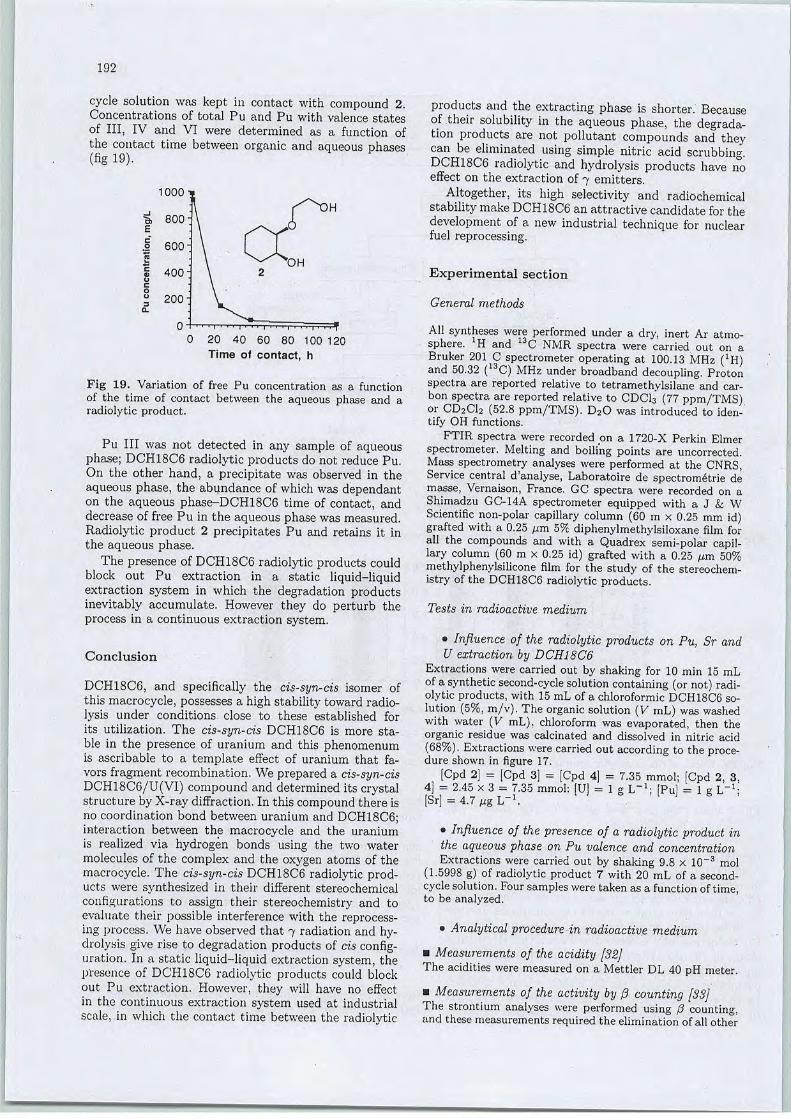
192
cycle solution was kept in contact with compound 2.Concentrations of total Pu and Pu with valence statesof III, IV and VI were determined as a function ofthe contact time between organic and aqueous phases(% 19).
20 40 60 80 100 120
Time of contact, h
Fig 19. Variation of free Pu concentration as a functionof the time of contact between the aqueous phase and aradiolytic product.
Pu III was not detected in any sample of aqueousphase; DCH18C6 radiolytic products do not reduce Pu.On the other hand, a precipitate was observed in theaqueous phase, the abundance of which was dépendanton the aqueous phase-DCH18C6 time of contact, anddecrease of free Pu in the aqueous phase was measured.Radiolytic product 2 précipitâtes Pu and retains it inthe aqueous phase.
The présence of DCH18C6 radiolytic products couldblock out Pu extraction in a static liquid-liquidextraction System in which the dégradation productsinevitably accumulate. However they do perturb theprocess in a continuous extraction system.
Conclusion
DCH18C6, and specifically the cis-syn-cis isomer ofthis macrocycle, possesses a high stability toward radiolysis under conditions, close to thèse established forits utilization. The cis-syn-cis DCH18C6 is more stable in the présence of uranium and this phenomenumis ascribable to a template effect of uranium that fa-vors fragment recombination. We prepared a cis-syn-cisDCH18C6/U(VI) compound and determined its crystalstructure by X-ray diffraction. In this compound there isno coordination bond between uranium and DCH18C6;interaction between the macrocycle and the uraniumis realized via hydrogen bonds using the two watermolécules of the complex and the oxygen atoms of themacrocycle. The cis-syn-cis DCH18C6 radiolytic products were synthesized in their différent stereochemicalconfigurations to assign their stereochemistry and toevaluate their possible interférence with the reprocessing process. We hâve observed that 7 radiation and hydrolysis give rise to dégradation products of cis configuration. In a static liquid-liquid extraction System, theprésence of DCH18C6 radiolytic products could blockout Pu extraction. However, they will hâve no effectin the continuous extraction System used at industrialscale, in which the contact time between the radiolytic
products and the extracting phase is shorter. Becauseof their solubility in the aqueous phase, the dégradation products are not pollutant compounds and theycan be eliminated using simple nitric acid scrubbing.DCH18C6 radiolytic and hydrolysis products hâve noeffect on the extraction of 7 emitters.
Altogether, its high selectivity and radiochemicalstability make DCH18C6 an attractive candidate for thedevelopment of a new industrial technique for nuclearfuel reprocessing.
Expérimental section
General methods
AH synthèses were performed under a dry, inert Ar atmosphère. :H and 13C NMR spectra were carried out on aBruker 201 C spectrometer operating at 100.13 MHz (1H)and 50.32 (13C) MHz under broadband decoupling. Protonspectra are reported relative to tetramethylsilane and car-bon spectra are reported relative to CDCI3 (77 ppm/TMS)or CD2CI2 (52.8 ppm/TMS). D20 was introduced to iden-tify OH functions.
FTIR spectra were recorded on a 1720-X Perkin Elmerspectrometer. Melting and boili'ng points are uncorrected.Mass spectrometry analyses were performed at the CNRS,Service central d'analyse, Laboratoire de spectrometrie demasse, Vernaison, France. GC spectra were recorded on aShimadzu GC-14A spectrometer equipped with a J & WScientific non-polar capillary column (60 m x 0.25 mm id)grafted with a 0.25 pm 5% diphenylmethylsiloxane film forail the compounds and with a Quadrex semi-polar capillary column (60 m x 0.25 id) grafted with a 0.25 um 50%methylphenylsilicone film for the study of the stereochemistry of the DCH18C6 radiolytic products.
Tests in radioactive médium
• Influence of the radiolytic products on Pu, Sr andU extraction by DCH18C6
Extractions were carried out by shaking for 10 min 15 mLofa synthetic second-cycle solution containing (or not) radiolytic products, with 15 mL of a chloroformic DCH18C6 solution (5%, m/v). Theorganic solution (V mL) was washedwith water (V mL), chloroform was evaporated, then theorganic residue was calcinated and dissolved in nitric acid(68%). Extractions were carried out according to the procédure shown in figure 17.
[Cpd 2] = [Cpd 3] = [Cpd 4] = 7.35 mmol; [Cpd 2, 3,4] = 2.45 x 3 = 7.35 mmol: [U] = 1 g L"1; [Pu] = 1 g L"1;[Sr] - 4.7 «g L"\
• Influence of the présence of a radiolytic product inthe aqueous phase on Pu valence and concentrationExtractions were carried out by shaking 9.8 x 10~3 mol
(1.5998 g) of radiolytic product 7 with 20 mL of a second-cycle solution. Four samples were taken as a functionoftime,to be analyzed.
• Analytical procedurein radioactive médium
mMeasurements of the acidity [32]The acidities were measured on a Mettler DL 40 pH meter.
• Measurements of the activity by /?• counting [33]The strontium analyses were performed using $ counting,and thèse measurements required the élimination of ail other
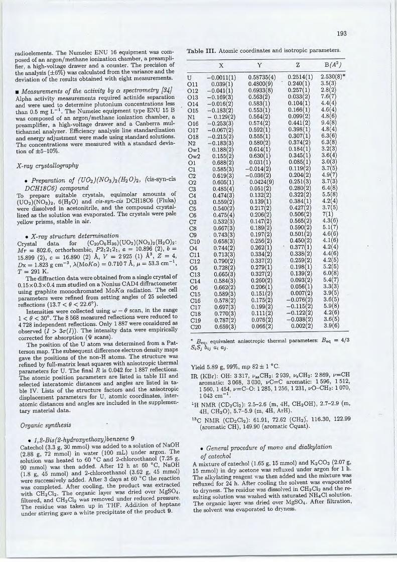
radioéléments. The Numelec ENU 16 equipment was composed ofan argon/méthane ionization chamber, a preampli-fier, a high-voltage drawer and a counter. The précision ofthe analysis (±6%) wascalculated fromthe variance and thedéviation of the results obtained with eight measurements.
• Measurements of the activity by a spectrometry [3j]Alpha activity measurements required actinide séparationand were used to détermine plutonium concentrations lessthan 0.5 mg L-1. The Numelec equipment type ENU 15 Bwas composed of an argon/methane ionization chamber, apreamplifier, a high-voltage drawer and a Canberra mul-tichannel analyzer. Efficiency analysis line standardizationand energy adjustment were made usingstandard solutions.The concentrations were measured with a standard déviation of ±5-10%.
X-ray crystallography
• Préparation of (U02)(N03)2(H20)2, (cis-syn-cisDCH18C6) compound
To prépare suitable crystals, equimolar amounts of(U02)(N03)2, 6(H20) and cis-syn-cis DCH18C6 (Fluka)were dissolved in acetonitrile, and the compound crystal-lized as the solution was evaporated. The crystals were paleyellow prisms, stable in air.
• X-ray structure déterminationCrystal data for (C2o06H36)(U02)(N03)2(H20)2:Mr = 802.6, orthorhombic, P2i2i2i, a = 10.896 (2), b =15.899 (2), c = 16.890 (2) Â, V = 2925 (1) Â3, Z - 4,Dx = 1.823 gcm-3, \{UoKa) = 0.710 7A, p = 53.3 cm \T = 291 K.
The diffraction data were obtained from a single crystal of0.15x0.3x0.4 mm studied on a Nonius CAD4 diffractometerusing graphite monochromated MoKa radiation. The cellparameters were refined from setting angles of 25 selectedreflections (13.7 < 6 < 22.6°).
Intensifies were collected using ui - 9 scan, in the range1 < 0 < 30°. The 8 568measured reflections were reducedto4 728 independent reflections. Only 1887 were considered asobserved (I > 3cr(J)). The intensity data were empiricallycorrected for absorption ("J/ scans).
The position of the U atom was determined from a Pat-terson map. The subséquentdifférence électrondensitymapsgave the positions of the non-H atoms. The structure wasrefined by full-rnatrix least squares with anisotropic thermalparameters for U. The final R is 0.042 for 1887 reflections.The atomic position parameters are listed in table III andselected interatomic distances and angles are listed in table IV. Lists of the structure factors and the anisotropicdisplacement parameters for U, atomic coordinates, interatomic distances and angles are included in the supplemen-tary material data.
Organic synthesis
• l,2-Bis(2-hydroxyethoxy)benzene 9Catéchol (3.3 g, 30 mmol) was added toa solution of NaOH(2.88 g, 72 mmol) in water (100 mL) under argon. Thesolution was heated to 60 °C and 2-chloroethanol (7.25 g,90 mmol) was then added. After 12 h at 60 °C, NaOH(18 g 45 mmol) and 2-chloroethanol (3.62 g, 45 mmol)were successively added. After 3 days at 60 °C the reactionwas completed. After cooling, the product was extractedwith CH2C12. The organic layer was dried over MgS04,filtered, and CH2C12 was removed under reduced pressure.The residue was taken up in THF. Addition of heptaneunder stirring gave a white precipitate of the product 9.
193
Table III. Atomic coordinates and isotropic parameters.
X Y B(A2)
U -0.0011(1) 0.58735(4) 0.2514(1) 2.530(8)*011 0.039(1) 0.4800(9) ' 0.240(1) 3.5(3)012 -0.041(1) 0.6933(8) 0.257(1) 2.8(2)013 -0.169(3) 0.563(2) 0.033(2) 7.6(7)014 -0.016(2) 0.583(1) 0.104(1) 4.4(4)015 -0.183(2) 0.553(1) 0.166(1) 4.6(4) 1NI - 0.129(2) 0.564(2) 0.099(2) 4.8(6)016 -0.253(3) 0.574(2) 0.441(2) 9.4(8)017 -0.067(2) 0.592(1) 0.398(1) 4.8(4) |018 -0.215(2) 0.555(1) 0.307(1) 6.3(6) }.N2 -0.183(3) 0.580(2) 0.374(2) 6.3(8)Owl 0.188(2) 0.614(1) 0.184(1) 3.2(3)Ow2 0.155(2) 0.630(1) 0.345(1) 3.6(4)Ol 0.688(2) 0.031(1) 0.085(1) 3.0(3)Cl 0.585(3) -0.014(2) 0.119(2) 3.7(5)C2 0.619(3) -0.036(2) 0.204(2) 4.9(7)02 0.605(1) 0.0424(9) 0.251(3) 3.7(3)C3 0.485(4) 0.051(2) 0.280(2) 6.4(8)C4 0.474(3) 0.132(2) 0.322(2) 5.5(8)03 0.559(2) 0.139(1) 0.384(1) 4.2(4)C5 0.540(2) 0.217(2) 0.427(2) 3.7(5)C6 0.475(4) 0.206(2) 0.506(2) 7(1)C7 0.532(3) 0.147(2) 0.565(2) 4.3(6)
C8 0.667(3) 0.189(2) 0.590(2) 5.1(7)C9 0.743(3) 0.197(2) 0.501(2) 4.6(6)C10 0.658(3) 0.256(2) 0.450(2) 4.1(6)04 0.744(2) 0.262(1) • 0.377(1) 4.2(4)
Cil 0.713(3) 0.334(2) 0.338(2) 4.4(6)C12 0.790(2) 0.337(2) 0.259(2) 4.2(5) ,05 0.728(2) 0.279(1) 0.198(1) 5.2(5)C13 0.665(3) 0.327(2) 0.139(2) 6.0(8)C14 0.584(3) 0.260(2) 0.093(2) 5.4(7)06 0.662(2) 0.206(1) 0.056(1) 3.3(3)C15 0.589(3) 0.151(2) 0.007(2) 3.9(5)C16 0.578(2) 0.175(2) -0.076(2) 3.6(5)C17 0.697(3) 0.199(2) -0.115(2) 5.9(8)C18 0.770(3) 0.111(2) -0.122(2) 4.2(6)
C19 0.787(2) 0.076(2) -0.038(2) 3.6(5)C20 0.659(3) 0.066(2) 0.002(2) 3.9(6)
* -Beq, équivalent anisotropic thermal parameters: Beq = 4/3OjOj Oij (Xi Qij.
Yield 5.89 g, 99%, mp 82 ± 1 °C.IR (KBr): OH: 3317, ^SCH2: 2939, i/sCH2: 2869, i/=CH
aromatic: 3 068, 3 030, i/C=C aromatic: 1 596, 1512,1560, 1454, i/=C-0: 1285, 1 256, 1 231, iX3-CH2: 1070,1043 cm"1.
XH NMR (CD2C12): 2.5-2.6 (m, 4H, CH2OH), 2.7-2.9 (m,4H, CH20), 5.7-5.9 (m, 4H, ArH).
13C NMR (CD2C12): 61.91, 72.62 (CH2)', 116.30, 122.99(aromatic CH), 149.90 (aromatic Cquat).
• General procédure of mono and dialkylationof catéchol
Amixture ofcatéchol (1.65 g, 15 mmol) and K2CO3 (2.07 g,15 mmol) in dry acétone was refluxed under argon for 1 h.The alkylating reagent was then added and the mixture wasrefluxed for 24 h. After cooling the solvent was evaporatedto dryness. The residue was dissolved in CH2C12 and theresulting solution was washed with saturated NH4C1 solution.The organic layer was dried over MgS04. After filtration,the solvent was evaporated to dryness.
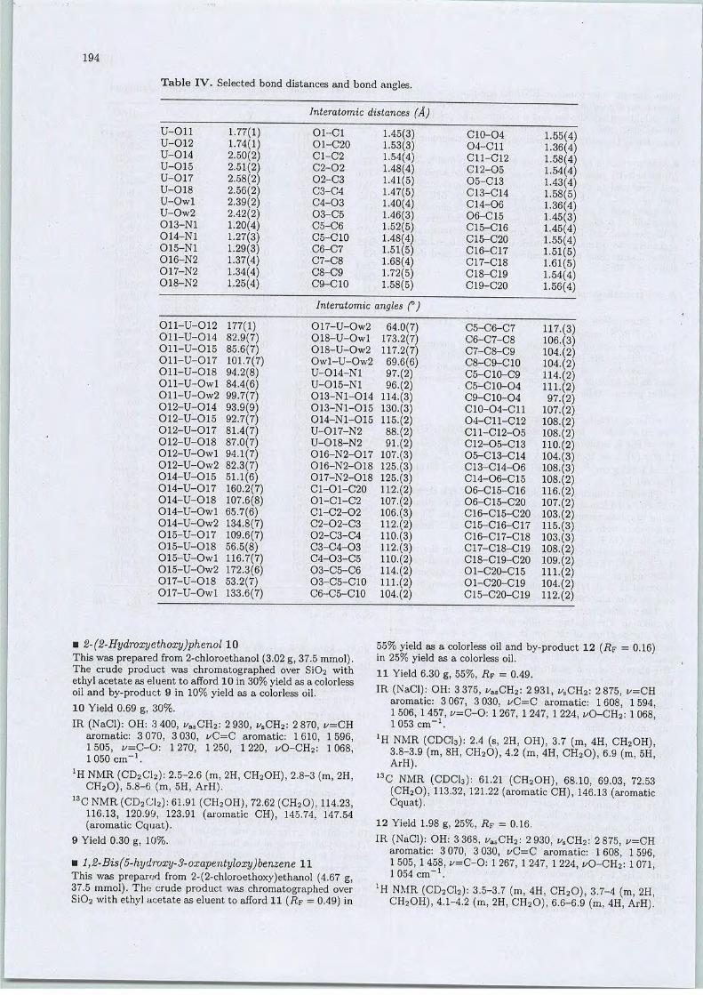
194
Table IV. Selected bond distances and bond angles.
U-Oll
U-012
U-014
U-015
U-017
U-018
U-Owl
U-0w2013-N1
014-N1
015-N1
016-N2
017-N2018-N2
Oll-U-
Oll-U-Oll-U-
Oll-U-Oll-U-
Oll-U-
Oll-U-
012-U-012-U-
012-U-
012-U-
012-U-
012-U-
014-U-
014-U-
014-U-
014-U-
014-U-
015-U-
015-U-015-U-
015-U-
017-U-
017-U-
-012
-014
-Ol5•017
-018
-Owl
Ow2
•014
015
•017
018
Owl
Ow2
015
017018
Owl
Ow2
017
018
Owl
Ow2
018
Owl
1.77(1)1.74(1)2.50(2)2.51(2)2.58(2)2.56(2)2.39(2)2.42(2)1.20(4)1.27(3)1.29(3)1.37(4)1.34(4)1.25(4)
177(1)82.9(7)85.6(7)101.7(7)94.2(8)84.4(6)99.7(7)93.9(9)92.7(7)81.4(7)87.0(7)94.1(7)82.3(7)51.1(6)160.2(7)107.6(8)65.7(6)134.8(7)109.6(7)56.5(8)116.7(7)172.3(6)53.2(7)133.6(7)
Interatomic distances (Â)
Ol-Cl
O1-C20
C1-C2
C2-02
02-C3
C3-C4
C4-03
03-C5
C5-C6
C5-C10
C6-C7
C7-C8
C8-C9
C9-C10
1.45(3)1.53(3)1.54(4)1.48(4)1.41(5)1.47(5)1.40(4)1.46(3)1.52(5)1.48(4)1.51(5)1.68(4)1.72(5)1.58(5)
Interatomic angles (°)
017-U-Ow2
018-U-Owl
018-U-Ow2
Owl-U-Ow2
U-014-N1
U-015-N1
013-N1-014
013-N1-015
014-N1-015
U-017-N2
U-018-N2
016-N2-017
016-N2-018017-N2-018
C1-O1-C2001-C1-C2
C1-C2-02
C2-02-C302-C3-C4
C3-C4-03C4-03-C5
03-C5-C6
O3-C5-C10
C6-C5-C10
64.0(7)173.2(7)117.2(7)69.6(6)97.(2)96.(2)
114.(3)130.(3)115.(2)88.(2)91.(2)
107.(3)125.(3)125.(3)112.(2)107.(2)106.(3)112.(2)110.(3)112.(3)110.(2)114.(2)111.(2)104.(2)
C10-O404-C11
C11-C12
G12-0505-C13C13-C14Cl4-0606-C15
C15-C16C15-C20
C16-C17
C17-C18
C18-C19
C19-C20
C5-C6-C7
C6-C7-C8
C7-C8-C9C8-C9-C10C5-C10-C9
C5-C10-O4
C9-C10-O4
C10-O4-C11
04-C11-C12
C11-C12-05C12-O5-01305-C13-C14
C13-C14-06C14-06-C15
06-C15-C16O6-C15-C20C16-C15-C20
C15-C16-C17C16-C17-C18
C17-C18-C19
C18-C19-C20O1-C20-C15O1-C20-C19
C15-C20-C19
1.55(4)1.36(4)1.58(4)1.54(4)1.43(4)1.58(5)1.36(4)1.45(3)1.45(4)1.55(4)1.51(5)1.61(5)1.54(4)1.56(4)
117.(3106.(3104.(2104.(2114.(2111.(297.(2
107.(2108.(2108.(2110.(2104.(3108.(3108.(2116.(2107.(2103.(2115.(3103.(3108.(2109.(2111.(2104.(2112.(2
• 2-(2-Hydroxyethoxy)phenol 10This was prepared from 2-chloroethanol (3.02g, 37.5 mmol).The crude product was chromatographed over Si02 withethyl acétate as eluent to afford 10 in 30% yield as a colorlessoil and by-product 9 in 10% yield as a colorless oil.
10 Yield 0.69 g, 30%.
IR (NaCl): OH: 3 400, z/asCH2: 2 930, fsCH2: 2 870, i/=CHaromatic: 3 070, 3 030, i/C=C aromatic: 1610, 1596,1505, f=C-0: 1270-, 1250, 1220, i/0-CH2: 1068,1050 cm-1.
lB. NMR (CD2C12): 2.5-2.6 (m, 2H, CH2OH), 2.8-3 (m, 2H,CH20), 5.8-6 (m, 5H, ArH).
13C NMR (CD2C12): 61.91 (CH2OH), 72.62 (CH20), 114.23,116.13, 120.99, 123.91 (aromatic CH), 145.74, 147.54(aromatic Cquat).
9 Yield 0.30 g, 10%.
• l,2-Bis(5-hydroxy-3-oxapentyloxy)benzene 11This was prepared from 2-(2-chloroethoxy)ethanol (4.67 g,37.5 mmol). The crude product was chromatographed overSi02 with ethyl acétate as eluent to afford11 (RF = 0.49) in
55% yield as a colorless oil and by-product 12 (RF - 0.16)in 25% yield as a colorless oil.
11 Yield 6.30 g, 55%, RF = 0.49.
IR (NaCl): OH: 3 375, ^asCH2: 2 931, ^SCH2: 2 875, z^=CHaromatic: 3 067, 3 030, i/C=C aromatic: 1608, 1594,1 506, 1 457, v=C-0: 1 267, 1 247, 1 224, i/0-CH2: 1 068,1053 cm-1.
JH NMR (CDC13): 2.4 (s, 2H, OH), 3.7 (m, 4H, CH2OH),3.8-3.9 (m, 8H, CH20), 4.2 (m, 4H, CH20), 6.9 (m, 5H,ArH). -
13C NMR (CDCI3): 61.21 (CH2OH), 68.10, 69.03, 72.53(CH20), 113.32, 121.22 (aromatic CH), 146.13 (aromaticCquat),
12 Yield 1.98 g, 25%, RF = 0.16.
IR (NaCl): OH: 3 368, ^asCH2: 2 930, i/sCH2: 2 875, i/=CHaromatic: 3 070, 3 030, i/C=C aromatic: 1608, 1596,1 505, 1458, i/=C-0: 1 267, 1 247, 1 224, ^0-CH2: 1071,1054 cm-1.
:H NMR (CD2C12): 3.5-3.7 (m, 4H, CH20), 3.7-4 (m, 2H,CH2OH), 4.1-4.2 (m, 2H, CH20), 6.6-6.9 (m, 4H, ArH).

13C NMR (CD2C12): 61.73 CH2OH, 68.81, 69.83, 72.97(CH20), 114.19, 116.14, 120.19, 122.93 (aromatic CH),146.26, 147.25 (aromatic Cquat).
• l-(5-Hydroxy-3-oxapentyloxy)-2- (2-hydroxyethoxy)-benzène 13
A mixture of 12 (4.70 g, 23.64 mmol) and K2C03 (6.54 g,47.29 mmol) in dry acétone was refluxed under argon for 1 h.2-Chloroethanol (4.76 g, 59.1 mmol) was then added and themixture was refluxed for 24 h. After cooling the solvent wasevaporated to dryness. The residue was dissolved in CH2C12and the resulting solution was washed with saturated NH4CIsolution. The organic layer was dried over MgSO<t. Afterfiltration, the solvent was evaporated to dryness. The crudeproduct was chromatographed over Si02 with ethyl acétateas eluent to afford 13 in 31% yield.
13 Yield 1.77 g, 31%.IR (NaCl): OH: 3 317, ^asCH2: 2 941, i/sCH2: 2879, t>=CH
aromatic: 3 068, 3 030, fC=C aromatic: 1608, 1595,1 506, 1 456, i/=C-0: 1 255, 1 247, 1 216, ^0-CH2: 1 076,1050 cm-1.
lK NMR (CD2C12): (m, H, CH2OH), (m, H, CH20), (m, H,ArH).
13C NMR (CD2C12): 60.71, 61.47 (CH2OH), 68.30, 69.22,71.52, 72.73 (CH20), 112.86, 114.23, 121.55, 121.66 (aromatic CH), 145.74, 147.54 (aromatic Cquat).
• General procédure for the réduction of compounds9, 10, 11, 12 and 13
The réduction was performed by adding 10 mmol of eachcompound to a suspension of rhodium on strontium titanatecatalyst (0.5%), oxidized 48 h in air, (6.17 g, 0.30 mmol ofRh) in MeOH/CHCls (1:1, v/v) mixture. The réduction wascompleted in 12 h under 1 atm H2 at room températureunder stirring. After filtration, the solvent was removedunder reduced pressure.
• l,2-Bis(2-hydroxyethoxy)cyclohexane 3This was prepared from compound 9 and obtained as acolorless oil.
3 Yield 2 g, 98%.MS (CI, CH4): m/z 99; 143; 205 (M + H+); 206 (M + 2H+).MS (El, 70 eV): m/z (%) 81 (100); 99 (53); 113 (11); 143
(8); 157 (2); 173 (4); 205 (3, [M + H]+ ).IR (NaCl): OH: 3 383, ^asCH2: 2 935, i/sCH2: 2 862, <5SCH2:
1457, i/asCH2OCH2: 1100, 1071, i/CH cyclic: 989,i/sCH2OCH2: 900-800 cm-1.
lïï NMR (CD2C12): 1.1-1.4 (m, 4H, CH2), 1.4-1.65 (m, 4H,CH2), 1.65-2.10 (m, 4H, CH2), 3.4-3.5 (m, 4H, CH2OH),3.6-3.8 (m, 6H, CH20 and CHO).
13C NMR (CD2C12): 23.79, 29.57 (CH2), 63.66 (CH2OH),72.31 (CH20), 79.8 (CHO).
• 2-(2-Hydroxyethoxy)cyclohexanol 2This was prepared from compound 10 and obtained as acolorless oil.
2 Yield 1.57 g, 98%.MS (CI, CH4) m/z99; 143; 161 (M + H+); 162 (M + 2H+).MS (El, 70eV) m/z 81 (100); 99 (85); 116 (3); 130 (4); 143
(12); 161 (2, [M + H]+ ).IR (NaCl): OH: 3 400, i/asCH2: 2993, ^SCH2: 2862, 6SCH2:
1458, i/asCH2OCH2: 1 126, 1080,.1 040, i^CH cyclic: 933,i/sCH2OCH2: 900-800 cm-1.
lH NMR (CDCI3): 1.2-1.4 (m, 4H, CH2), 1.6-1.7 (m, 2H,CH2), 2-2.1 (m, 2H, CH2), 3.1-3.2 (m, IH, CH), 3.4-3.5
195
(m, 2H, CH2), 3.8-4 (m, 3H, CHO and CH20), 4.3-4.4(s, 2H, OH).
13C NMR (CD2C12): 24.17, 24.27, 29.65, 32.75 (CH2), 61.84(CH2OH), 70.18 (CHOH), 73.71 (CH20), 84.05 (CHO).
• i;2-Bis-(5-hydroxy-3-oxapentyloxy)cyclohexane 4This was prepared from compound 12 and obtained as acolorless oil.
4 Yield 2 g, 98%.MS (CI, CH4) m/z 99; 127; 188; 205 (M + H+); 206
(M + 2H+).MS (El, 70 eV) m/z (%) 45 (44); 81 (100); 89 (16); 99 (77);
115 (2); 159 (7); 187 (3); 205 (4, [M + H]+ )..IR (NaCl): OH: 3 402, i/asCH2: 2 993,VSCH2: 2 862, <5SCH2:
1 452, i/asCH2OCH2: 1124, 1 099, 1 041, i^CH cyclic: 940,i/sCH2OCH2: 900-800 cm-1.
:H NMR (CDCI3): 1.05-1.4 (m, 4H, CH2), 1.5-1.8 (m, 2H,CH2), 1.8-2.1 (m, 2H, CH2), 3-3.2 (m, IH, CH), 3.3-3.5(m, IH, CH), 3.5-4 (m, 8H, CH20 and CH2OH).
13C NMR (CDCI3): 24.02, 24.29, 29.73, 32.38 (CH2), 61.32,68.37 (CH20), 70.73 (CH2OH), 72.73 (CH20), 73.59(CHOH), 84.54 (CH).
• l-(5-Hydroxy-3-oxapentyloxy)-2- (2-hydroxyethoxy)-cyclohexane 5This was prepared from compound 13 and obtained as acolorless oil.
5 Yield 1.65 g, 97%.MS'(CI, CH4) m/z 99; 143; 187; 249 (M + H+); 250
(M + 2H+); 251 (M + 3H+).MS (El, 70 eV) m/z (%) 45 (100); 89 (22); 99 (56); 114 (13);
127 (2); 143 (15); 156 (3).IR (NaCl): OH: 3 356, i/asCH2: 2 936, ^SCH2: 2 872, <5SCH2:
1 457, i/asCH2OCH2: 1117, 1 082, 1 057, i/CH cyclic: 990,i/sCH2OCH2: 900-800 cm-1.
XH NMR (CD2C12): 1.5-1.7 (m, 8H, CH2), 2.6 (s, 2H, OH),3.7-4 (m, 12H, CH2 and CH).
13C NMR (CD2C12): 21.75, 23.55, 27.30, 28.77 (CH2), 64.52(CH2OH), 70.95, 71.21, 72.99, 73.45 (CH20), 77.89, 79.58(CHO).
• General synthesis 0/trans compoundsA solution of cyclohexene oxide (4.9 g, 50 mmol) in glycolwas stirred at 0 °C. Concentrated sulfuric acid (4 drops)was added and then the solution was slowly heated to95 °C and stirred for 1 h at this température. After coolingCH2C12 was added. The organic layer was washed with asaturated NaHCOs solution and with water. The organiclayer was dried over MgSÛ4 and the solvent was removedunder reduced pressure.
• 2-(2-Hydroxyethoxy)cyclohexanol 2 transThis was prepared from ethyleneglycol (9.31 g, 150 mmol)and isolated by distillation (bp 105 °C at 10- mbar).2 Yield 3.36 g, 42%.
• 2-(5-Hydroxy-3-oxapentyloxy)cyclohexanol 4 transThis was prepared from diethyleneglycol (15.92 g, 150 mmol)and isolated by distillation (bp 115 °C at 10-3 mbar).4 Yield 4.39 g, 43%.
• 2,2'-[3-Oxapentane-l,5-diylbis(oxy)diyl]dicyclohexanol7 trans
. This was prepared from ethyleneglycol (3.72 g, 60 mmol)and isolated by thin layer chromatography with Et20 aseluent).7 Yield 2.57 g, 34%.

196
• 2,2'-[3-Oxapentane-l ,5-diylbis(oxy)diyl]dianisole 14Guaiacol (2-methoxyphenol) (111.73 g, 9 mol) wasadded toa solutionof NaOH (43.2 g, 10.8 mol) in water (600 mL).Thesolution was heated to 60 °C and bis-(2-chloroethyl)etherwas then added. After 48 h at 60 °C, the reaction wascompleted. After cooling, CH2C12 was added. The organiclayer was washed with a NaOH solution (10%) and thenwith water. The organic layer was dried over MgS04 andconcentrated. Addition of Et20 gave the product as a whitepowder.
14 Yield 57.3 g, 60%, mp"= 81 ± 1 °C.IR (KBr): ^sCH2: 2 914, i/asCH3: 2 933, i^CH2: 2877,
fsCH3: 2 891, i/sOCH3: 2 802, i/=CH aromatic: 3 060,3 029, i/C=C aromatic: 1 607,1 594, 1 508, 1 455, ^=C-0:1 258, 1 244, 1 227, i/0-CH2: 1 070, 1 056 cm-1.
XH NMR (CD2C12): 3.7-4 (m, 8H, CH20), 4.1-4.2 (m, 6H,OCH3), 6.8-7 (m, 8H, ArH).
13C NMR (CD2C12): 56.09 (CH3), 68.80, 70.24 (CH20),112.43, 114.10, 121.10, 121.71 (aromatic CH), 148.76,150.09 (aromatic Cquat).
• 2,2'-[3-Oxapentane-l,5-diylbis(oxy)diyl]bis-phenol15
A solution of 14 (17.47g, 54.9 mmol) in 75 mL of CHCI3 wasstirred under Ar at room température and iodotrimethylsi-lane (35.15 g, 175 mmol) was added. After the reaction wascompleted (typically 12 h) a MeOH/H20 mixture (50:50,v/v) was added. Saturated NaHSOs solution (10 mL) wasadded and then CH2C12. The organic layer was concentratedunder vacuum. Addition of Et20 gave the product as a whitepowder.
15 Yield 15.60 g, 97%.
IR (KBr): OH: 3 317, i/asCH2: 2 945, i/asCH3: 2 933, i/sCH2:2 885, fsCH3: 2 891, i/sOCH3: 2 802, i/=CH aromatic:3 070, 3 048, i/C=C aromatic: 1608, 1597, 1504, 1461,iv=C-0: 1 268, 1 247, 1 224, i^O-CH2: 1 064, 1 047 cm-1.
lH NMR (CD2CI2): 2.6-2.8 (m, 4H, 0H2O), 3.0-3.2 (m, 4H,CH2O), 5.6-6 (m, 8H, ArH), 6.3 (s, 2H, OH).
13C NMR (CD2CI2): 70.59, 71 (CH20), 116.93, 117.06,121.17, 124.4 (aromatic CH), 147.04, 148.62 (aromaticCquat).
• 2,2'-[3-Oxapentane-l,5-diylbis(oxy)diyl]dicyclohexanol7 cis
A mixture of 15 (1.45 g, 5 mmol) and rhodium on carbon(1 g, 0.48 mmol of Rh) in MeOH (15 mL) was placed in anautoclave. The réduction was completed in 2 h under 50 atmH2 at room température under stirring. After filtration, thecrude product was purified by thin layer chromatographywith Et20 as eluent.
7 Yield 0.45 g, 30%.
MS (CI, CH4) m/z 99; 127; 143; 187; 205; 303 (M + H+);304 (M + 2H+); 305 (M + 3H+).
MS (El, 70 eV) rn/z (%) 45 (74); 81 (88); 89 (16); 99 (100);143 (9); 187(8); 205 (9); 156 (3).
IR (NaCl): OH: 3 446, j/asCH2: 2 935, i/6CH2: 2 863, &CH2:1 458, ^asCH2OCH2: 1 133, 1 096, 1 024 t/CH cyclic: 990,i/sCH2OCH2: 900-800 cm-1.
XH NMR (CD2C12): 0.9-1.3 (m, 4H, CH2), 1.3-1.6 (m, 8H,CH2), 1.6-1.8 (m, 4H, CH2), 3.2-3.3 (m, 2H, CHO),3.4-3.7 (m, 8H, CH2), 3.7-3.9 (m, 2H, CHOH), 4-4.1(s, 2H, OH).
13C NMR (CD2C12): 21.80, 21.87, 22.71, 27.47, 27.67, 30.79,30.86 (CH2), 67.63, 67.70 (CH20), 68.35, 68.57 (CH20),70.96, 71.19 (CHOH), 79.84, 79.96 (CHO).
Acknowledgment
The authors are grateful to Graham Feast for helpful discussions.
Supplementary material available
Supplementary material data hâve been deposited with theBritish Library, Document Supply Center at Boston Spa,Wetherby, West Yorkshire, LS23 7BQ, UK assupplementarypublication N° SUP = 90406 (45 pp) and are available onrequest from the Documentary Supply Center.
Références
1 Draye M, Chomel R, Doutreluingne P, Guy A, Foos J,Lemaire M, J Radioanal Nucl Chem, Lett (1993) 175,55
2 Orth DA, Wolcott T, Nucl Sci Eng (1963) 17, 5933 Isaac M, CEA Report 2349 (1963)4 Schuler RG, Bowers CB, Smith JE, VanBrunt V, Davis
MW, SolvExtr Ion Exch (1985) 3, 5675 Wen-Ji W, Quing S, Bozhong C, J Radioanal Nucl
Chem (1986) 98, 116 Vijayvergiya V, Moorkerjee A, J Surf Sci Technol
(1991) 7, 3517 Dozol M, In: New Séparation Chemistry Techniques
for Radioactive Waste and Other Spécifie Applications,Cecille L, Casari M, Pietrelli L, Ed, Elsevier AppliedScience, 1991, p 1047
8 Nash KL, Solvent Extr Ion Exch (1993) 11, 7299 Favre-Réguillon A, Dumont N, Dunijc B, Tetrahedron
Lett (1995) 36, 643910 Moyer BA, Delmau LH, Case GN, Bajo S, Baes CF,
Sep Sci Technol (1995) 30, 104711 Foos J, Epherre P, Lemaire M, Guy A, Chomel R,
Cauquil G, FP 88 08076 (1988)12 Lemaire M, Guy A, Chomel R, Foos J, J Chem Soc,
Chem Commun (1991) 115213 Guyon V, Moutarde T, Draye M, Chomel R, Foos J,
Guy A, Lemaire M, Sep Sci Technol (1995) 30, 196114 Tarnero M, personal communication15 Zatonsky SV, Povolotskaya OS, J Radioanal Nucl
Chem, Lett (1987) 117, 36116 Makhlyarchuk VV, Zatonskii SV, Russ Chem Rev
(1992) 61, 48417 Mattel L, BilbaoT, J Radioanal Nucl Chem, Lett (1989)
137, 183
18 Shukla JP, Kumar A, Singh RK, J Nucl Sci Technol(1994) 31, 1066
19 Cox BG, Schneider H, In: Coordination and Transport Properties of Macrocyclic Compounds In Solution,Elsevier, 1992, p 87
20 Ritger PL, Burns JH, Bombieri G, Inorg Chim Acta(1983) 77, L217
21 Deshayes L, Keller N, Lance M, Nierlich M, Vigner D,Acta Cryst (1993) C49, 16
22 Bombieri G, De Paoli G, Immirzi A, J Inorg Nucl Chem(1978) 40, 799
23 Pedersen CJ, J Am Chem Soc (1967) 89, 7017; KybaEP, Helgeson RC, Madan K, GokelGW, Tarnowski TL,Moore SS, Cram DJ, J Am Chem Soc (1977) 99, 2564;Oepen G, Dix JP, Vôgtle F, Liebigs Ann Chem (1978)1592; Heo GS, Bartsch RA, Schlobohm LL, Lee JG,J Org Chem (1981) 46, 3575
24 Bartok M, In: Stereochemistry of Heterogeneous MétalCatalysis, Wiley, New York, 1985, p 251

197
25 Drognat Landré P, Richard D, Draye M, Gallezot P, 30 Kunitomo JI, Oshikata M, Akasu II, Heterocycks (1992)Lemaire M, J Catal (1994) 147, 214 32, 937
26 Timmer K, Harry D, Thewissen MW, Meinema HA, 31 Stoddart JF> Wheatley CM, J Chem Soc, Chem Com-Bulten EJ, Red Trav Chim Pays-Bas (1990) 109, 87 mun ^^ 360; Burden U, Coxon AC, Stoddart JF,
27 Allen CFC, Gates JW, Organic Synthesis, Wiley, New Wheatley CM, J Chem Soc, Perkin 7(1976) 220
28 itÎa Ï^L^mL '̂Lkatsuji Y, Okahara M, JOrg 32 COGEMA Marcoule 361-2-MA-43-03-Ind 0(1984)Chem (1980) 45, 5355 33 COGEMA Marcoule 361-2-MA-49-02-Ind 0 (1982)
29 Smith AB, Liverton NJ, Hrib NJ, Sivaramakrishnan H, ^ •Wizenberg K, J Am Chem Soc (1986) 108, 3040 34 COGEMA Marcoule 361-2-MA-49-04-Ind 0 (1984)
——

SEPARATION SCIENCE AND TECHNOLOGY, 30(7-9), pp. 1245-1257, 1995
USE OF A CROSS-LINKED POLY(4-VINYLPYRIDINE) FORNUCLEAR WASTE TREATMENT
M. Draye1 '2and M. Lemaire2*R. Chevillotte1 and R. Chomel1
P. Doutreluingne3J. Foos4 and A. Guy4
ABSTRACT
The nuclear fuel reprocessing currently used générâtes liquid wastes with asignificant level of radioactivity that requires expensive and spécifie treatments.Therefore, in this study, an attempt has been made to develop another process that ismore effective and produces less-active wastes by using a poly(4-vinylpyridine) resinas sélective material for fixation of métal ions présent at trace level, in particular ofnonactive ruthénium and, 106Ru, »Nb, 125Sb, 144(Ce + Pr), 241Am, Pu, z+'Cm.
INTRODUCTION
Irradiationof nuclearfuel in power reactorsleadsto the productionof many
fission products, ranging in atomic mass from 70 to 160. Thèse fission products
generally constitute theradioactive wastes generated at the end of the nuclearfuel
•Service Laboratoire COGEMA, Etablissement de Marcoule, BP 170, 30206Bagnols sur Cèze Cedex, France.
institut de Recherche sur la Catalyse (CNRS), Laboratoire de Catalyse etSynthèse Organique, UCBL, ESC1L, 43, boulevard du 11 Novembre 1918, 69622Villeurbanne Cedex, France.
3Service Laboratoire COGEMA, Etablissement de la Hague, BP 508, 50105Cherbourg Cédèx, France.
4Laboratoire de Chimie Organique etDépartement desSciences Nucléaires duCNAM, 292 rue St Martin, 75141 Paris Cedex 03, France.
1245
Copyright © 1995 by Marcel Dekier, Inc.

1246 DRAYE ET AL.
cycle. If nearly ail of them are recovered and stocked at the first reprocessing cycle,the process générâtes, at ail the stages, the forging of important waste volumes.
The liquid wastes impose acomplex treatment composed of several steps ofcoprécipitations with various chemical reagents (Ba(N03)2, Fe(N03)2,...) to betared, and, although satisfactory at the level of the rejection norms presentlyenforced, this method présents many disadvantages. Indeed, the method is not verysélective and générâtes important amounts oflow-activity solid waste which has tobe managed for many centuries. In addition, it requires significant reagent volumes,such as NaOH, H2S04, or Ba(NO.,)2, so a potential decrease of the maximalrejection norms allowed risks to reintroduce the use of such aprocess. Therefore, anattempt has been made to develop another process that is more effective andproduces less-active wastes. Among the radioactive éléments présent in traces in theliquid wastes, ruthénium is known tobethe most difficult toeliminate.
The use ofpoly(4-vinylpyridine), P4VP, for the removal ofheavy cationsand transition metals has been demonstrated (1-2), but no detailed report has beenfound on the recovery of Ru, although considering the literature (3-4-5), the poly(4-vinylpyridine) structure can be proposed to complex the Ru.
This paper describes the sorption behavior of the ruthénium on a crosslinked poly(4-vinylpyridine) resin. In addition, the behavior of some yand a, pemitters is studied.
EXPERIMENTAL PROCFmiRF
Chemicals and Reagents
The P4VP examined was supplied by Reilly Industries Inc., Indianapolis,Indiana. The stock solutions of ruthénium were prepared by dissolving a sait ofRuCl3 in nitric acid at pHs 0; 1.05; 2; 3.02; 4.02, and 5.11. The required amountsofsodium and chloride were weighed with the ruthénium and dissolved ina solutionwith the desired concentration ofnitric acid. In inactive médium, ruthénium, sodiumand chloride concentrations were determined by inductively coupled plasma-atomicémission spectrometry (ICP-AES) with a standard déviation of ±2 %. The Systemused for this work was the PE 2000 ICP System from Perkin Elmer Corporation.The acidities were measured on asuntex 2000A pH meter. The concentrations oftheradioéléments, arising from real liquid wastes from COGEMA MARCOULE, were

t
P0LY(4-VINYLPYRIDINE) FOR NUCLEAR WASTE TREATMENT 1247
determined by y, a spectrometry, (3 countage, after filtration and adjustment oftheconcentration ofthe nitric acid (0,1 mol L"1).
Measurementsof the Activity by v-Rav Spectrometry (6)
The INTERTECHNIQUE equipment was composed of a high-puritysemiconductor Ge detector, a preamplifier, an amplifier, a coder, an analyzer, and
• computer treatment. The concentrations were measured with astandard déviationof ± 5 %.
Measurements of ttie Activitybv a Spectrometry (71
Thèse measurements required actinides séparation from the fission productsusing dicyclohexano-18-crown-6 adsorbed on a FLORISIL (MgO/Si02 = 15,85)support (8).
The basic NUMELEC equipment was composed of an argon-methaneionization chamber, a preamplifier, a high-voltage drawer, and a multichannelanalyzer. The efficiency analysis Une standardization and the energy adjustmentwere effected from standard solutions. The concentrations were measured with a
standard déviation of ± 5 to 10 %.
Measurements of the Activity bv BCountage (9)
The strontium analysis were made using 6 countage, and thèsemeasurements necessitated theélimination of theotherradioéléments.
The NUMELEC equipment was composed ofan argon-methane ionizationchamber, apreamplifier, ahigh-voltage drawer, and acounter. The précision of theanalyses was calculated from the variance and the déviation of the results obtainedwith 8 measurements (± 6 %).
TCP- AFS Measurements in Active Médium (10)
The quantities of alkaline and alkaline earth éléments were determined byICP-AES using aJOBIN &YVON spectrometer. The measurements were based onthe internai standardization method and the results were given with a standarddéviation of ±3 %.
——*
1248 DRAYE ETAL.
Extraction Procédure in Inactive Médium
Theextractions were carried out byshaking 10mLof an aqueous nitric acidsolution containing Ru(N03)3 only or a mixture of various concentrations ofRu(N03)3 and, Na(N03) or NaCl with 0.2 g of P4VP resin.
Preliminary experiments hâve shown that the equilibrium of Ru extractionwas reached, under our conditions ofconcentrations, after 1h ofhorizontal shakingat room température. Afterfiltration, the concentration of metals in the aqueousphase was measured, and their concentration sorbed on the resin was calculated bydifférence. No modification of ions concentrations in the initial solution was
observed after filtration over a DURIEUX (No 111) filter paper (porediameter: 6um, thickness : 0.16 mm).
Extraction Procédure in Active Médium
Batch Procédure. Theextractions concerning the study of the pH influence werecarried out by shaking 3 mL of reprocessing liquid waste of known aciditycontaining 106Ru, 125Sb, 134Cs, and 60Co of known concentrations with 0.2 g ofP4VP resin ofa particule size ofca.60 mesh. After 40 min of vertical shaking, thesolution was filtered, and the concentrations of the nonsorbed éléments in the
aqueous phase were measured. Thekinetics of extraction was studied byshaking 3mLof reprocessing effluent atpH 1, containing l06Ru, 54Mn, 60Co, !44(Ce + Pr),95Nb, 134Cs, and 125Sb ofknown concentrations with 0.05 gofPVP resin. After 0to 180 min of vertical shaking, the solution was filtered, and the concentrations of
metals in the aqueous phase were measured to calculate, by différence, theirconcentrations sorbed on the resin.
Column Procédure. Column studies were conducted using a 0.8 x 22 cm glasstube packed with 1 g of P4VPof a particule size of ca. 60 mesh. Then 5 to 450 mL
of effluent was allowed to pass through the columnat a flow rateof 3 mL min"1.
RESULTS AND DISCUSSION
The cross-linked P4VP resin is stable up to 260°C for an extended period,and its pyridine functional groups are highly résistant to attack by oxidizing and
P0LY(4-VINYLPYRIDINE) FOR NUCLEAR WASTE TREATMENT 1249
reducing agents, leading to longer resin life under harsh conditions (11). Inaddition, apublished study (12) indicates that vinylpyridine resins are more stable toionizing radiation than are other resin types. Radiation stability of polymeric styrene-divinylbenzène resins, when irradiated in the présence of water in acidic (pH < 1) orbasic (pH > 10) conditions shows the following order of stability: pyridineexchangers >nuclear sulfonic and carboxyl cation exchangers >weakly basic anionexchangers of the primary, secondary and, the tertiary type >strongly basic anion
• exchangers ofthequaternary ammonium base type (13)
Tests in Inactive Médium
Considering the manipulation difficulties of the experiments in radioactivemédium, tests were first run on inactive solutions and later onradioactive wastes.
Extractions were doneaccording to theprocédure inFigure 1.
Fifect of pH on Ruflienium Extraction. A typical pH-profile ofthe Ru sorption ofP4VP isshown in Figure 2. The ruthénium concentration in the aqueous nitric phasewas measured using ICP-AES, and its concentration sorbed on the resin wascalculated by différence.
Maximum sorption ofRu is observed atpH 1in aqueous nitric solution; theamount of sorption decreases with increasing pH. Adecrease of the sorption ofmétal ions in chlorhydric médium has been observed by Sugii et al. (1), and thisphenomenon has been explained by assuming that the resin becomes lesshydrophilic above pH 5. Amaximum is observed because the ruthénium specieswhich gives the most stable complex with the P4VP is more abundant at pH 1.
Effect of Chloride anions on the ruthénium kinetics of extraction. Sorption kineticsof Ru on the P4VP from 1.38 mol L"1 nitric acid containing neutral salts has been
examined and the results are shown in Figure 3.
Ruthénium shows a slow extraction, except when sodium chloride isprésent, where the extent and the kinetics of sorption are increasing appreciably, onthe other hand the présence ofnitrate ions has no influence. This suggests thatchlorides contribue to the complex formation. In addition, the ruthénium capacity isfound to be independent of the présence of high sodium and potassiumconcentrations ([Na] = 50000 x [Ru] and [K] - 12 x [Ru]). This suggests that
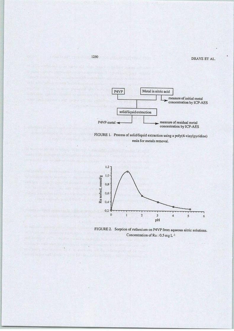
1250
P4VP
DRAYE ET AL.
Métal in nitric acid
I • measure ofinitial métalconcentration by ICP-AES
solid/liquid extraction
P4VP-metal -*- . measure of residual métalconcentration by ICP-AES
FIGURE 1. Process of solid/liquid extraction using apoly(4-vinylpyridine)resin for metals removal.
1,2-]
FIGURE 2. Sorption ofruthénium on P4VP from aqueous nitric solutions.Concentration of Ru : 0.5 mg L"1

POLY(4-VINYLPYRIDINE) FOR NUCLEAR WASTE TREATMENT 1251
<£
3
time, h
n without chloride• with chloride, 1 mol/L
-•—i—i—|
30
FIGURE3. Influence of chloride anions on extraction kinetics of ruthénium in
the présence ofsodium and potassium chloride. Concentration ofRu : 0.5mg L"1, Na: 25 g L1, K: 6 mgL'1
chloride ions may form chlorinated species of ruthénium which could be fastexchange on the resin or which induce a faster sorption by a complexationmechanism.
Inlight ofthe results obtained, thesélective removal ofruthénium présent innitric solutions can be achieved by a crosslinked poly(4-vinylpyridine) resin bycontrolling theacidity, the time ofcontact and theprésence ofan amount ofchloride
ions in the aqueous solution.
Tests in Radioactive Médium
The wastes used are produced by ail the industrial wholes of the spent
nuclear fuel reprocessing plant ofCOGEMA MARCOULE. Their characteristics aresummarized in Tables 1 and 2.
After the coprécipitations actually imposed on the liquid wastes and which permit toeliminate the major part ofthe radioactivity, ruthénium isresponsible for 90% of theresidual radioactivity.
Tests in Batch. Extractions were performed according to the procédure inFigure 1 and the initial and final métal concentrations were measured by yspectrometry.

1252 DRAYE ET AL.
TABLE 1. CHEMICAL COMPOSITION OF THE EFFLUENTS
Ion Ca2+ Na+ K+ Mg2+ Ba2+ U
Concentration
(mgL-i)
Ion
40
N02-
7000
N03-
120
so42-
80
ci-
<5
F-
6
P043-
Concentration
(mgL-i) 120 20000 1300 20 8 10
Salts content, 10 g L1 ; acidity < 0.5 mol L"1
TABLE 2. RADIOCHEMICAL COMPOSITION OF THE LIQUID WASTES
Global (5 Activity(GBqnr3)
Global a Activity(GBqm-3)
22 0.481
p spectrumConcentration
(|ig m-3)% a spectrum
Concentration
(Hgm-3)%
106Ru 57,9 33 239 to 242pu 300 48
137Cs 2100 31 241Am 800 21
134Cs . 40,9 8 238Pu 104 14
144(Ce+Pr) 17,1 9 242Cm 0,5 13
'->«Sr 250 6 244Cm 6,4 4

P0LY(4-VINYLPYRIDINE) FORNUCLEAR WASTE TREATMENT 1253
Influence of the pH on Ruthénium Extraction
Following the previous study ininactive médium, the influence of the acidityon Ru extraction from radioactive wastes has been evaluated, and ruthénium
behavior in real effluents and in synthetic inactive solutions is similar. Indeed,maximum sorption of 106Ru is observed at pH 1 in reprocessing aqueous nitricsolution, and a decrease of thesorption takes place with increasing pH. Fortunately,this maximal efficiency of ruthénium extraction corresponds to theusual acidity of
the MARCOULE liquid wastes.
Ruthénium Extraction Kinetics in Présence of the B. y Emitteis
Figure 4 shows the sorption kinetics of 106Ru on the P4VP from nitric acidin the présence of95Nb, 137Cs, and 125Sb at pH 1. 137Cs is not sorbed at ail ; 95Nband 125Sb are sorbed with the 106Ru, with their maximum sorption being observed
after40 minof contact. After75 min, the 106Ru is partly released from the resin.
This phenomenon may be ascribable toa compétition between sorption ofthe ionsstudied andof several other ions including H+and/or, a modification of the métalspecies présent in solution. This last transformation could be relatively lowcomparatly to ion exchange.
Tests in Column. In view of eventual industrial utilization, the P4VP resin has
been studiedby the continuousflow column method.
Efficiency of the P4VP in Relation to the ft. y Emttters
The P4VP has been applied to the sorption of I06Ru, 125Sb, 60Co, 137Cs,54Mn, and 144(Ce+Pr) by column opération. The results are shown Figure5.
106Ru, 125Sb, 54Mn, 60Co, and 144(Ce+Pr) are retained on the resin by a
mechanism that may not bebased onion exchange. Maximum sorption ofmétal ionsis observed after 50 mL of effluent are passed through the column. An importantdecrease in sorption is observed above a 60-mL volume of effluent solution for60Co and54Mn and above a 360-mL volume of effluent solution for 1()6Ru, 125Sband, 144(Ce +Pr). This can be assigned to an efficiency decrease of the resinfollowing a protonation of its functional groups. On the other hand, it has been
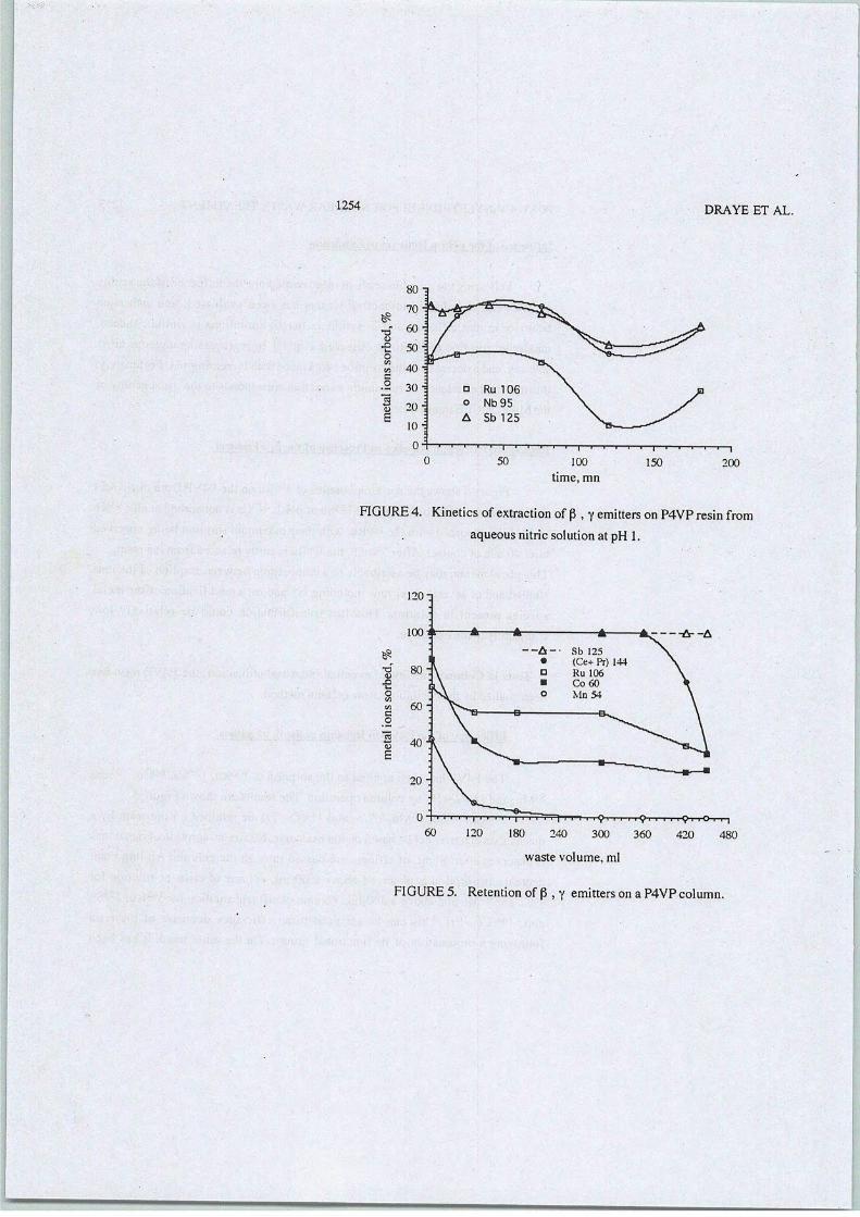
1254
80-3
100
time, mn
DRAYE ET AL.
150 200
FIGURE 4. Kinetics of extraction of p , yemitters onP4VP resin from
aqueous nitric solution at pH 1.
IDXJ
120-q
waste volume, ml
FIGURE5. Rétention of p , y emitters on a P4VPcolumn.
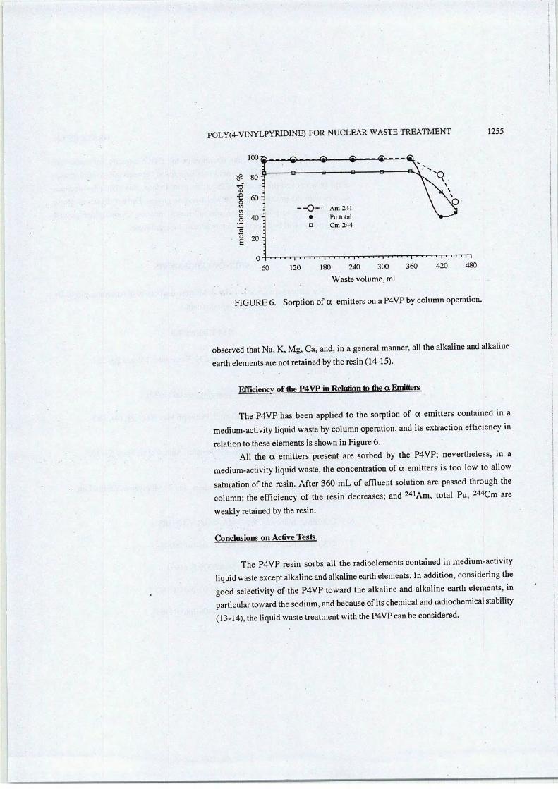
P0LY(4-VINYLPYRIDINE) FOR NUCLEAR WASTE TREATMENT
^9
loo ^—-q $ (g>— <g..
g. B B B—# 80:
T)<0
a 60-o</l .
w •
Co 40:
320
•-O-- Ara 241• Pu total
n Cm 244
60 120
! i i i i i I i i i i i I i ' ' ' ' I ' ' ' ' ' I V • ' ' ' I
180 240 300 360 420 480
1255
Waste volume, ml
FIGURE 6. Sorption ofa emitters on a P4VP by column opération.
observed that Na, K, Mg, Ca, and, ina gênerai manner, ail the alkaline and alkalineearth élémentsare not retained by the resin (14-15).
Ffficiencv of the P4VP in Relation to the a Emitteis
The P4VP has been applied to the sorption of a emitters contained in amedium-activity liquid waste by column opération, and its extraction efficiency inrelation to thèse éléments is shown in Figure 6.
AH the a emitters présent are sorbed by the P4VP; nevertheless, in amedium-activity liquid waste, the concentration ofa emitters is too low to allowsaturation of the resin. After 360 mLof effluent solution are passed through thecolumn; the efficiency of the resin decreases; and 241Am, total Pu, 244Cm areweakly retained by the resin.
Conclusions on Active Tests
The P4VP resin sorbs ail the radioéléments contained in medium-activityliquid waste except alkaline and alkaline earth éléments. In addition, considering thegood selectivity of the P4VP toward the alkaline and alkaline earth éléments, inparticular toward the sodium, and because of its chemical and radiochemical stability(13-14), the liquid waste treatment with the P4VP can be considered.
1256 DRAYE ET AL.
In a gênerai manner, the decrease of the P4VP capacity for métal ionssorption may be ascribable to the acid-base interaction between the pyridine groupsof the polymer and the protons of the nitric acid. Indeed, this efficiency decreasesquares with the protonation of 50% of pyridine groups. Further détails of protoninterférence in sorption mechanisms of métal ions on cross-linked poly(4-vinylpyridine) will bediscussed somewhere inthe near future.
ACKNOWLEDGEMENTS
The authors are grateful to Dr. J.Murphy for helpful discussions and to Dr.E. Poussel for ICP-AES inactivemeasurements.
REFERENCES
1. A. Sugii, N. Ogawa, Y. Iinuma, and H. Yanamura, Talanta 28, 551(1981).
2. D.C. Kennedy, Chemical Engineering, p. 106 (1980).
3. A.D. Pomogailo and LE. Uflyand, Platinum Met. Rev. 34* (4), 185(1990).
4. G. Ciantelli, P. Legittimo, and F. Pontani, Anal. Chim. Acta. 53, 303(1971).
5. T. Yamamoto, Z. H. Zhous, T. Kanbara, and T. Maruyama, Chem. Lett.223 (1990).
6. COGEMA Marcoule361-2-MA-49-08-Ind 0(1984).
7. COGEMA Marcoule 361-2-MA-49-04-Ind 0 (1984).
8. M. Lemaire etal., E. Patent 90403575.5- (1991).
9. COGEMA Marcoule 361-2-MA-49-02-Ind 0(1982/2).
10. COGEMA Marcoule 361-2-MA-48-09-Ind 0 (1985).

P0LY(4-VINYLPYRIDINE) FOR NUCLEAR WASTE TREATMENT 1257
11. Reilly Chemicals, ANew Family ofCross-linked Poly(vinylpyridines),Métal recovery, Reillex report5 (1990).
12. T.E. Gangwer, M. Godstein and, K.K.S. Pillay, Radiation Effects on IonExchange Materials, BNL-50781, Brookhaven National Laboratory,Upton, New-York (1977).
13. K. K. S. Pillay, J. Radioanal. Nucl. Chem. 102,1 , 247 (1986).
14. J. Foos et al., F. Patent 9,202,514 (1992).
15. M. Lemaire et al., F. Patent 9,202,516 ( 1992).
——

J.RADIOANAL.NUCL.CHEM.,LETTERS 175 (1) 55-62 (1993)
RADIOLYTIC PRODUCTS STUDY OF DICYCLOHEXANO-18-CROWN-6,A SELECTIVE EXTRACTANT FOR NUCLEAR FUEL REPROCESSING
Micheline Draye,ac R. Chomel, PA. Guy,D J. FoosD, M.
Doutreluingne,Lemaire*0
aService Laboratoire COGEMA, établissement de Marcoule,BP 170, 302 05 Bagnols sur Cêze Cedex, France
Laboratoire de Chimie Organique et Département desSciences Nucléaires du CNAM, 292 rue Saint Martin,
75141 Paris Cedex 03, France
cLaboratoire de Catalyse et Synthèse Organique,U.P. 5401, UCBL, Bât 308,
ESCIL, 43, bd. du 11 Novembre 1918,69622 Villeurbanne Cedex, France
Received 19 October 1992
Accepted 2 November 1992
The radiolytic products of the DCH18C6 obtained after y-irradiation hâve been determined, and the seven main structures hâvebeen separated and analyzed. The radiolyticproduct yields range from about 0.01 tonearly 0.3 molécules per 100 eV absorbed bythe DCH18C6 at an energy of 3290 kGy. Fromthe viewpoint of radiation décompositionrate, the DCH18C6 présents a considérablerésistance and its radiolytic products hâvelittle or no extraction power.
INTRODUCTION
Complexing properties of the DCH18C6 and its applica
tions in various fields of chemistry hâve been widely
*To whom ail correspondence should be addressed.
55
—
ElsevierSéquoiaS. A., Lausanne
AkadêmiaiKiadô, Budapest
1

DRAYE et al: RADIOLYTIC STUDY OFDCH18C6
studied. Thus, the possibility of strontium or plutonium séparation from médium and high activity used nuclearfuel and the extraction of radioactive strontium contained in water by the DCH18C6 has been démonstrated1~3.
In addition, the considérable radiation résistanceof solid DCH18C6 has been shown4'5 and the modificationsobserved after exposure to y-irradiation of DCH18C6chloroform solution hâve been attributed to the chloroform radiolytic products5. However, there is still nodefinite information on the behavior of DCH18C6 underthe action of ionizing radiation and no information onthe nature of its radiolytic products.
The présent work is concerned with the study of thestructural détermination of radiolytic products onDCH18C6 Y-irradiation. For each compound, we hâve reported the number of molécules formed per 100 eV ofenergy absorbed by the DCH18C6, i.e. the "G" values.
EXPERIMENTAL
The DCH18C6 cis-syn-cis isomer was separated fromits other isomer by the method described previously6.
The samples were made up of 0.2 g of cis-syn-cisDCH18C6 and 2 ml of uranyl nitrate (20 g U.l"1) aqueoussolution in 1N nitric acid. They were irradiated with a
Cs y-source in corked glass flasks. The absorbedenergy was, after calibration, 3290 kGy at a dose rateof 19.6 kGy.h-1.
After irradiation, to each sample were added 2 ml ofCH2C12 and 20 ml of distilled water. The aqueous phasewas extracted with 3 portions of 25 ml CH Cl
NMR experiments were carried out on a Bruker AC 200spectrometer operating at 200.132 MHz (1H) and 50.323
56

DRAYE et al: RADIOLYTIC STUDY OF DCH18C6
MHz { C) under broadband proton decoupling; trifluoro-
acetic acid was introduced to identify OH functions.
FTIR spectra were recorded on a 1720-X Perkin Elmer
spectrometer.
The radiolysis products were separated on a Del si DI
700 chromatograph equipped with a spiral FJ 1592 non-
polar capillary column (25 m x 0.22 mm i.d.) coated
with 100% of dimethylsiloxane stationary phase, and
they were analyzed on a mass spectrometer Nermag R
10-10H at 70 eV. Two methods of ionization, viz. élec
tron impact and chemical positive ionization with NH-.
were used.
RESULTS AND DISCUSSION
The FTIR results are given in Table 1.
The présence of ether and alcohol functions was con-
firmed by NMR, but no carbonyl function was identified.
Using gas chromatography, seven radiolytic products
and the DCH18C6 were separated and analyzed by mass
spectrometry; the characteristic masses obtained are
summarized in Table 2.
Masses were identified by chemical ionization. The
structures were distinguished by fragmentation analysis
using électron impact. For example, compounds B and C,
although having the same mass, differ in their struc
ture: with the électron impact, the ion I is character
istic of the structure B and the ion J is characteristic
of the other structure C (see Table 3).
The radiolytic product structures of dicyclohexano-
18-crown-6 are given in Table 4.
Structures A and C turned out to be the principal
products of DCH18C6 radiolysis when the energy absorbed
by the crown ether is 329 0 kGy.
57

DRAYE et al: RADIOLYTIC STUDYOF DCH18C6
TABLE 1
FTIR data of dicyclohexano-18-crown-6 and itsradiolytic product mixture
Frequency, cm-1 Corresponding vibration
3402 vOH bonded
2937 vas CH, |
2867 vs CH„
1734 vs C very weak ,II
0
1450 VS CH2
1099 VS CH2-0-CH2
736 PCH2
v = stretching, p = rocking, a = asymmetric,
s = symmetric.
TABLE 2
Chemical ionization mass spectral data for radiolyticproducts of dicyclohexano-18-crown-6
Compound M+1 M+1 8Corresponding ,
molécule composition
A 161 178 . C8°3H16B 205 212 C10°8H20C 205 212 C10°8H20D 249 266 C12°5H24E 293 310 C14°6H28F 303 320 C16°5H30H 347 364 C18°6H34
DCH18C6 373 390 C20°6H36
58

R
3
DRAYE etal: RADIOLYTIC STUDY OF DCH18C6
TABLE 3
Characteristic fragments of structures B and C
Ion IIon J
a;0 OHm/z = 143
+̂ cOOHm/z = 89
The values of the radiochemical yields, G, are listedin Table 5.
The sum of G values corresponding to the seven mainproducts is 0.75. For the number of DCH18C6 molécules dis-appeared for 100 eV absorbed, we found a value of 0,72which is comparable to 0.75. Thus, if this macrocyclehas to be used in radioactive médium, the molecularstructures described in Table 3 could be considered asimpurities produced during the process. No radiolyticproducts hâve a macrocyclic structure, and the dramati-cally lower complexing and extracting properties ofopen chain polyethers compared to the macrocyclic"analogs" has been demonstrated7. For example, the complexation of the K+ and Ba2+ by the 18-crown-6 is, respectively, 9,000 and 55,000 times as high as with thepentaglyme.
DCH18C6 possesses high stability towards radiolysis:the power of the dose received during our experiments(3290 kGy) is 11 times as high as the one estimatedduring a reprocessing campaign, but nevertheless 50% ofDCH18C6 remains unchanged.
59

DRAYE etal: RADIOLYTIC STUDY OFDCH18C6
TABLE 4
Radiolysis product structures of dicyclohexano-18-crown-6
Compound m/z
160
204
204
248
292
302
346
DCH18C6 372
Corresponding moléculecomposition
60
aOH
0 OH
O OH
ex OH\ /
0 O OH
OHa
O OH
aW W
OH
0 0 OH
o q ohN /\ /
a
N^nu un-V/
a ::x)
^"^0 o o-^J^.J v_y
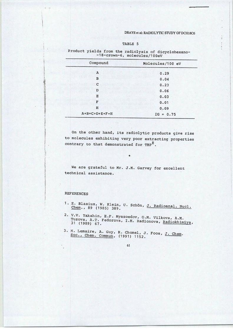
DRAYEet al: RADIOLYTIC STUDY 0FDCH18C6
TABLE 5
Product yields from the radiolysis of dicyclohexano--18-crown-6, molecules/1OOéV
Compound Molecules/100 eV
A 0.29
B 0.04
C 0.23
D 0. 06
E 0.03
F 0.01
H 0.09
A+B+C+D+E+F+H ZG = 0.75
On the other hand, its radiolytic products give riseto molécules exhibiting very poor extracting propertiescontrary to that demonstrated for TBP8.
We are grateful to Mr. J.M. Garvey for excellent
technical assistance.
REFERENCES
a^&'ilÏMrMÏ: °- SCh8"' ÎUSSS^i^^LV.V. Yakshin, E.F. Myasoedov, o.M. Vilkova A M
61
———
DRAYE etal: RADIOLYTIC STUDY OF DCH18C6
S.V. Zatonsky, O.S. -Povoloskaya, J. Radioanal. Nucl.Chem., Lett., 117 (1992) 361.
L. Mattel, T. Bilbao, J. Radioanal. Nucl. Chem-,Lett-, 137 (1989) 183.
V. Guyon, P. Drognat Landré, A. Guy, J. Foos, M.Lemaire, Chemistry Lett., (1992) 723.
B.G. Cox, H. Schneider, Coordination and TransportProperties of Macrocyclic Compounds in Solution,Elsevier Publishing Company (1992) p. 87.
M. Isaac, The Use of Tri-n-butyl Phosphate in Plutonium Extraction. Radiolysis and Recycling of theSolvent, CEA 2349 (1963).
62


JCàôiRution àdirigerdes recherches - 28mai 2004
Fonctions acide 1739 Cm-'carboxylique 1720cm
Chelatees1705 cm-1
1688 cm
3000 1800 1600
Longueur d'onde (cm-1)
MicheRne(D^VM
1400
Figure 24 :Comparaison des spectres infra rouge à transformée de Fourier de résinesformophénoliques 8-hydroxyquinoléines :
non irradiée (Do), dose intégrée 200 kGy (Di)
3-Us techniques membranaires
Le développement industriel des techniques à membranes ne date que des années 1960 pour lesdialyses et 1970 pour les techniques de solvo-transfert. Ce sont les techniques de dialyse qui sesont développées les premières et c'est seulement avec l'apparition et le développement desmembranes asymétriques que les techniques de solvo-transfert (osmose inverse, ultrafiltration...)ont finalement pu se développer de façon beaucoup plus rapide que les techniques de dialyse. Lestechniques séparatives à membranes se sont considérablement développées depuis quelquesannées. 6race à de nouveaux matériaux, les membranes sont de plus en plus performantes et
gagnent progressivement les domaines réservés de la séparation par extraction liquide-liquide,par évaporation, par centrifugation, par échange d'ions ou traitement chimique et précipitation.Les techniques séparatives à membranes assurent la filtration de particules solides, demacromolécules telles que les polymères, les protéines ou les colloïdes, et même de petites
molicules comme les sels, dans des conditions souvent moins coûteuses, plus économes en énergie
et moins polluantes. Longtemps les membranes ne furent qu'organiques. La première génération -celle des dérivés de la cellulose - a été remplacée par celle des polymères de type poly-(amide),
poly-(acrylonitrile), poly-(sulfone) ou polymère fluoré. La grande diversité des matériaux et leurmeilleure résistance aux agents basiques, acides et organiques ont engendré un développement
considérable de leur domaine d'application. Puis, au début des années 80, l'arrivée sur le marché

(Habilitation à dirigerdesrecherches - 28 mai2004 McheKwm&fà.
2.2.2-Développement de résines formophénoliques 8-hydroxyquinoléine
Les résines catéchol et résorcinol formaldehyde fixent très bien Eu(III) et La(III) mais sans
sélectivité pour l'un ou l'autre de ces deux lanthanides. L'idée conductrice du travail a donc étéd'affaiblir de manière différentielle l'affinité de ces résines, par incorporation de groupements
fonctionnalisés appropriés, leur conférant ainsi un pouvoir discriminant au bénéfice des
actinides(III).
Les premiers travaux ont porté sur l'incorporation de groupements 8-hydroxyquinoléine (Figure22)selon leschéma de synthèse présenté figure 23.
OH
HCHO
NaOH
H20
Figure 22 : la8-hydroxyquinoléine.
OH
OH
HCHO
NaOH
H20
Figure 23 : synthèse de résines cathéchol- et résorcinol 8-hydroxyquinoléine.
(*)Résines1
CF
RF
CQF
RQF
Capacité d'échangevis-à-vis des ions Na+
(meq g résine sècheJ
8,6
11,5
9,6
9,9
(mL g résine sècheJ
> 2 x 10⁶
6> 2 x 10'
100
80
&Eu
(mL g résine sècheJ
> 2 x 10⁶
> 2 x 10⁶
700
800
Facteur de séparation(Seu/Lcr Deu/Ou)
«1
«1
10
(*) CF =résine catéchol formaldehyde: RF =résine résorcinol formaldehyde; CQF =résine catéchol formaldehyde 8hydroxyquinoléine; RQF =résine résorcinol formaldehyde 8-hydroxyquinoléine
Tableau 3 : Coefficients dedistribution D(mL g"1 de résine sèche) et facteurs deséparationpour l'extraction compétitive de l'europium(III) et du lanthane(III) par diverses résines
formophénoliques ; [La3t] =[Eu3*] =2,5 mmol L-1; Vso, =10 mL; nvésir* =0,05 g; pH =4

KaAiRtation àdirigerdes recherches - 28 mai 2004 MicheRne <mP*E
fois en 1935 [30]. Il s'agissait de la découverte des propriétés d'échange d'ions d'une résine
phénol - formaldehyde.

ïfafnRtation àdirigerdes recherches - 28mai 2004 MicheRneQWMŒ.
Rapport molaire 8-hydroxyquinoline/Ln3t
DLa3* DGd3+ Ssd3+/u3+
0 1,1±0,3 5,9±0,3 5,4±1,4
2 1,7±0,3 6,9+0,3 4,0+0,8
4 2,2+0,3 13,2±0,4 6,0±0,9
6 5,3±0,3 32,6+0,6 6,1+0,5
8 11,3+0,4 100+1,0 8,8+0,3
10 18,9±0,5 394±4,0 20,8+0,6
12 38,1+0, 1059±10,0 27,8+0,6
14 63,8+0,9 2067+20 32,4±0,6[La(N03)3] s [6d(N03)3] =0,36mM ;pH =5,5:1% Triton X-U4 en poids ; température d'équilibre de 60°C ; temps
d'équilibre de lh ; volume de phase micellaire=45 mL ;volume de phase riche en surfactant après point de trouble=l,5 mL
Tableau 2 : Influence du rapport molaire agent chélatant-lanthanide(III) sur l'efficacité et lasélectivité pour l'extraction du Gd3* vis-à-vis du La et le facteur deconcentration.
Au cours de ces travaux, nous avons développé un nouveau procédé d'extraction liquide-liquide
sans solvant organique basé sur le concept de point de trouble pour la séparation de
lanthanides[28].
Ces premiers résultats définissent un système totalement nouveau pour la séparation de
lanthanides(III). Nous poursuivons actuellement ce travail par des expériences en milieu
radioactif dans l'Actinides Research 6roup du Massachusetts Institute of Technology, afin
d'évaluer les possibilités d'utiliser un tel système pour la séparation actinides
mineurs/lanthanides et de déterminersonefficacité pour l'extraction sélectivedes actinides.
2-L'extraction solide-liquide pour l'industrie nucléaire
Parmi les méthodes séparatives disponibles, l'extraction solide-liquide offre les bases des
schémas deséparations les plus pratiques. Du point devue de la gestion des déchets radioactifs,
l'un des avantages majeurs que présente l'extraction solide-liquide réside en sa capacité à
séparer les radioéléments tout en produisant un volume minimal d'effluent décontaminé et adapté
à un stockage direct. Des études ont mis en évidence l'utilisation de matrices minérales[29] qui,
malheureusement, constituent in fine un déchet supplémentaire. Par opposition, les résines
organiques ne comportant que des atomes de carbone (C), d'hydrogène (H), d'oxygène (O) et
d'azote (N) (principe CHON) sont totalement incinérables et constitueront, par conséquent, un
volume final de déchets radioactifs réduit.
L'échange d'ions peut être défini comme un échange réversible d'ions entre une phase solide etune phase liquide. Les résines échangeuses d'ions organiques ont été décrites pour la première
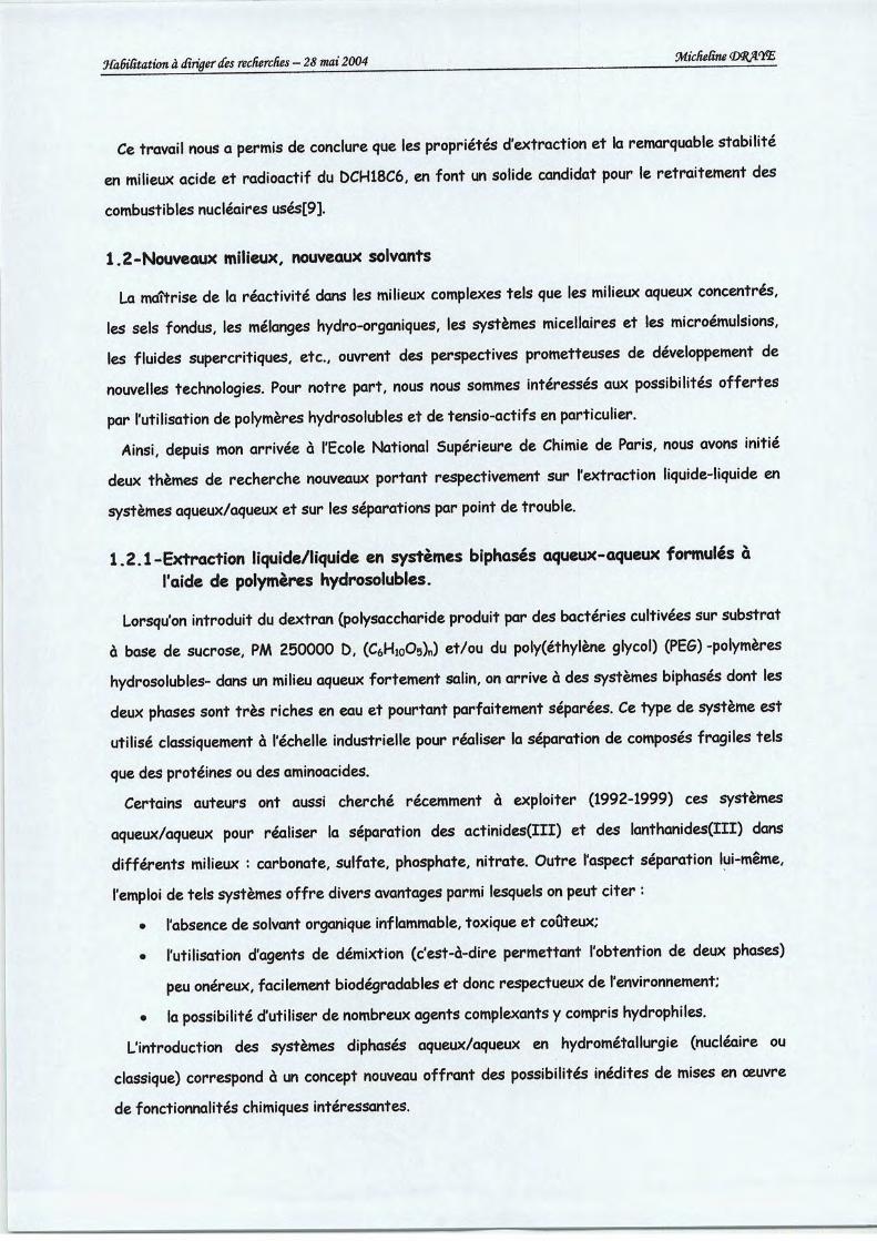
JfabtRtation àdiriger des recherches - 28 mai 2004 MicheRne <mjï<m
Ce travail nous a permis de conclure que les propriétés d'extraction et la remarquable stabilitéen milieux acide et radioactif du DCH18C6, en font un solide candidat pour le retraitement des
combustibles nucléaires usés[9].
1.2-Nouveaux milieux, nouveaux solvants
La maîtrise de la réactivité dans les milieux complexes tels que les milieux aqueux concentrés,
les sels fondus, les mélanges hydro-organiques, les systèmes micellaires et les microémulsions,
les fluides supercritiques, etc., ouvrent des perspectives prometteuses de développement denouvelles technologies. Pour notre part, nous nous sommes intéressés aux possibilités offertespar l'utilisation de polymères hydrosolubles et de tensio-actifs en particulier.
Ainsi, depuis mon arrivée à l'Ecole National Supérieure de Chimie de Paris, nous avons initiédeux thèmes de recherche nouveaux portant respectivement sur l'extraction liquide-liquide en
systèmes aqueux/aqueux et sur les séparations par point de trouble.
1.2.1-Extraction liquide/liquide en systèmes biphasés aqueux-aqueux formulés àl'aide de polymères hydrosolubles.
Lorsqu'on introduit du dextran (polysaccharide produit par des bactéries cultivées sur substratà base de sucrose, PM 250000 D, (C6Hi0O5)„) et/ou du poly(éthylène glycol) (PEG) -polymères
hydrosolubles- dans un milieu aqueux fortement salin, on arrive à des systèmes biphasés dont lesdeux phases sont très riches en eau et pourtant parfaitement séparées. Ce type de système estutilisé classiquement à l'échelle industrielle pour réaliser la séparation de composés fragiles tels
que des protéines ou des aminoacides.
Certains auteurs ont aussi cherché récemment à exploiter (1992-1999) ces systèmes
aqueux/aqueux pour réaliser la séparation des actinides(III) et des lanthanides(III) dansdifférents milieux : carbonate, sulfate, phosphate, nitrate. Outre l'aspect séparation lui-même,
l'emploi de tels systèmes offre divers avantages parmi lesquels on peut citer :
• l'absence de solvant organique inflammable, toxique et coûteux;
• l'utilisation d'agents de démixtion (c'est-à-dire permettant l'obtention de deux phases)
peu onéreux, facilement biodégradables et donc respectueux de l'environnement;
• la possibilité d'utiliser de nombreux agents complexants ycompris hydrophiles.L'introduction des systèmes diphasés aqueux/aqueux en hydrométallurgie (nucléaire ou
classique) correspond à un concept nouveau offrant des possibilités inédites de mises en œuvre
de fonctionnalités chimiques intéressantes.
———
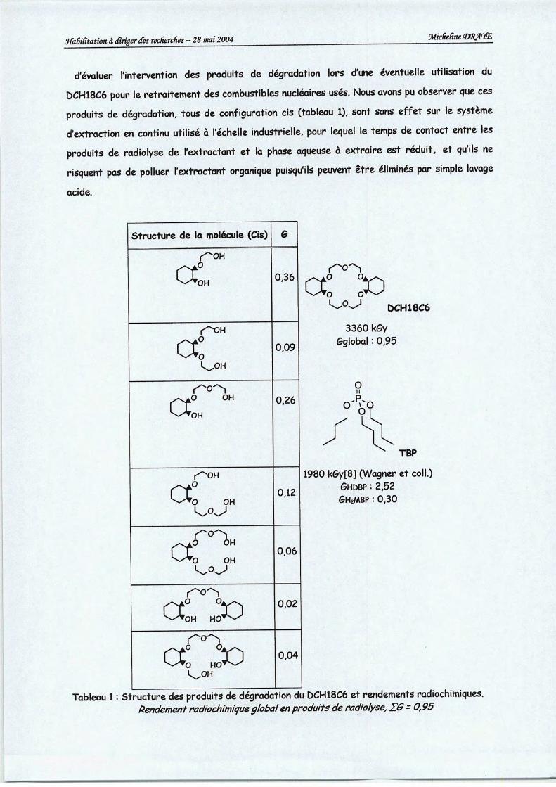
Wabïfitation à dirigerdes recherches - 28 mai 2004 9£cheRne<Mjlim
d'évaluer l'intervention des produits de dégradation lors d'une éventuelle utilisation du
DCH18C6 pour le retraitement des combustibles nucléaires usés. Nous avons pu observer que ces
produits de dégradation, tous de configuration cis (tableau 1), sont sans effet sur le systèmed'extraction en continu utilisé à l'échelle industrielle, pour lequel le temps de contact entre les
produits de radiolyse de l'extractant et la phase aqueuse à extraire est réduit, et qu'ils nerisquent pas de polluer l'extractant organique puisqu'ils peuvent être éliminés par simple lavage
acide.
kO
a: x>r0
DCH18C6
3360 kGyGglobal : 0,95
TBP
1980 kGy[8] (Wagner et coll.)GHDBP : 2,52
Gh2MBP : 0,30
Structure de la molécule (Cis) G
r^oH
^*OH0,36
r"^OH
a: 0,09
^aO OH^•OH
0,26
f^OH
^^•0 OHk.°^
0,12
r^o"^^aP OH^-A0 OH
0,06
Ct° °300,02
k^-TQ HO^^k^OH
0,04
Tableau 1: Structure des produits dedégradation du DCH18C6 et rendements radiochimiques.Rendement radiochimiqueglobal enproduits deradiolyse, E& =0,95
•mm^

yfatnRtation àdirigerdes recherches - 28mai 2004
U Pu
MCombustiblV PUREX
NpTe
Produits de fission
et actinides mineurs
Cs
I Actinides et
lanthanides ^
Produits
de fission
McheRne<M3WcE
Am + Cm
ïSANEX
CALIXARENE
Lanthanides
Produits
de fission
Stockage
Figure 4 : schéma de séparation poussée français.PUREX: Plutonium Uranium Refining by Extraction, procédé hydrométallurgique de séparation de
l'uranium et du plutonium du combustible usés - OIAMEX: ÙIAMide Extractant, procédé de séparation del'ensemble lanthanides et actinides mineurs des produits de fission - SANEX: Séparation desActiNides parExtraction ou Sélective ActiNides Extraction, procédé de séparation des actinides et des lanthanides,CAUXARENES- Séparation du césium des produits defission par des calixarènes.
1-L'extraction liquide-liquide pour l'industrie nucléaire
La stratégie du programme de recherches menée en France par le CEA pour la séparation des
radionucléides à vie longue consiste à articuler les recherches en complément de la stratégie
industrielle actuelle du retraitement du combustible usé et à tirer parti des potentialités du
procédé PUREX. La voie d'exploration principale pour la séparation des radionucléides à vie longue
est celle de l'extraction liquide-liquide, extraction sélective à partir de la solution aqueuse dans
laquelle a été solubilisé l'ensemble des composants du combustible usé. Ce choix découle de
plusieurs considérations. Tout d'abord le procédé PUREX de traitement du combustible usé,
actuellement mis en oeuvre pour la récupération de Uet de Pu est un procédé de ce type. Par
ailleurs, la séparation des radionucléides à vie longue ne prend tout son sens qu'en complément
d'une stratégie homologue à celle de la séparation U-Pu. Il apparaît donc pertinent de se placer
en aval de cette étape essentielle pour de nouveaux objectifs de séparations complémentaires.
Ensuite, la relative proximité de l'échéance privilégie naturellement les procédés dont la maturité
industrielle est éprouvée, ce qui est le cas des procédés hydrométallurgiques. Enfin le retour
d'expérience de la mise en oeuvre du procédé PUREX dans les unités de COGEMA à la Haguedémontre la capacité de tels procédés à procurer des performances de séparation remarquables
en ce qui concerne la quantitativité et la sélectivité de la récupération des éléments d'intérêt et

XaèiRtation àdirigerdes recherches - 28 mai 2004 flfefeft» (P^ME
Figure 3 : lephosphate den-tributyle.
Le concept de séparation peut être élargi à d'autres radioéléments présents, et possédant uneradiotoxicité et une durée de vie longue comme certains actinides mineurs et produits de fission.
Débarrassés d'eux, les déchets perdraient beaucoup de leur radiotoxicité. Les produits séparésdevraient alors faire l'objet d'une gestion nouvelle : la transmutation ou, éventuellement, leconditionnement spécifique. Les actinides mineurs concernés par cette séparation poussée sontle neptunium, l'américium et le curium. Ils représentent, après le plutonium, l'inventaireradiotoxique le plus élevé au sein des combustibles usés et leur gestion fait, pour l'instant, appelà des solutions d'entreposages sûres mais non définitives. Dans un second temps, il est aussinécessaire d'extraire certains produits de fission à vie longue, tel que l35Cs, ou très radioactifs,tel que 137Cs, relativement abondants et, de par leurs propriétés chimiques, potentiellementmobiles à très long terme dans un site de stockage. Actuellement, les technologies de séparationutilisées sont, comme le procédé PUREX, toutes basées sur l'extraction liquide-liquide, qui a
l'avantage de permettre la mise en œuvre de procédés en continu, mais l'inconvénient de générerdes déchets supplémentaires à gérer. Le procédé de séparation actuellement envisagé en France
est représenté figure 4.
Parmi les principaux pays qui ont recours à l'énergie nucléaire, la France poursuit depuislongtemps des recherches sur la gestion des déchets nucléaires mais àce jour, aucun pays n'a misen œuvre une politique de gestion des déchets nucléaires de haute activité etàvie longue.
<••••
Copyright © 2022 FDOKUMEN