
SPA OWNER'S MANUAL - Sunrise Spas
86
SPA OWNER’S MANUAL IMPORTANT SAFETY INSTRUCTIONS PART B – BRAND SPECIFIC MANUAL Pour voir ou imprimer ce document en Français, veuillez visiter: http://www.sunrisespas.com/site/owners ELECTRICAL CONNECTION KEYPAD OPERATION Read in conjunction with Part A – General Manual to form a complete Owner’s Manual SRE-M-B-17
-
Upload
khangminh22 -
Category
Documents
-
view
0 -
download
0
Transcript of SPA OWNER'S MANUAL - Sunrise Spas

SPA OWNER’S MANUAL IMPORTANT SAFETY INSTRUCTIONS
PART B – BRAND SPECIFIC MANUAL Pour voir ou imprimer ce document en Français, veuillez visiter:
http://www.sunrisespas.com/site/owners
ELECTRICAL CONNECTION
KEYPAD OPERATION
Read in conjunction with Part A – General Manual to form a complete Owner’s Manual SRE-M-B-17
2 DOC: SRE-M-B-17 Sunrise Spas 2017 Owner’s Manual
INDEX
Table of Contents
BRAND CONFIGURATION TABLE ................................................................................................................................................................ 3 ELECTRICAL CONNECTION - GENERAL INFORMATION............................................................................................................................... 4
LOCATING A CONDUIT WITHIN A CONCRETE PAD ............................................................................................................................... 4 SUPPLY CABLE ENTRY INTO SPA EQUIPMENT AREA ............................................................................................................................. 4 HOW TO PASS THE CABLE THROUGH THE SPA ENCLOSURE ................................................................................................................ 4 EUROPEAN 50HZ MODELS .................................................................................................................................................................... 4 TYPICAL RESIDUAL CURRENT DETECTOR (RCD) .................................................................................................................................... 5 230 VOLT SUPPLY CONNECTION ........................................................................................................................................................... 6
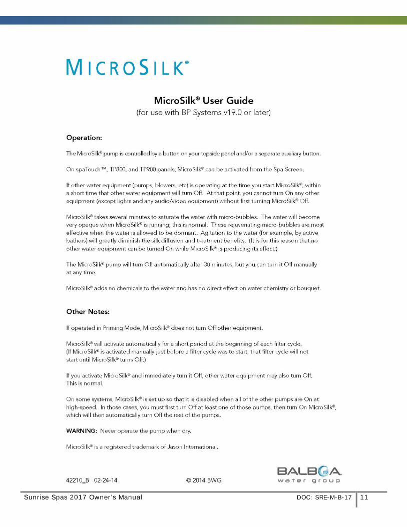
YOUR FILTER – REMOVAL & REPLACEMENT .............................................................................................................................................. 9 MICROSILK PUMP OPERATION ................................................................................................................................................................ 11 ADDENDUM A – TP600 USER GUIDE W/ SIMPLIFIED MENUS ................................................................................................................. 12 ADDENDUM B – TP600 USER GUIDE W/ STANDARD MENUS .................................................................................................................. 27 ADDENDUM C – SPATOUCH ICON DRIVEN USER GUIDE ......................................................................................................................... 53
Sunrise Spas 2017 Owner’s Manual DOC: SRE-M-B-17 3
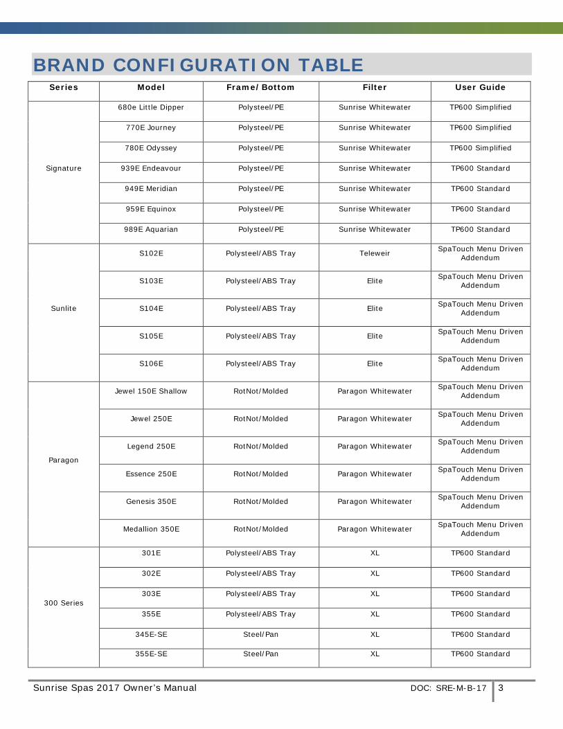
BRAND CONFIGURATION TABLE Series Model Frame/Bottom Filter User Guide
Signature
680e Little Dipper Polysteel/PE Sunrise Whitewater TP600 Simplified
770E Journey Polysteel/PE Sunrise Whitewater TP600 Simplified
780E Odyssey Polysteel/PE Sunrise Whitewater TP600 Simplified
939E Endeavour Polysteel/PE Sunrise Whitewater TP600 Standard
949E Meridian Polysteel/PE Sunrise Whitewater TP600 Standard
959E Equinox Polysteel/PE Sunrise Whitewater TP600 Standard
989E Aquarian Polysteel/PE Sunrise Whitewater TP600 Standard
Sunlite
S102E Polysteel/ABS Tray Teleweir SpaTouch Menu Driven Addendum
S103E Polysteel/ABS Tray Elite SpaTouch Menu Driven Addendum
S104E Polysteel/ABS Tray Elite SpaTouch Menu Driven Addendum
S105E Polysteel/ABS Tray Elite SpaTouch Menu Driven Addendum
S106E Polysteel/ABS Tray Elite SpaTouch Menu Driven Addendum
Paragon
Jewel 150E Shallow RotNot/Molded Paragon Whitewater SpaTouch Menu Driven Addendum
Jewel 250E RotNot/Molded Paragon Whitewater SpaTouch Menu Driven Addendum
Legend 250E RotNot/Molded Paragon Whitewater SpaTouch Menu Driven Addendum
Essence 250E RotNot/Molded Paragon Whitewater SpaTouch Menu Driven Addendum
Genesis 350E RotNot/Molded Paragon Whitewater SpaTouch Menu Driven Addendum
Medallion 350E RotNot/Molded Paragon Whitewater SpaTouch Menu Driven Addendum
300 Series
301E Polysteel/ABS Tray XL TP600 Standard
302E Polysteel/ABS Tray XL TP600 Standard
303E Polysteel/ABS Tray XL TP600 Standard
355E Polysteel/ABS Tray XL TP600 Standard
345E-SE Steel/Pan XL TP600 Standard
355E-SE Steel/Pan XL TP600 Standard
4 DOC: SRE-M-B-17 Sunrise Spas 2017 Owner’s Manual
Note: The factory default for spas using the TP600 keypad is Simplified Menus. However, more keypad settings and features are possible on some spas by accessing the Standard menus within the spa pack. A spa pack set up change is required to access these settings and features within the standard menus.
Ask your dealer about the set up change required.
When the spa has a circ pump or Microsilk option the spa pack changes and so does the default setting for the keypad to Standard menus.
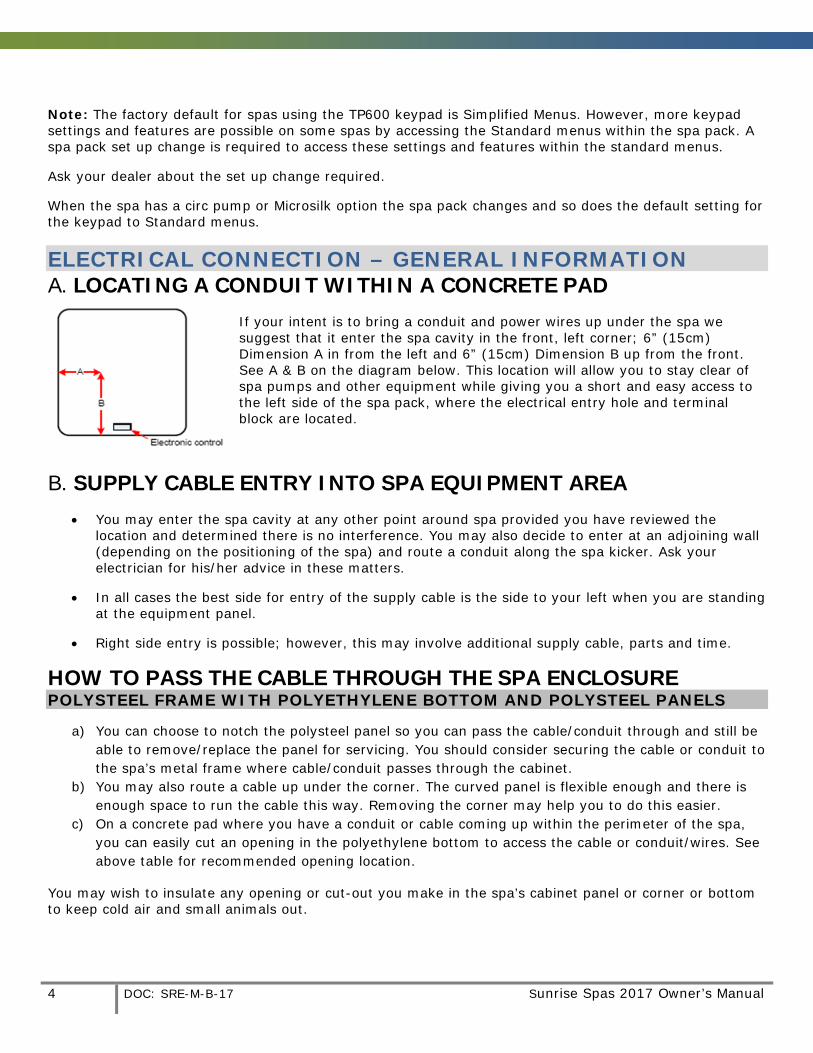
ELECTRICAL CONNECTION – GENERAL INFORMATION A. LOCATING A CONDUIT WITHIN A CONCRETE PAD
If your intent is to bring a conduit and power wires up under the spa we suggest that it enter the spa cavity in the front, left corner; 6” (15cm) Dimension A in from the left and 6” (15cm) Dimension B up from the front. See A & B on the diagram below. This location will allow you to stay clear of spa pumps and other equipment while giving you a short and easy access to the left side of the spa pack, where the electrical entry hole and terminal block are located.
B. SUPPLY CABLE ENTRY INTO SPA EQUIPMENT AREA • You may enter the spa cavity at any other point around spa provided you have reviewed the
location and determined there is no interference. You may also decide to enter at an adjoining wall (depending on the positioning of the spa) and route a conduit along the spa kicker. Ask your electrician for his/her advice in these matters.
• In all cases the best side for entry of the supply cable is the side to your left when you are standing at the equipment panel.
• Right side entry is possible; however, this may involve additional supply cable, parts and time.
HOW TO PASS THE CABLE THROUGH THE SPA ENCLOSURE POLYSTEEL FRAME WITH POLYETHYLENE BOTTOM AND POLYSTEEL PANELS
a) You can choose to notch the polysteel panel so you can pass the cable/conduit through and still be able to remove/replace the panel for servicing. You should consider securing the cable or conduit to the spa’s metal frame where cable/conduit passes through the cabinet.
b) You may also route a cable up under the corner. The curved panel is flexible enough and there is enough space to run the cable this way. Removing the corner may help you to do this easier.
c) On a concrete pad where you have a conduit or cable coming up within the perimeter of the spa, you can easily cut an opening in the polyethylene bottom to access the cable or conduit/wires. See above table for recommended opening location.
You may wish to insulate any opening or cut-out you make in the spa’s cabinet panel or corner or bottom to keep cold air and small animals out.

Sunrise Spas 2017 Owner’s Manual DOC: SRE-M-B-17 5
EUROPEAN (50HZ) MODELS Please note the following important information: When using this electrical equipment, basic safety instructions should be followed, including the following:
READ AND FOLLOW ALL DIRECTIONS
(1) This spa must be connected to an RCD (Residual Current Detector) with a residual operating current not exceeding 30mAmps.
(2) Electrical installation must be carried out by a qualified electrician strictly in accordance with local governing codes.
(3) A terminal marked "ground" is located within the control box. To reduce the risk of electric shock this terminal must be connected to the grounding means provided in the electric supply service panel with a continuous copper wire equivalent in size to the circuit conductors supplying the equipment.
(4) At least two lugs marked "bonding lugs" are provided on the external surface of the control box. To reduce the risk of electric shock connect the local common bonding grid in the area of the hot tub or spa to these terminals with an insulated or bare copper conductor not smaller than No. 6 AWG.
(5) Test the RCD before each use of the spa, according to the manufacturer's instructions.
(6) Before servicing any electrical components of the system make sure that the power supply is switched off.
(7) Keep the door closed in order to provide IPX5 protection to the electrical compartment.
Any opening made through the spa enclosure for the entry of input cables/wires, must be made watertight to preserve the IPX5 rating of the appliance.
TYPICAL RESIDUAL CURRENT DETECTOR (RCD) A residual current device (RCD,) is the generic term for a device that monitors the current in the line conductor and the neutral conductor of a circuit in an earthed system. In a circuit that’s operating properly, the vector sum of the live and neutral current values added together will be zero. Current flowing to earth, due to a line earth fault, will return via the earth conductor, and regardless of load conditions, will be registered as a fault. This current flow will give rise to a residual current that will be detected by the device. If the residual current exceeds the rated sensitivity of the RCD, it will automatically activate a tripping of the faulty circuit. Two Pole RCD Typical specifications are as follows: Residual Current Devices ( RCD’s ) range
Sensitivity - from 10 to 500mA Voltage - 2 poles : 230V; 3/4 poles: 230/400V Connection capacity - 25A: 6/10 mm² (flexible/ rigid cable) - 40,60A: 16/25 mm² - 80,100A: 35/50 mm² Four Pole RCD
6 DOC: SRE-M-B-17 Sunrise Spas 2017 Owner’s Manual
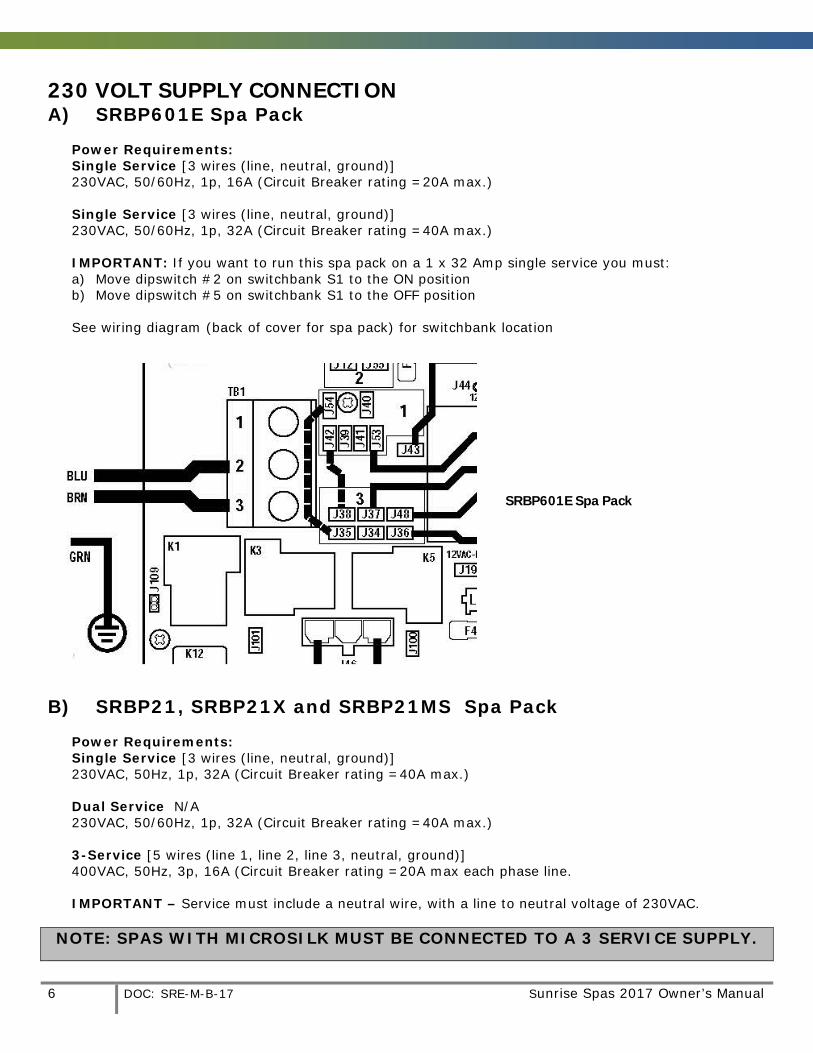
230 VOLT SUPPLY CONNECTION
A) SRBP601E Spa Pack Power Requirements: Single Service [3 wires (line, neutral, ground)] 230VAC, 50/60Hz, 1p, 16A (Circuit Breaker rating =20A max.) Single Service [3 wires (line, neutral, ground)] 230VAC, 50/60Hz, 1p, 32A (Circuit Breaker rating =40A max.) IMPORTANT: If you want to run this spa pack on a 1 x 32 Amp single service you must: a) Move dipswitch #2 on switchbank S1 to the ON position b) Move dipswitch #5 on switchbank S1 to the OFF position
See wiring diagram (back of cover for spa pack) for switchbank location
SRBP601E Spa Pack
B) SRBP21, SRBP21X and SRBP21MS Spa Pack
Power Requirements: Single Service [3 wires (line, neutral, ground)] 230VAC, 50Hz, 1p, 32A (Circuit Breaker rating =40A max.) Dual Service N/A 230VAC, 50/60Hz, 1p, 32A (Circuit Breaker rating =40A max.)
3-Service [5 wires (line 1, line 2, line 3, neutral, ground)] 400VAC, 50Hz, 3p, 16A (Circuit Breaker rating =20A max each phase line. IMPORTANT – Service must include a neutral wire, with a line to neutral voltage of 230VAC.
NOTE: SPAS WITH MICROSILK MUST BE CONNECTED TO A 3 SERVICE SUPPLY.
Sunrise Spas 2017 Owner’s Manual DOC: SRE-M-B-17 7
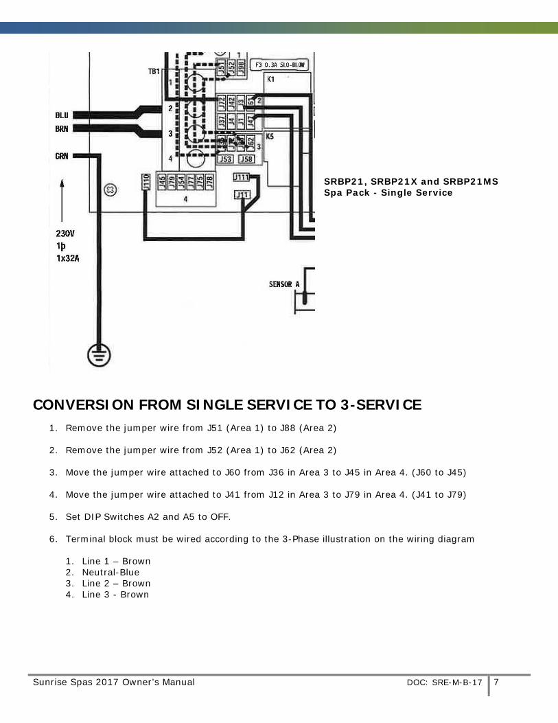
SRBP21, SRBP21X and SRBP21MS Spa Pack - Single Service
CONVERSION FROM SINGLE SERVICE TO 3-SERVICE 1. Remove the jumper wire from J51 (Area 1) to J88 (Area 2)
2. Remove the jumper wire from J52 (Area 1) to J62 (Area 2)
3. Move the jumper wire attached to J60 from J36 in Area 3 to J45 in Area 4. (J60 to J45)
4. Move the jumper wire attached to J41 from J12 in Area 3 to J79 in Area 4. (J41 to J79)
5. Set DIP Switches A2 and A5 to OFF.
6. Terminal block must be wired according to the 3-Phase illustration on the wiring diagram
1. Line 1 – Brown 2. Neutral-Blue 3. Line 2 – Brown 4. Line 3 - Brown
8 DOC: SRE-M-B-17 Sunrise Spas 2017 Owner’s Manual
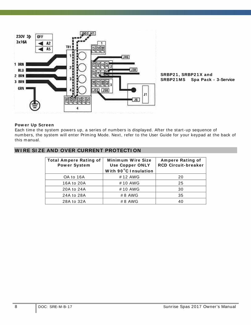
SRBP21, SRBP21X and SRBP21MS Spa Pack - 3-Service
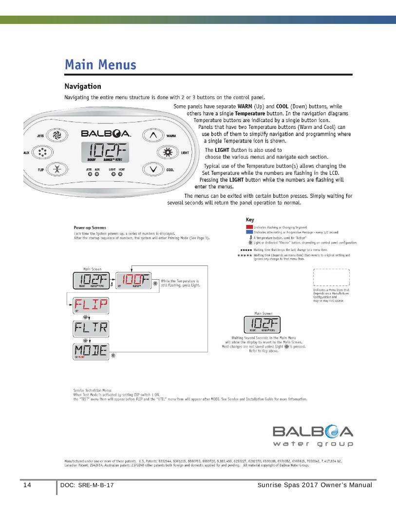
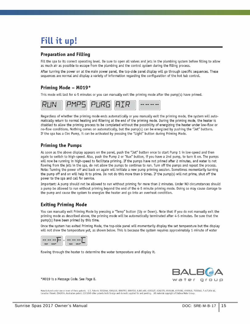
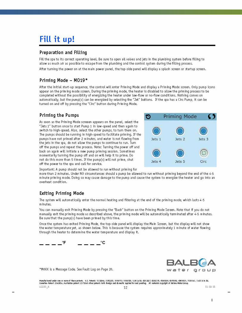
Power Up Screen Each time the system powers up, a series of numbers is displayed. After the start-up sequence of numbers, the system will enter Priming Mode. Next, refer to the User Guide for your keypad at the back of this manual. WIRE SIZE AND OVER CURRENT PROTECTION
Total Ampere Rating of Power System
Minimum Wire Size Use Copper ONLY
With 90°C Insulation
Ampere Rating of RCD Circuit-breaker
OA to 16A #12 AWG 20 16A to 20A #10 AWG 25 20A to 24A #10 AWG 30 24A to 28A #8 AWG 35 28A to 32A #8 AWG 40
Sunrise Spas 2017 Owner’s Manual DOC: SRE-M-B-17 9
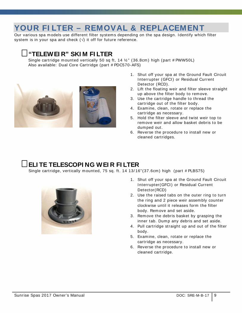
YOUR FILTER – REMOVAL & REPLACEMENT Our various spa models use different filter systems depending on the spa design. Identify which filter system is in your spa and check (√) it off for future reference.
� “TELEWEIR” SKIM FILTER Single cartridge mounted vertically 50 sq ft, 14 ½” (36.8cm) high (part #PWW50L) Also available: Dual Core Cartridge (part #PDC570-AFS)
1. Shut off your spa at the Ground Fault Circuit Interrupter (GFCI) or Residual Current Detector (RCD).
2. Lift the floating weir and filter sleeve straight up above the filter body to remove.
3. Use the cartridge handle to thread the cartridge out of the filter body.
4. Examine, clean, rotate or replace the cartridge as necessary.
5. Hold the filter sleeve and twist weir top to remove weir and allow basket debris to be dumped out.
6. Reverse the procedure to install new or cleaned cartridges.
� ELITE TELESCOPING WEIR FILTER Single cartridge, vertically mounted, 75 sq. ft. 14 13/16”(37.6cm) high (part #PLBS75)
1. Shut off your spa at the Ground Fault Circuit Interrupter(GFCI) or Residual Current Detector(RCD)
2. Use the raised tabs on the outer ring to turn the ring and 2 piece weir assembly counter clockwise until it releases form the filter body. Remove and set aside.
3. Remove the debris basket by grasping the inner tab. Dump any debris and set aside.
4. Pull cartridge straight up and out of the filter body.
5. Examine, clean, rotate or replace the cartridge as necessary.
6. Reverse the procedure to install new or cleaned cartridge.
10 DOC: SRE-M-B-17 Sunrise Spas 2017 Owner’s Manual
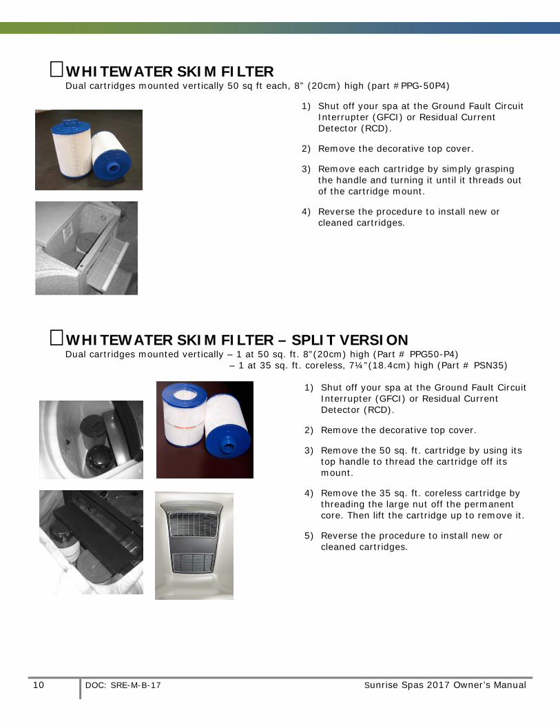
� WHITEWATER SKIM FILTER Dual cartridges mounted vertically 50 sq ft each, 8” (20cm) high (part #PPG-50P4)
1) Shut off your spa at the Ground Fault Circuit Interrupter (GFCI) or Residual Current Detector (RCD).
2) Remove the decorative top cover.
3) Remove each cartridge by simply grasping the handle and turning it until it threads out of the cartridge mount.
4) Reverse the procedure to install new or cleaned cartridges.
� WHITEWATER SKIM FILTER – SPLIT VERSION Dual cartridges mounted vertically – 1 at 50 sq. ft. 8”(20cm) high (Part # PPG50-P4) – 1 at 35 sq. ft. coreless, 7¼”(18.4cm) high (Part # PSN35)
1) Shut off your spa at the Ground Fault Circuit Interrupter (GFCI) or Residual Current Detector (RCD).
2) Remove the decorative top cover.
3) Remove the 50 sq. ft. cartridge by using its top handle to thread the cartridge off its mount.
4) Remove the 35 sq. ft. coreless cartridge by threading the large nut off the permanent core. Then lift the cartridge up to remove it.
5) Reverse the procedure to install new or cleaned cartridges.
Sunrise Spas 2017 Owner’s Manual DOC: SRE-M-B-17 11

12 DOC: SRE-M-B-17 Sunrise Spas 2017 Owner’s Manual
ADDENDUM A
TP600 User Guide With Simplified Menu Feature

Sunrise Spas 2017 Owner’s Manual DOC: SRE-M-B-17 13
14 DOC: SRE-M-B-17 Sunrise Spas 2017 Owner’s Manual
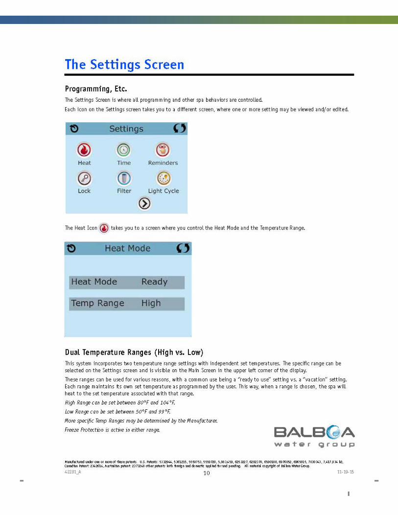
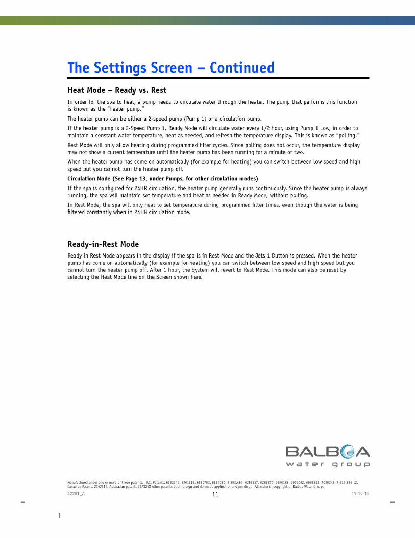
Sunrise Spas 2017 Owner’s Manual DOC: SRE-M-B-17 15
16 DOC: SRE-M-B-17 Sunrise Spas 2017 Owner’s Manual

Sunrise Spas 2017 Owner’s Manual DOC: SRE-M-B-17 17
18 DOC: SRE-M-B-17 Sunrise Spas 2017 Owner’s Manual
Sunrise Spas 2017 Owner’s Manual DOC: SRE-M-B-17 19
20 DOC: SRE-M-B-17 Sunrise Spas 2017 Owner’s Manual

Sunrise Spas 2017 Owner’s Manual DOC: SRE-M-B-17 21
22 DOC: SRE-M-B-17 Sunrise Spas 2017 Owner’s Manual
Sunrise Spas 2017 Owner’s Manual DOC: SRE-M-B-17 23
24 DOC: SRE-M-B-17 Sunrise Spas 2017 Owner’s Manual

Sunrise Spas 2017 Owner’s Manual DOC: SRE-M-B-17 25

26 DOC: SRE-M-B-17 Sunrise Spas 2017 Owner’s Manual
Sunrise Spas 2017 Owner’s Manual DOC: SRE-M-B-17 27
ADDENDUM B
TP600 User Guide With Standard Menu Feature
• Applies to all spas with a dedicated circulation pump and/or MicroSilk option. • Applies to any spa where the set up number has been re-configured to allow standard
menu features.

28 DOC: SRE-M-B-17 Sunrise Spas 2017 Owner’s Manual
Sunrise Spas 2017 Owner’s Manual DOC: SRE-M-B-17 29
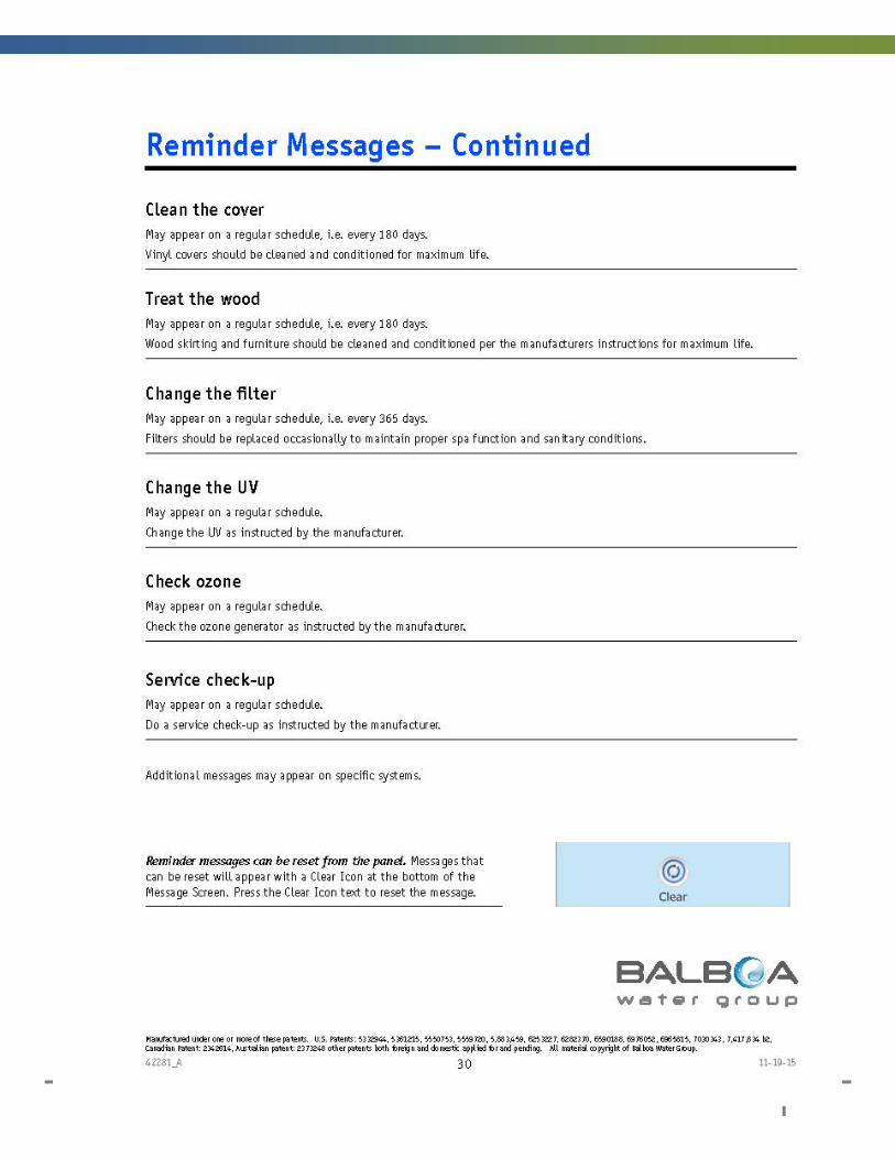
30 DOC: SRE-M-B-17 Sunrise Spas 2017 Owner’s Manual
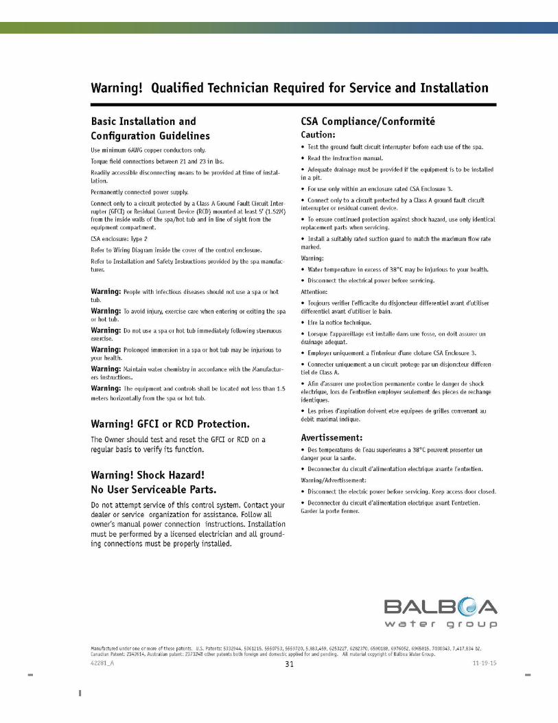
Sunrise Spas 2017 Owner’s Manual DOC: SRE-M-B-17 31
32 DOC: SRE-M-B-17 Sunrise Spas 2017 Owner’s Manual
Sunrise Spas 2017 Owner’s Manual DOC: SRE-M-B-17 33
34 DOC: SRE-M-B-17 Sunrise Spas 2017 Owner’s Manual
Sunrise Spas 2017 Owner’s Manual DOC: SRE-M-B-17 35
36 DOC: SRE-M-B-17 Sunrise Spas 2017 Owner’s Manual
Sunrise Spas 2017 Owner’s Manual DOC: SRE-M-B-17 37
38 DOC: SRE-M-B-17 Sunrise Spas 2017 Owner’s Manual
Sunrise Spas 2017 Owner’s Manual DOC: SRE-M-B-17 39
40 DOC: SRE-M-B-17 Sunrise Spas 2017 Owner’s Manual
Sunrise Spas 2017 Owner’s Manual DOC: SRE-M-B-17 41
42 DOC: SRE-M-B-17 Sunrise Spas 2017 Owner’s Manual
Sunrise Spas 2017 Owner’s Manual DOC: SRE-M-B-17 43
44 DOC: SRE-M-B-17 Sunrise Spas 2017 Owner’s Manual
Sunrise Spas 2017 Owner’s Manual DOC: SRE-M-B-17 45
46 DOC: SRE-M-B-17 Sunrise Spas 2017 Owner’s Manual

Sunrise Spas 2017 Owner’s Manual DOC: SRE-M-B-17 47
48 DOC: SRE-M-B-17 Sunrise Spas 2017 Owner’s Manual
Sunrise Spas 2017 Owner’s Manual DOC: SRE-M-B-17 49
50 DOC: SRE-M-B-17 Sunrise Spas 2017 Owner’s Manual
Sunrise Spas 2017 Owner’s Manual DOC: SRE-M-B-17 51
52 DOC: SRE-M-B-17 Sunrise Spas 2017 Owner’s Manual

Sunrise Spas 2017 Owner’s Manual DOC: SRE-M-B-17 53
ADDENDUM C
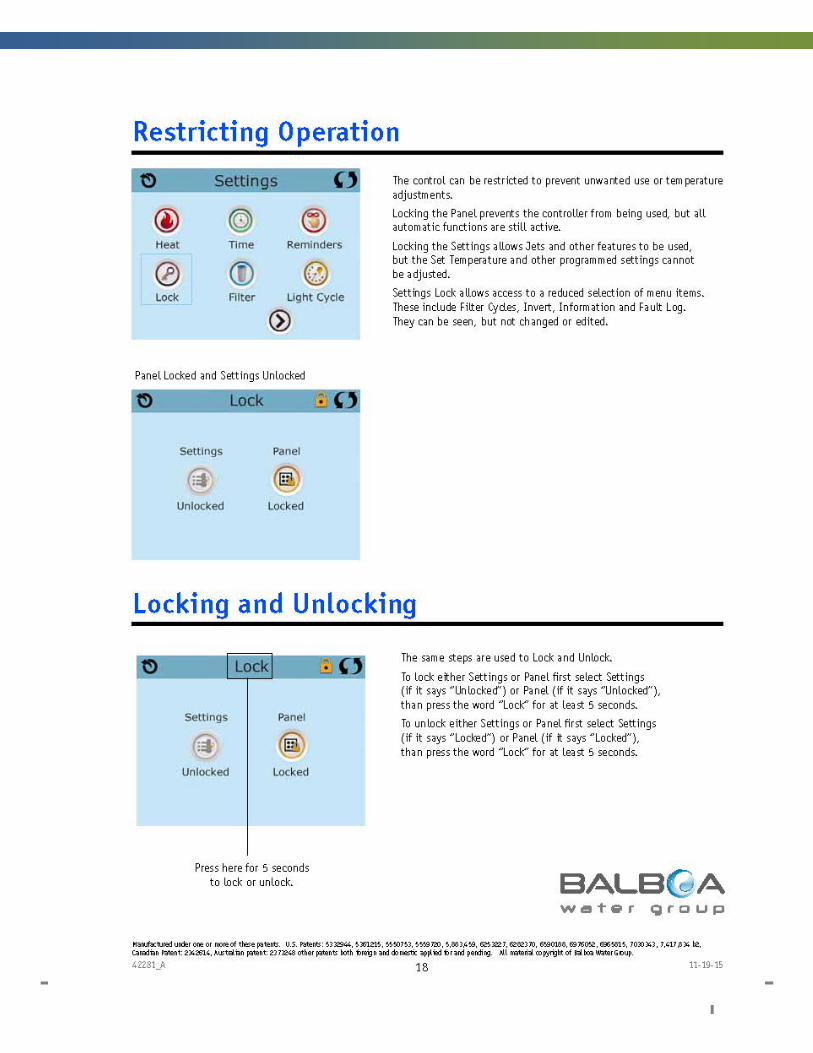
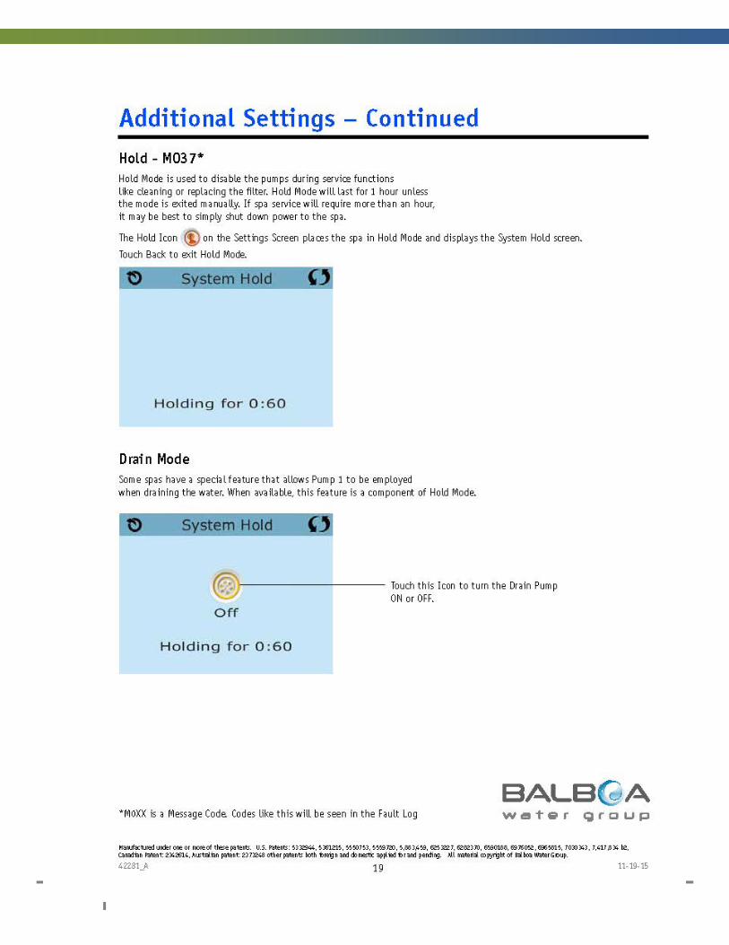
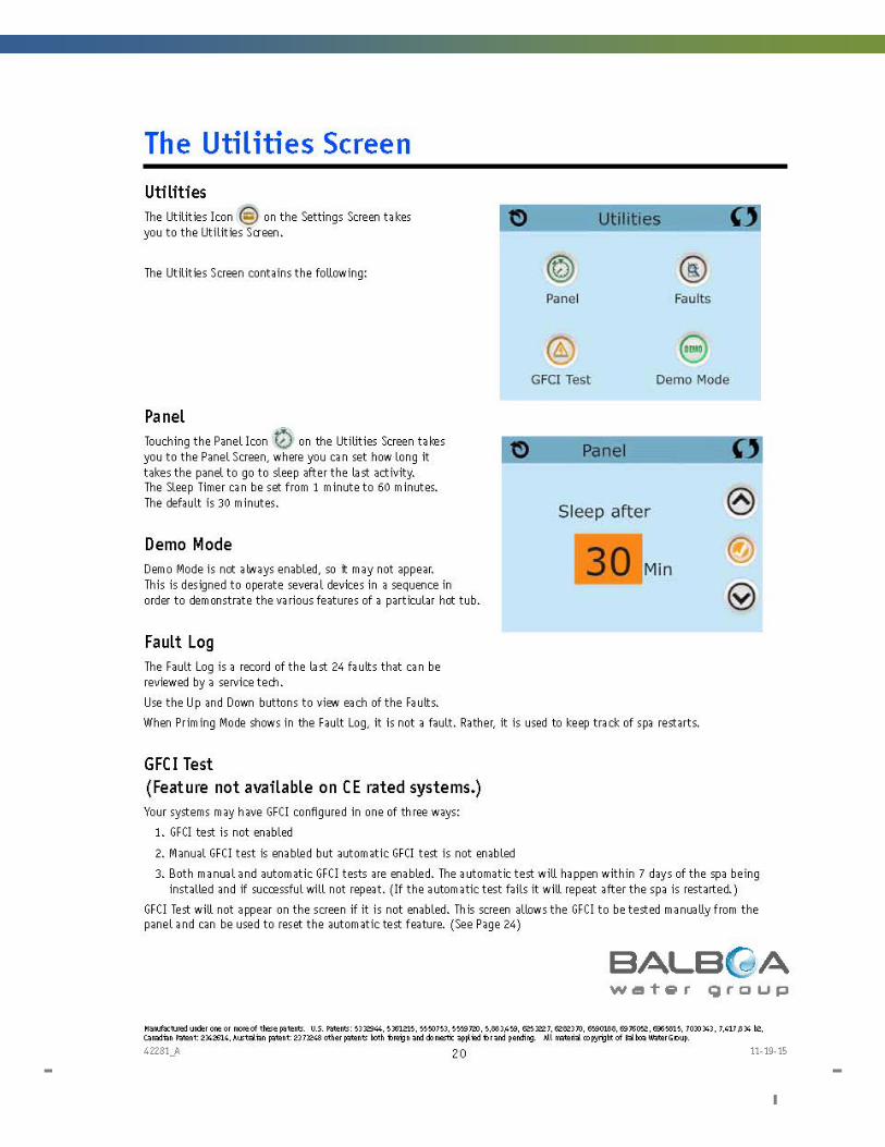
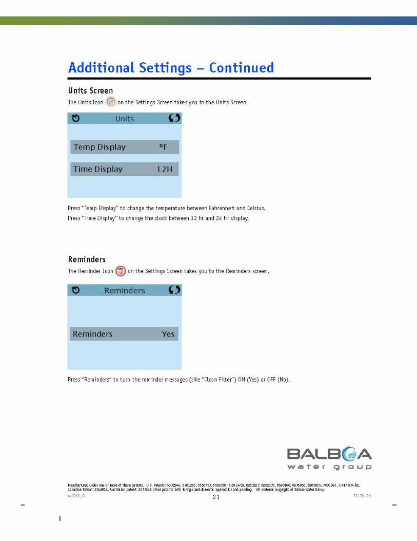
spaTouch Icon Driven User Guide

54 DOC: SRE-M-B-17 Sunrise Spas 2017 Owner’s Manual

Sunrise Spas 2017 Owner’s Manual DOC: SRE-M-B-17 55
56 DOC: SRE-M-B-17 Sunrise Spas 2017 Owner’s Manual
Sunrise Spas 2017 Owner’s Manual DOC: SRE-M-B-17 57
58 DOC: SRE-M-B-17 Sunrise Spas 2017 Owner’s Manual

Sunrise Spas 2017 Owner’s Manual DOC: SRE-M-B-17 59
60 DOC: SRE-M-B-17 Sunrise Spas 2017 Owner’s Manual
Sunrise Spas 2017 Owner’s Manual DOC: SRE-M-B-17 61
62 DOC: SRE-M-B-17 Sunrise Spas 2017 Owner’s Manual
Sunrise Spas 2017 Owner’s Manual DOC: SRE-M-B-17 63
64 DOC: SRE-M-B-17 Sunrise Spas 2017 Owner’s Manual
Sunrise Spas 2017 Owner’s Manual DOC: SRE-M-B-17 65
66 DOC: SRE-M-B-17 Sunrise Spas 2017 Owner’s Manual
Sunrise Spas 2017 Owner’s Manual DOC: SRE-M-B-17 67
68 DOC: SRE-M-B-17 Sunrise Spas 2017 Owner’s Manual
Sunrise Spas 2017 Owner’s Manual DOC: SRE-M-B-17 69
70 DOC: SRE-M-B-17 Sunrise Spas 2017 Owner’s Manual
Sunrise Spas 2017 Owner’s Manual DOC: SRE-M-B-17 71
72 DOC: SRE-M-B-17 Sunrise Spas 2017 Owner’s Manual
Sunrise Spas 2017 Owner’s Manual DOC: SRE-M-B-17 73
74 DOC: SRE-M-B-17 Sunrise Spas 2017 Owner’s Manual
Sunrise Spas 2017 Owner’s Manual DOC: SRE-M-B-17 75
76 DOC: SRE-M-B-17 Sunrise Spas 2017 Owner’s Manual
Sunrise Spas 2017 Owner’s Manual DOC: SRE-M-B-17 77
78 DOC: SRE-M-B-17 Sunrise Spas 2017 Owner’s Manual
Sunrise Spas 2017 Owner’s Manual DOC: SRE-M-B-17 79
80 DOC: SRE-M-B-17 Sunrise Spas 2017 Owner’s Manual
Sunrise Spas 2017 Owner’s Manual DOC: SRE-M-B-17 81
82 DOC: SRE-M-B-17 Sunrise Spas 2017 Owner’s Manual
Sunrise Spas 2017 Owner’s Manual DOC: SRE-M-B-17 83
84 DOC: SRE-M-B-17 Sunrise Spas 2017 Owner’s Manual

Sunrise Spas 2017 Owner’s Manual DOC: SRE-M-B-17 85
NOTES

86 DOC: SRE-M-B-17 Sunrise Spas 2017 Owner’s Manual