SP-030375 (CRs on TS 23060(PS domain Stage 2)) - 3GPP
93
Technical Specification Group Services and System Aspects TSGS#21(03)0375 Meeting #21, Frankfurt, Germany, 22-25 September 2003 Source: TSG SA WG2 Title: CRs on 23.060 Agenda Item: 7.2.3 The following Change Requests (CRs) have been approved by TSG SA WG2 and are requested to be approved by TSG SA plenary #21. Note: the source of all these CRs is now S2, even if the name of the originating company(ies) is still reflected on the cover page of all the attached CRs. Tdoc # Title Spec CR # cat Versio n in REL WI S2 meetin S2-032682 CR on “paging/out of service” issue 23.060 444r3 F 3.15.0 99 TEI S2-33 S2-032684 CR on “paging/out of service” issue 23.060 459 A 4.8.0 4 TEI S2-33 S2-032685 CR on “paging/out of service” issue 23.060 460 A 5.6.0 5 TEI S2-33 S2-032686 CR on “paging/out of service” issue 23.060 461 A 6.1.0 6 TEI S2-33 S2-032500 Controlling compression performed at the SGSN. 23.060 442r5 B 6.1.0 6 TEI6 S2-33 S2-033117 Usage of Allocation/Retention Priority in the BSS 23.060 450r3 B 6.1.0 6 TEI6 S2-34 S2-032718 BSS initiated BSS packet flow context deletion 23.060 455r1 C 6.1.0 6 TEI6 S2-33 S2-032603 Preservation procedure for realtime bearers in A/Gb mode 23.060 456 A 6.1.0 6 TEI6 S2-33
-
Upload
khangminh22 -
Category
Documents
-
view
0 -
download
0
Transcript of SP-030375 (CRs on TS 23060(PS domain Stage 2)) - 3GPP

Technical Specification Group Services and System Aspects TSGS#21(03)0375
Meeting #21, Frankfurt, Germany, 22-25 September 2003
Source: TSG SA WG2 Title: CRs on 23.060 Agenda Item: 7.2.3 The following Change Requests (CRs) have been approved by TSG SA WG2 and are requested to be approved by TSG SA plenary #21. Note: the source of all these CRs is now S2, even if the name of the originating company(ies) is still reflected on the cover page of all the attached CRs.
Tdoc # Title Spec CR # cat Version in
REL WI S2 meetin
S2-032682 CR on “paging/out of service” issue 23.060 444r3 F 3.15.0 99 TEI S2-33 S2-032684 CR on “paging/out of service” issue 23.060 459 A 4.8.0 4 TEI S2-33 S2-032685 CR on “paging/out of service” issue 23.060 460 A 5.6.0 5 TEI S2-33 S2-032686 CR on “paging/out of service” issue 23.060 461 A 6.1.0 6 TEI S2-33 S2-032500 Controlling compression performed at the
SGSN. 23.060 442r5 B 6.1.0 6 TEI6 S2-33
S2-033117 Usage of Allocation/Retention Priority in the BSS
23.060 450r3 B 6.1.0 6 TEI6 S2-34
S2-032718 BSS initiated BSS packet flow context deletion
23.060 455r1 C 6.1.0 6 TEI6 S2-33
S2-032603 Preservation procedure for realtime bearers in A/Gb mode
23.060 456 A 6.1.0 6 TEI6 S2-33

CR page 1
3GPP TSG-SA2 Meeting #33 Tdoc �S2-032500 Sophia Antipolis, France, 7 – 11 July 2003
CR-Form-v7
CHANGE REQUEST
� 23.060 CR 442 � rev 5 � Current version: 6.1.0 �
For HELP on using this form, see bottom of this page or look at the pop-up text over the � symbols.
Proposed change affects: UICC apps� ME Radio Access Network Core Network X
Title: � Controlling compression performed at the SGSN. Source: � Vodafone UK Work item code: � TEI-6 Date: � 23/06/2003 Category: � B Release: � Rel-6 Use one of the following categories:
F (correction) A (corresponds to a correction in an earlier release) B (addition of feature), C (functional modification of feature) D (editorial modification)
Detailed explanations of the above categories can be found in 3GPP TR 21.900.
Use one of the following releases: 2 (GSM Phase 2) R96 (Release 1996) R97 (Release 1997) R98 (Release 1998) R99 (Release 1999) Rel-4 (Release 4) Rel-5 (Release 5) Rel-6 (Release 6)
Reason for change: � In section 5.6.2.2 of 3GPP TS 23.060 it is stated:
"Unlike in A/Gb mode, user data compression is not supported in Iu mode, because the data compression efficiency depends on the type of user data, and because many applications compress data before transmission. It is difficult to check the type of data in the PDCP layer, and compressing all user data requires too much processing."
This statement is ambiguous in that it implies that in A/Gb mode it is not difficult to check the type of data in the equivalent SNDCP layer and that compressing all user data doesn’t require too much processing. However, it remains difficult to detect data type at the SNDCP layer, and also there are no controls defined in the specification dependent on data type to control compression. In addition, compression of all user data may require too much processing as the SGSN will waste processing time trying to compress user data which is known to have already been compressed especially where the end result is of little or no benefit
Summary of change: � To enable the operator to disable compression at the SGSN on a per APN basis
using a new information element that allows the GGSN to tell the SGSN not to compress downlink data in A/Gb mode. The new field will be configured per APN at the GGSN and may override a user request.
Consequences if � not approved:
There would be unnecessarily high SGSN processor load especially when downlink data is known to be either compressed already or optimised for transmission.
Clauses affected: � 5.3.2.6, 6.9.1.2.2, 6.9.1.3.2, 6.9.2.1, 6.9.2.2, 6.13.2, 9.2.2.1, 9.2.3.1, 9.2.3.2,
9.2.3.3, 12.3.2, 13.2, 13.3

CR page 2
Y N Other specs � X Other core specifications � 29.060 affected: X Test specifications X O&M Specifications Other comments: � This is a revision of S2-032190 which was previously based on 23.060 v.6.0.0.
S2-032190 was agreed in principle at SA#20 and referred back to SA2 to make it implementable.
How to create CRs using this form: Comprehensive information and tips about how to create CRs can be found at http://www.3gpp.org/specs/CR.htm. Below is a brief summary:
1) Fill out the above form. The symbols above marked � contain pop-up help information about the field that they are closest to.
2) Obtain the latest version for the release of the specification to which the change is proposed. Use the MS Word "revision marks" feature (also known as "track changes") when making the changes. All 3GPP specifications can be downloaded from the 3GPP server under ftp://ftp.3gpp.org/specs/ For the latest version, look for the directory name with the latest date e.g. 2001-03 contains the specifications resulting from the March 2001 TSG meetings.
3) With "track changes" disabled, paste the entire CR form (use CTRL-A to select it) into the specification just in front of the clause containing the first piece of changed text. Delete those parts of the specification which are not relevant to the change request.
CR page 3
**** First Modified Section ****
5.3.2.6 Compression Function
The compression function optimises use of radio path capacity by transmitting as little of the SDU (i.e. the exterior PDP PDU) as possible while at the same time preserving the information contained within it. Only IP header compression is supported in Iu mode. The GGSN may instruct the SGSN to negotiate no data compression for specific PDP contexts

CR page 4
**** Next Modified Section ****
6.9.1.2.2 Inter SGSN Routeing Area Update
The Inter SGSN Routeing Area Update procedure is illustrated in Figure 33.
MS BSS new SGSN HLR GGSN old SGSN
2. SGSN Context Response
3. Security Functions
1. Routeing Area Update Request
2. SGSN Context Request
6. Update PDP Context Request
6. Update PDP Context Response
7. Update Location
10. Update Location Ack
11. Routeing Area Update Accept
8. Cancel Location
8. Cancel Location Ack
9. Insert Subscriber Data Ack
9. Insert Subscriber Data
12. Routeing Area Update Complete
5. Forward Packets
4. SGSN Context Acknowledge
C3
C2
C1
Figure 33: Inter SGSN Routeing Area Update Procedure
1) The MS sends a Routeing Area Update Request (old RAI, old P-TMSI Signature, Update Type, Classmark, DRX parameters and MS Network Capability) to the new SGSN. Update Type shall indicate RA update or periodic RA update. The BSS shall add the Cell Global Identity including the RAC and LAC of the cell where the message was received before passing the message to the SGSN. Classmark contains the MS GPRS multislot capabilities and supported GPRS ciphering algorithms as defined in TS 24.008. DRX Parameters indicates whether or not the MS uses discontinuous reception and the DRX cycle length.

CR page 5
2) The new SGSN sends SGSN Context Request (old RAI, TLLI, old P-TMSI Signature, New SGSN Address) to the old SGSN to get the MM and PDP contexts for the MS. If the new SGSN provides functionality for Intra Domain Connection of RAN Nodes to Multiple CN Nodes, the new SGSN may derive the old SGSN from the old RAI and the old P-TMSI (or TLLI) and send the SGSN Context Request message to this old SGSN. Otherwise, the new SGSN derives the old SGSN from the old RAI. In any case the new SGSN will derive an SGSN that it believes is the old SGSN. This derived SGSN is itself the old SGSN, or it is associated with the same pool area as the actual old SGSN and it will determine the correct old SGSN from the P-TMSI (or TLLI) and relay the message to that actual old SGSN. The old SGSN validates the old P-TMSI Signature and responds with an appropriate error cause if it does not match the value stored in the old SGSN. This should initiate the security functions in the new SGSN. If the security functions authenticate the MS correctly, the new SGSN shall send an SGSN Context Request (old RAI, TLLI, MS Validated, New SGSN Address) message to the old SGSN. MS Validated indicates that the new SGSN has authenticated the MS. If the old P-TMSI Signature was valid or if the new SGSN indicates that it has authenticated the MS, the old SGSN stops assigning SNDCP N-PDU numbers to downlink N-PDUs received, and responds with SGSN Context Response (MM Context, PDP Contexts). If the MS is not known in the old SGSN, the old SGSN responds with an appropriate error cause. The old SGSN stores New SGSN Address, to allow the old SGSN to forward data packets to the new SGSN. Each PDP Context includes the SNDCP Send N-PDU Number for the next downlink N-PDU to be sent in acknowledged mode to the MS, the SNDCP Receive N-PDU Number for the next uplink N-PDU to be received in acknowledged mode from the MS, the GTP sequence number for the next downlink N-PDU to be sent to the MS and the GTP sequence number for the next uplink N-PDU to be tunnelled to the GGSN. The old SGSN starts a timer and stops the transmission of N-PDUs to the MS. The new SGSN shall ignore the MS Network Capability contained in MM Context of SGSN Context Response only when it has previously received an MS Network Capability in the Routeing Area Request.
3) Security functions may be executed. These procedures are defined in clause "Security Function". Ciphering mode shall be set if ciphering is supported.
If the security functions fail (e.g. because the SGSN cannot determine the HLR address to establish the Send Authentication Info dialogue), the Inter SGSN RAU Update procedure fails. A reject shall be returned to the MS with an appropriate cause.
4) The new SGSN sends an SGSN Context Acknowledge message to the old SGSN. This informs the old SGSN that the new SGSN is ready to receive data packets belonging to the activated PDP contexts. The old SGSN marks in its context that the MSC/VLR association and the information in the GGSNs and the HLR are invalid. This triggers the MSC/VLR, the GGSNs, and the HLR to be updated if the MS initiates a routeing area update procedure back to the old SGSN before completing the ongoing routeing area update procedure. If the security functions do not authenticate the MS correctly, then the routeing area update shall be rejected, and the new SGSN shall send a reject indication to the old SGSN. The old SGSN shall continue as if the SGSN Context Request was never received.
5) The old SGSN duplicates the buffered N-PDUs and starts tunnelling them to the new SGSN. Additional N-PDUs received from the GGSN before the timer described in step 2 expires are also duplicated and tunnelled to the new SGSN. N-PDUs that were already sent to the MS in acknowledged mode and that are not yet acknowledged by the MS are tunnelled together with the SNDCP N-PDU number. No N-PDUs shall be forwarded to the new SGSN after expiry of the timer described in step 2.
6) The new SGSN sends Update PDP Context Request (new SGSN Address, TEID, QoS Negotiated) to the GGSNs concerned. The GGSNs update their PDP context fields and return Update PDP Context Response (TEID, Prohibit Payload Compression). The Prohibit Payload Compression indicates that the SGSN should negotiate no data compression for this PDP context.
CR page 6
7) The new SGSN informs the HLR of the change of SGSN by sending Update Location (SGSN Number, SGSN Address, IMSI) to the HLR.
8) The HLR sends Cancel Location (IMSI, Cancellation Type) to the old SGSN with Cancellation Type set to Update Procedure. If the timer described in step 2 is not running, the old SGSN removes the MM and PDP contexts. Otherwise, the contexts are removed only when the timer expires. This allows the old SGSN to complete the forwarding of N-PDUs. It also ensures that the MM and PDP contexts are kept in the old SGSN in case the MS initiates another inter-SGSN routeing area update before completing the ongoing routeing area update to the new SGSN. The old SGSN acknowledges with Cancel Location Ack (IMSI).
9) The HLR sends Insert Subscriber Data (IMSI, GPRS Subscription Data) to the new SGSN. The new SGSN validates the MS's presence in the (new) RA. If due to regional subscription restrictions the MS is not allowed to be attached in the RA, the SGSN rejects the Routeing Area Update Request with an appropriate cause, and may return an Insert Subscriber Data Ack (IMSI, SGSN Area Restricted) message to the HLR. If all checks are successful, the SGSN constructs an MM context for the MS and returns an Insert Subscriber Data Ack (IMSI) message to the HLR.
10) The HLR acknowledges the Update Location by sending Update Location Ack (IMSI) to the new SGSN.
11) The new SGSN validates the MS's presence in the new RA. If due to roaming restrictions the MS, is not allowed to be attached in the SGSN, or if subscription checking fails, the new SGSN rejects the routeing area update with an appropriate cause. If all checks are successful, the new SGSN constructs MM and PDP contexts for the MS. A logical link is established between the new SGSN and the MS. The new SGSN responds to the MS with Routeing Area Update Accept (P-TMSI, P-TMSI Signature, Receive N-PDU Number). Receive N-PDU Number contains the acknowledgements for each acknowledged-mode NSAPI used by the MS, thereby confirming all mobile-originated N-PDUs successfully transferred before the start of the update procedure.
12) The MS acknowledges the new P-TMSI by returning a Routeing Area Update Complete (Receive N-PDU Number) message to the SGSN. Receive N-PDU Number contains the acknowledgements for each acknowledged-mode NSAPI used by the MS, thereby confirming all mobile-terminated N-PDUs successfully transferred before the start of the update procedure. If Receive N-PDU Number confirms reception of N-PDUs that were forwarded from the old SGSN, these N-PDUs shall be discarded by the new SGSN. LLC and SNDCP in the MS are reset.
In the case of a rejected routeing area update operation, due to regional subscription or roaming restrictions, or because the SGSN cannot determine the HLR address to establish the locating updating dialogue, the new SGSN shall not construct an MM context. A reject shall be returned to the MS with an appropriate cause. The MS does not re-attempt a routeing area update to that RA. The RAI value shall be deleted when the MS is powered-up.
If the new SGSN is unable to update the PDP context in one or more GGSNs, the new SGSN shall deactivate the corresponding PDP contexts as described in clause "SGSN-initiated PDP Context Deactivation Procedure". This shall not cause the SGSN to reject the routeing area update.
The PDP Contexts shall be sent from old to new SGSN in a prioritized order, i.e. the most important PDP Context first in the SGSN Context Response message. (The prioritization method is implementation dependent, but should be based on the current activity.)
If the new SGSN is unable to support the same number of active PDP contexts as received from old SGSN, the new SGSN should use the prioritisation sent by old SGSN as input when deciding which PDP contexts to maintain active and which ones to delete. In any case, the new SGSN shall first update all contexts in one or more GGSNs and then deactivate the context(s) that it cannot maintain as described in subclause "SGSN-initiated PDP Context Deactivation Procedure". This shall not cause the SGSN to reject the routeing area update.

CR page 7
If the timer described in step 2 expires and no Cancel Location (IMSI) was received from the HLR, the old SGSN stops forwarding N-PDUs to the new SGSN.
If the routeing area update procedure fails a maximum allowable number of times, or if the SGSN returns a Routeing Area Update Reject (Cause) message, the MS shall enter IDLE state.
The CAMEL procedure calls shall be performed, see referenced procedures in 3GPP TS 23.078:
C1) CAMEL_GPRS_PDP_Context_Disconnection, CAMEL_GPRS_Detach and CAMEL_PS_Notification.
They are called in the following order:
- The CAMEL_GPRS_PDP_Context_Disconnection procedure is called several times: once per PDP context. The procedure returns as result "Continue".
- Then the CAMEL_GPRS_Detach procedure is called once. The procedure returns as result "Continue".
- Then the CAMEL_PS_Notification procedure is called once. The procedure return as result "Continue".
C2) CAMEL_GPRS_Routeing_Area_Update_Session and CAMEL_PS_Notification.
They are called in the following order:
- The CAMEL_GPRS_Routeing_Area_Update_Session procedure is called. The procedure returns as result "Continue".
- Then the CAMEL_PS_Notification procedure is called. The procedure returns as result "Continue".
C3) CAMEL_GPRS_Routeing_Area_Update_Context.
This procedure is called several times: once per PDP context. It returns as result "Continue".

CR page 8
**** Next Modified Section ****
6.9.1.3.2 Combined Inter SGSN RA / LA Update
The Combined RA / LA Update (inter-SGSN) procedure is illustrated in Figure 35.

CR page 9
12b. Cancel Location
12c. Cancel Location Ack
12d. Insert Subscriber Data
16. TMSI Reallocation Complete
12f. Update Location Ack
13. Location Update Accept
15. Routeing Area Update Complete
14. Routeing Area Update Accept
8. Cancel Location
8. Cancel Location Ack
6. Update PDP Context Response
6. Update PDP Context Request
7. Update Location
10. Update Location Ack
12a. Update Location
11. Location Update Request
2. SGSN Context Response
3. Security Functions
2. SGSN Context Request
1. Routeing Area Update Request
9. Insert Subscriber Data
9. Insert Subscriber Data Ack
12e. Insert Subscriber Data Ack
MS BSS GGSN old SGSN new SGSN HLR
new MSC/VLR
old MSC/VLR
5. Forward Packets
4. SGSN Context Acknowledge
C3
C2
C1
Figure 35: Combined RA / LA Update in the Case of Inter SGSN RA Update Procedure

CR page 10
1) The MS sends a Routeing Area Update Request (old RAI, old P-TMSI Signature, Update Type, Classmark, DRX parameters and MS Network Capability) to the new SGSN. Update Type shall indicate combined RA / LA update, or, if the MS wants to perform an IMSI attach, combined RA / LA update with IMSI attach requested. The BSS shall add the Cell Global Identity including the RAC and LAC of the cell where the message was received before passing the message to the SGSN. Classmark contains the MS GPRS multislot capabilities and supported GPRS ciphering algorithms as defined in 3GPP TS 24.008. DRX Parameters indicates whether or not the MS uses discontinuous and the DRX cycle length.
2) The new SGSN sends SGSN Context Request (old RAI, TLLI, old P-TMSI Signature, New SGSN Address) to the old SGSN to get the MM and PDP contexts for the MS. If the new SGSN provides functionality for Intra Domain Connection of RAN Nodes to Multiple CN Nodes, the new SGSN may derive the old SGSN from the old RAI and the old P-TMSI (or TLLI) and send the SGSN Context Request message to this old SGSN. Otherwise, the new SGSN derives the old SGSN from the old RAI. In any case the new SGSN will derive an SGSN that it believes is the old SGSN. This derived SGSN is itself the old SGSN, or it is associated with the same pool area as the actual old SGSN and it will determine the correct old SGSN from the P-TMSI (or TLLI) and relay the message to that actual old SGSN. The old SGSN validates the old P-TMSI Signature and responds with an appropriate error cause if it does not match the value stored in the old SGSN. This should initiate the security functions in the new SGSN. If the security functions authenticate the MS correctly, the new SGSN shall send an SGSN Context Request (old RAI, TLLI, MS Validated, New SGSN Address) message to the old SGSN. MS Validated indicates that the new SGSN has authenticated the MS. If the old P-TMSI Signature was valid or if the new SGSN indicates that it has authenticated the MS, the old SGSN stops assigning SNDCP N-PDU numbers to downlink N-PDUs received, and responds with SGSN Context Response (MM Context, PDP Contexts). If the MS is not known in the old SGSN, the old SGSN responds with an appropriate error cause. The old SGSN stores New SGSN Address until the old MM context is cancelled, to allow the old SGSN to forward data packets to the new SGSN. Each PDP Context includes the SNDCP Send N-PDU Number for the next downlink N-PDU to be sent in acknowledged mode to the MS, the SNDCP Receive N-PDU Number for the next uplink N-PDU to be received in acknowledged mode from the MS, the GTP sequence number for the next downlink N-PDU to be sent to the MS and the GTP sequence number for the next uplink N-PDU to be tunnelled to the GGSN. The old SGSN starts a timer and stops the downlink transfer. The new SGSN shall ignore the MS Network Capability contained in MM Context of SGSN Context Response only when it has previously received an MS Network Capability in the Routeing Area Request.
3) Security functions may be executed. These procedures are defined in clause "Security Function". Ciphering mode shall be set if ciphering is supported. If the security functions fail (e.g. because the SGSN cannot determine the HLR address to establish the Send Authentication Info dialogue), the Inter SGSN RAU Update procedure fails. A reject shall be returned to the MS with an appropriate cause.
4) The new SGSN sends an SGSN Context Acknowledge message to the old SGSN. This informs the old SGSN that the new SGSN is ready to receive data packets belonging to the activated PDP contexts. The old SGSN marks in its context that the MSC/VLR association and the information in the GGSNs and the HLR are invalid. This triggers the MSC/VLR, the GGSNs, and the HLR to be updated if the MS initiates a routeing area update procedure back to the old SGSN before completing the ongoing routeing area update procedure. If the security functions do not authenticate the MS correctly, the routeing area update shall be rejected, and the new SGSN shall send a reject indication to the old SGSN. The old SGSN shall continue as if the SGSN Context Request was never received.
5) The old SGSN duplicates the buffered N-PDUs and starts tunnelling them to the new SGSN. Additional N-PDUs received from the GGSN before the timer described in step 2 expires are also duplicated and tunnelled to the new SGSN. N-PDUs that were already sent to the MS in acknowledged mode and that are not yet acknowledged by the MS are tunnelled together with the

CR page 11
SNDCP N-PDU number. No N-PDUs shall be forwarded to the new SGSN after expiry of the timer described in step 2.
6) The new SGSN sends Update PDP Context Request (new SGSN Address, TEID, QoS Negotiated) to the GGSNs concerned. The GGSNs update their PDP context fields and return an Update PDP Context Response (TEID, Prohibit Payload Compression). The Prohibit Payload Compression indicates that the SGSN should negotiate no data compression for this PDP context.
7) The new SGSN informs the HLR of the change of SGSN by sending Update Location (SGSN Number, SGSN Address, IMSI) to the HLR.
8) The HLR sends Cancel Location (IMSI, Cancellation Type) to the old SGSN with Cancellation Type set to Update Procedure. If the timer described in step 2 is not running, the old SGSN removes the MM and PDP contexts. Otherwise, the contexts are removed only when the timer expires. This allows the old SGSN to complete the forwarding of N-PDUs. It also ensures that the MM and PDP contexts are kept in the old SGSN in case the MS initiates another inter SGSN routeing area update before completing the ongoing routeing area update to the new SGSN. The old SGSN acknowledges with Cancel Location Ack (IMSI).
9) The HLR sends Insert Subscriber Data (IMSI, GPRS Subscription Data) to the new SGSN. The new SGSN validates the MS's presence in the (new) RA. If due to regional subscription restrictions the MS is not allowed to be attached in the RA, the SGSN rejects the Routeing Area Update Request with an appropriate cause, and may return an Insert Subscriber Data Ack (IMSI, SGSN Area Restricted) message to the HLR. If all checks are successful, the SGSN constructs an MM context for the MS and returns an Insert Subscriber Data Ack (IMSI) message to the HLR.
10) The HLR acknowledges the Update Location by sending Update Location Ack (IMSI) to the new SGSN.
11) If the association has to be established, if Update Type indicates combined RA / LA update with IMSI attach requested, or if the LA changed with the routeing area update, the new SGSN sends a Location Update Request (new LAI, IMSI, SGSN Number, Location Update Type) to the VLR. Location Update Type shall indicate IMSI attach if Update Type in step 1 indicated combined RA / LA update with IMSI attach requested. Otherwise, Location Update Type shall indicate normal location update. When the SGSN does not provide functionality for the Intra Domain Connection of RAN Nodes to Multiple CN Nodes, the VLR number is derived from the RAI. When the SGSN provides functionality for Intra Domain Connection of RAN Nodes to Multiple CN Nodes, the SGSN uses the RAI and a hash value from the IMSI to determine the VLR number. The SGSN starts the location update procedure towards the new MSC/VLR upon receipt of the first Insert Subscriber Data message from the HLR in step 9). The VLR creates or updates the association with the SGSN by storing SGSN Number.
12) If the subscriber data in the VLR is marked as not confirmed by the HLR, the new VLR informs the HLR. The HLR cancels the old VLR and inserts subscriber data in the new VLR:
a) The new VLR sends an Update Location (new VLR) to the HLR.
b) The HLR cancels the data in the old VLR by sending Cancel Location (IMSI) to the old VLR.
c) The old VLR acknowledges with Cancel Location Ack (IMSI).
d) The HLR sends Insert Subscriber Data (IMSI, subscriber data) to the new VLR.
e) The new VLR acknowledges with Insert Subscriber Data Ack (IMSI).
f) The HLR responds with Update Location Ack (IMSI) to the new VLR.
13) The new VLR allocates a new TMSI and responds with Location Update Accept (VLR TMSI) to the SGSN. VLR TMSI is optional if the VLR has not changed.

CR page 12
14) The new SGSN validates the MS's presence in the new RA. If due to roaming restrictions the MS is not allowed to be attached in the RA, or if subscription checking fails, the SGSN rejects the routeing area update with an appropriate cause. If all checks are successful, the new SGSN establishes MM and PDP contexts for the MS. A logical link is established between the new SGSN and the MS. The new SGSN responds to the MS with Routeing Area Update Accept (P-TMSI, VLR TMSI, P-TMSI Signature, Receive N-PDU Number). Receive N-PDU Number contains the acknowledgements for each acknowledged-mode NSAPI used by the MS, thereby confirming all mobile-originated N-PDUs successfully transferred before the start of the update procedure.
15) The MS confirms the reallocation of the TMSIs by returning a Routeing Area Update Complete (Receive N-PDU Number) message to the SGSN. Receive N-PDU Number contains the acknowledgements for each acknowledged-mode NSAPI used by the MS, thereby confirming all mobile-terminated N-PDUs successfully transferred before the start of the update procedure. If Receive N-PDU Number confirms reception of N-PDUs that were forwarded from the old SGSN, these N-PDUs shall be discarded by the new SGSN. LLC and SNDCP in the MS are reset.
16) The new SGSN sends a TMSI Reallocation Complete message to the new VLR if the MS confirms the VLR TMSI.
In the case of a rejected routeing area update operation, due to regional subscription or roaming restrictions, or because the SGSN cannot determine the HLR address to establish the locating updating dialogue, the new SGSN shall not construct an MM context. A reject shall be returned to the MS with an appropriate cause. The MS shall not re-attempt a routeing area update to that RA. The RAI value shall be deleted when the MS is powered-up.
If the new SGSN is unable to update the PDP context in one or more GGSNs, the new SGSN shall deactivate the corresponding PDP contexts as described in clause "SGSN-initiated PDP Context Deactivation Procedure". This shall not cause the SGSN to reject the routeing area update.
The PDP Contexts shall be sent from old to new SGSN in a prioritized order, i.e. the most important PDP Context first in the SGSN Context Response message. (The prioritization method is implementation dependent, but should be based on the current activity.)
If the new SGSN is unable to support the same number of active PDP contexts as received from old SGSN, the new SGSN should use the prioritisation sent by old SGSN as input when deciding which PDP contexts to maintain active and which ones to delete. In any case, the new SGSN shall first update all contexts in one or more GGSNs and then deactivate the context(s) that it cannot maintain as described in subclause "SGSN-initiated PDP Context Deactivation Procedure". This shall not cause the SGSN to reject the routeing area update.
If the routeing area update procedure fails a maximum allowable number of times, or if the SGSN returns a Routeing Area Update Reject (Cause) message, the MS shall enter IDLE state.
If the timer described in step 2 expires and no Cancel Location (IMSI) was received from the HLR, the old SGSN shall stop forwarding N-PDUs to the new SGSN.
If the Location Update Accept message indicates a reject, this should be indicated to the MS, and the MS shall not access non-GPRS services until a successful location update is performed.
The CAMEL procedure calls shall be performed, see referenced procedures in 3GPP TS 23.078:
C1) CAMEL_GPRS_PDP_Context_Disconnection, CAMEL_GPRS_Detach and CAMEL_PS_Notification.
They are called in the following order:
- The CAMEL_GPRS_PDP_Context_Disconnection procedure is called several times: once per PDP context. The procedure returns as result "Continue".

CR page 13
- Then the CAMEL_GPRS_Detach procedure is called once. The procedure returns as result "Continue".
- Then the CAMEL_PS_Notification procedure is called once. The procedure returns as result "Continue".
C2) CAMEL_GPRS_Routeing_Area_Update_Session and CAMEL_PS_Notification.
They are called in the following order:
- The CAMEL_GPRS_Routeing_Area_Update_Session procedure is called. The procedure returns as result "Continue".
- Then the CAMEL_PS_Notification procedure is called. The procedure returns as result "Continue".
C3) CAMEL_GPRS_Routeing_Area_Update_Context.
This procedure is called several times: once per PDP context. It returns as result "Continue".
**** Next Modified Section ****
6.9.2.1 Routeing Area Update Procedure
A routeing area update takes place when an attached MS detects that it has entered a new RA or when the periodic RA update timer has expired or when RRC connection is released with cause "Directed Signalling connection re-establishment" or when the MS has to indicate new access capabilities to the network.
The SGSN detects that it is an intra-SGSN routeing area update by noticing that it also handles the old RA. In this case, the SGSN has the necessary information about the MS and there is no need to inform the GGSNs or the HLR about the new MS location. A periodic RA update is always an intra-SGSN routeing area update. If the network operates in mode I, an MS that is in CS/PS mode of operation shall perform the Combined RA / LA Update procedures except this CS/PS mode MS is engaged in a CS connection, then it shall perform (non combined) RA Update procedures.
In Iu mode, an RA update is either an intra-SGSN or inter-SGSN RA update, either combined RA / LA update or only RA update, either initiated by an MS in PMM-CONNECTED or in PMM-IDLE state. The SRNC may provide a PMM-CONNECTED state MS with MM information like RAI by dedicated signalling. Typically, the SRNC should not provide a RAI to an MS in PMM-CONNECTED state. An exception is after an SRNS relocation, in which case the new SRNC shall indicate the RAI to the MS.
All the RA update cases are contained in the procedure illustrated in Figure 36.
NOTE 1: The network may receive an RA update from a UE in PMM-CONNECTED state over a new Iu signalling connection. This could happen when the UE enters PMM-IDLE state on receipt of RRC Connection Release with cause "Directed Signalling connection re-establishment" and initiates an RA or Combined RA update procedure (see clause 6.1.2.4.1).

CR page 14
3. SGSN Context Response 4. Security Functions
2. SGSN Context Request 1. Routeing Area Update Request
MS old
SRNS GGSN old
3G-SGSN new
3G-SGSN HLR
new MSC/VLR
old MSC/VLR
5. SGSN Context Ack
11. Cancel Location
11. Cancel Location Ack
9. Update PDP Context Response
9. Update PDP Context Request
10. Update Location
15b. Cancel Location
15c. Cancel Location Ack
15d. Insert Subscriber Data
19. TMSI Reallocation Complete
15f. Update Location Ack 16. Location Update Accept
18. Routeing Area Update Complete
17. Routeing Area Update Accept
13. Update Location Ack
15a. Update Location
14. Location Update Request
12. Insert Subscriber Data
12. Insert Subscriber Data Ack
15e. Insert Subscriber Data Ack
C3
C2
2a. SRNS Context Request
2a. SRNS Context Response
11a. Iu Release Command
11a. Iu Release Complete
6. SRNS Data Forward Command
7. Forward Packets
8. Forward Packets
new SRNS
C1
Figure 36: Iu mode RA Update Procedure

CR page 15
1) The RRC connection is established, if not already done. The MS sends a Routeing Area Update Request message (P-TMSI, old RAI, old P-TMSI Signature, Update Type, follow on request, Classmark, DRX Parameters, MS Network Capability) to the new SGSN. The MS shall set a follow-on request if there is pending uplink traffic (signalling or user data). The SGSN may use, as an implementation option, the follow-on request indication to release or keep the Iu connection after the completion of the RA update procedure. Update Type shall indicate:
- RA Update if the RA Update is triggered by a change of RA;
- Periodic RA Update if the RA update is triggered by the expiry of the Periodic RA Update timer;
- Combined RA / LA Update if the MS is also IMSI-attached and the LA update shall be performed in network operation mode I (see clause "Interactions Between SGSN and MSC/VLR"); or
- Combined RA / LA Update with IMSI attach requested if the MS wants to perform an IMSI attach in network operation mode I.
The SRNC shall add the Routeing Area Identity including the RAC and LAC of the area where the MS is located before forwarding the message to the 3G-SGSN. This RA identity corresponds to the RAI in the MM system information sent by the SRNC to the MS. Classmark is described in clause "MS Network Capability". DRX Parameters indicates whether or not the MS uses discontinuous reception and the DRX cycle length.
NOTE 2: Sending the Routeing Area Update Request message to the SGSN triggers the establishment of a signalling connection between RAN and SGSN for the concerned MS.
2) If the RA update is an Inter-SGSN Routeing area update and if the MS was in PMM-IDLE state, the new SGSN sends an SGSN Context Request message (old P-TMSI, old RAI, old P-TMSI Signature) to the old SGSN to get the MM and PDP contexts for the MS. If the new SGSN provides functionality for Intra Domain Connection of RAN Nodes to Multiple CN Nodes, the new SGSN may derive the old SGSN from the old RAI and the old P-TMSI and send the SGSN Context Request message to this old SGSN. Otherwise, the new SGSN derives the old SGSN from the old RAI. In any case the new SGSN will derive an SGSN that it believes is the old SGSN. This derived SGSN is itself the old SGSN, or it is associated with the same pool area as the actual old SGSN and it will determine the correct old SGSN from the P-TMSI and relay the message to that actual old SGSN. The old SGSN validates the old P-TMSI Signature and responds with an appropriate error cause if it does not match the value stored in the old SGSN. This should initiate the security functions in the new SGSN. If the security functions authenticate the MS correctly, the new SGSN shall send an SGSN Context Request (IMSI, old RAI, MS Validated) message to the old SGSN. MS Validated indicates that the new SGSN has authenticated the MS. If the old P-TMSI Signature was valid or if the new SGSN indicates that it has authenticated the MS, the old SGSN starts a timer.. If the MS is not known in the old SGSN, the old SGSN responds with an appropriate error cause.
2a) If the MS is PMM-CONNECTED state in the old 3G-SGSN or, in case of an intra-SGSN RA update, if the MS is in the PMM-CONNECTED state and the RAU was received over another Iu connection than the established one, the old SGSN sends an SRNS Context Request (IMSI) message to the old SRNS to retrieve the sequence numbers for the PDP context for inclusion in the SGSN Context Response message. Upon reception of this message, the SRNS buffers and stops sending downlink PDUs to the MS and returns an SRNS Context Response (IMSI, GTP-SNDs, GTP-SNUs, PDCP-SNUs) message. The SRNS shall include for each PDP context the next in-sequence GTP sequence number to be sent to the MS and the GTP sequence number of the next uplink PDU to be tunnelled to the GGSN. For each active PDP context which uses lossless PDCP, the SRNS also includes the uplink PDCP sequence number (PDCP-SNU). PDCP-SNU shall be the next in-sequence PDCP sequence number expected from the MS (per each active radio bearer). No conversion of PDCP sequence numbers to SNDCP sequence numbers shall be done in the 3G-SGSN.
CR page 16
3) The old 3G-SGSN responds with an SGSN Context Response (MM Context, PDP Contexts) message. For each PDP context the old 3G-SGSN shall include the GTP sequence number for the next uplink GTP PDU to be tunnelled to the GGSN and the next downlink GTP sequence number for the next PDU to be sent to the MS. Each PDP Context also includes the PDCP sequence numbers if PDCP sequence numbers are received from the old SRNS. The new 3G-SGSN shall ignore the MS Network Capability contained in MM Context of SGSN Context Response only when it has previously received an MS Network Capability in the Routeing Area Request. The GTP sequence numbers received from the old 3G-SGSN are only relevant if delivery order is required for the PDP context (QoS profile).
4) Security functions may be executed. These procedures are defined in clause "Security Function". If the security functions do not authenticate the MS correctly, the routeing area update shall be rejected, and the new SGSN shall send a reject indication to the old SGSN. The old SGSN shall continue as if the SGSN Context Request was never received.
5) If the RA update is an Inter-SGSN Routeing area update, the new SGSN sends an SGSN Context Acknowledge message to the old SGSN. The old SGSN marks in its context that the MSC/VLR association and the information in the GGSNs and the HLR are invalid. This triggers the MSC/VLR, the GGSNs, and the HLR to be updated if the MS initiates a routeing area update procedure back to the old SGSN before completing the ongoing routeing area update procedure.
6) If the MS is in PMM-CONNECTED state in the old 3G-SGSN or, in case of an intra-SGSN RA update, if the MS is PMM connected and the RAU was received over another Iu connection than the established one, the old 3G-SGSN sends an SRNS Data Forward Command (RAB ID, Transport Layer Address, Iu Transport Association) message to the SRNS. Upon receipt of the SRNS Data Forward Command message from the 3G-SGSN, the SRNS shall start the data-forwarding timer.
7) For each indicated RAB the SRNS starts duplicating and tunnelling the buffered GTP PDUs to the old 3G-SGSN. For each radio bearer which uses lossless PDCP the SRNS shall start tunnelling the partly transmitted and the transmitted but not acknowledged PDCP-PDUs together with their related PDCP sequence numbers and start duplicating and tunnelling the buffered GTP PDUs to the old 3G-SGSN. Upon receipt of the SRNS Data Forward Command message from the 3G-SGSN, the SRNS shall start the data-forwarding timer.
8) If the RA update is an Inter-SGSN RA Update, the old 3G-SGSN tunnels the GTP PDUs to the new 3G-SGSN. No conversion of PDCP sequence numbers to SNDCP sequence numbers shall be done in the 3G-SGSN.
9) If the RA update is an Inter-SGSN RA Update and if the MS was not in PMM-CONNECTED state in the new 3G-SGSN, the new SGSN sends Update PDP Context Request (new SGSN Address, QoS Negotiated, Tunnel Endpoint Identifier,) to the GGSNs concerned. The GGSNs update their PDP context fields and return an Update PDP Context Response (Tunnel Endpoint Identifier, Prohibit Payload Compression). The Prohibit Payload Compression indicates that the SGSN should negotiate no data compression for this PDP context. Note: If the RA update is an Inter-SGSN routeing area update initiated by an MS in PMM-CONNECTED state in the new 3G-SGSN, the Update PDP Context Request message is sent as described in subclause "Serving RNS Relocation Procedures".
10) If the RA update is an Inter-SGSN RA Update, the new SGSN informs the HLR of the change of SGSN by sending Update Location (SGSN Number, SGSN Address, IMSI) to the HLR.
11) If the RA update is an Inter-SGSN RA Update, the HLR sends Cancel Location (IMSI, Cancellation Type) to the old SGSN with Cancellation Type set to Update Procedure. If the timer described in step 2 is not running, the old SGSN removes the MM context. Otherwise, the contexts are removed only when the timer expires. It also ensures that the MM context is kept in the old SGSN in case the MS initiates another inter SGSN routeing area update before completing the ongoing routeing area update to the new SGSN. The old SGSN acknowledges with Cancel Location Ack (IMSI).

CR page 17
11a) On receipt of Cancel Location, if the MS is PMM-CONNECTED in the old 3G-SGSN, the old 3G-SGSN sends an Iu Release Command message to the old SRNC. When the data-forwarding timer has expired, the SRNS responds with an Iu Release Complete message.
12) If the RA update is an inter-SGSN RA Update, the HLR sends Insert Subscriber Data (IMSI, subscription data) to the new SGSN. The new SGSN validates the MS's presence in the (new) RA. If due to regional subscription restrictions the MS is not allowed to be attached in the RA, the SGSN rejects the Routeing Area Update Request with an appropriate cause, and may return an Insert Subscriber Data Ack (IMSI, SGSN Area Restricted) message to the HLR. If all checks are successful, the SGSN constructs an MM context for the MS and returns an Insert Subscriber Data Ack (IMSI) message to the HLR.
13) If the RA update is an Inter-SGSN RA Update, the HLR acknowledges the Update Location by sending Update Location Ack (IMSI) to the new SGSN.
14) If Update Type indicates combined RA / LA update with IMSI attach requested, or if the LA changed with the routeing area update, the association has to be established, and the new SGSN sends a Location Update Request (new LAI, IMSI, SGSN Number, Location Update Type) to the VLR. Location Update Type shall indicate IMSI attach if Update Type in step 1 indicated combined RA / LA update with ISI attach requested. Otherwise, Location Update Type shall indicate normal location update. When the SGSN does not provide functionality for the Intra Domain Connection of RAN Nodes to Multiple CN Nodes, the VLR number is derived from the RAI. When the SGSN provides functionality for Intra Domain Connection of RAN Nodes to Multiple CN Nodes, the SGSN uses the RAI and a hash value from the IMSI to determine the VLR number. The SGSN starts the location update procedure towards the new MSC/VLR upon receipt of the first Insert Subscriber Data message from the HLR in step 8). The VLR creates or updates the association with the SGSN by storing SGSN Number.
15) If the subscriber data in the VLR is marked as not confirmed by the HLR, the new VLR informs the HLR. The HLR cancels the old VLR and inserts subscriber data in the new VLR:
a) The new VLR sends an Update Location (new VLR) to the HLR.
b) The HLR cancels the data in the old VLR by sending Cancel Location (IMSI) to the old VLR.
c) The old VLR acknowledges with Cancel Location Ack (IMSI).
d) The HLR sends Insert Subscriber Data (IMSI, subscriber data) to the new VLR.
e) The new VLR acknowledges with Insert Subscriber Data Ack (IMSI).
f) The HLR responds with Update Location Ack (IMSI) to the new VLR.
16) The new VLR allocates a new TMSI and responds with Location Update Accept (VLR TMSI) to the SGSN. VLR TMSI is optional if the VLR has not changed.
17) The new SGSN validates the MS's presence in the new RA. If due to roaming restrictions the MS is not allowed to be attached in the RA, or if subscription checking fails, the SGSN rejects the routeing area update with an appropriate cause. If all checks are successful, the new SGSN establishes MM context for the MS. The new SGSN responds to the MS with Routeing Area Update Accept (P-TMSI, VLR TMSI, P-TMSI Signature).
18) The MS confirms the reallocation of the TMSIs by returning a Routeing Area Update Complete message to the SGSN.
19) The new SGSN sends a TMSI Reallocation Complete message to the new VLR if the MS confirms the VLR TMSI.
NOTE 3: Steps 15, 16, and 19 are performed only if step 14 is performed.

CR page 18
NOTE: The new SGSN may initiate RAB establishment after execution of the security functions (step 4), or wait until completion of the RA update procedure. For the MS, RAB establishment may occur anytime after the RA update request is sent (step 1).
In the case of a rejected routeing area update operation, due to regional subscription or roaming restrictions, the new SGSN shall not construct an MM context. A reject shall be returned to the MS with an appropriate cause. The MS shall not re-attempt a routeing area update to that RA. The RAI value shall be deleted when the MS is powered up.
If the new SGSN is unable to update the PDP context in one or more GGSNs, the new SGSN shall deactivate the corresponding PDP contexts as described in subclause "SGSN-initiated PDP Context Deactivation Procedure". This shall not cause the SGSN to reject the routeing area update.
The PDP Contexts shall be sent from old to new SGSN in a prioritized order, i.e. the most important PDP Context first in the SGSN Context Response message. (The prioritization method is implementation dependent, but should be based on the current activity.)
If the new SGSN is unable to support the same number of active PDP contexts as received from old SGSN, the new SGSN should use the prioritisation sent by old SGSN as input when deciding which PDP contexts to maintain active and which ones to delete. In any case, the new SGSN shall first update all contexts in one or more GGSNs and then deactivate the context(s) that it cannot maintain as described in subclause "SGSN-initiated PDP Context Deactivation Procedure". This shall not cause the SGSN to reject the routeing area update.
NOTE: In case MS was in PMM-CONNECTED state the PDP Contexts are sent already in the Forward Relocation Request message as described in subclause “Serving RNS relocation procedures”.
If the routeing area update procedure fails a maximum allowable number of times, or if the SGSN returns a Routeing Area Update Reject (Cause) message, the MS shall enter PMM-DETACHED state.
If the Location Update Accept message indicates a reject, this should be indicated to the MS, and the MS shall not access non-PS services until a successful location update is performed.
The CAMEL procedure calls shall be performed, see referenced procedures in 3GPP TS 23.078:
C1) CAMEL_GPRS_PDP_Context_Disconnection, CAMEL_GPRS_Detach and CAMEL_PS_Notification.
They are called in the following order:
- The CAMEL_GPRS_PDP_Context_Disconnection procedure is called several times: once per PDP context. The procedure returns as result "Continue".
- Then the CAMEL_GPRS_Detach procedure is called once. The procedure returns as result "Continue".
- Then the CAMEL_PS_Notification procedure is called once. The procedure returns as result "Continue".
C2) CAMEL_GPRS_Routeing_Area_Update_Session and CAMEL_PS_Notification.
They are called in the following order:
- The CAMEL_GPRS_Routeing_Area_Update_Session procedure is called. The procedure returns as result "Continue".
- Then the CAMEL_PS_Notification procedure is called. The procedure returns as result "Continue".

CR page 19
C3) CAMEL_GPRS_Routeing_Area_Update_Context.
This procedure is called several times: once per PDP context. It returns as result "Continue".
**** Next Modified Section ****
6.9.2.2.1 Serving RNS Relocation Procedure
This procedure is only performed for an MS in PMM-CONNECTED state where the Iur interface carries both the control signalling and the user data. This procedure is not applicable for GERAN.
The Serving SRNS Relocation procedure is used to move the RAN to CN connection point at the RAN side from the source SRNC to the target RNC, from a "standing still position". In the procedure, the Iu links are relocated. If the target RNC is connected to the same SGSN as the source SRNC, an Intra-SGSN SRNS Relocation procedure is performed. If the routeing area is changed, this procedure is followed by an Intra-SGSN Routeing Area Update procedure. The SGSN detects an Intra-SGSN routeing area update by noticing that it also handles the old RA. In this case, the SGSN has the necessary information about the MS and there is no need to inform the HLR about new location of the MS.
Figure 37 shows user data routing before SRNS relocation when source SRNC and target RNC are connected to different SGSNs. Figure 38 shows the user data routing after SRNS Relocation procedure and Routeing Area Update procedure is completed. In case depicted in Figure 37 and Figure 38, the MS is in state PMM-CONNECTED.
LA1, RA1
HLR/AuC
old SGSN
GGSN
LA2, RA2
new SGSN
source SRNC
new MSC/VLRold MSC/VLR
MS
target RNC
Figure 37: Before SRNS Relocation and Routeing Area Update
Before the SRNS Relocation procedure and RA update, the MS is registered in the old SGSN. The source RNC is acting as a serving RNC (SRNC).

CR page 20
LA1, RA1
MS
HLR/AuC
old SGSN
source RNC
GGSN
LA2, RA2
new SGSNold MSC/VLR new MSC/VLR
target SRNC
Figure 38: After SRNS Relocation and Routeing Area Update
After the SRNS Relocation procedure and RA update, the MS is registered in the new SGSN. The MS is in the state PMM-CONNECTED towards the new SGSN, and the target RNC is acting as the serving RNC.

CR page 21
The Serving SRNS Relocation procedure is illustrated in Figure 39. The sequence is valid for both intra-SGSN SRNS relocation and inter-SGSN SRNS relocation.
MS Target RNC
Source RNC
Old SGSN
New SGSN GGSN
3. Forward Relocation Request
4. Relocation Request
2. Relocation Required
6. Relocation Command
5. Forward Relocation Response
4. Relocation Request Acknowledge
9. Relocation Detect 10. RAN Mobility Information
10. RAN Mobility Information Confirm
Establishment of Radio Access Bearers
C1
1. Decision to perform SRNS relocation
8. Relocation Commit 7. Forwarding of data
11. Relocation Complete 12. Forward Relocation Complete
15. Routing Area Update
13. Update PDP Context Request 14. Iu Release Command 14. Iu Release Complete
C2
13. Update PDP Context Response
12. Forward Relocation Complete Acknowledge
C3
Figure 39: SRNS Relocation Procedure
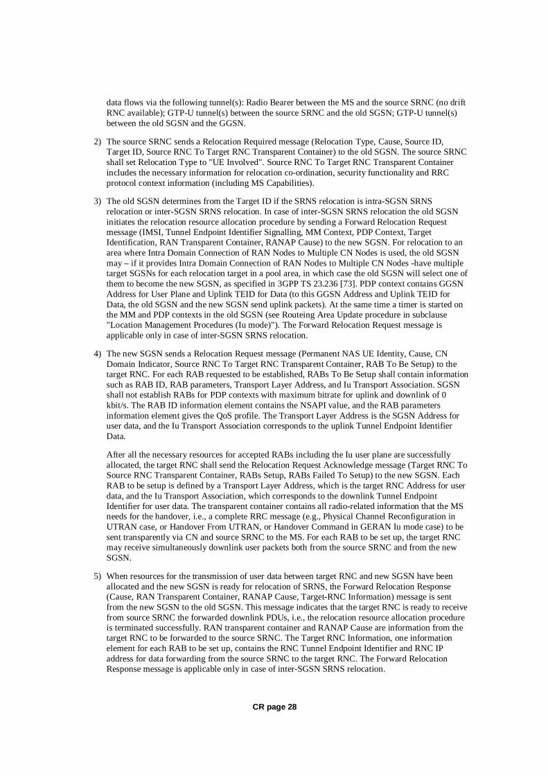
1) The source SRNC decides to perform/initiate SRNS relocation. At this point both uplink and downlink user data flows via the following tunnel(s): Radio Bearer between MS and source SRNC (data flows via the target RNC, which acts as a drift RNC); GTP-U tunnel(s) between source SRNC and old-SGSN; GTP-U tunnel(s) between old-SGSN and GGSN.
2) The source SRNC sends a Relocation Required message (Relocation Type, Cause, Source ID, Target ID, Source RNC to target RNC transparent container) to the old SGSN. The source SRNC shall set the Relocation Type to "UE not involved". The Source SRNC to Target RNC Transparent Container includes the necessary information for Relocation co-ordination, security functionality and RRC protocol context information (including MS Capabilities).

CR page 22
3) The old SGSN determines from the Target ID if the SRNS Relocation is intra-SGSN SRNS relocation or inter-SGSN SRNS relocation. In case of inter-SGSN SRNS relocation, the old SGSN initiates the relocation resource allocation procedure by sending a Forward Relocation Request message (IMSI, Tunnel Endpoint Identifier Signalling, MM Context, PDP Context, Target Identification, RAN transparent container, RANAP Cause) to the new SGSN. For relocation to an area where Intra Domain Connection of RAN Nodes to Multiple CN Nodes is used, the old SGSN may – if it provides Intra Domain Connection of RAN Nodes to Multiple CN Nodes -have multiple target SGSNs for each relocation target in a pool area, in which case the old SGSN will select one of them to become the new SGSN, as specified in 3GPP TS 23.236 [73]. The PDP context contains GGSN Address for User Plane and Uplink TEID for Data (to this GGSN Address and Uplink TEID for Data the old SGSN and the new SGSN send uplink packets). At the same time a timer is started on the MM and PDP contexts in the old SGSN (see the Routeing Area Update procedure in subclause "Location Management Procedures (Iu mode)"). The Forward Relocation Request message is applicable only in the case of inter-SGSN SRNS relocation.
4) The new SGSN sends a Relocation Request message (Permanent NAS UE Identity, Cause, CN Domain Indicator, Source-RNC to target RNC transparent container, RABs to be setup) to the target RNC. Only the Iu Bearers of the RABs are setup between the target RNC and the new-SGSN as the existing Radio Bearers will be reallocated between the MS and the target RNC when the target RNC takes the role of the serving RNC. For each requested RAB, the RABs to be setup information elements shall contain information such as RAB ID, RAB parameters, Transport Layer Address, and Iu Transport Association. SGSN shall not establish RABs for PDP contexts with maximum bitrate for uplink and downlink of 0 kbit/s. The RAB ID information element contains the NSAPI value, and the RAB parameters information element gives the QoS profile. The Transport Layer Address is the SGSN Address for user data, and the Iu Transport Association corresponds to the uplink Tunnel Endpoint Identifier Data. After all necessary resources for accepted RABs including the Iu user plane are successfully allocated; the target RNC shall send the Relocation Request Acknowledge message (RABs setup, RABs failed to setup) to the new SGSN. Each RAB to be setup is defined by a Transport Layer Address, which is the target RNC Address for user data, and an Iu Transport Association, which corresponds to the downlink Tunnel Endpoint Identifier for user data. For each RAB to be set up, the target RNC may receive simultaneously downlink user packets both from the source SRNC and from the new SGSN.
5) When resources for the transmission of user data between the target RNC and the new SGSN have been allocated and the new SGSN is ready for relocation of SRNS, the Forward Relocation Response message (Cause, RANAP Cause, and RAB Setup Information) is sent from the new SGSN to old SGSN. This message indicates that the target RNC is ready to receive from source SRNC the forwarded downlink PDUs, i.e. the relocation resource allocation procedure is terminated successfully. RANAP Cause is information from the target RNC to be forwarded to the source SRNC. The RAB Setup Information, one information element for each RAB, contains the RNC Tunnel Endpoint Identifier and the RNC IP address for data forwarding from the source SRNC to the target RNC. If the target RNC or the new SGSN failed to allocate resources, the RAB Setup Information element contains only NSAPI indicating that the source SRNC shall release the resources associated with the NSAPI. The Forward Relocation Response message is applicable only in case of inter-SGSN SRNS relocation.
6) The old SGSN continues the relocation of SRNS by sending a Relocation Command message (RABs to be released, and RABs subject to data forwarding) to the source SRNC. The old SGSN decides the RABs to be subject for data forwarding based on QoS, and those RABs shall be contained in RABs subject to data forwarding. For each RAB subject to data forwarding, the information element shall contain RAB ID, Transport Layer Address, and Iu Transport Association. These are the same Transport Layer Address and Iu Transport Association that the target RNC had sent to new SGSN in Relocation Request Acknowledge message, and these are used for forwarding of downlink N-PDU from source SRNC to target RNC. The source SRNC is now ready to forward downlink user data directly to the target RNC over the Iu interface. This forwarding is performed for downlink user data only.

CR page 23
7) The source SRNC may, according to the QoS profile, begin the forwarding of data for the RABs to be subject for data forwarding. The data forwarding at SRNS relocation shall be carried out through the Iu interface, meaning that the data exchanged between the source SRNC and the target RNC are duplicated in the source SRNC and routed at IP layer towards the target RNC. For each radio bearer which uses lossless PDCP the GTP-PDUs related to transmitted but not yet acknowledged PDCP-PDUs are duplicated and routed at IP layer towards the target RNC together with their related downlink PDCP sequence numbers. The source RNC continues transmitting duplicates of downlink data and receiving uplink data. Before the serving RNC role is not yet taken over by target RNC and when downlink user plane data starts to arrive to target RNC, the target RNC may buffer or discard arriving downlink GTP-PDUs according to the related QoS profile.
Note: The order of steps, starting from step 7 onwards, does not necessarily reflect the order of events. For instance, source RNC may start data forwarding (step 7) and send Relocation Commit message (step 8) almost simultaneously except in the delivery order required case where step 7 triggers step 8. Target RNC may send Relocation Detect message (step 9) and RAN Mobility Information message (step 10) at the same time. Hence, target RNC may receive RAN Mobility Information Confirm message (step 10) while data forwarding (step 7) is still underway, and before the new SGSN receives Update PDP Context Response message (step 11).
8) Before sending the Relocation Commit the uplink and downlink data transfer in the source, SRNC shall be suspended for RABs, which require delivery order. The source RNC shall start the data-forwarding timer. When the source SRNC is ready, the source SRNC shall trigger the execution of relocation of SRNS by sending a Relocation Commit message (SRNS Contexts) to the target RNC over the Iur interface. The purpose of this procedure is to transfer SRNS contexts from the source RNC to the target RNC, and to move the SRNS role from the source RNC to the target RNC. SRNS contexts are sent for each concerned RAB and contain the sequence numbers of the GTP-PDUs next to be transmitted in the uplink and downlink directions and the next PDCP sequence numbers that would have been used to send and receive data from the MS. For PDP context(s) using delivery order not required (QoS profile), the sequence numbers of the GTP-PDUs next to be transmitted are not used by the target RNC. PDCP sequence numbers are only sent by the source RNC for radio bearers, which used lossless PDCP [57]. The use of lossless PDCP is selected by the RNC when the radio bearer is set up or reconfigured.
If delivery order is required (QoS profile), consecutive GTP-PDU sequence numbering shall be maintained throughout the lifetime of the PDP context(s). Therefore, during the entire SRNS relocation procedure for the PDP context(s) using delivery order required (QoS profile), the responsible GTP-U entities (RNCs and GGSN) shall assign consecutive GTP-PDU sequence numbers to user packets belonging to the same PDP context for uplink and downlink, respectively.
9) The target RNC shall send a Relocation Detect message to the new SGSN when the relocation execution trigger is received. For SRNS relocation type "UE not involved", the relocation execution trigger is the reception of the Relocation Commit message from the Iur interface. When the Relocation Detect message is sent, the target RNC shall start SRNC operation.
10) The target SRNC sends a RAN Mobility Information message. This message contains UE information elements and CN information elements. The UE information elements include among others new SRNC identity and S-RNTI. The CN information elements contain among others Location Area Identification and Routeing Area Identification. The procedure shall be co-ordinated in all Iu signalling connections existing for the MS.

CR page 24
The target SRNC establishes and/or restarts the RLC, and exchanges the PDCP sequence numbers (PDCP-SNU, PDCP-SND) between the target SRNC and the MS. PDCP-SND is the PDCP sequence number for the next expected in-sequence downlink packet to be received in the MS per radio bearer, which used lossless PDCP in the source RNC. PDCP-SND confirms all mobile-terminated packets successfully transferred before the SRNC relocation. If PDCP-SND confirms reception of packets that were forwarded from the source SRNC, the target SRNC shall discard these packets. PDCP-SNU is the PDCP sequence number for the next expected in-sequence uplink packet to be received in the RNC per radio bearer, which used lossless PDCP in the source RNC. PDCP-SNU confirms all mobile originated packets successfully transferred before the SRNC relocation. If PDCP-SNU confirms reception of packets that were received in the source SRNC, the MS shall discard these packets.
Upon reception of the RAN Mobility Information message the MS may start sending uplink user data to the target SRNC. When the MS has reconfigured itself, it sends the RAN Mobility Information Confirm message to the target SRNC. This indicates that the MS is also ready to receive downlink data from the target SRNC.
If new the SGSN has already received the Update PDP Context Response message from the GGSN, it shall forward the uplink user data to GGSN over this new GTP-U tunnel. Otherwise, the new SGSN shall forward the uplink user data to that GGSN IP address and TEID(s), which the new SGSN had received earlier by the Forward Relocation Request message.
For all RABs, the target RNC should:
start uplink reception of data and start transmission of uplink GTP-PDUs towards the new SGSN;
start processing the already buffered and the arriving downlink GTP-PDUs and start downlink transmission towards the MS.
11) When the target SRNC receives the RAN Mobility Information Confirm message, i.e. the new SRNC—ID + S-RNTI are successfully exchanged with the MS by the radio protocols, the target SRNC shall initiate the Relocation Complete procedure by sending the Relocation Complete message to the new SGSN. The purpose of the Relocation Complete procedure is to indicate by the target SRNC the completion of the relocation of the SRNS to the CN.
12) Upon receipt of Relocation Complete message, if the SRNS Relocation is an inter SGSN SRNS relocation, the new SGSN signals to the old SGSN the completion of the SRNS relocation procedure by sending a Forward Relocation Complete message.
13) Upon receipt of the Relocation Complete message, the CN shall switch the user plane from the source RNC to the target SRNC. If the SRNS Relocation is an inter-SGSN SRNS relocation, the new SGSN sends Update PDP Context Request messages (new SGSN Address, SGSN Tunnel Endpoint Identifier, QoS Negotiated) to the GGSNs concerned. The GGSNs update their PDP context fields and return an Update PDP Context Response (GGSN Tunnel Endpoint Identifier, Prohibit Payload Compression) message. The Prohibit Payload Compression indicates that the SGSN should negotiate no data compression for this PDP context.
14) Upon receiving the Relocation Complete message or if it is an inter-SGSN SRNS relocation; the Forward Relocation Complete message, the old SGSN sends an Iu Release Command message to the source RNC. When the RNC data-forwarding timer has expired the source RNC responds with an Iu Release Complete.
15) After the MS has finished the RNTI reallocation procedure and if the new Routeing Area Identification is different from the old one, the MS initiates the Routeing Area Update procedure. See subclause "Location Management Procedures (Iu mode)". Note that it is only a subset of the RA update procedure that is performed, since the MS is in PMM-CONNECTED mode.

CR page 25
If the SRNS Relocation is inter-SGSN, then the following CAMEL procedure calls shall be performed (see referenced procedures in 3GPP TS 23.078)
C1) CAMEL_GPRS_PDP_Context_Disconnection, CAMEL_GPRS_Detach and CAMEL_PS_Notification.
They are called in the following order:
- The CAMEL_GPRS_PDP_Context_Disconnection procedure is called several times: once per PDP context. The procedure returns as result "Continue".
- Then the CAMEL_GPRS_Detach procedure is called once. The procedure returns as result "Continue".
- Then the CAMEL_PS_Notification procedure is called once. The procedure returns as result "Continue".
If the SRNS Relocation is intra-SGSN, then the above mentioned CAMEL procedures calls shall not be performed.
If Routeing Area Update occurs, then the following CAMEL procedure calls shall be performed (see referenced procedures in 3GPP TS 23.078):
C2) CAMEL_GPRS_Routeing_Area_Update_Session and CAMEL_PS_Notification.
They are called in the following order:
- The CAMEL_GPRS_Routeing_Area_Update_Session procedure is called. The procedure returns as result "Continue".
- Then, the CAMEL_PS_Notification procedure is called. The procedure returns as result "Continue".
C3) CAMEL_GPRS_Routeing_Area_Update_Context.
This procedure is called several times: once per PDP context. It returns as result ""Continue"".
For C2 and C3: refer to Routing Area Update procedure description for detailed message flow.
6.9.2.2.2 Combined Hard Handover and SRNS Relocation Procedure
This procedure is only performed for an MS in PMM-CONNECTED state in case the Iur interface is not available. In the context of this specification, the terms RNS or RNC refer also to a GERAN BSS or BSC (respectively) when serving a mobile in Iu mode.
The Combined Hard Handover and SRNS Relocation procedure is used to move the RAN to CN connection point at the RAN side from the source SRNC to the target RNC, while performing a hard handover decided by the RAN. In the procedure, the Iu links are relocated. If the target RNC is connected to the same SGSN as the source SRNC, an Intra-SGSN SRNS Relocation procedure is performed. If the routeing area is changed, this procedure is followed by an Intra-SGSN Routeing Area Update procedure. The SGSN detects that it is an intra-SGSN routeing area update by noticing that it also handles the old RA. In this case, the SGSN has the necessary information about the MS and there is no need to inform the HLR about the new MS location.
If the target RNC is connected to a different SGSN than the source SRNC, an Inter-SGSN SRNS Relocation procedure is performed. This procedure is followed by an Inter-SGSN Routeing Area Update procedure.

CR page 26
Figure 40 shows the situation before a Combined Hard Handover and SRNS Relocation procedure when source and target RNC are connected to different SGSNs. Figure 41 shows the situation after the Combined Hard Handover and SRNS Relocation procedure and RA update procedure have been completed. In the case described in Figure 40 and Figure 41 the MS is in PMM-CONNECTED state. Both figures are also applicable to BSS to RNS relocation and vice-versa, as well as for BSS to BSS relocation.
LA1, RA1
MS
HLR/AuC
old SGSN
GGSN
LA2, RA2
new SGSN
target RNCsource SRNC
new MSC/VLRold MSC/VLR
Figure 40: Before Combined Hard Handover and SRNS Relocation and Routeing Area Update
Before the SRNS Relocation and Routeing Area Update the MS is registered in the old SGSN and in the old MSC/VLR. The source RNC is acting as serving RNC.
LA1, RA1
MS
HLR/AuC
old SGSN
source RNC
GGSN
LA2, RA2
new SGSN
target SRNC
old MSC/VLR new MSC/VLR
Figure 41: After Combined Hard Handover and SRNS Relocation and Routeing Area Update
After the SRNS relocation and RA update, the MS is registered in the new SGSN and in the new MSC/VLR. The MS is in state PMM-CONNECTED towards the new SGSN and in MM IDLE state towards the new MSC/VLR. The target RNC is acting as serving RNC.
CR page 27
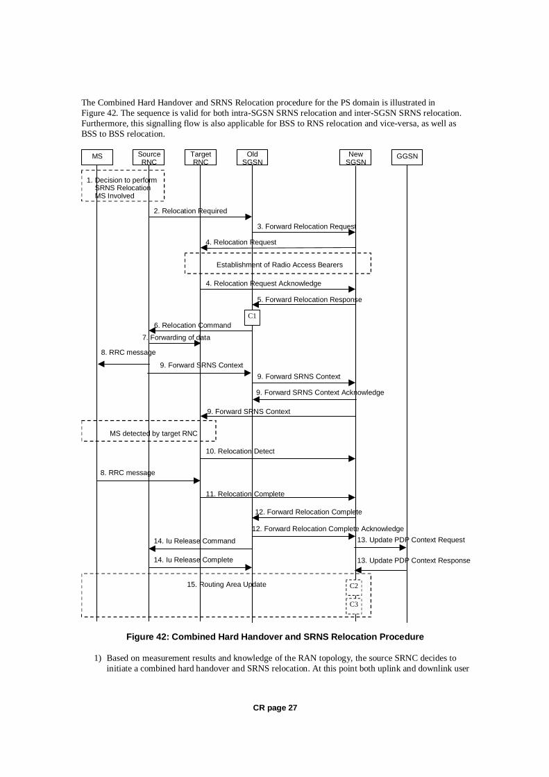
The Combined Hard Handover and SRNS Relocation procedure for the PS domain is illustrated in Figure 42. The sequence is valid for both intra-SGSN SRNS relocation and inter-SGSN SRNS relocation. Furthermore, this signalling flow is also applicable for BSS to RNS relocation and vice-versa, as well as BSS to BSS relocation.
MS Target RNC
Source RNC
Old SGSN
New SGSN GGSN
3. Forward Relocation Request
4. Relocation Request
2. Relocation Required
6. Relocation Command
5. Forward Relocation Response
4. Relocation Request Acknowledge
10. Relocation Detect
9. Forward SRNS Context 9. Forward SRNS Context
9. Forward SRNS Context
8. RRC message
8. RRC message
1. Decision to perform SRNS Relocation MS Involved
MS detected by target RNC
Establishment of Radio Access Bearers
C1
7. Forwarding of data
9. Forward SRNS Context Acknowledge
11. Relocation Complete
12. Forward Relocation Complete
15. Routing Area Update
13. Update PDP Context Request 14. Iu Release Command
14. Iu Release Complete 13. Update PDP Context Response
12. Forward Relocation Complete Acknowledge
C3
C2
Figure 42: Combined Hard Handover and SRNS Relocation Procedure
1) Based on measurement results and knowledge of the RAN topology, the source SRNC decides to initiate a combined hard handover and SRNS relocation. At this point both uplink and downlink user
CR page 28
data flows via the following tunnel(s): Radio Bearer between the MS and the source SRNC (no drift RNC available); GTP-U tunnel(s) between the source SRNC and the old SGSN; GTP-U tunnel(s) between the old SGSN and the GGSN.
2) The source SRNC sends a Relocation Required message (Relocation Type, Cause, Source ID, Target ID, Source RNC To Target RNC Transparent Container) to the old SGSN. The source SRNC shall set Relocation Type to "UE Involved". Source RNC To Target RNC Transparent Container includes the necessary information for relocation co-ordination, security functionality and RRC protocol context information (including MS Capabilities).
3) The old SGSN determines from the Target ID if the SRNS relocation is intra-SGSN SRNS relocation or inter-SGSN SRNS relocation. In case of inter-SGSN SRNS relocation the old SGSN initiates the relocation resource allocation procedure by sending a Forward Relocation Request message (IMSI, Tunnel Endpoint Identifier Signalling, MM Context, PDP Context, Target Identification, RAN Transparent Container, RANAP Cause) to the new SGSN. For relocation to an area where Intra Domain Connection of RAN Nodes to Multiple CN Nodes is used, the old SGSN may – if it provides Intra Domain Connection of RAN Nodes to Multiple CN Nodes -have multiple target SGSNs for each relocation target in a pool area, in which case the old SGSN will select one of them to become the new SGSN, as specified in 3GPP TS 23.236 [73]. PDP context contains GGSN Address for User Plane and Uplink TEID for Data (to this GGSN Address and Uplink TEID for Data, the old SGSN and the new SGSN send uplink packets). At the same time a timer is started on the MM and PDP contexts in the old SGSN (see Routeing Area Update procedure in subclause "Location Management Procedures (Iu mode)"). The Forward Relocation Request message is applicable only in case of inter-SGSN SRNS relocation.
4) The new SGSN sends a Relocation Request message (Permanent NAS UE Identity, Cause, CN Domain Indicator, Source RNC To Target RNC Transparent Container, RAB To Be Setup) to the target RNC. For each RAB requested to be established, RABs To Be Setup shall contain information such as RAB ID, RAB parameters, Transport Layer Address, and Iu Transport Association. SGSN shall not establish RABs for PDP contexts with maximum bitrate for uplink and downlink of 0 kbit/s. The RAB ID information element contains the NSAPI value, and the RAB parameters information element gives the QoS profile. The Transport Layer Address is the SGSN Address for user data, and the Iu Transport Association corresponds to the uplink Tunnel Endpoint Identifier Data.
After all the necessary resources for accepted RABs including the Iu user plane are successfully allocated, the target RNC shall send the Relocation Request Acknowledge message (Target RNC To Source RNC Transparent Container, RABs Setup, RABs Failed To Setup) to the new SGSN. Each RAB to be setup is defined by a Transport Layer Address, which is the target RNC Address for user data, and the Iu Transport Association, which corresponds to the downlink Tunnel Endpoint Identifier for user data. The transparent container contains all radio-related information that the MS needs for the handover, i.e., a complete RRC message (e.g., Physical Channel Reconfiguration in UTRAN case, or Handover From UTRAN, or Handover Command in GERAN Iu mode case) to be sent transparently via CN and source SRNC to the MS. For each RAB to be set up, the target RNC may receive simultaneously downlink user packets both from the source SRNC and from the new SGSN.
5) When resources for the transmission of user data between target RNC and new SGSN have been allocated and the new SGSN is ready for relocation of SRNS, the Forward Relocation Response (Cause, RAN Transparent Container, RANAP Cause, Target-RNC Information) message is sent from the new SGSN to the old SGSN. This message indicates that the target RNC is ready to receive from source SRNC the forwarded downlink PDUs, i.e., the relocation resource allocation procedure is terminated successfully. RAN transparent container and RANAP Cause are information from the target RNC to be forwarded to the source SRNC. The Target RNC Information, one information element for each RAB to be set up, contains the RNC Tunnel Endpoint Identifier and RNC IP address for data forwarding from the source SRNC to the target RNC. The Forward Relocation Response message is applicable only in case of inter-SGSN SRNS relocation.

CR page 29
6) The old SGSN continues the relocation of SRNS by sending a Relocation Command message (Target RNC To Source RNC Transparent Container, RABs To Be Released, RABs Subject To Data Forwarding) to the source SRNC. The old SGSN decides the RABs to be subject for data forwarding based on QoS, and those RABs shall be contained in RABs subject to data forwarding. For each RAB subject to data forwarding, the information element shall contain RAB ID, Transport Layer Address, and Iu Transport Association. These are the same Transport Layer Address and Iu Transport Association that the target RNC had sent to new SGSN in Relocation Request Acknowledge message, and these are used for forwarding of downlink N-PDU from the source SRNC to the target RNC. The source SRNC is now ready to forward downlink user data directly to the target RNC over the Iu interface. This forwarding is performed for downlink user data only.
7) The source SRNC may, according to the QoS profile, begins the forwarding of data for the RABs to be subject for data forwarding.
NOTE: The order of steps, starting from step 7 onwards, does not necessarily reflect the order of events. For instance, source RNC may start data forwarding (step 7), send the RRC message to MS (step 8) and forward SRNS Context message to the old SGSN (step 9) almost simultaneously.
The data forwarding at SRNS relocation shall be carried out through the Iu interface, meaning that the GTP-PDUs exchanged between the source SRNC and the target RNC are duplicated in the source SRNC and routed at the IP layer towards the target RNC. For each radio bearer which uses lossless PDCP the GTP-PDUs related to transmitted but not yet acknowledged PDCP-PDUs are duplicated and routed at IP layer towards the target RNC together with their related downlink PDCP sequence numbers. The source RNC continues transmitting duplicates of downlink data and receiving uplink data.
Before the serving RNC role is not yet taken over by target RNC and when downlink user plane data starts to arrive to target RNC, the target RNC may buffer or discard arriving downlink GTP-PDUs according to the related QoS profile.
8) Before sending the RRC message the uplink and downlink data transfer shall be suspended in the source SRNC for RABs, which require delivery order. The RRC message is for example Physical Channel Reconfiguration for RNS to RNS relocation, or Intersystem to UTRAN Handover for BSS to RNS relocation, or Handover from UTRAN Command for BSS relocation, or Handover Command for BSS to BSS relocation. When the source SRNC is ready, the source RNC shall trigger the execution of relocation of SRNS by sending to the MS the RRC message provided in the Target RNC to source RNC transparent container, e.g., a Physical Channel Reconfiguration (UE Information Elements, CN Information Elements) message. UE Information Elements include among others new SRNC identity and S-RNTI. CN Information Elements contain among others Location Area Identification and Routeing Area Identification.
When the MS has reconfigured itself, it sends an RRC message e.g., a Physical Channel Reconfiguration Complete message to the target SRNC. If the Forward SRNS Context message with the sequence numbers is received, the exchange of packets with the MS may start. If this message is not yet received, the target RNC may start the packet transfer for all RABs, which do not require maintaining the delivery order.
9) The source SRNC continues the execution of relocation of SRNS by sending a Forward SRNS Context (RAB Contexts) message to the target RNC via the old and the new SGSN. The Forward SRNS Context message is acknowledged by a Forward SRNS Context Acknowledge message, from new to old SGSN. The purpose of this procedure is to transfer SRNS contexts from the source RNC to the target RNC, and to move the SRNS role from the source RNC to the target RNC. SRNS contexts are sent for each concerned RAB and contain the sequence numbers of the GTP PDUs next to be transmitted in the uplink and downlink directions and the next PDCP sequence numbers that would have been used to send and receive data from the MS. PDCP sequence numbers are only sent by the source RNC for the radio bearers which used lossless PDCP [57]. The use of lossless PDCP

CR page 30
is selected by the RNC when the radio bearer is set up or reconfigured. For PDP context(s) using delivery order not required (QoS profile), the sequence numbers of the GTP-PDUs next to be transmitted are not used by the target RNC.
If delivery order is required (QoS profile), consecutive GTP-PDU sequence numbering shall be maintained throughout the lifetime of the PDP context(s). Therefore, during the entire SRNS relocation procedure for the PDP context(s) using delivery order required (QoS profile), the responsible GTP-U entities (RNCs and GGSN) shall assign consecutive GTP-PDU sequence numbers to user packets belonging to the same PDP context uplink and downlink, respectively.
The target RNC establishes and/or restarts the RLC and exchanges the PDCP sequence numbers (PDCP-SNU, PDCP-SND) between the target RNC and the MS. PDCP-SND is the PDCP sequence number for the next expected in-sequence downlink packet to be received by the MS per radio bearer, which used lossless PDCP in the source RNC. PDCP-SND confirms all mobile terminated packets successfully transferred before the SRNC relocation. If PDCP-SND confirms reception of packets that were forwarded from the source SRNC, then the target SRNC shall discard these packets. PDCP-SNU is the PDCP sequence number for the next expected in-sequence uplink packet to be received in the RNC per radio bearer, which used lossless PDCP in the source RNC. PDCP-SNU confirms all mobile originated packets successfully transferred before the SRNC relocation. If PDCP-SNU confirms reception of packets that were received in the source SRNC, the MS shall discard these packets.
10) The target RNC shall send a Relocation Detect message to the new SGSN when the relocation execution trigger is received. For SRNS relocation type "UE Involved", the relocation execution trigger may be received from the Uu interface; i.e., when target RNC detects the MS on the lower layers. When the Relocation Detect message is sent, the target RNC shall start SRNC operation.
11) When the target SRNC receives the appropriate RRC message, e.g. Physical Channel Reconfiguration Complete message or the Radio Bearer Release Complete message in UTRAN case, or the Handover To UTRAN Complete message or Handover Complete message in GERAN case, i.e. the new SRNC-ID + S-RNTI are successfully exchanged with the MS by the radio protocols, the target SRNC shall initiate a Relocation Complete procedure by sending the Relocation Complete message to the new SGSN. The purpose of the Relocation Complete procedure is to indicate by the target SRNC the completion of the relocation of the SRNS to the CN.
12) Upon receipt of Relocation Complete message, if the SRNS Relocation is an inter SGSN SRNS relocation, the new SGSN signals to the old SGSN the completion of the SRNS relocation procedure by sending a Forward Relocation Complete message.
13) Upon receipt of the Relocation Complete message, the CN shall switch the user plane from the source RNC to the target SRNC. If the SRNS Relocation is an inter-SGSN SRNS relocation, the new SGSN sends Update PDP Context Request messages (new SGSN Address, SGSN Tunnel Endpoint Identifier, QoS Negotiated) to the GGSNs concerned. The GGSNs update their PDP context fields and return an Update PDP Context Response (GGSN Tunnel Endpoint Identifier, Prohibit Payload Compression) message. The Prohibit Payload Compression indicates that the SGSN should negotiate no data compression for this PDP context.
14) Upon receiving the Relocation Complete message or, if it is an inter-SGSN SRNS relocation, the Forward Relocation Complete message, the old SGSN sends an Iu Release Command message to the source RNC. When the RNC data-forwarding timer has expired, the source RNC responds with an Iu Release Complete message.
15) After the MS has finished the reconfiguration procedure and if the new Routeing Area Identification is different from the old one, the MS initiates the Routeing Area Update procedure. See subclause "Location Management Procedures (Iu mode)". Note that it is only a subset of the RA update procedure that is performed, since the MS is in PMM-CONNECTED state.
CR page 31
If the SRNS Relocation is inter-SGSN, then the following CAMEL procedure calls shall be performed (see referenced procedures in 3GPP TS 23.078)
C1) CAMEL_GPRS_PDP_Context_Disconnection, CAMEL_GPRS_Detach and CAMEL_PS_Notification.
They are called in the following order:
- The CAMEL_GPRS_PDP_Context_Disconnection procedure is called several times: once per PDP context. The procedure returns as result "Continue".
- Then the CAMEL_GPRS_Detach procedure is called once. The procedure returns as result "Continue".
- Then the CAMEL_PS_Notification procedure is called once. The procedure returns as result "Continue".
If the SRNS Relocation is intra-SGSN, then the above mentioned CAMEL procedures calls shall not be performed.
If Routeing Area Update occurs, then the following CAMEL procedure calls shall be performed (see referenced procedures in 3GPP TS 23.078):
C2) CAMEL_GPRS_Routeing_Area_Update_Session and CAMEL_PS_Notification.
They are called in the following order:
- The CAMEL_GPRS_Routeing_Area_Update_Session procedure is called. In Figure 42, the procedure returns as result "Continue".
- Then the CAMEL_PS_Notification procedure is called. The procedure returns as result "Continue".
C3) CAMEL_GPRS_Routeing_Area_Update_Context.
This procedure is called several times: once per PDP context. It returns as result "Continue".
For C2 and C3: refer to Routing Area Update procedure description for detailed message flow.
6.9.2.2.3 Combined Cell / URA Update and SRNS Relocation Procedure
This procedure is only performed for an MS in PMM-CONNECTED state, where the Iur/Iur-g interface carries control signalling but no user data In the context of this specification, the terms RNS or RNC refer also to a GERAN BSS or BSC (respectively) when serving an MS in Iu mode.
The Combined Cell / URA Update and SRNS Relocation or Combined Cell/GRA Update and SBSS Relocation procedure is used to move the RAN to CN connection point at the RAN side from the source SRNC to the target RNC, while performing a cell re-selection in the RAN. In the procedure, the Iu links are relocated. If the target RNC is connected to the same SGSN as the source SRNC, an Intra-SGSN SRNS Relocation procedure is performed. If the routeing area is changed, this procedure is followed by an Intra-SGSN Routeing Area Update procedure. The SGSN detects that it is an intra-SGSN routeing area update by noticing that it also handles the old RA. In this case, the SGSN has the necessary information about the MS and there is no need to inform the HLR about the new MS location.
Before the Combined Cell / URA Update and SRNS Relocation or Combined Cell/GRA Update and SBSS Relocation and before the Routeing Area Update, the MS is registered in the old SGSN. The source RNC is acting as serving RNC or serving BSS.

CR page 32
After the Combined Cell / URA Update and SRNS Relocation or Combined Cell/GRA Update and SBSS Relocation and after the Routeing Area Update, the MS is registered in the new SGSN. The MS is in state PMM-CONNECTED towards the new SGSN, and the target RNC is acting as serving RNC.
The Combined Cell / URA Update and SRNS Relocation or Combined Cell/GRA Update and SBSS relocation procedure for the PS domain is illustrated in Figure 43. The sequence is valid for both intra-SGSN SRNS relocation and inter-SGSN SRNS relocation. This signalling flow is also applicable to BSS to RNS relocation and vice-versa, as well as for BSS to BSS relocation.
MS TargetRNC
SourceRNC
OldSGSN
NewSGSN
GGSN
3. Forward Relocation Request
4. Relocation Request
2. Relocation Required
6. Relocation Command
5. Forward Relocation Response
4. Relocation Request Acknowledge
9. Relocation Detect
12. Relocation Complete
12. Forward Relocation Complete
10. Cell Update Confirm/ URA Update Confirm orCell Update Confirm/GRA Update Confirm
10. UTRAN Mobility Information Confirm
Establishment of Radio Access Bearers
14. Routing Area Update
11. Update PDP Context Request
13. Iu Release Command
13. Iu Release Complete
C1
C2
1. Cell Update/ URA Update or Cell Update/GRA update
8. Relocation Commit
7. Forwarding of data
11. Update PDP Context Response
12. Forward Relocation Complete Acknowledge
C3
Figure 43: Combined Cell / URA Update and SRNS Relocation Procedure
1) The MS sends a Cell Update / URA Update or a Cell Update / GRA Update message to the source SRNC (if the cell is located under another RNC the message is routed via the DRNC to SRNC over the Iur). The source SRNC decides whether or not to perform a combined cell / URA update and SRNS relocation towards the target RNC. The rest of this subclause describes the case where a combined cell / URA update and SRNS relocation applies. In this case no radio bearer is established between the source SRNC and the UE. Nonetheless the following tunnel(s) are
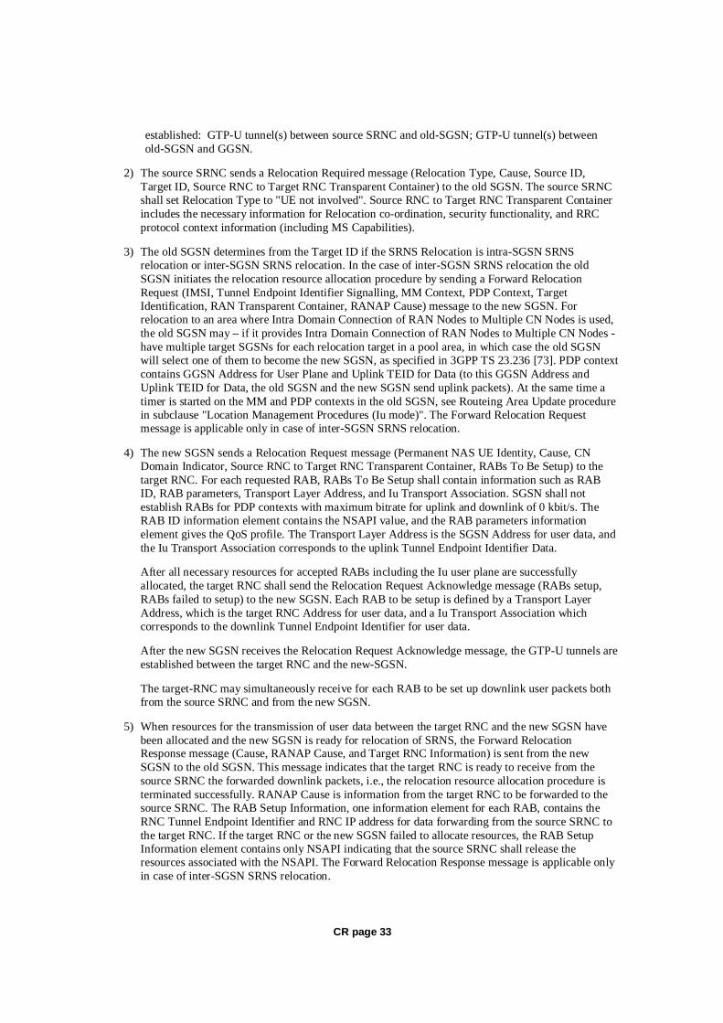
CR page 33
established: GTP-U tunnel(s) between source SRNC and old-SGSN; GTP-U tunnel(s) between old-SGSN and GGSN.
2) The source SRNC sends a Relocation Required message (Relocation Type, Cause, Source ID, Target ID, Source RNC to Target RNC Transparent Container) to the old SGSN. The source SRNC shall set Relocation Type to "UE not involved". Source RNC to Target RNC Transparent Container includes the necessary information for Relocation co-ordination, security functionality, and RRC protocol context information (including MS Capabilities).
3) The old SGSN determines from the Target ID if the SRNS Relocation is intra-SGSN SRNS relocation or inter-SGSN SRNS relocation. In the case of inter-SGSN SRNS relocation the old SGSN initiates the relocation resource allocation procedure by sending a Forward Relocation Request (IMSI, Tunnel Endpoint Identifier Signalling, MM Context, PDP Context, Target Identification, RAN Transparent Container, RANAP Cause) message to the new SGSN. For relocation to an area where Intra Domain Connection of RAN Nodes to Multiple CN Nodes is used, the old SGSN may – if it provides Intra Domain Connection of RAN Nodes to Multiple CN Nodes -have multiple target SGSNs for each relocation target in a pool area, in which case the old SGSN will select one of them to become the new SGSN, as specified in 3GPP TS 23.236 [73]. PDP context contains GGSN Address for User Plane and Uplink TEID for Data (to this GGSN Address and Uplink TEID for Data, the old SGSN and the new SGSN send uplink packets). At the same time a timer is started on the MM and PDP contexts in the old SGSN, see Routeing Area Update procedure in subclause "Location Management Procedures (Iu mode)". The Forward Relocation Request message is applicable only in case of inter-SGSN SRNS relocation.
4) The new SGSN sends a Relocation Request message (Permanent NAS UE Identity, Cause, CN Domain Indicator, Source RNC to Target RNC Transparent Container, RABs To Be Setup) to the target RNC. For each requested RAB, RABs To Be Setup shall contain information such as RAB ID, RAB parameters, Transport Layer Address, and Iu Transport Association. SGSN shall not establish RABs for PDP contexts with maximum bitrate for uplink and downlink of 0 kbit/s. The RAB ID information element contains the NSAPI value, and the RAB parameters information element gives the QoS profile. The Transport Layer Address is the SGSN Address for user data, and the Iu Transport Association corresponds to the uplink Tunnel Endpoint Identifier Data.
After all necessary resources for accepted RABs including the Iu user plane are successfully allocated, the target RNC shall send the Relocation Request Acknowledge message (RABs setup, RABs failed to setup) to the new SGSN. Each RAB to be setup is defined by a Transport Layer Address, which is the target RNC Address for user data, and a Iu Transport Association which corresponds to the downlink Tunnel Endpoint Identifier for user data.
After the new SGSN receives the Relocation Request Acknowledge message, the GTP-U tunnels are established between the target RNC and the new-SGSN.
The target-RNC may simultaneously receive for each RAB to be set up downlink user packets both from the source SRNC and from the new SGSN.
5) When resources for the transmission of user data between the target RNC and the new SGSN have been allocated and the new SGSN is ready for relocation of SRNS, the Forward Relocation Response message (Cause, RANAP Cause, and Target RNC Information) is sent from the new SGSN to the old SGSN. This message indicates that the target RNC is ready to receive from the source SRNC the forwarded downlink packets, i.e., the relocation resource allocation procedure is terminated successfully. RANAP Cause is information from the target RNC to be forwarded to the source SRNC. The RAB Setup Information, one information element for each RAB, contains the RNC Tunnel Endpoint Identifier and RNC IP address for data forwarding from the source SRNC to the target RNC. If the target RNC or the new SGSN failed to allocate resources, the RAB Setup Information element contains only NSAPI indicating that the source SRNC shall release the resources associated with the NSAPI. The Forward Relocation Response message is applicable only in case of inter-SGSN SRNS relocation.

CR page 34
6) The old SGSN continues the relocation of SRNS by sending a Relocation Command (RABs to be released, and RABs subject to data forwarding) message to the source SRNC. The old SGSN decides the RABs subject to data forwarding based on QoS, and those RABs shall be contained in RABs subject to data forwarding. For each RAB subject to data forwarding, the information element shall contain RAB ID, Transport Layer Address, and Iu Transport Association. These are the same Transport Layer Address and Iu Transport Association that the target RNC had sent to new SGSN in Relocation Request Acknowledge message, and these are used for forwarding of downlink N-PDU from the source SRNC to the target RNC. The source SRNC is now ready to forward downlink data directly to the target RNC over the Iu interface. This forwarding is performed for downlink user data only.
7) The source SRNC may, according to the QoS profile, begin the forwarding of data for the RABs subject to data forwarding and starts the data-forwarding timer. The data forwarding at SRNS relocation shall be carried out through the Iu interface, meaning that the data exchanged between the source SRNC and the target RNC are duplicated in the source SRNC and routed at the IP layer towards the target RNC. For each radio bearer which uses lossless PDCP the GTP-PDUs related to transmitted but not yet acknowledged PDCP-PDUs are duplicated and routed at IP layer towards the target RNC together with their related downlink PDCP sequence numbers. The source RNC continues transmitting duplicates of downlink data and receiving uplink data.
Note: The order of steps, starting from step 7 onwards, does not necessarily reflect the order of events. For instance, source RNC may send data forwarding (step 7) and start Relocation Commit message (step 8) almost simultaneously. Target RNC may send Relocation Detect message (step 9) and Cell Update Confirm/URA Update Confirm (or Cell Update Confirm/GRA Update Confirm) message (step 10) at the same time. Hence, target RNC may receive the UTRAN or GERAN Mobility Information Confirm message from MS (step 10) while data forwarding (step 8) is still underway, and before the new SGSN receives Update PDP Context Response message (step 11).
Before the serving RNC role is not yet taken over by target RNC and when downlink user plane data starts to arrive to target RNC, the target RNC may buffer or discard arriving downlink GTP-PDUs according to the related QoS profile.
8) Before sending the Relocation Commit the uplink and downlink data transfer in the source, SRNC shall be suspended for RABs, which require delivery order.
When the source SRNC is ready, the source SRNC shall trigger the execution of relocation of SRNS by sending a Relocation Commit message (SRNS Contexts) to the target RNC over the UTRAN Iur interface or over the GERAN Iur-g interface, respectively. The purpose of this procedure is to transfer SRNS contexts from the source RNC to the target RNC, and to move the SRNS role from the source RNC to the target RNC. SRNS contexts are sent for each concerned RAB and contain the sequence numbers of the GTP-PDUs next to be transmitted in the uplink and downlink directions and the next PDCP sequence numbers that would have been used to send and receive data from the MS. . PDCP sequence numbers are only sent by the source RNC for radio bearers, which used lossless PDCP [57]. The use of lossless PDCP is selected by the RNC when the radio bearer is set up or reconfigured. For PDP context(s) using delivery order not required (QoS profile), the sequence numbers of the GTP-PDUs next to be transmitted are not used by the target RNC.
If delivery order is required (QoS profile), consecutive GTP-PDU sequence numbering shall be maintained throughout the lifetime of the PDP context(s). Therefore, during the entire SRNS relocation procedure for the PDP context(s) using delivery order required (QoS profile), the responsible GTP-U entities (RNCs and GGSN) shall assign consecutive GTP-PDU sequence numbers to user packets belonging to the same PDP context for uplink and downlink respectively.
9) The target RNC shall send a Relocation Detect message to the new SGSN when the relocation execution trigger is received. For SRNS relocation type "UE not involved", the relocation execution trigger is the reception of the Relocation Commit message from the Iur interface. When the Relocation Detect message is sent, the target RNC shall start SRNC operation.

CR page 35
10) The target SRNC sends a Cell Update Confirm / URA Update Confirm or Cell Update Confirm / GRA Update Confirm message. This message contains UE information elements and CN information elements. The UE information elements include among others new SRNC identity and S-RNTI. The CN information elements contain among others Location Area Identification and Routeing Area Identification. The procedure shall be co-ordinated in all Iu signalling connections existing for the MS.
Upon reception of the Cell Update Confirm / URA Update Confirm or Cell Update Confirm / GRA Update Confirm message the MS may start sending uplink user data to the target SRNC. When the MS has reconfigured itself, it sends the RAN Mobility Information Confirm message to the target SRNC. This indicates that the MS is also ready to receive downlink data from the target SRNC.
If the new SGSN has already received the Update PDP Context Response message from the GGSN, it shall forward the uplink user data to the GGSN over this new GTP-U tunnel. Otherwise, the new SGSN shall forward the uplink user data to that GGSN IP address and TEID(s), which the new SGSN had received earlier by the Forward Relocation Request message.
The target SRNC and the MS exchange the PDCP sequence numbers; PDCP-SNU and PDCP-SND. PDCP-SND is the PDCP sequence number for the next expected in-sequence downlink packet to be received in the MS per radio bearer, which used lossless PDCP in the source RNC. PDCP-SND confirms all mobile terminated packets successfully transferred before the SRNC relocation procedure. . If PDCP-SND confirms the reception of packets that were forwarded from the source SRNC, the target SRNC shall discard these packets. PDCP-SNU is the PDCP sequence number for the next expected in-sequence uplink packet to be received in the RNC per radio bearer, which used lossless PDCP in the source RNC. PDCP-SNU confirms all mobile originated packets successfully transferred before the SRNC relocation. If PDCP-SNU confirms reception of packets that were received in the source SRNC, the target SRNC shall discard these packets.
11) When the target SRNC receives the RAN Mobility Information Confirm message, i.e. the new SRNC-ID + S-RNTI are successfully exchanged with the MS by the radio protocols, the target SRNC shall initiate the Relocation Complete procedure by sending the Relocation Complete message to the new SGSN. The purpose of the Relocation Complete procedure is to indicate by the target SRNC the completion of the relocation of the SRNS to the CN.
12) Upon receipt of Relocation Complete message, if the SRNS Relocation is an inter SGSN SRNS relocation, the new SGSN signals to the old SGSN the completion of the SRNS relocation procedure by sending a Forward Relocation Complete message.
13) Upon receipt of the Relocation Complete message, the CN shall switch the user plane from the source RNC to the target SRNC. If the SRNS Relocation is an inter-SGSN SRNS relocation, the new SGSN sends Update PDP Context Request messages (new SGSN Address, SGSN Tunnel Endpoint Identifier, QoS Negotiated) to the GGSNs concerned. The GGSNs update their PDP context fields and return an Update PDP Context Response (GGSN Tunnel Endpoint Identifier, Prohibit Payload Compression) message. The Prohibit Payload Compression indicates that the SGSN should negotiate no data compression for this PDP context.
14) Upon receiving the Relocation Complete message or if it is an inter-SGSN SRNS relocation, the Forward Relocation Complete message, the old SGSN sends an Iu Release Command message to the source RNC. When the RNC data-forwarding timer has expired the source RNC responds with an Iu Release Complete.
15) After the MS has finished the Cell / URA update or the Cell / GRA update and RNTI reallocation procedure and if the new Routeing Area Identification is different from the old one, the MS initiates the Routeing Area Update procedure. See subclause "Location Management Procedures (Iu mode)". Note that it is only a subset of the RA update procedure that is performed, since the MS is in PMM-CONNECTED state.
CR page 36
If the SRNS Relocation is inter-SGSN, then the following CAMEL procedure calls shall be performed (see referenced procedures in 3GPP TS 23.078)
C1) CAMEL_GPRS_PDP_Context_Disconnection, CAMEL_GPRS_Detach and CAMEL_PS_Notification.
They are called in the following order:
- The CAMEL_GPRS_PDP_Context_Disconnection procedure is called several times: once per PDP context. The procedure returns as result "Continue".
- Then the CAMEL_GPRS_Detach procedure is called once. The procedure returns as result "Continue".
- Then the CAMEL_PS_Notification procedure is called once. The procedure returns as result "Continue".
If the SRNS Relocation is intra-SGSN, then the above mentioned CAMEL procedures calls shall not be performed.
If Routeing Area Update occurs, then the following CAMEL procedure calls shall be performed (see referenced procedures in 3GPP TS 23.078):
C2) CAMEL_GPRS_Routeing_Area_Update_Session and CAMEL_PS_Notification.
They are called in the following order:
- The CAMEL_GPRS_Routeing_Area_Update_Session procedure is called. The procedure returns as result "Continue".
- Then, the CAMEL_PS_Notification procedure is called. The procedure returns as result "Continue".
C3) CAMEL_GPRS_Routeing_Area_Update_Context.
This procedure is called several times: once per PDP context. It returns as result "Continue". For C2 and C3: refer to Routing Area Update procedure description for detailed message flow.
**** Next Modified Section ****
6.13.2 Inter-SGSN Inter-system Change
6.13.2.1 Iu mode to A/Gb mode Inter-SGSN Change
An inter-SGSN inter-system change from Iu mode to A/Gb mode takes place when an MS in PMM-IDLE or PMM-CONNECTED state changes from UTRAN or GERAN Iu mode to A/Gb mode and the A/Gb mode radio access node serving the MS is served by a different SGSN. In this case, the RA changes. Therefore, the MS shall initiate a A/Gb mode RA update procedure. The RA update procedure is either combined RA / LA update or only RA update. These RA update cases are illustrated in Figure 54. In the context of this specification, the terms RNS or RNC refer also to a GERAN BSS or BSC (respectively) when serving an MS in Iu mode.
A combined RA / LA update takes place in network operation mode I when the MS enters a new RA or when a GPRS-attached MS performs IMSI attach. The MS sends a Routeing Area Update Request indicating that an LA update may also need to be performed, in which case the SGSN forwards the LA
CR page 37
update to the VLR. This concerns only idle mode (see 3GPP TS 23.122), as no combined RA / LA updates are performed during a CS connection.

CR page 38
MS new2G-SGSN
HLRGGSNold3G-SGSN
2. Routing Area Update Request
10. Update PDP Context Request
10. Update PDP Context Response
11. Update GPRS Location
15. Update GPRS Location Ack
5. SGSN Context Response
6. Security Functions
19. Routing Area Update Accept
12. Cancel Location
12. Cancel Location Ack
14. Insert Subscriber Data Ack
14. Insert Subscriber Data
7. SGSN Context Acknowledge
BSS SRNS
3. SGSN Context Request
13. Iu Release Command
13. Iu Release Complete
8a. Forward Packets
9. Forward Packets
4. SRNS Context Request
4. SRNS Context Response
8. SRNS Data Forward Command
22. BSS Packet Flow Context Procedure
1. Intersystem changedecision
C3
C1
20. Routing Area Update Complete
newMSC/VLR
oldMSC/VLR
16. Location Update Request
17a. Update Location
17b. Cancel Location
17c. Cancel Location Ack
17d. Insert Subscriber Data
17e. Insert Subscriber Data Ack
17f. Update Location Ack 18. Location Update Accept
21. TMSI Reallocation Complete
C2

CR page 39
Figure 54: Iu mode to A/Gb mode Inter-SGSN Change
1) The MS or RAN decides to perform an inter-system change, which makes the MS switch to a new cell where A/Gb mode has to be used, and stops transmission to the network.
2) The MS sends a Routeing Area Update Request (old RAI, old P-TMSI Signature, Update Type, MS Network Capability) message to the new 2G-SGSN. Update Type shall indicate RA update or combined RA / LA update, or, if the MS wants to perform an IMSI attach, combined RA / LA update with IMSI attach requested. The BSS shall add the Cell Global Identity including the RAC and LAC of the cell where the message was received before passing the message to the new 2G-SGSN.
3) The new 2G-SGSN sends an SGSN Context Request (old RAI, TLLI, old P-TMSI Signature, New SGSN Address) message to the old 3G-SGSN to get the MM and PDP contexts for the MS. If the new SGSN provides functionality for Intra Domain Connection of RAN Nodes to Multiple CN Nodes, the new SGSN may derive the old SGSN from the old RAI and the old P-TMSI (or TLLI) and send the SGSN Context Request message to this old SGSN. Otherwise, the new SGSN derives the old SGSN from the old RAI. In any case the new SGSN will derive an SGSN that it believes is the old SGSN. This derived SGSN is itself the old SGSN, or it is associated with the same pool area as the actual old SGSN and it will determine the correct old SGSN from the P-TMSI (or TLLI) and relay the message to that actual old SGSN. The old 3G-SGSN validates the old P-TMSI Signature and responds with an appropriate error cause if it does not match the value stored in the old 3G-SGSN. If the received old P-TMSI Signature does not match the stored value, the security functions in the new 2G-SGSN should be initiated. If the security functions authenticate the MS correctly, the new 2G-SGSN shall send an SGSN Context Request (old RAI, TLLI, MS Validated, New SGSN Address) message to the old 3G-SGSN. MS Validated indicates that the new 2G-SGSN has authenticated the MS. If the old P-TMSI Signature was valid or if the new 2G-SGSN indicates that it has authenticated the MS correctly, the old 3G-SGSN starts a timer. If the MS is not known in the old 3G-SGSN, the old 3G-SGSN responds with an appropriate error cause.
4) If the MS is PMM-CONNECTED the old 3G-SGSN sends an SRNS Context Request (IMSI) message to the SRNS. Upon receipt of this message the SRNS buffers and stops sending downlink PDUs to the MS and returns an SRNS Context Response (GTP-SNDs, GTP-SNUs, PDCP-SNDs, PDCP-SNUs) message. The SRNS shall include for each PDP context the next in-sequence GTP sequence number to be sent to the MS and the GTP sequence number of the next uplink PDU to be tunnelled to the GGSN. For each active PDP context, which uses lossless PDCP, the SRNS also includes the uplink PDCP sequence number (PDCP-SNU) downlink PDCP sequence number (PDCP-SND). PDCP-SNU shall be the next in-sequence PDCP sequence number expected from the MS. PDCP-SND is the PDCP sequence number for the first downlink packet for which successful transmission has not been confirmed. The 3G-SGSN shall strip off the eight most significant bits of the passed PDCP sequence numbers, thus converting them to SNDCP N-PDU numbers and stores the N-PDU numbers in its PDP contexts..
5) The old 3G-SGSN responds with an SGSN Context Response (MM Context, PDP Contexts) message. For each PDP context the old 3G-SGSN shall include the GTP sequence number for the next uplink GTP PDU to be tunnelled to the GGSN and the next downlink GTP sequence number for the next in-sequence N-PDU to be sent to the MS. Each PDP Context also includes the SNDCP Send N-PDU Number (the value is 0) for the next in-sequence downlink N-PDU to be sent in SNDCP acknowledged mode to the MS and the SNDCP Receive N-PDU Number (= converted PDCP-SNU) for the next in-sequence uplink N-PDU to be received in SNDCP acknowledged mode from the MS. The new 3G-SGSN shall ignore the MS Network Capability contained in MM Context of SGSN Context Response only when it has previously received an MS Network Capability in the Routeing Area Request.
6) Security functions may be executed.

CR page 40
7) The new 2G-SGSN sends an SGSN Context Acknowledge message to the old 3G-SGSN. This informs the old 3G-SGSN that the new 2G-SGSN is ready to receive data packets belonging to the activated PDP contexts. The old SGSN marks in its context that the MSC/VLR association and the information in the GGSNs and the HLR are invalid. This triggers the MSC/VLR, the GGSNs, and the HLR to be updated if the MS initiates a RA update procedure back to the old SGSN before completing the ongoing RA update procedure.
8) If the MS is in the PMM-CONNECTED state, the old 3G-SGSN sends an SRNS Data Forward Command (RAB ID, Transport Layer Address, Iu Transport Association) message to the SRNS. For each indicated RAB the SRNS starts duplicating and tunnelling the buffered GTP PDUs to the old 3G-SGSN. For each radio bearer which uses lossless PDCP the SRNS shall start tunnelling the GTP-PDUs related to transmitted but not yet acknowledged PDCP-PDUs to the old 3G-SGSN together with their related downlink PDCP sequence numbers. Upon receipt of the SRNS Data Forward Command message from the 3G-SGSN, the SRNS shall start the data-forwarding timer.
9) The old 3G-SGSN tunnels the GTP PDUs to the new 2G-SGSN. In the case of GTPv1, the conversion of PDCP sequence numbers to SNDCP sequence numbers (the eight most significant bits shall be stripped off) shall be done in the new SGSN. No N-PDU sequence numbers shall be indicated for these N-PDUs. If GTPv0 is used between the SGSNs, the conversion of PDCP sequence numbers to SNDCP numbers shall be done in the old 3G-SGSN (by stripping off the eight most significant bits).
10) The new 2G-SGSN sends an Update PDP Context Request (new SGSN Address, TEID, QoS Negotiated) message to each GGSN concerned. Each GGSN updates its PDP context fields and returns an Update PDP Context Response (TEID, Prohibit Payload Compression) message. The Prohibit Payload Compression indicates that the SGSN should negotiate no data compression for this PDP context.
11) The new 2G-SGSN informs the HLR of the change of SGSN by sending an Update GPRS Location (SGSN Number, SGSN Address, IMSI) message to the HLR.
12) The HLR sends a Cancel Location (IMSI) message to the old 3G-SGSN. The old 3G-SGSN acknowledges with a Cancel Location Ack (IMSI) message. The old 3G-SGSN removes the MM and PDP contexts if the timer described in step 3 is not running. If the timer is running, the MM and PDP contexts shall be removed when the timer expires.
13) When the MS is PMM-CONNECTED, the old 3G-SGSN sends an Iu Release Command message to the SRNS. When the RNC data-forwarding timer has expired, the SRNS responds with an Iu Release Complete message.
14) The HLR sends an Insert Subscriber Data (IMSI, GPRS Subscription Data) message to the new 2G-SGSN. The 2G-SGSN constructs an MM context and PDP contexts for the MS and returns an Insert Subscriber Data Ack (IMSI) message to the HLR.
15) The HLR acknowledges the Update GPRS Location by returning an Update GPRS Location Ack (IMSI) message to the new 2G-SGSN.
16) If the association has to be established i.e. if Update Type indicates combined RA / LA update with IMSI attach requested, or if the LA changed with the routeing area update, the new 2G-SGSN sends a Location Update Request (new LAI, IMSI, SGSN Number, Location Update Type) to the VLR. Location Update Type shall indicate IMSI attach if Update Type in step 1 indicated combined RA / LA update with IMSI attach requested. Otherwise, Location Update Type shall indicate normal location update. When the SGSN does not provide functionality for the Intra Domain Connection of RAN Nodes to Multiple CN Nodes, the VLR number is derived from the RAI. When the SGSN provides functionality for Intra Domain Connection of RAN Nodes to Multiple CN Nodes, the SGSN uses the RAI and a hash value from the IMSI to determine the VLR number. The 2G-SGSN starts the location update procedure towards the new MSC/VLR upon receipt of the first Insert

CR page 41
Subscriber Data message from the HLR in step 14). The VLR creates or updates the association with the 2G-SGSN by storing SGSN Number.
17) If the subscriber data in the VLR is marked as not confirmed by the HLR, the new VLR informs the HLR. The HLR cancels the old VLR and inserts subscriber data in the new VLR:
a) The new VLR sends an Update Location (new VLR) to the HLR.
b) The HLR cancels the data in the old VLR by sending Cancel Location (IMSI) to the old VLR.
c) The old VLR acknowledges with Cancel Location Ack (IMSI).
d) The HLR sends Insert Subscriber Data (IMSI, subscriber data) to the new VLR.
e) The new VLR acknowledges with Insert Subscriber Data Ack (IMSI).
f) The HLR responds with Update Location Ack (IMSI) to the new VLR.
18) The new VLR allocates a new TMSI and responds with Location Update Accept (VLR TMSI) to the 2G-SGSN. VLR TMSI is optional if the VLR has not changed.
19) The new 2G-SGSN validates the MS's presence in the new RA. If due to roaming restrictions the MS is not allowed to be attached in the RA, or if subscription checking fails, the new 2G-SGSN rejects the routeing area update with an appropriate cause. If all checks are successful, the new 2G-SGSN constructs MM and PDP contexts for the MS. A logical link is established between the new 2G-SGSN and the MS. 2G-SGSN initiates the establishment procedure. The new 2G-SGSN responds to the MS with a Routeing Area Update Accept (P-TMSI, P-TMSI Signature, Receive N-PDU Number (= converted PDCP-SNU) message. Receive N-PDU Number contains the acknowledgements for each NSAPI which used lossless PDCP before the start of the update procedure, thereby confirming all mobile-originated N-PDUs successfully transferred before the start of the update procedure. If Receive N-PDU Number confirms the reception of N-PDUs, the MS shall discard these N-PDUs.
20) The MS acknowledges the new P-TMSI by returning a Routeing Area Update Complete (Receive N-PDU Number (= converted PDCP-SND)) message to the SGSN. Receive N-PDU Number contains the acknowledgements for each lossless PDCP used by the MS before the start of the update procedure, thereby confirming all mobile-terminated N-PDUs successfully transferred before the start of the update procedure. If Receive N-PDU Number confirms the reception of N-PDUs that were forwarded from the old 3G-SGSN, the new 2G-SGSN shall discard these N-PDUs. The MS deducts Receive N-PDU number from PDCP-SND by stripping off the eight most significant bits. PDCP-SND is the PDCP sequence number for the next expected in-sequence downlink packet to be received in the MS per radio bearer, which used lossless PDCP. The new 2G-SGSN negotiates with the MS for each NSAPI the use of acknowledged or unacknowledged SNDCP regardless whether the SRNS used lossless PDCP or not.
21) The new 2G-SGSN sends TMSI Reallocation Complete message to the new VLR if the MS confirms the VLR TMSI.
22) The 2G-SGSN and the BSS may execute the BSS Packet Flow Context procedure.

CR page 42
If the new SGSN is unable to update the PDP context in one or more GGSNs, the new SGSN shall deactivate the corresponding PDP contexts as described in subclause "SGSN-initiated PDP Context Deactivation Procedure". This shall not cause the SGSN to reject the routeing area update.
The PDP Contexts shall be sent from old to new SGSN in a prioritized order, i.e. the most important PDP Context first in the SGSN Context Response message. (The prioritization method is implementation dependent, but should be based on the current activity.)
If the new SGSN is unable to support the same number of active PDP contexts as received from old SGSN, the new SGSN should use the prioritisation sent by old SGSN as input when deciding which PDP contexts to maintain active and which ones to delete. In any case, the new SGSN shall first update all contexts in one or more GGSNs and then deactivate the context(s) that it cannot maintain as described in subclause "SGSN-initiated PDP Context Deactivation Procedure". This shall not cause the SGSN to reject the routeing area update.
The CAMEL procedure calls shall be performed, see referenced procedures in 3GPP TS 23.078:
C1) CAMEL_GPRS_PDP_Context_Disconnection, CAMEL_GPRS_Detach and CAMEL_PS_Notification.
They are called in the following order:
- The CAMEL_GPRS_PDP_Context_Disconnection procedure is called several times: once per PDP context. The procedure returns as result "Continue".
- Then the CAMEL_GPRS_Detach procedure is called once. The procedure returns as result "Continue".
- Then the CAMEL_PS_Notification procedure is called once. The procedure returns as result "Continue".
C2) CAMEL_GPRS_Routeing_Area_Update_Session and CAMEL_PS_Notification.
They are called in the following order:
- The CAMEL_GPRS_Routeing_Area_Update_Session procedure is called. The procedure returns as result "Continue".
- Then the CAMEL_PS_Notification procedure is called. The procedure returns as result "Continue".
C3) CAMEL_GPRS_Routeing_Area_Update_Context.
This procedure is called several times once per PDP context. It returns as result "Continue".
6.13.2.2 A/Gb mode to Iu mode Inter-SGSN Change
The inter-system change from A/Gb mode to Iu mode takes place when a GPRS-attached MS changes from A/Gb mode to UTRAN or GERAN Iu mode and the new RAN node serving the MS is served by a different SGSN. In this case the RA changes. Therefore, the MS shall initiate a Iu mode RA update procedure by establishing an RRC connection and initiating the RA update procedure. The RA update procedure is either combined RA / LA update or only RA update, these RA update cases are illustrated in Figure 55. In the context of this specification, the terms RNS or RNC refer also to a GERAN BSS or BSC (respectively) when serving an MS in Iu mode.
If the network operates in mode I, then an MS, that is both PS-attached and CS-attached, shall perform the Combined RA / LA Update procedures. This concerns only idle mode (see 3GPP TS 23.122), as no combined RA / LA updates are performed during a CS connection.

CR page 43
MS new3G-SGSN
HLRGGSNold2G-SGSN
8. Update PDP Context Request
8. Update PDP Context Response
9. Update GPRS Location
12. Update GPRS Location Ack
2. Routeing Area Update Request
4. SGSN Context Response
5. Security Functions
16. Routeing Area Update Accept
10. Cancel Location
10. Cancel Location Ack
11. Insert Subscriber Data Ack
11. Insert Subscriber Data
17. Routeing Area Update Complete
6. SGSN Context Acknowledge
BSS SRNS
3. SGSN Context Request
20. RAB Assignment Request
20. RAB Assignment Response
7. Forward Packets
1. Intersystemchange decision
C3
C1
newMSC/VLR
oldMSC/VLR
13. Location Update Request
14a. Update Location
14b. Cancel Location
14b. Cancel Location Ack
14c. Insert Subscriber Data
14d. Insert Subscriber Data Ack
14e. Update Location Ack
15. Location Update Accept
18. TMSI Reallocation Complete
Set up RadioResources
19. Service Request
C2

CR page 44
Figure 55: A/Gb mode to Iu mode Inter SGSN Change
1) The MS or RAN decides to perform an inter-system change, which makes the MS switch to a new cell where Iu mode has to be used, and stops transmission to the network.
2) The MS sends a Routeing Area Update Request (P-TMSI, old RAI, old P-TMSI Signature, Update Type, CM, MS Network Capability) message to the new 3G-SGSN. Update Type shall indicate RA update or combined RA / LA update, or, if the MS wants to perform an IMSI attach, combined RA / LA update with IMSI attach requested, and also if the MS has a follow-on request, i.e. if there is pending uplink traffic (signalling or data). The SGSN may use, as an implementation option, the follow-on request indication to release or keep the Iu connection after the completion of the RA update procedure. The SRNC shall add the Routeing Area Identity including the RAC and LAC of the area where the MS is located before forwarding the message to the 3G-SGSN. This RA identity corresponds to the RAI in the MM system information sent by the SRNC to the MS.
3) The new 3G-SGSN uses the old RAI received from the MS to derive the old 2G-SGSN address, and sends an SGSN Context Request (old RAI, old P-TMSI, New SGSN Address) message to the old 2G-SGSN to get the MM and PDP contexts for the MS. If the new SGSN provides functionality for Intra Domain Connection of RAN Nodes to Multiple CN Nodes, the new SGSN may derive the old SGSN from the old RAI and the old P-TMSI and send the SGSN Context Request message to this old SGSN. Otherwise, the new SGSN derives the old SGSN from the old RAI. In any case the new SGSN will derive an SGSN that it believes is the old SGSN. This derived SGSN is itself the old SGSN, or it is associated with the same pool area as the actual old SGSN and it will determine the correct old SGSN from the P-TMSI and relay the message to that actual old SGSN. The old 2G-SGSN validates the old P-TMSI Signature and responds with an appropriate error cause if it does not match the value stored in the old 2G-SGSN. If the received old P-TMSI Signature does not match the stored value, the old 2G-SGSN should initiate the security functions in the new 3G-SGSN. If the security functions authenticate the MS correctly, the new 3G-SGSN shall send an SGSN Context Request (old RAI, IMSI, MS Validated, New SGSN Address) message to the old 2G-SGSN. MS Validated indicates that the new 3G-SGSN has authenticated the MS. If the old P-TMSI Signature was valid or if the new 3G-SGSN indicates that it has authenticated the MS correctly, the old 2G-SGSN starts a timer and stops the transmission of N-PDUs to the MS.
4) The old 2G-SGSN responds with an SGSN Context Response (MM Context, PDP Contexts) message. Each PDP Context includes the GTP sequence number for the next downlink N-PDU to be sent to the MS and the GTP sequence number for the next uplink N-PDU to be tunnelled to the GGSN. Each PDP Context also includes the SNDCP Send N-PDU Number for the next downlink N-PDU to be sent in acknowledged mode SNDCP to the MS and the SNDCP Receive N-PDU Number for the next uplink N-PDU to be received in acknowledged mode SNDCP from the MS. The new 3G-SGSN derives the corresponding PDCP sequence numbers from these N-PDU sequence numbers by adding eight most significant bits "1". These PDCP sequence numbers are stored in the 3G-SGSN PDP contexts. The new 3G-SGSN shall ignore the MS Network Capability contained in MM Context of SGSN Context Response only when it has previously received an MS Network Capability in the Routeing Area Request.
5) Security functions may be executed.
6) The new 3G-SGSN sends an SGSN Context Acknowledge message to the old 2G-SGSN. This informs the old 2G-SGSN that the new 3G-SGSN is ready to receive data packets belonging to the activated PDP contexts. The old SGSN marks in its context that the MSC/VLR association and the information in the GGSNs and the HLR are invalid. This triggers the MSC/VLR, the GGSNs, and the HLR to be updated if the MS initiates a routeing area update procedure back to the old SGSN before completing the ongoing routeing area update procedure.
7) The old 2G-SGSN duplicates the buffered N-PDUs and starts tunnelling them to the new 3G-SGSN. Additional N-PDUs received from the GGSN before the timer described in step 3 expires are also duplicated and tunnelled to the new 3G-SGSN. N-PDUs that were already sent to the MS in

CR page 45
acknowledged mode SNDCP and that are not yet acknowledged by the MS are tunnelled together with their related SNDCP N-PDU sequence number. No PDCP sequence numbers shall be indicated for these N-PDUs. No N-PDUs shall be forwarded to the new 3G-SGSN after expiry of the timer described in step 3.
8) The new 3G-SGSN sends an Update PDP Context Request (new SGSN Address, TEID, QoS Negotiated) message to each GGSN concerned. Each GGSN updates its PDP context fields and returns an Update PDP Context Response (TEID, Prohibit Payload Compression) message. The Prohibit Payload Compression indicates that the SGSN should negotiate no data compression for this PDP context.
9) The new 3G-SGSN informs the HLR of the change of SGSN by sending an Update GPRS Location (SGSN Number, SGSN Address, IMSI) message to the HLR.
10) The HLR sends a Cancel Location (IMSI, Cancellation Type) message to the old 2G-SGSN. The old 2G-SGSN removes the MM and PDP contexts if the timer described in step 3 is not running. If the timer is running, the MM and PDP contexts are removed when the timer expires. The old 2G-SGSN acknowledges with a Cancel Location Ack (IMSI) message.
11) The HLR sends an Insert Subscriber Data (IMSI, GPRS Subscription Data) message to the new 3G-SGSN. The 3G-SGSN constructs an MM context for the MS and returns an Insert Subscriber Data Ack (IMSI) message to the HLR.
12) The HLR acknowledges the Update GPRS Location by returning an Update GPRS Location Ack (IMSI) message to the new 3G-SGSN.
13) If the association has to be established, if Update Type indicates combined RA / LA update with IMSI attach requested, or if the LA changed with the routeing area update, the new SGSN sends a Location Update Request (new LAI, IMSI, SGSN Number, Location Update Type) to the VLR. Location Update Type shall indicate IMSI attach if Update Type in step 1 indicated combined RA / LA update with IMSI attach requested. Otherwise, Location Update Type shall indicate normal location update. When the SGSN does not provide functionality for the Intra Domain Connection of RAN Nodes to Multiple CN Nodes, the VLR number is derived from the RAI. When the SGSN provides functionality for Intra Domain Connection of RAN Nodes to Multiple CN Nodes, the SGSN uses the RAI and a hash value from the IMSI to determine the VLR number. The 3G-SGSN starts the location update procedure towards the new MSC/VLR upon receipt of the first Insert Subscriber Data message from the HLR in step 12). The VLR creates or updates the association with the 3G-SGSN by storing SGSN Number.
14) If the subscriber data in the VLR is marked as not confirmed by the HLR, the new VLR informs the HLR. The HLR cancels the old VLR and inserts subscriber data in the new VLR:
a) The new VLR sends an Update Location (new VLR) to the HLR.
b) The HLR cancels the data in the old VLR by sending Cancel Location (IMSI) to the old VLR.
c) The old VLR acknowledges with Cancel Location Ack (IMSI).
d) The HLR sends Insert Subscriber Data (IMSI, subscriber data) to the new VLR.
e) The new VLR acknowledges with Insert Subscriber Data Ack (IMSI).
f) The HLR responds with Update Location Ack (IMSI) to the new VLR.
15) The new VLR allocates a new TMSI and responds with Location Update Accept (VLR TMSI) to the 3G-SGSN. VLR TMSI is optional if the VLR has not changed.
16) The new 3G-SGSN validate the MS's presence in the new RA. If due to roaming restrictions the MS is not allowed to be attached in the RA, or if subscription checking fails, the new 3G-SGSN rejects

CR page 46
the routeing area update with an appropriate cause. If all checks are successful, the new 3G-SGSN constructs MM and PDP contexts for the MS. The new 3G-SGSN responds to the MS with a Routeing Area Update Accept (P-TMSI, P-TMSI signature) message.
17) The MS acknowledges the new P-TMSI by returning a Routeing Area Update Complete message to the SGSN.
18) The new 3G-SGSN sends TMSI Reallocation Complete message to the new VLR, if the MS confirms the VLR TMSI.
19) If the MS has uplink data or signalling pending it shall send a Service Request (P-TMSI, RAI, CKSN, Service Type) message to the SGSN. Service Type specifies the requested service. Service Type shall indicate one of the following: Data or Signalling.
20) If the MS has sent the Service Request, the new 3G-SGSN requests the SRNS to establish a radio access bearer by sending a RAB Assignment Request (RAB ID(s), QoS Profile(s), GTP-SNDs, GTP-SNUs, PDCP-SNUs) message to the SRNS. The PDCP sequence numbers are derived from the N-PDU sequence numbers in step 4) and stored in the SGSN PDP contexts. The SRNS sends a Radio Bearer Setup Request (PDCP-SNUs) message to the MS. The MS responds with a Radio Bearer Setup Complete (PDCP-SNDs) message. The MS deducts PDCP-SND from its Receive N-PDU Number by adding eight most significant bits "1". The SRNS responds with a RAB Assignment Response message. The SRNS shall discard all N-PDUs tunnelled from the SGSN with N-PDU sequence numbers older than the eight least significant bits of the PDCP-SNDs received from the MS. Other N-PDUs shall be transmitted to the MS. The MS shall discard all N-PDUs with SNDCP sequence numbers older than the eight least significant bits of the PDCP-SNUs received from the SRNS. Other N-PDUs shall be transmitted to the SRNS. The SRNS negotiates with the MS for each radio bearer the use of lossless PDCP or not regardless whether the old 2G-SGSN used acknowledged or unacknowledged SNDCP for the related NSAPI or not.
NOTE: The NSAPI value is carried in the RAB ID IE.
NOTE: The new SGSN may initiate RAB establishment after execution of the security functions (step 5), or wait until completion of the RA update procedure. For the MS, RAB establishment may occur anytime after the RA update request is sent (step 2).
If the new SGSN is unable to update the PDP context in one or more GGSNs, the new SGSN shall deactivate the corresponding PDP contexts as described in subclause "SGSN-initiated PDP Context Deactivation Procedure". This shall not cause the SGSN to reject the routeing area update.
The PDP Contexts shall be sent from old to new SGSN in a prioritized order, i.e. the most important PDP Context first in the SGSN Context Response message. (The prioritization method is implementation dependent, but should be based on the current activity.)
If the new SGSN is unable to support the same number of active PDP contexts as received from old SGSN, the new SGSN should use the prioritisation sent by old SGSN as input when deciding which PDP contexts to maintain active and which ones to delete. In any case, the new SGSN shall first update all contexts in one or more GGSNs and then deactivate the context(s) that it cannot maintain as described in subclause "SGSN-initiated PDP Context Deactivation Procedure". This shall not cause the SGSN to reject the routeing area update.
The CAMEL procedure calls shall be performed, see referenced procedures in 3GPP TS 23.078:
C1) CAMEL_GPRS_PDP_Context_Disconnection, CAMEL_GPRS_Detach and CAMEL_PS_Notification.
They are called in the following order:
- The CAMEL_GPRS_PDP_Context_Disconnection procedure is called several times: once per PDP context. The procedure returns as result "Continue".

CR page 47
- Then the CAMEL_GPRS_Detach procedure is called once. It returns as result "Continue".
- Then the CAMEL_PS_Notification procedure is called once. It returns as result "Continue".
C2) CAMEL_GPRS_Routeing_Area_Update_Session and CAMEL_PS_Notification.
They are called in the following order:
- The CAMEL_GPRS_Routeing_Area_Update_Session procedure is called. The procedure returns as result "Continue".
- Then the CAMEL_PS_Notification procedure is called. The procedure returns as result "Continue".
C3) CAMEL_GPRS_Routeing_Area_Update_Context
This procedure is called several times: once per PDP context. It returns as result "Continue".
**** Next Modified Section ****
9.2.2.1 PDP Context Activation Procedure
The PDP Context Activation procedure is illustrated in Figure 63 and Figure 64.
Figure 63: PDP Context Activation Procedure for A/Gb mode
GGSN
9. Activate PDP Context Accept
4. Create PDP Context Response
4. Create PDP Context Request
1. Activate PDP Context Request
SGSNRANMS
5. Radio Access Bearer Setup
C1
C2
6. Invoke Trace
8. Update PDP Context Response
8. Update PDP Context Request
Figure 64: PDP Context Activation Procedure for Iu mode
1) The MS sends an Activate PDP Context Request (NSAPI, TI, PDP Type, PDP Address, Access Point Name, QoS Requested, PDP Configuration Options) message to the SGSN. The MS shall use
GGSN
9. Activate PDP Context Accept
4. Create PDP Context Response
4. Create PDP Context Request
1. Activate PDP Context Request
SGSN
BSS
2. Security Functions
MS
7. BSS Packet Flow Context Procedures
C1
C2
3. Invoke Trace
8. Update PDP Context
8. Update PDP Context Response

CR page 48
PDP Address to indicate whether it requires the use of a static PDP address or whether it requires the use of a dynamic PDP address. The MS shall leave PDP Address empty to request a dynamic PDP address. The MS may use Access Point Name to select a reference point to a certain packet data network and/or to select a service. Access Point Name is a logical name referring to the packet data network and/or to a service that the subscriber wishes to connect to. QoS Requested indicates the desired QoS profile. PDP Configuration Options may be used to transfer optional PDP parameters and/or request to the GGSN (see GSM 29.060 [26] and 24.229 [75]). PDP Configuration Options is sent transparently through the SGSN.
2) In A/Gb mode, security functions may be executed. These procedures are defined in clause "Security Function".
3) In A/Gb mode and if BSS trace is activated, the SGSN shall send an Invoke Trace (Trace Reference, Trace Type, Trigger Id, OMC Identity) message to the BSS. Trace Reference, and Trace Type are copied from the trace information received from the HLR or OMC.
4) The SGSN validates the Activate PDP Context Request using PDP Type (optional), PDP Address (optional), and Access Point Name (optional) provided by the MS and the PDP context subscription records. The validation criteria, the APN selection criteria, and the mapping from APN to a GGSN are described in annex A.
If no GGSN address can be derived or if the SGSN has determined that the Activate PDP Context Request is not valid according to the rules described in annex A, the SGSN rejects the PDP context activation request.
If a GGSN address can be derived, the SGSN creates a TEID for the requested PDP context. If the MS requests a dynamic address, the SGSN lets a GGSN allocate the dynamic address. The SGSN may restrict the requested QoS attributes given its capabilities and the current load, and it shall restrict the requested QoS attributes according to the subscribed QoS profile.
The SGSN sends a Create PDP Context Request (PDP Type, PDP Address, Access Point Name, QoS Negotiated, TEID, NSAPI, MSISDN, Selection Mode, Charging Characteristics, Trace Reference, Trace Type, Trigger Id, OMC Identity, PDP Configuration Options) message to the affected GGSN. Access Point Name shall be the APN Network Identifier of the APN selected according to the procedure described in Annex A. PDP Address shall be empty if a dynamic address is requested. The GGSN may use Access Point Name to find a packet data network and optionally to activate a service for this APN. Selection Mode indicates whether a subscribed APN was selected, or whether a non-subscribed APN sent by an MS or a non-subscribed APN chosen by the SGSN was selected. Selection Mode is set according to Annex A. The GGSN may use Selection Mode when deciding whether to accept or reject the PDP context activation. For example, if an APN requires subscription, the GGSN is configured to accept only the PDP context activation that requests a subscribed APN as indicated by the SGSN with Selection Mode. Charging Characteristics indicates which kind of charging the PDP context is liable for. The charging characteristics on the GPRS subscription and individually subscribed APNs as well as the way the SGSN handles Charging Characteristics and chooses to send them or not to the GGSN is defined in 3GPP TS 32.215 [70]. The SGSN shall include Trace Reference, Trace Type, Trigger Id, and OMC Identity if GGSN trace is activated. The SGSN shall copy Trace Reference, Trace Type, and OMC Identity from the trace information received from the HLR or OMC.
The GGSN creates a new entry in its PDP context table and generates a Charging Id. The new entry allows the GGSN to route PDP PDUs between the SGSN and the packet data network, and to start charging. The way the GGSN handles Charging Characteristics that it may have received from the SGSN is defined in 3GPP TS 32.215 [70]. The GGSN may restrict QoS Negotiated given its capabilities and the current load. The GGSN then returns a Create PDP Context Response (TEID, PDP Address, PDP Configuration Options, QoS Negotiated, Charging Id, Prohibit Payload Compression, Cause) message to the SGSN. The Prohibit Payload Compression indicates that the SGSN should negotiate no data compression for this PDP context. PDP Address is included if the

CR page 49
GGSN allocated a PDP address. If the GGSN has been configured by the operator to use External PDN Address Allocation for the requested APN, PDP Address shall be set to 0.0.0.0, indicating that the PDP address shall be negotiated by the MS with the external PDN after completion of the PDP Context Activation procedure. The GGSN shall relay, modify and monitor these negotiations as long as the PDP context is in ACTIVE state, and use the GGSN-Initiated PDP Context Modification procedure to transfer the currently used PDP address to the SGSN and the MS. PDP Configuration Options contain optional PDP parameters that the GGSN may transfer to the MS. These optional PDP parameters may be requested by the MS in the Activate PDP Context Request message, or may be sent unsolicited by the GGSN. PDP Configuration Options is sent transparently through the SGSN. The Create PDP Context messages are sent over the backbone network.
If QoS Negotiated received from the SGSN is incompatible with the PDP context being activated, the GGSN rejects the Create PDP Context Request message. The GGSN operator configures the compatible QoS profiles.
5) In Iu mode, RAB setup is done by the RAB Assignment procedure, see subclause "RAB Assignment Procedure".
6) In Iu mode and if BSS trace is activated, the SGSN shall send an Invoke Trace (Trace Reference, Trace Type, Trigger Id, OMC Identity) message to the RAN. Trace Reference, and Trace Type are copied from the trace information received from the HLR or OMC.
7) In A/Gb mode, BSS packet flow context procedures may be executed. These procedures are defined in clause "BSS Context".
8) In case the QoS attributes have been downgraded in step 7 for A/Gb mode or in step 5 for Iu mode, the SGSN may inform the GGSN about the downgraded QoS attributes by sending an Update PDP Context Request to the affected GGSN. The GGSN confirms the new QoS attributes by sending an Update PDP Context Response to the SGSN.
9) The SGSN inserts the NSAPI along with the GGSN address in its PDP context. If the MS has requested a dynamic address, the PDP address received from the GGSN is inserted in the PDP context. The SGSN selects Radio Priority and Packet Flow Id based on QoS Negotiated, and returns an Activate PDP Context Accept (PDP Type, PDP Address, TI, QoS Negotiated, Radio Priority, Packet Flow Id, PDP Configuration Options) message to the MS. PDP Configuration Options may be used to transfer optional PDP parameters to the UE (see GSM 29.060 [26] and 24.229 [75]). PDP Configuration Options is sent transparently through the SGSN.The SGSN is now able to route PDP PDUs between the GGSN and the MS, and to start charging.
For each PDP Address a different quality of service (QoS) profile may be requested. For example, some PDP addresses may be associated with E-mail that can tolerate lengthy response times. Other applications cannot tolerate delay and demand a very high level of throughput, interactive applications being one example. These different requirements are reflected in the QoS profile. The QoS profile is defined in clause "Quality of Service Profile". If a QoS requirement is beyond the capabilities of a PLMN, the PLMN negotiates the QoS profile as close as possible to the requested QoS profile. The MS either accepts the negotiated QoS profile, or deactivates the PDP context.
After an SGSN has successfully updated the GGSN, the PDP contexts associated with an MS is distributed as shown in clause "Information Storage".
If the PDP Context Activation Procedure fails or if the SGSN returns an Activate PDP Context Reject (Cause, PDP Configuration Options) message, the MS may attempt another activation to the same APN up to a maximum number of attempts.
The CAMEL procedure calls shall be performed, see referenced procedures in 3GPP TS 23.078:
C1) CAMEL_GPRS_PDP_Context_Establishment.

CR page 50
In Figure 63 and Figure 64, procedures return as result "Continue".
C2) CAMEL_GPRS_PDP_Context_Establishment_Acknowledgement.
In Figure 63 and Figure 64, procedures return as result "Continue".
9.2.2.1.1 Secondary PDP Context Activation Procedure
The Secondary PDP Context Activation procedure may be used to activate a PDP context while reusing the PDP address and other PDP context information from an already active PDP context, but with a different QoS profile. Procedures for APN selection and PDP address negotiation are not executed. A unique TI and a unique NSAPI shall identify each PDP context sharing the same PDP address and APN.
The Secondary PDP Context Activation procedure may be executed without providing a Traffic Flow Template (TFT) to the newly activated PDP context if all other active PDP contexts for this PDP address and APN already have an associated TFT. Otherwise a TFT shall be provided. The TFT contains attributes that specify an IP header filter that is used to direct data packets received from the interconnected packet data network to the newly activated PDP context.
The Secondary PDP Context Activation procedure may only be initiated after a PDP context is already activated for the same PDP address and APN. The procedure is illustrated in Figure 65 and Figure 66.
Figure 65: Secondary PDP Context Activation Procedure for A/Gb mode
GGSN
7. Activate Secondary PDP Context Accept
3 . Create PDP Context Response
3 . Create PDP Context Request
1. Activate Secondary PDP Context Request
SGSN RAN MS
4 . Radio Access Bea rer Setup
C1
C2
6. Update PDP Context Response
6. Update PDP Context Request
Figure 66: Secondary PDP Context Activation Procedure for Iu mode
1) The MS sends an Activate Secondary PDP Context Request (Linked TI, NSAPI, TI, QoS Requested, TFT, PDP Configuration Options) message to the SGSN. Linked TI indicates the TI value assigned to any one of the already activated PDP contexts for this PDP address and APN. QoS Requested indicates the desired QoS profile. TFT is sent transparently through the SGSN to the GGSN to enable packet classification for downlink data transfer. TI and NSAPI contain values not used by any other activated PDP context. PDP Configuration Options may be used to transfer
GGSN
7. Activate Secondary PDP Context Accept
3. Create PDP Context Response
3. Create PDP Context Request
1. Activate Secondary PDP Context Request
SGSN
BSS
2. Security Functions
MS
5. BSS Packet Flow Context Procedures
C1
C2
6. Update PDP Context
6. Update PDP Context

CR page 51
optional PDP parameters and/or requests to the GGSN (see GSM 29.060 [26] and 24.229 [75]). PDP Configuration Options is sent transparently through the SGSN.
2) In A/Gb mode, security functions may be executed. These procedures are defined in clause "Security Function".
3) The SGSN validates the Activate Secondary PDP Context Request using the TI indicated by Linked TI. The same GGSN address is used by the SGSN as for the already-activated PDP context(s) for that TI and PDP address.
The SGSN may restrict the requested QoS attributes given its capabilities and the current load, and it shall restrict the requested QoS attributes according to the subscribed QoS profile, which represents the maximum QoS per PDP context to the associated APN. The GGSN may restrict and negotiate the requested QoS as specified in clause "PDP Context Activation Procedure". The SGSN sends a Create PDP Context Request (QoS Negotiated, TEID, NSAPI, Primary NSAPI, TFT, PDP Configuration Options) message to the affected GGSN. Primary NSAPI indicates the NSAPI value assigned to any one of the already activated PDP contexts for this PDP address and APN. TFT is included only if received in the Activate Secondary PDP Context Request message. PDP Configuration Options is sent transparently through the SGSN if received in the Activate secondary PDP Context Request message.
The GGSN uses the same packet data network as used by the already-activated PDP context(s) for that PDP address, generates a new entry in its PDP context table, and stores the TFT. The new entry allows the GGSN to route PDP PDUs via different GTP tunnels between the SGSN and the packet data network. The GGSN returns a Create PDP Context Response (TEID, QoS Negotiated, Cause, PDP Configuration Options, Prohibit Payload Compression) message to the SGSN. PDP Configuration Options may be used to transfer optional PDP parameters to the UE (see GSM 29.060 [26] and 24.229 [75]). The Prohibit Payload Compression indicates that the SGSN should negotiate no data compression for this PDP context.
4) In Iu mode, RAB setup is done by the RAB Assignment procedure.
5) In A/Gb mode, BSS packet flow context procedures may be executed. These procedures are defined in clause "BSS Context".
6) In case the QoS attributes have been downgraded in step 5 for A/Gb mode or in step 4 for Iu mode, the SGSN may inform the GGSN about the downgraded QoS attributes by sending an Update PDP Context Request to the affected GGSN. The GGSN confirms the new QoS attributes by sending an Update PDP Context Response to the SGSN.
7) The SGSN selects Radio Priority and Packet Flow Id based on QoS Negotiated, and returns an Activate Secondary PDP Context Accept (TI, QoS Negotiated, Radio Priority, Packet Flow Id, PDP Configuration Options) message to the MS. PDP Configuration Options is sent transparently through the SGSN if received in the Create PDP Context Response message. The SGSN is now able to route PDP PDUs between the GGSN and the MS via different GTP tunnels and possibly different LLC links.
For each additionally activated PDP context a QoS profile and TFT may be requested.
If the secondary PDP context activation procedure fails or if the SGSN returns an Activate Secondary PDP Context Reject (Cause, PDP Configuration Options) message, the MS may attempt another activation with a different TFT, depending on the cause.
The CAMEL procedure calls shall be performed, see referenced procedures in 3GPP TS 23.078:
C1) CAMEL_GPRS_PDP_Context_Establishment.
In Figure 65 and in Figure 66, procedures return as result "Continue".

CR page 52
C2) CAMEL_GPRS_PDP_Context_Establishment_Acknowledgement.
In Figure 65 and in Figure 66, procedures return as result "Continue".
**** Next Modified Section ****
9.2.3.1 SGSN-Initiated PDP Context Modification Procedure
The SGSN-Initiated PDP Context Modification procedure is illustrated in Figure 70.
GGSN
2. Update PDP Context Response
1. Update PDP Context Request
SGSNRANMS
3. Modify PDP Context Request
4. Modify PDP Context Accept
5. Radio Access Bearer Modification
C1
6. Invoke Trace
Figure 70: SGSN-Initiated PDP Context Modification Procedure
1) The SGSN may send an Update PDP Context Request (TEID, NSAPI, QoS Negotiated, Trace Reference, Trace Type, Trigger Id, OMC Identity) message to the GGSN. If QoS Negotiated received from the SGSN is incompatible with the PDP context being modified, the GGSN rejects the Update PDP Context Request. The GGSN operator configures the compatible QoS profiles. The SGSN shall include Trace Reference, Trace Type, Trigger Id, and OMC Identity in the message if GGSN trace is activated while the PDP context is active. The SGSN shall copy Trace Reference, Trace Type, and OMC Identity from the trace information received from the HLR or OMC.
2) The GGSN may restrict QoS Negotiated given its capabilities and the current load. The GGSN stores QoS Negotiated and returns an Update PDP Context Response (TEID, QoS Negotiated, Prohibit Payload Compression, Cause) message. The Prohibit Payload Compression indicates that the SGSN should negotiate no data compression for this PDP context.
3) The SGSN selects Radio Priority and Packet Flow Id based on QoS Negotiated, and may send a Modify PDP Context Request (TI, QoS Negotiated, Radio Priority, Packet Flow Id) message to the MS.
4) The MS acknowledges by returning a Modify PDP Context Accept message. If the MS does not accept the new QoS Negotiated it shall instead de-activate the PDP context with the PDP Context Deactivation Initiated by the MS procedure.
5) In Iu mode, radio access bearer modification may be performed by the RAB Assignment procedure.

CR page 53
6) If BSS trace is activated while the PDP context is active, the SGSN shall send an Invoke Trace (Trace Reference, Trace Type, Trigger Id, OMC Identity) message to the RAN. Trace Reference, and Trace Type are copied from the trace information received from the HLR or OMC.
The CAMEL procedure calls shall be performed, see referenced procedure in 3GPP TS 23.078:
C1) CAMEL_GPRS_Change_Of_QoS.
The procedure returns as result "Continue".
9.2.3.2 GGSN-Initiated PDP Context Modification Procedure
The GGSN-Initiated PDP Context Modification procedure is illustrated in Figure 71.
GGSN
5. Update PDP Context Response
1. Update PDP Context Request
SGSNRANMS
2. Modify PDP Context Request
3. Modify PDP Context Accept
4. Radio Access Bearer Modification
C1
Figure 71: GGSN-Initiated PDP Context Modification Procedure
1) The GGSN sends an Update PDP Context Request (TEID, NSAPI, PDP Address, QoS Requested, Prohibit Payload Compression) message to the SGSN. QoS Requested indicates the desired QoS profile. PDP Address is optional. The Prohibit Payload Compression indicates that the SGSN should negotiate no data compression for this PDP context.
2) The SGSN may restrict the desired QoS profile given its capabilities, the current load, the current QoS profile, and the subscribed QoS profile. The SGSN selects Radio Priority and Packet Flow Id based on QoS Negotiated, and sends a Modify PDP Context Request (TI, PDP Address, QoS Negotiated, Radio Priority, Packet Flow Id) message to the MS. PDP Address is optional.
3) The MS acknowledges by returning a Modify PDP Context Accept message. If the MS does not accept the new QoS Negotiated it shall instead de-activate the PDP context with the PDP Context Deactivation Initiated by MS procedure.
4) In Iu mode, radio access bearer modification may be performed by the RAB Assignment procedure.
5) Upon receipt of the Modify PDP Context Accept message, or upon completion of the RAB modification procedure, the SGSN returns an Update PDP Context Response (TEID, QoS Negotiated) message to the GGSN. If the SGSN receives a Deactivate PDP Context Request message, it shall instead follow the PDP Context Deactivation Initiated by MS procedure.
The CAMEL procedure calls shall be performed, see referenced procedure in 3GPP TS 23.078:
C1) CAMEL_GPRS_Change_Of_QoS.
The procedure returns as result "Continue".

CR page 54
9.2.3.3 MS-Initiated PDP Context Modification Procedure
The MS-Initiated PDP Context Modification procedure is illustrated in Figure 72.
GGSN
3. Update PDP Context Response
2. Update PDP Context Request
SGSNRANMS
1. Modify PDP Context Request
5. Modify PDP Context Accept
4. Radio Access Bearer Modification
C1
Figure 72: MS-Initiated PDP Context Modification Procedure
1) The MS sends a Modify PDP Context Request (TI, QoS Requested, TFT, PDP Configuration Options) message to the SGSN. Either QoS Requested or TFT or both may be included. QoS Requested indicates the desired QoS profile, while TFT indicates the TFT that is to be added or modified or deleted from the PDP context. PDP Configuration Options may be used to transfer optional PDP parameters and/or requests to the GGSN.
2) The SGSN may restrict the desired QoS profile given its capabilities, the current load, and the subscribed QoS profile. The SGSN sends an Update PDP Context Request (TEID, NSAPI, QoS Negotiated, TFT, PDP Configuration Options) message to the GGSN. If QoS Negotiated and/or TFT received from the SGSN is incompatible with the PDP context being modified (e.g., TFT contains inconsistent packet filters), the GGSN rejects the Update PDP Context Request. The GGSN operator configures the compatible QoS profile. PDP Configuration Options is sent transparently through the SGSN if received in Modify PDP Context Request message.
3) The GGSN may further restrict QoS Negotiated given its capabilities, operator policies and the current load. The GGSN stores QoS Negotiated, stores, modifies, or deletes TFT of that PDP context as indicated in TFT, and returns an Update PDP Context Response (TEID, QoS Negotiated, PDP Configuration Options, Prohibit Payload Compression) message. PDP Configuration Options may be used to transfer optional PDP parameters to the UE. The Prohibit Payload Compression indicates that the SGSN should negotiate no data compression for this PDP context.
4) In Iu mode, radio access bearer modification may be performed by the RAB Assignment procedure. In case the radio access bearer does not exist the RAB setup is done by the RAB Assignement procedure.
5) The SGSN selects Radio Priority and Packet Flow Id based on QoS Negotiated, and returns a Modify PDP Context Accept (TI, QoS Negotiated, Radio Priority, Packet Flow Id, PDP Configuration Options) message to the MS. PDP Configuration Options is sent transparently through the SGSN if received in Modify PDP Context Response message.
NOTE1: If the SGSN does not accept QoS Requested, then steps 2 and 3 of this procedure are skipped, and the existing QoS Negotiated is returned to the MS in step 4.
NOTE2: In this release of the standards no procedure is defined that uses the Protocol Configuration Options in the PDP context modification procedure.

CR page 55
The CAMEL procedure calls shall be performed, see referenced procedure in 3GPP TS 23.078:
C1) CAMEL_GPRS_Change_Of_QoS.
The procedure returns as result "Continue".
**** Next Modified Section ****
12.3.2 Subfunctions
Compression
Segmentation Reassembly
De-compression
SNDC Primitive SNDC Primitive
LLC Primitive LLC Primitive
Network Layer
SNDC Layer
LLC Layer
Figure 81: Sequential Invocation of SNDC Functionality
SNDCP performs the following subfunctions:
- Mapping of SNDC primitives received from the network layer into corresponding LLC primitives to be passed to the LLC layer, and vice versa.
- Multiplexing of N-PDUs from one or several NSAPIs onto one LLC SAPI. NSAPIs that are multiplexed onto the same SAPI shall use the same radio priority level, QoS traffic handling priority, and traffic class. In case BSS packet flow contexts are created all NSAPIs that are multiplexed onto the same LLC SAPI shall share the same BSS packet flow context.
- Compression of redundant protocol control information and user data. This may include e.g. TCP/IP header compression and V.42 bis [32] data compression. Compression may be performed independently for each QoS traffic handling priority and traffic class. If several network layers use the same QoS traffic handling priority and traffic class, one common compressor may be used for these network layers. The relationship between NSAPIs, compressors, and SAPIs is defined in GSM 04.65. Compression parameters are negotiated between the MS and the SGSN. Compression is an optional SNDC function. The GGSN may indicate to the SGSN during PDP Context Activation and during Update PDP Context to negotiate no data compression for the PDP context.
- Segmentation and reassembly. The output of the compression subfunctions are segmented to maximum-length LLC frames.

CR page 56
**** Next Modified Section ****
13.2 SGSN SGSN maintains MM context and PDP context information for MSs in the STANDBY, READY, PMM-IDLE, and PMM-CONNECTED states. Table 6 shows the context fields for one MS.
During the Intersystem Change, when new Authentication and Key Agreement is not performed, the KSI in the new 3G-SGSN shall be assigned the value of the CKSN, which has been sent by the MS. Similarly, in the new 2G-SGSN, when AKA does not take place, the CKSN shall be assigned the value of the KSI, which has been sent by the MS.

CR page 57
Table 6: SGSN MM and PDP Contexts
Field Description A/Gb mode
Iu mode
IMSI IMSI is the main reference key. X X MM State Mobility management state, IDLE, STANDBY, READY,
PMM-DETACHED, PMM-IDLE, or PMM-CONNECTED. X X
P-TMSI Packet Temporary Mobile Subscriber Identity. X X P-TMSI Signature A signature used for identification checking purposes. X X IMEI International Mobile Equipment Identity X X SVN Software Version Number (stored by SGSNs supporting the
“Provision of UE Specific Behaviour Information to Network Entities” feature as defined in 3GPP TS 23.195 [76].)
3) X
MSISDN The basic MSISDN of the MS. X X Routeing Area Current routeing area. X X Cell Identity Current cell in READY state, last known cell in STANDBY or IDLE
state. X
Cell Identity Age Time elapsed since the last LLC PDU was received from the MS at the SGSN.
X
Service Area Code Last known SAC when initial UE message was received or Location Reporting procedure was executed.
X
Service Area Code Age Time elapsed since the last SAC was received at the 3G-SGSN. X VLR Number The VLR number of the MSC/VLR currently serving this MS. X X New SGSN Address The IP address of the new SGSN where buffered and not sent
N-PDUs should be forwarded to. X X
Authentication Vectors Authentication and ciphering parameters (authentication triplets or quintets)..
X X
Kc Currently used A/Gb mode ciphering key. X 2) CKSN Ciphering key sequence number of Kc. X 2) Ciphering algorithm Selected ciphering algorithm. X X CK Currently used Iu mode ciphering key. 1) X IK Currently used Iu mode integrity key. 1) X KSI Key Set Identifier. 1) X MS Radio Access Capability MS radio access capabilities. X MS Network Capability MS network capabilities. X X DRX Parameters Discontinuous reception parameters. X X MNRG Indicates whether activity from the MS shall be reported to the
HLR. X X
NGAF Indicates whether activity from the MS shall be reported to the MSC/VLR.
X X
PPF Indicates whether paging for PS and CS services can be initiated. X X Subscribed Charging Characteristics
The charging characteristics for the MS, e.g. normal, prepaid, flat-rate, and/or hot billing subscription.
X X
Trace Reference Identifies a record or a collection of records for a particular trace. X X Trace Type Indicates the type of trace. X X Trigger Id Identifies the entity that initiated the trace. X X OMC Identity Identifies the OMC that shall receive the trace record(s). X X SMS Parameters SMS-related parameters, e.g. operator-determined barring. X X Recovery Indicates if HLR or VLR is performing database recovery. X X Radio Priority SMS The RLC/MAC radio priority level for uplink SMS transmission. X GPRS-CSI Optional GPRS CAMEL subscription information, see 3GPP TS
23.016 X X
MG-CSI Optional Mobility Management for GPRS CAMEL subscription information, see 3GPP TS 23.016.
X X
ODB for PS parameters Indicates that the status of the operator determined barring for packet oriented services.
X X
Each MM context contains zero or more of the following PDP contexts: PDP Context Identifier Index of the PDP context. X X PDP State Packet data protocol state, INACTIVE or ACTIVE. X X PDP Type PDP type, e.g. PPP or IP. X X PDP Address PDP address, e.g. an IP address. X X APN Subscribed The APN received from the HLR. X X

CR page 58
Field Description A/Gb mode
Iu mode
APN in Use The APN currently used. This APN shall be composed of the APN Network Identifier and the APN Operator Identifier.
X X
NSAPI Network layer Service Access Point Identifier. X X TI Transaction Identifier. X X TEID for Gn/Gp Tunnel Endpoint Identifier for the Gn and Gp interfaces. X X TEID for Iu Tunnel Endpoint Identifier for the Iu interface. X GGSN Address in Use The IP address of the GGSN currently used. X X VPLMN Address Allowed Specifies whether the MS is allowed to use the APN in the domain
of the HPLMN only, or additionally the APN in the domain of the VPLMN.
X X
QoS Profile Subscribed The quality of service profile subscribed. X X QoS Profile Requested The quality of service profile requested. X X QoS Profile Negotiated The quality of service profile negotiated. X X Radio Priority The RLC/MAC radio priority level for uplink user data
transmission. X
Packet Flow Id Packet flow identifier. X Aggregate BSS QoS Profile Negotiated
The aggregate BSS quality of service profile negotiated for the packet flow that this PDP context belongs to.
X
Send N-PDU Number SNDCP sequence number of the next downlink N-PDU to be sent to the MS.
X
Receive N-PDU Number SNDCP sequence number of the next uplink N-PDU expected from the MS.
X
GTP-SND GTP-U sequence number of the next downlink N-PDU to be sent to the MS.
X X
GTP-SNU GTP-U sequence number of the next uplink N-PDU to be sent to the GGSN.
X X
PDCP-SND Sequence number of the next downlink in-sequence PDCP-PDU to be sent to the MS.
X
PDCP-SNU Sequence number of the next uplink in-sequence PDCP-PDU expected from the MS.
X
Charging Id Charging identifier, identifies charging records generated by SGSN and GGSN.
X X
PDP Context Charging Characteristics
The charging characteristics of this PDP context, e.g. normal, prepaid, flat-rate, and/or hot billing.
X X
RNC Address in Use The IP address of the RNC/BSC currently used. X Prohibit Payload Compression
Indicates that the SGSN should negotiate no data compression for this PDP context.
X
The information marked with a "1)" in table 6 may be maintained if authentication is performed by the UMTS authentication procedure.
The information marked with a "2)" in table 6 may be maintained if authentication is performed by the GSM authentication procedure.
The information marked with a "3)" in table 6 is optional. It can be sent to a new SGSN at RA update.

CR page 59
13.3 GGSN GGSN maintains activated PDP contexts. Table 7 shows the PDP context fields for one PDP Address.
Table 7: GGSN PDP Context
Field Description IMSI International Mobile Subscriber Identity. NSAPI Network layer Service Access Point Identifier. MSISDN The basic MSISDN of the MS. PDP Type PDP type; e.g. PPP or IP. PDP Address PDP address; e.g. an IP address. Dynamic Address Indicates whether PDP Address is static or dynamic. APN in Use The APN Network Identifier currently used. TEID Tunnel Endpoint Identifier. TFT Traffic flow template. QoS Profile Negotiated The quality of service profile negotiated. SGSN Address The IP address of the SGSN currently serving this MS. MNRG Indicates whether the MS is marked as not reachable for PS at the
HLR. Recovery Indicates if the SGSN is performing database recovery. GTP-SND GTP-U sequence number of the next downlink N-PDU to be sent
to the SGSN. GTP-SNU GTP-U sequence number of the next uplink N-PDU to be received
from the SGSN. Charging Id Charging identifier, identifies charging records generated by
SGSN and GGSN. Charging Characteristics The charging characteristics for this PDP context, e.g. normal,
prepaid, flat-rate, and/or hot billing. Trace Reference Identifies a record or a collection of records for a particular trace. Trace Type Indicates the type of trace. Trigger Id Identifies the entity that initiated the trace. OMC Identity Identifies the OMC that shall receive the trace record(s). Prohibit Payload Compression
Indicates that the SGSN should negotiate no data compression for this PDP context.
If a PDP context is enabled for network-requested PDP context activation, then IMSI, PDP Type, PDP Address, SGSN Address and MNRG contain valid information also when the PDP context is inactive and when the MS is GPRS-detached.
**** End of Changes ****

CR page 1
3GPP TSG-SA2 Meeting #33 Tdoc �S2-032603 Sophia Antipolis, France, 7th – 11th July 2003
CR-Form-v7
CHANGE REQUEST
� 23.060 CR 456 � rev - � Current version: 6.1.0 �
For HELP on using this form, see bottom of this page or look at the pop-up text over the � symbols.
Proposed change affects: UICC apps� ME X Radio Access Network Core Network X
Title: � Preservation procedure for realtime bearers in A/Gb mode Source: � Siemens Work item code: � TEI6 Date: � 24/6/2003 Category: � A Release: � Rel-6 Use one of the following categories:
F (correction) A (corresponds to a correction in an earlier release) B (addition of feature), C (functional modification of feature) D (editorial modification)
Detailed explanations of the above categories can be found in 3GPP TR 21.900.
Use one of the following releases: 2 (GSM Phase 2) R96 (Release 1996) R97 (Release 1997) R98 (Release 1998) R99 (Release 1999) Rel-4 (Release 4) Rel-5 (Release 5) Rel-6 (Release 6)
Reason for change: � The preservation procedure for realtime PDP context is only described for Iu
mode. But realtime PDP contexts, especially of traffic class streaming, are also supported in A/Gb mode. The preservation for realtime PDP context in A/Gb mode is needed for the same reasons as for such contexts in Iu mode.
The triggers for the preservation in A/Gb mode are slightly different but the handling for the preservation is the same as well as the handling to return the bearer provision. The triggers are:
• Radio Status procedure as defined in 48.018 for the causes “Radio contact lost with MS” and “Radio link quality insufficient to continue communication” (but not “cell-reselection ordered”)
• Intra- and inter-SGSN Suspend procedure as defined in 48.018 (inter SGSN only in Rel-5).
Summary of change: � Preservation in A/GB mode can be triggered by Suspend or Radio Status
procedures. The return to normal bearer service provision for realtime PDP contexts is done via PDP context modification procedure.
Consequences if � not approved:
No stop of downlink traffic for realtime PDP contexts in A/Gb mode. Incompatible mechanisms for A/Gb and Iu modes.
Clauses affected: � 9.2.3.4, 16.2.1.1 Y N Other specs � X Other core specifications � affected: X Test specifications

CR page 2
X O&M Specifications Other comments: � How to create CRs using this form: Comprehensive information and tips about how to create CRs can be found at http://www.3gpp.org/specs/CR.htm. Below is a brief summary:
1) Fill out the above form. The symbols above marked � contain pop-up help information about the field that they are closest to.
2) Obtain the latest version for the release of the specification to which the change is proposed. Use the MS Word "revision marks" feature (also known as "track changes") when making the changes. All 3GPP specifications can be downloaded from the 3GPP server under ftp://ftp.3gpp.org/specs/ For the latest version, look for the directory name with the latest date e.g. 2001-03 contains the specifications resulting from the March 2001 TSG meetings.
3) With "track changes" disabled, paste the entire CR form (use CTRL-A to select it) into the specification just in front of the clause containing the first piece of changed text. Delete those parts of the specification which are not relevant to the change request.

3GPP TS aa.bbb vX.Y.Z (YYYY-MM) CR page 3
CR page 3
************First Modified Section **************** 9.2.3.4 RNC/BSS-Initiated PDP Context Modification Procedure
The RNC can request the release of the Iu connection (see clause "Iu Release Procedure") e.g. due to a break of the radio connection or due to user inactivity. The BSS may terminate the downlink data transfer to a MS by the Suspend procedure (which is triggered by the MS) or by the Radio Status procedure with cause "Radio contact lost with MS" or "Radio link quality insufficient to continue communication" both defined in GSM 08.18 [21]. After Iu Release in Iu mode, or after termination of the downlink data transfer in A/Gb mode, the PDP contexts are modified as follows:
- In the SGSN, for a PDP context using background or interactive traffic class, the PDP context is preserved with no modifications.
- In the SGSN, for a PDP context using streaming or conversational traffic class, the PDP context is preserved, but the maximum bit rate is downgraded to 0 kbit/s (for both uplink and downlink) when the associated RAB is released. The SGSN sends an Update PDP Context Request (TEID, QoS Negotiated) message to the GGSN to set the maximum bit rate to 0 kbit/s in the GGSN. The value of 0 kbit/s for the maximum bit rate indicates to the GGSN to stop sending packets to the SGSN for this PDP context. For the Iu mode Tthe value of 0 kbit/s for the maximum bit rate for both uplink and downlink indicates to the SGSN that a RAB shall not be re-established for this PDP Context in subsequent Service Request Procedure. For the A/Gb mode the value of 0 kbit/s for the maximum bit rate for both uplink and downlink indicates that the SGSN shall not send any downlink data for this PDP Context. In Iu and A/Gb mode CAMEL procedure calls shall be performed, see referenced procedure in 3G TS 23.078: CAMEL_GPRS_Change_Of_QoS. The procedure returns as result "Continue".
In Iu mode Tthe following procedures shall be performed in the MS when radio coverage is lost:
- For a PDP context using background or interactive traffic class, the PDP context is preserved even if RRC re-establishment procedures have failed.
- For a PDP context using streaming or conversational traffic class, the PDP context is preserved, but the maximum bit rate is downgraded to 0 kbit/s (for both uplink and downlink) when the RRC re-establishment procedure has failed. After coverage is regained and if the MS did not deactivate the PDP Context locally the MS should start MS-initiated PDP Context Modification procedure or the PDP Context Deactivation procedure. The MS shall use the PDP Context Modification procedure to re-activate the PDP context and re-establish the RAB .
In A/Gb mode the following procedures shall be performed in the MS when radio coverage is lost, when the radio link quality is insufficient or when the MS suspends GPRS:
- For a PDP context using background or interactive traffic class, the PDP context is preserved.
- For a PDP context using streaming or conversational traffic class, the PDP context is preserved, but the maximum bit rate is downgraded to 0 kbit/s (for both uplink and downlink). After coverage or radio link quality is regained or when GPRS services shall resume and if the MS did not deactivate the PDP Context locally the MS should start MS initiated PDP Context Modification procedure or the PDP Context Deactivation procedure. The MS shall use the PDP Context Modification procedure to re-activate the PDP context.
**********Second Modified Section ****************
16.2.1.1 Suspend and Resume procedure (A/Gb mode)
In the following procedures, when a suspended MS is resumed, the MS should either deactivate the PDP context of streaming or conversational traffic class, or the MS should modify the PDP context of streaming or conversational traffic class to reset the maximum bit rate to a proper value (see clause “RNC/BSS-Initiated PDP Context Modification Procedure”).

CR page 1
3GPP TSG-SA2 #33 Tdoc S2-032682
Sophia Antipolis, France, 7-11/7/03 rev of S2-032617 CR-Form-v7
CHANGE REQUEST
� 23.060 CR 444 � rev 3 � Current version: 3.15.0 �
For HELP on using this form, see bottom of this page or look at the pop-up text over the � symbols.
Proposed change affects: UICC apps� ME Radio Access Network X Core Network X
Title: � Paging with RNTI followed by CN identity to solve issues of UTRAN-UE RRC mis-
synchronisation causing lost CS domain calls Source: � Vodafone Ltd Work item code: � TEI Date: � 9/7/03 Category: � F Release: � R99 Use one of the following categories:
F (correction) A (corresponds to a correction in an earlier release) B (addition of feature), C (functional modification of feature) D (editorial modification)
Detailed explanations of the above categories can be found in 3GPP TR 21.900.
Use one of the following releases: 2 (GSM Phase 2) R96 (Release 1996) R97 (Release 1997) R98 (Release 1998) R99 (Release 1999) Rel-4 (Release 4) Rel-5 (Release 5) Rel-6 (Release 6)
Reason for change: � Temporary loss of coverage can lead to the UE entering RRC-IDLE while the
UTRAN remains for a long period in RRC-CONNECTED mode. During this time all MT voice calls and CS domain MT SMSs are lost.
Summary of change: � It is suggested that, following no response to RNTI paging, the UTRAN repages
with the Core Network identity for CS domain calls and SMSs. Consequences if � not approved:
MT voice calls and MT SMSs can be lost for long periods of time.
Clauses affected: � 6.1.2.4.1, 8.2.4, 8.2.5 Y N Other specs � ? Other core specifications � A note may be needed in RAN2
specifications (see LS from RAN 2 in R2-031458 =S2-032327).
affected: N Test specifications N O&M Specifications Other comments: � How to create CRs using this form: Comprehensive information and tips about how to create CRs can be found at http://www.3gpp.org/specs/CR.htm. Below is a brief summary:
1) Fill out the above form. The symbols above marked � contain pop-up help information about the field that they are closest to.
2) Obtain the latest version for the release of the specification to which the change is proposed. Use the MS Word "revision marks" feature (also known as "track changes") when making the changes. All 3GPP specifications can be

CR page 2
downloaded from the 3GPP server under ftp://ftp.3gpp.org/specs/ For the latest version, look for the directory name with the latest date e.g. 2001-03 contains the specifications resulting from the March 2001 TSG meetings.
3) With "track changes" disabled, paste the entire CR form (use CTRL-A to select it) into the specification just in front of the clause containing the first piece of changed text. Delete those parts of the specification which are not relevant to the change request.

Error! No text of specified style in document.
3GPP
Error! No text of specified style in document.3Error! No text of specified style in document.
6.1.2.4.1 Handling of Un-synchronous PMM States in the UE and the Network
6.1.2.4.1.1 Unsynchronous PMM states in the UE and the SGSN
In case of RRC connection release with cause "Directed Signalling connection re-establishment" or in case of an error, the PMM state of the MS and the 3G-SGSN may lose synchronisation. In this case the MS may be in the PMM-IDLE state while the 3G-SGSN is in the PMM-CONNECTED state.
NOTE: The opposite (MS in the PMM-CONNECTED state and SGSN in the PMM-IDLE state) shall never happen because the 3G-SGSN may not have the RAI where the MS is really located, so downlink transfer is impossible until the periodic URA update timer expires.
This situation is recovered by a successful RAU moving the MS to the PMM-CONNECTED state, or by a failed downlink transfer with cause "IMSI unknown in RNC", triggering a paging procedure from the 3G-SGSN.
The UE shall also perform a RAU procedure immediately on entering PMM-IDLE state when it has received a RRC Connection Release message with cause "Directed Signalling connection re-establishment" even if the RA has not changed since the last update.
The UE shall perform a subsequent Service request procedure after successful completion of the RA Update procedure to re-establish the radio access bearer when it has pending user data to send.
NOTE: The RNC will send a RRC CONNECTION RELEASE message with cause "Directed Signalling Connection re-establishment" when it is unable to contact the SRNC to validate the UE due to lack of Iur connection (see TS 25.331).
6.1.2.4.1.2 Unsynchronous states in the UE and the UTRAN
In abnormal cases, the UTRAN can believe the UE is in the RRC-CONNECTED state while the UE is actually in the RRC-IDLE state.
Symptoms of this condition are that the UTRAN has an Iu interface connection to the SGSN and the UTRAN pages with the RNTI but receives no answer from the UE.
For UTRAN paging triggered by CS domain pages, the RNC should take the responsibility to recover this situation by re-paging with the Core Network Identity in the cells of that RNC which are in the Location Area indicated by the CN. A consequence of this re-paging is that it may lead to the RNC having two RRC connections for one UE but different RNTIs. To resolve this, when the RNC receives the Common ID message from the MSC, the RNC should request the release of the Iu-PS connection associated with any different RNTI previously associated with that IMSI.

Error! No text of specified style in document.
3GPP
Error! No text of specified style in document.4Error! No text of specified style in document.
8.2.4 Paging Initiated by CN
A CN node requests paging only for MSs in CMM-IDLE state or PMM-IDLE state. In the separate CN architecture, paging from a CN node is done independently from the state of the MS in the other CN service domain.
In this alternative with paging co-ordination in the UTRAN, the MS does not need to listen to the PCH (Paging Channel) in the RRC Connected mode, at least not when MS is allocated a dedicated channel.
For each paging request received from a CN node, the RNC determines whether the MS has an established RRC connection or not. In order to achieve this, the context that is prepared within the SRNC for MS in RRC Connected mode must contain the IMSI, which is the common MS identity for the two CN domains.
If no context is found for the MS, "normal PCH paging" is performed. The paging message is transferred on the paging channel, and it includes the MS paging identity received from the CN and a CN service domain type indication.
If a context is found, a "CN paging message" is transferred using the existing RRC connection. This message includes a CN service domain type indication. If, potentially after repetition, this transfer is unsuccessful and if the CS domain originally triggered the paging, the RNC should decide whether to attempt “normal PCH paging” as described in sub-clause “Unsynchronous states in the UE and the UTRAN”.
.
8.2.4.1 PS Paging Initiated by 3G-SGSN without RRC Connection for CS
4. Service Request
4. Service Request
3. Paging Type12. Paging
MS RNS MSC/VLR
3G-SGSN
1. PDP PDU orDownlink signalling
Figure 1: PS Paging Without RRC Connection for CS
1) The 3G-SGSN receives a PDP PDU or downlink signalling for an MS in PMM Idle state.
2) The 3G-SGSN sends a RANAP Paging (IMSI, P-TMSI, Area, CN Domain Indicator, DRX parameters) message to each RNS belonging to the routeing area in which the MS is located. IMSI is needed by the RNS in order to calculate the MS paging group, and to identify the paged MS. If 3G-SGSN assigned the P-TMSI to the MS, P-TMSI is also included. Area indicates the routeing area in which the MS is paged. CN Domain Indicator indicates which domain (MSC or 3G-SGSN) initiated the paging message, and it represents "SGSN" in this case. DRX Parameters indicates whether or not the MS uses discontinuous reception and the DRX cycle length.
3) The RNS controls whether the MS has an established RRC connection or not. In this case, MS has no RRC connection, so a "normal PCH paging" is performed. Paging Type 1(IMSI or P-TMSI, Paging originator, CN domain ID) is transferred on the Paging channel, IMSI or P-TMSI identifies the MS. Paging originator indicates whether this is core network originated paging or UTRAN originated paging, so it represents "CN" in this case. And CN domain ID indicates whether this paging message is for CS service or PS service, so it represents "PS" in this case.
4) The paging request triggers the Service Request procedures in the MS. The service request procedures are described in subclause "Service Request Procedure (UMTS only)".

Error! No text of specified style in document.
3GPP
Error! No text of specified style in document.5Error! No text of specified style in document.
Optionally, 3G-SGSN may include "Non Searching Indication" in RANAP Paging message in this case. If a "Non Searching Indication" parameter is present, the RNC will not search the established RRC connection, and just initiate "normal PCH paging".

Error! No text of specified style in document.
3GPP
Error! No text of specified style in document.6Error! No text of specified style in document.
8.2.5 Paging Initiated by UTRAN
An MS in RRC URA connected state is paged by the RNC before a downlink transfer to that MS. The URA paging procedure shall move the RRC state to Cell Connected to allow the RNC to forward downlink data or signalling message to the radio resource. Therefore, the RRC: Cell Update message from the MS that moves the RRC State at the RNC to Cell Connected state is a valid response to URA paging.
The RNC supervises the paging procedure with a timer. If the RNC receives no response from the MS to the URA Paging Request message, it shall repeat the paging. The repetition strategy is implementation dependent. If it is unsuccessful and if the paging was originally triggered by the CS domain, it is the RNC’s responsibility to recover this situation by following the “normal PCH paging” mechanism (see sub-clause “Paging Initiated by CN”). For more information see TS 25.303.
The URA Paging procedure is illustrated in Figure 2.
MS RNS
1. PDP PDU or RANAP
3. Cell Update
2. Paging Type1
Figure 2: URA Paging Procedure
1) The RNS receives a downlink PDP PDU for an MS in RRC URA connected state. Downlink signalling to an MS in RRC URA connected state initiates URA paging as well.
2) The RNS pages the MS with one Paging Type 1 (RNTI, Paging originator) message in each cell belonging to the UTRAN routeing area where the MS exists. RNTI is the identifier by which the MS is paged. Paging originator indicates whether this is the core network originated paging or UTRAN originated paging, so it represents "UTRAN" in this case.
3) The paging request triggers the Cell Update procedures in the MS. The Cell Update procedures are described in TS 25.331.

3GPP
Error! No text of specified style in document.Error! No text of specified style in document. 1Error! No text of specified style in document.Error! No text of specified style in document.
3GPP TSG-SA2 #33 Tdoc S2-032684
Sophia Antipolis, France, 7-11/7/03 CR-Form-v7
CHANGE REQUEST
� 23.060 CR 459 � rev - � Current version: 4.8.0 �
For HELP on using this form, see bottom of this page or look at the pop-up text over the � symbols.
Proposed change affects: UICC apps� ME Radio Access Network X Core Network X
Title: � Paging with RNTI followed by CN identity to solve issues of UTRAN-UE RRC mis-
synchronisation causing lost CS domain calls Source: � Vodafone Ltd Work item code: � TEI Date: � 9/7/03 Category: � A Release: � Rel-4 Use one of the following categories:
F (correction) A (corresponds to a correction in an earlier release) B (addition of feature), C (functional modification of feature) D (editorial modification)
Detailed explanations of the above categories can be found in 3GPP TR 21.900.
Use one of the following releases: 2 (GSM Phase 2) R96 (Release 1996) R97 (Release 1997) R98 (Release 1998) R99 (Release 1999) Rel-4 (Release 4) Rel-5 (Release 5) Rel-6 (Release 6)
Reason for change: � Temporary loss of coverage can lead to the UE entering RRC-IDLE while the
UTRAN remains for a long period in RRC-CONNECTED mode. During this time all MT voice calls and CS domain MT SMSs are lost.
Summary of change: � It is suggested that, following no response to RNTI paging, the UTRAN repages
with the Core Network identity for CS domain calls and SMSs. Consequences if � not approved:
MT voice calls and MT SMSs can be lost for long periods of time.
Clauses affected: � 6.1.2.4.1, 8.2.4, 8.2.5 Y N Other specs � ? Other core specifications � A note may be needed in RAN2
specifications (see LS from RAN 2 in R2-031458 =S2-032327).
affected: N Test specifications N O&M Specifications Other comments: � How to create CRs using this form: Comprehensive information and tips about how to create CRs can be found at http://www.3gpp.org/specs/CR.htm. Below is a brief summary:
1) Fill out the above form. The symbols above marked � contain pop-up help information about the field that they are closest to.

3GPP
Error! No text of specified style in document.Error! No text of specified style in document. 2Error! No text of specified style in document.Error! No text of specified style in document.
2) Obtain the latest version for the release of the specification to which the change is proposed. Use the MS Word "revision marks" feature (also known as "track changes") when making the changes. All 3GPP specifications can be downloaded from the 3GPP server under ftp://ftp.3gpp.org/specs/ For the latest version, look for the directory name with the latest date e.g. 2001-03 contains the specifications resulting from the March 2001 TSG meetings.
3) With "track changes" disabled, paste the entire CR form (use CTRL-A to select it) into the specification just in front of the clause containing the first piece of changed text. Delete those parts of the specification which are not relevant to the change request.

3GPP
Error! No text of specified style in document.Error! No text of specified style in document. 3Error! No text of specified style in document.Error! No text of specified style in document.
6.1.2.4.1 Handling of Un-synchronous PMM States in the UE and the Network
6.1.2.4.1.1 Unsynchronous PMM states in the UE and the SGSN
In case of RRC connection release with cause "Directed Signalling connection re-establishment" or in case of an error, the PMM state of the MS and the 3G-SGSN may lose synchronisation. In this case the MS may be in the PMM-IDLE state while the 3G-SGSN is in the PMM-CONNECTED state.
NOTE 1: The opposite (MS in the PMM-CONNECTED state and SGSN in the PMM-IDLE state) shall never happen because the 3G-SGSN may not have the RAI where the MS is really located, so downlink transfer is impossible until the periodic URA update timer expires.
This situation is recovered by a successful RAU moving the MS to the PMM-CONNECTED state, or by a failed downlink transfer with cause "IMSI unknown in RNC", triggering a paging procedure from the 3G-SGSN.
The UE shall also perform a RAU procedure immediately on entering PMM-IDLE state when it has received a RRC Connection Release message with cause "Directed Signalling connection re-establishment" even if the RA has not changed since the last update.
The UE shall perform a subsequent Service request procedure after successful completion of the RA Update procedure to re-establish the radio access bearer when it has pending user data to send.
NOTE 2: The RNC will send a RRC CONNECTION RELEASE message with cause "Directed Signalling Connection re-establishment" when it is unable to contact the SRNC to validate the UE due to lack of Iur connection (see 3GPP TS 25.331).
6.1.2.4.1.2 Unsynchronous states in the UE and the UTRAN
In abnormal cases, the UTRAN can believe the UE is in the RRC-CONNECTED state while the UE is actually in the RRC-IDLE state.
Symptoms of this condition are that the UTRAN has an Iu interface connection to the SGSN and the UTRAN pages with the RNTI but receives no answer from the UE.
For UTRAN paging triggered by CS domain pages, the RNC should take the responsibility to recover this situation by re-paging with the Core Network Identity in the cells of that RNC which are in the Location Area indicated by the CN. A consequence of this re-paging is that it may lead to the RNC having two RRC connections for one UE but different RNTIs. To resolve this, when the RNC receives the Common ID message from the MSC, the RNC should request the release of the Iu-PS connection associated with any different RNTI previously associated with that IMSI.

3GPP
Error! No text of specified style in document.Error! No text of specified style in document. 4Error! No text of specified style in document.Error! No text of specified style in document.
8.2.4 Paging Initiated by CN
A CN node requests paging only for MSs in CMM-IDLE state or PMM-IDLE state. In the separate CN architecture, paging from a CN node is done independently from the state of the MS in the other CN service domain.
In this alternative with paging co-ordination in the UTRAN, the MS does not need to listen to the PCH (Paging Channel) in the RRC Connected mode, at least not when MS is allocated a dedicated channel.
For each paging request received from a CN node, the RNC determines whether the MS has an established RRC connection or not. In order to achieve this, the context that is prepared within the SRNC for MS in RRC Connected mode must contain the IMSI, which is the common MS identity for the two CN domains.
If no context is found for the MS, "normal PCH paging" is performed. The paging message is transferred on the paging channel, and it includes the MS paging identity received from the CN and a CN service domain type indication.
If a context is found, a "CN paging message" is transferred using the existing RRC connection. This message includes a CN service domain type indication. If, potentially after repetition, this transfer is unsuccessful and if the CS domain originally triggered the paging, the RNC should decide whether to attempt “normal PCH paging” as described in sub-clause “Unsynchronous states in the UE and the UTRAN”.
8.2.4.1 PS Paging Initiated by 3G-SGSN without RRC Connection for CS
4. Service Request
4. Service Request
3. Paging Type12. Paging
MS RNS MSC/VLR
3G-SGSN
1. PDP PDU orDownlink signalling
Figure 58: PS Paging Without RRC Connection for CS
1) The 3G-SGSN receives a PDP PDU or downlink signalling for an MS in PMM Idle state.
2) The 3G-SGSN sends a RANAP Paging (IMSI, P-TMSI, Area, CN Domain Indicator, DRX parameters) message to each RNS belonging to the routeing area in which the MS is located. IMSI is needed by the RNS in order to calculate the MS paging group, and to identify the paged MS. If 3G-SGSN assigned the P-TMSI to the MS, P-TMSI is also included. Area indicates the routeing area in which the MS is paged. CN Domain Indicator indicates which domain (MSC or 3G-SGSN) initiated the paging message, and it represents "SGSN" in this case. DRX Parameters indicates whether or not the MS uses discontinuous reception and the DRX cycle length.
3) The RNS controls whether the MS has an established RRC connection or not. In this case, MS has no RRC connection, so a "normal PCH paging" is performed. Paging Type 1(IMSI or P-TMSI, Paging originator, CN domain ID) is transferred on the Paging channel, IMSI or P-TMSI identifies the MS. Paging originator indicates whether this is core network originated paging or UTRAN originated paging, so it represents "CN" in this case. And CN domain ID indicates whether this paging message is for CS service or PS service, so it represents "PS" in this case.
4) The paging request triggers the Service Request procedures in the MS. The service request procedures are described in clause "Service Request Procedure (UMTS only)".

3GPP
Error! No text of specified style in document.Error! No text of specified style in document. 5Error! No text of specified style in document.Error! No text of specified style in document.
Optionally, 3G-SGSN may include "Non Searching Indication" in RANAP Paging message in this case. If a "Non Searching Indication" parameter is present, the RNC will not search the established RRC connection, and just initiate "normal PCH paging".
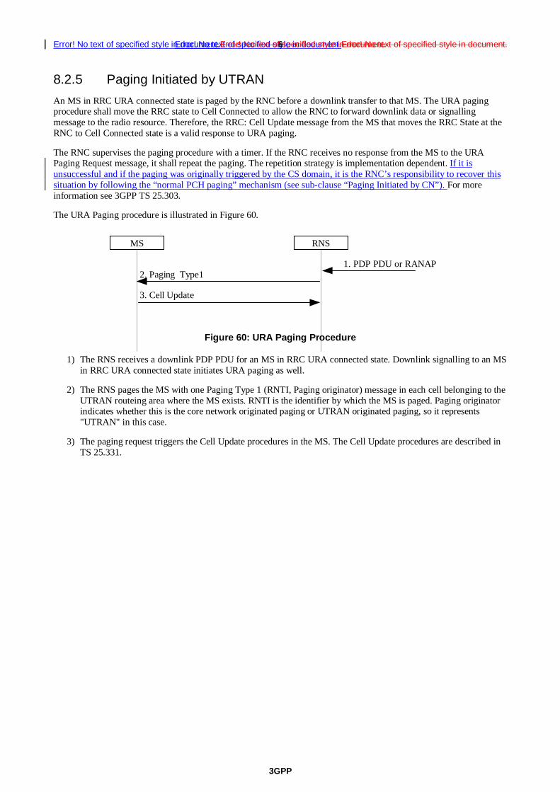
3GPP
Error! No text of specified style in document.Error! No text of specified style in document. 6Error! No text of specified style in document.Error! No text of specified style in document.
8.2.5 Paging Initiated by UTRAN
An MS in RRC URA connected state is paged by the RNC before a downlink transfer to that MS. The URA paging procedure shall move the RRC state to Cell Connected to allow the RNC to forward downlink data or signalling message to the radio resource. Therefore, the RRC: Cell Update message from the MS that moves the RRC State at the RNC to Cell Connected state is a valid response to URA paging.
The RNC supervises the paging procedure with a timer. If the RNC receives no response from the MS to the URA Paging Request message, it shall repeat the paging. The repetition strategy is implementation dependent. If it is unsuccessful and if the paging was originally triggered by the CS domain, it is the RNC’s responsibility to recover this situation by following the “normal PCH paging” mechanism (see sub-clause “Paging Initiated by CN”). For more information see 3GPP TS 25.303.
The URA Paging procedure is illustrated in Figure 60.
MS RNS
1. PDP PDU or RANAP
3. Cell Update
2. Paging Type1
Figure 60: URA Paging Procedure
1) The RNS receives a downlink PDP PDU for an MS in RRC URA connected state. Downlink signalling to an MS in RRC URA connected state initiates URA paging as well.
2) The RNS pages the MS with one Paging Type 1 (RNTI, Paging originator) message in each cell belonging to the UTRAN routeing area where the MS exists. RNTI is the identifier by which the MS is paged. Paging originator indicates whether this is the core network originated paging or UTRAN originated paging, so it represents "UTRAN" in this case.
3) The paging request triggers the Cell Update procedures in the MS. The Cell Update procedures are described in TS 25.331.

3GPP
Error! No text of specified style in document.Error! No text of specified style in document. 1Error! No text of specified style in document.Error! No text of specified style in document.
3GPP TSG-SA2 #33 Tdoc S2-032685
Sophia Antipolis, France, 7-11/7/03 CR-Form-v7
CHANGE REQUEST
� 23.060 CR 460 � rev - � Current version: 5.6.0 �
For HELP on using this form, see bottom of this page or look at the pop-up text over the � symbols.
Proposed change affects: UICC apps� ME Radio Access Network X Core Network X
Title: � Paging with RNTI followed by CN identity to solve issues of UTRAN-UE RRC mis-
synchronisation causing lost CS domain calls Source: � Vodafone Ltd Work item code: � TEI Date: � 9/7/03 Category: � A Release: � Rel-5 Use one of the following categories:
F (correction) A (corresponds to a correction in an earlier release) B (addition of feature), C (functional modification of feature) D (editorial modification)
Detailed explanations of the above categories can be found in 3GPP TR 21.900.
Use one of the following releases: 2 (GSM Phase 2) R96 (Release 1996) R97 (Release 1997) R98 (Release 1998) R99 (Release 1999) Rel-4 (Release 4) Rel-5 (Release 5) Rel-6 (Release 6)
Reason for change: � Temporary loss of coverage can lead to the UE entering RRC-IDLE while the
UTRAN remains for a long period in RRC-CONNECTED mode. During this time all MT voice calls and CS domain MT SMSs are lost.
Summary of change: � It is suggested that, following no response to RNTI paging, the UTRAN repages
with the Core Network identity for CS domain calls and SMSs. Consequences if � not approved:
MT voice calls and MT SMSs can be lost for long periods of time.
Clauses affected: � 6.1.2.4.1, 8.2.4, 8.2.5 Y N Other specs � ? Other core specifications � A note may be needed in RAN2
specifications (see LS from RAN 2 in R2-031458 =S2-032327).
affected: N Test specifications N O&M Specifications Other comments: � How to create CRs using this form: Comprehensive information and tips about how to create CRs can be found at http://www.3gpp.org/specs/CR.htm. Below is a brief summary:
1) Fill out the above form. The symbols above marked � contain pop-up help information about the field that they are closest to.
2) Obtain the latest version for the release of the specification to which the change is proposed. Use the MS Word "revision marks" feature (also known as "track changes") when making the changes. All 3GPP specifications can be

3GPP
Error! No text of specified style in document.Error! No text of specified style in document. 2Error! No text of specified style in document.Error! No text of specified style in document.
downloaded from the 3GPP server under ftp://ftp.3gpp.org/specs/ For the latest version, look for the directory name with the latest date e.g. 2001-03 contains the specifications resulting from the March 2001 TSG meetings.
3) With "track changes" disabled, paste the entire CR form (use CTRL-A to select it) into the specification just in front of the clause containing the first piece of changed text. Delete those parts of the specification which are not relevant to the change request.

3GPP
Error! No text of specified style in document.Error! No text of specified style in document. 3Error! No text of specified style in document.Error! No text of specified style in document.
6.1.2.4.1 Handling of Un-synchronous PMM States in the UE and the Network
6.1.2.4.1.1 Unsynchronous PMM states in the UE and the SGSN
In case of RRC connection release with cause "Directed Signalling connection re-establishment" or in case of an error, the PMM state of the MS and the 3G-SGSN may lose synchronisation. In this case the MS may be in the PMM-IDLE state while the 3G-SGSN is in the PMM-CONNECTED state.
NOTE 1: The opposite (MS in the PMM-CONNECTED state and SGSN in the PMM-IDLE state) shall never happen because the 3G-SGSN may not have the RAI where the MS is really located, so downlink transfer is impossible until the periodic URA update timer expires.
This situation is recovered by a successful RAU moving the MS to the PMM-CONNECTED state, or by a failed downlink transfer with cause "IMSI unknown in RNC", triggering a paging procedure from the 3G-SGSN.
The UE shall also perform a RAU procedure immediately on entering PMM-IDLE state when it has received a RRC Connection Release message with cause "Directed Signalling connection re-establishment" even if the RA has not changed since the last update.
The UE shall perform a subsequent Service request procedure after successful completion of the RA Update procedure to re-establish the radio access bearer when it has pending user data to send.
NOTE 2: The RNC will send a RRC CONNECTION RELEASE message with cause "Directed Signalling Connection re-establishment" when it is unable to contact the SRNC to validate the UE due to lack of Iur connection (see 3GPP TS 25.331).
6.1.2.4.1.2 Unsynchronous states in the UE and the UTRAN
In abnormal cases, the UTRAN can believe the UE is in the RRC-CONNECTED state while the UE is actually in the RRC-IDLE state.
Symptoms of this condition are that the UTRAN has an Iu interface connection to the SGSN and the UTRAN pages with the RNTI but receives no answer from the UE.
For UTRAN paging triggered by CS domain pages, the RNC should take the responsibility to recover this situation by re-paging with the Core Network Identity in the cells of that RNC which are in the Location Area indicated by the CN. A consequence of this re-paging is that it may lead to the RNC having two RRC connections for one UE but different RNTIs. To resolve this, when the RNC receives the Common ID message from the MSC, the RNC should request the release of the Iu-PS connection associated with any different RNTI previously associated with that IMSI.

3GPP
Error! No text of specified style in document.Error! No text of specified style in document. 4Error! No text of specified style in document.Error! No text of specified style in document.
8.2.4 Paging Initiated by CN
A CN node requests paging only for MSs in CMM-IDLE state or PMM-IDLE state. In the separate CN architecture, paging from a CN node is done independently from the state of the MS in the other CN service domain.
In the context of this specification, the terms RNS or RNC refer also to a GERAN BSS or BSC (respectively) when serving an MS in Iu mode.
In this alternative with paging co-ordination in the RAN, the MS does not need to listen to the PCH (Paging Channel) in the RRC Connected mode, at least not when MS is allocated a dedicated channel.
For each paging request received from a CN node, the RNC determines whether the MS has an established RRC connection or not. In order to achieve this, the context that is prepared within the SRNC for MS in RRC Connected mode must contain the IMSI, which is the common MS identity for the two CN domains.
If no context is found for the MS, "normal PCH paging" is performed. The paging message is transferred on the paging channel, and it includes the MS paging identity received from the CN and a CN service domain type indication.
If a context is found, a "CN paging message" is transferred using the existing RRC connection. This message includes a CN service domain type indication. If, potentially after repetition, this transfer is unsuccessful and if the CS domain originally triggered the paging, the RNC should decide whether to attempt “normal PCH paging” as described in sub-clause “Unsynchronous states in the UE and the UTRAN”.
8.2.4.1 PS Paging Initiated by 3G-SGSN without RRC Connection for CS
4. Service Request
4. Service Request
3. Paging Type12. Paging
MS RNS MSC/VLR
3G-SGSN
1. PDP PDU orDownlink signalling
Figure 58: PS Paging Without RRC Connection for CS
1) The 3G-SGSN receives a PDP PDU or downlink signalling for an MS in PMM Idle state.
2) The 3G-SGSN sends a RANAP Paging (IMSI, P-TMSI, Area, CN Domain Indicator, DRX parameters) message to each RNS belonging to the routeing area in which the MS is located. IMSI is needed by the RNS in order to calculate the MS paging group, and to identify the paged MS. If 3G-SGSN assigned the P-TMSI to the MS, P-TMSI is also included. Area indicates the routeing area in which the MS is paged. CN Domain Indicator indicates which domain (MSC or 3G-SGSN) initiated the paging message, and it represents "SGSN" in this case. DRX Parameters indicates whether or not the MS uses discontinuous reception and the DRX cycle length.
3) The RNS controls whether the MS has an established RRC connection or not. In this case, MS has no RRC connection, so a "normal PCH paging" is performed. Paging Type 1(IMSI or P-TMSI, Paging originator, CN domain ID) is transferred on the Paging channel, IMSI or P-TMSI identifies the MS. Paging originator indicates whether this is core network originated paging or RAN originated paging, so it represents "CN" in this case. And CN domain ID indicates whether this paging message is for CS service or PS service, so it represents "PS" in this case.

3GPP
Error! No text of specified style in document.Error! No text of specified style in document. 5Error! No text of specified style in document.Error! No text of specified style in document.
4) The paging request triggers the Service Request procedures in the MS. The service request procedures are described in clause "Service Request Procedure (Iu mode)".
Optionally, 3G-SGSN may include "Non Searching Indication" in RANAP Paging message in this case. If a "Non Searching Indication" parameter is present, the RNC will not search the established RRC connection, and just initiate "normal PCH paging".

3GPP
Error! No text of specified style in document.Error! No text of specified style in document. 6Error! No text of specified style in document.Error! No text of specified style in document.
8.2.5 Paging Initiated by RAN
An MS in RRC URA/GRA connected state is paged by the RAN before a downlink transfer to that MS. The URA/GRA paging procedure shall move the RRC state to Cell Connected to allow the RAN to forward downlink data or signalling message to the radio resource. Therefore, the RRC: Cell Update message from the MS that moves the RRC State at the RAN to Cell Connected state is a valid response to URA/GRA paging.
The RAN supervises the paging procedure with a timer. If the RAN receives no response from the MS to the URA or GRA Paging Request message, it shall repeat the paging. The repetition strategy is implementation dependent. If it is unsuccessful and if the paging was originally triggered by the CS domain, it is the RNC’s responsibility to recover this situation by following the “normal PCH paging” mechanism (see sub-clause “Paging Initiated by CN”). For more information see 3GPP TS 25.303.
The URA/GRA Paging procedure is illustrated in Figure 60.
MS RAN
1. PDP PDU or RANAP
3. Cell Update
2. Paging Type1
Figure 60: URA/GRA Paging Procedure
1) The RAN receives a downlink PDP PDU for an MS in RRC URA/GRA connected state. Downlink signalling to an MS in RRC URA/GRA connected state initiates URA/GRA paging as well.
2) The RAN pages the MS with one Paging Type 1 (RNTI, Paging originator) message in each cell belonging to the URA/GRA where the MS exists. RNTI is the identifier by which the MS is paged. Paging originator indicates whether this is the core network originated paging or RAN originated paging, so it represents "RAN" in this case.
3) The paging request triggers the Cell Update procedures in the MS. The Cell Update procedures are described in TS 25.331.

3GPP
Error! No text of specified style in document.Error! No text of specified style in document.Error! No text of specified style in document.
1Error! No text of specified style in document.Error! No text of specified style in document.Error! No text of specified style in document.
3GPP TSG-SA2 #33 Tdoc S2-032686
Sophia Antipolis, France, 7-11/7/03 CR-Form-v7
CHANGE REQUEST
� 23.060 CR 461 � rev - � Current version: 6.1.0 �
For HELP on using this form, see bottom of this page or look at the pop-up text over the � symbols.
Proposed change affects: UICC apps� ME Radio Access Network X Core Network X
Title: � Paging with RNTI followed by CN identity to solve issues of UTRAN-UE RRC mis-
synchronisation causing lost CS domain calls Source: � Vodafone Ltd Work item code: � TEI Date: � 9/7/03 Category: � A Release: � Rel-6 Use one of the following categories:
F (correction) A (corresponds to a correction in an earlier release) B (addition of feature), C (functional modification of feature) D (editorial modification)
Detailed explanations of the above categories can be found in 3GPP TR 21.900.
Use one of the following releases: 2 (GSM Phase 2) R96 (Release 1996) R97 (Release 1997) R98 (Release 1998) R99 (Release 1999) Rel-4 (Release 4) Rel-5 (Release 5) Rel-6 (Release 6)
Reason for change: � Temporary loss of coverage can lead to the UE entering RRC-IDLE while the
UTRAN remains for a long period in RRC-CONNECTED mode. During this time all MT voice calls and CS domain MT SMSs are lost.
Summary of change: � It is suggested that, following no response to RNTI paging, the UTRAN repages
with the Core Network identity for CS domain calls and SMSs. Consequences if � not approved:
MT voice calls and MT SMSs can be lost for long periods of time.
Clauses affected: � 6.1.2.4.1, 8.2.4, 8.2.5 Y N Other specs � ? Other core specifications � A note may be needed in RAN2
specifications (see LS from RAN 2 in R2-031458 =S2-032327).
affected: N Test specifications N O&M Specifications Other comments: � How to create CRs using this form: Comprehensive information and tips about how to create CRs can be found at http://www.3gpp.org/specs/CR.htm. Below is a brief summary:
1) Fill out the above form. The symbols above marked � contain pop-up help information about the field that they are closest to.
2) Obtain the latest version for the release of the specification to which the change is proposed. Use the MS Word "revision marks" feature (also known as "track changes") when making the changes. All 3GPP specifications can be

3GPP
Error! No text of specified style in document.Error! No text of specified style in document.Error! No text of specified style in document.
2Error! No text of specified style in document.Error! No text of specified style in document.Error! No text of specified style in document.
downloaded from the 3GPP server under ftp://ftp.3gpp.org/specs/ For the latest version, look for the directory name with the latest date e.g. 2001-03 contains the specifications resulting from the March 2001 TSG meetings.
3) With "track changes" disabled, paste the entire CR form (use CTRL-A to select it) into the specification just in front of the clause containing the first piece of changed text. Delete those parts of the specification which are not relevant to the change request.

3GPP
Error! No text of specified style in document.Error! No text of specified style in document.Error! No text of specified style in document.
3Error! No text of specified style in document.Error! No text of specified style in document.Error! No text of specified style in document.
6.1.2.4.1 Handling of Un-synchronous PMM States in the UE and the Network
6.1.2.4.1.1 Unsynchronous PMM states in the UE and the SGSN
In case of RRC connection release with cause "Directed Signalling connection re-establishment" or in case of an error, the PMM state of the MS and the 3G-SGSN may lose synchronisation. In this case the MS may be in the PMM-IDLE state while the 3G-SGSN is in the PMM-CONNECTED state.
NOTE 1: The opposite (MS in the PMM-CONNECTED state and SGSN in the PMM-IDLE state) shall never happen because the 3G-SGSN may not have the RAI where the MS is really located, so downlink transfer is impossible until the periodic URA update timer expires.
This situation is recovered by a successful RAU moving the MS to the PMM-CONNECTED state, or by a failed downlink transfer with cause "IMSI unknown in RNC", triggering a paging procedure from the 3G-SGSN.
The UE shall also perform a RAU procedure immediately on entering PMM-IDLE state when it has received a RRC Connection Release message with cause "Directed Signalling connection re-establishment" even if the RA has not changed since the last update.
The UE shall perform a subsequent Service request procedure after successful completion of the RA Update procedure to re-establish the radio access bearer when it has pending user data to send.
NOTE 2: The RNC will send a RRC CONNECTION RELEASE message with cause "Directed Signalling Connection re-establishment" when it is unable to contact the SRNC to validate the UE due to lack of Iur connection (see 3GPP TS 25.331).
6.1.2.4.1.2 Unsynchronous states in the UE and the UTRAN
In abnormal cases, the UTRAN can believe the UE is in the RRC-CONNECTED state while the UE is actually in the RRC-IDLE state.
Symptoms of this condition are that the UTRAN has an Iu interface connection to the SGSN and the UTRAN pages with the RNTI but receives no answer from the UE.
For UTRAN paging triggered by CS domain pages, the RNC should take the responsibility to recover this situation by re-paging with the Core Network Identity in the cells of that RNC which are in the Location Area indicated by the CN. A consequence of this re-paging is that it may lead to the RNC having two RRC connections for one UE but different RNTIs. To resolve this, when the RNC receives the Common ID message from the MSC, the RNC should request the release of the Iu-PS connection associated with any different RNTI previously associated with that IMSI.

3GPP
Error! No text of specified style in document.Error! No text of specified style in document.Error! No text of specified style in document.
4Error! No text of specified style in document.Error! No text of specified style in document.Error! No text of specified style in document.
8.2.4 Paging Initiated by CN
A CN node requests paging only for MSs in CMM-IDLE state or PMM-IDLE state. In the separate CN architecture, paging from a CN node is done independently from the state of the MS in the other CN service domain.
In the context of this specification, the terms RNS or RNC refer also to a GERAN BSS or BSC (respectively) when serving an MS in Iu mode.
In this alternative with paging co-ordination in the RAN, the MS does not need to listen to the PCH (Paging Channel) in the RRC Connected mode, at least not when MS is allocated a dedicated channel.
For each paging request received from a CN node, the RNC determines whether the MS has an established RRC connection or not. In order to achieve this, the context that is prepared within the SRNC for MS in RRC Connected mode must contain the IMSI, which is the common MS identity for the two CN domains.
If no context is found for the MS, "normal PCH paging" is performed. The paging message is transferred on the paging channel, and it includes the MS paging identity received from the CN and a CN service domain type indication.
If a context is found, a "CN paging message" is transferred using the existing RRC connection. This message includes a CN service domain type indication. If, potentially after repetition, this transfer is unsuccessful and if the CS domain originally triggered the paging, the RNC should decide whether to attempt “normal PCH paging” as described in sub-clause “Unsynchronous states in the UE and the UTRAN”.
8.2.4.1 PS Paging Initiated by 3G-SGSN without RRC Connection for CS
4. Service Request
4. Service Request
3. Paging Type12. Paging
MS RNS MSC/VLR
3G-SGSN
1. PDP PDU orDownlink signalling
Figure 58: PS Paging Without RRC Connection for CS
1) The 3G-SGSN receives a PDP PDU or downlink signalling for an MS in PMM Idle state.
2) The 3G-SGSN sends a RANAP Paging (IMSI, P-TMSI, Area, CN Domain Indicator, DRX parameters) message to each RNS belonging to the routeing area in which the MS is located. IMSI is needed by the RNS in order to calculate the MS paging group, and to identify the paged MS. If 3G-SGSN assigned the P-TMSI to the MS, P-TMSI is also included. Area indicates the routeing area in which the MS is paged. CN Domain Indicator indicates which domain (MSC or 3G-SGSN) initiated the paging message, and it represents "SGSN" in this case. DRX Parameters indicates whether or not the MS uses discontinuous reception and the DRX cycle length.
3) The RNS controls whether the MS has an established RRC connection or not. In this case, MS has no RRC connection, so a "normal PCH paging" is performed. Paging Type 1(IMSI or P-TMSI, Paging originator, CN domain ID) is transferred on the Paging channel, IMSI or P-TMSI identifies the MS. Paging originator indicates whether this is core network originated paging or RAN originated paging, so it represents "CN" in this case. And CN domain ID indicates whether this paging message is for CS service or PS service, so it represents "PS" in this case.

3GPP
Error! No text of specified style in document.Error! No text of specified style in document.Error! No text of specified style in document.
5Error! No text of specified style in document.Error! No text of specified style in document.Error! No text of specified style in document.
4) The paging request triggers the Service Request procedures in the MS. The service request procedures are described in clause "Service Request Procedure (Iu mode)".
Optionally, 3G-SGSN may include "Non Searching Indication" in RANAP Paging message in this case. If a "Non Searching Indication" parameter is present, the RNC will not search the established RRC connection, and just initiate "normal PCH paging".

3GPP
Error! No text of specified style in document.Error! No text of specified style in document.Error! No text of specified style in document.
6Error! No text of specified style in document.Error! No text of specified style in document.Error! No text of specified style in document.
8.2.5 Paging Initiated by RAN
An MS in RRC URA/GRA connected state is paged by the RAN before a downlink transfer to that MS. The URA/GRA paging procedure shall move the RRC state to Cell Connected to allow the RAN to forward downlink data or signalling message to the radio resource. Therefore, the RRC: Cell Update message from the MS that moves the RRC State at the RAN to Cell Connected state is a valid response to URA/GRA paging.
The RAN supervises the paging procedure with a timer. If the RAN receives no response from the MS to the URA or GRA Paging Request message, it shall repeat the paging. The repetition strategy is implementation dependent. If it is unsuccessful and if the paging was originally triggered by the CS domain, it is the RNC’s responsibility to recover this situation by following the “normal PCH paging” mechanism (see sub-clause “Paging Initiated by CN”). For more information see 3GPP TS 25.303.
The URA/GRA Paging procedure is illustrated in Figure 60.
MS RAN
1. PDP PDU or RANAP
3. Cell Update
2. Paging Type1
Figure 60: URA/GRA Paging Procedure
1) The RAN receives a downlink PDP PDU for an MS in RRC URA/GRA connected state. Downlink signalling to an MS in RRC URA/GRA connected state initiates URA/GRA paging as well.
2) The RAN pages the MS with one Paging Type 1 (RNTI, Paging originator) message in each cell belonging to the URA/GRA where the MS exists. RNTI is the identifier by which the MS is paged. Paging originator indicates whether this is the core network originated paging or RAN originated paging, so it represents "RAN" in this case.
3) The paging request triggers the Cell Update procedures in the MS. The Cell Update procedures are described in TS 25.331.

CR page 1
3GPP TSG-SA 2 Meeting #33 Tdoc �S2-032718 Sophia Antipolis, France, 07/07/2003 – 11/07/2003
CR-Form-v7
CHANGE REQUEST
� 23.060 CR 455 � rev 1 � Current version: 6.1.0 �
For HELP on using this form, see bottom of this page or look at the pop-up text over the � symbols.
Proposed change affects: UICC apps� ME Radio Access Network X Core Network X
Title: � BSS initiated BSS packet flow context deletion Source: � Siemens Work item code: � TEI6 Date: � 10/07/2003 Category: � C Release: � REL-6 Use one of the following categories:
F (correction) A (corresponds to a correction in an earlier release) B (addition of feature), C (functional modification of feature) D (editorial modification)
Detailed explanations of the above categories can be found in 3GPP TR 21.900.
Use one of the following releases: 2 (GSM Phase 2) R96 (Release 1996) R97 (Release 1997) R98 (Release 1998) R99 (Release 1999) Rel-4 (Release 4) Rel-5 (Release 5) Rel-6 (Release 6)
Reason for change: � TSG GERAN extendet the BSSGP (48.018) in a way that is possible for the BSS
to request a deletion of a BSS packet flow context. Therefor a new PDU (DELETE-BSS-PFC-REQ) was implemented. When the BSS has requested the Deletion of an BSS PFC the SGSN may either delete or modify the BSS PFC. Additionally, this CR provides some alignments of the Delete BSS packet flow context procedures with the BSSGP protocol specification.
Summary of change: � - Add clarification when the BSS can delete the BSS packet flow context
without notification to the SGSN according 48.018 - Implementation of the BSS Delete BSS PFC Req - Alignment of the parameters of the Delete BSS packet flow context message
to the BSSGP Consequences if � not approved:
Stage 2 is incomplete on high level BSS packet flow functionality
Clauses affected: � 12.6.3.5.4 Y N Other specs � X Other core specifications � 48.018 CR081 affected: X Test specifications X O&M Specifications Other comments: � How to create CRs using this form:

CR page 2
Comprehensive information and tips about how to create CRs can be found at http://www.3gpp.org/specs/CR.htm. Below is a brief summary:
1) Fill out the above form. The symbols above marked � contain pop-up help information about the field that they are closest to.
2) Obtain the latest version for the release of the specification to which the change is proposed. Use the MS Word "revision marks" feature (also known as "track changes") when making the changes. All 3GPP specifications can be downloaded from the 3GPP server under ftp://ftp.3gpp.org/specs/ For the latest version, look for the directory name with the latest date e.g. 2001-03 contains the specifications resulting from the March 2001 TSG meetings.
3) With "track changes" disabled, paste the entire CR form (use CTRL-A to select it) into the specification just in front of the clause containing the first piece of changed text. Delete those parts of the specification which are not relevant to the change request.

3GPP TS 23.060 v6.1.0 (2003-06) CR page 3
CR page 3
12.6.3.5.4 BSS Packet Flow Context Deletion Procedures
The BSS maycan, due to e.g. memory restrictions or user inactivity, at any time delete a BSS packet flow context without notifying the SGSN.
If the BSS is no longer able to support the aggregate BSS QoS profile of a BSS packet flow context, it may, especially for conversational or streaming traffic class, request the SGSN to delete or modify the BSS packet flow context. The SGSN should either modify or delete the BSS packet flow context. In addition the SGSN may need to initiate the PDP Context Modification or PDP Context Deletion procedure.
1. Delete BSS Packet Flow Context Request
BSS SGSN
2. SGSN initiated BSS Packet Flow Context deletion or modification
Figure xx: BSS-Initiated BSS Packet Flow Context Deletion Procedure
1) The BSS sends a Delete BSS Packet Flow Context Request (TLLI, Packet Flow Id, Cause) to the SGSN.
2) The SGSN should start either the SGSN-initiated BSS packet flow context modification procedure or the deletion of the BSS packet flow context. In addition the SGSN may need to initiate the PDP Context Modification or PDP Context Deletion procedure.
The SGSN may request the deletion of a BSS packet flow context with the SGSN-Initiated BSS Packet Flow Context Deletion procedure, as illustrated in Figure 87.
1. Delete BSS Packet Flow Context Request
2. Delete BSS Packet Flow Context Accept
BSS SGSN
Figure 87: SGSN-Initiated BSS Packet Flow Context Deletion Procedure
1) The SGSN sends a Delete BSS Packet Flow Context Request (TLLI IMSI, Packet Flow Id) message to the BSS. The BSS deletes the corresponding BSS packet flow context from its BSS context.
2) The BSS returns a Delete BSS Packet Flow Context Accept (TLLI, Packet Flow Id) message to the SGSN.
CR page 1
3GPP TSG-SA WG2 Meeting #34 Tdoc S2-033117� Brussels, Belgium, 18th –22nd August 2003
CR-Form-v7
CHANGE REQUEST
� 23.060 CR 450
� rev 3 � Current version: 6.1.0 �
For HELP on using this form, see bottom of this page or look at the pop-up text over the � symbols.
Proposed change affects: UICC apps� ME Radio Access Network X Core Network X
Title: � Usage of Allocation and Retention Priority in the BSS Source: � Alcatel Work item code: � TEI6 Date: � 18/08/2003 Category: � B Release: � Rel-6 Use one of the following categories:
F (correction) A (corresponds to a correction in an earlier release) B (addition of feature), C (functional modification of feature) D (editorial modification)
Detailed explanations of the above categories can be found in 3GPP TR 21.900.
Use one of the following releases: 2 (GSM Phase 2) R96 (Release 1996) R97 (Release 1997) R98 (Release 1998) R99 (Release 1999) Rel-4 (Release 4) Rel-5 (Release 5) Rel-6 (Release 6)
Reason for change: �
TSG GERAN has introduced Allocation and Retention Priority (ARP) within the BSS Packet Flow Context Creation Procedure on the Gb interface in the framework of Release 6. Inclusion of the ARP within the procedure allows the BSS to perform packet flow admission control based on Priority, Pre-emption Capability, Pre-emption Vulnerability and Queuing Allowed fields. Inclusion (resp. handling) of the ARP has been left optional for Rel-6 SGSN (resp. Rel-6 BSS).
As a consequence, TSG GERAN has reviewed and approved a CR to 48.018 Rel-6 introducing ARP within the BSSGP protocol.
This CR aims to update the BSS Packet Flow Context Procedure in 23.060 accordingly.
Summary of change: �
The Allocation / Retention Priority is added as an optional IE to the Create BSS PFC Request. Inclusion of this IE allows the BSS to perform packet flow admission control based on Priority, Pre-emption Capability, Pre-emption Vulnerability and Queuing Allowed fields.
Consequences if � not approved:
The Allocation / Retention Priority cannot be used at the time a PFC is created or modified. It is not possible to apply PFC differentiation between PFCs and/or between users.
Clauses affected: � 12.6.3.5.1

CR page 2
Y N Other specs � X Other core specifications � This CR aligns 23.060 to the approved
48.018 CR number 080. affected: X Test specifications X O&M Specifications Other comments: � How to create CRs using this form: Comprehensive information and tips about how to create CRs can be found at http://www.3gpp.org/specs/CR.htm. Below is a brief summary:
1) Fill out the above form. The symbols above marked � contain pop-up help information about the field that they are closest to.
2) Obtain the latest version for the release of the specification to which the change is proposed. Use the MS Word "revision marks" feature (also known as "track changes") when making the changes. All 3GPP specifications can be downloaded from the 3GPP server under ftp://ftp.3gpp.org/specs/ For the latest version, look for the directory name with the latest date e.g. 2001-03 contains the specifications resulting from the March 2001 TSG meetings.
3) With "track changes" disabled, paste the entire CR form (use CTRL-A to select it) into the specification just in front of the clause containing the first piece of changed text. Delete those parts of the specification which are not relevant to the change request.

3GPP TS 23.060 v6.1.0 (2003-03) CR page 3
CR page 3
12.6.3.5.1 BSS Packet Flow Context Creation Procedure
On receiving a request to transmit an uplink or downlink LLC PDU for which no BSS packet flow context exists in the BSS, the BSS may request the download of the BSS packet flow context from the SGSN.
The SGSN may at any time request the creation of a BSS packet flow context, e.g. due to the activation of a PDP context.
The BSS Packet Flow Context Creation procedure is illustrated in Figure 85.
2. Create BSS Packet Flow Context Request
3. Create BSS Packet Flow Context Accept
BSS SGSN
1. Download BSS Packet Flow Context Request
Figure 85: BSS Packet Flow Context Creation Procedure
1) The BSS receives a request to transfer an uplink or downlink user data LLC PDU for which it currently does not have a BSS packet flow context. In the uplink case, TLLI, Radio Priority, and Packet Flow Id are received from the MS as defined in GSM3GPP TS 044.060. In the downlink case, TLLI and Packet Flow Id are received from the SGSN as defined in GSM3GPP TS 048.018 [21]. If Packet Flow Id neither indicates best-effort service nor SMS, then the BSS sends a Download BSS Packet Flow Context Request (RAI, TLLI, Packet Flow Id) message to the SGSN. Until the BSS receives the BSS packet flow context, the BSS shall handle uplink and downlink transfers according to a default aggregate BSS QoS profile. For uplink transfers, the default profile is specific to the radio priority level.
2) The SGSN sends a Create BSS Packet Flow Context Request (IMSI, TLLI, Packet Flow Id, Aggregate BSS QoS Profile Requested, BSS Packet Flow Timer) message to the associated BSS. The SGSN derives Aggregate BSS QoS Profile Requested from the QoS profile negotiated for the PDP contexts that share a packet flow as follows: The SGSN shall divide the transfer delay attribute in the QoS profile in one core network part and one BSS part. The SGSN estimates the transfer delay in the core network and subtracts this from the GPRS bearer service transfer delay. The result only covers the delay in the MS to SGSN segment of the GPRS PLMN. Since the BSS transports LLC PDUs obtained after segmentation of SDUs by the SNDCP layer, the SGSN shall convert the values of the GPRS bearer service attributes maximum SDU size, SDU error ratio, residual bit error ration, maximum bit rate, guaranteed bit rate and the resulting transfer delay to values applicable to the LLC PDUs. All other attributes in Aggregate BSS QoS Profile shall be the same as the corresponding GPRS bearer service attribute, see 3GPP TS 23.107. The SGSN may also include the Allocation / Retention Priority Information Element in the Create BSS Packet Flow Context Request.
3) The BSS may restrict the requested aggregate BSS QoS profile given its capabilities and the current load. If the Allocation / Retention Priority Information Element is included by the SGSN in the Create BSS Packet Flow Context Request, the BSS may use it to perform queuing of the packet flow context creation or to pre-empt other packet flow contexts. The BSS creates a BSS packet flow context and inserts the parameters in its BSS context. The BSS returns a Create BSS Packet Flow Context Accept (IMSI, Packet Flow Id, Aggregate BSS QoS Profile Negotiated) message to the SGSN. The BSS uses the negotiated aggregate BSS QoS profile when allocating radio resources and other resources such as buffer capacity. The detailed operation is defined in 3GPP TS 48.018.