Sootblower with progressive cleaning arc - EP 2336704 A1
17
Printed by Jouve, 75001 PARIS (FR) (19) EP 2 336 704 A1 & (11) EP 2 336 704 A1 (12) EUROPEAN PATENT APPLICATION (43) Date of publication: 22.06.2011 Bulletin 2011/25 (21) Application number: 10194199.5 (22) Date of filing: 08.12.2010 (51) Int Cl.: F28G 3/16 (2006.01) F28G 15/04 (2006.01) B08B 3/02 (2006.01) B08B 5/02 (2006.01) (84) Designated Contracting States: AL AT BE BG CH CY CZ DE DK EE ES FI FR GB GR HR HU IE IS IT LI LT LU LV MC MK MT NL NO PL PT RO RS SE SI SK SM TR Designated Extension States: BA ME (30) Priority: 18.12.2009 US 642210 (71) Applicant: Diamond Power International Inc. Lancaster, OH 43130 (US) (72) Inventors: • Elder, Rodney H. Lancaster, OH 43130 (US) • Hipple, James H. Lancaster, OH 43130 (US) • Michael, Michael P. Baltimore, OH 43105 (US) • Honaker, Robert W. Pickerington, OH 43147 (US) (74) Representative: Solf, Alexander Patentanwälte Dr. Solf & Zapf Candidplatz 15 81543 München (DE) (54) Sootblower with progressive cleaning arc (57) A sootblower (10) of the short travel rotary fur- nace wall type having features which permit indexing of the angular position of the screw tube assembly (18) dur- ing successive operating cycles. Indexing of the arc swept by the sootblower nozzle (24) is provided through the use of a novel cam plate component (44,74) and op- erating the sootbtower (10) in a manner which provides for indexing between operating cycles.
-
Upload
khangminh22 -
Category
Documents
-
view
0 -
download
0
Transcript of Sootblower with progressive cleaning arc - EP 2336704 A1

Printed by Jouve, 75001 PARIS (FR)
(19)E
P2
336
704
A1
��&�� ���������(11) EP 2 336 704 A1
(12) EUROPEAN PATENT APPLICATION
(43) Date of publication: 22.06.2011 Bulletin 2011/25
(21) Application number: 10194199.5
(22) Date of filing: 08.12.2010
(51) Int Cl.:F28G 3/16 (2006.01) F28G 15/04 (2006.01)
B08B 3/02 (2006.01) B08B 5/02 (2006.01)
(84) Designated Contracting States: AL AT BE BG CH CY CZ DE DK EE ES FI FR GB GR HR HU IE IS IT LI LT LU LV MC MK MT NL NO PL PT RO RS SE SI SK SM TRDesignated Extension States: BA ME
(30) Priority: 18.12.2009 US 642210
(71) Applicant: Diamond Power International Inc.Lancaster, OH 43130 (US)
(72) Inventors: • Elder, Rodney H.
Lancaster, OH 43130 (US)
• Hipple, James H.Lancaster, OH 43130 (US)
• Michael, Michael P.Baltimore, OH 43105 (US)
• Honaker, Robert W.Pickerington, OH 43147 (US)
(74) Representative: Solf, AlexanderPatentanwälte Dr. Solf & Zapf Candidplatz 1581543 München (DE)
(54) Sootblower with progressive cleaning arc
(57) A sootblower (10) of the short travel rotary fur-nace wall type having features which permit indexing ofthe angular position of the screw tube assembly (18) dur-ing successive operating cycles. Indexing of the arcswept by the sootblower nozzle (24) is provided through
the use of a novel cam plate component (44,74) and op-erating the sootbtower (10) in a manner which providesfor indexing between operating cycles.

EP 2 336 704 A1
2
5
10
15
20
25
30
35
40
45
50
55
Description
FIELD OF THE INVENTION
[0001] The present invention generally relates to asootblower device for cleaning internal surfaces of large-scale combustion devices such as utility or industrial boil-ers. More particularly, the present invention is directedto a short travel, retracting rotary type sootblower, whichprovides indexing between the position of its dischargenozzle between the start of cleaning cycles to reducethermal stresses placed on internal components of thecombustion device.
BACKGROUND AND SUMMARY OF THE INVENTION
[0002] To optimize the thermal efficiency of large scalefossil fuel burning heat exchangers or boilers, it is nec-essary to periodically remove deposits such as soot, slagand fly ash from their interior heat exchanging surfaces.Typically, a number and types of cleaning devices knownas sootblowers are mounted to the exterior of the boiler.Periodically they are inserted into the boiler throughcleaning ports located in the boiler wall. Positioned onthe forward end of the screw tubes or screw tubes as-semblies are one or more cleaning nozzles. The nozzlesdischarge a pressurized fluid cleaning medium, such asair, water, or steam. The high pressure cleaning mediumcauses deposits of soot, slag, and fly ash to be dislodgedfrom the internal structures of the boiler.[0003] One type of sootblower is known as a short trav-el retracting rotary type. This type has a screw tube as-sembly which is inserted into the boiler, and once it reach-es its fully extended position, cleaning medium is dis-charged from the nozzle as it is rotated through a partialarc, full rotation, or multiple full rotations as desired forwall cleaning. The sootblower medium discharged fromthe nozzle provides the cleaning effect mentioned previ-ously. One very widely utilized design of the above-men-tioned sootblower type is manufactured by the assigneeof the present invention and is known as a Diamond Pow-er "IR-3Z" ™ sootblower device. These devices have op-erated in a highly reliable and effective manner aroundthe world for many years.[0004] One disadvantage of many sootblower designsis the erosion and thermal stresses caused to internalcomponents of the boiler when their cleaning cycle op-erates in the same repeated manner during each oper-ation. For the sootblower of the type mentioned previ-ously, once the screw tube assembly is advanced andreaches its fully extended position, the nozzle begins todischarge cleaning medium and rotates through a spec-ified arc or number of revolutions. At the conclusion ofthe cleaning cycle, the nozzle reaches its set rotationalindexed position, at which point the screw tube assemblyis retracted. The next operating cycle retraces the pathof the prior cycles. When steam is used as a sootblowingmedium, steam in the supply circuit piping may condense
into liquid water between operating cycles. When thesteam valve is opened to cause the steam sootblowingmedium to flow through the sootblower at the beginningof a cleaning cycle, an initial pulse of condensate is eject-ed from the sootblower nozzle. Thereafter, high pressuresteam flows through the nozzle until the cleaning mediumvalve is again shut-off. The initial ejection of the conden-sate has an undesirable consequence of placing erosionand thermal stresses on the internal components whichimpacts it. The heat transfer surfaces can tolerate con-densate, but when numerous cycles occur in which thesame surfaces are repeatedly impacted by condensate,failures of the internal heat transfer components can oc-cur. Accordingly, in many applications it is desirable toindex the position at which the sootblower nozzle beginsits cleaning cycle so that the same internal surfaces arenot struck by condensate at the start of each operatingcycle.[0005] Numerous approaches toward providing soot-blower nozzle indexing are known. For example, in longretracting sootblowers which discharge cleaning mediumas a lance tube is extended and retracted, the cleaningmedium path can be displaced between operating cycles.An approach implemented by the assignee of this inven-tion for indexing long retracting sootblowers uses a driverack for a gear driven type long retracting sootblowerwhich features a mechanism for indexing the phasing ofgear drive between operating cycles. This approach isdescribed in the assignee’s US Patent No. 4,803,959.Other types of indexing mechanisms are known, for ex-ample, some use gear drives having ratcheting indexingcomponents.[0006] While many approaches toward providing in-dexing of sootblower operating cycles are known, thesestrategies are not adaptable for modification to existingshort travel retracting rotary sootblowers.[0007] In accordance with the present invention, theseinventors have found that modifications of the existingIR-3Z™ sootblower components coupled with modifica-tions of the control schedule of the device provide thedesirable indexing feature. By preferably providing atleast four different rotated start positions for the soot-blowing start cycle, the erosion effects of condensateejection can be distributed over multiple internal surfac-es, reducing the likelihood of boiler component damage.The principles of this invention may be implemented asa modification to existing sootblowers or in newly con-structed sootblower assemblies.[0008] Additional benefits and advantages of thepresent invention will become apparent to those skilledin the art to which the present invention relates from thesubsequent description of the preferred embodiment andthe appended claims, taken in conjunction with the ac-companying drawings.
BRIEF DESCRIPTION OF THE DRAWINGS
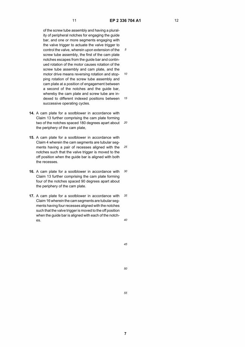
[0009] Figure 1 is a pictorial view of a short retracting
1 2
EP 2 336 704 A1
3
5
10
15
20
25
30
35
40
45
50
55
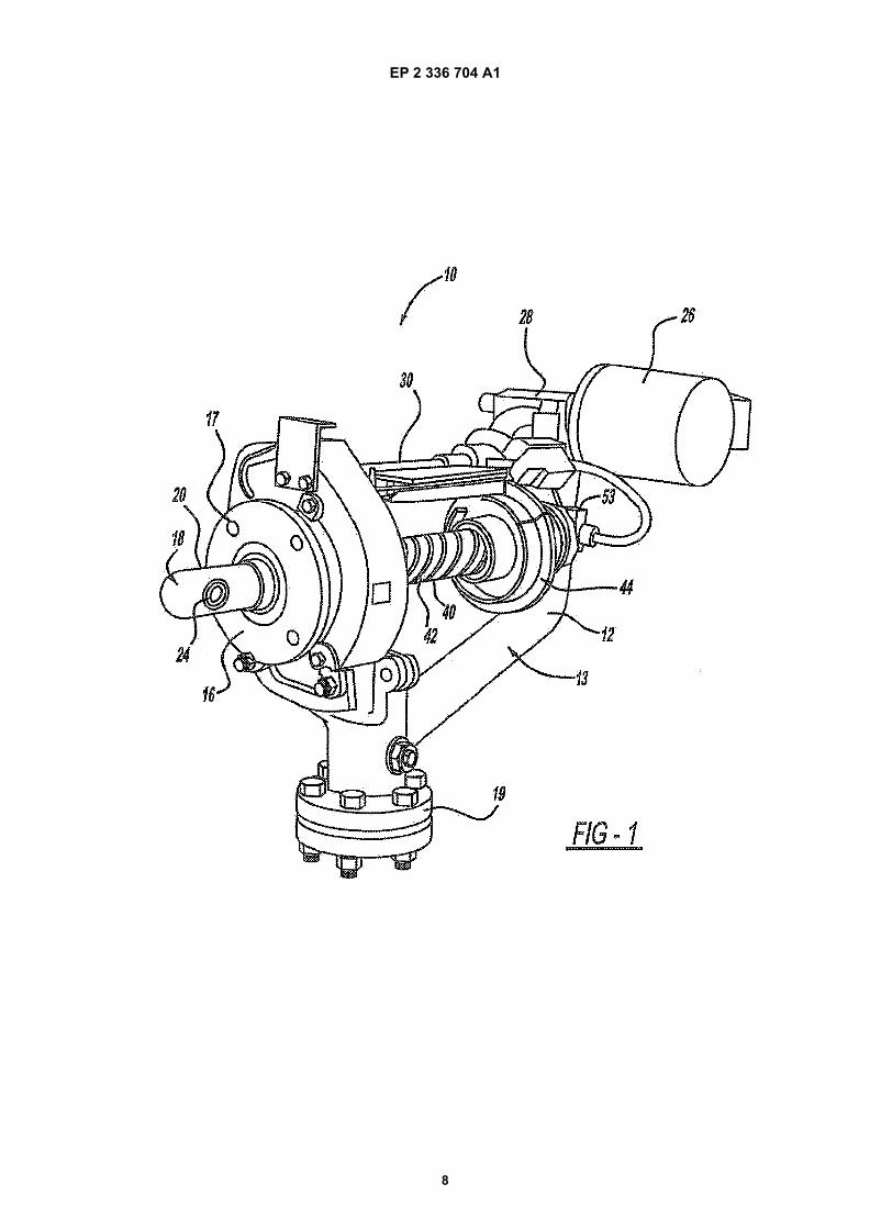
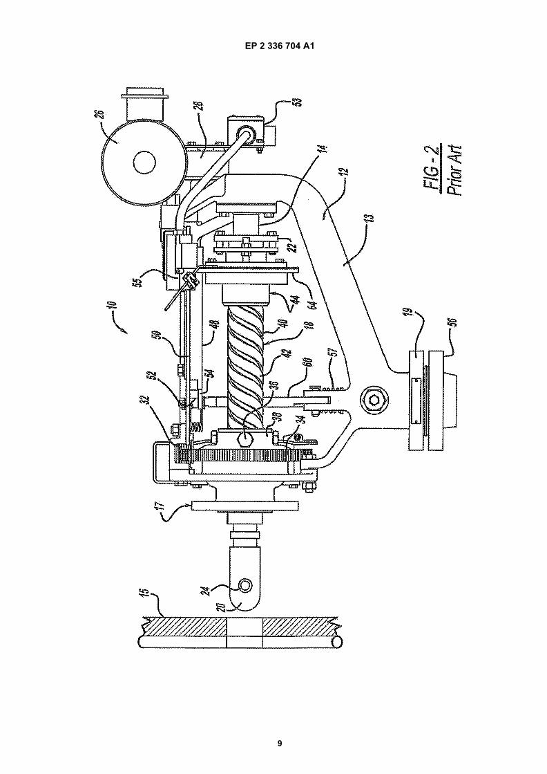
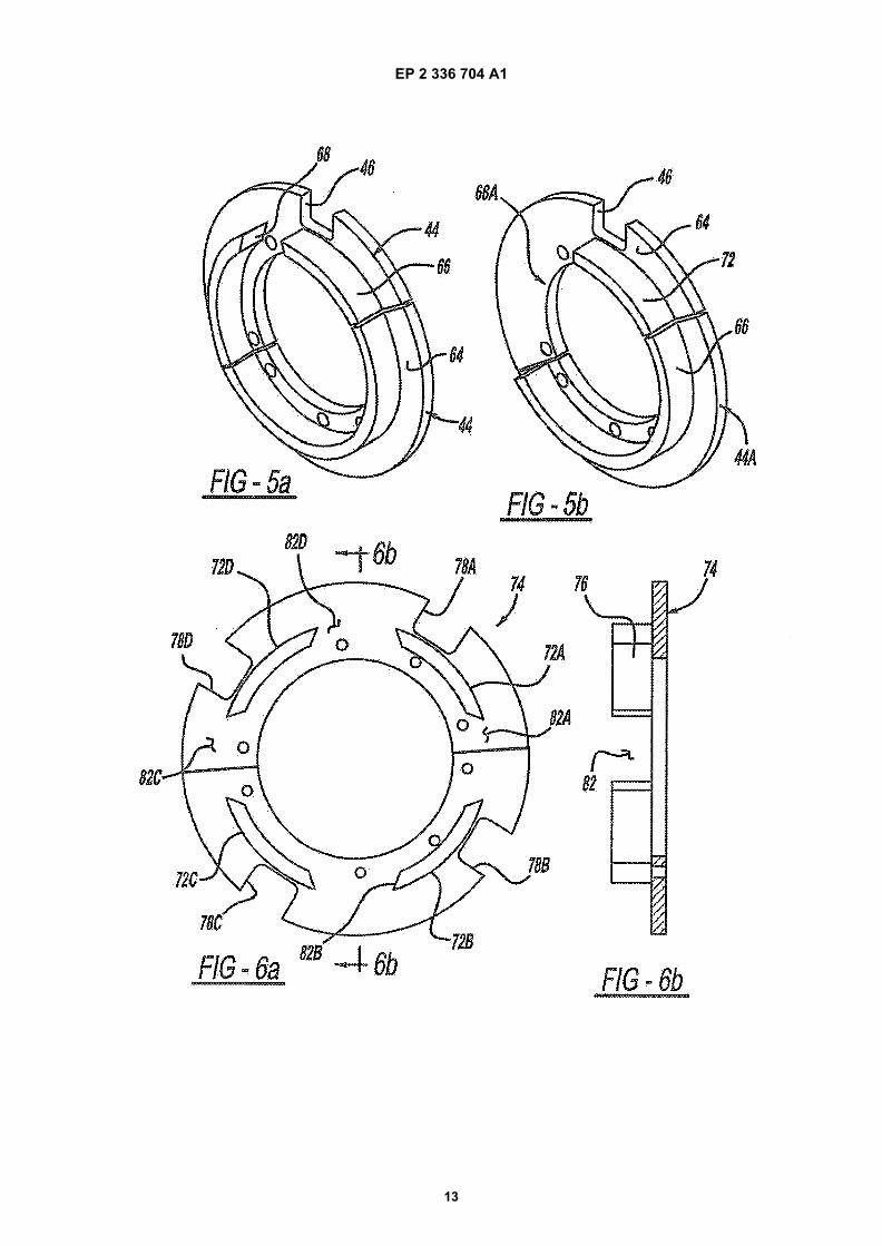
rotary sootblower in accordance with the prior art whichmay be modified to incorporate the features of the presentinvention;[0010] Figure 2 is a side elevational view of a shortretracting rotary sootblower in accordance with the priorart which may be modified to incorporate the features ofthe present invention;[0011] Figure 2a is an enlargement of a portion of theshort retracting rotary sootblower as shown in Figure 2;[0012] Figure 3 is an exploded pictorial view of thegooseneck valve assembly and feed tube of the soot-blower shown in Figures 1 and 2;[0013] Figure 4 is an exploded pictorial view of thescrew tube assembly screw drive assembly of the soot-blower shown in Figures 1 and 2;[0014] Figures 5a and 5b illustrate cam plates for soot-blowers in accordance with the prior art of the type shownin Figures 1 through 4;[0015] Figures 6a and 6b illustrate a cam plate for asootblower in accordance with the present invention; and[0016] Figures 7a and 7b illustrate the cam plate inaccordance with this invention as it interacts with otherelements of a short travel rotary sootblower assembly.
DETAILED DESCRIPTION OF THE INVENTION
[0017] Figures 1, 2, and 2a show a complete furnacewall sootblower in accordance with the prior art whichmay be modified to incorporate the features of the presentinvention. The illustrated sootblower is known in the in-dustry as a short travel, retracting rotary sootblowerwhich is designated by reference number 10. This typeof sootblower is primarily used for cleaning furnace walltubes, and an example of the design is designated bythe Assignee of this invention as an "IR-3Z" ™ blowerassembly. Figures 1, 2, and 2a show the basic elementsof sootblower 10. Gooseneck assembly 13 acts as aframe member to provide support for the major compo-nents of sootblower 10. Gooseneck assembly 13 in-cludes gooseneck tube 12 which conducts sootblowingcleaning medium. Feed tube 14 is mounted to gooseneckvalve assembly 13 and conducts the blowing mediumwhich is typically steam for the cleaning function, con-trolled by internal poppet valve assembly 19, as will bedescribed in more detail in the following description.Screw tube assembly 18 includes nozzle extension 20which is a hollow tube which over fits feed tube 14 in atelescoping manner. Nozzle extension 20 may be pro-vided in various lengths depending on the intendedcleaning application. Packing gland 22 provides a fluidseal between the nozzle extension 20 and feed tube 14such that the flow of blowing medium within feed tube 14is conducted into nozzle extension 20 without significantleakage between the tubes. The cleaning medium flowsthrough the interior hollow cavities of feed tube 14 andnozzle extension 20, and is ejected within the boilerthrough nozzle 24.[0018] Figure 3 shows in detail, feed tube 14 which is
mounted to gooseneck tube 12 at flange 16.[0019] Sootblower 10 is mounted to the boiler wall 15(shown in Figures 2 and 2a in a simplified form) by frontbracket assembly 17. When sootblower 10 is operated,nozzle extension 20 is extended into the furnace interior(the area to the left of boiler wall 15 as shown in Figures2 and 2a) and, when cleaning is completed, it is with-drawn. During cleaning, nozzle 24 is rotated to sweep anarc of cleaning medium spray.[0020] Drive motor 26 powers sootblower 10 througha gear reducer 28. Rotation of drive motor 26 is convertedto rotation of gear shaft 30 which in turn rotates drivepinion gear 32. Drive pinion gear 32 meshes with hubgear 34 mounted to hub 38. Screw tube 42 passesthrough hub gear 34 and hub 38. Pins 36 extend inwardlyfrom hub 38 and engage with the helical grooves 40formed on the outside surface of screw tube 42. Screwtube 42 is attached to nozzle extension 20.[0021] Cam plate 44 shown by Figures 4, 5a and 5bis affixed to the proximal end of screw tube 42 via hub35 adjacent to packing gland 22 and includes, in accord-ance with conventional designs, a single peripheral notch46 which engages with an elongated guide bar 48 whichis supported by support plate 50. Guide bar 48 has a freeend 52 positioned at the front end of the unit such thatcam plate notch 46 escapes from engagement with theguide bar 48 at near the fully extended position of screwtube 42.[0022] The extension and retraction movement ofscrew tube assembly 18 is started by a control commandthrough electric control assembly 53 which activatesdrive motor 26. Rotation of motor 26 rotates drive piniongear 32 and hub gear 34. This rotation causes pins 36,which engage with helical grooves 40, to cause screwtube 42 to move from the retracted position shown inFigure 2 to an extended position. During screw extensionmovement (between the fully retracted and fully extendedpositions), screw tube 42 is prevented from rotating dueto the engagement between cam plate notch 46 andguide bar 48. When screw tube assembly 18 reaches itsfully extended position, cam plate 44 extends past guidebar end 52, and therefore the screw tube 42 is no longerrestrained from rotating. At this point, continued rotationof hub gear 34 causes screw tube assembly 18 and con-sequently nozzle 24 to rotate. Front pawl 54 is springloaded to engage with cam plate notch 46 and is usedto establish a detent for the "park" position of the camplate 44 to position cam plate notch 46 to reengage withguide bar end 52 when screw tube assembly 18 is beingretracted. In the forward direction, the front pawl 54 isspring loaded and slip by the cam notches 46. In thereverse direction of cam plate 44, front pawl 44 stops thecam plate at the correct position for notch 46 to engagewith guide bar end 52.[0023] When screw tube assembly 18 reaches its fullyextended position and nozzle 24 is rotated through thedesired partial rotation arc or number of rotations, drivemotor 26 is stopped based on a control input from a timer
3 4
EP 2 336 704 A1
4
5
10
15
20
25
30
35
40
45
50
55
circuit in electric control assembly 53 and then command-ed through the electric control assembly to reverse itsrotation. Such reversal allows front pawl 54 to engagewith cam plate notch 46 and position it properly to causeit to reengage with guide bar end 52 in the retractionmovement. Continued reverse rotation of the motor 26causes screw tube assembly 18 to return to its fully re-tracted, parked position, shown in Figure 2. Limit switch55 is activated when cam plate 44 reaches its fully re-tracted position, and provides a control signal to electriccontrol 53 to stop current to drive motor 26 until the nextcleaning cycle.[0024] The flow of blowing medium is controlled by me-chanically operated valve 19 shown as a poppet typevalve. A supply of steam or air or other blowing fluid me-dium is connected with poppet valve 19 at flange 56 andit is opened to an "on" position and closed to an "off"position by motion of valve trigger 60. Valve trigger 60 isin the shape of a caliper arm and includes an inwardlydirected tooth 62. When poppet valve 19 is opened,steam flows through gooseneck assembly 13, into feedtube 14, through nozzle extension 20, and out of nozzle24.[0025] Cam plate 44 of convention design is bestshown with reference to Figures 4, 5a, and 5b, and formsa disc section 64 and a tubular section 66 extending fromthe disc section. Disc section 64 forms notch 46 de-scribed previously. Tubular section 66 includes, in ac-cordance with a conventional design, a single recess (ornotch) 68 which is engaged by valve trigger tooth 62.Poppet valve 19 is operated by movement of valve trigger60. When valve trigger 60 is in a radially outer positionwhich corresponds with tooth 62 riding on the outsidesurface of tubular section 66, the poppet valve 19 isopened to the "on" position to allow the flow of the fluidcleaning medium. On the other hand, when the valvetrigger tooth 62 fits into recess 68 thus moving to a radiallyinward position, the flow of cleaning medium is stoppedthrough the valve. Valve trigger 60 is biased to the inner(off) position by the force of valve spring 57. The radialextent of recess 68 (or stated another way, the angularlength of tubular section 66) can be adjusted such thatthe cleaning medium discharge occurs some arc seg-ment less than 360° using a cam plate such as cam plate44a shown in Figure 5b in which recess 68a has a greaterangular extent as compared with recess 68. This is pro-vided for applications where cleaning is only requiredover a partial are of rotation of screw tube assembly 18.Tubular section 66a as illustrated in Figure 5b providesabout 300° of cleaning medium discharge.[0026] It is noted that cam plates 44 and 44a may beformed as one-piece articles, or in arc segments as theyare illustrated. Multipiece construction provide ease ofassembly since a one-piece ring shaped cam plate wouldneed to be inserted over nozzle extension 20, whereasthe separate segments can be bolted to hub 35 with thescrew tube assembly 18 in its retracted position.[0027] Since the cam plate notch 46 needs to engage
and reengage with guide bar 48 at the beginning and endof each operating cycle, the start and stop position of thelance tube nozzle 24 and the position at which cleaningmedium discharge occurs, is fixed between operating cy-cles in the illustrated prior art sootblower 10 describedpreviously.[0028] The above description describes sootblower 10in accordance with prior art known features. Sootblower10 modified in accordance with the present invention uti-lizes cam plate 74 illustrated in Figures 6a, 6b, 7a, and7b. Notably, cam plate 74 includes more than one of theperipheral notches 78, designated as notches 78a, 78b,78c, and 78d which engage guide bar 48, as does notch46 in the prior art cam plate 44. This enables cam plate74 and consequently sootblower screw tube assembly18 to be moved to more than one angularly indexed po-sition during its extension and retraction motion (and im-portantly, its start position). Cam plate tubular section 72is segmented into sections 72a-d and has a number ofdiscontinuities or recesses 82a, 82b, 82c, and 82d which,like tubular section 66 of cam plate 44, controls the flowof cleaning medium discharge through poppet valve 19.It is necessary to move poppet valve 19 to a closed po-sition when the sootblower reaches its parked and in-dexed position during retraction and extension of screwtube assembly 18. For this reason, tubular section re-cesses 82 are equal in number to the number of camplate notches 78 provided. Cam plate 74 is a direct re-placement for cam plate 44 used in existing sootblower10. It should be noted that other configurations of camplate 74 may be provided. In accordance with this inven-tion, more than one notch 78 is needed to implement thefeatures of the present invention. However, various num-bers of notches 78 and therefore indexed start positionscan be provided. For example, two, three, or more notch-es 78 could be provided, with the notches 78 and 82 atequal angular arc spacings.[0029] In operation, cam plate 74 is positioned in itsbeginning park position with one of notches 78a, 78b,78c, and 78d engaged with guide bar 48. Drive motor 26is actuated to cause cam plate 74 to advance along guidebar 48 as screw tube assembly 18 is being extended intothe boiler. When cam plate 74 escapes from engagementwith guide bar 48 near its fully extended position, camplate 74, and consequently screw tube assembly 18, arecaused to rotate. Valve trigger 60 engages with recesses82a-d as the cam plate is rotated. Drive motor 26 is ac-tuated over a time period established by a timer unit withinelectric controller assembly 53. When the rotation of noz-zle extension 20 occurs through a desired arc (or fullrotations), drive motor 26 is caused to be deenergizedto stop the rotation when cam plate 74 is at some angularposition displaced from that of the first notch 78a (or an-other notch engaged in the preceding cycle). Since theforward/reverse motion is based on a timer control, thetimer is set to cause cam plate 74 to overshoot the desiredparked position slightly. The motor 76 is reversed to po-sition the cam plate 74 (as explained in more detail below)
5 6

EP 2 336 704 A1
5
5
10
15
20
25
30
35
40
45
50
55
and is stopped in its rotation so that another one of notch-es 78b, 78c, or 78d is positioned to engage with guidebar 48. Once the desired position is achieved, the drivemotor 26 causes the cam plate 74, at one of notches 78athrough 78d to reengage with the guide bar 48. In suc-cessive operating cycles, drive motor 26 is energizedthrough a predetermined time period which causes rota-tion again to a position just past that corresponding withthe notch 78a through 78d displaced from the immedi-ately preceding cycle. At full retraction, drive motor 26 isdeenergized by activation of limit switch 55.[0030] It is necessary for the flow of steam throughsootblower 10 to be stopped when cam plate 74 is at a"start" position at which one of notches 78a, 78b, 78c, or78d is positioned to engage with guide bar end 52. Ac-cordingly, cam tubular sections 72a-d have recesses82a-d equal in number to those of notches 78a-d.[0031] Figures 7a and 7b illustrate the interaction be-tween valve trigger 60 and tubular sections 72a-d. Asshown in Figure 7a, valve trigger 60 is moved to its radiallyouter position, overcoming the force of spring 57 andriding on the outside of tubular sections 72a-d. This po-sition opens the flow of steam through poppet valve 19.When the rotation has gone through a desired cleaningare, the electronic control timer signals the device to stoprotation and reverse. When cam plate 74 is stopped andits rotation is reversed, trigger tooth 62 contacts the as-sociate tubular section 72 a-d and continued reverse ro-tation causes valve trigger 60 to move to its radially innerposition which stops the flow of cleaning medium as itmoves into one of recesses 82 a-d. This interaction alsoacts as a "one-way ratchet" which positions cam plate74, such that guide bar end 52 is aligned with one ofnotches 78a-d.[0032] Cam plate 74 is illustrated in Figures 6a, 6b, 7a,and 7b and provide four possible indexed park positionsfor the sootblower nozzle corresponding with each of thefour notches 78a-d. This cam plate 74 provides rotationset positions at 90° spaced increments. For example, inoperation, cam plate 74 can provide more or less than360° of rotation for each operating cycle which wouldresult in a different one of the notches 78a-d engagingwith guide bar end 50 at each successive operating cycle.It is within the scope of the present invention to providediffering numbers of notches 78a. In order to provide thefeatures of the invention, at least two of such notches 78should be provided. The number of recesses 82 in tubularsection 72 are equal to those of notches 78.[0033] As is the prior art cam plate 44, cam plate 74may be made in a one piece or multipiece constructionas illustrated by the figures.[0034] While the above description constitutes the pre-ferred embodiment of the present invention, it will be ap-preciated that the invention is susceptible to modification,variation and change without departing from the properscope and fair meaning of the accompanying claims.
Claims
1. A retracting rotary sootblower for blowing a fluidcleaning medium against internal surfaces of a com-bustion device, comprising:
a screw tube assembly which can be extendedinto and retracted from the combustion deviceand slidably overfitting a feed tube, the screwtube assembly having a having a nozzle exten-sion and a screw tube having helical grooves ;a nozzle at an end of the nozzle extension fordischarging the cleaning medium;a cleaning medium valve having a valve triggerfor controlling the flow of the cleaning mediumbetween on and off positions;a frame for supporting the screw tube assembly,the feed tube, and the valve;a hub mounted to the frame and driven to rotateand having pin means for engaging the helicalgrooves;motor drive means for rotating the hub;a guide bar mounted to the frame;a cam plate mounted to an end of the screw tubeassembly and having a plurality of peripheralnotches for engaging the guide bar, and one ormore segments engaging with the valve triggerto actuate the valve trigger to control the valvebetween the on and off positions; andan electric controller for operating the motordrive means to rotate the hub causing the screwtube assembly to be extended through the inter-action between the helical grooves and pinmeans with a first of the cam plate peripheralgrooves engaging the guide bar, and upon ex-tension of the screw tube assembly, the first ofthe cam plate notches escapes from the guidebar and continued rotation of the motor drivemeans causes rotation of the screw tube assem-bly and cam plate, and the motor drive meansreversing rotation and the screw tube assemblyand cam plate stopping at a position of engage-ment between a second of the notches and theguide bar, whereby the cam plate and screwtube assembly are indexed to different indexedpositions between successive operating cycles.
2. A sootblower in accordance with Claim 1 furthercomprising the cam plate forming two of the notchesspaced 180 degrees apart about the periphery of thecam plate.
3. A sootblower in accordance with Claim 2 whereinthe cam segments are tubular segments having apair of recesses aligned with the notches such thatthe trigger is moved to control the valve to the offposition when the guide bar is aligned with either ofthe notches.
7 8
EP 2 336 704 A1
6
5
10
15
20
25
30
35
40
45
50
55
4. A sootblower in accordance with Claim 1 furthercomprising the cam plate forming four of the notchesspaced 90 degrees apart about the periphery of thecam plate.
5. A sootblower in accordance with Claim 4 whereinthe cam segments are tubular segments having fourrecesses aligned with the notches such that the trig-ger is moved to control the valve to the off positionwhen the guide bar is aligned with each of the open-ings.
6. A sootblower in accordance with Claim 1 furthercomprising the electric controller having a timerwhich can be set to cause the screw tube and camplate to be rotated through a desired arc segment ormultiple rotations before the motor drive means isstopped and reversed in direction, whereby the camplate is indexed to a desired rotated position at theconclusion of each operating cycle.
7. An indexing kit for a retracting rotary sootblower ofthe type having a screw tube assembly which canbe extended into and retracted from a combustiondevice and telescopically overfitting a feed tube, anozzle at an end of the screw tube assemby for dis-charging the cleaning medium, a cleaning mediumvalve having a valve trigger for controlling the flowof a cleaning medium, a frame for supporting thescrew tube assembly the feed tube and the valve, anozzle extension coupled with the screw tube havinghelical grooves, a hub mounted to the frame anddriven to rotate and having pin means for engagingthe helical grooves, motor drive means for rotatingthe hub, a guide bar mounted to the frame, the in-dexing kit comprising:
a cam plate for mounting to an end of the screwtube assembly and having a plurality of periph-eral notches for engaging the guide bar, and oneor more segments engaging with the valve trig-ger to actuate the valve trigger to control thevalve, andan electric controller for operating the motor torotate the hub causing the screw tube assemblyto be extended through interaction between thehelical grooves and pin means with a first oneof the cam plate peripheral grooves engagingthe guide bar, and upon extension of the screwtube assembly, the first of the cam plate notchesescapes from the guide bar and continued rota-tion of the motor drive means causes rotation ofthe screw tube assembly and cam plate, and themotor drive means reversing rotation and stop-ping rotation of the screw tube assembly andcam plate at a position of engagement betweena second of the notches and the guide bar,whereby the cam plate and screw tube are in-
dexed to different indexed positions betweensuccessive operating cycles.
8. An indexing kit for a sootblower in accordance withClaim 7 further comprising the cam plate forming twoof the notches spaced 180 degrees apart about theperiphery of the cam plate.
9. An indexing kit for a sootblower in accordance withClaim 8 wherein the cam segments are tubular seg-ments having a pair of recesses aligned with thenotches such that the valve trigger is moved to theoff position when the guide bar is aligned with boththe recesses.
10. An indexing kit for a sootblower in accordance withClaim 7 further comprising the cam plate forming fourof the notches spaced 90 degrees apart about theperiphery of the cam plate.
11. An indexing kit for a sootblower in accordance withClaim 10 wherein the cam segments are tubular seg-ments having four recesses aligned with the notchessuch that the valve trigger is moved to the off positionwhen the guide bar is aligned with each of the notch-es.
12. An indexing kit for a sootblower in accordance withClaim 7 further comprising the electric controlledhaving a timer which can be set to cause the screwtube assembly and cam plate to be rotated througha desired arc segment before the motor drive meansis stopped and reversed in direction, whereby thecam plate is indexed to a desired rotated positionduring each operating cycle.
13. A cam plate for a retracting rotary sootblower of thetype having a screw tube assembly which can beextended into and retracted from a combustion de-vice and telescopically overfitting a feed tube, a noz-zle at an end of the screw tube assembly for dis-charging the cleaning medium, a cleaning mediumvalve having a valve trigger for controlling the flowof a cleaning medium, a frame for supporting thescrew tube assembly the feed tube and the valve, anozzle extension coupled with the screw tube havinghelical grooves, a hub mounted to the frame anddriven to rotate and having pin means for engagingthe helical grooves, motor drive means for rotatingthe hub, a guide bar mounted to the frame, and anelectric controller for operating the motor to rotatethe hub causing the screw tube assembly to be ex-tended through interaction between the helicalgrooves and pin means with a first one of the camplate peripheral grooves engaging the guide bar thecam plate comprising:
the cam plate adapted for mounting to an end
9 10
EP 2 336 704 A1
7
5
10
15
20
25
30
35
40
45
50
55
of the screw tube assembly and having a plural-ity of peripheral notches for engaging the guidebar, and one or more segments engaging withthe valve trigger to actuate the valve trigger tocontrol the valve, wherein upon extension of thescrew tube assembly, the first of the cam platenotches escapes from the guide bar and contin-ued rotation of the motor causes rotation of thescrew tube assembly and cam plate, and themotor drive means reversing rotation and stop-ping rotation of the screw tube assembly andcam plate at a position of engagement betweena second of the notches and the guide bar,whereby the cam plate and screw tube are in-dexed to different indexed positions betweensuccessive operating cycles.
14. A cam plate for a sootblower in accordance withClaim 13 further comprising the cam plate formingtwo of the notches spaced 180 degrees apart aboutthe periphery of the cam plate,
15. A cam plate for a sootblower in accordance withClaim 4 wherein the cam segments are tubular seg-ments having a pair of recesses aligned with thenotches such that the valve trigger is moved to theoff position when the guide bar is aligned with boththe recesses.
16. A cam plate for a sootblower in accordance withClaim 13 further comprising the cam plate formingfour of the notches spaced 90 degrees apart aboutthe periphery of the cam plate.
17. A cam plate for a sootblower in accordance withClaim 16 wherein the cam segments are tubular seg-ments having four recesses aligned with the notchessuch that the valve trigger is moved to the off positionwhen the guide bar is aligned with each of the notch-es.
11 12
EP 2 336 704 A1
8
EP 2 336 704 A1
9

EP 2 336 704 A1
10

EP 2 336 704 A1
11

EP 2 336 704 A1
12
EP 2 336 704 A1
13

EP 2 336 704 A1
14
EP 2 336 704 A1
15

EP 2 336 704 A1
16

EP 2 336 704 A1
17
REFERENCES CITED IN THE DESCRIPTION
This list of references cited by the applicant is for the reader’s convenience only. It does not form part of the Europeanpatent document. Even though great care has been taken in compiling the references, errors or omissions cannot beexcluded and the EPO disclaims all liability in this regard.
Patent documents cited in the description
• US 4803959 A [0005]