Some Prototype Examples for Expert Systems v.1
294
Purdue University Purdue e-Pubs Department of Electrical and Computer Engineering Technical Reports Department of Electrical and Computer Engineering 3-1-1985 Some Prototype Examples for Expert Systems v.1 K . S. Fu Purdue University Follow this and additional works at: hps://docs.lib.purdue.edu/ecetr is document has been made available through Purdue e-Pubs, a service of the Purdue University Libraries. Please contact [email protected] for additional information. Fu, K. S., "Some Prototype Examples for Expert Systems v.1" (1985). Department of Electrical and Computer Engineering Technical Reports. Paper 534. hps://docs.lib.purdue.edu/ecetr/534
-
Upload
khangminh22 -
Category
Documents
-
view
1 -
download
0
Transcript of Some Prototype Examples for Expert Systems v.1

Purdue UniversityPurdue e-PubsDepartment of Electrical and ComputerEngineering Technical Reports
Department of Electrical and ComputerEngineering
3-1-1985
Some Prototype Examples for Expert Systems v.1K. S. FuPurdue University
Follow this and additional works at: https://docs.lib.purdue.edu/ecetr
This document has been made available through Purdue e-Pubs, a service of the Purdue University Libraries. Please contact [email protected] foradditional information.
Fu, K. S., "Some Prototype Examples for Expert Systems v.1" (1985). Department of Electrical and Computer Engineering TechnicalReports. Paper 534.https://docs.lib.purdue.edu/ecetr/534
J
Some Prototype Examples for Expert Systems
edited byK.S. FuVolume I
TR-EE 85-1 March 1985
School of Electrical EngineeringPurdue UniversityWest Lafayette, Indiana 47907

1
Table of Contents
Foreward
VOLUME 1
Part I — Manufacturing
Chapter 1Production Scheduling: A Sub-Aggregate Level Expert Scheduling ModuleJ: G Mateyt........... ... ... ......... .............. ..... ............... 1
Chapter 2Expert System for SchedulingD. Ben-Arieh........................................ ................................. ............ ......................... ..................................19
Chapter3Expert Systems in Quality Control•K S. Chert ......................... ............................................ ...................... ...........................106
Chapter 4Deep Drawing Feasibility Expert SystemG. i^Ae/...;.. ....... ...................... ......... ................................... .. ..................... .................................................. 167
Chapter 5An Expert System For Machine Selection of FMS•5.Lan...J;:::uv.:.,.....:V...................... ......................... ................ ................................................. ............ ................... 287
Chapter 6PROLOG EXPERT: A Simple PROLOG based Expert System Framework for Synthesis, the BAGGER Problem as An ExampleT. Sarjakoski ......... ................................................ ................................................ ............ ......................... ............... .....870
VOLUME 2
Part II»- Robotics
Chapter 7 .MR1: An Expert System for Configuration of Modular RobotsD. Dutta and S. Joshi............... ..................... ...................................... .........282
Chapter 8RP — An Expert System for Robot ProgrammingH. Zhang............... ..................... ............................... .............. ........... . ....................817
Chapter 9

-ii-
Spatial Planner, A Rule-Based System in RoboticsY. L.Gu... . . . . . . . . . . . . . . . . v.... ....... . . . . . . . . . . . . . . . . . . . . . . . . . . . . . . . . . . . . . . . ,.. . . . . .
Part III- Vision
Chapter 10An Application of Expert System Approach in Detection of Boundaries Between TexturesK. B. Eorti and C. Chatterjee ___ ___________________________ _____ ...............867
Chapter 11Stripe Pattern Interpreter and Stacker (SPIS): Expert SystemH. S. Yang.................................................. .................... ................... . . ........^77
Part IV — Management
Chapter 12An Expert System For New Product Evaluation in Small CompaniesZ . Xu a n d Q. Xue,.......... .... .... ..... ..................... ...................496
Chapter 13Expert System for Inventory ModelsK. Y. Tam and H. R. Rao............. .................... ..... ..... .................................. ........... ..............525
VOLUME 3
Part V — Structural Engineering
Chapter 14Expert System for Damage Assessment of Existing StructuresX J. Zhang............ . .................. ................... ............................................... ....... ............. .....i.568
Part VI—Automated Programming
Chapter 15An Experiment in Parallel Programming Environment:The Expert Systems ApproachK: Y. Wang..... .................. ................................................................. ........... .........591
Part VII ~ Others

-Ill-
Chapter 16A Prototype for an Expert System for Morphological Classificationof Prehistoric American PotteryC. Tsatsoulis and K. S.Fu..... .................. .................... ..... ..... .........625
Chapter 17Expert System for Contract Bridge BiddingL. Y. Chang and C. F. Yu.................. ......... ................... ..............665
Chapter 18Air Flight Scheduler Expert SystemA. J. Vayda and W. Y. Kim..... ........... ................. ....... ...................698
Chapter 19Diet Expert System in HospitalL. Chang and S. /. Lin .... .... ........... ................... ...................... ,...784

FORWARD
This report consists of the nineteen term project reports for the graduate-level course EE695G ” Expert Systems and Knowledge Engipeering”, which was offered for the fall semester of 1984 in the School of Electrical Engineering. The purpose of the term project is to provide each student an opportunity of designing and implementing a prototype expert system. The application area of each of these expert systems was selected by the studeiit(s) working on the projects. This report is published for the purpose of documenting these results for future reference by the students of the above-mentioned course and, possibly, other workers in expert systems.
The nineteen reports are grouped into seven parts based on their application domains. Part 1 - Manufacturing consists of six reports, and Part II - Robotics contains three. Two reports in each of Part III - Vision and Part IV - Management, and one in each of Part V - Structural Engineering and Part VI - Automatic Programming. The last part, Part VII - Others, consists of four reports with different applications.
I would like to thank Mr. Edward K. Wong for his valuable help in putting the materials together for this report.
K. S. FuInstructor, EE695G February 1985 Lafayette, Indiana

Manufacturing

Chapter 1
Production Scheduling: A Sub-Aggregate Level Expert Scheduling Module
J. G. Maley

1 -
Production Scheduling:
A Sub-Aggregate Level Expert Scheduling .Module
James G. Maley
1. Introduction
1. 1 Problem Statement
The problem to be solved within the context of EE695G is the development of an expert system which schedules a production environment according to a user specified set of performance measures. The■ system under consideration will not focus on the real-time scheduling of parts through this production environment but rather take the more aggregate view of a shift work schedule. Encompassed by the scheduler in question are: the integrated performance measures* the system status changes on a shift level* the input parameters or required due dates* and capacity for large-scale implementation. This system will be a generic representation of a manufacturing system now in use by the AMP Corporation with specific test cases using their system.
1. 2 Problem Motivation
Witfhin the production systems research area* the exact solution to the machine scheduling problem has eluded researchers for

a number of decades. Because of the difficulty of the problem, numerous heuristic methodologies have been implemented in actual production environments. These methods often require humans to solve parts of the problems. In past years this would suffice due to the fapt that a feasible schedule was better than no schedule at all and a human scheduler could develop such a schedule. Also, the human scheduler would become an expert at determining the interelationships which would provide 'good ' schedules. Today, however, the competitive initiative of foreign manufacturers has required a new look at schedulingi If 'better'
schedules are possible, then production can proceed at a greater level of efficiency which could result in a more competitive corporate production system. Thus the motivation for developing a production scheduler that more closely approaches the optimal solution than current methods.
1 3 Research Overview
The expert system scheduler developed as a part of the requirements for EE695G will be incorporated into the larger framework described herein. To rephrase this, the work described in this paper is only a part of the following more general model. Figure 1 represents the present concepts for the configuration of the system. The three inputs, orders, local data, and events; are factors which change the status of the production facility and thus affect the operation of the scheduler. These inputs have the magnitude of frequency change specified. Note that the

- 3 -
'events- is a continuously changing or real-time varying input to the system. At the level of scheduling under consideration in this research# the 'events' data will only be '.incorporated into the schedule at the next shift. Thus a different or an extended system will be required to incorporate the data as it becomes available. 7 ...
PerformanceLearning Module
MeasuresOrders
□(weekly)
Local dataSystemModel
Expert Scheduler
Events
0(coht.)Outside
UserInterface
Schedule
Output
Figure 1. System Conceptualization
The expert scheduler, the focus of this research, is the core or the heart of the complete system. With the ability to accept various levels of input, the scheduler is a flexible piece of the overall system. The implemented model currently takes only information on weekly orders to schedule the machines involved in the AMP manufacturing facility. The primary reason for this

4
limited implementation is the lack of a resident expert on the entire system. Dr. James J. So lberg was the expert knowledge source for the current scheduling process. His expertese stems from his direct contact with the manufacturing facilities at AMP. He was very knowledgeable on the more aggregate scheduling process as it actually occurs at the various facilities.
Also included in the system shown in figure 1 are the system modeler - perhaps a simulation* the user modifiable performance measurement criteria* and some type of learning module. The aspect of this system of highest research interest is the learning module. At this early stage of work* very few ideas of, its structure have been generated. Hopefully* the work involved in knowledge representation and reasoning will provide a basis for further work in the learning area. The schedule output is self- explanatory - it is just the resulting schedule from the system. The last major portion of the system is the user interface. This comes into play at both the performance criteria definitions and the schedule output. The former because the user may decide that different information is more important than during the previous week. The latter because the user may Want to know why the system developed the schedule that it did.

Sustem Organization
2. 1 Broad Overview
Appendix 1 shows the flow diagram of the scheduling system implemented for EE695g. Because of the nature of scheduling! a large number of computations are required. As such! complete use of LISP! PROLOG/ or a production system language (0PS5/ YAPS/... ) would not be efficient. Therefore/ an integrated system utilizing the control structure of UNIX was decided upon as the proper system. An initial entry of the needed data was entered into a standard data file. This file was processed by a production system implemented in 0PS5 to modify the records according to standard rules obtained from the "expert". The resulting data was transformed using a UNIX sort utility into the actual scheduling routine used by AMP's experts. This routine is a modified if-then set of rules programmed in FORTRAN-77 because of FORTRAN-77's quicker computation time as compared to LISP. Finally/ the after scheduling one week's worth of jobs/ the resulting schedule is outputted to a data file. If at some point new entries are added to the system/ then the loop would repeat itself as shown in the d iagram. V

* *6 -
2. 2 Knowledge Base
As was referred to above* production systems were chosen as the knowledge representation scheme for this expert system. The jp—THEN rules of production systems have almost become standards of expert system implementations. Success of projects such as R1 (or XCQN), DENDRAL, PROSPECTOR, and PUFF have shown that production systems are a practical approach to take in developing a working expert system. Advantages in production system's such as modularity and uniformity also assisted in the determination of using this method of representing the expert knowledge captured in this work.
? 3 Inference Mechanism
With the two distinct part of the scheduling expert system

- 7 -
come two separate 'inference mechanisms. The initial prbd'uction system is implemented in 0PS5 developed at Carnegie^Mel1 on University and uses its inference scheme. This scheme is based upon a recency ordering of the productions. When a production is fired/ it is tagged with a "time" which is used for conflict resolution. A complete description of the inference mechanism can be found in the "0PS5 User's Manual. "
The section of the expert system programmed in FOPTRAN-77 is basically a heirarchical structure with user defined parameters.The parameters permit the user to determine the depth of a search through the data to be applied to the rules. The rules themr selves are applieti in sequential order to the data set from the0PS5 section of the system.
3. Knowledae Acquisition
3.1 Where the Knowledge Came From
The knowledge acquisition stage of the development of this scheduler expert system was performed during the semester with an "expert" about the AMP manufacturing system. Dr. James J. Sol- berg/ Professor in Industrial Engineering/ has visited AMP sites and is well versed upon the subject of scheduling in the AMP production cells. Because of the financial impossibility of traveling to an AMP location in person/ Dr. Solberg volunteered t?o be the resident expert. Please remember that he is familiar with

- 8-
both the system and the scheduling literature.
3. 3 Observations and Conclusions,
After numerous discussions with the expert* thd following scenario was determined to be the usual process for scheduling production runs at the AMP facility:
When an order arrives at the manufacturing supervisor's office* a number of specific items are closely checked before the order is sent to the production scheduler. The cost of the order (directly related to the profit of the order)* the size of the order, the company who is ordering* and whether or not the company is asking for a special rush job (or a favor) are each taken into consideration. After which* the order's due date is modified so as to change the priority of the job. An example being* if the order is worth more than $10*000 then lessen the due date by 2 days. The reasoning behind this philosophy is that important jobs cannot afford to be late.
Once the due dates have been modified* scheduling takes place. The main thrust of the scheduling is to maximize the machine utilizations. Such a philosophy has developed due to the corporate policy of evaluating the various plants on their overall machine productivity. A second objective of the scheduling process is to minimize the lateness of jobs. In other words* try to get each job done on time. This is carried out by determining the slack in the system. Here slack refers to the due date minus the scheduled finish date. The production scheduler looks through an ordered list of the modified due dates and tries to pick the Jobs which will result in the least change over time from the now scheduled on the system. This process permits the change overs to be minimized and thus let the machines run longer to raise their average utilization. The expertise involved in the scheduling process is in the determination in how far to search for the best job to schedule next.
3. 3 Rules
The:rules that were ascertained from the AMP scheduling expert are listed below:

IF the company is IBM or HP or DEC
THEN the order has preference and reduce the due date by 5 days
IF the company is CDC or Apple
THEN the order has slight preference and reduce the due date by 3
IF the company is Honeywell
THEN the order has no preference and increase the due date by 3 days
IF the company is not (IBM* HP* DEC* CDC* Apple* or Honeywell)
THEN the order is left as is
IF the company is granted "a special favor"
THEN the order has its due date reduced by 3 days
IF the order is worth less than $10*000
THEN it's a small order* don't worry about it* increase the due date by 10 days
- 9 -

10 -
IF the order is worth between $10*000 and $100*000
THEN it's a good order and schedule as is
IF the order is worth more than $100*000
THEN it's a priority order* reduce the due date by 3 days
IF the company is IBM* HP* CDC* or Honeywell and the number toproduce is between 1000 and 5000 parts
THEN split the order into two equal sized parts* one with the current due data and one with the due date increased by 5 days
IF the company is IBM* HP* CDC* or Honeywell and the number toproduce is over 5000 parts
THEN split the order into three parts* two half the size of the first and increase the smaller orders' due dates by 5 and iO days respectively
4. Experimental Results
4. 1 Capabilities
The expert scheduler created for EE695g is capable of han-

'■■■• ■/; ' - , 11 -
dling up to 100 jobs with little difficulty. In order to increase the system's ability beyond this point the array structure of the FORTRAN-77 section of the program must be modified; Currently the memory requirements of the FORTRAN-77 code are the limiting factors. A number of different examples have been run using the current configuration of the expert system; all with positive results. An initial goal that was set forth for the project was to develop a user friendly interface. ''Unfortunately*’ time constraints did not permit this stage of development to be undertaken.
4. 2 Demonstrative Examples
Shown in figure 3 is an example input record for the due- date modification section of the expert system (implemented in 0PS5); The required information includes a job order number* the part number being Ordered* the name of the company* the cost of the order* the size of the order* the current due date and whether or not the job is a special job (a favor) or not. By referring to the rules listed above* the set of data shown in the figure provide all the necessary information to modify the current due dates. Using these two records* shown in figure 3* along with eight others for a total of ten records* an example problem was formed and executed.
Figure 4 shows the output of the 0PS5 due date modification routine after it has been sorted by the modified due date. This data is used as the input data stream for the FORTRAN-77 segment

702448 (order number)66654 (part number)IBM (company name)20000 (order cost)1000 (number to produce)20 (due date)20 'V (due date)no (is this job a favor?)702449 (order number)66245 (part number)CDC (company name)30000 (order cost)5000 (number to produce)20 (due date)20/ (due date)yes- (is this job a favor?)
Figure 3. 0PS5 Input Data Example
of the expert system. Note in figure 4 that the order numbers have been changed. This change takes place when a large order is split into smaller orders. , ... a new order number is created. The key aspect of this figure is the modified due date ordering of the records.
Figure 5 is the final output file for the system. It shows not only the orders and part numbers, but the machines that the parts were scheduled upon, the start and finish times of the parts as well as the resulting set-up time by scheduling the parts on the machines. Note that the order of the jobs in figure 5 does not correspond directly with the order of the jobs in figure 4 This shows that the system did modify the order that the jobs were processed so that the machines were subject to as little set-up changes as possible.

- 13 -
Order # Part # Quantity ModDue Date
Due Date Cost Company702449a 66245 2500 14 20 30000 CDC702448a 66654 500 15 20 20000 IBM702452 66624 2000 15 20 25000 DEC702451a 66624 3500 17 25 25000 HP702449b 66245 1250 19 25 30000 CDC702453a 208022 500 20 20 2000 IBM702448b 66654 500 20 25 20000 IBM702450a 207076 3500 20 25 25000 HP702457a 207076 2000 20 25 80000 HP702451b 66624 1750 22 30 25000 HP702449c 66245 1250 24 30 30000 CDC702453b 208022 500 25 25 2000 IBM702456a 66244 1500 25 28 75000 CDC '702450b 207076 1750 25 30 25000 HP702454a 66077 1250 25 30 22000 IBM702457b 207076 2000 25 30 80000702451c 66624 1750 27 35 25000 HP702455a 66624 1250 30 30 35000 HONEYWELL702456b 66244 1500 30 33 75000 CDC702450c 207076 1750 30 35 25000 HP ■ '702454b 66077 1250 30 35 22000 IBM702455b 66624 1250 35 35 35000 HONEYWELL
Figure 4- Sorted Input for FORTRAN-77
4.3 Performance Evaluation
The computational aspects of the scheduling expert system are not addressed in this report because of insufficient research time to perform such a task. Evaluation of the expert knowledge of the system! however! is now discussed. In order to evaluate the performance of an expert system/ one would follow the same procedure that one would use to evaluate a human expert. The tests possible are empirical and statistical tests. The empirical tests involve using a set of examples and observing how well the system performs on these examples. The statistical tests require a large number of examples to be executed by the expert

•Order # Part #702449a 66245702448a 66654702452 66624702451a 66624702449b 66245702453a 208022702448b 66654702450a 207076702453b 208022702449c 66245702451c 66624702457a 207076702451b 66624702456a 66244702454a 66077702450b 207076702457b 207076702455a 66624702450c 207076702456b 66244702454b 66077702455b
Quantity Mod Due Date Mach Set-upA A Start End
2500 336 480500 360 480
2000 360 4803500 408 6001250 456 600500 480 480500 480 600
3500 480 600500 600 6001250 576 7201750 648 8402000 480 6001750 528 7201500 600 6721250 600 7201750 600 7202000 600 7201250 720 7201750 720 8401500 720 7921250 720 8401250 840 840
0 34 1 " 90 14 72-- 90 29 73" 90 44 4 90 21 5 90 19 6 9
14 19 019 . 89 "■2: 019 31 6 021 43 5 029 68 3 031 110 6 1134 89 1 943 73 5' ' : 044 90 4 968 182 3 1173 228 757:. 1689 151 089 139 2 . ■ 090 136 4 16110 156 6 9136 157 4 7 9
Figure 5. System Output
system. Then, using the data gathered, the system is statist! cally evaluated. ' - ■
Due to lack of real problems at this point in time, no extensive testing of the scheduling expert system was performed. A small empirical testing of the system did show that on the limited problems, the expert system performed as expected by creat- ihg prod'Jct schedules that tried to maximize the machine utilization subject meeting due dates.

■ ■ - ■ 15- -
5. Conclusion and Discussion
The expert scheduler developed for EE695g is definitely a prototype for an actual system that could be implemented in the actual production environment at the AMP Corporation. The system must be enlarged to include more rules and larger working memory to handle the problems used in real production settings. With this enlargement of capacity# the expert system will be able to compete with the current human experts now scheduling the production system. From the results of this prototype* an expert system has been shown to have the ability to handle the expertise of human schedulers. This ability in itself is reason enough to press on with the expansion of the current expert system to upgrade it to the implementation level.

6. List of References
Baker. Kenneth R. , Introduction to Sequencing mi Schg d^jin g, New York: John Wi'ley and Sons. 1974.
Conway, Richard W. . William L. Maxwell. and Louis W.^ Miller. Theoru of Seheduling. Reading* Mass: Addison-Wesley. 19o7.
Forgy, Charles L. , "OPS5 User 's Manual." Department of Computer Science. Carnegie-Mel 1 on University, 1981.
Hayes-Roth. Frederick. Donald A. Waterman, and Douglas B. Lenat eds.. Building Expert Sustems Reading, Mass: Addison-Wesley.
Solberg, James J., Personal Interview, Purdue University. Fall 1984.-
Whinston, Patrick Henry, Artificial Intelligence, Reading. Mass Addison-Wesley. 1984.
1983.
•'Stamping Performance Data Output, '* AMP " >mputerScheduling Data, 1984.
Wilensky, Robert, LISPcraft 1984.
New York: W. W. Norton and Company.

- 17 -
Ap p endix 1
Flow Chart
{FORTRAN-77}
Any New Records
Modify Due Dates
By Expert Rules
Schedule Jobs
By Expert Rules
Input Orders
Raw Data
Sort Records
By Due Date

18
Start
Current Machine
Update Current Machine
Week ScheduledYest
Exit and Stop
No
Schedilie on Yes__ Update CurrentCurrent Machine i ' vdiiu uuy uu;
Machine
Yes, redfine

Chapter 2
Expert System for Scheduling
D. Ben-Arieh

' 19 -
EXP E R T SYSTEM F OR S CHE DHL I N G
David Ben - Arieh
1. THE EXPERT SYSTEM AND THE PROBLEM DOMAIN
The expert system in this project has to control a production facility that feeds an assembly station. The complete system consists of autonomous cells (CMS). and an assembly station. and the expert system task is to supervise this complex system.
1.1 A DESCRIPTION OF THE SYSTEM
The production system consists of computerized manufacturing cells, that can perform a large variety of processes with minimal set-up time. Parts are introduced into the system randomly or by demand and after being processed the parts are fed to an automated assembly station. Parts can choose almost any machine to perform the various processes in order to reach the assembly station on time. The routing problem in the production area is therefor a problem of dynamic routing. in a job-shop environment with multi-purpose machines. This problem is a combinatorial problem which does not have s closed analytical solution.
■V

Because of the difficulty in controlling the system with "conventional" methods. an expert system is suggested in this project. The expert system will use knowledge about the current state of the shop# capability of every machine and the end product structure {assembly tree and processing times). in order to decide upon the best behavior of the system <route the parts, assemble the product, etc).
The control problem of the production facility has a similar nature to the general decision process. This process involves the following steps which will be performed by the expert system:
1 Identifying the problem.
2. Establishing feasible alternative actions.
3 Evaluating the outcomes of the alternative actions.
4. Selecting the "best" action.
5. Implementing the chosen alternative,
t ? WHY EXPERT SVSEH
The problem of scheduling a job shop is a very complex one. as will be discussed later. Algorithms for solving this problem analytically using a computer do not exist, or consume too much time to be practical.

The next step in order to give a good solution was an interactive scheduling system that combines the coe- puter-computation■power* with the reasoning of a human scheduler. Not much research has been done on such symbiotic systems* but still some results can be shown CGodin 19782.It has been found that an interactive scheduler can get
a better performance of the system than an off line scheduler with a fixed policy * even with a simple not sophisticated policy. Another result showed that A scheduler with some “look ahead" capability perform better than a scheduler without predictive tools. Suresh in his research CSuresh 19743* built a system that used simulation to help the scheduler in predicting the - effect of his decision on the system.His system has the following structure:
Figure 1. The structure of an interactive scheduler
ORDERS
GPSSSCHEDULINGMODEL
REPORT *. GENERATOR
yr GOOD >■ SCHEDULE?DATA
GENERATOR
SCHEDULER

Other similar experiments can be seen in Ferguson <1969> and Conner (1972). Although many of the experiments not interested in the scheduling performance# but more in learning about the decision mater# the results gathered can be combined into the conclusion that interactive intelligent scheduler with predictive tools# is superior to any practical solution available.
the next step then will naturally lead to a computerized intelligent scheduler that has the knowledge and understanding of qualitative measures of the schedule as the human has# with the predictive and computational capability of the computer. A part of this idea is implemented in this projectIt seems adequate to end this part with Simon and
Newel1 CSimon# Newell 19583. enthusiasm (overenthusiasm ?) about a new era that begins in which computers will deal with judgemental and intuitive tasks.

2. SCHEDULINO - REVIEW
Scheduling is defined by Baker CBaker 19743as"the allocation- of resources over time to perform a collection of tasks69. Frost such a general definition it is clear that th» scheduling domain contains a wide variety of problems.
In order to narrow down the domain a problem classification is required* and the first approach is based upon the data variability* and data time dependency {King and Spachis 19803.
i. Data variability: The problem is deterministic if all of the data involved is deterministic. The scheduling problem is stochastic if any of the data is stochastic.
ii. Data time dependency: The problem is static if none of the initial data changes over time* otherwise the problem is dynamic.
This classification is depicted in figure 2.

y : > >
SCHEDULINGPROBLEMS
DYNAMICDYNAMICSTATICSTATICSTOCHASTICSTOCHASTIC DETERMINISTICDETERMINISTIC
QUEUEINGVP-OPTIMAL NP-^-OPTIMAL If HEURISTICS HEURISTICS
;\ '' : v ^
Combinatorial Relaxed Prob.search. incomplete Search
Branch & Bound. ■ . ^ , .' 1 .'Dispatching RulesInteger Prog.Dynamic Prog.
Limited Dispatching Markov Chains. Network of Queues. Mean Value Analysis Non-Linear Opt.
Rules
Figure 2. classification
of scheduling
problems and
solution methods

Another classification of scheduling problems is according to three factors CDay and Hottenstein 1970J:
i. Number of components comprising a job (single component jobs* or multi-component jobs).
ii. Production resources possessed by the shop (machines/ labor and machines).
iii. Jobs arrival for processing (all jobs are available initially* or jobs arrive continuously).
The last factor define the problem to be static or dynamic problem. The number of components factor determine the the nature of the job route. The production resources make the problem multi stage* or one machine problem. This classification is depicted in figure 3.

Figure 3. classification of scheduling problems
(STATIC CASE) (DYNAMIC CASE)
HYBRIDSHOP
PARALLELROUTING
PARALLELROUTING
SEQUENCINGPROBLEMS
MULTI-STAGEproblem
ONE MACHINE PROBLEM
SERIES ROUtlNG (PLOW SHOP)
SERIES ROUTING (FLOW SHOP)
SINGLE CHANNEL QUEUEING PROBLEM
MiN PROBLEMS (FIXED BATCH SIZE )
multi-stageQUEUEING PROBLEM
CONTINUOUS ARRIVALS (STOCHASTIC PROCESS)

2.1 SOLUTION METHODS
2.1.1 STATIC DETERMINISTIC PROBLEMS
An optimal solutions with an efficient polynomialalgorithms exist only for a limited set of static prob
lems: .
1. Singlemachine scheduling with a finite number of: JObS.
2. Two machines problems with flow shop structure or one operation on each machine.
3. M-mfichines problems with severe limitations (two jobs# or identical machines with a unit process time# etc).
For more complicated static problems the approaches com*-*monly used are:
1. Combinatorial approach. This approach is based on the changing of one permutation to another.
2. Mathematical programming. This includes linear programming# dynamic* convex# and quadratic programming# integer programming# branch and bound# networks of flow and the like.
3. Heuristic approach (approximate solutions). This approach when carried to completion guarantee an acceptable solution if one exists, or the knowledge

- 28 -
that none exits.Some of the methods used are:
i. Exact solutions to relaxed problems.
ii. Incomplete search.
iii. Ad hoc decision rules (dispatching rules).
2. 1, 2 DYNAMIC £C,HEftULiNQ
In the deterministic case* usually scheduling a system (especially a job-shop system) is done with dispatching rules that decide in real time which job to choose from a (queue. However this approach do not consider multiple routes for parts* or assembly precedencerelations.
In stochastic problems the common approach is by using queueing theory and networks of queues or operational analysis of queueing models CDenning and Buzen 19783. The typical assumptions for this class of prob
lems are:
1. The system can be modeled by a stationary stochas
tic process.
2. Jobs are statistically independent.
3. Jobs steps from device to device follow a Markov
;chain. ::

- 29 -
4. The system is in stochastic equilibrium.
5. Exponential service times.
6. First come first serve queue discipline.Because of the stochastic nature of the parameters
in dynamic scheduling* Monte-Carlo simulation has been the principle tool of analysis. In this case some of the scheduling solutions use dispatching rules.
In general the solutions to this class of problems are impeded severly by the assumptions that prohibit dependence between the system state and the policy in
use* there is no blocking allowed and no precedence con** straints that a solution can consider.

3. CHS CONTROL PROMS
The control of a CMS can be analyzed from various points of view. Most of the control mechanises decompose the CMS into hierarchical levels as mentioned in EBuzacott 19763. In this paper the system is composed
of three main levels:
1. Prerelease planning* deciding which jobs are to be
manufactured by the system.
2. Input control, determining the sequence and timing
of the release of jobs to the system.
3. Operational control, controlling the movements of parts between the machines and other process-time
decisions.
At each level of control the physical configuration and the decisions made at a higher levels set constraints on the alternative actions. It is also stated that in each level it is possible to generate a better solution if the 'rule' is more informed. It can also be shornn that using information in the input control level gives a better efficiency of the system than if rules
are only used in the prerelease level.
It is important to notice that the resource limitations causes the basic need for information to consider solution. If for example there is no space limitation

within the CMS then the decision on release of jobs can be made without using any information from the system at all. Since usually the system is limited in space and every machine has a small buffer. a better solution can be generated using the detailed level of information ” the operational control level.
A j»eiht Of view different from the hierarchical control strategy can be seen in the the paper of Kusiak (1984). In this paper the control of a CMS is performed by a management system. and the operational control is mainly interested in part scheduling. In this article the various levels in the hierarchy differ in the time horizon of the plans, and the lower level is the part scheduling. The solution to this problem determines the solutions to the tools. AOVs. pallets and the other resources scheduling.
j. Kinternia and S. ©ershwiO C243 developed a different structure of the control system of a CMS .In their work the tasks thatare performed at each level are not mentioned. but the lowest level deals with dispatching the parts. In this work the hierarchical structure is implicitly assumed but has no influence
upon the scheduling algorithm.
A different approach is found in CMcLean et.all. In this research the hierarchical control of the CMS con

- 32 — ■ ';tains the following levels:
i. Facility control: The highest level which contains
the design process and the management syStoat
<inventory# accounting etc ).
2. Shop control: This level is responsible for the reel tine management of resources distribution# and
jobs schedules in the shop.
3. Cell control: The sequencing of batches of jobs
through the workstations# and supervision of support services such as calibration and material ban-*
: dling.
4. Workstation control: coordination between theactivities in a workstation floor equipment (robot*
WC machine# storage buffer etc).
5. Equipment control: controls a particular piece of
equipment on the shop floor.
■3.1 SCHEDULING OF ACMS
In an attempt to find an analytic solution to the CMS routing problem# there is a need to examine the most similar family of scheduling problems : the job shop
scheduling CBellmanl.
'jn the job-shop scheduling problem there are njobs# ahd m machines. Any job can be processed on each

of the a machines only once* and the order of the machines required to process each job i» is represented by a nxm matrix with Ti as its ith row where Ti=( iql* iq2». . iqm).The time to process each job on each machine Hq* defines an nxm matrix with Pi as its ith row* where Pi*q is the processing time of job i on machine Mq.
The sequencing problem is a static problem that decides the order of all jobs on each machine in oreder to optimize an objective function* given the ordering matrix and processing time matrix for n jobs and m machines. The order of all jobs on machine Mq is expressed by Sq.
The assumptions that are taken in static job shop scheduling problems are:
1. All h job sets are available in the beginning.
2. No processing of any operation can be done by more than one machine.
3. Any operation starting to be processed cannot be
interrupted.
4. There are no priority orders within jobs and each job has the same importance.
5. There is no limit on in-process inventory. Every

6.
job can wait
Each job can
until the -former operation is done
be processed by each machine only
once.
7. All m machines are available. Breakdowns or repair of any machine does not occur during the planning
period.
8. The machines are independent of each other.
9. processing time of each operation are given and are constant regardless of the order of processing.
It is clear that assumptions 1.4.5. 6. 7. 8 are not valid in this case and violate the combined assembly and production model. This conclusions leads towards different solution methods, than the methods used in static:
job shop scheduling problems.
^ b CONTROL METHQOS. FQE—
In addition to the classical scheduling techniques
a large class of control algorithms uses close networks
of queues. This method uses theory developed by Jackson <1963) and Gordon and Newell <1967) models the system as a network of queues and parts that come out of one queue enter another one. The first direct application of queueing theory to FMS,s is due to Solberg <1978). 1"this model there are the assumptions of: equilibrium

behavior, exponential service times, and infinite queue space in the system. This assumptions makes the model to have good agreement with those performance measures obtained from similar systems. Some of the other works that uses this theory are Stecfce's doctoral work CStecke 19813 that dealt with FMS detailed parts scheduling and a research by Buzen CBuzen. 19733 that showed ways of solving networks of queues.
Another model for FMS was suggested by Buza— cott CBuzacott 19803. in which probabilities ^ij r create transition matrix to route a part from class r
from machine i to j. In this work process times and interarrival times are exponentially distributed. Some of the conclusions of the work are:
1. in FMS in order to have the best performance. jobs*
should have diverse routes available.
2. For jobs with same flexibility in the sequence of operations it is better not to fix this sequence at the pro—production planning level.
3. Common storage is superior to local storage because of control needs. Local storage should be used only if there is close control over the release of jobs to prevent blocking.A similar work by Suardo C19793 uses queues net
work. This work assumes FIFO discipline in the queues,

exponential service times and infinite buffer size in the system (no blocking). This work does not give a closed form solution but computationally it is solvable. The model is stated as a non linear programming with linear constraints and convex objective. The problem converges to linear programming when the system
approaches saturation.
Another approach to FMS scheduling is developed by Hilderbrant <1980) and is called mean value analysis. In this work the writer assumes FIFO discipline in the queues and steady state behavior. The model tries to minimize completion time of the production target under constraints of machines failures.

4. AI APPROACH TQ THE CONTROL. PROBLEM
Some researchers distinguish four phases in the developmentof computerized manufacturing systems CHat- vany 19833:
1. The first phase was that of direct computer control of groups of machine tools.
2. The second phase was that of flexible manufacturing systems equipped with automatic workpiece transport and changing devices* tool Changers.
3. The third step has been defined as that of computer integrated manufacturing and consists of systems that integrate the design* process planning and production control to some extent.
4. The fourth and final phase is that of intelligent flianufacturing systems that have the capability to solve problems without explicit algorithm available.
This approach emphasize the crucial role of Al in the manufacturing environment because the unstructured nature of the problems in this area.
Another work EBullers 19803 looked at the con-* trol needs in the manufacturing environment. In this areathere are three main levels of activities: the

strategic level* the tactical level and the operational level. It seems that the most demanding level is the operational level where problems are introduced dynami
cally and need to he solved as fast as possible. In this
wort the main task of an AX system is problem solving both in static and dynamic time domains. In the static time domain some of the necessary steps are: primitive problem procedure invocation which are procedure calls to the database that solve the problem. Some of the problems that this approach can solve are for example:Are there any parts of type B in the system?
Another mode of the system is procedure invocation of a unique axiomatic procedure. In this case a unique procedure is invoked to reduce the goal problem into a set of primitive problems. An example for such a problem is to find the first operation for part A for example. A more difficult step to take is 'procedure invocation of a non-unique axiomatic procedure'. In this case the system treats problems that require selection of one of many procedures with the same name to reduce
the goal problem to a set of primitive problems. An example to such a problem is: What operation is tab*
done next on part A?
The hardest problems to be solved involve 'procedure invocation of multiple* possibly non unique axiomatic procedures'. A problem of this type is: On

what machine should part A be scheduled for the next operation if the part needs a machine with the shortest processing time.Solving the problems in a dynamic time domain is more
difficult since the status of the system is changed with

a i ^PERT SYSTEM: REVIEW
Expert aystern is a tool that belong to the artificial-intelligence field*/ and its objective is to solve problems that are difficult or impossible to solve numerically .Expert systems are problem solving computer programs that can reach a level of performance comparable to that of a human expert in some specialized
problem domain.
Expert systems differ from regular application computer programs in the internal Structure of the program: Application programs are basically composed of tWb
elements:
I. Specialize problem solving knowledge.
II Specific data of the problem.On the other hand expert systems are composed of
three parts:
I. Knowledge base. A part that contains the general .''"''■'knowledge of the problem in the application domain.
II. Global database. This part contains the facts known
or inferred about a specific case. This is the
working database.
III. The control mechanism (inference procedure). This pari contains the set of functions that control the

41
interaction with the users# and update the current State of the knowledge about the case in hand. The control system also decides which rule to apply next in order to solve the problem# and how to search for a solution.
4.1.1 REPRESENTATION OF KNOWLEDGE
This topic is a crucial element in the expert system implementation. The representation of the knowledge is a commitment to a vocabulary# data structures and programs that allow the knowledge to be acquired and used. ,
There are three basic requirements on representation of knowledge in expert systems CBuchanan#Dudal:
I. Extendability: The data structures and the programs must be flexible enough to allow extension to the knowledge base without forcing substantial revision,. 7
II. Simplicity: The data structures must be conceptually simple and uniform to achieve flexibility and ease pf use# analysis display etc.
III. Explicitness: Represent the items of knowledgeexplicitly to get easy debugging# inspection and understanding of the knowledge available at each

' - 42 -
step of the solution.
In order to achieve the above goals three types of representation framework are used in expert
systems:
I. Rule base system {production system) CDavis and
King3.
II. Frame based system (frames# semantic networks#
. scripts).
III. Logic based system (first order predicate logic).
_ 4. 1.2 IHE CONTROL P.ROCglH/Rgg.
Ir» the control level there are several methods that
are used in expert systems ENau 19833.
I. Propagation of constraints. In this problem-solving technique# the set of possible solutions becomes further and further constrained by rules or opera-
. tors; ■■■-
II. Data drives control (forward system). In this case'■ are applied whenever their left hand side
condition is satisfied.
III. GoSl driven control (backward system). In this way^ pf control# only rules that are applicable to some
particular goal are applied. In this way the soly-

tion starts with the known goal and try to reach the initial conditions that are available in the
.: system.
IV. Mixed strategies. In this way the system looks fpr a path that connects the goal with the initial state/ by progressing from both ends of the problem.' '
V. Problem reduction. This technique converts the problem to an AND/OR tree* and the system then needs an AND/OR search for a solution. Several reduction steps can take place recursively in order to simplify the problem further.
VI. ©enerate and test. In this case the system generates states of the search space* and tests each in turn until it finds one satisfying the goal condition;
4.1.3- THE EXPERT SYSTEM FOR SHOP FLOOR CONTROL
In the scheduling domain* the expert system tries to imitate the shop floor experienced worker* that knows from his experience how the machines and jobs interact* and route the incoming parts upon his judgement. A good experienced worker can find it difficult to explain* justify and quantify his decisions. This fact makes it very difficult to summarize this experience into an

expert system.
An interesting example for an expert system
that schedules a job-shop environment is ISIS CFox 1982# 19833. This system uses an heuristic search approach in a constraint environment to achieve its objective. This system which is written in SRL. (a knowledge representation language)* schedules orders that arrive to Westinghouse Electric Corporation Turbine Component Plant. The objective is to meet due dates while satisfying the constraints in the plant. The constraints are divided into three main groups: In groupone there are "organizational SJoals" like in process inventory# resources level# production level and shop stability (in global terms). The second group contains physical constraints (ability of machines etc) # and in group three this system has the precedence relations and resource requirements. The scheduling decisions are made on the basis of current and future costs (lose of a cus'-? tomer if a job is late)# and profits. The scheduling then is a constraint directed search. taking into account conflicts# importance of constraints and interaction between constraints. The system has a multi
layer structure.
'■'■-■'."'■^■■'.'/'■■Another work that considers expert system for production control is found in Nof's work ENof 19833.

4. 1. 4 ClagsificaiLl-gB of the expert system
Expert systems can be classified according to the tasks they perform CStefik 19823* or the level Of complexity that the problem has. This expert system main task is planning* but it also supply monitoring capability to the system (tool life* machine failure..). The key problems that systems with these tasks have are:
I. Problems can be very large and complicated* and the consequences of actions are not well understood.
II. Many details to take care of.
III. Interaction between plans for different subgoals. This is one reason for the complexity of the system.
IV. If the plan is to be carried out by multiple actors* coordination can become difficult. In the routing case coordination is required between machines* material handling devices* load-unload stations* bar-code readers* etc.
V. The monitoring must be credible and the system must avoid false alarms.
The specific problem that this expert system must cope with has the following properties:

I. A 'real time' solution is required to the routing problem# independent from the status of the system (how complicated or 'bad' things are..).
II. Time varying data.
III. Large solution space. This property is reduced by the problem reduction technique and the special
search method used.
IV. Evaluation for partial solutions. It is desired that the system will have evaluation function for partial solutions in order to prune undesirable solutions. In this case the evaluation function is a heuristic function that evaluate the solution by the waiting time of the assembly station, and the in process inventory in the system.
f“<n,t>-100 W<t>+SQj<t>The expected idle time of the assembly sys
tem# caused by the shortage of part n.
Gi(t) = The buffer size at time t# in machine
■■ i. ■ . ■
Since this function is heuristic# we may find better functions that have a better 'resolution' or separation between good and bad partial solutions.
V. Interacting subproblems. This is the most severe problem in achieving an optimal solution to the

routing problem. An example to interacting subprob— lems can be found in the NOAH system CStefik 19821. The example can be described by the following fig
ure: '.
Figure 4. example for interacting subproblems
Paint the celling and paint the ladder.
Level 3(alter conflict resolution.)
Get Paint
Get Paint
Get Paint
Get Paint
Get ladder.
Get ladder. Apply paint to ceiling.
Apf>ly paint to ceiling.
Apply paint to ceiling.
Apply paint to ladder.
Paint the ladder.
Paint the ceiling.
Iri the context of parts routing# the system routes every part separately# without being aware of later routes that can interfere with the current one. For example the route of part A does not consider the route of part B (because it will take place after that of part A)V but part B will block one of the machines
that part A needs.
42 PROLOG AND EXPERT SYSTEMS
PROLOG if a computer language whoso name stands for PROgramming in LOGic. This language was initiated in

France at the university of Marseilles* by Alain Col-
merauer and others. This version of PROLOG was improved by David Warren in the University of Edinburgh. who created a PROLOG interpreter for the DEC-10 computer
CHayes and Michie 19833.
If we consider steps in the development of "AI** . languages the first such a work was implemented by Hewitt in PLAh&JER in 1971. and later on this language was the basic model for such works. Simpler versions were Imp1evented by Sussman. Winograd and Charniak in MicrbPLANNER. by Rulifson in GA4 and later on in Coh- niver (Sussman in 1972). However by 1972 these languages became known for being inefficient and hard to control,
and so by 1975 the idea of such languages died in United States. The only ■’language that was used was LISP that was developed in the fiftys as a general language. A* that time PROLOG was created in Europe, and it seemed remarkably like PLANNER. however this language has attracted the user community and seem to be successful.
In V work by McDermott he describe the advantages and shortcoming of PROLOG CMcDermott 19803 :
Advantages ojP Sfi.QLjBS
1 It has a powerful pattern matching mechanism(better than in PLANNER .GA4 or Conniver).

2. Data structures are very easily created according to the knowledge of interest. The pattern matching works the same on all kinds of terms.
3. The language is very efficient* not as compact as LISP but just as fast.
4. PROLOG supplies certain AI oriented features such as pattern matching and an assertional data base.
5. PROLOG- is easier to learn and implement than LISP.Disadvantages, of PROLOG
1. The notion that PROLOG uses programming in logic is not true.
2. The unification process used in PROLOG is in most implementations not a real full unification (logically it is even incorrect).
3. It is claimed that PROLOG do not use "side effects’* which is not really true.
In another research effort by Warren and Pereira in 1977* the writers compared PROLOG with LISP. The findings were that PROLOG uses a simpler syntax than LISP (it is more forgiving to syntax "errors")* and it ran about 1. 1 to 2.6 times faster than LISP. From space point of view PROLOG was at least two times better than LISP. Other properties of PROLOG are better readabil

ity* size of code and complexity (degree of nesting).
A more detailed survey compared PROLOG with INTER- LISP and FORTRAN CMizoguchi 19833. This research compared four expert systems written in the three languages. The expert systems were APLICOT (PROLOG?* EXPERT (FORTRAN). EMYCIN (Inter-Lisp) and AD IPS (Inter- LISP). All the systems were used for a mission of fault diagnosis in a reactor cooling system. The results show that the PROLOG code was 5 times shorter than the INTER-LISP and 10 times shorter than the FORTRAN, while the response time was similar in all three systems.
Another example for a successful expert system written in PROLOG is a system developed in Lockheed for tactical data fusion CRauch et.al 19823. This system gets as input high data rates from sophisticated military sensor system and outputs decisions about the military situation.
4. 3 Knowledge Based Simulation
The concept of using the knowledge embedded in a knowledge based system in order to achieve a very detailed simulation is new and not much has been done iVt
the area. One implementation is ROSS CKlahr and Faught 19803 which is used to create a very large scale simulation of a military air battles. This work was written in a language called Director which has properties like

pattern matching and IF—THEN rule structure (very similar to PROLOG). This system has about 75 behavioral rules* 10 types of entities and it has been run with up to 250 individual entities.
Another example that uses rule base system mas written on a PROLOG basis (T—PROLOG). This system teas developed in order to demonstrate the combination of simulation with operative problem solving available through the backtracking mechanism of PROLOG EFuto and Szeredi 19841. This system was used to run simple simulations that required some conditions to become true at the end of the simulation. Since during the simulation there was no information about the conditions the simulation used to advance blindly and then backtrack if the conditions were false.

5 THE IMPLEMENTATION
It is clear that scheduling a production with assembly process is a very complex problem* especially if a real time solution is expected. It is desired that the algorithm should be centralized in order to be powerful knowledgeable and fast enough* and it should be adaptive in order to face all possible situations in the system.
The inputs to the production system are 14 components that are to be machined. Nine of the components are aimed towards assembly (al* a2* a3* bl* bS* b3* c* d* e)* and five components are just using the CMS for machining purposes (dummy! to dummyS). Each component i has ki processes to take* and each process can be performed on one of li machines from the set of five machines in the shop. A component can be processed more than once on the same machine* and the process times are Ti» j (i*»l. . ki* j»l. . li) given in the database. .
The control system main task is to route the parts dynamically according to the system state* part require
ments and the assembly state.
51 ASSUMPTIONS
I. The assembly times are not negligible in comparisonwith the production times. This assumption force

the production system to consider the feedback from the assembly; other wise the production should consider only the precedence of the parts.
II. Parts in queues do not have any priority rule# and are processed in FIFO order.
III. The production system is balanced in the sense that the average processing time of the various alternatives is similar# and by chosing the route it is possible to control the arrival time of the finished component to the assembly station. If some of the parts are always late# there is no much need to dynamically control the system.

6. THE EXPERT SYSTEH STRUCTURE
The expert system is meant to introduce the context (or the environmental knowledge) into the decision making process. The objective of the proposed system is to
utilize all the data available in a computerized manufacturing cell* create a good control mechanism to supervise the system and generate real time answers to problems arise during the system run time. The system basically is structured as shown below:
Figure 5. system structure
DYNAMIC DATA BASE
STATIC DATA BASE
PROCEDURALKNOWLEDGE
SIMULATIONDRIVER
BEHAVIORALKNOWLEDGE
The control system interacts with the process controllers* gathers data from the shop floor and decide simple

decisions that reflects the automatic nature of the system. This system also consists of "algorithmic knowledge" and a simulation-driver.
Basically the expert system is in a production system form. A system of such type usually consists of three main parts:
1. Global database
2. Production roles.
3. Control (interpreter)This gives the system the following advantages:
1. Modularity. It is easy to add rules* change them or delete part of the rules.
2. Uniformity in structure. All parts of the system are expressed in IF—THEN form.
3. Easy to understand.The main disadvantage of the system is its inefficiency.It requires a lot of search to find the rules and process them.

6.1 KNOWLEDGE REPRESENTATION
In this system two types of knowledge exists: 6 production knowledge (rules)/ and procedural knowledge (which will be presented later on). The representation of the production type of knowledge is done in predicate form/ using PROLOG. In PROLOG the knowledge in a form of clauses of first order predicate logic have three basic forms:
1. Facts. This type of clause is of the formp(a# b. '
assembly(wheel/ Cquantity(al#3)# quantity(a2#1>3). part_i>rocess(al/Cdrill. mill3/bore93).
2. Goals. In PROLOG this type of clause is of the form : -GOAL.Example :
move_a_part (Machine/Process/Tool).
3. Procedures. This type of knowledge has the formA B/C/E.
The 'z '..-..represent AND condition# and the 'i ' represent OR condit
An examplesimulate :-check_conditions/
updatea*current_timez perf orm_event.
Although the PROLOG language claims to use first order

■ - 57 -predicate logic# there are several crucial differences between the two. The simple clauses in PROLOG can be thought of as first order implications. P : - G# means G implies P. However the unification in PROLOG does not follow the rules of first order logic because PROLOG allows f(s#f> to match with f(y#g<y))« and so bind x to g<x> without noticing the circularity.
6. 2
This system has two phases of acquisition of knowledge:
1. Initial knowledge acquisition. This step was taken when the system was built# and the knowledge about the desired behavior was embedded as a PROLOG predicates CIF-THEN rules).
2. Improvement phase. After the system was built several trial runs were made# and more knowledge about the system behavior was retrieved. This knowledge was added to the knowledge base.
As an example we can compare the performance of the assembly unit before the improvement and after. In this case after running the system# it was observed that parts in the production area do not consider similar
parts that have been arrived to the assembly# and the production parts still use higher priority routes (shorter routes). Several more rules were introduced as

- 58 -
a result/ and an improved behavior teas observed. Comparison between the performance of the two systems can be seen in figure* . Although the utilization of the assembly station was only slightly improved# a major reduction of queue sizes resulted from this change.
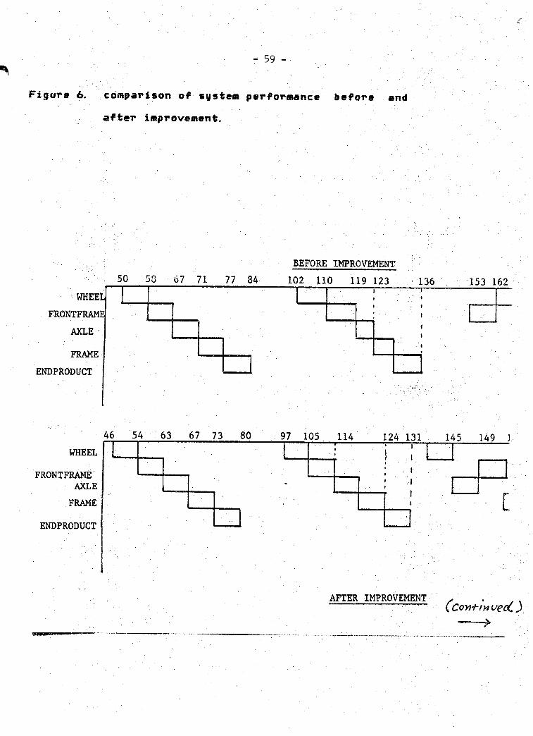
' - 59 -
Figure &. comparison of system performance before and after improvement.
BEFORE IMPROVEMENT67 71 77 84 102 110 119 123 153 162
ENDPRODUCT
67 73 97 105 124 131 149 ]
WHEELFRONTFRAME
AXLE
ENDPRODUCT
AFTER IMPROVEMENT

- 60 -
(---coyi+tviue oC')
153 162 170 180 187 204 212 221 225
204 210 217 225

6.3 THE DATA BASE
The data base is the part of the expert system which stores the system states* the properties of the system components* and interacts with the system. This part does not include the knowledge base part. The data base for the system is composed of a static data base* and a dynamic one. The static data base contains information about the processes required* the part structure* the machines available and their capabilities. The dynamic data base contains data about queues in the system* parts' current process* the time a part is required and the assembly unit states.
The data base stores the information in predicates form* that is available in PROLOG.
EXAMPLE QE BAM 1IE23S IM DAJA gAS£
/*• PART CODE NUMBER part_type(code* part type) •*/ part_type< 1* al >. part_typeCSi a2>.
/* PROCESS-MACHINE TABLE (PROCESS. EMACHINES LIST!). */
pro_machine(l» Cl* 23). pro_machine(2» C3* 4* 53).
/* PART-PROCESS TABLE (PART* C LIST OF PROCESSES 1). */

part_pro<ai» Ci» 8» 93). part_j»ro(a2. C7i3» 123>.
/♦PART-PROCESS-MACHINE-TIMETABLE *//# p__tCPART NUM. Cprocess(PROC. NIOT. Ctime(MACHINE. TIME). . 3)3) */
part_time(al» Cprocessd. Ctimed. 4)# time(2/ 6)1)#procMs(8/ Cti*i#(3i 7>» ti«ie(4»9)» 10) J)»process<9, Ctime<2. 4), time(3, 6). time<3.8)3)3).
/* LIST OF THE ASSEMBLY TREE */
assembly(li'heel# tquantity(al» i)» quantity (a2» 2). quantity <a3» 3)3). assembly (FrontFrame. Cquantity(bl. 1). quantity (b2. 1 ). quantity (b3. 1)3)
/•* QUEUES/ STATE : queue (MACH. NO. C q_t ime < PART« TIME)». . 3 )Time is the (queue+process) time. It is the time a new part has to wait For process.
queue< i# Cq_time(ai# 9). q_time(d. 5)3 >.
queue(2. C3>.
/* THE CURRENT PROCESS AND MACHINE: (Part,Process#Machine) */
current_process<ai»9. l). current jirocess Ca2* 7» 3).
6. 3. 1 INFORMATION RETftlgVMr.
During run time eF the system. the decisions and hypotheses are made based upon the system state at that

time. In order to have the desired information thi* system utilizes the query capability of the PROLOG language. The query process is based upon the predicate form of the PROLOG language and imitate the required predicate with a variable name for the required data item. This implies that the predicate form of the data base must be known in order to retrieve any desired
item.example
Data item in the database:current_j>rocess (al» 9* 1).
Query:current„j>roce*s(X. 9» Y).
Answer:X » ai Y * 1

6.4 THE PRODUCT IQN_RULES
This part contains the knowledge of the system Cits expertise). There are three components of knowledge in this system: The first one consults with the data base and the system behavior knowledge and decides upon the system response to basic changes in its states. The behavioral knowledge of the system is represented in a combination of predicate logic and production rules* which is given by the PROLOG language.
Examples for the rules are:IF a part finishes a processTHEN move the part to the next machine*
supply the machine with the first part in queue update the queues.
IF part arrives.THEN find its first process*
route it to a machine (found by the algorithm)* add the part to the appropriate queue.
IF a part is removed from the queue.THEN find the last part in the queue
delete the part from the dynamic data base:
The representation of those conditions in PROLOG is:
part arr ival (Part) : - f ind_f irst_j>rocess (Part# M* A)» ! #

- 65 -
(bigjnumber (3)* A < B)* add_to.jiueue<Part» M* A)» create_current_proces5<Part*M)» try_5Chedule__end_ofijjrocessCPart» M), !
move._a„pirt<rt* Part) :- f ind_next_step (Part. X).not_last<X)»f ind_jnext_process(Part» NewM. A)« check_Schedule(Part* NewM* A>« remove_from_queue<M)» schedule_next_j>art (M)* !.
m As it is seen from the example the objective ofthis part is to supply the system with the automatic nature it has. This part takes care of the part movements* activation Of the various components of the system* and the bookeeping required in the model.
The rules in this part can be divided into two main
groups:
1. Finding to finding rules. These rules relate to events that occur in the system as the antecedent* and the hypothesis as the consequence. In this system the hypotheses are stated in action form* they are the actions that are assumed to be the right
answers to the findings discovered.

66
IF cunent_ti(ii«(A)i st0p_fciflie<8>«A < B.
THEN #nd<jDf_simulation„time(C)t A<C.
2. Hypothesis to hypothesis roles. These are the more common rules in this system and they connect every hypothesis assumed to be true with all the other hypotheses that need to be checked (by performing an action).
EXAMPLEIF move_a_j>art (M* Part).THEN f ind_next_step (Part* X>*
not_last(X)»f ind_next_j>rocess(Part» NewM* A). . .
The second part of the knowledge is the algorithmic knowledge. This part solves the routing decision according to the current system states. The algorithm is dynamic and dependent upon the system current states as reflected in the dynamic data base* and not on mean
off-line data.The algorithm is composed of two parts:
I. A production system written in PROLOG* that checks the logical conditions# retrieve the required data from the data base* and decides what is needed to

be solved.
II. A computational unit* written in PASCAL that manipulates the decisions made by the production system; and computes the cost of the various candidate solutions (next step in the algorithm). The algorithm is presented later on with an initialization procedure.
The third part of the knowledge is the simulation driver. A discrete simulation system is basically consists of three major parts:
1. The model of the system being simulated. This part defines the network structure of the system; the entities flow and the decisions required at each node. Usually this part is modeled by using a simulation language; or graphic symbols.
2. The data base of the simulation. This part is usually transparent to the user and keeps track of queues; entities; time of operations and collect the required statistics.
3. The event listing mechanism. This component chooses the next event to be processed# advances the simulation clock and motivate the entire simulation process.

- 68 -
The control system needs to have a simulation driver* because it is cheaper and more flexible to try its decision capability on a simulated manufacturing environment* instead a real one. In this may me ignore the need for the interface part of the system* but loose the flexible behavior of a real system. Since the system contains the data base and the behavioral fcnomledge for controlling the environment* the only component needed is the event file mechanism. This part recognizes three major types of events in the system:
1. Part arrivals. Initially all parts are introduced to the system in the same time* and later on a part that finishes production phase generates a request
for the same type of part.
2. Process finishing. This event includes the decisions mhether the part needs a route to the next process* needs to be sent to the assembly phase* and deals mith the system ability to perform the decisions. When a machine becomes idle the first part in its queue is taken for production CFIFti
order).
3. Assembly event. When there is any combination of
parts in the assembly station that enables a subassembly or the end product to be assembled this
■event- is performed.

This part is written in PROLOG * it is very simple and modular and enable the control system to react to simulated events# instead of real ones.

6.5 CONTROL STRATEGY
In this section several components of the control
are described.
RULE
The main technique for rule selection is the matching technique. In PROLOG the matching is similar to unification in predicate logic with some variations.
SgNEkl&L R^sq^TlONSometimes several rules has the same L. H. S (there
for has the same name)* and all of them can be triggered. In oreder to choose a specific rule to fire* the system ithrough PROLOG) select the rule according to their order in the database. In order to make a rule more favorable* it is possible to move the rule Upwards in the list (or downwards for a lower likelihood rule).
Another strategy partially used is "context limiting" strategy. This approach checks the context of the rule* and Only rules with the right context can be triggered. In this system the context is mentioned immediately in the R.H.S (Consequent) so the rule is first
chosen by matching its name* and then by its order* and only then by the context.
, EXAMPLE .

Rules for event that deals with assembly are in the form:IF the step is perform_event»
the context is assembly.THEN change the status of the assembled part.
add the part to the finished part storage* change status of the robot to "idle".
Another rule for event that deals with finishing a process is in
the form:IF the step is perform_event*
the context is part_finish,THEN identify the part*
move the part.ACTION In this system any rule that fires leads to an action. This action is a change in the system state as is reflected in the data base. Part that moves from a queue to a process* or enters a different queue* start assembly or finishes assembly* all of these changes are reflected in the database.Changes in the database are utilized through predicates that are specified rules whose task is to create the desired change in the data base.Examples for such rules are:
opdaie_Jiyeue<_time<T).
asserta(robotCfree)>. updaie__event_list. r emove_jP rom_queue <M). add^to^queuetPart* M* A).

7. SUMMARY
This expert system tries to deal with a new domain: scheduling. In this field so far the expertise is limited and difficult to formulate. This system is used to schedule a specific environment in which a production
system feeds an automated assembly station.
It is difficult to compare this system to others because today only one expert system for scheduling exists (ISIS)* and there is no much information available about its scheduling process. As understood from the literature the ISIS system is used for higher level scheduling (daily schedule or even weekly or monthly)* since it considers aggregate constraints. The presented system is used for real time scheduling and real time answers for scheduling problems* rather than long term schedule..
Computationally this system is expensive. Running on the VAX 11/780 it takes the computer about 9 sec. to load the six different files that compose the system:
File "po" read time is 0.7 sec.
File —algo" read time is 1. 6 sec.
File "process" read time is 1. 75 sec.
File ■ "states" read time is 0. 35 sec.File "sira" read time is 2.9 sec.
File "assembly" read time is 1. 35 sec.

To reach a decision about the part's route it takes the system from 0.1 sec to 0.25 sec* and a simulation of 240 min in simulation time takes about 7 minuted on the computer <in this period hundreds of decisions* data base changes and retrievals has to take place). However the slowest part in the system execution are the "system calls" that execute the compiled PASCAL code for the decision procedure.
The readability of the expert system is good because the predicates were given names that show their function and explain their task. A different user that runs the system can understand its decision process but needs some familiarity with PROLOG and its recursive nature.
The decision network for parts of the system is shown in the appendix where the branches are AND branches and are executed from left to right.

REFERENCES
Cl 3 Baker K. R.# "Introduction to Sequencing AndScheduling"# Wiley and Sons# 1974.
£23 Be liman R. # Esogbue A. 0. # Nabesh ima I.#"MathematicalAspects Of Scheduling And Applications"# PergamonPress 1982.
£33 Buchanan B. G.# Duda R. 0# "Principles of Rule-BasedExpert Systems". Report no. HPP-82-14# Stanforduniversity.
£43 Boilers W. I. # Not S. Y. # Whins ton A. B. # "ArtificialIntelligence In Manufacturing Planning Arid Control"# AIIE Trans Dec# 1980.
£53 Buzacott J. A. # "The production capacity of jobshops with limited storage space"# Int J. Prod.Res. vol. 14# no 5# 1976.
£63 Buzacott J. A. » Shanthikumar J. 0. # "Models forUnderstanding Flexible Manufacturing Systems"#AIIE Trans. 12(4), Dec 1980# pp. 339-350.
£73 Buzacott J. A. » "Optimal operating rules forautomated manufacturing systems"# IEEE Trans.Automat. Contr. vol. 27# no 1# 1982.
/-"•s ■£83 Buzen J, P. »"Computational Algorithms For Closed
Queueing Networks with Exponential Servers"# Comm.

of ACM, VO 1 16. no. 9, 1973, pp. 527-531.
C93 Conner J. L. , "A Heuristic Method for Solving Job Shop Sequencing Problem", Production and Inventory Mgt. 13, 1, pp. S4”68, 1972.
C103 Davis R. , King J. , "An overview of production systems". Machine Intelligence vol 8, pp 300—332.
C113 Day J. E. and Hottenstein M. P. « "Review of Sequenc?- ing Research", Naval Research Logistics Quarterly
1970.
C123 Denning P. J. » Buzen J. P./"The Operational Analysis of Queueing Networks Models", Computing Surveys vol. lO, no. 3, 1978.
C133 Ferguson R. L. , Curtis H. J. , “A Computer Aided Decision System", Mgt. Science 15, 10, pp. 550—5&1, June 1969.
E143 Fox M. S. , Allen B. , Strohm Q. »"Job-Shop Scheduling:An Investigation in Constraint-Directed Reasoning", Proc. NCAI 1982, Pittsburg, PA, pp. 155-158.
C153 Fox MS.,"Constraint Directed Search: A Case Study of Job-Shop Scheduling", Ph.D Thesis, Carnegie-
Mellon University 1983.
C163 Futo I. »Szeredi J. ,"System Simulation and Cooperative Problem Solving on a PROLOG Basis", in

/•s ■ ■ ■ - 76 -
"Implementations of PROLOG" edited by Campbell
J. A. # Ellis Horwood# 1984.
C173 Godin V-B. # "Interactive Scheduling: HistoricalSurvey and State of the Art'S AIIE Trans. Sep
' 1978.
C183 Gordon W. J. # Newell G. F. # "Closed Queueing Networks with Exponential Servers"# OperationsResearch vo 1 IS. no. 2. Apr 1967# pp. 244-265.
C193 Hart P. E. .Nilsson N.-J. » Raphael B. "A Formal Basisfor the Heuristic Determination of Minimum CostPaths"# IEEE Trans, systems science and cybernet
ics vol ssc-4. no. 2. july 1968.
C203 Hatvany U. #Lettner F.V. • "The Efficient Use OfDeficient Knowledge"# Annals of the CIRP# vol
■ 32/1/1983. :
C213 Hayes J.E. . Michie D. "Intelligent Systems"# Ellis. Norwood# 1983. ; ■
C223 Milderbrant R. R. #"Scheduling Flexible MachiningSystems Using Mean Value Analysis". Proc. of IEEEconference on Decision and Control# Albuquergos#N, Mexico# 1980.
C233 Uacbsoin J. R. » "Jobshop like Queueing Systems"#Management Science vol 10# no.1# Oct 1963#

pp. 131-142.
£243 Kimefflia J. * Gershwin S. B. # "An algorithm for the computer control of a flexible manufacturing system VI IE Trans. dec 1983.
£253 King J. R. # Spachis A. S. #"Scheduling: Bibliographyand Review”# I. J. of Physical Distribution and Material Management# vol. 10 (3).
£263 Klahr P. # Faught W. S.»"Knowledge Based Simulation”# in proceedings of the first annual national conference on AI# Stanford 1980.
£273 Kusiak A. # “Flexible manufacturing systems: astructural approach"# working paper no. 4/84# university of Nova Scotia.
£283 McDermott D. # "The Prolog Phenomenon"# in SIGART newsletter# no. 72# July 1980# pp. 16-20.
£293 McLean C. R. # Bloom H. M. # and T. H. Hopp# "The virtual manufacturing cell"# NBS report.
£303 Mifoguchi F. # "PROLOG Based Expert System"# in "New Generation Computing"# no. 1# 1983# pp. 99-104.
£313 Nau D.S.# "Expert computer systems"# Computer# Feb
1983.
£323 Nilsson N. J. # "Principles of Artificial Intel I i'-

■ - 78 -<*v-
gence"# Tioga Pub. # 1980.
£333 Nof S Y. *"An Expert System For Planning/ReplanningProgrammable Production Facilities"# Proc ICPR Aug
1983* Windsor Canada.
£343 Pohl X. »“First Results on the Effect of Error inHeuristic Search"# in Machine Intelligence# vol 5#
1970. pp 219-236.
£353 Pohl'I.* "Practical and Theoretical Considerationsin Heuristic Search Algorithms"# in Machine Intel
ligence* 9# 1977# pp 55—72.
£363 Rauch H. * Firschein 0. .Perkins W. A, and PecoraV *"An Expert System for Tactical Data Fusion".IEEE conf. on circuits# systems and computers #
- .1982.
£373 Simon H. A.. Newell A.# "Heuristic Problem Solving:The Next Advance in Operations Research". Ppera-ftions Research 6# 1* pp.1—10* Jan. 1958.
£383 Solberg J. J. *"Quantitative Design Tools for Computerized Manufacturing Systems". Proc. Sixth
North—American Metalworking Research Committee#
Gainsviile# Florida# Apr 1978.
/~S £393 Stecke K.E.# “The optimal planning of ComputerizedManufacturing Systems"# Ph. D Thesis# Purdue

University/ 1981.
£403 Stefik M. et al. , "The organization of expert systems". AI, 18 <1982> pp. 135-173.
£413 Soar do O. M. S. . "Workload optimization in a FMS Modeled as a Closed Network of Queues". Fiat Research center. CIRP Annalen 28(1). pp. 381-383.
£423 Suresh J. K. . "A Simulation Based Scheduling and Management Information System for a Machine Shop", Interfaces 6. 1 part 2, pp. 81-96, Nov. 1975.
£433 Warren D. , Pereira F, »"PROLOG- The Language and its Implementation Compared with LISP", SIGART Newsletter, no. 64, Aug 1977.

- 80 -******************************* * * * A P P E N D I X ***************************'■******
8. rHE^LQmLTHM;_g:VAi,UATION OF PARTIAL SOLUTIONS
The scheduling algorithm has to search through many possible actions that the scheduler can take. These alternatives have to be evaluated and the best one is to be chosen. These possible assignments of jobs to machines depends upon the availability of the machines* queues that each machine has* type of process to be done next* capability of the machines to perform the task and other criteria. In order to evaluate the proposed route the scheduler needs to evaluate the route according to some measure of performance. The route decision is a tree like decision procedure: first the next process has to be scheduled than the next one (which depends upon it)* and so on. it is desired to have an evaluation function of partial solutions in order to reduce the number of possible solutions generated.
8. 1 AN ALGORITHM FOR-HeUB.I8TJ.flL-SEARCH
.;.^^/;In case of heuristic search there are several known algorithms* of which the best known is algorithm A* (Nilsson 1980* Hart Nilsson and Raphael 1967) or HPA (Pohl 1970* 1977). This algorithm makes use of anevaluation function for partial solutions of the form:
fw)g<x)+wh<x).
where s » start node* t «* terminal node.g(x) w The 'distance' from s to x as found in the search.

h(x> ** The estimated 'distance' from x to t. ui « weighting factor.
This function has some conditions to follow in
order to get desirable properties. The requirements are:
I. h (n> £' h*(n).where h»<n> is the cost of the minimal path .from
any n io t.
II. Consistency:(h<x)-h<y>><£<x«y) for all x#y. Here c(x#y> is the real distance from x to y.
III. O; 5£w£i.The properties of this search are:
I. Admissibility. The algorithm always terminate in an optimal path from s to t.
II. Optimality. The search includes the fewest nodes in finding « solution path fPohl 1970>.
Ill The more informed the algorithm is the shortest the search is. By information one means the accurate
estimate of h<ri>.
IV. The algorithm can use dynamic weighting w<x> that
changes according to the distance of x from s.

8. 2 SEARCH PROCEDURE FOR THE ROUTING PKOBLEH
The routing problem differs from the general search problem by severe! important properties: First only the initial state is known. The goal node is not known* therefor the solution to the search is not only the path from s to t but alsothe terminal node itself. A second major difference is that the routing problem with the proposed objective function is not a consistent problem. It means that h<x>-h<y> F c<x7y>, a situation caused by the fact that some of the arcs have a 'negative' cost which reduce the objective function when added. Another difference is that the routing problem is dynamic problem which means that the same subproblem can have various values under different conditions. Oneo-f the results is that h<n> cannot be evaluated in advance. These properties do not allow the use of algorithm A* as it is and some modifications must be done.
On the other hand since the search algorithm can be very 'informed' it is desired to use all the information available to reduce the search space. The
information can aid in considering the alternatives in various times and states (which imply different values for the evaluation function even for the same branch).

- 83 ■*» • ;
8. 3 THE SEARCH PROCEDURE
In order to evaluate various solutions the first step is to solve arbitrarily the routing problem, then to evaluate this solution according to the evaluation function and improve the solution by considering only the candidate solutions that can improve the function. By identifying undesired solutions the candidate list is reduced and an exhausting search is avoided. The solution estimation is performed according to the
knowledge available about the system and the conse
quences of the various partial solutions.
m The evaluation function is:f<x> * Mxlt '+■ Sw.. j .
The w is the waiting time of1 the part being routed
and j belongs to the set of available machines <including the assembly station>.The "It' is the idle time of the assembly station.
In order to discuss the algorithm more concretely the use of graph model is made for the heuristic
search and a program which can search problems
represented in the model.The problem space is the finite tree T.T m <x.E) is the feasible process assignment tree.
> .X « <xl,x2,...> the set of nodes.E=<el,e2, ..> the set of edges such that ej »

<xi,xj>, xi,xj « X and xj eP<xi?.p is the successor mapping and if x»P<y? then y“P *<x?.
It is important to notice the special structure of the tree. Since the successor edges do not depend upon the predecessor it means that PCxi? » E<i> * P <xj?> cohere xi> xj are in the same level in the tree.
Each edge i in the tree (connects xh to xi> have a finite cost associated with it and this cost can be represented as a tuple <Ai»wi).Wi is the waiting time of the part on the machine.Ai is the total time spent in the machine (Ai *» pi +
wi# and Pi is the process time).A Solution is called optimal if it has the least value
of fCx) (least costly path).
Other symbols are:C: E—>R2» the cost of the edges.m<s> t) * (s=xl#x2#. . . xk«t) the path from s to t. c<mCs,t?? * M<It+? + <It-? + Ew je m<s,t? .. ' J JIt+ is EA^ - Et, where EA^>= Et <the idle time of the
assembly station?..It- is ISAj ~ Et I where Et > EA^the waiting time for
assembly?."Et is the time the part is required for the assembly <due date?.

- 85 -
8-4 THE ALGORITHM
1. Start with xi*xl=s, calculate xj=r <xi> <for process j that follows i). such that Aj * MIN -CAk !
' keEi>.Repeat step 1 until T<x)*0. <no more processes to
take).Calculate f<x> for the path found.
2 If It+ >« O exit. The path is optimal for It+ > 0. Else start with E(i) * E(l>.
i. Remove from E(i) all arcs ej for which wj > wi
(wi belongs to ei found in 1).
ii Replace ei with ej such that CAj - Ai> <* lit?
and wj * MIN < wk I keE<i».Calculate f(x).
iii. Remove ei from Ei.
iv. Continue until Ei '*• ei '** O.
3. Calculate V <xi>. if P<xi>* O .y go back to 2.
EXAMPLE

- 86 -
Figure 7. example
Given: Et =10,
Calculate the initial path:
path is <(1.3). <3* 7). <7. 9>>M<0) +2 + 8 * 10f ( x >
There are no edges to remove Cwi =* MAX <wj>>.
Replace (1»3) with (1*2) with cost = (5.1).
6 and lt=0,

Since lt**0 e4 can be removed (cannot replace
In step 2 we exit with the final path: <(1«2)» <2» 7)* <7# 9)>. The cost is 6.

. .. - 88 -
8.5 THE INITIALIZATION ALGORITHM
SumbolsComponent: An elementary part (not subassembly).atime .: the assembly time of part (component) j•
Jexpected time.: The time part j is required at the assembly.
J •p<j>: The successor mapping (finds immediate sons of j>.
Input: assembly tree T(A» V)* assembly times for
part j: atime. for all jeV.•J
Output: list of expected times for all componentsand parts in T; expected time^ for allj e V.
THE ALGORITHM
1. Find the set of all the minimal subtrees . . 3 ithat are composed only of components.
Set Et » 0.
2. Until all subtrees are covered do:
i. All components j e l are assigne-d
expected time. = Et.J
ii. expected tirne^ “ Et.
iii. Et ■* Et + atimej.
3.

- 89 -
i. Ct «® O.
xi. Find A, such that j s A and expected time. =
Ct. (find set of all parts and componentswith expected time * Ct). If A contains component j then Find fc “ P ^(j) Cthe root oF j)> and l«T“1<k>.
Else <only part in A> 1 * F *<j>.
iii. If node 1 has no expected time assigned to it. and all its predecessors have then:
For every component j arrive to 1 assign: expected time.=Ct.
expected timej*Et.
Et * Et + atimej.
Ct = Ct + atime,r <1>
iv. IF 1 s* endprodoct <the root oF the tree) go to
ii.

- 90 -
EXAMPLE
Assembly Times
Part Time
Wheel 8
Frentfram® 9 Astle 4 Frame 6 Endproduct 7
f

Step 1: The parts are wheel composed of al#a2#a3.frontframe (also ff) composed of bl«b2#b3
Step 2: al#a2#a3 have expected time * Q. expected tifl«?wheel» 0,Et:» 8. ' -
bl>b2#b3 have expected time *8. expected t ime^=8.Et rn 17. .
Step 3:i. . . Ct'■«* O.
A « <al# a2#a3> with expected time * O.A contains only components so P * <A> = wheel. 1 = P~* (wheel> = axle.
part c which arrives to axle gets expected timec=17. e is the only component so Et « 17+8 =25.Ct = 0 + atime<whTO]l> » 8.
ii. ct « 8, A » -Cbl,b2,b3>/ k • P *(A> » ff, 1 « P”*(k> = ■frame (or f >.
part d gets expected tlme^ * 25.Et » 25+3 = 28. Ct = 8+9 * 17.
iii. A * <c>» k * axle# 1 « endproduct.1 gets expected time * 28.
Et * 28+6 « 34.Ct » 17 + atimea;><;le=25.Since 1 is endproduct we are done.

TRACE OF THE SIMULATION
G THE OPTIMAL ROUTE IS G
CHOOSE MACHINE 4CHOOSE MACHINE 4CHOOSE MACHINE 2THE OPTIMAL ROUTE COST IS: 1303 eyrrent_time 0 part b2
mG THE OPTIMAL ROUTE IS G
current time O part bl - 92 -
■%
•%
•%
CHOOSE MACHINE 5CHOOSE MACHINE 1CHOOSE MACHINE 5CHOOSE MACHINE 5THE OPTIMAL ROUTE COST IS: 2204 current__t ime O part b3G THE OPTIMAL ROUTE IS G
■H CHOOSE MACHINE 3CHOOSE MACHINE 5CHOOSE MACHINE 2
^ CHOOSE MACHINE 1THE OPTIMAL ROUTE COST IS: 2117
m current_time 6 part cG THE RESULT OF THE ALGORITHM G
THE EXPECTED TIME IS : 17THE INITIAL ARRIVAL TIME IS: 17
THE ROUTE FOR THE PART IS: mac hirie no: 2machine no: 1
367 statements executed in 0000.150 seconds cpo time% ■' '
THE ROUTE COST IS: 7
107

SYSTEM OUTPUT- 93 -
current_time 7 .'.■'ev*nt_list O C (3/ p#ri_finisht 2* *2>> (4, part_f inish, 1, al), (5, ;»a*»'twf ini*h, 5, b2),
C5, part__finish,3, a3)< (9i part^finishi^i bl )' queue(2, Cq__time(dummy5, 22)» q_time(dummy3, 17), q_time(c, 10), q_time(a2, 3)3). queued, Cq_tiffle(dummy4, 19), q_time(dummy!, 14), q_time(d, 7), q_time(al, 4)3). queue <3, C q_t i me (dummy 2, 15), q_time(e, 8), q_time(b3, 6), q__time(a3, 5)3). queue(5» Cq_time(b2, 5)3).queue(4, Cq__time(bl,9)3). -queue(assembly,'C3').
current_j)rocess (dummy 5, 96, 2). current_jjrocess(dummy4, 99, 1). current_process(dufflmy3»93, 2). current_proceis(dummy2, 92, 3). current jroeeWstdummyl, 90, 1). current^r^ceSs(e, 2,3). current_process(d« 1, 1). current _process(c» A, 2). current_j»rqcess (b3» 2, 3). current_j>roceSs(b2, 11, 5). current_j>rocess(bl, A* 4). current_process(a3» 10,3). current_j»rocess(a2» 7,2).-current_process{al, 1, 1).f inished_storage : C3current__time event dist3 £ (4, partLFinish, 1, al), (5, oart f inish, 5, b2), (5, part_f inish, 3, a3),
(9* part_finish, 4, b 1)» (10, part_f inish, 2, c ) 3 ■queue<2. Lq_tline("dummy5,19), q_time<dummy3, 14), q_time(c, 7)3).■queue<5, Cq time(a2,11), q time(b2, 2)3).■queue(assembly, '£3').■queue(4, Cq_time(bi» A) 3 ).■queue (3, Cq__time(dummy2» 12), q_time(e, 5), q_time(b3, 3), q_time(a3. 2) 3 ). ■queued, Cq_t ime(dummy4. 16), q__time<dummy 1,11), q_time(d,4), q__time(al, 1) 3).
“urrent__process(a2, 5, 5).::urrent__process(dummy5* 9A* 2)..rurrent^processXdummyd, 99, 1).::urrent_process(dummy3, 93, 2).::urrent_process(dummy2* 92, 3). current_j>rocess(dummy 1, 90, 1)."urrent j»roce95(e, 2, 3).~urrent_process(d» 1, 1)."urrent_process(c. A, 2).“urrent_j»rocess(b3, 2,3).::urrent_process(b2, 11,5).:urrent_process (bl, 6, 4). current _process <a3, 10, 3). current __process(al* 1, 1).Rinished_storage :C3current_time event_listI £(5, part_f inish, 5, b2), (5, part_finish» 3» a3), (7»part_f inish, 1, d ),
<9, part_f inish, 4, b 1)» (10, part__f inish, 2, c > 3

- 94 4-Till-: STATIC DATA BASK----- :----------- “
/* DEFINITION OF AN INFINITE NUMBER #/ m (l0mi b i g_nu(nber < lOOO).
/*• NUMBER OF COMPONENTS IN THE SYSTEM */ m' • part^types <9>.
PART CODE NUMBER part_type(code#part type) */ m par t_type (1# al ).
part_ty"p:e:X2# a2).. par t^trype(.3# a3).
0k. part__ty pe(4# bl>.part_jtype(5# b2>.■parfc_type<-'6> t*3>.
0k .part_type<7# c ). . part_type(8# d>. part_type(9# e). part_type<10#dummy 1). part_type(11#dummy2). part_type(12#dummy3).
.?% part_type(13#dummy4).part_type(14# dummy5). *
** /* PROCESS-MACHINE TABLE (PROCESS# CMACHINES LIST3). */pro_mach ined# Ci# 23).
m pro_mach ine (2# C3# 4# 53 ).pro_mach ine <3# Cl# 3# 43 ).
■ pro^machine(4# C4# 53). m • pro_machine(5# Cl# 4# 53 ).
pr d.jnach iiie (6# C2# 3# 43 ). pr o^mach ine (T# C1# 2# 43 ).
... ' prp^mach’inelS# C3# 4# 53 ).pro_maeh ine (9# C2# 3# 53 ).pr o_mach ine! 10# Cl# 2# 3# 43).
y% p rp^fnac h i ne ( 11 # C1 # 3# 4# 53 >.pro_mach ine< 12# Cl# 2# 3# 4# 53 ). pro_mach ine ( 13# C2# 3# 4# 53 )./* PART-PROCESS TABLE (PART#C LIST OF PROCESSES 3). */
^ par t__pro(al# Cl# 8# 93).part_prd(a2/ C7# 5# 123). par t j)r o (a3# C 10# 5# 7# 23 ).
. par t^ro Cb l# C6# 8# 123 ).par t_j»ro <b2# C11# 3# 5# 83 ). paT t_pro ( b3# C2# 4# 13# 73 ) . partj&rqCc# C6# 123). par tjro (d # C1 # 5# 7# 93 ). part^raCe# C2# 3# 10# 113). part^proCdummy 1 # C90#99#983>. parq (dummy2# C92# 94#953). part_jpro ( dummy3# C93# 94# 983 ). par t_jpra( dummy4# C99#92#973). part_prp(dummy5/C96#99#923).
^ /* • PART-PRQCESS-MACHINE-TIME TABLE *//* P_t(PART NUM# Cprocess(PROC. NUM# Ctime(MACHINE# TIME). .3)3) */part^time(al#Cprocess(1#Ctime(1#4)#time(2#6>3)#
process(8#Ctime(3#7)#time(4#9)#time<5#10)3)#

- 95 -
prdcess(9*£time(2#4)*time(3»6)»time(5»8)3)3). .part_time(a2* rpracess(7* Ctimed*2># time(2» 3)# time(4* 5)3)*
process(5# Ctimed* 7)# time(4# 9)» time(5* 9)3 >» process(12*[timeC1 * 2)* time(2*3)» time<3*4)*
time(4* 5) * time (5* 6)3)3).part_time(a3» £process (10* Ctime(1*2)* time(2* 4)* time(3* 5 )* time(4* 7) 3 )»
process(5* Ctimed. 3)* time(4# 5)* time(5# 5)3)» process(7» Ctimed* 5)* time(2* 6)# time(4» 9) 3 )* process(2*Ctime(3#6)#time(4#6)* time(5V&)3>3).
part_time(bl» Cprocess(6» Ctime(2# 7). time(3» 9)# time(4# 9) 3 )# process(8# Ctime(3» 2)* time(4# 4)* time(5# 6)3)# processd2# Ctimed. 5)* time(2# 5)» time(3. 8). time(4» 10). time(5* 10) 3) 3 ).
part_time(b2* Cprocess (11* Ctime (1» 2)* time (3* 2)* time(4» 5)* time (5* 5)3)*process(3* Ctime (1*4)* time(3* 4)* time<4* 5)3 )* process (5* Ct ime(1# 5)* time (4* 6)> time (5* 8) 3 )# process(8» Ctime(3* 5). time(4, 8). time(5* 9)3)3).
part__t ime (b3* Cprocess (2* C t ime (3* 1) * time (4* 2) * t ime (5* 5) 3 )* process(4* Ctime(4* 7) * time(5* 7) 3 )»proc#ss( 13* Ctime(2« 2)# time(3* 5)* time(4* 6)* time(5* 6) 3 )» process (7* Ctime(1*2)* time (2* 5) * time<4* 9) 3 ) 3 ).
part_time(c* Cprocess(6# Ctime(2* 7)* time(3* 8)*time(4*10)3)* process(12* Ctimed* 3)* time(2* 5). time(3* 7)» time(4, 10)* time(5, 10)3)3).
part_time(d*. Cpr.ocess (1* Ctime(1 * 3)* time(2* 6)3)*process(5* Ctime( 1* 3)* time(4» 6)* time(5* 7)3 )* process(7» Ctimed* 4)» time(2» 5)* time(4,8)3)* process(9» Ctime(2* 2)» time(3« 3)* time(5« 6)3)3).
part_time(e* Cprocess(2* Ctime(3* 2)» time(4» 4)* time(5* 6)3)*.^process<3* C.time (1* 4)# time(3* 6)# t ime'(4» 7) 3 )«. process( 10* Ctime(1*2)* time(2* 3)* time (3* 5) * time(4* 5)3 ) * process (11# Ct ime (1# 6)# time(3# 10)* time(4* 10)* t ime (5* 10)3)3).
part_time(dummy1* Cpr ocess (90# Ctimed* 7)3)*process(99* Ctime(3* 6)3 )* process(98* C time(5* 5)3)3).
part_time(dummy2# Cprocess(92# Ctime(3* 7)3)#process(94» Ctime (4. 3) 3 )# process(95» Ctimed* 5) 3 ) 3 ).part_time(dummy3* Eprocess<93* Ctime<2#7)3)*
process(94* Ctime(4* 6)3)* proc ess(98* C time(3* 6)3)3). part_time(dummy4* Cprocess(99* £time(1# 5 ) 3 )»process(92*Ctime(3»6)3)*process(97. Ctime(2*5)3)3). part_time(dummy5* Cprocess(96* Ctime(2* 5)3)*process(99» CtirneO* 6) 3 ). process (92# Ctime (5* 5)3 ) 3 )./* BUFFER SIZES */
buf f er_size( 1# 6). buffer_size(2# 6). buf fer_size(3* 6). buf f er^si^eX#* 6). buf fer_size(5* 6). buffer_size (assemb ly* 27).

THE DYNAMIC DATA BASE
/* EXPECTED TIME OF PART X *//■» The program computes these values *//* QUEUES' STATE : queue (MACH. NO, Cq_time (PART. TIME). .. 3)
Time is the (queue+process) time. It is the time.a nefc» part has to wait for process.
queue(1, £3). queue(2. £3>. queue (3. £3 >. queue(4.£3). queue(5* £3)./■» TOOL AVAILABLE : tool (MACH. NO. £TOOL NO. ... 3) */tool Cl. £1. 2. 4. 6. 8. 123).tool (2. £2. 3. 4, S, 7. 9. 103). tool (3, Cl. 3, 3, 6, 7, 93). tool (4. £10. 11. 12, 133). tool (5. Cl, &».©» 10. 123).
MACHINE STATUS : status(MACH. NO. FAIL/WORK). */
status ( i»:l ). status (2/1). status(3, 1). status (4.0). statusO. 1)./# THE CURRENT PROCESS AND MACHINE: (Part, Process, Machine) *//*current_prpce5s(aL 9. 1). current_process(a2, 7, 3).cuTrentjr oc ess < b 1, 8. 4). eurrervt_j»rocess (b2» 11,2). current process(b3, 1. x). currentjrocess(c» X. jc). current j»rdcess(di X, u). . current_j»rocess(e, X, m).*/
■/* REPAIR TIMES */ V. repair^time<M» T)./* CENTRAL STORAGE CONTENTS */ centralist or age (£ 3). • ./* ASSEMBLY STATION CONTENTS »/ queue(assembly,£1)./* FINISHED PARTS STORAGE */ f inishediStorage( £3 ).edit(s> :~ system("vi states").

- 97 - : , ■
PARTIAL AND/QR TREES OF THE RULES *
START SIM
EXPECTED TIME SIMULATE
CHECK_CONDITIONS
UPDATE_ > CURRENT TIME PERFORM
EVENTUPDAT E_EVENT>
LIST SIMULATE
NEXT ARRIVAL PART FINISH lEND ASSEMBLY
PART ARRIVAL
MOVE A PART
* All branches are AND branches, and the execution order is from left to right, in a depth first manner.

- 98 -
CHECK_> CONDITION,
CURRENT_ TIME(A)
STOP_TIME(B). END_OF_SIM
TIME(C)
PART ARRIVAL,FIND TRY_S CHEDUL
END OF PROC.FIRST PROCES
/ ”creAte_ sCURRENT PROCADD TO
QUEUE
A < B
QUEUE
ASSERTA(newqueue)RETRACT(oldQUEUE(M,K) (part-to-queui queue)

MOVE A PARTr SCHEDULE_ .NEXT PART.FIND NEXT ST
REMOVE_FROM_QUEUENOT LAST(X) CHECK SCH. ;
NOT(X=LAST)
)C READ[N,A] XSEE(OUT)INITIAL COST SEEN
(SCHEDULE_ NEXT_PART. )
SUCCEED ^
0

m
m
m
- 100 -
THE BEHAVIORAL KNOWLEDGE (RULES)
<0R%/* THIS PART OF THE PROGRAM TAKE CARE OF UPDATING THE
DATABASE, AND DECIDING UPON THE SEQUENCE OF OPERATIONS THAT THE SYSTEM MUST TAKE. */
/* THIS PART INTRODUCE A NEW COMPONENT TO THE SYSTEM *//» The •first two predicates generate 'dummy' parts */ part_arrival(Part) : —. beIong„to(Part, dummyset),part__t ime (Part,Cprocess(P,CtimeCM, T>3)
count_queue_size(M, Size), buffer_size(M, Q),Size < Q,
((queue (M, CD, A is T) » (queue(M, Cq_time(_» TT) «_3> », A is TT + T)>-add_to_queue(Part, M, A),asserta(current__process (Part, P» M))»try_schedule_end_of_jJr0c ess (Part, M>, ! .
/* Now queue is full */part_arriva1(Part) :— belong_to(Part,dummyset),schedule_event(next_arrival. Part, 10).*/This part deals with parts that goes to assembly
part_aTrival(Part) find_first_process(Part,M,A), 1,(big_nu«»ber (B>, A < B), add_to<_queue(Part, M» A), create_current_process (Part, M>» try_schedule_end_Qf_process(Part, M>» !.
part_arrival(Part). /*—- It means that all queues are blocked,and the part is rejected. —-*/
/* THIS PROCEDURE UPDATES THE QUEUE WITH THE NEW PART */ add_to_queye(Part, M, A) : —
queue(M, K),append (Cq_time(Part, A)3»K» Z), retract(queue(M, _)), asserta(queue(M»Z)).
/* THIS PROCEDURE REMOVE THE CHOSEN PART FROM THE QUEUE */remove_from_qUeue(NUM) ;- queue(NUM,A),find_last(A, X), \
effaee(X, A, Z>» retract(queue(NUM, A)), asserta(queue(NUM,Z)).
find_Iast(CA:B3, X) f ind_Iast(B, X).find last (CB « C33, B).efface!A, CAJL3,L) efface!A,CB«L3, CBJM3) #f faee ( A, L» M).belong^_tq(Part, dummyset) (Part * dummy 1; Partedummy2;
Part®dummy3i Part®dummy4; Part^dummyS).f ind_f irst__process (Part, M, A) : - initial_cost(Part, Z>,
see(out), read (CM. A3), seen.
try_schedule_end_of_process(Part, M) : - eount_queue_size(M»1)»current jjrocess(Part,Pro, M)» schedule_end_of_process(Part, Pro, M) .

101
trg_schedulewend_of_proces*(Part. M>.count_queu©_8ize(M»Size) queue(M«CList!Tai13).
count__tail_size(Tai 1. I >.Size is I + 1.
count_tail_size(CL!Tail3»I>count_tail_size(Tail» R).I is R + i.
eount__taiil_size(C3. 0). count_queue__si ze(M» O).
machine__ie_up <M) status(M. i ).update_current_j»rocess(Part. M) :— next_process(Part.G).
retract(current_process(Part. _. _)). asserta(current_process(Part.G»M)).
/* In case of a new part */create_current,,j»rocess(Part» M) : - part_pro(Part» CAIT3>.
asserta(current^process (Part. A. M)).
■** ' -.’M " ;'"V
■ * ■*//* THIS PART MAKE THE CHANGES WHEN A PROCESS IS FINISHED *//* First cluases represent dummy parts V.move_a_par t (M. Part > :^ belong_to(Part»dummyset),
part_time(Part« G). current _process(Part»-P.M). schedule_dummy (Part. G» P. M>» remove_from__queue(M). schedule_next.j)art (M).
schedule_dummy (Part. Q» P» M) : —loob_f or_next_pT‘ocess(Part. G. P. NewP. NewM* NewT). not(NewP ■ last). count__queue_size(NewM» Size). buffer_size(NewM»Qi).check_queue(Part. NewP. NewM. NewT. Gl. Size). retract(current_j»rocess(Part, P. M) >.
sehedule^dummy(Part.Q.P»M) retract(current_process(Part. P. M))./* This was dotie for process «*■ last */
chec ft _queu© (Part. NewP. NewM. NewT* Q» Size) r~ G Size.( (queue(NewM. Ca.time(._< Tl) «_3 ). A is T1 + NewT) i (queue(NewM. C3)» A is NewT) ).
add__to_queue(Part. NewM. A).asserta(current_process(Part. NewP. NewM))• try_sch ed u 1 e__end_of_jproc ess (Part. NewM ).
check_queue(Part. NewP. NewM. Q. Size) ~send_to_j:entral_storage(Part). asserta(current__process (Part* NewP. NewM)),
n iook_fot,_next_j»rocess(Part. G. P. NewP. NewM. NewT) : —G «® Cprocess(P.Ctime(M»Time)3)‘Tai13.(Tail » Cprocess(NewP. Ctime(NewM. NewT)3)ITailll
V (Tail ■ C3 .NewP * last. schedule_new_dummy(Part))). !.look_f or_nex t.j)rocess (Part. Q. P. NewP. NewM. NewT) : —
Q 885 Cprocess (__. £time(M. Time) 3) I Tai 13. loo5t_for_next_process(Part. Tai 1. P.NewP. NewM. NewT).

- 102
49%
mPS
m
■
schedule_new_dummy(Part) :— urand(10#U)»introduce_a_part(Part# U).
move_a_par t <M# Part) ?ind_next_step(Part#X)« not__last(X)»find_next_proeess(Part#NewM#A># checlc_schedule(Part# NewM# A)#remove__from_queue(M)#3chedule_next_part(M>» !.
move_a part(M, Part) send_ta_assembly (M. Part)#schedule_next.j>art(M).find_next_step(Part#X) next^procassCPart#X)# !. not_last(X> notCX ■ last).
find_next_j>rocess.(Part# NewM# A) : — initial_cost(Part# Z)#see(out)#read(CNewM# A3)#seen.
check schedule(Part#M# A) big__number (B).' ”/ A < B#add__to__queue(Part# M# A)#
opdate„current_jprocess(Part# M># try_schedule_end_of.j>rocess(Part# M).
check schedule(Part# M,A) update_current_process(Part, M),send_to_Gentral_storage(Part ).send_to_central_6torage(Part) central_storage(Q)#
current process(Part# CurrentP# _)#append(C(Part#CurrentP)3#G#List)# retract(centralist©rage(Q))# asserta(central-„storage(List)).
sc hedu1e_nex t part(M) : ~• Queue(M# A)#find„last(A#Q_time(Part#_>>» current_process(Part# Pro# M)# schedu 1 e_en d_of_precess (Part# Pro# M).
schedule_next_j»art(M). /* Means that the Queue is emptysendito_assembly(M#Part) : —count__queue_size (assembly# Site)#
buffer__size(assembly# G)#Size < Q»remove_from_queue(M)# retrac t (current process (Part# __# M) )# expected_time(Part# A)# add„_to_queue(Part# assembly# A)# introduce_a—part (Part# 1) » assemble.
send_to_assembly(M#Part).intr od uce a part (Part# Time) i *rschedule_event(next_arrival#Part#Time).
*/
/■#

curr ent_time<0>. stop_time(l20j. end_of__simolation_time(480). event_l ist (C3 )„start_sim find_jexpected.J;imes#
! introduce_a_unit-_load# prepare_output# simulate# !.
introduce_a_unit_load part_type(Num.Part>#part_arrival(Part)» fail.
introduce_a_unit_load. /* unit load is loaded */urand(R#N> :-seed(S)«
N is (S mod R) +1#■retract(seed(S))»NeuiSeed is (125 * S + 1) mod 4096# asserta(seed(Neu»Seed > )# !.
simulate :-check_conditions.current_time( A)# event__list(C(Al#Bl#Cl) 1TJ )# A »< Al#update_Gorrent_time(A« A1 )# perf orm_event (Al# Bl# Cl >« update_event_list# prepare_output# simulate.
simulate told# !.check_conditions :— current_time(A>»
stop_time(B)#A < B.end.j3f __s imu 1 a t i on__t i me (C) #A < C.~
check_conditions :— current_time(A)»end_of_simulation_time(C >»A <fc»stop_time(B>#Bl is B + 120# retract(stop_time(B>)# asserta(stop_t ime(Bl))#!, fail.
update_current_time(A#Al) retract(current_time(A>)#asserta(current_t ime(Al))»T is Al — A#update__yueue__time(T>»update_expected_time(T).

104
update__queue_time (T) queue(M, A).update_queue_timel(A, T»Nlist), retract(queue(M,A)), asserta(queue(M, Nlist))»■fail. ...... "Kr\
update_queue_time(T).update„_expected_time (T) expected_time(X,Y>,
NewTime is Y - T,retract(expected_time(X»Y))»asseTta(expected_time(X, NewTime)1..fail.
update_expected_time(T>.update_queue_timel ( C3, T» C3 ). update„_queue__timel (A, T, N1 ist) : —
A « Co time(Part. Time)’Tail3.Ntime is Time - T,update_queue_timel(Tail*T,List)/append ( Cq_time(Part« Ntime) 3, List. N1 ist), ! .
update_event_list event_list(CAJT3), retract(event_list(CAiT3) ). asserta(event_list(T)).
V.-
perfbrmJ_event(Etime» Ecode, Attrib>Erode .* next_arrival, part_arrival(Attrib>, !.
perform^event(Etime*Ecode. Attrib) : -Ecode * part__finish,(M, Part) ** Attrib, move_a_part(M» Part)» !.
perform_event(Etime, Ecode, Attrib)Ecode ** end_assembly» asserta(assembled(Attrib)), finished_storage(G>» append(C(Attrib. Etime)3. Q. List>. retract(finished_storage(Q>). asserta(finished_storage(List)>. ; retract(robot(busy>)» asserta(robot(free)>«
listing(expected_time>,(not(Attrib » endproduct) ; retract_all_assembled_parts)j
.itassemble.
v.
schedule_end_of_process(Part»Process, Machine)find_process_time(Part, Process, Machine. ProTime), schedule_event(part_finish, (Machine. Part), ProTime
find_j>rocess_time(Part» Process, Machine. ProTime)part_time(Part, G), find_j>roper_list(Process. Q. List). find_j>roper__tiroe(Machine. List, ProTime).
f ind_j»roper__list(Process, Q. List)Q «* CAJT3,A “ process (Process, List).
fj nd proper, 1 ist(Process» <3, List) G = CAST3,f ind_proper^list(Process» T. List).

- 105 -
f ind_properi_time(tt# L# ProTime) : — L ■* CA2ST3#A2 * time(M« ProTime).
find_proper_time(M#L»ProTime) :- L « CA2JT3.f ind_proper_time(M# T# ProTime).
retract_all_assembled_partsretract(assembled(wheel>)» retract(assembled (axle ) )» retract(assembled(frontframe)>» retract(assembled(frame)>* retract(assembled(endproduct)).
schedule_event(Ecode*Attrib. Time) : —current_time(A)»Etime is Time + A # Event « C (Etime#Ecode. Attrib)3# event_list(List)» append(Event#List#Listl)# bubble_sort(Listl<List2). retract(event_list(List)># asserta(event_l1st(List2)).
bubble_sort(L» S): —append (X, CA. B) Y1. L)»A » (Ti# _#__)# B * (T2#_#_),(T2 < Tl).append(X# CB» A«YJ#M)# bubble_sort(M. S># !.
bubble_sort(L# L).prepare_output : - tell (out 1)# current...time (X)# write(eurrent^time)# tab (5)
write(event_list)» nl# iirrite(X). tab(5># event_list(Y)# write(Y)»nl»listing(queue). nl>listing(current_process) nl# write( 'f inished_storage : ')# f inished_ storage(W)# write(W).
edit(sim) system("vi sim ”>.

Chapter 3
Expert Systems in Quality Control
Y. S. Chen

-106 -
Expert Systems in Quality Control*
Ye-Sho Chen
1. Introduction
1.1. Expert Systems
1.1.1. What Is An Expert System?
According to Weiss and Kulikowski [WEIS 84], an expert system is one that
(1) handles real-world, complex problems requiring an expert’s interpretation
(2) solves these problems using a computer model of expert human reasoning,
reaching the same conclusions that the human expert would reach if faced
with a comparable problem.
This artificial intelligence area focuses on developing programs that can
operate at human expert levels in restricted problem domains. Such programs
use knowledge and inference procedures to solve problems. They can act as
consultants backing up human experts, tutors, or program analyzers wading
through mountains of data. A typical rule-based expert system program uses
sets of production rules, all of which have the following form:
IF <antecedent assertion 1 is true><antecedent assertion 2 is true>
THEN Consequent assertion 1 is true>Consequent assertion 2 is true>
♦Note that this report will be part of the author's book on Expert System in Quality Control, please don’t copy.
The author would like to thank Mr. Muh-Cherng Wu for his courtesy of Figs. 1-6.

- 107 -
Using IF-THEN representation, the quality of the results of an expert system is
primarily a function of the size and quality of the knowledge base that it
possesses.
Work on expert systems has received extensive attention recently, and
prompted growing interest in a wide range of environments. Following is a par
tial listing of systems, each followed by its function and problem area [GEVA 82]:
ACE repair and maintenance, telephone cable.AM concept formation, mathematics;
CASNET glaucoma diagnosis/therapy, medicine;DENDRAL data analysis and interpretation, chemistry;
EL analysis, electrical circuits;GUIDON computer-assisted instruction, medicine.HARPY: signal interpretation, speech understanding;■IMS management, automated factory;
MOLGEN planning, molecular genetics;MYCIN diagnosis, medicine;NOAH planning, robotics;111 design, computer system configurations;
SACON user advisor, structural analysis computer program;VISIONS image understanding, physics; ■
VM monitoring, patient respiration;; XCEL consultant/intelligent assistant, computer sales;
In addition, a substantial effort is underway to develop expert systems for use in
the construction of other expert systems. These include [GEVA 82]: ■
Programming ROSIE, AGE, HEARSAY III, EMYCIN, OPS 5,Tools. RAINBOW, KMS, EXPERT, ARBY, MECS-AI, UNITS.
Knowledge TEIRESIAS Acquisition EXPERT
Tools KAS
Learning META-DENTRAL Tools EURISKO
1.1.2. Why Build An Expert System?
The motivations and advantages for building an expert system are:
(l) Expert systems are cheap. Human experts are expensive, in short supply,

108
and when available, can work for limited times and at limited locations.
(z) With machines that are relatively inexpensive, experts can be "cloned" pro
viding their expertise to many locations simultaneously.
(3) Expert systems never die. Human experts have limited life span. Expert
systems can continue updating the new knowledge if learning ability is
available.
(4) Expert systems can own "universal" expertise. Human experts are limited,
in the sense that they can only be expert of some small areas. Integration
of diverse expertise can possibly be implemented in an expert system.
Some of the earliest medical expert systems, like CASNET and MYCIN, used
knowledge from several experts in building their reasoning models.
(5) Expert systems assist people. Competent individuals in a field can be
assisted to operate at expert levels. They can receive expert training by
observing the behavior of the expert system and by interacting with the
expert system in tutor mode.
(6) Expert systems help formalize expert knowledge. To build an expert sys
tem, we need a formal knowledge representation of the expertise. In formal
izing the expert knowledge of how a human expert solves difficult problems
with today's best knowledge, we are laying out explicitly how future alterna
tives can be sought. The expert system thus becomes an empirical tool for
experimenting with the representation and uses of knowledge. As such it
. can make an invaluable constribution to the advancement of practical
knowledge.
1.1.3. Suitable Tasks for Developing An Expert System
Dr. Steven J. Fenves from Carnegie-Mellon University gave a presentation
entitled "Knowledge-Based Expert Systems" at a Purdue University Civil

-109-
Engineering seminar on November 13, 1984. In the talk, he pointed out tasks
suitable for building an expert system:
(1) A purely algorithmic solution is not appropriate.
(2) The task domain must have established experts.
(3) The experts shall be better than amateurs.
(4) The task shall not be too easy or too difficult for experts.
(5) The use of expert systems shall result in considerable savings.
Dr. Fenves gave as an illustration of item (5) the rule of one expert sys
tem firm: If it doesn't save $1,000,000, we won't do it.
Professor Davis of MIT also gave a list of characteristics of good problems
where expert systems can be applied [DAV1 84]. The following is part of his list
which is different from the previous five.
(1) The task is primarily cognitive. Medicine and physics quality; tennis, jug
gling, and bicycle riding do not.
(2) The skill is routinely taught to neophytes. It is good if the skill is routinely
taught to people who do not know it because it means the experts are
accustomed to explaining themselves.
(3) The task requires no common sense. A good problem involves no common
sense. Expert systems based on an established, taught body of knowledge
rather than on common sense are more likely to be built successfully.
1.1.4. Process of Building An Expert System
The process of building an expert system is called Knowledge Engineering.
The person who builds the system is called Knowledge Engineer. Experience
indicates that there are some important differences between the normal

- 110 -
software development cycle as experienced in a typical data processing environ
ment and the process of developing an expert system. The process of knowledge
engineering raises new challenges [SAGA 84], While a complete time-tested
methodology for building export systems does not yet exist, there are some
guidelines shared by several knowledge engineers [WEIS 84; SAGA 84].
(1) Problem identification. Identifying potential applications is perhaps the
most subtle and difficult task facing a knowledge engineering group. The
eight suitable tasks discussed in the previous section may serve as a good
reference.
(2) Problem assessment. Identifying a suitable problem is usually not enough to
justify proceeding. It is necessary to perform an economic analysis of the
application as well. Sagalowicz [SAGA 84] gave a technique which he
believed will reveal a number of savings. This is to identify the individual, or
group of individuals, in the organisation most competent at performing the
particular task, then determine the effect of "cloning” that individual to be
available round the clock at any location.
(3) Knowledge acquisition. In this stage, a knowledge engineer is needed to
acquire book knowledge or interview experts, abstract the main charac
teristics of the problem, and then proceed to build a protype system.
(4) Choice of knowledge representation. The choice of knowledge represention
in computer must have two attributes: power to express the expert
knowledge and simplicity to describe,, update and explain the knowledge in
the model Several methods are proposed, e.g. predicate logic, semantic
network, frame and production system. Among those methods, the IF-THEN
production system is widely used.
(5) Demonstration prototyping. We must recognize that a key success in build
ing an expert system is starting small prototype and building incrementally

111
to a significantly acceptable system. Demonstration prototypes serve
several purposes: first, they allow the knowledge engineer to get enough
experience with the application to meaningfully estimate the extent of a
project. Second, they provide a test of the suitability of the technical
approach taken and gain the feedback from the end-users which may be
crucial to later stages of the project. Lastly, the prototype may serve to
demonstrate feasibility. A good demonstration may be helpful for securing
the resources to build a full-scale operational system.
(6) Refinement and Performance Evaluation. Once the prototype produces
acceptable reasoning, it can be expanded to include more detailed variants
of the problems it must interpret. Then it will be tested against more com
plex cases that will be used as a standard test set for performance evalua
tion. Many adjustments of the primitive elements and their relationships
are bound to come about as the result of this evaluation. The process of
refinement and evaluation is iteratd until the system is acceptable to cover
the entire application.
(7) Operational Integration. During this phase the system is placed in its actual
environment and put to work. Depending on the nature of the application
this may involve porting the system to different hardware. Developing and
debugging the documentation, training the end-users and creating a
maintenance group are part of this phase.
1.2. Quality Engineering
(2) Japan's good product quality is well-known. Americans have compiled an
extensive list of explanations to account for the Japanese success including
management methods, statistical process control, just-in-time inventory,
quality circles and designed experiments using the Taguchi method [COPP
84] and others. The study of all these "keys to success" has been given the

name of Quality Engineering. Dr. Taguchi - Japan's secret weapon [AUTO 84],
divides further the quality engineering task into off-line quality control and
on-line quality control. In the following subsections, we will describe briefly
the two "lines" and propose the potential application areas of expert system
techniques.
1.2.1. On-line Quality Control and Trouble-Shooting
Traditional quality control programs in the U.S. and elsewhere have relied
on a combination of sampling inspections and statistical process control
methods. These programs, termed as on-line quality control, have the responsi
bility to keep processes on the target or nominal value of the specification. Pro
cess control deals firstly with the construction of control charts which are
used to detect assignable causes failing the quality of the product. When the
control charts give the signal of out-of-control, the process is usually shut down
and the quality control circle people get together to do trouble-shooting, the
second stage of process control. Trouble-shooting is fairly experience-oriented,
especially when the process is complicated. The heavy reliance on experience
in trouble-shooting makes it amenable to expert systems. Beranek and Newman
(BBN) has built an electronic trouble-shooting expert system, call SOPHIE [GEVA
83]. A microtroubleshooter for equipment fault diagnosis which runs on an IBM
Personal Computer was developed by Mainwork Ltd [CROA 84;page 10]. In the
foreseeable future, we expect more trouble-shooting expert systems to come to
the markets. >
Two powerful tools are commonly used in doing trouble-shooting. They
are: cause-and-effect diagram (or fish-bone diagram) and Pareto diagram. Fig
ure 1 illustrates a cause-and-effect diagram for car repair. The diagram is
obtained by translating the rules in [STOC 69]. The mnemonic variables are

listed in Table 1. The complexity of the diagram shows the necessity of experts.
Figure 2 demonstrates a Pareto diagram, a cumulation of past experience, of
problem in battery systems. So, when we have a battery problem, we may want
to check the lead line first. From Figure 1, we see a huge number of production
riiles, e.g.
IF NSTAR (car won’t start) and DMOTR (starter doesn’t work) and DSPKR (speaker doesn’t work)
THEN DBATS (problem in battery system) and
IF DBATS (problem in battery system)THEN ILCON (7 10) (7 out of 10, ill-contact in lead line)
NWBAT (2 10) (2 out of 10, no water in battery)DEBAT (1 10) (l out of 10, dead battery)
Using Figure 2, we have ranked priorities when we face uncertainty.
Since the cause-and-effect diagram comes as the result of a "brainstorming
process" and the equipment faults are well-defined, there is a high degree of
confidence in the reliability of using production rules. Also, the utility of Pareto
diagram is feasible, and we don’t have the problem of inexact reasoning. In
short, trouble-shooting in quality control is a task domain that is well suited for
expert system development.
1.2.2. Off-line Quality Control and Experimental Designs
The emphasis of on-line quality control has been on tightly controlling
manufacturing processes. However, as many products - and their associated
manufacturing processes - begin to assume extremely high degrees of complex
ity, the old "inspect and fix" mode may no longer be suitable. A story illustrating
the need of other quality control techniques is given by Mayo [MAYO 84]. One
American laboratory was testing a new product design for durability. Com
ponents that failed during the tests were simply replaced by better quality (and

more expensive) counterparts. No attempt was made to redesign the product
around the less expensive components. The final design released for manufac
ture therefore exceeded the original budgeted cost.
Today's managers and engineers are forced to redesign their approach to
quality control. They have to spend more time on quality engineering activities
before sending a product into full-scale production. This approach is called "off
line quality control". The overall goal at this stage is to design a product so that
it can be easily and cheaply produced.
According to Taguchi [TAGU 79], off-line quality control advocates a three
stage design process; (l) system design, (2) parameter design, and (3) tolerance
design. With the development of a new product, the engineers begin with the sys
tem design. The system is designed with a specific function. Parameter design
attempts to optimize the performance of the system through experimentation.
Different parameters in the system are modified for experimentation using the
least expensive materials. The final stage of the design process is tolerance
design. Only if the product is not acceptable at its optimum level is tolerance
design considered,
The Taguchi’s design process is fairly knowledge-intensive. Firstly, we need
to know the feasible factors and their associated knowledge to compose a good
system. Secondly, we need to know the right level of each factor and the
corresponding cost structure to achieve the "optimized" states. Finally, at the
tolerance design stage, we need to consider higher grade materials or more
expensive processes with tighter tolerances. The Taguchi’s design process is also
experience-oriented. Because in the real world one never gets a right goal
immediately, learning is an essential part of the design process.

Knowledge-intensive and experience-oriented task reveal the great demand
of expert systems in the Taguchi’s design process. Recently, Rutgers University
held a workshop on knowledge-based design [MOST 84] with the goal of gathering
researchers taking an AI approach to automating hardware and software design.
Also, AT&T Bell Laboratories is going to host a workshop on AI in statistics with
one area of emphasis on the use of expert systems in designed experiments
[AT&T 84].
1.3. Goal of the Paper
The goal of this paper is to build a prototype equipment fault diagnosis
expert system. Also, it is hoped to compare the system performance with other
existing ones'. With this goal in mind, the author began to look for a suitable
subject. The search procedures are :
(1) Find out all the quality control books through the computer search termi
nal of Potter library.
(2) Browse through all the good journals of quality control.
(3) Talk to several professors who taught quality control before.
(4) Read through the two expert system books [HAYE 83 & WEIS 84].
The decision was made after three week's search to focus on "car repair". The
reasons for this choice are :
(1) We know cars better than anything else.
(2) We have a good manual for car trouble-shooting.
(3) We can compare our system performance with the system of Weiss and Kuli-
kowski [WEIS 84].
The author also has interest in developing a prototype expert system for off-line

quality control. However, the task is more complicated than the trouble
shooting, it takes longer time to develop one. The author intends to have the
dream come true in the near future.
2. System Organization
Our system composes of four components. The first part will ask question of
the user to gather information about the problem. A summary report is printed
after the questions are answered. The second part does the interpretive analysis
and gives the user treatment recommendation. The "heart" of this step is
knowledge base and inference machine which will be examined carefully later.
The user may raise why, how and what questions, bur system can answer some
simple "canned" problems in part three. The final section inquire the
confirmation from the user in order to update the uncertainty values in the pro
duction rules. Figure 3 gives an overview of our system organization.
2.1. Dynamic Questionaire
In this case questions are posed using a straightforward format, involving
multiple choice questions, checklists, or individual numerical or truth-value
(yes/no/unknown) responses. The reported results are then summarized, An
example is given below.
Example 1.
Hello! You are working on the EXPERT system.
**** BEGINNING OF QUERY ***********************+*****************•+**«******
Enter Name or ID Number :^Chen
Enter Date of Visit :Dec-10-84
1. Type of Problem:(1) Car won't start(2) Car starts but problem in engine

- 117 -
(3) Other car problems Checklist :(l)
2. Does starter work?(1) No(2) Yes
Choose one :(2)
3. Is any fuel in carburetor?(1) Yes(2) No
Choose one :(l)
*****************************************tip********* SUMMARY REPORT ****************************************************
Name or ID Number: Chen
Date: Dec-10-84
List of Findings
(car won 't start) (starter works well) (fuel in carburetor)
The questionaire is dynamic, in the sense that we don’t ask dummy questions.
We think that an expert system should possess this characteristic. The other
example is listed to illustrate the dynamic merit of our questionaire,
Example 2.
Hello! You are working on the EXPERT system.
**$$$$*$$$$?***$*$$*$*3?<**$$ $#%****** $**$#**$#******* BEGINNING OF QUERY ******************#**+**********+**+*********#**«***
Enter Name or ID Number :Chen
Enter Date of Visit :Dec-4-84
1. Type of Problem:(1) Car won’t start

- 118 -
(2) Car starts but problem in engine(3) Other Car Problems
Checklist : (2)
2. What is the engine problem?(1) Engine heat(2) Odorous smell(3) Noise in engine(4) Low speed abnormal(5) High speed abnormal
Checklist : (30
3. What kind of noise in engine?(1) Pulon(2) Puchi
Checklist :(l)
*******************:***************************** **** SUMMARY REPORT *+**t***********************************************
Name or ID Number: Chen
Date: Dec-4-84
List ol Findings
(engine start but with problem)(noise in engine)(a kind of engine noise sounding like pulon)
2.2. Interpretive Analysis
After the findings are gathered, the system will give diagnostic status and treatment recommendations. The details of the output will be explained later.
Example 1 - Continued.
*************** *********>1*5** ********* **************** INTERPRETIVE ANALYSIS **•* ********************•************•*+******•*****
Treatment Priority Treatment Recommendation
0.3 (30 out of 100) Adjust the contact of high voltage line0.2 (20 out of 100) Replace the spark plug0.2 (20 out of 100) Adjust distributor line in contact

- 119 -
0.1 (10 out of 100) 0.1 (10 out of 100) 0.06 ( 6 out of 100) 0.04 ( 4 oilt of 100)
Fix the distributor connector Smoothing the platina contact Making width of platina contact shorter Making width of platina contact larger
Are you interested in the internal symbols? Yes/No : Yes
Diagnostic Status : Findings to Hypotheses
(rule f-i-3 says variable DIGNS)(rule i-h-3 says variable SECON (3 10)) (rule i-h-3 says variable DSCON (2 10)) (rule i-h-3 says variable DPLAT (2 10)) (rule i-h-3 says variable DSPRG (2 10)) (rule i-h-3 says variable DDIST (1 10)) (rule i-h-4 says variable PLASM (5 10)) (rule i-h-4 says variable PLAWL (3 10)) (rule i-h-4 says variable PLAWS (2 10))
Explanation of Variables
(DIGNS : problem in ignition system)(SECON : second high voltage lead line is ill-contact)(I)SCON : lines in distributor are ill-contact)(DPLAT : problem in platina contact)(DSPRG : problem of spark plug)(DDIST : disconnection in distributor)(PLASM : platina contact surface in not smooth) (PLAWL : width of platina contact is too large) (PLAWS : width of platina contact is too small)
Treatment Recommendations
(rule h-t-1 says variable FXDIS) (rule h-t-2 says variable AJSEL) (rule h-t-3 says variable LWPLA) (rule h-t-4 says variable SWPLA) (rule h-t-26 says variable SMPLA) (rule h-t-27 says variable AJDSL) (rule h-t-28 says variable RPSPG)
Explanation of Variables
(FXDIS : fix the distributor connector)(AJSEL : adjust the contact of high voltage line) (LWPLA : making width of platina contact larger) (SWPLA : making width of platina contact shorter) (SMPLA : smoothing the platina contact)

- 120 -
(AJDSL : adjust distributor line in contact) (RPSPG : replace the spark plug)
2.2.1. Knowledge Base
In our EXPERT system, four representional components are used to design the knowledge base :
(1) Findings or observations (data),(2) Hypotheses or conclusions,(3) Treatment Recommendations,(4) Reasoning or production rules.
Following the ideas of Weiss and Kulikowski [WEIS 84], there is a sharp distinc
tion between findings and hypotheses. Findings are the observations or measure
ment results needed to reach conclusion. Hypotheses are the conclusions that
may be inferred by the production rules. Treatment recommendations are asso
ciated with a measure of priority. The user may try the treatment with the
highest priority first. Findings, hypotheses and treatments are reported in the
form of mnemonic variables. For example, what follows is a list of variables used
in Example 1.
Findings
(NSTAR : car won't start)(MOTDE : starter works well) .(FCABU : fuel in carburetor)
Hypotheses
(DIGNS : problem in ignition system)(SECON : second high voltage lead line is ill-contact)(DSCON : lines in distributor are ill-contact)(DPLAT : problem in platina contact)(DSPRG : problem of spark plug) .(DDIST : disconnection in distributor)(PLASM : platina contact surface in not smooth)(PLAWL : width of platina contact is too large)(PLAWS : width of platina contact is too small)
Treatments
(FXDIS : fix the distributor connector)(AJSEL : adjust the contact of high voltage line) (LWPLA : making width of platina contact larger)

121
(SWPLA : making width of platina contact shorter) (SMPLA : smoothing the platina contact)(AJDSL: adjust distributor line in contact)(RPSPG : replace the spark plug)
The reasoning procedures are expressed as production rules, or IF-THEN
statements. In terms of our representation; the production rules can be
categorized in terms of the three types of logical relationships among findings,
hypotheses and treatments :
(1) FH : finding-to-hypothesis rules,(2) HH : hypothesis-to-hypothesis rules,(3) HT : hypothesis-to-treatment rules.
In the EXPERT program, FH rules are represented by the LISP variables : f-h-
rules and f-i-rules; where f, h and i stand for finding, hypothesis and intermedi
ate hypothesis. The two variables are :
(setq f-h-rules’((rule f-h-1
(if ((> variable) SENGP)((< variable) NSENG)((< variable) PULON))
(then ((< variable) DDIST)))
(rule f-h-2(if ((> variable) SENGP)
((< variable) NSENG)((< variable) PUCHI))
(then ((< variable) SECON)))
. (rule f-h-3 ■(if ((> variable) SENGP)
((< variable) ABLOW))(then ((< variable) PLAWS)))
(rule f-h-4(if ((> variable) SENGP)
((< variable) ABHIH))(then ((< variable) PLAWL)))
(rule f-br5 .(if ((> variable) OTHER)
((< variable) UNWHE)((< variable) SLONE))
(then ((< variable) LTIRP (8 10))((< variable) SQBRK (2 10))))
(rule f-h-6

(if ((> variable) OTHER)((< variable) UNWHE)((< variable) SLTWO))
(then ((< variable) LWHSW (5 10)) ((< variable) LJWHP (3 10)) ((< variable) LGERX (2 10))))
(rule f-h-7(if ((> variable) OTHER)
((< variable) BRAKE)((< variable) DBRKP))
(then ((< variable) BKFLU (8 10)) ((< variable) LKBFL (2 10))))
(rule f-h-8(if ((> variable) OTHER)
((< variable) BRAKE)((< variable) ONBRK))
(then ((< variable) WALYN (6 10)) ((< variable) GDRMU (4 10))))
(rule f-h-9(if ((> variable) OTHER)
((< variable) CLUTH)((< variable) NSHFT))
(then ((< variable) LSCLT)))
(rule f-h-10(if ((> variable) OTHER)
((< variable) CLUTH)((< variable) NHISP))
(then ((< variable) LSCLT)))
(rule f-h-11(if ((> variable) OTHER)
((< variable) ELECR)((< variable) ODSMK))
(then ((< variable) DSBAT)))
(rule f-h-12(if ((> variable) OTHER)
((< variable) ELECR)((< variable) SPKNP))
(then ((< variable) SHCON (6 10)) ((< variable) DRELY (4 10))))
(rule f-h-13(if ((> variable) OTHER)
((< variable) ELECR)((< variable) FLASH))
(then ((< variable) DFUSE (9 10)) ((< variable) LSWIR (1 10))))))
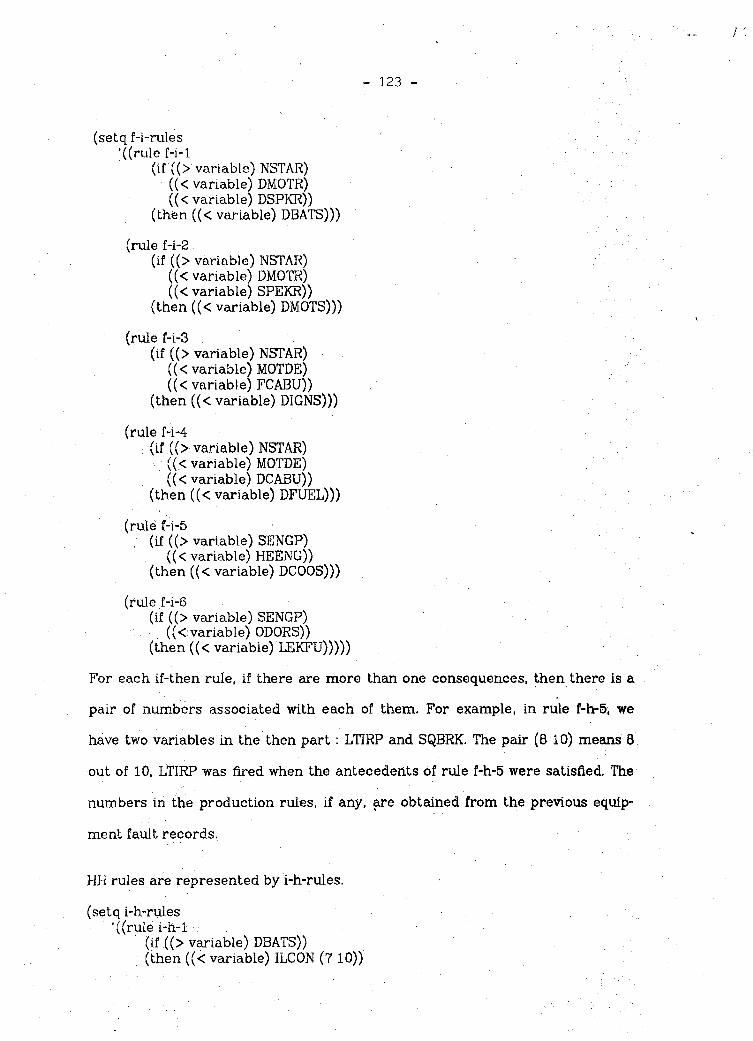
- 123
(setq f-i-rules ’((rule f-i-1
(if ((> variable) NSTAR)((< variable) DMOTR)((< variable) DSPKR))
(then ((< variable) DBATS)))
(rule f-i-2(if ((> variable) NSTAR)
((< variable) DMOTR)((< variable) SPEKR))
(then ((< variable) DMOTS)))
(rule f-i-3(if ((> variable) NSTAR)
((< variable) MOTDE)((< variable) FCABU))
(then ((< variable) DIGNS)))
(rule f-i-4(if ((> variable) NSTAR)
((.< variable) MOTDE)((< variable) DCABU))
(then ((< variable) DFUEL)))
(rule f-i-5(if ((> variable) SENGP)
((< variable) HEENG))(then ((< variable) DCOOS)))
(rule f-i-6(if ((> variable) SENGP)
((<■ variable) ODORS))(then ((< variable) LEKFU)))))
For each if-then rule, if there are more than one consequences, then there is a
pair of numbers associated with each of them. For example, in rule f-h-5, we
have two variables in the then part : LTIRP and SQBRK. The pair (8 10) means 8
out of 10, LTIRP was fired when the antecedents of rule f-h-5 were satisfied. The
numbers in the production rules, if any, are obtained from the previous equip
ment fault records.
HH rules are represented by i-h-rules.
(setq i-h-rules '((rule i-h-1
(if ((> variable) DBATS))(then ((< variable) ILCON (7 10))

- 124((< variable) NTOAT (2 10))((< variable) DEBAT (i 10))))
(rule i-h-2(if ((> variable) DMOTS))(then ((< variable) SGEAR (6 10))
((< variable) DIGCL (2 10))((< variable) BDCON (2 10))))
(rule i-h-3(if ((> variable) DIGNS))(then ((< variable) SECON (3 10))
((< variable) DSCON (2 10))((< variable) DPLAT (2 10))((< variable) DSPRG (2 10))((< variable) DDIST (1 10))))
(rule i-h-4(if ((> variable) DPLAT))(then ((< variable) PLASM (5 10))
((< variable) PLAWS (3 10))((< variable) PLAWL (2 10))))
(rule i-h-5(if ((> variable) DFUEL))(then ((< variable) VAFUE (4 10))
((< variable) FIFUE (2 10))((< variable) PIFUE (2 10))((< variable) PUFUE (1 10))((< variable) WAFUE- (1 10))))
(rulei-h-6(if ((> variable) DCOOS))(then ((< variable) LMOIL (5 10))
((< variable) BFANB (2 10))((< variable) BWPIP (2 10))((< variable) BWTAK (110))))
(rule i-h-7(if ((> variable) LEKFU))(then ((< variable) PIFUE (6 10))
((< variable) PUFUE (4 10))))))
Finally, HT rules are represented by h-t-rules.
(setq h-t-rules '((rule h-t-1
(if ((> variable) DDIST))(then ((< variable) FXDIS)))
(rule h-t-2(if ((> variable) SECON))(then ((< variable) AJSEL)))

(rule h-t-3(if ((> variable) PLAWS)) (then ((< variable) LWPLA)))
(rule h-t-4(if ((> variable) PLAWL)) (then ((< variable) SWPLA)))
(rule h-t-5(if ((> variable) LTIRP)) (then ((< variable) ADPSI)))
(rule h-t-6(if ((> variable) SQBRK)) (then ((< variable) LSBRK)))
(rule h-t-7(if ((> variable) LWHSW)) (then ((< variable) FXWSW)))
(rule h-t-B(if ((> variable) LJWHP)) (then ((< variable) FXWHP)))
(rule h-t-9(if ((> variable) LGERX)) (then ((< variable) FXGPX)))
(rule h-t-10(if ((> variable) BKFLU)) (then ((< variable) ABKFL)))
(ruleh-t-11(if ((> variable) LKBFL)) (then ((< variable) ABKFL)))
(rule h-t-12(if ((> variable) WALYN)) (then ((< variable) DRLYN)))
(rule h-h-13(if ((> variable) GDRMU)) (then ((< variable) JGDRM)))
(rule h7t-14(if ((> variable) LSCLT))(then ((< variable) FXCLT)))
(rule h-t^l5(if ((> variable) DSBAT)) (then ((< variable) CHELC)))
(rule h-t-16(if ((> variable) SHCON))
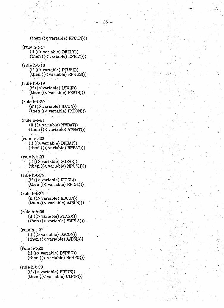
(then ((< variable) RPCON)))
(rule h-t-17(if ((> variable) DRELY)) (then ((< variable) RPRLY)))
(rule h-t-18(if ((> variable) DFUSE)) (then ((< variable) RPRUS)))
(rule h-t-19(if ((> variable) LSTYIR)) (then ((< Variable) FXWIR)))
(rule h-t-20(if ((> variable) ILCON)) (then ((< variable) FXCON)))
(rule h-t-21(if ((> variable) NWBAT)) (then ((< variable) AWBAT)))
(rule h-t-22(if ((> variable) DEBAT)) (then ((< Variable) RPBAT)))
(rule h-t-23(if ((^ variable) SGEAR)) (then ((< variable) NPUSH)))
(rule h-t-24(if ((> variable) DIGCL)) (then ((< variable) RPIGL)))
(rule h-t-25(if ((> variable) BDCON)) (then ((< variable) AJBLN)))
(nale h-h-26(if ((> variable) PLASM)) (then ((< variable) SMPLA)))
(rule h-t-27(if ((> variable) DSCON)) (then ((< variable) AJDSL)))
(rule h-t-28(if ((> variable) DSPRG)) (then ((< variable) RPSPG)))
(rule h-t-29(if ((> variable) PIFUE)) (then ((< variable) CLPIF)))

-127-
(rule h-t-30(if ((> variable) WAFUE)) (then ((< variable) CLFUT)))
(rule h-t-31(if ((> variable) VAFUE)) (then ((< variable) COCAB)))
(rule h-t-32(if ((> variable) FIFUE)) (then ((< variable) RPFIL)))
(rule h-h-33(if ((> variable) PUFUE)) (then ((< variable) RPFUE)))
(rule h-t-34(if ((> variable) LM01L))(then ((< variable) ADMOL)))
(rule h-t-35(if ((> variable) BFANB))(then ((< variable) RPBLT)))
(rule h-t-36(if ((> variable) BWP1P))(then ((< variable) RPWPI)))
(rule h-t-37(if ((> variable) BWTAK))(then ((< variable) RPWTK)))))
The FH, HH, and HT production rules represent the static knowledge struc
ture of our EXPERT system. The rules are extracted from the cause-and-effect
diagram and categorized by content. We will discuss rules-extraction and
conflict resolution by content limiting later in Section 3.1.
%2.2.2. Inference Machine
The control strategy in our EXPERT system is forward-chaining. It starts
with a collection of assertions and tries all available rules over and over, adding
new assertions as it goes, until no rule applies. Our forward-chaining program is
designed by modifying the "stream programming" of Winston and Horn [WINS

84], Stream programming is a powerful and newly developed concept [ABEL 84
& IDAJ 84]. An example of stream programming in its simplest form is shown in
Figure 4. A stream is created when an object is input to a stream generator. The
created stream is transformed in several stages, and finally reduced to an
object by a reducer. The use of the stream idea is common when talking about
input/output operations: programs read information from streams connected to
input files and write information to streams connected to output files. It is
claimed that a wide class of practical programming can be covered by the
stream programming paradigm [IDAJ 84].
Winston and Horn’s program was originally designed to handle complicated
types of production rules (see their book for examples). When applied to our
production rules (much easier type), the idea of the program is the simple
"match and fire" strategy. For example, in Example 1, we collected the findings
NSTAR, MOTDE and FCABU from the dynamic questionaire. When the forward
chaining procedure is applied, it loops through the FH rules, i.e. f-h-rules and f-
i-rules, first. Since all the antecedents of rule f-i-3 are satisfied, the rule is fired
and we get a new assertion DIGNS, the consequence part of rule f-i-3. The pro
cedure then loops through the HH rules, i.e. i-h-rules, and fires rule i-h-3. This
time the new assertions are : SECON, DSCON, DPLAT, DSPRG and DDIDT. Since
DPLAT satisfies the antecedent part of rule i-h-4, the rule is fired and the vari
ables PLASM, PLAWS and PLAWL are added to the previous assertions. Finally,
the procedure loops through HT rules and,fire rule h-t-1, h-t-2, h-t-3, h-t-4, h-t-
26, h-t-27 and h-t-28. At this moment, the system prints the treatment recom
mendations, explanation of variables and priority of the treatments.
Note that Winston and Horn’s program was written in COMMON LISP with
some minor errors in it. We modified it to run on the FRANZ LISP interpreter
- 128 -

-129 -
stored in the ECN machine.
2.3. Questions and Answers
The user may perform some simple questions and answers dialogue in our
system. At the end of the interpretive analysis, the system maintains a list of
rules successfully used. Each element is to contain the name of the rule, the
antecedents, and the. conclusion. From this set of rules, the system can answer
questions such as (Have you used rule ... ?), (How did you deduce that... ?), and
(Why did you need the assertion ...?). Besides these, the user may also ask ques
tion like (Can you explain ... ?); This procedure explains the mnemonic variables
used in the production rules. If the user asks questions besides the four
"canned" forms, the system will return: Sorry, I can't answer your question.
Example 1 - Continued.
****♦. *****************************************QUESTIONS AND ANSWERStit**********************************************
In this section, you may ask me questions like (Have you used rule h-t-i ?)(Can you explain DBATS ?)(How did you deduce that AWBAT ?)
or (Why did you heed the assertion RPIGL ?)I will answer your questions as soon as possible. Thank you!
Question :(;Have you used rule i-h-3 ?)Answer :Yes! I have used this rule.
Question :(Have you used rule h-t-1 ?) >Answer :Yes! I have used this rule.
Question :(Have you used rule f-h-5 ?)Answer :No! I did not used this rule.
Question :(Can you explain ABCDE ?)Answer : (There is no such variable!)
Question :(Can you explain DBATS ?)Answer : (DBATS : problem in battery system)

- 130 -
Question :(How did you deduce that AWBAT ?) Answer :(AWBAT is not established)
Question :(HQ>w did you deduce that NSTAR ?) Answer :(NSTAR was given)
Question :((Why did you need the assertion RPIGL ?) Answer : (RPIGL was not used)
Question :(Why did you need the assertion NSTAR ?) Answer :(NSTAR;is needed to show DIGNS)
Question :(Do you love me ?)Answer :Sorry, I can’t answer your question.
Question:(stop) Answer :ok!
2.4. Confirmation and UpdatingSince the user may have several choices of treatments with different priori
ties, the system will ask the user to make confirmation on his decision. The cer tainty factor in the production rules will be updated.
Example 1 - Continued.
**************************************************** CONFIRMATION AND UPDATING **** ************************************************
In this section, I need your confirmation on the treatment I gave you above in order to update the uncertainty numbers in the production rules.
Treatment Priority Treatment Recommendation
0.3 (30 out of 100) 0.2 (20 out of 100) 0.2 (20 out of 100) 0.1 (10 out of 100) 0.1 (10 out of 100) 0.06 ( 6 out of 100) 0.04 ( 4 ovit of 100)
Adjust the contact of high voltage line Replace the spark plug Adjust distributor line in contact Fix the distributor connector Smoothing the platina contact Making width of platina contact shorter Making width of platina contact larger
Do you accept the 1st treatment? Yes/No: No
Do you accept the 2nd treatment? Yes/No : Yes

-131 -
The production rules are updated.
Do you accept the 3rd treatment?Yes/No : YesThe production rules are updated.
Do you accept the 4th treatment?Yes/No : No
Do you accept the 5th treatment?Yes/No : No
Do you accept the 6th treatment?Yes/No : No
Do you accept the ?th treatment?Yes/No : No
Do you want to see the updated production rules?Yes/Xo : Yes
The updated production rules are :
(setq i-h-rules '((rule i-h-1
(if ((> variable) DBATS))(then ((< variable) ILCON (7 10))
((< variable) NWBAT (2 10))((< variable) DEBAT (1 10))))
(rule i-h-2(if ((> variable) DMOTS))(then ((< variable) SGEAR (6 10))
((< variable) DIGCL (2 10))((< variable) BDCON (2 10))))
(rule i-h-3 ■(if ((> variable) DIGNS))(then ((< variable) SEC ON (3 12))
■■■■., ((< variable) DSCON (3 12))((< variable) DPLAT (2 12))((< variable) DSPRG (3 12))
: .((< variable) DDIST(1 12))))(rule i-h-4
(if ((> variable) DPLAT))(then ((< variable) PLASM (5 10)) %
((< variable) PLAWS (3 10))((< variable) PLAWL (2 10))))
(rule i-h-5(if ((> variable) DFUEL))(then ((< variable) VAFUE (4 10))
, ((< variable) FIFUE (2 10))((< variable) PIFUE (2 10))((< variable) PUFUE (1 10))((< variable) WAFUE (1 10))))
(rule i-h-6

- 132 -
(if ((> variable) DCOOS))(then ((< variable) LMOIL (5 10))
((< variable) BFANB (2 10))((< variable) BWPIP (2 10))((< variable) BWTAK (1 10))))
(rule i-h-7(if ((> variable) LEKFU))(then ((< variable) PIFUE (6 10)) ((< variable) PUFUE (4 10))))
nil nil))
3. Knowledge AcquisitionAccording to Hayes-Roth, Waterman and Lenat [HAYE 83], knowledge
acquisition is the transfer and transformation of problem-solving expertise from some knowledge source to a program. The expertise to be elucidated is a collection of specialized facts, procedures, and judgemental rules about the narrow domain area rather than general knowledge about the domain or common-sense knowledge about the world. In general, the knowledge acquisition process is one of the most difficult phases of expert system building.
Dr. George V.E. Otto of AT&T Bell Laboratories in Whippany, New Jersey, gave a talk on "Artificial Intelligence and Expert Systems,” in the Chicago ACM Chapter on October 16, 1984. In his seminar, he stated "AI Mantra for the 80’s: In the Knowledge Lies the Power; In the Knowledge Acquisition Lies the Bottleneck!!" He then pointed out problems in knowledge acquisition:
(1) Knowledge engineering is not a well understood process.
(3) Knowledge engineers are in short supply.
(3) Knowledge representation language and environment is still evoling.
(4) Each expert system is still hand crafted.
(5) Reasons for rules often not coded.
(6) AI support environments still evoling.
Fortunately, in the equipment fault diagnosis task domain, the knowledge
acquisition is relatively easier to deal with. At least three reasons support this :
(1) The faults of equipment are Well-defined, because of their physical nature.
(3) The use of cause-and-effect diagram captures the expertise in a complete
and compact way.
(3) Pareto diagram solves the uncertainty problem.

133
In the following, we will discuss how cause-and-effect diagram and Pareto
diagram are used in our knowledge acquisition process.
3.1. Cause-and-EfTect Diagram
To create a cause-and-effect diagram, a team of experts is formed. In a
plant, the experts may include design engineers, technicians, line staffs and so
on, each of them shall have high degree of understand and long period of experi
ence about the system. After the team is formed, a brainstorming process
begins. During the process, various causes are proposed to explain a certain
effect. Sometimes previous data or pilot experimentations are necessary to sup
port the explanation. The more complicated the diagram is, the more sophisti
cated the system is.
In our car repair model, the knowledge was stored in a manual like book.
Since it is commercially available and has Chinese version, we assume the book
is reliable; in the sense that it was obtained by real experts using an intensive
degree of brainstorming process. We then transferred the rules in the manual
into a cause-and-effect diagram as shown in Figure 1. We also made a
corresponding decision tree because it is commonly used in real world. The tree
is shown in Figure 5. Cause-and-effect diagram and decision tree are basically
the same. Both diagrams illustrate a classification structure. The only difference
may be the former is easier to absorb knowledge of many experts and show
clearly the relationship between cause and effect. On the other hand, decision
tree is less complicated and easier to be understood by the readers.
From Figure 5, we see how the dynamic questionaire was designed, how the
FH, HH, HT production rules were extracted and how the certainty factors in
some rules were obtained.

- 134 -
At the root of the tree, three branches are possible. NSTAR, SENGP and
OTHER correspond to car won’t start, start but problem in engine and other car
problems, respectively. If NSTAR is chosen, then a question with two branches
brought to the user. If the user responds with MOTDE, then he receives a ques
tion with two possible choices again. At this moment, if he chooses FCABU, then
the system stops questioning by listing the findings collected up to this point.
For instance, in our case we have
List of Findings
Explanation of Variables
(NSTAR : car won 't start)
(MOTDE : starter works well)
(FCABU : fuel in carburetor)
In the meantime, the system moves to the inference engine by looping through
the FH and HH production rules and prints
Diagnostic Status : Findings to Hypotheses
(rule f-i-3 says variable DIGNS)(rule i-h-3 says variable SECON (3 10))(rule i-h-3 says variable DSCON (2 10))(rule i-h-3 says variable DPLAT (2 10))(rule i-h-3 says variable DSPRG (2 10))(rule i-h-3 says variable DDIST (1 10))(rule i-h-4 says variable PLASM (5 10))(rule i-h-4 says variable PLAWL (3 10))(rule i-h-4 says variable PLAWS (2 10))
Explanation of Variables
(DIGNS : problem in ignition system)(SECON: second high voltage lead line is ill-contact) (DSCON : lines in distributor are ill-contact)(DPLAT : problem plaintina contact)

- 135 -
(DSPRG : problem of spark plug)(DDIST : disconnection in distributor)(PLASM : platina contact surface in not smooth) (PLAWL ; width of platina contact is too large) (PLAWS : width of platina contact is too small)
Finally, the system moves to the HT rules and gives the treatment recommenda
tions, along with the priority list.
Treatment Recommendations
(rule h-t-1 says variable FXDIS)(rule h-t-2 says variable AJSEL)(rule h-t-3 says variable LWPLA)(rule h-t-4 says variable SWPLA)(rule h-t-26 says variable SMPLA)(rule h-t-27 says variable AJDSL)(rule h-t-28 says variable RPSPG)
Explanation of Variables
(FXDIS : fix the distributor connector)(AJSEL : adjust the contact of high voltage line) (LWPLA : making width of platina contact larger) (SWPLA : making width of platina contact shorter) (SMPLA : smoothing the platina contact)(AJDSL : adjust distributor line in contact)(RPSPG‘ replace the spark plug)
Priority of the Treatments
0.3 AJSEL0.2 RPSPG0.2 AJDSL0.1 FXDIS0.1 SMPLA0.06 SWPLA0.04 1 LWPLA
The use of decision tree (and cause-and-effect diagram), not only shows the
rules-extraction, but also demonstrates categorization of rules by content limit
ing.

- 136 -
3.2. Pareto Diagram
We saw from Figure 2, Pareto diagram is a graphical representation device
which gives the Weight distribution of possible causes. One way to transform a
Pareto diagram into a production rule is to assign a pair of data; with the first
tuple representing the number of faults for the corresponding variables and the
second tuple representing the previous total faults of the antecedents. For
example, before updating, the original form of rule i-h-3 is ,
(rule i-h-3(if ((> variable) DIGNS))(then ((< variable) SECON (3 10))
((< variable) DSCON (2 10))((< variable) DPLAT (2 10))((<variable)DSPRG(2 10))((< variable) DDIST (1 10))))
Since two variables RPSPG and AJDSL are confirmed (see Example 1 of Section
2.4.), the corresponding hypotheses shall be updated. Because the system kept
track of all the rules used, it is easy to trace the rules fired RPSPG and AJDSL.
The two rules Are
(rule h-t-27(if ((> variable) DSCON))(then ((< variable) AJDSL)))
(rule h-t-28(if ((> variable) DSPRG))(then ((< variable) RPSPG)))
Now, the two variables DSCON, DSPRG and the associated consequences of rule
i-h-3 are updated. The new rule is
(rule i-h-3 >(if ((> variable) DIGNS))(then ((< variable) SECON (3 12))
((< variable) DSCON (3 12))((< variable) DPLAT (2 12))((< variable) DSPRG (3 12))((< variable) DDIST (l 12))))

1 137 -
A Experimental Results
5. Demonstrative Examples
In the previous sections we decompose the program piecewise to explain
the system organization. Now, we demonstrate a complete program to show our
system in more details.
Example 3.
Script started on Sun Dec 23 21:04:28 1984 S lispFranz Lisp, Opus 38.69 -> (load 'EXPERT)[load EXPERT]
Hello! You are working on the EXPERT system.
**************************************************** BEGINNING OF QUERY ****************************************************
Enter Name or ID Number :Ye-Sho
Enter Date of Visit:Dec-27-84
1. Type of Problem:(1) Car won’t start(2) Car starts but problem in engine(3) Other Car Problems
Checklist: (3)
2. Possible other type of problems(1) Wheel(s)(2) Brake(3) Clutch(4) Electric
Checklist :(l'$)
3. How is the wheel unstable?(1) Slant in one direction(2) Slant right and left
Checklist :(l)
4. What type of brake problem?(1) No brake until deep press

138 -
(2) Only one side is bad brake Checklist :(2)
************************************************ ♦*** SUMMARY REPORT *•**
Name or ID Number: Ye-Sho
Date: Dec-27-84
List of Findings
(Possible other type of problems) '(Wheel(s) unstable when car is running) •(Brake system is in abnormal condition)(Wheel slants in one direction)(Brake on one side is good the other side malfunctions)
*******************************************,|l',94,4i**** INTERPRETIVE ANALYSIS *♦**• ♦•»*+***11'**'K* ********* ******** *****************
Treatment Priority Treatment Recommendation
0.4 (4 out of 10) Add tire pressure 0.3 (3 out of 10) Drying the lining of brake 0.2 (2 out of 10) Adjust the brake drum gap 0.1 (1 out of 10) Loosen the contact of brake
Are you interested in the internal symbols? Yes/No : Yes
Diagnostic Status : Findings to Hypotheses
(rule f-h-5 says variable LTIRP (8 10)) (rule f-h-5 says variable SQBRK (2 10)) (rule f-h-B says variable WALYN (6 10)) (rule f-h-8 says variable GDRMU (4 10))
Explanation of Variables
(LTIRP : lack of tire pressure)(SQBRK : squeeze of brake)(WALYN : water in lining of brake system) (QDRMU : unbalance of brake drum gap)
Treatment Recommendation *
(rule h-t-5 says variable ADPSI) (rule h-t-6 says variable LSBRK) (rule h-t-12 says variable DRLYN)

- 139 -
(rule h-t-13 says variable JGDRM)
Explanation of Variables
(ADPSI : add tire pressure)(LSBEK : loosen the contact of brake)(DRLYN : drying the lining of brake)(JGDRM -. adjust the brake drum gap)
*********************** ***************************.*«■ QUESTIONS AND ANSWERS •**■*■■************************************************
In this section, you may ask me questions like (Have you used rule h-t-1?)(Can you explain DBATS?)(How did you deduce that AWBAT?)
or (Why did you need the assertion RPIGL?)If you have no more questions, just type "(stop)".
Question :(Why did you need the assertion LT1RP?) Answer :(LTIRP is needed to show ADPSI)
Question :((Jiow did you deduce ADPSI?)Answer : (ADPSI demonstrated by LTIRP)
Question :(Can you. explain ADPSI?)Answer :(ADPSI : add tire pressure)
Question :(Yo¥ou are so stupid?)Answer :Sorry. I can’t answer your question.
Question :(tftank you Very rmuch! )Answer :Sorry, I can't answer your question.
Question.:(stop) Answer :ok!
************************************************ ***«■ \ , CONFIRMATION AND UPDATING ****m.*********************************************
In this section, I need your confirmation on, the treatments I gave you above in order to update the uncertainty numbers in the production rules.
Treatment Priority Treatment Recommendation
0.4 (4 out of 10) Add tire pressure 0.3 (3 out of 10) Drying the lining of brake 0.2 (2 out of 10) Adjust the brake drum gap 0.1 (1 out of 10) Loosen the contact of brake

- 140 -
Do you accept the 1st treatment? Yes/No : YesThe production rules are updated.
Do you accept the 2nd treatment? Yes/No : No
Do you accept the 3rd treatment? Yes/No : No
Do you accept the 4th treatment? Yes/No : YesThe production rules are updated.
Do you want to see the updated production rules? Yes/No: Yes
The updated production rules are :
(setq f-h-rules ’((rule f-h-1
(if ((> variable) SENGP)((< variable) NSENG)((< variable) PULON))
(then ((< variable) DDIST)))(rule f-h-2
(if ((> variable) SENGP)((< variable) NSENG)((< variable) PUCHI))
(then ((< variable) SECON)))(rule f-h-3
(if ((> variable) SENGP) ((< variable) ABLOW))(then ((< variable) PLAWS)))
(rule f-h-4(if ((> variable) SENGP) ((< variable) ABHIH))(then ((< variable) PLAWL)))
(rule f-h-5(if ((> variable) OTHER)
((< variable) UNWHE)((< variable) SLONE))
(then ((< variable) LT1RP (9 12)) ((< variable) SQBRK (3 12)))) (rule f-h-6
(if ((> variable) OTHER)((< variable) UNWHE)((< variable) SLTWO))
(then ((< variable) LWHSW (5 10))((< variable) LJWHP (3 10))((< variable) LGERX (2 10))))
(rule f-h-7(if ((> variable) OTHER)
((< variable) BRAKE)((< variable) DBRKP))
(then ((< variable) BKFLU (8 10)) ((< variable) LKBFL (2 10))))

- 141 -
(rule f-h-8(if ((> variable) OTHER)
((< variable) BRAKE)((< variable) ONBRK))
(then ((< variable) WALYN (6 10)) ((< variable) GDRMU (4 10)))) (rule f-h-9
(if ((> variable) OTHER)((< variable) CLUTH)((< variable) NSHFT))
(then ((< variable) LSCLT)))(rule f-h-10
(if ((> variable) OTHER)((< variable) CLUTH)((< variable) NHISP))
(then ((< variable) LSCLT)))(rule f-h-11
(if ((> variable) OTHER)((< variable) ELECR)((< variable) ODSMK))
(then ((< variable) DSBAT)))(rule f-h-12
(if ((> variable) OTHER)((< variable) ELECR)((< variable) SPKNP))
(then ((< variable) SHCON (6 10)) ((< variable) DRELY (4 10)))) (rule f-h-13
(if ((> variable) OTHER)((< variable) ELECR)((< variable) FLASH))
(then ((< variable) DFUSE (9 10)) ((< variable) LSWIR (1 10)))) nil nil))
t-> HD""Goodbye $ ~Dscript done on Sun Dec 23 21:08:43 1984
5.1. Performance Evaluation
Performance evaluation is an important area of building expert systems.
Weiss and Kulikowski [WEIS 84], and Hayes-Roth and others [HATE 83] devoted
several spaces discussing this topic in their building expert systems books. Pro
fessor King-Sun Fu of Purdue University believed at least three topics should be
covered in discussing performance evaluation. They are : reasoning power, cost

142 -
and learning.
As stated in Section 1.3., we select car trouble-shooting as a topic to com
pare the car repair model of Weiss and Kulikowski [WEIS 84]. Although their car
repair model is not complete, we may compare the two systems from the design
point of view.
5.1.1. Reasonihg Power
There are similar characteristics on reasoning power between the two sys
tems :
(1) The production rules are composed of.FH, HH and HT. The advantage of this
device is to resolve the rules conflict by content limiting. Also, the partition,
of the production rules into three categories, saves the execution time of
the inference engine. Otherwise, the system will loop through air the pro
duction rules, some of them might be irrelevant.
(2) Forward-chaining is used as the control strategy.
(3) Both systems have simple explanation ability. Matching the query with cer
tain template is used as question understanding device. Generation of
canned text is used to answer question.
There are differences on reasoning power between the two systems
(1) Knowledge acquisition. We use a cause-and-effect diagram and a Pareto
diagram to collect expertise. Weiss did not specify exactly how their pro
duction rules were obtained. In this sense, our system is easier to be under
stood and updated. These shall be important factors when we talk about
reasoning power.

: 143 -
(2) Collection of findings. We use dynamic questionaire to gather findings. A
good feature of this approach is to avoid asking irrelvant questions. Quite
differently, Weiss used a fixed format of questionaire. We ask questions as
most human experts do; in terms of cause-and-effect diagram, we start
from the effect part first and trace to the possible causes leading to the
effect. We continue the effect-first-cause-next process until we hit the leaf
of the diagram, conversely, they start from the leaves and move to the
body of the diagram. Figure 6 and Table 2 show the cause-and-effect
diagram of their car repair model. From this figure, we see their ques
tionaire was designed by partioning all the leaves of the diagram into
several groups. Each group represents a question shown on page 78 of their
book. One drawback of their approach is that questionaire shall be
changed, when new knowledge is added.
(3) Certainty factor. In our system, the use of uncertainty numbers is objective
and more reliable. This is because we use the idea of Pareto diagram which
enables the updating ability of the production rules. Conversely, thier cer
tainty factor is subjective and unreliable. As we all know certainty factor is
a very important ingredient of reasoning power.
5.1.2. CostSince our system is written in LISP, the cost of running our system shall be
cheaper than Weiss’s FORTRAN-oriented system. However, excution speed is not
the only factor in judging the use of programming languages. Several other fac
tors shall also be considered. One reason that FORTRAN was used is because this
language has more Users than the programming languages for AI, e.g. LISP and
PROLOG. According to the advertisements in the first issue of International jour
nal of Expert Systems and Knowledge Engineering [CROA 84], several dedicated
FORTRAN machines are commercially available for building expert systems.

- T.44 - ■.
The author believes to talk about the cost of expert systems, one should
consider what kinds of functions the expert system can perform. This is similar
to buying a personal computer in today's market.
Both of the systems don’t have the ability of learning. The ability to learn is
still a big research area in Artificial Intelligence.
6. Discussions and Conclusions
6.1. Discussions
In the following we will discuss several interesting topics related to this
paper. These include: beyond the prototype model, human fault diagnostic
models, and comparison of expert system program and conventional one.
6.1.1. Beyond the Prototype Model
As we mentioned in section 1.1.4., further testings, refinements and gen
eralizations are needed to shape a prototype expert system. In Figure 7, Dr.
Davis [DAVI 84] showed six states of development for some well-known expert
systems. Ranging from "a gleam in somebody’s eye” to wide commercial use,
five systems have reached the stage of commercial use. But a larger number of
programs are somewhere between the stage of debugged program and experi
mental use. Davis continued to make a note on R1 which has by far the most
clearly defined development process, evolving through a sequence of stages
similar to those listed in below.
(2) System development
(3) Formal evaluation of performance

- 145 -
(4) Formal evalution of acceptance
(5) Extended use in prototype environment
(6) Development of maintenance plans
(7) System release
In its first formal evalution the system was tested on approximately twenty
cases. The results suggested that R1 would soon solve problems correctly 90
percent of the time. But when it was distributed to its user community for more
extended testing, users criticized the system performance 40 percent of the
time. What happened? Some of those problems were mistakes on the part of the
users resulting from incorrect data or a misunderstanding of program opera
tion! But there was a more basic lesson: research environments, no matter how
carefully tailored, are not identical to user environments. John McDermott, one
of the developers of Ri, has said that Rl’s knowledge base grew at least as much
during the final stage of its development as it did in any of the previous stages of
its development.
The same theme shall apply to our trouble-shooting expert system. One
drawback of the system is the expertise came from a book knowledge. We need
criticisms from real car repair experts and further improvements if the system
is to be accepted in the marketplace.
6.1.2. Human Fault Diagnostic Models and Second Generation Expert Systems
Rouse and his colleagues [ROUS 83 & ROUS 84] made a series of investiga
tions of human problem solving performance in fault diagnosis tasks. They
attempted to synthesize a model capable of describing human problem solving
in general. This model, based on a thorough review of the problem solving litera
ture, is conceptually proposed recently. The model operates on three levels:

(1) Recognition and classification. This is the process whereby humans deter
mine the problem solving situations with which they are involved. Familiar
situations may invoke a standard "frame" [MINS 75] while unfamiliar situa
tions may lead to the use of analogies or even basic principles of investiga
tion.
(2) Planning. This may involve the use of familiar "scripts" [S.CHA 79] br, if no
script is available, require generation of alternatives, imagining of conse
quences, valuing of consequences, etc [JOHA 79].
(3) Execution and monitoring. This involves the use of so called symptomatic
rules (S-rules) and topographic rules (T-rules). This dichotomy between
symptomatic and topographic problem solving was formalized in a fuzzy
rule-based model. This model first attempts to find familiar patterns among
the symptoms of the failure (i.e., among the state variables of the system).
If a match is found, S-rules are used to map directly from symptoms to
hypothesized failure. If there are no familiar patterns among the state vari
ables, the model uses T-rules to search the structure (i.e., functioned rela
tionships) of the system.
What Rouse and his colleagues did matches the research direction of expert
systems, the so called second-generation. Second-generation systems are those
that perform the same task already accomplished by another system, but do so
using some variation in representation of the knowledge or control structure, or
both. One goal of second-generation systems is experimentation: to demon
strate, by doing the same task done by the first-generation system, whether the
altered knowledge representation or control structure results in improved per
formance. A good example of second-generation vs first-generation expert sys
tem is CENTAUR vs PUFF [AIKI 83], PUFF was written to perform pulmonary
function test interpretations. The structure used to represent knowledge in
- 146 -

PUFF were IF-THEN production, rules. CENTAUR is better than PUFF because the
format* represents its knowledge as a combination of frames and production
rules and performs tasks more flexible and powerful than the latter.
Evidently, our trouble-shooting expert system belongs to the first-
generation. To upgrade our system in an expert sense, one good way may be to
implement Rouse and his associates' conceptual model. This will be progressed
by the author in the near future.
6.1.3. Comparison of Expert System Program and Traditional One
One trivial question a beginner might ask in learning expert systems is
"What is the difference between an expert system from an ordinary computer
application?'7 A short answer to this question is that ordinary computer pro
grams organize knowledge on two levels: data and program. Most expert systems
organize knowledge on three levels: data, knowledge base, and control strategy.
More clearly, what distinguishes an expert system from an ordinary com
puter application is that in a conventional computer program, pertinent
knowledge and the methods for utilizing it are all intermixed. In an expert sys
tern, the problem-solving model appears explicitly as a knowledge base rather
than implicitly as part of the coding, and the knowledge base is manipulated by
a separate, clearly identifiable control stragey. For example, in our car repair
expert system, we have global data base, knowledge base and inference machine
clearly seperated (See Figure 3).
One important reason for the modualization is that each part may need to
be updated, edited and deleted frequently. The global data base is the working
memory of the system. It keeps track of input data for the current problem, the
status of the current problem, and the relevant history of what has been done so
far. The knowledge base stores the required knowledge of the tasks. Extendibil-

: - 148 -
ity, simplicity, and explicitness are basic requirements to consider when choos
ing a knowledge representation scheme. The inference machine is actually a
collection of procedures which makes decisions about how to use the system’s
knowledge by organizating and controling the steps. The procedures are
modified whenever a more powerful algorithm is released. For example, a new
algorithm, RETE developed by Forgy at Carnegie-Mellon University [FORG 81], is
claimed recently to have a nice feature. Large production systems that use the
RETE algorithm generally execute much faster than similar systems without it;
Someday, we might modify our inference engine by using RETE algorithm.
6.2. Conclusions
Quality control is a well-suited and cost-effective area for the development
of expert systems. In this report, the author showed a prototype expert system
for trouble-shooting in on-line quality control. Also, a prototype system for
experimental design in off-line quality control is in preparation. Besides con
tinuing shaping the prototype model by testing and refinement, we need to gen
eralize the model by closely keeping track of the newly developed techonology.
Listed below are part of them:
(1) Knowledge representation. Since real experts use more than rules, the use
of production rules only represents surface-structure knowledge of human
experts. Some causal models representing deep-structure knowledge are
being pursued, under the title of Congitive Science, by some leading AI
scientists. ’
(2) Inference machine. Besides forward-chaining, there are several other infer
ence procedures commonly used, e.g. backward-chaining, pattern match
ing. generate-and-test, and constraint satifaction. The use of these various
procedures depends on the nature of the problem tasks. It would be

interesting to see a paper discussing the use of each inference procedure in
its best working environment.
(3) Learning. The field of machine learning strives to develop methods and
techniques to automate the acquisition of new information, new skills, and
new ways of organizing existing information, As Simon [SIMO 03] has pointed
out, if learning could be automated and the results of that learning
transferred directly to other machines which could further augment and
refine the knowledge, one could accumulate expertise and wisdom in a way
not possible by humans - each individual person must learn all relevant
knowledge without benefit of a direct copying process.
(4) Programming tools. Brown [BROW 84], a pioneer researcher in Al, says that
the success of AI and expert systems rests not in the intellectual arena but
in the recent dramatic advances in hardware, particularly hardware that
can effectively execute LISP - the lingua franca of AI. He continued. "AI sys
tems that required dedicated, million-dollor mainframes five years ago now
can run on machines that cost only $25,000. For the first time we have
cost-effective delivery engines for expert systems, a major change." Besides
LISP, severed programming languages are suited for expert systems
development; e.g., PROLOG, and OPS 5. The RETE algorithm mentioned
above is used in the OPS family of production system languages.
(5) Natural language front-end. Expert systems that need to produce English
explanations have for the most part gotten along quite well so far on simple,
small, linguistically naive generation programs. Full-scale, linguistically
motivated text generation capabilities will be required of expert systems
simply because the intricate grammatical contraints on the text produced
by recursively embedded source data structures will eventually swamp any
ad hoc facility, especially as the number of objects in the system requiring

- 150 -
description grows and the sophistication of the desired text increases. This
trend will lead to a better explanation and consultation ability for expert
systems. ’
In summary, the feasibility of using expert systems technology in quality
control is without questions. However, to build a real expert system, it is neces
sary to do intensive testing, constant refinement, and incremental generaliza
tion as a cbntinuing task during the entire useful life of the system.

- 151 -
7. Ref erences and Appendix
7.1. References[ABE1.84] .
Abelson, H. and Gerald J.S. "Structure and Interpretation of Computer Programs," MIT Press, Cambridge, Massachusetts, 1984.
[AIM] •Aikins, J.S. "Prototypical Knowledge for Expert Systems," Artificial Intelligence, pp. 163-210, 1983.
[AT&T84]"Workship on Artificial Intelligence in Statistics," AT&T Conference Center,
Princeton NJ, 15-16 April 1985. (See the Ad in AI Magazine, p.87, Fail 1984)[AUT084] ;■.. °
"Dr. Taguchi - Japan’s Secret Weapon," August 1984 Issue of Automotive Industries, pages 18 and 20.
[BROW84]Brown, J.S. "The Low Road, the Middle Road, and the High Road," In the AI
Business, Commercial Uses of AI, 1984.[BUCH84] ;
Buchanan, B.G. and Shortliffe, E.H., "Rule-Based Expert Systems : The MYCIN Experiments of the STANDFORD Heuristic programming project," Reading, MA : Addison-Wesley, 1984.
[CORP]Copp Richard, "Report on Japanese Quality Engineering using Designed Experiments," July 1984, American Supplier Institute, Incorporated.
[CROA84]Croall, I., Ishizuka, M., and Watterman, D. (Eds.) "EXPERT SYSTEMS", VoL l, No.l, July 1984.
[DAVI84]Davis Randall, "Amplifying Expertise with Expert Systems," The AI Business, Commerical Uses of Artificial Intelligence, edited by P.H. Winston and K.A. Prendergast, 1984.
[FORG81]Forgy, C.L. "OPS5 user’s manual," Technical Report, Carnegie-Mellon University, Department of Computer Science, 1981.
[GEVA82]Gevarter, W.B. "An Overview of Expert Systems,” (NBSIR 82-2505) Washington, DC: National Bureau of Standards; 1982.
[GEVA83]Gevarter, W.B. "Expert Systems : Limited but Powerful," Computers, 1983.
[HAYE83]Hayes-Roth, F., Waterman, D., and Lenat, D. (editors) "Building Expert Systems,” Addison-Wesley, New York, 1983.
[IDAJ84]Ida, J. and Tanaka, J. "Functional Programming with Streams," New Generation Computing, 2 (1984) 261-275, OHMSHA LTD. and Spring-Verlag.
[JOHA79]Hohannsen, G. and Rouse, W.B. "Mathematical Concepts for Modeling Human Behavior in Complex Man-Machine Systems," Human Factors, 21(6):733-747,
M- 152. -
1979.[MAY084] .
Mayo John, "Process Design as Important as Product Design," Manger's Journal, The Wall Street Journal, 1984.
[MINS75] .Minsky, M. "A Framework for representing knowledge," In P.H. Winston (Ed.), The Psychology of Computer Vision. New York: McGraw-Hill, 1975.
rL M0ST84]MOSTOW Jack, "Rutgers Workshop on Knowledge-Based Design" ACM SIGART newsletter, pp. 19-32, #90, October 1984.
[ROUS]Rouse, W. B., "Models of Human Problem Solving: Detection, Diagnosis, and Compensation for System Failures", Automatica, vol. 19, 1983, pp. 613-625.
[R0US84]Rouse, W. B. and Ruston, M. H., "Human Problem Slolving in Fault DiagnosisTasks", Advances in Man-Machine Systems Research, Vol. 1, 1984.
[SAGA84]Sagalowicz, D. "Development of an Expert System," EXPERT SYSTEMS: The International Journal of Knowledge Engineering; Vol. 1, No.2, October 1984, pp. 137-141.
[SCHA77] : ■Schank, R.C. and Abelson, R.P. "Scripts, Plans, Goals, and Understanding." Hillsdale, NJ: Lawrence Erlbaum, 1977,
[SIM083] ; •Simon, H.A. "Why Should Machines Learn?" In R.S. Michalski, J.G. Carbonell, and T.M. Mitchell (Eds.). Machine Learning: An Artificial Intelligence Approach. Palo Alto, CA: Tioga Press; 1983; 25-37.
[STOC69]Stockel, M. W., " Auto Service and Repair". Good-Heart Willcox Company, Inc., S. Holland, IL.
[TAG U 79]Taguchi, Genichi. "Introduction to Off-Line Quality Control," June 1979, American Supplier Institute, Incorporated.
[WEIS84]Weiss, S.M. and Kulikowski, C.A. "A Practical Guide to Designing Expert Systems,” Rowman & Allanheld, Publishers, 1984.
[WINS84]Winston, P.H. and Horn, B.K.P. "LISP", 2nd edition, Addison-Wesley Publishing Company, 1984.

fit figures and Tables V? m? esOi &
L ( o V)
/ °'l/ . ■ BDCo


Table 1. Explanation of the Abbreviated Variables in our Gar Repair Model.
(ABHIH: engine abnormal in high spped but normal in low speed)(ABKPL: add brake fluid)(ABLOW: engine abnormal in low speed but normal in high speed)(ADMOL: add motor oil)(ADPS1: add tire pressure)(AJBLN : loosen the lead line clean and fix it)(AJDSL: adjust distributor line in contact)(AJSEL: adjust the contact of high voltage line)(AWBAT: adding water in batteiy)(BDCON : battery lead line ill-contact)(Bi-'ANB : loose or broken of fan belt)(BKPijU: lack of brake fluid)(BRAKE!: brake system in abnormal condition)(BWPIP : water pipe broken)(BWTAK: water tank broken)(CHELC: check electric circuit if short circuit exist)(CLEUT: clear fuel tank)(CLPIF: clean the fuel pipe line)(CLUTH : problem in clutch)(COCAB: Cool carburetor)(DBATS: problem in battery system)(DBRKP: no brake untill deep press on accelator)(DCABU : no fuel in carbretor)(DCOOS: proWem in coolant system)(DDIST: disconnection in distributor)(DE3BAT: dead battery)(DETJEL: problem in fuel system)(DEUSE: fuse is dead)(DIGCL: ignition coil does not work)(DIGNS: problem in iginition system)(DMOTR: starter does not work)(DMOTS: problem in motor system)(DPLAT : problem in platina contact)(DRELY: relay is out of order)(DRLYN : drying the lining of brake)(DSBAT: disconnecting batteiy)(DSCON : lines in distributor are ill-contact)(DSPKR: speaker does not work)(DSPRG : problem of spark plug)(E3LECR: problem in electric system)(EUABU : fuel in carburetor)(E1EUE: block of fuel filter)(ELASH: flash light is out of order)(EXCLT : fix the clutch)(EXCON : fix the connector)(EXDIS: fix the distributor connector)(EXGPX: fix the gear box screw)(EXWHP: fix the joint between wheel and propeller)(EXWIR: fix lead wire to light)(EXHTSIf: fix wheel screw)(GDRMU: unbalance of brake drum gap)
- 155 -

- 156 -
(HEENG: car start but engine has problems)(1LCON : ill-contact in lead line)(JGDRM : adjust the brake drum gap)(LEKFU: fuel leakage)(LGKRX: loosen of gear box screw)(UWHP : lossen between wheel and propeller shaft)(LKBFL: leakage of brake fluid)(LMOIL : lack of motor oil)(IiSBRK: loosen the contact of brake)(LBCLT : loosen of clutch)(JLSWIR: loosen of wire)(LTlliP: lack of tire pressure)(LWHSW : loosen of wheel screw)(LWPLA: making width of platina contact larger)(MOTDE : starter works well but engine doesn't work)(NHISP: no high speed)(NPUSH: put transmission in N and push the car)(NSENG : noise in engine)(NSHJT : noise in shifter)(NSTAR: car won't start)(NWBAT : no water in battery)(ODORS : odorous smell in engine)(ODSMK: odorous smell and smoke when car running)(ONBRK: one side brake is good the other side is malfunction) (OTHER : possible other type of problems)(PIFUfi : Mock of fuel pipe)(PLASM : platina contact surface is not smooth)(PLAWL : width of platina contact is too large)(PLAWS: width of platina contact is too small)(PUC111: a kind of engine noise sounding like puchi)(PULON : a kind of engine noise sounding like pulon)(POFUE : fuel pump is dead)(RPBAT : replace a battery)(HPBLT: replace the fan belt)(RPCON : replace the connector)(UPE1L : replace fuel filter)(ItPFUE : replace the fuel pump)(RPEUS: replace fuse)(liPIGL : replace the ignition coil)(RPRLY : replace the relay)(JtPSPG : replace the spark plug)(KPWPI: replace water pipe line)(RPWTK: replace water tank)(SECON : second high voltage lead line is ill-contact)(SENGP : engine start but with problem)(SGEAK : motor gear and fly gear squeeze)(SHGDN : short circut of connector)(SLONE r wheel slant in one direction)(SLTWO : wheel slant right and left two direction)(SMP1A : smoothing the platina contact)(SPEKR : speaker sound well) ’(SPKNP : speaker sound and can not be stopped)(SQBRK: squeeze of brake)(SWPLA: making width of platina contact shorter)

- 157
(UNWHE: wheel unstable when car is running) (YAFUE: verporization of fuel in carburetor) (WAFUE : water in fuel tank)(WALYN : water in lining of brake system)

user
Dia^wostic•Status
Tfc©\T*veA/r
R^Cc. AA M &A>AtX0*J^H/vt ^p^fe-T2c.v/^-
Fipure 3. Sustem Organization of Trouble-Shooting Expert Sustem.

of^LJb
liaure 4. Stream Programming.

ddxm
Kgure 5. Decision Tree of the Car Trouble-Shooting
fc** f
to it
160

r
Af oni>OS0.
■2- U-kf
>11/?^) mv)4) ')1V
'0
a

C\JvO
I
N ' ^
i ^ ■> ->e/ > - y

CL05‘
J-lVfo-n^sxs
■ inure £. Cause—and—Effect Diaoraffi of. Weiss 's Car Repair Model..

- 164 -
Table 2. Explanation of the Abbreviated Yaziables in Weiss's Car Repair Model
(BATD : battery discharged)(CAB : battery cables loose or corroded)(CULT: fuel filter clogged)(CHOKE: choke stuck)(CLEAN : clean and tighten battery cables)(DIM : headlights are dim)(EGAS : gas gauge reads empty) '(ELEC : electrical system problems)(EMPTY: no fuel)(FCWS : car won’t start)(HLT : fuel filter clogged)(FLOOD: car flooded)(FOTH : other car problems)(FUEL : fuel system problems)(GAS : put more gasoline into tank)(GBATT: charge or replace battery)(GRIND : grinding noise from starter)(LCAB : battery cables loose or corroded)(LGAS : very strong odor of gasoline in carburetor)(MGAS : normal odor of gasoline in carburetor)(NCKNK: no cranking)(NGAS : np odor of gasoline in carburetor)(NSl’AR: replace starter)(OCKNK: normal cranking)(OPEN : remove air cleaner assembly and manually open choke+ with pencil) (RFILT: replace gas filter)(SCRNK: slow cranking)(STRTR: starter malfunction)(TEMP : outdoor temperature(degrees lO)(WAIT : wait 10 minutes or depress accelerator to floor+)

- 165 -
HEARSAYHIIPROSPECTORPUFFTEIRESIASINTERNISTMACSYMAMETA-DENDRALDENDRALPROGRAMMER'SAPPRENTICEABELHARDWAREDEBUGGINGSOPHIESTEAMERMYCINR1DIP ADVISOR
. j : I ?i
y.^1^ f ;
: /j w
• •• ” i.
• ■ xixIII .... .
I- & i1' 1
■" . i' :
111 ^ j jI!III
Figure 7. State of Development of Some Well-Known Expert Systems.


Chapter 4
Deep Drawing Feasibility Expert System
G. Eshel

Seep Drawing Feasibiiitu Expert System - 167 -Sad EsheiABSTRACT
Peep Drawing Feasibility Expert System ( DDFE ) checks producib i 1 ity of axi-symmetric parts by the deep_drawing processes. The system will be incorporated within a general metal_working process_planning system, that will include forming processes, for generating multi-technology process_outlines.
Before entering the detailed-specifications design stage of a process, the processjlanner checks the feasiblity of producing the specified part by the examined process. The expert knows the capabilities of the process he is considered an expert in, the significant features of the raw_material, and the resources available - raw_material in stock and the capability of the machines.
The DDFE is designated to be operated by the designer or by the process_planning coordinator. Both are not domain experts (in the deep-drawing technology ). Nonetheless, they seek an answer about their feasibility inquiry. Thais why the system is not interactive, - it goes by the fundamental principle of automatic process_planning, as opposed to computer aided process_planning.
Since a complete theoretical analysis of the deep_drawing process has not yet been accomplished, the expert is vital. To infer the answer the expert uses a combination of theoretical computations, empirical results, and approximate measures. Extracting the process-capabi1ity knowledge, and putting it into a formal representation, is the core of the DDFE, and the most challenging task of the system designer. The essentials of the process_planning approach and the deep_drawing process are described in the first part of the report.
The knowledge of the DDFE is organized as a hierarchical ru!e_based system. The data_base and the inference machine, are largely independent and user_updatab1e. Inference, is done through primitive matching of Horn clauses. It draws primarily on the built-in theorem—proving capabilities of PROLOG, - the language it is programmed in - and higher level, "macro"s. To the extent possible, database ( relational, represented as: ” PROLOG facts'"--) is genralized in frames, and rules are structured. This facilitates almost unrestricted data_base updates and, some rule modification capabi1ity.
The portion of the DDFE described hereby gets as an input, the CAM representation of the required part, and tests producibi1ity, employing the main process ( "cupping" ) and redrawing.
It works and has produced sound advices.

%
%
%
%
^ ■
- 168 -
1. TERMINOLOGY General:The evaluated workpiece is represented by the right-hand side*
of the crp5s_sectional view, of a plane through the axis of symmetry.Sizes: longitudinal sizes given in inches* angles : degrees.
Abbreviations in the program:H - denotes height* or* in list processing; Head of a list. Final-shape - in program: the shape at end of process.ID - inside diameter.Initial-shape - in program: the shape at start of process.OD - outside diameter.R - denotes : radius. May be prefixed or suffixed to another term. RM - raw_material.T - in list processing* denotes Tail of a list.WT - wall thickness* default for: nominal wall thickness.
Notation for f1ow diagrams:
■ '% ■
%
*
FF — form feature*SE - Shape Element*WP — Workpiece.LEGEND:
t»
■—— - a possible path for material flow............. - a possible path for process_planning•v-*v-v-v'v<v<v»vs.<v, _ a cut in the global picture* to isolate a window,
x - a fork: path selection.<yy) - the No. of the conceptual process_planning operation.

- 169 -
I Process name* II II II I» I -
' <Process__Output>■ I ..•••' ' ' ' ’ : ■s .(yy) ! ^CConceptual backwards analysis!]#
... -1 •X~--------- ------------------- ;-----------I II I .
' >’ ' Vv !
Meaning assigned to terms in the document
assemblu - adopt the std. ANSI# ZI-94 definition: a joining ofparts / subassemblies that can be disassembled without destroying the components.
aux. operations /processes - if the main process is assumed to be a forming process# then all machining and HT operations are auxiliary operations.
comp 1ementaru processes - processes within a family of processes# that come to modify main shape obtained by main process.
component — usually refered to as: a component of anassemb1y/sub-assemb1y/fabrication
composite process - a sequence of one main process# or sliced raw_material» and the following secondary processes# being of different metalworking processes.
conceptually solved problem - A problem treated and conceptually solved in a dissertation or research work# although not yet imple-

merited.
Deiiachine. DeFojrm. DeDraw. ... - the conceptual backwards, proc ess_planning activity of producing the initial shape of the workpiece, once its final shape in the particular process is given.
Deep Drawing Ratio - deep drawing ratio. Usually denbtes the maxi
mal feasible cupping for
design - assumed to manufacture.
OBa complete draw.Befinedas: RM
OB
conform with principlescup
of design-for-
envelope - the wall + the two bases.
fabrication - workpieces joined so that to disassemble them means destruction of the components.
Feasibility - implies both technological workability, availability of resources. and an acceptable, upper bound limit, to the effort to achieve it. This last measure would be refered to as: "generalized cost". Further elaboration in & 2.
finished form — ( or: finished shape ) the shape and mechanicalproperties of the material after the end of the worked process. Note: "finished form" pertains to any intermediate process. while"finished required part" pertains to the final process.
finishing processes - processes which do not chnage the nominal sizes but the surface texture.
initial form — < or: initial shape ) the shape and specifications

- 171
of the material* of the workpiece* at the start of the process.
main shape - the "thinned" < skeletonized ) outline of the envelope, r- where its form features are "filled" with material.
main shape of a process - the standard prototype shape of either the initial or the final shape of a process.
massive Forming processes - A Forming process in which the shape undergoes massive change, usually Hot-Forming, and IS is a Billet.
methodologically - < or: symbolically ) applies to a demonstrationthat is included schematically or by an example only, to demonstrate existence and to imply that a thorough work is needed to include the entire scope. It is assumed that this form of presentation does not cause loss of generality of the issue at stake.
net shape—forming - forming process that yields a final shape and a surface that does not require finishing. Usually, this notion pertains to forging processes.
aarametrization of a process — a very flexible definition for filling up the frame of a process with semantics.
preform - a raw shape produced by a massive forming process.
orimaru processes - massive forming + casting .
primaru workpiece - a one-component workpiece - there is no joining operation in the current context of evaluated manufacturing processes.

prioritu o£ a process - the notion is used here when several processes compete over producing a certain feature* to denote that a certain process is always prefered to another.
process outline - the twin-tuple sequence of nasne^of^process and shape_of_workpiece at beginning of process.
process plan - the sequence of the processes and process parameters needed to produce a defined part to design specifications. Does not include control instructions of the equipment actuators.
process planning - the process of determining the proc ess _p Ian.
prototype shap e - the type of shape that a process is capable of producing ( might be referred to as : "simple prototype shape"* too >.
Revalue - the ratio between the plastic starin in the stretching direction (width and/or length* or hoop stretch ) to the ration in the orthogonal direction ( wall thickness ).secondary processes - processes that employ a relatively small
deformation ( drawing* spinning* swaging* ... ) or significant metal removal < to exclude various finishing processes ).
semi-composite proc ess - a sequence of e simple process followed by supplementary processes.
shape feature - a FF that is produced* clearly and solely* by a sheet metal process.
simple process - a secondary process whose initial shape is stock

- 173 -mater ial.
stage - < or: pass ) usually pertains to forming processes: anelement of the forming process which performs a change of shape. Corresponds to a "cut" in the machining process.
sub-assemblu - a lower level assembly, can be a fabrication or a workpiece.
supp1ementaru process - a forming process that modifies a certain shape element of the entire workpiece and thus complements the main process.
techno!oou - a sequence of main processes ( each might be a multi-stage ) and aun. operations to work a given initial form into a finished product.
wall - the rotational profile of the workpiece, - without the bases.
workpiece - a primary mechanical part while in the process of being worked on.
- 174 -
■%
% ■
'■%
■!»
•%
2. ENVIRONMENT, AUTOMATIC PROCESS PLANNING, DRAWING PROCESSES andTHE R5LE OF THE EXPERT2.1 INDUSTRIAL ENVIRONMENT, SCOPE
Environment.The industrial environment the DDFE is incorporated in, is the
small_batch, one of a kind, technologically advanced - manufacturing. The prevalance of this mode is widely publicized and will not be elaborated here. Normally, in this manufacturing environment, whenever a process_plan for a workpiece is designed, candidate processes to compose the processes_outline, unto which, the part will be manufactured, are all the known processes in' the plant/enterprise. Thus, expanding the Automated Process_Planning Methodology, to include non-chip-forming processes is a real industrial necessity.
Families Of Products And Processes:The "holistic" idea is demonstrated through a. simplified fam
ily of parts and processes. The parts are workpieces with rotational symmetry. This property leads to the use of rotational- shape_producing processes. A domain that contains machining, as well as various forming processes, like: drawing, spinning,tube_sinking, and raw^tube-producing processes: An expansion caninclude special surface deformation processes, which are grouped into the finishing processes < like shot-peening, burnishing, etc.) too. The system is currently capable of generating deep-drawing processes, only.
A process is capable of producing simple prototype end_shapes out of a predefined raw_workpiece prototype, ( see: prototype ) only. This constraint may be later released.
Types of materials, forms, and sizes of raw_material are the commercially available ones. "Commercially available" means here: within the range.of products, of the raw_stock producing mills, - not confined only to stock that is held usually in warehouses, or considered an 'off the shelf' product.
Comment: Axisummetric Products.The family of rotational parts constitutes a major share of
the batch manufacturing industry, and thus, the need to generalize the scope of products, is not that acute. - Due to its large share of the above described industry, furnishing a solution to the family of rotational parts is of great significance, even without applying the methodology to other types of products.

175 'Representation of technology:Technology is represented realistically : boundaries will be
set for normal industrial use# and not for the special cases. Assumptions# with regard to processes and relationships among the processes# apply to the bulk of the products in this environment# but not necessarily# to 100% of them. ( e. g. : Usually# the spunsurfaces in the tube-shear-spinning process are not machined# although they might on rare occasions. A rule that states "spunsurfaces are not machined" covers the normal shop practice ).

2.2 FORMING PROCESSES WITHIN THE MANUFACTURING PROCESSES.2.2.1 The Plastic Deformation
A solid body subjected to a force of small magnitude is deformed elastically such that the strain is directly proportional to the Stress. When relieved of the stress* the body returns to its original dimensions. Therefore* elastic deformation is a revesible or recoverable process. But* when the imparted forces result in a composition of stresses that exceed a certain yield boundary* the body is permanently deformed. and the process is irreversible, or: irrevocable. Actually > there is no complete ‘regain of the deformed strain in elastic deformations* and* on the other hand* each irrevocable process exhibits a small rate of elasticity. But* definite revocabi1ity / irrevocabi1ity are useful idealizations* even though a range of elasto-plastic problems is treated in plastic i ty..
The main properties that determine the workpiece behavior under stress* vary extremely with regard to material* its grain structure* temperature* duration of the process* the history of deformations taken place.The theoretical theory of plasticity attempts to formalize experi
mental observations of the macroscopic behavior of a plastically deformed workpiece.To put in the appropriate context: the physical explanation of the elastic and plastic properties of solids* is taken from the microscopic point of view, - in relation to the material crystal structure.. ;A comprehensiv study of plasticity in C Johnsonl, Slater j.
The term: "Forming processes" pertains to the whole range of processes in which the shape and mechanical properties of a solid metal workpiece, are altered without material removal. inspite of the remarkable advance of knowledge about the process during plastic deformation, and development of new analysis methodologies, in the last decades* full knowledge is yet illusive* and forming processes expertise remain largely experience based.2.2.2 ; Formina Processes* and Their Classification
There is no accepted classification method for the enormous number, and variations, of forming processes utilised in industry. The more common ones are:a. characterization by the homologous temperature - hot* warm*
cold.b. chip_forming vs. chipless forming ( already refered to above
).
c. a mechanical analysis point of view: state of stress of the workpiece (simple, complex, uniaxial* .. ).

- 177 -
d. a type_of_stress_involved view: tensile, compressive; . . . .e. characteristics of plastically deformed zone: size* local (
sheet forming ) <—> comprehensive < bulk deformationprocesses- ).
f. amount of strain rate involved.Several methods tried to unify the advantages of each of the
classifications above. Thomsen; Yang and Kobayashi C Slater 1 suggested a scheme based upon the kind of stresses involved; taking into account their properties. They have ended up in 4 groups; which will serve as a reference for further classification in the course of this work.1. Squeezing group: the workpiece is subjected to compressive
stresses and a large change in shape is produced. — forging; extrusion; rolling; swaging; spin and roll forging. Most of these processes are hot worked.
2. Drawino group: the workpiece is subject principally to a tensile stress. Generally; a smaller plastic deformation is acheived per operation. The workpiece is usually a bar sheet or tube; and primary changes are in shape; while changes in thickness are the result of those changes.. ' processes in this grbup include: wire bar and tube drawing; and the rangeof deep drawing processes.
3. Sending group: here the workpiece is subjected to couples;thus inducing stress gradient throughout the thickness. Change of shape is dominant; while change of thickness is mostly of secondary order. — flanging and break—form operations are included in this group.
4. Cutting group: chipless forming: - piercing; blanking, shearing/ Chip forming group: conventional machining operations. A third subgroup include more recent processes; mainly small-rate metal removal processes: EDM, ECM, ultrasonicmachining, electron-beam and laser machining.Sheet metal forming is a broad term for .metal-working
processes in which the shape of a punch and a die is reproduced directly in the metal. Thats why, it is sometimes called: " press forming ", or: " die forming ". From the kind_of_stress classification all the sheet metal processes fall within the drawing group.
Another classification of metal working processes, which is found useful for embedding the sheet metal forming processes, differentiates between primary and secondary processes, while the secondary are categorized by their < surface / volume > ratio.The primaru processes impart large strains, shape fluid metal or
mold doughy metal. This group corresponds to the " Squeezing group " + casting and powder metallurgy.

The secondary processes group include, thus the following families and processes ( U-S designates, here: Uni-Stage operation process, the default is multy-stage > :Forming:
Low surface/volume- main processes:
* Tube-Drawing (with stationary / floating mandrel)* Shear Forming ( tube spinning, cone spinning )* Deep Drawing < ironing, tube sinking )
- supplementary ( to complete/modify shape )* Nosing (Tube Sinking, Tube Expanding ), ( U_S )
Large surface/volume- main processes
*■ Deep Drawing ( rubber forming, hydroforming, with/without blank holder )
* Spinning (forming various surfaces of revolution)■ * Roll Forming + Weld. * ( U_S )
- supplementary ( to complete/modify shape).* Dimpling ( radius, cone, flange ), ( U_S )
tubular shape_producing methods (with some overlap with above classified processes):
■* Shear Forming: Tube Spinning* Ring Rolling, ( U_S )
■ * Roll-Forming + Weld. , ( U_S )Metal removal:
- large scale : shearing- small scale : point - machining.
Note: ......the various plastic surface deformation processes ( shot and blow peering, burnishing, etc. ) are grouped into the finishing processes and therefore will not be included, although the need to utilize a process of this familiy will be stated.

- T79 -
2.3 GENERALIZATION OF AUTOMATIC PROCESS-PLANNING2- 3. 1 Process Planning Functions & Phases:
Process_plahning is a function and a process. The function is: The subsystem responsible for conversion of design data to work instructions ", C Weil 3.
This view of process_planning is not confined to the metal removal domain of processes* although* currently, it is a standard practice to delimitate it to machining only C Weil 3.While production planning is intended to realize the efficient utilization of resources to obtain production goals* process_planning is exclusively concerned with the selection of the processes and process parameters to perform the manufacturing operation itself.
Proc©ss_p1anni^9 < manual or automatic > can be viewed as a tree of activities . In the process of determining the methods and the sequence of processes to work out a required finished component, to design specifications* 13 main phases can be distinguished:1. Selection of the process_outline.2. Determination of raw_material allowable forms and conditions.3. Determination of auxiliary operations, within the
process^outline framework.4. Determination of elements within the each process of the process_j3utl ine.5. Tool / die design.6. Machines selection.7. Determination of holding / clamping devices.8. Determination of inspection instrumentation and tools.9. Determination of the intermediate shapes and tolerances.
10. Parameterizing each operation / element. < e.g.: cutting conditions, press speed, ... ).
11. Identifying difficult / impossible design features and correct them, with designer, if possible.
12. Working duration, - direct and indirect. 1
1. extending C Weil 3 version of a machining_only process_planning.

- 180 -13 Selection of the optimal / " best " for shop needs
process_plan.The DDFE is going to concentrate on the c loser_to_the__root
branches of this tree of activities:- selection of raw-material / initial form- selection of a technology ( the sequence of processes)- specifying initial and final form at the end of each operation.- assigning machines to operations.
2. 3. 2 Foreward <—> Backward Process PlanningBefore an activity is automated it must be well formulated in
a formal way. Process_planning automation is difficult because it is not a straight forward activity. The manufacturing processes* on the other hand* are much easier formalizable. The manufacturing activities have definite order and procedures to be carried out upon. they consists of discrete sequential steps. Defining the process_planning activities in terms of the manufacturing operations* yields them formalizable too. One useful* recent* method for formulating the process_planning activities* in terms of the manufacturing activities* is the bac kward process blanning or: inverse-manufacturing. By this approach* every process_planning activity is seen as the inverse of the manufacturing activity* along the whole ladder of the process_plan.
Applying this principle, for drilling a hole* would mean: fill up the tubes removed during the machining activity* starting with the finished hole, ending with the hole filled to its initial- state-surf ace. Similarly* for a forming process, instead of drawing the cup from a blank* the inverse process_planning would mean: straighten the cup to produce a blank, such that can be found in s t p c k.
This approach, while implemented to the sequence of operations that comprise the process_plan, means: a backward sequence of processes* starting from the finishing process* ending up with the rawjnaterial recognised in stock.
*

- 181 -
2 3 3 BgDer^nnnfll Itli D.ggl^ln Q1 grPCCtSPt EfiL Process Planning
Aft noted ftbov#, expanding the applicability of process^planning beyond the chip-forming pfocotMi, it one of the primary objective* of building thi* eipert system. One view of »uch a generaliled system. it described here by.
MATERIAL FLOW IN THE MANUFACTURING ENVIRONMENT:
I Fiau_M.i ti»r i a 1 I acqoiiition I
K bars, sheet# plates# tubes..>
uastinp. IPowder_Mi*ta 1 lur gy I
Massive Forming
Kpreformed pert>
Secondary Forming processes + aux. metal removal
I<casting>I1IIIiIIIIr
i Machining vI 8c L____II Finishing Processes S
Kflfiished worbpieee>I
? I (Preparation for joint! I I
lx)I
(X)I
Kflnished worlpiece« -> K-ready to be joined»
lx) II I
I Fabrication
Kfabricated WP>
I MachiningI Fabricated I4P I
V V V V V
I Assembly I
<finished assembiy>
Note: Sheet foetal parts# that may employ several forming processes following a large-scale MR process, are all included in the domain of: 'secondary forming processes ♦ aux. metal removal

182 -
•%
■m
%
%
-%
I'fWGLSS'-P.LAIWNQ AfitftLYai.fi ELQH: i! Rau*_Ma ter i a 1 I! Acquisiton I
< t ub e>C r o d >‘C r i n g > <plate>
A< ingots > I IO- I- * |
<6 h e s? t> ! ICplateM I<tubes>l —-1 Krods*I ( b i 11 ats> I: ii (! 1j
111Casting*
Powder^metallurgyi? ( ■*<casting>i
*CDeForm_7o Std. _RM3*11
iS Massive l Forming i 11 11 1/\ <*v<preform>1 i
I1
IJII ! Secondary Forming*! I including multipleI t forming processes.—OI auxiliary processes I * metal removal
I 'Xformed p«rt> II « II 1 11 ——------—*------- >-----—“8 f tI I * II * I I------ >--——* ,~ I I I*C DeMa chining __1 3*1 ^ II *CDeMachinlng_23*I I *CDeMachining_33*
I l l I *CDeMochining 43*j Ilf “-------------- ——I--- ----I Machining j |» V L. j* Fininshing Processes I
I*tDeForm_To Mass. Form. 3* i
<Finished WP>1 <“■—*——~x #CDeJoin-Prep. 3*1
!
• l I Joint preparation I* I
^Finished WP*- <*>••<*> K-ready to join>*CDeFebricate3*
I . . I i
Fabrication's<fabrication>
Machining the Fabricated WP''Cmachined fab. >I
( t ) l Z ) < 2 ) i :i i —A i i
i i : i i i -----#CDeAssemb 1 « J# | J '- I I I I I I I I
(y) Uj) (y i l
Ass efflb1y
iII!
tl

- 183 -
2.4 ESSENTIALS OF THE DEEP DRAWING PROCESS.5h eet-metal—forming processes* broadly referred to as:
"press-forming", "die-forming", "deep-drawing" or: "stamping" processes# represent a wide spectrum of flow conditions. At one end of the spectrum, stands the forming of a flat bottomed cylindrical cups out of a flat blank, ( cupping ), where principal strain is positive ( tensile )» the other is negative ( compressive )» and the change of thickness is neglible. At the other end we find biaxial—stretching operations where two of the principal stresses are tensile, and resultant thinning is significant.
Sheet metal forming ' is distinguished from bulk-forming processes# in that here, tension dominates* and one or more surfaces of the deformed region are not supported by tools.
Formability depends upon: lubrication# tooling. rate of materiaL flow# material properties, and true -'slip-lines ( the lines in the deformation zone along which shear occurs •). The slip_lines depends largely on the radii of the boundaries connecting the zones of flow. See [ Johnson! 3* C Koistinen 3, t Niemeier 3.
A simple illustration of the relatively simple process : cupping, would explain the some of the basic highlights of the metal flow in the deep drawing processes. C Johnsonl 3. The essentials of the tools are shown in fig. 2.4.1, and the progressive states of the drawn blank illustrated in fig. 2.4.2.
punch
blank
Y BLANtf-HOLDgR /
fig. 2.4.1 - tools in cup drawing. ( from: I Johnsonl 3. )

%
%
■%
fig. 2.4.2 - progressive states of drawn blank. < from: C Lyman 3. )
For a more extensive evaluation of the drawing process. - see C Woo. Slater. Johnsonl. Lee 3.
Analysis of the cupping process shows 5 distinct regions developing in the blank C Johnsonl. Slater distinguishes 6 zones 3.

A forming limit in this process occurs when the stress at one of tin?. local 'necks* drawn in fig. 2. 4. 3 exceeeds the yield stress, - thlmv Lite local necking would start to elongate in the direction of tension, until fracture reached. The most frequent defects are: wrinkling, puckering, exaggerated earing, wall tearing, and edge cracking. An extensive discussion of defects common to the deep- drawing family of process in C Johnson2 3. Some typical deep_dr*aniing defects in fig. 2.4.5.
Sheet metal forming is limited either by wrinkling or buckling of the sheet, due to inadequate restraint or insufficient.tension, or, by tearing, out of excessive tension. From the analytic point of view, failure here, is usually caused by plastic instability in tension, rather than fracture. Nonetheless neither of the two most common measures of tensile ductility : -reduction in area and total elongation, - correlate significantly with the process performance. For each process, material, and operational parameters; if a large number of tears are examined, a curve which establish the "secure" boundaries of strain, can be drawn. This curve is called. Forming Limit Diagram, it has the typical shape as in fig. 2.. 4. 4.
- 185 - , :
— Punch Stretching—- In-Plane Sketching—M-K Predict Ion
(n • 0.24 m • Q, 012 r • 1.5 >
•Modified by Fracture Limit
f-aoio
0.8
fig. 2. 4. 4. - typical forming limit diagram( from: C Ghosh 1. )
See C Andersen 3. C Koistinen 3, C Hecker 3, for more details.

186• m.
■ y*
m
■m
Ear andelonqoied mch-v^
(funned
w°1J_thinningearing
Cxcesimetal
PunchPunch
puc ken rigcomp os i -te pyob I em
fig 2.4.5 - some typical defects occuring in deep_drawing.< . from: C Lyman 3. )
9

-187-
2- 5 COMPLEMENTARY DEEP DRAWING PRDCFRc;^When the basic preliminary draw can not produce the required
cup, additional complementary processes are required. The most common ones in practical die—forming industry are*i. Redrawing, >
ii. Sizing : Flanging,Contouring,
iii. Reducing: Necking,Nosing,
iv. Expanding:Regular,Bulging,
v. Ironing,vi. Embossing.vii. Trac trix_die drawingviii. Hydrostatic drawing
The main process itself, can be categorized, by the type of strains developing during the draw, into three main groups:i. cylindrical_cupping,
ii. taper_cupping,iii. spherical_cupping,
Analytical insufficiency does not prevent the deep-drawing processes from being carried out extensively in the industrial world. C Wick 3, C Lyman 3. The inability to provide exact solutions has led to the development of empirical knowledge and approximate rules. C Hobbs 3. These rules mostly rely upon consequential observations of the drawn shells. Such knowledge furnishes in practical performancei formability limits, blank holding force and the relationships between the various radii ( bottom fillet, flange fillet ), of the drawn shell. The subject of formability limits has only recently been extensively researched , thus, furnishing a more complete practical know-how. C Pittman 3.

2. 6 OTHER AXI-SVMMETRIC SHAPE PRODUCING PROCESSES% - 188 -
■%
■%
As noted above, the cause of automatically generating the proc ess_out 1ine is the existence of competing# axi-symmetric_shape producing processes. Some of the outstanding ones are:1. Hydroforming:
i. Guerin / Verson_Wheelon / Marform#ii. Rubberjad^f orming#
i i i. Bulging.2. Sp inning . ■
i. Metal spinningii. Flow forming
iii. Shear forming.3. Explosive forming:
i. Th in_shel1s# ii. Thick shells.
each of these processes# has its advantages# and shortcomings# especially# with regard to range of sheets and materials worked# and the outc oming mechanical properties. As a first stage extension of the system# it is recommended# to embed these processes.
%
%

189 -
2 7 THE ROLE AND THE NEED FOR OF THE DRAWING-PROCESSES EXPERTThe role of the metal_forming specialist ( expert ) is to
provide the designer and the manufacturing engineers with information required to design the product and efficiently operate a metal—forming process. The information includes the nature and extent of the deformation involved* and the forming parameters to facilitate the process* such as: force* power* lubrication Asindicated above* no complete analytical solution of any of the metal forming processes* has yet been accomplished. Among the main difficultie.s in obtaining such a solution:i. The phenomenological nature of the mechanical properties of
the materials. We are able* thus far* to characterize the material behaviour* in various ranges* but not to deduce quan— titavely its properties from its structure.
ii. Material properties are constantly changing during the flow of the metal. Its dependence upon the temperature* rate of flow, and internal flow directions has not yet been fully understood.
iii. Plastic anistropy ( inhomogeneous features of different directions ) and the exact values of friction* at each zone of deformation* are neither constant nor known.
iv. A complete solution* which involves elasticity and the changing conditions of plasticity* is mathematically complex.Because of the analytical complexity* process__planning of
f orming processes is done by spec ific_process experts. It is a common industrial practice to rely upon different experts for each sheet metal process* and even for different types and sizes of products, process. Moreover, specialization and expertise, are confined to class of products. Thus* one can find that conferences for producing stampings for the auto industry and for the airplane-building industry deal with different material. C Kois- tinen 3, C Chen 3.

a. e ’zmvmm ihe DBAHJWfi-EacfiEfiaEa &x£eri ttiiBiM a muzjtesm srsiEti E6R Qzmmnm auipmaiically. cjaaeoains PRqcE8flj3.uiLiME&One possible incorporation of the DDFE in a more comprehen
sive* generalized* process_planning system* that includes other axi-symmetric .shape producing processes of cless-II < drawing- stresses )* is shown below:
( for legend; see & terminology >.
. COMPOSITE PROCESS
UfcLPUI IP EEQQESR ELAbMIM:<Finished WP>I Machine : II I •!Nonrotational FF'sl
KFinished WP# with material fill-> Kfor nonrotational FF/s>I
<1> Y#CDeMachining nonrotational FF'» 3* v
I Machino: SI II Rotational FF's I
KFinished WP, with material fill->Kfor rotational & nonrotational FF 'i>I ^
(2)J #CDeMac hining rotational FF's .3#I(The FF's that can be obtained by machining only) v
I Machine : {I complement FF's I I of Forming Proc. I
KFormed WP, without comp 1emntary FF's>!< that are removed through machining >I
(3)I*E Demachine FF's.of.complementary.forming 3a v
IForm:First Process I ( fine. : aux. oper. ) ( I uni/multi-stage i
KFirst-Process.Formed WP><3. 3)f*C DeForm Complementary Forming processes 3*
I < i. e: Delronning. DeSizing* DeExpanding* ... )vK(n-1)-th process.Formed WP>
<3. 3)I*C DeForm.Intermediate.Forming 3*1 /(n-l)-th process#/I (eg: DeReDrawing* DeSplnning.Intermedlate_Pass )
I Form: n-th Processl I < inc. : aux. oper. ) I I uni/multi-stage I
Kn-th-Procees.Fermed WP>I<3. 2)l#C DeForm.Basic.process 3#
I ( DeDraw, DeSpin, ... ).v
tForm: Sup. Process I I < inc. : aux. oper. ) i I uni/multi-stage I
KFormed WP>. I<4)I#C DeForm.A.Squeeiing.Proeess 3#
vI Locate/ Purchase I I Raw-Material in I I in Stock. (
KStd. RM shape. >E1ML QQ6L QE EfifiCESS-ELAMlM
fig. 2.0.1 - One Concept of A Multg-Expert Process.Plenning System.

- 191 -
2. 9 ABOUT APPLICABILITY.
The applicability and generality of a research do not always go together. Engineering research is often directed to a class of problems which is quite clearly bounded. Extensive elaboration is required to convert a general methodology to a working application. None the less* results can be extended beyond the original field of application. It is hoped* this system will not be an exception to this rule.
Usage & ExtensionsSome of the potential uses of the DDFE within a plant are:
- A more thorough check of producibi1ity of designs at the design stage.- Make the process_planning function more efficient.- Discover new manufacturing possibilities.
The motivation to automate the machining processes* — to save tedious* recurring* manual work* optimize parameters* utilize more extensive knowledge and expertise* etc.*- is valid with all other metal working processes.A successful realization of the proceSs_planning design for the primary parts < i. e. : not including fabrications ) opens the route to "DeFabrication" - decomposition of the fabricated part into primary workpieces* and "DeAssembly" - decomposition of the assembled part into primary workpieces or fabrications.

%
%
- 192 -
3. 1 STRUCTURE OF FEASIBILITYFeasibility is intuitively perceived as technical workability,
but automating the process_outline generation requires a formal, complete definition of feasibility. Since technical feasibility alone, would have led to infinite number of process outlines, the need to tie feasibility to "soundness" or "cost viability" is obvious.
3. GENERATING FEASIBLE PROCESS OUTLINES FOR FORMING PROCESSES.
The following brief discussion of feasibility relatesprocess_planning parameters with it.A process_outline is feasible, IF (
Every operation of the sequence of processes is feasible,The sequence, as a whole, is feasible.
For any intermediate process, including the concluding one:An operation is feasible IF
The material (raw_workpiece ) entering the process conforms to the required prototype Initial Workpiece,
The changes of features of the finished ( outcoming )shape conform to the prototype changes of the process,
■■■■■.'.'...■Th'e. changes, of features of the finished ( outcoming ) shape are executable.
The appropriate and sufficient equipment exists (main machine and auxiliary equipment ).
The first operation should yield to an additional condition:First (Initial > operation is feasible IF
The material (raw_workpiece ) entering the process conforms to the required prototype Initial Workpiece,
The the changes of shape features and mechanical features of the finished ( outcoming ) shape conform to the prototype changes of the process,
The the changes of features of the finished (outcoming) shape are executable,
The appropriate and sufficient equipment exist (main machine and auxiliary equipment ),
Raw_liaterial of the required type, form, condition, & quantity is available.
The sequence as a whole is feasible IFManagement requirement are satisfied ( quantity, lead-time >, The over-all cost of the sequence is in the order* of or less
than some reference process, usually: machining. ( if that process is capable of
producing the desired properties ).

The cost criterion* which is the only hon-technical criterion, is introduced in order to block against generating technolo g ic a 11 y—f ea sib1e but logically absurd process^outlines" E.g.: If turning on a lathe can obtain the required surface finishhoning should not be considered.
The complementary process to verifying feasibility is: parametrization. In parametrization the process is assumed to be feasible and the detailed instructions to carry it out are filled.
. i -
3-2 THE ROLE OF FEASIBILITY TESTS IN AUTOMATIC PROCESS PLANNING
- 193 -
The first stage in the process of selecting the "best" < or: "optimal" > process_outlinej is generating the candidate process_outlines. These candidates should withstand the feasibility tests* as defined in the section above.
Whereas in machining feasibility is a clear-cut measure* being satisfied usually allows implementation of the process* - ih metal forming* the actual process parameters are matter of additional experiments and technological development. The successful accomplishment of the process is not guaranteed. Hence* feasibility check in metal forming corresponds to process-selection in machining. .
In machining, frequent feasibility tests are:i. If the tool can reach the machined area*
ii. If the process is capable of producing the type of feature*iii. If machine sizes suffice.iv. If the machine precision withstands requirementsIn forming processes, feasibility would test* in addition:i. If conditions for start_of_flow of material are satisfied*
ii. If the flow of material can be accomplished without a defect / failure been encountered.Because of the complicacy of the analytical analysis, and the
variety of affecting factors* and their relative weight* for each process* these feasibility checks assume distinguished importance.

3. 3 ASSUMPTIONS ABOUT FEASIBILITY OF A FORMING PROCESSThe following assumptions lay the foundations for the validity
of the feasibility discussion in the deep-drawing processes:I» If some parameter is within the required range* it is assumed*
the concrete selection will be successfully accomplished* dui— ing the actual parametrization.e. g. : if control of friction can bring us to values in the
range of: L 0.04* 0. OS 1* and the actual feasibility required friction of 0.05* it is assumed that the exact value will be obtained.
XI. Die and punch can be designed successfully to produce the required shape. 4
III. Feasibility can be decomposed. E. g. : feasibility of drawing a tapered wall can be separated from the checking the tapered shell radii. IV.
IV. Feasibility check can follow the extreme boundaries pattern.I. e.: for each feature examined either a lower or an upperbound can be set.

195 -3. 4 FEASIBILITY REQUIREMENTS OF EQUIPMENT and RAW MATERIAL.
Equipment FeasibilituAs defined above availability of the appropriate equipment is
a condition to carry out the operation/ while availability of raw_material conditions the gross process_outline. Equipment is appropriate IFi. It is of the right class*
ii. Its structural features of the main machine satisfy requirements* < i.e: control type* number of strokes in a press* typeof actuation* ... >.
iii. Its capacity contains the requirements* ( e. g. ; tonnage of the first stroke greater than the required blank holding force* ... ) '
iv. Its sizes facilitate the work < e. g. : bed size allows the partclamping* . . . ).In addition* each machine has a characteristic cost and other
managerial characteristics < restricted here to : average wait time )> that participate in the overall feasibility check of the process. '
The DDFE check feasibility by the following rules:The structural- requirements group consists of
i. the control type < NC* manual* . . . )*ii. the actuation < mechanical* hydraluic* pneumatic* . . . )*iii. group of special_machine oriented features < e. g. : for a
press: # of slides ).Here* the feasibility a goes by a scheme of descrete matching. Upper bound specification does not fit. A general rule may specify:
IF mechanical_actuation is required THEN hydraulic_actuation will do too.
OR: :.-VIF a two-slide press is requiredTHEN either a two-slide press or a three-slide press fits.
The scheme determines the applicable matching range.

g £^LB-iL£A.jlM. 9roup contains all the quantitative ■features of the main machine and the auxiliary equipment, l-or a press, the capacity requirements include such features as:- tonnage in the i-th stroke*- length of the cushion,
maximal speed of each stroke,- accuracy ( defined as deviation of punch under max. force ),
The features of the machine that facilitate the execution of the process, should be either "greater_equal_than" ( most of the features ), or "1 ess_equal_than” ( accuracy ) the computed requirements.
Raw Matera1 Feasibi1ituRaw_material is apprpriate IF
It is of the required material,It is of the right form < sheet, tube, rod, ... ),
- fiber direction dictates different features.It is in the right mechanical condition,Each raw_material unit in stock can issue at least one
workpiece,There are enough units to provide for all the required quantity.
The mechanical condition property is of special complicacy. If there is no exact matching with the exactly required condition for the forming operation, a heat-treatment should be considered. The heat-treatment for raw_materia1s is a complicate operation, in practice, and in extracting the knowledge for its feasibility. Among the underscored check-ups for this preparatory operation:
i. Check for the appropriate, available, proven, heat-treatment process.ii. Check for the apropriate heat-treatment furnace ( appropriate
in terms of: sizes, temperature, temperature distribution,temperature tolerance, cooling facilities, ... ),
iii. Check for the appropriate atmosphere ( air, neutral-gas,vacuum, ... )in order to simplify the first stage of the DDFE it is assumed
that only exact matching of the raw_material will satisfy therequirement.

35 A gENERALIZED ALGORITHM FOR GENERATING COMPOSITEPROCESS OUTLINES. • j ‘The generalized algorithm for generating feasible process__ou11 ines follows a general# recursive/ approach of "test
and rectify". Proceeding# backwards from the finished required workpiece# unto a recognized_in_stock' raw_material and initial basic process# an initial process_outline is generatad. The complete sequence of the process^outline is tested for feasibility# forewards# - from the first process# arid if a feasibility fault is found# the process__out1ine is rectified. The recursivelest_and_rectif y continues until no fault is found.
The logic for not following a generate_an_operation_and_test algorithm# is that since the intermediate twin-tuples of C Initial_shape# Process_name 1 are not definite an infinite number of process-out 1ines may be generated.
A schematic flow-diagram of this algorithm in fig. 3.5Note: the flow chart below only demonstrates the main idea about:"test and rectify " it does not present a ready_to_program algo- r i t h-m.
*K Finished WP, from designer >Iv
- 197 -
I set initially : I i Goal WP *« f I Finished UP I
v?-------------------- *-- --- <------v < Goal WP,I for process_outline >
I Update refinement I 1 stage. | ( I
Iv
! generate ( J backwards ) I process_outline J
I C Iinitial WP in I process_outline> v
IIIII(IIIII
ltIII
I test feasibility I (set: new goal_part I (of process_out1ine( (finished shape of 1 ( foreu/ard I (infeasible operation?
I < Pracess_outline- !I diagnostics > I
infeasibility fault
detected ? .
NO I
1 process_out1ine I ( is feasible. I( display results. I
1\ / v
fig. 3.-9 - Tes t^and^rec ti f y flow-diagram

- 198 -
%
%
■
4. 1 A GUESTION TO A DEEP DRAWING EXPERT, and EXPECTED ANSWERS.Since the Deep-Drawing Expert is perceived as incorporated
within the total automatic process—p lanning system ( the generalized one, that includes non-chip producing processes ); consultations with him will take the form of:
*' what is the combination of processes) in your field of expertise, that can produce the required end^product ""If the required end-product is not within the range of expected
end-products ( either not in the form of the main shape of the process, or of deviating sizes ) produce an intermediate product, out of which the end-product can be later extracted.”This modification produces an interdiscip1inary process—out 1ine, or: composite process—out1ine.
The simplest composite process-outlines are those composed of the main forming process and an auxiliary machining process. If the required end product can be extracted from the outcoming shell by machining only, the shell inscribes the end product - ( the end product is enclosed within the shell.)
Thus, for the composition of machining and deep—drawing, in case some irregularity of the end—shape is discovered, the deep—drawing expert assumes he is allowed to produce an inscribing shape In this case, his first operation will be: " inscribe the end product by a parametrized standard main shape of the process This enclosing is defined, symbolically, in appendix I-II, in the process independent predicate: "enclose". For the first stagedevelopment of the DDFE it is assumed the required parts are already beyond that preparatory stage. ( they fit the main—shape of the process').
If the required end product does conform to the standard prototype of the process, the expert is expected to come out with one O'P the ; follotning definite answers:
” The required end product is producible by the family ofprocesses,,. and this is the feasible process—outline ( the sequence of twin-tuples of initial shapes and processes ) "
OR:
’’ The required end product is not producible by the family ofprocesses, and this is the first irregularity discovered during thecheck
The DDFE leaves the task of modifying the design to thedesigner. ;
4. DESIGNING FEASIBLE DEEP-DRAN INO PROCESSES.

The expert infers the answer by utilizing his knowledge of the process flow_of_metal characteristics in the process* the general forming processes knowledge ( materials properties* fields of strains. . . >* and the plant resources ( raw_material availability and equipment properties ).
Note* that the feasibility check is not an interactive session. It is a basic concept of automatic process_planning that the inference of the process will be fully automatic and not interactive. Interactiveness requires some expertise in the manufacturing, field* and it is because of this inexpertise. that automatic process^) lanning systems are sought.
- 199 -
4. 2 APPLYING TEST AND RECTIFY FOR GENERATING DEEP DRAWING PROCESS OULINESThe methodology of generating a deep-drawing process_outline*
which is implemented in the predicate:GENER ATE_AND_TESTi_PROCESS_OUTL INE. ih appendix I-II* is hereby described:
The root-rule predicate - GENERATE_AND_TEST_PROCESS_OUTLINE - can be implemented ( start the feasibility check )if the required part (actually* the inscribing envelope* out of
which the part can be machined. ).If no need for machining* identify the candidate processes
required for producing each of the elements of the final shape* and assign priority to each of them. Output of this stage: a list ofcandidate processes. with priority of application for the current_fInal_shape.Backwards* generate a process_outline such that » each twin_tup1e
in the sequence consists of process_name and the initial shape for that process* back unto the first stage.The first process is distingushed from the intermediate processes
by the fills of the twin_tup1e-slots: a basic process (a processperformed out of a standard raw_material in stock )* and a standard raw_material in stock.For the initial candidate process_outline generated: start the
’’test and rectify " procedure.( The " test_and_rectify " process is currently implemented only
for the basic process ).For the raw_material selected test feasibility of initial process.
( the predicate : FEASIBLE INITIAL PROCESS in the program performs this test ).

Feasibility of an initial process is validated if :1. there exists an appropriate and sufficient material in stocl<
.2. an appropriate machine in the shop is available3. can the required shape be worked in the basic process without
defects from the stock raw_material as is ( no heat treatment or any machining except for cutting the blank ).
Shape tests include check if the die and punch radii/ are greater than the required minimum, for the draw_ratio is less than the max. allowable draw_ratio for the shell material.If a fault is detected rectify process:
Rectification root-rule for the main_process, rectifies process_outline and retests. The test is comprehensive for every modification.
i. IF raw_material fail: Check for next possib1e thicker size ( if thicker plates allowed )> until no more available raw_materials in stock.
i ;t. If machine fail: - do not rectify, - stop_and_explain.iii. IF shape fail: check redrawing.
Incorporating complementary processes, and ironning - see scheme in S< 3.5. These parts are not yet implemented.

- 201
THE METHODOLOGY OF INFER ING DRAWING-PROCESSES FEASIBILITYA Drawing_expert that gets the specifications of the part
required, first modify the shape to the std. output of the familyof processes. This adjustment includes:1. Prepare the required part for drawing feasibi1ity_check.
1. enclosing the finished part with a minimal rotational, axisymmetric envelope.
2. check for minimal fillet radii and mark them.3. modify marked radii ( if involves change of end_shape —
with designer ).4. Re-enclosing the axisymmetric envelope: increase wall
thicknesses of segments of the envelope, so that the fillet radii of a segement will be connected by straight continuous lines, subject to certain rules of thinning.
5. Check significance of mechanical properties: is aheat_treatment required after end of draw ? - if thebody does not undergo ironning,
6. add allowances for finish machining.2. Identify candidate complementary processes.3. In conformance with priority table : Infer the initial
input_workpiece ( raw_workpiece ) for the complementary process.'
4. Perform stages #2, & #3 until a main-process output_workpiece reached.
5. Check wall_thickness changes and decide upon ironing.6. Perform redraws, if required because of shape contour.7. Check feasibility of main process. Infer if redraws to produce
simple cup is required.

%.
%
■%
■%
- 202 -
4. 3 INPUT.4’ 3. 1 CAN REPRESENTATION OF THE WORKPIECE and THE ULTIMATE GOAL: RETRIEVAL FROM C. A- D. DATA BASE.
CAM representation is the description of the uiorkpiece in terms of the process it is bound to be produced. hence# the CAM representation of the workpiece is not unique and not general. It is process dependent. For machining purposes# the process generator should deal with form features - or rather surface features. Whereas for forming operations# volumetric description of the work- piece is required ( sometimes# together with surface features >.
Since axisymmetric shapes and axisymmetric__shape_prbducing processes are evaluated# a concatenation of volumetric shape elements will suffice as an appropriate CAM representation. In the following paragraph a CAM representation of a simple shell.
The ultimate goal of the automatic process_planning is to generate the process_outlines directly from the CAD data_base. In such art ideal system# a feature recognizer module would extract the information for the CAM representation of the workpiece. Another module would interpret and combine the extracted features to a set of workpiece properties ( one of them may be the GT class of the shape ). Features extraction directly from the CAD database have been thus far# only conceptually proved feasibile.4. 3. 2 FORMAT OF INPUTTING A QUESTION.
As noted above# conceptually# the required finished product description, is taken directly from the CAD database. Practically: the CAM interpretation of the CAD description is inputted directly. Then, assume: preliminary preparatory stage has been accomplished.- Main_shape recognized / modified to conform with the requirements of the process.In this case : the part was inscribed within a "minimal" rota
tional, axisymmetric# with bottom# envelope.The part is represented as a four-tuple predicate in the fol
lowing frame:part (Part name, Part_material» Part_shape# Part_requirements)The part shape slot is nested within the part frame# being a
frame in itself.The part_shape frame is composed of a list of elements# each
of them is a frame. The element frame is:

- 203 -
Element_name*Element_type»Wall_thickness*Ins i d e__d iameter* Appropriate_parameters
<- determined by 'element_type' ) Recess_radius» < Fillet-radius )
the The corresponding frame for parameter_type slot of the el each parameter tuoe dgtprmin^H ement. by
Frame for part requirements;t Required_quantity, allowed Lead_Time 3
The following shell-shape of fig. 4. 3. 2. l i description in illustration 4. 3. 2. 2
fig. 4. 3. 2. 1 - shell shape.

- 204
part( part_3,CC st, 4130 3, C 36, rc 33,C
C f, h, 1/2, 10, 15, 1 1,* C a, al, 1/2,6, CIO, 43, 2.5 3,
C ui, v, 1/2, 6, 7, 1 3,C b, h, 1/2, 0, 6, 0 3
3,C 100, 21 3
).% '
illustration 4. 3. 2. 2 - shell of fig. 4. 3. 2. 1 - coded.
%
-a

- 205 -5- IHE KNOWLEDGE OF JHE DRAWING-PROCESSES EXPERT and ITS REPRESEN- TATION ' ~ 75.1 GENERAL.
As noted above, a complete solution to the deep_drawing problem is not available get, only segments of the resultant behaviour of the deformed part in the process, are known. These practical segments fit the expert_like approach synthesis: different models apply to different sets of conditions and contexts.
It has been found that this real life appearance of knowledge best fits a production system formulation. Hence, the general forms of knowledge representation in the DDFE are either production rules or facts. The rules are structured in the form of "Horn Clauses", and the facts in relational database. The Horn_clause has one left hand predicate, which stands for the antecedent of the
"IF precedent THEN antecedent" form.Thus formally, allowing only one consequent to any combination of conditionals. The one_result form does not limit the actual result, only its formal representation, because any left-hand predicate can be the antecedent of any set of conjunctions / disjunctions of right hand predicates. Both recursion and graph structure of rules stem from the fact that any right-hand predicate may bear in itself a composite combination of precedents ( including itself ).
Since in many cases a rather natural description of knowledge may be a semantic network, an hierarchical structure of rules corresponds to this relationship. In this case the initial rule, out of which the tree branches down, is called: root-rule.
There are several layers of knowledge, according to the level of complicacy and generality of the rules. The knowledge in each layer is a set of rules.The layers, in descending order represented below:1. Rectify a process_outline.2. Generate a process_out1ine Define (generally) and infer feasi
bility of any intrmediate process.3. Define ( generally ) and infer feasibility of the basic (ini
tial ) process. 44. Define process capabilities ( any process ) to produce its
parametrized std. shape, from a std., parametri zeff, raw_workpiece.

its5. Define process capabi1ities ( any process ) to produce parametrized std. shape, in terms of the resources sought.Define composite computations ( related to search the data_base and manipulate the retrieved data ).Define primitive matching of the data_base : expand the PROLOG built-in capabilities to database search.
8. Define low_level computations.
% - 206 -
*
•%
m

5. 2 ALGORITHMIC, PROCESS-INDEPENDENT KNOWLEDGEThe algorithmic, process-independent knowledge, or the gen
eralized knowledge of the expert, is actually the high intelligence of the DDFE. It encompasses the following areas:i. General conditions for feasibility.
ii. Generation of a next processiii. Generation of a process_outline < " test_and_rectify " ).
This high level knowledge is reperesented in the form of production rules with some common structural elements; The predominant common structural elements are:i. The call to the stop_and_explain function in cases of
encountering a fault.ii. The definition of the feasibility conclusion.iii. The strctured interpretation of the part and final shape
information.
- 207 -
5-3 PROCESS CAPABILITIES KNOWLEDGE. - EXCERPTS5. 3. 1 Contents of Process Capabilities
The detailed process ...capability knowledge for the deep_drawing - main_,process - ; 2, The excerpts extracted inthis paragraph are intended to exemplify the type of the practical engineering knowledge, which is constitutes the process capabilities files. In the appendix, the rules are either, self explanatory or a preceeding comment helps clarify them.
The process capabilities knowledge is the process-dependent knowledge. Here at least one variable of the predicate is instantiated. Most commonly, to the name of the process.The rule here is of the following general form:IF
{ process conditions, inital_shape properties )THEN
< Required Final_shape feasible within the following range >.Or, in Horn_clause form:predicate_name< Part, Initial_shape, Process, Final_shape ) :-
combination_of<

•*
%
•C sets of process conditions in terms of the initial_shape >).
The three main areas of process capabilities rules are: i. Raw_,material and initial shape workable in the process,
ii. Exact and Minimal machine requirementsi i i, ■ Elements of the produced shape and their relationship to the
initial shape < of the particular material ).Some of the rules formulated in this paragraph are simplified
for the cause of demonstration. ( putting them in the coded rule form is much more efficient ). . —
- 208 - 2."
5. 3, 2 Assigning a workpiece to a process: verifuino practical boundaries.
Description of Shape■% ■ ....
As shown in St 4. 3 shape is a structured concatenation of rotational riji5L5.» starting from the rim ( flange ). Each of the elements filled in the slot* is an frame in itself. The element frame, which is a six-tuple predicate, has, as its second variable, "type of ring shape" slot. The possible values of this slot, and their meaning, is following:
%

- 209 -Bang ft of values foji iiLg. rina
TUPft Code
U
parameters:parameter
i n s i d e_diame t er
+ ( angle )- ( angle 1 t radius- radius t radius- radius + radius- radius t radius
a* 3* 3 Preliminary Constraints Qn Processed Shapes.Sometimes! it is useful to employ global boundary limits#
before going into detailed tests. Qy this principle# some rough features of the part are defined and checked through different predicates# in the process_capabilities data-base.The approach by which the feasibility is checked through series of
refinements# is adopted in other rule_Jbesed p r p c e sB_p 1 anning sys- terns < C Descottel# C daviesl ). To demonstrate the type of the feasibility constraints some excerpts for spveral deep drawing processes are presented. “
of deep_drawing processes holds whence:*
i
The following set some boundaries due to range of Machines to work the drawings out. These are machine-dependent# faetory- dependept constraints. The main machines that determine the following limits are:
The domainlaWT > 10

210
%
%
%
i.i i.
i i i
Deep draining.Presses sizes. ( largestHeat-Treatment furnaces nace height and diameterLathes to turn the discs
50 > 0D > 1 }50 > H i
opening & table sizes ).( highest possible temperature, ),for the initial drawing
f ur-
Hudroforming .The hydroforming process producess a nominally uniform wall
thickness shapes. The undesirable changes in wall thicknesses are of secondary order ( comparable to conventional deep drawing processes ). Control of that change, requires, currently, an engineering development, of a sophisticated, numerically controlled, process.The process domain contains:
In addition to the Deep_Drawing Constraints:WT<~ - for Alluminium 2024, ?0?5 16hTTCrT- - for Stainless Steel .Ik
5. 3. 4 Shape Producing Capabilities.< change in mechanical properties not presented here ).
Drawing, Main ProcessRaw material: Circular Sheet / Plate.In this process one draw is performed. The general con
straints on shape produced by the Main_process only, are:D.>B. for any j>i. x- j '
D.lrecess R.— l
<25
Deep_Drawing_Ratio for the first "cupping" operation is within the boundaries of: < 25% .. 55% >. The highest values obtained by the maximum drawability alloys: stainless steel and copper alloys, while the lowest for refractory metals ( like columbium based and tungsten ). The limitation of one draw, limits the practical scope

- 211
of products* significantly.Aside for the class of stretching processes, where normal aniso
tropy prevails, no pre_planned strain_hardening is considered.From the technological point of view, the drawn part undergoes
different type of process ( the resultant stresses is different, the dominant strain, ... ), depending upon its structural features.The features that determine the process behaviour are:i. relative depth of shell ( rough classification to: shallow -
deep;' ),ii. relative wall_thickness ( rough classification : thin -thick
),
iii. main shape (rough classification: tapered, ' straight_walled,spherical, - the dominant shape determines the class )»
iv. flanginess ( wide flanged cups, no_flange cups, ... ),v. strechabi1ity, ( rough classification would differentiate
between shells that undergo stretching to those who do not )A division of the main_process, based upon a those technologi
cal classification of shapes is employed in the process_capabi1ity rules. - <- .This classification turns to a different approximate model of computing allowed ( feasible ) drawing.
The class representation in the program takes a quin-tuple predicate, excluding the depth_of_shel1 class, which is treated as the resultant variable, dependent upon the previous four.
Some typical factors in the classification ( not necessarily the full classification criterion as in the "classify_X" rules ) are elaborated below:
The following rules pertain to shallow cups only:
4Shallow drawings : H < ^ * IDCupped Bottom shape type: Main_shape: horizontal,
flanged : flange : exists.width_of_flange > 3 * thickness_of_blanl<- (an estimate to thickness of blank:Bottom thickness )

%■%
■%
%
%
%
- 212 -
not_flanged
Stretched cups
flange does not exists.negation of conditions for flange existence. Bottom shape type: Main_shape: ri
OD-Ah2nominal desired/ WT reduction: —-———— .
0DRM
Shallow flanged cup: flange : exists.width_of_f lange £ thickness_of_blank . *strain_hardening:assuming an empirical equation of the form:
crsY+e .
corresponds to an engineering strain of:
3 , 0DRMa+ha2 In „ "a""ODRM
- assuming R values < 6thickness6length
in the order of : - 2$
( see R-values* in terminology ).
■%
' %
Schematic relationship between the limiting draw ratio* stock thickness and punch diameter for carbon Steel illustrated in fig.5. 3. 2. 1 ( from: l Hobbs 3. )

- 213
Cracks at bottom
0100 1.8Y1.85\ 1.9 \l.95\2.O
i Wrinkling in baseit i _ i 1 1 10 10 20I 30 40 50 ,60 70 80 90 100
fig. 5. 3.2.1 - limit draw_ratio as a function of: WT# R# for steel.aspects of differnt cuppings fif. iks. Ql§ill
Deep Drawing
18.760 sph R "■
j (straight)
43.300;=,diam
0.2M minimum thickness
after drawing
l.ow-corbon steel (ASTM A285,
grade C)0 263 •Detail of drow bead and draw rodlui 0243
*. Variation in wall thickness of a hemisphere drawn with the n*e of a draw
bead
f ig. 5. 3. 2. 2different WT in drawn hemisphere
< from: C Lyman 1 )
Blank cist, it In.
First draw operation
Final draw operation
fig. 5. 3. 2. 3 two-stage taper drawing.
( from: C Lyman 3 )

- 214 -
5. 3. 5 Shapes &£ complementaryRedrawing :
Initial Shapei. Straight dialled cylindrical segment.
ii. Max ^ratio of DeepJDrawing_Ratios: i redraw : i+1 redraw“ f:3
Product of Processi. A limit of 8 redraws is assumed* including intermediate heat-
treatments. #ii. The same shapes as of DeepJDrawing - Main_process* except for
the limitations on resultant Deep JDrawing_Ratios and heights,
4»
a
%
fig. 5. 3. 5. 1 fig. 5. 3. 5. 2typical redraws for a stepped cup diagramatic redraws:
( from: C Hobbs 1 ). < from: C johnsonl 3 ).

- 215 -
IroningInitial Shapei. straight cylindrical portion
ii. rest of shape features conform to deep_drawing ^ Main_process with / without redraws.
Ui' Dinitial_cylinder > Diron©d_cylinder by * 35£ “ 55J‘Product of Procesbi. thinned wall thickness of ironed segment.
ii. uniform wall thickness.iii. can be used for correcting ondesired thickening / wrinkles in
wall.
39 diem 1020 steel Hot rolled
(commercial quality) 0.220 in.
MateriolOperation 2 f°r
Re drown (hot) f00* r'n90.220 min-«^f—-
0.220 min
14 diam
0.130
Operation I Drown (cold)
0.2200.220
Operation f Spun and welded
Operation .3 Redrawn (hot)
Operation 4, Redrawn (hot)
Operation 6 Re-ironed (cold)
Drew 1500-ton double-action hydraulicFirst redraw 500-ton double-action hydraulicOther redraws ................ .500-ton single-action
hydraulicLubricants:
Draw............................................Sulfonated oilFourth and fifth redraws (a) ........... Dry Boap
Die materials: .Hot operations..........Graphitic tungsten tool
steel(b)Cold operations .......... . D2 tool steel
Die hardness ...................................Rockwell C 60Tool life, pieces per grind(c) ..»................. 1000Lot size, pieces ......................................... . . 1000Annual production, pieces............ ............ 1000
(a) Including ironing operations, which needed additional lubrication, (b) 1 J)0% G, 0.40% ton, 0.65% SI, 2.80% W. (c) Tools were reconditioned after annual run. v
fig. 5. 3. S. 3 - some typical uses of ironning and redrawing( from: C Lyman 3').

%
%
■ m
%
. %
216 -
Sams. &ft.ape,s af pe.EMp,q» - expandino and sizing.. t from: C Lyman 3. )
fig. 5.3.54 reduction - necking
Sizing plug ^— O«toil A 4130Zip) •••••
J-Nacking die
5.673
00900062
0.054Q04S
0.75 R
Oefoil A
Split bottom die
5. 3. 5. 6 sizing

5.4 RESOURCE KNOWLEDGE .The resource knowledge includes the properties of the
raw_materials in stock and the equipment capab i 1 i t i es. This knowledge* which is later termed as : dynamic data_base ( becauseit reperesents a current state in the plant ) is represented as facts. A PROLOG fact is of the form:
prediacte_name< Instantiated variables ).These facts are represented and interpretted as frames* with
all slots filled ( all the variables are instantiated ).
-.217 - ■■■■■•.
5.5 GENERAL TECHNOLOGICAL KNOWLEDGE.The general technological knowledge pertains to technological
facts which are not process related ( or process_dependent ). Such facts are the formability properties* the machinabi1ity ratings* per particular material* and empirical results about workpiece behaviour during the forming processes.Such designated facts are: max. draw ratio* min. allowed die radius*heet_treatmeht. requirements between stages ( passes ).
The general technological knowledge is reperesented as structured frames, and grouped in
static data_base. It is named static* although it is bound to be constantly updated* because it is current_state-independent.
5.6 EXTRACTING UPDATING and DEVELOPING THE DRAWING PROCESSESEXPERT KNOWLEDGE.The knowledge of any forming processes expert is extracted
from a combination ofi textbooks* research articles* summarized shop tables* handbooks for material properties* maintainance duco- ments (for machine capabilities ) and the plant's resource data_base.
Extracting the process-capabilitu knowledge is the c ore and the foundation of §. forming-proc esses expert su stem. It is conceived to constitute the next stage after accomplishing the process modeling phase. Process modeling of froming processes* is quite a new research area ( see references. See NAMRC Conferences for the last 7 years* C Chen 3* C Thomas 3. The referenced researches try to characterize the flow of the metal* in the deformation zone* as a function of the material and process parameters.
Putting the process capabilities knowledge into a (any ) formal representation is yet another difficult* innovative* and

challenging task. The e first module of the successfully accomplish master the domain exper
xperience of formulating and buiId in DDFE system* suggests that this task
ed only if the persons building the tise and the knwoledge engineering art
g the may be system
The process-capabilities knowledge of the DDFE is extractedfrom:i. Textbooks* - the analytical analysis. ( references C Lyman 1*
C Hobbs 3, C Wick 3 ), represent a real knowledge source for this portion >. The textbooks furnish the approximate-’idealized models for computing draw_ratios forces, and outcom- ing strain-hardenning.
ii. Research papers. especially the ones elaborating deep- drawabi1ity. and formability limits. ( for example see references C Koistinen 3. C Niemeier 3 ).
iii. Shop tables, are a kind of unique knowledge every formingengineer collects throughout his industrial experience. It refers to such topics as: lubrication rules. blank holdingdevices. and die-punch spacing to prevent wrinkling and puckering. Because of the enormous work done in composing such curves, the specific conditions, in which the experiments were taken, are of utmost importance.- tab 1es
iv. Materials handbooks are very important day-to-day tools for extracting the main properties affecting formability* such as:- yield and ultimate tensile strength- ductility characteristics: reduction of area. ^
elongation.- characteristic anisotropy during stretching;- strain hardening curve.- change of properties with temperature.
v. Maintainance documents - usually, in the plant the maintai- nance department has the most accurate records about machine capabilities. Current capabilies and the theoretical ones ( machine performance as specified by the manufacturer ). Plant data-base is the source of the state of raw_materials in stock. functioning facilities < main and auxiliary machines ) and shop managerial practices, such as cost of machine hour and typical lead-time.The underlying principle in the DDFE. and other Expert Sys
tems, is the independence of data of the program. Here, the independence assumes an additional aspect: the lower-level rulescan be modified, let alone the static and dynamic data base. A user-friendly mode of updating both the data_base and the lower- level rules is initiated by callnig the " up_date_X " files. - -
t ■ (Thus far only tentative action is specified as acomment ).

-219 -
6. THE PPf:E-51SJJSI36.1 8Y5TEM STRUCTURE^
USER
---------—>--------- ----- 1 START I
I I—----- —-- ---- ;I I required end pert lI I CAM definition and II I main shape check. It —----- -------------------------- —I II vI ------------------------- -----------------I I Query formulation: II I I 11 Is part feasible"!I I * l •
I II vI -------?—?---------I I System manager: f update^rules/scopp--------- <----- 1 initiate system I—-——-—->--------- •—
I I I——--------------- -— -----——»■ Stop and_explain 1
I —— -----— >---------------------- ----- -----— . II Run_module I I
I i iInference_machine v II
--------------- --------------------- -----------------------------------——---------—---------- I II —------——--I I II Generalized ProceesI | I I
I •———*—————----- -- I feasibility III If | Composite data I I inference rules II III | extraction Sc I —--——— I I II | computations I I IIII--------------------- -------------- --------- ------ —------------- -- I I I| I ‘ I II I Ij I I Process_cpabi1ities I I I II I I II II, i ---------------------—---IIII I I I <-— I
I I I II ---------------------------------- -------- | rI I PROLOG built-in I I II I search and match I III I routines I I I, ------------------------------------------- I I------------------------------------------------------------------------------------- ------------------- - I/ . I
Data-base / IIIIIIII static data-base: II general technology I
I dynamic data-base: II plant resources I

6. 2 SYSTEM MANAGER.Since the DDFE is not intended to be an interactive system*
the managing modules are designated to guide the useri- how to initiate the system*- houi to put in his question* and- how understand the system evaluation.
The system manager groups the following modlues:i. System communicator
ii. Knowledge_updating guideiii. Explainer /iv. System parametrizer
The sustem communicator is organized in files:" start ”* " explain " a "* " message ".Following the typing in of "start" the user is guided through the screen* to proceed the session. The message and the consultation are demonstrated in appendix I
The sustem knowledge updating auide sets the scope of updating the knowledge. It is intended to explain the user the allowed range of modifying the knowledge* lead him how to append* update and modify knowledge, in each of the modifyable files. This module is symbolically represented in the "update_ .. " files. ( not complete yet >.
The explainer is the program stop_and_explain* which is invoked whenever a feasibility fault is discovered. It is in charge of :- stopping the feasibility evaluation session*- getting out of the PROLOG mode*- explaining the user the design fault found.A demonstration of the job it is doing - in appendix I#
The sustem parametrizer is intended to set the parameters of the cost-feasibility function. The parametrizer specifies the standard comparative process in comparison to which cost feasibility is evaluated* and the order_of_the_cost parameter. A process will be considered feasible if its estimated cost is below X times the cost of the standard process. - that X is the order_of_^the__cost parameter. Cat this stage : machining from asolid block is taken to be the measure of cost-feasibility >»

- 221
.6.3 THEINFERENCE MACHINE and HIERARCHICAL RULE STRUCTURE:The implementation of the reasoning knowledge representation*
as elaborated in Sc 5, is in a hierarchical rule structure. Implementing the rule structure* the general inference machine and the partially instantiated rules for the process capabilities* in Horn_clauses* facilitates the PROLOG application. Conceptually the inference machine is built of the following modules :1. The generalized knowledge: structured rules.
2. Formal representation of the capabiliites knowledge base: instantiated rules. ?
3. Matching: PROLOG matching and backtracking* and DDFE composite matching. ■ .As noted above, all the rules* through all the inference
machine, are in clausal form, thus perpetuating, naturally* a top- down rule structure. This structure, is actually a net-structure, and not a tree structure, because "lower level" clauses are Embedded in different clauses which "stem" from different roots. The predicates employed in the different branches / layers of rules are not confined to general search procedures, but include functional clauses too. ( e. g. : the classify predicates* c
DDFE adopts the PROLOG depth-first bac ktree king search stra- teou to explore alternative branches of the search space. The order in which clauses are written determines the order in which they are tested. Thus, a clause of the form:
X : - A, B* C.will attempt to solve X by testing A first then B and lastly C.
Once a goal* say C, fails, PROLOG tries to resatisfy B. Once B is resatisfied* the search to resatisfy C resumes, from the beginning!This mode of search goes on until all the data_base is searched
or, other means ( "cuts", "cut-fail"s, ... ) clauses can not be resatisfied. Further discussion of these features can be found in C Clocksin 3* X Deyi 3.

As noted above# both the dynamic and static data_bases are frame based. The conceptul frame leads to an implementation of the represention in a "flexible relational data_base". The conceptual flexibility is of a restrained degree of freedom in the slot filling. It allows different types of variables and composite structures to be filled in every slot. This embarks on the PROLOG property of equally treating variables and nestedlists, which actually assume every possible network structure.
For example: The variable "Material" in the predicate: "rm" (raw_material ):where : rm< [ _!Material 3)# ,Material can be instantiated to :
steel;[ steel, 4130 3;[ [steel, 41303, [annealed! 3;[ [steel,[ sae 413033, [ 36, rc 13; ...
A 4 THE DATA BASE: RELATIONAL DATA BASES and FRAMES.
6.5 WORKING WITH THE DDFE.The DDFE is currently capable of evaluating the main question
it is designed for: " Can the particular end_workpiece be manufactured in the deep drawing process ? ". Nonetheless, other answers are extractble, provided that an appropriate predicate for them is defined. These expansions are in the process of development.
After initiating the system the user is guided how to read_in the knowledge files, and prepare the part to be evaluated. While the part is evaluated, the intermediate important conclusions are recorded, or if a design fault is discovered, the user is immediately informed about it, and the evaluation is terminated. The procedure of working with the system is described in appendix I -.
6.6 FORMULATING THE PROBLEM FOR THE DDFE.The user should write the description of the part, its produ-
cibility he wants to verify, in a designated file: " db_part ". The frame for the part specification is explained in the file, while it is invoked. Sample parts, tested and stored in the file "part", and their decoded meaning, in appendix I

- 223 -
7. TESTING AND EVALUATING THE DDFE.7.1 CURRENT SCOPE OF PRODUCTS AND PROCESSES.
Thus far only the main_process module and partial knowledge of the redrawing and ironning have been programmed. Running the DDFE with sample parts# largely demonstrated a dependable capability. Some results of the runs to evaluate the system appear in appendix I
The following conclusions can be drawn with regard to its current capability and future forecasted reliability:i. The range of feasible change of thickness in an intermediate
element has not yet been fully defined.ii. Four of the six main defects are not yet fully defined.7 P THE COMPUTATIONAL EFFORT.
The DDFE is written as a subset of the PROLOG C-intefpretter# in the UNIX system. Because the internal data-base representation in PROLOG is not user controlled# some assumptions about randomness and uniform distribution for entity search# have been introduced.
Reading ( "Consulting". in the PROLOG terminology ) the current files takes about 25 sec.# one third of them for the data_base files. This means that# were a real knowledge base to be consulted# it would have taken tens of minutes. ( introducing only 100 items of stock would add half the current consultation time , ). The time performance here is estimated to increase proportionally to the data__base size:— 0 ( n )» where n is the number of data_items in the data_base.
As for the program execution time:The two modes of search# in the DDFE differ significantly in performance. While there are % 100 rules, searched sequentially, the real performance problem lies with the data_base search. Since the depth-first search of PROLOG t Clocksin 3 is adopted# the computational effort is largely dependant upon the size of the data_base. Changing the order of sequence of the materials in the data_base ( in the "DB_ST0CK" file >* alone# increased the execution time from1.7 sec. to 3.3 sec. for a successful consultation. The depth- first tree search of the data_base here* yields an average performance measure of: 20 <<< LoQg number_of_tables > X #_of_data_items_in_a_table > >.
Hence* from the computer resources point of view# this system can not fit a real plant needs. In order to do it an interface to a more efficient DBMS should be introduced. An attempt to solve the PROLOG problem by this means* in T Deyi 3.

-■224
8, ABOUT RELATED EXPERT SYSTEMS.AI applications in CAM, and especially the utilization of
expert systems to process_planning has grasped the imagination end effort of the recent CAM research. But thus far, very few systems passed the conceptual definition stage and none is available beyond the academic environment of its designer.
Two systems have been reported in papers. GARY E Descotte ] is the oldest and the most known one. GARY uses a rule based system ( about fifty rules reported to have been formulated )» to generate, in a series of refinements, a process_plan to machine parts. The report elaborates only about, prismatic parts. The reasoning ability of the system, is quite limited, because it follows a rigid structure of preparatory metal-removal and finish-machining. When a contradiction among assertions ( or pieces of advice > is detected, the system discards the previously applied piece of advice, and updates the current solution. Gary is implemented in MACLISP on the HB-&8, under the MULTICS system.
GARY, unlike DDFE, attaches a weigh to each piece of advice, a measure which enables it to discriminate between assertions when a contradiction is detected. Machines are described by their properties, and each property < e. g. : type_of_mach ine_is_chuc k__lathe ) is examined in the program, according to the set of rules, which checks for it.
GARY uses a series of refinements to produce the final program The DDFE, which is concerned with verifying feasibility, before going to the detailed process_plan, resembles GARY in that it generates a rough process_outline first, and employs a recursive procedure to refine it,
The second, recently reported process_planning system, EXCAP C Davies 1, developed at UMIST, England. EXCAP is designed to generate process_plan to machine rotational parts ( axy-symmetric ). It uses a fuzzy logic rule structure, to introduce the element of uncertainty, in the form of:
IF < to a certain extent > condition THEN < to some degree > action.
From the paper, it appears, as if the system is partly interactive, and not all the decisions are automatic.
In comparison to the DDFE, its predominant enhancement is the fuzzy logic. But, it should be noted, the DDFE is designated to verify feasibility, and feasibility should not be fuzzy, - rendering the uncertainty measure, here, redundant.

• - - 225'- ■
9. EXTENSIONS AND FURTHER DEVELOPMENT.As mentioned throughout the report/ much of the effort/ put in
thus far in the system/ is directed towards completing and expanding the system. With the current generalized inference modules the following process can be readily incorporated/ once the process_capabi1ity knowledge is formalized:i. Redrawing/
ii. Sizing : Flanging/Contouring/
iii. Reducing: Necking/Nosing/
iv. Expanding: Regular/Bulging/
v. Embossing.Accomplishing a more rigorous definition/ of the main_proce55i
redrawing and ironing/ requires some/ relatively small changes in the instantiated < to process name > root-rule for for process feasibility. The appropriate way to take care of such expansions and future modifications/ is by:defining a supervisory rule for infering one_process feasibility/ that would search for all the instantiated feasibility predicates of the examined process.
Next envisioned expanding stage is to embed a data_base management system with the DDFE/ so that rules will be searched by the prolog interpretter/ directly/ while/ facts through interfacing the DBMS.
Another step in enhancing the utilyzation of the system is to facilitate additional queries. The most likely way to do this is by defining a set of predicates/ each of them can be instantiated independently.

- 226 -10. BIBLIOGRAPHY
Note: whenever there is more than 2 authors only the first one is mentioned here, together with the addendum: "et al".
1. Andersen, B. S. : A numerical Study of The Deep-Drawing process,in: Pittman, J. F. T. et al, ed. : Numerical Methods In Industrial Forming Processes, Pineridge press, U. K. 1982.
2. Chen, C. C. (ed. ) Experimental Verification of ProcessModels, Proceedings of Symposium, Cincinnati, Ohio, Sept. 1981, American Society of Metals, 1982.
3. Clocksin, W. F. > Mellish, C. S. : Programming In PROLOG,Springer—Verlag, 1981.
4. Davies, B. J. , Darbyshire, I. L. : The Use Of Expert Systems InProcess-Planning, in: Annals of CIRP, Vol. 33/1/1984.
5. Descotte, Y. , Latombe, J. C. : GAR I : A problem solver thatplans how to machine mechanical parts, IJCAI, Aug. "7-th, 1981,Vancouver, Canada.
6. Deyi, L. A PROLOG Data_base System, John Wiley & Sons, 1984.7 Hobbs, R. M, Duncan, J. L. : Press Forming, Advanced technology
Course # C21L4, American Society for Metals, 1979.8. Hecker, S. S. , et al (ed. ): Formability Analysis, Modeling, and
Experimentation, Proceedings, Oct. 1977, Chicago, 111, American Society of Metals, 1978.
9, Ghosh, K. A. : " Plastic Flow properties In Relation To Localized Necking In Sheets, in: Koistinen, D. P. , Wang, N. M. ( ed..V: Mechanics Of Sheet Metal Forming, Plenum Press, 1978.
10. C jp'h-nson 1 3/ Johnson/ W. city* Joun Wiley & Sons/
i Mellor/ 1976.
P.-B. : Engineering Plasti-
11. [ Johnson?]/ Jounson/ W. sical Defects Arising
j Mamalis* in Metal
A. G. : A Survey ofWorking Processes
Some Phy- # in: e d.
Tobias, S. A. : 17-th Inti. Machine Tool Design and ResearchConference, Birmingham, Sept. 1976.
12. Koistinen, D. P. , Wang, N. M. ( ed. ): Mechanics Of Sheet Metal Forming, Plenum Press, 1978.
13. Lee, D. : Computer Aided Control of Sheet Metal FormingProcesses, in: Journal of Metals, Nov. 1982.
14. Lyman, T. ( ed. >: Metals Handbook, Vol. 4: Forming, American Society for Metals, 1969.

- 227 -
15. Niemeier, B. A. * et al (ed. ): Formability Topics - MetallicMaterials, symposium. May. 1977. Toronto. Canada. American Society for Testing Materials. 1977.
16. Niwa, R. > et al: An Experimental Comparison od KnowledgeRepresentation Schemes, in: The Al Magazine. Summer 1984.
17. Pittman. J. F. T. et al. ed. : Numerical Methods in IndustrialForming Processes. Pineridge press. U. K. 1982.
18. Slater. R. A. C. : Engineering plasticity. Joun Wiley & Sons,1977.
19. Stefic. M. , et al: The Organization Of Expert Systems, ATutorial, in: Artificial Intelligence 18(1982), 135-173.
20. Semenkov, 0. I. , Bersenev. V. A. : Semiotic Models In GeometricDesign Automation, in: Blake, P. : ed. : Advanced ManufacturingTechnology. North Holland, IFIP. 1980.
21. Thomas. J. F. » Dadras. P. : Modeling Of Sheet Forming Processes- An Overview, in: Chen, C.C. (ed. > : Experimental Verification of Process Mod els, Proc eedings of Symposiurn. C incinnati,Ohio, Sept, 1981, American Society of Metals, 1982.
22. Wanheim, T. , et al: Physical Modelling of Metal FormingProcesses. in: Journal of Applied Metal Working. AmericanSociety For Metals, Vol. 1 No. 3-5, 1980.
23. Wick, C. , benedict, T. J. , Veillueux, R. F. : Tool and Manufacturing Engineers Handbook. Vol. 2: Forming, Society ofManufacturing Engineers, 1984.
24. Weil, R. , et al: Survey of Computer Aided Process_Planning Systems, in CIRP Annals, 1981.
25. Woo, D. M. : On The Complete Solution of The Deep-Drawing Problem, in: Inti. Journal of Mech. Sciences. Vol. 10, 1968.

- 228 - a
13. Appendix I - SAMPLE DDFE RUNS and RESULTS. Samp 1e Parts:
The parts were coded into Tile db_part.
4
'
/* File name: DB PART/* File contains the coded information about the enclosing part */•
It is assumed that, by a certain procedure the finished_part *r /* has been enclosed by an inscribing envelope throughout *r/•* preparatory stages. */■/« If that stage has not yet been accomplished, or; the part is #r /* already in the form of a drawable workpiece —'/# - proceed directly from this file. */*/* FRAME for part #/■/# part (Part_name> Part_material, Part_shape, Part_requirements> */* /•» FRAME for Part_shape: a list of axisymmetric elements: #/*■/* FRAME for element: *//* C *//•* ~ Element_name, #/
./*■■• - Element_type, #/./*■ ~ Wal l_th ic kness, *//*.;■ ~ Inside_diameter, */
“ Appropriate_parameters */'■ /* determined by 'element_type' ) */
“ Recess_radius, ( Fillet-radius ) *//* 3. .. . */■« Fhr corresponding FRAME for each parameter_type given in text */ /*■ FRAME for Part_requirements: &//'*; c Required_quantity, allowed Lead_Time 3 */
part < part_l»E C st, 4130 3, annealed 3,E
C f, h, 1/2, 8, 11, 4.5 3,C w, v, 1/2, 8, 4, 2.1 3,C b, rl, 1/2, 8, C3, 43, O 3
3,C 400, 21 3
'.part part_2,C C st, 4130 3, C 36, rc 3 3,C '
t f, h, 1/2, 10, 15, 1 3,C w, v, 1/2, 7, 5, 2. 1 3,C b, rl, 1/2, 7, E15, 43, 0 3
3,
•-H

- 229 -C 400, 21 3
>.
part< part_3,CC st, 4130 3, C 36, re 33, C
l f, h, 1 /2, 10, 15, 1 3,C b, dll 1/2, 6, CIO, 43, 2. 5 3,C ID, 1/2, 6, 7, 1 3,C f, h, 1/2, 10, 12, 0 3
3,C 100, 21 3
)./* end_of_file : "db_part" •*/

m
%
- 230 - ■ . ^
SAHPLE RUNS:Initiating The System:
user types: "start”}system returns:
WELCOME TO THE CONSULTATION WITH DDFE
- Deep-Drawing Feasibility Expert System -The session is carried out within a PROLOG interpretter
You will be automatically carried into the PROLOG mode The terminal will return with a ' ! ? ' sign.Then, please type in : *Czz1. * ■This command calls for the all the data_base files to be consult* After each file is consulted, you will get a messsage on the sen The consultation takes about 24 seconds.In the end of the consultation you will get a message:
' consultation finished successfully. 'Then, please print: C < file_name_of_your_part > 1.
GOOD LUCK WITH THE SESSION.- —— ---- -—— user types: CzzD.- —-------■— system returns:
CProlog version 1.3 ! ?— Czzl.db__draw^_ratio reconsulted 4728 bytes 1. 25 sec. db_draw_sphere reconsulted 340 bytes 0.150001 sec. db_1drawing_force reconsulted 604 bytes 0. 266668 sec. db_equipment reconsulted 1852 bytes 0. 5 sec. db_Torming_properties reconsulted 744 bytes 0.283334 sec. db_materials reconsulted 1404 bytes 0. 383335 sec. db_part reconsulted 1476 bytes 0.366667 sec. db_process_class reconsulted 1036 bytes 0. 35 sec. db_radius reconsulted 1228 bytes 0.400002 seC. db_shape_cap reconsulted 3140 bytes 0.7 sec. db^stock reconsulted 1732 bytes 0.316667 sec. comp_blank reconsulted 2416 bytes 0.700001 sec. comp_draw_ratio reconsulted 1300 bytes 0. 416667 sec. comp_force reconsulted 1396 bytes 0. 450003 sec. enclose reconsulted 0 bytes 0.11667 sec. explain reconsulted 532 bytes 0.166668 sec. extract_shape_data reconsulted 8800 bytes 2.95 sec. infer_sequence reconsulted 4692 bytes 1.71667 sec. prelim__process_match reconsulted 2788 bytes 0.850003 sec. print_data reconsulted 3412 bytes 0.900005 sec. priority reconsulted 1588 bytes 0.666667 sec.process_.shape_capabi 1 ity reconsulted 8480 bytes 3. 11667 sec. .

-231 -
process_machine_required reconsulted 1736 bytes 0.666672 sec. selec t_control reconsulted 0 bytes 0.0333415 sec. rule reconsulted 3484 bytes 1. 46667 sec. rm_search reconsulted 3092 bytes 1.2 sec. procedures reconsulted 4520 bytes 1.06667 sec. update_dynamic_db reconsulted 76 bytes 0. 116669 sec. update_static_db reconsulted 0 bytes 0.100004 sec.
Consultation completed successfully Your part is represented in file xl. type in "CxlD". In order to get out of the PROLOG mode/ type "CaT". message reconsulted 0 bytes 0. 133335 sec.
n consulted 66596 bytes 22. 4833 sec. yes! ?- Cxi 3.
user types: Cxll.system returns:
CONSULTATION SESSION COMPLETED SUCCESSFULLY please type in "Ca3. *' and read results in file "kovez"
xl consulted 0 bytes 1. 56667 sec.yes....! • ?—--------------- - user types: Cal.“-------- -----system returns:
Prompt_signand the user looks into the specified file.

■%
%
■■■*
■%
- 232
Advise About Part-1:
Desired Finished Part Specifications-g—-a: as as ssss as ss as rsssss: as ss as as as fis as ss as se.ssstssssssss
FinPart name Required ished Part
is —part iMaterial - CCst,41303, annealed3 Inscribed Within The Following Envelope
The structured form of the workpiece is
f t h >UIj- v> hr rl>
QuantityThe EXPERT
Start of g
1/2, 8, 11* 4. 5*1/2, 8* 4, 2. 1*1/2, 8, C3, 43, 0*and Due date required - 400 units, 21 weeks from n has learned your required part.
OUJ.
:
The Candidate processes are -£deep_drawing # tmain—process# draw33 [deep_drawing#redrawing!!
Current Sequence of Processes And Shapes TestedProcess name - Cdeep_drawing, Cmain_process Raw workpiece tested is of the shape of - BLANK
Its sizes are :Wall thickness - 1/2 Blank diameter - 16.4424
drawl3
— Next Process —Process name - inspectionDesired Shape At end Of Process
f, h, 1/2, 8, 11, 4.5,w, v, 1/2, 8, 4, 2. 1,b, rl, 1/2, S, C3» 43, 0,
Feasibility Check For Generated *!l!!Important intermediate findings will be reported by:/FOR INFORMATION ONLY /

/ FOR INFORMATION ONLY /The blank computed to produce the required shape
Blank wall tickness = 1/2 Blank diameter => 16.4424
Form of raw_material accepeted in this process is
- 233 -
OPERATIONAL INFORMATIONapplicable material found
The raw material found in stock ismaterial name - rm_3 Material form - flat Material sizes -
Wall Thickness -1/2 Width -36Length -96
Quantity - 50Matrial Type - 1st,41303 and condition - annealed
/FOR INFORMATION ONLY /Computed machine requirements:Machine build requirements are:Any legal value hydraulicAny legal valueMachine capacity requirements are:
3619. 11Any legal value
8.39999Any legal valueAny legal valueAny legal value 16. 4424 12
OPERATIONAL INFORMATIONappropriate machine found The appropriate machine is press6 Machine type - press Structural features -
Control - nc Actuation - hydraulic Number of slides 2
The maximum tonnage is - C4000#60003 Accuracy# in mm. -0.2
i s :
: flat
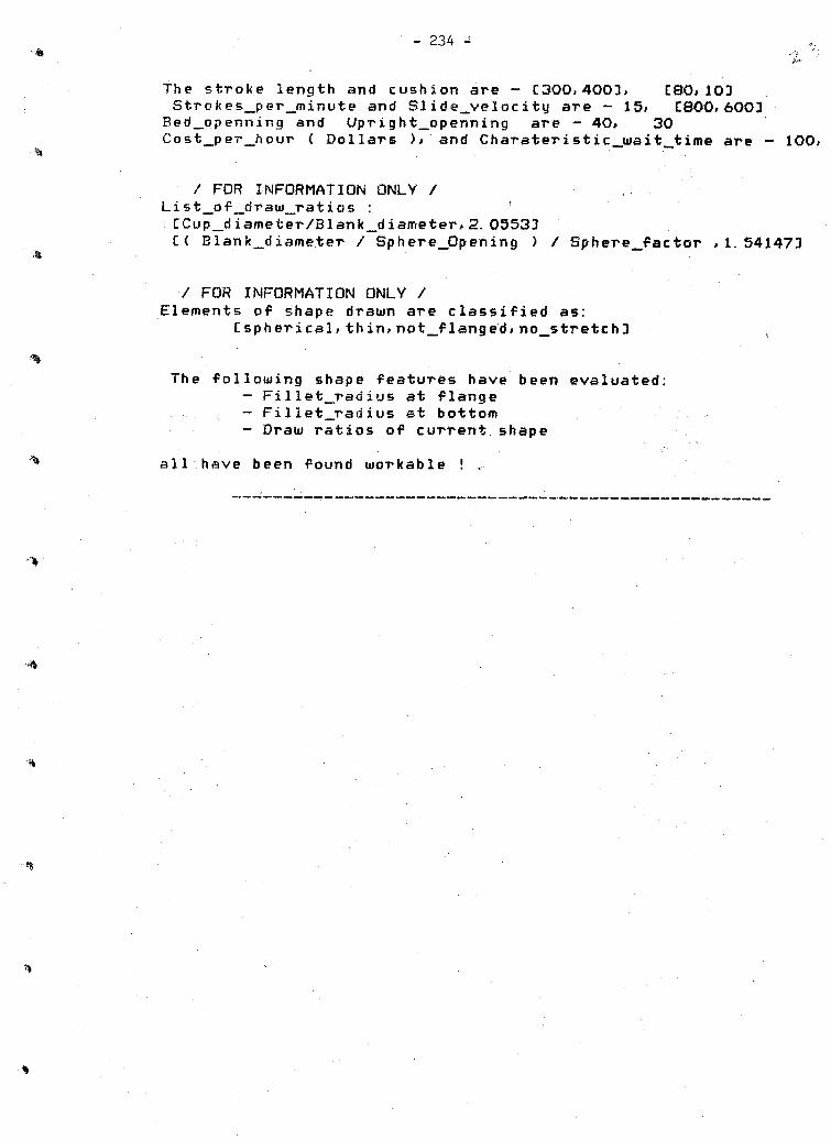
- 234 -
The stroke length and cushion are - C 300. 4003. C80,103Strokes_per_minute and SIide_velocity are - 15. C800, 6003
Bed_openning and Upright_openning are - 40. 30Cost_per_hour ( Dollars )» and Charateristic_wait_time are - 100.•%
/ FOR INFORMATION ONLY /List_of_draw_ratios : 
Advise About Part-2:
- 235 -
Desired Finished Part Specifications Part name is - part_2Required Material - CCst, 41303,C36, rc33
Finished Part Inscribed Within The Following EnvelopeThe structured form of the workpiece is
f, h> 1/2, 10, 15, 1,w, v, 1/2, 7, 5, 2. 1,b, rl, 1/2, 7, CIS, 43, 0,Quantity and Due date required - 400 units, 21 weeks from now.
The EXPERT has learned your required part.
Start of generating a feasible process for the part
The Candidate processes are -Cdeep_drawing, Cmain_process, draw!! Cdeep_drawing»redrawing!
Current Sequence of Processes And Shapes Tested -Process name — Cdeep_drawing, Cmain__process, draw!3Raw workpiece tested is of the shape of - BLANK
Its sizes are :Wall thickness - 1/2 Blank diameter - 27.2506
-— Next Process -—Process name — inspectionDesired Shape At end Of Process
f, h, 1/2, 10, 15, 1,w, v, 1/2, 7, 5, 2. 1,b, rl, 1/2, 7, C15,43, 0,
Feasibility Check For Generated Sequence of Processes Starts-Important intermediate findings will be reported by:
/ FOR INFORMATION ONLY /

/ FOR INFORMATION ONLY /The blank computed to produce the required shape is :
Blank wall tickness = 1/2 Blank diameter ~ 27.2506
Form of raw_material accepeted in this process is: flat
Violation of feasibility condition:Discovered in process: locate appropriate raw material in stockThe initial shape of this process is : exactly_blank_wtThe conditions that could not be satisfied: Too few sheetsDiscovered during: Computation of quantitythe EXPERT advises you to recheck your specifications.Freeeeding features and tests are in file: "kovez".

Chapter 5
An Expert System For Machine Selection of FMS
S. Lan

AN EXPERT SYSTEM FOR MACHINE SELECTION OF FMSSheree Lan
- 237 -
1. INTRODUCTION
1. 1 Background
The concept of flexible manufacturing systems (FMS) is very appealing to low volume and mid-volume manufacturing. In these types of manufacturing* both the productivity and flexibility of the manufacturing system are of major concern. An FMS consists of a number of numerical contrpl(NC) machines# a material handling system, and a computer control system. The machining system (NC machines) and the material handling system are automated and controlled by the computer system. By computer-integration of NC machines and the material handling system. FMS can easily adapt to different jobs and still achieve high productivity.
The design of FMS is a very Complicate task. It takes time from months to years. The design process of FMS follows theconfiguration—analysis—mod ificatioh loop iteratively until gooddesigns are found CBARA793. Most sources available in literature of FMS design deal with problems of using simulatipnal and analytical techniques for analyzing some known FMS designs. Very few. if not none, try to identify or formalize approaches needed to design initial configurations of FMS. The initial configurations of FMS have always been built up by some rules of thumb CKLAH831 and by designers' experience CIT082). If the knowledge of FMS configuration can be extracted from human designers and

- 238 -
put into the form of an expert system* then the FMS design task can be sped up significantly. These configurations then can be simulated or analyzed* and modified configurations obtained.
The most important component of an FMS is its machining system. Usually* this accounts for the largest expenditure of an FMS CLEWI733. Also* the configuration of the machining system has the largest influence on the capability of the system. It is felt that the configuration of machining system is the first step in FMS design. Once the machining system is configured* the performance of different material handling system? can be modeled and analyzed rather easily.
1.2 Statement of problem
This report is to describe the design of an expert system for machine selection of FMS. Machines under consideration are just generic machines. The purpose of the expert system is to decide the types and quantities of machines required to fulfill the manufacturing of some known products. Only prismatic work- pieces (workpieces in box shape) are considered. The information of product design and profess planning is assumed available.

- 239 -
2, SYSTEM ORGANIZATION
Th© designed expert system consists of four main components: role base# operation base* machine base* and stact base- The inference program looks for the adequate solution of machine combinations based on these four components.
2. 1 Rule Base
The rules are expressed in - tl^e(IF. . Then., ) form. Rules are put in a file and read by the program* which will convert the rules* and store them in a linked list. The, rules consist of "Simple fact" and defined "Function". "Simple facts" are less than 10 characters long words# represent the situation of certain stage or flag. "Functions" are eight characters long words specified by the knowledge engineer. They are coded in the program. users can only use defined functions while change rules. There are some attribute names for functions. Each attribute name represents one attribute in operation base. The program will recognize the attributes of rules and access the attributes information from operation base.
o o Operation base
For this system* the information of work contents is collected and put in a file which is accessible to the system. All required processes of all products are put in a table# attributed by their features# as shown in Figure 1. According to the defined format and order, users can input the operation data to

240 7
f>*\ the file, the system can recognize these data and put in a linkedlist of records.
2.3 Machine base
The machine configuration is changed when one possible rule is applied. The machine base links all operations in each group. The rules can easily apply to adequate machines and operations, change the operation base and machine base simultaneously.
2. 4 Stack base
The stack base is a record file, which keeps the inferencing procedure information. Any change in operation base, rule base, and machine base will be recorded, formalized in stack record and
• write to filestack. The stack base takes the advantage of various type of files in PASCAL language. The run time working space can be saved and backtracing is easier to perform.
3 5 Inference program
This is the program which checks the rules, searches for the one that the condition part is satisfied, and trigs the consequence action. The search of a satisfactory rule is done by the order priority strategy. To improve the efficiency of searching, rules are divided into two groups. and the configuration procedure is divided into three stages. The first group of rules are for the "grouping' of operations. The second group of rules manage to delete under-loaded machines and specialize well-loaded machines, so that a good combination is obtained.

- 241
2.6 Control strategy
The strategy selected is order priority# mainly’ because it is easy to implement and also it does not cause any'"'"confliction while using the system.
2.7 Information Management
The foie base is represented in IF. . THEN form. The simple facts are 10 characters long words. At the beginning of each rule# the global contexts can be present to represent repetition of operation type# horse power type# and special operation type. They are TO characters long words :
1. forallopty - for all operation types
2. forallhpty - for all horse power types
3. forellspop - for all special operationThe defined functions are 8 characters long followed by a The defined functions are listed as follows :
1. machloadt - machine load
2. machexisi - machine exists
3. transfer( - transfer load from machine one to machine two
4. attrload( - attribute load in a machine
5. attrexisC - attribute exists in a machine

6. attrtrant — transfer load for an attribute from on machine to another
7. defoptypt —define operation type number
8. defhptypt - define horse power type number
9. nofactext - no such fact exists
10. delefact( - delete the factThe attributes are represented as 8 characters long words followed by a '* ' and their ranges. The attributes are listed asfollows :
1. opertype - operation type* by a specific operation type
2. houpower - horse power* by lowerbound* to upper bound
3. spoperat — special operation* by a specific operation
4. wkspleng - workspace length* by range of length
5. wkspwide - workspace width* by range of wide
6. wksphigh - workspace height* by range of height
7. feedrate - feedrate* by range of feedrate
8. vrdemand - demand* by range of demand

- 243
3 KNOWLEDGE ACQUISITION• • . v
The knowledge required in selecting machines is the 'grouping' and 'combining' rules involved. Some of these rules are mentioned in journal papers and industrial magazines CKLAH833. Some of them are the result of the computer simulation runs, or from analysis. At this moment, only rules of the first type are used. However, it is possible to interface simulation or analytical programs with the rule base. All these rules can be explained by economic analysis from different levels. For examples, some rules try to eliminate machines with unsufficient loading, assign their work content to other machines. Some rules will reduce the flexibility imposed on the machine to impTpve the efficiency of the machine. The logic behind these rules is summarized in the following subsection.
3.1 Logic of machine selection
Selecting machines for some workpieces can be viewed as an function of matching work contents and machine capability. If the intended products for an FMS is known, then the process planning system will generate the processes required to manufacture them. Each process is characterized by some features, which are the implicit form of work content. Some of the important features are machine power, work space, degree of motion, and
type of operations.
Machine power required for operations can be calculated from process plans. Usually, higher powered machines are of higher

- ?Ak -
prices. It is expected to assign the work contents (operations) to appropriate machines* so that the operations can be performed under the best conditions (i.e. cutting speeds* feeds* etc. )* and also the machine is not overpowered.
Work space is concerned with the working envelop required while machining a workpiece. A machine over-facilitated of workspace not only cost the initial investment but also decrease the efficiency.
By degree of motion capability* it means the type of positioning and cutting motion the machine is able to operate. While under capacitated machines cannot achieve the work required* over capacity in degree of motion of machines increases the initial Cost,
Operation types include drilling* milling* boring* reaming* etc. One special type of operation is the multi—spindle operation. Machines specialized for multi-spindle operations are available* for examples* head indexers* head changers* and special drilling machines. Usually* machining centers can operate with small heads. For large-sized heads* head-changing machines are ..'required.
'i

4. EXPERIMENTAL RESULTS
4.1 Runs
Two illustrating examples have been run on this expert system and the results are analyzed. The sample run screen script file of Run 1 is included in Appendix. According to the program designing' the operation base can be added at some intermediate stage of inferencing procedure. The rule base can also be reset at anytime. Run 4 is a sample illustrating the operation base input at different stages. Run 3 is the comparing example of Run4. but input operation base all at once.
Irt Run l» there are 29 operations running. In first result combination, there is no machine horse power less than 10 of operation type 1 and 3 existing. If the user feel the cost of using machine horse power less than 10 is cheaper than using machine horse power between'10 and 20 , the user can go back to the stage that applying transforming from horse power less than 10 to horse power between 10 and 20.
In Run 2, there are 21 operations running. These operations do not have many type 3 operations. There are a lot of operations of type d in type 1 operations, and type f in type 2operations. The loads of these operations are comparatively less than
Run 1 data.
In Run 3, they are the combination of Run 1 and Run 2. The operations are input together at the beginning. The special

machines are introduced more than in Run 1 and Run 2.
In Run 4* they are also combination of Ron 1 and Run 2# but the operations are input at different time. The results are slightly different from Run 3.
4.2 Evaluation
The running time used is varied by the given operation data. The average time used to perform a 30 operations system is about 35 cputime. The backtracing will be more time - consuming* but comparing to human* it is still faster.
The user can change the rules i.e. total number of operation type* horse power ranges for machines* and the priority of rule order If the user has different grouping methods* he can also use the defined functions and attributes to implement his own rules-'.
The system can use several different rules at run time. The ruies change the context and apply different strategy as the user needed. Only one thing* the system does not check the ambiguous situation. The strategy is always rule order priority.
As we had shown above* the system can input operation at certain stages of inferencing procedure. Also* the system can keep the backtraced information in a file (filestack). When next time the system is called* the previous information is still there* and save computing time.

m, 5. CONCLUSIONS
The rule base we used in sample runs is a general rule for configuring. The smaller operation type will be grouped to larger operation type if it has low load. The lower hOrse power operation will also grouped to higher horse power machine if it has low load. So# initially# the larger operation type and higher horse power machine will be used as much as possible. The result i* optimal but when concerning efficiency may not be optimal. Thus# the certainty factors should be introduced here.
Since the certainty factors are not used in this system# the on line users should have some knowledge of their needs. The system will search the first combination. The rule applied and stack information can be backtraced. If the user does not like some machine being used# he can ask the system to go back to the stack number right before the machine is generated* or before the load of that machine is increased by transfering other machine load to it.
- 247 -

- 248 - . ■ , ..
REFEREES
CBARA793: BARASH. M. M. , et al. Optimal Planning of Computerized Manufacturing Systems. NSF Grant No. APR 15256. A Process Report. School of Industrial Engineering. Purdue University. 1979.
CBARR813: BARR. A. .Feigenbaum.E.A. . "The Handbook of Artificial Intelligence", vol 2. 1981.1982.
CHAYE833: HAYES-Roth. F. . Waterman. 0. A. » Lenat. D. B. . "Building Expert System". 1983.
CITO 823: ITO. Y. . et al. "Description of Machining Function in FMSm. and its Analysis". Proc. of MTDR Con.. 1982.
CKLAH833: KLAHORST. H. T. » "How to Plan Your FMS". Manufacturing Engineering. Sept. 1983.
CROFF813: KOFFMAN.E. B. » "Problem Solving and Structured Programming in PASCAL.”. Addison-Wesley. 1981.
CLEWI733:LEWIS,F. A. , "Some Factors Affecting the Design of Production Systems in Batch Manufacture". Proc. of MTDR Con. . 1973.
CMeDE813: MCDERMOTT. J. , "R1 The Formative Year". Al Magazine. Summer. 1981.

- 249 -
Figure 1 : Data Organization Table
Partid optype operation optimemin
workspacel*w*h
HPhp
tllnft
feedrate cuft/min
demon#/yr
OOOlOOOl 1 d 2. 37 3*4. 5*2 10 1.4 1. 56 200000010002 1 r 1. 65 4*5*1 15 2. 0 3. 44 200000010010 2 m 3. 00 1*1*1 30 0. 5 0. 11 200000020001 1 t 2. 50 1*1*1 15 1. 1 1. 22 120000030001 1 d 2. 90 1*1*1 25 1. 2 0. 90 900
Data specification :operation type : 1 - 2 axis positioning
2-2 axis contouting 3 - 3 axis 4-4 axis 5 - 5 axis
operation : d — drillingm - milling <2 axis and milling) t - tapping r — reaming
■I b - boringc - counterboring f — finish h - hole
operation time : (minutes / part)work—space required : L * W * H (cu. in. )horse power required : (hp)tool length : (in. )feed rate : (in. / revolution)demand : (yean demand)
maching loading ■*: total machine time / annual time per machine, annual time per machine *250 * 24 * 60 * demand

RUN ( - 250 -Script started on Tut Dec 4 04:49:57 1984 X ob}
This program will allow the users to
1) reset (change) "Inference Rule"» Its IFpart and THEN part. Only those "Simple Fact" and defined "Complicated Fact" can be used as the reasons. The rules are In order priority
2) Input operation data,
3) run the Inference procedure.
Please enter the option (1*2»3 or q) 1
What is the (simple fact) file name : filefact What 1s the rule file name 1 filerdle
This program will allow the users to
1) reset (change) "Inference Rule"* Its IFpart and THEN part. Only those "Simple Fact" and defined "Complicated Fact" can be used as the reasons. The rules are 1n order priority
2) Input operation data.
3) run the Inference procedure.
Please enter the option (1»2»3 or q) 2
Input operation data In a file (y/n)? y What i1 l e ? I an
This program will allow the users to
/^s
1) reset (change) "Inference Rule"» Its IFpart and THEN part. Only those "Simple Fact" and defined "Complicated Fact" can be used as the reasons. The rules are 1n order priority
2) input operation data.
3) run the Inference procedure.
Please enter the option (1,2»3 or q) 3

- 251
.Jhat stack number do you want to start with ? •Hease enter the stack number : 0
0.9 00 IF
stapeOnot actex(define)
THENdefoptyp(3) defhptypt3) define
1.000I F
attrex1s<opertype♦1♦0»0*0)
THEN a 11 r t ran(ope rtype * 1*0 » 0 » 0 »1»0 * 0 * 1•0 )2.0 00
1 F . a11rex1s (opertype*2* 0 * 0 * 0)
THENa 11 rt ran( Ope rty pe * 2*0*0*0*2*0*0»1.0)
3.0 00
a1trex 1 s(opertype* 3»0»0»0)
THENa11rt ran(opertype» 3*0*0*0*3*0*0*1.0)
A. 0 00 I 9
a11rex1s(opertype*4 * 0»0»0)
THENa11 rt ran (opert ype »4»0*0*0*3*0*0»1.0)
6.0001 F
nofactex(stagel)mac hex1s(-l»0 * 0) *
THENdelefact(stageO) de le f ac t ( de f 1 ne)stage!
7.000IF staoel
■ macbe x 1 s.( *»1 * 0 * 6 )attrex1s(houoower*0.0*l0.0»-l*0*0)
THEN ia 11 r t ran (hdupower»0.0*10* 0»**1»0*0 *“1*1*0* 1.0)■ft*.

- 252 -8.0 00
IFS t age 1attrexts(houpower*10.0,20.0,-1,0*0)
THENattrt ran(houpower,10.0 ,20.0,-l,0 ,0,-1*2,0,1.0)
9.0 00 ,IF
stapelattrex1s(houpower♦20.0,1000*0»-1*0*0)
THEMa 11 r t ran (h oupowe r, 20.0,1000.0 , -1■* 0,0»-1,3,0,1.0)
10.000IF
s t age 1
THENdelefact(stagel) s t age?
11.000IF
s't a ge 2is che x 1 s (1, -1,0 )* -■. nsch L oad(1,-1»0 * 0•0» 0•7)machload(2,-1*0,0.3,100.0)
ThentransferCl,-1,0,2,-1,0,1.0)
25.0 00 IF
stage?machex1s(3»1,0 )"i e c h L o a d ( 3,1,0,0 • 0,0.7 ) m a chload(4*1,0,0.0,0.3) machtoad(3,2,0,0.3,100.0)
THEN.transfer(3,1,0,3 ,2*0*1.0)
35.000 *. IF
stage 2machload(-1,-1,0,1.8,100.0)nttrloadCspooerat ,* ,-l»-l ,0,1.8,100.0)
THEN ’ .a 11 r t r a n (spooerat,*,-1,-1,0,-1,-1,*,0.5)
The result arrangements of oneratlons are :

253 -stack number; 13 rule applied : 35.000
*^35.000stage?machloadC-1»-l«0»1.8»100.0) a11rload ( spoperat»*»-1»“110 11.8>10O * 0 >
THENattrt rantsppperat♦*» 0»-l*-l»*»0.5)
1 00010001 12 00010002 13 00010003 14 00010004 15 00010010 26 00010020 17 00020001 18 00020002 19 0 002 0 0 03' 1
10 00020004 1n 11 00020010 2
2 00020011 V 213 00020021 314 00020031 315 00020032 316 00030001 117 00030001 218 00030002 119 00030003 120 00030004 121 00030010 222 00030011 223 00040001 124 00040002 125 00040010 226 00050001 127 00050002 128 00050003 129 00050020 3
(by parttool1d) load
0.728 0.5 56 1*750 0.519
0 0.5873 0 0.1033 0 0.7192 0 0.4882 t 0.3812 b 0.4833 0 0.7281 0 0.8002 0 0.6563 0 0.4532 0 0.659 '3 0 0.6251 0 0.6 043 c 0.4382 t 0.4152 b 0.4631 0 0.4583 0 0.2083 0 0.2293 c 0.0941 0 0*3023 0 0.66920 0.4632 t 0.1513 0 0.204
current existing ■ facts :1 stage?
current arrangement of operations oartld mach hp special
2 03 c3 0
machinemachinemachinemachinemachine
c h 1 ne machine machine machlne
1 2 0 include parttooUd1 2 0 Include parttooUd1 2 0 Include parttooUd12 0 Include parttooUd l 2 0 total load : J 1
1 2 t Include parttooUd1 2 t Include parttooUd1 2 t Include parttooUd1 2 t total load : 0.947
by machines) ••
00010001 load •• 0.728
00010004 load •• 0.5 19
00020002 load • •• 0.4 88
00050002 load ■ •• ' 0.463
197
00020003 t oad •• 0.381
00030003 load * 0.4150 C 0 5 0 0 0 3 l o a d • 0.151
machine 12b Include pa r 11 oo 11 d : 0 002 0004 machine 12b Include part too 11 d : 00030094 machine 1 2 b total load : 0.945
..achlne 13 0 include parttoolid : 00 01 0003machine 13 0 '1 nc lude . par 11 oo 11 d : 00010020machine 1 3 0 include parttoolid : 00020001machine 13 0 Include parttoolid : 00030001machine 1 3 0 include parttoolid : 00040001machine 1 30 include parttoolid : 00050001machine 1 3 0 total load I 4.095
machine 1 3 c Include parttoolid : 00010002machine 1 3 c include parttoolid : 00030002machine 1 3c Include parttoolid : 00040002 machine 13 c total load : 1.087
machine 2 10 include parttoolid 00020011machine 2 1 0 Include parttoolid : 00030001machine 210 Include parttoolid : 00030010 machine 2 1 0 Include parttoolid : 00040010 machine 2 1 0 total load t 2.165
machine 2 3 0 Include parttoolid * 00010010machine 2 3 0 include parttoolid : 00020010machine 2 3 0 Include parttoolid : 00030011machine 2 30 total load : 1.524
machine 3 20 Include parttoolid : 00020021schine 3 2 0 include parttoolid : 00020032
machine 3 2 0 total load : 1.316
machine 33 0 include parttoolid : 00020031machine 3 30 include Parttoolid : 00050020machine 3 3 0total load : 0.657
- 254 -load : load :
load J load : l oad : load : load : load 1
load : load : l oad :
load : load : load : load :
load : load : load :
load : load :
toad : toad :
Do yoii want to see the intermediate steps (y/n)? y
stack number t 0rule applied : 0.000
current existing facts : 1 stgqeO
current arrangement of operations (by parttoolid) : pertid mach hp special load
1 OOP 100012 000100023 000100034 ceo100045 CP 010 010
^6 00010020. 7 0 0 0200 01
:: 9. 0 002.00029 00020003
10 0002000411 0 P 0 2 0 010
00000000000
0 0 0.7280 0 1.1120 0 1.7500 0 0.5190 0 0.5870 0 0.1030 0 0.7190 0 0.4880 0 0.7620 0 0.9660 0 0.728
0.4830.463
1.7500.1030.7190.6250.2290.669
0.5560.4380.094
o.eoo0.6040.4580.302
0.587 0.728 0.2 08
0.6560.659
0.4530.204

A 715.00 0
s 13 fie 2maciiload(-l»-l»0»1.8»100.0) a 11 r l oad (s pooer at» * ♦ -1 ♦ -1 * 0 11 • 8 »10 0 • 0)
RUN 2. - 255 ‘stack number : 11rule applied: 35.000
THEMattrtranispoperat»*»-!♦-1»0»-l»-l»*»0.5)
current existing facts :1 stage?
current arrangement of operations (by parttoolld) :o a r 11 d mach hp special load
1 00060001 1 3 0 0.3482 CQ060002 1 3 0 0.0 693 00060003 1 1 0 0.4814 00060004 . 1 1 0 0.4125 00060010 2 1 0 0.4176 00060030 : 3 3 0 0.7837 00070001 ' 1 1 0 0.542B 00070002 1 o 0 0.7489 00070003 . ■ 1 ■ 3 0 0.382
10 00070004 1 2 d 0.332*11 00070005 v 1 2 d 0.293^12 0 00 70 0 1 C 2 1 0 0.37113 00070011 2 ■. 3 0 0.25914 0.00 70 050 ■ 3' 3 0 0.25115 00080001. ■ 1 2 d 0.287IS 00080002 ■ 1 2 0 0.77517 000B0003 1 3 0 0.4 7513 00030004 1 1 0 0.35019 Q0C6C005 1 3 0 0.40020 00030006 1 3 0 0.32521 00060010 '■V.,' 2 3 0 • 0.775
current arrangement of operations (by machines) •*machine i 1 0 Include parttoolld : 00060003 load •* 0.481machlne i 1 0 1nclude parttoolld J 00060004 l oa d •• 0.412machine i 1 0 Include parttoolid : 00070001 load • 0.542machine i 1 0 1nclude parttoolld : 00080004 load •• 0.350machine i 1 0 total load : 1.786
%machine i 2 0 1nclude parttoolld : 00070002 l oad • 0.74 8machine i 2 0 Include parttoolld : 00080002 load •• 0.775machine i 2 0 total load : 1.523
machine i 2 d Include parttoolld l 00070004 load •• 0.332machine i 2 d 1nclude parttoolld : 00070005 load •• 0.293mac H1ne i 2 d Include parttoolld : 00080001 load •- • 0.287
chine 2 d total load : 0.913
machine 1 3 0 1nclude parttoolld : 00060001 load •• 0.348machine 1 3 0 1nclude parttoolid : 00060002 load •• 0.069machlne 1 3 0 Include parttoolld : 00070003 l oad •* 0.382machine 1 3 0 1nclude parttoolld : 00080003 load •# 0.475

machine 13 0 Include part too lid : 00080005 load : 0*400 machine 1 3 G include parttooMd : 00080006 load : 0.325 machine 13 0 total load : 1*999
machine 2 1 0 1 nc l ude par tt oo 11 d : 00060010 load : 0*417 machine 21 0 Include parttoolld : 00070010 load : 0*371 machine 2 1 0 total load : 0*788
machine 2 3 0 Include parttoolld : 00070011 load 0.259 machine 2 3 0 Include parttoolld : 00080010 load : 0*775 machine 2 3 0 total load : 1*034
machine 3 3 0 Include parttoolld : 00060030 load : 0*783 machine 3 3 0Include parttoolld : 00070050 load : 0.251 machine 3 30 total load I 1*035
- 256 -

- 257 -
■N 35.000
stape 2machload(-l»-l»0♦1.81100.0 ) attrload(spoperat**»-l*-lt0*1.8»l00.0)
KON 3•tack number : 13jle applied : 35.000
attrtran(spoperatt**-l»-l»0*-l»-lf*»0.5)
nrrent existing facts :1 stage2
mrrent arrangement of operations (by parttooUd)■ r 11 d mac h hp special load
1 00010001 1 2 d 0.3642 00010002 1 3 c 0.5563 00010003 1 3 0 1.7504 00010004 1 2 0 0.5195 00010010 2 3 m 0.2946 00010020 1 3 0 0.1037 00020001 1 3 0 0.7198 00020002 1 2 d 0.2449 00020003 1 2 t 0.3810 00020004 1 2 b 0.4831 00020010 2 3 m 0.364
„2 00020011 2 1 f 0.4003 00020021 3 2 0 0.6564 00020031 3 3 0 0.4535 00020032 3 2 0 0.6598 00030001 1 3 0 0.6 257 00030001 1 1 0 0.6 04S 00030002 1 3 c 0.4 389 00030003 1 2 t 0.4150 00030004 1 2 b 0.4631 00030010 2 1 f 0.2292 00030011 2 3 m 0.1043 00040001 1 3 0 0 *2294 00040002 1 3 c 0.0945 00040010 2 1 f 0.1519 00050001 1 3 0 0.6697 00050002 1 2 0 0.4 638 00050003 1 2 t 0.1519 00050020 3 3 0 •0.2040 00060001 1 3 0 0.3481 00060002 1 3 0 0.0692 00060003 1 1 0 0.4813 00060004 1 1 0 0.4124 00060010 2 1 f 0.2085 00060030 3 3 0 0.7836 000700C1 1 1 0 0.5427 00070002 1 2 0 0.7488 00070003 1 3 0 0.3829 00070004 1 2 d 0.3320 00070005 1 2 d 0.2931 00070010 2 1 f 0.1'862 00070011 2 3 m 0.129

- 258 -
43 00070050 3 3 0 0.2514 <) 00030001 1 2 d 0.28745 0003000? 1 2 t 0.387^*\S 00030003 1 3 0 0.475't 7 00030004 1 1 0 0.3504 3 00030005 1 . 3 c 0.2004? 00080006 1 3 0 0.32550 00080010 2 3 m 0.387
current arrangement of operations (by machines) :machine i 1 0 1nclude parttoolld : 00030001 load • 0.604machine i 1 0 Include parttoolld : 00060003 load • 0.481machine i 1 0 1 nc lude parttoolld : 00060004 load •• 0.412machine i 1 0 include parttoolld : 00070001 load • 0.542machlne i 1 0 Include parttoolld : 00080004 l oad » -.• 0.350machine i 1 0 total load : 2. 390
machine i 2 0 Include parttoolld : 00010004 load •- » 0.519machine i 2 0 Include parttoolld : 00050002 load •• 0.4 63machlne i 2 0 Include parttoolld : 00070002 load •• 0.748machine i '2 0 total load : 1. 729
machine .1 2 d include parttoolld : 00010001 load •. • 0.364machine i 2 d include part too lid : 00020002 l oad «• 0.244machine ■i 2 d Include parttoolld : 00070004 load •o 0.332machine i 2 d include parttoolld : 00070005 load •ft 0.293machine i 2 d include parttoolld : 00080001 load ■ft 0.287machine i 2 d total load : 1. 521^chlne i 2 t 1nclude parttoolld : 00020003 load • ft• 0.381machine i n£ t Include parttoolld : 00030003 load •• 0.4 15ma c h 1 ne i 2 t Include parttoolld : 00050003 load ft« 0.151m a c h 1 n e i r>\£ t Include parttoolld : 00080002 load •ft 0.387machine i 2 t total load : l. 334
machine i 2 b Include parttoolid: 00020004 load ftft 0.483machine i 2 b Include parttoolld : 00030004 load ft 0.463m a c h 1 n e i 2 b total load : 0. 945
mac hine -t T 0 Include parttoolld : 00010003 load ftft 1.750machlne i 3 0 Include parttoolld : 00010020 load ftft 0.103machine i 3 0 Include parttoolld : 00020001 load ft 0.719machine i 3 0 include parttoolld : 00030001 load ftft 0.625machine i, 3 0 Include parttoolld : 00040001 l oad ftft 0.229machine i 3 0 include parttoolld : 00050001 t oad ft
■ ft 0.669machine i 3 0 include parttoolld : 00060001 load ft 0.346mac hine . i 3 0 1nclude oarttooUd : 00060002 load ftft • 0.069m a c h 1 n e i 3 0 Include parttoolld * 00070003 load ftft 0.362machine i 3 0 Include parttoolld : 00080003 load ft -ft 0.475machine 1 3 0 Include parttoolid: 00080006 load ftft 0.325machine i .3 0 total load : 5.694
m a c h 1 n e . i 3 c Include parttoolld : 00010002 load ftft 0.556machine i t c include parttoolld : 00030002 l oad ftft 0.438Mchine i 3 c 1nclude parttoolld : 00040002 l oad ftft 0.094
4 chine i-' 3 c Include parttoolld : 00080005 load ftft 0.2 00machine i 3 C total load 1.288
machine 2 l f 1nclude parttoolld : 00020011 load ftft 0.400machine 2,' l f 1 nc l ud e parttoolld : 00030010 load ft 0.229

•machine 2 1 f Include parttooUd : 00040010 load : 0 . 151n a c h 1 n e 2 1 f Include parttooUd : 00060010 toad : 0 ♦ 2 0 8nachlne o 1 f Include parttooUd : 00070010 l oad I 0*186""•'■chine 2 1 f total load : 1.174-nachl ne 2 3 m Include parttooUd : 00010010 load : 0 • 2 94machine 2 3 m Include parttooUd : 00020010 load : 0*364lac hi ne 2 3 *71 Include parttooUd : 00030011 load : 0.104eachl ne 2 3 m Include parttooUd : 00070011 load : 0.129machine 2 3 m Include parttooUd : 00080010 load : 0.387•achlne 2 3 m total toad : 1.279
nach1ne 3 2 0 Include parttooUd : 00020021 load : 0.656achlne 3 2 0 Include parttooUd : 00020032 load : 0.659ach1ne 3 2 0 total load : 1.316
ac hine 3 3 0 Include parttooUd : 00020031 load : 0.453achlne 3 3 0 Include parttooUd : 00050020 load : 0.204achlne 3 3 0 Include parttooUd : 00060030 load : 0.783achlne 3 3 0 Include parttooUd : 00070050 load : 0.251achlne 3 3 0 total load : 1.692

/■"N 3 5* 0 0 0i«
stage 2'rr a chto a d(~l9~l$Qfl*8tl00*05 attrload(spoDeratf*f-lf“lt0fl*8fl00*0)
T H 5 Mattrtr3n<spoperatf*f-lf-lf0t-lt-l?*t0«5>
RUN 4 - 260 -stack number l 23rule anplied : 35*000
current existing facts t 1 stage?
current arrangerrent of operations (by parttool 1 d)oar t id mach hp sped at Load
1 00010001 1 2 d 0.364c 00010002 1 3 c 0.5563 00010003 1 3 0 1.7504 00010004 1 2 0 0.5195 00010010 2 3 m 0.2946 00010020 1 3 0 0.1037 0 0 0 2 0 C 0 1 1 3 0 0.7198 00020002 1 2 d 0.2443 00C20003 - 1 2 t 0.381
10 0 0 0 .? 0 0 0 4 1 2 b 0.48311 0002 (3 010 2 3 m 0.364
,j$%2 00020011 2 1 f 0.4 00i 3 0 0 C 2 0 0 2 1 3 2 0 0.65614 00020031 3 3 0 0.4 5315 00020032 , 3. 2 0 0.65916 00030001 1 3 0 0.62517 00030001 1 3 0 0.604IB 0 00 30 0 02. 1 3 c 0.43819 00033003 1 2 t 0.41520 0 00 330 0 4 1 2 b 0.46321 . 00030010 oc. 1 f 0.229-> n <L C, 00030011 2 3 m 0.10423 00040001 1 3 0 0.22924 00040002 1 3 c 0.0 942 5 0 0 0 4 0 0 1 0 2 1 f 0.1512 6 0 0 0 5 0 0 01 1 3 0 0.66927 00050002 1 2 0 0 .4632 B 0 0 0 5C 0 0 3 1 2 t 0.15123 00050020 3 3 0 '0.2043 0 00060001 1 3 0 0.348•31 00060002 1 3 0 0.06932 0 0 0 6 0 0 0 3 . 1 1 0 0.48133 00060004 1 1 0 0.4123 4 00060210 2 1 f 0.20835 00060030 3 3 0 0.78336 00070001 1 1 0 0.542
00070Q02 1 2 0 0.74800070003 1 3 0 0.382
3 9 00 0 70 0 04 1 2 d 0.33240 00070005 1 2 d 0.29341 00070010 2 1 f 0.18642 0 0 0 70.0 11. 2 3 m 0.129

- 261 - ■
33 00070050 "'•33 0 0.251+4 00080001 1 2 d 0.287<5 00080.002 1 2 0 0.7751,6 000 80 0 03 ; 1 3 0 0.4 75»7 00080004 "-.'.■V. .-.I'-:". ■■■■; 1 0 0.350»8 00090005 1 3 0 0.400•9 00080006 / 1 3 0 0.325>0 00080010 ' 2 3 m id.387iirrent arrangement of operations (by machines) :■ chine 1 1 0 in clude pa rttoolld : 00060003 load : 0.481■chine 1 1 0 inetude parttoolld : 00060004 load : 0.412chine 1 1 0 include parttoolld : 00070001 load : 0.542■chine 1 1 0 1nelude part too 11d : 00080004 load : 0.350■ c h1ne 1 1 0 total load : 1. 7 86<cb1 ne 1 2 0 include parttoolld : 00010004 load : 0.519chine 1 2 0 include parttoolld : 00 050002 load : 0.463■chine 1 2 0 include parttoolld : 00070002 load : 0.748chine 1 />frl 0 I nc lude part t oo 11 d 00080002 load : 0.775ich1 ne 1 2 0 total load : 2.504chine 1 d include parttoolld : 00010001 load t 0.364chine 1 2 d include parttoolld : 00020002 load : 0.244chi ne 1 •O«c d in c lu d e par 11 o o11d : 00070004 load * 0.332chine 1 2 d in c 1 u d e part tool 1 d : 00070005 load : . 0.293chine 1 2 d Include parttoolid : 00080001 load : 0.287chine 1 2 d total load : 1• 521chine 1 2 t 1nclude par11oolid : 00020003 ■ load : 0.381chine 1 2 t Include parttoolld : 00030003 load I - C.415chine 1 2 t include parttoo lid : 00050003 load : 0.151chine ;i 2 t tOtat IPad * 0• 947:chine i 2 b Include parttoolid : 00020004 load I 0.483chine i 2 b include parttoolld * 00030004 load * 0.463chi ne i 2 b total load : 0. 945c hi ne l .3. 0 include par t tool id : 00010003 load * 1.750chine i 3 0 include parttool1d : 00010020 load : 0.10 3chine i 3 0 Include part toolid : 00020001 load : 0.719chine i 3 0 Include parttoolid : 00030001 load : 0.625chine i 3 0 include parttoolld : oo 03 oodi load : 0.604chine i 3 0 1h clud e pa r t too tid * 00040001 load * 0.229chine l 3 0 inc lude part too 1.1 d : 00050001 load : 0.669chine i 3 0 include parttoolld S 00060001 l oad : 0.348chine i 3 0 include parttoolld : 00060002 load : 0.069chine l 3 0 1n clude part t oo 1id : 00070003 load : 0.382chine i 3 0 include parttoolid : 00080003 load : 0.475chine l 3 0 include parttoolld : 00 08 0005 load : 0.400chine l 3 0 include parttoolld : 00080006 load ; 0.325chine . l 3 0 total load * 6. 698chine i 3 c Inc lude part too 1id : 00010002 load J 0.556chine . l 3 c Include part too lid I 00030002 load : 0.438**bh1ne l 3 c include parttoolid : 00040002 load : 0.094chine i 3 c total load i 1• 087chine 2 1 f include parttoolld : 00020011 load : 0.4 00chine 2 1 f 1nclude parttool1d I 00030010 load : 0.229

.71 a c h 1 ne machine iti a c h 1 ne
h 1 ne
mac hi ne. machine machlne machlne mac hine machine
machine machlne machine
machlne machine machine machine m a c h 1 n e
1111
f Include parttoolld f 1nclude parttoolld f Include parttoolldf total load : j
- 262 -
3m Include parttoolld Include parttoolld Include parttoolld Include parttoolld Include parttoolld
m total load : i,
m 3 m 3 m. 3 m
3 2 0 Include parttoolld3 2 0 Include parttoolld 3 20 total load : i
3 3 0 Include parttoolld 3 30 Include parttoolld 33 0 Include parttoolld 3 30 Include parttoolld 3 3 0 total load : j
: 00040010 load :: 00.060010 load :00070010 load :17400010010 load :00020010 load :00030011 load :00070011 load :00080010 load :27900020021 load :00020032 load :31600020031 toad :00050020 load :00060030 load :00070050 load :
16 92
0.1510*2080*186
0*2940.3640.1040.1290.387
0*6560.659
0*453 0*2 04 0 • 783 0*251

RULES - 263 -
0.9IFstageOnofactex (define)END IF THENdefoptyp(3) defhptyp(3) define ENDTHEN 1IFa11rex is<opertype»1♦0i010)ENDIFTHENattrtran(opert>-pe»l»O»0«O»lfO»O*l.O)ENDTHEN2IFattrexis(ooertype»2*0»G*0)ENDIFTHEN•attrtran(oDertype*2*0*0».0t2*0*0»1.0)ENDTHEN3IFat trex1s(ooertype*3f0«0*0)ENDIFTHENattrtran(opertyDe*3.0»0«0»3»0»0»1.0) ENDTHEN4IFattrex1s(opertype»4»0»0t0)ENDIFTHENattrtran(opertype*4*0*0*0»3t0*0»1.0)ENDTHEN5IFattrex1s(opertypet5»0.0»0)ENDIFTHENattrtran(opertype»5*0»0*0»3*0*0»1.0)ENDTHEN6 > , foraltoptyIFnotactexCstagel)machex1s(-l»0»0>ENDIFTHENdelefact(stageO) delefact(def1ne) stage 1 ENDTHEN 7fora 11op ty IFstagel

f** \
marhex1s{-l*0*C)attrex1s(houpower*0.0»l0.0,-1,0*0)EMDIFTHENattrtran(houpower»0.0*lG.0»-l*0»0*-l*l,0*1.0)ENDTHEN«foralloptyIFs t a g e 1attrex 1s(houpower*10.0*20.0*-l»0*0)END IF thenattrtran(houpower*10.0*20.0,-1,0*0*-l,2,0,1.0)F N D T H L N9 , . . >to ratloptyIF 's t agelattrex1s<houDower*20.0»l000.0»-l,0»0)END IF THENattrtran < houpo we r♦2 0.0,1000.0,-1,0 * 0 * -1 * 3 » 0 * 1.0) ENDTHEN10 IFstapelENDIFTHEN ' ' ,deletact( stage!) stage?ENDTHEN11torallhptyIFstage? 'machex1s(l»-l*0) machload(l*-l*0*0.0,0.7) machtoad<2,-1*0*0.3*100.0)E N DIF THENtranster(1,-1,0,2,-1,0 *1.0 )L ND THEN 12to ra 11hot yIE k . .stcge2-machex is(2 »-l* 0)macnLoac(2*-1,0*0.0*0.7)machLoaa(3,-1*0*0.3*100.0)EMDIFTHENtransfer(2,-1,0,3,-1*0*1.0)EMDTHEN13torallhptyIFstage 2 ■ma che xis( 3 »-1 * 0)machload(3,-1,0,0.0*0.7)
- 264 -

mac h l o ad (4 * -1 *0* 0.3*100.0)ENDIFTHEN
’.transfer (3*-1*0*«,-1,0 *1.0)EMDTHEN14forallhptyIFstage2machexis(4»-l,C)mac hload(4 *-1 * C * 0.0 * 0 • 7>mach load(5*-1,0*0.3*100.0)END I FTHEN.-transfer <4,-1,0*5 *-1*0 *1.0) ENDTHEN 16 ■IFstage?machex 1s(1,1»0)mach load(1,1,0*0.0,0.7)ma c h l o ad (2 * 1 * 0 * 0 • C * 0.3)mach load (■1*2*0*0.3*100.0)ENDIFTHENtransfer(1,1«0,1,2 *0,1.0) END!HEN17 IF ■ stage?machex1s(1*2*0) machload(1*2*0*0.0,0.7) mach Load(2*2,0*0.0*0.3) machload(1*3*0*0.3*100.0) ENDIF THENtransfer(l*2»Q»l*3*0*l.Q)ENDTHEN18 IFstage?machex i s (1»3*0) machload(1 * 3 * 0 *0•0* 0•7) machload(2*3,0*0.0*0.3) machload(1*4*0*0.3*100.0) ENDIF ,THENtransfer(l*3»0*l»4,0*1.0)FNDTHEN19IFstage?machexIs(1*4*0)machload(1*4*0*0.0*0.7)machload(2*4,0*0.0*0.3)-ma ch l.o add, 5* 0*0.3 *100.0 )■ ENDIF -THENtransfer (1*4 *0 *1 *5-*0,1.0)ENDTHEN

staae2irnchex is (2* 1* G) machload(2*1*0*0.0*0.7) machload(3«l*C*0.0*0.3) m a c h l o.ad (2« 2 * 0 * 0.3 * 10 O • 0 )END IF THENtranster<2*l*0«2*2*0*1.0>ENDTHEN 22 IFs t a g e 2,ri£ichex1s(2*2»0) mciChload(2*2»O*O.0,0.7) roachload<3*2*0*0.0*0.3) it, achlo ad (2*3*0*0.3*100.0) END] F THENtransfer(2»2»0»2»3»0*1.0) ENDTHEN 2 3 IFstage?machexis(2»3»0)machload(?*3*0*0.0*0.7)roachloaa(3*3*0»D.0*0.3)rnachlo ad(2*4*0*0.3*100.0)END IFTHENt ra nsfer(2*3«-0*2*4*0*1.0)ENDTHEN24IFstage?machex1s(2*4*0)mach load <2* 4* 0 «,0.0 * 0.7 )roachlo a'd(3*4»0»0.0*0,. 3)mach load(2 * 5» 0 « 0.3 * 100.0)END IFTHEN,trnnsfer('2*4*0*2»5*0*1.0)ENDTHEN 2 5.IFs t a g e 2machexis(3*l*0)machtoad(3 * 1 * 0«0 * 0 * 0.7)mach load( 4 * 1,0.0.0 *0.3)mac hto ad (3» 2 » 0 * 0.3*100.0)ENDIFTHENtransfer(3«lf0*3»2»0*1.0)ENDTHEN26IFs t a g e 2machexis(3«2*0) rnachlo ad (3*2*0*0.0*0.7-).

machload(4«2*0 *0.0*0.3) mac hload(3*3*0*0.3*100.0) END I F THE Nt r a n-s f e r (3 » 2 * 0 ♦ 3 * 3»0 * 1.0)ENDTHEN27IFs tage2mac hex 1s(3♦3»0 )rnach load (3« 3* 0 »0.0» 0.7)machload(4» 3» G♦C•0 * 0•3)machlo ad (3*.4 *0*0.3*100.0)END IFTHENt ransfer<3 *3*0*3*4*0*1.0) ENDTHEN
' 28 IF . staae2mac hex is( 3*4»0)ma c hlo ad(3 * 4 » 0 » 0•0 * 0•7)mac hload(4♦4♦0 »0•0 ♦ 0•3)maxhlo ad'(3*5*0*0.3*100.0)END IFTHENtransf er(3* 4 »0 *3»5*0* 1•0) ENOTHEN30IF , istage2machex1s(4*1*0)machload(4*1*0.0.0*0.7)machload(5«1*0»0.0*0.3)machLoad(4.2*0*0.3*100.0)ENDIFTHEMt ransfer(4*1*0»4,2*0»1.0) ENDTHEN31 IFstage2machexis(4*2*0)machtoad(4*2»0*0.0*0.7)m a c h l o ad ( 5 * 2 * G * C • 0 ». 0 • 3 )machloacj(4«3*G*0.3*100.0)ENDIFTHENt r an s f e r(4 * 2 * 0 * 4 » 3» 0 * 1... 0) ENDTHEN32 IFstacje2machexis(4*3 * 0)machload(4*3*0*0.0*0.7)m a c hi o ad (5 * 3 *0 *0.0*0.3)ma c hiLoad ( 4 * 4 * G * C • 3 * 10 0.0 )ENDIFTHEMtransfer(4*3*0* 4*4*0*1.0)

CNDT HEN- 33IF . . -
. s t <: g e 2mathexis(4,4♦0 ) machLoad(4«4*0 *0»0,C.7) ma c hload(5 * 4«0 « 0•0 * 0.3) mac hload(4♦5 * 0 * 0<.3»100*0)
. END IF THEN -■transfer <-4»4*Q*4*5»0*1.0)
ENT, THEN- 35 :• : ' ./
f o r a 11 op t y t ora 11 hot y fora 11spopIF - 's t a c, e 2marhload(-1♦-1,0,1.8*100.0)e 11 r load( scoperat ♦* *-l »-l * 0 *1,8 ♦ 10.0 *0 )E ND IF - -
' 'THENattrtran<spoperat »0 t-1 ♦-1 ♦ ** 0 *5)ENDTHE N
- 268 - O
t

Profrr&M
StartTnfetniWs o-*<i
£eti«ct stack w«*W
trkxck Aiumker a*d mxI yi*Il*tt*l*r

Chapter 6
PROLOG EXPERT: A Simple PROLOG based Expert System Framework for
Synthesis, the BAGGER Problem as An Example
T. Sarjakoski

- 270 -
PROLOG EXPERTS A simple PROLOG based Expert System framework for synthesis* the BAGGER problem as an
example •
Tapani Sarjakoski
1. IVlROQyCTIONThe design of this system 1s motivated by my research'•■■Xpert ' system for analyzing photogkammetric measurement
DATA": I noticed that there is a great resemblance betweer my research and the BAGGER. The BAGGER suited well as ar example-1 .problem to develop a simple EXPERT SYSTEM framework.
As stated above* my research deals with analyz1 ng photoaran- metric measurement data. On the other hand* the BAGGER is an example of synthesis* How can there be anything in coir- mon? there 1s* because the task of analyzing photogram- metric measurement data involves also synthesis: The task is very much computation oriented and it Vs thus critical that there is a plan of the secuence in which the computations w1ll bi carried out. On the other hand* the BAGGER alsc inctuaeS'soiiie features of an analysis system: 1t has tc decide* for example* it a bag is already full.In the following i have hot expanded the BAGGER example as Such out I have designed a simple PROLOG based framework for synthesis. It is not limited for BAGGER example and coulc be used tor example to implement my own problem.
?. GYSfEM ORGANIZATION :
2.1. Remarks of PROLOG and its usage
The PROLOG is as such already a fairly powerful tool for Logic programming: Facts and rules can be entered in s straightforward manner because the PROLOG interpreted is actually a realization of a systern ut111zing Clausal Form of Log 1c.-;■
The first Implementation of the BAGGER 1s a good example c1 using PROLOG directly for building an Expert System. The subseouent: phases of the 8AGGER ’can be rea11 zee as a simple prolos clause:.

;
I■;
11'
i
run_bagger
271 - m?
chec k^order^phase* .yo; :yf¥f:bag_large_1tems_bhase* -Vo;" \Vv AjpA, bag^medium^ltems_phase» bag_smalt_items phase*
The context limiting 1s now .realized In a very simple way: by writing a procedure tor each phase. Because PROLOG interpreter -satisfies the goals from left to right it actually assures a tixea order of execution*
The .complete listing of the first implementation of the ?.AGG£« is in Appendix BAGGERl* I consider that it shows very clearly that an Expert System can be written in PROLOG very easily by using a conventional procedural approach^ However* there is missing one feature which is usually considered to be an essential part of an Expert Systeih: er Explanation Facility*
, ' - ' . . ' . , -y.EY: •- ..yry?'. ■ ■In the following is described another PROLOG approach Which is called PROLOG EXPERT. It is a kino of framework whiC-ih is also supported by a simple explanation facility* "eXfi laian".
2.2. Knowledge re££esentatigg PROLOG EXPgRT-
*>£•1* L££i.s
%’M
The facts are represented by using PROLOG clauses, for exarr- 1 e:unbagpedlbread)• container ( bread *.plast 1 c_bag ) . sipe(granola*large)*tro7en(bread *no) •trozen(ice_crearn*yes) .
All the facts are considered to be HOARD of the PROLOG EXPERT1*.
The total set of facts for the BAGGER example are listecl ir the AOoendix BAGGER. FACTS.
£*■£•£• ' EeJLee yyyoThere are two kincs of rules which can be used in PROLCG t xBER T : main rules and auxit 1 ary rules.
' a in rules are written as PROLOG clauses and have the Syntax
rule(CrulenameX) <cond111ons>* then*<acttons>. >tec example y-y-yY---
rule(hi):-
/••LA . •"a".
located on the BLACK
Vyy

step(check_order)» unbapgedCpotato_ch1ds)t soft_dr1nk(X)» not unbagged(X)«
then •add^unbaggedlpeosl).
The Inference machine has access to this rules
Auxiliary rules are also written as PROLOG clauses. As e matter of fact they can be any PROLOG clauses. The auxiliary rules are accessed by the main rules* either as conditions or as actions* for example in the rule(bl) we have usee the auxiliary rule
arid^uhbdggedl X> ;1“ ywrit e_on_black_boa rfl(unbagped(X > > * pr intst r?no( " ^ < ")»pr1nt(X)*prIntstringl" added .•.")*nl.
N’oie! The print-commands are Included only for cfferine some*^ progress;5 InformatIon for demonstrating the run of the PROLOG EXPERT in solving the BAGGER example.
It sotekaUxIliary fules are used as conditions they can be Interpreted as "dehived tacts”.
There are two impohtantbrocedures which must be used In the action parts of the main rules lor in the auxiliary rules if these are then used in the action parts):
wr ite^on.b lac k_fboard (< tac t>)■ and ■
r emOve_,f r om ( < f adl>> •
They allow the user to add facts to or remove facts from the BLACK BOARD.
£.2.5. Explanation^
For each main rule the use has to enter also an explanations Tne syntax for it is as follows:
exPlanation(<rulOname>»X) :^X = C C"1f"*
" < e x p lanation for c ondit ion 1>"*
•*<explanat1on for condition n>BT*C“then"*
•*<exp lanat 1 on for action !>”♦

The exDlanation is rule in English* facility*
"<explanation for action
used for c lar if ying the ffieani rig of ; t he It can be displayed with the Exglanirti cr
.■ ■■ . . ■ - •v ■'.> -T’-s;fill the main rules* auxiliary rules and eXbtanations : arf listed in Appendix BAGGER RULES* • :. c':'/
2*3. Inference MachineThe Inference Machine of the PROLOG EXPERT w^ooLd ■: toe: ^¥al ly Simple if no history would be collected of the applicatior of the rules:
proloo^expert:-repeatapp ly__ru leC Rule^name) » step(stop)*
eooly_rule(Rule„name )rule (Rule__name)» !•
vhat actually would happen when using this i t-nWf^n ce Machine* is that poets •
r ul e (Rul e_name > and step(stOD)
would oe tried to be satisfied repeatedly until the goat s t er (stop) . ‘-i’ll''-
is satistied* This means that the user can stop the Infer- ence Machine by adding the fact
step(stop)*to the BLACK BOARD*
Because of the way PROLOG interpreted searches trough the note base. "Prolog expert" will always apply Rule Ordering Tor Conflict Resolution* It must be noticed* however* that Specificity Ordering and Size Ordering can actually: be implemented by using Rule Ordering - simply by ordering -the rules properly in the data base. ,
The actual implementation (listed in Appendix PROLOG EXPERT> *p only slightly more complex because it generates a list of ite noplication of rules: Following facts are saved each time .a rule ti res : • * . :

- rOte name ■- list: of fac ts removed f roni t he BLACK BOARD- 11st of facts addjed to the BLACK BOARD
The history 11st 1s stored as a fact on the BLACK BOARD. Additionally* two more facts* ‘"additions*' enc "removals", are ured to pass the information of actions on BLACK BOARD from of*bcedures "w:r 1 te_pn_black^board" and " remove_.f rom" tc the orotedure "op_oate_historyi.list'’*.
The Inference machine does not control the application of the auxiliary rules* nor does it collect any history cf -their applicat ion. •
?.4. Ejxg: l an a t jp p f a cl l it y
Once th# PROLOG EXP|RT has been run* the history of the application of the rules can be Investigated by using the explanation facility "explain". It allows the user to scar the history list forwards and backwards. For each applies- . tIon of a hule it is possible to display the actions on the BLACK BOARD as well as the '-explanationand the rule itself.
The explanation facility is listed in Appendix PRCLCG EX p CRT / EX PL A IN .r 'Add it Iona 11 y» 1 ts functions wl tl becomevery obvious by looking at the example run at Appendix EXAMPLE RU\U '■■■;'/' '/
3. . rnTTI^G RULESr AND FA£I£ ■
The rules and facts are stored In normal text files. They can be manipulated by conventional text editors. No special system if des 1 gne« vfor erterlng::ruIts - and facts. I feel that it is quite an adequate solution. Especially* because the rules and facts Can be split into several files accorc- ing to the context. The string-search capability of the editors is very useful. The user has to take care of the oroper Ordering of the rules•a. Eonning SXsjfcEFor running the system it is necessary to start the PROLOG interpreter and load the PROLOG EXPERT as well as the case- dependent facts and rules Into the PROLOG data base*
For the BAGGER example following parts must be: loaded:
-general routines’^ike "append"* "member"♦ "print- string" ' ; \-"prolog_expert" and "prolog_expert/expla1n"
-the facts and rules of the problem

f
i!-
- 275 -
-the initial facts which also have to be on the BLACK BOARD (the ones of BAGGER are listed in Appendix INI-
. TIAL FACTS)
The possible syntax errors of the rules and facts wilt be discoverec by the PROLOG Interpreter*
The problem can be solved by keying in the goat "rrolcg_expert". The Output of the proqram is listed it Appendix EXAMPLE RUN. , h
Or-ce .the. program has been finished* the final state on; the -LACK BOARD can be investigated by using for example PROLOG ■commands I
Iist1ng(1nit1ated_pag>.
listinu(numper_of_bags). " a'
11 s ting(unbapped)•
ft the moment, no more sophisticated tools have been built for that purpose. "
ine explanation facility can be started by keying In the coal "explain". The progress of the explain facility is very much self-explanatory which can be noticed from Abien- dix EXAMPLE RUM.
...h- discussion . ;2*i« ;■ EfiDLOG os a basis for oujUdina an EXPERT .SYSJEM
fs pointer! out already in'.the; introduction. PROLOG is a very sii 11ole tool for building an problem solver with, an essence ot an Expert System. This is demonstrated by BAGGERI. In a st r a ic,ht f or w ar a approach no explanat ion f a c 111 ty 1A of fere c .
As the Implementation of PROLOG EXPERT shows. it is relatively easy to design a simple framework for rule-HAasecExpert System with a simple explanation facility. Hdwiefeer.the framework obviously poses some restrictions, pcf ole, the contribution of the "auxiliary rules'* Oh the Ablution of the prob lem does not show up in the history. It 1s possible to replace the "auxiliary rules* by writing corresponding "main rules" which add the derived facts fcrruler. - to the BLACK BOARD. But then we lose something ofthe expressive power of PROLOG: It is very natural tcexpress /the derived facts in PROLOG as Horn clauses, haylnc the conclusion on the left hand side and the conditions or the- right hare side.

276
£•£• £fisi£Cail££ b£tw££Q iiEart SxsiaiQ sea araaadarjji
It seems beneficial to implement some portions of an Expert System by using conventional procedural approach* This holds especially for the low-level operations of an Expert System* for example In the BAGGER it was very natural tc write the procedure (or auxiliary rule) "start_fresh_bap"» even 1f 1t would be possible to implement ft by using mair rules. Analogically* it is very natural to write FRGLCG clause for "full bag"*
These low level rules (derived facts* rules and actions) car be catted "elementary conditions" and "elementary actions". They would* on a way* define a case-dependent language* which is reasonably static for the problem. It also has tc pc welt defined* for example the BLACK BOARD actions must well known Also* all the people being Involved with the case have to know and understand the elementary operations.
£.3. *ore about thfi Explanatjog Faci11tyFor clarifying the explanations* I have used the technique of writing separate explanations for each rule. I consider it useful* it allows the usage of liberal* comment-like explanations* Of course* the is a danger that the explanations do not correspond to the actual rules* Lack of explaining the application of the auxiliary rules, is a drawback in the current Explanation Facility.
5.4* Interaction
The current BAGGER run as a pure batch process because all the tacts are considered to be given at the moment of starting the ITAGGER* It would be possible to add rules for asking tor more facts* In such a situation a more versatile Exolanation Facility would be useful for answering to cues- tions lIke WHY?*
I • 2 • ' • LSSjaiCS l££':- -2£g.L '-
In the Current realization of PROLOG BAGGER there 1s a possibility that ^ run in a loop for ever* due to improper set cf rules for solving the problem* It wculc be relatively simple to expand PROLOG EXPERT for covering that situation: If no rule fires or the firing- rule has not caused any changes on the BLACK BOARD* the program is in an infinite Loop and must be interrupted* Automatic entering of the Explanation Facility and the user possibility tc modify the facts would be a nice feature for debugging purposes.

APPEND"* X A . example run ot the first version for solving the BAGGER problem
Srrint started on Sat Jan 5 18:55:03 1985 1 orologCf’rolog version 1.3 I ?- lstart 3*editor consulted 578 bytes 0*116667 sec* appends consulted 120 bytes 0*0666671 sec* member 1 consulted 148 bytes 0*05 000 08 sec. start consulted 8M bytes 0*316667 sec*
yesI ?- Cos gel ]. r -bag pi consulted 76 0 0 bytes 1*6 sec*yes| ?- run_bayper*
Bag per starts checking the order
< neosi > added Into the list of unbagged items
Pacoer starts bagging large items
< peosi > is placed In bag number < 1 >< granola > is placed in bag number < 1 ><-granola > is placed in bag number < 1 >
b taper starts bagging medium items
< ice-cream > 1s put in an insulated freezer bag< bread > is placed in bag number < 2 >< ice-cream > is placed in bag number < 2 >< po.ta t o_c h i ps > is placed in bag number < 2 >
Bagger starts bagging small Items
< plop > is placed in bag number < 2 >
. > c sI ?- c at( baag 1) • ur,bagged (bread ). unb’acge ci ( c l op) • u f ■ p a g g e d ( c r a n o l a ) *unbagged(era no la ) • .unosciied ( i ce_c ream) •'bagged (pot a t e„ch 1 ps ) •
container (bread*r'last1c_bap) • ' rentainer(glop•jar>. centainer(granola *carcbosrd„box)• c ont o 1 ne r (1 ce_c re am *c ar dbn rd__ca r t on) • c or. t a i n? p(oepsi*bottle) • r c n t o'iner ( pot a t o_ch ip s» o l sst 1 c_bap > •

278 -:0 size (breadf medium)*:U- S12 e (gtopt Sma l l ) • ■s1ze(granolatlarge)* s1ze(1ce_creamtmed1 urn>• s i ze(Depst»larpe)• s1ze(Dbtato_ch1ps»meoium)«
t rozendbreaeUrio) • trozen(gloptno)• frozen(grandla»no>• t rozend ce_cream t yes) . t rozen(peps 1 t no) *. t rozen<pot ato_chips tno)•
s o t1 _p r 1 n k (p e p s 1 ) •
run_bagger i.»check_orderwphaset bag_,ta rge_1 tems_phase« bag^medium_1terns_phase* bag_small_1tems_phaset! •
check^order_phase I- n l *pr intstrir.a("Bagger starts--checking the order")»nlt nl»cheek_order*. ,
check^order t~ /* rule B1 */unbaggedCpotato^chlps)* soft^drlnk(X)♦ not unbapged(X)t add_unbagged(pens 1)t check^order*
check_oroer ;- !• / * rule R 2 */
?rio_unbagaed(X) :-a s s e r t a ( u n b a a y e d ( X )) t pr 1 n ts t r 1 np ( " <■">•♦■print(X) t 'p r 1n t s t r 1 ng ( " > added into the 11st of unbagced items*')
check_select1on *- !« /* this 1s a dummy rule tor assuring that'.*//* »check_selec11 on * does not fall */
lbeg„.targe_1tefns_phase I- nl»pr int st r Ingl^B agger starts bagging la rge 1t err s* ) »r lt nl»bag^large_1terns♦ !•
bag^rred1um„1tems—phase t- nitpr lot st rlnq ('"Bagger starts bagging medium 1 terns." ) tn 11 nitbag^meoium_1temst! . “
Dag_smail_1tems_phaSe;:-

'0f%'
y---
n l ♦prints tring <"Bagger starts nl V ■ ?;■bag_.smatl._1 terns*! . . ■ ~
bag_large_items:*unbagged(X) ♦ size(X*Large)♦ container (X*bottle)*
■ items Numberput_item_in^bag(X»Bag^numba.,, bag_large^1tems*
' ■ ' ®::;'oag_larae_iterns
unbagged(X)* s1ze(X*Large)♦
Ifg* :"W;yrW1I®k
S-:'' ■- •!.'■yj :■MbfiW.":’-yy --my
;&eirs" ) »r t ♦
rc l e B2 */
3iner (X ,bottle) *5_in_bap(Bag_number» targe*Number)* .
itern_in bag(X *Bag_number) ♦
ft-.......... ■
items_in_bag<Bag_number*targe♦Number)*Number < 6* put_.it em_in_bag(X VBag_number) ♦ bag_large i terns.
V/7l
bag_tarpe._1 terns :-unbagped(X)♦ size(X * large)♦ start_fresh_bap» bag_la rae_iterns.
Deg_large_iterns !*
7/ ,v- .-•••■ftl®/. ■■ ;/*:; rule 65 */
;'Sft :■■ .
/* rule Bfc */. ■■ /: v ■ ■ • .■
/* rule B7 */oap_med1um_1ternsunbagged(X)* size(X*med1um)*empt y_bag_pr^.bag^wi th^mediumyl terns (Bag_nufnfber ) * not_tutt_bag(Bag_number) * *”
. trczen(X.yes)• not insu tated(X)♦ put_1n_1nsutateti_.freezer_bag<X> ♦ bac_med1um_1terns•
nag_medi um_i terns /* ruLf Pf */unbagged(X)♦ size(X*medium)•empty_bag_or_bag_wi th_medium^iterns (Bag_number)» not_1ull_bag(Bag_number)* ^ ~put_1tem_tn_bag(X*Bag_number)♦ bag_itiedi um_i tems *
oeg_metii urr_1 ternsunba'cged(X) ♦ s1ze(X♦medium)« start_fresh_bag* bag_medium_iterns•
!'l-ig_med1um_1tems .
r.,-'p._p'i!3 11_1 ternsunbagged(X)♦ s 1 ze(X♦smat t)*
• .. ft'ft-''
I*;,BS */
■ ^ ..
-v
/* rtrie BIO */
/* rule B11 *7

:■■■, . - 28o - ■■not^full_bag(Bag_number)«not conta1ns(Bag_numberYbottle)♦Put_1tPm.,l.1n_:bag(X ♦Bag_number) ♦
b e gsma-tlItems>;.:>"“ v'-; :■ . ■ /* rule B12 */r;:. ■■■ unbagped(X)»
V-.:-bdt^sfu tt^bag<Bag^nufflber) * out^ltem_1n_baa(X♦Sag_number)♦ bab^Sinal L_1tems»
' bee _s matt... 1 terns; l- :. ' /* rule B13 */unbaggedCX)♦ s1ze<X ♦ sma11)♦ start_fresh_bag» bep^smat ls_1 terns. .
b3g_sn;3tl_1tenis i • /* rule PM */
1t ems_1n_bag(Bag_number* SizetNumber) • “1n1t1ated_bag(Pag_number♦Item_t1st)♦ ccHiht^lt ems (Itenr.ii.st ♦SlzetNumber).
c oun t _11pitiS (t 3»S 1 ze*0 > ••count_1tem8(£Head|Ta1l3t$1ze«Mumber>
s1ze{head«S1ze)t count_items(Ta1t»S1ze*M)»Number 1s N
count_1'tems<CHead.|Ta1l3»Size* Number)county Items (TaHtSIze♦Numbe r i •
bVt_item_in^bagCItem»Baq^nU(nber)retrac t (1n1t lated^bag (Baq^number»I tem__ 11st))» append (I teiti_>l1stttItem3»Mew_iteni„l.istT# assertz(1n1tlated^bagCBag^bumber*New^item_l1st)):♦ retract(unbagped(Item))♦ pr1ntstr1ngC" < ")♦ pr1nt(Item)»pr1ntstrInp(" > ts ptaeed In bag number < ")> print(Bag_number)» or1ntstrina(" >">» nL •
1n1t1ateri_bap<l*CD)« number_ot_baqs(1)•start_fresh_bag:**
retipaet f niimber^P^bags CN ) )♦N; ;■ 1-s'...-;.N ■ * 1*assert7<number_of„bags<^))♦ assertzt 1n1 t1ated_bag(l“i*I 3)) •
e mp t y _o a g_o r„„b ag_v< 11 h^m ed 1 um^11 e m s (E3 ag_hu mb e r) :-1n1t1ated_bag(Ra0-.number-*C3)*
empty_bap_or-bag_;w1th_med1um_1tems(Bag<(.number) :- 1n11lated^bag<Bag_numfcer* 11emL1st)♦ count_1tems(Iteml1st♦medium»Number)«.Number >0.

- 281 -/ ' .
■■ r ";V. >c c-nt a1 ns (!3ag_number ♦■.Container)-
i n 111a ted_bag( Bag,enurober *I tem_l1st)« container(Itern?Container)*
".{SP;;' v.|i;;
member (I te/n* Item„t:1st>•
1 ut._i n_l nsu l steti_f reezer^bay (It em)!'4V .■ : a .■ -.v
a s ser t z ( 1 nsu La tecK Itein)) v printstr 1 nq(w < ")»print(Item)« •printstrinq(M > is put 1n an insulated freezer bec“)»rl.
nct_tult_bag(Bag_nurr!ber > /* the cheek 1s not 1npleihent.ee */* every bag 1s consider to be not.full »
in1t1atedtoDag<Bag_numb:er»It'em^^1'-s:t)'* •■■■■■■■■..yrsi ?-l Prolog execution halted 2
script done on Sat Jan 5 18:55:59 1985