Solving Logic Problems with a Twist - NSUWorks
19
Transformations Transformations Volume 6 Issue 1 Winter 2020 Article 6 11-30-2020 Solving Logic Problems with a Twist Solving Logic Problems with a Twist Angie Su Nova Southeastern University, [email protected] Bhagi Phuel Chloe Johnson Dylan Mandolini Shawlyn Fleming Follow this and additional works at: https://nsuworks.nova.edu/transformations Part of the Science and Mathematics Education Commons, and the Teacher Education and Professional Development Commons Recommended Citation Recommended Citation Su, Angie; Bhagi Phuel; Chloe Johnson; Dylan Mandolini; and Shawlyn Fleming (2020) "Solving Logic Problems with a Twist," Transformations: Vol. 6 : Iss. 1 , Article 6. Available at: https://nsuworks.nova.edu/transformations/vol6/iss1/6 This Article is brought to you for free and open access by the Abraham S. Fischler College of Education at NSUWorks. It has been accepted for inclusion in Transformations by an authorized editor of NSUWorks. For more information, please contact [email protected].
-
Upload
khangminh22 -
Category
Documents
-
view
3 -
download
0
Transcript of Solving Logic Problems with a Twist - NSUWorks
Transformations Transformations
Volume 6 Issue 1 Winter 2020 Article 6
11-30-2020
Solving Logic Problems with a Twist Solving Logic Problems with a Twist
Angie Su Nova Southeastern University, [email protected]
Bhagi Phuel
Chloe Johnson
Dylan Mandolini
Shawlyn Fleming
Follow this and additional works at: https://nsuworks.nova.edu/transformations
Part of the Science and Mathematics Education Commons, and the Teacher Education and
Professional Development Commons
Recommended Citation Recommended Citation Su, Angie; Bhagi Phuel; Chloe Johnson; Dylan Mandolini; and Shawlyn Fleming (2020) "Solving Logic Problems with a Twist," Transformations: Vol. 6 : Iss. 1 , Article 6. Available at: https://nsuworks.nova.edu/transformations/vol6/iss1/6
This Article is brought to you for free and open access by the Abraham S. Fischler College of Education at NSUWorks. It has been accepted for inclusion in Transformations by an authorized editor of NSUWorks. For more information, please contact [email protected].
Solving Logic Problems with a Twist Solving Logic Problems with a Twist
Cover Page Footnote Cover Page Footnote This article was originally published in the Dimensions Journal, A publication of the Florida Council of Teachers of Mathematics Journal.
This article is available in Transformations: https://nsuworks.nova.edu/transformations/vol6/iss1/6
Su, Hui Fang Huang, Bhagi Phuel, Chloe Johnson, Dylan Mandolini, and Shawlyn Fleming
Solving Logic Problems with a Twist
87
Solving Logic Problems with a Twist
Hui Fang Huang Su, Bhagi Phuel, Chloe Johnson, Dylan Mandolini, and
Shawlyn Fleming
Review of Symbolic Logic
Aristotle, Greek philosopher and scientist, was a pupil of Plato and asserted that any logical
argument is reducible to two premises and a conclusion (Gullberg, 1997). According to classical
(Aristotelian) logic, arguments are governed by three fundamental laws: the principle of identity,
the principle of the excluded middle, and the principle of contradiction. The first law states that a
thing is itself, i.e., 𝐴 = 𝐴. According to the principle of the excluded middle, a proposition is
prescribed a discrete truth value (true or false, but there exists no value in between). Lastly, the
principle of contradiction asserts that a single truth value can be assigned to a statement. A
proposition must either be true or false, 𝐴 or 𝑛𝑜𝑡 𝐴 (Gullberg, 1997).
The intimate relationship between logic and mathematics was established by German
mathematician and philosopher G.W. von Leibniz (Gullberg, 1997). Leibniz is recognized as the
founder of symbolic logic and for his discovery of a lingua universalis – a language where logical
errors would be equivalent to errors in mathematics. Furthermore, English mathematician and
logician George Boole published the Mathematical Analysis of Logic (1847) (Gullberg, 1997). In
this work, Boole devised a system of algebra to express logical relations. In 1854, Boole expanded
on his algebra in An Investigation into the Laws of Thought, on Which are Founded the
Mathematical Theories of Logic and Probabilities, eventually resulting in the extension of Boolean
algebra into electronics (applications in digital circuits) (Gullberg, 1997). Finally, Gottlob Frege is
acknowledged as the founder of modern symbolic logic (Gullberg, 1997). In 1879, his contributions
to predicate logic were acknowledged in his publication Begriffsschrift: Eine der aritmetischen
nachgebildete Formelschprache des reinen Denkens (“Concept-Script: A Formal Language of Pure
Thought on the Pattern of Arithmetic.”) (Gullberg, 1997).
Propositions are statements that can be assigned truth values. As mentioned previously,
truth values constitute a binary system: the two possible truth values are 𝑇 or 𝐹. In the context of
Boolean algebra, these truth values may be referred to as Boolean constants, where 1 denotes true
and 0 denotes false. A tilde ~ is applied in order to negate a proposition; hence, ~ 𝑝 is read “not 𝑝”.
The variable 𝑝 represents any arbitrary proposition. For instance, suppose we let 𝑝 denote “the ball
is red”. Negating this statement results in “the ball is not red”, or ~ 𝑝. Note that “is red” is referred
to as the predicate, i.e., the portion of the statement describing the state or condition of the noun.
In addition to negation, another logic symbol is the universal quantifier, ∀, denoting “for
every” or “for all” (Gullberg, 1997). As an example of its application, suppose you wish to state
that a polynomial 𝑃(𝑥) is defined for all real numbers, i.e., its domain is (−∞, ∞). An equivalent
symbolic representation is provided by 𝑃(𝑥) is defined ∀𝑥 ∈ ℝ (“𝑃(𝑥) is defined for every 𝑥
belonging to the set of real numbers”). Similarly, the existential quantifier ∃ also describes how

88
much or how many values can belong to a set. For instance, ∃𝑥 ∈ ℝ, 2𝑥 − 5 > 7 (“there exists at
least one 𝑥 belonging to the set of real numbers, such that the proposition (inequality) is valid”)
(Gullberg, 1997). Moreover, the conjunction ∧ denotes “and” and is analogous to multiplication in
Boolean algebra. For instance, in symbolic logic 𝐴 ∧ 𝐵 reads “A and B”, and is denoted as 𝐴 ⊗ 𝐵,𝐴 ⋅ 𝐵, or simply 𝐴𝐵 in Boolean algebra. Furthermore, the disjunction ∨ indicates “or”. The
proposition 𝐴 ∨ 𝐵 reads “𝐴 or 𝐵”, and is denoted 𝐴 ⊕ 𝐵, or simply 𝐴 + 𝐵 in Boolean algebra.
Note that subtraction does not exist in logic; therefore, division does not exist (since it is repeated
subtraction). On the other hand, because multiplication is compounded addition…
𝑥 ⊕ 𝑥 = 𝑥 𝑎𝑛𝑑 𝑥 ⊗ 𝑥 = 𝑥.
These properties will be discussed in the following sections.
Furthermore, propositions can take the form of “if-then” statements: 𝐴 ⇒ 𝐵, read
“𝐴 implies 𝐵” or “if 𝐴 then 𝐵”. In this logical expression, the term preceding the implication symbol
is referred to as the antecedent (hypothesis), whereas the subsequent term is the conclusion
(Gullberg, 1997). Note that the expression 𝐴 ⇒ 𝐵 is false only when 𝐴 is true and 𝐵 is false
(Gullberg, 1997). We have discussed the procedure for combining quantifiers or unary connectives
to propositions (operators that have a single statement as their operand, such as ∀, ∃, ~), combining
two propositions via binary logical connectives (such as ⊕, ⇒, etc.), and now we can apply this
foundational knowledge to form even larger logical expressions consisting of many logical
connectives. For instance, we can form expressions such as
~𝐴 ⇒ ~𝐵, which contains two unary connectives (the negations acting on each term) and a binary
connective (the implication acts on both ~𝐴 and ~𝐵). Suppose A represents the proposition “two
lines intersect at point, 𝑃” and B denotes “the ordered pair describing P is a solution to a system of
equations”. This suggests that the statement 𝐴 ⇒ 𝐵 indicates “if two lines intersect at point P, then
the ordered pair describing P is a solution to a system of equations”. The inverse of this statement
is found by negating both sides (and it is logically equivalent). In other words, ~𝐴 ⇒ ~𝐵 has the
same meaning as 𝐴 ⇒ 𝐵.
Finally, these complex propositions can constitute the premises and conclusions of our
logical arguments. Now that we are familiar with the notations, we can practice constructing a few
basic arguments. According to Palmer (2011), an argument is valid if the premises logically entail
the conclusion. In other words, there is no flaw in the form of the argument or its reasoning. A
common logical argument takes the form:
1. 𝑨 ⇒ 𝑩
2. A
∴ 𝑩
A logical argument of this form is called modus ponendo ponens (Palmer, 2011). As a concrete
example: 1. If I choose door 1 then I am free
2. I choose door 1
∴ I am free.
An inference of the form:
1. 𝑨 ⇒ 𝑩
2. ~B
∴ ~𝑨
is called modus tollendo tollens (Palmer, 2011). Notice how the conclusion in premise 1 is negated
in premise 2. The conclusion of the argument suggests that the antecedent is negated.
89
Finally, it is important to discuss the meaning of a tautology. “A tautology is a proposition
in which the clause following the word “is” or the word “are” (i.e., what is called in grammar the
copula) repeats in some form or other all or part of the clause before the copula”(Palmer, 2011).
All equations and definitions are tautological since they state that two expressions of different
forms are equal. For instance, “a sister is a female sibling”, “a fork is a utensil”, “𝑥2 − 4 = (𝑥 +2)(𝑥 − 2)". The statement “a derivative is the slope of a tangent line to a point on a curve” is not
a tautological proposition. This is because information is not repeated in the expression equated to
“derivative”; rather, additional information is provided.
Five Additional Logic Problem Examples and Applications
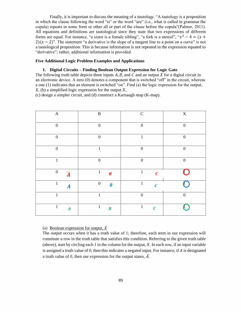
1. Digital Circuits – Finding Boolean Output Expression for Logic Gate
The following truth table depicts three inputs 𝐴, 𝐵, and 𝐶 and an output 𝑋 for a digital circuit in
an electronic device. A zero (0) denotes a component that is switched “off” in the circuit, whereas
a one (1) indicates that an element is switched “on”. Find (a) the logic expression for the output,
𝑋, (b) a simplified logic expression for the output 𝑋,
(c) design a simpler circuit, and (d) construct a Karnaugh map (K-map).
A B C X
0 0 0 0
0 0 1 0
0 1 0 0
1 0 0 0
0 1 1 1
1 0 1 1
1 1 0 0
1 1 1 1
(a) Boolean expression for output, 𝑋
The output occurs when it has a truth value of 1; therefore, each term in our expression will
constitute a row in the truth table that satisfies this condition. Referring to the given truth table
(above), start by circling each 1 in the column for the output, 𝑋. In each row, if an input variable
is assigned a truth value of 0, then this indicates a negated input. For instance, if 𝐴 is designated
a truth value of 0, then our expression for the output states, �̅�.
�̅� 𝑩 𝑪
𝑨 �̅� 𝑪
𝑨 𝑩 𝑪

90
Therefore, the output is given by…
𝑿 = �̅�𝑩𝑪 ⊕ 𝑨�̅�𝑪 ⊕ 𝑨𝑩𝑪.
(b) Simplify the expression for the output
𝑋 = �̅�𝐵𝐶 ⊕ 𝐴�̅�𝐶 ⊕ 𝐴𝐵𝐶
= �̅�𝐵𝐶 ⊕ 𝐴𝐶(�̅� + 𝐵)
= �̅�𝐵𝐶 ⊕ 𝐴𝐶
= (�̅�𝐵 ⊕ 𝐴)𝐶
= (𝐴 ⊕ 𝐵)𝐶 .
Note: Line 2 was simplified via the property: �̅� + 𝐵 = 1.
Line 4 was simplified via the property �̅�𝐵 ⊕ 𝐴 = 𝐴 ⊕ 𝐵.
(c) Design a circuit based off the simplified expression for the output:
In the schematic, note that…
= 𝑜𝑟 = ⊕
Therefore, the circuit corresponding to the output 𝑋 = (𝐴 ⊕ 𝐵)𝐶 is…
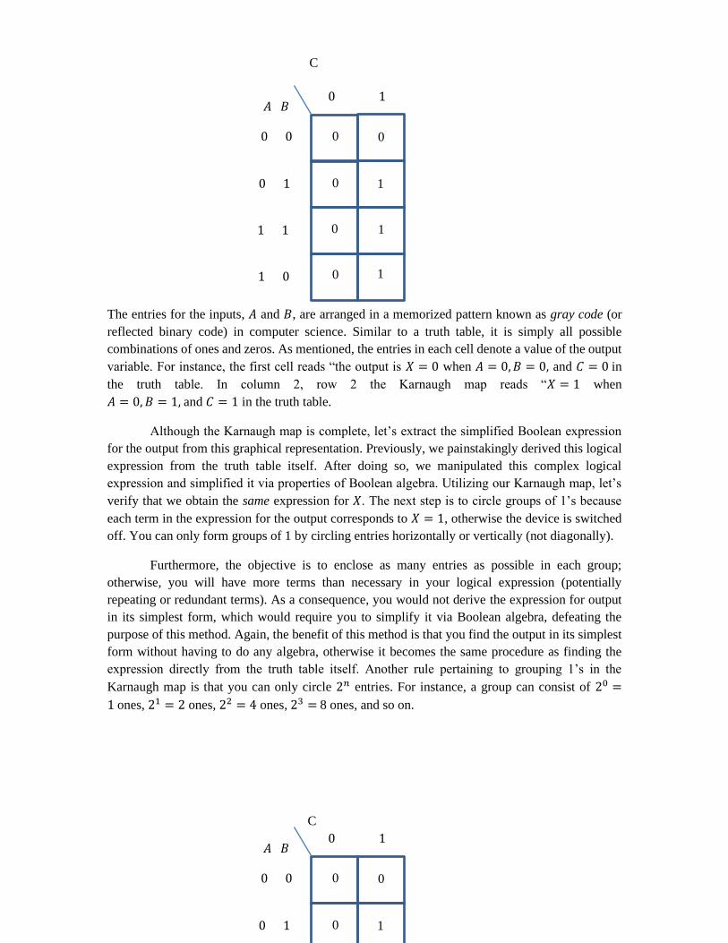
(d) Construct a Karnaugh map:
In applications such as circuits and computer science, a Karnaugh map is a graphical representation
of the simplified Boolean expression extracted from the truth table. Using a graphical method as
an alternative solution is a wonderful problem-solving strategy, because it verifies that our logical
(Boolean) expression for the output is correct. To construct a Karnaugh map, reference the given
truth table and count the number of rows. Since the truth table consists of 8 rows, our Karnaugh
map is comprised of 2 columns and 4 rows. Each entry in the Karnaugh map is an output (the value
for 𝑋) corresponding to each input.
Since 𝐴𝐶 appears in both term
2 and term 3, we can factor
out this expression. Although
tempting, do not combine any
like terms in the manner: 𝐴 +𝐴 = 2𝐴, for example. Recall,
this is Boolean algebra, not
traditional algebra. The
notation ⊕ serves as a
reminder.
= 𝑎𝑛𝑑 = ⊗
⊕
At this point, your (binary) logical operation
⊕ acts on inputs 𝐴 and 𝐵, outputting 𝐴 ⊕
𝐵.
⊗
A
B
C
This gate is also analogous to a function
machine, where the inputs are 𝐴 ⊕ 𝐵 and 𝐶,
the function (operation) is the ⊗, and the
output is (𝐴 ⊕ 𝐵) ⊗ 𝐶.
91
The entries for the inputs, 𝐴 and 𝐵, are arranged in a memorized pattern known as gray code (or
reflected binary code) in computer science. Similar to a truth table, it is simply all possible
combinations of ones and zeros. As mentioned, the entries in each cell denote a value of the output
variable. For instance, the first cell reads “the output is 𝑋 = 0 when 𝐴 = 0, 𝐵 = 0, and 𝐶 = 0 in
the truth table. In column 2, row 2 the Karnaugh map reads “𝑋 = 1 when
𝐴 = 0, 𝐵 = 1, and 𝐶 = 1 in the truth table.
Although the Karnaugh map is complete, let’s extract the simplified Boolean expression
for the output from this graphical representation. Previously, we painstakingly derived this logical
expression from the truth table itself. After doing so, we manipulated this complex logical
expression and simplified it via properties of Boolean algebra. Utilizing our Karnaugh map, let’s
verify that we obtain the same expression for 𝑋. The next step is to circle groups of 1’s because
each term in the expression for the output corresponds to 𝑋 = 1, otherwise the device is switched
off. You can only form groups of 1 by circling entries horizontally or vertically (not diagonally).
Furthermore, the objective is to enclose as many entries as possible in each group;
otherwise, you will have more terms than necessary in your logical expression (potentially
repeating or redundant terms). As a consequence, you would not derive the expression for output
in its simplest form, which would require you to simplify it via Boolean algebra, defeating the
purpose of this method. Again, the benefit of this method is that you find the output in its simplest
form without having to do any algebra, otherwise it becomes the same procedure as finding the
expression directly from the truth table itself. Another rule pertaining to grouping 1’s in the
Karnaugh map is that you can only circle 2𝑛 entries. For instance, a group can consist of 20 =
1 ones, 21 = 2 ones, 22 = 4 ones, 23 = 8 ones, and so on.
𝐴 𝐵
C
0 1
0 0
0 1
1 1
1 0
0 0
0 1
0 1
0 1
𝐴 𝐵 0 1
0 0
0 1
0 0
0 1
C
92
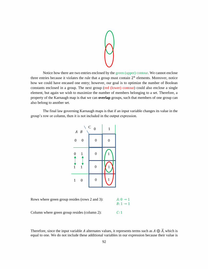
Notice how there are two entries enclosed by the green (upper) contour. We cannot enclose
three entries because it violates the rule that a group must contain 2𝑛 elements. Moreover, notice
how we could have encased one entry; however, our goal is to optimize the number of Boolean
constants enclosed in a group. The next group (red (lower) contour) could also enclose a single
element, but again we wish to maximize the number of members belonging to a set. Therefore, a
property of the Karnaugh map is that we can overlap groups, such that members of one group can
also belong to another set.
The final law governing Karnaugh maps is that if an input variable changes its value in the
group’s row or column, then it is not included in the output expression.
Rows where green group resides (rows 2 and 3): 𝐴: 0 → 1
𝐵: 1 → 1
Column where green group resides (column 2): 𝐶: 1
Therefore, since the input variable 𝐴 alternates values, it represents terms such as 𝐴 ⊕ 𝐴,̅ which is
equal to one. We do not include these additional variables in our expression because their value is
𝐴 𝐵 0 1
0 0
0 1
1 1
1 0
0 0
0 1
0 1
0 1
C
93
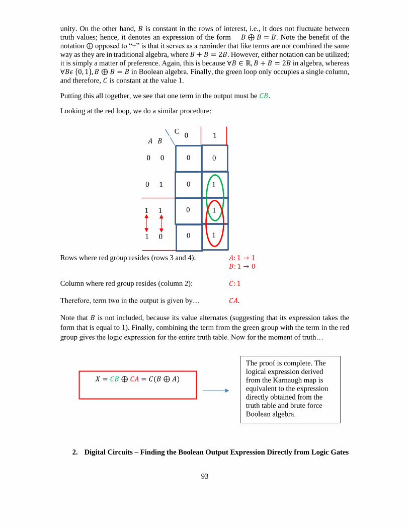
unity. On the other hand, 𝐵 is constant in the rows of interest, i.e., it does not fluctuate between
truth values; hence, it denotes an expression of the form 𝐵 ⊕ 𝐵 = 𝐵. Note the benefit of the
notation ⊕ opposed to “+” is that it serves as a reminder that like terms are not combined the same
way as they are in traditional algebra, where 𝐵 + 𝐵 = 2𝐵. However, either notation can be utilized;
it is simply a matter of preference. Again, this is because ∀𝐵 ∈ ℝ, 𝐵 + 𝐵 = 2𝐵 in algebra, whereas
∀𝐵𝜖 {0, 1}, 𝐵 ⊕ 𝐵 = 𝐵 in Boolean algebra. Finally, the green loop only occupies a single column,
and therefore, 𝐶 is constant at the value 1.
Putting this all together, we see that one term in the output must be 𝐶𝐵.
Looking at the red loop, we do a similar procedure:
Rows where red group resides (rows 3 and 4): 𝐴: 1 → 1
𝐵: 1 → 0
Column where red group resides (column 2): 𝐶: 1
Therefore, term two in the output is given by… 𝐶𝐴.
Note that 𝐵 is not included, because its value alternates (suggesting that its expression takes the
form that is equal to 1). Finally, combining the term from the green group with the term in the red
group gives the logic expression for the entire truth table. Now for the moment of truth…
2. Digital Circuits – Finding the Boolean Output Expression Directly from Logic Gates
𝐴 𝐵 0 1
0 0
0 1
1 1
1 0
0 0
0 1
0 1
0 1
C
𝑋 = 𝐶𝐵 ⊕ 𝐶𝐴 = 𝐶(𝐵 ⊕ 𝐴)
The proof is complete. The
logical expression derived
from the Karnaugh map is
equivalent to the expression
directly obtained from the
truth table and brute force
Boolean algebra.
94
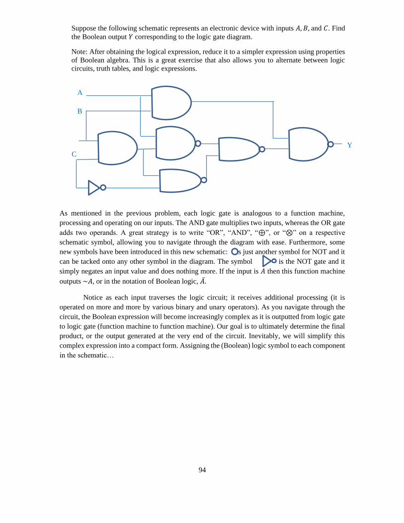
Suppose the following schematic represents an electronic device with inputs 𝐴, 𝐵, and 𝐶. Find
the Boolean output 𝑌 corresponding to the logic gate diagram.
Note: After obtaining the logical expression, reduce it to a simpler expression using properties
of Boolean algebra. This is a great exercise that also allows you to alternate between logic
circuits, truth tables, and logic expressions.
As mentioned in the previous problem, each logic gate is analogous to a function machine,
processing and operating on our inputs. The AND gate multiplies two inputs, whereas the OR gate
adds two operands. A great strategy is to write “OR”, “AND”, “⊕”, or “⊗” on a respective
schematic symbol, allowing you to navigate through the diagram with ease. Furthermore, some
new symbols have been introduced in this new schematic: is just another symbol for NOT and it
can be tacked onto any other symbol in the diagram. The symbol is the NOT gate and it
simply negates an input value and does nothing more. If the input is 𝐴 then this function machine
outputs ~𝐴, or in the notation of Boolean logic, �̅�.
Notice as each input traverses the logic circuit; it receives additional processing (it is
operated on more and more by various binary and unary operators). As you navigate through the
circuit, the Boolean expression will become increasingly complex as it is outputted from logic gate
to logic gate (function machine to function machine). Our goal is to ultimately determine the final
product, or the output generated at the very end of the circuit. Inevitably, we will simplify this
complex expression into a compact form. Assigning the (Boolean) logic symbol to each component
in the schematic…
A
B
C
Y

95
The expression is becoming rather complex. We could keep building our logical expression
and simplify once it exits the final logic gate. Alternatively, we could have simplified the
logical expression each step along the way. Before inputting the red expression into the final
AND gate, let’s simplify the sum…
..𝐴𝐵𝐶̅̅ ̅̅ ̅̅ ⊕ 𝐵𝐶 ⊕ 𝐶̅ ̅̅ ̅̅ ̅̅ ̅̅ ̅̅ ̅̅̅̅ ̅̅ ̅̅ ̅̅ ̅̅ ̅̅ ̅̅ ̅̅ ̅̅ ̅̅ ̅̅
= (𝐴𝐵𝐶)̿̿ ̿̿ ̿̿ ̿̿ ⊗ (𝐵𝐶 ⊕ 𝐶̅)̿̿ ̿̿ ̿̿ ̿̿ ̿̿ ̿̿ ̿
At this point, there are numerous ways to simplify the logical statement. By inspecting the
expression above, one can recognize the form 𝐵𝐶 ⊕ 𝐶̅ = 𝐵 ⊕ 𝐶. Also notice, we applied the
property �̿� = 𝑥 (this has the same meaning as ~(~𝑥) = 𝑥). This illustrates the purpose of De
Morgan’s Theorem, allowing us to cancel some NOT operators…
(𝐴𝐵𝐶) ⊗ (𝐵 ⊕ 𝐶)
= 𝐴𝐵𝐶𝐵 ⊕ 𝐴𝐵𝐶𝐶
= 𝐴𝐵𝐶 ⊕ 𝐴𝐵𝐶
= 𝐴𝐵𝐶.
Therefore, 𝐴𝐵𝐶̅̅ ̅̅ ̅̅ ⊕ 𝐵𝐶 ⊕ 𝐶̅ ̅̅ ̅̅ ̅̅ ̅̅ ̅̅ ̅̅ = 𝐴𝐵𝐶 is one of the inputs in the FINAL logic gate. Recall,
the schematic representing the final logic gate was…
A
B
C Y
⊗
⊗ ⊗ ⊗
⊕
⊕
𝐶 is inputted
into this
component.
This logic gate
outputs �̅�.
𝐶̅ is flowing through from the
other side. Although it is the
output of the previous logic
gate, 𝐶̅ is the input for the
proceeding OR gate.
𝐶 ̅
𝐶
𝐵
𝐵𝐶
𝐵𝐶
𝐴
𝐴𝐵𝐶̅̅ ̅̅ ̅̅
𝐴𝐵𝐶̅̅ ̅̅ ̅̅
𝐵𝐶 ⊕ 𝐶 ̅̅̅ ̅̅ ̅̅ ̅̅ ̅̅ ̅
𝐴𝐵𝐶̅̅ ̅̅ ̅̅ ⊕ 𝐵𝐶 ⊕ 𝐶̅ ̅̅ ̅̅ ̅̅ ̅̅ ̅̅ ̅̅̅̅ ̅̅ ̅̅ ̅̅ ̅̅ ̅̅ ̅̅ ̅̅ ̅̅ ̅̅ ̅̅
𝐴
𝐵
𝐴𝐵
Applying De Morgan’s Theorem: The bar
covering the entire expression is split
between two terms (where the first ⊕
appears). The first ⊕ then becomes ⊗.
Simplify according to the property
𝐵𝐵 = 𝐵 and 𝐶𝐶 = 𝐶.
Apply the property X + X = X

96
Performing the logical operation of the AND gate…𝐴𝐵 ⊗ 𝐴𝐵𝐶̅̅ ̅̅ ̅̅ ̅̅ ̅̅ ̅̅ ̅̅ = 𝑌
The entire logical output of that complicated circuit was reduced to a single term, where each
of the three input variables occur once in the expression. Likewise, the simplified schematic
corresponding to the original circuit is…
In the first example, we were given a truth table and then we converted it into a complex logical
statement. After doing so, we simplified the compound proposition into a simpler expression via
Boolean algebra. Finally, we proved that the simple expression derived from algebraic
manipulations was correct, via a graphical solution utilizing Karnaugh maps. In the second
application problem, we saw how propositions are analogous to input variables. Each logic gate is
analogous to a function machine, and as the input traverses the circuit, more operations are
performed on these logical statements, until they become complex propositions. Our next few
examples depict truth tables from pure discrete mathematics (outside the context of electronics and
computer science). We focused on methods of finding expressions for logical statements (from
truth table to logical statement or from logic gate to logical statement). In our next example, we are
given a logical statement and required to determine its corresponding truth table.
3. Constructing a Truth Table from a Given Logical Statement
Suppose you are given the proposition, 𝑝 → ~(𝑝⋀𝑞). Construct a truth table to model this given
situation.
p q 𝑝⋀𝑞 ~(𝑝⋀𝑞) 𝑝 → ~(𝑝⋀𝑞)
T T
𝐴𝐵
𝐴𝐵𝐶
⊗ 𝑌
𝐴𝐵𝐶̅̅ ̅̅ ̅̅ = 𝑌.
𝐴
𝐵
𝐶
𝑌

97
T F
F T
F F
We start by writing all possible combinations of T and F (this is analogous to the gray code in the
computer science example: all possible combinations of 1’s and 0’s). The first two columns are the
propositions without any logical connectives. Then, we depict the expression inside the parentheses
in the next column, and gradually continue to work our way out until we reach the desired
statement.
The statement 𝑝⋀𝑞 has a truth value of T only when both 𝑝 and 𝑞 are true. For instance, in
row 3, 𝑞 possesses a truth value of false; hence, the entire statement 𝑝⋀𝑞 is false. Filling in the
third column results in…
p q 𝑝⋀𝑞 ~(𝑝⋀𝑞) 𝑝 → ~(𝑝⋀𝑞)
T T T F
T F F T
F T F T
F F F T
The next column negates our previous column. This led to the truth values in blue. Finally, the last
column contains the implication arrow. Regardless of the truth value of the antecedent, if the
conclusion is true, then the entire statement 𝑝 → ~(𝑝⋀q) is true. If the conclusion is false, then the
entire statement is false. Comparing our first column to our blue column…
p q 𝑝⋀𝑞 ~(𝑝⋀𝑞) 𝑝 → ~(𝑝⋀𝑞)
T T T F F
T F F T T
F T F T T
F F F T T
The truth table is complete. The statement is false only in the first row of the truth table.
4. Using logic to answer quantitative problems

98
Let’s assume there are 4 students in the classroom: students 𝐴, 𝐵, 𝐶, and 𝐷. The teacher administers
writing utensils so each student can complete their assignment. Each student in the class received;
4, 5, or 6 pencils. Suppose students that receive 4 or 6 pencils always tell the truth, whereas students
administered 5 pencils never tell the truth. When asked to report the total number of pencils the
group received, each student stated the following numbers:
Given that three of the four students are lying, i.e., they received 5 pencils, which student is the
honest student?
There is only one honest student, since the given problem stated that three students received 5
pencils. This suggests that a total of 5(3) = 15 pencils were distributed to dishonest students.
Subtracting 15 pencils from each student, we can determine which student received either 4 or 6:
𝐴: 18 − 15 = 3
𝐵: 20 − 15 = 5
𝐶: 19 − 15 = 4
𝐷: 17 − 15 = 2
Therefore, the only student with 4 or 6 pencils remaining, is student, 𝐶.
5. Suppose you are given the following statement: It is summer and there is rain.
(a) Express the given statement symbolically
(b) Apply De Morgan’s Theorem to negate this statement
(c) Construct a truth table for the statement expressed in part (b).
The given statement consists of two propositions 𝑝 and 𝑞 combined by a single connective (and).
It is summer and there is rain.
(a) Expressing the statement symbolically: 𝑝 ⋀ 𝑞
(b) Negating the statement using De Morgan’s Theorem: ~(𝑝 ⋀ 𝑞) = ~𝑝⋁ ~𝑞
Note that we applied the same process in one of the application examples. In De Morgan’s Theorem, the sign alternates from multiplication to addition or vice versa.
Hence, the statement reads “it is not summer or there is no rain”.
A B C D
18 20
𝑝 𝑞
19 17

99
(c) Devise a truth table for the statement = ~𝑝 ⋁ ~𝑞, i.e., “it is not summer or there is no rain”. Since there are 2 statements, our truth table will consist of 22 = 4 rows:
p q ~p ~q ~𝒑 ⋁ ~𝒒
T T F F F
T F F T T
F T T F T
F F T T T
Solution to the Given Problem:
Suppose a prisoner must make a choice between two doors. One door leads to freedom and the
other door is booby-trapped so that it leads to death. The doors are labeled as follows:
Door 1: This door leads to freedom and the other door leads to death.
Door 2: One of these doors leads to freedom and the other of these doors leads to death.
If exactly one of the signs is true, which door should the prisoner choose? Give reasons for your
answer. Provide a detailed explanation of how you approach the problem. Use at least two different
models for your solutions.
Solution (Model) 1.
Convert the verbal (written) statements to symbolic logic. In order to create a logical expression,
we will start by assigning arbitrary variables to each proposition.
Let 𝒑 denote Door 1 leads to freedom and let 𝒒 denote Door 2 leads to death. Using this notation,
the first proposition becomes…
𝑝 ⋀ 𝑞
Statement two can also be expressed symbolically…
(𝑝 ⋀ 𝑞) ⋁ ~(𝑝 ⋀ 𝑞)
Using De Morgan’s theorem, we can replace ~(𝑝 ⋀ 𝑞) with ~𝑝 ⋁~𝑞…
(𝑝 ⋀ 𝑞)⋁ (~𝑝 ⋁ ~𝑞)
Perhaps this forms a complex logical expression with some redundancies. If this is the case, we can
form a compound proposition, simplify it, and then translate the meaning of the compact logical
statement. Combining propositions 1 and 2 gives…
(𝑝 ⋀ 𝑞) ⋁ (𝑝⋀𝑞)⋁ (~𝑝 ⋁ ~𝑞).
This expression simplifies to… 𝑝⋀𝑞
Therefore, the compound proposition formed from both doors reduces to the statement on door 1.
Thus, door 1 leads to freedom and door 2 leads to death.
Solution (Model) 2.
100
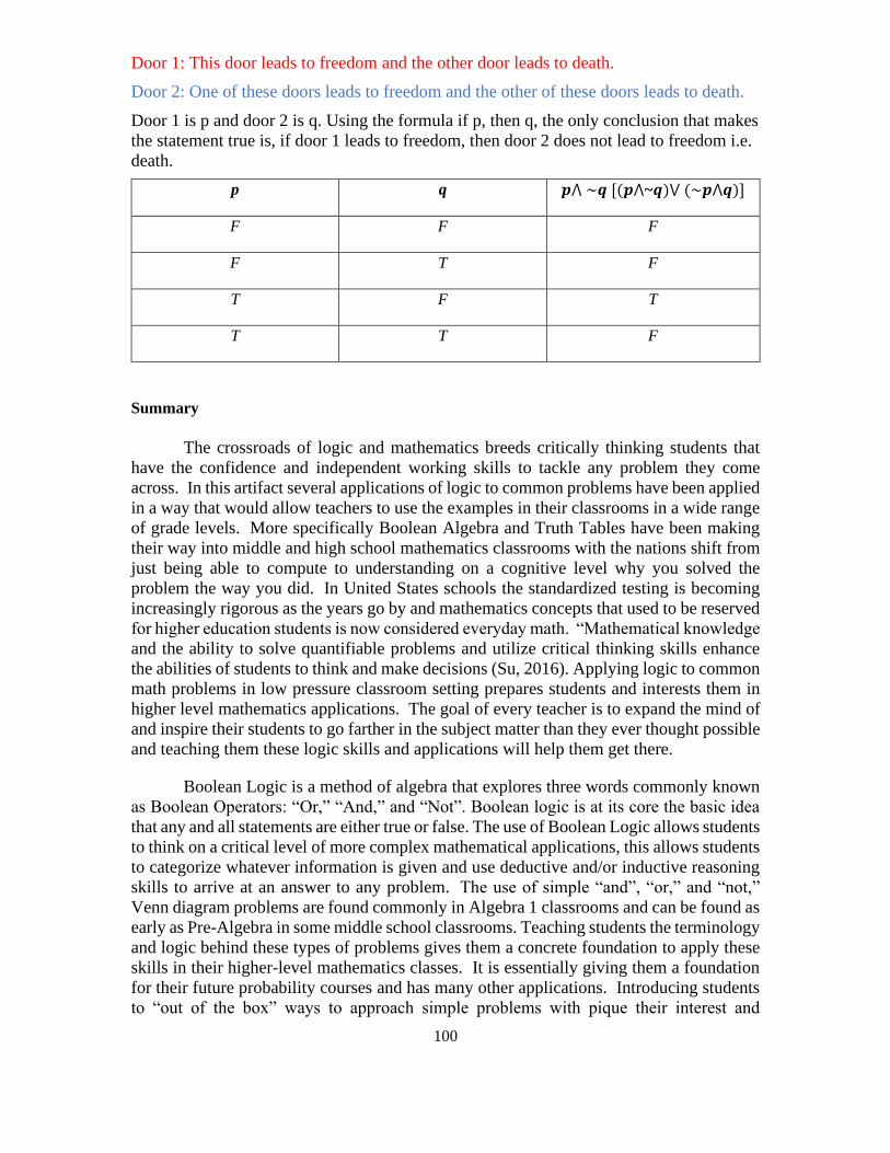
Door 1: This door leads to freedom and the other door leads to death.
Door 2: One of these doors leads to freedom and the other of these doors leads to death.
Door 1 is p and door 2 is q. Using the formula if p, then q, the only conclusion that makes
the statement true is, if door 1 leads to freedom, then door 2 does not lead to freedom i.e.
death.
p q 𝒑⋀ ~𝒒 [(𝒑⋀~𝒒)⋁ (~𝒑⋀𝒒)]
F F F
F T F
T F T
T T F
Summary
The crossroads of logic and mathematics breeds critically thinking students that
have the confidence and independent working skills to tackle any problem they come
across. In this artifact several applications of logic to common problems have been applied
in a way that would allow teachers to use the examples in their classrooms in a wide range
of grade levels. More specifically Boolean Algebra and Truth Tables have been making
their way into middle and high school mathematics classrooms with the nations shift from
just being able to compute to understanding on a cognitive level why you solved the
problem the way you did. In United States schools the standardized testing is becoming
increasingly rigorous as the years go by and mathematics concepts that used to be reserved
for higher education students is now considered everyday math. “Mathematical knowledge
and the ability to solve quantifiable problems and utilize critical thinking skills enhance
the abilities of students to think and make decisions (Su, 2016). Applying logic to common
math problems in low pressure classroom setting prepares students and interests them in
higher level mathematics applications. The goal of every teacher is to expand the mind of
and inspire their students to go farther in the subject matter than they ever thought possible
and teaching them these logic skills and applications will help them get there.
Boolean Logic is a method of algebra that explores three words commonly known
as Boolean Operators: “Or,” “And,” and “Not”. Boolean logic is at its core the basic idea
that any and all statements are either true or false. The use of Boolean Logic allows students
to think on a critical level of more complex mathematical applications, this allows students
to categorize whatever information is given and use deductive and/or inductive reasoning
skills to arrive at an answer to any problem. The use of simple “and”, “or,” and “not,”
Venn diagram problems are found commonly in Algebra 1 classrooms and can be found as
early as Pre-Algebra in some middle school classrooms. Teaching students the terminology
and logic behind these types of problems gives them a concrete foundation to apply these
skills in their higher-level mathematics classes. It is essentially giving them a foundation
for their future probability courses and has many other applications. Introducing students
to “out of the box” ways to approach simple problems with pique their interest and
101
encourage them research independently and be excited to share what they have learned
with the class.
One of the tools of Boolean Algebra that was used in this artifact is a truth
table. Truth tables are mathematical tables that organize the true or false outcomes to
compound statements. Each statement is usually represented by a variable, most commonly
p, q, and r, and each statement has its own corresponding column in the table that contains
the likely truth values. Truth tables could be introduced in high school geometry when they
are learning reasoning skills. “By using inductive and deductive reasoning and questioning,
while adhering to the Blooms Taxonomy, students learn mathematical concepts and solve
mathematical problems and also recognize the extent to which reasoning applies to
mathematics and how their critical thinking pathway can facilitate decision making and
strategic planning (Su, 2016).” Even though logic is considered higher order thinking and
complex, when teachers introduce students to these concepts as soon as possible and
constantly over time, they become simple. Promoting the highest levels of Bloom’s
Taxonomy will enable teachers to ensure all students are mastering the content while
building habits that will aid them in their chosen career.
Use in the Classroom
Teachers are under incredible pressure to teach content and prepare students for
standardized tests, but content is not the only thing students need to know in order to be
successful test takers as well as productive citizens. This missing link is critical thinking.
Students are not only asked to regurgitate facts and processes on standardized tests, they
need to be able to coherently describe their thinking. Students need to be able to examine
questions logically in order to fully understand what is being asked of them, and in return
answer in a comprehensive way (Harlin 2013). This is a skill that students need to be taught,
which leads to the question how exactly as teachers can you foster logical thinkers?
A great way to build logical thinkers is through logic puzzles. The wonderful thing
about logic puzzles is they can be adapted to any grade level. The next problem occurs
when teachers try to decide where to put these puzzles into their content packed schedule.
A few suggestions would be as a warm-up, center, or even homework activity. Logical
puzzles can also be used to build collaboration skills when assigned to a group to solve.
Another great thing about these puzzles is they do not need to be linked to your current
content, which allows them to be used as early finisher activities or just as tasks to keep
students engaged in the learning.
Along with many benefits of using logic puzzles there are a few mind fields that
educators can encounter when using them. Teachers who have ELLs in their classrooms
might notice that the language barrier will hinder the student’s ability to complete the
assignment. This is due to the fact that logic problems require a command over the English
language that these students may not possess. Another problem teacher may encounter is
the amount of time that more sophisticated problems will require. A way to combat both
of these problems is allowing students to work in groups (Bouchard n.d.).
References
102
Bouchard, B. n.d.. Think outside the box: 3 things you can teach with logic puzzles. Retrieved
from https://busyteacher.org/18402-logic-puzzles-3-things-you-can-teach.html.
Gullberg, J. (1997). Mathematics from the birth of numbers. New York, NY: W.W. Norton and
Company.
Palmer, D. (2011). Does the center hold: An introduction to western philosophy. New York, NY.
McGraw-Hill.
Harlin, T. (2013), Does critical thinking pass the test? The influence of critical thinking lessons
on achievement in middle school social studies. The Georgia Social Studies Journal 3,
125-137.
Dr. Hui Fang Huang “Angie” Su is a Professor of Mathematics Education for the Fischler College
of Education and School of Criminal Justice at Nova Southeastern University (NSU). Her
passion for teaching includes mentoring and encouraging students at all levels to extend their
knowledge beyond their current abilities.