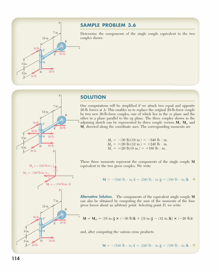
SOLUTION SAMPLE PROBLEM 3.6 114
25
SOLUTION Our computations will be simplified if we attach two equal and opposite 20-lb forces at A. This enables us to replace the original 20-lb-force couple by two new 20-lb-force couples, one of which lies in the zx plane and the other in a plane parallel to the xy plane. The three couples shown in the adjoining sketch can be represented by three couple vectors M x , M y , and M z directed along the coordinate axes. The corresponding moments are M x 5 2(30 lb)(18 in.) 5 2540 lb ? in. M y 5 1(20 lb)(12 in.) 5 1240 lb ? in. M z 5 1(20 lb)(9 in.) 5 1180 lb ? in. These three moments represent the components of the single couple M equivalent to the two given couples. We write M 5 2(540 lb ? in.)i 1 (240 lb ? in.)j 1 (180 lb ? in.)k ◀ Alternative Solution. The components of the equivalent single couple M can also be obtained by computing the sum of the moments of the four given forces about an arbitrary point. Selecting point D, we write M 5 M D 5 (18 in.)j 3 (230 lb)k 1 [(9 in.)j 2 (12 in.)k] 3 (220 lb)i and, after computing the various cross products, M 5 2(540 lb ? in.)i 1 (240 lb ? in.)j 1 (180 lb ? in.)k ◀ z y x A B C D E 30 lb 30 lb 12 in. 7 in. 20 lb 20 lb 9 in. 9 in. SAMPLE PROBLEM 3.6 Determine the components of the single couple equivalent to the two couples shown. y x A B C D E 30 lb 30 lb 12 in. 7 in. 20 lb z 9 in. 9 in. 20 lb y x A B C D E 30 lb 30 lb 12 in. 7 in. 20 lb 20 lb 20 lb 20 lb z 9 in. 9 in. y x z M y = + (240 lb•in.) j M x = – (540 lb•in.) i M z = + (180 lb•in.) k 114
-
Upload
khangminh22 -
Category
Documents
-
view
0 -
download
0
Transcript of SOLUTION SAMPLE PROBLEM 3.6 114
SOLUTION
Our computations will be simplified if we attach two equal and opposite 20-lb forces at A . This enables us to replace the original 20-lb-force couple by two new 20-lb-force couples, one of which lies in the zx plane and the other in a plane parallel to the xy plane. The three couples shown in the adjoining sketch can be represented by three couple vectors M x , M y , and M z directed along the coordinate axes. The corresponding moments are
Mx 5 2(30 lb)(18 in.) 5 2540 lb ? in. My 5 1(20 lb)(12 in.) 5 1240 lb ? in. Mz 5 1(20 lb)(9 in.) 5 1180 lb ? in.
These three moments represent the components of the single couple M equivalent to the two given couples. We write
M 5 2(540 lb ? in.)i 1 (240 lb ? in.)j 1 (180 lb ? in.)k ◀
Alternative Solution. The components of the equivalent single couple M can also be obtained by computing the sum of the moments of the four given forces about an arbitrary point. Selecting point D , we write
M 5 MD 5 (18 in.)j 3 (230 lb)k 1 [(9 in.)j 2 (12 in.)k] 3 (220 lb)i
and, after computing the various cross products,
M 5 2(540 lb ? in.)i 1 (240 lb ? in.)j 1 (180 lb ? in.)k ◀z
y
x
A
B
C
D
E
30 lb
30 lb
12 in.
7 in.
20 lb
20 lb
9 in.
9 in.
SAMPLE PROBLEM 3.6
Determine the components of the single couple equivalent to the two couples shown.
y
x
A
B
C
D
E
30 lb
30 lb
12 in.
7 in.
20 lbz
9 in.
9 in.
20 lb
y
x
A
B
C
D
E
30 lb
30 lb
12 in.
7 in.
20 lb
20 lb
20 lb20 lb
z
9 in.
9 in.y
x
z
My = + (240 lb•in.) j
Mx = – (540 lb•in.) i
Mz = + (180 lb•in.) k
114
bee29400_ch03_072-155.indd Page 114 11/28/08 9:37:21 PM user-s172bee29400_ch03_072-155.indd Page 114 11/28/08 9:37:21 PM user-s172 /Volumes/204/MHDQ076/work%0/indd%0/Volumes/204/MHDQ076/work%0/indd%0

SAMPLE PROBLEM 3.7
Replace the couple and force shown by an equivalent single force applied to the lever. Determine the distance from the shaft to the point of applica-tion of this equivalent force.
=C
– (400 N) j
– (400 N) j
– (84 N•m) k
O O
60°
=
B
150 mm
O
F = – (400 N) j
– (400 N) j
– (24 N•m) k– (24 N•m) k – (60 N•m) k
O
260 mm
B
400 N
200 N
200 N
150 mm
60 mmO
60°
300 mm
=C
– (400 N) j– (400 N) j
– (24 N•m) kB
O O
B
60°
=– (400 N) j – (400 N) j
– (24 N•m) k
– (24 N•m) k
B
150 mm
O
B
O
SOLUTION
First the given force and couple are replaced by an equivalent force-couple system at O . We move the force F 5 2(400 N) j to O and at the same time add a couple of moment M O equal to the moment about O of the force in its original position.
MO 5 OB¡
3 F 5 [ (0.150 m)i 1 (0.260 m)j] 3 (2400 N)j 5 2(60 N ? m)k
This couple is added to the couple of moment 2(24 N · m) k formed by the two 200-N forces, and a couple of moment 2(84 N · m) k is obtained. This last couple can be eliminated by applying F at a point C chosen in such a way that
2(84 N ? m)k 5 OC¡
3 F 5 [ (OC) cos 60°i 1 (OC) sin 60°j] 3 (2400 N)j 5 2(OC)cos 60°(400 N)k
We conclude that
(OC) cos 608 5 0.210 m 5 210 mm OC 5 420 mm ◀
Alternative Solution. Since the effect of a couple does not depend on its location, the couple of moment 2(24 N ? m) k can be moved to B ; we thus obtain a force-couple system at B . The couple can now be eliminated by applying F at a point C chosen in such a way that
2(24 N ? m)k 5 BC¡
3 F 5 2(BC) cos 60°(400 N)k
We conclude that
(BC) cos 608 5 0.060 m 5 60 mm BC 5 120 mm OC 5 OB 1 BC 5 300 mm 1 120 mm OC 5 420 mm ◀
115
bee29400_ch03_072-155.indd Page 115 11/28/08 9:37:22 PM user-s172bee29400_ch03_072-155.indd Page 115 11/28/08 9:37:22 PM user-s172 /Volumes/204/MHDQ076/work%0/indd%0/Volumes/204/MHDQ076/work%0/indd%0

116
In this lesson we discussed the properties of couples . To solve the problems which follow, you will need to remember that the net effect of a couple is to
produce a moment M . Since this moment is independent of the point about which it is computed, M is a free vector and thus remains unchanged as it is moved from point to point. Also, two couples are equivalent (that is, they have the same effect on a given rigid body) if they produce the same moment.
When determining the moment of a couple, all previous techniques for computing moments apply. Also, since the moment of a couple is a free vector, it should be computed relative to the most convenient point.
Because the only effect of a couple is to produce a moment, it is possible to rep-resent a couple with a vector, the couple vector , which is equal to the moment of the couple. The couple vector is a free vector and will be represented by a special symbol, , to distinguish it from force vectors.
In solving the problems in this lesson, you will be called upon to perform the fol-lowing operations:
1. Adding two or more couples . This results in a new couple, the moment of which is obtained by adding vectorially the moments of the given couples [Sample Prob. 3.6].
2. Replacing a force with an equivalent force-couple system at a specified point . As explained in Sec. 3.16, the force of the force-couple system is equal to the original force, while the required couple vector is equal to the moment of the original force about the given point. In addition, it is important to observe that the force and the couple vector are perpendicular to each other. Conversely, it follows that a force-couple system can be reduced to a single force only if the force and couple vector are mutually perpendicular (see the next paragraph).
3. Replacing a force-couple system (with F perpendicular to M ) with a single equivalent force . Note that the requirement that F and M be mutually perpen-dicular will be satisfied in all two-dimensional problems. The single equivalent force is equal to F and is applied in such a way that its moment about the original point of application is equal to M [Sample Prob. 3.7].
SOLVING PROBLEMSON YOUR OWN
bee29400_ch03_072-155.indd Page 116 11/28/08 9:37:23 PM user-s172bee29400_ch03_072-155.indd Page 116 11/28/08 9:37:23 PM user-s172 /Volumes/204/MHDQ076/work%0/indd%0/Volumes/204/MHDQ076/work%0/indd%0

117117
3.70 Two parallel 60-N forces are applied to a lever as shown. Deter-mine the moment of the couple formed by the two forces ( a ) by resolving each force into horizontal and vertical components and adding the moments of the two resulting couples, ( b ) by using the perpendicular distance between the two forces, ( c ) by summing the moments of the two forces about point A .
PROBLEMS
A
B
C
60 N
60 N
20°
55°
360 mm
520 mm
Fig. P3.70
A
B
C
D
160 mmM
160 mm100 mm
240 mm
140 mm
Fig. P3.72
A
D
B
C
16 in.
d
21 lb
12 lb12 lb
21 lb
a
Fig. P3.71
3.71 A plate in the shape of a parallelogram is acted upon by two cou-ples. Determine ( a ) the moment of the couple formed by the two 21-lb forces, ( b ) the perpendicular distance between the 12-lb forces if the resultant of the two couples is zero, ( c ) the value of a if the resultant couple is 72 lb ? in. clockwise and d is 42 in.
3.72 A couple M of magnitude 18 N ? m is applied to the handle of a screwdriver to tighten a screw into a block of wood. Deter-mine the magnitudes of the two smallest horizontal forces that are equivalent to M if they are applied ( a ) at corners A and D , ( b ) at corners B and C , ( c ) anywhere on the block.
bee29400_ch03_072-155.indd Page 117 11/28/08 9:37:24 PM user-s172bee29400_ch03_072-155.indd Page 117 11/28/08 9:37:24 PM user-s172 /Volumes/204/MHDQ076/work%0/indd%0/Volumes/204/MHDQ076/work%0/indd%0

118 Rigid Bodies: Equivalent Systems of Forces 3.73 Four 1-in.-diameter pegs are attached to a board as shown. Two strings are passed around the pegs and pulled with the forces indicated. ( a ) Determine the resultant couple acting on the board. ( b ) If only one string is used, around which pegs should it pass and in what directions should it be pulled to create the same couple with the minimum tension in the string? ( c ) What is the value of that minimum tension?
A B
C D35 lb
35 lb
25 lb
25 lb
6 in.
8 in.
Fig. P3.73 and P3.74
z 6 lb ft•
8 lb ft•
x
y
Fig. P3.75
x
y
z
A
B
C
D
E
FG
–P
P
34 N
34 N
18 N
18 N
160 mm
150 mm
150 mm170 mm
Fig. P3.76 and P3.79
3.74 Four pegs of the same diameter are attached to a board as shown. Two strings are passed around the pegs and pulled with the forces indicated. Determine the diameter of the pegs know-ing that the resultant couple applied to the board is 485 lb ? in. counterclockwise.
3.75 The shafts of an angle drive are acted upon by the two couples shown. Replace the two couples with a single equivalent couple, specifying its magnitude and the direction of its axis.
3.76 and 3.77 If P 5 0, replace the two remaining couples with a single equivalent couple, specifying its magnitude and the direc-tion of its axis.
x
y
z
B
CD
A
E
–PP
16 lb
16 lb
40 lb
40 lb
15 in.
15 in.
10 in.
10 in.
10 in.
Fig. P3.77 and P3.78
3.78 If P 5 20 lb, replace the three couples with a single equivalent couple, specifying its magnitude and the direction of its axis.
3.79 If P 5 20 N, replace the three couples with a single equivalent couple, specifying its magnitude and the direction of its axis.
bee29400_ch03_072-155.indd Page 118 11/28/08 9:37:27 PM user-s172bee29400_ch03_072-155.indd Page 118 11/28/08 9:37:27 PM user-s172 /Volumes/204/MHDQ076/work%0/indd%0/Volumes/204/MHDQ076/work%0/indd%0

119Problems 3.80 Shafts A and B connect the gear box to the wheel assemblies of a tractor, and shaft C connects it to the engine. Shafts A and B lie in the vertical yz plane, while shaft C is directed along the x axis. Replace the couples applied to the shafts with a single equivalent couple, specifying its magnitude and the direction of its axis.
3.81 The tension in the cable attached to the end C of an adjustable boom ABC is 560 lb. Replace the force exerted by the cable at C with an equivalent force-couple system ( a ) at A , ( b ) at B .
y
B
A
C
xz
1200 N•m
1120 N•m
1600 N•m
20°
20°
Fig. P3.80
10 ft20°
30°A
B
C
T
8 ft
Fig. P3.81
3.82 A 160-lb force P is applied at point A of a structural member. Replace P with ( a ) an equivalent force-couple system at C , ( b ) an equivalent system consisting of a vertical force at B and a second force at D .
3.83 The 80-N horizontal force P acts on a bell crank as shown. ( a ) Replace P with an equivalent force-couple system at B . ( b ) Find the two vertical forces at C and D that are equivalent to the couple found in part a .
A
B C
D
P
60°
1.25 ft
1.5 ft
2 ft 4 ft
Fig. P3.82
B
AP
C D
50 mm
100 mm 40 mm
Fig. P3.83
A B C
D60°
6.7 m 4 m
Fig. P3.84
3.84 A dirigible is tethered by a cable attached to its cabin at B . If the tension in the cable is 1040 N, replace the force exerted by the cable at B with an equivalent system formed by two parallel forces applied at A and C .
bee29400_ch03_072-155.indd Page 119 11/28/08 9:37:28 PM user-s172bee29400_ch03_072-155.indd Page 119 11/28/08 9:37:28 PM user-s172 /Volumes/204/MHDQ076/work%0/indd%0/Volumes/204/MHDQ076/work%0/indd%0
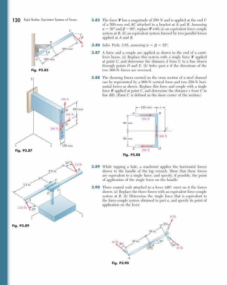
120 Rigid Bodies: Equivalent Systems of Forces 3.85 The force P has a magnitude of 250 N and is applied at the end C of a 500-mm rod AC attached to a bracket at A and B . Assuming a 5 30° and b 5 60°, replace P with ( a ) an equivalent force-couple system at B , ( b ) an equivalent system formed by two parallel forces applied at A and B .
3.86 Solve Prob. 3.85, assuming a 5 b 5 25°.
3.87 A force and a couple are applied as shown to the end of a canti-lever beam. ( a ) Replace this system with a single force F applied at point C , and determine the distance d from C to a line drawn through points D and E . ( b ) Solve part a if the directions of the two 360-N forces are reversed.
3.88 The shearing forces exerted on the cross section of a steel channel can be represented by a 900-N vertical force and two 250-N hori-zontal forces as shown. Replace this force and couple with a single force F applied at point C , and determine the distance x from C to line BD . (Point C is defined as the shear center of the section.)
A
B
C
200 mm
300 mmP
α
β
Fig. P3.85
450 mm
150 mm
360 N
360 N
B
dD
600 N
E
C
A
y
xz
Fig. P3.87
A
D
B
C
E
900 N
250 N
250 N
120 mm
90 mm
90 mm
x
Fig. P3.88
A
B
C3.2 in.
2.8 in.
2.9 lb
2.65 lb 25°
25°
x
y
z
D
Fig. P3.89
20 lb
20 lb
30°20°20°
48 lb
A
C
B40 in.
30 in.
55°
Fig. P3.90
3.89 While tapping a hole, a machinist applies the horizontal forces shown to the handle of the tap wrench. Show that these forces are equivalent to a single force, and specify, if possible, the point of application of the single force on the handle.
3.90 Three control rods attached to a lever ABC exert on it the forces shown. ( a ) Replace the three forces with an equivalent force-couple system at B . ( b ) Determine the single force that is equivalent to the force-couple system obtained in part a , and specify its point of application on the lever.
bee29400_ch03_072-155.indd Page 120 11/28/08 9:37:28 PM user-s172bee29400_ch03_072-155.indd Page 120 11/28/08 9:37:28 PM user-s172 /Volumes/204/MHDQ076/work%0/indd%0/Volumes/204/MHDQ076/work%0/indd%0

121Problems 3.91 A hexagonal plate is acted upon by the force P and the couple shown. Determine the magnitude and the direction of the smallest force P for which this system can be replaced with a single force at E .
3.92 A rectangular plate is acted upon by the force and couple shown. This system is to be replaced with a single equivalent force. ( a ) For a 5 40°, specify the magnitude and the line of action of the equivalent force. ( b ) Specify the value of a if the line of action of the equivalent force is to intersect line CD 300 mm to the right of D .
Fig. P3.91
a
A
B C
D
EF
300 N
300 N
P
0.2 m
3.93 An eccentric, compressive 1220-N force P is applied to the end of a cantilever beam. Replace P with an equivalent force-couple system at G .
3.94 To keep a door closed, a wooden stick is wedged between the floor and the doorknob. The stick exerts at B a 175-N force directed along line AB . Replace that force with an equivalent force-couple system at C .
a
a
AB
CD
15 N
15 N
48 N
240 mm
400 mm
Fig. P3.92
y
60 mm
100 mm
xP
GA
z
Fig. P3.93
z
990 mm
594 mm
100 mm
O
A
B
C
y
750 mm
67 mm
x
1850 mm
Fig. P3.94
bee29400_ch03_072-155.indd Page 121 11/28/08 9:37:29 PM user-s172bee29400_ch03_072-155.indd Page 121 11/28/08 9:37:29 PM user-s172 /Volumes/204/MHDQ076/work%0/indd%0/Volumes/204/MHDQ076/work%0/indd%0

122 Rigid Bodies: Equivalent Systems of Forces 3.95 An antenna is guyed by three cables as shown. Knowing that the tension in cable AB is 288 lb, replace the force exerted at A by cable AB with an equivalent force-couple system at the center O of the base of the antenna.
16 ft
x
y
z
O
A
B
C
D128 ft
96 ft
128 ft
64 ft
Fig. P3.95 and P3.96
3.96 An antenna is guyed by three cables as shown. Knowing that the tension in cable AD is 270 lb, replace the force exerted at A by cable AD with an equivalent force-couple system at the center O of the base of the antenna.
3.97 Replace the 150-N force with an equivalent force-couple system at A .
3.98 A 77-N force F 1 and a 31-N ? m couple M 1 are applied to corner E of the bent plate shown. If F 1 and M 1 are to be replaced with an equivalent force-couple system ( F 2 , M 2 ) at corner B and if ( M 2 ) z 5 0, determine ( a ) the distance d , ( b ) F 2 and M 2 .
x
y
z
A
C
120 mm
40 mm60 mm20 mm
35°
150 N D
B
200 mm
Fig. P3.97
x
z
y
BA
C
ED
G
H
J
F1
70 mm
30 mm
30 mm
d
60 mm
83.3 mm
250 mm
M1
Fig. P3.98
bee29400_ch03_072-155.indd Page 122 11/28/08 9:37:30 PM user-s172bee29400_ch03_072-155.indd Page 122 11/28/08 9:37:30 PM user-s172 /Volumes/204/MHDQ076/work%0/indd%0/Volumes/204/MHDQ076/work%0/indd%0

SAMPLE PROBLEM 3.8
A 4.80-m-long beam is subjected to the forces shown. Reduce the given system of forces to ( a ) an equivalent force-couple system at A, (b) an equiva-lent force-couple system at B, (c) a single force or resultant. Note . Since the reactions at the supports are not included in the given system of forces, the given system will not maintain the beam in equilibrium.
150 N 600 N 100 N 250 N
A B
1.6 m 1.2 m 2 m
A B
150 j – 600 j 100 j – 250 j
1.6 i2.8 i
4.8 i
A B
– (600 N) j
– (1880 N•m) k
A B
– (600 N) j– (1880 N•m) k
(2880 N•m) k4.8 m
A
– (600 N) j
(1000 N•m) kB
AB
– (600 N) j
x
130
SOLUTION
a. Force-Couple System at A . The force-couple system at A equivalent to the given system of forces consists of a force R and a couple MR
A defined as follows:
R 5 oF 5 (150 N)j 2 (600 N)j 1 (100 N)j 2 (250 N)j 5 2(600 N)j MR
A 5 o(r 3 F) 5 (1.6i) 3 (2600j) 1 (2.8i) 3 (100j) 1 (4.8i) 3 (2250j) 5 2(1880 N ? m)k
The equivalent force-couple system at A is thus
R 5 600 Nw MRA 5 1880 N ? m i ◀
b. Force-Couple System at B . We propose to find a force-couple system at B equivalent to the force-couple system at A determined in part a . The force R is unchanged, but a new couple MR
B must be determined, the moment of which is equal to the moment about B of the force-couple sys-tem determined in part a . Thus, we have
MRB 5 MR
A 1 BA¡
3 R 5 2(1880 N ? m)k 1 (24.8 m)i 3 (2600 N)j 5 2(1880 N ? m)k 1 (2880 N ? m)k 5 1 (1000 N ? m)k
The equivalent force-couple system at B is thus
R 5 600 Nw MRB 5 1000 N ? m l ◀
c. Single Force or Resultant. The resultant of the given system of forces is equal to R , and its point of application must be such that the moment of R about A is equal to MR
A . We write
r 3 R 5 MRA
xi 3 (2600 N)j 5 2(1880 N ? m)k 2x(600 N)k 5 2(1880 N ? m)k
and conclude that x 5 3.13 m. Thus, the single force equivalent to the given system is defined as
R 5 600 Nw x 5 3.13 m ◀
bee29400_ch03_072-155.indd Page 130 11/28/08 9:37:35 PM user-s172bee29400_ch03_072-155.indd Page 130 11/28/08 9:37:35 PM user-s172 /Volumes/204/MHDQ076/work%0/indd%0/Volumes/204/MHDQ076/work%0/indd%0
131
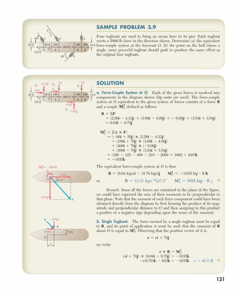
SAMPLE PROBLEM 3.9
Four tugboats are used to bring an ocean liner to its pier. Each tugboat exerts a 5000-lb force in the direction shown. Determine ( a ) the equivalent force-couple system at the foremast O, (b) the point on the hull where a single, more powerful tugboat should push to produce the same effect as the original four tugboats.
32 3
4
1
4
60°
50 ft 90 ft
110 ft
200 ftO
70 ft
45°
100
ft
100
ft
100
ft
SOLUTION
a. Force-Couple System at O . Each of the given forces is resolved into components in the diagram shown (kip units are used). The force-couple system at O equivalent to the given system of forces consists of a force R and a couple M R O defined as follows:
R 5 oF 5 (2.50i 2 4.33j) 1 (3.00i 2 4.00j) 1 (25.00j) 1 (3.54i 1 3.54j) 5 9.04i 2 9.79j
MRO 5 o(r 3 F)
5 (290i 1 50j) 3 (2.50i 2 4.33j) 1 (100i 1 70j) 3 (3.00i 2 4.00j) 1 (400i 1 70j) 3 (25.00j) 1 (300i 2 70j) 3 (3.54i 1 3.54j) 5 (390 2 125 2 400 2 210 2 2000 1 1062 1 248)k 5 21035k
The equivalent force-couple system at O is thus
R 5 (9.04 kips)i 2 (9.79 kips)j MRO 5 2(1035 kip ? ft)k
or R 5 13.33 kips c47.3° MRO 5 1035 kip ? ft i ◀
Remark. Since all the forces are contained in the plane of the figure, we could have expected the sum of their moments to be perpendicular to that plane. Note that the moment of each force component could have been obtained directly from the diagram by first forming the product of its mag-nitude and perpendicular distance to O and then assigning to this product a positive or a negative sign depending upon the sense of the moment.
b. Single Tugboat. The force exerted by a single tugboat must be equal to R , and its point of application A must be such that the moment of R about O is equal to MR
O. Observing that the position vector of A is
r 5 xi 1 70j
we write
r 3 R 5 MRO
(xi 1 70j) 3 (9.04i 2 9.79j) 5 21035k2x(9.79)k 2 633k 5 21035k x 5 41.1 ft ◀
– 4.33 j – 4 j – 5 jF1
F2 F3
F4
3 i
3.54 j
3.54 i
2.5i50 ft
110 ft
200 ftO
70 ft90 ft 100
ft
100
ft
100
ft
MO = –1035 kR
9.04 i
–9.79 j
47.3°
R
O
70 ft
x
9.04 i
– 9.79 jR
A
O
bee29400_ch03_072-155.indd Page 131 11/28/08 9:37:36 PM user-s172bee29400_ch03_072-155.indd Page 131 11/28/08 9:37:36 PM user-s172 /Volumes/204/MHDQ076/work%0/indd%0/Volumes/204/MHDQ076/work%0/indd%0

132
SAMPLE PROBLEM 3.10
Three cables are attached to a bracket as shown. Replace the forces exerted by the cables with an equivalent force-couple system at A .
x
y
z
O
(17.68 N•m) j
(439 N) j – (507 N) k
(1607 N) i(118.9 N•m) k
(30 N•m) i
SOLUTION
We first determine the relative position vectors drawn from point A to the points of application of the various forces and resolve the forces into rect-angular components. Observing that F B 5 (700 N)L BE where
LBE 5
BE¡
BE5
75i 2 150j 1 50k
175
we have, using meters and newtons,
rB/A 5 AB¡
5 0.075i 1 0.050k FB 5 300i 2 600j 1 200k rC/A 5 AC
¡5 0.075i 2 0.050k FC 5 707i 2 707k
rD/A 5 AD¡
5 0.100i 2 0.100j FD 5 600i 1 1039j
The force-couple system at A equivalent to the given forces consists of a force R 5 o F and a couple M R A 5 o( r 3 F ). The force R is readily obtained by adding respectively the x, y , and z components of the forces:
R 5 oF 5 (1607 N)i 1 (439 N)j 2 (507 N)k ◀
The computation of M R A will be facilitated if we express the moments of the forces in the form of determinants (Sec. 3.8):
rByA 3 FB 5
† i j k0.075 0 0.050300 2600 200
† 5 30i 245k
rCyA 3 FC 5
† i j k0.075 0 20.050707 0 2707
† 5 17.68j
rDyA 3 FD 5
†
i j k0.100 20.100 0600 1039 0
† 5 163.9k
Adding the expressions obtained, we have
MAR 5 o(r 3 F) 5 (30 N ? m)i 1 (17.68 N ? m)j 1 (118.9 N ? m)k ◀
The rectangular components of the force R and the couple M R A are shown in the adjoining sketch.
50 mm
50 mm
100 mm
100 mm
75 mm 1000 N
1200 N700 N
x
y
z
O
AB
C
D
45º
45º
30º
60º
E(150 mm, –50 mm, 100 mm)
bee29400_ch03_072-155.indd Page 132 11/28/08 9:37:37 PM user-s172bee29400_ch03_072-155.indd Page 132 11/28/08 9:37:37 PM user-s172 /Volumes/204/MHDQ076/work%0/indd%0/Volumes/204/MHDQ076/work%0/indd%0
A
B
C
4 ft5 ft
5 ft
6 ft
40 kips
20 kips
12 kips
x
z
O8 kips
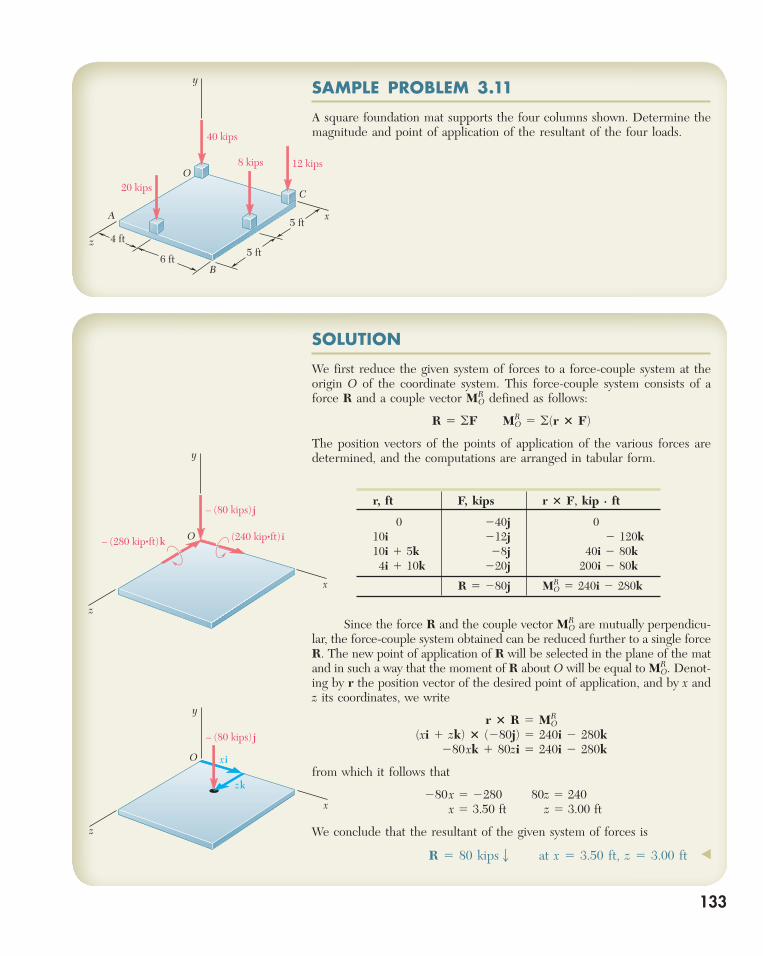
y SAMPLE PROBLEM 3.11
A square foundation mat supports the four columns shown. Determine the magnitude and point of application of the resultant of the four loads.
x
y
z
O
– (80 kips) j
xi
zk
x
z
O– (280 kip•ft)k
– (80 kips) j
(240 kip•ft) i
y
SOLUTION
We first reduce the given system of forces to a force-couple system at the origin O of the coordinate system. This force-couple system consists of a force R and a couple vector M R O defined as follows:
R 5 oF MRO 5 o(r 3 F)
The position vectors of the points of application of the various forces are determined, and the computations are arranged in tabular form.
r, ft F, kips r 3 F, kip · ft
0 240 j 0 10 i 212 j 2 120k 10 i 1 5k 28j 40i 2 80 k 4i 1 10 k 220 j 200 i 2 80 k
R 5 280 j MR O 5 240 i 2 280 k
Since the force R and the couple vector M R O are mutually perpendicu-lar, the force-couple system obtained can be reduced further to a single force R . The new point of application of R will be selected in the plane of the mat and in such a way that the moment of R about O will be equal to M R O. Denot-ing by r the position vector of the desired point of application, and by x and z its coordinates, we write
r 3 R 5 MRO
(xi 1 zk) 3 (280j) 5 240i 2 280k 280xk 1 80zi 5 240i 2 280k
from which it follows that
280x 5 2280 80z 5 240 x 5 3.50 ft z 5 3.00 ft
We conclude that the resultant of the given system of forces is
R 5 80 kipsw at x 5 3.50 ft, z 5 3.00 ft ◀
133
bee29400_ch03_072-155.indd Page 133 11/28/08 9:37:40 PM user-s172bee29400_ch03_072-155.indd Page 133 11/28/08 9:37:40 PM user-s172 /Volumes/204/MHDQ076/work%0/indd%0/Volumes/204/MHDQ076/work%0/indd%0
134
SAMPLE PROBLEM 3.12
Two forces of the same magnitude P act on a cube of side a as shown. Replace the two forces by an equivalent wrench, and determine ( a ) the magnitude and direction of the resultant force R , ( b ) the pitch of the wrench, ( c ) the point where the axis of the wrench intersects the yz plane.
y
xz
MOR
R
OPi
Pj
– Pai
– Pak
y
xz
R
O
=r
M1 = pR
yj
zk
SOLUTION
Equivalent Force-Couple System at O . We first determine the equivalent force-couple system at the origin O . We observe that the position vectors of the points of application E and D of the two given forces are r E 5a i 1 a j and r D 5 a j 1 a k. The resultant R of the two forces and their moment resultant M R O about O are
R 5 F1 1 F2 5 Pi 1 Pj 5 P(i 1 j) (1) MR
O 5 rE 3 F1 1 rD 3 F2 5 (ai 1 aj) 3 Pi 1 (aj 1 ak) 3 Pj 5 2Pak 2 Pai 5 2Pa(i 1 k) (2)
a. Resultant Force R. It follows from Eq. (1) and the adjoining sketch that the resultant force R has the magnitude R 5 P12, lies in the xy plane, and forms angles of 45° with the x and y axes. Thus
R 5 P12 ux 5 uy 5 45° uz 5 90° ◀
b. Pitch of Wrench. Recalling formula (3.62) of Sec. 3.21 and Eqs. (1) and (2) above, we write
p 5
R ? MRO
R2 5P(i 1 j) ? (2Pa)(i 1 k)
(P22)25
2P2a(1 1 0 1 0)
2P2 p 5 2a2 ◀
c. Axis of Wrench. It follows from the above and from Eq. (3.61) that the wrench consists of the force R found in (1) and the couple vector
M1 5 pR 5 2
a2
P(i 1 j) 5 2Pa2
(i 1 j)
(3)
To find the point where the axis of the wrench intersects the yz plane, we express that the moment of the wrench about O is equal to the moment resultant M R O of the original system:
M1 1 r 3 R 5 MRO
or, noting that r 5 y j 1 z k and substituting for R, M R O , and M 1 from Eqs. (1), (2), and (3),
2
Pa2
(i 1 j) 1 (yj 1 zk) 3 P(i 1 j) 5 2Pa(i 1 k)
2
Pa2
i 2Pa2
j 2 Pyk 1 Pzj 2 Pzi 5 2Pai 2 Pak
Equating the coefficients of k , and then the coefficients of j , we find
y 5 a z 5 a/2 ◀
y
xz
A
B
C
DE
O
F1 = PiF2 = Pj
a
a
a
bee29400_ch03_072-155.indd Page 134 11/28/08 9:37:40 PM user-s172bee29400_ch03_072-155.indd Page 134 11/28/08 9:37:40 PM user-s172 /Volumes/204/MHDQ076/work%0/indd%0/Volumes/204/MHDQ076/work%0/indd%0
135
SOLVING PROBLEMSON YOUR OWN
This lesson was devoted to the reduction and simplification of force systems. In solving the problems which follow, you will be asked to perform the opera-
tions discussed below.
1. Reducing a force system to a force and a couple at a given point A . The force is the resultant R of the system and is obtained by adding the various forces; the moment of the couple is the moment resultant of the system and is obtained by adding the moments about A of the various forces. We have
R 5 oF MRA 5 o(r 3 F)
where the position vector r is drawn from A to any point on the line of action of F .
2. Moving a force-couple system from point A to point B. If you wish to reduce a given force system to a force-couple system at point B after you have reduced it to a force-couple system at point A , you need not recompute the moments of the forces about B . The resultant R remains unchanged, and the new moment resultant M R B can be obtained by adding to M R A the moment about B of the force R applied at A [Sample Prob. 3.8]. Denoting by s the vector drawn from B to A , you can write
MRB 5 MR
A 1 s 3 R
3. Checking whether two force systems are equivalent . First reduce each force system to a force-couple system at the same, but arbitrary, point A (as explained in paragraph 1). The two systems are equivalent (that is, they have the same effect on the given rigid body) if the two force-couple systems you have obtained are identical, that is, if
oF 5 oF9 and oMA 5 oM9A
You should recognize that if the first of these equations is not satisfied, that is, if the two systems do not have the same resultant R , the two systems cannot be equivalent and there is then no need to check whether or not the second equation is satisfied.
4. Reducing a given force system to a single force . First reduce the given system to a force-couple system consisting of the resultant R and the couple vector M R A at some convenient point A (as explained in paragraph 1). You will recall from the previous lesson that further reduction to a single force is possible only if the
(continued)
bee29400_ch03_072-155.indd Page 135 11/28/08 9:37:42 PM user-s172bee29400_ch03_072-155.indd Page 135 11/28/08 9:37:42 PM user-s172 /Volumes/204/MHDQ076/work%0/indd%0/Volumes/204/MHDQ076/work%0/indd%0

136
force R and the couple vector M R A are mutually perpendicular . This will certainly be the case for systems of forces which are either concurrent, coplanar , or parallel . The required single force can then be obtained by moving R until its moment about A is equal to M R A , as you did in several problems of the preceding lesson. More formally, you can write that the position vector r drawn from A to any point on the line of action of the single force R must satisfy the equation
r 3 R 5 MRA
This procedure was used in Sample Probs. 3.8, 3.9, and 3.11.
5. Reducing a given force system to a wrench . If the given system is comprised of forces which are not concurrent, coplanar, or parallel, the equivalent force-couple system at a point A will consist of a force R and a couple vector M R A which, in general, are not mutually perpendicular . (To check whether R and M R A are mutually perpendicular, form their scalar product. If this product is zero, they are mutually perpendicular; otherwise, they are not.) If R and M R A are not mutually perpendicular, the force-couple system (and thus the given system of forces) can-not be reduced to a single force . However, the system can be reduced to a wrench —the combination of a force R and a couple vector M 1 directed along a common line of action called the axis of the wrench (Fig. 3.47). The ratio p 5 M 1 / R is called the pitch of the wrench.
To reduce a given force system to a wrench, you should follow these steps:
a. Reduce the given system to an equivalent force-couple system ( R , M R O ), typically located at the origin O . b. Determine the pitch p from Eq. (3.62)
p 5
M1
R5
R ? MRO
R2 (3.62)
and the couple vector from M 1 5 p R . c. Express that the moment about O of the wrench is equal to the moment resultant M R O of the force-couple system at O :
M1 1 r 3 R 5 MRO (3.63)
This equation allows you to determine the point where the line of action of the wrench intersects a specified plane, since the position vector r is directed from O to that point.
These steps are illustrated in Sample Prob. 3.12. Although the determination of a wrench and the point where its axis intersects a plane may appear difficult, the process is simply the application of several of the ideas and techniques developed in this chapter. Thus, once you have mastered the wrench, you can feel confident that you understand much of Chap. 3.
bee29400_ch03_072-155.indd Page 136 11/28/08 9:37:43 PM user-s172bee29400_ch03_072-155.indd Page 136 11/28/08 9:37:43 PM user-s172 /Volumes/204/MHDQ076/work%0/indd%0/Volumes/204/MHDQ076/work%0/indd%0
137137
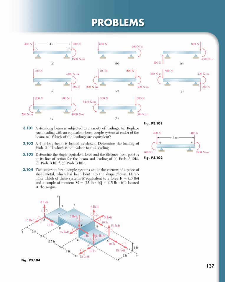
PROBLEMS
3.101 A 4-m-long beam is subjected to a variety of loadings. ( a ) Replace each loading with an equivalent force-couple system at end A of the beam. ( b ) Which of the loadings are equivalent?
3.102 A 4-m-long beam is loaded as shown. Determine the loading of Prob. 3.101 which is equivalent to this loading.
3.103 Determine the single equivalent force and the distance from point A to its line of action for the beam and loading of ( a ) Prob. 3.101 b , ( b ) Prob. 3.101 d , ( c ) Prob. 3.101 e .
3.104 Five separate force-couple systems act at the corners of a piece of sheet metal, which has been bent into the shape shown. Deter-mine which of these systems is equivalent to a force F 5 (10 lb) i and a couple of moment M 5 (15 lb ? ft) j 1 (15 lb ? ft) k located at the origin.
A B
4 m
(a)
400 N
400 N
200 N
800 N
(b)
600 N
(c)
900 N
300 N
(d) (e)
400 N 200 N
( f )
800 N
200 N
(h)
300 N 300 N
(g)
800 N200 N
4000 N⋅m 300 N⋅m200 N⋅m
1800 N⋅m
2300 N⋅m
2400 N⋅m
900 N⋅m
4500 N⋅m
300 N⋅m300 N⋅m
400 N⋅m200 N⋅m
Fig. P3.101
A B
4 m200 N 400 N
2800 N⋅m400 N⋅m Fig. P3.102
5 lb•ft
5 lb•ft15 lb•ft
5 lb•ft
15 lb•ft
15 lb•ft
15 lb•ft
15 lb•ft
80 lb•ft25 lb•ft
10 lb
10 lb
10 lb
10 lb
10 lb
y
z
O
H
A
C
J
I
BD
G
x
F
E
2 ft
2 ft2 ft
1 ft
2.5 ft
Fig. P3.104
bee29400_ch03_072-155.indd Page 137 11/28/08 9:37:44 PM user-s172bee29400_ch03_072-155.indd Page 137 11/28/08 9:37:44 PM user-s172 /Volumes/204/MHDQ076/work%0/indd%0/Volumes/204/MHDQ076/work%0/indd%0

138 Rigid Bodies: Equivalent Systems of Forces 3.105 The weights of two children sitting at ends A and B of a seesaw are 84 lb and 64 lb, respectively. Where should a third child sit so that the resultant of the weights of the three children will pass through C if she weighs ( a ) 60 lb, ( b ) 52 lb.
3.106 Three stage lights are mounted on a pipe as shown. The lights at A and B each weigh 4.1 lb, while the one at C weighs 3.5 lb. ( a ) If d 5 25 in., determine the distance from D to the line of action of the resultant of the weights of the three lights. ( b ) Determine the value of d so that the resultant of the weights passes through the midpoint of the pipe. Fig. P3.105
A
B
C
6 ft
6 ft
Fig. P3.106
D
B
C
E
d
34 in.
10 in.
84 in.
A
3.107 A beam supports three loads of given magnitude and a fourth load whose magnitude is a function of position. If b 5 1.5 m and the loads are to be replaced with a single equivalent force, determine ( a ) the value of a so that the distance from support A to the line of action of the equivalent force is maximum, ( b ) the magnitude of the equivalent force and its point of application on the beam.
Fig. P3.107
ba
A B
1300 N 400 N 600 N
a2
ab
400 N
9 m
3.108 Gear C is rigidly attached to arm AB . If the forces and couple shown can be reduced to a single equivalent force at A , determine the equivalent force and the magnitude of the couple M .
18 lb
40 lb
25 lb25°
30°
40°
A
B
C
M
22 in.
10 in.
16 in.
Fig. P3.108
bee29400_ch03_072-155.indd Page 138 11/28/08 9:37:47 PM user-s172bee29400_ch03_072-155.indd Page 138 11/28/08 9:37:47 PM user-s172 /Volumes/204/MHDQ076/work%0/indd%0/Volumes/204/MHDQ076/work%0/indd%0

139Problems 3.109 A couple of magnitude M 5 54 lb ? in. and the three forces shown are applied to an angle bracket. ( a ) Find the resultant of this sys-tem of forces. ( b ) Locate the points where the line of action of the resultant intersects line AB and line BC .
3.110 A couple M and the three forces shown are applied to an angle bracket. Find the moment of the couple if the line of action of the resultant of the force system is to pass through ( a ) point A , ( b ) point B , ( c ) point C .
3.111 Four forces act on a 700 3 375-mm plate as shown. ( a ) Find the resultant of these forces. ( b ) Locate the two points where the line of action of the resultant intersects the edge of the plate.
3.112 Solve Prob. 3.111, assuming that the 760-N force is directed to the right.
3.113 A truss supports the loading shown. Determine the equivalent force acting on the truss and the point of intersection of its line of action with a line drawn through points A and G .
A B
C
10 lb 30 lb
60°12 in.
45 lb
M 8 in.
Fig. P3.109 and P3.110
A B
D EC
500 N
600 N
760 N
340 N
500 mm200 mm
375 mm
Fig. P3.111
C
A
B D F
E
G
240 lb 160 lb 300 lb
40°
180 lb
70°
x
y4 ft
8 ft 8 ft
8 ft 8 ft 8 ft
6 ft
Fig. P3.113
2 in.
1 in.
210 lb
150 lb25°
25°
4 in.
120 lb 160 lb
A B
C D
EF
r = 2 in. r = 1 in.12
6 in.6 in.
Fig. P3.114
3.114 Pulleys A and B are mounted on bracket CDEF . The tension on each side of the two belts is as shown. Replace the four forces with a single equivalent force, and determine where its line of action intersects the bottom edge of the bracket.
C
A B
DF
E
G H
P
200 N240 mm
120 N
70°15°
50 mm
50 mm
50 mm
80 N42 N•m
40 N•m 180 mm
640 mm
520 mm
Fig. P3.115
3.115 A machine component is subjected to the forces and couples shown. The component is to be held in place by a single rivet that can resist a force but not a couple. For P 5 0, determine the location of the rivet hole if it is to be located ( a ) on line FG , ( b ) on line GH .
3.116 Solve Prob. 3.115, assuming that P 5 60 N.
bee29400_ch03_072-155.indd Page 139 11/28/08 9:37:48 PM user-s172bee29400_ch03_072-155.indd Page 139 11/28/08 9:37:48 PM user-s172 /Volumes/204/MHDQ076/work%0/indd%0/Volumes/204/MHDQ076/work%0/indd%0

140 Rigid Bodies: Equivalent Systems of Forces 3.117 A 32-lb motor is mounted on the floor. Find the resultant of the weight and the forces exerted on the belt, and determine where the line of action of the resultant intersects the floor.
3.118 As follower AB rolls along the surface of member C , it exerts a con-stant force F perpendicular to the surface. ( a ) Replace F with an equivalent force-couple system at the point D obtained by drawing the perpendicular from the point of contact to the x axis. ( b ) For a 5 1 m and b 5 2 m, determine the value of x for which the moment of the equivalent force-couple system at D is maximum.
3.119 Four forces are applied to the machine component ABDE as shown. Replace these forces by an equivalent force-couple system at A.
Fig. P3.117
140 lb
30°
60 lb
O
W
2 in.
2 in.
3.120 Two 150-mm-diameter pulleys are mounted on line shaft AD . The belts at B and C lie in vertical planes parallel to the yz plane. Replace the belt forces shown with an equivalent force-couple sys-tem at A.
y
b
a
C
B
A
F
D x
y = b (1 – )x2
a2
Fig. P3.118
z
200 mm
40 mm
160 mm
100 mm
20 mm
x
50 N
250 N
120 N
300 N
y
B
E
D
A
Fig. P3.119
A
B
C
D
x
y
z
20º
10º
10º 155 N
240 N
145 N
215 N
180 mm
225 mm
225 mm
Fig. P3.120
bee29400_ch03_072-155.indd Page 140 11/28/08 9:37:49 PM user-s172bee29400_ch03_072-155.indd Page 140 11/28/08 9:37:49 PM user-s172 /Volumes/204/MHDQ076/work%0/indd%0/Volumes/204/MHDQ076/work%0/indd%0

141Problems 3.121 While using a pencil sharpener, a student applies the forces and couple shown. ( a ) Determine the forces exerted at B and C know-ing that these forces and the couple are equivalent to a force-couple system at A consisting of the force R 5 (2.6 lb) i 1 R y j 2 (0.7 lb) k and the couple M R A 5 M x i 1 (1.0 lb ? ft) j 2 (0.72 lb ? ft) k . ( b ) Find the corresponding values of R y and M x .
3.122 A mechanic uses a crowfoot wrench to loosen a bolt at C . The mechanic holds the socket wrench handle at points A and B and applies forces at these points. Knowing that these forces are equiv-alent to a force-couple system at C consisting of the force C 5 2(8 lb) i 1 (4 lb) k and the couple M C 5 (360 lb ? in.) i , determine the forces applied at A and at B when A z 5 2 lb.
3.123 As an adjustable brace BC is used to bring a wall into plumb, the force-couple system shown is exerted on the wall. Replace this force-couple system with an equivalent force-couple system at A if R 5 21.2 lb and M 5 13.25 lb · ft.
B
B
1 lb•ft
3.5 in.
1.75 in.
2 in.
x
y
z
A
CCxi
–Czk
–Cyj
Fig. P3.121
2 in.
8 in.
10 in.
Ax
Ay
Az
Bx
By
Bz
A
Bx
y
C
z
Fig. P3.122
A
B
R
M
Cx
y
z
64 in.
96 in.
42 in.
48 in.
Fig. P3.123
bee29400_ch03_072-155.indd Page 141 11/28/08 9:37:49 PM user-s172bee29400_ch03_072-155.indd Page 141 11/28/08 9:37:49 PM user-s172 /Volumes/204/MHDQ076/work%0/indd%0/Volumes/204/MHDQ076/work%0/indd%0
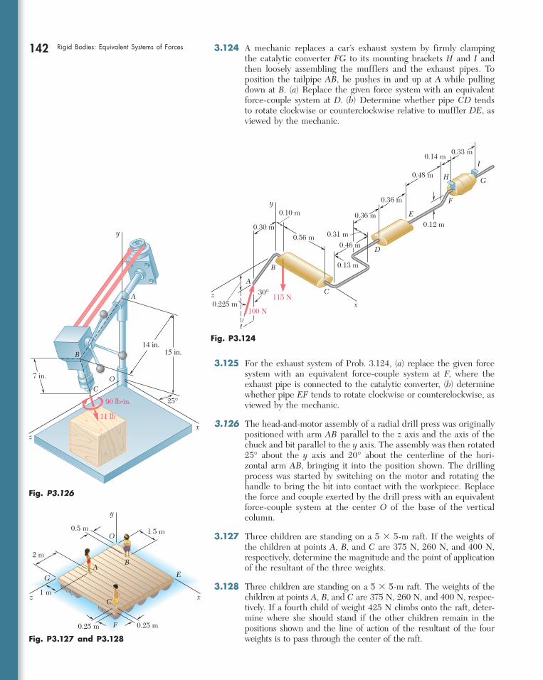
142 Rigid Bodies: Equivalent Systems of Forces 3.124 A mechanic replaces a car’s exhaust system by firmly clamping the catalytic converter FG to its mounting brackets H and I and then loosely assembling the mufflers and the exhaust pipes. To position the tailpipe AB , he pushes in and up at A while pulling down at B . ( a ) Replace the given force system with an equivalent force-couple system at D . ( b ) Determine whether pipe CD tends to rotate clockwise or counterclockwise relative to muffler DE , as viewed by the mechanic.
3.125 For the exhaust system of Prob. 3.124, ( a ) replace the given force system with an equivalent force-couple system at F , where the exhaust pipe is connected to the catalytic converter, ( b ) determine whether pipe EF tends to rotate clockwise or counterclockwise, as viewed by the mechanic.
3.126 The head-and-motor assembly of a radial drill press was originally positioned with arm AB parallel to the z axis and the axis of the chuck and bit parallel to the y axis. The assembly was then rotated 25° about the y axis and 20° about the centerline of the hori-zontal arm AB , bringing it into the position shown. The drilling process was started by switching on the motor and rotating the handle to bring the bit into contact with the workpiece. Replace the force and couple exerted by the drill press with an equivalent force-couple system at the center O of the base of the vertical column.
3.127 Three children are standing on a 5 3 5-m raft. If the weights of the children at points A , B , and C are 375 N, 260 N, and 400 N, respectively, determine the magnitude and the point of application of the resultant of the three weights.
3.128 Three children are standing on a 5 3 5-m raft. The weights of the children at points A , B , and C are 375 N, 260 N, and 400 N, respec-tively. If a fourth child of weight 425 N climbs onto the raft, deter-mine where she should stand if the other children remain in the positions shown and the line of action of the resultant of the four weights is to pass through the center of the raft.
y
z
A
B
0.30 m
0.10 m
0.56 m
0.225 m100 N
115 N30°
GH
x
C
D
E
F
I
0.13 m
0.46 m0.31 m
0.12 m
0.33 m
0.36 m
0.36 m
0.48 m
0.14 m
Fig. P3.124
Fig. P3.127 and P3.128
AB
Cx
y
z
E
F
G
O0.5 m
0.25 m 0.25 m
1.5 m
1 m
2 m
O7 in.
x
y
A
z
C
11 lb
90 lb•in.
14 in.15 in.
25°
B
Fig. P3.126
bee29400_ch03_072-155.indd Page 142 11/28/08 9:37:50 PM user-s172bee29400_ch03_072-155.indd Page 142 11/28/08 9:37:50 PM user-s172 /Volumes/204/MHDQ076/work%0/indd%0/Volumes/204/MHDQ076/work%0/indd%0
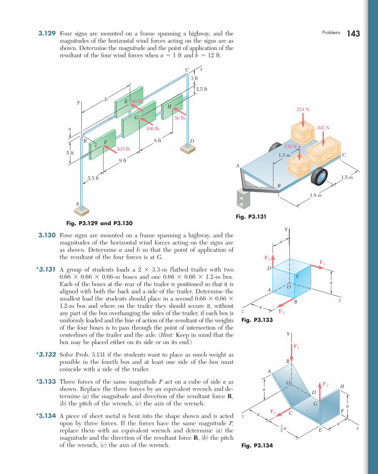
143Problems 3.129 Four signs are mounted on a frame spanning a highway, and the magnitudes of the horizontal wind forces acting on the signs are as shown. Determine the magnitude and the point of application of the resultant of the four wind forces when a 5 1 ft and b 5 12 ft.
Fig. P3.129 and P3.130
D
A
B
C x
y
z
E
F
G
H
a
2.5 ft
90 lb
160 lb
50 lb
105 lb
9 ft
5.5 ft
b
5 ft
8 ft
3 ft
3.130 Four signs are mounted on a frame spanning a highway, and the magnitudes of the horizontal wind forces acting on the signs are as shown. Determine a and b so that the point of application of the resultant of the four forces is at G .
*3.131 A group of students loads a 2 3 3.3-m flatbed trailer with two 0.66 3 0.66 3 0.66-m boxes and one 0.66 3 0.66 3 1.2-m box. Each of the boxes at the rear of the trailer is positioned so that it is aligned with both the back and a side of the trailer. Determine the smallest load the students should place in a second 0.66 3 0.66 3 1.2-m box and where on the trailer they should secure it, without any part of the box overhanging the sides of the trailer, if each box is uniformly loaded and the line of action of the resultant of the weights of the four boxes is to pass through the point of intersection of the centerlines of the trailer and the axle. ( Hint: Keep in mind that the box may be placed either on its side or on its end.)
*3.132 Solve Prob. 3.131 if the students want to place as much weight as possible in the fourth box and at least one side of the box must coincide with a side of the trailer.
*3.133 Three forces of the same magnitude P act on a cube of side a as shown. Replace the three forces by an equivalent wrench and de-termine ( a ) the magnitude and direction of the resultant force R , ( b ) the pitch of the wrench, ( c ) the axis of the wrench.
*3.134 A piece of sheet metal is bent into the shape shown and is acted upon by three forces. If the forces have the same magnitude P , replace them with an equivalent wrench and determine ( a ) the magnitude and the direction of the resultant force R , ( b ) the pitch of the wrench, ( c ) the axis of the wrench.
224 N
392 N
176 N
1.3 m
A
B
C
1.5 m
1.8 m
Fig. P3.131
Fig. P3.133
y
x
z
A
B
C
D
O
F1F2
F3
a
a
a
Fig. P3.134
A
B
C
D
E
FG
HO
x
y
z
F1
F2
F3
a
a
a
32 a
a
bee29400_ch03_072-155.indd Page 143 11/28/08 9:37:51 PM user-s172bee29400_ch03_072-155.indd Page 143 11/28/08 9:37:51 PM user-s172 /Volumes/204/MHDQ076/work%0/indd%0/Volumes/204/MHDQ076/work%0/indd%0

144 Rigid Bodies: Equivalent Systems of Forces *3.135 and *3.136 The forces and couples shown are applied to two screws as a piece of sheet metal is fastened to a block of wood. Reduce the forces and the couples to an equivalent wrench and determine ( a ) the resultant force R , ( b ) the pitch of the wrench, ( c ) the point where the axis of the wrench intersects the xz plane.
*3.139 Two ropes attached at A and B are used to move the trunk of a fallen tree. Replace the forces exerted by the ropes with an equiva-lent wrench and determine ( a ) the resultant force R , ( b ) the pitch of the wrench, ( c ) the point where the axis of the wrench intersects the yz plane.
*3.137 and *3.138 Two bolts at A and B are tightened by applying the forces and couples shown. Replace the two wrenches with a single equivalent wrench and determine ( a ) the resultant R , ( b the pitch of the single equivalent wrench, ( c ) the point where the axis of the wrench intersects the xz plane.
11 lb6 lb•in.
6 lb•in.
10 lb
15 in.
x
z
y
A
B
O
20 in.
Fig. P3.136
1 N•m
4 N•m
15 N
20 N
100 mm
x
z
y
A
O
Fig. P3.135
0.1 m
0.3 m
0.6 m
x
z
y
A
B
0.4 m
30 N•m
84 N
32 N•m
80 N
Fig. P3.137
10 in.10 in.
10 in.
30 in.
16 in.
x
z
y
A
B
238 lb•in.
17 lb
26.4 lb
220 lb•in.
Fig. P3.138
5 m2 m 2 m6 mx
y
z
O
AB
C D1650 N
1500 N
14 m
9 m12 m
9 m
Fig. P3.139
bee29400_ch03_072-155.indd Page 144 11/28/08 9:37:52 PM user-s172bee29400_ch03_072-155.indd Page 144 11/28/08 9:37:52 PM user-s172 /Volumes/204/MHDQ076/work%0/indd%0/Volumes/204/MHDQ076/work%0/indd%0

145Problems *3.140 A flagpole is guyed by three cables. If the tensions in the cables have the same magnitude P , replace the forces exerted on the pole with an equivalent wrench and determine ( a ) the resultant force R , ( b ) the pitch of the wrench, ( c ) the point where the axis of the wrench intersects the xz plane.
*3.143 Replace the wrench shown with an equivalent system consisting of two forces perpendicular to the y axis and applied respectively at A and B .
*3.144 Show that, in general, a wrench can be replaced with two forces chosen in such a way that one force passes through a given point while the other force lies in a given plane.
*3.145 Show that a wrench can be replaced with two perpendicular forces, one of which is applied at a given point.
*3.146 Show that a wrench can be replaced with two forces, one of which has a prescribed line of action.
A
B
x
y
z
C
D
E O
4a
20a
12a
18a
15a
9a
Fig. P3.140
160 mm
120 mm
120 mm
60 mm
60 mm
40 mm
40 mm
50 N
70 NBC H
D
I
y
A
E
z FG
x
10 N•m
14 N•m
Fig. P3.141
x
y
z
AB
C
D
E
FG
H
I
160 lb•in.
34 lb
30 lb
K
12 in.
6 in.
6 in.
6 in.
3 in.8 in.
18 in.18 in.
Fig. P3.142
Fig. P3.143
x
y
z
B
A
OM
R
b
a
*3.141 and *3.142 Determine whether the force-and-couple system shown can be reduced to a single equivalent force R . If it can, determine R and the point where the line of action of R intersects the yz plane. If it cannot be so reduced, replace the given system with an equivalent wrench and determine its resultant, its pitch, and the point where its axis intersects the yz plane.
bee29400_ch03_072-155.indd Page 145 11/28/08 9:37:52 PM user-s172bee29400_ch03_072-155.indd Page 145 11/28/08 9:37:52 PM user-s172 /Volumes/204/MHDQ076/work%0/indd%0/Volumes/204/MHDQ076/work%0/indd%0