Solid–liquid structural break-up in M2 tool steel for semi-solid metal processing
16
1 Solid-liquid structural break-up in M2 tool steel for semi-solid metal processing M.Z. Omar 1* , H.V. Atkinson 2 , A.A. Howe 3 , E.J. Palmiere 3 , P. Kapranos 3 and M.J. Ghazali 1 1 Department of Mechanical and Materials Engineering, National University of Malaysia, 43600 UKM Bangi, Selangor, Malaysia. 2 Department of Engineering, University of Leicester, University Rd., Leicester, LE1 7RH, UK. 3 Department of Engineering Materials, The University of Sheffield, Sir Robert Hadfield Building, Mappin St., Sheffield, S1 3JD, UK. Abstract The success of semi-solid metal processing mostly depends on the formation of suitable starting microstructure, which must consist of solid metal spheroids in a liquid matrix. Various methods of obtaining this structure have been established; they include Recrystallisation and Partial Melting (RAP), Strain-Induced Melt-Activated (SIMA), or simple mechanical stirring, to name a few. These methods, as widely discussed, have mostly been applied with light alloys, mainly aluminium-based. This paper discusses solid-liquid structural break-up in M2 tool steel subjected to a direct re-melting procedure from the as-annealed condition. The role of carbide dissolution in the grain boundary * Corresponding author. Tel.: +60389216116; fax.: +6038902314 E-mail address: [email protected] or [email protected] JMSC11504 - Final version
Transcript of Solid–liquid structural break-up in M2 tool steel for semi-solid metal processing
1
Solid-liquid structural break-up in M2 tool steel for semi-solid metal
processing
M.Z. Omar1*
, H.V. Atkinson2, A.A. Howe
3, E.J. Palmiere
3, P. Kapranos
3 and M.J. Ghazali
1
1Department of Mechanical and Materials Engineering, National University of Malaysia, 43600 UKM
Bangi, Selangor, Malaysia.
2Department of Engineering, University of Leicester, University Rd., Leicester, LE1 7RH, UK.
3Department of Engineering Materials, The University of Sheffield, Sir Robert Hadfield Building, Mappin
St., Sheffield, S1 3JD, UK.
Abstract
The success of semi-solid metal processing mostly depends on the formation of suitable
starting microstructure, which must consist of solid metal spheroids in a liquid matrix.
Various methods of obtaining this structure have been established; they include
Recrystallisation and Partial Melting (RAP), Strain-Induced Melt-Activated (SIMA), or
simple mechanical stirring, to name a few. These methods, as widely discussed, have
mostly been applied with light alloys, mainly aluminium-based. This paper discusses
solid-liquid structural break-up in M2 tool steel subjected to a direct re-melting procedure
from the as-annealed condition. The role of carbide dissolution in the grain boundary
* Corresponding author. Tel.: +60389216116; fax.: +6038902314
E-mail address: [email protected] or [email protected]
JMSC11504 - Final version
2
liquation of the steel is described. This leads to the production of near spheroidal solid
grains in a liquid matrix, a microstructure suitable for the thixoforming process.
Microstructural examination revealed that carbide particles contained in bands at 1220C
slowly disappeared with temperature. At 1300C, the solid grains seemed to be free from
carbides. Most of the carbides had now re-precipitated at the grain boundaries.
Thixoforming carried out at 1340C and 1360C revealed the thixotropic properties of the
semi-solid metal slurries. The results indicate a widening of the range of potential routes
to thixoformable microstructures.
Keywords: semi-solid metal processing, M2 tool steel, carbide dissolution, thixoforming
Introduction
The initial work that led to the interest in semi-solid metal processing (SSM) can be traced back to studies
by researchers at The Massachusetts Institute of Technology in the early 1970s [1]. This work was
originally directed at the problem of hot tearing in alloy castings but it was later realised that a new
technology for near net shaping of complex shapes had been discovered. This SSM technology can be
generally defined as a forming process that shapes metal components in their semi-solid state [2-4]. There
are several routes for SSM processing including thixoforming where material with an appropriate
microstructure is initially solid and is reheated into the semisolid state for forming.
There is a variety of routes to obtain the appropriate microstructure for thixoforming i.e. a microstructure
which consists of solid spheroids in a liquid matrix once the material is reheated into the semisolid state.
Some are based on the liquid state (e.g. see [5]). The more established solid state routes are RAP
(Recrystallisation And Partial melting) and SIMA (Strain Induced Melt Activated). The first involves cold
3
or warm working below the recrystallisation temperature followed by heating above the solidus of the
material, while the latter involves hot working between recrystallisation and solidus temperatures, followed
by cold working so as to produce a critical level of strain, before the material is reheated above the solidus.
Today, the process is mainly established in the production of parts made of aluminium alloys. Work in the
thixoforming of high temperature materials, such as steel, is still at its initial stage; this is mainly due to the
high processing temperatures involved [6-9]. For thixoforming to be possible, it is preferable for an alloy
to have an appreciable melting range and, before forming, the microstructure must consist of solid metal
spheroids in a liquid matrix. Here, a commercially produced M2 tool steel alloy, i.e. being hot worked (by
GFM), tempered and annealed, was directly reheated in a protective atmosphere from room temperature to
above its solidus with no prior additional cold working. GFM (from the German words for Gesellschaft für
Fertigungstechnik und Mashinenbau) forging is based on the radial forging principle whereby a long
workpiece is hammered by four forging tools.
One major attraction of thixoforming high temperature materials, (e.g. steels), is the low forging force
involved during thixoforming as compared to that in conventional forgings [6]. This means that more
intricate and complex shapes can be formed faster with some reduction in forming steps and with near net
shaping capabilities [6, 10-12]. Other major advantages include prolonged die life due to decreased
thermal shock (forging below liquidus as against castings), weight savings in components with less porosity
than conventionally, plus improved usage of feedstock materials because of improved designs.
This paper describes the microstructural development of an M2 tool steel when directly reheated into its
semi-solid zone from the as-annealed condition. In particular, it discusses the role of carbide dissolution in
the grain boundary liquation of the steel, hence producing near spheroidal solid grains in a liquid matrix, a
microstructure suitable for the process.
Experimental Procedure
4
The M2 high speed steel used was produced by GFM hot forging at the temperature of approximately
1150C. It was then tempered at 650-750C for about 4 hours, and subsequently annealed for 8-10 hours at
860C before being furnace cooled to ambient temperature. This is the state in which it is conventionally
received from the supplier (Barworth Flockton Limited, United Kingdom). All the heat treatment was
carried out in a controlled atmosphere to prevent oxidation and de-carburisation. The chemical
composition of the starting material is given in Table 1.
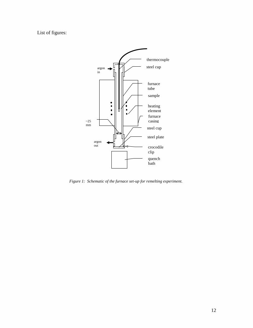
Partial remelting was carried out using a vertical, high temperature quench Carbolite tube furnace, capable
of reaching a maximum temperature of 1500C. The as-received billet was cut into coupons of
approximately 5 x 10 x 12 mm. A K-type thermocouple was placed inside a hole located on the 5 x 10 mm
surface of the coupon (5-6 mm deep), to ensure that the sample had reached the predefined quenching
temperature, and hung inside the furnace. The as-received samples were subjected to different holding
temperatures and times (it takes about 4 minutes for each sample to reach the respective targeted
temperatures). They were quenched in a salt bath after the predetermined experimental parameters had
been established to freeze the structures. To ensure that the sample is cooled rapidly, its dimensions must
be kept to a minimum while at the same time having enough strength in the mushy state to provide the
presence of thick walls around the thermocouple inside the thermocouple hole. A coupon thickness of
5mm was found suitable for the purpose. The selected temperatures were from 1220 to 1360C at 20C
intervals and for various holding times. The heating was carried out in an argon atmosphere to reduce
oxidation. The quench furnace set-up is shown in Figure 1.
The microstructural characterisation was carried out using KS-400 Imaging System Release 3.0 software
connected to a Reichert-Jung Polyvar MET optical microscope and Jeol JSM 6400 scanning electron
microscope. The grain or cell size and the volume fraction of liquid were respectively measured adopting
the Mean Lineal Intercept method as outlined in ASTM E112-96 standard [13] and by the Systematic
Manual Point Count as outlined in ASTM E562-99 standard [14]. All samples were etched using 5% Nital
(5ml HNO3 + 95ml methanol or ethanol).
5
Results and Discussion
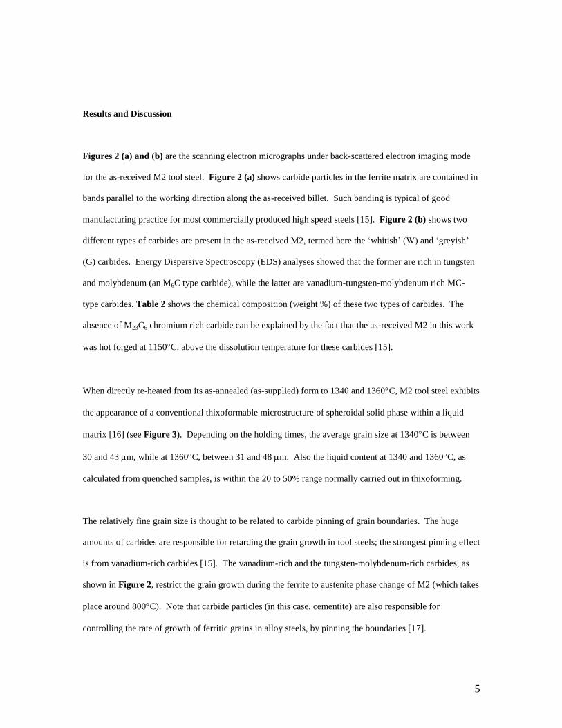
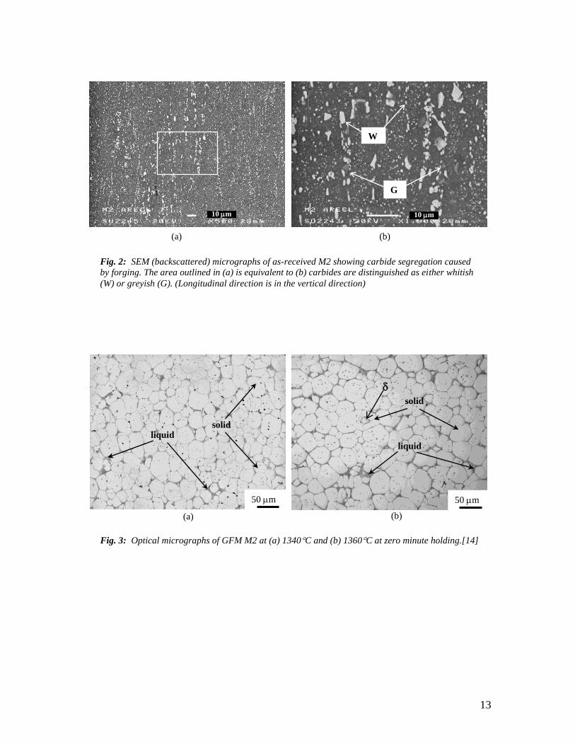
Figures 2 (a) and (b) are the scanning electron micrographs under back-scattered electron imaging mode
for the as-received M2 tool steel. Figure 2 (a) shows carbide particles in the ferrite matrix are contained in
bands parallel to the working direction along the as-received billet. Such banding is typical of good
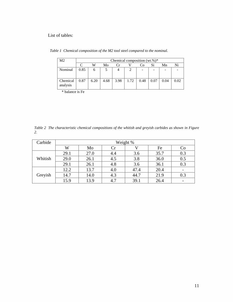
manufacturing practice for most commercially produced high speed steels [15]. Figure 2 (b) shows two
different types of carbides are present in the as-received M2, termed here the ‘whitish’ (W) and ‘greyish’
(G) carbides. Energy Dispersive Spectroscopy (EDS) analyses showed that the former are rich in tungsten
and molybdenum (an M6C type carbide), while the latter are vanadium-tungsten-molybdenum rich MC-
type carbides. Table 2 shows the chemical composition (weight %) of these two types of carbides. The
absence of M23C6 chromium rich carbide can be explained by the fact that the as-received M2 in this work
was hot forged at 1150C, above the dissolution temperature for these carbides [15].
When directly re-heated from its as-annealed (as-supplied) form to 1340 and 1360C, M2 tool steel exhibits
the appearance of a conventional thixoformable microstructure of spheroidal solid phase within a liquid
matrix [16] (see Figure 3). Depending on the holding times, the average grain size at 1340C is between
30 and 43 m, while at 1360C, between 31 and 48 m. Also the liquid content at 1340 and 1360C, as
calculated from quenched samples, is within the 20 to 50% range normally carried out in thixoforming.
The relatively fine grain size is thought to be related to carbide pinning of grain boundaries. The huge
amounts of carbides are responsible for retarding the grain growth in tool steels; the strongest pinning effect
is from vanadium-rich carbides [15]. The vanadium-rich and the tungsten-molybdenum-rich carbides, as
shown in Figure 2, restrict the grain growth during the ferrite to austenite phase change of M2 (which takes
place around 800C). Note that carbide particles (in this case, cementite) are also responsible for
controlling the rate of growth of ferritic grains in alloy steels, by pinning the boundaries [17].
6
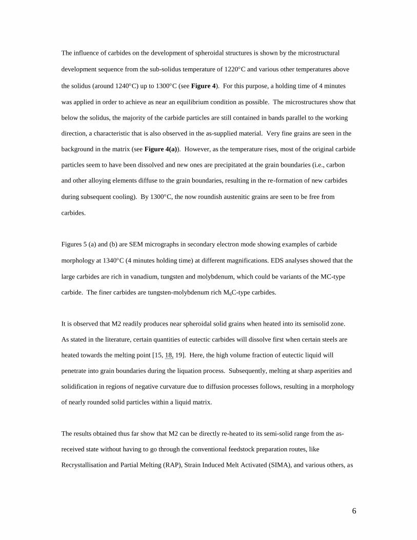
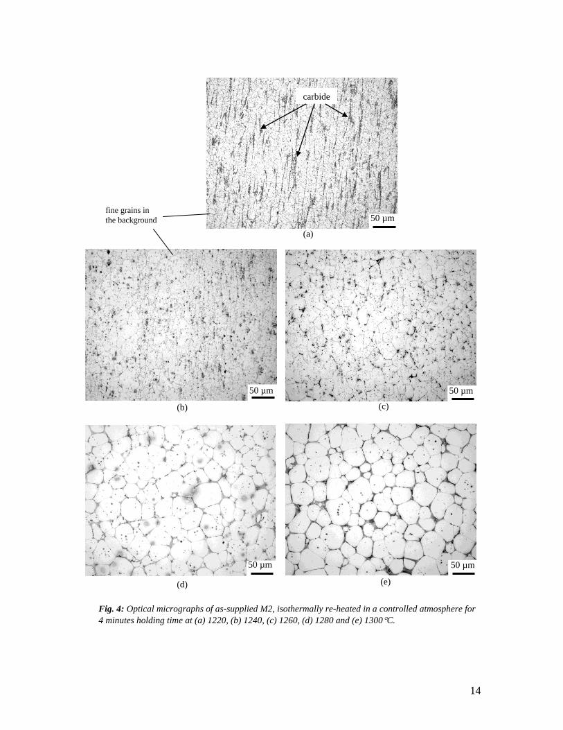
The influence of carbides on the development of spheroidal structures is shown by the microstructural
development sequence from the sub-solidus temperature of 1220C and various other temperatures above
the solidus (around 1240C) up to 1300C (see Figure 4). For this purpose, a holding time of 4 minutes
was applied in order to achieve as near an equilibrium condition as possible. The microstructures show that
below the solidus, the majority of the carbide particles are still contained in bands parallel to the working
direction, a characteristic that is also observed in the as-supplied material. Very fine grains are seen in the
background in the matrix (see Figure 4(a)). However, as the temperature rises, most of the original carbide
particles seem to have been dissolved and new ones are precipitated at the grain boundaries (i.e., carbon
and other alloying elements diffuse to the grain boundaries, resulting in the re-formation of new carbides
during subsequent cooling). By 1300C, the now roundish austenitic grains are seen to be free from
carbides.
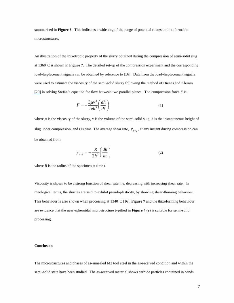
Figures 5 (a) and (b) are SEM micrographs in secondary electron mode showing examples of carbide
morphology at 1340C (4 minutes holding time) at different magnifications. EDS analyses showed that the
large carbides are rich in vanadium, tungsten and molybdenum, which could be variants of the MC-type
carbide. The finer carbides are tungsten-molybdenum rich M6C-type carbides.
It is observed that M2 readily produces near spheroidal solid grains when heated into its semisolid zone.
As stated in the literature, certain quantities of eutectic carbides will dissolve first when certain steels are
heated towards the melting point [15, 18, 19]. Here, the high volume fraction of eutectic liquid will
penetrate into grain boundaries during the liquation process. Subsequently, melting at sharp asperities and
solidification in regions of negative curvature due to diffusion processes follows, resulting in a morphology
of nearly rounded solid particles within a liquid matrix.
The results obtained thus far show that M2 can be directly re-heated to its semi-solid range from the as-
received state without having to go through the conventional feedstock preparation routes, like
Recrystallisation and Partial Melting (RAP), Strain Induced Melt Activated (SIMA), and various others, as
7
summarised in Figure 6. This indicates a widening of the range of potential routes to thixoformable
microstructures.
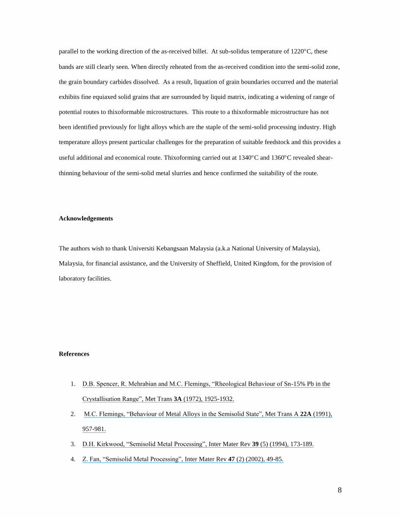
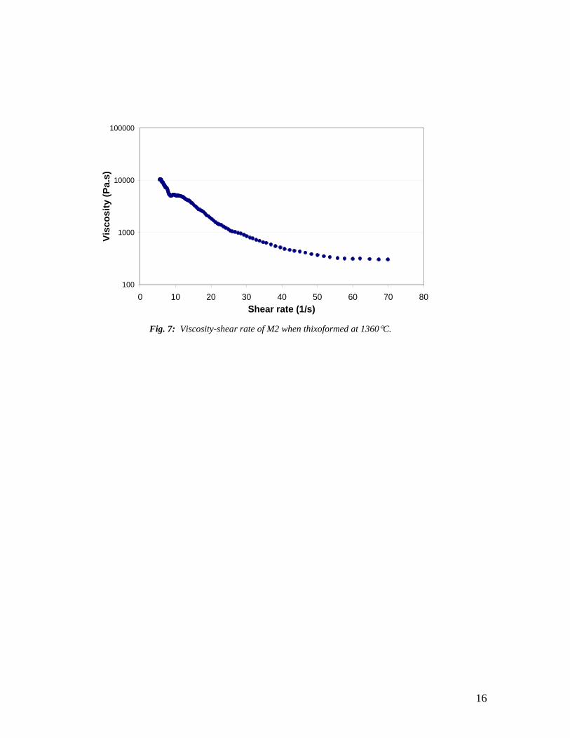
An illustration of the thixotropic property of the slurry obtained during the compression of semi-solid slug
at 1360C is shown in Figure 7. The detailed set-up of the compression experiment and the corresponding
load-displacement signals can be obtained by reference to [16]. Data from the load-displacement signals
were used to estimate the viscosity of the semi-solid slurry following the method of Dienes and Klemm
[20] in solving Stefan’s equation for flow between two parallel planes. The compression force F is:
dt
dh
h
vF
5
2
2
3
(1)
where is the viscosity of the slurry, v is the volume of the semi-solid slug, h is the instantaneous height of
slug under compression, and t is time. The average shear rate, avg , at any instant during compression can
be obtained from:
dt
dh
h
Ravg 22
(2)
where R is the radius of the specimen at time t.
Viscosity is shown to be a strong function of shear rate, i.e. decreasing with increasing shear rate. In
rheological terms, the slurries are said to exhibit pseudoplasticity, by showing shear-thinning behaviour.
This behaviour is also shown when processing at 1340C [16]. Figure 7 and the thixoforming behaviour
are evidence that the near-spheroidal microstructure typified in Figure 4 (e) is suitable for semi-solid
processing.
Conclusion
The microstructures and phases of as-annealed M2 tool steel in the as-received condition and within the
semi-solid state have been studied. The as-received material shows carbide particles contained in bands
8
parallel to the working direction of the as-received billet. At sub-solidus temperature of 1220C, these
bands are still clearly seen. When directly reheated from the as-received condition into the semi-solid zone,
the grain boundary carbides dissolved. As a result, liquation of grain boundaries occurred and the material
exhibits fine equiaxed solid grains that are surrounded by liquid matrix, indicating a widening of range of
potential routes to thixoformable microstructures. This route to a thixoformable microstructure has not
been identified previously for light alloys which are the staple of the semi-solid processing industry. High
temperature alloys present particular challenges for the preparation of suitable feedstock and this provides a
useful additional and economical route. Thixoforming carried out at 1340C and 1360C revealed shear-
thinning behaviour of the semi-solid metal slurries and hence confirmed the suitability of the route.
Acknowledgements
The authors wish to thank Universiti Kebangsaan Malaysia (a.k.a National University of Malaysia),
Malaysia, for financial assistance, and the University of Sheffield, United Kingdom, for the provision of
laboratory facilities.
References
1. D.B. Spencer, R. Mehrabian and M.C. Flemings, “Rheological Behaviour of Sn-15% Pb in the
Crystallisation Range”, Met Trans 3A (1972), 1925-1932.
2. M.C. Flemings, “Behaviour of Metal Alloys in the Semisolid State”, Met Trans A 22A (1991),
957-981.
3. D.H. Kirkwood, “Semisolid Metal Processing”, Inter Mater Rev 39 (5) (1994), 173-189.
4. Z. Fan, “Semisolid Metal Processing”, Inter Mater Rev 47 (2) (2002), 49-85.

9
5. E.C. Legoretta, H.V. Atkinson, H. Jones, “Cooling slope casting to obtain thixotropic feedstock II:
observations with A356 alloy”, J of Mat Sci, 43 (2008), 5456-5469.
6. B. Nohn, U. Morjan and D. Hartmann, “Thixoforming of Steel”, Proceedings of the 6th
International Conference on Semi-Solid Processing of Alloys and Composites (Edimet Spa,
Brescia, Turin, Italy, 2000), 265-272.
7. M.Z. Omar, H.V. Atkinson, E.J. Palmiere, A.A. Howe, P. Kapranos, “Microstructural
development of HP9/4/30 steel during partial remelting”, Steel Research Int. 75 (8/9) (2004), 552-
560.
8. M.Z. Omar, E.J. Palmiere, A.A. Howe, H.V. Atkinson and P. Kapranos, “Thixoforming of a high
performance HP9/4/30 steel”, Mater Sci and Eng A, A395 (2005), 53-61.
9. W. Puttgen, W. Bleck, G. Hirt and H. Shimahara, “Thixoforming of Steels – A Status Report”,
Adv Eng Mater 9 (4) (2007), 231-245.
10. P. Kapranos, D.H. Kirkwood and C.M. Sellars, “Semisolid Processing Of Tool Steel”, Journal De
Physique IV, Colloque C7, Supplément au Journal de Physique III, Vol. 3 (1993), 835-840.
11. P. Kapranos, D.H. Kirkwood and C.M. Sellars, “Thixoforming High Melting Point Alloys into
Non-Metallic Dies”, Proceedings of the 4th
International Conference on Semi-Solid Processing of
Alloys and Composites (The University of Sheffield, Sheffield, UK, 1996), 306-311.
12. P. Kapranos, P.J. Ward, H.V. Atkinson and D.H. Kirkwood, “Near Net Shaping By Semisolid
Metal Processing”, Mater and Des 21 (2000), 387-394.
13. American Society for Testing and Materials, ASTM E 112-96, 1996.
14. American Society for Testing and Materials, ASTM E 562-99, 1999.
15. G.A. Roberts, J.C. Hamaker Jr, and A.R. Johnson, Tool Steels, American Society for Metals,
Third Edition, 1971, Metals Park, Ohio.
16. M.Z. Omar, E.J. Palmiere, A.A. Howe, H.V. Atkinson, P. Kapranos, “Thixoforming of GFM M2
tool steel from the as-annealed condition”, Proceedings of the 8th
International Conference on
Semi-Solid Processing of Alloys and Composites, Published by the North American Die Casting
Association, 2004, Limassol, Cyprus.
10
17. R.W.K. Honeycombe and H.K.D.H. Bhadeshia, Steels: Microstructure and Properties, Edward
Arnold, 1995, United Kingdom.
18. H. Meuser and W. Bleck, “Microstructural investigation in the semi-solid state of the steel
X210CrW12”, Steel Research Int. 72 (7) (2001), 271-276.
19. H. Meuser and W. Bleck, “Determination of material parameters of steel alloys in the semi-solid
state”, 7th International Conference, Semisolid processing of alloys and composites, Tsukuba
(Japan), 2002, 349-354.
20. G.J. Dienes and H.F. Klemm, “Theory And Application Of The Parallel Plate Plastometer”, J of
Appl Phys 17 (1946) 458-471.
11
List of tables:
Table 1 Chemical composition of the M2 tool steel compared to the nominal.
M2 Chemical composition (wt.%)*
C W Mo Cr V Co Si Mn Ni
Nominal 0.85 6 5 4 2 - - - -
Chemical
analysis
0.87 6.20 4.68 3.98 1.72 0.48 0.07 0.04 0.02
* balance is Fe
Table 2 The characteristic chemical compositions of the whitish and greyish carbides as shown in Figure
2.
Carbide Weight %
W Mo Cr V Fe Co
Whitish
29.1 27.0 4.4 3.6 35.7 0.3
29.0 26.1 4.5 3.8 36.0 0.5
29.1 26.1 4.8 3.6 36.1 0.3
Greyish
12.2 13.7 4.0 47.4 20.4 -
14.7 14.0 4.3 44.7 21.9 0.3
15.9 13.9 4.7 39.1 26.4 -
12
List of figures:
quench
bath
heating
element
sample
furnace
casing
furnace
tube
steel cup
thermocouple
steel cup
steel plate
crocodile
clip
argon
out
argon
in
~25mm
Figure 1: Schematic of the furnace set-up for remelting experiment.
13
Fig. 2: SEM (backscattered) micrographs of as-received M2 showing carbide segregation caused
by forging. The area outlined in (a) is equivalent to (b) carbides are distinguished as either whitish
(W) or greyish (G). (Longitudinal direction is in the vertical direction)
(a) (b)
G
W
10 m 10 m
Fig. 3: Optical micrographs of GFM M2 at (a) 1340C and (b) 1360C at zero minute holding.[14]
(a)
50 m
liquid solid
grain
(b)
50 m
solid
grain
liquid
14
50 µm
carbide
s
50 µm 50 µm
50 µm 50 µm
fine grains in
the background
(a)
(c)
(e) (d)
(b)
Fig. 4: Optical micrographs of as-supplied M2, isothermally re-heated in a controlled atmosphere for
4 minutes holding time at (a) 1220, (b) 1240, (c) 1260, (d) 1280 and (e) 1300C.

15
Fig. 5: SEM micrographs showing examples of carbide morphology at 1340C (4 minutes holding time) at
different magnifications, in Secondary Electron mode. (b) is the area within the black rectangle shown in (a).
(a) (b)
Fig. 6: The different routes to obtain suitable thixformable microstructures.
10µm
fine
carbides
large carbides
10µm
Routes to thixoformable microstructures:
The conventional solid routes:
M2:
As-cast
ingots
Thixo.
Thixo.As-cast
ingots
re-heat
(Direct partial re-melting to
thixoformable microstructures)
Feedstock preparation:
- RAP
- SIMA
- etc
re-heat
Routes to thixoformable microstructures:
The conventional solid routes:
M2:
As-cast
ingots
Thixo.
Thixo.As-cast
ingots
re-heat
(Direct partial re-melting to
thixoformable microstructures)
Feedstock preparation:
- RAP
- SIMA
- etc
Feedstock preparation:
- RAP
- SIMA
- etc
re-heatThixoforming
Thixoforming
The conventional solid state routes:
As-received
ingots
As-received
ingots
16
M2gfm01 (filled) - Using a constant speed of 0.5m/s
100
1000
10000
100000
0 10 20 30 40 50 60 70 80
Shear rate (1/s)
Vis
co
sit
y (
Pa
.s)
Fig. 7: Viscosity-shear rate of M2 when thixoformed at 1360C.