STABILIZATION OF SOFT SOIL SUBGRADE LAYERS BY USING LIME-MICRO SILICA FUME MIXTURE
Upload
khangminh22Category
view
2download
0
Code of good practice Soil treatment with lime – European experiences for soil improvement and soil stabilisation State of the art
Institute recognized by application of the decree-law of 30.1.1947Boulevard de la Woluwe 42B-1200 BrusselsPhone : +32 2 775 82 20 www.brrc.be
This publication presents the state of art regarding soil treatment with lime in Europe. It results from the collaboration between EuLA (European Lime Association, Civil Engineering Task Force) and the BRRC (Belgian Road Research Centre). It is based on the existing knowledge and local practices in Europe regarding lime treatment of soils.
This document is addressed to agencies, investors and contractors concerned with earthworks and infrastructure projects in which lime treatment can be an affordable, durable and sustainable solution.
The document covers the theoretical fundamentals of the action of lime on soils and the keys to successful treatment, including laboratory studies and the practical aspects of execution and control. More than 15 case studies illustrate practical aspects, including the latest advanced techniques and innovations.
In addition to the technical aspects, the economic, environmental and societal benefits of lime use are also described.
The guide is in line with the new standards published by CEN/TC 396 (EN 16907-2 ‘Soil classification’ and EN 16907-4 ‘Soil treatment with lime and/or hydraulic binders’).
ITRD keywords
0255 – ECONOMICS ; 2427 – SUSTAINABILITY ; 2455 – ENVIRONMENT ; 3647 – PRODUCTION ; 3653 – EARTHWORKS ; 3655 – CONSTRUCTION ; 3674 – EQUIPMENT ; 3689 – SOIL STABILISATION ; 4156 – SOIL ; 4574 – LIME ; 5755 – SOIL MECHANICS ; 5925 – PROPERTIES ; 6226 – IN SITU ; 6237 – LABORATORY (NOT AN ORGANIZATION) ; 6255 – TEST ; 7165 – CHEMISTRY ; 8034 – EUROPE ; 8513 – CLASSIFICATION ; 8588 – STATE OF THE ART REPORT ; 9084 – USE ; 9096 – HISTORY ; 9101 – SURVEILLANCE ; 9108 – IMPROVEMENT
Recommendations
R 103

■ About BRRC
Since 1952, the Belgian Road Research Centre (BRRC) has been an impartial research centre at the service of all partners in the Belgian road sector. BRRC shares its knowledge with professionals from the road sector through its publications (manuals, syntheses, research reports, measurement meth-ods, information sheets, BRRC Newsletter and Dossiers, activity report). Our publications are widely distributed in Belgium and abroad at scientific research centres, universities, public institutions and international institutes. More information about our publications and activities: www.brrc.be.
■ About EuLA
The European Lime Association (EuLA) provides a sector-based representation for the European lime industry at EU level. It gathers the non-captive lime [1] producers organised through their national associations. As the voice of the European lime sector, its activities and missions focus on:
• Promoting the interests of the European lime industry on all non-commercial issues of common concern, such as sustainable development, product legislation, energy and climate environmental protection, health and safety, communication and image enhancement.
• Providing the members with a single voice and competent assistance to address the complex leg-islative framework on scientifically and technically-sound dossiers.
• Ensuring that the lime industry, at large, benefits from the sharing of non-sensitive information, and playing a supporting role in the promotion of best practices. The EuLA Membership represents about 95% of the European non-captive lime production, through 23 entities representing mainly national associations (in 23 countries). An essential part of the companies represented by EuLA are considered as SMEs (more than two thirds).
[1] “Non-captive” producers means producers whose main activity is lime production (to supply on the market) - in EU and non-EU countries. Some industrial players may produce lime for their own use (steel, cement, paper, sugar): these are captive producers.
More information on www.eula.eu
■ Other publications in the “Codes of good practice” series
Codes of good practice focus on the practice of design, execution, and maintenance of roads. They combine the results of the working groups that BRRC has set up on specific topics.
BRRC and EuLA members can download this publication free of charge on www.brrc.be and www.eula.eu.
More information: https://brrc.be/en/expertise/expertise-overview/all-about-brrc-publications
Order this publication: [email protected] – Phone : +32 (0)2 766 03 26 Reference: R 103 – Price: 18 € (excl. 6% VAT)
■ Other BRRC series
Research paper
Measurement method
Synthesis
Number Title Price
R 102Code de bonne pratique pour le choix du revêtement bitumineux lors de la conception ou de l’entretien des chaussées
20,00 € (excl. VAT)
R 98Code de bonne pratique pour les matériaux bitumineux coulés à froid (MBCF)
16,00 € (excl. VAT)
R 97Code de bonne pratique pour les revêtements en dalles, en dalles de grand format et en dalles préfabriquées en béton
16,00 € (excl. VAT
R 96Code de bonne pratique pour la mise en œuvre des revêtements bitumineux
20,00 € (excl. VAT
R 95 Revêtements modulaires en pierre naturelle18,00 €
(excl. VAT)
R 88Code de bonne pratique pour la protection des routes contre les effets de l’eau
18,00 € (excl. VAT)

Soil treatment with lime – European experiences for soil
improvement and soil stabilisation
State of the art
Code of good practice R 103
Belgian Road Research Centre Institute recognized by application of the decree-law of 30.1.1947
Brussels 2021

C
List of people involved in the preparation of the BRRC & EuLA document ‘Soil treatment with lime – European experiences for soil improvement and soil stabilisation – State of the art’
■ Composition of the Working Group
BRRC Secretariat Coordination and writing: Colette Grégoire (BRRC)
Redaction support: Wim Vosch (BRRC), Frank Theys (BBRC)
EuLA members/Secretariat Christophe Denayer (Carmeuse), Darren Scutt (Singleton Birch), Diana Oprean Herciu (Carmeuse), Ecaterina Giugica (Celco), Frederik Verhelst (Lhoist), Gontran Herrier (Lhoist), Gilles Van Rompaey (Carmeuse), Jorge Aladro Vico (Ancade), Juan Fernando López Hernández (EuLA), Larisa Soporan (Carmeuse), Marius Onofrei (Carmeuse), Martin Mengede (Franzefoss Minerals), Rebecca Hooper (British Lime Association), Servan Atay (Carmeuse), Sebastian Hammerschmidt (BVK), Slawomir Gasiorowski (Lhoist), Zoltan Varga (Carmeuse)
Contractor Patrice Chardard (Eiffage)
■ Message to the reader
This Code of good practice has been produced with the greatest possible care, but inaccuracies can never be ruled out. BRRC and the persons who contributed to this publication can in no way be held liable for the information collected and provided, which is purely for documentation purposes and certainly not for contractual use.
III
Soil treatment with lime – European experiences for soil improvement and soil stabilisation – State of the art Belgian Road Research Centre. Brussels: BRRC, 2021. 152 p. – (Code of good practice; R 103). Legal deposit: D/2021/0690/1
© BRRC – All rights reserved.
Responsible publisher: A. De Swaef, Boulevard de Woluwe 42 – 1200 Brussels

C
Contents V
Chapter 1 History of lime use and the evolution of soil treatment equipment 2 1.1 Use of lime 2 1.1.1 Ancient times 2 1.1.2 Modern times 3 1.2 Soil recycling with lime - a never-ending story for machinery providers as well 5 1.3 Literature 8
Chapter 2 Principles of soil treatment with lime 12 2.1 Introduction 12 2.2 Classification and characteristics of soils 12 2.2.1 European classification 12 2.2.2 Physical characterisation 17 2.3 Characteristics of lime for soil treatment 19 2.4 How lime reacts with soils 22 2.4.1 Immediate change in moisture content 22 2.4.2 Short-term modifications of the geotechnical properties of the soil 22 2.4.3 Long term modification of the treated soil properties 24 2.5 Literature 25
Chapter 3 Laboratory Study 28 3.1 Objectives 28 3.2 Soil identification 28 3.3 Soil preparation (adjustment of water content, mixing and mellowing) 30 3.4 Dosage 30 3.5 Treatment feasibility 31 3.6 Determination of characteristics for execution 31 3.7 Compaction methods 32 3.8 Mechanical performance soils 33 3.8.1 Strength for direct trafficking 33 3.8.2 Resistance to water 34 3.8.3 Frost resistance 35 3.9 Stabilisation - Levels of study 36 3.10 Literature 37
Chapter 4 Execution 40 4.1 Introduction 40 4.2 Site investigation 43 4.3 Binder delivery and storage 44 4.4 Soil preparation 45 4.5 Spreading 46 4.6 Mixing in situ 48 4.7 Mellowing 50 4.8 Compaction 51 4.9 Grading 53 4.10 Protection of works 53
■ ■ Contents
4.11 Ex situ treatment (fixed, semi-mobile and mobile plants) 54 4.12 Climatic considerations 55 4.13 Lime as a pre-treatment 55 4.14 Controls on execution 55 4.15 Literature 55
Chapter 5 Lime production, its markets and applications 60 5.1 Introduction 60 5.2 How lime is made today 60 5.3 EuLA is working towards the future: net zero emissions, circular economy
and resource efficiency. 64 5.4 European Lime Association data and reporting is available on the internet 65 5.5 Literature 66
Chapter 6 Lime as a sustainable solution 68 6.1 Lime as a sustainable solution 68 6.2 Literature 70 Chapter 7 Case studies 72 7.1 Soil improvement with lime for the construction of high-speed rail lines
in Belgium 72 7.2 Application in railways and high-speed rail lines in Italy 76 7.3 Lime treatment for the modernisation of railway lines across Europe 78 7.4 Contribution of lime treatment to the frost protection of roadbeds 84 7.5 Lime treatment of an experimental embankment – long-term
monitoring and pH 86 7.6 Lime treatment of soils at the Roissy-Charles de Gaulle airport site 88 7.7 Lime-treated soils for hydraulic earth structures 89 7.8 Use of lime for forest and rural road stabilisation 94 7.9 Thawing soils with lime 96 7.10 Treatment of clayey soils: ICBR after immersion and in situ permanent strains 98 7.11 Improvement of heavy plastic clayey soils using lime – French Terdouest
project results and evolution of recommendations 100 7.12 Treatment of silty and clayey soils in Central Europe 102 7.13 Lime treatment of chalks and soft limestones 104 7.14 Recycling aggregates, quarry and scalping materials, demolition
materials with lime 110

C
Contents VII
Appendix 1 Test Procedures 116 A.1.1 Grading size – Washing and dry sieving method EN 933-1 (CEN, 2012a) 116 A 1.2 Atterberg limits CEN ISO/TS 17892-12 (CEN, 2004d) 117 A 1.3 Methylene blue value (VBS) prEN 17542 3 (CEN, n.d.-a) 121 A 1.4 Proctor test and Modified Proctor test EN 13286-2 (CEN, 2010) 123 A 1.5 Moisture condition value EN 13286-46 (CEN, 2003e) 127 A 1.6 Immediate bearing index, California bearing ratio and linear swelling
EN 13286-47 (CEN, 2012b) 129 A 1.7 Pulverisation test EN 13286-48 (CEN, 2005) 131 A 1.8 Lime fixation point – EADES GRIM test ASTM D6276
(ASTM International, 2019) and CEN prTS 17693-1 (CEN, n.d.-b) 132 A 1.9 Measurement of binder spreading 134 A 1.10 Literature 135
■ List of figures
Figure 1.1 Disc plough 6Figure 1.2 Ploughshare plough 6Figure 1.3 Pulvimixer 6Figure 1.4 Self-propelled spreading machine 7Figure 1.5 Tractor-towed stabilisers for use in small-scale soil stabilisation projects 7Figure 1.6 New generation machinery performs to the highest quality standards 7Figure 2.1 Coarse and composite soils (D < 63 mm). This figure is based on EN 16907-2
(CEN, 2018b) ‘Earthworks. Classification of materials’ 13Figure 2.2 Intermediate and fine soils and their suitability for lime treatment. This figure is
based on EN 16907-2 (CEN, 2018b) ‘Earthworks. Classification of materials.’ 14Figure 2.3 Plasticity chart with soil groups (modified from DIN 18196 [DIN, 2011]) 14Figure 2.4 Swelling measurement of CBR samples after 4 days’ storage in water 16 Figure 2.5 Definition of plasticity index, liquid limit and plastic limit 17Figure 2.6 Examples of compaction classes in France 18Figure 2.7 Initial state and flocculated clay soil after lime addition 22Figure 2.8 Effect of the addition of lime on the plasticity properties of London clay 23Figure 2.9 Proctor curves of untreated and treated soil 23Figure 2.10 IIPI curves of untreated and treated soil 24Figure 3.1 Proctor curves 28 Figure 3.2 MCV equipment 29 Figure 3.3 Expansion test 31Figure 3.4 Static compaction 32 Figure 3.5 Example of a laboratory study with several water contents and lime dosages (Havard et al., 2004) 34Figure 3.6 Graphical method for calculating additional binder percentage required
to compensate for variations during installation, EN 16907-4 (CEN, 2018d) 36Figure 4.1 Execution steps on the job site 43Figure 4.2 Loading of spreader 44Figure 4.3 Loading of spreader 44 Figure 4.4 Loading of large size spreader 44Figure 4.5 Safety elements 44
Figure 4.6 Water addition to the surface before lime addition 45 Figure 4.7 Water addition to the surface before lime addition 45 Figure 4.8 Tractor pulled lime spreading 47Figure 4.9 Towed lime spreader 47Figure 4.10 Lime spreader with load transfer 47Figure 4.11 Self-propelled spreading machine 47 Figure 4.12 Dosing and mixing chamber on same tractor-pulled soil stabiliser 47 Figure 4.13 Mounted spreader 47 Figure 4.14 Mixing operations (left two passes – right one pass) 48 Figure 4.15 Mixing – Pulvimixer 48 Figure 4.16 Pulvimixer 48Figure 4.17 Tractor-towed stabiliser 48Figure 4.18 Tractor-towed stabiliser 49Figure 4.19 Pulvimixer 49 Figure 4.20 Pulvimixer pushing water silo truck 49 Figure 4.21 Pulvimixer in action on clay 50 Figure 4.22 Smooth drum roller / Padfoot rollers 51 Figure 4.23 Mixing and compaction operations 52 Figure 4.24 Grader 53Figure 4.25 Semi-mobile plant 54Figure 4.26 Dosage control 55Figure 4.27 Control of moisture, density, compaction ratio by nuclear gauge 56 Figure 4.28 Belgian plate test 56 Figure 4.29 German plate test 56Figure 5.1 Lime production process (British Lime Association, n.d.) 61Figure 5.2 Overview of lime customer markets (Sales by industry 2019.
‘Exports’ means the total quantity of burnt product sold to a market outside the EU28 or EFTA) (European Lime Association, 2020) 61
Figure 5.3 Axes of work to reach net zero emissions by 2050 64 Figure 7.1 HSR line 73Figure 7.2 Lime treatment on HSR sites 74Figure 7.3 Test pit showing contaminated ballast and a reinforced concrete
slab at the bottom of the pit (Herle, 2005) 80 Figure 7.4 Railway structure with stabilised layer 80 Figure 7.5 Lime treatment on railway structures (Puiatti, D. & Robinet, A., Georail 2011) 81 Figure 7.6 Railway structure and local requirements on each layer 81 Figure 7.7 Railway structure and lime treatment 82 Figure 7.8 Cross-section of the structure treated with lime (Verlaine et al., 2002) 82Figure 7.9 Lime treatment in cold conditions 84Figure 7.10 Swelling slope versus compressive strengths 85Figure 7.11 Change in pH in the treated zone by depth (upper 30 cm) 87 Figure 7.12 Earthworks at Paris-Charles de Gaulle airport (Raynaud et al., 2008) 88 Figure 7.13 Typical repair section of Mississippi levees (adapted from Forsythe, 1977) 91 Figure 7.14 Typical cross-section of the Friant-Kern canal with lime-treated clay lining,
and current state of the lime-treated bank (picture taken in 2012) with padfoot compactor imprints still evident, having undergone almost no erosion 92
Figure 7.15 Reconstruction of the 15 m high protection dyke at Hvezda (Czech Republic) using lime treatment of the sediments, after the floods of 2002 92
Figure 7.16 Before and after treatment; lime spreading 95
C
Contents IX
Figure 7.17 Modified Proctor curves of untreated and treated clays 98Figure 7.18 ICBR curves 99Figure 7.19 Plate loading tests 99 Figure 7.20 View of the experimental site 100Figure 7.21 Soil treatment operations 101Figure 7.22 Compressive strength measured at moisture content = 18% and 19% 102 Figure 7.23 Picture from a job site 103Figure 7.24 Model of lime-treated chalk carbonation with the presence
of bicarbonate ions in water (Paquet, 1993) 105Figure 7.25 Chalk treatment - TGV Est job site 107Figure 7.26 View of the Fond-Pignon basin area (left) - after revegetation (right) 108Figure 7.27 Typical section of the chalk mud storage zone and dam 108 Figure 7.28 Recycling platform 111Figure 7.29 Recycling facility 112Figure A1.1 Grading size equipment 116 Figure A1.2 Grading size equipment 116 Figure A1.3 Example of grading curves 117 Figure A1.4 Liquid limit test – Casagrande method 118 Figure A1.5 Plastic limit test 118 Figure A1.6 Schematic figure of cone penetration test 119Figure A1.7 Cone penetration test – liquid limit test 119 Figure A1.8 Methylene blue test 122Figure A1.9 Methylene blue test 122 Figure A1.10 Proctor equipment 123 Figure A1.11 Compaction mould 124 Figure A1.12 Proctor curves 126 Figure A1.13 Relation between density and moisture content (Parsons & Boden, 1979) 127 Figure A1.14 MCV equipment 128 Figure A1.15 MCV test (Parsons and Boden 1979) 128 Figure A1.16 CBR test, based on EN 13286-47 (CEN, 2012b) 130Figure A1.17 Swelling test 130Figure A1.18 Pulverisation test 130Figure A1.19 Practical example of lime fixation point determination 132Figure A1.20 Weighting lime on site 134
■ List of tables
Table 2.1 Compaction objectives (example from public works specifications in France) 19 Table 2.2 Chemical requirements of calcium lime according to EN 459-1 (CEN, 2015a) 20Table 2.3 Particle size distribution (P) of quicklime given as characteristic
values according to EN 459-1 (CEN, 2015a) 21Table 2.4 Reactivity of quicklime given as characteristic value (EN 459-1 [CEN, 2015a]) 21Table 3.1 Compaction methods used in laboratory for lime treated soil samples 33Table 4.1 Overview of national technical guides related to soil lime treatment 41Table 4.2 Comparison of in situ and ex situ treatment 54Table 5.1 Recycling rate – EuLA estimate 65
Table 7.1 Classification of chalk groups 104Table 7.2 Chalk improvement decision table 107Table 7.3 Methylene blue values before and after lime treatment 111Table A1.1 Mould as a function of soil grading size 124Table A1.2 Dimensions of Proctor moulds 125Table A1.3 Summary of Proctor and Modified Proctor test 125
■ List of symbols
CLfp % added lime corresponding to a pH value of 12.4 (%)Cu Uniformity coefficientD Particle size (mm)E Modulus of elasticity (MPa)Ec Modulus obtained by compression (MPa)Eit Modulus obtained by indirect tensile test (MPa)Gv Volumetric swelling (%)IC Consistency indexICBR California bearing ratio (%)IIPI Immediate bearing index (%)IP Plasticity index (%)LFP Lime fixation point (%)MBS Methylene blue value (g/1000 g - soil 0/2 mm)MCV Moisture condition valueOMC Optimum moisture content (%)P Degree of pulverisation (%)Rc Compressive strength (MPa)Rit Indirect tensile strength (MPa)ρOPN Optimum density (determined by Proctor compaction) (g/cm3)ρd Dry density (g/cm3)VBS Methylene blue value (g/100 g - soil 0/50 mm)w Moisture content (%)wL Liquid limit (%)wnat In situ water content (%)wOPN Optimum water content determined by Proctor compaction in accordance
with EN 13286-2 (%)wP Plastic limit (%)
C
Contents XI
■ Foreword
Soil treatment with lime is a technique whereby fine silty and clayey soils, often at humid state, are mixed with quicklime in order to obtain a new material with improved geotechnical and engineering properties that can be used to build trafficable platforms for roads or railways. The use of lime-treated soil is then similar to aggregate use, and also contributes to the management of soils on earthworks projects. This technique fully embraces the logic of the circular economy.
The addition of lime to soils can have two treatment objectives, improvement or stabilisation, depending on the lime quantity, the application and the specified performance level to be achieved. Stabilisation improves resistance to water damage and to frost damage.
Lime treatment has technical benefits as well as economic, environmental and societal benefits for agencies, investors, contractors and the local community. It reduces the transport and use of natural aggregates or borrow materials, prevents unwanted soils being sent to landfill, reduces construction time, and saves costs.
This guide presents the state of the art for soil treatment with lime in Europe. It provides an overview of lime and its properties, how lime is produced, the broad range of lime applications, the sustainability aspects of soil-lime treatment and the benefits of lime-soil treatment in civil engineering applications.
The fundamental theoretical principles of soil classification and the action of lime on soils are described. The keys to a successful treatment (laboratory studies and practical aspects related to execution and control) are detailed in two chapters. Practical examples and techniques are illustrated by case studies. For clarity, the common laboratory tests used for soil classification or preliminary study are described in the appendix to this document. This guide aligns with the new standards published by CEN/TC 396 (EN 16907-2 ‘Soil classification’ and EN 16907-4 ‘Soil treatment with lime and/or hydraulic binders’).
Colette Grégoire (BRRC), Christophe Denayer (Carmeuse) and Gontrant Herrier (Lhoist)

1
Chapter 1 Introduction
1 2
1.1 Use of lime
1.1.1 Ancienttimes
The first known use of hydraulic lime was in Syria in around 6500 B.C. (Pavement Tools Consortium, n.d.).
The first recorded use in construction was for the Shensi Pyramids in China in around 3000 B.C., where compacted mixtures of clay and lime were used (Bundesverband des Deutschen Kalkindustrie, 2013; Greaves, 1996; McDowell, 1959).
In the seventh century B.C., the Chinese used lime in the construction of the Great Wall (Bundesverband des Deutschen Kalkindustrie, 2013; van den Kerkhof et al., 2001; van Duy, 2013) and are known to have used lime-stabilised clay-gravel for massive bridge footings and the construction of underground chambers.
In India, lime-clay-sand mortars were used to prevent weeping of dams (McDowell, 1959). This indicates that lime has a long history of use in the construction of buildings (Deloye, 1996).
The first construction of roads is attributed to the Carthaginians in around 600 B.C., but it was the Romans who began to use a material exhibiting hydraulic properties, called Roman cement, in road construction, which led eventually to construction of a road network of around 87,000 km (Pavement Tools Consortium, n.d.).
The Romans used lime (Johnson, 1949) as an additive to pozzolanic mixtures in order to strengthen them (Bundesverband des Deutschen Kalkindustrie, 2013; Herrin & Mitchell, 1961; Pavement Tools Consortium, n.d.) and for road stabilisation (Comite Français pour les Techniques Routières, 2008; Herrin & Mitchell, 1961; Kumar Dash & Hussain, 2012; McDowell, 1959; van den Kerkhof et al., 2001; van Duy, 2013), although they were probably not the first to invent this practice (McDowell, 1959; van den Kerkhof et al., 2001).
In many of the countries where lime was used in ancient times, the practice continues right up to the present day. Some sources speculate that the practice of using lime was often a family trade handed down from generation to generation, and that for this reason almost no written procedures or specifications survive that can give us more insight in these ancient practices (McDowell, 1959).
As a result, the use of lime in modern geotechnical engineering applications was limited until 1945, mostly because of the subject was not properly understood (Kumar Dash & Hussain, 2012).
■ Chapter 1 ■ History of lime use and the evolution ■ of soil treatment equipment

1
Chapter 1 Introduction
3 4
1.1.2 Moderntimes
In 1904 the first tests on soil stabilisation took place in the USA (Johnson, 1949), after which lime was first used for soil stabilisation in the 1920s in Germany (Bundesverband des Deutschen Kalkindustrie, 2013) and the USA (Bürger, 1972). These later efforts in the USA concerned natural-earth roads, first in Missouri and then in some experimental work in Iowa and South Dakota. Work was abandoned with the arrival of paved highways (Johnson, 1949). However, there are some references to lime use for soil stabilisation for the construction of motorways in 1924 (van Duy, 2013).
In the 1930s the number of vehicles on the roads increased significantly, and the construction of highways expanded significantly as result. This increased the use of lime for soil stabilisation to improve the mechanical properties of clay soils (van Duy, 2013). To summarise, prior to 1945, the use of lime consisted of field experiments conducted in a number of US states without any consideration of mixing control, compacting or curing. Most of these projects involved open surfaced roads with disappointing performance as a result (Herrin & Mitchell, 1961; McDowell, 1959).
Around 1945 a new technique developed whereby expansive clay was stabilised with the use of lime (van den Kerkhof et al., 2001; Verhasselt, 1978) for the construction of canals, highways and airports. Lime added as a slurry allowed the expansion of the clay soil to be reduced to practically zero. Following this treatment, the processability of the soil improved so that it could be used as foundation material for roads (van den Kerkhof et al., 2001).
In the late 1940s, new developments in laboratory testing techniques for assessing soil mechanics were applied to the evaluation of soil-lime mixtures (Greaves, 1996). Research engineers from the Texas Highways Department published several articles about their successes using both waste lime and commercial hydrated lime. They concentrated their efforts mainly on improving the base materials for flexible pavements and observed that specification requirements for plasticity index and shrinkage could frequently be met by adding lime to the soil (Johnson, 1949).
The development of laboratory compaction and triaxial compression methods for testing made it possible to evaluate such mixtures more effectively as early as 1945 (McDowell, 1959). This culminated in the first report of the Committee on Lime-Soil Stabilization of the American Road Builders Association (ARBA) in 1948 (Aaron, 1948; Johnson, 1949).
In the 1950s quicklime was used for soil stabilisation in Poland (Jablonski & Blazejowski, 2011), and began to be used for the soil stabilisation of some agricultural roads in Spain (Jofre et al., 2008). Evidence for the use of lime for soil stabilisation prior to 1955 is scarce, but around this time an increase in its use is reported (Bundesverband des Deutschen Kalkindustrie, 2013; Bürger, 1972).
In around 1957, lime was introduced for soil stabilisation in road construction in Germany (Verhasselt, 1978) and the UK (Clare & Cruchley, 1957). By the late 1950s in the USA, sulfate-induced problems were being reported in soils stabilised with calcium-based stabilisers such as lime, Portland cement and fly ash: the first documented problems associated with lime stabilisation (National Lime Association, 2000).
In the UK, lime use for soil stabilisation was accompanied by significant laboratory work and a limited amount of site work between 1956 and 1962 (Greaves, 1996). In 1959-1960 the first known project with a lime-strengthened frost protection layer was constructed in Germany. Although lime had been used for soil stabilisation in Germany for many years, significant understanding of the lime stabilisation process was only made in the 1960s. This frost protection layer was later successfully replaced in test sections of fine-grained soils stabilised with quicklime, and these roads are still in use today (Bundesverband des Deutschen Kalkindustrie, 2013).
Lime for road stabilisation was introduced in Switzerland in 1963 (Verhasselt, 1978) and in France from the late 1960s to mid-1970s, mainly for re-using wet, water-¬sensitive soils as fill material (Havard et al., 2004; van den Kerkhof et al., 2001; van Duy, 2013).
Using lime for soil stabilisation enabled French engineers to speed up the construction of the motorways in northern, eastern and western France as well as the building of Charles de Gaulle airport. At that time, it was considered that enough knowledge and experience had been acquired to justify the publication of a methodological document that codified the soil improvement method in pavement applications (Laboratoire Central des Ponts et Chaussees & Service d’Etudes Techniques des Routes et Autoroutes, 1972). First used with fine soils, this specification was gradually extended to other materials as an increasing number of construction techniques, machinery and additives became available that could be adapted to their specific needs (Havard et al., 2004).
In 1986 the Belgian Road Research Centre (BRRC) conducted research on soil stabilisation with lime in connection with the construction of the national motorway network, in which more than 10,000,000 m3 of fine soils were modified and stabilised (van den Kerkhof et al., 2001; van Duy, 2013; Verhasselt, 1978).
As the US practice of using lime slurry was not suitable for wet Western European soils, quicklime was used instead, maximising the benefits of its exothermic reaction with water (van den Kerkhof et al., 2001). Until 1969-1970 however, the distinction between the immediate and long-term effects of lime was not clear, so unnecessarily large quantities of lime were used to obtain the desired soil improvement. This ended in 1970, when research was carried out by the BRRC for the specification of lime in soil stabilisation. (Verhasselt, 1978). After construction of the Belgian motorways was completed, the technique of lime stabilisation fell out of common practice (van den Kerkhof et al., 2001).
In around 1975, the deep mixing method (DMM) was trialled and implemented in the Nordic countries and Japan, after which it spread around the world. This approach mostly involves the use of either lime or lime-cement mixtures, depending on the type of soil (Ahnberg, 2006; Terashi, 1999).
The method is applied in order to reduce settlements, improve the stability of embankments, slopes, trenches and deep cuts or reduce the vibrations from traffic, blasting, pile driving, etc.
In its initial form, the method was also called ‘lime or lime cement columns’ or the ‘Chemico lime pile method’. The first stabilising unit produced lime columns by a dry-jet deep mixing method in Swedish clay. Lime proved to be the most suitable binder in the clay soils. A new era began in the late 1980s with the production of pile-like elements using the same technology but with cement-based binders.
When this technique is used in soft soils, the shear strength and compression modulus of lime and lime/cement mixtures are considerably higher than those of the unstabilised clay. Laboratory investigations are necessary to characterise the soil and to evaluate the reaction with the binder(s). Verification on site is also necessary (Broms, 1991; Carlsten, 1996; Rathmayer, 1996; Swedish Geotechnical Society, 1997; Takeda et al., 1998).
In 1981, the publication of the ‘Manuel de conception des chaussées neuves à faible trafic’ (LCPC & SETRA, 1981) marked the start of the use of fine treated soils in pavement base layers in France (CFTR, 2008). In the UK, the decade saw an increased use of lime stabilisation, mainly in the South-East of England and at airports, culminating with the inclusion of a method for lime stabilisation of subgrades in the Department of Transport’s ‘Specification for highway works’, published in 1986 (Department of Transport et al., 1986; Greaves, 1996).

1
Chapter 1 Introduction
5 6
The mass stabilisation method, which is a ground improvement method for soft soils such as peat soil, was developed in Finland in the early 1990s. The whole mass is strengthened to a homogeneous slab structure. Starting in 1993, the first large-scale applications included the mass stabilisation of peat areas in some road and railway line construction works in Finland and Sweden. The positive experience acquired from those projects expanded the range of possible applications for this method. Since 1996, mass stabilisation has been also employed for processing soft or polluted dredged sediments. The past decade has seen the rapid development of mass stabilisation equipment and binders, as well as several new applications. The method has been implemented in numerous countries, in a variety of infrastructure and environmental engineering applications. The most commonly used binders include cement, lime, or a mixture of both. Industrial by-products can also be added (Jelisic & Leppänen, 2000; Ramboll Group et al, 2015; Sha’abani & Kalantari, 2012).
Around 1990 lime began to be used again in Belgium to create usable soil for large infrastructure projects such as high-speed train lines and new motorways. Due to the scarcity of both landfill capacity and aggregate materials, the lime stabilisation technique was also applied to minimise the amount of earth moving required for roadbuilding and more broadly across other construction projects, such as industrial construction, shopping complexes and parking areas as well as the replenishment of collector and drainage ditches. Soil surpluses are also collected at a central processing site, processed and returned to the market as certified replenishment material (van den Kerkhof et al., 2001).
In around 1995 there was extensive use of stabilisation in roads and airports in Spain using modern stabilising equipment (Jofre et al., 2008). In the UK at that time, about 500,000 m3 of soil was treated with lime, and site investigations and tests of soils to be stabilised with lime resulted in the inclusion of the method in the Department of Transport’s ‘Design manual for roads and bridges’ (Department of Transport, 1995; Greaves, 1996).
Since then, the soil lime treatment technique has continued to develop and it is now routinely used. It is applied for large scale projects such as earthworks for high-speed rail lines or airports and the volume treated for individual projects can be as high as 1 million m3 per month. Over the last 20 years, we have seen increasing adoption of the technique in Eastern European countries for the construction of new road infrastructure.
In 2009, CEN TC396 began work on the development of new earthworks standards, which has so far resulted in the publication of a standard on soil treatment in 2018 (European Committee for Standardization, 2018d).
1.2 Soil recycling with lime - a never-ending story for machinery providers as well
Current key equipment suppliers in the soil recycling market (in situ soil stabilisation) are (among others, in alphabetical order) Bomag, Caterpillar, FAE, Panien, Raygo, Roadtec and Wirtgen. All suppliers have developed technology for tractor-towed and conventional soil recyclers that can mix sticky, cohesive clay-containing soils with lime. Machinery developments increase the mixing efficiency, as well as the working depth. Some recyclers can now mix up to 50 cm soil depth in a single pass. This technology has evolved tremendously over the last 60 years, transitioning from very simple agricultural equipment to the current robust and reliable high-tech recyclers.
The first mixers were disc and ploughshare ploughs and spading machines, used for soil improvement. Later, more complex (pulvimixers) and more powerful machines appeared, which allowed greater mixing depths.
Figure 1.1 – Disc plough (© BRRC)
Figure 1.2 – Ploughshare plough (© BRRC)
Figure 1.3 – Pulvimixer (© Lhoist)
1
Chapter 1 Introduction
7 8
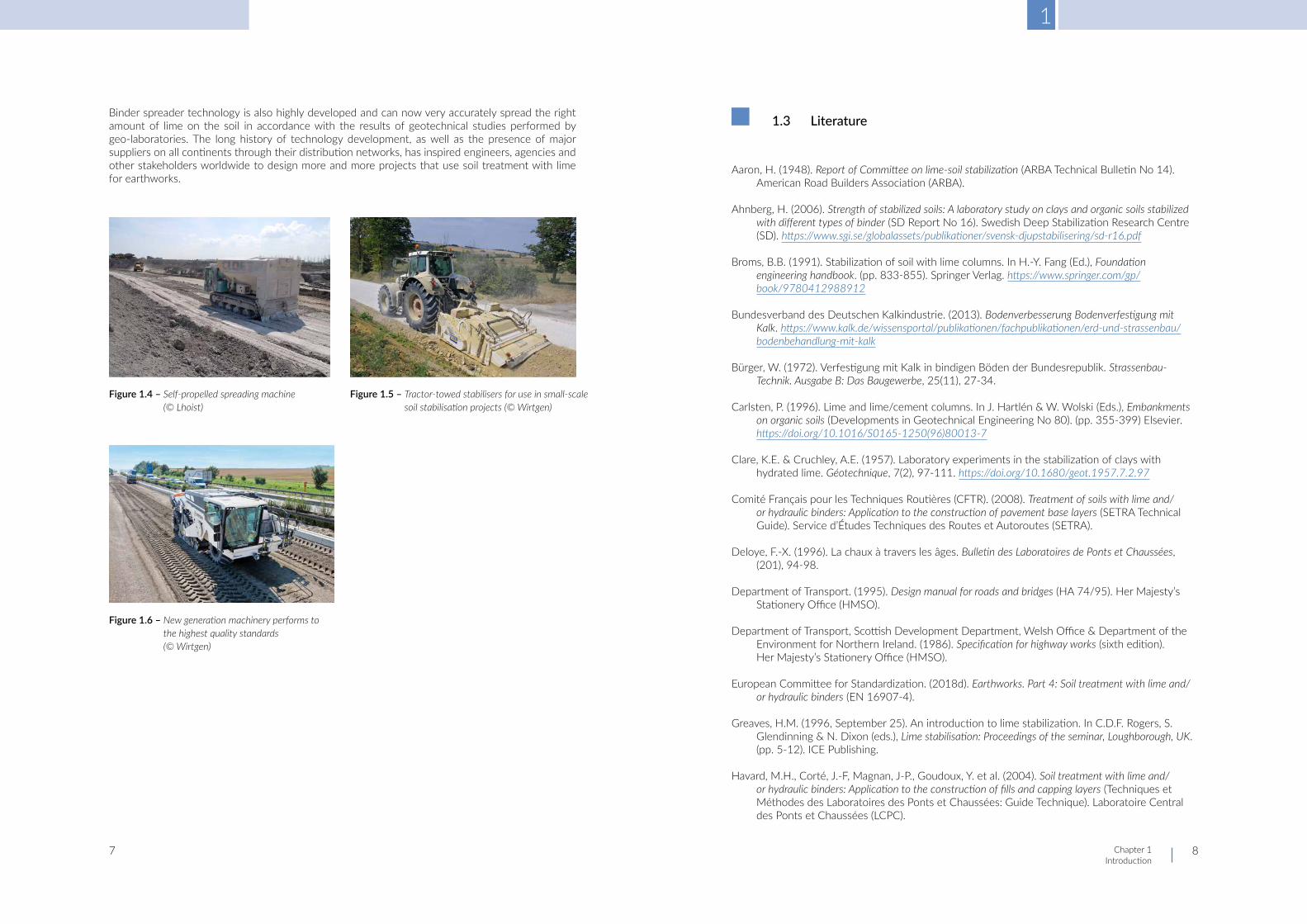
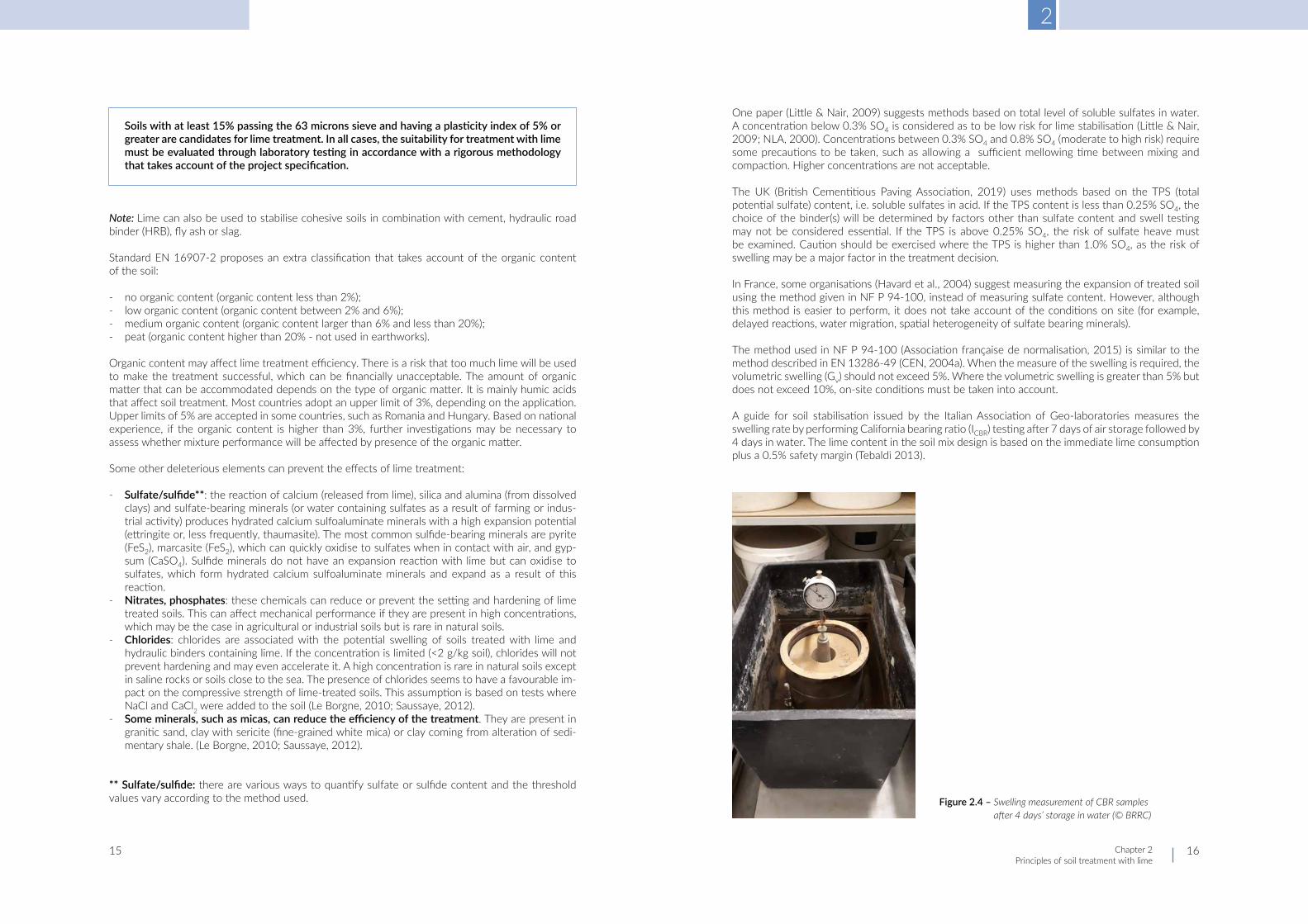
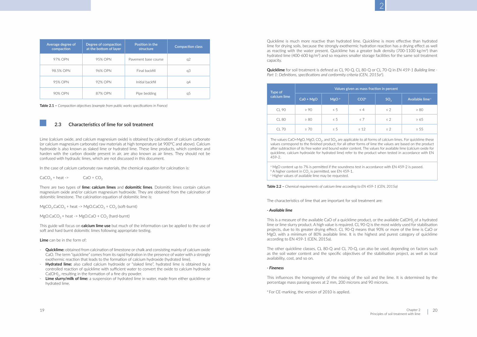
Binder spreader technology is also highly developed and can now very accurately spread the right amount of lime on the soil in accordance with the results of geotechnical studies performed by geo-laboratories. The long history of technology development, as well as the presence of major suppliers on all continents through their distribution networks, has inspired engineers, agencies and other stakeholders worldwide to design more and more projects that use soil treatment with lime for earthworks.
Figure 1.4 – Self-propelled spreading machine (© Lhoist)
Figure 1.6 – New generation machinery performs to the highest quality standards (© Wirtgen)
Figure 1.5 – Tractor-towed stabilisers for use in small-scale soil stabilisation projects (© Wirtgen)
1.3 Literature
Aaron, H. (1948). Report of Committee on lime-soil stabilization (ARBA Technical Bulletin No 14). American Road Builders Association (ARBA).
Ahnberg, H. (2006). Strength of stabilized soils: A laboratory study on clays and organic soils stabilized with different types of binder (SD Report No 16). Swedish Deep Stabilization Research Centre (SD). https://www.sgi.se/globalassets/publikationer/svensk-djupstabilisering/sd-r16.pdf
Broms, B.B. (1991). Stabilization of soil with lime columns. In H.-Y. Fang (Ed.), Foundation engineering handbook. (pp. 833-855). Springer Verlag. https://www.springer.com/gp/book/9780412988912
Bundesverband des Deutschen Kalkindustrie. (2013). Bodenverbesserung Bodenverfestigung mit Kalk. https://www.kalk.de/wissensportal/publikationen/fachpublikationen/erd-und-strassenbau/bodenbehandlung-mit-kalk
Bürger, W. (1972). Verfestigung mit Kalk in bindigen Böden der Bundesrepublik. Strassenbau-Technik. Ausgabe B: Das Baugewerbe, 25(11), 27-34.
Carlsten, P. (1996). Lime and lime/cement columns. In J. Hartlén & W. Wolski (Eds.), Embankments on organic soils (Developments in Geotechnical Engineering No 80). (pp. 355-399) Elsevier. https://doi.org/10.1016/S0165-1250(96)80013-7
Clare, K.E. & Cruchley, A.E. (1957). Laboratory experiments in the stabilization of clays with hydrated lime. Géotechnique, 7(2), 97-111. https://doi.org/10.1680/geot.1957.7.2.97
Comité Français pour les Techniques Routières (CFTR). (2008). Treatment of soils with lime and/or hydraulic binders: Application to the construction of pavement base layers (SETRA Technical Guide). Service d’Études Techniques des Routes et Autoroutes (SETRA).
Deloye, F.-X. (1996). La chaux à travers les âges. Bulletin des Laboratoires de Ponts et Chaussées, (201), 94-98.
Department of Transport. (1995). Design manual for roads and bridges (HA 74/95). Her Majesty’s Stationery Office (HMSO).
Department of Transport, Scottish Development Department, Welsh Office & Department of the Environment for Northern Ireland. (1986). Specification for highway works (sixth edition). Her Majesty’s Stationery Office (HMSO).
European Committee for Standardization. (2018d). Earthworks. Part 4: Soil treatment with lime and/or hydraulic binders (EN 16907-4).
Greaves, H.M. (1996, September 25). An introduction to lime stabilization. In C.D.F. Rogers, S. Glendinning & N. Dixon (eds.), Lime stabilisation: Proceedings of the seminar, Loughborough, UK. (pp. 5-12). ICE Publishing.
Havard, M.H., Corté, J.-F, Magnan, J-P., Goudoux, Y. et al. (2004). Soil treatment with lime and/or hydraulic binders: Application to the construction of fills and capping layers (Techniques et Méthodes des Laboratoires des Ponts et Chaussées: Guide Technique). Laboratoire Central des Ponts et Chaussées (LCPC).

1
Chapter 1 Introduction
9 10
Herrin, M. & Mitchell, H. (1961, January 9-13). Lime-soil mixtures. In 40th annual meeting of the Highway Research Board, Washington, USA (Highway Research Board Bulletin No 304). (pp. 99-138). Highway Research Board (HRB).
Jablonski, K. & Blazejowski, K. (Eds.). (2011). Kruzywo, wypetniacz, wapno: Poradnik drogowo-bodwlany [Aggregate, filler, lime: Road and construction guide]. Lime Industry Association. http://phavi.wapno-info.pl/at/attachments/2019/0405/113125-poradnik-drogowo- budowlany.pdf
Jelisic, N. & Leppänen, M. (2000, June 7-9). Mass stabilization of peat in road and railway construction. In H Rathmayer (ed.), Grouting soil improvement geosystems including reinforcement: Proceedings of the 4th international conference on ground improvement geosystems, Helsinki, Finland. Finnish Geotechnical Society.
Jofré, C., Kraemer, C. et al. (2008). Manual de estabilización de suelos con cimento o cal [Soil stabilization manual with cement or lime]. Instituto Español del Cemento y sus Aplicaciones (IECA). https://enriquemontalar.com/manual-de-estabilizacion-de-suelos-con-cemento-o-cal/
Johnson, A.M. (1949, April 11-14). Use of lime in improving bases and subgrades. In Proceedings of the 35th annual road school, Lafayette, IN, USA (Engineering Bulletin Purdue University: Extension Series No 69). (pp. 77-92). Purdue University. https://docs.lib.purdue.edu/cgi/viewcontent.cgi?article=2569&context=roadschool
Kumar Dash, S., & Hussain, M. (2012). Lime stabilization of soils: Reappraisal. Journal of Materials in Civil Engineering, 24(6), 707-714. https://ascelibrary.org/doi/abs/10.1061/%28ASCE%29MT.1943-5533.0000431
Laboratoire Central des Ponts et Chaussées & Service d’Études Techniques des Routes et Autoroutes. (1972). Recommandation pour le traitement en place des sols fins à la chaux (Recommandation SETRA). Service d’étude Techniques des Routes et des Autoroutes (SETRA).
Laboratoire Central des Ponts et Chaussées & Service d’Études Techniques des Routes et Autoroutes. (1981). Manuel de conception des chaussées neuves à faible trafic (Manuel de conception SETRA). Service d’étude Techniques des Routes et des Autoroutes (SETRA).
McDowell, C. (1959). Stabilization of soils with lime, lime-fly ash, and other lime reactive materials. In Lime and lime-fly ash as soil stabilizers (Highway Research Board Bulletin No 231). (pp. 60-66). Highway Research Board. http://onlinepubs.trb.org/Onlinepubs/hrbbulletin/231/231-004.pdf
National Lime Association. (2000). Guidelines for stabilization of soils containing sulfates: Austin white lime, chemical lime, Texas lime (NLA Technical Memorandum). https://www.lime.org/documents/publications/free_downloads/technical-memorandum.pdf
Pavement Tools Consortium. (n.d.). Pavement History. Pavement interactive. https://www.pavementinteractive.org/reference-desk/pavement-types-and-history/pavement- history/
Ramboll Group, Allu Group, Finnsementti, Lemminkäinen, Nordkalk, Russian Solutions. (2015). Mass stabilization manual. https://projektit.ramboll.fi/massastabilointi/materials/mass_stabilization_manual_2015.pdf
Rathmayer, H. (1996, May 14-17). Deep mixing methods for soft subsoil improvement in the Nordic countries. In R. Yonekura, M. Terashi & M. Shibazaki (Eds.), Proceedings of the 2nd international conference on ground improvement geosystems (IS-Tokyo ’96), Tokyo, Japan. (pp. 869-877). A.A. Balkema.
Sha’abani, M. & Kalantari, B. (2012). Mass stabilization technique for peat soil: A review. ARPN journal of science and technology, 2(5), 512-516.
Swedish Geotechnical Society. (1997). Lime and lime cement columns (SGF Report No 4:95E).
Takeda, T., Yamane, Y. & Ong, T.S. (1998, October 7-10). Ground improvement by chemico lime pile method. In Proceedings of the 2nd international conference on ground improvement techniques, Singapore. (pp. 483-490).
Terashi, M. (1999, September 6-12). Deep mixing method: Brief state of the art. In Proceedings of the 14th international conference on soil mechanics and foundation engineering, Hamburg, Germany. (pp. 2475-2478). A.A. Balkema. https://www.issmge.org/publications/publication/theme-lecture-deep-mixing-method-brief-state-of-the-art
Van den Kerkhof, E., Van Den Bergh, H., & Verhasselt, A. (2001). Amélioration des sols à la chaux. Bulletin CRR, (47), 3-7.
Van Duy, T. (2013). Étude de l’amélioration des sols par traitement à la chaux [Unpublished master’s thesis]. Université de Liège. https://matheo.uliege.be/bitstream/2268.2/2340/1/2012_2013_TRAN-Van_Duy.pdf
Verhasselt, A. (1978). Traitement des sols cohésifs humides par la chaux. I: Amélioration immédiate à la chaux (Rapport de Recherche CRR No. 176). Centre de Recherche Routières (CRR).

2
Chapter 2 Principles of soil treatment with lime
11 12
2.1 Introduction
This chapter describes soil characterisation and the different types of lime, with a focus on quicklime, the most commonly used substance for lime soil treatment in Europe. The action of lime on soil and the associated treatment processes are set out.
Characterisation of the soil to be treated is an essential step in evaluating whether the soil is suitable for lime treatment. This guide refers to soil characterisation as it is described in EN 16907-2 (CEN, 2018b) prepared by CEN/TC 396. Some deleterious elements can prevent soil lime treatment; the possible impacts on soil treatment are detailed.
Two objectives of treatment are defined in EN 16907-4 (CEN, 2018d):
Soil improvement: an operation that modifies the physical properties of a material - such as water content, plasticity, bearing capacity, water and frost susceptibility, compactability and swelling potential - by the addition of a binder.
Note: The quantity of lime added may not be sufficient to induce significant permanent properties.
Soil stabilisation: an operation consisting in obtaining a homogeneous mixture of soil with binder(s), and optionally with water, which properly compacted significantly changes (generally in the medium or long term) the characteristics of the soil in a way that renders it stable, particularly with respect to the action of water and frost.
Note: Soil stabilisation gives a permanent characteristic that can be measured by methods typical of solid materials.
2.2 Classificationandcharacteristicsofsoils
2.2.1 Europeanclassification
Soil characterisation is an essential step in determining the suitability of a soil for lime treatment. In engineering terms, the determination of the most appropriate combination of material and lime depends on the type of application or structure, the level of performance laid down in the specification or tender, and the costs, which are a key parameter in assessing whether lime treatment is worth performing.
National classifications may still be used but it is expected that they will be progressively replaced by the European classification.
■ Chapter 2 ■ Principles of soil treatment with lime

2
Chapter 2 Principles of soil treatment with lime
13 14
The classification draws a distinction between very coarse soils (Dmax > 63 mm) and other soils. Very coarse soils are subdivided into:
- very coarse soils; - soils with very coarse particles.
It is recognised that above a Dmax of 50 mm (or 63 mm), it becomes difficult to obtain a good mixing of the material with a binder. Moreover, large blocks, hard stones or clods can lead to (pulvi)mixer damage. Fractions smaller than 63 mm can be screened from the original material and then classified as below.
Soils with a Dmax below 63 mm are subdivided into:
- coarse soil - fines content < 5%; - composite coarse soil - fines content from 5 to 15%; - intermediate soil - fines content higher than 15 to 35%; - fine soil - fines content higher than 35%.
Note: fines are defined as particles < 63 microns.
Coarse soils and composite coarse soils are further subdivided based on the proportion of the sand fraction (63 microns - 2mm) to the gravel fraction (2 mm - 63 mm) and on the uniformity coefficient Cu (=d60/d10 ) (narrowly or widely graded). For those soils, the classification does not take account of the argillaceous content of the material.
Intermediate and fine soils are subdivided based on the liquid limit (wL), plasticity index (IP) and methylene blue value (VBS). Only one of these three parameters may be required, depending on local practices. IP is better suited to classifying soils with high clay content than VBS, whereas VBS is more suitable than IP for gravels, sands, and soils with low clay content (CEN, n.d.-a).
Figure 2.2 shows the classification of intermediate and fine soils and their suitability for lime index. The limit in wL for IP=5% given in figure 2.2 was estimated from the correlations given in figure 2.3.
Note: the VBS is expressed in g/100 g soil and measured on the fraction 0/50 mm.
Figure 2.1 – Coarse and composite soils (D < 63 mm). This figure is based on EN 16907-2 (CEN, 2018b) ‘Earthworks. Classification of materials.’
Figure 2.2 – Intermediate and fine soils and their suitability for lime treatment. This figure is based on EN 16907-2 (CEN, 2018b) ‘Earthworks. Classification of materials.’
As an example, the figure below shows the soil classification based on plasticity index, as used in Germany (DIN 18196 [Deutsches Institut für Normung, 2011]), which is used to derive the wL for soils with a low plasticity index given in figure 2.2.
Figure 2.3 – Plasticity chart with soil groups (modified from DIN 18196 [DIN, 2011])
2
Chapter 2 Principles of soil treatment with lime
15 16
Soils with at least 15% passing the 63 microns sieve and having a plasticity index of 5% or greater are candidates for lime treatment. In all cases, the suitability for treatment with lime must be evaluated through laboratory testing in accordance with a rigorous methodology that takes account of the project specification.
Note: Lime can also be used to stabilise cohesive soils in combination with cement, hydraulic road binder (HRB), fly ash or slag.
Standard EN 16907-2 proposes an extra classification that takes account of the organic content of the soil:
- no organic content (organic content less than 2%); - low organic content (organic content between 2% and 6%); - medium organic content (organic content larger than 6% and less than 20%); - peat (organic content higher than 20% - not used in earthworks).
Organic content may affect lime treatment efficiency. There is a risk that too much lime will be used to make the treatment successful, which can be financially unacceptable. The amount of organic matter that can be accommodated depends on the type of organic matter. It is mainly humic acids that affect soil treatment. Most countries adopt an upper limit of 3%, depending on the application. Upper limits of 5% are accepted in some countries, such as Romania and Hungary. Based on national experience, if the organic content is higher than 3%, further investigations may be necessary to assess whether mixture performance will be affected by presence of the organic matter.
Some other deleterious elements can prevent the effects of lime treatment:
- Sulfate/sulfide**: the reaction of calcium (released from lime), silica and alumina (from dissolved clays) and sulfate-bearing minerals (or water containing sulfates as a result of farming or indus-trial activity) produces hydrated calcium sulfoaluminate minerals with a high expansion potential (ettringite or, less frequently, thaumasite). The most common sulfide-bearing minerals are pyrite (FeS2), marcasite (FeS2), which can quickly oxidise to sulfates when in contact with air, and gyp-sum (CaSO4). Sulfide minerals do not have an expansion reaction with lime but can oxidise to sulfates, which form hydrated calcium sulfoaluminate minerals and expand as a result of this reaction.
- Nitrates, phosphates: these chemicals can reduce or prevent the setting and hardening of lime treated soils. This can affect mechanical performance if they are present in high concentrations, which may be the case in agricultural or industrial soils but is rare in natural soils.
- Chlorides: chlorides are associated with the potential swelling of soils treated with lime and hydraulic binders containing lime. If the concentration is limited (<2 g/kg soil), chlorides will not prevent hardening and may even accelerate it. A high concentration is rare in natural soils except in saline rocks or soils close to the sea. The presence of chlorides seems to have a favourable im-pact on the compressive strength of lime-treated soils. This assumption is based on tests where NaCl and CaCl2 were added to the soil (Le Borgne, 2010; Saussaye, 2012).
- Some minerals, such as micas, can reduce the efficiency of the treatment. They are present in granitic sand, clay with sericite (fine-grained white mica) or clay coming from alteration of sedi-mentary shale. (Le Borgne, 2010; Saussaye, 2012).
** Sulfate/sulfide: there are various ways to quantify sulfate or sulfide content and the threshold values vary according to the method used.
One paper (Little & Nair, 2009) suggests methods based on total level of soluble sulfates in water. A concentration below 0.3% SO4 is considered as to be low risk for lime stabilisation (Little & Nair, 2009; NLA, 2000). Concentrations between 0.3% SO4 and 0.8% SO4 (moderate to high risk) require some precautions to be taken, such as allowing a sufficient mellowing time between mixing and compaction. Higher concentrations are not acceptable.
The UK (British Cementitious Paving Association, 2019) uses methods based on the TPS (total potential sulfate) content, i.e. soluble sulfates in acid. If the TPS content is less than 0.25% SO4, the choice of the binder(s) will be determined by factors other than sulfate content and swell testing may not be considered essential. If the TPS is above 0.25% SO4, the risk of sulfate heave must be examined. Caution should be exercised where the TPS is higher than 1.0% SO4, as the risk of swelling may be a major factor in the treatment decision.
In France, some organisations (Havard et al., 2004) suggest measuring the expansion of treated soil using the method given in NF P 94-100, instead of measuring sulfate content. However, although this method is easier to perform, it does not take account of the conditions on site (for example, delayed reactions, water migration, spatial heterogeneity of sulfate bearing minerals).
The method used in NF P 94-100 (Association française de normalisation, 2015) is similar to the method described in EN 13286-49 (CEN, 2004a). When the measure of the swelling is required, the volumetric swelling (Gv) should not exceed 5%. Where the volumetric swelling is greater than 5% but does not exceed 10%, on-site conditions must be taken into account.
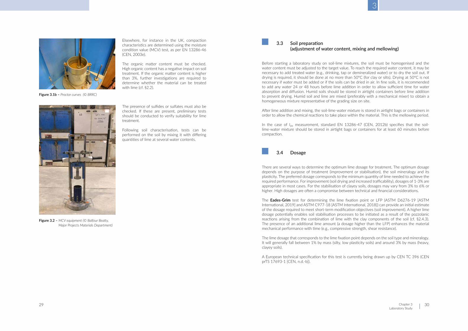
A guide for soil stabilisation issued by the Italian Association of Geo-laboratories measures the swelling rate by performing California bearing ratio (ICBR) testing after 7 days of air storage followed by 4 days in water. The lime content in the soil mix design is based on the immediate lime consumption plus a 0.5% safety margin (Tebaldi 2013).
Figure 2.4 – Swelling measurement of CBR samples after 4 days’ storage in water (© BRRC)

2
Chapter 2 Principles of soil treatment with lime
17 18
In an informative annex, standard EN 16907-4 (CEN, 2018d) describes the field and laboratory identification of common sulfide and sulfate minerals. The standard does not give any threshold values and refers to national guides and local practices.
On site, sulfate concentrations in soil exhibit high spatial heterogeneity. Selecting the right locations at which to perform sulfate testing can therefore be critical. A practical approach in controlling or limiting deleterious reaction effects when treating high-sulfate soils with lime is to create conditions that promote the dissolution (often limited) of available sulfates and force the formation of the expansive minerals before compaction, such as by increasing the duration of the mellowing period (up to 7 days) and slightly increasing the moisture content to help the formation of swelling minerals before compaction.
2.2.2 Physicalcharacterisation
European standard EN 16907-2 (CEN, 2018b) refers to classification based on physical parameters such as moisture content and density/degree of compaction, which are very important in the event of soil reuse in earthworks or subbase.
2.2.2.1 Water content
Water content impacts soil consistency, binder dosage, and setting and hardening conditions, as well as working conditions (spreading, mixing, compaction).
Depending on the water content, the soil can be in a solid, plastic or liquid state.
The liquid limit (wL) is the water content at which the soil passes from the plastic state to the liquid state.
The plastic limit (wP) is the water content at which the soil passes from the solid state to the plastic state.
The plasticity index (Ip) is defined as wL - wP .
The water content on its own is not sufficient to characterise the state of soil. The following measures can be used:
- Ratio wnat/wOPN (natural water content/optimum water content determined by Proctor compac-tion in accordance with EN 13286-2 [CEN, 2010]). This parameter is best suited to describing normal, dry and very dry soils.
- The immediate bearing index (IIPI) measured on a sample compacted using Standard Proctor com-paction energy and at wnat in accordance with EN 13286-47 (CEN, 2012b). This parameter is best suited to describing wet and very wet soils.
- The consistency index (Ic): wL-wnat
This parameter is best suited to describing soils with more than 35% passing 63 microns and a plasticity index higher than 12. If Ic is lower than 0.7, the soil has low consistency and there is a risk of trafficability issues. If Ic is higher than 1.3, the soil has a high consistency and there is a risk of issues during soil removal.
2.2.2.2 Degreeofcompaction
The degree of compaction directly impacts the bearing capacity of the treated soil.
In practice, the expected degree of compaction should be in the range from 95% to 98.5% at optimum Proctor dry density (OPN), depending on the application and the treatment purposes.
As an example, figure 2.6 and table 2.1 give the required compaction classes in France and the requirements for each class (https://www.wikitp.fr/compactage-de-trancheacutees/objectifs-de-compactage). The average values range from 90% OPN for pipe bedding to 98.5% OPN for pavement base courses.
Figure 2.5 – Definition of plasticity index, liquid limit and plastic limit (© BRRC)
wL-wp
Figure 2.6 – Examples of compaction classes in France
2
Chapter 2 Principles of soil treatment with lime
19 20
2.3 Characteristicsoflimeforsoiltreatment
Lime (calcium oxide, and calcium magnesium oxide) is obtained by calcination of calcium carbonate (or calcium magnesium carbonate) raw materials at high temperature (at 900°C and above). Calcium hydroxide is also known as slaked lime or hydrated lime. These lime products, which combine and harden with the carbon dioxide present in air, are also known as air limes. They should not be confused with hydraulic limes, which are not discussed in this document.
In the case of calcium carbonate raw materials, the chemical equation for calcination is:
CaCO3 + heat -> CaO + CO2
There are two types of lime: calcium limes and dolomitic limes. Dolomitic limes contain calcium magnesium oxide and/or calcium magnesium hydroxide. They are obtained from the calcination of dolomitic limestone. The calcination equation of dolomitic lime is:
MgCO3.CaCO3 + heat -> MgO.CaCO3 + CO2 (soft-burnt)
MgO.CaCO3 + heat -> MgO.CaO + CO2 (hard-burnt)
This guide will focus on calcium lime use but much of the information can be applied to the use of soft and hard burnt dolomitic limes following appropriate testing.
Lime can be in the form of:
- Quicklime: obtained from calcination of limestone or chalk and consisting mainly of calcium oxide CaO. The term “quicklime” comes from its rapid hydration in the presence of water with a strongly exothermic reaction that leads to the formation of calcium hydroxide (hydrated lime).
- Hydrated lime: also called calcium hydroxide or “slaked lime”, hydrated lime is obtained by a controlled reaction of quicklime with sufficient water to convert the oxide to calcium hydroxide Ca(OH)2, resulting in the formation of a fine dry powder.
- Lime slurry/milk of lime: a suspension of hydrated lime in water, made from either quicklime or hydrated lime.
Quicklime is much more reactive than hydrated lime. Quicklime is more effective than hydrated lime for drying soils, because the strongly exothermic hydration reaction has a drying effect as well as reacting with the water present. Quicklime has a greater bulk density (700-1100 kg/m3) than hydrated lime (400-600 kg/m3) and so requires smaller storage facilities for the same soil treatment capacity.
Quicklime for soil treatment is defined as CL 90-Q, CL 80-Q or CL 70-Q in EN 459-1 Building lime - Part 1: Definitions, specifications and conformity criteria (CEN, 2015a4).
Average degree of compaction
Degree of compaction at the bottom of layer
Position in the structure Compaction class
97% OPN 95% OPN Pavement base course q2
98.5% OPN 96% OPN Final backfill q3
95% OPN 92% OPN Initial backfill q4
90% OPN 87% OPN Pipe bedding q5
Table 2.1 – Compaction objectives (example from public works specifications in France)
Type of calcium lime
Values given as mass fraction in percent
Ca0 + MgO MgO a CO2b SO3 Available lime c
CL 90 ≥ 90 ≤ 5 ≤ 4 ≤ 2 ≥ 80
CL 80 ≥ 80 ≤ 5 ≤ 7 ≤ 2 ≥ 65
CL 70 ≥ 70 ≤ 5 ≤ 12 ≤ 2 ≥ 55
The values CaO+MgO, MgO, CO2, and SO3 are applicable to all forms of calcium limes. For quicklime these values correspond to the finished product; for all other forms of lime the values are based on the product after subtraction of its free water and bound water content. The values for available lime (calcium oxide for quicklime, calcium hydroxide for hydrated lime) refer to the product when tested in accordance with EN 459-2.
a MgO content up to 7% is permitted if the soundness test in accordance with EN 459-2 is passed. b A higher content in CO2 is permitted, see EN 459-1. c Higher values of available lime may be requested.
Table 2.2 – Chemical requirements of calcium lime according to EN 459-1 (CEN, 2015a)
The characteristics of lime that are important for soil treatment are:
- Available lime
This is a measure of the available CaO of a quicklime product, or the available Ca(OH)2 of a hydrated lime or lime slurry product. A high value is required. CL 90-Q is the most widely used for stabilisation projects, due to its greater drying effect. CL 90-Q means that 90% or more of the lime is CaO or MgO, with a minimum of 80% available lime. It is the highest and purest category of quicklime according to EN 459-1 (CEN, 2015a).
The other quicklime classes, CL 80-Q and CL 70-Q, can also be used, depending on factors such as the soil water content and the specific objectives of the stabilisation project, as well as local availability, cost, and so on.
- Fineness
This influences the homogeneity of the mixing of the soil and the lime. It is determined by the percentage mass passing sieves at 2 mm, 200 microns and 90 microns.
4 For CE-marking, the version of 2010 is applied.

2
Chapter 2 Principles of soil treatment with lime
21 22
- Reactivity
This represents the rate of hydration and the heat release due to the reaction of quicklime with water. Reactivity is related to the quality of the lime and is affected by the calcination process, purity and fineness. Quicklime reactivity is expressed by the t60 parameter, which is the time necessary to bring a given volume of water at 20°C to a temperature of 60°C when a standardised amount of quicklime is added to the water in an insulated Dewar bottle. The more reactive the quicklime is, the shorter the observed reaction time. For example, in Belgium, a maximum t60 of 8 minutes is required when CL90-Q is used for public works.
2.4 How lime reacts with soils
When lime is added to soil, there is a cation exchange and crowding of additional calcium cations onto the surfaces of particles of clay, which are negatively charged. The electrostatic disturbances induced by this cation exchange means that the clay particles become attracted to one other, causing flocculation.
Adding lime to the soil induces:
- immediate change in moisture content (particularly when quicklime is used); - short term modifications of the geotechnical properties of the soil; - long term modifications of the soil properties.
2.4.1 Immediate change in moisture content
Quicklime reduces the moisture content by combination of three processes:
- hydration of the quicklime according to the exothermic reaction: CaO + H2O->Ca(OH)2 + heat release (heat release =1155 kJ/kg CaO);
- vaporisation of water due to the heat generated by the exothermic reaction; - addition of dry material, reducing water density.
The reduction in the moisture content caused by adding quicklime to the soil is approximately 0.7% per 1% CaO by mass of dry soil addition at laboratory scale. On the project site, the drying can rise up to 4% in favourable conditions (for example, wind, sun, warmth, particular types of soil).
Note: Hydrated lime also affects water content, but only through the addition of dry matter. The reduction in moisture content is about 0.3% per 1% of hydrated lime addition.
2.4.2 Short-termmodificationsofthegeotechnicalpropertiesofthesoil
When quicklime is added to water-rich soil, it reacts with the water to form calcium hydroxide and dissolved calcium ions interact with and flocculate the clay particles. The soil becomes friable and granular.
This flocculation causes the following geotechnical changes:
Decrease of plasticity index (Ip ) due to the increase of the plasticity limit (wp ) without any significant change of the liquid limit (wL ). The consistency of the soil becomes higher. Due to the reduction in plasticity, cohesive soils become more friable and more easily worked. After treatment, the water content of the soil is lower than the new plasticity limit, improving trafficability.
Sieve sizeParticle size distributiona in accordance with EN 459-2
P4 P3 P2 P1 PSV
10 mm 100 - - -
other specified
value or no requirement
5 mm ≥ 95 100 100
2 mm - ≥ 95 ≥ 95 100
0.2 mm - - ≥ 70 ≥ 95
0,09 mm - ≥ 30 ≥ 50 ≥ 85
Particle size ≥ 2 mm shall be determined by dry sieving in accordance with EN 459-2 Particle size < 2 mm shall be determined by air-jet sieving in accordance with EN 459-2
Table 2.3 – Particle size distribution (P) of quicklime given as characteristic values according to EN 459-1 (CEN, 2015a)
Type of quicklime
Reactivity (time in min), in accordance with EN 459-2
R5 R4 R3 R2 RSV
CL 90 t60 < 10 t60 < 25 - - other specified
value or no requirement
CL 80 t60 < 10 t60 < 25 t50 < 25 -
CL 70 - - - t40 < 25
The test methods to measure available lime, fineness and reactivity are described in EN 459-2 Building lime - Part 2: Test methods (CEN, 2021)
Table 2.4 – Reactivity of quicklime given as characteristic value (EN 459-1 [CEN, 2015a])
Figure 2.7 – Initial state and flocculated clay soil after lime addition (© Lhoist)

2
Chapter 2 Principles of soil treatment with lime
23 24
Figure 2.8 shows the effect of lime content on the plasticity index.
Change of the Proctor curve
Quicklime addition lowers the dry density achieved by a given compaction energy and raises the water content (1.5% to 4%) at which this density can be achieved.
The shape of the Proctor curve for the stabilised soil is flattened in comparison with the one for the natural soil, and the optimum moisture content is shifted to the right (wet side). Better compaction can be achieved more easily for treated soil. Workability is improved due to the reduction of the plasticity and the flocculation of the soil.
Bearing capacity
An important increase of the immediate bearing index (IIPI) or Californian bearing ratio (ICBR) is observed after treatment. The effectiveness of the treatment is greatest when soil moisture content lies around 1.1 to 1.3 of the optimum water content - wOPN (or, for fine-grained soils, when the natural water content is close to the plasticity limit) (Havard et al., 2004).
2.4.3 Longtermmodificationofthetreatedsoilproperties
Adding quicklime or hydrated lime, which are strong alkalis, causes the pH of the soil to rise after mixing. The higher pH values promote the dissolution of silica and alumina oxides from the clay minerals. These dissolved compounds react with the lime in presence of water to form calcium silicate hydrates (CSH) and calcium aluminate hydrates (CAH), which precipitate and bind the soil particles. This reaction is called a pozzolanic reaction and produces similar cementitious compounds to cement manufacturing, albeit with slower kinetics. The pozzolanic reaction improves the mechanical properties of the mixed soil and lime, which gradually evolve with time (over months and years).
The kinetics and efficiency of the pozzolanic reaction are influenced by:
- the pH; - the type of clay; - cation exchange capacity (CAC); - the temperature; - the quantity of lime; - the water content: free water allows flocculation and carbonation to continue.
Pore water allows the continuation of pozzolanic reaction; - the presence of elements such as organic matter, nitrates, sulfides, sulfates, which will
be detrimental to the reactions; - the compaction of the lime-treated soil, as this will bring the reagents into closer proximity
and assist the pozzolanic reaction; - the target density.
Figure 2.8 – Effect of the addition of lime on the plasticity properties of London clay (Source: Bell & Coulthard, 1990)
Figure 2.9 – Proctor curves of untreated and treated soil (Nguyen, 2015)
Figure 2.10 – IIPI curves of untreated and treated soil (Nguyen, 2015)

2
Chapter 2 Principles of soil treatment with lime
25 26
2.5 Literature
Association française de normalisation. (2015). Sols: Reconnaissance et essais: Matériaux traités à la chaux et/ou aux liants hydrauliques: Essais d’évaluation de l’aptitude d’un sol au traitement (NF P94-100).
Bell, F.G. & Coulthard, J.M. (1990). Stabilization of clay soils with lime. Municipal engineer, 7(3), 125-140.
British Cementitious Paving Association. (2019). Soil improvement and soil stabilisation: Definitive industry guidance (Britpave No BP/62). https://www.britpave.org.uk/publications/Soil Stabilisation
Deutsches Institut für Normung. (2011). Earthworks and foundations: Soil classification for civil engineering purposes (DIN 18196).
European Committee for Standardization. (n.d.-a). Earthworks: Geotechnical laboratory tests. Part 3: Methylene blue value VBS on soils and rocks (prEN 17542-3).
European Committee for Standardization. (2004a). Unbound and hydraulically bound mixtures. Part 49: Accelerated swelling test for soil treated by lime and/or hydraulic binder (EN 13286-49).
European Committee for Standardization. (2010). Unbound and hydraulically bound mixtures. Part 2: Test methods for laboratory reference density and water content: Proctor compaction (EN 13286-2).
European Committee for Standardization. (2012b). Unbound and hydraulically bound mixtures. Part 47: Test method for the determination of California bearing ratio, immediate bearing index and linear swelling (EN 13286-47).
European Committee for Standardization. (2015a). Building lime. Part 1: Definitions, specifications and conformity criteria (EN 459-1).
European Committee for Standardization. (2018b). Earthworks. Part 2: Classification of materials (EN 16907-2).
European Committee for Standardization. (2018d). Earthworks. Part 4: Soil treatment with lime and/or hydraulic binders (EN 16907-4).
European Committee for Standardization. (2021). Building lime. Part 2: Test methods (EN 459-2).
Havard, M.H., Schaeffner, M. e.a. (2004). Soil treatment with lime and/or hydraulic binders: Application to the construction of fills and capping layers (Guide technique LCPC: Techniques et méthodes des Laboratoires des Ponts et chaussées). Laboratoire Central des Ponts et Chaussées (LCPC).Nguyen, T.-T.-H. (2015). Stabilisation des sols traités à la chaux et leur comportement au gel [Doctoral thesis]. Université Paris-Est. https://tel.archives-ouvertes.fr/NAVIER-GEOTECHNIQUE/tel-01191696v1
Le Borgne, T. (2010). Caractérisation et quantification des éléments perturbateurs de prise lors du traitement des sols [Unpublished doctoral thesis]. Institut National Polytechnique de Lorraine, École national Supérieure de Géologie de Nancy. https://tel.archives-ouvertes.fr/tel-00477768/document
Little, D.N. & Nair, S. (2009). Recommended practice for stabilization of sulfate rich subgrade soils (NCHRP Web-Only Document No 145). Transportation Research Board (TRB). https://www.nap.edu/catalog/22997/recommended-practice-for-stabilization-of-sulfate-rich-subgrade-soils
National Lime Association. (2000). Guidelines for stabilization of soils containing sulfates: Austin white lime, chemical lime, Texas lime (NLA Technical Memorandum). https://www.lime.org/documents/publications/free_downloads/technical-memorandum.pdf
Saussaye, L. (2012). Traitement des sols aux liants hydrauliques : Aspects géotechniques et physico-chimiques des perturbations de la solidification [Unpublished doctoral thesis]. Université de Caen Basse Normandie. https://tel.archives-ouvertes.fr/tel-00800952/document
Tebaldi, G. (2013). Stabilizzazione delle terre con calce [Soil stabilization with lime] (Quaderni Tecnici ALIG No 3). Associazione Laboratori d’Ingegneria e Geotecnica (ALIG), Unicalce.

3
Chapter 3 Laboratory Study
27 28
3.1 Objectives
The objectives of any laboratory study are: to determine the feasibility of soil treatment with lime and the optimum dosage for achieving the desired level of performance, as well as to assess the mechanical performance and behaviour of the mixtures.
This chapter refers to EN 16907-4 (CEN, 2018d) prepared by TC 396 ‘Earthworks’ for improvement and stabilisation in earthworks applications. EN 14227-15 (CEN, 2015d) prepared by TC 227 ‘Road materials’ is for stabilisation in pavement applications only.
3.2 Soilidentification
Soil identification is the first step in assessing whether a soil can be effectively treated with lime (cf. § 2.2, Classification). The procedure is performed on representative samples collected from the area to be treated. It is recommended that sufficient material is collected for the tests to be carried out (typically a minimum of 200 kg per soil type for a full laboratory study).
Soil identification includes ascertaining the grading size (determining as a minimum the fraction passing at 63 microns, the fraction passing at 2 mm, and the maximum grain size) and natural water content, as well as determining the argillaceous content via Atterberg limits or a methylene value test (the latter being more appropriate for soils with low clay content).
Note: National classifications can still be used but will be progressively replaced by the European classification described in EN 16907-2 (CEN, 2018b). Soil identification gives an indication of the possible compatibility/match between lime and soil (cf. 62.2).
The compaction characteristics, which are important for the installation of the earthworks on site, are determined from the Proctor curve, as per EN 13286-2 (CEN, 2010).
Most of countries use the Standard or ‘normal’ Proctor test to determine the compaction characteristics of soils. Others use the Modified Proctor test only, while a few use both.
■ Chapter 3 ■ Laboratory Study
Figure 3.1a – Proctor curves (© BRRC)
3
Chapter 3 Laboratory Study
29 30
Elsewhere, for instance in the UK, compaction characteristics are determined using the moisture condition value (MCV) test, as per EN 13286-46 (CEN, 2003e).
The organic matter content must be checked. High organic content has a negative impact on soil treatment. If the organic matter content is higher than 3%, further investigations are required to determine whether the material can be treated with lime (cf. §2.2).
The presence of sulfides or sulfates must also be checked. If these are present, preliminary tests should be conducted to verify suitability for lime treatment.
Following soil characterisation, tests can be performed on the soil by mixing it with differing quantities of lime at several water contents.
3.3 Soilpreparation (adjustment of water content, mixing and mellowing)
Before starting a laboratory study on soil-lime mixtures, the soil must be homogenised and the water content must be adjusted to the target value. To reach the required water content, it may be necessary to add treated water (e.g., drinking, tap or demineralized water) or to dry the soil out. If drying is required, it should be done at no more than 50°C (for clay or silts). Drying at 50°C is not necessary if water must be added or if the soils can be dried in air. In fine soils, it is recommended to add any water 24 or 48 hours before lime addition in order to allow sufficient time for water absorption and diffusion. Humid soils should be stored in airtight containers before lime addition to prevent drying. Humid soil and lime are mixed (preferably with a mechanical mixer) to obtain a homogeneous mixture representative of the grading size on site.
After lime addition and mixing, the soil-lime-water mixture is stored in airtight bags or containers in order to allow the chemical reactions to take place within the material. This is the mellowing period.
In the case of IIPI measurement, standard EN 13286-47 (CEN, 2012b) specifies that the soil-lime-water mixture should be stored in airtight bags or containers for at least 60 minutes before compaction.
3.4 Dosage
There are several ways to determine the optimum lime dosage for treatment. The optimum dosage depends on the purpose of treatment (improvement or stabilisation), the soil mineralogy and its plasticity. The preferred dosage corresponds to the minimum quantity of lime needed to achieve the required performance. For improvement (soil drying and increased trafficability), dosages of 1-3% are appropriate in most cases. For the stabilisation of clayey soils, dosages may vary from 3% to 6% or higher. High dosages are often a compromise between technical and financial considerations.
The Eades-Grim test for determining the lime fixation point or LFP (ASTM D6276-19 [ASTM International, 2019] and ASTM C977-18 [ASTM International, 2018]) can provide an initial estimate of the dosage required to meet short-term modification objectives (soil improvement). A higher lime dosage potentially enables soil stabilisation processes to be initiated as a result of the pozzolanic reactions arising from the combination of lime with the clay components of the soil (cf. §2.4.3). The presence of an additional lime amount (a dosage higher than the LFP) enhances the material mechanical performance with time (e.g., compressive strength, shear resistance).
The lime dosage that corresponds to the lime fixation point depends on the soil type and mineralogy. It will generally fall between 1% by mass (silty, low plasticity soils) and around 3% by mass (heavy, clayey soils).
A European technical specification for this test is currently being drawn up by CEN TC 396 (CEN prTS 17693-1 [CEN, n.d.-b]).
Figure 3.1b – Proctor curves (© BRRC)
Figure 3.2 – MCV equipment (© Balfour Beatty, Major Projects Materials Department)

3
Chapter 3 Laboratory Study
31 32
3.5 Treatment feasibility
If evidence suggests that deleterious elements may be present (organic matter, sulfur, sulfides, sulfates, and so on), it is recommended that some quick preliminary tests are carried out to check suitability of the soil for treatment with lime before starting a full study.
Measuring the swelling potential of the soil-lime mixture indicates the risk of expansion due to presence of sulfur-containing compounds, or other deleterious elements (EN 13286-49 [CEN 2004a]). If the volumetric swelling is too high, the soil may be considered unsuitable to be treated with lime.
Other tests performed on the soil-lime mixture, such as measuring the immediate bearing index or Californian bearing ratio (immediate or soaked), in combination with the Proctor curve, also give an idea of the suitability of the soil for treatment with lime. If the IIPI (or ICBR) of the treated soil is low at the moisture content expected on the project site (IIPI < 10 %), there is limited value in pursuing a laboratory study.
3.6 Determinationofcharacteristicsforexecution
The soil characteristics relevant to execution (EN 16907-4) are those that are directly affected by the lime addition.
For improvement, this means the workability of the soil (CEN, 2003d), the immediate bearing index, the moisture condition value or the degree of compaction.
For stabilisation, this means, in addition to the improvement criteria, the degree of compaction and water content required for the hydration of lime, the water content compared to the optimum water content (for low water content soils), the water content corresponding to a specified immediate bearing index (for high water content soils), or the moisture condition value (MCV).
For soil improvement, best results are obtained if the mixture is compacted at a moisture content close to the optimum moisture content (OMC).
For stabilisation, the initial water content can be slightly higher than the optimum moisture content to ensure lime hydration so that, after treatment, the treated soil is close to the optimum moisture content.
3.7 Compactionmethods
Several standardised methods are available to compact the specimens in the laboratory (soils, sand and gravel):
- Proctor compaction (EN 13286-50 [CEN, 2004b]) - Static compaction (EN 13286-53 [CEN, 2004c])
The choice of method depends on the type of material being tested (soil, sand or gravel) and the measure being determined (for example, IIPI or ICBR, MCV, Rc, Rit, E). The Optimum Proctor density (ρOMC) is often used as compaction reference (EN 13286-2 [CEN, 2010]).
For soils treated with lime, the most suitable compaction methods are static compaction and Proctor compaction. Static compaction allows variation in the degree of compaction and deviation from 100% OPN (for example 95% or 98% OPN).
Proctor compaction in sample moulds of 150 x 120 mm is commonly used for the measurement of IIPI or ICBR (specimen compacted at standard Proctor energy ). Proctor compaction in sample moulds of 100 x 120 mm can be used for compressive strength.
Static compaction is performed in moulds of 50 or 100 mm diameter, preferably with a slenderness ratio of 1 for Rit and 2 for Rc.
Figure 3.3 – Expansion test (© Lhoist)
Figure 3.4 – Static compaction (© BRRC)

3
Chapter 3 Laboratory Study
33 34
The next table, which is reproduced from EN 16907-4, gives an overview of the available compaction methods and the dimensions of the specimens.
Depending on local practice, it is recommended that laboratory tests be performed at a degree of compaction that is representative of the project site and the compaction equipment in use.
3.8 Mechanical performance
Mechanical performance (strength for direct trafficking, resistance to water and frost resistance) is determined in a laboratory study.
3.8.1 Strengthfordirecttrafficking
For improvement, direct trafficking is related to execution parameters (immediate bearing index (IIPI), degree of compaction or MCV value). In France, the IIPI values specified for the treated material depend on the type of soil. An average value of IIPI=10% is a reasonable target value; however, it must be aligned with local practice.
Figure 3.5 shows the results of a full laboratory study performed with several lime dosages at several water contents. From the results, the lime dosages can be selected, based on the measured water content. For example, if the target IIPI value is 10% and the water content on site is 21.5%, 2% lime addition by mass of soil is required. If the water content is 24%, more than 3% lime will be needed.
For stabilisation, the lime dosage is often determined by compressive strength measurement and the time to achieve the expected strength (for example Rc > 0,5 MPa – 1 MPa or more depending on soil, project site traffic or local installation practices).
3.8.2 Resistance to water
The resistance to water, or reduction of water sensitivity, is an important characteristic of the stabilised mixtures, particularly when used in subbase layers (which are often the draining layer of the road structure), as well as in the upper parts of embankments. There are two ways to determine water resistance in the laboratory, namely by retained strength after immersion in water or by swelling (linear, volumetric) after soaking or immersion in water.
To measure the retained strength after immersion, the compressive strength of specimens cured for ‘x’ days in the air and then ‘y’ days in water are compared with the compressive strength of specimens kept for ‘x + y’ days in air only (for example x=28 days and y=32 days).
For curing in air, the specimens are protected from water ingress with plastic film and/or aluminium foil, even if they are placed in a climatic chamber.
Swelling tests are performed in accordance with EN 13286-49 (CEN, 2004a) (volumetric swelling) or EN 13286-47 (CEN, 2012b) (linear swelling).
Parameter Compaction method Dimension of the mould (mm)
Maximum particle size permitted in
the specimen (mm)
ICBR/IIPI (EN 13286–47 [CEN 2012b])
Proctor (EN 13286–50 [CEN, 2004b])
d 150 ± 1 h 120 ± 1 22.4
Rc (EN 13286–41 [CEN 2003a])
Rit (EN 13286–42 [CEN, 2003b])
Ec and Eit (EN 13286-43 [CEN 2003c])
Proctor equipment EN 13286–50 (CEN, 2004b)
d 100 ± 1 h 120 ± 1 16 (or 22.4)
d 150 ± 1 h 120 ± 1 31.5
Static compression EN 13286–53 (CEN, 2004c)
d 50 h 50 or 100 11.2
d 100 h 100 or 200 22.4
Table 3.1 – Compaction methods used in laboratory for lime treated soil samples
Note: For Rc measurement, a slenderness ratio of 2 is preferred. For Rit measurement, a slenderness ratio of 1 is preferred. Figure 3.5 – Example of a laboratory study with several water contents and lime dosages (Havard et al., 2004)

3
Chapter 3 Laboratory Study
35 36
3.8.3 Frost resistance
This characteristic is important for treated soils used in subbase or other road layers subjected to frost. In several countries, the frost resistance of capping layers and the upper part of embankments is a parameter used for designing road structures. According to the soil type characteristics, minimal lime dosage and curing time, lime can help optimise the design of earthworks by enhancing mechanical performance and frost resistance.
Frost will affect the properties of materials through two mechanisms:
- Frost heave: swelling due to cryogenic suction (water migration, formation of ice lenses and swelling)
- Gelifraction: rupture of granular or bound materials due to repeated freeze-thaw cycles
Frost heave concerns the covered layers and gelifraction concern layers in direct contact with atmosphere in winter conditions.
In practice, there are several laboratory tests to determine the frost resistance of treated soil:
- Strength after curing - Frost heave test - Retained strength after freeze-thaw cycles (for example CEN TS 13286-54 [CEN, 2014]).
Compressive strength after curing is used by several countries (such as France, Belgium, and Sweden). However, the minimum strength value associated with frost resistance may be perceived as over-specified: in France, for instance, a lime-treated soil is considered frost resistant at a level of 2.5 MPa.
Retained strength after freeze-thaw cycles is also used (for example, in Germany and the Czech Republic), because it is easier to perform than the frost heave test. The curing conditions can be chosen by the user, but they can be quite severe. As a result, this method is not ideal for assessing the frost process in fine soils, as it is based on aggregate testing standards.
The frost heave test requires more complex equipment. It is used in Germany, Austria and Norway for research purposes and has been made standard in some countries (France, Norway, Austria).
French standardisation update
Recent advances in the frost behaviour of lime-treated soils have led to a better understanding of the materials characteristics to be achieved from treatment operations. The recently amended French standard for road design, NF P 98 086 (AFNOR, 2019), describes the soil characteristics and installation criteria for the production of a lime-treated soil with low frost susceptibility:
- VBS (methylene blue value) of the natural fine soil ≥ 0.5 g/100 g; - minimum lime dosage: 1.5%; - particle size of the mixture < 40 mm; - density level ≥ 95% ρd,OMC; - ratio ICBR after immersion / IIPI >1.
3.9 Stabilisation-Levelsofstudy
The extent of stabilisation laboratory studies depends on the context of the project and previous experience of the soil to be treated. The objective of a level 1 study is to check a formulation based on past experience with the same material. The level 1 study is performed at a single lime dosage. For projects with greater technical risks and financial implications, it is preferable to extend the level 1 study with a level 2 study. A level 2 study is performed to optimise the lime dosage and to establish the impact of the variability of the lime content, the degree of compaction and the water content on the performance of the mixture.
The level 1 study will check the direct construction trafficability and the short-term and long-term performance. For example, the study may include a Proctor curve and the measurement of IIPI or ICBR for the natural soil and the treated soil. Mechanical performance (water resistance, frost resistance, strength for direct trafficking, long-term performance) are tested at water contents representative of the in situ water content).
A level 2 study examines the long-term mechanical performance at different lime dosages (the level 1 study dose and two more). It also contains the study of the impact of variations during installation (dosage, water content, degree of compaction) on the long-term mechanical performance of the mixture (figure 3.6). Several water contents, compaction degrees and lime dosages are considered.
Figure 3.6 – Graphical method for calculating additional binder percentage required to compensate for variations during installation, EN 16907-4 (CEN, 2018d)
3
Chapter 3 Laboratory Study
37 38
3.10 Literature
Association française de normalisation. (2019). Dimensionnement structurel des chaussées routières: Application aux chaussées neuves: Chaussées: Terrassement: Dimensionnement et Terminologie: Vérification du dimensionnement structurel des chaussées routières: Application aux chaussées neuves (NF P98-086).
ASTM International. (2018). Standard specification for quicklime and hydrated lime for soil stabilization (ASTM C977-18).
ASTM International. (2019). Standard test method for using pH to estimate the soil-lime proportion requirement for soil stabilization (ASTM D6276-19).
European Committee for Standardization. (n.d.-b). Earthworks: Soil treatment tests. Part 1: pH-test for determination of the lime requirement of soils for stabilization (lime fixation point LFP, lime modification optimum LMO) (prCEN/TS 17693-1).
European Committee for Standardization. (2003a). Unbound and hydraulically bound mixtures. Part 41: Test method for the determination of the compressive strength of hydraulically bound mixtures (EN 13286-41).
European Committee for Standardization. (2003b). Unbound and hydraulically bound mixtures. Part 42: Test method for the determination of the indirect tensile strength of hydraulically bound mixtures (EN 13286-42).
European Committee for Standardization. (2003c). Unbound and hydraulically bound mixtures. Part 43: Test method for the determination of the modulus of elasticity of hydraulically bound mixtures (EN 13286-43).
European Committee for Standardization. (2003d). Unbound and hydraulically bound mixtures. Part 45: Test method for the determination of the workability period of hydraulically bound mixtures (EN 13286-45).
European Committee for Standardization. (2003e). Unbound and hydraulically bound mixtures. Part 46: Test method for the determination of the moisture condition value (EN 13286-46).
European Committee for Standardization. (2004a). Unbound and hydraulically bound mixtures. Part 49: Accelerated swelling test for soil treated by lime and/or hydraulic binder (EN 13286-49).
European Committee for Standardization. (2004b). Unbound and hydraulically bound mixtures. Part 50: Method for the manufacture of test specimens of hydraulically bound mixtures using Proctor equipment or vibrating table compaction (EN 13286-50).
European Committee for Standardization. (2004c). Unbound and hydraulically bound mixtures. Part 53: Methods for the manufacture of test specimens of hydraulically bound mixtures using axial compression (EN 13286-53).
European Committee for Standardization. (2010). Unbound and hydraulically bound mixtures. Part 2: Test methods for laboratory reference density and water content: Proctor compaction (EN 13286-2).
European Committee for Standardization. (2012b). Unbound and hydraulically bound mixtures. Part 47: Test method for the determination of California bearing ratio, immediate bearing index and linear swelling (EN 13286-47).
European Committee for Standardization. (2014). Unbound and hydraulically bound mixtures. Part 54: Test method for the determination of frost susceptibility: Resistance to freezing and thawing of hydraulically bound mixtures (CEN/TS 13286-54).
European Committee for Standardization. (2015d). Hydraulically bound mixtures: Specifications. Part 15: Hydraulically stabilized soils (EN 14227-15).
European Committee for Standardization. (2018b). Earthworks. Part 2: Classification of materials (EN 16907-2).
European Committee for Standardization. (2018d). Earthworks. Part 4: Soil treatment with lime and/or hydraulic binders (EN 16907-4).
Havard, M.H., Schaeffner, M. e.a. (2004). Soil treatment with lime and/or hydraulic binders: Application to the construction of fills and capping layers (Guide technique LCPC: Techniques et méthodes des Laboratoires des Ponts et chaussées). Laboratoire Central des Ponts et Chaussées (LCPC).

4
Chapter 4 Execution
40
4.1 Introduction
This chapter describes the different execution phases of lime treatment. The text is based on experience gathered across several countries (British Cementitious Paving Association, 2004, 2019; Centre de Recherches Routières, 2009; Havard et al., 2004; Heyer et al., 2013; Jablonski & Blazejowski, 2011; Jofré et al., 2008; Tebaldi, 2013).
The table on pages 41-42 provides a list of technical publications from European countries.
Some specifications and recommendations are also given in EN 16907-1, -2 and -4 (CEN, 2018a, 2018b, 2018d)
■ Chapter 4 ■ Execution
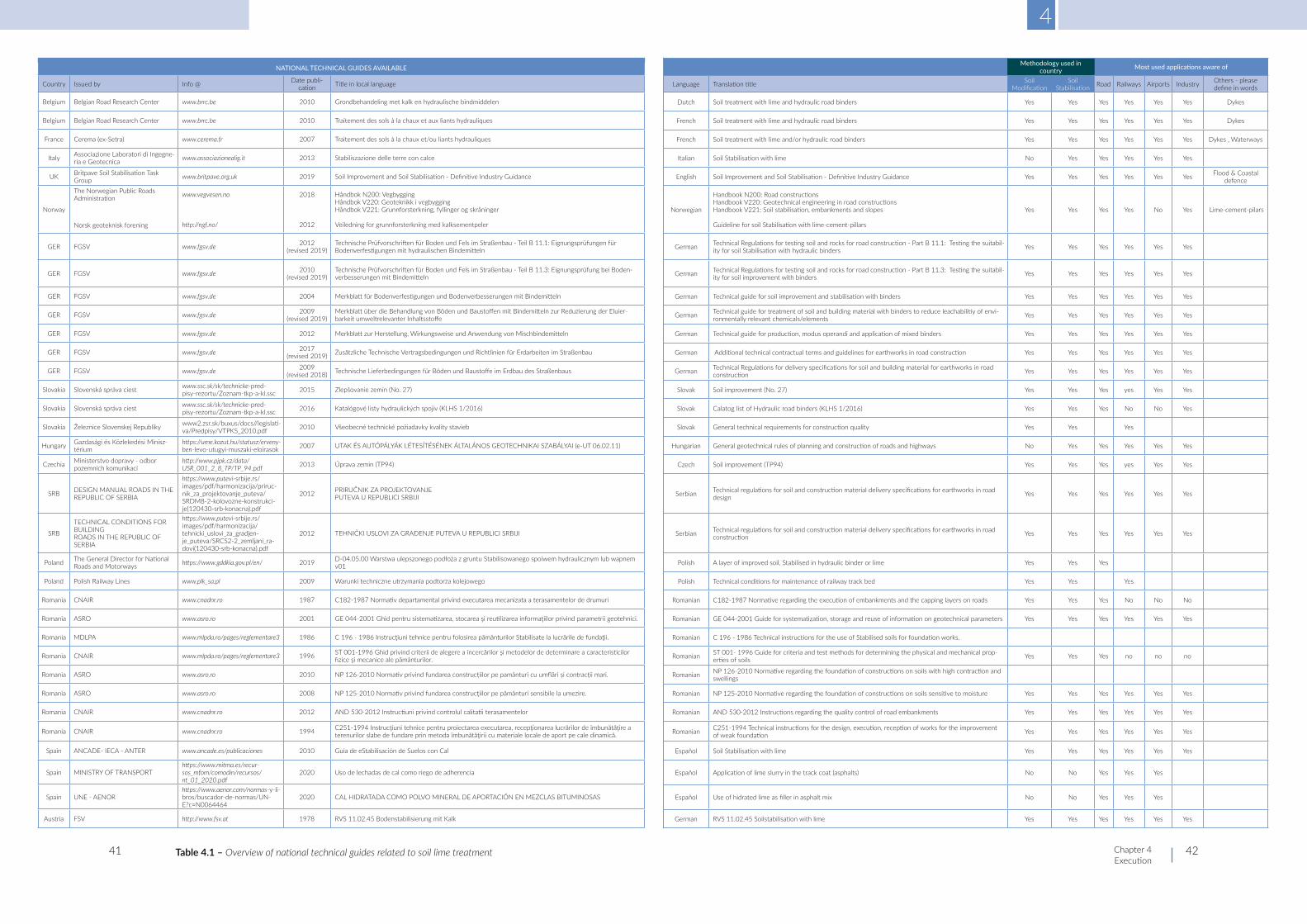
NATIONAL TECHNICAL GUIDES AVAILABLE Methodology used in country Most used applications aware of
Country Issued by Info @ Date publi-cation Title in local language Language Translation title Soil
ModificationSoil
Stabilisation Road Railways Airports Industry Others - please define in words
Belgium Belgian Road Research Center www.brrc.be 2010 Grondbehandeling met kalk en hydraulische bindmiddelen Dutch Soil treatment with lime and hydraulic road binders Yes Yes Yes Yes Yes Yes Dykes
Belgium Belgian Road Research Center www.brrc.be 2010 Traitement des sols à la chaux et aux liants hydrauliques French Soil treatment with lime and hydraulic road binders Yes Yes Yes Yes Yes Yes Dykes
France Cerema (ex-Setra) www.cerema.fr 2007 Traitement des sols à la chaux et/ou liants hydrauliques French Soil treatment with lime and/or hydraulic road binders Yes Yes Yes Yes Yes Yes Dykes , Waterways
Italy Associazione Laboratori di Ingegne-ria e Geotecnica www.associazionealig.it 2013 Stabiliszazione delle terre con calce Italian Soil Stabilisation with lime No Yes Yes Yes Yes Yes
UK Britpave Soil Stabilisation Task Group www.britpave.org.uk 2019 Soil Improvement and Soil Stabilisation - Definitive Industry Guidance English Soil Improvement and Soil Stabilisation - Definitive Industry Guidance Yes Yes Yes Yes Yes Yes Flood & Coastal
defence
Norway
The Norwegian Public Roads Administration Norsk geoteknisk forening
www.vegvesen.no http://ngf.no/
2018
2012
Håndbok N200: Vegbygging Håndbok V220: Geoteknikk i vegbygging Håndbok V221: Grunnforsterkning, fyllinger og skråninger Veiledning for grunnforsterkning med kalksementpeler
Norwegian
Handbook N200: Road constructions Handbook V220: Geotechnical engineering in road constructions Handbook V221: Soil stabilisation, embankments and slopes Guideline for soil Stabilisation with lime-cement-pillars
Yes Yes Yes Yes No Yes Lime-cement-pilars
GER FGSV www.fgsv.de 2012 (revised 2019)
Technische Prüfvorschriften für Boden und Fels im Straßenbau - Teil B 11.1: Eignungsprüfungen für Bodenverfestigungen mit hydraulischen Bindemitteln German Technical Regulations for testing soil and rocks for road construction - Part B 11.1: Testing the suitabil-
ity for soil Stabilisation with hydraulic binders Yes Yes Yes Yes Yes Yes
GER FGSV www.fgsv.de 2010 (revised 2019)
Technische Prüfvorschriften für Boden und Fels im Straßenbau - Teil B 11.3: Eignungsprüfung bei Boden-verbesserungen mit Bindemitteln German Technical Regulations for testing soil and rocks for road construction - Part B 11.3: Testing the suitabil-
ity for soil improvement with binders Yes Yes Yes Yes Yes Yes
GER FGSV www.fgsv.de 2004 Merkblatt für Bodenverfestigungen und Bodenverbesserungen mit Bindemitteln German Technical guide for soil improvement and stabilisation with binders Yes Yes Yes Yes Yes Yes
GER FGSV www.fgsv.de 2009 (revised 2019)
Merkblatt über die Behandlung von Böden und Baustoffen mit Bindemitteln zur Reduzierung der Eluier-barkeit umweltrelevanter Inhaltsstoffe German Technical guide for treatment of soil and building material with binders to reduce leachabilitiy of envi-
ronmentally relevant chemicals/elements Yes Yes Yes Yes Yes Yes
GER FGSV www.fgsv.de 2012 Merkblatt zur Herstellung, Wirkungsweise und Anwendung von Mischbindemitteln German Technical guide for production, modus operandi and application of mixed binders Yes Yes Yes Yes Yes Yes
GER FGSV www.fgsv.de 2017 (revised 2019) Zusätzliche Technische Vertragsbedingungen und Richtlinien für Erdarbeiten im Straßenbau German Additional technical contractual terms and guidelines for earthworks in road construction Yes Yes Yes Yes Yes Yes
GER FGSV www.fgsv.de 2009 (revised 2018) Technische Lieferbedingungen für Böden und Baustoffe im Erdbau des Straßenbaus German Technical Regulations for delivery specifications for soil and building material for earthworks in road
construction Yes Yes Yes Yes Yes Yes
Slovakia Slovenská správa ciest www.ssc.sk/sk/technicke-pred-pisy-rezortu/Zoznam-tkp-a-kl.ssc 2015 Zlepšovanie zemín (No. 27) Slovak Soil improvement (No. 27) Yes Yes Yes yes Yes Yes
Slovakia Slovenská správa ciest www.ssc.sk/sk/technicke-pred-pisy-rezortu/Zoznam-tkp-a-kl.ssc 2016 Katalógové listy hydraulických spojív (KLHS 1/2016) Slovak Calatog list of Hydraulic road binders (KLHS 1/2016) Yes Yes Yes No No Yes
Slovakia Železnice Slovenskej Republiky www2.zsr.sk/buxus/docs//legislati-va/Predpisy/VTPKS_2010.pdf 2010 Všeobecné technické požiadavky kvality stavieb Slovak General technical requirements for construction quality Yes Yes Yes
Hungary Gazdasági és Közlekedési Minisz-térium
https://ume.kozut.hu/statusz/erveny-ben-levo-utugyi-muszaki-eloirasok 2007 UTAK ÉS AUTÓPÁLYÁK LÉTESÍTÉSÉNEK ÁLTALÁNOS GEOTECHNIKAI SZABÁLYAI (e-UT 06.02.11) Hungarian General geotechnical rules of planning and construction of roads and highways No Yes Yes Yes Yes Yes
Czechia Ministerstvo dopravy - odbor pozemních komunikací
http://www.pjpk.cz/data/USR_001_2_8_TP/TP_94.pdf 2013 Úprava zemin (TP94) Czech Soil improvement (TP94) Yes Yes Yes yes Yes Yes
SRB DESIGN MANUAL ROADS IN THE REPUBLIC OF SERBIA
https://www.putevi-srbije.rs/images/pdf/harmonizacija/priruc-nik_za_projektovanje_puteva/SRDM8-2-kolovozne-konstrukci-je(120430-srb-konacna).pdf
2012 PRIRUČNIK ZA PROJEKTOVANJE PUTEVA U REPUBLICI SRBIJI Serbian Technical regulations for soil and construction material delivery specifications for earthworks in road
design Yes Yes Yes Yes Yes Yes
SRB
TECHNICAL CONDITIONS FOR BUILDING ROADS IN THE REPUBLIC OF SERBIA
https://www.putevi-srbije.rs/images/pdf/harmonizacija/tehnicki_uslovi_za_gradjen-je_puteva/SRCS2-2_zemljani_ra-dovi(120430-srb-konacna).pdf
2012 TEHNIČKI USLOVI ZA GRAĐENJE PUTEVA U REPUBLICI SRBIJI Serbian Technical regulations for soil and construction material delivery specifications for earthworks in road construction Yes Yes Yes Yes Yes Yes
Poland The General Director for National Roads and Motorways https://www.gddkia.gov.pl/en/ 2019 D-04.05.00 Warstwa ulepszonego podłoża z gruntu Stabilisowanego spoiwem hydraulicznym lub wapnem
v01 Polish A layer of improved soil, Stabilised in hydraulic binder or lime Yes Yes Yes
Poland Polish Railway Lines www.plk_sa.pl 2009 Warunki techniczne utrzymania podtorza kolejowego Polish Technical conditions for maintenance of railway track bed Yes Yes Yes
Romania CNAIR www.cnadnr.ro 1987 C182-1987 Normativ departamental privind executarea mecanizata a terasamentelor de drumuri Romanian C182-1987 Normative regarding the execution of embankments and the capping layers on roads Yes Yes Yes No No No
Romania ASRO www.asro.ro 2001 GE 044-2001 Ghid pentru sistematizarea, stocarea şi reutilizarea informaţiilor privind parametrii geotehnici. Romanian GE 044-2001 Guide for systematization, storage and reuse of information on geotechnical parameters Yes Yes Yes Yes Yes Yes
Romania MDLPA www.mlpda.ro/pages/reglementare3 1986 C 196 - 1986 Instrucţiuni tehnice pentru folosirea pământurilor Stabilisate la lucrările de fundaţii. Romanian C 196 - 1986 Technical instructions for the use of Stabilised soils for foundation works.
Romania CNAIR www.mlpda.ro/pages/reglementare3 1996 ST 001-1996 Ghid privind criterii de alegere a încercărilor şi metodelor de determinare a caracteristicilor fizice şi mecanice ale pământurilor. Romanian ST 001- 1996 Guide for criteria and test methods for determining the physical and mechanical prop-
erties of soils Yes Yes Yes no no no
Romania ASRO www.asro.ro 2010 NP 126-2010 Normativ privind fundarea construcțiilor pe pamânturi cu umflări și contracții mari. Romanian NP 126-2010 Normative regarding the foundation of constructions on soils with high contraction and swellings
Romania ASRO www.asro.ro 2008 NP 125-2010 Normativ privind fundarea construcţiilor pe pământuri sensibile la umezire. Romanian NP 125-2010 Normative regarding the foundation of constructions on soils sensitive to moisture Yes Yes Yes Yes Yes Yes
Romania CNAIR www.cnadnr.ro 2012 AND 530-2012 Instructiuni privind controlul calitatii terasamentelor Romanian AND 530-2012 Instructions regarding the quality control of road embankments Yes Yes Yes Yes Yes Yes
Romania CNAIR www.cnadnr.ro 1994 C251-1994 Instrucţiuni tehnice pentru proiectarea executarea, recepţionarea lucrărilor de îmbunătăţire a terenurilor slabe de fundare prin metoda îmbunătăţirii cu materiale locale de aport pe cale dinamică. Romanian C251-1994 Technical instructions for the design, execution, reception of works for the improvement
of weak foundation Yes Yes Yes Yes Yes Yes
Spain ANCADE- IECA - ANTER www.ancade.es/publicaciones 2010 Guía de eStabilisación de Suelos con Cal Español Soil Stabilisation with lime Yes Yes Yes Yes Yes Yes
Spain MINISTRY OF TRANSPORThttps://www.mitma.es/recur-sos_mfom/comodin/recursos/nt_01_2020.pdf
2020 Uso de lechadas de cal como riego de adherencia Español Application of lime slurry in the track coat (asphalts) No No Yes Yes Yes
Spain UNE - AENORhttps://www.aenor.com/normas-y-li-bros/buscador-de-normas/UN-E?c=N0064464
2020 CAL HIDRATADA COMO POLVO MINERAL DE APORTACIÓN EN MEZCLAS BITUMINOSAS Español Use of hidrated lime as filler in asphalt mix No No Yes Yes Yes
Austria FSV http://www.fsv.at 1978 RVS 11.02.45 Bodenstabilisierung mit Kalk German RVS 11.02.45 Soilstabilisation with lime Yes Yes Yes Yes Yes Yes
4
Chapter 4 Execution
41 42Table 4.1 – Overview of national technical guides related to soil lime treatment
NATIONAL TECHNICAL GUIDES AVAILABLE
Country Issued by Info @ Date publi-cation Title in local language
Belgium Belgian Road Research Center www.brrc.be 2010 Grondbehandeling met kalk en hydraulische bindmiddelen
Belgium Belgian Road Research Center www.brrc.be 2010 Traitement des sols à la chaux et aux liants hydrauliques
France Cerema (ex-Setra) www.cerema.fr 2007 Traitement des sols à la chaux et/ou liants hydrauliques
Italy Associazione Laboratori di Ingegne-ria e Geotecnica www.associazionealig.it 2013 Stabiliszazione delle terre con calce
UK Britpave Soil Stabilisation Task Group www.britpave.org.uk 2019 Soil Improvement and Soil Stabilisation - Definitive Industry Guidance
Norway
The Norwegian Public Roads Administration Norsk geoteknisk forening
www.vegvesen.no http://ngf.no/
2018
2012
Håndbok N200: Vegbygging Håndbok V220: Geoteknikk i vegbygging Håndbok V221: Grunnforsterkning, fyllinger og skråninger Veiledning for grunnforsterkning med kalksementpeler
GER FGSV www.fgsv.de 2012 (revised 2019)
Technische Prüfvorschriften für Boden und Fels im Straßenbau - Teil B 11.1: Eignungsprüfungen für Bodenverfestigungen mit hydraulischen Bindemitteln
GER FGSV www.fgsv.de 2010 (revised 2019)
Technische Prüfvorschriften für Boden und Fels im Straßenbau - Teil B 11.3: Eignungsprüfung bei Boden-verbesserungen mit Bindemitteln
GER FGSV www.fgsv.de 2004 Merkblatt für Bodenverfestigungen und Bodenverbesserungen mit Bindemitteln
GER FGSV www.fgsv.de 2009 (revised 2019)
Merkblatt über die Behandlung von Böden und Baustoffen mit Bindemitteln zur Reduzierung der Eluier-barkeit umweltrelevanter Inhaltsstoffe
GER FGSV www.fgsv.de 2012 Merkblatt zur Herstellung, Wirkungsweise und Anwendung von Mischbindemitteln
GER FGSV www.fgsv.de 2017 (revised 2019) Zusätzliche Technische Vertragsbedingungen und Richtlinien für Erdarbeiten im Straßenbau
GER FGSV www.fgsv.de 2009 (revised 2018) Technische Lieferbedingungen für Böden und Baustoffe im Erdbau des Straßenbaus
Slovakia Slovenská správa ciest www.ssc.sk/sk/technicke-pred-pisy-rezortu/Zoznam-tkp-a-kl.ssc 2015 Zlepšovanie zemín (No. 27)
Slovakia Slovenská správa ciest www.ssc.sk/sk/technicke-pred-pisy-rezortu/Zoznam-tkp-a-kl.ssc 2016 Katalógové listy hydraulických spojív (KLHS 1/2016)
Slovakia Železnice Slovenskej Republiky www2.zsr.sk/buxus/docs//legislati-va/Predpisy/VTPKS_2010.pdf 2010 Všeobecné technické požiadavky kvality stavieb
Hungary Gazdasági és Közlekedési Minisz-térium
https://ume.kozut.hu/statusz/erveny-ben-levo-utugyi-muszaki-eloirasok 2007 UTAK ÉS AUTÓPÁLYÁK LÉTESÍTÉSÉNEK ÁLTALÁNOS GEOTECHNIKAI SZABÁLYAI (e-UT 06.02.11)
Czechia Ministerstvo dopravy - odbor pozemních komunikací
http://www.pjpk.cz/data/USR_001_2_8_TP/TP_94.pdf 2013 Úprava zemin (TP94)
SRB DESIGN MANUAL ROADS IN THE REPUBLIC OF SERBIA
https://www.putevi-srbije.rs/images/pdf/harmonizacija/priruc-nik_za_projektovanje_puteva/SRDM8-2-kolovozne-konstrukci-je(120430-srb-konacna).pdf
2012 PRIRUČNIK ZA PROJEKTOVANJE PUTEVA U REPUBLICI SRBIJI
SRB
TECHNICAL CONDITIONS FOR BUILDING ROADS IN THE REPUBLIC OF SERBIA
https://www.putevi-srbije.rs/images/pdf/harmonizacija/tehnicki_uslovi_za_gradjen-je_puteva/SRCS2-2_zemljani_ra-dovi(120430-srb-konacna).pdf
2012 TEHNIČKI USLOVI ZA GRAĐENJE PUTEVA U REPUBLICI SRBIJI
Poland The General Director for National Roads and Motorways https://www.gddkia.gov.pl/en/ 2019 D-04.05.00 Warstwa ulepszonego podłoża z gruntu Stabilisowanego spoiwem hydraulicznym lub wapnem
v01
Poland Polish Railway Lines www.plk_sa.pl 2009 Warunki techniczne utrzymania podtorza kolejowego
Romania CNAIR www.cnadnr.ro 1987 C182-1987 Normativ departamental privind executarea mecanizata a terasamentelor de drumuri
Romania ASRO www.asro.ro 2001 GE 044-2001 Ghid pentru sistematizarea, stocarea şi reutilizarea informaţiilor privind parametrii geotehnici.
Romania MDLPA www.mlpda.ro/pages/reglementare3 1986 C 196 - 1986 Instrucţiuni tehnice pentru folosirea pământurilor Stabilisate la lucrările de fundaţii.
Romania CNAIR www.mlpda.ro/pages/reglementare3 1996 ST 001-1996 Ghid privind criterii de alegere a încercărilor şi metodelor de determinare a caracteristicilor fizice şi mecanice ale pământurilor.
Romania ASRO www.asro.ro 2010 NP 126-2010 Normativ privind fundarea construcțiilor pe pamânturi cu umflări și contracții mari.
Romania ASRO www.asro.ro 2008 NP 125-2010 Normativ privind fundarea construcţiilor pe pământuri sensibile la umezire.
Romania CNAIR www.cnadnr.ro 2012 AND 530-2012 Instructiuni privind controlul calitatii terasamentelor
Romania CNAIR www.cnadnr.ro 1994 C251-1994 Instrucţiuni tehnice pentru proiectarea executarea, recepţionarea lucrărilor de îmbunătăţire a terenurilor slabe de fundare prin metoda îmbunătăţirii cu materiale locale de aport pe cale dinamică.
Spain ANCADE- IECA - ANTER www.ancade.es/publicaciones 2010 Guía de eStabilisación de Suelos con Cal
Spain MINISTRY OF TRANSPORThttps://www.mitma.es/recur-sos_mfom/comodin/recursos/nt_01_2020.pdf
2020 Uso de lechadas de cal como riego de adherencia
Spain UNE - AENORhttps://www.aenor.com/normas-y-li-bros/buscador-de-normas/UN-E?c=N0064464
2020 CAL HIDRATADA COMO POLVO MINERAL DE APORTACIÓN EN MEZCLAS BITUMINOSAS
Austria FSV http://www.fsv.at 1978 RVS 11.02.45 Bodenstabilisierung mit Kalk
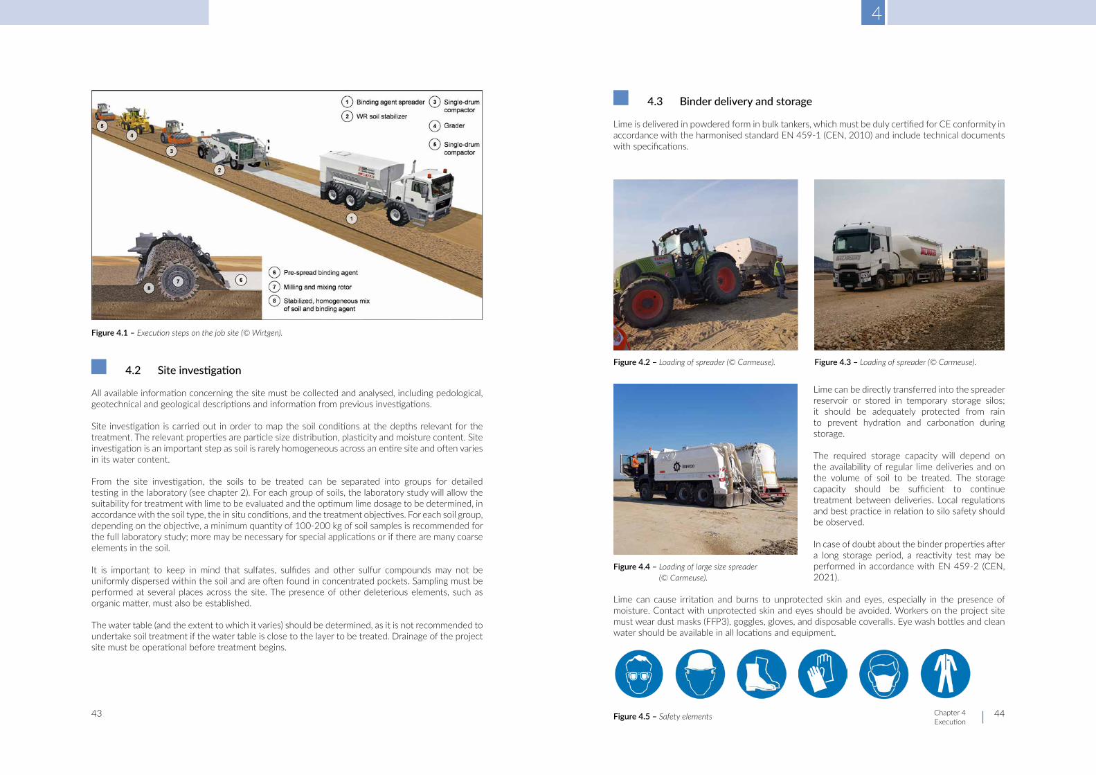
4
Chapter 4 Execution
43 44
4.2 Siteinvestigation
All available information concerning the site must be collected and analysed, including pedological, geotechnical and geological descriptions and information from previous investigations.
Site investigation is carried out in order to map the soil conditions at the depths relevant for the treatment. The relevant properties are particle size distribution, plasticity and moisture content. Site investigation is an important step as soil is rarely homogeneous across an entire site and often varies in its water content.
From the site investigation, the soils to be treated can be separated into groups for detailed testing in the laboratory (see chapter 2). For each group of soils, the laboratory study will allow the suitability for treatment with lime to be evaluated and the optimum lime dosage to be determined, in accordance with the soil type, the in situ conditions, and the treatment objectives. For each soil group, depending on the objective, a minimum quantity of 100-200 kg of soil samples is recommended for the full laboratory study; more may be necessary for special applications or if there are many coarse elements in the soil.
It is important to keep in mind that sulfates, sulfides and other sulfur compounds may not be uniformly dispersed within the soil and are often found in concentrated pockets. Sampling must be performed at several places across the site. The presence of other deleterious elements, such as organic matter, must also be established.
The water table (and the extent to which it varies) should be determined, as it is not recommended to undertake soil treatment if the water table is close to the layer to be treated. Drainage of the project site must be operational before treatment begins.
4.3 Binder delivery and storage
Lime is delivered in powdered form in bulk tankers, which must be duly certified for CE conformity in accordance with the harmonised standard EN 459-1 (CEN, 2010) and include technical documents with specifications.
Lime can be directly transferred into the spreader reservoir or stored in temporary storage silos; it should be adequately protected from rain to prevent hydration and carbonation during storage.
The required storage capacity will depend on the availability of regular lime deliveries and on the volume of soil to be treated. The storage capacity should be sufficient to continue treatment between deliveries. Local regulations and best practice in relation to silo safety should be observed.
In case of doubt about the binder properties after a long storage period, a reactivity test may be performed in accordance with EN 459-2 (CEN, 2021).
Lime can cause irritation and burns to unprotected skin and eyes, especially in the presence of moisture. Contact with unprotected skin and eyes should be avoided. Workers on the project site must wear dust masks (FFP3), goggles, gloves, and disposable coveralls. Eye wash bottles and clean water should be available in all locations and equipment.
Figure 4.1 – Execution steps on the job site (© Wirtgen).
Figure 4.2 – Loading of spreader (© Carmeuse). Figure 4.3 – Loading of spreader (© Carmeuse).
Figure 4.4 – Loading of large size spreader (© Carmeuse).
Figure 4.5 – Safety elements
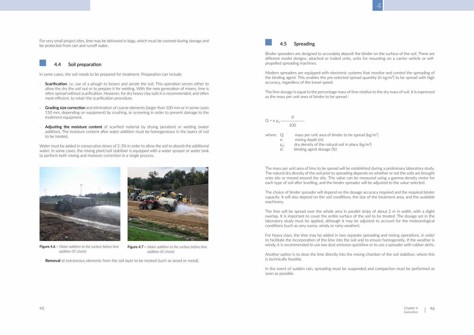
4
Chapter 4 Execution
45 46
For very small project sites, lime may be delivered in bags, which must be covered during storage and be protected from rain and runoff water.
4.4 Soilpreparation
In some cases, the soil needs to be prepared for treatment. Preparation can include:
- Scarification, i.e. use of a plough to loosen and aerate the soil. This operation serves either to allow the dry the soil out or to prepare it for wetting. With the new generation of mixers, lime is often spread without scarification. However, for dry heavy clay soils it is recommended, and often more efficient, to retain the scarification procedure.
- Grading size correction and elimination of coarse elements (larger than 100 mm or in some cases 150 mm, depending on equipment) by crushing, or screening in order to prevent damage to the treatment equipment.
- Adjusting the moisture content of scarified material by drying (aeration) or wetting (water addition). The moisture content after water addition must be homogeneous in the layers of soil to be treated.
Water must be added in consecutive doses of 2-3% in order to allow the soil to absorb the additional water. In some cases, the mixing plant/soil stabiliser is equipped with a water sprayer or water tank to perform both mixing and moisture correction in a single process.
- Removal of extraneous elements from the soil layer to be treated (such as wood or metal).
4.5 Spreading
Binder spreaders are designed to accurately deposit the binder on the surface of the soil. There are different model designs: attached or trailed units, units for mounting on a carrier vehicle or self-propelled spreading machines.
Modern spreaders are equipped with electronic systems that monitor and control the spreading of the binding agent. This enables the pre-selected spread quantity (in kg/m²) to be spread with high accuracy, regardless of the travel speed.
The lime dosage is equal to the percentage mass of lime relative to the dry mass of soil. It is expressed as the mass per unit area of binder to be spread :
Q = e ρd
where: Q: mass per unit area of binder to be spread (kg/m2) e: mixing depth (m) ρd: dry density of the natural soil in place (kg/m3) d: binding agent dosage (%)
The mass per unit area of lime to be spread will be established during a preliminary laboratory study. The natural dry density of the soil prior to spreading depends on whether or not the soils are brought onto site or moved around the site. This value can be measured using a gamma-density meter for each type of soil after levelling, and the binder spreader will be adjusted to the value selected.
The choice of binder spreader will depend on the dosage accuracy required and the required binder capacity. It will also depend on the soil conditions, the size of the treatment area, and the available machinery.
The lime will be spread over the whole area in parallel strips of about 2 m in width, with a slight overlap. It is important to cover the entire surface of the soil to be treated. The dosage set in the laboratory study must be applied, although it may be adjusted to account for the meteorological conditions (such as very sunny, windy or rainy weather).
For heavy clays, the lime may be added in two separate spreading and mixing operations, in order to facilitate the incorporation of the lime into the soil and to ensure homogeneity. If the weather is windy, it is recommended to use low dust emission quicklime or to use a spreader with rubber skirts.
Another option is to dose the lime directly into the mixing chamber of the soil stabiliser, where this is technically feasible.
In the event of sudden rain, spreading must be suspended and compaction must be performed as soon as possible.
Figure 4.6 – Water addition to the surface before lime addition (© Lhoist)
Figure 4.7 – Water addition to the surface before lime addition (© Lhoist)
d
100

4
Chapter 4 Execution
47 48
Figure 4.8 – Tractor pulled lime spreading (© Carmeuse) Figure 4.9 – Towed lime spreader (© Lhoist)
Figure 4.10 – Lime spreader with load transfer (© Lhoist) Figure 4.11 – Self-propelled spreading machine (© Lhoist)
Figure 4.12 – Dosing and mixing chamber on same tractor-pulled soil stabiliser (© Carmeuse)
Figure 4.13 – Mounted spreader (© Lhoist)
4.6 Mixing in situ
When mixing soil with lime, the aim is to maximise the contact between the binder and the soil to be treated. Mixing should be performed as soon as possible after spreading.
For the desired performance to be obtained, the soil layer must be mixed to the right thickness in order to achieve a correct dosage of lime and ensure that the whole layer is treated.
Specialised rotary mixing units are preferred, since they offer better mixing with lower wind-blown dust and minimum lime wastage. Although agricultural disc harrows or ploughs are sometimes used, they are not ideal for good mixing. They do, however, allow the water content to decrease.
Self-propelled spreaders are available, which have a rotavator built into a drive unit. These machines are computer-controlled and provide very efficient mixing and depth control, as well as integrated water addition. They are ideal for use with higher pavement layer applications (e.g. road subbases).
Figure 4.14 – Mixing operations (left two passes – right one pass) (© Carmeuse)
Figure 4.15 – Mixing – Pulvimixer (© Carmeuse)
Figure 4.16 – Pulvimixer (© Lhoist) Figure 4.17 – Tractor-towed stabiliser (© Lhoist)
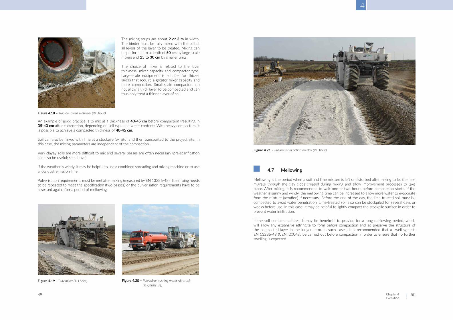
4
Chapter 4 Execution
49 50
The mixing strips are about 2 or 3 m in width. The binder must be fully mixed with the soil at all levels of the layer to be treated. Mixing can be performed to a depth of 50 cm by large-scale mixers and 25 to 30 cm by smaller units.
The choice of mixer is related to the layer thickness, mixer capacity and compactor type. Large-scale equipment is suitable for thicker layers that require a greater mixer capacity and more compaction. Small-scale compactors do not allow a thick layer to be compacted and can thus only treat a thinner layer of soil.
An example of good practice is to mix at a thickness of 40-45 cm before compaction (resulting in 35-40 cm after compaction, depending on soil type and water content). With heavy compactors, it is possible to achieve a compacted thickness of 40-45 cm.
Soil can also be mixed with lime at a stockpile (ex situ) and then transported to the project site. In this case, the mixing parameters are independent of the compaction.
Very clayey soils are more difficult to mix and several passes are often necessary (pre-scarification can also be useful; see above).
If the weather is windy, it may be helpful to use a combined spreading and mixing machine or to use a low dust emission lime.
Pulverisation requirements must be met after mixing (measured by EN 13286-48). The mixing needs to be repeated to meet the specification (two passes) or the pulverisation requirements have to be assessed again after a period of mellowing.
4.7 Mellowing
Mellowing is the period when a soil and lime mixture is left undisturbed after mixing to let the lime migrate through the clay clods created during mixing and allow improvement processes to take place. After mixing, it is recommended to wait one or two hours before compaction starts. If the weather is sunny and windy, the mellowing time can be increased to allow more water to evaporate from the mixture (aeration) if necessary. Before the end of the day, the lime-treated soil must be compacted to avoid water penetration. Lime-treated soil also can be stockpiled for several days or weeks before use. In this case, it may be helpful to lightly compact the stockpile surface in order to prevent water infiltration.
If the soil contains sulfates, it may be beneficial to provide for a long mellowing period, which will allow any expansive ettringite to form before compaction and so preserve the structure of the compacted layer in the longer term. In such cases, it is recommended that a swelling test, EN 13286-49 (CEN, 2004a), be carried out before compaction in order to ensure that no further swelling is expected.
Figure 4.18 – Tractor-towed stabiliser (© Lhoist)
Figure 4.19 – Pulvimixer (© Lhoist) Figure 4.20 – Pulvimixer pushing water silo truck (© Carmeuse)
Figure 4.21 – Pulvimixer in action on clay (© Lhoist)

4
Chapter 4 Execution
51 52
4.8 Compaction
Soil compaction aims to reduce voids and increase the cohesion and angle of internal friction, thus making the soil more stable and less prone to later collapse or settlements.
The soil/lime mixture is compacted to the required density for the treated soil. This target density may be heavily dependent on local conditions and on the soil treatment objectives and requirements.
The layer thickness and the number of roller passes depend on the type of soil, type of compactor and treatment objective. In most situations, it is recommended not to compact soil into layers with a final thickness exceeding 35-40 cm, as mixing cannot usually be performed on such a high thickness. Compactors for higher thicknesses can be used in some specific cases (cf. manufacturer’s instructions).
The compaction rollers must be appropriate to the type of soil and layer thickness to be compacted:
- padfoot or tamping rollers for heavy clays and certain specific purposes (hydraulic structures); - smooth drum vibrating self-propelled rollers > 13 tons in layers exceeding 25 cm; - pneumatic tyre rollers for better base, better density or tighter compaction can be used for top
level surface layers.
With stabilisation, the water content at compaction must be close to the Proctor optimum water content in order to be able to obtain the high degree of compaction that is usually required.
Where compaction is performed using pneumatic tyre rollers, tamping rollers or padfoot rollers, the final surface compaction is carried out using a smooth steel drum roller.
Compaction can be controlled either with reference to a specified method (for example, the Q/S method in France or the continuous compaction control (CCC) method as defined in CEN TC 396/TS 17006) or with reference to a specified end product, as per EN 16907-3 and -5 (CEN, 2018c, 2018e).
Method specification requires compaction to be performed using specified layer thicknesses, types of equipment, compaction methods, etc. according to the soil type and the required degree of compaction. The check involves ensuring that those specifications were followed.
The Q/S method specifies the ratio between the volume Q of compacted soil within time T and compacted surface within the same time. Compaction is classified and checked by comparing the value obtained at the project site with the theoretical value (Corté et al., 1992a, 1992b).
The CCC method uses an instrumented compactor with GPS to measure soil compaction in real time. The number of passes, layer thickness and speed of the roller are registered.
End product specifications give the earthworks practitioner the responsibility and flexibility to determine the method of compaction. The check is performed with reference to a specified engineering criterion, e.g. the degree of compaction obtained. For instance, compaction may be assessed by measuring the density directly, or via an indirect measure obtained using a plate bearing test, penetrometer test or other method. Note: a good bearing capacity does not necessarily imply a good density, since dry soils can have a good bearing capacity with a low density.
To apply the CCC method in the event of end product specifications, the roller needs to be equipped to measure some kind of stiffness or absorbed energy that can be used as an engineering criterion (preferably after a calibration test).
Figure 4.22 – Smooth drum roller / Padfoot rollers (© Lhoist)
Figure 4.23 – Mixing and compaction operations (© Carmeuse)

4
Chapter 4 Execution
53 54
4.9 Grading
Grading consists in removing a thin layer of treated material from the surface of the treated area. After compaction, grading may be necessary to obtain the final layer thickness specified in the project design. Grading also allows the removal of any delaminated material caused by compaction.
4.10 Protectionofworks
A lime-treated layer needs to be protected against water infiltration, water evaporation, and site traffic until the next layer of the construction is laid.
If improvement is being carried out for the purpose of earthworks, the surface of the treated layer can be kept moist by lightly sprinkling and rolling when necessary until the next layer of material is laid. In general, the surface is protected by moistening and then closing with a smooth roller compactor.
In the case of stabilisation, the treated layer should be sealed with a bituminous emulsion and sand if the next layer is not laid the same day.
Layer protection can also prevent dust emissions and degradation of the treated layer by site traffic. A thin gravel layer can be laid in sensitive areas (for example, where heavy vehicles are turning).
Drainage of the site should be considered in an early stage to prevent damage to the treated layer by groundwater and rainwater.
4.11 Exsitutreatment(fixed,semi-mobileandmobileplants)
Soil/binder mixtures can be prepared ex situ at fixed production sites or at mobile or semi-mobile treatment facilities. The choice between in situ and ex situ treatment depends on the application, requirements, environment, required mixing control, available budget, and so on.
Some ex situ stabilisation facilities can work on soils containing particles up to 150 mm.
The next table summarises the advantages and disadvantages of in situ and ex situ treatment.
Figure 4.24 – Grader (© Carmeuse)
In situ treatment Ex situ
Cost + Cheaper
- Higher production cost per m3
Soil manipulation+
Less manipulation – no storage
- Soil excavation - Soil must be
transported to the facility then back to the project site
Dust
- In situ treatment may produce dust – can be reduced by use of low dust emission lime and
appropriate equipment
+ Dust emission limited in the
facilities
Dosage + Greater accuracy
Homogeneity
- More difficult to obtain in situ.
Good knowledge of equipment and experience allow a quality similar to ex situ facilities to be obtained
+ Control of quantity. More
homogeneous mixture.
Functionality+
Can be used for other applications
Table 4.2 – Comparison of in situ and ex situ treatment
Figure 4.25 – Semi-mobile plant (© Lhoist)

4
Chapter 4 Execution
55 56
4.12 Climaticconsiderations
Lime treatment must not be performed if there is heavy rain. In the event of sudden rain, lime spreading must be suspended and the treated layer must be compacted as soon as possible.
Soil improvement and soil stabilisation with lime can be performed in the winter as long as the soil is not frozen.
In the event of strong winds, it is recommended to use low dust emission lime and/or dust reducing equipment in order to reduce dust emissions in surrounding areas.
4.13 Lime as a pre-treatment
Lime can also be used as pre-treatment agent, in combination with a stabilisation process using a hydraulic binder (HB) (such as cement as defined in EN 197-1 [CEN, 2011] or HRB as defined in EN 13282 [CEN, 2013, 2015b, 2015c]). Lime will combine with clay particles, dry and lower the plasticity of the soil to be treated, and improve the soil structure for further HB treatment. Spreading, mellowing, and mixing are performed in the same way as for treatment using a lime-only binder. The hydraulic binder is spread at least 2 hours after soil-lime mixing. After the HB is mixed with the soil and lime, compaction should be performed as soon as possible within the workability period of the hydraulic binder.
A hydraulically bound layer may not be trafficked for at least 7 days, depending on the compressive strength level. The treated layer must be protected against water evaporation and water infiltration with a curing membrane.
In the case of lime improvement, the layer may be trafficked when the bearing capacity is high enough.
Lime dosages used for pre-treatment are usually between 1% and 3%.
4.14 Controlsonexecution
Controls have to be in place during and after the execution.
The moisture content should always be measured before the execution begins. It should be measured regularly at all stages of the treatment process and adjusted if necessary.
Dosage
The actual lime dosage applied is determined from the quantity of binder used and the volume of soil to be treated, where known. It can also be estimated by weighing the lime quantity on a plate of known surface area (1 m2, 0.5 m2, 0.25 m2) during spreading. The records from spreading machines can be used: the difference in mass before and after treatment gives the quantity of lime that was spread.
The mixing depth can be checked by:
- Sounding/coring with checks for variations in colour or consistency. - Spraying phenolphthalein (or thymolphthalein) on the sounding/core walls: a blue colour
indicates a basic pH (lime).
Other controls are to be performed: IIPI, degree of pulverisation and so on.
The degree of pulverisation is measured in accordance with EN 13286-48 (CEN, 2005). It must be equal or larger than the specified value.
Degree of compaction/density
In the case of an end product specification, control involves checking against specified engineering criteria, such as a specified degree of compaction, as measured by a direct measurement of the density or by an indirect measurement obtained from a plate bearing test, penetrometer test or other test.
Figure 4.26 – Dosage control (© Carmeuse)
Figure 4.27 – Control of moisture, density, compaction ratio by nuclear gauge (© Carmeuse, BRRC)
Figure 4.28 – Belgian plate test (© BRRC) Figure 4.29– German plate test (© Hessen Mobil)
4
Chapter 4 Execution
57 58
4.15 Literature
British Cementitious Paving Association. (2004). Stabilised soils: As subbase or base for roads and other pavements (Britpave Technical Data Sheet No 8). https://www.britpave.org.uk/publications/Soil-Stabilisation
British Cementitious Paving Association. (2019). Soil improvement and soil stabilisation: Definitive industry guidance (Britpave No BP/62). https://www.britpave.org.uk/publications/Soil-Stabilisation
Centre de recherches routières. (2009). Code de bonne pratique pour le traitement des sols à la chaux et/ou aux liants hydrauliques (Recommandations CRR No R81/10).
Corté, J.-F., Fevre, A., Havard, H., Joubert, J.P., Kergoet, M., Morel, G., Perrot, A., Quibel, A., Schaeffner, M. & Veysset, J. (Eds.). (1992a). Réalisation des remblais et des couches de forme. Fascicule I: Principes généraux (Guide technique LCPC-SETRA). Laboratoire Central des Ponts et Chaussées (LCPC), Service d’Études Techniques des Routes et Autoroutes (SETRA).
Corté, J.-F., Fevre, A., Havard, H., Joubert, J.P., Kergoet, M., Morel, G., Perrot, A., Quibel, A.,Schaeffner, M. & Veysset, J. (Eds.). (1992b). Réalisation des remblais et des couches de forme. Fascicule II: Annexes techniques (Guide technique LCPC-SETRA). Laboratoire Central des Ponts et Chaussées (LCPC), Service d’Études Techniques des Routes et Autoroutes (SETRA).
European Committee for Standardization. (2004a). Unbound and hydraulically bound mixtures. Part 49: Accelerated swelling test for soil treated by lime and/or hydraulic binder (EN 13286-49).
European Committee for Standardization. (2005). Unbound and hydraulically bound mixtures. Part 48: Test method for the determination of degree of pulverization (EN 13286-48).
European Committee for Standardization. (2011). Cement. Part 1: Composition, specification and conformity criteria for common cements (EN 197-1).
European Committee for Standardization. (2013). Hydraulic road binders. Part 1: Rapid hardening hydraulic road binders: Composition, specifications and conformity criteria (EN 13282-1).
European Committee for Standardization. (2015a). Building lime. Part 1: Definitions, specifications and conformity criteria (EN 459-1).
European Committee for Standardization. (2015b). Hydraulic road binders. Part 2: Normal hardening hydraulic road binders: Composition, specification and conformity criteria (EN 13282-2).
European Committee for Standardization. (2015c). Hydraulic road binders. Part 3: Conformity evaluation (EN 13282-3).
European Committee for Standardization. (2018a). Earthworks. Part 1: Principles and general rules (EN 16907-1).
European Committee for Standardization. (2018b). Earthworks. Part 2: Classification of materials (EN 16907-2).
European Committee for Standardization. (2018c). Earthworks. Part 3: Construction procedures (EN 16907-3).
European Committee for Standardization. (2018d). Earthworks. Part 4: Soil treatment with lime and/or hydraulic binders (EN 16907-4).
European Committee for Standardization. (2018e). Earthworks. Part 5: Quality control (EN 16907-5).
European Committee for Standardization. (2021). Building lime. Part 2: Test methods (EN 459-2).
Havard, M.H., Schaeffner, M. e.a. (2004). Soil treatment with lime and/or hydraulic binders: Application to the construction of fills and capping layers (Guide technique LCPC: Techniques et méthodes des Laboratoires des Ponts et chaussées). Laboratoire Central des Ponts et Chaussées (LCPC).
Heyer, Binard-Kühne, Blaim, Custodis, Fischer, Frûhbote, Gietl, Hecht, Hillmann, Kloubert, Kudla, Kuhl, Möbius, Regel, Schleiter, Schüssler, Sieber, Straussberger, Ströhle & Taetz. (2013). Additional technical conditions of contract and directives for earthworks in road construction: ZTV E-StB 09 (FGSV Report No 599 E) (Ed. 2009, transl. 2012). Road and Transportation Research Association (FGSV).
Jablonski, K. & Blazejowski, K. (Eds.). (2011). Kruzywo, wypetniacz, wapno: Poradnik drogowo-bodwlany [Aggregate, filler, lime: Road and construction guide]. Lime Industry Association. http://phavi.wapno-info.pl/at/attachments/2019/0405/113125-poradnik-drogowo-budowlany.pdf
Jofré, C., Kraemer, C. e.a. (2008). Manual de estabilización de suelos con cimento o cal [Soil stabilization manual with cement or lime]. Instituto Espanol del Cemento y sus Aplicaciones (IECA). https://enriquemontalar.com/manual-de-estabilizacion-de-suelos-con-cemento-o-cal/
Tebaldi, G. (2013). Stabilizzazione delle terre con calce [Soil stabilization with lime] (Quaderni Tecnici ALIG No 3). Associazione Laboratori d’Ingegneria e Geotecnica (ALIG), Unicalce.

5
Chapter 5 Lime production, its markets and applications
59 60
5.1 Introduction
Lime is a generic term, but by strict definition it only includes manufactured forms of lime, i.e. quicklime (CaO) and hydrated lime (Ca(OH)2). It is, however, sometimes used to describe limestone products, which can be confusing. The raw material for all lime-based products is a natural stone: commonly limestone but sometimes chalk, which is composed almost exclusively of calcium carbonate (CaCO3). When limestone contains a certain proportion of magnesium, it is called dolomite, or dolomitic limestone (CaMg(CO3)2). For convenience, we will only refer to lime and limestone in this text, unless it is necessary to be more specific. Limestone is widely available all over the world, (the Earth’s crust contains more than 4% calcium carbonate) and it is used for many different purposes. (For more information, see the EuLA website, www.eula.eu)
Although the English word lime is shared with the citrus fruit, the word used in most European languages is derived from the Latin “calx”, e.g. kalk, calce, chaux, cal, kalko – this is also the origin of the English “chalk”.
5.2 How lime is made today
There are different steps in the lime production process:
- Extraction: explosives are used in the quarry to break up limestone or chalk rock. The broken rock is then picked up at the quarry face by huge, mechanised excavators.
- Crushing and screening: trucks tip the rock into crushers, which break it down into smaller pieces. Screeners sort and separate the rock pieces into different sizes.
- Calcination: the rock is heated in a preheater and then transferred to a kiln, where it is heated to around 1000°C to make lime. The burn temperature and the length of the process depend on the type of rock that is used as raw material. A number of filters and scrubbers clean the dust and gases generated from burning the rock.
- Cooling: the lime that leaves the kiln is cooled with air. - Hydration: water is sometimes added to lime after cooling to make hydrated lime. - Storage and dispatch: lime products are safely wrapped, packaged and stored on site. They are
then sent to the customer by road, rail and ship.
■ Chapter 5 ■ Lime production, its markets and applications

5
Chapter 5 Lime production, its markets and applications
61 62
A large range of lime applications and markets
Lime products are used by many industries in a wide range of applications, as can be seen in the chart below.
Steel making
- The largest use of lime is in steel manufacturing, where it serves as a flux to remove impurities (silica, phosphorus, and sulfur). Lime is used in basic oxygen furnaces and electric arc furnaces, as well as in secondary refining. Lime used in the steel industry must meet exacting physical and chemical properties.
- Quicklime is also used for further processing in steelworks, where harmful constituents such as phosphorus and sulfur are captured by the lime. Specially customised mixtures are provided for particularly high-quality steel grades with extremely low sulfur content.
- Dolomitic lime products are used to help to regenerate the refractory materials in furnaces.
Environmental protection
- Flue gas desulfurisation: Lime is essential to reduce emissions and purify flue gases. Lime pro-ducts are used to bind gases from combustion processes – such as sulfur dioxide, hydrogen chloride and hydrogen fluoride – and make them suitable for recycling. Special lime mixtures can absorb mercury and dioxins/furans. Every year, millions of tonnes of lime products are used for these applications alone, mainly in power plants, waste incineration plants and industrial plants.
- Drinking water: Drinking water is almost always purified with lime before it flows from our taps. The addition of lime binds corrosive carbonic acid and, depending on its original hardness, makes the water either harder or softer in order to prevent the formation of boiler scale and corrosion in the piping. Lime is also responsible for adjusting the pH value. Last but not least, lime is used to remove naturally occurring heavy metals from our drinking water.
- Treatment of effluent and sludge: Lime neutralises acid effluent and removes heavy metals in treatment plants for industrial effluent so that used process water can be returned to circulation. Users include a whole variety of industries, such as the silicic acid and silicone industry, as well as producers of printed circuit boards.
- In hundreds of municipal sewage treatment plants, lime serves to dewater and minimise the volume of sludge produced. Through its scrubbing action, it also produces a valuable and safe fertiliser or secondary raw material.
Construction materials
Lime is used as a filler and bonding agent in building materials, such as:
- Aerated autoclaved concrete blocks: Quicklime is mixed with cement, sand, water and alumi-nium powder to produce a slurry, which rises and sets to form honeycomb-structured blocks that have excellent thermal and sound insulation properties. The heat generated when quicklime reacts with water, the alkaline conditions and the addition of aluminium powder generate hy-drogen bubbles inside the blocks.
- Sand-lime bricks: Made entirely of natural sand, lime and water, the raw sand-lime brick mixture matures in reactors before being compressed under vapour pressure to form sand-lime bricks. When the mixture is pressure-hardened in an autoclave, the large proportion of available calcium oxide in the lime ensures that calcium silicate hydrate crystals are formed, giving the brick its high mechanical strength, density and stability.
- Mortars, plasters and renders: Current cement-lime mixes provide the most efficient mix in terms of possessing both ’freshness’ and controlled strength. The benefits of using lime and lime- cement mortars, plasters and renders promote ‘fresh’ and ‘hardened’ characteristics.
Figure 5.1 – Lime production process (British Lime Association, n.d.)
Figure 5.2 – Overview of lime customer markets (Sales by industry 2019. ‘Exports’ means the total quantity of burnt product sold to a market outside the EU28 or EFTA) (European Lime Association, 2020)

5
Chapter 5 Lime production, its markets and applications
63 64
Civil engineering
- Asphalt: Hydrated lime can be used as an additive to hot-mix asphalt for road construction. Adding lime to the asphalt mixture increases resistance to water stripping, allowing it to maintain strength and provide good resistance to heavy stress, e.g. for road surfaces prone to regular traffic or congestion. Lime also acts as a mineral filler which increases the viscosity of the binder, increasing the stiffness, tensile strength, compressive strength and resistance to water stripping.
- Soil treatment (which is the subject of this document). Chemical industry
- Lime is used as a neutralising agent in the petrochemical, cosmetics, pharmaceutical, animal feed and tanning industries and has many other applications in this sector. Among the many chemi-cal products produced using lime are propylene oxide, epichlorohydrin, calcium carbide, sodium carbonate, citric and lactic acid, plastics additives, fertilisers (mixed and nitrogen-based) and human food products such as gelatine, sugar and calcium phosphate.
- Pharmaceuticals: Products derived from lime, such as precipitated calcium carbonate, are found in a number of pharmaceuticals, including dietary supplements, antacids and other well-known medicines.
- Inorganics: Lime or its derivatives are essential building blocks in the manufacture of many inor-ganic salts such as calcium phosphate (a toothpaste additive) calcium citrate (a food and drink additive) and calcium nitrite (an additive for sludge treatment).
Agriculture: Lime is used to correct soil acidity and as part of fertilisers (European Commission, 2018).
- Fertiliser: Lime can all be used to adjust the pH of soils to create optimum growing conditions and hence improve crop yields. Lime has a beneficial effect on soil: it neutralises harmful acids and restores the humus balance, making the soil more fertile. The forestry sector relies on lime to combat the effects of acid rain.
- Fish farming: The pH of acidic ponds and lakes can be controlled and raised using lime. In general terms this creates a more hospitable environment for all aquatic organisms, especially fish. Lime is therefore used by fish farmers to maintain a suitable habitat for breeding fish.
- Fruit farming: As apples and other fruit ripen, they emit carbon dioxide. When in storage, the carbon dioxide lowers the level of oxygen in the atmosphere and accelerates the rate of deterio-ration of the fruit. By circulating air around the fruit and over lime, the level of carbon dioxide is reduced and the fruit remains fresh and usable for longer. Residues from processing citrus fruits, when mixed with lime, can be dried and sold as cattle feed. In addition, lime can also be used to neutralise waste citric acid and to raise the pH of fruit juices in order to stabilise the flavour and colour.
Paper and pulp: Lime is used in the manufacture of paper pulp, particularly in the production of precipitated calcium carbonate (PCC). Thanks to its exceptional physical and bleaching characteristics, it helps produce high quality paper. Precipitated calcium carbonate (PCC), is used as a whitening agent in the paper-making process. Lime is also used to help recover caustic soda (white liquor) from paper-mill sludge.
5.3 EuLA is working towards the future: net zero emissions, circulareconomyandresourceefficiency.
In recent years, a large number of studies have been conducted and published on the permanent CO2 capture that results from lime use. In 2018, EuLA therefore commissioned Politecnico di Milano (PoliMi) to conduct a literature review of peer-reviewed research on carbonation, with the aim of forming an accurate assessment of the carbon footprint of the lime industry.
After taking due account of the quantity and reliability of the available data, the study concludes that in total the natural carbonation rate of the European lime industry could be equal to 33% of the CO2 emissions generated by the initial production of lime through the thermal decomposition of calcium carbonate (Grosso et al., 2020).
In line with the EU 2050 Green Deal objectives, EuLA has also committed to establishing a list of non-competitive innovation areas that could enable the lime industry to become carbon neutral or even carbon negative by 2050. Three action areas have been identified, namely reducing CO2 emissions through post-combustion (end-of-pipe) carbon capture and concentration, switching kilns to electrical power sources, and enhancing the carbonation of lime in use.
With regard to the circular economy, the key benefit of lime is its durability and recyclability in its multiple applications in roadbuilding and earthworks. Lime-treated soils are particularly easy to remove and replace and can be reused in new construction, closing the circular economy loop. According to a study by IMA Europe based on a market analysis and estimated recycling rates, EuLA considers that about 86% of all lime used, and 75% of lime used in construction applications, is recycled. This figure is an EU-wide average and regional disparities do exist.
Figure 5.3 – Axes of work to reach net zero emissions by 2050 (© EuLA)

5
Chapter 5 Lime production, its markets and applications
65 66
5.4 EuropeanLimeAssociationdataand reporting is availableon theinternet
EuLA acts and reports on all aspects of lime production and its applications, from production issues to environmental and sustainability impacts. EuLA aims to realise the vision of the European lime sector. It speaks with a unified voice to defend the interests of European lime producers at a European level and help its members to achieve their national objectives.
EuLA is a member of IMA-Europe (Industrial Minerals Association Europe). Please visit www.eula.eu for the latest news on our activities and publications.
5.5 Literature
British Lime Association. (n.d.). How lime is made. https://britishlime.org/education/popup_how_lime_is_made.php
European Commission. (2018). Competitiveness of the European cement and lime sectors. Publications Office of the European Commission. https://op.europa.eu/en/publication-detail/-/publication/07d18924-07ce-11e8-b8f5-01aa75ed71a1/language-en
European Lime Association. (2020). EuLA 2019-2020 activity Report. https://www.eula.eu/2019-2020-eula-activity-report/
Grosso, M., Biganzoli, L., Campo, F.P., Pantini, S. & Tua, C. (2020). Literature review on the assessment of the carbon potential of lime in different markets and beyond (PoliMI Report No 845.0202.70.02). Politecnico di Milano (PoliMI), Assessment on Waste and Resources Research Group (AWARE). https://www.eula.eu/politecnico-di-milano-literature-review-on-the-assessment-of-the-carbonation-potential-of-lime-in-different-markets-and-beyond/
Application %age of Sales Recycling Rate Contribution
Steel 40% 95% 46%
Environment 14% 90% 15%
Concrete / Bricks 5% 65% 4%
Soil Stab / Mortars 12% 75% 11%
Agriculture 3% 65% 2%
Chemistry 8% 70% 7%
Exports / Others 18%
Total 86%
Table 5.1 – Recycling rate – EuLA estimate

6
Chapter 6 Lime as a sustainable solution
67 68
6.1 Limeasasustainablesolution
Soil treatment is a sustainable solution that has economic, environmental and social benefits and promotes the circular economy.
Earthworks often demand large volumes of materials, which are not always readily available close to the locations of the roads, railways, or other civil engineering projects being built and may be difficult to obtain in sufficient quantities. It follows that project planners should favour the reuse or recycling of the soil in situ to the use of quarried or recycled aggregates brought onto site. However, the use of in situ materials may require planners to work with poor-quality materials, such as clayey soils, whose geotechnical characteristics may fall short of normal standards.
As previously described, soil treatment with lime is a technique where poorly rated fine soils are mixed in situ with quicklime in order to create platforms for roads, railways, and other types of civil engineering works as an alternative to using aggregates. All three effects of lime treatment (soil drying, soil modification and soil stabilisation) offer a combination of economic, environmental and societal benefits for agencies, investors, contractors and the community.
As quicklime undergoes an exothermic chemical reaction with the moisture in soils, it is a very effective agent for drying out all types of wet soil. Drying occurs quickly, allowing the material to be worked within a few hours. Generally, between 1% and 3% lime by mass of dry soil will improve a wet site sufficiently for it to become accessible. This can reduce weather-related construction delays and extend the construction season, allowing projects to be delivered faster.
On many construction sites, short-term soil modification is needed in order to temporarily strengthen the working area, so that it is accessible for trucks and other heavy construction equipment. Adding sufficient lime can create a trafficable, rain-resistant working platform for subsequent construction and so speed up the progress of work. It also conditions the soil for further treatment and maximises the use of low-cost, on-site materials. Small amounts of lime between 1% and 3% can upgrade many unstable fine-grained soils, although higher percentages may be necessary for very cohesive soils. Although they are initially used for temporary purposes, the improved soil layers are generally incorporated into the final civil engineering project.
After stabilisation, the soil has chemically changed and its strength is permanently increased. As long as soil swelling risk is mitigated, excellent freeze-thaw resistance can be achieved. As an example of the long-term effects of lime stabilisation, measurements conducted on a German highway embankment that had been in place for 34 years showed that the performance of the aged lime treated soils was much higher than that measured on its first construction (Haas & Ritter, 2019; Haas et al., 2019).
If the thickness of the overlying layers is maintained, the service life expectations increase, reducing the life cycle cost of the pavement (National Lime Association, n.d.).
■ Chapter 6 ■ Lime as a sustainable solution

6
Chapter 6 Lime as a sustainable solution
69 70
Time savings from in situ soil treatment reduce overall construction time compared to traditional ‘dig and dump’ methods, where the soil is excavated and shipped off to a landfill or some alternative use and replaced by new aggregates purchased and brought to the site from elsewhere. The potential volumes are significant: case studies show that up to 1 million m³ of soil can be treated per month per project in Europe using only six large soil mixers per day. This is equivalent to importing more than two million tonnes of aggregates.
Soil treatment is also environmentally beneficial, with one truck delivering of 30t of lime replacing approximately 70-100 truck movements to remove soil and bring new materials to the site. It is also more resource-efficient, since the reuse of in situ soils means that aggregates do not need to be quarried elsewhere and obviates the need to send excavated materials to landfill, thus preserving landfill space.
All these benefits result in considerable cost savings – by eliminating the cost of buying and shipping new materials as well as the costs of taking materials offsite, dumping them in landfill and paying the associated landfill tax. Compared to traditional methods, savings of up to 60% are commonly achieved (Denayer, Amit, & Soporan, 2018; Denayer, Shtiza, Schlegel, Haas, & Lesueur, 2019; Educational Excellence School Advisory Council [EESAC], 2012, 2013).
The possible social advantages (such as less dust, noise, vibration, and fewer trucks and other machinery) are not yet precisely quantified, but minimising the duration of the works dramatically reduces the nuisance and inconvenience for the community close to the construction site. The risk of accidents on site and on local roads will be reduced, as there will be less traffic on site and fewer trucks carrying materials back and forth (Denayer et al., 2019; EESAC, 2012, 2013). Reducing the time needed for earthworks also has a direct influence on the completion deadline for the project as a whole, and given that the opening of new infrastructure usually brings economic and/or amenity benefits to the local area, the use of lime stabilisation thus ensures that these benefits are realised as soon as possible.
The sustainability of all these aspects can be quantified in terms of environmental, social and economic indicators (Abdo et al., 2015), which can also be used to compare the sustainability of soil treatment with that of traditional methods using aggregates. As economic indicators, we can also add the implications for local industry in terms of activity and employment.
6.2 Literature
Abdo, J., Boussafir, Y., Chardard, P., Cui, Y.-J., Gandille, D., Landes, B., Matynia, A. & Puiatti, D. (Eds.). (2015). Enseignements de TerDOUEST: Propositions de compléments au guide traitement des sols (Rapport IDRRIM). Institut des Routes, des Rues et es Infrastructures pour la Mobilité (IDRRIM). https://www.idrrim.com/ressources/documents/7/4054,17.12.15_-Rapport-TerDOUEST.pdf
Denayer, C., Amit, K. & Soporan, L.C. (2019). Soil treatment with lime for earthworks: An economical and sustainable solution. In R. Sundaram, J. Telangrao Shahu & V. Havanagi (Eds.), Geotechnics for transportation infrastructure: Recent developments, upcoming technologies and new concepts (Vol. 1) (Lecture Notes in Civil Engineering [LNCE] No 28). (pp. 203-215). Springer. https://link.springer.com/chapter/10.1007/978-981-13-6701-4_13
Denayer, C., Shtiza, A., Schlegel, T., Haas, S. & Lesueur, D. (2019, September 1-6). Geotechnical know-how that supports decision making towards sustainable infrastructure [paper presentation]. 17th European conference on soil mechanics and geotechnical engineering (ECSMGE-2019), Reykjavik, Iceland. https://www.eula.eu/geotechnical-know-how-that-supports-decision-making-towards-sustainable-infrastructure/
Educational Excellence School Advisory Council. (2012). Sustainability indicators of different techniques used in earthworks.
Educational Excellence School Advisory Council. (2013). Life cycle assessment of different techniques used in earthworks.
Haas, S. & Ritter, H.-J. (2019). Soil improvement with quicklime: Long-time behaviour and carbonation. Road materials and pavement design, 20(8), 1941-1951. https://doi.org/10.1080/14680629.2018.1474793
Haas, S., Hammerschmidt, S., Shtiza, A., Denayer, C. & Scutt, D. (2019, September 1-6). Soil improvement with quicklime: Quantification of the carbonation rate in an embankment after 34 years. In 17th European conference on soil mechanics and geotechnical engineering (ECSMGE-2019), Reykjavik, Iceland. International Society for Soil Mechanics and Geotechnical Engineering (ISSMGE). https://www.eula.eu/haas-s-hammerschmidt-s-shtiza-a-denayer-c-scutt-d-2019-soil-improvement-with-quicklime-quantification-of-the-carbonation-rate-in-an-embankment-after-34-years/
National Lime Association. (n.d.). Soil stabilization: Short- and long-term economic benefits. Lime.org. https://www.lime.org/lime-basics/uses-of-lime/construction/soil-stabilzation/

7
Chapter 7Case studies
71 72
7.1 Soilimprovementwithlimefortheconstructionofhigh-speedraillines in Belgium
Summary
High-speed rail (HSR) was launched in Belgium in 2007 and provides important links between Brussels and Paris, London, Cologne and Amsterdam. The Belgian part of the network is more than 300 km long, and includes 200 km of specially built high-speed lines. To build these new lines, meet the design specifications and avoid construction delays in spite of the unpredictable Belgian weather, lime treatment was adopted as the preferred technique for enabling works.
Fine, water sensitive, and in some cases very plastic soils showed sufficient reactivity with lime. Improvement resulted in the efficient reduction of water content and delivery of the required bearing capacity and stability. In most cases, a quicklime addition of between 1% and 3% was used. Once the lime enabling works were completed, platforms were ready for laying ballast, sleepers and rails.
The use of lime treatment in European railways began in the late 1970s with the construction of the French TGV (train à grande vitesse) network, the continent’s first HSR lines:
- Late 1970s: TGV Paris – Lyon – used locally in presence of wet soils - Mid 1980s: TGV Paris – Le Mans – used locally in presence of wet soils - Early 1990s: TGV Paris – Lille-Calais – systematic use in fills and subgrade - Mid 2000: TGV Paris – Nancy/Metz – systematic use in fills and subgrade - Mid 2000: TGV Paris by-pass (North-South-West) – fills and subgrade - Ongoing: TGV Nancy/Metz-Strasbourg – fills and subgrade - Starting: TGV Tours-Bordeaux; Le Mans – Rennes; Nîmes-Montpellier
For the new HSR lines currently being built in the North of France, the volume of lime-treated wet/clayey soils in the fills represents approximately 1/3 of the total earthworks.
Other European countries that use or have used lime treatment for the construction of HSR lines include:
- Mid-1980s onward: Germany - Mid-1990s to mid-2000s: Belgium, Spain - Early 2000s: UK - Early 2000s onwards: Italy - From 2012: Poland
The case study below focuses on the HSR network in Belgium.
■ Chapter 7 ■ Case studies

7
Chapter 7Case studies
73 74
The main objective of earthwork projects during HSR construction in Belgium was, as for every project, to obtain the best possible balance between cut and fill. This objective is, of course, based on the desire to minimise costs by maximising the reuse of the materials excavated on site and thus reduce the cost of external material supplies and transport.
Soils on HSR construction sites in Belgium were mostly moist to very wet, with moderate plasticity. They therefore responded favourably to quicklime improvement.
The specifications issued by TUC Rail (the Belgian rail infrastructure designer) for the treatment of soils with quicklime were essentially based on the recommendations of the two French LCPC/Setra guides, the Guide for Embankments and Capping Layers Constructions (Corté et al., 1992a; 1992b) and the Guide for Soil Treatment with Lime and/or Hydraulic Binders (Schaeffner et al., 2000). The aim was to reuse soil for the embankments of HSR platforms.
Geotechnical data obtained by TUC Rail allowed a preliminary identification to be made of the soils likely to be found on site. The contractor was required to carry out additional investigations to determine the conditions under which soil reuse would be feasible, either during the project mobilisation period or during the progress of works. These investigations essentially consisted of digging sampling trenches of 25-50 metres in length in order to identify the soils present on site. These length of the trenches was sufficient to establish the homogeneity of the ground.
The samples were first tested systematically in other to classify the soil type. For each soil type identified, the degree of treatment required was determined across a range of measured natural water contents.
In a second phase, a treatment study or ‘formulation study’ was carried out on the samples in each class in order to analyse the behaviour of each soil type likely to be treated. This phase two study also determined the variation of the immediate bearing index (IIPI) as a function of the original water content and the dosage of quicklime to be added in order to improve it.
The results were expressed as a series of curves showing the variation of IIPI as a function of the quantity of quicklime and the original water content. This allowed determination of the quantity of lime to be introduced as a function of moisture content measured on the project site. The values of the water content of the in situ soils were measured daily; additional measurements were also taken whenever the weather resulted in a change to the water content.
Full-scale field tests were also performed to check the results of the laboratory study in real conditions and to confirm the treatment approach for each soil type for which treatment was appropriate. The objective of these field tests was to adjust the lime dosing charts in accordance with the real site conditions and to refine the application methods to be used (modes of extraction, thickness of the layers, compaction procedure, etc.).
The efficiency of lime treatment observed in the field tests was generally higher than that observed in the laboratory, due to the different soil treatment machinery and because the treatment of a large quantity of soil favours water evaporation under normal weather conditions.
Daily, before work began, water content measurements were carried out on samples from the zones to be treated that day and checked against the lime dosing charts from the laboratory studies and full-scale field tests. After also taking account of the weather forecast, instructions for lime dosage or aeration were given to the work teams.
The lime spreader parameters were checked each time before spreading resumed. As a minimum, measurements of the lime spread were verified by sampling each time the dosage was changed. The actual dosages were evaluated daily by comparing the quantity of lime consumed with the volume of soil treated. Compaction of the treated material was checked in a similar manner to the compaction checks used for all other materials used in the works.
In sensitive areas, such as near existing highways, a low dust emission quicklime was used to prevent quicklime losses from the HSR project site from affecting highway workers and users.
Key figures
- 24.3 Mm³ cuts, 17.6 Mm³ fills; - 300,000 tons of quicklime delivered between 1997 and 2006; - earthworks costs represented 19% of the total project cost.
Figure 7.2 – Lime treatment on HSR sites (© Lhoist)
Figure 7.1 – HSR line (© Thalys)

7
Chapter 7Case studies
75 76
Conclusion
The final assessment of quicklime treatment during the earthworks construction for the Belgian HSR network was completely positive. Most materials had low plasticity but were very moist (5-8% above optimum normal Proctor), and were successfully treated with 1-3% of lime.
The alternative to lime treatment was to use quarried materials, which would have led to unacceptable volumes of excavated material being sent to landfill. The economic case for reusing materials in situ was therefore obvious. The successful delivery of structures using lime-treated soils demonstrated the benefits of thorough preparation involving both on-the-ground investigations and laboratory analyses. For the organisation of site works, the priority is to balance technical performance (quality of treatment) with economic performance (optimisation of the lime dosage).
Literature
Allouche, C., Dethy, B. & Maertens, J. (1997). Stabilisatie van gronden met kalk. Geotechniek, 1(2), 11-16.
Corté, J.-F., Fevre, A., Havard, H., Joubert, J.P., Kergoet, M., Morel, G., Perrot, A., Quibel, A., Schaeffner, M. & Veysset, J. (Eds.). (1992a). Réalisation des remblais et des couches de forme. Fascicule I: Principes généraux (Guide technique LCPC-SETRA). Laboratoire Central des Ponts et Chaussées (LCPC), Service d’Études Techniques des Routes et Autoroutes (SETRA).
Corté, J.-F., Fevre, A., Havard, H., Joubert, J.P., Kergoet, M., Morel, G., Perrot, A., Quibel, A., Schaeffner, M. & Veysset, J. (Eds.). (1992b). Réalisation des remblais et des couches de forme. Fascicule II: Annexes techniques (Guide technique LCPC-SETRA). Laboratoire Central des Ponts et Chaussées (LCPC), Service d’Études Techniques des Routes et Autoroutes (SETRA).
Dethy, B. (2001, May 11 & 16). Les spécifications propres au traitement des sols en vue de leur réutilisation au droit des remblais de plates-forme du TGV [paper presentation]. Matinée d’Études sur le traitement des sols à la chaux, Sterrebeek. Belgian Road Research Centre (BRRC) & Fédération Wallonne des Entrepreneurs de Travaux de Voirie (FWEV).
Dethy, B. & Verhelst, F. (2003). Soil improvement for the construction of the platform for Belgian High Speed Train in urban areas [paper presentation]. IABSE Symposium on structures for high-speed railway transportation, Antwerp. (pp. 230-231). International Association for Bridge and Structural Engineering (IABSE)
Schaeffner, M., e.a. (2000). Traitement des sols à la chaux et/ou aux liants hydrauliques: Application à la réalisation des remblais et des couches de forme (Guide technique LCPC-SETRA). Laboratoire Central des Ponts et Chaussées (LCPC), Service d’Études Techniques des Routes et Autoroutes (SETRA).
7.2 Applicationinrailwaysandhigh-speedraillinesinItaly
Summary
Lime soil treatment has been widely used in Italy for railway line embankments where significant volumes of plastic clays have to be managed.
Without lime treatment, an enormous amount of clay soil extracted from cuts, foundations, piles, etc. would have had to have been disposed as waste and, at the same time, large volumes of material would have had to have been quarried and transported to the project sites. Extensive stabilisation with a maximum 3% dosage of lime has enabled this to be avoided.
As shown in the examples below, soil from the demolition of an embankment treated with 3% lime was successfully used for the construction of new embankments. Soils containing bentonite, from excavations for the foundations of bridges, were also successfully treated. Lime treatment enabled cost to be reduced relative to more traditional construction approaches.
Case study 1
This case study concerns the building of a provisional embankment (volume 60,000 m3) on the Milan-Naples railway line in 2003 (Canziani et al., 2005). The embankment was 50 m wide at the base and 24 m wide at the top, with a maximum height of 8 m and a length of 200 m. It was built with lime-treated soil (dosage 3% by mass of dry soil) and the upper layer of the embankment was covered by a 0.4 m layer of cement-gravel mixture. Excavated soil was transported to the work site and layered uniformly. The water content of the soil was regularly checked (25-27%). An average of 1,700 m3 per day was laid (approximate thickness 30 cm).
The natural soil was a plastic clay with low IIPI and ICBR measured after 4 days immersion (plasticity index 23, IIPI=10, ICBR=3).
This soil was treated with 3% lime, which led to an increase in bearing capacity and compressive strength. The IIPI measured at optimum water content was 33 and the ICBR after 4 days immersion was 68. The compressive strengths were Rc7d=0.47 MPa and Rc28d=0.88 MPa.
The embankment was used for the transit of a 300 t launching crane, which was used to transport Omega beams to a viaduct. During the first 15 months, the embankment showed no damage or permanent deformation.
After 15 months, the embankment was demolished and the soil was reused to build two new embankments. The layers of the embankment were quite resistant to excavation. Soil taken from the first embankment was tested in the laboratory and found to contain a residual amount of 0.2-0.6% of free lime. To reuse the soil, the mixture was transported by truck in blocks and laid in regular layers 30 cm thick with a tracked blade which also broke down the blocks. A large pulvimixer worked the material so that it could pass through a 25 mm sieve. The measured moisture content showed that the material was at the correct water content for compaction and it was not necessary to add lime. Samples were taken before compaction in order to measure the IIPI and soaked ICBR. A large increase in both parameters was observed.

7
Chapter 7Case studies
77 78
Case study 2
The next case study concerns part of the 40 km line from Milan to Venice (Benedetto, 2010). This track lies on clay soils with high plasticity and with a very low CBR value.
The volume of material needed to build the embankments was approximately 3 million m3, with an additional 1.5 million m3 of aggregate for concrete construction. However, the construction of the foundations produced about 1 million m3 of soil: 350,000 m3 from foundations, 400,000 m3 from diaphragm walls and drilled piles and 70,000 m3 from helicoidal piles.
The results of the laboratory study demonstrated that the mechanical properties of the stabilised soil exceeded expectations, especially for a 3% lime addition. As a result of the lime addition, the optimum value of the compaction moisture increased, as did the ICBR and the compressive strength.
Field tests were performed to determine the best methodology for compaction and other site parameters. The compaction method adopted consisted of 1 cycle with a static roller + 1 cycle with a vibrating roller + 4 cycles with the static roller as a result of the change from a plastic to an elastic state caused by the use of lime.
In this case, the maximum layer thickness required to reach adequate mechanical characteristics was 30 cm. The CBR values obtained from the field tests were much higher than the CBR value of the soil before stabilisation.
To make a reasonable assessment of the benefits of using stabilised soils for railway development, three possible options were considered: (1) construction of embankments with quarried natural materials, (2) construction of embankments partly using stabilised soil in accordance with Italian regulations, (3) construction of embankments using only stabilised soil that was suitable from a mechanical point of view as demonstrated by laboratory and field tests. Experience from the HSR line in North Italy, one of the most important national transport infrastructure projects of the last 20 years, demonstrated that the costs of soil stabilisation were much lower than the cost of building embankments with quarried natural materials.
Case study 3
This case study concerns the use of soil lime treatment on the Bologna-Verona and Pontremolese conventional railway lines in Italy, which have a lot of embankments (Ciufegni et al., 2016).
The stabilised soil volume needed to replace the foundations and build the body of the embankments was more than 1 million m3, of which 400,000 m3 was used from excavations for the construction of other projects close to the railway line. This included soils from the excavations for the pile foundations of bridges, which included bentonite mud. The remaining 600,000 m3 would otherwise have gone to landfill. The potential for reusing these excavation materials was examined at the design stage.
Preliminary laboratory studies (IIPI, ICBR, RC and triaxial tests) were performed with several lime dosages (2%, 2.5%, 3%), with close attention being paid to the effect of the bentonite. The studies showed that a higher bentonite content had only a small effect on compressive strength.
Two field trials were performed with fine grained soils with creep tests, triaxial tests and modulus deformation. The trials were successful and a dosage of 2% was selected for the next steps.
For the doubling of the line between Solignano and Fornovo, 250,000 m3 of excavated soil was available for stabilisation and reuse in embankment construction. These soils were composed of clay and clayey silt.
A laboratory study investigated 3 lime dosages (2%, 2.5% and 3%) based on the lime fixation point (LFP).
Based on the compressive strength measured at different dosages at varying water contents, a 2.5% lime addition was selected. The embankment exhibited a higher modulus of deformation after treatment and conformed to the material specification.
Literature
Benedetto, A. (2010). Externalities of soil stabilization in the construction of main transportation infrastructures: The case of the high speed railway in North Italy: Economical and environmental benefits. Open Environmental Engineering Journal, 7(3), 1–12. http://dx.doi.org/10.2174/1874829501003010001
Canziani, A., Cariboni, L., Pressato, U., Tosoratti, P. & Ursi, N. (2005, October 24-26). Lime stabilised mixture recovery from a demolished provisional embankment and reusing for new subgrades along the high-speed railway Milan-Naples [paper presentation]. 2nd international TREMTI symposium: Treatment and recycling of materials for transport infrastructure: using lime, cement and hydraulic road binders, Paris, France (C178). Centre d’Information sur le Ciment et ses Applications (CimBéton) & Chambre Syndicale Nationale des Fabricants de Chaux, Grasses et Magnésiennes.
Ciufegni, S., Sacchi, F. & Accogli, F. (2016, December 8). Lime stabilization experience: Bologna - Verona and Parma: La Spezia Conventional Railway Lines [paper presentation]. ViaCalco Symposium, Budapest, Hungary.
7.3 LimetreatmentforthemodernisationofrailwaylinesacrossEurope
Summary
Several European countries have developed specific solutions to upgrade old railway networks by removing the old structures, treating the subgrade of the trackbed with lime and placing a new structure on top (capping layer + foundation + sleepers + ballast + rails).
This case study reports on some modernisation projects that have been carried out since the mid-1990s in the Czech Republic, Poland, Portugal and Belgium.

7
Chapter 7Case studies
79 80
In the early 1990s, several countries launched a series of projects to renovate and modernise old railways, often in parallel with the construction of new high-speed rail lines. Among the available methodologies and techniques, in situ soil treatment and stabilisation using lime, either alone or in combination with cement, was chosen by the Czech Republic, Portugal, Poland and Belgium.
Czech Republic (Herle, 2005)
From the beginning of the 1990s, the Czech Republic started a large-scale plan to upgrade its main railway corridors, in order to improve domestic routes and establish connections with European lines running both North-South and East-West. The aim was to improve safety and reliability while also increasing capacity and speed (up to 160 km/h). The first railway corridor, between the towns of Usti nad Labem and Lovosice, was reconstructed in 1999 to achieve a traffic speed of 160 km/h.
The major problems of the existing lines included:
- the poor quality of the existing structures, which were more than 100 years old; - the aged ballast, which was polluted by fine clays particles and dust; - the heterogeneity and weakness of the rail bed; - the deformation and instability of excavated and filled supports.
To achieve the best value for the available budget, the upgrade programme had the following main objectives:
- achieve the 160 km/h maximum travelling speed of the existing passenger rail stock; - keep the track at the existing alignment and elevation as much as possible; - improve the track subgrade, drainage, retaining structures, bridges, station buildings etc.; - improve safety.
It was therefore decided to excavate the old trackbed materials (aggregate, backfill, etc.) down to the subgrade. Soil improvement was needed due to the unfavourable subsoil conditions in many railway sections, frequently involving the presence of highly plastic soft clay soils. At first, three support stabilisation techniques were used: soil replacement, soil reinforcement with geosynthetics, and soil improvement. However, although soil replacement and soil strengthening were used more often in the early stages, the advantages of soil improvement were soon recognised. In situ soil improvement with lime, or with a combination of lime and cement for sections with sandier soils, is now among the most favoured subgrade stabilisation methods.
Soils were treated with lime either in situ or by laying pre-treated materials, to a thickness between 35 and 50 cm, in order to comply with the required bearing capacity set out in the Czech design code. The granular material layer (15 cm) was placed on the subgrade, followed by a 35 cm depth of ballast.
In some areas, alluvial soils composed of medium to highly plastic clay, with a stiff to soft consistency and variable proportions of sand and rock fragments, were present. The variable size of rock fragments meant that bigger stones had to be removed before mixing in the soil mixer, to avoid problems during lime improvement. The lime content varied between 1% and 3% of the dry soil weight.
The works were completed during summer and autumn 1999 amid unfavourable weather conditions. Compressive strength measurements were performed on specimens taken from lime-treated sections after 5 years of service. The recorded values were between 1.03 and 1.75 MPa, with an average of 1.34 MPa.
Due to delays with the relocation of some underground services, reinforced concrete slabs were constructed in a 50 m section near the rail switches. The slabs were placed on a levelled and recompacted subgrade formed from marly clay. A geogrid was placed below the slabs. After 3 years of service, the geometric position of the rail track near the switches showed some defects and needed periodic correction. The rest of the railway track, where the soil improved with lime was used, showed no deformation. After five years, the deformations of the track near the switches had increased even further and the ballast was found to be highly contaminated with fine clay particles due to the pumping effect of the concrete slabs. Czech railways asked SG Geotechnika to investigate the causes of the deformation and to propose a suitable solution. After observing the
good visual condition, behaviour and performance of the lime-treated materials, it was decided to excavate the contaminated ballast from the deformed track section, remove the concrete slabs and replace them with a lime-cement stabilised layer. Due to limited space, in situ stabilisation was not feasible and the stabilised soil was prepared ex situ and brought to the site. One year after the repair no deformation was visible, and the newly stabilised track section was behaving the same way as the neighbouring section constructed five years previously.
Figure 7.3 – Test pit showing contaminated ballast and a reinforced concrete slab at the bottom of the pit (Herle, 2005)
Figure 7.4 – Railway structure with stabilised layer

7
Chapter 7Case studies
81 82
The width of the lime-treated layers was at least 5 m under a single track or where the tracks were more than 5 m apart, and at least 10 m in all other cases.
One of the unusual features of this project was the opportunity to perform the works by ‘half-trackbed’ such that rail traffic on the adjacent track was allowed to continue to run while the work was being performed. Low dust emission quicklime was used in these circumstances.
Lime use for rail track subgrade improvement has been widely accepted in the Czech Republic as a very efficient and economical method for reconstruction of existing rail lines. In comparison with other methods (e.g. soil replacement, soil reinforcement) it is also environmentally friendly, as it avoids moving large quantities of soil to and from the site. The soil remains in place and is improved by the addition of a small quantity of lime or lime-cement. Furthermore, lime treatment reduced the time needed to complete the work by minimising the impact on progress of weather-related site stoppages. A substantial reduction of the site traffic on the existing trackbeds, which are much narrower than roadbeds, was also seen as a benefit.
Portugal (Montes et al., 2005)
The Porto-Lisbon railway line was modernised using lime treatment on embankments or the top layers of embankments during the early 2000s. On one 6 km section, after ballast removal, the 35 cm layer of aggregate was found to be polluted with clay and was also removed for recycling. The subgrade clayey soil showed an insufficient plate load test modulus, with values between 20 and 30 MPa, which was improved by lime treatment at a 2% dosage at 35 cm thickness to give a modulus of 60 MPa at the surface of the stabilised subgrade.
The stabilised subgrade was then capped with 0/40 mm limestone aggregate (20 cm layer) and 0/32.5 mm limestone aggregate (15 cm) before the final ballast layer was applied.
As with the Czech case study, the work was performed by half-trackbed while allowing train traffic to continue on the other line at 80 km/h. The reduced construction period, taking into account the limited space on site, was a highly valued benefit of the use of lime treatment. A rate of 200-250 m per day was achieved. Thanks to this modernisation work, it was possible to increase the train traffic speed to 170 km/h and even 220 km/h on some sections.
Belgium (Verlaine et al., 2002)
Belgium has a 6,000 km rail network of which approximately 200 km needed to be improved in the early 2000s. With a target rate of 25 km per year and an accompanying need to maintain traffic on the lines, the situation was different to that of the previous case studies. This led Belgium to organise work sites on the basis of the time available to execute the work, resulting in three types of sites:
- hour sites, with works taking place over 4 to 10 hours; - day sites, with works taking place over 2 to 3 days and nights, usually on weekends; - long-term sites, where works could last for 4 to 6 weeks.
The first tests of lime treatment were conducted on long-term sites, as these offered greater flexibility for operations. The results were successful. The plate load test modulus of the subgrade treated increased from 7 MPa before treatment to 60 MPa and in some cases even 120 MPa after treatment.
Figure 7.5 – Lime treatment on railway structures (Puiatti, D. & Robinet, A., Georail 2011)
Figure 7.6 – Railway structure and local requirements on each layer
Figure 7.7 – Railway structure and lime treatment (© Lhoist)
Figure 7.8 – Cross-section of the structure treated with lime (Verlaine et al., 2002)

7
Chapter 7Case studies
83 84
Several long-term sites were successfully completed, and this led to trials of the process on shorter duration projects. On day sites where the complete removal of the track was possible, traditional processing equipment (spreaders and mixers) was used in situ with equal success, so that lime treatment came to be seen as one of the best methods for meeting overall quality requirements. On hour sites, where work was often carried out at night, operations were more difficult because the surfaces were particularly cramped and only the ballast was removed, rather than the entire track. Lime spreading was done from bulk bags and only minimal mixing using a dipper shovel was possible before new ballast was laid and the track was reset.
These difficulties prompted maintenance managers to discontinue the use of this technique on day sites, and especially on hour sites, as the materials and procedures available were inadequate in view of the traffic stoppage constraints, and to confine the use of lime treatment to long-term sites.
Literature
Herle, V. (2005, October 24-26). Performance of lime improved railway subgrade after 5 years in service [paper presentation]. 2nd international TREMTI symposium: Treatment and recycling of materials for transport infrastructure: using lime, cement and hydraulic road binders, Paris, France (C026). Centre d’Information sur le Ciment et ses Applications (CimBéton) & Chambre Syndicale Nationale des Fabricants de Chaux, Grasses et Magnésiennes.
Montes, N., Marques, M. & Joly, C. (2005, October 24-26). Restoration of railways in Portugal [paper presentation]. 2nd international TREMTI symposium: Treatment and recycling of materials for transport infrastructure: using lime, cement and hydraulic road binders, Paris, France (C094). Centre d’Information sur le Ciment et ses Applications (CimBéton) & Chambre Syndicale Nationale des Fabricants de Chaux, Grasses et Magnésiennes.
Verlaine, P., Gérard, A., Puiatti, D. & Verhelst, F. (2002, June 24-26). Upgrading existing railways: The experience of the Belgian National Railways (NMBS/SNCB/NGBE) with renewing existing rail tracks using lime treatment [paper presentation]. 6th international conference on the bearing capacity of roads and airfields. Workshop 5: Upgrading of existing railway for heavy axle loads and high speed trains, Lisbon, Portugal.
Puiatti, D. & Robinet, A. (2011, May 19-20). Railways modernization through soil treatment: Examples of application in Europe. In J. P. Magnan (Ed.), International symposium on railway geotechnical engineering (GEORAIL 2011), Paris, France. (pp. 599-608). French institute of Science and Technology for Transport Developments and Networks (IFSTTAR).
7.4 Contributionoflimetreatmenttothefrostprotectionofroadbeds
Summary
A Ph.D. thesis presented in 2015 (Nguyen, 2015) sought to clarify the French design codes for levelling course or capping layer pavement structures treated with lime.
The research focused on the frost susceptibility of soils treated with lime, covering several more or less clay-containing fine soils. It led to an amendment of the French standard for designing roads (NF P 98 086), which has allowed the frost susceptibility of lime-treated fine soils to be evaluated as a function of the laying conditions and their mechanical performance.
In cold regions, the subgrades of earthworks are often treated like capping layers, leading to excess dosages of binder and an extra, unnecessary cost.
Nguyen’s research made it possible to confirm the specific properties of lime treatment and to describe its long-term effects on mechanical strength and frost resistance more accurately. The results obtained confirmed that lime is not only an effective binder for the improvement of fine soils with a high moisture content, but can also provide excellent mechanical performance and frost resistance in a way that allows the design of earthworks to be optimised.
Achieving this performance was dependent on:
- a sufficient dosage, which depends on the nature of the soil; - a sufficient curing time.
Beneficial performance is achieved beyond 28 days of curing. Compressive strengths of around 5 MPa were observed for the longest curing times (for example with 4% of lime in a weakly plastic silty soil, or 5% in a moderately plastic silty clay).
The behaviour of lime-treated fine soils in frost depends on the type of stressing envisaged: frost heave by cryosuction or frost splitting under the effect of freeze/thaw cycles. The first phenomenon is very dependent on the permeability of the treated soil in the short term (the lower the permeability, the more limited the frost heave),
Figure 7.9 – Lime treatment in cold conditions (© Lhoist)

7
Chapter 7Case studies
85 86
but it is the mechanical strength which comes out on top when the pozzolanic reaction develops. Lime treatment can therefore be used to make a fine soil frost-resistant by adopting a sufficient dosage to allow stabilisation and leaving a sufficient curing time.
For design considerations, it was confirmed that:
- frost resistance is demonstrated if the compressive strength reaches 2.5 MPa; - a dosage ensuring a ratio above 1 for ICBR after immersion / IIPI (conventional requirement for
subgrades) enabled all the soils studied to be classed as having ‘low susceptibility to frost’.
Resistance to frost splitting, even if it responds to different physical mechanisms than frost heave, likewise requires a dosage and a curing time that enable at least 60% of the original compressive strength to be retained after the freeze/thaw cycles.
The inclusion of simplified criteria for demonstrating the low frost susceptibility of lime-treated fine soils in the current version of the French standard for road design (NF P 98 086) makes it possible to dispense with long and costly frost heave tests.
Literature
Herrier, G., Nguyen, T.-T.-H. & Ferber, V. (2016). Contribution du traitement à la chaux à la protection contre le gel des plateformes routières. Travaux, (924), 30-35.
Herrier, G., Nguyen, T.-T.-H., Cui, Y.-J., Ferber, V. & Tang, A.M. (2017). Protection des plates-formes routières contre le gel: Contribution du traitement à la chaux. Revue Générale des Routes et de l’Aménagement (RGRA), (942), 32-39.
Herrier, G., Nguyen, T.-T.-H., Ferber, V., Puiatti, D. & Cui, Y.-J. (2018, April 19-20). Contribution of lime treatment to the frost protection of roadbed [paper presentation]. 4th international seminar on earthworks in Europe, Madrid, Spain. Spanish Committee of PIARC (ATC) & PIARC Technical Committee on Rural Roads and Earthworks (D.4).
Nguyen, T.-T.-H. (2015). Stabilisation des sols traités à la chaux et leur comportement au gel [unpublished doctoral dissertation]. Université Paris-Est. https://tel.archives-ouvertes.fr/NAVIER-GEOTECHNIQUE/tel-01191696v1
Nguyen, T.-T.-H., Cui, Y.-J., Ferber, V., Herrier, G., Ozturk, T., Plier, F., Puiatti, D., Salager, S. & Tang, A.M. (2019). Effect of freeze-thaw cycles on mechanical strength of lime-treated fine-grained soils. Transportation Geotechnics, 21, Article 100281. https://doi.org/10.1016/j.trgeo.2019.100281
7.5 Limetreatmentofanexperimentalembankment–long-termmonitoring and pH
Summary
This case study concerns an embankment treated with a high dosage of lime (7%) and investigated after 30 years. As a result of the lime treatment, increased compressive strength was observed with time due to pozzolanic reactions, although the initial water content increased after heavy rain due to limited compaction. The surface remained in a good state and the damage was very limited, even after several years. The penetrometer resistance measured after 30 years was quite high compared to the surrounding soil. It was observed that the pH change was limited to the treated layer and did not affect the surrounding soil.
This case study concerns the test section made in August 1972 on a section of soil at the Sterrebeek field test site, which belongs to the BRRC (Belgian Road Research Centre).
A silty soil with a plasticity index of 8 was mixed with 7% quicklime (90% available CaO) to a depth of 30 cm over an area of 225 m2 (15x15 m square). The compaction, due to a problem with the compactor, was limited to 80% of the Modified Proctor optimum density. Due to the low density, the initial water content (16%) increased to 22-24%, rising to 26% after heavy rain. Due to the lime treatment, an increase in the ICBR was observed which was confirmed by laboratory tests. The compressive strength was regularly measured. During the first six months, it was limited to 0.23 MPa. Thereafter a regular increase of the compressive strength was observed. It reached 0.6 MPa after 400 days as a consequence of pozzolanic reactions, despite the poor density achieved.
During the first winter, only the first 1 cm on the surface was damaged, and after 5 years, only 2 cm.
The treated area was left in this condition for more than 30 years without bearing traffic loads and without any additional treatment or changes. After 30 years, measurements with penetrometers were performed in the treated and untreated areas. The results showed an increase in resistance between 20 and 30 cm depth. Below 40 cm, the resistance was close to the resistance of the natural soil. Using the correlation between the CBR and the resistance measured by the penetrometer, the calculated CBR after 30 years was 200-300%, which evidenced a high stiffness level.
The pH of the treated area was also measured. It proved to be alkaline only in the first 40 cm. The influence of lime treatment is limited to 10 cm below the treated area, which means that the impact of lime species diffusion or leaching on the surrounding environment is very limited.
Figure 7.10 – Swelling slope versus compressive strengths

7
Chapter 7Case studies
87 88
A study of vegetation in the treated area was performed by a specialist laboratory from the University of Brussels.
The objective was to study the impact of lime treatment on the type and development of plant species.
The species present in the untreated and treated areas were quite similar. Calciphilic species were also present in the untreated area.
Fertility studies based on nitrogen and Ellenberg indicator values were also performed and did not show any significant differences between the two areas.
Reference
Detry, J., Van Den Berg, H. & Bollens, Q. (2005, October 24-26). Study of a 30 years old lime treated silt area: Analysis of its mechanical behaviour and environmental influence on the directly surrounding zone [paper presentation]. 2nd international TREMTI symposium: Treatment and recycling of materials for transport infrastructure: using lime, cement and hydraulic road binders, Paris, France (C155). Centre d’Information sur le Ciment et ses Applications (CimBéton) & Chambre Syndicale Nationale des Fabricants de Chaux, Grasses et Magnésiennes.
7.6 Lime treatment of soils at the Roissy-Charles de Gaulle airport site
Summary
During 1990s and 2000s, increasing air traffic to and from Paris-Charles de Gaulle airport prompted the airport operator ADP (Aéroports de Paris) to modify and extend the capacity of its infrastructure. Several projects were therefore begun in order to reduce congestion on existing taxiways and increase aircraft movements between the plane parks, aprons and runways.
The improvements included the construction of a new runway (1996-98), new aprons and a new terminal (2006-2008). Lime was used to manage excavated soils (mainly silts and marls) and to deliver works that promote sustainable development.
This project aimed to build a new fourth runway for Paris-Charles de Gaulle airport within the existing airport perimeter (1996-98). It included earthworks on the linked aprons and taxiways as well as the runway itself.
For embankments and a 1 m layer on top of the embankments (subgrade), silts and marls were treated with lime at the stockpile, then moved to the construction site, spread and compacted in 35 cm layers. After treatment with 1-3% quicklime was applied during the day, the stockpile was closed with a smooth drum roller.
For capping layers, the treatment operations were performed directly on the construction site. A 2% lime dosage was used for the pre-treatment of soils, before stabilisation with cement (6%).
Figure 7.11 – Change in pH in the treated zone by depth (upper 30 cm)
Figure 7.12 – Earthworks at Paris-Charles de Gaulle airport (Raynaud et al., 2008)
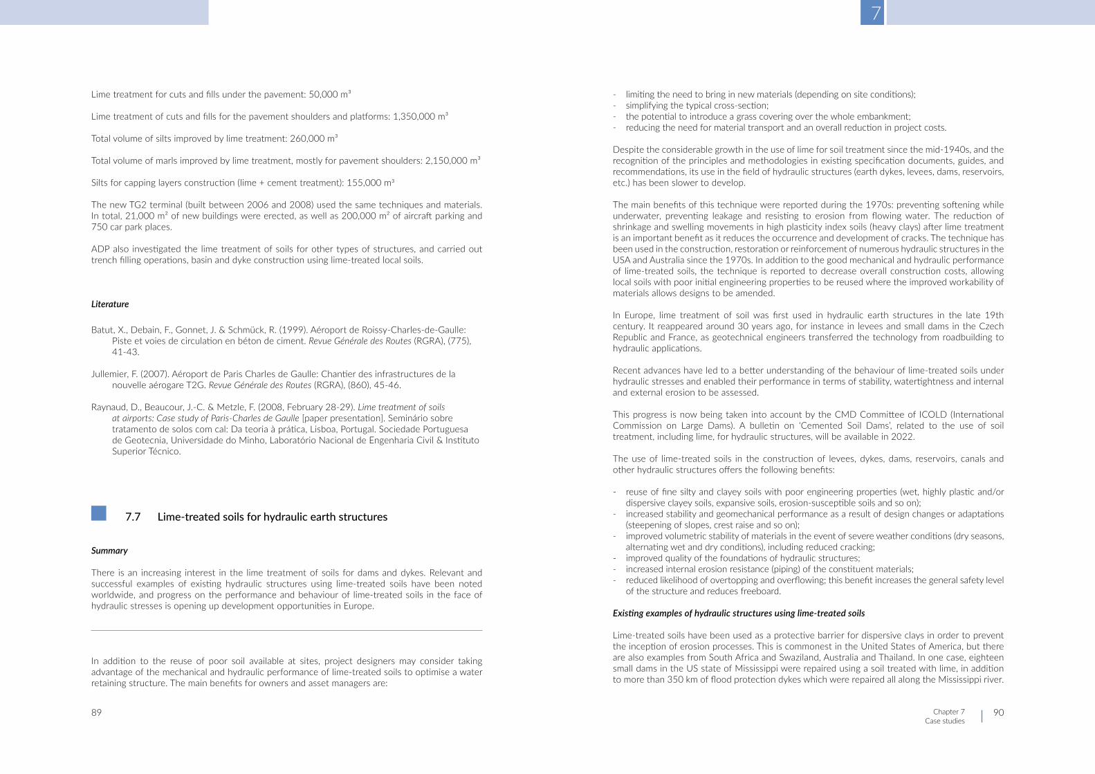
7
Chapter 7Case studies
89 90
Lime treatment for cuts and fills under the pavement: 50,000 m³
Lime treatment of cuts and fills for the pavement shoulders and platforms: 1,350,000 m³
Total volume of silts improved by lime treatment: 260,000 m³
Total volume of marls improved by lime treatment, mostly for pavement shoulders: 2,150,000 m³
Silts for capping layers construction (lime + cement treatment): 155,000 m3
The new TG2 terminal (built between 2006 and 2008) used the same techniques and materials. In total, 21,000 m² of new buildings were erected, as well as 200,000 m² of aircraft parking and 750 car park places.
ADP also investigated the lime treatment of soils for other types of structures, and carried out trench filling operations, basin and dyke construction using lime-treated local soils.
Literature
Batut, X., Debain, F., Gonnet, J. & Schmück, R. (1999). Aéroport de Roissy-Charles-de-Gaulle: Piste et voies de circulation en béton de ciment. Revue Générale des Routes (RGRA), (775), 41-43.
Jullemier, F. (2007). Aéroport de Paris Charles de Gaulle: Chantier des infrastructures de la nouvelle aérogare T2G. Revue Générale des Routes (RGRA), (860), 45-46.
Raynaud, D., Beaucour, J.-C. & Metzle, F. (2008, February 28-29). Lime treatment of soils at airports: Case study of Paris-Charles de Gaulle [paper presentation]. Seminário sobre tratamento de solos com cal: Da teoria à prática, Lisboa, Portugal. Sociedade Portuguesa de Geotecnia, Universidade do Minho, Laboratório Nacional de Engenharia Civil & Instituto Superior Técnico.
7.7 Lime-treated soils for hydraulic earth structures
Summary
There is an increasing interest in the lime treatment of soils for dams and dykes. Relevant and successful examples of existing hydraulic structures using lime-treated soils have been noted worldwide, and progress on the performance and behaviour of lime-treated soils in the face of hydraulic stresses is opening up development opportunities in Europe.
In addition to the reuse of poor soil available at sites, project designers may consider taking advantage of the mechanical and hydraulic performance of lime-treated soils to optimise a water retaining structure. The main benefits for owners and asset managers are:
- limiting the need to bring in new materials (depending on site conditions); - simplifying the typical cross-section; - the potential to introduce a grass covering over the whole embankment; - reducing the need for material transport and an overall reduction in project costs.
Despite the considerable growth in the use of lime for soil treatment since the mid-1940s, and the recognition of the principles and methodologies in existing specification documents, guides, and recommendations, its use in the field of hydraulic structures (earth dykes, levees, dams, reservoirs, etc.) has been slower to develop.
The main benefits of this technique were reported during the 1970s: preventing softening while underwater, preventing leakage and resisting to erosion from flowing water. The reduction of shrinkage and swelling movements in high plasticity index soils (heavy clays) after lime treatment is an important benefit as it reduces the occurrence and development of cracks. The technique has been used in the construction, restoration or reinforcement of numerous hydraulic structures in the USA and Australia since the 1970s. In addition to the good mechanical and hydraulic performance of lime-treated soils, the technique is reported to decrease overall construction costs, allowing local soils with poor initial engineering properties to be reused where the improved workability of materials allows designs to be amended.
In Europe, lime treatment of soil was first used in hydraulic earth structures in the late 19th century. It reappeared around 30 years ago, for instance in levees and small dams in the Czech Republic and France, as geotechnical engineers transferred the technology from roadbuilding to hydraulic applications.
Recent advances have led to a better understanding of the behaviour of lime-treated soils under hydraulic stresses and enabled their performance in terms of stability, watertightness and internal and external erosion to be assessed.
This progress is now being taken into account by the CMD Committee of ICOLD (International Commission on Large Dams). A bulletin on ‘Cemented Soil Dams’, related to the use of soil treatment, including lime, for hydraulic structures, will be available in 2022.
The use of lime-treated soils in the construction of levees, dykes, dams, reservoirs, canals and other hydraulic structures offers the following benefits:
- reuse of fine silty and clayey soils with poor engineering properties (wet, highly plastic and/or dispersive clayey soils, expansive soils, erosion-susceptible soils and so on);
- increased stability and geomechanical performance as a result of design changes or adaptations (steepening of slopes, crest raise and so on);
- improved volumetric stability of materials in the event of severe weather conditions (dry seasons, alternating wet and dry conditions), including reduced cracking;
- improved quality of the foundations of hydraulic structures; - increased internal erosion resistance (piping) of the constituent materials; - reduced likelihood of overtopping and overflowing; this benefit increases the general safety level
of the structure and reduces freeboard.
Existing examples of hydraulic structures using lime-treated soils
Lime-treated soils have been used as a protective barrier for dispersive clays in order to prevent the inception of erosion processes. This is commonest in the United States of America, but there are also examples from South Africa and Swaziland, Australia and Thailand. In one case, eighteen small dams in the US state of Mississippi were repaired using a soil treated with lime, in addition to more than 350 km of flood protection dykes which were repaired all along the Mississippi river.

7
Chapter 7Case studies
91 92
Lime treatment has also been adopted for several dams of significant height, such as Los Esteros in New Mexico, a 67 m high dam in which the core of the foundation is protected by a 13 cm layer of soil treated with 4% hydrated lime in a 13 cm layer, and the McGee Creek dam in Oklahoma, a 49 m high dam built in the 1980s for which soil-lime treatment was used for the protection of the core and for the 0.7 m thick downstream facing earthwork.
An outstanding example of the durability of lime-treated soils is the Friant-Kern irrigation canal in California. Since its construction in the late 1940s, the earth banks have suffered periodic damage from cracks, slips and slides. In 1972, it was decided to restore approximately 8.5 km of failed sections using lime treatment with 3-4% quicklime on clays taken from the banks of the canal. The mixing operations were followed by the placement of layers of 30 to 40 cm thickness on the slopes, which were then compacted with a vibrating padfoot roller (kneading compaction) that was winched ‘yo-yo fashion’ up and down the slope, or compacted by a sheepsfoot roller (‘stair-step construction’) (Herrier et al., 2012) before grading. A typical cross-section of the rehabilitated canal is shown in Figure 7.14 (Howard & Bara, 1976).
No new slides have been observed since the rehabilitation works, and the lime-soil lining is the material that needs the least maintenance on the canal. From 1975 to the present day, applications of lime treatment have been extended to include levee repair after sliding and reconstruction after flooding: examples include Mississippi River levees in the states of Arkansas, Tennessee, Illinois, Mississippi, Missouri, and Louisiana. Lime has also been used for remedial treatment of existing dams suffering surface erosion and piping in Oklahoma, Mississippi, Tennessee. Lime contents from 2% to 3%, are reported.
In Australia, the use of lime to protect dispersive clays from piping was successfully adopted for the dams at Flagstaff (1964), Wallan and Bungal (1972) and Kilmore (1979), first for repairs of homogeneous dams and then later as an initial design concept. For the 48 m high Bungal dam, for example, the core was entirely protected on its downstream face by a treated soil-lime mixture in order to isolate the dispersive clays of the core from direct contact with the downstream filters. The same protective design concept was also adopted for the 42 m high Mnjoli dam in Swaziland in the early 1980s, following several satisfactory uses of lime for the repair of small dam failures in South Africa. Other examples can be found in several other countries, such as Thailand, where in the 1970s the Royal Irrigation Department had to deal with the repair or construction of small dams (e.g. Lam Chieng Krai, Huay Sawai) with the clay material available in situ, which was classified as dispersive. In Europe, recent examples of protective dyke restoration using lime are reported in the Czech Republic after the severe floods in 2002 (Chobot, Hvezda, Hradec Kralové). In North-Western France, mainly in Normandy, lime treatment is commonly used for the construction of flood control dams (about 5 m high).
Figure 7.13 – Typical repair section of Mississippi levees (adapted from Forsythe, 1977)
Figure 7.14 – Typical cross-section of the Friant-Kern canal with lime-treated clay lining, and current state of the lime-treated bank (picture taken in 2012) with padfoot compactor imprints still evident, having undergone almost no erosion (© Lhoist; diagram adapted from Howard & Bara, 1976)
Figure 7.15 – Reconstruction of the 15 m high protection dyke at Hvezda (Czech Republic) using lime treatment of the sediments, after the floods of 2002 (© Lhoist)

7
Chapter 7Case studies
94
Literature
Batut, X., Debain, F., Gonnet, J. & Schmück, R. (1999). Aéroport de Roissy-Charles-de-Gaulle: Piste et voies de circulation en béton de ciment. Revue Générale des Routes (RGRA), (775), 41-43.
Chevalier, C., Haghighi, I & Herier, G. (2012, August 27-31). Resistance to erosion of lime treated soils: A complete parametric study in laboratory. In Proceedings of the 6th international conference on scour and erosion (ICSE-6), Paris, France. (pp. 1065-1072). Société Hydrotechnique de France.
Cole, B.A., Ratanasen, C., Maiklad, P., Liggins, T.B. & Chirapuntu, S. (1977). Dispersive clay in irrigation dams in Thailand. In J. Sherard & R. Decker (Eds.), ASTM Special Technical Publication: STP 623. Dispersive clays, related piping, and erosion in geotechnical projects. (pp. 25-41). ASTM International. https://doi.org/10.1520/STP26977S
Fleming, R.L. Jr., Sills, G.L. & Stewart, E.S. Jr. (1992, November 2-5). Lime stabilization of levee slope. In 2nd interagency symposium on stabilization of soils and other materials, Metairie, LA, USA. US Army, Corps of Engineers.
Forbes, P.J., Sheerman-Chase, A. & Birrell, J. (1980). Control of dispersion on the Mnjoli Dam. Waterpower and dam construction, 32(12), 23-28.
Forsythe, P. (1977). Experiences in identification and treatment of dispersive clays in Mississippi dams. In J.L. Sherard & R.S. Decker (Eds.), ASTM Special Technical Publication: STP 623. Dispersive clays, related piping, and erosion in geotechnical projects. (pp. 135-155). ASTM International. https://doi.org/10.1520/STP26985S
Gutschick, K.A. (1978, September 21-22). Lime stabilization under hydraulic conditions. In 4th
international lime congress, Hershey, PA, USA.
Gutschick, K.A. (1985). Canal lining stabilization proves successful. Pit & Quarry, (5), 58-60.
Herrier, G., Berger, E. & Boneli, S. (2012, August 27-31). The Friant-Kern Canal: A Forgotten example of lime-treated structure in hydraulic conditions. In J.-J. Chevalier (Ed.), Proceedings of the 6th international conference on scour and erosion (ICSE-6), Paris, France. Société Hydrotechnique de France.
Herrier, G. & Bonelli, S. (2014, December 2-4). Internal erosion resistance of soils treated with lime: An evolutive benefit. In L. Cheng, S. Draper & H. An (Eds.), Proceedings of the 7th international conference on scour and erosion (ICSE-7), Perth, Australia. https://doi.org/10.1201/b17703
Herrier, G., Bonelli, S., Cornacchioli, F., Nerincx, N., Nicaise, S., Puiatti, D., Richard, J.-M. & Tachker, P. (2018, June 6-8). Erosion resistant dikes thanks to soil treatment with lime [paper presentation]. 3rd international conference on protection against overtopping, Kendal, UK.
Howard, A.K. & Bara, J.P. (1976). Lime stabilization on Friant-Kern Canal (Engineering and Research Center Report No REC-ERC-76-20). Engineering and Research Center, Bureau of Reclamation.
Knodel, P.C. (1987). Lime in canal and dam stabilization (Bureau of Reclamation Report No GR-87-10). US Bureau of Reclamation. https://www.usbr.gov/tsc/techreferences/research/GR8710.pdf
Kresta, F. & Marecek, M. (2010, September 22-23). Water reservoirs for production of artificial snow “javor” and “Kohútka”: Experience from the construction of the reinforced earth dams. In Zenz, G. (Ed.), Proceedings of the 8th ICOLD European club symposium on Dam safety: Sustainability in a changing environment, Innsbruck, Austria. (pp. 543-546). Austrian National Committee on Large Dams (ATCOLD).
7.8 Useoflimeforforestandruralroadstabilisation
Summary
Construction of forest and rural roads is an important issue for wood management. Lime stabilisation techniques derived from experience in road-related applications allow the soil in situ to be reused, by reducing plasticity, improving bearing capacity and increasing resistance to water ingress and erosion. They enable constructors to dispense with the transportation of borrow materials (aggregates) and provide, often when combined with a thin surface protection, good durability with respect to the traffic associated with woodland management.
Forestry management, in which roads are mostly used for timber extraction, requires a well-thought-out and durable access network. However, forest roads do not follow the technical requirements for the design and construction of public roads for several reasons: high costs, ecological issues, the aesthetics of the road surface, which needs to be in harmony with the surrounding environment, and the need to provide access for heavy equipment.
For these reasons, the use of local soils is advantageous because it reduces the amount of material (e.g. crushed stone) brought into the area from outside. Lime treatment techniques, which are widely used and well-developed in the construction of transport infrastructure, have therefore been adapted for use in forestry. This is also a solution that limits costs while improving the efficiency of forest and rural road network, with positive consequences for the economic viability of forestry and agricultural businesses.
Forest roads usually comprise two almost indistinguishable layers, namely a subgrade or natural soil and an improved layer. Both must be able to bear the demands of timber transportation and resist prevalent climatic conditions, especially during rainy seasons. As light clayey soils are typically abundant in woodlands, lime can be used to reduce plasticity and improve the bearing capacity.
Although it is common to spread aggregates or bituminous mixture at the upper surface for protection purposes, this can in some circumstances be avoided, allowing the road to keep a light brown to brown appearance that fits in with the forest or rural environment. This also means that need for an annual or twice-yearly aggregate recharge can be avoided. Specific care must be taken to provide efficient water run-off, by using a slightly sloped or convex profile, excavating and clearing ditches, mowing verges and so on.
93

7
Chapter 7Case studies
95 96
Early examples worth mentioning include approximately 53 km of forest roads built on lime-stabilised subgrade in South-Western Hungary between 1960 and 1970. In 2007, the Belgian Forest Society published recommendations for the stabilisation of forest roads.
Another relevant and detailed example comes from Spain, where lime stabilisation was used in 2004 in the La Rioja region to build roads inside a natural area that included conifer plantations. An access road in this mountainous area had to be designed to provide access for 4x4s, logging trucks, clearing equipment and other machinery. There were no specific design regulations on the geotechnical needs of land used for road works of this type.
A gravel obtained from the excavation of the forest trail, with high red clay content and sand matrices, was stabilised with 2% quicklime in 20 cm thickness layers. This resulted in a reduction in the plasticity of the material and an increase its bearing capacity from 5% to 28%. Subsequent visits and monitoring have found that the treated layer continues to exhibit a high level of consistency and resistance, with an excellent resistance to erosion after a strong storm.
Literature
Armayor, J.L. (2005a, October 24-26). Use of lime to improve the preservation and duration of the forest trails and hauling roads [paper presentation]. 2nd international TREMTI symposium: Treatment and recycling of materials for transport infrastructure: using lime, cement and hydraulic road binders, Paris, France (C110). Centre d’Information sur le Ciment et ses Applications (CimBéton) & Chambre Syndicale Nationale des Fabricants de Chaux, Grasses et Magnésiennes.
de Wouters, P. & Vecchiato, F. (2007). Voirie forestière par stabilisation: Une nouvelle technique (Fiche Technique No 12). Silva Belgica, (114).
Péterfalvi, J., Primusz, P., Gergely, M., Balázs, K. & Miklós, K. (2015). Evaluation of the effect of lime-stabilized subgrade on the performance of an experimental road pavement. Croation Journal of Forest Engineering, 36(2), 269-282.
Pereira, R.S., Emmert, F., Pereira Miguel, E. & Gatto, A. (2018). Soil stabilization with lime for the construction of forest roads. Floresta e Ambiente, 25(2). https://doi.org/10.1590/2179-8087.007715
Souza Rocha, G., de Carvalho Silva, C.H., Nunes Pitanga, H., Soares de Mendoça, E.P, Cardosa de Lima, D. & Diniz da Côrte, G. (2020). Effect of lime on the mechanical response of a soil for use in unpaved forest roads. Acta Scientiarum: Technology, 42, Article e44764. https://doi.org/10.4025/actascitechnol.v42i1.44764
7.9 Thawing soils with lime
Summary
Lime is used to dry soils but it can also be used to thaw soils in very cold periods. This was successfully demonstrated with a high reactivity lime in central areas of Spain, as presented in the first case study. The second case study concerns the use of lime in order to dry soil and the procedure that was applied.
Introduction
Central Spain has a continental climate with low winter temperatures and periods of heavy rain. These climatic conditions have a significant influence on civil engineering works. The use of quicklime to reduce the water content of soils and also to thaw soils in very cold weather has proved to be a satisfactory practice. The addition of lime thaws and dries the soil because the calcium oxide combines with water in an exothermic chemical reaction.
Figure 7.16 – Before and after treatment; lime spreading (© Nonet)

7
Chapter 7Case studies
97 98
Thawing of soils on the A51 highway
The first case study concerns the building of the A51 highway. Rain in December 2002 was followed by unusually cold weather in which a large part of the ground froze. However, the base layer (wet mix macadam) had to be laid. The work consisted in spreading and mixing 2-3% CL 90 Q quicklime (with a high reactivity of 1-2 minutes). The layers treated were 30 cm thick. The addition of lime eliminated the frozen layers and raised the soil temperature from -4°C to 14°C, thus drying out the soil and resulting in improved soil behaviour over the long term.
Drying of soil for the new runways at Barajas airport
After heavy rain in December 2002, work was suspended as the drainage system was not yet in service. The plan for the road structure was to stabilise the soil with cement and then spread several bituminous layers on top. The lime treatment work consisted of either drying or replacing the soil, depending on the water collected on the surface of each zone, until it was suitable for stabilisation with cement.
Quicklime treatment was applied to a surface area of 100 ha at a layer thickness of 30, 40 and 50 cm.
The procedure involved:
- collection of rain data; - measurement of soil moisture; - determination of the lime dosage (1.5% to 3%) depending on soil moisture; - continuous working.
As a result, the water content of the soil was reduced to 1 to 2 points above optimum moisture content. The ground was prepared for stabilisation with cement, well levelled and compacted, and finally finished with emulsion pulverising to prevent water penetration.
Literature
Armayor, J.L., Bachiller, M.L. & Sampedro, A. (2005b, October 24-26). Lime application for drying and thawing of materials used in civil engineering works [paper presentations]. 2nd international TREMTI symposium: Treatment and recycling of materials for transport infrastructure: using lime, cement and hydraulic road binders, Paris, France (C108). Centre d’Information sur le Ciment et ses Applications (CimBéton) & Chambre Syndicale Nationale des Fabricants de Chaux, Grasses et Magnésiennes.
7.10 Treatmentofclayeysoils:ICBRafterimmersionandinsitupermanent strains
Summary
This case study concerns the treatment of Turkish clay soils with lime (dosages from 2% to 5%). Laboratory studies included measuring ICBR after immersion and the plasticity index after lime addition, which is not very common. The case study shows that ICBR after immersion increases over time and that measurements of permanent strains on site are reduced compared with the natural soil.
Some case histories of lime stabilisation in Turkey were presented at the TREMTI conference in 2005 (Kavak et al., 2005). They concern the in situ treatment of clay soils with lime using basic equipment:
- a 200 m village road (Ankara Yukari Yurtcu village) where brown and green clays were treated with 5% lime;
- a 350 m road section (Kulu-Bala clay) where 40 cm of excavated clay was treated with 5% lime, laid in 20 cm thickness layers and compacted;
- a 650 m road section (Kirklareli clay), similar to the previous case but where the clay was treated with 2% lime.
Laboratory studies included grading content, plasticity index (before and after lime addition), Proctor tests and ICBR after immersion with several curing times.
With the addition of lime, optimum water contents increase and maximum dry densities decrease.
Figure 7.17 – Modified Proctor curves of untreated and treated clays

7
Chapter 7Case studies
99 100
ICBR after immersion was measured for different curing times. Significant increases in ICBR occurred and linear swelling values were less than 1%.
In the field, CBR and plate bearing tests were performed. The figure below shows the permanent strains, which are much smaller after lime addition.
Literature
Kavak, A., Keskin, E. & Akyarli, A. (2005, October 24-26). Lime stabilization for road constructions: Recent applications in Turkey [paper presentations]. 2nd international TREMTI symposium: Treatment and recycling of materials for transport infrastructure: using lime, cement and hydraulic road binders, Paris, France (C028). Centre d’Information sur le Ciment et ses Applications (CimBéton) & Chambre Syndicale Nationale des Fabricants de Chaux, Grasses et Magnésiennes.
7.11 Improvementofheavyplasticclayeysoilsusinglime–FrenchTerdouestprojectresultsandevolutionofrecommendations
Summary
Information on the reuse and improvement of soils using lime and hydraulic binders can be found in available guides or recommendations. However, not all materials are covered in those publications, and the lack of experience in difficult soils can be limiting.
Lime treatment is a technique in continuous development. It allows the behaviour, characteristics and performance of heavy clayey soils to be improved, as described in reports on the advances made in the French Terdouest project. The construction of an experimental embankment using heavy plastic clay with an IP from 37 to 45 led to some interesting data and enabled the conditions and methodology for its successful use in the construction of earth structures to be described.
One of the most important contributions of the French Terdouest project (2008-2014) was the construction of an experimental embankment, which constitutes a benchmark for the reuse of fine soils after treatment. One of the soils used was a highly plastic clay with an IP ranging from 37 to 45. Such heavy clays cannot be used in their natural state for the construction of embankments or platforms, due to their very poor mechanical performance, their associated sensitivity to swelling and shrinkage, the lack of stability with a rising water level, and the difficulties related to installation (sticky materials, difficult to compact).
Materials management considerations led to a reconsideration of the supposed impossibility of reusing these difficult materials during earthworks projects, as a result of:
- risk of materials shortage for the project; - excavation and landfill costs; - need for other borrow materials, and the associated consumption of primary materials of the
required quality.
To provide evidence for the satisfactory behaviour of lime-treated clays, the experimental structure had to face a series of specific stresses, namely flooding, high and rising groundwater levels, and freezing/thawing. The chosen site was located in Héricourt (France, Haute-Saône department) and consisted of a retaining embankment for rainwater in connection with the RD 438 bypass road.
Figure 7.18 – ICBR curves
Figure 7.19 – Plate loading tests
Figure 7.20 – View of the experimental site (© Terdouest)

7
Chapter 7Case studies
101 102
The structure was built in March-April 2010. During construction, the heavy plastic clayey soil was wetted (having been very dry in its initial state) and treated with several quicklime additions:
- 4% in the embankment itself; - 5% in the upper part (top 1 m) of the embankment; - 5% in the capping layer; - other treatment options, including lime pre-treatment (2%) and several cement additions, were
also investigated.
The spreading and mixing operations were performed in several passes, in order to allow the quicklime to be absorbed in stages and because of the need for water addition. The progressive quicklime addition led to efficient soil modification and granulation. The mixing procedure was performed using a powerful pulvimixer. The compaction target was fixed at 95% of Standard Proctor density, using a vibrating padfoot roller.
Throughout six years of monitoring, this structure suffered no visible damage during the winter. Positive behaviour and results resulted in a revision of the French recommendations to allow the reuse of plastic clays in embankments under the following conditions:
- materials identification (variability) and specific treatment study; - reuse in low height embankments (< 5 m); - systematic treatment with lime, the lime fixation point (pH of 12.4 reached after lime addition)
will indicate the minimal lime dosage to apply; - water content: close to optimum moisture content (dry state is to be avoided); - mixing using a Pulvimixer with a target particle size of 0/40 to 0/50 mm; - compaction with a padfoot roller.
Literature
Abdo, J., Boussafir, Y., Chardard, P., Cui, Y.-J., Gandille, D., Landes, B., Matynia, A. & Puiatti, D. (Eds.). (2015). Enseignements de TerDOUEST: Propositions de compléments au guide traitement des sols (Rapport IDRRIM). Institut des Routes, des Rues et des Infrastructures pour la Mobilité (IDRRIM). https://www.idrrim.com/ressources/documents/7/4054,17.12.15_-Rapport-TerDOUEST.pdf
Boussafir, Y. (2017a). Project TerDouest. I: Objectifs et premiers résultats. Revue Générale des Routes et de l’Aménagement (RGRA), (942), 20-24.
Boussafir, Y. (2017b). Project TerDouest. II: Exploitation des premiers résultats. Revue Générale des Routes et de l’Aménagement (RGRA), (842), 25-30.
7.12 Treatment of silty and clayey soils in Central Europe
Summary
Lime treatment was successfully used for the treatment of silts, plastic or very plastic clay soils with high water content. Treatment was necessary to decrease the water content and to decrease the plasticity of clays. Laboratory studies were performed to estimate the optimum lime dosage. The quantity of lime which was used was usually limited to 2% but was sufficient to achieve the local requirements, as measured with static plate tests. The mixing depth may vary from 30 cm to 50 cm. Lime treatment avoids the long-distance delivery of aggregates.
This case study, from the NATO air base at Constanta, Romania in 2019, concerns the lime treatment of silty soil with a in situ water content of 24-26% and a plasticity index of 9.2% for use in the subgrade of a road structure.
The laboratory study, which involved measuring compressive strength after 28 days, was performed with 2% and 3% lime. The soil reacted well to treatment and a dosage of 2% was enough to achieve the local requirement, as measured with a static plate. The figure below shows the compressive strengths obtained in the laboratory with 2% and 3% lime.
A vibrating roller compactor was used for compaction, in combination with a smooth drum compactor. The stabilised layer was protected with 0/31.5 mm aggregates.
The second case study concerns the site of the Jaguar Land Rover plant in Nitra, Slovakia, where a surface of 280 ha was treated.
Figure 7.21 – Soil treatment operations (© Terdouest)
Figure 7.22 – Compressive strength measured at moisture content = 18% and 19%

7
Chapter 7Case studies
103 104
The soils were classified as between semi-plastic clay and extremely plastic clay. The objective of the lime treatment was to reduce the plasticity of the soil and reduce the moisture content, which ranged from 26% to 33%.
For the preliminary study, Proctor curves, bearing capacity, water sensitivity, mechanical performance, and frost susceptibility were determined and accelerated swelling tests were performed. The mechanical performance had to be high enough to reach the required plate modulus. Based on this, quicklime was used as binder, with a dosage of 2%.
Mixing was carried out up to 3 times in very plastic clay. The mixing depth was a minimum 30 cm and occasionally 40 cm. Compaction was performed in several passes (with and without vibrations).
Another case study concerns the subgrade of a motorway in the Czech Republic (the D11 motorway running northwards from Hradec Králové towards the Polish border). The treated area was 170 ha. The traffic intensity on this road currently reaches up to 17,000 vehicles per day. The soil was a plastic to very plastic clay. The dosage was 2-3% lime in order to reach the local requirements, as measured with static plate. The mixing was performed on a 50 cm thickness.
Literature
Information collected by Carmeuse
7.13 Limetreatmentofchalksandsoftlimestones
Summary
Chalks are soft, porous limestones with low resistance and high water and frost susceptibility. As the water content varies with the seasons, it is a difficult material to use for earthworks in its natural state: if too dry, it is rigid and very difficult to compact; if too wet, it quickly turns into paste or mud.
Improvement with quicklime significantly decreases the water content and increases the immediate bearing capacity, thanks to calcite precipitation in the pores of the chalk and the carbonation of portlandite at the surface, which initiates the formation of calcite needles and thus creates cohesion between the chalk particles and aggregates.
Below we discuss some relevant experiences of chalk treatment, in relation to the construction of embankments for high-speed rail lines and the retaining walls of a reservoir constructed during Channel tunnel excavations.
Introduction
Chalks and soft limestones are rocky materials that are widely found in the Northern half of France and in England. They have variable to high porosity and thus have a lower density than other aggregates. They typically contain more than 90% CaCO3 and are composed of calcite particle stacks of 1 to 10 µm. In their natural state, these materials exhibit low mechanical resistance, high water sensitivity and frost susceptibility. The water content varies significantly in accordance with the seasons and weather conditions, which consequently affects their behaviour during earthworks construction, in terms of extraction, workability, adherence and so on.
Under EN 16907-2 (CEN, 2018b), chalks are classified according to their intact dry density:
Figure 7.23 – Picture from a job site (© Carmeuse)
Group name Group Symbol ρdi (Mg/m3)
Chalk of very high density CH1 > 1.95
Chalk of high density CH2 1.7 < ρdi ≤ 1.95
Chalk of medium density CH3 1.55 < ρdi ≤ 1.7
Chalk of low density CH4 ≤ 1.55
Table 7.1 – Classification of chalk groups

7
Chapter 7Case studies
105 106
Use of these materials in earthworks is common and treatment is often required to improve their characteristics and behaviour. Chalks are difficult to handle and place if the water content exceeds about 25% or if the weather conditions do not allow a sufficient damping rate. Under such conditions, trafficability is low, and construction work quickly becomes difficult. Under the action of earthworks equipment, chalks can crumble into fine particles, turning into sticky paste or mud when wet. The project site then becomes non-trafficable, leading to delays and cost overruns. When dry, chalks are very rigid, but also difficult to compact efficiently.
Even if the water content is acceptable, the heights of embankments made with untreated chalks have to be limited in order to prevent further settlement. Maximum heights of 5-10 m are advised, depending on the density of the natural chalks. Above these thresholds, treatment is considered to be the best solution.
Quicklime treatment is an efficient way to reduce the water content of chalks and improve immediate bearing capacity. In favourable weather conditions, 1% quicklime addition can lead up to 5% water reduction. As with clayey and silty soils, fine chalk particles lose their sticky aspect and become sandier. At the same time, the optimal compaction conditions are generally at lower dry densities and higher water contents. The assessment and specification of treatment conditions will depend on the balance between water content, bearing capacity and the intended purpose of the structure (embankment, capping layer, technical block, etc).
Mechanisms induced by lime treatment of chalks and soft limestones.
During treatment with quicklime, several mechanisms are induced. The successive phases are as follows:
Chalk aggregates obtained from mechanical decohesion due to the action of earthwork equipment are surrounded by quicklime particles. Due to the high water content, the quicklime hydrates rapidly, which dries out the chalk aggregate starting from the outer shell. Hydrated lime then covers the surface of the chalk aggregate.
When in contact with water containing bicarbonate ions, hydrated lime undergoes recarbonation induced by its precipitation in the pore solution. Formation of calcite induces the filling of pores, and at the same time calcite needles grow at the chalk particle surface that join chalk particles together. This carbonisation causes the cohesion of the system to increase, until the available portlandite (hydrated lime, Ca(OH)2) in the system is depleted.
Studies by Paquet have shown that the carbon dioxide from air is not the most efficient parameter to explain the carbonation, which could, however, be accounted for by pore water and capillary rising water charged with bicarbonate ions. These react with hydrated lime to produce calcite and therefore ‘cement’ the lime-treated chalk. The tangle of growing calcite needles brings cohesion to the material. This series of phenomena is referred to as the ‘syntaxic effect’.
Mechanical properties of lime-treated chalks
Treating chalk with lime leads to an immediate improvement of the bearing capacity, linked to the lime dosage. This result seems to be somewhat reversible upon immersion in water, probably because of the potential dissolution of portlandite. However, the ‘residual’ bearing capacity values remain well above those of natural chalks.
For reuse in embankments, the addition of 1% to 3% quicklime is required, depending on water content and the desired bearing capacity. This is also needed to ensure the stability of the materials under their own weight; an additional cement treatment should also be applied at the bottom for high embankments above 5-10 m. Wet chalks can also be used for capping layer construction, in which case the mechanical resistance and frost resistance targets can be reached by using a double treatment (lime + cement or lime + hydraulic road binder). Current French practice regarding chalk treatment for road applications is collected in the French ’Champagne-Ardennes’ guide, which is the product of significant experience of chalk use gathered in the 1990s and 2000s in infrastructure projects such as the A6 and A25 motorways and the Eastern TGV high-speed rail line.
Example: Eastern France TGV line (Comité Français pour les Techniques Routières, Groupe Spécialisé Matériaux, 2004; Henry et al., 2005)
In the area around Reims (Champagne Region), the construction of line embankments for the TGV high-speed rail line and the railway station at Champagne de Bezanne involved the use of 4 million m³ of chalk. The most abundant material was a chalk with a dry density between 1.5 and 1.7 t/m³ and a water content ranging from 23.0% to 36.0%.
Figure 7.24 – Model of lime-treated chalk carbonation with the presence of bicarbonate ions in water (Paquet, 1993)

7
Chapter 7Case studies
107 108
In accordance with French national recommendations as contained in the GTS (Guide de Traitement des Sols), it was assumed that treatment was needed where the natural water content was above 24.5%, which corresponds to an immediate bearing capacity value of 15. Laboratory studies indicated lime dosages of between 1% and 3% were required, depending on the initial moisture content, leading to the chalk improvement decision table reproduced below:
It is notable that attempts to reduce the water content of high moisture content chalks through dozer mixing and subsequent aeration for 24 hours during the summer led only to a 1% decrease in the water content. This result was considered insufficient and the process was abandoned in favour of systematic lime treatment.
Walls of the Fond Pignon retaining basin (Barthes et al., 1994; Colombet & Lurin, 1992)
The Fond-Pignon basin, near Sangatte on the Calais coastline, is part of the ancillary structures of the Channel Tunnel. It was built as a discharge point for spoil resulting from the excavation of the tunnel, beginning in 1987.
The basin lies in a depression around 2 km from the Sangatte shaft access to the tunnel. It was chosen as a discharge site for tunnelling spoil, and a curvilinear embankment with retaining functions was built across the basin (Figure 7.26a) using lime-treated chalks. To limit the impact of the basin on the countryside and to increase its performance, the material needed for the embankment construction was taken directly from the basin itself. The site was landscaped after construction and rehabilitation work continues with environmental monitoring (Figure 7.26b).
Despite the lack of precedents for the construction of a chalk dam, it was determined that construction was feasible because the material was a chalk mud. The embankment has a crest length of 1160 m, a width of 6 m and a height of 37 m, with an approximate volume of 1.9 x 10⁶ m³. It is made with white chalk excavated as far as possible from five borrow pits in the area of the storage basin itself. Upon the completion of tunnel boring on 14 July 1991, the spoil reached its maximum height of 84 m with a stored volume of 5.4 x 10⁶ m³, corresponding to a volume of 3 x 10⁶ m³ of excavated chalk.
For technical and economic reasons, the dam was constructed in three phases, given that the storage capability of the basin depends in part on the consolidation rate of the spoil and on the angle of deposition. At each stage of construction, the dam was made with homogeneous fill, with two lime-treated chalk shoulders separated by a vertical drain.
w in situ 25 to 26 26 to 27 27 to 28 28 to 29 29 to 30
% CaO 1 1.5 2 2.5 3
Table 7.2 – Chalk improvement decision table
Figure 7.25 – Chalk treatment - TGV Est job site (© Lhoist)
Figure 7.26 – View of the Fond-Pignon basin area (left) - after revegetation (right). Sources: (a) La Mémoire de Transmanche; (b) http://www.lesdeuxcaps.fr/de/L-Actu-du-Site/La-photo-du-jour/Le-Fond-Pignon
a b
Figure 7.27 – Typical section of the chalk mud storage zone and dam

7
Chapter 7Case studies
109 110
Special attention was given to placement conditions. Specifications called for the chalk to be placed with the water content and density close to the Optimum Proctor and for large particles to be broken up to avoid settlement caused by subsequent disintegration. The thickness of layers was originally specified at 45 cm for the downstream shoulder and 30 cm for the upstream one. A 30 cm thickness restriction was then applied for phases 2 and 3.
To reduce the water content and to allow the normal placement of the chalk onto the dam, the contractor systematically treated the material with lime. Generally 2-2.5% (by dry mass) of quicklime was used, enabling a water content reduction of 3-4% and thus reaching a water content slightly above the optimum. The density of the compacted material was systematically higher than the Optimum Proctor.
Literature
Barthes, H., Bordas, A., Bouillot, D., Buzon, M., Dumont, P., Fermin, J., Landry, J.-C., Larive, J.-P., Leblond, L., Morlot, J.-J., Szypura, L., Vandebrouck, P. & Vielliard, B. (1994). Tunnels: The Fond-Pignon discharge site. Proceedings of the Institution of Civil Engineering: Civil Engineering, 102(5), 23-25. https://doi.org/10.1680/icien.1994.26805
Bell, F.G., Culshaw, M.G. & Cripps, J.C. (1999). A review of selected engineering geological characteristics of English chalk. Engineering Geology, 54(3-4), 237-269. https://doi.org/10.1016/S0013-7952(99)00043-5
Chauvet, F., Bouillet, D. & Lurin, P. (1991). Storage of tailings from the French site of the Channel Tunnel. International Water Power & Dam Construction, 43(9), 37-39.
Colombet, G. & Lurin, P. (1992). La digue de Fond Pignon: Le tunnel sous la Manche [paper presentation]. Journées d’études 1989.
Comité Français pour les Techniques Routières, Groupe Spécialisé Matériaux. (2004). Guide technique régional Champagne-Ardenne: La craie.
Delhommel, A. & Robinet, A. (2006). L’utilisation du traitement des sols pour la construction des lignes nouvelles. Revue Générale des Chemins de Fer, (juin), 7-19.
European Committee for Standardization. (2018b). Earthworks. Part 2: Classification of materials (EN 16907-2).
Henry, J.M., Daouadi, E. & Frey, J. (2005, October 24-26). Example of use of chalk treated with lime in linear transport infrastructure: East European HST lot 22 between Taissy and Gueux [paper presentation]. 2nd international TREMTI symposium: Treatment and recycling of materials for transport infrastructure: using lime, cement and hydraulic road binders, Paris, France (C145). Centre d’Information sur le Ciment et ses Applications (CimBéton) & Chambre Syndicale Nationale des Fabricants de Chaux, Grasses et Magnésiennes.
Le dépôt de Fond-Pignon. (1992). Travaux, (677), 22-24.
Paquet, J. (1993). Mécanique et microstructure de la craie: Influence du traitement à la chaux. Lhoist & Université de Lille.
7.14 Recyclingaggregates,quarryandscalpingmaterials,demolitionmaterials with lime
Summary
Lime is used in quarries to separate the clay fraction from aggregates and sand, to decrease the clay activity of materials, and to reduce their water sensitivity. Lime incorporation as a well-designed and optimised step in the process reduces the volume of material that needs to be extracted from quarries and reduces by-product accumulation. The lime-treated materials can be used for added-value applications such as concrete manufacture, bituminous mixtures, and hydraulically bound mixtures.
Lime treatment is also used at dedicated facilities for recycling construction and demolition waste, enabling materials from diverse project sites to be recovered and given a second life in embankments, road, construction of platforms, trench filling, etc.
Quarry materials management
Every quarry has to manage scalping materials and clay-polluted aggregates. In stone quarrying, the amount of residual materials after screening by the primary crushers can range from 10% to 40% of the total extracted volume. Such scalping materials, typically 0/60 to 0/80 mm size, often do not meet the specifications for use in road construction or in other markets such as concrete or bituminous mixtures. Possible reasons include high clay content, which increases water sensitivity and reduces mechanical performance. Unless they can be recycled, such materials can only be used for internal purposes such as quarry restoration.
The treatment of scalping materials with lime results in the flocculation of clay particles, allowing the materials to be reused either directly after treatment or after subsequent removal of the flocculated clay particles. Clayey gravels can be mixed with 0.5% to 2.0% lime (considered as the economic limit) in fixed or mobile mixing equipment. The methylene blue value, reflecting the clay activity, is significantly reduced to within the admissible values for multiple reuses:
- unbound subbases or base courses, or subbases treated with cement or hydraulic road binders for the same purpose;
- asphalt mixtures; - concrete production.
Once fully integrated into the aggregate production process, lime production can eliminate the production of quarry by-products and allow up to 100% of the materials to be used commercially. This can be the case if the treatment facilities are well-designed, efficiently operated and placed at the right point in the process.
Besides aggregates production, using lime in the extraction process can improve dehydration levels for the sludge produced in the washing process and accelerate the dewatering step; a lower amount of flocculating agent is needed for this part.
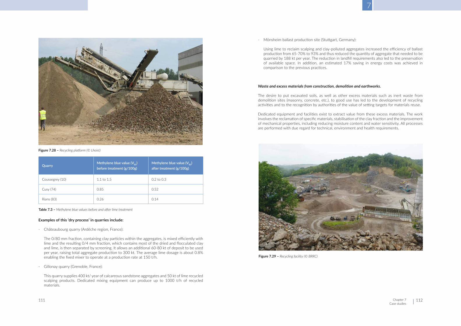
7
Chapter 7Case studies
111 112
Examples of this ‘dry process’ in quarries include:
- Châteaubourg quarry (Ardêche region, France):
The 0/80 mm fraction, containing clay particles within the aggregates, is mixed efficiently with lime and the resulting 0/4 mm fraction, which contains most of the dried and flocculated clay and lime, is then separated by screening. It allows an additional 60-80 kt of deposit to be used per year, raising total aggregate production to 300 kt. The average lime dosage is about 0.8% enabling the fixed mixer to operate at a production rate at 150 t/h.
- Gillonay quarry (Grenoble, France):
This quarry supplies 400 kt/ year of calcareous sandstone aggregates and 50 kt of lime recycled scalping products. Dedicated mixing equipment can produce up to 1000 t/h of recycled materials.
- Mönsheim ballast production site (Stuttgart, Germany):
Using lime to reclaim scalping and clay-polluted aggregates increased the efficiency of ballast production from 65-70% to 93% and thus reduced the quantity of aggregate that needed to be quarried by 188 kt per year. The reduction in landfill requirements also led to the preservation of available space. In addition, an estimated 17% saving in energy costs was achieved in comparison to the previous practices.
Waste and excess materials from construction, demolition and earthworks.
The desire to put excavated soils, as well as other excess materials such as inert waste from demolition sites (masonry, concrete, etc.), to good use has led to the development of recycling activities and to the recognition by authorities of the value of setting targets for materials reuse.
Dedicated equipment and facilities exist to extract value from these excess materials. The work involves the reclamation of specific materials, stabilisation of the clay fraction and the improvement of mechanical properties, including reducing moisture content and water sensitivity. All processes are performed with due regard for technical, environment and health requirements.
Figure 7.28 – Recycling platform (© Lhoist)
Table 7.3 – Methylene blue values before and after lime treatment
QuarryMethylene blue value (VBS) before treatment (g/100g)
Methylene blue value (VBS) after treatment (g/100g)
Coussegrey (10) 1.1 to 1.5 0.2 to 0.3
Cusy (74) 0.85 0.52
Rians (83) 0.26 0.14
Figure 7.29 – Recycling facility (© BRRC)

7
Chapter 7Case studies
113 114
Note that the process does not include contaminated soils or materials containing dangerous substances; topsoil (organic soils) and peat soils are also excluded. The typical treatment sequence is:
- scalping (separation of the coarse fraction above 63-100 mm) - screening of materials between 20 mm and 63-100 mm; material passing through the Dmax
sieve is then sent to the lime recycling unit; - depending on the origin of the materials, a further step may be required to remove ferrous
particles; - mixing with lime in a mobile of fixed unit; - stockpiling. Recycled material can be stockpiled for several weeks, allowing a progressive
mellowing of the mixture without loss of properties. The stockpile must be constructed so as to shed rainwater and ensure correct drainage – it will generally be pyramid-shaped with a lightly closed surface.
Depending on its new classification and properties, the recycled fine material can then be used for embankments, platforms, roads, trench filling, and so on in accordance with the local specifications.
Literature
Blanche, J., Eisenlohr, L., Denot, A. & Rojat, F. (2018). Valorisation des matériaux par traitement à la chaux sur les installations de recyclage (Guide Technique National SEDDRe). Syndicat des Entreprises de Déconstruction, Dépollution et Recyclage (SeDDRe). https://www.ensemble77.fr/images/Materiaux/Terres_excavees/Guide/Guide_technique_national_valorisation_materiaux_traites_chaux_sur_installations_recyclage_SEDDR_mai_2018.pdf
Chaix, C. & Cantegrel, B. (2004). Valorisation des stériles de carrière calcaires. Revue Générale de Routes (RGRA), (833), 68-72.
Joly, C. & Lelong, V. (2005, October 24-26). Treatment of scalping materials with lime [paper presentation]. 2nd international TREMTI symposium: Treatment and recycling of materials for transport infrastructure: using lime, cement and hydraulic road binders, Paris, France (C092). Centre d’Information sur le Ciment et ses Applications (CimBéton) & Chambre Syndicale Nationale des Fabricants de Chaux, Grasses et Magnésiennes.
Le Port, J.-L. (2014). Valorisation des stériles: Scalpez, malaxez, criblez, c’est prêt!. Mines et carrières, 159(212), 30-32.
S.C. (2017). Traitement des stériles: Malaxe, malaxe, le stérile. Terrassements et carrières, (161), 36-41.
T&C Rédaction & Bernabé, A. (2016). Stériles: Traitement à sec pour les stériles. Terrassements et carrières, (156), 34-35.
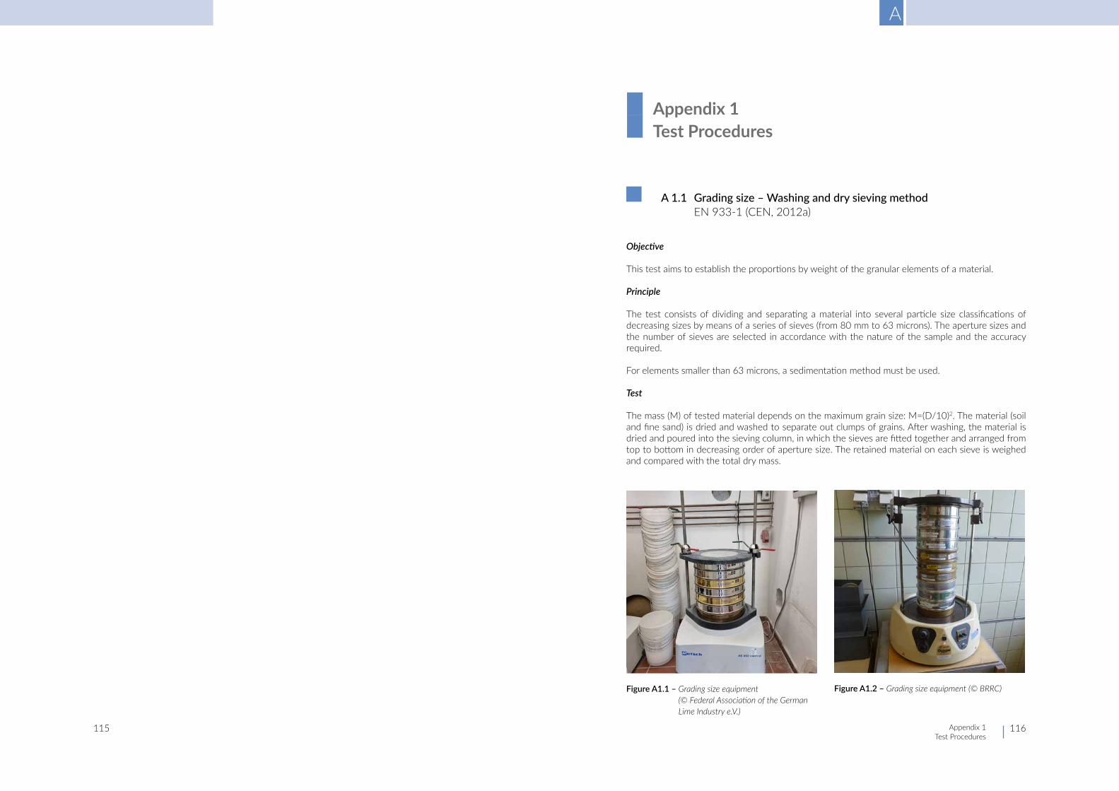
A
Appendix 1Test Procedures
115 116
A1.1 Gradingsize–Washinganddrysievingmethod EN 933-1 (CEN, 2012a)
Objective
This test aims to establish the proportions by weight of the granular elements of a material.
Principle
The test consists of dividing and separating a material into several particle size classifications of decreasing sizes by means of a series of sieves (from 80 mm to 63 microns). The aperture sizes and the number of sieves are selected in accordance with the nature of the sample and the accuracy required.
For elements smaller than 63 microns, a sedimentation method must be used.
Test
The mass (M) of tested material depends on the maximum grain size: M=(D/10)2. The material (soil and fine sand) is dried and washed to separate out clumps of grains. After washing, the material is dried and poured into the sieving column, in which the sieves are fitted together and arranged from top to bottom in decreasing order of aperture size. The retained material on each sieve is weighed and compared with the total dry mass.
■ Appendix 1 ■ Test Procedures
Figure A1.1 – Grading size equipment (© Federal Association of the German Lime Industry e.V.)
Figure A1.2 – Grading size equipment (© BRRC)

A
Appendix 1Test Procedures
117 118
Interpretation
- Sand fraction: 63 microns < sand fraction ≤ 2 mm - Silt fraction: 2 microns < silt fraction ≤ 63 microns - Clay fraction: ≤ 2 microns - Fines: ≤ 63 microns (= fraction sensitive to water)
A1.2 Atterberglimits CEN ISO/TS 17892-12 (CEN, 2004d)
Objective
Atterberg limits allow the clay content of a soil to be determined. This test is preferred to the methylene blue test when the soil has a medium to high clay content.
wL: water at which a soil passes from the liquid to the plastic state, as determined by the liquid limit test.
wP: water content at which a specimen ceases to be plastic when dried further, as determined by the plastic limit test.
The plasticity index (IP) is the numerical difference between the liquid limit and the plastic limit of a soil.
The consistency index Ic characterises the plastic state of a fine soil. It maps the water content of a soil in its natural state, in relation to Atterberg limits, and can be considered as indicative of the soil resistance to deformation.
The consistency index is suitable for soils of which more than 35% passes through a 63 microns sieve (63 microns > 35%) and a plasticity index greater than 12 (Ip > 12).
The consistency index is defined as:
Ic= (wL-wn)/ IP
where wn is the natural water content of the 0/400 microns fraction of the soil.
It varies between 0 (liquid state, when wn is equivalent to wL), and 1 or above (solid state, when wn ≥ wP).
When the consistency index is too low (< 0.7), there is a risk of trafficability problems. When the consistency index is too high (> 1.3), there is a risk of earthmoving problems.
It is generally considered that the primary action of lime treatment is to decrease the plasticity of soils and, if too wet, to reduce the moisture content in order to achieve a Ic value above 0.9.
Principle
The test is carried out on the 0/400 microns fraction in two steps:
- Determination of the liquid limit water content wL, at which the penetration of a cone is 10 mm or 20 mm depending of the cone type (fall cone method, 60 g/60° or 80 g/30°), or at which a groove formed in a cup closes after 25 rotations (Casagrande method).
- Determination of the plastic limit water content wP at which a soil roller (3 mm diameter) cracks.
Figure A1.3 – Example of grading curves (© BRRC)
Figure A1.4 – Liquid limit test – Casagrande method (© Carmeuse)
Figure A1.5 – Plastic limit test (© Carmeuse)

A
Appendix 1Test Procedures
119 120
Results and interpretation
IP=wL-wP
- IP < 12: low clay content - 12 < IP < 25: intermediate clay content - 25 < IP < 40: high clay content - IP > 40: very high clay contentFigure A1.6 – Schematic figure of cone penetration test
Figure A1.7 – Cone penetration test – liquid limit test (© Lhoist)
Figure A1.7 – Cone penetration test – liquid limit test (© Lhoist)

A
Appendix 1Test Procedures
121 122
A 1.3 Methylene blue value (VBS) prEN 17542 3 (CEN, n.d.-a)
Objective
The methylene blue value test allows the semi-quantitative determination of the clay content of a soil. The test is based on the fact that methylene blue is absorbed by the clay particles of the soil. The quantity of methylene blue that is absorbed by the soil can be related to its clay content. This is the preferred method for determining the plasticity index for soils with low clay content.
Principle
Increments of a solution of methylene blue are successively added to a suspension of the test soil sample in water. The test is performed on the fraction 0/5 mm.
The adsorption of the dye solution by the sample is checked after each addition of solution by carrying out a stain test on filter paper to detect the presence of free methylene blue.
After each addition of methylene blue, a drop of suspension, removed using a glass rod, is deposited on the filter paper. The stain which is formed is composed of a central deposit of material, generally of a solid blue colour, surrounded by a colourless wet zone.
The test is deemed to be positive if, in the wet zone, a halo consisting of a persistent light blue ring of about 1 mm is formed around the central deposit.
When the presence of free dye is confirmed, the methylene blue value is calculated and expressed as grams of dye adsorbed per 100 grams of the 0/50 mm fraction tested.
Results and interpretation
The methylene blue value, VBS, expressed in grams of dye per 100 grams of the 0/50 mm soil fraction is given by the following equations:
VB 0/5 = B x 100
VBS = B x C x 100
where
VB 0/5 is the methylene blue value on the 0/5 mm fraction;
M1 is the mass of the test portion, in grams;
B is the total mass of methylene blue added (solution 10.0 g/l), in gram, determined by B = V × 0.01 (V is the total volume of methylene blue solution added to produce a halo that persists for 5 min, to the nearest 1 ml);
C is the percentage of the 0/50 soil fraction passing at 5 mm.
A factor of 10 may be applied to express the result of the test in grams of methylene blue per kilogram of the 0/50 mm fraction. The result should be noted as MBS to avoid confusion: MBS = 10 × VBS.
M1
M1
Figure A1.8 – Methylene blue test (© BRRC)
Figure A1.9 – Methylene blue test (© Carmeuse)

A
Appendix 1Test Procedures
123 124
A1.4 ProctortestandModifiedProctortest EN 13286-2 (CEN, 2010)
Objective
This test is used to determine the relationship between the water content and the dry density of hydraulically bound or unbound mixtures after compaction under specified test conditions using Proctor compaction. It allows estimation of the mixture density that can be achieved on construc-tion sites and provides a reference parameter for assessing the density of a compacted layer of the mixture.
Principle
The soil sample is compacted in several layers in a compaction mould, the dimensions of which (A, B) are chosen as a function of the particle size of the mixture sample. The standard also refers to a larger mould C, but this is not used for soils.
The specific energy of compaction is 0.6 MJ/m3 for the Proctor test and 2.7 MJ/m3 for the Modified Proctor test. The selected compaction energy is representative of the compaction energy achievable on site.
Using moulds A or B, the sample is compacted by a 2.5 kg rammer in a mould in 3 layers (Proctor test) or by a 4.5 kg rammer in 5 layers (Modified Proctor test).
Figure A1.10 – Proctor equipment (© BRRC)
Figure A1.11 – Compaction mould (© Carmeuse)
Percentage passing test sieves
16 mm 31.5 mm 63 mm Proctor mould
100 - -A
B
75 to 100 100 - B
< 75 75 to 100 100 B
Table A1.1 – Mould as a function of soil grading size

A
Appendix 1Test Procedures
125 126
For soils, the Proctor test is often preferred. However, some countries use the Modified Proctor test.
The compaction is often performed in mould B followed by an immediate bearing index (IIPI) or California bearing index (ICBR) test (CEN 2012b) on the compacted sample.
Results and interpretation
The Proctor curve is obtained for several water contents. The curve ρd = f(w) shows the influence of water content on the compactibility of the material. The water content corresponding to the maximum dry density is the optimum moisture content. The compaction of the material is optimum at this water content.
The maximum of the curve is the optimum water content. If the curve is flat, the compaction characteristics are less sensitive to water content.
Proctor mould Diameter [mm] Height [mm]Thickness
Wall [mm] Base plate [mm]
A 100.0 ± 1.0 120.0 ± 1.0 7.5 ± 0.5 11.0 ± 0.5
B 150.0 ± 1.0 120.0 ± 1.0 9.0 ± 0.5 14.0 ± 0.5
Table A1.2 – Dimensions of Proctor moulds
Type of test Characteristics of test Dimension Mould A Mould B
Proctor test
Mass of rammer kg c 2.5
Diameter of rammer mm 50 50
Height of fall mm 305 305
Number of layers - 3 3
Number of blows per layer - 25 56
Modified Proctor test
Mass of rammer kg 4.5 4.5
Diameter of rammer mm 50 50
Height of fall mm 457 457
Number of layers - 5 5
Number of blows per layer - 25 56
Table A1.3 – Summary of Proctor and Modified Proctor test
Figure A1.12 – Proctor curves (© BRRC)

A
Appendix 1Test Procedures
127 128
A1.5 Moistureconditionvalue EN 13286-46 (CEN, 2003e)
Principle
The moisture condition value (MCV) test was developed in UK to assess the suitability of earthwork materials for use in embankments while avoiding the measurement of moisture content with its associated delays. This test gives an immediate result, is applicable to a wide range of soils (treated or not). The test is quick, can easily be carried out on site and is particularly suitable for cohesive soils. The test is described in EN 13286-46 (CEN, 2003e).
The test consists of determining the compaction effort necessary, in terms of the number of blows of a rammer, to fully compact a sample of soil. It is known that relations between density and moisture content produced by different compaction efforts tend to converge as the moisture content increases.
In figure A1.13, compaction effort A is sufficient to produce full compaction at moisture content A’, as no further increase in bulk density can be achieved by using compaction effort B or C. Similarly, compaction effort B is sufficient to produce full compaction at moisture content B’, as no further increase in bulk density can be achieved by using compaction effort C. The higher the moisture content, the lower the compaction effort (i.e. number of blows) beyond which no further increase of density occurs.
Test
To determine the MCV of a sample of soil (1.5 kg), the penetration of the rammer into the mould is measured at various stages of compaction. The penetration of the rammer after any given number of blows is compared with the penetration for four times as many blows and the change in penetration is determined. This change in penetration is plotted against the lower number of blows in each case, the number of blows being in log scale. A change of penetration of 5 mm has been arbitrarily selected (instead of zero) as indicating the point beyond which no significant change of density occurs.
The MCV is defined as 10 times the log10 (log to base 10) of the number of blows corresponding to a change in penetration of 5 mm on the plotted curve.
Satisfactory compaction can be carried out within an MCV range of 8-12, where an MCV of 12 is optimum water content and an MCV of 8 represents a condition wetter than the optimum water content but still able to support construction plant and compaction. The range of 8-12 is applicable to a wide range of soil types irrespective of their optimum water content (which is different for different soil types).Figure A1.13 – Relation between density and moisture content (Parsons & Boden, 1979)
Figure A1.14 – MCV equipment (© Singleton Birch)
Figure A1.15 – MCV test (Parsons and Boden 1979)

A
Appendix 1Test Procedures
129 130
A 1.6 Immediate bearing index, Californiabearingratioandlinearswelling EN 13286-47 (CEN, 2012b)
Objective
These tests determine the bearing capacity (Immediate bearing index IIPI or California bearing ratio ICBR) of a soil compacted in mould B at Proctor or Modified Proctor compaction effort, immediately after compaction or after a period of curing.
The curing can consist of conditions preventing evaporation, full soaking (immersion) or prevention of evaporation followed by full soaking.
For the immediate bearing index, there is no additional load on the specimen. The index is a measure of trafficability.
For the California bearing ratio, an additional load is applied to the specimen in order to simulate the road structure and road traffic.
Principle
The relationship between force and penetration is determined when a cylindrical piston of a standard cross-sectional area is made to penetrate a compacted specimen contained within a mould, at a given rate (1.27 mm/min).
The values of the forces corresponding to penetration of 2.5 mm and 5 mm are measured. Those values are compared to the values obtained for a reference material to deduce the immediate bearing index or California bearing ratio.
Results
The immediate bearing index or the California bearing ratio is the value:
F x 100 %
F ref
Fref is the force related to a reference material (Fref=13.2 kN for a penetration of 2.5 mm and 20 kN for a penetration of 5 mm). The highest percentage is taken as the value for the California bearing ratio or immediate bearing index.
Depending on the shape of the curve at the origin (concave or convex), a correction needs to be performed.
Measure of linear swelling during immersion
The CBR assembly can be used to measure the vertical swelling of the specimen. The assembly and specimen are placed in a tank filled with water and with free access for water to the top and bottom of the specimen for a minimum of 96 hours. A device suitable for measuring vertical deformations is placed on the top of the specimen. The expansion is measured at suitable intervals of time depending on the rate of vertical swell.
In some countries, the ratio obtained by dividing the ‘immediate bearing index’ by the ‘California bearing ratio after 4 days immersion’ is determined in order to evaluate the durability of the mixture. The ratio must be larger than 1. It is intended to show the resistance of the mixture to immersion.
Figure A1.16 – CBR test, based on EN 13286-47 (CEN, 2012b)
Figure A1.17 – Swelling test (© BRRC)

A
Appendix 1Test Procedures
131 132
A1.7 Pulverisationtest EN 13286-48 (CEN, 2005)
Objective
The purpose of this test is to measure the effectiveness of mixing and the breaking-down of the cohesive material during mixing.
Principle
A sample of mixture is gently shaken on a 5.6 mm sieve, ensuring that the individual lumps of cohesive material are broken as little as possible, and the mass of mixture retained is determined. The lumps of mixture retained on the sieve are broken until all particles finer than 5.6 mm pass the sieve. The mass of mixture retained on the sieve is determined.
The degree of pulverisation P is the ratio of the mass passing the sieve before and after breaking the retained lumps.
Results
P=100 (m1-m2)/(m1-m3)
- P is the degree of pulverisation (%) - m1 is the initial mass (g) - m2 is the mass of mixture retained on the sieve after initial sieving (g) - m3 is the mass of mixture retained on the sieve after breaking up the lumps and re-sieving (g)
A1.8 Limefixationpoint–EADESGRIMtest ASTM D6276 (ASTM International, 2019) and CEN prTS 17693-1 (CEN, n.d.-b)
Objective
The test determines of the lime fixation point (LFP) or lime modification optimum (LMO), which is the theoretical lime content that results in hardening of the soil-lime mixture due to pozzolanic reactions between the lime and the clay components in the soil.
The LFP may be regarded as the optimal lime amount to be added to a soil in order to achieve its improvement, and the minimum lime amount from which stabilisation can occur (terms “improvement” and “stabilisation” as defined in EN 16907-4 [CEN, 2018d]).
Principle
The principle of the test is to measure the pH of a liquid suspension of soil in water after successive lime additions. The LFP is then the lime amount needed to reach a pH value of 12.4.
Test and results
Increments of lime (quicklime, hydrated lime or lime slurry of known purities or concentrations) are added successively to a test beaker containing a suspension of the soil test portion in water, at a temperature of 25 ± 1°C. The pH values of the soil-mix suspension are measured and recorded after each addition stage with a calibrated pH-meter.
The pH value of at least 12.4 results from the free lime remaining in the soil-lime mixture suspension.
A graph plotting recorded pH values (Y-axis) vs lime additions (X-axis) is drawn, from which the lime content at the lime fixation point is determined (CLfp).
An alternative method consists of preparing 12 beakers of identical soil suspensions and making a single lime addition of between 0% and 5% to each beaker.
A graph plotting recorded pH values (Y-axis) vs lime additions (X-axis) is drawn, from which the CLfp is determined.
Figure A1.18 – Pulverisation test (© BRRC)
Figure A1.19 – Practical example of lime fixation point determination

A
Appendix 1Test Procedures
133 134
A 1.9 Measurement of binder spreading
Objective
The objective is to check, in an easy way, the quantity of spread binder per unit of area on site.
Principle
The test consists in placing tarpaulins, aluminium plates or troughs of a known area (S), before treatment, on the surface to be treated and weighing, after spreading, the quantities of lime (M) collected. Surfaces of 1 m2 or 0.5 m2 are frequently used.
The number of tarpaulins, plates or troughs used depends on the accuracy of the spreader. It is recommended that routine on-site testing be carried out in order to ensure the regularity of spreading.
Results
The mass per unit of area spread is given by: ms=M/S in kg/m2 (Aimé et al., 2007)
Figure A1.19 – Practical example of lime fixation point determination
Figure A1.20 – Weighting lime on site (© Carmeuse)

A
Appendix 1Test Procedures
135 136
A 1.10 Literature
Aimé, C., Auriol, J.-C. & Borrel, L.R. (2007). Design and execution of earthworks. Section 3: Test procedures (Guide Technique SETRA). Service d’Études Techniques des Routes et Autoroutes (SETRA). https://www.cerema.fr/fr/centre-ressources/boutique/guide-technique-design-and-execution-earthworks
ASTM International. (2019). Standard test method for using pH to estimate the soil-lime proportion requirement for soil stabilization (ASTM D6276-19).
European Committee for Standardization. (n.d.-a). Earthworks: Geotechnical laboratory tests. Part 3: Methylene blue value VBS on soils and rocks (prEN 17542-3).
European Committee for Standardization. (n.d.-b). Earthworks: Soil treatment tests. Part 1: pH-test for determination of the lime requirement of soils for stabilization (lime fixation point LFP, lime modification optimum LMO) (prCEN/TS 17693-1).
European Committee for Standardization. (2003e). Unbound and hydraulically bound mixtures. Part 46: Test method for the determination of the moisture condition value (EN 13286-46).
European Committee for Standardization. (2004d). Geotechnical investigation and testing: Laboratory testing of soil. Part 12: Determination of Atterberg limits (CEN ISO/TS 17892-12).
European Committee for Standardization. (2005). Unbound and hydraulically bound mixtures. Part 48: Test method for the determination of degree of pulverization (EN 13286-48).
European Committee for Standardization. (2010). Unbound and hydraulically bound mixtures. Part 2: Test methods for laboratory reference density and water content: Proctor compaction (EN 13286-2).
European Committee for Standardization. (2012a). Tests for geometrical properties of aggregates. Part 1: Determination of particle size distribution: Sieving method (EN 933-1).
European Committee for Standardization. (2012b). Unbound and hydraulically bound mixtures. Part 47: Test method for the determination of California bearing ratio, immediate bearing index and linear swelling (EN 13286-47).
European Committee for Standardization. (2018d). Earthworks. Part 4: Soil treatment with lime and/or hydraulic binders (EN 16907-4).
Parsons, A.W. & Boden, J.B. (1979). The moisture condition test and its potential applications in earthworks (TRRL Supplementary Report No 522). Transportation and Road Research Laboratory (TRRL).
Copyright © 2022 FDOKUMEN