snappyHexMesh Basic Training multi Region meshing ...
25
snappyHexMesh Basic Training multi Region meshing simulation of heat transfer with chtMultiRegionFoam 1 st edition, Aug. 2015 Editor: Philipp Schretter (TU Wien)
-
Upload
khangminh22 -
Category
Documents
-
view
0 -
download
0
Transcript of snappyHexMesh Basic Training multi Region meshing ...

snappyHexMesh Basic Training
multi Region meshing
simulation of heat transfer with
chtMultiRegionFoam
1st edition, Aug. 2015
Editor:
Philipp Schretter (TU Wien)
OpenFOAM® Basic Training
snappyHexMesh
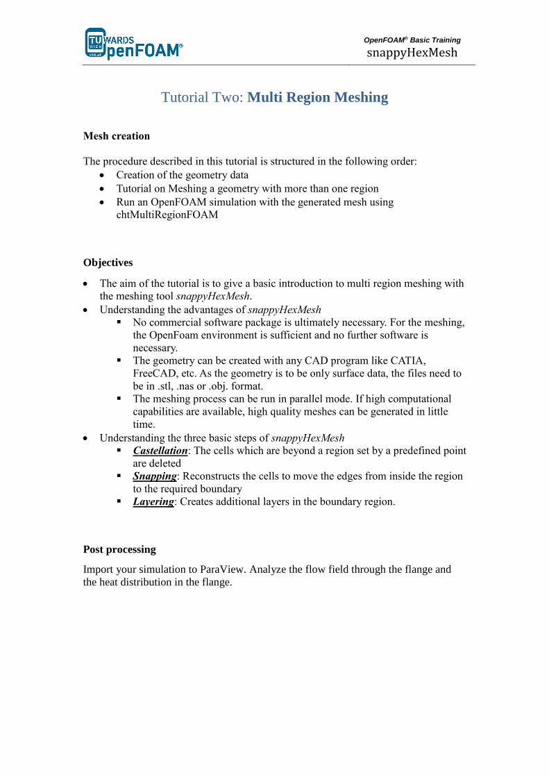
Tutorial Two: Multi Region Meshing
Mesh creation
The procedure described in this tutorial is structured in the following order:
Creation of the geometry data
Tutorial on Meshing a geometry with more than one region
Run an OpenFOAM simulation with the generated mesh using
chtMultiRegionFOAM
Objectives
The aim of the tutorial is to give a basic introduction to multi region meshing with
the meshing tool snappyHexMesh.
Understanding the advantages of snappyHexMesh
No commercial software package is ultimately necessary. For the meshing,
the OpenFoam environment is sufficient and no further software is
necessary.
The geometry can be created with any CAD program like CATIA,
FreeCAD, etc. As the geometry is to be only surface data, the files need to
be in .stl, .nas or .obj. format.
The meshing process can be run in parallel mode. If high computational
capabilities are available, high quality meshes can be generated in little
time.
Understanding the three basic steps of snappyHexMesh
Castellation: The cells which are beyond a region set by a predefined point
are deleted
Snapping: Reconstructs the cells to move the edges from inside the region
to the required boundary
Layering: Creates additional layers in the boundary region.
Post processing
Import your simulation to ParaView. Analyze the flow field through the flange and
the heat distribution in the flange.

OpenFOAM® Basic Training
snappyHexMesh
Step by step meshing
Creation of the .stl files
For the geometry data, the CAD software CATIA was used, to create the solid
geometry. The creation of the .stl files for single region and multi-region is slightly
different. Either way, it is necessary, to create the .stl files as ASCII .stl and not as
binary .stl.
For the multi region case, several .stl files are necessary in order to create the mesh
for the flange. One Possibility is to create the surface files with CATIA with the
Wireframe and Surface Design tool.
Another possibility is to create a solid geometry with CATIA and export the geometry
data as .stp format. This file is imported to FreeCAD to generate the .ast files. With
FreeCAD, the .stl files can be extracted from the .stp solid geometry: Open the .stp
geometry file in the draft workbench and select the object in the tree view view-
section. Then click on Downgrade in the combo view view-section. This gives a list
of all faces of the geometry, which can be selected and exported as .ast format. In
FreeCAD, it's necessary to distinguish between .stl, which is binary .stl, and .ast,
which is ASCII .stl.
Figure 1 Select the surfaces from a solid geometry

OpenFOAM® Basic Training
snappyHexMesh
In the case which was prepared for this tutorial, the dimensions from from the .stl files
exported from the CAD software are in meters. To convert the dimensinos, the open
source software Blender can be used. Therefore, import the .stl files and use the scale
tool with a factor 0.001 to convert from m to mm. To export the file, it is necessary to
tick the box for Ascii to save the .stl file in ascii format. Otherwise, OpenFoam won't
be able to deal with the file.
In the multi region case, the header line and the base line of the .stl files, exported
from blender need to be updated with an appropriate labelling. For example for
header line for the .stl for inlet 1 is renamed to solid inlet_1.
In order to create a .stl from a geometry which is already available in gambit, the
geometry data can be exported in .stp or alternatively in .igs format. Afterwards,
the .stp or .igs (msbo) file can be imported to FreeCAD and converted via export
as .stl.
The technical drawing with the dimensions of the geometry for this tutorial is
depicted below.

OpenFOAM® Basic Training
snappyHexMesh
OpenFOAM® Basic Training
snappyHexMesh
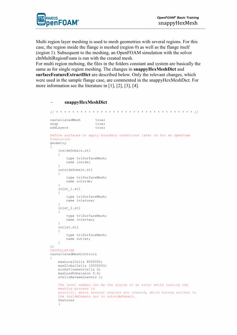
Multi region layer meshing is used to mesh geometries with several regions. For this
case, the region inside the flange is meshed (region 0) as well as the flange itself
(region 1). Subsequent to the meshing, an OpenFOAM simulation with the solver
chtMultiRegionFoam is run with the created mesh.
For multi region mehsing, the files in the folders constant and system are basically the
same as for single region meshing. The changes in snappyHexMeshDict and
surfaceFeatureExtractDict are described below. Only the relevant changes, which
were used in the sample flange case, are commented in the snappyHexMeshDict. For
more information see the literature in [1], [2], [3], [4].
- snappyHexMeshDict
// * * * * * * * * * * * * * * * * * * * * * * * * * * * * * * * * * * //
castellatedMesh true;
snap true;
addLayers true;
Define surfaces to apply boundary conditions later on for an OpenFoam
Simulation
geometry
{
insideDomain.stl
{
type triSurfaceMesh;
name inside;
}
outsideDomain.stl
{
type triSurfaceMesh;
name outside;
}
inlet_1.stl
{
type triSurfaceMesh;
name inletone;
}
inlet_2.stl
{
type triSurfaceMesh;
name inlettwo;
}
outlet.stl
{
type triSurfaceMesh;
name outlet;
}
};
CASTELLATING
castellatedMeshControls
{
maxLocalCells 8000000;
maxGlobalCells 10000000;
minRefinementCells 0;
maxLoadUnbalance 0.0;
nCellsBetweenLevels 1;
The level number can be the source of an error while running the
meshing process in
parallel, where several regions are created, which belong neither to
the insideDomain nor to outsideDomain.
features
(

OpenFOAM® Basic Training
snappyHexMesh
{
file "insideDomain.eMesh";
level 3;
}
{
file "outsideDomain.eMesh";
level 3;
}
);
All surfaces defined in the geometry subdirectory must be listed here.
List of the surfaces, which need to be listed in in the boundary files
In constant/polyMesh/boundary
refinementSurfaces
{
inside
{
It is necessary to define a specific point anywhere inside the
region. Simply labelling the cellZoneInside as inside is not
sufficient.
level (3 3);
faceZone insideFaces;
cellZone insideZone;
cellZoneInside insidePoint;
insidePoint (0.0 0.0 0.0);
}
outside
{
It is necessary to define a specific point anywhere inside the
inside the region. Simply labelling the cellZoneInside as
inside is not sufficient.
level (3 3);
faceZone outsideFaces;
cellZone outsideZone;
cellZoneInside insidePoint;
insidePoint (0.010 0.0 0.0);
}
inletone
{
No empty boundary. Define inlet/outlet as patch
level (0 0);
patchInfo
{
type patch;
}
}
inlettwo
{
No empty boundary. Define inlet/outlet as patch
level (0 0);
patchInfo
{
type patch;
// possibly also define inGroups
}
}
outlet
{
No empty boundary. Define inlet/outlet as patch.
level (0 0);
patchInfo
{
type patch;
possibly also define inGroups
}
}
}
resolveFeatureAngle is an important setting. Edges, whose adjacent
surface normals are at an angle higher than the value set, are
resolved. The lower the value, the better is the resolution at sharp
edges
resolveFeatureAngle 30;

OpenFOAM® Basic Training
snappyHexMesh
In this case, no refinement regions are defined.
refinementRegions
{
}
The point is chosen inside the surface domain of the flange. Hence,
snappy creates the internal mesh.
In contrast to that, choosing the locationInMesh point outside the
flange domain, lets snappy mesh the part between the surface and the
blockMesh.
locationInMesh (0 0 0);
allowFreeStandingZoneFaces true;
}
SNAPPING
Important parameters are number of mesh displacement iterations,
nSolveIter and the number of feature edge snapping iterations,
nFeatureSnapIter.
snapControls
{
nSmoothPatch 5;
tolerance 1.0;
nSolveIter 300;
nRelaxIter 10;
nFeatureSnapIter 5;
implicitFeatureSnap false;
explicitFeatureSnap true;
//multiRegionFeatureSnap not necessary in this case
multiRegionFeatureSnap false;
}
LAYERING
addLayersControls
{
relativeSizes false;
layers
{
The layers are added on the inside region of the flange
insideZone_to_outsideZone
{
define the number of surface layers on the inside of the
flange
nSurfaceLayers 3;
}
}
define the expansion ratio of the surface layers
expansionRatio 1.005;
define the min and the final thickness of the surface layers
finalLayerThickness 0.0001;
minThickness 0.00005;
nGrow 0;
featureAngle 85;
slipFeatureAngle 25;
nRelaxIter 5;
nSmoothSurfaceNormals 4;
nSmoothNormals 3;
nSmoothThickness 10;
maxFaceThicknessRatio 0.5;
maxThicknessToMedialRatio 0.2;
minMedianAxisAngle 90;
nBufferCellsNoExtrude 0;
LayerIter : If not snapped smoothly enough, the max number of layer
Addition iteration can be increased
nLayerIter 50;
}
meshQualityControls
{
#include "meshQualityDict"
nSmoothScale 4;
errorReduction 0.75;
}
writeFlags
(
scalarLevels

OpenFOAM® Basic Training
snappyHexMesh
layerSets
layerFields
);
mergeTolerance 1e-6;
// ******************************************************************** //
- surfaceFeatureExtractDict
// * * * * * * * * * * * * * * * * * * * * * * * * * * * * * * * * * * //
outsideDomain.stl
{
extractionMethod extractFromSurface;
All edges are refined, whose surface normals include angles with less
than the angle specified. For the included angels, a special level of
refinement can be set in the snappyHexMeshDict in the features
subdictionary.
extractFromSurfaceCoeffs
{
includedAngle 120;
}
writeObj no;
}
insideDomain.stl
{
extractionMethod extractFromSurface;
extractFromSurfaceCoeffs
{
includedAngle 120;
}
writeObj no;
}
// ******************************************************************** //
Basically, .stl files for the snappyHexMesh tool have to encompass a closed
geometry. This is especially important for geometries which consist of several
different .stl files to create one closed geometry. Therefore it is important to take care
especially of the exact dimensions of the parts of the geometry while creating the .stl
files,
To ensure that the mesh from two domains, stl.inside, and stl.outside, is compatible
and connected, it is necessary, that both domains are created from the same surfaces
which are shared with both domains. In this case, the .stl. file flange_inside is part of
the domains stlinside as well as of stloutside.
This is also depicted in the following:

OpenFOAM® Basic Training
snappyHexMesh
In order to set the boundary types in the boundary files in
/constant/polyMesh/boundary and also to generate a mesh for the inlets, outets and
walls, it is necessary that the .stl files for those boundaries are located in
/constant/triSurface.
All those files must be listed in the geometry subdirectory as well as in the
refinementSurfaces subdirectory in the snappyHexMeshDict.
The following commands combine the .stl files for the region inside the flange,
stlinside, and for the region of the flange itself, stloutside. The files are taken from the
folder cad in the main directory.
In figure XX, the combined stl files are depicted. The resulting file insideDomain.stl

OpenFOAM® Basic Training
snappyHexMesh
for the region 0 consists of the stls for the wall inside the flange (black) for the inlet 1
(blue) for the inlet 2 (green) and for the outlet (red).
he resulting file outsideDomain.stl for the region 1 consists of the sls for the wall
outside the flange.
The resulting file outsideDomain.stl for the region 1 consists of the stls for the wall
outside the flange (orange) and for the wall inside the flange (black).
>cat cad/flange_stl/stloutside/* > constant/triSurface/outsideDomain.stl
>cat cad/flange_stl/stlinside/* > constant/triSurface/insideDomain.stl
Figure 2 Surface geometry of the flange domain inside (black) and outside (orange)
The background mesh is created with blockMesh.
>blockMesh
The block mesh for the multi region case is the same as for the single region case with
30 cells in x- and y direction and with 20 cells in z direction.
Also in the multi region case, it is very important to create perfect cubes in the first
place to ensure that the sharp edges are refined properly. Otherwise, highly skewed
cells could be generated while the snapping process.

OpenFOAM® Basic Training
snappyHexMesh
Figure 3 Block mesh for flange
The dimensions of the blockmesh are as follows.
// * * * * * * * * * * * * * * * * * * * * * * * * * * * * * * * * * * * * * //
convertToMeters 1;
vertices
(
(-0.03 -0.03 -0.02)
(0.03 -0.03 -0.02)
(0.03 0.03 -0.02)
(-0.03 0.03 -0.02)
(-0.03 -0.03 0.02)
(0.03 -0.03 0.02)
(0.03 0.03 0.02)
(-0.03 0.03 0.02)
);
blocks
(
hex (0 1 2 3 4 5 6 7) (30 30 20) simpleGrading (1 1 1)
);
.
.
.
// ************************************************************************* //
Equal to the single region case, the command surfaceFeatureExtract creates
the .eMesh files from the .stl-files with the geometry data. Also the folder
extendedFeatureEdgeMesh is created in the /constant directory.
The creation of .eMesh files with the command surfaceFeatureExtract is not
obligatory. This step is only necessary, if certain edges need to be refined.
>surfaceFeatureExtract

OpenFOAM® Basic Training
snappyHexMesh
As the meshing process is run in parallel, the geometry needs to be decomposed prior
to run snappyHexMesh. Depending on the number of subdomains, defined in the
decomposeParDict, the processor folders are created accordingly.
Note: It is recommended, not to use the scotch method to decompose the region.
Rather, the hierarchical or the simple method should be used. In case of scotch
method, errors can occur while executing snappyHexMesh or while reconstructing the
mesh, so that more domains are reconstructed than have been decomposed before.
Nevertheless, using snappyHexMesh for meshing geometries in parallel, can still
produce errors if the refinement levels of the edges or surfaces in the respective
subdirectories in snappyHexMeshDict is set too high.
After running the command reconstructParMesh, the following message appears
in the terminal window:
This is an experimental tool, which tries to merge individual processor meshes back
into one master mesh. ...
Not well tested & use at your own risk!
In case, additional domains are created, even after decomposing the region with the
hierarchical - or with the scotch method, the geometry can still be meshed on one
processor only.
In this case, the domain is divided into 2 subdomains, which is also indicated by the
command mpirun -np 2, whereas np stands for number of processors.
>decomposePar

OpenFOAM® Basic Training
snappyHexMesh
a) Running snappyHexMeshDict step by step (only
recommended for learning the tool or finding errors)
Step 1 castellatedMesh
In the following, the execution of snappyHexMeshDict is described step by step.
This procedure is only useful to see the intermediate steps or to find bugs in the
meshing process. Therefore, the steps snap or layering can be set to false. Running
snappyHexMeshDict completely is described in the next section.
If in the snappyHexMeshDict, castellatedMesh and snap are set to true, the folders 1
and 2 are created after running the command snappyHexMesh in parallel. Folder 1
contains the mesh files after the step castellatiedMesh and folder 2 after the step snap.
>mpirun -np 2 snappyHexMesh -parallel
After running snappyHexMesh in parallel, the mesh data is located in the different
processor folders. This data needs to be reconstructed. The following command
reconstructs the mesh after the step castellatedMesh.
>reconstructParMesh -time 1
After performing these steps, the flange is meshed, but still the outside mesh needs to
be removed. As the point locationInMesh in the snappyHexMeshDict file is defined
inside the flange domain, no mesh is removed by snappyHexMesh and therefore has
to be removed manually.
Figure 4 Mesh after reconstructParMesh

OpenFOAM® Basic Training
snappyHexMesh
In the file boundary in the folder /1/constant/polyMesh, are 4 entries with zero
number of faces: inside, inside_slave, outside, outside_slave. Those entries are
removed by snappyHexMesh while performing the command below.
Occasionally, the entries XXX_slave are not removed and still remain in the
boundary files. The following steps can be attempted to avoid those entries
- rename the header – and bottome lines in the .stl files and remove the labeling
after 'solid'.
- add the entries with the .stl files to both subdirectories in the
snappyHexMeshDict, geometry and refinementSurfaces.
>splitMeshRegions -cellZones -overwrite
In order to display the geometry with paraview, the mesh files must be copied to the
constant directory.
>cp -r 1/* constant/
Figure 5 Mesh after splitMeshRegions
The folder domain0 contains the mesh which remains after splitting the block mesh
from the flange geometry. These mesh files as well as the block mesh from the
polyMesh folder can be deleted so that only the flange mesh remains. As paraview
displays mesh files from all polyMesh folders, also the folder from the time step 2 is
removed.
>rm -r constant/polyMesh 1/polyMesh constant/domain0
system/domain0 1/domain0

OpenFOAM® Basic Training
snappyHexMesh
Figure 6 Flange mesh after removing domain0 and polyMesh with domain of the
slice (red rectangle)
Figure 7 Slice view of the Flange after step castellatedMesh
Occasionally, the surface of the geometry seems to have holes while displaying a Slice
view in paraview. In this case, the tool Crinkle slice can be used to remove the holes,
which are mostly attributed due to triangular cells, intersecting the surface.

OpenFOAM® Basic Training
snappyHexMesh
Step 2 snap
The following command reconstructs the mesh after the step snap.
>reconstructParMesh -time 2
If the geometry is both, castellated and snapped, also the following command can be
used to reconstruct the mesh after the step snap.
>reconstructParMesh -latestTime
The following commands are similar to the step castellatedMesh, except that the mesh
files are copied and removed from folder 2 instead of folder 1.
>splitMeshRegions -cellZones -overwrite
>cp -r 2/* constant/
To display only the mesh of the flange, without the blockmesh, remove the folders
polyMesh and domain0. The mesh between the .stl files and the blockmesh is labelled
as domain0.
>rm -r constant/polyMesh 2/polyMesh constant/domain0
system/domain0 2/domain0
Figure 8 Slice view of the Flange after step snap

OpenFOAM® Basic Training
snappyHexMesh
b) Running snappyHexMeshDict without intermediate steps
This chapter includes the chapter step 3 addLayers. As step 3 is the last step it
coincides with running the case all in once.
In order to prevent the creation of the folders 1, 2 (and 3) and only keep the final time
step folder with the final mesh, the command -overwrite can be added after
snappyHexMesh. In this case, only one folder, 0, is created with the files pointLevel
and cellLevel. The mesh data in this case is located in constant/polyMesh.
>mpirun -np 2 snappyHexMesh -parallel -overwrite
The following command reconstructs the final mesh, depending on the settings in
snappyHexMeshDict.
If for example castellatedMesh an snap are set on true in the snappyHexMeshDict,
only the snapped mesh is reconstructed and stored, whereas the intermediate step snap
is overwritten.
If for example castellatedMesh, snap and addLayers are set on true in the
snappyHexMeshDict, only the layered mesh is reconstructed and stored and the
previous intermediate steps castellatedMesh and snap are overwritten.
In the case at hand for this tutorial, the layers are only necessary on the fluid side
which is labelled insideZone. The snappyHexMesh tools needs to have the files,
which have to be layered in the constant/polyMesh directory. Thereofre, in this case,
only the steps castellatedMesh and snap are set to true, as these steps are applied to
the whole mesh.
>reconstructParMesh -constant
>splitMeshRegions -cellZones -overwrite
As already mentioned above, the mesh around the flange is deleted with the following
command. Even so the files cellToRegion, as they are not needed in the further
process.
>rm -rf constant/domain0 system/domain0
>rm -rf constant/cellToRegion constant/polyMesh
>rm -rf 0/domain0 0/cellToRegion 0/insideZone/cellToRegion
0/outsideZone/cellToRegion
>rm -rf processor*
After reconstructing the mesh, only the mesh files of insideZone, which is the zone to
be layered, are copied to the /constant/polyMesh folder.

OpenFOAM® Basic Training
snappyHexMesh
>mv constant/insideZone/polyMesh constant/polyMesh
Only layering is set to true in the snappyHexMeshDict.
>sed -i -e 18c"castellatedMesh false;" system/snappyHexMeshDict
>sed -i -e 19c"snap false;" system/snappyHexMeshDict
>sed -i -e 20c"addLayers true;" system/snappyHexMeshDict
The step addLayers is executed in parallel.
>decomposePar
>mpirun -np 2 snappyHexMesh -overwrite -parallel
>reconstructParMesh -constant
After layering the inside of the flange domain, the snappyHexMeshDict is reset to
the previous settings.
>sed -i -e 18c"castellatedMesh true;" system/snappyHexMeshDict
>sed -i -e 19c"snap true;" system/snappyHexMeshDict
>sed -i -e 20c"addLayers false;" system/snappyHexMeshDict
The layered mesh is moved to the constant/insideZone folder.
>mv constant/polyMesh constant/insideZone/polyMesh
Remove entries from the constant/insideZone/polyMesh/boundary file
>sed -i -e 42c"1" constant/insideZone/polyMesh/boundary
>sed -i -e 18c"4" constant/insideZone/polyMesh/boundary
>sed -i '45d;54,137d' constant/insideZone/polyMesh/boundary
Review the mesh quality
>checkMesh –region insideZone
>checkMesh –region outsideZone

OpenFOAM® Basic Training
snappyHexMesh
Figure 9 Slice of the flange after step addLayers

OpenFOAM® Basic Training
snappyHexMesh
Running OpenFoam simulation with chtMultiRegionFoam
Compared to previous tutorials or cases, where the mesh was created with other
software, in this case, several steps can be omitted.
topoSet is not needed as the regions of insideDomain and outsideDomain were
already defined in the snappyHexMeshDict subdirectory geometry.
Even so, the commands blockMesh and splitMeshRegions are already part of the
snappyHexMesh meshing procedure.
The case is run similar to the chtMultiRegionHeater tutorial sample case which is
provided by OpenFoam.
Some adjustments are necessary to run the case and check if the mesh quality is
satisfactory.
- Copy the files alphat, epsilon, k, p, p_rgh, rho, T, U from the tutorial folder
/0 to the folder 0/insideZone
- Copy the files p, rho, T from the tutorial folder /0 to the folder 0/outsideZone
- Copy the radiationProperties and thermophysicalProperties from the
tutorial folder constant/heater to the folder constant/outsideZone
- Copy the g, radiationProperties, RASProperties,
thermophysicalProperties, and turbulenceProperties from the tutorial folder
constant/bottomAir to constant/insideZone
- Copy the regionProperties from the tutorial folder constant to the folder
constant and update the regions fluid (insideZone) and solid (outsideZone)
- Copy the controldict from the tutorial system folder to the folder system.
Change the start time to 0, the end time to 0.01, the writeInterval to 0.0005
and the max Courant number to 1.
- Copy the fvSchemes, fvSolution and changeDictionaryDict files from the
tutorial folders system/bottomAir and system/heater to the folders
system/insideZone and system/outsideZone respectively.
- Update the changeDictionaryDict of insideZone
remove the entry boundary
for the velocity
o set the velocity internalField to 1
o velocity inlet 1 is set to 1
o velocity inlet 2 is set to 2
o the outlet is set to zeroGradient
for the temperature
o set the internal field to 298
o temperature at inlet 1 is set to 773
o temperature at inlet 2 is set to 573
o the outlet is set to zeroGradient
o insideZone_to_outsideZone is has type
turbulentTemperatureCoupledBaffleMixed with value uniform
298
for the p_rgh
o the internal field is set to uniform 1e5
o the pressure at the outlet is set to fixedValue with value uniform

OpenFOAM® Basic Training
snappyHexMesh
1e5
o inlet 1 and inlet 2 are set to zeroGradient
o the boundary insideZone_to_outsideZone is set to
fixedFluxPressure with value uniform 1e5
for the p
o the internal field is set to uniform 1e5
o the pressure at the outlet is set to fixedValue with value uniform
1e5
o inlet 1 and inlet 2 are set to zeroGradient
o the boundary insideZone_to_outsideZone is set to calculated
with value uniform 1e5.
Update the changeDictionaryDict of outsideZone
o remove the entry boundary
o set outsideZone_to_domain0 type zeroGradient
o set outsideZone_to_insideZone type
compressible::turbulentTemperatureCoupledBaffleMixed
>changeDictionary -region insideZone
>changeDictionary -region outsideZone
Decompose the mesh for example in two domains.
>decomposePar -allRegions
Run the case on two cores in parallel.
>mpirun -np 2 chtMultiRegionFoam -parallel
Reconstruct the mesh and convert the data to the Visualization ToolKit format.
>reconstructPar –allRegions
>checkMesh –region insideZone
>checkMesh –region outsideZone
>foamToVTK -region insideZone
>foamToVTK -region outsideZone

OpenFOAM® Basic Training
snappyHexMesh
0.0005s 0.001s
0.0015 0.01s
Figure 10 Mixing inside the flange from 0.0005 to 0.01s

OpenFOAM® Basic Training
snappyHexMesh
0.0005s 0.0035s

OpenFOAM® Basic Training
snappyHexMesh
0.0085s 0.01s
Figure 11 Heating of the flange from 0.0005 to 0.01s
Literature
[1] http://cfd.direct/openfoam/user-guide/snappyhexmesh/
[2] http://www.openfoamwiki.net/index.php/SnappyHexMesh
[3] https://openfoamwiki.net/images/f/f0/Final-AndrewJacksonSlidesOFW7.pdf
[4] https://sites.google.com/site/snappywiki/snappyhexmesh#TOC-snappyHexMesh