
SMT IPMI (Aten) User Guide 2.0a.indb
106
SMT IPMI User's Guide Revision 2.0a
-
Upload
khangminh22 -
Category
Documents
-
view
2 -
download
0
Transcript of SMT IPMI (Aten) User Guide 2.0a.indb

SMT IPMI
User's GuideRevision 2.0a

Manual Revision 2.0aRelease Date: March 4, 2011Unless you request and receive written permission from Super Micro Computer, Inc., you may not copy any part of this document.Information in this document is subject to change without notice. Other products and companies referred to herein are trademarks or registered trademarks of their respective companies or mark holders.Copyright © 2011 by Super Micro Computer, Inc.All rights reserved.Printed in the United States of America
The information in this User’s Manual has been carefully reviewed and is believed to be accurate. The vendor assumes no responsibility for any inaccuracies that may be contained in this document, and makes no commitment to update or to keep current the information in this manual, or to notify any person or organization of the updates. Please Note: For the most up-to-date version of this manual, please see our web site at www.supermicro.com.
Super Micro Computer, Inc. ("Supermicro") reserves the right to make changes to the product described in this manual at any time and without notice. This product, including software and docu-mentation, is the property of Supermicro and/or its licensors, and is supplied only under a license. Any use or reproduction of this product is not allowed, except as expressly permitted by the terms of said license.
IN NO EVENT WILL SUPER MICRO COMPUTER, INC. BE LIABLE FOR DIRECT, INDIRECT, SPECIAL, INCIDENTAL, SPECULATIVE OR CONSEQUENTIAL DAMAGES ARISING FROM THE USE OR INABILITY TO USE THIS PRODUCT OR DOCUMENTATION, EVEN IF ADVISED OF THE POSSIBILITY OF SUCH DAMAGES. IN PARTICULAR, SUPER MICRO COMPUTER, INC. SHALL NOT HAVE LIABILITY FOR ANY HARDWARE, SOFTWARE, OR DATA STORED OR USED WITH THE PRODUCT, INCLUDING THE COSTS OF REPAIRING, REPLACING, INTEGRATING, INSTALLING OR RECOVERING SUCH HARDWARE, SOFTWARE, OR DATA.
Any disputes arising between manufacturer and customer shall be governed by the laws of Santa Clara County in the State of California, USA. The State of California, County of Santa Clara shall be the exclusive venue for the resolution of any such disputes. Supermicro's total liability for all claims will not exceed the price paid for the hardware product.
FCC Statement: Refer to Supermicro's web site for FCC Compliance Information.
California Best Management Practices Regulations for Perchlorate Materials: This Perchlorate warning applies only to products containing CR (Manganese Dioxide) Lithium coin cells. “Perchlorate Material-special handling may apply. See www.dtsc.ca.gov/hazardouswaste/perchlorate”.
WARNING: Handling of lead solder materials used in this product may expose you to lead, a chemical known to the State of California to cause birth defects and other reproductive harm.

Preface
About this User's Guide
This user guide is written for system integrators, PC technicians and knowledgeable PC users who intend to confi gure the IPMI settings supported by the Nuvoton WPCM450 BMC Controller embedded in Supermicro's motherboards. It provides detailed information on how to confi gure the IPMI settings supported by the WPCM450 Controller.
Note: Nuvoton Technology is a subsidiary of Winbond Corp.
User's Guide Organization
Chapter 1 provides an overview on the Nuvoton WPCM450 Controller. It also introduces the features and the functionality of IPMI.
Chapter 2 provides detailed instructions on how to confi gure the IPMI settings supported by the WPCM450 Controller.
Chapter 3 provides the answers to frequently asked questions.
Conventions Used in This User's Guide
Pay special attention to the following symbols for proper IPMI confi guration.
Warning: Important information given to avoid IPMI confi guration errors,
Note: Additional information given to ensure correct IPMI confi guration setup.
iii
Preface

SMT IPMI User's Guide
Contacting Supermicro
HeadquartersAddress: Super Micro Computer, Inc.
980 Rock Ave.San Jose, CA 95131 U.S.A.
Tel: +1 (408) 503-8000Fax: +1 (408) 503-8008Email: [email protected] (General Information)
[email protected] (Technical Support)Web Site: www.supermicro.com
EuropeAddress: Super Micro Computer B.V.
Het Sterrenbeeld 28, 5215 ML 's-Hertogenbosch, The Netherlands
Tel: +31 (0) 73-6400390Fax: +31 (0) 73-6416525Email: [email protected] (General Information)
[email protected] (Technical Support)[email protected] (Customer Support)
Asia-Pacifi c Address: Super Micro Computer, Inc.
4F, No. 232-1, Liancheng Rd.Chung-Ho 235, Taipei CountyTaiwan, R.O.C.
Tel: +886-(2) 8226-3990Fax: +886-(2) 8226-3991Web Site: www.supermicro.com.twTechnical Support:Email: [email protected] Tel: 886-2-8228-1366, ext.132 or 139
iv

Preface
Notes
v

vi
SMT IPMI User's Guide
Table of Contents
Preface Chapter 1 Introduction1-1 Overview of the Nuvoton WPCM 450 BMC Controller ................................... 1-1
WPCM450 DDR2 Memory Interface ............................................................... 1-1WPCM450 PCI System Interface .................................................................... 1-1Supermicro IPMI Features .............................................................................. 1-2
1-2 WPCM450 Block Diagram .............................................................................. 1-31-3 Introduction to the IPMI Platform .................................................................... 1-31-4 Motherboards Supported ................................................................................ 1-41-5 An Important Note to the User ........................................................................ 1-4
Chapter 2 Confi guring the IPMI Settings2-1 Confi guring BIOS ............................................................................................ 2-12-2 Confi guring the IP/MAC Addresses for Remote Servers ................................ 2-3
Using the IPMICFG Utility to Set the IP/MAC Addresses for Remote Servers ... ........................................................................................................................ 2-3
2-3 Connecting to the Remote Server .................................................................. 2-5Using the IPMIView to Connect to the Remote Server .................................. 2-5Using the Browser to Connect to the Remote Server .................................... 2-5
2-4 Accessing the Remote Server via Console Redirection Using the Browser .. 2-6To Log In to the Remote Console ................................................................... 2-6
2.5 IPMI Main Screen ........................................................................................... 2-72.6 System Status ................................................................................................. 2-82.7 Server Health .................................................................................................. 2-9
2.7.1 Sensor Readings ................................................................................. 2-102.7.2 Event Log ............................................................................................. 2-12
2.8 Confi guration ................................................................................................. 2-132.8.1 Confi guring the Alerts Settings ............................................................ 2-142.8.2 Confi guring Date and Time Settings .................................................... 2-162.8.3 Confi guring the Light-Weight Directory Access Protocol (LDAP) Settings . ...................................................................................................................... 2-172.8.4 Active Directory Settings ...................................................................... 2-182.8.5 Confi guring the Radius Settings .......................................................... 2-202.8.6 Confi guring the Mouse Mode Settings ................................................ 2-212.8.7 Confi guring Network Settings .............................................................. 2-222.8.8 Confi guring Dynamic DNS (Domain Name System) Settings ............. 2-242.8.9 Confi guring the Remote Session Settings ........................................... 2-25
2.8.10 Confi guring the SMTP Settings ......................................................... 2-262.8.11 Confi guring the SSL (Secure Sockets Layer) Certifi cation ................ 2-272.8.12 Confi guring Users Settings ................................................................ 2-28
2.9 Remote Control ............................................................................................ 2-302.9.1 Launching Console Redirection ........................................................... 2-312.9.2 Remote Control - Server Power Control .............................................. 2-522.9.3 Remote Control-Launch SOL ............................................................... 2-53
2.10 Virtual Media ................................................................................................ 2-552.10.1 Confi guring USB Floppy & Flash Device Settings ............................ 2-562.10.2 Confi guring CD ROM Image File Settings ......................................... 2-57
2.11 Maintenance .................................................................................................. 2-592.11.1 Maintenance - Firmware Update ........................................................ 2-602.11.2 Maintenance - Unit Reset .................................................................. 2-622.11.3 Maintenance - IKVM Reset ................................................................ 2-632.11.4 Maintenance - Factory Default ........................................................... 2-642.11.5 Maintenance - IPMI Confi guration ..................................................... 2-65
2.12 Miscellaneous ................................................................................................ 2-662.11.1 Miscellaneous - POST Snooping ....................................................... 2-662.12.2 Miscellaneous - UID Control .............................................................. 2-67
Chapter 3 Frequently Asked Questions3-1 Frequently Asked Questions ........................................................................... 3-1
Appendix A Flash ToolsA-1 Overview .........................................................................................................A-1A-2 Reference ........................................................................................................A-1A-3 Using Aten Flash Tools in the DOS Environment ...........................................A-1
Firmware Updating via KCS Channels ...........................................................A-2Dumping Firmware from the BMC via KCS channels ....................................A-3
A-4 Windows/Linux Version of Flash Tools ..........................................................A-4
Appendix B Introduction to SMASHB-1 Overview .........................................................................................................B-1
How SMASH works .........................................................................................B-1SMASH Compliance Information ....................................................................B-2
B-2 An Important Note to the User ........................................................................B-2B-3 Using SMASH .................................................................................................B-3B-4 Initiating the SMASH Protocol ........................................................................B-3
To Initiate SMASH Automatically.....................................................................B-3B-5 SMASH-CLP Main Screen ..............................................................................B-4B-6 Using SMASH for System Management .........................................................B-4B-7 Defi nitions of Command Verbs .......................................................................B-5
Table of Contents
vii

viii
SMT IPMI User's Guide
B-8 SMASH Commands ........................................................................................B-7B-9 Standard Command Options...........................................................................B-8B-10 Target Addressing ...........................................................................................B-9
Terms Used in the Target Addressing Diagram ..............................................B-9
Appendix C Using SMASHC-1 Initiating the SMASH Protocol ........................................................................C-1
To Initiate SMASH Automatically.....................................................................C-1C-2 SMASH-CLP Main Screen ..............................................................................C-2C-3 Using SMASH for System Management .........................................................C-2C-4 Defi nitions of Command Verbs .......................................................................C-3C-5 SMASH Commands ........................................................................................C-5C-6 Standard Command Options...........................................................................C-6C-7 Target Addressing ...........................................................................................C-7
Terms Used in the Target Addressing Diagram ..............................................C-7Target Addressing and Supporting Commands ..............................................C-8

1-1
Chapter 1: Introduction
Chapter 1
Introduction
1-1 Overview of the Nuvoton WPCM 450 BMC Controller
The Nuvoton WPCM450, a Baseboard Management Controller (BMC), supports PCI-based 2D/VGA Graphics cores via PCI interfaces, multi-media virtualization, and Keyboard/Video/Mouse Redirection (KVMR). The WPCM450 Controller is ideal for networking management.
The WPCM450 interfaces with the host system via PCI connections to communicate with the Graphics core. It supports USB 2.0 and 1.1 for remote KVM emulation. It also provides LPC interface support to control Super IO functions. The WPCM450 is connected to the network via an external Ethernet PHY module or shared NCSI connections.
The WPCM450 communicates with onboard components via SMBus interface, PECI (Platform Environment Control Interface) buses, and General Purpose I/O ports.
WPCM450 DDR2 Memory InterfaceThe WPCM450 Controller supports 16-bit DDR2 memory with a speed of up to 220 MHz. The motherboard supports 128 MB of memory which is shared between the BMC and onboard graphics card. For best signal integrity, the WPCM450 provides point-to-point connections.
WPCM450 PCI System InterfaceThe WPCM450 provides 32-bit, 33 MHz 3.3V PCI interface, which is compliant with PCI Local Bus Specifi cation Rev. 2.3. The PCI system interface connects to the onboard PCI Bridge and is used by the graphics controller.
SMT IPMI User's Guide
1-2
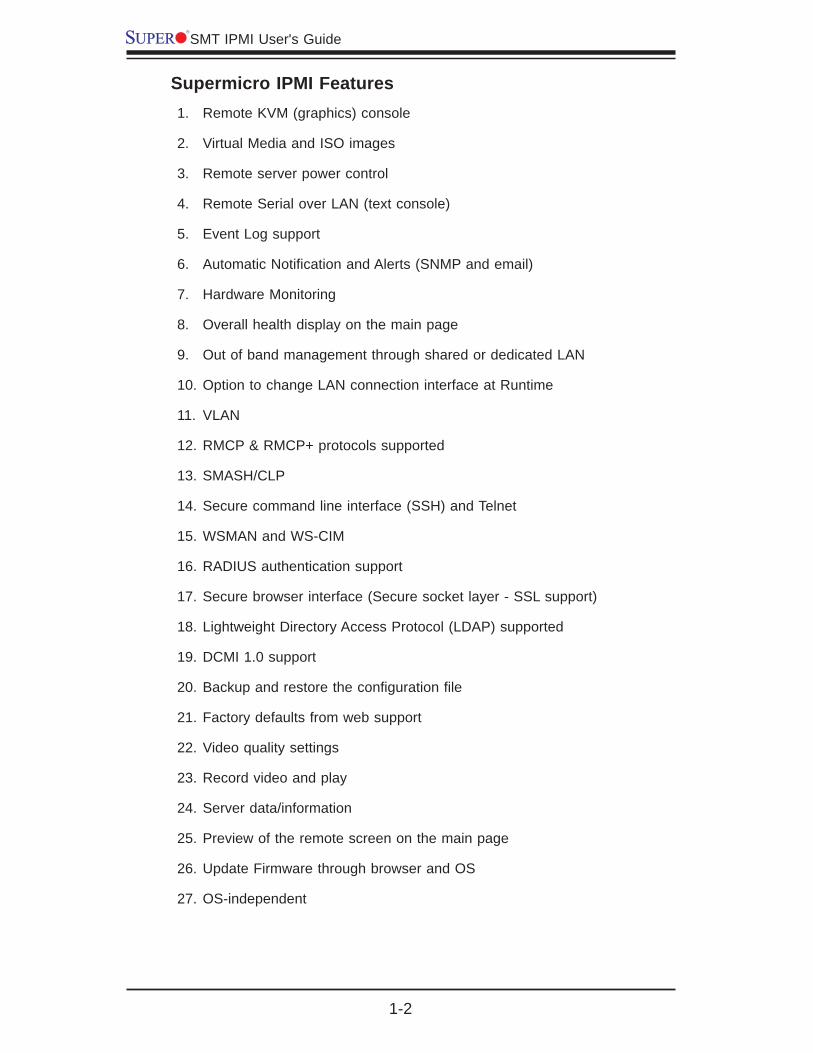
Supermicro IPMI FeaturesRemote KVM (graphics) console1.
Virtual Media and ISO images2.
Remote server power control3.
Remote Serial over LAN (text console)4.
Event Log support5.
Automatic Notifi cation and Alerts (SNMP and email)6.
Hardware Monitoring7.
Overall health display on the main page8.
Out of band management through shared or dedicated LAN9.
Option to change LAN connection interface at Runtime10.
VLAN11.
RMCP & RMCP+ protocols supported12.
SMASH/CLP13.
Secure command line interface (SSH) and Telnet14.
WSMAN and WS-CIM15.
RADIUS authentication support16.
Secure browser interface (Secure socket layer - SSL support)17.
Lightweight Directory Access Protocol (LDAP) supported18.
DCMI 1.0 support19.
Backup and restore the confi guration fi le20.
Factory defaults from web support21.
Video quality settings22.
Record video and play23.
Server data/information 24.
Preview of the remote screen on the main page25.
Update Firmware through browser and OS26.
OS-independent27.
1-3
Chapter 1: Introduction
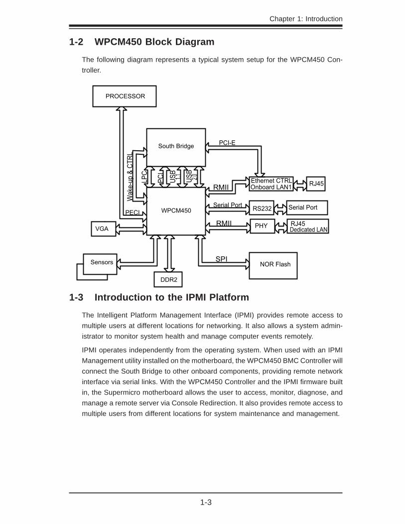
1-2 WPCM450 Block Diagram
The following diagram represents a typical system setup for the WPCM450 Con-troller.
WPCM450
Sensors
DDR2
LPC
SPI
Serial Port
South Bridge
PCI
USB
1.1 USB
2.0 Ethernet CTRLRMII RJ45
PROCESSOR
RS232 Serial Port
NOR Flash
PECI
Wak
e-up
& C
TRL
VGA
PCI-E
PHY
Onboard LAN1
RJ45Dedicated LAN
RMII
1-3 Introduction to the IPMI Platform
The Intelligent Platform Management Interface (IPMI) provides remote access to multiple users at different locations for networking. It also allows a system admin-istrator to monitor system health and manage computer events remotely.
IPMI operates independently from the operating system. When used with an IPMI Management utility installed on the motherboard, the WPCM450 BMC Controller will connect the South Bridge to other onboard components, providing remote network interface via serial links. With the WPCM450 Controller and the IPMI fi rmware built in, the Supermicro motherboard allows the user to access, monitor, diagnose, and manage a remote server via Console Redirection. It also provides remote access to multiple users from different locations for system maintenance and management.
SMT IPMI User's Guide
1-4
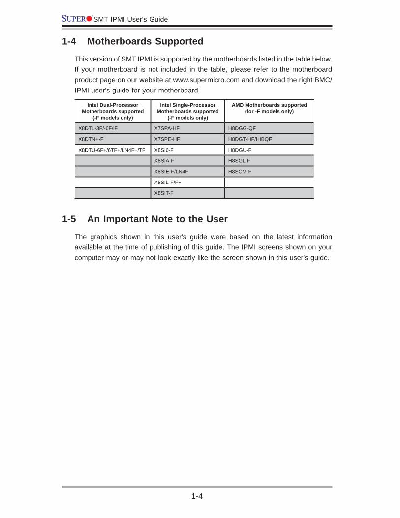
1-4 Motherboards Supported
This version of SMT IPMI is supported by the motherboards listed in the table below. If your motherboard is not included in the table, please refer to the motherboard product page on our website at www.supermicro.com and download the right BMC/IPMI user's guide for your motherboard.
Intel Dual-Processor Motherboards supported
(-F models only)
Intel Single-Processor Motherboards supported
(-F models only)
AMD Motherboards supported (for -F models only)
X8DTL-3F/-6F/iF X7SPA-HF H8DGG-QF
X8DTN+-F X7SPE-HF H8DGT-HF/HIBQF
X8DTU-6F+/6TF+/LN4F+/TF X8SI6-F H8DGU-F
X8SIA-F H8SGL-F
X8SIE-F/LN4F H8SCM-F
X8SIL-F/F+
X8SIT-F
1-5 An Important Note to the User
The graphics shown in this user's guide were based on the latest information available at the time of publishing of this guide. The IPMI screens shown on your computer may or may not look exactly like the screen shown in this user's guide.

Chapter 2: Confi guring BMC/IPMI Settings
2-1
Chapter 2
Confi guring the IPMI Settings
With the Nuvoton WPCM450 BMC Controller and the IPMIView fi rmware built in, Supermicro motherboards allow the user to access, monitor, manage and interface with multiple systems in different remote locations. The necessary fi rmware for ac-cessing and confi guring the IPMI settings are available on Supermicro's website at hppt://www.supermcro.com/products/nfo/ipmi.cfm. This section provides detailed information on how to confi gure the IPMI settings.
2-1 Confi guring BIOS
Before confi guring IPMI, follow the instructions below to confi gure the system BIOS settings.
Enabling COM Port for SOL (IPMI)
Press the <Del> key at bootup to enter the BIOS Setup utility.1.
Select 2. Advanced and press <Enter> to enter the Advanced menu.
From the Advanced menu, select 3. Remote Access and press <Enter>.
Make sure that the COM port for SOL (COM2 or COM3) is enabled (marked 4. with "*"). If not, Select the port for SOL and press <Enabled>. (For IPMI to work properly, BIOS will set the console redirection on this port by default.)

2-2
SMT IPMI User's Guide
B. Enabling All Onboard USB ports
Press the <Del> key at bootup to enter the BIOS Setup utility.1.
Select 2. Advanced and press <Enter> to enter the Advanced menu.
Select 3. Advanced Chipset Control and press <Enter>.
From the Advanced Chipset Control submenu, select 4. South Bridge Control and press <Enter>.
Make sure that all onboard USB ports are enabled (highlighted). If not, Select 5. USB Functions and press <Enabled> or select the number of onboard USB ports or press <Enter>to enable all onboard USB ports. (This is required for KVM to work properly.)
Chapter 2: Confi guring BMC/IPMI Settings
2-3
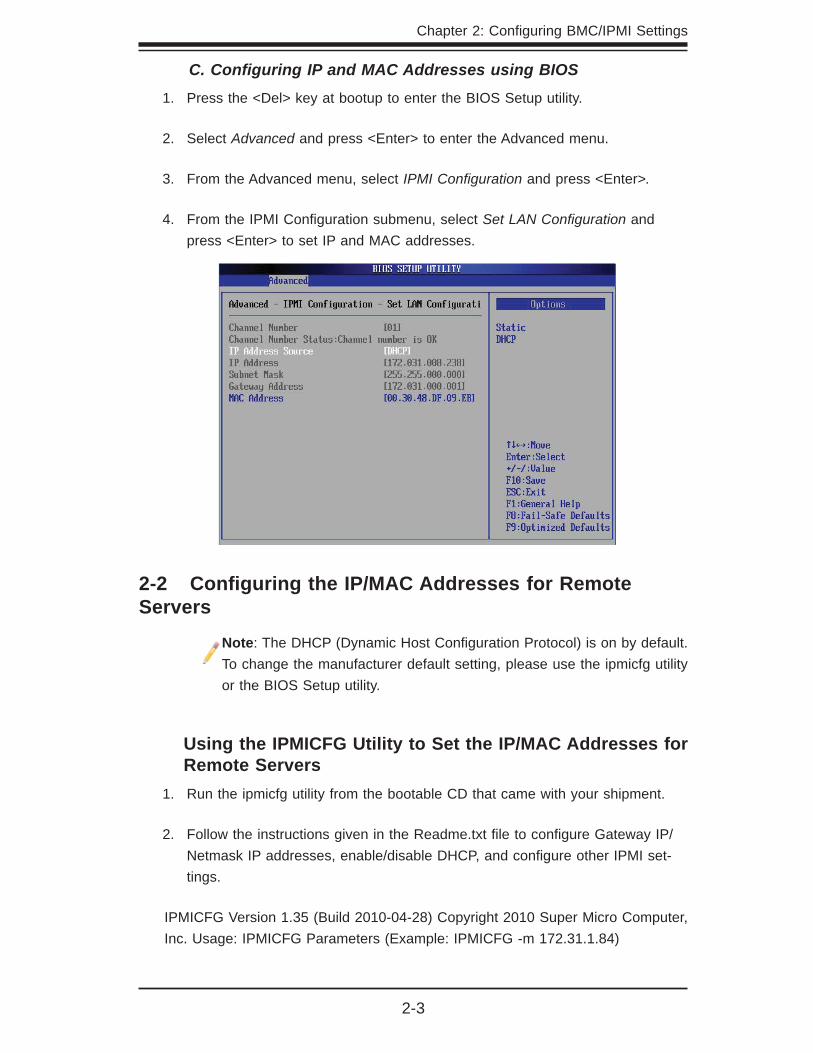
C. Confi guring IP and MAC Addresses using BIOS
Press the <Del> key at bootup to enter the BIOS Setup utility.1.
Select 2. Advanced and press <Enter> to enter the Advanced menu.
From the Advanced menu, select 3. IPMI Confi guration and press <Enter>.
From the IPMI Confi guration submenu, select 4. Set LAN Confi guration and press <Enter> to set IP and MAC addresses.
2-2 Confi guring the IP/MAC Addresses for Remote Servers
Note: The DHCP (Dynamic Host Confi guration Protocol) is on by default. To change the manufacturer default setting, please use the ipmicfg utility or the BIOS Setup utility.
Using the IPMICFG Utility to Set the IP/MAC Addresses for Remote ServersRun the ipmicfg utility from the bootable CD that came with your shipment. 1.
Follow the instructions given in the Readme.txt fi le to confi gure Gateway IP/2. Netmask IP addresses, enable/disable DHCP, and confi gure other IPMI set-tings.
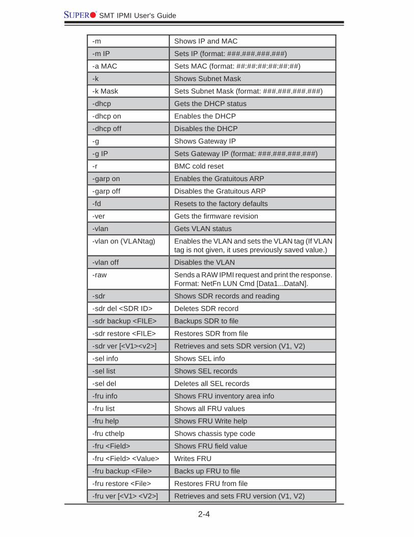
IPMICFG Version 1.35 (Build 2010-04-28) Copyright 2010 Super Micro Computer, Inc. Usage: IPMICFG Parameters (Example: IPMICFG -m 172.31.1.84)
2-4
SMT IPMI User's Guide
-m Shows IP and MAC
-m IP Sets IP (format: ###.###.###.###)
-a MAC Sets MAC (format: ##:##:##:##:##:##)
-k Shows Subnet Mask
-k Mask Sets Subnet Mask (format: ###.###.###.###)
-dhcp Gets the DHCP status
-dhcp on Enables the DHCP
-dhcp off Disables the DHCP
-g Shows Gateway IP
-g IP Sets Gateway IP (format: ###.###.###.###)
-r BMC cold reset
-garp on Enables the Gratuitous ARP
-garp off Disables the Gratuitous ARP
-fd Resets to the factory defaults
-ver Gets the fi rmware revision
-vlan Gets VLAN status
-vlan on (VLANtag) Enables the VLAN and sets the VLAN tag (If VLAN tag is not given, it uses previously saved value.)
-vlan off Disables the VLAN
-raw Sends a RAW IPMI request and print the response. Format: NetFn LUN Cmd [Data1...DataN].
-sdr Shows SDR records and reading
-sdr del <SDR ID> Deletes SDR record
-sdr backup <FILE> Backups SDR to fi le
-sdr restore <FILE> Restores SDR from fi le
-sdr ver [<V1><v2>] Retrieves and sets SDR version (V1, V2)
-sel info Shows SEL info
-sel list Shows SEL records
-sel del Deletes all SEL records
-fru info Shows FRU inventory area info
-fru list Shows all FRU values
-fru help Shows FRU Write help
-fru cthelp Shows chassis type code
-fru <Field> Shows FRU fi eld value
-fru <Field> <Value> Writes FRU
-fru backup <File> Backs up FRU to fi le
-fru restore <File> Restores FRU from fi le
-fru ver [<V1> <V2>] Retrieves and sets FRU version (V1, V2)
Chapter 2: Confi guring BMC/IPMI Settings
2-5
2-3 Connecting to the Remote Server
Using the IPMIView to Connect to the Remote ServerConnect a LAN cable to the onboard LAN1 port or the dedicated IPMI LAN 1. port.
Choose a computer that is connected to the same network and open the 2. IPMIView utility.
Go to File>New>System. Enter the System Name, IP Address of LAN1 (or 3. the dedicated LAN, and the Description in the appropriate fi elds, and press <Enter>.
Select the system from the IPMI Domain. Enter the Login ID and Password in 4. the appropriate fi elds to log in to the IPMIView utility.
Using the Browser to Connect to the Remote ServerConnect a LAN cable to the onboard LAN1 port or the IPMI LAN port.1.
Choose a computer that is connected to the same network and open the 2. browser.
Enter the IP address of each server that you want to connect to in the ad-3. dress bar of your browser.
Once the connection is made, the Login screen as shown on the next page 4. will display.
Notes:
1. The default network setting is "Failover", which will allow the IPMI to connect to the network through a shared LAN port (onboard LAN Port 1 or 0) or through the IPMI_Dedicated_LAN_Port. If the IPMI must be con-nected through a specifi c port, please change the LAN confi guration setting under the Network Settings.
2. For IPMI to work properly, please enable all onboard USB ports and the COM port designated for SOL (IPMI) on the motherboard. All USB ports and the COM port for IPMI are enabled in the system BIOS by default. The COM port for IPMI is marked with "*" in the BIOS. It is usually listed as COM2 or COM3 in the BIOS. Refer to Section 2-1 Confi guring BIOS for more information.

2-6
SMT IPMI User's Guide
2-4 Accessing the Remote Server via Console Redirection Using the Browser
To Log In to the Remote ConsoleOnce you are connected to the remote server via IPMI Console Redirection, the following IPMI Login screen will display.
Enter your Username in the 1. Username fi elds.
Note: The manufacturer default username and password are ADMIN/ADMIN. Once you have logged into the BMC using the manufacturer default password, be sure to change your password for security purpose.
Enter your Password in the 2. Password box and click <Login>.
The Home Page will display as shown on the next page.3.
Note 1: To use the IPMIView utility for Console Redirection, please refer to the IPMIView User's Guide for instructions.
Note 2: The Administrator account cannot be deleted.

Chapter 2: Confi guring BMC/IPMI Settings
2-7
2.5 IPMI Main Screen
The IPMI Main screen displays the following information.
The IPMI Main screen displays system information, including the following:
The Menu Bar: The menu bar on the top displays System Information, Server 1. Health, Confi guration, Remote Control, Virtual Media, Maintenance, and Miscellaneous. Click an item on the Menu Bar to access an IPMI feature and confi gure its settings.
The Options Window: This window displays IPMI submenu items. Click an 2. item in this window to confi gure the setting.
The Main Display Area: This area displays the contents of the particular sec-3. tion. Click an item in this area to confi gure the setting.
System Health Status: This icon displays the health status of the server.4.
Green: It indicates that the server is normal.•
Orange: At least an alert has occurred. Take proper actions to ensure system • health.
Red: At least one critical condition has occurred. Immediate attention is required • to resolve the critical condition for the server to function normally.
Language Select: From the pull-down menu, select a language. 5.
English•
Japanese•
1
2
3
4 5
2-8
SMT IPMI User's Guide
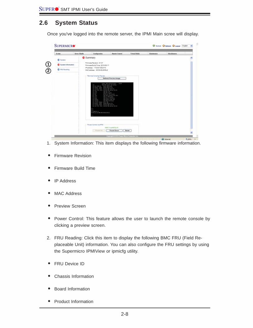
2.6 System Status
Once you've logged into the remote server, the IPMI Main scree will display.
System Information: This item displays the following fi rmware information.1.
Firmware Revision •
Firmware Build Time•
IP Address•
MAC Address•
Preview Screen•
Power Control: This feature allows the user to launch the remote console by • clicking a preview screen.
FRU Reading: Click this item to display the following BMC FRU (Field Re-2. placeable Unit) information. You can also confi gure the FRU settings by using the Supermicro IPMIView or ipmicfg utility.
FRU Device ID•
Chassis Information•
Board Information•
Product Information•
12
Chapter 2: Confi guring BMC/IPMI Settings
2-9
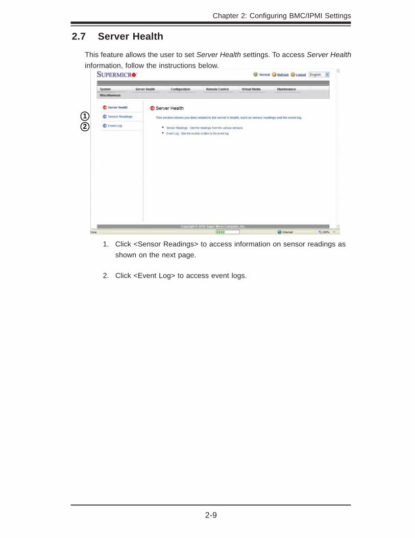
2.7 Server Health
This feature allows the user to set Server Health settings. To access Server Health information, follow the instructions below.
Click <Sensor Readings> to access information on sensor readings as 1. shown on the next page.
Click <Event Log> to access event logs.2.
12
2-10
SMT IPMI User's Guide
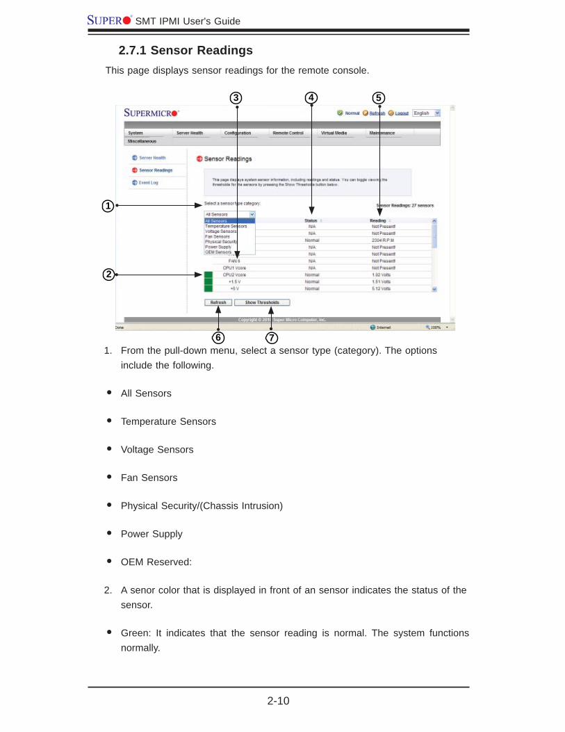
2.7.1 Sensor ReadingsThis page displays sensor readings for the remote console.
From the pull-down menu, select a sensor type (category). The options 1. include the following.
All Sensors•
Temperature Sensors•
Voltage Sensors•
Fan Sensors•
Physical Security/(Chassis Intrusion)•
Power Supply•
OEM Reserved:•
A senor color that is displayed in front of an sensor indicates the status of the 2. sensor.
Green: It indicates that the sensor reading is normal. The system functions • normally.
1
2
3 4 5
6 7
Chapter 2: Confi guring BMC/IPMI Settings
2-11
Amber: There is an alert on the sensor reading. Attention is needed to ensure • that the system is functioning properly.
Red: One or more sensors have reached the critical state. Immediate action is • needed to resolve the problem.
Name of the Sensor: This column displays the names of the sensors that are 3. currently active in system monitoring, including system temperature, CPU temperature, fan speeds, CPU core voltages, +3.3Vcc, and +12V voltage monitoring.
Status: This column indicates the status of each sensor reading.4.
Reading: This column indicates the reading of each sensor.5.
Refresh: Click this item to refresh the page.6.
Show Thresholds: Click this item to display senor thresholds.7.
2-12
SMT IPMI User's Guide
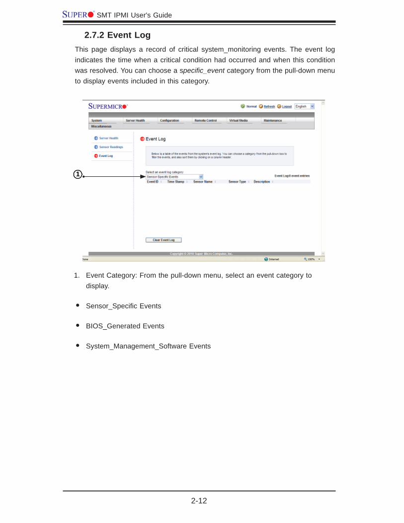
2.7.2 Event LogThis page displays a record of critical system_monitoring events. The event log indicates the time when a critical condition had occurred and when this condition was resolved. You can choose a specifi c_event category from the pull-down menu to display events included in this category.
Event Category: From the pull-down menu, select an event category to 1. display.
Sensor_Specifi c Events•
BIOS_Generated Events•
System_Management_Software Events•
1

Chapter 2: Confi guring BMC/IPMI Settings
2-13
This section allows the user to confi gure the following settings.Alerts: Use this item to confi gure alert destination settings.•
Date & Time•
LDAP: Use this item to confi gure LDAP (Lightweight Directory Access Protocol) • settings for authentication and access to the LDAP server.
Active Directory: Use this item to confi gure the settings for authentication and • access to the Active Directory server.
Radius: Use this item to confi gure the settings for authentication and access • to the Radius server.
Mouse mode•
Network•
Dynamic DNS•
Remote Session•
SMTP•
SSL Certifi cate•
2.8 Confi guration
This feature allows the user to confi gure various network settings. When you click the Confi guration icon on the menu bar, the following screen will display.

2-14
SMT IPMI User's Guide
2.8.1 Confi guring the Alerts SettingsThis feature allows the user to confi gure Alert settings. When you click the <Alerts> icon in the menu bar, the following screen will display.
To setup an alert or to modify an alert setting, do the following.
Click <Alerts> to activate the alert submenu.1.
Click <Modify> to confi gure or modify the settings of an alert. 2.
Send Test Alert3. is used to check if the alerts have been set and sent out cor-rectly.
Click <Delete> to delete an alert.4.
1
2 3 4

Chapter 2: Confi guring BMC/IPMI Settings
2-15
To Setup an Alert
Follow the steps below to setup an alert.
Select 1. Alert Severity.
Enter the IP address and/or the email address to receive the SNMP Trap.2.
Enter a subject or a message if applicable.3.
23456
7
2-16
SMT IPMI User's Guide
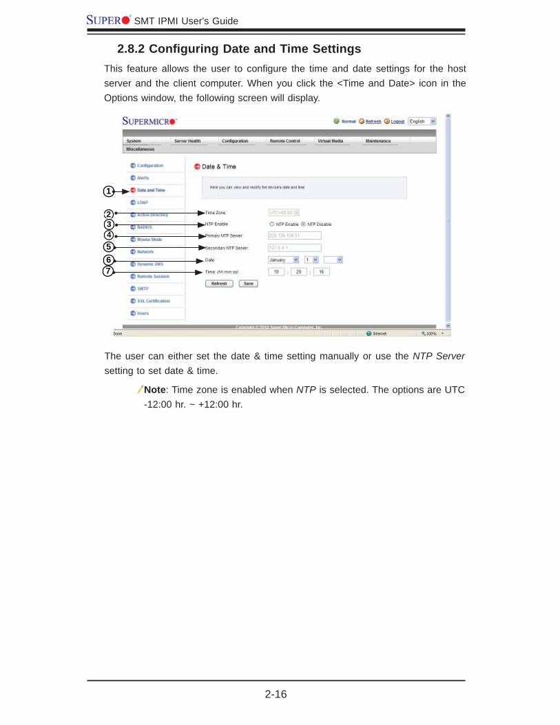
2.8.2 Confi guring Date and Time SettingsThis feature allows the user to confi gure the time and date settings for the host server and the client computer. When you click the <Time and Date> icon in the Options window, the following screen will display.
The user can either set the date & time setting manually or use the NTP Server setting to set date & time.
Note: Time zone is enabled when NTP is selected. The options are UTC -12:00 hr. ~ +12:00 hr.
1
234567
Chapter 2: Confi guring BMC/IPMI Settings
2-17
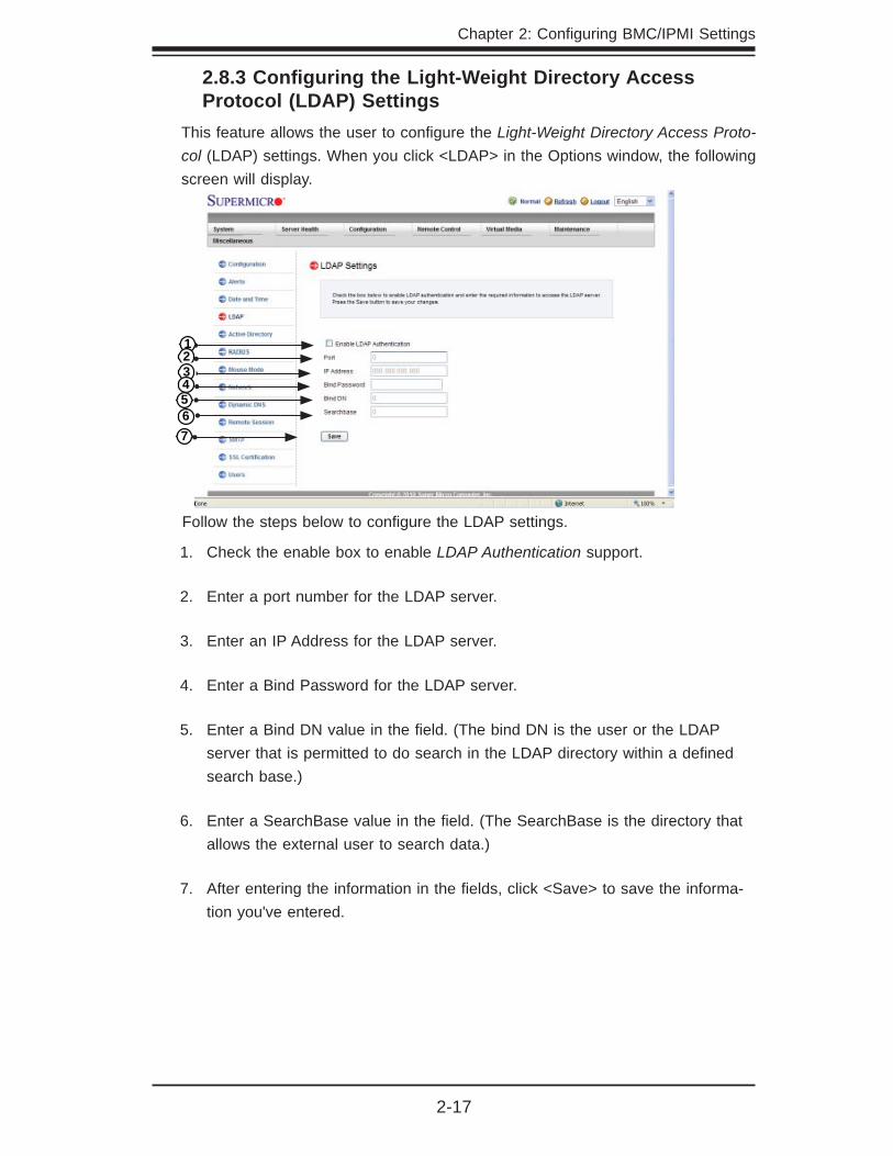
2.8.3 Confi guring the Light-Weight Directory Access Protocol (LDAP) Settings
This feature allows the user to confi gure the Light-Weight Directory Access Proto-col (LDAP) settings. When you click <LDAP> in the Options window, the following screen will display.
Follow the steps below to confi gure the LDAP settings.
Check the enable box to enable 1. LDAP Authentication support.
Enter a port number for the LDAP server. 2.
Enter an IP Address for the LDAP server. 3.
Enter a Bind Password for the LDAP server.4.
Enter a Bind DN value in the fi eld. (The bind DN is the user or the LDAP 5. server that is permitted to do search in the LDAP directory within a defi ned search base.)
Enter a SearchBase value in the fi eld. (The SearchBase is the directory that 6. allows the external user to search data.)
After entering the information in the fi elds, click <Save> to save the informa-7. tion you've entered.
1234567
2-18
SMT IPMI User's Guide
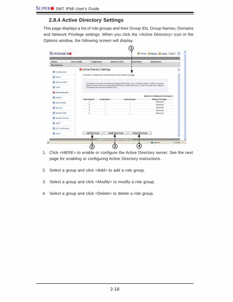
2.8.4 Active Directory SettingsThis page displays a list of role groups and their Group IDs, Group Names, Domains and Network Privilege settings. When you click the <Active Directory> icon in the Options window, the following screen will display.
Click <HERE1. > to enable or confi gure the Active Directory server. See the next page for enabling or confi guring Active Directory instructions.
Select a group and click <Add> to add a role group. 2.
Select a group and click <Modify> to modify a role group. 3.
Select a group and click <Delete> to delete a role group.4.
1
2 3 4

Chapter 2: Confi guring BMC/IPMI Settings
2-19
Confi guring the Active Directory Settings
This feature allows the user to confi gure the Advanced Active Directory settings. When you click <Here> on the screen shown on the previous page, the following screen will display.
Check the <Enable> box to enable 1. Active Directory authentication support. Then, Enter the values in the fi elds below.
Enter User Domain Name in the fi eld. 2.
Enter Time_Out value in the fi eld to set the time limit for a user to stay 3. logging-in.
Enter <Controller Server Address1>. 4.
Enter <Controller Server Address2>. 5.
Enter <Controller Server Address3>. 6.
After entering the information, click <Save> to save the settings.
123456

2-20
SMT IPMI User's Guide
2.8.5 Confi guring the Radius SettingsThis feature allows the user to confi gure Radius Option settings. When you click <Radius>in the Options Window, the following screen will display.
Check the <Enable> box to enable 1. Radius support. Enter the information in the fi elds below to confi gure Radius settings.
Enter the port number for the Radius server. 2.
Enter the IP address of the Radius server. 3.
Enter a (secret) password for the user to access the Radius server4.
After entering the information in the fi elds, click <Save> to save the information you've entered.
1234

Chapter 2: Confi guring BMC/IPMI Settings
2-21
2.8.6 Confi guring the Mouse Mode SettingsThis feature allows the user to confi gure the Mouse_Mode settings. When you click the <Mouse Mode> icon in the Options Window, the following screen will display.
This item displays the current Mouse_Mode setting. To select a proper 1. Mouse_Mode setting, click the proper radio button as shown below.
Check the radio button to set the mouse mode to• Absolute Mode for the Windows OS. (This is the default setting.)
Check the radio button to set the mouse mode to • Relative Mode for the Linux/Unix OS.
After entering the information, click "Save" to save the settings.
Note: IPMI is an OS-independent platform, and IKVM support is an added feature for IPMI. For your mouse to function properly, please confi gure the Mouse_Mode settings (see above) according to the type of OS used in your machine.
1
2-22
SMT IPMI User's Guide
56
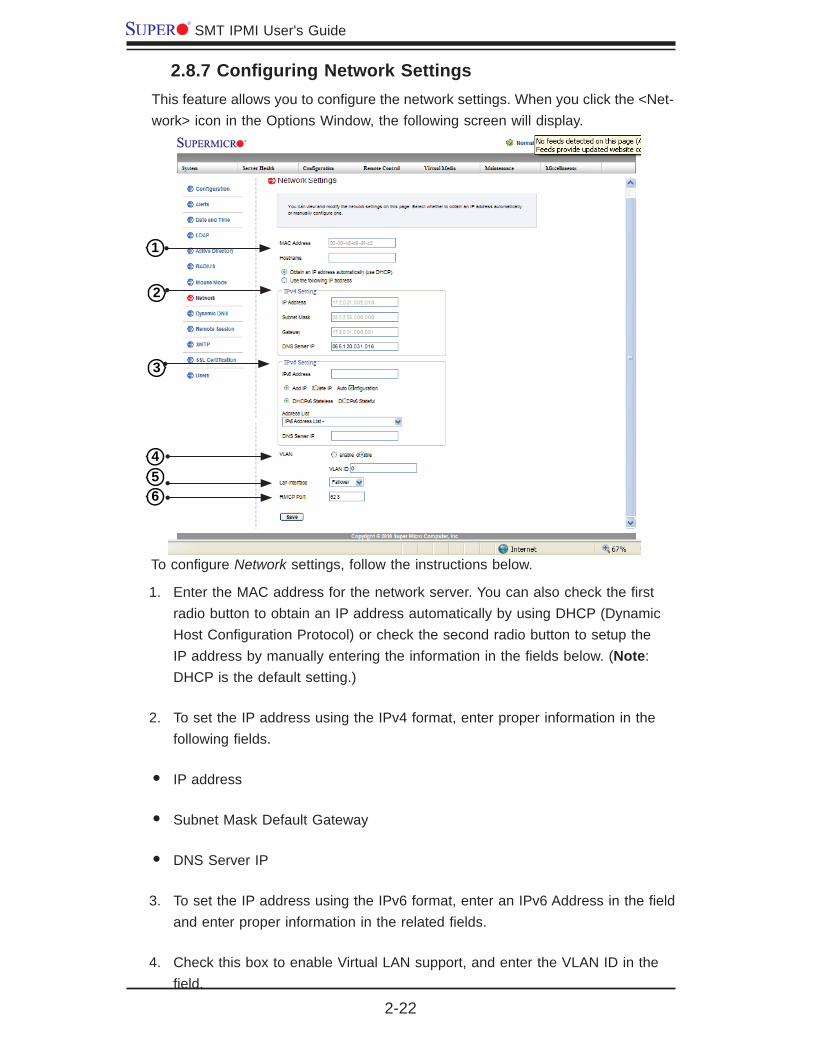
To confi gure Network settings, follow the instructions below.
Enter the MAC address for the network server. You can also check the fi rst 1. radio button to obtain an IP address automatically by using DHCP (Dynamic Host Confi guration Protocol) or check the second radio button to setup the IP address by manually entering the information in the fi elds below. (Note: DHCP is the default setting.)
To set the IP address using the IPv4 format, enter proper information in the 2. following fi elds.
IP address •
Subnet Mask Default Gateway •
DNS Server IP •
To set the IP address using the IPv6 format, enter an IPv6 Address in the fi eld 3. and enter proper information in the related fi elds.
Check this box to enable Virtual LAN support, and enter the VLAN ID in the 4. fi eld.
2.8.7 Confi guring Network SettingsThis feature allows you to confi gure the network settings. When you click the <Net-work> icon in the Options Window, the following screen will display.
1
2
3
4

Chapter 2: Confi guring BMC/IPMI Settings
2-23
LAN Interface5.
This feature allows the user to select the port to be used for IPMI out-of-band communication.
The default setting is Failover, which will allow IPMI to be connected from either • the shared LAN port (LAN1/0) or the dedicated IPMI LAN port. Precedence is given to the Dedicated LAN port over the shared LAN port.
Select <Dedicated LAN> for IPMI to connect through the IPMI Dedicated LAN • port at all time.
Select • Shared LAN for IPMI to connect through the LAN port on the board.
RMCP Port6.
This feature allows the user to select the desired RMCP (Remote Mail Checking Protocol) port based on his confi guration. The default port is 623.
After entering all fi elds above, click <Save> to save the Network settings.
2-24
SMT IPMI User's Guide
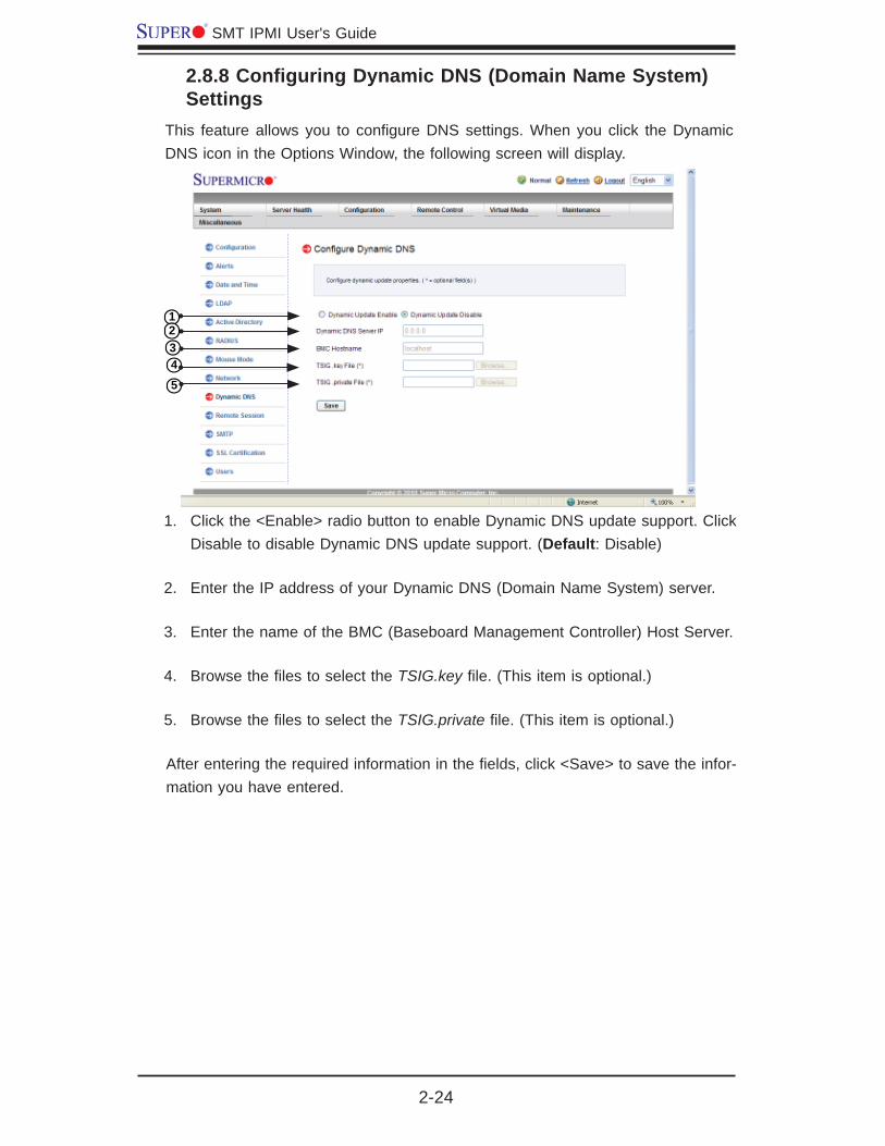
2.8.8 Confi guring Dynamic DNS (Domain Name System) Settings
This feature allows you to confi gure DNS settings. When you click the Dynamic DNS icon in the Options Window, the following screen will display.
Click the <Enable> radio button to enable Dynamic DNS update support. Click 1. Disable to disable Dynamic DNS update support. (Default: Disable)
Enter the IP address of your Dynamic DNS (Domain Name System) server. 2.
Enter the name of the BMC (Baseboard Management Controller) Host Server.3.
Browse the fi les to select the 4. TSIG.key fi le. (This item is optional.)
Browse the fi les to select the 5. TSIG.private fi le. (This item is optional.)
After entering the required information in the fi elds, click <Save> to save the infor-mation you have entered.
4
5
123
Chapter 2: Confi guring BMC/IPMI Settings
2-25
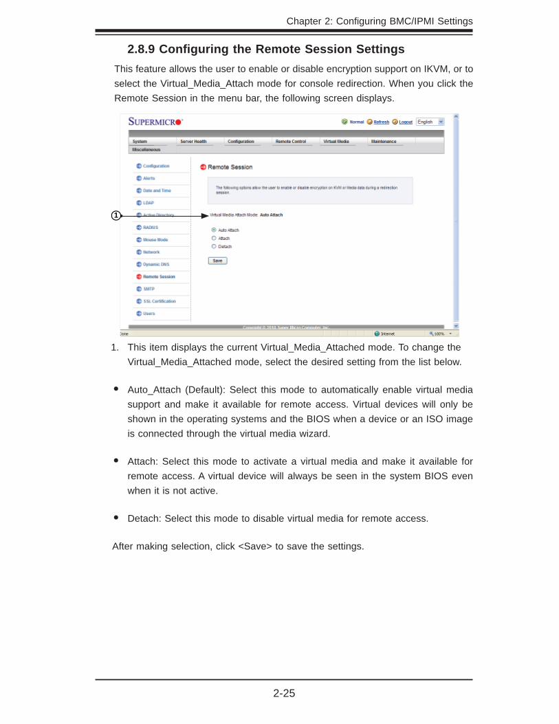
2.8.9 Confi guring the Remote Session SettingsThis feature allows the user to enable or disable encryption support on IKVM, or to select the Virtual_Media_Attach mode for console redirection. When you click the Remote Session in the menu bar, the following screen displays.
This item displays the current Virtual_Media_Attached mode. To change the 1. Virtual_Media_Attached mode, select the desired setting from the list below.
Auto_Attach (Default): Select this mode to automatically enable virtual media • support and make it available for remote access. Virtual devices will only be shown in the operating systems and the BIOS when a device or an ISO image is connected through the virtual media wizard.
Attach: Select this mode to activate a virtual media and make it available for • remote access. A virtual device will always be seen in the system BIOS even when it is not active.
Detach: Select this mode to disable virtual media for remote access.•
After making selection, click <Save> to save the settings.
1

2-26
SMT IPMI User's Guide
2.8.10 Confi guring the SMTP SettingsThis feature allows the user to confi gure SMTP (Simple Mail Transfer Protocol) settings for email transmission through the network. When you click the <SMTP> icon in the Options window, the following screen will display.
To confi gure SMTP settings, enter information in the fi elds below.
Enter the IP address for the SMTP (Simple Mail Transfer Protocol) Mail 1. server.
Enter the port number for your SMTP Mail server.2.
Enter the user name for your SMTP Mail server. (Optional)3.
Enter the user password for your SMTP Mail server. (Optional) 4.
After entering the information above, click <Save> to save the settings.
4
123

Chapter 2: Confi guring BMC/IPMI Settings
2-27
2.8.11 Confi guring the SSL (Secure Sockets Layer) Certifi cation
This feature displays the default certifi cate and private keys. It also allows the user to upload a new SSL certifi cate. When you click the <SSL> icon in the Options window, the following screen will display.
12
3
To enter a new SSL Certifi cate, enter a new certifi cate in the fi eld. You can 1. also browse the data base to select a new certifi cate.
Enter a new Private Key in the fi eld, if desired. You can also browse the data 2. base to select a new key.
After entering the new SSL certifi cate or/and a new private key, press <Up-3. load> to upload the certifi cate and private key to the server.

2-28
SMT IPMI User's Guide
2.8.12 Confi guring Users SettingsThis page displays information on the current users. It also allows you to add, de-lete or modify user information. When you click the <Users> icon in the Options window, the following screen will display.
This item lists current user information, including User ID, User name and 1. Network Privilege settings. Network privilege settings are shown below.
4
1
3 5
2
Privilege Levels DefinedFunction User Operator AdministratorSystem Information Full Access Full Access Full Access
Chassis Locator Control View Only Full Access Full Access
FRU Reading Full Access Full Access Full Access
Sensor Readings Full Access Full Access Full Access
Event Log View Only Full Access Full Access
Alert No View Only Full Access
LDAP No View Only Full Access
Mouse Mode No View Only Full Access
Network No View Only Full Access
Remote Session No View Only Full Access
SMTP No View Only Full Access
SSL No View Only Full Access
Users No View Only Full Access
Event Action No View Only Full Access
Power Control View Only Full Access Full Access
KVM View Only Full Access Full Access
F/W update View Only View Only Full Access
SDR update View Only View Only Full Access
Logout Full Access Full Access Full Access

Chapter 2: Confi guring BMC/IPMI Settings
2-29
This item displays the number of the users that are set up for the network. 2. The maximum of 10 user profi les can be made.
To add a new user to the network, click <Add User>. When prompted, select 3. an empty slot from the users list to add an user.
To modify the information or the status of a user, click <Modify User>. When 4. prompted, using the arrow keys, select a user from the users list to modify the user information.
To delete a user from the network, click <Delete User>. When prompted, us-5. ing the arrow keys, select a user from the users list to delete it from the list.
2-30
SMT IPMI User's Guide
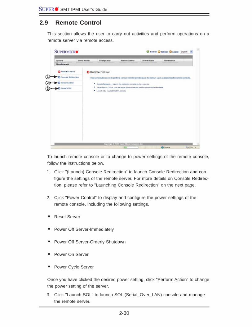
2.9 Remote Control
This section allows the user to carry out activities and perform operations on a remote server via remote access.
To launch remote console or to change to power settings of the remote console, follow the instructions below.
Click "(Launch) Console Redirection" to launch Console Redirection and con-1. fi gure the settings of the remote server. For more details on Console Redirec-tion, please refer to "Launching Console Redirection" on the next page.
Click "Power Control" to display and confi gure the power settings of the 2. remote console, including the following settings.
Reset Server•
Power Off Server-Immediately•
Power Off Server-Orderly Shutdown•
Power On Server•
Power Cycle Server•
Once you have clicked the desired power setting, click "Perform Action" to change the power setting of the server.
Click "Launch SOL" to launch SOL (Serial_Over_LAN) console and manage 3. the remote server.
2
1
3
Chapter 2: Confi guring BMC/IPMI Settings
2-31
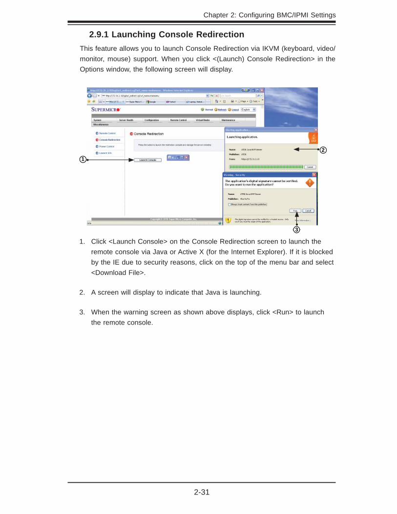
2.9.1 Launching Console RedirectionThis feature allows you to launch Console Redirection via IKVM (keyboard, video/monitor, mouse) support. When you click <(Launch) Console Redirection> in the Options window, the following screen will display.
Click <Launch Console> on the Console Redirection screen to launch the 1. remote console via Java or Active X (for the Internet Explorer). If it is blocked by the IE due to security reasons, click on the top of the menu bar and select <Download File>.
A screen will display to indicate that Java is launching. 2.
When the warning screen as shown above displays, click <Run> to launch 3. the remote console.
1
3
2

2-32
SMT IPMI User's Guide
2.9.1.1 Console Redirection - Virtual Device
This feature allows you to confi gure Virtual Device settings for your console redirec-tion. When you click the <Virtual Device> icon in the Menu bar, the video settings of the remote console will display as shown below.
Click <Virtual Media> to confi gure virtual device settings of a server at a 1. remote site via Console Redirection.
Click <Virtual Storage> to select a device you want to connect to the remote 2. server as a virtual device. When you click on this item, the screen as shown below displays.
You can connect Floppy, USB Flash, CD-ROM, DVD ROM or ISO images using this feature.
12
Chapter 2: Confi guring BMC/IPMI Settings
2-33
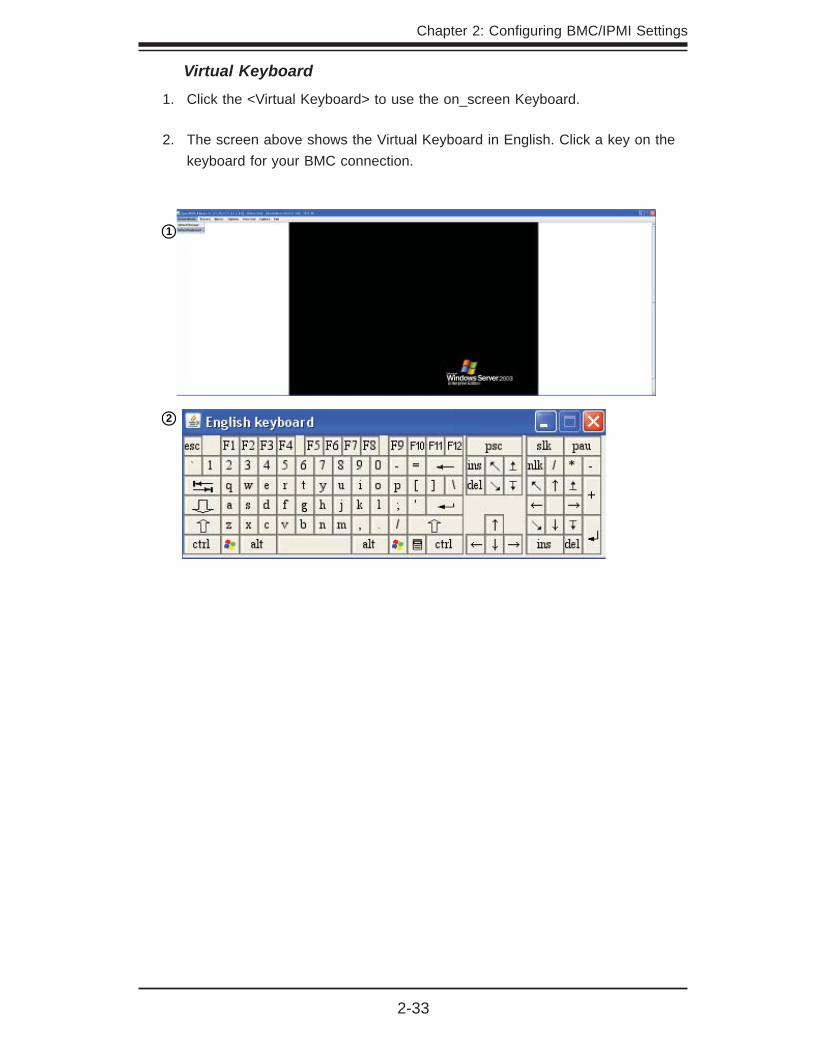
Virtual Keyboard
Click the <Virtual Keyboard> to use the on_screen Keyboard. 1.
The screen above shows the Virtual Keyboard in English. Click a key on the 2. keyboard for your BMC connection.
1
2
2-34
SMT IPMI User's Guide
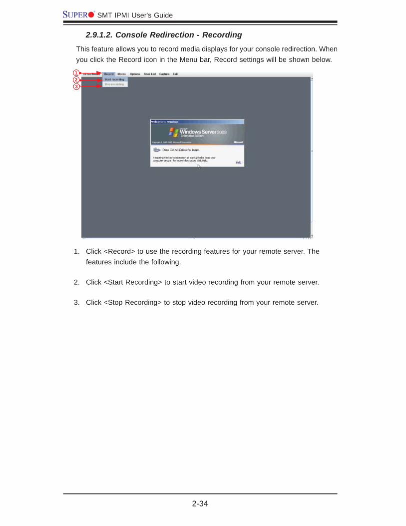
Click <Record> to use the recording features for your remote server. The 1. features include the following.
Click <Start Recording> to start video recording from your remote server.2.
Click <Stop Recording> to stop video recording from your remote server. 3.
2.9.1.2. Console Redirection - Recording
This feature allows you to record media displays for your console redirection. When you click the Record icon in the Menu bar, Record settings will be shown below.
123

Chapter 2: Confi guring BMC/IPMI Settings
2-35
Click <Record> to enable media recording support. Click <Start Recording> to 1. start recording.
From the pull-down menu, select the location where you want to save the 2. recording.
Enter the fi lename and click <Save> to save the recording.3.
2.9.1.3. Console Redirection - Recording
This feature allows you to record the media displays. Click <Record> in the Menu bar to enable virtual media recording support.
1
2
3
2-36
SMT IPMI User's Guide
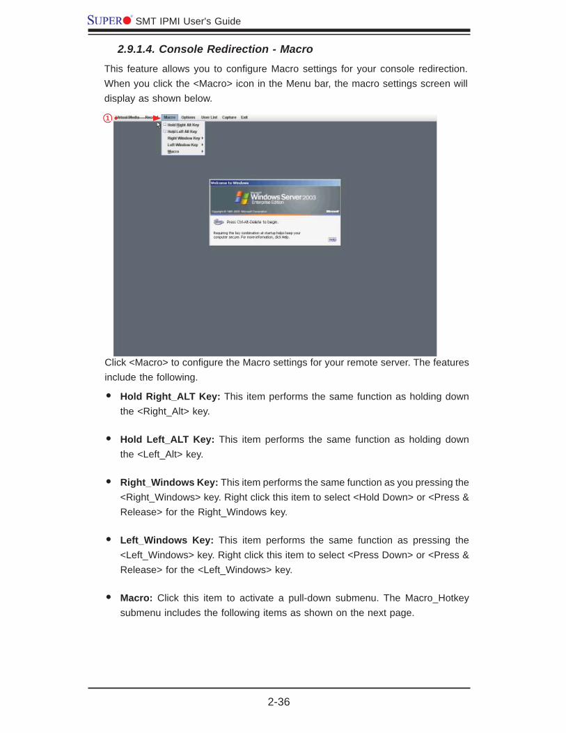
2.9.1.4. Console Redirection - Macro
This feature allows you to confi gure Macro settings for your console redirection. When you click the <Macro> icon in the Menu bar, the macro settings screen will display as shown below.
Click <Macro> to confi gure the Macro settings for your remote server. The features include the following.
Hold Right_ALT Key: • This item performs the same function as holding down the <Right_Alt> key.
Hold Left_ALT Key: • This item performs the same function as holding down the <Left_Alt> key.
Right_Windows Key: • This item performs the same function as you pressing the <Right_Windows> key. Right click this item to select <Hold Down> or <Press & Release> for the Right_Windows key.
Left_Windows Key: • This item performs the same function as pressing the <Left_Windows> key. Right click this item to select <Press Down> or <Press & Release> for the <Left_Windows> key.
Macro: • Click this item to activate a pull-down submenu. The Macro_Hotkey submenu includes the following items as shown on the next page.
1
Chapter 2: Confi guring BMC/IPMI Settings
2-37
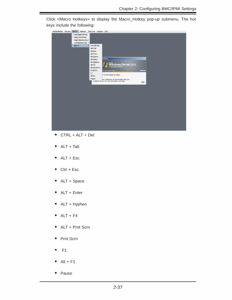
Click <Macro Hotkeys> to display the Macro_Hotkey pop-up submenu. The hot keys include the following:
CTRL + ALT + Del•
ALT + Tab•
ALT + Esc•
Ctrl + Esc•
ALT + Space•
ALT + Enter•
ALT + Hyphen•
ALT + F4•
ALT + Prnt Scrn•
Prnt Scrn•
F1•
Alt + F1•
Pause•

2-38
SMT IPMI User's Guide
2.9.1.5 Console Redirection - Options
This feature allows you to confi gure Options settings for your console redirection. When you click the <Options> icon in the Menu bar, the Options menu will display as shown below.
Click <Options> to activate the pull-down menu to confi gure 1. Options settings.
The options menu2. allows you to confi gure the following settings.
Hotkey•
Preference •
Full-Screen Mode•
OSD UI Style •
Keyboard_Mouse_Hotplug •
12

Chapter 2: Confi guring BMC/IPMI Settings
2-39
2.9.1.5.1 Console Redirection - Options: Hotkey Settings
This feature allows you to confi gure Hotkey settings for your console redirection. When you click the <Options-Hotkey> icon in the Menu bar, the Hotkey menu will display as shown below.
To assign a hotkey for an action, follow the steps below.
Click <Start>.1.
Enter the hotkey of your choice (-it can be a single word or a combination).2.
Click <Stop>. 3.
Select an item from the action list and click <Assign>.4.
Click <Close> to exit.5.
1
2
3 4 5
2-40
SMT IPMI User's Guide
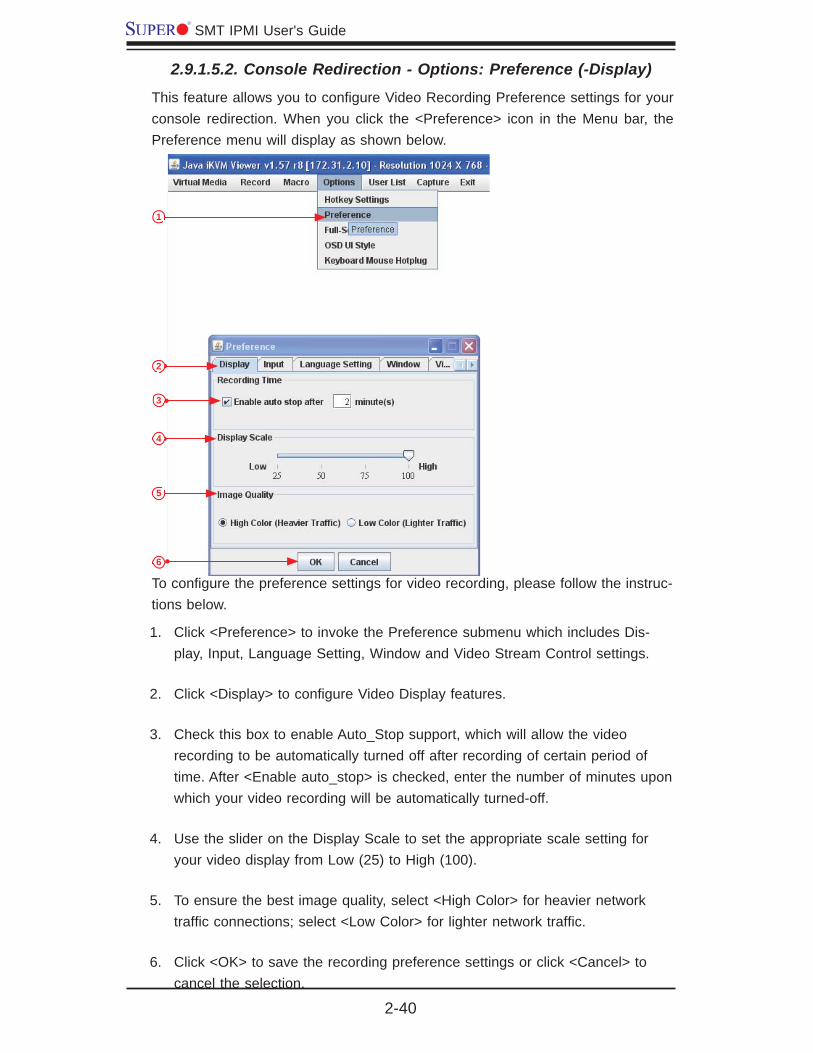
2.9.1.5.2. Console Redirection - Options: Preference (-Display)
This feature allows you to confi gure Video Recording Preference settings for your console redirection. When you click the <Preference> icon in the Menu bar, the Preference menu will display as shown below.
To confi gure the preference settings for video recording, please follow the instruc-tions below.
Click <Preference> to invoke the Preference submenu which includes Dis-1. play, Input, Language Setting, Window and Video Stream Control settings.
Click <Display> to confi gure Video Display features.2.
Check this box to enable Auto_Stop support, which will allow the video 3. recording to be automatically turned off after recording of certain period of time. After <Enable auto_stop> is checked, enter the number of minutes upon which your video recording will be automatically turned-off.
Use the slider on the Display Scale to set the appropriate scale setting for 4. your video display from Low (25) to High (100).
To ensure the best image quality, select <High Color> for heavier network 5. traffi c connections; select <Low Color> for lighter network traffi c.
Click <OK> to save the recording preference settings or click <Cancel> to 6. cancel the selection.
1
2
3
4
5
6

Chapter 2: Confi guring BMC/IPMI Settings
2-41
To confi gure Video Input settings, follow the instructions below.
Click <Preference> to invoke the Options submenu.1.
From the Options submenu, click <Input> to invoke the 2. Input page to confi g-ure mouse and keyboard settings.
Check <Enable Mouse Input> to enable mouse support so that you can use 3. the mouse as an input device. Once mouse support is enabled, set a proper mode for your console redirection.
Select • Absolute_Mode if you have the Windows OS
Select • Relative_Mouse for the Linux OS.
Select 4. Enable Keyboard Input to enable keyboard support so that you can use soft keyboard as an input device. From the Keyboard layout pull-down menu, select the right language setting for your soft keyboard.
Use the slider on the 5. Repeat Key Timeout scale to select the appropriate timeout settings for repeat keystrokes from 0ms to 1000ms (micro-second).
Click <Save> to save the keyboard setting or click <Cancel> to cancel it.6.
2.9.1.5.3. Console Redirection - Options: Preference (-Input)
This feature allows you to confi gure Video_Recording input settings for your console redirection. Click <Input> in the menu bar to activate the Input submenu.
1
2
3
4
5
6

2-42
SMT IPMI User's Guide
To select the correct language setting for your console, follow the steps below.
Select 1. Options from the Menu bar. From the pull-down menu, select Prefer-ence.
Click <Language Setting>.2.
From the Language Setting pop-up menu, select the language you want to 3. use for your console redirection. The language options include English, Chi-nese (Traditional), Japanese, German, French, Spanish, Korean, and Italian.
Once you have selected a language setting, click <OK> to use the language. 4.
2.9.1.5.4. Console Redirection - Options: Preference (-Language Settings)
This feature allows you to confi gure Language settings for your console redirection. Click <Options> in the Menu bar to activate the Preference menu.
1
2
3
4

Chapter 2: Confi guring BMC/IPMI Settings
2-43
2.9.1.5.5. Console Redirection - Options: Preference (-Window)
This feature allows you to confi gure Window settings for your console redirection. Click <Options> in the Menu bar to activate the Preference menu.
To select the correct Window settings for your console redirection, follow the in-structions below.
Select 1. Options from the Menu bar. From the pull-down menu, select Prefer-ence.
Click <Window>.2.
Check <Auto Re-size Window> for the system to reset the size of your dis-3. play window. (If you do not wish your display window to be re-sized automati-cally, leave the box blank.)
Click <OK> to save the window settings. 4.
1
23
4

2-44
SMT IPMI User's Guide
2.9.1.5.6. Console Redirection - Options: Preference (-Video Stream Control)
This feature allows you to confi gure Window settings for your console redirection. Click <Options> in the Menu bar to activate the Preference menu.
To select the correct Video Stream Control settings for your console redirection, follow the instructions below.
Select <Options> from the Menu bar. From the pull-down menu, select 1. Prefer-ence.
Click <Video Stream Control>.2.
Check <Enable Flow Control> to provide support for video fl ow control. 3. Once the Flow Control support is enabled, select the proper speed for video streaming from the pull-down menu. The speed settings listed below.
256K Cable/DSL•
T1•
T2•
Click <OK> to save the Video Stream Control setting. 4.
1
2
3
4
Chapter 2: Confi guring BMC/IPMI Settings
2-45
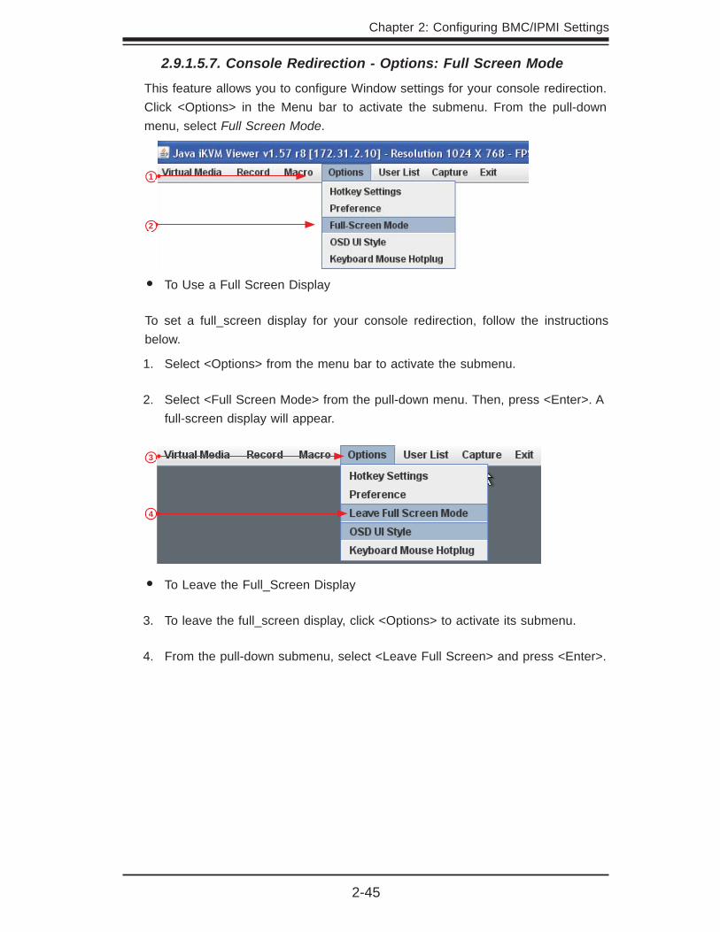
2.9.1.5.7. Console Redirection - Options: Full Screen Mode
This feature allows you to confi gure Window settings for your console redirection. Click <Options> in the Menu bar to activate the submenu. From the pull-down menu, select Full Screen Mode.
To Use a Full Screen Display•
To set a full_screen display for your console redirection, follow the instructions below.
Select <Options> from the menu bar to activate the submenu.1.
Select <Full Screen Mode> from the pull-down menu. Then, press <Enter>. A 2. full-screen display will appear.
To Leave the Full_Screen Display•
To leave the full_screen display, click <Options> to activate its submenu.3.
From the pull-down submenu, select <Leave Full Screen> and press <Enter>.4.
1
2
3
4

2-46
SMT IPMI User's Guide
2.9.1.5.8 Console Redirection - Options: OSD UI Style
This feature allows you to confi gure OSD (On-screen Display) UI (User-Interface) Style settings for your console redirection. To confi gure the OSD UI settings, follow the steps below.
1. From the Options pull-down menu, click <OSD UI Style> to display the OSD UI Style screen as shown below. This screen provides shortcuts to the main features provided by the fi rmware for your console redirection.
Click an <OSD_UI_Style> icon to change the settings listed on the next page. 2.
The OSD UI Style Screen Close-up
1
2

Chapter 2: Confi guring BMC/IPMI Settings
2-47
Move OSD UI Screen:1. Click this icon to move the OSD_UI Screen to a new location on the display.
Hotkey Settings: 2. Click this icon to access the Hotkeys submenu and change the settings.
Virtual Media: 3. Click this item to access the Virtual Media submenu and confi gure the settings.
Virtual Keyboard: 4. Click this item to access the Virtual Keyboard submenu and use your virtual (soft) keyboard.
Preferences submenu:5. Click this item to access the References submenu as indicated in the previous sections.
Full Screen Mode:6. Click this item to change the size of your display window to the full screen mode.
Exit Remote Console: 7. Click this item to exit from the remote connection.
Users List: 8. Click this item to display the user list.
Change Tool Bar Display: 9. Click this item to change the tool_bar display format.
Hotplug Keyboard/Mouse: 10. Click this item to hotplug keyboard and mouse.
Macro: 11. Click this item to enable Macro support and use Macro features.
Video Recording: 12. Click this item to access the Video Recording submenu and to use video recording.
Image Size: 13. This item displays the image size in pixel.
IP Address:14. This item displays the IP Address of IPMI.
The OSD UI Style Screen Close-up
2 3 4 5 61 7 8 9 10 11 12
13
14

2-48
SMT IPMI User's Guide
2.9.1.5.9 Console Redirection - Keyboard/Mouse Hotplug
Click <Options> on the menu bar to invoke the pull-down submenu. 1.
Click <Keyboard/Mouse Hotplug> from the pull-down menu to enable key-2. board/mouse hotplug support for your console redirection.
2
1

Chapter 2: Confi guring BMC/IPMI Settings
2-49
2.9.1.6 Console Redirection - User List
This feature allows you to access the user list. To confi gure User List settings, fol-low the instructions below.
From the menu bar, click <User List> to display the User List screen as 1. shown above.
Session ID: 2. This item displays the current session ID#.
User Name: 3. This item displays the name(s) of the user(s).
IP Address: 4. This item displays the IP Address of the client server.
2 3 4
1

2-50
SMT IPMI User's Guide
2.9.1.7 Console Redirection - Capture
This feature allows you to capture the screen displayed on your remote console.

Chapter 2: Confi guring BMC/IPMI Settings
2-51
To exit from Console Redirection, click <Exit>. 1.
2.9.1.8 Console Redirection - Exit
At the prompt- "Are you sure?", click <Yes> to exit from remote redirection.2.
Click <No> to return to the current session.3.
2 3
1
2-52
SMT IPMI User's Guide
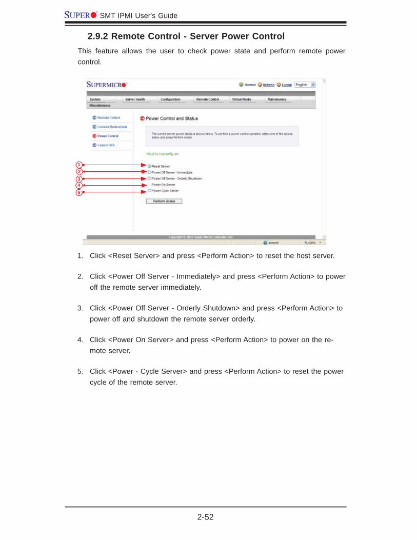
2.9.2 Remote Control - Server Power ControlThis feature allows the user to check power state and perform remote power control.
Click <Reset Server> and press <Perform Action> to reset the host server.1.
Click <Power Off Server - Immediately> and press <Perform Action> to power 2. off the remote server immediately.
Click <Power Off Server - Orderly Shutdown> and press <Perform Action> to 3. power off and shutdown the remote server orderly.
Click <Power On Server> and press <Perform Action> to power on the re-4. mote server.
Click <Power - Cycle Server> and press <Perform Action> to reset the power 5. cycle of the remote server.
2345
1

Chapter 2: Confi guring BMC/IPMI Settings
2-53
2.9.3 Remote Control-Launch SOLThis feature allows you to launch the remote console by using SOL (Serial_over_LAN). This feature provides serial port connections over LAN to allow the user to access a host server via Console Redirection. It also allows a system administra-tor to monitor and manage a server from a remote site. To launch SOL, follow the instructions below.
Click <Launch SOL> in the left Options window to enable SOL (Serial Over 1. LAN) support.
Click the <Launch SOL> button to launch SOL. After SOL is launched, the 2. following screen will display as shown on the next page.
2
1

2-54
SMT IPMI User's Guide
Launching SOL
You can select a Baud Rate (bps) from the pull-down menu as your SOL 1. transfer rate. The options are listed below. Make sure that the Baud Rate selected here matches the Baud Rate set in the BIOS.
9600 bps (bit-per-second) •
19200 bps•
38400 bps •
57600 bps•
115200 bps•
Manufacture Default. •
Once you've selected the Baud rate, press <Start> to start the session.2.
You can also press <Stop> to stop SOL connection.3.
2 31

Chapter 2: Confi guring BMC/IPMI Settings
2-55
2.10 Virtual Media
This feature allows you to upload and share images via the BMC (Baseboard Management Controller). These images will be emulated to the host server as USB applications. To follow the Virtual Media settings, follow the instructions below.
Click <Virtual Media> to confi gure virtual media settings for your remote con-1. sole, including Floppy Disk and CD-ROM image settings.
Click <Floppy Disk> on the Options Window to confi gure the fl oppy disk 2. settings for your console redirection. The Floppy Disk screen will display as shown on the next page.
Click <CD-ROM Image> to confi gure CD-ROM image settings for your 3. console redirection. When you click on this item, the screen on Page 2-55 displays.
2
3
1
2-56
SMT IPMI User's Guide
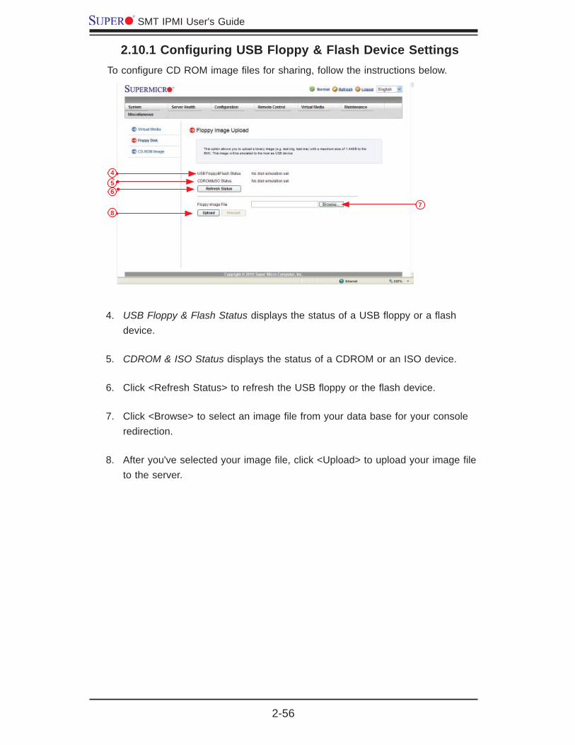
2.10.1 Confi guring USB Floppy & Flash Device SettingsTo confi gure CD ROM image fi les for sharing, follow the instructions below.
USB Floppy & Flash Status4. displays the status of a USB fl oppy or a fl ash device.
CDROM & ISO Status5. displays the status of a CDROM or an ISO device.
Click <Refresh Status> to refresh the USB fl oppy or the fl ash device. 6.
Click <Browse> to select an image fi le from your data base for your console 7. redirection.
After you've selected your image fi le, click <Upload> to upload your image fi le 8. to the server.
456
78

Chapter 2: Confi guring BMC/IPMI Settings
2-57
2.10.2 Confi guring CD ROM Image File SettingsTo confi gure CD ROM image fi les for sharing, follow the instructions below.
Click <CD-ROM Image File> to invoke the <Image on Windows Share> 9. screen as shown above. The following items will display.
USB Floppy & Flash Status• indicates the status of a USB fl oppy or a fl ash device.
CD ROM & ISO Status• indicates the status of a CD-ROM or an ISO device.
Click <Refresh Status> to refresh 10. USB Floppy/Flash and CD ROM/ISO devices.
Enter the 11. Share_Host server for your console redirection.
In the 12. Path_to_Image fi eld, enter the path to the CD-ROM image fi le for shar-ing.
In the 13. Users (Optional) fi eld, specify the users that have access to the CD-ROM image fi les. (This item is optional).
In the 14. Password (Optional) fi eld, enter your user password. (Optional.)
To 15. mount an image fi le, follow the steps below.
Click <Save>.1.
Click <Mount>.2.
9
10
1112
1314
15 16

2-58
SMT IPMI User's Guide
To 3. unmount an image fi le, follow the steps below.
Click <Unmount>.1.
Click <Save>.2.
Chapter 2: Confi guring BMC/IPMI Settings
2-59
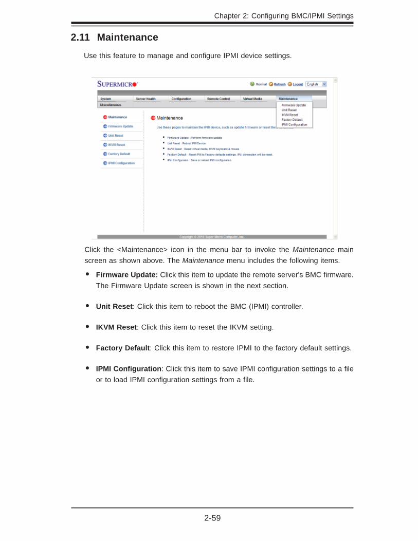
2.11 Maintenance
Use this feature to manage and confi gure IPMI device settings.
Click the <Maintenance> icon in the menu bar to invoke the Maintenance main screen as shown above. The Maintenance menu includes the following items.
Firmware Update:• Click this item to update the remote server's BMC fi rmware. The Firmware Update screen is shown in the next section.
Unit Reset• : Click this item to reboot the BMC (IPMI) controller.
IKVM Reset• : Click this item to reset the IKVM setting.
Factory Default• : Click this item to restore IPMI to the factory default settings.
IPMI Confi guration• : Click this item to save IPMI confi guration settings to a fi le or to load IPMI confi guration settings from a fi le.
2-60
SMT IPMI User's Guide
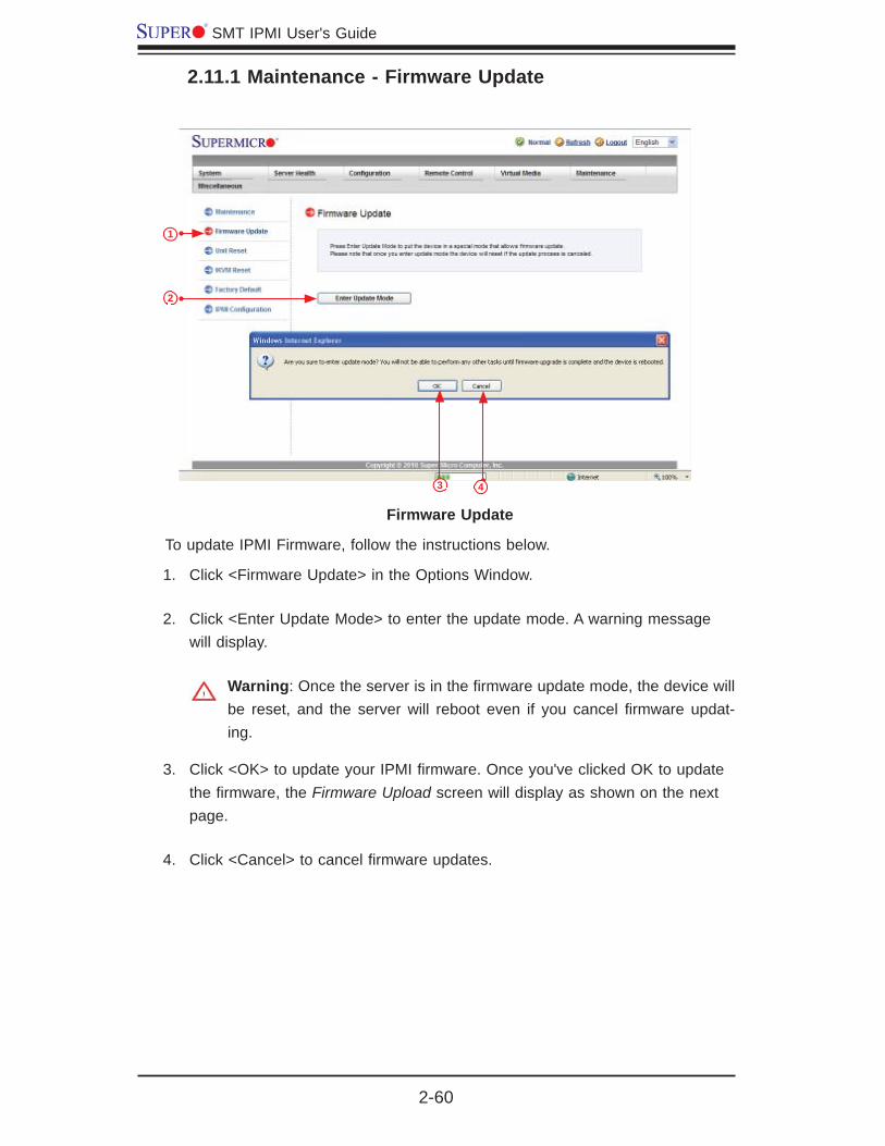
2.11.1 Maintenance - Firmware Update
Firmware Update
To update IPMI Firmware, follow the instructions below.
Click <Firmware Update> in the Options Window.1.
Click <Enter Update Mode> to enter the update mode. A warning message 2. will display.
Warning: Once the server is in the fi rmware update mode, the device will be reset, and the server will reboot even if you cancel fi rmware updat-ing.
Click <OK> to update your IPMI fi rmware. Once you've clicked OK to update 3. the fi rmware, the Firmware Upload screen will display as shown on the next page.
Click <Cancel> to cancel fi rmware updates.4.
2
3
1
4
Chapter 2: Confi guring BMC/IPMI Settings
2-61
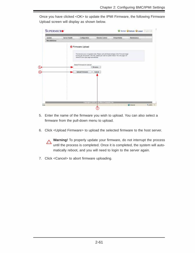
Once you have clicked <OK> to update the IPMI Firmware, the following Firmware Upload screen will display as shown below.
Enter the name of the fi rmware you wish to upload. You can also select a 5. fi rmware from the pull-down menu to upload.
Click <Upload Firmware> to upload the selected fi rmware to the host server. 6.
Warning! To properly update your fi rmware, do not interrupt the process until the process is completed. Once it is completed, the system will auto-matically reboot, and you will need to login to the server again.
Click <Cancel> to abort fi rmware uploading. 7.
5
6
7

2-62
SMT IPMI User's Guide
2.11.2 Maintenance - Unit ResetUse this feature to reset the IPMI device.

Chapter 2: Confi guring BMC/IPMI Settings
2-63
2.11.3 Maintenance - IKVM ResetThis feature allows you to reset IKVM. It will reset virtual media, IKVM keyboard and mouse.

2-64
SMT IPMI User's Guide
2.11.4 Maintenance - Factory DefaultThis feature allows the user to restore IPMI to factory default settings.

Chapter 2: Confi guring BMC/IPMI Settings
2-65
2.11.5 Maintenance - IPMI Confi gurationThis feature allows the user to save IPMI confi guration settings. To save the IPMI confi guration settings, follow the instructions below.
To save the IPMI Confi guration settings, click <Save> and enter a fi le name.•
To load IPMI Confi guration settings from a previously saved fi le, click <browse> • and select a fi le. Then, click <reload>.
23
1
4 5

2-66
SMT IPMI User's Guide
2.12 Miscellaneous
This feature allows the user to perform various network activities including POST (Power-On-Self Test) code query and turning-on/-off UID control. To query POST codes or to turn on/off UID control, follow the instructions below.
2.11.1 Miscellaneous - POST SnoopingClick <Post Snooping> in the Options window. The 1. Post Snooping screen will display as shown above.
Click <Refresh> to query the POST Snooping code for BIOS LPC Port80.2.
2
1

Chapter 2: Confi guring BMC/IPMI Settings
2-67
2.12.2 Miscellaneous - UID ControlThis feature allows the user to turn-on or turn-off UID (Unit Identifi cation) control. To turn on or off UID control, follow the instructions below.
Click <UID Control> in the 1. Options window. The <UID Control> screen will display as shown above. It will also show the current UID Control status.
Click <Turn On> to turn on UID control.2.
Click <Turn Off> to turn off UID control.3.
Click <Save> to save the setting.4.
23
1
4

3-1
Chapter 3: Troubleshooting
Chapter 3
Frequently Asked Questions
3-1 Frequently Asked Questions
A. Question: How do I fl ash the IPMI fi rmware?
Answer:
Method#1
Click the <Maintenance> button. Browse the fi les available and select the cor-1. rect fi le to fl ash the fi rmware.
Click the <Update Firmware> button to proceed with fi rmware fl ashing.2.
Method#2
You can fl ash the IPMI fi rmware using fl ash tools located at •
ftp://ftp.supermicro.com/utility/IPMI FW fl ash tools/.
For the latest IPMI Firmware, please refer to •
ftp://ftp.supermicro.com/fi rmware/nuvoton/.
B. Question: If I am using a fi rewall for my network connections, which ports should I open so that I can access my IPMI connection?
Answer: In order to access your IPMI connection behind a fi rewall, please open the following ports:
HTTP: 80 (TCP)
HTTPS: 443 (TCP)
IPMI: 623 (UDP)
Remote console: 5900 (TCP)
Virtual media: 623 (TCP)
SMASH: 22 (TCP)
WS-MAN: 8889 (TCP)

SMT IPMI User's Guide
3-2
C. Question: When I update IPMI fi rmware through web, I got a fi le download pop-up, but the fi rmware was not updated. Why?
Answer: This may be caused by your anti-virus software. Some anti-virus software can cause this. Disable your anti-virus software temporarily and update your fi rmware.
D. Question: My system seems to function properly; however, the IPMI event log indicates that my voltage and temperatures are beyond the limits. Why?
Answer: It is not a normal condition. Make sure that there is no other device accessing the I2C bus. If another device accesses the I2C bus frequently, it might cause a collision with the BMC when this device accesses the I2C bus. When you see this error, please uninstall lm_sensors in the Linux.
A-1
Appendix A: Flash Tools
Appendix A
Flash Tools
A-1 Overview
This chapter provides instructions on how to use Aten Flash Tools. Aten Flash Tools Utility supports fi rmware updates and fi rmware dumping.
Firmware Updates1.
The Aten Flash Tools utility provides a complete solution for fi rmware updates. The user can fl ash the fi rmware using DOS, Windows or Linux. In addition, Windows and Linux allow the user to update the fi rmware via LAN or KCS.
Firmware Dumping2.
In addition to fi rmware updating, Aten Flash Tools also support fi rmware_dumping from the BMC (Baseboard Management Controller). You can use this feature to back up the fi rmware by dumping the current version of the fi rmware to an archive folder before updating to a new version. It will also allow you to fl ash other BMCs in the factory for mass production. Firmware_dumping is supported by DOS, Win-dows and Linux.
A-2 Reference
Aten Flash Tools Utility was built in reference to the IPMI - Intelligent Platform Management Interface Specifi cation Second Generation v2.0, Document Revision 1.0, February 12, 2004, by Intel, Hewlett-Packard, NEC, and Dell.
A-3 Using Aten Flash Tools in the DOS Environment
To use the Aten Flash Tools in DOS, follow the steps below:
Enter <dupdate.exe> and press <Enter>. 1.
The information about the utility will be displayed. Follow the instructions 2. given on the screen to confi gure the settings as shown in Figure 1.

SMT IPMI User's Guide
A-2
The main screen of the IPMI Update Utility for DOS (above) displays the version and the built date of the utility currently used in the system. The DOS version of Flash Tools Utility allows the user to update or dump the fi rmware via KCS channels.
Firmware Updating via KCS ChannelsTo update your fi rmware via KCS, type <dUpdate.exe –f [fi lename.bin] –r y.> After entering this command, a screen will display as shown in Figure 2.
–f: Type <-f> to enter the fi le name of the fi rmware that you want to update.1.
–r: Type <-r> to preserve the confi guration settings you've chosen. This fea-2. ture is optional. The default setting is to "preserve" the confi guration.
y: Type <y> for the BMC to keep all settings after the fi rmware is updated; 3. otherwise, the BMC will reset all settings to factory default.
Figure 1: IPMI Firmware Updates Utility in DOS - Main Screen
After you've entered the commands above, Aten Flash Tools will start to update the fi rmware. There are two phases in fi rmware updating.
Phase 1 is to transfer the FW image fi le to the BMC. In this phase, Flash 1. Tools will transfer three parts to the BMC as shown in Figure 3, Figure 4 and Figure 5.
Figure 2: Examples of Firmware Updates with or without the "Preserved" Command
Figure 3: Transferring (Part 0)
Figure 4: Transferring (Part 1)
A-3
Appendix A: Flash Tools
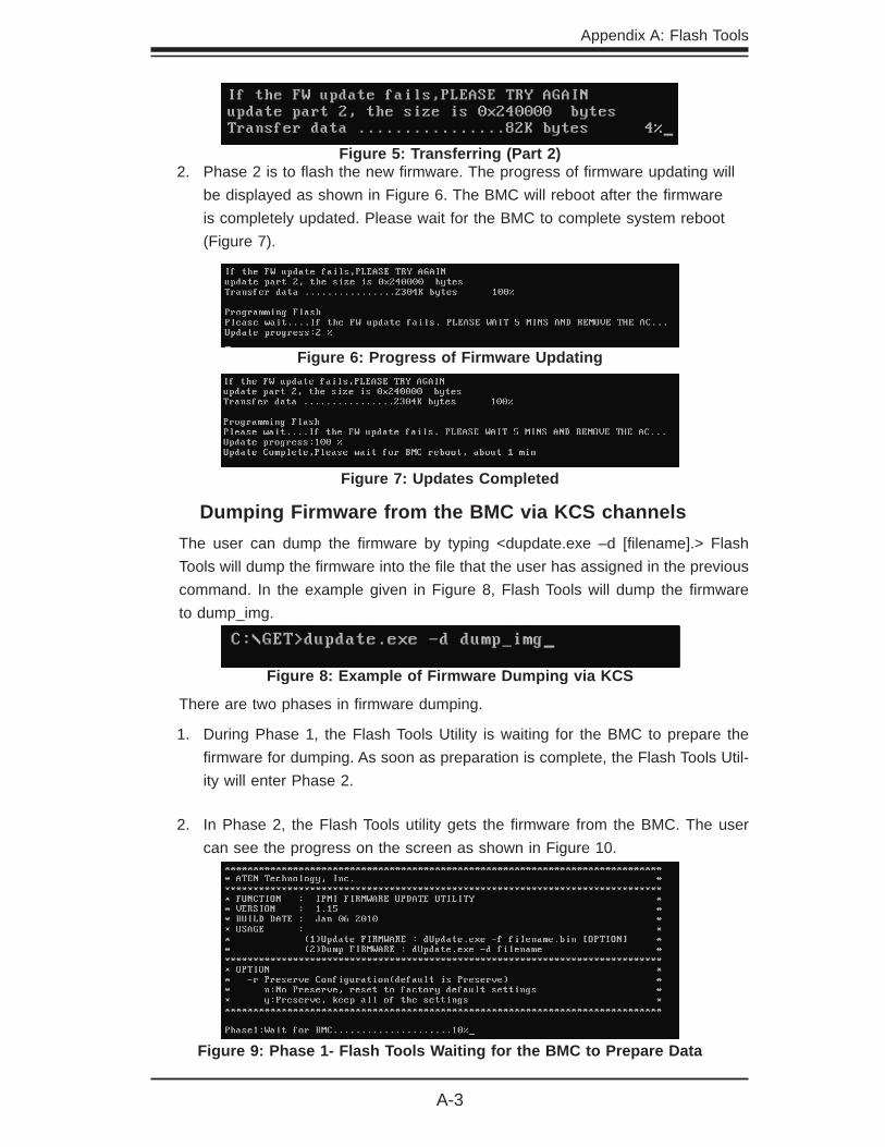
Phase 2 is to fl ash the new fi rmware. The progress of fi rmware updating will 2. be displayed as shown in Figure 6. The BMC will reboot after the fi rmware is completely updated. Please wait for the BMC to complete system reboot (Figure 7).
Figure 5: Transferring (Part 2)
Figure 6: Progress of Firmware Updating
Figure 7: Updates Completed
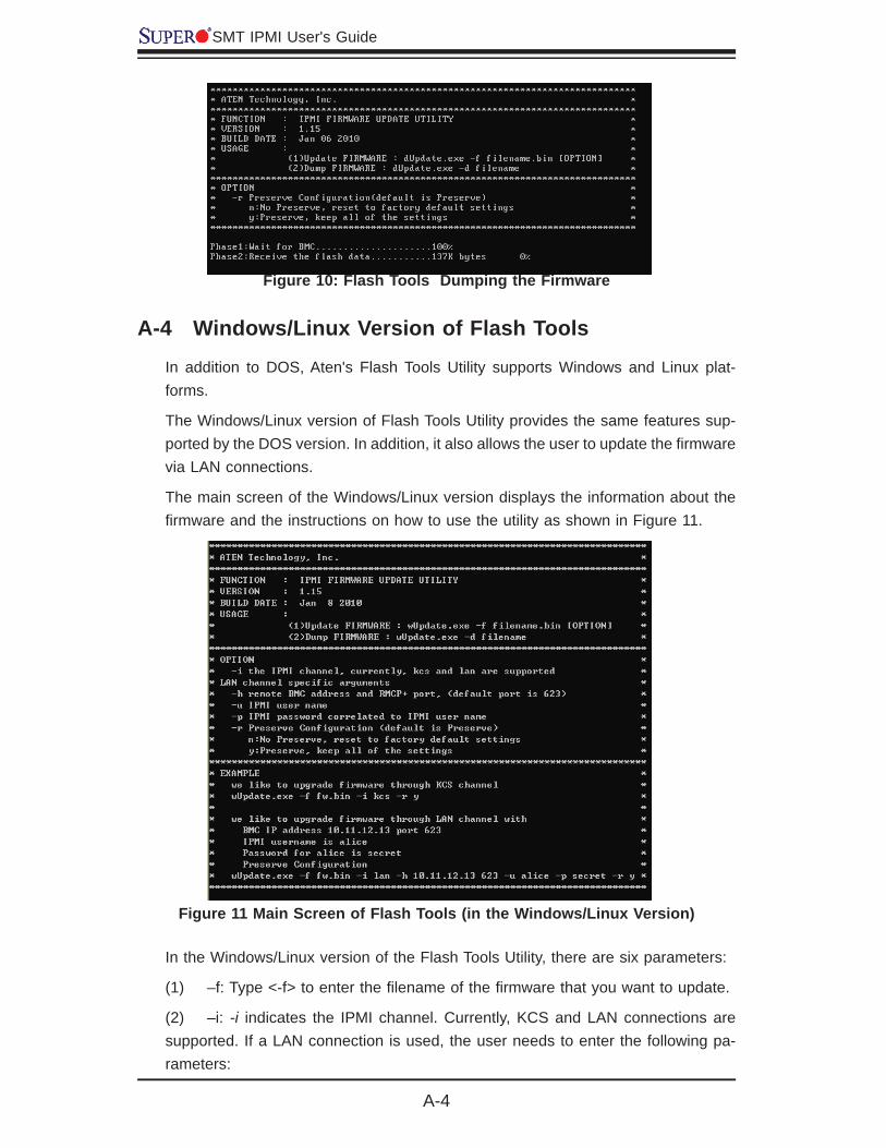
Dumping Firmware from the BMC via KCS channelsThe user can dump the fi rmware by typing <dupdate.exe –d [fi lename].> Flash Tools will dump the fi rmware into the fi le that the user has assigned in the previous command. In the example given in Figure 8, Flash Tools will dump the fi rmware to dump_img.
Figure 8: Example of Firmware Dumping via KCS
There are two phases in fi rmware dumping.
During Phase 1, the Flash Tools Utility is waiting for the BMC to prepare the 1. fi rmware for dumping. As soon as preparation is complete, the Flash Tools Util-ity will enter Phase 2.
In Phase 2, the Flash Tools utility gets the fi rmware from the BMC. The user 2. can see the progress on the screen as shown in Figure 10.
Figure 9: Phase 1- Flash Tools Waiting for the BMC to Prepare Data
SMT IPMI User's Guide
A-4
Figure 10: Flash Tools Dumping the Firmware
In the Windows/Linux version of the Flash Tools Utility, there are six parameters:
(1) –f: Type <-f> to enter the fi lename of the fi rmware that you want to update.
(2) –i: -i indicates the IPMI channel. Currently, KCS and LAN connections are supported. If a LAN connection is used, the user needs to enter the following pa-rameters:
Figure 11 Main Screen of Flash Tools (in the Windows/Linux Version)
A-4 Windows/Linux Version of Flash Tools
In addition to DOS, Aten's Flash Tools Utility supports Windows and Linux plat-forms.
The Windows/Linux version of Flash Tools Utility provides the same features sup-ported by the DOS version. In addition, it also allows the user to update the fi rmware via LAN connections.
The main screen of the Windows/Linux version displays the information about the fi rmware and the instructions on how to use the utility as shown in Figure 11.
A-5
Appendix A: Flash Tools
–h: Type <-h> to enter the addresses of the remote BMC and the RMCP+ 1. port (default port is 623).
–u: Type <-u> to enter the IPMI username.2.
–p: Type <-p> to enter the password for the IPMI user.3.
–r: Type <-r> to preserve (to save) the confi guration settings you've entered. 4. (This feature is optional.) (Default: preserve confi guration.)
-y: Type <-y> for the BMC to keep all settings after updating the fi rmware; 5. otherwise, the BMC will reset the settings to factory default.
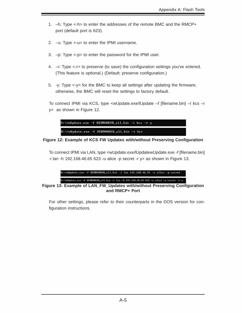
To connect IPMI via KCS, type <wUpdate.exe/lUpdate –f [fi lename.bin] –I kcs –r y> as shown in Figure 12.
Figure 12: Example of KCS FW Updates with/without Preserving Confi guration
Figure 13: Example of LAN_FW_Updates with/without Preserving Confi guration and RMCP+ Port
To connect IPMI via LAN, type <wUpdate.exe/lUpdatewUpdate.exe -f [fi lename.bin] -i lan -h 192.168.46.65 623 -u alice -p secret -r y> as shown in Figure 13.
For other settings, please refer to their counterparts in the DOS version for con-fi guration instructions.

SMT IPMI User's Guide
A-6
Notes
Appendix B: Using SMASH
B-1
Appendix B
Introduction to SMASH
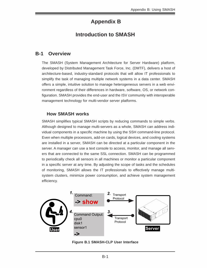
B-1 Overview
The SMASH (System Management Architecture for Server Hardware) platform, developed by Distributed Management Task Force, Inc. (DMTF), delivers a host of architecture-based, industry-standard protocols that will allow IT professionals to simplify the task of managing multiple network systems in a data center. SMASH offers a simple, intuitive solution to manage heterogeneous servers in a web envi-ronment regardless of their differences in hardware, software, OS, or network con-fi guration. SMASH provides the end-user and the ISV community with interoperable management technology for multi-vendor server platforms.
How SMASH worksSMASH simplifi es typical SMASH scripts by reducing commands to simple verbs. Although designed to manage multi-servers as a whole, SMASH can address indi-vidual components in a specifi c machine by using the SSH command-line protocol. Even when multiple processors, add-on cards, logical devices, and cooling systems are installed in a server, SMASH can be directed at a particular component in the server. A manager can use a text console to access, monitor, and manage all serv-ers that are connected to the same SSL connection. SMASH can be programmed to periodically check all sensors in all machines or monitor a particular component in a specifi c server at any time. By adjusting the scope of tasks and the schedules of monitoring, SMASH allows the IT professionals to effectively manage multi-system clusters, minimize power consumption, and achieve system management effi ciency.
Figure B.1 SMASH-CLP User Interface
Command:
-> show1. 2.
User
TransportProtocol
Server
TransportProtocol
3.Command Output:cpu0disk1sensor1
->
4.
SMT IPMI User's Guide
B-2
SMASH Compliance InformationSMASH documented in this user's guide is developed in reference to and in compliance with the SMASH Initiative Standards based on the following DMTF documents.
System Management Architecture for Server Hardware (SMASH) Command • Line Protocol (CLP) Architecture White Paper (DSP 2001)
SM CLP Specifi cation (DSP 0214)•
SM ME Addressing Specifi cations (DSP 0215)•
SM SLP to CIM Common Mapping Specifi cation (DSP 0216)•
Common Information Model (CIM) Infrastructure Specifi cation (DSP0004)•
The Secure Shell (SSH) Protocol Architecture (RFC4251)•
The Secure Shell (SSH) Connection Protocol (RFC4254)•
B-2 An Important Note to the User
The information included in this user's guide provides a general guideline on how to use the SMASH protocol for your system management. Instructions given in this document may or may not be applicable to your system; it depends on the confi guration of the system or the environment it operates in.

Appendix B: Using SMASH
B-3
B-3 Using SMASH
This section provides a general guideline on how to use SMASH for your system management in a web-based environment. Refer to the SMASH script provided below to curtail a server management protocol for your systems.
Note: The instructions listed below are applicable to both Windows and Linux systems. We use the Windows platform as our default setting.
B-4 Initiating the SMASH Protocol
There are two ways of initiating the SMASH protocol.
To Initiate SMASH AutomaticallyYou can initiate SMASH automatically by connecting the BMC (Baseboard Manage-ment Controller) via the Secure Shell protocol (SSH) from a client machine.
To connect from a Linux machine
Use 'ssh<BMC ip address>'.1.
Enter the password.2.
To connect from other machines
Use a terminal emulator application such as 1. Putty.
Enter the 2. BMC ip address in the terminal emulator application.
Choose 3. ssh as the connection type
Enter the password at the prompt.4.
At the prompt '#", enter <SMASH> to invoke the SMASH prompt ' '.5.
If you have successfully logged in, the SMASH prompt will display.6.
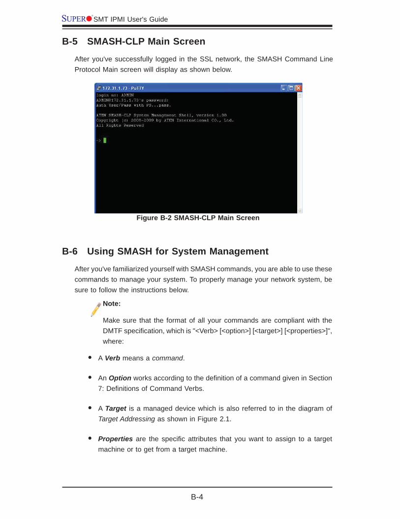
SMT IPMI User's Guide
B-4
B-5 SMASH-CLP Main Screen
After you've successfully logged in the SSL network, the SMASH Command Line Protocol Main screen will display as shown below.
B-6 Using SMASH for System Management
After you've familiarized yourself with SMASH commands, you are able to use these commands to manage your system. To properly manage your network system, be sure to follow the instructions below.
Note:
Make sure that the format of all your commands are compliant with the DMTF specifi cation, which is "<Verb> [<option>] [<target>] [<properties>]", where:
A • Verb means a command.
An • Option works according to the defi nition of a command given in Section 7: Defi nitions of Command Verbs.
A • Target is a managed device which is also referred to in the diagram of Target Addressing as shown in Figure 2.1.
Properties• are the specifi c attributes that you want to assign to a target machine or to get from a target machine.
Figure B-2 SMASH-CLP Main Screen

Appendix B: Using SMASH
B-5
B-7 Defi nitions of Command Verbs
Based on the DSP Specifi cation, each target supports its own set of verbs. These verbs allow the user to issue commands to a target system to perform certain tasks. For example, the verbs supported by the admin target group include: cd, help, load, dump, create, delete, exit, version and show etc.
cd•
The command verb cd is used to navigate to a specifi c target address using the SSL protocol. For example, issuing the command cd/admin1 will direct you to the target admin (AdminDomain).
show•
The command verb show is used to display the properties and the contents of a target, a group of targets, a sub-groups of the target(s). Properties, contents, sup-ported operations related to the target, the group of targets or their sub-targets will be displayed.
exit•
The command verb exit is used when you want to exit from a SMASH session or close a session.
help•
The command verb help is used when you want to get helpful hints or information on a context-specifi c item. This command has the same function as the help option listed for the target group.
Version•
Use the command verb version to display the CLP version used in a specifi c machine.
Figure B-3 Using SMASH for System Management

SMT IPMI User's Guide
B-6
set•
Use the command verb set to assign a set of values to the properties of a target machine.
start•
The command verb start is used to turn on the power control, to start a process, or to change an operation state from a lower level to a higher level in a system.
stop•
The command verb stop is used to turn off the power, to stop a process, or to change an operation state from a higher level to a lower level.
reset•
The command verb reset is used to enable or to disable the power control of or the processes of the machine.
delete•
The command verb delete is used to delete or to destroy an entry or a value previ-ously entered. It can only be used in a specifi c target as defi ned according to the SAMSHCLP Standards.
load•
The command verb load is used to move a binary image fi le from a URI source to the MAP. This command will achieve different results depending on the setting of a target system, and how the verb load is defi ned in the DSP specifi cation used in the system.
dump•
The command verb dump is used to move a binary image fi le from the MAP to a URI source. This command will achieve different results depending on the setting of a target system, and how the verb dump is defi ned in the DSP specifi cation implemented in the system.
create•
The command verb create is used to create a new address entry or a new item in the MAP. It can only be used in a specifi c target as defi ned in the SMASH profi le or in MAP specifi cations.
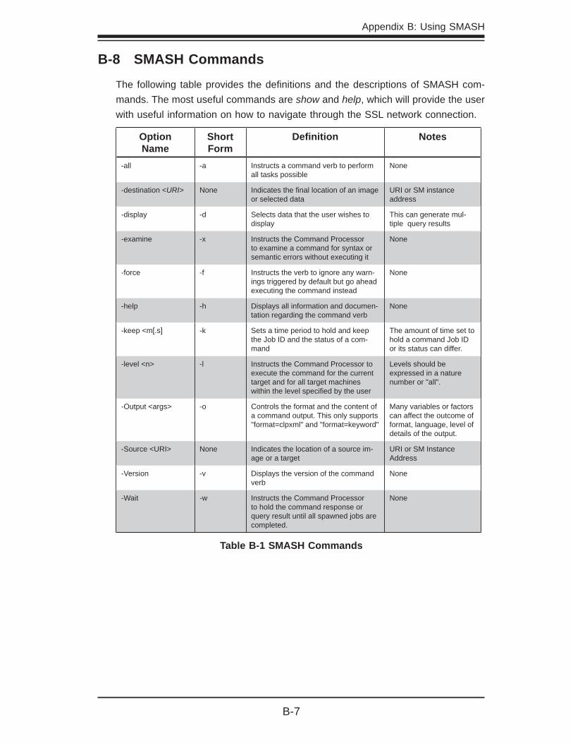
Appendix B: Using SMASH
B-7
B-8 SMASH Commands
The following table provides the defi nitions and the descriptions of SMASH com-mands. The most useful commands are show and help, which will provide the user with useful information on how to navigate through the SSL network connection.
Option Name
Short Form
Defi nition Notes
-all -a Instructs a command verb to perform all tasks possible
None
-destination <URI> None Indicates the fi nal location of an image or selected data
URI or SM instance address
-display -d Selects data that the user wishes to display
This can generate mul-tiple query results
-examine -x Instructs the Command Processor to examine a command for syntax or semantic errors without executing it
None
-force -f Instructs the verb to ignore any warn-ings triggered by default but go ahead executing the command instead
None
-help -h Displays all information and documen-tation regarding the command verb
None
-keep <m[.s] -k Sets a time period to hold and keep the Job ID and the status of a com-mand
The amount of time set to hold a command Job ID or its status can differ.
-level <n> -l Instructs the Command Processor to execute the command for the current target and for all target machines within the level specifi ed by the user
Levels should be expressed in a nature number or "all".
-Output <args> -o Controls the format and the content of a command output. This only supports "format=clpxml" and "format=keyword"
Many variables or factors can affect the outcome of format, language, level of details of the output.
-Source <URI> None Indicates the location of a source im-age or a target
URI or SM Instance Address
-Version -v Displays the version of the command verb
None
-Wait -w Instructs the Command Processor to hold the command response or query result until all spawned jobs are completed.
None
Table B-1 SMASH Commands

SMT IPMI User's Guide
B-8
B-9 Standard Command Options
The following table lists the standard command options.
CLPOption
CLP Verbs
all x
destination x
display x
examine x x x x x x x x x x x x x
force x x x x x x x x
help x x x x x x x x x x x x x
keep
level x
Output x x x x x x x x x x x x x
Source x
Version x x x x x x x x x x x x x
Wait
Table B-2 Standard Command Options
CD
Cre
ate
dele
te
dum
p
exit
help
load
rese
t
set
show
star
t
Stop
vers
ion
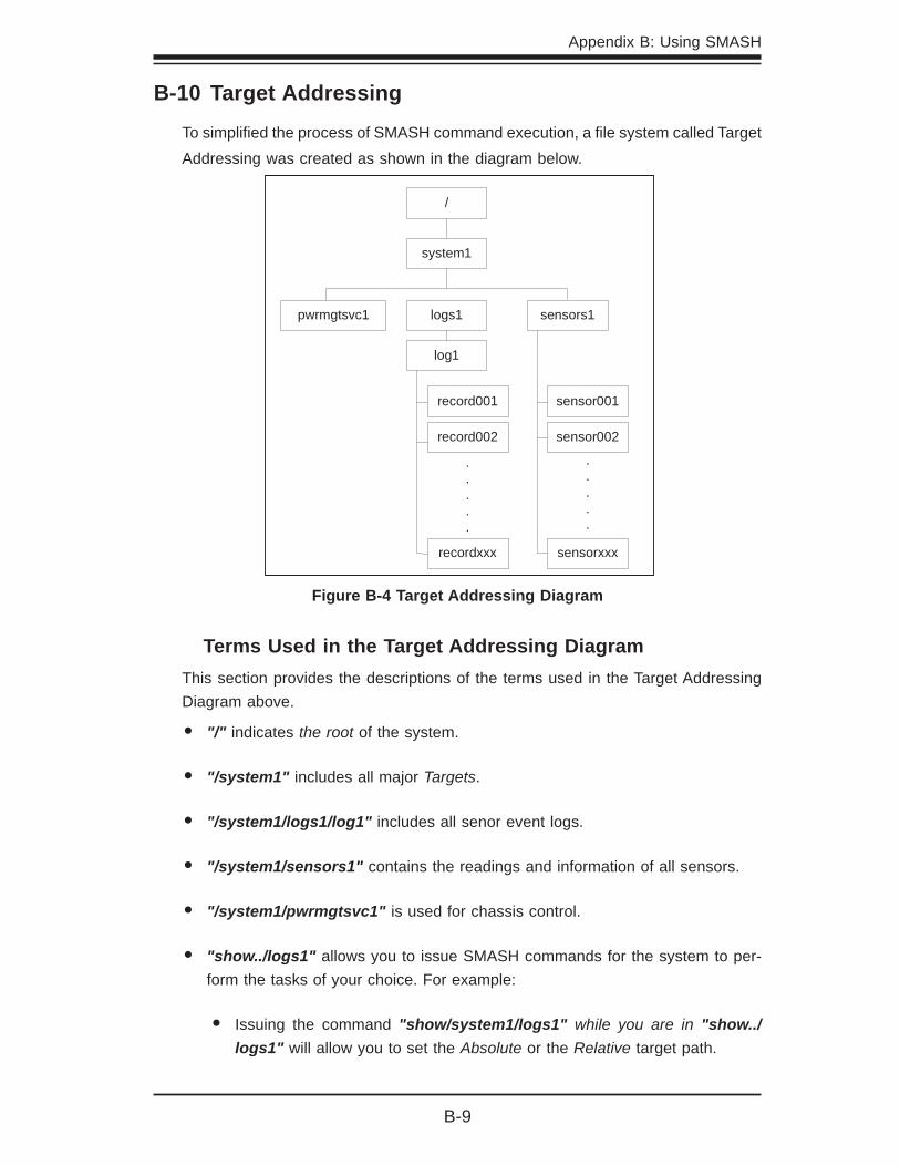
Appendix B: Using SMASH
B-9
/
system1
pwrmgtsvc1 logs1 sensors1
log1
record001
record002
recordxxx
.
.
.
.
.
sensor001
sensor002
.
.
.
.
.
sensorxxx
B-10 Target Addressing
To simplifi ed the process of SMASH command execution, a fi le system called Target Addressing was created as shown in the diagram below.
Figure B-4 Target Addressing Diagram
Terms Used in the Target Addressing DiagramThis section provides the descriptions of the terms used in the Target Addressing Diagram above.
"/"• indicates the root of the system.
"/system1"• includes all major Targets.
"/system1/logs1/log1"• includes all senor event logs.
"/system1/sensors1"• contains the readings and information of all sensors.
"/system1/pwrmgtsvc1"• is used for chassis control.
"show../logs1"• allows you to issue SMASH commands for the system to per-form the tasks of your choice. For example:
Issuing the command• "show/system1/logs1" while you are in "show../logs1" will allow you to set the Absolute or the Relative target path.

SMT IPMI User's Guide
B-10
Notes

Appendix C: Using SMASH
C-1
Appendix C
Using SMASH
This chapter provides a general guideline on how to use SMASH for your system management in a web-based environment. Refer to the SMASH script provided below to curtail a server management protocol for your systems.
Note: The instructions listed below are applicable to both Windows and Linux systems. We use the Windows platform as our default setting.
C-1 Initiating the SMASH Protocol
There are two ways of initiating the SMASH protocol.
To Initiate SMASH AutomaticallyYou can initiate SMASH automatically by connecting the BMC (Baseboard Manage-ment Controller) via the Secure Shell protocol (SSH) from a client machine.
To connect from a Linux machine
Use 'ssh<BMC ip address>'.1.
Enter the password.2.
To connect from other machines
Use a terminal emulator application such as "Putty"1.
Enter the BMC ip address in the terminal emulator application.2.
Choose 'ssh' as the connection type 3.
Enter the password at the prompt.4.
At the prompt '#", enter 'SMASH' to invoke the SMASH prompt ' '.5.
If you have successfully logged in, the SMASH prompt will display.6.

C-2
SMT IPMI User's Guide
C-2 SMASH-CLP Main Screen
After you've successfully logged in the SSL network, the SMASH Command Line Protocol Main screen will display as shown below.
C-3 Using SMASH for System Management
After you've familiarized yourself with SMASH commands, you are able to use these commands to manage your system. To properly manage your network system, be sure to follow the instructions below.
Note:
Make sure that the format of all your commands are compliant with the DMTF specifi cation, which is "<Verb> [<option>] [<target>] [<properties>]", where:
A • "Verb" means a "command".
An • "Option" works according to the defi nition of a command given in Sec-tion C-2 Defi nitions of Command Verbs.
A "• Target" is a managed device which is also referred to in the diagram of "Target Addressing" as shown in Figure 2.1.
"• Properties" are the specifi c attributes that you want to assign to a target machine or to get from a target machine.
Figure C-1 SMASH-CLP Main Screen
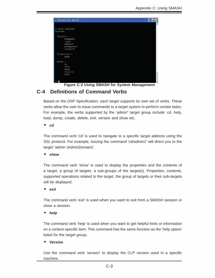
Appendix C: Using SMASH
C-3
C-4 Defi nitions of Command Verbs
Based on the DSP Specifi cation, each target supports its own set of verbs. These verbs allow the user to issue commands to a target system to perform certain tasks. For example, the verbs supported by the 'admin" target group include: cd, help, load, dump, create, delete, exit, version and show etc.
cd•
The command verb 'cd' is used to navigate to a specifi c target address using the SSL protocol. For example, issuing the command 'cd/admin1' will direct you to the target 'admin (AdminDomain)'.
show•
The command verb 'show' is used to display the properties and the contents of a target, a group of targets, a sub-groups of the target(s). Properties, contents, supported operations related to the target, the group of targets or their sub-targets will be displayed.
exit•
The command verb 'exit' is used when you want to exit from a SMASH session or close a session.
help•
The command verb 'help' is used when you want to get helpful hints or information on a context-specifi c item. This command has the same function as the 'help option' listed for the target group.
Version•
Use the command verb 'version' to display the CLP version used in a specifi c machine.
Figure C-2 Using SMASH for System Management

C-4
SMT IPMI User's Guide
set•
Use the command verb 'set' to assign a set of values to the properties of a target machine.
start•
The command verb 'start' is used to turn on the power control, to start a process, or to change an operation state from a lower level to a higher level in a system.
stop•
The command verb 'stop' is used to turn off the power, to stop a process, or to change an operation state from a higher level to a lower level.
reset•
The command verb 'reset' is used to enable or to disable the power control of or the processes of the machine.
delete•
The command verb 'delete' is used to delete or to destroy an entry or a value previ-ously entered. It can only be used in a specifi c target as defi ned according to the SAMSHCLP Standards.
load•
The command verb 'load' is used to move a binary image fi le from a URI source to the MAP. This command will achieve different results, depending on the setting of a target system, and how the verb 'load' is defi ned in the DSP specifi cation used in the system.
dump•
The command verb 'dump is used to move a binary image fi le from the MAP to a URI source. This command will achieve different results, depending on the setting of a target system, and how the verb 'dump' is defi ned in the DSP specifi cation implemented in the system.
create•
The command verb 'create' is used to create a new address entry or a new item in the MAP. It can only be used in a specifi c target as defi ned in the SAMSH profi le or in MAP specifi cations.

Appendix C: Using SMASH
C-5
C-5 SMASH Commands
The following table provides the defi nitions and the descriptions of SMASH com-mands. The most useful commands are "show" and "help", which will provide the user with useful information on how to navigate through the SSL network connec-tion.
Option Name
Short Form
Defi nition Notes
-all -a Instructs a command verb to perform all tasks possible
None
-destination <URI> None Indicates the fi nal location of an image or selected data
URI or SM instance address
-display -d Selects data that the user wishes to display
This can generate mul-tiple query results
-examine -x Instructs the Command Processor to examine a command for syntax or semantic errors without executing it
None
-force -f Instructs the verb to ignore any warnings triggered by default but go ahead executing the command instead
None
-help -h Displays all informa-tion and documentation regarding the command verb
None
-keep <m[.s] -k Sets a time period to hold and keep the Job ID and the status of a command
The amount of time set to hold a command Job ID or its status can differ.
-level <n> -l Instructs the Command Processor to execute the command for the current target and for all target machines within the level specifi ed by the user
Levels should be expressed in a nature number or "all".
-Output <args> -o Controls the format and the content of a com-mand output. This only supports "format=clpxml" and "format=keyword"
Many variables or factors can affect the outcome of format, language, level of details of the output.
-Source <URI> None Indicates the location of a source image or a target
URI or SM Instance Address
-Version -v Displays the version of the command verb
None
-Wait -w Instructs the Command Processor to hold the command response or query result until all spawned jobs are com-pleted.
None
Table C-1 SMASH Commands
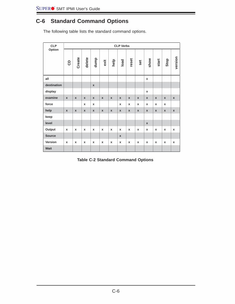
C-6
SMT IPMI User's Guide
C-6 Standard Command Options
The following table lists the standard command options.
CLPOption
CLP Verbs
all x
destination x
display x
examine x x x x x x x x x x x x x
force x x x x x x x x
help x x x x x x x x x x x x x
keep
level x
Output x x x x x x x x x x x x x
Source x
Version x x x x x x x x x x x x x
Wait
Table C-2 Standard Command Options
CD
Cre
ate
dele
te
dum
p
exit
help
load
rese
t
set
show
star
t
Stop
vers
ion
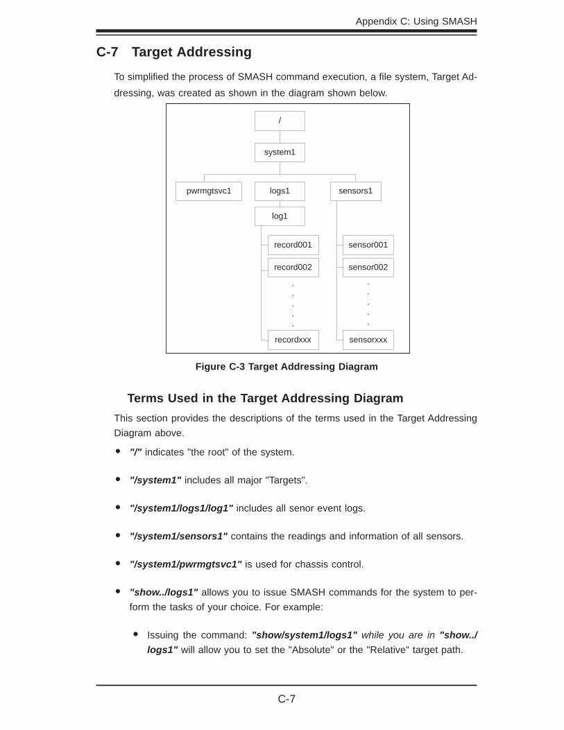
Appendix C: Using SMASH
C-7
/
system1
pwrmgtsvc1 logs1 sensors1
log1
record001
record002
recordxxx
.
.
.
.
.
sensor001
sensor002
.
.
.
.
.
sensorxxx
C-7 Target Addressing
To simplifi ed the process of SMASH command execution, a fi le system, Target Ad-dressing, was created as shown in the diagram shown below.
Figure C-3 Target Addressing Diagram
Terms Used in the Target Addressing DiagramThis section provides the descriptions of the terms used in the Target Addressing Diagram above.
"/"• indicates "the root" of the system.
"/system1"• includes all major "Targets".
"/system1/logs1/log1"• includes all senor event logs.
"/system1/sensors1"• contains the readings and information of all sensors.
"/system1/pwrmgtsvc1"• is used for chassis control.
"show../logs1"• allows you to issue SMASH commands for the system to per-form the tasks of your choice. For example:
Issuing the command:• "show/system1/logs1" while you are in "show../logs1" will allow you to set the "Absolute" or the "Relative" target path.
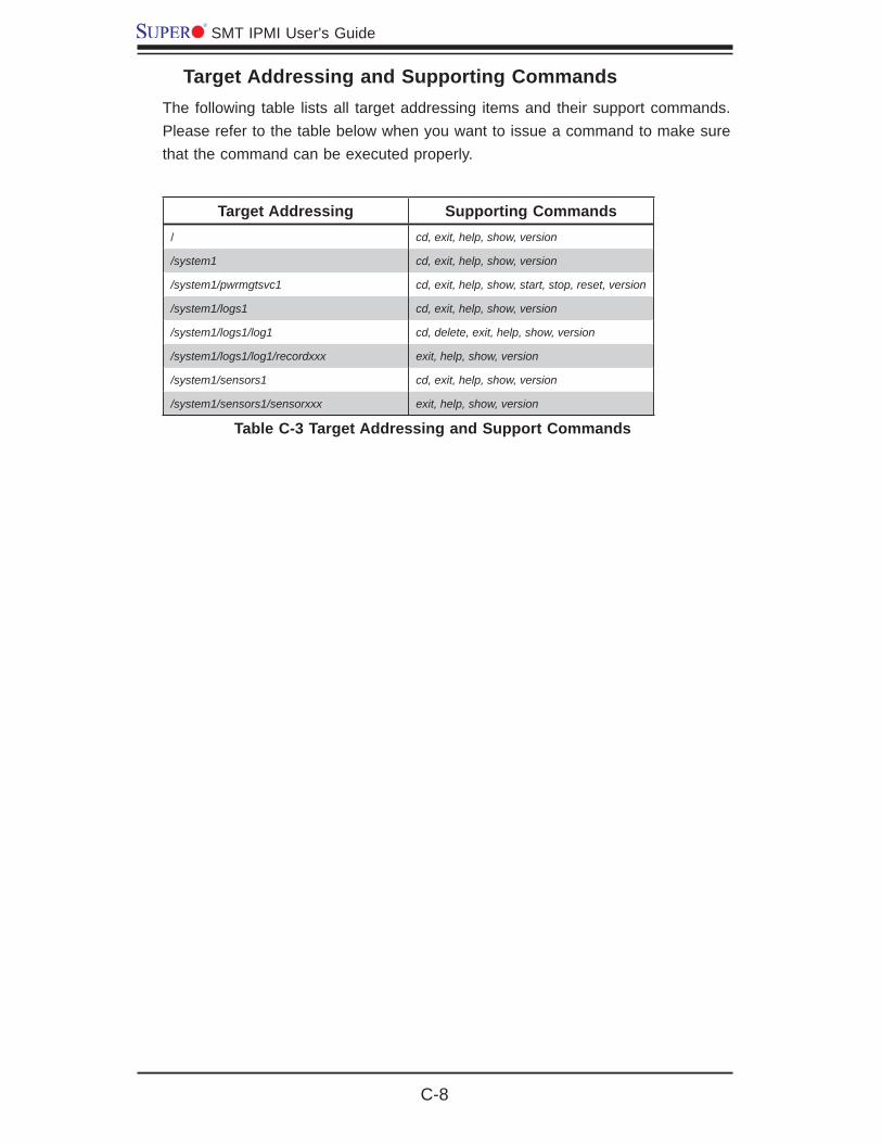
C-8
SMT IPMI User's Guide
Target Addressing and Supporting CommandsThe following table lists all target addressing items and their support commands. Please refer to the table below when you want to issue a command to make sure that the command can be executed properly.
Target Addressing Supporting Commands/ cd, exit, help, show, version
/system1 cd, exit, help, show, version
/system1/pwrmgtsvc1 cd, exit, help, show, start, stop, reset, version
/system1/logs1 cd, exit, help, show, version
/system1/logs1/log1 cd, delete, exit, help, show, version
/system1/logs1/log1/recordxxx exit, help, show, version
/system1/sensors1 cd, exit, help, show, version
/system1/sensors1/sensorxxx exit, help, show, version
Table C-3 Target Addressing and Support Commands

(Disclaimer Continued)
The products sold by Supermicro are not intended for and will not be used in life support systems, medical equipment, nuclear facilities or systems, aircraft, aircraft devices, aircraft/emergency communication devices or other critical systems whose failure to perform be reasonably expected to result in signifi cant injury or loss of life or catastrophic property damage. Accordingly, Supermicro disclaims any and all liability, and should buyer use or sell such products for use in such ultra-hazardous applications, it does so entirely at its own risk. Furthermore, buyer agrees to fully indemnify, defend and hold Supermicro harmless for and against any and all claims, demands, actions, litigation, and proceedings of any kind arising out of or related to such ultra-hazardous use or sale.