SMR TT HYBRID GLENOID - Link Sweden
52
SMR TT HYBRID GLENOID
-
Upload
khangminh22 -
Category
Documents
-
view
2 -
download
0
Transcript of SMR TT HYBRID GLENOID - Link Sweden

SMR TTHYBRID GLENOID


LEONARDO DA VINCI: Vitruvian Man. Study of the proportions of the human body (1490).
Limacorporate S.p.A., as manufacturer of prosthetic devices, does not practice medicine. This surgical technique brochure has been developed in consultation with an experienced surgeons team
and provides the surgeon with general guidance when implanting SMR TT Hybrid Glenoid.Proper surgical procedures and techniques are necessarily the responsibility of the medical
professional. Each surgeon must evaluate the appropriateness of the surgical technique used based on personal medical training, experience and clinical evaluation of each individual patient.
For further information about our products, please visit our web site at www.limacorporate.com
This brochure describes the SMR TT Hybrid Glenoid components. For the complete set of products and combinations of the SMR Shoulder System refer to the dedicated brochures.
Please check the codes list for the availability of products in your market.
The symbol allows to distinguish the products NOT available in the US.
SMR TT HYBRID GLENOID Surgical Technique 3
SMR TT HYBRID GLENOID SURGICAL TECHNIQUE
Index
Indications, Contraindications, Warnings and Risk Factors pag. >> 6
Introduction pag. >> 10
SMR TT HYBRID GLENOID SURGICAL TECHNIQUE
Glenoid Preparation pag. >> 13
Final Implant pag. >> 18
Conversion and Revision Technique pag. >> 19
INSTRUMENT SET pag. >> 29
PRODUCT CODES pag. >> 36

SMR TT HYBRID GLENOID Surgical Technique 5
SMR TT HYBRID GLENOID SURGICAL TECHNIQUE
The SMR Shoulder System is a modular shoulder platform
that was introduced on the European market in 2002.
The system offers interchangeable components, allowing
the surgeon to choose different configuration solutions in
resurfacing, fracture replacement, total shoulder, reverse
shoulder or revision surgeries.
The SMR TT Hybrid Glenoid is a glenoid component
composed of a polyethylene baseplate connected to a
central peg made of Trabecular Titanium. The baseplate
has two peripheral pegs intended to be cemented into the
native glenoid. The SMR TT Hybrid Glenoid is available
in different sizes of baseplate and peg. In case of the
baseplate 3 sizes are available (Small, Standard and
Large), and each one is in turn provided with two radii
of curvature options (standard and low mismatch) and
different thicknesses, to allow a better soft tissue tensioning.
If an SMR TT Hybrid Glenoid is in place and revision to a
reverse prosthesis is required, the prosthesis can be revised
by removing the polyethylene baseplate, leaving the metal
peg in place and by connecting it to the SMR TT Hybrid
Glenoid Reverse Baseplate. The SMR TT Hybrid Glenoid
Reverse Baseplate is intended for uncemented use with the
addition of screws for fi xation. Refer to the IFU for complete
descriptions of indications for use.
SMR TTHYBRID GLENOID

6 Surgical Technique SMR TT HYBRID GLENOID
SMR TT HYBRID GLENOID SURGICAL TECHNIQUE
Indications, Contraindications, Warnings and Risk Factors
INDICATIONS
The SMR TT Hybrid Glenoid is intended for total shoulder
joint replacement in patients suffering from disability due to:
• non-infl ammatory degenerative joint disease including
osteoarthritis and avascular necrosis;
• inflammatory degenerative joint disease such as
rheumatoid arthritis;
• glenoid arthrosis without excessive glenoid bone loss:
A1, A2 and B1 according to Walch classifi cation.
The SMR Reverse Shoulder System is indicated for primary,
fracture or revision total shoulder replacement in a grossly
deficient rotator cuff with severe arthropathy (disabled
shoulder). The patient’s joint must be anatomically and
structurally suited to receive the selected implants and a
functional deltoid muscle is necessary to use the device.
The SMR TT Hybrid Glenoid Reverse Baseplate must not be
used in cases of excessive glenoid bone loss and/or when
bone graft is needed.
The peripheral pegs of the SMR TT Hybrid Glenoid are
intended for fi xation by means of cement.
SMR TT Hybrid Glenoid is intended to be used if an
anatomical prosthesis is required. If an SMR TT Hybrid
Glenoid is in place and revision to a reverse prosthesis
is required, the patient can be revised by removing the
polyethylene baseplate and connecting the SMR TT Hybrid
Glenoid Reverse Baseplate to the intact, well fi xed TT Peg.
The SMR TT Hybrid Glenoid Reverse Baseplate is intended
for uncemented use with the addition of screws for fi xation.
In both cases on the humeral side all the components of
the SMR System can be used according to the clinical case
and their indication.
Please follow the instructions for use enclosed in the product packaging.

SMR TT HYBRID GLENOID Surgical Technique 7
SMR TT HYBRID GLENOID SURGICAL TECHNIQUEIndications, Contraindications, Warnings and Risk Factors
System UseAvai labi l i ty
in USAnatomic Reverse Components Mater ia l Cem Not Cem
• • SMR Stems (Cemented, Cemented Revis ion) T i6Al4V X •
• • SMR Stems (Cement less F inned, Cement less Revis ion) T i6Al4V X •
• • SMR Large Resect ion Stems T i6Al4V X
• • S MR Modular Augments T i6Al4V X •
• SMR Humeral Bodies (Trauma, F inned) T i6Al4V X X •
• • SMR Reverse Humeral Bodies T i6Al4V X X •
• • SMR Reverse HA Coated Humeral Body T i6Al4V X X
• • SMR Humeral Extension T i6Al4V X X •
• SMR Humeral Heads (Standard, CTA)CoCrMo X X •
T i6Al4V X X
• SMR Adaptor Tapers (Neutra l , Eccentr ica l ) T i6Al4V X X •
• SMR CTA Head Adaptor for Reverse Humeral Body T i6Al4V X X •
• SMR Glenospheres
CoCrMo X •
T i6Al4V X
UHMWPE X-L ima+T i6A l4V X
• SMR Connectors T i6A l4V X •
• SMR Reverse L iners
UHMWPE X X •
UHMWPE X-Lima X X
CoCrMo X X
Alumina X X
• SMR Cemented Glenoids UHMWPE X •
• SMR 3-Pegs Cemented G leno ids U H M W PE X •
UHMWPE X-Lima X
• •* SMR T T Hybr id G leno id UHMWPE+T i6Al4V+Tanta lum X X •
• SMR T T Hybr id G leno id Basep la te + Screw T i6Al4V X •
• • SMR Meta l Back G leno ids T i6Al4V+PoroT i X* X* •
T i6Al4V+PoroT i+HA X •
• • SMR T T Meta l Back Basep la te T i6Al4V X* X* •
• • SMR T T Meta l Back Peg T i6Al4V X* X* •
• SMR Meta l Back L ine r UHMWPE X* X* •
•* • SMR Bone Screws T i6Al4V X •
• SMR G leno id P la tes T i X
Mater ia l Standards
T i6A l4V ( ISO5832-3 – ASTM F1472) – CoCrMo ( ISO5832-12 – ASTM F1537 ) – T i (ASTM F67 ) – UHMWPE ( ISO5834-2 – ASTM F648) – A lumina ( ISO6474) – PoroT i Coat ing (ASTM F1580) – HA Coat ing ( ISO13779) – Tanta lum (ASTM F560 / ISO13782)

8 Surgical Technique SMR TT HYBRID GLENOID
SMR TT HYBRID GLENOID SURGICAL TECHNIQUE
Indications, Contraindications, Warnings and Risk Factors
*NOTE:• In the US, the SMR Metal Backed Glenoid/Liner
construct, used as part of the SMR Anatomic Shoulder
Replacement, is intended for use with bone cement and
should be used without bone screws.
• The SMR Metal Backed Glenoid/Connector/Glenosphere
construct, used as part of the SMR Reverse Shoulder
replacement, is intended for uncemented use with the
addition of screws for fixation.
• If an SMR TT Hybrid Glenoid is in place and revision to a
reverse prosthesis is required, the patient can be revised
by removing the polyethylene baseplate and connecting
the SMR TT Hybrid Glenoid Reverse Baseplate to the
intact, well fi xed TT Peg. The SMR TT Hybrid Glenoid
Reverse Baseplate is intended for uncemented use with
the addition of screws for fi xation.
• The Dia. 52 and 54 mm Humeral Heads with
+ 2mm increased height cannot be coupled to the Long
Adaptor Tapers (both concentric and eccentric).
The radial mismatches on coupling between the different
sizes of the SMR TT Hybrid Glenoid and the humeral heads
of the SMR System are shown in the following table.
R[m m]
Humeral Heads R [mm]
2 0( D i a 4 0 )
2 1( D i a 42 )
2 2( D i a 4 4 )
2 3( D i a 4 6 )
24( D i a 4 8 )
2 5( D i a 5 0 )
2 6( D i a 52 )
2 7( D i a 5 4 )
Smal l Low 27 7 6 5 4 3 2 1 0
Smal l 3 2 . 5 12 . 5 11. 5 10 . 5 9 . 5 8 . 5 7. 5 6 . 5 5 . 5
Standard Low 2 9 9 8 7 6 5 4 3 2
Standard 3 5 15 14 13 12 11 10 9 8
Large Low 31 11 10 9 8 7 6 5 4
Large 37. 5 17. 5 16 . 5 15 . 5 14 . 5 13 . 5 12 . 5 11. 5 10 . 5
GL
EN
OID
S
NOTE: Red couplings: not allowed.

SMR TT HYBRID GLENOID Surgical Technique 9
SMR TT HYBRID GLENOID SURGICAL TECHNIQUEIndications, Contraindications, Warnings and Risk Factors
CONTRAINDICATIONS
Absolute contraindications include:
• local or systemic infection;
• septicemia;
• persistent acute or chronic osteomyelitis;
• confirmed nerve lesion compromising shoulder joint
function;
• deltoid muscle insufficiency;
Relative contraindications include:
• vascular or nerve diseases affecting the concerned limb;
• poor bone stock (for example osteoporosis or extended
previous revision surgery) compromising the stability of
the implant;
• metabolic disorders which may impair fixation and
stability of the implant;
• any concomitant disease and dependence that might
affect the implanted prosthesis;
• metal hypersensitivity to implant materials.
RISK FACTORS
The following risk factors may result in poor results with
this prosthesis:
• overweight (elevated BMI);
• strenuous physical activities (active sports, heavy
physical work);
• fretting of modular junctions;
• incorrect implant positioning;
• muscle deficiencies;
• multiple joint disabilities;
• refusal to modify postoperative physical activities;
• patient history of infections or falls;
• systemic diseases and metabolic disorders;
• local or disseminated neoplastic diseases;
• drug therapies that adversely affect bone quality, healing,
or resistance to infection;
• drug use or alcoholism;
• marked osteoporosis or osteomalacia;
• patient’s resistance to disease generally weakened (HIV,
tumour, infections);
• severe deformity leading to impaired anchorage or
improper positioning of implants;
• osteolysis.
The shoulder must be positioned off the edge of the table to
afford unobstructed arm extension.

10 Surgical Technique SMR TT HYBRID GLENOID
SMR TT HYBRID GLENOID SURGICAL TECHNIQUE
PREOPERATIVE PLANNING
Standard X-rays are used to assist with planning of the
operation. It is recommended to use a normal AP-view in
internal and external rotation as well as an axillary view,
Bernageau or Morrison view. It is recommended to use
a CT-Scan in fracture cases and for planning the glenoid
insertion.
If required an MRI can be used to quantify the extent of
the bone deficiency and to see the muscle/capsule quality.
In post-traumatic cases, such as in special cases of
disabling shoulder, a neurological exam is helpful for
decision making.
Templates are used in all osteoarthritic cases; they can
also be used in fracture cases but often in a limited mode,
depending on the type of fracture.
The X-ray templates provided for SMR have a 105% scale;
digital templates are available as well.
ANESTHESIA
Shoulder surgery is one of the areas in which an
understanding of the surgery and participation by the
anaesthesiologist is especially important for the outcome of
the surgery. This applies to accurate preoperative evaluation
of the patient as well as intra op techniques.
They should have a good understanding of positioning on
the operating table and postoperative pain management.
Shoulder prosthetic replacement can be performed with
regional anaesthesia combined with sedation and/or with
general anaesthesia.
The modern technique of interscalea block was introduced
by Winnie in 1970 and soon became the standard for
anaesthesia and postoperative pain management in
shoulder surgery.
Requested surgical positioning (beach chair position) must
be accurately followed by the anaesthetic staff to avoid
hypotension and consecutive brain hypoperfusion.
POSITIONING
Shoulder arthroplasty is normally performed in a “beach-
chair” position; the surgeon needs complete access to
the shoulder joint. The arm is free or stabilized by arm-
holders. The shoulder must be positioned off the edge of
the table to afford unobstructed arm extension.
The patient’s head must be supported and stabilized in
the neutral position. Nerve injury due to brachial plexus
traction during positioning and surgery must be avoided.
If possible, one assistant should stay behind the shoulder,
the second on the opposite side of the patient, so that the
surgeon has a complete anterior view of the shoulder and
can move the joint without any obstacle.
Introduction

SMR TT HYBRID GLENOID Surgical Technique 11
SMR TT HYBRID GLENOID SURGICAL TECHNIQUEIntroduction
ACCESS
We recommend two types of surgical approaches to the
shoulder joint. As in every surgical procedure, the access
depends not only on diagnosis and planned surgical
treatment but also on the experience of the surgeon.
Ranges of glenohumeral motion are evaluated with the
patient under anaesthesia to confirm the preoperative
assessment and the extent of capsular release needed to
restore the ROM postoperatively.
DELTO-PECTORAL APPROACH
Anterior vertical incision, starting 1 cm laterally of the
coracoid bone, slanting towards the axillary’s pouch.
If there is a metaphysal fracture, slanting laterally towards
the deltoid insertion at the humerus. The cephalic vein is
retracted laterally with the deltoid muscle.The clavipectoral
fascia is incised along the lateral edge of the conjoined
tendon up to the coracoacromial ligament.
With the clavipectoral fascia incised, a retractor can
easily be placed over the superolateral aspect of the
humeral head to retract the deltoid. The conjoined
tendon is retracted medially.
The musculocutaneous nerve penetrates the lateral
coracobrachialis muscle 3 to 8 cm distally of the tip
of the coracoid process. The position of the axillary
nerve should be indentified along the anterior surface
of the subscapularis muscle, below the conjoined
tendon. The axillary nerve crosses the inferolateral
border of the subscapularis 3 to 5 mm medially of
its musculotendinous junction and has an intimate
anatomic relation with the inferior capsule of the
shoulder joint.
The anterior humeral circumflex artery and veins are
visualized, ligated and divided.
The subscapularis tendon is released, divided 1 cm
medially to its attachment or with some bone chip of the
lesser tuberosity. Separation of the subscapularis from
the capsule and incision of the capsule is performed
to the inferior border of the glenoid rim, protecting
the axillary nerve with a blunt retractor. Release of the
subscapularis and 360° capsular release.
Closure. In fracture cases, accurate reconstruction of the
lesser and major tuberosities by suture, bone anchors or
cerclage is reccomended.
If the long head of the biceps tendon is intact, reconstruct
also the biceps groove to avoid impingement. Closure of
delto-pectoral groove.
12 Surgical Technique SMR TT HYBRID GLENOID
SMR TT HYBRID GLENOID SURGICAL TECHNIQUE
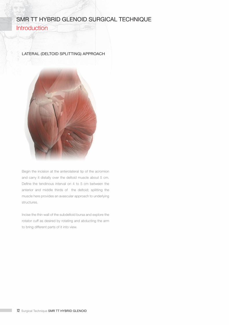
LATERAL (DELTOID SPLITTING) APPROACH
Begin the incision at the anterolateral tip of the acromion
and carry it distally over the deltoid muscle about 5 cm.
Define the tendinous interval on 4 to 5 cm between the
anterior and middle thirds of the deltoid; splitting the
muscle here provides an avascular approach to underlying
structures.
Incise the thin wall of the subdeltoid bursa and explore the
rotator cuff as desired by rotating and abducting the arm
to bring different parts of it into view.
Introduction

SMR TT HYBRID GLENOID Surgical Technique 13
SMR TT HYBRID GLENOID SURGICAL TECHNIQUESMR TT HYBRID GLENOID SURGICAL TECHNIQUEGlenoid Preparation
� EXPOSURE OF THE GLENOID
For a correct glenoid preparation an adequate glenoid
exposure is required. The fukuda (N33) and the glenoid
retractor (I33) are included into the Glenoid set.
Any peripheral osteophytes should be removed to restore
the natural anatomic shape of the glenoid. During this
phase be careful since the axillary nerve is close to the
inferior edge of the glenoid.
INSERTION OF THE GUIDE WIRE
For the glenoid preparation use a long 2.5 mm dia. guide
wire (not included in the instrument set).
The K-Wire can be positioned in place by using the K-Wire
position jig (H33) and handle (G33) (Figure 1).
The direction taken by the guide wire will determine the
version of the glenoid component. Therefore, a preoperative
CT Scan or MRI is useful to evaluate any deformities in the
articular surface. Any corrections in the wire direction should
be made at this point, correction is more difficult once the
surface is reamed and/or the pegs are drilled.
Figure 1Figure 1

14 Surgical Technique SMR TT HYBRID GLENOID
SMR TT HYBRID GLENOID SURGICAL TECHNIQUE
Glenoid Preparation
PREPARATION OF GLENOID SURFACE
Once the K-wire has been inserted, remove the K-wire
positioning jig and handle. Connect the glenoid reamer
(E33) of the proper size to the reamer shaft (J33) (Figure 2)
and ream the glenoid carefully (Figure 3).
Ream carefully to avoid glenoid fractures. The aim of the
reaming is just to remove the cartilage and expose the
subchondral bone rather than excessive bone removal.
Remove the reamer leaving the K-wire in place and proceed
with the preparation of the central hole by using the glenoid
drill (A77) connected to the reamer shaft (J33) (Figure 4).
Drill on the guide wire, until the reamer baseplate touches
the subchondral bone (Figure 5).
Figure 3
Figure 2
Figure 5
Figure 4

SMR TT HYBRID GLENOID Surgical Technique 15
SMR TT HYBRID GLENOID SURGICAL TECHNIQUESMR TT HYBRID GLENOID SURGICAL TECHNIQUEGlenoid Preparation
Connect the glenoid drill guide (C77) of the proper size
to the quick connection handle (B77) (Figure 6) and
introduce it into the glenoid cavity by using the K-wire as
guide (Figure 7).
The glenoid drill guide has a central peg which is intended
to fi t in the previously prepared hole in the glenoid in order
to increase the device stability.
Drill the fi rst peripheral hole by using the quick connection
drill dia. 5 mm (E77) connected to the power tools by
means of the quick connection driver (D77). Disconnect
the quick connection shaft from the drill and leave the drill
in situ (as described in the previous step) while drilling the
second hole to stabilize the jig (Figure 8).
Remove the quick connection drills, the glenoid drill guide
and the K-Wire. If required, compact the central hole by
using the compactor (G77) connected to the compactor
handle (F77).
Figure 6
Figure 7
Figure 8Figure 8

16 Surgical Technique SMR TT HYBRID GLENOID
SMR TT HYBRID GLENOID SURGICAL TECHNIQUE
INSERTION OF THE TRIAL IMPLANT
Complete the preparation of the peripheral pegs by using
the countersink (J77) (Figure 9). The aim of this step is to
remove some bone that will otherwise make difficult the
proper seating of the final implants.
Choose the proper size of the trial glenoid (H77) according
to the clinical case and the prepared seat on the glenoid
(Figure 10).
The trial glenoids have color codes according to the
following table.
To remove the trial component use the removal pliers
(I77) by connecting them into the grooves of the trial
components.
.
Glenoid Preparation
Figure 9 Figure 10
SIZE COLOR CODE
Small Low
Small Low +2
Small
Small +2
Standard Low
Standard Low +2
Standard
Standard +2
Large Low
Large Low +2
Large
Large +2
Figure 9

SMR TT HYBRID GLENOID Surgical Technique 17
SMR TT HYBRID GLENOID SURGICAL TECHNIQUESMR TT HYBRID GLENOID SURGICAL TECHNIQUEGlenoid Preparation
INSERTION OF THE FINAL IMPLANT
Remove the SMR TT Hybrid Glenoid of the correct size
(according to the trial implant) from the sterile packaging.
Connect the central peg protector (L77) to the quick
connection handle (B77) (Figure 11) and introduce it into
the central hole (Figure 12), then remove the handle. The
aim of this step is to prevent cement penetration during the
cement compaction phase.
Place the acrylic cement in the peripheral holes
(Figure 13) and compact it by means of the cement
compactor of the proper size (K77) connected to the
compactor handle (F77) (Figure 14). The aim of this phase is
to pressurize the cement. If more compaction is required,
repeat the previous steps.
Note. Make sure that no cement is present at the interface
between glenoid face and backside of the implant.
Figure 11
Figure 12
Figure 13
Figure 14
Figure 13

18 Surgical Technique SMR TT HYBRID GLENOID
SMR TT HYBRID GLENOID SURGICAL TECHNIQUE
Final Implant
Use the glenoid positioner (M77) of the proper size
(according to the chosen final implant) connected to the
quick connection handle (B77) to position the SMR TT
Hybrid Glenoid on the glenoid cavity (Figure 15).
Note. This instrument is not intended for impaction of the
SMR TT Hybrid Glenoid device, which is impacted in the
following step using a dedicated instrument.
Note. Be sure that the two pegs are aligned with prepared
holes filled of cement.
Disconnect the positioning device from the SMR TT
Hybrid Glenoid by sliding it anteriorly and check that the
peripheral pegs are aligned with the peripheral holes into
the glenoid. Impact the SMR TT Hybrid Glenoid by using
the glenoid pusher (O77) connected to the handle of the
glenoid impactor handle (N77) until the device is fully seated
(Figure 16).
The glenoid pushers are available in two sizes and are
color coded according to SMR TT Hybrid Glenoid radius
of curvature: grey glenoid pusher is intended to be used in
case of regular mismatches, instead the yellow one in case
of low mismatches sizes.
In case of hard bone the retentive glenoid pusher (P77) can
be used to impact the SMR TT Hybrid Glenoid. Completely
surrounding the SMR TT Hybrid Glenoid, the retentive
Figure 15 Figure 16

SMR TT HYBRID GLENOID Surgical Technique 19
SMR TT HYBRID GLENOID SURGICAL TECHNIQUESMR TT HYBRID GLENOID SURGICAL TECHNIQUEConversion and Revision Technique
glenoid pusher allows to impact the component according
to his main axis, preventing impingement or misalignment
that could compromize implant proper seating in case of
hard bone.
Complete the surgical technique steps according to the
SMR Anatomic surgical technique.
POLYETHYLENE BASEPLATE REMOVAL
In the case of a conversion from anatomic to reverse, or
revision of the SMR TT Hybrid Glenoid, the first step is
to disconnect the polyethylene baseplate from the central
peg.
Connect the removal guide (A79) of the proper size to the
removal guide handle (D79) (Figure 17) and position it on the
SMR TT Hybrid Glenoid surface.
The guide has a central pin which is intended to fit into
the central hole of the polyethylene baseplate, in order to
center the guide (Figure 18).
Fix the removal guide to the baseplate by means of two
headless twisted pins (B79) (Figure 19). The pins have laser
marks to indicate the sinking. Be sure that the pins are
inserted only into the polyethylene not on the bone. Ensure
that the jig is positioned perpendicular to the glenoid
baseplate surface.
Figure 18
Figure 19
Figure 17

20 Surgical Technique SMR TT HYBRID GLENOID
SMR TT HYBRID GLENOID SURGICAL TECHNIQUE
Conversion and Revision Technique
Remove the removal guide handle, connect the quick
connection handle (E79) and drill the central hole by
using the removal drill (C79) (Figure 20) connected to the
power tools.
The removal drill has a stopper that allows to drill the
polyethylene at the proper depth to prevent TT peg
damaging; ensure that the stopper is properly set
according to the size (thickness) of the baseplate.
Note. In the case that the polyethylene baseplate is deformed
or damaged due to in vivo wear, please proceed carefully
during the drilling phase, by verifying step-by-step if the
bottom of the peg has been reached.
To disconnect the baseplate from the TT peg (Figure 22)
remove the removal drill and screw the baseplate extractor
(F79) into the polyethylene by using the removal guide as
stopper (Figure 21).
Note. A small amount of pressure should be applied initially to
the baseplate extractor so that it engages the polyethylene.
Note. While screwing the baseplate extractor on the
baseplate, the quick connection handle can be used as
counter torque.
In case of complete revision of the SMR TT Hybrid Glenoid
move to the section dedicated to the central peg removal.
Figure 20
Figure 22
Figure 21
Figure 22
Figure 21

SMR TT HYBRID GLENOID Surgical Technique 21
SMR TT HYBRID GLENOID SURGICAL TECHNIQUESMR TT HYBRID GLENOID SURGICAL TECHNIQUEConversion and Revision Technique
CONVERSION
If a reverse prosthesis is required, after the polyethylene
baseplate removal, check the stability of the central
peg before proceeding. Improper fi xation of the TT
peg could affect the stability of reverse confi guration.
If the TT peg is not stable and the tissue ingrowth is not
guaranteed, proceed with peg removal (see dedicated
section).
Note. After removal of the polyethylene baseplate, if one of
the following conditions arises move to a dedicated device,
like the TT Metal Back:
• Peg not properly seated into the cavity, that comes
out from the glenoid surface;
• Bone loss;
• Bone graft required.
Screw the guide for conversion glenoid reamer (I79) into the
TT peg (Figure 23) by means of the quick connection handle
(E79). Connect the conversion glenoid reamer (H79) to the
T-handle with Zimmer connection (G79) and carefully ream
the glenoid surface (Figure 24).
Figure 23
Ensure cement removal from
peripheral pegs holes
Figure 24
Conversion and Revision Technique

22 Surgical Technique SMR TT HYBRID GLENOID
SMR TT HYBRID GLENOID SURGICAL TECHNIQUE
Conversion and Revision Technique
Figure 25 Figure 26
The aim of this step is to remove cement remains or some
osteophytes that can impair the proper seating of the
reverse baseplate on the TT peg. This step is mandatory
for any SMR TT Hybrid Glenoid Reverse Baseplate. The
conversion glenoid reamer has the same radius of curvature
as the reverse baseplate. This allows one to prepare the
glenoid surface so as to achieve a proper seating of the
reverse baseplate and to avoid any bone/tissue impingement
with it.
Central to the reaming phase is the guide for conversion
glenoid reamer which is connected to the peg. The guide
for conversion glenoid reamer has been developed to work
as a stopper, to allow a proper reaming and cleaning of
the glenoid surface, and to prevent possible peg damage
due to reaming phase. Once fi nished, remove the guide for
conversion glenoid reamer from the peg.
Note. After the reaming phase, before introducing the
reverse baseplate, check that the inner taper of the peg is
not damaged or scratched. If the inner taper is damaged,
proceed with peg removal (see dedicated section); if not
clean the inner taper of the peg before connecting the
reverse baseplate.
Remove the reverse baseplate from the sterile package
and introduce it by using the reverse baseplate orienter
(K79) and the glenosphere impactor extractor (Z45), which
has to be screwed into the taper of the reverse baseplate
intended to host the glenosphere (Figure 25).
Once the proper orientation has been set, impact the
system into the TT peg (Figure 26).

SMR TT HYBRID GLENOID Surgical Technique 23
SMR TT HYBRID GLENOID SURGICAL TECHNIQUESMR TT HYBRID GLENOID SURGICAL TECHNIQUEConversion and Revision Technique
Note. The packaging of the reverse baseplate also includes
the safety screw needed to fix the final glenosphere. The
SMR TT Hybrid Glenoid Reverse Baseplate can be coupled
with the Hybrid Glenoid peg ONLY and not with the TT Metal
Back one. See also the warning label on the package.
Drill the seats for the fi xation screws by using the helix drill
(O33) connected to the flexible mandrel (T33).
During this step, the cement in the peripheral holes must
be removed. This step has to be performed by using the
drill guide for reverse baseplate (J79) as a guide (Figure
27), in order to be sure to provide the proper inclination
to the screws to prevent impingement against the TT peg
and the central taper of the reverse baleplate, this could
prevent proper screws insertion.
The seat of the screw head on the metal shell is spherical
and therefore the fitting direction can be chosen within
an angular range of -12°/+5°. Nevertheless, the superior
screw should be oriented toward the base of the coracoid,
while the inferior screw should point dorsally. In any case,
the screws have to be positioned in the area of maximum
bone stock to obtain a stronger fi xation.
Measure the length of the screws by using the depth
gauge (S33) and introduce them by using the screwdriver
shaft (R33) connected to the ratchet handle with Zimmer
connection (Q33) (Figure 28) and the screw pliers (P33).
Note. Do not fully tighten the first screw until the second
screw has been inserted. The screws must be tightened
once both are properly seated to guarantee the best fit of
the Reverse Baseplate on the prepared glenoid.
Figure 27 Figure 28

24 Surgical Technique SMR TT HYBRID GLENOID
SMR TT HYBRID GLENOID SURGICAL TECHNIQUE
Conversion and Revision Technique
Note. Before proceeding with the glenophere connection,
verify the reverse baseplate stability after connection to
the peg and screw insertion. If the reverse baseplate is not
stable, remove the components (see dedicated section) and
move to a dedicated device, like the TT Metal Back
INSERTION OF THE TRIAL GLENOSPHERE
Introduce the trial glenosphere for hybrid reverse baseplate
(M79) of the chosen size by using the screwdriver shaft (R33)
connected to the ratchet handle with Zimmer connection
(Q33) to tighten the glenosphere screw (Figure 29).
Check that the screw of the trial glenosphere is completely
seated into the peg. This helps in verifying that the peg
thread has not been damaged during the removal of the
polyethylene baseplate. If it is not possible to completely
tighten the screw, proceed with the peg removal (see
dedicated section).
In terms of the eccentric trial glenosphere, the surgeon
can rotate the glenosphere on the SMR TT Hybrid Glenoid
Reverse Baseplate until the most stable position for the
new joint has been obtained.
Be sure to note the last position used for the eccentric
glenosphere and trace a reference point in order to
reproduce the correct position with the fi nal implant.
Figure 29

SMR TT HYBRID GLENOID Surgical Technique 25
SMR TT HYBRID GLENOID SURGICAL TECHNIQUESMR TT HYBRID GLENOID SURGICAL TECHNIQUEConversion and Revision Technique
Figure 30 Figure 31
INSERTION OF THE FINAL GLENOSPHERE
Remove the trial glenosphere using the screwdriver and
take the correct sized fi nal glenosphere (eccentric or
concentric) from the sterile package.
Connect the glenosphere to the glenosphere impactor
orienter (N79), by screwing its internal bar to expand the
petals of the connection feature (Figure 30).
Connect the glenosphere to the reverse baseplate
(Figure 31) by tapping it into place.
Finally introduce the safety screw (included into the
packaging of the reverse baseplate) and tigthen it with the
screwdriver shaft (R33) connected to the ratchet handle
with Zimmer connection (Q33).
Refer to SMR Primary Surgical Technique for preparation
of the humerus.
Reduce the joint and carry out a fi nal assessment of joint
stability and range of motion. By palpating the axillary
nerve, the surgeon should fi nd a normal structure tension
as before surgery.

26 Surgical Technique SMR TT HYBRID GLENOID
SMR TT HYBRID GLENOID SURGICAL TECHNIQUE
Conversion and Revision Technique
REVERSE COMPONENTS REMOVAL
GLENOSPHERE REMOVAL
In case of glenosphere removal, fi rst remove the safety
screw by using the screwdriver shaft (R33) connected to
the ratchet handle with Zimmer connection (Q33).
Connect the proper sized glenosphere extraction insert
(S79 or T79) in case of Reverse HP Glenosphere according
to the glenosphere diameter and eccentricity, to the
glenosphere extractor handle (U79) by means of the quick
connection. Connect them to the glenosphere (Figure 32
or 33 in case of Reverse HP Glenosphere) and introduce
the internal bar connected to the T-handle with Zimmer
connection (G79).
Connect the multipurpose handle (R79) to the glenosphere
extractor handle (Figure 34) which prevents load
transmission to the bone during the disconnection
phase. By screwing the internal bar, the glenosphere will
disconnect from the baseplate.
Figure 32
Figure 33
Figure 34

SMR TT HYBRID GLENOID Surgical Technique 27
SMR TT HYBRID GLENOID SURGICAL TECHNIQUESMR TT HYBRID GLENOID SURGICAL TECHNIQUEConversion and Revision Technique
REVERSE BASEPLATE REMOVAL
Remove the baseplate screws, this should be performed in
a smooth manear to avoid excessive torsion on the glenoid
and/or screw damage.
Connect the reverse baseplate extractor (T79) to the
reverse baseplate (Figure 35) and screw in the internal bar
connected to the T-handle with Zimmer connection (G79).
Before disconnecting, connect the multipurpose handle
(P79) to the reverse baseplate extractor (T79) to prevent
load transmission to the bone (Figure 36).
Figure 35 Figure 36

28 Surgical Technique SMR TT HYBRID GLENOID
SMR TT HYBRID GLENOID SURGICAL TECHNIQUE
Conversion and Revision Technique
CENTRAL PEG REMOVAL
In the case of need to remove the SMR TT Hybrid Glenoid
peg, screw the internal bar of the canulated reamer (U79)
into the implanted peg (Figure 37). Connect the T-handle
with Zimmer connection (G79) to the canulated reamer and
afterwards use the cannulated reamer to remove the peg
(Figure 38).
In the case of a revision of the Hybrid Glenoid by utilizing
the TT Metal Back, once the SMR TT Hybrid Glenoid peg
has been removed, use the K-wire positioning jig for TT peg
(V79) to introduce the K-Wire. Refer to the TT Metal Back
Surgical Technique for the implantation of the device.
Figure 37 Figure 38

SMR TT HYBRID GLENOID Surgical Technique 29
SMR TT HYBRID GLENOID SURGICAL TECHNIQUEInstrument set
Ref. CODE DESCRIPTION Qty.
A13 9013.02.001 Awl 1
B13 9013.02.016 Humeral Reamer Dia. 16mm 1
C13 9013.02.141 Dia. 14 - Trial Stem with Quick Connection 1
C13 9013.02.151 Dia. 15 - Trial Stem with Quick Connection 1
C13 9013.02.161 Dia. 16 - Trial Stem with Quick Connection 1
C13 9013.02.171 Dia. 17 - Trial Stem with Quick Connection 1
C13 9013.02.181 Dia. 18 - Trial Stem with Quick Connection 1
C13 9013.02.191 Dia. 19 - Trial Stem with Quick Connection 1
C13 9013.02.201 Dia. 20 - Trial Stem with Quick Connection 1
C13 9013.02.211 Dia. 21 - Trial Stem with Quick Connection 1
C13 9013.02.221 Dia. 22 - Trial Stem with Quick Connection 1
C13 9013.02.231 Dia. 23 - Trial Stem with Quick Connection 1
C13 9013.02.241 Dia. 24 - Trial Stem with Quick Connection 1
D13 9013.02.301 Stem Extractor 1
E13 9013.02.302 Quick Connection Stem Impactor 2
F13 9095.11.201 Ratchet T-Handle with Zimmer Connection 1
G13 9095.11.251 Multipurpose Handle 1
* 9013.13.990 Instrument Tray 1
9013.13.000 ‘General’ Instrument Set for SMR Shoulder Prosthesis Set

30 Surgical Technique SMR TT HYBRID GLENOID
SMR TT HYBRID GLENOID SURGICAL TECHNIQUE
Instrument set
* Boxes are only for transportation. Please remove the instruments and place them in appropriate sterilization trays.
Ref. CODE DESCRIPTION Qty.
A23 9013.02.303 Inserter-Extractor Handle 1
B23 9013.02.321 Anatomic Adaptor Sleeve 1
C23 9013.22.100 Humeral Head Impactor 1
D23 9013.22.200 Humeral Head Press 1
E23 9013.22.405 Trial Humeral Head Dia. 40mm 1
E23 9013.22.425 Trial Humeral Head Dia. 42mm 1
E23 9013.22.445 Trial Humeral Head Dia. 44mm 1
E23 9013.22.465 Trial Humeral Head Dia. 46mm 1
E23 9013.22.485 Trial Humeral Head Dia. 48mm 1
9013.23.000 ‘Endoprosthesis’ Instrument Set for SMR Shoulder Prosthesis
E23 9013.22.505 Trial Humeral Head Dia. 50mm 1
E23 9013.22.525 Trial Humeral Head Dia. 52mm 1
E23 9013.22.545 Trial Humeral Head Dia. 54mm 1
F23 9013.22.800 Head Gauge 1
G23 9013.30.011 Trial Adaptor Taper Neutral 1
G23 9013.30.016 Trial Adaptor Taper Ecc. 2mm 1
G23 9013.30.021 Trial Adaptor Taper Ecc. 4mm 1
G23 9013.30.031 Trial Adaptor Taper Ecc. 8mm 1
G23 9013.31.011 Trial Adaptor Taper Neutral Long 1
G23 9013.31.016 Trial Adaptor Taper Ecc. 2mm Long 1
G23 9013.31.021 Trial Adaptor Taper Ecc. 4mm Long 1
G23 9013.31.031 Trial Adaptor Taper Ecc. 8mm Long 1
H23 9013.50.011 Trial Humeral Body Short 1
I23 9013.50.012 Pushrod Tip for Short Humeral Body 1
H23 9013.50.021 Trial Humeral Body Medium 1
I23 9013.50.022 Pushrod Tip for Medium Humeral Body 2
H23 9013.50.031 Trial Humeral Body Long 1
I23 9013.50.032 Pushrod Tip for Long Humeral Body 1
J23 9013.50.101 Body Stopper 1
K23 9013.50.121 Multipurpose Extractor 1
L23 9013.50.165 Threaded Extractor 1
M23 9013.50.175 Universal Stem for Extractor 1
N23 9013.50.210 Allen Wrench 5mm 1
N23 9013.50.211 Allen Wrench 3.5mm 1
O23 9013.50.251 45° Stop Guide 1
P23 9013.50.303 Guide for Resection Jigs 1
Q23 9013.50.304 Anatomic Resection Jig 1
R23 9013.50.305 Sickle 1
S23 9013.50.316 Alignment Rod 1
T23 9013.52.165 Expansion Extractor 1
U23 9013.75.145 Humeral Head Trauma Ruler 1
V23 9066.15.095 Pin Ø3 x 80 mm 6
W23 9066.35.610 Extracting Plier for Trial Adaptors 1
* 9013.23.990 Instrument Tray 1

SMR TT HYBRID GLENOID Surgical Technique 31
SMR TT HYBRID GLENOID SURGICAL TECHNIQUEInstrument set
Ref. CODE DESCRIPTION Qty.
A25 9013.21.401 Trial Humeral Head Dia.40 H13mm Neutral 1
A25 9013.21.402 Trial Humeral Head Dia.40 H13mm Ecc.2mm 1
A25 9013.21.404 Trial Humeral Head Dia.40 H13mm Ecc.4mm 1
A25 9013.21.407 Trial Humeral Head Dia.40 H13mm Ecc.7mm 1
A25 9013.21.421 Trial Humeral Head Dia.42 H13mm Neutral 1
A25 9013.21.422 Trial Humeral Head Dia.42 H13mm Ecc.2mm 1
A25 9013.21.424 Trial Humeral Head Dia.42 H13mm Ecc.4mm 1
A25 9013.21.427 Trial Humeral Head Dia.42 H13mm Ecc.7mm 1
A25 9013.21.441 Trial Humeral Head Dia.44 H14mm 1
A25 9013.21.461 Trial Humeral Head Dia.46 H15mm 1
A25 9013.21.481 Trial Humeral Head Dia.48 H16mm 1
A25 9013.22.501 Trial Humeral Head Dia.50 H16mm 1
A25 9013.22.521 Trial Humeral Head Dia.52 H17mm 1
A25 9013.22.541 Trial Humeral Head Dia.54 H18mm 1
A25 9013.24.401 Trial Humeral Head Dia.40 H17mm 1
A25 9013.24.421 Trial Humeral Head Dia.42 H17mm 1
A25 9013.24.441 Trial Humeral Head Dia.44 H18mm 1
A25 9013.24.461 Trial Humeral Head Dia.46 H19mm 1
A25 9013.24.481 Trial Humeral Head Dia.48 H20mm 1
A25 9013.24.501 Trial Humeral Head Dia.50 H21mm 1
A25 9013.24.521 Trial Humeral Head Dia.52 H22mm 1
A25 9013.24.541 Trial Humeral Head Dia.54 H23mm 1
* 9013.25.990 Transportation Tray 1
9013.25.000 SMR Variable Height Humeral Heads Instrument Set
* Boxes are only for transportation. Please remove the instruments and place them in appropriate sterilization trays.

32 Surgical Technique SMR TT HYBRID GLENOID
SMR TT HYBRID GLENOID SURGICAL TECHNIQUE
Instrument set
* Boxes are only for transportation. Please remove the instruments and place them in appropriate sterilization trays.
9013.33.000 ‘Glenoid’ Instrument Set for SMR Shoulder Prosthesis
Ref. CODE DESCRIPTION Qty.
A33 9013.02.305 Extractor for Small-R MB Glenoid 1
A33 9013.02.310 Extractor for MB Glenoid 1
B33 9013.75.125 Glenoid Drill - Small-R 1
B33 9013.75.130 Glenoid Drill - Small/STD/Large 1
C33 9013.75.140 Cemented Glenoid Pusher 1
D33 9013.75.150 Humeral Cover Small 1
D33 9013.75.151 Humeral Cover Large 1
E33 9013.75.160 Glenoid Reamer Small 1
E33 9013.75.165 Glenoid Reamer STD 1
E33 9013.75.170 Glenoid Reamer Large 1
F33 9013.75.180 Liner Inserter 1
G33 9013.75.301 K-Wire Positioning Handle 1
H33 9013.75.315 K-Wire Positioning Jig S 0° 1
H33 9013.75.316 K-Wire Positioning Jig S 10° 1
H33 9013.75.317 K-Wire Positioning Jig S 10° ANT 1
H33 9013.75.325 K-Wire Positioning Jig STD 0° 1
H33 9013.75.326 K-Wire Positioning Jig STD 10° 1
H33 9013.75.327 K-Wire Positioning Jig STD 10° ANT 1
I33 9013.75.330 Glenoid Retractor 1
J33 9013.75.350 Reamers and Drills Shaft 1
K33 9013.75.385 Metal Back Impactor 1
L33 9013.75.386 Guide for Metal Back Impactor - Small-R 1
L33 9013.75.387 Guide for Metal Back Impactor - Small/STD/Large 1
M33 9013.75.400 Drill Guide 1
N33 9075.10.281 Fukuda 1
O33 9084.20.081 Helix Drill Dia. 3.5mm 1
O33 9084.20.086 Long Helix Drill Dia 3.5mm x 79mm 1
P33 9095.10.115 Screw Pliers 1
Q33 9095.10.227 Ratchet Handle with Zimmer Connection 1
R33 9095.10.228 Screwdriver Shaft 1
S33 9095.11.301 Depth Gauge 1
T33 9095.11.700 Flexible Mandrel 1
U33 9013.75.181 Suction Cup for Liner Inserter 2
* 9013.33.990 Instrument Tray 1

SMR TT HYBRID GLENOID Surgical Technique 33
SMR TT HYBRID GLENOID SURGICAL TECHNIQUEInstrument set
9013.42.000 SMR Reverse HP
Ref. CODE DESCRIPTION Qt.
A42 9013.62.010 Trial Liner SHORT Dia. 44mm 1
A42 9013.62.015 Trial Liner MEDIUM Dia. 44mm 1
A42 9013.62.020 Trial Liner LONG Dia. 44mm 1
A42 9013.62.115 Trial Liner Lateralizing MEDIUM Dia. 44mm 1
A42 9013.62.120 Trial Liner Lateralizing LONG Dia. 44mm 1
B42 9013.65.010 Trial Liner SHORT Dia. 40mm 1
B42 9013.65.015 Trial Liner MEDIUM Dia. 40mm 1
B42 9013.65.020 Trial Liner LONG Dia. 40mm 1
B42 9013.65.115 Trial Liner Lateralizing MEDIUM Dia. 40mm 1
B42 9013.65.120 Trial Liner Lateralizing LONG Dia. 40mm 1
C42 9013.74.105 Guide-Screw SMALL-R Trial Glenosphere 2
D42 9013.74.120 Guide-Screw Trial Glenosphere 2
E42 9013.74.401 Trial Glenosphere Dia. 40mm 1
F42 9013.74.440 Trial Glenosphere Dia. 44mm 1
F42 9013.74.444 Trial Glenosphere Dia. 44mm Corrective 1
G42 9013.74.605 Positioner for Glenosphere Plug 1
H42 9013.74.650 Trial Glenosphere Positioner 1
9013.42.950 Instrument Tray 1

34 Surgical Technique SMR TT HYBRID GLENOID
SMR TT HYBRID GLENOID SURGICAL TECHNIQUE
Instrument set
Ref. CODE DESCRIPTION Qty.
A43 9013.02.303 Inserter-Extractor Handle 1
B43 9013.52.022 Pushrod Tip 2
C43 9013.50.121 Multipurpose Extractor 1
D43 9013.50.165 Threaded Extractor 1
E43 9013.50.175 Universal Stem for Extractor 1
F43 9013.50.210 Allen Wrench 5mm 1
F43 9013.50.211 Allen Wrench 3.5mm 1
G43 9013.50.303 Guide for Resection Jigs 1
H43 9013.50.305 Sickle 1
I43 9013.50.316 Alignment Rod 1
J43 9013.52.002 Trial Extension for Reverse Humeral Body 1
K43 9013.52.021 Trial Reverse Humeral Body 1
L43 9013.52.304 Reverse Resection Jig - Deltopectoral Approach 1
M43 9013.52.305 Reverse Resection Jig - Lateral Approach 1
N43 9013.52.116 Guide for Conical Reamer 1
O43 9013.52.131 Conical Reamer 1
P43 9013.52.141 Reverse Adaptor Sleeve 1
Q43 9013.52.142 Reverse Prosthesis Inserter 1
R43 9013.52.165 Expansion Extractor 1
S43 9013.52.201 30° Stop Guide 1
T43 9013.60.011 STD Trial Liner 1
T43 9013.60.016 +3 Trial Liner 1
T43 9013.60.031 +6 Trial Liner 1
U43 9013.74.105 Guide Screw for S-R Trial Glenosphere 2
V43 9013.74.111 Trial Glenosphere Dia. 36mm 1
U43 9013.74.120 Guide Screw for Trial Glenosphere 2
W43 9013.74.131 Drive Shaft for Trial Glenosphere 1
X43 9013.74.141 Glenosphere Impactor-Extractor 1
Y43 9013.74.142 Ecc. Glenosphere Orienter 1
Z43 9013.76.031 Trial Ecc. Glenosphere Dia. 36mm 1
Γ43 9066.15.095 Pin Ø3 x 80 mm 6
∆43 9095.11.201 Ratchet T-Handle with Zimmer Connection 1
Ʃ43 9095.11.907 Namba Shoulder Slide 1
9013.43.990 Instrument Tray 1
9013.43.000 Instrument Set for ‘Reverse’ SMR Shoulder Prosthesis

SMR TT HYBRID GLENOID Surgical Technique 35
SMR TT HYBRID GLENOID SURGICAL TECHNIQUEInstrument set
9013.77.000 SMR TT Hybrid Glenoid General Instrument Set
Ref. CODE DESCRIPTION Qt.
A77 9013.79.500 Glenoid Drill S 1
B77 9013.75.481 Quick connection Handle 1
C77 9013.79.510 Glenoid Drill Guide SMALL 1
C77 9013.79.511 Glenoid Drill Guide STD 1
C77 9013.79.512 Glenoid Drill Guide LARGE 1
D77 9013.79.215 Quick Connection Driver 1
E77 9013.79.216 Quick Connection Drill Dia. 5mm 4
F77 9013.75.370 Compactor Handle 1
G77 9013.79.505 Compactor S 1
H77 9013.79.400 Trial Glenoid SMALL LOW 1
H77 9013.79.402 Trial Glenoid SMALL LOW +2mm 1
H77 9013.79.405 Trial Glenoid SMALL 1
H77 9013.79.407 Trial Glenoid SMALL +2mm 1
H77 9013.79.410 Trial Glenoid STD LOW 1
H77 9013.79.412 Trial Glenoid STD LOW +2mm 1
H77 9013.79.415 Trial Glenoid STD 1
H77 9013.79.417 Trial Glenoid STD +2mm 1
H77 9013.79.420 Trial Glenoid LARGE LOW 1
H77 9013.79.422 Trial Glenoid LARGE LOW +2mm 1
H77 9013.79.425 Trial Glenoid LARGE 1
H77 9013.79.427 Trial Glenoid LARGE +2mm 1
I77 9013.79.226 Removal Pliers 1
J77 9013.79.520 Countersink 1
K77 9013.79.530 Cement Compactor SMALL 1
K77 9013.79.531 Cement Compactor STD 1
K77 9013.79.532 Cement Compactor LARGE 1
L77 9013.79.535 Central Peg Protector 1
M77 9013.79.540 Glenoid Positioner SMALL 1
M77 9013.79.541 Glenoid Positioner STD 1
M77 9013.79.542 Glenoid Positioner LARGE 1
N77 9013.75.141 Glenoid Impactor Handle 1
O77 9013.79.544 Glenoid Pusher 1
O77 9013.79.545 Glenoid LOW Pusher 1
P77 9013.79.546 Retentive Glenoid Pusher SMALL 1
P77 9013.79.547 Retentive Glenoid Pusher STD 1
P77 9013.79.548 Retentive Glenoid Pusher LARGE 1
O77 9013.77.990 Instrument Tray 1
* Boxes are only for transportation.
Please remove the instruments and place them in appropriate sterilization trays.
Ref. CODE DESCRIPTION Qt.
n 9013.79.501 Glenoid Drill L 1
n 9013.79.506 Compactor L 1
n 9013.79.435 Trial Glenoid SMALL - Peg L 1
n 9013.79.445 Trial Glenoid STD - Peg L 1
n 9013.79.455 Trial Glenoid LARGE - Peg L 1
n Upon Request

36 Surgical Technique SMR TT HYBRID GLENOID
SMR TT HYBRID GLENOID SURGICAL TECHNIQUE
Product Codes
9013.79.000 SMR TT Hybrid Glenoid Revision & Conversion Instrument Set
Ref. CODE DESCRIPTION Qty.
A79 9013.79.550 Removal Guide SMALL 1
A79 9013.79.551 Removal Guide STD 1
A79 9013.79.552 Removal Guide LARGE 1
B79 9095.11.A80 Headless Twisted Pin Dia. 3x80mm 4
C79 9013.79.553 Removal Drill 1
D79 9013.79.555 Removal Guide Handle 1
E79 9013.75.481 Quick Connection Handle 1
F79 9013.79.560 Baseplate Extractor 1
G79 9095.11.200 T handle with Zimmer connection 1
H79 9013.79.561 Conversion Glenoid Reamer 1
I79 9013.79.562 Guide for Conversion Glenoid Reamer 2
J79 9013.79.563 Drill Guide for Reverse Baseplate 1
K79 9013.79.565 Reverse Baseplate Orienter 1
L79 9013.79.568 Dia. 36mm Glenosphere Reamer 1
M79 9013.79.570 Trial Glenosphere Dia. 36mm for Hybrid Reverse Baseplate 1
M79 9013.79.571 Trial Ecc. Glenosphere Dia. 36mm for Hybrid Reverse Baseplate 1
N79 9013.79.572 Trial Glenosphere HP Dia. 40mm for Hybrid Reverse Baseplate 1
O79 9013.79.575 Trial Glenosphere HP Dia. 44mm for Hybrid Reverse Baseplate 1
O79 9013.79.576 Trial Glenos. HP Dia. 44mm Corrective for Hybrid Reverse Baseplate 1
P79 9013.79.579 Glenosphere Impactor & Orienter 1
Q79 9013.79.585 Glenosphere Insertion Guide 1
R79 9095.11.251 Multipurpose Handle 1
S79 9013.79.580 Glenosphere Dia. 36mm Extraction Insert 1
S79 9013.79.581 Ecc. Glenosphere Dia. 36mm Extraction Insert 1
T79 9013.79.584 HP Glenosphere Extractor Insert 1
U79 9013.79.588 Glenosphere Extractor Handle 1
V79 9013.79.590 Reverse Baseplate Extractor 1
W79 9013.79.595 Canulated Reamer 1
X79 9013.79.596 K-Wire Positioning Jig for TT Peg 1
9013.79.990 Instrument Tray 1
* Boxes are only for transportation. Please remove the instruments and place them in appropriate sterilization trays.

SMR TT HYBRID GLENOID Surgical Technique 37
SMR TT HYBRID GLENOID SURGICAL TECHNIQUEProduct Codes
9013.80.000 ‘Revison+Resection’ Instrument Set for SMR Shoulder Prosthesis
Ref. CODE DESCRIPTION Qty.
A8 9013.08.134 Trial Revision Stem Dia. 13 h 150 mm 1
A8 9013.08.136 Trial Revision Stem Dia. 13 h 180 mm 1
A8 9013.08.144 Trial Revision Stem Dia. 14 h 150 mm 1
A8 9013.08.146 Trial Revision Stem Dia. 14 h 180 mm 1
A8 9013.08.148 Trial Revision Stem Dia. 14 h 210 mm 1
A8 9013.08.154 Trial Revision Stem Dia. 15 h 150 mm 1
A8 9013.08.156 Trial Revision Stem Dia. 15 h 180 mm 1
A8 9013.08.164 Trial Revision Stem Dia. 16 h 150 mm 1
A8 9013.08.166 Trial Revision Stem Dia. 16 h 180 mm 1
A8 9013.08.168 Trial Revision Stem Dia. 16 h 210 mm 1
B8 9013.13.010 Trial Resection Stem Dia. 7 mm H50 mm 1
B8 9013.13.040 Trial Resection Stem Dia. 7 mm H80 mm 1
B8 9013.13.110 Trial Resection Stem Dia. 10 mm H50 mm 1 1
B8 9013.13.140 Trial Resection Stem Dia. 10 mm H80 mm1 1
C8 9013.13.200 Dia. 13 mm Wrench 2
D8 9013.14.020 Trial Modular Spacer H20 mm 1
D8 9013.14.030 Trial Modular Spacer H30 mm 1
D8 9013.14.040 Trial Modular Spacer H40 mm 1
D8 9013.14.050 Trial Modular Spacer H50 mm 1
* 9013.80.950 Transportation Tray 1
* Boxes are only for transportation. Please remove the instruments and place them in appropriate sterilization trays.
38 Surgical Technique SMR TT HYBRID GLENOID
SMR TT HYBRID GLENOID SURGICAL TECHNIQUE
Product Codes
* Boxes are only for transportation. Please remove the instruments and place them in appropriate sterilization trays.
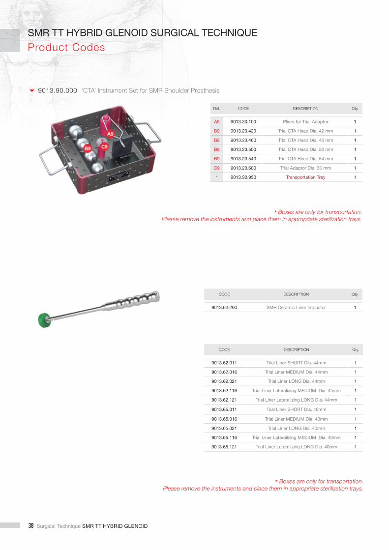
9013.90.000 ‘CTA’ Instrument Set for SMR Shoulder Prosthesis
Ref. CODE DESCRIPTION Qty.
A9 9013.30.100 Pliers for Trial Adaptor 1
B9 9013.23.420 Trial CTA Head Dia. 42 mm 1
B9 9013.23.460 Trial CTA Head Dia. 46 mm 1
B9 9013.23.500 Trial CTA Head Dia. 50 mm 1
B9 9013.23.540 Trial CTA Head Dia. 54 mm 1
C9 9013.23.600 Trial Adaptor Dia. 36 mm 1
* 9013.90.950 Transportation Tray 1
* Boxes are only for transportation. Please remove the instruments and place them in appropriate sterilization trays.
CODE DESCRIPTION Qty.
9013.62.200 SMR Ceramic Liner Impactor 1
CODE DESCRIPTION Qty.
9013.62.011 Trial Liner SHORT Dia. 44mm 1
9013.62.016 Trial Liner MEDIUM Dia. 44mm 1
9013.62.021 Trial Liner LONG Dia. 44mm 1
9013.62.116 Trial Liner Lateralizing MEDIUM Dia. 44mm 1
9013.62.121 Trial Liner Lateralizing LONG Dia. 44mm 1
9013.65.011 Trial Liner SHORT Dia. 40mm 1
9013.65.016 Trial Liner MEDIUM Dia. 40mm 1
9013.65.021 Trial Liner LONG Dia. 40mm 1
9013.65.116 Trial Liner Lateralizing MEDIUM Dia. 40mm 1
9013.65.121 Trial Liner Lateralizing LONG Dia. 40mm 1

SMR TT HYBRID GLENOID Surgical Technique 39
SMR TT HYBRID GLENOID SURGICAL TECHNIQUEProduct Codes
FINNED HUMERAL BODY WITH LOCKING SCREW
Ti6Al4V 1350.15.110 Finned Humeral Body
TRAUMA HUMERAL BODIES WITH LOCKING SCREW
Ti6Al4V 1350.15.010 Medium
1350.15.020 Long
1350.15.030 Short
CEMENTED STEMS L. 80 MM
Ti6Al4V 1306.15.120 Dia. 12 mm
1306.15.140 Dia. 14 mm
1306.15.160 Dia. 16 mm
1306.15.180 Dia. 18 mm
1306.15.200 Dia. 20 mm
CEMENTLESS MINI STEMS L. 60 MM
Ti6Al4V 1304.15.110 Dia. 11 mm n
1304.15.120 Dia. 12 mm n
1304.15.130 Dia. 13 mm n
This brochure describes the complete set of products and combinations of the SMR Shoulder System. Please check the codes list for the availability of products in your market. The symbol allows to distinguish the products NOT available in the US.
n Upon Request = Not Available in the United States

40 Surgical Technique SMR TT HYBRID GLENOID
SMR TT HYBRID GLENOID SURGICAL TECHNIQUE
Product Codes
RING
Ti6Al4V 1314.15.200 Ring
Ti6Al4V 1304.15.140 Dia. 14 mm
1304.15.150 Dia. 15 mm
1304.15.160 Dia. 16 mm
1304.15.170 Dia. 17 mm
1304.15.180 Dia. 18 mm
1304.15.190 Dia. 19 mm
1304.15.200 Dia. 20 mm
1304.15.210 Dia. 21 mm
1304.15.220 Dia. 22 mm
1304.15.230 Dia. 23 mm
1304.15.240 Dia. 24 mm
Ti6Al4V 1313.15.010 Dia. 7 mm, h 50 mm
1313.15.040 Dia. 7 mm, h 80 mm
1313.15.110 Dia. 10 mm, h 50 mm
1313.15.140 Dia. 10 mm, h 80 mm
Ti6Al4V 1314.15.020 h 20 mm
1314.15.030 h 30 mm
1314.15.040 h 40 mm
1314.15.050 h 50 mm
CEMENTLESS FINNED STEMS L. 80 MM
LARGE RESECTION STEMS
MODULAR AUGMENTS
n Upon Request = Not Available in the United States
SMR TT HYBRID GLENOID Surgical Technique 41
SMR TT HYBRID GLENOID SURGICAL TECHNIQUEProduct Codes
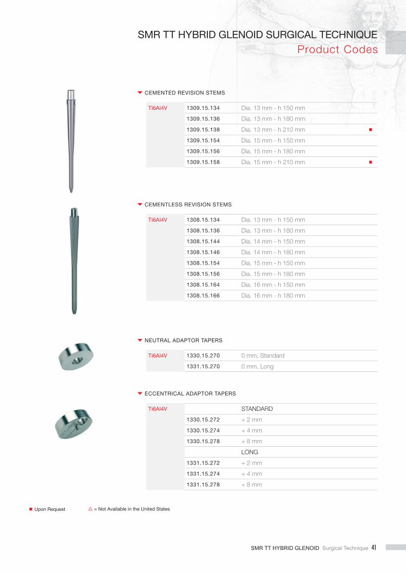
CEMENTED REVISION STEMS
NEUTRAL ADAPTOR TAPERS
CEMENTLESS REVISION STEMS
ECCENTRICAL ADAPTOR TAPERS
Ti6Al4V 1309.15.134 Dia. 13 mm - h 150 mm
1309.15.136 Dia. 13 mm - h 180 mm
1309.15.138 Dia. 13 mm - h 210 mm n
1309.15.154 Dia. 15 mm - h 150 mm
1309.15.156 Dia. 15 mm - h 180 mm
1309.15.158 Dia. 15 mm - h 210 mm n
Ti6Al4V 1330.15.270 0 mm, Standard
1331.15.270 0 mm, Long
Ti6Al4V 1308.15.134 Dia. 13 mm - h 150 mm
1308.15.136 Dia. 13 mm - h 180 mm
1308.15.144 Dia. 14 mm - h 150 mm
1308.15.146 Dia. 14 mm - h 180 mm
1308.15.154 Dia. 15 mm - h 150 mm
1308.15.156 Dia. 15 mm - h 180 mm
1308.15.164 Dia. 16 mm - h 150 mm
1308.15.166 Dia. 16 mm - h 180 mm
Ti6Al4V STANDARD
1330.15.272 + 2 mm
1330.15.274 + 4 mm
1330.15.278 + 8 mm
LONG
1331.15.272 + 2 mm
1331.15.274 + 4 mm
1331.15.278 + 8 mm
n Upon Request = Not Available in the United States

42 Surgical Technique SMR TT HYBRID GLENOID
SMR TT HYBRID GLENOID SURGICAL TECHNIQUE
Product Codes
CoCrMo 1322.09.400 Dia. 40 mm n
1322.09.420 Dia. 42 mm
1322.09.440 Dia. 44 mm
1322.09.460 Dia. 46 mm
1322.09.480 Dia. 48 mm
1322.09.500 Dia. 50 mm
1322.09.520 Dia. 52 mm
1322.09.540 Dia. 54 mm
CoCrMo 1322.09.501 D.50mm H16
1322.09.521 D.52mm H17
1322.09.541 D.54mm H18
1321.09.401 D.40mm H13
1321.09.402 D.40mm H13 ECC2
1321.09.404 D.40mm H13 ECC4
1321.09.407 D.40mm H13 ECC7
1321.09.421 D.42mm H13
1321.09.422 D.42mm H13 ECC2
1321.09.424 D.42mm H13 ECC4
1321.09.427 D.42mm H13 ECC7
1321.09.441 D.44mm H14
1321.09.461 D.46mm H15
1321.09.481 D.48mm H16
1324.09.401 D.40mm H17
1324.09.421 D.42mm H17
1324.09.441 D.44mm H18
1324.09.461 D.46mm H19
1324.09.481 D.48mm H20
1324.09.501 D.50mm H21
1324.09.521 D.52mm H22
1324.09.541 D.54mm H23
HUMERAL HEADS
HUMERAL HEADS WITH DIFFERENT HEIGHTS
SMR TT HYBRID GLENOID Surgical Technique 43
SMR TT HYBRID GLENOID SURGICAL TECHNIQUEProduct Codes
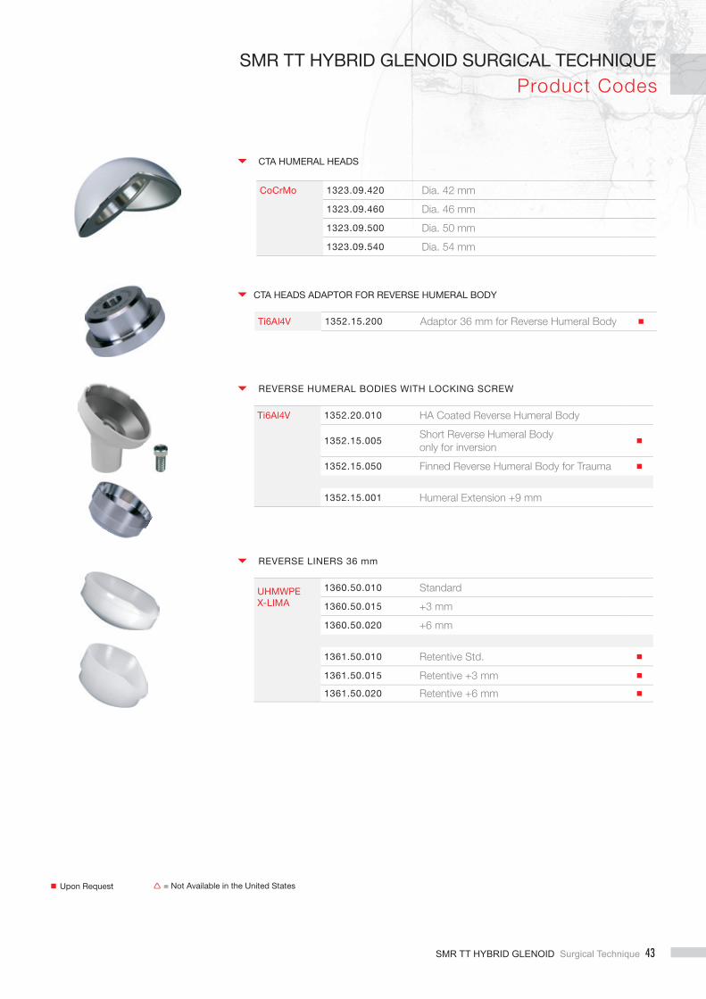
CTA HEADS ADAPTOR FOR REVERSE HUMERAL BODY
Ti6Al4V 1352.15.200 Adaptor 36 mm for Reverse Humeral Body n
Ti6Al4V 1352.20.010 HA Coated Reverse Humeral Body
1352.15.005Short Reverse Humeral Bodyonly for inversion
n
1352.15.050 Finned Reverse Humeral Body for Trauma n
1352.15.001 Humeral Extension +9 mm
UHMWPEX-LIMA
1360.50.010 Standard
1360.50.015 +3 mm
1360.50.020 +6 mm
1361.50.010 Retentive Std. n
1361.50.015 Retentive +3 mm n
1361.50.020 Retentive +6 mm n
REVERSE HUMERAL BODIES WITH LOCKING SCREW
REVERSE LINERS 36 mm
CoCrMo 1323.09.420 Dia. 42 mm
1323.09.460 Dia. 46 mm
1323.09.500 Dia. 50 mm
1323.09.540 Dia. 54 mm
CTA HUMERAL HEADS
n Upon Request = Not Available in the United States

44 Surgical Technique SMR TT HYBRID GLENOID
SMR TT HYBRID GLENOID SURGICAL TECHNIQUE
Product Codes
CoCrMo 1374.09.105 Glenosphere Small-R
1374.09.110 Glenosphere
1376.09.025 Eccentrical Glenosphere Small-R
1376.09.030 Eccentrical Glenosphere
CoCrMo 1374.09.111 Glenosphere
1376.09.031 Eccentrical Glenosphere
GLENOSPHERE 36 mm WITH CONNECTOR *
GLENOSPHERE 36 mm
* do not couple with Hybrid Glenoid Reverse Baseplate
CoCrMo 40 MM
1365.09.010 Short
1365.09.015 Medium
1365.09.020 Long
1365.09.115 Lateralizing Liner - Medium n
1365.09.120 Lateralizing Liner - Long n
44 MM
1362.09.010 Short
1362.09.015 Medium
1362.09.020 Long
1362.09.115 Lateralizing Liner - Medium n
1362.09.120 Lateralizing Liner - Long n
REVERSE HP LINERS
REVERSE CERAMIC LINERS 44 MM
Alumina 1362.39.015 Medium n
1362.39.020 Long n
n Upon Request = Not Available in the United States

SMR TT HYBRID GLENOID Surgical Technique 45
SMR TT HYBRID GLENOID SURGICAL TECHNIQUEProduct Codes
Ti6Al4V 1374.15.305 Small-R n
1374.15.310 Small STD n
UHMWPE 1378.50.005 Small-R
1378.50.010 Standard
1378.50.020 Small
UHMWPEX-Lima
1379.51.005 X-Small
1379.51.010 Standard
1379.51.020 Small
1379.51.030 Large
CONNECTORS WITH SCREW *
CEMENTED GLENOIDS
CEMENTED GLENOID 3 PEGS
* Optional with 36 mm glenospheres
40 MM
1374.50.400 Glenosphere
44 MM
1374.50.440 Glenosphere
1374.50.444 Corrective Glenosphere
REVERSE HP GLENOSPHERE
UHMWPE X-LIMA+ Ti6Al4V
n Upon Request = Not Available in the United States

46 Surgical Technique SMR TT HYBRID GLENOID
SMR TT HYBRID GLENOID SURGICAL TECHNIQUE
Product Codes
LINERS FOR METAL BACK GLENOID L1
UHMWPE 1377.50.005 Small - R
1377.50.020 Small
1377.50.010 Standard
1377.50.030 Large n
BONE SCREWS
Ti6Al4V DIA. 6.5 MM
8420.15.010 L. 20 mm
8420.15.020 L. 25 mm
8420.15.030 L. 30 mm
8420.15.040 L. 35 mm
8420.15.050 L. 40 mm
n Upon Request = Not Available in the United States
METAL BACK GLENOID
Ti6Al4V +PoroTi + HA
1375.20.005 Small - R
1375.20.020 Small
1375.20.010 Standard
1375.20.030 Large n

SMR TT HYBRID GLENOID Surgical Technique 47
SMR TT HYBRID GLENOID SURGICAL TECHNIQUEProduct Codes
Ti6Al4V 1379.15.160 Smal
1379.15.170 Standard
HYBRID GLENOID REVERSE BASEPLATE PLUS SCREW
HYBRID GLENOID
Ti6Al4V +UHMWPE+Tantalum
1379.59.100 Small LOW
1379.59.102 Small LOW + 2
1379.59.110 Small
1379.59.112 Small + 2
1379.59.200 Standard LOW
1379.59.202 Standard LOW + 2
1379.59.210 Standard
1379.59.212 Standard + 2
1379.59.300 Large LOW
1379.59.302 Large LOW + 2
1379.59.310 Large
1379.59.312 Large + 2
1379.59.120 Small LOW Peg L n
1379.59.122 Small LOW + 2 Peg L n
1379.59.130 Small Peg L n
1379.59.132 Small + 2 Peg L n
1379.59.220 Standard LOW Peg L n
1379.59.222 Standard LOW + 2 Peg L n
1379.59.230 Standard Peg L n
1379.59.232 Standard + 2 Peg L n
1379.59.320 Large LOW Peg L n
1379.59.322 Large LOW + 2 Peg L n
1379.59.330 Large Peg L n
1379.59.332 Large + 2 Peg L n
n Upon Request = Not Available in the United States

NotesNotes
SMR TT HYBRID GLENOID SURGICAL TECHNIQUE
48 Surgical Technique SMR TT HYBRID GLENOID

NotesNotesSMR TT HYBRID GLENOID SURGICAL TECHNIQUE
SMR TT HYBRID GLENOID Surgical Technique 49

NotesNotes
SMR TT HYBRID GLENOID SURGICAL TECHNIQUE
50 Surgical Technique SMR TT HYBRID GLENOID


B.1379.23.002.1 121800
limacorporate.com
Limacorporate S.p.A.Via Nazionale, 5233038 Villanova di San Daniele del FriuliUdine - ItalyT +39 0432 945511F +39 0432 [email protected]
Lima Implantes sluCalle Asura n. 97Madrid 28043España
Lima France sasLes Espaces de la Sainte BaumeParc d’ Activité de Gemenos - Bât.A530 Avenue du Château de Jouques13420 Gemenos - FranceT +33 (0) 4 42 01 63 12 F +33 (0) 4 42 04 17 25
Lima O.I. dooAnte Kovacica, 3 10000 Zagreb - CroatiaT +385 (0) 1 2361 740 F +385 (0) 1 2361 [email protected]
Lima Switzerland saBirkenstrasse, 49CH-6343 Rotkreuz - ZugSwitzerlandT +41 (0) 41 747 06 60F +41 (0) 41 747 06 [email protected]
Lima Japan kk Shinjuku Center Building, 29th fl oor1-25-1, Nishi-shinjuku, Shinjuku, Tokyo 163-0629 - JapanT +81 3 5322 1115F +81 3 5322 1175
Lima CZ sroDo Zahrádek I., 157/5155 21 Praha 5 - Zličín Czech RepublicT +420 222 720 011F +420 222 723 [email protected]
Lima Deutschland GmbH Kapstadtring 1022297 Hamburg - GermanyT +49 40 6378 4640 F +49 40 6378 [email protected]
Lima Austria GmbHSeestadtstrasse 27 / Top 6-71220 Wien - AustriaT +43 (1) 2712469F +43 (1) 2712469101offi [email protected]
Lima SK s.r.o.Zvolenská cesta 1497405 Banská Bystrica - SlovakiaT +421 484 161 126 F +421 484 161 [email protected]
Lima NetherlandsHavenstraat 303115 HD SchiedamThe NetherlandsT +31 (0) 10 246 26 60F +31 (0) 10 246 26 [email protected]
Lima Implantes Portugal S.U. LdaRua Olavo D’Eça Leal Nº6 Loja-1 1600-306 Lisboa - PortugalT +35 121 727 233 7F +35 121 296 119 [email protected]
Lima Orthopaedics Australia Pty LtdUnit 1, 40 Ricketts RdMt Waverley 3149Victoria AustraliaT +61 (03) 9550 0200F +61 (03) 9543 4003limaortho.com.au
Lima Orthopaedics New Zealand Ltd20 Crummer RoadAuckland 1021New ZealandT +64 93606010F +64 93606080
Lima Orthopaedics UK LimitedUnit 1, Campus 5Third AvenueLetchworth Garden CityHerts, SG6 2JFUnited KingdomT +44 (0) 844 332 0661F +44 (0) 844 332 0662
Lima USA Inc.2001 NE Green Oaks Blvd., Suite 100 Arlington, TX 76006T +1 817-385-0777 F +1 817-385-0377
Lima Sweden ABFöretagsallén 14 BSE-184 40 ÅKERSBERGASwedenT +46 8 544 103 80F +46 8 540 862 68www.linksweden.se
Lima ItalyCentro Direzionale Milanofi oriStrada 1 - Palazzo F920090 Assago - Milano - ItalyT +39 02 57791301
Lima Korea Co. Ltd11 FL., Zero Bldg.14 Teheran Road 84 GLLGangnam Gu, Seoul 135-845, South KoreaT +82 2 538 4212F +82 2 538 0706
Lima do Brasil EIRELIAv. Sagitário 138, Sala 2707Edifi cio Torre City, Condominio Alpha Square06473-073 Barueri SPBrasilT +55 1126640620F +55 1126640621
Lima Belgium sprlAvenue Newton, 41300 Wavre - BelgiumT +32 (0) 10 888 804F +32 (0) 10 868 [email protected]
Lima Denmark ApSLyngebækgårds Allé 2 2990 Nivå - DenmarkT +45 45860028F +45 4586 0068 [email protected]
Lima Turkey Ortopedi A.S.Ekinciler Cad. Necip Fazil Sk. Pekiz Plaza N°5 D134810 Kavacik, Beykoz - Istanbul/Turkey T +90 (216) 693 1373F +90 (216) 693 [email protected]
Lima Orthopaedics South AfricaNorthlands Deco Park, Stand 32610 New Market streetDesign BoulevardNorthriding2189
Lima Polska Sp. z o.o.Ul. Łopuszańska 9502-457 WarszawaPolandT 0048 22 6312786F 0048 22 [email protected]
Lim
acor
pora
te S
.p.A
. res
erve
s th
e rig
ht to
mak
e ch
ange
s.
Cop
yrig
ht ©
Lim
acor
pora
te S
.p.A
. - A
ll rig
hts
rese
rved
.