SmartLine® Guided Radar Level Meter Specification
24
Honeywell Field Solutions 512 Virginia Drive Fort Washington, PA 19034 SmartLine Guided Radar Level Meter Technical Datasheet 34-VF-03-20 September 2010 Specification The superior TDR solution The SmartLine Guided Radar Level Meter is a Guided Radar (TDR: Time Delay Reflectometry) Level Meter for measuring distance, level, interface, level and interface, volume and mass. A variant with a remote housing can be mounted up to 14.5 m / 47.6 ft from the probe. The SmartLine Guided Radar Level Meter has higher signal dynamics and a sharper pulse than conventional TDR devices and therefore better reproducibility and accuracy. Displays level and interface Configuration software and DTMs included as standard Optional FOUNDATION™ Fieldbus and PROFIBUS PA outputs Optional second current output - used for displaying interface measurements, for example High-pressure and high-temperature versions Optimal process safety (with Metaglas® dual process sealing system for dangerous products) Display in 9 languages: including Chinese, Japanese and Russian Available in stainless steel and Hastelloy ® C-22. Other materials are available on request Angled single cable and rod probes are available on request for installation in tanks which contain obstructions Chemicals Petrochemicals Oil & Gas Minerals & Mining Water & Wastewater Blending tanks Distillation tanks Process tanks Separator Solid silos (inventory) Storage tanks Figure 1 – SmartLine Guided Radar Level Meter 1 Touch screen with 4-button operation 2 2-wire level meter , 4 wire Foundation Fieldbus 3 Housing is rotatable and removable under process conditions 4 5 different types of probes suitable for a wide range of media 5 Optional ESD protection (30 kV) or Metaglas® dual process sealing system for dangerous products 6 Same housing for Ex and non-Ex 7 Large graphical display Highlights Industries Applications
-
Upload
khangminh22 -
Category
Documents
-
view
3 -
download
0
Transcript of SmartLine® Guided Radar Level Meter Specification

Honeywell Field Solutions 512 Virginia Drive Fort Washington, PA 19034
SmartLine Guided Radar Level Meter Technical Datasheet
34-VF-03-20September 2010
Specification
The superior TDR solution
The SmartLine Guided Radar Level Meter is a Guided Radar (TDR: Time Delay Reflectometry) Level Meter for measuring distance, level, interface, level and interface, volume and mass. A variant with a remote housing can be mounted up to 14.5 m / 47.6 ft from the probe. The SmartLine Guided Radar Level Meter has higher signal dynamics and a sharper pulse than conventional TDR devices and therefore better reproducibility and accuracy.
Displays level and interface
Configuration software and DTMs included as standard
Optional FOUNDATION™ Fieldbus and PROFIBUS PA outputs
Optional second current output - used for displaying interface measurements, for example
High-pressure and high-temperature versions
Optimal process safety (with Metaglas® dual process sealing system for dangerous products)
Display in 9 languages: including Chinese, Japanese and Russian
Available in stainless steel and Hastelloy® C-22. Other materials are available on request
Angled single cable and rod probes are available on request for installation in tanks which contain obstructions
Chemicals
Petrochemicals
Oil & Gas
Minerals & Mining
Water & Wastewater
Blending tanks
Distillation tanks
Process tanks
Separator
Solid silos (inventory)
Storage tanks
Figure 1 – SmartLine Guided Radar Level Meter
1 Touch screen with 4-button operation 2 2-wire level meter , 4 wire Foundation Fieldbus 3 Housing is rotatable and removable under process conditions 4 5 different types of probes suitable for a wide range of media 5 Optional ESD protection (30 kV) or Metaglas® dual process
sealing system for dangerous products 6 Same housing for Ex and non-Ex 7 Large graphical display
Highlights
Industries
Applications

34-VF-03-20 Page 2
Honeywell Field Solutions 512 Virginia Drive Fort Washington, PA 19034
Applications 1. Level measurement of liquids
The SmartLine Guided Radar Level Meter can measure the level of a wide range of liquid products on a large variety of installations within the stated pressure and temperature range, including LPG and LNG. It does not require calibration or commissioning when installed. A Metaglas® option is also available for dangerous products and ensures that no leakage is possible.
A number of probe end attachments are available. For example, the user can fix the end of cable probes to heating coils: this prevents deposits building up on the probe.
2. Interface measurement of liquids
SmartLine Guided Radar Level Meter can measure interface with or without an air gap. It can also measure level and interface simultaneously. It has an optional second analogue output.
The coaxial probe of the SmartLine Guided Radar Level Meter has a top dead zone of only 10 mm / 0.4": this makes it ideal for tracking full tank or ballast interface.
For installation requirements and application needs please refer to the User manual. Please refer to the User manual for details of how and where to use these products.

34-VF-03-20 Page 3
Honeywell Field Solutions 512 Virginia Drive Fort Washington, PA 19034
3. Level Measurement of solids
The SmartLine Guided Radar Level Meter has a strengthened 8 mm / 0.3" cable probe for measuring powders and granulates in silos up to 35 m / 115 ft high. The 4 mm cable probe is used for small silos. An ESD protection (30 kV) option is also available.
If a product has a very low dielectric constant (εr <1.6), SmartLine Guided Radar Level Meter automatically switches to TBF (Tank Bottom Following) mode and keeps operating.
4. Measurement of liquids in a
bypass chamber
The SmartLine Guided Radar Level Meter can measure accurately in agitated conditions and in the presence of foam. If the tank is full of obstructions such as agitators and reinforcements, Honeywell recommends installing the SmartLine Guided Radar Level Meter in a bypass chamber.

34-VF-03-20 Page 4
Honeywell Field Solutions 512 Virginia Drive Fort Washington, PA 19034
5. Level measurement of liquids in a
still well
You can also install the SmartLine Guided Radar Level Meter in stilling well if there are vortices, agitators or other obstructions in the tank. It is also suitable for tanks with floating roofs. The SmartLine Guided Radar Level Meter setup wizard allows you to quickly configure your instrument to suit specific types of installations and get the best possible performance from it.
For installation requirements and application needs please refer to the User manual. Please refer to the User manual for details of how and where to use these products. 6. Remote Display on high or
inaccessible tanks
If it is difficult or impossible to read the SmartLine Guided Radar Level Meter integrated display at the top of the tank, Honeywell recommends the remote display variant. It is provided with a cable up to 14.5 m / 47.6 ft. long and a bracket for mounting in an accessible position. If there is vibration in the installation, we also recommend that you attach the remote converter to a wall or another safe object that is not attached to the installation.
For installation requirements and application needs please refer to the User manual. Please refer to the User manual for details of how and where to use these products.

34-VF-03-20 Page 5
Honeywell Field Solutions 512 Virginia Drive Fort Washington, PA 19034
Technical Data
Input
Measurement principle Time Domain Reflectometry (TDR )
Parameter Level, distance, volume and/or interface
Max. measuring range
Double rod Ø8 mm /0.3¨: 4 m / 13 ft
Single rod Ø8 mm /0.3¨: 4 m / 13 ft
Single rod Ø8 mm /0.3¨ (segmented): 6 m / 20 ft
Coaxial Ø22 mm / 0.9¨: 6 m / 20 ft
Coaxial Ø22 mm / 0.9¨ (segmented): 6 m / 20 ft
Double cable Ø4 mm / 0.15¨: 8 m / 26 ft
Single cable Ø2 mm / 0.08¨: 35 m / 115 ft (for liquids only)
Single cable Ø4 mm / 0.15¨: 35 m / 115 ft (For liquids only. An angled probe is available on request for installations with very low ceilings or objects in the tank that prevent installation on top of the tank.)
Single cable Ø8 mm / 0.3¨: 35 m / 115 ft (For solids only. Tolerance, probe length: -1%/+0%.)
Current Output
Output signal (Output 1) 4…20 mA HART® or 3.8…20.5 mA acc. to NAMUR NE 43 (11)
Output signal (Output 2) 4…20 mA (no HART® signal) or 3.8…20.5 mA acc. to NAMUR NE 43 (1)
Resolution ±3 µA
Temperature drift Typically 50 ppm/K
Error signal High: 22 mA; Low: 3.6 mA acc. to NAMUR NE 43
PROFIBUS PA
Type 4 wire (+ local HART) level transmitter; Time Domain Reflectometry (TDR)
Function blocks 11 (level, distance, interface level, interface distance, layer, interface conversion, ullage conversion, layer conversion, level conversion, level mass and distance mass)
Protocol / Communication
Standard PROFIBUS PA protocol that agrees with IEC 61158-2, galvanically isolated
Physical layer types Standard power signaling bus powered
Other features Bus interface with integrated reverse polarity protection
Device power supply (24 V input) 18...30 VDC
Current consumption on PROFIBUS network 20 mA
Output data Level, distance, interface level, interface distance, layer, interface conversion, ullage conversion, layer conversion, level conversion, level mass and distance mass
Input data None
Error current FDE Typically 0 mA (FDE =Fault Disconnection Electronic)
Address range 0...125. Default address: 126.

34-VF-03-20 Page 6
Honeywell Field Solutions 512 Virginia Drive Fort Washington, PA 19034
FOUNDATION Fieldbus
Type 4 wire (+ local HART) level transmitter; Time Domain Reflectometry (TDR)
1 × Resource Block (RB), 4 × Analog Input Blocks (AI), 1 × Transducer Block (TB) Function blocks
Analog Input Block: 50 ms
Protocol / Communication
standard Foundation Fieldbus protocol that agrees with IEC 61158-2, galvanically isolated
ITK version 5.1
Physical layer types Standard power signaling, bus powered, non I.S.
Other features Bus interface with integrated reverse polarity protection
Device power supply (24 V input) 18...30 VDC
Bus power supply 9...32 VDC (non-Ex); 9...17.5 VDC (intrinsically-safe)
Basic current 20 mA
Maximum error current 20 mA
Start current after 10 ms 20 mA
Polar sensitivity Yes
Minimum cycle time 100 ms
Output data Level, distance, level conversion, interface level, interface distance, layer, interface conversion, ullage conversion, layer conversion, level conversion, level mass or distance mass
Input data None
Error current FDE Typically 0 mA (FDE =Fault Disconnection Electronic)
Link Master function Not supported
Reference Conditions acc. to EN 60770
Temperature +20°C ±5°C / +70°F ±10°F
Pressure 1013 mbar abs. ±20 mbar / 14.69 psig ±0.29 psig
Relative air humidity 60% ±15%
Accuracy
Resolution 1 mm / 0.04“
Repeatability ±1 mm / ±0.04“
Accuracy (in direct mode)
Liquids ±3 mm / ±0.12", when distance < 10 m / 33 ft; ±0.03% of measured distance, when distance > 10 m / 33 ft
Powders ±20 mm / ±0.8“
Interface ±10 mm / ±0.4" (r constant)Accuracy (in TBF mode) ±20 mm / ±0.8" (r constant)Minimum layer (interface) 50 mm / 2"
User Interface
Display - LCD 9 lines, 160 x 160 pixels in 8-step grayscale with 4-button keypad
Operating languages English, German, French, Italian, Spanish, Portuguese, Japanese,Chinese (Mandarin) and Russian
34-VF-03-20 Page 7
Honeywell Field Solutions 512 Virginia Drive Fort Washington, PA 19034
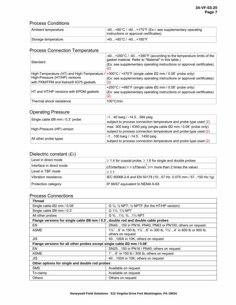
Process Conditions
Ambient temperature -40…+80°C / -40…+175°F (Ex i: see supplementary operating instructions or approval certificates).
Storage temperature -40…+85°C / -40…+185°F
Process Connection Temperature
Standard
-40…+200°C / -40…+390°F (according to the temperature limits of the gasket material. Refer to "Material" in this table.) (Ex: see supplementary operating instructions or approval certificates) (2)
High-Temperature (HT) and High-Temperature / High-Pressure (HT/HP) versions with FKM/FPM and Kalrez® 6375 gaskets
+300°C / +570°F (single cable Ø2 mm / 0.08¨ probe only) (Ex: see supplementary operating instructions or approval certificates) (2)
HT and HT/HP versions with EPDM gaskets +250°C / +480°F (single cable Ø2 mm / 0.08¨ probe only) (Ex: see supplementary operating instructions or approval certificates) (2)
Thermal shock resistance 100°C/min
Operating Pressure
Single cable Ø8 mm / 0.3¨ probe -1…40 barg / -14.5…580 psig subject to process connection temperature and probe type used (2)
High-Pressure (HP) version max. 300 barg / 4350 psig (single cable Ø2 mm / 0.08¨ probe only) subject to process connection temperature and probe type used (2)
All other probe types -1…100 barg / -14.5…1450 psig subject to process connection temperature and probe type used (2)
Dielectric constant (r) Level in direct mode 1.4 for coaxial probe; 1.6 for single and double probes
Interface in direct mode r(interface) > > r(level)²
(>> more than 2 times the value)Level in TBF mode 1.1
Vibration resistance IEC 60068-2-6 and EN 50178 (10...57 Hz: 0.075 mm / 57...150 Hz:1g)
Protection category IP 66/67 equivalent to NEMA 6-6X
Process Connections
Thread
Single cable Ø2 mm / 0.08¨ G ½; ½ NPT; ½ NPTF (for the HT/HP version)
Single cable Ø8 mm / 0.3¨ G 1½; 1½ NPT
All other probes G ¾…1½; ¾…1½ NPT
Flange versions for single cable Ø8 mm / 0.3¨, double rod and double cable probes
EN DN40…150 in PN16, PN40, PN63 or PN100; others on request
ASME 1½¨…8¨ in 150 lb, 1½¨...6¨ in 300 lb, 1½¨...4¨ in 600 lb or 900 lb; others on request
JIS 40…100A in 10K; others on request
Flange versions for all other probes except single cable Ø2 mm / 0.08¨
EN DN25…150 in PN16 / PN40; others on request
ASME 1¨…8¨ in 150 lb / 300 lb; others on request
JIS 40…100A in 10K; others on request
Other options for single and double rod probes
SMS Available on request
Tri-clamp Available on request
Others Others on request

34-VF-03-20 Page 8
Honeywell Field Solutions 512 Virginia Drive Fort Washington, PA 19034
Material
Standard: Aluminium Housing
Option: Stainless steel (1.4404 / 316L)
Standard: Stainless steel (1.4404 / 316L)
Option: Hastelloy® C-22 (2.4602) 3
On request: Stainless steel (1.4404 / 316L) in a PVC, PVDF or PP protective sheath
Single rod (single-piece)
On request: Monel; Tantalum; Titanium; Duplex
Single rod (segmented) Standard: Stainless steel (1.4404 / 316L)
Standard: Stainless steel (1.4404 / 316L)
Option: Hastelloy® C-22 (2.4602) Double rod
On request: Monel; Tantalum; Titanium; Duplex
Standard: Stainless steel (1.4404 / 316L) Coaxial (single-piece)
Option: Hastelloy® C-22 (2.4602)
Standard: Stainless steel (1.4401 / 316)
Option: Hastelloy® C-22 (2.4602)
- only for the Ø2 mm / 0.15¨ or Ø4 mm / 0.15¨ single cable probes Single cable
On request: FEP-coated stainless steel (-20...+150°C / -4...+300°F)
- only for the Ø4 mm / 0.15¨ single cable probe
Double cable Stainless steel (1.4401 / 316)
Standard: Stainless steel (1.4404 / 316 L)
Option: Hastelloy® C-22 (2.4602) Process fitting
On request: Monel; Tantalum; Titanium; Duplex
Gaskets
FKM/FPM (-40…+200°C / -40…+390°F); Kalrez® 6375 (-20…+200°C / -4…+390°F);
EPDM (-50...+150°C / -58...+300°F) - all probes except single cable Ø8 mm / 0.3¨ (9)
Weather protection (Option) Stainless steel (1.4301 / 304)
Protective sheath
(On request for single rod only)
PP (-40…+90°C / -40…+194°F); PVC (-15…+80°C / +5…+176°F);
PVDF (-40…+150°C / -40…+302°F)
Conduit for remote housing (Option) Zinc-coated steel in a PVC sheath (-40...+105°C / -40...+220°F)
Electrical Connections
Instrument terminal 1 - Non-Ex / Ex i 14…30 VDC (6)
Instrument terminal 1 - Ex d 20…36 VDC (6)
Instrument terminal 2 - Non-Ex/ Ex i/ Ex d 10…30 VDC (7)
M20×1.5; ½ NPT
G ½ (not for FM- and CSA-approved devices. Not for stainless steel housings.)Cable Entry
M25×1.5 (for stainless steel housings only)
Standard: none
Cable Gland Options: M20×1.5 (for non-Ex and Ex-approved devices with M20×1.5 and M25×1.5
Cable tightening capacity 0.5…1.5 mm²

34-VF-03-20 Page 9
Honeywell Field Solutions 512 Virginia Drive Fort Washington, PA 19034
Approvals CE This device fulfills the statutory requirements of the EC
directives. The manufacturer certifies successful testing of the product by applying the CE mark.
ATEX II 1 G, 1/2 G, 2 G Ex ia IIC T6...T2;
ATEX II 1 D, 1/2 D, 2 D Ex iaD 20 or Ex iaD 20/21 IP6X T70°C...T95°C;
ATEX II 1/2 G, 2 G Ex d[ia] IIC T6...T2 ;
ATEX II 1/2 D, 2 D Ex tD[iaD] A21/20 IP6X T70°C...T95°C;
ATEX (approval for fieldbus
outputs pending)
ATEX II 3 G Ex nA IIC T6…T2
Ex ia IIC T6…T3 Ga; Ex iaD 20 IP6X T70°C…T95°C; IECEx (approval for fieldbus
outputs options pending) Ex d[ia] IIC T6…T3 Ga/Gb; Ex tD[iaD] A21/20 IP6X T70°C…T95°C
NEC 500
XP-IS, Cl. I, Div. 1, Gr. ABCD T6...T2;
DIP, Cl. II/III, Div. 1, Gr. EFG T6...T2;
IS, Cl. I/II/III, Div. 1, Gr. ABCDEFG T6...T2;
NI, Cl. I, Div. 2, Gr. ABCD T6...T2
NEC 505
Cl. I, Zone 0, AEx d[ia] IIC T6...T2;
Cl. I, Zone 0, AEx ia IIC T6...T2;
Cl. I, Zone 2, AEx nA[ia] IIC T6...T2
FM - Dual Seal-approved
(approval for fieldbus output
options pending)
Hazardous (Classified) Locations, indoor/outdoor Type 4X and 6P, IP66, Dual Seal
CEC Section 18 (Zone ratings)
Cl. I, Zone 1, Ex d, IIC (Probe: Zone 0) T6...T2;
Cl. I, Zone 0, Ex ia, IIC T6...T2;
Cl. I, Zone 2, Ex nA, IIC T6...T2
CEC Section 18 and Annex J (Division ratings)
XP-IS, Cl. I, Div. 2, Gr. ABCD; Cl. II, Div. 2, Gr. FG; Cl. III, Div. 2 T6...T2;
CSA - Dual Seal-approved
(approval for Drop antenna,
hygienic antenna and fieldbus
output options pending)
IS, Cl. I, Div. 1, Gr. ABCD; Cl. II, Gr. FG; Cl. III T6...T2
NEPSI (approval pending) Ex dia IIC T2~T6; Ex ia IIC T2~T6
CEPEL / INMETRO (approval pending) BR-Ex ia IIC T2…T6; BR-Ex d[ia] IIC T2…T6
Other standards and approvals
EMC Electromagnetic Compatibility Directive 2004/108/EC in conjunction with
EN 61326-1 (2006) and EN 61326-2-3 (2006). The device agrees with this standard if:
- the device has a coaxial probe or
- the device has a single / double probe that is installed in a metallic tank.
NAMUR NE 21 Electromagnetic Compatibility (EMC) of Industrial Process and Laboratory Control Equipment
NAMUR
NAMUR NE 43 Standardization of the Signal Level for the Failure Information of
Digital Transmitters
Construction code On request: NACE MR0175 / ISO 15156

34-VF-03-20 Page 10
Honeywell Field Solutions 512 Virginia Drive Fort Washington, PA 19034
Options and Accessories Integrated LCD display with sun cover (-20...+60°C / -4...+140°F); (8)
2nd current output;
Remote housing connected to the probe via a flexible conduit Standard lengths: 2 m / 6.6 ft, 4.5 m / 14.8 ft, 9.5 m / 31.2 ft and 14.5 m / 47.6 ft
ESD protection (30 kV)
Options
Metaglas® (dual process sealing system for dangerous products (ammonia, chlorine, ...)) (10)
Accessories Weather protection
1 optional 2 refer to the Pressure/temperature table for probe selection. 3 Hastelloy® is a registered trademark of Haynes International, Inc. 4 Hastelloy® C-22 (2.4602) on request for theØ2 mm / 0.15" single cable probe. 5 others on request 6 min./max. value for an output of 22 mA at the terminal 7 min/max. value for an output of 22 mA at the terminal (additional power supply needed - output only) 8 if the ambient temperature is not in these limits, the display switches off; 9 Kalrez® is a registered trademark of DuPont Performance Elastomers L.L.C. 10 Metaglas® is a registered trademark of Herberts Industrieglas, GMBH & Co., KG 11 HART® is a registered trademark of the HART Communication Foundation

34-VF-03-20 Page 11
Honeywell Field Solutions 512 Virginia Drive Fort Washington, PA 19034
Probe Selection
Dou
ble
rod
Sin
gle
rod
Sin
gle
rod
(seg
men
ted)
Coa
xial
Coa
xial
(se
gmen
ted)
Dou
ble
cabl
e
Sin
gle
cabl
e Ø
8 m
m /
0.3
¨
Sin
gle
cabl
e Ø
4 m
m /
0.1
5¨
Sin
gle
cabl
e Ø
2 m
m /
0.0
8¨
Maximum probe length, L
4 m / 13 ft
6 m / 20 ft
8 m / 26 ft
35 m / 115 ft
Liquids
Liquid application
LPG, LNG (1) (1)
Highly viscous liquids
Highly crystallizing liquids
Highly corrosive liquids
Foam
Agitated liquids (2) (2) (2) (2) (2)
High-pressure applications (3) (3) (3) (3) (3) (3) (3) (4)
High-temperature applications (5)
Spray in tank (1) (1) (1) (1)
Storage tanks
Installation in bypass chamber
Small diameter nozzles
Long nozzles
Stilling wells
Interface measurement (6) (6)
Solids
Powders (7)
Granules, <5 mm / 0.1¨ (7)
1 Install the device in a stilling well or a bypass chamber 2 Use this probe with an anchor fitting. For more data, refer to the handbook. 3 Max. pressure is 100 bar / 1450 psig. Refer to the pressure-temperature table for probe selection. 4 Optional. Max. pressure is 300 bar / 4350 psig. Refer to the pressure-temperature table for probe selection. 5 Optional. Max. temperature is 300°C / 570°F. Refer to the pressure-temperature table for probe selection. 6 Max. length is 20 m / 65.5 ft, more on request 7 Max. length is 10 m / 33 ft, more on request

34-VF-03-20 Page 12
Honeywell Field Solutions 512 Virginia Drive Fort Washington, PA 19034
Dimensions and Weight
Standard Housing
1 Converter (front view) 2 Thread version for all probes except the Ø2 mm / 0.08¨ single cable probe (right side) 3 Flange version (right side) 4 Thread version for Ø2 mm / 0.08¨ single cable probe - High-Pressure (HP) version (right side) 5 Thread version for Ø2 mm / 0.08¨ single cable probe - High-Temperature (HT) and High-Temperature/High-Pressure
(HT/HP) versions (right side)
Note:
Cable glands are delivered on demand with non-Ex, Ex i- and Ex d-approved devices. Non-Ex and Ex i fittings are plastic and Ex d fittings are metallic. Non-Ex fittings are black and Ex i fittings are blue. The diameter of the outer sheath of the cable must be 6…12 mm or 0.2…0.5¨. Cable glands for FM- or CSA-approved devices must be supplied by the customer.

34-VF-03-20 Page 13
Honeywell Field Solutions 512 Virginia Drive Fort Washington, PA 19034
Dimensions in mm and kg Dimensions – mm (inches)
a b c D (1) e f g H (2) I (2)
Weights
kg (lb)
Housing 180
(7.1)
122
(4.8)
158.5
(6.2)
182
(7.2)
170
(6.7)
197
(7.8)
- - - 3.3
(7.3)
Flange DN25…80 (ASME1…3) 180
(7.1)
122
(4.8)
158.5
(6.2)
182
(7.2)
170
(6.7)
197
(7.8)
123
(4.8)
320
(12.6)
357
(14.1)
4...7
(8.8… 15.4)
Flange DN100…150 (ASME4…8) 180
(7.1) 122
(4.8)
158.5
(6.2)
182
(7.2)
170
(6.7)
197
(7.8)
123
(4.8)
320
(12.6)
357
(14.1)
7…12
(15.4… 26.5)
Thread, single cable Ø2 (Ø0.08) –
version HT/HTP
180
(7.1)
122
(4.8)
158.5
(6.2)
182
(7.2)
170
(6.7)
197
(7.8)
144
(5.7)
341
(13.4)
378
(14.9)
4.3
(9.5)
Thread, single cable Ø2 (Ø0.08) -
version HP
180
(7.1) 122
(4.8) 158.5
(6.2)
182
(7.2)
170
(6.7)
197
(7.8)
43
(1.7)
240
(9.4)
277
(10.9)
4
(8.8)
Thread, all other probes 180
(7.1)
122
(4.8)
158.5
(6.2)
182
(7.2)
170
(6.7)
197
(7.8)
95
(3.7)
292
(11.5)
329
(12.9
3
(6.6)
1 This dimension is subject to the size of the cable gland used 2 With 30 kV ESD protection option: add 3.9" (99mm) to this dimension. With Metaglas® option: add 1.7" (43mm) to this dimension.

34-VF-03-20 Page 14
Honeywell Field Solutions 512 Virginia Drive Fort Washington, PA 19034
Remote Housing
1 Front view 2 Left side 3 Rear view
Note:
• Refer to "ESD protection and Metaglas® (dual process sealing system for dangerous products) options" for the height to add to dimension "n".
Dimensions and Weights in mm and kg
Dimensions [mm]
a b c d e f g h i k l m n o p
Weight [kg]
Remote 180 109 165 193 98.5 58 21 183 117 150 150.4 100 86 58 60 6.6… version 12.85 (1)
1 wall bracket (1.4 kg) + housing support (1.5 kg) + remote probe housing (2.7 kg) + flexible conduit (2 m: 1 kg; 4.5 m: 2.25 kg; 9.5 m: 4.75 kg; 14.5 m: 7.25 kg)
Dimensions and Weights in inches and lbs
Dimensions [inches]
a b c d e f g h i k l m n o p
Weight [lbs]
Remote 7.09 4.29 6.50 7.60 3.88 2.28 0.83 7.20 4.60 5.91 5.92 3.94 3.39 2.28 2.36 14.6... version 28.3 (1)
1 wall bracket (3.1 lbs) + housing support (3.3 lbs) + remote probe housing (6.0 lbs) + flexible conduit (6.6 ft: 2.2 lbs; 14.8 ft: 5.0 lbs; 31.2 ft: 10.5 lbs; 47.6 ft: 16.0 lbs)

34-VF-03-20 Page 15
Honeywell Field Solutions 512 Virginia Drive Fort Washington, PA 19034
Remote version limits For interface and solid (powder, granulate) applications the maximum extension length is 4.5 m / 14.8 ft.
For liquid level applications, the maximum measuring range is reduced according to the length of the coaxial cable between the flange and the converter (extension length).
Extension length Max. measuring range (or sensor length, L)
[m] [ft] [m] [ft]
2 6.6 30 98
4.5 14.8 25 82
9.5 31.2 15 29
14.5 47.6 5 16.4
Applications
Tank with a lot of vibration
Limited space on the top of the tank or limited access (due to the size of the compact converter)
Remote display at the bottom of the tank

34-VF-03-20 Page 16
Honeywell Field Solutions 512 Virginia Drive Fort Washington, PA 19034
Weather protection option
Dimensions and Weight in mm and kg
Dimensions [mm]
a b c d Weight [kg]
Weather protection
208 231.5 268 (1) 66 2.9
1 radius
Dimensions and Weight in inches and lbs Dimensions [inches]
a b c d Weight [lbs]
Weather protection
8.2 9.1 10.6 (1) 2.6 6.4
1 radius

34-VF-03-20 Page 17
Honeywell Field Solutions 512 Virginia Drive Fort Washington, PA 19034
ESD protection and Metaglas® options
1 Optional ESD protection (30 kV) for solid applications 2 Optional Metaglas® (dual process sealing system for dangerous products)
The ESD protection and the Metaglas® options cannot be fitted to the same device.
Special options: Dimensions and weight
Dimensions – mm (inches) Options
a b
Weights kg (lb)
ESD protection 30 kV 99
(3.9) Ø58
(Ø2.3) 0.85
(1.87)
Metaglas® 43
(1.7) Ø58
(Ø2.3) 0.83
(1.82)
34-VF-03-20 Page 18
Honeywell Field Solutions 512 Virginia Drive Fort Washington, PA 19034
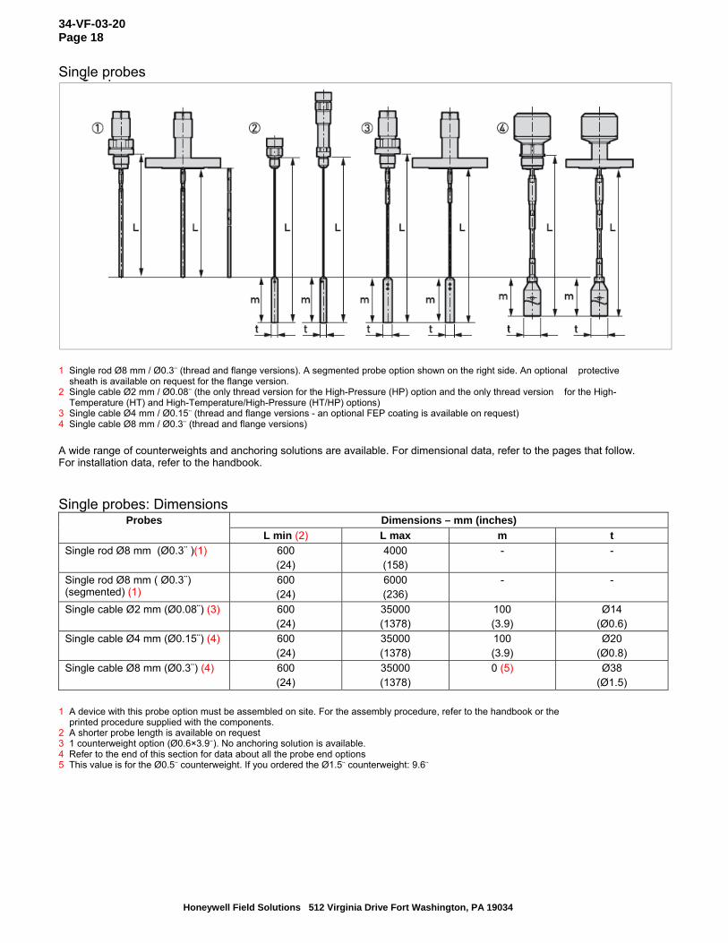
Single probes
1 Single rod Ø8 mm / Ø0.3¨ (thread and flange versions). A segmented probe option shown on the right side. An optional protective
sheath is available on request for the flange version. 2 Single cable Ø2 mm / Ø0.08¨ (the only thread version for the High-Pressure (HP) option and the only thread version for the High-
Temperature (HT) and High-Temperature/High-Pressure (HT/HP) options) 3 Single cable Ø4 mm / Ø0.15¨ (thread and flange versions - an optional FEP coating is available on request) 4 Single cable Ø8 mm / Ø0.3¨ (thread and flange versions)
A wide range of counterweights and anchoring solutions are available. For dimensional data, refer to the pages that follow. For installation data, refer to the handbook. Single probes: Dimensions
Dimensions – mm (inches) Probes
L min (2) L max m t
Single rod Ø8 mm (Ø0.3¨ )(1) 600 (24)
4000 (158)
- -
Single rod Ø8 mm ( Ø0.3¨) (segmented) (1)
600 (24)
6000 (236)
- -
Single cable Ø2 mm (Ø0.08¨) (3) 600 (24)
35000 (1378)
100 (3.9)
Ø14 (Ø0.6)
Single cable Ø4 mm (Ø0.15¨) (4) 600 (24)
35000 (1378)
100 (3.9)
Ø20 (Ø0.8)
Single cable Ø8 mm (Ø0.3¨) (4) 600 (24)
35000 (1378)
0 (5)
Ø38 (Ø1.5)
1 A device with this probe option must be assembled on site. For the assembly procedure, refer to the handbook or the
printed procedure supplied with the components. 2 A shorter probe length is available on request 3 1 counterweight option (Ø0.6×3.9¨). No anchoring solution is available. 4 Refer to the end of this section for data about all the probe end options 5 This value is for the Ø0.5¨ counterweight. If you ordered the Ø1.5¨ counterweight: 9.6¨
34-VF-03-20 Page 19
Honeywell Field Solutions 512 Virginia Drive Fort Washington, PA 19034
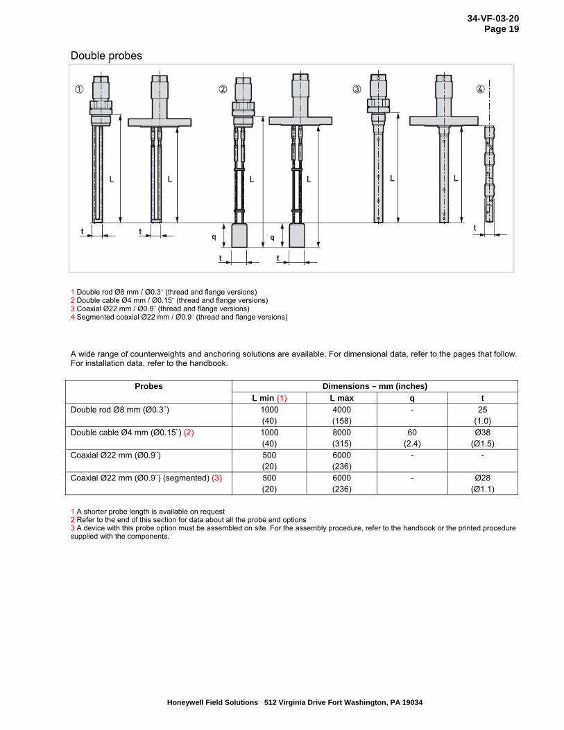
Double probes
1 Double rod Ø8 mm / Ø0.3¨ (thread and flange versions) 2 Double cable Ø4 mm / Ø0.15¨ (thread and flange versions) 3 Coaxial Ø22 mm / Ø0.9¨ (thread and flange versions) 4 Segmented coaxial Ø22 mm / Ø0.9¨ (thread and flange versions)
A wide range of counterweights and anchoring solutions are available. For dimensional data, refer to the pages that follow. For installation data, refer to the handbook.
Dimensions – mm (inches) Probes
L min (1) L max q t
Double rod Ø8 mm (Ø0.3¨) 1000 (40)
4000 (158)
- 25 (1.0)
Double cable Ø4 mm (Ø0.15¨) (2) 1000 (40)
8000 (315)
60 (2.4)
Ø38 (Ø1.5)
Coaxial Ø22 mm (Ø0.9¨) 500 (20)
6000 (236)
- -
Coaxial Ø22 mm (Ø0.9¨) (segmented) (3) 500 (20)
6000 (236)
- Ø28 (Ø1.1)
1 A shorter probe length is available on request 2 Refer to the end of this section for data about all the probe end options 3 A device with this probe option must be assembled on site. For the assembly procedure, refer to the handbook or the printed procedure supplied with the components.

34-VF-03-20 Page 20
Honeywell Field Solutions 512 Virginia Drive Fort Washington, PA 19034
Pressure/temperature table for probe selection
Ensure that the transmitters are used within their operating limits. Observe the following requirements.
1 Process pressure, Ps [bar] 2 Process connection temperature, T [°C] 3 All probes 4 High-Pressure (HP) version of the Ø2 mm single cable probe 5 High-Temperature/High-Pressure (HT/HP) version of the Ø2 mm single cable probe 6 High-Temperature (HT) version of the Ø2 mm single cable probe
1 Process pressure, Ps [psi] 2 Process connection temperature, T [°F] 3 All probes 4 High-Pressure (HP) version of the Ø0.08¨ single cable probe 5 High-Temperature/High-Pressure (HT/HP) version of the Ø0.08¨ single cable probe 6 High-Temperature (HT) version of the Ø0.08¨ single cable probe
34-VF-03-20 Page 21
Honeywell Field Solutions 512 Virginia Drive Fort Washington, PA 19034
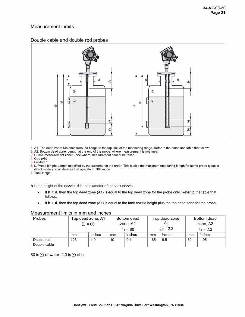
Measurement Limits
Double cable and double rod probes
1 A1, Top dead zone: Distance from the flange to the top limit of the measuring range. Refer to the notes and table that follow. 2 A2, Bottom dead zone: Length at the end of the probe, where measurement is not linear. 3 D, non measurement zone: Zone where measurement cannot be taken. 4 Gas (Air) 5 Product 1 6 L, Probe length: Length specified by the customer in the order. This is also the maximum measuring length for some probe types in
direct mode and all devices that operate in TBF mode. 7 Tank Height
h is the height of the nozzle. d is the diameter of the tank nozzle.
If h d, then the top dead zone (A1) is equal to the top dead zone for the probe only. Refer to the table that follows.
If h d, then the top dead zone (A1) is equal to the tank nozzle height plus the top dead zone for the probe.
Measurement limits in mm and inches
Top dead zone, A1
r = 80 Bottom dead
zone, A2
r = 80
Top dead zone, A1
r = 2.3
Bottom dead zone, A2
r = 2.3
Probes
mm inches mm inches mm inches mm inches
Double rod Double cable
125 4.9 10 0.4 165 6.5 50 1.95
80 is r of water; 2.3 is r of oil

34-VF-03-20 Page 22
Honeywell Field Solutions 512 Virginia Drive Fort Washington, PA 19034
Single cable and single rod probes
1 A1, Top dead zone: Distance from the flange to the top limit of the measuring range. Refer to the notes and table that
follow. 2 A2, Bottom dead zone: Length at the end of the probe, where measurement is not linear. 3 D, non measurement zone: Zone where measurement cannot be taken. 4 Gas (Air) 5 Product 1 6 L, Probe length: Length specified by the customer in the order. This is also the maximum measuring length for some
probe types in direct mode and all devices that operate in TBF mode. 7 Tank Height
h is the height of the nozzle. d is the diameter of the tank nozzle.
If h < d, then the top dead zone (A1) is equal to the top dead zone for the probe only. Refer to the table that follows.
If h d, then the top dead zone (A1) is equal to the tank nozzle height plus the top dead zone for the probe.
Measurement limits in mm and inches Top dead zone, A1
r = 80 Bottom dead
zone, A2 r = 80
Top dead zone, A1 r = 2.3
Bottom dead zone, A2 r = 2.3
Probes
mm inches mm inches mm inches mm inches
Single rod Single cable
200 7.9 10 0.4 250 9.9 50 1.95

34-VF-03-20 Page 23
Honeywell Field Solutions 512 Virginia Drive Fort Washington, PA 19034
Coaxial probe
1 A1, Top dead zone: Distance from the flange to the top limit of the measuring range. Refer to the notes and table that follow.
2 A2, Bottom dead zone: Length at the end of the probe, where measurement is not linear. 3 D, non measurement zone: Zone where measurement cannot be taken. 4 Gas (Air) 5 Product 1 6 L, Probe length: Length specified by the customer in the order. This is also the maximum measuring length for some
probe types in direct mode and all devices that operate in TBF mode. 7 Tank Height h is the height of the nozzle. d is the diameter of the tank nozzle.
The dimensions of the tank nozzle have no effect on the top dead zone of the coaxial probe.
Measurement limits in mm and inches Top dead zone,
A1 r = 80
Bottom dead zone, A2 r = 80
Top dead zone, A1
r = 2.3
Bottom dead zone, A2 r = 2.3
Probes
mm inches mm inches mm inches mm inches Coaxial 10 0.4 10 0.4 10 0.4 50 1.95

34-VF-03-20 Page 24
Honeywell Field Solutions 512 Virginia Drive Fort Washington, PA 19034
Ordering Information Contact your nearest Honeywell sales office, or In the U.S.:
Honeywell Process Solutions Honeywell International Inc 2500 West Union Hills Drive Phoenix, AZ 85027 1-800-343-0228
In Canada:
The Honeywell Centre 155 Gordon Baker Rd. North York, Ontario M2H 3N7 1-800-461-0013
In Latin America:
Honeywell Inc. 480 Sawgrass Corporate Parkway, Suite 200 Sunrise, FL 33325 (954) 845-2600
In Europe and Africa:
Honeywell S. A. Avenue du Bourget 1 1140 Brussels, Belgium
In Eastern Europe:
Honeywell Praha, s.r.o. Budejovicka 1 140 21 Prague 4, Czech Republic
In the Middle East:
Honeywell Middle East Ltd. Khalifa Street, Sheikh Faisal Building Abu Dhabi, U. A. E.
In Asia:
Honeywell Asia Pacific Inc. Honeywell Building, 17 Changi Business Park Central 1 Singapore 486073 Republic of Singapore
In the Pacific:
Honeywell Pty Ltd. 5 Thomas Holt Drive North Ryde NSW Australia 2113 (61 2) 9353 7000
In Japan:
Honeywell K.K. 14-6 Shibaura 1-chrome Minato-ku, Tokyo, Japan 105-0023
Or, visit Honeywell on the World Wide Web at: http://www.honeywell.com/ps Specifications are subject to change without notice.