SMART Energy Homes and the Smart Grid - CiteSeerX
190
SMART Energy Homes and the Smart Grid A Framework for Intelligent Energy Management Systems for Residential Customers Ballard Asare-Bediako
-
Upload
khangminh22 -
Category
Documents
-
view
1 -
download
0
Transcript of SMART Energy Homes and the Smart Grid - CiteSeerX

SMART Energy Homes and the Smart Grid
A Framework for Intelligent Energy Management Systems for Residential Customers
Ballard Asare-Bediako
SMA
RT Energy H
omes and the Sm
art Grid
Ballard Asare-Bediako
Invitation
You are cordially invited to attend the public defense of my Ph.D. dissertation entitled
SMART Energy Homes and the Smart Grid
The defense will take place on Thursday December 11, 2014 at 16:00 in the Auditorium (Room 4) of Eindhoven University of Technology.
After the defense you are also invited to the reception which will take place in the same location.
Ballard Asare-Bediako


SMART Energy Homes and the Smart GridA Framework for Intelligent Energy Management Systems for Residential Customers
PROEFSCHRIFT
ter verkrijging van de graad van doctor aan deTechnische Universiteit Eindhoven, op gezag van derector magnificus, prof.dr.ir. C.J. van Duijn, voor een
commissie aangewezen door het College voorPromoties in het openbaar te verdedigen
op donderdag 11 december 2014 om 16.00 uur
door
Ballard Asare-Bediako
geboren te Accra, Ghana

Dit proefschrift is goedgekeurd door de promotoren en de samenstelling van depromotiecommissie is als volgt:
voorzitter: prof.dr.ir. A. C. P. M. Backx
1e promotor: prof.ir. W. L. Kling
2e promotor: prof.dr.ir. J. F. G. Cobben
leden: Univ.-Prof.Dr.-Ing. J. M. A. Myrzik (Technische Universität Dortmund)
prof.dr.ir. J. Driesen (Katholieke Universiteit Leuven)
prof.dr.ir. J. L. Hurink (Universiteit Twente)
prof.dr.ir. J. L. M. Hensen
adviseur: dr. P. Mancarella (The University of Manchester)

To my beloved family

This work is part of the IOP EMVT ("Innovatiegerichte Onderzoeksprogramma’sElektromagnetische vermogenstechniek") research program. It is funded by Rijksdienstvoor Ondernemend Nederland (RVO.nl), an agency of the Dutch Ministry of EconomicAffairs.
Printed by Ipskamp drukkers, Enschede.
A catalogue record is available from the Eindhoven University of Technology Library.
ISBN: 978-90-386-3730-3
Copyright c© 2014 Ballard Asare-Bediako, Eindhoven, The Netherlands.All rights reserved. No part of this publication may be reproduced or transmitted in any form orby any means, electronic, mechanical, including photocopy, recording, or any information storageand retrieval system, without the prior written permission of the copyright owner.

Summary
This thesis investigates the expected changes in the energy supply systems andenergy demand profiles for the residential sector. Investigations are carried out onresidential energy consumption, energy conversion technologies and the impacts ofenergy management systems on the residential load profile. The thesis also presentsa framework of concepts and technologies that enable Smart Grid applications at theresidential environment.
Residential energy supply systems are influenced by two main factors. First is thepenetration of new energy conversion technologies such as photovoltaic (PV) systems,micro combined heat and power (μCHP) units, heat pumps and electric vehicles in theresidential sector. PV systems are one of the fastest growing energy supply technologiesin the residential environment, attributable to the improved efficiency of PV modulesand financial incentives offered by national governments, such as feed-in tariffs, capitalsubsidies and income tax credits. μCHP units are replacing conventional gas boilers ingas-connected houses to provide heat for space heating and domestic hot water, andalso supply part of the electricity needs of the home.
The electrification of heating systems is expected to increase significantly for newlybuilt residential areas in the Netherlands. Furthermore, electrification of mobility istaking off. The concurrent penetration of new conversion systems will significantlychange the residential energy supply system. Secondly, residential neighborhoods areevolving in terms of building type and household composition. Analyses show thatresidential gas consumption is affected by the type of building, date of constructionand the orientation, and age-group of occupants. The electricity demand is directlyinfluenced by the composition of the household and the level of income. Families withyoung children are found to have high electricity consumption due to the frequent useof electrical appliances. Gas consumption is found to be high among the elderly dueto their demands for more thermal comfort. Also, analyses indicate that a good mix ofbuilding types and residential groups could provide natural smoothing of the residentialload profiles.
i

ii SUMMARY
The research focuses on the deployments of smart energy homes as importantinfrastructure for smart cities and the Smart Grid. Smart energy homes are equippedwith home automation technologies to improve occupants’ comfort, health and safety,and provide savings on energy bills. They offer convenience to the occupants wherebymany daily activities are fully automated or can be controlled from customers’ computersand smart phones. They play crucial roles in the development of smart cities bycontributing to better living conditions, quality of functional space, minimization ofgreenhouse gas emissions, and stimulating economic development. Another importantaspect is the seamless integration of smart energy homes into the Smart Grid framework.They can support the public grid by enabling Smart Grid applications. Smart energyhomes are emerging among academic institutions as experimental laboratories forvalidating technology and systems and also as pilot demonstration projects to testefficient use of energy and Smart Grid interaction. The deployments of smart energyhomes vary in purpose and functionality, yet results from pilot projects indicatepromising prospects for large-scale implementations.
Furthermore, residential energy consumption continues to grow despite theenforcement of energy efficiency policies. The demand for more comfort, the use of moreappliances and the lack of real-time or historical feedback on energy use to customerscontribute to the increase in energy use. Home energy management systems (HEMS)employ automated technologies to manage and reduce residential energy use and cost,as well as make energy reductions through energy efficiency measures more visible tothe customer, and extend Smart Grid applications to the home environment. HEMSfacilitate the integration of residential generation to match users’ needs, and to supportthe reliability and robustness of the energy supply infrastructure. Their deployments aremotivated by the need for more efficient operation of the power system, energy security,reduction in carbon footprints, and customer retention for the utilities.
Four main areas for HEMS applications are outlined in this thesis. First is thecustomer-based HEMS, where residential devices are managed to accommodate dailyactivities, preferences and needs of the residential customers without the influenceof external parties. The second focuses on reduction of network peak loading andalleviation of network congestion through optimal control of flexible residential loads,storages and generation systems. The third is a market-oriented way of implementingHEMS, which is managing residential energy use in response to fluctuating energyprices. Finally, HEMS can be installed to inform customers on their energy useto prevent rebound effect (consuming more energy after implementation of energy-efficient measures), and to stay within the limits set by contractual agreements.Furthermore, barriers to large-scale introduction of HEMS technologies are investigated.Conservatism, cost and privacy are the major barriers to large scale implementationof HEMS. To address these challenges, five aspects - technological, economic, socio-cultural, structural and legal - have been outlined as crucial for sustainable deploymentsof HEMS technologies.
A sustainable HEMS should be robust, flexible, and capable of integrating the interestof the various stakeholders. This thesis proposes a multi-agent system (MAS) for home

SUMMARY iii
energy management. The agent-based systems employ distributed intelligence to solvecomplex problems and facilitate the implementation of multiple control algorithmsfor the household. The proposed MAS architecture is hierarchical, comprising deviceagents for monitoring and control of devices, and a central agent who coordinates theactivities of all other agents and determines the control objectives. The architecture issuited for present and near future Smart Grid applications such as the use of dynamictariff systems, demand response programs, or households’ participation in a virtualpower plant system. A co-simulation model of the MAS-based HEMS is tested usingJava Agent Development Framework (JADE) and MATLAB software linked via TCP/IPprotocol. The design of agents and control algorithms are implemented with JADE, whilethe residential devices are modelled with MATLAB software. Two control strategiesare tested - a green optimization control algorithm which takes advantage of locallygenerated electricity, and a price-based control that integrates electricity price variationsand the distribution network constraints.
Finally, laboratory demonstrations of two parts of home energy management areperformed. The first part focuses on the extraction, processing and analysis of smartmeter’s data for effective energy management. The second experiment investigatesdevice-level monitoring and control using a mesh network of smart plugs, domesticappliances and a gateway (which also acts as coordinator) connected via ZigBee wirelesscommunication protocol.


Samenvatting
Dit proefschrift beschrijft het onderzoek naar de verwachte veranderingen in hetenergievoorzieningssysteem en de energievraag profielen van de huishoudelijkesector. Onderzoeken zijn uitgevoerd op het gebied van huishoudelijk energieverbruik,energieconversie technologieën en de impact van energiemanagement systemen op hethuishoudelijke belastingprofiel. Het proefschrift presenteert ook een raamwerk vanconcepten en technologieën die Smart Grid toepassingen in de woonomgeving mogelijkmaken.
Huishoudelijke energievoorzieningssystemen worden beïnvloed door tweebelangrijke factoren. De eerste is de penetratie van nieuwe energieconversietechnologieën zoals fotovoltaïsche (PV) systemen, micro warmtekrachtkoppeling(μWKK) eenheden, warmtepompen en elektrische voertuigen in de huishoudelijkesector. PV systemen zijn een van de snelst groeiende energie-opweksystemen inde woonomgeving, dit is te danken aan de verbeterde efficiëntie van PV-modulesen de financiële prikkels die worden aangeboden door de nationale overheden,zoals teruglevertarieven, investeringssubsidies en inkomstenbelastingvoordeel. μWKK-eenheden vervangen conventionele gasboilers in huizen met een gasaansluiting, omwarmte voor ruimteverwarming en warm water te leveren, en ook om in een deel vande elektriciteitsbehoefte te voorzien.
De elektrificatie van verwarmingssystemen zal naar verwachting aanzienlijktoenemen in nieuwbouwwijken in Nederland. Bovendien, neemt de elektrificatie vanhet vervoer ook sterk toe. De gelijktijdige penetratie van nieuwe conversiesystemenzal het huishoudelijke energievoorzieningssysteem aanzienlijk veranderen. Ten tweede,evolueren woonwijken ook in termen van type gebouwen en de samenstelling vanhet huishouden. Uit analyses blijkt dat de huishoudelijke gas vraag wordt beïnvloeddoor het type gebouw, het bouwjaar en de oriëntatie, en de leeftijdsgroep van debewoners. Het elektriciteitsverbruik wordt direct beïnvloed door de samenstelling vanhet huishouden en het inkomensniveau. Gezinnen met jonge kinderen blijken een hoogelektriciteitsverbruik te hebben als gevolg van het veelvuldig gebruik van elektrische
v

vi SAMENVATTING
apparaten. Het gasverbruik blijkt hoog te zijn onder ouderen, als gevolg van hunvraag naar meer thermisch comfort. Ook blijkt uit analyses dat een goede mix vantype gebouwen en samenstelling van huishoudens voor een natuurlijk afvlakking vande huishoudelijke belastingprofielen zorgt.
Dit onderzoek richt zich op de implementatie van zogenoemde ”smart energyhomes” als belangrijke infrastructuur voor ”smart cities” en het ”Smart Grid”. Smartenergy homes zijn uitgerust met huisautomatisering technologie om het comfort, degezondheid en de veiligheid van de bewoners te verbeteren, en om te besparen opde energierekening. Ze bieden de bewoners gebruiksgemak, terwijl veel dagelijkseactiviteiten volledig geautomatiseerd zijn of kunnen worden bediend vanaf decomputers of de smart phones van de klanten. Ze spelen cruciale rollen in deontwikkeling van smart cities door bij te dragen aan betere leefomstandigheden,de kwaliteit van de functionele ruimte, het minimaliseren van de uitstoot vanbroeikasgassen, en het stimuleren van economische ontwikkeling. Een ander belangrijkaspect is de naadloze integratie van smart energy homes in het Smart Grid raamwerk.Ze kunnen het publieke net ondersteunen door het mogelijk maken van Smart Gridtoepassingen. Smart energy homes zijn in opkomst in academische kringen alsexperimentele laboratoria voor het valideren van de technologie en systemen, enook als pilot demonstratieprojecten om efficiënt gebruik van energie en Smart Gridinteractie te testen. De implementaties van smart energy homes variëren in doelen de functionaliteit, maar de resultaten van pilotprojecten geven veelbelovendeperspectieven voor grootschalige implementaties.
Bovendien blijft het huishoudelijke energieverbruik groeien, ondanks een beleidgericht op efficiënt gebruik van energie. De vraag naar meer comfort, het gebruikvan meer apparatuur en het gebrek aan real-time of historische feedback aan klantenover hun energieverbruik, draagt bij aan de toename van energieverbruik. HomeEnergy Management Systems (HEMS) gebruiken geautomatiseerde technologieën omzowel het huishoudelijke energieverbruik en de kosten te beheren en te verminderen,als ook het beter zichtbaar maken voor de klant van energie reducties, door energie-efficiënte maatregelen, en kunnen de Smart Grid toepassingen naar de woonomgevingbrengen. HEMS faciliteren de integratie van lokale opwekking en koppelen dat aande behoefte van de gebruikers, en ondersteunen de betrouwbaarheid en robuustheidvan de het energievoorzieningssysteem. Hun toepassingen worden gemotiveerd doorde behoefte aan een efficiëntere werking van het elektriciteitsvoorzieningssysteem,energiezekerheid, vermindering van de milieuaspecten, en klantenbinding voor deenergie gerelateerde bedrijven.
Vier hoofdgebieden voor HEMS toepassingen worden beschreven in dit proefschrift.De eerste is het klant georiënteerde HEMS, waar huishoudelijke apparaten wordenbeheerd om de huishoudelijke klanten te ondersteunen in hun dagelijkse activiteiten,voorkeuren en behoeften, zonder de invloed van externe partijen. De tweede richtzich op de vermindering van de piekbelasting in het net en het voorkomen vannetwerkcongestie, door middel van een optimale sturing van flexibele huishoudelijkebelastingen, opslag en opweksystemen. De derde is een marktgeoriënteerde

SAMENVATTING vii
implementatie van HEMS, waarin het huishoudelijke energieverbruik reageert opde fluctuerende energieprijzen. Ten slotte kan HEMS geïnstalleerd worden omklanten te informeren over hun energieverbruik om zo het rebound-effect (hetconsumeren van meer energie na de implementatie van energie-efficiënte maatregelen)te voorkomen, en binnen de grenzen van de contractuele afspraken te blijven. Verderzijn de belemmeringen voor een grootschalig introductie van HEMS technologieënonderzocht. Conservatisme, kosten en privacy zijn de belangrijkste belemmeringenvoor grootschalige implementatie van HEMS. Om deze uitdagingen te adresseren, zijnvijf aspecten benoemd - technologische, economische, sociaal-culturele, structurele enwettelijke - die belangrijk zijn voor duurzame implementaties van HEMS technologieën.
Een duurzame HEMS moet robuust, flexibel, en in staat zijn de belangen vanverschillende stakeholders te integreren. Dit proefschrift introduceert een multi-agentsysteem (MAS) voor het beheer van de huishoudelijke energievraag. Agent-basedsystemen maken gebruik van gedistribueerde intelligentie om complexe problemen opte lossen, en faciliteren het de implementatie van meervoudige controle algoritmesvoor de huishoudens. De voorgestelde MAS architectuur is hiërarchisch en bestaat uitagenten voor de bewaking en besturing van apparaten, en een centrale agent die deactiviteiten van alle andere agenten coördineert en de regeldoelstellingen bepaalt. Dearchitectuur is geschikt voor huidige en toekomstige Smart Grid toepassingen, zoals hetgebruik van dynamische tariefsystemen, vraagsturing programma’s, of de participatievan huishoudens in zogenoemde ”virtual power plants”. Een co-simulatiemodel vande op MAS-gebaseerde HEMS is getest met behulp van een Java Agent DevelopmentFramework (JADE), samen met MATLAB software op basis van een TCP/IP-protocol.Het ontwerp van de agenten en de regelalgoritmen is geïmplementeerd met JADE,terwijl de huishoudelijke apparaten zijn gemodelleerd met MATLAB software. Tweeregelstrategieën zijn getest - een groen optimalisatie regelalgoritme dat gebruik maaktvan de lokaal opgewekte elektriciteit, en een op prijs gebaseerde regelalgoritme dat deelektriciteitsprijs variaties en de beperkingen in het distributienetwerk integreert.
Tot slot, met laboratorium demonstraties zijn twee onderdelen van home energymanagement uitgevoerd. Het eerste deel richt zich op de extractie, verwerkingen analyse van de slimme meter data voor effectief energiebeheer. Het tweedeexperiment onderzoekt de monitoring op apparaatniveau en de aansturing metbehulp van een vermaasd netwerk van smart plugs, huishoudelijke apparaten en eengateway (die tevens fungeert als coördinator) aangesloten via het ZigBee draadlozecommunicatieprotocol.


Contents
Summary i
Samenvatting v
List of Figures xiii
1 Introduction 11.1 Background . . . . . . . . . . . . . . . . . . . . . . . . . . . . . . . . . . . . . . 11.2 Towards energy-efficient and smart residential environments . . . . . . . . 2
1.2.1 Net-zero energy residential environment . . . . . . . . . . . . . . . . 31.2.2 Smart residential network . . . . . . . . . . . . . . . . . . . . . . . . . 4
1.3 Research framework . . . . . . . . . . . . . . . . . . . . . . . . . . . . . . . . . 51.4 Research objective and scope . . . . . . . . . . . . . . . . . . . . . . . . . . . . 61.5 Research approach . . . . . . . . . . . . . . . . . . . . . . . . . . . . . . . . . . 71.6 Thesis outline . . . . . . . . . . . . . . . . . . . . . . . . . . . . . . . . . . . . . 8
2 Residential energy systems 112.1 Introduction . . . . . . . . . . . . . . . . . . . . . . . . . . . . . . . . . . . . . . 112.2 Energy consumption in the residential sector . . . . . . . . . . . . . . . . . . 11
2.2.1 Electricity consumption . . . . . . . . . . . . . . . . . . . . . . . . . . 122.2.2 Gas consumption . . . . . . . . . . . . . . . . . . . . . . . . . . . . . . 132.2.3 Heat consumption . . . . . . . . . . . . . . . . . . . . . . . . . . . . . . 13
2.3 Demographics and residential energy consumption . . . . . . . . . . . . . . 132.4 Residential loads categorization . . . . . . . . . . . . . . . . . . . . . . . . . . 16
2.4.1 Inflexible loads . . . . . . . . . . . . . . . . . . . . . . . . . . . . . . . . 172.4.2 Shiftable loads . . . . . . . . . . . . . . . . . . . . . . . . . . . . . . . . 172.4.3 Thermal loads . . . . . . . . . . . . . . . . . . . . . . . . . . . . . . . . 202.4.4 Buffer loads . . . . . . . . . . . . . . . . . . . . . . . . . . . . . . . . . 22
ix

x CONTENTS
2.4.5 Energy storage systems . . . . . . . . . . . . . . . . . . . . . . . . . . 242.5 Distributed generation . . . . . . . . . . . . . . . . . . . . . . . . . . . . . . . . 26
2.5.1 Photovoltaic system . . . . . . . . . . . . . . . . . . . . . . . . . . . . . 262.5.2 Micro combined heat and power . . . . . . . . . . . . . . . . . . . . . 282.5.3 Micro wind turbines . . . . . . . . . . . . . . . . . . . . . . . . . . . . 29
2.6 Conclusion . . . . . . . . . . . . . . . . . . . . . . . . . . . . . . . . . . . . . . . 30
3 Residential load aggregation 313.1 Introduction . . . . . . . . . . . . . . . . . . . . . . . . . . . . . . . . . . . . . . 313.2 Synthetic load profiles . . . . . . . . . . . . . . . . . . . . . . . . . . . . . . . . 323.3 Housing type and residential groups on load profiles . . . . . . . . . . . . . 333.4 Future residential load profiles for planning . . . . . . . . . . . . . . . . . . 36
3.4.1 Existing situation . . . . . . . . . . . . . . . . . . . . . . . . . . . . . . 373.4.2 Scenario-based simulations . . . . . . . . . . . . . . . . . . . . . . . . 373.4.3 Penetration of individual technologies . . . . . . . . . . . . . . . . . 383.4.4 Combinations of technologies . . . . . . . . . . . . . . . . . . . . . . . 40
3.5 Forecasting residential load profiles for operations . . . . . . . . . . . . . . 443.5.1 Load forecasting models . . . . . . . . . . . . . . . . . . . . . . . . . . 443.5.2 An example of load forecasting with artificial neural networks . . 45
3.6 Conclusion . . . . . . . . . . . . . . . . . . . . . . . . . . . . . . . . . . . . . . . 49
4 Smart energy home concept 514.1 Introduction . . . . . . . . . . . . . . . . . . . . . . . . . . . . . . . . . . . . . . 514.2 Essence of smart homes . . . . . . . . . . . . . . . . . . . . . . . . . . . . . . . 51
4.2.1 Smart homes in smart cities . . . . . . . . . . . . . . . . . . . . . . . . 544.2.2 Smart energy home and the Smart Grid . . . . . . . . . . . . . . . . 55
4.3 Enablers of smart energy homes . . . . . . . . . . . . . . . . . . . . . . . . . . 574.3.1 Metering devices . . . . . . . . . . . . . . . . . . . . . . . . . . . . . . 574.3.2 Smart sensors . . . . . . . . . . . . . . . . . . . . . . . . . . . . . . . . 584.3.3 Smart home communication network . . . . . . . . . . . . . . . . . . 594.3.4 The Internet of Things . . . . . . . . . . . . . . . . . . . . . . . . . . . 624.3.5 Smart appliances . . . . . . . . . . . . . . . . . . . . . . . . . . . . . . 634.3.6 Monitoring and control systems . . . . . . . . . . . . . . . . . . . . . 63
4.4 Essential factors for smart energy home integration . . . . . . . . . . . . . . 644.5 Conclusion . . . . . . . . . . . . . . . . . . . . . . . . . . . . . . . . . . . . . . . 66
5 Energy management for households 695.1 Introduction . . . . . . . . . . . . . . . . . . . . . . . . . . . . . . . . . . . . . . 695.2 The evolution of energy management systems . . . . . . . . . . . . . . . . . 705.3 Smart metering system . . . . . . . . . . . . . . . . . . . . . . . . . . . . . . . 71
5.3.1 The EU directives . . . . . . . . . . . . . . . . . . . . . . . . . . . . . . 715.3.2 The device . . . . . . . . . . . . . . . . . . . . . . . . . . . . . . . . . . 725.3.3 The data . . . . . . . . . . . . . . . . . . . . . . . . . . . . . . . . . . . . 72

CONTENTS xi
5.3.4 The drawbacks . . . . . . . . . . . . . . . . . . . . . . . . . . . . . . . . 735.4 Home energy management systems: drivers and stakeholders . . . . . . . 735.5 Applications of home energy management systems . . . . . . . . . . . . . . 75
5.5.1 Customer-based applications . . . . . . . . . . . . . . . . . . . . . . . 755.5.2 Network-based applications . . . . . . . . . . . . . . . . . . . . . . . . 775.5.3 Market-based applications . . . . . . . . . . . . . . . . . . . . . . . . . 785.5.4 Service-based applications . . . . . . . . . . . . . . . . . . . . . . . . . 78
5.6 Residential demand response and demand side management . . . . . . . . 795.7 HEMS and energy efficiency . . . . . . . . . . . . . . . . . . . . . . . . . . . . 815.8 Barriers to home energy management systems penetration . . . . . . . . . 815.9 Sustainable HEMS deployment . . . . . . . . . . . . . . . . . . . . . . . . . . 83
5.9.1 Technological aspects . . . . . . . . . . . . . . . . . . . . . . . . . . . . 835.9.2 Economic aspects . . . . . . . . . . . . . . . . . . . . . . . . . . . . . . 845.9.3 Structural aspects . . . . . . . . . . . . . . . . . . . . . . . . . . . . . . 855.9.4 Socio-cultural aspects . . . . . . . . . . . . . . . . . . . . . . . . . . . 865.9.5 Legal aspects . . . . . . . . . . . . . . . . . . . . . . . . . . . . . . . . . 87
5.10 Conclusion . . . . . . . . . . . . . . . . . . . . . . . . . . . . . . . . . . . . . . . 87
6 Agent-based framework for home energy management 896.1 Introduction . . . . . . . . . . . . . . . . . . . . . . . . . . . . . . . . . . . . . . 896.2 Agent-based systems: definitions and applications . . . . . . . . . . . . . . . 906.3 Multi-agent architecture for home energy management . . . . . . . . . . . 906.4 Energy optimization . . . . . . . . . . . . . . . . . . . . . . . . . . . . . . . . . 926.5 Multi-agent system model . . . . . . . . . . . . . . . . . . . . . . . . . . . . . . 94
6.5.1 Bid function control scheme . . . . . . . . . . . . . . . . . . . . . . . 966.6 Demonstration of MAS model through co-simulation . . . . . . . . . . . . . 97
6.6.1 Green optimization . . . . . . . . . . . . . . . . . . . . . . . . . . . . . 986.6.2 Price-based control . . . . . . . . . . . . . . . . . . . . . . . . . . . . . 102
6.7 Conclusion . . . . . . . . . . . . . . . . . . . . . . . . . . . . . . . . . . . . . . . 106
7 Laboratory-scale demonstration of home energy management systems 1097.1 Introduction . . . . . . . . . . . . . . . . . . . . . . . . . . . . . . . . . . . . . . 1097.2 Energy management using smart meter . . . . . . . . . . . . . . . . . . . . . 109
7.2.1 Experimental set-up . . . . . . . . . . . . . . . . . . . . . . . . . . . . 1107.2.2 Data extraction and analysis . . . . . . . . . . . . . . . . . . . . . . . 111
7.3 Device-level energy management system . . . . . . . . . . . . . . . . . . . . 1137.3.1 ZigBee network set-up . . . . . . . . . . . . . . . . . . . . . . . . . . . 1147.3.2 Receiving, parsing and storing data . . . . . . . . . . . . . . . . . . . 1157.3.3 Device control . . . . . . . . . . . . . . . . . . . . . . . . . . . . . . . . 1157.3.4 HTTP server interface . . . . . . . . . . . . . . . . . . . . . . . . . . . 1197.3.5 External networking interface . . . . . . . . . . . . . . . . . . . . . . 120
7.4 Conclusion . . . . . . . . . . . . . . . . . . . . . . . . . . . . . . . . . . . . . . . 122
xii CONTENTS
8 Conclusions, contributions and recommendations 1238.1 Conclusions . . . . . . . . . . . . . . . . . . . . . . . . . . . . . . . . . . . . . . 123
8.1.1 Residential energy consumption and demand patterns . . . . . . . 1238.1.2 Smart energy homes and the Smart Grid . . . . . . . . . . . . . . . . 1248.1.3 Smart meters . . . . . . . . . . . . . . . . . . . . . . . . . . . . . . . . . 1248.1.4 Home energy management systems . . . . . . . . . . . . . . . . . . . 1258.1.5 Multi-agent system architecture for device monitoring and control 1258.1.6 Testing home energy management systems . . . . . . . . . . . . . . 126
8.2 Thesis contribution . . . . . . . . . . . . . . . . . . . . . . . . . . . . . . . . . . 1268.3 Recommendations for future research . . . . . . . . . . . . . . . . . . . . . . 128
A Appendix for Load aggregation 129A.1 Examples of special loads and distributed generation in households in the
Netherlands . . . . . . . . . . . . . . . . . . . . . . . . . . . . . . . . . . . . . . 129A.2 Standard load profile categorisation . . . . . . . . . . . . . . . . . . . . . . . 130
B Appendix for agent-based home energy management system 131B.1 Modelling household loads and generation for multi-agent system
simulation . . . . . . . . . . . . . . . . . . . . . . . . . . . . . . . . . . . . . . . 131B.2 Device Bid functions . . . . . . . . . . . . . . . . . . . . . . . . . . . . . . . . . 133
C Appendix for lab demonstration 137C.1 Demonstration of home energy management . . . . . . . . . . . . . . . . . . 137C.2 ZigBee network concepts . . . . . . . . . . . . . . . . . . . . . . . . . . . . . . 137
Bibliography 141
Nomenclature 154List of acronyms . . . . . . . . . . . . . . . . . . . . . . . . . . . . . . . . . . . . . . . 154List of symbols . . . . . . . . . . . . . . . . . . . . . . . . . . . . . . . . . . . . . . . . 156
List of publications 159
Acknowledgements 163
Curriculum Vitae 165

List of Figures
1.1 Final energy consumption by sector for EU (28 countries), Euro area (18countries) and the Netherlands (Source: Eurostat). . . . . . . . . . . . . . . . . 3
1.2 (a)Share of energy consumptionby end uses in total households’ consumption in the EU-27 (b)Householdenergy efficiency index (Source:ODYSSEE). . . . . . . . . . . . . . . . . . . . . . 4
1.3 Evolutions in residential loads and comfort levels. . . . . . . . . . . . . . . . . . 51.4 IOP EMVT ”Intelligent Power Systems” research framework [1]. . . . . . . . . 61.5 Thesis outline . . . . . . . . . . . . . . . . . . . . . . . . . . . . . . . . . . . . . . . 10
2.1 Final energy demand in the residential sector in Europe [2]. . . . . . . . . . . 122.2 Average annual electricity and gas consumptions for a household in the
Netherlands [3]. . . . . . . . . . . . . . . . . . . . . . . . . . . . . . . . . . . . . . . 132.3 Electricity consumption (a) per sector (b) per domestic activity for an
average household in the Netherlands for 2010 [3]. . . . . . . . . . . . . . . . . 142.4 Gas consumption (a) per sector (b) per domestic activity for an average
household in the Netherlands for 2010 [3]. . . . . . . . . . . . . . . . . . . . . . 142.5 Residential energy consumption for building types in the Netherlands
(Source: AgentschapNL, 2010). . . . . . . . . . . . . . . . . . . . . . . . . . . . . 152.6 Energy consumption of residential buildings according to year built [4]. . . . 162.7 Annual average electricity and gas consumption for residential groups in the
Netherlands (Source: CBS, NL). . . . . . . . . . . . . . . . . . . . . . . . . . . . . 162.8 Generalized power and temperature profiles for shiftable loads [5]. . . . . . . 182.9 Installed heat pumps in the Netherlands (source: CBS, 2014). . . . . . . . . . 202.10 Measured one week power profile of residential heat pump in a detached
house (Source: Laborelec GDF-SUEZ). . . . . . . . . . . . . . . . . . . . . . . . . 212.11 Measured one day power profile of residential heat pump in a semi-detached
house (Source: Laborelec GDF-SUEZ). . . . . . . . . . . . . . . . . . . . . . . . . 22
xiii

xiv LIST OF FIGURES
2.12 Electric vehicles (3 or more wheels) in the Netherlands (Source: RVO.nl-2014). 232.13 Average power demand profile of about 15000 electric vehicles charging at
home, office and shopping area for (a)weekday and (b)weekend [6]. . . . . . 242.14 Cumulative installed PV capacity for the Netherlands, Europe and the world
[7] [8]. . . . . . . . . . . . . . . . . . . . . . . . . . . . . . . . . . . . . . . . . . . . 272.15 Schematic diagram of a single-phase two-stage PV system converter. . . . . . 272.16 Energy flows in a residential μCHP system [9]. . . . . . . . . . . . . . . . . . . . 29
3.1 Synthetic load profiles of residential electricity for the four seasons(Source:EDSN.nl). . . . . . . . . . . . . . . . . . . . . . . . . . . . . . . . . . . . . 32
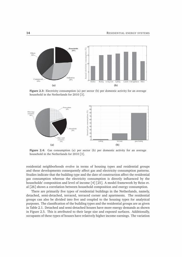
3.2 Synthetic load profile compared with smart meter data. . . . . . . . . . . . . . 333.3 A 3-day load profiles based on smart meter data and Simula software. . . . . 343.4 Load profile for residential groups in a terraced house. . . . . . . . . . . . . . . 343.5 Load profiles for a family with children in different types of building. . . . . . 353.6 A 2-day electricity consumption profile for 200 houses with weighted mixed
residential groups. . . . . . . . . . . . . . . . . . . . . . . . . . . . . . . . . . . . . 353.7 Winter load profiles for 25, 50, 100 and 200 households from smart meter
data . . . . . . . . . . . . . . . . . . . . . . . . . . . . . . . . . . . . . . . . . . . . . 373.8 Flow diagram for simulation scenarios and cases . . . . . . . . . . . . . . . . . . 393.9 Summer load profiles for penetrations of PV, heat pump, μCHPs and electric
vehicle. . . . . . . . . . . . . . . . . . . . . . . . . . . . . . . . . . . . . . . . . . . . 403.10 Winter load profiles for penetrations of PV, heat pump, μCHPs and electric
vehicle. . . . . . . . . . . . . . . . . . . . . . . . . . . . . . . . . . . . . . . . . . . . 413.11 Load profiles for one hundred households with PV systems and μCHPs. . . . . 413.12 Load profiles for one hundred households with base load-PV-heat pumps. . . 423.13 Winter load profiles for aggregation of houses with equal proportions of PV-
heat pump and PV-μCHP. . . . . . . . . . . . . . . . . . . . . . . . . . . . . . . . . 423.14 Load profiles for aggregation of houses with PV, electric vehicles and heat
pumps in winter. . . . . . . . . . . . . . . . . . . . . . . . . . . . . . . . . . . . . . . 433.15 Impacts of loads and distributed generations on future residential load profiles. 433.16 Mathematical representation of a feed-forward artificial neural network . . . 453.17 Architecture of artificial neural network forecast model. . . . . . . . . . . . . . 463.18 Forecasted data compared with actual data for seven consecutive days. . . . . 473.19 Histogram of error distribution. . . . . . . . . . . . . . . . . . . . . . . . . . . . . 483.20 Boxplot of error distribution. . . . . . . . . . . . . . . . . . . . . . . . . . . . . . . 48
4.1 An impression of a smart home [10]. . . . . . . . . . . . . . . . . . . . . . . . . . 524.2 Smart homes as integral part of smart cities [11]. . . . . . . . . . . . . . . . . . 544.3 Interaction of residential customers with energy retailers and distribution
network operators. . . . . . . . . . . . . . . . . . . . . . . . . . . . . . . . . . . . . 564.4 Smart energy homes as integral part of the Smart Grid. . . . . . . . . . . . . . . 564.5 Fundamental components enabling smart energy homes. . . . . . . . . . . . . . 58

LIST OF FIGURES xv
4.6 Schematic of an integrated end-to-end Smart Grid communication platformconcept [12]. . . . . . . . . . . . . . . . . . . . . . . . . . . . . . . . . . . . . . . . . 59
4.7 Qualitative comparison of three HAN communication technologies. . . . . . . 624.8 The Internet of Things enabled by IPv6 protocol. . . . . . . . . . . . . . . . . . . 634.9 Integrated framework for smart energy home penetration. . . . . . . . . . . . . 65
5.1 Timeline of energy management systems evolution. . . . . . . . . . . . . . . . . 705.2 Smart metering system architecture in the Netherlands. . . . . . . . . . . . . . 715.3 Home energy management products available in the market. . . . . . . . . . . 745.4 Comparison of day-ahead market price with residential electricity tariffs. . . . 795.5 Example of energy service contract between residential customers and ESCos
[13] [14]. . . . . . . . . . . . . . . . . . . . . . . . . . . . . . . . . . . . . . . . . . . 805.6 Integrating home energy management systems with smart meters, smart
loads and external parties. . . . . . . . . . . . . . . . . . . . . . . . . . . . . . . . 845.7 Keys aspects for HEMS penetrations. . . . . . . . . . . . . . . . . . . . . . . . . . 855.8 Simplification of residential customer interaction with external parties. . . . . 86
6.1 Household installations divided into local control areas (cells) monitoredand/or controlled by agents. . . . . . . . . . . . . . . . . . . . . . . . . . . . . . . 91
6.2 A multi-agent system architecture for smart home energy management. . . . 926.3 Agent platform with message dialogue in JADE. . . . . . . . . . . . . . . . . . . 956.4 Multi-agent system for device control and agent coordination. . . . . . . . . . 956.5 Example of device bid curves. . . . . . . . . . . . . . . . . . . . . . . . . . . . . . 966.6 Co-simulation platform. . . . . . . . . . . . . . . . . . . . . . . . . . . . . . . . . . 976.7 Diagram of Coordinator Agent algorithm for green optimization. . . . . . . . . 986.8 Determination of Coordinator control signal (λCS) from aggregated bid curves. 996.9 Variations of control signal (λCS) for local and aggregated demand-supply
matching (winter day). . . . . . . . . . . . . . . . . . . . . . . . . . . . . . . . . . . 1006.10 Variations of control signal (λCS) for local and aggregated demand-supply
matching (summer day). . . . . . . . . . . . . . . . . . . . . . . . . . . . . . . . . . 1006.11 House indoor temperature variations. . . . . . . . . . . . . . . . . . . . . . . . . . 1016.12 Freezer compartment temperature variations. . . . . . . . . . . . . . . . . . . . . 1016.13 Total energy use by the twenty houses. . . . . . . . . . . . . . . . . . . . . . . . . 1016.14 Total power consumption of the twenty houses. . . . . . . . . . . . . . . . . . . 1026.15 Diagram for Coordinator Agent algorithm for price-based control. . . . . . . . 1046.16 Residential network used as a case study for agent-based energy
management system. . . . . . . . . . . . . . . . . . . . . . . . . . . . . . . . . . . . 1056.17 Price variations and power consumptions of a single house. . . . . . . . . . . . 1066.18 Price variations and power consumption of twenty houses. . . . . . . . . . . . 1066.19 Power consumption and price variation of the twenty houses for the three
scenarios. . . . . . . . . . . . . . . . . . . . . . . . . . . . . . . . . . . . . . . . . . . 107
7.1 Division of a house into zones for energy management. . . . . . . . . . . . . . . 110

xvi LIST OF FIGURES
7.2 Experimental set-up for smart meter data extraction and processing . . . . . . 1107.3 Comparison of energy consumption data from P1 and P3 ports. . . . . . . . . . 1127.4 System overview. . . . . . . . . . . . . . . . . . . . . . . . . . . . . . . . . . . . . . 1137.5 Schematic of implemented ZigBee network for the laboratory set-up. . . . . . 1147.6 Process of receiving, parsing and storing data by the gateway. . . . . . . . . . . 1167.7 Connection between the different Python files. . . . . . . . . . . . . . . . . . . . 1167.8 Data strings sent by the different plug meters. . . . . . . . . . . . . . . . . . . . 1167.9 Priority control mechanism. . . . . . . . . . . . . . . . . . . . . . . . . . . . . . . . 1177.10 Power consumption of individual devices. . . . . . . . . . . . . . . . . . . . . . . 1187.11 Data gathering with 1 second data transmission interval. . . . . . . . . . . . . . 1187.12 Total power consumption with priority control mechanism for the case
without PV system. . . . . . . . . . . . . . . . . . . . . . . . . . . . . . . . . . . . . 1197.13 Total power consumption with priority control mechanism with a PV system. 1197.14 Dashboard for the Home Area Network Smart Grid Monitor. . . . . . . . . . . . 1207.15 External communication with ZigBee network. . . . . . . . . . . . . . . . . . . . 121
C.1 Smart meter installed in the laboratory and in a house. . . . . . . . . . . . . . . 137C.2 RJ11 to RS232 connection. . . . . . . . . . . . . . . . . . . . . . . . . . . . . . . . 138C.3 Domestic appliances, smart plugs and gateway for the device-level energy
management set-up. . . . . . . . . . . . . . . . . . . . . . . . . . . . . . . . . . . . 138C.4 ZigBee network topologies. . . . . . . . . . . . . . . . . . . . . . . . . . . . . . . . 139C.5 Averaging data received from smart plugs implemented in
GettingMeanValue.py. . . . . . . . . . . . . . . . . . . . . . . . . . . . . . . . . . . 140

CHAPTER 1Introduction
1.1 Background
Energy is a life sustaining commodity. As part of the overall energy needs, electricalenergy has become a basic necessity for society and a vital entity for socio-economicdevelopment. It is one of the enabling technologies that is not always noticed buthas become a ubiquitous necessity of human life for the last century. The necessityand dependence on this commodity has never shown signs to recede and it is stillexpected to increase in the future. In most part of the world, access to electricity is theright of every citizen but has to be paid for according to the market rules. The powerindustry has been under a constant but slow evolution. Power grids arose because localdemand could not be met by local generation. With generators and their natural fuelsources often situated far from consumers, networks were set up to transmit powerfrom generators to consumers. The development of the power system was, and still is,governed by the ultimate goal of providing consumers with quality and reliable powersupply at minimum cost. Nowadays, electricity is generated from multiple sourcessuch as hydro, nuclear and fossil fuel power plants, giving it the greatest degree ofenergy resilience. As our society becomes more sustainable through awareness of futureshortages and environmental consequences of fossil fuels, an effective way of ensuringfossil fuel independency is a transition towards alternative energy sources (such as windand photovoltaic), and a more efficient use of electricity.
In the meantime, energy consumption in Europe keep rising. Table 1.1 shows thatfinal energy consumption increased by 4.7% and 7.4% (for EU-28 countries), 10.8%and 14.7% (for Euro area 18 countries) in 2000 and 2010 respectively compared tothe consumptions in 1990. The Netherlands experienced a more significant increaseof 22.2% and 30.5% in 2000 and 2010 respectively. The residential sector shares agreat deal of the energy consumption in the EU-28 countries, accounting for 23.85% -27.35% of the total annual energy consumption from 1990 to 2012 [15] (see Figures?? and 1.1). Key factors driving the residential energy consumption include growing
1

2 INTRODUCTION
Table 1.1: Comparison of final energy consumptions for EU (28 countries), Euro area (18countries) and the Netherlands for the years 1990, 2000 and 2010 (Source: Eurostat).
YearFinal energy consumption (1000 TOE)
EU-28 Euro area Netherlands
1990 1079865.7 713244.6 41331.9
20001130953.1 790372.1 50504.6
(+4.7%) (+10.8%) (+22.2%)
20101159826.4 818365.0 53935.0
(+7.4%) (+14.7%) (+30.5%)
incomes, globalization of the economy, technological breakthroughs (such as smartphones and computers), ageing population, as well as habits and cultures [16]. Tokeep up with the European 20/20/20 objectives (namely, reduction in greenhousegas emissions by 20% from 1990 levels; increasing the share of renewable energyresources to 20%; and 20% improvement in the EU’s energy efficiency) [17], researchand government policies are set on finding ways to minimize energy consumptionand consequently reduce greenhouse gas emissions in the residential sector. Scientificadvances in sustainable distributed energy generations are promising. The transitionfrom fossil fuels to renewable energy sources (RES) is favored by the majority of theparties involved in the electricity market because they are often considered to be lesspolluting and more efficient. Furthermore, it is necessary to ensure an efficient use ofenergy by the end user, reforming the current habits of consumption and shaping themarket towards overall energy sustainability.
1.2 Towards energy-efficient and smart residential environments
Energy efficiency is a way of managing and restraining the growth in energyconsumption by delivering more services for the same energy input, or the same servicesfor less energy input [18]. Over the last decades, energy efficiency in the residentialsector has increased steadily, particularly in areas such as space and water heating (dueto better thermal insulation of buildings and high efficiency boilers), and also amonglarge domestic appliances like refrigerators, freezers, washing machines, dishwashersand televisions. Figure 1.2 shows a large increase in the overall energy efficiency and forsome electrical appliances (refrigerators, freezers, washing machines, dishwashers andtelevisions) in the residential sector for the EU-27 countries from 1990 to 2009. Overthe same period, energy consumption of households increased by about 13% while thatof large electrical appliances increased by 48%. The increased number of devices anddemands for higher thermal comforts at homes offset the gains from energy efficiencymeasures (Figures 1.2 and 1.3).

1.2. TOWARDS ENERGY-EFFICIENT AND SMART RESIDENTIAL ENVIRONMENTS 3
Year
1990
2000
2010
24,1 28,6 25,1
14,0
8,1 0,2
20,4
29,3 28,3
14,3
7,7 0,0
21,4
26,5 27,8
18,2
6,2 0,0
Share per sector (%)
Netherlands
25,3
34,0 26,3
10,1
2,9 1,2
26,0
29,4 30,5
10,3
2,4 1,2
EU-28
26,8
25,1 31,2
13,6
2,1 1,0 Residential
Industry
Transport
Services
Agriculture
Others
24,9
32,1 28,6
10,9 2,7 0,7
25,0
29,1
32,1 10,2
2,3 0,0
25,3
25,7 31,7
14,0
2,0 1,2
Euro area
Figure 1.1: Final energy consumption by sector for EU (28 countries), Euro area (18countries) and the Netherlands (Source: Eurostat).
1.2.1 Net-zero energy residential environment
One of the identified key sectors to achieve the vision 20/20/20 is the building sector.Low-energy houses are emerging concepts due to the potential for energy savings withinthe built environment. The net zero-energy building (NZEB) concept is a trending topicin the field of sustainable buildings and also gaining the attention of municipalities,commercial and residential stakeholders, as a way to enhance energy reliability andefficiency. A NZEB is a grid-connected building with reduced energy demands and highenergy performance, such that its thermal and electrical energy requirements can becompensated with local energy generation using the electricity grid as a buffer. It is anapproach that involves energy-efficient buildings, installation of distributed generations,and energy-efficient devices. The European Commission Directive 2010/31/EU onthe energy performance of buildings (EPBD) sets the principle of nearly zero-energybuildings as one of decisive mechanisms for the development of the building sector [19].The EPBD directive requires Member States to ”ensure that all new buildings are nearlyzero-energy buildings by 31 December 2020; and after 31 December 2018, new buildingsoccupied and owned by public authorities are nearly zero-energy buildings ” [20]. However,it is up to the Member States to develop specific policies and implementation plans forincreasing the number of NZEBs.

4 INTRODUCTION
Space heating Water heating Cooking Lighting and appliances
80
70
60
50
40
30
20
10 0
1990 2009
Shar
e of
hou
seho
ld e
nerg
y co
nsum
ptio
n (%
)
(a)
0 1990 1992 1994 1996 1998 2000 2002 2004 2006 200870
75
80
85
90
95
100
105
Year
Relativeenergy
consumption
(%)
CookingLarge electrical appliancesSpace heatingWater heatingOverall
Index 100 = 1990
(b)
Figure 1.2: (a)Share of energy consumption by end uses in total households’ consumptionin the EU-27 (b)Household energy efficiency index (Source:ODYSSEE).
1.2.2 Smart residential network
Residential loads are changing in power, complexity and quantity (Figure 1.3). Servingthe residential electricity demand is the main goal of the power grid with constantmonitoring and control to provide a safe, reliable and efficient electricity supply. Withincreasing share of distributed generation in the home environment, there is a newchallenge to operate the power grid in an efficient, safe and reliable manner. Theexisting electricity distribution system must be transformed to a more robust, reliable,and efficient one with more control functions to enable bidirectional flow of energy andinformation between households and the power system. The Smart Grid technology isenvisioned as an intelligent way to effectively accommodate the changes in the powersystem.

1.3. RESEARCH FRAMEWORK 5
(a) early house
(b) modern house
Figure 1.3: Evolutions in residential loads and comfort levels.
At the residential level, the smart meter is recently introduced as one of the means tostimulate energy efficiency culture by creating more energy awareness. However, usingseveral devices at home makes it difficult for consumers to track how much energy isconsumed per device and to identify high energy consuming devices. Smart energyhomes enabled by emerging technologies and a home area network (HAN), to measure,control and communicate energy consumption are expected to provide customers anenabling tool for managing energy consumption, and to support the power system atthe residential level by relieving congestion and enhancing balancing.
1.3 Research framework
This research is carried out within the ”Intelligent Power Systems” research framework ofthe ”Innovatiegerichte Onderzoeksprogramma Elektromagnetische vermogenstechniek”(IOP EMVT) research program supported financially by Rijksdienst voor OndernemendNederland (RVO.nl). RVO.nl is an agency of the Ministry of Economic Affairs inthe Netherlands. The Intelligent Power System project has four major parts (seeFigure 1.4) involving over 20 PhD students. Consultancy firms and energy companies

6 INTRODUCTION
give inputs and advice to steer the various research. This dissertation falls underthe self-controlling autonomous networks and it is performed under a joint-projectentitled: ”Intelligent energy supply at household and district level”. The project isdivided into two parts: ”Intelligent energy management and distribution in homes” and”Development of energy managements at district level”. Two PhD researchers (one at DelftUniversity of Technology and the other at Eindhoven University of Technology) workedin collaboration to investigate the feasibility of a comprehensive energy managementat household and district levels through design, simulation and testing. The part thatfocused on the district level was performed at the Electrical Power Systems Group ofDelft University of Technology. The main objective was to ” develop a scheduling andcontrol tool at the district level for small-scale systems with multiple energy carriers andto apply exergy-related concepts for the optimization of these systems” [1]. The project iscompleted and the results are presented in the dissertation entitled : ” Optimal Usageof Multiple Energy Carriers in Residential Systems Unit Scheduling and Power Control”[1]. This dissertation is devoted to the first part of the project, the intelligent energymanagement within the home environment. Industrial partners within this researchproject were Laborelec GDF-SUEZ, Eaton (Nederland) and DWA installatie techniek.
1.4 Research objective and scope
The energy infrastructure of the future must be more efficient, smart and adjustableto reflect the changing needs of users and society. The integration of renewable(intermittent) and other distributed generators in homes, neighborhoods and offices arelinked to the need for efficient and cost-effective energy conversion and distribution. Theincreasing need to keep the grid balanced under high penetrations levels of intermittentresources has sparked interest in designing new paradigms that allow electricity demandto respond to economic signals. For residential neighborhoods there are applications ofheat and cold storages with the use of heat pumps and micro-combine heat and power.The deployment of advanced metering infrastructure is one of the necessary steps toexposing customers to the electricity market pressures and analyzing their responses.This has stimulated the research on the design of home energy management systems
Manageable distribution networks
Inherently stable
transmission system
Self-controlling autonomous
networks
Optimal power quality
Intelligent Power Systems projects
Intelligent energy supply at household
and district level
Energy management at household level (TU Eindhoven)
Energy management at district level
(TU Delft)
Figure 1.4: IOP EMVT ”Intelligent Power Systems” research framework [1].

1.5. RESEARCH APPROACH 7
(HEMS) that handle the consumption and/or generation of customers in response touser-defined goals or dynamically changing price signals. HEMS is crucial for theintegration of distributed generators to match the different needs of users, secure thereliability and robustness of the electricity supply infrastructure, and for settlement ofcosts and benefits among generators, distribution companies and energy consumers.Additionally, socio-economic issues will undoubtedly be crucial in the development andcommercialization of new forms of energy at household and neighborhood level. Thisleads to the following research objective:
To investigate changes in the residential energy supply system and to develop anddemonstrate a framework for energy management in homes, where decentralizedand renewable energy sources and smart loads are integrated with the public gridand managed in a sustainable way.
To achieve the research objective, the following research questions are addressed:
1. What developments will change future residential energy demand and supply?
2. How will energy conversion technologies affect future residential load profiles?
3. What factors and technological advancements will facilitate sustainablepenetration of smart energy homes?
4. What are the evolutions in energy management systems for households and therole of smart meters?
5. What will be an adequate framework for a sustainable home energy managementsystem with respect to power system requirements and market structures?
6. In what ways can smart energy homes be integrated into the Smart Grid vision?
1.5 Research approach
To achieve the main objectives, the research is approached in the following order:
• Analysis of residential loads, generation and aggregated load profiles:Analyses into the influences of residential load profiles with focus on changingresidential loads - electrification of heating system and mobility, penetration ofdistributed energy resources, and type of housing and occupants.
• Investigation into smart energy homes and energy management systems: Theessence, fundamental constituents, drivers, and the added value of smart energyhomes are investigated. An integrated framework is developed for a sustainableimplementation and integration of smart energy homes into the bigger smartgrid vision and as part of the infrastructure for the smart energy buildings andcities. Further, analyses are made on energy management systems for households(HEMS).

8 INTRODUCTION
• A multi-agent-based architecture for home energy management: Smartoperation of residential grid will require simultaneous optimization of theobjectives of various actors present. Agent-based systems which implementdistributed intelligence are capable of solving complex and dynamic decisionprocesses. A multi-agent system architecture for home energy management andintegration into the smart grid is developed. The architecture is simulated inJava Agent Development Framework and MATLAB simulation platforms. Usingbid function algorithms, local demand-supply matching and price-based controls,taking into account customers comfort and priorities, dynamic pricing, networkloading or capacity management are demonstrated.
• Laboratory-scale demonstration of home energy management systems: Apractical set-up is built to investigate data extraction and processing from smartmeters for energy management. Further, a demonstration test is performed whichincludes smart plugs, and smart appliances connected via Zigbee network with acentral controller to verify device-level home energy management.
1.6 Thesis outline
The outline of thesis is graphically depicted in Figure 1.5. After the introductory chapter(Chapter 1), the rest of the thesis is structured as follows:
• Chapter 2: This chapter provides insight into the energy consumption inthe residential sector. It focuses on electricity and gas consumptions for theNetherlands over the past decade. It describes how housing types and residentialgroups affect gas and electricity consumption. Furthermore, it presents acategorization of residential loads based on their flexibility and mode of operation.Distributed generation and storage systems applied in the residential environmentare also explored.
• Chapter 3: This chapter analyzes the electricity demand profiles for aggregatedhouseholds. It explores energy conversion technologies that are expected tosubstantially change the residential electricity demand. It presents a scenario-based approach for generating representative future residential load profiles foraggregated households. The chapter concludes with an illustration of forecastingmodel for short-term predictions of residential load demand.
• Chapter 4: In this chapter, the smart energy home concept is elaborated. Ithighlights the added benefits of smart homes, and gives examples of smart energyhome demonstration projects and the objectives of the projects. It also treats theintegration of smart energy homes as part of smart cities and the interaction withthe Smart Grid. Furthermore, it discusses the main technologies (matured as wellas those underdevelopment) which are driving the penetration of smart energyhomes. Finally, it presents overview of interrelated aspects as a framework forsustainable deployment of future smart energy homes.

1.6. THESIS OUTLINE 9
• Chapter 5: The chapter focuses on energy management systems for households.The evolution of energy management systems in the energy sector is presented.The smart meter considered as a major innovative technology facilitating energymonitoring and control in homes is addressed. The state-of-the-art, driversand stakeholders of HEMS technologies are summarily discussed. Differentapplications of HEM systems are also discussed.
• Chapter 6: A multi-agent system architecture for home energy management isproposed and demonstrated in this chapter. The MAS-model is developed and co-simulated using Java Agent Development Framework for agent design and controlalgorithm, and MATLAB for modelling domestic devices. The two platforms arelinked via TCP/IP protocol. A demand-supply matching and a dynamic pricingcontrol algorithm are explained and tested with the MAS-model using a residentialstreet for a case study.
• Chapter 7: In this chapter, two types of home energy management are practicallydemonstrated. Data extraction and processing from the P1 port of the smartmeter is demonstrated in the laboratory and in a residential building. Thechapter also presents a set-up and results of a laboratory-scale, device-level energymanagement using a ZigBee network and Python scripts for device monitoring andcontrol.
• Chapter 8: The conclusions, thesis contributions as well as recommendations forfuture research are presented in this chapter.

10 INTRODUCTION
Chapter 1 Research Background, Scope Definition
Research Question & Methodology
Chapters 2 & 3 Residential Energy Systems and Load Profiles
Chapters 2 Residential Energy Consumption, Load
Categorization & Distributed Generation
Chapters 3 Synthetic and Future Residential Load
Profiles, Load Forecasting
Chapters 4 & 5 Smart Homes and Energy Management
Systems
Chapters 4 Essence , Enablers and Essentials of
Smart Homes for Smart Grid Integration Chapters 5
Home Energy Management Systems: Evolutions, Drivers, Applications,
Barriers & Integration Aspects Chapters 6
Multi-agent System for Home Energy Management
Chapters 7 Demonstration of ZigBee-based Home Energy
Management System
Chapters 8 Conclusions, Contributions and
Recommendations
Figure 1.5: Thesis outline

CHAPTER 2Residential energy systems
2.1 Introduction
Many primary energy sources are limited and relatively expensive. The prices of coal,oil and natural gas fluctuate yearly. Solar and wind are unlimited primary sources,yet technologies to fully harvest their energy contents are still under development. Inthe meantime, there is steady increase in the domestic electricity consumption dueto changing needs of residential customers with respect to comfort, convenience andflexibility. This chapter analyses the residential energy consumptions, the changesin residential loads, and the introduction of energy generation technologies at theresidential environment. Section 2.2 presents an overview of residential electricity,gas and heat consumptions for the Netherlands. It highlights the trends and possiblereasons for decrease or increase in energy use. The impacts of housing types andhousehold compositions on the gas and electricity consumptions are given in Section 2.3.Residential loads are evolving in complexity and power ratings. Section 2.4 presentscategorization of residential loads based on their mode of operation and flexibility,while Section 2.5 summarizes developments and operations of distributed generationtechnologies in the residential sector.
2.2 Energy consumption in the residential sector
The global energy consumptions keep rising yearly, primarily due to increase in globalpopulation, and rise in economic activities (particularly in China, Brazil and India) [21].In Europe, space heating and cooling, and domestic hot water are estimated to accountfor approximately 80% of the final energy demand in the residential sector for 2010 (seeFigure 2.1) [2]. However, the residential energy demand is projected to stabilize after2015, attributable to policies and regulatory provisions for the residential sector whichdrives considerable energy efficiency savings [22]. Better insulation of new buildings,retrofitting of existing ones, and the implementation of intelligent technologies are
11

12 RESIDENTIAL ENERGY SYSTEMS
2010 2020 2030 20500
20
40
60
80
100
120
Year
Share
in%
Heating Cooling Hot water Cooking Lighting Electrical appliances
14
7
1
13
7
12
13
7
4
12
7
65 64 60 54
12 14 17 232 1 11
Figure 2.1: Final energy demand in the residential sector in Europe [2].
measures towards energy savings. In the Netherlands three main energy sources areentering houses and buildings, namely, electricity, natural gas, and heat.
2.2.1 Electricity consumption
Electricity is one of the most efficient and convenient energy carriers. Hence increase inthe electricity consumption is not a negative scenario if it contributes to the reductionin the total energy consumption. The EU report on Energy Trends to 2030 describes agrowing electrical energy use resulting from the rising demand for increased comfortin households, and a decreased dependency on natural gas for heating and cookingpurposes [22]. The expected rates of increase for the future are 1.2% and 0.7% perannum in the periods 2010 - 2020 and 2020 - 2030 respectively, excluding the possiblescenarios of increased penetration of special loads, such as electrical vehicles and heatpumps. In the Netherlands, the residential sector takes a sizeable portion of the totalelectric power consumption. Figure 2.2 shows growth in the average annual electricityconsumption per household, mainly due to increasing use of household appliancessuch as freezers, dishwashers and cloth dryers [3]. Households accounted for 24%of the national electricity consumption in 2010 (see Figure 2.3a) with an average of3500 kWh per household. Cold appliances, laundry appliances, consumer electronics,and lighting are the top electricity consuming devices in the residential sector on ayearly basis (see Figure 2.3b ). With the emerging of low-energy residential lightingtechnologies, such as light-emitting-diode (LED) and compact fluorescent (CFL) lamps,electricity consumption due to residential lighting can be reduced by 60% compared totheir conventional counterparts [23].

2.3. DEMOGRAPHICS AND RESIDENTIAL ENERGY CONSUMPTION 13
2000 2001 2002 2003 2004 2005 2006 2007 2008 2009 20103000
3200
3400
3600
3800
4000
Year
Electricity
consumption
(kW
h)
1000
1300
1600
1900
2200
2500
Gas
consumption
[m3]
gas
electricity
Figure 2.2: Average annual electricity and gas consumptions for a household in theNetherlands [3].
2.2.2 Gas consumption
The Netherlands has a dense gas network with about 96% of all households, businessesand buildings connected to the natural gas network [24]. The trend in domestic gasdemand (see Figure 2.2) has shown a steady decline for the past years as building stocksare upgraded with better and more efficient designs, materials and equipment, and theintroduction of high efficiency heat boilers. The residential sector was responsible for20% of the total annual gas consumptions in 2010 (see Figure 2.4a ). About 79% ofthe gas is used for space heating, 20% for domestic hot water and the remaining forcooking (see Figure 2.4b ). Though there is a shift towards all-electric households, theNetherlands still has one of the highest proportions of gas-heated homes in Europe [3].
2.2.3 Heat consumption
Heat supplies are primarily from conventional generation plants and are consumed bylarge commercial buildings and some households in specific areas. There are about4% of residential customers who are connected to the district heating systems as mosthouseholds have direct connections to the natural gas network.
2.3 Demographics and residential energy consumption
Consumption patterns of neighborhoods are important for supply systems designs.Analyses of residential energy consumption are mostly focused on the physicaland technical aspects, such as type of appliances, neglecting the role of thedemographics and economic behaviors of residential customers [4]. However,
14 RESIDENTIAL ENERGY SYSTEMS
Households 24%
Industries 28% Commercial
10%
Others 38%
(a)
Kitchen Heating Living room Lighting Laundry Cold appliances Others0
5
10
15
20
Annualelectricityconsumption(%
)(b)
Figure 2.3: Electricity consumption (a) per sector (b) per domestic activity for an averagehousehold in the Netherlands for 2010 [3].
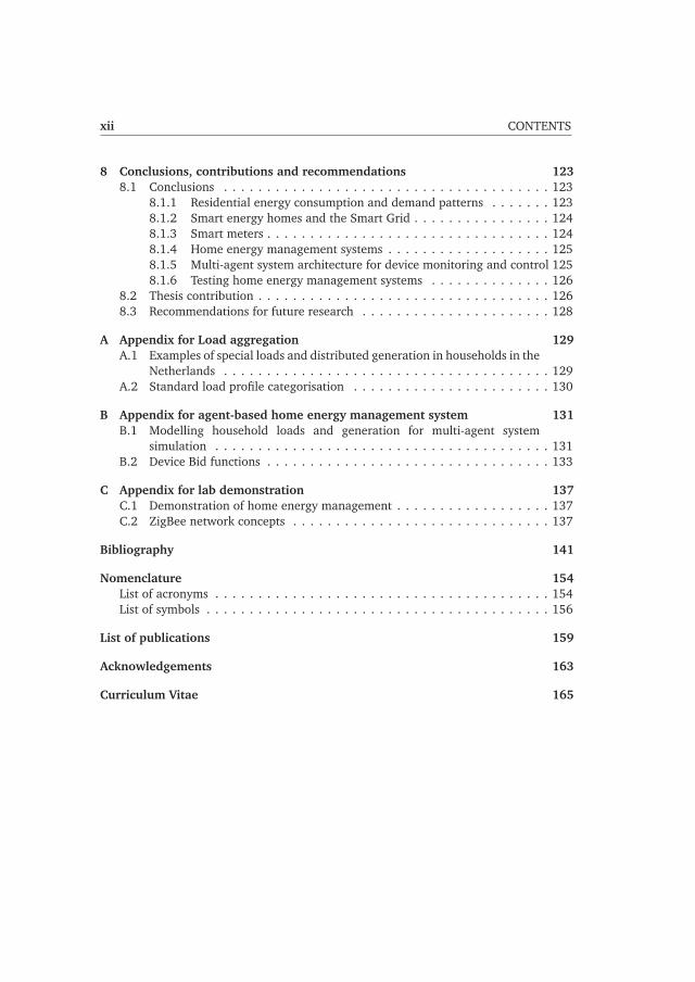
Power plants 20%
Households 20%
Other small consumers
10%
Other large consumers
50%
(a)
cooking hot water space heating0
10
20
30
40
50
60
70
80
90
100
Annualgasconsumption(%
)
(b)
Figure 2.4: Gas consumption (a) per sector (b) per domestic activity for an averagehousehold in the Netherlands for 2010 [3].
residential neighborhoods evolve in terms of housing types and residential groupsand these developments consequently affect gas and electricity consumption patterns.Studies indicate that the building type and the date of construction affect the residentialgas consumption whereas the electricity consumption is directly influenced by thehouseholds’ composition and level of income [4] [25]. A model framework by Reiss et.al [26] shows a correlation between household composition and energy consumption.
There are primarily five types of residential buildings in the Netherlands, namely,detached, semi-detached, terraced, terraced corner and apartments. The residentialgroups can also be divided into five and coupled to the housing types for analyticalpurposes. The classification of the building types and the residential groups are as givenin Table 2.1. Detached and semi-detached houses have more energy demands as shownin Figure 2.5. This is attributed to their large size and exposed surfaces. Additionally,occupants of these types of houses have relatively higher income earnings. The variation

2.3. DEMOGRAPHICS AND RESIDENTIAL ENERGY CONSUMPTION 15
in energy demand according to the building’s date of construction is shown in Figure2.6. Modern houses have less gas consumptions due to better insulation of the buildingenvelope. However, their electricity consumptions are higher presumably due to thepresence of more appliances and the electrification of the cooking and heating systems.Figure 2.7 shows the correlation between the household compositions and the energydemand. Family with children consumes the most amount of electricity attributable tomore washing cycles, use of more appliances and for longer duration, electronic devicesfor children (recreation and education), and more frequent opening of refrigerators. Forgas consumption, the elderly group (couple and single) has the highest demand. Theirannual gas consumptions exceed the electricity demand since they are mostly indoors,live in relatively old houses, and require higher thermal comfort.
Table 2.1: Household compositions and housing types
Residential groups
Family with children
Family without children
Elderly couples (>65 years)
Elderly single (>65 years)
Single (30− 64 years)
Housing types
Detached
Semi-detached
Terraced
Corner
Apartment
Detached Semi−detached Corner Terraced Apartment0
1000
2000
3000
4000
5000
Housing type
Annualelectricityconsumption
[kW
h]
0 0
1000
2000
3000
4000
5000Annual
gasconsumption
[m3]
ElectrictiyGas
Figure 2.5: Residential energy consumption for building types in the Netherlands (Source:AgentschapNL, 2010).

16 RESIDENTIAL ENERGY SYSTEMS
<1905 1906−1929 1930−1944 1945−1959 1960−1970 1971−1980 1981−1990 1991−2000 >20010
1000
2000
3000
4000
5000
Year built
Annualelectricityconsumption[kW
h]
0 0
1000
2000
3000
4000
5000
Annualgasconsumption[m
3]
ElectrictiyGas
Figure 2.6: Energy consumption of residential buildings according to year built [4].
FamWithKids FamNoKids OldCouple OldSingle Single Average0
1000
2000
3000
4000
5000
Residential group
Annualelectricityconsumption(kW
h)
0 0
1000
2000
3000
4000
5000
Annual
gasconsumption
[m3]
ElectrictiyGas
Figure 2.7: Annual average electricity and gas consumption for residential groups in theNetherlands (Source: CBS, NL).
2.4 Residential loads categorization
Residential loads may be categorized based on multiple factors. Some studies broadlydivide the loads into two categories with respect to energy management possibilitiessuch as deferrable and non-deferrable loads, where the former refers to devices whoseoperation can be shifted to later times of the day, and the later implies those whoseoperation cannot be shifted. Other studies use flexible and non-flexible loads to virtuallyrefer to the same category of loads [27]. The loads may also be divided along theability to control the devices either locally or remotely via automatic actions, hence

2.4. RESIDENTIAL LOADS CATEGORIZATION 17
the terms controllable and uncontrollable loads. Other categorization are based onappliances’ rated power consumption, dividing into heavy loads (>1000 W), normalloads (100 - 1000 W) and light loads(<100 W). However, the power consumption mayvary between two devices of similar use but are from different manufacturers, makingthis method of categorization unsuitable. Device functionalities or activity groups areother ways of load categorization. This leads to groupings such as: heating, cold,kitchen, lighting, laundry, entertainment, etc. appliances. The different categorizationsprove that residential loads are changing in composition, capacity and complexity. In thisresearch, the loads are divided based on their modes of operation and their flexibility andare grouped under: inflexible, shiftable, thermal, and buffer loads. Flexibility is definedas the ability of devices to increase, decrease or postpone their power consumption orgeneration in time without impacting on the services they provide [28].
2.4.1 Inflexible loads
Inflexible loads refer to domestic appliances whose operation cannot be interruptedor shifted to later periods as this would have significant impact on the service theyprovide [28]. There are two categories of inflexible loads. There are appliances thatare ”Always ON” or on ”Stand-by” throughout (most part of) the day. Examples areinternet gateways, modems, telephones, sensors, and answering machines. The secondgroup are appliances that must be in operation at the desired period and cannot (orhave very limited potential to) be shifted. Personal computers, television, lighting,printers, and most kitchen appliances fall under this category. They are regarded asinflexible because they are incapable of adapting or changing their operations to meetcircumstances without impacting on the service they provide.
2.4.2 Shiftable loads
They are defined as loads with fixed time periods of operational cycles and which are nottime dependent [28]. Wet appliances such as washing machine, dishwasher and tumblerdryer are examples of shiftable loads. Their energy consumptions are determined bysuch factors as: frequency of operation, machine efficiency, selected program, load sizeand ambient conditions [5]. Due their relatively high power ratings, their aggregatedimpacts on the electricity network loading are significant. However, the shiftabilitypotentials of these appliances depend on the behavior and needs of the users.
Washing machine
Washing machines are used for cleaning laundry and basically consist of a tub, rotatingdrum and a heating system. Modern washing machines are in two categories: toploading (vertically-rotating drum) and front loading (horizontally-rotating drum). Thecomplete washing cycles involve immersion of laundry in sufficient amount of water,heating of the water to desired (preset) temperature (usually 30, 40, 60 or 90 degree

18 RESIDENTIAL ENERGY SYSTEMS
0 15 30 45 60 75 90 105 1200
500
1000
1500
2000
2500
3000
Time [mins]
Pow
er[W
]
0
10
20
30
40
50
60
Tem
perature[oC]
washing machinePowerTemperature
(a) washing machine
0 15 30 45 60 75 90 105 1200
500
1000
1500
2000
2500
3000
Time [mins]
Pow
er[W
]
PowerTemperature
0
20
40
60
80
100
120
Tem
perature[oC]
tumble dryer
(b) tumble dryer
0 15 30 45 60 75 90 105 120
500
1000
1500
2000
2500
3000
Time [mins]
Pow
er[W
]
dishwasher
15
30
45
60
75
90
Tem
perature
[oC]
PowerTemperature
(c) dishwasher
Figure 2.8: Generalized power and temperature profiles for shiftable loads [5].
.

2.4. RESIDENTIAL LOADS CATEGORIZATION 19
Celsius), rinse cycles enabled by the rotating drum and the spinning (rotating ofthe drum at high speed) to extract water from the laundry [5]. Most Europeanwashing machines are between 1800 W and 2500 W rated power with annual energyconsumptions range from 129 kWh to 300 kWh. The general power demand andtemperature profile is represented in Figure 2.8(a). The evolutions in the washingmachine technology has resulted in new and energy-efficient devices equipped withstart-time delay functions which allow customers to shift the starting time to any periodof the day or night when conditions (e.g. prices, local generation) are favorable.The penetration level is about 95% for most Western European countries with theNetherlands having one of the highest ownership rates of approximately 98% [29].Depending on the size of the family, washing machines are used averagely two to fourtimes per week.
Tumble dryer
Drying laundry by conventional tumble dryers requires two to four times the energyneeded to wash the same amount at 60oC [30]. There are two basic types of dryers:condenser dryers which condense the humid air, collecting it as water, and ventilation(or evacuation) driers, which channel the humid air outdoors. The highest ownershiprates are in Belgium, Denmark and Norway with 63%, 62% and 53% respectively [5].The average penetration level in private homes in the Netherlands is estimated to be 35%[5]. Typical power ratings are from 2000 - 2500 W with an average energy consumptionof 1.40 - 2.50 kWh per cycle. The general power demand and temperature curve isrepresented in Figure 2.8(b). Dryers are not so often used as their washing machinecounter-parts on a yearly basis. They are mostly used in winter and spring periods withan average of two to three times per week. Laundry drying process in most cases directlyfollows the washing process, hence start-delay functions in dryers are hardly used.
Dishwasher
Dishwashers are mechanical devices for cleaning plates, cups, utensils. The standardbuilt-in is the most popular type of dishwasher, mostly installed under kitchen cabinetand connects directly to the household plumbing. The penetration level differssignificantly among European countries with a reported average of 42% [5]. Thewashing has three stages: high temperature washing, rinsing, and drying. The generalpower demand and temperature curve is represented in Figure 2.8(c). The energyconsumptions per cycle are between 0.9 - 2.0 kWh depending on the selected program.Large part of the energy is used to heat up the water to the desired temperature and thedry the dishes. New dishwashers have incorporated time delay functions to start or endthe washing process at predefined time. Dishwashers make less noise during operation,hence they have one of the highest potential to be shifted to any time of the day.

20 RESIDENTIAL ENERGY SYSTEMS
2.4.3 Thermal loads
Thermal loads refer to thermostatically controlled devices that supply heat or cold.Heat pumps, air-conditioners, refrigerators and freezers are common residential thermalloads.
Heat pump
Heat pumps are highly efficient, matured technologies that supply heat for space heatingand domestic hot water by applying external work to extract heat from a cold reservoir(air, water or ground) to a hot reservoir (e.g. residential building). A resistive heatingelement is mostly present for additional heating on extremely cold days. The penetrationof heat pumps in the Dutch residential sector has grown steadily especially after 2010(see Figure 2.9). In 2012, the penetration was about 1%, and it is expected to increase to15% by 2018 [31]. Depending on the fluid used for the transfer of heat between the coldand hot sources, heat pumps can be categorized into two major types: air-source (air-to-air or air-to-water) and ground-source (water-to-air or water-to-water) heat pumps.In the Netherlands, the amount of installed residential air-source heat pumps is higherthan the ground-source. The air-source heat pumps possess the advantage of air beingavailable everywhere; however, the heat output is affected by the external climaticconditions. Ground-source (water as cold reservoir) ensures optimal performance ofthe heat pump due to almost constant external climatic conditions, though is relativelymore expensive. Ground source heat pumps are expected to be mainly applied in newlydeveloped neighborhoods. The heat flow (in kW) is related to the input power according
2000 2001 2002 2003 2004 2005 2006 2007 2008 2009 2010 2011 2012 20130
50
100
150
200
250
Year
Number
ofinstalled
heatpumps(x
1000) Residential - Air-source heat pumps
Residential - Ground-source heat pumpsResidential - Total heat pumpsOverall installed heat pumps in NL
Figure 2.9: Installed heat pumps in the Netherlands (source: CBS, 2014).

2.4. RESIDENTIAL LOADS CATEGORIZATION 21
to the equation:
Q̇hp = Php ∗ COPhp + Pel−boost ∗ COPel−boost (2.1)
such that
COP =thermal ener g y output
input ener g y(2.2)
where Q̇hp is heat flow from the heat pump, Php is the heat pump rated power, Pel−boostis the rated power of resistive heating element, and COPhp and COPel−boost are thecoefficients of performance of the heat pump and the heating element respectively.
In Figures 2.10 and 2.11 are given the measured power consumption profiles oftwo heat pumps installed in a detached and semi-detached houses respectively. Themeasurements show that for a well-dimensioned heat pump, the electricity demand forheat pumps are virtually constant throughout the day in extremely cold days to providethe basic thermal comfort.
0 1 2 3 4 5 6 70
1
2
3
4
5
6
Pow
er[kW
]
Time [days]
−10
−5
0
5
10
15
Tem
perature[oC]
detached houseOutside temp
HP power
Figure 2.10: Measured one week power profile of residential heat pump in a detached house(Source: Laborelec GDF-SUEZ).
Cooling appliances
Refrigerators and freezers are common cold appliances in the households. In theNetherlands, about 17% of the annual household electricity consumption in 2010resulted from cold appliances making them one of the highest energy-consumingappliances. On the contrary, air-conditioners for residential space cooling are very

22 RESIDENTIAL ENERGY SYSTEMS
0 4 8 12 16 20 240
1
2
3
4
Pow
er[kW
]
Time [hours]
−15
−10
−5
0
5
Tem
perature[oC]
semi-detached house
Outside temp
HP power
Figure 2.11: Measured one day power profile of residential heat pump in a semi-detachedhouse (Source: Laborelec GDF-SUEZ).
uncommon in the Netherlands due to the low average temperature (about 10 degreeCelsius). Space cooling is basically for office buildings since most residential customersuse window blinds to reduce the external heat gains and particularly spend their timeoutside the homes during periods of high temperatures. However, with growing comfortlevels in recent years, air-conditioners for residential space cooling are growing.
2.4.4 Buffer loads
These are loads with incorporated storage systems. Electric vehicles, laptops, PDAs, andelectricity and heat storage systems are examples of buffers.
Electric vehicle
Electric vehicles (EV) are of strategic importance in increasing the sustainability of carmobility and energy supplies. Use of plug-in (hybrid) electric vehicles is growing acrossEurope, and so is the charging infrastructure that enables vehicles to be charged athome, workplace or in public areas. The growth of all-electric and plug-in hybrid EVsis remarkable for the Netherlands (see Figure 2.12) with over 40,000 electric vehicleson the road. The goal of the Dutch government is to reach a total of 1 million EVs by2025 [32]. In single-phase domestic networks, standardized sockets (J1772 Type 1 and62196-2 Type 2) can accept a power of 3.7 kW (for 230V at 16A), and 7.4 kW (for 230Vat 32A). The charging process may be controlled or uncontrolled and it is related to themaximum allowed charging power (Pmax) and the battery’s state of charge (SoC). The

2.4. RESIDENTIAL LOADS CATEGORIZATION 23
2011 2012 2013 20140
10
20
30
40
50
Year
Totalelectric
vehicles(x1000)
fully electric vehiclesplug-in hybrid electric vehicles
Figure 2.12: Electric vehicles (3 or more wheels) in the Netherlands (Source: RVO.nl-2014).
energy accumulated in the battery and the battery state of charge can be defined byequations 2.3 - 2.5 [33].
EEV char ge = PEV char ge ∗Δt (2.3)
SoC(t) = SoC(tstar t,char ge) +
∫ t
0
PEV char ge
Cbat ter yds (2.4)
SoC(tstar t,char ge) = SoC(t t rip,end) = SoC(t t rip,star t)−Dtravel led
Drange(2.5)
where, SoC(t) is the battery’s state of charge, Dtravel led is the distance travelled bycommuters, Drange is EV’s driving range, t t rip,star t and t t rip,end denote trips’ start timeand end time respectively.
Figure 2.13 (a) and (b) respectively show weekday and weekend average powerdemand profile of about 15000 electric vehicles charging at home, office and shoppingarea. It can be deduced that the effect of EV on the residential energy system will dependon the charging scheme, day of the week and the available charging possibilities (home,office or public area).

24 RESIDENTIAL ENERGY SYSTEMS
4 8 12 16 20 240
0.4
0.8
1.2
1.6
Time (hours)
Pow
er(kW
)
homeshopoffice
weekday
(a)
4 8 12 16 20 240
0.4
0.8
1.2
1.6
Time (hours)
Pow
er(kW
)
homeofficeshop
weekend
(b)
Figure 2.13: Average power demand profile of about 15000 electric vehicles charging athome, office and shopping area for (a)weekday and (b)weekend [6].
2.4.5 Energy storage systems
Energy storage systems (ESS) are enabling technologies for transport and gridapplications. Examples of energy storage technologies are: electrochemical batteries,ultracapacitors, flywheel, compressed air energy storage, pumped hydropower,superconducting magnetic energy storage, and thermal energy storage [34]. Pumpedhydropower storage (PHS) uses combination of water and gravity to capture off-peakpower and release it at times of high demand. It is the most widely used form of bulk-energy storage accounting for more than 99% of bulk storage capacity worldwide [35][36]. Compressed air energy storage (CAES) is largely equivalent to PHS in terms ofstorage capacity and applications. However, in CAES plants, ambient air is compressedand stored under pressure in underground taverns [37]. CAES is limited in real-life

2.4. RESIDENTIAL LOADS CATEGORIZATION 25
Table 2.2: Examples of energy storage systems
Type Energydensity(Wh/kg)
Energyefficiency(%)
Cycle life(cycles)
Selfdischarge
Residentialapplication
Lead acid 20-35 70-80 200-2000 low Yes
Li-Ion 100-200 70-85 500-2000 med Yes
Flywheel >50 95 >20000 high limited
EDL capacitors < 50 95 50000 very high Yes
CAES 10-30 40-50 >20yrs - No
Pumped hydro 0.3 65-80 >20yrs negligible No
SMES 50 80-90 >20yrs very high No
application. The only two existing CAES plants in the world are in Huntorf, Germany,and McIntosh, Alabama USA [37].
Among the energy storage systems, electrochemical batteries (such as Lead acid andLithium Ion (Li-ion)) and thermal storages are the most common ESSs in households(see Table 2.2). Lead acid batteries are dominant ESS for automotive and residentialapplications because of their robustness, tolerance to abuse, less expensive and simpleto manufacture [38] [39]. The disadvantages of lead acid batteries are that they havelow energy density, shorter life-cycle, low depth of discharge (typical DOD of 50%), andtend to be big and heavy especially for higher power applications. Li-ion batteries areone of the fastest growing battery systems. They have high-energy density, light-weight,low maintenance but relatively expensive. Flywheel energy storage for residentialapplications can support power system applications, such power quality applications,peak shaving and stability enhancement of residential distribution network. Howeverthe potential safety risk that could result should it be loaded up with more energy thatthe components can handle is a major limitation [38] [39].
The increasing interest in energy storage for the electricity grid can be attributed tothe capital costs of managing peak demands, the investments needed for grid reliability,modular storage technology development, and the integration of renewable energysources. Significant incorporation of ESSs into the grid would relax the constraintthat the generation of electricity continuously follows the demand by serving as reservecapacities. Locating storage near loads opens up opportunities to use the same storagefor many more applications than a larger centralized resource could address. ESSsapplications include voltage control (support a heavily loaded feeder, and reducethe need to curtail distributed generation); power flow management (redirect powerflows, delay network reinforcement, reduce reverse power flows, minimize losses), andsecurity improvement (providing a more efficient distribution grid that is more resistantto disruptions [40]). The flexibility of storage and retrieval systems can help provideinstant response to demand changes, and consequently, add more flexibility to the grid

26 RESIDENTIAL ENERGY SYSTEMS
[41].
2.5 Distributed generation
Distributed generation (DG) technologies are electricity production units that are notcentrally planned, or dispatched, often located close to the load center, and connected tothe distribution electricity network. They are primarily not involved in system balancing,systems reserves or auxiliary services. The maximum rating that can be connectedto a distribution system depends on the capacity of the distribution system, which iscorrelated to the voltage level within the distribution system. DGs offer the possibility ofintroducing renewable energy resources, like wind, solar and biomass into the electricalpower system. This provides significant environmental benefits, such as local use ofgenerated energy, reduction in CO2 emissions, and furthermore, fuel diversification,energy autonomy, and eventually improvement on power quality and reliability of thelocal electricity network. However, integration of (non-dispatchable) DG technologiesinto power systems is technically challenging due to their less controllability. Thepenetration of large amount of DGs without strict requirements is a concern for networkoperators as they have to balance out generation and demand, and to provide forsecure network operation. This section summarizes the development and operation ofthree most common DG systems in the residential sector: photovoltaic systems, microcombined heat and power units, and micro wind turbines.
2.5.1 Photovoltaic system
Photovoltaic system installations has grown (and continues to grow) at a remarkablerate over the past decade. The growth is attributed to reduced capital cost of thePV system, improved generation efficiency of PV modules, increased utility electricitycosts, and incentives offered by national governments - enhanced feed-in tariff, capitalsubsidies, and income tax credits [42]. From Figure 2.14, it can be noticed that thetechnology grew globally from 24 GW installed capacity in the world at the end of 2009to 138.9 GW by end of 2013 with Europe as the world’s leading region in terms ofcumulative installed capacity [7]. In the Netherlands, the total installed capacity PVsystems by 2010 was 88 MW. However, in year 2012 alone, a total capacity of 220 MWof PV systems was installed, resulting in an increase of 152% in capacity compared tothe level of the previous year [8]. By the end of 2013, the total cumulative installed PVpower for the Netherlands has reached 722 MW (see Figure 2.14) [8].
Figure 2.15 gives a representation of a single-phase two-stage PV system converterfor a household. In general, PV systems are operated to maximize the production(tracking the maximum power point) to serve part of or the entire domestic load.However, high PV penetration creates reverse power flows (flow from LV into MVdistribution network and possibly even into the HV network), voltage fluctuations,and frequency deviations. Therefore, the integration of PV systems into the electricity

2.5. DISTRIBUTED GENERATION 27
2000 2001 2002 2003 2004 2005 2006 2007 2008 2009 2010 2011 2012 20130
20
40
40
80
100
120
140
160
Year
Installed
PV
capacity
[GW
]
0.20
0.40
0.60
0.80
1.00
1.20
1.40
1.60
Installed
PV
inNL[G
W]
world europe is a wonderful laNetherlands
Figure 2.14: Cumulative installed PV capacity for the Netherlands, Europe and the world[7] [8].
Grid
household load
DC-AC inverter
LC filter
PV array
DC-DC boost
converter Vpv_dc Vlink
Control circuitry
Ipv_ac
Vpv_ac
Ipv_a,c Vpv_ac Vlink
vgrid
c
c
Metering & Distribution
system
igrid
vgrid Vpv_dc
Figure 2.15: Schematic diagram of a single-phase two-stage PV system converter.
grid will require flexible operation of the inverter control circuitry to meet theexpectations of owners and to support the grid. Multi-purpose control strategies whichcombines maximum power point tracking, specified real power injection, voltage/varcontrol, frequency support and off-grid operations, will make PV system to have moreadaptability. The switch between different operation modes must be automatic andseamless to provide means to deliver control commands to coordinate multiple PV

28 RESIDENTIAL ENERGY SYSTEMS
systems.
2.5.2 Micro combined heat and power
Micro combined heat and power (μCHPs) units are replacing the conventional gas boilerto provide heat and hot water, and to supply part of the homes’ electricity needs. Severalstudies and pilot projects show that μCHP systems can reduce household energy costsand carbon emissions. The technology is growing in the Netherlands and, for instance,also in the United Kingdom due to the existing extensive gas network and the largenumber of gas-connected households in these countries. The main systems are based oninternal combustion engine (ICE), Stirling engine (SE), and fuel cell (FC) technologies.The availability of a suitable internal combustion engine for domestic use is low. Stirlingengines, which are external combustion engines, have the freedom of choosing the fueland the ease of installation as advantages; however they have low electrical efficiency.The fuel cell based μCHPs have the lowest market penetration due to the high capitalcost, however their high electrical efficiency, modularity, and quiet operations makethem the most suitable μCHPs for the residential sector. The integration of μCHPs ina single house faces challenges since thermal demand does not always coincide withelectrical demand. Figure 2.16 shows the energy flows of a μCHP unit consisting ofa prime mover, an auxiliary burner and a thermal storage. The heat and electricitybalances can be respectively expressed by equations 2.6 and 2.7 [43]:
Qstore(t + 1)−Qstore(t) =
∫ t+1
s=t
(Qchp,pm +Qaux −Qhse,dmd)ds (2.6)
Ehse,dmd(t) = Echp,prod(t) + Ehse,imp(t)− Ehse,ex p(t) (2.7)
such that
Qchp,pm = Gchp,suppl y ×ηchp,th
Qaux = Gaux ,suppl y ×ηaux
Echp,prod = Gchp,suppl y ×ηchp,elec
where Qhse,dmd is the house heat demand; Qchp,pm is the heat production from theprime mover of the μCHP; Qaux is the heat production from the auxiliary burner;Qstore is the heat storage content in the buffer; Ehse,dmd is the house electrical energydemand; Echp,prod is the electrical energy generation from the μCHP; Ehse,imp is theelectrical energy taken from the grid; Ehse,ex p is the electrical energy delivered to thegrid; Gchp,suppl y is the gas supply to the μCHP; Gaux ,suppl y is the gas supply the auxiliary

2.5. DISTRIBUTED GENERATION 29
household
μCHP
prime mover
auxiliary burner
heat storage
electricity demand
heat demand
gas network
electricity network
Qpm
Eprod
Qaux
Qdmd
Eimp
Eexp Edmd
Qstore
Gsupply
Gpm
Gaux
heat flow
gas flow
electricity flow
ηelec ηth
ηaux
Figure 2.16: Energy flows in a residential μCHP system [9].
burner; ηaux is the thermal efficiency of the auxiliary burner; and ηchp,th and ηchp,elecare the thermal and electrical efficiency of the μCHP respectively.
The annual heat-to-power ratio for a household varies from 2 : 1 to 8 : 1, dependingon the age, type, size and occupancy of the house [44]. Therefore hybrid controlfunctions (combinations of ‘time-led’, ‘heat-led’, ‘electricity-led’ or model predictiveapproach) combined with thermal storage systems will improve the efficiency andflexibility of μCHP operations. The BlueGen SOFC, for example, uses ceramic fuelcells to electrochemically convert gas into electricity and produces electricity at highefficiency, up to 60 per cent electrical efficiency and when combined with thermalstorage can be operated throughout the year.
2.5.3 Micro wind turbines
Wind power is one of the most promising sources of renewable energy. The yield fromlarge wind parks (on- and off-shore) show that the technology is yet economically morefeasible than solar or biomass for electricity generation. The output mechanical powerof the wind turbines is a cubic function of the wind speed and can be expressed as(assuming steady-state power characteristics of the turbine) [45]:
Pm =ρairAW T
2V 3
wind cp(ϕ,β) (2.8)
where ρair is the air density; AW T is the turbine swept area; Vwind is the wind speed; cpis the turbine’s coefficient of performance which is a function of the tip speed ratio (ϕ)and the blade pitch angle (β).

30 RESIDENTIAL ENERGY SYSTEMS
Technically, large scale integration of residential micro wind turbines into the lowvoltage has the same issues as PV systems. However, building integrated or roof-mounted wind turbines are located in areas where wind is normally weak, turbulentand unstable in terms of direction and speed [46] [47]. Further, because of the peculiarcharacteristics of the built environment, micro wind turbines for residential applicationsmust comply with low noise levels, reliable operation, good energy yield, structural andelectrical safety requirements, and minimized visual intrusion to win the approval ofconsumers, municipalities, planners, and distribution network operators [46] [47].
2.6 Conclusion
Energy consumption in the residential sector keeps rising. In Europe, however,residential energy consumption is expected to stabilize because of the enforcementof energy efficiency measures. The electrification of mobility and heating systems,the use of more domestic electrical appliances and the demand for more comfort byresidential customers will cause significant rise in residential electricity consumptionwhereas gas and heat consumption will decline. In this chapter the key determinants ofthe residential energy consumption which are important for implementation of effectivepolicies and energy efficiency measures are presented. The relationship between gasand electricity consumptions and the physical characteristics of residential buildings (thetype and the vintage), and the household demographic composition were investigated.Housing units built after year 2000 use about 60 - 70% less gas compared with similarbuildings constructed before 1905. The variation among housing types and the year ofconstruction are less pronounced with regards to electricity consumption. Families withchildren living in detached houses have the highest annual electricity consumption. Theelderly households have the highest annual gas demand because they live in relativelyold houses and need for more thermal comfort. Additionally, residential loads arechanging in capacity and complexity. Shiftable loads (washing machines, dishwashersand tumble dryers) represent a huge cost saving potential because of the ability toshift their operation cycle to favorable time periods. New technologies such as heatpumps, electric vehicles, PV systems and μCHPs will contribute significantly to the totalresidential energy consumption. The penetration of these technologies depends onsocietal acceptance and national or regional government policies. Residential energystorage systems may not be economically beneficial for individual customers at themoment however, aggregation and of storage units and implementation of controland coordination techniques will provide collective benefits to the customers, energysuppliers and the network operators.

CHAPTER 3Residential load aggregation
3.1 Introduction
Electric load profiles indicate variations in the electrical load with time. The profilesvary according to weather, seasons and customer load types (residential, commercial orindustrial). These load data are useful for accurate load forecasting, system planningand operations. In a deregulated environment, competing entities need to assess theircustomer demands to accurately estimate the demand for load balancing, bidding andmanagement in energy trading, accurate billing, and penalties for consumers whodeviate from contracted schedules [48] [49]. The benefit to the consumer is generallyseen as the possibility of offering a better price for energy consumption and the prospectof additional services [50]. Residential energy consumption data is highly protected inmany European countries due to privacy concerns. Access to energy consumption datais limited to assigned companies who monitor them and are not keen on sharing thesedata. The use of models and simulations for estimating residential load profiles arenovel practices to circumvent the privacy bottlenecks. There are several methods forconstructing demand profiles for aggregated households, the most common ones beingthe Area model (regional model) and the Category model (or consumer-group-related).In the Area model, large or medium size consumers may be equipped with facilitiesfor time interval metering. The metered power consumptions are subtracted from thetotal energy consumption for the entire area for each time interval. The average of thisdifference is considered to be the load profile for all end users that were not meteredwithin the area. The category model however, defines the load of a consumer takinginto account the average aggregated load of the group [50].
This chapter looks into electricity demand profiles for aggregated households.Section 3.2 investigates synthetic load profiles to generate representative load profilesfor aggregated households. Section 3.3 analyzes the effects of housing types andresidential compositions on the load profiles. In Section 3.4, a scenario-based approachis developed to investigate the impacts of electric vehicles, heat pumps, μCHP units, and
31

32 RESIDENTIAL LOAD AGGREGATION
PV systems on residential winter and summer load profiles. Finally, Section 3.5 presentsan example of a short-term forecasting model for predicting load profiles of aggregatedhouseholds using artificial neural networks.
3.2 Synthetic load profiles
Synthetic load profiles (SLPs) are statistically determined load curves of representativeresidential customers. They can be categorized into static or dynamic. The formeris developed from historic data from sufficiently large sample of customer class forover a year. It is then modified to take into account factors that affect consumptionand which may vary from day to day as well as from year to year (variations in theweather, holiday periods, special events) [50]. Dynamic profiles, on the other hand,are developed from ”real-time” power measurements of a sample of customer groups atspecific time intervals. The data is analyzed to derive the average load profile. The real-time measurements inherently take into account weather variation, and special eventsand hence modifications are not required. In the Netherlands, standardized electricityload profiles are widely used for developing representative load profiles for the differentcustomer categories. The standardized profiles are expressed as dimensionless timeseries fractions of the yearly demand. Customers are divided into groups accordingto the power consumption and meter type as given in Table A.5 of Appendix A. Theload profile for a household is obtained by multiplying the normalized time series bythe yearly electricity demand of that household. Representative synthetic load profilesfor the winter, spring, summer and autumn periods for residential customers in theNetherlands are as shown in Figure 3.1. These profiles are for households withoutspecial new types of loads such as, heat pumps and electric vehicles, storage systems,and distributed generations. In Figure 3.2 residential load profiles generated from SLPs
0 3 6 9 12 15 18 21 24
200
400
600
800
1000
Time [hours]
Pow
er[W
]
winterspringssummerautumn
Figure 3.1: Synthetic load profiles of residential electricity for the four seasons(Source:EDSN.nl).

3.3. HOUSING TYPE AND RESIDENTIAL GROUPS ON LOAD PROFILES 33
0 1 2 3 4 5 6 70
200
400
600
800
1000
Time [Days]
Pow
er[W
]
SLP Smart meter
Figure 3.2: Synthetic load profile compared with smart meter data.
are compared with measured smart meter data for 190 households. The results indicatethat SLPs are useful estimations and provide an important alternative way to generaterepresentative load profiles for aggregated households.
3.3 Housing type and residential groups on load profiles
This section examines the effects of the two demographic aspects, namely, housingtypes and household compositions, on the residential load profiles. Simulations ofrepresentation residential load profiles based on the two aspects are developed withSimula software1. The profiles developed by the Simula software generally follow asimilar pattern to those obtained with the smart meter (see Figure 3.3). The differencesarise because detailed information about the smart meter data (housing type, numberof residents, and age group) to simulate corresponding profiles could not be obtained.
Figures 3.4 (a) and (b) show the winter and summer electricity profiles respectivelyfor the residential groups living in a terraced housing. The simulation is done with50 houses. It could be observed that for a neighborhood dominated by one residentialgroup, high peaks of energy consumptions occur. This is due to a high coincidence factorof their activities. For example, families with children will have similar activities suchas cooking periods, children activities, etc., occurring about the same time. In Figures3.5 (a) and (b) are consumption profiles for a family with children in different buildingtypes. The variations in the consumptions profiles affirm that the type of house affectsnot only the amount of energy consumed but also the consumption pattern. Varyingproportions of the residential groups are analyzed to determine their impacts on theenergy consumption profile.
1Simula software is a simulation tool designed to generate heat and electricity profiles of typical Dutchhouseholds based on a large household inquiry and has the option to simulate profiles according to age-groups,number of residents, and housing type for both summer and winter periods [51].

34 RESIDENTIAL LOAD AGGREGATION
0 1 2 30
0.4
0.8
1.2
Time (days)
Pow
er(kW
)
smart metersimula
Figure 3.3: A 3-day load profiles based on smart meter data and Simula software.
0 4 8 12 16 20 240
0.2
0.4
0.6
0.8
1
1.2
Time [hours]
Pow
er[kW
]
singleelderly singleelderly couplefamily w/o kidsfamily with kids
(a) winter
0 4 8 12 16 20 240
0.2
0.4
0.6
0.8
1
1.2
Time [hours]
Pow
er[kW
]
singleelderly singleelderly couplefamily w/o kidsfamily with kids
(b) summer
Figure 3.4: Load profile for residential groups in a terraced house.
3.3. HOUSING TYPE AND RESIDENTIAL GROUPS ON LOAD PROFILES 35
0 4 8 12 16 20 240
0.5
1
1.5
2
Time [hours]
Pow
er[kW
]terracedterraced cornersemi-detacheddetachedapartment
(a) winter
0 4 8 12 16 20 240
0.5
1
1.5
2
Time [hours]
Pow
er[kW
]
terracedterraced cornersemi-detacheddetachedapartment
(b) summer
Figure 3.5: Load profiles for a family with children in different types of building.
0 0.5 1 1.5 20
100
200
300
Time (Days)
Powe
r, (k
W)
mixed groups family with kids working couples
Figure 3.6: A 2-day electricity consumption profile for 200 houses with weighted mixedresidential groups.

36 RESIDENTIAL LOAD AGGREGATION
A ’Mixed’ group is obtained through weighted combinations of the residential groupsand housing types. Figure 3.6 shows that a neighborhood with a good mix of residentialgroups and building types provides a natural smoothing of peaks and hence limits theneed for peak shaving programs. Social integration seems to positively impact on energyconsumption by reducing its peak demand.
3.4 Future residential load profiles for planning
The penetration of electric vehicles, heat pumps, micro combined heat and power, andphotovoltaic systems generate uncertainties in consumption patterns of the residentialsector. In the future energy supply systems, residential load profile models withstandard load profiles are not suited for a reliable representation of the future electricitydistribution needs with the rapid changes in customer loads and the penetration ofdistributed generations. Studies show two basic approaches to generate present andfuture residential load profiles. They are “top-down” and “bottom-up” approaches[52]. Each approach relies on different levels of input information and diversesimulation techniques, to provide results and analysis with different end-goals andareas of applications. The top-down approaches treat the residential sector as energysinks and do not differentiate energy consumption of individual end-users. Clustering,pattern recognition, forecasting technique and demand-supply scenarios are examplesof top-down methods to estimate load profiles [53] [54]. The shortcomings of theseapproaches are that information about individual peaks, load factors, and customers’behaviors are overlooked. Conversely, bottom-up methods account for the energyconsumption and behaviors of individual end-users and extrapolate to representneighborhoods, districts or regions. Probabilistic and scenario-based modellingapproaches are examples of the bottom-up methods for generating future residentialelectricity demand and their impacts on distribution grid [55] [56]. The downsidesof bottom-up method are the high intensity of modelling, and the risk of missingappliance(s) to model. Other studies examine the effects of specific technologies such asheat pumps, electric vehicles, μCHPs, and PV systems on residential load profiles and onthe low or medium voltage grid [9] [57] [58] [59]. This section accesses the impact ofdistributed generation and special loads on the future residential demand pattern. Thescope is limited to the residential environment involving 25, 50, 100 and 200 houses forwinter and summer weeks. These are average numbers of houses connected to typicaldistribution transformers in the Netherlands (see Table 3.1). The methodology adoptedcombines top-down (requires less modelling intensity and computational time) and thebottom-up (generally gives good results due to the inclusion of end-user behavioralmodels) approaches. Scaled synthetic load profiles represent base loads per household.A scenario-based approach is implemented for the analysis of different combination andvarying penetration levels of heat pumps, μCHPs, electric vehicles and PV systems.

3.4. FUTURE RESIDENTIAL LOAD PROFILES FOR PLANNING 37
1 2 3 4 5 6 70
50
100
150
Time (days)
Energy
dem
and(kW
h)
25houses 50houses 100houses 200houses
Figure 3.7: Winter load profiles for 25, 50, 100 and 200 households from smart meter data
3.4.1 Existing situation
Figure 3.7 shows winter load profiles for aggregated households from smart metermeasurements. In general, winter periods have the highest peak loads in theNetherlands. For network planning purposes an average peak load per householdis estimated to be 1.1 kVA. However, to allow load growth 1.3 kVA is mostly used.Comparing Figure 3.7 with Table 3.1, it can be observed that the existing distributiontransformers (with the connected number of household) the peak loads reach half ofthe transformer capacities. It is therefore expected that the local residential networkhas some room to cope with the penetration of new technologies.
3.4.2 Scenario-based simulations
Simulations are done according to scenarios indicated in Table 3.2. Two scenarioswere investigated - penetration of single new technology, and combination of newtechnologies additional to the base load. Each scenario is sub-divided into cases. Each
Table 3.1: Distribution transformers (MV/LV) in the Netherlands with number of connectedhouseholds.
Index Transformercapacity
Number of connectedhouseholds
Locations
1 630 kVA 300 - 350 highly dense areas
2 400 kVA 200 - 250 large cities
3 250 kVA 100 - 150 cities and towns
4 100 kVA 40 - 60 rural areas

38 RESIDENTIAL LOAD AGGREGATION
case is investigated for the aggregation of households and different penetration levelsof special loads and/or DGs. The simulation flow diagram is shown in Figure 3.8.The base load, temperature and irradiation profiles for the winter and summer weeksare for February 1 - 7th, 2012 (coldest week of the year) and August 16 - 22, 2012(hottest week of the year). The base load in this context is defined as power demandof a household without heat pumps, μCHPs, electric vehicles and photovoltaic systems.They are represented by smart meter data from households without special loads anddistributed generations.
The simulation spans the usage over a week divided into quarter-hourly slots andrepresented by a set of time slots T, where |T| = 672. The temperature and globalirradiation data for the year 2012 are obtained from the Royal Dutch MeteorologicalInstitute (KNMI)2 in De Bilt. The schemes for the simulation of EVs are from weekdayand weekend home charging patterns of electric vehicles from Netbeheer Nederland3
and the mobility patterns of the Netherlands [6]. The minimum and maximum indoortemperature varied per household ranging from 19oC to 21oC for the winter week and21oC to 23oC for summer week [60] [61]. A uniformly distributed pseudo randomnumber set is used to set the house initial temperatures to account for the variabilityin indoor temperature and to prevent all heat pumps or μCHPs starting at the sametime. The compositions of loads and generations chosen for the simulations are given inTable 3.3. The values are chosen from installations and pilot projects involving specialloads and distributed generations in existing households [35]. Though heat pumps’COP values vary with outside or source temperature, test results from [62] show thatthe variations are small for small temperature variations (about 0.1 for a temperaturedifference of 10oC). Hence the COPs are kept constant for the entire simulation period.Tables A.1 - A.4 in Appendix A give examples of installed special loads and distributiongenerations in households in the Netherlands.
3.4.3 Penetration of individual technologies
We consider Scenario A with the introduction of individual technologies (see Table 3.2).Figure 3.9 indicates that large PV penetration will result in two loading peaks during thesummer periods: a peak generation which occurs at midday and the conventional loadpeak during the evenings. Due to large disparity between winter and summer irradiationin the Netherlands, the peak PV generation in winter has little effect on the load profile.For the same number of houses, 100% penetrations of heat pumps will double the peakload in winter (see Figure 3.10). In the case of electric vehicles, the level of penetrationand the charging scheme will determine their impact on the residential load profile.
2The Royal Netherlands Meteorological Institute (In Dutch: Koninklijk Nederlands MeteorologischInstituut, KNMI) is the Dutch national research and information center for climate, climate change andseismology (http://www.knmi.nl/).
3Netbeheer Nederland is association of all national and regional electricity and gas network companiesin the Netherlands.

3.4. FUTURE RESIDENTIAL LOAD PROFILES FOR PLANNING 39
PV system
Heat pump
Base loadprofile
Housing typetemperaturerequirements
μ-CHP
EV Chargingprofile
Historical DataMobility patterns
select
Scenario Load profile
Historical DataSynthetic Load
Profile Database
WeatherTemperatureIrradiation
Figure 3.8: Flow diagram for simulation scenarios and cases
Table 3.2: Simulated scenarios (BL = base load; EV = electric vehicle; HP = heat pump; PV= photovoltaic system.)
Index Description
Scenario A Penetration of individual technologies
Case 1 BL + PV
Case 2 BL + HP
Case 3 BL + μCHP
Case 4 BL + EV
Scenario B Combination of technologies
Case 1 BL + PV + HP
Case 2 BL + PV + μCHP
Case 3 BL + PV + μCHP + HP
Case 4 BL + PV + HP + EV

40 RESIDENTIAL LOAD AGGREGATION
Table 3.3: Loads and distributed generations per housing type used for simulating scenarios.
Housingtype
PV system Heat pump μCHP
Peak power(kWpeak)
Powerusage(kWelec)
Thermaloutput(kWheat)
Coolingoutput(kWcool)
Poweroutput(kWelec)
Thermaloutput(kWheat)
Detached 3.00 2.00 10.00 6.70 1.00 8.00
Semi-detached
2.40 2.00 10.00 6.70 1.00 8.00
Terraced 1.60 1.50 6.75 4.90 1.00 6.00
Apartment 1.00 1.50 6.75 4.90 1.00 6.00
Wed Thu Fri Sat Sun Mon Tue−100
−50
0
50
100
150
200
250
Time [Days]
Power
[kW
]
PVheat pumpCHPelectric vehicles
100 households − summer
Figure 3.9: Summer load profiles for penetrations of PV, heat pump, μCHPs and electricvehicle.
3.4.4 Combinations of technologies
BL + PV + μCHP
For residential neighborhoods with a mixture of existing and new buildings,combinations of different types of distributed generation will occur. Most of the existinghouses are connected to the gas network. They often have relatively less insulationand are often equipped with boilers and radiators requiring high temperature heating.μCHPs, which can operate at such high temperatures, are suitable to replace theseboilers. Therefore μCHPs will be used more in existing neighborhoods. A PV - μCHPcombination is expected for gas-connected neighborhoods with renovated houses andgas connection. Figure 3.11 indicates that winter and summer profiles will result in morepower injection into the network. The situation will lead to power flow congestions. The

3.4. FUTURE RESIDENTIAL LOAD PROFILES FOR PLANNING 41
Wed Thu Fri Sat Sun Mon Tue−100
−50
0
50
100
150
200
250
Time [Days]
Power
[kW
]
PVheat pumpCHPelectric vehicles
100 households −winter
Figure 3.10: Winter load profiles for penetrations of PV, heat pump, μCHPs and electricvehicle.
addition of electric vehicles to PV - μCHP could reduce the amount of injected power tothe network.
BL + PV + heat pump
New buildings, in general, have nowadays better insulation and less heat demand. Theirheating systems are often floor or wall heated at low temperatures. This suits heatpumps, which utilize low temperature heating. Combining heat pumps with PV systemsare expected for new and often all-electric residential neighborhoods. Figures 3.11indicates that large installations of such systems will result in peak generations during
0 1 2 3 4 5 6 7
−100
−50
0
50
100
Time [days]
Power[kW
]
SummerWinterBase load + PV + CHP
Figure 3.11: Load profiles for one hundred households with PV systems and μCHPs.

42 RESIDENTIAL LOAD AGGREGATION
summer and increased peak loads in winter. With regards to the existing transformercapacity and loadings, the peak loads of PV-HP-dominated neighborhoods are within thecapacity of the existing network transformers.
BL + PV + μCHP + heat pump
Neighborhoods with both existing and new buildings lead to use μCHP and heatpumps. Optimized proportions of μCHP and heat pumps will minimize peak load andgenerations (from Figures 3.13).
0 1 2 3 4 5 6 7−100
−50
0
50
100
150
200
250
Time [days]
Power[kW
]
SummerWinter
Base load + PV + HP
Figure 3.12: Load profiles for one hundred households with base load-PV-heat pumps.
Wed Thu Fri Sat Sun Mon Tue−50
0
50
100
150
200
250
Time [Days]
Power
[kW
]
25 houses50 houses100 houses200 houses
Base load + PV + 50% HP +50%CHP: winter
Figure 3.13: Winter load profiles for aggregation of houses with equal proportions of PV-heat pump and PV-μCHP.

3.4. FUTURE RESIDENTIAL LOAD PROFILES FOR PLANNING 43
BL + PV + EV + heat pump
The addition of electric vehicle-charging-at-home to high penetration of heat pumps willcreate problems for existing residential network. In the winter, electric vehicles use extraenergy for internal heating and hence require more charging cycles; heat pumps operatemore often to maintain comfortable indoor temperatures whereas the PV power outputis lowest. Compared with the existing situation, winter load profiles of BL-PV-EV-heatpump combination results in three times the peak load and could require replacementof network cables and/or addition or replacement of transformers (from Figure 3.14).
Figure 3.15 summarizes the potential impact of new types of loads and DGs on winter
Wed Thu Fri Sat Sun Mon Tue0
100
200
300
400
500
600
700
Time [Days]
Power
[kW
]
25 houses50 houses100 houses200 houses
Base load + PV + EV + HP − winter week
Figure 3.14: Load profiles for aggregation of houses with PV, electric vehicles and heatpumps in winter.
Impa
ct o
n su
mm
er re
siden
tial l
oad
prof
ile
Low
Hig
h
PV systems
Heat pumps
μCHP
Electric vehicles
Impact on winter residential load profile Low High
Figure 3.15: Impacts of loads and distributed generations on future residential load profiles.

44 RESIDENTIAL LOAD AGGREGATION
and summer load profiles with reference to the situation in the Netherlands.
3.5 Forecasting residential load profiles for operations
Forecasting is making calculations or predictions of a near future event or conditionbased on analysis or study of historical data, events or observations. The relevance ofaccurate forecasting is evident in the meteorological system where significant progresshas been achieved in computerized weather predictions. These forecasts are necessaryfor the aviation, industry, farmers, and governments. Similarly, load forecasts arevery important in the electric industry, and are utilized by supply companies andnetwork operators to anticipate the amount of power needed to meet the demandand to predict transport flows on short and medium term. Forecasting assistscompanies in their decision-making processes, such as asset management, schedulingof generation units, and network congestion management [63]. With increasingpenetration of new technologies in the energy system, a good knowledge of the futureelectricity consumption and generation is crucial for the reliability of the networkand operating strategies. In the Netherlands, the ”old” residential energy meters areread once a year making it impossible for utilities to capture the dynamics of thedaily, weekly and monthly residential electricity consumptions. The introduction ofsmart metering systems provides the utilities with more data (15 minutes averages ofenergy consumption). However real-time retrieval of customers’ data is not allowedat the moment due to customer privacy concerns. By using historical meter data, loadforecast models could be developed to estimate residential demands. The estimation ofresidential load can minimize the imbalance costs to the energy supplier, and providemore insight for the network operator on the state of his network. Additionally,residential energy management systems can be optimized for peak-shaving, load shiftingand other demand response applications with embedded forecasting models.
3.5.1 Load forecasting models
There are many load forecasting models depending on the time horizon and thecomplexity of the forecast. Forecasting models are broadly used for long-, medium-,and short-term load forecasting [63]. The accuracy of these models is a function ofthe forecasting techniques and the forecasted scenarios. Known forecasting techniquesinclude: multiple regression, exponential smoothing, iterative re-weighted least-squares, adaptive load forecasting, stochastic time series, fuzzy logic and artificial neuralnetworks [64] [65]. Important parameters often considered in such models are weatherdata, time factors, historical data, economic variables, and customer classes [64]. Acomparison of multiplicative load forecasting models reveals that the most accuratemodel for short and medium term forecasting has features according to equation 3.1[63]:
L(t) = F{d(t),h(t)}. f {w(t) + R(t)} (3.1)
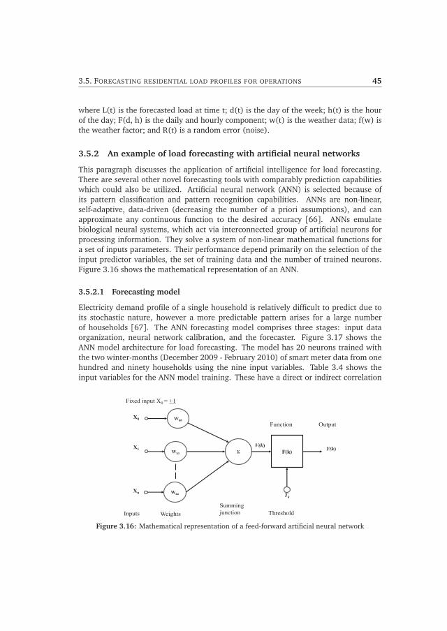
3.5. FORECASTING RESIDENTIAL LOAD PROFILES FOR OPERATIONS 45
where L(t) is the forecasted load at time t; d(t) is the day of the week; h(t) is the hourof the day; F(d, h) is the daily and hourly component; w(t) is the weather data; f(w) isthe weather factor; and R(t) is a random error (noise).
3.5.2 An example of load forecasting with artificial neural networks
This paragraph discusses the application of artificial intelligence for load forecasting.There are several other novel forecasting tools with comparably prediction capabilitieswhich could also be utilized. Artificial neural network (ANN) is selected because ofits pattern classification and pattern recognition capabilities. ANNs are non-linear,self-adaptive, data-driven (decreasing the number of a priori assumptions), and canapproximate any continuous function to the desired accuracy [66]. ANNs emulatebiological neural systems, which act via interconnected group of artificial neurons forprocessing information. They solve a system of non-linear mathematical functions fora set of inputs parameters. Their performance depend primarily on the selection of theinput predictor variables, the set of training data and the number of trained neurons.Figure 3.16 shows the mathematical representation of an ANN.
3.5.2.1 Forecasting model
Electricity demand profile of a single household is relatively difficult to predict due toits stochastic nature, however a more predictable pattern arises for a large numberof households [67]. The ANN forecasting model comprises three stages: input dataorganization, neural network calibration, and the forecaster. Figure 3.17 shows theANN model architecture for load forecasting. The model has 20 neurons trained withthe two winter-months (December 2009 - February 2010) of smart meter data from onehundred and ninety households using the nine input variables. Table 3.4 shows theinput variables for the ANN model training. These have a direct or indirect correlation
Wk0
Wk1
Wkn
Σ
Xn
X1
X0
F(k) V(k)
Tk
Y(k)
Inputs Weights Summing junction
Function Output
Threshold
Fixed input X0 = +1
Figure 3.16: Mathematical representation of a feed-forward artificial neural network

46 RESIDENTIAL LOAD AGGREGATION
Generate predictor variables
Calibrating neural network Forecaster
Validate network
Train network
Weather data Historical load profiles
Input data organization
Initialize network
Create and configure network
Forecasting Model
Input weather, Date and Flagging
Load Forecast
Figure 3.17: Architecture of artificial neural network forecast model.
with the residential electricity consumption. A time resolution of 15 minutes is usedfor the hourly and daily load profiles. A Levenburg-Marquardt algorithm (LMA) is usedfor training the neurons. LMA is a numerical solution for minimizing a function, F(x),which is a sum of squares of m non-linear functions, as indicated by equation 3.2.
F(x) =12
m∑
i=1
[ fi(x)]2 (3.2)
Table 3.4: Predictor variables as inputs to the ANN Model. [68]
Factors Predictor variables
Weather factorsAir temperature
Dew point temperature
Relative Humidity
Time factorsHour and minute of the day
Day of the week
Holidays (flagging)
Historical dataPrevious day, same hour load
Previous week, same day, same hour load
Previous 24 hours’ averaged load profile

3.5. FORECASTING RESIDENTIAL LOAD PROFILES FOR OPERATIONS 47
19/02 20/02 21/02 22/02 23/02 24/02 25/02
40
80
120
160
Pow
er[kW
]
Actual data Forecast
Figure 3.18: Forecasted data compared with actual data for seven consecutive days.
3.5.2.2 Forecast results
Figure 3.18 shows a load forecast for seven consecutive days compared with actual data.The model predicted accurately the rising and descends of the slopes. However, it wasnot able to capture accurately the load dynamics in the mornings and at peak timesdue to the model’s linear regression approach. Noticeable deviations can be foundduring peak periods and during times of rapid changes in energy consumption. Figure3.19 shows a histogram of the error distribution spread over one hundred divisions.The error margins are spread between -20 units to +20 units for over-estimation andunder-estimation respectively. The negative axis had relatively higher values comparedwith the positive implying more errors occurred from over-forecasting than under-forecasting. Figure 3.20 is a boxplot showing hourly lowest to largest error observations.It can be observed that the highest hourly error was 20.5%. Whether this range isacceptable or not depends on the application that the forecasting model is intendedfor. For instance, the statistics will be crucial to the energy supplier for estimating theimbalances that could arise and takes measures in advance to mitigate them.
3.5.2.3 Forecasting accuracy measurements
Forecasting model accuracy is often evaluated in diverse ways by calculating the so-called forecast error. This error is the difference between the actual or measured profileand the predicted or forecasted value. There are many methods proposed and used forcomparing accuracy of time-series forecasting methods. These accuracy methods giveindications of how close forecasts or predictions are to the final outcome. Three mostcommonly used are: Mean Average Percentage Error (MAPE), Root Mean Square Error(RMSE) and Mean Average Scaled Error (MASE). If, Ft is the prediction and, At theactual value, the three methods can be mathematically defined as in equations 3.3 -3.5. The MAPE is an accuracy measure based on percentage (or relative) of the mean

48 RESIDENTIAL LOAD AGGREGATION
-15 -10 -5 0 5 10 15 200
20
40
60
80
Spread over 100 divisions
Fre
quen
cy
5 10 15 200
50
100
Spread over 100 divisions
Fre
quen
cy
Percentage error distribution ErrorsMAPE
ErrorsError distribution
Figure 3.19: Histogram of error distribution.
Perc
enta
ge e
rror
sta
tistic
s
Time [hours]
Figure 3.20: Boxplot of error distribution.

3.6. CONCLUSION 49
errors. It is suitable for situations where one is interested more in the relative error.For example, an error of 5 kWh in the prediction of energy consumption of 1000 kWhis not very significant, while the same amount of error in a 50 kWh prediction couldbe very relevant. The RMSE, on the other hand, calculates the square of the errorbefore evaluating the mean. It is more a measure of goodness of fit than a correlationcoefficient, and it is often used because it amplifies and punishes large errors making ita good general purpose error metric for numerical predictions. The MASE is suited forintermittent-demand series because it never gives infinite or undefined values.
MAPE(t) =1n
n∑
t=1
| At − Ft
At| ·100% (3.3)
RMSE(t) =
√√√∑nt=1(At − Ft)2
n(3.4)
MASE(t) =1n
n∑
t=1
{ |At − Ft |1
n−1
∑ni=2 |Ai − Ai−1|
} (3.5)
For the distribution system operators and for energy management systems, peakconsumption periods are important. A Daily Peak Mean Average Percentage Error(DpMAPE) expressed as
DpMAPE(t) =|Amax − Fmax |
Amax| (3.6)
which is a measure of the relative (percentage) difference between the observed dailypeak consumption (Amax) and predicted peak value (Fmax). DpMAPE evaluation will beuseful for estimating the performance of the model in predicting peak consumption.Accurate prediction of peak consumptions will enable effective deployment of advancedcontrol actions such as peak-shaving and load shifting.
3.6 Conclusion
The electricity consumption and generation patterns in the residential environment willplay an important role as we move towards Smart Grid applications. The variation inthe residential profile for different seasons will be profound. Summer load profiles willbe affected by PV systems and electric vehicles; the winter profiles will be determinedby the penetration levels of heat pumps, μCHP units, PV systems and electric vehicles.Existing neighbourhoods will experience rise in PV systems and μCHP units, whereasheat pumps and PV systems will dominate new neighbourhoods. For all-electricresidential neighborhoods, the electrification of mobility and residential heating systems

50 RESIDENTIAL LOAD AGGREGATION
will increase the winter peak loads. Their levels of penetration will influence thedesign of the distribution network. Though the energy sector has little influence onthe type of house to be constructed and the category of people in a neighborhood,having prior knowledge ensures good planning and prevents unaccommodated demandfor energy. Also, long-term energy demand forecasting must not only be limited tocurrent demand profiles extrapolated to the future, but should take into account thepossible changes in the demographic composition of the neighborhood and the typesof new technologies used. The integration of the goals (short or long term) of themunicipality for a neighborhood will be necessary for the design and implementationof smart, sustainable energy management systems. Artificial intelligence facilitatesdecision making and enables advance monitoring and control. Load forecasting modelswith intelligent systems can be fed with historical residential data. These models areuseful for predicting utilization of assets, providing input for load/supply balancing andsupporting optimal energy utilization. With the complexities and uncertainties in theresidential environment, design of future smart residential grids should be adaptableto handle the variations in the residential load and generations. Therefore smarterand close to real-time operating systems will be paramount for smart, efficient andsustainable residential neighborhoods.

CHAPTER 4Smart energy home concept
4.1 Introduction
The home is a place for individuals or families to stay while being safe, relaxed, andsatisfied. It has a great potential for substantial influence on the quality of life. Themajor part of occupants’ actual needs is in accordance with the functional spaces of theirhomes - a place for basic activities such as eating, sleeping, entertaining guests and manyother functions [69]. This suggests the need for an adaptable built environment thatpromotes occupants’ comfort, well-being, safety, and energy savings, and harmonizesthe environmental and social-cultural values of users [69] [70]. This chapter analysesthe smart energy home concept. The chapter aims to give an overview of smart homes,the drivers, the current state of development, and presents a comprehensive frameworkfor future smart energy home deployments. In Section 4.2, the essence of smarttechnologies for present and future occupants is presented. The section discusses theadded value of smart homes to the occupants and highlights the role of smart homesin providing solutions to the present challenges in cities. Further, the integration ofsmart homes with the electric grid to facilitate Smart Grid application at the residentiallevel is discussed. Section 4.3 is focused on the energy aspects of smart homes.It presents the technological advancements enabling the realization of smart energyhomes. Some technologies are fully developed and implemented whereas others arein the experimental stages. The chapter concludes with a proposition on the essentialfactors which will drive the penetration and sustainability of smart energy homes. Thesignificance of these factors will depend on national government’s policies and roadmapfor smart energy homes integration.
4.2 Essence of smart homes
Houses are important for the quality of life and well-being of occupants. Therefore,improving residential buildings through novel materials and technological systems is an
51

52 SMART ENERGY HOME CONCEPT
Figure 4.1: An impression of a smart home [10].
important step towards optimizing the quality of homes for health, comfort, and energyuse. Such a home is generally called a smart home. There are several benefits attributedto smart homes. They are considered as one of the main constituents of smarter andsustainable living environments. Medically, a smart home can be designed to improveearly detection and prevention of health and medical problems to help residents livelonger. Besides, due to the aging population, these homes provide the means forthe elderly and disabled to live by themselves and meet their potential needs usingadvanced sensors and monitoring technologies. Additionally, they provide convenientcontrols to occupants, where many daily activities can be monitored and controlledfrom the computer and/or smart phone. The automated systems free house inhabitantsfrom performing routine tasks as switching all lights off or securing all house entrypoints. More importantly, smart homes can provide savings on energy and utility bills bymonitoring and efficiently managing houses’ energy demand. Table 4.1 lists examples ofsmart home demonstration projects around the world. This thesis focuses on the energyuse in smart homes, hence the term ”smart energy homes”. A smart energy home (SEH)is defined as a house that employs home automation technologies to monitor and/orcontrol residential devices to provide improved comfort, convenience, security, and lesscost to occupants (see Figure 4.1). It has been conceptualized as ”a house of the future”-a creative dream for future communities. However, recent projects in Europe, and otherparts of the world, confirm the penetration of SEHs in urban areas.

4.2. ESSENCE OF SMART HOMES 53
Table 4.1: Examples of smart home demonstration projects
Name Characteristics Reference
Stichting SmartHomes(Eindhoven,Netherlands)
Home for demonstration of the latest availableproducts and services. Integration, testingand validation of new innovative productsand services, and showing the possibilities oftechnology in a real life setting: eHealth,Ambient Assisted Living (AAL) and energymanagement
http://www.smart-homes.nl/
Energy PlusHouse (Berlin,Germany)
An automated family house with, well-timeduse of appliances, PV system with batterystorage, energy management systems, andelectric vehicles.
http://www.dw.de/berlin-family-tests-plus -energy-home/a-15933870
Smarthome for elderlypeople (HOPE)
European project for an integrated, smartplatform that enables the elderly people withAlzheimer’s disease to use innovative technologyfor a more independent life, easy access toinformation, monitor their health, and serve asa source of inspiration for users.
http://www.hope-project.eu/
Adaptive House,(University ofColorado, USA)
Home-like laboratory equipped with over 75sensors. Control systems are based on neuralnetwork for observing lifestyle and desires ofinhabitants, and learning to anticipate andaccommodate their needs
http://www.cs.colorado.edu/mozer/nnh/
Drexel SmartHouse(University ofDrexel,USA)
Renovated urban home with new technologies toserve as a living laboratory for students. Focusedon residential design, energy efficiency, smartappliances, and lifestyle
http://www.drexelsmarthouse.com/
Gator TechSmart House(University ofFlorida, USA)
An experimental laboratory and ’live-in’ trialenvironment for validating technology andsystems developed in a mobile and pervasivecomputing laboratory to assist older persons andindividuals with special needs in maximizingindependence and maintaining a high quality oflife.
http://www.icta.ufl.edu/gt.htm
Smart MedicalHome(University ofRochester, USA)
Home-like setting packed withtechnology designed to improve early detectionand prevention of health and medical problemsto help residents live longer, have more healthylives within the comforts of home.
https://www.rochester.edu/pr/Review/V64N3/feature2.html
Duke UniversitySmart House(University ofDuke, UK)
Experimental laboratory for demonstrating thefutureof residential design in housing developments viathe integration of intelligent technological valuesto enhance the quality of life.
http://smarthome.duke.edu/

54 SMART ENERGY HOME CONCEPT
4.2.1 Smart homes in smart cities
Cities are increasing in size and population, and so are the different challenges such as:transportation systems, coordination and improvement of social services, reduction intraffic congestion, sustainable water and energies supplies, and public safety. Abouthalf of the world’s population now resides in cities, according to the World HealthOrganization, and that proportion is expected to grow [71]. The smart use oftechnologies is a novel approach towards making life easier for city residents and visitors,and hence the shift towards smart cities.
The European smart city project defines a smart city by six characteristics, namely,smart governance, smart economy, smart environment, smart mobility, smart people,and smart living [11]. Smart governance involves the participation of citizens indecision-making, transparent government, and access to public and social services,whereas an innovative and entrepreneurial spirit, productivity, labor flexibility, andinternational embededdness declare a city with a smart economy. Smart environmentis characterized by sustainable resource management, minimization of pollution andattractive natural conditions. The ease in local accessibility, availability of ICT-infrastructure, sustainable, innovative and safe transport systems are the key factorsand indicators applicable for smart mobility. Smart people are indicated by their level ofqualification, affinity to life-long learning, creativity, open-mindedness and participationin public life. Finally, the indicators for smart living are defined as health conditions,housing quality, individual safety, and educational and cultural facilities. A smart citytherefore must combine various resources and activities to handle issues such as housing,economy, services, socio-cultural and environmental conditions to be competitive andsustainable.
Smart Cities
Smart economy
Smart environment
Smart living
Smart mobility Smart people Smart
governance
Smart homes
Housing quality Individual safety
Smart EV charging
New residential infrastructure
Energy efficient buildings
Healthy conditions
Independence
Communal development
Figure 4.2: Smart homes as integral part of smart cities [11].

4.2. ESSENCE OF SMART HOMES 55
The European Innovation Partnership on Smart Cities and Communities seeks tosignificantly accelerate the industrial-scale roll-out of smart city solutions integratingtechnologies from energy, transport and ICT [72]. However, a city is meant for itsinhabitants. The significance of smart cities, therefore, embodies the creation ofcommunities and municipalities with smart living styles through the amalgamation ofthese smart homes [69]. SEHs will play important roles in smart cities contributingto better living conditions, better quality on functional space, energy (cost) savings,safety and comfort for users. There are several benefits attributed to smart homes.The six characteristics of smart cities as described by the European smart cityproject are encapsulated in smart homes as depicted by Figure 4.2. Installation ofnew infrastructure for a smart residential neighborhood contributes to the economicdevelopment of the city. The energy-efficient measures and the in-home smarttechnologies in smart homes reduce greenhouse gas emission, improve health conditionand safety, and optimize energy use.
Many of the smart city projects are still in the early stages of development.Preliminary reports of pilot projects show the central role of smart homes. In theAmsterdam metropolitan smart city project, for example, Liander (the distributionnetwork operator in that area), in collaboration with Plugwise (an energy serviceprovider), tested an energy management system with 250 customers in the Haarlemregion. The system enables monitoring of energy use and enables automatic andremote control of specific appliances giving customers more insight into their energyconsumptions [73].
4.2.2 Smart energy home and the Smart Grid
This section discusses the integration of smart energy homes into the bigger SmartGrid concept. SEHs are not only important components for smart cities, but will alsoplay important roles in the transition towards Smart Grids. The large penetration ofrenewable energy sources, electrification of space heating and mobility, growing localmicro-generation in the distribution grid, and increased focus on reliability and powerquality are the main challenges of the electrical grid system operation. Additionally,the growing customer awareness, less predictable consumption and generation, short-term contracts, add to the existing challenges in residential energy distribution. Anotherparadigm shift is the unbundling of the power system into generators, network operatorsand energy providers. This implies the residential customers have to deal withdistribution network operators as well energy retailers as illustrated by Figure 4.3.Governments expect efficient, reliable and environmental friendly supply system, energyretailers want to earn from the market, network operators desire reliable and efficienttransport within the safety limits of their assets, whereas consumers expect affordableelectricity for their comfort levels. Energy retailers need more engagement fromresidential customers for effective trading at the wholesale market whereas networkoperators require their collaboration for efficient operation of the residential network.The traditional grid, with its unidirectional power and information flows, cannot

56 SMART ENERGY HOME CONCEPT
effectively deal with all these challenges, hence a more robust, flexible and smart systemis required - the Smart Grid.
Residential customers
Economic
Technical
Distribution Generation / Imports Transmission
TSO
Wholesale energy market
DSO
Energy retailers
DG
power flow information flow
Figure 4.3: Interaction of residential customers with energy retailers and distributionnetwork operators.
Smart Grid
Industrial plant Wind turbines
Nuclear power plant
Hydro power plant
Thermal power plant
Photovoltaic systems
Cities and offices
Smart homes Electrical energy flow
Information flow
Figure 4.4: Smart energy homes as integral part of the Smart Grid.

4.3. ENABLERS OF SMART ENERGY HOMES 57
The Smart Grid (SG) can be considered as a conceptual merging of power systems,regulations and market rules, and Information and Communication Technologies (ICT)[74]. SG is envisaged as an essential development for transporting and distributinglarger amounts of electrical energy and to facilitate the integration of renewableenergy sources through automated control, sensing and metering technologies, andmodern energy management [75]. The focus of SG can be either economics (systemmanagement and operation, remote metering and billing, network extensions costs),ecology (carbon-dioxide reduction, integrating renewables) or security of supply(efficient use of assets, integration of DER) or a weighted mixture of the three [76].The benefits of SG are not limited to the public infrastructure but also at the residentiallevel.
The home can be considered as reduced model of a public grid. It could be termedas a ”nanogrid” as it can comprise generation, distribution, and loads. Householdsare increasingly able to supply energy back to the network. The communicationsinfrastructure in smart energy homes enables bi-directional flow of information betweenthe SEHs and the power system facilitates Smart Grid applications at the residentiallevel. Figure 4.4 depicts the interaction of smart energy homes with the Smart Grid.This interaction is crucial for the development of sustainable residential neighborhoodssince a smart residential infrastructure is expected to require less home energy use,reduce carbon footprint, and to increase energy efficiency and grid reliability.
4.3 Enablers of smart energy homes
This section analyzes the new technological developments driving the penetration ofsmart energy homes. Defining the correct infrastructure that provides the properseamless interconnection of SEHs with higher layers in the Smart Grid is an importantrequirement for today’s and future Smart Grid applications. Figure 4.5 shows thefundamental components that enable smart energy homes to become an integral part ofthe bigger Smart Grid and will be discussed in following sections.
4.3.1 Metering devices
Most often, what can be measured can be controlled, hence measuring devices are vitalto home automation. Electricity meters have emerged as the most visible technologyof the major modernization of the global electricity infrastructure. Gas, water andelectricity meters are the main measuring devices for households. Automatic meterreading (AMR) came about in the mid-’80s, and more prominently in the early 1990sas an automated way to collect basic meter-reading data. The AMR technology is a uni-directional automated meter reading solution, collecting consumption and diagnosticdata from metering devices (water or energy meters) and sending them to a centraldatabase purposely for billing, troubleshooting, and analysis [77]. However, AMRsystems tend to be collection only (typically gathered monthly or yearly), with no means

58 SMART ENERGY HOME CONCEPT
for broadcasting command or control messages. The advent of Advanced MeteringInfrastructure (AMI) with its ”bi-directional” communication systems creates a linkbetween the meters and external information systems facilitating remote meter reading,remote meters/devices activation, and the use of dynamic tariffs. The technology behindAMI evolved from the foundations of the AMR and became apparent around 2005.The smart metering technology is at the heart of the AMI as a viable infrastructure forenhancing the Smart Grid concept at the residential level. Detail analysis of smart metersis presented in Section 5.3.
4.3.2 Smart sensors
In our world today, miniature sensors are available in almost every device or installation,automobiles, cell phones, shops, and highways. Sensor technology enables users toactivate security systems, turn ON/OFF lights, close/open window blinds, and controlthe thermostat when away from home. Studies indicate that over 30 sensors are requiredfor an average North American home to make smart homes comprehensively meaningfulto occupants [78]. Most sensors are specially designed for health, safety and securityreasons such as smoke and epilepsy sensors. In Europe, the elderly are moving intoambient-assisted living homes, which are smart structures able to monitor a resident’shealth and daily routine and to warn when conditions move beyond a certain threshold[79]. Household sensors that are relevant for energy management are for detections ofcurrent, voltage, temperature, motion, light and occupancy [80]. They sense the desired
Smart sensors and actuators
Smart meters
Smart appliances
Energy management systems Enabling ICT
Figure 4.5: Fundamental components enabling smart energy homes.
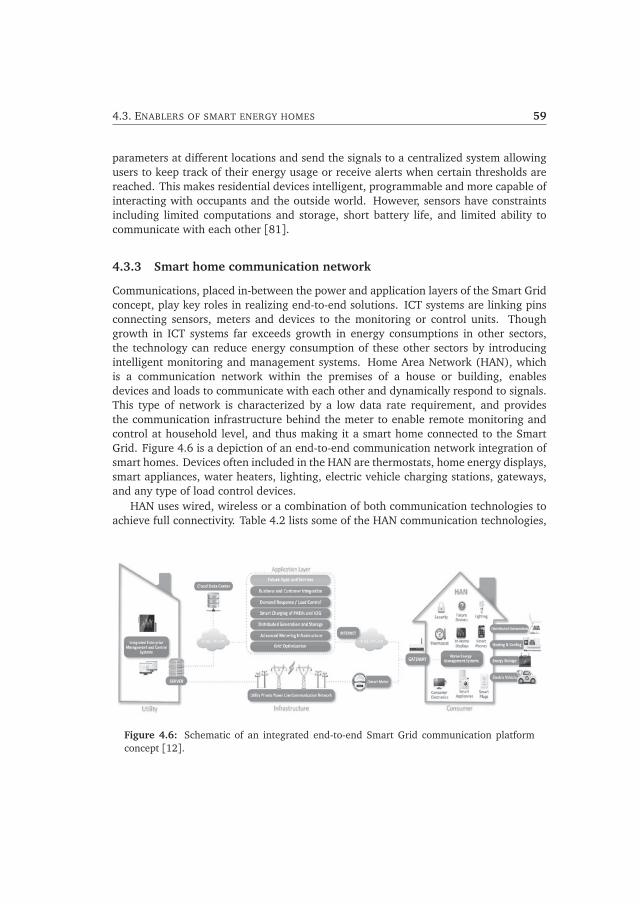
4.3. ENABLERS OF SMART ENERGY HOMES 59
parameters at different locations and send the signals to a centralized system allowingusers to keep track of their energy usage or receive alerts when certain thresholds arereached. This makes residential devices intelligent, programmable and more capable ofinteracting with occupants and the outside world. However, sensors have constraintsincluding limited computations and storage, short battery life, and limited ability tocommunicate with each other [81].
4.3.3 Smart home communication network
Communications, placed in-between the power and application layers of the Smart Gridconcept, play key roles in realizing end-to-end solutions. ICT systems are linking pinsconnecting sensors, meters and devices to the monitoring or control units. Thoughgrowth in ICT systems far exceeds growth in energy consumptions in other sectors,the technology can reduce energy consumption of these other sectors by introducingintelligent monitoring and management systems. Home Area Network (HAN), whichis a communication network within the premises of a house or building, enablesdevices and loads to communicate with each other and dynamically respond to signals.This type of network is characterized by a low data rate requirement, and providesthe communication infrastructure behind the meter to enable remote monitoring andcontrol at household level, and thus making it a smart home connected to the SmartGrid. Figure 4.6 is a depiction of an end-to-end communication network integration ofsmart homes. Devices often included in the HAN are thermostats, home energy displays,smart appliances, water heaters, lighting, electric vehicle charging stations, gateways,and any type of load control devices.
HAN uses wired, wireless or a combination of both communication technologies toachieve full connectivity. Table 4.2 lists some of the HAN communication technologies,
Figure 4.6: Schematic of an integrated end-to-end Smart Grid communication platformconcept [12].

60 SMART ENERGY HOME CONCEPT
Table 4.2: Communication technologies for home area network [12][82].
Technology Transmission medium Data rate Typical range
Fibre optic 0.1 - 10 Gbps up to 100 km
Ethernet 10 Mbps - 10 Gbps 100 m
Wired Coaxial cables 172 Mpbs 30 km
PLC (HomePlug) 0.1 - 200 Mbps up to 200 m
Zigbee 20 - 250 kbps 70 - 100 m
WiFi 1 - 600 Mbps 70 - 100 m
Bluetooth 700 Mbps 70 - 100 m
Wireless Z-Wave 40 kbps 10 - 30 m
6LoWPAN 20 - 250 kbps 10 - 30 m
each having particular advantages and area of application. For smart energy homes,communication technologies that provide data rate of up to 100 kbps with shortcoverage distance (up to 100 m) are adjudged sufficient [82]. In general wirelessnetworks are preferred because they offer more flexibility in the home environment.HAN designs must respond to the needs of today and at least the next decade, aswell as seamless integration in the behind-the-meter communication infrastructure.This requires selecting the standard which makes more sense regarding wide spreadimplementation, where energy consumption and cost are prime concerns, while at thesame time enabling the integration in the existing Internet Protocol based networks inthe upper layers of the Smart Grid concept [83]. In the selection of HAN communicationtechnologies to implement in smart homes, important features worth noting include[12]:
• Reliability: Reliability is defined as the percentage of accurate data reachingits destination. It represents the amount of successfully transmitted or receiveddata packages. It could be the case where retransmission is required in order tosuccessfully complete a data transaction.
• Interoperability and scalability: A HAN communication should enable deviceswithin the home to interact and work together with each other, irrespective of themanufacturer or the physical transmission medium. By doing so, the overall valueof the network opens opportunities for innovation and paves the way towardsrealization of smart applications.
• Coexistence: Where more than one communication technology has to sharethe same physical medium, the network should be able to continue workinguninterrupted and with low performance impact. Many of the HANcommunication technologies are designed to anticipate interference, especially

4.3. ENABLERS OF SMART ENERGY HOMES 61
if wireless. Incorporation of coexistence features such as Carrier Sense MultipleAccess (CSMA), acknowledgements and retransmission algorithms, ensuresrobust operation of the communication network.
• Bandwidth and latency: From the performance point of view, these two technicalrequirements are critical in HAN. Bandwidth refers to the volume of data per unittime that can be moved through the network. Latency measures the time delay ittakes a data packet to be transmitted from origin to destination. These depend onfactors such as network depth (hop-count), link quality and packet size.
• Security: There are ranges of security concerns depending on the sourceof information when mined inside homes. Security covers aspects such asauthentication (verification of users and devices), authorization (right to access),admission control (access limited to authenticated and authorized devicesand users), encryption (data confidentiality), integrity check (detection ofunauthorized changes to message content), alerting (notification of potentialattacks or security compromises) and auditing (recording all activity on thenetwork) [84].
• Power consumption: Low energy consumption per device in HAN is desiredespecially when the potential amount of smart connected devices assumed to riseup to billions in the next decade. The aggregated amount of power required bythose devices could reach the scale of hundreds of MW worldwide. Ability fordevices to automatically switch to stand-by mode during periods of idleness couldreduce the power consumption.
• Total Cost: Market studies conducted by ON World Research in 2010 indicatedthat for savings of 30 percent on the energy bill, customers in the US are willingto spend around $150 USD on home energy management equipment [12] [85].With the aim of minimizing costs further, HAN technologies are required to beeasy to install, use, maintain, and use less energy.
• Forward and backward compatibility: Consumers should not worry abouttheir products becoming obsolete or being incompatible with other items. Oldappliances should connect seamlessly with new versions of communicationprotocol.
In Figure 4.7, three of the leading HAN communication technologies - Zigbee,WiFi and HomePlug - are qualitatively compared on the most relevant features. Theresults indicate that no single technology is dominant in all the requirements. A hybridcross-physical transmission medium (wired-wireless systems) will contribute to a more,robust, secured and reliable communication system.

62 SMART ENERGY HOME CONCEPT
Figure 4.7: Qualitative comparison of three HAN communication technologies.
4.3.4 The Internet of Things
The Internet of Things (IoT) refers to a network of items with embedded sensors andwhich are capable of connecting to the internet facilitating the exchange of productsand services in global supply chain networks [86]. The introduction of the InternetProtocol Version 6 (IPv6) has extended the number of unique internet addresses, makingit possible to connect myriads of objects to the internet (see Figure 4.8). The presentInternet of personal computers and smart phones will move towards an "Internet ofThings" in which billions of devices will be connected to the internet [87]. The IoT visionis facilitated by wireless communication systems, sensors that handle radio-frequencyidentification (RFID) and microelectromechanical systems, clouding computing (whichstore data from sensors), new analytical tools, and high-performance computers [87].
The major technical challenges for IoT are the immaturity of the industry standards,the lack of open architecture for interoperability and ubiquity, and guaranteeingconnectivity for a large number of mobile and energy-dependent objects [88]. Onsocietal issues, the use of IoT is perceived as gross invasions of privacy. The EU report onIoT Privacy, Information, and Security recommends the development of privacy-friendlydefault settings on IoT products and services that would give users more control overwhat information is shared, and to give individuals the rights to their own data [89]. Asprivacy becomes a great concern , individuals would have to become their own serviceproviders, storing their information privately and can therefore choose what informationleaves their homes and to which parties.

4.3. ENABLERS OF SMART ENERGY HOMES 63
IPv4 protocol IPv6 protocol
Figure 4.8: The Internet of Things enabled by IPv6 protocol.
4.3.5 Smart appliances
Smart appliances are domestic devices with integrated intelligence and communicationsystems that can be connected to home energy management systems to shift theiroperational times to suitable periods of the day or be monitored and controlled remotely.These appliances do not just turn OFF during times of peak electricity demand or hightariff; instead they implement simple, intelligent algorithms to alter their energy usewith less customer involvement or awareness. An appliance may either shift theirentire operational cycle or run less frequently to save energy and/or cost. Refrigerators,dishwashers, washing machines, air conditioners are some domestic appliances beingmade smart. A smart refrigerator, for example, can postpone its defrost cycle to the nighthours, whereas a smart washing machine located in a house with installed PV system,can start washing during the time of high PV generation. Smart washing machines,which respond to control signals (price or local generation) to start their operations,have been tested on a pilot project in Hoogkerk and Zwolle, cities in the north and middleof the Netherlands respectively. [90]. If manufacturing and adoption of smart appliancesbecome widespread, residential customers can influence and preferably reduce demandon a large scale without being unduly inconvenienced [91].
4.3.6 Monitoring and control systems
These are in-home installations that connect metering devices, sensor networks, andsmart appliances for the purpose of monitoring and/or control of energy use. Monitoringand control systems for households are discussed in more detail in Chapter 5

64 SMART ENERGY HOME CONCEPT
4.4 Essential factors for smart energy home integration
In this section, a framework for the integration of smart energy homes is presented. Thisis a broad overview of interrelated aspects and serves as a guide to make smart energyhomes an integral part the Smart Grid. Figure 4.9 shows the proposed framework fordeployment of smart energy homes.
The buildingThe design of the physical building structure is more important than any advancedtechnologies for monitoring and control of residential demands. There arevery limited (if any) benefits for installing advanced automated systems in anold, poorly insulated building. Therefore making better insulated and energy-efficient buildings are fundamental steps towards smart energy homes. Thetype of building (detached, semi-detached, apartment, etc.), the orientation, andaesthetics are also important aspects. Passive, energy-neutral, and energy-positivehouses are ideal type of houses for the installation of automation and controltechnologies. In general, building new homes with additional wiring for advancedhome automation systems is more cost-effective compared with retrofitting ahouse (adding smart home technologies to an existing property). The types ofpeople living in a house - elderly, large families, students or singles - also affect thefunctional operation of the building. Hence, buildings designs should be adaptableto meet the needs of the various residential groups.
Home installationThe installations at the customers’ site determine the ”smartness” of the home.Sensor networks to gather information about the physical environment, actuatorsto perform appropriate actions (ON/OFF), and smart appliances to respondappropriately to control signals must be present for a smart energy home to beSG-ready. How smart meters, sensors and appliances are integrated via the HAN,determines the level of Smart Grid functionalities of the home. Automation ofhomes with local generation is more desired than those with only automatedtechnologies, except homes for ambient assisted living. However, the localgeneration should be controllable both locally and externally (by DSOs, energyretailers, other third parties).
Energy management systemsThese are advanced tools to monitor and/or control household loads andgeneration. The ICT infrastructure, software platform and the algorithms in such asystem must support different appliances and technologies from different vendors.Home energy management systems are further discussed in Chapter 5.
Smart residential gridStand-alone smart energy homes could have adverse effects on the public grid.Therefore a smart residential grid for integrating aggregated smart energy homes

4.4. ESSENTIAL FACTORS FOR SMART ENERGY HOME INTEGRATION 65
Customers Energy
management systems
Smart residential
grid
Stakeholders Local
installations
Socio-economic &
environmental issues
The building
Architects
House builders
Appliance manufactures
Housing corporations
Policy makers
Energy service companies
Consumer Groups
Capital investment &
incentives
Customer data and privacy
protection
Affordable smart
technologies
Bi-directional energy flows
Seamless integration of smart
homes into the bigger Smart Grid
User friendliness
Bundle choices
Scalability and interoperability
Customer support services
Control of appliances (locally
and externally)
Integration of local generation
with(out) storage
Provision for emerging and
future loads
Making buildings better (retrofitting)
Making better buildings (new
buildings)
e
Figure 4.9: Integrated framework for smart energy home penetration.
is desirable. Such a grid should apply secure communication and computationalintelligence to integrate market dynamics (which has fair pricing and encouragesconsumer participation) with the technical characteristics of the distributionnetwork, local electricity generation and consumption, to realize a safe, resilient,cost- and energy-efficient grid, and to ensure consumer’s comfort, safety andprivacy [92]. Therefore retrofitting of old houses and installation of advancedloads such as heat pumps, μCHPs in old neighborhoods should be done in closecooperation with local network operators.
Socio-economic and environmental issuesSocio-economic and environmental issues are worth considering for sustainablepenetration of smart energy homes. Contractual agreements between customersand the utilities (DSO and energy retailers) on the control of loads and generationwill be required to protect all parties. Economically, smart energy homes are stillvery expensive due to less advantage of scale. Therefore economic incentives willbe necessary to stimulate the construction and use of smart energy homes.

66 SMART ENERGY HOME CONCEPT
StakeholdersAs SEHs are still in the developmental stages, all key stakeholders should beinvolved especially in pilot projects. Though the key stakeholders may differfrom region to region and from country to country, collaboration betweenhouse builders, home appliance manufacturers, housing corporations, technologycompanies, and the utilities (network operators and energy retailers) will presentmore efficient and sustainable path to smart energy home integration. JouwEnergie Moment (Your energy moment) is an example of integrated smart energyhome - Smart Grid project. The pilot project initiated by Enexis (distributionnetwork operator) involves the collaboration among: housing cooperation (Thebuilding), Dong Energy and Greenchoice (Energy retailers), and CGI, Flexicontrol,Technolution and Marvin (business and technology solutions) [93]. FurthermoreTU/e is involved in analyzing the pilot results.
Customers’ changing behaviorAt the heart of all the aspects sits the customer, who makes the choice anddrives the acceptance of smart energy homes. The unpredictable behaviour ofresidential people is an important factor to be taken into account. Pilot projects todemonstrate smart energy home - Smart Grid integration are indirect but effectivemethods to build trust and win the support of residential customers to move intosmart energy homes.
4.5 Conclusion
The future smart energy homes are present-day realities but their penetration isscarce. Smart energy homes are changing the lifestyle of modern society. As citiesgrow in size, population and challenges, SEHs are crucial in providing improvedliving conditions, energy savings, cleaner environment, safety and comfort to theinhabitants. SEHs will grow among academic institutions as experimental laboratoriesfor validating technology and systems for maintaining a high quality of life, andmaximizing independence of individuals with special needs. Finally, the evolution of theSmart Grid concept will be incomplete without the involvement of residential customers.Smart energy homes provide the enabling technologies for Smart Grid applications atthe residential level. Smart meters, smart sensor technologies, home area networks,smart appliances and home energy management systems are the fundamental buildingblocks facilitating the integration of SEHs. In order to realize maximum benefits of SEHs,the underlying smart residential grid should be built on the right network infrastructurefrom the very beginning. The design of such network must account for the presentfunctional needs and economic constraints, while anticipating future requirementsand applications. For a sustainable penetration of SEHs, the main aspects have beenidentified and discussed. New buildings and neighborhoods are the ideal location fortesting interactions between SEHs and the Smart Grid. However, collaboration amongstakeholders such as municipalities, housing corporations, network operators, energy

4.5. CONCLUSION 67
retailers and policy makers will prove to be a more sustainable approach for SEHspenetration than individual desires to live in smart energy homes.


CHAPTER 5
Energy management forhouseholds
5.1 Introduction
This chapter focuses on the deployment of intelligent energy management for residentialcustomers. Energy management systems have been in existence in the energy sectorfor several decades with dedicated applications in the generation, transmission andnowadays also in distribution systems of the electrical power system. At the householdlevel, the incentive and motivation to manage energy is influenced by commercial andtechnical reasons. Commercially, it offers the otherwise passive residential customer tobe active in the energy market. The technical aspect enables them to provide support tothe public grid through demand response, peak shaving, and load shifting measures aswell as provide ancillary services.
In Section 5.2, the evolution of energy management systems in the energy sectoris presented. Section 5.3 discusses the smart meter as a major innovative technologyfacilitating energy monitoring and control in homes. This novel technology is pivotal forthe deployment of home energy management solutions. The state-of-the-art, drivers andstakeholders of home energy management system (HEMS) technologies are summarilypresented in Section 5.4. In Section 5.5, four areas are identified for the applicationof HEMS for comprehensive benefits: customer, market, network and service-basedapplications. Like many technologies, HEMS penetration is not without challenges.Section 5.8 looks into the key barriers to the penetration of HEMS such as cost,implementation and privacy issues. The chapter concludes with a framework fordeveloping sustainable HEMS in Section 5.9. It presents five aspects - technological,socio-cultural, economic, structural and legal aspects - that are crucial for successfuland sustainable HEMS deployment.
69

70 ENERGY MANAGEMENT FOR HOUSEHOLDS
5.2 The evolution of energy management systems
Energy management systems (EMS) monitor, control, and optimize the generation,transport and use of energy. Early EMS operations were based on analogue meterswith fast and easy-to-understand information, though limited in scope and application.Mimic boards (wall-size boards with power grid symbols, LEDs, meters, switches todisplay the state of the power system) were the traditional means for power control[94]. Energy management became a real concern in the 1970s, especially with themultiple energy crises, increasing energy cost, and the idea of energy conservation. Mostsystems delivered in the early 1970s were built on Xerox Sigma 5 and Sigma 9 [95]. Thetechnological evolutions in the 1980s changed the EMS, particularly with the comingof computer-based technologies (mostly with proprietary hardware and operatingsystems). By the early 2000s, software-based system such as UNIX, Linux and Windowshave dominated EMS technologies [80]. Presently, embedded systems technologieshave taken over. The old, bulky, space-consuming solid-state technologies have givenway to more compact, small and efficient embedded or chip-based systems. Figure 5.1shows the timeline for EMS evolutions. The conversion of theoretical considerations intoeffective and robust algorithms accounts for the growth and effectiveness of the EMS.Significant among the EMS technologies is the Supervisory Control and Data Acquisition(SCADA) with Energy Management System (EMS) functionalities. These tools enableapplications such as dispatcher training simulator (DTS), optimal power flow (OPF),state estimation, load forecasting, unit commitment, flow and contingency analysis [95][94]. In principle, EMS is also a matured technology in the residential sector but itis mostly not named like that. The use of night thermostat as a form of automatedenergy control dates back to the early 1900’s. The system has grown over the years intoother fields such as security systems, entertainment, energy-efficient appliances, HVACcontrol, e-health and remote controls [96]. Automation of the distribution networkoperation to facilitate and incorporate the emerging Smart Grid functionalities hasgained attention just recently. This also brings EMS operations closer to the customer.Hence, home energy management systems that enable residential customers to realizeenergy efficiency and comfort, and provide support to the power system is important.
<1970 1970s 1980s >2000 >2010
Solid state systems Xerox systems
Computer-based (proprietary hardware and
operating systems)
Software-based systems
(Unix, Linux, Windows)
Embedded systems
(micro-chips)
Figure 5.1: Timeline of energy management systems evolution.

5.3. SMART METERING SYSTEM 71
5.3 Smart metering system
Smart meters integrate embedded computing and two-way communications totransform meters from simple recording instruments into intelligent devices servingincreasingly broad roles within the energy infrastructure. They are the final points ofcontact for information exchange and control in the power grid. The smart meter devicesimprove the means by which customers’ awareness of actual energy consumption canbe raised to allow timely adaptation in their demands. Many advantages are attributedto smart meters, including lower data collection cost, energy savings for residentialconsumers, reliability of supply, variable pricing schemes to attract new consumers, andeasier detection of fraud [97]. In most European countries, smart meters are beingdeployed to increase operational efficiency, improve energy efficiency, and to meet arange of new customer requirements and market opportunities. However, the smartmetering market is exceptionally local with different market drivers, maturity, regulatoryenvironments, technology preference, standards, value and supply chains, and markettiming [98].
5.3.1 The EU directives
Directive 2006/32/EC of the European Parliament and the EU Council, on energyend-use efficiency and energy services was to make the end-use of energy moreeconomic and efficient. It states that Member States must ensure that end-users areprovided with competitively priced individual metering and informative billing thatshows their actual energy consumption Directive 2006/32/EC [99]. In addition, current
Metering system
Other Metering instruments/ Grid operator equipment
Other service module
Energy retailers
Distribution network company
Independent service provider
Central Access Server
P4
P3
P2
P1
P0
Figure 5.2: Smart metering system architecture in the Netherlands.

72 ENERGY MANAGEMENT FOR HOUSEHOLDS
actual consumption and prices, information on energy efficiency, and comparison ofconsumption with previous year and with similar consumers should be provided. Therewas at that time no notion of smart meters. It was up to Members States to define how tofollow the guidelines. In 2009, the Internal Market Directive 2009/72/EC was proposed.The Directive recommended the introduction of intelligent metering systems and SmartGrids as a way to be more energy-efficient and to integrate decentralized and renewableenergy resources [100]. It recommended the performance of economic assessment of thelong-term costs and benefits of the implementation of such intelligent metering systemby the Member States. However, it was Directive 2012/27/EU on energy efficiencywhich enhanced efforts for energy efficiency and underlined the significance of smartmetering systems [101]. Detailed recommendations were outlined for successful roll-out of smart meters namely, data protection and security considerations, methodologyfor the long-term costs and benefits assessment, and minimum functional requirement.
5.3.2 The device
Smart meter is an electronic measuring device of electrical energy, with no mechanicalparts. It consists of a step-down transformer for rectifying, converting and regulating theac output voltage for the rest of the integrated circuits (ICs) of the smart meter. Othercomponents are the microprocessors for processing the stream of data, storing data ina flash memory, and driving the liquid-crystal display (LCD) screen. It has a voltageamplifier for regulating the voltage for digital system use, and a radio-frequency (RF)transceiver which is used for data transmission. Perhaps, the most revolutionary featureof the smart meter is the bi-directional communication between the meter and externalparties. The meters can sample at a rate even higher than 1 MHz, however, one hour,30 minutes or 15 minutes are the common data transmittal intervals for existing smartmeters, to ensure reliable data transmission [102].
5.3.3 The data
The Dutch smart meters have four communication ports P0, P1, P2, and P3 (see Figure5.2). The P0 is used for communication with external devices during meter installation,or maintenance of the smart meter and hand held devices that energy utilities use toextract data through RF communication. P1 port is a read-only RJ11 interface thatlinks the meter with auxiliary equipment. This port is accessible by customers, andit is intended to provide insight regarding householders’ energy consumption, and forretrieval of external information (signals) from the grid. Table 5.1 summarizes theaccessible data transmission through the P1 port. Port P2 allows connection to othermetering devices at home (gas, water) through M-Bus communication. The P3 portprovides the communication between the smart meter and the central access server(CAS). However, only the distribution network operator is allowed to access the P3. TheP4 port is at the CAS which allows data transfer to market parties such as energy retailerand independent service providers. The network operator controls the authorization.

5.4. HOME ENERGY MANAGEMENT SYSTEMS: DRIVERS AND STAKEHOLDERS 73
Table 5.1: Smart meter P1 Port data transmission
Category Description
Meter Electrical energy delivered to / by client (kWh)readings Electrical power (delivery and consumption) (W).
Actual energy tariff
Equipment status Position of breaker (on/off/released)
Number of power failure in any phase
Power Number of long term failures in any phase
quality Power failure event log
Number of voltage sags and voltage swells in each phase
Standard messages 8 character numerical message
Long messages Message of maximum 1024 characters
5.3.4 The drawbacks
The smart meter data is retrieved on daily basis (via P3 port) by distribution networkoperators. Energy suppliers can access the data in the following cases [103]: once peryear for annual billing, six times per year for bi-monthly statements, change of energysupplier or relocation, or when it is necessary for the management of the power grid.In the Netherlands, network operators and energy suppliers may not invade customers’privacy, hence (near) real-time bi-directional communication with the smart meter isnot enhanced. Pilot projects in the Netherlands involving smart meters are primarilydesigned to act as information collecting devices that tend to leave it to the user tomanage devices in the home with the hope they will reduce or shift energy demands[90][104]. The privacy and other issues against the smart metering systems havereverted this novel technology (and the associated advanced metering infrastructure)back to the automated meter reading system. The AMI functionalities present in smartmeters are not enabled. The smart meter is thus smart by design but yet limited inoperation.
5.4 Home energy management systems: drivers and stakeholders
This section introduces home energy management systems with focus on the state-of-the-art, drivers and stakeholders. HEMS can be defined as in-home devices or systemsthat monitor, control, and analyze home energy use and provide information to theoccupants. These systems are to conserve energy, reduce cost and improve comfortusing intelligent monitoring and control systems. With the growing uncertainties infuture residential energy profiles and appliance types, energy management systemsusing historical data, statistical methods, forecasting techniques, and load estimationwill grow in the next decade. They facilitate the integration of residential generation

74 ENERGY MANAGEMENT FOR HOUSEHOLDS
to match the different needs of users, and to secure the reliability and robustness ofthe energy supply infrastructure. HEMS technologies are evolving in complexity andcapability and are being deployed commercially and in demonstration projects aroundthe world. Figure 5.3 shows examples of HEMS products currently available in themarket whereas Table 5.3 gives a summary of some of the leading HEMS technologiesand their major features or functions. The exponential growth in HEMS vendorsunderscores the importance of the technology to the residential sector. In spite of thehundreds of products, HEMS can be broadly grouped under the following functionalities[80] [105]:
1. Informative systems: They enable a one-way communication providing real-time and historical information about energy use in various graphical forms (bargraphs, pie charts, etc.) to the users. Informative HEMS expect users to takeadvantage of the available information and take steps towards saving energy andcost.
2. Automated systems: They provide a two-way flow of information between ahome gateway and domestic appliances. This offers customer additional optionsto set priorities and wishes for the operation of household appliances and/or localgenerations.
3. Integrated systems: They have all the features of the information, automatedand control systems, but also include direct control of devices by third parties. Thepossibility for forecasting (e.g. price) and scheduling of loads and generations athousehold levels are present in some products.
The level of HEMS deployment differs from region to region driven by differentnational or regional goals. In North America, the growth is driven by the need for moreefficient management of the aging power system infrastructure, energy security, andbenefits from demand/supply management and demand response applications [105].In Europe, however, the technology is still at the preliminary stages and it is expectedto grow in the next decade especially with the imminent large scale roll-out of smart
Figure 5.3: Home energy management products available in the market.

5.5. APPLICATIONS OF HOME ENERGY MANAGEMENT SYSTEMS 75
meters. This is driven by energy efficiency, reduction of carbon footprints, and energysecurity issues. Another important driver is customer retention, motivation for utilitiesto set up pilot projects from distribution system operators such as Enexis, and Lianderin the Netherlands, and energy suppliers like RWE and E-on in Germany. Australia andNew Zealand are far ahead of other regions in the world, in terms of large-scale smartmeter deployment. HEMS in these regions are mostly utility-led and also motivatedby customer retention possibilities. Asia and Africa have no well-defined direction forHEMS implementations. Large disparities exist among the various countries with thetechnology mostly deployed as an integrated system for local generations (e.g. from PVsystems) in stand-alone or emergency systems. In Japan, Toshiba is actively involvedin the development of commercial systems to optimally control energy use in homes,buildings and factories [106]. Panasonic collaborate with government of Singapore fora pilot project on HEMS [107]. Different stakeholders drive the penetration of HEMStechnology. The major stakeholders and their interests in Europe are summarized inTable 5.2.
Table 5.2: HEMS Stakeholders and their potential interests [108]
Residentialcustomer
Energy retailers Networkoperators
Government Others
Comfort Customerretention
Load shifting Carbon emissionreduction
HEM sales
Cost reduction Demandresponse
Demandresponse
Energy efficiencymeasures
Energy services
Social prestige HEMS productssales
Assetmanagement
Fuel povertyalleviation
Research
5.5 Applications of home energy management systems
This section outlines the present and future applications of HEMS. Home energymanagement systems can be applied in four major areas: customer-, network-, market-,and service-based applications.
5.5.1 Customer-based applications
The customer-based HEMS provide households with a means to manage and reduceenergy use while accommodating their everyday activities, preferences and needs withno external influence from third parties [109] [110]. The Observe, Learn and Adapt(OLA) algorithm is based on an adaptive learning system integrating wireless sensorsand artificial intelligence to a programmable communicating thermostat [109]. Itis designed to provide households with a means to manage and reduce energy usewhile accommodating their everyday activities, preferences and needs. The digital

76 ENERGY MANAGEMENT FOR HOUSEHOLDS
Table 5.3: Examples of energy management systems for residential applications and theirkey features [80] [105] [68].
Technology Vendor Key features
xComfort Eaton NL,Netherlands
Centralized control of electrical equipment via sensors,actuators and control/communication devices for energysavings, comfort, safety and security.
PowerMatcher TNO,Netherlands
Agent-based technology using bidding schemes.It incorporates: local agent per device, auctioneer agent forprice-forming process, concentrator agent for sub-clusteringlocal device agents and objective agent which gives a clusterits purpose.
PowerRouter Nedap B. V.Netherlands
Integrated power management system with advanced inverterrouting technology. It has three main modules: solar, batteryand grid. It has internet connectivity and web application forcustomers monitoring.
IntelliGator VITO,Belgium
A market-based control scheme with a virtual electronicmarket. It tries to find market equilibrium between supplyand demand of energy. It has functionalities similar to thePowerMachter.
TRIANA University ofTwente,Netherlands
A hierarchical three-step control methodology for SmartGrids, combining forecasting, planning and real-time controlstrategies to exploit the optimization potential of domesticdevices.
Synco Living Siemens,Germany
Centralized wireless automation systems with monitoringheating, cooling, hot and cold water, gas and electricity andfor lighting and climate control
RWE SmartHome
RWE,Germany
Home automation system for electrical devices and heating.A wireless network connecting household appliances with acentral controller which also provides intelligent control ofheating.
HomeControl
Control4,USA
Wirelessly networked household devices. It incorporates in-home displays, smart phone apps and web applications.
Tendril SmartHome
Tendril, USA In-home display with networked utility and customer basedapplications and devices. Open standards-based approachwith mobile device capability.
NestLearningThermostat
Nest, USA Intelligent thermostat with learning capabilities. Real-timetemperature control via laptop, smart phone or tablet.Updates done via Wi-Fi connection to the local internet.
Web SmartHome
GeneralElectric, USA
Nucleus is a communication and data device that plugs intoan electricity outlet. Displays near real time energy usage,tariff pricing, and historical energy use. Automates appliancesaccording to consumer preferences, and in response to ToUtariffs.
PanasonicSMARTHEMS
Panasonic,Japan
Wireless connection of energy measurement unit andequipment compatible with Artificial Intelligence and SmartEnergy Gateway (AiSEG)- meters (smart meter, gas meter,water meter) and domestic appliances. Energy flows aremonitored on in-home displays and smart phones.

5.5. APPLICATIONS OF HOME ENERGY MANAGEMENT SYSTEMS 77
environment home energy management systems (DEHEMS) EU project is an example ofcustomer-based HEMS aimed at encouraging customers’ behavioural changes towardsenergy efficiency by providing customers with close-to-real-time energy monitoring andmanagement, analysis and feedbacks [110]. This places the residential customers at thecenter of the decision-making process. Results indicate positive behavioural changesand less energy consumption among participated households. The functionalities ofcustomer-based HEMS may include:
1. Power monitoring and feedback: Real-time power consumptions of the houseor selected appliances are monitored to improve energy awareness. The directfeedback information is used to determine appliances with high energy-demand,and to decide the right moment for user to switch off appliances. The in-home energy displays make energy visible and encourage energy savings andbehavioural changes. Historical overviews about energy consumption by device oractivity group are given. Comparisons or trends of energy use by specific devicesenable the customer to decide on when to replace an appliance (e.g. purchase anew refrigerator).
2. Device control: HEMS enable customers to control specific devices remotely. Highenergy consumption devices such as electric vehicles, smart washing machines andheating systems can be remotely controlled according to user’s preferences. Forexample, heating the house to the required temperature can be remotely delayed ifcustomers will be arriving late in the house. All the lights can be centrally switchedoff before leaving home or going to bed.
3. Personalization and goal setting: Customers can set daily to yearly energyconsumption targets, such as reduction of annual electricity consumption by 10%.The system gives feedbacks and makes recommendations towards achieving theset-goals.
4. Safety: Keeping the home safe and secured is important especially whenoccupants are on holidays. Automatic changing of home internal lightingscenarios, control of the window blinds and activation of alarms can be done whenoccupants are away.
5.5.2 Network-based applications
Network-based HEMS are focused on optimal control of residential loads, storages, andgeneration to reduce peak loading and enhance network’s power quality and reliability,taking account customers’ preferences and comfort [111] [112] [113] [114] [115][116]. HEMS can provide support to the distribution network through:
1. Demand response: Demand response is designed to encourage the residentialcustomers to make short-term reduction in energy demand in response to signalsby switching on/off some high energy loads. Residential demand response istreated in detail in Section 5.6.

78 ENERGY MANAGEMENT FOR HOUSEHOLDS
2. Load shifting: Shifting loads from peak to off-peak periods would reduce the needfor generation capacity and increase utilization of generating plants. Applianceswith storage capabilities, especially electric vehicles, have high controllability andshifting capabilities. A real-time or priority based scheduling of smart, flexibleresidential devices considering real-time network characteristics indicate 8% and41% peak load reduction of a single apartment for the average and worst casescenarios respectively [116].
3. Congestion management: Congestion in the distribution network occurs whenthere is insufficient capacity in a cable or transformer to accommodate allconstraints for the distribution of energy [117]. HEMS can alleviate networkcongestion via curtailment of residential loads or generation. This results inoptimal asset investment and optimal utilization of network capacity.
5.5.3 Market-based applications
Market-oriented HEMS applications have strong emphasis on the implementation ofdynamic tariff system for residential demand response [113] [118] [119] [120] [121][122]. To date, residential customers are offered fixed yearly electricity tariffs byenergy retailers in the Netherlands. For residents with on-site generation the same kWhprice applies for both feed-in and consumed energy unless the consumer delivers morethan he consumes on annual basis. Table 5.4 shows representative electricity tariff forresidential consumers with less than 10,000 kWh of annual electricity consumption inthe Netherlands. The price per kWh of electricity comprises energy tax, valued addedtax (VAT), transport cost, and the supply tariff. Basically, customers pay more on taxesfor every kilowatt-hour of electricity than on the actual electricity consumed. Figure 5.4compares the day-ahead market price with the electricity tariff for residential customers.The fluctuations of electricity price in market are not reflected in the residential tariff.As transition is made towards smarter grids, it is expected that future tariffs will bemore dynamic. HEMS will play a pivotal role for the application of dynamic electricitypricing and demand response programs to change the residential energy consumptionand for settlement of costs and benefits among customers, network operators and energyretailers.
5.5.4 Service-based applications
Energy Service Companies (ESCos) are legal entities that deliver energy servicesthrough contracts that ensure energy provision at lowest cost. This includes theprovision of efficient retrofits, distributed generation, energy management systems,energy procurement and energy consultancy. The payment for the services delivered tocustomers is based partly or fully on the achievement of energy efficiency improvementsand on meeting of other agreed performance criteria [123]. Figure 5.5 shows anexample of contractual agreement between an ESCo and a customer. The savingsthat will be achieved due to the energy efficiency measures is shared between the two

5.6. RESIDENTIAL DEMAND RESPONSE AND DEMAND SIDE MANAGEMENT 79
4 8 12 16 20 240
0.1
0.2
0.3
0.4
0.5
Time [hours]
Customer
tariff[EUR/k
Wh]
day and night tariff om day-ahead marketsingle tariff
10
20
30
40
50
Marketclearing
price[EUR/M
Wh]
day-ahead market
Figure 5.4: Comparison of day-ahead market price with residential electricity tariffs.
parties. The customer enjoys the additional comfort at his household, without havingany additional expenses. At the end of the contract, the benefits from the energy savingsare transferred to the end user. It is therefore necessary that energy managementsystems are installed to inform customers on their energy use to prevent rebound effects(customers consuming more energy), and to stay within contractual agreements.
5.6 Residential demand response and demand side management
Though often used interchangeably, Demand Response (DR) and Demand SideManagement (DSM) are fundamentally different. DR is designed to encourage end-usersto make short-term reductions in energy demand (range of 1 to 4 hours) in response toa control (price) signal [124]. DSM programs are medium to long-term measures tostimulate end-users towards energy efficiency. DR programmes are virtually limitedto electricity users, whereas DSM programs extend to any system that uses energy
Table 5.4: Typical values of electricity tariffs for residential customers with up to 10,000kWhannual electricity consumption in the Netherlands.
Tariff component Description Value Present Future
standard 0.0844 fixed variable
Energy supply day 0.0942 fixed variable
(€/kWh) night 0.0696 fixed variable
Energy tax government 0.1165 fixed fixed
VAT (€/kWh) government 0.0245 fixed fixed
Network transport 199.98 fixed variable
connection connection 20.47 fixed fixed
(€/year) meter service 23.87 fixed fixed

80 ENERGY MANAGEMENT FOR HOUSEHOLDS
Initial energy cost
Final energy cost
Savings – ESCo remuneration
Savings - Customer
Savings -customer
Time
Cost
(€)
Project implementation
End of contract
Present Future
Figure 5.5: Example of energy service contract between residential customers and ESCos[13] [14].
(natural gas, heat or electricity). However, both programs have similar end-goal - toinfluence the energy consumption patterns of end-users. DR activities can be classifiedas incentive-based (where customers devices are directly controlled and remuneratedaccordingly ) or time-based (where dynamic pricing is applied). Application of DSMand DR programs at residential level is considered one of the mechanisms to deal withthe growing demand of residential customers. These applications encourage customersto adjust their electricity consumption patterns relating to both the timing and levelof demand (kW) and energy (kWh) [125]. Three types of DR automation levels aredescribed in [126], namely, manual DR (turning off or changing comfort set-pointsby user), semi-automated DR (pre-programmed devices by user), and fully-automatedDR (no human intervention). Residential customers’ behaviors are complex to predict;therefore automated demand response (ADR) via local intelligent energy managementsystems is the most suitable application.
However, the intrinsic characteristics of domestic appliances and devices, putconstraints on the implementation of DR. The initial power consumed by reconnectingloads is often higher than their rated power. This surge in initial power consumption,also known as rebound effect, can result in peak powers that are two to five timeshigher than the rated power [127]. One of the causes is that the usual types ofresponsive loads are thermostatically driven loads, such as air-conditioning and spaceheating, whose consumption after being switched off for some time is higher thantheir steady-state consumption [128]. Due to the non-homogeneity and the dispersednature of residential energy resources, residential DR exploration is still challenging[118]. Effective application of DR requires comprehensive knowledge about the workingprinciples, energy consumption profiles of the household, the installed appliances, and

5.7. HEMS AND ENERGY EFFICIENCY 81
application of home automated systems. With intelligent home energy managementsystems, rebound effects can be minimised through controlled switching devices.
5.7 HEMS and energy efficiency
Energy efficiency can be defined as reduction in the energy used for a given service orlevel of activity. It is also using less energy to provide the same service, performance,comfort, and convenience [129]. There are several measures to achieve energyefficiency. One approach is through better (re-)organization and efficient managementof existing infrastructure. This requires users to be energy-conscious by activelyswitching off standby or unwanted devices. Besides change in user’s behaviour,reduction in energy consumption is achieved through the energy efficiency requirementsimposed to products in the design phase, and energy labels on domestic appliances[130]. The adoption of the EU Directive 2009/125/EC on eco-design was a meansof reducing the environmental impact of products, including the energy consumptionthroughout their entire life cycle. Energy labels provide consumers with accurate,distinguishable and comparable information on domestic household products on energyconsumption, performance and other essential characteristics [131].
Though energy labels are simple and cheap to implement, and have full scaleimplementation in Europe and have direct and indirect environmental benefits, theirimpacts seem to be on the decline. Customers have no way of verifying if an appliancefunctions as specified on the label. Neither are they able to detect and replace energy-demanding devices simply via labels. For energy efficiency through consumptionreductions to be successful, customers’ involvement by way of direct feedback isessential. Energy management systems for monitoring and/or controling domesticenergy consumptions make energy efficiency and savings visible to the customer throughreal-time and historical feedbacks. Studies indicate that if residential customers aremade aware of their energy consumptions in shorter periods (e.g. from real-time todaily consumptions), it could reduce domestic consumption by 15% [132]. Table 5.5compares energy labels with HEMS on stimulating energy efficiency at household level.
5.8 Barriers to home energy management systems penetration
Though the enabling technological systems already exist (smart meters, smart sensors,smart appliances, ICT networks and software), there are barriers to the widespreadadoption of HEMS. The technology is not yet in full implementation due to severalchallenges, some of which are summarized below:
1. Cost: HEMS products are relatively expensive, both in the cost of devices and inthe installation. Home owners are reluctant to introduce systems whose benefitshardly meet their investment. The benefits of HEMS, however, may be indirectlyderived from customer retention (by the utilities) and residential smart demand-side management benefits in the longer-term.

82 ENERGY MANAGEMENT FOR HOUSEHOLDS
Table 5.5: Energy labels and HEMS comparison
Description Energy labels HEMS
Cost cheap relatively expensive
Acceptance very high low
Penetration full-scale new entrance
Technology paper-based computer-aided
Installation easy and simple guide required
Maturity old and matured new and evolving
Feedback indirect direct and measurable
Flexibility static dynamic
2. No standards for HEMS: Integration of HEMS solutions from different vendorsare a major challenge facing the technology. There are at the moment no standardplatforms for the design and implements of HEMS. Every vendor provides its ownunique systems, configuration and control strategies.
3. Low consumer awareness: Information and education related aspects are alsocommon hindrances to the implementation of HEMS. Customers are usuallyoblivious or are misinformed about the functionality of HEMS. The market ischocked with several HEMS solutions and they tend to confuse the customers intheir choices, acceptance and level of involvement. If home energy managementis to be successful, they need to be made obvious, tangible, and meaningful toresidential customers.
4. Problem of HEMS aggregation: Research shows that energy management forindividual households is not very efficient [133]. Aggregation presents betteroptimization and utilization of resources. HEMS should be part of the biggerpicture of the Smart Grid. How the various HEMS can be integrated into thispicture remains unclear.
5. Choice of ICT: ICT is an enabling technology to the successful implementation ofHEMS. To which extent should its role be and how will it be designed? Someresidential customers are concerned with health hazards that the influxes ofwireless signals present in their homes due to HEMS implementations.
6. Designing system intelligence: Due to the different levels of customers’knowledge of HEMS, designing the system to meet all the residential classes isa difficult choice. Do HEMS technologies require smart customer decisions or arethe intelligences embedded in the hardware/software system?
7. Trust: There are uncertainties among customers regarding the effectiveness ofHEMS. Some consider it as a waste of investment while others are skeptical aboutthe network security and privacy.

5.9. SUSTAINABLE HEMS DEPLOYMENT 83
8. Implementation in existing homes: HEMS technologies are relatively easier todeploy in new buildings. Their implementation in existing homes will requireredesigning (parts of) the existing residential electrical infrastructure. This willincrease the total cost of HEMS for existing homes.
5.9 Sustainable HEMS deployment
Developing functional and customer-friendly energy management systems at residentiallevel requires a relatively different approach from the existing EMS in the transmissionand distribution networks. Customer-acceptable HEMS is not as simple as it might seemeven for the big smart technology companies. Google and Microsoft put on hold theirGoogle Powermeter in September 2011 [134], and Hohm energy management systemin May 2012 [135] respectively. Cisco, one of the giants in routing technology, alsoannounced the abandonment of their home energy management program in August2011 [136]. These companies deal directly or indirectly with residential customerswho, at this moment, have less knowledge about their expectations from HEMS. TheDutch government conducted cost-benefit analysis on the use of smart meters in 2010.It was estimated that the smart meter, in combination with indirect feedback throughbi-monthly energy usage and cost statements, would result in an average reduction inhousehold energy consumption of 3.2% for electricity and 3.7% for gas [137]. However,actual results show 0.9 % less gas and 0.6 % less electricity after a full consumptionyear [137]. Residential customers just lack the fundamental interest in spending timemanaging their home energy consumption. The integration of the P1 port of the smartmeter with the local home area communication network enables real-time, bi-directionaland smart monitoring and control functions (see Figure 5.6). Therefore for a sustainabledeployment of HEMS, five key aspects have been identified. The significance of theseaspects depends on the drivers and type of implementation.
5.9.1 Technological aspects
Technological aspects that will influence HEMS acceptance and penetration include:
• Graphical user interface for direct feedback: Real-time self-explanatory,impressionable, and eye catching interface designs (e.g. energy dashboards) aremore appealing than tables and bars. Home automation is beneficial when itcounters our lack of awareness and provides direct feedback. Historical datacan be used for forecasting on how to react today with a good predictive model.However, real-time data (every 15 seconds to 15 minutes) stimulates directand effective response. Pilot project conducted in the Netherlands by Alliander(network operator), with a real-time feedback to residential customers showedaverage savings of 3% for electricity and 4% for gas. A similar trial by Stedin(network operator) delivered average savings of 5.6 % for electricity and 6.9 %for gas [137].

84 ENERGY MANAGEMENT FOR HOUSEHOLDS
HEMS
Energy supplier
WLAN
CAS P4
P0
P3
P2
P1
Other metering
instruments
Smart metering system
Network operator
Distribution network
PV system Household appliances
Electrical network ICT network
Independent service providers
Gateway/ Hub Internet
Figure 5.6: Integrating home energy management systems with smart meters, smart loadsand external parties.
• Back-end engine: HEMS that are limited to in-home displays only will result inan evolutionary dead end. After two to three months of use, customers becomefamiliar with their daily and weekly energy patterns. HEMS products shouldinclude analytical tools to perform simple control functions in addition to devicemonitoring.
• Universal platform: HEMS will thrive on a universal platform for seamlessconnection of all products for the purpose of producing beneficial services. Thetechnology will not achieve industrial and commercial acceleration without auniversal platform (like the internet).
• Adaptability: the software for an automated home must be tailored to the needsof a particular house and/or residential group, and updated as the family’s lifestylechanges.
5.9.2 Economic aspects
Direct sale of HEMS products to residential customers is an unlikely route to entera mass-market [105] [138]. Indirect financing through contractual agreements (likemobile phone contracts) will hide the cost of HEMS and facilitate large-scale roll-out.Energy retailers can offer HEMS as an integral part of the yearly contract. Further,there should be new value added services to the HEMS packages currently offered inthe market. Most of the existing HEMS technologies are focused on energy savingsand customer engagement, customer retention or acquisition. However customer data

5.9. SUSTAINABLE HEMS DEPLOYMENT 85
harvesting and support for the power grid are yet to be fully exploited. Multiplesources of value in terms of data harvesting for energy efficiency and contracts offerextra economic incentives. Moreover, a good business model and strategic marketintroduction for HEMS products could remove most of the apparent barriers to HEMS.
5.9.3 Structural aspects
Systematic top-down integration of home energy management systems into the SmartGrid is recommended. This means a move from centralized systems to micro gridconcepts or virtual power plants, to aggregation of buildings and finally to individualbuildings. This approach makes it possible for systematic development of enabling ICTinfrastructure to handle the transfer of data. Moreover, the overall goals for HEMSimplementation must be clearly defined and sub-defined for the various interest groups.HEMS offer different potential benefits to the various stakeholders. Simplification ofcustomers’ HEMS interactions with external parties (see Figure 5.8) would limit theexposure of customers to the complexities of the power systems and the numerousinterests of stakeholders. This will also enable residential customers to indirectly interactwith the power system without the need for in-depth knowledge about the operation ofthe power system.
Home energy management
systems
Technological aspects
Economic aspects
Socio-cultural aspects
Structural aspects
Legal aspects
Figure 5.7: Keys aspects for HEMS penetrations.

86 ENERGY MANAGEMENT FOR HOUSEHOLDS
Residential customers
Energy retailers
Network operators
Virtual power plants
Others
Energy and service
providers
Multiple parties Single party
Figure 5.8: Simplification of residential customer interaction with external parties.
5.9.4 Socio-cultural aspects
The developments around the roll-out of smart meters in the Netherlands highlight theneed to blend regulation with collaboration and to take into account customer socio-cultural values. The original proposal was a mandated roll-out in 2009 - 2010 withdefaulters facing a fine and/or imprisonment. Customers opposed to this propositionbranding it as violation of privacy. This resulted in a switch from top-down (mandatory)to collaborative approach giving freedom of choice to customers. Residential customerswere offered the options of keeping their traditional meters, and for those who acceptedsmart meter installation, three options were possible: no data transfer, data transferon selected occasions, and daily data transfer. A systematic introduction of HEMSthrough pilot projects to understand, influence and engage customers is a necessaryrequirement. At this moment, consumers lack the fundamental interest in spendingtime managing their energy consumption. Hence automated control systems to controlload types without compromising on the services they provide are good approaches.The functionality of such automated systems should require less customers’ interactions(customers unaware of the control measures), or could learn customers’ habits onpreferred device set-points or modes of operation. An example is the NEST thermostatwhich learns occupants’ temperature preferences and adjusts itself accordingly. Also,adaptable and bundle-based HEMS which takes into account the age-group, level ofeducation and family composition will provide more options and expand the penetrationof HEMS. Additionally customers should be able to compare their energy use withtheir neighbors or similar customer groups to sustain their engagement level. Provisionshould be made for an office or system (online or telephone) to respond immediately tocustomer-related problems.

5.10. CONCLUSION 87
5.9.5 Legal aspects
As HEMS become a mainstream product, it is important that the necessary lawsare designed to control or govern the deployment of HEMS products in terms ofenergy management requirements, mitigation against customers’ privacy violation, andprotection of customers’ data if used by third parties.
5.10 Conclusion
Residential energy consumption and generation will continue to increase though energy-efficient measures are expected to neutralize net demand. Monitoring, control andoptimizing energy use at the residential level is an absolute necessity. Home energymanagement systems combined with energy-efficient building designs will drive energy-saving measures. Intelligent energy management for households will be a mass marketand mainstream residential service in the next decade especially with roll-out of smartmeters. The deployment of smart meters is one of the necessary steps to exposingcustomers to the electricity market pressures and analyzing their responses. Theinitiative for the roll out of smart meters in Europe may differ from one country toanother; however, the main drivers are common. HEMS should handle the consumptionand generation of customers in response to user-defined goals or dynamically changingsignals at close-to-real-time, through interaction with the power supply system. Thesystems will need better user interfaces, and the ability to convert data into usefulknowledge that enables customers to make quick decisions.
Presently no single technology combines design, interface, powerful back-engine,useful apps and sustainable business models. A continuous product evaluation andadaptation via pilot projects will converge to an acceptable framework for HEMSdeployment. At the moment, pilot projects involving HEMS products are focused ontesting product functionalities, developing business models, and engaging customers.Furthermore, the short-term opportunity of implementing an energy managementsystem should not be with individual consumers. The aggregation and integration ofseveral consumers presents better opportunity and efficient utilization of resources.Therefore, energy retailers, DSOs, ESCos and device manufacturers need to interfaceand integrate components to ensure smooth grid-household-third party interaction.Finally, the main aspects - technological, economic, socio-cultural, structural and legal- have been identified as indispensable for the sustainability of HEMS deployment.However, it must be stated that noticing and taking into account these aspects is nota guarantee for successful deployments of HEMS.


CHAPTER 6
Agent-based framework for homeenergy management
6.1 Introduction
Energy management at the residential level has varying drivers. For the households,cost minimization with optimal comfort is crucial and self-supporting might be anissue. Prevention of network congestion, optimal utilization of network capacity andasset investment are important to the network operator whereas the energy supplier isconcerned with profit maximization and minimization of imbalance cost. Efficient andsustainable home energy management requires models and tools capable of meetingcustomers’ demands as well as integrating and interacting with the network operators,energy retailers, and other energy service providers. This requires automation andcontrol systems to allow for simultaneous optimization of the objectives of various actorsand to resolve possible conflicts of interest. This chapter presents a multi-agent system(MAS) for intelligent energy management in residential buildings.
Section 6.2 describes agent-based systems and their applications in the powersystem. In Section 6.3 the multi-agent system architecture for home energy managementis presented. It is a hierarchical system for control and coordination of the distributedintelligence. Different agent groups and their functionalities are defined. Fouroptimization approaches, namely comfort, cost, green and smart, are presented andexplained. In Section 6.5, bid functions for controlling flexible residential loads andlocal generation are defined. The overall objective function either maximizes self-consumption of locally produced energy, minimizes energy consumption, or considersthe real-time situation of the residential grid. A JADE-MATLAB co-simulation platformis used to model the MAS-based system. Simulations are performed for different loadsand scenarios presented in Section 6.6 to demonstrate the agent-based HEMS.
89

90 AGENT-BASED FRAMEWORK FOR HOME ENERGY MANAGEMENT
6.2 Agent-based systems: definitions and applications
Agents are broadly used and hence no precise definition exits. They are considered astools with distributed intelligence for learning the preferred environmental conditions,habits, states and situations of their owners and to take appropriate monitoringand control actions. They can be classified into two groups: hardware (fixed andunintelligent) and software (where artificial intelligences are implemented). For thisresearch, the following agent definition is adopted [139] [140]:
An agent is a software (or hardware) component that provides an interoperable interfaceto an arbitrary system or implements distributed intelligence to act toward specified goals,and is able to autonomously interact with and react to changes in its environment.
This research focusses on the software (intelligent) part of agents. Some of the importantcharacteristics of intelligent agents include: autonomy - control over its actions andinternal state and to operate without direct intervention of humans; reactivity - abilityto timely respond to changes that occur in their environments; and proactivity -setting goals and reconfiguring based on the prevailing condition. Other importantcharacteristics are sociability - cooperation and interacting with other agents to achievetasks; and adaptability: - change behaviour to fit into its environment and to thedesires of its users. A multi-agent system is, therefore, a community of autonomous,intelligent and goal-oriented agents who cooperate and coordinate their decisionsmaking to reach a global goal. MAS has been applied in areas such as industrialprocess controls, transportation planning and control, and in supply chain managementof virtual enterprises [141] [142] [143]. With the transition towards a smarter gridconcept, agent-based systems have been proposed for power flow management, energytrading, decentralized demand side management, and for the control of distributedenergy resources to achieve higher reliability and power quality [144] [145] [146][104]. Power Matching City, a pilot project in the Netherlands, practically employs thePowerMatcher agent-based technology for Smart Grid applications [90].
6.3 Multi-agent architecture for home energy management
The ability for intelligent agents to efficiently cooperate and coordinate their decisionmaking to reach a higher-level or global goal provides an alternative control mechanismto the centralized systems prevailing in the power industry [147]. With the introductionof more distributed generation units in the residential sector, a flexible, effective andintelligent distributed control system to efficiently optimize the flow of energy in theresidential system is required. In this section, a multi-agent architecture for home energymanagement is presented. The house load installations are divided into local controlareas (cells) supervised and controlled by agents (see Figure 6.1). Figure 6.2 showsthe proposed hierarchical agent-based architecture for home energy management.

6.3. MULTI-AGENT ARCHITECTURE FOR HOME ENERGY MANAGEMENT 91
Smart meter
P1
Grid Smartmeter
P1
ICT network Electrical network
Figure 6.1: Household installations divided into local control areas (cells) monitored and/orcontrolled by agents.
The respective agents groups meet their goals through local control algorithms andcollaboration with other agent groups. The agent groups consist of:
Control and Monitoring Agents (CMA): These are agents responsible for directmonitoring or control of sensors and actuators. The CMA comprises Device Agents(DA), which monitor and/or control (by switching ON/OFF) individual devicessuch as heat pumps, electric vehicles, etc.; Group Agents (GA) which monitorconsumption per group of devices(entertainment devices, lighting, etc.), andthe Smart Meter Agents (SMA) which handle the measurements from the smartmetering system and external signals from utility companies and/or other thirdparties.
Information Agents (IA): They store or retrieve relevant information for optimaloperation of domestic devices. In this group are Weather Agents (WA) -responsible for temperature, solar irradiation, humidity, and wind speed data;and User Agents (UA) - responsible for user inputs.
Application Agents (AA): In this group are: Forecasting Agents - for load, generationor price predictions, Scheduling Agents - for optimal time allocation of shiftableloads (e.g. washing machines) and Feedback Agents - for information to thecustomer (via web, apps or in-home displays).
Coordinator or Optimization Agent (CA): This agent coordinates the activities ofall other distributed agents. It sets the overall optimization strategy for thehousehold. For residential customers, energy optimization involves effective andefficient use of energy and this is reflected in the reduction of their energy bills ora good balance between local generation and consumption.

92 AGENT-BASED FRAMEWORK FOR HOME ENERGY MANAGEMENT
Back-end engine
Multi-agent system
Information Agents (IA) Monitoring and Control Agents (CMA)
Sensors Actuators
Weather Climate Smart meter
Coordinator Agent (CA)
Cost Green Smart Comfort
User Feedback
• Web • Apps • IHDs
Device Agent
Smart meter Agent
Weather Agent
Group Agent
User Agent
Application Agents (AA)
Feedback Scheduling Forecasting
User preferences
C
A))i
Devices and influences
Figure 6.2: A multi-agent system architecture for smart home energy management.
6.4 Energy optimization
In this section, optimization schemes are investigated for a grid-connected householdwith on-site generation. Energy flows bi-directionally (to and from the public grid) andthere is no local storage. Discrete time periods (15 minutes per time slot) are considered.For a given household, the electrical energy balance can be expressed as:
Ehse,prod(t) + Ehse,imp(t)− Ehse,dmd(t)− Ehse,ex p(t) = 0 (6.1)
where Ehse,dmd is the house electrical energy demand; Echp,prod is the electrical energygeneration in the house; Ehse,imp is the electrical energy taken from the grid; and Ehse,ex pis the electrical energy delivered to the grid. Electrical power is related to the electricalenergy (Power = Ener g y
time ). Therefore for the analysis of energy consumption for shortertime periods (up to 15 minutes) the power consumption is used. Equation 6.1 is re-written as:
Phse,dmd(t) = Phse,prod(t) + Phse,imp(t)− Phse,ex p(t) (6.2)
where Phse,dmd is the house electrical power demand; Pchp,prod is the electrical powergeneration in the house; Phse,imp is the electrical power taken from the grid; and Phse,ex pis the electrical power delivered to the grid.
Energy optimization involves effective and efficient use of energy (either generatedlocally or taken from the public grid). For residential customers, it is reflected inthe reduction of their energy bills or a good balance between local generation andconsumption. The general objective function and the constraints can be formulated

6.4. ENERGY OPTIMIZATION 93
as:
min P =T∑
t=1
Phse,imp(t)− Phse,ex p(t)
sub jec t to :
|Phse,imp(t)− Phse,ex p(t)| ≤ Phse,max_grid
(6.3)
where P is the power function, and Phse,max_grid is the maximum capacity of housecontracted with the grid.
In the agent-based system, four optimization methods - comfort, cost, green andsmart - are proposed to offer flexibility, control and freedom for the residential customerwhile offering support to the distribution network, the energy supplier and/or otherthird parties.
Comfort: The objective of comfort optimization is to make the occupants comfortableby keeping to the user-defined set-points or priorities for indoor temperature andrelative humidity using the least possible amount of energy. It is also to reducenoise level by restricting the use of shiftable loads to non-critical periods of theday. The objective function can be defined as:
min P =T∑
t=1
Phse,imp(t)− Phse,ex p(t) + Phse,prod(t)
such that :
Thse,min ≤ Thse(t)≤ Thse,max
RHhse,min ≤ RHhse(t)≤ RHhse,max
ΓSL,star t ≤ ΓΔSL ≤ ΓSL, f inish
(6.4)
where P is the power function, Thse(t), Thse,min, Thse,max and RHhse(t), RHhse,minand RHhse,max are the instantaneous, minimum, and maximum temperatures andrelative humidities respectively. ΓSL,star t and ΓSL, f inish are user-defined startingand ending times for shiftable loads, and ΓΔSL is shiftable load’s operational cycleduration.
Cost: This strategy minimizes cost or maximizes profit to the residential customer. Thisis important in cases where a variable tariff system is implemented. The objectivefunctions can simplified as:
min F =T∑
t=1
(αimp(t) · Phse,imp(t))− (αex p(t) · Phse,ex p(t))
such that :
|Phse,imp(t)− Phse,ex p(t)| ≤ Phse,max_grid
(6.5)

94 AGENT-BASED FRAMEWORK FOR HOME ENERGY MANAGEMENT
where F is the total cost function; Phse,imp and αimp are the power taken from thegrid and the cost respectively; and Phse,ex p and αex p are the power delivered to thegrid and the cost respectively.
Green: This option is meant to enable customers to be energy efficient by maximizingself-consumption, giving feedbacks on energy consumption and recommendationsfor energy savings, and shifting loads to time periods where the shared areabetween the demand and the local generation is at its maximum [28]. Theobjective is given us [28]:
min Pnet =T∑
t=1
|Phse,imp(t)− Phse,ex p(t)|
such that :
maxAshared =T∑
t=1
DSk(t)d t
DSk(t) =
�Phse,dmd(t), i f Phse,dmd(t)< Phse,prod(t)
Phse,prod , i f Phse,dmd(t)≥ Phse,prod(t)
(6.6)
where Pnet is the instantaneous net power; Ashared is the shared area between thetotal demand and generation; and DSk is the lower value of the total demand andgeneration.
Smart: Smart strategy is designed for customers who accept to participate in demandresponse (DR) and/or demand side management (DSM) programmes due to theincentives it offers or contractual agreements with third parties. Customer’sappliance(s) operate in response to external signals. An appliance may alsobe directly controlled by the external party if user permission is given. Thesmart control strategy using the above-mentioned MAS-based architecture isdemonstrated in Section 6.6.
6.5 Multi-agent system model
There are several agent platforms (Cougaar, Emerald, Cybele, Jason, etc.) [148]due to diverse communication languages, ontology, toolkits, data standards andinteroperability issues. Each platform has its characteristic strengths and limitations. Inthis research, Java Agent Development Framework (JADE) is used for the agent designand coordination, and the development of control algorithms. JADE is a middlewarethat facilitates the development of multi-agent systems with a runtime environment, alibrary of classes to develop agents, and a suite of graphical tools for administratingand monitoring the activity of active agents. It has a single Main Container and allother Containers register with it. A Container is a running instance of a runtimeenvironment and a set of active containers constitute a Platform. The Main Container

6.5. MULTI-AGENT SYSTEM MODEL 95
Figure 6.3: Agent platform with message dialogue in JADE.
hosts the Agent Management System (AMS) responsible for managing agent platformoperations and the Directory Facilitator (DF), which keeps the list of agents and providesupdated information about agents. Each agent is identified by a unique name and cancommunicate with other known agents irrespective of their actual location: whetherwithin the same container or from different platforms. Figure 6.3 shows a JADE agentplatform with communication between agents. Agents communicate with each other viathe Foundation for Intelligent Physical Agents (FIPA) communication language [149], aninternational standard language for agent interoperability, sharing the same language,vocabulary and protocols. The JADE MAS platform is configured to handle the functionof device control and the coordination of device agents as illustrated in Figure 6.4
Devices
Agent 1 Agent 2 Agent 3 Agent 4
Coordinator
Agent 11 Agent 2 Agent 3 Agent 4
Device Agents
CoordinatorCoordinator Agent
Figure 6.4: Multi-agent system for device control and agent coordination.

96 AGENT-BASED FRAMEWORK FOR HOME ENERGY MANAGEMENT
6.5.1 Bid function control scheme
A bid function algorithm is chosen for the agent-based home energy managementsystems. The algorithm is similar to that implemented by the PowerMatcher [150].Bid functions are demand curves indicating device’s power consumption and generationin relation to a control signal. The bidding strategy is relatively simple, flexible, andefficient, requires not much computational time, and can be applied to multi-objectiveapplications - network, market, customer-focused applications. Each Device Agent (DA)makes a bid curve, indicating the amount of power it will consume and at what price,and sends it to the Coordinator Agent. The CA aggregates all connected device bids intoa single bid function as:
Φ(λ) =N∑
j=1
dj(λ) (6.7)
where Φ(λ) is the aggregated bid function; dj(λ) is the bid function of device j; N isthe total number of device agents connected to the Coordinator.
The CA determines the final control signal (λCS) from the aggregated bid functionbased on the objective function. Depending on the λCS value, a device may either turnON/OFF or reduce/increase its energy consumption. An illustration of the bid curvesis given by Figure 6.5. The λ-axis has 10 discrete values from 1 (more consumptionallowed) to 10 (least consumption), which is an internally generated normalized scale.All the devices will consume or generate energy if λCS equals 1. If λCS is set to 10, onlythe base load and the PV system will operate. A heat pump, however, will switch ONor continue operation if λCS is 5 or less, and will switch OFF if otherwise. The biddingstrategy at each time instant depends on the current state of the device (ON/OFF),and the external conditions (temperature, irradiation). Thus the individual device bidfunctions change over each time interval. Bid functions for different category of devicesare given in Appendix B.
1 2 3 4 5 6 7 8 9 10−2
−1
0
1
2
Lamda
Pow
er(kW
)
FreezerUncontrolled loadHeat pumpPVAggregated bids
Figure 6.5: Example of device bid curves.

6.6. DEMONSTRATION OF MAS MODEL THROUGH CO-SIMULATION 97
6.6 Demonstration of MAS model through co-simulation
In this section two simulation platforms, JADE and MATLAB simulation software linkedby a TCP/IP protocol are used to model and simulate the agent-based HEMS illustratedby Figure 6.6. Co-simulation allows for comprehensive modelling and simulation ofcomplex systems particularly with the merging of ICT and the physical power system.The household devices are modelled in MATLAB and the JADE platform is used forthe multi-agent design and communication. A residential feeder with twenty detachedhouseholds is considered for a case study. Detached households are selected dueto their high demand for heat and electricity. Each household is assumed to beequipped with a smart meter, an agent-based home energy management system, a roof-mounted PV system, a domestic freezer and an electric heat pump. The heat pumpand domestic freezer are assumed to be flexible and equipped with in-built systems forcommunication.
JADE
T
CP
/I
P
Device Agents
Device bid curve
PV bid curve
Heat pump bid curve
E
Coordinator Agent
Smart Meter Agent
Heat Pump Agent
PV Agent
Device Agent
Control (price) signal
Net power, Price
Heat pump
PV system
Other Devices
Power, PBL(t)
Power, PHP(t) House Temp, THSE(t)
Output Power, PPV(t)
External Price, λprice(t)
Freezer bid curve Freezer
Agent Freezer Power, PFR(t) Freezer Temp,TFR(t)
Objective function
Heat pump
PVsystem
OtherDevices
Power, PBLP (t)
Power, PHPP (t)House Temp, THSET (t)
Output Power, Ppp
PV(t)
External Price, λpriceλ (t)
Freezer Power, PFRP (t)tFreezer Temp,TFRT (t)
MATLAB
Figure 6.6: Co-simulation platform.
The device models in MATLAB are first simulated to generate their powerconsumptions/generations and/or temperature values. The values of the devices aresent to respective agents in JADE via TCP/IP protocol. After receiving the data (powerand temperature every 15 minutes) from MATLAB, each Device Agent makes a bid curveand sends it upward to the Coordinator Agent. The CA evaluates the objective function,sets the control signal value and sends it to the connected agents. The houses’ net powerand external price signals at any time instant are monitored by the Smart Meter Agent.The process is repeated every time step. The simulation period spans over a day dividedinto 15-minute time intervals and is represented by a set of time slots t, where t = (1,

98 AGENT-BASED FRAMEWORK FOR HOME ENERGY MANAGEMENT
2, 3, ..., 96). Simulations are performed to investigate demand-supply matching andprice-based control.
6.6.1 Green optimization
The green optimization maximizes self-consumption and minimizes the exchange ofenergy to and from the grid, hence reducing network asset and transport losses. Figures6.7 and 6.8 explain the process for determining λCS . First, the CA searches for theequilibrium point (the value of λ at which total consumption equals local generation).The nearest λ value to the equilibrium point is selected as the final control signal (λCS= 5 from Figure 6.8). If there is more than one equilibrium point; the point withthe lowest value is selected as λCS . Where there is no equilibrium point(s), and theaggregated bid function is positive for all values of λ (not enough generation), the λwith the minimum total power consumption is chosen (λCS = 8 ). For maximizationof self-consumption, if the aggregated bid curve is negative for all λ values (moregeneration than consumption), λCS is set to 1 to increase local energy consumption.
The CA sets the value of λCS to 10 for all other cases. The uncontrolled loads are
Receive bids from connected device agents, dj(λ)
Aggregate received bids, Φ(λ)
Determine if equilibrium point(s) exist
Φ(λk) = 0?
Set λCS = λk
Send λCS to all device agents
End
Query if Φ(λk) < 0, for all k Set λCS = λk (k = minimum
power consumption)
Set λCS = 1
Is Φ(λk) < 0?, for all k
Yes
No
No
Yes
Figure 6.7: Diagram of Coordinator Agent algorithm for green optimization.

6.6. DEMONSTRATION OF MAS MODEL THROUGH CO-SIMULATION 99
λCS λCS
λCS
equilibrium point
( λ )
Figure 6.8: Determination of Coordinator control signal (λCS) from aggregated bid curves.
represented by measured consumption data from smart meters in residential buildings.The data are assumed to exclude heat pumps, PV systems and freezers. Device modeland specifications for this simulation are given in Appendix B.
Two scenarios are simulated, Local Demand-Supply Matching (LDSM) andAggregated Demand-Supply Matching (ADSM), and compared with the No Control(NC) case. This is to assess the power demand profile when optimization isperformed independently at individual household level, and when this is coordinatedfor aggregated number of households. The NC strategy is for the case where there areno device agents. All devices are then considered to be uncontrollable and have no bidfunctions. The devices switch ON/OFF according to predefined modes of operation.For LDSM, each household has a Local Coordinator Agent (LCA) for demand-supplymatching at the household level. There is, however, one Central Coordinator Agent(CCA) for all households in the ADSM approach. Bids from all device agents in thesystem are sent directly to the CCA.
Figures 6.9 and 6.10 show the λCS values for a single house during winter andsummer respectively with LDSM and ADSM approaches. The λCS values for LDSMshow higher fluctuations due to the less likelihood of demand-supply matching for asingle house compared with aggregated houses. However, LDSM approach has lowerλCS values for periods with higher generation, hence maximizing self-consumptionfor a household. The aggregated control method, on the contrary, has a relativelysmooth λCS profile; hence devices do not turn ON/OFF often. The house indoor andfreezer compartment temperature variations are respectively shown in Figures 6.11 and6.12. The temperatures are within the specified upper and lower boundaries, hence noviolation of user thermal comfort. The house temperature for the thermostatic controlhas a relatively higher swing between the upper and lower temperature boundaries.The LDSM and ADSM approaches tend to keep the temperature above the minimumand increase the indoor temperature during higher local generation, hence energy isoptimized to provide the same thermal comfort (see Figure 6.14).

100 AGENT-BASED FRAMEWORK FOR HOME ENERGY MANAGEMENT
0 4 8 12 16 20 240
2
4
6
8
10
12
Time [hours]
Coordinator
control
sign
al
Local controlAggregated control
Winter
Figure 6.9: Variations of control signal (λCS) for local and aggregated demand-supplymatching (winter day).
0 4 8 12 16 20 240
2
4
6
8
10
12
Time [hours]
Coordinator
control
sign
al Local controlAggregated control
Summer
Figure 6.10: Variations of control signal (λCS) for local and aggregated demand-supplymatching (summer day).
From Figure 6.13, energy reduction of 16.6% and 16.2% was achieved for theLDSM and ADSM controls respectively when compared with the uncontrolled scenario.However, the downside of both approaches is that the thermal loads switch ON and OFFmore frequently. The results for the summer day show little differences in the powerprofile and total energy consumption. This is because heat pumps do not operate oroperate for very short periods in the summer. Though the freezers work more frequently,they have less power consumption to make noticeable difference in the load profile andenergy consumption.

6.6. DEMONSTRATION OF MAS MODEL THROUGH CO-SIMULATION 101
0 4 8 12 16 20 2417
18
19
20
21
22
23
Time [hours]
Hou
setemperature
Thermostatic controlLocal agent controlAggregated agent control
Winter
Figure 6.11: House indoor temperature variations.
0 4 8 12 16 20 24−32
−28
−24
−20
−16
−12
−8
Time [hours]
Freezer
temperature
Thermostatic controlLocal agent controlAggregated agent control
Summer
Figure 6.12: Freezer compartment temperature variations.
Uncontrolled Local control Aggregated control0
200
400
600
800
1000
Energyconsumption[kW
h] summer day
winter day
Figure 6.13: Total energy use by the twenty houses.

102 AGENT-BASED FRAMEWORK FOR HOME ENERGY MANAGEMENT
0 4 8 12 16 20 240
20
40
60
80
100
Time [hours]
Pow
er[kW
]
UncontrolledLocal controlAggregated control
Winter
(a) winter
0 4 8 12 16 20 24−40
−20
0
20
40
60
80
Time [hours]
Pow
er[kW
]
UncontrolledLocal controlAggregated control
(b) summer
Figure 6.14: Total power consumption of the twenty houses.
6.6.2 Price-based control
In this section, a dynamic pricing system which integrates the fluctuating energy pricesfrom the market, the loading of the public network, and the fixed tariffs (taxes,connection, metering service) is developed for the simulation. The main objective isto reduce cost to the consumer, while maintaining optimal power flow to and from theresidential network using the dynamic price mechanism.
To date, residential customers primarily have a fixed standard tariff λEST,std . Toinclude the energy price fluctuations in the customers’ tariff, a dynamic energy tariffλEST (t) is assumed. This tariff is intended to reflect the variations in the APX-ENDEXday-ahead market and is expressed as [151]:
λEST (t) = {APX (t)
APXaverage}2 ·λEST,std (6.8)

6.6. DEMONSTRATION OF MAS MODEL THROUGH CO-SIMULATION 103
Furthermore, the consumption of a household may be influenced by the capacityof the network. This control (price) signal from the distribution network operator(DSO) can be made dependent on the network loading at any given time to facilitatecongestion management. An assumption is made that network operators have a fixedmaximum price λDSO,max which is related to the full capacity of a feeder and that thedynamic network tariff is relevant only when the network is more than 75% loaded. The75% value is a choice and can be varied depending on the network configuration andsituation.
λDSO(t) =
∑Mi=1 Phse,dmd i(t)
Pk,max·λDSO,max
sub jec t to :
|M∑
i=1
Phse,dmd i(t) |≥ 0.75∗ | Pk,max |(6.9)
where M is the total number of houses connected to a feeder, k, and Pk,max is themaximum rated capacity of the feeder, k.
The connection and the meter service fees are one-time annual payments and areindependent of the real-time energy consumption. Other fixed tariffs included in theper kWh price are the energy tax (λener g y,tax) and the VAT (λVAT ).
λ f i xed(t) = λener g y,tax +λVAT (6.10)
The cumulative (dynamic) price (λprice) to the households at each time instant isgiven as:
λprice(t) = λEST (t) +λDSO(t) +λ f i xed(t) (6.11)
For a given household (house x), the objective function is expressed as:
min F =T∑
t=1
λprice{Phse,imp(t)− Phse,ex p(t)
such that :
|Phse,imp(t)− Phse,ex p(t)| ≤ Phse,max_grid
Thse,min ≤ Thse(t)≤ Thse,max
(6.12)
where F is the total cost function.
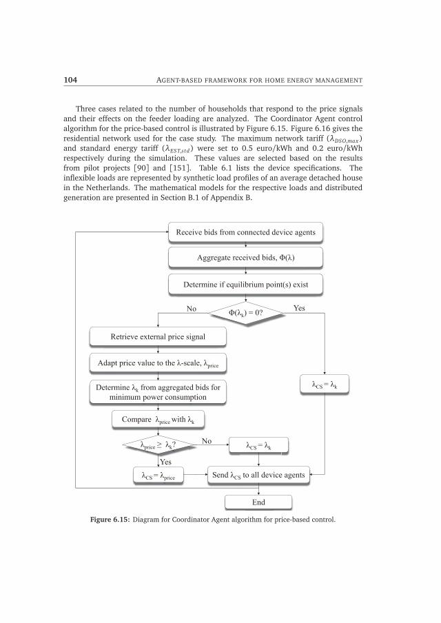
104 AGENT-BASED FRAMEWORK FOR HOME ENERGY MANAGEMENT
Three cases related to the number of households that respond to the price signalsand their effects on the feeder loading are analyzed. The Coordinator Agent controlalgorithm for the price-based control is illustrated by Figure 6.15. Figure 6.16 gives theresidential network used for the case study. The maximum network tariff (λDSO,max)and standard energy tariff (λEST,std) were set to 0.5 euro/kWh and 0.2 euro/kWhrespectively during the simulation. These values are selected based on the resultsfrom pilot projects [90] and [151]. Table 6.1 lists the device specifications. Theinflexible loads are represented by synthetic load profiles of an average detached housein the Netherlands. The mathematical models for the respective loads and distributedgeneration are presented in Section B.1 of Appendix B.
Receive bids from connected device agents
Aggregate received bids, Φ(λ)
Determine if equilibrium point(s) exist
Φ(λk) = 0?
λCS = λk
Send λCS to all device agents
End
λCS = λprice
λCS = λk
Yes No
Yes
Retrieve external price signal
Adapt price value to the λ-scale, λprice
Determine λk from aggregated bids for minimum power consumption
Compare λprice with λk
λprice ≥ λk? No
Figure 6.15: Diagram for Coordinator Agent algorithm for price-based control.
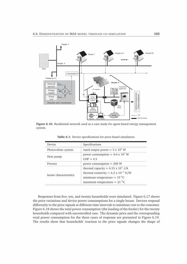
6.6. DEMONSTRATION OF MAS MODEL THROUGH CO-SIMULATION 105
Dynamic price mechanism
House 20House 1 House x+1
Feeder 1
MAS-HEMS
WLAN
Internet
P0
P1
P2
P3
Other metering
instruments
Smart metering system
PV system
Household appliances
Electric power
ICT
House, x
Heat pump
Grid
Feeder k
Feeder (k+1)
Network operator Energy retailer Fixed cost
Σ
Concentrator
λfixed
λDSO
λEST
λprice
Am
bien
t tem
pera
ture
G
loba
l irr
adia
tion
Figure 6.16: Residential network used as a case study for agent-based energy managementsystem.
Table 6.1: Device specifications for price-based simulation.
Device Specifications
Photovoltaic system rated output power = 5 x 10³ W
Heat pumppower consumption = 4.0 x 10³ W
COP = 4.5
Freezer power consumption = 200 W
house characteristics
thermal capacity = 6.55 x 10⁷ J/Kthermal resistivity = 6.3 x 10⁻³ K/Wminimum temperature = 19 0C
maximum temperature = 21 0C
Responses from five, ten, and twenty households were simulated. Figure 6.17 showsthe price variations and device power consumptions for a single house. Devices responddifferently to the price signals at different time intervals to minimize cost to the customer.Figure 6.18 shows the total power consumption (the loading of the feeder) for the twentyhouseholds compared with uncontrolled case. The dynamic price and the correspondingtotal power consumption for the three cases of response are presented in Figure 6.19.The results show that households’ reaction to the price signals changes the shape of

106 AGENT-BASED FRAMEWORK FOR HOME ENERGY MANAGEMENT
0 4 8 12 16 20 240
1
2
3
4
5
Time [hours]
Pow
er[kW
]
heat pump freezer washing machine dish washer dishwasher
0 4 8 12 16 20 24
0.2
0.4
0.6
0.8
Price
[Euro/kW
h]
price
Figure 6.17: Price variations and power consumptions of a single house.
4 8 12 16 20 240
20
40
60
Time [hours]
Pow
er[kW
]
4 8 12 16 20 24
0
0.2
0.4
0.6
0.8
Price
[Euro/k
Wh]
uncontrolled controlled -pricebbaprice
Figure 6.18: Price variations and power consumption of twenty houses.
the load profile. Also, the effect of dynamic pricing is visible when more householdsrespond to the price signal. More households’ participation results in relatively lowerprices, reduction in peak power consumption, and less prices volatility.
6.7 Conclusion
Smart energy management systems enable automation and control applicationbeneficial to the residential consumers and the grid. In this chapter, a multi-agent systemarchitecture for home energy management is presented. Using distributed agents’intelligence, residential appliances can be operated to respond to external signals whilemaintaining the users’ preferences of comfort level and needs or meeting contractual

6.7. CONCLUSION 107
0 4 8 12 16 20 240
0.2
0.4
0.6
0.8
1.0
1.2
Time[hours]
Price
[Euro]
5 houses response10 houses response20 housese response
(a)
0 4 8 12 16 20 240
10
20
30
40
50
60
70
Time [hours]
Pow
er(kW
)
5 houses response10 houses response20 houses response
(b)
Figure 6.19: Power consumption and price variation of the twenty houses for the threescenarios.
agreement. Optimization strategies that offer flexibility, control and freedom to thecustomer while offering services to external parties are expounded. The proposedarchitecture is suited for present and near future Smart Grid applications such as the useof dynamic tariff system, demand response programmes, or households’ participationin a virtual power plant system. Where external parties are involved, the MAS-basedHEMS enable customers to decide which devices should be granted external directcontrol or participate in DR activities. The chapter introduced a bid function algorithmusing distributed intelligent agents for control of flexible residential loads and localgeneration. The bidding strategy is simple, efficient, involves small data flows, andcan be implemented on systems with less computational capabilities. The continuousbidding process makes the MAS system suited for near real-time applications and canoperate without a prediction model. As a proof of concept, a co-simulation model

108 AGENT-BASED FRAMEWORK FOR HOME ENERGY MANAGEMENT
using MATLAB and JADE platforms was developed. Simulations were performed forresidential houses with flexible loads and local generation. A demand-supply matchingmechanism which maximizes self-consumption and minimizes the exchange of energyto and/from the grid was simulated. The matching algorithm is suited for householdswith local generation, heat pumps with buffer storages, or electric vehicle, or placescustomers are restricted on the amount of energy they can feed back into the grid.The results show up to 16% reduction in energy consumption for a household inwinter. Further, dynamic price mechanism which integrates fluctuating prices of theelectricity, loading of the residential distribution network was analyzed. Price-basedcontrols are relatively easier to implement and the control signals can be optimizedto reflect the dynamics of the electricity market, and the constraints of distributionnetwork. Simulation results show that the MAS-based home energy management systemcan offer benefits to residential consumers beyond the traditional energy consumptionpatterns. Reduction in customers’ energy bills is directly related to the price fluctuations,customers load types and the number of households that respond to the price signal.

CHAPTER 7Laboratory-scale demonstration ofhome energy management systems
7.1 Introduction
The smart meter is an important technology expected to facilitate energy management atthe residential level. Additionally, there are several home energy management systemsthat are currently being deployed in homes. This chapter focusses on laboratory-scale development and demonstration of two types of home energy managementsystem: Zone A (using the smart meter only) and Zone C (using smart plugs fordevice monitoring and control) (see Figure 7.1). Section 7.2 presents Zone A energymanagement with smart meter as the major component. Smart meters were installedin the laboratory and a five-family residential building. Data from the P1 port isextracted and processed using a raspberry Pi micro-controller. The energy consumptiondata are compared with the corresponding P3 port data to investigate the effect ofdata granularity and customer feedbacks. Section 7.3 looks into device-level energymanagement (Zone C). The system is built on a ZigBee network comprising smart plugswith embedded XBees for wireless communication, selected domestic appliances, anda gateway which acts as a coordinator and it is programmed to gather data from, andsend commands to smart plugs. A device control mechanism is developed for automaticcontrol of devices. An external interface to enable remote control of devices and anHTTP interface for feedback to customers are also presented.
7.2 Energy management using smart meter
Data collected from the smart meter can provide various information about households’energy consumption and generation. However, their volume, velocity and variety haveto be carefully controlled to prevent collecting large amount of unwanted data. In thissection experiments are carried out in the laboratory and in a residential building to
109

110 LABORATORY-SCALE DEMONSTRATION OF HOME ENERGY MANAGEMENT SYSTEMS
Smart Meter
P1 P2
P0 P3
EMS Server
IHD
Apps
Web portals
Grid
Information flow Power flow
SmartMeter
P11P2
P0P0P3
Zone A Zone B Zone C
Figure 7.1: Division of a house into zones for energy management.
identify the level of difficulty in accessing the data from the P1 port, and to determinethe necessary data required for meaningful feedback to the customer.
7.2.1 Experimental set-up
The laboratory set-up and house installations are depicted in Figures 7.2 and C.1respectively comprising a smart meter, an RS232 connector, a micro-controller and acloud-based storage. The smart meter is a single-phase Iskra ME382 smart meter withmeasurements and communication ports (P1 - P4) as described in Section 5.3. The mostimportant feature of this smart meter is the accessibility of the P1 port to the customer.The port is a standard RJ11 socket: a half-duplex serial port with signals on transistor-transistor logic (TTL)-level (0-5V) and with 4 connected pins (see Figure C.2). As longas pin 2 (RxD= request data) is activated (receives the required voltage), data packagesare sent through the pin 5 (TxD = transmit data) every 10 seconds.
Smart meter
P1 port RJ11 RS 232
Connector
Cloud-based data storage
Micro-controller (RPi)
USB port
Local storage
Ethernet port
Graphic outputs
Display
Figure 7.2: Experimental set-up for smart meter data extraction and processing

7.2. ENERGY MANAGEMENT USING SMART METER 111
However, the data package that is sent by the meter contains reversed serial data(1=0 and 0=1), therefore an RS232 plug is connected to the RJ11 to convert theincoming data to the correct format. The RS232 output has USB interface for connectionto the micro-controller. A raspberry Pi (RPi) micro-controller is used to extract andprocess the P1 data. RPi allows the use of a standard mouse and keyboard, a USBperipheral for local storage, Ethernet port for connection to the internet, and videooutputs for graphical user interface. It can be programmed using Python programminglanguage. The set-up is completed with a connection to a cloud-based storage as back-up storage, and to mimic the interaction of the smart meter with independent serviceproviders.
7.2.2 Data extraction and analysis
P1 port data takes the form of a telegram and it is sent out by the port every 10 seconds.Table C.2 of Appendix C gives the full description of the lines of information which canbe extracted from the P1 port. Nine out of them are considered to be useful for energymanagement purposes (see Table 7.1). Important among them are the time-of-use (ToU)measurement of active energy for day and night (up to 4 tariffs), the instantaneouspower consumption or delivery, and the total gas consumption. The P1 port has notime stamp since it was originally intended to be connected to in-home display withno storage in mind. Thus a time stamp (line 10) is added to the extracted P1 data forefficient data processing and to provide meaningful historical overview. To analyze theimpact of the consumption data granularity and feedback duration, consumption datathrough the P3 port are obtained from Slimmemeterportal.nl, which provides daily toyearly consumption data for households, giving the kWh consumption in time slots of 15minutes. The data are available to the customer one day after (i.e. Monday consumptiondata are available earliest on Tuesday).
Results
Figure 7.3 shows a comparison of the P1-port data with corresponding data from the P3port. The P3-port data transfers 15 minutes averages of the energy consumption data.The P3 data have the advantage of being sufficient for historical overview. However, itis limited in the sense that it does not give insight on device peak power consumptions,actual device start and end-of-operation times, and provides no real-time feedback. Forinstance, in Figure 7.3(b), the operation of a washing machine is noticeable from the P1data but can be hardly identified by the P3 data. Also, there is 15 minute time differencebetween the actual start time of the device (see Figure 7.3(c)). On the contrary, thenear real-time and high granularity of the P1 data enables real time observation ofdevice consumption to encourage occupants to implement direct energy or cost savingmeasures. It also enables users to identify the operational time and power consumptionof high power devices. However, storing P1 data will requires much more storage space.Cloud-base storage could serve as back-up for data storage.

112 LABORATORY-SCALE DEMONSTRATION OF HOME ENERGY MANAGEMENT SYSTEMS
4 8 12 16 20 240
1
2
3
4
Time [hours]
Pow
erconsumption[kW
]
30/5/2014 P1-port DataP3-port Data
Period A Period B
(a) A day profile
7 8 90
1
2
3
4
Time [hours]
Pow
erconsumption[kW
]
P1-port dataP3-port dataSection A
Washingmachineoperates
(b) Period A
14 15 160
1
2
Time [hours]
Pow
erconsumption
[kW
]
P1-port DataP3-port Data
device started- P1 data
device started- P3 data
(c) Period B
Figure 7.3: Comparison of energy consumption data from P1 and P3 ports.
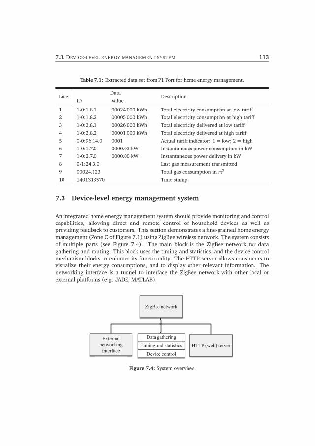
7.3. DEVICE-LEVEL ENERGY MANAGEMENT SYSTEM 113
Table 7.1: Extracted data set from P1 Port for home energy management.
LineData
DescriptionID Value
1 1-0:1.8.1 00024.000 kWh Total electricity consumption at low tariff
2 1-0:1.8.2 00005.000 kWh Total electricity consumption at high tariff
3 1-0:2.8.1 00026.000 kWh Total electricity delivered at low tariff
4 1-0:2.8.2 00001.000 kWh Total electricity delivered at high tariff
5 0-0:96.14.0 0001 Actual tariff indicator: 1 = low; 2 = high
6 1-0:1.7.0 0000.03 kW Instantaneous power consumption in kW
7 1-0:2.7.0 0000.00 kW Instantaneous power delivery in kW
8 0-1:24.3.0 Last gas measurement transmitted
9 00024.123 Total gas consumption in m3
10 1401313570 Time stamp
7.3 Device-level energy management system
An integrated home energy management system should provide monitoring and controlcapabilities, allowing direct and remote control of household devices as well asproviding feedback to customers. This section demonstrates a fine-grained home energymanagement (Zone C of Figure 7.1) using ZigBee wireless network. The system consistsof multiple parts (see Figure 7.4). The main block is the ZigBee network for datagathering and routing. This block uses the timing and statistics, and the device controlmechanism blocks to enhance its functionality. The HTTP server allows consumers tovisualize their energy consumptions, and to display other relevant information. Thenetworking interface is a tunnel to interface the ZigBee network with other local orexternal platforms (e.g. JADE, MATLAB).
External networking
interface HTTP (web) server Timing and statistics
Device control
Timing and statisticsData gathering
ZigBee network
Figure 7.4: System overview.

114 LABORATORY-SCALE DEMONSTRATION OF HOME ENERGY MANAGEMENT SYSTEMS
7.3.1 ZigBee network set-up
ZigBee is a protocol based on the IEEE 802.15.4 standard and provides routing andnetworking functionalities required for wireless sensor network applications. It operatesin a license-free frequency band, sharing the same frequency band with other wirelesstechnologies such as WiFi (802.11) and Bluetooth (802.15.1). It also focuses on highreliability and large range combined with low-cost and low-power-consumption. AZigBee-based set-up consists of three key nodes: end devices, routers and coordinatorswhich can be configured in star, tree or mesh network topologies (see Section C.2 ofAppendix C). Each network has one coordinator with an arbitrary number of routersand end devices.
NXP plug meter XBee
module
Pikkerton smart meter
Digi X4 Gateway
Wall router
Figure 7.5: Schematic of implemented ZigBee network for the laboratory set-up.
Figure 7.5 shows the schematic laboratory set-up of the ZigBee mesh networkconsisting of smart plugs, a wall router and a gateway. Figure C.3 shows domesticappliances used in the experiment, namely refrigerator, freezer, air-conditioner,electric heater, ventilator and vacuum cleaner. These appliances have no embeddedmeasurement and communication devices, hence smart plugs are attached to each ofthem to measure and transmit device consumption data. Two types of smart plugswere used - NXP demo plug meter and Pikkerton smart energy meters. The NXPPlug Meter was modified to use ZigBee communication protocol instead of the originalwireless M-Bus protocol by attaching an XBee module. Each smart plug has its ownmeasurements characteristics and capabilities, but they transmit the information in aserial communication way using an XBee module. It is important to remark that ZigBeeand XBee are different. While ZigBee refers to a standard communication protocol, XBeerefers to a family of radio frequency (RF) modules that supports ZigBee protocol and its

7.3. DEVICE-LEVEL ENERGY MANAGEMENT SYSTEM 115
characteristics.The Digi X4 gateway acts as a ZigBee coordinator. It is an embedded device which
supports Python scripts only and is able to communicate with both the ZigBee networkand the Ethernet. Its operating system allows user scripts to be executed. It has 32 MB ofRAM, 16 MB of flash memory (about 15 MB of RAM is in use during normal operation)and a 4 GB USB stick with flash memory is attached for local data storage. The WallRouter measures ambient light and temperature from 0 and 1200 lumen, and −22oC to48oC respectively. It also expands the ZigBee network by allowing other ZigBee devicesto seamlessly communicate with each other, acting as a mesh network routing node.
7.3.2 Receiving, parsing and storing data
Figure 7.6 illustrates the data receiving, parsing and storage process. The gateway isresponsible for starting and coordinating the ZigBee network. It is configured to allowdevices to join the Personal Area Network (PAN); devices need to have the same PANID and need to be placed in ’discovery’ mode. A device can transmit its data onceit is registered with the gateway. The transmitted data are stored in a flash driveavailable in the gateway. However appending data to files could not be done reliablyevery second. A caching mechanism is implemented which stores the data first in theglobal memory. When enough data is received and parsed, the content of the globalmemory is flushed to a queue. Data storage process is accomplished by Python scriptsrunning on the gateway: ’StartGathering.py’, ’DataSpooler.py’, ’MessageBuffer.py’, and’MessageOutputBuffer.py’ (see Figure 7.7). The StartGathering.py is the main entry forthe routine that listens to the attached XBee network, and links all the other files. TheDataSpooler.py receives data packets from StartGathering.py and writes them in thedata storage device. The MessageBuffer.py receives data packets and writes them to anetwork socket, enabling the user to follow the consumption parameters in real-time.The MessageOutputBuffer.py receives data packets from the network command socket,and it sends the commands to the main file.
Each smart plug has its own set of output data streams (see Figure 7.8); thereforedifferent data-parsing routines were set up for each device type. The NXP plug meteronly sends a text string containing measurements to its serial port every second and hasno actuating capabilities whereas the Pikkerton smart meter enables switching ON/OFFof connected devices.
7.3.3 Device control
A device control mechanism was developed to test automated control of the domesticappliances taking into account user inputs. The actuating capability of the Pikkertonsmart plugs enables devices to be switched ON or OFF remotely by the user or throughautomated control functions. These plugs were used for the control of the devices. Toprevent creating big data in the global memory of the system, a GettingMeanValue.pyscript was created which allows the system to store only two values - the mean of

116 LABORATORY-SCALE DEMONSTRATION OF HOME ENERGY MANAGEMENT SYSTEMS
Receive data from ZigBee socket
Create timestamp for this device
Device type specific parsing
Store data point in a queue
Register device
Known device? Yes
No
Figure 7.6: Process of receiving, parsing and storing data by the gateway.
External networking interface
Python files on X4 Gateway
StartGathering.py
MessageBuffer.py DataSpooler.py MessageOutputBuffer.py RunningStatistics.py
StartWebserver.py
Network socket Storage device
ki i t f
Network command socket HTTP server
Figure 7.7: Connection between the different Python files.
NXP plug meter output data
229.206 00.191 0043.778 0.85 0037.211 0018.403 0023.061 0000.479 V I S PF P SN Q THDI
Pikkerton plug meter output data
[ ‘POW =ON’, ‘FREQ = 49,8125Hz’, ‘VRMS = 230V, ‘IRMS = 3.5mA’, LOAD =0.805W, ‘WORK = 32.64kWh’, “, “ ]
Figure 7.8: Data strings sent by the different plug meters.

7.3. DEVICE-LEVEL ENERGY MANAGEMENT SYSTEM 117
measured quantity such as current, voltage or load, and the number of samples thathave been averaged - instead of keeping a matrix with every single sample. A prioritycontrol mechanism was developed to test the dynamic control of selected devices in thelaboratory (see Figure 7.9). The objective function for the device control is expressedas:
min P =T∑
t=1
Phse,dmd(t)− Phse,prod(t)
suchthat :
Phse,dmd(t)− Phse,prod(t)≤ Phse,max_spec(t)
(7.1)
where P is the total power function; and Phse,max_spec is the household’s maximum powerconsumption set by the user for defined time period.
Devices were arranged in order of (users’) priority. Figure 7.10 shows the powerconsumption of the test devices. During the experiment, a data transmission interval of1 second was initially selected for the smart plugs. The ZigBee network had problemswith sending messages and storing data of the smart plugs. Measurements arrived atirregular time intervals (see Figure 7.11). The time stamp (first column) should beadvancing with steps of 1 second. However, there were jumps, repetitions, and missingdata points. This problem was peculiar to the Pikkerton plugs only and the reason forthis error could not be determined. The transmittal interval was then increased to 10seconds, just like the smart meter P1 port, and problem was resolved.
At every 15 minutes, the total power consumption is compared with the thresholdvalue Phse,max_spec . If the power consumption exceeds the threshold, the device with theleast priority is switched off. The cycle is repeated a minute later to check if the violation
Yes
DataAnalyzer.py
Analyze which devices are running
Y
Threshold exceeded?
No
Switch off device with least priority
Update total load consumption (Pload)
Threshold exceeded?
Wait time_A
Can a device be turned on?
Pth >= Pload
Switch on device by priority.
Update total load consumption (Pload)
Wait time_B
Wait time_A
No
Yes
No
Yes
Figure 7.9: Priority control mechanism.

118 LABORATORY-SCALE DEMONSTRATION OF HOME ENERGY MANAGEMENT SYSTEMS
0 20 40 600
30
60
90
120
Pow
er c
onsu
mpt
ion
[W]
device7 - refrigerator
0 20 40 600
20
40
60
80
100device8 - freezer
0 20 40 600
200
400
600
800
1000
1200device11 - air-conditioner
0 20 40 600
5
10
15
20
25device13 - ventilator
0 20 40 600
200
400
600
800
1000device14 - vacuum cleaner 1
Time [minutes]0 20 40 60
0
200
400
600
800
1000device16 - vacuum cleaner 2
Figure 7.10: Power consumption of individual devices.
Time stamp measurements
Jumps
Repetitions
Figure 7.11: Data gathering with 1 second data transmission interval.
still exists. The process continues until the power consumption is equal or less than thethreshold value. Figures 7.12 and 7.13 show the power consumption when the controlmechanism was implemented for cases without and with PV system power generationrespectively. The results indicate that the system controlled the devices to stay aroundthe user-defined threshold. However, due to the limited number of flexible devices therewere disparities between the threshold value and the power consumption.

7.3. DEVICE-LEVEL ENERGY MANAGEMENT SYSTEM 119
0 10 20 30 40 50 600
1.0
2.0
3.0
Pow
er[W
]
Time [minutes]
Total consumptionThresholdPoint of analysis
Figure 7.12: Total power consumption with priority control mechanism for the case withoutPV system.
0 10 20 30 40 50 60
−1.0
0
1.0
2.0
3.0
Pow
er[kW
]
Time [minutes]
Devices’ consumptionTotal consumptionPV outputThresholdPoint of analysis
Figure 7.13: Total power consumption with priority control mechanism with a PV system.
7.3.4 HTTP server interface
The Digi ConnectPort family consists of ZigBee coordinator devices that can be attacheddirectly to a TCP/IP network and are programmable via Python. This means that datacan be parsed and stored locally, thereafter served on the local network or the internet.This enables the consumer to have direct access to its data, instead of via a cloudserver. Due to the processing limitations of the DigiWeb callback, a simple HttpServerand corresponding HttpHandler were implemented. The StartWebserver.py script (fromFigure 7.7) starts the web server to bring the dynamic and static files to the browser.It gets from the file RunningStatistics.py different energy measurements that have beenprocessed, such as average daily, weekly or monthly consumption data. The server isextended to load dynamic files to create a more flexible way of writing web pages.

120 LABORATORY-SCALE DEMONSTRATION OF HOME ENERGY MANAGEMENT SYSTEMS
These files have the normal Python syntax and act like server pages, such as PHP orASP. Therefore, new pages can be simply uploaded into the Gateway’s flash memoryand automatically become available to the outside world. The default page is a simpledashboard which is able to show several containers. At this point, only a simple bargraph of the energy consumption of the current day is shown, together with a gaugethat shows the energy consumption of the last minute (see Figure 7.14).
Figure 7.14: Dashboard for the Home Area Network Smart Grid Monitor.
7.3.5 External networking interface
The device consumption data can be accessed from the attached storage or via theweb server interface. This does not allow external access to devices. The gateway istherefore programmed to provide networking ports for each of the devices. The portsprovide a way of feeding data into external application (multi-agent system in JADE)for monitoring and control of devices. Once data from a ZigBee device is time stampedand parsed, it is sent to a queue. The queue sends the data to any client connected tothis device socket.
To feed the decisions back to the network, a command port is provided to sendcommands to the different devices regardless of the ZigBee network set-up. This socketexpects a device ID in the form of an integer, an underscore-separator followed by theactual command, which is a text/binary string that is directly sent to the correspondingZigBee device. For example, sending ”14 set pow=on” means send the string ”ON”to the device with ID 14. The ZigBee device will receive this message on its serialcommunication port. Each command is buffered in the command queue. When a socketis ready to send a command, the oldest entry in the queue is sent (see Figure 7.15(b)).

7.3. DEVICE-LEVEL ENERGY MANAGEMENT SYSTEM 121
Devices are called by using a specific port; the first device has port number 9001, thesecond one has port number 9002 and so on (see Table 7.2).
Yes
Receive string via command socket
Append string to command
String contains new line?
Add command to queue
Command queue
empty? Idle
Send oldest command to ZigBee network
No
Yes
No
Wait
DeviceAgent 2
DeviceAgent 1
(a) (b)
Figure 7.15: External communication with ZigBee network.
Table 7.2: Port numbers for the different network servers.
Server Port number
Telnet 23
SSH 22
SMNP 161
RealPort 771
Emcrypted RealPort 1027
Custom HTTP Server 8080
Web configuration: HTTP Server 80
Web configuration: HTTPS Server 443
Zigbee Command listener 8081
Zigbee device 9000+ device ID (e.g. 9001 for device 1)

122 LABORATORY-SCALE DEMONSTRATION OF HOME ENERGY MANAGEMENT SYSTEMS
7.4 Conclusion
In this chapter, laboratory-scale demonstrations of two parts of home energymanagement systems are presented. The first experiment involves extraction, processingand analysis of smart meter’s data. Nine out of the 20 lines of P1-port data streams areconsidered useful for feedback to the customer. Though the P1 port is meant to providecustomers with their energy consumption/generation, obtaining useful data from theport requires extra hardware and software. Two most important components are theinterface connection to invert P1 port output data stream in the correct format, anda micro-controller for data processing and display. In this experiment a RaspberryPi was found to be a suitable micro-controller for data extraction and processing,and for providing direct feedback to the customer. For being smart meters useful tothe residential customers, their deployments should be accompanied with an easy-to-connect web-based or in-home display interfaces for better access to the P1 port data.
Further, a device-level energy management system was developed using a ZigBeehome area network. The network provides a bidirectional communication platformenabling devices to communicate with each other, and to provide a means tocommunicate with higher external communication networks through a gateway. Resultsshow that ZigBee network with an X4 gateway is capable of processing, parsing andstoring device consumption data. A priority control technique was developed to testthe system’s ability to dynamically control devices. Results show successful flow ofinformation and command messages with the ZigBee network.
However, existing smart plugs have proprietary hardware and software with differentmeasuring parameters and data sampling. The differences in data output streamsrequired separate routines for data extraction. It is recommended for smart plugsto have standardized output measured data and sampling rates to enable seamlessintegration of different smart plugs regardless of the vendor. 10 seconds measurementwas found to be sufficient for real time monitoring and control of residential devices.Higher sampling rates may require smart plugs and central control units with highcomputational capabilities and hence more energy consumption. An HTTP serverinterface for energy monitoring developed to provide feedback to the customer providesonly a dashboard and further work is required for a meaningful interface. This washowever beyond the scope of this research. Also, an external networking interface wasdeveloped to enhance remote monitoring and control of specific devices at near real-time.

CHAPTER 8Conclusions, contributions and
recommendations
8.1 Conclusions
Economic growth, increase in population, and developments in policy and technologyare changing the residential energy distribution infrastructure. The penetration ofspecial loads such as heat pumps and electric vehicles, enforcement of energy efficiencymeasures (energy efficient buildings and domestic appliances), utilization of morerenewable energy sources, and deployment of intelligent home energy managementsystems are important factors influencing the residential energy supply systems.
8.1.1 Residential energy consumption and demand patterns
The annual residential energy consumption keeps increasing. The energy consumptionis expected to stabilize or reduce among European countries due to the enforcementof energy efficiency measures. However, the use of more domestic electrical appliancesand the demands for more comfort by residential customers tend to offset the reductionsin energy consumption through these energy efficiency policies. The penetration ofemerging energy conversion technologies, such as heat pumps, electric vehicles, microcombined heat and power units, and photovoltaic systems will significantly affect theresidential energy demand and supply. The increase or decrease in electricity and gasdemands will be affected by societal acceptance of the energy conversion technologies,and also by governments’ goals and policies. With transition towards smart residentialpower grids, variations in electricity consumption and generation for different seasonswill play an important role. PV systems, electric vehicles and cooling loads will alterthe residential summer load profiles. Winter load profiles will be influenced by thepenetration of heat pumps, μCHP units and electric vehicles. For new residentialneighborhoods, PV systems, heat pumps and electric vehicles will be dominant. The
123

124 CONCLUSIONS, CONTRIBUTIONS AND RECOMMENDATIONS
design of the residential energy infrastructure should therefore integrate governments’medium to long term goals, and to account for possible changes in the demographiccomposition, to prevent unaccommodated demand for energy.
8.1.2 Smart energy homes and the Smart Grid
Smart energy homes (SEHs) have potential for improved living conditions, energysavings, safety and comfort to the inhabitants, decreasing carbon footprint byintroducing renewable sources, and changing the role of residential customers inthe electrical power system. Smart metering and sensor technologies, home areacommunication networks, smart appliances and home energy management systems arethe main enablers of smart energy home concept. SEHs are crucial in the transitiontowards smart cities by creating communities with smart livings styles. With increasedfocus on reliability and power quality, SEHs provide the enabling technologies for SmartGrid applications at the residential level. New buildings and neighborhoods are ideallocations for testing the interactions between smart energy homes and the Smart Grid.It is desirable that SEHs be aggregated and managed due to potential adverse effects ofstand-alone operation on the public grid. Also aggregation provides better opportunityfor optimization and utilization of resources. For smart energy homes to be sustainablyintegrated into the Smart Grid, the following aspects are crucial: Affordability - smartenergy homes should not be too expensive to scare away prospective home owners or bereserved for the affluent class only. Comfortability- residents should be more comfortableand healthier living in smart energy homes. Security- they should provide more securityagainst burglary and violation of customers’ privacy. Flexibility- they should offer supportto the local electric grid through Smart Grid applications and be easily adaptable tonew type residential occupants. Interoperability- seamless integration of advanced hometechnologies into the Smart Grid framework irrespective of the vendor. Internet Protocolis a proven, viable and attractive solution for interoperability purposes and contributesto an open, standard-based network. Cooperation: smart energy home demonstrationprojects should involve the collaboration of key stakeholders such as municipalities,housing corporations, distribution network operators, energy retailers, policy makersand residential customers.
8.1.3 Smart meters
The roll-out of smart meters is one of the important steps toward encouraging theparticipation of residential customers in the energy supply system. It is expectedthat residential customers will have access to their energy consumption data via theP1 port of the smart meter. However, accessing the smart meter data requires extrahardware and a good knowledge of data processing. Furthermore, real-time bi-directional communication capabilities of smart meter are not enabled yet because ofcustomers’ privacy concerns. This has limited the functional capabilities of the smartmeter. The device is smart by design but consequently limited in operation. The

8.1. CONCLUSIONS 125
deployments of smart meters should be accompanied by user-friendly interfaces forbetter access to essential data such as real-time energy exchange and the correspondingtariff information.
8.1.4 Home energy management systems
Home energy management systems are growing worldwide and with the imminentfull scale roll-out of smart meters, HEMS technologies will be a mass market andmainstream residential service. Their deployments are driven by the need for moreefficient operation of the power system infrastructure, customer retention for utilities,and specific use of HEM products. Presently, no single technology combines all theaspects of design, interface, powerful back-end engine and sustainable business model.However, HEMS technologies that only provide real-time or historical information mayprovide fewer benefits to the customer and the power grid. A sustainable HEMS shouldbe multi-functional to enable households manage and reduce their energy use and cost,support dynamic pricing for demand-side management, and reduce network loadings.They should also facilitate the integration of residential distributed generations to matchthe needs of users, while securing the reliability and robustness of the residential energyinfrastructure. Addressing location-specific socio-cultural issues, and instituting a legaland organizational framework to regulate HEMS deployments and operations are vitalaspects. Pilot projects that test HEMS product functionalities, encourage customersparticipation, develop clever business models, and aggregate consumers for efficientutilization of resources, will prove to be a sustainable route for large-scale HEMSdeployments.
8.1.5 Multi-agent system architecture for device monitoring and control
An efficient home energy management system requires automation and control systemsto meet the objectives of the different actors. In this thesis a hierarchical multi-agentsystem architecture is proposed for intelligent energy management for households.The agent-based system implements distributed intelligence to monitor and controlresidential devices according to users’ preferences or in response to external signals.A bid function algorithm is employed for control of flexible loads. A co-simulationmodel is developed that implements Java Agent Development Platform for the designof the multi-agent system and device control algorithms, and MATLAB software formodelling residential devices. The dynamic pricing mechanism which integrates pricefluctuations of the electricity market and network loadings, and a green optimizationcontrol algorithm that maximizes consumption of locally generated energy are testedwith the MAS-based HEMS. Devices are controlled to maximize comfort or consumptionof local generation, minimize energy cost to the customer, or participate in externalprogrammes giving control and freedom to the customer, while providing support tothe power system. The hierarchical structure with intelligence on the different devicelevels, coupled with the continuous bidding process, ensures scalability and aggregation

126 CONCLUSIONS, CONTRIBUTIONS AND RECOMMENDATIONS
of households for Smart Grid applications. Price-based control is found to be suitablefor the power system operation since the price signal can be optimized to reflect thedynamics of the electricity market and constraints in the distribution network.
8.1.6 Testing home energy management systems
Two parts of home energy management systems are tested in practice. In the first case,the use of smart meters as a tool for home energy management was investigated inlaboratory and real world environments. Nine out of the twenty output data streamsof the P1 port are considered important for home energy management purposes. ARaspberry Pi micro-controller, RS232 cable, and an in-home display (or a cloud-basedcomputing service) are sufficient for extracting smart meter data and providing feedbackto the customer. The second set-up involves monitoring and control of residential devicesusing a mesh network of smart plugs and a gateway (coordinator), linked wireless bya ZigBee communication protocol. ZigBee is a low-cost, low-power wireless technologythat provides routing and networking functionalities. A real-time control algorithm,which employs users’ predefined device preferences and maximum power consumptionlimits, was used to test the ability to dynamically monitor and control devices. Resultsindicate successful communication of information and command message between thesmart plugs and the gateway. It was noticed that different smart plugs have proprietaryhardware and software, as well as different measuring parameters. Separate routineshad to be deployed for data extraction from different smart plugs. It is recommended tostandardize the output streams and sampling rates of smart plugs to facilitate seamlessintegration of plugs from different vendors.
8.2 Thesis contribution
The main contributions of the thesis are summarized below:
1. Residential energy demand: An overview of residential energy consumptionsis presented. The impacts of housing types and household compositions onresidential gas and electricity consumptions are investigated. The analyses showdirect correlation between residential electricity consumptions and householdcomposition (number, family composition, and income level) whereas the gasdemands are virtually affected by the residential building (type, vintage andorientation) and the age-group of occupants. Four classifications of residentialloads are presented with regards to their ability to be shifted in time withoutimpacting on the services they provide. The classification aims to facilitate thechoice of control measures to be deployed for each load category.
2. Demographics and energy conversion technologies: Demographic analyses ofaggregated households indicate that an optimal mix of residential groups andhousing types will provide a natural smoothing of the residential load profile,increasing efficient use of grid capacity. Also, the residential demand and supply

8.2. THESIS CONTRIBUTION 127
systems are changing due to the penetration of energy conversion technologiessuch as PV systems, heat pumps, μCHPs and electric vehicles. A scenario-based methodology is presented to model future residential load profiles. Themethodology combines top-down and the bottom-up approaches to evaluates theimpact of PV systems, μCHPs, heat pumps and electric vehicles on the futureresidential demand patterns.
3. Smart energy homes, smart cities and the Smart Grid: Analyses showthat a smart residential electrical energy infrastructure will lead to less energyconsumption, and increase in energy efficiency and grid reliability. The thesisoutlines the enabling technologies and essential factors for sustainable integrationof smart energy homes as a part of infrastructure for smart cites, and as importantconstituents of smart residential power grids.
4. Energy management systems for households: An overview of HEMStechnologies is given and it is shown that HEMS technologies are still in theevolutionary stage with different vendors focusing on different aspects. Fourways of HEMS application and their potential benefits have been outlined. HEMStechnologies should be multi-functional to meet the demands of the customer,and be able to interact with the power system. Sustainable deployment HEMSwill depend on the effective harmonization of the technological, economic, social-cultural, legal and structural aspects.
5. Multi-agent system for intelligent home energy management: The thesispresents a multi-agent system architecture as a framework to enable efficient andflexible operation of residential loads and generations. Optimization strategiesthat offer flexibility, control and freedom to the customer while offering servicesto external parties are expounded. The proposed hierarchical architecture enablesscalability for multi-purpose applications such as energy trading and power systemoperation.
6. Demonstration of home energy management system: Extraction, processingand analysis of energy consumption data from the P1 port of the smart meterwas demonstrated in practice. The test results show retrieving P1 port datarequire extra hardware and software and data processing experience. Nineout of the twenty lines of the P1 port data are considered useful for homeenergy management. Furthermore, a device-level HEMS is developed thatemploys ZigBee wireless communication protocol, smart plugs, and adaptablePython scripts for parsing, processing and storage of data, and for device controlalgorithms. The system provides an interface for HTTP (web) server, providingfeedback to the customer, and an external networking interface to interconnectwith other platforms.

128 CONCLUSIONS, CONTRIBUTIONS AND RECOMMENDATIONS
8.3 Recommendations for future research
This research provides the fundamental steps towards an integrated and efficient energymanagement system for the residential environment. As a result further researchdirections have been identified and summarized below:
• ICT infrastructure for large-scale integration of smart energy homes: Thisthesis focusses primarily on the technologies for monitoring and control ofresidential devices within the home. However, aggregation of households offersbetter utilization of resources. Designing a sustainable ICT infrastructure formonitoring and optimal control aggregated smart energy homes will be crucial.
• AC-DC hybrid homes: Recently, there has been attention on DC homes. They areconsidered to provide better energy conversion efficiencies and save materials fordesigning AD-DC converters. Research into AC-DC hybrid homes can harness thecollective advantages of AC and DC homes.
• Socio-technological aspects for HEMS deployments: It was briefly mentionedin this thesis that social factors hindered the full functionality and large scale roll-out of smart meters. It is recommended to make assessment of social aspects thatcould hinder the deployment of HEMS, and to provide ways to mitigate them fromthe technological perspective.
• Testing other control algorithms with the multi-agent home energymanagement system: In this research the bid function algorithm was employedfor device monitoring and control. The algorithm proves to be robust, simple andrequires less computations and data transfer, although other control algorithmscould be investigated and the results compared in terms of complexity, optimaluse of energy, scalability and robustness.

APPENDIX A
Appendix for Load aggregation
A.1 Examples of special loads and distributed generation inhouseholds in the Netherlands
Table A.1: Heat pumps
Brand Type Thermaloutput(kWth)
Coolingoutput(kWth)
Powerinput(kW)
COP
Techneco Toros Brine/water 3.2 - 12.1 2.6 - 8.4 1.1 - 3.0 4.0 - 5.3
Viessmann Vitocal300 Water/water 8.0 - 21.6 6.7 - 17.9 1.4 - 4.3 5.1 - 5.5
WadusDOOR 081EH5 Air/water 8.1 6.0 2.0 4.0
Table A.2: Micro combined heat and power
Brand Fuel Thermaloutput(kWth)
Electricoutput(kWe)
Efficiency(%)
Whispergen Natural gas 7.5 - 8.3 1.0 96
Remeha eVita Natural gas up to 25.0 1.0 89 - 93
Vailant ecoPower Natural gas, bio gas 2.5 - 12.5 1.0 90 - 92
129

130 APPENDIX FOR LOAD AGGREGATION
Table A.3: Electric vehicles
Make & model Type Batterycapacity(kWh)
Reportedrange (km)
Tesla Model S Fully electric 60.0 300
Nissan leaf Fully electric 24.0 175
Renault Zoe Fully electric 22.0 200
Peugeot iOn Fully electric 16.0 150
VW Golf station Fully electric 30.0 200
Table A.4: Photovoltaic systems
Housing type PV output PV output
(kWpeak) with heat pump(kWpeak)
Detached 2.00 - 4.00 4.00 - 8.00
Semi-detached 1.50 - 3.00 2.00 - 6.00
Terraced 1.00 - 2.00 2.40 - 4.00
Apartment 0.50 - 1.00 -
A.2 Standard load profile categorisation
Table A.5: Customer categories for standard load profiles (Source:EDSN.nl)
Index Description
1a ≤ 3× 25A, single counter
1b ≤ 3× 25A, double counter, night tariff
1c ≤ 3× 25A, double meter, active evening tariff
2a > 3× 25A≤ 3× 80A, single counter
2b > 3× 25A≤ 3× 80A, double counter
3a > 3× 80A< 100kW, BT ≤ 2000hours
3b > 3× 80A< 100kW, 2000hours < BT ≤ 3000hours
3c > 3× 80A< 100kW, 3000hours < BT < 3000hours
3d > 3× 80A< 100kW, 3000hours < BT ≤ 5000hours

APPENDIX B
Appendix for agent-based homeenergy management system
B.1 Modelling household loads and generation for multi-agentsystem simulation
House heating model
The house loses or gains heat through conduction (via walls, windows, doors, floors andthe roof), ventilation (forced or natural) and infiltration. However, heat can always begained through the fenestration products by direct or indirect solar radiation irrespectiveof the outside temperature. This amount of heat gain is measured in terms of the solarheat gain coefficient (SHGC) of the glazing. The SHGC is expressed as a dimensionlessnumber from 0 to 1. A high coefficient indicates high heat gain. An SHGC of 0.70 is atypical value for double-pane IGU windows which is common in most of the residentialbuildings. The heat loses or gains can be expressed as:
Qcond(t) = Aex p.U .(Thse(t)− Tamb(t))
Qvent(t) = Cair ..qvent .(Thse(t)− Tamb(t))Qinf l(t) = Cair .ρair .nshi f t .Vhouse.(Thse(t)− Tamb(t))
QSHG(t) = SHGC .Ap f .G(t)
(B.1)
where, Qcond , Qvent and Qinf l are heat loses through conduction, ventilation andinfiltration respectively; QSHG is the solar gain; Cair is the specific heat capacity of air;ρair the density of air; U is the overall coefficient of heat transfer (U-factor); Vhouse isthe volume of the house; qvent is the air volume flow; Ap f is the total projected areaof fenestration; Aex p the total exposed area of house; SHGC the overall solar heat gaincoefficient or fraction of incident solar radiation transmitted to interior; G(t) the incidenttotal irradiance.
131

132 APPENDIX FOR AGENT-BASED HOME ENERGY MANAGEMENT SYSTEM
To maintain indoor thermal comfort, the installed domestic heating/cooling systemmust supply the required heat/cold, which can be defined as:
Qsuppl y(t) = m.Cair .(Tsource(t)− Thse(t)) (B.2)
The house interior temperature variation is modelled as a first order dynamic systemrepresented by the stochastic differential equation as given by [32]:
dTin =1
Rie.Cair(Ten − Thse)d t +
1Cair
.θhd t +1
Cair.Ap f G(t)d t
dTen =1
RieCen(Thse − Ten)d t +
1ReaCen
(Tout − Ten)d t(B.3)
where Rie is the thermal resistance between the interior and the building envelope,Rea is the thermal resistance between the building envelope and the ambient air, Cen isthe heat capacity of the building envelope; θh is the energy flux from the heating system,and Tamb is the ambient air temperature.
Heat pump
Assuming an air-to-air heat pump with discrete number of air flows, the thermal modelof the heat pump for residential space-heating can be expressed by [57]:
Qhp =N∑
i=1
Υi .ωi .βi,t
sub jec t to :
Thse,min ≤ Thse(t)≤ Thse,max
0≤ Php(t)≤ Php,rated
(B.4)
where N is the total number of flows, Υi is the energy/ air-flow ratio, ωi is the heatpump air flow rate, and β(i, t) is a binary variable (0 or 1) for each time slot t.
Freezer
The freezer compartment temperature evolution is modelled using the energy balanceequation. When the compressor is OFF, the active power consumption P(t) is 0; whenthe compressor is ON, P(t) has the shape of an exponential decay function. Thefreezer temperature variation is regarded as a function of electric power input, ambienttemperature and freezer properties as [152]:
TFR(t) =−Amc(T (t − 1)− (Tamb(t)−
ηFRPFR(t)A
)) i f ON
TFR(t) =−Amc(T (t − 1)− (Tamb(t))) i f OF F
(B.5)

B.2. DEVICE BID FUNCTIONS 133
where mc is the freezer thermal mass, TFR(t) the cooling compartment temperature,PFR(t) the instantaneous power, AFR the overall thermal insulation, Tamb(t) the ambienttemperature at discrete time instant t, and ηFR is the coefficient of performance definedas ratio of cabinet heat loss to the power consumption.
PV output power
The power output from the PV arrays is modelled as [25]:
PPV (t) = PW p.ηdc−ac .G(t)GST P
.(1− ξ ∗ (T (t)− TST P)) (B.6)
where, PPV is the output power, PW p is the rated capacity power of the PV system, G(t)is the incident solar radiation at current time instant, GST P is the incident radiation atstandard test conditions, ηdc−ac is the overall conversion factor from DC to AC, T(t) isthe PV array temperature at the current time instant, TST P is the cell temperature understandard test conditions, and ξ is the temperature coefficient of power.
B.2 Device Bid functions
The paragraph gives the equations of device bid functions. Thermal loads (heat pumpsand μCHPs) use a step bid function depending on thermal comfort. PV systems andinflexible load agents produce bids that are independent of the control signal.
Table B.1: Device specifications for demand-supply matching simulation.
Device Specifications
Photovoltaic system rated output power = 3.0 x 10³ W
Heat pump
rated output = 8.0 x 10³ W
power consumption = 1.45 x 10³ W
cooling output = 2.0 x 10³ W
COP = 5.5
Freezer
power consumption = 150 W
thermal mass = 4.2 x 10⁴ J/ 0C
thermal insulation = 1.06 W/Ccoefficient of performance = 1.67
minimum temperature = - 24 0C
maximum temperature = - 18 0C
house characteristicsthermal capacity = 6.55 x 10⁷ J/Kthermal resistivity = 6.3 x 10⁻³ K/W

134 APPENDIX FOR AGENT-BASED HOME ENERGY MANAGEMENT SYSTEM
Micro combined heat and power
dchp(λ) =
⎧⎪⎨⎪⎩
−Pchp, i f ( Thse,max−Thse
Thse,max−Thse,min× L)≤ λ
0, i f otherwise
(B.7)
where dchp, is the μCHP bid curve, and Pchp is the electrical power produced by theμCHP during operation, λ ∈ L = {1, 2,3, ..., L}, is the scale of the control signal.
Table B.2: Other house specific characteristics for demand-supply matching simulation.
Houseindex
Freezer initialtemp
House initialtemp
House indoor temp
0C 0C Winter(0C) Summer (0C)
1 -20.0 19.5 19.5 - 21.0 22.0 - 24.0
2 -21.5 20.0 20.0 - 21.0 22.5 - 23.5
3 -24.0 20.8 21.0 - 22.5 21.0 - 23.0
4 -23.0 22.0 20.0 - 22.0 20.5 - 23.0
5 -18.5 19.0 19.0 - 20.5 22.5 - 24.5
6 -19.0 18.9 20.5 - 22.0 21.0 - 22.5
7 -22.5 21.0 20.0 - 21.0 21.0 - 22.0
8 -20.5 20.5 21.0 - 22.5 22.0 - 24.0
9 -21.0 19.9 19.0 - 21.0 22.5 - 23.5
10 -22.5 21.5 21.0 - 22.5 21.0 - 23.0
11 -20.0 19.5 19.5 - 21.0 20.5 - 23.0
12 -21.5 20.0 20.0 - 21.0 22.5 - 24.5
13 -24.0 20.8 21.0 - 22.5 21.0 - 22.5
14 -23.0 22.0 20.5 - 22.0 21.0 - 23.0
15 -18.5 19.0 19.5 - 20.5 22.5 - 24.0
16 -19.0 18.9 20.5 - 22.0 21.5 - 23.5
17 -22.5 21.0 20.0 - 21.0 22.0 - 24.0
18 -20.5 20.5 21.0 - 22.5 21.5 - 23.0
19 -21.0 19.9 19.0 - 21.0 22.0 - 24.0
20 -22.5 21.5 21.0 - 22.5 21.5 - 23.0
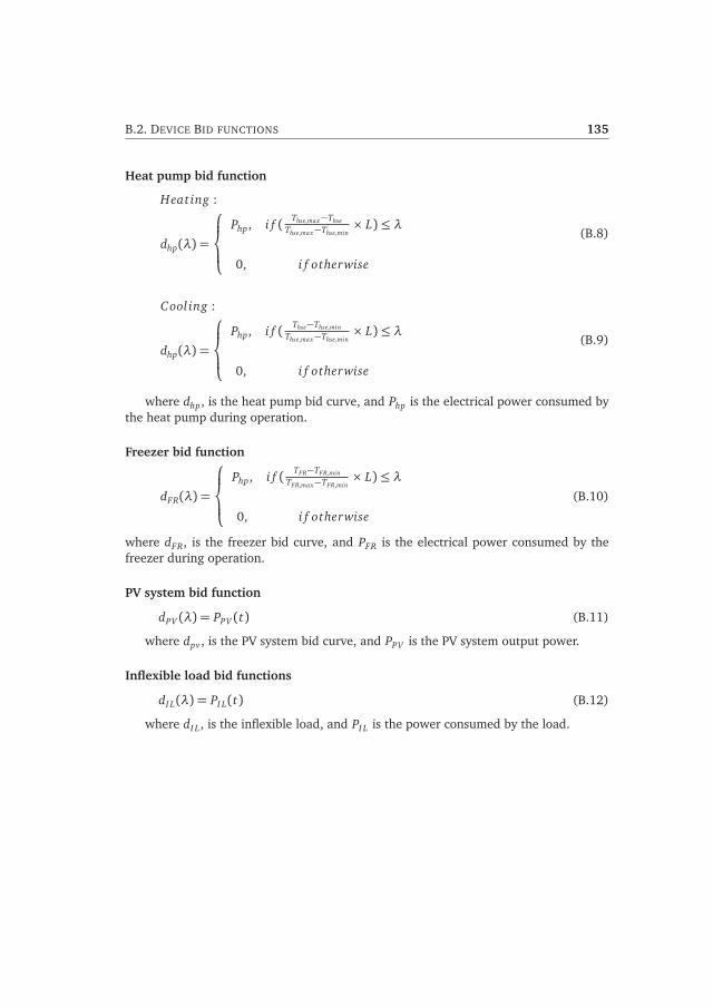
B.2. DEVICE BID FUNCTIONS 135
Heat pump bid function
Heating :
dhp(λ) =
⎧⎪⎨⎪⎩
Php, i f ( Thse,max−Thse
Thse,max−Thse,min× L)≤ λ
0, i f otherwise
(B.8)
Cooling :
dhp(λ) =
⎧⎪⎨⎪⎩
Php, i f ( Thse−Thse,min
Thse,max−Thse,min× L)≤ λ
0, i f otherwise
(B.9)
where dhp, is the heat pump bid curve, and Php is the electrical power consumed bythe heat pump during operation.
Freezer bid function
dFR(λ) =
⎧⎪⎨⎪⎩
Php, i f ( TFR−TFR,min
TFR,max−TFR,min× L)≤ λ
0, i f otherwise
(B.10)
where dFR, is the freezer bid curve, and PFR is the electrical power consumed by thefreezer during operation.
PV system bid function
dPV (λ) = PPV (t) (B.11)
where dpv , is the PV system bid curve, and PPV is the PV system output power.
Inflexible load bid functions
dI L(λ) = PI L(t) (B.12)
where dI L , is the inflexible load, and PI L is the power consumed by the load.


APPENDIX C
Appendix for lab demonstration
C.1 Demonstration of home energy management
Laboratory House
Figure C.1: Smart meter installed in the laboratory and in a house.
C.2 ZigBee network concepts
This section describes the specifics of ZigBee networks such as device types andspecifications and network topologies. There are three different types of nodes inZigBee network topologies: Coordinator, Router and End-device. A coordinator acts asthe ”root” or ”reference” node and is responsible for starting the network, configuringsecurity and key networking parameters, managing admission/rejection of other nodes,and assigning network addresses. A router is a type of node that increases networkreliability by extending the coverage area and creating additional data paths. It
137
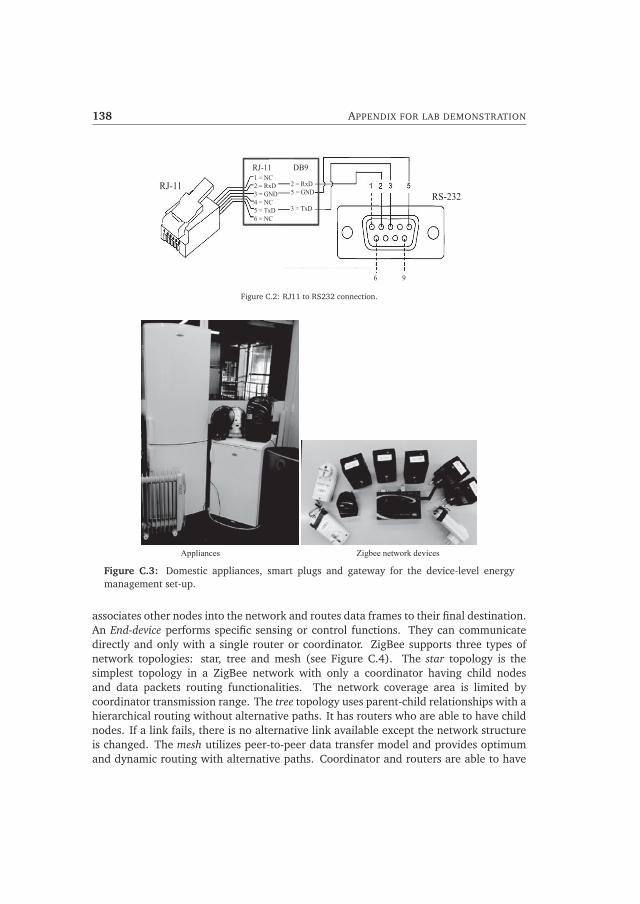
138 APPENDIX FOR LAB DEMONSTRATION
RJ-11 RS-232
1 = NC 2 = RxD 3 = GND 4 = NC 5 = TxD 6 = NC
2 = RxD 5 = GND 3 = TxD
6 9
RJ-11 DB9
Figure C.2: RJ11 to RS232 connection.
Appliances Zigbee network devices
Figure C.3: Domestic appliances, smart plugs and gateway for the device-level energymanagement set-up.
associates other nodes into the network and routes data frames to their final destination.An End-device performs specific sensing or control functions. They can communicatedirectly and only with a single router or coordinator. ZigBee supports three types ofnetwork topologies: star, tree and mesh (see Figure C.4). The star topology is thesimplest topology in a ZigBee network with only a coordinator having child nodesand data packets routing functionalities. The network coverage area is limited bycoordinator transmission range. The tree topology uses parent-child relationships with ahierarchical routing without alternative paths. It has routers who are able to have childnodes. If a link fails, there is no alternative link available except the network structureis changed. The mesh utilizes peer-to-peer data transfer model and provides optimumand dynamic routing with alternative paths. Coordinator and routers are able to have

C.2. ZIGBEE NETWORK CONCEPTS 139
Coordinator Router End device
Star topology Tree topology Mesh topology
Figure C.4: ZigBee network topologies.
child nodes, however end-devices can only exchange data with its parent node.
Table C.1: ZigBee network device specifications.
Device type Measured values Units
NXP plug meter
RMS Voltage (V) V
RMS Current (I) A
Apparent power (S) VA
Power factor (PF) dimensionless
Active power (P) W
Non-Fundamental Apparent Power (Harmonics) (SN) VA
Reactive power (Q) var
Current total harmonic distortion (THDI) dimensionless
Pikkerton ZBS-110V2
Device status (ON/OFF) dimensionless
System frequency (f) Hz
RMS Voltage (V) V
RMS Current (I) mA
Actual load (P) W
Integrated work /energy since meter last reset kWh
Digi Wall RouterLuminosity Lumen
Temperature 0C

140 APPENDIX FOR LAB DEMONSTRATION
Wait till new value arrive
Is value the first sample?
newMean = newValue numberOfSamples = 1
numberOfSamples = numberOfSamples + 1 newMean = newMean + (newValue-newMean)/numberOfSamples
Yes Store newMean and numberOfSamples
No
Figure C.5: Averaging data received from smart plugs implemented in GettingMeanValue.py.
Table C.2: Data set from P1 Port of the smart meter.
Line Data Remarks
1 /ISk5− 2M E381− 1003 Device name
2 Empty line
3 0-0:96.1.1(204B4136553... ) smart meter ID
4 1-0:1.8.1(00024.000*kWh) Total electricity consumption at low tariff in kWh
5 1-0:1.8.2(00005.000*kWh) Total electricity consumption at high tariff in kWh
6 1-0:2.8.1(00026.000*kWh) Total electricity delivered at low tariff in kWh
7 1-0:2.8.2(00001.000*kWh) Total electricity delivered at high tariff in kWh
8 0-0:96.14.0(0002) Actual tariff: 1 = low; 2 = high
9 1-0:1.7.0(0000.03*kW) Actual electricity consumption in kW
10 1-0:2.7.0(0000.00*kW) Actual electricity feed-in in KW
11 0-0:17.0.0(999*A) Maximum current
12 0-0:96.3.10(1) Actual switch position (1/0 for On/Off)
13 0-0:96.13.1() Short numeric message code
14 0-0:96.13.0() Long text message (max 1025 characters)
15 0-1:24.1.0(3) Device type connected in M-Bus. (i.e. gas meter)
16 0-1:96.1.0(32383130313... ) ID for gas meter
17 0-1:24.3.0(121030140000)(00)(60)(1)(0-1:24.2.1)(m3)
Time and amount of the last gas measurement
18 (00024.123) Total gas consumption in m3
19 0-1:24.4.0(1) Switch of throttle position of M-Bus device
20 ! End of the message

Bibliography
[1] Laura Maria Ramirez Elizondo. Optimal Usage of Multiple Energy Carriers inResidential Systems Unit Scheduling and Power Control. Phd thesis, TechnischeUniversiteit Delft, The Netherlands, 2013.
[2] Capros, P and De Vita, A and Tasios, N and Papadopoulos, D and Siskos, Pand Apostalaki, E and Zampara, M and Paraoussos, L and Fragiadakis, K andKouvaritakis, N. EU Energy, Transport and Greenhouse gas emissions: Trends to2050. pages 40– 44, Luxemborg-2014.
[3] Energie-Nederland and Netbeheer Nederland. Energie in nederland 2011. pages1–83, 2011.
[4] Dirk Brounen, Nils Kok, and John M. Quigley. Residential energy use andconservation: Economics and demographics. European Economic Review,56(5):931–945, July 2012.
[5] R. Stamminger, G. Broil, C. Pakula, H. Jungbecker, M. Braun, I. Rudenauer, andC. Wendker. Synergy potential of smart appliances. pages 10 –237, 2008.
[6] Movares Nederland B.V. Laadstrategie Elektrisch Wegvervoer. pages 1–95, 2013.
[7] European Photovoltaic Industry Association. Global market outlook forphotovoltaics 2014 - 2018. pages 1 – 60, 2013.
[8] Centraal Bureau voor de Statistiek, Nederland. Hernieuwbare energie inNederland 2013. pages 50 – 55, 2011.
[9] M Houwing, Rudy R. Negenborn, and Bart De Schutter. Demand response withmicro-CHP systems. Proceedings of the IEEE, 99(1):200 – 213, 2011.
[10] Derek A Kelly Consulting. Home Services: Smart home automation,2014. Available [Online]: http://derekakelly.com/home-services/smart-home-automation/. [Last accessed]: Jun. 2014.
[11] European Smart Cities. The smart city model, 2014. Available [Online]:
141

142 BIBLIOGRAPHY
http://www.smart-cities.eu/model.html. [Last accessed]: Jun. 2014.
[12] C. E. P. Jordan Cordova. Design and implementation of a Zigbee-based wirelesssensor network within the smart home area network for electical energy dataacquisition: insights and trends. Master graduation thesis, Eindhoven Universityof Technology, 2011.
[13] Nikolleta Christou. Utilization of smart meter data by Energy Service Companies tooptimize consumption and energy efficiency. Master graduation thesis, EindhovenUniversity of Technology, 2014.
[14] S De Boer. Views on the emerging dutch esco market: can it become successful?Graduation Report, Utrecht University, Department of Science, Technology andSociety, 2011.
[15] Eurostat European Commission. Final energy consumption by sector,2013. Available [Online]: http://epp.eurostat.ec.europa.eu/portal/page/portal/energy/data/main_tables. [Last accessed]: Jul-2013.
[16] European Environment Agency. Household consumption, 2014. Available[Online]: http://www.eea.europa.eu/themes/households. [Last accessed]: Aug.2014.
[17] European Commission Directorate-General for Energy. Energy 2020: A strategyfor competitive, sustainable, and secure energy. pages 1– 205, 2011.
[18] International Energy Agency. Energy efficiency, 2014. Available [Online]:www.iea.org/topics/energyefficiency/. [Last accessed]: Aug. 2014.
[19] Grözinger, Jan and Boermans, Thomas and John, Ashok and Wehringer, Felix andSeehusen, Jan . Overview of Member States information on NZEBs (Backgroundpaper - final report). pages 1–25, 2014.
[20] European Commission. Directive 2010/31/EU of the European Parliament and ofthe Council on energy performance of buildings. Official Journal of the EuropeanUnion, L153:1–23, 2010.
[21] Enerdata. Global energy statistical yearbook: Total energy consumption, 2014.Available [Online]: https://yearbook.enerdata.net/. [Last accessed]: Nov. 2014.
[22] European Commission Directorate-General for Energy. European Union energytrends to 2030. pages 1– 256, Luxemborg-2009.
[23] European Commission Joint Research Centre: Institute for Energy and Transport.Research shows huge potential energy savings through light-bulbs and householdgoods, 2014. Available [Online]: http://iet.jrc.ec.europa.eu/energyefficiency/tags/residential-lighting. [Last accessed]: Nov. 2014.
[24] Nederlandse Gasunie N.V. Natural gas, part of an efficient sustainable energyfuture: The Dutch case. pages 2–5, Feb 2010.
[25] David J Fritzsche. An analysis of energy consumption patterns by stage of familylife cycle. Journal of Marketing Research (JMR), 18(2), 1981.

BIBLIOGRAPHY 143
[26] Peter C Reiss and Matthew W White. Household electricity demand, revisited.The Review of Economic Studies, 72(3):853–883, 2005.
[27] Sean Barker, Sandeep Kalra, David Irwin, and Prashant Shenoy. Empiricalcharacterization and modeling of electrical loads in smart homes. Proceedingsof International Green Computing Conference, pages 1–10, June 2013.
[28] Jun Hong, Johnstone M Cameron, Jae Min Kim, and Paul Tuohy. Demand-sidemanagement and control in buildings, volume 69, pages 129–147. CambridgeUniversity Press, 2011.
[29] Christiane Pakula and Rainer Stamminger. Electricity and water consumption forlaundry washing by washing machine worldwide. Energy efficiency, 3(4):365–382, 2010.
[30] Jürg Nipkow and Eric Bush. Promotion of energy-efficient heat pump dryers. InProceedings of the 5th International Conference on Energy Efficiency in DomesticAppliances and Lighting, volume 9, pages 16–18, 2009.
[31] Netbeheer Nederland, DNV GL, and CE Delft.Scenario - ontwikkeling energievoorziening 2030, 2014. Available [Online]:http://www.netbeheernederland.nl/publicaties/onderzoek/. [Last accessed]:Jun. 2014.
[32] Rijksdienst voor Ondernemend Nederland. Cijfers elektrisch vervoer (inDutch, 2014. Available [Online]: http://www.rvo.nl/onderwerpen/duurzaam-ondernemen/energie-en-milieu-innovaties/elektrisch-rijden/stand-van-zaken/cijfers. [Last accessed]: Oct. 2014.
[33] Alicja Lojowska, Dorota Kurowicka, George Papaefthymiou, and Lou van derSluis. Stochastic modeling of power demand due to evs using copula. IEEETransactions on Power Systems, 27(4):1960–1968, Nov 2012.
[34] Jim Eyer and Garth Corey. Energy storage for the electricity grid: Benefits andmarket potential assessment guide. Sandia National Laboratories, 2010. Available[Online]: http://www.sandia.gov/ess/publications/SAND2010-0815.pdf. [Lastaccessed]: Mar. 2014.
[35] The Economist. Energy storage: packing some power, 2014. Available [Online]:http://www.economist.com/node/21548495?frsc=dg|a. [Last accessed]: Oct.2014.
[36] National Hydropower Authority Pumped Storage Development Council (USA).Challenges and opportunities for new pumped storage development. pages1–33, 2012. Available [Online]: http://www.hydro.org/wp-content/uploads/2014/01/NHA_PumpedStorage_071212b12.pdf. [Last accessed]: Oct. 2014.
[37] Energy Storage Association. Compressed air energy storage, 2014. Available[Online]: http://energystorage.org/compressed-air-energy-storage-caes. [Lastaccessed]: Oct. 2014.
[38] Office of Science, U.S. Department of Energy. Basic research needs for electrical

144 BIBLIOGRAPHY
energy storage: Report of the basic energy sciences workshop on electrical energystorage. pages 51–150, April 2007.
[39] Battery University. What’s the best battery?, 2014. Available [Online]:http://batteryuniversity.com/learn/article/whats_the_best_battery. [Lastaccessed]: Oct. 2014.
[40] N.S. Wade, P.C. Taylor, P.D. Lang, and P.R. Jones. Evaluating the benefits of anelectrical energy storage system in a future smart grid. Energy Policy, 38(11):7180– 7188, 2010. Energy Efficiency Policies and Strategies with regular papers.
[41] H. Ibrahim, A. Ilinca, and J. Perron. Energy storage systems-characteristics andcomparisons. Renewable and Sustainable Energy Reviews, 12(5):1221 – 1250,2008.
[42] Ecofys Consultancy Nederland B.V. National survey report of PV powerapplications in The Netherlands 2011. (June):1–53, 2012.
[43] Michiel Houwing, W . Petra Heijnen, and Ivo Bouwmans. Deciding on Micro-CHP; A Multi-Level Decision-Making Approach. In Proceedings of the 2006 IEEEInternational Conference on Networking, Sensing and Control, pages 302 – 307,Florida USA, 2006.
[44] A.D. Peacock and M. Newborough. Impact of micro-chp systems on domesticsector co2 emissions. Applied Thermal Engineering, 25(17-18):2653 – 2676, 2005.
[45] Iulian Munteanu, Antoneta Iuliana Bratcu, Nicolaos-Antonio Cutululis, and EmilCeanga. Optimal control of wind energy systems: towards a global approach.Springer, 2008.
[46] Jorge L. Acosta, Kevin Combe, Sasa Z. Djokic, and Ignacio Hernando-Gil.Performance assessment of micro and small-Scale wind turbines in urban areas.IEEE Systems Journal, 6(1):152–163, Mar.
[47] A.D. Peacock, D. Jenkins, M. Ahadzi, A. Berry, and S. Turan. Micro wind turbinesin the UK domestic sector. Energy and Buildings, 40(7):1324–1333, Jan 2008.
[48] David Gerbec, S Gasperic, and Ferdinand Gubina. Determination and allocationof typical load profiles to the eligible consumers. In Power Tech ConferenceProceedings, pages 1–5, Bologna, Italy, 2003.
[49] Huaiwei Liao and Dagmar Niebur. Load profile estimation in electric transmissionnetworks using independent component analysis. IEEE Transactions on PowerSystems, 18(2):707–715, 2003.
[50] System Tariff Issues Working Group. Metering, load profiles and settlement inderegulated markets. Union of Electricity Industry EURELECTRIC, pages 1–67,2000. Available [Online]: http://public.eurelectric.org/Content/Default.asp.[Last accessed]: Jan. 2013.
[51] Jan Uitzinger. Simulatie van energievraag patronen van huisholdens [in Dutch], 2003.

BIBLIOGRAPHY 145
[52] Lukas G. Swan and V. Ismet Ugursal. Modeling of end-use energy consumptionin the residential sector: A review of modeling techniques. Renewable andSustainable Energy Reviews, 13(8):1819–1835, October 2009.
[53] Adonias Ferreira, Carlos AMT Cavalcante, Cristiano HO Fontes, and Jorge ESMarambio. A new method for pattern recognition in load profiles to supportdecision-making in the management of the electric sector. International Journalof Electrical Power & Energy Systems, 53:824–831, 2013.
[54] Wouter Labeeuw and Geert Deconinck. Residential electrical load model basedon mixture model clustering and Markov models. IEEE Transaction on IndustrialInformatics, 9(3):1561–1569, Aug 2013.
[55] Jorn K. Gruber and Milan Prodanovic. Residential energy load profile generationusing a probabilistic approach. In Sixth UKSim/AMSS European Symposium onComputer Modeling and Simulation, pages 317–322. IEEE, November 2012.
[56] Else Veldman, Madeleine Gibescu, J.G. Slootweg, and Wil L. Kling. Scenario-based modelling of future residential electricity demands and assessing theirimpact on distribution grids. Energy Policy, 56:233–247, February 2013.
[57] Francesco De Angelis, Matteo Boaro, Danilo Fuselli, and Stefano Squartini.Optimal home energy managment under dynamic electrical and thermalconstraints. IEEE Transaction on Industrial Informatics, 9(3):1518–1527, Aug2013.
[58] Aldo Canova, Luca Giaccone, Filippo Spertino, and Michele Tartaglia. Electricalimpact of photovoltaic plant in distributed network. IEEE Transactions on IndustryApplications, 45(1):341–347, Jan.-Feb 2009.
[59] Kevin Mets, Reinhilde D’hulst, and Chris Develder. Comparison of intelligentcharging algorithms for electric vehicles to reduce peak load and demandvariability in a distribution grid. Journal of Communications and Networks,14(6):672–681, Dec 2012.
[60] ANSI/ASHRAE Standard 55-2004. Thermal environmental conditions for humanoccupancy. Technical report, 2004.
[61] Sensirion. Conditions of thermal comfort - Influence of humidity and temperatureon personal well-being. page 4, 2010.
[62] Van Lumig Michiel. Inventarisatie warmtepomp metingen en simulaties inbestaande. 2007:1–6, 2012.
[63] E.A. Feinberg, D. Genethliou, J.T. Hajagos, B.G. Irrgang, and R.J. Rossin. Loadpocket forecasting software. In IEEE PES Power Systems Conference and Exposition,pages 1386–1390. IEEE, 2004.
[64] Tao Hong, Min Gui, Mesut E. Baran, and H. Lee Willis. Modeling and forecastinghourly electric load by multiple linear regression with interactions. In Power andEnergy Society General Meeting, page 8, 2010.

146 BIBLIOGRAPHY
[65] Tao Hong, Pu Wang, and HL Willis. A Naïve multiple linear regression benchmarkfor short term load forecasting. Power and Energy Society General Meeting, (2):1–6, 2011.
[66] Guoqiang Zhang, B. Eddy Patuwo, and Michael Y. Hu. Forecasting with artificialneural networks:: The state of the art. International Journal of Forecasting,14(1):35 – 62, 1998.
[67] R. A. Verzijlbergh, Z. Lukszo, E. Veldman, J. G. Slootweg, and M. Ilic. Derivingelectric vehicle charge profiles from driving statistics. IEEE Power and EnergySociety General Meeting, pages 1–6, July 2011.
[68] Vincent Bakker. TRIANA: a control strategy for Smart Grids: Forecasting, planningand real-time control. Phd thesis, Universiteit Twente, Enschede Netherlands.
[69] AmirHosein GhaffarianHoseini, Nur Dalilah Dahlan, Umberto Berardi, AliGhaffarianHoseini, and Nastaran Makaremi. The essence of future smart houses:From embedding {ICT} to adapting to sustainability principles. Renewable andSustainable Energy Reviews, 24(0):593 – 607, 2013.
[70] H. W. Kua and S. E. Lee. Demonstration intelligent building - a methodologyfor the promotion of total sustainability in the built environment. Building andEnvironment, 37(3):231 – 240, 2002.
[71] World Health Organization. Global health obervatory: urban population growth,2014. Available [Online]: http://www.who.int/gho/urban_health/situation_trends/urban_population_growth_text/en/. [Last accessed]: Jul. 2014.
[72] European Commission. European innovation partnership on smart citiesand communities: strategic implementation plan. pages 1–22, 2013.Available [Online]: http://ec.europa.eu/eip/smartcities/files/sip_final_en.pdf.[Last accessed]: Apr. 2013.
[73] Amsterdam Smart City. Energy Management Haarlem, 2014. Available[Online]: http://amsterdamsmartcity.com/projects/detail/id/15/slug/energy-management-haarlem. [Last accessed]: Jul. 2014.
[74] Math H. J. Bollen. The smart grid: Adapting the power system to new challenges.Synthesis Lectures on Power Electronics, 2(1):1–180, 2011.
[75] V. C. Gungor, D. Sahin, T. Kocak, S. Ergut, C. Buccella, C. Cecati, and G.P. Hancke.Smart grid technologies: Communication technologies and standards. IEEETransactions on Industrial Informatics, 7(4):529–539, Nov 2011.
[76] Mathias Uslar. Introduction and smart grid basics. In Standardization in SmartGrids, pages 3–12. Springer, 2013.
[77] Jim Roche. Advanced meter reading versus advanced metering infrastructure,2008. Available [Online]: http://www.elp.com/articles/powergrid_international/print/volume-13/issue-10/features/amr-vs-ami.html. [Lastaccessed]: Jul. 2014.

BIBLIOGRAPHY 147
[78] Frog. Home energy management solution beyond numbers, 2011. Available[Online]: http://www.frogdesign.cn/files/pdf/Home%20Energy%20Management%20-%20Beyond%20the%20Numbers.pdf. [Last accessed]: Mar. 2011.
[79] Michiel Brink. Future-proof platforms for aging-in-place. PhD thesis, TechnischeUniversiteit Eindhoven, 2013.
[80] Ballard Asare-Bediako, W L Kling, and P F Ribeiro. Home Energy ManagementSystems : Evolution , Trends and Frameworks. In 47th International UniversitiesPower Engineering Conference, pages 1–5, London, UK, 2012.
[81] Jennifer Yick, Biswanath Mukherjee, and Dipak Ghosal. Wireless sensor networksurvey. Computer Networks, 52(12):2292 – 2330, 2008.
[82] Murat Kuzlu, Manisa Pipattanasomporn, and Saifur Rahman. Communicationnetwork requirements for major smart grid applications in HAN, NAN and WAN. Computer Networks, 67(0):74 – 88, 2014.
[83] C.E.P. Jordan Cordova, B. Asare-Bediako, G. M. A. Vanalme, and W. L. Kling.Overview and Comparison of Leading Communication Standard Technologiesfor Smart Home Area Networks Enabling Energy Management Systems. In46th International Universities Power Engineering Conference, pages 1–6, Soest,Germany, 2011.
[84] Silver Spring Networks. Smart grid security: Myths vs reality, 2011. Available[Online]: http://www.silverspringnet.com/pdfs/whitepapers/SilverSpring-Whitepaper-SmartGridSecurity-MythsReality.pdf. [Last accessed]: Jul. 2014.
[85] Hatler Mareca, Gurganious Darryl, and Chi Charlie. Marketing Dynamics Report:Smart energy homes. 2010.
[86] Rolf H. Weber. Internet of Things–New security and privacy challenges. ComputerLaw & Security Review, 26(1):23–30, 2010.
[87] Harald Sundmaeker, Patrick Guillemin, Peter Friess, and Sylvie Woelfflé. Visionand challenges for realising the Internet of Things. European Research Cluster onthe Internet of Things, 2010.
[88] The IEEE Institute. The value of privacy, 2014.Available [Online]: http://theinstitute.ieee.org/technology-focus/ technology-topic/the-value-of-privacy. [Last accessed]: Jul. 2014.
[89] European Commission. IoT privacy, data protection, informationsecurity. 2014. Available [Online]: http://ec.europa.eu/information_society/newsroom/cf/dae/document.cfm?doc_id=1753. [Last accessed]: Jun. 2014.
[90] Frits Bliek, Albert van den Noort, Bart Roossien, Rene Kamphuis, Johan de Wit,Jorgen van der Velde, and Marcel Eijgelaar. PowerMatching City, a living lab smartgrid demonstration. In IEEE PES Innovative Smart Grid Technologies ConferenceEurope, pages 1–8. IEEE, October 2010.
[91] Electric Power Research Institute. Advanced Metering Infrastructure (AMI),

148 BIBLIOGRAPHY
2007. Available [Online]: http://www.ferc.gov/eventcalendar/Files/20070423091846-EPRI - Advanced Metering.pdf. [Last accessed]: Jan. 2013.
[92] H Gharavi and R Ghafurian. Smart Grid: The electric energy system of the future.Proceedings of the IEEE, 99(6):917–921, 2011.
[93] Jouw Energie Moment. Jouw energie moment, 2014. Available [Online]:http://jouwenergiemoment.nl/ [Last accessed]: Jul. 2014.
[94] I. E. Hopley, T. Holden, and G. P. Wilhelmij. Decision support for energymanagement systems. In International Conference on Information-Decision-ActionSystems in Complex Organisations, pages 95–99. IET, 1992.
[95] Jerry W Evans. Energy management system survey of architectures. IEEEComputer Application Power;(United States), 2(1), 1989.
[96] Miguel A Zamora-Izquierdo, José Santa, and Antonio F Gómez-Skarmeta.An integral and networked home automation solution for indoor ambientintelligence. IEEE Pervasive Computing, 9(4):66–77, 2010.
[97] Rob van Gerwen, Fred Koenis, Marnix Schrijner, and Gisele Widdershoven. Smartmeters in the Netherlands: Revised financial analysis and policy advice. page 119,2010.
[98] Navigant Research. Smart meters: smart electric meters, advanced meteringinfrastructure, and meter communications: global market analysis and forecasts,2014. Available [Online]: http://www.navigantresearch.com/research/smart-meters: Mar. 2014.
[99] European Commission. Directive 2006/32/EC of the European Parliament andof the Council on energy end-use efficiency and energy services and repealingCouncil Directive 93/76/EEC. Official Journal of the European Union, L114:64–85, 2006.
[100] European Commission. Directive 2009/72/EC of the European Parliament andof the Council concerning common rules for the internal market in electricity andrepealing Council Directive 2003/54/EC. Official Journal of the European Union,L211:55–93, 2009.
[101] European Commission. Directive 2012/27/EU of the European Parliament andof the Council on energy efficiency, amending Directives 2009/125/EC and2010/30/EU and repealing Directives 2004/8/EC and 2006/32/EC. OfficialJournal of the European Union, L315:1–56, 2012.
[102] Feng Chen, Jing Dai, Bingsheng Wang, Sambit Sahu, Milind Naphade, and Chang-Tien Lu. Activity analysis based on low sample rate smart meters. In Proceedingsof the 17th ACM SIGKDD International Conference on Knowledge Discovery andData Mining, pages 240–248. ACM, 2011.
[103] Rijksoverheid (Netherlands). Gas en electriciteit thuis: Hoe zit het bij de slimmemeter met mijn pricacy, 2014. Available [Online]: http://www.rijksoverheid.nl/onderwerpen/gas-en-elektriciteit-thuis/vraag-en-antwoord/hoe-zit-het-bij-de-

BIBLIOGRAPHY 149
slimme-meter-met-mijn-privacy.html. [Last accessed]: May. 2014.
[104] S. D. Ramchurn, Perukrishnen Vytelingum, Alex Rogers, and Nick Jennings.Agent-based control for decentralised demand side management in the smartgrid. In 10th International Conference on Autonomous Agents and MultiagentSystems - Innovative Applications Track, pages 1–12, 2011.
[105] S Harkin. Home energy management in Europe, lots of solutions, but what’s theproblem? Delta Energy & Environment, UK, pages 1–8, 2011. Available [Online]:http://docs.caba.org/documents/IS/IS-2012-33.pdf. [Last accessed]: Apr. 2012.
[106] Toshiba Transmission & Distribution Systems Asia. Smart Grid Solutions:HEMS, BEMS and FEMS, 2014. Available [Online]: http://toshiba-ttda.com/2011/08/16/smart-grid-solutions/. [Last accessed]: Jul. 2014.
[107] Environmental Leader. Panasonic launches household-level energy managementproject in singapore, 2014. Available [Online]: http://www.environmentalleader.com/2011/08/02/panasonic-launches-household-level-energy-management-project-in-singapore/. [Last accessed]: Jul. 2014.
[108] S Harkin. Home energy management in Europe, capturing value for HEMS. DeltaEnergy & Environment, UK, 2011.
[109] B. Qela and H.T. Mouftah. Observe, learn, and adapt (ola);an algorithmfor energy management in smart homes using wireless sensors and artificialintelligence. IEEE Transactions on Smart Grid, 3(4):2262–2272, Dec 2012.
[110] Qi Liu, Grahame Cooper, Nigel Linge, Haifa Takruri, and Richard Sowden.Dehems: creating a digital environment for large-scale energy management athomes. IEEE Transactions on Consumer Electronics, 59(1):62–69, 2013.
[111] Filipe Fernandes, Hugo Morais, Zita Vale, and Carlos Ramos. Dynamic loadmanagement in a smart home to participate in demand response events. Energyand Buildings, 82(0):592 – 606, 2014.
[112] M C Bozchalui, S A Hashmi, H Hassen, Claudio A Canizares, and KankarBhattacharya. Optimal operation of residential energy hubs in smart grids. IEEETransactions on Smart Grid, 3(4):1755–1766, Dec 2012.
[113] Rim Missaoui, Hussein Joumaa, Stephane Ploix, and Seddik Bacha. Managingenergy Smart Homes according to energy prices: Analysis of a Building EnergyManagement System. Energy and Buildings, 71:155–167, 2014.
[114] Asim Kaygusuz, Cemal Keles, Baris Baykant Alagoz, and Abdulkerim Karabiber.Renewable energy integration for smart sites. Energy and Buildings, 64:456–462,September 2013.
[115] Davide Caprino, Marco L Della Vedova, and Tullio Facchinetti. Peak shavingthrough real-time scheduling of household appliances. Energy and Buildings,75:133–148, 2014.
[116] George Koutitas. Control of flexible smart devices in the smart grid. IEEE

150 BIBLIOGRAPHY
Transactions on Smart Grid, 3(3):1333–1343, 2012.
[117] L Rajalakshmi, M. V. Suganyadevi, and S Parameswari. Congestion managementin deregulated power system by locating series facts devices. International journalof Computer applications, 13:0975–8887, 2011.
[118] Ioannis Lampropoulos. Energy management of distributed resources in powersystems operations. Phd thesis, Technische Universiteit Eindhoven, TheNetherlands, 2014.
[119] S Tiptipakorn, W. J. Lee, C. Mao, and J. Lu. Price naming on home applianceload controls in real-time pricing environment. In IEEE Power and Energy SocietyGeneral Meeting, pages 1–6, 2010.
[120] A.-H. Mohsenian-Rad and A. Leon-Garcia. Optimal residential load control withprice prediction in real-time electricity pricing environments. IEEE Transactionon Smart Grids, 1(2):120–133, Sep 2010.
[121] Antoine Lefort, Romain Bourdais, Guillaume Ansanay-Alex, and Hervé Guéguen.Hierarchical control method applied to energy management of a residentialhouse. Energy and Buildings, 64:53–61, September 2013.
[122] Shuhui Li, Dong Zhang, Adam B. Roget, and Zheng O’Neill. Integrating homeenergy simulation and dynamic electricity price for demand response study. SIEEE Transactions on mart Grid, 5(2):779–788, March 2014.
[123] European PPP Expertise Centre. Guidance on energy efficiency in publicbuildings. final:4–62, 2012.
[124] Peter Rowles. Demand response and demand side management: what’s thedifference?, 2010. Available [Online]: http://www.energyadvantage.com/blog/2010/02/demand-response-demand-side-management-what%E2%80%99s -difference/. [Last accessed]: Nov. 2010.
[125] A. A. Sallam and O. P Malik. Electric distribution systems. John Wiley & Sons,Inc., first edition, 2011.
[126] Mary Ann Piette, David Watson, Naoya Motegi, Sila Kiliccote, and Eric Linkugel.Automated demand response strategies and commissioning commercial buildingcontrols. In Proceedings of NAtional Conference on Builing Commissioning, pages1–14, 2006.
[127] B Asare-Bediako, L. M. Ramirez Elizondo, P. F. Ribeiro, W. L. Kling, and G. CPaap. Consideration of Electricity and Heat Load Profiles for Intelligent EnergyManagement Systems. In 46th International Universities Power EngineeringConference, pages 1–6, Soest, Germany, 2011.
[128] Jose Medina, Nelson Muller, and Ilya Roytelman. Demand response anddistribution grid operations: Opportunities and challenges. IEEE Transactionson Smart Grid, 1(2):193–198, Sep.
[129] World Energy Council. Energy efficiency policies around the world: review

BIBLIOGRAPHY 151
and evaluation, 2011. Available [Online]: http://www.worldenergy.org/. [Lastaccessed]: Apr. 2012.
[130] European Commission. Energy Efficiency: Eco-design of energy-related products,2014. Available [Online]: http://ec.europa.eu/energy/efficiency/ecodesign/eco_design_en.htm. [Last accessed]: Jun. 2014.
[131] European Committee of Domestic Equipment Manufacturers. The newEU energy label: A guide for retailers, 2014. Available [Online]:http://www.newenergylabel.com. [Last accessed]: Jul. 2014.
[132] Marco Jahn, Marc Jentsch, Christian R Prause, Ferry Pramudianto, Amro Al-akkad, Schloss Birlinghoven, and Sankt Augustin. The energy aware smart home.In International Conference on Future Information Technology, pages 1–8, 2010.
[133] G Strbac. Demand side management: Benefits and challenges. Energy Policy,36(12):4419–4426, December 2008.
[134] Google Inc. An update on google health and google powermeter, 2011.Available [Online]: http://googleblog.blogspot.nl/2011/06/update-on-google-health-and-google.html. [Last accessed]: Jun. 2011.
[135] PC Magazine. Microsoft to shut down hohm energy-management service, 2011.Available [Online]: http://googleblog.blogspot.nl/2011/06/update-on-google-health-and-google.html. [Last accessed]: Jun. 2012.
[136] Adam Aston. Cisco quietly shuts down building energy managementprogram, 2011. Available [Online]: http://www.pcmag.com/article2/0,2817,2387984,00.asp. [Last accessed]: Jun. 2012.
[137] Henk van Elburg. Dutch energy savings monitor for the smart meter. final:4–60,2014.
[138] Navigant Research. Home energy management: In-Home Displays, NetworkedHEM Systems, Standalone HEM Systems, Web Portals, and Paper Bill HEMReports: Global Market Analysis and Forecasts, 2014.
[139] FL Bellifemine, G Caire, and D Greenwood. Developing multi-agent systems withJADE. John Wiley & Sons, Inc., West Sussex, England, 2007.
[140] M. Wooldridge and G. Ed Weiss. Intelligent Agents, pages 3–51. MIT Press, Apr1999.
[141] Klaus Fischer, Petra Funk, and Christian Ruß. Specialised agent applications. InMulti-Agent Systems and Applications, pages 365–382. Springer Verlag, 2001.
[142] Mieczyslaw Metzger and Grzegorz Polakow. A survey on applications ofagent technology in industrial process control. IEEE Transactions on IndustrialInformatics, 7(4):570–581, Nov 2011.
[143] JM Moonen. Multi-agent systems for transportation planning and coordination.Phd. thesis, Erasmus Universiteit Rotterdam, The Netherlands, 2009.
[144] Daniel Divenyi and András M. Dan. Agent-based modeling of distributed

152 BIBLIOGRAPHY
generation in power system control. IEEE Transaction on Smart Grids, 4(4):886–893, Oct 2013.
[145] H.S.V.S. Kumar Nunna and S. Doolla. Energy management in microgridsusing demand response and distributed storage: A multiagent approach. IEEETransactions on Power Delivery, 28(2):939–947, April 2013.
[146] P. H. Nguyen, W. L. Kling, and P. F. Ribeiro. A game theory strategy to integratedistributed agent-based functions in smart grids. IEEE Transactions on Smart Grid,4(1):568–576, Mar 2013.
[147] Vladimir Marik and Duncan McFarlane. Industrial adoption of agent-basedtechnologies. IEEE Intelligent Systems, 20(1):27–35, Feb 2005.
[148] Agent Programming. Agent programming: Agent platforms, 2014. Available[Online]: http://agentprogramming.com/agent-platforms/. [Last accessed]:Nov. 2014.
[149] IEEE Computer Soceity. The Foundation for Intelligent Physical Agents (FIPA),2014. Available [Online]: http://www.fipa.org/. [Last accessed]: Jun-2014.
[150] J.K.A.H.P.J. Kok. The PowerMatcher: Smart Coordination for the Smart ElectricityGrid. PhD thesis, 2013.
[151] E. A. M. Klaassen, Else Veldman, J. G. Slootweg, and Wil L Kling. Energy efficientresidential areas through smart grids. In 2013 IEEE Power and Energy SocietyGeneral Meeting, pages 1–5, 2013.
[152] I. Lampropoulos, N. Baghina, W.L. Kling, and P.F. Ribeiro. A predictive controlscheme for real-time demand response applications. IEEE Transactions on SmartGrid, 4(4):2049–2060, Dec 2013.

153

154 NOMENCLATURE
Nomenclature
List of acronyms
Acronym Meaning
AA Application Agents
AC Alternating Current
ADR Automated Demand Response
ADSM Aggregated Demand-Supply Matching
AMI Advanced Metering Infrastructure
AMR Automatic Meter Reading
ANN Artificial Neural Network
APX ENDEX Amsterdam Power Exchange
BL Base Load
CA Coordinator Agent
CAES Compressed Air Energy Storage
CAS Central Access Server
CCA Central Coordinator Agent
CMA Control and Monitoring Agents
CO2 Carbon Dioxide
COP Coefficient of Performance
CSMA Carrier Sense Multiple Access
DA Device Agent
DC Direct Current
DER Distributed Energy Resources
DG Distributed Generation
DpMAPE Daily Peak Mean Average Percentage Error
DR Demand Response
DSM Demand-Side Management
DSO Distribution System Operator
DTS Dispatcher Training Simulator
EC European Commission
EDL Electric double-layer
EMS Energy Management Systems
ESCos Energy Service Companies
ESS Energy Storage System
EU European Union
EV Electric Vehicle
FC Fuel Cell
FIPA Foundation for Intelligent Physical Agents

NOMENCLATURE 155
Acronym Meaning
HAN Home Area Network
HEMS Home Energy Management System
HTTP Hypertext Transfer Protocol
HVAC Heating Ventilation and Air-conditioning
IA Information Agents
IC Integrated Circuit
ICE Internal Combustion Engine
ICT Information and Communication Technology
IOP EMVT Innovatiegerichte Onderzoeksprogramma’sElektromagnetische Vermogenstechniek
IoT Internet of Things
JADE Java Agent Development Framework
LCA Local Coordinator Agent
LCD Liquid Crystal Display
LDSM Local Demand-Supply Matching
LED Light Emitting Diode
LMA Levenburg-Marquardt Algorithm
LV Low Voltage
MAPE Mean Average Percentage Error
MAS Multi-Agent System
MASE Mean Average Scaled Error
MV Medium Voltage
NZEB Net Zero-Energy Building
OPF Optimal Power Flow
PHP Hypertext Preprocessor
PLC Power-Line Communication
PV Photovoltaic
RES Renewable Energy Sources
RF Radio Frequency
RFID Radio Frequency Identification
RMSE Root Mean Square Error
RVO Rijksdienst voor Ondernemend
SCADA Supervisory Control and Data Acquisition
SE Sterling Engine
SEH Smart Energy Home
SG Smart Grid
SLP Synthetic Load Profile
SMES Superconducting magnetic energy storage
SNMP Simple Network Management Protocol
SSH Secure Shell
TCP/IP Transmission Control Protocol/Internet Protocol
ToU Time-of-Use
TSO Transmission System Operator
VAT Value-Added Tax
μCHP Micro Combined Heat and Power

156 NOMENCLATURE
List of symbols
Symbol Meaning Units
αex p Cost of energy delivered to the grid Euro/kWh
αimp Cost of energy taking from the grid Euro/kWh
β Wind turbine blade pitch angle degrees
ΓSL, f inish Ending time for shiftable load min
ΓSL,star t Starting time for shiftable load min
ΓΔSL Operational cycle duration of a shiftable load min
ηchp,elec Electrical efficiency of μCHP %
ηchp,th Thermal efficiency of μCHP %
λ Control (price) signal -
λCS Final control(price) signal from Coordinator Agent -
λDSO,max Maximum network tariff Euro/kWh
λener g y,tax Energy tax Euro/kWh
λEST,std Fixed standard tariff Euro/kWh
λEST (t) Dynamic energy tariff Euro/kWh
λprice Cumulative (dynamic) price Euro/kWh
λVAT Value-added tax Euro/kWh
ρair Density of air kg/m3
Φ(λ) Aggregated bid function -
ϕ Wind turbine tip speed ratio -
Amax Actual daily peak consumption kWh
At Value of actual electrical energy consumption kWh
AW T Wind turbine swept area m2
COPel−boost Coefficient of performance of heating element -
COPhp Coefficient of performance of heat pump -
cp Wind turbine’s coefficient of performance -
dj(λ) Bid function of device j -
Drange Electric vehicle driving range km
Dtravel led Distance travelled by commuters km
Echp,prod Electrical energy generation from μCHP kWh
Ehse,dmd House electrical energy demand kWh
Ehse,ex p Electrical energy delivered to the grid by a household kWh
Ehse,imp Electrical energy taken from the grid by a household kWh
Ehse,prod Household’s local electrical energy generation kWh
Fmax Predicted daily peak consumption kWh
Ft Value of predicted electrical energy consumption kWh
Gchp,suppl y Gas supply to μCHP m3
Gaux ,suppl y Gas supply to auxiliary burner m3

NOMENCLATURE 157
Symbol Meaning Units
M the total number of houses connected to a feeder -
N Total number of device agents connected to aCoordinator Agent
-
Pel−boost Rated power of resistive heating element W
Php Heat pump rated power W
Phse,ex p Power delivered to the grid by a house W
Phse,imp Power taken from the grid by a house W
Phse,max_grid Maximum capacity of house contracted with the grid W
Phse,max_spec Household’s maximum power consumption set by theuser
W
Phse,prod Local power produced by DG(s) in a house W
Pk,max Maximum rated capacity of feeder, k W
Qaux Heat production from auxiliary burner J
Qchp,pm Heat production from the prime mover of μCHP J
Qhp Heat supplied by heat pump J
Qhse,dmd House heat demand J
Qstore Heat storage in a buffer J
RHhse(t) Instantaneous house relative humidity %
RHhse,max Maximum house relative humidity %
RHhse,min Minimum house relative humidity %
SoC(t) Electric vehicle battery’s state-of-charge %
Thse(t) Instantaneous house temperature oC
Thse,min Minimum house temperature oC
Thse,max Minimum house temperature oC
ttrip,end Trip’s end time hours
t t rip,star t Starting time of a trip hours
Vwind Wind speed ms−1


List of publications
Journal publication
• Asare-Bediako, B., Kling, W.L. and Ribeiro, P.F. (2014). Future residentialloads profiles: Scenario-based analysis of high penetration of heavy loads anddistributed generation. Elsevier Energy and Buildings Journal, 75(0), 228-238.
• Asare-Bediako, B., Kling, W.L. and Ribeiro, P.F. (2014). Application of Bid FunctionAlgorithm for Demand-Supply Matching in Smart Homes. Elsevier Energy Journal.(under review)
• Asare-Bediako, B., Cobben J.F.G., Kling, W.L. and Ribeiro, P.F. (2014). SmartEnergy Homes: Benefits, Enabling Technologies and Framework for SustainableDeployments. Elsevier Sustainable Energy Technologies and Assessments Journal.(under review)
Conference Publication
• Asare-Bediako, B., Kling, W.L. and Ribeiro, P.F. (2014). Residential Heating Systemin Multi-physical Domains. In Proceedings of IEEE Power and Energy Society GeneralMeeting, July 27-31, 2014, Washington DC, USA (pp. 1-5).
• Alipuria, B., Asare-Bediako, B., Slootweg, J.G. and Kling, W.L. (2013). Applicationof DC micro grids for integration of solar home systems in smart grids. Inproceedings of the 35th International Telecommunication Energy Conference, 13-17October 2013, Hamburg, Germany (pp. 726-731).
• Klaassen, E.A.M., Balkema, A.J., Asare-Bediako, B. and Kling, W.L. (2013).Application of smart grid technologies in developing areas. In Proceedings ofthe IEEE Power and Energy Society General Meeting, July 21-25, 2013, Vancouver,Canada (pp. 1-5).
159

160 LIST OF PUBLICATIONS
• Asare-Bediako, B., Kling, W.L. and Ribeiro, P.F. (2013). Day-ahead residential loadforecasting with artificial neural network using smart meter data. In Proceedings ofthe 2013 IEEE Grenoble PowerTech, 16-20 June 2013, Grenoble, France (pp. 1-6).
• Asare-Bediako, B., Kling, W.L. and Ribeiro, P.F. (2013). Integrated agent-basedhome energy management systems for smart grid applications. In 4th IEEE PESinternational conference and exhibition on innovative smart grid technologies, 6-13October 2013, Lyngby, Denmark (pp. 1-5).
• Asare-Bediako, B., Kling, W.L. and Ribeiro, P.F. (2013). Multi-agent systemarchitecture for smart home energy optimization. In 4th IEEE PES internationalconference and exhibition on innovative smart grid technologies 6-13 October 2013,Lyngby, Denmark (pp. 1-5).
• Sarker, J., Asare-Bediako, B., Alipuria, B., Slootweg, J.G. and Kling, W.L. (2012).DC micro-grid with distributed generation for rural electrification. In Proceedingsof the 47th International Universities’ Power Engineering Conference, 4-7 September2012, London, United Kingdom (pp. 1-6).
• Morales Gonzalez, R.M.D.G., Asare-Bediako, B., Cobben, J.F.G., Kling, W.L.,Scharrenberg, G.R. and Dijkstra, D. (2012). Distributed energy resources for azero-energy neighbhourhood. In Proceedings of the 3rd IEEE PES Innovative SmartGrid Technologies Europe Conference, 14-17 October 2012, Berlin, Germany (pp.1-8).
• Asare-Bediako, B., Kling, W.L. and Ribeiro, P.F. (2012). Home energy managementsystems : evolutions, trends and frameworks. In Proceedings of the 47thInternational Universities’ Power Engineering Conference, 4-7 September 2012,London, UK (pp. 1-5).
• Alipuria, B., Asare-Bediako, B., Groot, R.J.W. de, Sarker, J., Slootweg, J.G. andKling, W.L. (2012). Incorporating solar home system for smart grid application.In Proceedings of the 47th International Universities’ Power Engineering Conference,4-7 September 2012 (pp. 1-6).
• Asare-Bediako, B., Ribeiro, P.F. and Kling, W.L. (2012). Integrated energyoptimization with smart home energy management systems. In Proceedings of the3rd IEEE PES Innovative Smart Grid Technologies (ISGT) Europe Conference, 14-17October 2012, Berlin, Germany (pp. 1-8).
• Baghina, N. G., Lampropoulos, I., Asare-Bediako, B., Kling, W.L. and Ribeiro, P.F.(2012). Predictive Control of a Domestic Freezer for Real-Time Demand ResponseApplications. In Proceedings of the 3rd IEEE PES Innovative Smart Grid TechnologiesEurope Conference, 14-17 October 2012, Berlin, Germany (pp. 1-8).

LIST OF PUBLICATIONS 161
• Gopakumar, R., Asare-Bediako, B., Slootweg, J.G., Ribeiro, P.F. and Haytema, A.P.(2012). Realisation of smart grid employing powerrouter. In Proceedings of the47th International Universities’ Power Engineering Conference, 4-7 September 2012,London, UK (pp. 1-5).
• Asare-Bediako, B., Ramirez Elizondo, L. M, Ribeiro, P.F., Paap, G.C. and Kling, W.L.(2011). Consideration of electricity and heat load profiles for intelligent energymanagement systems. In Proceedings of the 46th International Universities’ PowerEngineering Conference, 5-8 September 2011, Soest, Germany.
• Leeuwen, W.J.A. van, Bongaerts, M., Vanalme, G.M.A., Asare-Bediako, B. andKling, W.L. (2011). Load shifting by heat pumps using thermal storage. InProceedings of the 46th International Universities Power Engineering Conference, 5-8September 2011, Soest, Germany.
• Jordan Cordova, C.E.P., Asare-Bediako, B., Vanalme, G.M.A. and Kling, W.L.(2011). Overview and comparison of leading communication standardtechnologies for smart home area networks enabling energy management systems.In Proceedings of the 46th International Universities Power Engineering Conference,5-8 September 2011, Soest, Germany.
• Asare-Bediako, B., Ribeiro, P.F. and Kling, W.L. (2011). Smart home energyintegration and management for the future. In Proceedings of An InnovativeTruth III: Congres over Duurzame ICT and Energie, 22 June 2011, Utrecht, theNetherlands.
Conference presentations
• Asare-Bediako, B., Kling, W.L. and Ribeiro, P.F. (2014). Analysis of ControlTechniques for PV Systems and their Application in the Residential Environment.IEEE Power and Energy Society General Meeting, July 27-31, 2014, Washington DC,USA (pp. 1-5).


Acknowledgements
Finalizing my PhD research with this dissertation has been a great achievement. Thismay not have been possible without the support, collaboration and contributions ofseveral individuals and groups and I would like to express my gratitude to them. First,my sincere gratitude goes to prof. Wil Kling, my promotor, for giving me the opportunityto do this research and for his enormous support, motivation and guidance over theyears. Sincere thanks also go to prof. Paulo Ribeiro, for his invaluable assistance andcoaching in all things during this research. To prof. Sjef Cobben, I am very grateful foryour supervision and support during the final stage of my research.
Appreciation goes to Rijksdienst voor Ondernemend Nederland (RVO.nl) for thefinancial support, and the insightful half-year IOP meetings. I also received valuablefeedback from industrial and academic partners and so I would like to thank LaborelecGDF-SVEZ, Eaton (Nederland), DWA installatie techniek, Department of BuildingPhysics (TU Eindhoven), and the IOP EMVT family, especially ir. Geert-Wessel Boltjeand prof. Michel Antal.
My thanks goes to prof. Ton Backx, prof. Johanna Myrzik, prof. Johan Driesen, prof.Johann Hurink, prof. Jan Hensen and dr. Pierluigi Mancarella for being part of my PhDexamination committee.
During my research, I had constructive discussions with several people related tomy project which contributed greatly to my research. Special thanks go to ir. Michielvan Lumig (Laborelec GDF-SVEZ) for sharing his knowledge and valuable data with me.Also thanks to dr. Laura Ramirez-Elizondo (TU Delft) for her collaboration. Specialthanks to dr. Phuong Nguyen for his support in multi-agent systems, ir. Geert Boxem(TU Eindhoven), ir. Egbert Bouwhuis (GPX Energiebank), ir. Hans Buitenhuis (DWAinstallatie techniek), and ir.Wim Pijffers, ir. Freddie Kuipers and ir. Henk Huisman (allof Eaton Hengelo, NL).
Much appreciation goes to my office colleague ir. Elke Klaassen, for the invaluablediscussions, contributions and the Dutch translation of the thesis summary. ”Hartelijkbedankt!” Special thanks go to all colleagues of the Electrical Energy Systems group in
163

164 ACKNOWLEDGEMENT
TU/e who contributed who in diverse ways to make the four year journey a memorableand enjoyable one. I am also grateful to Annemarie van de Moosdijk, secretary ofElectrical Energy Systems Group, for her administrative support.
I also had the privilege to supervise and work with many master students during theirinternship and graduation projects, and who also contributed to the work presented inthis thesis. In particular, I would like to thank ir. Claudio Córdova, ir. Rose MoralesGonzalez, ir. Joost van Pinxten, ir. Nadina Baghina, ir. Brhamesh Alipuria, ir. MdJunayed Sarker, ir. Nikolleta Christou, ir. Miguel Manso, ir. Ernst Bijl and Nico Rikken.
My sincere gratitude goes to my parents for supporting me in ways difficult toexpress. To Mr. Anthony Ojo, his family and the entire membership of the DeeperChristian Life Ministry in Northern Europe, I would like to say I appreciate your prayers,care and counselling.
Most of all, I would like to express my profound gratitude to my wife, Evelyn andchildren Lois, Jayden and Phoebe for their love, prayers, support and encouragementthroughout the entire program.

Curriculum Vitae
Ballard Asare-Bediako was born on 12th July 1979 in Ghana. From October 2000 to June2004, he studied Electrical & Electronic Engineering at the Kwame Nkrumah Universityof Science and Technology (KNUST) in Kumasi, Ghana. His main subject areas wereelectrical power systems and electrical machines. From August 2004 to July 2005, hewas appointed as a Student Assistant at KNUST for his national service assignment,organizing tutorial lectures and supervising bachelor end-projects.
From August 2005 to August 2008, he worked as a SCADA/EMS technicianwith Siemens AG, Power Transmission and Distribution Energy Automation Groupin collaboration with CBB Software AG on a project in Nigeria. His major tasksincluded: building SCADA/EMS database for transmission and distribution stationsusing oracle and Siemens Sinault Spectrum, transmission and distribution networkanalysis, installation of control center equipment, and on-the-job training in SiemensSCADA/EMS for about 20 clients.
In September 2008, he was awarded University of Twenty Scholarship to follow theprogram MSc. in Sustainable Energy Technology at University of Twente and specializedin the integration of sustainable energy technologies in the electrical power system.For his graduation project, he joined the Electrical Energy Systems Group at EindhovenUniversity of Technology and obtained his MSc. degree in 2010 with a thesis on thetopic ”Laboratory-scale implementation of agent-based active distribution networks”.
From 2010 he started a PhD project at Eindhoven University of Technology underthe supervision of prof. ir. Wil. L. Kling. In his research, he focused on intelligent energymanagement systems for the residential environment employing multi-agent systems forcontrol and integration of distributed energy sources, smart loads, and the smart grid.The results of his research are presented in this dissertation. Besides his research, hegave lectures and supported laboratory assignments and system integrated projects onelectrical energy systems.
165


SMART Energy Homes and the Smart Grid
A Framework for Intelligent Energy Management Systems for Residential Customers
Ballard Asare-Bediako
SMA
RT Energy H
omes and the Sm
art Grid
Ballard Asare-Bediako
Invitation
You are cordially invited to attend the public defense of my Ph.D. dissertation entitled
SMART Energy Homes and the Smart Grid
The defense will take place on Thursday December 11, 2014 at 16:00 in the Auditorium (Room 4) of Eindhoven University of Technology.
After the defense you are also invited to the reception which will take place in the same location.
Ballard Asare-Bediako