
Electrical Smart Grid Resilience Based on GSM Technology
14
International Journal of Academic Engineering Research (IJAER) ISSN: 2643-9085 Vol. 4, Issue 4, April – 2020, Pages: 36-49 www.ijeais.org/ijaer 36 Electrical Smart Grid Resilience Based on GSM Technology Emalu Mark 1 , Ibrahim Adabara 2 , Kalulu Mathias 3 , Mufana Masisani William 4 , Ginabel Otiang Okoth 5 , Faseun Yusuf Olusola 6 1,3 Student, Department of Telecommunication Engineering, Kampala International University, Uganda 2,4,5 Student, Department of Electrical Engineering, Kampala International University, Uganda 6 Student, Department of Computer Science, Kampala International University, Western Campus Uganda Email: [email protected] 1 , [email protected] 2 , [email protected] 3 , [email protected] 4 , [email protected] 5 , [email protected] 6 Abstract: This paper is about a smart grid resilience three-phase power selector, voltage regulator, and overload protection system based on a GSM technology present three-phase power supply, solar mains and generator sources to supply electrical energy to the load centers. It incorporates three steps down transformers that step down the input voltage from 230V or 240V to 12V alternating current (AC). Using the AC to DC converters, this 12V AC is rectified and regulated to 5V direct current (DC), which is fed to the microcontroller as its input. when the microcontroller receives this input of a given source, the relay module will either switch ON/OFF the system. In the event where all the three sources are present, the android app is used to select a suitable source. When the amount of load demand exceeds the capacity of the source, the mobile app is employed to trigger the other remaining sources to meet the load demand. The GSM module controls and sends messages to the GSM operator for any overload notifications. The operator then initiates an operation to the loads utilizing GSM by sending a text message “normal” to restore the system operation. Keywords: ACS712 current sensor, ATMEGA328P, Bluetooth module, GSM SIM900A Module. 1.0 Introduction One of the most important requirements for electrical power distribution systems is that they need an automatic operation, equipment that sensitive and reliable to ensure that there is minimal failure in the supply of power. An automatic phase selector and overload protector is an electrical device that is designed to alternate and transfer loads from one phase to the other of power supply and to initiate other phases to come in in the event where one phase becomes incapable of supplying power the loads. The conventional electrical systems in developing countries are based on more than one source of power supply at the generation points, though one supply source is placed at consumers' end. This system demands that an individual should monitor the continuity of supply at the interconnection station closely. In the event where the system is overloaded, it may cause fatal injuries to electrical personals and damage to the utility equipment, and that is the reason why Qualified Electrical Workers (QEW) with enough competence should be the ones always to do the works of installation and maintenance. One major concern of utility companies in the protection of this equipment as they are costly and replacement from time to time is very costly. With the ever- growing population, there is a huge demand for electrical energy, and different schemes have to be employed to meet that demand. However, wherever there is electrical energy, you cannot eliminate problems such as power outages, transients, voltage surges, and overload due to the under-utilizing of other energy resources and increased demand for electricity. Other factors include industrialization and domestic use. Therefore, this system ensures that there are uninterrupted power supply, voltage stabilization, and overload protection schemes to the different kinds of loads and integral utilization of other sources of energy like solar and generator power supplies. Existing Technologies Kasali et al., 2019. Designed an automatic transfer switch for households solar Photovoltaic systems providing a solution to households that want to have continuity of power supply during an event where there is a power supply failure from the utility company or when no sufficient sunlight or heat is being radiated from the Photovoltaic solar systems. On the other hand, it also eliminates the problem of drawing too much current at a given time, since most small business and domestic utilities do not buy or rarely buy solar photovoltaic systems that meet their load requirements. Praful et al. 2018, Designed an auto-selection system for a three-phase electrical power supply system that is used to select any available phase in the three-phase system, the load will thus be connected only to that particular live phase by using an ATMega328 microcontroller. Hassan et al., 2018. Proposed an automatic power supply with a continued supply of power to a load through any available source, for example, solar, mains, thermal, or wind energies when the other ones are unavailable.
-
Upload
khangminh22 -
Category
Documents
-
view
1 -
download
0
Transcript of Electrical Smart Grid Resilience Based on GSM Technology

International Journal of Academic Engineering Research (IJAER) ISSN: 2643-9085
Vol. 4, Issue 4, April – 2020, Pages: 36-49
www.ijeais.org/ijaer
36
Electrical Smart Grid Resilience Based on GSM Technology Emalu Mark
1, Ibrahim Adabara
2, Kalulu Mathias
3, Mufana Masisani William
4, Ginabel Otiang Okoth
5, Faseun Yusuf
Olusola6
1,3Student, Department of Telecommunication Engineering, Kampala International University, Uganda 2,4,5Student, Department of Electrical Engineering, Kampala International University, Uganda
6Student, Department of Computer Science, Kampala International University, Western Campus Uganda
Email: [email protected], [email protected], [email protected], [email protected],
[email protected], [email protected]
Abstract: This paper is about a smart grid resilience three-phase power selector, voltage regulator, and overload protection
system based on a GSM technology present three-phase power supply, solar mains and generator sources to supply electrical
energy to the load centers. It incorporates three steps down transformers that step down the input voltage from 230V or 240V to
12V alternating current (AC). Using the AC to DC converters, this 12V AC is rectified and regulated to 5V direct current (DC), which is fed to the microcontroller as its input. when the microcontroller receives this input of a given source, the relay module
will either switch ON/OFF the system. In the event where all the three sources are present, the android app is used to select a
suitable source. When the amount of load demand exceeds the capacity of the source, the mobile app is employed to trigger the
other remaining sources to meet the load demand. The GSM module controls and sends messages to the GSM operator for any
overload notifications. The operator then initiates an operation to the loads utilizing GSM by sending a text message “normal” to
restore the system operation.
Keywords: ACS712 current sensor, ATMEGA328P, Bluetooth module, GSM SIM900A Module.
1.0 Introduction
One of the most important requirements for electrical power distribution systems is that they need an automatic operation,
equipment that sensitive and reliable to ensure that there is minimal failure in the supply of power. An automatic phase selector and
overload protector is an electrical device that is designed to alternate and transfer loads from one phase to the other of power
supply and to initiate other phases to come in in the event where one phase becomes incapable of supplying power the loads. The conventional electrical systems in developing countries are based on more than one source of power supply at the generation
points, though one supply source is placed at consumers' end. This system demands that an individual should monitor the
continuity of supply at the interconnection station closely. In the event where the system is overloaded, it may cause fatal injuries
to electrical personals and damage to the utility equipment, and that is the reason why Qualified Electrical Workers (QEW) with
enough competence should be the ones always to do the works of installation and maintenance. One major concern of utility
companies in the protection of this equipment as they are costly and replacement from time to time is very costly. With the ever-
growing population, there is a huge demand for electrical energy, and different schemes have to be employed to meet that demand.
However, wherever there is electrical energy, you cannot eliminate problems such as power outages, transients, voltage surges, and
overload due to the under-utilizing of other energy resources and increased demand for electricity. Other factors include
industrialization and domestic use. Therefore, this system ensures that there are uninterrupted power supply, voltage stabilization,
and overload protection schemes to the different kinds of loads and integral utilization of other sources of energy like solar and
generator power supplies.
Existing Technologies
Kasali et al., 2019. Designed an automatic transfer switch for households solar Photovoltaic systems providing a solution to
households that want to have continuity of power supply during an event where there is a power supply failure from the utility
company or when no sufficient sunlight or heat is being radiated from the Photovoltaic solar systems. On the other hand, it also
eliminates the problem of drawing too much current at a given time, since most small business and domestic utilities do not buy or
rarely buy solar photovoltaic systems that meet their load requirements.
Praful et al. 2018, Designed an auto-selection system for a three-phase electrical power supply system that is used to select any
available phase in the three-phase system, the load will thus be connected only to that particular live phase by using an
ATMega328 microcontroller.
Hassan et al., 2018. Proposed an automatic power supply with a continued supply of power to a load through any available source,
for example, solar, mains, thermal, or wind energies when the other ones are unavailable.

International Journal of Academic Engineering Research (IJAER) ISSN: 2643-9085
Vol. 4, Issue 4, April – 2020, Pages: 36-49
www.ijeais.org/ijaer
37
In 2017, Nirbhay et al. Proposed an automatic system selector that selects any active phase for a single-phase load from a three-
phase supply. However, this proposal did not address the connection of electricity in an apartment where each apartment uses a
separate meter. Secondly, there is a protective system incorporated in this design, which poses a major threat to the electrical
equipment.
Prasad et al., 2017. Designed an automatic phase selector using microcontroller ATMEGA 89c51. This system did not consider
the use of a GSM to enable the control of sources or phases when the operator is unavailable. Also, there is a protection scheme
built into the system.
Alexander & Gyimah, in 2017. Designed an automatic phase selector for a multisource power supply. However, they did not
consider any protection scheme into the system; neither did they consider communication means such as IT and GSM.
Ofualagba & Udopha, 2017, designed an Automatic Phase Selector and Changeover Switch for three-phase Supply. This design
was an improvement to the already existing types of electro-mechanical devices that have been in use over the years. This has been
achieved by the use of 1- of - 4 analog multiplexers (CD4052), analog to digital converter (ADC0804), AT89C51 microcontroller,
and relay switches. Being a comprehensive system, it lacks the protection system and communication means.
Atiqul Islam, 2017, designed an automatic phase changer. The idea was to simulate the design using Proteus 8. An Automatic
Phase Changer (APC) automatically changes the phases. In a three-phase power system, three inputs of the Automatic Phase
Changer (APC) circuit are connected to three phases of the system, and its three outputs are connected to three different loads.
Ihedioha, 2017, designed an automatic three-phase selector using a microcontroller. It had an interesting construction but also
stimulating and challenging. Its level of success can be measured by its efficient performance and reliability.
Vipula & Karuna, 2017, designed an Automatic Phase Changer. This was aimed at improving power stability in developing
countries. With the need for more power, it necessitates the need for operations that are automatic in the generation power. This
automation is required because power outages in the power system are common due to various kinds of faults such as voltage
surge, short circuit, etc.
In 2016, Ayan et al. designed an Automatic Phase Selector from Any Available Three Phase Supply was designed using a
microcontroller. It was noticed that most power interruptions on the distribution systems, about 70% of them are due to single-
phase faults, while the other two phases are in normal working conditions.
Lalit et al. 2016 designed an automatic phase selector using micro-controller 89C52. It was realized that, in three-phase
equipment, the supply voltage is usually low in any one of the phases, and there is a need to run all the equipment properly by
phase balancing.
Himadri & Sayan, 2016, Designed an automatic phase selector using the logic gate and relay driver. This was because they
discovered that power failure is a common problem that cannot be completely be done away with. This helps the production in
industries, construction of new plants, and building. This problem can be overcome by using a backup power such as a standby
generator, which automatically switches on in the event of a power failure.
2.0 Materials and Methods

International Journal of Academic Engineering Research (IJAER) ISSN: 2643-9085
Vol. 4, Issue 4, April – 2020, Pages: 36-49
www.ijeais.org/ijaer
38
Figure 1: Block Diagram, Smart Grid Resilience Protection System.
2.1 Bluetooth module (HC-05)
Bluetooth is one of the most popular wireless communication technologies because of its properties of drawing less power, has low
cost, and has a light stack but can compensate on the range. Having a connection between the Bluetooth module and the android
application requires a smartphone with Bluetooth enabled. The HC-05 module connections are VCC to 5V output of the circuit,
GND to ground, RX to TX of the microcontroller, and vice versa. Since the RX pin is designed for 3.3V signals, a voltage divider
will be used to ensure no damages are done to the Bluetooth module.
Figure 2: Showing Bluetooth Module HC-5A
2.2 GSM SIM900A Module
GSM SIM900A Modem is constructed using a Dual Band GSM/GPRS based SIM900A modem from SIMCOM on frequencies
900/1800 MHz SIM900A two bands. The frequency bands are set by using AT Commands. The band rate is configurable from
1200-115200 through AT command. The GSM/GPRS Modem has an internal TCP/IP stack that makes it possible to connect to the
internet via GPRS. The SIM900A is a reliable and ultra-compact wireless module. This is a complete GSM/GPRS module in an
SMT type, and it is designed with a single-chip processor that is very powerful integrating AMR926EJ-Score, and it allows you to
enjoy the benefits of small dimensions and cost-effective solutions.

International Journal of Academic Engineering Research (IJAER) ISSN: 2643-9085
Vol. 4, Issue 4, April – 2020, Pages: 36-49
www.ijeais.org/ijaer
39
Figure 3: GSM Module SIM900A
2.3 ACS712 current sensor
ACS712 current sensor is designed by Allegro, which is a Hall effect-based current-sensing chip that is used to measure both DC
and AC sources. It conforms to the property of linearity and has other properties or features such as that of noise cancellation and
very high response or operating time. The error signal at the output is about 1.5%, and this can be eliminated using some standard
intelligent programming and multiplying measured values with a standard error of sensor. If you fed a DC to an input, it would
give a proportion of DC voltage at the output of the sensor, and if you fed AC at the input of ACS712 current sensor, it would give
you a proportion of ac voltage at the output. The proportionality depends on the output sensitivity of the sensor.
Figure 4: showing ACS712 current sensor
2.4 ATMEGA328P
ATMEGA328P is a very high performance that consumes low power controller Microchip. ATMEGA328P is an 8-bit
microcontroller based on AVR RISC architecture. It is the most popular of all AVR controllers as it is used in ARDUINO boards.
Figure 5: ATMEGA 328P Microcontroller & Arduino Uno Pin Mapping
3. 0 Working Principle

International Journal of Academic Engineering Research (IJAER) ISSN: 2643-9085
Vol. 4, Issue 4, April – 2020, Pages: 36-49
www.ijeais.org/ijaer
40
Figure 6: Automatic Phase Selector Circuit
Three power supplies of 5V DC each have been used as the voltage sensors to the microcontroller. The sequence of operation is in
such a way that the primal power source is solar energy, the second one being the primary grid, and the third is the generator. The
microcontroller is programmed in such a way that it will isolate all other available sources of supply from the load remaining only
the solar power to supply to the load. If there is no solar power due to say insufficient radiant heat from the sun, then the main grid
line will supply power to the load, thereby isolating the generator from the load. This process will continue until it reaches the
generator. Once the generator is on, this indicates that the other sources are unavailable. However, in the case where the solar
energy is available when either of the primary grid or generator is on, then the microcontroller switches the load to solar and isolate
the other sources.
Figure 7: Smart Grid Sequence of operation
In case the load increases such that the solar power becomes insufficient, the Bluetooth device with an android app is used to bring
on board all other sources depending on the load demand.
FILE NAME:
BY:
DATE:
PAGE:
Automatic Phase Selector.pdsprj
8/22/2019
@AUTHOR
C:\Users\ACER COMPUTER\Desktop\UNI NOTES\YEAR IV\Sem 1\CORE\Project\Proteus Circuits\Project\Automatic Phase Selector.pdsprjPATH:1 of 1
REV:@REV TIME: 11:15:59 AM
DESIGN TITLE: Automatic Phase Selector.pdsprj
SOLAR POWER
AMP=240V
FREQ=50Hz
D1
1N4007
D2
1N4007
D3
1N4007
D4
1N4007
C12200u C2
100u
VI3
VO1
GN
D2
U178L05
R1330
D5LED-RED
AN
AL
OG
IN
AT
ME
GA
328P
-PU
1121
~~
~
~~
~
TX
RX
Reset B
TN
ON
ww
w.T
he
En
gin
ee
ring
Pro
jec
ts.c
om PD0/RXD
0PD1/TXD
1PD2/INT0
2PD3/INT1
3PD4/T0/XCK
4PD5/T1
5PD6/AIN0
6PD7/AIN1
7
PB0/ICP1/CLKO8
PB1/OC1A9
PB2/SS/OC1B10
PB3/MOSI/OC2A11
PB4/MISO12
PB5/SCK13
AREF
PC5/ADC5/SCLA5
PC4/ADC4/SDAA4
PC3/ADC3A3
PC2/ADC2A2
PC1/ADC1A1
PC0/ADC0A0
RESET
VCC
GND
ARD1
ARDUINO UNO
RL1RTB14050F
RL2RTB14050F
RL3RTB14050F
VCC
TR1
TRAN-2P2S
MAIN GRID
AMP=240V
FREQ=50Hz
D6
1N4007
D7
1N4007
D8
1N4007
D9
1N4007
C32200u C4
100u
VI3
VO1
GN
D2
U278L05
R2330
D10LED-RED
TR2
TRAN-2P2S
GENERATOR
AMP=240V
FREQ=50Hz
D11
1N4007
D12
1N4007
D13
1N4007
D14
1N4007
C52200u C6
100u
VI3
VO1
GN
D2
U378L05
R3
330
D15
LED-RED
TR3
TRAN-2P2S
5Vdc
GND
23
0 V
ac
23
0 V
ac
D7
14
D6
13
D5
12
D4
11
D3
10
D2
9D
18
D0
7
E6
RW
5R
S4
VS
S1
VD
D2
VE
E3
LCD1LM016L
D4
D7
D6
D5E
RS
RSE
D4
D5
D6
D7
RV110k
R4
330
R5
330
R6
330
Bluetooth
HC-05
KeyVccGNDTXDRXDState
www.TheEngineeringProjects.com
HC1
BLUETOOTH HC-05
Q1BC547
Q2BC547
Q3BC547
D161N4007
D171N4007
D181N4007
International Journal of Academic Engineering Research (IJAER) ISSN: 2643-9085
Vol. 4, Issue 4, April – 2020, Pages: 36-49
www.ijeais.org/ijaer
41
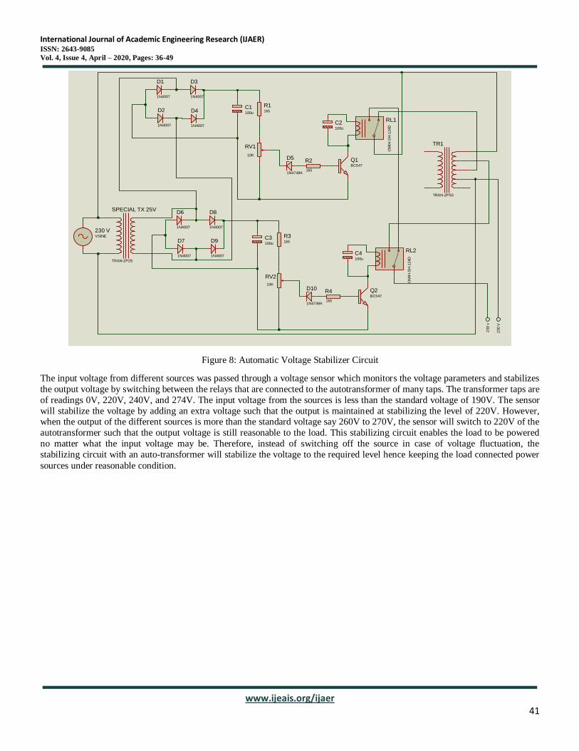
Figure 8: Automatic Voltage Stabilizer Circuit
The input voltage from different sources was passed through a voltage sensor which monitors the voltage parameters and stabilizes
the output voltage by switching between the relays that are connected to the autotransformer of many taps. The transformer taps are
of readings 0V, 220V, 240V, and 274V. The input voltage from the sources is less than the standard voltage of 190V. The sensor
will stabilize the voltage by adding an extra voltage such that the output is maintained at stabilizing the level of 220V. However, when the output of the different sources is more than the standard voltage say 260V to 270V, the sensor will switch to 220V of the
autotransformer such that the output voltage is still reasonable to the load. This stabilizing circuit enables the load to be powered
no matter what the input voltage may be. Therefore, instead of switching off the source in case of voltage fluctuation, the
stabilizing circuit with an auto-transformer will stabilize the voltage to the required level hence keeping the load connected power
sources under reasonable condition.
TR1
TRAN-2P5S
D1
1N4007
D2
1N4007
D3
1N4007
D4
1N4007
D5
1N4749A
C1100u
C2100u
RV1
10K
R11k5
R2
1k5
RL1
OM
IH-S
H-1
24D
Q1BC547
SPECIAL TX 25V
TRAN-2P2S
D6
1N4007
D7
1N4007
D8
1N4007
D9
1N4007
D10
1N4749A
C3100u
C4100u
RV2
10K
R31k5
R4
1k5
RL2
OM
IH-S
H-1
24D
Q2BC547
230 VVSINE
23
0 v
23
0 V

International Journal of Academic Engineering Research (IJAER) ISSN: 2643-9085
Vol. 4, Issue 4, April – 2020, Pages: 36-49
www.ijeais.org/ijaer
42
Figure 9: Automatic Overload Protection Circuit
The stabilized power source 220V AC is then connected to the load through an overload protection system. This system measures
the current drawn by the load and determines whether the system is overloaded or not. The loads are switched ON using an android
app that operates through Bluetooth. This system does not need the operator to be there in person to switch ON the load but to be at
some distance away from the load source such that the Bluetooth will be within the range of connectivity. This prevents the operator from being exposed to the switching surges and sparks that may cause injury to the personnel. In case the operator is
within the range, the mobile device is connected to the Bluetooth device in the circuitry. Once the connectivity is established, the
operator can switch on the loads while the current sensor measures the amount of current drawn by the load.
Before turning ON any load, the system initially draws a current of 0.04 amps, this ampere was considered in the design of the system. When loads 1 & 2 are switched ON, the current sensors record the current value and are read on the LCD; at the same time
a green led was turn on, indicating that the system is standard. When load-3 is ON, the system is at its maximum capacity, and this
was indicated by turning on the blue LED, whereas the green LED is switched OFF. At this point, the current through the load is
that the current system can handle without any problem.
When the fourth load is switched ON, at this point, the system is overloaded, the blue LED turns OFF, and the red LED then
switches ON, which indicates that the system is under overload condition. The system will then isolate the fourth load
automatically and, in turn, activate the GSM to send the message “circuit overloaded” to the operator. The operator will respond to
the message “all-loads-off,” and all the loads will be turn off. After the loads are turned OFF, the operator can send another
message “normal” to return the system to be controlled again by Bluetooth device.
FILE NAME:
BY:
DATE:
PAGE:
Overload Protection Circuit.pdsprj
8/19/2019
@AUTHOR
C:\Users\ACER COMPUTER\Desktop\UNI NOTES\YEAR IV\Sem 1\CORE\Project\Proteus Circuits\Project\Overload Protection Circuit.pdsprjPATH:1 of 1
REV:@REV TIME: 1:45:51 PM
DESIGN TITLE: Overload Protection Circuit.pdsprj
AN
AL
OG
IN
AT
ME
GA
328P
-PU
1121
~~
~
~~
~
TX
RX
Reset B
TN
ON
ww
w.T
he
En
gin
ee
ring
Pro
jec
ts.c
om PD0/RXD
0PD1/TXD
1PD2/INT0
2PD3/INT1
3PD4/T0/XCK
4PD5/T1
5PD6/AIN0
6PD7/AIN1
7
PB0/ICP1/CLKO8
PB1/OC1A9
PB2/SS/OC1B10
PB3/MOSI/OC2A11
PB4/MISO12
PB5/SCK13
AREF
PC5/ADC5/SCLA5
PC4/ADC4/SDAA4
PC3/ADC3A3
PC2/ADC2A2
PC1/ADC1A1
PC0/ADC0A0
RESET
VCC
GND
ARD1
ARDUINO UNO
IP+1/2
IP-3/4
VIOUT7
VCC8
GND5
FILTER6
U1
ACS712ELCTR-20A-T
Q1BC547
R1
330
RL112V
5V
L1230V
D41N4007
Vcc 5V
230V
230V
D7
14
D6
13
D5
12
D4
11D
310
D2
9D
18
D0
7
E6
RW
5R
S4
VS
S1
VD
D2
VE
E3
LCD1LM016L
RV2
10K
D6
D7
D5
D4
RS E
D4
D5
D6
D7
RS
E
Bluetooth
HC-05
KeyVccGNDTXDRXDState
www.TheEngineeringProjects.com
HC1
BLUETOOTH HC-05
SIM Card
SIM900D
S2-1041Y-Z097C
CE0980
Power BTN
ON
NEXT
STATUS
TXD
RXD
www.TheEngineeringProjects.com
GSM1
SIM900D
Q2BC547
RL212V
D11N4007
Vcc 5V
Q3BC547
RL312V
D21N4007
Vcc 5V
Q4BC547
RL412V
D31N4007
Vcc 5V
R2
10k
R3
10k
R4
10k
L212V
L312V
L412V

International Journal of Academic Engineering Research (IJAER) ISSN: 2643-9085
Vol. 4, Issue 4, April – 2020, Pages: 36-49
www.ijeais.org/ijaer
43
Figure 10: Regulated Power Supply Circuit
3.1 Transformer
This system uses a transformer that steps down the voltage from 230V AC to 12V AC with less power loss depending on the
transformer 𝑡𝑢𝑟𝑛𝑠 ratio.
The input AC varies from 160V to 270V in the ratio of the transformer primary voltage 𝑉𝑝 to Secondary Voltage. The secondary
transformer voltage (𝑉𝑠) is governed by the formula; (𝑉𝑝/𝑉𝑠) = (𝑁𝑝/𝑁𝑠)
Thus, if the transformer has 220V as the input or secondary voltage, it will deliver 12V at 220V and can be worked out as follows;
At 160V; (160/𝑉𝑠) = (220/12)
𝑉𝑠 = (160 × 12)/220 = 8.72𝑉
A 270V; 𝑉𝑠 = (270 ×12)/220 = 14.72𝑉
Therefore, a step down between 8V to 15V was sufficient since the current limitation was handled by the regulator.
3.2 Bridge Rectifier
The next stage is the process where AC is converted to DC, which involves inverting the negative cycles of the input AC source.
The circuit for this process is built using a full-wave rectifier diode bridge and requires a specific bridge rectifier that would be able
to handle a peak voltage of 20V and 2A. The 2W04G rectifier was used for the simulation process.
At 220V; 𝑖𝑛𝑝𝑢𝑡 𝑣𝑜𝑙𝑡𝑎𝑔𝑒 𝑉𝑠 = 12𝑉
𝑂𝑢𝑡𝑝𝑢𝑡 𝑑𝑐 𝑣𝑜𝑙𝑡𝑎𝑔𝑒 = 0.9𝑉𝑠= 0.9×12= 10.8𝑉
The bridge rectifier delivers pulsating DC
𝑅𝑖𝑝𝑝𝑙𝑒 𝑓𝑎𝑐𝑡𝑜𝑟 = √(𝑉𝑟𝑚𝑠/𝑉𝑑𝑐)^2 – 1
=√(12/10.8)^2 −1^0.5
=0.66
𝐸𝑓𝑓𝑖𝑐𝑖𝑒𝑛𝑐𝑦 = 𝑃𝑑𝑐/𝑃𝑟𝑚𝑠×100%
= (10.8/12)×100%
TR1
TRAN-2P2S
D1
1N4007
D2
1N4007
D3
1N4007
D4
1N4007
VI1
VO3
GN
D2
U17805
C12200uF
R1330
D5LED-RED
C2100uF

International Journal of Academic Engineering Research (IJAER) ISSN: 2643-9085
Vol. 4, Issue 4, April – 2020, Pages: 36-49
www.ijeais.org/ijaer
44
= 90%
3.3 Filter Capacitor
The capacitance value was needed to filter off the ripple voltage. The output of the transformer was 12V AC at 50Hz. The required
minimum capacitor value can be calculated from the formula;
𝐶 = 𝐼𝑜𝑢𝑡/(2×𝑓×𝑅𝐹×𝑉𝑖𝑛)
𝐼𝑜𝑢𝑡 = 𝐼𝑚𝑎𝑥 = 2𝐴, since it is the maximum forward rectified/output current of the bridge rectifier.
𝐶= 1/(2×50×0.66×12)≅1000𝜇𝐹
Therefore, an electrolytic capacitor of about 470𝜇𝐹 𝑡𝑜 1000𝜇𝐹 to filter the output DC from the bridge rectifier.
3.4 Voltage Regulator LM7805/LM7805A
After the filtering process, the DC that is obtained is unregulated. In the simulation process, the IC LM7805 was used to get 5V DC
at its PIN 3, but the input DC varies from 8V to 15V, and the regulated output from the LM7805 remains constant at 5V.
A small electrolytic capacitor of 10μF is used to filter the regulated 5V DC further to eliminate any noise that may be generated by
the circuit.
3.5 Resistor
One LED is connected to the 5V point in series with a 330Ω resistor that limits the current to the ground, i.e., a negative voltage
indicates that 5V power supply is available. A 330Ω resistor is so connected to limit the flow of electric current through the LED
by producing a voltage drop between its terminals following the current sensor, and the LED has a forward voltage of 2.2V and full
drive current of 10mA.
From ohm’s law; I=V/R=5/330=15mA
Therefore, a 330Ω was sufficient to produce a full drive current of 15mA required by the LED.
Figure 11: Flow Chart Automatic Phase Selector

International Journal of Academic Engineering Research (IJAER) ISSN: 2643-9085
Vol. 4, Issue 4, April – 2020, Pages: 36-49
www.ijeais.org/ijaer
45
Figure 12: Flow Chart Automatic Voltage Stabilizer.
are
Figure 13: Flow Chart Automatic Overload Protector.
The power supplies are connected to three different socket outlets. The output of these three power supplies are connected to the
Atmega 328P microcontroller, and they act as sensors to the analog input to the microcontroller. When a socket outlet is turned ON, a 240V (AC) is reduced to 14V (AC), which is then rectified and regulated to 5V (DC). This regulated voltage act as an input
to the microcontroller. Once there is an input of 5V (DC) to the analog terminal of the microcontroller, a relay switch is turned ON
to supply the load with an AC voltage. A Lamp rated 100W was used as a load for illustration, which draws power from the main.

International Journal of Academic Engineering Research (IJAER) ISSN: 2643-9085
Vol. 4, Issue 4, April – 2020, Pages: 36-49
www.ijeais.org/ijaer
46
When all the electrical energy sources are available, solar power takes the lead and supplies to the load. However, when whenever
there is a failure in the solar power to supply to the load, the next source available automatically steps, for example, the main grid,
and so on. However, if solar power is restored, it will take its leading position and supply power to the load surpassing all the other
sources. In case the load is more than the capacity of one source, the Bluetooth is used to bring one or more sources on board to
meet the load demand.
The output of the ATS is then connected to the voltage regulation circuit, which has an inbuilt voltage sensor to detect under or
overvoltage. When there are any voltage variations in the supply, the sensor will activate the responsible relay to select an appropriate tap on the auto-transformer, thus maintaining a constant output voltage. From the voltage regulating circuit, a load is
connected through an overload protection system. This will isolate the load from the supply in case of overload, and the system
will notify the engineer/technician via message to control the load utilizing GSM messages.
4.0 Results and Discussions
The input from the three sources was given to the microcontroller, and the output of the microcontroller, in turn, sends to the relay
that maintains continuous power supply to the load through a voltage stabilizer. Finally, the system status of the available sources
and load characteristic is displayed on the LCD, the following modes of operation were obtained as shown by the figures below.
Figure 14: Smart Grid protection system
4.1 Results

International Journal of Academic Engineering Research (IJAER) ISSN: 2643-9085
Vol. 4, Issue 4, April – 2020, Pages: 36-49
www.ijeais.org/ijaer
47
Table 1: Showing results of the DC power supply circuit and microcontroller
The output of the
bridge rectifier
Input into the voltage
regulator
The output of the
voltage regulator
Input into the microcontroller
(Vcc)
11.7Vdc 10.2Vdc 4.96Vdc 4.96Vdc
Table 2: showing Sources status when control by automatic mode.
Power source The input of the power
source (VAC) Switch status LCD Display
Solar 220V ON SOLAR ON
Solar 220V OFF SOLAR OFF
Grid 220V ON GRID ON
Grid 220V OFF GRID OFF
Generator 220V ON GENERATOR ON
Generator 220V OFF GENERATOR OFF
All source 220V ON CONTROL BY BLUETOOTH
(CTRL WITH 12-20)
Table 3: Showing Sources status when control by Bluetooth
Power source The input of the power
source (VAC)
Input to the
app
Switch status LCD Display
Solar 220V 12 ON SOLAR ON
220V 13 OFF SOLAR OFF
Grid 220V 14 ON GRID ON
220V 15 OFF GRID OFF
Generator 220V 16 ON GENERATOR ON
220V 17 OFF GENERATOR OFF
All sources 220V 18 ON ALL SOURCES
220V 19 OFF NO POWER
Automatic
controlled
220V 20 ON ANY SOURCE
AVAILABLE
Table 4: Showing status of voltage stabilizer
Input Voltages (V) Relays Relay Status Output Voltage (V)
190 Relay 1 ON 220
260 Relay 2 ON 220
Table 5: Showing status of loads been controlled by Bluetooth
Loads The input of the power
source (VAC)
Input to the app Switch
status
LCD Display
All Load OFF 220V Nothing OFF CTRL WITH 1-10
Load-1 220V 1 ON LOAD-1 ON
220V 2 OFF LOAD-1 OFF

International Journal of Academic Engineering Research (IJAER) ISSN: 2643-9085
Vol. 4, Issue 4, April – 2020, Pages: 36-49
www.ijeais.org/ijaer
48
Load-2 220V 3 ON LOAD-2 ON
220V 4 OFF LOAD-2 OFF
Load-3 220V 5 ON LOAD-3 ON
220V 6 OFF LOAD-3 OFF
Load-4 220V 7 ON LOAD-4 ON
220V 8 OFF LOAD-4 OFF
ALL LOADS
ON
220v 9 ON GSM CONTROL
(circuit overloaded)
Table 6: showing loads status Controlled by GSM
Loads The input of the power
source (VAC)
GSM Messages Switch
status
LCD Display
Load-1 220V Load1_on ON LOAD-1 ON
220V Load1_off OFF LOAD-1 OFF
Load-2 220V Load2_on ON LOAD-2 ON
220V Load2_off OFF LOAD-2 OFF
Load-3 220V Load3_on ON LOAD-3 ON
220V Load3_off OFF LOAD-3 OFF
Load-4 220V Load4_on ON LOAD-4 ON
220V Load4_off OFF LOAD-4 OFF
All loads on 220v All_loads_on ON GSM CONTROL (OVERLOAD
STATUS)
All loads off 220V All_loads_off OFF ALL-LOADS-OFF
Set to Bluetooth
control
220V normal OFF CTRL WITH 1-10
5.0 Conclusion
The main objective of this paper is to develop a smart grid resilience three-phase selector voltage regulator and an overload
protection system based on GSM technology. It involves the selection of power supply from either solar power, the primary grid,
or a standby generator. This is achieved automatically using the microcontroller and GSM concept. This system helps in protecting the load against voltage fluctuations and overloads. These protection schemes are not found in the currently developed systems,
hence make APS and overload protector superior to all of them. The significance lies in the various and wide range of applications
such as; power generation plants, schools, hospitals, manufacturing industries, and mining industries where continuity of power is
needed.
References

International Journal of Academic Engineering Research (IJAER) ISSN: 2643-9085
Vol. 4, Issue 4, April – 2020, Pages: 36-49
www.ijeais.org/ijaer
49
Abdurrahman Shuaibu Hassan, Ibrahim Adabara, Amanyire Ronald, Kaumba Muteba. Design and Implementation of an
Automatic Power Supply from Four Different Source Using Microcontroller. International Journal of Electrical and Electronic
Science. Vol. 4, No. 5, 2017, pp. 40-46.
Amol Prabhakar Patil (2017), “Auto power supply from different sources.” International Journal of Research in Electrical
Engineering. Volume 04: Issue 02: pp 160-162.
Lanre Olatomiwa, Rasheed Olufadi (2014), “Automatic Transfer Switch (ATS) with Over Voltage Protection.” Journal of
Multidisciplinary Engineering Science and Technology (JMEST) Vol. 1, Issue 4, pp 190-196.
L.S. Ezema, B.U. Peter, O.O. Harris (2012), “Design of Automatic Change Over Switch with Generator Control Mechanism.”
Electrical Power and Electronic Development Department, Projects Development Institute (PRODA), Enugu Nigeria: Natural and
Applied Science, Vol.3, No.3. November 2012. PP 125 – 130.
Mbaocha C. (2012), “Smart Phase Change Over Switch using AT89C52 Microcontroller.” Journal of Electrical and Electronics
Engineering vol.1; Issue 3: PP 31-44.
Robert Dowuona-Owoo (2008), “Design and construction of Three-phase Automatic Transfer Switch.” Master thesis at Regent
University College of Science and Technology Ghana. PP100-120.
Shahaji Dudhate, Amol Attargekar, Dhanaji Desai, Aditi Patil (2016), “Power Supply Control from Different Sources.”
International Journal of Scientific & Engineering Research, Volume 7, Issue 1, pp 484-487
Shanmukha Nagaraj and Ramesh S (2013), “Programmable Logic Controlled Circuits.” International Journal of Research in
Engineering and Technology Vol.1, issue 2, July 2013; PP 111-116.