Size effects on stress concentration induced by a prolate ellipsoidal particle and void nucleation...
23
Size effects on stress concentration induced by a prolate ellipsoidal particle and void nucleation mechanism Minsheng Huang a , Zhenhuan Li a,b, * a Department of Mechanics, Huazhong University of Science and Technology, Wuhan 430074, PR China b Chair of Applied Mechanics, University of Kaiserslautern, P.O. Box 3049, D67653 Kaiserslautern, Germany Received in final revised form 20 July 2004 Available online 21 November 2004 Abstract There generally exist two void nucleation mechanisms in materials, i.e. the breakage of hard second-phase particle and the separation of particle–matrix interface. The role of particle shape in governing the void nucleation mechanism has already been investigated carefully in the literatures. In this study, the coupled effects of particle size and shape on the void nucle- ation mechanisms, which have not yet been carefully addressed, have been paid to special attention. To this end, a wide range of particle aspect ratios (but limited to the prolate sphe- roidal particle) is considered to reflect the shape effect; and the size effect is captured by the Fleck–Hutchinson phenomenological strain plasticity constitutive theory (Advance in Applied Mechanics, vol. 33, Academic Press, New York, 1997, p. 295). Detailed theoretical analyses and computations on an infinite block containing an isolated elastic prolate spheroidal particle are carried out to light the features of stress concentrations and their distributions at the matrix–particle interface and within the particle. Some results different from the scale-inde- pendent case are obtained as: (1) the maximum stress concentration factor (SCF) at the par- ticle–matrix interface is dramatically increased by the size effect especially for the slender particle. This is likely to trigger the void nucleation at the matrix–particle interface by cleavage or atomic separation. (2) At a given overall effective strain, the particle size effect significantly 0749-6419/$ - see front matter Ó 2004 Elsevier Ltd. All rights reserved. doi:10.1016/j.ijplas.2004.07.006 * Corresponding author. E-mail addresses: [email protected], [email protected] (Z. Li). www.elsevier.com/locate/ijplas International Journal of Plasticity 21 (2005) 1568–1590
-
Upload
independent -
Category
Documents
-
view
2 -
download
0
Transcript of Size effects on stress concentration induced by a prolate ellipsoidal particle and void nucleation...
www.elsevier.com/locate/ijplas
International Journal of Plasticity 21 (2005) 1568–1590
Size effects on stress concentration induced bya prolate ellipsoidal particle and void
nucleation mechanism
Minsheng Huang a, Zhenhuan Li a,b,*
a Department of Mechanics, Huazhong University of Science and Technology, Wuhan 430074, PR Chinab Chair of Applied Mechanics, University of Kaiserslautern, P.O. Box 3049,
D67653 Kaiserslautern, Germany
Received in final revised form 20 July 2004
Available online 21 November 2004
Abstract
There generally exist two void nucleation mechanisms in materials, i.e. the breakage of
hard second-phase particle and the separation of particle–matrix interface. The role of particle
shape in governing the void nucleation mechanism has already been investigated carefully in
the literatures. In this study, the coupled effects of particle size and shape on the void nucle-
ation mechanisms, which have not yet been carefully addressed, have been paid to special
attention. To this end, a wide range of particle aspect ratios (but limited to the prolate sphe-
roidal particle) is considered to reflect the shape effect; and the size effect is captured by the
Fleck–Hutchinson phenomenological strain plasticity constitutive theory (Advance in Applied
Mechanics, vol. 33, Academic Press, New York, 1997, p. 295). Detailed theoretical analyses
and computations on an infinite block containing an isolated elastic prolate spheroidal particle
are carried out to light the features of stress concentrations and their distributions at the
matrix–particle interface and within the particle. Some results different from the scale-inde-
pendent case are obtained as: (1) the maximum stress concentration factor (SCF) at the par-
ticle–matrix interface is dramatically increased by the size effect especially for the slender
particle. This is likely to trigger the void nucleation at the matrix–particle interface by cleavage
or atomic separation. (2) At a given overall effective strain, the particle size effect significantly
0749-6419/$ - see front matter � 2004 Elsevier Ltd. All rights reserved.
doi:10.1016/j.ijplas.2004.07.006
* Corresponding author.
E-mail addresses: [email protected], [email protected] (Z. Li).

M. Huang, Z. Li / International Journal of Plasticity 21 (2005) 1568–1590 1569
elevates the stress level at the matrix–particle interface. This means that the size effect is likely
to advance the interface separation at a smaller overall strain. (3) For scale-independent cases,
the elongated particle fracture usually takes place before the interface debonding occurs. For
scale-dependent cases, although the SCF within the particle is also accentuated by the particle
size effect, the SCF at the interface rises at a much faster rate. It indicates that the probability
of void nucleation by the interface separation would increase.
� 2004 Elsevier Ltd. All rights reserved.
Keywords: Strain gradient plasticity; Size effect; Shape effect; Void nucleation; Elongated particles
1. Introduction
The second-phase particles or fibers are often embedded into ductile materials to
improve their mechanical properties. However, the higher stress concentration at the
particle–matrix interface or within the particle induced by the second phase hard
particle or fiber may result in the particle–matrix interface separation (Keer et al.,
1973) or the particle fracture (Gurland and Plateau, 1963; Lloyd, 1991). The former
failure is generally governed by the traction across the interface (Needleman, 1987)
and the interface debonding strength, while the latter is related to the opening stress
within the particle and the particle fracture strength (Brechet et al., 1991). If the par-ticle and interfacial strengths are known a priori, a rational void nucleation predic-
tion through an accurate determination of the stress distributions within the particle
and at the interface is possible. Several studies on these stress distributions at the
interface and within the particle have been performed to explain the void nucleation
mechanism (Thomson and Hancock, 1984; Wilner, 1988, 1995; Tvergaard, 1993,
1995). Various possible influences, which come from the particle morphology such
as the particle shape (Lee and Mear, 1999); from the particle distribution (Brocken-
brough et al., 1992; Ganguly and Pool, 2004); from the material parameters such asthe elastic constants (including Young�s modulus and Poisson�s ratio), the yield stress
and the hardening exponent (Christman et al., 1989; Bao et al., 1991; Tvergaard,
1990a); and from interface features such as the perfect bonding and partial debond-
ing (Tvergaard, 1990b, 1993, 1995), on the mesoscopic and the macroscopic response
of MMC have been addressed carefully. These works contributed to a good under-
standing of the size-independent damage initiation in MMC, but they cannot capture
the size effect at the micron or submicron scale.
Recent experiments and computational simulations have repeatedly demonstratedthat composites reinforced by second-phase particles display strong size effects when
the main size of particles is in the micron or submicron size range. Lloyd (1994) ob-
served that a decrease of the particle size can markedly increase the stiffness of SiC-
reinforced aluminum for given material parameters and particle volume fraction. By
the transmission electron microscope (TEM) technique, Barlow and co-workers
(Barlow and Hansen, 1991, 1995; Barlow and Liu, 1998) continually observed that
the strain gradient distribution around the micron scale whiskers is much smoother
than that predicted by the size-independent FEM. Recent simulations based on the

1570 M. Huang, Z. Li / International Journal of Plasticity 21 (2005) 1568–1590
discrete dislocation plasticity also validated that the stress level and distribution
around the reinforcement strongly depend on the particle size (Cleveringa et al.,
1997, 1999a; Khraishi et al., 2004). Similar size effect is also found in other experi-
ments and theoritical analyses such as the micro-indentation (Ma and Clark, 1995;
Mcelhaney et al., 1998; Rashid and Voyiadjis, 2004), the micro-twin (Fleck et al.,1994), the micro-bend (Stolken and Evans, 1998; Wang et al., 2003; Cleveringa
et al., 1999b) and the metallic materials containing microvoids (Shu, 1998; Khraishi
and Khaleel, 2001; Taylor et al., 2002). The classical local plasticity theories fail to
explain this size effect due to the lack of material intrinsic length. In recent years, var-
ious high-order and lower-order non-local theories possessing the intrinsic length
have been developed to capture the size-dependent behavior of materials (Huang
et al., 2004; Hwang et al., 2004; Li et al., 2003; Li and Huang, 2005). Although
the presently available constitutive models are far from being firmly established(Hutchinson, 2000; Gudmundson, 2004), many investigators actively employed them
to probe into the size-dependent response of the particle-reinforced composites; see
Fleck and Hutchinson (1993, 1997), Dai et al. (1999), Shu and Barlow (2000), Huang
et al. (2000), Xue et al. (2002), Niordson and Tvergaard (2001, 2002), Niordson
(2003), Bittencourt et al. (2003), for example. A general conclusion is reached: smal-
ler particles tend to dramatically elevate the bulk stiffness of MMC and the micro-
scopic stress within matrix and particles.
Previous works on the particle size effect include two main limitations. First, theinfluence of particle shape is not carefully taken into account. In fact, the particles
dispersed in the matrix rarely have idealized shapes like spheres or cylinders. Signif-
icant strain gradients inevitably develop at the high curvature regions of non-spher-
ical particles. Second, the bulk constitutive response of the particle-reinforced
composites are paid sufficient attention whereas details about stress distributions
within particles and matrix are usually neglected, although they are crucial to under-
stand the scale-dependent void nucleation mechanism. So far, it is not clear how par-
ticle shape and size jointly influence the stress distribution and the void nucleationmechanism when the particle is in the micron or submicron size range.
Motivated by these backgrounds, we perform here detailed investigations on the
coupled effects of particle size and shape on the stress concentration and void nuclea-
tionmechanism.Aboundary value problemof an infinitematrix containing an isolated
prolate spheroidal particle has been theoretically analyzed and numerically solved by a
Ritz procedure. For the sake of simplicity, our attention is restricted to the remote pro-
portional and monotonic axisymmetric small deformation tension loading.
2. Size-dependent stress concentrations
2.1. The constitutive theories of matrix and particle
The matrix material is assumed to be isotropic and plastic incompressible. As
known, there are several size-dependent constitutive theories available to capture
the size dependence although they are still in development. Here, the multi-parameter

M. Huang, Z. Li / International Journal of Plasticity 21 (2005) 1568–1590 1571
phenomenological SG deformation theory (Fleck and Hutchinson, 1997) is adopted
since it has the advantage of obtaining closed-form solutions to some basic problems
(Fleck and Hutchinson, 2001).
In this theory, the strain tensor eij and the strain gradient tensor gijk are related to
the displacement components ui by
eij ¼1
2ui;j þ uj;i� �
; gijk ¼ uk;ij ¼ eik;j þ ejk;i � eij;k; ð1Þ
where eij = eji and gijk = gjik. Further, the strain gradient tensor gijk can be decom-
posed as follows:
gijk ¼ g0ijk þ gHijk; ð2Þ
where gHijk and g0ijk are the hydrostatic and deviatoric parts of gijk, respectively. Thedeviatoric strain gradient tensor g0ijk can be reformulated in terms of a unique orthog-
onal decomposition, introduced by Smyshlyaev and Fleck (1996):
g0ijk ¼ g0ð1Þijk þ g0ð2Þijk þ g0ð3Þijk ; ð3Þ
where the tensors g0ðnÞijk ðn ¼ 1; 2; 3Þ are mutually orthogonal and symmetric about the
subscript i and j, i.e. g0ðnÞijk ¼ g0ðnÞjik .
To introduce the intrinsic material length, the generalized effective stress re andthe generalized effective strain ne are defined as
n2e ¼2
3e0ije
0ij þ l21g
0ð1Þijk g
0ð1Þijk þ l22g
0ð2Þijk g
0ð2Þijk þ l23g
0ð3Þijk g
0ð3Þijk ; ð4Þ
r2e ¼
3
2r0ijr
0ij þ l�2
1 s0ð1Þijk s0ð1Þijk þ l�2
2 s0ð2Þijk s0ð2Þijk þ l�2
3 s0ð3Þijk s0ð3Þijk ; ð5Þ
where s0ðnÞijk , which is work conjugated to the deviatoric strain gradient tensor g0ðnÞijk , is
the deviatoric part of the higher order stress tensor sðnÞijk ; l1, l2 and l3 are three material
constitutive lengths of the matrix. The length l1 relates to the stretch gradient closely,
while l2 and l3 are two lengths associates only with the rotation gradients. If depend-
ence on stretch gradients is eliminated, the theory reduces to that for a couple–stresssolid (Fleck and Hutchinson, 1993).
By fitting the experimental data from the bending of ultra-thin beams (Stolken and
Evans, 1998), torsion of thin wires (Fleck et al., 1994) and micro-indentation (Ma and
Clark, 1995; Mcelhaney et al., 1998), Begley and Hutchinson (1998) suggest that
l1 ¼1
jl; l2 ¼
1
2l; l3 ¼
ffiffiffiffiffi5
24
rl; ð6Þ
where l is the intrinsic material length of the matrix. The constitutive parameter jwas taken to be 1 by Fleck and Hutchinson (1997), but this particular choice is defi-
cient in physical basis (Begley and Hutchinson, 1998). Hutchinson (2000) pointed
out that there are only small variations in the constitutive length parameters for dif-
ferent metals and tentatively concluded that l � 5 lm, l1 � 0.25–1 lm. This is to saythat j should fall within the range 5–20 for most metallic materials. In this paper, j is
typically set to be j = 8.

1572 M. Huang, Z. Li / International Journal of Plasticity 21 (2005) 1568–1590
To consider the elastic compressibility of the elastic–plastic matrix material,
Hwang and Huang (1999) extended the SG constitutive relation by appending an
elastic volume strain energy density part -mV ðeVÞ to the strain energy density -m as
follows:
-m ¼ -mVðeVÞ þ -mðneÞ; ð7Þ
where the superscript m denotes the matrix and -m(ne) is the shape change part of
the strain energy density function.
Assuming that the volume deformation is linearly elastic, the hydrostatic strain
gradient gHijk has no contribution to the strain energy density and thus the change
in volume can induce hydrostatic Cauchy stress but no hydrostatic higher-order
stress. Accordingly, the elastic volume strain energy density function can be ex-
pressed as
-mV ¼ 1
2Kme2V; eV ¼ tre ¼ eii: ð8Þ
Here, Km ¼ Em
3ð1�2mmÞ is the bulk modulus, Em ¼ r0e0and mm are Young�s modulus and
Poisson�s ratio of the matrix material, respectively.
According to the assumption of matrix plasticity incompressibility and the defor-
mation SG theory employed, a power dependence of the strain energy density -m(ne)on the generalized effective strain can be assumed as
-mðneÞ ¼n
nþ 1r0e0
nee0
� �nþ1n
; ð9Þ
where n is the power hardening exponent, r0 the generalized flow stress correspond-
ing to ne = n0. Considering that rij and s0ijk are work conjugated to eij and g0ijk, respec-tively, rij and s0ijk can be obtained by
rij ¼o-m
oeij; s0ijk ¼
o-m
og0ijk: ð10Þ
For multiaxial stress and strain states, the scale-dependent constitutive equations
(10) can be rewritten as
r0ij ¼ KmeVdij þ
2
3
re
nee0ij;
s0ðnÞijk ¼ re
nel2ng
0ðnÞijk ¼ re
nel2ng
ðnÞijk ðthe index n no sumÞ:
ð11Þ
The particle embedded in the elastic–plastic matrix is assumed to be an isotropic
elastic solid with Young�s modulus Ep and Poisson�s ratio mp. Its constitutive behav-ior can be described as
rpij ¼ kpepkk þ 2Gpepij; ð12Þ
where kp ¼ Epmp
2ð1þmpÞð1�2mpÞ; Gp ¼ Ep
2ð1þvpÞ and the superscript p denotes the particle.

M. Huang, Z. Li / International Journal of Plasticity 21 (2005) 1568–1590 1573
2.2. Boundary condition
In the present paper, an infinite aggregate comprising of a power-law SG matrix
and an isolated prolate spheroidal particle is considered, as shown in Fig. 1. The par-
ticle is assumed to be aligned to the main tension direction (i.e. the x3-axis). For con-venience, both the Cartesian system (x1,x2,x3) oriented with respect to the axes of the
particle and the prolate spheroidal coordinates (f,h,u) are adopted as in Lee and
Mear (1999).
The surface of elongated spheroidal particles Sp (see Fig. 1) can be expressed as
x1b
� �2
þ x2b
� �2
þ x3a
� �2
¼ 1 or f ¼ b; ð13Þ
where a and b denote the lengths of semi-major axis and semi-minor axis of the par-
ticle, respectively. With the radial coordinate of the prolate coordinate system f = bdefining the boundary of the spheroidal particle, the constant b can be expressed in
terms of the particle aspect ratio S = a/b by the relation b = tanh�1(1/S).
As the volume Vr and the outer surface Sr of the material block under consider-
ation tend to be infinite, the remote strain gradient g1ijk is so small over the infinitelength scale that the remote high order stress s1ijk can be neglected (i.e. s1ijk ¼ 0 on
Sr, Fleck and Hutchinson, 1993). Thus, the surface traction tk and double-stress trac-
tion rk boundary conditions on surface Sr
tk ¼ niðRik � s1ijk;jÞ þ ninjs1ijkðDpnpÞ � Djðnis1ijkÞ;rk ¼ ninjs1ijk
(k ¼ 1; 2; 3 ð14Þ
P
X3
b b
a
T
X1
TX2
ζ
φ
θx
pole
equator
Fig. 1. Schematic infinite solid containing a prolate particle relative to a prolate spheroidal coordinate
system (f,h,u) and a Cartesian reference coordinate system (x1,x2,x3). The prolate radial coordinate
f ¼ tanh�1ðffiffiffiffiffiffiffiffiffiffiffiffiffiffix21 þ x22
p=x3Þ. Remote axisymmetric stress components are R11 = R22 = T and R33 = P with
P > T P 0. Then the position vector x ¼ x1�iþ x2�jþ x3�k ¼ fef þ heh þ ueuand the correlation between
these two coordinates {x1,x2,x3} and {f,h,u} is provided by Lee and Mear (1999).

1574 M. Huang, Z. Li / International Journal of Plasticity 21 (2005) 1568–1590
can be reduced to the classical forms as follows:
tk ¼ niRik and rk ¼ 0; ð15Þ
where Dj is the surface gradient operator (Fleck and Hutchinson, 1997), n is the out-ward unit vector normal to the surface Sr and Rij is the remote Cauchy stress applied
on Sr.
For the sake of simplicity, our attention is restricted to the cases of small strain
deformation and axisymmetric loading, in which the non-zero remote uniform mac-
roscopic stresses R11 = R22 = T and R33 = P (P > T P 0) are applied as indicated in
Fig. 1. It is further assumed that the remote stress is increased proportionally such
that the stress triaxiality Rr ¼ Pþ2T3ðP�T Þ remains fixed throughout the loading history.
These stipulations allow a generalization of Illuyshin�s theorem to be enforced: pro-portional loading occurs at each material point within the body and results of the
deformation theory exactly coincide with the predictions of the flow theory (Fleck
and Hutchinson, 1993).
2.3. Stress concentration factors
To characterize the void nucleation mechanism, two kinds of SCFs (stress con-
centration factors) are introduced. One is the SCF KI at the matrix–particle inter-face; the other is the SCF Kp within the particle. They are associated with two void
nucleation mechanisms, i.e. the interface debonding and the particle fracture,
respectively.
As a measure of the normal traction intensity at the particle–matrix interface, the
interfacial SCF KI is defined by
KI ¼ rff=P at f ¼ b ð16Þ
in which the interfacial normal traction r11 on the boundary f = b is obtained by
using the stress field within the particle.Similarly, the SCF Kp within the particle is introduced to measure the opening
stress intensity on the particle equator plane as
Kp ¼ rhh=P at h ¼ p=2; ð17Þwhere the opening stress rhhjh¼p
2within particle equals to the stress component r33 in
the Cartesian coordinate system exactly.
To reflect the size effect on SCFs, the radius of an ‘‘equivalent sphere parti-
cle’’ with the same volume as the prolate spheroidal particle is defined as the
‘‘particle equivalent radius’’ r ¼ffiffiffiffiffiffiffiab23
pand a characteristic length ratio k is intro-
duced as
k ¼ l=r ¼ l=ffiffiffiffiffiffiffiab2
3p
: ð18ÞObviously, r and l characterize the geometrical scale of the particle and the physicalintrinsic scale of the matrix, respectively.

M. Huang, Z. Li / International Journal of Plasticity 21 (2005) 1568–1590 1575
3. Numerical procedure
3.1. Trial displacement field
Following Lee and Mear (1999), the classical Ritz procedure is employed to solvethe present boundary value problem, and special attentions are paid to determine the
SCFs induced by an elongated elastic spheroidal particle embedded in an infinite SG
matrix. Apparently, the precision of the solution for this kernel problem relies
mainly on a good choice of the displacement fields within the interior particle and
in the exterior matrix.
According to Gurtin�s work (Gurtin, 1984), the displacement field up within the
particle can be expressed as (Lee and Mear, 1999)
upg ¼ a2
h
Pn¼1;3;5;...
f½HnP 1nþ1ðcosh fÞ þ ðnþ 1Þðnþ cpÞInP 1
n�1ðcosh fÞ�Pnþ1ðcos hÞ
þnðnþ 1� cpÞInP 1nþ1ðcosh fÞPn�1ðcos hÞg;
uph ¼ a2
h
Pn¼1;3;5;...
f½HnPnþ1ðcosh fÞ þ nðnþ 1� cpÞInPn�1ðcosh fÞ�P 1nþ1ðcos hÞ
þðnþ 1Þðnþ cpÞInP nþ1ðcosh fÞP 1n�1ðcos hÞg;
8>>>>>>><>>>>>>>:
ð19Þwhere cp = 4(1 � mp), h ¼ aðsinh2fþ sin2hÞ1=2; a ¼
ffiffiffiffiffiffiffiffiffiffiffiffiffiffiffia2 � b2
pis the distance from the
origin to the foci of the spheroid, {Hn,In} are the real constants, Pn and P 1n are the
Legendre polynomials and the associated Legendre functions of order one, respec-
tively. It can be verified easily that this displacement field has proper symmetry with
respect to the median plane (i.e. equator plane) h = p/2.The trial local displacement and strain fields within the matrix are expressed as
(Budiansky et al., 1982)
u ¼ U0 þ ~u; e ¼ E0 þ ~e; ð20Þwhere U0 and E0 are the linear displacement field and the uniform strain field asso-
ciated with the remote stress Rij in the absence of particle. Further, the strain gradi-
ent g can also be written as
g ¼ g0 þ ~g: ð21Þ
Similarly, g0 denotes the strain gradient in the absence of particle. Since E0 is uni-form, g0 naturally equals to zero. ~e and ~g are the reduced strain and strain gradient
tensors associated with the reduced displacement ~u, respectively.Corresponding to the axisymmetric remote stress applied, the non-zero compo-
nents of the linear displacement field U0 with respect to prolate spheroidal coordi-
nates can be expressed as
U 0f ¼ a2
3h P12ðcosh fÞ½Em þ EeP 2ðcos hÞ�;
crU 0h ¼ a2
3h P12ðcos hÞ½Em þ EeP 2ðcosh fÞ�
(ð22Þ

1576 M. Huang, Z. Li / International Journal of Plasticity 21 (2005) 1568–1590
in which Em and Ee are the remote mean strain and the remote effective strain,
respectively:
Em ¼ 1Km Rm ¼ 1
3Km ðP þ 2T Þ;
Ee ¼ e0Re
r0
� �n¼ e0 P�T
r0
� �n:
8<: ð23Þ
Correspondingly, Rm, Re are the remote mean stress and the remote effective stress,
respectively.
The non-zero components of ~u in the prolate spheroidal coordinates are expressed
in terms of a complete set of orthogonal functions (Lee and Mear, 1999):
~uf ¼ a2
h
Pk¼0;2;4;...
F kðfÞPkðcos hÞ;
~uh ¼ a2
h
Pk¼0;2;4;...
GkðfÞP 1kðcos hÞ;
8><>: ð24Þ
where Fk and Gk are functions of f alone and taken as
F kðfÞ ¼P
m¼0;1;2;...
AkmQ1mðcosh fÞ;
GkðfÞ ¼P
m¼0;1;2;...
BkmQmðcosh fÞ:
8><>: ð25Þ
Note that this trial displacement field has also proper symmetry with respect to the
plane h ¼ p2(x1–x2 plane).
To insure the displacement field to be continuous across the matrix–particle inter-
face, the displacement fields within the matrix and the particle must satisfy
up ¼ U þ ~u on f ¼ b: ð26ÞClearly, this equation establishes the relations between the constants {Hj,Ij} associ-ated with the displacement field within the particle and the real coefficients
{Akm,Bkm} involved in the trial reduced displacement field within the matrix (Lee
and Mear, 1999).
3.2. Minimum functional and numerical method
Among all the possible trail displacement fields up and u, the actual displacement
field should minimize the functional F(up, u) (Hill, 1956; Lee and Mear, 1999):
F ðup; uÞ ¼ZV p
-pðepÞ dV þ F m ¼ZV p
kp
2epkke
pmm þ Gpep : ep
� dV þ F m; ð27Þ
where
F m ¼ZV m
½xðe; gÞ � xðE0; 0Þ� dV �ZSr
½t � ~uþ r � ðn � r~uÞ� dS: ð28Þ
Substituting the boundary condition (15) into (28) and applying the divergence the-
orem, the following relation can easily be achieved:

M. Huang, Z. Li / International Journal of Plasticity 21 (2005) 1568–1590 1577
F m ¼ZV m
½xðe; gÞ � xðE0; 0Þ � R : ~e� dV þZSp
~u � R � n dS; ð29Þ
where x(e, g) = xm is the strain energy density given by (7) and n is the unit normal
on the surface of the particle and points into the particle.
In above relations, Vm and Vp denote the volume occupied by the matrix and theparticle, respectively. Since the reduced displacement field ~u decays faster than r�1=2
x
as rx ! 1, where rx ¼ffiffiffiffiffiffiffiffiffix � x
pand x ¼ x1~iþ x2~jþ x3~k is the position vector (see Fig.
1), the volume integral in (29) can converge rapidly although the volume Vm is
infinite.
Since the continuity equation (26) is enforced to express the coefficients {Hj,Ij} in
terms of the coefficients {Akm,Bkm}, only the real constants {Akm,Bkm} are independ-
ent unknown parameters. Once the functional (27) has been minimized with respect
to a set of free coefficients {Akm,Bkm} by a Ritz procedure, the deformation fieldswithin the particle and the matrix are all solved. Then the aforementioned SCFs
can be evaluated easily.
To implement the numerical calculation, the double series of the trial field (24)
within the matrix are truncated and the remaining terms in the approximate dis-
placement fields correspond to k = 0, 2, 4,. . . ,2K and m = 1, 2, . . . ,M. When this
is done, the infinite series (19), which is associated with the trial field within the
particle, is also simultaneously truncated and only the terms corresponding to
n = 1, 3, 5, . . . ,N with N = 2K � 1 remain. Apparently, the accuracy of the kernelproblem is mainly controlled by the parameters K and M. In this paper,
K = M = 10 are selected. Convergence studies show that this choice is accurate en-
ough for the present problem of interest. Besides, to ensure that the numerical
solutions converge correctly, the Newton–Raphson descent method and 20 · 20
three-point Gaussian quadrature procedure are adopted. Fig. 2 compares the pre-
sent results with the FE results achieved by MARC� for the classical scale-inde-
pendent case. Obviously, the present results are in excellent agreement with the
FE results. This proves that the selected displacement field representations are rea-sonable to describe the microscopic stress and strain fields within the matrix and
the prolate particle.
4. Size effects on the stress concentration factors
In general, when the size of the particle is above the micron range, the stress con-
centration factor (SCF) depends mainly on the particle morphology, the materialparameter and the applied load condition. However, when the particle size is in
the micron or submicron range, the influence of the particle size on the SCF will pro-
trude remarkably. The present work aims to describe the coupled effects of particle
size and shape on SCFs. Although a lot of information about the SCFs can be de-
rived easily from the present model, only partial results, which are crucial for us to
understand the coupled effects of the particle shape and size on the void nucleation
mechanism, are graphically presented. To simplify the range considered, the results

1.3
1 .5
1 .7
1 .9
0 0 .2 0 .4 0 .6 0 .8 1 .0
FE resu ltsE
e=0 .05 , S =2.0 , λ
σ
σ
σ
=0
P resen t resu lts
R =3.0
R =2.0
R =1.0
γ
Kp
Fig. 2. Comparisons of the present results for the scale-independent SCF Kp along the semi-minor axis of
particle (i.e. the x1 axis and the x2 axis) with the FEM results, where c ¼ ðf=bÞjh¼p2is the normalized radial
distance from the center of particle.
1578 M. Huang, Z. Li / International Journal of Plasticity 21 (2005) 1568–1590
are restrict to that for Poisson�s ratio mp = mm = 0.3, modulus ratio Ep/Em = 2, refer-
ence strain e0 = 0.2% and hardening exponent n = 10.
4.1. Size effects on the interfacial stress concentration factor KI
The void nucleation by interface debonding rests mainly with the normal stresslevel at the particle–matrix interface. Considering for this, the distributions of the
interfacial normal SCF KI are displayed in Fig. 3 as a function of the physical
angle h measured from the x3-axis, where h = 0 corresponds to the particle pole
and h ¼ p2
denotes the particle equator (see Fig. 1). It can be seen from
Fig. 3(a) that, for the scale-independent case k = 0, the maximum interfacial nor-
mal SCF KmaxI increases with increasing particle aspect ratio S. Kmax
I locates usu-
ally at somewhat off the pole, especially for the particle with small aspect ratio.
For example, at the given stress triaxiality Rr = 1 and remote effective strainEe = 0.03, Kmax
I locates at h � 60 for S = 2 and at h � 130 for S = 1.001. It is
worth noting that although KmaxI sometimes occurs away from the pole, it differs
slightly from that at the pole h = 0�. This result is in good agreement with the
findings of Lee and Mear (1999). In contrast, for the size dependent case k = 1,
Fig. 3(b) indicates that dramatic changes in the distribution of SCF KI along

0
0 .5
1 .0
1 .5
2 .0
0 30 60 90
32.01.001
λ=0, R =1.0 , Ee=0 .03
S=
KI
m ax=1 .681
KI
m ax=1 .459
KI
m ax=1 .236
6 13θ
KI
(a)
-2
0
2
4
6
8
0 30 60 90
321 .001
λ=1, R =1.0 , Ee=0 .03
S=
KI
m ax=7 .087
KI
m ax=4 .621
KI
m ax=2 .363
0
θ
KI
(b)
σ
σ
Fig. 3. Distribution of the interfacial SCF KI, for remote stress triaxiality Rr = 1.0 and various aspect
ratios S = 1.001, 2, 3, as a function of physical angle h measured from the x3-axis (see Fig. 1): (a) scale-
independent cases k = 0; (b) scale-dependent cases k = 1.
M. Huang, Z. Li / International Journal of Plasticity 21 (2005) 1568–1590 1579
the interface arise. KI around the particle pole increases greatly while KI near the
equator decreases remarkably. Further, the maximum interfacial normal SCFKmax
I , which always locates at the pole h = 0�, is enhanced 2–4 times. Thus, the

1580 M. Huang, Z. Li / International Journal of Plasticity 21 (2005) 1568–1590
void at the interface is likely to nucleate by cleavage or atomic separation of the
particle–matrix interface (Elssner et al., 1994). These findings are basically accord-
ant with the FE results of Niordson (2003), where they investigated the size effect
on the whisker-reinforced composite by using the reformulation of SG theory
(Fleck and Hutchinson, 2001) and reported that the normal stresses close tothe fiber corner are significantly enhanced by the strain gradient effects.
The variations of KmaxI with the remote effective strain Ee are displayed in Fig. 4
for three typical particle aspect ratios S = 1.001, 2, 3. It is clear at a glance that,
whether for the size-independent case k = 0 or the size-dependent case k = 1, KmaxI in-
creases with Ee increasing; but the increase rate of KmaxI for k = 1 is more rapid than
that for k = 0. Further, at a given remote effective strain level, KmaxI is significantly
enhanced by introducing gradient effects. By this token, the interface separation will
occur at smaller overall strains for the present size-dependent material than that forthe conventional size-independent material. This result is also consistent with the FE
predictions of Niordson and coworkers, where the whisker-reinforced composites
were considered and the matrix materials were modeled using the lower-order
(Niordson and Tvergaard, 2001, 2002) and higher-order (Niordson, 2003) non-local
constitutive theories.
0 .5
3 .5
6 .5
9 .5
0 0 .01 0 .02 0 .03 0 .04 0 .05
321 .001 D ash lines λ
σ
=0
S o lid lines λ=1
R = 1 .0
S =
Ee
KIm
ax
Fig. 4. The maximum interfacial stress concentration KmaxI versus macroscopic effective strain Ee for
various aspect ratios S = 1.001, 2, 3 and stress triaxiality Rr = 1.0.
M. Huang, Z. Li / International Journal of Plasticity 21 (2005) 1568–1590 1581
To investigate the size effect on KmaxI in more detail, we normalize the scale-de-
pendent ðKmaxI Þk¼1
by the scale-independent ðKmaxI Þk¼0
. A new parameter RkI is intro-
duced as
RkI ¼ Kmax
I
� �k¼1= Kmax
I
� �k¼0: ð30Þ
In Fig. 5(a), RkI is presented as a function of the particle aspect ratio S, where the
remote stress triaxiality remains constant at Rr = 1.0 and a wide range of remote
effective strains are covered. It is interesting that the parameter RkI appears to in-
crease linearly with increasing S, and the slopes of these straight lines increases
monotonically with Ee increasing. At lower effective strains such as Ee = 0.0025,the slope is negligible, whereas at higher effective strains such as Ee = {0.05,0.03},
the slopes become very considerable. This indicates that an increase in the particle
aspect ratio tends to accentuate the size effect on KmaxI ; and this accentuation be-
comes more and more significant with increasing Ee.
Fig. 5(b) shows the parameter RkI versus the remote effective strain Ee for a given
particle aspect ratio S = 2.0. To investigate the influence of the remote stress triaxi-
alities on the size effect, the results for Rr = 1/3, 1, 2, 3 are displayed together. Obvi-
ously, RkI is also a monotonically increasing function of Ee and that, at a given strain
level Ee;RkI decreases rapidly with the remote stress triaxiality Rr increasing. This
means that higher stress triaxiality Rr will cause weaker size effect on KmaxI .
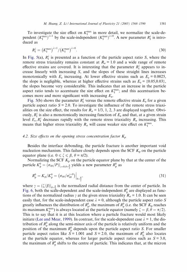
4.2. Size effects on the opening stress concentration factor Kp
Besides the interface debonding, the particle fracture is another important void
nucleation mechanism. This failure closely depends upon the SCF Kp on the particle
equator plane (i.e. 0 6 f 6 b, h = p/2).Normalizing the SCF Kp on the particle equator plane by that at the center of the
particle K0p ¼ ðrhh=P Þjc¼0;h¼p
2yields a new parameter R0
p as
R0p ¼ Kp=K0
p ¼ rhh=rc¼0hh
� �h¼p
2
; ð31Þ
where c ¼ ðf=bÞjh¼p2is the normalized radial distance from the center of particle. In
Fig. 6, both the scale-dependent and the scale-independent R0p are displayed as func-
tions of the normalized radius c at the given stress triaxiality Rr = 1.0. It can be seen
easily that, for the scale-independent case k = 0, although the particle aspect ratio S
greatly influences the distribution of R0p, the maximum of R0
p (i.e. the SCF Kp reaches
its maximum Kmaxp ) is always located at the particle equator (namely f ¼ b; h ¼ p=2Þ.
This is to say that it is at this location where a particle fracture would most likelyinitiate (Lee and Mear, 1999). In contrast, for the scale-dependent case k = 1, the dis-
tribution of R0p along the semi-minor axis of the particle is relatively uniform and the
position of the maximum R0p depends upon the particle aspect ratio S. For smaller
particle aspect ratios like S = 1.001 and S = 2.0, the maximum of R0p also locates
at the particle equator, whereas for larger particle aspect ratios such as S = 3.0,
the maximum of R0p shifts to the centre of particle. This indicates that, at the micron

1
2
3
4
5
1.0 1 .5 2 .0 2 .5 3 .0
0 .00250 .010 .030 .05
R =1.0
Ee
increas ing
Ee=
S
RI
σ
σ
λR
Iλ
(a)
(b)
1
2
3
4
5
0 0.01 0 .02 0 .03 0 .04 0 .05
3211 /3
increas ing R
S =2.0R =
Ee
σ
Fig. 5. Variations of RkI which characterizes the size effect on the maximum interfacial SCF Kmax
I : (a) as a
function of particle aspect ratio S; (b) as a function of remote effective strain Ee.
1582 M. Huang, Z. Li / International Journal of Plasticity 21 (2005) 1568–1590

0 .98
1 .00
1 .02
1 .04
1 .06
1 .08
0 0 .2 0 .4 0 .6 0 .8 1.0
321 .5
D ash lines λ
σ
=0
S o lid lines λ=1
Ee=0 .03, R =1 .0
1 .00
S =
γ
Rp0
Fig. 6. Distribution of the normalized particle opening SCF R0p ¼ Kp=K0
p along the semi-minor axis of
particle (i.e. the x1 or x2 axis), which indicates the location of the maximum opening SCF at the particle
equator plane h ¼ p2, for both scale-independent problem k = 0 and scale-dependent problem k = 1.
M. Huang, Z. Li / International Journal of Plasticity 21 (2005) 1568–1590 1583
or submicron scale, when the particle aspect ratio is large enough, the possibility of
fracture initiation at the center of particle would increase.
As a measure of the most critical opening stress within the particle, the maximum
of SCF Kmaxp ¼ maxðKpÞ is plotted as a function of the remote effective strain Ee in
Fig. 7. Obviously, Kmaxp within the particle is a monotonically increasing function of
Ee both for the size-dependent case and for the size-independent case. Since the in-
crease of Kmaxp for the size dependent case with increasing Ee is more rapid than that
for the size-independent case, the size-dependent Kmaxp is much higher than the size-
independent one. Thus, it can be seen that the maximum SCF Kmaxp within the par-
ticle is significantly enhanced by strain gradient effects in the matrix.
Similarly, to examine the size effect on the maximum opening stress within the
particle more clearly, it is convenient to introduce a normalized maximum SCF Rkp as
Rkp ¼ Kmax
p
� �k¼1�
Kmaxp
� �k¼0
: ð32Þ
The variations of Rkp with the increasing particle aspect ratio S are plotted in Fig.
8(a) for a wide range of remote effective strains Ee. It is evident that an increase of
the remote effective strain serves to elevate Rkp. This indicates that the size effect on
Kmaxp is enhanced by the increasing effective strain Ee. On the other hand, Rk
p
decreases monotonically with increasing S. This demonstrates that the size effect
on Kmaxp is weakened by increasing S. In addition, the influences of the stress

1
2
3
4
5
6
0 0.01 0 .02 0 .03 0 .04 0 .05
321 .001 D ash lines λ =0
S o lid lines λ =1R =1.0S =
Ee
Kpm
ax
σ
Fig. 7. The maximum opening stress concentration Kmaxp within the particle equator plane h ¼ p
2for
various aspect ratios S = 1.001, 2, 3, as a function of macroscopic effective strain Ee.
1584 M. Huang, Z. Li / International Journal of Plasticity 21 (2005) 1568–1590
triaxiality Rr on the Rkp � Ee curves are plotted in Fig. 8 (b). Clearly, the stress
triaxiality also has a significant effect on Rkp. With the remote stress triaxiality
increasing, Rkp significantly decreases. This is shown that the size effect on Kmax
p is
also weaken by the stress triaxiality Rr. To sum up, the increasing overall plastic
strain Ee aggravates the size effect on the maximum SCF Kmaxp within the particle,
whereas the increase in the particle aspect ratio S and the remote stress triaxiality
Rr weaken it.
4.3. Size effects on the stress concentration factor ratio Kmaxp =Kmax
I
There exist two competitive void nucleation mechanisms in materials, i.e. the
interface debonding and the particle fracture. Which is the predominant nuclea-tion mechanism mainly rests with the SCFs and the critical strengths at the
interface and within the particle. Fig. 9 presents the variations of
Rpi ¼ Kmaxp =Kmax
I with the remote effective strain Ee, where Kmaxp is the maximum
opening SCF on the particle equator plane and KmaxI is the maximum normal
SCF at the particle–matrix interface. It is interesting that for the scale-independ-
ent matrix material, Kmaxp is greater than Kmax
I (i.e. Rpi > 1). And with the overall
effective strain Ee and the particle aspect ratio S increasing, Rpi increases
monotonically. This partially explains why the elongated particle often cracksbefore the interface significantly separates, as observed in the size-independent

1.6
1.8
2.0
2.2
2.4
2.6
1 2 3 4
0 .010 .020 .030 .040 .05
increasing S
increasing Ee
R =1.0
Ee=
S
Rp
(a)
1 .0
1 .3
1 .6
1 .9
2 .2
2 .5
2 .8
0 0 .01 0 .02 0 .03 0 .04 0 .05
3211 /3 increas ing R
S=2.0R =
Ee
Rp
(b)
σ
σ
λλ
σ
Fig. 8. Variations of Rkp ¼ ðKmax
p Þk¼1=ðKmax
p Þk¼0, which characterizes the size effect on the maximum SCF
KmaxI within the particle equator plane f 6 b; h ¼ p=2: (a) as a function of particle aspect ratio S; (b) as a
function of remote strain Ee.
M. Huang, Z. Li / International Journal of Plasticity 21 (2005) 1568–1590 1585

0 .55
0 .85
1 .15
1 .45
0 0 .01 0 .02 0 .03 0 .04 0 .05
321 .5
1 .00
R =1.0D ash lines λ σ=0
S o lid lines λ =1S=
Ee
Rp
i
Fig. 9. Ratio of the maximum SCF within the particle equator plane Kmaxp to that at the particle–matrix
interface Rpi ¼ Kmaxp =Kmax
I versus macroscopic effective strain Ee.
1586 M. Huang, Z. Li / International Journal of Plasticity 21 (2005) 1568–1590
experiments. However, for the prolate particles in the micron or submicron
range, Kmaxp is smaller than Kmax
I (i.e. Rpi < 1) and Rpi is a monotonically decreas-
ing function of Ee and S. According to this, local interface debonding may pre-
cede particle fracture. However, local debonding does not necessarily imply total
interface separation. On the contrary, although the parameter Rpi is less than 1,
the opening stress concentration within the particle is roughly uniform over the
entire equator plane (see Fig. 6, ð0:98 6 R0p 6 1:08Þ � 1Þ. Then it is likely that
once a particle fracture initiates, it will propagate to the whole particle breakage.So within the context of the present study, it is not possible to draw a definitive
conclusion about whether the dominant void nucleation mechanism for scale-de-
pendent problem is the particle fracture or the interface debonding. But nonethe-
less, these results indicate that, when the leading size of the prolate particle is in
the micron or submicron range, the probability of void nucleation by interface
separation would increase.
5. Summary
In the present paper, an infinite solid with a prolate spheroidal particle under
axisymmetric proportional and monotonic tension loading has been theoretically
investigated. By lengthy theoretical deductions and time-consuming numerical

M. Huang, Z. Li / International Journal of Plasticity 21 (2005) 1568–1590 1587
calculations, the SCFs KI at the matrix–particle interface and Kp within the particle
for the scale-independent cases k = 0 and for the scale-dependent cases k = 1 are
comparatively analyzed. Some interesting results, which are apparently different
from the size-independent case, are obtained as follows:
� The distribution of KI along the matrix–particle interface is dramatically modified
and the maximum interfacial normal SCFs KmaxI are significantly elevated by the
particle size effect. Thus, it can be expected that the void nucleation at the inter-
face may occur by cleavage or atomic separation mechanisms (Elssner et al.,
1994). In addition, the ratio RkI ¼ ðKmax
I Þk¼1=ðKmax
I Þk¼0is a linear monotonic
increasing function of the particle aspect ratio. And the more slender the particle
is, the more significant the size effect on KmaxI is.
� Due to the size effect on the plastic deformation in the matrix, the increase ofthe scale-dependent Kmax
I with the remote effective strain Ee increasing is more
rapidly than that for scale-independent case. Then at a given effective strain,
KmaxI is significantly enhanced by the particle size effect. This indicates that
the size effect can advance the interface to separate at smaller overall strains
Ee.
� For the size-dependent case, the maximum of SCF Kmaxp on the particle equator
plane is elevated by the particle size effect, and the position of Kmaxp depends on
the particle aspect ratio. It can be concluded that, if the particle fracture domi-nates the void nucleation mechanism and the particle aspect ratio is large enough,
the possibility of fracture initiation at the center of particle would increase. This is
significantly different from that for the scale-independent case, where Kmaxp is
always located at the equator of particle.
� At the micron or submicron scale, the strain gradient effects influence the void
nucleation mechanism to a certain extent. For the large elongated spheroidal par-
ticle, where the scale effect is negligible, the particles often break up before the
interface separates. In contrast, when the leading size of spheroidal particle iscomparable to the internal characteristic length, the probability of void nucleation
by the interface separation would increase.
It is worth noting that the void nucleation not only depends on the SCF but also
on the critical strengths of the particle and the interface. The present conclusions
about void nucleation are based on the precondition that the particle fracture and
particle–matrix debonding strengths are size-independent. Without doubt, an exten-
sion to account for the size effect on the critical strengths of the particle and the inter-face is very useful towards more reasonable descriptions of size-dependent void
nucleation mechanism and nucleation criterion. In addition, it should be noted that,
in the present analysis, the particle–matrix interface is assumed to be perfectly
bonded and only the displacement continuity condition is applied at this boundary.
Since an elastic phase and a plastic phase are considered simultaneously, dislocations
will accumulate at the interface. These accumulated dislocations maybe lead to an
additional condition at the interface. This problem will be considered further in
our following study by introducing the concept of interface energy.

1588 M. Huang, Z. Li / International Journal of Plasticity 21 (2005) 1568–1590
Acknowledgments
The support from NSFC under the grant A10102006 is acknowledged. Li Z.H. is
grateful to the Alexander von Humboldt Foundation of Germany.
References
Barlow, C.Y., Hansen, N., 1991. Deformation structure and flow stress in aluminum containing short
whiskers. Acta Metall. Mater. 39, 1871.
Barlow, C.Y., Hansen, N., 1995. Dislocation configurations in metal–matrix composites correlated with
numerical predictions. Acta Metall. Mater. 43, 3633.
Barlow, C.Y., Liu, Y.L., 1998. Microstructure, strain fields and flow stress in deformed metal matrix
composites. Acta Metall. Mater. 46, 5807.
Bao, G., Hutchinson, J.W., McMeeking, R.M., 1991. Particle reinforcement of ductile matrix against
plasticity flow and creep. Acta Metall. Mater. 39, 1871–1882.
Begley, M.R., Hutchinson, J.W., 1998. The mechanics of size-dependent indention. J. Mech. Phys. Solids
46, 2049–2068.
Bittencourt, E., Needleman, A., Gurtin, M.E., Van der Giessen, E., 2003. A comparison of nonlocal
continuum and discrete dislocation plasticity predictions. J. Mech. Phys. Solids 51, 281–310.
Brechet, Y., Embury, J.D., Tao, S., Luo, L., 1991. Damage initiation in metal matrix composites. Acta
Metall. Mater. 39, 1781–1786.
Brockenbrough, J.R., Hunt, W.H., Richmond, O., 1992. A reinforced material model using actual
microstructural geometry. Scr. Metall. Mater. 27, 385–390.
Budiansky, B., Hutchinson, J.W., Slutsky, S., 1982. Void growth and collapse in viscous solids. In:
Hopkins, H.G., Swell, M.J. (Eds.), Solid Mechanics, The Rodney Hill 60th Anniversary Volume.
Pergamon Press, Oxford, pp. 13–45.
Christman, T., Needleman, A., Suresh, S., 1989. An experimental and numerical study of deformation in
metal–ceramic composites. Acta Metall. Mater. 37, 3029–3050.
Cleveringa, H.H.M., Van der Giessen, E., Needleman, A., 1997. Comparison of discrete dislocation and
continuum plasticity predictions for a composite material. Acta Mater. 45, 3163–3179.
Cleveringa, H.H.M., Van der Giessen, E., Needleman, A., 1999a. A discrete dislocation analysis of
residual stress in a composite material. Philos. Mag. A 79, 863–920.
Cleveringa, H.H.M., Giessen, E.V.D., Needleman, A., 1999b. A discrete dislocation analysis of bending.
Int. J. Plasticity 15, 837–868.
Dai, L.H., Ling, Z., Bai, Y.L., 1999. A strain gradient-strengthening law for particle reinforced metal
matrix composites. Scr. Mater. 41, 245–251.
Elssner, G., Korn, D., Ruhle, M., 1994. The influence of interface impurities on fracture energy of UHV
diffusion bonded metal–ceramic bicrystals. Scr. Metall. Mater. 31, 1037–1042.
Fleck, N.A., Hutchinson, J.W., 1993. A phenomenological theory for strain gradient effects in plasticity. J.
Mech. Phys. Solids 41, 1825–1857.
Fleck, N.A., Muller, G.M., Ashby, M.F., Hutchinson, J.W., 1994. Strain gradient plasticity: theory and
experiment. Acta Mater. 42, 475–487.
Fleck, N.A., Hutchinson, J.W., 1997. Strain gradient plasticity. In: Hutchinson, J.W., Wu, T.Y. (Eds.),
Advance in Applied Mechanics, vol. 33. Academic Press, New York, pp. 295–361.
Fleck, N.A., Hutchinson, J.W., 2001. A reformulation of strain gradient plasticity. J. Mech. Phys. Solids
49, 2245–2271.
Ganguly, P., Pool, W.J., 2004. Influence of reinforcement arrangement on the local reinforcement stresses
in composite materials. J. Mech. Phys. Solids 52, 1355–1377.
Gudmundson, G., 2004. A unified treatment of strain gradient plasticity. J. Mech. Phys. Solids 52, 1379–
1406.

M. Huang, Z. Li / International Journal of Plasticity 21 (2005) 1568–1590 1589
Gurland, J., Plateau, J., 1963. The mechanism of ductile rupture of metals containing particles. Trans.
Quart. Am. Soc. Metals 56, 442.
Gurtin, M.E., 1984. The linear theory of elasticity. In: Truesdell, C. (Ed.), Mechanics of Solids, vol. II.
Springer, New York, p. 1.
Hill, R., 1956. New horizons in the mechanics of solids. J. Mech. Phys. Solids 5, 66.
Huang, Y., Gao, H., Nix, W.D., Hutchinson, J.W., 2000. Mechanism-based strain gradient plasticity – II.
Anal. J. Mech. Phys. Solid 48, 99–128.
Huang, Y., Qu, S., Hwang, K.C., Li, M., Gao, H., 2004. A conventional theory of mechanism-based strain
gradient plasticity. Int. J. Plasticity 20, 753–782.
Hwang, K.C., Huang, Y., 1999. The Constitutive Theory of Solid, The Strain Gradient Theory, first ed.
Tsinghua University Press, Beijing (in Chinese).
Hwang, K.C., Guo, Y., Jiang, H., Huang, Y., Gao, H., 2004. The finite deformation theory of Taylor-
based nonlocal plasticity. Int. J. Plasticity 20, 831–839.
Hutchinson, J.W., 2000. Plasticity at micron scale. Int. J. Solids Struct. 37, 225–238.
Keer, L.M., Dundurs, J., Kiattikomol, K., 1973. Separation of a smooth circular particle from a matrix.
Int. J. Eng. Sci. 11, 1221–1233.
Khraishi, T.A, Khaleel, M.A., 2001. A parametric-experimental study of void growth in superplastic
deformation. Int. J. Plasticity 17, 297–315.
Khraishi, T.A., Yan, L., Shen, Y., 2004. Dynamic simulations of the interaction between dislocations and
dilute particle concentrations in metal–matrix composites (MMCs). Int. J. Plasticity 20, 1039–1057.
Lee, B.J., Mear, M.E., 1999. Stress concentration induced by an elastic spheroidal particle in a plastically
deforming solid. J. Mech. Phys. Solids 47, 1301–1336.
Li, Z., Huang, M., 2005. Combined effect of void shape and void size-oblate spheroidal microvoid
embedded in infinite non-linear solid. Int. J. Plasticity 21, 625–650.
Li, Z., Huang, M., Wang, C., 2003. Scale–dependent plasticity potential of pours materials and void
growth. Int. J. Solid Struct. 40, 3935–3954.
Lloyd, D.J., 1991. Aspects of fracture in particulate reinforced metal matrix composites. Acta Metall.
Mater. 39, 59–71.
Lloyd, D.J., 1994. Particle reinforced aluminum and magnesium matrix composites. Int. Mater. Rev. 39,
1–23.
Ma, Q., Clark, D.R., 1995. Size dependent hardness in silver single crystals. J. Mater. Res. 10, 853–863.
Mcelhaney, K.W., Vlassak, J.J., Nix, W.D., 1998. Determination of indenter tips geometry and
indentation contact area for depth-sensing indentation experiments. J. Mater. Res. 13, 1300–1306.
Needleman, A., 1987. A continuum model for void nucleation by inclusion debonding. J. Appl. Mech. 54,
525–531.
Niordson, C.F., Tvergaard, V., 2001. Nonlocal plasticity effects on the tensile properties of a metal matrix
composite. Eur. J. Mech. A/Solids 20, 601–613.
Niordson, C.F., Tvergaard, V., 2002. Nonlocal plasticity effects on fiber debonding in a whisker-reinforced
metal. Eur. J. Mech. A/Solids 21, 239–248.
Niordson, C.F., 2003. Strain gradient plasticity effects in whisker-reinforced metals. J. Mech. Phys. Solids
51, 1863–1883.
Rashid, K. Abu Al-Rub, George, Z. Voyiadjis, 2004. Analytical and experimental determination of the
material intrinsic length scale of strain gradient plasticity theory from micro- and nano-indentation
experiments. Int. J. Plasticity 20, 1139–1182.
Shu, J.Y., 1998. Scale-dependent deformation of porous single crystals. Int. J. Plasticity 14, 1085–1107.
Shu, J.Y., Barlow, C.Y., 2000. Strain gradient effects on microscopic strain field in a metal matrix
composite. Int. J. Plasticity 16, 563–591.
Smyshlyaev, V.P., Fleck, N.A, 1996. The role of strain gradients in the grain size effect for polycrystals. J.
Mech. Phys. Solids 44, 465–496.
Stolken, J.S., Evans, A.G., 1998. A microbend test method for measuring the plasticity length scale. Acta
Mater. 46, 5109–5115.
Taylor, M.B., Zbib, H.M., Khaleel, M.A., 2002. Damage and size effect during superplastic deformation.
Int. J. Plasticity 18, 415–442.

1590 M. Huang, Z. Li / International Journal of Plasticity 21 (2005) 1568–1590
Thomson, R.D., Hancock, J.W., 1984. Local stress and strain fields near a spherical near a spherical elastic
particle in a plastically deforming matrix. Int. J. Fract. 24, 209.
Tvergaard, V., 1990a. Analysis of tensile properties for a whisker reinforced metal–matrix composte. Acta
Mater. 46, 5109–5115.
Tvergaard, V., 1990b. Effect of fibre debonding in a whisker-reinforced metal. Mater. Sci. Eng. A 125,
203–213.
Tvergaard, V., 1993. Model studies of fibre breakage and debonding in a metal reinfoeced by short fibres.
J. Mech. Phys. Solids 41, 1309–1326.
Tvergaard, V., 1995. Fiber debonding and breakage in whisker-reinforced meatl. Mater. Sci. Eng. A 190,
215–222.
Wang, W., Huang, Y., Hsia, K.J., Hu, K.X., Chandra, A., 2003. A study of microbend test by strain
gradient plasticity. Int. J. Plasticity 19, 365–382.
Wilner, B., 1988. Stress analysis of particles in metals. J. Mech. Phys. Solids 36, 141–165.
Wilner, B., 1995. Asymptotic stress analysis of two phase materials. Int. J. Eng. Sci. 33, 127–130.
Xue, Z., Huang, Y., Li, M., 2002. Particle size effect in metallic materials: a study by the theory of
mechanism-based strain gradient plasticity. Acta Mater. 50, 149–160.