SiriUs-I User Manual
141
1 / 141 SiriUs-I User Manual Operating Manual HW Maintenance Manual © 1997-2020 PULOON Technology, Inc. All Rights Reserved.
-
Upload
khangminh22 -
Category
Documents
-
view
2 -
download
0
Transcript of SiriUs-I User Manual
1 / 141
SiriUs-I User Manual
Operating Manual
HW Maintenance Manual
© 1997-2020 PULOON Technology, Inc. All Rights Reserved.
2 / 141
Operating Manual
Table of Contents
1. Introduction ................................................................................................................................................................ 6
1.1 Menu Composition & User Authorization ........................................................................................................... 7
2. Detail Menu by Functions .......................................................................................................................................... 8
2.1 ATM Initial Setting Menu ....................................................................................................................................13
2.1.1 Terminal ID .......................................................................................................................................................13
2.1.2 Routing ID ........................................................................................................................................................13
2.1.3 ATM Serial No ..................................................................................................................................................14
2.1.4 Denomination ..................................................................................................................................................14
2.1.4.1 Denomination List.........................................................................................................................................15
2.1.4.2 Cassette Setting ............................................................................................................................................16
2.1.5 Receipt Printer Type .........................................................................................................................................16
2.1.6 Card Reader Type .............................................................................................................................................17
2.1.7 CDM Type .........................................................................................................................................................17
2.1.8 Switching (Processor) Company......................................................................................................................18
2.1.9 Nation ...............................................................................................................................................................18
2.1.10 Language .......................................................................................................................................................19
2.1.11 Communication Type .....................................................................................................................................19
2.1.12 ADA ................................................................................................................................................................20
2.1.12.1 ADA Permit .................................................................................................................................................20
2.1.13 Data/Time ......................................................................................................................................................21
2.1.13.1 Data/Time Set .............................................................................................................................................22
2.1.13.2 Sync Host Time ...........................................................................................................................................22
2.1.14 Change Password ..........................................................................................................................................23
2.1.14.1 Change Host Password ..............................................................................................................................23
2.1.14.2 Change System Password ..........................................................................................................................23
2.1.14.3 Customer Password ....................................................................................................................................24
2.1.14.4 EPP Password ..............................................................................................................................................24
2.2 Cash Register / Settlement Setting Menu ..........................................................................................................27
2.2.1 Add Cash ..........................................................................................................................................................27
2.2.2 Settlement ........................................................................................................................................................28
2.3 Transaction Setting Menu ...................................................................................................................................30
2.3.1 Select Receipt ...................................................................................................................................................30
2.3.2 Out of Paper .....................................................................................................................................................30
2.3.3 Check Balance ..................................................................................................................................................31
2.3.4 Balance Display ................................................................................................................................................31
2.3.5 Idle Display .......................................................................................................................................................32
3 / 141
2.3.5.1 Count Image .................................................................................................................................................32
2.3.5.2 Display Time ..................................................................................................................................................33
2.3.5.3 Image Upload ...............................................................................................................................................33
2.3.6 EMV ..................................................................................................................................................................34
2.3.6.1 Fallback Option .............................................................................................................................................34
2.3.6.2 Common AID Selection ................................................................................................................................35
2.3.6.3 Magnetic Stripe Permit .................................................................................................................................35
2.3.6.4 BIN Option ....................................................................................................................................................36
2.3.6.4.1 Enable/Disable checking Default BIN........................................................................................................36
2.3.6.4.2 Editing Default BIN List ..............................................................................................................................37
2.3.6.4.3 Uploading Default BIN List File ..................................................................................................................37
2.3.6.4.4 Enable/Disable checking Extra BIN List .....................................................................................................38
2.3.6.4.5 Searching Extra BIN ...................................................................................................................................38
2.3.6.4.6 Uploading Extra BIN List File .....................................................................................................................39
2.3.7 Amount Range .................................................................................................................................................39
2.3.7.1 Cash Range Set .............................................................................................................................................40
2.3.7.2 Amount Range Display .................................................................................................................................40
2.3.8 Surcharge .........................................................................................................................................................41
2.3.8.1 Surcharge Set ................................................................................................................................................41
2.3.8.3 Surcharge Amount .......................................................................................................................................42
2.3.8.4 Surcharge Percent .........................................................................................................................................43
2.3.8.5 Surcharge Use ...............................................................................................................................................43
2.3.8.6 BIN List ..........................................................................................................................................................44
2.3.8.6.1 BIN List Enable/Disable ..............................................................................................................................44
2.3.8.6.2 BIN List Set .................................................................................................................................................45
2.3.8.6.3 BIN List File Upload ....................................................................................................................................45
2.3.9 Coupon .............................................................................................................................................................46
2.3.9.1 Coupon Message ..........................................................................................................................................46
2.3.9.2 Coupon Frequency .......................................................................................................................................47
2.3.10 Max Amount ..................................................................................................................................................47
2.3.11 Fast Cash ........................................................................................................................................................48
2.3.12 Welcome Message .........................................................................................................................................48
2.3.13 Background Image Upload ............................................................................................................................49
2.3.14 SW Download ................................................................................................................................................50
2.3.15 Reboot Time ...................................................................................................................................................50
2.3.16 Change Text Color .........................................................................................................................................51
2.3.17 Config Copy ...................................................................................................................................................51
2.3.18 Bill.Dat Copy...................................................................................................................................................52
2.3.19 Status Monitoring ..........................................................................................................................................52
2.3.20 Use 12-Digit ...................................................................................................................................................53
2.3.21 Printer Option ................................................................................................................................................53
2.3.22 Set Screen Timer ............................................................................................................................................54
2.3.23 Monitoring .....................................................................................................................................................54
2.3.23.1 RMS Server ..................................................................................................................................................55
4 / 141
2.3.23.2 Connecting Test ..........................................................................................................................................55
2.3.23.3 Manage Account ........................................................................................................................................56
2.3.23.4 Set Interval ..................................................................................................................................................57
2.3.23.5 Emergency Reset ........................................................................................................................................57
2.4 Communication Setting Menu ...........................................................................................................................58
2.4.1 Modem Set .......................................................................................................................................................58
2.4.1.1 Sound ............................................................................................................................................................58
2.4.1.2 Baudrate ........................................................................................................................................................59
2.4.1.3 Status ............................................................................................................................................................59
2.4.1.4 Predialing ......................................................................................................................................................60
2.4.1.5 Timeout .........................................................................................................................................................60
2.4.1.5.1 View Timeout ............................................................................................................................................61
2.4.1.5.2 Dial Timeout ..............................................................................................................................................61
2.4.1.5.3 ENQ Timeout .............................................................................................................................................62
2.4.1.5.4 ACK Timeout .............................................................................................................................................62
2.4.1.5.5 STX Timeout ..............................................................................................................................................63
2.4.1.5.6 ETX Timeout ..............................................................................................................................................63
2.4.1.5.7 EOT Timeout ..............................................................................................................................................64
2.4.2 Phone No. ........................................................................................................................................................64
2.4.3 Redundancy Server ..........................................................................................................................................65
2.4.4 TCPIP Set ..........................................................................................................................................................65
2.4.4.1 Server URL or IP ............................................................................................................................................66
2.4.4.2 ATM IP ...........................................................................................................................................................68
2.4.4.3 TCP/IP Option ................................................................................................................................................68
2.4.4.3.1 TCP Length .................................................................................................................................................69
2.4.4.3.2 TCP Type .....................................................................................................................................................69
2.4.4.4 TCP/IP Timeout .............................................................................................................................................70
2.4.4.4.1 View Timeout ............................................................................................................................................70
2.4.4.4.2 Session Timeout.........................................................................................................................................71
2.4.4.4.3 Send Timeout ............................................................................................................................................71
2.4.4.4.4 Receive Timeout ........................................................................................................................................72
2.4.4.4.5 ETX Timeout ..............................................................................................................................................72
2.4.4.5 DHCP .............................................................................................................................................................73
2.4.4.6 SSL/TLS ..........................................................................................................................................................73
2.4.4.7 URL Option....................................................................................................................................................74
2.4.5 Message Type ...................................................................................................................................................74
2.4.6 ENQ Check .......................................................................................................................................................75
2.4.7 EOT Check ........................................................................................................................................................75
2.5 Master Key Setting Menu ...................................................................................................................................76
2.5.1 Master A ...........................................................................................................................................................76
2.5.2 Master B ...........................................................................................................................................................77
2.6 Electronic Journal Operation and Error List Menu .............................................................................................78
2.6.1 E-Journal...........................................................................................................................................................78
2.6.1.1 View All .........................................................................................................................................................78
5 / 141
2.6.1.2 Search by Date ..............................................................................................................................................80
2.6.1.3 Save Specific Month Data ............................................................................................................................81
2.6.1.4 Search by Sequence Number .......................................................................................................................83
2.6.2 Error View ........................................................................................................................................................84
2.6.3 Error Detail .......................................................................................................................................................84
2.6.3.1 View All .........................................................................................................................................................85
2.6.3.2 Search ...........................................................................................................................................................86
2.7 System Mode Menu ............................................................................................................................................88
2.7.1 Version ..............................................................................................................................................................88
2.7.2 Setup Print ........................................................................................................................................................88
2.7.3 EJ Delete ...........................................................................................................................................................89
2.7.4 Printer Test .......................................................................................................................................................89
2.7.5 CDM Test ..........................................................................................................................................................90
2.7.6 MS C/R Test ......................................................................................................................................................90
2.7.7 Key Test ............................................................................................................................................................91
2.7.8 Modem Test .....................................................................................................................................................91
2.7.9 TCP/IP Test ........................................................................................................................................................92
2.7.10 IC C/R Test ......................................................................................................................................................92
2.8 ETC .......................................................................................................................................................................93
2.8.1 Initialize / Reset ................................................................................................................................................93
2.8.2 Select CDM Type ..............................................................................................................................................93
6 / 141
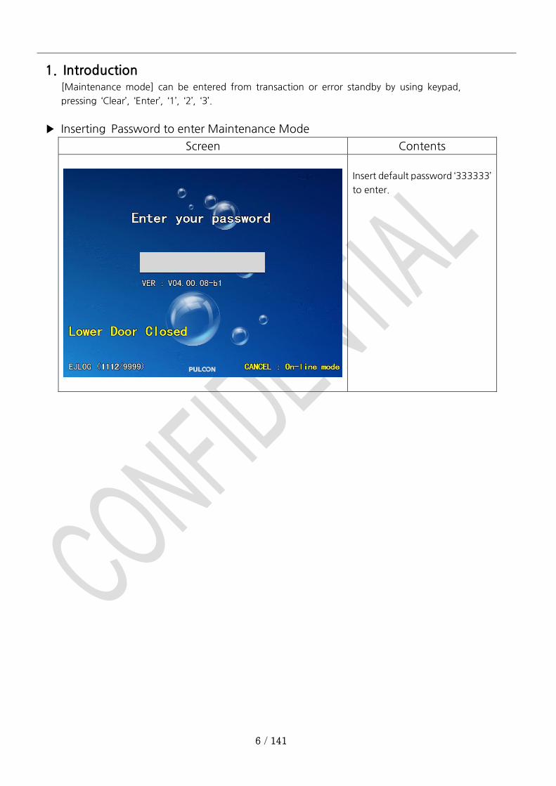
1. Introduction [Maintenance mode] can be entered from transaction or error standby by using keypad,
pressing ‘Clear’, ‘Enter’, ‘1’, ‘2’, ‘3’.
▶ Inserting Password to enter Maintenance Mode
Screen Contents
Insert default password ‘333333’
to enter.
7 / 141
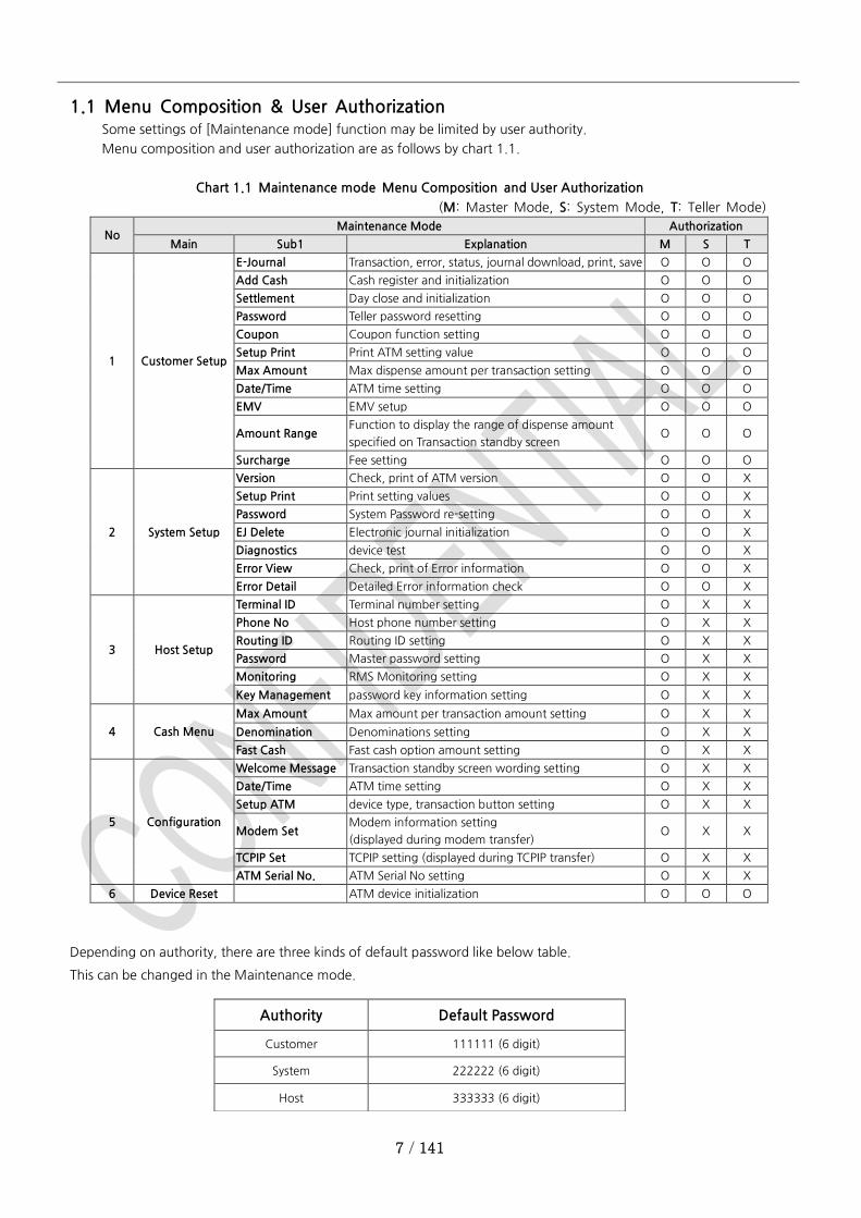
1.1 Menu Composition & User Authorization Some settings of [Maintenance mode] function may be limited by user authority.
Menu composition and user authorization are as follows by chart 1.1.
Chart 1.1 Maintenance mode Menu Composition and User Authorization
(M: Master Mode, S: System Mode, T: Teller Mode)
No Maintenance Mode Authorization
Main Sub1 Explanation M S T
1 Customer Setup
E-Journal Transaction, error, status, journal download, print, save O O O
Add Cash Cash register and initialization O O O
Settlement Day close and initialization O O O
Password Teller password resetting O O O
Coupon Coupon function setting O O O
Setup Print Print ATM setting value O O O
Max Amount Max dispense amount per transaction setting O O O
Date/Time ATM time setting O O O
EMV EMV setup O O O
Amount Range Function to display the range of dispense amount
specified on Transaction standby screen O O O
Surcharge Fee setting O O O
2 System Setup
Version Check, print of ATM version O O X
Setup Print Print setting values O O X
Password System Password re-setting O O X
EJ Delete Electronic journal initialization O O X
Diagnostics device test O O X
Error View Check, print of Error information O O X
Error Detail Detailed Error information check O O X
3 Host Setup
Terminal ID Terminal number setting O X X
Phone No Host phone number setting O X X
Routing ID Routing ID setting O X X
Password Master password setting O X X
Monitoring RMS Monitoring setting O X X
Key Management password key information setting O X X
4 Cash Menu
Max Amount Max amount per transaction amount setting O X X
Denomination Denominations setting O X X
Fast Cash Fast cash option amount setting O X X
5 Configuration
Welcome Message Transaction standby screen wording setting O X X
Date/Time ATM time setting O X X
Setup ATM device type, transaction button setting O X X
Modem Set Modem information setting
(displayed during modem transfer) O X X
TCPIP Set TCPIP setting (displayed during TCPIP transfer) O X X
ATM Serial No. ATM Serial No setting O X X
6 Device Reset ATM device initialization O O O
Depending on authority, there are three kinds of default password like below table.
This can be changed in the Maintenance mode.
Authority Default Password
Customer 111111 (6 digit)
System 222222 (6 digit)
Host 333333 (6 digit)
8 / 141
2. Detail Menu by Functions ◎ [CORD ONLY] The 5 minutes timer will be activated when the switching company is “DNS” and the
lower vault door is closed.
◎ [ALL] The 5 minutes timer will be activated when the “Screen Timer” option is enabled and the lower
vault door is closed. If the switching company is “DNS”, the option button is hidden and the option
is disabled.
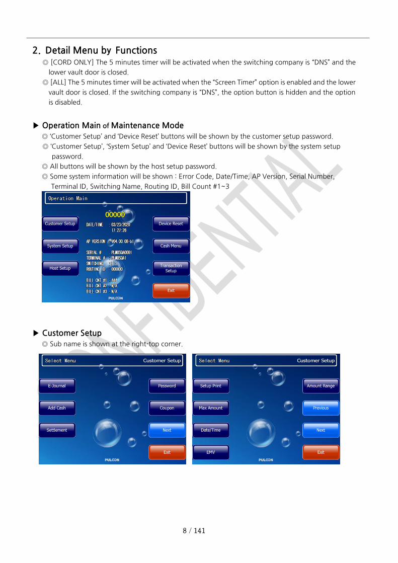
▶ Operation Main of Maintenance Mode
◎ ‘Customer Setup’ and ‘Device Reset’ buttons will be shown by the customer setup password.
◎ ‘Customer Setup’, ‘System Setup’ and ‘Device Reset’ buttons will be shown by the system setup
password.
◎ All buttons will be shown by the host setup password.
◎ Some system information will be shown : Error Code, Date/Time, AP Version, Serial Number,
Terminal ID, Switching Name, Routing ID, Bill Count #1~3
▶ Customer Setup
◎ Sub name is shown at the right-top corner.
9 / 141
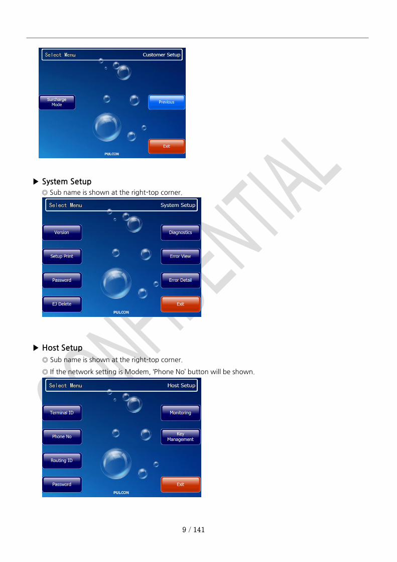
▶ System Setup
◎ Sub name is shown at the right-top corner.
▶ Host Setup
◎ Sub name is shown at the right-top corner.
◎ If the network setting is Modem, ‘Phone No’ button will be shown.
10 / 141
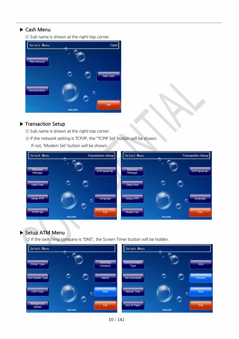
▶ Cash Menu
◎ Sub name is shown at the right-top corner.
▶ Transaction Setup
◎ Sub name is shown at the right-top corner.
◎ If the network setting is TCP/IP, the “TCPIP Set’ button will be shown.
If not, ‘Modem Set’ button will be shown.
▶ Setup ATM Menu
◎ If the switching company is “DNS”, the Screen Timer button will be hidden.
11 / 141
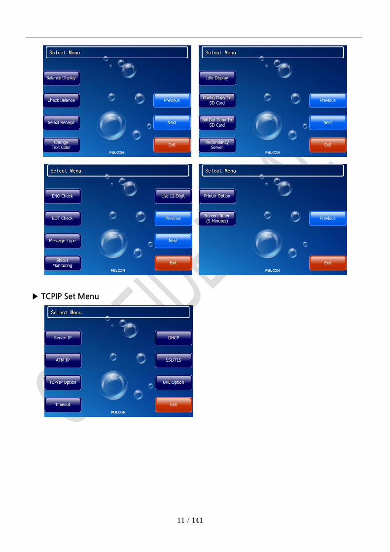
▶ TCPIP Set Menu
12 / 141
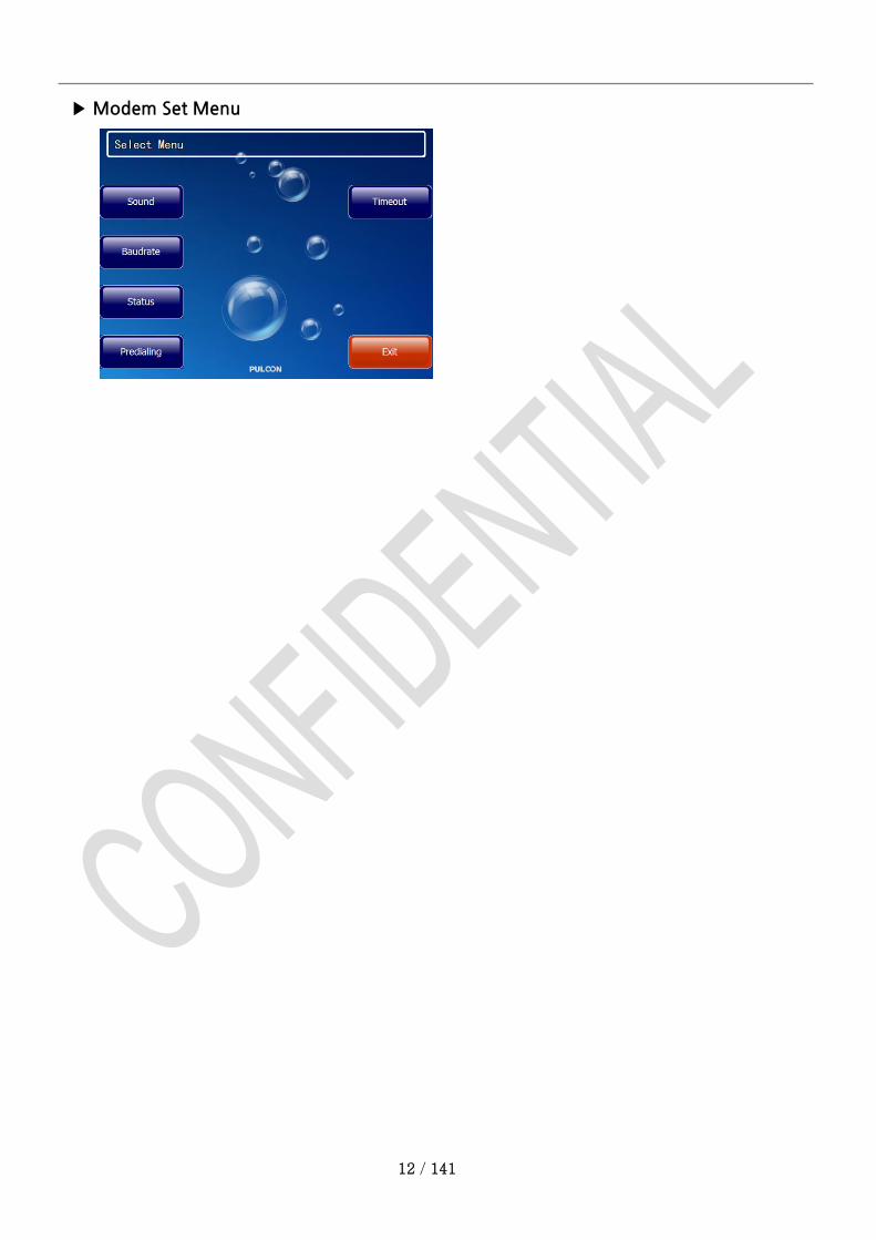
▶ Modem Set Menu
13 / 141
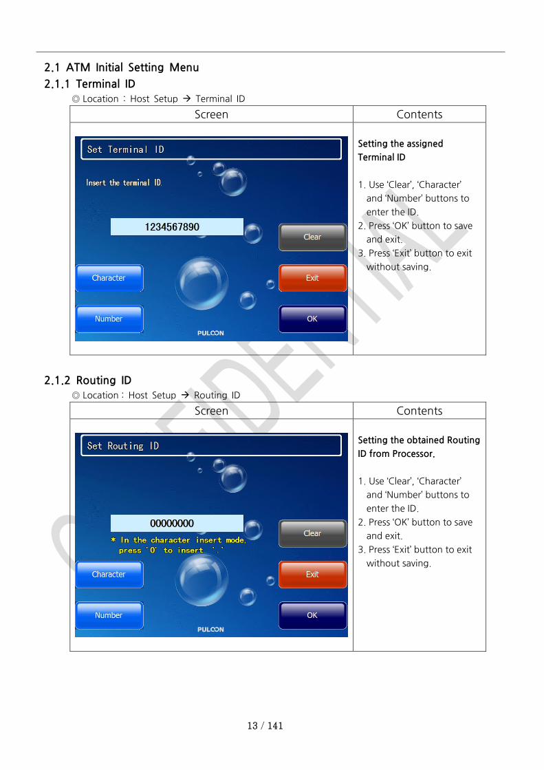
2.1 ATM Initial Setting Menu
2.1.1 Terminal ID
◎ Location : Host Setup Terminal ID
Screen Contents
Setting the assigned
Terminal ID
1. Use ‘Clear’, ‘Character’
and ‘Number’ buttons to
enter the ID.
2. Press ‘OK’ button to save
and exit.
3. Press ‘Exit’ button to exit
without saving.
2.1.2 Routing ID
◎ Location : Host Setup Routing ID
Screen Contents
Setting the obtained Routing
ID from Processor.
1. Use ‘Clear’, ‘Character’
and ‘Number’ buttons to
enter the ID.
2. Press ‘OK’ button to save
and exit.
3. Press ‘Exit’ button to exit
without saving.
14 / 141
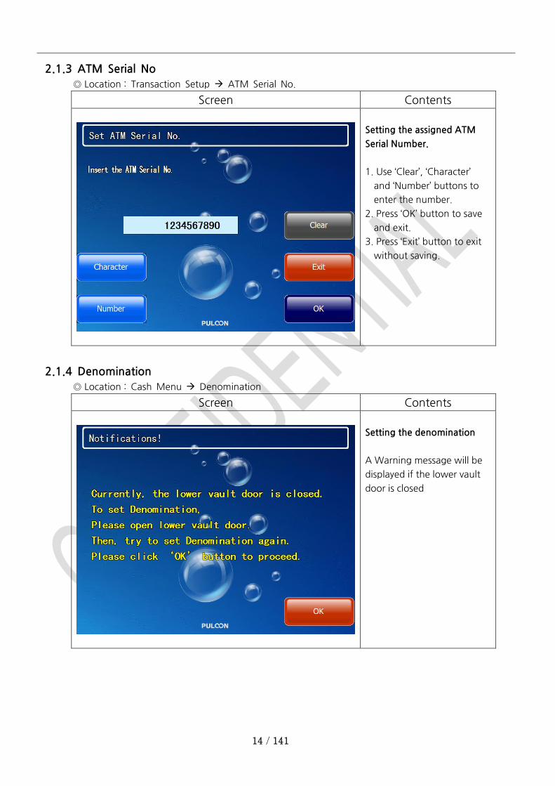
2.1.3 ATM Serial No
◎ Location : Transaction Setup ATM Serial No.
Screen Contents
Setting the assigned ATM
Serial Number.
1. Use ‘Clear’, ‘Character’
and ‘Number’ buttons to
enter the number.
2. Press ‘OK’ button to save
and exit.
3. Press ‘Exit’ button to exit
without saving.
2.1.4 Denomination
◎ Location : Cash Menu Denomination
Screen Contents
Setting the denomination
A Warning message will be
displayed if the lower vault
door is closed
15 / 141
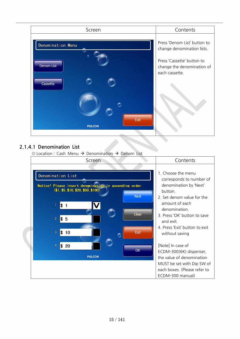
Screen Contents
Press ‘Denom List’ button to
change denomination lists.
Press ‘Cassette’ button to
change the denomination of
each cassette.
2.1.4.1 Denomination List
◎ Location : Cash Menu Denomination Denom List
Screen Contents
1. Choose the menu
corresponds to number of
denomination by ‘Next’
button.
2. Set denom value for the
amount of each
denomination.
3. Press ‘OK’ button to save
and exit.
4. Press ‘Exit’ button to exit
without saving
[Note] In case of
ECDM-300(6K) dispenser,
the value of denomination
MUST be set with Dip SW of
each boxes. (Please refer to
ECDM-300 manual)

16 / 141
2.1.4.2 Cassette Setting
◎ Location : Cash Menu Denomination Cassette
Screen Contents
1. Choose the cassette to
change the denomination.
2. Set the denom value.
3. Press ‘OK’ button to save
and exit.
4. Press ‘Exit’ button to exit
without saving
2.1.5 Receipt Printer Type
◎ Location : Transaction Setup Setup ATM Printer Type
Screen Contents
Setting the printer type
1. Choose the printer type
supported by the ATM.
2. Press ‘OK’ button to save
and exit.
3. Press ‘Exit’ button to exit
without saving
17 / 141
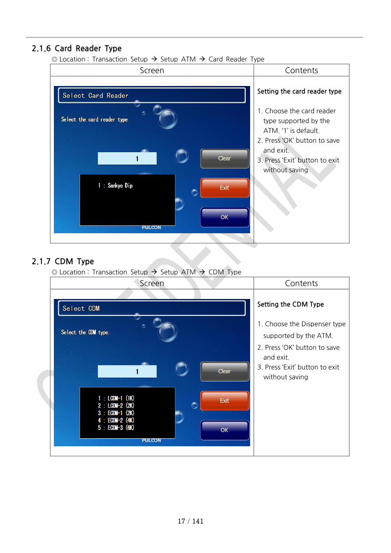
2.1.6 Card Reader Type
◎ Location : Transaction Setup Setup ATM Card Reader Type
Screen Contents
Setting the card reader type
1. Choose the card reader
type supported by the
ATM. ‘1’ is default.
2. Press ‘OK’ button to save
and exit.
3. Press ‘Exit’ button to exit
without saving
2.1.7 CDM Type
◎ Location : Transaction Setup Setup ATM CDM Type
Screen Contents
Setting the CDM Type
1. Choose the Dispenser type
supported by the ATM.
2. Press ‘OK’ button to save
and exit.
3. Press ‘Exit’ button to exit
without saving

18 / 141
2.1.8 Switching (Processor) Company
◎ Location : Transaction Setup Setup ATM Switching Company
Screen Contents
Setting the switching
company
1. Choose the processor from
the list for transaction.
2. Press ‘OK’ button to save
and exit.
3. Press ‘Exit’ button to exit
without saving
2.1.9 Nation
◎ Location : Transaction Setup Setup ATM Nation
Screen Contents
Setting the nation
1. Select the country ATM is
being operated.
2. Press ‘OK’ button to save
and exit.
3. Press ‘Exit’ button to exit
without saving
19 / 141
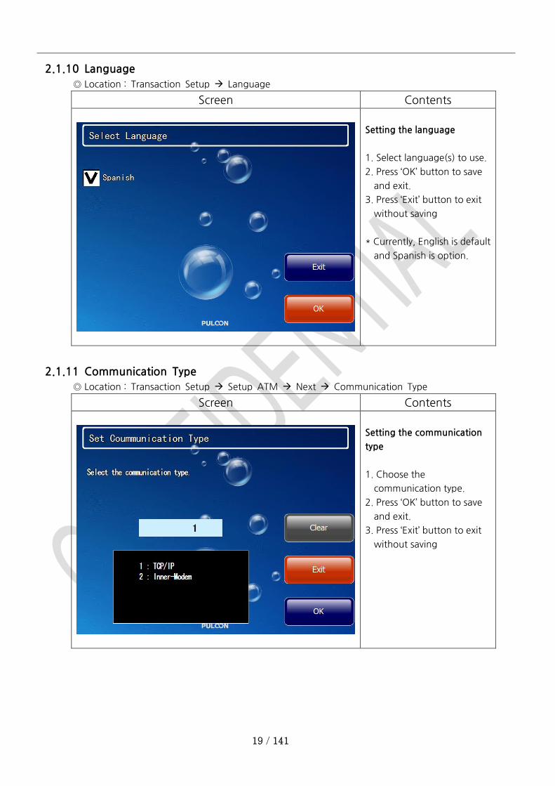
2.1.10 Language
◎ Location : Transaction Setup Language
Screen Contents
Setting the language
1. Select language(s) to use.
2. Press ‘OK’ button to save
and exit.
3. Press ‘Exit’ button to exit
without saving
* Currently, English is default
and Spanish is option.
2.1.11 Communication Type
◎ Location : Transaction Setup Setup ATM Next Communication Type
Screen Contents
Setting the communication
type
1. Choose the
communication type.
2. Press ‘OK’ button to save
and exit.
3. Press ‘Exit’ button to exit
without saving
20 / 141
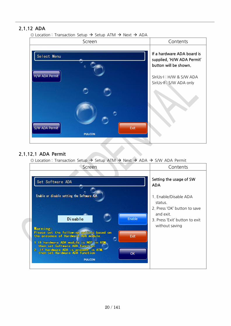
2.1.12 ADA
◎ Location : Transaction Setup Setup ATM Next ADA
Screen Contents
If a hardware ADA board is
supplied, ‘H/W ADA Permit’
button will be shown.
SIriUs-I : H/W & S/W ADA
SiriUs-II : S/W ADA only
2.1.12.1 ADA Permit
◎ Location : Transaction Setup Setup ATM Next ADA S/W ADA Permit
Screen Contents
Setting the usage of SW
ADA
1. Enable/Disable ADA
status.
2. Press ‘OK’ button to save
and exit.
3. Press ‘Exit’ button to exit
without saving
21 / 141
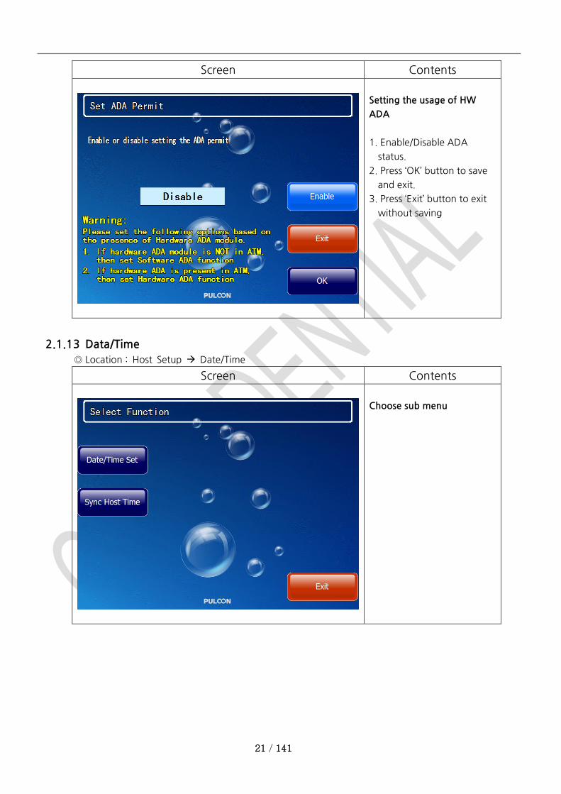
Screen Contents
Setting the usage of HW
ADA
1. Enable/Disable ADA
status.
2. Press ‘OK’ button to save
and exit.
3. Press ‘Exit’ button to exit
without saving
2.1.13 Data/Time
◎ Location : Host Setup Date/Time
Screen Contents
Choose sub menu
22 / 141
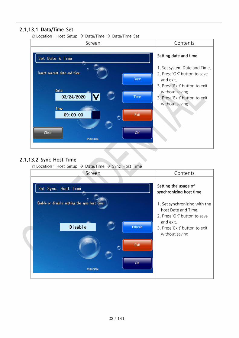
2.1.13.1 Data/Time Set
◎ Location : Host Setup Date/Time Date/Time Set
Screen Contents
Setting date and time
1. Set system Date and Time.
2. Press ‘OK’ button to save
and exit.
3. Press ‘Exit’ button to exit
without saving
3. Press ‘Exit’ button to exit
without saving
2.1.13.2 Sync Host Time
◎ Location : Host Setup Date/Time Sync Host Time
Screen Contents
Setting the usage of
synchronizing host time
1. Set synchronizing with the
host Date and Time.
2. Press ‘OK’ button to save
and exit.
3. Press ‘Exit’ button to exit
without saving
23 / 141
2.1.14 Change Password
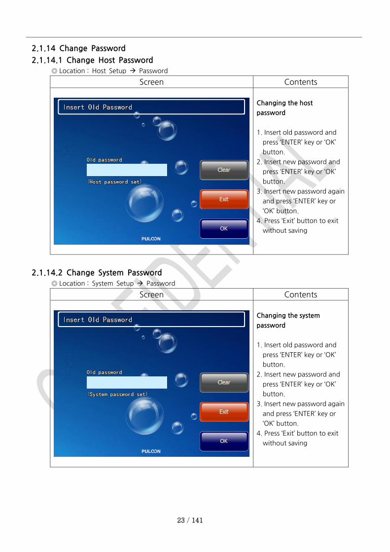
2.1.14.1 Change Host Password
◎ Location : Host Setup Password
Screen Contents
Changing the host
password
1. Insert old password and
press ‘ENTER’ key or ‘OK’
button.
2. Insert new password and
press ‘ENTER’ key or ‘OK’
button.
3. Insert new password again
and press ‘ENTER’ key or
‘OK’ button.
4. Press ‘Exit’ button to exit
without saving
2.1.14.2 Change System Password
◎ Location : System Setup Password
Screen Contents
Changing the system
password
1. Insert old password and
press ‘ENTER’ key or ‘OK’
button.
2. Insert new password and
press ‘ENTER’ key or ‘OK’
button.
3. Insert new password again
and press ‘ENTER’ key or
‘OK’ button.
4. Press ‘Exit’ button to exit
without saving

24 / 141
2.1.14.3 Customer Password
◎ Location : Customer Setup Password
Screen Contents
Changing the customer
password
1. Insert old password and
press ‘ENTER’ key or ‘OK’
button.
2. Insert new password and
press ‘ENTER’ key or ‘OK’
button.
3. Insert new password again
and press ‘ENTER’ key or
‘OK’ button.
4. Press ‘Exit’ button to exit
without saving
2.1.14.4 EPP Password
◎ Location : Host Setup Key Management EPP Password #1 & #2
Screen Contents
Changing EPP Passwords
1. Insert default or current
password and press
‘ENTER’ key.
25 / 141
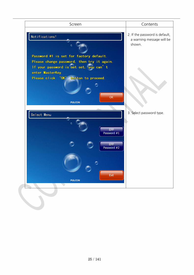
Screen Contents
2. If the password is default,
a warning message will be
shown.
3. Select password type.
26 / 141
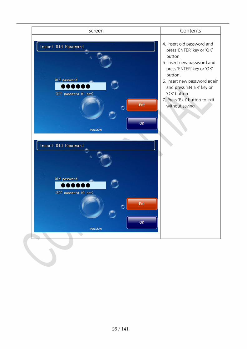
Screen Contents
4. Insert old password and
press ‘ENTER’ key or ‘OK’
button.
5. Insert new password and
press ‘ENTER’ key or ‘OK’
button.
6. Insert new password again
and press ‘ENTER’ key or
‘OK’ button.
7. Press ‘Exit’ button to exit
without saving
27 / 141
2.2 Cash Register / Settlement Setting Menu
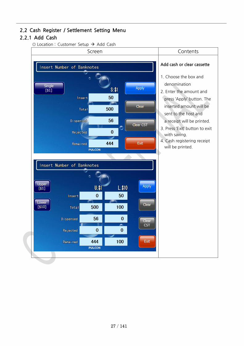
2.2.1 Add Cash
◎ Location : Customer Setup Add Cash
Screen Contents
Add cash or clear cassette
1. Choose the box and
denomination
2. Enter the amount and
press ‘Apply’ button. The
inserted amount will be
sent to the host and
a receipt will be printed.
3. Press ‘Exit’ button to exit
with saving.
4. Cash registering receipt
will be printed.

28 / 141
Screen Contents
2.2.2 Settlement
◎ Location : Customer Setup Settlement
Screen Contents
[Trial Close]
Total amounts are sent to the
Host and a receipt will be
printed. The registered
amounts are not deleted.
[Day Close]
Total amounts are sent to the
Host and a receipt will be
printed. Then registered
amount will be deleted.
29 / 141
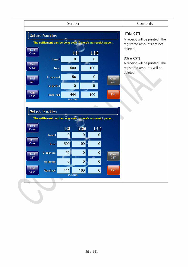
Screen Contents
[Trial CST]
A receipt will be printed. The
registered amounts are not
deleted.
[Clear CST]
A receipt will be printed. The
registered amounts will be
deleted.
30 / 141
2.3 Transaction Setting Menu
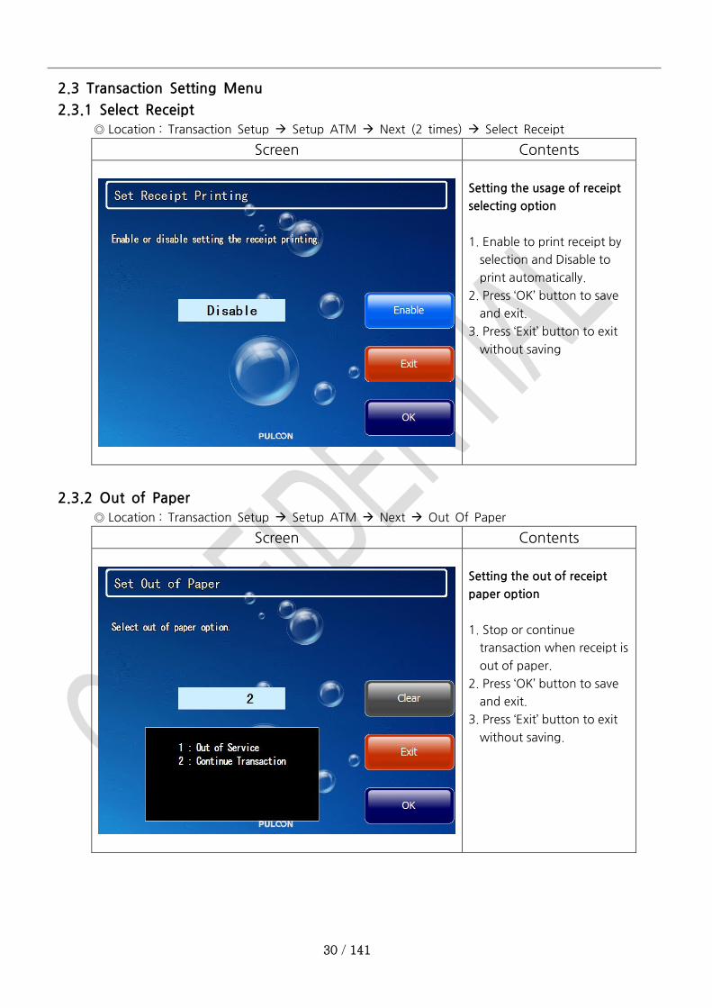
2.3.1 Select Receipt
◎ Location : Transaction Setup Setup ATM Next (2 times) Select Receipt
Screen Contents
Setting the usage of receipt
selecting option
1. Enable to print receipt by
selection and Disable to
print automatically.
2. Press ‘OK’ button to save
and exit.
3. Press ‘Exit’ button to exit
without saving
2.3.2 Out of Paper
◎ Location : Transaction Setup Setup ATM Next Out Of Paper
Screen Contents
Setting the out of receipt
paper option
1. Stop or continue
transaction when receipt is
out of paper.
2. Press ‘OK’ button to save
and exit.
3. Press ‘Exit’ button to exit
without saving.

31 / 141
2.3.3 Check Balance
◎ Location : Transaction Setup Setup ATM Next (2 times) Check Balance
Screen Contents
Setting the usage of balance
checking
1. Enable or disable checking
default balance before
withdraw and transfer
transaction.
2. Press ‘OK’ button to save
and exit.
3. Press ‘Exit’ button to exit
without saving.
2.3.4 Balance Display
◎ Location : Transaction Setup Setup ATM Next (2 times) Balance Display
Screen Contents
Setting the usage of balance
display
1. Enable or disable display
balance.
2. Press ‘OK’ button to save
and exit.
3. Press ‘Exit’ button to exit
without saving.
32 / 141
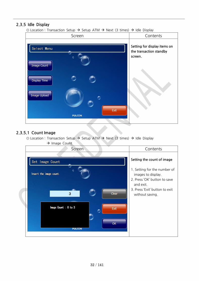
2.3.5 Idle Display
◎ Location : Transaction Setup Setup ATM Next (3 times) Idle Display
Screen Contents
Setting for display items on
the transaction standby
screen.
2.3.5.1 Count Image
◎ Location : Transaction Setup Setup ATM Next (3 times) Idle Display
Image Count
Screen Contents
Setting the count of image
1. Setting for the number of
images to display.
2. Press ‘OK’ button to save
and exit.
3. Press ‘Exit’ button to exit
without saving.
33 / 141
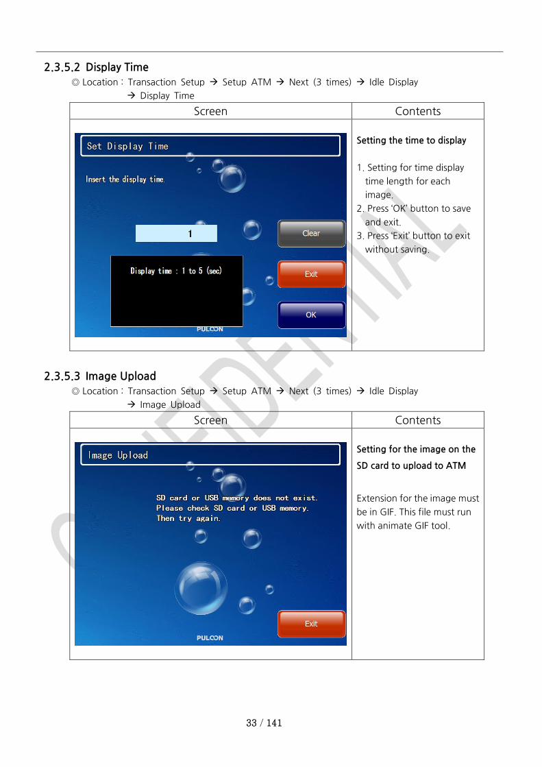
2.3.5.2 Display Time
◎ Location : Transaction Setup Setup ATM Next (3 times) Idle Display
Display Time
Screen Contents
Setting the time to display
1. Setting for time display
time length for each
image.
2. Press ‘OK’ button to save
and exit.
3. Press ‘Exit’ button to exit
without saving.
2.3.5.3 Image Upload
◎ Location : Transaction Setup Setup ATM Next (3 times) Idle Display
Image Upload
Screen Contents
Setting for the image on the
SD card to upload to ATM
Extension for the image must
be in GIF. This file must run
with animate GIF tool.
34 / 141
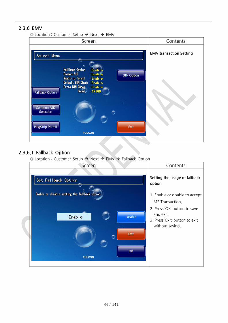
2.3.6 EMV
◎ Location : Customer Setup Next EMV
Screen Contents
EMV transaction Setting
2.3.6.1 Fallback Option
◎ Location : Customer Setup Next EMV Fallback Option
Screen Contents
Setting the usage of fallback
option
1. Enable or disable to accept
MS Transaction.
2. Press ‘OK’ button to save
and exit.
3. Press ‘Exit’ button to exit
without saving.

35 / 141
2.3.6.2 Common AID Selection
◎ Location : Customer Setup Next EMV Common AID Selection
Screen Contents
Setting the usage of
common AID selection
1. Enable or disable to select
the common AID
automatically
2. Press ‘OK’ button to save
and exit.
3. Press ‘Exit’ button to exit
without saving.
2.3.6.3 Magnetic Stripe Permit
◎ Location : Customer Setup Next EMV MagStrip Permit
Screen Contents
Setting the usage of MS only
card
1. Enable or disable to permit
MS only card.
2. Press ‘OK’ button to save
and exit.
3. Press ‘Exit’ button to exit
without saving.
36 / 141
2.3.6.4 BIN Option
◎ Location : Customer Setup Next EMV BIN Option
Screen Contents
Choose sub menu.
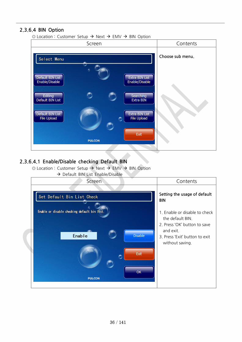
2.3.6.4.1 Enable/Disable checking Default BIN
◎ Location : Customer Setup Next EMV BIN Option
Default BIN List Enable/Disable
Screen Contents
Setting the usage of default
BIN
1. Enable or disable to check
the default BIN.
2. Press ‘OK’ button to save
and exit.
3. Press ‘Exit’ button to exit
without saving.

37 / 141
2.3.6.4.2 Editing Default BIN List
◎ Location : Customer Setup Next EMV BIN Option Editing Default BIN List
Screen Contents
Add or Delete AID bin
1. To add new one, insert AID
BIN code (4 digit) and press
‘Add’ button.
2. To delete one, insert AID
bin
code and press ‘Delete’
button
2.3.6.4.3 Uploading Default BIN List File
◎ Location : Customer Setup Next EMV BIN Option Default BIN List File Upload
Screen Contents
Default BIN list file will be
copied from SD card or USB
memory to the internal
storage.
38 / 141
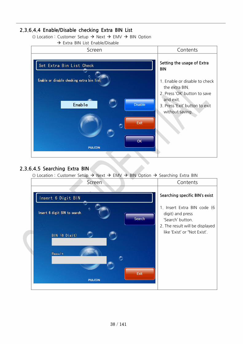
2.3.6.4.4 Enable/Disable checking Extra BIN List
◎ Location : Customer Setup Next EMV BIN Option
Extra BIN List Enable/Disable
Screen Contents
Setting the usage of Extra
BIN
1. Enable or disable to check
the extra BIN.
2. Press ‘OK’ button to save
and exit.
3. Press ‘Exit’ button to exit
without saving.
2.3.6.4.5 Searching Extra BIN
◎ Location : Customer Setup Next EMV BIN Option Searching Extra BIN
Screen Contents
Searching specific BIN’s exist
1. Insert Extra BIN code (6
digit) and press
‘Search’ button.
2. The result will be displayed
like ‘Exist’ or “Not Exist’.
39 / 141
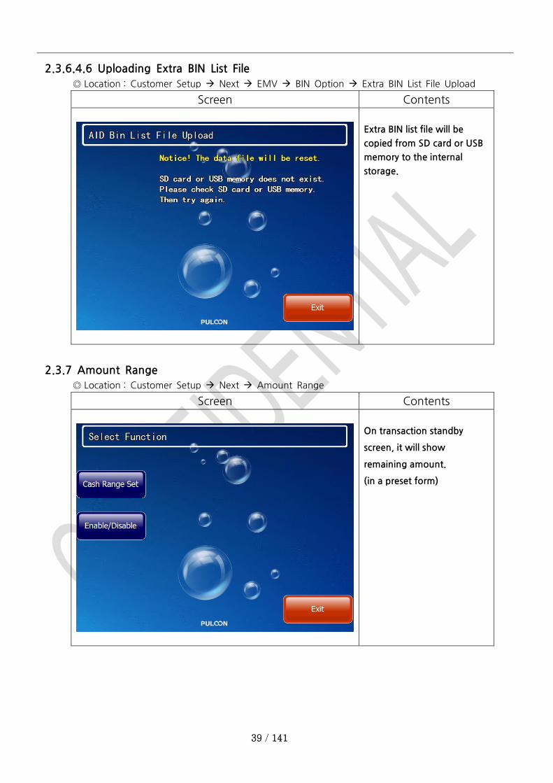
2.3.6.4.6 Uploading Extra BIN List File
◎ Location : Customer Setup Next EMV BIN Option Extra BIN List File Upload
Screen Contents
Extra BIN list file will be
copied from SD card or USB
memory to the internal
storage.
2.3.7 Amount Range
◎ Location : Customer Setup Next Amount Range
Screen Contents
On transaction standby
screen, it will show
remaining amount.
(in a preset form)
40 / 141
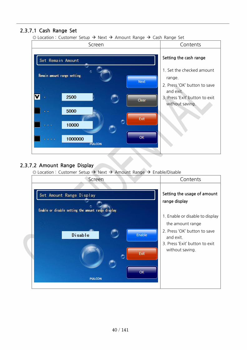
2.3.7.1 Cash Range Set
◎ Location : Customer Setup Next Amount Range Cash Range Set
Screen Contents
Setting the cash range
1. Set the checked amount
range.
2. Press ‘OK’ button to save
and exit.
3. Press ‘Exit’ button to exit
without saving.
2.3.7.2 Amount Range Display
◎ Location : Customer Setup Next Amount Range Enable/Disable
Screen Contents
Setting the usage of amount
range display
1. Enable or disable to display
the amount range
2. Press ‘OK’ button to save
and exit.
3. Press ‘Exit’ button to exit
without saving.
41 / 141
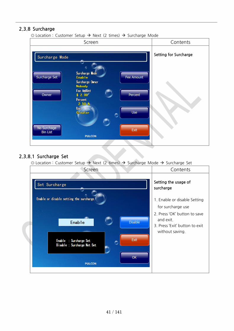
2.3.8 Surcharge
◎ Location : Customer Setup Next (2 times) Surcharge Mode
Screen Contents
Setting for Surcharge
2.3.8.1 Surcharge Set
◎ Location : Customer Setup Next (2 times) Surcharge Mode Surcharge Set
Screen Contents
Setting the usage of
surcharge
1. Enable or disable Setting
for surcharge use
2. Press ‘OK’ button to save
and exit.
3. Press ‘Exit’ button to exit
without saving.

42 / 141
2.3.8.2 Surcharge Owner
◎ Location : Customer Setup Next (2 times) Surcharge Mode Owner
Screen Contents
Setting the surcharge owner
1. Set the owner of
surcharge.
2. Press ‘OK’ button to save
and exit.
3. Press ‘Exit’ button to exit
without saving.
2.3.8.3 Surcharge Amount
◎ Location : Customer Setup Next (2 times) Surcharge Mode Fee Amount
Screen Contents
Setting the surcharge
amount
1. Set surcharge amount.
2. Press ‘OK’ button to save
and exit.
3. Press ‘Exit’ button to exit
without saving.
43 / 141
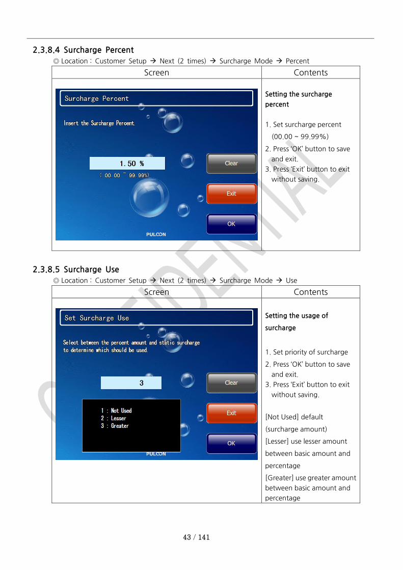
2.3.8.4 Surcharge Percent
◎ Location : Customer Setup Next (2 times) Surcharge Mode Percent
Screen Contents
Setting the surcharge
percent
1. Set surcharge percent
(00.00 ~ 99.99%)
2. Press ‘OK’ button to save
and exit.
3. Press ‘Exit’ button to exit
without saving.
2.3.8.5 Surcharge Use
◎ Location : Customer Setup Next (2 times) Surcharge Mode Use
Screen Contents
Setting the usage of
surcharge
1. Set priority of surcharge
2. Press ‘OK’ button to save
and exit.
3. Press ‘Exit’ button to exit
without saving.
[Not Used] default
(surcharge amount)
[Lesser] use lesser amount
between basic amount and
percentage
[Greater] use greater amount
between basic amount and
percentage

44 / 141
2.3.8.6 BIN List
◎ Location : Customer Setup Next (2 times) Surcharge Mode No Surcharge Bin List
Screen Contents
Choose sub menu.
2.3.8.6.1 BIN List Enable/Disable
◎ Location : Customer Setup Next (2 times) Surcharge Mode No Surcharge Bin List
Bin List Enable/Disable
Screen Contents
Setting the usage of bin list
1. Enable or disable to check
the bin list.
2. Press ‘OK’ button to save
and exit.
3. Press ‘Exit’ button to exit
without saving.

45 / 141
2.3.8.6.2 BIN List Set
◎ Location : Customer Setup Next (2 times) Surcharge Mode No Surcharge Bin List
Bin List Set
Screen Contents
Add or Delete bin list
1. To add new one, insert bin
code (6 digit) and press
‘Add’ button.
2. To delete one, insert bin
code and press ‘Delete’
button.
2.3.8.6.3 BIN List File Upload
◎ Location : Customer Setup Next (2 times) Surcharge Mode No Surcharge Bin List
Bin List File Upload
Screen Contents
All bin lists can be saved in
SD card or USB memory.
46 / 141
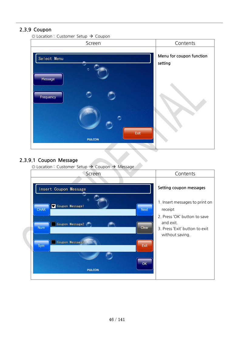
2.3.9 Coupon
◎ Location : Customer Setup Coupon
Screen Contents
Menu for coupon function
setting
2.3.9.1 Coupon Message
◎ Location : Customer Setup Coupon Message
Screen Contents
Setting coupon messages
1. Insert messages to print on
receipt
2. Press ‘OK’ button to save
and exit.
3. Press ‘Exit’ button to exit
without saving.
47 / 141
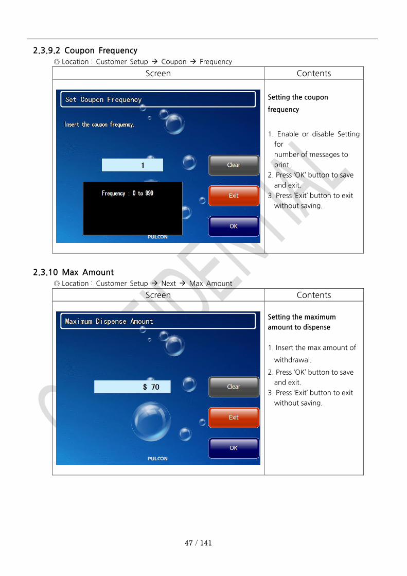
2.3.9.2 Coupon Frequency
◎ Location : Customer Setup Coupon Frequency
Screen Contents
Setting the coupon
frequency
1. Enable or disable Setting
for
number of messages to
print.
2. Press ‘OK’ button to save
and exit.
3. Press ‘Exit’ button to exit
without saving.
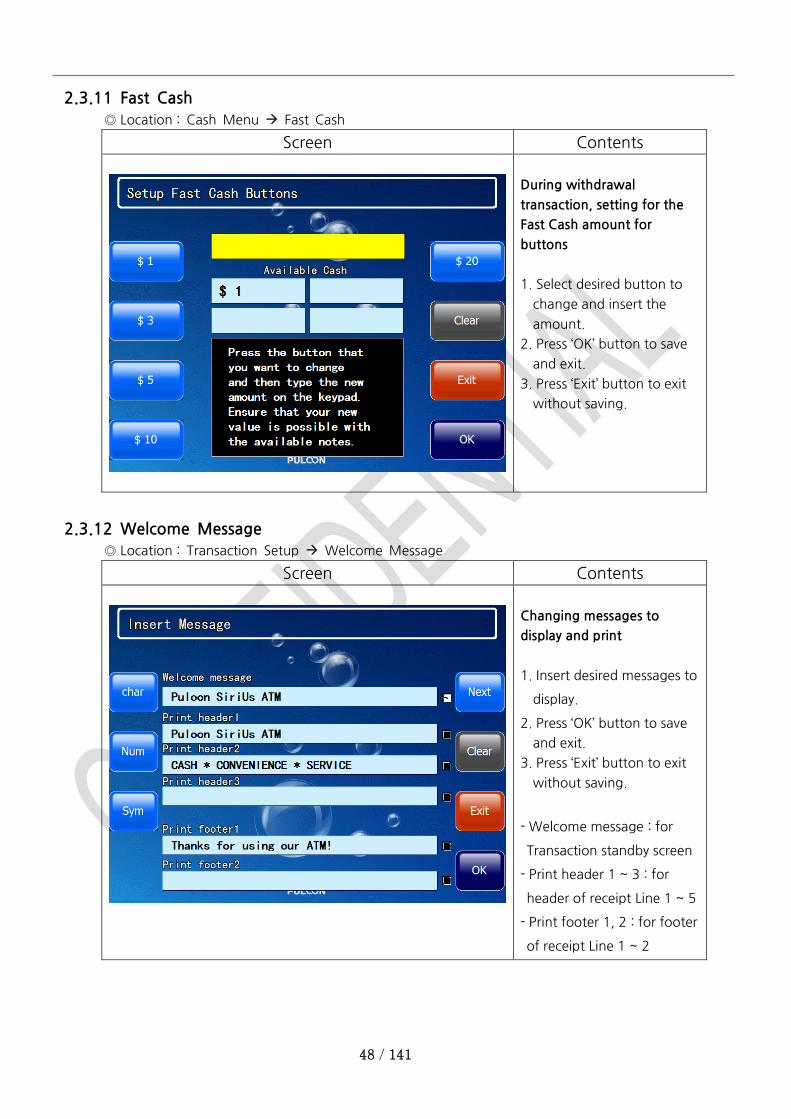
2.3.10 Max Amount
◎ Location : Customer Setup Next Max Amount
Screen Contents
Setting the maximum
amount to dispense
1. Insert the max amount of
withdrawal.
2. Press ‘OK’ button to save
and exit.
3. Press ‘Exit’ button to exit
without saving.
48 / 141
2.3.11 Fast Cash
◎ Location : Cash Menu Fast Cash
Screen Contents
During withdrawal
transaction, setting for the
Fast Cash amount for
buttons
1. Select desired button to
change and insert the
amount.
2. Press ‘OK’ button to save
and exit.
3. Press ‘Exit’ button to exit
without saving.
2.3.12 Welcome Message
◎ Location : Transaction Setup Welcome Message
Screen Contents
Changing messages to
display and print
1. Insert desired messages to
display.
2. Press ‘OK’ button to save
and exit.
3. Press ‘Exit’ button to exit
without saving.
- Welcome message : for
Transaction standby screen
- Print header 1 ~ 3 : for
header of receipt Line 1 ~ 5
- Print footer 1, 2 : for footer
of receipt Line 1 ~ 2
49 / 141
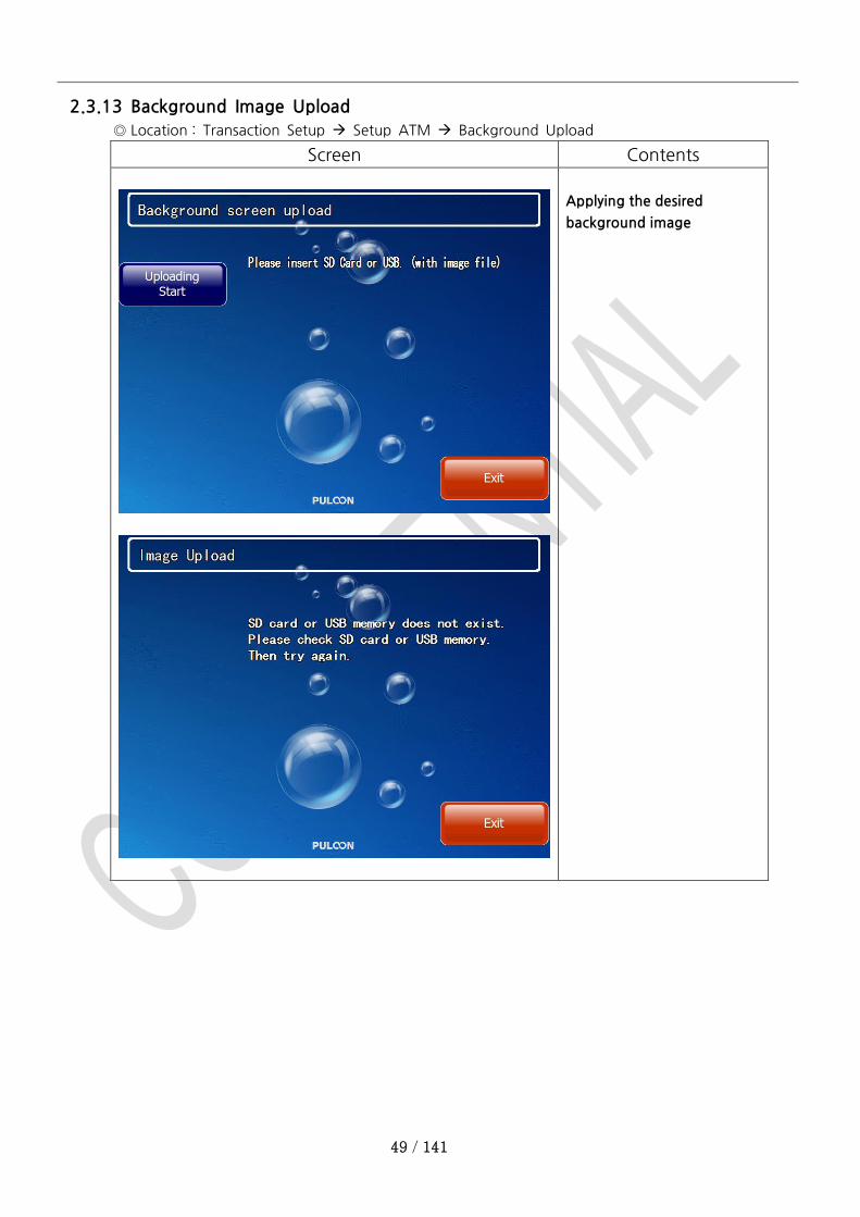
2.3.13 Background Image Upload
◎ Location : Transaction Setup Setup ATM Background Upload
Screen Contents
Applying the desired
background image
50 / 141
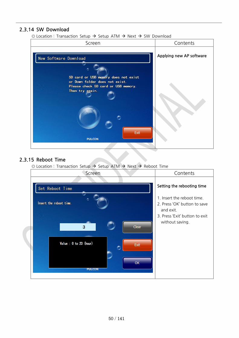
2.3.14 SW Download
◎ Location : Transaction Setup Setup ATM Next SW Download
Screen Contents
Applying new AP software
2.3.15 Reboot Time
◎ Location : Transaction Setup Setup ATM Next Reboot Time
Screen Contents
Setting the rebooting time
1. Insert the reboot time.
2. Press ‘OK’ button to save
and exit.
3. Press ‘Exit’ button to exit
without saving.
51 / 141
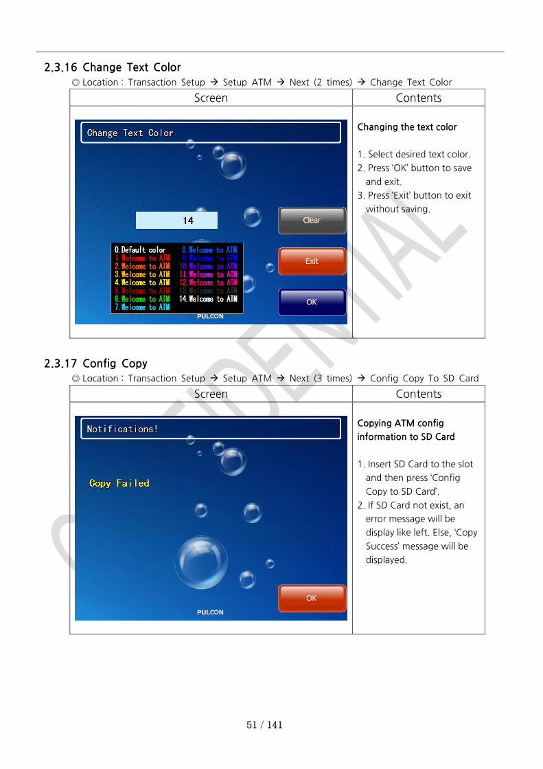
2.3.16 Change Text Color
◎ Location : Transaction Setup Setup ATM Next (2 times) Change Text Color
Screen Contents
Changing the text color
1. Select desired text color.
2. Press ‘OK’ button to save
and exit.
3. Press ‘Exit’ button to exit
without saving.
2.3.17 Config Copy
◎ Location : Transaction Setup Setup ATM Next (3 times) Config Copy To SD Card
Screen Contents
Copying ATM config
information to SD Card
1. Insert SD Card to the slot
and then press ‘Config
Copy to SD Card’.
2. If SD Card not exist, an
error message will be
display like left. Else, ‘Copy
Success’ message will be
displayed.
52 / 141
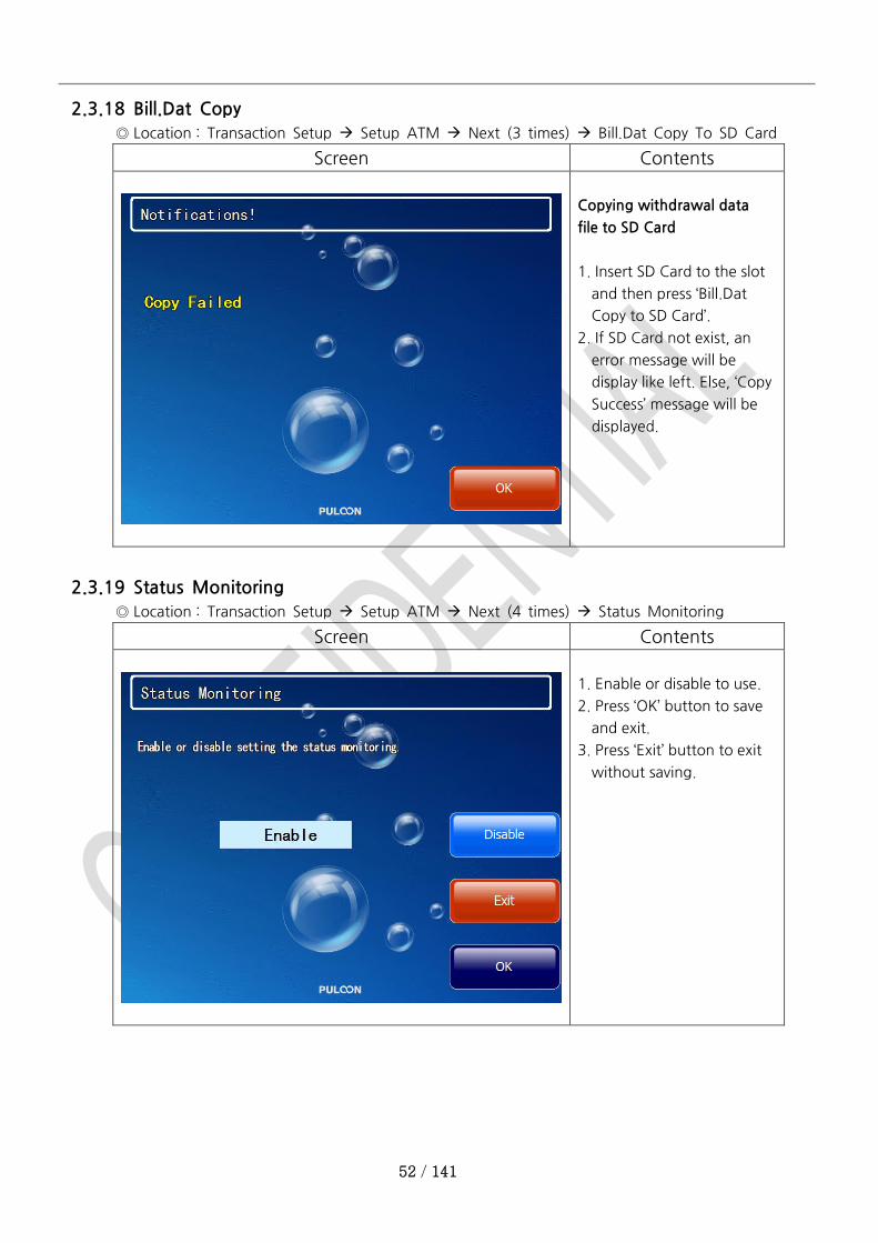
2.3.18 Bill.Dat Copy
◎ Location : Transaction Setup Setup ATM Next (3 times) Bill.Dat Copy To SD Card
Screen Contents
Copying withdrawal data
file to SD Card
1. Insert SD Card to the slot
and then press ‘Bill.Dat
Copy to SD Card’.
2. If SD Card not exist, an
error message will be
display like left. Else, ‘Copy
Success’ message will be
displayed.
2.3.19 Status Monitoring
◎ Location : Transaction Setup Setup ATM Next (4 times) Status Monitoring
Screen Contents
1. Enable or disable to use.
2. Press ‘OK’ button to save
and exit.
3. Press ‘Exit’ button to exit
without saving.

53 / 141
2.3.20 Use 12-Digit
◎ Location : Transaction Setup Setup ATM Next (4 times) Use 12-Digit
Screen Contents
1. Enable or disable to use.
2. Press ‘OK’ button to save
and exit.
3. Press ‘Exit’ button to exit
without saving.
2.3.21 Printer Option
◎ Location : Transaction Setup Setup ATM Next (5 times) Printer Option
Screen Contents
Setting Printer Option in
case of printing error
1. Stop or continue
transaction when printer is
in error.
2. Press ‘OK’ button to save
and exit.
3. Press ‘Exit’ button to exit
without saving.

54 / 141
2.3.22 Set Screen Timer
◎ Location : Transaction Setup Setup ATM Next (5 times) Screen Timer
Screen Contents
Setting Screen Timer in
case of returning to the
Idle screen after 5 minutes
1. Enable or disable to use.
2. Press ‘OK’ button to save
and exit.
3. Press ‘Exit’ button to exit
without saving.
2.3.23 Monitoring
◎ Location : Host Setup Monitoring
Screen Contents
Setting for RMS function
(Remote Management
System)
If the interval is not 0(zero),
the Manage Account button
will be hidden.
55 / 141
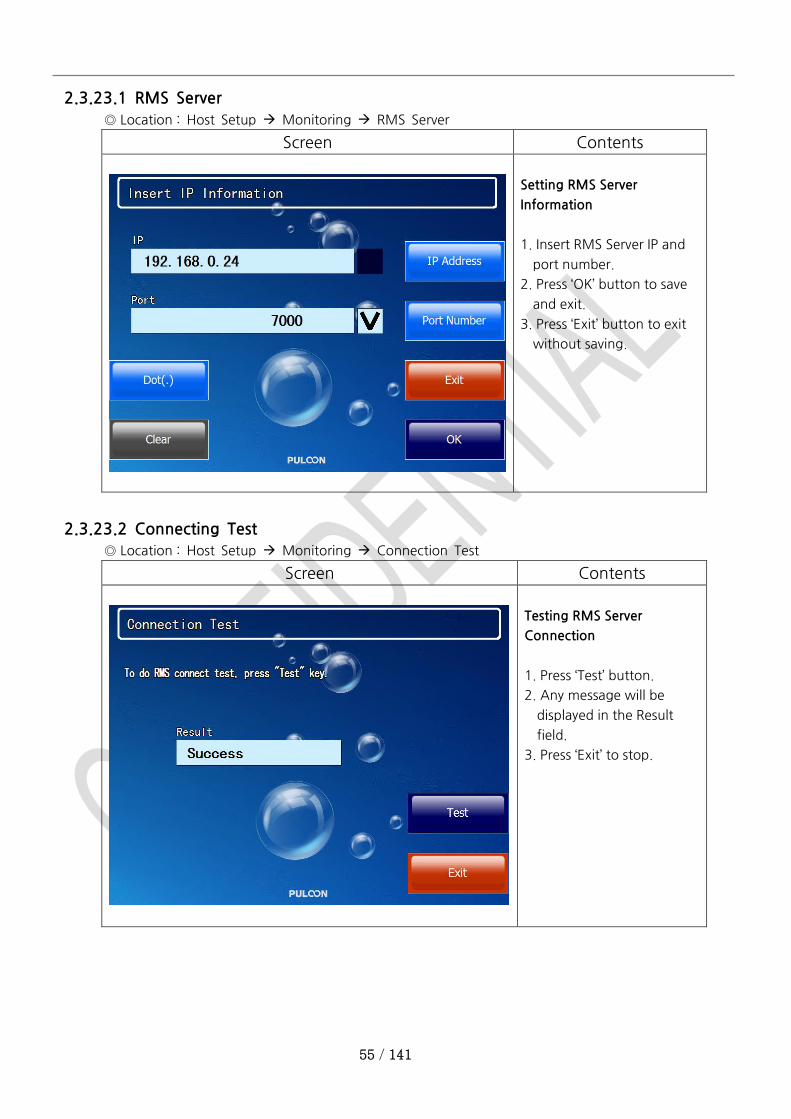
2.3.23.1 RMS Server
◎ Location : Host Setup Monitoring RMS Server
Screen Contents
Setting RMS Server
Information
1. Insert RMS Server IP and
port number.
2. Press ‘OK’ button to save
and exit.
3. Press ‘Exit’ button to exit
without saving.
2.3.23.2 Connecting Test
◎ Location : Host Setup Monitoring Connection Test
Screen Contents
Testing RMS Server
Connection
1. Press ‘Test’ button.
2. Any message will be
displayed in the Result
field.
3. Press ‘Exit’ to stop.

56 / 141
2.3.23.3 Manage Account
◎ Location : Host Setup Monitoring Manage Account
Screen Contents
Managing Account (TID
folder) of RMS Server
1. Create or Delete Account
(TID folder) of RMS Server.
2. Press ‘OK’ button to save
and exit.
3. Press ‘Exit’ button to exit
without saving.
* If creating or deleting
account is being
processed, “Processing”
message will be shown.
* If the account is exist,
“Exist” message will be
shown.
* If the account is not exist,
“Not Exist” message will be
shown.

57 / 141
2.3.23.4 Set Interval
◎ Location : Host Setup Monitoring Set Interval
Screen Contents
Setting RMS interval time
1. Insert RMS interval time.
2. Press ‘OK’ button to save
and exit.
3. Press ‘Exit’ button to exit
without saving.
* If the account (TID folder)
is not created, the interval
cannot be set.
2.3.23.5 Emergency Reset
◎ Location : Host Setup Monitoring Emergency Reset
Screen Contents
Emergency Reset
* It the ATM is power off
accidently or the network
status is not stable while
being created or deleted
the account at the RMS
server, you can ignore the
creating or deleting
action.
* It dose not effect to the
RMS server.

58 / 141
2.4 Communication Setting Menu
2.4.1 Modem Set
◎ Location : Transaction Setup Modem Set
◎ This menu will be shown in case of MODEM only.
Screen Contents
Setting menu for Modem
transfer
2.4.1.1 Sound
◎ Location : Transaction Setup Modem Set Sound
Screen Contents
Modem sound setting

59 / 141
2.4.1.2 Baudrate
◎ Location : Transaction Setup Modem Set Baudrate
Screen Contents
Transfer rate setting
2.4.1.3 Status
◎ Location : Transaction Setup Modem Set Status
Screen Contents
Status check

60 / 141
2.4.1.4 Predialing
◎ Location : Transaction Setup Modem Set Predialing
Screen Contents
Setting for use of Pre-dialing
during transaction
2.4.1.5 Timeout
◎ Location : Transaction Setup Modem Set Timeout
Screen Contents
Setting the timeout value
between ATM and the Host.

61 / 141
2.4.1.5.1 View Timeout
Screen Contents
Reviewing the timeout
values.
2.4.1.5.2 Dial Timeout
Screen Contents
Setting the timeout of
dialing.
1. Enter desired timeout
value.
2. Press ‘OK’ button to save
and exit.
3. Press ‘Exit’ button to exit
without saving.
62 / 141
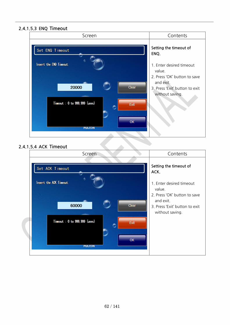
2.4.1.5.3 ENQ Timeout
Screen Contents
Setting the timeout of
ENQ.
1. Enter desired timeout
value.
2. Press ‘OK’ button to save
and exit.
3. Press ‘Exit’ button to exit
without saving.
2.4.1.5.4 ACK Timeout
Screen Contents
Setting the timeout of
ACK.
1. Enter desired timeout
value.
2. Press ‘OK’ button to save
and exit.
3. Press ‘Exit’ button to exit
without saving.

63 / 141
2.4.1.5.5 STX Timeout
Screen Contents
Setting the timeout of
STX.
1. Enter desired timeout
value.
2. Press ‘OK’ button to save
and exit.
3. Press ‘Exit’ button to exit
without saving.
2.4.1.5.6 ETX Timeout
Screen Contents
Setting the timeout of
ETX.
1. Enter desired timeout
value.
2. Press ‘OK’ button to save
and exit.
3. Press ‘Exit’ button to exit
without saving.
64 / 141
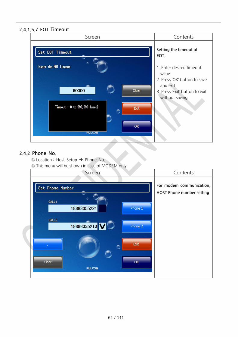
2.4.1.5.7 EOT Timeout
Screen Contents
Setting the timeout of
EOT.
1. Enter desired timeout
value.
2. Press ‘OK’ button to save
and exit.
3. Press ‘Exit’ button to exit
without saving.
2.4.2 Phone No.
◎ Location : Host Setup Phone No.
◎ This menu will be shown in case of MODEM only.
Screen Contents
For modem communication,
HOST Phone number setting
65 / 141
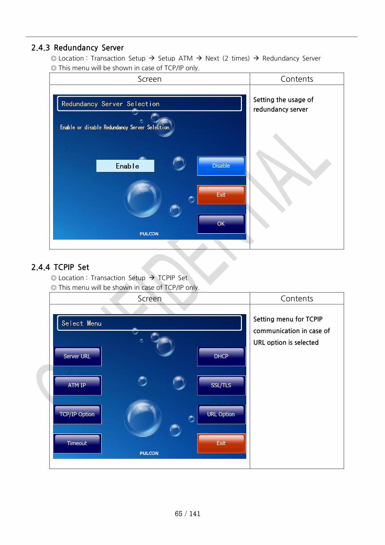
2.4.3 Redundancy Server
◎ Location : Transaction Setup Setup ATM Next (2 times) Redundancy Server
◎ This menu will be shown in case of TCP/IP only.
Screen Contents
Setting the usage of
redundancy server
2.4.4 TCPIP Set
◎ Location : Transaction Setup TCPIP Set
◎ This menu will be shown in case of TCP/IP only.
Screen Contents
Setting menu for TCPIP
communication in case of
URL option is selected
66 / 141
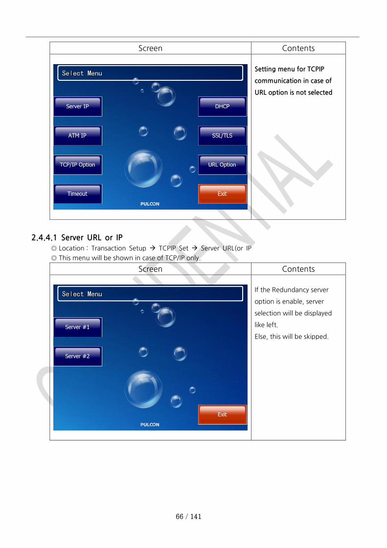
Screen Contents
Setting menu for TCPIP
communication in case of
URL option is not selected
2.4.4.1 Server URL or IP
◎ Location : Transaction Setup TCPIP Set Server URL(or IP
◎ This menu will be shown in case of TCP/IP only.
Screen Contents
If the Redundancy server
option is enable, server
selection will be displayed
like left.
Else, this will be skipped.
67 / 141
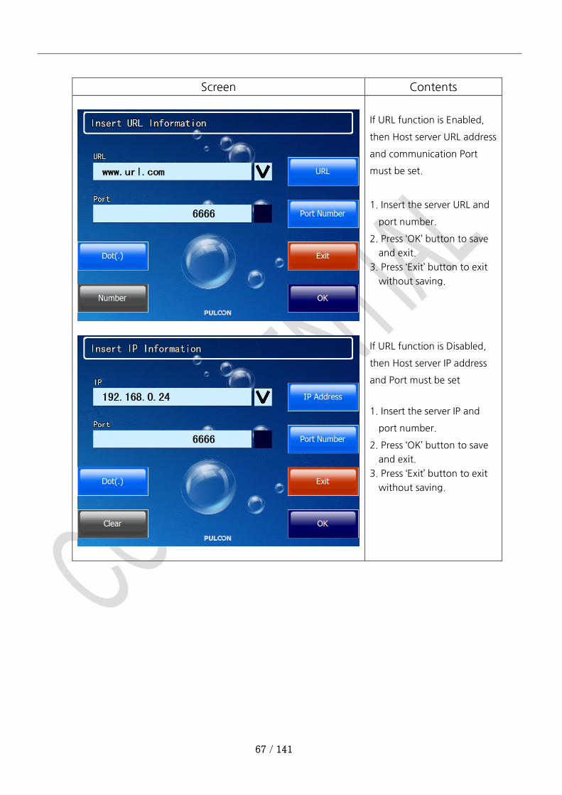
Screen Contents
If URL function is Enabled,
then Host server URL address
and communication Port
must be set.
1. Insert the server URL and
port number.
2. Press ‘OK’ button to save
and exit.
3. Press ‘Exit’ button to exit
without saving.
If URL function is Disabled,
then Host server IP address
and Port must be set
1. Insert the server IP and
port number.
2. Press ‘OK’ button to save
and exit.
3. Press ‘Exit’ button to exit
without saving.
68 / 141
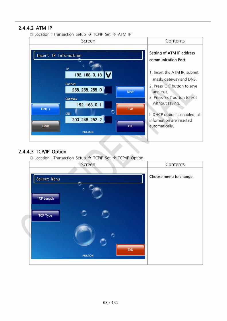
2.4.4.2 ATM IP
◎ Location : Transaction Setup TCPIP Set ATM IP
Screen Contents
Setting of ATM IP address
communication Port
1. Insert the ATM IP, subnet
mask, gateway and DNS.
2. Press ‘OK’ button to save
and exit.
3. Press ‘Exit’ button to exit
without saving.
If DHCP option is enabled, all
information are inserted
automatically.
2.4.4.3 TCP/IP Option
◎ Location : Transaction Setup TCPIP Set TCP/IP Option
Screen Contents
Choose menu to change.
69 / 141
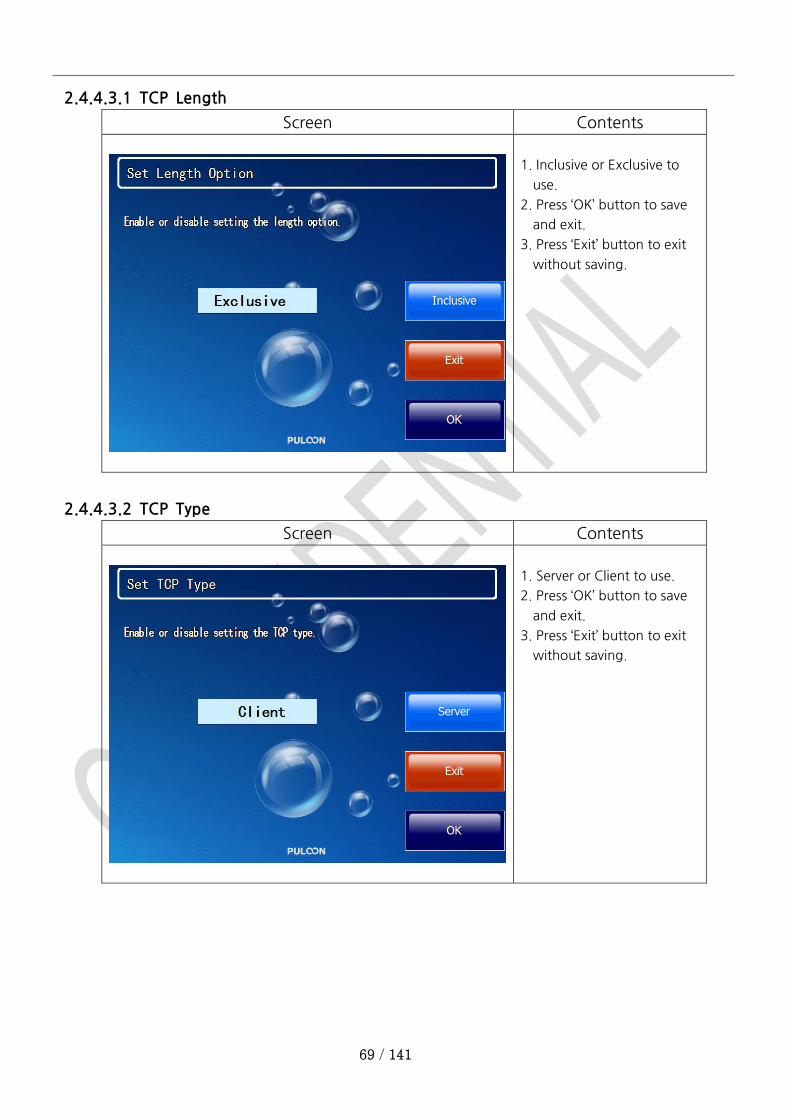
2.4.4.3.1 TCP Length
Screen Contents
1. Inclusive or Exclusive to
use.
2. Press ‘OK’ button to save
and exit.
3. Press ‘Exit’ button to exit
without saving.
2.4.4.3.2 TCP Type
Screen Contents
1. Server or Client to use.
2. Press ‘OK’ button to save
and exit.
3. Press ‘Exit’ button to exit
without saving.
70 / 141
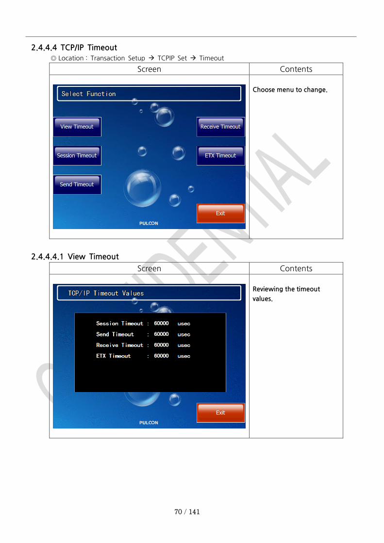
2.4.4.4 TCP/IP Timeout
◎ Location : Transaction Setup TCPIP Set Timeout
Screen Contents
Choose menu to change.
2.4.4.4.1 View Timeout
Screen Contents
Reviewing the timeout
values.

71 / 141
2.4.4.4.2 Session Timeout
Screen Contents
Setting the timeout of
making session between
ATM and the Host.
1. Enter desired timeout
value.
2. Press ‘OK’ button to save
and exit.
3. Press ‘Exit’ button to exit
without saving.
2.4.4.4.3 Send Timeout
Screen Contents
Setting the timeout of
sending message to the
Host.
1. Enter desired timeout
value.
2. Press ‘OK’ button to save
and exit.
3. Press ‘Exit’ button to exit
without saving.
72 / 141
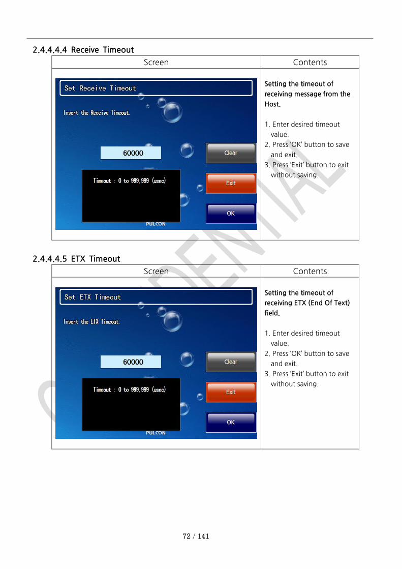
2.4.4.4.4 Receive Timeout
Screen Contents
Setting the timeout of
receiving message from the
Host.
1. Enter desired timeout
value.
2. Press ‘OK’ button to save
and exit.
3. Press ‘Exit’ button to exit
without saving.
2.4.4.4.5 ETX Timeout
Screen Contents
Setting the timeout of
receiving ETX (End Of Text)
field.
1. Enter desired timeout
value.
2. Press ‘OK’ button to save
and exit.
3. Press ‘Exit’ button to exit
without saving.
73 / 141
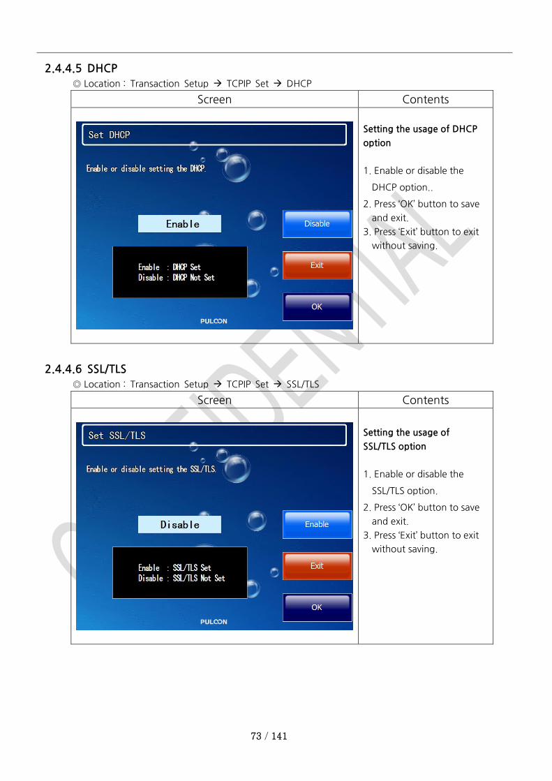
2.4.4.5 DHCP
◎ Location : Transaction Setup TCPIP Set DHCP
Screen Contents
Setting the usage of DHCP
option
1. Enable or disable the
DHCP option..
2. Press ‘OK’ button to save
and exit.
3. Press ‘Exit’ button to exit
without saving.
2.4.4.6 SSL/TLS
◎ Location : Transaction Setup TCPIP Set SSL/TLS
Screen Contents
Setting the usage of
SSL/TLS option
1. Enable or disable the
SSL/TLS option.
2. Press ‘OK’ button to save
and exit.
3. Press ‘Exit’ button to exit
without saving.
74 / 141
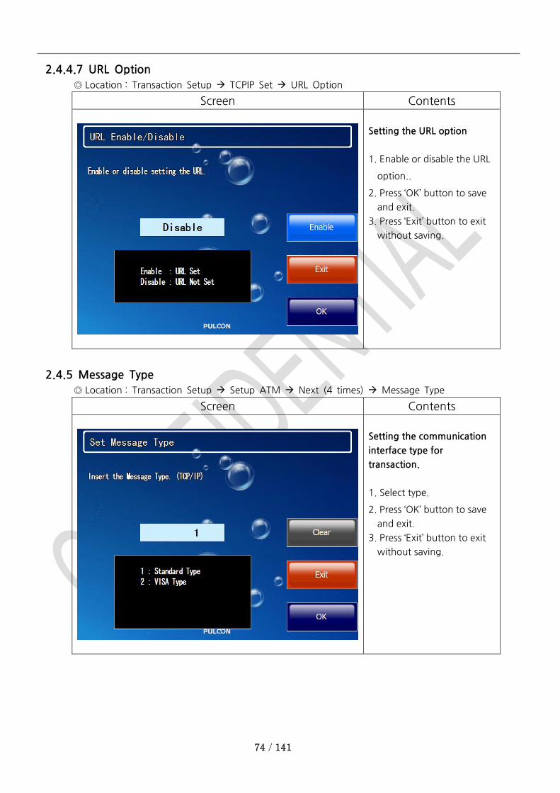
2.4.4.7 URL Option
◎ Location : Transaction Setup TCPIP Set URL Option
Screen Contents
Setting the URL option
1. Enable or disable the URL
option..
2. Press ‘OK’ button to save
and exit.
3. Press ‘Exit’ button to exit
without saving.
2.4.5 Message Type
◎ Location : Transaction Setup Setup ATM Next (4 times) Message Type
Screen Contents
Setting the communication
interface type for
transaction.
1. Select type.
2. Press ‘OK’ button to save
and exit.
3. Press ‘Exit’ button to exit
without saving.

75 / 141
2.4.6 ENQ Check
◎ Location : Transaction Setup Setup ATM Next (3 times) ENQ Check
Screen Contents
If enabled, the AP will check
the ENQ (ENQuiry) field of
received message.
2.4.7 EOT Check
◎ Location : Transaction Setup Setup ATM Next (3 times) EOT Check
Screen Contents
If enabled, the AP will check
the EOT (End Of Text) field of
received message.

76 / 141
2.5 Master Key Setting Menu
2.5.1 Master A
◎ Location : Host Setup Key Management Insert Master A
◎ Before doing this, you’d better changing EPP password #1 and #2.
◎ To entering this menu, you must enter EPP password #1 and #2.
Screen Contents
Select Master Key Type
Insert the Part A master Key.

77 / 141
2.5.2 Master B
◎ Location : Host Setup Key Management Insert Master B
◎ Before doing this, you’d better to change EPP password #1 and #2.
◎ To entering this menu, you must enter EPP password #1 and #2.
Screen Contents
Insert the Part B master Key.
78 / 141
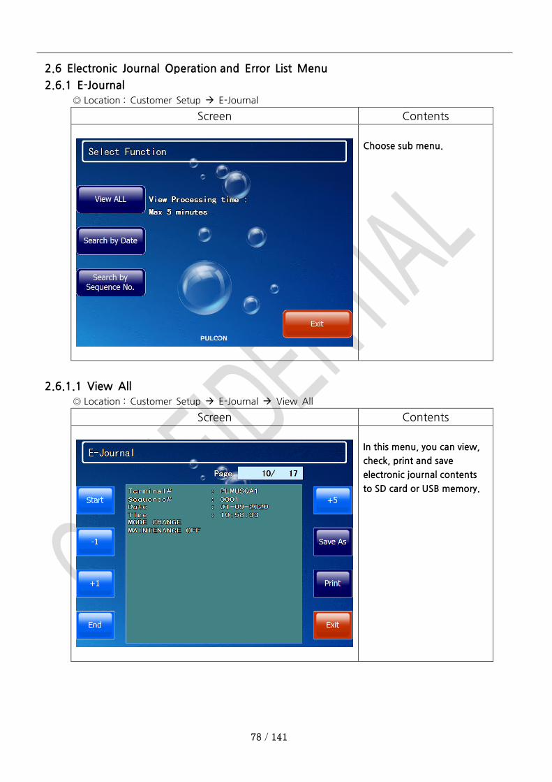
2.6 Electronic Journal Operation and Error List Menu
2.6.1 E-Journal
◎ Location : Customer Setup E-Journal
Screen Contents
Choose sub menu.
2.6.1.1 View All
◎ Location : Customer Setup E-Journal View All
Screen Contents
In this menu, you can view,
check, print and save
electronic journal contents
to SD card or USB memory.
79 / 141
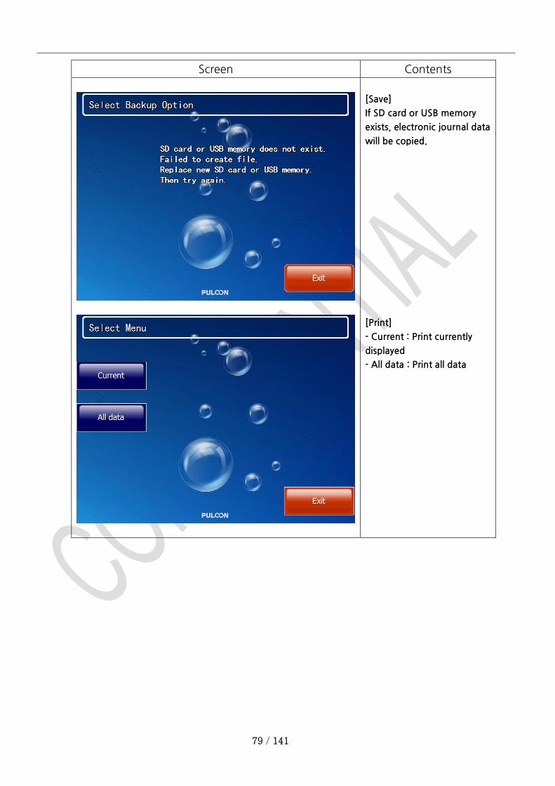
Screen Contents
[Save]
If SD card or USB memory
exists, electronic journal data
will be copied.
[Print]
- Current : Print currently
displayed
- All data : Print all data
80 / 141
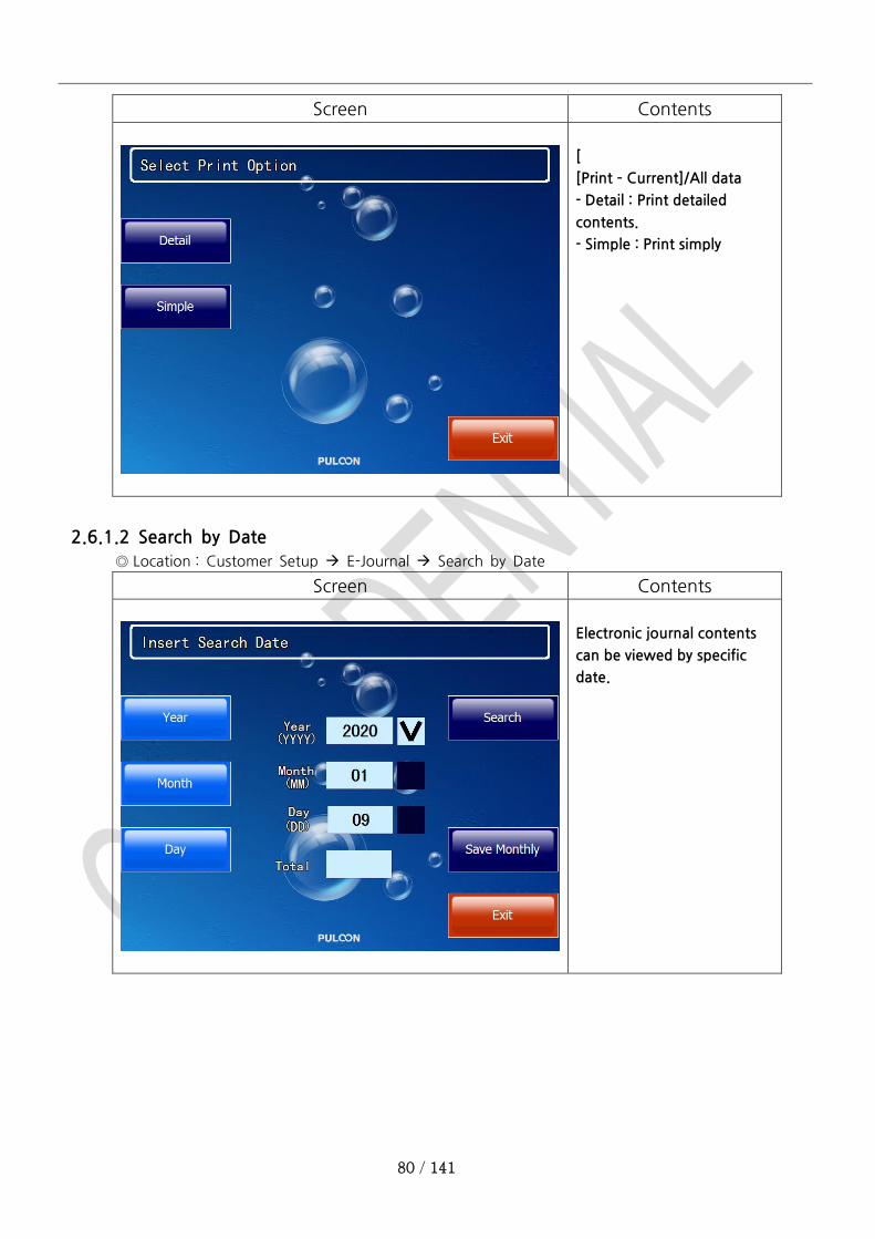
Screen Contents
[
[Print – Current]/All data
- Detail : Print detailed
contents.
- Simple : Print simply
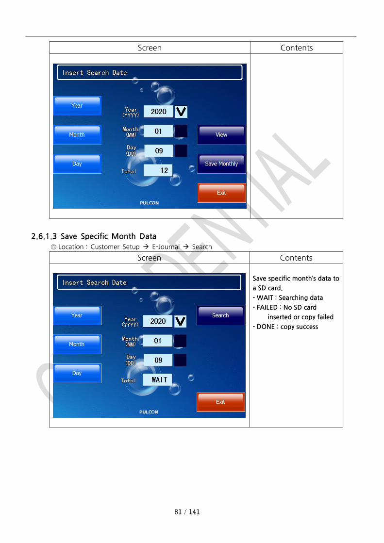
2.6.1.2 Search by Date
◎ Location : Customer Setup E-Journal Search by Date
Screen Contents
Electronic journal contents
can be viewed by specific
date.
81 / 141
Screen Contents
2.6.1.3 Save Specific Month Data
◎ Location : Customer Setup E-Journal Search
Screen Contents
Save specific month’s data to
a SD card.
- WAIT : Searching data
- FAILED : No SD card
inserted or copy failed
- DONE : copy success

82 / 141
Screen Contents
83 / 141
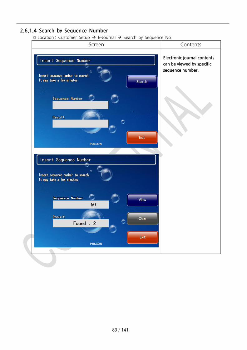
2.6.1.4 Search by Sequence Number
◎ Location : Customer Setup E-Journal Search by Sequence No.
Screen Contents
Electronic journal contents
can be viewed by specific
sequence number.
84 / 141
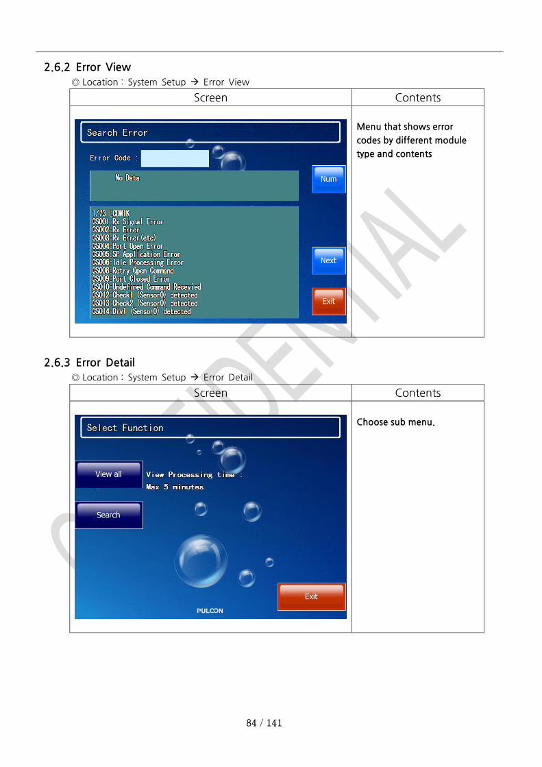
2.6.2 Error View
◎ Location : System Setup Error View
Screen Contents
Menu that shows error
codes by different module
type and contents
2.6.3 Error Detail
◎ Location : System Setup Error Detail
Screen Contents
Choose sub menu.
85 / 141
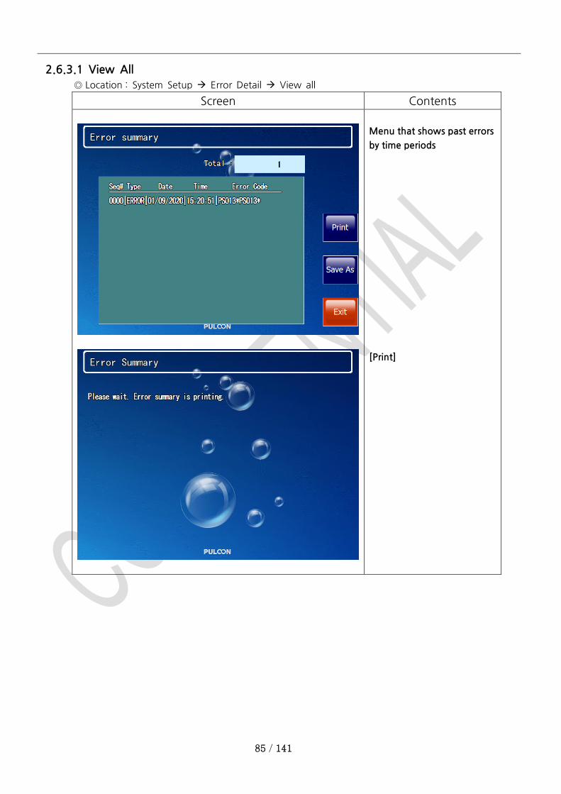
2.6.3.1 View All
◎ Location : System Setup Error Detail View all
Screen Contents
Menu that shows past errors
by time periods
[Print]
86 / 141
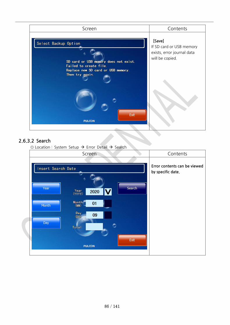
Screen Contents
[Save]
If SD card or USB memory
exists, error journal data
will be copied.
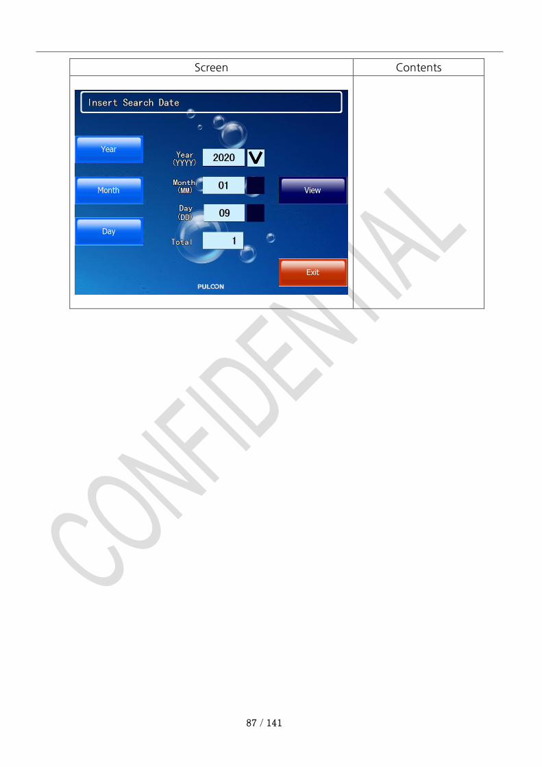
2.6.3.2 Search
◎ Location : System Setup Error Detail Search
Screen Contents
Error contents can be viewed
by specific date.
87 / 141
Screen Contents

88 / 141
2.7 System Mode Menu
2.7.1 Version
◎ Location : System Setup Version
Screen Contents
Menu that shows the S/W
and device versions
2.7.2 Setup Print
◎ Location : System Setup Setup Print
Screen Contents
Menu that can print ATM
setting information.
89 / 141
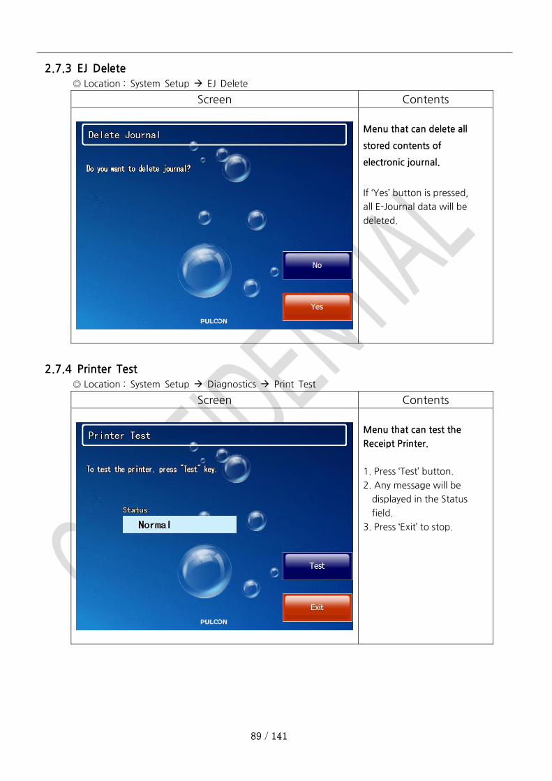
2.7.3 EJ Delete
◎ Location : System Setup EJ Delete
Screen Contents
Menu that can delete all
stored contents of
electronic journal.
If ‘Yes’ button is pressed,
all E-Journal data will be
deleted.
2.7.4 Printer Test
◎ Location : System Setup Diagnostics Print Test
Screen Contents
Menu that can test the
Receipt Printer.
1. Press ‘Test’ button.
2. Any message will be
displayed in the Status
field.
3. Press ‘Exit’ to stop.
90 / 141
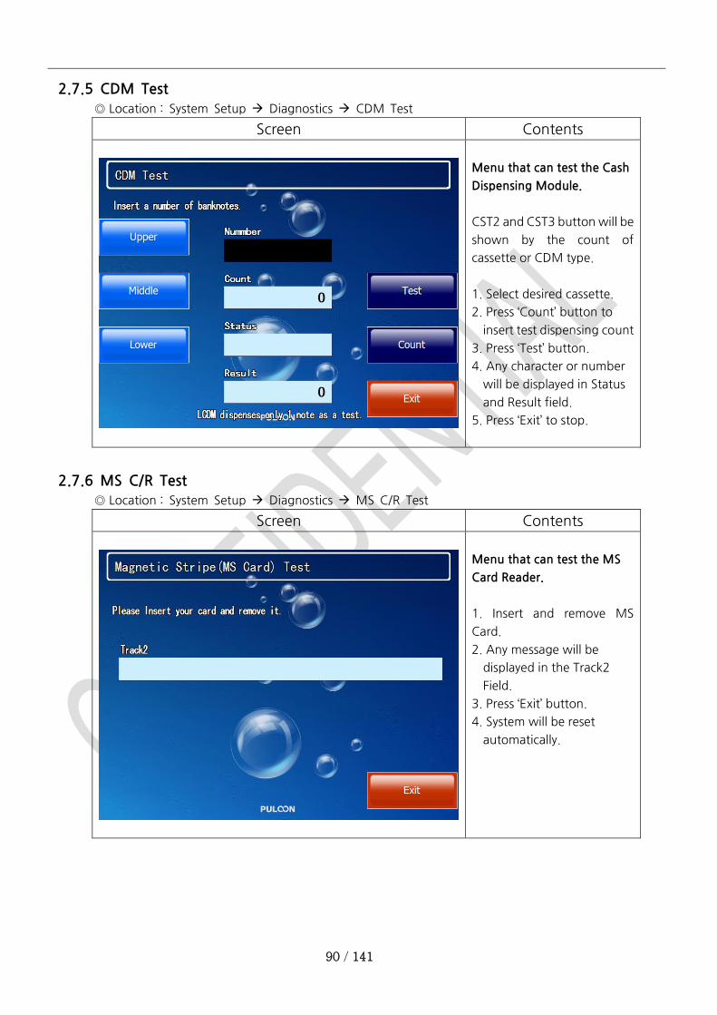
2.7.5 CDM Test
◎ Location : System Setup Diagnostics CDM Test
Screen Contents
Menu that can test the Cash
Dispensing Module.
CST2 and CST3 button will be
shown by the count of
cassette or CDM type.
1. Select desired cassette.
2. Press ‘Count’ button to
insert test dispensing count
3. Press ‘Test’ button.
4. Any character or number
will be displayed in Status
and Result field.
5. Press ‘Exit’ to stop.
2.7.6 MS C/R Test
◎ Location : System Setup Diagnostics MS C/R Test
Screen Contents
Menu that can test the MS
Card Reader.
1. Insert and remove MS
Card.
2. Any message will be
displayed in the Track2
Field.
3. Press ‘Exit’ button.
4. System will be reset
automatically.
91 / 141
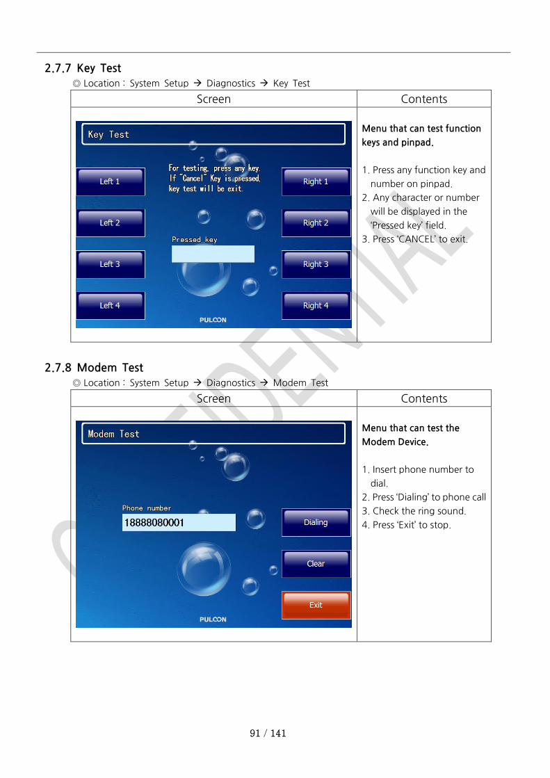
2.7.7 Key Test
◎ Location : System Setup Diagnostics Key Test
Screen Contents
Menu that can test function
keys and pinpad.
1. Press any function key and
number on pinpad.
2. Any character or number
will be displayed in the
‘Pressed key’ field.
3. Press ‘CANCEL’ to exit.
2.7.8 Modem Test
◎ Location : System Setup Diagnostics Modem Test
Screen Contents
Menu that can test the
Modem Device.
1. Insert phone number to
dial.
2. Press ‘Dialing’ to phone call
3. Check the ring sound.
4. Press ‘Exit’ to stop.
92 / 141
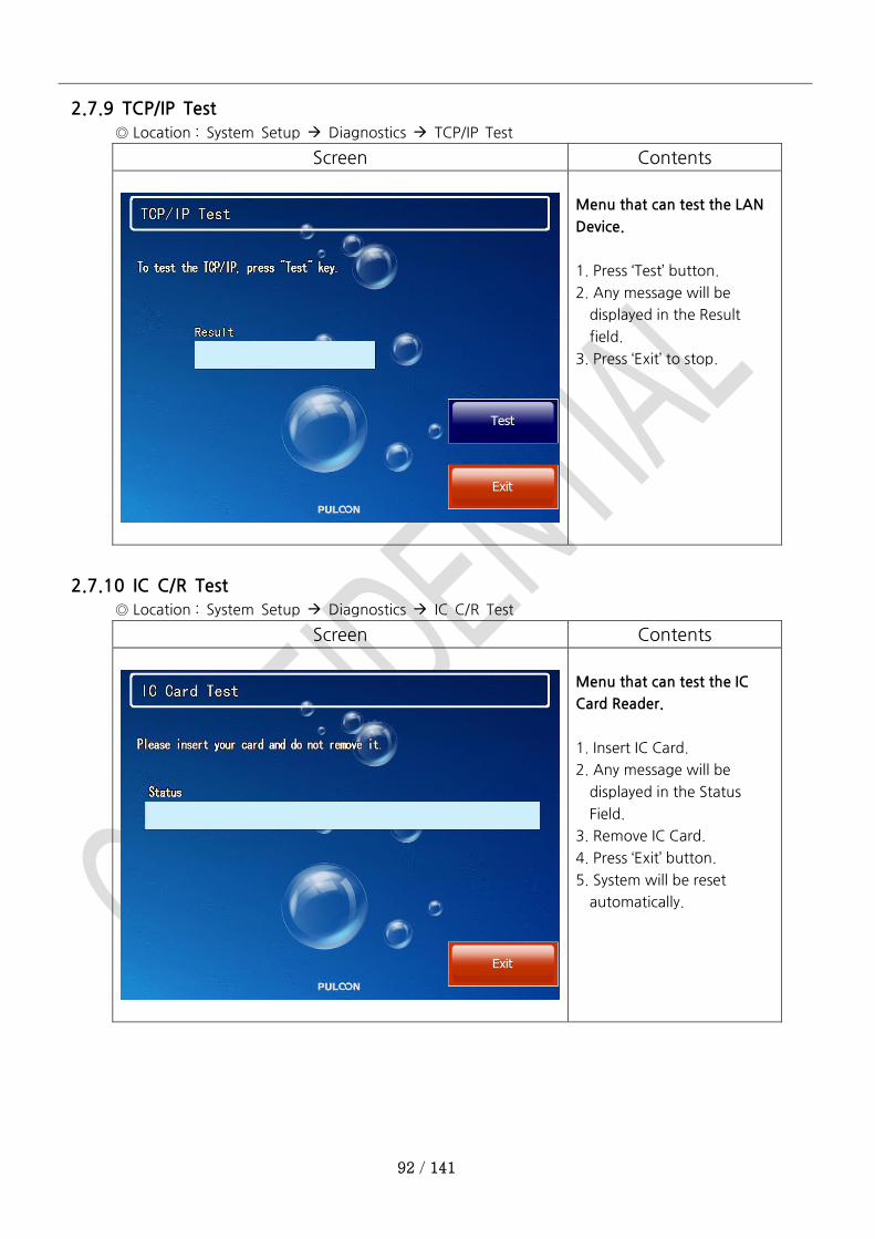
2.7.9 TCP/IP Test
◎ Location : System Setup Diagnostics TCP/IP Test
Screen Contents
Menu that can test the LAN
Device.
1. Press ‘Test’ button.
2. Any message will be
displayed in the Result
field.
3. Press ‘Exit’ to stop.
2.7.10 IC C/R Test
◎ Location : System Setup Diagnostics IC C/R Test
Screen Contents
Menu that can test the IC
Card Reader.
1. Insert IC Card.
2. Any message will be
displayed in the Status
Field.
3. Remove IC Card.
4. Press ‘Exit’ button.
5. System will be reset
automatically.
93 / 141
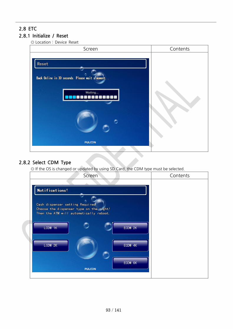
2.8 ETC
2.8.1 Initialize / Reset
◎ Location : Device Reset
Screen Contents
2.8.2 Select CDM Type
◎ If the OS is changed or updated by using SD Card, the CDM type must be selected.
Screen Contents
94 / 141
HW Maintenance Manual
Table of Contents
1 External Features ........................................................................................................................................ 95
1.1 Internal Features .......................................................................................................................... 96
2 System Specifications .................................................................................................................................. 97
3 H/W Operation and Maintenance ............................................................................................................... 98
3.1 SYSTEM POWER .......................................................................................................................... 98
3.2 System Block Diagram .................................................................................................................. 99
3.3 Embedded-PC (WinCE 6.0) ........................................................................................................ 100
3.3.1 Device Parts .......................................................................................................................100
3.3.2 ETC Parts Port ....................................................................................................................100
3.3.3 How to Insert and Remove SD Card ....................................................................................101
3.3.4 How to Load & Upgrade the Software ................................................................................101
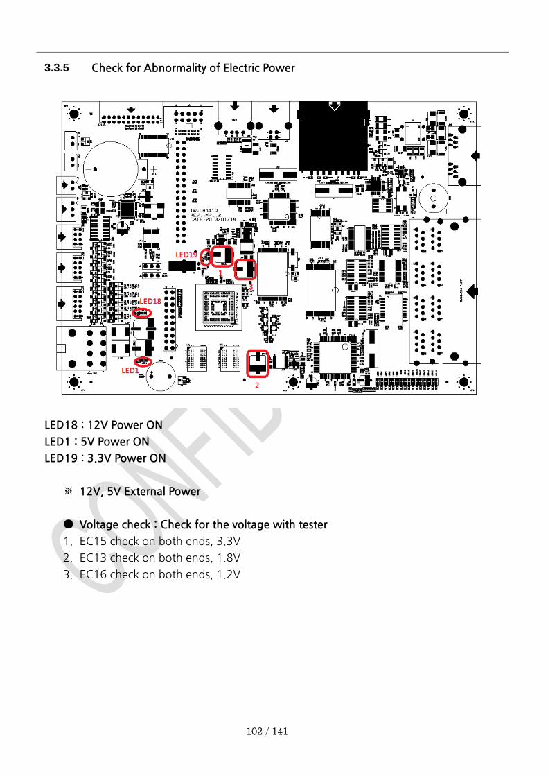
3.3.5 Check for Abnormality of Electric Power .............................................................................102
3.3.6 Check for Abnormality in COM Port ....................................................................................103
3.3.7 Check point when screen looks abnormal ...........................................................................104
3.4 Bill Dispenser : LCDM ................................................................................................................. 105
3.4.1 To refill cassette with cash ..................................................................................................105
3.4.2 Fix Dispenser Error .............................................................................................................106
<Restoring jam> .................................................................................................................................106
3.5 Card Reader .............................................................................................................................. 107
3.5.1 Card reader instruction .......................................................................................................107
3.5.2 In case of card reader error .................................................................................................107
3.6 Keypad(PCI3.0) .......................................................................................................................... 108
3.7 SMPS ........................................................................................................................................ 109
3.8 Receipt Printer ........................................................................................................................... 110
3.8.1 Printer Module Name of each parts ....................................................................................110
3.8.2 Module of print unit ...........................................................................................................110
3.8.3 Method of installation and removal of Paper .......................................................................112
3.8.4 Solution for common errors ................................................................................................113
4 Installation space .......................................................................................................................................118
5 PL-MU101T Dimension ..............................................................................................................................120
Appendix A. Device Error Code ......................................................................................................................121
95 / 141
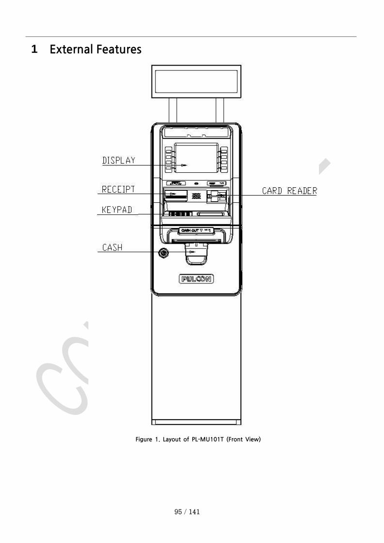
1 External Features
Figure 1. Layout of PL-MU101T (Front View)
96 / 141
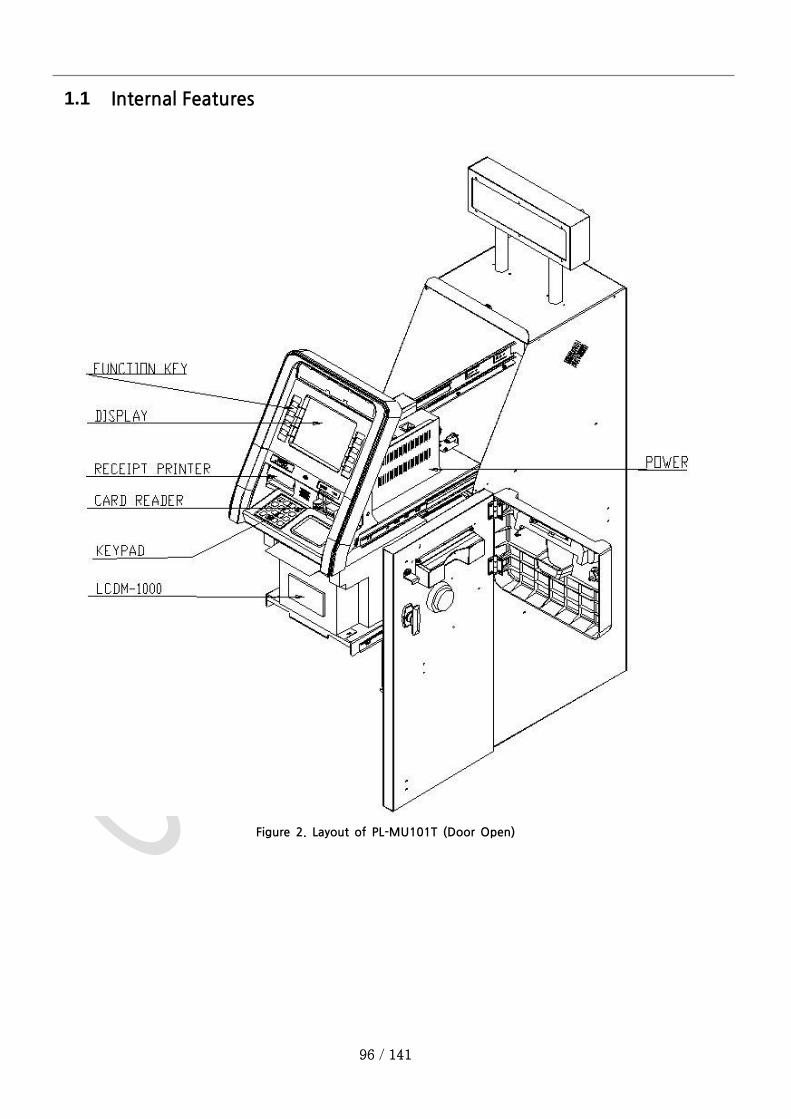
1.1 Internal Features
Figure 2. Layout of PL-MU101T (Door Open)
97 / 141
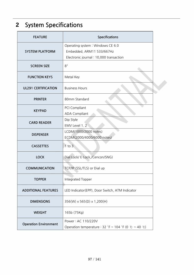
2 System Specifications
FEATURE Specifications
SYSTEM PLATFORM
Operating system : Windows CE 6.0
Embedded, ARM11 533/667Hz
Electronic journal : 10,000 transaction
SCREEN SIZE 8"
FUNCTION KEYS Metal Key
UL291 CERTIFICATION Business Hours
PRINTER 80mm Standard
KEYPAD PCI Compliant
ADA Compliant
CARD READER Dip Style
EMV Level 1. 2
DISPENSER LCDM(1000/2000 notes)
ECDM(2000/4000/6000 notes)
CASSETTES 1 to 3
LOCK Dial Lock/ E-Lock,/Cencon/SNG)
COMMUNICATION TCP/IP (SSL/TLS) or Dial up
TOPPER Integrated Topper
ADDITIONAL FEATURES LED Indicator(EPP), Door Switch, ATM Indicator
DIMENSIONS 356(W) x 565(D) x 1,200(H)
WEIGHT 165b (75Kg)
Operation Environment Power : AC 110/220V
Operation temperature : 32 °F ~ 104 °F (0 ℃ ~ 40 ℃)

98 / 141
3 H/W Operation and Maintenance
3.1 SYSTEM POWER
1) Turn on the Power Switch.
>> Turn on Power Switch of SMPS.
>> To turn off the system power, and turn off the power switch of SMPS.
Figure 3. Power Switch of SMPS
99 / 141
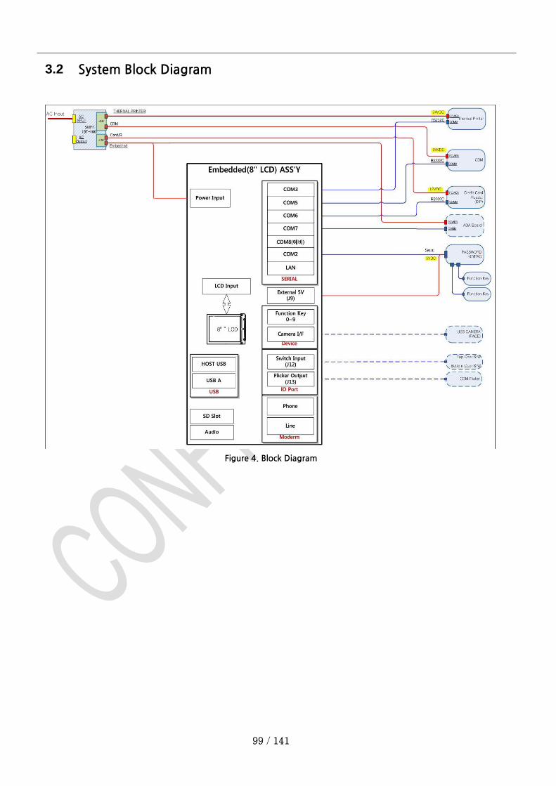
3.2 System Block Diagram
Figure 4. Block Diagram

100 / 141
3.3 Embedded-PC (WinCE 6.0)
3.3.1 Device Parts
COM2 : KEPAD(EPP)
COM3 : Thermal Printer(DH)
COM5 : Cash Dispenser(CDM)
COM6 : Card Reader(C/R)
COM7 : Reserved
COM1 : Debug
3.3.2 ETC Parts Port
>> Power
>> I/O IN (J12) : 10Pin Connector Lower Door Switch
>> I/O OUT (J13) : 8Pin Connector EPP Flicker & ATM_Logo Flicker
>> 5V OUT (J9) : KEYPAD Power
>> Function Key(J10) : 12Pin Function Key Left/Right
>> SD CARD : SD Slot
Figure 6. ETC Parts Port
Figure 5. Device Port
101 / 141
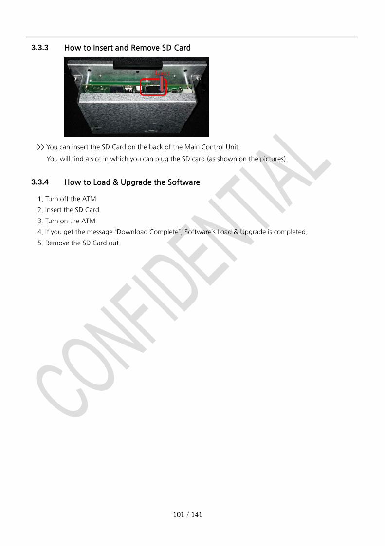
3.3.3 How to Insert and Remove SD Card
>> You can insert the SD Card on the back of the Main Control Unit.
You will find a slot in which you can plug the SD card (as shown on the pictures).
3.3.4 How to Load & Upgrade the Software
1. Turn off the ATM
2. Insert the SD Card
3. Turn on the ATM
4. If you get the message “Download Complete”, Software’s Load & Upgrade is completed.
5. Remove the SD Card out.
Insert
102 / 141
3.3.5 Check for Abnormality of Electric Power
LED18 : 12V Power ON
LED1 : 5V Power ON
LED19 : 3.3V Power ON
※ 12V, 5V External Power
● Voltage check : Check for the voltage with tester
1. EC15 check on both ends, 3.3V
2. EC13 check on both ends, 1.8V
3. EC16 check on both ends, 1.2V
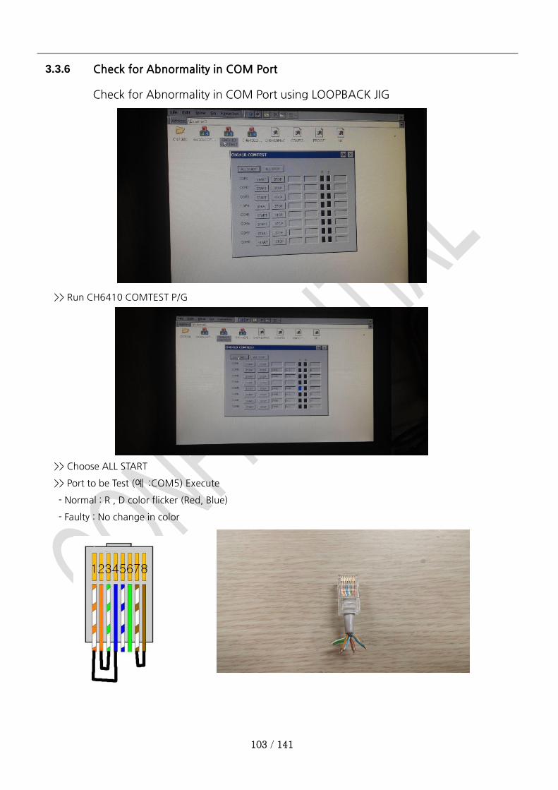
103 / 141
3.3.6 Check for Abnormality in COM Port
Check for Abnormality in COM Port using LOOPBACK JIG
>> Run CH6410 COMTEST P/G
>> Choose ALL START
>> Port to be Test (예 :COM5) Execute
- Normal : R , D color flicker (Red, Blue)
- Faulty : No change in color
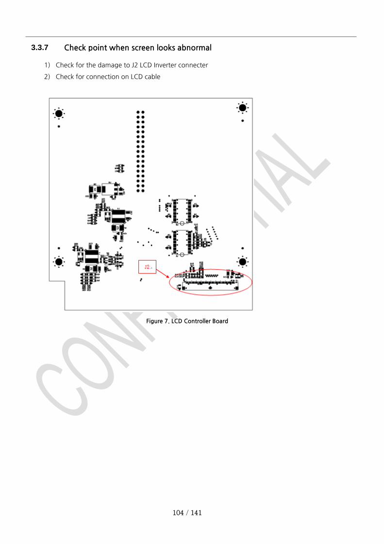
104 / 141
3.3.7 Check point when screen looks abnormal
1) Check for the damage to J2 LCD Inverter connecter
2) Check for connection on LCD cable
Figure 7. LCD Controller Board
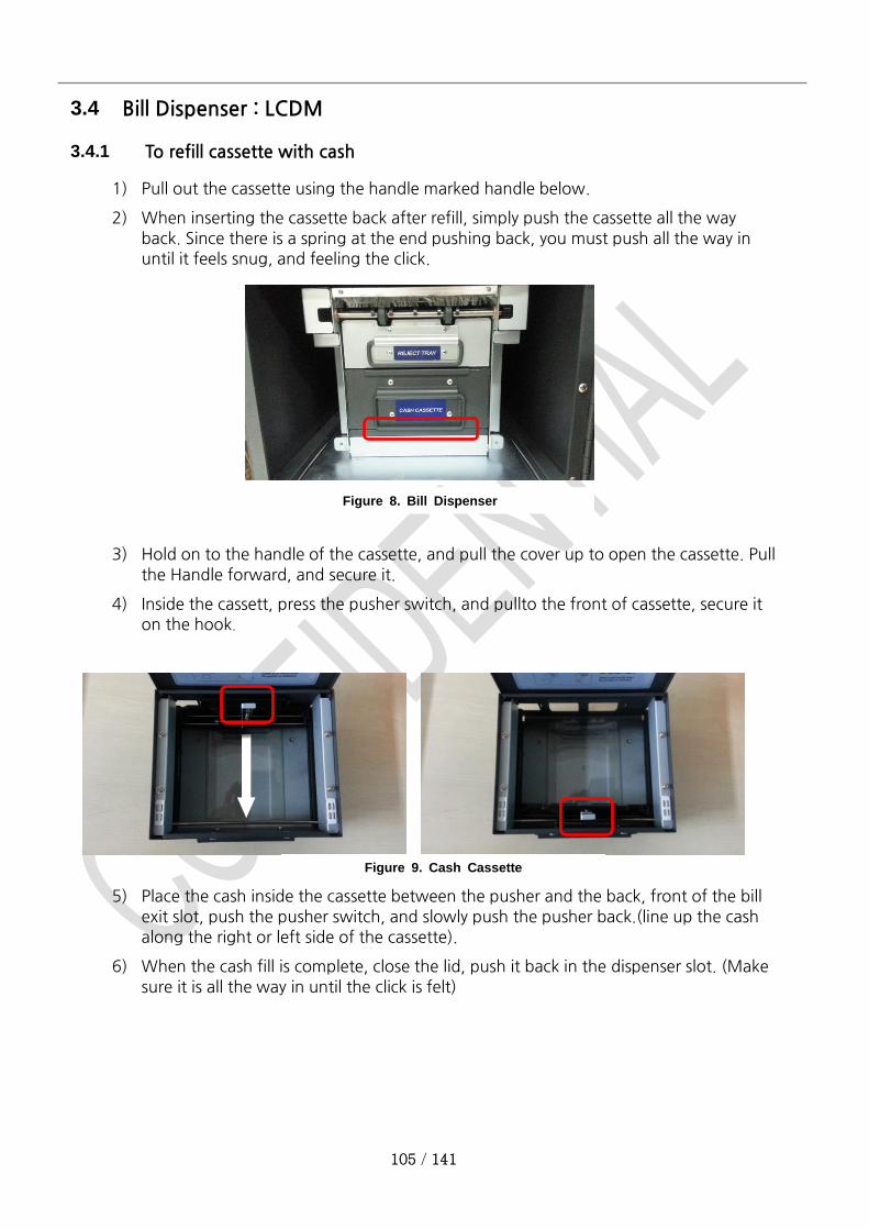
105 / 141
3.4 Bill Dispenser : LCDM
3.4.1 To refill cassette with cash
1) Pull out the cassette using the handle marked handle below.
2) When inserting the cassette back after refill, simply push the cassette all the way
back. Since there is a spring at the end pushing back, you must push all the way in
until it feels snug, and feeling the click.
3) Hold on to the handle of the cassette, and pull the cover up to open the cassette. Pull
the Handle forward, and secure it.
4) Inside the cassett, press the pusher switch, and pullto the front of cassette, secure it
on the hook.
5) Place the cash inside the cassette between the pusher and the back, front of the bill
exit slot, push the pusher switch, and slowly push the pusher back.(line up the cash
along the right or left side of the cassette).
6) When the cash fill is complete, close the lid, push it back in the dispenser slot. (Make
sure it is all the way in until the click is felt)
Figure 6. Bill Despenser
Figure 9. Cash Cassette
Figure 8. Bill Dispenser
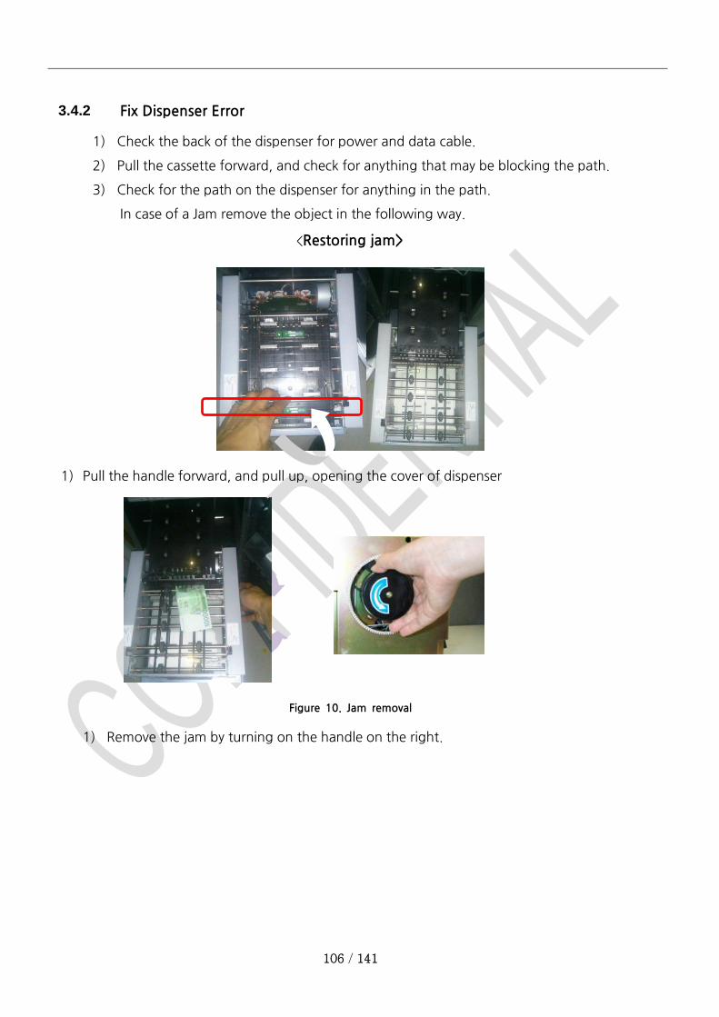
106 / 141
3.4.2 Fix Dispenser Error
1) Check the back of the dispenser for power and data cable.
2) Pull the cassette forward, and check for anything that may be blocking the path.
3) Check for the path on the dispenser for anything in the path.
In case of a Jam remove the object in the following way.
<Restoring jam>
1) Pull the handle forward, and pull up, opening the cover of dispenser
Figure 10. Jam removal
1) Remove the jam by turning on the handle on the right.

107 / 141
3.5 Card Reader
3.5.1 Card reader instruction
1) When instructed to do so on the screen, insert the card all the way back to the card
reader. As the Dip Type, push all the way until it clicks.
3.5.2 In case of card reader error
1) Check the power switch and data cable connection.
>> Both data and 12V power are connected by a single cable.
: check 12V power and COM6 Port
: check for any damage to the Cable( including bracket)
2) When communication functions normally between AP Program, LED will turn On
Figure 11. Card Reader Cable drawing
Figure 12. Card Reader LED
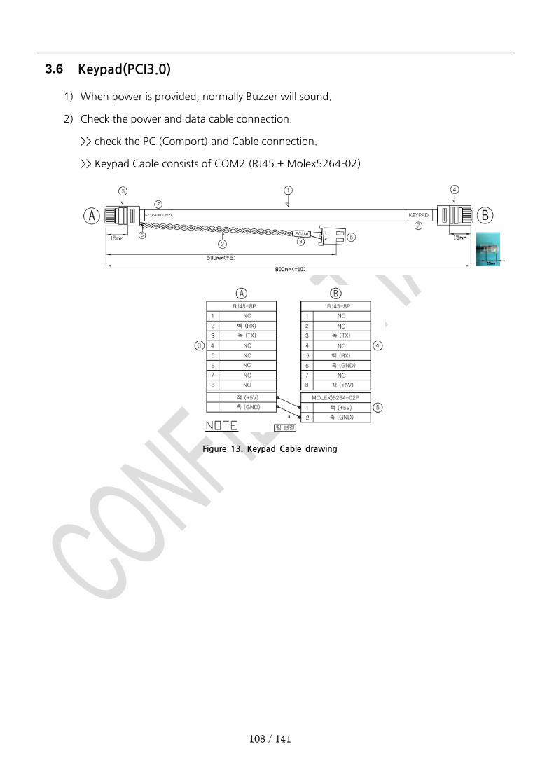
108 / 141
3.6 Keypad(PCI3.0)
1) When power is provided, normally Buzzer will sound.
2) Check the power and data cable connection.
>> check the PC (Comport) and Cable connection.
>> Keypad Cable consists of COM2 (RJ45 + Molex5264-02)
Figure 13. Keypad Cable drawing

109 / 141
3.7 SMPS
1) Check connection
+5V (2Pin) : Embedded Board
+12V (4Pin) : Card Reader, Embedded Board
+24V (6Pin) : Cash Dispenser. Receipt Printer
Input Voltage Range : AC90V~264V
Output Voltage Range : DC 11.4V~12.6V, 23.5V~26.5V, 4.75V~5.25V
Figure 14. SMPS Connector
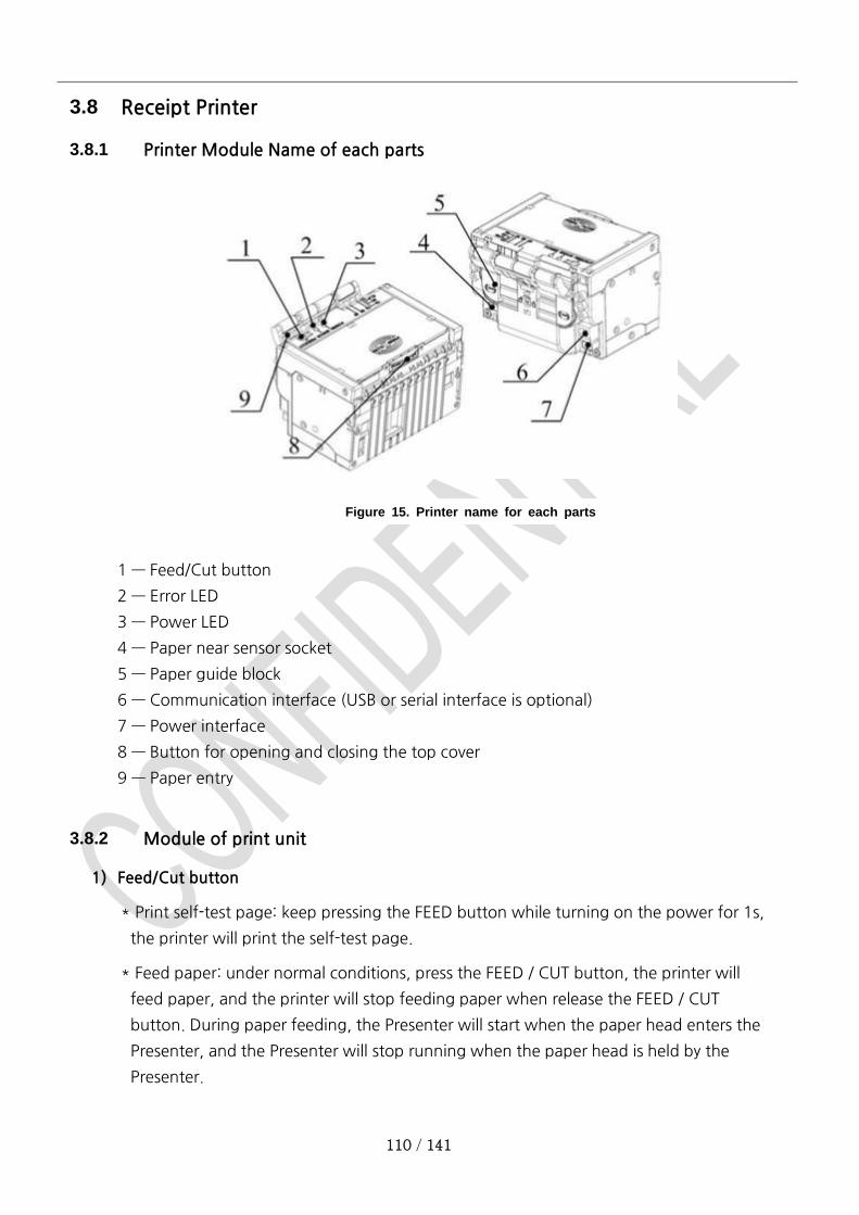
110 / 141
3.8 Receipt Printer
3.8.1 Printer Module Name of each parts
1 — Feed/Cut button
2 — Error LED
3 — Power LED
4 — Paper near sensor socket
5 — Paper guide block
6 — Communication interface (USB or serial interface is optional)
7 — Power interface
8 — Button for opening and closing the top cover
9 — Paper entry
3.8.2 Module of print unit
1) Feed/Cut button
* Print self-test page: keep pressing the FEED button while turning on the power for 1s,
the printer will print the self-test page.
* Feed paper: under normal conditions, press the FEED / CUT button, the printer will
feed paper, and the printer will stop feeding paper when release the FEED / CUT
button. During paper feeding, the Presenter will start when the paper head enters the
Presenter, and the Presenter will stop running when the paper head is held by the
Presenter.
Figure 15. Printer name for each parts
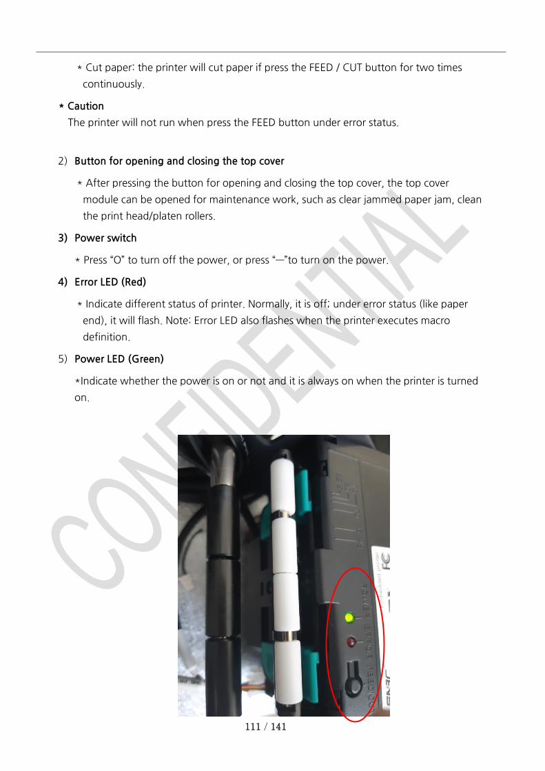
111 / 141
* Cut paper: the printer will cut paper if press the FEED / CUT button for two times
continuously.
* Caution
The printer will not run when press the FEED button under error status.
2) Button for opening and closing the top cover
* After pressing the button for opening and closing the top cover, the top cover
module can be opened for maintenance work, such as clear jammed paper jam, clean
the print head/platen rollers.
3) Power switch
* Press “O” to turn off the power, or press “—”to turn on the power.
4) Error LED (Red)
* Indicate different status of printer. Normally, it is off; under error status (like paper
end), it will flash. Note: Error LED also flashes when the printer executes macro
definition.
5) Power LED (Green)
*Indicate whether the power is on or not and it is always on when the printer is turned
on.
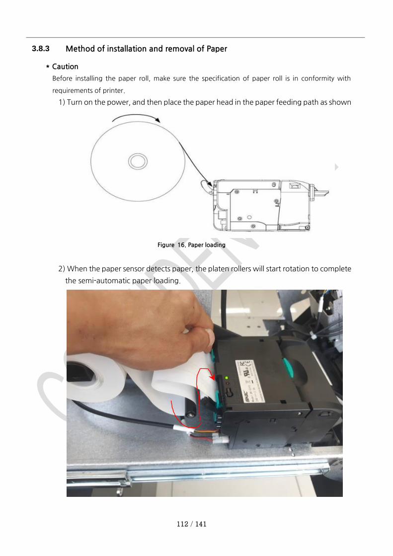
112 / 141
3.8.3 Method of installation and removal of Paper
* Caution
Before installing the paper roll, make sure the specification of paper roll is in conformity with
requirements of printer.
1) Turn on the power, and then place the paper head in the paper feeding path as shown
Figure 16. Paper loading
2) When the paper sensor detects paper, the platen rollers will start rotation to complete
the semi-automatic paper loading.
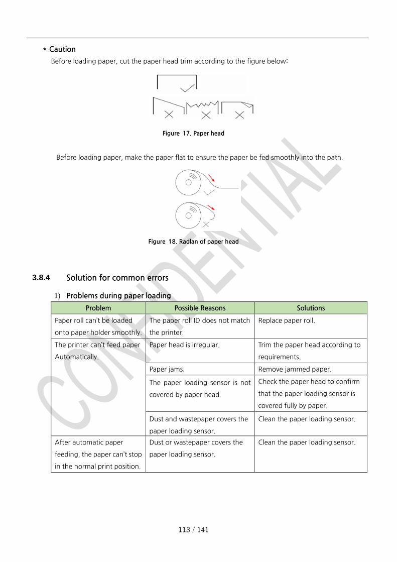
113 / 141
* Caution
Before loading paper, cut the paper head trim according to the figure below:
Figure 17. Paper head
Before loading paper, make the paper flat to ensure the paper be fed smoothly into the path.
Figure 18. Radlan of paper head
3.8.4 Solution for common errors
1) Problems during paper loading
Problem Possible Reasons Solutions
Paper roll can’t be loaded
onto paper holder smoothly.
The paper roll ID does not match
the printer.
Replace paper roll.
The printer can’t feed paper
Automatically.
Paper head is irregular. Trim the paper head according to
requirements.
Paper jams. Remove jammed paper.
The paper loading sensor is not
covered by paper head.
Check the paper head to confirm
that the paper loading sensor is
covered fully by paper.
Dust and wastepaper covers the
paper loading sensor.
Clean the paper loading sensor.
After automatic paper
feeding, the paper can’t stop
in the normal print position.
Dust or wastepaper covers the
paper loading sensor.
Clean the paper loading sensor.
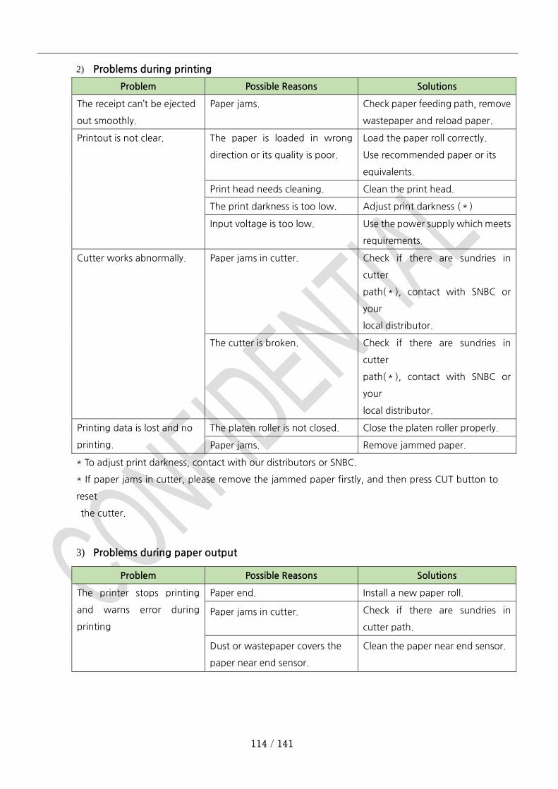
114 / 141
2) Problems during printing
Problem Possible Reasons Solutions
The receipt can’t be ejected
out smoothly.
Paper jams. Check paper feeding path, remove
wastepaper and reload paper.
Printout is not clear. The paper is loaded in wrong
direction or its quality is poor.
Load the paper roll correctly.
Use recommended paper or its
equivalents.
Print head needs cleaning. Clean the print head.
The print darkness is too low. Adjust print darkness (*)
Input voltage is too low. Use the power supply which meets
requirements.
Cutter works abnormally. Paper jams in cutter. Check if there are sundries in
cutter
path(*), contact with SNBC or
your
local distributor.
The cutter is broken. Check if there are sundries in
cutter
path(*), contact with SNBC or
your
local distributor.
Printing data is lost and no
printing.
The platen roller is not closed. Close the platen roller properly.
Paper jams. Remove jammed paper.
* To adjust print darkness, contact with our distributors or SNBC.
* If paper jams in cutter, please remove the jammed paper firstly, and then press CUT button to
reset
the cutter.
3) Problems during paper output
Problem Possible Reasons Solutions
The printer stops printing
and warns error during
printing
Paper end. Install a new paper roll.
Paper jams in cutter. Check if there are sundries in
cutter path.
Dust or wastepaper covers the
paper near end sensor.
Clean the paper near end sensor.
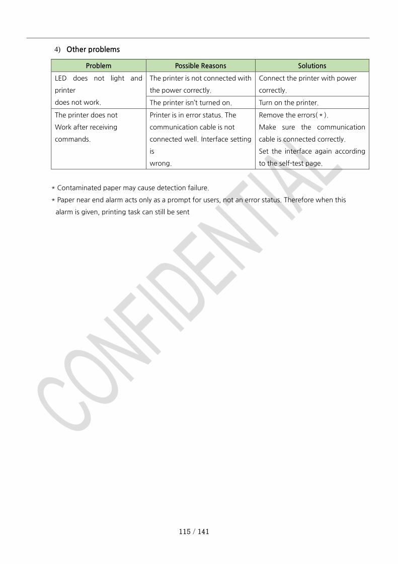
115 / 141
4) Other problems
Problem Possible Reasons Solutions
LED does not light and
printer
does not work.
The printer is not connected with
the power correctly.
Connect the printer with power
correctly.
The printer isn’t turned on. Turn on the printer.
The printer does not
Work after receiving
commands.
Printer is in error status. The
communication cable is not
connected well. Interface setting
is
wrong.
Remove the errors(*).
Make sure the communication
cable is connected correctly.
Set the interface again according
to the self-test page.
* Contaminated paper may cause detection failure.
* Paper near end alarm acts only as a prompt for users, not an error status. Therefore when this
alarm is given, printing task can still be sent
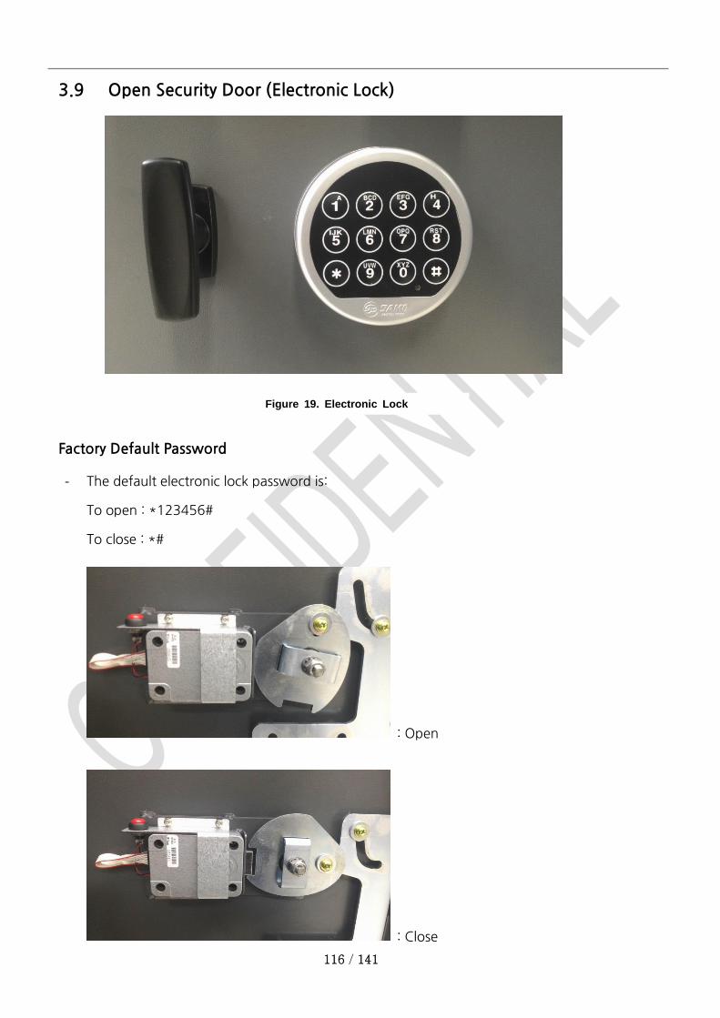
116 / 141
3.9 Open Security Door (Electronic Lock)
Factory Default Password
- The default electronic lock password is:
To open : *123456#
To close : *#
: Open
: Close
Figure 19. Electronic Lock
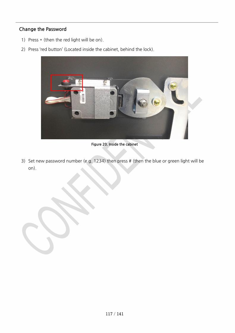
117 / 141
Change the Password
1) Press * (then the red light will be on).
2) Press ‘red button’ (Located inside the cabinet, behind the lock).
Figure 20. Inside the cabinet
3) Set new password number (e.g. 1234) then press # (then the blue or green light will be
on).
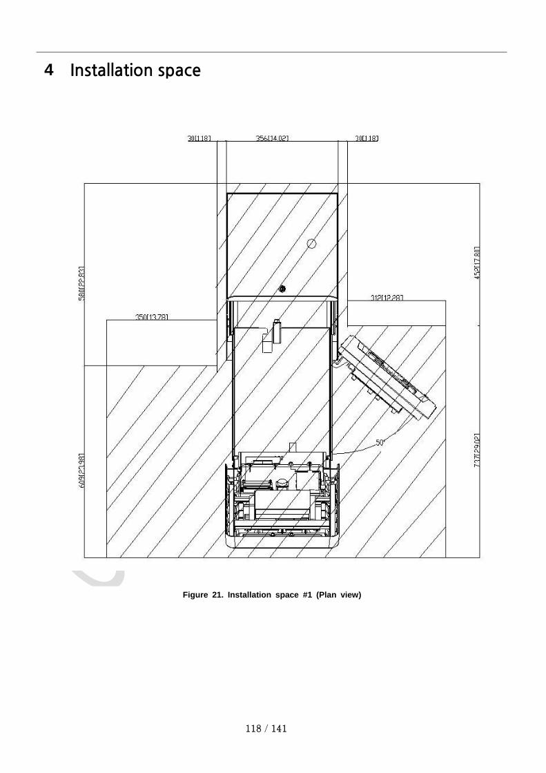
118 / 141
4 Installation space
Figure 21. Installation space #1 (Plan view)

119 / 141
Figure 22. Installation space #2 (Side view)

120 / 141
5 PL-MU101T Dimension
Figure 23. Dimension of PL-MU101T
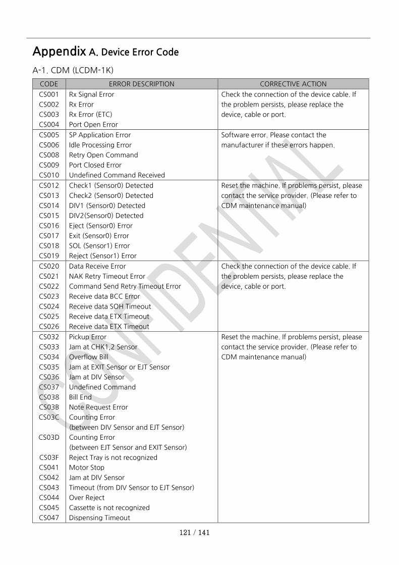
121 / 141
Appendix A. Device Error Code
A-1. CDM (LCDM-1K)
CODE ERROR DESCRIPTION CORRECTIVE ACTION
CS001
CS002
CS003
CS004
Rx Signal Error
Rx Error
Rx Error (ETC)
Port Open Error
Check the connection of the device cable. If
the problem persists, please replace the
device, cable or port.
CS005
CS006
CS008
CS009
CS010
SP Application Error
Idle Processing Error
Retry Open Command
Port Closed Error
Undefined Command Received
Software error. Please contact the
manufacturer if these errors happen.
CS012
CS013
CS014
CS015
CS016
CS017
CS018
CS019
Check1 (Sensor0) Detected
Check2 (Sensor0) Detected
DIV1 (Sensor0) Detected
DIV2(Sensor0) Detected
Eject (Sensor0) Error
Exit (Sensor0) Error
SOL (Sensor1) Error
Reject (Sensor1) Error
Reset the machine. If problems persist, please
contact the service provider. (Please refer to
CDM maintenance manual)
CS020
CS021
CS022
CS023
CS024
CS025
CS026
Data Receive Error
NAK Retry Timeout Error
Command Send Retry Timeout Error
Receive data BCC Error
Receive data SOH Timeout
Receive data ETX Timeout
Receive data ETX Timeout
Check the connection of the device cable. If
the problem persists, please replace the
device, cable or port.
CS032
CS033
CS034
CS035
CS036
CS037
CS038
CS03B
CS03C
CS03D
CS03F
CS041
CS042
CS043
CS044
CS045
CS047
Pickup Error
Jam at CHK1,2 Sensor
Overflow Bill
Jam at EXIT Sensor or EJT Sensor
Jam at DIV Sensor
Undefined Command
Bill End
Note Request Error
Counting Error
(between DIV Sensor and EJT Sensor)
Counting Error
(between EJT Sensor and EXIT Sensor)
Reject Tray is not recognized
Motor Stop
Jam at DIV Sensor
Timeout (from DIV Sensor to EJT Sensor)
Over Reject
Cassette is not recognized
Dispensing Timeout
Reset the machine. If problems persist, please
contact the service provider. (Please refer to
CDM maintenance manual)
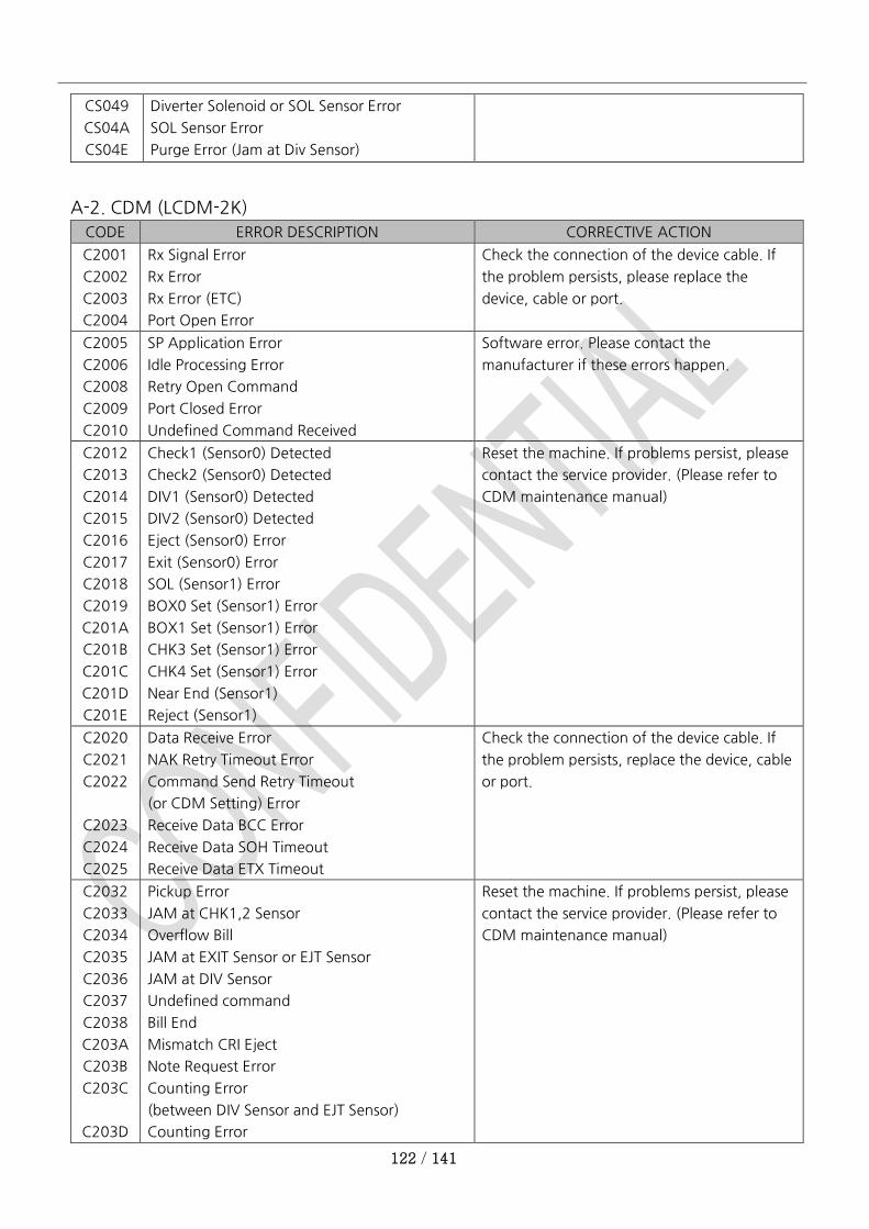
122 / 141
CS049
CS04A
CS04E
Diverter Solenoid or SOL Sensor Error
SOL Sensor Error
Purge Error (Jam at Div Sensor)
A-2. CDM (LCDM-2K)
CODE ERROR DESCRIPTION CORRECTIVE ACTION
C2001
C2002
C2003
C2004
Rx Signal Error
Rx Error
Rx Error (ETC)
Port Open Error
Check the connection of the device cable. If
the problem persists, please replace the
device, cable or port.
C2005
C2006
C2008
C2009
C2010
SP Application Error
Idle Processing Error
Retry Open Command
Port Closed Error
Undefined Command Received
Software error. Please contact the
manufacturer if these errors happen.
C2012
C2013
C2014
C2015
C2016
C2017
C2018
C2019
C201A
C201B
C201C
C201D
C201E
Check1 (Sensor0) Detected
Check2 (Sensor0) Detected
DIV1 (Sensor0) Detected
DIV2 (Sensor0) Detected
Eject (Sensor0) Error
Exit (Sensor0) Error
SOL (Sensor1) Error
BOX0 Set (Sensor1) Error
BOX1 Set (Sensor1) Error
CHK3 Set (Sensor1) Error
CHK4 Set (Sensor1) Error
Near End (Sensor1)
Reject (Sensor1)
Reset the machine. If problems persist, please
contact the service provider. (Please refer to
CDM maintenance manual)
C2020
C2021
C2022
C2023
C2024
C2025
Data Receive Error
NAK Retry Timeout Error
Command Send Retry Timeout
(or CDM Setting) Error
Receive Data BCC Error
Receive Data SOH Timeout
Receive Data ETX Timeout
Check the connection of the device cable. If
the problem persists, replace the device, cable
or port.
C2032
C2033
C2034
C2035
C2036
C2037
C2038
C203A
C203B
C203C
C203D
Pickup Error
JAM at CHK1,2 Sensor
Overflow Bill
JAM at EXIT Sensor or EJT Sensor
JAM at DIV Sensor
Undefined command
Bill End
Mismatch CRI Eject
Note Request Error
Counting Error
(between DIV Sensor and EJT Sensor)
Counting Error
Reset the machine. If problems persist, please
contact the service provider. (Please refer to
CDM maintenance manual)
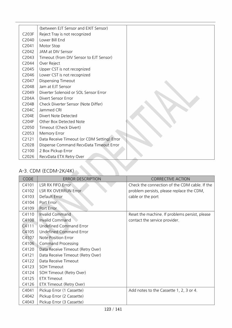
123 / 141
C203F
C2040
C2041
C2042
C2043
C2044
C2045
C2046
C2047
C2048
C2049
C204A
C204B
C204C
C204E
C204F
C2050
C2053
C2121
C2028
C2100
C2026
(between EJT Sensor and EXIT Sensor)
Reject Tray is not recognized
Lower Bill End
Motor Stop
JAM at DIV Sensor
Timeout (from DIV Sensor to EJT Sensor)
Over Reject
Upper CST is not recognized
Lower CST is not recognized
Dispensing Timeout
Jam at EJT Sensor
Diverter Solenoid or SOL Sensor Error
Divert Sensor Error
Check Diverter Sensor (Note Differ)
Jammed CRI
Divert Note Detected
Other Box Detected Note
Timeout (Check Divert)
Memory Error
Data Receive Timeout (or CDM Setting) Error
Dispense Command RecvData Timeout Error
2 Box Pickup Error
RecvData ETX Retry Over
A-3. CDM (ECDM-2K/4K)
CODE ERROR DESCRIPTION CORRECTIVE ACTION
C4101
C4102
C4103
C4104
C4109
LSR RX FIFO Error
LSR RX OVERRUN Error
Default Error
Port Error
Port Error
Check the connection of the CDM cable. If the
problem persists, please replace the CDM,
cable or the port
C4110
C4108
C4111
C4105
C4107
C4106
C4120
C4121
C4122
C4123
C4124
C4125
C4126
Invalid Command
Invalid Command
Undefined Command Error
Undefined Command Error
Note Position Error
Command Processing
Data Receive Timeout (Retry Over)
Data Receive Timeout (Retry Over)
Data Receive Timeout
SOH Timeout
SOH Timeout (Retry Over)
ETX Timeout
ETX Timeout (Retry Over)
Reset the machine. If problems persist, please
contact the service provider.
C4041
C4042
C4043
Pickup Error (1 Cassette)
Pickup Error (2 Cassette)
Pickup Error (3 Cassette)
Add notes to the Cassette 1, 2, 3 or 4.

124 / 141
C4044 Pickup Error (4 Cassette)
C4002
C4003
C4004
C4005
C4006
Timeout on feeding between CHK Sensor and
RVDT Start Sensor
Timeout on feeding between DIV Sensor and
EJT Sensor
Timeout on feeding between EJT Sensor and
EXIT Sensor
A note is not passed on EXIT Sensor
Ejecting the note suspected as rejected
C4007
C4008
C4009
C400A
C400B
C400C
C400D
C400E
C4020
C4021
C4022
C4023
C4024
C4025
C4010
C4FFF
Abnormal Note Management
Abnormal Note Management
Jamming on EJT Sensor
Jamming on EXT Sensor
Detecting Notes on the path before Start of
pick-up
Dispensing too many notes for one transaction
(120 notes)
Rejecting too many notes for one transaction
(Default limit: 20 notes)
Abnormal Termination during Purge Execution
Detecting sensor trouble or abnormal material
before start
Detecting sensor trouble or abnormal material
before start
Detecting trouble of solenoid operation before
dispense
Detecting trouble in motor or slit sensor before
dispense
Detecting no cassette0 requested to dispense
banknotes
Detecting Near End Status in the Cassette
Requested to Dispense (When Near End
Detection Mode is Turned On)
Data Receive Timeout (or CDM Setting)
CDM Setting Error
Reset the machine. If problems persist, please
contact the service provider. (Please refer to
CDM maintenance manual)
C4026
C4027
C4028
C4029
C402A
C402B
C402C
C4030
C4031
Detecting no reject cassette before start or for
operation
Failed to calibrate sensors
Jamming or sensor failure in the Cash Cassette
More banknotes than the requested are
dispensed
Jamming between RVDT Start Sensor and DIV
Sensor
Dispensing is not terminated within 90 seconds
Detecting no cassette1 requested to dispense
banknotes
Recognizing abnormal Command
Recognizing abnormal Parameters on the
Reset the machine. If problems persist, please
contact the service provider. (Please refer to
CDM maintenance manual)
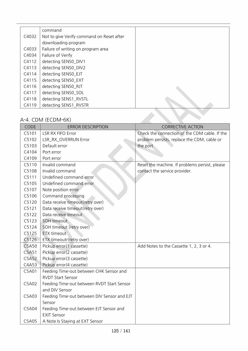
125 / 141
C4032
C4033
C4034
C4112
C4113
C4114
C4115
C4116
C4117
C4118
C4119
command
Not to give Verify command on Reset after
downloading program
Failure of writing on program area
Failure of Verify
detecting SENS0_DIV1
detecting SENS0_DIV2
detecting SENS0_EJT
detecting SENS0_EXT
detecting SENS0_RJT
detecting SENS0_SOL
detecting SENS1_RVSTL
detecting SENS1_RVSTR
A-4. CDM (ECDM-6K)
CODE ERROR DESCRIPTION CORRECTIVE ACTION
C5101
C5102
C5103
C4104
C4109
LSR RX FIFO Error
LSR_RX_OVERRUN Error
Default error
Port error
Port error
Check the connection of the CDM cable. If the
problem persists, replace the CDM, cable or
the port
C5110
C5108
C5111
C5105
C5107
C5106
C5120
C5121
C5122
C5123
C5124
C5125
C5126
Invalid command
Invalid command
Undefined command error
Undefined command error
Note position error
Command processing
Data receive timeout(retry over)
Data receive timeout(retry over)
Data receive timeout
SOH timeout
SOH timeout (retry over)
ETX timeout
ETX timeoutr(retry over)
Reset the machine. If problems persist, please
contact the service provider.
C5A50
C5A51
C5A52
C4A53
Pickup error(1 cassette)
Pickup error(2 cassette)
Pickup error(3 cassette)
Pickup error(4 cassette)
Add Notes to the Cassette 1, 2, 3 or 4.
C5A01
C5A02
C5A03
C5A04
C5A05
Feeding Time-out between CHK Sensor and
RVDT Start Sensor
Feeding Time-out between RVDT Start Sensor
and DIV Sensor
Feeding Time-out between DIV Sensor and EJT
Sensor
Feeding Time-out between EJT Sensor and
EXIT Sensor
A Note Is Staying at EXT Sensor
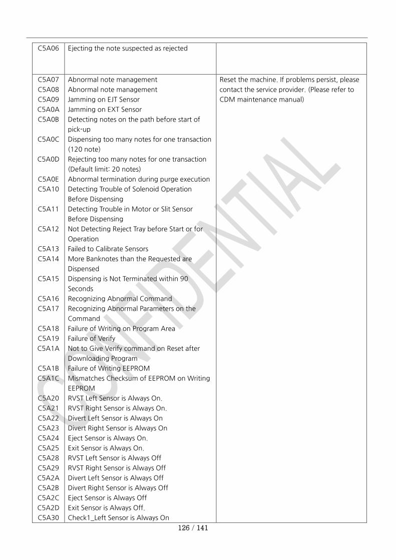
126 / 141
C5A06 Ejecting the note suspected as rejected
C5A07
C5A08
C5A09
C5A0A
C5A0B
C5A0C
C5A0D
C5A0E
C5A10
C5A11
C5A12
C5A13
C5A14
C5A15
C5A16
C5A17
C5A18
C5A19
C5A1A
C5A1B
C5A1C
C5A20
C5A21
C5A22
C5A23
C5A24
C5A25
C5A28
C5A29
C5A2A
C5A2B
C5A2C
C5A2D
C5A30
Abnormal note management
Abnormal note management
Jamming on EJT Sensor
Jamming on EXT Sensor
Detecting notes on the path before start of
pick-up
Dispensing too many notes for one transaction
(120 note)
Rejecting too many notes for one transaction
(Default limit: 20 notes)
Abnormal termination during purge execution
Detecting Trouble of Solenoid Operation
Before Dispensing
Detecting Trouble in Motor or Slit Sensor
Before Dispensing
Not Detecting Reject Tray before Start or for
Operation
Failed to Calibrate Sensors
More Banknotes than the Requested are
Dispensed
Dispensing is Not Terminated within 90
Seconds
Recognizing Abnormal Command
Recognizing Abnormal Parameters on the
Command
Failure of Writing on Program Area
Failure of Verify
Not to Give Verify command on Reset after
Downloading Program
Failure of Writing EEPROM
Mismatches Checksum of EEPROM on Writing
EEPROM
RVST Left Sensor is Always On.
RVST Right Sensor is Always On.
Divert Left Sensor is Always On
Divert Right Sensor is Always On
Eject Sensor is Always On.
Exit Sensor is Always On.
RVST Left Sensor is Always Off
RVST Right Sensor is Always Off
Divert Left Sensor is Always Off
Divert Right Sensor is Always Off
Eject Sensor is Always Off
Exit Sensor is Always Off.
Check1_Left Sensor is Always On
Reset the machine. If problems persist, please
contact the service provider. (Please refer to
CDM maintenance manual)
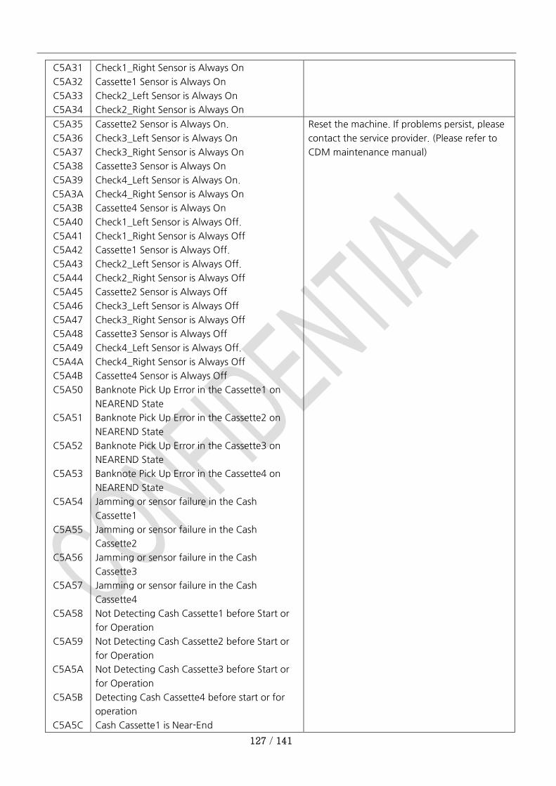
127 / 141
C5A31
C5A32
C5A33
C5A34
Check1_Right Sensor is Always On
Cassette1 Sensor is Always On
Check2_Left Sensor is Always On
Check2_Right Sensor is Always On
C5A35
C5A36
C5A37
C5A38
C5A39
C5A3A
C5A3B
C5A40
C5A41
C5A42
C5A43
C5A44
C5A45
C5A46
C5A47
C5A48
C5A49
C5A4A
C5A4B
C5A50
C5A51
C5A52
C5A53
C5A54
C5A55
C5A56
C5A57
C5A58
C5A59
C5A5A
C5A5B
C5A5C
Cassette2 Sensor is Always On.
Check3_Left Sensor is Always On
Check3_Right Sensor is Always On
Cassette3 Sensor is Always On
Check4_Left Sensor is Always On.
Check4_Right Sensor is Always On
Cassette4 Sensor is Always On
Check1_Left Sensor is Always Off.
Check1_Right Sensor is Always Off
Cassette1 Sensor is Always Off.
Check2_Left Sensor is Always Off.
Check2_Right Sensor is Always Off
Cassette2 Sensor is Always Off
Check3_Left Sensor is Always Off
Check3_Right Sensor is Always Off
Cassette3 Sensor is Always Off
Check4_Left Sensor is Always Off.
Check4_Right Sensor is Always Off
Cassette4 Sensor is Always Off
Banknote Pick Up Error in the Cassette1 on
NEAREND State
Banknote Pick Up Error in the Cassette2 on
NEAREND State
Banknote Pick Up Error in the Cassette3 on
NEAREND State
Banknote Pick Up Error in the Cassette4 on
NEAREND State
Jamming or sensor failure in the Cash
Cassette1
Jamming or sensor failure in the Cash
Cassette2
Jamming or sensor failure in the Cash
Cassette3
Jamming or sensor failure in the Cash
Cassette4
Not Detecting Cash Cassette1 before Start or
for Operation
Not Detecting Cash Cassette2 before Start or
for Operation
Not Detecting Cash Cassette3 before Start or
for Operation
Detecting Cash Cassette4 before start or for
operation
Cash Cassette1 is Near-End
Reset the machine. If problems persist, please
contact the service provider. (Please refer to
CDM maintenance manual)

128 / 141
C5A5D
C5A5E
C5A5F
C5A60
C5A61
C5A62
C5A63
C5A64
C5A65
C5A66
C5A67
C5A68
C5A69
C5A6A
C5A6B
C5A6C
C5A6D
C5A6E
C5A6F
C5FFF
(In Case of Near End Detection Mode)
Cash-Cassette2 is Near-End
(In Case of Near End Detection Mode)
Cash-Cassette3 is Near-End
(In Case of Near End Detection Mode)
Cash-Cassette4 is Near-End
(In Case of Near End Detection Mode)
Pick-up Error in Cassette1
( Banknotes exist in Cash Cassette1)
Pick-up Error in Cassette2
( Banknotes exist in Cash Cassette2)
Pick-up Error in Cassette3
( Banknotes exist in Cash Cassette3)
Pick-up Error in Cassette4
( Banknotes exist in Cash Cassette4)
Different between Type of Cassette1 Set to
Main Body (Control Board) and Type of Cash
Cassette1 by Dip Switches
Different between Type of Cassette2 Set to
Main Body (Control Board) and Type of Cash
Cassette2 by Dip Switches
Different between Type of Cassette3 Set to
Main Body (Control Board) and Type of Cash
Cassette3 by Dip Switches
Different between Type of Cassette4 Set to
Main Body (Control Board) and Type of Cash
Cassette4 by Dip Switches
Cannot Find Type1 Cassette on Request of
Dispensing Type1
Cannot Find Type2 Cassette on Request of
Dispensing Type2
Cannot Find Type3 Cassette on Request of
Dispensing Type3
Cannot Find Type4 Cassette on Request of
Dispensing Type4
All Type1 Cassettes Are under Bill End Status
on Request of Dispensing Type1
All Type2 Cassettes Are under Bill End Status
on Request of Dispensing Type2
All Type3 Cassettes Are under Bill End Status
on Request of Dispensing Type3
All Type4 Cassettes Are under Bill End Status
on Request of Dispensing Type4
CDM Setting Error
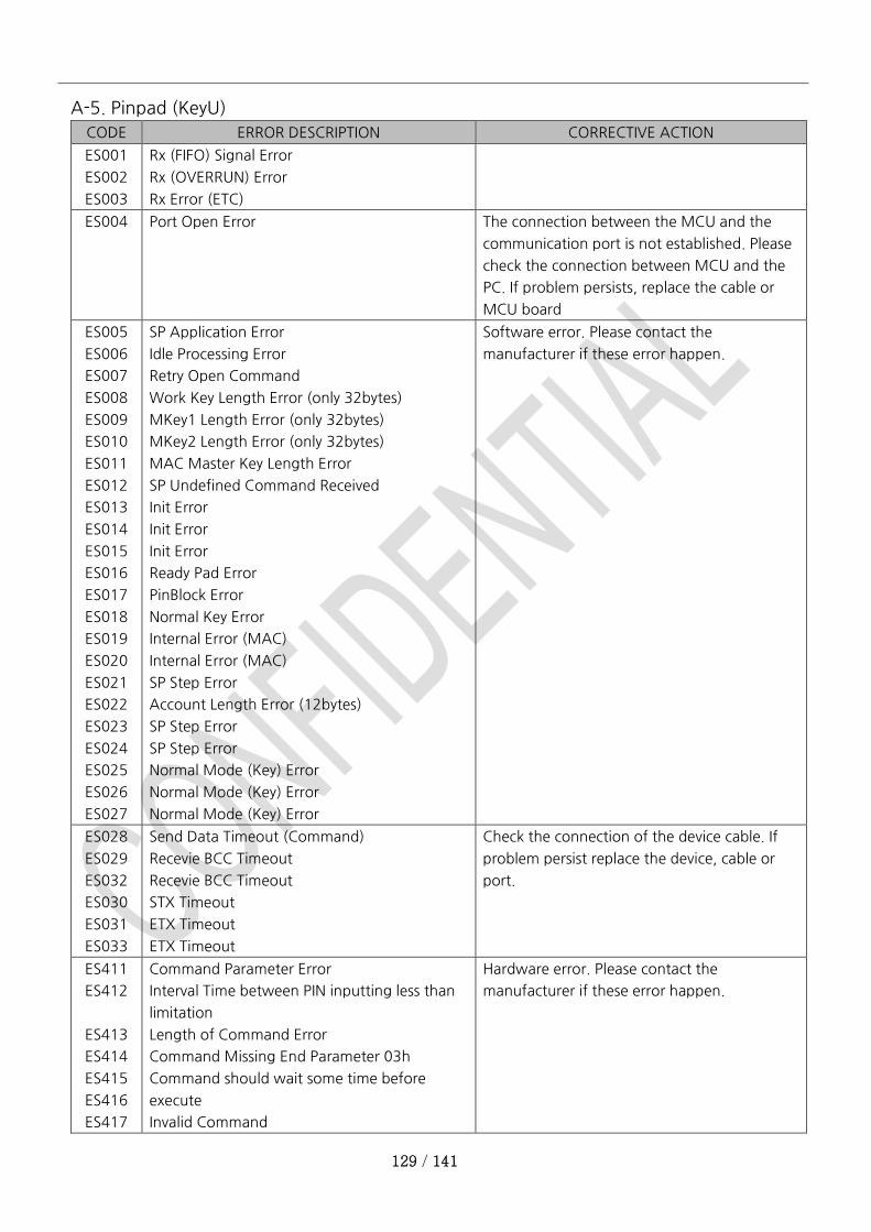
129 / 141
A-5. Pinpad (KeyU)
CODE ERROR DESCRIPTION CORRECTIVE ACTION
ES001
ES002
ES003
Rx (FIFO) Signal Error
Rx (OVERRUN) Error
Rx Error (ETC)
ES004 Port Open Error The connection between the MCU and the
communication port is not established. Please
check the connection between MCU and the
PC. If problem persists, replace the cable or
MCU board
ES005
ES006
ES007
ES008
ES009
ES010
ES011
ES012
ES013
ES014
ES015
ES016
ES017
ES018
ES019
ES020
ES021
ES022
ES023
ES024
ES025
ES026
ES027
SP Application Error
Idle Processing Error
Retry Open Command
Work Key Length Error (only 32bytes)
MKey1 Length Error (only 32bytes)
MKey2 Length Error (only 32bytes)
MAC Master Key Length Error
SP Undefined Command Received
Init Error
Init Error
Init Error
Ready Pad Error
PinBlock Error
Normal Key Error
Internal Error (MAC)
Internal Error (MAC)
SP Step Error
Account Length Error (12bytes)
SP Step Error
SP Step Error
Normal Mode (Key) Error
Normal Mode (Key) Error
Normal Mode (Key) Error
Software error. Please contact the
manufacturer if these error happen.
ES028
ES029
ES032
ES030
ES031
ES033
Send Data Timeout (Command)
Recevie BCC Timeout
Recevie BCC Timeout
STX Timeout
ETX Timeout
ETX Timeout
Check the connection of the device cable. If
problem persist replace the device, cable or
port.
ES411
ES412
ES413
ES414
ES415
ES416
ES417
Command Parameter Error
Interval Time between PIN inputting less than
limitation
Length of Command Error
Command Missing End Parameter 03h
Command should wait some time before
execute
Invalid Command
Hardware error. Please contact the
manufacturer if these error happen.
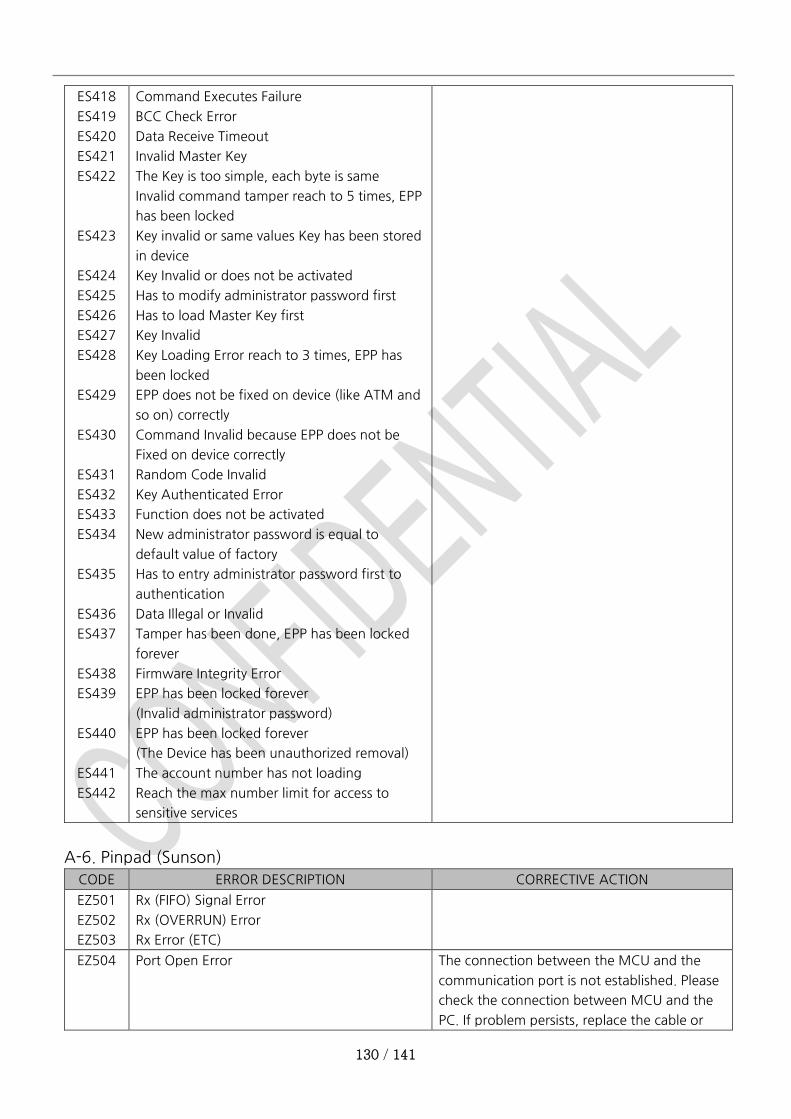
130 / 141
ES418
ES419
ES420
ES421
ES422
ES423
ES424
ES425
ES426
ES427
ES428
ES429
ES430
ES431
ES432
ES433
ES434
ES435
ES436
ES437
ES438
ES439
ES440
ES441
ES442
Command Executes Failure
BCC Check Error
Data Receive Timeout
Invalid Master Key
The Key is too simple, each byte is same
Invalid command tamper reach to 5 times, EPP
has been locked
Key invalid or same values Key has been stored
in device
Key Invalid or does not be activated
Has to modify administrator password first
Has to load Master Key first
Key Invalid
Key Loading Error reach to 3 times, EPP has
been locked
EPP does not be fixed on device (like ATM and
so on) correctly
Command Invalid because EPP does not be
Fixed on device correctly
Random Code Invalid
Key Authenticated Error
Function does not be activated
New administrator password is equal to
default value of factory
Has to entry administrator password first to
authentication
Data Illegal or Invalid
Tamper has been done, EPP has been locked
forever
Firmware Integrity Error
EPP has been locked forever
(Invalid administrator password)
EPP has been locked forever
(The Device has been unauthorized removal)
The account number has not loading
Reach the max number limit for access to
sensitive services
A-6. Pinpad (Sunson)
CODE ERROR DESCRIPTION CORRECTIVE ACTION
EZ501
EZ502
EZ503
Rx (FIFO) Signal Error
Rx (OVERRUN) Error
Rx Error (ETC)
EZ504 Port Open Error The connection between the MCU and the
communication port is not established. Please
check the connection between MCU and the
PC. If problem persists, replace the cable or
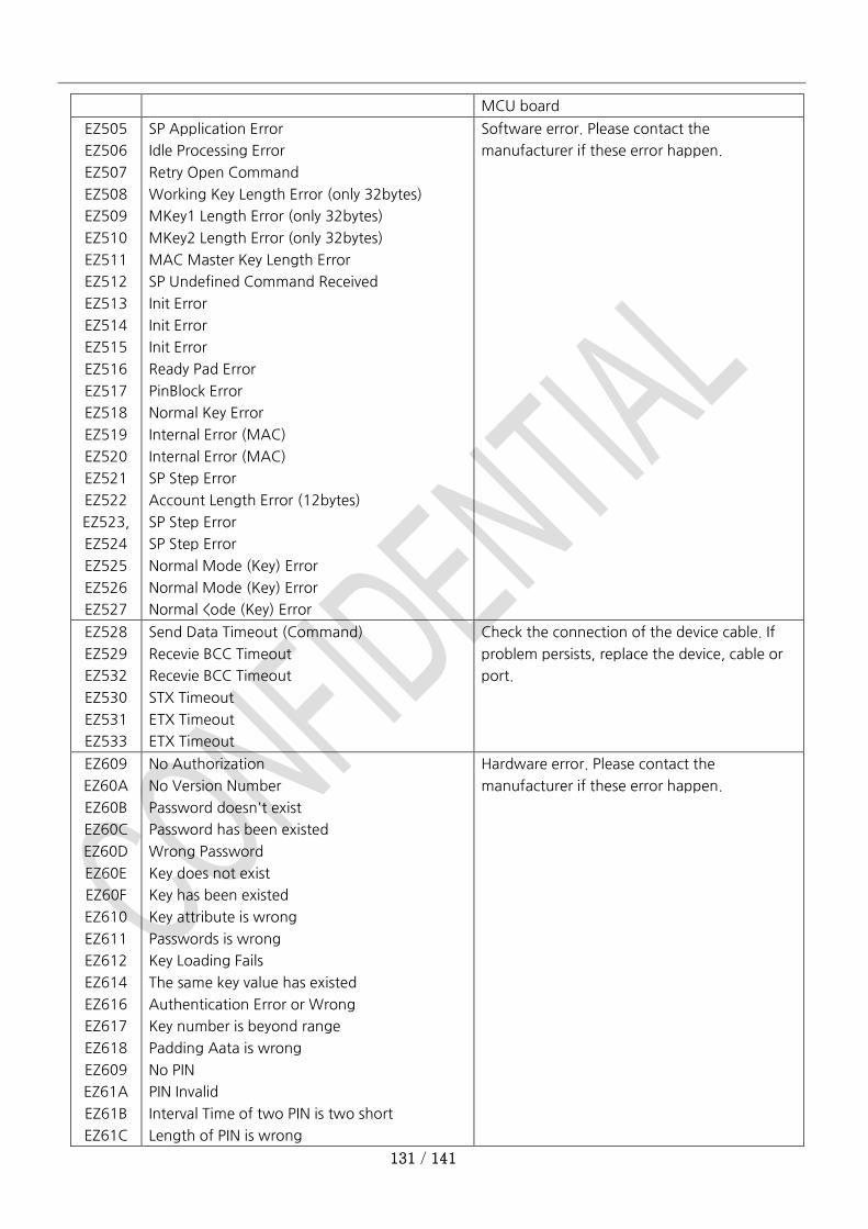
131 / 141
MCU board
EZ505
EZ506
EZ507
EZ508
EZ509
EZ510
EZ511
EZ512
EZ513
EZ514
EZ515
EZ516
EZ517
EZ518
EZ519
EZ520
EZ521
EZ522
EZ523,
EZ524
EZ525
EZ526
EZ527
SP Application Error
Idle Processing Error
Retry Open Command
Working Key Length Error (only 32bytes)
MKey1 Length Error (only 32bytes)
MKey2 Length Error (only 32bytes)
MAC Master Key Length Error
SP Undefined Command Received
Init Error
Init Error
Init Error
Ready Pad Error
PinBlock Error
Normal Key Error
Internal Error (MAC)
Internal Error (MAC)
SP Step Error
Account Length Error (12bytes)
SP Step Error
SP Step Error
Normal Mode (Key) Error
Normal Mode (Key) Error
Normal <ode (Key) Error
Software error. Please contact the
manufacturer if these error happen.
EZ528
EZ529
EZ532
EZ530
EZ531
EZ533
Send Data Timeout (Command)
Recevie BCC Timeout
Recevie BCC Timeout
STX Timeout
ETX Timeout
ETX Timeout
Check the connection of the device cable. If
problem persists, replace the device, cable or
port.
EZ609
EZ60A
EZ60B
EZ60C
EZ60D
EZ60E
EZ60F
EZ610
EZ611
EZ612
EZ614
EZ616
EZ617
EZ618
EZ609
EZ61A
EZ61B
EZ61C
No Authorization
No Version Number
Password doesn't exist
Password has been existed
Wrong Password
Key does not exist
Key has been existed
Key attribute is wrong
Passwords is wrong
Key Loading Fails
The same key value has existed
Authentication Error or Wrong
Key number is beyond range
Padding Aata is wrong
No PIN
PIN Invalid
Interval Time of two PIN is two short
Length of PIN is wrong
Hardware error. Please contact the
manufacturer if these error happen.
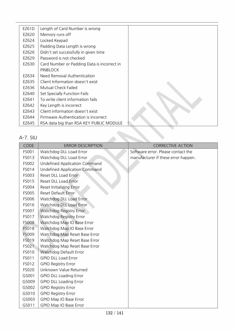
132 / 141
EZ61D
EZ620
EZ624
EZ625
EZ626
EZ629
EZ630
EZ634
EZ635
EZ636
EZ640
EZ641
EZ642
EZ643
EZ644
EZ645
Length of Card Number is wrong
Memory runs off
Locked Keypad
Padding Data Length is wrong
Didn't set successfully in given time
Password is not checked
Card Number or Padding Data is incorrect in
PINBLOCK
Need Removal Authentication
Client Information doesn't exist
Mutual Check Failed
Set Specially Function Fails
To write client information fails
Key Length is incorrect
Client information doesn't exist
Firmware Authentication is incorrect
RSA data big than RSA KEY PUBLIC MODULE
A-7. SIU
CODE ERROR DESCRIPTION CORRECTIVE ACTION
FS001
FS013
FS002
FS014
FS003
FS015
FS004
FS005
FS006
FS016
FS007
FS017
FS008
FS018
FS009
FS019
FS021
FS010
FS011
FS012
FS020
GS001
GS009
GS002
GS010
GS003
GS011
Watchdog DLL Load Error
Watchdog DLL Load Error
Undefined Application Command
Undefined Application Command
Reset DLL Load Error
Reset DLL Load Error
Reset Initializing Error
Reset Default Error
Watchdog DLL Load Error
Watchdog DLL Load Error
Watchdog Registry Error
Watchdog Registry Error
Watchdog Map IO Base Error
Watchdog Map IO Base Error
Watchdog Map Reset Base Error
Watchdog Map Reset Base Error
Watchdog Map Reset Base Error
Watchdog Default Error
GPIO DLL Load Error
GPIO Registry Error
Unknown Value Returned
GPIO DLL Loading Error
GPIO DLL Loading Error
GPIO Registry Error
GPIO Registry Error
GPIO Map IO Base Error
GPIO Map IO Base Error
Software error. Please contact the
manufacturer if these error happen.
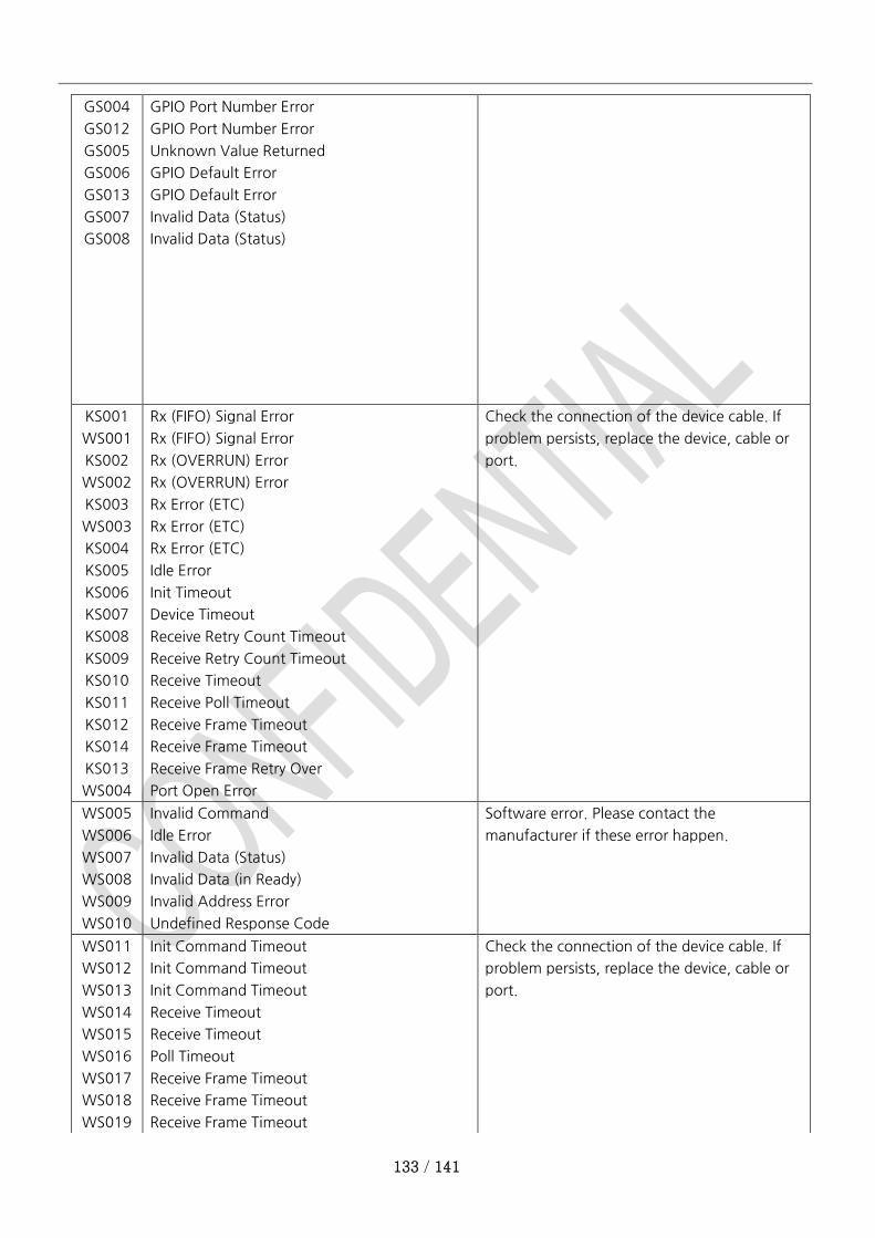
133 / 141
GS004
GS012
GS005
GS006
GS013
GS007
GS008
GPIO Port Number Error
GPIO Port Number Error
Unknown Value Returned
GPIO Default Error
GPIO Default Error
Invalid Data (Status)
Invalid Data (Status)
KS001
WS001
KS002
WS002
KS003
WS003
KS004
KS005
KS006
KS007
KS008
KS009
KS010
KS011
KS012
KS014
KS013
WS004
Rx (FIFO) Signal Error
Rx (FIFO) Signal Error
Rx (OVERRUN) Error
Rx (OVERRUN) Error
Rx Error (ETC)
Rx Error (ETC)
Rx Error (ETC)
Idle Error
Init Timeout
Device Timeout
Receive Retry Count Timeout
Receive Retry Count Timeout
Receive Timeout
Receive Poll Timeout
Receive Frame Timeout
Receive Frame Timeout
Receive Frame Retry Over
Port Open Error
Check the connection of the device cable. If
problem persists, replace the device, cable or
port.
WS005
WS006
WS007
WS008
WS009
WS010
Invalid Command
Idle Error
Invalid Data (Status)
Invalid Data (in Ready)
Invalid Address Error
Undefined Response Code
Software error. Please contact the
manufacturer if these error happen.
WS011
WS012
WS013
WS014
WS015
WS016
WS017
WS018
WS019
Init Command Timeout
Init Command Timeout
Init Command Timeout
Receive Timeout
Receive Timeout
Poll Timeout
Receive Frame Timeout
Receive Frame Timeout
Receive Frame Timeout
Check the connection of the device cable. If
problem persists, replace the device, cable or
port.
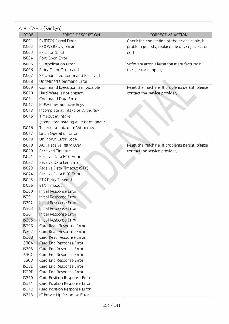
134 / 141
A-8. CARD (Sankyo)
CODE ERROR DESCRIPTION CORRECTIVE ACTION
IS001
IS002
IS003
IS004
Rx(FIFO) Signal Error
Rx(OVERRUN) Error
Rx Error (ETC)
Port Open Error
Check the connection of the device cable. If
problem persists, replace the device, cable, or
port.
IS005
IS006
IS007
IS008
SP Application Error
Retry Open Command
SP Undefined Command Received
Undefined Command Error
Software error. Please the manufacturer if
these error happen.
IS009
IS010
IS011
IS012
IS013
IS015
IS016
IS017
IS018
Command Execution is impossible
Hard Ware is not present
Command Data Error
ICRW does not have keys
Incomplete at Intake or Withdraw
Timeout at Intake
(completed reading at least magnetic
Timeout at Intake or Withdraw
Latch Operation Error
Unknown Error Code
Reset the machine. If problems persist, please
contact the service provider.
IS019
IS020
IS021
IS022
IS023
IS024
IS025
IS026
IS300
IS301
IS302
IS303
IS304
IS305
IS306
IS307
IS308
IS30A
IS30B
IS30C
IS30D
IS30E
IS30F
IS310
IS311
IS312
IS313
ACK Receive Retry Over
Received Timeout
Receive Data BCC Error
Receive Data Len Error
Receive Data Timeout (STX)
Receive Data BCC Error
ETX Retry Timeout
ETX Timeout
Initial Response Error
Initial Response Error
Initial Response Error
Initial Response Error
Initial Response Error
Initial Response Error
Card Read Response Error
Card Read Response Error
Card Read Response Error
Card End Response Error
Card End Response Error
Card End Response Error
Card End Response Error
Card End Response Error
Card End Response Error
Card Position Response Error
Card Position Response Error
Card Position Response Error
IC Power Up Response Error
Reset the machine. If problems persist, please
contact the service provider.
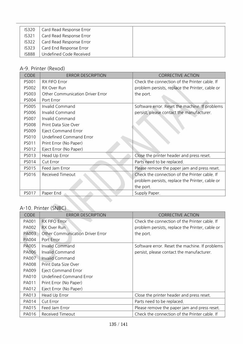
135 / 141
IS320
IS321
IS322
IS323
IS888
Card Read Response Error
Card Read Response Error
Card Read Response Error
Card End Response Error
Undefined Code Received
A-9. Printer (Rexod)
CODE ERROR DESCRIPTION CORRECTIVE ACTION
PS001
PS002
PS003
PS004
RX FIFO Error
RX Over Run
Other Communication Driver Error
Port Error
Check the connection of the Printer cable. If
problem persists, replace the Printer, cable or
the port.
PS005
PS006
PS007
PS008
PS009
PS010
PS011
PS012
Invalid Command
Invalid Command
Invalid Command
Print Data Size Over
Eject Command Error
Undefined Command Error
Print Error (No Paper)
Eject Error (No Paper)
Software error. Reset the machine. If problems
persist, please contact the manufacturer.
PS013 Head Up Error Close the printer header and press reset.
PS014 Cut Error Parts need to be replaced.
PS015 Feed Jam Error Please remove the paper jam and press reset.
PS016 Received Timeout Check the connection of the Printer cable. If
problem persists, replace the Printer, cable or
the port.
PS017 Paper End Supply Paper.
A-10. Printer (SNBC)
CODE ERROR DESCRIPTION CORRECTIVE ACTION
PA001
PA002
PA003
PA004
RX FIFO Error
RX Over Run
Other Communication Driver Error
Port Error
Check the connection of the Printer cable. If
problem persists, replace the Printer, cable or
the port.
PA005
PA006
PA007
PA008
PA009
PA010
PA011
PA012
Invalid Command
Invalid Command
Invalid Command
Print Data Size Over
Eject Command Error
Undefined Command Error
Print Error (No Paper)
Eject Error (No Paper)
Software error. Reset the machine. If problems
persist, please contact the manufacturer.
PA013 Head Up Error Close the printer header and press reset.
PA014 Cut Error Parts need to be replaced.
PA015 Feed Jam Error Please remove the paper jam and press reset.
PA016 Received Timeout Check the connection of the Printer cable. If
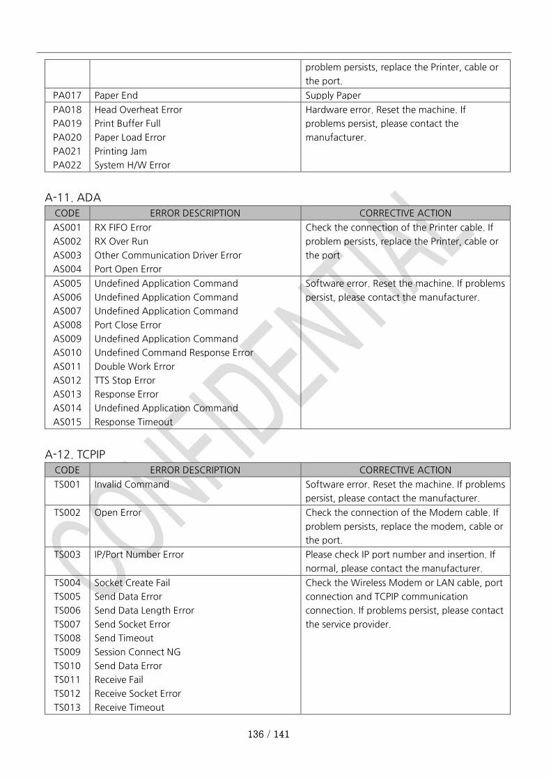
136 / 141
problem persists, replace the Printer, cable or
the port.
PA017 Paper End Supply Paper
PA018
PA019
PA020
PA021
PA022
Head Overheat Error
Print Buffer Full
Paper Load Error
Printing Jam
System H/W Error
Hardware error. Reset the machine. If
problems persist, please contact the
manufacturer.
A-11. ADA
CODE ERROR DESCRIPTION CORRECTIVE ACTION
AS001
AS002
AS003
AS004
RX FIFO Error
RX Over Run
Other Communication Driver Error
Port Open Error
Check the connection of the Printer cable. If
problem persists, replace the Printer, cable or
the port
AS005
AS006
AS007
AS008
AS009
AS010
AS011
AS012
AS013
AS014
AS015
Undefined Application Command
Undefined Application Command
Undefined Application Command
Port Close Error
Undefined Application Command
Undefined Command Response Error
Double Work Error
TTS Stop Error
Response Error
Undefined Application Command
Response Timeout
Software error. Reset the machine. If problems
persist, please contact the manufacturer.
A-12. TCPIP
CODE ERROR DESCRIPTION CORRECTIVE ACTION
TS001 Invalid Command Software error. Reset the machine. If problems
persist, please contact the manufacturer.
TS002 Open Error Check the connection of the Modem cable. If
problem persists, replace the modem, cable or
the port.
TS003 IP/Port Number Error Please check IP port number and insertion. If
normal, please contact the manufacturer.
TS004
TS005
TS006
TS007
TS008
TS009
TS010
TS011
TS012
TS013
Socket Create Fail
Send Data Error
Send Data Length Error
Send Socket Error
Send Timeout
Session Connect NG
Send Data Error
Receive Fail
Receive Socket Error
Receive Timeout
Check the Wireless Modem or LAN cable, port
connection and TCPIP communication
connection. If problems persist, please contact
the service provider.
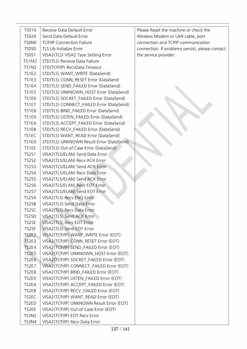
137 / 141
TS014
TS020
TS0N0
TS0S0
TS0S1
TS1M2
TS1N2
TS1E2
TS1E3
TS1E4
TS1E5
TS1E6
TS1E7
TS1E8
TS1E9
TS1EA
TS1EB
TS1EC
TS1ED
TS1EE
TS2S1
TS2S2
TS2S3
TS2S4
TS2S5
TS2S6
TS2S7
TS2SA
TS2SB
TS2SC
TS2SD
TS2SE
TS2SF
TS2E2
TS2E3
TS2E4
TS2E5
TS2E6
TS2E7
TS2E8
TS2E9
TS2EA
TS2EB
TS2EC
TS2ED
TS2EE
TS3N2
TS3N4
Receive Data Default Error
Send Data Default Error
TCP/IP Connection Failure
TLS Lib Initialize Error
VISA2(TLS) VISA2 Type Setting Error
STD(TLS) Receive Data Failure
STD(TCP/IP) RecvData Timeout
STD(TLS) WANT_WRITE (DataSend)
STD(TLS) CONN_RESET Error (DataSend
STD(TLS) SEND_FAILED Error (DataSend)
STD(TLS) UNKNOWN_HOST Error (DataSend)
STD(TLS) SOCKET_FAILED Error (DataSend)
STD(TLS) CONNECT_FAILED Error (DataSend)
STD(TLS) BIND_FAILED Error (DataSend)
STD(TLS) LISTEN_FAILED Error (DataSend)
STD(TLS) ACCEPT_FAILED Error (DataSend)
STD(TLS) RECV_FAILED Error (DataSend)
STD(TLS) WANT_READ Error (DataSend)
STD(TLS) UNKNOWN Result Error (DataSend)
STD(TLS) Out of Case Error (DataSend)
VISA2(TLS/ELAN) Send Data Error
VISA2(TLS/ELAN) Recv ACK Error
VISA2(TLS/ELAN) Send ACK Error
VISA2(TLS/ELAN) Recv Data Error
VISA2(TLS/ELAN) Send ACK Error
VISA2(TLS/ELAN) Recv EOT Error
VISA2(TLS/ELAN) Send EOT Error
VISA2(TLS) Recv ENQ Error
VISA2(TLS) Send Data Error
VISA2(TLS) Recv Data Error
VISA2(TLS) Send ACK Error
VISA2(TLS) Recv EOT Error
VISA2(TLS) Send EOT Error
VISA2(TCP/IP) WANT_WRITE Error (EOT):
VISA2(TCP/IP) CONN_RESET Error (EOT)
VISA2(TCP/IP) SEND_FAILED Error (EOT)
VISA2(TCP/IP) UNKNOWN_HOST Error (EOT)
VISA2(TCP/IP) SOCKET_FAILED Error (EOT)
VISA2(TCP/IP) CONNECT_FAILED Error (EOT)
VISA2(TCP/IP) BIND_FAILED Error (EOT)
VISA2(TCP/IP) LISTEN_FAILED Error (EOT)
VISA2(TCP/IP) ACCEPT_FAILED Error (EOT)
VISA2(TCP/IP) RECV_FAILED Error (EOT)
VISA2(TCP/IP) WANT_READ Error (EOT)
VISA2(TCP/IP) UNKNOWN Result Error (EOT)
VISA2(TCP/IP) Out of Case Error (EOT)
VISA2(TCP/IP) EOT Recv Error
VISA2(TCP/IP) Recv Data Error
Please Reset the machine or check the
Wireless Modem or LAN cable, port
connection and TCPIP communication
connection. If problems persist, please contact
the service provider.
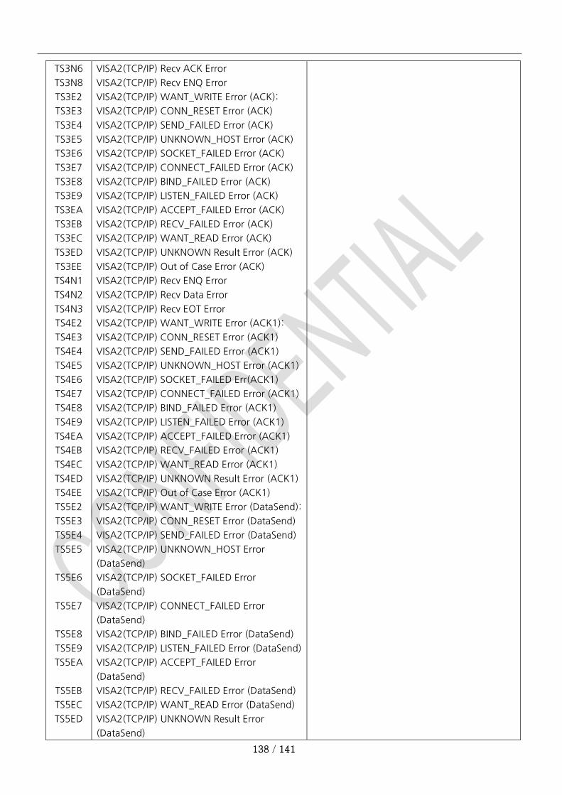
138 / 141
TS3N6
TS3N8
TS3E2
TS3E3
TS3E4
TS3E5
TS3E6
TS3E7
TS3E8
TS3E9
TS3EA
TS3EB
TS3EC
TS3ED
TS3EE
TS4N1
TS4N2
TS4N3
TS4E2
TS4E3
TS4E4
TS4E5
TS4E6
TS4E7
TS4E8
TS4E9
TS4EA
TS4EB
TS4EC
TS4ED
TS4EE
TS5E2
TS5E3
TS5E4
TS5E5
TS5E6
TS5E7
TS5E8
TS5E9
TS5EA
TS5EB
TS5EC
TS5ED
VISA2(TCP/IP) Recv ACK Error
VISA2(TCP/IP) Recv ENQ Error
VISA2(TCP/IP) WANT_WRITE Error (ACK):
VISA2(TCP/IP) CONN_RESET Error (ACK)
VISA2(TCP/IP) SEND_FAILED Error (ACK)
VISA2(TCP/IP) UNKNOWN_HOST Error (ACK)
VISA2(TCP/IP) SOCKET_FAILED Error (ACK)
VISA2(TCP/IP) CONNECT_FAILED Error (ACK)
VISA2(TCP/IP) BIND_FAILED Error (ACK)
VISA2(TCP/IP) LISTEN_FAILED Error (ACK)
VISA2(TCP/IP) ACCEPT_FAILED Error (ACK)
VISA2(TCP/IP) RECV_FAILED Error (ACK)
VISA2(TCP/IP) WANT_READ Error (ACK)
VISA2(TCP/IP) UNKNOWN Result Error (ACK)
VISA2(TCP/IP) Out of Case Error (ACK)
VISA2(TCP/IP) Recv ENQ Error
VISA2(TCP/IP) Recv Data Error
VISA2(TCP/IP) Recv EOT Error
VISA2(TCP/IP) WANT_WRITE Error (ACK1):
VISA2(TCP/IP) CONN_RESET Error (ACK1)
VISA2(TCP/IP) SEND_FAILED Error (ACK1)
VISA2(TCP/IP) UNKNOWN_HOST Error (ACK1)
VISA2(TCP/IP) SOCKET_FAILED Err(ACK1)
VISA2(TCP/IP) CONNECT_FAILED Error (ACK1)
VISA2(TCP/IP) BIND_FAILED Error (ACK1)
VISA2(TCP/IP) LISTEN_FAILED Error (ACK1)
VISA2(TCP/IP) ACCEPT_FAILED Error (ACK1)
VISA2(TCP/IP) RECV_FAILED Error (ACK1)
VISA2(TCP/IP) WANT_READ Error (ACK1)
VISA2(TCP/IP) UNKNOWN Result Error (ACK1)
VISA2(TCP/IP) Out of Case Error (ACK1)
VISA2(TCP/IP) WANT_WRITE Error (DataSend):
VISA2(TCP/IP) CONN_RESET Error (DataSend)
VISA2(TCP/IP) SEND_FAILED Error (DataSend)
VISA2(TCP/IP) UNKNOWN_HOST Error
(DataSend)
VISA2(TCP/IP) SOCKET_FAILED Error
(DataSend)
VISA2(TCP/IP) CONNECT_FAILED Error
(DataSend)
VISA2(TCP/IP) BIND_FAILED Error (DataSend)
VISA2(TCP/IP) LISTEN_FAILED Error (DataSend)
VISA2(TCP/IP) ACCEPT_FAILED Error
(DataSend)
VISA2(TCP/IP) RECV_FAILED Error (DataSend)
VISA2(TCP/IP) WANT_READ Error (DataSend)
VISA2(TCP/IP) UNKNOWN Result Error
(DataSend)
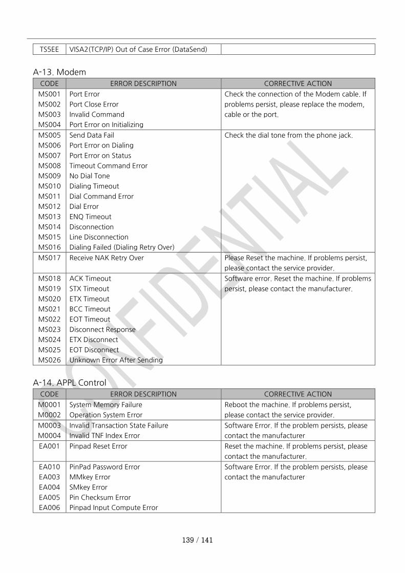
139 / 141
TS5EE VISA2(TCP/IP) Out of Case Error (DataSend)
A-13. Modem
CODE ERROR DESCRIPTION CORRECTIVE ACTION
MS001
MS002
MS003
MS004
Port Error
Port Close Error
Invalid Command
Port Error on Initializing
Check the connection of the Modem cable. If
problems persist, please replace the modem,
cable or the port.
MS005
MS006
MS007
MS008
MS009
MS010
MS011
MS012
MS013
MS014
MS015
MS016
Send Data Fail
Port Error on Dialing
Port Error on Status
Timeout Command Error
No Dial Tone
Dialing Timeout
Dial Command Error
Dial Error
ENQ Timeout
Disconnection
Line Disconnection
Dialing Failed (Dialing Retry Over)
Check the dial tone from the phone jack.
MS017 Receive NAK Retry Over Please Reset the machine. If problems persist,
please contact the service provider.
MS018
MS019
MS020
MS021
MS022
MS023
MS024
MS025
MS026
ACK Timeout
STX Timeout
ETX Timeout
BCC Timeout
EOT Timeout
Disconnect Response
ETX Disconnect
EOT Disconnect
Unknown Error After Sending
Software error. Reset the machine. If problems
persist, please contact the manufacturer.
A-14. APPL Control
CODE ERROR DESCRIPTION CORRECTIVE ACTION
M0001
M0002
System Memory Failure
Operation System Error
Reboot the machine. If problems persist,
please contact the service provider.
M0003
M0004
Invalid Transaction State Failure
Invalid TNF Index Error
Software Error. If the problem persists, please
contact the manufacturer
EA001 Pinpad Reset Error Reset the machine. If problems persist, please
contact the manufacturer.
EA010
EA003
EA004
EA005
EA006
PinPad Password Error
MMkey Error
SMkey Error
Pin Checksum Error
Pinpad Input Compute Error
Software Error. If the problem persists, please
contact the manufacturer
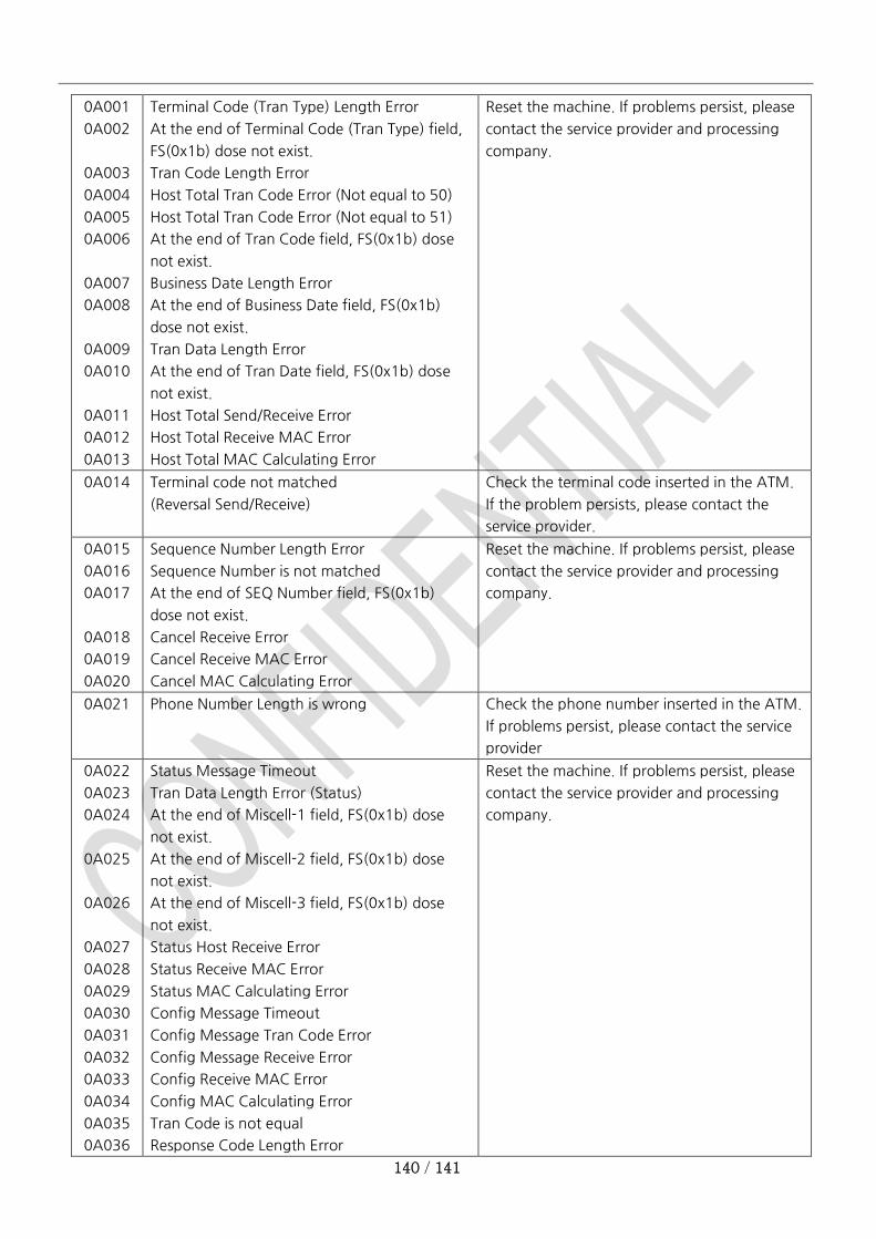
140 / 141
0A001
0A002
0A003
0A004
0A005
0A006
0A007
0A008
0A009
0A010
0A011
0A012
0A013
Terminal Code (Tran Type) Length Error
At the end of Terminal Code (Tran Type) field,
FS(0x1b) dose not exist.
Tran Code Length Error
Host Total Tran Code Error (Not equal to 50)
Host Total Tran Code Error (Not equal to 51)
At the end of Tran Code field, FS(0x1b) dose
not exist.
Business Date Length Error
At the end of Business Date field, FS(0x1b)
dose not exist.
Tran Data Length Error
At the end of Tran Date field, FS(0x1b) dose
not exist.
Host Total Send/Receive Error
Host Total Receive MAC Error
Host Total MAC Calculating Error
Reset the machine. If problems persist, please
contact the service provider and processing
company.
0A014 Terminal code not matched
(Reversal Send/Receive)
Check the terminal code inserted in the ATM.
If the problem persists, please contact the
service provider.
0A015
0A016
0A017
0A018
0A019
0A020
Sequence Number Length Error
Sequence Number is not matched
At the end of SEQ Number field, FS(0x1b)
dose not exist.
Cancel Receive Error
Cancel Receive MAC Error
Cancel MAC Calculating Error
Reset the machine. If problems persist, please
contact the service provider and processing
company.
0A021 Phone Number Length is wrong Check the phone number inserted in the ATM.
If problems persist, please contact the service
provider
0A022
0A023
0A024
0A025
0A026
0A027
0A028
0A029
0A030
0A031
0A032
0A033
0A034
0A035
0A036
Status Message Timeout
Tran Data Length Error (Status)
At the end of Miscell-1 field, FS(0x1b) dose
not exist.
At the end of Miscell-2 field, FS(0x1b) dose
not exist.
At the end of Miscell-3 field, FS(0x1b) dose
not exist.
Status Host Receive Error
Status Receive MAC Error
Status MAC Calculating Error
Config Message Timeout
Config Message Tran Code Error
Config Message Receive Error
Config Receive MAC Error
Config MAC Calculating Error
Tran Code is not equal
Response Code Length Error
Reset the machine. If problems persist, please
contact the service provider and processing
company.
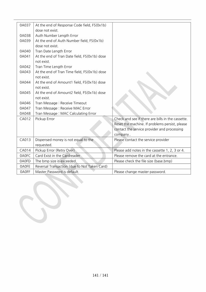
141 / 141
0A037
0A038
0A039
0A040
0A041
0A042
0A043
0A044
0A045
0A046
0A047
0A048
At the end of Response Code field, FS(0x1b)
dose not exist.
Auth Number Length Error
At the end of Auth Number field, FS(0x1b)
dose not exist.
Tran Date Length Error
At the end of Tran Date field, FS(0x1b) dose
not exist.
Tran Time Length Error
At the end of Tran Time field, FS(0x1b) dose
not exist.
At the end of Amount1 field, FS(0x1b) dose
not exist.
At the end of Amount2 field, FS(0x1b) dose
not exist.
Tran Message : Receive Timeout
Tran Message : Receive MAC Error
Tran Message : MAC Calculating Error
CA012 Pickup Error Check and see if there are bills in the cassette.
Reset the machine. If problems persist, please
contact the service provider and processing
company..
CA013 Dispensed money is not equal to the
requested.
Please contact the service provider
CA014 Pickup Error (Retry Over) Please add notes in the cassette 1, 2, 3 or 4.
0A0FC Card Exist in the Cardreader Please remove the card at the entrance.
0A0FD The bmp size is exceeded. Please check the file size (base.bmp)
0A0FE Reversal Transaction (due to Not Taken Card)
0A0FF Master Password is default. Please change master password.