Sinomags Current Sensor STK-CTS_W Ver4.5
10
Sinomags Product Datasheet CURRENT SENSOR Product series: STK-CTS/W Product part number: STK-15CTS/W 、STK-20CTS/W STK-25CTS/W Version: Ver 4.5 Sinomags Technology Co., Ltd. Web site: www.sinomags.com
-
Upload
khangminh22 -
Category
Documents
-
view
2 -
download
0
Transcript of Sinomags Current Sensor STK-CTS_W Ver4.5
Sinomags Product Datasheet
CURRENT SENSOR
Product series: STK-CTS/W
Product part number: STK-15CTS/W 、STK-20CTS/WSTK-25CTS/W
Version: Ver 4.5
Sinomags Technology Co., Ltd.Web site: www.sinomags.com
STK-CTS/W series current sensor
1/9 Sinomags Technology Co.,Ltd http://www.sinomags.com
CONTENTS
1. Description......................................................................................................................................................
2. STK-15CTS/W parameters...........................................................................................................................
3. STK-20CTS/W parameters...........................................................................................................................
4. STK-25CTS/W parameters...........................................................................................................................
5. Accuracy..........................................................................................................................................................
6. Frequency band width...................................................................................................................................
7. Step response time........................................................................................................................................
8. Frequency delay performace.......................................................................................................................
9. Install on PCB.................................................................................................................................................
10. Dimensions & Pins & Footprint..................................................................................................................
STK-CTS/W series current sensor
2/9 Sinomags Technology Co.,Ltd http://www.sinomags.com
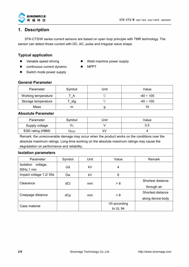
1. Description
STK-CTS/W series current sensors are based on open loop principle with TMR technology. Thesensor can detect those current with DC, AC, pulse and irregular wave shape.
Typical application Variable speed driving Weld machine power supply continuous current dynamo MPPT Switch mode power supply
General ParameterParameter Symbol Unit Value
Working temperature T_A ℃ -40 ~ 105
Storage temperature T_stg ℃ -40 ~ 105
Mass m g 10
Absolute ParameterParameter Symbol Unit Value
Supply voltage VC V 5.5
ESD rating (HBM) UESD kV 4
Remark: the unrecoverable damage may occur when the product works on the conditions over theabsolute maximum ratings. Long-time working on the absolute maximum ratings may cause thedegradation on performance and reliability.
Isolation parametersParameter Symbol Unit Value Remark
Isolation voltage,50Hz,1 min
Ud kV 4
Impact voltage 1.2/ 50s Ûw kV 6
Clearance dCI mm > 8Shortest distance
through air
Creepage distance dCp mm > 8Shortest distance
along device body
Case materialV0 accordingto UL 94
STK-CTS/W series current sensor
3/9 Sinomags Technology Co.,Ltd http://www.sinomags.com
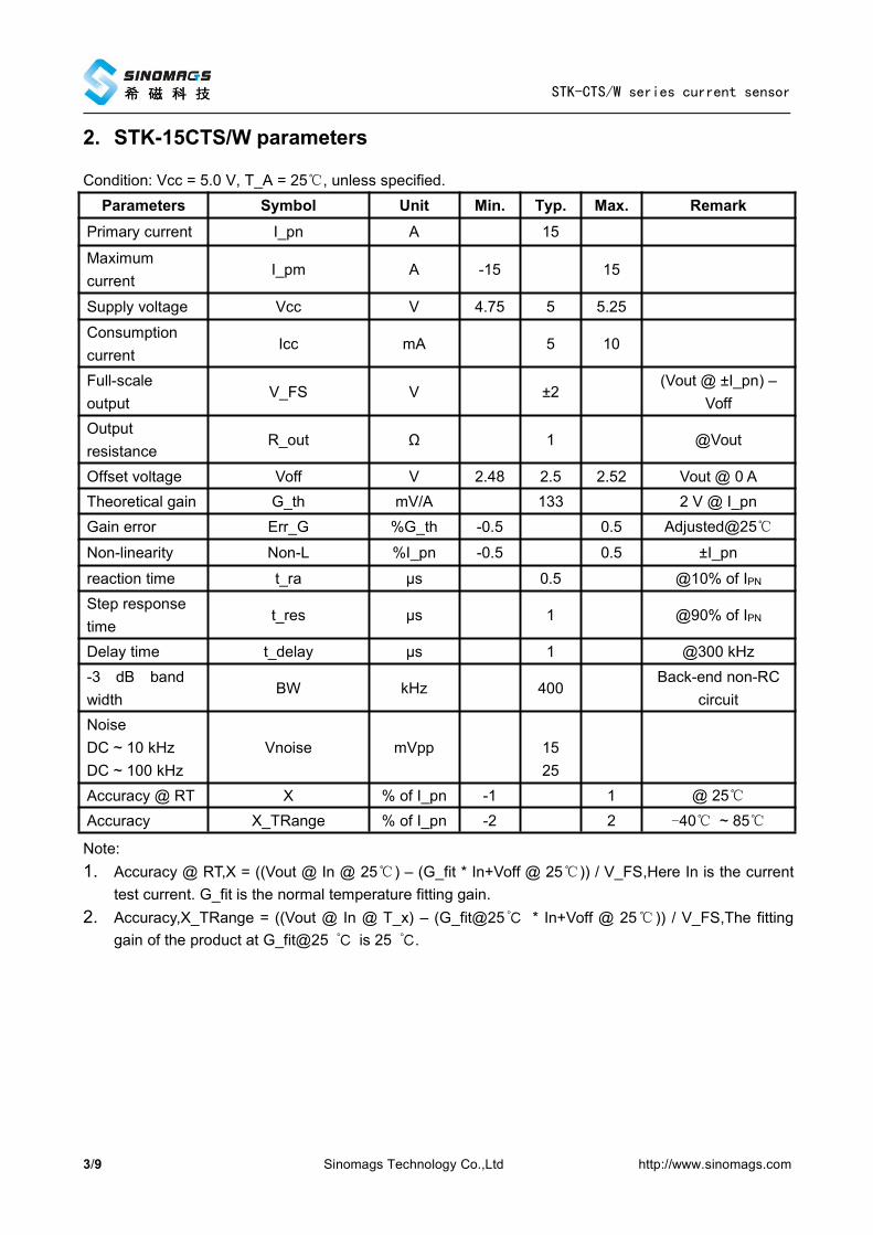
2. STK-15CTS/W parameters
Condition: Vcc = 5.0 V, T_A = 25℃, unless specified.Parameters Symbol Unit Min. Typ. Max. Remark
Primary current I_pn A 15
Maximumcurrent
I_pm A -15 15
Supply voltage Vcc V 4.75 5 5.25
Consumptioncurrent
Icc mA 5 10
Full-scaleoutput
V_FS V ±2(Vout @ ±I_pn) –
VoffOutputresistance
R_out Ω 1 @Vout
Offset voltage Voff V 2.48 2.5 2.52 Vout @ 0 ATheoretical gain G_th mV/A 133 2 V @ I_pnGain error Err_G %G_th -0.5 0.5 Adjusted@25℃
Non-linearity Non-L %I_pn -0.5 0.5 ±I_pn
reaction time t_ra µs 0.5 @10% of IPNStep responsetime
t_res µs 1 @90% of IPN
Delay time t_delay µs 1 @300 kHz-3 dB bandwidth
BW kHz 400Back-end non-RC
circuitNoiseDC ~ 10 kHzDC ~ 100 kHz
Vnoise mVpp 1525
Accuracy @ RT X % of I_pn -1 1 @ 25℃Accuracy X_TRange % of I_pn -2 2 -40℃ ~ 85℃
Note:1. Accuracy @ RT,X = ((Vout @ In @ 25℃) – (G_fit * In+Voff @ 25℃)) / V_FS,Here In is the current
test current. G_fit is the normal temperature fitting gain.2. Accuracy,X_TRange = ((Vout @ In @ T_x) – (G_fit@25℃ * In+Voff @ 25℃ )) / V_FS,The fitting
gain of the product at G_fit@25 ℃ is 25 ℃.
STK-CTS/W series current sensor
4/9 Sinomags Technology Co.,Ltd http://www.sinomags.com
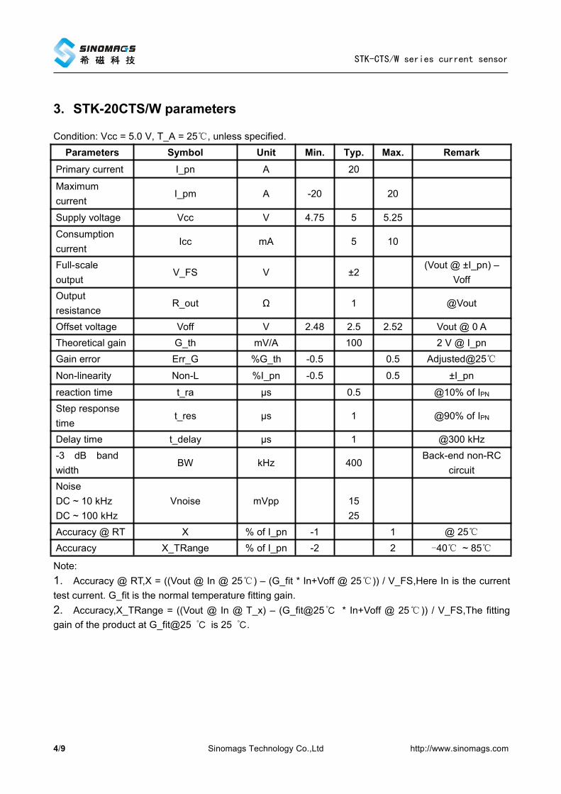
3. STK-20CTS/W parameters
Condition: Vcc = 5.0 V, T_A = 25℃, unless specified.Parameters Symbol Unit Min. Typ. Max. Remark
Primary current I_pn A 20
Maximumcurrent
I_pm A -20 20
Supply voltage Vcc V 4.75 5 5.25
Consumptioncurrent
Icc mA 5 10
Full-scaleoutput
V_FS V ±2(Vout @ ±I_pn) –
VoffOutputresistance
R_out Ω 1 @Vout
Offset voltage Voff V 2.48 2.5 2.52 Vout @ 0 ATheoretical gain G_th mV/A 100 2 V @ I_pnGain error Err_G %G_th -0.5 0.5 Adjusted@25℃
Non-linearity Non-L %I_pn -0.5 0.5 ±I_pn
reaction time t_ra µs 0.5 @10% of IPNStep responsetime
t_res µs 1 @90% of IPN
Delay time t_delay µs 1 @300 kHz-3 dB bandwidth
BW kHz 400Back-end non-RC
circuitNoiseDC ~ 10 kHzDC ~ 100 kHz
Vnoise mVpp 1525
Accuracy @ RT X % of I_pn -1 1 @ 25℃Accuracy X_TRange % of I_pn -2 2 -40℃ ~ 85℃
Note:1. Accuracy @ RT,X = ((Vout @ In @ 25℃) – (G_fit * In+Voff @ 25℃)) / V_FS,Here In is the currenttest current. G_fit is the normal temperature fitting gain.2. Accuracy,X_TRange = ((Vout @ In @ T_x) – (G_fit@25℃ * In+Voff @ 25℃ )) / V_FS,The fittinggain of the product at G_fit@25 ℃ is 25 ℃.

STK-CTS/W series current sensor
5/9 Sinomags Technology Co.,Ltd http://www.sinomags.com
4. STK-25CTS/W parameters
Condition: Vcc = 5.0 V, T_A = 25℃, unless specified.Parameters Symbol Unit Min. Typ. Max. Remark
Primary current I_pn A 25
Maximumcurrent
I_pm A -25 25
Supply voltage Vcc V 4.75 5 5.25
Consumptioncurrent
Icc mA 5 10
Full-scaleoutput
V_FS V ±2(Vout @ ±I_pn) –
VoffOutputresistance
R_out Ω 1 @Vout
Offset voltage Voff V 2.48 2.5 2.52 Vout @ 0 ATheoretical gain G_th mV/A 80 2 V @ I_pnGain error Err_G %G_th -0.5 0.5 Adjusted@25℃
Non-linearity Non-L %I_pn -0.5 0.5 ±I_pn
reaction time t_ra µs 0.5 @10% of IPNStep responsetime
t_res µs 1 @90% of IPN
Delay time t_delay µs 1 @300 kHz-3 dB bandwidth
BW kHz 400Back-end non-RC
circuitNoiseDC ~ 10 kHzDC ~ 100 kHz
Vnoise mVpp 1525
Accuracy @ RT X % of I_pn -1 1 @ 25℃Accuracy X_TRange % of I_pn -2 2 -40℃ ~ 85℃
Note:1. Accuracy @ RT,X = ((Vout @ In @ 25℃) – (G_fit * In+Voff @ 25℃)) / V_FS,Here In is the currenttest current. G_fit is the normal temperature fitting gain.2. Accuracy,X_TRange = ((Vout @ In @ T_x) – (G_fit@25℃ * In+Voff @ 25℃ )) / V_FS,The fittinggain of the product at G_fit@25 ℃ is 25 ℃.

STK-CTS/W series current sensor
6/9 Sinomags Technology Co.,Ltd http://www.sinomags.com
5. Accuracy
Fig.2 Deviation between actual output and theoretical output of STK-CTS/W current Sensor in fulltemperature range (-40 ℃ ~ 85 ℃),((Vout @ In @ T_x) – (G_th * In + Voff @ 25℃)) / V_FS.Vout is thesensor Vout pin voltage,Voff is the static output voltage of the sensor,In is the current primarycurrent,T_x is the current temperature,G_th is the theoretical gain of the sensor,V_FS is the full rangeoutput of the sensor.
6. Frequency band width
Fig.4 the band width of STK-CTS/W series current sensors.The bandwidth of the sensor is in the rangeof DC ~ 400 kHz (-3 dB).
STK-CTS/W series current sensor
7/9 Sinomags Technology Co.,Ltd http://www.sinomags.com
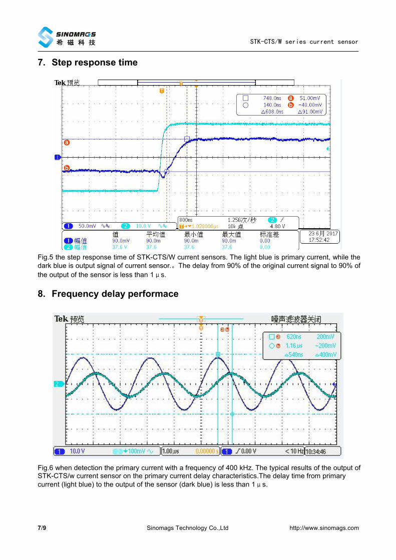
7. Step response time
Fig.5 the step response time of STK-CTS/W current sensors. The light blue is primary current, while thedark blue is output signal of current sensor.。The delay from 90% of the original current signal to 90% ofthe output of the sensor is less than 1μs.
8. Frequency delay performace
Fig.6 when detection the primary current with a frequency of 400 kHz. The typical results of the output ofSTK-CTS/w current sensor on the primary current delay characteristics.The delay time from primarycurrent (light blue) to the output of the sensor (dark blue) is less than 1μs.
STK-CTS/W series current sensor
8/9 Sinomags Technology Co.,Ltd http://www.sinomags.com
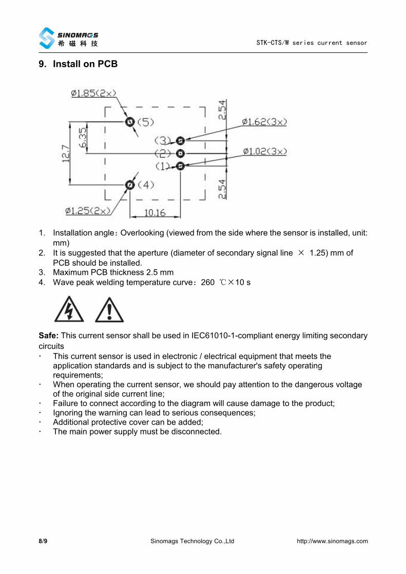
9. Install on PCB
1. Installation angle:Overlooking (viewed from the side where the sensor is installed, unit:mm)
2. It is suggested that the aperture (diameter of secondary signal line × 1.25) mm ofPCB should be installed.
3. Maximum PCB thickness 2.5 mm4. Wave peak welding temperature curve:260 ℃×10 s
Safe: This current sensor shall be used in IEC61010-1-compliant energy limiting secondarycircuits This current sensor is used in electronic / electrical equipment that meets the
application standards and is subject to the manufacturer's safety operatingrequirements;
When operating the current sensor, we should pay attention to the dangerous voltageof the original side current line;
Failure to connect according to the diagram will cause damage to the product; Ignoring the warning can lead to serious consequences; Additional protective cover can be added; The main power supply must be disconnected.
STK-CTS/W series current sensor
9/9 Sinomags Technology Co.,Ltd http://www.sinomags.com
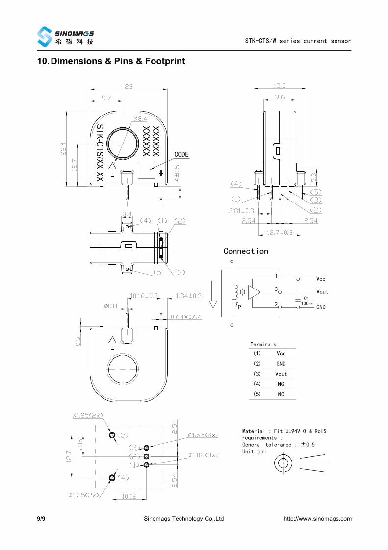
10.Dimensions & Pins & Footprint