Simulation of the fluid dynamics in active liquid heat sink for CPU cooling system
7
Simulation of the Fluid Dynamics in Active Liquid Heat Sink for CPU Cooling System Song-Hao Wang, Steven Melendez, Milton Gomez Micro and Precision Manufacturing Center, Kun-Shan University of Technology, Taiwan e-mail: [email protected] Tel: 886-06-2050000-267 NSC PROJECT: NSC -95-2221-E-168-001 ABSTRACT This study numerically investigates the fluid dynamics in an Active-Liquid-Heat-Sink (ALHS) for a computer microprocessor cooling system. Principal concepts, basic design, and the integration of the ALHS technology into an internal CPU liquid cooling system are presented. Basic assumptions and numerical methods, especially for rotating machinery in fluid dynamics in the numerical simulation, are discussed in detail. From the numerical simulation, the stirring effect by the impeller on the velocity field is quite significant. The maximum velocity, which occurs in the vicinity of the impeller, can be well over five times the average velocity. Since convective heat transfer is largely dependent on liquid velocity, much higher cooling efficiency is expected, especially in the neighborhood of the impeller that could be located on top of the CPU heat source. The simulation also revealed that with the increase of impeller rpm, the velocity as well the flow rate increase almost linearly. This result is very useful for the design and optimization of the cooling system. Key Words Active-Liquid-Heat-Sink, Impeller, fluid dynamics, CAE, COMSOL Multiphysics 3.3 1. INTRODUCTION The thermal characteristics of new generation, high- power-density CPUs in today’s high-end computing applications are rapidly outpacing the cooling capabilities of the best commercially available strategies [9]. Current microprocessors may consume more than 100 W of electrical power, and heat generation in CPUs follows Moore’s Law. With the amount of transistors in them doubling every 18 months, a similar trend in heat generation is expected. Heat dissipation has become more of an issue since current microprocessors are reaching a point where they can no longer be cooled by traditional air cooling systems [13]. Davis et al. (2006) has outlined the recent advances in pumped-liquid cooling system technology, those improvements offering a promising alternative for cooling high power density processors. However, a successful implementation of this approach requires a high degree of innovation and careful attention to design details to optimally cool high heat flux chips within a targeted system volume. To address this problem, a revolutionary new Active Liquid Heat Sink is proposed in this paper. The performance of any liquid-cooled system depends on several factors, like physical dimensions of the heat- exchanger channels, liquid flow rate through the channels, radiator fin surface area and the airflow available for heat rejection [9]. The Optimization of these system elements can result in very high thermal performance from low air- flow volume, which enables system fans to run at quieter, lower speeds. Where fan noise is not a concern, higher airflow results in even better performance. In the meantime it is important to mention that air cooling is not good enough to dissipate heat in new generation microprocessors. As Wang et al., (2006) mention, since the new multiple core chips have a greater, non uniform heat distribution, the several “hot spots” will require a different cooling approach. Actually air can only carry away so much heat; the more heat you want to dissipate, the more air flow and surface area you need for a heat-sink. Diminishing returns start to set in fairly rapidly once you get beyond the Alpha heat-sink stage. No matter how large the heat-sink, its contact point is still the CPU's slug. As heat moves beyond this contact area, it encounters something called "spread resistance". The reason copper is used as bases in some heat-sinks is that copper is more efficient in spreading heat over its surface than aluminum, but only up to a point (Wang et al., 2006). Therefore, if the task at hand is to get as much cooling concentrated in a given area, the more efficient "dissipating medium" (i.e. air or water) will cool better than its inferior for a given set of conditions. In the case of air vs. water, there is no question - water is best. Within the past two to three years, the personal computer market has seen the introduction and usage of liquid cooling for both desktop and notebook applications. Some mainstream examples of this cooling technology can be found in the systems of Apple and NEC on the desktop side as well as Hitachi on the notebook side. However, presently there are still several key limitations in liquid cooling technology that have 1 Excerpt from the Proceedings of the COMSOL Users Conference 2007 Taipei
Transcript of Simulation of the fluid dynamics in active liquid heat sink for CPU cooling system
Simulation of the Fluid Dynamics in Active Liquid Heat Sink for CPU Cooling System
Song-Hao Wang, Steven Melendez, Milton Gomez Micro and Precision Manufacturing Center, Kun-Shan University of Technology, Taiwan
e-mail: [email protected] Tel: 886-06-2050000-267
NSC PROJECT: NSC -95-2221-E-168-001
ABSTRACT
This study numerically investigates the fluid dynamics in an Active-Liquid-Heat-Sink (ALHS) for a computer microprocessor cooling system. Principal concepts, basic design, and the integration of the ALHS technology into an internal CPU liquid cooling system are presented. Basic assumptions and numerical methods, especially for rotating machinery in fluid dynamics in the numerical simulation, are discussed in detail.
From the numerical simulation, the stirring effect by the impeller on the velocity field is quite significant. The maximum velocity, which occurs in the vicinity of the impeller, can be well over five times the average velocity. Since convective heat transfer is largely dependent on liquid velocity, much higher cooling efficiency is expected, especially in the neighborhood of the impeller that could be located on top of the CPU heat source.
The simulation also revealed that with the increase of impeller rpm, the velocity as well the flow rate increase almost linearly. This result is very useful for the design and optimization of the cooling system. Key Words Active-Liquid-Heat-Sink, Impeller, fluid dynamics, CAE, COMSOL Multiphysics 3.3 1. INTRODUCTION
The thermal characteristics of new generation, high-power-density CPUs in today’s high-end computing applications are rapidly outpacing the cooling capabilities of the best commercially available strategies [9].
Current microprocessors may consume more than 100 W of electrical power, and heat generation in CPUs follows Moore’s Law. With the amount of transistors in them doubling every 18 months, a similar trend in heat generation is expected. Heat dissipation has become more of an issue since current microprocessors are reaching a point where they can no longer be cooled by traditional air cooling systems [13].
Davis et al. (2006) has outlined the recent advances in pumped-liquid cooling system technology, those improvements offering a promising alternative for cooling high power density processors. However, a successful
implementation of this approach requires a high degree of innovation and careful attention to design details to optimally cool high heat flux chips within a targeted system volume. To address this problem, a revolutionary new Active Liquid Heat Sink is proposed in this paper.
The performance of any liquid-cooled system depends on several factors, like physical dimensions of the heat-exchanger channels, liquid flow rate through the channels, radiator fin surface area and the airflow available for heat rejection [9]. The Optimization of these system elements can result in very high thermal performance from low air-flow volume, which enables system fans to run at quieter, lower speeds. Where fan noise is not a concern, higher airflow results in even better performance.
In the meantime it is important to mention that air cooling is not good enough to dissipate heat in new generation microprocessors. As Wang et al., (2006) mention, since the new multiple core chips have a greater, non uniform heat distribution, the several “hot spots” will require a different cooling approach. Actually air can only carry away so much heat; the more heat you want to dissipate, the more air flow and surface area you need for a heat-sink. Diminishing returns start to set in fairly rapidly once you get beyond the Alpha heat-sink stage. No matter how large the heat-sink, its contact point is still the CPU's slug. As heat moves beyond this contact area, it encounters something called "spread resistance". The reason copper is used as bases in some heat-sinks is that copper is more efficient in spreading heat over its surface than aluminum, but only up to a point (Wang et al., 2006). Therefore, if the task at hand is to get as much cooling concentrated in a given area, the more efficient "dissipating medium" (i.e. air or water) will cool better than its inferior for a given set of conditions. In the case of air vs. water, there is no question - water is best.
Within the past two to three years, the personal computer market has seen the introduction and usage of liquid cooling for both desktop and notebook applications. Some mainstream examples of this cooling technology can be found in the systems of Apple and NEC on the desktop side as well as Hitachi on the notebook side.
However, presently there are still several key limitations in liquid cooling technology that have
1
Excerpt from the Proceedings of the COMSOL Users Conference 2007 Taipei
prevented its widespread adoption by the mainstream desktop and notebook computer makers. Therefore, large amount of research and money have been invested on this subject.
A traditional (external) liquid cooling system includes a liquid block (heat-exchanger), a pump (with a motor), a fan (with another motor), a radiator, a reserve tank, and some form of conduit to connect all of these parts. All of this additional equipment results in a great increase in the cost of the system when compared to conventional air cooling.
Moreover, the complexity and overall dimensions of the traditional system forces most of the components to be outside the computer case, as shown in Fig. 1.
Recently, some advances have been made to integrate and simplify the system while maintaining a comparable level of cooling efficiency. In the newly developed and integrated liquid cooling systems, all the components are designed together as one piece of assembly and only one motor is need to drive both the external fan and the impeller inside the liquid media. However, for components such as bearings, impeller and coupling to operate, a complex pump housing is needed. That increases the cost and weight of the whole system.
To improve the efficiency of cooling, there have been countless discussions and designs of liquid heat sinks (water block) in literary and online resources. The discussions usually consider the optimal internal geometry under constant volume and pressure drop constraints or constant pumping power. The major objective of those discussions was to increase the liquid-solid interface area and enhance forced heat convection. For example, the fundamental concept and procedure of liquid heat sink design was presented by Kraus and Bar-Cohen [12], and the heat transfer and flow characteristics for liquid heat sinks were investigated by Liu and Hung [14]. In their study [14], multi-channel was chosen in order to increase the contact area between the liquid flow and solid material for transporting heat generated from the CPU die by liquid flow and for reducing the pressure drop. The non-uniform temperature distribution inside a micro-channel was also demonstrated by Hetsroni et al. [10] who performed a two-phase boiling experiment using a micro-channel heat sink.
However, most of the researchers have been concentrating on PASSIVE liquid heat sinks, which need an external pump to drive cooling liquid in and out.
Recent research work of the authors has been concentrated on the development of a liquid cooling system that contains ACTIVE-Liquid-Heat-Sink (ALHS) Technology. It has been proven that this unique technology greatly simplifies the system, reduces overall weight and dimensions, lowers costs, and, more importantly, intensifies the forced convection heat transfer and increases the overall cooling efficiency.
In this paper, numerical simulation of the fluid dynamics in an Active-Liquid-Heat-Sink (ALHS) is presented. Principal concepts, basic design, and the integration of the ALHS technology into an internal CPU liquid cooling system are presented. Basic assumptions in the numerical simulation are discussed in detail. Numerical methods, especially for rotating machinery, are introduced.
The stirring effect by the impeller on the velocity field is quite significant. Lu and Wang reported that temperature decreases with cooling liquid velocity, locally and globally, and by controlling the inlet velocity of the cooling liquid, the maximum temperature can be reduced by almost 30% and average temperature by 13% [14]. Since convective heat transfer is largely dependent on liquid velocity, much higher cooling efficiency is expected, especially in the neighborhood of the impeller that could be located on top of the CPU heat source. 2. BASIC CONCEPTS AND STRUCTURE OF THE ACTIVE LIQUID HEAT SINK
The meaning of “Active-Liquid-Heat-Sink” is that the liquid heat sink (water block) can ACTIVELY pump cooling liquid in and out by itself, without help from outside pumping system. In fact, it is a pump and a liquid heat sink in one piece of assembly.
Before, even the most simplified, integrated CPU/GPU liquid cooling system had at least four basic components: a liquid heat sink, a liquid pump (chamber), a fan and a radiator. During the cooling process, the pump forces the cooled liquid into the liquid heat sink, which is usually a copper box clamped over the integrated heat spreader of the microprocessor. The heat generated in the silicon chip is transferred to the copper IHS (integrated heat sink), through the thermal interface material by conduction, and finally to the liquid heat sink. Inside the liquid sink, as the heat flows through the copper interface, the liquid will absorb the heat by forced convection due to the flow generated by the pump. After completing its flow path the heated liquid will move into the radiator, where air cooled metal fins will remove the heat from the liquid into the ambient. Because of the integration, the whole system can be fit nicely into a computer case, just like an air-cooling system. However, for the bearings and the impeller to sit and operate, a complex pump housing is needed, increasing the cost and weight of the system.
An ordinary (passive) liquid-heat-sink contains a hollow block or block having flow passages with only an inlet and out-let tube connections (Fig.1). In that design outside the liquid-block, a mechanism (such as pump) is needed to move cooling fluid from the liquid-heat-sink, where it absorbs the heat generated by the CPU/GPU, into the radiator where the heat is transferred trough air cooled fins into the ambient.
2
Excerpt from the Proceedings of the COMSOL Users Conference 2007 Taipei
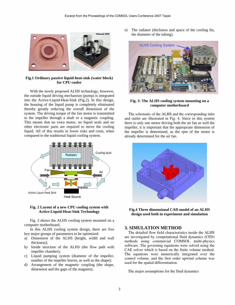
Fig.1 Ordinary passive liquid-heat-sink (water block) for CPU cooler
With the newly proposed ALHS technology, however,
the outside liquid driving mechanism (pump) is integrated into the Active-Liquid-Heat-Sink (Fig.2). In this design, the housing of the liquid pump is completely eliminated thereby greatly reducing the overall dimension of the system. The driving torque of the fan motor is transmitted to the impeller through a shaft or a magnetic coupling. This means that no extra motor, no liquid seals and no other electronic parts are required to move the cooling liquid. All of this results in lower risks and costs, when compared to the traditional liquid cooling system.
Fig. 2 Layout of a new CPU cooling system with Active-Liquid-Heat-Sink Technology
Fig. 3 shows the ALHS cooling system mounted on a
computer motherboard. In this ALHS cooling system design, there are five
key major groups of parameters to be optimized: a) Dimension of the ALHS (height, width and wall
thickness); b) Inside structure of the ALHS (the flow path with
impeller chamber); c) Liquid pumping system (diameter of the impeller,
number of the impeller leaves, as well as the shape); d) Arrangement of the magnetic coupling (the shape,
dimension and the gaps of the magnets);
e) The radiator (thickness and space of the cooling fin, the diameter of the tubing).
Fig. 3: The ALHS cooling system mounting on a
computer motherboard
The schematic of the ALHS and the corresponding inlet and outlet are illustrated in Fig. 4. Since in this system there is only one motor driving both the air fan as well the impeller, it is important that the appropriate dimension of the impeller is determined, as the rpm of the motor is already determined for the air fan.
Fig.4 Three dimensional CAD model of an ALHS design used both in experiment and simulation
3. SIMULATION METHOD
The detailed flow field characteristics inside the ALHS are investigated by computational fluid dynamics (CFD) methods using commercial COMSOL multi-physics software. The governing equations were solved using the CAE solver which is based on the finite volume method. The equations were numerically integrated over the control volume, and the first order upwind scheme was used for the spatial differentiation.
The major assumptions for the fluid dynamics
3
Excerpt from the Proceedings of the COMSOL Users Conference 2007 Taipei

simulation are: 1) Two-dimensional transient flow; 2) Incompressible fluid; 3) Constant fluid properties.
Nomenclature of variables and parameters in the
numerical simulation is listed as the following: ρ = Density of liquid μ = Dynamic viscosity of liquid Vx = Velocity component in x direction Vy = Velocity component in x direction = impeller rotating angle
The governing equations for the fluid flow include the
mass conservation and momentum conservation equations. The initial velocity and pressure of the water flow equals zero. Since this is a transient fluid dynamics problem, time step is extremely important for numerical convergence. By trial and error, a set of time steps have been settled corresponding to different impeller rpm.
Cases under 500, 1000, 2000 and 3000 impeller rpm are simulated in the present study, because under 500 rpm, there is not enough fan speed to cool the radiator, while over 3000, the noise level of the cooling system generally does not satisfy the ‘‘Quiet-CPU-Cooler’’ requirement. The numerical code is checked to ensure the validity of the numerical analysis. The grid dependence test is first conducted by using several different mesh sizes. Finite element mesh created from the COMSOL software is shown in Fig 5.
Fig. 5 Finite element Mesh for the ALHS
The rotating machinery application mode of COMSOL makes it possible to model moving rotating parts in for example stirred tanks, mixers and pumps. The application mode takes care of the formulation of the momentum and mass balances in a rotating coordinate system. Parts that are not rotated are expressed in the fixed coordinate system. The application mode then takes care of the necessary administration to join the parts of the model that uses a rotating coordinate system with the parts that are fixed. The model equations are the Navier-Stokes
equations, which are formulated in a rotating frame in the inner subdomain and in fixed coordinates in the outer one. The boundary conditions at the fixed wall of the ALHS are no-slip conditions. The boundary conditions for the impeller blades are no-slip clock-wise rotation conditions. At the ALHS inlet, pressure is specified, while neutral conditions are implemented at the outlet (Fig.6).
Fig. 6 Boundary condition set-up
First you have to draw the geometry using two
separate subdomains for the fixed and rotating parts; then you have to activate the assembly feature, which makes it possible to treat the two subdomains as two separate parts in an assembly. After this you specify which part that uses a rotating frame. You have to activate the create-pair feature. After all these are done, you can proceed to the usual steps of setting fluid properties, boundary conditions, and then to the meshing and solving of the problem.
The density and dynamic viscosity of liquid in this simulation were 1.0e3 (kg/m3) and 2.0e-2 (Pa), respectively.
The velocity varies along the impeller surfaces and is defined by:
Vx=-π*rpm/30*[sin(θ)*x+cos(θ)*y]
Vy=-π*rpm/30*[cos(θ)*x-sin(θ)*y]
Where:
θ=π*rpm*t/30
is the rotational angle of the impeller.
4. RESULTS AND DISCUSIONS Velocity distribution is presented in Fig 7, its scale shown on the side. It is clear that the higher velocity occurs in the vicinity of the impeller, 3.574 (m/s) in this case.
4
Excerpt from the Proceedings of the COMSOL Users Conference 2007 Taipei
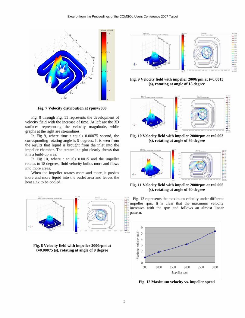
Fig. 7 Velocity distribution at rpm=2000
Fig. 8 through Fig. 11 represents the development of velocity field with the increase of time. At left are the 3D surfaces representing the velocity magnitude, while graphs at the right are streamlines.
In Fig 9, where time t equals 0.00075 second, the corresponding rotating angle is 9 degrees. It is seen from the results that liquid is brought from the inlet into the impeller chamber. The streamline plot clearly shows that it is a build-up area.
In Fig 10, where t equals 0.0015 and the impeller rotates to 18 degrees, fluid velocity builds more and flows into more areas.
When the impeller rotates more and more, it pushes more and more liquid into the outlet area and leaves the heat sink to be cooled.
Fig. 8 Velocity field with impeller 2000rpm at t=0.00075 (s), rotating at angle of 9 degree
Fig. 9 Velocity field with impeller 2000rpm at t=0.0015
(s), rotating at angle of 18 degree
Fig. 10 Velocity field with impeller 2000rpm at t=0.003
(s), rotating at angle of 36 degree
Fig. 11 Velocity field with impeller 2000rpm at t=0.005
(s), rotating at angle of 60 degree
Fig. 12 represents the maximum velocity under different impeller rpm. It is clear that the maximum velocity increases with the rpm and follows an almost linear pattern.
0
1
2
3
4
5
6
500 1000 1500 2000 2500 3000
Impeller rpm
Max
imun
vel
osit
y (m
/s)
Fig. 12 Maximum velocity vs. impeller speed
5
Excerpt from the Proceedings of the COMSOL Users Conference 2007 Taipei
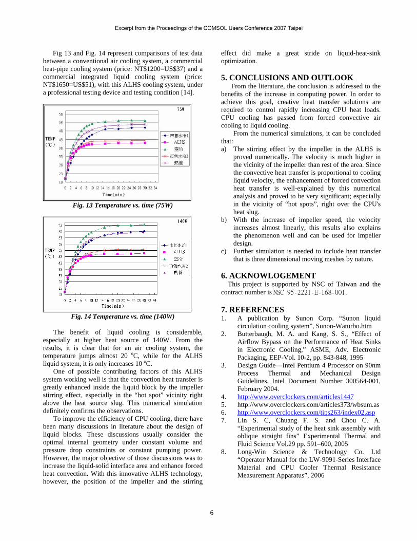
Fig 13 and Fig. 14 represent comparisons of test data between a conventional air cooling system, a commercial heat-pipe cooling system (price: NT$1200=US$37) and a commercial integrated liquid cooling system (price: NT$1650=US$51), with this ALHS cooling system, under a professional testing device and testing condition [14].
Fig. 13 Temperature vs. time (75W)
Fig. 14 Temperature vs. time (140W)
The benefit of liquid cooling is considerable, esp
s of this ALHS sys
cooling, there have bee
5. CONCLUSIONS AND OUTLOOK d to the
ben
mulations, it can be concluded that:
tirring effect by the impeller in the ALHS is
b) increase of impeller speed, the velocity
c) imulation is needed to include heat transfer
. ACKNOWLOGEMENT
C of Taiwan and the co
. REFERENCES Sunon Corp. “Sunon liquid
2. of
3. 0nm
4. clockers.com/articles1447
ecially at higher heat source of 140W. From the results, it is clear that for an air cooling system, the temperature jumps almost 20 oC, while for the ALHS liquid system, it is only increases 10 oC.
One of possible contributing factortem working well is that the convection heat transfer is
greatly enhanced inside the liquid block by the impeller stirring effect, especially in the “hot spot” vicinity right above the heat source slug. This numerical simulation definitely confirms the observations.
To improve the efficiency of CPUn many discussions in literature about the design of
liquid blocks. These discussions usually consider the optimal internal geometry under constant volume and pressure drop constraints or constant pumping power. However, the major objective of those discussions was to increase the liquid-solid interface area and enhance forced heat convection. With this innovative ALHS technology, however, the position of the impeller and the stirring
effect did make a great stride on liquid-heat-sink optimization.
From the literature, the conclusion is addresseefits of the increase in computing power. In order to
achieve this goal, creative heat transfer solutions are required to control rapidly increasing CPU heat loads. CPU cooling has passed from forced convective air cooling to liquid cooling.
From the numerical si
a) The sproved numerically. The velocity is much higher in the vicinity of the impeller than rest of the area. Since the convective heat transfer is proportional to cooling liquid velocity, the enhancement of forced convection heat transfer is well-explained by this numerical analysis and proved to be very significant; especially in the vicinity of “hot spots”, right over the CPU's heat slug. With the increases almost linearly, this results also explains the phenomenon well and can be used for impeller design. Further sthat is three dimensional moving meshes by nature.
6This project is supported by NSntract number is NSC 95-2221-E-168-001.
71. A publication by
circulation cooling system”, Sunon-Waturbo.htm Butterbaugh, M. A. and Kang, S. S., “Effect Airflow Bypass on the Performance of Heat Sinks in Electronic Cooling,” ASME, Adv. Electronic Packaging, EEP-Vol. 10-2, pp. 843-848, 1995 Design Guide—Intel Pentium 4 Processor on 9Process Thermal and Mechanical Design Guidelines, Intel Document Number 300564-001, February 2004. http://www.over
bsum.as 5. http://www.overclockers.com/articles373/w6. http://www.overclockers.com/tips263/index02.asp 7. Lin S. C, Chuang F. S. and Chou C. A.
8. Co. Ltd
“Experimental study of the heat sink assembly with oblique straight fins” Experimental Thermal and Fluid Science Vol.29 pp. 591–600, 2005 Long-Win Science & Technology “Operator Manual for the LW-9091-Series Interface Material and CPU Cooler Thermal Resistance Measurement Apparatus”, 2006
6
Excerpt from the Proceedings of the COMSOL Users Conference 2007 Taipei

9. Davis M., Weymouth R., and Clarke P. (2005) "Thermoelectric CPU Cooling using High Efficiency Liquid Flow Heat Exchangers" Hydrocool Pty Ltd, Fremantle, Australia.
10. Ming-Chang Lu and Chi-Chuan Wang, “Effect of the Inlet Location on the Performance of Parallel-Channel Cold-Plate”, IEEE transactions on components and packaging technologies, vol. 29, no. 1, march 2006
11. Tsai M. C., Yu C. S. and Kang S. W. (2005) “Flat Plate Loop Heat Pipe with a Novel Evaporator Structure”. Department of Mechanical and Electro-Mechanical Engineering, Tamkang University, Tamsui, Taiwan, R.O.C.
12. Sebastian Flores, Song-Hao Wang, Chong-Ching Chang, “Development of an Internal Liquid Cooling Systems for CPU with CAE”, IEEE-EuroSime2006, London, U.K.
13. Song-Hao Wang, Sebastian Flores, Chong-Ching Chang, “Development of an Internal Liquid Cooling Systems for CPU using RP Technology”, IEEE-ICPT2006, Shanghai, China
14. Song-Hao Wang, et al. “An Innovative Active Liquid Heat Sink Technology for CPU Cooling System”, IEEE-ICPT2006, Shanghai, China
7
Excerpt from the Proceedings of the COMSOL Users Conference 2007 Taipei