SIMATIC Modbus/TCP communication using CP 343-1 and ...
66
SIMATIC SIMATIC Modbus/TCP communication using CP 343-1 and CP 443-1 Programming Manual 11/2017 A5E32489434-AC Preface Product description 1 Step-by-step instructions 2 Putting a function block into operation 3 Parameter assignment for Modbus/TCP communication 4 MODBUSCP licensing 5 MODBUSCP function block 6 Additional blocks 7 Diagnostics 8 Examples of applications 9 Reference A
-
Upload
khangminh22 -
Category
Documents
-
view
2 -
download
0
Transcript of SIMATIC Modbus/TCP communication using CP 343-1 and ...

SIMATIC
SIMATIC Modbus/TCP communication using CP 343-1 and CP 443-1 Programming Manual
11/2017 A5E32489434-AC
Preface
Product description 1
Step-by-step instructions 2
Putting a function block into operation
3
Parameter assignment for Modbus/TCP communication
4
MODBUSCP licensing 5
MODBUSCP function block 6
Additional blocks 7
Diagnostics 8
Examples of applications 9
Reference A
Siemens AG Division Digital Factory Postfach 48 48 90026 NÜRNBERG GERMANY
A5E32489434-AC Ⓟ 11/2017 Subject to change
Copyright © Siemens AG 2017. All rights reserved
Legal information Warning notice system
This manual contains notices you have to observe in order to ensure your personal safety, as well as to prevent damage to property. The notices referring to your personal safety are highlighted in the manual by a safety alert symbol, notices referring only to property damage have no safety alert symbol. These notices shown below are graded according to the degree of danger.
DANGER indicates that death or severe personal injury will result if proper precautions are not taken.
WARNING indicates that death or severe personal injury may result if proper precautions are not taken.
CAUTION indicates that minor personal injury can result if proper precautions are not taken.
NOTICE indicates that property damage can result if proper precautions are not taken.
If more than one degree of danger is present, the warning notice representing the highest degree of danger will be used. A notice warning of injury to persons with a safety alert symbol may also include a warning relating to property damage.
Qualified Personnel The product/system described in this documentation may be operated only by personnel qualified for the specific task in accordance with the relevant documentation, in particular its warning notices and safety instructions. Qualified personnel are those who, based on their training and experience, are capable of identifying risks and avoiding potential hazards when working with these products/systems.
Proper use of Siemens products Note the following:
WARNING Siemens products may only be used for the applications described in the catalog and in the relevant technical documentation. If products and components from other manufacturers are used, these must be recommended or approved by Siemens. Proper transport, storage, installation, assembly, commissioning, operation and maintenance are required to ensure that the products operate safely and without any problems. The permissible ambient conditions must be complied with. The information in the relevant documentation must be observed.
Trademarks All names identified by ® are registered trademarks of Siemens AG. The remaining trademarks in this publication may be trademarks whose use by third parties for their own purposes could violate the rights of the owner.
Disclaimer of Liability We have reviewed the contents of this publication to ensure consistency with the hardware and software described. Since variance cannot be precluded entirely, we cannot guarantee full consistency. However, the information in this publication is reviewed regularly and any necessary corrections are included in subsequent editions.
SIMATIC Modbus/TCP communication using CP 343-1 and CP 443-1 Programming Manual, 11/2017, A5E32489434-AC 3
Preface
Purpose of the document With the information in this document, you can establish and commission a link between a CP 343-1 or CP 443-1 and a device that supports the Modbus/TCP protocol.
Contents of the document This document describes the function and parameter assignment of the MODBUSCP function block.
The document covers the following topics:
● Product description (Page 9)
● Step-by-step instructions (Page 11)
● Putting a function block into operation (Page 13)
● Parameter assignment for Modbus/TCP communication (Page 27)
● MODBUSCP licensing (Page 33)
● MODBUSCP function block (Page 37)
● Additional blocks (Page 51)
● Diagnostics (Page 53)
● Examples of applications (Page 61)
Additional sources of information For all other information relating to the CP 343 and CP 443, please refer to the following documents:
SIEMENS SIMATIC NET S7 CPs for Industrial Ethernet manual C79000-G8976-C155
SIEMENS SIMATIC NET S7 CPs for Industrial Ethernet manual, Part B1 CP 343 1 / CP 343 1EX20 C79000-G8976-C158
SIEMENS SIMATIC NET S7 CPs for Industrial Ethernet manual, Part B4 CP 443 1 C79000-G8976-C152

Preface
SIMATIC Modbus/TCP communication using CP 343-1 and CP 443-1 4 Programming Manual, 11/2017, A5E32489434-AC
SIEMENS SIMATIC NET NCM S7 for Industrial Ethernet manual C79000-G8976-C129
You will find further information relating to STEP 7 in the following manuals:
SIEMENS SIMATIC Software Basic Software for S7 and M7 STEP 7 user manual C79000-G7076-C502-..
SIEMENS SIMATIC Software System Software for S7-300/400 System and Standard Functions reference manual C79000-G7076-C503-02
Technical support You can reach Technical Support using the Web form for the Support Request (https://support.industry.siemens.com/my/ww/en/requests/#createRequest).
Area of application The function block described in this manual establishes a connection between the CP 343-1/CP 443-1 and Modbus/ TCP devices of other manufacturers.
Scope of validity This documents applies to:
● SIMATIC communications processor CP 343-1
● SIMATIC communications processor CP 443-1
This document applies to the following software: Product Identification number As of version SIMATIC Modbus/TCP CP 6AV6676-6MB00-6AX0
6AV6676-6MB00-6AD0 6.0
FB 905 "MODBUSCP" 5.0 FB 906 "MB_CPSRV" 3.0 FB 908 "MB_CPCLI" 3.0
Note
This document contains the description of the FB valid at the time the document was published.

Preface
SIMATIC Modbus/TCP communication using CP 343-1 and CP 443-1 Programming Manual, 11/2017, A5E32489434-AC 5
Note
Observe the following points: • You are also going to need this document whenever the system is recommissioned. • Keep this supplementary documentation in a safe place for the entire life cycle of the
software. • Pass on all of these documents to any future owner of the software.
Knowledge required General knowledge of automation engineering and process communication is needed to understand this document. To create a project, knowledge of the "STEP 7" engineering software is necessary.
Style conventions Style Convention Scope "Add screen" • Terminology for the user interface, e.g. dialog name, tab, but-
ton, menu command • Necessary entries, e.g. limit value, tag value • Path information
"File > Edit" Operational sequences, e.g, menu command, shortcut menu command
<F1>, <Alt+P> Designation of a key on a keyboard
You should also observe the notes that are marked as follows:
Note
A note contains important information about the product described in the document and its handling, or a specific section of the document to which you should pay particular attention.
Naming conventions Term Applies to CP • CP 343-1
• CP 443-1
Figures This document includes illustrations of the described software. The detail of the images may deviate from the supplied software.

Preface
SIMATIC Modbus/TCP communication using CP 343-1 and CP 443-1 6 Programming Manual, 11/2017, A5E32489434-AC

SIMATIC Modbus/TCP communication using CP 343-1 and CP 443-1 Programming Manual, 11/2017, A5E32489434-AC 7
Table of contents Preface ................................................................................................................................................... 3
1 Product description ................................................................................................................................. 9
1.1 Scope of delivery ...................................................................................................................... 9
1.2 Possible applications ................................................................................................................ 9
1.3 Hardware and software requirements ..................................................................................... 10
2 Step-by-step instructions ....................................................................................................................... 11
3 Putting a function block into operation ................................................................................................... 13
3.1 Installing the library on the STEP 7 PG/PC ............................................................................ 13
3.2 Assigning CP parameters ....................................................................................................... 14
3.3 Assigning link partner parameters .......................................................................................... 15
3.4 Configuring the communications connection .......................................................................... 17 3.4.1 Configuring the connection in "CP is Client" ........................................................................... 17 3.4.2 Configuring an unspecified connection with "CP is server" .................................................... 21
3.5 Inserting Modbus/TCP function blocks ................................................................................... 23
3.6 Using connections on port 502 ............................................................................................... 25
3.7 Startup behavior of the CP 343-1 and CP 443-1 .................................................................... 26
4 Parameter assignment for Modbus/TCP communication ....................................................................... 27
4.1 Parameter assignment for Modbus/TCP communication with the Wizard ............................. 28
4.2 Manual parameter assignment for Modbus/TCP communication .......................................... 29 4.2.1 Structure of the connection parameters.................................................................................. 29 4.2.2 Parameter assignment for Modbus/TCP communication ....................................................... 31
5 MODBUSCP licensing .......................................................................................................................... 33
5.1 MODBUSCP licensing ............................................................................................................ 33
5.2 Missing or incorrect licensing .................................................................................................. 36
6 MODBUSCP function block ................................................................................................................... 37
6.1 How the MODBUSCP function block works ........................................................................... 37
6.2 Parameters of the MODBUSCP function block ...................................................................... 40
6.3 Address mapping of MODBUSCP function block ................................................................... 45
6.4 Data and standard functions of the MODBUSCP function block ............................................ 48
6.5 Rewiring blocks ....................................................................................................................... 49
7 Additional blocks ................................................................................................................................... 51
7.1 Job list for cyclic frame exchange ........................................................................................... 51
7.2 Support in CFC ....................................................................................................................... 52

Table of contents
SIMATIC Modbus/TCP communication using CP 343-1 and CP 443-1 8 Programming Manual, 11/2017, A5E32489434-AC
8 Diagnostics ........................................................................................................................................... 53
8.1 Diagnostics with the display elements of the CPU ................................................................ 53
8.2 Diagnostics messages of FB MODBUSCP ........................................................................... 54
8.3 Diagnostics messages from FC5/FC6 and FC50/FC60 ........................................................ 59
8.4 Diagnostics messages of the blocks used ............................................................................. 59
8.5 Diagnostics messages of SFC24 ........................................................................................... 59
9 Examples of applications ...................................................................................................................... 61
9.1 Sample project in STL ............................................................................................................ 61
9.2 Sample project in CFC ........................................................................................................... 63
A Reference ............................................................................................................................................. 65

SIMATIC Modbus/TCP communication using CP 343-1 and CP 443-1 Programming Manual, 11/2017, A5E32489434-AC 9
Product description 1 1.1 Scope of delivery
The scope of delivery includes the following order units:
● 1 × CD "SIMATIC Modbus/TCP CP"
The CD contains a setup for installation in the relevant STEP 7 directories:
– "Modbus_TCP_CP" library
– 2 Sample projects
– Documents in German and English
The CD also contains the documents in PDF format.
1.2 Possible applications
Driver in the system environment The following driver represents a software product for the communications processor (CP).
● The CP 343-1 can be used in the S7-300 automation systems and can establish communications connections to partner systems.
● The CP 443-1 can be used in the S7-400 automation systems and can establish communications connections to partner systems.
Function of the FBs With the supplied function blocks, a communications connection is possible between the communications module CP and a device that supports the Modbus/TCP protocol. The function codes 1, 2, 3, 4, 5, 6, 15 and 16 are supported.
Data transfer is handled based on the client-server principle. The SIMATIC S7 can be operated as client as well as server during the transfer.
TCP/IP with CP The TCP/IP connections via the CP are static connections that are not terminated during error-free operation.
With the TCP stack used on the CP, the STEP 7 connection configuration only allows one use of a particular port number. Certain CP types can maintain and operate connections to multiple clients simultaneously via the local port 502.
The technical details of this topic are explained in the section "Using connections on port 502 (Page 25)".

Product description 1.3 Hardware and software requirements
SIMATIC Modbus/TCP communication using CP 343-1 and CP 443-1 10 Programming Manual, 11/2017, A5E32489434-AC
1.3 Hardware and software requirements
Modules for FB MODBUSCP You can find the current hardware requirements at: Technical specifications of the SIMATIC Modbus/TCP blocks (https://support.industry.siemens.com/cs/de/en/view/104946406)
Software versions The blocks can be used as of STEP 7 V5.5. The AG_LSEND/AG_LRECV V3.1 blocks must be used for this.
Memory requirements ● FB MODBUSCP requires approximately 8 KB of work memory and 9 KB of load memory.
● FB MB_CPCLI requires approximately 9 KB of work memory and 10 KB of load memory.
● FB MB_CPSRV requires approximately 9 KB of work memory and 9 KB of load memory.
You will find the precise lengths of the function blocks in their properties in the SIMATIC Manager.

SIMATIC Modbus/TCP communication using CP 343-1 and CP 443-1 Programming Manual, 11/2017, A5E32489434-AC 11
Step-by-step instructions 2
The following list provides an overview of the steps in the procedure and the sections in which the steps are described in this document:
1. Installation of "SIMATIC Modbus/TCP CP" – refer to the section "Installing the library on the STEP 7 PG/PC (Page 13)"
2. Setting the connection parameters according to the plant configuration - refer to the section "Configuring the communications connection (Page 17)"
3. Inserting the Modbus/TCP blocks in the user project - refer to the section "Inserting Modbus/TCP function blocks (Page 23)"
4. Calling the Modbus/TCP block FB905 in the required OB – see section "How the MODBUSCP function block works (Page 37)"
5. Setting the parameter DB MODBUS_PARAM_CP according to the requirements (client/server, Modbus/TCP addresses, DB areas, etc.) – refer to the section "Parameter assignment for Modbus/TCP communication with the Wizard (Page 28) and Structure of the connection parameters (Page 29)"
6. Parameter assignment of the Modbus/TCP block for initialization and for the runtime - refer to the section "Parameters of the MODBUSCP function block (Page 40)"
7. Downloading the user program to the CPU and licensing the Modbus/TCP block for this CPU – refer to the section "MODBUSCP licensing (Page 33)"

Step-by-step instructions
SIMATIC Modbus/TCP communication using CP 343-1 and CP 443-1 12 Programming Manual, 11/2017, A5E32489434-AC

SIMATIC Modbus/TCP communication using CP 343-1 and CP 443-1 Programming Manual, 11/2017, A5E32489434-AC 13
Putting a function block into operation 3
The CP can be configured via MPI or LAN/Industrial Ethernet. The STEP 7 configuration software is required.
The following information on STEP 7 and on configuring the communications connection relates to STEP 7 V5.5. In later versions, sequences, names and directories can change.
Requirements for the configuration are as follows:
● Knowledge of STEP 7
● Knowledge of STL
● Knowledge of PLCs
3.1 Installing the library on the STEP 7 PG/PC
Requirements The STEP 7 configuration software must be installed.
Procedure 1. Insert the Modbus/TCP CD in the CD-ROM drive of your PG/PC.
If the setup program does not start automatically, install as follows:
– Select the CD-ROM drive in the Windows Explorer
– Open the Setup directory
– Start the file "Simatic S7 ModbusTCP CP V6.0.exe"
2. Follow the instructions displayed by the installation program step by step.
On completion of the installation, you will find the following:
– "Modbus_TCP_CP" library in \Program Files\Siemens\Step 7\S7LIBS
– 2 sample projects in \Program Files\Siemens\Step 7\EXAMPLES
– The programming manual in \Program Files\Siemens\Step 7\S7MANUAL\S7Comm
– The software registration form in \Program Files\Siemens\Step 7\S7LIBS\Modbus_TCP_CP

Putting a function block into operation 3.2 Assigning CP parameters
SIMATIC Modbus/TCP communication using CP 343-1 and CP 443-1 14 Programming Manual, 11/2017, A5E32489434-AC
This document can be opened using the shortcut as follows:
● "\Program Files\Siemens\Documentation" from the directory "S7MANUAL\S7Comm"
● "Start > SIMATIC > Documentation"
3.2 Assigning CP parameters The CP is connected to Industrial Ethernet in the "Subnet" list. If you have interconnected your stations without routers, they must be located in the same subnet.
Procedure 1. Select the list entry with the name of your network.
For a new network, this is normally the list entry "Ethernet(1)".
2. Confirm by clicking "OK".
The parameter assignment is compiled and saved.

Putting a function block into operation 3.3 Assigning link partner parameters
SIMATIC Modbus/TCP communication using CP 343-1 and CP 443-1 Programming Manual, 11/2017, A5E32489434-AC 15
3.3 Assigning link partner parameters In the "CP is Client" mode, an "Other station" is necessary for the connection configuration.
Procedure 1. Select "Properties > Other station > Interfaces".
2. Click on the "New" button.
3. In the type selection box that then appears, select "Industrial Ethernet".

Putting a function block into operation 3.3 Assigning link partner parameters
SIMATIC Modbus/TCP communication using CP 343-1 and CP 443-1 16 Programming Manual, 11/2017, A5E32489434-AC
4. Confirm by clicking "OK".
The following dialog is displayed.
5. Enter an IP address located in the same subnet as the link partner station.
The subnet mask should be the same as for the partner station.
6. Select the subnet that represents the connection between CP interface and the link partner interface.
7. Confirm by clicking "OK". The following dialog is displayed.
No settings are required in the "General" tab.

Putting a function block into operation 3.4 Configuring the communications connection
SIMATIC Modbus/TCP communication using CP 343-1 and CP 443-1 Programming Manual, 11/2017, A5E32489434-AC 17
3.4 Configuring the communications connection For the connection between an S7 CPU and a communications partner/bus connected via Industrial Ethernet, the CP represents the link. To connect the relevant interface to the link partner/bus, the connection must be configured.
3.4.1 Configuring the connection in "CP is Client"
Procedure 1. In the STEP 7 project, select the CPU in your open S7-300/400 station.
2. By double-clicking on "Connections" you open the connection configuration.
The "NetPro" program opens with which you can configure your connections.
3. Select "Insert > New Connection...".
The following dialog is displayed.

Putting a function block into operation 3.4 Configuring the communications connection
SIMATIC Modbus/TCP communication using CP 343-1 and CP 443-1 18 Programming Manual, 11/2017, A5E32489434-AC
4. For the new connection, select the connection partner "Other station" and "TCP connection" as the connection.
The following dialog is displayed.
5. Select the "Display properties before inserting" check box.

Putting a function block into operation 3.4 Configuring the communications connection
SIMATIC Modbus/TCP communication using CP 343-1 and CP 443-1 Programming Manual, 11/2017, A5E32489434-AC 19
6. Confirm by clicking "OK".
The following dialog is displayed.
In the dialog, you can set the properties for the connection.
Note
Note that the connection ID (local ID) must be used in the user program when calling the FB.
7. Set the ID based on the project requirements.
8. Enter a name for the connection.
The "Via CP" box displays the communications processor used to establish the connection. If you want to use a different plugged-in CP, this can be selected with the "Route..." button.
– If the S7 is operating as a Modbus client, the "Active connection establishment" check box must be enabled.
– If the S7 is operating as a Modbus server, the check box must be disabled.

Putting a function block into operation 3.4 Configuring the communications connection
SIMATIC Modbus/TCP communication using CP 343-1 and CP 443-1 20 Programming Manual, 11/2017, A5E32489434-AC
9. Change to the "Addresses" tab.
The following dialog is displayed.
In this dialog, the port numbers for both communications partners are specified.
10. Specify the port numbers in the "Addresses" tab.
Note
Selecting the port number: • In Modbus/TCP communication, the Modbus/TCP servers are normally addressed via
port 502. • With Modbus/TCP clients, port numbers higher than 2000 are used.
11. Confirm by clicking "OK".
The entries are applied.

Putting a function block into operation 3.4 Configuring the communications connection
SIMATIC Modbus/TCP communication using CP 343-1 and CP 443-1 Programming Manual, 11/2017, A5E32489434-AC 21
3.4.2 Configuring an unspecified connection with "CP is server"
Procedure 1. If the CP operates as a server on a link, communication is activated via an unspecified
connection.
The client needs to handle active connection establishment.
2. After selecting Insert > New connection..., you change to the "Insert New Connection" dialog.

Putting a function block into operation 3.4 Configuring the communications connection
SIMATIC Modbus/TCP communication using CP 343-1 and CP 443-1 22 Programming Manual, 11/2017, A5E32489434-AC
3. For the new connection, instead of the connection partner, select "Unspecified" and "TCP connection" as the connection.
4. Select the "Display properties before inserting" check box.
5. Confirm by clicking "OK".
This brings you to the "Properties - TCP connection" dialog.

Putting a function block into operation 3.5 Inserting Modbus/TCP function blocks
SIMATIC Modbus/TCP communication using CP 343-1 and CP 443-1 Programming Manual, 11/2017, A5E32489434-AC 23
6. Disable the "Active connection establishment" check box.
In the "Addresses" dialog, no settings are made for the "Partner". "IP" and "PORT" do not have an entry.
7. Confirm by clicking "OK".
The entries are applied.
3.5 Inserting Modbus/TCP function blocks The following FBs are required for Modbus/TCP communication:
● MODBUSCP
● MB_CPCLI
● MB_CPSRV
To be able to insert these in your project, you need to copy the blocks from the library.
You will also see the parameter data block MODBUS_PARAM_CP as a template in the library. To simplify your work, you can also copy this to your project.

Putting a function block into operation 3.5 Inserting Modbus/TCP function blocks
SIMATIC Modbus/TCP communication using CP 343-1 and CP 443-1 24 Programming Manual, 11/2017, A5E32489434-AC
Procedure 1. Copy the blocks from the library to insert them in your project.
To do this, open the "Modbus_TCP_CP" library by selecting "File > Open...".
2. In the "Open project" dialog, change to the "Libraries" tab.
3. Select the "Modbus_TCP_CP" library.
4. Click "OK" to confirm the selection.
The library opens.
5. Depending on your configuration, open the "CP 300" or "CP 400" folder by double-clicking on it.
6. Select the function blocks and copy them with "Edit > Copy".
7. Change to your project.
8. In the STEP 7 project, select the CPU in your open S7-300/S7-400 station.
9. Open the block folder by double-clicking on "S7 Program" and then on "Blocks".
10. Insert the blocks in your program with "Edit > Insert".
Inserting communications blocks The Modbus/TCP function blocks use the functions AG_SEND and AG_RECV for S7-300 or AG_LSEND and AG_LRECV for S7-400 and the AG_CNTRL block. You will find these communications blocks in the "SIMATIC_NET_CP" library.
● CP 300
Copy the functions FC5 (AG_SEND), FC6 (AG_RECV) and FC10 (AG_CNTRL) from the "CP 300" folder and insert the functions in your project.
● CP 400
Copy the functions FC50 (AG_LSEND), FC60 (AG_LRECV) and FC10 (AG_CNTRL) from the "CP 400" folder and insert the functions in your project.
Note
Note that the following versions of the FCs are required for error-free operation of FB MODBUSCP.
S7-400: • AG_LSEND V3.1 or higher • AG_LRECV V3.1 or higher
S7-300: • AG_SEND V4.2 or higher • AG_RECV V4.7 or higher
The Modbus blocks were compiled with the SIMATIC NET Library Update for STEP 7 V5.5. PCS 7 V8 also contains the blocks AG_LSEND and AG_LRECV with version number V3.1. These, however, have a different time stamp from that of the V3.1 blocks from the update for STEP 7 V5.5.

Putting a function block into operation 3.6 Using connections on port 502
SIMATIC Modbus/TCP communication using CP 343-1 and CP 443-1 Programming Manual, 11/2017, A5E32489434-AC 25
For this reason, there may be a time stamp conflict when the Modbus blocks are inserted. In this case, rewire the AG_LSEND and AG_LRECV blocks in the project to a different number and then wire them back again. This updates all time stamps internally.
AG_CNTRL
With the FC10 AG_CNTRL function from the SIMATIC_NET library, it is possible to terminate and re-establish an existing connection. To be able to use the resources of the CPU/CP more effectively, this block was also included in the Modbus/TCP blocks.
Note
The older CPs or older firmware versions do not support this AG_CNTRL. You can find information about which CP supports AG_CNTRL with which firmware version here: Ethernet CP and AG_CNTRL (http://support.automation.siemens.com/WW/view/en/33414377)
If the CP being used is not listed here, it cannot be used with the Modbus/TCP blocks supplied.
3.6 Using connections on port 502 Some CPs can multiplex TCP connections. This means that several Modbus/TCP clients can connect to port 502 of the CP. The CP acts as a Modbus/TCP server.
Here, you will find information about which CP allows multiple use of port 502 and with which firmware version: Technical specifications of the SIMATIC Modbus/TCP blocks (https://support.industry.siemens.com/cs/de/en/view/104946406)
Requirements To be able to use this function, the following settings need to be made in the connection parameter assignment in NetPro:
● CP is server
● Port 502 as local port
● Passive connection establishment
Note
Note that only 1 connection is configured in NetPro regardless of how many clients access the CP as a server.
Number of connections Via port 502, the CP can communicate with a maximum of 4 clients at any one time.

Putting a function block into operation 3.7 Startup behavior of the CP 343-1 and CP 443-1
SIMATIC Modbus/TCP communication using CP 343-1 and CP 443-1 26 Programming Manual, 11/2017, A5E32489434-AC
Displaying the status of the connection Both in NetPro online and in the special diagnostics of the CP, the status of the connection can be displayed.
Since only 1 connection is configured in NetPro, the display represents the status of all TCP connections to the various clients.
If no client has yet established a connection, "Passive connection establishment in progress" is displayed. As soon as a client has established a connection, "Connection established" is displayed. It is not possible to determine how many clients are currently connected to the CP.
Response to errors In certain error situations, the CP needs to terminate and then re-establish the connection to be able to return to the initial state. This action is handled by the Modbus block. All existing connections via port 502 are then terminated.
Tips for the user program If there are multiple connections via port 502, it is not possible to differentiate in the user program which client sent the current Modbus/TCP request. If the clients use different UNIT numbers, a distinction can be made by evaluating these in the program.
3.7 Startup behavior of the CP 343-1 and CP 443-1 The startup of the CP is divided into the following phases:
● Initialization (CP network on)
As soon as power is applied to the CP, the firmware on the CPU is prepared for operation after running through a hardware test program.
● Parameter assignment
During the parameter assignment, the CP receives the module parameters assigned to the current slot. The CP is now ready for operation.

SIMATIC Modbus/TCP communication using CP 343-1 and CP 443-1 Programming Manual, 11/2017, A5E32489434-AC 27
Parameter assignment for Modbus/TCP communication 4
For communication via a CP 343 and a CP 443, the connection must be configured in NetPro.
Several connections to different communications partners can be configured and established at the same time. The number of simultaneously established connections depends on the CPU and the CP being used.
Parameter data block MODBUS_PARAM_CP The data required to assign the connections and process the Modbus/TCP frames is defined in a data block (the parameter data block MODBUS_PARAM_CP). The connection-specific data is first saved. The connection-specific data is followed by the Modbus/TCP parameters.
A parameter block in which the connection parameters of the NetPro configuration and the Modbus/TCP parameters are defined is required for each connection. For each new connection, the data block can be expanded or a new block created and the matching parameter block inserted with the connection and Modbus/TCP parameters.
The parameter data block can contain the configuration data of all connections. You can also create a separate parameter data block for each connection.
Note
If there is more than one CP in a station and Modbus/TCP connections are configured via these, connections with the same ID cannot be saved in the same parameter data block. In this case, a separate parameter data block must be created for each CP.
A completed parameter data block is included in the "Modbus_TCP_CP" library as an example.

Parameter assignment for Modbus/TCP communication 4.1 Parameter assignment for Modbus/TCP communication with the Wizard
SIMATIC Modbus/TCP communication using CP 343-1 and CP 443-1 28 Programming Manual, 11/2017, A5E32489434-AC
Structure of DB MODBUS_PARAM_CP
● Connection parameters
In the first block, the connection-specific parameters "id" and "laddr" are defined. Based on these parameters, the connection configured in NetPro can be assigned.
● Modbus/TCP parameters
The data required for the mode and address reference is saved in the Modbus/TCP parameters, for example the mode of the S7 as Modbus/TCP server or Modbus/TCP client, the Modbus/TCP register addresses and the numbers of the DBs in which the data is mapped. You must keep to the data structure of the Modbus/TCP parameters because they cannot be processed correctly otherwise.
Configuration options
You have two options for configuring the connection and Modbus/TCP parameters. On the one hand, the entries can be made with a Wizard making the parameter assignment extremely convenient. On the other hand, the parameters can be set by editing the parameter data block.
These two options are described in the sections "Parameter assignment for Modbus/TCP communication with the Wizard (Page 28)" and "Structure of the connection parameters (Page 29)".
4.1 Parameter assignment for Modbus/TCP communication with the Wizard
The "Modbus/TCP Wizard" allows convenient configuration of the connection ID, the CPU address and the Modbus/TCP parameters in the parameter data block MODBUS_PARAM_CP. The entire parameter block is created with connection parameters and Modbus/TCP parameters.
You find the wizard at: Modbus/TCP CP Wizard (http://support.automation.siemens.com/WW/view/en/60735352)

Parameter assignment for Modbus/TCP communication 4.2 Manual parameter assignment for Modbus/TCP communication
SIMATIC Modbus/TCP communication using CP 343-1 and CP 443-1 Programming Manual, 11/2017, A5E32489434-AC 29
4.2 Manual parameter assignment for Modbus/TCP communication
4.2.1 Structure of the connection parameters
Structure of the connection parameters
Each parameter begins with the prefix "ID_x_", where x stands for the number of the connection ID. In this documentation, this prefix will be omitted below to improve clarity.
The first two parameters of the block are connection parameters that are used internally in FB MODBUSCP for the AG_SEND/AG_RECV or AG_LSEND/AG_LRECV calls.

Parameter assignment for Modbus/TCP communication 4.2 Manual parameter assignment for Modbus/TCP communication
SIMATIC Modbus/TCP communication using CP 343-1 and CP 443-1 30 Programming Manual, 11/2017, A5E32489434-AC
The remaining parameters specify the mode of the Modbus/TCP communication and the mapping of the Modbus/TCP addresses to the SIMATIC addresses. Up to 8 data areas can be set. At least the first of these data areas must be defined; the other 7 are optional.
The parameters are explained below.
id A connection ID is assigned for each configured connection in STEP 7 (NetPro). The connection ID uniquely describes the connection from the CPU via the CP to the link partner. The number from the connection configuration is entered here. The range of values for this parameter is 1 to 64.
laddr The "laddr" parameter is the base address of the CP from HW Config (I address). The configured value is entered here. The range of values for this parameter depends on the CPU. The "id" and "laddr" parameters can also be taken from the "Properties" dialog of the TCP connection.
server_client This parameter distinguishes client and server mode. If the input is TRUE, the "CP is server" mode is used. If the setting is FALSE, the "CP is client" mode is used.
single_write In the "CP is client" mode, if the "single_write" parameter = TRUE, the function codes 5 and 6 are used for write jobs with length 1. If "single_write" = FALSE, function codes 15 and 16 are used for all write jobs.
data_type_x The "data_type_x" parameter specifies which Modbus/TCP data type is mapped in this DB. If the value 0 is entered in data_type_x, the corresponding data area is not used. Identifier Data type Data width 0 Area not used – 1 Coils Bit 2 Inputs Bit 3 Holding register Word 4 Input register Word

Parameter assignment for Modbus/TCP communication 4.2 Manual parameter assignment for Modbus/TCP communication
SIMATIC Modbus/TCP communication using CP 343-1 and CP 443-1 Programming Manual, 11/2017, A5E32489434-AC 31
db_x The "db_x" parameter specifies the data block in which ModbusTCP registers or bit values defined below are mapped. When using a global DB, the DB number 0 is not permitted because it is reserved for the system. If a data collector block is used in CFC, the DB number 0 must be specified.
DB number 0 to 65535 (W#16#0000 to W#16#FFFF)
start_x, end_x "start_x" specifies the first Modbus/TCP address that is mapped in data word 0 of the DB. The "end_x" parameter defines the address of the last Modbus/TCP address.
● When accessing registers, the data word number in the S7 DB in which the last Modbus/TCP address is entered is calculated as follows:
DBW number = (end_x – start_x) ∗ 2
● With bit access, the data byte number in the S7 DB in which the last Modbus/TCP address is entered is calculated as follows:
DBB number = (end_x – start_x) / 8
The defined data areas must not overlap. The "end_x" parameter must not be lower than "start_x". In case of an error, startup of the FB is aborted with an error. If both values are identical, one Modbus/TCP address (1 register or 1 bit value) is assigned.
In the section "Address mapping of MODBUSCP function block (Page 45)", there is an example of the mapping of the Modbus/TCP addresses to S7 memory areas.
4.2.2 Parameter assignment for Modbus/TCP communication
Procedure 1. Copy DB2 from the "Modbus_TCP_CP" library and insert it in your project.
If the number is already being used elsewhere, the DB can be renamed. The parameters in the MODBUS_PARAM_CP block must not be changed during runtime.
2. Following a change to the parameters, restart the CPU with STOP > RUN.
A parameter block is required for each connection.

Parameter assignment for Modbus/TCP communication 4.2 Manual parameter assignment for Modbus/TCP communication
SIMATIC Modbus/TCP communication using CP 343-1 and CP 443-1 32 Programming Manual, 11/2017, A5E32489434-AC

SIMATIC Modbus/TCP communication using CP 343-1 and CP 443-1 Programming Manual, 11/2017, A5E32489434-AC 33
MODBUSCP licensing 5 5.1 MODBUSCP licensing
The MODBUSCP block must be licensed on each CPU individually. Licensing takes place in two steps:
● Reading out the IDENT_CODE and
● entering the registration key REG_KEY.
OB121 must be present in the CPU.
Procedure
Reading out the IDENT_CODE
1. Set the parameters for the MODBUSCP block according to your requirements in a cyclic OB (OB1 or a cyclic interrupt OB).
Download the program to the CPU and set it to RUN.
2. Open the project in online mode in the SIMATIC Manager.
3. Open the instance DB of the Modbus block in this online project.
An 18-character string is displayed at the IDENT_CODE output.
4. Copy this string from the DB and paste it in the SOFTWARE REGISTRATION FORM.
This form is stored during installation in the library path ..\Program Files\Siemens\Step 7\S7LIBS\Modbus_TCP_CP and is also available on the installation CD.

MODBUSCP licensing 5.1 MODBUSCP licensing
SIMATIC Modbus/TCP communication using CP 343-1 and CP 443-1 34 Programming Manual, 11/2017, A5E32489434-AC
5. Enter the license number from the product packaging in the form.
6. Send the form to Customer Support
(https://support.industry.siemens.com/my/ww/en/requests/#createRequest) using a service request. You will then receive the registration key for your CPU.

MODBUSCP licensing 5.1 MODBUSCP licensing
SIMATIC Modbus/TCP communication using CP 343-1 and CP 443-1 Programming Manual, 11/2017, A5E32489434-AC 35
Entering the registration key REG_KEY
The registration code REG_KEY must be specified with each MODBUSCP block call. You should save the REG_KEY in a global data block via which all MODBUSCP blocks instructions receive the necessary registration key. The following steps are an example.
1. Copy the ready-made licensing block DB3 from the "Modbus_TCP_CP" library to your project.
If the DB number is already being used in the project, the license DB can also be renamed.
2. Open the license DB and copy the 17-character registration key and paste it into the "Initial value" column.
To avoid having to enter the registration key REG_KEY again after reloading the CPU, it needs to be entered permanently in the data block.
3. Change to the data view of the DB with the menu item "View > Data View".
With the menu command "Edit > Initialize Data Block", all the values from the "Initial value" column are transferred to the "Actual value" column.
4. In the cyclic OB, enter the number or name of the license DB at the REG_KEY_DB of the MODBUSCP block parameter.
5. Download the modified blocks to the CPU.
The registration key REG_KEY can be entered during runtime. It is not necessary to change from "STOP > RUN".
Result
The Modbus/TCP block is now licensed for this CPU; the LICENSED output bit is set to TRUE.

MODBUSCP licensing 5.2 Missing or incorrect licensing
SIMATIC Modbus/TCP communication using CP 343-1 and CP 443-1 36 Programming Manual, 11/2017, A5E32489434-AC
5.2 Missing or incorrect licensing If no or an incorrect registration key is entered, the following LED flashes:
● CPU S7-300: LED SF
● CPU S7-400: LED INTF
An entry relating to the missing license is entered in the diagnostics buffer cyclically.
Description The error number for a missing license is W#16#A090.
WARNING
If OB121 is missing in the controller, the CPU is set to STOP.
In the case of a missing or incorrect registration key, the Modbus/TCP communication is processed but W#16#A090 "No valid license available" is always displayed at the STATUS output. The output bit LICENSED is FALSE.

SIMATIC Modbus/TCP communication using CP 343-1 and CP 443-1 Programming Manual, 11/2017, A5E32489434-AC 37
MODBUSCP function block 6 6.1 How the MODBUSCP function block works
The MODBUSCP function block allows communication to be established between a CP 443-1 or CP 343-1 and a partner that supports the Modbus/TCP protocol. The function codes 1, 2, 3, 4, 5, 6, 15 and 16 are supported.
Depending on the parameter assignment, the FB can be operated both as client and server. It is also possible to operate a CP as client and server at the same time. To achieve this, to NetPro connections and 2 FB calls are required.
In terms of the library, there is no limitation regarding the maximum number of Modbus/TCP blocks running at the same time. There is, however a CPU- and CP-dependent maximum number of PLC function calls that can run at the same time. The maximum number of PLC calls can be found in the CPU manual in "Technical specifications > Communication". In the manual of the CP, you will find how many AG_SEND/AG_RECV or AG_LSEND/AG_LRECV blocks can be processed simultaneously by the CP.
Internally, the MODBUSCP function block calls the MB_CPSRV (FB 906) and MB_CPCLI (FB 908) blocks. The MB_CPCLI block contains the functionality of the Modbus/TCP client and the MB_CPSRV block implements the functionality of the Modbus/TCP server.
Tasks of the blocks ● Calling the standard functions for data transfer between CPU and CP
● Generating Modbus/TCP-specific frame headers
● Checking the Modbus/TCP-specific frame headers when received
● Checking whether the addressed data areas exist
● Generating exception frames if an error has occurred (only when the CPU is the server)
Exception code Meaning 1 The sent function code is not supported. 2 There was access to an address that is non-existent or is not permitted. 3 An invalid length was specified for this function code.
● Data transfer from/to the set DB
● Time monitoring of the receipt of data
● License check
Online Help For the MODBUSCP function block, there is a block online help available in the SIMATIC Manager. By selecting the block and pressing the "F1" key, the online help with the most important information on the module opens.

MODBUSCP function block 6.1 How the MODBUSCP function block works
SIMATIC Modbus/TCP communication using CP 343-1 and CP 443-1 38 Programming Manual, 11/2017, A5E32489434-AC
Calling the FB For the program to run correctly, the MODBUSCP function block must be installed in a cyclic OB (OB1 or a time-driven OB, for example OB35).
The other FBs in the library MB_CPCLI and MB_CPSRV are called at a lower level and must not be called extra in an OB.
The simultaneous call for FB MODBUSCP in OB1 and in a time-driven OB (e.g. OB35) is not permitted.
OB121 must be exist in the CPU. You will find more detailed information on this in the section "MODBUSCP licensing (Page 33)".
Initialization The MODBUSCP function block is initialized with a positive edge at the "Init" input.
● The initialization parameters must be assigned according to the plant configuration.
● The initialization parameters are checked for plausibility and entered in the instance DB.
● The parameter DB is evaluated and the parameter assignment is applied to the instance DB.
● The runtime parameters are not evaluated during startup.
If a positive edge is detected at the "Init" parameter, the actions described above are carried out. If it was possible to complete the check without error, "Init" is reset, "Init_Error" and "Init_Status" display 0.
If errors occurred during the check, this is displayed at the "Init_Error" and "Init_Status" outputs. As long as an Init error is pending, no Modbus/TCP communication is possible via the block. The Init error must be corrected first.
Cyclic operation of the FB ● The block functions are activated based on the runtime parameters.
● Changes to the runtime parameters are not evaluated while a job is in progress.
● Initialization parameters are not evaluated.
Response to programming errors OB121 If the Modbus/TCP block is not yet licensed for this CPU, OB121 is called.
WARNING
CPU STOP if OB121 is missing
If OB121 is missing, the CPU changes to STOP mode and unforeseeable plant statuses can arise.
Before putting the plant into operation, make sure that OB121 exists.

MODBUSCP function block 6.2 Parameters of the MODBUSCP function block
SIMATIC Modbus/TCP communication using CP 343-1 and CP 443-1 Programming Manual, 11/2017, A5E32489434-AC 39
Job start - CP is client A positive edge change at the trigger input ENQ_ENR initiates a job. Depending on the input parameters UNIT, DATA_TYPE, START_ADDRESS, LENGTH and WRITE_READ, a Modbus/TCP request frame is generated and sent to the partner station via the TCP/IP connection. The client waits for a response from the server for the set MONITOR time. If there is a timeout (no response from the server), the activated job is ended with an error. A new job can be initiated.
A validity check is performed after the response message has been received. If this check is successful, the required actions are performed and the job is ended without error and the output DONE_NDR is set. If errors were detected during the check, the job is ended with error, the ERROR bit is set and an error number is displayed in STATUS.
Activating FB - CP is server With a positive level at the ENQ_ENR trigger input, the FB is ready to receive a request frame from the client. The server is passive in this case and waits for a frame from the client.
When the server receives a request frame, it checks the received frame. If the check is successful, the server sends a response frame. The server signals the end of frame exchange with the bit DONE_NDR = TRUE. At this time, the executed function is indicated at the outputs UNIT, DATA_TYPE, START_ADDRESS, LENGTH and WRITE_READ.
A request frame with an error results in an error message. The ERROR bit is set, the error number is indicated in STATUS and the request from the client is not replied to.
Data transfer CPU - CP Data is transferred between the CP and CPU using the standard blocks AG_SEND and AG_RECV or AG_LSEND and AG_LRECV.
If the user activates a job (CP is client) or if the user receives a frame from the client (CP is server), the FB calls the standard blocks for the CP in the required number and order.
If the CP receives a frame, initially 6 bytes are read with an AG_(L)RECV. These 6 bytes contain the length of the remainder of the frame. AG_(L)RECV is then called a second time with the remaining length. The user data is evaluated only after the frame has been fully received.
Connection termination by the communications partner If the TCP connection is terminated by the communications partner, due to system properties in the "CP is server" mode, the next frame can only be received after 1 second. In this case in the "CP is client" mode, data can only be sent again after 150 ms. This delay time is implemented by the function block.

MODBUSCP function block 6.2 Parameters of the MODBUSCP function block
SIMATIC Modbus/TCP communication using CP 343-1 and CP 443-1 40 Programming Manual, 11/2017, A5E32489434-AC
6.2 Parameters of the MODBUSCP function block
Parameter Decl. Type Description Range of values Init id IN WORD Connection ID from NetPro 1 to 64 yes db_param IN BLOCK_DB Number of the parameter DB MODBUS_PARAM_CP Depends on CPU yes REG_KEY_DB IN BLOCK_DB Data block with the registration key for licensing Depends on CPU no MONITOR IN TIME Monitoring time for data reception from link partner. The
minimum time that can be set is 20 ms. T#20ms to T#+24d20h31 m23s647ms
no
ENQ_ENR IN BOOL CP is client: Start of job on positive edge CP is server: Ready to receive if positive level
TRUE/FALSE no
LICENSED OUT BOOL License status of block Block is licensed Block is not licensed
TRUE FALSE
no
BUSY OUT BOOL Processing status of the AG_(L)SEND or AG_(L)RECV functions being processed not being processed
TRUE FALSE
no
DONE_NDR OUT BOOL CP is client: TRUE: Activated job completed without error CP is server: TRUE: Request from client was executed and response was sent
TRUE/FALSE no
ERROR OUT BOOL An error occurred No error occurred
TRUE FALSE
no
STATUS OUT WORD Error code 0 to FFFF no STATUS_FUNC OUT STRING[8] Name of the function that caused the error at STATUS Character no IDENT_CODE OUT STRING[18] Identification for licensing. Request the license with this
identification string. Character no
Init_Error OUT BOOL TRUE: An error occurred during initialization. TRUE/FALSE no Init_Status OUT WORD Status of initialization 0 to FFFF no UNIT IN/OUT
BYTE Unit identifier (INPUT for CLIENT function, OUTPUT for
SERVER function) 0 to 255 no
DATA_TYPE IN/OUT
BYTE Data type to be processed (INPUT for CLIENT function, OUTPUT for SERVER function)
no
Coils 1 Inputs 2 Holding register 3 Input register 4
START_ ADDRESS
IN/OUT
WORD MODBUS start address (INPUT for CLIENT function, OUTPUT for SERVER function)
0 to 65535 no
LENGTH IN/OUT WORD Number of values to be processed (INPUT for CLIENT function, OUTPUT for SERVER function)
no
Coils: Read function 1 to 2000 Coils: Write function 1 to 1968 Inputs: Read function 1 to 2000 Holding register: Read function 1 to 125 Holding register: Write function 1 to 123 Input register: Read function 1 to 125
WRITE_ READ IN/OUT BOOL INPUT for CLIENT function, OUTPUT for SERVER function Write access or read access
TRUE/FALSE no
Init IN/OUT BOOL Initialization on a positive edge TRUE/FALSE no

MODBUSCP function block 6.2 Parameters of the MODBUSCP function block
SIMATIC Modbus/TCP communication using CP 343-1 and CP 443-1 Programming Manual, 11/2017, A5E32489434-AC 41
General information The parameters of FB MODBUSCP are divided into two groups:
● Initialization parameters
The initialization parameters are only evaluated and entered in the instance DB if there is a positive edge at the "Init" parameter. The initialization parameters are identified with "yes" in the "Init" column in the above table. A change to the initialization parameters during operation has no effect. After changing these parameters, for example, in test mode, the instance DB (I-DB) needs to be re-initialized with a positive edge at the "Init" parameter.
● Runtime parameters
Runtime parameters can be changed during cyclic operation.
In the "CP is client" mode, it does not, however, make any sense to change input parameters while a job is running. Preparations for the next job and the associated changes to the parameters should only start after the previous job was ended with DONE_NDR or ERROR.
In the "CP is server" mode, the output parameters may only be evaluated when DONE_NDR is set.
The output parameters are dynamic indicators and are therefore only pending for 1 CPU cycle. This means they have to be copied to other memory areas for further processing or display in the variable table.
Ranges of values With the ranges of values of the various parameters, CPU-specific restrictions may need to be taken into account.
id A connection ID is assigned for each configured connection in STEP 7 (NetPro). The connection ID uniquely describes the connection from the CPU via the CP to the link partner. This connection ID is configured in the connection parameter block included in the parameter data block. This ID must be entered here. The range of values for this parameter is 1 to 64.
db_param The db_param parameter contains the number of the MODBUS_PARAM_CP data block. The connection-specific and Modbus-specific parameters required for communication between the CPU and the link partner are stored in this parameter data block.
The range of values for this parameter depends on the CPU. The DB number 0 is not permitted because it is reserved for the system. The DB number is entered in plain text as "DBxy".
If you want to implement several connections, the parameter data block can include the necessary parameters of all connections in sequence. You can also create a separate parameter data block for each connection.
MODBUSCP function block 6.2 Parameters of the MODBUSCP function block
SIMATIC Modbus/TCP communication using CP 343-1 and CP 443-1 42 Programming Manual, 11/2017, A5E32489434-AC
REG_KEY_DB The block must be licensed on every CPU. With correct entry of the registration key in this parameter, the block is licensed and Modbus/TCP communication can be used without restrictions. You will find further information in the section "Licensing".
MONITOR The monitoring time MONITOR monitors the incoming data from the link partner. The monitoring time is specified in the time format T#... A monitoring time of approximately 1.5 s is recommended.
In "CP is client" mode, the input of the entire response frame from the server is monitored with the MONITOR time. If the monitoring time is exceeded, the activated job is ended with an error. The time is started after the request frame has been sent completely and stopped after reception of the entire data.
In "CP is server" mode, the input of the second part of the frame is monitored with the MONITOR time. If the monitoring time is exceeded, an error is signaled. The time is started after receipt of the Modbus/TCP-specific frame header and stopped after receipt of the request frame is complete.
ENQ_ENR "CP is client" mode: The data transfer is initiated on a positive edge. The request message is generated with the values of the input parameters UNIT, DATA_TYPE, START_ADDRESS, LENGTH and WRITE_READ. A new job can only be sent if the previous job has been completed with DONE_NDR or ERROR.
"CP is server" mode: With a positive level at the input, the FB is activated. Frames can be received from the client. If the ENQ_ENR input is not set and a connection exists, the received data is discarded.
LICENSED If this output is set to TRUE, the Modbus/TCP block is licensed on this CPU. If the output has the status FALSE, no or an incorrect license string was entered. You will find further information in the section "Licensing".
BUSY If this output is set, AG_(L)SEND or AG_(L)RECV is active.
DONE_NDR In "CP is client" mode, the activated job ended error-free. With a read function, the response data from the server has already been entered in the DB; with a write function, the response to the request message was received from the server.
In "CP is server" mode, the output indicates error-free completed frame exchange with the client. The job parameters of the client are indicated in the UNIT, DATA_TYPE, START_ADDRESS, LENGTH and WRITE_READ parameters. These outputs are only valid as long as DONE_NDR is set.

MODBUSCP function block 6.2 Parameters of the MODBUSCP function block
SIMATIC Modbus/TCP communication using CP 343-1 and CP 443-1 Programming Manual, 11/2017, A5E32489434-AC 43
ERROR An error is detected when this output is set.
In "CP is client" mode, the activated job ended with an error. The corresponding error number is indicated at the STATUS output.
In "CP is server" mode, an error was detected in a request frame of the client or when sending the response frame. The corresponding error number is indicated at the STATUS output.
STATUS If ERROR is set, the STATUS output indicates the error number. The error numbers are described in the section "Diagnostics (Page 53)".
Status information continues to be indicated at this output.
STATUS_FUNC This parameter indicates the name of the function that caused the error in the form of a character string.
IDENT_CODE After the CPU has started up, an 18-character identification code with which the registration key for Modbus/TCP communication is requested is indicated at this parameter.
You will find further information in the section "MODBUSCP licensing (Page 33)".
Init_Error If an error occurred during initialization, this is indicated by Init_Error = TRUE.
Init_Status The Init_Status output indicates the error number when Init_Error is set. The error numbers are described in the "Diagnostics" section.
UNIT In the "CP is client" mode, the UNIT parameter is an input parameter. This input needs to be set according to the requirements. The FB enters this value in the request frame and checks the value when it receives the response.
The UNIT parameter is typically used with protocol converters to address serial slaves concealed behind a common IP address.
Most devices can be addressed with UNIT = 1.
In the "CP is server" mode, the UNIT parameter is an output parameter. The FB enters the value from the request frame in the response. When the job is completed, the output is set to the received value.

MODBUSCP function block 6.2 Parameters of the MODBUSCP function block
SIMATIC Modbus/TCP communication using CP 343-1 and CP 443-1 44 Programming Manual, 11/2017, A5E32489434-AC
DATA_TYPE The DATA_TYPE parameter indicates which Modbus/TCP data type is processed with the current frame. The following values are permitted: Coils B#16#1 Inputs B#16#2 Holding register B#16#3 Input register B#16#4
In the "CP is client" mode, this is an input parameter, in the "CP is server" mode, it is an output parameter.
The different data types are directly related to the used function codes. Data type DATA_TYPE Function Length single_write Function code Coils 1 read any irrelevant 1 Coils 1 write 1 TRUE 5 Coils 1 write 1 FALSE 15 Coils 1 write > 1 irrelevant 15 Inputs 2 read any irrelevant 2 Holding register 3 read any irrelevant 3 Holding register 3 write 1 TRUE 6 Holding register 3 write 1 FALSE 16 Holding register 3 write > 1 irrelevant 16 Input register 4 read any irrelevant 4
START_ADDRESS The START_ADDRESS parameter determines the first Modbus/TCP address that is written or read.
In the "CP is client" mode, this is an input parameter, in the "CP is server" mode, it is an output parameter.
LENGTH The LENGTH parameter determines the number of Modbus/TCP values that are written or read.
In the "CP is client" mode, this is an input parameter, in the "CP is server" mode, it is an output parameter.
With read functions, a maximum of 125 registers are possible per frame for holding and input registers. For coils and inputs, a maximum of 2000 bits are possible. With write functions, the maximum number of registers is 123 for holding registers and 1968 bits for coils. The registers or bit values processed with a request frame must be located within one DB.

MODBUSCP function block 6.3 Address mapping of MODBUSCP function block
SIMATIC Modbus/TCP communication using CP 343-1 and CP 443-1 Programming Manual, 11/2017, A5E32489434-AC 45
WRITE_READ This parameter defines whether a read or write function is to be performed. If the input/output has the value FALSE, it is a read function. The value TRUE defines a write function.
Only holding registers and coils can be written to. Input registers and inputs can only be read.
In the "CP is client" mode, this is an input parameter, in the "CP is server" mode, it is an output parameter.
Init The Modbus block is initialized on a positive edge at the Init parameter. The initialization can only be performed when no job is currently running. This must be ensured with ENQ_ENR = FALSE ad BUSY = FALSE in the program.
6.3 Address mapping of MODBUSCP function block
Interpretation of the Modbus/TCP addresses The Modbus/TCP data model is based on a series of memory areas that have different characteristics. These memory areas are distinguished in some systems, for example, MODICON PLCs, by means of the register address or bit address. The holding register with offset 0, for example, is referred to as register 40001 (memory type 4xxxx, reference 0001).
This often causes confusion because some manuals describe and mean the register address of the application layer and others the register/bit address actually transferred in the protocol.
In its parameters, FB MODBUSCP uses start_x and START_ADDRESS; in other words, the actually transferred Modbus/TCP address. This means that register/bit addresses from 0000H to FFFFH can be transferred with each function code.

MODBUSCP function block 6.3 Address mapping of MODBUSCP function block
SIMATIC Modbus/TCP communication using CP 343-1 and CP 443-1 46 Programming Manual, 11/2017, A5E32489434-AC
Example: Parameter assignment for the data areas
Address mapping The figure below shows a comparison of the SIMATIC memory areas with the register-oriented and bit-oriented memory allocation of the Modbus/TCP devices. The figure references the parameter assignment described above.
The Modbus/TCP addresses shown in black relate to the data link layer, those shown gray the application layer.
The SIMATIC addresses shown in the "Address" column are the offsets in the DB. In addition to this, the Modbus/TCP register numbers are entered in the "Name" column in square brackets, for example Coils[640]

MODBUSCP function block 6.3 Address mapping of MODBUSCP function block
SIMATIC Modbus/TCP communication using CP 343-1 and CP 443-1 Programming Manual, 11/2017, A5E32489434-AC 47

MODBUSCP function block 6.4 Data and standard functions of the MODBUSCP function block
SIMATIC Modbus/TCP communication using CP 343-1 and CP 443-1 48 Programming Manual, 11/2017, A5E32489434-AC
6.4 Data and standard functions of the MODBUSCP function block
Instance DB The MODBUSCP function block saves its data in an instance DB. This instance DB is generated by STEP 7 the first time the FB is called.
The instance data block contains parameters of the type Input, Output, Input/Output and static variables it requires to run. These variables are retentive and remain valid between FB calls. The internal execution of the FB is controlled by the variables.
Memory requirements of the instance DB: Instance DB Work memory Load memory MODBUSCP Approx. 2 KB Approx. 3 KB
Local variables In total, the MODBUSCP block requires a maximum of 288 bytes of local data.
Timers The function block does not use any timers
Memory bits The function block does not use any memory bits.
Standard FCs for data transfer FB MB_CPCLI or MB_CPSRV called in FB MODBUSCP uses the blocks AG_SEND/AG_RECV (S7-300) or AG_LSEND/AG_LRECV (S7-400) from the SIMATIC_NET library for transferring data between the CPU and the CP.
The MB_CPCLI and MB_CPSRV blocks also use the AG_CNTRL block.
FB MODBUSCP has been tested and released with the following versions of the FCs: S7-300: FC5 "AG_SEND" version 4.2
FC6 "AG_RECV" version 4.7 FC10 "AG_CNTRL" version 1.4
S7-400: FC50 "AG_LSEND" version 3.1 FC60 "AG_LRECV" version 3.1 FC10 "AG_CNTRL" version 1.0

MODBUSCP function block 6.5 Rewiring blocks
SIMATIC Modbus/TCP communication using CP 343-1 and CP 443-1 Programming Manual, 11/2017, A5E32489434-AC 49
MODBUSCP – SFCs for other functions FB MODBUSCP uses the following SFCs from the standard library:
● SFB4 "TON"
● SFC20 "BLKMOV"
● SFC51 "RDSYST"
● SFC52 "WR_USMSG"
MB_CPCLI and MB_CPSRV – SFCs for other functions FBs MB_CPCLI and MB_CPSRV use the following SFCs from the standard library:
● SFC20 "BLKMOV"
● SFC24 "TEST_DB"
● SFB4 "TON"
6.5 Rewiring blocks If the numbers of the functions and function blocks are already being used in your project or if the number range is reserved for other applications, you can rewire the called functions internally FC5/FC50, FC6/FC60 or FC10. The MODBUSCP block is BlockPrivacy protected. The internally called blocks FB 906 MB_CPSRV and FB 908 MB_CPCLI therefore cannot be rewired.
The system functions SFC20, SFC24, SFC51 and SFC52 and the system function block SFB4 cannot be renamed/rewired.
Procedure 1. Call up information about the addresses used with "Options > Reference Data > Display".
2. Set the address priority in the object properties of the block folder to "Absolute value".
3. In the SIMATIC Manager, select the "Options > Rewire" function to rewire the addresses into free areas.
4. To be able to continue using symbols in diagnostics tools, update the symbol table with the changes.
5. If you want to check the changes, select "Options >Reference Data >Display".

MODBUSCP function block 6.5 Rewiring blocks
SIMATIC Modbus/TCP communication using CP 343-1 and CP 443-1 50 Programming Manual, 11/2017, A5E32489434-AC

SIMATIC Modbus/TCP communication using CP 343-1 and CP 443-1 Programming Manual, 11/2017, A5E32489434-AC 51
Additional blocks 7
To allow convenient configuration of the Modbus/TCP blocks, several open source blocks are available. The options for downloading the blocks and a detailed description can be found here:
● FAQ add-on blocks for Modbus/TCP (http://support.automation.siemens.com/WW/view/en/62830463)
7.1 Job list for cyclic frame exchange
Functionality With the "Job_List" block, it is possible to process several Modbus/TCP frames one after the other with little programming effort. The block is inserted before the Modbus/TCP block and connected to it. As default, the number of frames is 5, but this can be increased to any number. The cyclic processing of the list is controlled by the CYCLICAL input.

Additional blocks 7.2 Support in CFC
SIMATIC Modbus/TCP communication using CP 343-1 and CP 443-1 52 Programming Manual, 11/2017, A5E32489434-AC
7.2 Support in CFC
Functionality To support configuration in CFC, it is possible to configure the Modbus values not using global DBs but using "data collector FBs". In this case, the send and receive buffers for the values are dragged to the CFC chart.
Example The data collector FBs are placed in the CFC chart. The "IDB" output is connected to the db parameters in the parameter data block.
The Modbus values can subsequently be connected directly from the channel blocks to the data collector FB.

SIMATIC Modbus/TCP communication using CP 343-1 and CP 443-1 Programming Manual, 11/2017, A5E32489434-AC 53
Diagnostics 8
Diagnostics functions The diagnostics functions of the CP allow you to localize errors quickly. The following diagnostics options are available:
● Diagnostics using the display elements of the CP
● Diagnostics via the STATUS output of the MODBUSCP function block
Display elements Display elements are LEDs on the CP. The display elements indicate the operating status or possible error states of the CP. The display elements give you an initial overview of any internal or external errors that have occurred as well as interface-specific errors.
STATUS output of FB MODBUSCP To allow error diagnostics, the MODBUSCP function block has a STATUS output. By reading the STATUS output, you can obtain general information about errors that have occurred in the communication. You can evaluate the STATUS parameter in the user program. The STATUS_FUNC output displays the name of the function that caused the error.
8.1 Diagnostics with the display elements of the CPU The display elements of the CP provide information about the module. The following display functions need to be distinguished:
Group error displays INTF Internal errors EXTF External errors
Special displays CP 343-1 RX/TX a frame is transferred via the interface CP 443-1 TXD a frame is sent via the interface RXD a frame is received via the interface
You can find a description of the display elements in the manual of the CP.

Diagnostics 8.2 Diagnostics messages of FB MODBUSCP
SIMATIC Modbus/TCP communication using CP 343-1 and CP 443-1 54 Programming Manual, 11/2017, A5E32489434-AC
8.2 Diagnostics messages of FB MODBUSCP
Messages at the STATUS outputs of the FB The error messages are displayed at the status outputs of the MODBUSCP FB.
● The STATUS output displays error messages and status information during the block processing.
● The STATUS_FUNC output displays the name of the function that caused the error.
● The Init_Status output displays error messages and status information during the initialization.
Below is a listing of the error messages of specific to the FBs.
Error messages from the called SFCs and FBs The FBs MODBUSCP, MB_CPCLI and MB_CPSRV use the standard blocks SFC20, SFC24, SFC51 and SFC52 as well as AG_SEND/AG_LSEND and AG_RECV/AG_LRECV. The error messages of these blocks are passed unchanged to STATUS.
You will find information on these error messages in the diagnostics buffer or the online help for the SFCs/FBs in the SIMATIC Manager. Sta-tus (hex)
Event text Remedy
A001 The parameter DB MODBUS_PARAM_CP is too short. Correct the length of the DB MODBUS_ PARAM_CP.
A002 The end_x parameter is lower than start_x. Correct the parameter settings for start_x and end_x.
A003 A DB on which the MODBUS addresses are to be mapped is too short. Minimum length: For registers: (end_x - start_x + 1) * 2 + 2 - For bit values: (end_x - start_x) / 8 + 3 Other possible causes: • CP is the client: wrong call parameter • CP is server: incorrect address range in the client request frame. The CP replies with an exception frame.
Lengthen the DB. CP is client: Correct the job parame-ters START_ ADDRESS or LENGTH. CP is the server. Change the client re-quest.
A004 Only CP is client: An invalid combination of DATA_TYPEand WRITE_READ was specified.
Correct the call parame-ters. Only data types 1 and 3 can be written.

Diagnostics 8.2 Diagnostics messages of FB MODBUSCP
SIMATIC Modbus/TCP communication using CP 343-1 and CP 443-1 Programming Manual, 11/2017, A5E32489434-AC 55
Sta-tus (hex)
Event text Remedy
A005 CP is client: An invalid value was specified in the LENGTH parameter. CP is server: The number of registers/bits in the request frame is invalid. The CP replies with an exception frame.
CP is client: Correct the LENGTH parameter. CP is server: Change the number in the request frame.
Ranges of values: Read coils/inputs 1 to 2000 Write coils 1 to 1968 Read registers 1 to 125 Write holding registers 1 to 123
A006 The area specified with DATA_TYPE, START_ADDRESS and LENGTH does not exist in data_type_1 to data_type_8. CP is server: The CP replies with an exception frame.
CP is client: Correct the parameter combination DATA_TYPE, START_ ADDRESS and LENGTH. CP is server: Change the client's request or correct the parameter assign-ment for data_type_x.
A007 CP is client: An invalid monitoring time was set for MONITOR. A value >= 20 ms must be entered.
Correct the parameter assignment.
A008 Within the set monitoring time MONITOR, the activated AG_RECV signals no reception, e.g. partner not ready. The connection is terminated and re-established.
Check the settings and if applicable error messag-es of the link partner. Check whether or not the link partner requires a specific UNIT identifier.
A009 CP is client: The received Transaction Identifier TI is not the same as the one sent. The connection is terminated and re-established.
Record frames to check the data of the link part-ner.
A00A CP is client: The received UNIT is not the same as the one sent. The connection is terminated and re-established.
A00B CP is client: The received function code is not the same as the one sent. CP is server: An invalid function code was received. The CP re-plies with an exception telegram.
CP is client: Record frames to be able to check the data of the link partner. CP is server: Change the client re-quest. The FB MODBUSCP processes the function codes 1, 2, 3, 4, 5, 6, 15 and 16.
A00C The received byte count does not match the number of regis-ters/bits. CP is server: The CP sends an exception message frame. The connection is terminated and re-established.
Record frames to check the data of the link part-ner.
A00D Only when CP is client: The register address/bit address or the number of registers/bits in the response frame is not the same as in the request frame.

Diagnostics 8.2 Diagnostics messages of FB MODBUSCP
SIMATIC Modbus/TCP communication using CP 343-1 and CP 443-1 56 Programming Manual, 11/2017, A5E32489434-AC
Sta-tus (hex)
Event text Remedy
A00E The length information in the Modbus-specific telegram header does not match the specified byte count in the frame or the num-ber of registers/bits. The FB discards the data. The connection is terminated and re-established.
Record frames to check the data of the link part-ner
A00F A Protocol Identifier other than 0 was received. The connection will be terminated and re-established.
A010 A DB number was assigned twice in the parameters db_1 to db_8. Correct the parameter assignment for db_x.
A011 An invalid value was specified for the DATA_TYPE input parame-ter (valid values are 1, 2, 3 and 4).
Correct the call parame-ters.
A012 Configured data_type_1 and data_type_2 areas overlap. Correct the parameter assignment, The data areas must not have a common register address area.
A013 Configured data_type_1 and data_type_3 areas overlap. A014 Configured data_type_1 and data_type_4 areas overlap. A015 Configured data_type_1 and data_type_5 areas overlap. A016 Configured data_type_1 and data_type_6 areas overlap. A017 Configured data_type_1 and data_type_7 areas overlap. A018 Configured data_type_1 and data_type_8 areas overlap. A019 One of the db_x parameters was set to 0 even though the associ-
ated data_type_x is set to > 0. DB0 must not be used because this is reserved for the system.
Correct the parameter setting for db_x to >0. If you use a data collector FB, check the parameter assignment in CFC.
A01A Incorrect length in the header: 3 to 253 bytes are permitted. The connection is terminated and re-established.
Record frames to check the data of the link part-ner.
A01B CP is server and function code 5: An invalid status for Coil was received. An exception frame is sent.
A01E Invalid data was received that could not be assigned. The connection is terminated and re-established.
Check the error message of the link partner. If nec-essary, check the data by recording frames.
A01F FB MODBUSCP is in an illegal operating status. Contact Product Support. A023 Configured data_type_2 and data_type_3 areas overlap. Correct the parameter
assignment. The data areas must not have a common register address area.
A024 Configured data_type_2 and data_type_4 areas overlap. A025 Configured data_type_2 and data_type_5 areas overlap. A026 Configured data_type_2 and data_type_6 areas overlap. A027 Configured data_type_2 and data_type_7 areas overlap. A028 Configured data_type_2 and data_type_8 areas overlap. A034 Configured data_type_3 and data_type_4 areas overlap. A035 Configured data_type_3 and data_type_5 areas overlap. A036 Configured data_type_3 and data_type_6 areas overlap. A037 Configured data_type_3 and data_type_7 areas overlap. A038 Configured data_type_3 and data_type_8 areas overlap.

Diagnostics 8.2 Diagnostics messages of FB MODBUSCP
SIMATIC Modbus/TCP communication using CP 343-1 and CP 443-1 Programming Manual, 11/2017, A5E32489434-AC 57
Sta-tus (hex)
Event text Remedy
A045 Configured data_type_4 and data_type_5 areas overlap. A046 Configured data_type_4 and data_type_6 areas overlap. A047 Configured data_type_4 and data_type_7 areas overlap. A048 Configured data_type_4 and data_type_8 areas overlap. A056 Configured data_type_5 and data_type_6 areas overlap. A057 Configured data_type_5 and data_type_7 areas overlap. A058 Configured data_type_5 and data_type_8 areas overlap. A067 Configured data_type_6 and data_type_7 areas overlap. A068 Configured data_type_6 and data_type_8 areas overlap. A078 Configured data_type_7 and data_type_8 areas overlap. A079 The connection ID specified for the id parameter is not included in
the parameter DB MODBUS_PARAM_CP. Correct the parameter assignment for the id input. A07A An invalid value was specified for the id parameter (value range
from 1 to 64). A07B The specified ID is included twice in the parameter DB. Correct the parameter
assignment in the DB MODBUS_PARAM_CP.
A07C An invalid value was specified for the data_type_x parameter (val-id values are 0 to 4).
A07D The data_type_1 parameter does not contain an entry. The pa-rameter area "_1" is the initial area and must be set.
Correct the parameter assignment in the DB MODBUS_PARAM_CP. A07E The number of the instance DB of the MODBUSCP block
was specified in db_x. A080 The Modbus block has not yet been initialized. The Modbus block must
be initialized with Init = TRUE after the transfer of the IDB to the CPU. Check to see if an error occurred during initializa-tion.
A081 Only for CP is client and function code 5: The data of the response frame is not the echo of the request.
Record frames to check the data of the link part-ner.
A082 Only for CP is client and function code 6: The received register value is not the same as the one sent.
Record frames to check the data of the link part-ner.
A083 CP is client: A job was triggered while the previous job is still in progress. The job will not be executed. This is status information. The ERROR bit is not set. There was an attempt to initialize the block while a job was still running or while ENQ_ENR was set.
Only start a new job when the previous job ended with DONE_ NDR = TRUE or ERROR = TRUE. Wait with the initialization until no job is running any more. Set ENQ_ENR = FALSE.

Diagnostics 8.2 Diagnostics messages of FB MODBUSCP
SIMATIC Modbus/TCP communication using CP 343-1 and CP 443-1 58 Programming Manual, 11/2017, A5E32489434-AC
Sta-tus (hex)
Event text Remedy
A085 Due to an illegal write access an internal error has occurred during the license check.
Check that there is no illegal write access to the license DB in the S7 program. The structure of REG_KEY must not be modified. If necessary, contact Product Support.
A086 An attempt was made to write to a write-protected data block. Remove the write protec-tion or use a different DB.
A090 The MODBUSCP block has not yet been licensed for this CPU. This is status information. The ERROR bit is not set. MODBUS communication is possible even without license.
Read out the identifica-tion code for this CPU at the IDENT_CODE output and request the registra-tion key. See section "Licensing (Page 33)".
A091 Only when CP is client: An exception frame with exception code 1 was received as the response.
The link partner does not support the requested function.
A092 Only when CP is client: An exception frame with exception code 2 was received as the response. There was access to a non-existent or illegal address on the link partner.
Correct LENGTH or START_ADDRESS in the FB call.
A093 Only when CP is client: An exception frame with exception code 3 was received as the response.
The link partner cannot process the received frame (for example, it does not support the requested length).
A094 Only when CP is client: An exception frame with exception code 4 was received as the response.
The link partner is in a status in which it cannot process the received frame.
A095 Only when CP is client: An exception frame with an unknown exception code was received as the response.
Check the error messag-es of the link partner and if necessary record the frames to check the data.
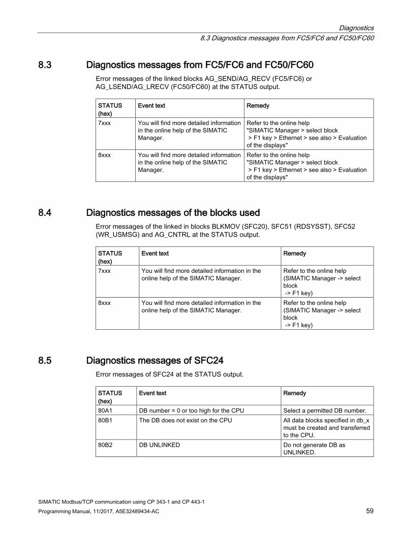
Diagnostics 8.3 Diagnostics messages from FC5/FC6 and FC50/FC60
SIMATIC Modbus/TCP communication using CP 343-1 and CP 443-1 Programming Manual, 11/2017, A5E32489434-AC 59
8.3 Diagnostics messages from FC5/FC6 and FC50/FC60 Error messages of the linked blocks AG_SEND/AG_RECV (FC5/FC6) or AG_LSEND/AG_LRECV (FC50/FC60) at the STATUS output. STATUS (hex)
Event text Remedy
7xxx You will find more detailed information in the online help of the SIMATIC Manager.
Refer to the online help "SIMATIC Manager > select block > F1 key > Ethernet > see also > Evaluation of the displays"
8xxx You will find more detailed information in the online help of the SIMATIC Manager.
Refer to the online help "SIMATIC Manager > select block > F1 key > Ethernet > see also > Evaluation of the displays"
8.4 Diagnostics messages of the blocks used Error messages of the linked in blocks BLKMOV (SFC20), SFC51 (RDSYSST), SFC52 (WR_USMSG) and AG_CNTRL at the STATUS output. STATUS (hex)
Event text Remedy
7xxx You will find more detailed information in the online help of the SIMATIC Manager.
Refer to the online help (SIMATIC Manager -> select block -> F1 key)
8xxx You will find more detailed information in the online help of the SIMATIC Manager.
Refer to the online help (SIMATIC Manager -> select block -> F1 key)
8.5 Diagnostics messages of SFC24 Error messages of SFC24 at the STATUS output. STATUS (hex)
Event text Remedy
80A1 DB number = 0 or too high for the CPU Select a permitted DB number. 80B1 The DB does not exist on the CPU All data blocks specified in db_x
must be created and transferred to the CPU.
80B2 DB UNLINKED Do not generate DB as UNLINKED.

Diagnostics 8.5 Diagnostics messages of SFC24
SIMATIC Modbus/TCP communication using CP 343-1 and CP 443-1 60 Programming Manual, 11/2017, A5E32489434-AC

SIMATIC Modbus/TCP communication using CP 343-1 and CP 443-1 Programming Manual, 11/2017, A5E32489434-AC 61
Examples of applications 9
During the installation, 2 sample projects are stored in \Program Files\Siemens\Step7\Examples:
● 1 sample project in STL "MB_TCP_CP" and
● 1 sample project in CFC "MB_TCP_CP_CFC".
Note
Please note that the supplied sample projects are only intended to provide orientation when handling the Modbus/TCP blocks and that they are not suitable for use in productive plants.
The program examples consist of the following blocks:
● Startup block OB100 with setting of the Init bit
● Programming error OB121
● Cyclic operation OB1 or OB35 with FB MODBUSCP call
● Global data blocks for starting a job (e.g. with the aid of a variables table) and for licensing
● Data blocks for register and bit values
The following sections illustrate the use of the MODBUSCP FB in a simple program example.
9.1 Sample project in STL In the sample project in STL, SIMATIC stations were created for all function variants.
● SIMATIC station is S7-300 and S7-400
● SIMATIC station is client or server

Examples of applications 9.1 Sample project in STL
SIMATIC Modbus/TCP communication using CP 343-1 and CP 443-1 62 Programming Manual, 11/2017, A5E32489434-AC
Blocks used The blocks listed are used in the supplied sample project for S7 stations with FB MODBUSCP. Block Symbol Comment OB 1 CYCL_EXC Cyclic program execution OB 100 COMPLETE RESTART Startup OB for cold restart OB 121 PROG_ERR Programming error OB FB 905 MODBUSCP User block FB MODBUSCP FB 906 MB_CPSRV FB MB_CPSRV called internally FB 908 MB_CPCLI FB MB_CPCLI called internally DB 1 CONTROL_DAT Work DB CONTROL DAT for FB MODBUSCP DB 2 MODBUS_PARAM_CP_DB2 Parameter DB for FB MODBUSCP DB 3 LICENSE_DB License DB for FB MODBUSCP DB 11 DATA_AREA_1 Values DB for area 1 DB 12 DATA_AREA_2 Values DB for area 2 DB 13 DATA_AREA_3 Values DB for area 3 DB 14 DATA_AREA_5 Values DB for area 5 DB 15 DATA_AREA_6 Values DB for area 6 DB 16 DATA_AREA_7 Values DB for area 7 DB 905 IDB_MODBUS Instance DB for FB MODBUSCP

Examples of applications 9.2 Sample project in CFC
SIMATIC Modbus/TCP communication using CP 343-1 and CP 443-1 Programming Manual, 11/2017, A5E32489434-AC 63
9.2 Sample project in CFC The sample project was created with CFC V8.0 Update 1. In the sample project in CFC, stations were created for the variants SIMATIC S7-400 station is client or server.
Blocks used The blocks listed are used in the supplied sample project for S7 stations with FB MODBUSCP. The system functions and system function blocks and the blocks generated by CFC are not listed. Block Symbol Comment OB 35 CYC_INT5 Cyclic program execution OB 100 COMPLETE RESTART Startup OB for cold restart OB 121 PROG_ERR Programming error OB FB 8 R_TRIG Detection of a positive edge FB 24 CTU Count up counter FB 99 Save_STATUS Save the error FB 905 MODBUSCP User block FB MODBUSCP FB 906 MB_CPSRV FB MB_CPSRV called internally FB 908 MB_CPCLI FB MB_CPCLI called internally FC100 AG_CNTRL FC for connection establishment and termination FC 500 AG_LSEND FC for sending data FC 600 AG_LRECV FC for receiving data DB 1 MEMORY_DB DB for runtime parameters (only when S7 is server) DB 2 MODBUS_PARAM_CP_DB2 Parameter DB for FB MODBUSCP DB 3 LICENSE_DB License DB for FB MODBUSCP DB 11 DATA_AREA_1 Values DB for area 1 DB 12 DATA_AREA_2 Values DB for area 2 DB 13 DATA_AREA_3 Values DB for area 3 DB 14 DATA_AREA_5 Values DB for area 5 DB 15 DATA_AREA_6 Values DB for area 6 DB 16 DATA_AREA_7 Values DB for area 7

Examples of applications 9.2 Sample project in CFC
SIMATIC Modbus/TCP communication using CP 343-1 and CP 443-1 64 Programming Manual, 11/2017, A5E32489434-AC

SIMATIC Modbus/TCP communication using CP 343-1 and CP 443-1 Programming Manual, 11/2017, A5E32489434-AC 65
Reference A
The MODBUS Organization MODBUS APPLICATION PROTOCOL SPECIFICATION V1.1b, December 28, 2006
Modbus home page (http://www.modbus.org)

Reference
SIMATIC Modbus/TCP communication using CP 343-1 and CP 443-1 66 Programming Manual, 11/2017, A5E32489434-AC


![u[sonic] Modbus - Lambrecht meteo](https://static.fdokumen.com/doc/165x107/6334bd04a6138719eb0b33dc/usonic-modbus-lambrecht-meteo.jpg)