SIM-C300 User Guide
56
EXPERION PKS RELEASE 516 SIM-C300 User Guide EPDOC-X133-en-516A August 2020
-
Upload
khangminh22 -
Category
Documents
-
view
1 -
download
0
Transcript of SIM-C300 User Guide

EXPERION PKSRELEASE 516
SIM-C300 User GuideEPDOC-X133-en-516A
August 2020

DisclaimerThis document contains Honeywell proprietary information. Information contained herein is to be usedsolely for the purpose submitted, and no part of this document or its contents shall be reproduced,published, or disclosed to a third party without the express permission of Honeywell International Sàrl.
While this information is presented in good faith and believed to be accurate, Honeywell disclaims theimplied warranties of merchantability and fitness for a purpose and makes no express warrantiesexcept as may be stated in its written agreement with and for its customer.
In no event is Honeywell liable to anyone for any direct, special, or consequential damages. Theinformation and specifications in this document are subject to change without notice.
Copyright 2020 - Honeywell International Sàrl
- 2 -

Contents 3
Chapter 1 - About this guide 6
1.1 Revision history 6
1.2 Intended audience 6
1.3 Prerequisite skills 6
1.4 Related documentation 6
Chapter 2 - SIMC300 - Simulation for C300 8
2.1 Getting started 8
2.1.1 SIMC300 and C300 comparison 8
2.2 Supported function blocks and IO families 9
2.3 Licensing scheme for SIMC300 12
Chapter 3 - SIMC300 - Planning 13
3.1 SIMC300 simulation environment 13
3.1.1 SIMC300 usage 13
3.1.2 Interoperability of SIMC300 with other environments 13
3.2 HART Device Simulation 15
3.2.1 Supported HART functions in simulation 15
3.2.2 Monitoring HART device parameters 16
3.2.3 Non-supported HART functions in simulation 16
Chapter 4 - SIMC300 - Installation 18
4.1 Installing SIMC300 18
4.1.1 Selecting the simulation environment 18
Chapter 5 - SIMC300 - Configuration 19
5.1 Configuration overview 19
5.1.1 Configuration Studio 19
5.1.2 Control Builder 19
5.2 Creating an IO module for simulation 20
5.2.1 Creating a SIMC300 controller 21
5.2.2 Configuring a CEEC300 block in simulation 22
5.2.3 Configuring IOLINK block in simulation 22
5.2.4 Creating a Series A I/O module for simulation 22
5.2.5 1756 Series A in simulation 23
5.2.6 Creating a 1756 I/O module for simulation 23
5.2.7 Creating a Series C I/O module for simulation 24
- 3 -

5.2.8 Defining the FTEB for SIMC300 25
5.3 Creating a Control Module for simulation 25
5.3.1 To create a Control Module for simulation 25
5.4 Assigning a Control Module and IOM to a CEEC300 block in aSIMC300 environment 25
5.4.1 To assign a Control Module and IOM to a CEE300 block in a SIMC300environment 26
5.5 Assigning an IOP to an IOLINK in a SIMC300 environment 26
5.5.1 To assign an IOP to an IOLINK block in a SIMC300 environment 26
5.6 Adding an IO Channel to a Control Module in a simulatedenvironment 26
5.6.1 To add IO Channel blocks to a Control Module in a simulated environment 26
5.7 Converting C300 to SIMC300 26
5.7.1 Converting a C300 to a SIMC300 27
5.7.2 Converting a redundant C300 to a SIMC300 28
5.7.3 Converting a redundant C300 Controller to a non-redundant controller 28
5.8 Understanding SIMC300 parameters 29
5.8.1 C300 parameters used for simulation 29
5.8.2 SIMTARGET 30
5.8.3 SIMCOMMAND 30
5.8.4 SIMSTATE 31
5.8.5 SPDFACTOR 32
5.8.6 Supported PM IO functionality for SIMC300 32
5.8.7 Non-supported PM IO functionality for SIMC300 32
Chapter 6 - SIMC300 - Operations 33
6.1 Activating CEE in a SIMC300 environment 33
6.1.1 Initial activation order guidelines for SIMC300 CEE 33
6.1.2 To activate CEE in a SIMC300 environment 34
6.2 Similarities between loading SIMC300 and C300 34
6.3 Inactivating the CEE in a SIMC300 environment 34
6.4 Shutting down the SIMC300 34
6.4.1 To shutdown a SIMC300 35
6.5 Deleting a SIMC300 35
6.5.1 To delete a SIMC300 35
6.6 SIMC300 operator displays 36
6.7 Save and restore Snapshot data 37
- 4 -

6.7.1 Type of snapshots 37
6.7.2 Reviewing snapshot rules 39
6.7.3 Checkpoint operations that can be launched from Control Builder 39
6.7.4 Creating/saving a static snapshot 40
6.7.5 Restoring an older snapshot 40
6.7.6 Creating/saving a dynamic snapshot 41
6.7.7 Restoring/loading a dynamic snapshot 42
6.8 UniSim operations 43
6.8.1 Type of UniSim operations 43
6.8.2 Changing the execution speed of SIMC300 43
6.8.3 Defining the STEP operations 44
6.8.4 To freeze/unfreeze the simulation 46
Chapter 7 - SIMC300 - Maintenance 48
7.1 Upgrading SIMC300 software 48
7.1.1 To upgrade SIMC300 software - general guidelines 48
7.2 Migrating SIMC300 48
7.2.1 Migration support for SIMC300 48
7.2.2 Migrating a SIMC300 49
Chapter 8 - SIMC300 - Troubleshooting 50
8.1 Fixing common problems 50
8.1.1 Loss of power 50
8.1.2 Simulation environment was not installed 50
8.2 SIMC300 alarms 51
8.2.1 Notifications 51
8.2.2 Cycle Overruns 51
8.2.3 CEE Notification 52
8.3 Recovering from CDA disconnect 52
8.3.1 Losing the CDA connection 52
8.3.2 Recovering from a CDA disconnect 53
8.4 Reporting SIMC300 problems to Honeywell 53
8.4.1 SIMC300 failures 53
- 5 -

ABOUT THIS GUIDE
This document provides guidelines to use the SIM-C300 modules.
1.1 Revision history
Revision Date Description
A August 2020 Initial release of the document.
1.2 Intended audience
This guide is intended for the following users:
l Persons responsible for system planning, initial hardware installation, and control strategyconfiguration
l Operators who help to maintain control system operations on a day-by-day basis
l Service persons responsible for routine maintenance of control hardware and who also diagnoseand repair faults.
1.3 Prerequisite skills
It is assumed that you should have some knowledge of Experion PKS control systems and experienceof working in a Microsoft Windows environment.
1.4 Related documentation
The User Assistance Media is a browser- based documentation for the Experion PKS system. It isprovided on a compact disc and can be installed on a suitable personal computer.
Within the User Assistance Media information for both the Series C release and other Experion PKScontrol hardware, such as Process Manager I/O, Series C I/O, and Series A Chassis I/O can be found.
Listed here are the User Assistance Media documents that contain general information for planningand implementing control hardware and network communications in your Experion PKS system:
C300 Controller User's Guide - This guide provides information that assists you in planning anddesigning activities, as well as the installation, operation, and troubleshooting of C300 ProcessControllers in an Experion PKS system.
Control Building Guide - This guide contains basic tasks within the Control Builder application such asconfiguring hardware devices, continuous control strategies, and sequential control strategies. Onlyrepresentative forms are shown to illustrate a procedure/concept.
- 6 -
CHAPTER
1

Series C I/O User's Guide - The guide contains planning and implementation information for Series CI/O modules. Module types include: AI, AO, LLMUX, DI and DO.
SIM-ACE User's Guide - This document covers placing the ACE FB in simulation and other proceduresfor interacting with the ACE simulation functionality.
SIM-C200E Implementations Guide - This document provides information about simulating your C200Controller control strategy with or without Honeywell's UniSim Operations simulator application.
Control Hardware Planning Guide - Provides general information to assist you in planning and designof control hardware in an Experion PKS system. Control hardware includes C200 Controllers, Series AChassis I/O and FIMs, also, all I/O families, (except Series C I/O). It includes some supervisory networkconsiderations for general reference.
Process Manager I/O Troubleshooting and Maintenance Guide - Guide features notification messages(soft fail codes and hard fail codes), service procedures and parts lists for PMIO I/O control hardware.
Various UniSim documents:
l UniSim documentation - installation and node administration information resides in the UniSimdocumentation book-set.
l UniSim Operations R310 Help - online help within the UniSim application
l UniSim Operations Shadow Plant Configuration Guide - online help within the UniSim application
- 7 -
Chapter 1 - About this guide

SIMC300 - SIMULATION FOR C300
l Getting started
l Supported function blocks and IO families
l Licensing scheme for SIMC300
2.1 Getting startedThis section includes information that compares the SIMC300 and C300.
Topic Link
SIMC300 and C300 comparison SIMC300 and C300 comparison
l SIMC300 and C300 comparison
2.1.1 SIMC300 and C300 comparisonThe following is applied to the SIMC300 and C300:
l They share the same template.
l Converting from a SIMC300 to a C300 does not impact most parameters. (MODISREDUN isdisabled when the C300 is converted to a SIMC300).
l SIMC300 supports full simulation of C300 controller including:o load and execution of all function blocks supported by C300 controller.
o EE executing with the same base execution cycles, blocks executing with the same blockexecution period selections.
o interaction with Series C I/O, PM I/O, and ControlNet resident I/O.
l Simple importing of a set of strategies from a on-process to an OTS system. You only need to:o check the SIMTARGET checkbox, and
o give a proper IP address or Hostname if you chose to maintain the original configuration
l In the R310 Release, SIMC300 is released as non-redundant platform.o The option of configuring a SIMC300 as redundant controller is disabled.
o Converting a redundant C300 controller directly to a SIMC300 is also not allowed. Anerror message is returned.
The following is recommended:
You convert the redundant C300 to a non-redundant controller, and then convert it to aSIMC300 controller.
l SIMC300 supports both FTE and Ethernet network configurations. Unlike SIMC200E, it does not
- 8 -
CHAPTER
2

support CNet.
l SIMC300 requires Experion server to support Operator Interface, History, and other functions justlike the C300 controller.
l SIMC300 accepts commands from UniSim.
l SIMC300 supports the same Checkpoint save/restore functions that are supported by C300controller.
l Multiple SIMC300s are allowed to be running on the same node (up to 5 physical CPUs whenexecution cycle determinism is guaranteed, or 20/Dual CPU when execution cycle determinism isnot guaranteed).
ATTENTION
Simulation in high capacity must be run in a separate simulation node where as those in lowcapacity must be run in the Engineering Station.
2.2 Supported function blocks and IO familiesAll of the Experion PKS function blocks that are supported by C300 in the R310 release also aresupported by SIMC300. This means those function blocks can be assigned and loaded to SIMC300environment. UCNIF and CAB function blocks are not supported by C300, therefore, are not supportedby SIMC300. An error is generated if you attempt to assign/import/load these unsupported block typesto either C300 or SIMC300.
The following table demonstrates what type of function block family is supported in SIMC300 R310Release.
Function Block library C300 SIMC300
STATIC BLOCK
AUXILIARY X X
DEVCTL X X
DATAACQ X X
IOMODULE X X
IOCHANNEL X X
LOGIC X X
MATH X X
RCM X X
REGCTL X X
SCM X X
UCM X X
UCNIF n/a n/a
UTILITY X X
Table 2.1 FBs supported in SIMC300
- 9 -
Chapter 2 - SIMC300 - Simulation for C300

Chapter 2 - SIMC300 - Simulation for C300
Function Block library C300 SIMC300
PCDI X X
POWERGEN X X
CCL BLOCK
AGA X X
EXCHANGE X X
ABDRIVE X X
DNET X X
HARTIO X X
PBUSIF X X
PULSEINPUT X X
RAIL_IO X X
RAIL_IO_HAZ X X
CUSTOM BLOCK
CAB n/a n/a
CDB X X
PHASE X X
IO
PMIO X X
SERIES C IO X X
IOMName
RockwellI/O module
Description AssociatedBlocks
Channel Name Channels
TC-IAH061
1756-IF6I Analog Input,Isolated
CEE AICHANNEL 6
TC-IHA161
1756-IF16 Analog Input CEE AICHANNEL 16
TC-IDA161
1756-IA16 Digital Input CEE DICHANNEL 16
TC-IDD321
1756-IB32/B
Digital Input CEE DICHANNEL 32
Table 2.2 1756 Series A I/O modules and channels
- 10 -

IOMName
RockwellI/O module
Description AssociatedBlocks
Channel Name Channels
TC-IDJ161
1756-IB16I Digital Input,Isolated
CEE DICHANNEL 16
TC-IDK161
1756-IA16I Digital Input,Isolated
CEE DICHANNEL 16
TC-IDW161
1756-IM16I Digital Input,Isolated
CEE DICHANNEL 16
TC-IDX081
1756-IA8D Digital Input,Diagnostic
CEE DICHANNEL 8
TC-IDX161
1756-IB16D
Digital Input,Diagnostic
CEE DICHANNEL 16
TC-IXL061
1756-IT6I Analog Input,Thermocouple(TC/mV)
CEE AOCHANNEL 6
TC-IXL062
1756-IT6I2 Analog Input,Thermocouple(TC/mV)
CEE AOCHANNEL 6
TC-IXR061
1756-IR6I Analog Input, RTD CEE AOCHANNEL 6
TC-MUX021
Serial Interface CEE SIFLAGARRCH
SINUMARRC
SITEXTARRCH
32
TC-OAH061
1756-OF6CI
AnalogOutput,Isolated
CEE AOCHANNEL 6
TC-OAV061
1756-OF6VI
AnalogOutput,Isolated
CEE AOCHANNEL 6
TC-OAV081
1756-OF8 AnalogOutput CEE AOCHANNEL 8
TC-ODA161
1756-OB16I
Digital Output CEE DOCHANNEL 16
TC-ODD321
1756-OB32 Digital Output CEE DOCHANNEL 32
TC-ODJ161
1756-OB16I
Digital Output,Isolated
CEE DOCHANNEL 16
TC-ODK161
1756-OA16I
Digital Output,Isolated
CEE DOCHANNEL 16
- 11 -
Chapter 2 - SIMC300 - Simulation for C300

Chapter 2 - SIMC300 - Simulation for C300
IOMName
RockwellI/O module
Description AssociatedBlocks
Channel Name Channels
TC-ODX081
1756-OA8D
Digital Output,Diagnostic
CEE DOCHANNEL 8
TC-ODX161
1756-OB16D
Digital Output,Diagnostic
CEE DOCHANNEL 16
TC-ORC081
1756-OX8I RelayOutput,Isolated
CEE PWMCHANNEL 8
TC-ORC161
1756-OW16I
RelayOutput,Isolated
CEE PWMCHANNEL 16
2.3 Licensing scheme for SIMC300A new license key - CX00 Simulation Environment is introduced in R310 Release for the purpose oftracking the usage of SIMC200E, SIMC300 and future SIMX00 controllers.
It is prohibited to load a SIMC200E or a SIMC300 instance if the CX00 Simulation Environment licensewas not purchased as part of the license package
SIMC300activity
If license is available If license is not available
Create Can be created beyond the rangeset by the license
Can be created beyond the rangeset by the license
Load Can be created Cannot be loaded
If the system does have a valid CX00 simulation environment license, SIMC200E and SIMC300 areallowed to be created even if the total instances of SIMC200E and SIMC300 has reached thepurchased license limit. SIMC200E and SIMC300 can be loaded only if it is within the purchasedlicense range.
- 12 -

SIMC300 - PLANNING
l SIMC300 simulation environment
l HART Device Simulation
3.1 SIMC300 simulation environmentIn some cases simulation and on-process environments exists on different systems utilizing differentEngineering Repository Databases (ERDBs). If this is the case, a one-time:
l import/export operation, or
l engineering database backup/restore
from simulation to on-process (or on-process to simulation) and loading of all the controllers isnecessary.
Topic Link
SIMC300 usage SIMC300 usage
Interoperability of SIMC300with otherenvironments
Interoperability of SIMC300with otherenvironments
l SIMC300 usage
l Interoperability of SIMC300 with other environments
3.1.1 SIMC300 usageThe following are the possible simulation scenarios that SIMC300 supports:
l C300 hardware is not available - create control strategies in a SIMC300 environment.
l Using an existing on-process strategy - bringing it into a SIMC300 environment.
l Creating a simulation strategy - then bringing it into an on-process environment.
l Using the same ERDB for simulation and on-process work (although you must modify theSIMTARGET from C300 to SIMC300).
l Moving an ERDB from on-process to simulation.
3.1.2 Interoperability of SIMC300 with other environmentsExperion R310 is the first official release for SIMC300. Experion PKS Experionserverand have to beon the R310 release also to allow proper functionality between the on-process and the OTS systems.
Refer to the following table for the interoperability between C300 and other environments.
- 13 -
CHAPTER
3

SIMC300
and …
Relationship
Server/Station The engineering tool and databasemust match the release of theSIMC300.
If: SIMC300 = release 310.1
Then: EPKS server and station = release 310.1
engineering too and database = release 310.1
Othercontrollers
The general operability principle allows the peer-to-peercommunication to one release back.
If the node is at Experion R310 with SIMC300, then peer-to-peercommunication to SIMC200E is allowed.
UniSim It is recommended to use the corresponding release of UniSim andExperion PKS. This allows thematching of the on-process andOTSfunctions If Experion PKS = release R310.1 Then: UniSim = releaseR310
Table 3.1 SIMC300 and other environments
SIMC300 and other simulation environments
SIMC300 has full bidirectional connectivity with other simulation environments. This means SIMC300can either read-from or write-to other simulation environments. Therefore, other simulationenvironments can also read-from or write to the SIMC300 environment.
TIP
Only SIMC300 initiated read connection or on-process environment initiated store connectionsare allowed between SIMC300 and an on-process controller. All other types of peercommunications are rejected.
SIMC300 and communication between two different servers
Communication between two execution environments on two different servers must use SIMACE tocommunicate with OPC Gateway and Inter Cluster Gateway. In order to write data from a SIMACE, theOPC Gateway must be specified as a Simulation OPC Gateway. This is done by setting SIMENABLE asTRUE on an OPC Gateway platform block.
Function block family SIMC300 as initiator SIMC300 as responder
Read Write Read Write
C200 n/a n/a n/a n/a
C300 X n/a n/a X
Table 3.2 SIMC300 and read/write permissions
- 14 -
Chapter 3 - SIMC300 - Planning

Chapter 3 - SIMC300 - Planning
Function block family SIMC300 as initiator SIMC300 as responder
Read Write Read Write
ACE X n/a n/a X
IOLIM n/a n/a n/a n/a
FIM2 X n/a n/a X
FIM4 X n/a n/a X
LIOM n/a n/a n/a n/a
SM n/a n/a n/a n/a
EHG n/a n/a n/a n/a
SIMC200E X X X X
SIMC300 X X X X
SIMACE X X X X
SIMIOLIM n/a n/a n/a n/a
FF-SIM2 n/a n/a n/a n/a
FF-SIM4 n/a n/a n/a n/a
SIM-EHG n/a n/a n/a n/a
SIMC300-EHB communication
To allow communication between all SIMC300 and EHB blocks, each SIMC300 should be hosted by aunique Simulation Control Environment (SCE). If multiple SIMC300 are hosted by a single SCE, onlythe first loaded SIMC300 will be able to communicate to the EHB block. Any other loaded SIMC300hosted on the same SCE, that tries to communicate to the same EHB block will result in Hb Timeoutmessage.
3.2 HART Device Simulationl Supported HART functions in simulation
l Monitoring HART device parameters
l Non-supported HART functions in simulation
3.2.1 Supported HART functions in simulationIn the simulation environment, the HART channel block functions, support:
l Monitoring HART device.o Configuration parameters.
o Status parameters including Command 48.
l Building HART device network in FDM.
- 15 -

3.2.2 Monitoring HART device parametersSIMC300 supports the monitoring of the following HART channel block parameters from ControlBuilder, FDM and SWMUX.
Parameter Description Value Read Remarks
HDEVMFG Manufacturer HDVMFGCD Configured value
HDEVTYPE Type HDVTYPCD Configured value
HDEVID Id (Serial Number) HDEVIDCD Configured value
HDEVREV Revision HDVREVCD Configured value
HHWREV Hardware Revision “0” Default value
HSWREV Software Revision “0” Default value
HFLAGS HART Device Flags “0” Default value
HNMSMINPRE MinimumM to SPreambles
“2” Default value
HUCMDREV Universal CommandRevision
“HART Version 6” Default value
HCOMSTS HART CommunicationStatus
“OK” Default value
HDEVST General Device Status dynamic Read andWritesupport
HTAG Tag Null Default value
HDEVTYPENAME Type (Name) HDVTYPCDNAME Configured value
HCMD48BT[1..200]
Command 48 Bits dynamic Read andWritesupport
HGCHNGFL HARTGlobal ChangeFlag
dynamic Read andWritesupport
HDEVST HART Device Status dynamic Read support
IOM.HGCHNG1 IOMHARTGlobalChange Flag
dynamic Read support
Table 3.3 Supported HART Device Parameters
3.2.3 Non-supported HART functions in simulationThe following FDM operations are not supported for HART devices assigned to SIMC300:
l Configuring a field device
l Offline Configuration - Offline Download to device, Bulk Offline download
l Accessing Device Specific Parameters
l Executing HART Field Device methods
- 16 -
Chapter 3 - SIMC300 - Planning

Chapter 3 - SIMC300 - Planning
l Viewing Device Status
l Viewing and editing Device Properties
l Comparing Device Configuration
l Device History
l Exporting Online Configuration
l Saving an Online Configuration as an Offline Configuration
l Renaming FDM tags
- 17 -

SIMC300 - INSTALLATION
l Installing SIMC300
4.1 Installing SIMC300This section identifies where to find the various SIMC300 installation options.
Topic Link
Selecting the simulation environment Selecting the simulation environment
l Selecting the simulation environment
4.1.1 Selecting the simulation environmentThere are multiple selection options when installing the simulation environment for an Experion PKSsystem.
Refer to the Supplementary Installation Tasks Guide (SITG) for assistance in installing the simulationenvironment.
- 18 -
CHAPTER
4

SIMC300 - CONFIGURATION
l Configuration overview
l Creating an IO module for simulation
l Creating a Control Module for simulation
l Assigning a Control Module and IOM to a CEEC300 block in a SIMC300 environment
l Assigning an IOP to an IOLINK in a SIMC300 environment
l Adding an IO Channel to a Control Module in a simulated environment
l Converting C300 to SIMC300
l Understanding SIMC300 parameters
5.1 Configuration overviewThis section includes information that you use to configure the SIMC300 environment from within yourExperion PKS system.
Topic Link
Configuration Studio Configuration Studio
Control Builder Control Builder
l Configuration Studio
l Control Builder
5.1.1 Configuration StudioConfiguration Studio is the central location from which you can access engineering tools andapplications to configure your Experion PKS system. When you choose Control Strategy in theConfiguration Explorer tree and then choose the task Configure a Control Strategy, Control Builder islaunched so you can configure Series C hardware modules, build the process control strategies foryour system and configure the SIMC300 environment.
5.1.2 Control BuilderControl Builder is the application used to create and configure Series C hardware modules andfunction blocks so you can build process control strategies for your system. Control Builder is accessedthrough Configuration Explorer.
- 19 -
CHAPTER
5
H332110
Highlight
as is
H332110
Highlight
as is
l If you are familiar with using Control Builder, then most of the same rules apply for configuring,loading and monitoring when implementing Series C control hardware.
l If you are new to Control Builder, you should first refer to the Control Building Guide to familiarizeyourself with the application and its capabilities.
l To complete some configuration selections for the SIMC300, you should refer to the C300 ControllerUser's Guide.
ATTENTION
The information and procedures presented in this section apply to using Control Builder forconfiguring the C300 Controller. Some procedures cover the creation and configuration of theControl Execution Environment block (CEEC300) where you create your control strategies. Thissection does not attempt to provide all details for using Control Builder in configuring thenumerous components that are associated with the Experion PKS system.
Please refer to the Control Building Guide for additional information and procedures.
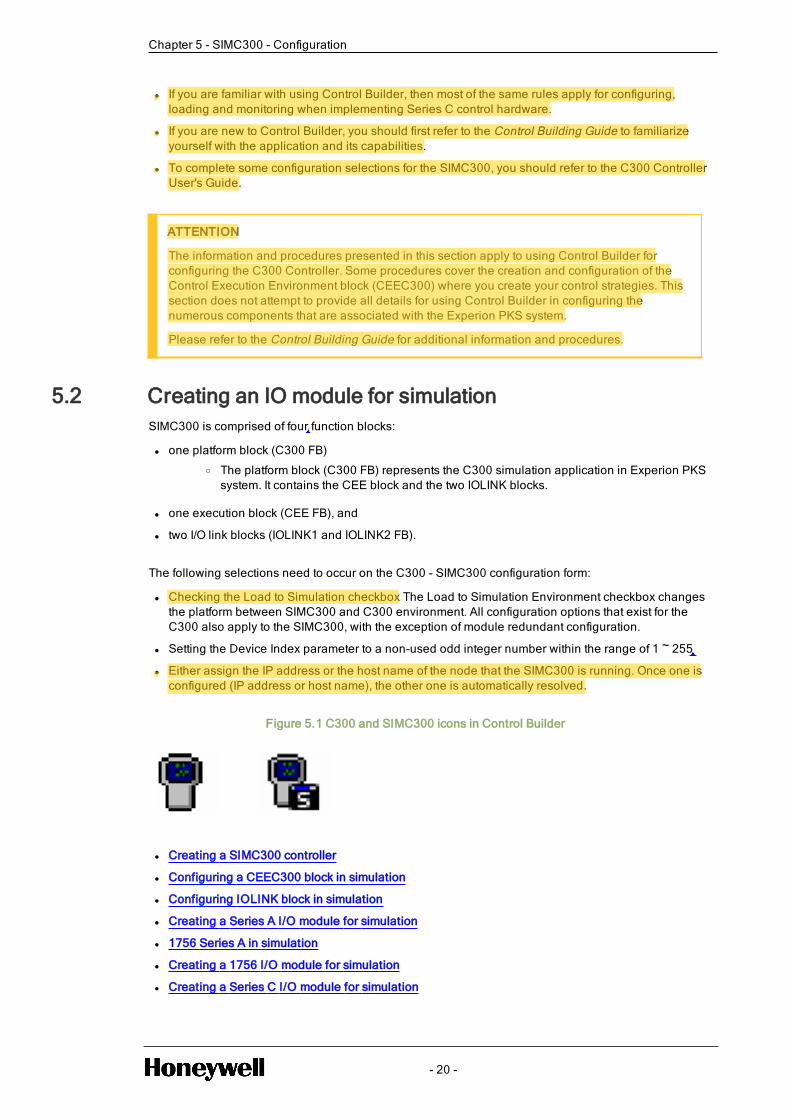
5.2 Creating an IO module for simulationSIMC300 is comprised of four function blocks:
l one platform block (C300 FB)o The platform block (C300 FB) represents the C300 simulation application in Experion PKS
system. It contains the CEE block and the two IOLINK blocks.
l one execution block (CEE FB), and
l two I/O link blocks (IOLINK1 and IOLINK2 FB).
The following selections need to occur on the C300 - SIMC300 configuration form:
l Checking the Load to Simulation checkbox The Load to Simulation Environment checkbox changesthe platform between SIMC300 and C300 environment. All configuration options that exist for theC300 also apply to the SIMC300, with the exception of module redundant configuration.
l Setting the Device Index parameter to a non-used odd integer number within the range of 1 ~ 255
l Either assign the IP address or the host name of the node that the SIMC300 is running. Once one isconfigured (IP address or host name), the other one is automatically resolved.
Figure 5.1 C300 and SIMC300 icons in Control Builder
l Creating a SIMC300 controller
l Configuring a CEEC300 block in simulation
l Configuring IOLINK block in simulation
l Creating a Series A I/O module for simulation
l 1756 Series A in simulation
l Creating a 1756 I/O module for simulation
l Creating a Series C I/O module for simulation
- 20 -
Chapter 5 - SIMC300 - Configuration
H332110
Highlight
replace C300 with CN100
H332110
Cross-Out
H332110
Inserted Text
two function blocks. * CN100 platform block and one I/O link block
H332110
Cross-Out
H332110
Cross-Out
H332110
Inserted Text
510
H332110
Highlight
get it checked
H332110
Highlight
check if it has a check box

Chapter 5 - SIMC300 - Configuration
l Defining the FTEB for SIMC300
5.2.1 Creating a SIMC300 controllerThe C300 and SIMC300 share the same template.
Figure 5.2 C300 FB configured as SIMC300
To create a SIMC300 controller
1. Click File - > New - > Controllers - > C300 - Controller (2 I/O links).
Result: The C300 Block, SIMC300 configuration form appears.
2. Type in desired name for the SIMC300 of up to 40 characters or accept the default in the Tag Namefield.
3. Click in the Device Index field (DEVICEIDX parameter).
4. Type a non-used odd integer number in the range of 1 through 255.
5. Check the Load Simulation Environment (SIMTARGET parameter) check box.
NOTE
unchecking the Load Simulation Environment check box causes the SIMC300 to revertback to C300. All configuration options (except Module redundant configuration) thatare specific to SIMC300 are applicable to C300.
- 21 -
H332110
Rectangle
check for SIMCN100 image
H332110
Highlight
check if it is controller or gateway
H332110
Cross-Out
H332110
Inserted Text
510
H332110
Highlight
check if it is applicable

6. Type the IP address (or the host name of the node) of where the SIMC300 is located.
Result: The following is an example of the SIMC300 block icons that now appear in the projectwindow:
7. All additional configuration selections for the SIMC300 are identical in the manner to which theC300 selections are made (with the exception of redundancy determination).
Refer to the Controller User's Guide for support with these selections.
5.2.2 Configuring a CEEC300 block in simulationThe CEE300 function block publishes parameters reflecting status and configuration of the executionenvironment. It monitors the peer connection between itself and other execution environments, as wellas the local data transfer between itself and two IOLINKs within the same SIMC300.
There are two parameters introduced to CEE FB configuration form that are meaningful only when thecontroller is running as SIMC300 - NOTIFINHIBIT SIMSTATE.
For more information on the procedure to configure the CEEC300 block for simulation, refer to the C300Controller User's Guide EPDOC-XX11-en in the User Assistance Media.
5.2.3 Configuring IOLINK block in simulationTwo IOLINK blocks are created automatically when a SIMC300 Controller function block is added to theProject tab.
For more information on the procedure to configure the IOLINK block for simulation, refer to the C300Controller User's Guide EPDOC-XX11-en in the User Assistance Media.
5.2.4 Creating a Series A I/O module for simulation1. Click File - > New - > I/O Modules - > [desired I/O module].
Result: The I/O module's configuration form appears.
2. On the Main Tab of the form, enter the appropriate I/O hardware location data in the applicablefields such as; the IOM Slotnum in Chassis, Uplink CNB in IO Rack, and Downlink CNB SlotNumber for Chassis I/O. If necessary, access the on-line help for assistance during this step.
3. Click the OK button to create an instance of the I/O Module block in the Project. tree.
4. If multiple IOMs are required, repeat this procedure for each occurrence of the IOM, even if the typeis the same as a previously created IOM.
5. Complete the configuration of each module before loading it to the Controller. Use the appropriateconfiguration procedure in this document or the applicable I/O component Implementation Guidefor reference along with the on-line help.
6. All additional configuration selections for the I/O module for simulation are identical in the mannerto which the I/O module selections are made (with the exception of redundancy determination).
- 22 -
Chapter 5 - SIMC300 - Configuration
H332110
Inserted Text
Creating and
H332110
Highlight
check if it is applicable
H332110
Cross-Out
H332110
Inserted Text
CN100
H332110
Inserted Text
CN100
H332110
Highlight
H332110
Cross-Out
H332110
Inserted Text
One
H332110
Cross-Out
H332110
Sticky Note
take the configuration for CN100 user guide
H332110
Cross-Out

Chapter 5 - SIMC300 - Configuration
7. Refer to the C300 Controller User's Guide for support with these selections.
5.2.5 1756 Series A in simulationUse the following links to access 1756 modules/channels information that support SIMC300 simulation.
l Refer to ‘Table – 1756 Series A I/O modules and channels’ for a listing of the 1756 modules thatsupport simulation with SIMC300.
5.2.6 Creating a 1756 I/O module for simulation1. Click File -- > New - > I/O Modules - > I0MODULE - > [desired I/O module]..
Result: The I/O module's configuration form appears.
2. On the Main Tab of the form, enter the appropriate I/O hardware data in the applicable fields suchas;
Module Name:
Item Name
Module Description
The IOM requires a properly defined path consisting of the following:
IOM Slot Number (IOMSLOT): The limit is 39
Remote IO Chassis MAC Address (ULCNBMAC) : The limit is 20
ControlNet Module Slot Number (DLCNBSLOT): The limit is 20
Also required is the FTEBBLOCK although not visible on the IOM until the IOM block is assigned toa SIMC300 CEEFB. Then the list of applicable FTEB's is available.
TIP
The following occurs if there is any invalid configuration
l A warning will be returned at configuration time.
l An error will be returned at the load time
l The load operation will fail.
IOMs that have the same path with a loaded IOM will also be rejected during load time.
- 23 -
H332110
Cross-Out
H332110
Cross-Out
H332110
Cross-Out

3. Click the OK button to create an instance of the I/O Module block in the Project. tree.
4. If multiple IOMs are required, repeat this procedure for each occurrence of the IOM, even if the typeis the same as a previously created IOM.
5. Complete the configuration of each module before loading it to the Controller. Use the appropriateconfiguration procedure in this document or the applicable I/O component Implementation Guidefor reference along with the on-line help.
5.2.7 Creating a Series C I/O module for simulation1. Drag the Series C I/O module to the IOLINK block of the SIMC300.
2. Double-click the I/O module.
The I/O module configuration form appears.
3. Complete the configuration of the I/O module. For more information about configuring the I/Omodule, refer to the Series C I/O User's Guide.
4. Assign a channel to the CM.
For more information about adding IO channel blocks to a CM, refer to the C300 Controller User'sGuide.
5. Double-click the channel block.
The channel block configuration form appears.
6. Click the Configuration Parameters tab.
7. Add SIMMODE parameter as a configuration parameter.
The SIMMODE parameter appears on the channel block's faceplate.
8. Click the Monitoring Parameters tab.
9. Add SIMVALUE parameter as a monitoring parameter.
10. Click the Block Pins tab.
11. Select the SIMVALUE parameters and expose it as a block pin.
12. Click OK.
The SIMVALUE parameter appears on the channel block's faceplate.
13. Double-click the SIMMODE parameter on the faceplate and select one of the following options.
a. None - If simulation is not required.
b. DirectSub - If you want the operator to write the target value manually.
c. SimValSub - If you want the operator to write the target value or if the target value can befetched from other program.
NOTE
You can select the simulation mode while configuring the channel or after loading themodule.
14. Double-click the SIMVALUE parameter on the faceplate and enter the simulation value.
When you enter the SIMVALUE, the same value is reflected in the PV parameter.
NOTE
You can enter the simulation value only after loading the module.
- 24 -
Chapter 5 - SIMC300 - Configuration
H332110
Cross-Out

Chapter 5 - SIMC300 - Configuration
15. Click OK.
You can activate the CEE to start the simulation.
ATTENTION
The Series C Pulse Input Module also supports simulation with SIM-C300.
5.2.8 Defining the FTEB for SIMC300The following rules apply to the FTEB for SIMC300:
l Maximum number of IOMs allowed to be assigned to the same FTEB is 16.
l Maximum number of FTEBs allowed to be used for a particular SIMC300 is 8.
l Maximum number of IOMs allowed to be loaded to a particular SIMC300 in total is 64.
l Redundant FTE Bridge is not allowed.
There is a load failure for the IOM for any violation of the above rules.
5.3 Creating a Control Module for simulationThe SIMC300 environment allows building a Control Strategy, where a Control Module (CM) is createdand function blocks are inserted and connected with other function blocks.
WARNING
All edits done on project-related objects must be reloaded to the controller before those editscan be seen in the controller. See Control Strategy Loading for information on how to loadcontrol strategy objects.
5.3.1 To create a Control Module for simulation
For more information on the procedure to create and save a Control Module for simulation, refer to theC300 Controller User's Guide EPDOC-XX11-en in the User Assistance Media.
5.4 Assigning a Control Module and IOM to a CEEC300 blockin a SIMC300 environmentOnce a Control Module (CM) or Sequential Control Module (SCM) is created, you can assign it to aCEEC300 block of a SIMC300. Use the following procedure as a general guide to assign configuredCMs and I/O Modules (IOMs) to the CEEC300 block.
Note that in the SIMC300 controller environment, Chassis IOMs and Rail IO modules can be assignedonly to the CEEC300 block.
For additional information on CM assignment, see the Control Building Guide; or for SCM assignment,the Sequential Control User's Guide.
- 25 -
H332110
Cross-Out

ATTENTION
l Before Control Builder allows you to associate an IOM to an IOCHANNEL block, itchecks to make sure that the CM and IOM are assigned to the same CEE
l All edit windows (such as CM charts) must be closed before proceeding with thisprocedure or a lock contention may occur. To resolve these types of lock contentions,close the open CM chart and attempt to open the CM chart again.
5.4.1 To assign a Control Module and IOM to a CEE300 block in aSIMC300 environment
1. The steps to assign a Control Module and IOM to a CEEC300 block are the same in the on-processand simulation environment.
2. Refer to the following, To assign Control Modules and IOMs to a CEE for the procedure to activatethe CEE for simulation.
5.5 Assigning an IOP to an IOLINK in a SIMC300 environment
5.5.1 To assign an IOP to an IOLINK block in a SIMC300environment
1. The steps to assign a Control Module and IOM to a CEEC300 block are the same in the on-processand simulation environment.
2. Refer to the following, To assign Control Modules and IOMs to a CEE for the procedure to activatethe CEE for simulation.
5.6 Adding an IO Channel to a Control Module in a simulatedenvironmentAn IO Channel block represents a channel in one of the various IO modules (IOMs). The IO Channelblocks can be added to a Control Module (CM) in the Project tab to build a process control strategy.
The procedure is a drag and drop operation and is the same for any type IO Channel, whether it is an AIchannel in a Series C IO module or an DO channel in a Series A IO module.
5.6.1 To add IO Channel blocks to a Control Module in a simulatedenvironment
Refer to the following, To add IO Channel blocks to a Control Module chart for the procedure to activate theCEE for simulation.
5.7 Converting C300 to SIMC300This section includes information that you use to convert a C300 to a SIMC300.
Topic Link
To convert a C300 to a SIMC300 Converting a C300 to a SIMC300
To convert a redundant C300 to a Converting a redundant C300 to a
- 26 -
Chapter 5 - SIMC300 - Configuration
H332110
Cross-Out
H332110
Cross-Out
H332110
Inserted Text
CN100
H332110
Cross-Out
H332110
Inserted Text
CN100
H332110
Cross-Out
H332110
Cross-Out
H332110
Inserted Text
IOM to a IO Link
H332110
Cross-Out
H332110
Inserted Text
Series C
H332110
Inserted Text
in any Series C IO module.
H332110
Cross-Out

Chapter 5 - SIMC300 - Configuration
Topic Link
SIMC300 SIMC300
To convert a redundant C300 Controller toa non-redundant controller
Converting a redundant C300 Controller toa non-redundant controller
l Converting a C300 to a SIMC300
l Converting a redundant C300 to a SIMC300
l Converting a redundant C300 Controller to a non-redundant controller
5.7.1 Converting a C300 to a SIMC300The C300 and SIMC300 share the same template and configuration forms. The process to convert anexisting C300 to a SIMC300 requires that you:
l Delete the C300 from your monitoring tab
l Define the C300 as a SIMC300
l Reload the controller as a SIMC300
To convert a C300 to a SIMC300
1. In the Control Builder Monitoring tab, delete all assigned blocks under the SIMC300/CEE/IOLINKs
2. In the Project window, double-click on the CEEC300 block icon.
Result: Calls up CEEC300 Block configuration form
3. From the Powerup Restart Settings section, click the CEE State's down-arrow button and select theIDLE state.
Result: This places both the C300 and the CEE in an IDLE state.
NOTE
The Simulation State of the C300/CEE/IOLINK blocks are not evaluated.
4. In the Project tab, double-click the C300 block icon that is to be placed in simulated.
Result: Calls up C300 configuration form
5. On the C300 configuration form verify the following:
a. Type in desired name for the SIMC300 of up to 40 characters or accept the default in the TagName field.
b. Click in the Device Index field (DEVICEIDX parameter). Type a non-used odd integer numberin the range of 1 through 509.
- 27 -
H332110
Cross-Out
H332110
Cross-Out
H332110
Cross-Out
H332110
Inserted Text
510

6. Check the Load Simulation Environment (SIMTARGET parameter) check box.
NOTE
Unchecking the Load Simulation Environment check box causes the SIMC300 to revertback to C300. All configuration options (except Module redundant configuration) thatare specific to SIMC300 are applicable to C300.
7. Type the IP address (or the host name of the node) of where the SIMC300 is located.
Result: The following is an example of the SIMC300 block icons that now appear in the projectwindow:
8. All additional configuration selections for the SIMC300 are identical in the manner to which theC300 selections are made (with the exception of redundancy determination).
Refer to the C300 Controller User's Guide for support with these selections.
5.7.2 Converting a redundant C300 to a SIMC300Configuring a SIMC300 as a redundant controller is not allowed. An error message is returned.
Converting a redundant C300 controller directly to a SIMC300 is also not allowed. An error message isreturned.
The following is recommended:
1. You convert the redundant C300 to a non-redundant controller. Refer to the following: Converting aredundant C300 Controller to a non-redundant controller
2. And then convert the C300 to a SIMC300 controller. Refer to the following: Creating a SIMC300controller
NOTE
Once the checkbox Module is Redundant (MODISREDUN parameter) is unchecked, thesecondary controller is automatically deleted from database and the view tree.
5.7.3 Converting a redundant C300 Controller to a non-redundantcontroller1. Disconnect the redundancy cable from the primary C300 Controller.
- 28 -
Chapter 5 - SIMC300 - Configuration
H332110
Cross-Out

Chapter 5 - SIMC300 - Configuration
Result: Alarms are generated.
2. In the Monitor view, right click on the secondary C300 Controller block.
Choose delete.
Result: The secondary C300 Controller icon disappears from the tree view.
3. In the Project view, right click on the primary C300 Controller icon and choose Module Properties.
Result: Calls up the primary C300 Controller configuration form.
4. Uncheck the Module is redundant check box.
5. Click the OK button.
Result:
l The secondary C300 Controller icon is deleted from the project view,
l The non-redundant C300 Controller icon changes from a redundant to a non-redundant icon
l The non-redundant C300 icon shows a delta
6. Click non-redundant C300 block icon in Project view.
Perform a Load to the controller.
The delta sign should disappear from the C300 Controller icon in the Project view. The C300Controller icon in the Monitor view should indicate the controller is now non-redundant.
5.8 Understanding SIMC300 parametersThis section includes information that you use to understand SIMC300 parameters.
Topic Link
C300 parameters used for simulation C300 parameters used for simulation
SIMTARGET SIMTARGET
SIMCOMMAND SIMCOMMAND
SIMSTATE SIMSTATE
SPDFACTOR SPDFACTOR
Supported PM IO functionality forSIMC300
Supported PM IO functionality forSIMC300
Non-supported PM IO functionality forSIMC300
Non-supported PM IO functionality forSIMC300
l C300 parameters used for simulation
l SIMTARGET
l SIMCOMMAND
l SIMSTATE
l SPDFACTOR
l Supported PM IO functionality for SIMC300
l Non-supported PM IO functionality for SIMC300
5.8.1 C300 parameters used for simulation
- 29 -
H332110
Cross-Out
H332110
Cross-Out

Parameter Description
Configuration parameters
SIMTARGET The environment is:
C300 if SIMTARGET = FALSE
SIMC300 if SIMTARGET = TRUE
HOSTIPPRI The host IP addresswhere the SIMC300 is running.
HOSTNAMEPRI The host namewhere the SIMC300 is running.
PROCESS_ID The windows process ID is assigned to the SIMC300when itwas created.
SIMCOMMAND Commands the simulation state.
Run-time parameters
SIMSTATE The current state of simulation environment.
TNUMSC3INCON Number of other C300s/SIMC300s this SIMC300 is connectedto as an initiator.
TNUMSC3OUTCON Number of other C300s/SIMC300s this SIMC300 is connectedto as a responder.
STEPTIME The step execution time inms.
SPDFACTOR The target Base cycle speed factor.
5.8.2 SIMTARGETSIMTARGET parameter is located on the C300 configuration form's Main tab. The text appears as “Loadto simulation”. The following is true:
l For SIMC300 - Checking the checked box equals SIMTARGET = TRUE
l For C300 - Unchecking the check box equals SIMTARGET = FALSE
5.8.3 SIMCOMMANDSIMCOMMAND is used to change the state of simulation and can be issued only when SIMTARGET =TRUE
WhenSIMCOMMANDis
Then
SIMNONE C300 is not in simulationmode and the blocks are being executed.
If the SIMC300 is not in simulation (SIMSTATE is NONE), theFREEZE command is rejected, and an error is logged in ExperionPKS error log.
SIMRUN C300 is in simulationmode and the blocks are being executed.
- 30 -
Chapter 5 - SIMC300 - Configuration
H332110
Cross-Out
H332110
Sticky Note
check this table with suraj
H332110
Cross-Out

Chapter 5 - SIMC300 - Configuration
WhenSIMCOMMANDis
Then
UniSim switches SIMSTATE fromSIMFREEZE to SIMRUN.
SIMFREEZE UniSim stops simulation.
UniSim issues this commandwhen a save/restore dynamic datasnapshot or for Single/Multi-Step execution is needed.
Only the UniSim simulator can successfully change the SIMC300'sSIMSTATE to SIMFREEZE.
SIMDISABLE If UniSim freezes the simulation, then the Engineer can useSIMDISABLE to unfreeze the simulation.
On receiving this command SIMSTATE is set to SIMRUN.
5.8.4 SIMSTATESIMC300 checks the SIMSTATE value to make sure it is in simulation. The CEE and IOLINKs are alsoplaced in simulation and share the same SIMSTATE as the SIMC300.
ATTENTION
l In C300, SIMSTATE is always SIMNONE.
l In SIMC300, SIMSTATE is never SIMNONE.
WhenSIMSTATE is
Then
SIMNONE C300 is not in simulationmode. Default setting for the C300.
SIMRUN C300 is in simulationmode and the blocks are being executed.
UniSim or the engineer switches SIMSTATE fromSIMFREEZE toSIMRUN.
SIMFREEZE UniSim stops simulation to do a Save/Restore Dynamic Data Snapshotor for Single/Multi-Step execution.
After a successful Save or Restore, UniSim commandsSIMSTATE toSIMRUN.
NOTE
nly the UniSim simulator can successfully change theSIMC300's SIMSTATE to SIMFREEZE.
SIMDISABLE There is no SIMDISABLE state.
- 31 -
H332110
Highlight
check with suraj and mark yantek

5.8.5 SPDFACTORUniSim commands SIMC300 to run slower or faster by setting the value of SPDFACTOR parameter.This parameter is processed only when this SIMC300 controller is in SIMFREEZE.
l If the value is out of the range, the request is rejected with an error indicating the value is out ofrange. Since SPDFACTOR is a float value, the value requested by a user may not be valid.Therefore the value of parameter SPDFACTOR must be adjusted to the nearest supported value.
l If the value of SPDFACTOR that UniSim commands is within the supported range (0.01 to 5), thevalue is reset.
l The controller will run at the same speed until the SPDFACTOR is reset.
5.8.6 Supported PM IO functionality for SIMC300PM IO in SIMC300 is configured the same as PM in the C300 environment. This means that:
l The IOP is allowed to be assigned and loaded to the SIMC300
l The IOP can be configured as redundant or non-redundant. This allows a redundant on-processC300 to retain its original configuration in SIMC300, although the redundancy capability is notsupported in SIMC300.
l The PV can be simulated
l A close loop tail-to-mouth wiring can be configured
5.8.7 Non-supported PM IO functionality for SIMC300The following PM IO functionality is not supported for SIMC300 since the actual hardware is required toinvoke these functions:
l Alarming and events (including IOM soft failures, SOE events, etc.)
l HART device parameters
l Smart Transmitter device specific parameters (PM IO only)
l IO redundancy operations (Swap, DisableSync, EnableSync, etc.)
l IOM hardware and maintenance related parameters
l IOM statistics (CPU free averages, minimums, etc.)
- 32 -
Chapter 5 - SIMC300 - Configuration
H332110
Cross-Out

SIMC300 - OPERATIONS
l Activating CEE in a SIMC300 environment
l Similarities between loading SIMC300 and C300
l Inactivating the CEE in a SIMC300 environment
l Shutting down the SIMC300
l Deleting a SIMC300
l SIMC300 operator displays
l Save and restore Snapshot data
l UniSim operations
6.1 Activating CEE in a SIMC300 environmentFor the SIMC300 to begin executing its control strategy, you must activate the CEEC300 block.
Topic Link
Initial activation order guidelines forSIMC300CEE
Initial activation order guidelines forSIMC300CEE
To activate a CEE in a SIMC300environment
To activate CEE in a SIMC300environment
l Initial activation order guidelines for SIMC300 CEE
l To activate CEE in a SIMC300 environment
6.1.1 Initial activation order guidelines for SIMC300 CEEMake the initial activation of control strategy components in Control Builder from the Monitoring tab inthe following suggested order to minimize possible bad data generated alarms.
Order Component
1 Control environment components such as:
CEEC300
ACECEE
2 ProcessManager IOMs
3 PMIO I/OChannels
- 33 -
CHAPTER
6
H332110
Cross-Out

Order Component
4 Fieldbus contained function blocks
5 Fieldbus device resident blocks
6 Input/Output Modules (IOMs)
7 Control Modules (CMs) and/or Sequential Control Modules (SCMs)
6.1.2 To activate CEE in a SIMC300 environmentThe steps to activate the CEEC300 block is the same for both in the on-process and simulationenvironment.
Refer to the Activating the CEE for the procedure to activate the CEE for simulation.
6.2 Similarities between loading SIMC300 and C300The C300 User's Guide provides an extensive list of Loading C300 Controller Configuration informationthat also applies to the SIMC300. It provides sections for the following main topics:
l About load operations
l Initial load order guidelines
l Load components from Project
l Load With Contents command
l Reloading components from project
l Restrictions and conditions for reloading operations
l Upload to the Monitoring database
Refer to the Load C300 Controller Configuration for the complete listing of Loading C300 ControllerConfiguration topics.
6.3 Inactivating the CEE in a SIMC300 environmentThe steps to inactivate the CEEC300 block is the same for both in the on-process and simulationenvironment.
Refer to Setting the CEE inactive for the procedure to inactivate the CEE for simulation.
6.4 Shutting down the SIMC300To properly shutdown a SIMC300 the following needs to occur:
l The CEE state is set to IDLE. This also places the SIMC300 in an IDLE state.
l The Simulation state (SIMSTATE) of the C300 block is set to SIMRUN.
l From the Monitoring tab a shutdown command is issued from the C300 configuration form.
TIP
Once the SIMC300 shutdown command is processed:
l all the blocks inside of the SIMC300 become red, excluding the SIMC300
l SIMC300.exe exits from the task manager
- 34 -
Chapter 6 - SIMC300 - Operations
H332110
Cross-Out
Series C I/O modules

Chapter 6 - SIMC300 - Operations
6.4.1 To shutdown a SIMC300
1. In the Monitoring window, double-click on the CEEC300 block icon.
Result: Calls up CEEC300 Block configuration form
2. From the Command/State section, click the CEE Command's down-arrow button and select theIDLE state.
3. From the Powerup Restart Settings section, click the CEE State's down-arrow button and select theIDLE state.
Result: This places both the C300 and the CEE in an IDLE state.
4. In the Monitoring window, double-click on the SIMC300 block icon.
Result: Calls up C300 Block configuration form.
5. From the Simulation Node Operation section, click the SIM Command's down-arrow button andselect the SIMDISABLE state.
6. In the Monitoring window, double-click on the SIMC300 block icon.
Result: Calls up C300 Block configuration form..
7. On the Main tab, click Controller Command box and select Shutdown from the list.
8. Click the Yes button to confirm the action.
9. This completes the configuration procedure for shutting down the SIMC300.
6.5 Deleting a SIMC300
6.5.1 To delete a SIMC300
To properly delete the SIMC300 the following needs to occur:
l Delete all assigned blocks under SIMC300/CEE/IOLINKs
l The CEE state is set to IDLE. This also places the SIMC300 in an IDLE state.
TIP
Once the SIMC300 is deleted:
l The CEE/IOLINK for that SIMC300 is also deleted
l SIMC300.exe exits from the task manager
1. In the Control Builder Monitoring tab, delete all assigned blocks under the SIMC300/CEE/IOLINKs
2. In the Project window, double-click on the CEEC300 block icon.
Result: Calls up CEEC300 Block configuration form
3. From the Command/State section, click the CEE Command's down-arrow button and select theIDLE state.
4. From the Powerup Restart Settings section, click the CEE State's down-arrow button and select theIDLE state.
- 35 -

Result: This places both the C300 and the CEE in an IDLE state.
NOTE
The Simulation State of the C300/CEE/IOLINK blocks is not evaluated.
5. In the Project tab, right-click the SIMC300 icon and select Delete from the menu.
6. This completes the configuration procedure for deleting the SIMC300.
6.6 SIMC300 operator displaysC300, C300 CEE and C300 IOLINK share the same detail display and group faceplate as theirsimulation counterpart displays SIMC300, SIMC300 CEE, and SIMC300 IOLINK. The displays havebeen modified to be able to indicate whether it is a simulation or on-process platform.
l When the detail display is used for a simulation, “Simulation” is displayed at the bottom of the detaildisplay.
l When the detail display is used for a simulation and it is in SIMFREEZE, “SIMFREEZE” will bedisplayed at the bottom of the detail display.
When the detail display is used for a C300, the detail display retains its non-simulation appearance.
C300 SIMC300 in SIMRUN SIMC300 in SIMFREEZE
C300 SIMC300 in SIMRUN SIMC300 in SIMFREEZE
C300CEE SIMC300CEE in SIMRUN SIMC300CEE in SIMFREEZE
- 36 -
Chapter 6 - SIMC300 - Operations
H332110
Highlight
check with padhu

Chapter 6 - SIMC300 - Operations
C300 SIMC300 in SIMRUN SIMC300 in SIMFREEZE
C300 IOLINK SIMC300 IOLINK in SIMRUN SIMC300 IOLINK in SIMFREEZE
6.7 Save and restore Snapshot dataThis section includes information that you use to save and restore Snapshot data.
Topic Link
Type of snapshots Type of snapshots
Reviewing snapshot rules Reviewing snapshot rules
To create/save a static snapshot Creating/saving a static snapshot
To restore an older snapshot Restoring an older snapshot
To create/save a dynamic snapshot Creating/saving a dynamic snapshot
To restore/load a dynamic snapshot Restoring/loading a dynamic snapshot
l Type of snapshots
l Reviewing snapshot rules
l Checkpoint operations that can be launched from Control Builder
l Creating/saving a static snapshot
l Restoring an older snapshot
l Creating/saving a dynamic snapshot
l Restoring/loading a dynamic snapshot
6.7.1 Type of snapshotsBy doing a snapshot save you capture the state of a controller at a particular time, allowing:
- 37 -
H332110
Cross-Out

l for SIMC300 to be able to backtrack to a previous simulation state
l or be able to recover from a power loss scenario
A successfully saved snapshot file can be used to restore the controller to the state at the time it wassaved.
Type ofsnapshot
Description
StructuralSnapshot(checkpointfile)
The structural snapshot file contains the controller configuration data plusadditional run-time data sufficient to do a warm start.
PURPOSE OF A STRUCTURALSNAPSHOT:
Structural snapshots are used to store a binary image of the simulationdatabase. They containmodel configuration data aswell as statevariables. They can be thought of as a database dump or amemorymapof the simulation database.
Refer to the following: Creating/saving a static snapshot.
Non-StructuralSnapshot(Dynamic)
The non-structural snapshot file contains the runtime data sufficient to do ahot start of a controller.
PURPOSE OF A DYNAMIC SNAPSHOT:
During a hot start, the dynamic state of the controller is retained and is alsoreferred to as a dynamic snapshot. It does not contain configuration data,andmust be restored to a controller that is identically configured as the onefromwhich the non-structural snapshot was saved.
NOTE
Only UniSim can command a non-structural snapshot.
Refer to the following: Creating/saving a dynamic snapshot.
BacktrackSnapshot
A Backtrack Snapshot is a UniSim snapshot set that consists of the:
l controllers' non-structural snapshots and
l UniSimmodels' dynamic state
PURPOSE OF A BACKTRACK SNAPSHOT:
With backtrack snapshots you can reset amodel's conditions in order to tryvarious operating techniques, to correct a process upset, or to allow thetrainee to practice a procedure several times. To backtrackmeans to resetboth the simulation time and simulation conditions to an earlier state.
Backtrack snapshots persist only while amodel is open. Once you close amodel, all backtrack snapshots are automatically deleted.
Refer to the UniSimOperationsR310 Help for instructions on creating,
- 38 -
Chapter 6 - SIMC300 - Operations

Chapter 6 - SIMC300 - Operations
Type ofsnapshot
Description
deleting and importing instructions a backtrack snapshot.
ASCIISnapshot
An ASCII Snapshot is a UniSim snapshot that consists of:
l the controllers' non-structural snapshots and
l UniSimmodels' dynamic state that can be used between simulationsessions.
PURPOSE OF ASCII SNAPSHOT:
They are an engineering feature, designed to be used for troubleshooting,for migratingmodel files to a new version of UniSimOperations, or forintegrating structural changes to amodel.
Do not use ASCII snapshots for training purposes or in place of initialcondition snapshots.
Refer to the UniSimOperationsR310 Help for instructions on creating,deleting and importing instructions an ASCII snapshot.
6.7.2 Reviewing snapshot rulesWhen the controller is in the middle of snapshot, UniSim requests a Save operation. If there is aCheckpoint Restore also happening, these operations may be attempting to function at the same time.To eliminate the possibility of a conflict between a Save activity and a Restore activity happeningsimultaneously, the following rules must be followed:
If Then
The controller is doing a snapshot restore a checkpoint save is not allowed
The controller is doing a snapshot save a checkpoint restore is not allowed
The controller is doing a snapshot restore a checkpoint restore is not allowed
The controller is doing a snapshot save a checkpoint save is allowed
6.7.3 Checkpoint operations that can be launched from ControlBuilderThe following table summarizes the checkpoint operations that can be launched from Control Builder.
Initiate This Operation . . . If You Want To . . .
On Controller menu orright-click node, clickCheckpoint > ScheduleCheckpoint Tasks
Create tasks that periodically checkpoint all the nodeslisted in the task.
The complete functionality of the Checkpoint Schedulerdialog can only be launched fromControl Builder.
On Controller menu or Archive desired set of checkpoint files to a different
- 39 -

Initiate This Operation . . . If You Want To . . .
right-click node, clickCheckpoint > ArchiveCheckpoint Files
location.
On Controller menu orright-click node, clickCheckpoint > SaveCheckpoint Manually
Checkpoint a selected node and store the currentconfiguration and operational data. In addition, you cansave a group of nodes based on previously configuredmanual tasks.
On Controller menu orright-click node, clickCheckpoint > RestoreFrom Checkpoint
Restore a failed hardware node or return to a previousconfiguration/operational condition by choosing acheckpoint file from amongmultiple checkpoint files. Forcertain nodes, you can selectively restore lower levelhardwaremodules.
On Controller menu orright-click node, clickCheckpoint > RebuildSelected Object(s) andContents Checkpoint fromMonitoring Tab
Re-construct both the checkpoint base information (CCDinfo) of that node, and regenerate the node's Latest.cpcheckpoint file with just the configuration information. Theinformation for doing this is obtained from that node'sloaded information in theMonitor side of the ERDB.
6.7.4 Creating/saving a static snapshotCreating/Saving a static snapshot
The structural data snapshot saving and restoring is, but commanded by Control Builder or Station.
TIP
All the structural information is saved when the controller is first loaded, and information that canbe changed during run-time is saved in the snapshot file. Therefore, a periodic manualcheckpoint file save is recommended, but not required.
To create/save a static snapshot
1. In Control Builder with the SIMC300 selected, right-click the node, select Indent1oint - > SaveIndent1oint Manually.
Result: Save Indent1oint Manually … dialog opens
2. Do one of the following:
In the Available field select the SIMC300 to be saved. Click the right-arrow key to move theSIMC300 to the To Be Saved field
Select the SIMC300 in the To Be Saved field.
3. Click Save,
4. This completes the procedure for creating/saving the SIMC300.
6.7.5 Restoring an older snapshotOnce the snapshot restore is completed, UniSim issues a notification recover command to the
- 40 -
Chapter 6 - SIMC300 - Operations

Chapter 6 - SIMC300 - Operations
controller. The snapshot restore event, notification recovery begin event and notification recover endevent is saved in server event log.
TIP
A Checkpoint restore can't be performed when a snapshot restore is planned, since bothoperations write to the controller.
The controller has to be in IDLE and IOM has to be in INACTIVE in order to perform a Checkpointrestore.
To restore an older snapshot
1. In Control Builder with the SIMC300 selected, right-click the node, select Checkpoint > RestoreFrom Checkpoint.
Result: Restore From Checkpoint … dialog opens
2. Do one of the following:
a. In the left-hand window, select one of the listed controller files.
b. Click Browse to locate the file to restore.
3. Click the proper Restore Scope selection
4. Click Restore.
5. This completes the procedure for restoring the SIMC300.
6.7.6 Creating/saving a dynamic snapshotThe non-structural data snapshot saving and restoring is commanded by UniSim.
TIP
SAVING DYNAMIC SNAPSHOT:
Once the dynamic snapshot is saved all the active alarms get time stamped and saved.
RESTORING DYNAMIC SNAPSHOT:
When the dynamic snapshot is restored, the current alarms get cleared and the alarms that werepresent while the snapshot was saved appear with the timestamp.
To create/save a dynamic snapshot
1. In UniSim select File > Snapshot.
Result: Snapshot dialog opens
2. Click the Backtrack tab.
3. Click Create.
- 41 -

Result: A new snapshot is created and the Snapshot dialog box is updated.
4. This completes the procedure for creating/saving the dynamic snapshot.
6.7.7 Restoring/loading a dynamic snapshotThe non-structural data snapshot restoring and loading is commanded by UniSim.
TIP
SAVING DYNAMIC SNAPSHOT:
Once the dynamic snapshot is saved all the active alarms get time stamped and saved.
RESTORING DYNAMIC SNAPSHOT:
When the dynamic snapshot is restored, the current alarms get cleared and the alarms that werepresent while the snapshot was saved appear with the timestamp.
To restore/load a dynamic snapshot
1. In UniSim, select File - > Snapshot.
Result: Snapshot dialog opens
2. Click the Backtrack tab.
3. Click the snapshot you wish to load:
- 42 -
Chapter 6 - SIMC300 - Operations

Chapter 6 - SIMC300 - Operations
4. Click Load.
Result: Confirmation dialog box appears.
5. Select one of the following:
a. Click Yes to delete the listed backtrack snapshots and load the newly selected snapshot.
b. Click No to not delete these backtrack snapshots and load the newly selected snapshot.
c. Click Cancel to do neither.
6. This completes the procedure for restoring the SIMC300.
6.8 UniSim operationsPlease refer to the following sources for UniSim installation, configuration, and operational informationthat are not included in this document:
l UniSim documentation - installation and node administration information resides in the UniSimdocumentation book-set.
l UniSim Operations R310 Help - online help within the UniSim application
l UniSim Operations Shadow Plant Configuration Guide - online help within the UniSim application
l Type of UniSim operations
l Changing the execution speed of SIMC300
l Defining the STEP operations
l To freeze/unfreeze the simulation
6.8.1 Type of UniSim operationsUniSim sends commands to the SIMC300 in the same manner as the SIMC200E. It requests the statusof the SIMSTATE parameter to determine if SIMC300 is in SIMFREEZE or not.
UniSim commands such as: STEP, STEPTOPHASE, STEPTIME, FREEZE and UNFREEZE only impactpulse-related scenarios. They are not meaningful to either PM and Series C IO, since there is no controlalgorithm executed in IO.
6.8.2 Changing the execution speed of SIMC300By setting the parameter SPDFACTOR, UniSim commands the SIMC300 to run faster or slower.. Thefollowing is true:
l This is only done when the SIMC300 controller is in SIMFREEZE.
l If the value is out of the range, the request is rejected with an error indicating the value is out ofrange.
l If the value is within the supported range (0.01 to 5), and since SPDFACTOR is a float value: there isa chance that the value requested by user is not applicable. In this case, the value of parameter
- 43 -

SPDFACTOR needs to be adjusted to the nearest supported value.
l The controller keeps running at the same speed until the SPDFACTOR is reset.
l The value of SPDFACTOR gets reset only when a command with a new acceptable SPDFACTOR issent from UniSim.
Execution speed and STEP Operations
STEP commandtype
Description
STEP Controller still executes the exact number of steps aswhat UniSimcommands even if the SPDFACTOR is something other than 1X.
The controller finishes this command faster or slower based on thevalue of SPDFACTOR
STEPTOPHASE Controller still executes to the phase that UniSim commands eventhe SPDFACTOR is something other than 1X.
The controller finishes this command faster or slower based on thevalue of SPDFACTOR.
STEPTIME STEPTIME is converted to cycles.
6.8.3 Defining the STEP operationsThe SIMC300 controller must be set to SIMFREEZE to allow a UniSim command to be set to STEP,STEPTOPHASE, or STEPTIME.
STEP commandtype (value)
Description
STEP
(single or multi-stepping)
The STEP command can be a single-stepping or amulti-stepping.
First, the SIMC300 is placed in SIMRUN and then one of thefollowing is executed:
l If it is single-stepping:
the SIMC300 is executed one cycle and then the SIMC300 isplaced SIMFREEZE.
l If it is multi-stepping:
SIMC300 is executed the number of cycles that is commanded.(Parameter STEP is counting downwhile the SIMC300 isexecuting.) Once the parameter STEP reaches to ZERO theSIMC300 is placed in SIMFREEZE.
NOTE
l While SIMC300 is in SIMRUN, other STEP,STEPTOPHASE or STEPTIME commands are
- 44 -
Chapter 6 - SIMC300 - Operations

Chapter 6 - SIMC300 - Operations
STEP commandtype (value)
Description
rejected.
l The only way to abort the current STEP command isto issue an SIMFREEZE command toSIMCOMMAND. This resets STEP to ZERO.
EXAMPLE
If a single step command is issued:
l and the current frozen cycle is 20, SIMC300CEE is executing incycle 20.
l SIMC300CEE will be in SIMFREEZE again in cycle 21.
If a step of 5 (multi-stepping) command is used:
l and the current frozen cycle is 20, SIMC300CEE will start fromcycle 20 and stop at cycle 25
l CEE will execute in cycle 20, 21, 22, 23 and 24, and thenSIMC300CEE is in SIMFREEZE again in cycle 25.
STEPTOPHASE(0 to 39)
First, the SIMC300 is placed in SIMRUN until the PHASE that isrequested by the STEPTOPHASE command is reached. Then theSIMC300CEE is placed in SIMFREEZE again.
NOTEl While SIMC300 is in SIMRUN, other STEPTOPHASE, STEP,or STEPTIME commands are rejected.
l The only way to abort the current STEPTOPHASEcommand is to issue an SIMFREEZE command toSIMCOMMAND.
EXAMPLE:
If a STEPTOPHASE command is issued:
l and the current frozen cycle is 20 with a value of 3
l SIMC300CEE will be running from cycle 20 to 39, then from 0to 2. It will stop at cycle 3. At this point, SIMC300CEE is inSIMFREEZE.
STEPTIME
(milliseconds)
SIMC300 converts frommillisecond to the execution cycle based onthe base cycle of SIMC300.
STEPTIME command:
- 45 -

STEP commandtype (value)
Description
l is accepted only if the STEPTIME is smaller than the base cycleand SIMC300 is executing for the amount of time that theSTEPTIME command requested.
l while the SIMC300 is executing, the parameter STEPTIME iscounting down by the base cycle. Once the STEPTIME is lessthan the base cycle, the SIMC300 is placed in SIMFREEZE,and the remaining is discarded.
NOTE
l While SIMC300 is in SIMRUN, other STEPTIME,STEP, or STEPTOPHASE commands are rejected.
l The only way to abort the current STEPTIMEcommand is to issue an SIMFREEZE command toSIMCOMMAND. This resets STEP to ZERO.
EXAMPLE:
If STEPTIME command is issued:
l and the current frozen cycle is 20 with a value of 15.
SIMC300will start running.
l and the current frozen cycle is 20 with value of 110,
SIMC300will be running in cycle 20 and 21,and will stop atcycle 22.
6.8.4 To freeze/unfreeze the simulationUsing UniSim you can and stop (freeze) and start (unfreeze) a model whenever you want. Stopping asimulation means stopping the simulation time and halting current processes.
The current state of the model simulation, either frozen or unfrozen, is displayed on the status bar.
- 46 -
Chapter 6 - SIMC300 - Operations

Chapter 6 - SIMC300 - Operations
The state is also indicated by the image of the Freeze/Unfreeze icon on the Time Manager toolbar.
Icon Description
Indicates the state is frozen. Clicking again unfreezes the simulation
Indicates the state is unfrozen. Clicking again freezes the simulation
- 47 -

SIMC300 - MAINTENANCE
l Upgrading SIMC300 software
l Migrating SIMC300
7.1 Upgrading SIMC300 softwareYou do not just upgrade the SIMC300 software to a newer version without upgrading the entireExperion PKS application. Please refer to the SIUG installation instructions for upgrading the ExperionPKS software.
l To upgrade SIMC300 software - general guidelines
7.1.1 To upgrade SIMC300 software - general guidelinesThe following items are general guidelines to upgrade the SIMC300 software.
l IDLE the SIMC300 CEE.
l Shutdown the SIMC300.
l Install the new version of SIMC300 software.
l Reload the controller and its contents from the project side.
l Restore snapshot data from UniSim.
7.2 Migrating SIMC300This section includes information that you use to migrate a SIMC300.
Topic Link
Migration support for SIMC300 Migration support for SIMC300
Tomigrate a SIMC300 Migrating a SIMC300
l Migration support for SIMC300
l Migrating a SIMC300
7.2.1 Migration support for SIMC300The simulation environment does not support on-process migration (for SIMC300 or any othersimulation environment). SIMC300 migration means carry database and dynamic data from onerelease to another. There is no dependency on checkpoint for dynamic save/restore. The database can
- 48 -
CHAPTER
7

be carried over by:
l database migration during server migration, or by
l importing the exported strategies directly
Dynamic data and initial state can be carried over as long as the migration path is supported from onerelease to the other.
TIP
Backtrack data has to be saved either as dynamic data or initial state in order to be carried to thenew release.
7.2.2 Migrating a SIMC300
TIP
Please refer to the Supplementary Installation Tasks Guide (SIUG) and the Experion PKSMigration User's Guide for instructions to migrate the Experion PKS software.
To migrate a SIMC300
1. Back up the database
If you chose to migrate your database, no additional operation is required. The migration activityhandles database migration.
If you chose not to migrate your database, your existing simulation strategies need to be exportedand saved before migrating the Experion PKS application.
2. Back up DSD data
Save the dynamic data and initial state.
3. Upgrade software
Migrate the EPKSserver, station, UniSim node and SIMC300 by following the SIUG and theExperion PKS Migration User's Guide instructions.
NOTE
Make sure the database migration option is selected if the database needs to bemigrated.
4. Restore database
If you chose to migrate your database, no additional operation is required. The migration activityhandles database restoration.
If you chose not to migrate your database, your previous exported simulation strategies need to beimported.
5. Load the controller
The controller has to be reloaded from monitoring side since checkpoint data is not migratable.
6. Restore DSD data
Start up OTS session, and then restore DSD from saved dynamic file.
- 49 -
Chapter 7 - SIMC300 - Maintenance

SIMC300 - TROUBLESHOOTING
l Fixing common problems
l SIMC300 alarms
l Recovering from CDA disconnect
l Reporting SIMC300 problems to Honeywell
8.1 Fixing common problemsThis section identifies some common problems and describes how you might fix them.
Refer to C300 Controller User's Guide for a complete list on how to fix SERIES C IO C300 (SIMC300)common problems.
l Loss of power
l Simulation environment was not installed
8.1.1 Loss of powerThe power supply has failed or the main power source has been shut down or is experiencing abrownout or blackout condition.
Diagnostic check
l In the Monitoring tab, the SIMC300 Controller icon turns red.
Cause
Main power source has been disconnected or shut down either manually or temporarily by brownout orblackout condition.
Solution
The SIMC300 is recovered by restoring the previous saved checkpoint restore from Control Builder orstation.
8.1.2 Simulation environment was not installedThe SIMC300 simulation environment was not included as an installation selection during the install.
- 50 -
CHAPTER
8

Diagnostic check
Attempting to create and load a SIMC300 fails because a simulated controller is not recognized by thesystem
Cause
Improper selection options during the Experion PKS install.
Solution
There are multiple selection options when installing the simulation environment for Experion PKSsystem.
Refer to the Supplementary Installation Tasks Guide (SIUG) for assistance in installing the simulationenvironment
8.2 SIMC300 alarmsThe C300 User's Guide provides an extensive list of Troubleshooting information that also applies tothe SIMC300. It provides sections for the following main topics:
l Initial checks
l Fixing common problems
l Status and fault messages
l Startup fault scenarios
Refer to the C300 User's Guide for the complete listing of C300 Troubleshooting topics.
l Notifications
l Cycle Overruns
l CEE Notification
8.2.1 NotificationsSIMC300 transmits alarms in the manner as the C300. The following information is specific to theSIMC300 notifications:
l CPULO - CPU Free Low Alarm
When the CPU resources fall to less than the configured limit, a CPULO diagnostic alarm isgenerated. All SIMC300s that are running on this node report a CPULO alarm. The CPU resourceswill be obtained from windows task manager.
l OVERTEMPTHLD - Temperature Threshold Alarm
The following applies for the parameter OVERTEMPTHLD with regards to SIMC300:o Default value of the limit 80
o Disabled temperature alarm 0
o Default value of the temperature 42
The actual temperature value displayed via SIMC300 is less meaningful since it is not changeable. Thevalue can be manipulated and a temperature alarm can be simulated when the limit is set to a valuelower than the default value.
8.2.2 Cycle OverrunsA cycle overrun occurs if the current cycle doesn't complete its execution before the next cycle starts. An
- 51 -
Chapter 8 - SIMC300 - Troubleshooting

Chapter 8 - SIMC300 - Troubleshooting
alarm is:
l generated when there is accumulated cycle overruns and
l is cleared when there is accumulated time without any cycle overruns
This reporting and clearing of the alarms is based on the multiple of the macro cycle.
l A CEE cycle overrun alarm generates when there are overruns in two consecutive macro cycles.
l The CEE cycle overrun alarm gets RTN'd when there are no overruns in four consecutive macrocycles and the CEE is currently in CEE cycle overrun alarm
8.2.3 CEE NotificationThe CEE is responsible for reporting the following notifications. This is the same on both C300 andSIMC300.
l CEE state change - A notification is sent to the server when there is a CEE function state change torespond the new value of parameter CEESTATE
l Memory alarm - a memory limit exceeded alarm is generated by the CEE when the memory usageexceeds the total memory.
o If the current free memory on the Memory tab shows a negative, an alarm is generated
o When the usage of memory returns to normal, in another word if the currently free memoryin Memory tab shows positive number, this alarm will get RTN'd
The parameter NOTIFINHIBIT (CEE Main tab) is introduced to determine if the CEE-wide notifications ofa simulation controller are allowed to be detected, reported, and displayed. This parameter pertains tothe simulation environments like SIMC300, SIMC200E and SIMACE.
NOTE
For on-process controller it can only be FALSE.
Once this parameter is checked, the notifications that belong to this SIMC300 CEE are detected andreported. The notifications that have been reported and displayed from this SIMC300 CEE aresuppressed in Station. When this parameter is unchecked the notifications are detected and reported asa new alarm with the new time stamp.
8.3 Recovering from CDA disconnectThis section includes information that you use ro recover from a CDA disconnect.
Topic Link
Losing the CDA connection Losing the CDA connection
To recover from aCDA disconnect Recovering from aCDA disconnect
l Losing the CDA connection
l Recovering from a CDA disconnect
8.3.1 Losing the CDA connectionWhen there is a lost connection between CDA server and the UniSim node: and if the connection is lostmore than the CDA time-out tolerable duration (6 seconds), the connection information saved in CDA
- 52 -

server for this UniSim node is removed.
8.3.2 Recovering from a CDA disconnectIn order to re-establish the connection between CDA server and UniSim, UniSim has to:
l exit the current simulation session, and
l restart the simulation session
8.4 Reporting SIMC300 problems to HoneywellIf an unexpected behavior is observed and technical assistance is required you should:
l collect the following information
l contact Honeywell TAC for any further information and directions
l SIMC300 failures
8.4.1 SIMC300 failures
General SIMC300 operation failure
Collect the following:
l The detail description on the sequence of events and operations that caused the problem or thesteps that can be used to reproduce the problem.
l The information from the system that is having problem, such as: the network type, the networkconfiguration, the release version and the patching level.
l The Experion PKS event logs named as ErrLog_xx.txt and IXP_log_xx.txt. They both are locatedunder C:\Documents and Settings\All Users\Application Data\Honeywell\Experion PKS
l If FTE is the network type: the windows application, system and FTE event log.
l The strategy that triggered the problem.
l The screenshot(s) when problem the occurred.
Operation failure related to UniSim operation
In addition to the information collected to identify SIMC300 operation failures, it is also recommended tosave the error log of UniSim.
The error log is found:
l under the same directory where the UniSim model is located
l or go to View -> Error Logs from the UniSim application
In addition to these logs, TAC may request the ErrLog_xx.txt file from the UniSim machine. This logrecords errors, reported during the save/restore of dynamic snapshots.
Controller crash
As any other win32-based controller, the crash dump of the SIMC300 is saved in directory C:\ProgramFiles\Honeywell\Experion PKS\Engineering Tools\system\bin\user\controller name. It is named with acombination of Executable Name, Tagged Block Name, Executable Process ID and Crash Time(year/month/day/hour/minute/second).
- 53 -
Chapter 8 - SIMC300 - Troubleshooting

Chapter 8 - SIMC300 - Troubleshooting
When there is a crash, you send the crash dump along with the system application event log forinvestigation.
- 54 -

NoticesTrademarks
Experion®, PlantScape®, SafeBrowse®, TotalPlant®, and TDC 3000® are registered trademarks ofHoneywell International, Inc.
ControlEdge™ is a trademark of Honeywell International, Inc.
OneWireless™ is a trademark of Honeywell International, Inc.
Matrikon® and MatrikonOPC™ are trademarks of Matrikon International. Matrikon International is abusiness unit of Honeywell International, Inc.
Movilizer® is a registered trademark of Movilizer GmbH. Movilizer GmbH is a business unit ofHoneywell International, Inc.
Other trademarksMicrosoft and SQL Server are either registered trademarks or trademarks of Microsoft Corporation in theUnited States and/or other countries.
Trademarks that appear in this document are used only to the benefit of the trademark owner, with nointention of trademark infringement.
Third-party licensesThis product may contain or be derived from materials, including software, of third parties. The thirdparty materials may be subject to licenses, notices, restrictions and obligations imposed by the licensor.The licenses, notices, restrictions and obligations, if any, may be found in the materials accompanyingthe product, in the documents or files accompanying such third party materials, in a file named third_party_licenses on the media containing the product, or athttp://www.honeywell.com/ps/thirdpartylicenses.
Documentation feedbackYou can find the most up-to-date documents on the Honeywell Process Solutions support website at:http://www.honeywellprocess.com/support
If you have comments about Honeywell Process Solutions documentation, send your feedback to:[email protected]
Use this email address to provide feedback, or to report errors and omissions in the documentation. Forimmediate help with a technical problem, contact your local Honeywell Process Solutions CustomerContact Center (CCC) or Honeywell Technical Assistance Center (TAC).
How to report a security vulnerabilityFor the purpose of submission, a security vulnerability is defined as a software defect or weakness thatcan be exploited to reduce the operational or security capabilities of the software.
Honeywell investigates all reports of security vulnerabilities affecting Honeywell products and services.
To report a potential security vulnerability against any Honeywell product, please follow the instructionsat:
https://www.honeywell.com/product-security
Support
- 55 -

For support, contact your local Honeywell Process Solutions Customer Contact Center (CCC). To findyour local CCC visit the website, https://www.honeywellprocess.com/en-US/contact-us/customer-support-contacts/Pages/default.aspx.
Training classesHoneywell holds technical training classes that are taught by process control systems experts. For moreinformation about these classes, contact your Honeywell representative, or seehttp://www.automationcollege.com.
- 56 -