Signaling Link Access Control (LAC) Standard for cdma2000 ...
256
3GPP2 C.S0004-C Version 1.0 Date: May 28, 2002 Signaling Link Access Control (LAC) 1 Standard for cdma2000 Spread Spectrum 2 Systems 3 Release C 4 5 6 7 8 COPYRIGHT 3GPP2 and its Organizational Partners claim copyright in this document and individual Organizational Partners may copyright and issue documents or standards publications in individual Organizational Partner's name based on this document. Requests for reproduction of this document should be directed to the 3GPP2 Secretariat at [email protected] . Requests to reproduce individual Organizational Partner's documents should be directed to that Organizational Partner. See www.3gpp2.org for more information. 9
-
Upload
khangminh22 -
Category
Documents
-
view
0 -
download
0
Transcript of Signaling Link Access Control (LAC) Standard for cdma2000 ...

3GPP2 C.S0004-C
Version 1.0
Date: May 28, 2002
Signaling Link Access Control (LAC) 1
Standard for cdma2000 Spread Spectrum 2
Systems 3
Release C 4
5
6
7
8
COPYRIGHT 3GPP2 and its Organizational Partners claim copyright in this document and individual Organizational Partners may copyright and issue documents or standards publications in individual Organizational Partner's name based on this document. Requests for reproduction of this document should be
directed to the 3GPP2 Secretariat at [email protected]. Requests to reproduce individual Organizational Partner's documents should be directed to that Organizational
Partner. See www.3gpp2.org for more information. 9

3GPP2 C.S0004-C
No text.1

3GPP2 C.S0004-C
CONTENTS
i
FOREWORD ...................................................................................................................xiv 1
NOTES ............................................................................................................................xv 2
REFERENCES ................................................................................................................xvi 3
1 DEFINITIONS AND CONCEPTUAL MODEL..................................................................1-1 4
1.1 Terms and Numeric Information............................................................................1-1 5
1.1.1 Terms .............................................................................................................1-1 6
1.1.2 Numeric Information .......................................................................................1-7 7
1.2 Conceptual Model for the LAC Sublayer............................................................... 1-10 8
1.2.1 General Architecture ..................................................................................... 1-10 9
1.2.2 Protocol Sublayers......................................................................................... 1-11 10
1.2.3 Logical Channels ........................................................................................... 1-12 11
1.2.4 Interfaces ...................................................................................................... 1-16 12
1.2.4.1 Interface to Layer 3.................................................................................. 1-16 13
1.2.4.1.1 Message Control and Status Block (MCSB) ......................................... 1-16 14
1.2.4.1.2 Interface Primitives ............................................................................ 1-17 15
1.2.4.2 Interface to MAC Sublayer ....................................................................... 1-18 16
1.2.4.2.1 Reserved............................................................................................ 1-19 17
1.2.4.2.2 Interface Primitives ............................................................................ 1-19 18
1.2.5 Functional Description .................................................................................. 1-21 19
1.2.5.1 Operation on r-csch................................................................................. 1-22 20
1.2.5.2 Operation on f-csch ................................................................................. 1-25 21
1.2.5.3 Operation on r-dsch and f-dsch ............................................................... 1-32 22
1.2.6 ARQ Model.......................................................................................................... 1-35 23
2 MOBILE STATION REQUIREMENTS............................................................................2-1 24
2.1 Common Channel Operation .................................................................................2-1 25
2.1.1 Transmission on r-csch ...................................................................................2-1 26
2.1.1.1 Authentication and Message Integrity Sublayer ..........................................2-1 27
2.1.1.1.1 Parameters ..........................................................................................2-1 28
2.1.1.1.1.1 Definition of the Authentication and Message Integrity Fields ..........2-1 29
2.1.1.1.1.2 Requirements for Setting the Authentication Fields .........................2-3 30
2.1.1.1.1.3 Requirements for Setting the Message Integrity Fields .....................2-3 31
2.1.1.1.2 Procedures...........................................................................................2-4 32

3GPP2 C.S0004-C
CONTENTS
ii
2.1.1.1.2.1 Overview of Authentication Procedures........................................... 2-4 1
2.1.1.1.2.2 Requirements for Authentication Procedures .................................. 2-6 2
2.1.1.1.2.3 Overview of the Integrity Procedures............................................... 2-8 3
2.1.1.1.2.4 Requirements for Message Integrity Procedures on r-csch............... 2-9 4
2.1.1.1.2.5 Procedure for computing the MAC-I value....................................... 2-9 5
2.1.1.1.2.6 Procedure for computing the UMAC value .................................... 2-11 6
2.1.1.2 ARQ Sublayer ......................................................................................... 2-12 7
2.1.1.2.1 Parameters ........................................................................................ 2-12 8
2.1.1.2.1.1 Definition of the ARQ Fields ......................................................... 2-12 9
2.1.1.2.1.2 Requirements for Setting the ARQ Fields ...................................... 2-12 10
2.1.1.2.2 Procedures ........................................................................................ 2-14 11
2.1.1.2.2.1 Overview of Transmission and Retransmission Procedures ........... 2-14 12
2.1.1.2.2.2 Requirements for Transmission and Retransmission Procedures... 2-18 13
2.1.1.2.2.3 Accumulated Statistics for r-csch................................................. 2-22 14
2.1.1.3 Addressing Sublayer ............................................................................... 2-27 15
2.1.1.3.1 Parameters ........................................................................................ 2-27 16
2.1.1.3.1.1 Definition of Addressing Fields ..................................................... 2-28 17
2.1.1.3.1.2 Requirements for Setting the Addressing Fields ............................ 2-33 18
2.1.1.3.1.2.1 Value of the MSID_LEN Field .................................................. 2-35 19
2.1.1.3.1.3 Requirements for Setting IMSI Class and IMSI Class-specific 20
Subfield Parameters................................................................... 2-36 21
2.1.1.3.2 Procedures ........................................................................................ 2-38 22
2.1.1.4 Utility Sublayer ....................................................................................... 2-38 23
2.1.1.4.1 Parameters ........................................................................................ 2-38 24
2.1.1.4.1.1 Message Type Fields .................................................................... 2-38 25
2.1.1.4.1.1.1 Definition of Message Type Fields ........................................... 2-38 26
2.1.1.4.1.1.2 Requirements for Setting Message Type Fields ........................ 2-38 27
2.1.1.4.1.2 LAC Length Field ......................................................................... 2-40 28
2.1.1.4.1.2.1 Definition of LAC Length Field ................................................ 2-40 29
2.1.1.4.1.2.2 Requirements for Setting LAC Length Field ............................. 2-40 30
2.1.1.4.1.3 Extended-Encryption Fields ......................................................... 2-40 31
2.1.1.4.1.3.1 Definition of Extended-Encryption Fields ................................ 2-40 32
3GPP2 C.S0004-C
CONTENTS
iii
2.1.1.4.1.3.2 Requirements for Setting Extended-Encryption Fields ............. 2-41 1
2.1.1.4.1.4 LAC Padding Field ........................................................................ 2-41 2
2.1.1.4.1.4.1 Definition of LAC Padding Field............................................... 2-41 3
2.1.1.4.1.4.2 Requirements for Setting LAC Padding Field............................ 2-42 4
2.1.1.4.1.5 Radio Environment Report Fields.................................................. 2-42 5
2.1.1.4.1.5.1 Definition of Radio Environment Report Fields ........................ 2-42 6
2.1.1.4.1.5.2 Requirements for Setting Radio Environment Report Fields ..... 2-44 7
2.1.1.4.1.6 PDU Padding Field ....................................................................... 2-46 8
2.1.1.4.1.6.1 Definition of PDU Padding Field .............................................. 2-46 9
2.1.1.4.1.6.2 Requirements for Setting PDU Padding Field ........................... 2-47 10
2.1.1.4.1.7 MACI Field ................................................................................... 2-47 11
2.1.1.4.1.7.1 Definition of MACI field ........................................................... 2-47 12
2.1.1.4.1.7.2 Requirements for Setting MACI Field ....................................... 2-47 13
2.1.1.4.2 Procedures......................................................................................... 2-47 14
2.1.1.5 Segmentation and Reassembly Sublayer .................................................. 2-51 15
2.1.1.5.1 Parameters ........................................................................................ 2-51 16
2.1.1.5.1.1 Definition of SAR Parameters........................................................ 2-51 17
2.1.1.5.1.2 Requirements for Setting SAR Parameters..................................... 2-52 18
2.1.1.5.2 Procedures......................................................................................... 2-54 19
2.1.2 Reception on f-csch ....................................................................................... 2-54 20
2.1.2.1 ARQ Sublayer.......................................................................................... 2-55 21
2.1.2.1.1 Parameters ........................................................................................ 2-55 22
2.1.2.1.2 Procedures......................................................................................... 2-55 23
2.1.2.1.2.1 Overview of Reception Procedures................................................. 2-55 24
2.1.2.1.2.2 Requirements for Reception Procedures ........................................ 2-56 25
2.1.2.2 Addressing Sublayer ................................................................................ 2-58 26
2.1.2.2.1 Parameters ........................................................................................ 2-58 27
2.1.2.2.2 Procedures......................................................................................... 2-58 28
2.1.2.2.2.1 Page Match Procedure for the General Page Message..................... 2-58 29
2.1.2.2.2.2 Page Match Procedure for the Universal Page Message .................. 2-61 30
2.1.2.2.2.3 Address Recognition Procedure for Messages Other than the 31
General Page Message and the Universal Page Message .............. 2-65 32

3GPP2 C.S0004-C
CONTENTS
iv
2.1.2.2.2.4 Determination of Address Mismatch............................................. 2-67 1
2.1.2.2.2.4.1 Determination of Address Mismatch for the General Page 2
Message............................................................................... 2-68 3
2.1.2.2.2.4.1.1 Requirements for Determination of Address Mismatch for 4
the General Page Message ............................................... 2-68 5
2.1.2.2.2.4.2 Determination of Address Mismatch for the Universal Page 6
Message............................................................................... 2-69 7
2.1.2.2.2.4.2.1 Requirements for Determination of Address Mismatch for 8
the Universal Page Message............................................. 2-70 9
2.1.2.2.3 Accumulated Addressing Statistics for f-csch ..................................... 2-72 10
2.1.2.3 Utility Sublayer ....................................................................................... 2-73 11
2.1.2.3.1 Parameters ........................................................................................ 2-73 12
2.1.2.3.2 Procedures ........................................................................................ 2-73 13
2.1.2.3.2.2 Procedures for Processing of the Universal Page Message .............. 2-74 14
2.1.2.3.2.2.1 Procedures for Reassembly of the Universal Page Block ........... 2-74 15
2.1.2.4 Segmentation and Reassembly (SAR) Sublayer......................................... 2-75 16
2.1.2.4.1 Parameters ........................................................................................ 2-75 17
2.1.2.4.2 Procedures ........................................................................................ 2-75 18
2.1.2.4.3 Accumulated Statistics for f-csch ....................................................... 2-79 19
2.1.2.5 Message Integrity Sublayer...................................................................... 2-81 20
2.1.2.5.1 Parameters ........................................................................................ 2-81 21
2.1.2.5.2 Procedures ........................................................................................ 2-81 22
2.2 Dedicated Channel Operation ............................................................................. 2-81 23
2.2.1 Transmission on r-dsch ................................................................................ 2-81 24
2.2.1.1 ARQ Sublayer ......................................................................................... 2-81 25
2.2.1.1.1 Parameters ........................................................................................ 2-81 26
2.2.1.1.1.1 Definition of ARQ Fields ............................................................... 2-82 27
2.2.1.1.1.2 Requirements for Setting ARQ Fields............................................ 2-82 28
2.2.1.1.2 Procedures ........................................................................................ 2-83 29
2.2.1.1.2.1 Overview of Transmission and Retransmission Procedures ........... 2-83 30
2.2.1.1.2.2 Requirements for Transmission and Retransmission Procedures... 2-84 31
2.2.1.1.3 Accumulated ARQ Statistics .............................................................. 2-88 32
2.2.1.2 Utility Sublayer ....................................................................................... 2-89 33

3GPP2 C.S0004-C
CONTENTS
v
2.2.1.2.1 Parameters ........................................................................................ 2-89 1
2.2.1.2.1.1 Definition of Utility Sublayer Fields............................................... 2-89 2
2.2.1.2.1.2 Requirements for Setting Utility Sublayer Fields............................ 2-91 3
2.2.1.2.2 Procedures......................................................................................... 2-95 4
2.2.1.3 Segmentation and Reassembly (SAR) Sublayer ......................................... 2-97 5
2.2.1.3.1 Parameters ........................................................................................ 2-97 6
2.2.1.3.1.1 Definition of SAR Parameters........................................................ 2-97 7
2.2.1.3.1.2 Requirements for Setting SAR Parameters..................................... 2-97 8
2.2.1.3.2 Procedures......................................................................................... 2-99 9
2.2.1.4 Message Integrity Sublayer ...................................................................... 2-99 10
2.2.1.4.1 Parameters ........................................................................................ 2-99 11
2.2.1.4.2 Procedures......................................................................................... 2-99 12
2.2.2 Reception on f-dsch..................................................................................... 2-100 13
2.2.2.1 ARQ Sublayer........................................................................................ 2-100 14
2.2.2.1.1 Parameters ...................................................................................... 2-100 15
2.2.2.1.2 Procedures....................................................................................... 2-100 16
2.2.2.1.2.1 Overview of Reception Procedures............................................... 2-100 17
2.2.2.1.2.2 Requirements for Reception Procedures ...................................... 2-101 18
2.2.2.2 Utility Sublayer ..................................................................................... 2-103 19
2.2.2.2.1 Parameters ...................................................................................... 2-103 20
2.2.2.2.2 Procedures....................................................................................... 2-103 21
2.2.2.3 Segmentation and Reassembly (SAR) Sublayer ....................................... 2-103 22
2.2.2.3.1 Parameters ...................................................................................... 2-103 23
2.2.2.3.2 Procedures....................................................................................... 2-103 24
2.2.2.4 Message Integrity Sublayer .................................................................... 2-104 25
2.2.2.4.1 Parameters ...................................................................................... 2-104 26
2.2.2.4.2 Procedures....................................................................................... 2-104 27
3 BASE STATION REQUIREMENTS................................................................................3-1 28
3.1 Common Channel Operation .................................................................................3-1 29
3.1.1 Reception on r-csch.........................................................................................3-1 30
3.1.1.1 Authentication and Message Integrity Sublayer ..........................................3-1 31
3.1.1.1.1 Parameters ..........................................................................................3-1 32

3GPP2 C.S0004-C
CONTENTS
vi
3.1.1.1.2 Authentication Procedures................................................................... 3-1 1
3.1.1.1.3 Message Integrity Procedures............................................................... 3-2 2
3.1.1.1.4 Security Sequence Number Duplicate and Out-of-Range Detection 3
(refer also to 2.3.12.4.1.5 in [5]) ......................................................... 3-3 4
3.1.1.2 ARQ Sublayer ........................................................................................... 3-4 5
3.1.1.2.1 Parameters .......................................................................................... 3-4 6
3.1.1.2.2 Procedures .......................................................................................... 3-5 7
3.1.1.2.2.1 Overview of Reception Procedures .................................................. 3-5 8
3.1.1.2.2.2 Requirements for the Reception Procedures.................................... 3-5 9
3.1.1.3 Addressing Sublayer ................................................................................. 3-6 10
3.1.1.3.1 Parameters .......................................................................................... 3-6 11
3.1.1.3.2 Procedures .......................................................................................... 3-6 12
3.1.1.4 Utility Sublayer ......................................................................................... 3-6 13
3.1.1.4.1 Parameters .......................................................................................... 3-6 14
3.1.1.4.2 Procedures .......................................................................................... 3-6 15
3.1.1.5 Segmentation and Reassembly (SAR) Sublayer........................................... 3-7 16
3.1.1.5.1 Parameters .......................................................................................... 3-7 17
3.1.1.5.2 Procedures .......................................................................................... 3-7 18
3.1.2 Transmission on f-csch ................................................................................... 3-9 19
3.1.2.1 ARQ Sublayer ........................................................................................... 3-9 20
3.1.2.1.1 Parameters .......................................................................................... 3-9 21
3.1.2.1.1.1 Definition of ARQ Fields ................................................................. 3-9 22
3.1.2.1.1.2 Requirements for Setting ARQ Fields............................................ 3-10 23
3.1.2.1.2 Procedures ........................................................................................ 3-10 24
3.1.2.1.2.1 Overview of Transmission and Retransmission Procedures ........... 3-10 25
3.1.2.1.2.2 Requirements for Transmission and Retransmission Procedures... 3-11 26
3.1.2.2 Addressing Sublayer ............................................................................... 3-13 27
3.1.2.2.1 Parameters ........................................................................................ 3-13 28
3.1.2.2.1.1 Addressing Fields of Page Records in a General Page Message....... 3-13 29
3.1.2.2.1.1.1 Page Class Fields of a General Page Message .......................... 3-13 30
3.1.2.2.1.1.1.1 Definition of Page Class Fields of a General Page Message . 3-13 31

3GPP2 C.S0004-C
CONTENTS
vii
3.1.2.2.1.1.1.2 Requirements for Setting Page Class Fields of a General 1
Page Message .................................................................. 3-14 2
3.1.2.2.1.1.2 Page Type-specific Fields of a General Page Message................ 3-18 3
3.1.2.2.1.1.2.1 Definition of Page Type-specific Fields of a General Page 4
Message ............................................................................... 3-18 5
3.1.2.2.1.1.2.2 Requirements for Setting Page Type-specific Fields of a 6
General Page Message........................................................... 3-23 7
3.1.2.2.1.2 Addressing Fields of Page Records in a Universal Page Message..... 3-25 8
3.1.2.2.1.2.1 Interleaved Address Fields ...................................................... 3-25 9
3.1.2.2.1.2.1.1 Definition of Interleaved Address Fields ............................. 3-25 10
3.1.2.2.1.2.1.1.1 Definition of BC_ADDR_BLOCK ................................... 3-26 11
3.1.2.2.1.2.1.1.2 Definition of IMSI_ADDR_BLOCK................................. 3-26 12
3.1.2.2.1.2.1.1.3 Definition of TMSI_ADDR_BLOCK................................ 3-26 13
3.1.2.2.1.2.1.1.4 Definition of RESERVED_ADDR_BLOCK ...................... 3-26 14
3.1.2.2.1.2.1.2 Requirements for Setting Interleaved Address Fields .......... 3-26 15
3.1.2.2.1.2.2 Page Class Fields of a Universal Page Message ........................ 3-29 16
3.1.2.2.1.2.2.1 Definition of Page Class Fields of a Universal Page Message .. 3-29 17
3.1.2.2.1.2.2.2 Requirements for Setting Page Class Fields of a Universal 18
Page Message ....................................................................... 3-30 19
3.1.2.2.1.2.3 Page Type-specific Fields of a Universal Page Message ............. 3-31 20
3.1.2.2.1.2.3.1 Definition of Page Type-specific Fields of a Universal Page 21
Message ............................................................................... 3-32 22
3.1.2.2.1.2.3.2 Requirements for Setting Page Type-specific Fields of a 23
Universal Page Message ........................................................ 3-37 24
3.1.2.2.1.3 Addressing Fields of PDUs Carrying Messages Other than the 25
General Page Message and the Universal Page Message ......... 3-38 26
3.1.2.2.1.3.1 Definition of Addressing Fields ................................................ 3-38 27
3.1.2.2.1.3.2 Requirements for Setting Addressing Fields............................. 3-44 28
3.1.2.2.1.3.3 Requirements for Setting IMSI Class Subfields ........................ 3-45 29
3.1.2.2.2 Procedures......................................................................................... 3-46 30
3.1.2.3 Utility Sublayer ....................................................................................... 3-47 31
3.1.2.3.1 Parameters ........................................................................................ 3-47 32
3.1.2.3.1.1 Message Type Fields ..................................................................... 3-47 33
3.1.2.3.1.1.1 Definition of Message Type Fields............................................ 3-47 34

3GPP2 C.S0004-C
CONTENTS
viii
3.1.2.3.1.1.2 Requirements for Setting Message Type Fields ........................ 3-47 1
3.1.2.3.1.2 General Page Message Common Fields ......................................... 3-49 2
3.1.2.3.1.2.1 Definition of General Page Message Common Fields ................ 3-49 3
3.1.2.3.1.2.2 Requirements for Setting GPM Common Fields ....................... 3-50 4
3.1.2.3.1.3 Extended-Encryption Fields ......................................................... 3-50 5
3.1.2.3.1.3.1 Definition of Extended-Encryption Fields ................................ 3-50 6
3.1.2.3.1.3.2 Requirements for Setting Extended-Encryption Fields ............. 3-51 7
3.1.2.3.1.4 PDU Padding Field ....................................................................... 3-51 8
3.1.2.3.1.4.1 Definition of PDU Padding Field.............................................. 3-52 9
3.1.2.3.1.4.2 Requirements for Setting PDU Padding Field........................... 3-52 10
3.1.2.3.1.5 Universal Page Message Common Fields....................................... 3-52 11
3.1.2.3.1.5.1 Definition of Universal Page Message Common Fields.............. 3-52 12
3.1.2.3.1.5.2 Requirements for Setting UPM Common Fields ....................... 3-52 13
3.1.2.3.1.6 UPM Segment Sequence Number Field ......................................... 3-53 14
3.1.2.3.1.6.1 Definition of UPM Segment Sequence Number Field ................ 3-53 15
3.1.2.3.1.6.2 Requirements for Setting UPM Segment Sequence Number 16
Field .................................................................................... 3-53 17
3.1.2.3.1.7 Record-specific Fields................................................................ 3-53 18
3.1.2.3.1.7.1 Definition of Record-specific Fields....................................... 3-53 19
3.1.2.3.1.7.2 Requirements for Setting Record-specific Fields.................... 3-54 20
3.1.2.3.1.8 MACI Field................................................................................... 3-55 21
3.1.2.3.1.8.1 Definition of MACI Field ......................................................... 3-55 22
3.1.2.3.1.8.2 Requirements for Setting MACI Field ...................................... 3-56 23
3.1.2.3.2 Procedures ........................................................................................ 3-56 24
3.1.2.3.2.1 PDU Assembly on the sync channel or broadcast channel............. 3-57 25
3.1.2.3.2.2 PDU Assembly on the Paging Channel when the PDU does not 26
contain Extended-Encryption Fields........................................... 3-57 27
3.1.2.3.2.3 PDU Assembly on the Paging Channel when the PDU contains 28
Extended-Encryption Fields ....................................................... 3-59 29
3.1.2.3.2.4 PDU Assembly on the Forward Common Control Channel ............ 3-62 30
3.1.2.3.2.4.1 PDU Assembly for PDUs Carrying Messages Other than the 31
Universal Page Message........................................................ 3-62 32

3GPP2 C.S0004-C
CONTENTS
ix
3.1.2.3.2.4.2 PDU Assembly for PDUs Carrying the Universal Page 1
Message ............................................................................... 3-68 2
3.1.2.3.2.4.2.1 Assembly of the Universal Page Block................................. 3-68 3
3.1.2.3.2.4.2.2 PDU Assembly for PDUs Carrying the Universal Page 4
Message .......................................................................... 3-69 5
3.1.2.3.2.4.2.2.1 PDU Assembly for an Unsegmented Universal Page 6
Message .................................................................... 3-69 7
3.1.2.3.2.4.2.2.2 PDU Assembly for a Segmented Universal Page 8
Message .................................................................... 3-70 9
3.1.2.4 Segmentation and Reassembly (SAR) Sublayer ......................................... 3-72 10
3.1.2.4.1 Parameters ........................................................................................ 3-72 11
3.1.2.4.1.1 Definition of SAR parameters........................................................ 3-72 12
3.1.2.4.1.2 Requirements for Setting SAR Parameters..................................... 3-74 13
3.1.2.4.2 Procedures......................................................................................... 3-75 14
3.1.2.5 Message Integrity Sublayer ...................................................................... 3-77 15
3.1.2.5.1 Parameters ........................................................................................ 3-77 16
3.1.2.5.2 Procedures......................................................................................... 3-77 17
3.2 Dedicated Channel Operation.............................................................................. 3-78 18
3.2.1 Reception on r-dsch ...................................................................................... 3-78 19
3.2.1.1 ARQ Sublayer.......................................................................................... 3-78 20
3.2.1.1.1 Parameters ........................................................................................ 3-78 21
3.2.1.1.2 Procedures......................................................................................... 3-78 22
3.2.1.1.2.1 Overview of Reception Procedures................................................. 3-78 23
3.2.1.1.2.2 Requirements for Reception Procedures ........................................ 3-79 24
3.2.1.2 Utility Sublayer ....................................................................................... 3-80 25
3.2.1.2.1 Parameters ........................................................................................ 3-80 26
3.2.1.2.2 Procedures......................................................................................... 3-80 27
3.2.1.3 Segmentation and Reassembly Sublayer .................................................. 3-80 28
3.2.1.3.1 Parameters ........................................................................................ 3-80 29
3.2.1.3.2 Procedures......................................................................................... 3-81 30
3.2.1.4 Message Integrity Sublayer ......................................................................... 3-81 31
3.2.1.4.1 Parameters ........................................................................................ 3-81 32
3.2.1.4.2 Procedures......................................................................................... 3-81 33

3GPP2 C.S0004-C
CONTENTS
x
3.2.2 Transmission on f-dsch................................................................................. 3-81 1
3.2.2.1 ARQ Sublayer ......................................................................................... 3-81 2
3.2.2.1.1 Parameters ........................................................................................ 3-81 3
3.2.2.1.1.1 Definition of ARQ Fields ............................................................... 3-81 4
3.2.2.1.1.2 Requirements for Setting ARQ Fields............................................ 3-82 5
3.2.2.1.2 Procedures ........................................................................................ 3-83 6
3.2.2.1.2.1 Overview of Transmission and Retransmission Procedures ........... 3-83 7
3.2.2.1.2.2 Requirements for Transmission and Retransmission Procedures... 3-84 8
3.2.2.2 Utility Sublayer ....................................................................................... 3-87 9
3.2.2.2.1 Parameters ........................................................................................ 3-87 10
3.2.2.2.1.1 Definition of Utility Sublayer Fields .............................................. 3-87 11
3.2.2.2.1.2 Requirements for Setting Utility Sublayer Fields ........................... 3-89 12
3.2.2.2.2 Procedures ........................................................................................ 3-93 13
3.2.2.3 Segmentation and Reassembly Sublayer .................................................. 3-95 14
3.2.2.3.1 Parameters ........................................................................................ 3-95 15
3.2.2.3.1.1 Definition of SAR parameters ....................................................... 3-95 16
3.2.2.3.1.2 Requirements for Setting SAR Parameters .................................... 3-95 17
3.2.2.3.2 Procedures ........................................................................................ 3-95 18
3.2.2.4 Message Integrity Sublayer...................................................................... 3-95 19
3.2.2.4.1 Parameters........................................................................................... 3-95 20
3.2.2.4.2 Procedures........................................................................................... 3-95 21
ANNEX A TIMERS AND CONSTANTS ............................................................................. A-1 22
23
3GPP2 C.S0004-C
FIGURES
xi
Figure 1.2.1-1. cdma2000 Signaling – General Architecture......................................... 1-11 1
Figure 1.2.2-1. LAC Data Unit Processing.................................................................... 1-12 2
Figure 1.2.3-1. Architecture of the forward logical channels seen by the LAC Sublayer .. 1-14 3
Figure 1.2.3-2. Architecture of the reverse logical channels seen by the LAC Sublayer... 1-15 4
Figure 1.2.5.1-1. Protocol Architecture: r-csch ............................................................ 1-22 5
Figure 1.2.5.2-1. Protocol Architecture: f-csch............................................................. 1-26 6
Figure 1.2.5.3-1. Protocol Architecture: f-dsch and r-dsch ........................................... 1-33 7
Figure 1.2.6-1. ARQ Model.......................................................................................... 1-36 8
Figure 2.1.1.1.2.1–1. Computation of AUTHR for Mobile Station Authentication.............2-5 9
Figure 2.1.1.1.2.5-1. Function used for calculation of MAC-I ........................................ 2-10 10
Figure 2.1.1.1.2.6-1. Function used for calculation of UMAC ........................................ 2-11 11
Figure 2.1.1.5.1.2-1. The 30-bit CRC Calculation ........................................................ 2-53 12
Figure 2.1.2.1.2.2-1. Time Interval for Duplicate Message Detection ............................ 2-57 13
Figure 2.2.1.1.2.2-1. Time Limit for Retransmission of PDUs on r-dsch........................ 2-85 14
Figure 2.2.1.1.2.2-2. Time Limit for Acknowledgment of PDUs on f-dsch...................... 2-87 15
Figure 2.2.1.3.1.2-1. The 16-bit CRC Calculation ........................................................ 2-98 16
Figure 2.2.2.1.2.2-1. Time Window for Detecting Duplicate Messages not Requiring 17
Acknowledgment ...................................................................... 2-102 18
Figure 3.1.1.6,2,1-1 The 8-bit security sequence number space divided into 3 segments .3-4 19
Figure 3.1.2.1.2.2-1. MSG_SEQ Reuse ........................................................................ 3-12 20
Figure 3.2.2.1.2.2-1. Time Requirement for the Base Station Not to Reuse a MSG_SEQ 21
Number...................................................................................... 3-85 22
23

3GPP2 C.S0004-C
TABLES
xii
Table 2.1.1.1.2.1-1. Auth_Signature Input Parameters .................................................. 2-6 1
Table 2.1.1.1.2.2-1. Representation of Digits................................................................. 2-8 2
Table 2.1.1.2.2.3-1. Accumulated Statistics for the Access Channel ............................ 2-24 3
Table 2.1.1.2.2.3-2. Accumulated Statistics for the Enhanced Access Channel in Basic 4
Access Mode .............................................................................. 2-25 5
Table 2.1.1.2.2.3-3. Accumulated Statistics for the Enhanced Access Channel in 6
Reservation Access Mode ........................................................... 2-26 7
Table 2.1.1.2.2.3-4. Accumulated Statistics for the Reverse Common Control Channel 2-27 8
Table 2.1.1.3.1.1-1. Address Types ............................................................................. 2-28 9
Table 2.1.1.3.1.1-2. IMSI Class 0 Types ...................................................................... 2-30 10
Table 2.1.1.3.1.1-3. IMSI Class 1 Types ...................................................................... 2-32 11
Table 2.1.1.4.1.1.2-1. MSG_ID values on r-csch.......................................................... 2-39 12
Table 2.1.1.4.2-1. PDU Format on r-csch for P_REV_IN_USE < 4 ................................. 2-48 13
Table 2.1.1.4.2-2. PDU Format on r-csch for P_REV_IN_USE = 4 or 5 .......................... 2-48 14
Table 2.1.1.4.2-3. PDU Format on r-csch for P_REV_IN_USE = 6 ................................. 2-49 15
Table 2.1.1.4.2-4. PDU Format on r-csch for P_REV_IN_USE ≥ 7 ................................. 2-49 16
Table 2.1.1.4.2-5. PDU Format on r-csch for P_REV_IN_USE ≥ 9 ................................. 2-50 17
Table 2.1.2.2.3-1. Accumulated Addressing Statistics for f-csch .................................. 2-72 18
Table 2.1.2.4.3-1. Accumulated Statistics for f-csch.................................................... 2-80 19
Table 2.2.1.1.3-1. Accumulated ARQ Statistics for Regular PDUs ................................ 2-88 20
Table 2.2.1.1.3-2. Accumulated ARQ Statistics for Mini PDUs ..................................... 2-89 21
Table 2.2.1.2.1.2-1. MSG_TYPE Values for Regular PDUs on r-dsch (part 1 of 2).......... 2-92 22
Table 2.2.1.2.1.2-1. MSG_TYPE Values for Regular PDUs on r-dsch (part 2 of 2).......... 2-93 23
Table 2.2.1.2.1.2-2. MSG_TYPE Values (3 bits) for Mini PDUs on r-dsch...................... 2-94 24
Table 2.2.1.2.1.2-3. MSG_TYPE Values (6 bits) for Mini PDUs on r-dsch...................... 2-94 25
Table 3.1.2.2.1.1.1.2-1. Page Record Formats (part 1 of 2)........................................... 3-15 26
Table 3.1.2.2.1.1.1.2-1. Page Record Formats (part 2 of 2)........................................... 3-16 27
Table 3.1.2.2.1.3.1-1. Address Types .......................................................................... 3-39 28
Table 3.1.2.2.1.3.1-2. IMSI Class 0 Types ................................................................... 3-41 29
Table 3.1.2.2.1.3.1-3. IMSI Class 1 Types ................................................................... 3-41 30
Table 3.1.2.3.1.1.2-1. MSG_ID Values on f-csch (part 1 of 2) ....................................... 3-48 31
Table 3.1.2.3.1.1.2-1. MSG_ID Values on f-csch (part 2 of 2) ....................................... 3-49 32

3GPP2 C.S0004-C
TABLES
xiii
Table 3.1.2.3.1.7.2-1. Values of EXT_BCAST_SDU_LENGTH_IND and 1
EXT_BCAST_SDU_LENGTH Fields .............................................. 3-55 2
Table 3.1.2.3.2.4.2.2.2-1 Number of bits for First Segment of UPM ............................... 3-71 3
Table 3.1.2.3.2.4.2.2.2-2 Number of bits for Middle Segment of UPM ............................ 3-72 4
Table 3.1.2.4.1.2-1 Position of “always included” SAR parameters................................. 3-75 5
Table 3.2.2.2.1.2-1. MSG_TYPE Values for Regular PDUs on f-dsch (Part 1 of 3) .......... 3-90 6
Table 3.2.2.2.1.2-1. MSG_TYPE Values for Regular PDUs on f-dsch (Part 2 of 3) .......... 3-91 7
Table 3.2.2.2.1.2-1. MSG_TYPE Values for Regular PDUs on f-dsch (Part 3 of 3) .......... 3-92 8
Table 3.2.2.2.1.2-2. MSG_TYPE Values (3 bits) for Mini PDUs on f-dsch....................... 3-92 9
Table 3.2.2.2.1.2-3. MSG_TYPE Values (6 bits) for Mini PDUs on f-dsch....................... 3-92 10
Table A-1. Time Limits ..................................................................................................A-1 11
Table A-2. Other Constants...........................................................................................A-2 12
13

3GPP2 C.S0004-C
xiv
FOREWORD 1
(This foreword is not part of this standard) 2
3
This standard describes the Layer 2 Link Access Control (LAC) signaling protocol 4
architecture and functionality used to provide the transport and delivery of Layer 3 5
signaling messages over cdma2000 radio channels. In this document, the term “Layer 2” is 6
understood to mean the signaling Layer 2, in the sense that non-signaling traffic (e.g., 7
circuit or packet data) may have a different Layer 2 not described here. In addition, some 8
traditional ISO Layer 2 functionality may be placed in the MAC Layer, but such 9
functionality is not signaling-specific and thus is outside the scope of this document. 10
This document has the following organization: 11
1. Definitions and Conceptual Model. This section defines the terms and numeric 12
information used in this standard, and describes the architectural and functional model 13
used to develop cdma2000 LAC signaling. 14
2. Mobile Station Requirements. This section describes the requirements for cdma2000 15
mobile stations. A mobile station complying with these requirements will be able to operate 16
in the CDMA mode with cdma2000 base stations complying with this document. 17
3. Base Station Requirements. This section describes the requirements for cdma2000 18
base stations. A base station complying with these requirements will be able to operate in 19
the CDMA mode with cdma2000 mobile stations complying with this document. 20
Annex A. Timers and Constants. This normative annex contains tables that give specific 21
values for the constant identifiers found in Section 2 and Section 3. 22
This standard includes provisions for future expansion of system capabilities. 23

3GPP2 C.S0004-C
xv
NOTES 1
1. Compatibility, as used in connection with this specification, is understood to mean 2
the following: any mobile station is able to place and receive calls from any base 3
stations. In addition, all base stations are able to place and to receive calls for any 4
mobile station. 5
2. This compatibility specification is based upon the specific spectrum allocations 6
defined by various governmental administrations. 7
3. Each mobile station is assigned a single unique 32-bit binary serial number (ESN) 8
which cannot be changed by the subscriber without rendering the mobile station 9
inoperative (see 2.3.2 of [5]). 10
4. This specification uses the following verbal forms: “Shall” and “shall not” identify 11
requirements to be followed strictly to conform to the standard and from which no 12
deviation is permitted. “Should” and “should not” indicate that one of several 13
possibilities is recommended as particularly suitable, without mentioning or 14
excluding others; that a certain course of action is preferred but not necessarily 15
required; or that (in the negative form) a certain possibility or course of action is 16
discouraged but not prohibited. “May” and “need not” indicate a course of action 17
permissible within the limits of the standard. “Can” and “cannot” are used for 18
statements of possibility and capability, whether material, physical, or causal. 19
5. Footnotes appear at various points in this specification to elaborate and further 20
clarify items discussed in the body of the specification. 21
6. Unless indicated otherwise, this document presents numbers in decimal form. 22
Binary numbers are distinguished in the text by the use of single quotation marks. 23
7. The following operators define mathematical operations: 24
× indicates multiplication. 25
x indicates the largest integer less than or equal to x: 1.1 = 1, 1.0 = 1. 26
x indicates the smallest integer greater or equal to x: 1.1 = 2, 2.0 = 2. 27
|x| indicates the absolute value of x: |-17| = 17, |17| = 17. 28
⊕ indicates exclusive OR (modulo-2 addition). 29
min (x, y) indicates the minimum of x and y. 30
max (x, y) indicates the maximum of x and y. 31
x mod y indicates the remainder after dividing x by y: x mod y = x - (y × x/y). 32
8. While communication between Layer 3 and Layer 2 and between the LAC Sublayer 33
and the MAC Sublayer are specified, there is no requirement to implement layering. 34

3GPP2 C.S0004-C
xvi
REFERENCES 1
The following standards contain provisions that, through reference in this text, constitute 2
provisions of this specification. All standards are subject to revision, and parties to 3
agreements based upon this specification are encouraged to apply the most recent editions 4
of the standards indicated below. ANSI and TIA maintain registers of current valid national 5
standards published by their respective organizations. 6
1. Reserved. 7
2. C.S0002-C, Physical Layer Standard for cdma2000 Spread Spectrum Systems. 8
3. C.S0003-C, Medium Access Control (MAC) Standard for cdma2000 Spread Spectrum 9
Systems. 10
4. Reserved. 11
5. C.S0005-C, Upper Layer (Layer 3) Signaling Standard for cdma2000 Spread Spectrum 12
Systems. 13
6. Reserved. 14
7. TIA/EIA/IS-735, Enhancements to TIA/EIA-41-D & TIA/EIA-664 for Advanced Features 15
in Wideband Spread Spectrum Systems. 16
8. Common Cryptographic Algorithms, Revision C, 1997. An EAR-controlled document 17
subject to restricted distribution. Contact the Telecommunications Industry 18
Association, Arlington, VA, USA. 19
9. Interface Specification for Common Cryptographic Algorithms, Revision C, 1997. Contact 20
the Telecommunications Industry Association, Arlington, VA, USA. 21
10. ITU-T Recommendation E.212, Identification Plan For Land Mobile Stations, 1998. 22
11. TIA/EIA-95-B, Mobile Station-Base Station Compatibility Standard for Dual-Mode Spread 23
Spectrum Systems. 24
12. C.R1001-C, Administration of Parameter Value Assignments for cdma2000 Spread 25
Spectrum Standards. 26
13. C.S0007-0 v 2.0, Direct Spread Specification for Spread Spectrum Systems on ANSI-41 27
(DS-41) - Upper Layers Air Interface. 28
14. C.S0008-0 v 2.0, Multi-Carrier Specification for Spread Spectrum Systems on GSM MAP 29
(MC-MAP) (Lower Layers Air Interface). 30
15. Enhanced Cryptographic Algorithms Revision B, TR45 AHAG 2001. Available at 31
http://ftp.tiaonline.org/tr-45/tr45ahag/public/ 32

3GPP2 C.S0004-C
1-1
1 DEFINITIONS AND CONCEPTUAL MODEL 1
1.1 Terms and Numeric Information 2
1.1.1 Terms 3
Access Attempt. The entire process of sending one message and receiving (or failing to 4
receive) an acknowledgment for that message, consisting of one or more access sub-5
attempts. See also Access Probe, Access Probe Sequence, and Access Sub-attempt. 6
Access Probe. One Access Channel transmission consisting of a preamble and a message. 7
The transmission is an integer number of frames in length and transmits one Access 8
Channel message. See also Access Probe Sequence, Access Sub-attempt, and Access 9
Attempt. 10
Access Probe Sequence. A sequence of one or more access probes on the Access Channel. 11
Other than the reported pilot information, the same Access Channel message content is 12
transmitted in every access probe of an access sub-attempt. See also Access Probe, Access 13
Sub-attempt, and Access Attempt. 14
Access Sub-attempt. A sequence of one or more access probe sequences on the Access 15
Channel transmitted to one pilot, containing the same message content other than the 16
reported pilot information. See also Access Probe, Access Probe Sequence, and Access 17
Attempt. 18
AKA. Authentication and Key Agreement protocol. 19
ARQ. Automatic Repeat Request. 20
Assured Mode. Mode of delivery that guarantees that a PDU will be delivered to the peer. 21
A PDU sent in assured mode is retransmitted by the LAC Sublayer, up to a maximum 22
number of retransmissions, until the LAC entity at the sender receives an 23
acknowledgement for the PDU. See also Confirmation of Delivery. 24
Authentication. A procedure used by a base station to validate a mobile station’s identity. 25
Authentication Response (AUTHR). An 18-bit output of the authentication algorithm. It 26
is used, for example, to validate mobile station registrations, originations and terminations. 27
Automatic Repeat Request (ARQ). Technique for providing reliable delivery of signals 28
between communicating stations which involves autonomous retransmission of the signals 29
and transmission of acknowledgments until implicit or explicit confirmation of delivery is 30
received. 31
Base Station. A fixed station used for communicating with mobile stations. Depending 32
upon the context, the term base station may refer to a cell, a sector within a cell, an MSC, 33
or other part of the cellular system. See also MSC. 34
broadcast channel. When the channel name is written with lower case letters, it refers to 35
the logical channel on which system overhead information is transmitted by the base 36
station. The logical “broadcast channel” can be mapped to the physical Paging Channel or 37
to the physical Broadcast Channel. 38
3GPP2 C.S0004-C
1-2
Call History Parameter (COUNT). A modulo-64 event counter maintained by the mobile 1
station and Authentication Center that is used for clone detection. 2
CDMA. See Code Division Multiple Access. 3
CK. Ciphering Key for the AKA security protocol, used for message encryption and 4
decryption. 5
CMEA. Cellular Message Encryption Algorithm. 6
Code Division Multiple Access (CDMA). A technique for spread-spectrum multiple-access 7
digital communications that creates channels through the use of unique code sequences. 8
Confirmation of Delivery. A notification sent by the LAC Sublayer to Layer 3 at the 9
sender, when the LAC entity at the sender receives the acknowledgment for a specific PDU 10
sent in assured mode. 11
Electronic Serial Number (ESN). A 32-bit number assigned by the mobile station 12
manufacturer, uniquely identifying the mobile station equipment. 13
Emergency Call. A call placed by a mobile station user to request emergency assistance, 14
typically to an emergency services or public safety provider. The method used by a mobile 15
station to identify a call as an emergency call is outside the scope of this document. 16
ENC_KEY. A 4-entry array of keys used by Layer 3 for message encryption and decryption, 17
indexed by the key identifier that ranges from ‘00’ to ‘11’. Keys indexed by the ‘00’ and the 18
‘01’ values of the key identifier are CMEA keys, while keys indexed by the ‘10’ and ‘11’ 19
values of the key identifier are AKA CK keys. 20
Encapsulated PDU. A LAC PDU together with the associated length and CRC SAR 21
parameters. 22
Encapsulated PDU Fragment. A portion of the encapsulated PDU which is limited in size 23
to the available capacity of Lower Layer frames, and is transferred at the interface between 24
the LAC SAR Sublayer and the MAC Sublayer. 25
EXT_SSEQ. Extended security sequence number. A 32-bit crypto-sync that is used for 26
encryption, message integrity, or both. 27
ESN. See Electronic Serial Number. 28
f-csch. Forward common signaling logical channel (analogous to Paging and Sync 29
Channels in [11]). 30
f-dsch. Forward dedicated signaling logical channel (analogous to Forward Traffic or 31
Fundamental Channel in [11]). 32
F-PDCH. Forward packet data channel, capable of carrying both bearer traffic and 33
signaling. 34
Full TMSI. The combination of TMSI_ZONE and TMSI_CODE. The full TMSI is a globally 35
unique address for the mobile station. 36
IK. Integrity Key for the AKA security protocol, used for message integrity. 37
IMSI. See International Mobile Subscriber Identity. 38

3GPP2 C.S0004-C
1-3
IMSI_M. MIN-based IMSI using the lower 10 digits to store the MIN. 1
IMSI_O. Operational value of IMSI (either IMSI_M or IMSI_T) used by the mobile station for 2
operation with the base station. 3
IMSI_S. A 10-digit number derived from the IMSI that is encoded as a 34-bit value (see 4
2.3.1 of [5]). IMSI_S generally corresponds to the last 10 digits of the IMSI. 5
IMSI_S1. A 24-bit value that corresponds to the last 7 digits of IMSI_S. 6
IMSI_T. True IMSI not associated with MIN. Could be 15 digits or fewer. 7
INT_KEY. A 4-entry array of keys used for message integrity calculations, indexed by the 8
key identifier that ranges from ‘00’ to ‘11’. Keys indexed by the ‘00’ and the ‘01’ values of 9
the key identifier are CMEA keys, while keys indexed by the ‘10’ and ‘11’ values of the key 10
identifier are AKA IK keys. 11
Interface Control Information. Data passed between adjacent layers in the protocol 12
stack, together with the SDU, to assist a layer to properly encapsulate/decapsulate the 13
SDU. An example of interface control information in this document is the MCSB. 14
International Mobile Subscriber Identity (IMSI). A method of identifying subscribers in 15
the wireless service, based on [10]. 16
Key Identifier. An index in the arrays INT_KEY[.], ENC_KEY[.], TX_EXT_SSEQ[0][.], 17
TX_EXT_SSEQ[1][.], RX_EXT_SSEQ[0][.], and RX_EXT_SSEQ[1][.] that are “in use”. ‘00’ and 18
‘01’ are used to index CMEA keys and the associated security sequence numbers. ‘10’ and 19
‘11’ are used to index AKA keys and the associated security sequence numbers. 20
L1. See Layer 1. 21
L2. See Layer 2. 22
L3. See Layer 3. 23
LAC PDU. LAC protocol data unit transferred between peer Utility Sublayers on the mobile 24
station and the base station. 25
LAC Sublayer. See Link Access Control Sublayer. 26
Layering. A method of organization for communication protocols in which the transmitted 27
or received information is transferred conceptually in pipeline fashion within each station, 28
in well-defined encapsulated data units between coordinated processing entities (“layers”). 29
A layer is defined in terms of its communication protocol to the peer layer in the other 30
station and the services it offers to the next higher layer in its own station. 31
Layer 1 (L1). Layer 1 (Physical Layer) provides for the transmission and reception of radio 32
signals between the base station and the mobile station. 33
Layer 2 (L2). Layer 2 provides for delivery of signaling messages generated by Layer 3 (see 34
below). Layer 2 consists of two sublayers: the LAC Sublayer and the MAC Sublayer (see 35
below). Layer 2 makes use of the services provided by Layer 1. 36
Layer 3 (L3). Layer 3 originates and terminates signaling messages according to the 37
semantics and timing of the communication protocol between the base station and the 38
mobile station. Layer 3 makes use of the services provided by Layer 2. 39

3GPP2 C.S0004-C
1-4
Link Access Control (LAC) Sublayer. The LAC Sublayer is the upper sublayer of Layer 2. 1
It implements a data link protocol that provides for the correct transport and delivery of 2
signaling messages generated by Layer 3. The LAC Sublayer makes use of the services 3
provided by the Lower Layers (Layer 1 and the MAC Sublayer). 4
Logical Channel. A communication path between stations, described in terms of the 5
intended use of, and access to, the transferred data, and direction of transfer. A logical 6
channel can be “mapped” to and from one or more physical channels. In this document, 7
channel names beginning with lowercase letters specify logical channels. 8
Lower Layers. In this document, layers below the LAC Sublayer (e.g., Layer 1 and the 9
MAC Sublayer). 10
MAC Sublayer. See Medium Access Control Sublayer. 11
MAC-I. Message Authentication Code for message integrity. The 32-bit output of the 12
message integrity algorithm that allows the receiver to authenticate the message. 13
MACI. A 32-bit LAC Layer field that carries either the MAC-I or the UMAC of a signaling 14
message. 15
Mapping. In this context, the technique for forming associations between logical and 16
physical channels. 17
MCC. See Mobile Country Code. 18
MCSB. See Message Control and Status Block. 19
Medium Access Control (MAC) Sublayer. The MAC Sublayer is the lower sublayer of 20
Layer 2. It implements the medium access protocol and is responsible for transport of LAC 21
protocol data units using the services provided by Layer 1. 22
Message. Signaling data unit transferred between the base station and the mobile station. 23
In this document, it should be interpreted as the Layer 3 PDU or the LAC SDU. 24
Message Control and Status Block (MCSB). In this document, a parameter block 25
representing the interface control information transferred between Layer 3 and the LAC 26
Sublayer. The MCSB is also used to carry relevant information within the LAC Sublayer. 27
MIN. See Mobile Identification Number. 28
Mini PDU. A PDU that carries a Layer 3 mini message. The total length of a mini PDU is 29
48 bits. A mini PDU may not be fragmented, and is carried in a 5 ms physical frame. See 30
also Regular PDU. 31
MNC. See Mobile Network Code. 32
Mobile Country Code (MCC). A part of the E.212 IMSI identifying the home country. See 33
[10]. 34
Mobile Network Code (MNC). A part of the E.212 IMSI identifying the home network 35
within the home country. See [10]. 36
Mobile Identification Number (MIN). The 34-bit number that is a digital representation of 37
the 10-digit number assigned to a mobile station. 38

3GPP2 C.S0004-C
1-5
Mobile Station. A station in the Public Cellular Radio Telecommunications Service 1
intended to be used while in motion or during halts at unspecified points. Mobile stations 2
include portable units (e.g., hand-held personal units) and units installed in vehicles. 3
Mobile Subscriber Identification Number (MSIN). A part of the E.212 IMSI identifying 4
the mobile subscriber within the home network. See [10]. 5
MSC. Mobile Switching Center. 6
MSIN. See Mobile Subscriber Identification Number. 7
Multiplex Layer. Protocol Layer situated between Layer 2 and Layer 1 on dedicated 8
channels that is responsible for multiplexing Layer 2 SDUs from multiple sources (user 9
traffic, such as voice or data packets, and signaling traffic) onto the same physical channel, 10
according to priority and QoS criteria. 11
NAM. See Number Assignment Module. 12
National Mobile Subscriber Identity (NMSI). A part of the E.212 IMSI identifying the 13
mobile subscriber within the home country. The NMSI consists of the MNC and the MSIN. 14
See [10]. 15
NMSI. See National Mobile Subscriber Identity. 16
Number Assignment Module (NAM). A set of MIN/IMSI-related parameters stored in the 17
mobile station. 18
PACA. Priority Access and Channel Assignment. See PACA Call. 19
PACA Call. A priority mobile station originated call for which no traffic channel or voice 20
channel was immediately available, and which has been queued for a priority r-csch 21
assignment. 22
PDU. See Protocol Data Unit. 23
Physical Channel. A communication path between stations, described in terms of the 24
radio characteristics such as coding, power control policies, etc. In this document, channel 25
names beginning with uppercase letters specify physical channels. 26
Primitive. An atomic, well-defined conceptual method of transferring data and control 27
information between two adjacent layers and sublayers. It is conventionally represented as 28
a function invocation, with the data and control information passed as parameters. 29
Protocol Data Unit (PDU). Encapsulated data communicated between peer layers on the 30
mobile station and the base station. 31
Protocol Stack. Conceptual model of the layered architecture for communication protocols 32
(see Layering) in which layers within a station are represented in the order of their numeric 33
designation and requiring that transferred data be processed sequentially by each layer, in 34
the order of their representation. Graphically, the “stack” is drawn vertically, with the layer 35
having the lowest numeric designation at the base. 36
QoS. Quality of Service. 37

3GPP2 C.S0004-C
1-6
Random Challenge (RANDC). A 32-bit value held in the mobile station. It is used, in 1
conjunction with SSD_A and other parameters, to validate mobile station originations, 2
terminations and registrations. 3
r-csch. Reverse common signaling logical channel (analogous to Access Channel in [11]). 4
r-dsch. Reverse dedicated signaling logical channel (analogous to Reverse Traffic or 5
Fundamental Channel in [11]). 6
Regular PDU. A PDU that carries a Layer 3 message other than a mini message. The 7
length of a regular PDU is variable. A regular PDU may be fragmented, and fragments of a 8
regular PDU are carried in 20 ms physical frames. See also Mini PDU. 9
Rescue Channel. A Fundamental Channel used for call rescue soft handoff. The Walsh 10
Code is pre-allocated and advertised to the mobile station. In the event that the mobile 11
station loses the Forward Traffic Channel or declares an acknowledgment failure, 12
communication with a new base station can be established on the Rescue 13
Channel.RX_EXT_SSEQ[i][j] – An 8-entry array of 32-bit crypto-sync counters used by the 14
receiver to decrypt messages and compute the message integrity related data, where i = 0 is 15
for messages sent in unassured mode and i = 1 is for messages sent in assured mode, 16
where j is the key identifier that ranges from ‘00’ to ‘11’. 17
SAP. See Service Access Point. 18
SAR. Segmentation and Reassembly. 19
SDU. See Service Data Unit. 20
Service Access Point (SAP). Conceptual point at the interface between two adjacent layers 21
where services are provided to the upper layer and data and protocol information is 22
exchanged between layers. 23
Service Data Unit (SDU). Data transferred between adjacent layers in the protocol stack. 24
Unless specified otherwise, in this document SDU refers to the Layer 3 service data unit 25
transferred to or from the LAC Sublayer. 26
SID. See System Identification. 27
Sublayer. A protocol layer of finer granularity within another protocol layer or sublayer. 28
The LAC Sublayer itself may be seen as having several sublayers. 29
System Identification (SID). A number uniquely identifying a wireless system. 30
Temporary Mobile Subscriber Identity (TMSI). A temporary mobile subscriber 31
identification assigned by the base station. 32
TMSI. See Temporary Mobile Subscriber Identity. 33
TMSI Zone. The administrative zone that allows the TMSI to be reused. The TMSI_CODE 34
has to be unique within a TMSI zone but may be reused in a different TMSI zone. The TMSI 35
zone is identified by the field TMSI_ZONE. 36
TX_EXT_SSEQ[i][j] – An 8-entry array of 32-bit crypto-sync counters used by the 37
transmitter to encrypt messages and compute the message integrity related data, where i = 38

3GPP2 C.S0004-C
1-7
0 is for messages sent in unassured mode and i = 1 is for messages sent in assured mode, 1
where j is the key identifier that ranges from ‘00’ to ‘11’. 2
UAK. UIM authentication key. 3
UIM. See User Identity Module. 4
UMAC. See User Message Authentication Code. 5
Unassured Mode. Mode of delivery that does not guarantee that a PDU will be delivered to 6
the peer. The LAC entity at the receiver does not acknowledge a PDU sent in unassured 7
mode. 8
Upper Layers. General reference to Layer 3 and the layers above it. 9
User Identity Module. A “card” (real or conceptual) permanently or temporarily attached to 10
the mobile station and containing all the information related to the user subscription for 11
service. 12
User Message Authentication Code. A 32-bit output of the UMAC algorithm computed by 13
UIM, based on MAC-I. 14
1.1.2 Numeric Information 15
Numeric information is used to describe the operation of the mobile station. The following 16
subscripts are used to clarify the use of the numeric information: 17
• “s” indicates a value stored in a mobile station’s temporary memory. 18
• “sv” indicates a stored value that varies as a mobile station processes various tasks. 19
• “sl” indicates the stored limits on values that vary. 20
• “r” indicates a value received by a mobile station over a forward analog control 21
channel or a CDMA Forward Channel. 22
• “p” indicates a value set in a mobile station’s permanent security and identification 23
memory. 24
• “s-p” indicates a value stored in a mobile station’s semi-permanent security and 25
identification memory. 26
ACCOLCp – A four-bit number used to identify which overload class field controls access 27
attempts. 28
ACH_ACC_TMOs – Access Channel acknowledgment timeout, in units of 80 ms. 29
ACH_FRAME_SIZE – The size of the frame used on the Access Channel (see [2]). 30
ASSIGNING_TMSI_ZONE_LENs-p – The 4-bit assigning TMSI zone length. 31
ASSIGNING_TMSI_ZONEs-p – The 8-octet assigning TMSI zone. 32
AUTHs – Current authentication mode. 33
BCAST_INDEXs – Broadcast slot cycle index. 34
COUNTs-p – A modulo-64 count held in the mobile station. COUNTs-p is maintained 35
during power-off. 36

3GPP2 C.S0004-C
1-8
CURRENT_ACTIVE_PILOTs – Identifies the current pilot in the Active Set during an access 1
attempt. 2
EACH_ACC_TMOs – Enhanced Access Channel acknowledgment timeout, in units of 20 3
ms. 4
FIRST_ACTIVE_PILOTs – While the mobile station is in the System Access State, identifies 5
the pilot to which the first access probe was transmitted, upon entering the System Access 6
State. 7
FPC_PRI_CHANs – Primary power control subchannel measured channel. 8
IMSI_11_12s – The 11th and 12th digits of the IMSI used for address matching. 9
IMSI_M_Sp – The 34-bit IMSI_S derived from the mobile station’s IMSI_M. 10
IMSI_M_S1p – The least significant 24 bits of IMSI_M_Sp. 11
IMSI_M_S2p – The most significant 10 bits of IMSI_M_Sp. 12
IMSI_O_ADDR_NUMs – The number of digits in the NMSI of IMSI_O, minus four. 13
IMSI_O_Ss – The 34-bit IMSI_S derived from the mobile station’s IMSI_O. 14
IMSI_O_11_12s – The 11th and 12th digits of IMSI_O. 15
KEY_IDs – The key identifier. 16
M_MSG_SEQ_ACKs – Next message sequence number for mini PDUs requiring 17
acknowledgment. 18
M_MSG_SEQ_NOACKs – Next message sequence number for mini PDUs not requiring 19
acknowledgment. 20
M_MSG_SEQ_RCVDs[i] – Received message indicator for a mini PDU with message 21
sequence number i. Set to YES if a mini PDU with message sequence number i has been 22
received. Set to NO when a mini PDU with message sequence number (i+4) modulo 4 has 23
been received. 24
MAX_CAP_SZs – Maximum number of Access Channel frames in an Access Channel 25
message capsule, less 3. 26
MAX_REQ_SEQs – Maximum number of access probe sequences for an r-csch request. 27
MAX_RSP_SEQs – Maximum number of access probe sequences for an r-csch response. 28
MAX_SLOT_CYCLEs – Maximum value of the slot cycle index allowed by the current base 29
station. 30
MCCs – The Mobile Country Code used for address matching. 31
MCC_Os – The Mobile Country Code of IMSI_O. 32
MSG_PSISTs – Persistence modifier for r-csch message transmissions. 33
MSG_SEQ_ACKs – Next message sequence number for regular PDUs requiring 34
acknowledgment. 35

3GPP2 C.S0004-C
1-9
MSG_SEQ_NOACKs – Next message sequence number for regular PDUs not requiring 1
acknowledgment. 2
MSG_SEQ_RCVDs[i] – Received message indicator for a regular PDU with message 3
sequence number i. Set to YES if a regular PDU with message sequence number i has been 4
received. Set to NO when a regular PDU with message sequence number (i+4) modulo 8 5
has been received. 6
NUM_STEPs – Number of access probes in a single access probe sequence. 7
P_REV_IN_USEs – Protocol revision level currently in use by a mobile station. 8
PAM_SZs – Number of frames in the Access Channel preamble, less 1. 9
PILOT_PN_PHASE – Calculated Pilot Channel PN phase, in chips, including the PN 10
sequence offset and the arrival time relative to the mobile station’s time reference. 11
PILOT_REPORTs – Pilot reporting indicator. 12
PREF_MSID_TYPEs – Preferred mobile station identifier field type. 13
PROBE_BKOFFs – Access Channel probe backoff range, in slots. 14
PROBE_PN_RANs – Range for hashing function selection of the delay prior to transmission 15
of Access Channel probes. Value is log2(range + 1). 16
PSISTs – Persistence value for the mobile station’s overload class. 17
PSIST_EMGs – Persistence value for emergency calls placed from mobile stations having an 18
access overload control class (ACCOLC) value from 0 to 9. 19
RA – Random access channel number. The Access Channel number generated (pseudo-20
randomly) by the mobile station. 21
RANDs – Authentication random challenge value. 22
RANDC – The eight most-significant bits of the random challenge value used by the mobile 23
station. 24
REG_PSISTs – Persistence modifier for registration accesses (except ordered registrations). 25
RESQ_ENABLEDs – Rescue channel enabled indicator. 26
RESQ_NUM_TOT_TRANS_20MSs – Total number of unacknowledged transmissions of a 27
regular PDU requiring acknowledgment after which the rescue operation can be triggered. 28
RESQ_NUM_TOT_TRANS_5MSs – Total number of unacknowledged transmissions of a 29
mini PDU requiring acknowledgment after which the rescue operation can be triggered. 30
RETRY_COUNTs – Message retransmission count. Counter used to determine when the 31
maximum number of retransmissions has been exceeded for a given message. 32
SSD_As-p – The 64 most significant bits of the Shared Secret Data. SSD_As-p is used for 33
support of the authentication procedures. 34
SSD_Bs-p – The 64 least significant bits of the Shared Secret Data. SSD_Bs-p is used for 35
message encryption. 36
TA – Acknowledgment response timeout. 37

3GPP2 C.S0004-C
1-10
TMSI_CODEs-p – The 4-octet TMSI code that uniquely identifies the mobile station within 1
the assigning TMSI zone. 2
TMSI_ZONEs-p – The TMSI zone number of the base station, from 1 to 8 octets in length. 3
TMSI_ZONE_LENs-p – The number of octets in TMSI zone. 4
TX_EXT_SSEQ[i][j] – An array of 32-bit crypto-sync counters used by the transmitter to 5
encrypt and compute the message integrity, where i = 0 is for unassured messages and i = 6
1 is for assured messages, where j is the key identifier that ranges from ‘00’ to ‘11’. 7
USE_TMSIs – Base station’s preference of the use of TMSI. 8
USE_UAKs – Indication of whether or not the mobile station uses the UMAC generated by 9
the UIM for message integrity. 10
1.2 Conceptual Model for the LAC Sublayer 11
The layers, sublayers, SAPs, primitives and parameters are abstract modeling constructs, 12
and thus should not be interpreted as implementation requirements. However, the 13
observable behavior of base stations and mobile stations compliant with this specification 14
should be consistent with the interactions described via the primitives and the other 15
modeling constructs mentioned above. 16
LAC signaling for cdma2000 is modeled as follows: 17
• Protocol Layers. The LAC Sublayer provides services to Layer 3. SDUs are passed 18
between Layer 3 and the LAC Sublayer. The LAC Sublayer provides the proper 19
encapsulation of the SDUs into LAC PDUs, which are subject to segmentation and 20
reassembly and are transferred as encapsulated PDU fragments to the MAC 21
Sublayer. 22
• Sublayers. Processing within the LAC Sublayer is done sequentially, with 23
processing entities passing the partially formed LAC PDU to each other in a well 24
established order. 25
• Logical Channels. SDUs and PDUs are processed and transferred along functional 26
paths, without the need for the Upper Layers to be aware of the radio characteristics 27
of the physical channels. However, the Upper Layers could be aware of the 28
characteristics of the physical channels and may direct Layer 2 to use certain 29
physical channels for the transmission of certain PDUs. 30
1.2.1 General Architecture 31
The general architecture is presented in Figure 1.2.1-1. 32
33

3GPP2 C.S0004-C
1-11
Layer 3Signaling
SAP
SignalingData
LACSignaling
SAP
Supervisionand
ConfigurationManagement
1
Figure 1.2.1-1. cdma2000 Signaling – General Architecture 2
1.2.2 Protocol Sublayers 3
As a generated or received data unit traverses the protocol stack, it is processed by various 4
protocol sublayers in sequence. Each sublayer processes only specific fields of the data 5
unit that are associated with the sublayer-defined functionality. For example, the ARQ 6
Sublayer operates only on the acknowledgment-related fields, and carries out duplicate 7
detection and retransmission functions. 8
The general processing of data units by the LAC Sublayer and its sublayers is shown in 9
Figure 1.2.2-1. 10
11

3GPP2 C.S0004-C
1-12
LAC SDU
LAC SDU Partially-formedLAC PDU
LAC SDU LAC PDU
LAC SDUL CRC EncapsulatedPDU
Encapsulated PDU Fragments
MAC SDU
...
Layer 3
PhysicalLayer
Authentication,Integrity,
ARQ,Addressing
UtilitySublayer
SARSublayer
L3 PDU
LAC
Subl
ayer
MACSublayer
Low
erLa
yers
1
Figure 1.2.2-1. LAC Data Unit Processing 2
1.2.3 Logical Channels 3
Layer 3 and the LAC Sublayer send and receive signaling information on logical channels, 4
thus avoiding the need to be sensitive to the radio characteristics of the physical channels 5
used at Layer 1. A logical channel is generally characterized as unidirectional (either 6
forward or reverse), but in many cases it may be functionally coupled or paired with a 7
logical channel carrying related traffic in the opposite direction. cdma2000 systems use the 8
following types of logical channel to carry signaling information: 9
• f-csch/r-csch (forward and reverse common signaling channel, respectively). 10
• f-dsch/r-dsch (forward and reverse dedicated signaling channel, respectively). 11
Logical channels are classified based upon whether they carry information for a single 12
target only or for multiple targets, upon whether the information carried is signaling or user 13
data, upon the direction of the transfer (forward or reverse) and upon other criteria. Logical 14
channels are defined for the following purposes on cdma2000 systems: 15
• Synchronization. 16
• Broadcast. 17
• General signaling (includes paging). 18
3GPP2 C.S0004-C
1-13
• Access. 1
• Dedicated signaling. 2
Multiple instances of the same logical channel may be deployed. 3
Since the traffic on a logical channel is ultimately carried via one or more physical 4
channels, there must be associations between logical channels and physical channels. 5
Such associations are called mappings. A logical channel may have permanent and 6
exclusive use of a physical channel (e.g., the synchronization channel), or may have 7
temporary – but still exclusive – use of a physical channel (e.g., successive r-csch access 8
probe sequences can be sent on different physical Access Channels), or may share the 9
physical channel with other logical channels (requiring a multiplex function to perform the 10
mapping, possibly on a PDU-by-PDU basis). 11
In certain cases, a logical channel can be mapped to another logical channel. The two (or 12
more) channels are “fused” into one effective logical channel capable of carrying different 13
traffic types (e.g., the broadcast channel and the general forward signaling channel are 14
mapped to one common logical channel carrying signaling information). Since a logical 15
channel can carry only one PDU at a time, there must be serialization at Layer 3 to ensure 16
deterministic behavior. 17
Figures 1.2.3-1 and 1.2.3-2 show the cdma2000 logical channels (seen by the LAC 18
Sublayer) on the forward and reverse links, respectively. Various types of mappings are 19
present: Permanent and temporary logical-to-physical (e.g., the reverse access channel), 20
multiplexed logical-to-physical (between dsch and dtch for both forward and reverse link) 21
and logical-to-logical (broadcast channel and general signaling channel). 22
23

3GPP2 C.S0004-C
1-14
sync
cha
nnel
broa
dcas
t cha
nnel
gene
ral
sig
nalin
g ch
.
ARQSublayer
ARQSublayer
f-dsc
h
f-dtc
h (o
utsi
de s
cope
of t
his
docu
men
t)
AddressingSublayer
UtilitySublayer
SARSublayer
SARSublayer
SARSublayer
Laye
r 3LA
C S
ubla
yer
Laye
r 1
Signaling LogicalChannels
User TrafficLogical
Channels
Physical Channels
CommonLogical
Channels
DedicatedLogical
Channels
f-csch
MA
CSu
blay
er
UtilitySublayer
UtilitySublayer
1
Figure 1.2.3-1. Architecture of the forward logical channels seen by the LAC Sublayer 2
3

3GPP2 C.S0004-C
1-15
r-cs
chARQ
SublayerARQ
Sublayer
r-ds
ch
r-dt
ch (
outs
ide
scop
e of
this
doc
umen
t)
UtilitySublayer
UtilitySublayer
SARSublayer
SARSublayer
Laye
r 3La
yer 1
Signaling LogicalChannels
User TrafficLogical
Channels
Physical Channels
CommonLogical
Channels
DedicatedLogical
Channels
AuthenticationSublayer
AddressingSublayer
LAC
Sub
laye
rM
AC
Subl
ayer
1
2
Figure 1.2.3-2. Architecture of the reverse logical channels seen by the LAC Sublayer 3
4
5
6

3GPP2 C.S0004-C
1-16
1.2.4 Interfaces 1
1.2.4.1 Interface to Layer 3 2
The interface between Layer 3 and Layer 2 is a Service Access Point (SAP). At the SAP, 3
Layer 3 and Layer 2 exchange Service Data Units (SDUs) and interface control information 4
in the form of Message Control and Status Blocks (MCSBs) using a set of primitives. The 5
general format of a primitive invocation is: 6
L2-<Primitive_Name>.<Primitive_Type> (<data_unit>, MCSB) 7
The optional parameters data_unit and MCSB represent the SDU being exchanged and the 8
message control and status block described in 1.2.4.1.1, respectively. 9
1.2.4.1.1 Message Control and Status Block (MCSB) 10
The MCSB is a parameter block for the defined primitives, containing relevant information 11
about individual Layer 3 messages (SDU) as well as instructions on how the message may 12
be handled or how it is to be (for transmission), or was (for reception), processed by the LAC 13
Sublayer or the MAC Sublayer, or both. On transmission, the MCSB is received from Layer 14
3 and is discarded by the SAR Sublayer. On reception, the MCSB is generated by the SAR 15
Sublayer and is passed up the stack to Layer 3. The MCSB is a conceptual construct and 16
is not subject to detailed specification in this document; however, it is envisioned the MCSB 17
would contain information such as: 18
• The MSG_TAG. If the message is generated in response to a previously received 19
message, the MSG_TYPE of the previously received message is also stored. 20
• The length of the SDU. 21
• Page record length parameters, i.e., values of the SDU_INCLUDED field for a Mobile 22
Station-addressed record in a General Page Message, the 23
EXT_MS_SDU_LENGTH_INCL and EXT_MS_SDU_LENGTH fields for a Mobile 24
Station-addressed record in a Universal Page Message, and the 25
EXT_BCAST_SDU_LENGTH_IND and EXT_BCAST_SDU_LENGTH fields for an 26
Enhanced Broadcast record sent in a General Page Message or a Universal Page 27
Message. 28
• A unique instance identifier associated with the message, which enables 29
identification of a message for notifications of delivery/non-delivery or recovery 30
procedures. 31
• Whether the message should be acknowledged at the LAC Sublayer (i.e., delivered in 32
assured mode or unassured mode). 33
• Whether notification of delivery is required. 34
• The identity of the addressee for the message. 35
• Whether the SDU being delivered to Layer 3 is a duplicate (in cases where the LAC 36
Sublayer does not discard duplicates). 37

3GPP2 C.S0004-C
1-17
• Data needed by the authentication procedures (e.g., the CHARi fields of the 1
Origination Message). 2
• Relevant SDU classification (e.g., registrations, originations), where processing at 3
the LAC Sublayer is sensitive to the type of SDU being transferred. 4
• The encryption status of the logical channel, the encryption mode, encryption 5
sequence number and the encrypted 8-bit CRC computed over the unencrypted 6
SDU. 7
• CDMA System Time corresponding to the frame in which the first or last bit of a 8
message was received. 9
• Transmission instructions for the LAC Sublayer, such as a scheduling hint 10
indicating how to send a message with a certain relative priority (before, after, or by 11
interrupting the transmission of other messages), an instruction regarding message 12
supervision, and so on. 13
• Abnormal condition indications from the LAC Sublayer. 14
• An indication whether or not a received PDU requires Layer 2 acknowledgment. 15
• An indication that an acknowledgment to a received PDU has been sent and 16
acknowledged. 17
• When a PDU is received on the f-csch, an indication whether or not an access 18
attempt for a PDU being transmitted on the r-csch was terminated as a result of 19
processing the ARQ fields of the received PDU. 20
• The physical channel on which the message is to be transmitted. The LAC uses this 21
information to specify the “channel_type” parameter used by the MAC primitives. 22
• An emergency call indicator. When the mobile station determines the message is for 23
an emergency call, the mobile station sets the emergency call indicator on. 24
• On transmission, an indication from Layer 3 whether or not the PDU is to be 25
protected by message integrity. 26
• On transmission, if the PDU is to be protected by message integrity, a 32-bit or 24-27
bit crypto-sync supplied by Layer 3. 28
• On reception, an indication to Layer 3 whether or not the received PDU contains a 29
valid MACI. 30
• On reception, either the 8-bit SDU_SSEQ or the 32-bit EXT_SSEQ. 31
• On reception, the SDU_KEY_ID field of the PDU. 32
1.2.4.1.2 Interface Primitives 33
The following primitives are defined for communication between Layer 2 and Layer 3: 34

3GPP2 C.S0004-C
1-18
Name: L2-Data.Request 1
Type: Request 2
Direction: Layer 3 to Layer 2 3
Parameters: SDU, MCSB 4
Action: The SDU is handed to Layer 2 for delivery across the radio interface. 5
Name: L2-Data.Confirm 6
Type: Confirm 7
Direction: Layer 2 to Layer 3 8
Parameters: MCSB 9
Action: Reception of the specified (in the MCSB) transmitted SDU was acknowledged 10
at Layer 2 by the addressee. 11
Name: L2-Data.Indication 12
Type: Indication 13
Direction: Layer 2 to Layer 3 14
Parameters: SDU, MCSB 15
Action: The received SDU is handed to Layer 3. 16
Name: L2-Condition.Notification 17
Type: Indication 18
Direction: Layer 2 to Layer 3 19
Parameters: MCSB 20
Action: Layer 3 is notified of a relevant event (e.g., abnormal condition) detected at 21
Layer 2. Details are indicated via the MCSB. 22
Name: L2-Supervision.Request 23
Type: Request 24
Direction: Layer 3 to Layer 2 25
Parameters: MCSB 26
Action: Layer 2 executes a control command as directed by Layer 3 (for example, an 27
order to abandon retransmission of a message, or an order to reset the 28
message sequence number, the acknowledgment sequence number, and the 29
timers used for duplicate detection). 30
1.2.4.2 Interface to MAC Sublayer 31
The interface between the LAC Sublayer and the MAC Sublayer is a Service Access Point 32
(SAP). At the SAP, the LAC Sublayer and the MAC Sublayer exchange LAC PDUs or 33
encapsulated PDU fragments and interface control information in the form of a parameter 34
list. The general format of a primitive invocation is: 35
MAC-<Primitive_Name>.<Primitive_Type> (<parameter_list>) 36
Transmission and reception by the MAC Sublayer do not guarantee delivery, uniqueness, or 37
order. A LAC PDU or encapsulated PDU fragment submitted for transmission, or received, 38
is transmitted or delivered immediately, one time only, by the MAC Sublayer, unless 39
requested otherwise. The MAC Sublayer transmits and delivers LAC PDUs and 40
encapsulated PDU fragments in the order of submission or reception, unless indicated 41

3GPP2 C.S0004-C
1-19
otherwise. Received LAC PDUs and encapsulated PDU fragments containing errors 1
detected by the Lower Layers are not delivered. 2
1.2.4.2.1 Reserved 3
1.2.4.2.2 Interface Primitives 4
The following primitives are defined for communication between the LAC Sublayer and the 5
MAC Sublayer: 6
Name: MAC-SDUReady.Request (channel_type, size, P, seqno, scheduling_hint) 7
Type: Request 8
Direction: LAC Sublayer to MAC Sublayer 9
Action: Invocations represent requests for a series of availability notifications for the 10
fragments of an encapsulated PDU and may provide information necessary 11
for scheduling the transmission of those fragments. 12
Name: MAC-SDUReady Response (access_mode) 13
Type: Response 14
Direction: MAC Sublayer to LAC Sublayer 15
Action: The LAC Sublayer is notified of the access mode to be used by the MAC 16
Sublayer for the transmission of the PDU corresponding to the most recent 17
MAC_SDUReady.Request. 18
Name: MAC-Data.Request (channel_type, data, size) 19
Type: Request 20
Direction: LAC Sublayer to MAC Sublayer 21
Action: The encapsulated PDU fragment is transmitted across the radio interface. 22
Invocations without an encapsulated PDU fragment and with the size 23
parameter set to zero indicate that the LAC Sublayer does not have any more 24
data to be transferred. 25
Name: MAC-Data.Indication (channel_id, channel_type, data, size, system_time, 26
physical_channel_id) 27
Type: Indication 28
Direction: MAC Sublayer to LAC Sublayer 29
Action: The received PDU is delivered to the LAC Sublayer. Invocation without an 30
encapsulated PDU fragment can be used to signal reception errors. 31
Name: MAC-Availability.Indication (channel_type, max_size, system_time) 32
Type: Indication 33
Direction: MAC Sublayer to LAC Sublayer 34
Action: The LAC Sublayer is notified of the maximum size of the encapsulated PDU 35
fragment that can be transferred in the next Lower Layer transfer unit (e.g., 36
frame). Invocations can also be used to signal significant time boundaries 37
(e.g., beginning or end of a time slot). 38

3GPP2 C.S0004-C
1-20
Name: MAC-AccessFailure.Indication (reason, acceptable_rate) 1
Type: Indication 2
Direction: MAC Sublayer to LAC Sublayer 3
Action: The LAC Sublayer is notified when the MAC Sublayer determines that a PDU 4
cannot be transmitted on the r-csch. 5
Parameter definitions: 6
• channel_type is set to “5ms FCH/DCCH frame”, “20ms FCH/DCCH frame”,”F-PDCH 7
frame”, “F-CCCH frame”, “F-BCCH frame”, “R-CCCH frame”, “F-PCH frame”, “F-8
SYNC frame”, “R-ACH frame” or “ENHANCED ACCESS frame”. 9
• size is set to the number of bits in the encapsulated PDU or the fragment of the 10
encapsulated PDU (if data parameter is present). 11
• P is the value used in the persistence tests on R-ACH, R-EACH and R-CCCH. 12
• seqno is the access probe count within the current access sub-attempt for R-ACH, 13
R-EACH and R-CCCH. 14
• scheduling-hint is used to indicate to the multiplex sublayer of the MAC how to 15
prioritize fragments of the encapsulated PDU versus other types of multiplexed 16
traffic. 17
• access_mode is the access mode (Basic Access Mode or Reservation Access Mode) to 18
be used by the MAC Sublayer for the transmission of a PDU. 19
• data is a fragment of the encapsulated PDU. 20
• system_time is the time at which the Physical Layer received the first bit of the 21
Physical Layer frame containing the information bits or at which the frame will be 22
transmitted. 23
• physical_channel_id is a unique identifier for the Physical Channel on which the 24
data was received at the Physical Layer. 25
• max_size maximum acceptable value for the size parameter of the matching 26
MAC-Data.Request primitive. 27
• reason is set equal to “Timer Expired”, “Loss of Channel” or “Insufficient 28
Transmission Rate”. 29
• acceptable_rate is set to the maximum instantaneous transmission rate that can be 30
used for the transfer, whenever reason is set to “Insufficient Transmission Rate”. 31
When the LAC Sublayer has a PDU to transmit, it invokes the MAC-SDUReady.Request 32
primitive, passing the size of the encapsulated PDU, and other information about it such as 33
type, sequence number, persistence threshold, or information needed for scheduling (e.g., 34
priority). The MAC Sublayer uses this information to perform the transmission. If a 35
subsequent MAC-SDUReady.Request primitive is received before the MAC Sublayer 36
completes transmission of the PDU corresponding to the current MAC-SDUReady.Request, 37

3GPP2 C.S0004-C
1-21
the new invocation overrides the previous one, in the sense that transmission of the 1
previous PDU is in general,1 interrupted and replaced by transmission of the new PDU. For 2
each subsequent available Physical Layer transfer unit (e.g., frame), the MAC Sublayer 3
invokes the MAC-Availability.Indication primitive, advertising how many bits can be 4
carried by the transfer unit. The LAC Sublayer responds immediately with the MAC-5
Data.Request primitive, carrying data of size less than or equal to the amount indicated in 6
the matching MAC-Availability.Indication. If there is no more data to be transferred but 7
the MAC-Availability.Indication primitive is received, the LAC Sublayer responds by 8
invoking the MAC-Data.Request primitive with the size parameter set to zero. This signals 9
the MAC Sublayer that the transfer of the PDU was completed. 10
On reception, the MAC Sublayer invokes the MAC-Data.Indication primitive every time 11
there is a received encapsulated PDU fragment to be delivered. 12
1.2.5 Functional Description 13
The LAC Sublayer performs the following functions: 14
• Delivery of SDUs to the Layer 3 peer entity using ARQ techniques, when needed, to 15
provide reliability. See ARQ Sublayer below. 16
• Assembling and validating well-formed PDUs, appropriate for carrying the SDUs. 17
See Utility Sublayer below. 18
• Segmentation of encapsulated PDUs into encapsulated PDU fragments of sizes 19
suitable for transfer by the MAC Sublayer. See SAR Sublayer below. 20
• Reassembly of encapsulated PDU fragments into encapsulated PDUs. See SAR 21
Sublayer below. 22
• Access control through “global challenge” authentication2, message integrity 23
validation or both. Conceptually, some messages failing authentication or message 24
integrity check on a common channel may not necessarily need to be delivered to 25
the Upper Layers for processing. See Authentication Sublayer below. 26
• Address control to ensure delivery of PDUs based upon addresses that identify 27
particular mobile stations. See Addressing Sublayer below. 28
• Internal signaling, by exchanging notifications and data with Layer 3 and the 29
supervisory and configuration entities, resulting from the processing of LAC 30
Sublayer level information. 31
1 The transmission of a mini-message may be punctured (i.e. overlapped) with the transmission of a regular message.
2 Some authentication is a Layer 3 function while some resides in Layer 2. Specifically, the “global challenge” type of authentication is placed in Layer 2, because it can be viewed as related to access. Implementations are not constrained by this modeling consideration.

3GPP2 C.S0004-C
1-22
1.2.5.1 Operation on r-csch 1
Figure 1.2.5.1-1 shows an example structure of the LAC Sublayer for the r-csch logical 2
channel: 3
LACSublayer
LowerLayers
SAPLayer 3
Transmission/Reception
r-csch
SAP
Utility Sublayer
Addressing Sublayer
ARQ Sublayer
SAR Sublayer
Authentication and Message Integrity Sublayer
4
Figure 1.2.5.1-1. Protocol Architecture: r-csch 5
Message transmission by the mobile station on the r-csch operates as follows: 6
• At the SAP, Layer 3 invokes the L2-Data.Request primitive that carries the SDU 7
and the associated MCSB to the LAC Sublayer. 8
• The SDU and the MCSB are presented to the Authentication and Message Integrity 9
Sublayer, which sets the mobile station authentication fields and the message 10
integrity fields and adds them to the SDU, producing the initial LAC Protocol Data 11
Unit (PDU). 12
• The PDU and the MCSB are then presented to the ARQ Sublayer, which sets the 13
mobile station acknowledgment fields accordingly, based upon information available 14
in the MCSB. These fields are added to the PDU. 15
– If the ARQ sublayer is required to send an acknowledgment for a received PDU 16
and Layer 3 indicates that there is no Layer 3 response to the received PDU, the 17
ARQ Sublayer sends an acknowledgment-only PDU to acknowledge the received 18
PDU. 19
– If the ARQ sublayer is required to send an acknowledgment for a received PDU 20
and Layer 3 indicates that there is a Layer 3 response to the received PDU, the 21
ARQ sublayer includes the acknowledgment in the PDU carrying the Layer 3 22
response. 23

3GPP2 C.S0004-C
1-23
• The PDU and the MCSB are then presented to the Addressing Sublayer, which sets 1
the mobile station address fields to proper values and adds them to the PDU. 2
• The PDU and the MCSB are then presented to the Utility Sublayer, which maps the 3
MSG_TAG in the MCSB to the MSG_TYPE field of the PDU. The Utility Sublayer 4
further assembles the mobile station pilot measurement report fields and adds them 5
to the PDU. For each retransmission, the old set of pilot measurement report fields 6
may be replaced by a new set of pilot measurement report fields. Then, the PDU is 7
padded so its length is an integral number of octets plus two bits by appending 0-7 8
bits of ‘0’, as necessary. The Utility Sublayer then further computes the value for the 9
message authentication code field and adds the message authentication code field to 10
the padded PDU, if the PDU is to be integrity protected. This operation completes 11
the construction of the PDU. If an error occurs, the LAC Sublayer can inform Layer 12
3 by using the L2-Condition.Notification primitive. 13
• The PDU and the MCSB are then presented to the SAR Sublayer, which computes 14
the length, if not already computed at the Utility Sublayer3, and the CRC 15
parameters for the PDU. The PDU is logically encapsulated between the prepended 16
length parameter and the appended CRC parameter. 17
• By means of a one-time invocation of the MAC-SDUReady.Request primitive, the 18
SAR Sublayer indicates to the MAC Sublayer that there is a PDU ready for 19
transmission on the r-csch. If the base station allows r-csch signaling only on the 20
Access Channel, the PDU is submitted to the MAC sublayer for transmission on the 21
Access Channel. If the base station allows r-csch signaling on the Enhanced Access 22
Channel, the PDU is submitted to the MAC sublayer on the Enhanced Access 23
Channel. The information sent via this invocation of the primitive may be used by 24
the MAC Sublayer to decide whether to invoke the MAC-Availability.Indication 25
primitive (and if so, how many times). The LAC sublayer can also receive the 26
MAC-AccessFailure.Indication primitive to indicate to the LAC sublayer that 27
specific conditions or events that prevented a successful transmission have 28
occurred. 29
• The SAR Sublayer waits for each reception of the MAC-Availability.Indication 30
primitive from the MAC Sublayer, indicating the availability, transmission time, and 31
capacity of the physical channel frame that can carry the contents of the LAC PDU. 32
On each reception of the primitive, the SAR Sublayer assembles an encapsulated 33
PDU fragment to be transmitted using the next untransmitted bits of the PDU (up to 34
the specified available capacity), and invokes the MAC-Data.Request primitive. If 35
the SAR Sublayer has nothing (more) to transmit but continues to receive the 36
MAC-Availability.Indication primitive, it replies by invoking the 37
MAC-Data.Request primitive with the length indicator set to zero. 38
3The computation of the message authentication code is performed over the message length, which means that if message integrity is required, the message length has to be computed at the Utility Sublayer and just passed down into the MCSB to the SAR Sublayer.

3GPP2 C.S0004-C
1-24
Message reception by the base station on the r-csch operates as follows: 1
• Within an r-csch time slot, the SAR Sublayer receives each encapsulated PDU 2
fragment and the associated parameter list from the MAC Sublayer via the 3
MAC-Data.Indication primitive.4 Upon receiving a first fragment, the PDU capsule 4
length is determined. All of the subsequently received fragments are concatenated 5
according to the expected length or until the r-csch time slot expires, whichever 6
occurs first. If the CRC matches, a copy of the entire received encapsulated PDU is 7
kept to be used for message integrity computations, if necessary, and then the 8
length and CRC parameters are discarded5 and the PDU is presented to the Utility 9
Sublayer. If the CRC does not match, the PDU and the SAR parameters are 10
discarded. 11
• The MCSB is generated. 12
• The Utility Sublayer maps the MSG_TYPE to a MSG_TAG suitable for Layer 3. •13
The PDU and the MCSB are presented to the Addressing Sublayer, which 14
recognizes and processes the address of the mobile station that generated the 15
message. An address-specific instance is created in the ARQ Sublayer and 16
Authentication and Message Integrity Sublayer for the mobile station. The address 17
fields are removed from the PDU. 18
• The PDU and the MCSB are presented to the ARQ Sublayer, for the addressed 19
mobile. If message integrity validation is not required the ARQ fields are processed 20
and the internal ARQ variables are updated immediately. The ARQ fields are 21
removed from the PDU. A unique identifier is created containing the identity of the 22
mobile station, the MSG_TAG, and an instance specification and is associated with 23
the message in the MCSB. If message integrity validation is required, the completion 24
of the processing of the ARQ fields is postponed until the result of the message 25
integrity validation is known. ARQ processing will not be performed for a message 26
that fails the message integrity check, unless the base station makes an explicit 27
decision to proceed despite the security failure (e.g. in case of an emergency call). 28
4 If the MAC Sublayer detects that a frame was received in error, the MAC Sublayer may notify the SAR Sublayer (via the MAC-Data.Indication primitive) or may stop sending the contents of that frame and subsequent ones (to the end of the r-csch time slot), or both.
5 The length of the PDU is first recorded in the MCSB.

3GPP2 C.S0004-C
1-25
• The Authentication and Message Integrity Sublayer selects, stores in the MCSB and 1
removes from the PDU the mobile station authentication fields, the message 2
integrity fields, and the message authentication code, if present. It then initiates 3
their processing. If message integrity is supported, the crypto-sync value is 4
validated, if necessary, and if valid, the message authentication code is computed 5
over the copy of the received encapsulated PDU and is compared with the message 6
authentication code from the received PDU6. The copy of the encapsulated PDU is 7
discarded, as it is no longer needed. The PDU is then returned to the ARQ sublayer 8
to complete processing and then comes back to the Authentication and Message 9
Integrity Sublayer. The authentication then proceeds. If the authentication or 10
message integrity check fail, the PDU will be delivered to the Upper Layers with a 11
notification of failed integrity check, failed authentication or both7. In some cases it 12
may be desirable to perform the authentication function in parallel with the Upper 13
Layer functions invoked by the message carried in the PDU. If the authentication or 14
the message integrity check fail, the Authentication and Integrity Sublayer can 15
generate an L2-Condition.Notification primitive to Layer 3 specifying the unique 16
message identifier of the message that was not properly authenticated or that failed 17
the message integrity check. 18
• The remaining Layer 3 SDU and the associated MCSB are then presented to Layer 3 19
at the SAP via the L2-Data.Indication primitive. 20
1.2.5.2 Operation on f-csch 21
Figure 1.2.5.2-1 shows an example structure of the LAC Sublayer for the f-csch logical 22
channel: 23
6 The message integrity check is considered to have failed if message integrity fields were expected (see [5]) but missing from the received message, if the crypto-sync value was not deemed valid, if the crypto-sync value was an invalid duplicate, or if the computed and the received values of the message authentication codes were not identical.
7 It is up to the base station to decide when authentication is performed on a message that failed the message integrity check.

3GPP2 C.S0004-C
1-26
LACSublayer
LowerLayers
SAPLayer 3
Transmission/Reception
f-csch
SAP
Utility Sublayer
Addressing Sublayer
ARQ Sublayer
SAR Sublayer
Message Integrity Sublayer
1
Figure 1.2.5.2-1. Protocol Architecture: f-csch 2
Message transmission by the base station on the f-csch operates as follows: 3
• The Layer 3 message (LAC SDU) and the associated MCSB are presented to the LAC 4
Sublayer via the L2-Data.Request primitive. The associated MCSB indicates the 5
proper f-csch logical channel (sync, broadcast, or general signaling) to be used for 6
the LAC SDU and the physical channel that the logical channel maps to (the Paging 7
Channel or the Broadcast Channel for the broadcast channel, and the Paging 8
Channel or the Forward Common Control Channel for the general signaling 9
channel). The MCSB may indicate that a message needs to be transmitted on 10
multiple physical channels. 11
• For messages sent on the sync and broadcast logical channels and those messages 12
sent on the general signaling channel that are addressed to a single mobile station, 13
the LAC Sublayer encapsulates each SDU in a PDU. The corresponding PDU is 14
assembled as follows: 15
– If the PDU is sent on the general signaling channel, the ARQ Sublayer adds the 16
relevant acknowledgment fields to the PDU carrying the message. The PDU and 17
the MCSB are passed to the Addressing Sublayer. 18
– If the PDU is sent on the general signaling channel, the Addressing Sublayer 19
adds the relevant mobile station address parameters to the PDU carrying the 20
message. The PDU and the MCSB are passed to the Message Integrity Sublayer. 21
– If the PDU is sent on the general signaling channel, the Message Integrity 22
Sublayer adds the message integrity information fields to the PDU carrying the 23
message. The PDU and the MCSB are passed to the Utility Sublayer. 24

3GPP2 C.S0004-C
1-27
– The Utility Sublayer completes assembly of the PDU (selecting the appropriate 1
PDU format according to the protocol) and maps the MSG_TAG to MSG_TYPE. 2
Then, the PDU is padded by appending 0-7 bits of ‘0’, as necessary, for the 3
subsequent transfer of an integral number of octets plus two bits to the SAR 4
Sublayer. Then, the Utility Sublayer adds the message authentication code field 5
to the padded PDU, if the PDU is to be integrity protected. The PDU and the 6
MCSB are passed to the SAR Sublayer. 7
• For messages addressed to multiple mobile stations other than the Universal Page 8
Message and which do not contain the Extended Encryption Fields (e.g., the Order 9
Message, the Channel Assignment Message, the Extended Channel Assignment 10
Message, the General Page Message), the LAC sublayer encapsulates one or more 11
SDUs of the same type in a single PDU. If the base station uses the Extended 12
Encryption Fields or the Message Integrity Fields and encapsulates multiple SDUs in 13
a single PDU, the base station can send only the Extended Channel Assignment 14
Message (i.e., the base station may not send the Channel Assignment Message or 15
the Order Message). The corresponding PDU is assembled as follows: 16
– Layer 3 presents each of the LAC SDUs (records) to be included in a PDU, one at 17
a time, and indicates to the LAC Sublayer when it has sent all records to be 18
included in a single PDU. For the General Page Message: 19
+ Layer 3 sends a record of non-zero length for each mobile station-addressed 20
page record, if any, and a record of zero length for each broadcast page 21
record, if any. 22
+ When Layer 3 indicates to the LAC Sublayer that it has sent all records, if 23
any, to be included in a single message, it sends the GPM Common Fields to 24
the LAC Sublayer. The Message Integrity Sublayer adds the relevant 25
message integrity information fields to the record, if the record is to be 26
integrity protected. The ARQ Sublayer adds the relevant acknowledgment 27
fields to the record. The record and the MCSB are passed to the Addressing 28
Sublayer. 29
– The Addressing Sublayer adds the relevant mobile station address parameters to 30
the record. The record and the MCSB are passed to the Message Integrity 31
Sublayer. 32
– The Message Integrity Sublayer adds the message integrity information fields to 33
the record. The record and the MCSB are passed to the Utility Sublayer. 34

3GPP2 C.S0004-C
1-28
– The Utility Sublayer appends a MACI field to each record that needs message 1
integrity protection and then collects the records to be included in a single PDU. 2
When it receives an indication from Layer 3, it encapsulates all records of the 3
type indicated by Layer 3 in a single PDU, selects the appropriate PDU format 4
according to the protocol, and maps the MSG_TAG to MSG_TYPE. The Utility 5
Sublayer includes records in a PDU in the same order as they were received 6
from Layer 3. If the PDU corresponds to a General Page Message, the Utility 7
Sublayer creates a header for the message using the GPM Common Fields. 8
Then, the PDU is padded by appending 0-7 bits of ‘0’, as necessary, for the 9
subsequent transfer of an integral number of octets plus two bits to the SAR 10
Sublayer. The Utility Sublayer then adds the message authentication code field, 11
if the PDU is to be integrity protected. The PDU and the MCSB are passed to the 12
SAR Sublayer. 13
• For the Universal Page Message (which may be addressed to multiple mobile 14
stations), the LAC Sublayer encapsulates one or more SDUs of the same type into 15
one or more PDUs. The PDUs are assembled as follows: 16
– Layer 3 presents each of the LAC SDUs (records) to be included in the message, 17
one at a time, and indicates to the LAC Sublayer when it has sent all records to 18
be included in the message. Layer 3 sends a record of non-zero length for each 19
mobile station-addressed page record. Layer 3 sends a record of non-zero length 20
for each enhanced broadcast page record. Layer 3 sends a record of zero length 21
for each mobile station-directed message announcement. When Layer 3 22
indicates to the LAC Sublayer that it has sent all records to be included in the 23
message, it also sends the UPM Common Fields to the LAC Sublayer. Layer 3 24
may send only the UPM Common Fields and not send any records. 25
– The ARQ Sublayer adds the relevant acknowledgment fields to the record. The 26
record and the MCSB are passed to the Addressing Sublayer. 27
– The Addressing Sublayer adds the relevant mobile station address parameters to 28
the record. The record and the MCSB are passed to the Utility Sublayer. 29
– The Utility Sublayer collects records to be included in the message. When an 30
indication is received from Layer 3, all records of the type indicated by Layer 3 31
are encapsulated in a preliminary structure called the Universal Page Block that 32
includes the UPM Common Fields. The Utility Sublayer then includes the 33
Universal Page Block in a single PDU, or optionally segments the Universal Page 34
Block into multiple PDUs. For each PDU, the Utility Sublayer then selects the 35
appropriate PDU format according to the protocol and maps the MSG_TAG to 36
MSG_TYPE. Then each PDU is padded by appending 0-7 bits of ‘0’, as 37
necessary, for the subsequent transfer of an appropriate number of bits to the 38
SAR Sublayer. The PDU and the MCSB are passed to the SAR Sublayer. 39
• The SAR Sublayer computes the length and the CRC parameters for the PDU. The 40
PDU is logically encapsulated between the prepended length parameter and the 41
appended CRC parameter. 42

3GPP2 C.S0004-C
1-29
• By means of a one-time invocation of the MAC-SDUReady.Request primitive for 1
each channel (Paging Channel, Broadcast Channel, or Forward Common Control 2
Channel) on which the PDU is to be transmitted, the SAR Sublayer indicates to the 3
MAC Sublayer that there is a PDU ready for transmission on that channel. The 4
information sent via this invocation of the primitive may be used by the MAC 5
Sublayer to decide whether to invoke the MAC-Availability.Indication primitive 6
(and if so, how many times). 7
• The SAR Sublayer waits to receive the MAC-Availability.Indication primitive from 8
the MAC Sublayer (on each frame for the sync channel, each half-frame for the 9
Paging Channel, or each partial-frame for the Forward Common Control Channel or 10
the Broadcast Channel), indicating the availability, transmission time, and capacity 11
of the physical channel frame that can carry the contents of the PDU. On each 12
reception of the primitive,8 the SAR Sublayer assembles the encapsulated PDU 13
fragment to be transmitted using the next untransmitted bits of the PDU (up to one 14
or two bits less than the specified available capacity). The SAR Sublayer then adds 15
the Start of Message (SOM) bit for the sync channel, or the Synchronized Capsule 16
Indicator (SCI) bit for the Paging Channel and the Broadcast Channel, or the 17
Segmentation Indicator (SI) field for the Forward Common Control Channel, 18
indicating the fragment’s position in the encapsulated PDU (first or subsequent), 19
and invokes the MAC-Data.Request primitive. 20
– On the sync channel, if at the reception of the MAC-Availability.Indication 21
primitives there are fewer information bits to transfer than the specified capacity 22
of the frame, enough padding bits (set to ‘0’) to fill the specified capacity of the 23
frame are appended to the information bits and the padded data is transferred 24
via the MAC-Data.Request primitive. Following each of the subsequent 25
receptions of the MAC-Availability.Indication primitive corresponding to 26
frames within the current sync channel superframe (if any), only padding bits 27
(set to ‘0’) are transferred to fill each sync channel frame to the specified 28
capacity. 29
8 On the sync channel, the transfer of a new encapsulated PDU begins only in the first frame of a superframe.

3GPP2 C.S0004-C
1-30
– On the Paging Channel, if at the reception of the MAC-Availability.Indication 1
primitives there are fewer information bits to transfer than the specified capacity 2
of the half-frame, enough padding bits (set to ‘0’) to fill the specified capacity of 3
the half-frame may be appended to the information bits and the padded data 4
may be transferred via the MAC-Data.Request primitive. Alternatively, if there 5
are at least eight bits of extra capacity left in the half-frame, enough (to fill the 6
half-frame) beginning bits of the next encapsulated PDU (and possibly extending 7
further to subsequent encapsulated PDUs) to be transmitted are appended to 8
the untransmitted information bits of the last encapsulated PDU and 9
transferred. If no other encapsulated PDUs are available to transfer, 10
encapsulated PDUs corresponding to the Null Message are transferred 11
continuously. 12
– On the Broadcast Channel or the Forward Common Control Channel, if at the 13
reception of the MAC-Availability.Indication primitives there are fewer 14
information bits to transfer than the specified capacity of the partial-frame, 15
enough padding bits (set to ‘0’) to fill the specified capacity of the partial-frame 16
may be appended to the information bits and the padded data may be 17
transferred via the MAC-Data.Request primitive. Alternatively, if there are 18
enough bits of extra capacity left in the partial-frame, to include at least the 19
entire message length fields of the next encapsulated PDU (and possibly 20
extending further to subsequent encapsulated PDUs) to be transmitted, enough 21
bits (to fill the partial-frame) of the PDU are appended to the untransmitted 22
information bits of the last encapsulated PDU and transferred. 23
Message reception by the mobile station on the f-csch operates as follows: 24
• The SAR Sublayer receives information bits containing the encapsulated PDU 25
fragment and the parameter list from the MAC Sublayer via the 26
MAC-Data.Indication primitive. The MCSB is generated. 27
• The first encapsulated PDU fragment is identified (via the SOM bit for the sync 28
channel, or via the SCI bit or SI field for any other f-csch logical channel) and the 29
PDU capsule length is determined. For f-csch logical channels other than the sync 30
channel, a first fragment of an encapsulated PDU may start immediately after the 31
last bit of a preceding PDU capsule, if it is immediately followed by eight or more 32
information bits transferred via the same MAC-Data.Indication primitive and if the 33
aforementioned eight bits binary encode an unsigned integer greater than or equal 34
to five. 35
• For the assembly of each PDU, all subsequently received encapsulated PDU 36
fragments are concatenated, either up to the expected length or until a new first 37
fragment is received (which restarts the reassembly procedure). The SOM/SCI/SI 38
bits are discarded. The CRC is checked against the received data and if the check 39
fails, all of the received data (encapsulated PDU fragments and the associated SAR 40
parameters) are discarded; otherwise, only the length and CRC parameters are 41
discarded, and the remaining PDU is presented to the Utility Sublayer. 42
3GPP2 C.S0004-C
1-31
• At the Utility Sublayer, the Message Type fields are mapped to the corresponding 1
MSG_TAG. For the Universal Page Message, the Utility Sublayer may perform 2
reassembly of the Universal Page Message from multiple received PDUs. • For 3
messages received on the sync channel or the broadcast channel, the LAC SDU 4
(from the received PDU) and the associated MCSB are presented to Layer 3 through 5
the SAP via the L2-Data.Indication primitive. 6
• For messages received on the general signaling channel that are addressed to a 7
single mobile station: 8
– The SAR Sublayer assembles the message and checks its CRC. The length of the 9
message is passed up to the Utility Sublayer. 10
– The Utility Sublayer strips the MACI field and saves a copy of the message for 11
MACI validation. 12
– The Message Integrity Sublayer triggers the integrity checks (crypto-sync and 13
MACI validation) procedure and the result determines how to handle the PDU 14
further.Then the PDU passes to the Addressing Sublayer. 15
– The Addressing Sublayer converts the address fields in the PDU according to the 16
protocol and processes them for address matching. If the destination of the PDU 17
does not match the identity of the mobile station, the PDU and the MCSB are 18
discarded; otherwise, the address fields are removed from the PDU, and the 19
remainder of the PDU and the MCSB are sent to the ARQ Sublayer. 20
– The PDU and the MCSB are then passed to the ARQ Sublayer where the ARQ 21
fields are processed and then removed from the PDU. If the received PDU has 22
passed the message integrity checks and requires an acknowledgment, the ARQ 23
Sublayer includes an indication for this requirement in the MCSB. If an access 24
attempt is in progress and the received PDU does not contain an 25
acknowledgment for the PDU being transmitted, the ARQ Sublayer includes an 26
indication for this condition in the MCSB. 27
– The LAC SDU (from the received PDU) and the associated MCSB are then 28
presented to Layer 3 through the SAP via the L2-Data.Indication primitive, 29
together with an indication of wether or not the message integrity has 30
succeeded. If the received PDU includes an acknowledgment to a previously 31
transmitted PDU containing an acknowledgment, the LAC Sublayer sends an 32
indication to Layer 3 via the L2-Condition.Notification primitive. 33
• For messages received on the general signaling channel that are addressed to 34
multiple mobile stations: 35
– If the message is a General Page Message, the Utility Sublayer removes the GPM 36
Common Fields from the PDU and puts them in the MCSB. 37
– If the message is a Universal Page Message, the Utility Sublayer removes the 38
UPM Common Fields from the PDU and puts them in the MCSB. 39

3GPP2 C.S0004-C
1-32
– The Utility Sublayer separates the individual records, strips the respective MACI 1
fields, bypasses the Message Integrity Sublayer and passes the records to the 2
Addressing Sublayer. 3
– The Addressing Sublayer converts the address fields in each record of the PDU 4
according to the protocol and processes them for address matching. If the 5
destination of the record does not match the identity of the mobile station, the 6
record is discarded; otherwise, the address fields are removed from the record, 7
and the remainder of the record and the MCSB are sent to the Message Integrity 8
Sublayer. 9
– The Message Integrity Sublayer stores the message integrity fields and validates 10
the crypto-sync. The message integrity check (MACI validation) procedure is 11
triggered and its result determines how to handle the PDU further. If the 12
received record is deemed valid, the record and the MCSB are passed to the ARQ 13
Sublayer where the ARQ fields are processed and then removed from the record. 14
– If the received record requires an acknowledgment, the ARQ Sublayer includes 15
an indication for this requirement in the MCSB. If an access attempt is in 16
progress and the received PDU does not contain an acknowledgment for the PDU 17
being transmitted, the ARQ Sublayer includes an indication for this condition in 18
the MCSB. 19
– The LAC SDU (from the record of the received PDU) and the associated MCSB 20
are then presented to Layer 3 through the SAP via the L2-Data.Indication 21
primitive, with an indication of whether or not the message integrity check has 22
succeeded. For the General Page Message and the Universal Page Message, the 23
MCSB (containing the GPM Common Fields or the UPM Common Fields, 24
respectively) is presented to Layer 3 even if there is no record addressed to the 25
mobile station. 26
– If the received PDU includes an acknowledgment to a previously transmitted 27
PDU containing an acknowledgment, the LAC Sublayer sends an indication to 28
Layer 3 via the L2-Condition.Notification primitive. 29
1.2.5.3 Operation on r-dsch and f-dsch 30
Figure 1.2.5.3-1 shows an example structure of the LAC Sublayer for the f-dsch and r-dsch 31
logical channels: 32

3GPP2 C.S0004-C
1-33
LACSublayer
Utility Sublayer
LowerLayers
SAPLayer 3
Transmission/Reception
f-dsch and r-dsch
ARQ Sublayer
SAP
SAR Sublayer
Message Integrity Sublayer
1
Figure 1.2.5.3-1. Protocol Architecture: f-dsch and r-dsch 2
Message transmission by the base station and the mobile station on the logical dedicated 3
signaling channels operates as follows: 4
• The Layer 2 SDU and the associated MCSB are presented to the LAC Sublayer via 5
the SAP, using the L2-Data.Request primitive. 6
• The ARQ Sublayer processes and adds acknowledgement-related fields to the PDU, 7
and presents the PDU and the MCSB to the Message Integrity Sublayer. 8
• The Message Integrity Sublayer processes and adds message integrity-related fields 9
to the PDU, and presents the PDU and the MCSB to the Utility Sublayer. 10
• The Utility Sublayer maps the MSG_TAG to the MSG_TYPE field of the PDU. For a 11
regular PDU, the Utility Sublayer adds the ENCRYPTION field (identifying the status 12
of encryption on the channel), and padding bits (set to ‘0’) are added as needed to 13
extend the PDU’s length to an integral number of octets. If necessary, the value for 14
the MACI field is computed and the MACI field is added to the PDU. The PDU and 15
the MCSB are passed to the SAR Sublayer. 16
• For a regular PDU, the SAR Sublayer computes the length9 and the CRC parameter 17
for the PDU. The PDU is logically encapsulated between the prepended length 18
parameter and the appended CRC parameter. 19
9 Since the message length is needed to compute the value of the MACI field, the message length may be computed at the Utility Sublayer, after the PDU is built, and passed in the MCSB to the SAR Sublayer.

3GPP2 C.S0004-C
1-34
• Via a one-time invocation of the MAC-SDUReady.Request primitive, the SAR 1
Sublayer may indicate to the MAC Sublayer that there is a pending PDU for 2
transmission. The information sent via this invocation of the primitive may be used 3
by the MAC Sublayer to decide whether to invoke the MAC-Availability.Indication 4
primitive (and if so, how many times). 5
• The SAR Sublayer waits for each notification from the MAC Sublayer indicating the 6
availability, transmission time, and capacity of the frame that can carry the 7
contents of the PDU. For transmission on logical dedicated channels mapped to 8
Fundamental Channels or Dedicated Control Channels, the MAC Sublayer invokes 9
the MAC-Availability.Indication primitive on 20 ms boundaries, at least until the 10
“payload” requested via the MAC-SDUReady.Request primitive has been processed, 11
and, optionally, on 5 ms boundaries, indicating availability of mini frames. For 12
transmission on F-PDCH, the MAC Sublayer invokes the 13
MAC-Availability.Indication primitive every time when transmission capacity is 14
available via a F-PDCH frame. 15
– If a mini PDU is available for transmission at the time of the reception of the 16
MAC-Availability.Indication primitive that indicates available capacity for a 17
mini frame, the SAR Sublayer invokes the MAC-Data.Request primitive 18
containing a mini PDU. 19
– If a regular PDU is available for transmission at the time of the reception of the 20
MAC-Availability.Indication primitive that indicates available capacity for a 21
frame, the SAR Sublayer assembles the encapsulated PDU fragment to be 22
transmitted using the next untransmitted bits of the encapsulated PDU (up to 23
one bit less than the specified available capacity). It then adds the SOM bit, as 24
appropriate, indicating the fragment position (first or subsequent) in the PDU, 25
and invokes the MAC-Data.Request primitive containing the assembled 26
encapsulated PDU fragment. The SAR Sublayer does not send fragments of 27
another regular PDU to the MAC Sublayer for transmission before all fragments 28
of the current regular PDU have been sent to the MAC Sublayer. 29
• If the SAR Sublayer has nothing (more) to transmit but continues to receive the 30
MAC-Availability.Indication primitive, it replies by invoking the 31
MAC-Data.Request primitive with the length indicator set to zero. 32
Reception procedures are similar on both the f-dsch and r-dsch. Reception on the f-dsch 33
by the mobile station is explained here, as an example. 34
• The SAR Sublayer receives the encapsulated PDU fragment and the parameter list 35
from the MAC Sublayer via the MAC-Data.Indication primitive, with information 36
which identifies it as a mini PDU or a fragment of a regular PDU. Each 37
encapsulated PDU fragment is timestamped with the system time corresponding to 38
the frame that carried it. The MCSB is generated. 39
3GPP2 C.S0004-C
1-35
– For encapsulated PDU fragments of a regular PDU, the first fragment is 1
identified (via the SOM bit) and the PDU capsule length is determined. All 2
subsequently received fragments are concatenated up to the expected length or 3
until a new first fragment (corresponding to a regular PDU or mini PDU) is 4
received and restarts the reassembly procedure. The SOM bit is discarded. The 5
CRC is checked against the received data and if the check fails, all of the 6
received data (encapsulated PDU fragments and the associated SAR parameters) 7
are discarded; otherwise, only the length and CRC parameters are discarded and 8
the remaining PDU is presented to the Utility Sublayer. 9
– An encapsulated PDU fragment corresponding to a mini PDU is presented to the 10
Utility Sublayer without additional processing. 11
• The Utility Sublayer maps the MSG_TYPE to a MSG_TAG. The PDU and the MCSB 12
are forwarded to the Message Integrity Sublayer. 13
• The Message Integrity Sublayer processes the message integrity fields, including 14
checking for valid crypto-sync values. If the PDU requires message integrity, the 15
PDU would be returned to the Utility Sublayer to strip the MACI off the PDU and the 16
message integrity check (MACI validation) procedure is triggered. Its result 17
determines how to handle the PDU further. If the received record is deemed valid, 18
it is moved directly to the ARQ Sublayer for processing. 19
• The ARQ fields are removed from the PDU. If the received PDU requires an 20
acknowledgment, the ARQ Sublayer will include an indication for this requirement 21
in the MCSB, to be processed further. 22
• The resulting SDU is then sent to Layer 3 via the SAP with the corresponding 23
MCSB, using the L2-Data.Indication primitive, together with an indication of 24
whether the message integrity check has succeeded or not. 25
1.2.6 ARQ Model 26
Within both the base station and the mobile station, the ARQ Sublayer for each logical 27
channel is viewed as split between a transmitter side and a receiver side (see Figure 28
1.2.6-1). The two sides signal one another, with the receiver side typically notifying the 29
transmitter side of the reception of an acknowledgment or of a PDU requiring 30
acknowledgment. In addition to the PDUs transported between sublayers, the two sides 31
can transport signaling with other sublayers and with supervisory and configuration 32
management entities. 33

3GPP2 C.S0004-C
1-36
Transmitter side Receiver side
Signaling SDU/PDU 1
Figure 1.2.6-1. ARQ Model 2
3
With respect to ARQ, the LAC Sublayer provides two major types of service to Layer 3: 4
• Assured Delivery Service. PDUs sent in assured mode on a logical channel are 5
repeated autonomously several times at fixed intervals until an acknowledgement 6
from the LAC Sublayer of the receiving station is received by the LAC Sublayer of 7
the transmitting station. If no such acknowledgement is received after a specific 8
number of retransmissions, the logical channel is dropped. When requesting a PDU 9
transfer in assured mode, Layer 3 may also request a confirmation of delivery from 10
the LAC Sublayer. In such cases, the LAC Sublayer in the transmitting station 11
notifies Layer 3 immediately (for example, by using the L2-Data.Confirm primitive) 12
upon receiving the LAC acknowledgment from the receiving station LAC Sublayer. 13
Such notifications can be used by Layer 3 to order and serialize the delivery of 14
messages. 15
• Unassured Delivery Service. PDUs sent in unassured mode are not acknowledged 16
by the LAC Sublayer of the receiving station, and thus there is no guarantee that 17
they were actually received. When requesting a PDU transfer in unassured mode, 18
Layer 3 may also request the LAC Sublayer to increase the probability of delivery of 19
the PDU (for example, by having the PDU sent multiple times in rapid succession 20
and relying on the duplicate detection capabilities of the receiver to achieve unique 21
delivery). 22
When requesting transmission of a Layer 3 PDU, Layer 3 typically specifies whether the 23
transfer is to be performed in assured mode (with or without confirmation of delivery) or in 24
unassured mode (for example, by setting the proper parameters in the MCSB argument of 25
the L2-Data.Request primitive). 26
Layer 3 can also request the LAC Sublayer to perform a reset of the LAC ARQ procedures 27
(for example, by using the L2-Supervision.Request primitive). 28

3GPP2 C.S0004-C
2-1
2 MOBILE STATION REQUIREMENTS 1
When operating on common channels, the mobile station shall meet the requirements 2
specified in 2.1. When operating on dedicated channels the mobile station shall meet the 3
requirements specified in 2.2. 4
2.1 Common Channel Operation 5
The mobile station shall meet the requirements specified in 2.1.1 for operation on the 6
r-csch and in 2.1.2 for operation on the f-csch. 7
2.1.1 Transmission on r-csch 8
The mobile station shall meet the requirements specified in 2.1.1.1.2, 2.1.1.2.2, 2.1.1.3.2, 9
2.1.1.4.2 and 2.1.1.5.2. 10
2.1.1.1 Authentication and Message Integrity Sublayer 11
2.1.1.1.1 Parameters 12
The mobile station shall use the authentication and message integrity fields defined in 13
2.1.1.1.1.1 for PDUs transmitted on the r-csch. The mobile station shall set the 14
authentication fields according to the requirements specified in 2.1.1.1.1.2. The mobile 15
station shall set the message integrity fields according to the requirements specified in 16
2.1.1.1.1.3. 17
2.1.1.1.1.1 Definition of the Authentication and Message Integrity Fields 18
The Authentication Fields10 are AUTH_INCL, AUTHR, RANDC and COUNT. The Message 19
Integrity Fields are MACI_INCL, RANDC11, SDU_KEY_ID, SDU_INTEGRITY_ALGO, 20
SDU_SSEQ_OR_SSEQH, SDU_SSEQ and SDU_SSEQ_H12. The authentication fields for 21
PDUs transmitted on the r-csch have the following format: 22
23
10 In previous releases, the PDU showed a 2 bit long Authentication Field called AUTH_MODE, having the values ‘00’ and ‘01’ in use, and all other values reserved. For P_REV_IN_USE greater than or equal to nine, the AUTH_MODE is conceptually replaced by (or split into) two 1-bit long fields: MACI_INCL and AUTH_INCL. The change is backwards compatible with previous versions of the standard.
11 RANDC is both an Authentication Field and a Message Integrity Field.
12 For practical purposes, the MACI field is handled at the Utility Sublayer, separately from the Message Integrity Fields.

3GPP2 C.S0004-C
2-2
Field Length (bits)
MACI_INCL 1
AUTH_INCL 1
AUTHR 0 or 18
RANDC 0 or 8
COUNT 0 or 6
SDU_KEY_ID 0 or 2
SDU_INTEGRITY_ALGO 0 or 3
SDU_SSEQ_OR_SSEQH 0 or 1
SDU_SSEQ 0 or 8
SDU_SSEQ_H 0 or 24
1
MACI_INCL – Message integrity fields included indicator. 2
Presence indicator for the message integrity fields, set to ‘1’ if 3
the message integrity fields are present and to ‘0’, otherwise. 4
AUTH_INCL – Authentication fields included indicator. 5
This field indicates whether other authentication fields are 6
present in the PDU. The field is set to ‘0’ if no other 7
authentication fields are present, or to ‘1’ if the authentication 8
fields below are included in the PDU. 9
AUTHR – Authentication Response. 10
If AUTH_INCL is ‘1’, this field is the response output of the 11
authentication algorithm. It is used, for example, to validate 12
mobile station registrations, originations, and terminations. If 13
AUTH_INCL is ‘0’, the field is omitted. 14
RANDC – Random challenge value. 15
If AUTH_INCL is ‘1’ or if MACI_INCL is ‘1’, this field is set to 16
the eight most significant bits of the 32-bit Random Challenge 17
(RAND) held in the mobile station. RAND is used, in 18
conjunction with SSD_A and other parameters, to validate 19
mobile station originations, terminations and registrations 20
and for message integrity. If AUTH_INCL is ‘0’and if 21
MACI_INCL is ‘0’, the field is omitted. 22
COUNT – Call history parameter. 23
If AUTH_INCL is ‘1’, this field is set to the Call History 24
Parameter, a modulo-64 event counter maintained by the 25
mobile station and Authentication Center that is used for 26
clone detection. If AUTH_INCL is ‘0’, the field is omitted. 27
SDU_KEY_ID – The key id of the integrity key that is used to compute the 28
MAC-I value for this PDU. If MACI_INCL is ‘0’, the field is 29
omitted. 30

3GPP2 C.S0004-C
2-3
SDU_INTEGRITY_ALGO – The identity of the message integrity algorithm that is used for 1
the SDU carried by this PDU. If MACI_INCL is ‘0’, the field is 2
omitted. 3
SDU_SSEQ_OR_SSEQH – Security sequence number format indicator. If MACI_INCL is 4
‘0’, the field is omitted. 5
SDU_SSEQ – The 8 least significant bits of the 32-bit security sequence 6
number that is used to compute the MAC-I value for this 7
PDU. If MACI_INCL is equal to ‘0’ or if SDU_SSEQ_OR_SSEQH 8
is equal to ‘1’, the field is omitted. 9
SDU_SSEQ_H – The 24 most significant bits of the 32-bit security sequence 10
number that is used to compute the MAC-I value for this 11
PDU. If MACI_INCL is equal to ‘0’ or if SDU_SSEQ_OR_SSEQH 12
is equal to ‘0’, the field is omitted. 13
14
2.1.1.1.1.2 Requirements for Setting the Authentication Fields 15
The mobile station shall set the authentication fields as follows: 16
• If the PDU carries an Order Message, Authentication Challenge Response Message, 17
Status Response Message or an Extended Status Response Message, the mobile 18
station shall set the AUTH_INCL to ‘0’ and shall not include the other authentication 19
fields in the PDU, except for the RANDC field, which is further subject to 20
requirements in 2.1.1.1.1.3. 21
• If the PDU carries any other message: 22
– If authentication information is not available, or if the base station has indicated 23
that authentication is not required (AUTHs is set to ‘00’), the mobile station shall 24
set AUTH_INCL to ‘0’ and shall not include the other authentication fields in the 25
PDU. 26
– Otherwise, the mobile station shall: 27
+ Set AUTH_INCL to ‘1’. 28
+ Set AUTHR to the output value of the Auth_Signature procedure executed as 29
specified in 2.1.1.1.2.2. 30
+ Set RANDC to the eight most significant bits of the stored value of RAND. 31
+ Set COUNT to the current value COUNTs-p. 32
2.1.1.1.1.3 Requirements for Setting the Message Integrity Fields 33
The Message Integrity Fields shall be set as follows: 34
• If the PDU carries any message that requires message integrity (as indicated by 35
Layer 3, see [5]) or the PDU is a Layer 2 acknowledgment PDU required to be 36

3GPP2 C.S0004-C
2-4
integrity-protected (see [5]), and if INT_KEY[key_id] is not equal to NULL, where 1
key_id is the index of the key to be used for message integrity13 for the PDU, then14: 2
- Set MACI_INCL to ‘1’. 3
- Set RANDC, if present in the PDU, to the eight most significant bits of the stored 4
value of RAND. 5
- Set SDU_KEY_ID to key_id. 6
- Set SDU_INTEGRITY_ALGO to the id of the integrity algorithm15 to be used for 7
message integrity for the PDU. 8
- Either: 9
+ set SDU_SSEQ_OR_SSEQH to ‘0’, omit SDU_SSEQ_H, include the 10
SDU_SSEQ field and set it to the 8 least significant bits of the EXT_SSEQ 11
(see 2.1.1.1.2.5 for computation of EXT_SSEQ) used to compute the value 12
MAC-I for this PDU; or 13
+ set SDU_SSEQ_OR_SSEQH to ‘1’, omit SDU_SSEQ, include the 14
SDU_SSEQ_H field and set it to the 24 most significant bits of the 15
EXT_SSEQ (see 2.1.1.1.2.5 for computation of EXT_SSEQ) used to compute 16
the value MAC-I for this PDU. 17
• Otherwise, set the MACI_INCL to ‘0’ and omit the SDU_KEY_ID, 18
SDU_INTEGRITY_ALGO, SDU_SSEQ_OR_SSEQH, SDU_SSEQ, and SDU_SSEQ_H fields. 19
The RANDC field shall be omitted unless further requirements in 2.1.1.1.1.2 specify 20
otherwise. 21
2.1.1.1.2 Procedures 22
2.1.1.1.2.1 Overview of Authentication Procedures 23
Authentication is the process by which information is exchanged between a mobile station 24
and a base station for the purpose of confirming the identity of the mobile station. A 25
successful outcome of the authentication process occurs only when it can be demonstrated 26
that the mobile station and base station possess identical sets of shared secret data. 27
The authentication algorithms are described in [8]. The interface (input and output 28
parameters) for the algorithms is described in [9]. 29
The mobile station provides the base station with the response to the authentication 30
algorithm, the 8 most significant bits of the stored RAND variable and the stored Call 31
13 For a mobile station transmitting, this index is KEY_IDs.
14 That may be the case when the protocol revision is ten or higher.
15 For a mobile station transmitting, this id is INTEGRITY_ALGOs.

3GPP2 C.S0004-C
2-5
History Parameter. The response to the authentication algorithm is generated by executing 1
the Auth_Signature procedure using the same input parameters, as in Figure 2.1.1.1.2.1-1. 2
3
RAND32
ESN32
AUTHR18
AUTH_SIGNATURE
Auth_SignatureProcedure
RAND_CHALLENGE ESN
IMSI_S1 or DIGITS24
SSD_A64
AUTH_DATA SSD_AUTH
4
5
Figure 2.1.1.1.2.1–1. Computation of AUTHR for Mobile Station 6
Authentication 7
8
The stored values for the random challenge (RAND), electronic serial number (ESN), and 9
shared secret data (SSD_A) are used for all PDUs. The setting for the AUTH_DATA field 10
(IMSI_S1 or DIGITS) depends upon the nature of the SDU being carried by the PDU. Layer 11
3 provides an indication of the value to be used, as shown in Table 2.1.1.1.2.1-1. 12
13

3GPP2 C.S0004-C
2-6
Table 2.1.1.1.2.1-1. Auth_Signature Input Parameters 1
Message Name AUTH_DATA SAVE_ REGISTERS
Registration Message
IMSI_S1 See below
Origination Message Digits TRUE
Page Response Message or Reconnect Message
IMSI_S1 TRUE
Data Burst Message Digits FALSE
TMSI Assignment Completion Message
IMSI_S1 FALSE
PACA Cancel Message
IMSI_S1 FALSE
Device Information Message
IMSI_S1 FALSE
Security Mode Request Message
IMSI_S1 FALSE
2
2.1.1.1.2.2 Requirements for Authentication Procedures 3
The mobile station shall perform the Auth_Signature authentication procedures when 4
AUTHs is set to ‘01’ (standard authentication mode). 5
For authentication purposes, the mobile station shall use IMSI_M if it is so programmed; 6
otherwise, the mobile station shall use IMSI_T.16 7
The mobile station shall set the input parameters of the Auth_Signature procedure (see 8
Section 2.3 of [9]) as illustrated in Figure 2.1.1.1.2.1–1: 9
• RAND_CHALLENGE shall be set to the 32-bit stored value of RAND. 10
• ESN shall be set to the 32-bit electronic serial number of the mobile station. 11
• SSD_AUTH shall be set to the 64-bit current value of SSD_A. 12
• AUTH_DATA and SAVE_REGISTERS shall be set as follows: 13
16 The base station uses the IMSI selected according to the same criteria.

3GPP2 C.S0004-C
2-7
– If the PDU carries a TMSI Assignment Completion Message, PACA Cancel 1
Message, Device Information Message or Security Mode Request Message (see 2
Table 2.1.1.1.2.1-1), the mobile station shall set AUTH_DATA to the 24-bit 3
IMSI_S1 and shall set the SAVE_REGISTERS input parameter to FALSE. 4
– If the PDU carries a Registration Message, the mobile station shall set 5
AUTH_DATA to the 24-bit IMSI_S1. If P_REV_IN_USEs is less than or equal to 6, 6
the mobile station shall set the SAVE_REGISTERS input parameter to FALSE; 7
otherwise, the mobile station shall set the SAVE_REGISTERS input parameter to 8
TRUE. 9
– If the PDU carries an Origination Message (see Table 2.1.1.1.2.1-1), the mobile 10
station shall set AUTH_DATA to the 24-bit quantity based upon the dialed digits 11
as follows: the AUTH_DATA input parameter shall include the last six digits 12
contained in the CHARi fields of the Origination Message, encoded as follows: If a 13
CHARi field represents one of the digits 0-9, *, or #, the digit shall be encoded 14
according to Table 2.1.1.1.2.2-1. If the CHARi field represents any other 15
character, the CHARi field shall be converted to its decimal equivalent (treated 16
as an unsigned binary number), and the digit shall be the least significant 17
decimal digit of the decimal equivalent, encoded according to 18
Table 2.1.1.1.2.2-1. If fewer than six digits are included in the Origination 19
Message, the most significant bits of IMSI_S1 shall be used to replace the 20
missing digits. The exact procedure is that IMSI_S1 is used to initially fill the 21
AUTH_DATA input parameter, and then the last dialed digits included in the 22
Origination Message are used to replace all or part of this initial value. If a full 6 23
digits are dialed and included in the Origination Message, the first digit of the 6 24
that were included is used as the most significant 4 bits of AUTH_DATA, the 25
second digit is the next less-significant 4 bits of AUTH_DATA, and so forth. If 26
fewer than 6 digits are included in the Origination Message, then the least 27
significant 4 bits of AUTH_DATA are the last included dialed digit, the second-28
last dialed digit becomes the next more-significant 4 bits of AUTH_DATA, and so 29
on up to the first of the dialed digits. The mobile station shall set the 30
SAVE_REGISTERS input parameter to TRUE. 31
– If the PDU carries a Page Response Message or a Reconnect Message (see Table 32
2.1.1.1.2.1-1), the mobile station shall set AUTH_DATA to the 24-bit IMSI_S1 33
and shall set the SAVE_REGISTERS input parameter to TRUE. 34
– If the PDU carries a Data Burst Message (see Table 2.1.1.1.2.1-1), the mobile 35
station shall set AUTH_DATA to the 24-bit quantity as follows: The AUTH_DATA 36
input is generated by first filling the AUTH_DATA parameter with the 24 bits of 37
IMSI_S1 and then replacing part or all of the pre-filled value with up to six 4-bit 38
digits that are provided by the procedure (according to BURST_TYPE) requesting 39
the Data Burst Message. Specifically, the mobile station shall generate the 40
AUTH_DATA input as follows: 41
1. Let AUTH_DATA = IMSI_S1. 42

3GPP2 C.S0004-C
2-8
2. The requesting procedure shall supply a sequence of digits that is 0 to 6 1
digits in length. Each digit shall be represented as a 4-bit binary value, 2
encoded according to Table 2.1.1.1.2.2-1. 3
3. The least significant digit in the sequence shall replace the least significant 4
four bits of AUTH_DATA, the next-least significant digit in the sequence shall 5
replace the next-least significant four bits of AUTH_DATA, and so on, until 6
all of the supplied digits in the sequence have been incorporated into the 7
value of AUTH_DATA. 8
The mobile station shall set the SAVE_REGISTERS input parameter to FALSE. 9
The mobile station shall set the Authentication fields of the PDU to be transmitted as 10
specified in 2.1.1.1.1.2. 11
12
Table 2.1.1.1.2.2-1. Representation of Digits 13
Digit Code (binary) Digit Code (binary)
1 0001 7 0111
2 0010 8 1000
3 0011 9 1001
4 0100 0 1010
5 0101 * 1011
6 0110 # 1100
All other codes are reserved.
14
2.1.1.1.2.3 Overview of the Integrity Procedures 15
Message integrity ensures the integrity and authenticity of the messages by attaching to the 16
message a Message Authentication Code for integrity (MAC-I) or a UIM Authentication Code 17
(UMAC). The MAC-I is computed based on the integrity key established by either the 18
AUTHR based authentication (CMEA) or Authentication and Key Agreement (AKA) 19
procedures over the message length field of the encapsulated PDU and the non-20
encapsulated LAC PDU, up to and including the PDU_PADDING field. 21
Only a subset of Layer 3 messages is specified to be integrity-protected (see [5]). For each 22
integrity-protected message, Layer 3 passes the Layer 3 PDU (or the encrypted Layer 3 PDU 23
if encryption is turned on) to the LAC Layer to perform message integrity. Layer 3 also 24
indicates for each message, whether a 32-bit crypto-sync or a 24-bit crypto-sync is 25
provided by Layer 3. At the Utility Sublayer, the LAC Layer then computes the MAC-I as 26
specified in 2.1.1.1.2.5. Furthermore, if UIM Authentication Key (UAK) is supported and 27
enabled (i.e. USE_UAKs is set to ‘1’), the mobile station converts the MAC-I to a UMAC by 28
using the UAK as described in 2.1.1.1.2.6. The LAC Layer then sets the MACI field to the 29
value MAC-I or UMAC. 30

3GPP2 C.S0004-C
2-9
The LAC Layer then forms a LAC PDU by assembling the SDU_KEY_ID, 1
SDU_INTEGRITY_ALGO, SDU_SSEQ or SDU_SSEQ_H, and MACI fields with the Layer 3 2
PDU (or the encrypted Layer 3 PDU if encryption is turned on). 3
2.1.1.1.2.4 Requirements for Message Integrity Procedures on r-csch 4
Mobile stations with MOB_P_REV greater than or equal to ten shall support message 5
integrity on r-csch. 6
The mobile station shall set channel_specific_buffer to the 34 bits corresponding to 7
“RANDs[31:0] | ACK_REQ |’1’”, where ACK_REQ17 is set to ‘0’, if the message is to be sent 8
in unassured mode or to ‘1’, if the message is to be sent in assured mode, where the most 9
significant bit of the channel_specific_buffer corresponds to the most significant bit of 10
RANDs. 11
When the mobile station executes the procedure for setting up the MACI field (see 12
2.1.1.4.2), the channel_specific_buffer shall be passed as input parameter to that 13
procedure. 14
2.1.1.1.2.5 Procedure for computing the MAC-I value 15
In addition to the arrays that contain the correct keys and contain information allowing the 16
computation of the correct crypto-sync values, this procedure receives as input parameters 17
the channel_specific_buffer, the msg_length of the encapsulated PDU and the message to be 18
protected. Typically, the message to be protected is the entire non-encapsulated PDU 19
(which contains both the ACK_REQ and the SDU_KEY_ID fields considered set properly), 20
including the PDU_PADDING bits, but excluding the MACI field. In case of information 21
records addressed to individual mobile stations, the message to be protected is the record 22
itself, up to and excluding its MACI field. Any of the input parameters of this procedure can 23
have a length of 0, which, in practice, means that there are no bits coming from that 24
parameter to participate in the computation of the MAC-I. The output of the procedure is 25
the MAC-I value associated with the message and its transmission. 26
For each message and Layer 2 acknowledgment PDU required to be message integrity 27
protected (see [5]): 28
• if the PDU is being transmitted and Layer 3 provides a 32-bit crypto-sync, the 29
EXT_SSEQ shall be set to the 32-bit crypto-sync; otherwise, 30
• if the PDU is being transmitted and Layer 3 provides a 24-bit crypto-sync, the 31
EXT_SSEQ shall be set to 256 multiplied by the 24-bit crypto-sync; otherwise, 32
17 Currently, all messages on the r-csch are sent in assured mode, thus ACK_REQ is always ‘1’ (see 2.1.1.2.1.2).

3GPP2 C.S0004-C
2-10
• if the PDU is being transmitted, the EXT_SSEQ shall be set to 1
TX_EXT_SSEQ[ACK_REQ][SDU_KEY_ID] and then 2
TX_EXT_SSEQ[ACK_REQ][SDU_KEY_ID] shall be incremented by one, where 3
ACK_REQ is used as the first index in the TX_EXT_SSEQ array and is set to ‘0’, if 4
the PDU is to be sent in unassured mode or to ‘1’, if the PDU is to be sent in 5
assured mode; otherwise, 6
• if the PDU is being received and this procedure is invoked for the computation of the 7
MAC-I value for the received PDU, EXT_SSEQ shall be set as specified in 3.1.1.1.3. 8
Integrity Algorithm Identified viaSDU_INTEGRITY_ALGO
KEY
L_KEY
MESSAGE_LENGTH
HMAC16
INT_KEY[SDU_KEY_ID](128 bits)
MESSAGE
Length_1+ 32 +Length_2+Length_3
MAC-I (32 bits)
MESSAGE_OFFSET
0
4
L_HMAC
channel_specific_buffer msg_length message
Length_1 Length_2 Length_3
EXT_SSEQ
32
9
Figure 2.1.1.1.2.5-1. Function used for calculation of MAC-I 10
The input parameters of the EHMACSHA (see [15]) procedure shall be set as follows: 11
• The KEY parameter of EHMACSHA (see [15]) shall be set INT_KEY[SDU_KEY_ID]. 12
• The L_KEY parameter of EHMACSHA (see [15]) shall be set to 16. 13
• An input working buffer of sufficient size shall be loaded, in order, from the most 14
significant bit to the least significant bit, with the channel_specific_buffer, 15
immediately followed by EXT_SSEQ[31:0], immediately followed by msg_length, 16
immediately followed by the message parameter. 17
• The MESSAGE parameter of EHMACSHA (see [15]) shall be set to the pointer to the 18
most significant bit of the input working buffer. 19
• The MESSAGE_OFFSET parameter of EHMACSHA (see [15]) shall be set to 0. 20
• The MESSAGE_LENGTH parameter of EHMACSHA (see [15]) shall be set to the 21
number of bits of data in the input working buffer 22

3GPP2 C.S0004-C
2-11
• The HMAC parameter of EHMACSHA (see [15]) shall be set to the pointer to the 1
most significant bit of the output buffer that will contain the computed MAC-I value. 2
• The L_HMAC parameter of EHMACSHA (see [15]) shall be set to 4. 3
The integrity algorithm identified by the SDU_INTEGRITY_ALGO field of the message being 4
integrity-protected shall then be executed and the resultant MAC-I value shall be returned 5
to the entity that invoked the procedure. 6
2.1.1.1.2.6 Procedure for computing the UMAC value 7
If UAK is supported and enabled, the MAC-I value is converted to UMAC using this 8
procedure. The procedure is not used by a transmitting base station and by a receiving 9
mobile station, since the UMAC is not used on the forward channels. 10
In addition to the 128-bit long UAK, the procedure receives MAC-I as input parameter and 11
returns UMAC as output parameter. 12
UMAC_GenerationAlgorithm
UAK
L_UAK
L_MAC
UMAC16
UAK (128 bits)MAC
MAC-I (32 bits) 4
UMAC (32 bits)
13
Figure 2.1.1.1.2.6-1. Function used for calculation of UMAC 14
For each MAC-I received: 15
• The UAK parameter of UMAC_Generation (see [15]) shall be set to the UAK 16
associated with the user who is sending the message or to whom the message is 17
being sent. 18
• The L_UAK parameter of UMAC_Generation (see [15]) shall be set to 16. 19
• The MAC parameter of UMAC_Generation (see [15]) shall be set to the pointer to the 20
most significant bit of the buffer containing MAC-I. 21
• The L_MAC parameter of UMAC_Generation (see [15]) shall be set to 4. 22
• The UMAC parameter of UMAC_Generation (see [15]) shall be set to the pointer to 23
the most significant bit of the output buffer that will contain the computed UMAC 24
value. 25
The UMAC_Generation (see [15]) procedure shall then be executed and the resultant UMAC 26
value shall be returned to the entity that invoked the procedure. 27

3GPP2 C.S0004-C
2-12
2.1.1.2 ARQ Sublayer 1
2.1.1.2.1 Parameters 2
The mobile station shall use the ARQ fields defined in 2.1.1.2.1.1 for PDUs transmitted on 3
the r-csch. The mobile station shall set the ARQ fields according to the requirements 4
specified in 2.1.1.2.1.2. 5
2.1.1.2.1.1 Definition of the ARQ Fields 6
The ARQ fields for PDUs transmitted on the r-csch have the following format: 7
8
Field Length (bits)
ACK_SEQ 3
MSG_SEQ 3
ACK_REQ 1
VALID_ACK 1
ACK_TYPE 3
9
ACK_SEQ - Acknowledgment sequence number. 10
This field contains the value of the MSG_SEQ field of a PDU 11
received on the f-csch that is being acknowledged on the 12
r-csch. 13
MSG_SEQ - Message sequence number. 14
This field contains the message sequence number for the PDU 15
to be sent on the r-csch. 16
ACK_REQ - Acknowledgment required indicator. 17
This field indicates whether the PDU being sent on the r-csch 18
requires an acknowledgment from the base station. The 19
ACK_REQ field is set to ‘1’ for all PDUs sent on the r-csch. 20
VALID_ACK - Valid acknowledgment indicator. 21
This field is set to ‘1’ when the PDU being sent on the r-csch 22
includes an acknowledgement for a PDU received on the 23
f-csch; otherwise, the field is set to ‘0’. 24
ACK_TYPE - Acknowledgment address type. 25
This field is set as described in 2.1.1.2.1.2 26
2.1.1.2.1.2 Requirements for Setting the ARQ Fields 27
The mobile station shall set the ACK_REQ field to ‘1’. 28
The mobile station shall set the MSG_SEQ field according to the following procedure. The 29
mobile station shall generate a single set of MSG_SEQ numbers for a PDU sent on the 30
r-csch. The mobile station shall set the MSG_SEQ field to ‘000’ in the first PDU sent on the 31

3GPP2 C.S0004-C
2-13
r-csch after powering up. The mobile station may set the MSG_SEQ field to ‘000’ in the 1
first PDU sent on the r-csch after a transition from analog mode to CDMA mode, or from 2
another CDMA band class. If the ARQ Sublayer supports supervisory control (see 3
2.1.1.2.2) and receives a supervisory directive to perform a reset operation, the mobile 4
station may set the MSG_SEQ field to ‘000’ in the first PDU sent on the r-csch after the 5
execution of the reset operation. The mobile station shall increment MSG_SEQ, modulo 8, 6
for each new access attempt (see 2.1.1.2.2.1), regardless of the content of the new PDU. 7
When sending a PDU that includes an acknowledgment for a PDU other than a General 8
Page Message or a Universal Page Message: 9
• The mobile station shall set the VALID_ACK field to ‘1’, 10
• The mobile station shall set the ACK_SEQ field to the MSG_SEQ field of the PDU 11
received on the f-csch and being acknowledged, and 12
• The mobile station shall set the ACK_TYPE field to the ADDR_TYPE field of the PDU 13
received on the f-csch and being acknowledged. 14
When sending a PDU that includes an acknowledgment of a General Page Message or a 15
Universal Page Message: 16
• The mobile station shall set the VALID_ACK field to ‘1’, 17
• The mobile station shall set the ACK_SEQ field equal to the MSG_SEQ field of the 18
record addressed to the mobile station, and 19
• The mobile station shall set the ACK_TYPE field according to the PAGE_CLASS field 20
of the record addressed to the mobile station as follows: 21
– If the PAGE_CLASS is equal to ‘00’ or ‘01’, the mobile station shall set the 22
ACK_TYPE field to ‘010’. 23
– If the PAGE_CLASS is equal to ‘10’, the mobile station shall set the ACK_TYPE 24
field to ‘011’. 25
When sending a PDU that does not include an acknowledgment: 26
• The mobile station shall set the VALID_ACK field to ‘0’, and 27
• The mobile station shall set the ACK_TYPE and ACK_SEQ fields as follows: 28
– If the last PDU received on the f-csch addressing the mobile station and 29
requiring acknowledgment was not a General Page Message or a Universal Page 30
Message, the mobile station shall set the ACK_TYPE and ACK_SEQ fields equal 31
to the ADDR_TYPE and MSG_SEQ fields, respectively, of that PDU. 32
– If the last PDU received on the f-csch addressing the mobile station and 33
requiring acknowledgment was a General Page Message or a Universal Page 34
Message, the mobile station shall: 35
+ Set the ACK_SEQ field equal to the MSG_SEQ field of the record of the 36
General Page Message or the Universal Page Message addressed to the 37
mobile station, and 38

3GPP2 C.S0004-C
2-14
+ Set the ACK_TYPE field according to the PAGE_CLASS field of the record of 1
the General Page Message or the Universal Page Message addressed to the 2
mobile station as follows: 3
ο If the PAGE_CLASS is equal to ‘00’ or ‘01’, the mobile station shall set the 4
ACK_TYPE field to ‘010’. 5
ο If the PAGE_CLASS is equal to ‘10’, the mobile station shall set the 6
ACK_TYPE field to ‘011’. 7
– If no PDU has been received addressing the mobile station and requiring 8
acknowledgment since the mobile station last started monitoring the f-csch, the 9
mobile station shall set the ACK_TYPE field to ‘000’ and shall set the ACK_SEQ 10
field to ‘111’. 11
2.1.1.2.2 Procedures 12
2.1.1.2.2.1 Overview of Transmission and Retransmission Procedures 13
The entire process of attempting to send (or actually sending) one PDU on the r-csch and 14
receiving (or failing to receive) an indication that an acknowledgment for that PDU was 15
received on the f-csch is called an access attempt. In general, an access attempt may 16
consist of one transmission and several retransmissions of the same PDU. If the Access 17
Channel or the Enhanced Access Channel operating in Basic Access Mode (see [3]) are 18
used, each transmission is called an access probe and contains the PDU being transmitted 19
(or retransmitted). If the Enhanced Access Channel operating in Reservation Access Mode 20
(see [3]) is used, each transmission on the Enhanced Access Channel is called an access 21
probe and contains just overhead information (“header”, see [3]) associated with the PDU to 22
be transmitted; in this case, the PDU itself is transmitted on the Reverse Common Control 23
Channel. 24
When the mobile station stops transmitting access probes of an access attempt to one base 25
station and begins transmitting access probes of the same access attempt to another base 26
station, the mobile station is said to perform an access probe handoff. The portion of an 27
access attempt that begins when the mobile station starts transmitting the first access 28
probe to one base station and ends when the mobile station either performs an access 29
probe handoff or terminates the access attempt is called an access sub-attempt. One 30
access attempt consists of one or more access sub-attempts. In the absence of an access 31
probe handoff, an access attempt has only one sub-attempt. Within an access sub-32
attempt, access probes are grouped into access probe sequences. Each access probe 33
sequence consists of up to 1 + NUM_STEPs access probes. With each transmission and 34
retransmission request to the layers below, the LAC Sublayer provides the sequence 35
number of the current access probe within the current access sub-attempt. 36
The ARQ Sublayer is notified after each access probe handoff to start a new access sub-37
attempt, if necessary. 38
The ARQ Sublayer receives information from Layer 3 on the general type of the SDU 39
(“response”, “request”, “registration”, etc.). Based upon this information and the access 40
information for the current base station, the ARQ Sublayer computes a threshold value P 41

3GPP2 C.S0004-C
2-15
which is to be used by the MAC Sublayer to introduce a persistence delay before each 1
access probe sequence in the sub-attempt (see [3]). 2
The exact timing of the start of each access probe may be subject to delays introduced 3
under supervisory control. The exact timing between access probes of an access probe 4
sequence is determined at the MAC Sublayer. An indication is provided by the SAR 5
Sublayer to the ARQ Sublayer immediately after each transmission of the last encapsulated 6
PDU fragment. After each such indication, the ARQ Sublayer waits a specified period, TA = 7
(2 + ACH_ACC_TMOs) × 80 ms (when operating on the Access Channel),18 or TA = (1 + 8
EACH_ACC_TMOs) × 20 ms (when operating on the Enhanced Access Channel),19 to get an 9
indication that an acknowledgment from the base station was received on the f-csch. If 10
such an acknowledgment is received, the access attempt ends. The access attempt may 11
also end if supervisory control is supported and the ARQ Sublayer is explicitly directed by 12
Layer 3 to cancel the access attempt or to reset. 13
The mobile station ARQ Sublayer on the transmitter side interacts with the layers above it 14
in the protocol stack, the layers below it in the protocol stack, the mobile station ARQ 15
Sublayer on the receiver side, and with entities that may exercise supervisory control. 16
When interacting with the Upper Layers in the protocol stack, the ARQ Sublayer may 17
receive the following: 18
• A request-type SDU to be transmitted and its subtype (e.g., registration). In such 19
cases, the ARQ Sublayer does not include an acknowledgment within the PDU to be 20
transmitted. 21
• A response-type SDU to be transmitted, its subtype (e.g., registration), identifying 22
information to allow the pairing of the message to be transmitted with the received 23
message to which it is replying, and possible information on how the ACK_TYPE 24
should be set in the reply PDU. In such cases, the ARQ Sublayer on the transmitter 25
side includes an acknowledgment in the PDU, if the ARQ Sublayer on the receiver 26
side indicates that an acknowledgment is required. 27
• An indication that no response SDU is outstanding. In such cases, the ARQ 28
Sublayer on the transmitter side may generate an acknowledgment-only PDU,20 if 29
the ARQ Sublayer on the receiver side indicates that an acknowledgment is 30
required. 31
18 Based upon the possible values for ACH_ACC_TMOs, TA can be valued between 160 ms and 1360
ms.
19 Based upon the possible values for EACH_ACC_TMOs, TA can be valued between 20 ms and 1280
ms.
20 In [11], this acknowledgment-only PDU is referred to as the Mobile Station Acknowledgement Order.

3GPP2 C.S0004-C
2-16
When an SDU is received from the Upper Layers for transmission, the Upper Layers may 1
request a confirmation of delivery. This request, together with the MSG_SEQ assigned to 2
the PDU carrying the SDU, is passed to the ARQ Sublayer on the receiver side. 3
When interacting with the Upper Layers in the protocol stack, the ARQ Sublayer sends the 4
following: 5
• The SDU carried by a PDU received from the base station, together with: 6
– an indication whether or not the PDU requires acknowledgment, and 7
– an indication whether or not an access attempt for a PDU being transmitted on 8
the r-csch was terminated as a result of processing the ARQ fields of the 9
received PDU. 10
• An indication that an acknowledgment to a message has been sent and 11
acknowledged. 12
When interacting with the MAC Sublayer, the ARQ Sublayer sends one or more of the 13
following: 14
• An indication that a PDU is ready for transmission. 15
• The PDU for transmission and the sequence number of the access probe within the 16
access sub-attempt. 17
When interacting with the MAC Sublayer, the ARQ Sublayer may receive one or more of the 18
following: 19
• An indication that the LAC Sublayer can send to the MAC Sublayer the PDU to be 20
transmitted. 21
• An indication specifying the access mode to be used (Basic Access Mode or 22
Reservation Access Mode), if the access is on the Enhanced Access Channel. 23
• An indication that the overhead information (“header”, see [3]) corresponding to the 24
PDU was not acknowledged by the base station within the required time interval. 25
• An indication that that the transmission of a PDU was aborted. 26
When interacting with the SAR Sublayer, the ARQ Sublayer may receive a completion 27
indication immediately after each PDU is transmitted. 28
When interacting with the mobile station ARQ Sublayer on the receiver side, the mobile 29
station ARQ Sublayer on the transmitter side is provided with: 30
• An indication of whether an acknowledgment is required. 31
• Identifying information necessary for including the acknowledgment in the response 32
PDU. 33
• The values the MSG_SEQ and ADDR_TYPE fields (if available) of the PDU being 34
acknowledged, or of the most recently received PDU requiring acknowledgment. 35
• An indication when an acknowledgment for a transmitted PDU is received. 36

3GPP2 C.S0004-C
2-17
If an acknowledgment is required, the mobile station ARQ Sublayer on the transmitter side 1
includes the acknowledgment in the proper PDU as determined through the interaction 2
with Upper Layers on the protocol stack. 3
The ARQ Sublayer on the transmitter side provides the ARQ Sublayer on the receiver side 4
with an indication of whether an access probe is still in progress after processing an 5
indication from the ARQ Sublayer on the receiver side that an acknowledgment for a 6
transmitted PDU was received. 7
When interacting with entities that exercise supervisory control: 8
• The ARQ Sublayer raises a TA expired indication when the TA timer expires, after 9
sending each access probe, to allow access probe handoffs in case of insufficiency of 10
the forward link channels21 being monitored (see 2.6.3.1.3.3 of [5]). 11
• If the ARQ Sublayer is directed to perform a reset operation, the ARQ Sublayer 12
immediately cancels the transmissions of access probes and resets the pool of 13
values for the MSG_SEQ (see 2.1.1.2.1.2). 14
• If the ARQ Sublayer is directed to perform a cancel operation (see 2.6.3.1.4 of [5]), 15
the ARQ Sublayer immediately terminates the access attempt. More than one 16
temporary loss of a monitored control channel during an access attempt, as well as 17
a determination that the PDU may not be suitable after an access probe handoff 18
(e.g., too large for the new transmission capsule size), could cause a cancellation. 19
• If the ARQ Sublayer is directed to perform a suspend operation (see 2.6.3.1.3.3 and 20
2.6.3.1.8 of [5]), the ARQ Sublayer stops transmitting access probes, until 21
instructed to resume the transmissions, or until directed to perform a cancel or 22
reset operation. The reasons for suspending transmission may be a temporary loss 23
of a monitored control channel or an access probe handoff, which may result in the 24
mobile station having to wait for overhead messages on the new base station. 25
• If the ARQ Sublayer is directed to perform a resume operation after being suspended 26
(see 2.6.3.1.8 of [5]), the ARQ Sublayer does not continue the interrupted access 27
probe sequence if one was in progress at the time of the suspension. Instead, it 28
restarts the interrupted access probe sequence from the beginning (i.e., with the 29
first access probe in the sequence). 30
• If the ARQ Sublayer is directed to perform a restart operation after being suspended 31
(see 2.6.3.1.3.3 of [5]), the ARQ Sublayer does not continue the interrupted access 32
probe sequence if one was in progress at the time of the suspension. Instead, it 33
starts a new access sub-attempt at the beginning of the first access probe sequence 34
in the access sub-attempt, using the most current values of stored variables (e.g., 35
NUM_STEPs, MAX_REQ_SEQs, MAX_RSP_SEQs, ACH_ACC_TMOs, 36
EACH_ACC_TMOs, PROBE_PN_RANs). 37
21 Paging Channel, Forward Common Control Channel or Common Power Control Sub-Channel, as applicable.

3GPP2 C.S0004-C
2-18
The ARQ Sublayer signals an access attempt failure to the Upper Layers (or to the entities 1
exercising supervisory control) if the access attempt concludes after sending all of the 2
required access probes but a PDU acknowledgment indication is not received. 3
2.1.1.2.2.2 Requirements for Transmission and Retransmission Procedures 4
For PDUs requiring acknowledgment received on the Paging Channel, the mobile station 5
shall send the acknowledgment(s) on the Access Channel. For PDUs requiring 6
acknowledgment received on the Forward Common Control Channel, the mobile station 7
shall send the acknowledgment(s) on the Enhanced Access Channel or the Reverse 8
Common Control Channel. 9
The mobile station shall compute the persistence variable P: 10
• If the type of the SDU is a response, P shall be set to ‘1’. 11
• If the type of the SDU is a request and a registration, P shall be computed by 12
P = ≠× −−
otherwise 063 PSIST if 22 s
_/4 ss PSISTREGPSIST
ACCOLCp = 0, 1, ..., 9 13
14
P = ≠× −−
otherwise 07 PSIST if 22 s
_ ss PSISTREGPSIST
ACCOLCp = 10, 11, ..., 15 15
• If the type of the SDU is a request and a message transmission, except in the case of 16
an emergency message transmission from a mobile station having an ACCOLCp 17
value between 0 and 9 inclusive, P shall be computed by 18
P = ≠× −−
otherwise 063 PSIST if 22 s
_/4 ss PSISTMSGPSIST
ACCOLCp = 0, 1, ..., 9 19
20
P = ≠× −−
otherwise 07 PSIST if 22 s
_ ss PSISTMSGPSIST
ACCOLCp = 10, 11, ..., 15 21
• If the type of the SDU is a request for an emergency call or for an emergency 22
message transmission, and the mobile station has an ACCOLCp value between 0 23
and 9 inclusive, P shall be computed by 24
P =
≠−
otherwise 07 PSIST_EMG if 2 s
EMG_PSIST sACCOLCp = 0, 1, …, 9 25
• If the type of the SDU is a request other than a registration or a message 26
transmission, and the SDU is not for an emergency call or emergency message 27
transmission, P shall be computed by 28

3GPP2 C.S0004-C
2-19
P = ≠−
otherwise 063 PSIST if 2 s
/4sPSIST
ACCOLCp = 0, 1, ..., 9 1
2
P = ≠−
otherwise 07 PSIST if 2 s
sPSIST
ACCOLCp = 10, 11, ..., 15 3
If P is equal to 0, the mobile station shall end the access attempt, shall declare an access 4
attempt failure, and send an indication to Layer 3 that the system access is denied. 5
Otherwise, the mobile station shall transmit the access probe. Details on access probe 6
transmission are given in [3]. 7
When the mobile station performs an access sub-attempt, the LAC Sublayer shall send one 8
or more indications to the MAC Sublayer that a PDU is ready for transmission. If the access 9
sub-attempt is a request, the LAC Sublayer shall send no more than (NUM_STEPs + 1) × 10
MAX_REQ_SEQs indications to the MAC Sublayer that a PDU is ready for transmission, 11
except that: 12
• When an access sub-attempt resumes, following a temporary loss of the forward 13
link channels being monitored, the number of PDU-ready-for-transmission 14
indications considered to have been sent to the MAC Sublayer since the beginning of 15
the sub-attempt shall be adjusted down to the closest integer multiple of 16
(NUM_STEPs + 1). 17
• When an access sub-attempt resumes on the Enhanced Access Channel operating 18
in Reservation Access Mode, following a failure to receive an acknowledgment within 19
TA seconds since the transmission of the PDU, the number of PDU-ready-for-20
transmission indications considered to have been sent to the MAC Sublayer since 21
the beginning of the sub-attempt shall be adjusted up to the closest integer multiple 22
of (NUM_STEPs + 1). 23
If the access sub-attempt is a response, the LAC Sublayer shall send no more than 24
(NUM_STEPs + 1) × MAX_RSP_SEQs indications to the MAC Sublayer that a PDU is ready 25
for transmission, except that: 26
• When an access sub-attempt resumes, following a temporary loss of the forward 27
link channels being monitored, the number of PDU-ready-for-transmission 28
indications considered to have been sent to the MAC Sublayer since the beginning of 29
the sub-attempt shall be adjusted down to the closest integer multiple of 30
(NUM_STEPs + 1). 31
• When an access sub-attempt resumes on the Enhanced Access Channel operating 32
in Reservation Access Mode, following a failure to receive an acknowledgment within 33
TA seconds since the transmission of the PDU, the number of PDU–ready-for-34
transmission indications considered to have been sent to the MAC Sublayer since 35
the beginning of the sub-attempt shall be adjusted up to the closest integer multiple 36
of (NUM_STEPs + 1). 37

3GPP2 C.S0004-C
2-20
At any time during an access attempt, the mobile station may stop the current sub-attempt 1
and start another sub-attempt to a new pilot (i.e. perform access probe handoff), subject to 2
the restrictions and specifications in [5]. 3
The mobile station may terminate an access attempt at any time. 4
During each sub-attempt, the mobile station shall proceed as follows (or equivalent): 5
After sending an indication that a PDU is ready for transmission, if the Enhanced Access 6
Channel is used, the LAC Sublayer shall consider the access mode (Basic Access Mode or 7
Reservation Access Mode, see [3]) determined as specified by the indication received from 8
the MAC Sublayer. 9
If the Access Channel or the Enhanced Access Channel operating in Basic Access Mode is 10
used, the mobile station shall perform the following: 11
• If, after sending an indication that a PDU is ready for transmission, the LAC 12
Sublayer receives an indication from the MAC Sublayer to transmit the PDU, the 13
LAC Sublayer shall transmit the PDU. 14
• Immediately upon completing transmission of the PDU, the mobile station shall 15
start a timer TA = (2 + ACH_ACC_TMOs) × 80 ms (if the access was on the Access 16
Channel) or TA = (1 + EACH_ACC_TMOs) × 20 ms (if the access was on the 17
Enhanced Access Channel). If a valid acknowledgment22 is received for the PDU 18
being transmitted before the TA timer expires, the mobile station shall stop the TA 19
timer and shall terminate the access attempt; otherwise, when the TA timer expires, 20
the mobile station shall perform the following: 21
– If fewer than the maximum allowed (for the type of the sub-attempt) number of 22
access probes have been transmitted in the current access sub-attempt, the 23
mobile station shall transmit another access probe within the current sub-24
attempt; otherwise, the LAC Sublayer shall terminate the access sub-attempt 25
and shall send an access failure indication to Layer 3. 26
If the Enhanced Access Channel operating in Reservation Access Mode is used, the mobile 27
station shall perform the following: 28
• If, after sending an indication that a PDU is ready for transmission, the LAC 29
Sublayer receives an indication from the MAC Sublayer that the overhead 30
information (“header”, see [3]) corresponding to the PDU was not acknowledged by 31
the base station within the required time interval, the mobile station shall perform 32
the following: 33
22 An acknowledgment is valid if it is not required to be message integrity protected (see [5]) or if it passes the message integrity checks (see 3.1.1.1.3).

3GPP2 C.S0004-C
2-21
– If fewer than the maximum allowed (for the type of the sub-attempt) number of 1
access probes have been transmitted in the current access sub-attempt, the LAC 2
Sublayer shall send another indication to the MAC Sublayer that a PDU is ready 3
for transmission; otherwise, the LAC Sublayer shall terminate the access sub-4
attempt and shall send an access failure indication to Layer 3. 5
• If the LAC Sublayer receives an indication from the MAC Sublayer to transmit the 6
PDU, the LAC Sublayer shall transmit the PDU. 7
• Immediately upon completing transmission of the PDU the mobile station shall start 8
a timer TA = (1 + EACH_ACC_TMOs) × 20 ms. If a valid acknowledgment23 is 9
received for the PDU being transmitted before the TA timer expires, the mobile 10
station shall stop the TA timer and shall terminate the access attempt; otherwise, 11
when the TA timer expires, the mobile station shall perform one of the following: 12
– The mobile station shall consider the number of PDU ready for transmission 13
indications sent to the MAC Sublayer in the current sub-attempt to be the next 14
higher multiple of (NUM_STEPs + 1). If this number is less than the maximum 15
allowed, the mobile station shell send to the MAC Sublayer an indication that 16
the PDU is ready for transmission and resume the sub-attempt; otherwise, the 17
LAC Sublayer shall terminate the access sub-attempt and shall send an access 18
failure indication to Layer 3. 19
20
If the mobile station terminates the access attempt without having received an 21
acknowledgment for the PDU, the mobile station shall declare an access attempt failure, 22
and send an indication to Layer 3 that the system is lost, except when the access attempt 23
termination was due to supervisory action. 24
The mobile station shall not acknowledge received PDUs on the f-csch, unless requested. 25
When requested (see 2.1.2.1.2.1), the mobile station shall acknowledge PDUs received on 26
the f-csch by performing access attempts on the r-csch to send PDUs containing 27
acknowledgments. The mobile station shall set the acknowledgment fields (see 2.1.1.2.1.1) 28
of the PDUs transmitted on the r-csch as described in 2.1.1.2.1.2. 29
If the transmission of an acknowledgment for a received PDU is requested: 30
• If the mobile station either has or receives an indication that the Upper Layer 31
message carried by the received PDU does not have an Upper Layer response, the 32
mobile station shall generate a PDU carrying an SDU which has the following format 33
(to be sent as an Order Message):24 34
35
23 An acknowledgment is valid if it is not required to be message integrity protected (see [5]) or if it passes the message integrity checks (see 3.1.1.1.3).
24 In [11], this acknowledgment-only PDU is referred to as the Mobile Station Acknowledgement Order.

3GPP2 C.S0004-C
2-22
Field Length (bits)
ORDER = ‘010000’ 6
ADD_RECORD_LEN = ‘000’ 3
1
and shall include the acknowledgment in the generated PDU. 2
• Otherwise, the mobile station shall include the acknowledgment in the PDU carrying 3
the Upper Layers’ reply to the Upper Layer message carried by the received PDU. 4
After a PDU carrying an acknowledgment has been sent (i.e., transmitted and possibly 5
retransmitted as part of the same access attempt), the mobile station shall not send an 6
acknowledgment in any subsequent transmitted PDUs until requested again. 7
The mobile station shall not begin a new access attempt until the previous access attempt 8
has ended. 9
2.1.1.2.2.3 Accumulated Statistics for r-csch 10
The mobile station shall maintain the counters shown in Table 2.1.1.2.2.3-1.25 11
The mobile station shall initialize each counter described in Table 2.1.1.2.2-3-1 to zero 12
upon powering on; the mobile station shall not re-initialize those counters at any other time 13
except upon command from the base station. Each counter shall be 16 bits long and shall 14
be maintained modulo 216. 15
The mobile station shall increment the ACC_1 counter for each Access Channel “request” 16
type SDU transmitted. The mobile station shall increment the ACC_2 counter for each 17
Access Channel “response” type SDU transmitted. The mobile station shall increment the 18
ACC_i counter during the i minus one transmission on the Access Channel of an access 19
probe in the access attempt, for i equals three to seven. The mobile station shall increment 20
the ACC_8 counter if the access attempt on the Access Channel is unsuccessful due to the 21
transmission of the maximum allowed number of probes. 22
The mobile station shall increment the EACH_BA_1 counter for each “request” type SDU 23
transmitted on the Enhanced Access Channel in Basic Access mode. The mobile station 24
shall increment the EACH_BA_2 counter for each “response” type SDU transmitted on the 25
Enhanced Access Channel in Basic Access mode. The mobile station shall increment the 26
EACH_BA_i counter during the i minus one transmission on the Enhanced Access Channel 27
in Basic Access mode of an access probe in the access attempt, for i equals three to seven. 28
The mobile station shall increment the EACH_BA_8 counter if the access attempt on the 29
25 From a modeling point of view, the information necessary to update the counters for the Enhanced Access Channel and the Reverse Common Control Channel reside at the MAC sublayer rather than at the LAC sublayer. The exchange of information between the two sublayers, as modeled by the set of primitives and their associated parameters, allows the maintenance of the counters to be done at the LAC sublayer, which is the solution shown here.

3GPP2 C.S0004-C
2-23
Enhanced Access Channel in Basic Access mode is unsuccessful due to the transmission of 1
the maximum allowed number of probes. 2
The mobile station shall increment the EACH_RA_i counter during the i minus one 3
transmission on the Enhanced Access Channel in Reservation Access mode of an access 4
probe, as part of an access attempt, for i equals three to seven. The mobile station shall 5
increment the EACH_RA_8 counter if the access attempt on the Enhanced Access Channel 6
in Reservation Access mode is unsuccessful due to the transmission of the maximum 7
allowed number of probes. 8
The mobile station shall increment the RCCCH_1 counter for each Reverse Common 9
Control Channel “request” type SDU transmitted. The mobile station shall increment the 10
RCCCH_2 counter for each Reverse Common Control Channel “response” type SDU 11
transmitted. The mobile station shall increment the RCCCH_i counter during the i minus 12
one transmission on the Reverse Common Control Channel of an SDU, for i equals three to 13
seven. The mobile station shall increment the RCCCH_8 counter if the transmission on the 14
Reverse Common Control Channel is unsuccessful (i.e., no acknowledgment was received 15
on the Forward Common Control Channel). The mobile station shall increment the 16
RCCCH_9 counter when the transmission on the Reverse Common Control Channel is 17
abandoned due to loss of power control feed-back on the forward link. 18
19

3GPP2 C.S0004-C
2-24
Table 2.1.1.2.2.3-1. Accumulated Statistics for the Access Channel 1
Counter Identifier Description
ACC_1 Number of “request” type SDUs transmitted on the Access Channel.
ACC_2 Number of “response” type SDUs transmitted on the Access Channel.
ACC_3 Number of times that an access probe was transmitted at least twice on the Access Channel.
ACC_4 Number of times that an access probe was transmitted at least three times on the Access Channel.
ACC_5 Number of times that an access probe was transmitted at least four times on the Access Channel.
ACC_6 Number of times that an access probe was transmitted at least five times on the Access Channel.
ACC_7 Number of times that an access probe was transmitted at least six times on the Access Channel.
ACC_8 Number of unsuccessful access attempts on the Access Channel.
2

3GPP2 C.S0004-C
2-25
Table 2.1.1.2.2.3-2. Accumulated Statistics for the Enhanced Access Channel in 1
Basic Access Mode 2
Counter Identifier Description
EACH_BA_1 Number of “request” type SDUs transmitted on the Enhanced Access Channel in Basic Access mode.
EACH_BA_2 Number of “response” type SDUs transmitted on the Enhanced Access Channel in Basic Access mode.
EACH_BA_3 Number of times that an access probe was transmitted at least twice on the Enhanced Access Channel in Basic Access mode.
EACH_BA_4 Number of times that an access probe was transmitted at least three times on the Enhanced Access Channel in Basic Access mode.
EACH_BA_5 Number of times that an access probe was transmitted at least four times on the Enhanced Access Channel in Basic Access mode.
EACH_BA_6 Number of times that an access probe was transmitted at least five times on the Enhanced Access Channel in Basic Access mode.
EACH_BA_7 Number of times that an access probe was transmitted at least six times on the Enhanced Access Channel in Basic Access mode.
EACH_BA_8 Number of unsuccessful access attempts on the Enhanced Access Channel in Basic Access mode.
3

3GPP2 C.S0004-C
2-26
Table 2.1.1.2.2.3-3. Accumulated Statistics for the Enhanced Access Channel in 1
Reservation Access Mode 2
Counter Identifier Description
EACH_RA_3 Number of times that an access probe was transmitted at least twice on the Enhanced Access Channel in Reservation Access mode.
EACH_RA_4 Number of times that an access probe was transmitted at least three times on the Enhanced Access Channel in Reservation Access mode.
EACH_RA_5 Number of times that an access probe was transmitted at least four times on the Enhanced Access Channel in Reservation Access mode.
EACH_RA_6 Number of times that an access probe was transmitted at least five times on the Enhanced Access Channel in Reservation Access mode.
EACH_RA_7 Number of times that an access probe was transmitted at least six times on the Enhanced Access Channel in Reservation Access mode.
EACH_RA_8 Number of unsuccessful access attempts on the Enhanced Access Channel in Reservation Access mode.
3

3GPP2 C.S0004-C
2-27
Table 2.1.1.2.2.3-4. Accumulated Statistics for the Reverse Common Control 1
Channel 2
Counter Identifier Description
RCCCH_1 Number of “request” type SDUs transmitted on the Reverse Common Control Channel.
RCCCH_2 Number of “response” type SDUs transmitted on the Reverse Common Control Channel.
RCCCH_3 Number of times that an SDU was transmitted at least twice on the Reverse Common Control Channel.
RCCCH_4 Number of times that an SDU was transmitted at least three times on the Reverse Common Control Channel.
RCCCH_5 Number of times that an SDU was transmitted at least four times on the Reverse Common Control Channel.
RCCCH_6 Number of times that an SDU was transmitted at least five times on the Reverse Common Control Channel.
RCCCH_7 Number of times that an SDU was transmitted at least six times on the Reverse Common Control Channel.
RCCCH_8 Number of unsuccessful transmissions on the Reverse Common Control Channel in which an acknowledgment was not received on the Forward Common Control Channel.
RCCCH_9 Number of unsuccessful transmissions on the Reverse Common Control Channel in which transmission was abandoned due to loss of power control feedback on the forward link.
3
2.1.1.3 Addressing Sublayer 4
2.1.1.3.1 Parameters 5
The mobile station shall use the addressing fields defined in 2.1.1.3.1.1 for PDUs 6
transmitted on the r-csch. The mobile station shall set the addressing fields according to 7
the requirements specified in 2.1.1.3.1.2 and 2.1.1.3.1.3. 8

3GPP2 C.S0004-C
2-28
2.1.1.3.1.1 Definition of Addressing Fields 1
Addressing fields of PDUs transmitted on the r-csch are given by the mobile station 2
identifier type. Mobile station identifier types may be: IMSI_S and ESN (Band Class 0 only), 3
ESN, IMSI, IMSI and ESN, and TMSI. 4
The addressing fields for PDUs transmitted on the r-csch have the following format: 5
6
Field Length (bits)
MSID_TYPE 0 or 3
MSID_LEN 0 or 4
MSID 0 or 8 × MSID_LEN
7
MSID_TYPE – Mobile station identifier field type. 8
The mobile station sets this field to the value shown in Table 9
2.1.1.3.1.1-1 corresponding to the address type used by the 10
mobile station. 11
12
Table 2.1.1.3.1.1-1. Address Types 13
Description MSID_TYPE (binary)
MSID_LEN (octets)
IMSI_S and ESN (Band Class 0 only) 000 9
ESN 001 4
IMSI 010 5 to 7
IMSI and ESN 011 9 to 11
Reserved 100 −
TMSI 101 2 to 12
Reserved (for MC-MAP) 110 2 to 12
Reserved (for MC-MAP) 111 5 to 10
14
MSID_LEN – Mobile station identifier field length. 15
The mobile station sets this field to the number of octets 16
included in the MSID field, as shown in Table 2.1.1.3.1.1-1. 17
MSID – Mobile station identifier. 18
The mobile station sets this field to the mobile station 19
identifier, using the identifier type specified in the MSID_TYPE 20
field. 21
22
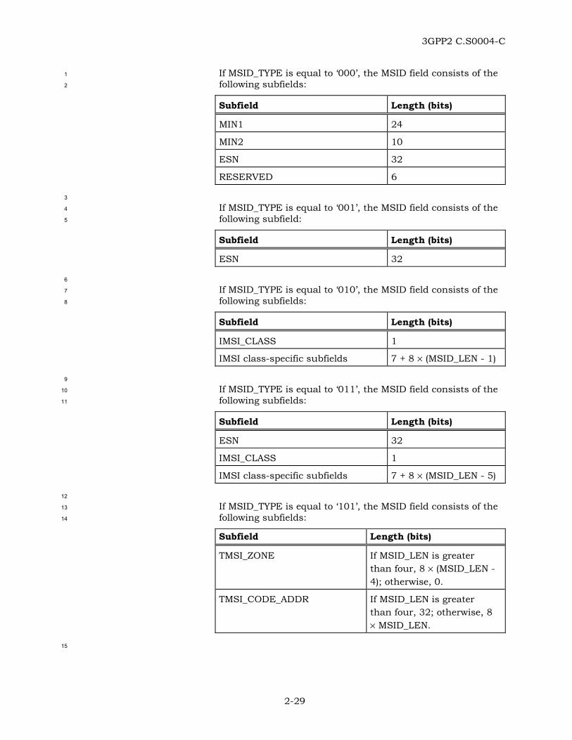
3GPP2 C.S0004-C
2-29
If MSID_TYPE is equal to ‘000’, the MSID field consists of the 1
following subfields: 2
Subfield Length (bits)
MIN1 24
MIN2 10
ESN 32
RESERVED 6
3
If MSID_TYPE is equal to ‘001’, the MSID field consists of the 4
following subfield: 5
Subfield Length (bits)
ESN 32
6
If MSID_TYPE is equal to ‘010’, the MSID field consists of the 7
following subfields: 8
Subfield Length (bits)
IMSI_CLASS 1
IMSI class-specific subfields 7 + 8 × (MSID_LEN - 1)
9
If MSID_TYPE is equal to ‘011’, the MSID field consists of the 10
following subfields: 11
Subfield Length (bits)
ESN 32
IMSI_CLASS 1
IMSI class-specific subfields 7 + 8 × (MSID_LEN - 5)
12
If MSID_TYPE is equal to ‘101’, the MSID field consists of the 13
following subfields: 14
Subfield Length (bits)
TMSI_ZONE If MSID_LEN is greater than four, 8 × (MSID_LEN - 4); otherwise, 0.
TMSI_CODE_ADDR If MSID_LEN is greater than four, 32; otherwise, 8 × MSID_LEN.
15
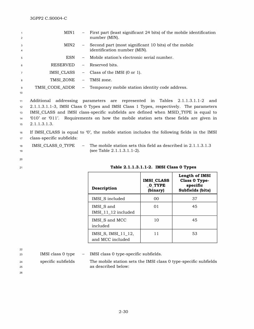
3GPP2 C.S0004-C
2-30
MIN1 – First part (least significant 24 bits) of the mobile identification 1
number (MIN). 2
MIN2 – Second part (most significant 10 bits) of the mobile 3
identification number (MIN). 4
ESN – Mobile station’s electronic serial number. 5
RESERVED – Reserved bits. 6
IMSI_CLASS – Class of the IMSI (0 or 1). 7
TMSI_ZONE – TMSI zone. 8
TMSI_CODE_ADDR – Temporary mobile station identity code address. 9
10
Additional addressing parameters are represented in Tables 2.1.1.3.1.1-2 and 11
2.1.1.3.1.1-3, IMSI Class 0 Types and IMSI Class 1 Types, respectively. The parameters 12
IMSI_CLASS and IMSI class-specific subfields are defined when MSID_TYPE is equal to 13
‘010’ or ‘011’. Requirements on how the mobile station sets these fields are given in 14
2.1.1.3.1.3. 15
If IMSI_CLASS is equal to ‘0’, the mobile station includes the following fields in the IMSI 16
class-specific subfields: 17
IMSI_CLASS_0_TYPE – The mobile station sets this field as described in 2.1.1.3.1.3 18
(see Table 2.1.1.3.1.1-2). 19
20
Table 2.1.1.3.1.1-2. IMSI Class 0 Types 21
Description
IMSI_CLASS
_0_TYPE (binary)
Length of IMSI Class 0 Type-
specific Subfields (bits)
IMSI_S included 00 37
IMSI_S and IMSI_11_12 included
01 45
IMSI_S and MCC included
10 45
IMSI_S, IMSI_11_12, and MCC included
11 53
22
IMSI class 0 type – IMSI class 0 type-specific subfields. 23
specific subfields The mobile station sets the IMSI class 0 type-specific subfields 24
as described below: 25
26

3GPP2 C.S0004-C
2-31
If IMSI_CLASS_0_TYPE is equal to ‘00’, then IMSI class 0 type-1
specific subfields consist of: 2
IMSI Class 0 Type-specific Subfield
Length (bits)
RESERVED 3
IMSI_S 34
3
If IMSI_CLASS_0_TYPE is equal to ‘01’, then IMSI class 0 type-4
specific subfields consist of: 5
IMSI Class 0 Type-specific Subfield
Length (bits)
RESERVED 4
IMSI_11_12 7
IMSI_S 34
6
If IMSI_CLASS_0_TYPE is equal to ‘10’, then IMSI class 0 type-7
specific subfields consist of: 8
IMSI Class 0 Type-specific Subfield
Length (bits)
RESERVED 1
MCC 10
IMSI_S 34
9
If IMSI_CLASS_0_TYPE is equal to ‘11’, then IMSI class 0 type-10
specific subfields consist of: 11
IMSI Class 0 Type-specific Subfield
Length (bits)
RESERVED 2
MCC 10
IMSI_11_12 7
IMSI_S 34
12
If IMSI_CLASS is equal to ‘1’, the mobile station includes the following fields in the IMSI 13
class-specific subfields: 14
IMSI_CLASS_1_TYPE – The mobile station is to set this field as described in 15
2.1.1.3.1.3 (see Table 2.1.1.3.1.1-3). 16

3GPP2 C.S0004-C
2-32
1
Table 2.1.1.3.1.1-3. IMSI Class 1 Types 2
Description
IMSI_CLASS
_1_TYPE (binary)
Length of IMSI Class 1 Type
Specific Subfields
(bits)
IMSI_S and IMSI_11_12 included
0 46
IMSI_S, IMSI_11_12, and MCC included
1 54
3
IMSI class 1 type – IMSI class 1 type-specific subfields. 4
specific subfields The mobile station sets the IMSI class 1 type-specific subfields 5
as described below: 6
If IMSI_CLASS_1_TYPE is equal to ‘0’, then IMSI class 1 type-7
specific subfields consist of: 8
IMSI Class 1 Type-specific Subfield
Length (bits)
RESERVED 2
IMSI_ADDR_NUM 3
IMSI_11_12 7
IMSI_S 34
9
If IMSI_CLASS_1_TYPE is equal to ‘1’, then IMSI class 1 type-10
specific subfields consist of: 11
IMSI Class 1 Type-specific Subfield
Length (bits)
IMSI_ADDR_NUM 3
MCC 10
IMSI_11_12 7
IMSI_S 34
12
RESERVED – Reserved bits. 13

3GPP2 C.S0004-C
2-33
IMSI_S – Ten-digit number based upon the IMSI (see 2.3.1 of [5]). 1
IMSI_11_12 – Two-digit number based upon the IMSI (see 2.3.1 of [5]). 2
MCC – Mobile Country Code (see 2.3.1 of [5]). 3
IMSI_ADDR_NUM – Number of digits in the NMSI minus four (see 2.3.1 of [5]). 4
2.1.1.3.1.2 Requirements for Setting the Addressing Fields 5
The mobile station shall determine and set the type of address to use as follows: 6
• The mobile station shall set MSID_TYPE equal to ‘000’ and shall use IMSI_O_Ss 7
(equal to IMSI_M_Sp) and the ESN as the mobile station identifier if the following 8
conditions are met: 9
1. PREF_MSID_TYPEs is equal to ‘00’, and 10
2. USE_TMSIs is equal to ‘0’. 11
The mobile station shall include the following subfields in the MSID field: 12
MIN1 – The mobile station shall set this field to IMSI_M_S1p. 13
MIN2 – The mobile station shall set this field to IMSI_M_S2p. 14
ESN – The mobile station shall set this field to its electronic serial 15
number. 16
RESERVED – Reserved bits. 17
The mobile station shall set this field to ‘000000’. 18
• The mobile station shall set MSID_TYPE equal to ‘001’ and shall use the ESN as the 19
mobile station identifier if neither IMSI_M nor IMSI_T has been assigned to the 20
mobile station. The mobile station shall include the following subfield in the MSID 21
field: 22
ESN – The mobile station shall set this field to its electronic serial 23
number. 24
• The mobile station shall set MSID_TYPE to ‘010’ and shall use the IMSI_O as the 25
mobile station identifier if all of the following conditions are met: 26
– The mobile station has been assigned either an IMSI_T, or an IMSI_M, or both; 27
– PREF_MSID_TYPEs is equal to ‘10’; and 28
– USE_TMSIs is equal to ‘0’ or all of the bits of TMSI_CODEs-p are equal to ‘1’. 29
The mobile station shall include the following subfields in the MSID field: 30
IMSI_CLASS – The mobile station shall set this field as specified in 31
2.1.1.3.1.3. 32
IMSI class-specific – IMSI class-specific subfields. 33
subfields The mobile station shall set these fields as specified in 34
2.1.1.3.1.3. 35
• The mobile station shall set MSID_TYPE to ‘011’ and shall use both the IMSI_O and 36
the ESN as the mobile station identifier if all of the following conditions are met: 37

3GPP2 C.S0004-C
2-34
– The mobile station has been assigned either an IMSI_T, or an IMSI_M, or both; 1
– PREF_MSID_TYPEs is equal to ‘11’; and 2
– USE_TMSIs is equal to ‘0’ or all of the bits of TMSI_CODEs-p are equal to ‘1’. 3
The mobile station shall include the following subfields in the MSID field: 4
ESN – The mobile station shall set this field to its electronic serial 5
number. 6
IMSI_CLASS – The mobile station shall set this field as specified in 7
2.1.1.3.1.3. 8
IMSI class-specific – IMSI class-specific subfields. 9
subfields The mobile station shall set these fields as specified in 10
2.1.1.3.1.3. 11
• The mobile station shall set MSID_TYPE to ‘101’ and shall use the TMSI as the 12
mobile station identifier if all of the following conditions are met: 13
– The mobile station has been assigned either an IMSI_T, or an IMSI_M, or both; 14
– The bits of TMSI_CODEs-p are not all equal to ‘1’; 15
– PREF_MSID_TYPEs is equal to ‘10’ or ‘11’; and 16
– USE_TMSIs is equal to ‘1’. 17
The mobile station shall determine the value of the MSID_LEN field according to the 18
procedure described in 2.1.1.3.1.2.1, and then the mobile station shall include the 19
following subfields in the MSID subfields: 20
TMSI_ZONE – If MSID_LEN is greater than four, the mobile station shall set 21
this field to the ASSIGNING_TMSI_ZONE_LENs-p most 22
significant octets of ASSIGNING_TMSI_ZONEs-p, the assigning 23
TMSI zone. If MSID_LEN is less than or is equal to four, the 24
mobile station shall omit this field. 25
TMSI_CODE_ADDR – If TMSI_ZONE is included in the address, the mobile station 26
shall set this field to the 32-bit TMSI code assigned to the 27
mobile station. 28
If TMSI_ZONE is not included in the address, the mobile 29
station shall set this field as follows: 30
1. If the most significant octet of the TMSI_CODE assigned to 31
the mobile station is equal to ‘00000000’ and the second 32
most significant octet of the TMSI_CODE assigned to the 33
mobile station is not equal to ‘00000000’, the mobile 34
station shall set TMSI_CODE_ADDR to the 24 least 35
significant bits of the TMSI_CODE assigned to the mobile 36
station. 37

3GPP2 C.S0004-C
2-35
2. If the two most significant octets of the TMSI_CODE 1
assigned to the mobile station are both equal to 2
‘00000000’, the mobile station shall set 3
TMSI_CODE_ADDR to the 16 least significant bits of the 4
TMSI_CODE assigned to the mobile station. 5
3. In all other cases, the mobile station shall set 6
TMSI_CODE_ADDR to the TMSI_CODE assigned to the 7
mobile station. 8
2.1.1.3.1.2.1 Value of the MSID_LEN Field 9
If MSID_TYPE is not equal to ‘101’ the mobile station shall set MSID_LEN to the number of 10
octets included in MSID (see Table 2.1.1.3.1.1-1). If MSID_TYPE is equal to ‘101’ the 11
mobile station shall set MSID_LEN as follows: 12
1. The mobile station shall set MSID_LEN to 4 (TMSI_CODE_ADDR is to include all 13
four octets of TMSI_CODEs-p) if all of the following conditions are met: 14
– ASSIGNING_TMSI_ZONE_LENs-p is equal to TMSI_ZONE_LENs, 15
– The least significant ASSIGNING_TMSI_ZONE_LENs-p octets of 16
ASSIGNING_TMSI_ZONEs-p are equal to TMSI_ZONEs, and 17
– The most significant octet of TMSI_CODEs-p is not equal to ‘00000000’. 18
2. The mobile station shall set MSID_LEN to 3 (TMSI_CODE_ADDR is to include the 19
three least significant octets of TMSI_CODEs-p) if all of the following conditions are 20
met: 21
– ASSIGNING_TMSI_ZONE_LENs-p is equal to TMSI_ZONE_LENs, 22
– The least significant ASSIGNING_TMSI_ZONE_LENs-p octets of 23
ASSIGNING_TMSI_ZONEs-p are equal to TMSI_ZONEs, 24
– The most significant octet of TMSI_CODEs-p is equal to ‘00000000’, and 25
– The next most significant octet of TMSI_CODEs-p is not equal to ‘00000000’. 26
3. The mobile station shall set MSID_LEN to 2 (TMSI_CODE_ADDR is to include the 27
two least significant octets of TMSI_CODEs-p) if all of the following conditions are 28
met: 29
– ASSIGNING_TMSI_ZONE_LENs-p is equal to TMSI_ZONE_LENs, 30
– The least significant ASSIGNING_TMSI_ZONE_LENs-p octets of 31
ASSIGNING_TMSI_ZONEs-p are equal to TMSI_ZONEs, and 32
– The two most significant octets of TMSI_CODEs-p are both equal to ‘00000000’. 33
4. The mobile station shall set MSID_LEN to 4 + ASSIGNING_TMSI_ZONE_LENs-p 34
(TMSI_ZONE is to include the ASSIGNING_TMSI_ZONE_LENs-p least significant 35
octets of ASSIGNING_TMSI_ZONEs-p while TMSI_CODE_ADDR is to include all four 36
octets of TMSI_CODEs-p) if the following condition is met: 37
– ASSIGNING_TMSI_ZONE_LENs-p is not equal to TMSI_ZONE_LENs, or 38

3GPP2 C.S0004-C
2-36
– The least significant ASSIGNING_TMSI_ZONE_LENs-p octets of 1
ASSIGNING_TMSI_ZONEs-p are not equal to TMSI_ZONEs. 2
2.1.1.3.1.3 Requirements for Setting IMSI Class and IMSI Class-specific Subfield 3
Parameters 4
When the IMSI_O is used in the MSID field of a PDU (see 2.1.1.3.1.2), the mobile station 5
shall use the following procedures to set the values for the IMSI_CLASS and the IMSI class-6
specific subfields: 7
• The mobile station shall set IMSI_CLASS to ‘0’ and IMSI_CLASS_0_TYPE to ‘00’ if all 8
of the following conditions are met: 9
– The mobile station’s IMSI_O is a class 0 IMSI, 10
– IMSI_O_11_12s is equal to IMSI_11_12s, and 11
– MCC_Os is equal to MCCs. 12
The mobile station shall include the following fields in IMSI class 0 type-specific 13
subfields: 14
RESERVED – The mobile station shall set these bits to ’000’. 15
IMSI_S – The mobile station shall set this field to IMSI_O_Ss. 16
• The mobile station shall set IMSI_CLASS to ‘0’ and IMSI_CLASS_0_TYPE to ‘01’ if all 17
of the following conditions are met: 18
– The mobile station’s IMSI_O is a class 0 IMSI, 19
– IMSI_O_11_12s is not equal to IMSI_11_12s, and 20
– MCC_Os is equal to MCCs. 21
The mobile station shall include the following fields in IMSI class 0 type-specific 22
subfields: 23
RESERVED – The mobile station shall set these bits to ’0000’. 24
IMSI_11_12 – The mobile station shall set this field to IMSI_O_11_12s. 25
IMSI_S – The mobile station shall set this field to IMSI_O_Ss. 26
• The mobile station shall set IMSI_CLASS to ‘0’ and IMSI_CLASS_0_TYPE to ‘10’ if all 27
of the following conditions are met: 28
– The mobile station’s IMSI_O is a class 0 IMSI, 29
– IMSI_O_11_12s is equal to IMSI_11_12s, and 30
– MCC_Os is not equal to MCCs. 31
The mobile station shall include the following fields in IMSI class 0 type-specific 32
subfields: 33
RESERVED – The mobile station shall set this bit to ’0’. 34
MCC – The mobile station shall set this field to the MCC_Os. 35

3GPP2 C.S0004-C
2-37
IMSI_S – The mobile station shall set this field to IMSI_O_Ss. 1
• The mobile station shall set IMSI_CLASS to ‘0’ and IMSI_CLASS_0_TYPE to ‘11’ if all 2
of the following conditions are met: 3
– The mobile station’s IMSI_O is a class 0 IMSI, 4
– IMSI_O_11_12s is not equal to IMSI_11_12s, and 5
– MCC_Os is not equal to MCCs 6
The mobile station shall include the following fields in IMSI class 0 type-specific 7
subfields: 8
RESERVED – The mobile station shall set these bits to ’00’. 9
MCC – The mobile station shall set this field to the MCC_Os. 10
IMSI_11_12 – The mobile station shall set this field to IMSI_O_11_12s. 11
IMSI_S – The mobile station shall set this field to IMSI_O_Ss. 12
• The mobile station shall set IMSI_CLASS to ‘1’ and IMSI_CLASS_1_TYPE to ‘0’ if all 13
of the following conditions are met: 14
– The mobile station’s IMSI_O is a class 1 IMSI, and 15
– MCC_Os is equal to MCCs. 16
The mobile station shall include the following fields in IMSI class 1 type-specific 17
subfields: 18
RESERVED – The mobile station shall set these bits to ’00’. 19
IMSI_ADDR_NUM – The mobile station shall set this field to the number of digits 20
in the NMSI minus four. 21
IMSI_11_12 – The mobile station shall set this field to IMSI_O_11_12s. 22
IMSI_S – The mobile station shall set this field to IMSI_O_Ss. 23
• The mobile station shall set IMSI_CLASS to ‘1’ and IMSI_CLASS_1_TYPE to ‘1’ if all 24
of the following conditions are met: 25
– The mobile station’s IMSI_O is a class 1 IMSI, and 26
– MCC_Os is not equal to MCCs. 27
The mobile station shall include the following fields in IMSI class 1 type-specific 28
subfields: 29
IMSI_ADDR_NUM – The mobile station shall set this field to the number of digits 30
in the NMSI minus four. 31
MCC – The mobile station shall set this field to the MCC_Os. 32
IMSI_11_12 – The mobile station shall set this field to IMSI_O_11_12s. 33
IMSI_S – The mobile station shall set this field to IMSI_O_Ss. 34

3GPP2 C.S0004-C
2-38
2.1.1.3.2 Procedures 1
The mobile station shall set the addressing fields of the PDU as specified in 2.1.1.3.1.2. 2
2.1.1.4 Utility Sublayer 3
2.1.1.4.1 Parameters 4
2.1.1.4.1.1 Message Type Fields 5
The mobile station shall use the fields defined in 2.1.1.4.1.1.1 to support message type 6
identification for PDUs transmitted on the r-csch. The mobile station shall set the fields 7
according to the requirements in 2.1.1.4.1.1.2. 8
2.1.1.4.1.1.1 Definition of Message Type Fields 9
The message type fields of PDUs transmitted on the r-csch have the following format: 10
11
Field Length (bits)
PD 2
MSG_ID 6
12
PD - Protocol Discriminator. 13
MSG_ID - Message Identifier. 14
2.1.1.4.1.1.2 Requirements for Setting Message Type Fields 15
If P_REV_IN_USEs is less than six, the mobile station shall set the PD field to ‘00’. If 16
P_REV_IN_USEs is equal to six, the mobile station shall set the PD field to ‘01’. If 17
P_REV_IN_USEs is greater than or equal to seven, the mobile station shall set the PD field 18
to ‘10’. 19
The mobile station shall set the MSG_ID field as shown in Table 2.1.1.4.1.1.2-1. 20
21

3GPP2 C.S0004-C
2-39
Table 2.1.1.4.1.1.2-1. MSG_ID values on r-csch 1
Message Name MSG_TAG MSG_ID (binary)
Registration Message RGM 000001
Order Message ORDM 000010
Data Burst Message DBM 000011
Origination Message ORM 000100
Page Response Message PRM 000101
Authentication Challenge Response Message
AUCRM 000110
Status Response Message STRPM 000111
TMSI Assignment Completion Message
TACM 001000
PACA Cancel Message PACNM 001001
Extended Status Response Message ESTRPM 001010
Reserved N/A 001011
Reserved N/A 001100
Device Information Message DIM 001101
Security Mode Request Message SMRM 001110
Data Burst Response Message (DS-41 only, see [13])
DBRM 001111
RR-level Registration Message (MC-MAP only, see [14])
RRLRM 010000
MC-MAP Initial L3 Message (MC-MAP only, see [14])
MAPIL3M 010001
MC-MAP L3 Message (MC-MAP only, see [14])
MAPL3M 010010
MC-MAP RRC Connection Request Message (MC-MAP only, see [14])
MAPCRM 010011
R-TMSI Assignment Completion Message (MC-MAP only, see [14])
RTACM 010100
Authentication Response Message AURSPM 010101
Authentication Resynchronization Message
AURSYNM 010110
Reconnect Message RCNM 010111

3GPP2 C.S0004-C
2-40
1
2.1.1.4.1.2 LAC Length Field 2
The mobile station shall use the field defined in 2.1.1.4.1.2.1 for PDUs transmitted on the 3
r-csch. The mobile station shall set this field according to the requirements in 4
2.1.1.4.1.2.2. 5
2.1.1.4.1.2.1 Definition of LAC Length Field 6
The LAC Length field for PDUs transmitted on the r-csch has the following format: 7
8
Field Length (bits)
LAC_LENGTH 5
9
LAC_LENGTH – Length of the LAC fields. 10
2.1.1.4.1.2.2 Requirements for Setting LAC Length Field 11
The mobile station shall set the LAC_LENGTH field to the combined length in octets of the 12
LAC_LENGTH field, the Authentication fields (see 2.1.1.1.1.1), the ARQ fields (see 13
2.1.1.2.1.1), the Addressing fields (see 2.1.1.3.1.1) and the LAC Padding field (see 14
2.1.1.4.1.4). 15
2.1.1.4.1.3 Extended-Encryption Fields 16
The mobile station shall use the fields defined in 2.1.1.4.1.3.1 to support Extended-17
Encryption for PDUs transmitted on the r-csch. The mobile station shall set the fields 18
according to the requirements in 2.1.1.4.1.3.2. 19
2.1.1.4.1.3.1 Definition of Extended-Encryption Fields 20
The Extended-Encryption fields for PDUs transmitted on the r-csch have the following 21
format: 22
23
Field Length (bits)
ENC_FIELDS_INCL 0 or 1
SDU_ENCRYPT_MODE 0 or 3
ENC_SEQ 0 or 8
24
ENC_FIELDS_INCL – Extended-Encryption fields included indicator. 25
SDU_ENCRYPT_MODE – Signaling encryption mode in use for the SDU carried by this 26
PDU. 27

3GPP2 C.S0004-C
2-41
ENC_SEQ – Eight least significant bits of the encryption sequence number 1
used to construct a cryptographic synchronization crypto-2
sync (see 2.3.12.4 of [5]) for the encryption algorithm. 3
2.1.1.4.1.3.2 Requirements for Setting Extended-Encryption Fields 4
The mobile station shall set the Extended-Encryption fields as follows: 5
• If P_REV_IN_USEs is greater than or equal to seven, the mobile station shall include 6
the ENC_FIELDS_INCL field in the PDU; otherwise, the mobile station shall omit all 7
the Extended-Encryption fields from the PDU. 8
• If the ENC_FIELDS_INCL field is present in the PDU, the mobile station shall set the 9
ENC_FIELDS_INCL field to ‘1’ if the SDU_ENCRYPT_MODE field is included in this 10
PDU; otherwise, the mobile station shall set the ENC_FIELDS_INCL field to ‘0’.26 11
• If the SDU_ENCRYPT_MODE field is included in the PDU, the mobile station shall 12
set it to the signaling encryption mode that is used for the SDU carried by this PDU 13
and is provided by Layer 3. 14
• If the SDU_ENCRYPT_MODE field is included and is equal to ‘001’ or ‘010’ and if the 15
MACI_INCL field is not present in the PDU or it is present, but it is equal to ‘0’, the 16
mobile station shall include the ENC_SEQ field and shall set it to the value provided 17
by Layer 3; otherwise, the mobile station shall omit the ENC_SEQ field. 18
If the PDU is retransmitted, the mobile station shall not change either the value of the 19
Extended-Encryption fields or the encryption state of the SDU carried by the PDU. 20
2.1.1.4.1.4 LAC Padding Field 21
The mobile station shall use the field defined in 2.1.1.4.1.4.1 to extend the combined length 22
of the LAC Length field, the Authentication fields, the ARQ fields, and the Addressing fields 23
to the closest integer number of octets, so as to ensure an octet boundary alignment for 24
subsequent fields in the PDU. The mobile station shall set this field according to the 25
requirements in 2.1.1.4.1.4.2. 26
2.1.1.4.1.4.1 Definition of LAC Padding Field 27
The LAC Padding field for PDUs transmitted on the r-csch has the following format: 28
29
Field Length (bits)
LAC_PADDING 0-7
30
LAC_PADDING – Padding bits. 31
26 Some messages sent on the r-csch are not meant to be encrypted (see 2.3.12.4.1 of [5]). For such messages, the mobile station sets the ENC_FIELDS_INCL to ‘0’.

3GPP2 C.S0004-C
2-42
2.1.1.4.1.4.2 Requirements for Setting LAC Padding Field 1
The mobile station shall set the LAC Padding field to contain the minimum number of bits 2
needed to extend the combined length of the LAC_LENGTH field, the Authentication fields, 3
the ARQ fields, and the Addressing fields to an integer number of octets. The mobile 4
station shall set these bits to ‘0’. 5
2.1.1.4.1.5 Radio Environment Report Fields 6
The mobile station shall use the fields defined in 2.1.1.4.1.5.1 to support time-sensitive 7
radio environment reporting for PDUs transmitted on the r-csch. The mobile station shall 8
set the fields according to the requirements in 2.1.1.4.1.5.2. 9
2.1.1.4.1.5.1 Definition of Radio Environment Report Fields 10
The time-sensitive radio environment report fields for PDUs transmitted on the r-csch have 11
the following format: 12
13
Field Length (bits)
ACTIVE_PILOT_STRENGTH 0 or 6
FIRST_IS_ACTIVE 0 or 1
FIRST_IS_PTA 0 or 1
NUM_ADD_PILOTS 0 or 3
NUM_ADD_PILOTS occurrences of the following record:
PILOT_PN_PHASE 15
PILOT_STRENGTH 6
ACCESS_HO_EN 1
ACCESS_ATTEMPTED 1
NUM_AUX_PILOTS 0 or 3
NUM_AUX_PILOTS occurrences of the following record:
PILOT_PN_PHASE 15
PILOT_STRENGTH 6
PILOT_REC_TYPE 3
RECORD_LEN 3
Type-specific fields 8 × RECORD_LEN
14

3GPP2 C.S0004-C
2-43
ACTIVE_PILOT_- 1
STRENGTH – Pilot strength of the pilot in the Active Set. 2
FIRST_IS_ACTIVE – Indicates when the pilot in the Active Set corresponds to the 3
first base station to which the mobile station transmitted an 4
access probe after entering the System Access State (see 5
2.6.3.1.3 of [5]). 6
FIRST_IS_PTA – Indicates when the first base station to which the mobile 7
station transmitted an access probe after entering the System 8
Access State is the base station used in the access sub-9
attempt immediately prior to the current access sub-attempt 10
within the current access attempt. 11
NUM_ADD_PILOTS – Number of additional (to the pilot in the Active Set) reported 12
common pilots. 13
The mobile station includes NUM_ADD_PILOTS occurrences of the following four-field 14
record (one occurrence for each additional common pilot being reported): 15
PILOT_PN_PHASE – Pilot measured phase. 16
PILOT_STRENGTH – Pilot strength. 17
ACCESS_HO_EN – Access handoff enable. 18
ACCESS_ATTEMPTED – Access attempted flag. 19
20
NUM_AUX_PILOTS – Number of reported auxiliary pilots. 21
The mobile station includes NUM_AUX_PILOTS occurrences of the following five-field record 22
(one occurrence for each auxiliary pilot being reported): 23
PILOT_PN_PHASE – Pilot measured phase. 24
PILOT_STRENGTH – Pilot strength. 25
PILOT_REC_TYPE – Pilot record type. 26
RECORD_LEN – Length in octets of the pilot record type-specific fields. 27
Type-specific fields – Type-specific fields. 28
If PILOT_REC_TYPE is equal to ‘000’, the mobile station 29
includes the following fields as the type-specific fields: 30
31
Field Length (bits)
QOF 2
WALSH_LENGTH 3
PILOT_WALSH WALSH_LENGTH + 6
RESERVED 0-7 (as needed)
32
QOF – Index of the Quasi-orthogonal function corresponding to the 33
auxiliary pilot being reported. 34

3GPP2 C.S0004-C
2-44
WALSH_LENGTH – Length of the Walsh code for the auxiliary pilot being 1
reported. 2
PILOT_WALSH – Walsh code corresponding to the auxiliary pilot being 3
reported. 4
RESERVED – Reserved bits. 5
2.1.1.4.1.5.2 Requirements for Setting Radio Environment Report Fields 6
If P_REV_IN_USEs is greater than or equal to four, the mobile station shall include the 7
radio environment report fields; otherwise, the mobile station shall omit the radio 8
environment report fields. 9
When the mobile station includes time-sensitive radio environment report fields in the PDU 10
being transmitted, the mobile station shall set the time-sensitive radio environment report 11
fields as follows: 12
ACTIVE_PILOT_- 13
STRENGTH – The mobile station shall set this field to 14
min (max (-2 × 10 log10 PS, 0), 64) 15
where PS is the strength of the pilot in the Active Set (see 16
2.6.3.1.7 of [5]). 17
FIRST_IS_ACTIVE – The mobile station shall set this field to ‘1’ if 18
FIRST_ACTIVE_PILOTs is equal to CURRENT_ACTIVE_PILOTs 19
(see 2.6.3.1.3 of [5]); otherwise, the mobile station shall set 20
this field to ‘0’. 21
FIRST_IS_PTA – The mobile station shall set this field to '1' if 22
FIRST_ACTIVE_PILOTs is equal to PREVIOUS_ACTIVE_PILOTs 23
(see 2.6.3.1.3 of [5]); otherwise, the mobile station shall set 24
this field to ‘0’. 25
NUM_ADD_PILOTS – If PILOT_REPORTs is equal to ‘0’ and the PDU corresponds to 26
a message other than the Origination Message, Reconnect 27
Message or the Page Response Message, the mobile station 28
shall set this field to ‘000’; otherwise, the mobile station shall 29
set this field as follows: 30
The mobile station shall set this field to the sum of the 31
number of common pilots being reported from the 32
ACCESS_HO_LIST (see 2.6.3.1.7 of [5]), other than the pilot in 33
the Active Set, and the number of common pilots being 34
reported from the OTHER_REPORTED_LIST. 35
The mobile station shall include NUM_ADD_PILOTS occurrences of the following record, 36
with each occurrence corresponding to a different common pilot: 37
PILOT_PN_PHASE – The mobile station shall set this field to the phase of the 38
common pilot PN sequence (see 2.6.3.1.7 of [5]). 39
PILOT_STRENGTH – The mobile station shall set this field to 40
min (max (-2 × 10 log10 PS, 0), 64) 41

3GPP2 C.S0004-C
2-45
where PS is the strength of this common pilot (see 2.6.3.1.7 of 1
[5]). 2
ACCESS_HO_EN – If the common pilot is in ACCESS_HO_LIST, the mobile 3
station shall set this field to ‘1’; otherwise, the mobile station 4
shall set this field to ‘0’. 5
ACCESS_ATTEMPTED – The mobile station shall set this field to ‘1’ if an access probe 6
has been transmitted to the base station corresponding to this 7
common pilot within the current access attempt; otherwise, 8
the mobile station shall set this field to ‘0’ (see 2.6.3.1.3.3 of 9
[5]). 10
11
NUM_AUX_PILOTS – If P_REV_IN_USEs is less than seven, the mobile station shall 12
omit this field; otherwise the mobile station shall include this 13
field and set it as follows: 14
If PILOT_REPORTs is equal to ‘0’ and the PDU corresponds to 15
a message other than the Origination Message, Reconnect 16
Message or the Page Response Message the mobile station 17
shall set this field to ‘000’; otherwise, the mobile station shall 18
set this field to the number of auxiliary pilots being reported 19
from the OTHER_REPORTED_LIST (see 2.6.3.1.7 of [5]). 20
21
The mobile station shall include NUM_AUX_PILOTS occurrences of the following record, 22
with each occurrence corresponding to a different auxiliary pilot: 23
PILOT_PN_PHASE – The mobile station shall set this field to the phase of the 24
auxiliary pilot PN sequence (see 2.6.3.1.7 of [5]). 25
PILOT_STRENGTH – The mobile station shall set this field to 26
min (max (-2 × 10 log10 PS, 0), 64) 27
where PS is the strength of this auxiliary pilot (see 2.6.3.1.7 of 28
[5]). 29
PILOT_REC_TYPE – The mobile station shall set this field to the pilot record type 30
as specified in Table 3.7.2.3.2.34-1 of [5]. 31
RECORD_LEN – The mobile station shall set this field to the number of octets 32
in the type-specific fields. 33
If PILOT_REC_TYPE is equal to ‘000’, the mobile station shall include the following fields as 34
the type-specific fields: 35
QOF – The mobile station shall set this field to the index of the 36
Quasi-orthogonal function of the corresponding auxiliary 37
pilot. 38
WALSH_LENGTH – The mobile station shall set this field to the WALSH_LENGTH 39
value shown in Table 2.7.2.3.2.34-2 of [5] corresponding to 40
the length of the Walsh code for the auxiliary pilot being 41
reported. 42
PILOT_WALSH – The mobile station shall set this field to the Walsh code 43
corresponding to the auxiliary pilot reported. 44
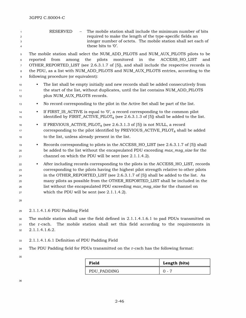
3GPP2 C.S0004-C
2-46
RESERVED – The mobile station shall include the minimum number of bits 1
required to make the length of the type-specific fields an 2
integer number of octets. The mobile station shall set each of 3
these bits to ‘0’. 4
The mobile station shall select the NUM_ADD_PILOTS and NUM_AUX_PILOTS pilots to be 5
reported from among the pilots monitored in the ACCESS_HO_LIST and 6
OTHER_REPORTED_LIST (see 2.6.3.1.7 of [5]), and shall include the respective records in 7
the PDU, as a list with NUM_ADD_PILOTS and NUM_AUX_PILOTS entries, according to the 8
following procedure (or equivalent): 9
• The list shall be empty initially and new records shall be added consecutively from 10
the start of the list, without duplicates, until the list contains NUM_ADD_PILOTS 11
plus NUM_AUX_PILOTS records. 12
• No record corresponding to the pilot in the Active Set shall be part of the list. 13
• If FIRST_IS_ACTIVE is equal to ‘0’, a record corresponding to the common pilot 14
identified by FIRST_ACTIVE_PILOTs (see 2.6.3.1.3 of [5]) shall be added to the list. 15
• If PREVIOUS_ACTIVE_PILOTs (see 2.6.3.1.3 of [5]) is not NULL, a record 16
corresponding to the pilot identified by PREVIOUS_ACTIVE_PILOTs shall be added 17
to the list, unless already present in the list. 18
• Records corresponding to pilots in the ACCESS_HO_LIST (see 2.6.3.1.7 of [5]) shall 19
be added to the list without the encapsulated PDU exceeding max_msg_size for the 20
channel on which the PDU will be sent (see 2.1.1.4.2). 21
• After including records corresponding to the pilots in the ACCESS_HO_LIST, records 22
corresponding to the pilots having the highest pilot strength relative to other pilots 23
in the OTHER_REPORTED_LIST (see 2.6.3.1.7 of [5]) shall be added to the list. As 24
many pilots as possible from the OTHER_REPORTED_LIST shall be included in the 25
list without the encapsulated PDU exceeding max_msg_size for the channel on 26
which the PDU will be sent (see 2.1.1.4.2). 27
28
2.1.1.4.1.6 PDU Padding Field 29
The mobile station shall use the field defined in 2.1.1.4.1.6.1 to pad PDUs transmitted on 30
the r-csch. The mobile station shall set this field according to the requirements in 31
2.1.1.4.1.6.2. 32
2.1.1.4.1.6.1 Definition of PDU Padding Field 33
The PDU Padding field for PDUs transmitted on the r-csch has the following format: 34
35
Field Length (bits)
PDU_PADDING 0 - 7
36

3GPP2 C.S0004-C
2-47
PDU_PADDING – Padding bits. 1
2.1.1.4.1.6.2 Requirements for Setting PDU Padding Field 2
The mobile station shall set the PDU Padding field to contain the minimum number of bits 3
needed to make the length of the PDU 8k+2 bits, where k is an integer (k ≥ 0). The mobile 4
station shall set these bits to ‘0’. 5
2.1.1.4.1.7 MACI Field 6
The mobile station shall include the field defined in 2.1.1.4.1.7.1 to provide message 7
integrity, if and only if the MACI_INCL field in the PDU transmitted on the r-csch is 8
included and is equal to ‘1’; otherwise, the mobile station shall omit the MACI field. If the 9
MACI field is included, the mobile station shall set this field according to the requirements 10
in 2.1.1.4.1.7.2. 11
2.1.1.4.1.7.1 Definition of MACI field 12
The MACI field for PDUs transmitted on the r-csch has the following format: 13
14
Field Length (bits)
MACI 0 or 32
15
MACI – Message Authentication Code for Integrity. 16
2.1.1.4.1.7.2 Requirements for Setting MACI Field 17
The mobile station shall execute the procedure described in 2.1.1.4.2. If USE_UAKs is equal 18
to ‘0’, the mobile station shall set the MACI field to MAC-I. Otherwise, the mobile station 19
shall set the MACI field to the UMAC value. 20
2.1.1.4.2 Procedures 21
The mobile station shall set the parameters defined in 2.1.1.4.1 according to their 22
corresponding requirements. When required, the mobile station shall update the time-23
sensitive radio environment report fields for each transmission or retransmission of a PDU. 24
The format of the PDU sent to the MAC Sublayer for transmission on the r-csch depends 25
upon the protocol capabilities of both the mobile station and base station. 26
If P_REV_IN_USEs is less than four, the mobile station shall assemble the PDU as shown in 27
Table 2.1.1.4.2-1. 28

3GPP2 C.S0004-C
2-48
Table 2.1.1.4.2-1. PDU Format on r-csch for P_REV_IN_USE <<<< 4 1
Parameter Reference
Message Type Fields Section 2.1.1.4.1.1
ARQ Fields Section 2.1.1.2.1
Addressing Fields Section 2.1.1.3.1
Authentication Fields Section 2.1.1.1.1
SDU [5]
PDU Padding Field Section 2.1.1.4.1.6
2
If P_REV_IN_USEs is equal to four or P_REV_IN_USEs is equal to five, the mobile station 3
shall assemble the PDU as shown in Table 2.1.1.4.2-2. 4
Table 2.1.1.4.2-2. PDU Format on r-csch for P_REV_IN_USE = 4 or 5 5
Parameter Reference
Message Type Fields Section 2.1.1.4.1.1
ARQ Fields Section 2.1.1.2.1
Addressing Fields Section 2.1.1.3.1
Authentication Fields Section 2.1.1.1.1
SDU [5]
Radio Environment Report Fields Section 2.1.1.4.1.5
PDU Padding Field Section 2.1.1.4.1.6
6
If P_REV_IN_USEs is equal to six, the mobile station shall assemble the PDU as shown in 7
Table 2.1.1.4.2-3. 8

3GPP2 C.S0004-C
2-49
Table 2.1.1.4.2-3. PDU Format on r-csch for P_REV_IN_USE ==== 6 1
Parameter Reference
Message Type Fields Section 2.1.1.4.1.1
LAC Length Field Section 2.1.1.4.1.2
ARQ Fields Section 2.1.1.2.1
Addressing Fields Section 2.1.1.3.1
Authentication Fields Section 2.1.1.1.1
LAC Padding Field Section 2.1.1.4.1.4
Radio Environment Report Fields Section 2.1.1.4.1.5
SDU [5]
PDU Padding Field Section 2.1.1.4.1.6
2
If P_REV_IN_USEs is greater than or equal to seven, the mobile station shall assemble the 3
PDU as shown in Table 2.1.1.4.2-4. 4
Table 2.1.1.4.2-4. PDU Format on r-csch for P_REV_IN_USE ≥≥≥≥ 7 5
Parameter Reference
Message Type Fields Section 2.1.1.4.1.1
ARQ Fields Section 2.1.1.2.1
Addressing Fields Section 2.1.1.3.1
Authentication Fields Section 2.1.1.1.1
Extended-Encryption Fields Section 2.1.1.4.1.3
Radio Environment Report Fields Section 2.1.1.4.1.5
SDU [5]
PDU Padding Field Section 2.1.1.4.1.6
6
If P_REV_IN_USEs is greater than or equal to nine, the mobile station shall assemble the 7
PDU as shown in Table 2.1.1.4.2-5. 8

3GPP2 C.S0004-C
2-50
Table 2.1.1.4.2-5. PDU Format on r-csch for P_REV_IN_USE ≥≥≥≥ 9 1
Parameter Reference
Message Type Fields Section 2.1.1.4.1.1
ARQ Fields Section 2.1.1.2.1
Addressing Fields Section 2.1.1.3.1
Authentication and Message Integrity Fields
Section 2.1.1.1.1
Extended-Encryption Fields Section 2.1.1.4.1.3
Radio Environment Report Fields Section 2.1.1.4.1.5
SDU [5]
PDU Padding Field Section 2.1.1.4.1.6
Message Authentication Code for Integrity (MACI)
Section 2.1.1.4.1.7
If the MACI field is included in the PDU, the mobile station shall proceed as follows: 2
• The mobile station shall compute EXT_MSG_LENGTH and MSG_LENGTH as 3
described 2.1.1.5.1.2. 4
• If EXT_MSG_LENGTH is included in the encapsulated PDU, as described in 5
2.1.1.5.1.2, the mobile station shall set msg_length to a bit configuration 6
corresponding to EXT_MSG_LENGTH immediately followed by MSG_LENGTH; 7
otherwise, the mobile station shall set msg_length to MSG_LENGTH. 8
• If EXT_MSG_LENGTH is included in the encapsulated PDU and is equal to ‘1’, as 9
described in 2.1.1.5.1.2, the mobile station shall consider the length of the 10
msg_length parameter to be 16 bits; otherwise the mobile station shall consider the 11
length of the msg_length parameter to be 8 bits. 12
• The mobile station shall set channel_specific_buffer as described in 2.1.1.1.2.4 and 13
shall invoke the procedure for computing the MAC-I value described in 2.1.1.1.2.5 14
with the channel_specific_buffer, msg_length and the non-encapsulated PDU without 15
the MACI field, as parameters. 16
• If USE_UAKs is equal to ‘1’, the mobile station shall invoke the procedure for 17
computing the UMAC value described in 2.1.1.1.2.6, with the computed MAC-I as 18
input parameter. 19
• The mobile station shall use the values MAC-I or UMAC, if computed, to set the 20
MACI field as described in 2.1.1.4.1.7.2. 21

3GPP2 C.S0004-C
2-51
The mobile station shall not transmit PDUs larger than max_msg_size = 1
(3 + MAX_CAP_SZs) × ACH_FRAME_SIZE - 38 bits on the Access Channel.27 2
When using the Enhanced Access Channel, the mobile station shall not transmit PDUs 3
larger than max_msg_size, where: 4
max_msg_size = max ( (max_BA_duration × max_BA_rate), 5
(max_RA_duration × max_RA_rate)), 6
max_BA_duration = maximum of MODE_SELECTIONs[i].MAX_DURATION such 7
that MODE_SELECTIONs[i].ACCESS_MODE is Basic Access 8
mode, 9
max_BA_rate = maximum transmission rate for Basic Access mode that can be 10
supported by both the mobile station and the base station 11
(determined from EACH_BA_RATES_SUPPORTEDs for the base 12
station and implementation-specific for the mobile station), 13
max_RA_duration = maximum of MODE_SELECTIONs[i].MAX_DURATION such 14
that MODE_SELECTIONs[i].ACCESS_MODE is Reservation 15
Access mode, 16
max_RA_rate = maximum transmission rate for Reservation Access mode that 17
can be supported by both the mobile station and the base 18
station (determined from RCCCH_RATES_SUPPORTEDs for the 19
base station and implementation-specific for the mobile 20
station). 21
2.1.1.5 Segmentation and Reassembly Sublayer 22
2.1.1.5.1 Parameters 23
The mobile station shall use the SAR parameters defined in 2.1.1.5.1.1 for PDUs 24
transmitted on the r-csch. The mobile station shall set the SAR parameters according to 25
the requirements specified in 2.1.1.5.1.2. 26
2.1.1.5.1.1 Definition of SAR Parameters 27
The SAR parameters for PDUs transmitted on the r-csch have the following format: 28
29
Field Length (bits)
EXT_MSG_LENGTH 0 or 1
30
27 Consistent with a maximum MAX_CAP_SZ of 7 and ACH_FRAME_SIZE of 88, the maximum PDU size can be 842 bits, which translates into a MSG_LENGTH parameter valued between 5 and 110.

3GPP2 C.S0004-C
2-52
EXT_MSG_LENGTH – Extended message length. 1
2
Field Length (bits)
MSG_LENGTH 7, 8 or 15
3
MSG_LENGTH – Length of the PDU in octets. 4
5
Field Length (bits)
CRC 30
6
CRC – Cyclic Redundancy Check for the PDU. 7
8
Field Length (bits)
SI 2
9
SI – Segmentation Indicator. 10
2.1.1.5.1.2 Requirements for Setting SAR Parameters 11
For PDUs that are sent on the Reverse Common Control Channel or on the Enhanced 12
Access Channel, the EXT_MSG_LENGTH parameter shall be included. For PDUs that are 13
sent on the Access Channel, the EXT_MSG_LENGTH parameter shall be omitted. 14
For PDUs that are sent on the Reverse Common Control Channel or on the Enhanced 15
Access Channel: 16
• If the size of the LAC PDU is less than or equal to 978 bits: 17
– The EXT_MSG_LENGTH shall be set to ‘0’. 18
– The MSG_LENGTH field shall be seven bits long and shall be set to 19
(size of LAC PDU in bits + 38) / 8. 20
• If the size of the LAC PDU is greater than 978 bits: 21
– The EXT_MSG_LENGTH shall be set to ‘1’. 22
– The MSG_LENGTH field shall be fifteen bits long and shall be set to 23
(size of LAC PDU in bits + 46) / 8. 24
For PDUs that are sent on the Access Channel, the MSG_LENGTH parameter shall be eight 25
bits long and shall be set to (size of LAC PDU in bits + 38) / 8. 26
The 30-bit value of the CRC shall be computed over the EXT_MSG_LENGTH parameter (if 27
included), the MSG_LENGTH parameter and the LAC PDU, in this order. The generator 28
polynomial for the CRC shall be as follows: 29

3GPP2 C.S0004-C
2-53
g(x) = x30 + x29 + x21 + x20 + x15 + x13 + x12 + x11 + x8 + x7 + x6 + x2 + x + 1. 1
The following procedure and the logic shown in Figure 2.1.1.5.1.2-1 shall be used to 2
compute the CRC: 3
• All shift register elements shall be initialized to logical one.28 4
• The switches shall be set in the up position. 5
• If the EXT_MSG_LENGTH parameter is included and is equal to ‘1’, the information 6
bit count k shall be defined as 16 plus the size of the LAC PDU in bits; otherwise, 7
the information bit count shall be defined as eight plus the size of the LAC PDU. 8
• The register shall be clocked k times for the k information bits. 9
• The switches shall be set in the down position so that the output is a modulo-2 10
addition with a ‘1’ and the successive shift register inputs are ‘0’. 11
• The register shall be clocked an additional 30 times. 12
• The 30 additional output bits shall be the CRC value. 13
The CRC parameter shall be set to the CRC value in such a way that its bits are 14
transmitted in the order in which they appeared at the output of the CRC encoder. 15
16
x29x21x20x15x14
x 0 x 1 x 2 x 6 x7 x8 x9 x10 x11 x12 x13
Up for first k bitsDown for last 30 bits
Input
Output
1
0
Denotes modulo-2 addition
Denotes one-bit storage element
17
18
Figure 2.1.1.5.1.2-1. The 30-bit CRC Calculation 19
28 Initialization of the register to ones causes the CRC for all-zero data to be non-zero.

3GPP2 C.S0004-C
2-54
1
For encapsulated PDU fragments that are sent on the Reverse Common Control Channel or 2
on the Enhanced Access Channel, the SI parameter shall be included and shall be set to 3
‘00’. For PDUs that are sent on the Access Channel, the SI parameter shall be omitted. 4
2.1.1.5.2 Procedures 5
The mobile station shall set the SAR parameters as specified in 2.1.1.5.1.2. The mobile 6
station shall assemble an encapsulated PDU from the SAR parameters and the PDU by 7
concatenating them in the following order: 8
• For PDUs that are sent on the Reverse Common Control Channel or on the 9
Enhanced Access Channel, the EXT_MSG_LENGTH parameter. 10
• The MSG_LENGTH parameter, starting with the most significant bit. 11
• The PDU, starting with the most significant bit of PD of the Message Type Fields. 12
• The CRC parameter, starting with the bit that appeared first at the output of the 13
CRC encoder. 14
The mobile station shall segment the encapsulated PDU into fragments. The mobile station 15
shall transmit consecutive fragments of the encapsulated PDU in consecutive r-csch 16
frames, within an r-csch time slot. If the mobile station transmits an encapsulated PDU 17
fragment on the Reverse Common Control Channel or on the Enhanced Access Channel, it 18
shall transmit the SI parameter associated with the encapsulated PDU fragment before 19
transmitting the fragment. The message authentication code field for PDUs transmitted on 20
the r-csch has the following format: 21
22
Field Length (bits)
MACI 0 or 32
23
MACI – Message Authentication Code for message integrity. 24
This field carries the message authentication code of the PDU. 25
The field is set to the 32-bit output of the integrity algorithm 26
or UMAC. If MACI_INCL is ‘0’, the field is omitted. 27
2.1.2 Reception on f-csch 28
The mobile station shall meet the requirements specified in 2.1.2.5.2, 2.1.2.1.2.2, 2.1.2.2.2, 29
2.1.2.3.2 and 2.1.2.4.2. 30
If a received PDU is not expected to be message integrity protected (see [5]), but contains a 31
MACI_INCL field equal to ‘1’, the mobile station shall ignore the Message Integrity Fields 32
and the MACI field in the received PDU. 33

3GPP2 C.S0004-C
2-55
2.1.2.1 ARQ Sublayer 1
2.1.2.1.1 Parameters 2
The mobile station shall use the ARQ fields defined in 3.1.2.1.1.1 for PDUs received on the 3
f-csch. 4
2.1.2.1.2 Procedures 5
2.1.2.1.2.1 Overview of Reception Procedures 6
The ARQ Sublayer removes the ARQ fields from the PDU received on the f-csch and passes 7
the remainder of the PDU (which generally includes the SDU) to the Upper Layers. The 8
timestamp indicating when the message was received is also passed to the Upper Layers to 9
assist these layers with duplicate detection, in the event that duplicate detection is not 10
performed by the ARQ Sublayer. 11
The Upper Layers may provide the ARQ Sublayer with a dedicated channel assignment 12
indication (see 2.6.3.3 and 2.6.3.5 of [5]), which is used to control the ARQ processing. 13
When the ARQ Sublayer on the receiver side receives a PDU with the VALID_ACK field set 14
to ‘1’ and the received PDU includes an acknowledgment for a PDU being transmitted, the 15
ARQ Sublayer on the receiver side provides an indication to the ARQ Sublayer on the 16
transmitter side (see 2.1.1.2.2.1) that the access probe has been acknowledged. If the 17
ACK_REQ field of the received PDU is set to ‘1’, the ARQ Sublayer on the receiver side 18
provides an indication to the ARQ Sublayer on the transmitter side that an 19
acknowledgment needs to be sent for the received PDU, together with the MSG_SEQ field of 20
the received PDU. 21
When the ARQ Sublayer on the receiver side receives a dedicated channel assignment 22
indication from the Upper Layers for a received PDU, then the ARQ Sublayer on the receiver 23
side provides an indication to the ARQ Sublayer on the transmitter side to terminate the 24
access attempt in progress, if any. If the ACK_REQ field of the received PDU is set to ‘1’, 25
the ARQ Sublayer on the receiver side provides an indication to the ARQ Sublayer on the 26
transmitter side that an acknowledgment needs to be sent for the received PDU, together 27
with the MSG_SEQ field of the received PDU. If the received PDU does not include an 28
acknowledgment for the PDU currently being transmitted, the ARQ Sublayer signals the 29
Upper Layers to update the registration variables. 30
When the ARQ Sublayer on the receiver side receives a PDU that has the VALID_ACK field 31
set to ‘0’ or that does not include an acknowledgment for a PDU being transmitted, the ARQ 32
Sublayer on the receiver side ignores the ACK_REQ field even if it is set to ‘1’ (i.e., no 33
acknowledgement is sent for the received PDU). 34
The ARQ Sublayer performs duplicate detection by using the MSG_SEQ field of the received 35
PDUs, information (provided by the MAC Sublayer) on which physical channel 36
(corresponding to the f-csch) the PDUs were received, and on the relative time of the 37
receptions. The identity of the physical channel on which a PDU is received is determined 38
by the Lower Layers and is made available to the ARQ Sublayer (see the 39

3GPP2 C.S0004-C
2-56
MAC-Data.Indication primitive; see also [3] for a description of how physical channels are 1
identified) to assist with duplicate detection. 2
In cases when the ARQ Sublayer does not perform duplicate detection, the same 3
information is made available to the Upper Layers to assist these layers in duplicate 4
detection. The ARQ Sublayer discards received PDUs considered to be duplicate. 5
2.1.2.1.2.2 Requirements for Reception Procedures 6
When receiving a PDU on the f-csch: 7
• Except for PDUs associated with emergency calls, the mobile station shall not 8
process the ARQ fields and ARQ variables if the received PDU is expected to be 9
message integrity protected (see [5]), but the Message Integrity Fields and the MACI 10
field are either missing or fail the message integrity check29 (see 3.1.1.1.3); 11
• Otherwise, if the VALID_ACK field is set to ‘1’ and the ACK_SEQ field is set to the 12
value of the MSG_SEQ field of a PDU currently being sent (via an access attempt in 13
progress): 14
– The mobile station shall consider the PDU being sent as acknowledged (see 15
2.1.1.2.2.2 for requirements on the processing of a PDU after being 16
acknowledged). 17
– If the ACK_REQ field of the received PDU is set to ‘1’, the mobile station shall 18
recognize it as a request for acknowledgment. 19
• Otherwise: 20
– If a dedicated channel assignment indication is received (see 2.6.3.3 and 2.6.3.5 21
of [5]): 22
+ The mobile station shall terminate any access attempt in progress. 23
+ If the ACK_REQ field of the received PDU is set to ‘1’, the mobile station shall 24
recognize it as a request for acknowledgment. 25
– Otherwise, if the ACK_REQ field of the received PDU is set to ‘1’, the mobile 26
station shall ignore the ACK_REQ field (i.e., no acknowledgment is sent by the 27
mobile station). 28
The mobile station shall detect duplicate received PDUs according to the following rules. 29
The mobile station shall consider two PDUs or records (except records in the General Page 30
Message or in the Universal Page Message) addressed to the mobile station to be duplicates 31
if all of the following are true: 32
• The PDUs (records) were received on the same physical channel corresponding to 33
the f-csch (see [3] for a description of how physical channels are identified); and 34
29 In such cases, the mobile station will notify the base station via a Mobile Station Reject Order which identifies the exact condition and the offending received PDU (see [5]).

3GPP2 C.S0004-C
2-57
• The PDUs (records) contain the same values in the ADDR_TYPE, MSG_SEQ and 1
ACK_REQ fields; and 2
• The PDUs (records) were received within T4m seconds of each other (see Figure 3
2.1.2.1.2.2-1); and 4
• The PDUs do not have ADDR_TYPE equal to ‘101’ (broadcast address); and 5
• An address match was declared (see 2.1.2.2.2.3) for both PDUs (records). 6
The mobile station shall consider two page records (as contained in the General Page 7
Message or in the Universal Page Message) to be duplicates if all of the following are true: 8
• The records were received on the same physical channel corresponding to the f-csch 9
(see [3] for a description of how physical channels are identified); and 10
• The records contain the same values in the MSG_SEQ field; and 11
• The records were received within T4m seconds of each other (see Figure 12
2.1.2.1.2.2-1) or in the same message; and 13
• A page match was declared (see 2.1.2.2.2.1) for both records. 14
The mobile station shall then discard, without further processing, PDUs or records 15
considered to be duplicate. 16
The LAC Sublayer shall make available to Layer 3 all the broadcast pages and broadcast 17
messages addressed to the mobile station, for further processing (including duplicate 18
detection, to be performed at the Upper Layers, as specified in [5]). 19
20
The mobile station shall consider PDUs and records to be different if they are not duplicates 21
according to the rules given above. The mobile station shall process all PDUs and records 22
that are considered to be different. 23
24
f-csch
Transmissionof a PDU with
MSG_SEQ number k,ACK_REQ = a
Any PDU whose last frame ends in this interval,and is transmitted to the mobile station on the
same physical channel corresponding to thef-csch, and has MSG_SEQ = k and ACK_REQ = a
is considered to be the same PDU.
T4m is initialized T4m expiresT4m
25
Figure 2.1.2.1.2.2-1. Time Interval for Duplicate Message Detection 26
27

3GPP2 C.S0004-C
2-58
2.1.2.2 Addressing Sublayer 1
2.1.2.2.1 Parameters 2
The mobile station shall use the addressing fields defined in 3.1.2.2.1.1 for PDUs carrying 3
the General Page Message. The mobile station shall use the addressing fields defined in 4
3.1.2.2.1.2 for PDUs carrying the Universal Page Message. The mobile station shall use the 5
addressing fields defined in 3.1.2.2.1.3 for PDUs carrying messages other than the General 6
Page Message or the Universal Page Message. 7
2.1.2.2.2 Procedures 8
2.1.2.2.2.1 Page Match Procedure for the General Page Message 9
The mobile station shall use the addressing fields of the received PDU (see 3.1.2.2.1.1) to 10
determine a page match. 11
The mobile station shall process the records in the General Page Message in the order they 12
occur using the following procedures: 13
• The mobile station shall ignore all remaining bits in a page record that has: 14
– PAGE_CLASS equal to ‘11’ and PAGE_SUBCLASS equal to ‘01’, or 15
– PAGE_CLASS equal to ‘11’, PAGE_SUBCLASS equal to ‘10’ and 16
PAGE_SUBCLASS_EXT equal to ‘00’, or 17
– PAGE_CLASS equal to ‘11’, PAGE_SUBCLASS equal to ‘10’ and 18
PAGE_SUBCLASS_EXT equal to ‘01’, or 19
– PAGE_CLASS equal to ‘11’, PAGE_SUBCLASS equal to ‘10’ and 20
PAGE_SUBCLASS_EXT equal to ‘10’, or 21
– PAGE_CLASS equal to ‘11’, PAGE_SUBCLASS equal to ‘11’ and 22
PAGE_SUBCLASS_EXT equal to ‘01’, or 23
– PAGE_CLASS equal to ‘11’, PAGE_SUBCLASS equal to ‘11’ and 24
PAGE_SUBCLASS_EXT equal to ‘10’. 25
• The mobile station shall ignore all remaining bits in the message if a page record 26
has: 27
– PAGE_CLASS equal to ‘01’ and PAGE_SUBCLASS equal to ‘10’ or ‘11’, or 28
– PAGE_CLASS equal to ‘11’, PAGE_SUBCLASS equal to ‘10’ and 29
PAGE_CLASS_EXT equal to ‘11’, or 30
– PAGE_CLASS equal to ‘11’, PAGE_SUBCLASS equal to ‘11’ and 31
PAGE_SUBCLASS_EXT equals ‘11’. 32
• If PAGE_CLASS is equal to ‘00’ and PAGE_SUBCLASS is equal to ‘00’, the mobile 33
station shall declare a page match if all of the following conditions are met: 34
– The mobile station’s IMSI_O is a class 0 IMSI, 35
– IMSI_O_Ss is equal to the IMSI_S received in the page record, 36

3GPP2 C.S0004-C
2-59
– IMSI_O_11_12s is equal to IMSI_11_12s, and 1
– MCC_Os is equal to MCCs. 2
• If PAGE_CLASS is equal to ‘00’ and PAGE_SUBCLASS is equal to ‘01’, the mobile 3
station shall declare a page match if all of the following conditions are met: 4
– The mobile station’s IMSI_O is a class 0 IMSI, 5
– IMSI_O_Ss is equal to the IMSI_S received in the page record, 6
– IMSI_O_11_12s is equal to the IMSI_11_12 received in the page record, and 7
– MCC_Os is equal to MCCs. 8
• If PAGE_CLASS is equal to ‘00’ and PAGE_SUBCLASS is equal to ‘10’, the mobile 9
station shall declare a page match if all of the following conditions are met: 10
– The mobile station’s IMSI_O is a class 0 IMSI, 11
– IMSI_O_Ss is equal to the IMSI_S received in the page record, 12
– IMSI_O_11_12s is equal to IMSI_11_12s, and 13
– MCC_Os is equal to the MCC received in the page record. 14
• If PAGE_CLASS is equal to ‘00’ and PAGE_SUBCLASS is equal to ‘11’, the mobile 15
station shall declare a page match if all of the following conditions are met: 16
– The mobile station’s IMSI_O is a class 0 IMSI, 17
– IMSI_O_Ss is equal to the IMSI_S received in the page record, 18
– IMSI_O_11_12s is equal to the IMSI_11_12 received in the page record, and 19
– MCC_Os is equal to the MCC received in the page record. 20
• If PAGE_CLASS is equal to ‘01’ and PAGE_SUBCLASS is equal to ‘00’, the mobile 21
station shall declare a page match if all of the following conditions are met: 22
– The mobile station’s IMSI_O is a class 1 IMSI (see 2.3.1 of [5]), 23
– IMSI_O_Ss is equal to the IMSI_S received in the page record, 24
– IMSI_O_11_12s is equal to the IMSI_11_12 received in the page record, 25
– MCC_Os is equal to MCCs, and 26
– IMSI_O_ADDR_NUMs is equal to the IMSI_ADDR_NUM received in the page 27
record. 28
• If PAGE_CLASS is equal to ‘01’ and PAGE_SUBCLASS is equal to ‘01’, the mobile 29
station shall declare a page match if all of the following conditions are met: 30
– The mobile station’s IMSI_O is a class 1 IMSI, 31
– IMSI_O_Ss is equal to the IMSI_S received in the page record, 32
– IMSI_O_11_12s is equal to the IMSI_11_12 received in the page record, 33
– MCC_Os is equal to the MCC received in the page record, and 34

3GPP2 C.S0004-C
2-60
– IMSI_O_ADDR_NUMs is equal to the IMSI_ADDR_NUM received in the page 1
record. 2
• If PAGE_CLASS is equal to ‘10’ and PAGE_SUBCLASS is equal to ‘00’, the mobile 3
station shall declare a page match if all of the following conditions are met: 4
– The bits of TMSI_CODEs-p are not all equal to ‘1’, 5
– ASSIGNING_TMSI_ZONE_LENs-p is equal to TMSI_ZONE_LENs, 6
– The least significant ASSIGNING_TMSI_ZONE_LENs-p octets of 7
ASSIGNING_TMSI_ZONEs-p are equal to TMSI_ZONEs, and 8
– TMSI_CODEs-p is equal to the TMSI_CODE_ADDR received in the page record. 9
• If PAGE_CLASS is equal to ‘10’ and PAGE_SUBCLASS is equal to ‘01’, the mobile 10
station shall declare a page match if all of the following conditions are met: 11
– The bits of TMSI_CODEs-p are not all equal to ‘1’, 12
– ASSIGNING_TMSI_ZONE_LENs-p is equal to TMSI_ZONE_LENs, 13
– The least significant ASSIGNING_TMSI_ZONE_LENs-p octets of 14
ASSIGNING_TMSI_ZONEs-p are equal to TMSI_ZONEs, 15
– The most significant octet of TMSI_CODEs-p is equal to ‘00000000’, and 16
– The least significant 24 bits of TMSI_CODEs-p are equal to the 17
TMSI_CODE_ADDR received in the page record. 18
• If PAGE_CLASS is equal to ‘10’ and PAGE_SUBCLASS is equal to ‘10’, the mobile 19
station shall declare a page match if all of the following conditions are met: 20
– The bits of TMSI_CODEs-p are not all equal to ‘1’, 21
– ASSIGNING_TMSI_ZONE_LENs-p is equal to TMSI_ZONE_LENs, 22
– The least significant ASSIGNING_TMSI_ZONE_LENs-p octets of 23
ASSIGNING_TMSI_ZONEs-p are equal to TMSI_ZONEs, 24
– The two most significant octets of TMSI_CODEs-p are both equal to ‘00000000’, 25
and 26
– The least significant 16 bits of TMSI_CODEs-p are equal to the 27
TMSI_CODE_ADDR received in the page record. 28
• If PAGE_CLASS is equal to ‘10’ and PAGE_SUBCLASS is equal to ‘11’, the mobile 29
station and shall declare a page match if the following conditions are met: 30
– The bits of TMSI_CODEs-p are not all equal to ‘1’, 31
– ASSIGNING_TMSI_ZONE_LENs-p is equal to the TMSI_ZONE_LEN received in 32
the page record, 33
– The least significant ASSIGNING_TMSI_ZONE_LENs-p octets of 34
ASSIGNING_TMSI_ZONEs-p are equal to the TMSI_ZONE received in the page 35
record, and 36
3GPP2 C.S0004-C
2-61
– TMSI_CODEs-p is equal to the TMSI_CODE_ADDR received in the page record. 1
• If the mobile station is configured to receive broadcast messages, then for each 2
record of the page message with PAGE_CLASS equal to ‘11’ and PAGE_SUBCLASS 3
equal to ‘00’, the mobile station shall compare the BURST_TYPE and BC_ADDR 4
fields to the burst types and broadcast addresses that the mobile station has been 5
configured to receive. The mobile station shall determine if the record type contains 6
a burst type and broadcast address that the mobile station has been configured to 7
receive. 8
The mobile station shall not declare a page match for a page record with 9
PAGE_CLASS equal to ‘11’ and PAGE_SUBCLASS equal to ‘00’. 10
• If the mobile station is configured to receive broadcast messages, then for each 11
record of the page message with PAGE_CLASS equal to ‘11’, PAGE_SUBCLASS equal 12
to ‘11’, and PAGE_SUBCLASS_EXT equal to ‘00’, the mobile station shall compare 13
the BURST_TYPE and BC_ADDR fields to the burst types and broadcast addresses 14
that the mobile station has been configured to receive. The mobile station shall 15
determine if the record type contains a burst type and broadcast address that the 16
mobile station has been configured to receive, and if so, the LAC Sublayer shall 17
make the Record-specific fields (see 3.1.2.3.1.7) available to Layer 3 for further 18
processing. 19
The mobile station shall not declare a page match for a page record with 20
PAGE_CLASS equal to ‘11’, PAGE_SUBCLASS equal to ‘11’, and 21
PAGE_SUBCLASS_EXT equal to ‘00’. 22
2.1.2.2.2.2 Page Match Procedure for the Universal Page Message 23
The mobile station shall use the addressing fields of the received Universal Page Message 24
(see 3.1.2.2.1.2) to determine a page match. 25
The mobile station shall process the page records in the Universal Page Message in the 26
order they occur using the following procedures: 27
• The mobile station shall ignore all remaining bits in a page record that has: 28
– PAGE_CLASS equal to ‘11’ and PAGE_SUBCLASS equal to ‘00’, or 29
– PAGE_CLASS equal to ‘11’ and PAGE_SUBCLASS equal to ‘01’, or 30
– PAGE_CLASS equal to ‘11’, PAGE_SUBCLASS equal to ‘10’ and 31
PAGE_SUBCLASS_EXT equal to ‘00’, or 32
– PAGE_CLASS equal to ‘11’, PAGE_SUBCLASS equal to ‘10’ and 33
PAGE_SUBCLASS_EXT equal to ‘01’, or 34
– PAGE_CLASS equal to ‘11’, PAGE_SUBCLASS equal to ‘10’ and 35
PAGE_SUBCLASS_EXT equal to ‘10’, or 36
– PAGE_CLASS equal to ‘11’, PAGE_SUBCLASS equal to ‘11’ and 37
PAGE_SUBCLASS_EXT equal to ‘01’, or 38
3GPP2 C.S0004-C
2-62
– PAGE_CLASS equal to ‘11’, PAGE_SUBCLASS equal to ‘11’ and 1
PAGE_SUBCLASS_EXT equal to ‘10’. 2
• The mobile station shall ignore all remaining bits in the record, except the 3
RESERVED_LEN field, if a page record has: 4
– PAGE_CLASS equal to ‘01’ and PAGE_SUBCLASS equal to ‘10’ or ‘11’, or 5
– PAGE_CLASS equal to ‘11’, PAGE_SUBCLASS equal to ‘10’ and 6
PAGE_CLASS_EXT equal to ‘11’, or 7
– PAGE_CLASS equal to ‘11’, PAGE_SUBCLASS equal to ‘11’ and 8
PAGE_SUBCLASS_EXT equals ‘11’. 9
• If PAGE_CLASS is equal to ‘00’ and PAGE_SUBCLASS is equal to ‘00’, the mobile 10
station shall declare a page match if all of the following conditions are met: 11
– The mobile station’s IMSI_O is a class 0 IMSI, 12
– The most significant 18 bits of IMSI_O_Ss are equal to the IMSI_S_33_16 13
received in the page record, 14
– The least significant 16 bits of IMSI_O_Ss are equal to the 16 IMSI_S bits of the 15
Interleaved Address Fields that are associated with the received page record, 16
– IMSI_O_11_12s is equal to IMSI_11_12s, and 17
– MCC_Os is equal to MCCs. 18
• If PAGE_CLASS is equal to ‘00’ and PAGE_SUBCLASS is equal to ‘01’, the mobile 19
station shall declare a page match if all of the following conditions are met: 20
– The mobile station’s IMSI_O is a class 0 IMSI, 21
– The most significant 18 bits of IMSI_O_Ss are equal to the IMSI_S_33_16 22
received in the page record, 23
– The least significant 16 bits of IMSI_O_Ss are equal to the 16 IMSI_S bits of the 24
Interleaved Address Fields that are associated with the received page record, 25
– IMSI_O_11_12s is equal to the IMSI_11_12 received in the page record, and 26
– MCC_Os is equal to MCCs. 27
• If PAGE_CLASS is equal to ‘00’ and PAGE_SUBCLASS is equal to ‘10’, the mobile 28
station shall declare a page match if all of the following conditions are met: 29
– The mobile station’s IMSI_O is a class 0 IMSI, 30
– The most significant 18 bits of IMSI_O_Ss are equal to the IMSI_S_33_16 31
received in the page record, 32
– The least significant 16 bits of IMSI_O_Ss are equal to the 16 IMSI_S bits of the 33
Interleaved Address Fields that are associated with the received page record, 34
– IMSI_O_11_12s is equal to IMSI_11_12s, and 35
– MCC_Os is equal to the MCC received in the page record. 36

3GPP2 C.S0004-C
2-63
• If PAGE_CLASS is equal to ‘00’ and PAGE_SUBCLASS is equal to ‘11’, the mobile 1
station shall declare a page match if all of the following conditions are met: 2
– The mobile station’s IMSI_O is a class 0 IMSI, 3
– The most significant 18 bits of IMSI_O_Ss are equal to the IMSI_S_33_16 4
received in the page record, 5
– The least significant 16 bits of IMSI_O_Ss are equal to the 16 IMSI_S bits of the 6
Interleaved Address Fields that are associated with the received page record, 7
– IMSI_O_11_12s is equal to the IMSI_11_12 received in the page record, and 8
– MCC_Os is equal to the MCC received in the page record. 9
• If PAGE_CLASS is equal to ‘01’ and PAGE_SUBCLASS is equal to ‘00’, the mobile 10
station shall declare a page match if all of the following conditions are met: 11
– The mobile station’s IMSI_O is a class 1 IMSI (see 2.3.1 of [5]), 12
– The most significant 18 bits of IMSI_O_Ss are equal to the IMSI_S_33_16 13
received in the page record, 14
– The least significant 16 bits of IMSI_O_Ss are equal to the 16 IMSI_S bits of the 15
Interleaved Address Fields that are associated with the received page record, 16
– IMSI_O_11_12s is equal to the IMSI_11_12 received in the page record, 17
– MCC_Os is equal to MCCs, and 18
– IMSI_O_ADDR_NUMs is equal to the IMSI_ADDR_NUM received in the page 19
record. 20
• If PAGE_CLASS is equal to ‘01’ and PAGE_SUBCLASS is equal to ‘01’, the mobile 21
station shall declare a page match if all of the following conditions are met: 22
– The mobile station’s IMSI_O is a class 1 IMSI, 23
– The most significant 18 bits of IMSI_O_Ss are equal to the IMSI_S_33_16 24
received in the page record, 25
– The least significant 16 bits of IMSI_O_Ss are equal to the 16 IMSI_S bits of the 26
Interleaved Address Fields that are associated with the received page record, 27
– IMSI_O_11_12s is equal to the IMSI_11_12 received in the page record, 28
– MCC_Os is equal to the MCC received in the page record, and 29
– IMSI_O_ADDR_NUMs is equal to the IMSI_ADDR_NUM received in the page 30
record. 31
• If PAGE_CLASS is equal to ‘10’ and PAGE_SUBCLASS is equal to ‘00’, the mobile 32
station shall declare a page match if all of the following conditions are met: 33
– The bits of TMSI_CODEs-p are not all equal to ‘1’, 34
– ASSIGNING_TMSI_ZONE_LENs-p is equal to TMSI_ZONE_LENs, 35

3GPP2 C.S0004-C
2-64
– The least significant ASSIGNING_TMSI_ZONE_LENs-p octets of 1
ASSIGNING_TMSI_ZONEs-p are equal to TMSI_ZONEs, 2
– The most significant two octets of TMSI_CODEs-p are equal to the 3
TMSI_CODE_ADDR_31_16 received in the page record, and 4
– The least significant 16 bits of TMSI_CODEs-p are equal to the 16 5
TMSI_CODE_ADDR bits of the Interleaved Address Fields that are associated 6
with the received page record. 7
• If PAGE_CLASS is equal to ‘10’ and PAGE_SUBCLASS is equal to ‘01’, the mobile 8
station shall declare a page match if all of the following conditions are met: 9
– The bits of TMSI_CODEs-p are not all equal to ‘1’, 10
– ASSIGNING_TMSI_ZONE_LENs-p is equal to TMSI_ZONE_LENs, 11
– The least significant ASSIGNING_TMSI_ZONE_LENs-p octets of 12
ASSIGNING_TMSI_ZONEs-p are equal to TMSI_ZONEs, 13
– The most significant octet of TMSI_CODEs-p is equal to ‘00000000’, 14
– The next to most significant octet of TMSI_CODEs-p is equal to the 15
TMSI_CODE_ADDR_23_16 received in the page record, and 16
– The least significant 16 bits of TMSI_CODEs-p are equal to the 16 17
TMSI_CODE_ADDR bits of the Interleaved Address Fields that are associated 18
with the received page record. 19
• If PAGE_CLASS is equal to ‘10’ and PAGE_SUBCLASS is equal to ‘10’, the mobile 20
station shall declare a page match if all of the following conditions are met: 21
– The bits of TMSI_CODEs-p are not all equal to ‘1’, 22
– ASSIGNING_TMSI_ZONE_LENs-p is equal to TMSI_ZONE_LENs, 23
– The least significant ASSIGNING_TMSI_ZONE_LENs-p octets of 24
ASSIGNING_TMSI_ZONEs-p are equal to TMSI_ZONEs, 25
– The two most significant octets of TMSI_CODEs-p are both equal to ‘00000000’, 26
and 27
– The least significant 16 bits of TMSI_CODEs-p are equal to the 16 28
TMSI_CODE_ADDR bits of the Interleaved Address Fields that are associated 29
with the received page record. 30
• If PAGE_CLASS is equal to ‘10’ and PAGE_SUBCLASS is equal to ‘11’, the mobile 31
station and shall declare a page match if the following conditions are met: 32
– The bits of TMSI_CODEs-p are not all equal to ‘1’, 33
– ASSIGNING_TMSI_ZONE_LENs-p is equal to the TMSI_ZONE_LEN received in 34
the page record, 35
– The least significant ASSIGNING_TMSI_ZONE_LENs-p octets of 36
ASSIGNING_TMSI_ZONEs-p are equal to the TMSI_ZONE received in the page 37
record, 38

3GPP2 C.S0004-C
2-65
– The most significant two octets of TMSI_CODEs-p are equal to the 1
TMSI_CODE_ADDR_31_16 received in the page record, and 2
– The least significant 16 bits of TMSI_CODEs-p are equal to the 16 3
TMSI_CODE_ADDR bits of the Interleaved Address Fields that are associated 4
with the received page record. 5
• If the mobile station is configured to receive broadcast messages, then for each 6
record of the page message with PAGE_CLASS equal to ‘11’, PAGE_SUBCLASS equal 7
to ‘11’, and PAGE_SUBCLASS_EXT equal to ‘00’, the mobile station shall compare 8
the received broadcast address (specified by the BC_ADDR_REMAINDER from the 9
page record and the BC_ADDR_PA from the Interleaved Address Fields) and the 10
received BURST_TYPE (from the Interleaved Address Fields) to the broadcast 11
addresses and corresponding burst types that the mobile station has been 12
configured to receive. The mobile station shall determine if it is a burst type and 13
broadcast address that the mobile station has been configured to receive, and if so, 14
the LAC Sublayer shall make the Record-specific fields (see 3.1.2.3.1.7) available to 15
Layer 3 for further processing. 16
The mobile station shall not declare a page match for a page record with 17
PAGE_CLASS equal to ‘11’, PAGE_SUBCLASS equal to ‘11’, and 18
PAGE_SUBCLASS_EXT equal to ‘00’. 19
2.1.2.2.2.3 Address Recognition Procedure for Messages Other than the General Page 20
Message and the Universal Page Message 21
The mobile station shall use the addressing fields of the received PDU (see 3.1.2.2.1.3) to 22
determine an address match. 23
If the ADDR_TYPE is equal to ‘000’ (the address is an IMSI_S address), the mobile station 24
shall declare an address match if the mobile station’s IMSI_O is set to IMSI_M, and 25
IMSI_O_Ss is equal to the value of the IMSI_S subfield received in the ADDRESS field (see 26
3.1.2.2.1.1). 27
If the ADDR_TYPE is equal to ‘001’ (the address is an ESN address), the mobile station shall 28
declare an address match if the addressed ESN is equal to the mobile station’s ESN. 29
If the ADDR_TYPE is equal to ‘010’ (the address is an IMSI address), the mobile station 30
shall use the following procedures: 31
• If IMSI_CLASS is equal to ‘0’ and IMSI_CLASS_0_TYPE is equal to ‘00’, the mobile 32
station shall declare an address match if the following conditions are met: 33
– The mobile station’s IMSI_O is a class 0 IMSI (see 2.1.1.3.1.1), 34
– IMSI_O_11_12s is equal to IMSI_11_12s, 35
– IMSI_O_Ss is equal to the IMSI_S received in the IMSI class 0 type-specific 36
subfield (see 3.1.2.2.1.1), and 37
– MCC_Os is equal to MCCs. 38

3GPP2 C.S0004-C
2-66
• If IMSI_CLASS is equal to ‘0’ and IMSI_CLASS_0_TYPE is equal to ‘01’, the mobile 1
station shall declare an address match if the following conditions are met: 2
– The mobile station’s IMSI_O is a class 0 IMSI, 3
– IMSI_O_Ss is equal to the IMSI_S received in the IMSI class 0 type-specific 4
subfield (see 3.1.2.2.1.1), 5
– IMSI_O_11_12s is equal to the IMSI_11_12 received in the IMSI class 0 type-6
specific subfield (see 3.1.2.2.1.1), and 7
– The MCC_Os is equal to MCCs. 8
• If IMSI_CLASS is equal to ‘0’ and IMSI_CLASS_0_TYPE is equal to ‘10’, the mobile 9
station shall declare an address match if the following conditions are met: 10
– The mobile station’s IMSI_O is a class 0 IMSI, 11
– IMSI_O_Ss is equal to the IMSI_S received in the IMSI class 0 type-specific 12
subfield (see 3.1.2.2.1.1), 13
– IMSI_O_11_12s is equal to IMSI_11_12s, and 14
– MCC_Os is equal to the MCC received in the IMSI class 0 type-specific subfield 15
(see 3.1.2.2.1.1). 16
• If IMSI_CLASS is equal to ‘0’ and IMSI_CLASS_0_TYPE is equal to ‘11’, the mobile 17
station shall declare an address match if the following conditions are met: 18
– The mobile station’s IMSI_O is a class 0 IMSI, 19
– IMSI_O_Ss is equal to the IMSI_S received in the IMSI class 0 type-specific 20
subfield (see 3.1.2.2.1.1), 21
– IMSI_O_11_12s is equal to the IMSI_11_12 received in the IMSI class 0 type-22
specific subfield (see 3.1.2.2.1.1), and 23
– MCC_Os is equal to the MCC received in the IMSI class 0 type-specific subfield 24
(see 3.1.2.2.1.1). 25
• If IMSI_CLASS is equal to ‘1’ and IMSI_CLASS_1_TYPE is equal to ‘0’, the mobile 26
station shall declare an address match if the following conditions are met: 27
– The mobile station’s IMSI_O is a class 1 IMSI (see 2.1.1.3.2.1), 28
– IMSI_O_Ss is equal to the IMSI_S received in the IMSI class 1 type-specific 29
subfield (see 3.1.2.2.1.1), 30
– IMSI_O_11_12s is equal to the IMSI_11_12 received in the IMSI class 1 type-31
specific subfield (see 3.1.2.2.1.1), 32
– MCC_Os is equal to MCCs, and 33
– The IMSI_O_ADDR_NUMs is equal to IMSI_ADDR_NUM received in the IMSI 34
class 1 type-specific subfield (see 3.1.2.2.1.1). 35
• If IMSI_CLASS is equal to ‘1’ and IMSI_CLASS_1_TYPE is equal to ‘1’, the mobile 36
station shall declare an address match if the following conditions are met: 37

3GPP2 C.S0004-C
2-67
– The mobile station’s IMSI_O is a class 1 IMSI, 1
– IMSI_O_Ss is equal to the IMSI_S received in the IMSI class 1 type-specific 2
subfield (see 3.1.2.2.1.1), 3
– IMSI_O_11_12s is equal to the IMSI_11_12 received in the IMSI class 1 type-4
specific subfield (see 3.1.2.2.1.1), 5
– MCC_Os is equal to the MCC received in the IMSI class 1 type-specific subfield 6
(see 3.1.2.2.1.1), and 7
– The IMSI_O_ADDR_NUMs is equal to IMSI_ADDR_NUM received in the IMSI 8
class 1 type-specific subfield (see 3.1.2.2.1.1). 9
If the ADDR_TYPE is equal to ‘011’ (the address is a TMSI address), the mobile station shall 10
declare an address match if the following conditions are met: 11
• The bits of TMSI_CODEs-p are not all equal to ‘1’ and the received ADDR_LEN is less 12
than or equal to four: 13
– ASSIGNING_TMSI_ZONE_LENs-p is equal to TMSI_ZONE_LENs, 14
– The least significant ASSIGNING_TMSI_ZONE_LENs-p octets of 15
ASSIGNING_TMSI_ZONEs-p are equal to TMSI_ZONEs, 16
– The received ADDRESS (TMSI_CODE_ADDR) is equal to the ADDR_LEN least 17
significant octets of TMSI_CODEs-p, and 18
– Each of the four minus ADDR_LEN most significant octets of TMSI_CODEs-p are 19
equal to ‘00000000’. 20
• The bits of TMSI_CODEs-p are not all equal to ‘1’ and the received ADDR_LEN is 21
greater than four: 22
– The ASSIGNING_TMSI_ZONE_LENs-p most significant octets of the received 23
ADDRESS (TMSI_ZONE) are equal to the least significant 24
ASSIGNING_TMSI_ZONE_LENs-p octets of TMSI_ZONEs-p, 25
– ADDR_LEN minus four is equal to ASSIGNING_TMSI_ZONE_LENs-p, and 26
– The least significant four octets of ADDRESS (TMSI_CODE_ADDR) are equal to 27
TMSI_CODEs-p. 28
If the ADDR_TYPE is equal to ‘101’ (the address is a broadcast address), the mobile station 29
shall declare an address match if the following conditions are met: 30
• The mobile station is configured to receive broadcast addresses; 31
• The SDU carried by the PDU is identified as a Data Burst Message (see 2.1.2.3.2); 32
• The ADDRESS field of the PDU is equal to a broadcast address that the mobile 33
station is configured to receive. 34
2.1.2.2.2.4 Determination of Address Mismatch 35
In order to assist Layer 3 in determining when the mobile station may stop monitoring the 36
Paging Channel or the Forward Common Control Channel for the sake of power 37

3GPP2 C.S0004-C
2-68
conservation (see 2.6.2.1.1.1.1.1 and 2.6.2.1.1.1.1.2 of [5]), the LAC Sublayer performs 1
procedures which determine whether or not a further page or mobile station-directed 2
message for the mobile station will be included in a slot. The LAC Sublayer examines the 3
addressing fields to determine if there is an address mismatch. When the LAC Sublayer 4
determines that no further pages or mobile station-directed messages for the mobile station 5
will be included in a Paging Channel slot or a Forward Common Control Channel slot, the 6
LAC Sublayer sends an address mismatch indication to Layer 3. 7
2.1.2.2.2.4.1 Determination of Address Mismatch for the General Page Message 8
The General Page Message common fields (see 3.1.2.3.1.2) can be used to determine if there 9
is an address mismatch. 10
• A mobile station that has a class 0 IMSI address type assigned, and does not have a 11
TMSI assigned, can determine that there is an address mismatch if the 12
CLASS_0_DONE field of the General Page Message is set to ‘1’. 13
• A mobile station that has a class 1 IMSI address type assigned, and does not have a 14
TMSI assigned, can determine that there is an address mismatch if the 15
CLASS_1_DONE field of the General Page Message is set to ‘1’. 16
• A mobile station that has a class 0 IMSI address type assigned, and has a TMSI 17
assigned, can determine that there is an address mismatch if the CLASS_0_DONE 18
and the TMSI_DONE fields of the General Page Message are both set to ‘1’. 19
• A mobile station that has a class 1 IMSI address type assigned, and has a TMSI 20
assigned, can determine that there is an address mismatch if the CLASS_1_DONE 21
and the TMSI_DONE fields of the General Page Message are both set to ‘1’. 22
• A mobile station that has a class 0 IMSI address type assigned, and has a TMSI 23
assigned, can determine that there is an address mismatch if the CLASS_0_DONE 24
and the ORDERED_TMSIS fields of the General Page Message are both set to ‘1’, 25
and the mobile station processes a page record with a TMSI_CODE value of higher 26
numerical value than TMSI_CODE s-p. 27
• A mobile station that has a class 1 IMSI address type assigned, and has a TMSI 28
assigned, can determine that there is an address mismatch if the CLASS_1_DONE 29
and the ORDERED_TMSIS fields of the General Page Message are both set to ‘1’, 30
and the mobile station processes a page record with a TMSI_CODE value of higher 31
numerical value than TMSI_CODE s-p. 32
A mobile station that is configured to receive broadcast addresses can determine that there 33
is a broadcast address mismatch if any of the above conditions is true and the 34
BROADCAST_DONE field of the received General Page Message is set to ‘1’. 35
2.1.2.2.2.4.1.1 Requirements for Determination of Address Mismatch for the General Page 36
Message 37
When the mobile station receives a General Page Message, the LAC Sublayer shall send an 38
address mismatch indication to Layer 3 if any of the following conditions is satisfied: 39
3GPP2 C.S0004-C
2-69
• The mobile station has a class 0 IMSI assigned, all the bits of TMSI_CODEs-p are 1
equal to ‘1’, and the CLASS_0_DONE field of the General Page Message is set to ‘1’; 2
or 3
• The mobile station has a class 1 IMSI assigned, all the bits of TMSI_CODEs-p are 4
equal to ‘1’, and the CLASS_1_DONE field of the General Page Message is set to ‘1’; 5
or 6
• The mobile station has a class 0 IMSI assigned, the bits of TMSI_CODEs-p are not 7
all equal to ‘1’, and the CLASS_0_DONE and TMSI_DONE fields of the General Page 8
Message are both set to ‘1’; or 9
• The mobile station has a class 1 IMSI assigned, the bits of TMSI_CODEs-p are not 10
all equal to ‘1’, and the CLASS_1_DONE and TMSI_DONE fields of the General Page 11
Message are both set to ‘1’; or 12
• The mobile station has a class 0 IMSI assigned, the bits of TMSI_CODEs-p are not 13
all equal to ‘1’, the CLASS_0_DONE and ORDERED_TMSIS fields of the General 14
Page Message are both set to ‘1’, and the General Page Message contains a record 15
with TMSI_CODE value greater than TMSI_CODEs-p; or 16
• The mobile station has a class 1 IMSI assigned, the bits of TMSI_CODEs-p are not 17
all equal to ‘1’, the CLASS_1_DONE and ORDERED_TMSIS fields of the General 18
Page Message are both set to ‘1’, and the General Page Message contains a record 19
with TMSI_CODE value greater than TMSI_CODEs-p. 20
The LAC Sublayer shall send a broadcast address mismatch indication to Layer 3 if any of 21
the above conditions is satisfied and the BROADCAST_DONE bit of the received General 22
Page Message is set to ‘1’. 23
2.1.2.2.2.4.2 Determination of Address Mismatch for the Universal Page Message 24
The address information from the Interleaved Address Fields (see 3.1.2.1.1.2.1) can be used 25
to determine if there is an address mismatch. If a portion of, but not all of the Interleaved 26
Address Fields, has been received due to segmentation of the Universal Page Message (see 27
3.1.2.3.2.4.2.2.2), the mobile station can determine whether or not there is an address 28
mismatch based upon the portion received. If the mobile station has not yet determined 29
there to be an address mismatch, when a subsequent segment of the Universal Page 30
Message is received (see 2.1.2.3.2.2.1), the mobile station can again determine whether or 31
not there is an address mismatch based upon the portion of the Interleaved Address Fields 32
so far received. If the mobile station has not yet determined there to be an address 33
mismatch based on the complete Interleaved Address Fields, the mobile station shall 34
continue the process of determining whether or not there is an address mismatch, based on 35
the remaining portion of the complete address. 36
A mobile station that has an IMSI address type assigned, and does not have a TMSI 37
assigned can determine that there is an address mismatch if any of the following conditions 38
are met: 39
• IMSI_INCLUDED is equal to ‘0’, or 40

3GPP2 C.S0004-C
2-70
• a comparison of the portion of each IMSI address included in the received portion of 1
the Interleaved Address Fields with the corresponding bits of the mobile station’s 2
IMSI yields no matches. 3
A mobile station that has an IMSI address type assigned, and has a TMSI assigned can 4
determine that there is an address mismatch if any of the following conditions are met: 5
• IMSI_INCLUDED is equal to ‘0’ and TMSI_INCLUDED is equal to ‘0’, or 6
• IMSI_INCLUDED is equal to ‘0’ and a comparison of the portion of each TMSI 7
address in the received portion of the Interleaved Address Fields with the 8
corresponding bits of the mobile station’s TMSI yields no matches, or 9
• TMSI_INCLUDED is equal to ‘0’ and a comparison of the portion of each IMSI 10
address in the received portion of the Interleaved Address Fields with the 11
corresponding bits of the mobile station’s IMSI yields no matches. 12
A mobile station that has an IMSI address type assigned, and has a TMSI assigned can 13
determine that there is an address mismatch if a comparison of the portion of each IMSI 14
address included in the received portion of the Interleaved Address Fields with the 15
corresponding bits of the mobile station’s IMSI yields no matches, and if a comparison of 16
the portion of each TMSI address in the received portion of the Interleaved Address Fields 17
with the corresponding bits of the mobile station’s TMSI yields no matches. 18
A mobile station that is configured to receive broadcast addresses can determine that there 19
is a broadcast address mismatch if any of the following conditions is satisfied: 20
• BCAST_INCLUDED is equal to ‘0’, or 21
• The mobile station has one or more broadcast addresses assigned, the received 22
portion of the Interleaved Address Fields contains at least one BCAST_ADDR_BIT bit 23
for each broadcast page, and a comparison of the portion of each broadcast address 24
included in the received portion of the Interleaved Address Fields with the 25
corresponding bits of the broadcast addresses that the mobile station is configured 26
to receive, yields no matches. 27
If a mobile station has not yet determined to have an address mismatch based on the 28
complete Interleaved Address Fields, the mobile station shall continue the process of 29
determining whether or not there is an address mismatch, based on the remaining portion 30
of the complete address. 31
2.1.2.2.2.4.2.1 Requirements for Determination of Address Mismatch for the Universal Page 32
Message 33
Each time a segment of the Universal Page Message is received (see 2.1.2.3.2.2.1), the 34
mobile station shall determine whether or not there is an address mismatch. The LAC 35
Sublayer shall send an address mismatch indication to Layer 3 if any of the following 36
conditions is satisfied: 37
• The mobile station has an IMSI assigned, all the bits of TMSI_CODEs-p are equal to 38
‘1’, and IMSI_INCLUDED is equal to ‘0’; or 39

3GPP2 C.S0004-C
2-71
• The mobile station has an IMSI assigned, all the bits of TMSI_CODEs-p are equal to 1
‘1’, the received portion of the Interleaved Address Fields contains at least one 2
IMSI_S bit for each mobile station with an IMSI address type being paged, and a 3
comparison of the portion of each IMSI address included in the received portion of 4
the Interleaved Address Fields with the corresponding bits of the mobile station’s 5
IMSI yields no matches or matches, but a comparison of the remaining IMSI 6
address included in the page record with the corresponding bits of the mobile 7
station’s IMSI yields no matches (unless a Mobile Station-directed Message 8
Announcement Record is included in the message); or 9
• The mobile station has an IMSI assigned, the bits of TMSI_CODEs-p are not all 10
equal to ‘1’, and IMSI_INCLUDED is equal to ‘0’ and TMSI_INCLUDED is equal to ‘0’; 11
or 12
• The mobile station has an IMSI assigned, the bits of TMSI_CODEs-p are not all 13
equal to ‘1’, IMSI_INCLUDED is equal to ‘0’, the received portion of the Interleaved 14
Address Fields contains at least one TMSI address bit for each mobile station with a 15
TMSI address type being paged, and a comparison of the portion of each TMSI 16
address included in the received portion of the Interleaved Address Fields with the 17
corresponding bits of the mobile station’s TMSI yields no matches or matches, but a 18
comparison of the remaining TMSI address included in the page record with the 19
corresponding bits of the mobile station’s TMSI yields no matches (unless a Mobile 20
Station-directed Message Announcement Record is included in the message); or 21
• The mobile station has an IMSI assigned, the bits of TMSI_CODEs-p are not all 22
equal to ‘1’, TMSI_INCLUDED is equal to ‘0’, the received portion of the Interleaved 23
Address Fields contains at least one IMSI_S bit for each mobile station with an IMSI 24
address type being paged, and a comparison of the portion of each IMSI address 25
included in the received portion of the Interleaved Address Fields with the 26
corresponding bits of the mobile station’s IMSI yields no matches, or matches but a 27
comparison of the remaining IMSI address included in the page record with the 28
corresponding bits of the mobile station’s IMSI yields no matches (unless a Mobile 29
Station-directed Message Announcement Record is included in the message); or 30

3GPP2 C.S0004-C
2-72
• The mobile station has an IMSI assigned, the bits of TMSI_CODEs-p are not all 1
equal to ‘1’, the received portion of the Interleaved Address Fields contains at least 2
one IMSI_S bit for each mobile station with an IMSI address type being paged and 3
contains at least one TMSI address bit for each mobile station with a TMSI address 4
type being paged, a comparison of the portion of each IMSI address included in the 5
received portion of the Interleaved Address Fields with the corresponding bits of the 6
mobile station’s IMSI yields no matches, or matches but a comparison of the 7
remaining IMSI address included in the page record with the corresponding bits of 8
the mobile station’s IMSI yields no matches (unless a Mobile Station-directed 9
Message Announcement Record is included in the message), and a comparison of 10
the portion of each TMSI address included in the received portion of the Interleaved 11
Address Fields with the corresponding bits of the mobile station’s TMSI yields no 12
matches or matches, but a comparison of the remaining TMSI address included in 13
the page record with the corresponding bits of the mobile station’s TMSI yields no 14
matches (unless a Mobile Station-directed Message Announcement Record is 15
included in the message). 16
Each time a segment of the Universal Page Message is received (see 2.1.2.3.2.2.1), the 17
mobile station shall determine whether or not there is a broadcast address mismatch. The 18
LAC Sublayer shall send a broadcast address mismatch indication to Layer 3 if any of the 19
following conditions is satisfied: 20
• BCAST_INCLUDED is equal to ‘0’; or 21
• The mobile station has one or more broadcast addresses assigned, the received 22
portion of the Interleaved Address Fields contains at least one BCAST_ADDR_BIT bit 23
for each broadcast page, and a comparison of the portion of each broadcast address 24
included in the received portion of the Interleaved Address Fields with the 25
corresponding bits of the broadcast addresses the mobile station is configured to 26
receive yields no matches, or matches but a comparison of the remaining 27
BC_ADDR_REMAINDER address included in the page record with the corresponding 28
bits of the mobile station’s BC_ADDR, yields no matches. 29
2.1.2.2.3 Accumulated Addressing Statistics for f-csch 30
The mobile station shall maintain the 16-bit counters shown in Table 2.1.2.2.3-1. 31
Table 2.1.2.2.3-1. Accumulated Addressing Statistics for f-csch 32
Counter Identifier Description
PAG_3 Number of Paging Channel messages or records received by the mobile station that were addressed to it
FCCCH_3 Number of Forward Common Control Channel messages or records received by the mobile station that were addressed to it
33

3GPP2 C.S0004-C
2-73
The mobile station shall initialize each counter in Table 2.1.2.2.3-1 to zero upon power-up. 1
The mobile station shall not re-initialize any of the counters at any other time except upon 2
command from the base station. Each counter shall be maintained modulo 216. 3
The mobile station shall increment the counter PAG_3 for each record or message that it 4
receives on the Paging Channel addressed to the mobile station. The PAG_3 counter shall 5
not be incremented for messages detected as duplicates or for acknowledgments. The 6
mobile station shall increment the counter FCCCH_3 for each record or message that it 7
receives on the Forward Common Control Channel addressed to the mobile station. The 8
FCCCH_3 counter shall not be incremented for messages detected as duplicates or for 9
acknowledgments. 10
2.1.2.3 Utility Sublayer 11
2.1.2.3.1 Parameters 12
The mobile station shall use the fields defined in 3.1.2.3.1 for PDUs received on the f-csch. 13
2.1.2.3.2 Procedures 14
The mobile station shall identify a PDU having a length of 2 bits, with the bits equal to ‘0’, 15
as a Null PDU. The mobile station shall discard a Null PDU, if one is received. The mobile 16
station shall identify the SDU carried by the received PDU based upon the MSG_TYPE field 17
as shown in Table 3.1.2.3.1.1.2-1. If such identification is not possible, the mobile station 18
shall discard the PDU. Whenever the mobile station receives a valid PDU on the f-csch, it 19
shall raise an indication to the Upper Layers that a valid PDU has been received.30 20
If the mobile station receives a valid PDU, the mobile station shall do the following: 21
• If the ENC_FIELDS_INCL field of the received PDU is equal to ‘1’, the LAC Sublayer 22
shall make the SDU included in the PDU available to Layer 3, together with the 23
Extended-Encryption fields (see 3.1.2.3.1.3.1). 24
• If the ENC_FIELDS_INCL field of the received PDU is equal to ‘0’, the LAC Sublayer 25
shall make the SDU included in the PDU available to Layer 3, together with 26
SDU_ENCRYPT_MODE set to ‘000’. 27
2.1.2.3.2.1 Procedures for Processing of the General Page Message 28
If the received PDU corresponds to a General Page Message, the mobile station shall remove 29
the GPM Common fields (see 3.1.2.3.1.2.1) from the PDU. These fields are made available 30
to the Addressing Sublayer and Layer 3 for further processing. 31
30 These indications are used by the Upper Layers to maintain the timers used for f-csch monitoring (T21m, T30m, T40m, and T72m).

3GPP2 C.S0004-C
2-74
2.1.2.3.2.2 Procedures for Processing of the Universal Page Message 1
If the received PDU is a UPM First Segment PDU or an Unsegmented UPM PDU (see 2
3.1.2.3.2.4.2.2), the mobile station shall remove the UPM Common fields (see 3.1.2.3.1.5.1) 3
from the PDU. These fields are made available to Layer 3 for further processing. 4
2.1.2.3.2.2.1 Procedures for Reassembly of the Universal Page Block 5
The mobile station shall assemble the Universal Page Block from received PDUs using the 6
following procedure, or equivalent: 7
• A reassembly buffer large enough to accommodate the maximum size Universal 8
Page Block shall be available. The reassembly buffer shall be emptied at the 9
beginning of every Forward Common Control Channel slot and every time the mobile 10
station receives a PDU other than a UPM First Segment PDU, a UPM Middle Segment 11
PDU, or a UPM Final Segment PDU. 12
• If the received PDU is a UPM First Segment PDU, the mobile station shall perform the 13
following: 14
– The mobile station shall empty the reassembly buffer, and 15
– The mobile station shall place the First Segment of the Universal Page Block 16
from the UPM First Segment PDU at the beginning of the reassembly buffer. 17
• If the received PDU is a UPM Middle Segment PDU, the mobile station shall perform 18
the following: 19
– If the reassembly buffer is empty the mobile station shall discard the received 20
PDU; otherwise, 21
– If the value of the UPM_SEGMENT_SEQ is greater than ‘00’ and the mobile 22
station has not received any UPM Middle Segment PDU from which the buffer has 23
been filled , the mobile station shall empty the reassembly buffer and shall 24
discard the received PDU; otherwise, 25
– If the value of the UPM_SEGMENT_SEQ is greater than ‘00’ and is not equal to 26
one plus the UPM_SEGMENT_SEQ of the most recently received PDU from 27
which the buffer has been filled, the mobile station shall empty the reassembly 28
buffer and shall discard the received PDU; otherwise, 29
– The mobile station shall append the Middle Segment of the Universal Page Block 30
from the UPM Middle Segment PDU to the contents of the reassembly buffer. 31
• If the received PDU is a UPM Final Segment PDU, the mobile station shall perform 32
the following: 33
– If the reassembly buffer is empty the mobile station shall discard the received 34
PDU; otherwise, 35
– If the value of the UPM_SEGMENT_SEQ is greater than ‘00’ and the mobile 36
station has not received any UPM Middle Segment PDU from which the buffer has 37
been filled , the mobile station shall empty the reassembly buffer and shall 38
discard the received PDU; otherwise, 39

3GPP2 C.S0004-C
2-75
– If the value of the UPM_SEGMENT_SEQ is greater than ‘00’ and is not equal to 1
one plus the UPM_SEGMENT_SEQ of the most recently received PDU from 2
which the buffer has been filled, the mobile station shall empty the reassembly 3
buffer and shall discard the received PDU; otherwise, 4
– The mobile station shall append the Final Segment of the Universal Page Block 5
from the UPM Final Segment PDU to the contents of the reassembly buffer. The 6
mobile station shall then forward the content of the reassembly buffer to the 7
Addressing Sublayer in order to enable the Page Match Procedure for the 8
Universal Page Message (see 2.1.2.2.2.2). The mobile station shall then empty 9
the reassembly buffer. 10
When content from a PDU is introduced into the reassembly buffer, the Utility Sublayer 11
shall forward the portion of the Universal Page Block reassembled so far to the Addressing 12
Sublayer in order to enable partial address comparison (see 2.1.2.2.2.4). 13
2.1.2.4 Segmentation and Reassembly (SAR) Sublayer 14
2.1.2.4.1 Parameters 15
The mobile station shall use the parameters defined in 3.1.2.4.1.1 for operation on the 16
f-csch. 17
2.1.2.4.2 Procedures 18
The mobile station shall maintain the counters described in Section 2.1.2.4.3. 19
The mobile station shall assemble PDUs from encapsulated PDU fragments received on the 20
sync channel using the following procedure: 21
• A reassembly buffer large enough to accommodate the largest encapsulated PDU 22
shall be available. The reassembly buffer shall be empty initially and shall be 23
emptied at the end of each sync channel superframe. 24
• When an encapsulated PDU fragment is received: 25
– If the SOM parameter is equal to ‘1’: 26
+ The current contents of the reassembly buffer, if any, shall be discarded (the 27
reassembly buffer becomes empty). 28
+ The encapsulated PDU fragment (which corresponds to the beginning of a 29
PDU) shall be placed in the buffer (without the SOM parameter). The first 30
eight bits shall be interpreted as the MSG_LENGTH parameter associated 31
with the PDU. If MSG_LENGTH is less than five, the reassembly buffer shall 32
be emptied. 33
– If the SOM parameter is equal to ‘0’: 34
+ If the reassembly buffer is empty, the encapsulated PDU fragment shall be 35
discarded. 36
3GPP2 C.S0004-C
2-76
+ If the reassembly buffer is not empty, the encapsulated PDU fragment (which 1
corresponds to a subsequent part of the PDU being received) shall be 2
appended to the contents of the reassembly buffer (without the SOM 3
parameter). 4
– If the reassembly buffer is not empty and if there are at least MSG_LENGTH 5
octets in the buffer, the data representing the first MSG_LENGTH × 8 - 30 bits in 6
the buffer shall be run through the 30-bit CRC computation specified in 7
2.1.1.5.1.2. The result of the computation shall be compared with the 30-bits 8
located in the reassembly buffer after the first MSG_LENGTH × 8 - 30 bits and 9
the following actions shall be taken: 10
+ If the computed CRC is equal to the received CRC, the PDU is considered to 11
have been correctly received and reassembled. The contents of the 12
reassembly buffer, starting with the ninth bit and ending with the bit having 13
the ordinal MSG_LENGTH × 8 - 30, are treated as a valid PDU and shall be 14
passed up the protocol stack. 15
+ If the computed CRC is not equal to the received CRC, the content of the 16
reassembly buffer shall be discarded (the buffer becomes empty). 17
The mobile station shall assemble PDUs from encapsulated PDU fragments received on f-18
csch logical channels other than the sync channel using the following procedure: 19
• A reassembly buffer large enough to accommodate all of the bits in all of the f-csch 20
partial-frames (half-frames for the Paging Channel) necessary to transfer the largest 21
possible encapsulated PDU shall be available. The reassembly buffer shall be empty 22
initially. The reassembly buffer should be emptied when the mobile station stops 23
monitoring the physical channel(s) which carry the f-csch traffic. 24
• When an encapsulated PDU fragment is received: 25
– If the encapsulated PDU fragment is received on a Paging Channel: 26
+ If the SCI parameter is equal to ‘1’: 27
ο The current contents of the reassembly buffer, if any, shall be discarded 28
(the reassembly buffer becomes empty). 29
ο The encapsulated PDU fragment (which corresponds to the beginning of 30
a PDU) shall be placed in the buffer (without the SCI parameter). The 31
first eight bits shall be interpreted as the MSG_LENGTH parameter 32
associated with the PDU. If MSG_LENGTH is less than five, the 33
reassembly buffer shall be emptied. 34
+ If the SCI parameter is equal to ‘0’: 35
ο If the reassembly buffer is empty, the encapsulated PDU fragment shall 36
be discarded. 37

3GPP2 C.S0004-C
2-77
ο If the reassembly buffer is not empty, the encapsulated PDU fragment 1
(which corresponds to a subsequent part of the PDU being received) shall 2
be appended to the contents of the reassembly buffer (without the SCI 3
parameter). 4
– If the encapsulated PDU fragment is received on the Broadcast Channel: 5
+ If the SCI parameter is equal to ‘1’: 6
ο The current contents of the reassembly buffer, if any, shall be discarded 7
(the reassembly buffer becomes empty). 8
ο The encapsulated PDU fragment (which corresponds to the beginning of 9
a PDU) shall be placed in the buffer (without the SCI parameter). The 10
first bit shall be interpreted as the EXT_MSG_LENGTH parameter. 11
◊ If EXT_MSG_LENGTH is equal to ‘0’, the next seven bits shall be 12
interpreted as the MSG_LENGTH parameter associated with the PDU. 13
If MSG_LENGTH is less than six, the reassembly buffer shall be 14
emptied. 15
◊ If EXT_MSG_LENGTH is equal to ‘1’, the next 15 bits shall be 16
interpreted as the MSG_LENGTH parameter associated with the PDU. 17
If MSG_LENGTH is less than 128, the reassembly buffer shall be 18
emptied. 19
+ If the SCI parameter is equal to ‘0’: 20
ο If the reassembly buffer is empty, the encapsulated PDU fragment shall 21
be discarded. 22
ο If the reassembly buffer is not empty, the encapsulated PDU fragment 23
(which corresponds to a subsequent part of the PDU being received) shall 24
be appended to the contents of the reassembly buffer (without the SCI 25
parameter). 26
– If the encapsulated PDU fragment is received on the Forward Common Control 27
Channel: 28
+ If the SI parameter is equal to ‘01’: 29
ο The current contents of the reassembly buffer, if any, shall be discarded 30
(the reassembly buffer becomes empty). 31
ο The encapsulated PDU fragment (which corresponds to the beginning of 32
a PDU) shall be placed in the buffer (without the SI parameter). The first 33
bit shall be interpreted as the EXT_MSG_LENGTH parameter. 34
◊ If EXT_MSG_LENGTH is equal to ‘0’, the next seven bits shall be 35
interpreted as the MSG_LENGTH parameter associated with the PDU. 36
If MSG_LENGTH is less than six, the reassembly buffer shall be 37
emptied. 38
3GPP2 C.S0004-C
2-78
◊ If EXT_MSG_LENGTH is equal to ‘1’, the next 15 bits shall be 1
interpreted as the MSG_LENGTH parameter associated with the PDU. 2
If MSG_LENGTH is less than 128, the reassembly buffer shall be 3
emptied. 4
+ If the SI parameter is equal to ‘00’: 5
ο If the reassembly buffer is empty, the encapsulated PDU fragment shall 6
be discarded. 7
ο If the reassembly buffer is not empty, the encapsulated PDU fragment 8
(which corresponds to a subsequent part of the PDU being received) shall 9
be appended to the contents of the reassembly buffer (without the SI 10
parameter). 11
+ If the SI parameter is equal to ‘10’ or ‘11’, the encapsulated PDU fragment 12
and the current contents of the reassembly buffer, if any, shall be discarded 13
(the reassembly buffer becomes empty). 14
– If the reassembly buffer is not empty and if there are at least MSG_LENGTH 15
octets in the buffer, the data representing the first MSG_LENGTH × 8 - 30 bits in 16
the buffer shall be run through the 30-bit CRC computation specified in 17
2.1.1.5.1.2. The result of the computation shall be compared with the 30 bits 18
located in the reassembly buffer after the first MSG_LENGTH × 8 - 30 bits and 19
the following actions shall be taken: 20
+ If the computed CRC is equal to the received CRC, the PDU is considered to 21
have been correctly received and reassembled. Then: 22
ο If the PDU is received on a Paging Channel: 23
◊ The contents of the reassembly buffer, starting with the ninth bit and 24
ending with the bit having the ordinal MSG_LENGTH × 8 - 30, are 25
treated as a valid PDU and shall be passed up the protocol stack. 26
◊ The first MSG_LENGTH × 8 bits in the reassembly buffer shall be 27
shifted out and discarded in such a way that the remaining bits, if 28
any, are stored at the beginning of the buffer. 29
◊ If there are at least eight bits left in the reassembly buffer and the 30
first eight bits from the beginning of the reassembly buffer binary 31
encode an unsigned integer greater than or equal to five, then the 32
eight bits shall be interpreted as the MSG_LENGTH parameter for a 33
new PDU and the process shall continue; otherwise, the reassembly 34
buffer shall be emptied. 35
ο If the PDU is received on the Forward Common Control Channel or 36
Broadcast Channel: 37
◊ If EXT_MSG_LENGTH is equal to ‘0’, the contents of the reassembly 38
buffer, starting with the 9th bit and ending with the bit having the 39
ordinal MSG_LENGTH × 8 - 30, are treated as a valid PDU and shall 40
be passed up the protocol stack. 41

3GPP2 C.S0004-C
2-79
◊ If EXT_MSG_LENGTH is equal to ‘1’, the contents of the reassembly 1
buffer, starting with the 17th bit and ending with the bit having the 2
ordinal MSG_LENGTH × 8 - 30, are treated as a valid PDU and shall 3
be passed up the protocol stack. 4
◊ The first MSG_LENGTH × 8 bits in the reassembly buffer shall be 5
shifted out and discarded in such a way that the remaining bits, if 6
any, are stored at the beginning of the buffer. 7
◊ The remaining bits in the reassembly buffer shall be discarded except 8
for the following cases: 9
> If there are at least sixteen bits left in the reassembly buffer with 10
the first bit equal to ‘1’ and the next 15 bits binary encoding an 11
unsigned integer greater than or equal to 128, then the 15 bits 12
shall be interpreted as the MSG_LENGTH parameter for a new 13
PDU and the process shall continue. 14
> Otherwise, if there are at least eight bits left in the reassembly 15
buffer with the first bit equal to ‘0’ and the next seven bits binary 16
encoding an unsigned integer greater than or equal to six, then 17
the seven bits shall be interpreted as the MSG_LENGTH 18
parameter for a new PDU and the process shall continue. 19
+ If the computed CRC is not equal to the received CRC, the contents of the 20
reassembly buffer shall be discarded (the buffer becomes empty). 21
2.1.2.4.3 Accumulated Statistics for f-csch 22
The mobile station shall maintain the 24-bit counters shown in Table 2.1.2.4.3-1. 23
24

3GPP2 C.S0004-C
2-80
Table 2.1.2.4.3-1. Accumulated Statistics for f-csch 1
Counter Identifier Description
PAG_1 Number of Paging Channel encapsulated PDUs the mobile station attempted to receive
PAG_2 Number of Paging Channel encapsulated PDUs received by the mobile station with a CRC that does not match
PAG_4 Number of Paging Channel half-frames received by the mobile station
PAG_5 Number of Paging Channel half-frames that contain any part of a message with a CRC that matches
BCCH_1 Number of Broadcast Channel encapsulated PDUs the mobile station attempted to receive
BCCH_2 Number of Broadcast Channel encapsulated PDUs received by the mobile station with a CRC that does not match
BCCH_3 Number of Broadcast Channel partial-frames received by the mobile station
BCCH_4 Number of Broadcast Channel partial-frames received by the mobile station with a CRC that matches
FCCCH_1 Number of Forward Common Control Channel encapsulated PDUs the mobile station attempted to receive
FCCCH_2 Number of Forward Common Control Channel encapsulated PDUs received by the mobile station with a CRC that does not match
2
The mobile station shall initialize each counter in Table 2.1.2.4.3-1 to zero upon power-up. 3
The mobile station shall not re-initialize any of the counters at any other time except upon 4
command from the base station. Each counter shall be maintained modulo 224. 5
The mobile station shall increment the counter PAG_1 for each CRC that it tests for an 6
encapsulated PDU received on a Paging Channel. The mobile station shall increment the 7
counter PAG_2 for each invalid Paging Channel encapsulated PDU. The mobile station 8
shall increment the counter PAG_4 for each Paging Channel half-frame that it receives. The 9
mobile station shall increment the counter PAG_5 for each Paging Channel half-frame that 10
contains any part of a valid encapsulated PDU. 11
The mobile station shall increment the counter BCCH_1 for each CRC that it tests for an 12
encapsulated PDU received on the Broadcast Channel. The mobile station shall increment 13
the counter BCCH_2 for each invalid Broadcast Channel encapsulated PDU. The mobile 14
station shall increment the counter BCCH_3 for each Broadcast Channel frame that it 15

3GPP2 C.S0004-C
2-81
receives. The mobile station shall increment the counter BCCH_4 for each Broadcast 1
Channel frame that contains any part of a valid encapsulated PDU. 2
The mobile station shall increment the counter FCCCH_1 for each CRC that it tests for an 3
encapsulated PDU received on the Forward Common Control Channel. The mobile station 4
shall increment the counter FCCCH_2 for each invalid Forward Common Control Channel 5
encapsulated PDU. 6
2.1.2.5 Message Integrity Sublayer 7
The mobile station shall process the Message Integrity Fields and the MACI field of PDUs 8
received on f-csch as specified in 2.1.2.5.1 and 2.1.2.5.2. 9
2.1.2.5.1 Parameters 10
The mobile station uses and interprets the Message Integrity Fields defined in 2.1.1.1.1.1 11
and the MACI field for PDUs received on the f-csch31. 12
2.1.2.5.2 Procedures 13
If the received PDU contains Message Integrity Fields and the MACI field and the mobile 14
station operates at a protocol revision equal to ten or higher, the mobile station shall 15
perform the procedures32 specified in 3.1.1.1.3. 16
2.2 Dedicated Channel Operation 17
The mobile station shall meet the requirements specified in 2.2.1 for operation on the 18
r-dsch and in 2.2.2 for operation on the f-dsch. 19
2.2.1 Transmission on r-dsch 20
The mobile station shall meet the requirements specified in 2.2.1.1.2.2, 2.2.1.2.2 and 21
2.2.1.3.2. 22
2.2.1.1 ARQ Sublayer 23
2.2.1.1.1 Parameters 24
To support the ARQ mechanism on the dedicated channels, the mobile station shall use the 25
ARQ fields defined in 2.2.1.1.1.1 for PDUs transmitted on the r-dsch. The mobile station 26
shall set the ARQ fields according to the requirements in 2.2.1.1.1.2. 27
31 When receiving on the f-csch, the mobile station uses the same Message Integrity Fields as when transmitting on r-csch.
32 When receiving on the f-csch, the mobile station uses the same message integrity procedures as the base station does when receiving on r-csch.

3GPP2 C.S0004-C
2-82
2.2.1.1.1.1 Definition of ARQ Fields 1
The ARQ fields for PDUs transmitted on the r-dsch have the following format: 2
3
Field Length (bits)
ACK_SEQ 2 or 3
MSG_SEQ 2 or 3
ACK_REQ 1
4
ACK_SEQ - Acknowledgment sequence number. 5
This field contains the value of the MSG_SEQ field of a regular 6
PDU (3 bits) or a mini PDU (2 bits) received on the f-dsch and 7
acknowledged on the r-dsch. If no PDU requiring 8
acknowledgment has been received, all bits of the field are set 9
to ‘1’. 10
MSG_SEQ - Message sequence number. 11
This field contains the message sequence number for the 12
regular PDU (3 bits) or the mini PDU (2 bits) to be sent on the 13
r-dsch. 14
ACK_REQ - Acknowledgment required indicator. 15
This field indicates whether the PDU being sent on the r-dsch 16
requires an acknowledgment from the base station. The 17
ACK_REQ field is set to ‘1’ to request an acknowledgment and 18
to ‘0’ otherwise. 19
2.2.1.1.1.2 Requirements for Setting ARQ Fields 20
The mobile station shall set the ACK_REQ field of PDUs transmitted on the r-dsch to: 21
• ‘1’ to request an acknowledgment from the base station, or 22
• ‘0’ to indicate to the base station that an acknowledgment is not requested. 23
The mobile station shall set the MSG_SEQ field of the PDU being transmitted on the r-dsch 24
according to the following procedures: 25
• For PDUs requiring acknowledgment, the mobile station uses the message sequence 26
number variables MSG_SEQ_ACKs for regular PDUs and uses M_MSG_SEQ_ACKs 27
for mini PDUs. When the mobile station prepares a new regular PDU or mini PDU 28
requiring acknowledgment for transmission on the r-dsch, the mobile station shall 29
set the MSG_SEQ field of the PDU to MSG_SEQ_ACKs or M_MSG_SEQ_ACKs, 30
respectively. In subsequent retransmissions of the PDU, the mobile station shall set 31
the MSG_SEQ field to the same value used for the initial transmission of that PDU. 32

3GPP2 C.S0004-C
2-83
• For PDUs not requiring acknowledgment, the mobile station uses the message 1
sequence number variables MSG_SEQ_NOACKs for regular PDUs and uses 2
M_MSG_SEQ_NOACKs for mini PDUs. When the mobile station prepares a new 3
regular PDU or mini PDU not requiring acknowledgment for transmission on the 4
r-dsch, the mobile station shall set the MSG_SEQ field of the PDU to 5
MSG_SEQ_NOACKs or M_MSG_SEQ_NOACKs, respectively. 6
The mobile station shall set the ACK_SEQ field of regular PDUs and mini PDUs transmitted 7
on the r-dsch to the MSG_SEQ field of a regular PDU or mini PDU, respectively, previously 8
received on the f-dsch and being acknowledged. If no PDU requiring acknowledgment has 9
been received since r-dsch was acquired, the mobile station shall set all bits of the 10
ACK_SEQ field to ‘1’. 11
2.2.1.1.2 Procedures 12
2.2.1.1.2.1 Overview of Transmission and Retransmission Procedures 13
Both PDUs requiring acknowledgment and those not requiring acknowledgment are sent on 14
the r-dsch. The order of delivery of either type of PDU is not guaranteed. The procedure for 15
PDUs requiring acknowledgment is a selective repeat scheme in which a PDU is 16
retransmitted only if an acknowledgment for the PDU is not received before the expiration 17
of a timer. PDUs not requiring acknowledgment are not retransmitted. 18
The LAC Sublayer is notified as soon as a PDU is actually transmitted by the MAC 19
Sublayer. At this time, for a PDU requiring acknowledgment, the ARQ Sublayer on the 20
transmitter side stores the PDU and starts a timer. If the ARQ Sublayer on the transmitter 21
side receives an indication from the ARQ Sublayer on the receiver side that an 22
acknowledgment for the transmitted PDU was received on the f-dsch, the ARQ Sublayer on 23
the transmitter side stops the timer and discards the copy of the transmitted PDU; 24
otherwise, if the timer expires before the ARQ Sublayer on the transmitter side receives an 25
indication of acknowledgment for the transmitted PDU, the ARQ Sublayer resubmits the 26
stored PDU and, upon notification of retransmission, restarts the timer. The procedure is 27
repeated until each PDU requiring acknowledgment is either acknowledged or is 28
transmitted a total of N1m times for regular PDUs or N15m times for mini PDUs. 29
If the ARQ Sublayer on the transmitter side receives an indication from the ARQ Sublayer 30
on the receiver side that a PDU requiring acknowledgment has to be acknowledged, the 31
ARQ Sublayer on the transmitter side issues an acknowledgment within T2m seconds for 32
regular PDUs or within T76m seconds for mini PDUs (either by setting the ACK_SEQ field in 33
a PDU pending transmission, or by generating an “acknowledgment-specific” PDU33). 34
The ARQ Sublayer may receive a reset disposition from the controlling management 35
function (for both regular and mini PDUs), from Layer 3 (for both regular and mini PDUs), 36
or from the ARQ Sublayer on the receiver side upon the reception of a Reset PDU (for mini 37
33 In [11], this “acknowledgment-specific” PDU is referred to as the Mobile Station Acknowledgement Order.
3GPP2 C.S0004-C
2-84
PDUs only). The ARQ Sublayer is reset simultaneously on the transmitter and the receiver 1
sides. In such cases the message sequence number variables for PDUs both requiring and 2
not requiring acknowledgments are set to ‘0’, the acknowledgment timers are reset and the 3
repetition counters for all PDUs are set to ‘0’. Since the reset operation results in pending 4
acknowledgments being discarded, all bits of the ACK_SEQ field are set to ‘1’ for PDUs sent 5
immediately after a reset operation. 6
2.2.1.1.2.2 Requirements for Transmission and Retransmission Procedures 7
When assembling PDUs for transmission, the mobile station shall set the ARQ fields as 8
specified in 2.2.1.1.1.2. The mobile station shall maintain the ARQ statistics as specified in 9
2.2.1.1.3. 10
The mobile station shall store a message sequence number variable MSG_SEQ_ACKs for 11
regular PDUs requiring acknowledgment and M_MSG_SEQ_ACKs for mini PDUs requiring 12
acknowledgment. After sending a PDU requiring acknowledgment, the mobile station shall 13
increment MSG_SEQ_ACKs modulo 8 for regular PDUs or shall increment 14
M_MSG_SEQ_ACKs modulo 4 for mini PDUs. For PDUs not requiring acknowledgment, the 15
mobile station shall store different message sequence number variables MSG_SEQ_NOACKs 16
for regular PDUs and M_MSG_SEQ_NOACKs for mini PDUs. After sending a PDU not 17
requiring acknowledgment, the mobile station shall increment MSG_SEQ_NOACKs modulo 18
8 for regular PDUs or shall increment M_MSG_SEQ_NOACKs modulo 4 for mini PDUs. 19
The mobile station may transmit up to four regular PDUs before receiving an indication 20
that one of the transmitted regular PDUs was acknowledged. The mobile station may 21
transmit up to two mini PDUs before receiving an indication that one of the transmitted 22
mini PDUs was acknowledged. If a transmitted (regular or mini) PDU of a given type 23
requiring acknowledgment and having the MSG_SEQ field equal to (MSG_SEQ_ACKs + 4) 24
modulo 8 for regular PDUs or equal to (M_MSG_SEQ_ACKs + 2) modulo 4 for mini PDUs is 25
awaiting acknowledgment, the mobile station shall not send a new PDU of the same type 26
requiring acknowledgment until it receives an indication that the transmitted PDU was 27
acknowledged. 28
The mobile station shall not retransmit PDUs not requiring acknowledgment or previously 29
acknowledged. If the mobile station has not received a valid acknowledgment34 indication 30
within T1m seconds for regular PDUs or within retransmission_timer seconds for mini PDUs 31
after sending a PDU requiring acknowledgment, the mobile station shall retransmit the 32
PDU (see Figure 2.2.1.1.1.2-1; only T1m is shown). The value of retransmission_timer is 33
equal to: 34
• T75m, for the first N14m (re)transmissions of the mini PDU, 35
• T1m, for the next (N15m - N14m) retransmissions of the mini PDU. 36
34 An acknowledgment is valid if it is not required to be message integrity protected (see [5]) or if it passes the message integrity checks (see 3.1.1.1.3).
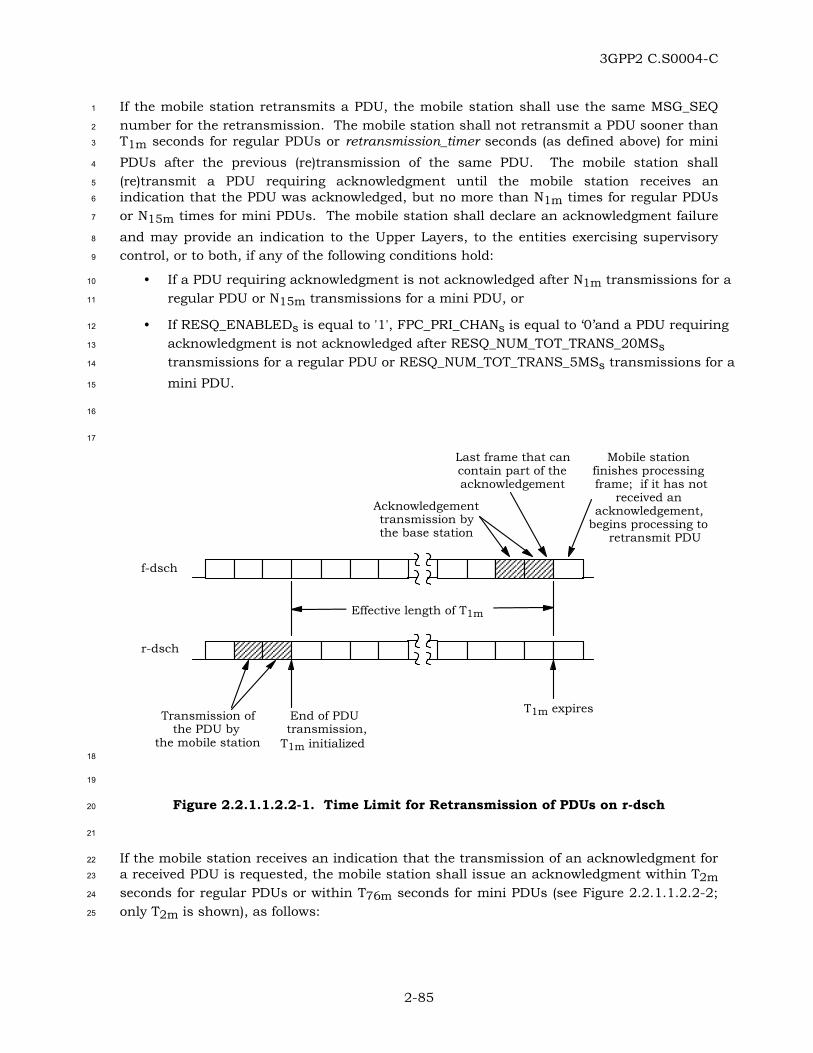
3GPP2 C.S0004-C
2-85
If the mobile station retransmits a PDU, the mobile station shall use the same MSG_SEQ 1
number for the retransmission. The mobile station shall not retransmit a PDU sooner than 2
T1m seconds for regular PDUs or retransmission_timer seconds (as defined above) for mini 3
PDUs after the previous (re)transmission of the same PDU. The mobile station shall 4
(re)transmit a PDU requiring acknowledgment until the mobile station receives an 5
indication that the PDU was acknowledged, but no more than N1m times for regular PDUs 6
or N15m times for mini PDUs. The mobile station shall declare an acknowledgment failure 7
and may provide an indication to the Upper Layers, to the entities exercising supervisory 8
control, or to both, if any of the following conditions hold: 9
• If a PDU requiring acknowledgment is not acknowledged after N1m transmissions for a 10
regular PDU or N15m transmissions for a mini PDU, or 11
• If RESQ_ENABLEDs is equal to '1', FPC_PRI_CHANs is equal to ‘0’and a PDU requiring 12
acknowledgment is not acknowledged after RESQ_NUM_TOT_TRANS_20MSs 13
transmissions for a regular PDU or RESQ_NUM_TOT_TRANS_5MSs transmissions for a 14
mini PDU. 15
16
17
r-dsch
f-dsch
End of PDUtransmission,
T1m initialized
Last frame that cancontain part of theacknowledgement
T1m expiresTransmission ofthe PDU by
the mobile station
Acknowledgementtransmission bythe base station
Mobile stationfinishes processingframe; if it has not
received anacknowledgement,
begins processing toretransmit PDU
Effective length of T1m
18
19
Figure 2.2.1.1.2.2-1. Time Limit for Retransmission of PDUs on r-dsch 20
21
If the mobile station receives an indication that the transmission of an acknowledgment for 22
a received PDU is requested, the mobile station shall issue an acknowledgment within T2m 23
seconds for regular PDUs or within T76m seconds for mini PDUs (see Figure 2.2.1.1.2.2-2; 24
only T2m is shown), as follows: 25

3GPP2 C.S0004-C
2-86
• The mobile station shall acknowledge a regular PDU requiring acknowledgment by 1
transmitting a regular PDU. The mobile station shall acknowledge a mini PDU 2
requiring acknowledgment by transmitting a mini PDU. 3
• If the mobile station needs to acknowledge a regular PDU and either has or receives 4
an indication that no regular SDUs are to be transmitted within T2m seconds of 5
receiving the PDU being acknowledged, the mobile station shall generate and 6
transmit a regular PDU carrying an SDU which has the following format (to be sent 7
as an Order Message):35 8
9
Field Length (bits)
ORDER = ‘010000’ 6
ADD_RECORD_LEN = ‘000’ 3
10
The mobile station shall set the ACK_REQ field in the generated PDU to ‘0’ and shall 11
set the ACK_SEQ field in the generated PDU as specified in 2.2.1.1.1.2. 12
• If the mobile station needs to acknowledge a mini PDU and either has or receives an 13
indication that no mini SDUs are to be transmitted within T76m seconds of receiving 14
the PDU being acknowledged, the mobile station shall generate and transmit a mini 15
PDU carrying an SDU which has the following format (to be sent as an 16
Acknowledgment PDU): 17
18
Field Length (bits)
RESERVED = ‘0000000000000’ 13
19
The mobile station shall set the ACK_SEQ field in the generated PDU as specified in 20
2.2.1.1.1.2. 21
• Otherwise, the mobile station shall either generate and transmit a PDU with its 22
fields set as described above or shall use an existing PDU carrying an Upper Layer 23
SDU as the PDU to be transmitted and shall set the ACK_SEQ field as specified in 24
2.2.1.1.1.2. 25
26
35 In [11], this “acknowledgment-specific” PDU is referred to as the Mobile Station Acknowledgement Order.

3GPP2 C.S0004-C
2-87
r-dsch
Effective length of T2m
Last frame that cancontain part of theacknowledgement
T2m expires
Transmission ofPDU by the
base station
Acknowledgementtransmission by
the mobile station
Base station finishesprocessing frame, if ithas not received anacknowledgement,
begins processing toretransmit PDU
Mobile stationfinishes receivingPDU, sets T2m
f-dsch
1
2
Figure 2.2.1.1.2.2-2. Time Limit for Acknowledgment of PDUs on f-dsch 3
4
The mobile station may send an order to reset the ARQ parameters on the base station side 5
via a mini PDU carrying an SDU which has the following format (to be sent as a Reset PDU): 6
7
Field Length (bits)
RESERVED = ‘0000000000000’ 13
8
If the mobile station is instructed to perform a reset for both regular and mini PDUs, the 9
mobile station shall: 10
• Reset its retransmission count for each PDU that is awaiting acknowledgment. 11
• Set MSG_SEQ_ACKs, M_MSG_SEQ_ACKs, MSG_SEQ_NOACKs and 12
M_MSG_SEQ_NOACKs to ’0’. 13
• Discard each of the pending requests for acknowledgment for PDUs received on the 14
f-dsch. 15
If the mobile station is instructed to perform a reset for mini PDUs only, the mobile station 16
shall: 17
• Reset its retransmission count for each mini PDU that is awaiting acknowledgment. 18
• Set M_MSG_SEQ_ACKs and M_MSG_SEQ_NOACKs to ’0’. 19
• Discard each of the pending requests for acknowledgment for mini PDUs received on 20
the f-dsch. 21

3GPP2 C.S0004-C
2-88
After completing the reset for the specified type of PDUs, the mobile station should resume 1
normal operation, starting with the transmission of the PDUs of the specified type that were 2
awaiting acknowledgment at the time the reset disposition was received. Further 3
requirements for the processing of a reset request by the mobile station are given in 4
2.2.2.1.2.2. 5
2.2.1.1.3 Accumulated ARQ Statistics 6
The mobile station shall maintain the counters shown in Table 2.2.1.1.3-1 and Table 7
2.2.1.1.3-2. Each counter shall be 16 bits long. The mobile station shall initialize each 8
counter described herein to zero upon power-up; the mobile station shall not re-initialize 9
any counter described herein at any other time except upon command from the base 10
station. Each counter shall be maintained modulo 216. 11
When the mobile station transmits a regular PDU or a mini PDU on the r-dsch requiring an 12
acknowledgment for the ith time, for i equals one to three, it shall increment the counter 13
LAYER2_RTCi or the counter MM_RTCi, respectively. 14
The mobile station shall increment the counter LAYER2_RTC4 or the counter MM_RTC4 15
each time it aborts using the r-dsch because the timeout expired after the N1mth 16
transmission of a regular PDU or the N15mth transmission of a mini PDU, respectively, 17
requiring an acknowledgment. 18
The mobile station shall increment the counter LAYER2_RTC5 or the counter MM_RTC5 for 19
each transmission of a regular PDU or a mini PDU, respectively, not requiring an 20
acknowledgment on the r-dsch. This count shall include all transmissions, including those 21
that were repeated multiple times or those carrying an identical SDU. 22
23
Table 2.2.1.1.3-1. Accumulated ARQ Statistics for Regular PDUs 24
Counter Identifier Description
LAYER2_RTC1 Number of regular PDUs requiring acknowledgment that were transmitted at least once on the r-dsch
LAYER2_RTC2 Number of regular PDUs requiring acknowledgment that were transmitted at least twice on the r-dsch
LAYER2_RTC3 Number of regular PDUs requiring acknowledgment that were transmitted at least three times on the r-dsch
LAYER2_RTC4 Number of times that the mobile station dropped the r-dsch as a result of the timeout expiring after the N1mth transmission of a regular PDU requiring acknowledgment
LAYER2_RTC5 Number of times a regular PDU not requiring an acknowledgment was sent on the r-dsch
25

3GPP2 C.S0004-C
2-89
Table 2.2.1.1.3-2. Accumulated ARQ Statistics for Mini PDUs 1
Counter Identifier Description
MM_RTC1 Number of mini PDUs requiring acknowledgment that were transmitted at least once on the r-dsch
MM_RTC2 Number of mini PDUs requiring acknowledgment that were transmitted at least twice on the r-dsch
MM_RTC3 Number of mini PDUs requiring acknowledgment that were transmitted at least three times on the r-dsch
MM_RTC4 Number of times that the mobile station dropped the r-dsch as a result of the timeout expiring after the N15mth transmission of a mini PDU requiring acknowledgment
MM_RTC5 Number of times a mini PDU not requiring an acknowledgment was sent on the r-dsch
2
2.2.1.2 Utility Sublayer 3
2.2.1.2.1 Parameters 4
The mobile station shall use the fields defined in 2.2.1.2.1.1 to support message type 5
identification parameters, encryption parameters, and padding for PDUs transmitted on the 6
r-dsch. The mobile station shall set these fields according to the requirements in 7
2.2.1.2.1.2. 8
2.2.1.2.1.1 Definition of Utility Sublayer Fields 9
The message type field for PDUs transmitted on the r-dsch has the following format: 10
11
Field Length (bits)
MSG_TYPE 3, 6 or 8
12
MSG_TYPE - Message type indicator. 13
This field contains the message type indicator for regular 14
PDUs (8 bits) or mini PDUs (3 or 6 bits) sent on the r-dsch. 15
16
A regular PDU transmitted on the r-dsch includes the Encryption field and may include the 17
Extended-Encryption fields, based upon P_REV_IN_USEs and the current encryption mode 18
(see 2.2.1.2.1.2). 19

3GPP2 C.S0004-C
2-90
The Encryption field for regular PDUs transmitted on the r-dsch has the following format: 1
2
Field Length (bits)
ENCRYPTION 2
3
ENCRYPTION – Message encryption indicator. 4
5
The Extended-Encryption fields for regular PDUs transmitted on the r-dsch have the 6
following format: 7
8
Field Length (bits)
SDU_ENCRYPT_MODE 0 or 3
ENC_SEQ 0 or 8
9
SDU_ENCRYPT_MODE – Signaling encryption mode in use for the SDU carried by this 10
PDU. 11
ENC_SEQ – The eight least significant bits of the encryption sequence 12
number used to construct a cryptographic synchronization 13
crypto-sync (see [5]) for the encryption algorithm. 14
15
The PDU padding field for PDUs transmitted on the r-dsch has the following format: 16
17
Field Length (bits)
PDU_PADDING 0 - 7
18
PDU_PADDING – Padding bits. 19
The MACI field for PDUs transmitted on the r-dsch has the following format: 20
21
Field Length (bits)
MACI 0 or 32
22
MACI – Message Authentication Code for Integrity. 23
24

3GPP2 C.S0004-C
2-91
2.2.1.2.1.2 Requirements for Setting Utility Sublayer Fields 1
The mobile station shall set the MSG_TYPE field of regular PDUs as shown in Table 2
2.2.1.2.1.2-1. 3

3GPP2 C.S0004-C
2-92
Table 2.2.1.2.1.2-1. MSG_TYPE Values for Regular PDUs on r-dsch (part 1 of 2) 1
Message Name MSG_TAG MSG_TYPE (binary)
Order Message ORDM 00000001
Authentication Challenge Response Message
AUCRM 00000010
Flash With Information FWIM 00000011
Data Burst Message DBM 00000100
Pilot Strength Measurement Message PSMM 00000101
Power Measurement Report Message PMRM 00000110
Send Burst DTMF Message BDTMFM 00000111
Status Message STM 00001000
Origination Continuation Message ORCM 00001001
Handoff Completion Message HOCM 00001010
Parameters Response Message PRSM 00001011
Service Request Message SRQM 00001100
Service Response Message SRPM 00001101
Service Connect Completion Message SCCM 00001110
Service Option Control Message SOCM 00001111
Status Response Message STRPM 00010000
TMSI Assignment Completion Message
TACM 00010001
Supplemental Channel Request Message
SCRM 00010010
Candidate Frequency Search Response Message
CFSRSM 00010011
Candidate Frequency Search Report Message
CFSRPM 00010100
Periodic Pilot Strength Measurement Message
PPSMM 00010101
Outer Loop Report Message OLRM 00010110
Resource Request Message RRM 00010111
Extended Release Response Message ERRM 00011000
Reserved N/A 00011001
2

3GPP2 C.S0004-C
2-93
Table 2.2.1.2.1.2-1. MSG_TYPE Values for Regular PDUs on r-dsch (part 2 of 2) 1
Message Name MSG_TAG MSG_TYPE (binary)
Enhanced Origination Message EOM 00011010
Extended Flash With Information Message
EFWIM 00011011
Extended Pilot Strength Measurement Message
EPSMM 00011100
Extended Handoff Completion Message EHOCM 00011101
Resource Release Request Message RRRM 00011110
Security Mode Request Message SMRM 00011111
Data Burst Response Message (DS-41 only, see [13])
DBRM 00100000
DS-41 Inter-system Transfer Message (DS-41 only, see [13])
D41ISTM 00100001
User Zone Update Request Message UZURM 00100010
Call Cancel Message CLCM 00100011
Device Information Message DIM 00100100
MC-MAP Initial L3 Message (MC-MAP only, see [14])
MAPIL3M 00100101
MC-MAP L3 Message (MC-MAP only, see [14])
MAPL3M 00100110
R-TMSI Assignment Completion Message (MC-MAP only, see [14])
RTACM 00100111
Base Station Status Request Message BSSREQM 00101000
Authentication Response Message AURSPM 00101001
Authentication Resynchronization Message
AURSYNM 00101010
CDMA Offtime Report Message COTRM 00101001
2
The mobile station shall set the MSG_TYPE field of mini PDUs as shown in Tables 3
2.2.1.2.1.2-2 and 2.2.1.2.1.2-3. 4
5

3GPP2 C.S0004-C
2-94
Table 2.2.1.2.1.2-2. MSG_TYPE Values (3 bits) for Mini PDUs on r-dsch 1
Message Name MSG_TAG MSG_TYPE (binary)
Pilot Strength Measurement Mini Message
PSMMM 000
Supplemental Channel Request Mini Message
SCRMM 001
Reserved N/A 010
2
Table 2.2.1.2.1.2-3. MSG_TYPE Values (6 bits) for Mini PDUs on r-dsch 3
Message Name MSG_TAG MSG_TYPE (binary)
Acknowledgment PDU ACK 111000
Reset PDU RESET 111001
Resource Request Mini Message RRMM 111010
Extended Release Response Mini Message
ERRMM 111011
Resource Release Request Mini Message
RRRMM 111100
4
The mobile station shall set the ENCRYPTION field to the current encryption mode for 5
regular PDUs to be transmitted on the r-dsch (see [5]). The mobile station shall not change 6
the value of this field and the encryption state of the SDU carried by the PDU if the PDU is 7
retransmitted. 8
If P_REV_IN_USEs is greater than or equal to seven and the ENCRYPTION field is set to ‘11’, 9
the mobile station shall include the Extended-Encryption fields; otherwise, these fields 10
shall be omitted. 11
If the Extended-Encryption fields are included, the mobile station shall set the Extended-12
Encryption Fields as follows: 13
• The mobile station shall set the SDU_ENCRYPT_MODE field to the signaling 14
encryption mode that is used for the SDU carried by this PDU and is provided by 15
Layer 3. 16
• If the SDU_ENCRYPT_MODE field is set to ‘001’ or ‘010’ and if the MACI_INCL field 17
is not present in the PDU or it is present, but it is equal to ‘0’, the mobile station 18
shall include the ENC_SEQ field and shall set it to the value provided by Layer 3; 19
otherwise, the mobile station shall omit the ENC_SEQ field. 20

3GPP2 C.S0004-C
2-95
The mobile station shall not change the value of the Extended-Encryption fields and the 1
encryption state of the SDU carried by the PDU if the PDU is retransmitted. 2
The mobile station shall set the PDU_PADDING field to contain the minimum number of 3
bits needed to make the length of the PDU, in bits, an integral multiple of eight. The mobile 4
station shall set these bits to ‘0’. 5
The mobile station shall include the MACI field, if and only if the MACI_INCL field in the 6
transmitted PDU is included and is equal to ‘1’; otherwise, the mobile station shall omit the 7
MACI field. If the MACI field is included, the mobile station shall set this field as follows: 8
the mobile station shall execute the procedure described in 2.2.1.2.2. If USE_UAKs is equal 9
to ‘0’, the mobile station shall set the MACI field to MAC-I. Otherwise, the mobile station 10
shall set the MACI field to the UMAC value. 11
The mobile station shall not change the values of the MACI field and the Message Integrity 12
Fields of the PDU, if the PDU is retransmitted. 13
2.2.1.2.2 Procedures 14
When sending regular PDUs on the r-dsch, the mobile station shall set the parameters 15
defined in 2.2.1.2.1.1 according to the requirements specified in 2.2.1.2.1.2. 16
The format of a regular PDU sent to the MAC Sublayer for transmission on the r-dsch 17
depends upon the protocol capabilities of both the mobile station and the base station, as 18
well as on the value of the ENCRYPTION field (see 2.2.1.2.1.2). 19
If P_REV_IN_USEs is less than nine, the mobile station shall assemble regular PDUs for the 20
r-dsch using the following format: 21
22
Parameter Reference
Message Type Field Section 2.2.1.2.1.1
ARQ Fields Section 2.2.1.1.1.1
Encryption Field Section 2.2.1.2.1.1
Extended-Encryption Fields Section 2.2.1.2.1.1
SDU [5]
PDU Padding Field Section 2.2.1.2.1.1
23
If P_REV_IN_USEs is greater than or equal to nine, the mobile station shall assemble 24
regular PDUs for the r-dsch using the following format: 25
26

3GPP2 C.S0004-C
2-96
Parameter Reference
Message Type Field Section 2.2.1.2.1.1
ARQ Fields Section 2.2.1.1.1.1
Encryption Field Section 2.2.1.2.1.1
Message Integrity Fields Section 2.1.1.1.1.1
Extended-Encryption Fields Section 2.2.1.2.1.1
SDU [5]
PDU Padding Field Section 2.2.1.2.1.1
Message Authentication Code for Integrity (MACI) Field
Section 2.2.1.2.1.1
If the MACI field is included in the PDU, the mobile station shall proceed as follows: 1
• The mobile station shall compute MSG_LENGTH as described 2.1.1.3.1.2. 2
• The mobile station shall set msg_length to MSG_LENGTH and shall consider the 3
length of the msg_length parameter to be 8 bits. 4
• The mobile station shall set channel_specific_buffer as described in 2.2.1.4.2 and 5
shall invoke the procedure for computing the MAC-I value described in 2.1.1.1.2.5, 6
with the channel_specific_buffer, msg_length and the non-encapsulated PDU without 7
the MACI field, as parameters. 8
• If USE_UAKs is equal to ‘1’, the mobile station shall invoke the procedure for 9
computing the UMAC value described in 2.1.1.1.2.6, with the computed MAC-I as 10
input parameter. 11
• The mobile station shall use the values MAC-I or UMAC, if computed, to set the 12
MACI field as described in 2.2.1.2.1.2. 13
When sending mini PDUs on the r-dsch, the mobile station shall assemble the mini PDU 14
using the following format: 15
16
Parameter Reference
ARQ Fields Section 2.2.1.1.1.1
Message Type Field Section 2.2.1.2.1.1
SDU [5]
PDU Padding Field Section 2.2.1.2.1.1
17
The mobile station shall not assemble and transmit regular PDUs larger than 2016 bits. 18
The mobile station shall not assemble and transmit mini PDUs larger than 24 bits. 19

3GPP2 C.S0004-C
2-97
2.2.1.3 Segmentation and Reassembly (SAR) Sublayer 1
2.2.1.3.1 Parameters 2
The mobile station shall use the SAR parameters defined in 2.2.1.3.1.1 for PDUs 3
transmitted on the r-dsch. The mobile station shall set the SAR parameters according to 4
the requirements specified in 2.2.1.3.1.2. 5
2.2.1.3.1.1 Definition of SAR Parameters 6
The SAR parameters for regular PDUs transmitted on the r-dsch have the following format: 7
8
Field Length (bits)
MSG_LENGTH 8
9
MSG_LENGTH – Length of the PDU in octets. 10
11
Field Length (bits)
CRC 16
12
CRC - Cyclic Redundancy Check for the PDU. 13
14
A regular PDU transmitted on the r-dsch includes SOM field . 15
16
Field Length (bits)
SOM 1
17
SOM - Start of Message indicator, for each encapsulated PDU 18
fragment. 19
There are no SAR parameters defined for mini PDUs. 20
2.2.1.3.1.2 Requirements for Setting SAR Parameters 21
If the LAC PDU is a regular PDU, the MSG_LENGTH field shall be eight bits long and shall 22
be set to (size of LAC PDU in bits + 24) / 8. 23
The 16-bit value of the CRC shall be computed over the MSG_LENGTH parameter and the 24
LAC PDU, in this order. The generator polynomial for the CRC shall be as follows: 25
g(x) = x16 + x12 + x5 + 1. 26
The following procedure and the logic shown in Figure 2.1.1.3.1.2-1 shall be used to 27
compute the CRC: 28

3GPP2 C.S0004-C
2-98
• All shift register elements shall be initialized to logical one.36 1
• The switches shall be set in the up position. 2
• The information bit count k shall be defined as eight plus the size of the LAC PDU in 3
bits. 4
• The register shall be clocked k times for the k information bits. 5
• The switches shall be set in the down position so that the output is a modulo-2 6
addition with a ‘1’ and the successive shift register inputs are ‘0’. 7
• The register shall be clocked an additional 16 times. 8
• The 16 additional output bits shall be the CRC value. 9
The CRC parameter shall be set to the CRC value in such a way that its bits are 10
transmitted in the order in which they appeared at the output of the CRC encoder. 11
12
Up for first k bitsDown for last 16 bits
Input
Outputx15x12x5x1x0
1
0
Denotes modulo-2 addition
Denotes one-bit storage element
13
14
Figure 2.2.1.3.1.2-1. The 16-bit CRC Calculation 15
16
The mobile station shall set the SOM field as follows: 17
• The SOM field shall be set to ‘1’ in the frame carrying the first encapsulated PDU 18
fragment (corresponding to the MSG_LENGTH parameter and the beginning of the 19
PDU). 20
• The SOM field shall be set to ‘0’ in all subsequent frames that carry encapsulated 21
PDU fragments. 22
36 Initialization of the register to ones causes the CRC for all-zero data to be non-zero.

3GPP2 C.S0004-C
2-99
2.2.1.3.2 Procedures 1
The mobile station shall set the SAR parameters as specified in 2.2.1.3.1.2. The mobile 2
station shall assemble an encapsulated PDU from the SAR parameters and the PDU by 3
concatenating them in the following order: 4
• If the PDU is a regular PDU, the MSG_LENGTH parameter, starting with the most 5
significant bit. 6
• The PDU, starting with the most significant bit of the MSG_TYPE field. 7
• The CRC parameter (for regular PDUs only), starting with the bit that appeared first 8
at the output of the CRC encoder. 9
The mobile station shall segment the encapsulated regular PDU into fragments of 10
maximum available size necessary to fit in a Lower Layer transport unit, except for the last 11
fragment, which may be shorter. The mobile station shall transmit the encapsulated PDU 12
fragments in order. Before transmitting an encapsulated PDU fragment of an encapsulated 13
regular PDU, the mobile station shall transmit the SOM parameter associated with it. 14
Unless transmission of an encapsulated PDU is to be canceled, the mobile station shall not 15
transmit encapsulated PDU fragments from a new encapsulated regular PDU until all 16
fragments of the previous encapsulated regular PDU have been transmitted (i.e., 17
interleaving fragments from different regular PDUs is not permitted). Encapsulated PDU 18
fragments of a regular PDU may be interleaved with mini PDUs. 19
2.2.1.4 Message Integrity Sublayer 20
2.2.1.4.1 Parameters 21
The mobile station shall use and set the Message Integrity Fields37 specified in 2.1.1.1.1.1 22
according to the procedures in 2.2.1.4.2 and 2.1.1.1.1.3. 23
2.2.1.4.2 Procedures 24
Mobile stations with MOB_P_REV greater than or equal to ten shall support message 25
integrity on r-dsch. 26
The mobile station shall set channel_specific_buffer to the 2 bits corresponding to 27
“ACK_REQ |’1’”, where ACK_REQ is set to ‘0’, if the message is to be sent in unassured 28
mode or to ‘1’, if the message is to be sent in assured mode, where the most significant bit 29
of the channel_specific_buffer corresponds to the ACK_REQ bit. 30
When the mobile station executes the procedure for setting up the MACI field (see 31
2.2.1.2.2), the channel_specific_buffer shall be passed as input parameter to that 32
procedure. 33
37 Except where explicitly specified otherwise (see 2.2.1.4.2), for regular PDUs transmitted on r-dsch, the mobile station uses the same Message Integrity Fields and the same procedures for inclusion and setting of values for these fields as it does when transmitting PDUs on r-csch.
3GPP2 C.S0004-C
2-100
2.2.2 Reception on f-dsch 1
The mobile station shall meet the requirements specified in 2.2.2.3.2, 2.2.2.4.2, 2.2.2.2.2 2
and 2.2.2.1.2.2. 3
If a received PDU is not expected to be message integrity protected (see [5]), but contains a 4
MACI_INCL field equal to ‘1’, the mobile station shall ignore the Message Integrity Fields 5
and the MACI field in the received PDU. 6
2.2.2.1 ARQ Sublayer 7
2.2.2.1.1 Parameters 8
To support the ARQ mechanism on the dedicated channels, the mobile station interprets 9
the ARQ fields defined in 3.2.2.1.1.1 for PDUs received on the f-dsch. 10
2.2.2.1.2 Procedures 11
2.2.2.1.2.1 Overview of Reception Procedures 12
The mobile station removes the ARQ fields from PDUs received on the f-dsch and passes 13
the remainder of the PDU (which generally includes the SDU) to the Upper Layers. 14
When the ARQ Sublayer on the receiver side receives a PDU, it provides an indication to the 15
ARQ Sublayer on the transmitter side (see 2.2.1.1.2.1) of the acknowledgment of a 16
previously transmitted PDU with the MSG_SEQ field equal to the ACK_SEQ field of the 17
received PDU. 18
The ARQ Sublayer performs duplicate detection for received PDUs that require 19
acknowledgment as well as for PDUs that do not require acknowledgment, using slightly 20
different mechanisms. For PDUs requiring acknowledgment, the ARQ Sublayer uses 21
received status indicators. For PDUs not requiring acknowledgment, the ARQ Sublayer 22
uses a timer to delineate the interval during which PDUs with the same MSG_SEQ fields 23
are considered duplicates. Duplicates of PDUs requiring acknowledgment are 24
acknowledged (see below) and then discarded. Duplicates of PDU not requiring 25
acknowledgment are discarded. 26
When the ARQ Sublayer on the receiver side receives a PDU with the ACK_REQ field set to 27
‘1’, it provides an indication to the ARQ Sublayer on the transmitter side, amounting to a 28
request for the transmission of an acknowledgment. The MSG_SEQ field of the received 29
PDU and the time of reception are also provided to the ARQ Sublayer on the transmitter 30
side (see 2.2.1.1.2.1). 31
Following the reception of an acquiring dedicated channel indication from Layer 3 (see 32
2.6.4.2 of [5]), the ARQ Sublayer considers the reception of the first valid PDU on the f-dsch 33
as a signal that the dedicated signaling channel was properly established and further 34
signaling can proceed. When that happens, the ARQ Sublayer sends a forward dedicated 35
channel acquired indication to Layer 3 (see 2.6.4.2 of [5]) signaling that the connection with 36
the base station was established. 37

3GPP2 C.S0004-C
2-101
The ARQ Sublayer for dedicated channels can be reset locally, under dispositions from 1
Layer 3 or the managing entity in the control plane, and can also be reset upon the 2
reception of a Reset PDU by the LAC Sublayer (for mini PDUs only, see Table 3.2.2.2.1.2-3). 3
The ARQ Sublayer is reset simultaneously on the receiver and the transmitter sides. In 4
such cases, the information needed to perform duplicate detection and the pending 5
requests for acknowledgment are discarded. 6
2.2.2.1.2.2 Requirements for Reception Procedures 7
The mobile station shall process PDUs received on the f-dsch. 8
Except for PDUs associated with emergency calls, the mobile station shall not process the 9
ARQ fields and ARQ variables if the received PDU is expected to be message integrity 10
protected (see [5]), but the Message Integrity Fields and the MACI field are either missing or 11
fail the message integrity check38 (see 3.1.1.1.3). Otherwise: 12
When a PDU is received on the f-dsch with the ACK_REQ field set to ‘1’, the mobile station 13
shall recognize it as a request for acknowledgment. See 2.2.1.1.1.2 for requirements on the 14
processing of requests for acknowledgment. 15
When a PDU is received on the f-dsch, the mobile station shall recognize it as including an 16
acknowledgment for a previously transmitted PDU if the ACK_SEQ field of the received PDU 17
matches the MSG_SEQ field of a previously transmitted PDU. See 2.2.1.1.1.2 for 18
requirements on the processing of a PDU after being acknowledged. 19
The mobile station may ignore received acknowledgments for PDUs that were not sent or 20
are not awaiting acknowledgment, except immediately after the reception of an acquiring 21
dedicated channel indication from Layer 3. After receiving an acquiring dedicated channel 22
indication, the mobile station shall consider the reception of the first valid PDU as a signal 23
that the dedicated channel was successfully acquired, and shall send a forward dedicated 24
channel acquired indication to Layer 3. 25
For the detection of duplicate PDUs requiring acknowledgment, the mobile station shall 26
store a received status indicator for each possible value of the regular PDU MSG_SEQ field 27
(MSG_SEQ_RCVD[n], for n equal to 0 through 7) and the mini PDU MSG_SEQ field 28
(M_MSG_SEQ_RCVD[n], for n equal to 0 through 3). Duplicate detection is performed 29
independently for regular PDUs and for mini PDUs.39 The mobile station shall perform the 30
following procedures: 31
38 In such cases, the mobile station will notify the base station via a Mobile Station Reject Order which identifies the exact condition and the offending received PDU (see [5]).
39 A regular PDU and a mini PDU cannot be duplicates of one another.

3GPP2 C.S0004-C
2-102
• When a PDU requiring acknowledgment is received having the message sequence 1
number field MSG_SEQ, and MSG_SEQ_RCVD[MSG_SEQ] (for a regular PDU) or 2
M_MSG_SEQ_RCVD[MSG_SEQ] (for a mini PDU) is equal to NO, the mobile station 3
shall process the PDU as a new PDU. The mobile station shall then set 4
MSG_SEQ_RCVD[MSG_SEQ] (for a regular PDU) or M_MSG_SEQ_RCVD[MSG_SEQ] 5
(for a mini PDU) to YES, and shall set MSG_SEQ_RCVD[(MSG_SEQ + 4) modulo 8] 6
(for a regular PDU) or M_MSG_SEQ_RCVD[(MSG_SEQ + 2) modulo 4] (for a mini 7
PDU) to NO. 8
• When a PDU requiring acknowledgment is received having the message sequence 9
number field MSG_SEQ, and MSG_SEQ_RCVD[MSG_SEQ] (for a regular PDU) or 10
M_MSG_SEQ_RCVD[MSG_SEQ] (for a mini PDU) is equal to YES, the mobile station 11
shall acknowledge the PDU and then discard it. 12
For the detection of duplicate PDUs not requiring acknowledgment, the mobile station shall 13
consider all PDUs having the same MSG_SEQ field received within an interval of T3m 14
seconds for regular PDUs or within an interval of T77m seconds for mini PDUs to be 15
duplicates (see Figure 2.2.2.1.2.2-1; only T3m is shown). If the mobile station receives 16
multiple copies of the same PDU, it shall discard the duplicate copies. 17
18
f-dsch
T3m
Last frame containingpart of a PDU
with MSG_SEQnumber k that is
considered the samemessage
Any PDUreceived in this
frame withMSG_SEQ numberk is considered as a
new PDU
First receipt of aPDU with MSG_SEQ
number k
T3m is initialized T3m expires
19
20
Figure 2.2.2.1.2.2-1. Time Window for Detecting Duplicate Messages not 21
Requiring Acknowledgment 22
23
When processing a reset request for both regular PDUs and mini PDUs, the mobile station 24
shall set MSG_SEQ_RCVD[n] to NO for all values of n from 0 to 7 and shall set 25
M_MSG_SEQ_RCVD[n] to NO for all values of n from 0 to 3. When processing a reset 26
request for mini PDUs only, the mobile station shall set M_MSG_SEQ_RCVD[n] to NO for all 27
values of n from 0 to 3. Further requirements for the processing of a reset request by the 28
mobile station are given in 2.2.1.1.1.2. 29

3GPP2 C.S0004-C
2-103
2.2.2.2 Utility Sublayer 1
2.2.2.2.1 Parameters 2
The mobile station shall use the fields defined in 3.2.2.2.1.1 for PDUs received on the 3
f-dsch. 4
2.2.2.2.2 Procedures 5
The mobile station shall identify the SDU carried by the received PDU as shown in Table 6
3.2.2.2.1.2-1 for regular PDUs or in Table 3.2.2.2.1.2-2 or 3.2.2.2.1.2-3 for mini PDUs 7
received on the f-dsch. If identification is not possible, the mobile station shall discard the 8
PDU without further processing. 9
If the mobile station receives a valid PDU, the LAC Sublayer shall make the SDU included 10
in the PDU available to Layer 3, together with the Encryption field and the Extended-11
Encryption fields, if any (see 3.1.2.3.1.3.1). 12
13
2.2.2.3 Segmentation and Reassembly (SAR) Sublayer 14
2.2.2.3.1 Parameters 15
The mobile station shall use the parameters defined in 3.2.2.3.1.1 for PDUs received on the 16
f-dsch. 17
2.2.2.3.2 Procedures 18
The mobile station shall assemble regular PDUs40 from encapsulated PDU fragments 19
received on the f-dsch using the following procedure: 20
• A reassembly buffer large enough to accommodate the largest possible encapsulated 21
PDU shall be available. The reassembly buffer shall be emptied whenever a reset 22
indication is received. 23
• When an encapsulated PDU fragment is received: 24
- If the SOM parameter is equal to ‘1’: 25
+ The current contents of the reassembly buffer, if any, shall be discarded (the 26
reassembly buffer becomes empty). 27
+ The encapsulated PDU fragment (which corresponds to the beginning of a 28
PDU) shall be placed in the buffer (without the SOM parameter). The first 29
eight bits shall be interpreted as the MSG_LENGTH parameter associated 30
with the PDU. If MSG_LENGTH is less than three, the reassembly buffer 31
shall be emptied. 32
40 Since mini PDUs are not fragmented, no reassembly procedures are defined for mini PDUs.

3GPP2 C.S0004-C
2-104
- If the SOM parameter is equal to ‘0’: 1
+ If the reassembly buffer is empty, the encapsulated PDU fragment shall be 2
discarded. 3
+ If the reassembly buffer is not empty, the encapsulated PDU fragment (which 4
corresponds to a subsequent part of the PDU being received) shall be 5
appended to the contents of the reassembly buffer (without the SOM 6
parameter). 7
– If the reassembly buffer is not empty and if there are at least MSG_LENGTH 8
octets in the buffer, the data representing the first (MSG_LENGTH – 2) octets in 9
the buffer shall be run through the 16-bit CRC computation specified in 10
3.2.2.3.1.2. The result of the computation shall be compared with the 16-bits 11
located in the reassembly buffer after the first (MSG_LENGTH - 2) octets and the 12
following actions shall be taken: 13
+ If the computed CRC is equal to the received CRC, the PDU is considered to 14
have been correctly received and reassembled. 15
+ If the computed CRC is not equal to the received CRC, the contents of the 16
reassembly buffer shall be discarded (the buffer becomes empty). 17
2.2.2.4 Message Integrity Sublayer 18
If the mobile station supports message integrity (MSG_INTEGRITY_SUPs is equal to ‘1’), the 19
mobile station shall process the Message Integrity Fields and the MACI field of regular 20
PDUs received on f-dsch as specified in 2.2.2.4.1 and 2.2.2.4.2. 21
2.2.2.4.1 Parameters 22
The mobile station uses and interprets the Message Integrity Fields defined in 2.1.1.1.1.1 23
and the MACI field for regular PDUs received on the f-dsch41. 24
2.2.2.4.2 Procedures 25
If the received regular PDU contains Message Integrity Fields and the MACI field and the 26
mobile station operates at a protocol revision equal to ten or higher, the mobile station shall 27
perform the procedures42 specified in 3.1.1.1.3. 28
41 When receiving on the f-dsch, the mobile station uses the same Message Integrity Fields as when transmitting on r-csch.
42 When receiving on the f-dsch, the mobile station uses the same message integrity procedures as the base station does when receiving on r-csch.

3GPP2 C.S0004-C
3-1
3 BASE STATION REQUIREMENTS 1
When operating on common channels, the base station shall meet the requirements 2
specified in 3.1. When operating on dedicated channels the base station shall meet the 3
requirements specified in 3.2. 4
3.1 Common Channel Operation 5
The base station shall meet the requirements specified in 3.1.1 for operation on the r-csch 6
and in 3.1.2 for operation on the f-csch. 7
3.1.1 Reception on r-csch 8
The base station shall meet the requirements specified in 3.1.1.5.2, 3.1.1.4.2, 3.1.1.3.2, 9
3.1.1.2.2.2, 3.1.1.1.3, and 3.1.1.1.2. 10
If a received PDU is not expected to be message integrity protected (see [5]), but contains a 11
MACI_INCL field equal to ‘1’, the base station shall ignore the Message Integrity Fields and 12
the MACI field in the received PDU. 13
3.1.1.1 Authentication and Message Integrity Sublayer 14
3.1.1.1.1 Parameters 15
The base station uses and interprets the authentication and message integrity fields 16
defined in 2.1.1.1.1.1 for PDUs received on the r-csch. 17
3.1.1.1.2 Authentication Procedures 18
If the base station supports message integrity and the received PDU carries message 19
integrity fields, the base station shall execute the procedures defined in 3.1.1.1.3. 20
The base station may be equipped with a database that includes unique mobile station 21
authentication keys, shared secret data, or both, for each registered mobile station in the 22
system. This database is used for authentication of mobile stations that are equipped for 23
authentication operation. 24
If the base station supports mobile station authentication: 25
• The base station may compare the COUNT field of the received PDU with its 26
internally stored value associated with the mobile station as identified by IMSI or 27
TMSI. 28
• The base station shall compare the RANDC field of the PDU to the most significant 29
eight bits of its internally stored value of RAND. If the comparison results in a 30
match: 31
– The base station shall perform authentication calculations using IMSI_M if it is 32
programmed for the mobile station; otherwise the base station shall use IMSI_T. 33

3GPP2 C.S0004-C
3-2
– The base station shall compute the value AUTHR in the same manner that the 1
mobile station does (see 2.1.1.1.2.2), but using its internal stored value SSD_A. 2
The base station shall compare the computed value of AUTHR with the AUTHR 3
field of the received PDU. 4
• If all of the performed comparisons result in matches, the base station may grant 5
access or service. If any one comparison fails, the base station may deny access or 6
service or may execute other security procedures. 7
3.1.1.1.3 Message Integrity Procedures 8
If the received PDU requires message integrity protection (see [5] for information on which 9
PDUs are required to contain the MACI field) and message integrity is supported, the 10
following procedures for the validation of the MACI field included in the PDU shall be 11
performed: 12
• If the MACI_INCL field is not included or is included but is set to ‘0’, the Layer 3 13
SDU should be forwarded to Layer 3 with a message integrity failed indication, the 14
ARQ fields shall be processed appropriately for this condition (see specifications in 15
the ARQ Sublayer for the channel on which the PDU is received) and the rest of the 16
procedures in this section shall not be performed. 17
• If the SDU_SSEQ field is included in the received PDU, then: 18
- If the ACK_REQ field is set to ‘0’, let N = 8; otherwise, let N = 4. Let V be the 8 19
least significant bits of RX_EXT_SSEQ[ACK_REQ][SDU_KEY_ID]. The duplicate 20
and out-of-range detection procedure specified in 3.1.1.1.4 shall be performed 21
using N, V and SDU_SSEQ as parameters, before proceeding further. 22
- If the received PDU is considered to contain a duplicate or an out-of-range 23
SDU_SSEQ, based on the result of the procedure described in 3.1.1.1.4, the 24
Layer 3 SDU should be forwarded to Layer 3 with a message integrity failed 25
indication, the ARQ fields shall be processed appropriately for this condition (see 26
specifications in the ARQ Sublayer for the channel on which the PDU is received) 27
and the rest of the procedures in this section shall not be performed; otherwise, 28
- If (SDU_SSEQ - V) mod 256 is less than 128, EXT_SSEQ shall be set to 29
(RX_EXT_SSEQ[ACK_REQ][SDU_KEY_ID] + (SDU_SSEQ - V) mod 256) mod 232; 30
- otherwise, EXT_SSEQ shall be set to (RX_EXT_SSEQ[ACK_REQ][SDU_KEY_ID] - 31
(V – SDU_SSEQ) mod 256) mod 232. 32
• Otherwise, if the SDU_SSEQ_H field is included in the received PDU, EXT_SSEQ 33
shall be set43 to SDU_SSEQ_H * 256. 34
43 Crypto-sync duplicate detection is not performed when SDU_SSEQ_H is used.

3GPP2 C.S0004-C
3-3
• The receiver shall set the channel_specific buffer and msg_length parameters 1
associated with the received PDU and the channel it was received on, in the same 2
manner that the transmitter was required to do when it set those values for the 3
procedures (see specifications in the Integrity Sublayer for the channel on which the 4
received PDU was transmitted) used in the computation of the value for the MACI 5
field. Using also the computed value of EXT_SSEQ and the received non-6
encapsulated PDU, the receiver shall compute the value for the MACI field (see 7
2.1.1.1.2.5 and 2.1.1.1.2.6), that it would have associated with the PDU on the 8
respective channel, had it been the transmitter. 9
• If the computed value for the MACI field is not equal to the value in the MACI field of 10
the received PDU, the Layer 3 SDU should be forwarded to Layer 3 with a message 11
integrity failed indication, the ARQ fields shall be processed appropriately for this 12
condition (see specifications in the ARQ Sublayer for the channel on which the PDU 13
is received) and the rest of the procedures in this section shall not be performed; 14
otherwise, 15
• The Layer 3 SDU may be forwarded to Layer 3 with a message integrity succeeded 16
indication and the ARQ fields shall be processed appropriately for this condition (see 17
specifications in the ARQ Sublayer for the channel on which the PDU is received). In 18
addition: 19
- If the ENC_FIELDS_INCL field is not included in the received PDU or is included 20
but is equal to ‘0’, and if the SDU_SSEQ field was included in the received PDU, 21
and if ((SDU_SSEQ - V) mod 256) is less than 128, the receiver shall set 22
RX_EXT_SSEQ[ACK_REQ][SDU_KEY_ID] to EXT_SSEQ constructed above; 23
otherwise, 24
- if the ENC_FIELDS_INCL field is included in the received PDU and is equal to ‘1’, 25
the EXT_SSEQ constructed above and the SDU_ENCRYPT_MODE shall be 26
passed to Layer 344. 27
3.1.1.1.4 Security Sequence Number Duplicate and Out-of-Range Detection (refer also to 28
2.3.12.4.1.5 in [5]) 29
This procedure is invoked only if message integrity is supported by the receiver and the 30
received PDU specifies the value of the crypto-sync via the SDU_SSEQ field. The procedure 31
accepts as input parameters SDU_SSEQ and the variables V and N (set as specified in 32
3.1.1.1.3). The procedure returns an indication of whether or not the value SDU_SSEQ is 33
considered valid. 34
Given the value of the latest sequence number previously received and accepted, V, and the 35
window size, N, the 8-bit security sequence number space at the receiver can be divided 36
into the following three segments as shown in Figure 3.1.1.1.4-1: 37
44 Layer 3 will also update the RX_EXT_SSEQ array, if necessary (see [5]).

3GPP2 C.S0004-C
3-4
• Segment #1 - sequence numbers from ((V - N + 1) mod 256) to V inclusive (the anti-1
replay window) 2
• Segment #2 - sequence numbers from ((V + 1) mod 256) to ((V + 127) mod 256) 3
inclusive (future sequence numbers) 4
• Segment #3 - sequence numbers from ((V + 128) mod 256) to ((V - N) mod 256) 5
inclusive (past sequence numbers) 6
8-bit Circle
V
N[i] (segment #1)
127 (Segment #2)
Segm
ent #
3
7
Figure 3.1.1.6,2,1-1 The 8-bit security sequence number space divided into 3 8
segments 9
10
If the received sequence number, SDU_SSEQ, belongs to segment #1, the receiver shall 11
check whether a PDU having the same SDU_SSEQ has already been received successfully 12
during the most recent time interval that SDU_SSEQ has been part of segment #1. If the 13
SDU_SSEQ corresponds to a value that is considered to have been received already, the 14
SDU_SSEQ shall be considered a duplicate. 15
If the received sequence number, SDU_SSEQ, belongs to segment #2, the SDU_SSEQ shall 16
be considered valid and the value of SDU_SSEQ shall be considered as “already received 17
and accepted”, to be used for duplicate detection at further invocations of the procedure. 18
If the received sequence number, SDU_SSEQ, belongs to segment #3 the SDU_SSEQ shall 19
be considered out-of-range. 20
21
3.1.1.2 ARQ Sublayer 22
3.1.1.2.1 Parameters 23
The base station interprets the ARQ fields defined in 2.1.1.2.1.1 for PDUs received on the 24
r-csch. 25

3GPP2 C.S0004-C
3-5
3.1.1.2.2 Procedures 1
3.1.1.2.2.1 Overview of Reception Procedures 2
The ARQ Sublayer removes the ARQ fields in the PDUs received on the r-csch and passes 3
the remainder of the PDU (which generally includes the SDU) to the Upper Layers. 4
When the ARQ Sublayer on the receiver side receives a PDU with the ACK_REQ field set to 5
‘1’, it provides an indication to the ARQ Sublayer on the transmitter side. The MSG_SEQ 6
field of the received PDU and the time of reception are also provided to the ARQ Sublayer 7
on the transmitter side (see 3.1.2.1.2.1). 8
When the ARQ Sublayer on the receiver side receives a PDU with the VALID_ACK field set 9
to ‘1’, it provides an indication to the ARQ Sublayer on the transmitter side (see 3.1.2.1.2.1) 10
together with the ACK_SEQ and ACK_TYPE fields of the received PDU. 11
When the ARQ Sublayer receives a mobile station inactive on common channel indication 12
from Layer 3 (see 3.6.3 of [5]), it considers the mobile station to be no longer active on the r-13
csch. The ARQ Sublayer uses this information to process PDUs (see 3.1.1.2.2.2). 14
The ARQ Sublayer performs duplicate detection by using the MSG_SEQ field of the received 15
PDUs. In the case where a duplicate is detected the ARQ Sublayer processes the PDU like 16
any other, but raises an indication to the Upper Layers specifying that the PDU is a 17
duplicate (see 3.1.1.2.2.2). 18
3.1.1.2.2.2 Requirements for the Reception Procedures 19
Except for PDUs associated with emergency calls, the base station should not process the 20
ARQ fields and ARQ variables if the received PDU is expected to be message integrity 21
protected (see [5]), but the Message Integrity Fields and the MACI field are either missing or 22
fail the message integrity check45 (see 3.1.1.1.3). Otherwise: 23
When receiving a PDU on the r-csch with the ACK_REQ field set to ‘1’, the base station 24
shall recognize it as a request for acknowledgment. See 3.1.2.1.2.2 for requirements on the 25
processing of a request for acknowledgment. 26
When receiving a PDU on the r-csch with the VALID_ACK field set to ‘1’, the base station 27
shall use the ACK_TYPE and ACK_SEQ fields of the received PDU to identify the PDU being 28
acknowledged. See 3.1.2.1.2.2 for requirements on the processing of a PDU after being 29
acknowledged. If the base station receives an acknowledgment for a PDU that was 30
transmitted on more than one channel (e.g., the Paging Channel and the Forward Common 31
Control Channel), the base station shall consider the PDU to have been acknowledged for 32
all the channels on which the PDU was transmitted. 33
If the base station performs duplicate detection using r-csch message sequence numbers, it 34
should use the following procedures: The base station should store, for each mobile station 35
45 In such cases, the base station will notify the mobile station via a Base Station Reject Order which identifies the exact condition and the offending received PDU (see [5]).

3GPP2 C.S0004-C
3-6
that is active on the r-csch, a received status indicator for each possible value of the r-csch 1
PDU MSG_SEQ field (MSG_SEQ_RCVD[n], where n has a value from 0 to 7). 2
The base station should consider a mobile station active on the r-csch when it receives an 3
r-csch PDU from the mobile station. The base station should consider the mobile station 4
inactive on the r-csch if either of the following conditions exist: 5
• It has received no PDU from the mobile station within a time period to be selected 6
by the base station manufacturer; or 7
• The ARQ Sublayer receives a mobile station inactive on common channel indication 8
from Layer 3. 9
When the base station receives a PDU on the r-csch from an inactive mobile station, the 10
base station should set MSG_SEQ_RCVD[n] to NO for all values of n from 0 to 7. The base 11
station should then consider the mobile station active on the r-csch. 12
For each active mobile station, the base station should perform the following procedures: 13
• When a PDU requiring acknowledgment is received (including a PDU received while 14
the mobile station was inactive) having the message sequence number MSG_SEQ, 15
and MSG_SEQ_RCVD[MSG_SEQ] is equal to NO, the base station should process 16
the PDU as a new PDU. The base station should set MSG_SEQ_RCVD[MSG_SEQ] to 17
YES and should set MSG_SEQ_RCVD[(MSG_SEQ + 4) modulo 8] to NO. 18
• When a PDU requiring acknowledgment is received having the message sequence 19
number MSG_SEQ, and MSG_SEQ_RCVD[MSG_SEQ] is equal to YES, the base 20
station shall acknowledge the PDU as specified in 3.1.2.1.2.2 but should treat the 21
PDU as a duplicate. Requirements for the processing of SDUs that are part of PDUs 22
received in duplicate are given in [5]. 23
3.1.1.3 Addressing Sublayer 24
3.1.1.3.1 Parameters 25
The base station interprets the addressing fields defined in 2.1.1.3.1 for PDUs received on 26
the r-csch. 27
3.1.1.3.2 Procedures 28
The base station should identify the mobile station based upon the addressing fields in the 29
received PDU and further process the PDU in the context of the identified mobile station. 30
3.1.1.4 Utility Sublayer 31
3.1.1.4.1 Parameters 32
The base station interprets the fields defined in 2.1.1.4.1 for PDUs received on the r-csch. 33
3.1.1.4.2 Procedures 34
The value of the PD field identifies the format of the PDU (see 2.1.1.4.1.1.2 and 2.1.1.4.2). 35
The base station should identify the SDU carried by the received PDU based upon the 36

3GPP2 C.S0004-C
3-7
MSG_ID field as shown in Table 2.1.1.4.1.1.2-1. If the MSG_ID field cannot be mapped to 1
MSG_TAG, the PDU should be discarded.46 2
Except for PDUs associated with emergency calls, the base station should not update its 3
record of the Radio Environment Reports associated with the mobile station, if the received 4
PDU is expected to be message integrity protected (see [5]), but the Message Integrity Fields 5
and the MACI field are either missing or fail the message integrity check (see 3.1.1.1.3). If 6
the base station further communicates with the mobile station via channels selected based 7
on the Radio Environment Reports, the base station should select those channels based on 8
both the Radio Environment Reports of the received PDU and on the most recent Radio 9
Environments Reports that did not fail the message integrity check. 10
If the base station receives a valid PDU, the base station shall do the following: 11
• If the ENC_FIELDS_INCL field is present in the received PDU and is equal to ‘1’, the 12
LAC Sublayer shall make the SDU included in the PDU available to Layer 3, 13
together with the Extended-Encryption fields (see 3.1.2.3.1.3.1). 14
• If the ENC_FIELDS_INCL field is not present in the received PDU or is equal to ‘0’, 15
the LAC Sublayer shall make the SDU included in the PDU available to Layer 3, 16
together with SDU_ENCRYPT_MODE set to ‘000’. 17
3.1.1.5 Segmentation and Reassembly (SAR) Sublayer 18
3.1.1.5.1 Parameters 19
The base station shall use the parameters defined in 2.1.1.5.1.1 for operation on the 20
r-csch. 21
3.1.1.5.2 Procedures 22
The base station shall assemble PDUs from encapsulated PDU fragments received on the 23
r-csch, using the following procedure: 24
• A reassembly buffer large enough to accommodate the largest encapsulated PDU 25
shall be available. The buffer shall be empty initially and shall be emptied 26
immediately after each completion of the reassembly procedure or at the end of the 27
mobile station’s access probe, whichever comes first, regardless of whether a PDU 28
was successfully reassembled or not. 29
• When an encapsulated PDU fragment is received: 30
– If the encapsulated PDU fragment is received on the Access Channel: 31
+ The encapsulated PDU fragment shall be placed in the reassembly buffer 32
immediately after the previous encapsulated PDU fragment. 33
46 The base station may choose to discard the message only after acknowledging it, if possible, to try to prevent the mobile station from monopolizing the access channel with retransmissions of the same erroneous message in successive access probes.
3GPP2 C.S0004-C
3-8
+ The first eight bits in the reassembly buffer shall be interpreted as the 1
MSG_LENGTH parameter associated with the PDU. If MSG_LENGTH is less 2
than six, the reassembly buffer shall be emptied. 3
– If the encapsulated PDU fragment is received on the Reverse Common Control 4
Channel or on the Enhanced Access Channel: 5
+ The SI parameter shall be removed from the fragment. 6
+ The encapsulated PDU fragment shall be placed in the reassembly buffer 7
immediately after the previous encapsulated PDU fragment. 8
+ The first bit of the reassembly buffer shall be interpreted as the 9
EXT_MSG_LENGTH parameter. 10
ο If EXT_MSG_LENGTH is equal to ‘0’, the next seven bits shall be 11
interpreted as the MSG_LENGTH parameter associated with the PDU. If 12
MSG_LENGTH is less than six, the reassembly buffer shall be emptied. 13
ο If EXT_MSG_LENGTH is equal to ‘1’, the next 15 bits shall be interpreted 14
as the MSG_LENGTH parameter associated with the PDU. If 15
MSG_LENGTH is less than 128, the reassembly buffer shall be emptied. 16
– If the reassembly buffer is not empty and there are at least MSG_LENGTH octets 17
in the reassembly buffer, or at the end of the r-csch time slot, whichever comes 18
first, the base station shall run the first MSG_LENGTH × 8 - 30 bits in the 19
reassembly buffer through the 30-bit CRC computation procedure described in 20
2.1.1.5.1.2. The result of the computation shall be compared with the 30 bits 21
located in the reassembly buffer after the first MSG_LENGTH × 8 - 30 bits and 22
the following actions shall be taken: 23
+ If the computed CRC is equal to the received CRC, the PDU is considered to 24
have been correctly received and reassembled. Then: 25
ο If the PDU is received on the Access Channel, the contents of the 26
reassembly buffer, starting with the 9th bit and ending with the bit 27
having the ordinal MSG_LENGTH × 8 - 30, are treated as a valid PDU 28
and shall be passed up the protocol stack. 29
ο If the PDU is received on the Reverse Common Control Channel or on the 30
Enhanced Access Channel: 31
◊ If EXT_MSG_LENGTH is equal to ‘0’, the contents of the reassembly 32
buffer, starting with the 9th bit and ending with the bit having the 33
ordinal MSG_LENGTH × 8 - 30, are treated as a valid PDU and shall 34
be passed up the protocol stack. 35
◊ If EXT_MSG_LENGTH is equal to ‘1’, the contents of the reassembly 36
buffer, starting with the 17th bit and ending with the bit having the 37
ordinal MSG_LENGTH × 8 - 30, are treated as a valid PDU and shall 38
be passed up the protocol stack. 39
ο The reassembly procedure shall be considered complete at this point. 40

3GPP2 C.S0004-C
3-9
+ If the computed CRC is not equal to the received CRC, the procedure 1
completes by emptying the reassembly buffer and discarding its contents. 2
3.1.2 Transmission on f-csch 3
The base station shall meet the requirements specified in 3.1.2.1.1.2, 3.1.2.2.2, 3.1.2.3.2 4
and 3.1.2.4.2 when transmitting on the general signaling channel. The base station shall 5
meet the requirements specified in 3.1.2.3.2 and 3.1.2.4.2 when transmitting on the sync 6
or on the broadcast logical channels. 7
3.1.2.1 ARQ Sublayer 8
3.1.2.1.1 Parameters 9
The base station shall use the ARQ fields defined in 3.1.2.1.1.1 for PDUs transmitted on 10
the f-csch. The base station shall set the ARQ fields according to the requirements 11
specified in 3.1.2.1.1.2. 12
3.1.2.1.1.1 Definition of ARQ Fields 13
For PDUs carrying the General Page Message and for PDUs carrying the Universal Page 14
Message, the ARQ fields have the following format: 15
16
Field Length (bits)
MSG_SEQ 3
17
For all other PDUs, the ARQ fields have the following format: 18
19
Field Length (bits)
ACK_SEQ 3
MSG_SEQ 3
ACK_REQ 1
VALID_ACK 1
20
ACK_SEQ – Acknowledgment sequence number. 21
If VALID_ACK is set to ‘1’, this field contains the value of the 22
MSG_SEQ field of a PDU received on the r-csch that is being 23
acknowledged on the f-csch; otherwise, this field may contain 24
any value. 25
MSG_SEQ – Message sequence number. 26
This field contains the message sequence number for the PDU 27
being sent on the f-csch. 28

3GPP2 C.S0004-C
3-10
ACK_REQ – Acknowledgment required indicator. 1
This field indicates whether the PDU being sent on the f-csch 2
requires an acknowledgment from the mobile station. The 3
ACK_REQ field is set to ‘1’ if an acknowledgment is required; 4
otherwise, the field is set to ‘0’. 5
VALID_ACK – Valid acknowledgment indicator. 6
This field is set to ‘1’ when the PDU being sent on the f-csch 7
includes an acknowledgement for a PDU received on the 8
r-csch; otherwise, the field is set to ‘0’. 9
3.1.2.1.1.2 Requirements for Setting ARQ Fields 10
The base station shall set the ACK_REQ field to ‘1’ to request an acknowledgment from the 11
mobile station for a PDU sent on the f-csch; otherwise, the base station shall set the 12
ACK_REQ field to ‘0’. When sending a PDU that has the ADDR_TYPE field set to ‘101’ [see 13
3.1.2.2.1.3], indicating a broadcast address, the base station should set the ACK_REQ field 14
to ‘0’. 15
The base station shall set the MSG_SEQ field according to the following procedure: 16
The base station shall maintain independent message numbering sequences (MSG_SEQ) on 17
the f-csch for each message address type (i.e., for each value of the ADDR_TYPE field that is 18
used) and for each address. The address type is determined by the Addressing Sublayer 19
(see 3.1.2.2) or is provided by Layer 3, together with the SDU to be transmitted. For each 20
message address type, separate message numbering sequences shall be maintained for 21
messages requiring acknowledgment and for messages not requiring acknowledgment. 22
Each base station may maintain the sequence numbers independently of other base 23
stations. For each new message sent to a message address, the base station shall 24
increment the appropriate MSG_SEQ value, modulo 8. 25
When sending a PDU that includes an acknowledgment: 26
• The base station shall set the VALID_ACK field to ‘1’ 27
• The base station shall set the ACK_SEQ field to the MSG_SEQ field of the PDU 28
received on the r-csch and being acknowledged. 29
When sending a PDU that does not include an acknowledgment: 30
• The base station shall set the VALID_ACK field to ‘0’ 31
• The base station may set the ACK_SEQ field to any value. 32
3.1.2.1.2 Procedures 33
3.1.2.1.2.1 Overview of Transmission and Retransmission Procedures 34
The ARQ Sublayer controls the transmission and retransmission of PDUs on the f-csch. 35
The ARQ Sublayer receives an SDU from the Upper Layers, as well as an indication of 36
whether an acknowledgment for that SDU should be required from the mobile station, a 37
repetition counter indicating how many times the PDU containing the SDU should be 38
repeated (to increase the probability of delivery), and an indication of the addressing type 39

3GPP2 C.S0004-C
3-11
for the PDU (the Upper Layers may provide an explicit address type or an indication to use 1
the default value appropriate for the mobile station being addressed). Based upon this 2
information, the ARQ Sublayer sets the value of the ACK_REQ field and assigns a 3
MSG_SEQ value to the PDU, as described in 3.1.2.1.1.2. If the PDU is retransmitted, all of 4
the transmissions occur within a T4m seconds interval, starting with the first transmission. 5
During the T4m seconds interval following the last transmission of the PDU, the same value 6
for MSG_SEQ cannot be used in transmissions to the same destination and address type. 7
The ARQ Sublayer on the transmitter side may get an indication from the ARQ Sublayer on 8
the receiver side that a PDU received on the r-csch needs to be acknowledged on the f-csch. 9
In such cases, the MSG_SEQ of the received PDU and the time of the reception of the PDU 10
by the base station are also made available. Within ACH_ACC_TMO × 80 ms (if the PDU 11
was received on the Access Channel) or within EACH_ACC_TMO × 20 ms (if the PDU was 12
received on the Enhanced Access Channel or the Reverse Common Control Channel) since 13
the indicated time of reception, the ARQ Sublayer on the transmitter side transmits a PDU 14
that includes an acknowledgment for the received PDU. The transmitted PDU may be 15
carrying an SDU from the Upper Layers or may be generated locally by the ARQ Sublayer. 16
The acknowledgment for the received PDU may be included in several PDUs transmitted on 17
the f-csch. 18
The ARQ Sublayer on the transmitter side may get an indication from the ARQ Sublayer on 19
the receiver side that an acknowledgment for a PDU sent on the f-csch and requiring 20
acknowledgment was received on the r-csch. The values of the ACK_SEQ and ACK_TYPE 21
fields in the received PDU are also provided to the ARQ Sublayer on the transmitter side, 22
and are used to identify the PDU with the same value in the MSG_SEQ field and awaiting 23
retransmission. The retransmission of the identified PDU is terminated. 24
3.1.2.1.2.2 Requirements for Transmission and Retransmission Procedures 25
For PDUs requiring acknowledgment received on the Access Channel, the base station shall 26
send the acknowledgment(s) on the Paging Channel. For PDUs requiring acknowledgment 27
received on the Enhanced Access Channel or the Reverse Common Control Channel, the 28
base station shall send the acknowledgment(s) on the Forward Common Control Channel. 29
The base station shall wait at least T4m seconds after transmitting a MSG_SEQ number in 30
a PDU sent to an address before using the same MSG_SEQ number in a different PDU (see 31
Figure 3.1.2.1.2.2-1). 32
The base station may send the same PDU several times to increase the probability of 33
reception. The base station shall complete all retransmissions of the same PDU within T4m 34
seconds after the first transmission, as shown in Figure 3.1.2.1.2.2-1. 35
36

3GPP2 C.S0004-C
3-12
f-csch
T4m
T4m expires
The base station does nottransmit a PDU with
MSG_SEQ number k thatends in this interval
Last transmissionof a PDU with
MSG_SEQ number k
T4m is initialized
First transmissionof a PDU with
MSG_SEQ number k
Less than T 4m
1
2
Figure 3.1.2.1.2.2-1. MSG_SEQ Reuse 3
4
The base station should not retransmit a PDU requiring acknowledgment after the 5
transmitted PDU was acknowledged (see 3.1.1.2.2.2) via a valid acknowledgment47. 6
When requested (see 3.1.1.2.2.2), the base station shall acknowledge PDUs received on the 7
r-csch by including acknowledgments in PDUs sent on the f-csch to the same mobile 8
station. The acknowledgment shall be transmitted within ACH_ACC_TMO × 80 ms (if the 9
PDU was received on the Access Channel) or within EACH_ACC_TMO × 20 ms (if the PDU 10
was received on the Enhanced Access Channel or the Reverse Common Control Channel), 11
after receiving an indication of a PDU from the mobile station that requires 12
acknowledgment, where: 13
• ACH_ACC_TMO is the value sent in the ACC_TMO field of the Access Parameters 14
Message on the mobile station’s assigned f-csch; 15
• EACH_ACC_TMO is the value sent in the ACC_TMO field of the Enhanced Access 16
Parameters Message on the mobile station’s assigned f-csch. 17
The base station may include the acknowledgment in an existing PDU carrying an SDU or 18
in a generated PDU carrying an SDU which has the following format (to be sent as an Order 19
Message):48 20
21
47 An acknowledgment is valid if it is not required to be message integrity protected (see [5]) or if it passes the message integrity checks (see 3.1.1.1.3).
48 In [11], this “acknowledgment-specific” PDU is referred to as the Base Station Acknowledgement Order.

3GPP2 C.S0004-C
3-13
Field Length (bits)
ORDER = ‘010000’ 6
ADD_RECORD_LEN = ‘000’ 3
1
To include an acknowledgment for a received PDU, the base station shall set the 2
VALID_ACK field to ‘1’ and shall set the ACK_SEQ field in subsequent f-csch PDUs directed 3
to that mobile station to the MSG_SEQ field specified in the received PDU. The VALID_ACK 4
field shall be set to ‘1’ for the first transmission of the PDU with this value of ACK_SEQ sent 5
to the mobile station on the f-csch. For all f-csch transmissions of the PDUs after the first, 6
directed to the same mobile station and containing the same ACK_SEQ field value: 7
• The base station may set the VALID_ACK field to ‘1’ if the PDU is sent within T4m 8
seconds after the first transmission (see Figure 3.1.2.1.2.2-1). 9
• The base station shall set the VALID_ACK field to ‘0’ if the PDU is sent more than 10
T4m seconds after the first transmission. 11
3.1.2.2 Addressing Sublayer 12
3.1.2.2.1 Parameters 13
The addressing fields of page records included in a General Page Message are described in 14
3.1.2.2.1.1. The addressing fields of page records included in a Universal Page Message are 15
described in 3.1.2.2.1.2. The addressing fields of all other PDUs are described in 16
3.1.2.2.1.3. 17
3.1.2.2.1.1 Addressing Fields of Page Records in a General Page Message 18
3.1.2.2.1.1.1 Page Class Fields of a General Page Message 19
The base station shall use the fields defined in 3.1.2.2.1.1.1.1 for each record included in a 20
General Page Message. The base station shall set these fields according to the 21
requirements in 3.1.2.2.1.1.1.2. 22
3.1.2.2.1.1.1.1 Definition of Page Class Fields of a General Page Message 23
The page class fields have the following format: 24
25
Field Length (bits)
PAGE_CLASS 2
PAGE_SUBCLASS 2
PAGE_SUBCLASS_EXT 0 or 2
26
PAGE_CLASS – Class of the page record included in the message. 27

3GPP2 C.S0004-C
3-14
PAGE_SUBCLASS – Subclass of the page record included in the message. 1
PAGE_SUBCLASS_EXT – Subclass extension of the page record included in the 2
message. 3
The base station uses the PAGE_CLASS, PAGE_SUBCLASS and PAGE_SUBCLASS_EXT 4
fields to identify the type of the page record included in the message. Page records with 5
PAGE_CLASS set to ‘00’ are used to page mobile stations that have registered with a class 0 6
IMSI. Page records with PAGE_CLASS set to ‘01’ are used to page mobile stations that have 7
registered with a class 1 IMSI. Page records with PAGE_CLASS set to ‘10’ are used to page 8
mobile stations using a TMSI. Page records with PAGE_CLASS set to ‘11’ and 9
PAGE_SUBCLASS set to ‘00’ are used to announce broadcast messages sent on the Paging 10
Channel. Page records with PAGE_CLASS set to ‘11’, PAGE_SUBCLASS set to ‘11’, and 11
PAGE_SUBCLASS_EXT set to ‘00’ are used to announce broadcast messages sent on the 12
Broadcast Control Channel. 13
3.1.2.2.1.1.1.2 Requirements for Setting Page Class Fields of a General Page Message 14
The base station shall set the PAGE_CLASS, PAGE_SUBCLASS and PAGE_SUBCLASS_EXT 15
(if included) fields of each page record included in a General Page Message, as specified in 16
Table 3.1.2.2.1.1.1.2-1, to identify the type of the page record. 17
18

3GPP2 C.S0004-C
3-15
Table 3.1.2.2.1.1.1.2-1. Page Record Formats (part 1 of 2) 1
Description PAGE- _CLASS (binary)
PAGE- _SUBCLASS
(binary)
PAGE- _SUBCLASS-
_EXT (binary)
Page Record Format Number
Class 0, IMSI_S included
00 00 − 0
Class 0, IMSI_S and IMSI_11_12 included
00 01 − 1
Class 0, IMSI_S and MCC included
00 10 − 2
Class 0, IMSI_S, IMSI_11_12, and MCC included
00 11 − 3
Class 1, IMSI_S and IMSI_11_12 included
01 00 − 4
Class 1, IMSI_S, IMSI_11_12, and MCC included
01 01 − 5
Reserved 01 10 − 6
Reserved 01 11 − 7
Class 2 with 32-bit TMSI_CODE_ADDR (TMSI_ZONE not included)
10 00 − 8
Class 2 with 24-bit TMSI_CODE_ADDR (TMSI_ZONE not included)
10 01 − 9
Class 2 with 16-bit TMSI_CODE_ADDR (TMSI_ZONE not included)
10 10 − 10
Class 2 with 32-bit TMSI_CODE_ADDR (TMSI_ZONE included)
10 11 − 11
Class 3, Broadcast (Paging Channel only)
11 00 − 12

3GPP2 C.S0004-C
3-16
Table 3.1.2.2.1.1.1.2-1. Page Record Formats (part 2 of 2) 1
Description PAGE- _CLASS (binary)
PAGE- _SUBCLASS
(binary)
PAGE- _SUBCLASS-
_EXT (binary)
Page Record Format Number
Class 3a (Reserved for MC-MAP)
11 01 00 13.0
Class 3a (Reserved for MC-MAP)
11 01 01 13.1
Class 3a (Reserved for MC-MAP)
11 01 10 13.2
Class 3a (Reserved for MC-MAP)
11 01 11 13.3
Class 3b (Reserved for MC-MAP)
11 10 00 14.0
Class 3b (Reserved for MC-MAP)
11 10 01 14.1
Class 3b (Reserved for MC-MAP)
11 10 10 14.2
Reserved 11 10 11 14.3
Class 3c, Enhanced Broadcast (Forward Common Control Channel only)
11 11 00 15.0
Class 3c, Partial IMSI (Universal Page Message only)
11 11 01 15.1
Class 3c, Partial TMSI (Universal Page Message only)
11 11 10 15.2
Reserved 11 11 11 15.3
2
The base station shall use the following procedure to select the class of each page record: 3
• The base station may page the mobile station using a page record with 4
PAGE_CLASS equal to ‘00’ and PAGE_SUBCLASS equal to ‘00’ if all of the following 5
conditions are met: 6
– The mobile station’s IMSI is a class 0 IMSI, 7
– The IMSI_11_12 sent by the base station in overhead messages is set to 8
‘1111111’ or is equal to IMSI_11_12 assigned to the mobile station, 9

3GPP2 C.S0004-C
3-17
– The MCC sent by the base station in overhead messages is set to ‘1111111111’ 1
or is equal to the MCC assigned to the mobile station. 2
• The base station may page the mobile station using a page record with 3
PAGE_CLASS equal to ‘00’ and PAGE_SUBCLASS equal to ‘01’ if all of the following 4
conditions are met: 5
– The mobile station’s IMSI is a class 0 IMSI, 6
– The MCC assigned to the mobile station is equal to the MCC sent by the base 7
station in overhead messages. 8
• The base station may page the mobile station using a page record with 9
PAGE_CLASS equal to ‘00’ and PAGE_SUBCLASS equal to ‘10’ if all of the following 10
conditions are met: 11
– The mobile station’s IMSI is a class 0 IMSI, 12
– The IMSI_11_12 assigned to the mobile station is equal to the IMSI_11_12 sent 13
by the base station in overhead messages. 14
• The base station may page the mobile station using a page record with 15
PAGE_CLASS equal to ‘00’ and PAGE_SUBCLASS equal to ‘11’ if the mobile station’s 16
IMSI is a class 0 IMSI. 17
• The base station may page the mobile station using a page record with 18
PAGE_CLASS equal to ‘01’ and PAGE_SUBCLASS equal to ‘00’ if all of the following 19
conditions are met: 20
– The mobile station’s IMSI is a class 1 IMSI, 21
– The MCC assigned to the mobile station is equal to the MCC sent by the base 22
station in overhead messages. 23
• The base station may page the mobile station using a page record with 24
PAGE_CLASS equal to ‘01’ and PAGE_SUBCLASS equal to ‘01’ if the mobile station’s 25
IMSI is a class 1 IMSI. 26
• The base station may page the mobile station using a page record with 27
PAGE_CLASS equal to ‘10’ and PAGE_SUBCLASS equal to ‘00’ if the mobile station 28
has been assigned a TMSI within the same TMSI zone as the base station. 29
• The base station may page the mobile station using a page record with 30
PAGE_CLASS equal to ‘10’ and PAGE_SUBCLASS equal to ‘01’ if the following 31
conditions are met: 32
– The mobile station has been assigned a TMSI within the same TMSI zone as the 33
base station, and 34
– The most significant octet of TMSI_CODE is equal to ‘00000000’. 35
• The base station may page the mobile station using a page record with 36
PAGE_CLASS equal to ‘10’ and PAGE_SUBCLASS equal to ‘10’ if the following 37
conditions are met: 38

3GPP2 C.S0004-C
3-18
– The mobile station has been assigned a TMSI within the same TMSI zone as the 1
base station, and 2
– The two most significant octets of TMSI_CODE are both equal to ‘00000000’. 3
• If the base station pages the mobile station using the TMSI assigned to the mobile 4
station and the TMSI was assigned in a different TMSI zone than that being sent by 5
the base station in overhead messages, the base station shall use a page record with 6
PAGE_CLASS equal to ‘10’ and PAGE_SUBCLASS equal to ‘11’. 7
• The base station may announce on the Paging Channel the presence of broadcast 8
Data Burst Messages on the Paging Channel by paging, using a broadcast address 9
with PAGE_CLASS equal to ‘11’ and PAGE_SUBCLASS equal to ‘00’. 10
• The base station may announce on the Forward Common Control Channel the 11
presence of broadcast Data Burst Messages on the Broadcast Control Channel by 12
paging, using a broadcast address with PAGE_CLASS equal to ‘11’, 13
PAGE_SUBCLASS equal to ‘11’, and PAGE_SUBCLASS_EXT equals ‘00’. 14
3.1.2.2.1.1.2 Page Type-specific Fields of a General Page Message 15
The base station shall use the fields defined in 3.1.2.2.1.1.2.1 for each record included in a 16
General Page Message. The base station shall set these fields according to the 17
requirements in 3.1.2.2.1.1.2.2. 18
3.1.2.2.1.1.2.1 Definition of Page Type-specific Fields of a General Page Message 19
If PAGE_CLASS is equal to ‘00’ and PAGE_SUBCLASS is equal to ‘00’ (page record format is 20
equal to 0), the page type-specific fields have the following format: 21
22
Field Length (bits)
IMSI_S 34
23
If PAGE_CLASS is equal to ‘00’ and PAGE_SUBCLASS is equal to ‘01’ (page record format is 24
equal to 1), the page type-specific fields have the following format: 25
26
Field Length (bits)
IMSI_11_12 7
IMSI_S 34
27

3GPP2 C.S0004-C
3-19
If PAGE_CLASS is equal to ‘00’ and PAGE_SUBCLASS is equal to ‘10’ (page record format is 1
equal to 2), the page type-specific fields have the following format: 2
3
Field Length (bits)
MCC 10
IMSI_S 34
4
If PAGE_CLASS is equal to ‘00’ and PAGE_SUBCLASS is equal to ‘11’ (page record format is 5
equal to 3), the page type-specific fields have the following format: 6
7
Field Length (bits)
MCC 10
IMSI_11_12 7
IMSI_S 34
8
If PAGE_CLASS is equal to ‘01’ and PAGE_SUBCLASS is equal to ‘00’ (page record format is 9
equal to 4), the page type-specific fields have the following format: 10
11
Field Length (bits)
IMSI_ADDR_NUM 3
IMSI_11_12 7
IMSI_S 34
12
If PAGE_CLASS is equal to ‘01’ and PAGE_SUBCLASS is equal to ‘01’ (page record format is 13
equal to 5), the page type-specific fields have the following format: 14
15
Field Length (bits)
IMSI_ADDR_NUM 3
MCC 10
IMSI_11_12 7
IMSI_S 34
16

3GPP2 C.S0004-C
3-20
If PAGE_CLASS is equal to ‘10’ and PAGE_SUBCLASS is equal to ‘00’ (page record format is 1
equal to 8), the page type-specific fields have the following format: 2
3
Field Length (bits)
TMSI_CODE_ADDR 32
4
If PAGE_CLASS is equal to ‘10’ and PAGE_SUBCLASS is equal to ‘01’ (page record format is 5
equal to 9), the page type-specific fields have the following format: 6
7
Field Length (bits)
TMSI_CODE_ADDR 24
8
If PAGE_CLASS is equal to ‘10’ and PAGE_SUBCLASS is equal to ‘10’ (page record format is 9
equal to 10), the page type-specific fields have the following format: 10
11
Field Length (bits)
TMSI_CODE_ADDR 16
12
If PAGE_CLASS is equal to ‘10’ and PAGE_SUBCLASS is equal to ‘11’ (page record format is 13
equal to 11), the page type-specific fields have the following format: 14
15
Field Length (bits)
TMSI_ZONE_LEN 4
TMSI_ZONE 8 × TMSI_ZONE_LEN
TMSI_CODE_ADDR 32
16
If PAGE_CLASS is equal to ‘11’ and PAGE_SUBCLASS is equal to ‘00’ (page record format is 17
equal to 12), the page type-specific fields have the following format: 18
19
Field Length (bits)
BURST_TYPE 6
ADDR_LEN 4
BC_ADDR 8 × ADDR_LEN
20

3GPP2 C.S0004-C
3-21
If PAGE_CLASS is equal to ‘11’, and if PAGE_SUBCLASS is equal to ‘01’, and if 1
PAGE_SUBCLASS_EXT = ‘00’ (page record format is equal to 13.0), the page type-specific 2
fields have the following format: 3
4
Field Length (bits)
RESERVED 32
5
If PAGE_CLASS is equal to ‘11’, and if PAGE_SUBCLASS is equal to ‘01’, and if 6
PAGE_SUBCLASS_EXT = ‘01’ (page record format is equal to 13.1), the page type-specific 7
fields have the following format: 8
9
Field Length (bits)
RESERVED 24
10
If PAGE_CLASS is equal to ‘11’, and if PAGE_SUBCLASS is equal to ‘01’, and if 11
PAGE_SUBCLASS_EXT = ‘10’ (page record format is equal to 13.2), the page type-specific 12
fields have the following format: 13
14
Field Length (bits)
RESERVED 16
15
If PAGE_CLASS is equal to ‘11’, and if PAGE_SUBCLASS is equal to ‘01’, and if 16
PAGE_SUBCLASS_EXT = ‘11’ (page record format is equal to 13.3), the page type-specific 17
fields have the following format: 18
19
Field Length (bits)
LENGTH 4
RESERVED 8 × LENGTH + 32
20

3GPP2 C.S0004-C
3-22
If PAGE_CLASS is equal to ‘11’, and if PAGE_SUBCLASS is equal to ‘10’, and if 1
PAGE_SUBCLASS_EXT = ‘00’ (page record format is equal to 14.0), the page type-specific 2
fields have the following format: 3
4
Field Length (bits)
RESERVED 32
5
If PAGE_CLASS is equal to ‘11’, and if PAGE_SUBCLASS is equal to ‘10’, and if 6
PAGE_SUBCLASS_EXT = ‘01’ (page record format is equal to 14.1), the page type-specific 7
fields have the following format: 8
9
Field Length (bits)
RESERVED 68
10
If PAGE_CLASS is equal to ‘11’, and if PAGE_SUBCLASS is equal to ‘10’, and if 11
PAGE_SUBCLASS_EXT = ‘10’ (page record format is equal to 14.2), the page type-specific 12
fields have the following format: 13
14
Field Length (bits)
RESERVED 76
15
If PAGE_CLASS is equal to ‘11’, and if PAGE_SUBCLASS is equal to ‘11’, and if 16
PAGE_SUBCLASS_EXT = ‘00’ (page record format is equal to 15.0), the page type-specific 17
fields have the following format: 18
19
Field Length (bits)
BURST_TYPE 6
ADDR_LEN 4
BC_ADDR 8 × ADDR_LEN
20

3GPP2 C.S0004-C
3-23
IMSI_S – Ten-digit number based upon the IMSI (see 2.3.1 of [5]). 1
IMSI_11_12 – Two-digit number based upon the IMSI (see 2.3.1 of [5]). 2
MCC – Mobile Country Code (see 2.3.1 of [5]). 3
IMSI_ADDR_NUM – Number of digits in the NMSI minus four (see 2.3.1 of [5]). 4
TMSI_CODE_ADDR – Temporary mobile station identity code address. 5
TMSI_ZONE_LEN – TMSI zone length. 6
TMSI_ZONE – TMSI zone. 7
BURST_TYPE – Data burst type. 8
ADDR_LEN – Address field length. 9
BC_ADDR – Broadcast address. 10
LENGTH – Length parameter. 11
RESERVED – Reserved bits. 12
3.1.2.2.1.1.2.2 Requirements for Setting Page Type-specific Fields of a General Page 13
Message 14
The base station shall set the page type-specific fields of each page record included in the 15
General Page Message according to the page record format number defined in Table 16
3.1.2.2.1.1.1.2-1. 17
The base station shall use only the page record format equal to nine if the most significant 18
octet of the TMSI code assigned to the specified mobile station is ‘00000000’. 19
The base station shall only use the page record format equal to ten if the two most 20
significant octets of the TMSI code assigned to the specified mobile station are ‘00000000’. 21
The base station shall set the page type-specific fields as follows: 22
• If IMSI_S is included in the page type-specific fields, the base station shall set this 23
field to IMSI_S. 24
• If IMSI_11_12 is included in the page type-specific fields, the base station shall set 25
this field to IMSI_11_12. 26
• If MCC is included in the page type-specific fields, the base station shall set this 27
field to the MCC. 28
• If IMSI_ADDR_NUM is included in the page type-specific fields, the base station 29
shall set this field according to the number of digits in the NMSI minus four. 30
• If TMSI_CODE_ADDR is included in the page type-specific fields, the base station 31
shall set this field to the TMSI code assigned to the addressed mobile station of the 32
length corresponding to the page record format (see Table 3.1.2.2.1.1.1.2-1). 33
• If TMSI_ZONE_LEN included in the page type-specific fields, the base station shall 34
set this field to the number of octets included in the TMSI_ZONE. The base station 35
shall set this field to a value in the range 1 to 8 inclusive. 36

3GPP2 C.S0004-C
3-24
• If TMSI_ZONE is included in the page type-specific fields, the base station shall set 1
this field to the TMSI zone number associated with the assigned TMSI. 2
• If BURST_TYPE is included in the page type-specific fields, the base station shall set 3
this field to the value shown in [12], for the type of the broadcast Data Burst 4
Message being announced. 5
• If ADDR_LEN is included in the page type-specific fields, the base station shall set 6
this field to the number of octets in the BC_ADDR field. 7
• If BC_ADDR is included in the page type-specific fields, the base station shall set 8
this field according to the requirements applicable to the burst type of the Data 9
Burst Message being announced. 10

3GPP2 C.S0004-C
3-25
3.1.2.2.1.2 Addressing Fields of Page Records in a Universal Page Message 1
3.1.2.2.1.2.1 Interleaved Address Fields 2
3.1.2.2.1.2.1.1 Definition of Interleaved Address Fields 3
4
Field Length (bits)
BCAST_INCLUDED 1
NUM_BCAST 0 or 5
IMSI_INCLUDED 1
NUM_IMSI 0 or 6
TMSI_INCLUDED 1
NUM_TMSI 0 or 6
RESERVED_TYPE_INCLUDED 1
NUM_RESERVED_TYPE 0 or 6
If NUM_BCAST is included, NUM_BCAST plus one occurrences of the following field are included:
BURST_TYPE 6
16 occurrences of the following subrecord are included, one occurrence for each nth least significant bit of the partial address that is included, where:
• n= 8…23, for BC_ADDR_BLOCK corresponding to BURST_TYPE equal to ‘000011’;
• n= 0…15, for all other cases.
BC_ADDR_BLOCK 0 or NUM_BCAST + 1
IMSI_ADDR_BLOCK 0 or NUM_IMSI + 1
TMSI_ADDR_BLOCK 0 or NUM_TMSI + 1
RESERVED_ADDR_BLOCK 0 or NUM_RESERVED_TYPE + 1
5

3GPP2 C.S0004-C
3-26
3.1.2.2.1.2.1.1.1 Definition of BC_ADDR_BLOCK 1
2
Field Length (bits)
If NUM_BCAST is included, NUM_BCAST plus one occurrences of the following field are included:
BC_ADDRESS_BIT 1
3
3.1.2.2.1.2.1.1.2 Definition of IMSI_ADDR_BLOCK 4
5
Field Length (bits)
If NUM_IMSI is included, NUM_IMSI plus one occurrences of the following field are included:
IMSI_S_BIT 1
6
3.1.2.2.1.2.1.1.3 Definition of TMSI_ADDR_BLOCK 7
8
Field Length (bits)
If NUM_TMSI is included, NUM_TMSI plus one occurrences of the following field are included:
TMSI_CODE_ADDR_BIT 1
9
3.1.2.2.1.2.1.1.4 Definition of RESERVED_ADDR_BLOCK 10
11
Field Length (bits)
If NUM_RESERVED_TYPE is included, NUM_RESERVED_TYPE plus one occurrences of the following field are included:
RESERVED_BIT 1
3.1.2.2.1.2.1.2 Requirements for Setting Interleaved Address Fields 12
BCAST_INCLUDED – Pages addressed to broadcast addresses are included. 13
If pages addressed to broadcast addresses are included, the 14
base station shall set this field to ‘1’; otherwise, the base 15
station shall set this field to ‘0’. 16
NUM_BCAST – Number of pages addressed to broadcast addresses. 17

3GPP2 C.S0004-C
3-27
If BCAST_INCLUDED is set to ‘1’, the base station shall 1
include the field NUM_BCAST and shall set this field as 2
described below; otherwise, the base station shall omit this 3
field. 4
The base station shall set this field to the number of pages 5
addressed to broadcast addresses included minus one. 6
IMSI_INCLUDED – Pages addressed to IMSI addresses are included. 7
If pages addressed to IMSI addresses are included, the base 8
station shall set this field to ‘1’; otherwise, the base station 9
shall set this field to ‘0’. 10
NUM_IMSI – Number of pages addressed to IMSI addresses. 11
If IMSI_INCLUDED is set to ‘1’, the base station shall include 12
the field NUM_IMSI and shall set this field as described below; 13
otherwise, the base station shall omit this field. 14
The base station shall set this field to the number of pages 15
addressed to IMSI addresses included minus one. 16
TMSI_INCLUDED – Pages addressed to TMSI addresses are included. 17
If pages addressed to TMSI addresses are included, the base 18
station shall set this field to ‘1’; otherwise, the base station 19
shall set this field to ‘0’. 20
NUM_TMSI – Number of pages addressed to TMSI addresses. 21
If TMSI_INCLUDED is set to ‘1’, the base station shall include 22
the field NUM_TMSI and shall set this field as described 23
below; otherwise, the base station shall omit this field. 24
The base station shall set this field to the number of pages 25
addressed to TMSI addresses included minus one. 26
RESERVED_TYPE_INCLUDED – Pages addressed to reserved address types are included. 27
If pages addressed to reserved addresses are included, the 28
base station shall set this field to ‘1’; otherwise, the base 29
station shall set this field to ‘0’. 30
NUM_RESERVED_TYPE – Number of pages addressed to reserved address types. 31
If RESERVED_TYPE_INCLUDED is set to ‘1’, the base station 32
shall include the field NUM_RESERVED_TYPE and shall set 33
this field as described below; otherwise, the base station shall 34
omit this field. 35
The base station shall set this field to the number of pages 36
addressed to reserved address types included minus one. 37
BURST_TYPE – Data Burst Type. 38
The base station shall set this field to the value shown in [12] 39
for the type of the broadcast Data Burst Message being 40
announced. 41

3GPP2 C.S0004-C
3-28
BC_ADDRESS_BIT – Bits of the broadcast address. 1
The base station shall include NUM_BCAST plus one 2
occurrences of this field in the BC_ADDR_BLOCK fields, one 3
occurrence for each page using a broadcast address type 4
corresponding to Page Record Format Number 15.0 (see Table 5
3.1.2.2.1.1.1.2-1). 6
The base station shall use the same order for the 7
BC_ADDRESS_BIT fields in this BC_ADDR_BLOCK field as is 8
used for the BURST_TYPE fields in the Interleaved Page Fields 9
which correspond to the same broadcast pages. Specifically, 10
the ith occurrence of the BC_ADDRESS_BIT field for this 11
subrecord shall correspond the ith occurrence of the 12
BURST_TYPE field in the Interleaved Page Fields. 13
The base station shall also use the same order for the 14
BC_ADDRESS_BIT fields in this BC_ADDR_BLOCK field as is 15
used for all other BC_ADDR_BLOCK fields in the Interleaved 16
Page Fields. Specifically, the ith occurrence of the 17
BC_ADDRESS_BIT field for this subrecord shall correspond 18
the ith occurrence of the BC_ADDRESS_BIT field for all other 19
BC_ADDR_BLOCK fields in the Interleaved Page Fields. 20
IMSI_S_BIT – Bits of the last ten digits of the IMSI. 21
The base station shall include NUM_IMSI plus one 22
occurrences of this field in the IMSI_ADDR_BLOCK field, one 23
occurrence for each page using an IMSI address type 24
corresponding to a Page Record Format Number of 0, 1, 2, 3, 25
4, 5, or 15.1 (see Table 3.1.2.2.1.1.1.2-1). See 2.3.1 of [5] for 26
the encoding of IMSI_S. The base station shall use the same 27
order for the IMSI_S_BIT fields in this IMSI_ADDR_BLOCK 28
field as is used for all other IMSI_ADDR_BLOCK fields in the 29
Interleaved Page Fields. Specifically, the ith occurrence of the 30
IMSI_S_BIT field for this subrecord shall correspond the ith 31
occurrence of the IMSI_S_BIT field for all other 32
IMSI_ADDR_BLOCK fields in the Interleaved Page Fields. 33
TMSI_CODE_ADDR_BIT – Bit of the temporary mobile station identity code address. 34
If NUM_TMSI is included, the base station shall include 35
NUM_TMSI plus one occurrences of this field in the 36
TMSI_ADDR_BLOCK field, one occurrence for each partial 37
address using a TMSI address type corresponding to a Page 38
Record Format Number of 8, 9, 10, 11, or 15.2 (see Table 39
3.1.2.2.1.1.1.2-1). The base station shall use the same order 40
for the TMSI_CODE_ADDR_BIT fields in this 41
TMSI_ADDR_BLOCK field as is used for all other 42
TMSI_ADDR_BLOCK fields in the Interleaved Page Fields. 43
Specifically, the ith occurrence of the TMSI_CODE_ADDR_BIT 44
field for this subrecord shall correspond the ith occurrence of 45
the TMSI_ADDR_BLOCK fields in the Interleaved Page Fields. 46

3GPP2 C.S0004-C
3-29
RESERVED_BIT – Bit of a reserved address type. 1
The base station shall include NUM_RESERVED_TYPE plus 2
one occurrences of this field in the RESERVED_ADDR_BLOCK 3
field, one occurrence for each page using a reserved address 4
type corresponding to a reserved Page Record Format (see 5
Table 3.1.2.2.1.1.1.2-1). The base station shall use the same 6
order for the RESERVED_BIT fields in this 7
RESERVED_ADDR_BLOCK field as is used for all other 8
RESERVED_ADDR_BLOCK fields in the Interleaved Page 9
Fields. Specifically, the ith occurrence of the RESERVED_BIT 10
field for this subrecord shall correspond the ith occurrence of 11
the RESERVED_BIT field for all other 12
RESERVED_ADDR_BLOCK fields in the Interleaved Page 13
Fields. 14
3.1.2.2.1.2.2 Page Class Fields of a Universal Page Message 15
The base station shall use the fields defined in 3.1.2.2.1.2.2.1 for each record included in a 16
Universal Page Message. The base station shall set these fields according to the 17
requirements in 3.1.2.2.1.2.2.2. 18
3.1.2.2.1.2.2.1 Definition of Page Class Fields of a Universal Page Message 19
The page class fields have the following format: 20
21
Field Length (bits)
PAGE_CLASS 2
PAGE_SUBCLASS 2
PAGE_SUBCLASS_EXT 0 or 2
22
PAGE_CLASS – Class of the page record included in the message. 23
PAGE_SUBCLASS – Subclass of the page record included in the message. 24
PAGE_SUBCLASS_EXT – Subclass extension of the page record included in the 25
message. 26
The base station uses the PAGE_CLASS, PAGE_SUBCLASS, and PAGE_SUBCLASS_EXT 27
fields to identify the type of the page record included in the message. Page records with 28
PAGE_CLASS set to ‘00’ are used to page mobile stations that have registered with a class 0 29
IMSI. Page records with PAGE_CLASS set to ‘01’ are used to page mobile stations that have 30
registered with a class 1 IMSI. Page records with PAGE_CLASS set to ‘10’ are used to page 31
mobile stations using a TMSI. Page records with PAGE_CLASS set to ‘11’, 32
PAGE_SUBCLASS set to ‘11’, and PAGE_SUBCLASS_EXT set to ‘00’ are used to announce 33
broadcast messages sent on the Broadcast Control Channel. 34

3GPP2 C.S0004-C
3-30
3.1.2.2.1.2.2.2 Requirements for Setting Page Class Fields of a Universal Page Message 1
The base station shall set the PAGE_CLASS, PAGE_SUBCLASS, and 2
PAGE_SUBCLASS_EXT (if included) fields of each page record included in a Universal Page 3
Message, as specified in Table 3.1.2.2.1.1.1.2-1, to identify the type of the page record. 4
The base station shall use the following procedure to select the class of each page record: 5
• The base station may page the mobile station using a page record with 6
PAGE_CLASS equal to ‘00’ and PAGE_SUBCLASS equal to ‘00’ if all of the following 7
conditions are met: 8
– The mobile station’s IMSI is a class 0 IMSI, 9
– The IMSI_11_12 sent by the base station in overhead messages is set to 10
‘1111111’ or is equal to IMSI_11_12 assigned to the mobile station, and 11
– The MCC sent by the base station in overhead messages is set to ‘1111111111’ 12
or is equal to the MCC assigned to the mobile station. 13
• The base station may page the mobile station using a page record with 14
PAGE_CLASS equal to ‘00’ and PAGE_SUBCLASS equal to ‘01’ if all of the following 15
conditions are met: 16
– The mobile station’s IMSI is a class 0 IMSI, and 17
– The MCC assigned to the mobile station is equal to the MCC sent by the base 18
station in overhead messages. 19
• The base station may page the mobile station using a page record with 20
PAGE_CLASS equal to ‘00’ and PAGE_SUBCLASS equal to ‘10’ if all of the following 21
conditions are met: 22
– The mobile station’s IMSI is a class 0 IMSI, and 23
– The IMSI_11_12 assigned to the mobile station is equal to the IMSI_11_12 sent 24
by the base station in overhead messages. 25
• The base station may page the mobile station using a page record with 26
PAGE_CLASS equal to ‘00’ and PAGE_SUBCLASS equal to ‘11’ if the mobile station’s 27
IMSI is a class 0 IMSI. 28
• The base station may page the mobile station using a page record with 29
PAGE_CLASS equal to ‘01’ and PAGE_SUBCLASS equal to ‘00’ if all of the following 30
conditions are met: 31
– The mobile station’s IMSI is a class 1 IMSI, and 32
– The MCC assigned to the mobile station is equal to the MCC sent by the base 33
station in overhead messages. 34
• The base station may page the mobile station using a page record with 35
PAGE_CLASS equal to ‘01’ and PAGE_SUBCLASS equal to ‘01’ if the mobile station’s 36
IMSI is a class 1 IMSI. 37

3GPP2 C.S0004-C
3-31
• The base station may page the mobile station using a page record with 1
PAGE_CLASS equal to ‘10’ and PAGE_SUBCLASS equal to ‘00’ if the mobile station 2
has been assigned a TMSI within the same TMSI zone as the base station. 3
• The base station may page the mobile station using a page record with 4
PAGE_CLASS equal to ‘10’ and PAGE_SUBCLASS equal to ‘01’ if the following 5
conditions are met: 6
– The mobile station has been assigned a TMSI within the same TMSI zone as the 7
base station, and 8
– The most significant octet of TMSI_CODE is equal to ‘00000000’. 9
• The base station may page the mobile station using a page record with 10
PAGE_CLASS equal to ‘10’ and PAGE_SUBCLASS equal to ‘10’ if the following 11
conditions are met: 12
– The mobile station has been assigned a TMSI within the same TMSI zone as the 13
base station, and 14
– The two most significant octets of TMSI_CODE are both equal to ‘00000000’. 15
• If the base station pages the mobile station using the TMSI assigned to the mobile 16
station and the TMSI was assigned in a different TMSI zone than that being sent by 17
the base station in overhead messages, the base station shall use a page record with 18
PAGE_CLASS equal to ‘10’ and PAGE_SUBCLASS equal to ‘11’. 19
• The base station may send a mobile station-directed message announcement to a 20
mobile station with an IMSI using a page record with PAGE_CLASS equal to ‘11, 21
PAGE_SUBCLASS equal to ‘11’, and PAGE_SUBCLASS_EXT equal to ‘01’. 22
• The base station may send a mobile station-directed message announcement to a 23
mobile station with a TMSI assigned using a page record with PAGE_CLASS equal to 24
‘11, PAGE_SUBCLASS equal to ‘11’, and PAGE_SUBCLASS_EXT equal to ‘10’. 25
• The base station may announce on the Forward Common Control Channel the 26
presence of broadcast Data Burst Messages on the Broadcast Control Channel by 27
paging, using a broadcast address with PAGE_CLASS equal to ‘11’, 28
PAGE_SUBCLASS equal to ‘11’, and PAGE_SUBCLASS_EXT equals ‘00’. 29
3.1.2.2.1.2.3 Page Type-specific Fields of a Universal Page Message 30
The base station shall use the fields defined in 3.1.2.2.1.2.3.1 for each record included in a 31
Universal Page Message. The base station shall set these fields according to the 32
requirements in 3.1.2.2.1.2.3.2. 33

3GPP2 C.S0004-C
3-32
3.1.2.2.1.2.3.1 Definition of Page Type-specific Fields of a Universal Page Message 1
If PAGE_CLASS is equal to ‘00’ and PAGE_SUBCLASS is equal to ‘00’ (page record format is 2
equal to 0), the page type-specific fields have the following format: 3
4
Field Length (bits)
IMSI_S_33_16 18
5
If PAGE_CLASS is equal to ‘00’ and PAGE_SUBCLASS is equal to ‘01’ (page record format is 6
equal to 1), the page type-specific fields have the following format: 7
8
Field Length (bits)
IMSI_11_12 7
IMSI_S_33_16 18
9
If PAGE_CLASS is equal to ‘00’ and PAGE_SUBCLASS is equal to ‘10’ (page record format is 10
equal to 2), the page type-specific fields have the following format: 11
12
Field Length (bits)
MCC 10
IMSI_S_33_16 18
13
If PAGE_CLASS is equal to ‘00’ and PAGE_SUBCLASS is equal to ‘11’ (page record format is 14
equal to 3), the page type-specific fields have the following format: 15
16
Field Length (bits)
MCC 10
IMSI_11_12 7
IMSI_S_33_16 18
17

3GPP2 C.S0004-C
3-33
If PAGE_CLASS is equal to ‘01’ and PAGE_SUBCLASS is equal to ‘00’ (page record format is 1
equal to 4), the page type-specific fields have the following format: 2
3
Field Length (bits)
IMSI_ADDR_NUM 3
IMSI_11_12 7
IMSI_S_33_16 18
4
If PAGE_CLASS is equal to ‘01’ and PAGE_SUBCLASS is equal to ‘01’ (page record format is 5
equal to 5), the page type-specific fields have the following format: 6
7
Field Length (bits)
IMSI_ADDR_NUM 3
MCC 10
IMSI_11_12 7
IMSI_S_33_16 18
8
If PAGE_CLASS is equal to ‘10’ and PAGE_SUBCLASS is equal to ‘00’ (page record format is 9
equal to 8), the page type-specific fields have the following format: 10
11
Field Length (bits)
TMSI_CODE_ADDR_31_16 16
12
If PAGE_CLASS is equal to ‘10’ and PAGE_SUBCLASS is equal to ‘01’ (page record format is 13
equal to 9), the page type-specific fields have the following format: 14
15
Field Length (bits)
TMSI_CODE_ADDR_23_16 8
16

3GPP2 C.S0004-C
3-34
If PAGE_CLASS is equal to ‘10’ and PAGE_SUBCLASS is equal to ‘10’ (page record format is 1
equal to 10), the page type-specific fields have the following format: 2
3
Field Length (bits)
– 0
4
If PAGE_CLASS is equal to ‘10’ and PAGE_SUBCLASS is equal to ‘11’ (page record format is 5
equal to 11), the page type-specific fields have the following format: 6
7
Field Length (bits)
TMSI_ZONE_LEN 4
TMSI_ZONE 8 × TMSI_ZONE_LEN
TMSI_CODE_ADDR_31_16 16
8
If PAGE_CLASS is equal to ‘11’, and if PAGE_SUBCLASS is equal to ‘01’, and if 9
PAGE_SUBCLASS_EXT = ‘00’, (page record format is equal to 13.0), the page type-specific 10
fields have the following format: 11
12
Field Length (bits)
RESERVED 16
13
If PAGE_CLASS is equal to ‘11’, and if PAGE_SUBCLASS is equal to ‘01’, and if 14
PAGE_SUBCLASS_EXT = ‘01’, (page record format is equal to 13.1), the page type-specific 15
fields have the following format: 16
17
Field Length (bits)
RESERVED 8
18
If PAGE_CLASS is equal to ‘11’, and if PAGE_SUBCLASS is equal to ‘01’, and if 19
PAGE_SUBCLASS_EXT = ‘10’, (page record format is equal to 13.2), the page type-specific 20
fields have the following format: 21
22
Field Length (bits)
– 0
23

3GPP2 C.S0004-C
3-35
If PAGE_CLASS is equal to ‘11’, and if PAGE_SUBCLASS is equal to ‘01’, and if 1
PAGE_SUBCLASS_EXT = ‘11’, (page record format is equal to 13.3), the page type-specific 2
fields have the following format: 3
4
Field Length (bits)
RESERVED_LEN 4
RESERVED 8 × RESERVED_LEN + 16
5
If PAGE_CLASS is equal to ‘11’, and if PAGE_SUBCLASS is equal to ‘10’, and if 6
PAGE_SUBCLASS_EXT = ‘00’, (page record format is equal to 14.0), the page type-specific 7
fields have the following format: 8
9
Field Length (bits)
RESERVED 16
10
If PAGE_CLASS is equal to ‘11’, and if PAGE_SUBCLASS is equal to ‘10’, and if 11
PAGE_SUBCLASS_EXT = ‘01’, (page record format is equal to 14.1), the page type-specific 12
fields have the following format: 13
14
Field Length (bits)
RESERVED 52
15
If PAGE_CLASS is equal to ‘11’, and if PAGE_SUBCLASS is equal to ‘10’, and if 16
PAGE_SUBCLASS_EXT = ‘10’, (page record format is equal to 14.2), the page type-specific 17
fields have the following format: 18
19
Field Length (bits)
RESERVED 60
20

3GPP2 C.S0004-C
3-36
If PAGE_CLASS is equal to ‘11’, PAGE_SUBCLASS is equal to ‘11’, and 1
PAGE_SUBCLASS_EXT is equal to ‘00’ (page record format is equal to 15.0), the page type-2
specific fields have the following format: 3
4
Field Length (bits)
ADDR_LEN 4
BC_ADDR_REMAINDER 8 × (ADDR_LEN – 2)
5
If PAGE_CLASS is equal to ‘11’, PAGE_SUBCLASS is equal to ‘11’, and 6
PAGE_SUBCLASS_EXT is equal to ‘01’ (page record format is equal to 15.1), the page type-7
specific fields have the following format: 8
9
Field Length (bits)
– 0
10
If PAGE_CLASS is equal to ‘11’, PAGE_SUBCLASS is equal to ‘11’, and 11
PAGE_SUBCLASS_EXT is equal to ‘10’ (page record format is equal to 15.2), the page type-12
specific fields have the following format: 13
14
Field Length (bits)
– 0
15
For all of the following: 16
• PAGE_CLASS is equal to ‘01’ and PAGE_SUBCLASS is equal to ‘10’, 17
• PAGE_CLASS is equal to ‘01’ and PAGE_SUBCLASS is equal to ‘11’, 18
• PAGE_CLASS is equal to ‘11’, PAGE_SUBCLASS is equal to ‘10’, and 19
PAGE_SUBCLASS_EXT is equal to ‘11’, and 20
• PAGE_CLASS is equal to ‘11’, PAGE_SUBCLASS is equal to ‘11’, and 21
PAGE_SUBCLASS_EXT is equal to ‘11’, 22
the page type-specific fields have the following format: 23
24
Field Length (bits)
RESERVED_LEN 5
RESERVED 8 × RESERVED_LEN
25

3GPP2 C.S0004-C
3-37
IMSI_S – Ten-digit number based upon the IMSI (see 2.3.1 of [5]). 1
IMSI_S_33_16 – The 18 most significant bits of the IMSI_S (see 2.3.1 of [5]). 2
IMSI_11_12 – Two-digit number based upon the IMSI (see 2.3.1 of [5]). 3
MCC – Mobile Country Code (see 2.3.1 of [5]). 4
IMSI_ADDR_NUM – Number of digits in the NMSI minus four (see 2.3.1 of [5]). 5
TMSI_CODE_ADDR – Temporary mobile station identity code address. 6
TMSI_CODE_ADDR_23_16 – The next to most significant octet of TMSI_CODE_ADDR. 7
TMSI_CODE_ADDR_31_16 – The two most significant octets of TMSI_CODE_ADDR. 8
TMSI_ZONE_LEN – TMSI zone length. 9
TMSI_ZONE – TMSI zone. 10
ADDR_LEN – Length of the entire broadcast address including the least 11
significant two octets. 12
BC_ADDR_REMAINDER – Broadcast Address remainder. For addresses of BURST_TYPE 13
not equal to ‘000011’, all but the least significant two octets of 14
a broadcast address. For addresses of BURST_TYPE equal to 15
‘000011’, the most significant two octets of the broadcast 16
address followed by the least significant octet of the broadcast 17
address. 18
RESERVED_LEN – Length parameter. 19
RESERVED – Reserved bits. 20
3.1.2.2.1.2.3.2 Requirements for Setting Page Type-specific Fields of a Universal Page 21
Message 22
The base station shall set the page type-specific fields of each page record included in the 23
Universal Page Message according to the page record format number defined in Table 24
3.1.2.2.1.1.1.2-1. 25
The base station shall only use the page record format equal to 9 if the most significant 26
octet of the TMSI code assigned to the specified mobile station is ‘00000000’. 27
The base station shall only use the page record format equal to 10 if the two most 28
significant octets of the TMSI code assigned to the specified mobile station are ‘00000000’. 29
The base station shall set the page type-specific fields as follows: 30
• If IMSI_S_33_16 is included in the page type-specific fields, the base station shall 31
set this field to the most significant 18 bits of IMSI_S. 32
• If IMSI_11_12 is included in the page type-specific fields, the base station shall set 33
this field to IMSI_11_12. 34
• If MCC is included in the page type-specific fields, the base station shall set this 35
field to the MCC. 36
• If IMSI_ADDR_NUM is included in the page type-specific fields, the base station 37
shall set this field according to the number of digits in the NMSI minus four. 38

3GPP2 C.S0004-C
3-38
• If TMSI_CODE_ADDR_31_16 is included in the page type-specific fields, the base 1
station shall set this field to the most significant 16 bits of the TMSI code assigned 2
to the addressed mobile station. 3
• If TMSI_CODE_ADDR_23_16 is included in the page type-specific fields, the base 4
station shall set this field to the second most significant octet of the TMSI code 5
assigned to the addressed mobile station. 6
• If TMSI_ZONE_LEN included in the page type-specific fields, the base station shall 7
set this field to the number of octets included in the TMSI_ZONE. The base station 8
shall set this field to a value in the range 1 to 8 inclusive. 9
• If TMSI_ZONE is included in the page type-specific fields, the base station shall set 10
this field to the TMSI zone number associated with the assigned TMSI. 11
3.1.2.2.1.3 Addressing Fields of PDUs Carrying Messages Other than the General Page 12
Message and the Universal Page Message 13
The base station shall use the addressing fields defined in 3.1.2.2.1.3.1 for PDUs carrying 14
messages other than the General Page Message or the Universal Page Message. The base 15
station shall set these fields according to the requirements in 3.1.2.2.1.3.2. 16
3.1.2.2.1.3.1 Definition of Addressing Fields 17
PDUs carrying a message other than the General Page Message or the Universal Page 18
Message have the following addressing fields: 19
20
Field Length (bits)
ADDR_TYPE 3
ADDR_LEN 4
ADDRESS 8 × ADDR_LEN
21
ADDR_TYPE - Address field type. 22
This field is set to the value shown in Table 3.1.2.2.1.3.1-1 23
corresponding to the address type contained in the ADDRESS 24
field. 25
26

3GPP2 C.S0004-C
3-39
Table 3.1.2.2.1.3.1-1. Address Types 1
Description
ADDR_TYPE (binary)
ADDR_LEN(octets)
IMSI_S 000 5
ESN 001 4
IMSI 010 5 to 7
TMSI 011 2 to 12
Reserved 100 –
BROADCAST 101 Variable
Reserved 110 –
Reserved 111 –
2
ADDR_LEN – Address field length. 3
This field is set to the number of octets in the ADDRESS field. 4
ADDRESS – Mobile station address or broadcast address. 5
This field is set to the mobile station address or broadcast 6
address using the address type specified in the ADDR_TYPE 7
field, as follows: 8
If ADDR_TYPE is equal to ‘000’, the ADDRESS field consists of 9
the following subfields: 10
11
Subfield Length (bits)
IMSI_S 34
RESERVED 6
12
IMSI_S – Ten-digit number based upon the IMSI (see 2.3.1 of [5]). 13
RESERVED – Reserved bits. 14
15
If ADDR_TYPE is equal to ‘001’, the ADDRESS field consists of 16
the following subfields: 17
18
Subfield Length (bits)
ESN 8 × ADDR_LEN
19
ESN – Mobile station’s electronic serial number. 20
21

3GPP2 C.S0004-C
3-40
If ADDR_TYPE is equal to ‘010’, the ADDRESS field consists of 1
the following subfields: 2
3
Subfield Length (bits)
IMSI_CLASS 1
IMSI class-specific subfields 7 + 8 × (ADDR_LEN – 1)
4
IMSI_CLASS – Class type (0 or 1) of the IMSI. 5
The field IMSI_CLASS is set to ‘0’ if the IMSI used by the 6
mobile station is of Class 0, and to ‘1’ if the IMSI used by the 7
mobile station is of Class 1. 8
9
If ADDR_TYPE is equal to ‘011’, the ADDRESS field consists of 10
the following subfields: 11
12
Subfield Length (bits)
TMSI_ZONE If ADDR_LEN is greater than four, 8 × (ADDR_LEN – 4); otherwise, 0.
TMSI_CODE_ADDR If ADDR_LEN is greater than four, 32; otherwise, 8 × ADDR_LEN.
13
TMSI_ZONE – TMSI zone. 14
TMSI_CODE_ADDR – Temporary mobile station identity code address. 15
16
If ADDR_TYPE is equal to ‘101’, the ADDRESS field consists of 17
the following subfields: 18
19
Subfield Length (bits)
BC_ADDR 8 × ADDR_LEN
20
BC_ADDR – Broadcast address. 21
22
For ADDR_TYPE ‘010’, IMSI class-specific subfields are represented in Tables 23
3.1.2.2.1.3.1-2 and 3.1.2.2.1.3.1-3, IMSI Class 0 Types and IMSI Class 1 Types, 24
respectively. 25

3GPP2 C.S0004-C
3-41
If the IMSI_CLASS field is equal to ‘0’, the following fields are included in the IMSI class-1
specific subfields: 2
IMSI_CLASS_0_TYPE – IMSI Class 0 type. 3
This field is set as shown in Table 3.1.2.2.1.3.1-2. 4
5
Table 3.1.2.2.1.3.1-2. IMSI Class 0 Types 6
Description
IMSI_CLASS_
0_TYPE (binary)
Length of IMSI Class 0 Type-
Specific Subfields (bits)
IMSI_S included 00 37
IMSI_S and IMSI_11_12 included
01 45
IMSI_S and MCC included
10 45
IMSI_S, IMSI_11_12, and MCC included
11 53
7
IMSI class 0 type – IMSI class 0 type-specific subfields. 8
specific subfields These subfields are set as described below. 9
10
If the IMSI_CLASS field is equal to ‘1’, the following fields are included in the IMSI class-11
specific subfields: 12
IMSI_CLASS_1_TYPE – IMSI Class 1 type. 13
This field is set as shown in Table 3.1.2.2.1.3.1-3. 14
15
Table 3.1.2.2.1.3.1-3. IMSI Class 1 Types 16
Description
IMSI_CLASS_
1_TYPE (binary)
Length of IMSI Class 1 Type-
Specific Subfields (bits)
IMSI_S and IMSI_11_12 included
0 46
IMSI_S, IMSI_11_12, and MCC included
1 54
17

3GPP2 C.S0004-C
3-42
IMSI class 1 type – IMSI class 1 type-specific subfields. 1
specific subfields These subfields are set as described below. 2
3
If the IMSI_CLASS field is equal to ‘0’ and the IMSI_CLASS_0_TYPE field is equal to ‘00’, 4
then the IMSI class 0 type-specific subfields consist of: 5
6
IMSI Class 0 Type-Specific Subfield
Length (bits)
RESERVED 3
IMSI_S 34
7
RESERVED – Reserved bits. 8
IMSI_S – Ten-digit number based upon the IMSI (see 2.3.1 of [5]). 9
10
If the IMSI_CLASS field is equal to ‘0’ and the IMSI_CLASS_0_TYPE field is equal to ‘01’, 11
then the IMSI class 0 type-specific subfields consist of: 12
13
IMSI Class 0 Type-Specific Subfield
Length (bits)
RESERVED 4
IMSI_11_12 7
IMSI_S 34
14
RESERVED – Reserved bits. 15
IMSI_11_12 – Two-digit number based upon the IMSI (see 2.3.1 of [5]). 16
IMSI_S – Ten-digit number based upon the IMSI (see 2.3.1 of [5]). 17
18
If the IMSI_CLASS field is equal to ‘0’ and the IMSI_CLASS_0_TYPE field is equal to ‘10’, 19
then the IMSI class 0 type-specific subfields consist of: 20
21

3GPP2 C.S0004-C
3-43
IMSI Class 0 Type-Specific Subfield
Length (bits)
RESERVED 1
MCC 10
IMSI_S 34
1
RESERVED – Reserved bit. 2
MCC – Mobile Country Code (see 2.3.1 of [5]). 3
IMSI_S – Ten-digit number based upon the IMSI (see 2.3.1 of [5]). 4
5
If the IMSI_CLASS field is equal to ‘0’ and the IMSI_CLASS_0_TYPE field is equal to ‘11’, 6
then the IMSI class 0 type-specific subfields consist of: 7
8
IMSI Class 0 Type-Specific Subfield
Length (bits)
RESERVED 2
MCC 10
IMSI_11_12 7
IMSI_S 34
9
RESERVED – Reserved bits. 10
MCC – Mobile Country Code (see 2.3.1 of [5]). 11
IMSI_11_12 – Two-digit number based upon the IMSI (see 2.3.1 of [5]). 12
IMSI_S – Ten-digit number based upon the IMSI (see 2.3.1 of [5]). 13
14
If the IMSI_CLASS field is equal to ‘1’ and the IMSI_CLASS_1_TYPE field is equal to ‘0’, then 15
the IMSI class 1 type-specific subfields consist of: 16
17
IMSI Class 1 Type-Specific Subfield
Length (bits)
RESERVED 2
IMSI_ADDR_NUM 3
IMSI_11_12 7
IMSI_S 34
18

3GPP2 C.S0004-C
3-44
RESERVED – Reserved bits. 1
IMSI_ADDR_NUM – Number of digits in the NMSI minus four (see 2.3.1 of [5]). 2
IMSI_11_12 – Two-digit number based upon the IMSI (see 2.3.1 of [5]). 3
IMSI_S - Ten-digit number based upon the IMSI (see 2.3.1 of [5]). 4
5
If the IMSI_CLASS field is equal to ‘1’ and the IMSI_CLASS_1_TYPE field is equal to ‘1’, then 6
the IMSI class 1 type-specific subfields consist of: 7
8
IMSI Class 1 Type-Specific Subfield
Length (bits)
IMSI_ADDR_NUM 3
MCC 10
IMSI_11_12 7
IMSI_S 34
9
RESERVED – Reserved bits. 10
IMSI_ADDR_NUM – Number of digits in the NMSI minus four (see 2.3.1 of [5]). 11
MCC – Mobile Country Code (see 2.3.1 of [5]). 12
IMSI_11_12 – Two-digit number based upon the IMSI (see 2.3.1 of [5]). 13
IMSI_S – Ten-digit number based upon the IMSI (see 2.3.1 of [5]). 14
15
3.1.2.2.1.3.2 Requirements for Setting Addressing Fields 16
If the base station addresses a mobile station by IMSI_S, the base station shall set 17
ADDR_TYPE to ‘000’, shall include in the ADDRESS field the RESERVED field set to 18
‘000000’ and the IMSI_S field set to the 34 bit value for IMSI_S computed as described in 19
[5], and shall set the ADDR_LEN to five. 20
If the base station addresses a mobile station by ESN, the base station shall set 21
ADDR_TYPE to ‘001’, shall include the electronic serial number of the mobile station in the 22
ADDRESS field, and shall set ADDR_LEN to four. 23
If the base station addresses a mobile station by IMSI, the base station shall set 24
ADDR_TYPE to ‘010’. The base station shall include the IMSI_CLASS and IMSI class-25
specific subfields in the ADDRESS field. If the IMSI of the mobile station is of class 0, the 26
base station shall set IMSI_CLASS to ‘0’; otherwise the base station shall set IMSI_CLASS to 27
‘1’. If IMSI_CLASS is ‘0’, the base station shall set the IMSI class-specific subfields to 28
IMSI_CLASS_0_TYPE and the corresponding IMSI class 0 type-specific subfields. If 29
IMSI_CLASS is ‘1’, the base station shall set the IMSI class-specific subfields to 30
IMSI_CLASS_1_TYPE and the corresponding IMSI class 1 type-specific subfields. The base 31
station shall set the IMSI class-specific subfields as specified in 3.1.2.2.1.3.3. 32

3GPP2 C.S0004-C
3-45
If the base station addresses a mobile station by TMSI, the base station shall set 1
ADDR_TYPE to ‘011’, and shall set the ADDRESS field as follows: 2
• If the base station includes the TMSI_ZONE in the ADDRESS field, the base station 3
shall set the TMSI_ZONE field to the TMSI zone number associated with the 4
assigned TMSI as specified in [7], and shall set the ADDR_LEN field to 4 + the length 5
of the TMSI zone number in octets. The base station shall also include the 6
TMSI_CODE_ADDR in the ADDRESS field, set to the 32-bit TMSI code assigned to 7
the mobile station. 8
• If the base station does not include the TMSI_ZONE in the ADDRESS field, the base 9
station shall include only the TMSI_CODE_ADDR in the ADDRESS field and shall 10
set this field as follows: 11
– If the most significant octet of the TMSI_CODE assigned to the mobile station is 12
equal to ‘00000000’, the base station may set TMSI_CODE_ADDR to the 24 least 13
significant bits of the TMSI_CODE assigned to the mobile station and set 14
ADDR_LEN to 3. 15
– If the two most significant octets of the TMSI_CODE assigned to the mobile 16
station are both equal to ‘00000000’, the base station may set 17
TMSI_CODE_ADDR to the 16 least significant bits of the TMSI_CODE assigned 18
to the mobile station and set ADDR_LEN to two. 19
– Otherwise, the base station shall set TMSI_CODE_ADDR to the TMSI_CODE 20
assigned to the mobile station and set ADDR_LEN to four. 21
If the base station addresses a mobile station by a broadcast address, the base station shall 22
set ADDR_TYPE to ‘101’, shall include BC_ADDR in the ADDRESS field set according to the 23
requirements applicable to the burst type of the Data Burst Message to be sent to the 24
mobile station, and shall set ADDR_LEN to the length of the ADDRESS field in octets. 25
3.1.2.2.1.3.3 Requirements for Setting IMSI Class Subfields 26
If the IMSI_CLASS is equal to ‘0’, the base station shall perform the following: 27
• The base station may set IMSI_CLASS_0_TYPE to ‘00’ if both conditions shown 28
below are true: 29
– The IMSI_11_12 sent by the base station in overhead messages is set to 30
‘1111111’ or is equal to the IMSI_11_12 assigned to the mobile station, and 31
– The MCC sent by the base station in overhead messages is set to ‘1111111111’ 32
or is equal to the MCC assigned to the mobile station. 33
If the base station sets IMSI_CLASS_0_TYPE to ‘00’, it shall include the RESERVED 34
field set to ‘000’ and the IMSI_S field set to the last 10 digits of the IMSI in the IMSI 35
class 0 type-specific subfields. 36
• The base station may set IMSI_CLASS_0_TYPE to ‘01’ if the MCC sent by the base 37
station in overhead messages is equal to the MCC assigned to the mobile station. 38

3GPP2 C.S0004-C
3-46
If the base station sets IMSI_CLASS_0_TYPE to ‘01’, it shall include the RESERVED 1
field set to ‘0000’, the IMSI_11_12 field set to the 11th and 12th digits of the IMSI, 2
and the IMSI_S field set to the last 10 digits of the IMSI in the IMSI class 0 type-3
specific subfields. 4
• The base station may set IMSI_CLASS_0_TYPE to ‘10’ if the IMSI_11_12 sent by the 5
base station in overhead messages is equal to the IMSI_11_12 assigned to the 6
mobile station. 7
If the base station sets IMSI_CLASS_0_TYPE to ‘10’, it shall include the RESERVED 8
field set to ‘0’, the MCC field set to the Mobile Country Code, and the IMSI_S field 9
set to the last 10 digits of the IMSI in the IMSI class 0 type-specific subfields. 10
• Otherwise, the base station may set IMSI_CLASS_0_TYPE equal to ‘11’. 11
If the base station sets IMSI_CLASS_0_TYPE to ‘11’, it shall include the RESERVED 12
field set to ‘00’, the MCC field set to the Mobile Country Code, the IMSI_11_12 field 13
set to the 11th and 12th digits of the IMSI, and the IMSI_S field set to the last 10 14
digits of the IMSI in the IMSI class 0 type-specific subfields. 15
If the IMSI_CLASS is equal to ‘1’, the base station shall perform the following: 16
• The base station may set IMSI_CLASS_1_TYPE to ‘0’ if the MCC sent by the base 17
station in overhead messages is equal to the MCC assigned to the mobile station. 18
If the base station sets IMSI_CLASS_1_TYPE to ‘0’, it shall include the RESERVED 19
field set to ‘00’, the IMSI_ADDR_NUM set to the number of digits in the NMSI minus 20
four, the IMSI_11_12 field set to the 11th and 12th digits of the IMSI, and the 21
IMSI_S field set to the last 10 digits of the IMSI in the IMSI class 1 type-specific 22
subfields. See [5] for the definition of NMSI and the treatment of class 1 IMSI. 23
• Otherwise, the base station may set IMSI_CLASS_1_TYPE to ‘1’. 24
If the base station sets IMSI_CLASS_1_TYPE to ‘1’, it shall include the 25
IMSI_ADDR_NUM set to the number of digits in the NMSI minus four, the MCC field 26
set to the Mobile Country Code, the IMSI_11_12 field set to the 11th and 12th digits 27
of the IMSI, and the IMSI_S field set to the last 10 digits of the IMSI in the IMSI 28
class 1 type-specific subfields. See [5] for the definition of NMSI and the treatment 29
of class 1 IMSI. 30
3.1.2.2.2 Procedures 31
When the base station sends PDUs directed to a specific mobile station, the base station 32
shall address the mobile station using the ESN, the IMSI with which the mobile station 33
registered last, or the TMSI. When the base station sends PDUs carrying Data Burst 34
Messages to a group of mobile stations, the base station shall use a broadcast address for 35
the group of mobile stations. 36

3GPP2 C.S0004-C
3-47
3.1.2.3 Utility Sublayer 1
3.1.2.3.1 Parameters 2
3.1.2.3.1.1 Message Type Fields 3
The base station shall use the fields defined in 3.1.2.3.1.1.1 for PDUs transmitted on the 4
f-csch, and shall set these fields according to the requirements in 3.1.2.3.1.1.2. 5
3.1.2.3.1.1.1 Definition of Message Type Fields 6
The message type fields for PDUs transmitted on the f-csch have the following format: 7
8
Field Length (bits)
PD 2
MSG_ID 6
9
PD – Protocol Discriminator. 10
MSG_ID – Message Identifier. 11
3.1.2.3.1.1.2 Requirements for Setting Message Type Fields 12
The base station shall set the PD field as follows: 13
• If the message is addressed to a mobile station with MOB_P_REV greater than or 14
equal to nine and the message is sent on the Paging Channel or the Forward 15
Common Control Channel and the message contains the Extended-Encryption 16
Fields and the Message Integrity Fields49, the base station shall set the PD field to 17
‘10’. The base station shall not send PDUs containing the Message Integrity Fields, 18
but not the Extended-Encryption fields. 19
• Otherwise, if the message is addressed to a mobile station with MOB_P_REV greater 20
than or equal to seven and the message is sent on the Paging Channel and the 21
message contains Extended-Encryption Fields, the base station shall set the PD 22
field to ‘01’. 23
• Otherwise, the base station shall set the PD field to ‘00’. 24
The base station shall set the MSG_ID field in PDUs transmitted on the f-csch as shown in 25
Table 3.1.2.3.1.1.2-1. 26
27
49 If PD is ‘10’, both the MACI_INCL and the ENC_FIELDS_INCL fields are present in the PDU.

3GPP2 C.S0004-C
3-48
Table 3.1.2.3.1.1.2-1. MSG_ID Values on f-csch (part 1 of 2) 1
Message Name MSG_TAG MSG_ID (binary)
Logical Channel
System Parameters Message SPM 000001 broadcast
Access Parameters Message APM 000010 broadcast
Neighbor List Message NLM 000011 broadcast
CDMA Channel List Message CCLM 000100 broadcast
Order Message ORDM 000111 general signaling
Channel Assignment Message CAM 001000 general signaling
Data Burst Message DBM 001001 general signaling
Authentication Challenge Message AUCM 001010 general signaling
SSD Update Message SSDUM 001011 general signaling
Feature Notification Message FNM 001100 general signaling
Extended System Parameters Message ESPM 001101 broadcast
Extended Neighbor List Message ENLM 001110 broadcast
Status Request Message STRQM 001111 general signaling
Service Redirection Message SRDM 010000 general signaling
General Page Message GPM 010001 general signaling
Global Service Redirection Message GSRDM 010010 broadcast
TMSI Assignment Message TASM 010011 general signaling
PACA Message PACAM 010100 general signaling
Extended Channel Assignment Message
ECAM 010101 general signaling
General Neighbor List Message GNLM 010110 broadcast
User Zone Identification Message UZIM 010111 broadcast
Private Neighbor List Message PNLM 011000 broadcast
Reserved N/A 011001 N/A
Extended Global Service Redirection Message
EGSRM 011010 broadcast
Extended CDMA Channel List Message ECCLM 011011 broadcast
Sync Channel Message SCHM 000001 sync
2

3GPP2 C.S0004-C
3-49
Table 3.1.2.3.1.1.2-1. MSG_ID Values on f-csch (part 2 of 2) 1
Message Name MSG_TAG MSG_ID (binary)
Logical Channel
User Zone Reject Message UZRM 011100 general signaling
ANSI-41 System Parameters Message A41SPM 011101 broadcast
MC-RR Parameters Message MCRRPM 011110 broadcast
ANSI-41 RAND Message A41RANDM 011111 broadcast
Enhanced Access Parameters Message EAPM 100000 broadcast
Universal Neighbor List Message UNLM 100001 broadcast
Security Mode Command Message SMCM 100010 general signaling
Universal Page Message UPM 100011 100100 100101 100110
general signaling
MC-MAP Sync Channel Message (MC-MAP only, see [14])
MAPSCHM 100111 sync
MC-MAP System Information Message (MC-MAP only, see [14])
MAPSIM 101000 broadcast
MC-MAP L3 Message (MC-MAP only, see [14])
MAPL3M 101001 general signaling
R-TMSI Assignment Message (MC-MAP only, see [14])
RTASM 101010 general signaling
MC-MAP Flow Release Message (MC-MAP only, see [14])
MAPFRM 101011 general signaling
Authentication Request Message AUREQM 101100 general signaling
2
3.1.2.3.1.2 General Page Message Common Fields 3
The base station shall use the fields defined in 3.1.2.3.1.2.1 for a PDU corresponding to the 4
General Page Message (see Table 3.1.2.3.1.1.2-1), and shall set these fields according to the 5
requirements in 3.1.2.3.1.2.2. 6
3.1.2.3.1.2.1 Definition of General Page Message Common Fields 7
The GPM common fields for a PDU corresponding to the General Page Message have the 8
following format: 9
10

3GPP2 C.S0004-C
3-50
Field Length (bits)
CONFIG_MSG_SEQ 6
ACC_MSG_SEQ 6
CLASS_0_DONE 1
CLASS_1_DONE 1
TMSI_DONE 1
ORDERED_TMSIS 1
BROADCAST_DONE 1
RESERVED 4
ADD_LENGTH 3
ADD_PFIELD 8 × ADD_LENGTH
1
CONFIG_MSG_SEQ – Configuration message sequence number. 2
ACC_MSG_SEQ – Access parameters message sequence number. 3
CLASS_0_DONE – Class 0 pages are done. 4
CLASS_1_DONE – Class 1 pages are done. 5
TMSI_DONE – TMSI pages are done. 6
ORDERED_TMSIS – TMSIs sent in numerical order. 7
BROADCAST_DONE – Broadcast pages are done. 8
RESERVED – Reserved bits. 9
ADD_LENGTH – Number of octets in the page message specific fields. 10
ADD_PFIELD – Additional page message specific fields. 11
3.1.2.3.1.2.2 Requirements for Setting GPM Common Fields 12
The base station shall set the CONFIG_MSG_SEQ, ACC_MSG_SEQ, CLASS_0_DONE, 13
CLASS_1_DONE, TMSI_DONE, ORDERED_TMSIS, BROADCAST_DONE, RESERVED, 14
ADD_LENGTH and ADD_PFIELD fields to the values received from Layer 3 for these fields 15
(see 3.7.2.3.2.17 of [5]). 16
3.1.2.3.1.3 Extended-Encryption Fields 17
The base station shall use the PDU formats defined in 3.1.2.3.2.2, 3.1.2.3.2.3 and 18
3.1.2.3.2.4 for PDUs transmitted on the general signaling channel. When the base station 19
uses the Extended-Encryption fields defined in 3.1.2.3.1.3.1, the base station shall set 20
these fields according to the requirements in 3.1.2.3.1.3.2. 21
3.1.2.3.1.3.1 Definition of Extended-Encryption Fields 22
The Extended-Encryption fields for PDUs transmitted on the general signaling channel have 23
the following format: 24

3GPP2 C.S0004-C
3-51
1
Field Length (bits)
ENC_FIELDS_INCL 0 or 1
SDU_ENCRYPT_MODE 0 or 3
ENC_SEQ 0 or 8
2
ENC_FIELDS_INCL – Extended-Encryption Fields included indicator. 3
SDU_ENCRYPT_MODE – Signaling encryption mode in use for the SDU carried by this 4
PDU. 5
ENC_SEQ – Eight least significant bits of the encryption sequence number 6
used to construct a cryptographic synchronization crypto-7
sync (see [5]) for the encryption algorithm. 8
3.1.2.3.1.3.2 Requirements for Setting Extended-Encryption Fields 9
The base station shall set the Extended-Encryption fields as follows: 10
• The base station shall omit all the Extended-Encryption fields if both signaling 11
encryption and the message integrity are disabled for the SDU type and addressing 12
mode of the PDU (see [5]) on the channel on which it is being transmitted50; 13
otherwise, the base station shall include the ENC_FIELDS_INCL field. 14
• If the ENC_FIELD_INCL field is included, the base station shall set the 15
ENC_FIELDS_INCL field to ‘1’, if the field SDU_ENCRYPT_MODE is also included in 16
this PDU; otherwise, the base station shall set the ENC_FIELDS_INCL field to ‘0’. 17
• If the SDU_ENCRYPT_MODE field is included in the PDU, the base station shall set 18
it to the signaling encryption mode that is used for the SDU carried by this PDU and 19
is provided by Layer 3. 20
• If the SDU_ENCRYPT_MODE field is included and is equal to ‘001’ or ‘010’, and if 21
the MACI_INCL field is not present in the PDU or it is present, but it is equal to ‘0’, 22
the base station shall include the ENC_SEQ field and shall set it to the value 23
provided by Layer 3; otherwise, the base station shall omit the ENC_SEQ field. 24
The base station shall not change the value of the Extended-Encryption fields and the 25
encryption state of the SDU carried by the PDU if the PDU is retransmitted. 26
3.1.2.3.1.4 PDU Padding Field 27
The base station shall use the field defined in 3.1.2.3.1.4.1 to pad PDUs transmitted on the 28
f-csch. The base station shall set this field according to the requirements in 3.1.2.3.1.4.2. 29
50 Examples of such Layer 3 SDUs are the General Page Message and a Data Burst Message containing a broadcast address.

3GPP2 C.S0004-C
3-52
3.1.2.3.1.4.1 Definition of PDU Padding Field 1
The PDU padding field for PDUs transmitted on the f-csch has the following format: 2
3
Field Length (bits)
PDU_PADDING 0 - 7
4
PDU_PADDING – Padding bits. 5
3.1.2.3.1.4.2 Requirements for Setting PDU Padding Field 6
The base station shall set the PDU Padding field to contain the minimum number of bits 7
needed to make the length of the PDU equal to 8k+2 bits, where k is an integer (k ≥ 0). The 8
base station shall set these bits to ‘0’. 9
3.1.2.3.1.5 Universal Page Message Common Fields 10
3.1.2.3.1.5.1 Definition of Universal Page Message Common Fields 11
The UPM common fields for a PDU corresponding to the Universal Page Message have the 12
following format: 13
14
Field Length (bits)
CONFIG_MSG_SEQ 6
ACC_MSG_SEQ 6
READ_NEXT_SLOT 1
READ_NEXT_SLOT_BCAST 1
15
CONFIG_MSG_SEQ – Configuration message sequence number. 16
ACC_MSG_SEQ – Access parameters message sequence number. 17
READ_NEXT_SLOT – Pages carried into next slot indicator. 18
READ_NEXT_SLOT_BCAST – Enhanced Broadcast Pages carried into next slot indicator. 19
3.1.2.3.1.5.2 Requirements for Setting UPM Common Fields 20
The base station shall set the CONFIG_MSG_SEQ, ACC_MSG_SEQ, READ_NEXT_SLOT and 21
READ_NEXT_SLOT_BCAST fields to the values received from Layer 3 for these fields (see 22
3.7.2.3.2.35 of [5]). 23

3GPP2 C.S0004-C
3-53
3.1.2.3.1.6 UPM Segment Sequence Number Field 1
3.1.2.3.1.6.1 Definition of UPM Segment Sequence Number Field 2
The UPM common fields for a PDU corresponding to the Universal Page Message have the 3
following format: 4
5
Field Length (bits)
UPM_SEGMENT_SEQ 2
6
UPM_SEGMENT_SEQ – Universal Page Message segment sequence number. 7
3.1.2.3.1.6.2 Requirements for Setting UPM Segment Sequence Number Field 8
In the UPM Middle Segment PDU corresponding to the second, third, or fourth segment of a 9
segmented Universal Page Message, the base station shall set UPM_SEGMENT_SEQ to ‘00’, 10
‘01’, or ‘10’, respectively. 11
In the UPM Final Segment PDU corresponding to the second, third, fourth, or fifth segment 12
of a segmented Universal Page Message, the base station shall set UPM_SEGMENT_SEQ to 13
‘00’, ‘01’, ‘10’ or ‘11’, respectively. 14
3.1.2.3.1.7 Record-specific Fields 15
The base station shall use the fields defined in 3.1.2.3.1.7.1 page records included in a 16
General Page Message or a Universal Page Record (see Table 3.1.2.3.1.1.2-1), and shall set 17
these fields according to the requirements in 3.1.2.3.1.7.2. 18
3.1.2.3.1.7.1 Definition of Record-specific Fields 19
The record-specific fields to be included in a page record depends on the type of page 20
record. 21
If the record is a Mobile Station-addressed record sent in a General Page Message (see 22
3.1.2.3.2.2), the record-specific field has the following format: 23
24
Field Length (bits)
SDU_INCLUDED 1
25
SDU_INCLUDED – SDU included indicator51. 26
51 In [11] this field is referred to as SPECIAL_SERVICE.

3GPP2 C.S0004-C
3-54
Indicates whether an SDU is included in the page 1
record. 2
If the record is a Mobile Station-addressed record sent in a Universal Page Message (see 3
3.1.2.3.2.4.2.1), the record-specific field has the following format: 4
5
Field Length (bits)
EXT_MS_SDU_LENGTH_INCL 1
EXT_MS_SDU_LENGTH 0 or 4
6
EXT_MS_SDU_LENGTH_INCL – Extended mobile station-addressed SDU length included 7
indicator. 8
Indicates whether an extended SDU length field is 9
included in the page. 10
EXT_MS_SDU_LENGTH – Extended mobile station-addressed SDU length. 11
Number of octets in the SDU included in the page 12
record, minus two. 13
If the record is an Enhanced Broadcast record sent in a General Page Message or a 14
Universal Page Message (see 3.1.2.3.2.4.1 and 3.1.2.3.2.4.2.1), the record-specific field has 15
the following format: 16
17
Field Length (bits)
EXT_BCAST_SDU_LENGTH_IND 2
EXT_BCAST_SDU_LENGTH 0 or 4
18
EXT_BCAST_SDU_LENGTH_IND – Extended broadcast SDU length indicator 19
EXT_BCAST_SDU_LENGTH – Extended broadcast SDU length. 20
The EXT_BCAST_SDU_LENGTH_IND and 21
EXT_BCAST_SDU_LENGTH fields together 22
determine the length of the SDU included in the 23
page. 24
3.1.2.3.1.7.2 Requirements for Setting Record-specific Fields 25
For a Mobile Station-addressed record sent in a General Page Message, if Layer 3 sends an 26
SDU to be included in the page record, the base station shall set the SDU_INCLUDED field 27
to ‘1’; otherwise, the base station shall set this field to ‘0’. (If SDU_INCLUDED is set to ‘1’, 28
the length of the SDU included in the page record is two octets.) 29
For a Mobile Station-addressed record sent in a Universal Page Message, if Layer 3 sends an 30
SDU to be included in the page record whose length is greater than two octets, the base 31
station shall set the EXT_MS_SDU_LENGTH_INCL field to ‘1’; otherwise, the base station 32

3GPP2 C.S0004-C
3-55
shall set this field to ‘0’. If EXT_MS_SDU_LENGTH_INCL is set to ‘0’, the base station shall 1
omit the EXT_MS_SDU_LENGTH field; otherwise, the base station shall include the 2
EXT_MS_SDU_LENGTH field and set it to the number of octets in the SDU included in the 3
page record, minus two. (If EXT_MS_SDU_LENGTH_INCL is set to ‘0’, the length of the 4
SDU included in the page record is two octets). 52 5
For an Enhanced Broadcast record sent in a General Page Message or a Universal Page 6
Message, the base station shall set the EXT_BCAST_SDU_LENGTH_IND based on the 7
length of the SDU, as shown in Table 3.1.2.3.1.7.2-1. The base station shall include or 8
omit the EXT_BCAST_SDU_LENGTH field based on the length of the SDU, and shall set it 9
as shown in Table 3.1.2.3.1.7.2 -1. 53 10
11
Table 3.1.2.3.1.7.2-1. Values of EXT_BCAST_SDU_LENGTH_IND and 12
EXT_BCAST_SDU_LENGTH Fields 13
Length of the SDU
(bits)
EXT_ BCAST_SDU_- LENGTH_IND
(binary)
EXT_-BCAST_SDU_-LENGTH field included?
EXT_-BCAST_SDU_-LENGTH
(decimal)
13 00 No N/A
18 01 No N/A
13 + 8k, k > 0 10 Yes k
18 + 8k, k > 0 11 Yes k
14
3.1.2.3.1.8 MACI Field 15
If the base station supports message integrity for the PDU being transmitted, the base 16
station shall use the field defined in 3.1.2.3.1.8.1 as Message Authentication Code for 17
Integrity. The base station shall set this field according to the requirements in 3.1.2.3.1.8.2. 18
3.1.2.3.1.8.1 Definition of MACI Field 19
The MACI field for PDUs transmitted on the f-csch has the following format: 20
21
Field Length (bits)
MACI 0 or 32
22
52 The ADD_MS_RECORD field is defined in [5] for future expansion.
53 The ADD_BCAST_RECORD field is defined in [5] for future expansion.

3GPP2 C.S0004-C
3-56
MACI – Message Authentication Code for Integrity. 1
3.1.2.3.1.8.2 Requirements for Setting MACI Field 2
The base station shall include the MACI field, if and only if the MACI_INCL field in the 3
transmitted PDU is included and is equal to ‘1’; otherwise, the base station shall omit the 4
MACI field. If the MACI field is included, the base station shall set this field as follows: the 5
base station shall execute the procedure for setting the MACI field described in 3.1.2.3.2. 6
The base station shall set the MACI field to MAC-I. 7
The base station shall not change the values of the MACI field and the Message Integrity 8
fields of the PDU, if the PDU is retransmitted. 9
3.1.2.3.2 Procedures 10
The base station should set the fields defined in 3.1.2.3.1 according to their corresponding 11
requirements. 12
When setting the MACI field for a PDU the base station shall proceed as follows: 13
• The base station shall compute EXT_MSG_LENGTH and MSG_LENGTH as described 14
in 3.1.2.4.1.2. 15
• If EXT_MSG_LENGTH is included in the encapsulated PDU, as described in 16
3.1.2.4.1.2, the base station shall set msg_length to a bit configuration 17
corresponding to EXT_MSG_LENGTH immediately followed by MSG_LENGTH; 18
otherwise, the base station shall set msg_length to MSG_LENGTH. 19
• If EXT_MSG_LENGTH is included in the encapsulated PDU and is equal to ‘1’, as 20
described in 3.1.2.4.1.2, the base station shall consider the length of the msg_length 21
parameter to be 16 bits; otherwise the base station shall consider the length of the 22
msg_length parameter to be 8 bits. 23
• If the PDU is addressed to a single mobile station, the base station shall set 24
channel_specific_buffer as described in 3.1.2.5.2 and shall invoke the procedure for 25
computing the MAC-I value described in 2.1.1.1.2.5, with the 26
channel_specific_buffer, msg_length and the non-encapsulated PDU without the 27
MACI field, as parameters. The base station shall use the value MAC-I to set the 28
MACI field as described in 3.1.2.3.1.8.2. 29
• Otherwise, if the PDU has several records addressed to different mobile stations 30
with some records carrying each a MACI field, the base station shall proceed as 31
follows: For each record that carries a MACI field and is addressed to an individual 32
mobile, the base station shall set the individual channel_specific_buffer as described 33
in 3.1.2.5.2 and shall invoke the procedure for computing the MAC-I value 34
described in 2.1.1.1.2.5 with the channel_specific_buffer, msg_length, and the 35
message parameter set to the concatenation, in order, of the PD field, the MSG_ID 36
field and the record itself, up to and excluding the MACI field of the record. The 37
mobile station shall use the value MAC-I to set the individual MACI field as 38
described in 3.1.2.3.1.8.2. 39

3GPP2 C.S0004-C
3-57
3.1.2.3.2.1 PDU Assembly on the sync channel or broadcast channel 1
For PDUs transmitted on the sync channel or on the broadcast channel, the base station 2
shall use the following format: 3
4
Field Reference
Message Type Fields Section 3.1.2.3.1.1.1
SDU [5]
PDU_PADDING Section 3.1.2.3.1.4.1
5
3.1.2.3.2.2 PDU Assembly on the Paging Channel when the PDU does not contain 6
Extended-Encryption Fields 7
8
For PDUs transmitted on the Paging Channel which do not contain the Extended-9
Encryption Fields, the base station shall use the following formats: 10
• For PDUs carrying the Order Message or the Channel Assignment Message (see 11
Table 3.1.2.3.1.1.2-1): 12
13
Field Reference
Message Type Fields Section 3.1.2.3.1.1.1
One or more occurrences of the following record:
ARQ Fields Section 3.1.2.1.1.1
Addressing Fields Section 3.1.2.2.1.3.1
SDU [5]
PDU_PADDING Section 3.1.2.3.1.4.1
14
• For PDUs carrying the Extended Channel Assignment Message (see Table 15
3.1.2.3.1.1.2-1): 16
17

3GPP2 C.S0004-C
3-58
Field Reference/Length
Message Type Fields Section 3.1.2.3.1.1.1
One or more occurrences of the following record:
ARQ Fields Section 3.1.2.1.1.1
Addressing Fields Section 3.1.2.2.1.3.1
RESERVED_1 1-bit field set to ‘0’
ADD_RECORD_LEN 8-bit field set to the number of octets in the SDU
SDU [5]
PDU_PADDING Section 3.1.2.3.1.4.1
1
• For PDUs carrying the General Page Message (see Table 3.1.2.3.1.1.2-1): 2
3
Field Reference
Message Type Fields Section 3.1.2.3.1.1.1
GPM Common Fields Section 3.1.2.3.1.2.1
Zero or more occurrences of the Page Record.
PDU_PADDING Section 3.1.2.3.1.4.1
4
The Page Record can be a Mobile Station-addressed record, or a Broadcast record. 5
The base station shall insert Page Records in the General Page Message in the same 6
order as the corresponding SDUs are received from Layer 3. 7
– A Mobile Station-addressed record has the following format: 8
9
Field Reference
Page Class Fields Section 3.1.2.2.1.1.1.1
ARQ Fields Section 3.1.2.1.1.1
Page Type-specific Fields Section 3.1.2.2.1.1.2.1
Record-specific Fields Section 3.1.2.3.1.7.1
SDU [5]
10

3GPP2 C.S0004-C
3-59
– A Broadcast record has the following format: 1
2
Field Reference
Page Class Fields Section 3.1.2.2.1.1.1.1
Page Type-specific Fields Section 3.1.2.2.1.1.2.1
3
• For the Null PDU: 4
5
Field Reference
PDU_PADDING Section 3.1.2.3.1.4.1
6
• For any other PDU: 7
8
Field Reference
Message Type Fields Section 3.1.2.3.1.1.1
ARQ Fields Section 3.1.2.1.1.1
Addressing Fields Section 3.1.2.2.1.3.1
SDU [5]
PDU_PADDING Section 3.1.2.3.1.4.1
9
3.1.2.3.2.3 PDU Assembly on the Paging Channel when the PDU contains Extended-10
Encryption Fields 11
For PDUs transmitted on the Paging Channel when P_REV_IN_USE is greater than or equal 12
to nine, the base station may include the Extended-Encryption Fields or both the Message 13
Integrity Fields and the Extended-Encryption Fields54. For PDUs transmitted on the Paging 14
Channel when P_REV_IN_USE is greater than or equal to seven, the base station may 15
include the Extended-Encryption Fields. If the Extended-Encryption Fields are included, 16
the base station shall use the following formats: 17
• For PDUs carrying the Order Message or Channel Assignment Message (see 18
Table 3.1.2.3.1.1.2-1), when the protocol discriminator field PD is equal to ‘01’: 19
54 If only Extended-Encryption fields are included, the protocol discriminator field, PD, is set to ‘01’. If both the Message Integrity fields and the Extended-Encryption fields are included, the protocol discriminator field, PD, is set to ‘10’. See 3.1.2.3.1.1.2.

3GPP2 C.S0004-C
3-60
1
Field Reference
Message Type Fields Section 3.1.2.3.1.1.1
ARQ Fields Section 3.1.2.1.1.1
Addressing Fields Section 3.1.2.2.1.3.1
Extended-Encryption Fields
Section 3.1.2.3.1.3.1
SDU [5]
PDU_PADDING Section 3.1.2.3.1.4.1
• For PDUs carrying the Order Message or Channel Assignment Message (see 2
Table 3.1.2.3.1.1.2-1), when the protocol discriminator field PD is equal to ‘10’: 3
4
Field Reference
Message Type Fields Section 3.1.2.3.1.1.1
ARQ Fields Section 3.1.2.1.1.1
Addressing Fields Section 3.1.2.2.1.3.1
Message Integrity Fields Section 3.1.2.5.1
Extended-Encryption Fields
Section 3.1.2.3.1.3.1
SDU [5]
PDU_PADDING Section 3.1.2.3.1.4.1
MACI Section 3.1.2.3.1.8.1
5
6
• For PDUs carrying the Extended Channel Assignment Message (see Table 7
3.1.2.3.1.1.2-1), when the protocol discriminator field PD is equal to ‘01’: 8
9

3GPP2 C.S0004-C
3-61
Field Reference/Length
Message Type Fields Section 3.1.2.3.1.1.1
One or more occurrences of the following record:
ARQ Fields Section 3.1.2.1.1.1
Addressing Fields Section 3.1.2.2.1.3.1
Extended-Encryption Fields
Section 3.1.2.3.1.3.1
RESERVED_1 1-bit field set to ‘0’
ADD_RECORD_LEN 8-bit field set to the number of octets in the SDU
SDU [5]
PDU_PADDING Section 3.1.2.3.1.4.1
1
• For PDUs carrying the Extended Channel Assignment Message (see Table 2
3.1.2.3.1.1.2-1), when the protocol discriminator field PD is equal to ‘10’: 3
4
Field Reference/Length
Message Type Fields Section 3.1.2.3.1.1.1
One or more occurrences of the following record:
ARQ Fields Section 3.1.2.1.1.1
Addressing Fields Section 3.1.2.2.1.3.1
Message Integrity Fields Section 3.1.2.5.1
Extended-Encryption Fields
Section 3.1.2.3.1.3.1
RESERVED_1 1-bit field set to ‘0’
ADD_RECORD_LEN 8-bit field set to the number of octets in the SDU
SDU [5]
MACI Section 3.1.2.3.1.8.1
PDU_PADDING Section 3.1.2.3.1.4.1
5
• For any other PDU except the General Page Message and the Null Message: 6
- when the protocol discriminator field PD is equal to ‘01’: 7

3GPP2 C.S0004-C
3-62
1
Field Reference
Message Type Fields Section 3.1.2.3.1.1.1
ARQ Fields Section 3.1.2.1.1.1
Addressing Fields Section 3.1.2.2.1.3.1
Extended-Encryption Fields
Section 3.1.2.3.1.3.1
SDU [5]
PDU_PADDING Section 3.1.2.3.1.4.1
2
- when the protocol discriminator field PD is equal to ‘10’: 3
4
Field Reference
Message Type Fields Section 3.1.2.3.1.1.1
ARQ Fields Section 3.1.2.1.1.1
Addressing Fields Section 3.1.2.2.1.3.1
Message Integrity Fields Section 3.1.2.5.1
Extended-Encryption Fields
Section 3.1.2.3.1.3.1
SDU [5]
PDU_PADDING Section 3.1.2.3.1.4.1
MACI Section 3.1.2.3.1.8.1
5
6
3.1.2.3.2.4 PDU Assembly on the Forward Common Control Channel 7
3.1.2.3.2.4.1 PDU Assembly for PDUs Carrying Messages Other than the Universal Page 8
Message 9
For PDUs transmitted on the Forward Common Control Channel other than those carrying 10
the Universal Page Message, the base station shall use the following formats: 11
• For PDUs carrying the Order Message (see Table 3.1.2.3.1.1.2-1): 12
- for a non-encrypted SDU, when the protocol discriminator field PD is equal to ‘00’: 13

3GPP2 C.S0004-C
3-63
1
Field Reference
Message Type Fields Section 3.1.2.3.1.1.1
One or more occurrences of the following record:
ARQ Fields Section 3.1.2.1.1.1
Addressing Fields Section 3.1.2.2.1.3.1
Extended-Encryption Fields
Section 3.1.2.3.1.3.1
SDU [5]
PDU_PADDING Section 3.1.2.3.1.4.1
2
- for a non-encrypted SDU without message integrity protection, when the protocol 3
discriminator field PD is equal to ‘10’: 4
5
Field Reference
Message Type Fields Section 3.1.2.3.1.1.1
One or more occurrences of the following record:
ARQ Fields Section 3.1.2.1.1.1
Addressing Fields Section 3.1.2.2.1.3.1
Message Integrity Fields Section 3.1.2.5.1
Extended-Encryption Fields
Section 3.1.2.3.1.3.1
SDU [5]
MACI Section 3.1.2.3.1.8.1
PDU_PADDING Section 3.1.2.3.1.4.1
6
- for an encrypted SDU without message integrity protection, when the protocol 7
discriminator field PD is equal to ‘00’: 8

3GPP2 C.S0004-C
3-64
1
Field Reference
Message Type Fields Section 3.1.2.3.1.1.1
ARQ Fields Section 3.1.2.1.1.1
Addressing Fields Section 3.1.2.2.1.3.1
Extended-Encryption Fields
Section 3.1.2.3.1.3.1
SDU [5]
PDU_PADDING Section 3.1.2.3.1.4.1
2
- for an encrypted or non-encrypted SDU with message integrity protection, when 3
the protocol discriminator field PD is equal to ‘10’: 4
5
Field Reference
Message Type Fields Section 3.1.2.3.1.1.1
ARQ Fields Section 3.1.2.1.1.1
Addressing Fields Section 3.1.2.2.1.3.1
Message Integrity Fields Section 3.1.2.5.1
Extended-Encryption Fields
Section 3.1.2.3.1.3.1
SDU [5]
PDU_PADDING Section 3.1.2.3.1.4.1
MACI Section 3.1.2.3.1.8.1

3GPP2 C.S0004-C
3-65
• For PDUs carrying the Extended Channel Assignment Message (see Table 1
3.1.2.3.1.1.2-1), when the protocol discriminator field PD is equal to ‘00’: 2
3
Field Reference/Length
Message Type Fields Section 3.1.2.3.1.1.1
One or more occurrences of the following record:
ARQ Fields Section 3.1.2.1.1.1
Addressing Fields Section 3.1.2.2.1.3.1
Extended-Encryption Fields
Section 3.1.2.3.1.3.1
RESERVED_1 1-bit field set to ‘0’
ADD_RECORD_LEN 8-bit field set to the number of octets in the SDU
SDU [5]
PDU_PADDING Section 3.1.2.3.1.4.1
4
• For PDUs carrying the Extended Channel Assignment Message (see Table 5
3.1.2.3.1.1.2-1), when the protocol discriminator field PD is equal to ‘10’: 6
7
Field Reference/Length
Message Type Fields Section 3.1.2.3.1.1.1
One or more occurrences of the following record:
ARQ Fields Section 3.1.2.1.1.1
Addressing Fields Section 3.1.2.2.1.3.1
Message Integrity Fields Section 3.1.2.5.1
Extended-Encryption Fields
Section 3.1.2.3.1.3.1
RESERVED_1 1-bit field set to ‘0’
ADD_RECORD_LEN 8-bit field set to the number of octets in the SDU
SDU [5]
MACI Section 3.1.2.3.1.8.1
PDU_PADDING Section 3.1.2.3.1.4.1

3GPP2 C.S0004-C
3-66
1
2
• For PDUs carrying the General Page Message (see Table 3.1.2.3.1.1.2-1): 3
4
Field Reference
Message Type Fields Section 3.1.2.3.1.1.1
GPM Common Fields Section 3.1.2.3.1.2.1
Zero or more occurrences of the Page Record.
PDU_PADDING Section 3.1.2.3.1.4.1
5
The Page Record can be a Mobile Station-addressed record, a Broadcast record, or 6
an Enhanced Broadcast record. The base station shall insert Page Records in the 7
General Page Message in the same order as the corresponding SDUs are received 8
from Layer 3. 9
– A Mobile Station-addressed record has the following format: 10
11
Field Reference
Page Class Fields Section 3.1.2.2.1.1.1.1
ARQ Fields Section 3.1.2.1.1.1
Page Type-specific Fields Section 3.1.2.2.1.1.2.1
Record-specific Fields Section 3.1.2.3.1.7.1
SDU [5]
12
– A Broadcast record has the following format: 13
14
Field Reference
Page Class Fields Section 3.1.2.2.1.1.1.1
Page Type-specific Fields Section 3.1.2.2.1.1.2.1
15

3GPP2 C.S0004-C
3-67
– An Enhanced Broadcast record has the following format: 1
2
Page Class Fields Section 3.1.2.2.1.1.1.1
Page Type-specific Fields Section 3.1.2.2.1.1.2.1
Record-specific Fields Section 3.1.2.3.1.7.1
SDU [5]
3
• For any other PDU 4
- when the protocol discriminator field PD is equal to ‘00’: 5
Field Reference
Message Type Fields Section 3.1.2.3.1.1.1
ARQ Fields Section 3.1.2.1.1.1
Addressing Fields Section 3.1.2.2.1.3.1
Extended-Encryption Fields
Section 3.1.2.3.1.3.1
SDU [5]
PDU_PADDING Section 3.1.2.3.1.4.1
6
- when the protocol discriminator field PD is equal to ‘10’: 7
8
Field Reference
Message Type Fields Section 3.1.2.3.1.1.1
ARQ Fields Section 3.1.2.1.1.1
Addressing Fields Section 3.1.2.2.1.3.1
Message Integrity Fields Section 3.1.2.5.1
Extended-Encryption Fields
Section 3.1.2.3.1.3.1
SDU [5]
PDU_PADDING Section 3.1.2.3.1.4.1
MACI Section 3.1.2.3.1.8.1
9
10
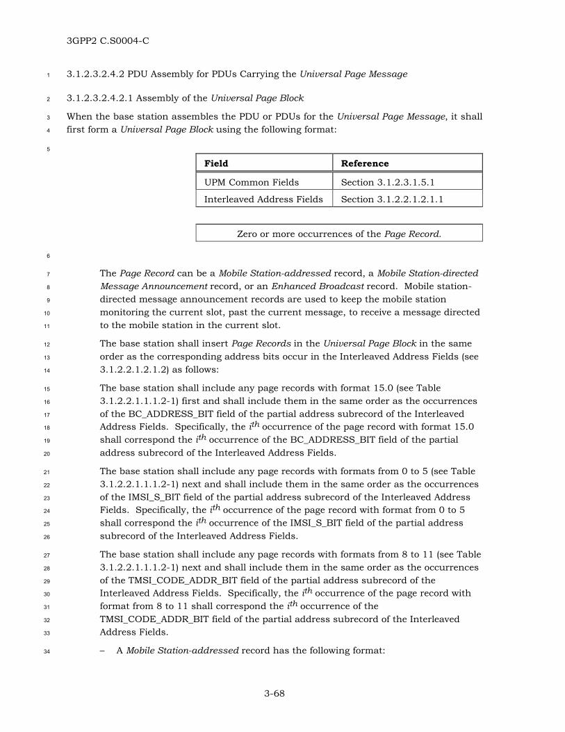
3GPP2 C.S0004-C
3-68
3.1.2.3.2.4.2 PDU Assembly for PDUs Carrying the Universal Page Message 1
3.1.2.3.2.4.2.1 Assembly of the Universal Page Block 2
When the base station assembles the PDU or PDUs for the Universal Page Message, it shall 3
first form a Universal Page Block using the following format: 4
5
Field Reference
UPM Common Fields Section 3.1.2.3.1.5.1
Interleaved Address Fields Section 3.1.2.2.1.2.1.1
Zero or more occurrences of the Page Record.
6
The Page Record can be a Mobile Station-addressed record, a Mobile Station-directed 7
Message Announcement record, or an Enhanced Broadcast record. Mobile station-8
directed message announcement records are used to keep the mobile station 9
monitoring the current slot, past the current message, to receive a message directed 10
to the mobile station in the current slot. 11
The base station shall insert Page Records in the Universal Page Block in the same 12
order as the corresponding address bits occur in the Interleaved Address Fields (see 13
3.1.2.2.1.2.1.2) as follows: 14
The base station shall include any page records with format 15.0 (see Table 15
3.1.2.2.1.1.1.2-1) first and shall include them in the same order as the occurrences 16
of the BC_ADDRESS_BIT field of the partial address subrecord of the Interleaved 17
Address Fields. Specifically, the ith occurrence of the page record with format 15.0 18
shall correspond the ith occurrence of the BC_ADDRESS_BIT field of the partial 19
address subrecord of the Interleaved Address Fields. 20
The base station shall include any page records with formats from 0 to 5 (see Table 21
3.1.2.2.1.1.1.2-1) next and shall include them in the same order as the occurrences 22
of the IMSI_S_BIT field of the partial address subrecord of the Interleaved Address 23
Fields. Specifically, the ith occurrence of the page record with format from 0 to 5 24
shall correspond the ith occurrence of the IMSI_S_BIT field of the partial address 25
subrecord of the Interleaved Address Fields. 26
The base station shall include any page records with formats from 8 to 11 (see Table 27
3.1.2.2.1.1.1.2-1) next and shall include them in the same order as the occurrences 28
of the TMSI_CODE_ADDR_BIT field of the partial address subrecord of the 29
Interleaved Address Fields. Specifically, the ith occurrence of the page record with 30
format from 8 to 11 shall correspond the ith occurrence of the 31
TMSI_CODE_ADDR_BIT field of the partial address subrecord of the Interleaved 32
Address Fields. 33
– A Mobile Station-addressed record has the following format: 34

3GPP2 C.S0004-C
3-69
1
Page Class Fields Section 3.1.2.2.1.2.2.1
ARQ Fields Section 3.1.2.1.1.1
Page Type-specific Fields Section 3.1.2.2.1.2.3.1
Record-specific Fields Section 3.1.2.3.1.7.1
SDU [5]
2
– A Mobile Station-directed Message Announcement record has the following 3
format: 4
5
Page Class Fields Section 3.1.2.2.1.2.2.1
Page Type-specific Fields Section 3.1.2.2.1.2.3.1
6
– An Enhanced Broadcast record has the following format: 7
8
Page Class Fields Section 3.1.2.2.1.2.2.1
Page Type-specific Fields Section 3.1.2.2.1.2.3.1
Record-specific Fields Section 3.1.2.3.1.7.1
SDU [5]
9
3.1.2.3.2.4.2.2 PDU Assembly for PDUs Carrying the Universal Page Message 10
The base station can send the Universal Page Message using one PDU. The base station 11
can also optionally segment the Universal Page Message into multiple PDUs in order to 12
allow mobile stations operating in the slotted mode and monitoring the Forward Common 13
Control Channel to quickly stop monitoring the Forward Common Control Channel for the 14
sake of power conservation. For example, if a Universal Page Message would span multiple 15
Forward Common Control Channel frames if included in a single PDU, the base station 16
could segment the Universal Page Message into two PDUs. By including the first PDU 17
within the first Forward Common Control Channel frame of a slot, the base station can give 18
mobile stations operating in the slotted mode the ability to conserve power after the first 19
frame. 20
3.1.2.3.2.4.2.2.1 PDU Assembly for an Unsegmented Universal Page Message 21
When transmitting a PDU on the Forward Common Control Channel carrying an 22
unsegmented Universal Page Message (the PDU is called the Unsegmented UPM PDU), the 23
base station shall use the following format: 24

3GPP2 C.S0004-C
3-70
1
Field Reference/Value
PD Section 3.1.2.3.1.1.2
MSG_ID ‘100011’
Universal Page Block Section 3.1.2.3.2.4.2.1
PDU_PADDING Section 3.1.2.3.1.4.1
2
3.1.2.3.2.4.2.2.2 PDU Assembly for a Segmented Universal Page Message 3
When the base station segments the Universal Page Block into multiple PDUs, the Utility 4
Sublayer shall submit the PDUs to the SAR Sublayer in order, with the PDU corresponding 5
to the most significant portion of the Universal Page Block first, followed by PDU(s) 6
corresponding to less significant portions of the Universal Page Block. 7
The base station shall not transmit PDUs derived from the same Universal Page Block in 8
different Forward Common Control Channel slots. The base station shall not transmit 9
more than two UPM First Segment PDUs in the same Forward Common Control Channel 10
slot. 11
When transmitting the first PDU on the Forward Common Control Channel of a segmented 12
Universal Page Message (the PDU is called the UPM First Segment PDU), the base station 13
shall use the following format: 14
15
Field Reference/Value
PD Section 3.1.2.3.1.1.2
MSG_ID ‘100100’
First Segment of the Universal Page Block
Section 3.1.2.3.2.4.2.1
16
In the above PDU format,55 for the First Segment of the Universal Page Block field, the base 17
station shall include N bits of the Universal Page Block, starting with the most significant 18
bit, where N is specified in Table 3.1.2.3.2.4.2.2.2-1. 19
55 This PDU format does not include PDU Padding.
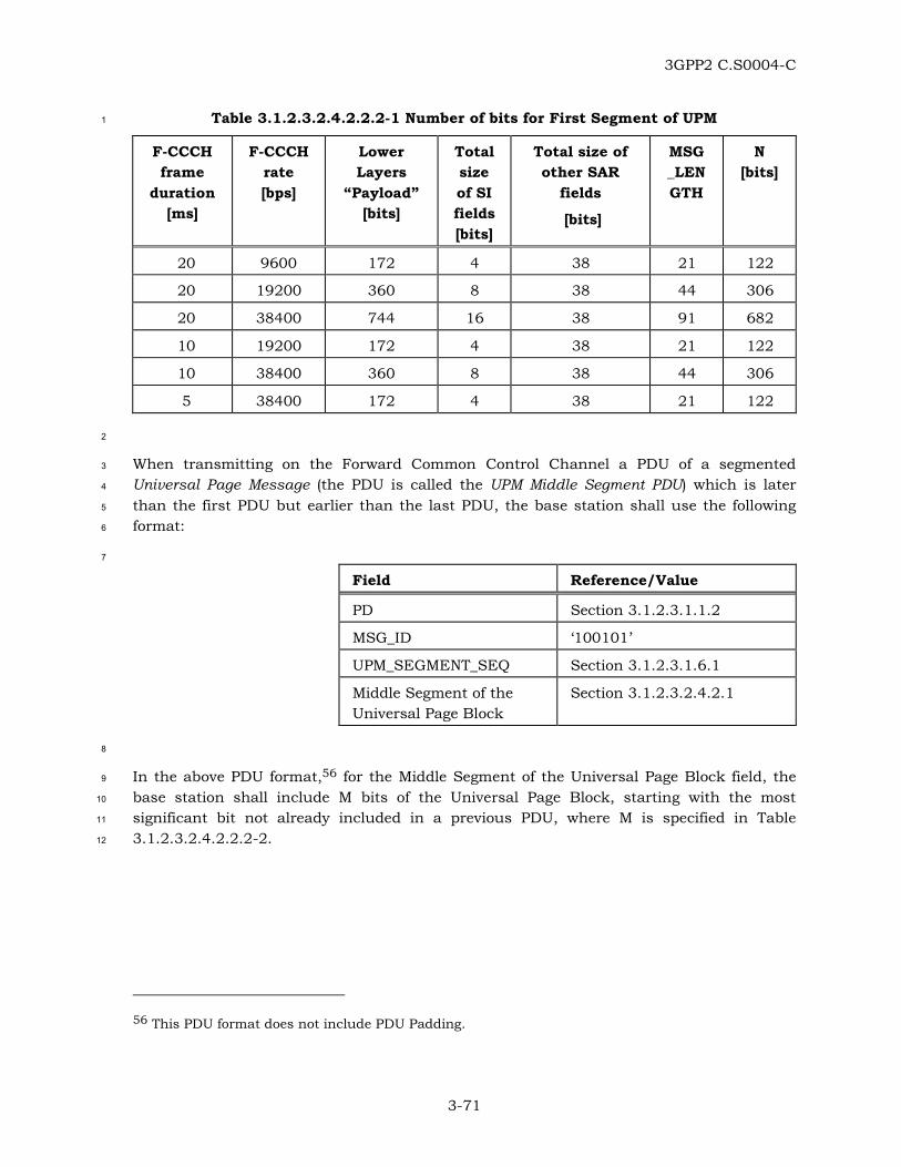
3GPP2 C.S0004-C
3-71
Table 3.1.2.3.2.4.2.2.2-1 Number of bits for First Segment of UPM 1
F-CCCH frame
duration [ms]
F-CCCH rate [bps]
Lower Layers
“Payload” [bits]
Total size of SI fields [bits]
Total size of other SAR
fields
[bits]
MSG_LENGTH
N [bits]
20 9600 172 4 38 21 122
20 19200 360 8 38 44 306
20 38400 744 16 38 91 682
10 19200 172 4 38 21 122
10 38400 360 8 38 44 306
5 38400 172 4 38 21 122
2
When transmitting on the Forward Common Control Channel a PDU of a segmented 3
Universal Page Message (the PDU is called the UPM Middle Segment PDU) which is later 4
than the first PDU but earlier than the last PDU, the base station shall use the following 5
format: 6
7
Field Reference/Value
PD Section 3.1.2.3.1.1.2
MSG_ID ‘100101’
UPM_SEGMENT_SEQ Section 3.1.2.3.1.6.1
Middle Segment of the Universal Page Block
Section 3.1.2.3.2.4.2.1
8
In the above PDU format,56 for the Middle Segment of the Universal Page Block field, the 9
base station shall include M bits of the Universal Page Block, starting with the most 10
significant bit not already included in a previous PDU, where M is specified in Table 11
3.1.2.3.2.4.2.2.2-2. 12
56 This PDU format does not include PDU Padding.

3GPP2 C.S0004-C
3-72
Table 3.1.2.3.2.4.2.2.2-2 Number of bits for Middle Segment of UPM 1
F-CCCH frame
duration [ms]
F-CCCH rate [bps]
Lower Layers
“Payload” [bits]
Total size of SI fields [bits]
Total size of other SAR
fields
[bits]
MSG_LENGTH
M [bits]
20 9600 172 4 38 21 120
20 19200 360 8 38 44 304
20 38400 744 16 38 91 680
10 19200 172 4 38 21 120
10 38400 360 8 38 44 304
5 38400 172 4 38 21 120
2
When transmitting on the Forward Common Control Channel the final PDU of a segmented 3
Universal Page Message (the PDU is called the UPM Final Segment PDU) the base station 4
shall use the following format: 5
6
Field Reference
PD Section 3.1.2.3.1.1.2
MSG_ID ‘100110’
UPM_SEGMENT_SEQ Section 3.1.2.3.1.6.1
Final Segment of the Universal Page Block
Section 3.1.2.3.2.4.2.1
PDU_PADDING Section 3.1.2.3.1.4.1
In the above PDU format, for the Final Segment of the Universal Page Block field, the base 7
station shall include bits of the Universal Page Block, starting with the most significant bit 8
not already included in a previous PDU. 9
3.1.2.4 Segmentation and Reassembly (SAR) Sublayer 10
3.1.2.4.1 Parameters 11
The base station shall use the SAR parameters defined in 3.1.2.4.1.1 for PDUs transmitted 12
on the f-csch, and shall set the SAR parameters according to the requirements specified in 13
3.1.2.4.1.2. 14
3.1.2.4.1.1 Definition of SAR parameters 15
The SAR parameters for PDUs transmitted on the f-csch have the following format: 16
17

3GPP2 C.S0004-C
3-73
Field Length (bits)
EXT_MSG_LENGTH 0 or 1
1
EXT_MSG_LENGTH – Extended message length. 2
3
Field Length (bits)
MSG_LENGTH 7, 8 or 15
4
MSG_LENGTH – Length of the PDU in octets. 5
6
Field Length (bits)
CRC 30
7
CRC – Cyclic Redundancy Check for the PDU. 8
9
Field Length (bits)
SOM 1
10
SOM – Start of Message indicator, for each encapsulated PDU 11
fragment sent on the sync channel. 12
13
Field Length (bits)
SCI 1
14
SCI – Synchronized Capsule Indicator, for each encapsulated PDU 15
fragment sent on the Paging Channel or Broadcast Channel. 16
17
Field Length (bits)
SI 2
18
SI – Segmentation Indicator, for each encapsulated PDU fragment 19
sent on the Forward Common Control Channel. 20

3GPP2 C.S0004-C
3-74
3.1.2.4.1.2 Requirements for Setting SAR Parameters 1
For PDUs that are sent on the Forward Common Control Channel or Broadcast Channel, 2
the EXT_MSG_LENGTH parameter shall be included. For PDUs that are sent on a Paging 3
Channel, the EXT_MSG_LENGTH parameter shall be omitted. 4
For PDUs that are sent on the Forward Common Control Channel or on the Broadcast 5
Channel: 6
• If the size of the LAC PDU is less than or equal to 978 bits: 7
– The EXT_MSG_LENGTH shall be set to ‘0’. 8
– The MSG_LENGTH field shall be seven bits long and shall be set to 9
(size of LAC PDU in bits + 38) / 8. 10
• If the size of the LAC PDU is greater than 978 bits: 11
– The EXT_MSG_LENGTH shall be set to ‘1’. 12
– The MSG_LENGTH field shall be fifteen bits long and shall be set to 13
(size of LAC PDU in bits + 46) / 8. 14
For PDUs that are sent on a Paging Channel, the MSG_LENGTH parameter shall be eight 15
bits long and shall be set to (size of LAC PDU in bits + 38) / 8. 16
The base station shall set the CRC parameter as specified in 2.1.1.5.1.2.57 17
For transmission on the Sync Channel, the base station shall include the SOM parameter 18
at the position in the information part of the frames indicated in Table 3.1.2.4.1.2-1. The 19
SOM parameter shall be set to ‘1’ for the first encapsulated PDU fragment of the 20
encapsulated PDU and shall be set to ‘0’ in all other cases. 21
For transmission on a Paging Channel or Broadcast Channel, the base station shall include 22
the SCI parameter at the position in the information part of the frames indicated in Table 23
3.1.2.4.1.2-1. The SCI parameter shall be set to ‘1’ for an encapsulated PDU fragment if 24
the most significant bit of an encapsulated PDU immediately follows the SCI bit; otherwise, 25
the SCI parameter shall be set to ‘0’. 26
For transmission on the Forward Common Control Channel, the base station shall include 27
the SI parameter at the positions in the information part of the frames indicated in Table 28
3.1.2.4.1.2-1. If the most significant bit of an encapsulated PDU immediately follows the SI 29
parameter, the SI parameter shall be set to ‘01’; otherwise, the SI parameter shall be set to 30
‘00’. 31
57 When transmitting on the f-csch, the base station sets the EXT_MSG_LENGTH parameter (if included), the MSG_LENGTH parameter and CRC parameter in the same manner that the mobile station does when it is transmitting on the r-csch.

3GPP2 C.S0004-C
3-75
Table 3.1.2.4.1.2-1 Position of “always included” SAR parameters58 1
Channel type
Frame duration
[ms]
Rate [bps]
Infor-mation bits in
a frame
Name of the SAR field
Size of
SAR field [bits]
Position in information
part of frame
Sync 26.66666
1200 32 SOM 1 1
Paging 20 4800 96 SCI 1 1, 49
Paging 20 9600 192 SCI 1 1, 97
Broadcast 20 38400 744 SCI 1 1, 94, 187, 280, 373, 466, 559, 652
Forward Common Control
20 9600 172 SI 2 1-2, 87-88
Forward Common Control
20 19200 360 SI 2 1-2, 91-92, 181-182, 271-272
Forward Common Control
20 38400 744 SI 2 1-2, 94-95, 187-188, 280-281, 373-374, 466-467, 559-560, 652-653
Forward Common Control
10 19200 172 SI 2 1-2, 87-88
Forward Common Control
10 38400 360 SI 2 1-2, 91-92, 181-182, 271-272
Forward Common Control
5 38400 172 SI 2 1-2, 87-88
2
3.1.2.4.2 Procedures 3
The base station shall set the SAR parameters as specified in 3.1.2.4.1.2. 4
58 Bit 1 refers to the bit of the information part of the frame that is transmitted first.
3GPP2 C.S0004-C
3-76
The base station shall assemble an encapsulated PDU from the SAR parameters and the 1
PDU by concatenating them in the following order: 2
• For PDUs that are sent on the Forward Common Control Channel or Broadcast 3
Channel, the EXT_MSG_LENGTH parameter. 4
• The MSG_LENGTH parameter, starting with the most significant bit. 5
• The PDU, starting with the most significant bit of the MSG_TYPE field. 6
• The CRC parameter, starting with the bit that appeared first at the output of the 7
CRC encoder. 8
The base station shall segment the encapsulated PDU into fragments of maximum available 9
size (except for the last fragment which may be shorter) necessary to fit in a frame (for the 10
sync channel), a half-frame (for the Paging Channel) or a partial-frame (for the Forward 11
Common Control Channel or for the Broadcast Channel). The base station shall send 12
encapsulated PDU fragments of an encapsulated PDU in consecutive frames (for the sync 13
channel), consecutive half-frames (for the Paging Channel) or consecutive partial-frames 14
(for the Forward Common Control Channel or for the Broadcast Channel). 15
For the sync logical channel, if the SOM parameter is equal to ‘1’, the base station shall 16
transmit the most significant bit of the encapsulated PDU immediately after the SOM bit. 17
For f-csch channels other than the sync channel, the base station shall proceed as follows: 18
• For PDUs that are sent on a Paging Channel: 19
– The base station shall transmit the SCI parameter (set as described in 20
3.1.2.4.1.2). 21
– If there are fewer than eight bits remaining in the half-frame after the end of the 22
last bit of the encapsulated PDU, the base station shall set those remaining bits 23
to ‘0’. 24
• For PDUs that are sent on the Broadcast Channel: 25
– The base station shall transmit the SCI parameter (set as described in 26
3.1.2.4.1.2). 27
– If there are fewer than eight bits remaining in the partial-frame after the end of 28
the last bit of the encapsulated PDU, the base station shall set those remaining 29
bits to ‘0’. 30
• For PDUs that are sent on the Forward Common Control Channel: 31
– The base station shall transmit the SI parameter (set as described in 32
3.1.2.4.1.2). 33
– If there are fewer than eight bits remaining in the partial-frame after the end of 34
the last bit of the encapsulated PDU, the base station shall set those remaining 35
bits to ‘0’. 36

3GPP2 C.S0004-C
3-77
• For PDUs that are sent on a Paging Channel, if there are eight or more bits 1
remaining in the half-frame after the end of the last bit of the encapsulated PDU, or 2
for PDUs that are sent on the Forward Common Control Channel or the Broadcast 3
Channel, if there are sufficient bits remaining to fit the MSG_LENGTH and 4
EXT_MSG_LENGTH parameters in the partial-frame after the end of the last bit of 5
the encapsulated PDU, the base station shall perform one of the following: 6
– The base station shall append sufficient number of padding bits (set to ‘0’) to fill 7
the remainder of the half-frame or partial-frame, or 8
– The base station shall start transmission of the next encapsulated PDU by 9
appending a sufficient number of bits from the beginning of that PDU to fill the 10
remainder of the half-frame or partial-frame. If there are not enough bits 11
available in the PDU to fill the half-frame or partial-frame, the transmission of 12
the subsequent PDU can commence, and so on. The base station shall not 13
select this option if it results in sending the first PDU in the f-csch time slot as 14
an unsynchronized capsule. 15
• On the Paging Channel, if there are fewer than four bits remaining in the half-frame 16
after the end of the last bit of the encapsulated PDU, and if the half-frame is the last 17
one in the Paging Channel slot, and if the last 4 bits in the half-frame are not all ‘0’, 18
the base station shall set the SCI parameter and all of the bits in the following half-19
frame to ‘0’. 20
Unless transmission of a PDU is to be canceled, the base station shall not transmit 21
encapsulated PDU fragments from a new encapsulated PDU until all fragments of the 22
previous encapsulated PDU have been transmitted (i.e., interleaving fragments from 23
different PDUs is not permitted). 24
3.1.2.5 Message Integrity Sublayer 25
3.1.2.5.1 Parameters 26
The base station shall use and set the Message Integrity Fields specified in 2.1.1.1.1.159 27
according to the procedures in 3.1.2.5.2 and 2.1.1.1.1.3. 28
3.1.2.5.2 Procedures 29
If message integrity is supported and enabled for a PDU transmitted on f-csch and 30
addressed to a single mobile station, the base station shall set channel_specific_buffer to 31
the 2 bits corresponding to “ACK_REQ |’0’”, where ACK_REQ is set to ‘0’, if the message is 32
to be sent in unassured mode or to ‘1’, if the message is to be sent in assured mode, where 33
59 Except where explicitly specified otherwise (see 3.1.2.5.2), for regular PDUs transmitted on f-csch, the base station uses the same Message Integrity Fields and the same procedures for inclusion and setting of values for these fields as the mobile station does when transmitting PDUs on r-csch.

3GPP2 C.S0004-C
3-78
the most significant bit of the channel_specific_buffer corresponds to the ACK_REQ bit. If 1
message integrity is supported and enabled for a PDU transmitted on f-csch, containing 2
several records addressed to different mobile stations60, but encapsulated in the same 3
PDU, the base station shall generate as many channel_specific_buffers as there are records 4
in the PDU requiring message integrity protection, and set them to the 2 bits corresponding 5
to “ACK_REQ |’0’”, where the ACK_REQ field from each of the individual records is used in 6
the corresponding channel_specific_buffer. 7
When the base station executes the procedure for setting up the MACI field (see 3.1.2.3.2), 8
(or fields), the channel_specific_buffer (or the set of channel specific_buffers) shall be passed 9
as input parameter(s) to that procedure. 10
3.2 Dedicated Channel Operation 11
The base station shall meet the requirements specified in 3.2.1 for operation on the r-dsch 12
and in 3.2.2 for operation on the f-dsch. 13
3.2.1 Reception on r-dsch 14
The base station shall meet the requirements stated in 3.2.1.4.2, 3.2.1.1.2.2, 3.2.1.2.2 and 15
3.2.1.3.2. 16
If a received PDU is not expected to be message integrity protected (see [5]), but contains a 17
MACI_INCL field equal to ‘1’, the base station shall ignore the Message Integrity Fields and 18
the MACI field in the received PDU. 19
3.2.1.1 ARQ Sublayer 20
3.2.1.1.1 Parameters 21
To support the ARQ mechanism on the dedicated channels, the base station shall interpret 22
the ARQ fields defined in 2.2.1.1.1.1 for PDUs received on the r-dsch. 23
3.2.1.1.2 Procedures 24
3.2.1.1.2.1 Overview of Reception Procedures 25
The ARQ Sublayer removes the ARQ fields from PDUs received on the r-dsch and passes 26
the remainder of the PDU (which generally includes the SDU) to the Upper Layers. 27
When a PDU is received, the ARQ Sublayer on the receiver side provides an indication to 28
the ARQ Sublayer on the transmitter side (see 3.2.2.1.2.1) of the acknowledgment of a 29
previously transmitted PDU with the MSG_SEQ field equal to the ACK_SEQ field of the 30
received PDU. 31
60 For example, PDUs carrying the Extended Channel Assignment Message.

3GPP2 C.S0004-C
3-79
The ARQ Sublayer performs duplicate detection for received PDUs that require 1
acknowledgment by using the MSG_SEQ field of the received PDUs. Duplicates of PDUs 2
requiring acknowledgment are acknowledged (see below) and then discarded. 3
When a PDU is received with the ACK_REQ field set to ‘1’, the ARQ Sublayer on the receiver 4
side provides an indication to the ARQ Sublayer on the transmitter side requesting the 5
transmission of an acknowledgment. The MSG_SEQ field of the received PDU and the time 6
of reception are also provided to the ARQ Sublayer on the transmitter side (see 3.2.2.1.2.1). 7
The ARQ Sublayer for dedicated channels can be reset locally via indications from Layer 3 8
or the managing entity in the control plane, or upon the reception of a Reset PDU (for mini 9
PDUs only, see Table 2.2.1.2.1.2-3). 10
The ARQ Sublayer is reset simultaneously on the receiver and the transmitter sides. In 11
such cases the information needed to perform duplicate detection and the pending requests 12
for acknowledgment are discarded. 13
3.2.1.1.2.2 Requirements for Reception Procedures 14
The base station shall process PDUs received on the r-dsch. 15
Except for PDUs associated with emergency calls, the base station should not process the 16
ARQ fields and ARQ variables if the received PDU is expected to be message integrity 17
protected (see [5]), but the Message Integrity Fields and the MACI field are either missing or 18
fail the message integrity check61 (see 3.1.1.1.3). Otherwise: 19
When a PDU is received with the ACK_REQ field set to ‘1’, the base station shall recognize it 20
as a request for acknowledgment (see 3.2.2.1.2.2). The base station shall recognize the 21
received PDU as including an acknowledgment if the received ACK_SEQ fields match the 22
MSG_SEQ field of a previously transmitted PDU (see 3.2.2.1.2.2). The base station should 23
ignore received acknowledgments for PDUs that were not sent or are not awaiting 24
acknowledgment. 25
For duplicate detection, the base station shall store a received status indicator for each 26
possible value of the MSG_SEQ field (MSG_SEQ_RCVD[n] for all values of n from 0 to 7, for 27
regular PDUs, and M_MSG_SEQ_RCVD[n] for all values of n from 0 to 3, for mini PDUs). 28
Duplicate detection is performed independently for regular PDUs and for mini PDUs.62 The 29
base station shall perform the following procedures: 30
61 In such cases, the base station will notify the mobile station via a Base Station Reject Order which identifies the exact condition and the offending received PDU (see [5]).
62 A regular PDU and a mini PDU cannot be duplicates of one another.

3GPP2 C.S0004-C
3-80
• When a PDU requiring acknowledgment is received containing the message 1
sequence number field MSG_SEQ, and MSG_SEQ_RCVD[MSG_SEQ] (for regular 2
PDUs) or M_MSG_SEQ_RCVD[MSG_SEQ] (for mini PDUs) is equal to NO, the base 3
station shall process the PDU as a new PDU. The base station shall then set 4
MSG_SEQ_RCVD[MSG_SEQ] (for regular PDUs) or M_MSG_SEQ_RCVD[MSG_SEQ] 5
(for mini PDUs) to YES, and shall set MSG_SEQ_RCVD[(MSG_SEQ + 4) modulo 8] 6
(for regular PDUs) or M_MSG_SEQ_RCVD[(MSG_SEQ + 2) modulo 4] (for mini PDUs) 7
to NO. 8
• When a PDU requiring acknowledgment is received containing the message 9
sequence number field MSG_SEQ, and MSG_SEQ_RCVD[MSG_SEQ] (for regular 10
PDUs) or M_MSG_SEQ_RCVD[MSG_SEQ] (for mini PDUs) is equal to YES, the base 11
station shall acknowledge the PDU and then discard it. 12
When processing a reset request for both regular PDUs and mini PDUs, the base station 13
shall set MSG_SEQ_RCVD[n] to NO for all values of n from 0 to 7 and 14
M_MSG_SEQ_RCVD[n] to NO for all values of n from 0 to 3. When processing a reset 15
request for mini PDUs only, the base station shall set M_MSG_SEQ_RCVD[n] to NO for all 16
values of n from 0 to 3. Further requirements for the processing of a reset request by the 17
base station are given in 3.2.2.1.2.2. 18
3.2.1.2 Utility Sublayer 19
3.2.1.2.1 Parameters 20
The base station shall interpret the MSG_TYPE field of a PDU received on the r-dsch as 21
defined in 2.2.1.2.1.1. 22
3.2.1.2.2 Procedures 23
The base station should identify the SDU carried by the received PDU based upon the 24
MSG_TYPE field as shown in Table 2.2.1.2.1.2-1 for regular PDUs and Table 2.2.1.2.1.2-2 25
and 2.2.1.2.1.2-3 for mini PDUs. 26
If the base station receives a valid PDU, the LAC Sublayer shall make the SDU included in 27
the PDU available to Layer 3, together with the Encryption field and the Extended-28
Encryption fields, if any (see 3.1.2.3.1.3.1). 29
3.2.1.3 Segmentation and Reassembly Sublayer 30
3.2.1.3.1 Parameters 31
The base station shall use the parameters defined in 2.2.1.3.1.1 for PDUs received on the 32
r-dsch. 33

3GPP2 C.S0004-C
3-81
3.2.1.3.2 Procedures 1
The base station shall reassemble PDUs from encapsulated PDU fragments received on the 2
r-dsch63 (see 2.2.2.3.2). 3
3.2.1.4 Message Integrity Sublayer 4
If the base station supports message integrity, the base station shall process the Message 5
Integrity Fields and the MACI field of regular PDUs received on r-dsch as specified in 6
3.2.1.4.1 and 3.2.1.4.2. 7
3.2.1.4.1 Parameters 8
The base station uses and interprets the Integrity Fields defined in 2.1.1.1.1.1 and the 9
MACI field for PDUs received on the r-dsch64. 10
3.2.1.4.2 Procedures 11
If the base station supports message integrity, the base station shall perform the 12
procedures65 specified in 3.1.1.1.3. 13
3.2.2 Transmission on f-dsch 14
The base station shall meet the requirements stated in 3.2.2.1.1.2, 3.2.2.2.2, 3.2.2.4.2 and 15
3.2.2.3.2. 16
3.2.2.1 ARQ Sublayer 17
3.2.2.1.1 Parameters 18
To support the ARQ mechanism on the f-dsch and r-dsch, the base station shall use the 19
ARQ fields defined in 3.2.2.1.1.1 for PDUs transmitted on the f-dsch. The base station 20
shall set the ARQ fields according to the requirements in 3.2.2.1.1.2. 21
3.2.2.1.1.1 Definition of ARQ Fields 22
The ARQ fields for PDUs transmitted on the f-dsch have the following format: 23
24
63 When receiving on the r-dsch, the base station reassembles PDUs in the same manner that the mobile station does when it is receiving on the f-dsch.
64 When receiving on the r-dsch, the base station uses the same Message Integrity Fields as the mobile station does when transmitting on r-csch.
65 When receiving on the r-dsch, the base station uses the same message integrity procedures as when receiving on r-csch.

3GPP2 C.S0004-C
3-82
Field Length (bits)
ACK_SEQ 2 or 3
MSG_SEQ 2 or 3
ACK_REQ 1
1
ACK_SEQ – Acknowledgment sequence number. 2
This field contains the value of the MSG_SEQ field of a regular 3
PDU (3 bits) or a mini PDU (2 bits) received on the r-dsch and 4
being acknowledged on the f-dsch. 5
MSG_SEQ – Message sequence number. 6
This field contains the message sequence number for the 7
regular PDU (3 bits) or the mini PDU (2 bits) to be sent on the 8
f-dsch. 9
ACK_REQ – Acknowledgment required indicator. 10
This field indicates whether the PDU being sent on the f-dsch 11
requires an acknowledgment from the mobile station. 12
3.2.2.1.1.2 Requirements for Setting ARQ Fields 13
The base station shall set the ACK_REQ field of a PDU transmitted on the f-dsch to: 14
• ‘1’ to request an acknowledgment from the mobile station, or 15
• ‘0’ to indicate to the mobile station that an acknowledgment is not requested. 16
The base station shall set the MSG_SEQ field of a PDU transmitted on the f-dsch according 17
to the following procedures: 18
• For PDUs requiring acknowledgment, the base station shall use the message 19
sequence number variables MSG_SEQ_ACK for regular PDUs and shall use 20
M_MSG_SEQ_ACK for mini PDUs. When the base station prepares a new PDU 21
requiring acknowledgment, the base station shall set the MSG_SEQ field of the PDU 22
to MSG_SEQ_ACK for regular PDUs or to M_MSG_SEQ_ACK for mini PDUs. In 23
subsequent retransmissions of the PDU, the base station shall set the MSG_SEQ 24
field to the same value used for the initial transmission of that PDU. 25
• For PDUs not requiring acknowledgment, the base station shall use the message 26
sequence number variables MSG_SEQ_NOACK for regular PDUs and shall use 27
M_MSG_SEQ_NOACK for mini PDUs. When the base station prepares a new PDU 28
not requiring acknowledgment for transmission on the f-dsch, the base station shall 29
set the MSG_SEQ field of the PDU to MSG_SEQ_NOACK for regular PDUs or to 30
M_MSG_SEQ_NOACK for mini PDUs. 31
The base station shall set the ACK_SEQ field of regular PDUs and mini PDUs transmitted 32
on the f-dsch to the MSG_SEQ field of a regular PDU or mini PDU, respectively, previously 33
received on the r-dsch and being acknowledged. If no PDU requiring acknowledgment has 34

3GPP2 C.S0004-C
3-83
been received since f-dsch was acquired, the base station shall set all bits of the ACK_SEQ 1
field to ‘1’. 2
3.2.2.1.2 Procedures 3
3.2.2.1.2.1 Overview of Transmission and Retransmission Procedures 4
Both PDUs requiring acknowledgment and PDUs not requiring acknowledgment are sent on 5
the f-dsch. The order of delivery of either type of PDU is not guaranteed. The procedure for 6
PDUs requiring acknowledgment is a selective repeat scheme in which a PDU is 7
retransmitted only if an acknowledgment for it is not received. PDUs not requiring 8
acknowledgment may be transmitted several times. 9
After transmitting a PDU requiring acknowledgment, the ARQ Sublayer on the transmitter 10
side stores the PDU. The ARQ Sublayer may retransmit the PDU if no acknowledgment for 11
it was received. If the ARQ Sublayer on the transmitter side receives an indication from the 12
ARQ Sublayer on the receiver side that an acknowledgment for the transmitted PDU was 13
received on the r-dsch, the ARQ Sublayer on the transmitter side discards the copy of the 14
transmitted PDU; otherwise, the ARQ Sublayer retransmits the stored PDU. The procedure 15
is repeated until each PDU requiring acknowledgment is either acknowledged or is 16
transmitted a fixed number of times (implementation-specific). 17
If the ARQ Sublayer on the transmitter side receives an indication from the ARQ Sublayer 18
on the receiver side that a PDU requiring acknowledgment must be acknowledged, the ARQ 19
Sublayer on the transmitter side sends an acknowledgment within T1m seconds for regular 20
PDUs or within T75m seconds for mini PDUs. 21
When the ARQ Sublayer operating on the f-dsch receives a reverse dedicated channel 22
acquired indication from Layer 3 (see 3.6.4.2 of [5]) indicating that the dedicated signaling 23
channels were properly established and further signaling can proceed, the ARQ Sublayer 24
generates an acknowledgment PDU66 and sends it to the mobile station on the f-dsch. 25
The ARQ Sublayer may receive a reset indication from the controlling management 26
function, from Layer 3, or from the ARQ Sublayer on the receiver side upon the reception of 27
a Reset PDU by the LAC Sublayer (for mini PDUs only, see Table 2.2.1.2.1.2-3). The ARQ 28
Sublayer is reset simultaneously on the transmitter and the receiver sides. In such cases 29
the message sequence number variables for PDUs both requiring and not requiring 30
acknowledgments are set to ‘0’, the acknowledgment timers are reset and the repetition 31
counters for all PDUs are set to ‘0’. Since the reset disposition results in pending 32
acknowledgments being discarded, all bits of the ACK_SEQ field are set to ‘1’ for PDUs sent 33
immediately after a reset operation. 34
66 In [11], this “acknowledgment-specific” PDU is referred to as the Base Station Acknowledgement Order.

3GPP2 C.S0004-C
3-84
3.2.2.1.2.2 Requirements for Transmission and Retransmission Procedures 1
When assembling PDUs for transmission, the base station shall set the ARQ fields as 2
specified in 3.2.2.1.1.2. 3
The base station shall store the message sequence number variables MSG_SEQ_ACK for 4
regular PDUs and M_MSG_SEQ_ACK for mini PDUs. After sending a PDU requiring 5
acknowledgment, the base station shall increment MSG_SEQ_ACK modulo 8 for regular 6
PDUs or shall increment M_MSG_SEQ_ACK modulo 4 for mini PDUs. For PDUs not 7
requiring acknowledgment, the base station shall store different message sequence number 8
variables MSG_SEQ_NOACK for regular PDUs and M_MSG_SEQ_NOACK for mini PDUs. 9
After sending a PDU not requiring acknowledgment, the base station shall increment 10
MSG_SEQ_NOACK modulo 8 for regular PDUs or shall increment M_MSG_SEQ_NOACK 11
modulo 4 for mini PDUs. 12
The base station may transmit up to four regular PDUs before receiving an indication that 13
one of the transmitted regular PDUs was acknowledged. The base station may transmit up 14
to two mini PDUs before receiving an indication that one of the transmitted mini PDUs was 15
acknowledged. If a transmitted (regular or mini) PDU of a given type requiring 16
acknowledgment and having the MSG_SEQ field equal to (MSG_SEQ_ACK + 4) modulo 8 for 17
regular PDUs or equal to (M_MSG_SEQ_ACK + 2) modulo 4 for mini PDUs is awaiting 18
acknowledgment, the base station shall not send a new PDU of the same type requiring 19
acknowledgment until it receives an indication that the transmitted PDU was 20
acknowledged. 21
If the base station transmits the same PDU not requiring acknowledgment more than once, 22
it shall use the same MSG_SEQ number for all transmissions. The base station shall 23
complete all retransmissions of the same PDU within T3m seconds for regular PDUs or 24
within T77m seconds for mini PDUs after the first transmission (see Figure 3.2.2.1.2.2-1; 25
only T3m is shown). The base station shall wait at least T3m seconds for regular PDUs or 26
T77m seconds for mini PDUs after the last transmission of a PDU not requiring 27
acknowledgment before transmitting another PDU of the same type not requiring 28
acknowledgment that has the same MSG_SEQ number67 (see Figure 3.2.2.1.2.2-1; only 29
T3m is shown). 30
31
67This is necessary because it is possible that the mobile station receives only the last transmission.

3GPP2 C.S0004-C
3-85
f-dsch
T3m
T3m expires
The base station does nottransmit a PDU with
MSG_SEQ number k thatends in this interval
Last transmission ofa PDU with
MSG_SEQ number k
T3m is initialized
First transmission ofa PDU with
MSG_SEQ number k
May not exceed T3m
1
2
Figure 3.2.2.1.2.2-1. Time Requirement for the Base Station Not to Reuse a 3
MSG_SEQ Number 4
5
The base station shall not retransmit PDUs requiring acknowledgments for which it has 6
received an acknowledgment indication (see 3.1.1.2.2.2). If the base station has not 7
received a valid acknowledgment68 indication after transmitting a PDU requiring 8
acknowledgment, the base station shall retransmit the PDU. If the base station retransmits 9
a PDU, the base station shall use the same MSG_SEQ number for the retransmission. The 10
base station shall retransmit a PDU only an implementer-defined maximum number of 11
times; if the maximum number of retransmissions is to be exceeded, the base station shall 12
declare an acknowledgment failure. 13
If the base station receives an indication that the transmission of an acknowledgment for a 14
received PDU is requested (see 3.1.2.2.2), the base station shall transmit a PDU including 15
an acknowledgment within T1m seconds for regular PDUs or within T75m seconds for mini 16
PDUs, as follows: 17
• The base station shall acknowledge a regular PDU requiring acknowledgment by 18
transmitting a regular PDU. The base station shall acknowledge a mini PDU 19
requiring acknowledgment by transmitting a mini PDU. 20
• If the base station needs to acknowledge a regular PDU, and either has or receives 21
an indication that no regular SDUs are to be transmitted within T1m seconds, the 22
base station shall generate and transmit a regular PDU carrying an SDU which has 23
the following format (to be sent as an Order Message):69 24
25
68 An acknowledgment is valid if it is not required to be message integrity protected (see [5]) or if it passes the message integrity checks (see 3.1.1.1.3).
69 In [11], this “acknowledgment-specific” PDU is referred to as the Base Station Acknowledgement Order.

3GPP2 C.S0004-C
3-86
Field Length (bits)
USE_TIME = ‘0’ 1
ACTION_TIME = ‘000000’ 6
ORDER = ‘010000’ 6
ADD_RECORD_LEN = ‘000’ 3
1
The base station shall set the ACK_REQ field in the generated PDU to ‘0’, and shall 2
set the ACK_SEQ field in the generated PDU as specified in 3.2.2.1.1.2. 3
• If the base station needs to acknowledge a mini PDU, and either has or receives an 4
indication that no mini SDUs are to be transmitted within T75m seconds, the base 5
station shall generate and transmit a mini PDU carrying an SDU which has the 6
following format (to be sent as an Acknowledgment PDU): 7
8
Field Length (bits)
RESERVED = ‘0000000000000’ 13
9
The base station shall set the ACK_SEQ field in the generated PDU as specified in 10
3.2.2.1.1.2. 11
• Otherwise, the base station shall either generate and transmit a PDU with fields 12
defined as described above, or it shall use a PDU carrying an Upper Layer SDU as 13
the PDU to be transmitted and shall set the ACK_SEQ field as specified in 14
3.2.2.1.1.2. 15
If the base station receives a reverse dedicated channel acquired indication from Layer 3, 16
the base station shall immediately generate a PDU carrying an SDU which has the following 17
format (to be sent as an Order Message):70 18
19
Field Length (bits)
USE_TIME = ‘0’ 1
ACTION_TIME = ‘000000’ 6
ORDER = ‘010000’ 6
ADD_RECORD_LEN = ‘000’ 3
20
70 In [11], this “acknowledgment-specific” PDU is referred to as the Base Station Acknowledgement Order.

3GPP2 C.S0004-C
3-87
The base station should set the ACK_REQ field to ‘1’, should set the ACK_SEQ field in the 1
generated PDU as specified in 3.2.2.1.1.2, and shall immediately transmit the PDU. 2
When sending mini PDUs, the base station may send an order to reset the ARQ parameters 3
on the mobile station side via a PDU carrying an SDU which has the following format (to be 4
sent as a Reset PDU): 5
6
Field Length (bits)
RESERVED = ‘0000000000000’ 13
7
If the base station receives a reset indication for both regular and mini PDUs, the base 8
station shall: 9
• Reset its retransmission count for each PDU awaiting acknowledgment. 10
• Set MSG_SEQ_ACK, M_MSG_SEQ_ACK, MSG_SEQ_NOACK and 11
M_MSG_SEQ_NOACK to ’0’. 12
• Discard each pending request for acknowledgment for PDUs received on the r-dsch. 13
If the base station performs a reset for mini PDUs only, the base station shall: 14
• Reset its retransmission count for each mini PDU awaiting acknowledgment. 15
• Set M_MSG_SEQ_ACK and M_MSG_SEQ_NOACK to ’0’. 16
• Discard each pending request for acknowledgment for mini PDUs received on the 17
r-dsch. 18
After completing the reset for the specified type of PDUs, the base station should resume 19
normal operation, starting with the transmission of the PDUs of the specified type that were 20
awaiting acknowledgment at the time the reset disposition was received. Additional 21
requirements for the processing of a reset request by the base station are given in 22
3.1.1.2.2.2. 23
3.2.2.2 Utility Sublayer 24
3.2.2.2.1 Parameters 25
The base station shall use the fields defined in 3.2.2.2.1.1 for PDUs transmitted on the 26
f-dsch, and shall set these fields according to the requirements in 3.2.2.2.1.2. 27
3.2.2.2.1.1 Definition of Utility Sublayer Fields 28
The message type field for PDUs transmitted on the f-dsch has the following format: 29
30
Field Length (bits)
MSG_TYPE 3, 6 or 8
31

3GPP2 C.S0004-C
3-88
MSG_TYPE – Message type indicator. 1
This field contains the message type indicator for regular 2
PDUs (8 bits) or mini PDUs (3 or 6 bits) to be sent on the 3
f-dsch. 4
5
A regular PDU transmitted on the f-dsch includes the Encryption field and may also 6
include the Extended-Encryption fields, based upon P_REV_IN_USE and the current 7
encryption mode. 8
The Encryption field for regular PDUs transmitted on the f-dsch has the following format: 9
10
Field Length (bits)
ENCRYPTION 2
11
ENCRYPTION – Message encryption indicator. 12
The Extended-Encryption fields for regular PDUs transmitted on the f-dsch have the 13
following format: 14
15
Field Length (bits)
SDU_ENCRYPT_MODE 0 or 3
ENC_SEQ 0 or 8
16
SDU_ENCRYPT_MODE – Signaling encryption mode in use for the SDU carried by this 17
PDU. 18
ENC_SEQ – The eight least significant bits of the encryption sequence number used 19
to construct a cryptographic synchronization crypto-sync (see [5]) for the encryption 20
algorithm. 21
The PDU padding field for PDUs transmitted on the f-dsch has the following format: 22
23
Field Length (bits)
PDU_PADDING 0 - 7
24
PDU_PADDING – Padding bits. 25
The MACI field for PDUs transmitted on the f-dsch has the following format: 26
27
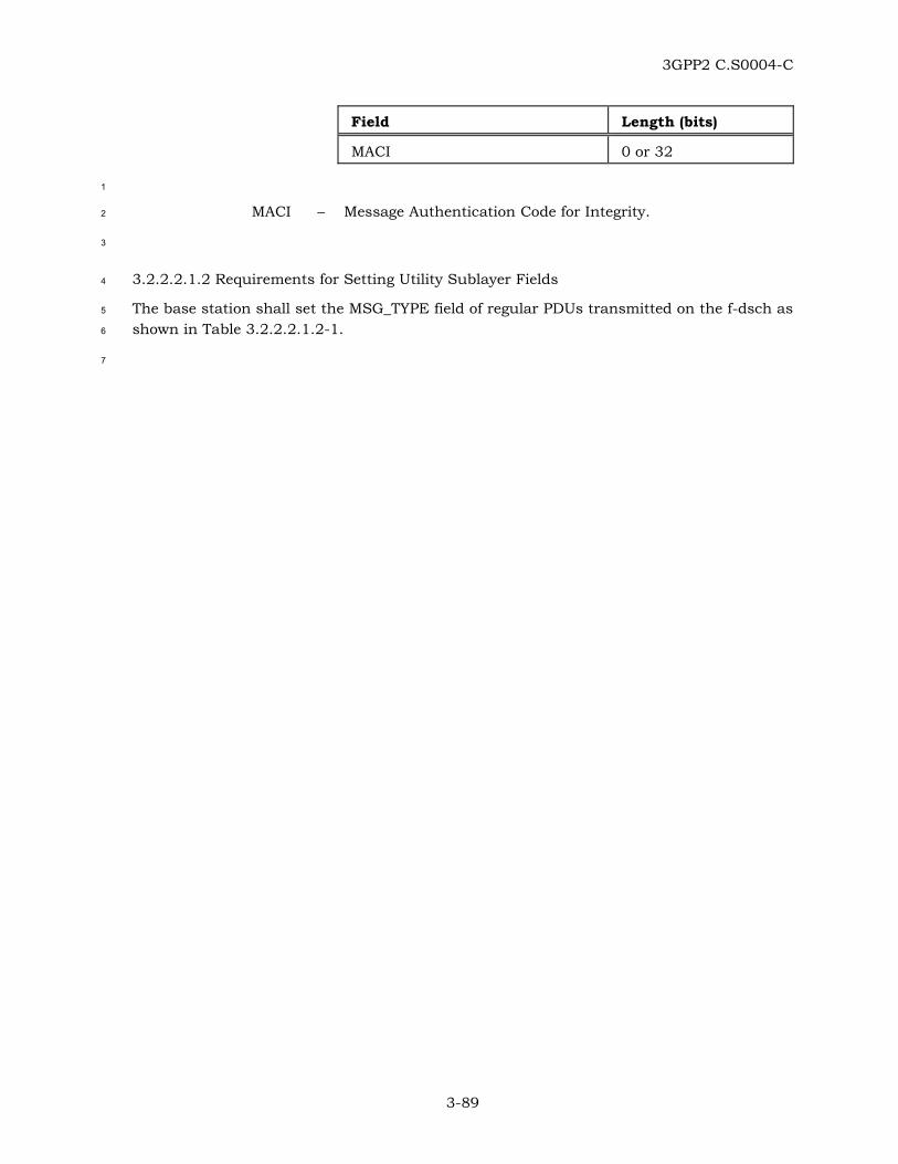
3GPP2 C.S0004-C
3-89
Field Length (bits)
MACI 0 or 32
1
MACI – Message Authentication Code for Integrity. 2
3
3.2.2.2.1.2 Requirements for Setting Utility Sublayer Fields 4
The base station shall set the MSG_TYPE field of regular PDUs transmitted on the f-dsch as 5
shown in Table 3.2.2.2.1.2-1. 6
7

3GPP2 C.S0004-C
3-90
Table 3.2.2.2.1.2-1. MSG_TYPE Values for Regular PDUs on f-dsch (Part 1 of 3) 1
Message Name MSG_TAG MSG_TYPE (binary)
Order Message ORDRM 00000001
Authentication Challenge Message AUCM 00000010
Alert With Information Message AWIM 00000011
Data Burst Message DBM 00000100
Analog Handoff Direction Message AHDM 00000110
In-Traffic System Parameters Message ITSPM 00000111
Neighbor List Update Message NLUM 00001000
Send Burst DTMF Message BDTMFM 00001001
Power Control Parameters Message PCNPM 00001010
Retrieve Parameters Message RTPM 00001011
Set Parameters Message STPM 00001100
SSD Update Message SSDUM 00001101
Flash With Information Message FWIM 00001110
Mobile Station Registered Message MSRM 00001111
Status Request Message STRQM 00010000
Extended Handoff Direction Message EHDM 00010001
Service Request Message SRQM 00010010
Service Response Message SRPM 00010011
Service Connect Message SCM 00010100
Service Option Control Message SOCM 00010101
TMSI Assignment Message TASM 00010110
Service Redirection Message SRDM 00010111
Supplemental Channel Assignment Message
SCAM 00011000
Power Control Message PCNM 00011001
Extended Neighbor List Update Message
ENLUM 00011010
Candidate Frequency Search Request Message
CFSRQM 00011011
Candidate Frequency Search Control Message
CFSCNM 00011100

3GPP2 C.S0004-C
3-91
Table 3.2.2.2.1.2-1. MSG_TYPE Values for Regular PDUs on f-dsch (Part 2 of 3) 1
Message Name MSG_TAG MSG_TYPE (binary)
Power Up Function Message PUFM 00011101
Power Up Function Completion Message
PUFCM 00011110
General Handoff Direction Message GHDM 00011111
Resource Allocation Message RAM 00100000
Extended Release Message ERM 00100001
Universal Handoff Direction Message UHDM 00100010
Extended Supplemental Channel Assignment Message
ESCAM 00100011
Mobile Assisted Burst Operation Parameters Message
MABOPM 00100100
User Zone Reject Message UZRM 00100101
User Zone Update Message UZUM 00100110
Call Assignment Message CLAM 00100111
Extended Alert With Information Message
EAWIM 00101000
DS-41 Inter-system Transfer Message (DS-41 only, see [13])
D41ISTM 00101001
Extended Flash With Information Message
EFWIM 00101010
Security Mode Command Message SMCM 00101011
MC-MAP L3 Message (MC-MAP only, see [14])
MAPL3M 00101100
MC-MAP Inter-System Handover Command Message (MC-MAP only, see [14])
MAPISHCM 00101101
MC-MAP Dedicated Mode Paging Message (MC-MAP only, see [14])
MAPDMPM 00101110
R-TMSI Assignment Message (MC-MAP only, see [14])
RTASM 00101111
MC-MAP Flow Release Message (MC-MAP only, see [14])
MAPFRM 00110000
Base Station Status Response Message
BSSRSPM 00110001

3GPP2 C.S0004-C
3-92
Table 3.2.2.2.1.2-1. MSG_TYPE Values for Regular PDUs on f-dsch (Part 3 of 3) 1
Message Name MSG_TAG MSG_TYPE (binary)
Authentication Request Message AUREQM 00110010
Rate Change Message RATCHGM 00110011
2
The base station shall set the MSG_TYPE field of mini PDUs as shown in Tables 3
3.2.2.2.1.2-2 and 3.2.2.2.1.2-3. 4
5
Table 3.2.2.2.1.2-2. MSG_TYPE Values (3 bits) for Mini PDUs on f-dsch 6
Message Name MSG_TAG MSG_TYPE (binary)
Resource Allocation Mini Message RAMM 000
Extended Release Mini Message ERMM 001
Forward Supplemental Channel Assignment Mini Message
FSCAMM 010
Reverse Supplemental Channel Assignment Mini Message
RSCAMM 011
7
Table 3.2.2.2.1.2-3. MSG_TYPE Values (6 bits) for Mini PDUs on f-dsch 8
Message Name MSG_TAG MSG_TYPE (binary)
Acknowledgment PDU ACK 111000
Reset PDU RESET 111001
9
The base station shall set the ENCRYPTION field of regular PDUs sent on the f-dsch to the 10
current encryption mode (see [5]). The base station shall not change the value of this field 11
and the encryption state of the SDU carried by the PDU if the PDU is retransmitted. 12
If P_REV_IN_USE is greater than or equal to seven and the ENCRYPTION field is set to ‘11’, 13
the mobile station shall include the Extended-Encryption fields; otherwise, these fields 14
shall be omitted. 15
If the Extended-Encryption fields are included, the base station shall set them as follows: 16
• The base station shall set the SDU_ENCRYPT_MODE field to the signaling 17
encryption mode that is used for the SDU carried by this PDU and is provided by 18
Layer 3. 19

3GPP2 C.S0004-C
3-93
• If the SDU_ENCRYPT_MODE field is set to ‘001’ or ‘010’ and if the MACI_INCL field 1
is not present in the PDU or it is present, but it is equal to ‘0’, the base station shall 2
include the ENC_SEQ field and shall set it to the value provided by Layer 3; 3
otherwise, the base station shall omit the ENC_SEQ field. 4
The base station shall not change the value of the Extended-Encryption fields and the 5
encryption state of the SDU carried by the PDU if the PDU is retransmitted. 6
The base station shall set the PDU_PADDING field to contain the minimum number of bits 7
needed to make the length of the PDU, in bits, an integral multiple of eight. The base 8
station shall set these bits to ‘0’. 9
The base station shall include the MACI field, if and only if the MACI_INCL field in the 10
transmitted PDU is included and is equal to ‘1’; otherwise, the base station shall omit the 11
MACI field. If the MACI field is included, the base station shall set this field as follows: the 12
base station shall execute the procedure71 for setting the MACI field described in 2.2.1.2.2. 13
The base station shall set the MACI field to MAC-I. 14
The base station shall not change the values of the MACI field and the Message Integrity 15
fields of the PDU, if the PDU is retransmitted. 16
3.2.2.2.2 Procedures 17
The base station shall set the parameters defined in 3.2.2.2.1.1 according to the 18
requirements specified in 3.2.2.2.1.2. 19
If P_REV_IN_USEs is less than nine, the base station shall use the following format to 20
assemble regular PDUs for transmission on the f-dsch: 21
22
Field Reference
MSG_TYPE Section 3.2.2.2.1.1
ARQ Fields Section 3.2.2.1.1.1
ENCRYPTION Section 3.2.2.2.1.1
Extended-Encryption Fields
Section 3.2.2.2.1.1
SDU [5]
PDU_PADDING Section 3.2.2.2.1.1
If P_REV_IN_USEs is greater than or equal to nine, the base station shall assemble regular 23
PDUs for transmission on the f-dsch using the following format: 24
71 With respect to the MACI field, when formatting a PDU for transmission on f-dsch, the base station uses the same procedures that the mobile station uses when formatting a PDU or transmission on r-dsch, except that the channel_specific_buffer is set differently, USE_UAKs is not tested and the UMAC
value is not computed or used.
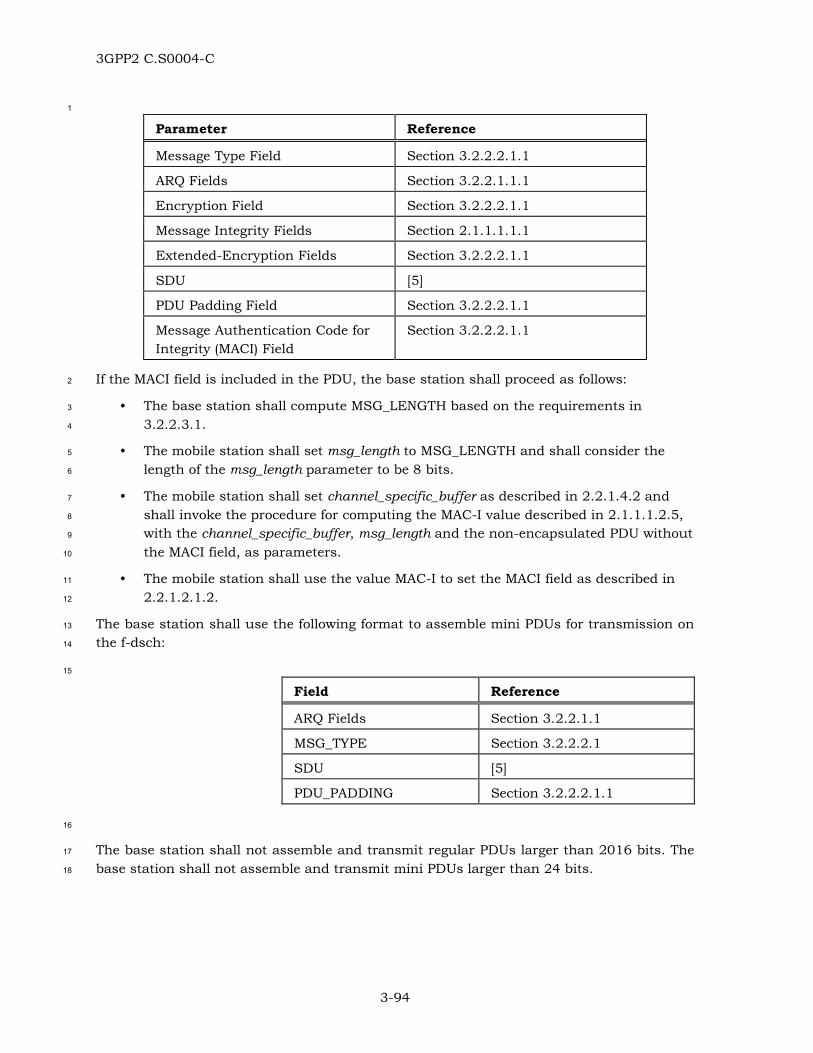
3GPP2 C.S0004-C
3-94
1
Parameter Reference
Message Type Field Section 3.2.2.2.1.1
ARQ Fields Section 3.2.2.1.1.1
Encryption Field Section 3.2.2.2.1.1
Message Integrity Fields Section 2.1.1.1.1.1
Extended-Encryption Fields Section 3.2.2.2.1.1
SDU [5]
PDU Padding Field Section 3.2.2.2.1.1
Message Authentication Code for Integrity (MACI) Field
Section 3.2.2.2.1.1
If the MACI field is included in the PDU, the base station shall proceed as follows: 2
• The base station shall compute MSG_LENGTH based on the requirements in 3
3.2.2.3.1. 4
• The mobile station shall set msg_length to MSG_LENGTH and shall consider the 5
length of the msg_length parameter to be 8 bits. 6
• The mobile station shall set channel_specific_buffer as described in 2.2.1.4.2 and 7
shall invoke the procedure for computing the MAC-I value described in 2.1.1.1.2.5, 8
with the channel_specific_buffer, msg_length and the non-encapsulated PDU without 9
the MACI field, as parameters. 10
• The mobile station shall use the value MAC-I to set the MACI field as described in 11
2.2.1.2.1.2. 12
The base station shall use the following format to assemble mini PDUs for transmission on 13
the f-dsch: 14
15
Field Reference
ARQ Fields Section 3.2.2.1.1
MSG_TYPE Section 3.2.2.2.1
SDU [5]
PDU_PADDING Section 3.2.2.2.1.1
16
The base station shall not assemble and transmit regular PDUs larger than 2016 bits. The 17
base station shall not assemble and transmit mini PDUs larger than 24 bits. 18

3GPP2 C.S0004-C
3-95
3.2.2.3 Segmentation and Reassembly Sublayer 1
3.2.2.3.1 Parameters 2
3.2.2.3.1.1 Definition of SAR parameters 3
The SAR parameters for regular PDUs transmitted on the f-dsch have the same format as 4
those for regular PDUs transmitted on the r-dsch (see 2.2.1.3.1.1). 5
There are no SAR parameters defined for mini PDUs. 6
3.2.2.3.1.2 Requirements for Setting SAR Parameters 7
For regular PDUs sent on the f-dsch, the base station shall set the SAR parameters as 8
specified in 2.2.1.3.1.2.72 9
3.2.2.3.2 Procedures 10
The base station shall assemble and shall transmit encapsulated PDUs as specified in 11
2.2.1.3.2.73 12
3.2.2.4 Message Integrity Sublayer 13
3.2.2.4.1 Parameters 14
The base station shall use and set the Message Integrity Fields specified in 2.1.1.1.1.174 15
according to the procedures in 3.2.2.4.2. and 2.1.1.1.1.3. 16
3.2.2.4.2 Procedures 17
If message integrity is supported and enabled for a regular PDU transmitted on f-dsch, the 18
base station shall set channel_specific_buffer to the 2 bits corresponding to “ACK_REQ |’0’”, 19
where ACK_REQ is set to ‘0’, if the message is to be sent in unassured mode or to ‘1’, if the 20
message is to be sent in assured mode, where the most significant bit of the 21
channel_specific_buffer corresponds to the ACK_REQ bit. 22
72 When transmitting on the f-dsch, the base station sets the SAR parameters in the same manner that the mobile station does when transmitting on the r-dsch.
73 When transmitting on the f-dsch, the base station assembles PDUs in the same manner that the mobile station does when transmitting on the r-dsch.
74 Except where explicitly specified otherwise (see 3.2.2.4.2 and 3.2.2.2.2), for regular PDUs transmitted on f-dsch, the base station uses the same Message Integrity Fields and the same procedures for inclusion and setting of values for these fields as the mobile station does when transmitting PDUs on r-dsch.

3GPP2 C.S0004-C
3-96
When the base station executes the procedure for setting up the MACI field (see 3.2.2.2.2), 1
the channel_specific_buffer shall be passed as input parameter to that procedure. 2

3GPP2 C.S0004-C
A-1
ANNEX A TIMERS AND CONSTANTS 1
Annex A is a normative annex, which contains tables that give specific values for the 2
constant identifiers. These identifiers take the forms such as T75m and N15m. The 3
subscripted numbers vary to identify the particular constant. Typically the subscripted 4
letter “m” refers to the mobile station and the subscripted letter “b” refers to the base 5
station. The following tables provide values for identifiers given in the text: 6
Table A-1. Time Limits 7
Table A-2. Other Constants 8
9
Table A-1. Time Limits 10
Time Limit Description Value References
T1m Maximum time the mobile station waits for an acknowledgment of a regular PDU. Maximum time the mobile station waits for an acknowledgment of a mini PDU after the first N14m transmissions or retransmissions of the mini PDU.
0.4 s 2.2.1.1.2 3.2.2.1.2
T2m Maximum time allowed for the mobile station to send an acknowledgment of a regular PDU.
0.2 s 2.2.1.1.2
T3m Period in which two regular PDUs received by the mobile station on the f-dsch, not requiring an acknowledgment and carrying the same sequence numbers, are considered duplicates
0.32 s 2.2.2.1.2.2 3.2.2.1.2.2
T4m Period in which two PDUs received by the mobile station on the same physical channel corresponding to the f-csch, not requiring an acknowledgment and carrying the same sequence numbers, are considered duplicates
2.2 s 2.1.2.1.2.2 3.1.2.1.2.1
3.1.2.1.2.2
T75m Maximum time the mobile station waits for an acknowledgment of a mini PDU for the first N14m transmissions or retransmissions of the mini PDU.
0.12 s 2.2.1.1.2 3.2.2.1.2
T76m Maximum time allowed for the mobile station to send an acknowledgment of a mini PDU.
0.06 s 2.2.1.1.2
T77m Period in which two mini PDUs received by the mobile station on the f-dsch, not requiring an acknowledgment and carrying the same sequence numbers, are considered duplicates
0.02 s 2.2.2.1.2.2 3.2.2.1.2.2
11

3GPP2 C.S0004-C
A-2
Table A-2. Other Constants 1
Con-stant Description Value References
N1m Maximum number of times that a mobile station transmits or retransmits a regular PDU requiring acknowledgment on the r-dsch.
13 2.2.1.1.2 2.2.1.1.3
N14m Maximum number of times that a mobile station transmits or retransmits a mini PDU requiring acknowledgment on the r-dsch with retransmission_timer set to T75m.
6 2.2.1.1.2 2.2.1.1.3
N15m Maximum number of times that a mobile station transmits or retransmits a mini PDU requiring acknowledgment on the r-dsch.
17 2.2.1.1.2
2