Shut-off valves type DA and EA - Comar Fluid Power
218
Shut-off valves type DA and EA D 1741 Shut-off valves type DA, EA Septembre 2006-00 © 1960 by HAWE Hydraulik HAWE HYDRAULIK SE STREITFELDSTR. 25 • 81673 MÜNCHEN 2.2 Pressure p max = 700 bar Flow Q max = 150 lpm 1. General information 2. Available versions, main data aThese 2/2-way directional seated valves are manually actuated and serve to block (zero leakage) the flow in one or both directions. They are mounted directly in the piping of hydraulic circuits. Version Standard, control lever with female thread M8 at the shaft end Control lever with cross drilling #3 at the shaft end Actuation shaft with- out hand lever going through on both sides Standard, actuation shaft with female thread M8 at the shaft end DA 2 DA 2L DA 2B DA 3 EA 2 EA 2L EA 2B EA 3 Coding, size and Symbols shut-off valves Double acting Single acting Pressure p max (bar) Flow Q max (lpm) Tapped ports A and B DIN ISO 228/1 (BSPP) 700 60 150 500 G 1 G 3/4 Schematic drawing Flow blocked in both directions Free flow in both directions Flow: A → B blocked A ← B open, but not intended for free flow! Direction A ← B flow Switching position 0 Switching position a Typ DA.. Typ EA..
-
Upload
khangminh22 -
Category
Documents
-
view
0 -
download
0
Transcript of Shut-off valves type DA and EA - Comar Fluid Power

Shut-off valves type DA and EA
D 1741Shut-off valves type DA, EA
Septembre 2006-00© 1960 by HAWE Hydraulik
HAWE HYDRAULIK SE
STREITFELDSTR. 25 • 81673 MÜNCHEN
2.2
Pressure pmax = 700 bar
Flow Qmax = 150 lpm
1. General information
2. Available versions, main data
aThese 2/2-way directional seated valves are manually actuatedand serve to block (zero leakage) the flow in one or both directions.They are mounted directly in the piping of hydraulic circuits.
Version
Standard, control leverwith female thread M8at the shaft end
Control lever withcross drilling #3 at theshaft end
Actuation shaft with-out hand lever goingthrough on both sides
Standard, actuationshaft with femalethread M8 at the shaftend
DA 2
DA 2L
DA 2B
DA 3
EA 2
EA 2L
EA 2B
EA 3
Coding, size and Symbolsshut-off valves
Double acting Single acting
Pressurepmax
(bar)
FlowQmax
(lpm)
Tapped ports A and B DIN ISO228/1 (BSPP)
700 60
150500 G 1
G 3/4
Schematic drawing
Flow blocked in both directions Free flow in both directions
Flow: A → B blockedA ← B open, but not intendedfor free flow!
Direction A ← B flow
Switching position 0 Switching position a
Typ DA..
Typ EA..

D 1741 page 2
3. Further characteristic data
Design Seated ball valve
Material Steel, internal functional parts hardened and ground, valve ball made from bearing steel quality
Body surface Zinc galvanized
Mounting D(E)A 2.. in the pipingD(E)A 3 in the piping or via thread M8, see dimensional drawing (sect. 4)
Installation position D(E)A 2.. level, actuation lever upD(E)A 3 arbitrary; level if vibrations may occur, actuation levers up
Actuation forces max. force at the end of the actuation lever with 500 bar:and moments DA 2.. approx. 75 N
DA 3 approx. 300 N (EA.. approx. 60%)
max. moment with 500 bar:DA 2.. approx. 15 Nm;DA 3 approx. 60 Nm (EA.. approx. 60%)
Static overload capacity 2.0 x pmax
Pressure fluid Hydraulic oil conforming DIN 51524 part 1 to 3: ISO VG 10 to 68 conforming DIN 51519.Viscosity limits: min. approx. 4, max. approx. 1500 mm2/s;opt. operation approx. 10... 500 mm2/s.Also suitable are biologically degradable pressure fluids types HEPG (Polyalkylenglycol) andHEES (synth. Ester) at service temperatures up to approx. +70 °C.
Temperatures Ambient: approx. -40 ... +80 °CFluid: -25 ... +80°C, note the viscosity range !Permissible temperature during start: -40°C (observe start-viscosity!), as long as the service temperature is at least 20K higher for the following operation. Biologically degradable pressure fluids: Observe manufacturer's specifications. By considerationof the compatibility with seal material not over +70 °C.
Bac
k p
ress
ure
|p
(bar
)
Bac
k p
ress
ure
|p
(bar
)
Flow Q (lpm) Flow Q (lpm)
|p-Q-curves
Oil viscosity during testsapprox. 53 mm2/s
Mass (weight) Type DA 2(L) = approx. 1.5 kg Type EA 2(L) = approx. 1.4 kg
DA 2B = approx. 1.3 kg EA 2B = approx. 1.3 kg
DA 3 = approx. 3.2 kg EA 3 = approx. 3.0 kg

D 1741 page 3
4. Unit dimensions
All dimensions in mm and subject to change without notice!
Type DA 2L and EA 2L
Type DA 2B and EA 2B
Type DA 2 and EA 2 Type DA 3 and EA 3
Switching position Switching position
M8, 6 deep
M8, 6 deep
M8, 8 deep
Missing dimensions like type DA 2 and EA 2
M issing dimensions like typeDA 2 and EA 2

Directional spool valve type SG and SPVersions for direct pipe connection or manifold mounting
D 5650/1Directional spool valve
type SG and SP
March 2013-01
HAWE HYDRAULIK SESTREITFELDSTR. 25 • 81673 MÜNCHEN
2.1
© 1969 by HAWE Hydraulik
Directional spool valves are generally employed in oil-hydraulic systems. They serve to control the oil flow and thus the direction of movement of the consumers (hydraulic cylinders and hydr. motors). These valves are designed for individual installation. They feature an internal leakage compensation, hence no leakage connection is required. All valve versions are available either for:
o direct pipe connection or
o manifold mounting
Every directional spool valves consists of a control element (valve spool incl. housing) and a directly mounted actuation.The valve unit is manufactured entirely of steel, thus rendering the housing insensitive to pressure surges and leakage as can sometimes be observed after prolonged periods of use with cast housings. This is caused usually by hairline cracks which form and migrate externally, especially when the permissible pressure range has been fully utilized. Such phenomena are ruled out right from the start. The housing bores are diamond-honed. The hardened and ground valve spools are polished/deburred. This preserves their roundness and exact geometric shape (the control edges are not worn down or widened) ensuring even sealing gaps with a minimum leakage rate. Cast material (zinc and aluminum die casting) is used solely for non-pressurized components e.g. actuation housing, spring dome, base plates, etc. There is also a version available where the housing of the manual actuation is made of spheroidal cast iron which is intended especially for rough operation conditions or when these valves are connected in series.
Pressure pmax = 400 barFlow Qmax = 100 lpm
Version for pipe connection
Actuation modes (illustration represents size 3)
Version for manifold mounting
Example: SP 3 G - AK
Example: SG 1 L - AK
Example: SG 3 H - NM
Size0 and 1
Size2, 3, and 5
Manual acc. to D 6511/1
Pressure acc. to D 6250
Shielded or un-shieldeddesign
For brief description and main data, see table 4 in sect. 2.1!
AC or DC voltage
Roller head
Ball head
Pneumatic or hydraulic and resp. combinations pneumatic/manual or hydraulic/manual
Solenoid acc. to D 7055
Mechanical acc. to D 5870
1. General

D 5650/1 page 2
2. Available versions, main data2.1 Type coding
Order examples: Version for pipe connection
Version for manifold mounting
Desired pressure setting (bar) for the pressure limiting valve
SG 3 L 3E - AK - 120
SP 3 G - MD 23/24
Table 1: Basic type and size
Table 2: Flow pattern symbols
Table 3: Optional pressure limiting valve (only type SG)
For actuation mode, see table 4
Coding
SG 0
SG 1
SG 2
SG 3
SG 5
SP 1
SP 3
SP 5
Port size
A, B, P R
G 1/4 G 3/8
G 3/8
G 3/8
G 1/2
G 1
Flow 1)
Qmax (lpm)
12
20
30
50
100
12
50
100
Pressure pmax
(bar) at portsA, B, P R
400
400
400
400
315
400
400
315
Dep. on ac-tuation, see tab. 4 2)
Connection desig
Pipe mount-ing acc. to ISO 228/1 (BSPP)
Manifold mounting
See dimensional drawings in sect. 4 ++
Basic type
SG 0SG 1
SG 2SG 3SG 5
Spring housing made ofZinc die casting 3) Steel 4)perm. pressure at pressure atR = 20 bar R > 20 bartool ad manu. tool ad manu.justable adjust. justable adjust.
1B 2B --- ---
1C 2C --- ---
1E 2E --- ---
1F 2F --- ---
3B 4B 6B 7B
3C 4C 6C 7C
3E 4E 6E 7E
3F 4F 6F 7F
Pressure range(bar)
(315) ... 400
(160) ... 315
(80) ... 160
20 ... 80
(315) ... 400
(160) ... 315
(80) ... 160
20 ... 80
Essential note:
Permissible pressure at R depends on the spring housing material (see above). Connection R must always be the return, any pressure at R adds itself to the pressure setting. Do not use for series connections. In parallel connections, only equip one valve with a pressure limiting valve. Attention: Pressure limiting valves are not available for all flow pattern symbols (see table 2).
Basic flow pattern symbols and switch-ing positions
Avail. for type SG..
L 13) P F 13) H Y 7) 11) S 13) X 7) K 6) 7) 8) LS 12)13) 13) FS 12)13) 14) SS 12)13) 9) 10)
Suited for series connec-tion
With pres-sure limiting valve
Avail. for type SP..
Remarks on use:
If several single valves are being used in a system, attention must be paid to the connec-tion (parallel, series). In a series connection, the permissible system pres-sure = permissible pres-sure in the return!Hence, not all modes of actuation are suitable for aseries connection (ect. 4).
Check valve insert type ER 21 optionally available for type SP 1:
The check valve type it 21 must be ordered separately.The check valve insert type ER 21 acc. to D 7325 may be installed in port P, when required. This is advantageous when several directional spool valve sections (flow pattern symbols D, E, G, N, R, V, and W) are connected in parallel and situations might occur where two valve sections are actuated subsequently but simultaneous. Thereby preventing a pressure drop of the first actuated consumer.
Overlap between two switching positions:
None (neutral)
Positive (intermedi-ate blocked position)
Negative (slight intermediate blocked position)
Suited for parallel connec-tion
G C D E N W R V 5) Q 5) 6) Z U 6) 7) B 7) 8) 9) 10)
Size 0 and 1
Size2, 3, 5
1) Recommended value; if the pump output flow is near the specified limits, the plunger side must be connected at A if differential cylinders are being used as consumers
2) In SP design with flow pattern for parallel connection depending on actuation, although not in excess of 100 bar
3) Standard material for models with pressure limiting valve 4) Normally only for special applications: Resistant to pressure surges up to
300 bar (pay attention to permissible pressures for actuations). For maritime versions, see D 6511/15) Port R must be connected to the tank as leakage drain 6) Not available for size 0 and 17) Without pressure limiting valve8) Only available with manual actuation Y... acc. to D 6511/1 (detent, four
switching positions)9) Not available for SP.. manifold mounting10) Not for size 511) Observe the position of the ports in the dimensional drawings, see also notes
in sect. 3 ++12) Version to the avoidance of decompression surges (only size 5), see sect. 2.213) Not available for type SG 5 with pressure limiting valve14) Not available for type SG 0(1)
Coding is omitted for versions without pressure limiting valve!
6) 7) 10)

D 5650/1 page 3
1) For versions fitted with a pressure limiting valve, observe table 3, the lower pressure applies. Furthermore, not more than 100 bar in SP 2) Not for size 5
Table 4: Actuation modes (Selection table, for more detailed information refer to the corresponding pamphlets)
Actuation
Manual
(spring return/detent)acc. toD 6511/1
Coding Notes, remarks
AD, CD: (zinc die cast.) for normal conventional use. Only for parallel connection!
AK, CK: (spheroidal cast iron) for especially rough use. Suited for series connection
BX: Sturdy but not shield-ed design; only for parallel connection; corrosion-pro-tected by galvanized and nitrided components
AIso avaiIable with emer-gency manual actuation. Suffix code N: MD2/... N, etc. Attention: Permis. pressure at R only approx. 40 bar during use. Pay attention to the special note for actuating emergency manual operation as ex-plained in D 7055!
Only for parallel connection !In case of double stroke, idle pos. is determined by cam.
Only for parallel connection !NE, ND and NU:
also available with emer-gency manual operation, add coding H: NDH etc. Pressure-relieved version (D 6250) can be subjected to pressures up to 200 bar in the return
Only for parallel connection !
SymbolsPressurepmax (bar)at portsA, B, P R 1)
Solenoid
acc. to D 7055
Mechan-
ical
acc. to D 5870
Pressure
acc. toD 6250
Control mediumair or oil
Size
Shielded design
Unshieldeddesign
Voltage UN
12 24 110 W 230 W
12 V DC 24 V DC 110 V AC 230 V AC 50 and 60 Hz
400 50 (20)
400 315 (20)
400 50 (20)
200 200 (20)
200 200
315 200
200 200
400 100 (20)
400 40 (20)
400 30
400 12
With spring return0 and 1 2, 3 and 5
A AD
AK(S) AK(S)
--- BX 2)
With detent0 and 1 2, 3 and 5
C CD
CK(S) CK(S)
--- ---
Size0 and 1
Size2 and 3
Size2, 3,and 5
Size0 and 1
Size2, 3,and 5
Size0 ... 5
Size2, 3 and 5
ME 1 12 V DC
ME 2 24 V DC
ME 81 110 V AC 50/60 Hz
ME 8 230 V AC 50/60 Hz
MD 1 12 V DC
MD 2 24 V DC
MD 81 110 V AC 50/60 Hz
MD 8 230 V AC 50/60 Hz
ME 2/... Single stroke
MD 2/... Double stroke
MU 2/... Reverse stroke
ME 23/... Single stroke
MD 23/... Double stroke
MU 23/... Reverse stroke
ME 3/... Single stroke
MD 3/... Double stroke
MU 3/... Reverse stroke
Single stroke
Double stroke
RE Single stroke
RD Double stroke
BE Single stroke
BD Double stroke
NE Single stroke
ND Double stroke
Air or oil
Standard design
Standard design
Double stroke
hand/air
hand/oil
KD Double stroke
KM Double stroke
NE Single stroke
ND Double stroke
NU Reserve stroke
NM Single stroke and
Double stroke
A CAD CDAK CKBX
ME.. MD..
MU..
RE BERD BD
NE NUND
NM
KD KM
Output45 W100% ED
Output 60W 100% oper-ating factor
Output150 WS3-35% ED5 min
Output65 W100% ED
Observe the note in D 5870
Roller head
Ballhead
(size 2, 3)
(size 5)
The manual actuation is also available without hand lever (add coding 1, e.g. A 1, CK 1 etc.)
AKS, CKS = Seaworthy version
air
oil

D 5650/1 page 4
Design Spool-type directional control valve
Mounting Type SG: See unit dimensions in sect. 3.1 Type SP: Onto manifold
Pipe connection Tapped ports conforming ISO 228/1 (BSPP) Suited for male fittings, shape B acc. to DIN 3852 P = Pump port A, B = Consumer ports R = Return port (pressure resistance dep. on the actuation, see also table 4)
Installed position Any
Flow direction According to symbol but also reverse, pay attention to permissible pressure at R
Operation pressure pmax = 400 bar, dep. on size and actuation
Static overload capacity approx. 2 x pmax
Pressure adjustment ofthe pressure limiting valve
Mass (weigth) approx. kg
Pressure SG 0(1) SG 2(3) SG 5range
B 100 80 80
C 55 35 35
E 19 17.5 17.5
|p (bar) per 1 rev.
2.2 Additional parameters and notes
Type
SG 0(1)SP 1
SG 2(3)SP 3
SG 5
SP 5
Pressure Complete incl. actuatuionlimiting Manual Solenoid Mecha- Pressurevalve MD.. ME 2/.. MD(U) 2/.. MD 3/.. nical Standard Combined AD AK BX ME.. MU.. ME 23/.. MD(U) 23/.. ME 3/.. MU 3/.. actuation actuation
without 1.0 1.0 --- 1.4 1.7 --- --- --- --- 1.1 0.9 ---
with 1.2 1.2 --- 1.6 1.9 --- --- --- --- 1.3 1.1 ---
without 3.0 3.5 2.5 --- --- 3.9 5.0 4.5 4.8 2.7 2.5 2.9
with 3.3 3.8 2.8 --- --- 4.2 5.3 4.8 5.0 3.0 2.8 3.2
without 3.4 3.9 2.9 --- --- 4.3 5.4 4.9 5.1 3.1 2.9 3.3
with 4.7 5.2 --- --- --- 5.6 6.7 6.2 7.0 4.4 4.2 4.6
without 4.3 4.8 --- --- --- 5.2 6.3 5.8 6.6 4.0 3.8 4.2
Pressure fluid Hydraulic oil conf. DIN 51524 part 1 to 3: ISO VG 10 to 68 conf. DIN 51519 Viscosity limits: min. approx. 4, max. approx. 1500 mm2/s Optimal operation: approx. 10 ... 500 mm2/s Also suitable for biological degradable pressure fluids types HEPG (Polyalkylenglycol) and
HEES (Synth. Ester) at service temperatures up to approx. +70°C
Temperature range Ambient: approx. -40 ... +80°C Fluid: -25 ... +80°C, Note the viscosity range Permissible temperature during start: -40°C (observe start-viscosity!), as long as the
service temperature is at least 20K higher for the following operation Biological degradable pressure fluids: Observe manufacturer‘s specifications. Considering
the compatibility with seal material not over +70°C. Attention: Observe the restrictions regarding the permissible operation duration of the
actuation solenoids, see sect. 3.1 in D 7055!
Notes for flow pattern symbols LS, FS, and SS:
Directional spool valves to the avoidance of decompression surg-es (only available for type SG 5!)
It is common practice in the shipbuilding industry to utilize directional spool valves with big sized ports (even for very low flows) to minimize the back pressure within the usually very lengthy pipe system. Such high in-pipe volume usually cause pressure surges being very strainous for the complete hydraulic equipment. The directional spool valves versions type SG 5 ... S feature valve spools with long notches which cause a rather smooth pressure built-up during switching operations, thus minimizing such pressure surges. The big-port design (G 1) enables use of pipes #25 with accordingly low back pressure.Technical data: All technical data and dimensions are like with the standard version, beside the |p-Q curve.

D 5650/1 page 5
|p - Q - characteristicsThe flow resistance values (recommended values) are understood without pipe fittings (SG) and without manifold (SP)
Double-acting consumers with unequal area ratios (differential cyl.):The return flow Qreturn may be lower or higher than the inlet flow Qinlet (pump deliv-ery flow) depending on the direction of movement. The flow resistance |ptotal of the directional spool valve must always be related to the inlet side (connection P):
Directional spool valves for parallel connection:The cylinder port of the piston side (larger surface) should always be connect-ed to port A.
Valves for parallel connections Valves for series connectionsType
SG 0SG 1SP 1
SG 2
SG 3SP 3
SG 5SP 5
Flow Q (lpm)Flow Q (lpm)
Flow Q (lpm)Flow Q (lpm)
Flow Q (lpm) Flow Q (lpm)
Flow Q (lpm) Flow Q (lpm)
Flo
w r
esis
tance
|p
(bar
)
Flo
w r
esis
tance
|p
(bar
)
Flo
w r
esis
tance
|p
(bar
)
Flo
w r
esis
tance
|p
(bar
)F
low
res
ista
nce
|p
(bar
)F
low
res
ista
nce
|p
(bar
)
Flo
w r
esis
tance
|p
(bar
)F
low
res
ista
nce
|p
(bar
)
Note
SP 3SG 3
SP 3SG 3
Fluid viscosity during tests approx. 60 mm2/s
Aout
Aout
Ain
Ain
Qin
Qin
Qout
Qout
|ptotal = |pin + |poutAout
Ain
Qreturn = QinAout
Ain

D 5650/1 page 6
3. Dimensions All dimensions in mm, subject to change without notice!
3.1 Directional spool valves for direct pipe connection
Type SG 0 and SG 1
M 8, 10 deep, core bore #6.5 is a thru-hole
M 8, 10 deep (rear side), core bore #6.5 is a thru-hole
1) Port B is omitted with coding N, S, and R
Plugged with coding X
Provision for a lead sealTool adjustable
Manually adjustable
Version with pressure limiting valve
(For pressure adjustment, see sect. 2.2)
Ports ISO 228/1 (BSPP)
Size
0
1
Coding
D, E, G, W, N, R
F, H, L, P, V, S, X
Y
Other codings
a b c d h P, A, and B R
17.5 20.5 9.5 20.5 59.5 G 1/4 G 3/8
21.5 12 9.5 20.5 59.5 G 1/4 G 3/8
18.5 21.5 11 17.5 70 G 3/8 G 3/8
18.5 21.5 11 17.5 59.5 G 3/8 G 3/8
Type SG 5 2)
Ports ISO 228/1 (BSPP):P, R, A, B = G 1
#10.5thru-hole
Version with pressure limiting valve
(For pressure adjustment, see sect. 2.2)
Type SG 2 and SG 3 2)
Manually adjustable
Tool adjustableProvision for a lead seal
Ports ISO 228/1 (BSPP):P, R, A, B = G 3/8 (SG 2) G 1/2 (SG 3)
Dimension a = 30 for coding B, C, K, YDimension b = 11 for coding U 16 for other codings
#10.5thru-hole
Pay attention to the differing dimensions of the base plate for the pressure compensated ver-sion with pressure actuatuation (see D 6250).
1)
Version with pressure limiting valve
(For pressure adjustment, see sect. 2.2)
2) Port B is omitted with coding N, S, R, U, and X. Ports P and A are mixed up with coding Y. Port A is stamped R with coding U
Provision for a lead sealT
oo
l ad
just
able
Man
ual
ly a
dju
stab
le
(For actuations, see sect. 3.3, on page 8 ++)
max. approx. 91
max. approx. 80
max. approx. 102
max. approx. 92

D 5650/1 page 7
1) Port B is missing with coding N, S, R, U, and X.
Ports A and R can be used alterna-tively as return with coding U
Type SP 1
Washer ISO 7089/7090-6.4-140 HV-A2K
Washer ISO 7089/7090-8.4-140 HV-A2K
Valve housing
Manifold
Sealing of ports A, B, P, and R via O-rings NBR 90 Sh. (There is also a seal kit available, order No. )
Attention: Port B is omitted with directional spool valves coding N, S, and R
Position of the ports with coding Y
Check valve insert type ER 21 (not available with coding Y,see also sect 2.1, table 2).
Important notes (for SG valves, all sizes)
Type SG 0 and SG 1 Type SG 3 and SG 5
Type SP 3 1) Type SP 5 1)
Dimensions a1 = 11 with coding D, E, G, N, R, U, V, W, X and Z 15 with coding C, F, L, P, S, H
Washer ISO 7089/7090-10.4-140-HV-A2K
Type #d O-ring Order no.
SP 3 11 12x2.5 DS 5650/1-3
SP 5 16.5 20x2.5 DS 5650/1-5
Ports A, B, R P
#d 7 7 to 9
O-ring 8x2 14x2
Valve housing
Manifold
Sealing of ports A, B, P, and R viaO-rings NBR 90 Sh. (There is also a seal kit available, order no. DS 5650/1-1)
3.2 Directional spool valve for manifold mounting (For actuations, see sect. 3.3 on page 8 ++)
Washers must be in-stalled betwean valve and mounting area to prevent warping of the valve housing in case of uneven mounting surfaces.

D 5650/1 page 8
3.3 Actuation modes, orientation and main data
For missing specifications, see respective pamphlets!
Manual actuation
Size 0 and 1codingA, AK, C and CK
c = 28 for version with DC-solenoid
= 35 for version with AC-solenoid
This dimension de-pends on the manufac-turer and may be max. 40 mm (acc. to DIN 43650)!
Solenoid actuation
Mechanical actuation
Coding RE and RD Coding BE and BD
Size Coding
0 a. 1 ME.. and MD..
2, 3 ME(D, U) 2/..and 5 ME(D, U) 23/..
ME(D, U) 3/..
a b b1 h h1
32 39 51 104 135
54 51.5 60 158 199
54 #72 #72 158 199
Size 0 and 1 2, 3, and 5
h2 66 102
s 5 10
Hand lever can also be mount-ed here
Flange (mounting) area with directional spool valve type SP 1
Size 2, 3 and 5codingAD, AK, CD and CK
Flange (mounting) area with directional spool valve type SP 3(5)
Size 2 and 3 coding BX
Flange (mounting) area with directional spool valve type SP 3
Hand le-ver can also be mounted here
Occasionally lube the ar-ticulatet bolt
Hand lever can also be mounted here
Double actuation coding KM and KD
PortsISO 228/1 (BSPP):1 and 2 = G 1/4
Pressure actuation
Standard versions, coding NE, ND, NU and NM
Size h3
0 and 1 60
2, 3 97and 5
Flange (mounting) area with directional spool valve type SP..
PortsISO 228/1 (BSPP):1 and 2 = G 1/4
app
rox.
13
2 app
rox.
23
5
app
rox.
20
0
app
rox.
342

Lifting / Lowering valve type HSV and HZV
D 7032Lifting/Lowering valve
type HSV, HZV
August 2003-04© 1976 by HAWE Hydraulik
HAWE HYDRAULIK SESTREITFELDSTR. 25 • 81673 MÜNCHEN
2.2
Flow Qmax = 160 lpm
Pressure pmax = 400 bar
1. General information
This valve combination type HSV or HZV is preferably used for controlling lifting equipment with one or two single acting hydraulic cylinders.
The valve consists of:
' Solenoid actuated 2/2-way directional seated valve for lowering the lifted load
' Adjustable throttle valve (optional) for limiting the drop rate
' The 2-way flow control valve, available as option for valves type HSV 23-R6 and HZV 21(22)-R6, ensure a largely load independentdrop rate.
' Pressure limiting valve for the limitation of the permissible load (max. operation pressure). Factory set to 220 bar, adjustable upto 400 bar.
' Check valve prevents load pressure from acting on the switched off pump, when the load is lifted and prevents e.g. reverse rotation of the pump. The location of the check valve in relation to the pressure limiting valve depends on the application. Version R2 and R4 (S2 and S4) prevents uncontrolled lowering of the load in case the pressure limiting valve is "floating" (loadpressure in the range of the set pressure).
Type HSV 21(22)
Type HSV 41(61)
Example circuits Type HZV 21 R6/10 - 150 - G 24
Type HSV 21 R2 - 150 - G 24
D 7032 page 2
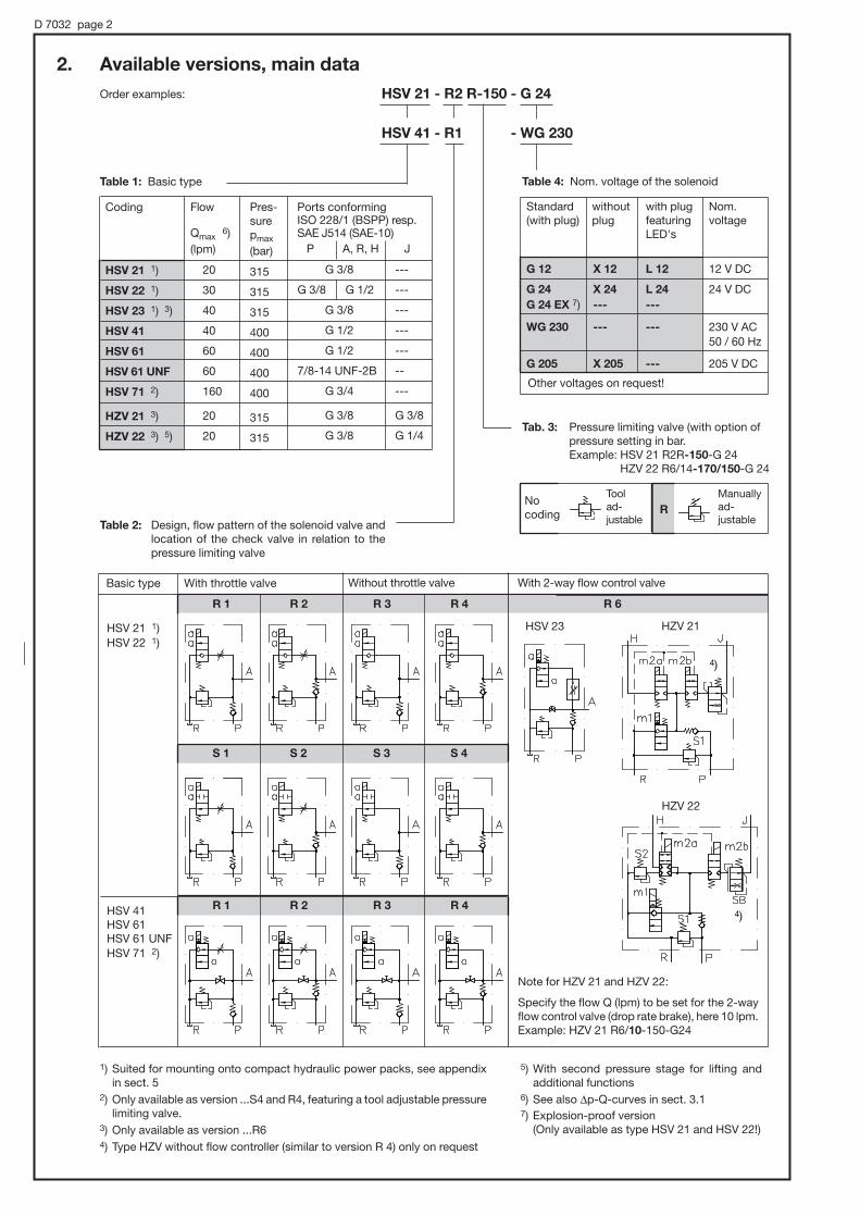
2. Available versions, main data
Coding
HSV 21 1)
HSV 22 1)
HSV 23 1) 3)
HSV 41
HSV 61
HSV 61 UNF
HSV 71 2)
HZV 21 3)
HZV 22 3) 5)
Flow
Qmax 6)
(lpm)
20
30
40
40
60
60
160
20
20
Pres-surepmax
(bar)
315
315
315
400
400
400
400
315
315
P A, R, H
G 3/8
G 3/8 G 1/2
G 3/8
G 1/2
G 1/2
7/8-14 UNF-2B
G 3/4
G 3/8
G 3/8
J
---
---
---
---
---
--
---
G 3/8
G 1/4
Order examples: HSV 21 - R2 R-150 - G 24
HSV 41 - R1 - WG 230
Ports conformingISO 228/1 (BSPP) resp.SAE J514 (SAE-10)
Table 1: Basic type Table 4: Nom. voltage of the solenoid
Tab. 3: Pressure limiting valve (with option ofpressure setting in bar. Example: HSV 21 R2R-150-G 24
HZV 22 R6/14-170/150-G 24
Other voltages on request!
No coding R
Tool ad-justable
Manuallyad-justable
Table 2: Design, flow pattern of the solenoid valve and location of the check valve in relation to thepressure limiting valve
Basic type With throttle valve Without throttle valve With 2-way flow control valve
HSV 21 1)HSV 22 1)
HSV 41 HSV 61HSV 61 UNFHSV 71 2)
R 1 R 2 R 3 R 4
S 1 S 2 S 3 S 4
R 1
R 6
R 2 R 3 R 4
HSV 23 HZV 21
HZV 22
1) Suited for mounting onto compact hydraulic power packs, see appendixin sect. 5
2) Only available as version ...S4 and R4, featuring a tool adjustable pressure limiting valve.
3) Only available as version ...R64) Type HZV without flow controller (similar to version R 4) only on request
Note for HZV 21 and HZV 22:
Specify the flow Q (lpm) to be set for the 2-wayflow control valve (drop rate brake), here 10 lpm.Example: HZV 21 R6/10-150-G24
4)
4)
Standard without with plug Nom.(with plug) plug featuring voltage
LED's
G 12 X 12 L 12 12 V DC
G 24 X 24 L 24 24 V DCG 24 EX 7) --- ---
WG 230 --- --- 230 V AC50 / 60 Hz
G 205 X 205 --- 205 V DC
5) With second pressure stage for lifting and additional functions
6) See also |p-Q-curves in sect. 3.17) Explosion-proof version
(Only available as type HSV 21 and HSV 22!)

D 7032 page 3
Nomenclature, design 2/2-way directional seated valve (cone seated valve), solenoid actuated, combined with a pressure limiting, a throttle and a check valve in one valve body.
Pipe connection P = Inlet for pressurized oilA, H, J = ConsumerR = Return
Mounting position Any
Mass (weight) Type HSV 21(22, 23) HSV 41 HSV 61 HSV 71 HZV 21 HZV 22
approx. kg 2.2 2.2 2.5 3.1 3.9 4.0
Flow direction P → A lifting; A → R loweringThe function of the valves rule ports P, R and A(H, J) and mustn't be interchanged. R is the return port always (|p < 20 bar)
Perm. pressure max. 400 bar
Perm. flow see section 2 and |p-Q-curves
Pressure fluid Hydraulic oil conforming DIN 51524 part 1 to 3: ISO VG 10 to 68 conforming DIN 51519.Viscosity limits: min. approx. 4, max. approx. 1500 mm2/sec;opt. operation approx. 10... 500 mm2/sec .Also suitable for biological degradable pressure fluids types HEPG (Polyalkylenglycol) and HEES (Synth.Ester) at service temperatures up to approx. +70°C
Temperature Ambient: approx. -40...+80°C; Fluid: -25...+80°C, pay attention to the viscosity range! Start temperature down to -40°C are allowable (Pay attention to the viscosity range during start!), as longas the operation temperature during subsequent running is at least 20K higher. Biological degradable pressure fluids: Pay attention to manufacturer's information. With regard to the compatibility with sealingmaterials do not exceed +70°C.Restrictions for version with ex-proof solenoid!
|p-Q-curves
3. Additional parameter3.1 General and hydraulic data
Flo
wre
sist
ance|
p(b
ar)
Op
erat
ion
pre
ssure
p(b
ar)
Flow rate Q (lpm)
2-way flow control valve (with type HSV 23-R6)
Flow rate Q (lpm)
Flow rate Q (lpm)
Flow rate Q (lpm) Flow rate Q (lpm)
Oil viscosity during tests approx. 60 mm2/s
ISO 228/1 (BSPP), for pipe fittings with male thread shape B, DIN 2852 page 2Type HSV 61 UNF with thread 7/8-14 UNF-2B (acc. to table 1)

D 7032 page 4
Electrical data for ex-proof solenoids
ATEX-Certificate of conformity TÜV-A 03ATEX 0017 XCoding II 2 G Ex d IIB + H2 T4
II 2 D Ex mbD 21 T135°COper. duration 100% EDDuty cycle IP 67 (IEC 60529)Nom. voltage UN 24 VDC
Power PN 23 W
Restrictions for use:
Ambient temperature -35 ... +40°Cmax. fluid temperature +70°Cel. protection against overload(conf. IEC 60127) IF < 1.6 A-T
Surface coating Housing galvanically zinc coatedCoil and connection cavity are moulded
Electrical connection 3x0.5 mm2
Cable length 3 m, Option 10 m (cable ÖLFLEX-440P ® Co. LAPP, D-70565 Stuttgart)
Attention : Protect the complete valve against direct sun light.Observe the operation manuals B 03/2004 and B ATEX!Electrical lay-out and testing conforming EN 60079, VDE 0170-1, VDE 0170-5
Plugs (connectionand circuitry)
All plugs EN 175 301-801 A
DC-voltage coding G 24
AC-voltage coding WG 230
Terminals atthe solenoid
3.2 Electrical data
Coding HSV 21(22) HSV 23(41) HSV 61(...UNF) HSV 71 HZV 21(22)
Nom. voltage UN
For further data seesolenoid valve type ...acc. to pamphlet ...
Nom. power PN (W)
on
off
Switchings
Protection mode
24 V DC 230 V AC50/60 Hz
G 24G 24 EX 2)
WG 2301)
24 V DC 230 V AC50/60 Hz
G 24 WG 2301)
24 V DC 230 V AC50/60 Hz
G 24 WG 2301)
24 V DC 230 V AC50/60 Hz
G 24 WG 2301)
24 V DC 230 V AC50/60 Hz
G 24 WG 2301)
m1: EM 21V (D 7490/1)m2a/m2b: VZP1 (D 7785A)m1 m2.. m1 m2..
26.4
100
80
26. 6
200
160
21
50
150
21
100
300
21
50
150
21
100
300
30
50
150
30
100
300
21
100
80
27
~50
~65
21
200
160
26
~70
~130
BVG 2 BVP 2D 7400
EM 21VD 7490/1
EM 31VD 7490/1
EM 41VD 7490/1
max. approx. 2000 (roughly even distributed)
IP 65, acc. to IEC 60529 (plug properly mounted)
Switching time(guideline) ms
1) With bridge rectifierin the plug (solenoid 205 V DC)
2) Only available for type HSV 21 and HSV 22.For detailed informa-tion, see below.
Device socket
with LED and safety circuitwith 2 diodes
with clamp diode
for all valves
SVS 296048SVS 3129020
MSD 3-209 C1
add. with HZV 21(22)
SVS 296107
MSD 4-309 C2
Order coding
The valve order coding always includes the plug. Additionally available plugs (for more details, see D 7163):

D 7032 page 5
4. Unit dimensions All dimensions are in mm and subject to change without notice!
4.1 Type HSV 21-.. and HSV 22-...
Cable gland
Plug may bemounted offsetby 4x90°
Manual emergencyactuation (see below)
Throttlevalve
Pressure limiting valve
#8.3 Thru-hole
Additionalthru-holes#8.5 with typeHSV 21-R-...
M8, 8 deep
(tool adjustable) max. 128
(manually adjustable) max. 136.5
Important notes:
This valve may be mounted onto customer furnished manifold also. The ports will then be sealed to the outside by O-rings.Two socket head bolts ISO 4762-M8x65-10.9-A2K are required for mounting.
Manual emergency actuation
Actuation aid (max # 4.5 mm). Do not use any sharp edged parts.Actuation force $ 10 N
Thread ISO 228/1 (BSPP)
#d
#d1
O-ringNBR 90 Sh
HSV 21-..A, P and R
G 3/8
22.5
14
18x2.5
A and R
G 1/2
26.5
19
22x2.5
P
G 3/8
22.5
14
18x2.5
HSV 22-...
Manifold not part of delivery from HAWE !
Ex-proof solenoid
approx. 34

D 7032 page 6
Cable gland Plug may bemounted offsetby 4x90°
Drain valve a/f 5
4.2 Type HSV 23-R6/...
Pressure limitingvalve
#8.5 Thru-hole
#8.5 Thru-hole
M8, 8 deep
Metering throttle fordrop-rate braking valve,adjustable (0) ... 40 lpm
(tool adjustable) max. 116
(manually adjustable) max. 128
Important notes:
This valve may be mounted onto customer furnished manifold also. The ports will then besealed to the out-side by O-rings 18x2.5 NBR 90 Sh(customer furnished).Two socket head bolt ISO 4762-M8x65-10.9-A2Kare required for mounting.
4.3 Type HSV 41-..
Cable gland Plug may bemounted offsetby 4x90°
Throttlevalve
Drainvalve a/f 5
Pressurelimitingvalve
#8,5 Thru-hole
M8, 10 deep
(tool adjustable)max. 79
(manually adjustable)max. 90
Ports conforming ISO 228/1 (BSPP): A, P and R = G 1/2
Ports conforming ISO 228/1 (BSPP): A, P, and R = G 3/8
Important notes:
This valve may be mounted onto customer furnishedmanifold also. The ports will then be sealed to the out-side by O-rings 22x2 NBR 90 Sh (customer furnished).Two socket head bolt ISO 4762-M8x65-10.9-A2Kare required for mounting.
approx. 32
approx. 32

D 7032 page 7
4.5 Type HSV 71-...
a/f 6Pressure limitingvalve
Drain valve a/f 5
Plug may bemountedoffset by4x90°
Cable gland #11 Thru-hole
Ports conforming ISO 228/1 (BSPP): A, P, and R = G 3/4
4.4 Type HSV 61-.. and HSV 61 UNF
Cable gland
Plug may bemounted off-set by 4x90°
M8, 10 deep
(tool adjustable)
(manually adjustable)
Ports A, P, and R conforming ISO 228/1 (BSPP) = G 1/2 (type HSV 61)conforming SAE J 514 (SAE-10) = 7/8-14 UNF-2B (type HSV 61 UNF)
max. adjustmenttravel
Drain valvea/f 5
Pressure limiting valve
Thro
ttle
valv
eo
pen
clo
sed
approx. 32
approx. 32
app
rox.
38

D 7032 page 8
4.6 Type HZV 21-R6/...-... and HZV 22-R6/...-...
Terminals at thesolenoid m2a: 1-3m2b: 1-2
Cable gland
2)
2)
Pressurelimitingvalves
M8, 10 deep
Ports conforming ISO 228/1 (BSPP): H, P, and R = G 3/8
J = G 1/4
1) Pressure limiting valve S2 only apparent with type HZV 22 - R6/...-...
2) Plug may be mounted offset by 4x90°
Drop rate brakingvalve
1)
5. Appendix, mounting onto compact hydraulic power packs
Order example: HC 24/0,64 - HSV 23 - R6 - G 24
Directly mounted lifting/lowering valveacc. to sect. 2,suited types: HSV 21.., HSV 23-R6
Example circuit corresponding to theorder coding example above
3) Including O-ringsand screw set
For missing data ofcompact hydraulicpower packs, referto the correspond-ing pamphlets
Order No. of the complete connection block:6905 910 3)
For dimensions oftype HSV 23-R6-...,see sect. 4.2
Compact hydraulic power pack Suited types:HC acc. to D 7900HCG acc. to D 7900 G
MP acc. to D 7200D 7200 H
HK acc. to D 7600-2D 7600-3D 7600-4
app
rox.
32.5
app
rox.
32.5

Switch unit type CRwith an automatic pre-relieving feature (shock-free decompression)
for the control of bottom-ram presses with dual stage drive
either manual or solenoid actuation
D 7150Switch unit type CR
September 1999-02
HAWE HYDRAULIK SE
STREITFELDSTR. 25 • 81673 MÜNCHEN
2.2
' Opening the press
Type CR 4 M
CR 5 M
Type CR 4 H
Pressure pmax = 400 bar (high pressure)
= 60 bar (low pressure)
Flow Qmax = 300 lpm
Example type CR 4 H
1. General information
' Compression cycle
Combines both pump delivery flows for the rapid approach cycle. Ful-ly automatic switch-over of the low-pressure pump to idle circulation,when the pressure equals or exceeds the low-pressure value selected for the rapid approach cycle. Both pressure stages are safe-guarded by a built-in high pressure limiting valve and by the pressurelimiting function of the low-pressure switch-over valve.
' Maintaining the pressure
2/2-way valves, check valves and all other functional parts show zero leakage while connected to consumer port A. An additional pumpis not required during the compression interval. The two-stage pumpis cut-off by the pressure switch unit when the compression pressureis attained (see pamphlet 5440). Prerequisite: Press cylinders with noleakage.
Electrical actuation of the pilot-operated solenoid valve initiates a soft pressure reduction (decompres-sion) down to approx. 10 bar. This occurs without any pressure surges, thus protecting the unit from dam-age, and then passes over into a rapid and complete opening of the 2/2-way valve which also occurs with-out any pressure surges. Optimum lowering rates are attained from a tare or deadweight pressure of approx. 2 bar or more.
When the hand lever is thrown into position a , the operator will first distinctly feel a straining point at whicha pre-relieving valve connected in parallel to the return valve opens, thereby effecting shock-free de-compression. The straining point disappears upon completion of decompression and the hand lever canbe moved until it stops, thereby opening the return line completely. The deadweight pressure should be higher than 0.5 bar.
LP

D 7150 page 2
Electrical Applies to CR 4 and CR 5
Solenoid, conf. VDE 0580
Coding M-G 24 M-WG 110 M-WG 230
Nom. 24V DC 110V AC 230V ACvoltage UN
Current IN (A) 1.1 0.26 0.13
Power 26 26 26PN (W)
On 140 140 140
Off 55 150 150
Manual Hand lever (only for CR 4!)
Coding H Only little manual force necessary
Further data
Design 2/2-way ball seated valve (main valve) with direct or indirect operation depending on the respectivetype, combined with ball type check valves and pressure valves. Automatic decompression whenopening procedure is initiated.
Line connection HP, NP, A, B, M = for fittings with tapped journal conf. DIN 3852, Bl. 2 shape G or F.R = for threaded pipes conf. DIN 2440 or pipe sections and elbows conf. DIN 2980
Installed position Preferably in a vertical upright position with ports NP and R at the bottom
Pressure fluid Hydraulic oil conforming DIN 51524 part 1 to 3: ISO VG 10 to 68 conforming DIN 51519.Viscosity limits: min. approx. 4, max. approx. 1500 mm2/s;opt. operation approx. 10... 500 mm2/s.Also suitable are biologically degradable pressure fluids types HEPG (Polyalkylenglycol) and HEES(Synth. Ester) at service temperatures up to approx. +70 °C.
Temperature Ambient: approx. -40 ... +80 °CFluid: -25 ... +80°C, Note the viscosity range !Permissible temperature during start: -40°C (observe start-viscosity!), as long as the service temper-ature is at least 20K higher for the following operation.Biologically degradable pressure fluids: Observe manufacturer's specifications. By consideration ofthe compatibility with seal material not over +70 °C.
|p-Q-Characteristics
2. Available versions, main data
Example:
Table 1: Basic type and size
Pressure setting (bar):Low pressure High pressure
Application
Coding
HP
NP
A→R
Pressure pmax1) 2)
Mass (weight)
Deadweight pressure
Symbols
Bottom-ram presses with deadweight return
CR 4 M-... CR 5 M-... CR 4 H
8 20 8
80 160 80
200 300 200
5.2 kg 10.0 kg 4.7 kg
≥ 2 bar ≥ 2 bar ≥ 0.5 bar
Table 2: Actuation / mode
CR 4 M - WG 230 - 400/60
CR 4 H
Flow Qmax (lpm)
Switching
time (ms)
High pressure (HP): = 400 barLow pressure (NP): = (0) ... 60 bar
1) Available with a fixed setting only, specify thedesired pressure setting when ordering; seesect. 3 for adjustability
2) Pressure rangeHigh pressure : (0) ... 400 barLow pressure: (0) ... 30 bar
(0) ... 60 bar
Flo
w r
esis
tance
|p
(bar
)
Wei
ght
pre
ssure
(bar
)
Dec
om
pre
ssio
n t
ime
t (s
)
Flow Q (lpm)
Return flow as a function of dead-weight (standard value)
Decompression time (standard value) CR 4 M.. and CR 5 M..
CR 5
CR 4
Return flow Q (lpm) Pressurized cylinder volume Vo (l)
Viscosity during measurements approx. 60 mm2/s
NP→
R re
leas
ed
NP→A
NP→
A(R) r
elea
sed
LP LP
50 and 60 Hz

D 7150 page 3
Manual emergency operation 1)
M10, 12 deep in front andback (thread),thru-hole
3. Unit dimensions All dimension in mm and subject to change without notice!
Type CR 4 M.. and CR 5 M..
High pressure adjustmentpossible after loosening thelock nut.Clock-wise rotation= pressure increase.1 turn , 80 bar.
CR 4...: Washer #18x#10.5x0.5Part No. 5650 005 (1 mm , 8 bar)
CR 5 M..: Washer #13 (1 mm , 1 bar)
1) Press the emerg. bolt inwardly with an appropriate tooI (screw driver, etc.), max. operating force is 150 Nm.The manual emergency function can be put out of commission by inserting a screw M3 x 5 DIN 921
M10, 12 deep infront and back(thread), thru-hole
Possible attachments (Example CR 4 M..)
Attachment to tank cover; Low pressure enters directly from below, high pressure enters through cover, for example by means of a rubber grommet
Lateral attach-ment to theassembly wallor elbow
Double nipple DIN 2982
Discharge funnel
Abil seals
Type Part No.
CR 4... 7161 050
CR 5 M.. 7181 050
Washer forcompensatingunevenness
Ports DIN ISO 228/1 (BSPP):
A, R HP NP M
G 1 G 1/4 G 3/4 G 1/4
Type L B H a b b1 c e e1 e2 e3 e4
CR 4 M 100 50 130 31 34 31 9.5 36 57 70 11 31
CR 5 M 135 63 160 124 24 21 0 46 69 100 10 36
Ports DIN ISO 228/1 (BSPP)
Type f f1 h1 h2 i k A a. R HP NP M
CR 4 M 44 33 90 66 6 54 G 1 G 1/4 G 3/4 G 1/4
CR 5 M 56 41 112 86 9 70 G 1 1/4 G 3/8 G 1 G 1/4
Grommet
Type CR 4 H
Subsequent pressure adjustment
(always check using a manometer)monitored by a pressure gange and pumps running
Low pressure adjustment up to 30 resp. 60 bar possi-ble by adding or removingwashers
LP
LP
approx. 90
approx. !90

D 7150 page 4
4. Typical circuit diagrams
4.1. Bottom-ram press with CR 4 M..- or CR 5 M..- control
(CR 4 H analogously)
CR 4 M..orCR 5 M..
Two-stage pumpType RZ acc. to D 6910 H Type MP acc. to D 7200 H
DG..
Cycle chart for this circuit
Cycle
1
2
3
4
5
Platenmovement
Remarks
Start by pushingbutton
Automatic relief oflow pressure pump
Pressure switch incycle 2 - end, e.g.also starts timer forcycle 3
By pressing a but-ton or expiration oftimer
By limit switch, but-ton release, etc.
PumpM3+
on
on
off
off
off
CR 4 M..CR 5 M..
m1
de-energized
de-energized
de-energized
energized
de-energized
Pressureswitch
DG..
1 - 2
final press.1 - 3
M off
1 - 3
1 - 2
1 - 2
In the CR 4 H control, cycles 1 (hand lever in "close" position) to 3 are identical.Cycle 4 is started by throwing the lever to the "open" position and in cycle 5-end or cycle 1-start, this lever must again be moved to the "close " position.Pressure switch e.g type DG 1 acc. to D 5440.
Closure (rapid approach)
Pressurebuild-up
Pressuremainten.
Decompr.a. opening
Open,stop
LP
LP

Directional spool valve banks type SKP and SKH
for parallel and series connection
D 7230Directional spool
valve bank SKP(H)
January 2000-02© 1982 by HAWE Hydraulik
HAWE HYDRAULIK SESTREITFELDSTR. 25 • 81673 MÜNCHEN
2.1
Pressure pmax = 400 bar; Flow Qmax = 100 lpm
Type SKP and SKH directional valve blocks are employed in hydraulic system. They serve to control the flow and thus the direc-tion of movement of the consumers (hydraulic cylinders and motors). Depending on the flow pattern, the individual valves are con-nected in parallel or in series to form banks. Mixed combinations are also possible for special circuits. The valve part is made en-tirely of steel. This means that the housing is insensitive to pressure surges. Leaks of the kind which can sometimes be observedon cast housings after an extended operating period and which are caused by hairline cracks migrating outwards, particularly whenthe permissible pressure ranges are fully utilized, are excluded here right from the start. The housing bores are diamond-honed.The hardened and ground valve spools are polished and deburred. This maintains roundness and exact geometrical shape
applying to standardversions where pumpand return are con-nected via pipes.For direct mountingon to hydraulic powerpacks, see sect. 5.2and 5.3.
1. Version
(all sizes)
Photo showssize 2
2. Version
(not size 4!)
Photo showssize 1
Add-on valve (end valve)
Add-on valves(intermed. valves)
Opt. intermed. platesInitialvalve
End plate
Add-on valves(interm. valves)
Opt. intermed. platesConnect.bank
Actuation
Manual
Encapsulatedand non-cap-sulated version
Solenoid
AC and DCvoltage
Mechanical
Roller andspherical heads
Pressure and
combined
actuation
1. General information
2. General outlay
Initial valve with an integrated pressure oil inlet (pump connection) and return connection depending on design.With or without a pressure limiting valve.
Add-on valve (end valve), which shuts off the pressurized oil and return channels internally and which has the returnconnection in the case of series connection.
Very reasonable in price because the parts for the connec-tion block and end plate are superfluous compared to thesecond version.
Not all flow patterns can be used as initial and end valvesection. End section have a different coding when orderedindividually.
Feature
Advan-tage
Disad-vantage
Notesto SKH
Connecting bank with pressure oil inlet and returnconnection depending on design. With and withoutpressure limiting valve.
End plate which externally closes off the pressure oil and return channels at the final valve section or whichcomprises the return connection with series connection.
Simplifies own storage, when valve banks are assem-bled by the customer:Clarity for customer service
Higher price compared to the first version due to the additional parts connection block and end plate.
Add-on valves (intermediate valves) with parallel connection of SKP with continuous pressurized oil and returnchannels. Meandering flow in the case of series connect. SKH (see flow pattern symbols in table 5, sect. 3.1).
Optional intermediate plates for increasing the distance and /or reversing the direction of flow, if required.
Before defining the order coding, sketch the circuit diagrams with the proposed number of valves to determine themost favourable combination.
(the control edges are not worn down or widened) and even sealing gaps with a minimum leakage rate are produced. Castmaterials (diecast zinc and aluminium and also spheroidal casting) are only used for the actuation housing, end plates etc.

D 7230 page 2
3. Available versions, main dataFor series connection SKH: Pay attention to reversal of flow direction (direction of arrow for the 2nd, 4th, 6th etc. valve in
the flow diagrams opposite to that shown in table 5).
3.1. Valve bank
Order examples: 1. Version
2. Version
SKH - 3 - 7 L 1YLH - MD2 - 120
SKP - 4 - 5 G DEN - AD
SKP 32 B - 2 - GND - MD2/24 - 120
Table 1: Basic type
Table 2: Size
Table 3: Pressure limiting valve (permitted max. operating pressure depending on the actuation, see table 7 and 8)
(20)...400 145...400 (20)...315 80...315(10)...160 25...160
(0)...400 145...400 (0)...315 80...315(0)...160 25...160
Pressure setting(bar) for pressurelimiting valvesacc. to table 3
Actuation (table 7 and 8)
Pressurelimitingvalveacc. to table 3
End valve (at size 4)Add-on valve (table 4 and 5)
Intermediate plate (here: reversion plate), if requiredfor reasons cited in table 6
Initial valve (symbols see table 4 and 5)
2) See also notes in table 5 and sect. 5.1 3) Port M only apparent with size 2 and 34) 400 bar range not for type SKH
1) Bottom sided port P with type SKH,see flow pattern symbol (table 4)
Avail-able forsize
0 ... 4
0, 1, 2and 3
Design
without pressure limiting valve
Fixed
Adjustable
1. Version
with pressure limiting valve in the startingvalve sectionSerie Steel Pressure range (bar)
spring at sizedome 0 and 1 2 and 3
5 --- ---
6 3
7 4
2. Version
with pressure limiting valve in the connectionblockSerie Steel spring dome Pressure
at size range0.1 2, 3 only 0 and 1 (bar)
15 35 --- ---
11B 31B 13B (20) ... 400 4)
11C 31C 13C (20) ... 315
11E 31E 13E (10) ... 160
12B 32B 14B (0) ... 400 4)
12C 32C 14C (0) ... 315
12E 32E 14E (0) ... 160
ConnectionsDIN ISO 228/1(BSPP)
Coding Internal connection mode
SKP Parallel connection
SKH Series connection
SKC Mounting on to compact hydraulic power
packs or adapter plate (sect. 5.2 and 5.3)
Table 4: Internal connection mode (to be completed with the respective flow pattern and actuation symbols, table 5 or 7 and 8)
1. Version
Parallelconnec-tionSKP ..
Seriesconnec-tionSKH ..
Parallel connection SKP ..
Connection block Add-on valve End plate15 a. 35 11(2).., 31(2).. (intermed. valve) (no coding)
Series connection SKH ..
Connection block Add-on valve End plate15 a. 35 11(2).., 31(2).. (intermediate valve) (no coding)
Initial valvewithout pressure with pressurelimiting valve limiting valve
Add-on valve(as intermediatevalve)
Add-on valve (as end valve) with end plate 2)
(only size 2 and 3)
Inlet P also on bottom (alsosee note in footnote 8) page 3)
R dependingon direction of flow
Note:
Coding for indiv.valve sectionsee sect. 3.2!
3)
3)
Coding1
Coding2
2. Version
Coding 0 1 2 3 4
Flow Qmax (lpm) 12 20 30 50 100
A and B G 1/4 G 3/8 G 3/8 G 1/2 G 3/4
P G 1/4 (G 3/8 1) ) G 3/8 G 3/8 G 1/2 G 3/4
R and R1 G 3/8 G 3/8 G 3/8 G 1/2 G 3/4
M G 1/4 --- --- --- ---

1) Must not be used as initial valve section (1. version, table 3 and 4)
2) To be used as end valve section together with an end plate (see table 4 and sect. 5.1)
3) Generally only as an end valve section. Otherwise, connection A or A and B will be subject to the pressure of the consumer connectedto a downstream valve when the latter is actuated.
4) Specified direction of flow as illustrated; Must be located at an uneven position within the valve bank or an reversion plate (coding 1,table 6) has to be used upstream
5) Only with manual actuation coding Y.. (detent), see D 6511/1
6) When used as circulation valve, generally only for solenoid, mechanical or pressure actuation in automatic cycle sequences with idlingintervals
7) Port R at the valve section serves to route leakage into return duct, hence return R to tank is nonpressurized
8) Use reversion plate (coding 1, table 6) to rectify the flow direction of the end section valve
D 7230 page 3
Table 5: Symbols Essential note: Footnotes 1) and 2) apply only to 1. version!
Parallel connection type SKP
Size
0 and 1 ' 1) ' ' ' ' 1) ' ' 1) ' ' '
2 and 3 ' 1)2) ' ' ' ' 1)2) ' 1)2) ' ' 1)2) ' ' 1)2) ' 1)2) ' ' ' 1)2)
4 ' ' ' ' ' ' ' ' '
Coding G M D E C N A W J V Q R U B
and flow 7) 7) 6) 5)patternsymbol
Series connection type SKH
Size
0 and 1 ' 8) ' 8) ' 1)8) ' 1)8) ' 8)
2 and 3 ' ' ' 1)2) ' 1)2) ' ' 1)2) ' 1)2)
4 ' ' ' ' '
Coding L P F H S Y K
and flow 3) 3) 4) 4) 5)patternsymbol
Switching positions
Overlapping:none positive negative
Table 6: Intermediate plates(their codings should be added to the respective flow pattern symbol (table 5) upstream, see order example in sect. 3.1!)
Reversion plate for type SKH Spacer plate for type SKPCoding and flow pattern symbol Coding and flow pattern symbol
1 2
Part No. for intermediateplate when ordered indi-vidually for retrofitting(longer tension rodsmight be required):
Part No. for:Coding size 0, 1 size 2, 3 size 4
1 6702 116 5702 250 7194 013
2 --- 7230 151 7194 012
Combinations of valve sections being con-nected either in parallel or series within onevalve bank are possible for special circuitsthus enabling existing connections from the pump to the consumers and return to be utilized depending on the flow patternsymbol. Observe the perm. pressure at R(table 7 and 8) as this may cause the actua-tions to be pressurized.
Application:
a) Codings 1 and 2: Serve to widen the space be-tween the valve sections in case all solenoidactions are same sided M..3/.. (see table 7, 8and sect. 5.1).
b) Coding 1: Reversal of the flow direction at thesubsequent valve section (flow pattern sym-bol), e.g. S, Y footnote 4) when on even posi-tion within the valve bank or when identicalswitching direction of subsequent sections isrequired with manual or mechnical actuation.

D 7230 page 4
Table 7: Actuation modes (selection table, see corresponding pamphlets for more detailed information)
Actuation
Manual
(springreturn/detent),acc. to D 6511/1
Coding Remarks
Zinc die casting for normal,conventional use.Only for parallel connection!
Spheroidal cast iron for espe-cially rough use.Basically for series connec-tion
Available also with manualemergency actuation. Addcoding N e.g. MD 2/.. N etc.Attention:The perm. pressure at port Rmust not exceed 40 bar dur-ing operation! The flowQA,B→R must not exceed
160 lpm with size 5 to ensuresave switching function.Observe the note regardingthe operation of the manualemergency actuation in D 7055!
Note to ME(D, U) 3/.. :
The solenoids can be installedonly with alternating orienta-tion due to their size. An spac-er plate coding 2 (see table 6sect. 3.1) has to be used whenall solenoids should be orient-ed to the same side.See also example circuits insect. 5.1.
Only for parallel connection!The cam must also feature aposition for idle position withdouble stroke actuations!
Only for parallel connection!NE, ND and NU:
Available also with manualemergency actuation, addcoding H: NDH etc..The pressure at port P mustnot exceed 200 bar with de-pressurized versions (D 6250).
Only for parallel connection!
Pressure pmax (bar)
at the ports forType SKP Type SKH
A, B, P R 1) A, B, P, R R1
Solenoid
acc. to D 7055
Mechanical
acc. to D 5870
RE(D) BE(D)
Pressure
acc. to D 6250
Size
Coding
Nom. voltage UN
12 24 110 W 230 W
12V DC 24V DC 110V AC 230V AC50 and 60 Hz
400 2) 50(20)
400 2) 315(20)
--- ---
315 12
200 200(20)
200 12
200 100(20)
200 12
315 100(20)
200 100(20)
400 40(20)
400 30(20)
315 30
--- ---
--- ---
--- ---
with spring return0 and 1 2, 3 and 4
A AD
AK(S) AK(S)
with detent0 and 1 2, 3 and 4
C CD
CK(S) CK(S)
Size0 and 1
Size2 and 3
Size2, 3and 4
Size0 and 1
Size2, 3,and 4
Size0 ... 4
Size2, 3, and 4
ME 1 12V DC
ME 2 24V DC
ME 81 110V AC 50/60 Hz
ME 8 230V AC 50/60 Hz
MD 1 12V DC
MD 2 24V DC
MD 81 110V AC 50/60 Hz
MD 8 230V AC 50/60 Hz
ME 2/... Single stroke
MD 2/... Double stroke
MU 2/... Reversal strocke
ME 23/... Single stroke
MD 23/... Double stroke
MU 23/... Reversal strocke
ME 3/... Single stroke
MD 3/... Double stroke
MU 3/... Reversal strocke
Double stroke
Output45 W100% ED
RE Single stroke
RD Double stroke
BE Single stroke
BD Double stroke
NE Single stroke
ND Double stroke
air oroil
Controlmedium
Controlmedium
Com-binedactuation
manual/air
manual/oil
KD Double stroke
KM Double stroke
NE Single stroke
air ND Double stroke
NU Reversal strocke
oil NM Single stroke anddouble stroke
A.. C..
ME.. MD..
MU..
NE(D) NU
NM KD KM
Single stroke
Output45 W100% ED
Output60 W100% ED
Output150 WS3-35% ED5 min
Output65 W100% ED
See alsoD 5870
Rollerhead
Sphericalhead
Size 2, 3:
Size 4:
400 2) 12
400 100(20)
400 100(20)
315 12
--- ---
Size 0, 1:
Size 2, 3:
Size 4:
200 12
Only size2, 3:
The manual actuation is also avail. without hand lever(add coding 1, e.g. A 1, CK 1 etc.)
AKS, CKS = Sea worthy version
Size 2, 3:
Size 4:
1) ( )-values apply to versions with a pressure limiting valve, for “Return pressure” refer to sect. 3.32) max. 315 bar with size 4

D 7230 page 5
3.2. Order coding for individually ordered valve sections
Only for indiv. sections to expand existing valve banks, storage, replacement, etc. End section valves: Attention must be paid onthe internal connection depending on design and on the orientation with solenoid actuations ME(MD, MU) 3/.. (only size 2, 3, and 4), see also appendix (sect. 5.1.). State the intended total number of valve sections and intermediate plates within the valve bank for ordering tension rods with correct length.
Application
Initial valve
Intermediate valve
End valve(only size2, 3, and 4)
Initial valve
Intermediate valve
End valve(only size2, 3, and 4)
Suited for
Parallelconnection
Seriesconnection
Actuationmode
all
all
ME 3/..MD 3/..MU 3/..
all
all
all besideME 3/..MD 3/..MU 3/..
ME 3/..MD 3/..MU 3/..
Coding
..SCA
SC
SCE
SCA
..SHA
..SHU
SH
SHE
SHU
SHE
SHA
Remark(see also appendix in sect. 5.1)
with lateral port P
Uneven pos. No. without intermediate plates; Even or uneven pos. No.incl. intermediate plates
Even pos. No. excl. intermediate plates (alternating assembly)
With lateral port P
With bottom side port P(only size 0, 1 without pressure limiting valve !)
Size 0 and 1: SH spool valve sections may be used after removal ofthe bottom side tapped plug.
Uneven pos. No. without intermediate plates; Even or uneven pos. No.incl. reversion plates
Even pos. No. excl. reversion plates
Uneven pos. No. excl. reversion plates; Even or uneven pos. No. incl. reversion plates
Even pos. No. excl. reversion plates (alternating assembly)
Table 9: Indiv. valve sections (incl. spacers, seals and O-rings)
1. Version
Example: Initial valve for parallel connection
6 SCA 2 M - MD2/230W - 100
Pressure limiting valve version (sect. 3.1, table 3),
Size (sect. 3.1, table 2)
Flow pattern symbol (sect. 3.1, table 5)
For actuation (table 7)
Pressure specification (bar) for pressure limiting valve
2. Version
Example: Individual connection block for series connection
SKH 31E - 140
Connection block (like with basic type, see sect. 3.1)
Pressure limiting valve (like with versions in sect. 3.1, table 3)
Pressure specification (bar), for versions with pressure limiting valve
' Additional specifications for alternating assembly:Initial and end valve sections (actuations ME (MD, MU) 3/..) with connection plate No. 5703 011 (size 2)
No. 7230 011 (size 3)No. 7194 011 (size 4)
' Connection plate with port R is available for size 2 and 3(type SEH and ..SHA also with G 3/4 (BSPP)(Specify in uncoded text " including connection plateNo. 5703 025"). Not available with alternating actuationassembly ME(MD; MU) 3/.., i.e. without intermediate plate.
SKP - 3 - 6 D/MD 2/24 - M/MD 2/24 - J/ME 2/24 - 130
Table 8: Mixed modes of actuation
The coding for the actuation mode has to be added directly after the flow pattern coding when differing actuations are used with-in one valve bank (applies also to solenoid actuations with single, double or reverse stroke).It should be observed, that if the modes of actuation differ, the manually actuated valves should always be cited first (startingwith the initial valve), another arrangement is not possible.
Order examples:
4/3-way directional spoolvalve with double-strokesolenoid actuation
4/3-way directional spoolvalve with double-strokesolenoid actuation
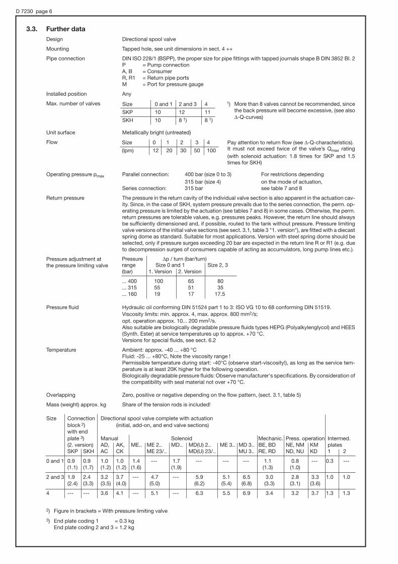
Design Directional spool valve
Mounting Tapped hole, see unit dimensions in sect. 4 ++
Pipe connection DIN ISO 228/1 (BSPP), the proper size for pipe fittings with tapped journals shape B DIN 3852 Bl. 2P = Pump connectionA, B = ConsumerR, R1 = Return pipe portsM = Port for pressure gauge
Installed position Any
Max. number of valves
Unit surface Metallically bright (untreated)
Flow
Operating pressure pmax Parallel connection: 400 bar (size 0 to 3) For restrictions depending
315 bar (size 4) on the mode of actuation,Series connection: 315 bar see table 7 and 8
Return pressure The pressure in the return cavity of the individual valve section is also apparent in the actuation cav-ity. Since, in the case of SKH, system pressure prevails due to the series connection, the perm. op-erating pressure is limited by the actuation (see tables 7 and 8) in some cases. Otherwise, the perm.return pressures are tolerable values, e.g. pressures peaks. However, the return line should alwaysbe sufficiently dimensioned and, if possible, routed to the tank without pressure. Pressure limitingvalve versions of the initial valve sections (see sect. 3.1, table 3 "1. version"), are fitted with a diecastspring dome as standard. Suitable for most applications. Version with steel spring dome should beselected, only if pressure surges exceeding 20 bar are expected in the return line R or R1 (e.g. dueto decompression surges of consumers capable of acting as accumulators, long pump lines etc.).
Pressure adjustment atthe pressure limiting valve
Pressure fluid Hydraulic oil conforming DIN 51524 part 1 to 3: ISO VG 10 to 68 conforming DIN 51519.Viscosity limits: min. approx. 4, max. approx. 800 mm2/s;opt. operation approx. 10... 200 mm2/s.Also suitable are biologically degradable pressure fluids types HEPG (Polyalkylenglycol) and HEES(Synth. Ester) at service temperatures up to approx. +70 °C.Versions for special fluids, see sect. 6.2
Temperature Ambient: approx. -40 ... +80 °CFluid: -25 ... +80°C, Note the viscosity range !Permissible temperature during start: -40°C (observe start-viscosity!), as long as the service tem-perature is at least 20K higher for the following operation.Biologically degradable pressure fluids: Observe manufacturer's specifications. By consideration ofthe compatibility with seal material not over +70 °C.
Overlapping Zero, positive or negative depending on the flow pattern, (sect. 3.1, table 5)
Mass (weight) approx. kg Share of the tension rods is included!
Size 0 and 1 2 and 3 4
SKP 10 12 11
SKH 10 8 1) 8 1)
1) More than 8 valves cannot be recommended, sincethe back pressure will become excessive, (see also|-Q-curves)
Size 0 1 2 3 4
(lpm) 12 20 30 50 100
Pay attention to return flow (see |-Q-characteristics). It must not exceed twice of the valve’s Qmax rating
(with solenoid actuation: 1.8 times for SKP and 1.5times for SKH)
Size Connection Directional spool valve complete with actuationblock 2) (initial, add-on, and end valve sections)with endplate 3) Manual Solenoid Mechanic. Press. operation Intermed. (2. version) AD, AK, ME.. ME 2.. MD.. MD(U) 2.. ME 3.. MD 3.. BE, BD NE, NM KM platesSKP SKH AC CK ME 23/.. MD(U) 23/.. MU 3.. RE, RD ND, NU KD 1 2
0 and 1 0.9 0.9 1.0 1.0 1.4 --- 1.7 --- --- --- 1.1 0.8 --- 0.3 ---(1.1) (1.7) (1.2) (1.2) (1.6) (1.9) (1.3) (1.0)
2 and 3 1.9 2.4 3.2 3.7 --- 4.7 --- 5.9 5.1 6.5 3.0 2.8 3.3 1.0 1.0(2.4) (3.3) (3.5) (4.0) (5.0) (6.2) (5.4) (6.8) (3.3) (3.1) (3.6)
4 --- --- 3.6 4.1 --- 5.1 --- 6.3 5.5 6.9 3.4 3.2 3.7 1.3 1.3
Pressure |p / turn (bar/turn)range Size 0 and 1 Size 2, 3(bar) 1. Version 2. Version
... 400 100 65 80
... 315 55 51 35
... 160 19 17 17.5
D 7230 page 6
3.3. Further data
2) Figure in brackets = With pressure limiting valve
3) End plate coding 1 = 0.3 kgEnd plate coding 2 and 3 = 1.2 kg

D 7230 page 7
|p-Q-CurveThe curves below illustrates the typical back pressure for valve banks with 5 sections and are to beunderstood as a guideline only. The actual figures depend on the No. of utilized sections.The high back pressure apparent with valve banks type SKH with a high number of sections and solenoid actuation (also manual with contact switch) can be minimized by using type SKP together with idle circulation spool valve (flow pattern U) or a piloted pressure limiting valve type DV 5 G.. - WN 1 F acc. to D 4350. Circulation back pressure approx. 5 bar.
Initial valve
Valve No.
Viscosity during measurements approx. 60 mm2/s
Double acting consumers with unequal area ratio show a return flow thatis either higher or lower than the inflow (dep. on direction). The back pres-sure |ptotal of the spool valve section applies to the inflow side (port P) always.:
Flow Q (lpm)
Flow Q (lpm) Flow Q (lpm) Flow Q (lpm)
Flow Q (lpm) Flow Q (lpm)
Inlet P→A, B
Inlet P→A, B
Inle
t P→
A, B
Inlet P→A, B
InletP→
A, B
Inlet P→A, B
Outlet A, B→R
Outlet A, B→R
Outlet A, B→R
Outlet A, B→R
Outlet A, B→ROutlet A, B→
R
Idle positionP→R
Idle positionP→R
Idle positionP→R
Type SKP
Type SKP
Type SKP
Type SKH
Type SKH
Type SKH
Val
veN
o.
Val
veN
o.
Val
veN
o.
Val
veN
o.
Val
veN
o.
Val
veN
o.
Val
veN
o.
Flow Q (lpm)F
low
resi
stan
ce|
p(b
ar)
Flo
wre
sist
ance|
p(b
ar)
Flo
wre
sist
ance|
p(b
ar)
Flo
wre
sist
ance
|p
(bar
)
Flo
wre
sist
ance
|p
(bar
)F
low
resi
stan
ce|
p(b
ar)
Size 0 and 1
Size 2 and 3
Size 4
inlet
outletoutletinlettotal
A
Appp ∆+∆=∆
inlet
outletinletreturn
A
AQQ =
return
inlet
inlet inlet
inletoutlet
outlet
return

4. Dimension of unitsAll dimensions in mm, subject to change without notice!
4.1. Size 0 and 1
4.1.1. Initial valve 1. version
Parallel connection type SKP
Connection block withpress. limiting valveSKH 11(12)..
Connection block with-out press. limiting valveSKH 15..
Port P onrear side
M8, 10 deep
M8, 8 deep
M6, 8 deep
End plate
D 7230 page 8
Initial valve withpress. limitingvalve..-6 and ..-3
..-7 and ..-4
Initial valve withoutpress. limiting valve..-5
Add-onvalve section
End valvesection
Endplate
M8, 8 deep
M6, 8 deep
R1 with symbol U
Attention: Port B is not appar-ent with symbol N, A, R, and S;A and B are not apparent withsymbol U!
M8,10 deep
Reversionplatecoding 1
h1 Ports DIN ISO 228/1(BSPP)Size e e1 h SKP SKH P 1), A, B R, R1
0 9.5 30 17.5 20.5 12 G 1/4 G 3/8
1 11 28.5 18.5 21.5 G 3/8
1) P = G 3/8 (BSPP) with SKH-0-5 when at the bottom side2) Solenoid actuation: The piston side of double acting
cylinders should be always connected to A!3) Contact faces sealed via O-rings
Actuation, see sect. 4.4
Series connection type SKH
Connection block withpress. limiting valveSKP 11(12)..
Connection block with-out press. limiting valve SKP 15..
For missingdimensions,see type SKP!
For missing dimensions,see 1. version!
M8, 10 deep
M8, 10 deep
Ports DIN ISO 228/1 (BSPP)Size P, R, R1 A, B M
0 G 3/8 G 1/4 G 1/4
1 G 3/8 G 3/8 G 1/4
Port P onrear side
Series connection type SKH
4.1.2. Connection block 2. version
Parallel connection type SKP
Adjustable
Fixed setting
2)
3)
(For actuations, see sect. 4.4.1)
appox. 12appox. 12
max. appox. 80
max. appox. 91
appox. 8
appox. 8

D 7230 page 9
Initial valve withpress. limitingvalve..-6 and ..-3
..-7 and ..-4
Initial valve with-out press. limit-ing valve..-5
Spacerplatecoding 2
Add-onsection valve
Endvalvesection
M8,8 deep
Ports A, B, P, R and R1(DIN ISO 228/1) (BSPP):= G 3/8 1) Size 2= G 1/2 Size 3
Ports A, B, P, and R DIN ISO 228/1 (BSPP):4) Size 2 = G 3/8
Size 3 = G 1/2
1) G 1/2 (BSPP) for R, when an end plate is used2) Solenoid actuation: The piston side of double
acting cylinders should be always connectedto A!
3) Contact faces sealed via an intermediate platewith vulcanized seals (SKP) or O-rings (SKH,see symbols table 5, sect. 3.1)
4) Port R with SKH = G 1/2 (BSPP)5) Reversion plate coding 1 is like coding 2 of 1. version.
Attention: Port B is not appar-ent with symbol N, A, R, and S;A and B are not apparent withsymbol U!
M8, 8 deep
If pump if con-nected on theside, the baseconnection isplugged off andvice-versa
If the return con-nection is on the bottom, theside connectionis plugged andvice -versa
Base plate with laterally offset return port only with solenoid actuation M.. 3/.. and alternating mounting pattern
Actuationssee sect. 4.4
Series connection type SKH 5)
Connection block withpress. limiting valveSKP 31(32)..
Connection block with-out press. limiting valve SKP 35..
Connecting bank withpress. limiting valveSKH 31(32)..
Connecting bank with-out press. limiting valveSKH 35..
For missing dimensions, see 1. version!
For missing dimensions, see type SKP!
M8, 10 deep M8, 8 deep
Port P on rear side
M8, 10 deep
End platecoding 2
End platecoding 1
Series connection type SKH 5)
4.2.2. Connecting bank 2. version
Parallel connection type SKP
4.2.1. Initial valve 1. Version
Parallel connection type SKP
Adjustable
Fixed setting
4.2. Size 2 and 3
2)
3)
5)
Manuallyadjustable
Tool adjustable
(For actuations, see sect. 4.4.2)
For missing dimensions,see type SKP!
max. appox. 91
max. appox. 102 appox. 15 appox. 15
appox. 15
appox. 15appox. 15
max. appox. 82
max. appox. 95

D 7230 page 10
Initialvalve
Add-onvalve section
Endvalvesection
Ports DIN ISO 228/1 (BSPP):A, B, P and R = G 3/4
Separating joint sealed viaspacer with O-rings.
The R connection plate with laterallyoff-set bores is intended for alternatingsolenoid assembly direction M..3/..
The R connection plate with laterally off-set bores is intend-ed for alternating solenoid assembly direction M..3/.., if thesecond to the last solenoid is directed downwards.
For missing data, see above! Lateralport R
Bottom sidedport R
Reversion plate,coding 1
M10,12 deep
The dimensions of spacer platecoding 2 (required for identicalassembly direction of the sole-noids M..3/..) are like with rever-sion plate coding 1, see below.
The piston side of double acting cylinders shouldbe connected to A with solenoid actuation!
Actuations see sect. 4.4.2
Series connection type SKH
Parallel connection type SKP
4.3. Size 4
(Actuations see sec. 4.4.2)
appox. 20 appox. 20

D 7230 page 11
4.4 Modes of actuation
Only main data is listed here, for more detailed information, see the corresponding pamphlets!
4.4.1. Size 0 and 1
Manual actuation
coding A, AK, C, CK
Solenoid actuation
coding ME.. and MD..
Mechanical actuation
coding RE and RD
Pressure actuation
coding NE and ND
Hand levercan also bemountedhere
Manual emer-gency actuation
Manual emergency actuation ME..N and MD..N:
Illustration showsidle position (not detented).
Attention:Observe the description in D 7055. Thispamphlet may be ordered separately toinclude the section "Manual emergencyactuation" in your operation manual.
Special note for series connection of type SKH:
The manual emergency actuation of valve sections on even position within the valve bank will be very heavy or impossibleto actuate for pressure above 40 bar due to the internal flowreversal (see table 4, sect. 3.1). This effect can be preventedby utilization of reversion plates coding 1 (table 6, sect. 3.1)!
MD.. ME..
app
ox.
40

D 7230 page 12
Solanoid actuation
Coding ME.., MD.. and MU..
For notes regarding manual emergency actuation (M...N) and specialtiesof type SKH, see sect. 4.4.1!
4.4.2. Size 2, 3, and 4 Illustration for size 2, 3, and 4 is identical!
Manual actuation
Coding AD, AK, CD, and CK
(in preferred mounting, assembly Lis shown in pamphlet D 6511/1)
Mechanical actuation
Roller heads Spherical headscoding RE and RD coding BE and BD
Pressure actuation
Standard versionscoding NE, ND, NU, and NM
Hand levercan also bemounted here
MD(U).. ME..
Coding b b1
ME2/..MD 2/.. 51.5 60MU 2/..
ME 23/..MD 23/.. 51.5 60MU 23/..
ME3/..MD 3/.. #72 #72
MU 3/..
Combined actuationcoding KD and KM
app
ox.
235
app
ox.
342

D 7230 page 13
5. Appendix5.1. Circuit and assembly examples
Size 0 and 1
Example 1: 1. Version (series connection), initial spool valve sectionwith manually adjustable pressure limiting valve (120 bar),solenoid actuation and reversion plate to ensure correctflow direction of the bottom side port R at the end spoolvalve section (size 1) due to even number of valve sections.
SKH - 1 -7LLP1H - MD8 - 120
Example 2: 2. Version (parallel connection),connection block with tool ad-justable pressure limiting valve (300 bar), pressure actuation, size 0.
SKP 11C -0 -DDE - ND - 300
Example 3: 1. Version (parallel connection), initial spoolvalve section without pressure limiting valve,manual actuation (AD), size 3.
SKP - 5 -5MNC - AD
Example 4: 1. Version (parallel connection), initial spoolvalve section without pressure limiting valve andend plate after the last spool valve section (see footnote 2) regarding table 5, sect. 3.1).
SKP - 3 - 5MGN - 1 - MD 2/24
Example 5: 1. Version (parallel connection), initial spoolvalve section with manually adjustable pressure limiting valve (240 bar), solenoid actuation MD 3/24 alternatingly sided (with-out spacer plate coding 2), every valve section on an even position is rotated by 180°(upside down).
SKP - 3 - 7MMMM - MD 3/24 - 240
Size 2 and 3
Endplate

D 7230 page 14
Size 4
Example 6: Parallel connection, solenoid actuation MD 3/24 or MU 3/24 alternatingly sided (without spacer plate coding 2). This examplealso shown mixed actuation modes (table 8).
SKP - 45 N/MD 3/24 - G/MD 3/24 - G/MD 3/24 - W/MU 3/24
Example 7: Series connection, solenoid actuation MD3/24 with identical assembly orientationenabled via reversion plates coding 1
SKH - 4 - 5L1L1S - MD 3/24
Intended for direct mounting onto compact hydraulic power packs type HC acc. to D 7900; HK acc .to D 7600 ++MP acc. to D 7200 H
5.2. Connection block type SKC 1.. for directional spool valves type SKP and SKH
- SKC 11 M/MD 2
- SKC 14 S
Coding examples: HC 34/5,6 - D/MD2 - W/ME2 - 130 Motor voltage 3 + 400V 50Hz
MP 44A-Z9/B25 - LF- MD8 - 100 Motor voltage 3 + 230/400V 50Hz
Compact hydraulic power packsacc. to D 7900 or D 7200H
Basic typeandsize
SKC 1
Pressure limiting valveStand- Steel Pressure ard spring dome range (bar)
1 3
2 4
(20) ... 400 1)(20) ... 315(20) ... 160
(0) ... 400 1)(0) ... 315(0) ... 160
Tooladjustable
Manuallyadjustable 1) Not for series connection.
With solenoid actuation only up to200 bar (see table 7 and 8)
Pressure specification (bar)for the pressure limiting valve
Add-on spool valve (inter-spool valve)with solenoid actuation (best with actu-ations below).Manual actuation only with bent handlever (see Sk 7257).Mechanical and pressure actuation only for parallel connection; series con-nection only with type SKC 1.. withoutadd-on spool valves.
Integrated direction-al spool valve (initialspool valve section)
Applicable flow pat-tern symbols, acc.to table 5, sect. 3.1:
M, D, E, A, J, R,
U, L, P, S
Ports DIN ISO228/1(BSPP):A, B, R, R1 = G 3/8M = G 1/4
Mass (weight):approx. 2.6 kg (at ME..-act.)approx.. 3 kg(at MD(U)..-act.)
Example circuits according to above order examples
HC 34/5,6-SKC11M/MD2-D/MD2-W/ME2-130 MP44A-Z9/B25-SKC14S-LF-MD8-100
Motor voltage 3 + 400V 50Hz Motor voltage 3 + 230/400V 50Hz
Attention: The return connection between portR1 at the end plate and port R at theinitial valve section has to be customerfurnished, when the valve sections areconnected internally in series!
MP 44A-Z9HC 34/5,6

D 7230 page 15
Dimensions
All dimensions in mm, subject to change without notice!
Pressure limiting valve
Adjustable FixedFor missing dimensions,see sect. 4.1!
Pressure porte.g. for pres-sure gauge orpressure switchunit
Illustration, when directly mounted onto compact
hydraulic power pack type HC
(similar assembly onto type HK)
Illustration, when directly mounted onto compact
hydraulic power pack type MP
Pumps HC 1 HC 2 HC 3 HC 4 HK 2.. HK 3.. HK 4..HCG 11
a 70 85 102 124 100 108 124
b 24 39 52 65 35 45 50
End platewith SKP..
End platewith SKH.. 1)
Ports DIN ISO 228/1 (BSPP):A, B, R, R1 = G 3/8M = G 1/4
1) Connections for external, customer furnished return lineR→R1, see circuit example in sect. 5.2.
Tanks B 3 B 5 B 10 B 25 B 55
Cover plates D 3 D 5 D 10 D 25 D 55
c 59 74 77 87 117
appox. 12appox. 12

Coding examp.: Z 12.3/B40-V2.2-A100 - GE - MD8
R 23.5/B75-V11- A230 - LH - AK
D 7230 page 16
5.3. Adapter plates for directional spool valve banks type SKP and SKHfor direct mounting onto hydraulic power packs type R acc. to D 6010 H and type Z acc .to D 6820
- SKP 16
- SKH 37
Hydraulic power packs acc. to D 6010 H and D 6820
Basic type (table 1, sect. 3.1)SKP = Parallel connectionSKH = Series connection
Table 10: Adapter plate
Motor voltage 3 + 230/400V 50Hz
Motor voltage 3 + 400V 50Hz
Suited forsize
0
1
2
3
2
3
Coding
06
16
27
37
28
38
Suitable for tank / coverplate (acc. to D 6010 H,D 6820)
B 6 to B 40D 6 to D 30
B 50 and B 75D 50
B 100 to B 400D 100 and D 250
Mass(weight)approx. kg
0.8
0.8
2.3
Add-on spool valve (for flow pattern symbols, see table 5,sect. 3.1)
Z 12.3/B40-V2.2-A100-SKP16-GE-MD8
R 23.5/B75-V11-A230-SKH37-LH-AK
Actuation (table 7 and 8)Best with solenoid or manual actuation. Other actuations areless common here:Mechanical and pressure actuation only for parallel connec-tion; only with an add-on spool valve section when seriesconnection is intended.
Attention:The return connectionbetween port R1 at theend plate and port R atthe initial valve sectionhas to be customer fur-nished, when the valvesections are connectedinternally in series!
Dimensions of units
All dimensions are in mm, subject to change without notice!
For missing dimensions,see sect. 4.1!
Adapter platecoding 06 and 16
For connection block withpressure limiting valve,see D 6010 H or D 6820
Adapter platecoding 27 and 37
28 and 38
For connection block withpressure limiting valve,see D 6010 H or D 6820
End plate forSKP SKH.. 1)
End plate forSKP SKH.. 1)
For missing dimensions,see sect. 4.1!
1) Ports for external, customer furnished return line R→R1, see example above.
l = 115 (D50); 135 (D100); 190 (D 250)
b = 134 (D50) 138 (D100)193 (D 250)

Directional seated valvesDirectly actuated, leakagefree for hydraulic systems
For the assembly on connection sub-plates
D 7300Directional seated valves
May 2007-06
HAWE HYDRAULIK SESTREITFELDSTR. 25 • 81673 MÜNCHEN
2.2
© 1980 by HAWE Hydraulik
Valve for sub-plate mounting Section 3 Pressure pmax = 350...500 (700) barValve with individual connection sub-plate Section 5 Flow Qmax = 6...120 lpmDirectional valve bank D 7302
1. General informationDirectional control valves are generally used for the direct, leakage free control of consumers and as pilot valves for hydraulically actuated valves (depending on the flow pattern). They are designed as spring returned ball seated valves. The valve elements are forced into their respective switching position against the spring force and fluid pressure by various actuation elements via an elbow lever acting on a pin. A strainer insert in the inlet port prevents the entry of coarse contamination.The fluid ducts end as holes with O-ring seals at the ground, bottom surface of the valve body. Pipes may be connected either via customer furnished connection blocks or sub-plates (for individual valves with sub-plates see sect. 5 or for valve banks see D 7302).These valves do not show any leakage in blocked switching position. Reliable shifting is ensured, as these valves are designed as ball seated valves where there is no seizing or sticking in working position under full pressure. The leverage between actuation and valve element ensures low actuation forces and smooth shifting. To avoid interaction, most of these directional control valves are available with check valve inserts and return pressure stops or orifice inserts to limit the inflow of oil.Individual valves with sub-plate, enabling direct pipe connection, may be equipped with a by-pass check valve, a pressure limiting valve, or a rectifier circuit by means of check valves.
2. Overview(For complete type overview, see sect. 8)
Individual valve for manifold mounting
Solenoid actuated 2/2-way directional seated valve, size 1, free flow when deenergized
Actuation modesFor detailed data. see section 4++.(Max. pressure rating depending on flow pattern and size. see sect. 3.1 table 2)
Solenoid actuated 3/2-way directional seated valve, size 2 with check valve insert in port P
Tapped ports in the connection sub-plate, G 3/8 (BSPP)
Individual valve with connection sub-plate for direct pipe connection
e.g. GS 2-1-G 24 e.g. GZ 3-2R-3/8-G 24
Code letter
Picture and symbol
Solenoid
G WG
Pressure hydraulic pneumatic
H P
Mechanical roller pin
K T
Manual feeler turn-knob
F D

D 7300 page 2
Order example:
Solenoid actuation (acc. to sect. 4.1)G = DCWG = AC
For actuation modes H, P, K, T, F, D, see sect. 2 and 4.2 ++
3. Individual valves, manifold mounting 3.1 Valve
(For individual valves with connection sub-plate for pipe connection, see sect. 5)
G R2 - 3 R - G 24
Table 1: Flow pattern
Coding
Detailed symbols (must be completed by actua-tion sym-bol)
Simplified flow pattern symbol
2/2-way valve
R2 3) S2 3)
3/2-way valve
3 3) Z3 3)
3/3-way valve
21 3)
4/3-way valve
22 1)
4/2-way valve
4 2) 3) Z4 2) 3)
1) Not available for size 4! Note the arrangement of solenoids a and b in relation to the ports A and B, see dim. drawings sect. 3.3.3
2) Only available for size 13) Size 1 also available as explosion-proof version, see sect. 4.1.3
Table 2: Size, main data
Coding
Max. flow approx. lpm
Directional valves (... -way)
Type G.. and WG..
Type H..
Type P..
Type K..
Type T..
Type F..
Type D..
0
6
2/2; 3/2 3/3 4/3
500 350
500 500
--- ---
--- ---
--- ---
--- ---
500 --- ---
1
12
2/2; 3/2; 3/3; 4/2 4/3
500 4) 350
700 500
700 400
700 400
700 400
700 400
700 400
2
25
2/2; 3/2; 3/3 4/3
500 4) 350
500 500
500 400
500 400
500 400
500 400
500 ---
3
65
2/2; 3/2; 3/3 4/3
400 350
400 400
400 350
400 350
--- ---
400 350
--- ---
4
120
2/2; 3/2; 3/3
350
---
---
---
---
---
---
Pres-surepmax(bar)
4) For max. pressure during shifting, see sect. 4.1
Table 3: Additional elements to influence shifting operations, inserted in port P or R (can be retrofitted).
Additional element
solenoid voltage (standard)G 24 = 24 V DC; WG 230 = 230 V ACsee sect. 4.1Additional element (see table 3)
Size and main data (see table 2)
Note
Not avail. for 3/3- and 4/3-way directional spool valves type ...21 and ...22The check valve prevents an uncontrolled impact or reflow RdP or AdP, e.g. if the inlet pressure at P drops below the consumer pressure at A (during idle position or actuation of another consumer with a lower pres-sure requirement) when several valves are connected in parallel. A pressure reduction is prevented during such switching operations.
Not available for 4/3-way valves type ...22 !The orifice serves to limit the flow (see |p-Q curves) and should be installed if flow rates higher than Qmax (table 2) can occur while switching from PdA(R): Hydraulic accumulators on the pump side P or in the case of hydr. servo operation of directional spool valves with control oil supply from the high flow main gallery.
Only available for 3/2-way valves types ..3-.. or ..Z3-.. .Check valves may be installed in the reflow ports R of 3/2-way valves size 0 and 1. With parallel shifting of several valves, they prevent pressure surg-es from migrating via the common reflow gallery into non-operated, easily moving and unloaded consumers if there is a connection AdR, thus preventing uncontrolled extension movements. Such pressure surges can be caused by shifting operations. These check valves are not intended for blocking off hydraulic oil, which depending on the combination of switching operations of other valves, can arise at port R.
Coding and symbol
R
B
S
for Type size
all
all
0 7332 000 a
1 7332 000 b
Insert check valves type ER acc. to D 7325 e.g. type ER 01 for valves size 0
Insert orifices type EBacc. toD 6465
Return pressure stop
A combination with check valve or orifice in port P is possible e.g. G 3-1 BS-G 24, GZ 3-1 RS-G 24
Installation illustration
Check valve or orifice installed in port P
Return pressure stop installed in port R
Mechanical actuation
Pressure actuation
Solenoid actuation
Manual actuation
size 0 = EB 0-0,6 1 = EB 1-0,8 2 = EB 2-1,2 3 = EB 3-2,5 4 = EB 4-4,0
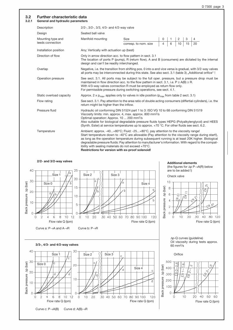
D 7300 page 3
3.2 Further characteristic data3.2.1 General and hydraulic parameters
Description 2/2-, 3/2-, 3/3, 4/3- and 4/2-way valve
Design Seated ball valve
Mounting type and Manifold mountingleeds connection
Installation position Any; Vertically with actuation up (best)
Direction of flow Only in arrow direction acc. to flow pattern in sect. 3.1 The location of ports P (pump), R (return flow), A and B (consumers) are dictated by the internal
design and can‘t be readily interchanged.
Overlap Negative, i.e. the transition from shifting pos. 0 into a and vice versa is gradual, with 3/2-way valves all ports may be interconnected during this state. See also sect. 3.1 (table 3) „Additional orifice“ !
Operation pressure See sect. 3.1. All ports may be subject to the full oper. pressure, but a pressure drop must be maintained in flow direction acc. to the flow pattern in sect. 3.1, i.e. P Ú A(B) Ú R. With 4/3-way valves connection R must be employed as return flow only.For permissible pressure during switching operations, see sect. 4.1.
Static overload capacity Approx. 2 x pmax, applies only to valves in idle position (pmax from table 2 sect. 3.1)
Flow rating See sect. 3.1. Pay attention to the area ratio of double acting consumers (differtial cylinders), i.e. the return might be higher than the inflow.
Pressure fluid Hydraulic oil conforming DIN 51524 part 1 to 3: ISO VG 10 to 68 conforming DIN 51519 Viscosity limits: min. approx. 4, max. approx. 800 mm2/s Optimal operation: Approx. 10 ... 200 mm2/s Also suitable for biological degradable pressure fluids types HEPG (Polyalkylenglycol) and HEES
(Synth. Ester) at service temperatures up to approx. +70 °C. For other fluids see sect. 6.2.
Temperature Ambient: approx. -40...+80°C; Fluid: -25...+80°C, pay attention to the viscosity range! Start temperature down to -40°C are allowable (Pay attention to the viscosity range during start!),
as long as the operation temperature during subsequent running is at least 20K higher. Biological degradable pressure fluids: Pay attention to manufacturer‘s information. With regard to the compat-ibility with sealing materials do not exceed +70°C.
Restrictions for version with ex-proof solenoid!
2/2- and 3/2-way valvesAdditional elements
(the figures for |p PdA(R) below are to be added !)
Check valve
Orifice
3/3-, 4/3- and 4/2-way valves
Curve c: PdA(B) Curve d: A(B)dR
Curve a: PdA and AdR Curve b: PdR
Size 1
Size 0
Size 2 Size 3
Size 4
Size 1
Size 0
Size 2 Size 3
Size 4
Bac
k p
ress
ure
|p
(bar
)B
ack
pre
ssur
e |
p (b
ar)
Bac
k p
ress
ure
|p
(bar
)B
ack
pre
ssur
e |
p (b
ar)
Flow rate Q (lpm) Flow rate Q (lpm) Flow rate Q (lpm)
Flow rate Q (lpm)Flow rate Q (lpm)Flow rate Q (lpm)
Size 0 1 2 3 4
corresp. to nom. size 4 6 10 15 20
|p-Q curves (guideline)Oil viscosity during tests approx. 60 mm2/s

D 7300 page 4
3.3.2 4/2-way valve
Coding .4-.. or .Z4-.. Holes in the manifold and sealing of the ports by O-rings 2)
3.3 Dimensions,All dimensions are in mm and are subject to change without notice!
3.3.1 2/2- and 3/2-way valves
Coding .R2-.., .S2-.., .3-.., .Z3-..Port A is internally blocked at 2/2-way valves, but an O-ring must be installed if the valve is mounted on a sub-plate.
Size 0 and 1 Size 2 and 3 Size 4
valve only. For the dimensions of the actuations see sect. 4.1 ++
1) Port B (G1/4 (BSPP)) is unplugged, at versions with sub-plate acc. to section 5 or when installed in a valve bank type VB11... acc. to D 7302
2) Available as a complete seal kit (see sect. 4.5).
Size 1:Countersinking of the mounting thread
2/2- and3/2-way valve
4/2- way valve
Size
0
1
2
3
4
1
Ports
P and R
A
P and R
A
P
A and R
P
A and R
A, P and R
P
A, B and R
#d
3.5
3
4.5
4.5
9
9
12
12
20
4.5
4.5
O-ringNBR 90 Sh
6x1.5
3.5x1.2
8x1.5
5x1.5
14x2
10x2.2
17.12x2.62
13.95x2.62
8x1.5
5x1.5
Size
0
1
2
3
L
32
40
50
70
L1
41.5
50
62.5
91.5
B
36
45
56
70
H
27
35
55
70
a
10
13
16.6
24
a1
12
14.5
18
20
b
16
20
26.6
40
b1
18
22.5
31
45
c
22
27
38.8
55
c1
24
30.5
32
45
e
24
30
39
54
e1
28
35
43
54
f
4
5
5.1
8
f1
4
5
6.5
8
g
M5
M6
M8
M10
k
7
8
11
17
m
4
9
10
10
O-ring
For dimensions of the valve, see sect. 3.3.1 (size 1)!
M6
KANTSEAL seal ring 6096 5217-00
Size 0: 6.5 NmSize 1: 9.5 Nm
Size 2: 23 NmSize 3: 46 Nm Size 4: 80 Nm

D 7300 page 5
Ports Size 0 Size 1 Size 2 Size 3
#d P, R, A a. B 3.5 4.5 9 12
P 6x1.5 8x1.5 14x2 17.12x2.62
R, A and B 6x1.5 5x1.5 10x2.2 13.95x2.62
Holes in the manifold and sealing of the ports by O-rings 1)
Size
0 1 2 3
L 75 92 116 144
B 32 40 50 70
H 31 40 59 70
a 4 5 5.5 8
b 24 30 39 54
c 23 28 39 55
e 11 13 17 22
f 27 35 45 55
g M5 M6 M8 M10
h 4.5 9 10 10
i 19 24 30 38
l 66 82 103 128
m 7 8 11 17
n 11 13 17 23
o 38 45 53 64
Size 0 1 2 3 4
L 75 92 116 144 162
B 32 40 50 70 100
H 27 35 55 70 101
a 4 5 5.5 8 9
b 24 30 39 54 82
c 23 28 39 55 74
e 11 13 20 24 27
f 16 27 26 26 41
g M5 M6 M8 M10 M12
h 3.5 9 10 10 16
i 19 20 26 20 25
k 13 15 22 20 25
l 66 82 103 128 144
m 7 8 11 17 18
n 10 10 13 22 26
o 38 45 53 72 82
3.3.3 3/3- and 4/3-way valves
3/3-way valve
Coding .21-..
4/3-way valve
Coding .22-..
O-ring
1) Available as a complete seal kit (see sect. 4.5).
P, R, A and B
Attention: Both return ports R have to be connected, as there is no internal connection.

D 7300 page 6
With load cycles Ò 10% ED Ambient temp. Ò 40°C (not 4/3-way valves type ...22)
4. Actuation modes4.1 Solenoid actuation (standard)
The solenoids are built and checked conforming to VDE 0580.
Valve type acc. to sect. 3.1 Size 0 Size 1 Size 2 Size 3 Size 4
G... WG... 1) G... WG... 1) G... WG... G... WG... G... WG...
Nom. voltage UN 12V DC, 24V DC, 110V DC, 230V AC see also sect. 4.1.2
Nom. current IN 2) (A) 0.67 0.08 0.83 0.1 1.1 0.13 2.1 0.26 3.6 0.44
Nom. power PN 2) (W) 16 16 20 20 26 26 50 50 86 86
on (ms) 40 80 100 100 140 140 175 175 150 150
off (ms) 40 100 50 125 55 150 65 200 100 4) 350 4)
Switchings per hour / h Approx. 2000 (G.. and WG.. all sizes); approx. evenly distributed
Protection mode IP 54 acc. to IEC 60529 (readily assembled), IP 67 acc. to IEC 60529 for explosion-proof version
Isolationsklasse F H
Cut-off energy (Ws) 0.16 0.16 0.24 0.24 0.38 0.38 1.59 1.59 3.4 3.4
Guideline for max. value + approx. 10% according to tests with nom. voltage and 20°C
; ? < > 1) = > = > = >
; Plug MSD 2 3)
< Plug MSD 1 3)
= Plug conf. EN 175 301-803, e.g. MSD 3-309 3)
> Adapter + Socket A MSD 1-MSD 3 + MSD 4-209 P10 3)
? Adapter + Socket A MSD 2-MSD 3 WG + MSD 3-309 3)
These connectors 3) are part of the order coding as standard. For other connectors e.g. with clamp diode, economy circuit or LED‘s see D 7163.
The solenoid valves are suitable for normal outdoor use, if the solenoids are installed vertcall (indicated by previous experience).
100% ED (stamped on the solenoid), however observe operating duty cycle !Rel. duty cycle
Permissible operation conditions for outdoor use
Connection scheme of the plugs
Plug conf. EN 175 301-803
Adapters for size 0 and 1, see sect. 4.1.1
The curves do apply to stand-alone, individual valves only! If the valves are installed in a cabinet, it should be al-ways equipped with louvers! In case of bank arrangement and ambient temperatures above 40°C the layout should be designed in such a way that adjoining solenoids are not energized over prolonged periods.
Increased switchable pressure (other than listed in sect. 3.1) for size 1, 2 and 4
1) Only with adapter, see sect. 4.1.12) The electrical data for solenoids G and WG are only a guideline (max) and may vary depending on manufacturer.3) Co. K + B GmbH, D-84056 Rottenburg a.d.L.; This type of plug must be specified, when placing a separate orders.4) Possibly increased tolerance, above 250 bar.5) Attention: The storage capability of high pressure consumers has to be taken into consideration. Pressure surges during decharging, which
might harm internal functional parts of the valve or fatigue fracture of other hydraulic components of the application can be prevented by installing orifices (see sect. 3.1) upstream.
Switching time (guideline)
Type WG...
Type G...
Rel. duty cycle during operation
Am
bie
nt
tem
per
ature
U (°
C)
Rel. duty cycle
Rel. duty cycle (%ED) Continuous operation
Type
G... a. WG..
pmax(bar)
700
Qmax 5)(lpm)
8
Valves size 1
pmax(bar)
700
Qmax 5)(lpm)
12
Valves size 2
pmax(bar)
400
Qmax 5)(lpm)
60
Valves size 4type GR 2-4-G..
Version for size 0 to 3
Version for size 4
(Cycle time)
Time
tr = · 100 (%ED)tein
T

D 7300 page 7
4.1.1 Plugs for valves size 0 and size 1
The standard version comes with a plug (see dimensional drawing and connection scheme)
Order example: GR 2-1 Solenoid voltage 24V DC
Plug type
4.1.2 Solenoid voltage Attention: It is important to specify the voltage !
1) Notes for proper selection: DC: The order specification (solenoid)
should be identical with the one of the power supply (DC). If the supply voltage is lower it will reduce the force of the solenoid, if it is high-er the solenoid will be heated up unpermissibly (tolerance ± 5-10%).
AC: The order specification should be identical with the one of the power supply (50/60 Hz AC). The voltage of the solenoid is approx. 0.9 UAC-2 V due to the corresponding bridge rectifier. The table identifies the so-lenoids utilized in such cases (e.g. for 110V AC 50 Hz; solenoid with UN = 98V DC)
The indicated nominal power ratings are ap-proximate reference values, which may dif-fer insignificantly depending on the voltage and the manufacturer of the solenoid. The current rating in cold state is I20 = PN / UN (see examples)
Order specification Size 0 Size 1 Size 2 Size 3 Size 4
DC 1) AC 1) (& UN [V]) 50/60 Hz (16 W) (20 W) (26 W) (50 W) (86 W)
G 12 x x x x x
G 24 WG...-WG 24 x x x x x
G 24 EX x (23 W)
G 36 WG...-WG 42 x x
G 42 WG...-WG 48 x x x
G 48 x x x x
G 80 x x x x
G 98 WG...-WG 110 x x x x x
G 110 x x x x
G 125 x x x
G 185 WG...-WG 200 x x x (180V DC) x
G 205 WG...-WG 230 x x x x x
G 220 x x x
-A 24
Coding
Note
Socket Size 0
Size 1
MSD 2
MSD 1
MSD 2-MSD 3WG+ MSD 3-309MSD 1-MSD 3+ MSD 4-209 P10
MSD 2-MSD 3 MSD 1-MSD 3
MSD 2-MSD 3+ MSD 3-309MSD 1-MSD 3+ MSD 3-309
Central plugs (serie)
Valve with adapter and bridge rectifier (socket)The bridge rectifier is incorpo-rated in the adapter for size 0
Valve with adapter for plugs shape A EN 175301-803 is customer furnished
Valve with adapter and, plug shape A EN 175301-803
G WG A N
(Nominal power PN)
GR 2-2 - G 24 (I20 = 0.54 A)G 3-0R - A 110 (I20 = 0.15 A)WGZ 4-1 - W 200 (I20 = 0.11 A)
Examples:
Directional seated valve acc. to section 3.1
Electrical data for explosion-proof solenoids
ATEX-Certificate of conformity TÜV-A-03 ATEX 0017 XCoding O II 2 G Ex d IIB + H2 T4 O II 2 D Ex mbD 21 T135°C Oper. duration 100% EDDuty cycle IP 67 (IEC 60529)Nom. voltage UN 24 V DCPower PN 23 WRestrictions for use:
Ambient temperature -35 ... +40°Cmax. fluid temperature +70°Cel. protection against overload (conf. IEC 60127) IF < 1.6-A-TSurface coating Housing galvanically zinc coated
Coil and connection cavity are mouldedElectrical connection 3x0.5 mm2
Cable length 3 m, Option 10 m (cable ÖLFLEX-440P ® Co. LAPP, D-70565 Stuttgart)
Attention: Protect the complete valve against direct sun light.
Observe the operation manuals B 03/2004 and B ATEX!Electrical lay-out and testing conforming EN 60079, VDE 0170-1, VDE 0170-5
Note:
Only 40 % ED are permissible if the valves are neighboring, it is additionally recom-mended that neighboring valves are not actuated simultaneously.
PE 1 2 Housing
Attention:
- Flow pattern 21 and 22 not available with explosion-proof solenoids
Explosion-proof solenoids
Connection scheme of the plugs

D 7300 page 8
4.1.3 Unit dimensions
All dimensions are in mm and are subject to change without notice!
1) It is not possible to install the plug in any position if the valve is part of a valve bank (see D 7302)
2) Either in upward or downward valve bank (see
D 7302)
3) This dimension is depending on the manufacturer and
may be up to 40 mm more DIN 43650
4) The bridge rectifier is incorporated in the adapter with type WG.. size 0 and with size 1 it is part of the plug
May be installed rotated by 90° 2)
May be installed rotated by 90° 2)
May be installed rotated by 22.5° 1)
Suited for leeds #6
Plug may be installed rotated by 180°
Adapter for plugs DIN (ISO 4400) 4)
Adapter plug acc. to sect. 4.1.1, for dimension see size 4
Adapter may be in-stalled rotated by 180°
Size 0 Size 1 Size 2 and 3 Size 4
For di-mensions see size 4
Size D Hmax hmax a
2 50 71.5 26 30 3 62 92 27 46
Size 0 and 1
Push the emergency actua-tion pin inward by means of a screw driver or similar, if required
Press the actuation pin hid-den under the rubber cap.
Size
Max. actuation force (N)
Cross sectional drawing
0 1 4 2 3
35 80 450 150 250
Manual emergency operation
The manual emergency actuation may be put out of function by blocking the tapped hole by means of a screw M3x5 DIN 921
Note
Size 1 with explosion-proof solenoids
Twist stop
Manual emergency
app
rox.
24
app
rox.
34

D 7300 page 9
4.2 Hydraulic and pneumatic actuation
The actuation element is a single acting piston with spring return.The valve will remain in its working position a as long as the control pressure prevails. It will return automatically in its idle position 0 if the control pressure is relieved.The piston is sealed and operates without any leakage.
Hydraulically
(Size 0 ... 3)
Oil
H...
Pneumatically
(Size 1, 2, 3)
Compressed air, filtered and oiled
P...
Actuation
Control medium
Coding
Size 0 1 2 3 1 2 3
Control pressure (bar) max 500 700 500 400 15
min 16 12 9 9 4 2.5 2.5
Control volume (cm3) 0.2 0.4 0.7 6.1 1 2.5 7
D 32 39 49 60 39 49 60
H 44 36 52 77 36 39 52
a/f 27 27 32 41 --- --- ---
Temperature (ambient and control medium) -40 to + 80°C -20 to + 70°C
a/f
Size 1 2 3 1 2
Switching force range s (N) 25 to 28 42 to 47 55 to 80 51 to 57 95 to 120
Start of function (H + h) 38.5 46.5 76 --- ---
Function path h 10.5 15.5 30 4 5
Switching position range s 3 4 6 --- ---
D 39 49 60 39 49
d 25 25 35 18 22
H 28 31 46 20.5 25.5
H1 --- --- --- 16.5 20.5
a 42 41 62.5 --- ---
b 21 21 26 --- ---
c 12 12 15 --- ---
Actuation mode
Code letter
Dimensional drawing
Roller lever (Size 1, 2, 3) Feeler pin (Size 1 and 2)
K... T...
Do not use as a stop!
Do not use as a stop!
Roller lever switching curve operation direction
dea
d m
otio
n
4.3 Mechanical actuation
The actuation element is a pin (tracer) with spring return, which may be used either directly for vertical directions of operation or via a roller lever for lateral directions. The valve is in working position a if the actuation element is forced into the hatched area of the lever path.
All dimensions are in mm and are subject to change without notice!
±0.5
±0.5
±0.5
±0.5
±0.5
±0.5
±0.5
±0.5
±0.5
Switch-ing path (mm)
1) conforming ISO 228/1 (BSPP)
All dimensions are in mm and are subject to change without notice!

D 7300 page 10
4.4 Manual actuation
Feeler lever coding F: The actuation element is a feeler lever which acts on a spring loaded pin. Switching position a is retained as long as the feeler lever is pressed down within the hatched area.v
Turn knob coding D: This actuation element is with detent. Switching position a or 0 alternate as the knob is turned by 90°. The direction of rotation is arbitrary.
Actuation mode
Code letter
Dimensional drawing
Feeler lever (size 1, 2, 3) Turn knob (size 0, 1, 2)
F... D...
Size 1 2 3 0 1 2
Actuation force in the range s (N) 25 to 28 42 to 47 55 to 80 --- --- ---
Switching torque (Ncm) --- --- --- 45 63 98
Actuation travel (mm) hmax 20.5 23.5 45 --- --- ---
s 3.5 4 10 3.5 3.5 5
D 39 49 60 --- --- ---
H 37 43 70 38 40 47
B 34.5 32 56.5 43 43 52
Not to usedas a stop !
Switch-ingposition
4.5 Seal kitsFlow pattern
..R2
..S2
..3
..Z3
..4
..Z4
..21
..22
Size
0
1
2
3
4
0
1
2
3
4
0
1
2
3
G, WG, K, T, F and D
1 x DS 7300-01
1 x DS 7300-11
1 x DS 7300-2N
1 x DS 7300-31
1 x DS 7300-41
1 x DS 7300-02
1 x DS 7300-12
1 x DS 7300-21N
1 x DS 7300-32
1 x DS 7300-42
1 x DS 7300-02
1 x DS 7300-12
1 x DS 7300-22
1 x DS 7300-33
H and P
1 x DS 7300-011 x DS 7300-03
1 x DS 7300-111 x DS 7300-13
1 x DS 7300-2N1 x DS 7300-23
1 x DS 7300-311 x DS 7300-34
1 x DS 7300-022 x DS 7300-03
1 x DS 7300-122 x DS 7300-13
1 x DS 7300-21N2 x DS 7300-23
1 x DS 7300-322 x DS 7300-34
1 x DS 7300-022 x DS 7300-03
1 x DS 7300-122 x DS 7300-13
1 x DS 7300-222 x DS 7300-23
1 x DS 7300-332 x DS 7300-34
Seal kit for actuation
These seal kits contain the O-rings listed in sect. 3.3 and additional parts and seals.For more detailed information, see spare parts lists E 7300-0, E 7300-1, E 7300-2, E 7300-3 and E 7300-4.
All dimensions are in mm and are subject to change without notice!

D 7300 page 11
5. Individual valve with connection sub-plateAll ports of the 2/2-, 3/2-, 3/3- and 4/3-way directional seated valves acc. to section 3 are designed as holes with O-ring sealing at the ground bottom of the valve body. These valves have to be completed with sub-plates or customer furnished manifolds to enable pipe connection.
5.1 Available versions, main data
Order example: GR 2-2 - 1/2S 220- G 12 -
Valve coding acc. to sect. 3
Desired pressure setting in bar
(Pressure range depending on spring, see <)
Suited for connection in series and in parallel, if the perm. pressure stated in section 3.2. „Operation pressure“ for P, A, B and R are not exceeded.
The rectifier circuit by means of check valves enables both flow directions for the 2/2-way valves. Therefore the port codings P and R are not stamped on the sub-plate.
1) For male pipe fittings with journals shape B DIN 3852 page 2. 2) Not available for flow pattern 4 and Z4 (table 1)
Port R may be used only for unpressurized return flow to ensure proper function of the pressure reducing valve. Paral-
lel connection of additional valves is only permissible with sub-plates acc. to ; but not with sub-plates acc. to <
A by-pass check valve (RK 3 acc. to D 7445) is required to enable flow RdP. Pressure surges (decompression) in flow direction RdP should be avoided ! For pressure rating of R, see sect. 3.2.
Version with G 1 is not available
The pressure specification in the order coding determines the pressure range of the spring (size 0) and additionally the valve seat dimension for size 1 and 2.
Connection block without additional features
Connection with pressure limiting valve
../..Stool adjust-able
../..SRmanually adjustable
Connection block with by-pass check valve
Not available for other sizes !
Connection block with recti-fier circuit by means of check valves
Coding
-1/4
-3/8
-1/2
-3/4
-1
Ports con-forming ISO 228/1 1) (BSPP)
G 1/4
G 3/8
G 1/2
G 3/4
G 1
Avail-able for size
0 and 1
1 and 2
2 and 3
3 and 4
4
-1/4 S(R)
-3/8 S(R)
-1/2 S(R)
G 1/4
G 3/8
G 1/2
0 and 1
1 and 2
2
-1/4 C
-3/8 C
-1/2 C
-3/4 C
G 1/4
G 3/8
G 1/2
G 3/4
0 and 1
1 and 2
2
3
-1/4 G
-3/8 G
-1/2 G
-3/4 G
G 1/4
G 3/8
G 1/2
G 3/4
0 and 1
2
3
4
Flow pattern overviewThese symbols have to be completed with the actuation symbols.
2/2-way valve
3/2-way valve
3/3-way valve
4/2-way valve
4/3-way valve
Not available for other sizes !
The connection block with pressure limiting valve is not available for 3/3- and 4/3-way directional valves!
Pressure range Coding
-1/4 S(R)
-3/8 S(R)
-1/2 S(R)
Valve size
0
1
1 and 2
2
Press. (bar
(0) ... 350(0) ... 500
(0) ... 100(0) ... 200(0) ... 400(0) ... 700
This connection block is only available for 2/2-way direc-tional valves!pmax (bar) and Qmax (lpm) are determined by the installed valve.
This connection block is only available for 2/2-way direc-tional valves!pmax (bar) and Qmax (lpm) are determined by the installed valve.
;
<
>
=
2)

D 7300 page 12
5.2 |p - Q - curves
Guideline for valve including sub-plate and a fluid viscosity of approx. 60 mm2/s
Flow direction P d R
sub-plates ; , < and =
Flow direction R d P
sub-plates =
Flow direction P d R (R d P)
sub-plates >
Flo
w r
esis
tance
|p
(bar
)
Flo
w r
esis
tance
|p
(bar
)
Flo
w r
esis
tance
|p
(bar
)
3/2- and4/2-way valve
PdAAdR
2/2--way valve
PdR
Flow Q (lpm) Flow Q (lpm)
Flow Q (lpm)
ValvesSize 0
Size 1
Size 2
Size 3
Size 4
ValvesSize 0
Size 1
Size 2
Example:
A flow of 20 l/min is applied to valve type GR 2-2-1/2C (sub-plate =)
SpP d R , 12 ... 14 bar acc. to table ;SpR d P , 2 bar acc. to table

D 7300 page 13
5.3 Unit dimensions
5.3.1 Connection sub-plates acc. to ; and =
2/2- and 3/2-way valves
Attention: Port A is alsolete with 2/2-way valves, for all other dimensions see 3/2-way valve.
Size 0 and 1Type: ..-1/4(C) or ..-3/8(C) e.g. GZ 3-1-1/4C-G 24
Size 2 and 3Type: ..-3/8(C); ..-1/2(C); ..-3/4(C) e.g. WG 3-3-1/2-G 24
Size 4Type: ..-3/4 or ..-1 e.g. GS 2-4-1-G 24
All dimensions are in mm and are subject to change without notice!
Size L L1 B H H1 a a1 a2 a3 a4 a5 a6 b c c1 e e1 f g h
0 75 75 40 25 25 50 20 30 56.5 15 25 18.5 24 8.5 9 66 66 4.5 M5, 6 deep 12.5
1 92 92 50 30 30 62 22 22 71 21 30 21 30 7 7 82 82 5 M6, 10 deep 15
2 116 116 60 30 30 81 31 31 88 24 38 28 39 12.5 12.5 103 103 6.5 M8, 10 deep 15
3 144 144 80 40 40 92 46 52 110 29 43 34 54 18 18 128 128 8 M10, 12 deep 20
4 162 182 100 63 63 106 40 56 141 31 60 41 82 9 9 144 164 9 M12, 12 deep 38
h1 i i1
14 12.5 7.5
15 8 8
15 3 3
20 10 10
38 0 0
Type: ..21-0-1/4 to ..21-4 - 1 e.g. WG 21-2-3/8-WG 230
Type: ..22-0-1/4 to ..22-4 - 1 e.g. G 22-1-1/4-G 24
Type: ..4-1-1/4 ..Z4-1-1/4 e.g. G 4-1-1/4-G 24
Size Port P, R a. A L B H a a1 a2 b c e f g h
0 G 1/4 * 40 36 25 16 16 18 28 4 24 4 M5, 6 deep 12.5
1 G 1/4 * 50 45 30 29 21 20 35 5 30 10 M6, 15
G 3/8 * 50 45 30 27 23 18 35 5 30 10 10 deep 15
2 G 3/8 * 56 60 30 33 -- 33 39 5.5 43 6.5 M8, 15
G 1/2 * 56 60 30 33 -- 27 39 7.5 43 6.5 10 deep 15
3 G 1/2 * 70 80 40 43 -- 40 54 18 54 8 M10, 20
G 3/4 * 70 80 40 41 -- 40 54 18 54 8 10 deep 20
M12, 15 deep
3/3-way valve 4/2-way valve 4/3-way valve
* (BSPP)
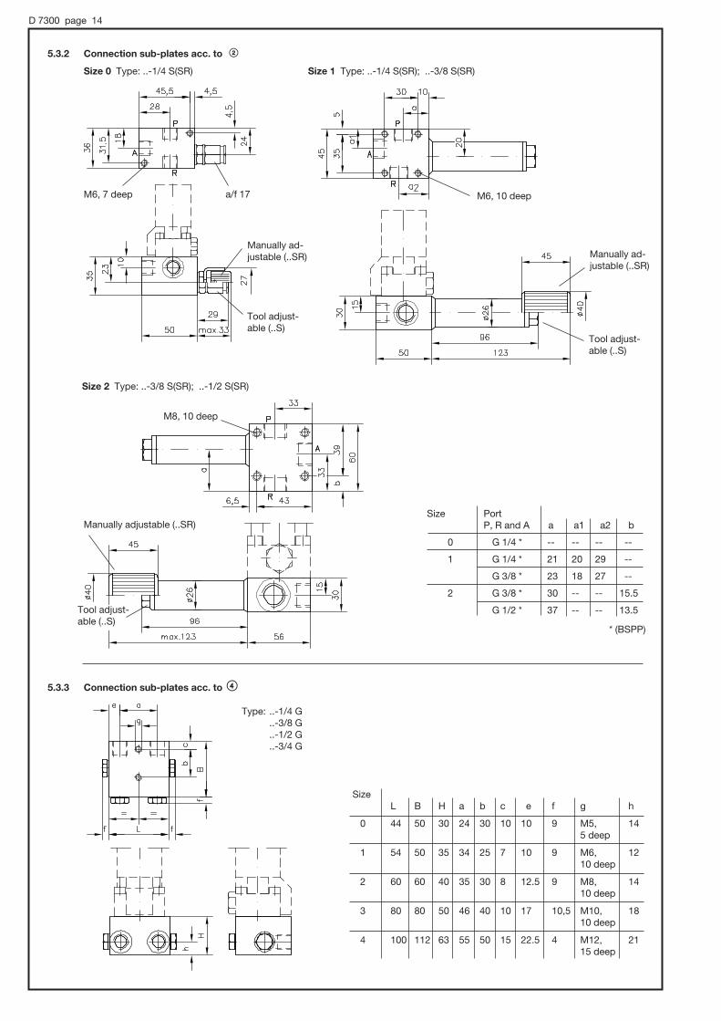
D 7300 page 14
5.3.2 Connection sub-plates acc. to <
Size 0 Type: ..-1/4 S(SR) Size 1 Type: ..-1/4 S(SR); ..-3/8 S(SR)
Size 2 Type: ..-3/8 S(SR); ..-1/2 S(SR)
5.3.3 Connection sub-plates acc. to >
Type: ..-1/4 G ..-3/8 G ..-1/2 G ..-3/4 G
Size Port P, R and A a a1 a2 b
0 G 1/4 * -- -- -- --
1 G 1/4 * 21 20 29 --
G 3/8 * 23 18 27 --
2 G 3/8 * 30 -- -- 15.5
G 1/2 * 37 -- -- 13.5
Size L B H a b c e f g h
0 44 50 30 24 30 10 10 9 M5, 14 5 deep
1 54 50 35 34 25 7 10 9 M6, 12 10 deep
2 60 60 40 35 30 8 12.5 9 M8, 14 10 deep
3 80 80 50 46 40 10 17 10,5 M10, 18 10 deep
4 100 112 63 55 50 15 22.5 4 M12, 21 15 deep
M6, 7 deep M6, 10 deep
M8, 10 deep
a/f 17
Manually ad-justable (..SR) Manually ad-
justable (..SR)
Manually adjustable (..SR)
Tool adjust-able (..S)
Tool adjust-able (..S)
Tool adjust-able (..S)
* (BSPP)

D 7300 page 15
6. Appendix6.1 Protection of directional seated valves against coarse contamination
Directional seated valves are rather unsensitive to ultra fine contamination always evident in hydraulic fluids. Nevertheless directional seated valves are fitted with screen filter elements with 0.25 mm mesh width to prevent sudden disturbance caused by coarse contaminations that may occasionally be carried along in the oil (such as torn off particles of tubing, packing, scale swarf,) and which otherwise might get trapped at the valve seat gap.The sub-plates for individual valves (sect. 5) are fitted with fine screen filter discs HFC 1/4F 1 or HFC 3/8 (acc. to D 7235) as standard at A and B with size 0, additionally in P with size 1. Valves size 2, 3 and 4 with port size G 3/8 *, G 1/2 * and G 3/4 * may be retrofitted-. These screen filters are not available for G 1 *. ( * BSPP )These screen filter elements must not be understood as a replacement for usual hydraulic filters. In practice, however, they provide sufficient protection against malfunctions in small hydraulic systems. If such malfunctions should occur, the filter elements should be checked first.For the sake of simplicity, these filter elements are not explicitly shown in the diagrams.
Symbols
Individual valves acc. to section 3: Connection sub-plates acc. to section 5:
6.2 Versions for special fluids
o HFA (water / glycol solution, conforming VDMA 24317) The functionally essential parts are of stainless steel or tuffrided to prevent corrosion (valve balls, valve seat, actuation pin etc.).
The valve body (size 3), external parts e.g. tapped plugs etc. are zinc galvanized. There are only 2/2-, 3/2- and 4/2-way directional seated valves available with flow pattern R2, S2, 3, a. Z3, 4, Z4 (see table 1 in
sect. 3.1)
Type coding: G 3-1-G 24 HFA
Flow Qperm. (lpm) approx. with reflow back pressure
1 bar 2 bar
3 4
5 6
14 18
36 45
Pres-surepmax (bar)
400
Size
0
1
2
3
Throttles (cascade type or a coiled, small diameter pipe) should be installed at the pressure inlet to limit the flow down to permissible values for the applied pressure. This is to prevent cavitation and applies to all valves with return connection (3/2- und 4/2-way valves and 2/2-way valve as by-pass to the tank) or valves in circuits connected to an accumulator.
o Brake fluid based on glycol Versions equipped with EPDM (Ethylenpropylendien-rubber) seals suited for glycol based brake fluid or other special fluids.
Type coding: GR 2-2-G 24 AT
o Versions equipped with FKM (flour rubber, Viton) seals suited for some HFD type fluids (fire inhibiting, conforming VDMA 24317)
Type coding: WGS 2-0-WG 230 PYD
Screen filter elements type HFC acc. to D 7235
Note:
A slight compensating force in the return pipe may be created by installing the tank at the highest possible location within the system.
2/2-way valve
3/2-way valve
2/2-way valve
3/2-way valve
3/3-way valve
4/2- and 4/3-way valve

D 7300 page 16
7. Mass (weight) approx. in kg
Basic valve complete with actuation acc. to section 3 and 4
3/3-way valvesize
4/3-way valvesize
4/2-way valvesize
2/2- and 3/2-way valvesize
Actuation mode
0 1 2 3 4 0 1 2 3 4 0 1 2 3 1
Electrical G.. 0.4 0.65 1.2 3.1 7.2 0.8 1.4 2.9 5.9 16.3 0.9 1.6 3.0 6.0 1.9
WG.. 0.4 0.7 1.2 3.1 7.2 0.8 1.5 2.9 5.9 16.3 0.9 1.7 3.1 6.0 2.0
Hydraulic H.. 0.4 0.5 1.1 2.8 -- 0.8 1.1 2.7 5.2 -- 0.8 1.3 2.8 5.3 1,8
Pneumatic P.. 0.4 0.4 0.9 2.2 -- -- 0.9 2.3 4.1 -- -- 1.1 5.4 4.2 1.7
Act. roll K.. -- 0.4 0.8 2.0 -- -- 0.9 2.1 3.7 -- -- 1.1 5.2 3.8 1.7
Act. pin T.. -- 0.4 0.8 -- -- -- 0.8 2.1 -- -- -- 1.0 5.2 -- 1.6
Lever F.. -- 0.4 0.8 2.0 -- -- 0.9 2.1 3.7 -- -- 1.1 5.2 3.8 1.7
Turn knob D.. 0.4 0.4 0.9 -- -- 0.8 0.9 2.2 -- -- 0.8 1.1 5.3 -- 1.7
Connection sub-plates acc. to section 5
Connection block only, for weight of the directional seated valves see above!
Size
0 1 2 3 4
Simple connection block ; 0.2 0.5 1.0 1.2 3.8
Connection block < with pressure limiting valve 0.4 1.2 1.6 -- --
Connection block = with by-pass check valve 0.2 0.5 1.0 -- --
Connection block > with rectifying circuit by means of check valves 0.5 0.7 1.0 2.4 4.7
Flow patternR2, S2 2/2-way valves3, Z3 3/2-way valves21 3/3-way valves22 4/3-way valves (not for size 4)4, Z4 4/2-way valves (size 1 only )
ActuationG Solenoid, DC versionWG Solenoid, AC version (50/60 Hz)H Hydraulic (not avail. size 4)P Pneumatic (not avail. for size 0 and 4)K Roll (not avail. for size 0 and 4)T Pin (not avail. for size 0, 3 and 4)F Key levers (not avail. for size 0 and 4)D Turn knob (not avail. for size 3 and 4)
Size0, 1, 2, 3, 4
Additional elements (option), see sect. 3.1R Check valve in port PB Orifice in port P S Return pressure stop in port R (size 0 and 1 only)RS, BS Combination of check valve or orifice with return pressure stop (size 0 and 1 only)
Connection sub-plates (option), see sect. 5-1/4, -3/8, -1/2, -3/4, -1 Simple connection block-1/4S, -3/8S, -1/2S Connection block with pressure limiting valve-1/4SR, -3/8SR, -1/2SR Connection block manually adjustable pressure
limiting valve-1/4C, -3/8C, -1/2C, -3/4C Connection block with by-pass check valve
(2/2-directional valves only)-1/4G, -3/8G, -1/2G, -3/4G Connection block with rectifying circuit by means of check
valves (2/2-directional valves only)
Additional information (option)e.g. special voltage, special fluids, pressure setting (sect. 4.1; 5.1; 6.2)
G R2 - 2 R - G 24
WG 3 - 1 -1/2S - WG 110 - 230
H 22 - 3
Mec
ha-
nic
alM
anual
8. Type overview
Type
Solenoid voltage (standard)

Directional seated valves with various actuationsconnection hole pattern NG 6 (DIN 24 340-A 6) or CETOP 3
D 7300 NIndustrial standard connection
hole pattern
January 2004-00
HAWE HYDRAULIK SE
STREITFELDSTR. 25 • 81673 MÜNCHEN
2.2
© 1999 by HAWE Hydraulik
Pressure pmax = 500 bar
Flow Qmax = 12 lpm
Further valves with the same function: type NBVP acc. to D 7765N
1. General information
2. Available versions, main data
The solenoid actuated directional seated valves (only size 1), illustrated in pamphlet D 7300, are available with a connection hole pattern conforming NG 6 acc. to DIN 24 340-A 6 (or CETOP 3).For a detailed description regarding the basic functions as well as the actuations, see D 7300.
Order example: NG 3 -1 RS - N 24
Coding. for industrial standard connection holepattern (NG 6, CETOP 3)
For plugs incl. voltage specification, seetable 1 "Solenoid actuation"
Table 1: Actuation mode
Solenoid
actuation
Pressure
actuation
Mechanic
actuation
Manual
actuation
Roller
Turn knob
Pin
Lever
Codings, flow pattern symbols and main data 1)
Switchingtime (guide line)
Basic type DC AC
NG, exNG 6) NWG
UN 12V DC 24V DC 110V AC 230V AC
50/60 Hz 3)
Current IN 0,83 A 0,1 A
Power tating PN 20 W (Type exNG.. = 23 W)
On 100 ms 100 ms
Off 50 ms 125 ms
Control pcontr min = 12 bar
pressure: pst max = 700 bar
Control pst min = 2.5 bar
pressure: pst max = 15 bar
Actuation 25 ... 28 Nforce:
Actuation 51 ... 57 Nforce:
Actuation 25 ... 28 Nforce:
Actuation 63 Ncmmoment:
NH
NP
NK
NT
NF
ND
1) For detailed data see D 73002) Standard; For special voltages, see D 7300 sect. 4.13) DC-solenoid (98V DC or 205V DC) with bridge rectifier in
the plug4) Orifice #0.8 as standard;
Also available (#0.4 - 0.6 - 1.0) specify when required, e.g. NG... -1 B 0,4 - ...; NWG... -1 B 0,6 S - ... etc.
5) Shape A DIN 43 650 (ISO 4400)6) Type ex NG.. - version with explosion-proof solenoid.
The notes stated in D 7300, B ATEX and B02/2003 are
binding!
Hydraulic
Pneumatic
Coding anddetailed flowpattern symbols(complete by actuationsymbol)
2/2-directional valve
R 2 3
S 2 Z 3
3/2-directional valve
Simplified flow patternsymbols
Table 2: Flow pattern symbols
Check valve insert type ER 11 acc. to D 7325
Orifice insert4) type EB 1-0,8 acc.to D 6465
Return pres-sure stopHAWE-No. 7332 000 b
Note: Combinations are possible, e.g. checkvalve with orifice (NG 3-1 BS) or orificewith return pressure stop (NWGZ 3-1 RS)
Table 3: Additional elements
R B S
Plug versions:Coding G G (24) Standard
A (24) Adapter; Plug 5) is customer furnished
N (24) Adapter with plug 5)L (24) Adapter with plug 5)
with integrated LEDCoding WG WG (230) Adapter with plug 5)
with integrated bridge rectifier
Nom. size 6 corresponds valve size 1(Only this size is available !)
Nom.voltage 2)

D 7300 N page 2
3. Unit dimensions
Sealing of ports A, P and Rvia O-rings 8x1.5 NBR 90 Sh
All dimensions in mm, subject to change without notice !
Standard plug incl.cable gland Pg 9
Special version plugs:
Coding -A .. (without DIN-plug)
Solenoid actuation
Hydraulic actuation
Pneumatic actuation
Mechanical actuation
With roller With pin
Manual actuation
With lever With turn knob
Must not beused as a stop!
Must not beused as astop!
Must notbe usedas a stop!
Switchingposition
2) DIN ISO 228/1 (BSPP)
M 5, 10 deep
a/f 27
Hole pattern of the manifold exNG..
1) This dimension is depending on themanufacturer and can be up to 40 mmacc. to DIN 43650.
Coding-
N ..
-W..
approx. 41
app
rox.
37
app
rox.
80
app
rox.
84
3 m cable

Directional seated valve banks type VB 01... to VB 41...with directional valves acc. to D 7300
(This also lists individual valves with connection sub-plates for direct pipe connection)
D 7302Directional valve banks type VB...
January 2000-09© 1980 by HAWE Hydraulik
HAWE HYDRAULIK SESTREITFELDSTR. 25 • 81673 MÜNCHEN
2.2
End platewith spacer
Pressure switch
Con-nectionblock
P = Inlet (from the pump)R = Outlet (reflow to the tank)A, B = Consumer ports
Example 2: HK 34/1M - H1,25 - A1/420 - VB01 FMH - FR/N/32 - 1 - WG230
2. Available versions, type codingFor total type coding overview, see sect. 7
2.1. Order examples
Example 1: VB11AM - 2/350 - F G45 S/11 - 2 - G24
Directionalvalves sect. 2.4
1. General These valve banks consist of a connection block, laterally added directional valves (acc. to pamphlet D 7300) installed on individual sub-plates and an end plate. All is held together by a tension rod. The connection block incorporating a pressurized oilinlet and return outlet may also feature a pressure limiting valve. Two basic designs are available, either for pipe connection or direct mounting onto hydraulic power packs. The galleries for pressurized oil and return run through all sub-plates and thereby connect the valves in parallel. An end plate terminates the valve bank (not with size 4).The valves are counted starting from the connection block. For data and notes concerning the individual valves (not being coveredby this pamphlet), see D 7300.
Pressure pmax = 350 ... 500(700) bar; Flow Qmax = 6 ... 120 lpm
Directional valve bank for pipe connection(Actuation mode is similar for all directional valves)
For assignment of the coding and main data, see sect. 2.2
Valve bank for direct mounting onto a com-pact hydraulic power pack type HK acc. toD 7600-3, e.g. HK 34/1M - H1,25 - A1/420
Directional valve bankFor the correlation between identificationand main data, see sect. 2.2
Order coding of the pump
R = Return portM, M4 = Pick-up port e.g. for
a pressure gauge ora sensor
A = Consumer port

D 7302 page 2
2.2. Type coding and general parameter
VB11AM - 2/350 - FG45S /11- 2 - G24
VB01FMH - FR/N /32- 1 - WG230
(example 1 acc. to sect. 2.1)
(example 2 acc. to sect. 2.1)
The slash indicates which valves (coding) feature which actuation mode (sequence). Inthis example, valves F and R are equipped withactuation M whereas valve N with actuation H.
Coding 1 2 3 4 5
Ports conf. DIN ISO 228/1 G 1/4 G 3/8 G 1/2 G 3/4 G 1(BSPP) 1)
For valve banks VB01.. VB11.. VB21.. VB31.. VB41..VB11.. VB21.. VB31.. VB41..
Table 3: Actuations for the directional valves
Flow pattern (For identificationof codings and additional features,see sect. 2.4
see end platein sect. 2.3
Table 2: Connection block or adapter plate
Note:When selecting the valve size, it is determined not only bythe indiv. consumer flow but also by the resulting total flowdep. on the control sequence. As this can be higher thanthe pump delivery flow, e.g. with double acting cylinders (unequal areas) in a differential circuit.Therefore the valve size should be selected according tothe resulting total flow.
Table 4: Ports
Coding
Actuation modeand symbol
Available for
M
solenoid
Nom. voltage:G12 = 12V DCG24 = 24V DCWG230 = 230V AC
50 Hz
For further data, see D 7300
VB01toVB41
Other available actuationsH
hydraul.
VB01toVB31
P
pneum.
VB11VB21VB31
K
roller
VB11VB21VB31
T
pin
VB11VB21
F
level
VB11VB21VB31
D
turn-knob
VB11VB21
standard
CodingandDesign 16)
A .-1/...
A .-2/...
A .-3/...
A .-4/...
A .-5
C 8)
D 8)
E
F
F1
G 9)
Availablefor valvebank
VB01toVB41
VB01toVB31
VB01toVB41
VB01VB11VB21
VB11VB21VB31
VB31
VB01VB11VB21
VB01
VB11VB21
Directconnection to
pipes
TanksD6 to D30B6 to B40
TanksD50B50 and B75
TanksD100 and D250B100 to B400
Tanks10)
Tanks
Suited for pump type
Acc. to pamphlet Symbol
Arbitrary, all pumps of the HAWE productrange. (see also note below !)
R.. D 6010H etc. 3)Z.. D 6820RZ.. D 6910H
R.. D 6010HZ.. D 6820 5)
R.. D 6010H 4)Z.. D 6820 5)
HK.. D 7600-... F F1MP.. D 7200H
HC.. D 7900HCG.. D 7900GFP.. D 7310
MP.. D 7200H 7) VB11 VB21:RZ.. D 6910H 7) Direct
connection
pre
ssur
esp
ecifi
catio
nin
bar
,e.
gA
M-2
/230
Pressurelimitingvalve
tool adjustable
tool adjustable
without
Spring-housingmaterial
VB01 toVB31: diecastVB41: steel
steel 2)
Coding
Pressure pmax
Flow(lpm)
(bar) 11)
Qmax approx.
perm. deliveryflow 12)
VB01
500
6
$ 6
VB11
700
12
5 ......12
VB21
500
25
11 ...... 25
VB22
700
25
11 ... ... 25
VB31
400
65
20 ...... 60
VB41
350
120
> 60
Table 1: Valve bank (basic type, size, sub-plate)
without
The connectionblock of the hydraulic powerpack features apressure limitingvalve
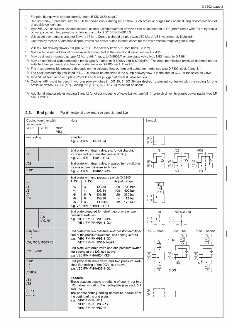
D 7302 page 3
1) For pipe fittings with tapped journal, shape B DIN 3852 page 22) Required only, if pressure surges > 20 bar could occur during return flow. Such pressure surges may occur during decompression of
chargable consumers.3) Type VB...A... should be selected instead, as only a limited number of valves can be connected at P1 (interference with P2) at hydraulic
power packs with two pressure outlets e.g. acc. to D 6010 DB, D 6010 S. 4) Valves are over dimensioned for flows < 17 lpm. Controls should employ type VB21A.. or VB11A.. (remotely installed)5) Controls by means of directional spool valves are better suited in most cases for the low pressure range of gear pumps.
7) VB11G.. for delivery flows < 10 lpm; VB21G.. for delivery flows > 10 lpm (max. 25 lpm)8) Not available with additional pressure switch mounted at the directional valve (see sect. 2.4.2)9) May be directly mounted at type A51/.. to A61/.. (acc. to D 6905A) or two stage valve type NE21 (acc. to D 7161)10) May be combined with connection block type A... (acc. to D 6905A and D 6905AF/1). The max. permissible pressure depends on the
selected flow pattern and actuation mode, see also D 7300, sect. 2 and 3.1.11) The max. permissible pressure depends on the selected flow pattern and actuation mode, see also D 7300, sect. 2 and 3.1.12) The back pressure figures listed in D 7300 should be observed if the pump delivery flow is in the area of Qmax of the selected valve.13) Type VB 41 feature no end plate. Ports P and R are plugged at the last valve section.14) Coding /56 must be used if two pressure switches (1. DG 35; 2. DG 36) are desired to prevent confusion with the coding for one
pressure switch DG 365 (/65). Coding /65 (1. DG 36, 2. DG 35) must not be used!
16) Additional adapter plates (coding S and L) for direct mounting of valve banks type VB 11 onto air driven hydraulic power packs type LPsee D 7280 H
2.3. End plate (For dimensional drawings. see sect. 3.1 and 3.2)
Coding together with valve bankVB01 VB11 VB21
VB31
(no coding
/2
/02
/002
/3
/4
/5
/6
/65
/0
/00
(/.0, /0.)
/33, /34..
“
“
/56, /665, /6565 14)
/32 ... /652
/332
“
“
/65652
/11
/12
/... 11
/... 12
Symbol
/2 /02 /002
/0 /00 (/.0, /.0)
/33 ... 6565 /32 ... 652 /332 ... 65652
1.DG
2.DG
Note
Standarde.g. VB11FM-FHH-1-G24
End plate with drain valve, e.g. for discharging a connected accumulator (see sect. 6.3) e.g. VB01FM-FHH/2-1-G24
End plate with drain valve, prepared for retrofittingfor one or two pressure switchese.g. VB11FM-FHH/02-1-G24
End plate with one pressure switch (D 5440)1. DG 2. DG Adjust. range
/3 3 DG 33 200 ... 700 bar/4 4 DG 34 100 ... 400 bar/5 5 14) DG 35 20 ... 250 bar/6 6 DG 36 4 ... 12 bar/65 65 DG 365 12 ... 170 bar
e.g. VB01FM-FHH/4-1-G24
End plate prepared for retrofitting of one or twopressure switchese.g. VB11FM-FHH/0-1-G24
VB11FM-FHH/04-1-G24
End plate with two pressure switches (for identifica-tion of the pressure switches, see coding /3 etc.)e.g. VB01FM-FHH/63-1-G24
VB11FM-FHH/365-1-G24
End plate with drain valve and one pressure switch(for coding of the DG, see above)e.g. VB01FM-FHH/52-1-G24
End plate with drain valve and two pressure swit-ches (for coding of the DG's, see above)e.g. VB01FM-FHH/432-1-G24
Spacers:
These spacers enable retrofitting of one (11) or two(12) valves including their sub-plate (see sect. 3.2and 3.5). The corresponding coding should be added afterthe coding of the end plate.e.g. VB01FM-FHH/11
VB01FM-FHH/365 12
VB01FM-FHH/62 11
13)
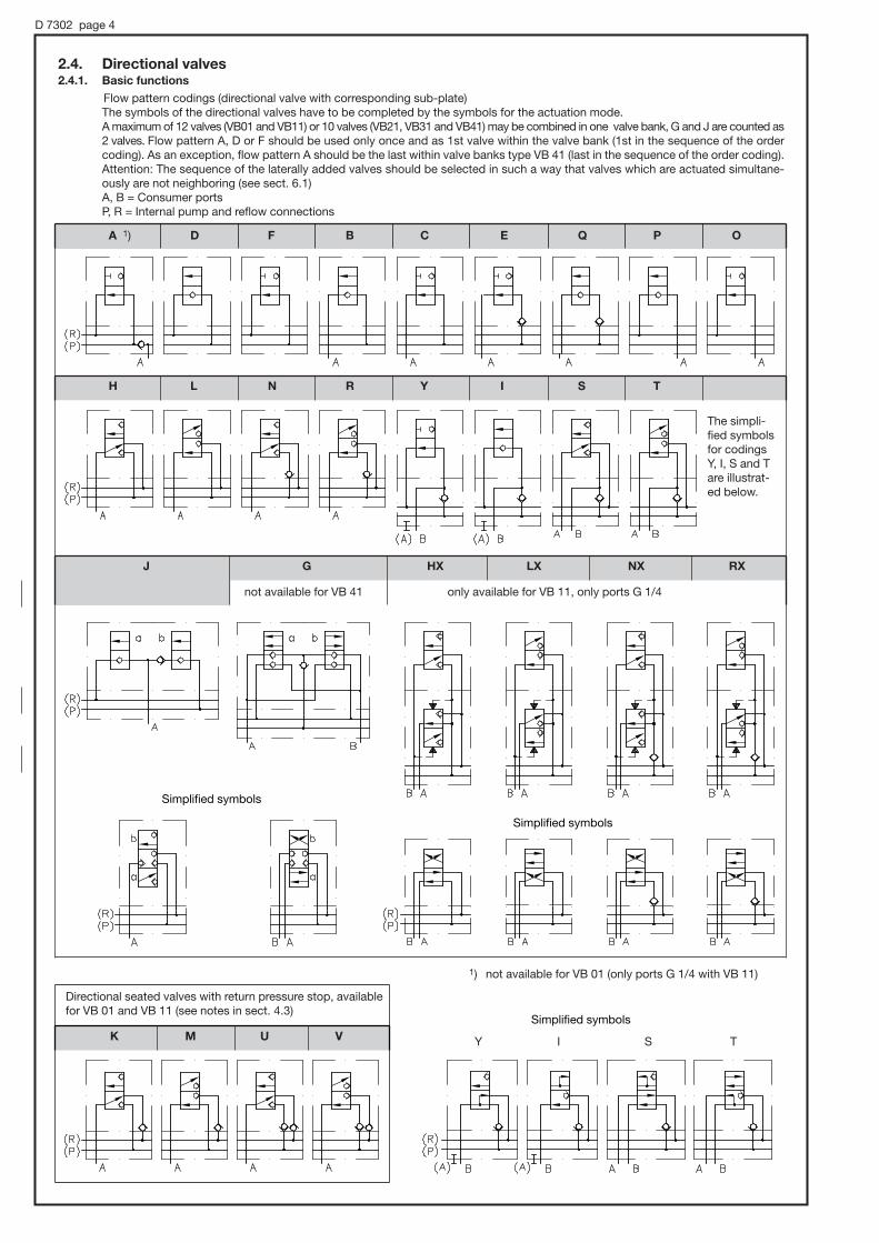
D 7302 page 4
2.4. Directional valves2.4.1. Basic functions
Flow pattern codings (directional valve with corresponding sub-plate)The symbols of the directional valves have to be completed by the symbols for the actuation mode.A maximum of 12 valves (VB01 and VB11) or 10 valves (VB21, VB31 and VB41) may be combined in one valve bank, G and J are counted as2 valves. Flow pattern A, D or F should be used only once and as 1st valve within the valve bank (1st in the sequence of the ordercoding). As an exception, flow pattern A should be the last within valve banks type VB 41 (last in the sequence of the order coding).Attention: The sequence of the laterally added valves should be selected in such a way that valves which are actuated simultane-ously are not neighboring (see sect. 6.1)A, B = Consumer portsP, R = Internal pump and reflow connections
The simpli-fied symbolsfor codingsY, I, S and Tare illustrat-ed below.
Directional seated valves with return pressure stop, availablefor VB 01 and VB 11 (see notes in sect. 4.3)
1) not available for VB 01 (only ports G 1/4 with VB 11)
A 1) D F B C E Q P O
Simplified symbols
Simplified symbols
Simplified symbols
not available for VB 41 only available for VB 11, only ports G 1/4
K M U V
H L N R Y I S T
J G HX LX NX RX
Y I S T
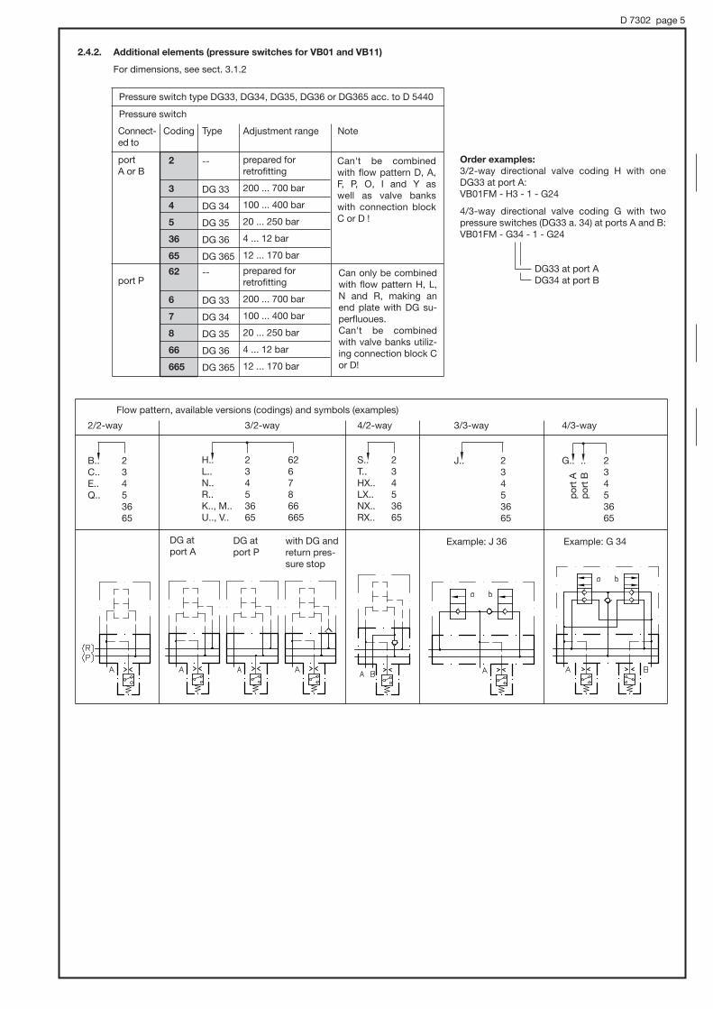
D 7302 page 5
2.4.2. Additional elements (pressure switches for VB01 and VB11)
For dimensions, see sect. 3.1.2
Pressure switch type DG33, DG34, DG35, DG36 or DG365 acc. to D 5440
Pressure switch
Order examples:
3/2-way directional valve coding H with oneDG33 at port A:VB01FM - H3 - 1 - G24
4/3-way directional valve coding G with two pressure switches (DG33 a. 34) at ports A and B:VB01FM - G34 - 1 - G24
DG33 at port ADG34 at port B
Flow pattern, available versions (codings) and symbols (examples)
Coding
2
3
4
5
36
65
62
6
7
8
66
665
Type
--
DG 33
DG 34
DG 35
DG 36
DG 365
--
DG 33
DG 34
DG 35
DG 36
DG 365
Adjustment range
prepared for retrofitting
200 ... 700 bar
100 ... 400 bar
20 ... 250 bar
4 ... 12 bar
12 ... 170 bar
prepared forretrofitting
200 ... 700 bar
100 ... 400 bar
20 ... 250 bar
4 ... 12 bar
12 ... 170 bar
Connect-ed to
portA or B
port P
Note
Can't be combinedwith flow pattern D, A,F, P, O, I and Y as well as valve bankswith connection blockC or D !
Can only be combinedwith flow pattern H, L,N and R, making anend plate with DG su-perfluoues. Can't be combinedwith valve banks utiliz-ing connection block Cor D!
3/2-way
H.. 2 62L.. 3 6N.. 4 7R.. 5 8K.., M.. 36 66U.., V.. 65 665
2/2-way
B.. 2 C.. 3E.. 4Q.. 5
3665
4/2-way
S.. 2T.. 3HX.. 4LX.. 5NX.. 36RX.. 65
3/3-way
J.. 2 3453665
4/3-way
G.. .. 2 3453665
po
rtA
po
rtB
DG atport A
DG atport P
with DG andreturn pres-sure stop
Example: J 36 Example: G 34

D 7302 page 6
2.5. 2-way pressure reducing valve for valve banks
VB 01 and VB 11
Max. permissible inlet pressure 450 bar (P side).They can be placed arbitrarily within the valve bank. The pressure reducing valvedetermines the pressure for all directional valves mounted downstream (sec-ondary side) and the consumers connected to them, independent from simul-taneous withdrawal of pressurized oil with a higher pressure level via direction-al valves located upstream (primary side). Example: Clamping cylinders with low pressure setting or piloting valves forelectro-hydraulic low-pressure remote control purposes.The pressure reducing valves type CDK 3 (acc. to D 7745) are used here. Thesevalves do not show any leakage in blocked state (pressure upstream is higherthan the set secondary pressure) as they are designed as 2/2-way valves, act-ing like a seated valve in idle position. This prevents any return flow from thesecondary side to the primary side (pump side) or any pressure drop.It is necessary to install a pressure limiting valve in the consumer pipe if externally induced loads could cause unpermissible peak pressure.For version with 3-way pressure reducing valve, see sect. 4.8.
Order example: VB01 FM - HR - HH - 1 - G 24
1) There is only a tool adjustable version available. The adjustment can be altered after slackening the lock nut with an a/f 17 spanner (monitored by a pressure gauge).
2) The secondary pressure setting is valid for flow Q = 0 lpm if the consumer is in its end position. It will drop slightly if there is a flow to the consumer.
3) With tapped plug, prepared for retrofitting of a CDK 3-..
4) Version with low pressure dependence at variable pump (inlet) pressure as well as use at low pressure settings (Attention: Max. flow 6 lpm).
5) Version with low back pressure, however with a higher pressure dependence at variable pump (inlet) pressure.
- CZ2/180/5R/4
VB 11 - CZ5/130 /5R /7
Example1: - CZ1/280/5R-...
Example 3: - CZX 5R-...
Example 2: - CZ5/130/5R/7-...
For individual order(example) e.g. as sparepart, extension, ownstorage etc.
Pressure switch type DG 3.. acc. to D 5440
(no coding)
/2
/3
/4
/5
/6
/7
without pressure switch
DG may be retrofitted
DG 33 200 ... 500 bar
DG 34 100 ... 400 bar
DG 35 20 ... 250 bar
DG 36 4 ... 12 bar
DG 365 12 ... 170 bar
Check valve in P gallery
5R with check valve
Coding
X
081/...
08/...
- CZ 1/...
2/...
5/...
25/...
55/...
2-way pressure reducing valve 1)
Utilized pres-sure reducingvalve
without 3)
CDK 3-081
CDK 3-08
CDK 3-1
CDK 3-2
CDK 3-5
CDK 32-5 4)
CDK 35-5 5)
Pressurerange(bar) 2)
---
50 ... 500
50 ... 450
30 ... 300
20 ... 200
15 ... 130
8 ... 130
15 ... 130

D 7302 page 7
3. Unit dimensions3.1. Directional valve bank for installation in a pipe system3.1.1. Valves without pressure switch
Type VB 01
Coding Coding Coding J Coding GD,F,H, B,C,Q,L,N,R E,P,O
Coding S,T,Y,I
End plate
(standard) 1)
End
plate
(stan-dard)1)
1) For other end plates,see sect. 3.2
M6, 6 deepM6, 6 deep
M6, 6 deepM6, 6 deep
Only with coding I and Y
Only with coding D and F Only with coding I and Y
Only with coding D and FTorque25 Nm
Torque40 Nm
Connection block Directional valves
Connection block Directional valves
A.-2(4)/..
A.-1(3)/..
Coding Coding Coding J Coding GA,D,F,H, B,C,Q,L,N,R E,P,O
Coding S,T,Y,IHX,LX,NX,RX
A.-2(4)/..
A.-1(3)/..
A.-5
A.-5
Coding a
P and O 15
B,C,Q,E 23
Type VB 11
Type
VB 11
Ports A, B, Pand R (BSPP)
G 1/4
G 3/8
a
12
14
a1
27
25
Coding Aa2 a3
20 30
-- --
Other valvesa2 a3
15 25
14 25
Valvecoding
b
h
h1
A
20
D,F,H,L,N,R
23
B,C,Q,E
18
P a. O
28
HX,LX,NX,RX
--
50.5
60
42
55
All dimensions are in mm, subject to change without notice!
hyd
r.ac
tuat
ion
71
foroth
erac
tuat
ion
D73
00
approx.20
approx.21

D 7302 page 8
Type VB 21 and VB 31
G = M8, 8 deep
Torque85 Nm (VB 21)190 Nm (VB 31)
Torque120 Nm
Coding Coding Coding J Coding GA,B,C, O and PD,E,F,H,L,N,Q,R
Coding S,T,Y,IConnection block
Directional valves
A.-2(4)/..
A.-1(3)/..
A.-5
Coding Coding Coding JB,C,D,E,F, O and PH,L,N,Q,R
Coding S,T,Y,IType VB 41
Connection block
Directional valves
A.-2(4)/..
A.-1(3)/..
A.-5
End
plate
Only withVB 21!
Type
VB 21
VB 31
PortsA, B, Pand R 1)
G 3/8
G 1/2
G 1/2
G 3/4
b1
20
18
25
22
b2
56
58
66
68
a7
22
24
28
b
18
20
22
B
63
80
H
42
50
H1
60
55
H2
32
40
H3
72
90
H4
148
162
L
32
40
L1
58
72
L2
117
145
a
18
23
a1
20
23
a2
22
28
a3
33
44
a4
32
52.5
a6
60
76
c
48
63
e
15
32
h
80
90
h1
91
104
i
20
23
j
16
20
m
10
15
n
25
32.5
o
43
56.5
p
65
81
a5
28.5
34.5
a8
33
46
Only with coding D and F
Only with coding D and F
Only with coding I and Y
Only with coding I and Y
M10, 12 deep
Ports (BSPP)G 3/4 G 1
a 100 110
b 32 35
c 19 21
d 51 46
e 78 88
f 29 35
foroth
erac
tuat
ion
D73
00
foroth
erac
tuat
ion
D73
00
approx. e
approx.25
1) (BSPP)
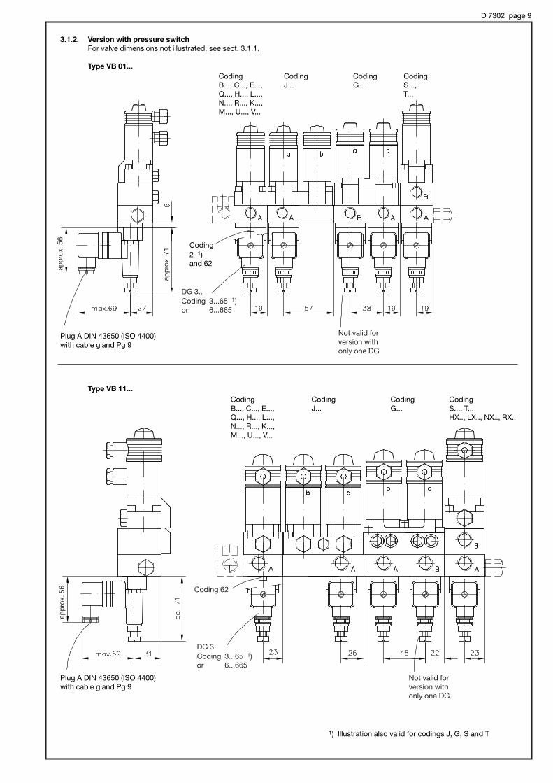
D 7302 page 9
3.1.2. Version with pressure switch
For valve dimensions not illustrated, see sect. 3.1.1.
Type VB 01...
Type VB 11...
Plug A DIN 43650 (ISO 4400)with cable gland Pg 9
Plug A DIN 43650 (ISO 4400)with cable gland Pg 9
1) Illustration also valid for codings J, G, S and T
Coding Coding Coding CodingB..., C..., E..., J... G... S...,Q..., H..., L..., T...N..., R..., K...,M..., U..., V...
Coding Coding Coding CodingB..., C..., E..., J... G... S..., T...Q..., H..., L..., HX.., LX.., NX.., RX..N..., R..., K...,M..., U..., V...
Coding2 1)and 62
Coding 62
DG 3..Coding 3...65 1)or 6...665
DG 3..Coding 3...65 1)or 6...665
Not valid forversion withonly one DG
Not valid forversion withonly one DG
app
rox.
71
app
rox.
56
app
rox.
56

D 7302 page 10
app
rox.
71
3.2. End plate
The standard version of the end plate (no coding) is illustrated at the corresponding valve bank drawings, see sect. 3.1 !
3.2.1. Additional versions for VB 01
Dimensionsvalid for allend plates!
Type L L1 ØD
VB 01 59 97 14
VB 11 66 110.5 18
Coding /11 Coding /12/...11 /...12
3.2.3. Spacers for retrofitting of one or two valves (see also note in sect. 3.5)
3.2.2. Additional versions for VB 11
Version without DG..,but with drain valve,coding /2
Version with one DG..,coding /3...65
Version with twoDG.., coding/33...6565
Version with one DG..,coding /0
/3...65
Version with one DG.., coding /00
/.0, /0. /33...6565
Version with one (two) DG.. and drain valve, coding /02 /002
/32...652 /332...65652
Version with one (two) DG..and drain valve, coding /02 /002
/32...652 /332...65652
M6,6 deep
M6, 6 deep
M6, 6 deep
Drain screw a/f 5
Drain screw a/f 5
Port M4 = G 1/4
Drain valvescrew a/f 5
1. DG
1. DG
2. DG
2. DG
Coding/32...652
Coding/3...65
Coding/32...652
Coding/02
Coding/0
Coding/02
Port M4 = G 1/4
For missing dimensions, see below!
app
rox.
71
app
rox.
71
app
rox.
71
app
rox.
71

D 7302 page 11
Type VB 01F and VB 11F
VB 21F
Type VB 01F1
Connection blockinstalled on the hy-draulic power pack
PortsG 1/4 (BSPP)
R-Ports G 1/4 (BSPP)on the rear side
PortsType H a b c d e M and R (BSPP)
VB 01F 50 14 25 20 10 -- G 1/4
VB 11F 60 30 -- 25 15 20 G 1/4
VB 21F 75 11 26.5 25 12.5 -- G 1/4
Adapter plates
3.3. Direct mounting onto hydraulic power packs
Type VB...C
VB...D
VB...E
Connection block installed on the hydraulic power pack(design depends onthe size of the coverplate, see D 6010H)
Adapter plates
For valve bank dimensions,see sect. 3.1
Type a b c
VB 01C 20 5 9
VB 11C 20 2 9
VB 21C 20 2 9
VB 11D 30 12 5
VB 21D 30 14 5
VB 31D 35 14 5
VB 31E 30 19 5
Reflow portVB 11F
VB 01FVB 21F
Port e.g. for pressuregauge or pressureswitch
For valve bankdimensions,see sect. 3.1

D 7302 page 12
Type VB 11 G
Mounting onto hydraulic power packtype MP... acc. to D 7200 via connectionblock type A51/.. or A61/..
Type VB 21 G
Mounting onto hydraulic powerpack type MP... acc. to D 7200 via connection block type A51/..or A61/..
Type VB 11 G
Mounting onto hydraulic power packtype MP... acc. to D 7200 via dualstage valve type NE 21..
Type VB 21 G
Mounting onto hydraulic powerpack type MP... acc. to D 7200 viadual stage valve type NE 21..
Connection blockon the hydraulicpower pack
Adapter plate
Adapter plate
For valve bankdimensions, see sect. 3.1
Dual stage valvetype NE 21.. acc. to D 7161

D 7302 page 13
3.4. Directional valve bank with pressure reducing valve3.4.1. Type -CZ .., to be installed within valve banks type VB 01 and 11 (acc. to sect. 2.5)
Provision fora lead seal
Type-CZ 08/..
1/..
2/..
5/..
25/..
55/..
Type -CZ X
withoutDG..
with DG..
Cable glandPg 9
a
a1
b
b1
e
e1
f
f1
h
h1
VB 01
40
20
40
24
13
11
3
11
81
62
VB 11
47
23.5
50
19
13.5
9.5
--
30
75
53
Port M = G 1/4 (BSPP)
Type
VB 01
VB 11
a
40
47
a1
26
23.5
b
40
50
c
10.5
10
#d
32
42
e
12
13.5
e1
34
35
e2
13
21
f
3
--
f1
11
31
h
55
50
h1
81
75
h2
90
115
h3
62
56
Port M = G 1/4 (BSPP)
Type Z1 to Z8
Type Z11 to Z28 Type Z114 to Z2865
3.4.2. Type Z1 to Z2865, to be installation within valve banks type VB 01 and VB 11 (old version acc. to sect. 4.8)
Suited forleeds # 6(VB 01) or# 9 (VB 11)
Orientation rotated by180° with VB 11, seealso sect. 3.1++
Cable glandPg 9
app
rox.
h
app
rox.
h2
app
rox.
h3
app
rox.
h1
app
rox.
h
91 (manually adjustable)
(tool adjustable)
a/f 24Torque 70Nm
a/f 30Torque 60Nm

D 7302 page 14
3.5. Individual valve sectionsThey are intended for retrofitting in valve banks, replacing the spacers after the end plate (/.11; /.12 with VB 01 a. 11, see sect. 2.3and 3.2 ++. Tension rods, corresponding to the total number of valve sections, have to be ordered additionally, if no spacers were installed or more sections should be added than spacers were installed. The order coding must contain the terms “valve section ...“and ”for valve bank VB..“ in uncoded text.
Order example: Valve section For valve bank VB 01
Size Torque for the acron nut
VB 01 25 NmVB 11 40 NmVB 21 85 NmVB 31 190 NmVB 41 120 Nm
Retrofitting of a valve section
Assembly procedure:1. Remove nut(s) and all parts
after the last valve sectionfrom the tension rod(s)
2. Install the additional valvesection
3. Reinstall seals, end plate andnut(s). For the correct torque,see table below. The USITseal ring as well as the spac-er are not required with cod-ing /.11 or /.12 (only VB 01 orVB 11)
1) Two spacers with USIT-rings for end plate coding /.12 (version with spacers are only available with type VB 01 and 11).
Example
End plate coding /11(12)consisting of:
Acorn nutHAWE No. 7250 015 (VB 01)
7251 026 (VB 11)USIT-ring U 8.7x16x1 (VB 01)
U 10.7x18x1.5 (VB 11)Spacer 1)HAWE-No. 7250 041 (VB 01)
7251 041 (VB 11)End plate withUSIT-ring U 8.7x16x1 (VB 01)
U 10.7x18x1.5 (VB 11)
Take care that the O-rings (at the con-nection area) are not lost, when addingthe valve section!
H - 1 - G24
Flow pattern coding, acc. to sect. 2.4
Port size, acc. to sect. 2.2
Nom. voltage, acc. to sect. 2.2
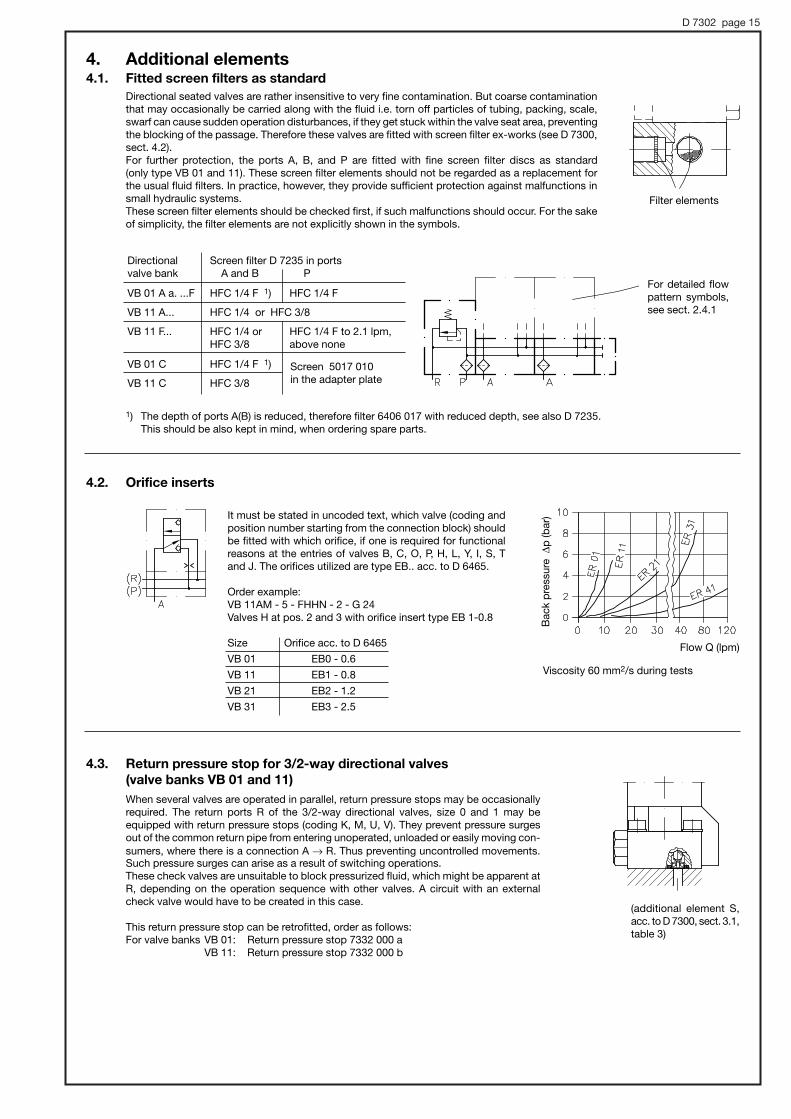
D 7302 page 15
4. Additional elements4.1. Fitted screen filters as standard
Directional seated valves are rather insensitive to very fine contamination. But coarse contaminationthat may occasionally be carried along with the fluid i.e. torn off particles of tubing, packing, scale,swarf can cause sudden operation disturbances, if they get stuck within the valve seat area, preventingthe blocking of the passage. Therefore these valves are fitted with screen filter ex-works (see D 7300, sect. 4.2).For further protection, the ports A, B, and P are fitted with fine screen filter discs as standard (only type VB 01 and 11). These screen filter elements should not be regarded as a replacement forthe usual fluid filters. In practice, however, they provide sufficient protection against malfunctions insmall hydraulic systems. These screen filter elements should be checked first, if such malfunctions should occur. For the sakeof simplicity, the filter elements are not explicitly shown in the symbols.
It must be stated in uncoded text, which valve (coding andposition number starting from the connection block) shouldbe fitted with which orifice, if one is required for functionalreasons at the entries of valves B, C, O, P, H, L, Y, I, S, T and J. The orifices utilized are type EB.. acc. to D 6465.
Order example:VB 11AM - 5 - FHHN - 2 - G 24Valves H at pos. 2 and 3 with orifice insert type EB 1-0.8
Size Orifice acc. to D 6465
VB 01 EB0 - 0.6
VB 11 EB1 - 0.8
VB 21 EB2 - 1.2
VB 31 EB3 - 2.5
4.2. Orifice inserts
For detailed flowpattern symbols,see sect. 2.4.1
Viscosity 60 mm2/s during tests
Directional Screen filter D 7235 in portsvalve bank A and B P
VB 01 A a. ...F HFC 1/4 F 1) HFC 1/4 F
VB 11 A... HFC 1/4 or HFC 3/8
VB 11 F... HFC 1/4 or HFC 1/4 F to 2.1 lpm,HFC 3/8 above none
VB 01 C HFC 1/4 F 1)
VB 11 C HFC 3/8
1) The depth of ports A(B) is reduced, therefore filter 6406 017 with reduced depth, see also D 7235. This should be also kept in mind, when ordering spare parts.
Screen 5017 010in the adapter plate
When several valves are operated in parallel, return pressure stops may be occasionallyrequired. The return ports R of the 3/2-way directional valves, size 0 and 1 may beequipped with return pressure stops (coding K, M, U, V). They prevent pressure surgesout of the common return pipe from entering unoperated, unloaded or easily moving con-sumers, where there is a connection A → R. Thus preventing uncontrolled movements.Such pressure surges can arise as a result of switching operations.These check valves are unsuitable to block pressurized fluid, which might be apparent atR, depending on the operation sequence with other valves. A circuit with an externalcheck valve would have to be created in this case.
This return pressure stop can be retrofitted, order as follows:For valve banks VB 01: Return pressure stop 7332 000 a
VB 11: Return pressure stop 7332 000 b
Flow Q (lpm)
Bac
kp
ress
ure|
p(b
ar)
(additional element S,acc. to D 7300, sect. 3.1,table 3)
Filter elements
4.3. Return pressure stop for 3/2-way directional valves
(valve banks VB 01 and 11)

D 7302 page 16
4.4. Sub-plate only featuring a pressure switch (valve banks VB 01 and 11)They should be used if it is not possible to install a pressure switch at the end plate, due to spatial requirements. This sub-plate with pressure switch may be installed at any location within the valve bank.
Order example: VB 11AM - 1/200 - HM - H/02 - 1 - G 24
Basic type codingacc. to sect. 2.1++
4.5. Versions with pressure limiting valve and throttle (valve banks VB 21 and 31)
This special 3/2-way directional valve features a pressure limiting valve and a throttle in its sub-plate. It is intended for press controls and may be located at any position within valve banks type VB 21.. or VB 31...
Order example: VB 21AM - 5 - F HQ - 3 - G 24
Flow pattern codingH, L, N, R
Throttle coding
Pressure limiting valve codingtool adjustable 1/..
manually adjustable 2/..
Pressure setting of the pressure limiting valve
Type B B1 H a b c e f
VB 21.. 60 66 148 17.5 31 17.5 35 35
VB 31.. 72 100 162 22 36 28 26 30
Type h i k l l1 m n o
VB 21.. 60 35 25 72 82 37.5 69 16
VB 31.. 63 42 35 85 97 56.5 85 18
Pressure limiting valve
Cable glandPg 9
Port A, conforming DIN ISO 228/1 (BSPP):VB 21..-..91(2) /... -2 = G 3/8
-3 = G 1/2VB 31..-..91(2) /... -3 = G 1/2
Throttle(QR 4 orQR 5 acc. toD 7050)
- 33
Symbol acc. to the orderexample
Symbol acc. to theorder coding
R91/250
(tool adjustable)
(manually adjustable)
Pressure switch Coding of the sub- Adjustment acc. to D 5440 plate with DG.. range (bar)
prep. for retrofitting
DG 33 - 33 200 ... 700
DG 34 - 34 100 ... 400
DG 35 - 35 20 ... 250
DG 36 - 36 4 ... 12
DG 365 - 365 12 ... 170
- 32 -
Coding -32-

D 7302 page 17
4.6. 2-way flow control valves VB 31
The proportional 2-way flow control valves enable arbitraryvelocity control for the connected consumers by opening aby-pass to the tank for the excess delivery.This valve section should be located first within the valvebank (after the connection block).
Order example:
VB 31AM - 5 - HQ - 3 - G 24
Flow control valve
Flow
Coding Metering orifice max. lpm
6 6
15 15
30 30
36 36
50 50
Cable glandPg 9
Symbol acc. to the order coding
4.7. Blanking plate
An already assembled sub-plate with blanking plate can be used instead of a spacer (see sect. 2.3 end plates) enabling valves to beretrofitted. They can be fitted anywhere within the valve bank.It has to be specified in uncoded text, which flow pattern coding should be retrofittable (determining the sub-plate type) and on whichlocation (start numberizing after the connection block) within the valve bank.
Order example: VB 11 AM - 1/380 - FHH - 1 - G 12
Valve H with blanking plate at position 3 5000 099 (or 6540 039 (see below))
Blanking plate(height 10 mm)
- SE2 15/1
For more detailed data con-cerning the proportional flowcontrol valve (type SE 2-2..),see D 7557/1!
Individual parts (e.g. as spare parts):
Size VB 01 VB 11 VB 21 VB 31 VB 41
Blanking plate 6540 039 5000 099 4900 099 5005 099 7070 0993 O-rings NBR 90 Sh 3.7x1.78 5x1.5 10x2.2 13.95x2.62 DKAR 00119N90064 screws ISO 4762- M5x12- M6x20- M8x20 M10x40 M12x50
-12.9-galvanized
approx.60
app
rox.
34

D 7302 page 18
4.8. Pressure reducing valve as option for size VB 01 and VB 11
Pressure reducing valve, max. permissible inlet pressure 300 bar. For version up to 400 bar and functional description, see sect. 2.5.
The primary side can only be kept leakage-free (if necessary) with versions Z11 ... Z28 (Z114 ... Z2865) which features a prelocated 2/2-way seated valve. This is due to the functionally determined, permanent internal leakage even if there is no flow of pressurized oilto the secondary side. The 2/2-way seated valve must be actuated whenever pressurized oil is withdrawn. The secondary side isprotected against leakage by a check valve downstream of the pressure reducing valve, so there is no loss of pressure if the secondary consumer is free of leaks and the pump is switched off.However, this means that the pressure reducing valve cannot be used for secondary pressure limitation here, if the secondary pres-sure is exceeded due to external, rising forces acting on the consumer. The check valve prevents any return flow via the pressurereducing valve and therefore stops the consumer giving way i.e. the pressure in the consumer would rise. If necessary the consumerline would have to be safeguarded by its own pressure limiting valve and made flexible. For dimensional drawings, see sect. 3.4.2.
Pressure range Coding within the directional valve bank 1)(bar) Standard version with upstream located 2/2-way directional seated valveadjustable GR 2-0(1), WGR 2-0(1) GS 2-0(1), WGS 2-0(1) Vers. Z11 to Z28from ... to 2) with add. pressure
tool manually tool manually tool manually switch adjustable adjustable adjustable adjustable adjustable adjustable acc. to D 5440 3)
1) As single unit for own storage, replacement, etc. order coding is:Size VB01 = ADV1 - Z13 - ...
VB11 = ADV11 - Z17 - ...
Nom. voltage (G12, G24, WG230)
2) Set value for secondary pressure (pressure gauge reading) at flow Q = 0 lpm (consumer in end position). The pressure drops a little if pressurized oil flows to the consumer.
3) For adjustment ranges see section 2.5, table 4. Monitoring of the pump sided (primary) P duct.Note: Version Z1 ... Z8 can’t be used with pressure switch, as the leakage oil consumption would lead to permanent on/off switching of the pump being controlled by the DG. .
Z114 ... Z284
with DG34
Z115 ... Z285
with DG35
Z 116 ... Z286
with DG36
Z1165 ... Z2865
with DG365
160 .. 250
60 ... 160
30 ... 120
10 ... 30
Z1
Z2
Z3
Z4
Z5
Z6
Z7
Z8
Z11
Z12
Z13
Z14
Z15
Z16
Z17
Z18
Z21
Z22
Z23
Z24
Z25
Z26
Z27
Z28
Symbols
tooladjustable
manuallyadjustable
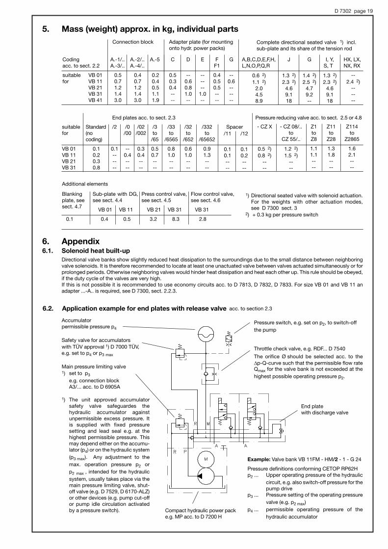
D 7302 page 19
1) Directional seated valve with solenoid actuation.For the weights with other actuation modes, see D 7300 sect. 3
2) + 0.3 kg per pressure switch
6. Appendix6.1. Solenoid heat built-up
Directional valve banks show slightly reduced heat dissipation to the surroundings due to the small distance between neighboringvalve solenoids. It is therefore recommended to locate at least one unactuated valve between valves actuated simultaneously or forprolonged periods. Otherwise neighboring valves would hinder heat dissipation and heat each other up. This rule should be obeyed,if the duty cycle of the valves are very high.If this is not possible it is recommended to use economy circuits acc. to D 7813, D 7832, D 7833. For size VB 01 and VB 11 anadapter ...-A.. is required, see D 7300, sect. 2.2.3.
Accumulatorpermissible pressure p4
Safety valve for accumulators with TÜV approval 1) D 7000 TÜV,e.g. set to p4 or p3 max
Main pressure limiting valve1) set to p3
e.g. connection blockA3/... acc. to D 6905A
1) The unit approved accumulatorsafety valve safeguardes the hydraulic accumulator against unpermissible excess pressure. Itis supplied with fixed pressure setting and lead seal e.g. at thehighest permissible pressure. Thismay depend either on the accumu-lator (p4) or on the hydraulic system
(p3 max). Any adjustment to the
max. operation pressure p2 or
p2 max , intended for the hydraulic
system, usually takes place via themain pressure limiting valve, shut-off valve (e.g. D 7529, D 6170-ALZ)or other devices (e.g. pump cut-offor pump idle circulation activatedby a pressure switch).
Pressure switch, e.g. set on p2, to switch-off
the pump
Throttle check valve, e.g. RDF... D 7540
The orifice Ø should be selected acc. to the |p-Q-curve such that the permissible flow rateQmax for the valve bank is not exceeded at the
highest possible operating pressure p2.
Compact hydraulic power packe.g. MP acc. to D 7200 H
Example: Valve bank VB 11FM - HM/2 - 1 - G 24
Pressure definitions conforming CETOP RP62Hp2 ... Upper operating pressure of the hydraulic
circuit, e.g. also switch-off pressure for thepump drive
p3 ... Pressure setting of the operating pressure
valve (e.g. p2 max)
p4 ... permissible operating pressure of the
hydraulic accumulator
6.2. Application example for end plates with release valve acc. to section 2.3
End platewith discharge valve
5. Mass (weight) approx. in kg, individual parts
Connection block Adapter plate (for mountingonto hydr. power packs)
Complete directional seated valve 1) incl.sub-plate and its share of the tension rod
Codingacc. to sect. 2.2
suitable VB 01for VB 11
VB 21VB 31VB 41
A.-1/..A.-3/..
0.50.71.21.43.0
A.-2/..A.-4/..
0.40.71.21.43.0
A.-5
0.20.40.51.11.9
C
0.50.30.4----
D
--0.60.81.0--
E
------
1.0--
FF1
0.40.50.5----
G
--0.6------
A,B,C,D,E,F,H,L,N,O,P,Q,R
0.6 2)1.1 2)
2.04.58.9
J
1.3 2)2.3 2)
4.69.118
G
1.4 2)2.5 2)
4.79.2--
I, Y,S, T
1.3 2)2.3 2)
4.69.118
HX, LX,NX, RX
--2.4 2)
------
End plates acc. to sect. 2.3
Additional elements
Pressure reducing valve acc. to sect. 2.5 or 4.8
suitablefor
VB 01VB 11VB 21VB 31
Standard(no coding)
0.10.20.30.8
/2
0.1------
/0/00
--0.4----
/02/002
0.30.4----
/3to/65
0.50.7----
/33to
/6565
0.81.0----
/32to
/652
0.61.0----
/332to
/65652
0.91.3----
/11
0.10.1----
/12
0.10.2----
Spacer - CZ X
0.5 2)0.8 2)
----
- CZ 08/..to
CZ 55/..
1.2 2)1.5 2)
----
Z1toZ8
1.11.1----
Z11to
Z28
1.31.8----
Z114to
Z2865
1.62.1----
Blankingplate, seesect. 4.7
0.1
Flow control valve,see sect. 4.6
VB 31
2.8
Sub-plate with DG,see sect. 4.4
VB 01 VB 11
0.4 0.5
Press control valve,see sect. 4.5
VB 21 VB 31
3.2 8.3

D 7302 page 20
6.3.1. General information
This valve bank is especially designed to enable use of those directional seated valves described in supplement No. 76 (D 7300) atan raised operation pressure range between 500 and 700 bar. Main difference to type VB 21 is, that valve banks type VB 22 are heldtogether via two instead of one tension rod. Additionally they enable utilization of sub-plates featuring idle circulation and shuttlevalves. There are also pressure switches available monitoring the pressure at the consumer ports.
VB 22 AM-5 - G49/U43
- G49/W22
- G39/W22 - 8E - 2- G24
Example 1:
Example 2:
Connection block Valve sections End plateincl. sub-plates
Connection Valve sections Directional valve with end plateblock incl. sub-plates (acc. to sect. 2.3 and 2.4)
VB 21 AM -1/500 - G49/0
- G49/0 - H R - 2 - G24
Valve bank with two tension rodsand integrated idle circulation valve for operation pressure pmax = 700 bar.
Connection block without pres-sure limiting valve, valve sectionswith 4/3- or 3/3-way function andoptional provision for pressureswitches type DG3. at port Aand/or B.Sub-plates /W, /U and end platesare prepared to operate the inte-grated idle circulation valve.
Valve bank with one tension rod foroperation pressure pmax = 500 bar.
Connection block with pressurelimiting valve, two valve sectionswith 4/3-way function and sub-plates /0 to enable combinationwith standard valve sections andend plates acc. to sect. 2.2 to 2.4.
6.3. Valve bank Type VB 22
with 3/3- and 4/3-directional seated valve type G 39 resp. G 49 acc. to D 7300 (Supplement No. 76)

D 7302 page 21
1) The idle circulation valve is automatically activated via a sequence of shuttle valves and the control galleries X and Y.
2) Omitted with symbol coding G 39
6.3.2. Available versions, main data
Order example: VB 22 AM-5 - G49/U43
- G49/W22
- G39/W22 - 8E - 2 - G24
2 G 3/8 conf. DIN ISO 228/1 (BSPP)
3/8-18 NPT 3/8-18 NPT conf. ANSI B1.20.1(3)
DG 3.. atport Bport A
G 39
G 49
Simplified illustration
Simplified illustration
Table 5: Flow pattern symbols
Table 8: End plates
Table 9: Port thread
Table 6: Sub-plate (identical for flow pattern symbols G 39 and G 49)
Sub-plate with shuttle valve sub-sequent to a valve section with thesub-plate coding /U.
Solenoid voltage G12, G24
WG110, WG230
(For data see table 3 and D 7300)
Termination of a valve bank 8E with sub-plate coding /U
and /W
1E Termination of a valve bankwith sub-plate coding /0
8E 1E
Sub-plate without additional elements.Can't be combined with sub-platescoding /U and /W!
Sub-plate with idle circulationvalve and shuttle valvesCirculation pressure|p = 7 bar at Q = 25 lpm|p = 4.5 bar at Q = 12 lpm (Should be always installed as firstsub-plate within a valve bank!)
2)
2)
Connection block(Basic type and size, for description see sect. 6.3.1)
Flow and operation pressureQB ≤ 25 lpm; pmax = 500 bar
QB ≤ 12 lpm; pmax = 700 bar
/0
/U1)
/W1)
Table 7: Pressure switches type DG 3..acc. to D 5440at consumer ports A or B
2 Prepared for retrofitting of a DG 3..Intermediate plates (see sect. 6.3.3) are requiredwhen sub-plates type U or W are used
3 DG 33 200 ... 700 bar
4 DG 34 100 ... 400 bar
5 DG 35 20 ... 250 bar
6 DG 36 4 ... 12 bar
7 DG 365 12 ... 170 bar

D 7302 page 22
6.3.3. Unit dimensions
All dimensions in mm, subject to change without notice !
Connection blockType VB 22 AM - 5
Illustration with valve section coding G 49 1)and sub-plate coding /U and /W
This tension rod isomitted when mount-ed onto connectionblocks type VB 21.
Sub-platecoding /0
End platecoding 8 E
End platecoding 1 E
1) Identical dimensions for G 39
2) Port B is blocked with a tapped plug, when a valve section type G 39 is mounted.
3) Mounting of the intermediate plate part No. 7250 036 with O-ring 3.5x1.2; AU,90 Sh and 2 socket head screws DIN 6912-M5x6-8.8-A2K
Mass (weight):
Connection block VB 22 M = approx. 0.7 kg
Valve sections G 39, G 49 = approx. 3.7 kg
Sub-plates /0, /U, /W = approx. 2.3 kg+ 0.3 kg per pressure switch DG 3..
End plates 8 E, 1 E = approx. 0.5 kg
Ports: DIN ISO 228/1 ANSI B1.20.1(3)(BSPP)
P and R G 3/8 G 3/8-18 NPTA and B G 3/8 G 3/8-18 NPTM G 1/4 G 1/4-18 NPT
Pressure switches:
Coding 2
Coding 3 ... 7 3)
M8, 10 deep M8, 9 deep
Cable gland Pg 9
M8, 9 deep
2)
2)
appro
x.53
approx. 60
Intermediateplate 3)
M8, 10 deep

D 7302 page 23
1) DG = Pressure switch type DG 3.. acc. to D 54402) With tapped plug, prepared for retrofitting of a CDK 3(32, 35)-..
01 11 21 31 41
' '
' '
' ' ' '
' ' ' ' '
' '
' '
' '
' '
'
' ' ' '
'
' '
' '
'
' '
'
' '
'
' '
'
' '
' '
' '
' '
' ' ' ' '
' ' ' ' '
' '
'
' ' ' ' '
' ' ' '
' '
' '
'
' '
' ' ' ' '
' ' ' '
' ' '
' '
' ' '
' ' ' ' '
' ' ' '
' ' ' ' '
' ' '
' ' '
'
' ' '
' '
' ' ' ' '
2-way pressure reducing valve with pressure specification, reducing the
pressure for the subsequent system. For options, see sect. 2.5
Size
Suffixes in uncoded text:
Adapter version for solenoid plug (see also D 7300)
Blanking plate (sub-plate without valve), sect. 4.7
Orifice in the pump gallery (type EB. acc. to D 6465, sect. 4.2)
Nom. voltage (sect. 2.2)
G12, G24, WG230 12 and 24V DC or 230V AC (for other
voltage see D 7300, sect. 4.1.2 )
Port size (sect. 2.2)
1 Tapped ports G 1/4
2 Tapped ports G 3/8
3 Tapped ports G 1/2
4 Tapped ports G 3/4
5 Tapped ports G 1
End plate (sect. 2.3) 1)
(without) Standard
/2 End plate with drain valve
/3, /4, /5, /6, /65 With one pressure switch DG 3..
/33, /34, /35, /36, /265 With two pressure switches DG 3..
/44, /45, /46, /465
/55, /56, /565, /66, /665, /6565
/0, /00, /.0, /0 Prepared for retrofitting of one (two) pressure switches
/32, /42, /52, /62, /652 With drain valve and one pressure switch DG 3..
/332 ... /65652 With drain valve and two pressure switches DG 3..
/02 Prepared for retrofitting of one DG 3..
/002 Prepared for retrofitting of two DG 3..
/.11, /12 Spacer for retrofitting of one or two valves
Valve sections - additional elements (sect. 2.4.2) 1)
2 Prepared for retrofitting of one pressure switch DG 3.. (connected to the consumer port)
62 Prepared for retrofitting of one pressure switch DG 3..) (connected to the pump gallery),
only coding H, L, N, R
3, 4, 5, 36, 65 Pressure switch DG 3.. (connected to the consumer port), two pressure switches with coding G
6, 7, 8, 66, 665 Pressure switch DG 3.. (connected to the pump gallery), only coding H, L, N, R
91/.., 92/.. Suffix for press control valves (only with coding R), sect. 4.5
Valve sections (sect. 2.4, 2.5, 4)
D,F,B,E,Q,A,C,P,O,I,Y 2/2-way function (seated valve), coding A not available for size 41
H,N,M,R,S,T 3/2-way function (seated valve)
K,M,U,V 3/2-way function (seated valve with return pressure stop)
HX,LX,NX,RX 4/2-way function (seated valve)
J 3/3-way function (seated valve combination)
G 4/3-way function (seated valve combination)
-CZX 2) and
-CZ08 to CZ55/..
Z1.. to Z2865 3-way pressure reducing valve (previous design) sect. 4.8
SE2../1- 2-way flow control valve (sect. 4.6)
-33, -34, -35, -36, -365 Pressure switch installed on individual sub-plate (sect. 4.4) 1)
Actuations (sect. 2.2), available combinations
M Solenoid
H Hydraulic
P, K, F Pneumatic, roller resp. level
T Pin
D Turn knob
Connection blocks for pipe mounting (sect. 2.2)
A.-1/.., A.-2/.. With pressure limiting valve with pressure specification (manually or tool adjustable
A.-3/.., A.-4/.. With pressure limiting valve with pressure specification (manually or tool adjustable (all steel design)
A.-5 No pressure limiting valve
Adapter plates for mounting onto hydraulic power packs
C For type R (D 6010H ++) and Z (D 6820)
D For type R (D 6010H ++) and Z (D 6820)
E For type R (D 6010H ++) and Z (D 6820)
F, F1 For type HC (D 7900), HCG (D 7900 G), MP (D 7200 H), FP (D 7310) and HK (D 7600-...)
type F1 for size VB 01 only
G For type MP acc. to D 7200 H or RZ acc. to D 6910 H together with connection block
A51/.., A61/.. or two stage valve NE21 acc. to D 7161
Basic type and size (sect. 2.2)
VB 01, VB 11, VB 21, VB 31, VB 41 Type and size
7. Type overviewOrder examples:VB01 F1M - H6 H36 Z16 H /4 65 - 1 - WG230
VB11 AM -1/350 - F H R 3 G35 H /3 2 11 - 2 - G24
VB21 GMF - R H H H /H - 3 - G24

2/2- and 3/2-way directional seated valves type BVG and BVPfor any flow direction, zero leakage
all ports pressure resistant
D 7400Seated valves BVG and BVP
September 2012-01
HAWE HYDRAULIK SESTREITFELDSTR. 25 • 81673 MÜNCHEN
2.2
© 1987 by HAWE Hydraulik
Perm. pressure pmax = 320 barPerm. flow Qmax = 50 lpm
Additional valves with same function:o Type BVG 11(12 and 2), BVP 11(2) see appendix, sect. 5.1,
Run-out design do not use for new layouts!o Type BVG, BVP 1 D 7765 (Qmax = 20 lpm, pmax = 400 bar)o Type NBVP 16 D 7765 N (Qmax = 20 lpm, pmax = 400 bar)o Type BVE D 7921 (Qmax = 70 lpm, pmax = 400 bar)o Type VP D 7915 (Qmax = 15 lpm, pmax = 400 bar)
Design for pipe
connection
Example: Type BVG 3 S-G 24
Design for manifold mounting
Example: Type BVP 3 R-G 12
1. GeneralThese 2/2- and 3/2-way directional cone seated valves are available with electrical, hydraulic or pneumatic actuation. All ports are equally pressure resistant due to the internal pressure balance.The zero or idle position is achieved automatically if the valve is not actuated due to spring return. They are of all steel design and all functionally essential internal parts are hardened and run maintenance free in oil; Cones and seats are ground.

D 7400 page 2
BVP 3 Z - H 1/4 BVP 3 R(S) - H 1/4
BVP 3 Z - P BVP 3 R(S) - P
2. Available versions, main data
Order examples: BVG 3 R/B 2,5 - WG 230
BVP 3 Z - P
Complete symbols
(The actuation symbols apply to all flow symbols)
Pipe connection
BVG 3 R - H BVG 3 S - P
BVG 3 Z - G...BVG 3 Z - WG...
Manifold mounting
Table 1: Basic type and size 1)
Coding
BVG 3
BVP 3
Design and connection
Pipe connection G 1/2 ISO 228/1(BSPP)
Manifold mounting
FlowQmax (lpm)
50
50
Pressure pmax(bar)
320
320
BVP 3 Z - H BVP 3 R(S) - H
BVP 3 Z - G...BVP 3 Z - WG...
Table 2: Symbols
R S Z
Table 3: Orifices(in ports A, B, and C, see also sect. 3.1)
Coding No. for subsequent orders System or # accumulator (mm) BVG 3.. BVP 3.. pressure range
B 2,5 2.5 7405 014 b 7405 013-2,5 about 300 barB 3 3 7405 014 c 7405 013-3,0 about 200 barB 3,5 3.5 7405 014 d 7405 013-3,5 about 150 barB 4 4 7405 014 e 7405 013-4,0 about 100 bar
2) 0 2) 7405 014 a 7405 013 --
1) Type BVG 11(12, 2) and BVP 11(2) see appendix, sect. 5.1, Run-out design do not use for new layouts!
2) Undrilled for customized diameter acc. to |p-Q-curve of the orifices, sect. 3.13) DC-solenoid (98 V DC, 205 V DC) with plug featuring a bridge rectifier circuit
Table 4: Actuations
Main data, see also sect. 3.2
UN = 12 V DC
UN = 24 V DC
UN = 110 V AC, 50/60 Hz (98 V DC) 3)
UN = 230 V AC, 50/60 Hz (205 V DC) 3)
Ext. control port G 1/4 (BSPP). Only with type BVP 3 !
Ext. control port G 1/4 (BSPP)
with plug
G 12
G 24
WG 110
WG 230
H
H 1/4
P
Coding
Plug withLED
L 12
L 24
---
---
without plug
X 12
X 24
X 98
X 205
Solenoid
Hydraulic
Pneumatic
Actuation
Control pcontr min = 24 barpressure: pcontr max = 320 bar
Control pcontr min = 4 barpressure: pcontr max = 15 bar
Actuation Solenoid Hydraulic Pneumatic symbols Coding H 1/4 Coding H

D 7400 page 3
3. Further parameters3.1 General and hydraulic
Installation position Any
Negative (transverse of one into the other flow direction is only completed when the switch-ing position is achieved). All passages are interconnected during the switching operation.
Operating pressure pmax = 320 bar
Static overload capacity Ports A, B, and C approx. 2 x pmax (640 bar)
Body material and Steel, zinc galvanizedsurface coating
Mass (weight) approx. kg
Pressure fluid Hydraulic oil conforming DIN 51514 part 1 to 3: ISO VG 10 to 68 conforming to DIN 51519.Viscosity limits: min. approx. 4, max. approx. 1500 mm2/s; opt. operation approx. 10... 500 mm2/s.
Also suitable are biological degradable pressure fluids types HEPG (Polyalkylenglycol) and HEES (Synth. Ester) at service temperatures up to approx. +70°C.
Temperature Ambient: approx. -40 ... +80°CFluid: -25 ... +80°C, Note the viscosity range !
Permissible temperature during start: -40°C (Observe start-viscosity!), as long as the service temperature is at least 20K higher for the following operation.
Biological degradable pressure fluids: Note manufacturer’s specifications. By consideration of the compatibility with seal material not over +70°C.
Attention: Observe the restriction regarding the operation duration in sect. 3.2. !
Perm. flow Qperm acc. to sect. 2 applies to pmax = 320 bar with solenoid actuation in usual pump circuits. With pressure < 150 bar (solenoid actuated) or with all other actuation modes Qperm may be exceeded up to 50% as long as the back pressure is permissible.
Flow limitation The max. flow has to be limited (depending on the pressure) by means of orifices in the case of accumulator circuits or if connected to high pressure circuits (circulation lines or central supplies) down to the specified Qmax (see sect. 2).
These orifices must be located always on the accumulator side. With valves type ..Z..- they are installed in port C. If mounting in port A or B is requested, this has to stated in uncoded text. For detailed description see table 3, sect. 2.
Overlapping with 3/2-way directional valves
Complete with actuation
Solenoid
Hydraulic
Pneumatic
BVG 3 RBVG 3 S
2.3
1.9
1.9
BVP 3 Z
2.4
2.0
1.7
BVP 3 RBVP 3 S
2.3
1.9
1.9
BVG 3 Z
3.3
2.9
2.6
3/2-way-valve
2/2-way-valve
Bac
k p
ress
ure
|p
(bar
)
Bac
k p
ress
ure
|p
(bar
)
Flow Q (lpm) Flow Q (lpm)
Viscosity of the oil during tests approx. 60 mm2/s
Additional orificesBasic valve|p-Q-curve

D 7400 page 4
3.2 Actuations
Solenoid
The solenoids are manufactured and tested conforming VDE 0580
DC-voltage AC-voltage
Coding G 12 G 24 WG 110 WG 230 L 12 L 24 --- --- X 12 X 24 --- ---
Nom voltage UN (V) 12 24 110 230
Nom. power PN (W) 33.2 30.0 32.8 33.0
(DC-voltage) (AC-voltage, 50/60 Hz)
Switching time (guideline) ON or OFF: approx. 50 ... 60 ms; with WG.. approx. 2-3 times prolonged
Switchings / hour approx. 2000/h to be regarded as approx. evenly distributed
Protection class IP 65 (IEC 60529) (plug properly mounted)
Insulation material class F
Contact temperature approx. 98°C, at 20°C ambient temperature
Cut-off energy WA Ò 0.5 Ws
Surface coating DIN 50961-Fe/Zn 12 bk cC (solenoid)
Relative duty cycle during service (100% ED stamped on the solenoid)
Rel. duty cycle %ED-5 min
Am
bie
nt
tem
p.
U (°
C)
Pneumatic
(Coding P)Hydraulic
(Coding H, H 1/4)
Type G... Type L.. Type WG..
24 bar 4 bar
320 bar 15 bar
< 2 bar ---
approx. 1.5 pcontr max bar approx. 1.5 pcontr max bar
0.6 cm3 3 cm3
Steel (body) Light alloy (body)galv. zinc plated black anodized
Control pressure Pcontr min
pcontr max
Perm. residual pressure in the control line for save return to idle position
Static over load capacity of Z
Control oil volume (geom.)
Housing material and surface coating
Solenoid terminalsPlug DIN EN 175 301-803
(circuitry and symbol)
All plugs
For additional plugs, see D 7163

D 7400 page 5
4. Unit dimensionsAll dimensions are in mm and subject to change without notice!
4.1 Version for pipe connectionIllustrations are with solenoid actuation (coding G.. or WG..), for other actuations see below
Type BVG 3 R(S) Type BVG 3 Z
For missing dimensions see below!
Ports conf. ISO 228/1 (BSPP):A, B, and C = G 1/2
Ports conf. ISO 228/1 (BSPP): A and B = G 1/2
Hydraulic actuation
Coding H 1/4
Pneumatic actuation
Coding P
#8.5 thru-hole
Manual emer-gency actuation
Cable gland
#8.5 thru-hole
Actuation aid (do not use any sharp-edged parts)
1) Note: This dimension is depending on the manufacturer and can be up to max. 40 mm acc. to DIN EN 175 301-803!
2) When required the solenoid may be rotat ed to the valve body by another 4x90° in addition to the standard assembly position illustrated here.
Manual emergency actuation
The valve may be actuated by pressing down the brass bolt visible from above by means of a steel pin or a screw driver etc.Note: All pressure apparent at port B
loads on the cross section of the brass bolt #5.5 i.e. 100 bar or 240 N !
#5.5
approx. 35 1)
2)

D 7400 page 6
M 6, 9 deep
4.2 Version for manifold mountingIllustrations are with solenoid actuation (coding G.. or WG..), for other actuations see below 4.1
Type BVP 3 R(S)
M 6, 7 deep
Hole pattern of the manifold (top view)
Sealing of ports A, B, and C via O-rings 13.95x2.62 NBR 90 Sh
Port Z: via O-ring 2.54x1.78 NBR 90 Sh
Available as spare part, seal-kit DS 7400-3 incl. O-rings for actuation coding H, H 1/4.
For missing data see sect. 4.1 !
For missing data see sect. 4.1 !
Type BVP 3 Z
Hydraulic actuation
Coding H
Coding H 1/4
Pneumatic actuation
Coding P
1) Control port Z is only apparent at versions with hydraulic actuation coding H!
Hole pattern of the manifold (top view)
1)
1)
Control port Z is at the upper (valve section)

D 7400 page 7
5. Appendix5.1 Type BVG 11(12 and 2) or BVP 11(2)
Run-out design do not use for new layouts! (Alternative, type BVG 1 and BVP 1 acc. to D 7765)
Order examples:
BVG 11 R - G 24
BVP 2 S/B 1,5 - WG 230
Table 5: Basic type and size
Coding
BVG 11
BVG 12
BVG 2
BVP 11
BVP 2
Design and connection
G 1/4
G 3/8
G 3/8
Manifold mounting
FlowQmax (lpm)
12
20 1)
20
12
20
Pressurepmax(bar)
320
320
1) With solenoid actuation:20 lpm up to 200 bar12 lpm up to 320 bar and Ò 80% EDsee also sect. 3.1 “Flow”
2) Undrilled for customized diameter acc. to |p-Q-curve of the orifices, sect. 3.1
3) Only with type BVP 11(2), not available for type BVG.. (housing dimensions to small - radiation insufficient)
Pipe connection ISO 228/1(BSPP)
Table 7: Actuation modes
Actuation Coding, note
Solenoid G 12, L 12, X 12 see table 4, G 24, L 24, X 24 sect. 2 WG 100, X 98
WG 230, X 205
G 24 EX 3)
Ex-proof design UN = 24 V DC; pmax = 220 bar !
Manual A for type BVG 11(12) !
Body material and surface treatment = Steel (lever housing gas nitrated) Actuation torque = approx. 70 Nm at 320 bar
Table 6: Additional orifice (at ports A, B, and C, see also sect. 3.1)
Coding
B 0,6
B 0,8
B 1,1
B 1,3
B 1,5
2)
B 0,4
B 0,5
B 0,6
B 0,7
B 0,8
B 0,9
B 1,0
B 1,1
B 1,3
B 1,5
B 2,0
B 2,5
B 4,0
2)
B 0,6
B 0,8
B 1,1
B 1,3
B 1,5
B 2,0
B 2,5
2)
#(mm)
0.60.81.11.31.5
0
0.40.50.60.70.80.91.01.11.31.52.02.54.0
0
0.60.81.11.31.52.02.5
0
for subsequent orders
7406 012 b7406 012 c7406 012 d 7406 012 f7406 012 h
7406 012 a
7400 003 k7400 003 l7400 003 d7400 003 m7400 003 e7400 003 n7400 003 o7400 003 g7400 003 h7400 003 c7400 003 f7400 003 i7400 003 b
7400 003 a
7921 012-0,67921 012-0,87921 012-1,17921 012-1,37921 012-1,57921 012-2,07921 012-2,5
7921 012
Basic type
BVG 11
BVG 2
BVP 11BVP 2
Symbols (see table 2 sect. 2)Attention: Symbol Z not available for type BVG 12 !

D 7400 page 8
Further parameters
For general and electrical data see sect. 3.1 or 3.2
Mass (weight) approx. kg Complete with actuation
Solenoid
Manual
BVG 11 R(S)BVG 12 R(S)
1.0
0.6
BVP 11 Z
1.0
---
BVP 11 R(S)
0.9
---
BVG 11 Z
1.6
---
Complete with actuation
Solenoid
BVG 2 R(S)
1.3
BVP 2 Z
1.4
BVP 2 R(S)
1.1
BVG 2 Z
1.7
|p-Q-curveB
ack
pre
ssure
|p
(bar
)
Bac
k p
ress
ure
|p
(bar
)
Flow Q (lpm) Flow Q (lpm)
Viscosity of the oil during tests approx. 60 mm2/s
Additional orificesBasic valve

D 7400 page 9
Unit dimensions
All dimensions are in mm and subject to change without notice!
Version for pipe connection
Illustration with solenoid actuation (coding G.. or WG..); For manual actuations, see below
Type BVG 11 R(S) Type BVG 12 R(S)
Ports conf. ISO 228/1 (BSPP):A, B, and C = G 1/4 (BVG 11 R, S and Z) = G 3/8 (BVG 12 R and S)
#6.5 thru-hole
Manual emergency actuation
Cable gland
Ports conf. ISO 228/1 (BSPP): A, B, and C = G 3/8
#6.5 thru-hole
Manual emergency actuation
Cable gland
Actuation aid (do not use any sharp-edged parts)
1) Note: This dimension is depending on the manufacturer and can be up to max. 40 mm acc. to DIN EN 175 301-803 !
2) When required the solenoid may be rotated to the valve body by another 4x90° in addition to the standard assembly position illustrated here.
Manual emergency actuation
(applies to type BVG ..11(12 and 2))
The valve may be actuated by pressing down the brass bolt visible from above by means of a steel pin or a screw driver etc.Note: All pressure apparent at port B
loads on the cross section of the brass bolt #5 i.e. 100 bar or 195 N !
#5
Type BVG 11 Z
Type BVG 2 Z
Type BVG 2 R(S)
Manual emergency actuation
Coding A (applies to type BVG ..11(12))
#6.5 thru-hole
1)
2)
2)
approx. 35 1)
app
rox.
35
app
rox.
35
approx. 35

D 7400 page 10
Version for manifold mounting
Illustration with solenoid actuation (coding G.. or WG..), For manual actuations, see type BVG..
Type BVP 11 R(S) Type BVP 11 Z
Type BVP 2 R(S)
Type BVP 2 Z
For missing data see type BVG.. !
Hole pattern of the manifold (top view)
Hole pattern of the manifold (top view)
Hole pattern of the manifold (top view)
Hole pattern of the manifold (top view)
Sealing of ports A, B, and C via O-rings 7.65x1.78 NBR 90 Sh.
Available as spare part, seal-kit DS 7400-1.
Sealing of ports A, B, and C via O-rings 7.65x1.78 NBR 90 Sh.
Available as spare part, seal-kit DS 7400-1.
Sealing of ports A, B, and C via O-rings 7.65x1.78 NBR 90 Sh.
Available as spare part, seal-kit DS 7400-1.
For missing data see type BVG.. !
M5, 6 deep
For missing data see type BVG.. !
M 5, 6.5 deep
M 5, 6.5 deep
M6, 6 deep

D 7400 page 11
5.3 Schematic cross sectional views (standard versions acc. to sect. 2)
The schematic cross sectional views are represented here to show the functional principle, illustrated are valves in actuated state.They do apply to all actuations acc. to table 4.
Type BVG 3 R.. Type BVG 3 S.. Type BVG 3 Z..
5.2 2/2-way directional valve with by-pass check valve
There is a modified version of valve type BVG-2R available, which may be equipped with a check valve to by-pass the blocked passage BdA.
Order example: BVG R 2 R - ... Symbol
Coding like in sect. 5.1
R = By-pass check valve
Flow Q (lpm)
|p-Q-curve
Bac
k p
ress
ure
|p
(bar
)
Opening pressure of the check valve approx. 0.8 bar
Posi
tion
0
Position
a
Note: Dimensional drawing and mass (weight) like type BVG 2 R acc. to sect. 5.1

Directional seated valves Type WN and WHZero leakage
(Type WN also as directional spool valve)
D 7470 A/1Directional seated valves
WN and WH
August 2008-00
HAWE HYDRAULIK SESTREITFELDSTR. 25 • 81673 MÜNCHEN
2.2
© 1985 by HAWE Hydraulik
Individual valves for manifold mounting Section 2Valves with individual connection sub-plates Section 3Directional valve banks D 7470 B/1
Pressure pmax = 350 ... 450 barFlow Qmax = 5 ... 60 lpm
1. General information
Individual valve for
manifold mounting
(see section 2)
Valve with indiv. connection
sub-plate for pipe connection
(see section 3)Example as size 3
Size 1
Size 2
Size 3
Size 4
o The directional seated valves type WN and WH are of compact design and feature 2/2-, 3/2-way functions. 2/2-, 3/2-way functions are possible by combining two individual valves on one joint sub-plate (see sect 3).
o All functionally important components, from the solenoid armature to the valve elements, are lubricated by the hydraulic fluid, therefore no maintenance is required.
o Type WN is only available as size 1. The armature cavity is pressure resistant up to 300 bar and directly connected to port R. This means that between the solenoid armature and the valve elements only a simple pin (with no seal) is required. This results in a very long service life (no seal wear).
The solenoid force is largely dependent on the respective pressures to be switched. This often enables operation with reduced supply voltage (see sect. 2.2.1) thereby reducing the solenoid temperature and increasing its service life.
o Additionally to the directional seated valve versions of type WN, there is also a 4/2-way directional spool valve available (pmax = 300 bar).
o Type WH features an actuation pin between solenoid armature and valve elements which is sealed and shaped in such a way, that the solenoid force is supported by an additional hydraulic force. This enables pressure up to 450 bar (WH 1) or 350 bar (WH 2, 3 and 4) to be achieved.
For lubrication purposes and to equalize the volume, the armature cavity is either connected internally to the return port, or in case of 2/2-way valves connected externally to the return pipe (depending on application).
Type WH 1 features larger valve elements and more stroke resulting in a reduced flow resistance than with WN 1.

D 7470 A/1 page 2
2. Individual valve for manifold mountingFor valves with individual sub-plate suited for pipe connection, see section 3.
2.1 Type coding, main data
For complete type overview see section 6.1, page 19
Coding example: WH 1 M - G 24
Table 1: Basic type and size Table 2: Actuation solenoid 5)
Table 3: Flow pattern symbols (also see section 3 for combinations of individual valves)
Type Pressure pmax (bar) Flow (lpm)
1) See sect. 2.22) The additional check valve on the P-side in types Q, E, N, R, and WX
prevents an equalization of pressure when the passage is open, or a change in direction of flow when due to other switching operations the pressure at P becomes lower than at A (B, R).
See also section 3, table 4 a footnote 3). The check valve insert can be retrofitted and is therefore separately
available. Order coding EK 01.3) See also installation instruction in sect. 5.44) Not available for WH 4 5) For further special voltage see section 2.2.2 “Special voltages“
Suitedfor
WN 1
2/2-way
WN 1
3/2-way
WH 1 to WH 4
2/2-way
WH 1 toWH 4
3/2-way
Directional seated valves Directional spool valves
D Q 2) 3) F E 2) W
H N 2) 3) M R 2) WX
H N 2) M R 2)
D Q 2) F E 2)
Only for WN 1, WH 1 and WH 2:
3/2-way valves H1
with additional N1
return pressure M1
stop R1
When several valves are operating in parallel, the return pressure stop prevents pressure surges out of the common return pipe from entering unoperated, unloaded or easily moving consumers, where there is a connection AdR. Thus preventing uncontrolled movements. Such pressure surges can arise as a result of switching operations. Occasionally the return pressure stop may be required for WN 1 or WN 2 valves, as the resetting spring has a lower force than in WH 1. These check valves are not suit-able for stopping pressurized oil, which may be apparent at R, depending on the combination of valves. A circuit with an external check valve would have to be installed in this case.
Directional seated valve
... 350 1)
450
350
350
350
Directional seated valve
5
8
15
30
60
Directional spool valve
300
Directional spool valve
6
WN 1
WH 1
WH 2
WH 3
WH 4
Standard Without With plug Nom.with plug featuring voltageplug LED‘s
G 12 4) X 12 4) L 12 4) 12 V DC
G 24 X 24 L 24 24 V DC
G 98 4) X 98 4) --- 98 V DC
G 205 X 205 --- 205 V DC
WG 110 4) --- --- 110 V AC
WG 230 --- --- 230 V AC
The following parts are required for retrofitting:
WN(H) 1 Valve shim 7470 021
WH 2 Ball 3/16” DIN 5401 and housing 7545 019
Only for WN 1, WH 1:
2/2- and 3/2-way direction-al seated valves feature an additional orifice in port P, flow pattern symbols D, F, H and M (see also sect. 5.2).
50 /60 Hz
2/2-way directional seated valves featur-ing a pressure limiting valve in the intermedi-ate plate, flow pattern symbols D and F (see also sect. 5.1).

D 7470 A/1 page 3
2.2 Further characteristic data2.2.1 General and hydraulic
Nomenclature, design Seated ball valve or spool valve in 2/2-, 3/2- or 4/2-way versions, depending on type
Pipe connection Basic valve (sect. 2.1): Via manifold Sub-plates (sect. 3): Via tapped ports
Ports P = Inlet (pump side); A, B = Consumers; R = Return L = Relief port, connect pressureless to the tank (return) always For pressure rating, see below
Installed position Any
Flow resistance Seated valves: Only in arrow direction in accordance with symbolSpool valves: Preferably in arrow direction (see symbol W/WX in sect. 2.1). Contrary to the
arrow direction is permissible; Note pressure rating of R (see below )
Overlapping 3/2-way Negative. Transition from one to the other flow direction is only completed when seated valves end position is achieved i.e. all passages are interconnected during the switching operation. The switching operation is unhampered by this, due to their quick response. Spool valves: None
Flow (lpm)
Operation pressure
Ports P, A and B
Perm. pressure in port R WN 1: pR Ò 350 bar, but observe that pR Ò pA Ò pP! Note: Use code letter F and E as straight-way valve up to 320 bar only! WH 1(2, 3 a. 4): Flow pattern symbols H, N, M and R pR Ò 20 bar Flow pattern symbols D, Q, F and E pR Ò 350 bar, pL Ò 20 bar Sub-plates acc. to sect. 3: Version ..S(SR) or ..V(VR) pR Ò 20 bar
Pressure fluid Hydraulic oil conforming DIN 51524 part 1 to 3: ISO VG 10 to 68 conforming DIN 51519. Viscosity limits: min. approx. 4, max. approx. 800 mm2/s; opt. operation approx. 10... 200 mm2/s. Flow resistance will increase more sharply at viscosities over approx. 300 mm2/s! Also suitable for biological degradable pressure fluids types HEPG (Polyalkylenglycol) and HEES
(Synth. Ester) at service temperatures up to approx. +70°C. Versions for glycol-based brake fluids (conforming DOT 4) are available for WN 1, WH 1, and
WH 2. Add suffix -AT to the order coding acc. to sect. 2.1.
Temperature Ambient: approx. -40 ... +80 °C (Observe restrictions in sect. 2.2.2 “Duty cycle” Fluid: -25 ... +80°C, Note the viscosity range! Permissible temperature during start: -40°C (Note start-viscosity!), as long as the service tempera-
ture is at least 20K higher for the following operation. Biological degradable pressure fluids: Note manufacturer’s specifications. By consideration of the
compatibility with seal material not over +70°C.
Static overload capacity approx. 2 x pmax
See table 1 in section 2.1
Basic type
WN 1 Directional seated valves
WH 1
WH 2 (3 and 4)
Flowpattern
D, Q, R, H, N, M,J
F, E
W, WX
all
Appliedvoltage
UN
0.75 UN
0.5 UN
UN ... 0.5 UN
UN
UN
Relative duty cycle % ED100 50 <10
230 250 350
110 160 200
100 100 120
350
300
450
350
Ambient temperature
Guideline for 20°Cat 40°C reduced by approx. 10 to 15%
Guideline for 40°C(For restrictions see also section 2.2.2)
Switchable pressure (bar)
WN(H) 1WH 2WH 3WH 4
Individual valve acc. to sect. 2.1
D H (1) W,to to WXF R (1)
0.6 0.6 0.60.7 1.2 --0.7 1.3 --2.7 3.0 --
Individual valve with connection sub-plate acc. to section 3without pressure limiting valve with pressure limiting valveWN 1 - 1/4 (C) WN 1../.. - 1/4 .. - 1/4 S .. - 1/4 VWH..- 1/4 (C, L) WH 1../.. - 1/4 .. - 1/4 SR .. - 1/4 VRD, Q, H (1), N (1), W, U, J, H (1), N (1), Q to W,E, F M (1), R (1) WX L M (1), R (1) R (1) WX F, D
0.9 0.9 1.0 1.1 1.7 1.0 1.2 1.71.0 1.0 -- 1.9 -- 1.2 -- --1.8 1.8 -- 3.5 -- 2.1 -- --3.6 4.0 -- 7.4 -- -- -- --
Mass (weight) approx. kg
o An under voltage < 90% of UN is not permissible with type WH.
o Valves type WN 1: The required solenoid force is usually directly proportional to the operating pressure to be switched. The supply voltage can be reduced (undervoltage see table above with 0.75 UN a. 0.5 UN), if the operation pressure in a hydraulic circuit is limited to a value lower than the maximum permissible value, by a pressure limiting valve. This means that the heat build-up of the solenoid is reduced, resulting in increased service life of the winding and reduced heat dissipation to neighboring parts (valve body with seals) and other valves (valve banks).
o The use of an economy circuit is recommended for prolonged operation durations. See also the respective notes in sect. 2.2.2 “Plugs“.
Directional spool valves

D 7470 A/1 page 4
|p - Q-curves
Flo
w r
esis
tance
|p
(bar
)F
low
res
ista
nce
|p
(bar
)
Flow Q (lpm)Guideline for a fluid viscosity of approx. 60 mm2/s
1) Add to the characteristic flow resistance of the valve in flow direction when apparent2) Add to the characteristic flow resistance of the valve (Q, E, N, and R) in flow direction when a check valve is installed at P
2.2.2 Electrical data (standard)
Solenoid
Basic type
Coding acc. to section 2.1
Nom. voltage UN for other voltage,see page 5
Nom. current I20 3) (A)
Power PN 3) (W)
Wet armature solenoid, manufactured and tested conforming VDE 0580
WN 1, WH 1 and WH 2 WH 3 6) WH 4
G 12 G 24 WG 110 4) WG 230 4) G 12 G 24 WG 110 4) WG 230 4) G 24 WG 230 4)X 12 X 24 (G 98) (G 205) X 12 X 24 (G 98) (G 205) X 24 (G 205)L 12 L 24 (X 98) (X 205) L 12 L 24 (X 98) (X 205) (X 205)
12V DC 24V DC 110V AC 230V AC 12V DC 24V DC 110V AC 230V AC 24V DC 230V AC (98V DC) (205 V DC) (98 V DC) (205V DC) (205V DC)
2 1 0.25 0.14 2.72 1.36 0.30 0.16 3.4 0.4
24.4 24.4 24.4 24.4 30 30 30 30 82.2 82.2
60 ... 70 (WN(H) 1; 50 (WH 2) 50 100
30 ... 60 (WN(H) 1; 65 (WH 2) 40 40 ... 200 5)
approx. 2 ... 3 times prolonged with WG versions
WN 1 = 3600; WH 1 and WH 2 = 2000 2000 2000
to be regarded as approx. evenly distributed
On: (ms)
Off: (ms)
Switching frequency / h approx.
3) The electrical data of the solenoids are reference values (max.) and can differ insignificantly depending on manufacturer
4) DC-solenoid 98 V DC or 205 V DC with plug featuring a bridge rectifier, see also „Plugs“, suited for mains 50 and 60 Hz.
5) D, Q 130 ms F, E 40 ms H, N, M, R pressure-dependent (50 bar = 40 ms; 200 bar = 100 ms; 350 bar = 200 ms)
6) For version with switching performance of 8 Watt, see section 5.3
Switching time (guideline)
Type WN 1 Type WH 1
Flo
w r
esis
tance
|p
(bar
)
Flow Q (lpm)WH 2
WH 3
Flo
w r
esis
tance
|p
(bar
)
Flow Q (lpm)Flow Q (lpm)
Type WH 2 and WH 3 Type WH 4
check valve at P
(E, Q, N, R) 1 )check valve at P
(E, Q, N, R) 1 )
return pressure stop
(D1,H1 etc.) 1)
return pressure stop
(D1, H1 etc.)1)
Switching time „off“ with WH 4 and flow pattern symbol
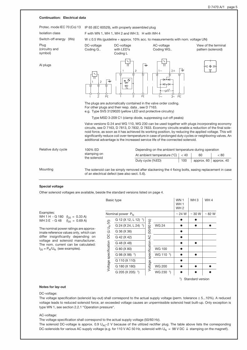
D 7470 A/1 page 5
Continuation: Electrical data
Protec. mode IEC 70 (Co) 13
Isolation class
Switch-off energy (Ws)
Plug (circuitry and symbol)
Al plugs
Relative duty cycle
Mounting
Depending on the ambient temperature during operation
At ambient temperature (°C) < 40 60 < 80
Duty cycle (%ED) 100 approx. 60 approx. 40
IP 65 (IEC 60529), with properly assembled plug
F with WN 1, WH 1, WH 2 and WH 3; H with WH 4
W Ò 0.5 Ws (guideline + approx. 10% acc. to measurements with nom. voltage UN)
DC-voltage DC-voltage AC-voltage View of the terminalCoding G.. with LED‘s Coding WG.. pattern (solenoid) Coding L
The plugs are automatically contained in the valve order coding.For other plugs and their resp. data , see D 7163.e.g. Type SVS 3129020 (yellow LED and protective circuitry)
Type MSD 3-209 C1 (clamp diode, suppressing cut-off peaks)
Valve versions G 24 and WG 110, WG 230 can be used together with plugs incorporating economy circuits, see D 7163, D 7813, D 7832, D 7833. Economy circuits enable a reduction of the final sole-noid force, as soon as it has achieved its working position, by reducing the applied voltage. This will significantly reduce coil over-temperature in case of prolonged duty cycles or neighboring valves. An additional advantage is the increased service life of the connected solenoid.
100% EDstamping on the solenoid
The solenoid can be simply removed after slackening the 4 fixing bolts, easing replacement in case of an electrical defect (see also sect. 5.6).
Special voltage
Other solenoid voltages are available, beside the standard versions listed on page 4.
Examples: WH 1 H - G 180 (I20 = 0.33 A)WH 3 E - G 48 (I20 = 0.69 A)
The nominal power ratings are approx-imate reference values only, which can differ insignificantly depending on voltage and solenoid manufacturer. The nom. current can be calculated: I20 = PN/UN (see examples).
Notes for lay-out
DC-voltage:
The voltage specification (solenoid lay-out) shall correspond to the actual supply voltage (perm. tolerance * 5...10%). A reduced
voltage leads to reduced solenoid force, an exceeded voltage causes an unpermissible solenoid heat built-up. Only exception is
type WN 1, see section 2.2.1 “Operation pressure“.
AC-voltage:
The voltage specification shall correspond to the actual supply voltage (50/60 Hz).
The solenoid DC-voltage is approx. 0.9 UAC-2 V because of the utilized rectifier plug. The table above lists the corresponding
DC-solenoids for various AC supply voltage (e.g. for 110 V AC 50 Hz, solenoid with UN = 98 V DC & stamping on the magnet!).
Basic type
Nominal power PN
G 12 (X 12, L 12) 1)
G 24 (X 24, L 24) 1) WG 24
G 36 (X 36)
G 42 (X 42)
G 48 (X 48)
G 80 (X 80) WG 100
G 98 (X 98) 1) WG 110 1)
G 110 (X 110)
G 180 (X 180) WG 200
G 205 (X 205) 1) WG 230 1)
WN 1WH 1WH 2
+ 24 W
o
o
o
o
o
o
o
o
o
o
WH 3
+ 30 W
o
o
o
o
o
o
WH 4
+ 82 W
o
o
o
Vo
ltag
e sp
ecifi
catio
n D
C (&
UN (V
))
Vo
ltag
e sp
ecifi
catio
n A
C (5
0/6
0 H
z)
1) Standard version

D 7470 A/1 page 6
3. Individual valve with connection sub-plate For complete type overview see section 6.2, page 19.
3.1 Type WN 1
Order example: WN 1H - 1/4 S - G 24 - 150
WN 1 D - 1/4 V - G 24 - 50
Connection sub-plate with tool adjustable pressure limiting valve
Connection sub-plate with pressure limiting valve connected in series 1)
Valve coding acc. to section 2.1
Desired pressure setting Pressure ranges: (0) ... 80 bar (0) ... 160 bar (0) ... 315(350) bar
Table 4 a: Connection sub-plates for individual valves
S, V = Tool adjustable
SR, VR = Manually adjustable
Pressure limiting valve:
WN 1.../... - 1/4 - ..
Double directional seated valve for pipe connection.Serve for the compact realization of two separate 3/2-way functions.
Port P, R, A, B 4) : Thread G 1/4 ISO 228/1 (BSPP), suited for pipe fittings shape B DIN 3852 page 2
2/2-way directional seated valve combination WN 1 D, Q or FFixation of the consumer at any intermediate position
3/3-way function
Table 4 b: Directional valve combinations
WN 1 J - 1/4 - .. WN 1 U - 1/4 - ..
Flow pattern symbol H(1), N(1), M(1), R(1)at port Bat port A
Order coding for connec-tion sub-plate only (enabling retrofitting of a double valve): Sub-plate 7470 061 com-plete with readily installed screen filter discs HFC 1/4 F in P, A, and B.
For valves with flow pattern acc. to section 2.1
2/2-way directional valves 3/2-way directional valves
Valve D, F D, F D, F H, N, M, R W, WXcoding Q, E 2) Q, E 2)
Pressure lim. valve without without with 1) 3) with 3) without with 3) without with 3)
WN 1 - 1/4 - 1/4 C - 1/4 V - 1/4 S - 1/4 - 1/4 S - 1/4 - 1/4 S
- 1/4 VR - 1/4 SR - 1/4 SR - 1/4 SR
Suited for basic type
Flow pattern symbols
4/2-way directional spool valve
Port P, R, A and B 4) :Thread G 1/4 ISO 228/1 (BSPP), suited for pipe fittings shape B DIN 3852 page 2.
1) Utilized to activate a second pressure stage, e.g. for prop. directional spool valves type PSL, PSV acc. to D 7700 ++ or for pressure stage circuits of piloted pressure valves e.g. type DV acc. to D 4350 or AS, ALZ acc. to D 6170.
2) Valves coding E and Q should be preferred for by-passing to the tank; A return pressure stop may be installed at R, when pressure peaks could occur at R (see sect. 2.1).
3) Attention: Permissible pressure 20 bar in the return! A steel spring housing is available, required when pressure surges (> 20 bar) might occur in the return, e.g. as result of decompression
surges induced by accumulating consumers. Indicate in uncoded text „with steel spring housing“ added to the order coding.
4) For permissible operation pressure, see section 2.2.1
Example: WN 1 J - 1/4 - G 24 WN 1 U - 1/4 - WG 230
Example: WN 1 M/M - 1/4 - G 12

D 7470 A/1 page 7
WH 1.../... - 1/4 - ..
Double directional seated valve for pipe connection.Serve for the compact realization of two separate 3/2 way functions.
2/2-way directional seated valve combination WH..D, Q or FFixation of the consumer at any intermediate position
3/3-way funtion
Table 5 b: Directional valve combinations
WH 1 J - 1/4 - .. WH 1 U - 1/4 - ..
WH 2 J - 1/4 - .. WH 2 U - 1/4 - ..
WH 3 J - 3/8 - .. WH 3 U - 3/8 - ..
at port Bat port A
Example: WH 1 M/M-1/4-G 12
Order coding for connection sub-plate only (enabling retrofitting of a double valve): Sub-plate 7470 061 complete with readily installed screen filter discs HFC 1/4 F in P, A, and B.
3.2 Type WH 1, WH 2, WH 3 and WH 4
Order example: WH 2 H - 1/4 - WG 230
WH 3 D - 3/8 SR - G 24 - 200
Valve coding acc. to section 2.1
Version with pressure limiting valve
S, V = Tool adjustable
SR, VR = Manually adjustable
Desired pressure setting Pressure ranges: (0) ... 80 bar (0) ... 160 bar (0) ... 315(350) bar (0) ... 450 bar with WH 1
Table 5 a: Connection sub-plates for individual valves
For valves with flow pattern acc. to section 2.1 2/2-way directional valves 3/2-way directional valves
Port R is not pressure resistant, Port R is not suited for by-pass circuits pressure resistant 2)
Valve coding D, F D, Q, F, E H, N, M, R
Pressure lim. valve without 1) without with 1) with 1) without without with 1)
WH 1 - 1/4 - 1/4 C - 1/4 V(VR) - 1/4 S(SR) - 1/4 L - 1/4 - 1/4 S(SR) G 1/4
WH 2 - 1/4 --- --- - 1/4 S(SR) - 1/4 L - 1/4 - 1/4 S(SR) G 1/4
WH 3 - 3/8 --- --- - 3/8 S(SR) - 3/8 L - 3/8 - 3/8 S(SR) G 3/8
WH 4 - 1/2 --- --- --- - 1/2 L - 1/2 --- G 1/2
Suited for basic type
Flow pattern symbols
For perm. operation pressure, see sect. 2.2.1
For perm. operation pressure, see sect. 2.2.1
PortP, R, A a. B ISO 228/1 (BSPP)
1) The connection sub-plate features an internal connection LdR only for idle circulation circuits. Attention: Permissible pressure 20 bar in the return! A steel spring housing is available, required when pressure surges (> 20 bar) might occur in the return, e.g. as result of decompression surges induced by accumulating consumers. Indicate in uncoded text „with steel spring housing“ added to the order coding.
2) The relieve port L should be routed pressurless to the tank, mainly used when A and P may be pressurized during operation.
Port P, R, A and L ISO 228/1 (BSPP)
Example: WH 2 J - 1/4 - G 24
WH 1 U - 1/4 - WG 230
G 1/4
G 1/4
G 3/8
Flow pattern symbol H(1), N(1), M(1), R(1)

D 7470 A/1 page 8
4. Unit dimensions All dimensions are in mm and subject to change without notice !
4.1 Single valve (basic version)
4.1.1 Type WN 1 and WH 1
Manual emer-gency stop see below
Plug may be fitted rotated by 3x90°, cable gland
View from below A
Mounting centre pin (see also note in section 5.7)
Connection holes for A, B, P, R, L and accommodation for mounting centre pin
O-ring seal 6x1.5 for connections A, B, P, R, LAlso part of seal kit DS 7470 A-10.
Views from below A: Manual emergency operation:
Type WN 1 D, Q, F and E
Type WN 1 W(X)
Type WH 1 D, Q, F and E
Type WN 1 H, N, M and R WH 1 H, N, M and R
Tool used (max # 4.5 mm) for manual actuation (must not have sharp edges)
For WN 1 type valves (not WH 1) a higher actuation force is necessary if the valve outlet is connected to a pressurized consumer.Symbol D, Q, F, E and J, U, L (always solenoid a).
1) This dimension depends on the manufacturer and can be max. 40 mm acc. to EN 175 301-803 A
2) Blind counterbore with O ring 6x1.5. Serves only to close the compensation hole in the sub-plate (see sect. 3), which is also used for WH 1 type valves. In the case of WH 1 it serves for the volume compensation of the armature cavity (sect. 1).
When sub-plates for 2/2-way WN 1 valves are customer furnished this counterbore is unimportant, as there is no such hole.
3) Inserted screen filter (mesh width 0.25 mm)
Torque 4 Nm
RR
R
28 1)(Type G..)
35 1)(Type WG..)

D 7470 A/1 page 9
Manual emergency stop see section 4.1.1
Plug may be fitted rotated by 3x90°, cable gland
Assembly centering pin (Also see assembly note in section 5.6)
Type WH 2 D to E Type WH 2 H(1) to R(1)
1) This dimension depends on the manufacturer and may be max. 40 mm acc. to DIN EN 175 301-803 A
4.1.2 Type WH 2
Torque 4 Nm
Manual emergency operation:
Manual emergency stop see below!
Plug may be fitted rotated by 3x90°, cable gland
Assembly centering pin (Also see assembly note in section 5.6)
Type WH 3 D to E Type WH 3 H(1) to R(1)
4.1.3 Type WH 3
Torque 7.8 Nm
Note:
For routing of gal-leries (ports) within the sub-plate see section 4.1.5 !
Inserted screen filter (#0.9 mm)
Note:
For routing of galler-ies (ports) within the sub-plate see section 4.1.5 !
Actuation force approx. 40 N for pressure 20 bar in R(L)
Inserted screen filter (#0.9 mm)
Sealing of ports via O-rings NBR 90 Sh:
O-ring
A, P and L 6.07x1.78 R 7.65x1.78
Also part of seal kit DS 7470 A-20.
Connection holes for A, P, R, L and accommodation for mounting centre pin
Sealing of ports via O-rings NBR 90 Sh:
O-ringe
A, R and L 7.65x1.78 P 11.1x1.78
Also part of seal kit DS 7470 A-30.
app
rox.
35
app
rox.
35
Tool used (max # 4.5 mm) for manual actua-tion (must not have sharp edges)
28 1)(Type G..)
35 1)(Type WG..)
28 1)(Type G..)
35 1)(Type WG..)
Connection holes for A, P, R, L and accommodation for mounting centre pin
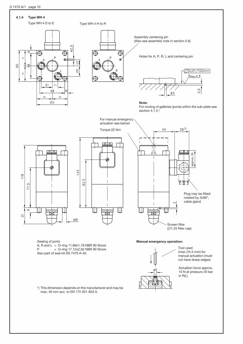
D 7470 A/1 page 10
1) This dimension depends on the manufacturer and may be max. 40 mm acc. to EN 175 301-803 A.
Manual emergency operation:
For manual emergency actuation see below!
Assembly centering pin (Also see assembly note in section 5.6)
Sealing of ports A, R and L = O-ring 11.89x1.78 NBR 90 ShoreP = O-ring 17.12x2.62 NBR 90 ShoreAlso part of seal kit DS 7470 A-40.
Type WH 4 D to E Type WH 4 H to R
4.1.4 Type WH 4
Torque 22 Nm
Holes for A, P, R, L and centering pin
Note:
For routing of galleries (ports) within the sub-plate see section 4.1.5 !
Screen filter(#1.25 filter cap)
Tool used (max #4.5 mm) for manual actuation (must not have sharp edges)
Actuation force approx. 10 N at pressure 20 bar in R(L)
Plug may be fitted rotated by 3x90°, cable gland
app
rox.
35

D 7470 A/1 page 11
4.1.5 Routing of galleries (ports) within the sub-plate (for type WH 2, WH 3 and WH 4)
Type WH .. D to E Type WH .. H(1) to R(1)
2/2 directional valves may be connected either directly to a pressur-ized pipe (both P and A are pressure resistant) or to a bypass pipe leading directly back to the tank (e.g. depressurizing a consumer, idle pump circulation etc.). Therefore the routing of the galleries in the manifold depends on the intended function.
Valve directly in the pressure pipe (thru-valve)
Both sides A and B are pressure resistant, L pressureless to the tank.
Ongoing pressure gallery
Pressure gallery
Ongoing pressure gallery
By-pass circuitry, A connected to the return gallery.
Rea
min
g d
epth
Both L and outlet A may be joint and led to outlet R(T) within the manifold, which again is routed to the tank. For permissible pressure at L and R, see sect. 2.2.1.
The valve inlet P is protected against coarse contaminations that may occasionally be carried along in the fluid via a screen filter (filter cap), see dimensional drawings in sect. 4.1.2 to 4.1.3. They serve to prevent sudden disturbance caused by coarse contamina-tions that otherwise could get struck at the valve seat. It may be also advantageous to protect port A from coarse contaminations returning from the consumer via screen filters (e.g. type HFC in D 7235) mounted in the customer furnished manifold.The sub-plates for type WN 1, WH 2, and WH 3 are equipped with screen filters as standard (see sect. 5.5).
Lateral P connection (example)
For missing dimensions, see illustration below!
Type D d d1 d2 d3 t t1 t2 t3
WH 2 10H7 7 5 6 3 10 1 13 11
WH 3 15H7 8 6 8 3 8 1.5 20 18
WH 4 22H8 12 10 12 4 16 1.5 34 29
t2 and t3 = min. dimension

D 7470 A/1 page 12
4.2 Individual valves with connection sub-plates
Valves acc. to section 3. Only the connection sub-plate dimensions are illustrated. For missing dimensions of the directly mounted valves, see section 4.1.
Type WN(H) 1 D (Q, F, E) -1/4
Type WN(H) 1 H (N, M, R) -1/4
Type WN(H) 1 H (N, M, R) -1/4 S(SR)Type WH 1 D (Q, F, E) -1/4 L
Type WN(H) 1 D (Q, F, E) -1/4 S
Type WN(H) 1 D (Q, F, E) -1/4 SR
Port A, P and R = G 1/4 (BSPP)
Port A, P, R and L = G 1/4 (BSPP)
Type WN 1 W(X)-1/4Type WN 1 W(X)-1/4 SR
Type WN 1 W(X)-1/4 S
M 5, 6 deep
M 5, 6 deep
M 5, 6 deep
M 5, 6 deep
Port P, R, A and B = G 1/4 (BSPP)
For missing dimen-sions see sect. 4.1.1!
For missing dimensions see sect. 4.1.1!
For missing dimensions see sect. 4.1.1!
For missing dimen-sions see sect. 4.1.1!
4.2.1 Type WN 1 and WH 1

D 7470 A/1 page 13
Type WN(H) 1 J-1/4
WN(H) 1 U-1/4M 5, 6 deep
M 5, 6 deep M 5, 6 deep
Can be fitted rotated by 90°
Port P, A and R = G 1/4 (BSPP)For missing dimensions, see sect. 4.1.1!
Type WN 1 D(F)-1/4C Type WH 1 D(F)-1/4C
Port P and A = G 1/4 (BSPP)For missing dimensions, see sect. 4.1.1!
Port A, P and L = G 1/4 (BSPP)For missing dimensions, see sect. 4.1.1!

D 7470 A/1 page 14
Port ISO 228/1: A, B, P, R = G 1/4 (BSPP)
Port ISO 228/1: P and R = G 1/4 (BSPP)
M 5, 6 deep
M 5, 6 deep
For missing dimensions, see sect. 4.1.1!
For missing dimensions, see sect. 4.1.1!
Type WN(H) 1 D -1/4 V
Type WN(H) 1 D -1/4 VR
Type WN(H) 1 .../...-1/4

Type d1 d2 e e1 f g h h1
WH 2.. 17.5 38 18 25 22 M5, 30 14 8 deep
WH 3.. 23.5 50 27.5 27.5 25 M6, 32 12 8 deep
D 7470 A/1 page 15
4.2.2 Type WH 2 ..-1/4 ... and WH 3..-3/8...
llustration shows type WH 2!
Type WH 2 D(F) -1/4
WH 3 D(F) -3/8
Type WH.. D(Q, F, E) -1/4 L (3/8 L)
WH.. H(N, M, R) -1/4 (3/8)
Type WH.. H(N, M, R) -1/4 (3/8) S
WH.. H(N, M, R) -1/4 (3/8) SR
Type WH.. D(F) -1/4 (3/8) SR
Type WH.. D(F) -1/4 (3/8) S
Type WH 2 J -1/4
WH 3 J -3/8
For missing dimensions, see sect. 4.1.2 and 4.1.3!
Type Ports ISO 228/1 (BSPP) A, P and R B B1 B2 B3 H H1
WH 2.. G 1/4 40 50 45 73 30 32
WH 3.. G 3/8 50 63 50 97 35 35
Type a a1 a2 b b1 b2 b3 b4 c
WH 2.. 28 14 28 12 12 34 55 20 20
WH 3.. 36 15 39 11 19 41 73.5 25 29
Type c1 c2 c3 c4 c5 c6 c7 c8 d
WH 2.. 34 68 31 4.5 40 23.5 6 44 18
WH 3.. 29 92 40 5 45 30 7 56 25
For missing dimensions, see sect. 4.1.2 and 4.1.3!
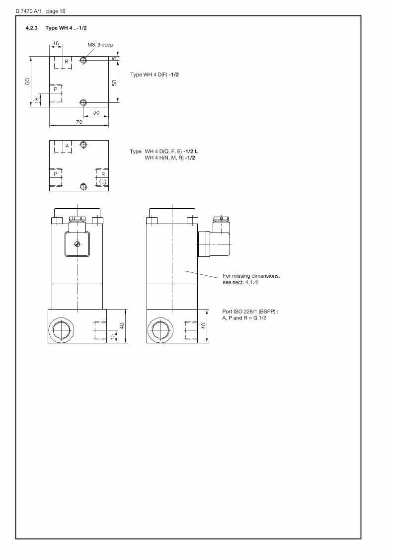
D 7470 A/1 page 16
4.2.3 Type WH 4 ..-1/2
Type WH 4 D(F) -1/2
Type WH 4 D(Q, F, E) -1/2 L
WH 4 H(N, M, R) -1/2
For missing dimensions, see sect. 4.1.4!
M8, 9 deep
Port ISO 228/1 (BSPP) :A, P and R = G 1/2

D 7470 A/1 page 17
5. Appendix
5.1 2/2-way directional seated valve with pressure limiting valve in the intermediate plate
(only type WN 1 D(F), WH 1 D(F))
5.2 Orifice insert (only type WN 1 and WH 1)
These orifices serve as flow limitation (see |p-Q curves). They should be used, whenever flows higher than Qmax (sect. 2.1) could appear during switching operation PdA(R): Hydraulic accumulators on the pump side (gallery P) or at hydraulic pre-controls of directional spool valves with control oil supply from a main line with large flow.Available for type WN 1 and WH 1, symbols D, F, H, M and W (acc. to table 3).
Avail. versions
Coding #-orifice
B 0,4 0.4 mm 7470 075 AB 0,6 0.6 mm 7470 075 DB 0,7 0.7 mm 7470 075 BB 0,8 0.8 mm 7470 075 EB 1,2 1.2 mm 7470 075 C
Order example: WN 1 H / B 0,7 - G 24 WH 1 H / B 0,4 - 1/4 - WG 230
Flow Q (lpm)
Bac
k p
ress
ure
|p
(bar
)
This intermediate plates, features a pressure limiting valve (tool adjustable), allow compact and easy realization of pressure stage ciruitries at piloting circuits. They are used e.g. with prop. directional spool valves type PSL/PSV (see D 7700 ++) for activating a second pressure stage at the gallery LS. They can be also combined with connection sub-plates (acc. to sect. 3) coding . ..-1/4 or ..-1/4 L as alternative to version ..-1/4 V.
Parameters:
Pressure pmax = 400 barFlow Qmax = 2 lpm
For all other parameters and dimensions, see section 2 and 4!
Order coding for individual valve (example):
WN 1 F/250 - G 24WH 1 D/400 - 1/4 - WG 230
Pressure specification (bar) of the pressure limiting valve
Order coding for intermediate plate as individual element (complete with pressure limiting valve and 4 socket head screws ISO 4762-M4x85-12.9 galvanized):
Intermediate plate 7470 104
Symbol
(shown as type WN 1..)
Coding D Coding F
5.3 Wegesitzventile mit verminderter Schaltleistung
Valves with reduced switching performance may be required, when several valves are connected in parallel or individual valves are connected to a SPS or field bus system. Type WH 1 and WH 2 come with plug M12x1, conforming DESINA.
Order example: WH 1 H - M 24 / 8 W WH 3 N - G 24 / 8 W
Coding M.. / 8 W
Parameters
Basic and size WH 1 WH 2 WH 3
Flow pattern symbols all all H, N
Switching power 8 W 8 W 8 W
Electr. connection M12x1 M12x1 EN 175 301-803 A
Nom. voltage 24 V DC 24 V DC 24 V DC
max. flow 6 l/min 15 l/min 30 l/min
max. operating pressure 400 bar 200 bar 250 bar
For all other parameters and dimensions, see sect. 2 and 4. A combination with connection sub-plates acc. to section 3 is possible.
Dwg-No.
for indiv. orders

D 7470 A/1 page 18
5.7 Rotating the solenoid
When required the solenoid can be rotated on the valve body by another 3x90° in addition to the standard assembly position: The best way is to carefully clamp the valve body in a vice and partly or completely remove the screws from above. Turn the solenoid in the desired position and retighten the screws. In order to pre-vent mounting the valve incorrectly onto the sub-plate (e.g. during replacement, if only the position of the solenoid is considered), a center pin is provided on the underside of the valve, which fits into a hole in the sub-plate.
Solenoid
Visible part of the valve
To prevent sudden disturbance caused by coarse con-taminations that may occasionally be carried along in the oil (such as torn off particles of tubing, packing, scale swarf,) directional seated valves are fitted with screen filter elements with 0.25 mm mesh width in the ports P and A (see sect. 4.1). The directional spool valves (only WN 1) cannot be fitted in the housing with these filter elements for reasons of the ducts’ design but they are less sensitive to the contaminations mentioned above.For further protection, the sub-plates for individual valves (sect. 3) are fitted with fine screen filter discs HFC 1/4F and 3/8 (acc. to D 7235) as standard at A and B. Con-nection blocks without pressure limiting valve also in P. These screen filter elements must not be understood as a replacement for usual hydraulic filters. In practice, however, they provide sufficient protection against mal-functions in small hydraulic systems. The filter elements should be checked first, whenever such malfunctions occur. These filter elements are not explicitly shown in the diagrams, for the sake of simplicity,.
2/2-way valve 3/2-way valve
Individual valves acc. to sect. 2.1
Connec-tion sub-plates acc. to sect. 3
Without pressure limiting valve
With pressure limiting valve
5.6 Screen filter elements installed as standard (only type WN(H) 1, WH 2 and WH 3!)
5.4 Installation instruction
Check valve insert EK 01Only for WN 1 type valves code letter Q and N acc. to sect. 2.1
O-ring 6x1.5 NBR90 Shore
Installation side
Screen filter (section 5.6)
Due to the O-ring’s elasticity it may occur that the check valve may move and protrude a few tenths of a millimetre before being bolted to the sub-plate. If the valve WN 1 is filled with oil (e.g. due to functional test on a test rig previously), tightening of the bolts may cause a compression of the trapped oil due to the check valve being forced in. The resulting pres-sure would exceed the one at which the solenoid is still able to actuate. While tightening, it is therefore advisable to press either the manual emergency actuation (see sect. 4.1.1) or energise the solenoid via the plug. This cannot occur with WH 1 type valves due to the hydraulic relief.

D 7470 A/1 page 19
6. Type overview6.1 Single valve acc. to sect. 2.1:
WN 1 H/200 1 - G 24
Nom. voltage (see sect. 2.2.2)G 12, G 24, WG 110, WG 230 and others.
Additional element (see sect. 2.1 or 5.2)1 Return pressure stop (optional, for 2/2 and 3/2-way functions/B 0,7 Orifice insert #0.7 mm (only with flow pattern D, F, H, M and W)/.. Pressure limiting valve in the intermediate plate, acc. to sect. 5.1 (only flow pattern D and F)
Flow pattern (see sect. 2.1)D, Q, F, E 2/2-way function (seated valve)
H, N, M, R 3/2-way function (seated valve)
W, WX Only type WN 1: 4/2-way function (directional spool valve)
Basic valve type and size (differences see sect. 1)WN 1 WH 1
WH 2 WH 3 WH 4
6.2 Individual valve with connection sub-plate section 3:
WN 1 H 1 - 1/4 SR - G 24 - 200
WH 1 R 1/M - 1/4 - G 24
Nom. voltage (see sect. 2.2.2)G 12, G 24, WG 230 and others
o o
o
o
o o o o
o o o o
o
o o o o o
1 2 3 4Size
o o o o
o o o o
o o o oo o o o o o o
o
o
o o o o
o ooo
o o o oo o o oo o o o o
oo o o o
1 2 3 4Size
Connection sub-plate (additional element)(without) no additional elements in the connection sub-plateL Only with type WH: external leakage connection 2/2-way valves S, SR Pressure limiting valve (tool or manually adjustable) with
pressure specification, connected in parallel to the 3/2- or 4/2-way directional valve (PdR, sect. 3.1 table 4 a)
V, VR Pressure limiting valve (adjustable manually or with tools) con-nected in series behind the directional valve (only flow pattern D and F, sect. 3.1 Table 4 a) mit Druckangabe
C bypass check valve (sect. 3.1 Table 4 a)
Connection sub-plate (ports, ISO 228/1 (BSPP))-1/4 G 1/4 -3/8 G 3/8 -1/2 G 1/2
Additional elements (see sect. 2.1 or 5.2)1 Return pressure stop (optional, with 2/2, 3/2, 3/3-way function; see sect. 2.1)/B 0,7 Orifice insert #0.7 mm (only with flow pattern D, F, H, M, W)/.. Pressure limiting valve in the intermediate plate, acc. to sect. 5.1 (only
with flow pattern D and F), e.g. in comb. with connection sub-plate -1/4(L)
Flow pattern (see sect. 2.1)D, Q, F, E 2/2-way function (seated valve)H, N, M, R 3/2-way function (seated valve)W, WX 4/2-way function (directional spool valve)J, U 3/3-way function (combination of two seated valves)L 4/3-way function (combination of two seated valves)M. / R. Double valve, two separately actuatable 3/2-way functions (flow pattern H(1), N(1), M(1), R(1), section 3.2 Table 5 b)
Basic valve type and size. For differences see sect. 1.WN 1 WH 1
WH 2 WH 3 WH 4

2/2-way directional seated valves type EM and EMPfor oil hydraulic systems, zero leakage in blocked state, available as on/off,
soft-shift or proportional valve
D 7490/12/2-way cartridge valve
type EM and EMP
October 2012-02
HAWE HYDRAULIK SESTREITFELDSTR. 25 • 81673 MÜNCHEN
2.2
© 1996 by HAWE Hydraulik
Operation pressure pmax = 450 barFlow Qmax = 160 lpm
Cartridge valve(see section 2)
Example: EMP 21 V Cartridge valve with indiv. con-nection block for pipe connec-tion or by means of a banjo bolt (see section 3)
Example: EM 31 V - 3/4 F - G 24
1. General
These 2/2-way directional cone seated valves show zero leakage while in blocked shifting position.The following versions are available:
Basic version
o Directly actuated, two sizes for up to 5 lpm (type EM..D.. and EM..DS..). Application, as piloting or discharge valves for hydraulic consumers, e.g. idle circulation circuit for 2/2-way cartridge valves, 3-way
flow control valves or piloted pressure limiting valves.o Piloted, four sizes for up to 160 lpm.
Basic flow pattern symbol
o Blocked in idle position, opening when energized (NC-characteristic)o Open in idle position, blocking when energized (NO-characteristic)
Switching characteristics
o On/Off, version with defined flow direction (type EM 11 ... EM 41) as well as for arbitrary flow direction (type EM 12 ... EM 42)o Soft-shift, hydraulically dampened shifting „hydraulic ramp“ (type EMP.. VG.. and EMP.. SG..)o Proportional, prop. throttle (type EMP.. V.. and EMP.. S..)
Versions
o Cartridge valve o Cartridge valve with indiv. connection block for direct pipe connection with various additional functions, e.g. drain valve, throttle
valve or as manifold mounting valve o Valve bank – series connection of several valves
The actuation solenoid is a wet armature type, i.e. all moving parts of the valve and the solenoid are lubricated by the hydraulic fluid, the coil cavity is sealed to the outside at the armature tube by means of O-rings. Therefore the solenoid is highly protected against ambient influences e.g. corrosion. The valves are bled automatically during operation.A tapered pin directly opens or closes the valvular passage with the directly actuated type. Whereas a tapered pin opens (NC) or closes (NO) the piloting duct of a stepped piston with the piloted type. Thereby creating an opening (lifting off from the valve seat) or closing force at the opposing cross section and annular areas which open or close the main valvular passage.The solenoid acts either on the tapered pin (directly actuated valves) or on the tapered piloting pin (piloted valves) thereby pulling with NC-valves or pushing with NO-valves and always acting against the spring return.The valve is designed to be self-locking i.e. it is vibration save.There are various passage cross sections available with type EMP.. to enable a customized shifting characteristic.Control of the prop. valve is via a proportional amplifier (see sect. 5.4). The mounting hole is a simple stepped hole where the transition from one to the next diameter shows a chamfer of 118° (std. point angle of drills). All valve versions of identical size (ON/OFF, soft-shift or prop.) do share the same mounting hole pattern - only exception are non-piloted valves.

D 7490/1 page 2
2. Available versions, main data2.1 Directional seated valves, ON/OFF-characteristic
Order example: EM 21 S - AMP 24 - M
EM 32 V - 3/4 F - G 24 - AT
Basic type
EM 11 D
EM 11 D 0,8
EM 11 D 1,2
EM 21 D
EM 11 V
EM 21 V
EM 31 V
EM 41 V
EM 12 V
EM 22 V
EM 32 V
EM 42 V
EM 11 DS
EM 11 DS 0,8
EM 21 DS
EM 11 S
EM 11 ST
EM 21 S
EM 31 S
EM 41 S
EM 12 S
EM 22 S
EM 32 S
EM 42 S
Pressure pmax (bar)
450 150 60 400
400 400 400 350
400 400 400 350
450 150 400
400 400 400 400 350
400 400 400 350
Flow Qmax approx. (lpm)
1 2.5 5 3
20 40 80 160
20 40 80 160
1 2.5 3
20 20 40 80 160
20 40 80 160
Flow direction
A d BB d A = inadmissible
Non-piloted
o For piloting applications
A d BB d A = Free flow, solenoid must be deenergized
Piloted
Piloted Any
Any
A d BB d A = inadmissible
Non-piloted
o For piloting applications
A d BB d A = inadmissible
Piloted
o With manual emer-gency actuation (not detailed)
o Type .ST with actuation button, see sect. 3.1
Symbol NoteBasic symbol
NC-valve
NO-valve
Note: Max. permissible pressure only with manifolds made of steel. Observe the reduced strength of the thread for other materials e.g. cast iron, light alloy!
Table 1a: Function lock (e.g. for emergency- or initial operation)
Note: Only available with type EM 11 DS, EM 21 DS, EM 1. S and EM 2 S!
Coding Description
(without) No function lock (std.) but incl. manual emergency actuation
M Winged nut (fixed laterally via lead seal)
Function lock, see table 1a
Seal spec., see table 5
Actuation solenoid, see table 4
Indiv. connection block, see sect. 2.4Table 1: Basic type, ON/OFF

D 7490/1 page 3
Piloted
o With manual emer-gency actuation (not detailed)
o Type .SG 10(20) with customized throttling characte-ristic, see sect. 3.1
Piloted
o With manual emer-gency actuation (not detailed)
o Type .S 10(20) with customized thrott-ling characteristic, see sect. 3.1
2.2 Directional seated valves, soft-shift
Application: For delayed activation and deactivation of consumers, e.g. for preventing pressure surges
Order example: EMP 21 VG 10 - WG 230
EMP 31 SG - 3/4 - G 24
Basic type
EMP 21 VG
EMP 21 VG 10
EMP 21 VG 20
EMP 31 VG
EMP 41 VG
EMP 21 SG
EMP 21 SG 10
EMP 21 SG 20
EMP 31 SG
400 400 400
400 350
400 400 400 350
40 40 40
80 160
40 40 40 80
Flow direction
A d BB d A = Free flow, solenoid must be deenergized
Piloted
o Type .VG 10(20) with customized throttling characte-ristic (see |p-Q-curve in sect. 3.1)
A d BB d A = inadmissible
Symbol NoteBasic symbol
NC-valve
NO-valve
Note: Max. permissible pressure only with manifolds made of steel. Observe the reduced strength of the thread for other materials e.g. cast iron, light alloy.
Note: Max. permissible pressure only with manifolds made of steel. Observe the reduced strength of the thread for other materials e.g. cast iron, light alloy.
A proportional amplifier is mandatory for this valve type. For recommended components, see sect. 5.4.
Actuation solenoid, table 4
Connection blocks, sect. 2.4Table 2: Basic type, soft-shift
Flow Qmax approx. (lpm)
Pressure pmax (bar)
2.3 Prop. directional seated valves, prop. throttle valves
Order example: EMP 21 S 20 - AMP 24 - M
EMP 31 V - 1/4 - G 24
Basic type
EMP 21 V
EMP 21 V 10
EMP 21 V 20
EMP 31 V
EMP 31 V 80
EMP 41 V
EMP 21 S
EMP 21 S 10
EMP 21 S 20
EMP 31 S
Pressure pmax (bar)
400 400 400 400 400 400 350
400 400 400 400
Flow Qmax approx. (lpm)
40 40 40 80 80 80 160
40 40 40 80
Flow direction
Piloted
o Type ..V 10(20,70,80) with customized throttling characteri-stic (see |p-Q-curve in sect. 3.1)
A d BB d A = Free flow, solenoid must be deenergized
A d BB d A = inadmissible
Symbol NoteBasic
NC-valve
NO-valve
Actuation solenoid, table 4
Connection blocks, sect. 2.4Table 3: Basic type, prop.

D 7490/1 page 4
Table 4: Actuation solenoid
Note: o The specified protection class is only valid when the plug is properly mounted. o Type EMP... only 12V DC and 24V DC
Connection pattern
Coding Note
(without) Standard, fluid seals made of NBR or AU, e.g. suited for mineral oil and synth. Ester HEES
PYD Fluid seals made of FKM
AT Fluid seals made of EPDM, e.g. suited for glycol based brake fluid (DOT4)
Table 5: Seal specification, for fluid exposed seals
Coding and nom. voltage 12 V DC 24 V DC 48 V DC 110 V 230 V 50/60 HZ 50/60 Hz
Basic valve type EM 1
EM 2
EM 3
EMP 2
EMP 3
EM 4
EMP 4
Protection class (IEC 60529)
Electrical connection
G 12 G 24 G 48 WG 110 WG 230
X 12 X 24 X 48 X 98 X 205
L 12 L 24 -- -- --
AMP 12 AMP 24 AMP 48 -- --
DT 12 DT 24 -- -- --
K 12 K 24 -- -- --
S 12 S 24 -- -- --
-- M 24 -- -- --
-- F 24 -- -- --
-- ITT 24 -- -- --
-- DTL 24 -- -- --
o
o
o
o
o
o
o
o
o
o
o
o
o
o
o
o
o
o
o
o
o
o
o
IP 65
(IP 65)
IP 65
IP 65
IP 67
IP 67
IP 67
IP 67
(IP 67)
IP 67
IP 67
DIN EN 175 301-803 A with plug
DIN EN 175 301-803 A without plug
DIN EN 175 301-803 A with LED-plug
Co. AMP Junior Timer
Co. DEUTSCH (DT 04-2P)
Co. KOSTAL
Co. SCHLEMMER (Bajonett PA 6)
M12x1
With lead ends
MIL-VG 95234
MIL-DTL-38999 series III
G .., X .., L .. AMP .. K .. S ..
M .. F .. ITT .. DTL ..
DT ..

D 7490/1 page 5
2.4 Indiv. connection blocks Suited for direct pipe connection of manifold mounting
2.4.1 Indiv. connection blocks without and with drain valve
Order example: EMP 21 S - 1/4 - G 24
Actuation solenoid, table 4Basic type acc. to table 1, 2, 3
Table 6a: Indiv. connection blocks
Description Ports A, B (BSPP)
EM 11 D
EM 11 DS
EM 1. V
EM 1. S
EM 21 D
EM 21 DS
Basic types EM. 2. V
EM. 2. S
EM. 3. V
EM. 3. S
EM. 4. V
EM. 4. S
Coding
For pipe
connection
For pipe
connection with
(accumulator)
discharge valve
For pipe connec-
tion with manual
bypass valve
For manifold
mounting
o
G 1/4
G 3/8
G 1/2
G 3/4
G 1
1 5/16-12UN-2B
G 1/4
G 3/8
G 1/2
G 3/4
G 1
G 3/8
--
o
o
o
o
o
o
o
o
o
o
o
o
o
o
o
o
o
o
o
o
o
o
1/4
3/8
1/2
3/4
1
1 5/16-12 UN
1/4 A
3/8 A
1/2 A
3/4 A
1 A
3/8 N 0,8
3/8 N 1,5
P
Coding3/8 N 0,8
3/8 N 1,5
CodingP
Coding1/4 A
3/8 A
1/2 A
3/4 A
1 A
Coding1/4
3/8
1/2
3/4
Coding 1 5/16-12UN
Below symbols are only exemplary and have to be completed with the flow pattern symbols, see table 1, 2, 3
Symbols
Orifice 0.8 mm or 1.5 mm

D 7490/1 page 6
Symbol
Symbols to be completed by the flow pattern symbol acc. to sect. 2.1
Coding ..F
Coding ..D
Coding ..DG
Coding ..SJ
Coding ..F - SB
1
2.5 ... 4
16 ... 21
SB 1
SB 2
3
4 ... 6.3
21 ... 28
5
6.3 ... 10
28 ... 37
7
10 ... 16
37 ... 50
9
16 ... 25
50 ... 57
90
25 ... 35
---
Desired flow rate setting acc. to the selected flow rate coding. Flow rate from ... to ... (lpm)
EM 21V - 1/2 F - K 12
EM 11S - 3/8 F - SB15H - 6,3 - G 24
Order example:
Basic type acc. to table 1, 2, 3
2.4.2 Connection block with additional functions
Table 6b: Indiv. connection blocks
EM 11S - 3/8 DG 35 - G 24
EM 11V - 1/4 D - K 12
Coding Description Tapped ports con-forming ISO 228/1(BSPP)A, F B
Basic type
EM 1. V EM. 2. V EM. 3. V EM 1. S EM. 2. S EM. 3. S
3/8 F
16 F
1/2 F
3/4 F
3/8 F - SB 1 . H -..
1/2 F - SB 2 . H -..
1/4 D
3/8 D
3/8 DG ..
3/8 SJ 0. C..
Banjo bolt version with (accumulator)discharge valve
Banjo bolt version with (accumulator) discharge valve and drop-rate braking valve acc. to D 6920 Note: pmax = 315 bar
With bypass throttle
With pressure switchacc. to D 5440
G 3/8
G 3/8
G 1/2
G 3/4
G 3/8
G 1/2
G 3/8 A
M16x1.5
G 1/2 A
G 3/4 A
G 3/8 A
G 1/2 A
o
o - -
- -
- -o
- - o
- -
33
200 ... 700
34
100 ... 400
35
20 ... 250
36
4 ... 12
364
4 ... 50
365
12 ... 170
G 1/4 G 1/4
G 3/8 G 3/8
G 3/8 G 3/8
o - -
With load independent flow limitation B d F via flow control valve type SJ acc. to D 7395. Note: pmax = 315 bar
G 3/8 G 3/8 - o -
- -o
o - -
o
-- o
Pressure range coding. Pressure range from ... to ... (bar)
1
1.0 ... 1.6
3
1.6 ... 2.5
5
2.5 ... 4.0
7
4.0 ... 6.4
9
6.4 ... 10.0
90
10.0 ... 15.0
Desired flow setting acc. to the selected flow range coding. Flow range from ... to ... (lpm)

D 7490/1 page 7
2.5 Valve combinations 2.5.1 Valve banks type BEM
Order example: BEM 11 - SS - 1/4 - G 12 BEM 11 - SS/SS/S - 1/4 - G 24
Actuation solenoid Note: Only available are actuations for 12 or 24 V DC,
type G..., X..., L... (see table 4)!
Basic type and sizeQmax = 20 lpmpmax = 400 bar
Table 7: Valve sections (max. 10 valve sections can be combined)
Note: The solenoid coils utilized are not standard as they show a flat side (see also sect. 5.3)
Coding Description
SS, VV, SV, VS Double valve, (port A = first letter, port B = second letter) S = NO-valve type EM 11 S V = NC-valve type EM 11 V
S, V Indiv. valve (B-side is blocked)
Ports A, B, R = G 1/4 (BSPP)
2.5.2 Valve bank type BEMD 21
Application: Various different pressure stages can be arbitrarily activated as over-load protection e.g. for the changing operation conditions of cranes
Symbols
Order example: BEMD 21 - DS 80/DS 140/DS 180 - G 24
Actuation solenoid table 4
Pressure setting per valve sectionBasic type Qmax = 3 lpmpmax = 400 bar
Symbol
Table 8: Valve sections (max. 10 valve sections can be combined)
Coding Description
D NC-valve, type EM 21 D
DS NO-valve, type EM 21 DS

D 7490/1 page 8
3. Further parameters3.1 General and hydraulic data (type EM.. and EMP..)
Nomenclature and design 2/2-way solenoid actuated seated valve (cone seated design)
Installed position Arbitrary
Operation pressure pmax = 450 bar (see restrictions in sect. 2.1); With type EM..V: pmin = 2 bar
Perm. flow Depending on type (section 2.)
Pressure fluid Standard (without coding acc. to table 5), hydraulic fluid (DIN 51524 table 1 to 3); ISO VG 10 to 68 acc. to (DIN 51519). The compatibility with the seal material has to be checked, when other pressure fluid types are intended (see table 5)!
Viscosity range min. 4; max. 1500 mm2/s; optimal operation range: 10...300 mm2/s Also suitable are biodegradable pressure fluids of the type HEPG (Polyalkylenglycol) and HEES (synth. Ester) at operation temperatures up to +70°C. HETG (seed oil) is not suited.
Not suited for water based pressure fluids and see oil (HETG).
Temperatures Ambient: -40...+80°C Fluid: -25...+80°C, pay attention to the viscosity range! Start temperature down to -40°C are allowable (Pay attention to the viscosity range during start-up!),
as long as the operation temperature during consequent running is at least 20K (Kelvin) higher. Biodegradable pressure fluids: Pay attention to manufacturer‘s information. With regard to the
compatibility with sealing materials do not exceed +70°C. Attention: Observe the restrictions regarding the max. permissible operation of the solenoid
specified in sect. 3.2 !
Mass (weight) Cartridge valves
EM 1 0.3 kg
EM 2, EMP 2 0.35 kg
EM 3, EMP 3 0.4 kg
EM 4 0.6 kg EMP 4 0.7 kg
Indiv. connection blocks, see sect. 4.3 Valve banks, see sect. 4.4
|p-Q-curves
Fluid viscosity during measure-ment 60 mm2/s
AdB EM(P)...V energized solenoid
EM11D(S)..; EM21D(S); EM(P)...S deenergized solenoid
1) Only with EM...V: Free flow BdA, only while
solenoid is deenergized
2) Applies also to type EMP.. VG..(SG..)
Non illustrated flow direc-tions are like type EM.. of similar size
Bac
k p
ress
ure
|p
(bar
)
Bac
k p
ress
ure
|p
(bar
)
Bac
k p
ress
ure
|p
(bar
)
Bac
k p
ress
ure
|p
(bar
)B
ack
pre
ssure
|p
(bar
)
Bac
k p
ress
ure
|p
(bar
)B
ack
pre
ssu
re |
p (b
ar)
Flow Q (lpm)
Flow Q (lpm)Flow Q (lpm)
Flow Q (lpm) Flow Q (lpm)
Flow Q (lpm) Flow Q (lpm)

D 7490/1 page 9
3.2 Electrical data (type EM.. and EMP..)
Protection class
Connector and connection
Switching time approx. ms
Switchings / h
Insulation material class
EM..S: On 150 EM..V: On 50 Off 50 Off 150The switching times with version WG.. are 2 to 3 times andwith type EMP.. VG.. and EMP.. SG.. 5 to 10 times longer
approx. 2000 (rather even distributed)
F; Contact temperature approx. 85 ... 95°C (solenoid housing) with an ambient temperature of 20°C.Classification F permits a max. winding temperature of approx. 150°C; This won‘t be exceeded if the guideline figures for %ED are observed during operation. The thermal load of the coil may be reduced when an economy circuit is employed (see sect. 5.4).
Depending on actuation solenoid, see table 4
Depending on actuation solenoid, see table 4
DC-voltage AC-voltage G .. DT .. L.. WG 110..
X .. K ..
S ..
AMP..
F ..
M.. ITT..
DTL..
Relative duty cycle: 100% ED (Specification on the solenoid)
Reference value and restriction in the operation
Required connectors
Coding K.. 03888005 Co. KOSTAL
Coding S..Taper with quarter-turn 10 SL Co. SCHLEMMER
Coding AMP.. Co. AMP Junior 2-pole, Coding 1
Coding G.., X.., L.. DIN EN 175 301-803 A
Coding F.. Lead length approx. 600 mm
Cut-off energy
Dither frequencyfor type EMP..V(S)
Guideline for max: approx. < 10 Ws + approx. 10% when measuring at UN
50 ...150 Hz
Ambient temperature U °C
Nom. voltage UN 12 V DC 24 V DC 98 V DC 205 V DC
Nom. power PN EM 1.., EM 2.., EM 3.. 21 W 21 W 21 W 21 W EMP 2.., EMP 3.., EM 4.. 32 W 32 W 32 W 32 W EMP 4.. 30 W 30 W
Nom. current IN EM 1.., EM 2.., EM 3.. 1.75 A 0.89 A 0.2 A 0.1 A EMP 2.., EMP 3.., EM 4.. 2.67 A 1.33 A 0.3 A 0.15 A EMP 4.. 2.5 A 1.25 A
Max. current Ilim. EM 1.., EM 2.., EM 3.. 1.23 A 0.62 A -- -- EMP 2.., EMP 3.., EM 4.. 1.87 A 0.93 A -- -- EMP 4.. 1.75 A 0.88 A -- --
%E
D S
3-5
min

D 7490/1 page 10
Flow Q (lpm)
Flow Q (lpm)
Flow Q (lpm)
Flow Q (lpm)
Co
ntr
ol c
urr
ent
(A)
Co
ntr
ol c
urr
ent
(A)
Co
ntr
ol c
urr
ent
(A)
Co
ntr
ol c
urr
ent
(A)
24 V DC12 V DC
24 V DC12 V DC24 V DC12 V DC
Flow Q (lpm)
Co
ntr
ol c
urr
ent
(A)
12 V DC 24 V DC
24 V DC12 V DC
Curve a: Load pressure p = 50 bar;Curve b: Load pressure p = 200 bar
I-Q-curve

D 7490/1 page 11
4. Unit dimensions All dimensions in mm, subject to change without notice
4.1 Valve and actuation solenoid
Coding G.., WG.., X.., L.. Type EM 11 ST stop coding
Actuation solenoid
Coding AMP.. Coding K..
Plug may be installed rotated by 4x90°
Manual emergency actuation with EM(P)...S
Actuation forceat pressure 100 barat A = approx. 70 N
Function lock coding M Winged nut is laterally fixed at a/f 2, when delivered from HAWE
Type a/f 2 (Nm)
EM 1.. 12 30EM 2.. 12 30EM 3.. 12 60EM 4.. 14 90EMP 2.. 14 30EMP 3.. 14 60EMP 4.. 14 90
1)
1) This dimension depends on the manufacturer (of the plug) and may be up to 40 mm acc. to DIN EN 175 301-803!
Type EM 1 EM 4 EMP 4 EM 2 EMP 2 EM 3 EMP 3
a 36.5 --- ”37
a1 --- 37.5 -
b 12 15 18.3
c 22 25 28
d #36.5 #38.5 ”37
e Version G: 28 1) WG: 34.5 1) L: 40
a/f 2
a/f
2
app
rox.
25

D 7490/1 page 12
Coding ITT..
DTL..
Coding F..
Coding S.. Coding M..
approx. 600 mm
Type EM 1 EM 2
d #37
Type EM 1 EM 4 EMP 4 EM 2 EMP 2 EM 3 EMP 3
d #36,5 #38,5 ”37
d (DT) #36,5 #39
Coding DT..

D 7490/1 page 13
Type EM 2. V, EM 2. S
EMP 21 VG, EMP 21 SG
EMP 21 V.., EMP 21 S..
Mounting hole:
4.2 Screwed-in section of the valve
Type EM 21 D, EM 21DS
Mounting hole:
1) Detail “X” see page 14
1)
1)
Type EM 1. V, EM 1. S
Mounting hole:
1)
Type EM 11 D, EM 11 DS
EM 11 D 0,8, EM 11 DS 0,8
Mounting hole:
1)
Reaming depth 4.5 Reaming depth 4.5
Reaming depth 4.5Reaming depth 4.5
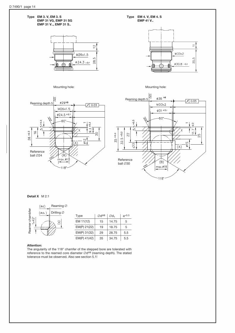
D 7490/1 page 14
Mounting hole:
Type EM 4. V, EM 4. S
EMP 41 V..
Type EM 3. V, EM 3. S
EMP 31 VG, EMP 31 SG
EMP 31 V.., EMP 31 S..
Mounting hole:
Detail X M 2:1
Type
EM 11(12)
EM(P) 21(22)
EM(P) 31(32)
EM(P) 41(42)
#dH8
15
19
29
35
#d1
14.75
18.75
28.75
34.75
a+0.3
5
5
5.5
5.5
Attention:
The angularity of the 118° chamfer of the stepped bore are tolerated with reference to the reamed core diameter #dH8 (reaming depth). The stated tolerance must be observed. Also see section 5.1!
Reaming depth 5
Reference ball #24
Reference ball #30
Reaming #
Drilling #
Rea
mer
cham
bfe
r
Reaming depth 5

D 7490/1 page 15
Coding
- 1/4
- 1/4
- 3/8
- 1/4
- 3/8
- 1/2
- 1/2
- 3/4
- 3/4
- 1
- 1 5/16-12 UN
- 1/4 A
- 3/8 A
- 3/8 A
- 1/2 A
- 1/2 A
- 3/4 A
- 3/4 A
- 1 A
- 3/8 N 0,8
- 3/8 N 1,5
P
4.3 Connection blocks
Note regarding the provision for mounting (dimension f): #.. -thru-hole, thread M.. on both sides (exception -3/8 N.. only rear side)
Port A and B ISO 228/1(BSPP)
G 1/4
G 1/4
G 3/8
G 1/4
G 3/8
G 1/2
G 1/2
G 3/4
G 3/4
G 1
- 1 5/16-12 UN-2B
G 1/4
G 3/8
G 3/8
G 1/2
G 1/2
G 3/4
G 3/4
G 1
G 3/8
--
L
35
35
40
45
45
50
55
60
65
70
81
40
45
45
50
56
60
65
70
50
--
B
20
20
25
30
30
30
40
40
40
50
51
20
25
30
30
40
40
40
50
40
--
H
40
40
40
50
50
50
60
60
70
70
85
45
45
50
50
60
60
70
70
50
--
a
14.5
16
16
13
18
18
20
20
25
25
25
13
13
14
14
20
20
25
25
18
--
b
10
10
15
14
14
14
20
20
22
22
28
10
15
14
14
20
20
22
22
14
--
c
25
25
32
30
30
32
37
40
50
55
63
35
40
28
31
34
40
41
47
25
--
--
--
--
--
--
--
--
--
--
--
--
27
33
33
36
42
46
49
52
--
--
e
30
30
32
35
35
35
38
40
55
55
60
25
27
32
32
36
40
45
50
--
--
f
#6.5
#6.5
#6.5
#8.5
#8.5
#8.5
#10.5
#10.5
#12.5
#12.5
M12, 12 deep
#6.3
#6.3
M8, 8 deep
M8, 8 deep
M10, 10 deep
M10, 10 deep
M12, 12 deep
M12, 12 deep
M8, 10 deep
--
Order No.Connection block wit-hout valve
7490 013
7490 010
7490 011
7902 310
7491 012
7491 013
7590 011
7590 012
7591 011
7591 012
7591 018
7490 038
7490 039
7491 015
7491 016
7590 015
7590 016
7591 015
7591 016
7902 150
7902 3607903 140B
Mass(weight)approx.(kg)
0.3
0.3
0.3
0.45
0.35
0.35
0.45
0.45
0.6
0.6
0.7
0.3
0.3
0.4
0.4
0.5
0.5
0.6
0.6
0.4
0.30.6
Main dimensions (mm)
Coding
-1/4
-3/8
-1/2
-3/4
-1
-1 5/16-12 UN
Coding
-1/4 A
-3/8 A
-1/2 A
-3/4 A
-1 A
Coding
-3/8 N 0,8
-3/8 N 1,5
c1
Drain screw a/f 5
Drain (push-button red galvanized)
1) only coding -1 5/16-12 UN M = 7/16-20 UNF-2B
1)
Basic type acc.to sect. 2
EM 11 D..EM 11 DS..
EM 1. V(S)
EM 21 D(DS)
EM 2. V(S)EMP 2. V.(S.)
EM 3. V(S)EMP 3. V.(S.)
EM 4. V(S)EMP 4. V.(S.)
EM 1. V(S)
EM 2. V..(S..)EMP 2. V..(S..)
EM 3. V..(S..)EMP 3. V..(S..)
EM 4. V(S)
EM 2. V..(S..)EMP 2. V..(S..)
EM 21 D(DS) - PEM(P) 3. - P

D 7490/1 page 16
Type EM 21 D - P
EM 21 DS - P
Type EM 3. - P
EMP 3. - P
Type EM 1. - .F
EM 2. - .F
EM 3. - .F
EMP 2. - .F
EMP 3. - .F
Type EM 1. - .F - SB 1. H
EM 2. - .F - SB 2. H
EMP 2. - .F - SB 2. H
Seal ring (see sect. 5.3)
a/f (banjo bolt) Can be mounted on both sides with - 3/4 F
Drain screw a/f 5
a/f(drop-rate braking valve cartridge acc. to D 6920)
Respec-tively 360° rotatable
EM(P) 3.: - 3/4 F
EM(P) 2.. - 1/2 F
EM(P) 2.. - 1/2 F-SB2.. G 1/2 A G 1/2 52 50 30 30 20.7 4.5 2.6 26.9 15 15 14 35 15 30 229.512.5 30
1.31.4
G 3/4 A G 3/4 70 60 -- 40 19.5 5 -- 36 20 20 20 50 18 40 20 10 36 1.7
EM 1.. - 16 F
EM 1.. - 3/8 F
EM 1.. - 3/8 F - SB1..
A
G 3/8 A
B
G 3/8
45M16x1.5 G 3/8
B
45
40
H
40
24
D
24
25
a
25
15
b
15
3
c
3
2.1
c1
2.1
21.9
d
21.9
12.5
e
12.5
15.5
e1
15.5
12
e2
12
30
f
30
12.5
h1
12.5
27
h2
27
18
g
18
7.5
m
7.511
24
a/f
24
1.0
Mass(weight)approx. (kg)
1.01.0
PortsISO 228/1 (BSPP)
DimensionsType
max
. 120
M = G 1/4
M6x55 ISO 4762
M4x35 ISO 4762

D 7490/1 page 17
Type EM 1.. - 1/4 D
EM 2.. - 3/8 D
EMP 2.. - 3/8 D
EM 1.. - 1/4 D
EM 2.. - 3/8 D
EMP 2.. - 3/8 D
Type
25
55
B
47
62
H
12
13.5
a
23
34
b
21.5
27
h
2
3
s Mass (weight)approx. (kg)
0.7
0.9
Type EM 2.. - 3/8 - SJ 0..
EMP 2.. - 3/8 - SJ 0..
Mass (weight) = approx. 0.9 kg
Type EM 1.. - 3/8 DG
Mass (weight) = approx. 0.9 kg
For missing specifications see D 5440 (DG 3..)
Plug may be installed rotated by 4 x 90°
app
rox.
37
app
rox.
71
s

D 7490/1 page 18
4.4 Valve combination
Type BEM 11
1)
M8, 10 deep
M6, 10 deep
a/f 12
approx. 5
approx. 10
app
rox.
66
approx. 10
Type BEMD 21

D 7490/1 page 19
The angularity of the 118° chamfer of the stepped bore tolerance is in reference to the reamed core diameter #dH8 (reaming depth). The stated tolerance must be observed. Also see section 4.2!This enables a max. edge force on the facial area of the tapped journal when the valve is screwed in with the correct torque and it also prevents distortion of functional valve parts which might cause malfunction (sticking).The correct angular orientation may be checked when the valve is installed the first time and can be remachined in case of minor deviation.
1. Screw in the valve and tighten steadily with the correct torque (see sect. 4.1).
2. Remove the valve again and check whether the journal of the valve a has produced an annular impact b at the chamfer of the stepped bore. When this impact is even everything is correct and the valve can be reinstalled as described above.
3. When the annular impact is not evenly distributed over its length or not complete the valve should be reinstalled but with up to 120% of the specified torque (see sect. 2.3.1). Remove the valve and check the annular impact again whether it is correct now (see above); It will be so in most cases and the valve can be reinstalled with the torque specified in sect. 2.
If it is still not correct after above procedure it will be necessary to remachine the bore.
5. Appendix5.1 Notes for initial operation
5.2 Tapped plugs
Type
EM 1... V(S)
EM 11 D(DS)
EM(P) 2... V(S)
EM 21 D(DS)
EM(P) 3...
EM(P) 4...
Tapped plug 1)
7490 105 b
7490 105 b
7491 105 b
7491 105 b
7590 105 b
7904 019
Tapped blockage 1)plug
7490 105 a
7490 105 c
7491 105 a
7902 315 a
7590 105 a
7904 018
a/f Torque (Nm)
6 30
6 30
8 30
8 30
12 40
14 60
Seal ring ;P5001 94*5 Shore
10.3x2.4
10.3x2.4
14.03x2.61
14.03x2.61
21x3.53
28.17x3.53
Seal ring <HNBR 90 Sh
7.65x1.78
7.65x1.78
12.42x1.78
12.42x1.78
18.72x2.62
25.07x2.62
Mounting holes in the manifold may be blocked if required by tapped plugs e.g. if uniform manufactured manifolds should be equipped with or without cartridge valves depending on application.
Passage open
Tapped plug
Passage blocked
Tapped blockage pluga/f
1) Complete with seal ring
Dimensions of the mounting holes acc. to sect. 2.3.2 !
Seal ring ; Seal ring ;
Seal ring <
a/f

D 7490/1 page 20
5.3 Seal kit
Plug coding/coding Order coding
G.. : MSD 3-309
L.. : SVS 3129020
L5K L5K
L10K L10K
WG.. : MSD 4-209 P 10
Seal kit:
Order coding
DS 7490-11
DS 7490-21
DS 7490-21P
DS 7490-31
DS 7490-31P
DS 7490-41
Type
EM 11(12)..
EM 21(22)..
EMP 21..
EM 31(32)..
EMP 31..
EM(P) 41(42)..
Seals for connection blocks with banjo bolt (acc. to sect. 2.4.2)
Order coding
KDS 16 A 3 C
KDS 22 A 3 C
7590 018
For valve type
EM 1... - F..
EM(P) 2... - F..
EM(P) 3... - F..
Recommended prop. amplifier for type EMP.. V(S): EV 22 K 2-12/24 (card) acc. to D 7817/1
EV 1 G 1-12/24 (module with housing) acc. to D 7837
EV 1 M 2-12/24 (module) acc. to D 7831/1
EV 1 D (module) acc. to D 7831 D
Plugs with clamp diode MSD 3-209 C 1 150 V DC acc. to D 7163
Plugs with LED and protective MSE 28026 24 V DC acc. to D 7832
circuitry SVS 3129020 24 V DC acc. to D 7163
Additional plugs available
Economy circuit plugs MSD 4 P 55 24 V DC acc. to D 7833
MSD 4 P 53 230 V DC acc. to D 7813
MSD 4 P 63 115 V DC acc. to D 7813
5.4 Additional components
These components have to be ordered separately!

Directional spool valves type HSF
manifold mounting, eIectro-hydraulicaIIy actuated for oil-hydraulic systems
D 7493 EDirectional spool valves HSF
January 2003-01© 1988 by HAWE Hydraulik
HAWE HYDRAULIK SESTREITFELDSTR. 25 • 81673 MÜNCHEN
2.1
Operating pressure pmax = 400 bar
Flow Qmax = 80 and 160 lpm
1. General
2. Types available, main data
This pamphlet is a supplement to D 7493 covering the directionalspool valve banks type HSR. The individual valves for manifoldmounting described here share the same functional principle, directional seated pilot valves and optional thread-type throttlesfor switching time adjustment, as outlined in the basic pamphlet D 7493. The switching time adjustment is detailed also there. Therequired manifolds are customer furnished, as they are not avail-able from HAWE. Important: The valve has two outlet ports R (see dimensionalsketches). Both must be connected at the manifold, but may beinternally joined there.
Order example: HSF 3 G - G 24
Table 1: Basic type and size
Table 2: Symbols
Table 3: Pilot valve
Standard, Without With plug with plug plug featuring LED’s Nom. voltage
G 12 X 12 L 12 12V DC
G 24 X 24 L 24 24V DC
G 98 X 98 --- 98V DC
G 205 X 205 --- 205V DC
WG 110 --- --- 110V AC
WG 230 --- --- 230V AC50 /60 Hz
Without pilotvalve, forhydraulic remote control
X
See section 5.1
Solenoid actuated via pilot valve type WN 1H (for missing data, see D 7470 A/1)
Coding
Nominal size appr.
Flow Qmax (lpm)
Pressure pmax (bar)
Attention: When several valves are con-nected in series, note that when the H(1)and F(1) valves are in their zero position,outlets connected to R are pressurizedwhen a downstream valve is operated.
HSF 3 HSF 4
NG 12 NG 16
80 160
400
Valve with blocked middle position,suitable for connection in parallel
Valve with middle position P→ R (circulation),suitable for connection in series
G D E C W B L H F
G 1 D 1 E 1 C 1 W 1 B 1 L 1 H 1 F 1
Switchingtime adjustment
SimpIifiedsymbol 2)
without
with 1)
Without pilot valve, for hydraulic remote control With switchingtime adjustmentG 1 to F 1
Without pilot valve...G (D, E, C, ...W - XL, H, F) - X (..B - X analog.)G, D, E, C, L, H, F W B
1) Thread type throttle, see dimensionaldrawings.
2) For detailed symbols e.g. to ease understanding of the function, see appendix in sect. 5 ++.

D 7493 E page 2
3. General parameter
Type and version Directional spool valve, full steel design. Housing zinc galvanized, giving a good resistance to corrosion.Valve spools hardened, ground and polished/deburred. Together with the diamond-honed and polished and deburred housing bore, this gives an exactly circular and even sealing gap with a minimum leakage rate. BuiIt-on directional ball seated valves type WN 1H acc. to D 7470 A/1 as pilot valves
Installation position Any
Line connection Via manifold, customer-furnished, as not available from HAWE
Port coding P = Pump inlet R = Return. Important: 2 ports! (exception coding C, see section 5.1)A, B = ConsumersZ = Control oil inletX = Control oil outlet (tank) Control oil outlet (tank) for version with solenoid actuation
= Control oil inlet for version X with hydraulic remote control (table 3) at position a with 4/3-way directional spool valves (see sect. 5.1)
Overlapping Zero
Switching time Without switching time adjustment (not throttled) (guideline figures) HSF 3: ton = 30...40 ms; toff = 70...100 ms
HSF 4: ton = 50...60 ms; toff = 110...140 ms
Mass (weight) HSF 3 = 2,8 kgHSF 4 = 5 kg
Flow HSF 3 = 80 lpmHSF 4 = 160 lpm
Pressure P, A, B, and R = 400 bar; Z and X = 160 bar
Control pressure Max. 160 bar, min. 10 bar; optimum operation at 15... 40 bar, either from own control circuit or viaa pressure control valve ADC 1-25 (e.g. housed in base plate, see circuit examples, section 5.2). Refer to notes on flow diagrams L, F and H in example 3.
Control volume HSF 3 = approx. 1.8 cm3
HSF 4 = approx. 5 cm3
Surface Nitrided
Hydraulic fluid Fluids conf. DIN 51524 table 1 to 3; ISO VG 10 to 68 conf. DIN 51519Viscosity range: min. approx. 4; max. approx. 1500 mm2/secOptimal operation range: approx. 10...500 mm2/secAlso suitable are biologically degradable pressure fluids of the type HEPG (Polyalkylenglycol) andHEES (synth. Ester) at operation temperatures up to approx. +70°C.
Temperature Ambient: approx. -40...+80°C Fluid: -25...+80°C, pay attention to the viscosity range! Start temperature down to -40°C are allowable (Pay attention to the viscosity range during start!),as long as the operation temperature during subsequent running is at least 20 K (Kelvin) higher.Biological degradable pressure fluids: Pay attention to manufacturer's information. With regard tothe compatibility with sealing materials do not exceed +70°C.
Pilot valves At 60°C ambient temperature not over 60 % duty cycle, at 80°C not over 35% duty cycle. The heat generation of the solenoid can be decreased by reducing the supply voltage. This gives somesafety marging as a balance for increased ambient temperatures and greater safety under normal conditions at possibily changing ambient temperaturesControl pressure $ 160 bar → Ureduc. = 0.75 Unom, permissible ambient temperature 60°C
Control pressure 35 bar → Ureduc. = 0.5 Unom, permissible ambient temperature 80°C
|p-Q-curves
(Type WN1H acc. to D 7470 A/1)
All flow
directions
Flow Q (lpm)
Bac
kp
ress
ure
|p
(bar
)
HSF 3 HSF 4

D 7493 E page 3
4. Unit dimensions
Type HSF 3...
Type HSF 4...
Coding
G, D, E, C, L, H, F
(G1 to F1)
Coding
G, D, E, C, L, H, F
(G1 to F1)
Coding
B (B1) W (W1)
Coding
B (B1) W (W1)
Manual emergencyactuation
Manual emergencyactuation
Cable gland
Cablegland
Actuation aid(do not useany sharp-edged tools)
Ports Sealing of theflange areavia O-ringNBR 90 Sh
A, B, P, R 13.95x2.62
X, Z 3.7x1.78
Sealing of theflange areavia O-ringNBR 90 Sh
A, B 18.75x2.62
P, R 20.29x2.62
X, Z 3.7x1.78
Hole pattern of
the manifold
(top view)
Hole pattern of
the manifold
(top view)
M12, 12 deep
M8, 10 deep
Screw for switching time adjustmentHexagon head screw a/f 10
Screw for switching time adjustmentAllan head a/f 3
Tapped plug(without switchingtime adjustment)
Tapped plug(without switchingtime adjustment)
1) This dimension is dependingon the manufacturer and maybe up to max. 40 (conf. DIN43650)
2) Not present with codes C, C1
All dimension in mm and subject to change without notice!
Manual emer-
gency actuation
(X,Z)
(X,Z)
2)
2)
Max. torque39 Nm
Max. torque140 Nm
Ports
Ports

D 7493 E page 4
5. Appendix5.1 Detailed flow symbols
Examples not listed should be drawn accordingly. Control port X serves as drain/leakage port to the tank with spools W1 and B1.
Standard versionwith pilot valves
Version ...-X, without pilot valve
To the tank or to port P of a subsequent spool valve coding L, F, or H
In the case of 4/3-way versions with switching time adjustment (e.g. G1,D1 etc.), only the control port Z can be influenced via the throttle screw.In the case of control port X, it is necessary to install a throttle (e.g. FG orFG-S 6 acc. to D 7275) externally into the connected control line. Thesymbol illustration opposite, applies to valve coding G and W and anal-ogously to D, E, C, B, L, H, and F.
5.2 Circuit examples The illustrated manifolds are not scope of delivery!
Example 1:
Most simple control with directional spoolvalves suited for parallel connection. Controloil pick-up and return is internal in the manifold.Permissible pressure is approx.160 bar (seecontrol pressure in sect. 3) and when no pres-sure surges (decompression surges) are ex-pected in the return line.
Example 2:
Same control task as example 1, but with control oil pick-up from a pressure circuit >160 bar. The pressure for the control oil circuit is reduceddown to approx. 30 bar here via pressure reducing valve type ADC1-25screwed into the manifold, see D 7458 for mounting hole deails).It is recommended to to provide an additional gallery for the control oil re-turn (as illustrated), when pressure surges are expected in the main returnline.
$
%
HSF 3 G1-G 24 HSF 3 D1-G 24 HSF 3 G1-WG 230 HSF 3 D1-WG 230
Type DV... - WN 1F-...acc. to D 4350 for idlepump circulation
Pressure reducing valve type ADC 1-25 acc. to D 7458
Example 3:
A direct control oil pick-up from the pumppressure line is not possible in most caseswith flow pattern symbols L, H, and F as theback pressure in idle position does not ex-ceed the minimum control pressure requiredfor switching operations (particularly if there isonly one single valve). It is therefore recom-mended to employ a pump, e.g. type R acc.to D 6010 S feeding a separate control oil cir-cuit (see example). Another way is to use acompletely separate control circuit pump, i.e.gear pump with approx. 0.5...1 lpm, limited toapprox. 20 bar, making an ADC 1-25 super-fluous. Otherwise, pay attention to the sum-mation of the back pressure, particularly whenseveral valves are connected in series.
TypeMVE 6C acc. to D 7000/1
TypeMVE 4Facc. to D 7000/1
Type ADC 1-25acc. to D 7458
Type R 58.6-1.2acc. to D 6010 S
HSF 3L- G 24 HSF 3L- G 24
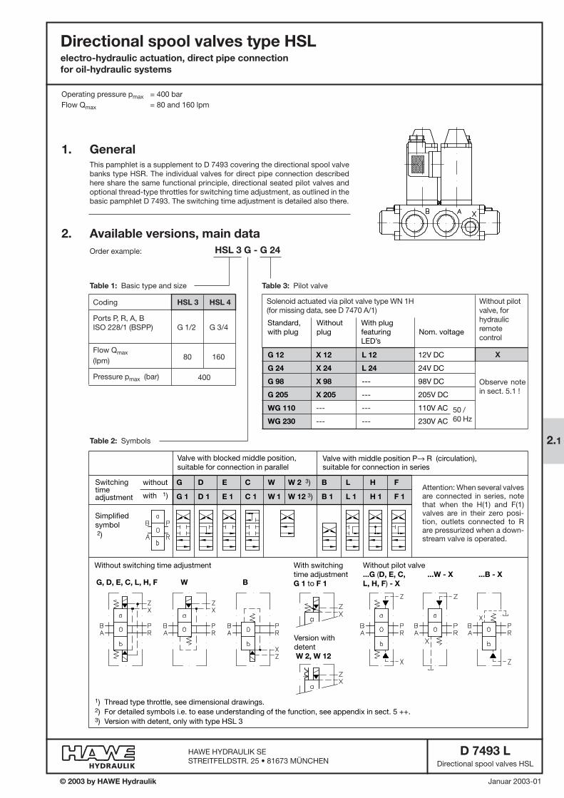
Directional spool valves type HSLelectro-hydraulic actuation, direct pipe connection
for oil-hydraulic systems
D 7493 LDirectional spool valves HSL
Januar 2003-01© 2003 by HAWE Hydraulik
HAWE HYDRAULIK SESTREITFELDSTR. 25 • 81673 MÜNCHEN
2.1
Operating pressure pmax = 400 bar
Flow Qmax = 80 and 160 lpm
1. General
2. Available versions, main data
This pamphlet is a supplement to D 7493 covering the directional spool valvebanks type HSR. The individual valves for direct pipe connection describedhere share the same functional principle, directional seated pilot valves and optional thread-type throttles for switching time adjustment, as outlined in thebasic pamphlet D 7493. The switching time adjustment is detailed also there.
Order example: HSL 3 G - G 24
Table 1: Basic type and size
Table 2: Symbols
Table 3: Pilot valve
50 /60 Hz
Without pilotvalve, forhydraulic remote control
X
Observe notein sect. 5.1 !
Solenoid actuated via pilot valve type WN 1H (for missing data, see D 7470 A/1)
Coding
Ports P, R, A, BISO 228/1 (BSPP)
Flow Qmax
(lpm)
Pressure pmax (bar)
HSL 3 HSL 4
G 1/2 G 3/4
80 160
400
G 12 X 12 L 12 12V DC
G 24 X 24 L 24 24V DC
G 98 X 98 --- 98V DC
G 205 X 205 --- 205V DC
WG 110 --- --- 110V AC
WG 230 --- --- 230V AC
Standard,with plug
Withoutplug
With plugfeaturingLED’s
Nom. voltage
Attention: When several valvesare connected in series, notethat when the H(1) and F(1)valves are in their zero posi-tion, outlets connected to Rare pressurized when a down-stream valve is operated.
Valve with blocked middle position,suitable for connection in parallel
Valve with middle position P→ R (circulation),suitable for connection in series
G D E C W W 2 3) B L H F
G 1 D 1 E 1 C 1 W 1 W 12 3) B 1 L 1 H 1 F 1
Switchingtime adjustment
SimpIifiedsymbol 2)
without
with 1)
Without switching time adjustment With switchingtime adjustmentG 1 to F 1
Without pilot valve...G (D, E, C, ...W - X ...B - X
L, H, F) - XG, D, E, C, L, H, F W B
1) Thread type throttle, see dimensional drawings.2) For detailed symbols i.e. to ease understanding of the function, see appendix in sect. 5 ++.3) Version with detent, only with type HSL 3
Version withdetentW 2, W 12

D 7493 L page 2
3. Further data
Type and version Directional spool valve, full steel designValve spool hardened, ground, polished and deburred. An exactly circular sealing gap with a minimum leakage rate is achieved by the diamond-honed and polish-deburred housing bore.Directional ball seated valves type WN1H acc. to D 7470 A/1 are utilized as pilot valves.
Installation position Any
Ports P, R, A, B depending on size; X, Z = G 1/4 ISO 228/1 (BSPP)
Port coding P = Pump inletR = Return Attention: 2 ports! (exception spool C). See sect. 5.1A, B = ConsumerZ = Control oil inletX = Control oil outlet (tank) for version with solenoid actuation
= Control oil inlet for version X with hydraulic remote control (table 3) at position a with 4/3-way directional spool valves (see sect. 5.1)
Overlapping Zero
Switching times Without switching time adjustment (non-throttled)(guide line) HSL 3: ton = 30 ... 40 ms; toff = 70 ... 100 ms
HSL 4: ton = 50 ... 60 ms; toff = 110 ... 140 ms
Necessary pulse duration for sure switching operations with coding W2(12) = approx. 200 ms
Mass (weight) HSL 3 = 2.8 kgHSL 4 = 5 kg
Flow HSL 3 = 80 lpmHSL 4 = 160 lpm
Pressure P, A, B, and R = 400 bar; Z and X = 160 bar
Control pressure max. 160 bar, min. 10 bar; optimum operation range 15 ... 40 bar, either tapped from individual control circuit or via a pressure reducing valve i.e. ADC 1-25 acc. to D 7458. Observe the notes regarding symbols L, F, and H in example 3.
Control volume HSL 3 = approx. 1.8 cm3
HSL 4 = approx. 5 cm3
Surface Gas nitrided
Pressure fluid Hydraulic oil conf. DIN 51524 part 1 to 3; ISO VG 10 to 68 conf. DIN 51519.Viscosity limits: min. approx. 4, max. approx. 1500 mm2/sec;opt. operation approx. 10 ... 500 mm2/sec.Also suitable are biologically degradable pressure fluids types HEPG (Polyalkylenglycol) and HEES(Synth. Ester) at service temperatures up to approx. +70°C.
Temperature Ambient: approx. -40 ... +80°CFluid: -25 ... +80°C, Note the viscosity range!Permissible temperature during start: -40°C (observe start-viscosity!), as long as the service temperature is at least 20 K (Kelvin) higher for the following operation.Biologically degradable pressure fluids: Observe manufacturer's specifications. By consideration ofthe compatibility with seal material not over +70°C.
Pilot valves Not over 60% duty cycle if the ambient temperature is 60°C and not over 35% duty cycle if the ambient temperature is 80°C.Heat generation of the solenoid can be reduced by reducing the supply voltage.This gives a tem-perature reserve as a balance for increased ambient temperatures and greater safety under normal conditions and if the ambient temperatures are fluctuating.Control pressure $ 160 bar → Ureduc. = 0.75 UNom, permissible ambient temperature 60°C
Control pressure 35 bar → Ureduc. = 0.5 UNom, permissible ambient temperature 80°C
|p-Q-curves (guideline)
(Type WN1H acc. to D 7470 A/1)
All flow
directions
Flow Q (lpm)
Bac
kp
ress
ure
|p
(bar
)
HSL 3 HSL 4

D 7493 L page 3
4. Unit dimensions
Type HSL 3...
Coding
G, D, E, C, L, H, F, W2
(G1 to F1, W12)
Coding
B (B1) W (W1) Manual emergencyactuation
Cablegland
Actuation aid(do not useany sharp-edged tools)
Set screw for switch-time adjustment:Allan key 3 mm and spanner a/f 10 forthe lock nut
' Lock nutLoosen the SEAL-Lock nut prior toadjusting the throttle screw to pre-vent damage of the integrated threadseal.
' Blocked with tapped plug M6 forversions without switch-time adjust-ment.
All dimension in mm and subject to change without notice!
Manual emer-
gency actuation
Mountinghole M8,10 deep
Mounting holeM8, 10 deep
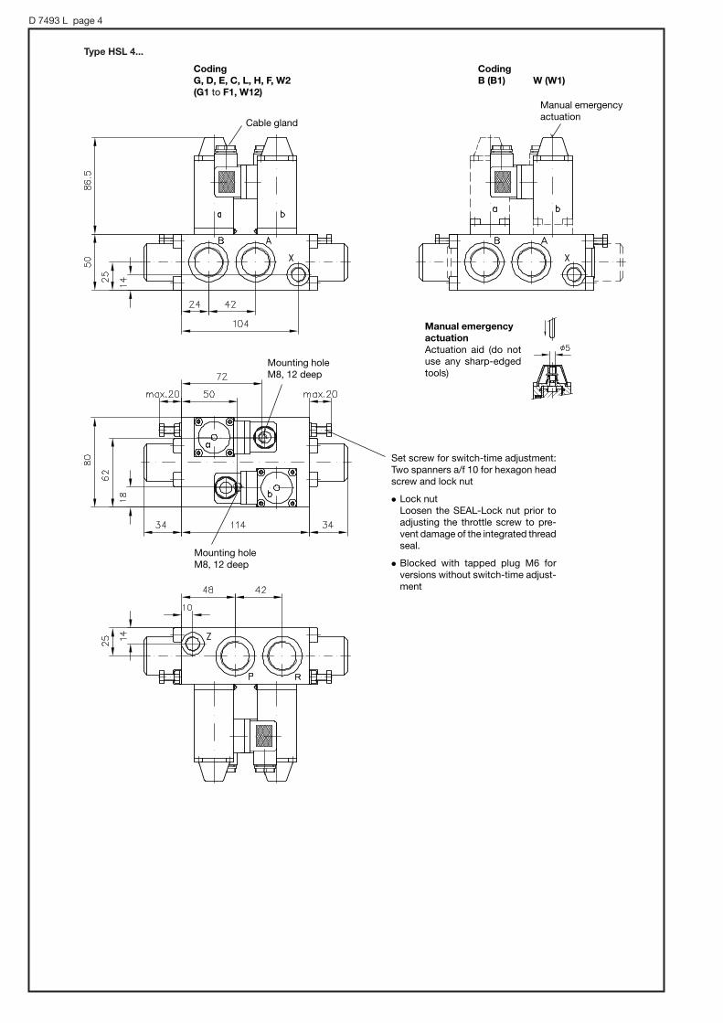
D 7493 L page 4
Type HSL 4...
Set screw for switch-time adjustment:Two spanners a/f 10 for hexagon headscrew and lock nut
' Lock nutLoosen the SEAL-Lock nut prior toadjusting the throttle screw to pre-vent damage of the integrated threadseal.
' Blocked with tapped plug M6 for versions without switch-time adjust-ment
Manual emergency
actuation
Actuation aid (do notuse any sharp-edgedtools)
Cable gland
Manual emergencyactuation
Mounting holeM8, 12 deep
Mounting holeM8, 12 deep
Coding
G, D, E, C, L, H, F, W2
(G1 to F1, W12)
Coding
B (B1) W (W1)

D 7493 L page 5
5. Appendix5.1 Detailed flow illustrated symbols
Examples not listed should be drawn accordingly. Control port X serves as drain/leakage port to the tank with spools W1 and B1.
Standard versions with pilot valves
Version ...-X, without pilot valve
To the tank or to port P of a subsequent spool valve coding L, F, or H
In the case of 4/3-way versions with switching time adjustment (i.e. G1,D1 etc.), only the control port Z can be influenced via the throttle screw.In the case of control port X, it is necessary to install a throttle (i.e. FGor FG-S 6 acc. to D 7275) externally into the connected control line.The symbol illustration opposite, applies to valve coding G and W andanalogously to D, E, C, B, L, H, and F.
5.2 Example circuits
Example 1:
Most simple control with directional spoolvalves suited for parallel connection. Controloil pick-up and return are internal via ports Xand Z. Permissible pressure is approx.160 bar(see control pressure in sect. 3) and when nopressure surges (decompression surges) are ex-pected in the return line.
Example 2:
Same control task as example 1, but with control oil pick-up from a pressure circuit >160 bar. The pressure for the control oil circuit is reduced down to approx. 30 bar here via pressure reducing valve typeADC1-25 acc. to D 7458.It is recommended to to provide an additional line for the control oil return (as illustrated), when pressure surges are expected in the mainreturn line.
Type HSL 3 G1-G 24 Type HSL 3 G1-WG 230
Type DV... - WN 1F-... acc. to D 4350for idle pump circulation
Pressure reducing valve ADC 1-25 acc. to D 7458
Example 3:
A direct control oil pick-up from the pumppressure line is not possible in most caseswith flow pattern symbols L, H, and F as theback pressure in idle position does not exceedthe minimum control pressure required forswitching operations (particularly if there isonly one single valve). It is therefore recom-mended to employ a pump, e.g. type R acc. toD 6010 S feeding a separate control oil circuit(see example). Another way is to use a com-pletely separate control circuit pump, i.e. gearpump with approx. 0.5...1 lpm, limited to approx. 20 bar, making an ADC 1-25 superflu-ous. Otherwise, pay attention to the summa-tion of the back pressure, particularly whenseveral valves are connected in series.
Type MV 6C acc. toD 7000/1
Type MV 4F acc. toD 7000/1
Type ADC 1-25-1/4 acc. to D 7458Type R 58,6-1,2 acc. to D 6010 S
Type HSL 3L- G 24

4/3- and 3/3-way directional seated valves type VH (R) and VHPManually actuated, leakagefree
D 7647Directional seated valves of
VH(R), VHP
April 2008-05
HAWE HYDRAULIK SESTREITFELDSTR. 25 • 81673 MÜNCHEN
2.2
© 1991 by HAWE Hydraulik
Size 1 Flow Qmax = 12 lpm Operating pressure pmax = 700 barSize 2 Flow Qmax = 25 lpmOperating pressure pmax = 500 bar
Individual valve
Type VH 1(2) for pipe connection (photo)
Type VHP 1 for installation onto cus-tomer supplied manifolds
Directional valve bank
Type VHR 1 (2) for pipe connection
1. General
The 4/3- and 3/3-way directional ball seated valves feature zero leakage and are intended for the movement control of single and double acting consumers. The actuation is via hand lever with spring return into idle position or they will remain in the respecting working position by a detent. The shifting operation is transmitted via an eccenter shaft and pin onto the valve balls. All moving internal parts are lubricated by the hydraulic fluid and therefore maintenance-free. All these parts and the valve seats are hardened and ground. The valve balls are from ball bearings and conform industrial standard DIN 5401 ISO-class G 5 (DIN-class I).These valves are available either as individual valves for pipe connection (type VH) and for manifold mounting (type VHP) or as valve banks (type VHR). The valve banks are internally connected in parallel and held together by a strong tension rod. The individual valve type VH may be arranged later to form a valve bank.

D 7647 page 2
2. Type coding, main data
Order examples:
Individual valve
Directional valve bank
VH 1 - L 1K
VHR 1 - G1/N1/E2
Spring return 1) Detent
without 1 2
with 1 K 2 K
Switch 2)
Symbols acc. to order examples above
1) Automatic selfreturn into idle position up to approx. 50 bar. The lever must be returned manually with higher pressure.
2) Not available for flow pattern symbol coding N and S
Electrical data
Co. Burgess No. V 3S Protection class IP 67 (IEC 60529)
Note
230V AC 5 A cos ϕ = 0.6
15V DC 10 A
30V DC 7.5 A L/R , 3 ms
110V DC 0.07 A
230V DC 0.03 A
Service life, 105 opera-tions
Connection scheme
NO-contact (blue)NC-contact (grey)
Supply(black)
The switch is engaged via the hand lever in idle position of the valve and released if the valve is actuated (no matter to which side).
Table 1: Basic type and size
Coding
VH 1
VH 2
VHP 1
VHR 1
VHR 2
Nomen-clature
Individual valve
Directional valve bank
Tapped portsISO 228/1
(BSPP)
G 1/4
G 3/8
see dim. drawings sect. 4
G 1/4
G 3/8
Flow Qmax
(lpm)
12
25
12
12
25
Pres-surepmax(bar)
700
500
700
700
500
Type VH 1 - L1K
Type VHR 1 - G1 / N1 / E2
Flow pattern symbols
1 2 e.g. 1K
Table 3: Actuation
Table 2: Flow pattern symbols
Available for:
Switching position
Individual valve type VH (P) 1 and VH 2 and valve banks type VHR 1(2)
G E M N D H L
Individual valve type
S
VH(P)1 and VH 2
Connec-tion
Pipe con-nection
Manifold mounting
Pipe con-nection
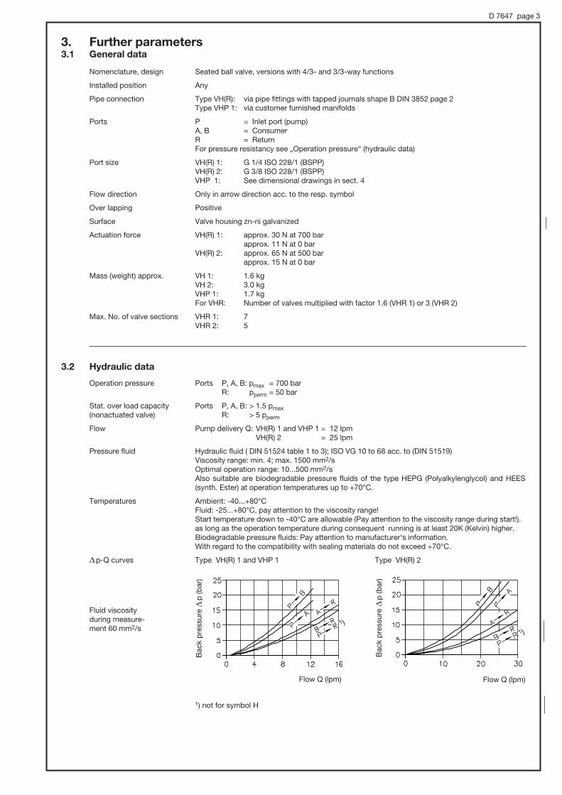
D 7647 page 3
Fluid viscosity during measure-ment 60 mm2/s
Bac
k p
ress
ure
Sp
(bar
)
Bac
k p
ress
ure
Sp
(bar
)
Flow Q (lpm) Flow Q (lpm)
3. Further parameters3.1 General data
Nomenclature, design Seated ball valve, versions with 4/3- and 3/3-way functions
Installed position Any
Pipe connection Type VH(R): via pipe fittings with tapped journals shape B DIN 3852 page 2 Type VHP 1: via customer furnished manifolds
Ports P = Inlet port (pump) A, B = Consumer R = Return For pressure resistancy see „Operation pressure“ (hydraulic data)
Port size VH(R) 1: G 1/4 ISO 228/1 (BSPP) VH(R) 2: G 3/8 ISO 228/1 (BSPP) VHP 1: See dimensional drawings in sect. 4
Flow direction Only in arrow direction acc. to the resp. symbol
Over lapping Positive
Surface Valve housing zn-ni galvanized
Actuation force VH(R) 1: approx. 30 N at 700 bar approx. 11 N at 0 bar VH(R) 2: approx. 65 N at 500 bar approx. 15 N at 0 bar
Mass (weight) approx. VH 1: 1.6 kg VH 2: 3.0 kg VHP 1: 1.7 kg For VHR: Number of valves multiplied with factor 1.6 (VHR 1) or 3 (VHR 2)
Max. No. of valve sections VHR 1: 7 VHR 2: 5
3.2 Hydraulic data
Operation pressure Ports P, A, B: pmax = 700 bar R: pperm = 50 bar
Stat. over load capacity Ports P, A, B: > 1.5 pmax(nonactuated valve) R: > 5 pperm
Flow Pump delivery Q: VH(R) 1 and VHP 1 = 12 lpm VH(R) 2 = 25 lpm
Pressure fluid Hydraulic fluid ( DIN 51524 table 1 to 3); ISO VG 10 to 68 acc. to (DIN 51519) Viscosity range: min. 4; max. 1500 mm2/s Optimal operation range: 10...500 mm2/s Also suitable are biodegradable pressure fluids of the type HEPG (Polyalkylenglycol) and HEES
(synth. Ester) at operation temperatures up to +70°C.
Temperatures Ambient: -40...+80°C Fluid: -25...+80°C, pay attention to the viscosity range! Start temperature down to -40°C are allowable (Pay attention to the viscosity range during start!). as long as the operation temperature during consequent running is at least 20K (Kelvin) higher. Biodegradable pressure fluids: Pay attention to manufacturer‘s information. With regard to the compatibility with sealing materials do not exceed +70°C.
Sp-Q curves Type VH(R) 1 and VHP 1 Type VH(R) 2
1 )1 )
1) not for symbol H

D 7647 page 4
4. Unit dimensions 4.1 Individual valve
All dimensions in mm, subject to change without notice !
Type VH 1 and VH 2
Flow pattern symbols G, E, M, N, D and H
Type VH 1 and VH 2
Flow pattern symbols of L and S
Plugged with a tapped plug with flow pattern symbol N !
Tapped plugVSTI R 1/8 ED ERMETO (VH 1)VSTI R 1/4 ED ERMETO (VH 2)
#12.2through hole
Mounting hole for rollpin (anti-rotation device)
Tapped ports ISO 228/1 (BSPP): VHR 1 = G 1/4 VHR 2 = G 3/8
When mounting onto a connection plate: Sealing of ports P and R by O-rings 14x1.78 (VH 1..) or 17.17x1.78 (VH 2..) NBR 90 Sh
M 12, 11 deepFastening thread for manifold mounting
Plugged with a tapped plug with type VH 1(2)-S For missing dimensions see VH 1(2) - G...H !
Spring return only for pressure below 50 bar!
Mounting hole for rollpin 1) (anti-rotation device)
1) When a customer furnished connection plate utilized rollpins ISO 8750-4x8-St (VH 1..) or ..-5x10 St (VH 2) must be provided
Type
VH 1 - L, S
VH 2 - L, S
d3
19
15.5
d4
13
15.5
e2
5
55
h2
39
46
h3
10
16
h4
29
33
l3
60
79
l4
44
53
Type L B H c c1 c2 d d1 d2 e e1 f g h h1 i i1 i2 l l1 l2 l3 l4 s
VH 1-.. 90 50app. 172
6 9 2.6 11.5 26.5 13 39 45 40M6, 8 deep
20 15 25 23 21 11 70 25 77.5 55.5#4.2, 4 deep
VH 2-.. 120 60 app. 162
7 12 5 12 39 13.5 46 55 54M6, 10 deep
27 16 30 30 23 12 91.5 29 107.5 74#5.2, 5.3 deep

D 7647 page 5
Type VHP 1
all flow pattern symbols
Sealing of ports A, B, P and R by O-rings 6.07x178 NBR 90 Sh.Available as seal kit DS 7647-1.
Socket head screw ISO 4762-M6x60-12.9 zinc coated
4.2 Switch assembly
Type VH 1(2) ... and VHR 1(2) ...
Switch
Switch
Type VHP 1 ...
app
rox.
192

D 7647 page 6
4.3 Directional valve bank
Hexagon nut ISO 4032-M8-8-A2K
VHR 1 = rollpin ISO 8750- 4x8-St
VHR 2 = rollpin ISO 8750-5x10-St
Inlet section
End section
Tension rod DIN 940-M12 Fo x (N x B)-8.8-A2K
Sealing of ports P and R by O-rings
Ports P and R plugged with tapped plugs.
For missing dimensions see section 4.1!
Type O-ring NBR90 Shore
Tapped plug (end section P, and R)
NNumber of valves
B
VHR 1 14x1.78 VSTI R 1/8 ED ERMETOmax. 7 50
VHR 2 17.17x1.78 VSTI R 1/4 ED ERMETOmax. 5 60
app.16 app.16
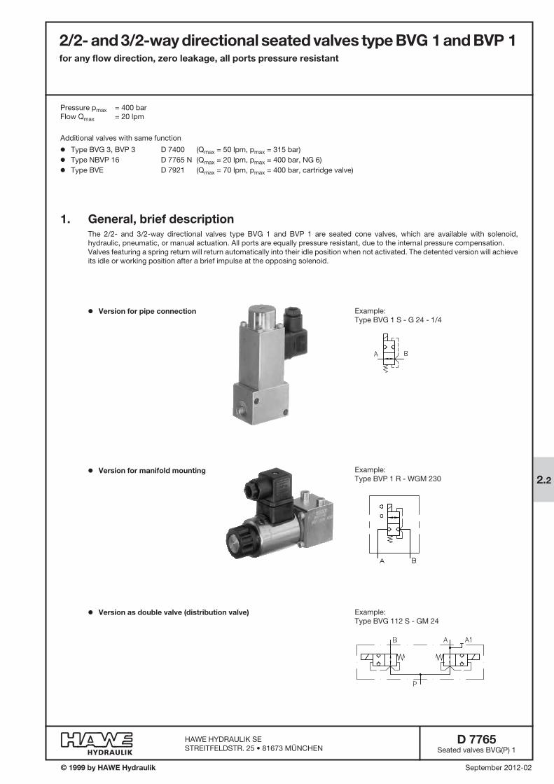
2/2- and 3/2-way directional seated valves type BVG 1 and BVP 1for any flow direction, zero leakage, all ports pressure resistant
D 7765Seated valves BVG(P) 1
September 2012-02© 1999 by HAWE Hydraulik
HAWE HYDRAULIK SESTREITFELDSTR. 25 • 81673 MÜNCHEN
2.2
1. General, brief descriptionThe 2/2- and 3/2-way directional valves type BVG 1 and BVP 1 are seated cone valves, which are available with solenoid, hydraulic, pneumatic, or manual actuation. All ports are equally pressure resistant, due to the internal pressure compensation.Valves featuring a spring return will return automatically into their idle position when not activated. The detented version will achieve its idle or working position after a brief impulse at the opposing solenoid.
Pressure pmax = 400 bar Flow Qmax = 20 lpm
o Version for pipe connection
o Version for manifold mounting
o Version as double valve (distribution valve)
Example:Type BVP 1 R - WGM 230
Example:Type BVG 112 S - GM 24
Example:Type BVG 1 S - G 24 - 1/4
Additional valves with same function
o Type BVG 3, BVP 3 D 7400 (Qmax = 50 lpm, pmax = 315 bar)
o Type NBVP 16 D 7765 N (Qmax = 20 lpm, pmax = 400 bar, NG 6)
o Type BVE D 7921 (Qmax = 70 lpm, pmax = 400 bar, cartridge valve)

D 7765 page 2
2. Available versions2.1 Type coding, main data
BVP 1 R - WGM 230
BVG 1 Z - H - 3/8
BVG 1 R /B 1,1 - A - 1/4
Table 3: Flow pattern symbols
1) 250 bar applies to solenoid actuation coding GM.., WGM.. (acc. to table 4)2) Only with solenoid actuation3) Not possible with port size G 3/8 (BSPP)4) Part No. for spare parts order etc. see section 5.1 “Appendix”
With detent
Coding Description
BVG 1 Pipe connection ISO 228/1 (BSPP)
BVP 1 Manifold mounting
Ports A, B, C acc. to ISO 228/1 (BSPP)
1/4
3/8
See dimensional drawing:Version with indiv. connection block, see sect. 5.2
Pressurepmax
(bar)
400/ 250 1)
Flow Qmax (lpm)
20
Table 1: Basic type
Table 2: Additional elements (for ports A, B, and C, see also section 3.1 „Flow limitation“)
Additional element
Orifice 3)
Orifice
Coding 4)
B 0,6
B 0,8
B 1,1
B 1,3
B 1,5
B 0,6
B 0,8
B 1,1
B 1,3
B 1,5
B 2,0
B 2,5
#(mm)
0.60.81.11.31.5
0.60.81.11.31.52.02.5
Suited for
BVG 1
BVP 1 RBVP 1 RKBVP 1 SBVP 1 SK
R S Z RK 2) SK 2) ZD 2)
With contact switch
Additional element
Orifice
Check valve(in A, B, or C)
Coding 4)
B 0,8
B 1,0
B 1,2
B 1,4
R
#(mm)
0.81.01.21.4
---
Suited for
BVP 1 ZBVP 1 ZD
BVP 1 ZBVP 1 ZD
Actuation, see table 4 on page 3
optional
Version as double valve (distribution valve)
Type BVG 112 see sect. 5.3

D 7765 page 3
Cod. H
1) Explosion-proof version 2) DC-solenoid (98 V DC, 205 V DC) with bridge rectifier in the device socket3) These symbols, together with solenoids GM, WGM, LM, XM, cost less than versions G, WG etc. but the max. pressure rating is lower!4) actuation via tool, a/f 13
Cod. H 1/4
Solenoid Hydraulic Pneumatic Manual MechanicalPin Roller
Flow pattern symbol
Table 4: Actuation modes
Main data, also see section 3.2 Coding with plug Plug with LED Without plug
G 24 EX 1) --- ---
G 12 L 12 X 12
G 24 L 24 X 24
WG 110 2) --- X 98
WG 230 2) --- X 205
GM 12 3) LM 24 XM 12
GM 24 3) LM 24 XM 24
WGM 110 2) 3) --- XM 98
WGM 230 2) 3) --- XM 205
220
Solenoid 400
250
Mechanical 400
Manual 400
Manual 400with detent
Hydraulic 400
Pneumatic 400
Actuation
P External control port G 1/4 (BSPP)
H 1/4 External control oil port G 1/4 (BSPP)
H Control oil port (type BVP 1)
A
CD with hand lever
KD 4) without handlever
T Pin
K Roller
Control: pcontr. min = 24 barpressure pcontr. max = 400 bar
Control: pcontr. min = 3 barpressure pcontr. max = 15 bar
Pressurepmax(bar)
Actuation torque: approx. 1.5 ... 3 Nm
Actuation torque: approx. 1.5 ... 3 Nm
Actuation force: F = approx. 80 ... 190 N
Actuation force: F = approx. 22 ... 35 N
For flow pattern symbols
R (RK), S (SK),
Z (ZD)
R (RK), S (SK),
Z (ZD)
all
R, S, Z
UN = 12 V DC
UN = 24 V DC
UN = 110 V AC, 50/60 Hz (98 V DC)
UN = 230 V AC, 50/60 Hz (205 V DC)
UN = 12 V DC
UN = 24 V DC
UN = 110 V AC, 50/60 Hz (98 V DC)
UN = 230 V AC, 50/60 Hz (205 V DC)
UN = 24 V DC
Table 4 a: Additionally locked at actuations CD and KD
without (no coding) switching position a
in switching position a and b
--
1
2
3switching position b
CD CD 1 KD KD 1
CD 2 CD 3 KD 2 KD 3
Symbols

D 7765 page 4
3. Further characteristic data3.1 General and hydraulic data
Installed position Any
Negative (overlap only apparent during transition from one to the other end position). All ports are interconnected during the switching process.
Operating pressure According to table 4, sect. 2.1
Static overload capacity Ports A, B, and C approx. 2 x pmax
Housing material and Steel, gas nitrided (basic valve)surface coating
Mass (weight) approx. kg
Pressure fluid Hydraulic oil conf. DIN 51514 part 1 to 3: ISO VG 10 to 68 conf. DIN 51519Viscosity limits: min. approx. 4, max. approx. 1500 mm2/sec. Optimal operation: approx. 10 ... 500 mm2/sec
Also suitable for biological degradable pressure fluids types HEPG (Polyalkylenglycol) and HEES (Synth. Ester) at service temperatures up to approx. +70°C
Temperature Ambient: approx. -40...+80°C; Fluid: -25...+80°C, pay attention to the viscosity range! Start temperature down to -40°C are allowable (Pay attention to the viscosity range during start!),
as long as the operation temperature during subsequent running is at least 20K higher. Biological degradable pressure fluids: Pay attention to manufacturer‘s information. With regard to the compat-ibility with sealing materials do not exceed +70°C.
Restrictions for version with ex-proof solenoid!
Attention: Observe the restrictions regarding the perm. duty cycles of the solenoids in sect. 3.2!
Flow Qmax acc. to sect. 2.1
Flow limitation It is necessary to limit the flow down to the permissible range depending on the system pressure via orifices (see sect. 2.1). This applies to all circuits fed by an accumulator or when connected to high pressure circuits fed by high delivery pumps.
The orifice must be located on the accumulator side always. With valves version ..Z.. it is installed in port C as standard. It must be specified in uncoded text, when the orifices are desired in ports A or B. For more detailed information, see table 2, section 2.1.
The check valve prevents an unintended reversal of the flow direction. Mounting possibility like with orifices.
Overlap with 3/2-way directional valves
Completewith actuation
G.., G 24 EX, L.., X.., WG.., M..
GM.., LM.., XM.., WGM..
Hydraulic H, H 1/4
Pneumatic P
Manual A
Manual CDWithout detent KD
Mechanical T
K
BVG(P) 1 RBVG(P) 1 S
1.0
0.9
0.6
0.5
0.9
0.9
0.6
0.9
BVG(P) 1 RKBVG(P) 1 SK
1.2
1.0
---
---
---
---
---
---
BVP 1 ZDBVG 1 ZD
1.7
1.5
---
---
---
---
---
---
BVG 1 ZBVP 1 Z
1.2
1.1
0.8
0.7
1.1
1.1
0.8
1.1
Solenoid
Bac
k p
ress
ure
. |
p (b
ar)
Bac
k p
ress
ure
|p
(bar
)
Flow Q (lpm) Flow Q (lpm)
Viscosity during measurements approx. 60 mm2/sec
Additional orifices(Other diameters may be interpolated)
Basic valves|p-Q-curve
Orifice Check valve
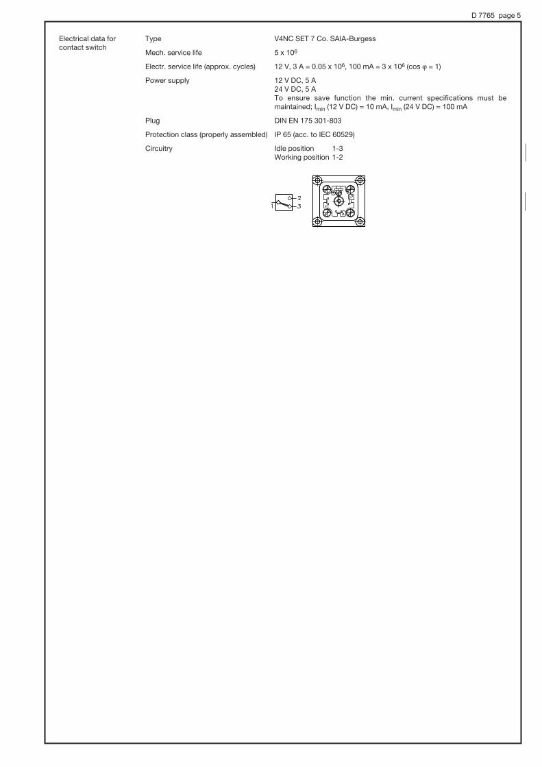
D 7765 page 5
Electrical data forcontact switch
Type V4NC SET 7 Co. SAIA-Burgess
Mech. service life 5 x 10⁶
Electr. service life (approx. cycles) 12 V, 3 A = 0.05 x 10⁶, 100 mA = 3 x 10⁶ (cos 9 = 1)
Power supply 12 V DC, 5 A 24 V DC, 5 A
To ensure save function the min. current specifications must be maintained; Imin (12 V DC) = 10 mA, Imin (24 V DC) = 100 mA
Plug DIN EN 175 301-803
Protection class (properly assembled) IP 65 (acc. to IEC 60529)
Circuitry Idle position 1-3 Working position 1-2

D 7765 page 6
Control pressure pcontr. min 24 bar 3 bar --- --- ---
pcontr. max 400 bar 15 bar --- --- ---
Permissible residual pressure in the control line for save < 2 bar --- --- --- --- return into the idle position
Prot. Z overload capacity approx. approx. --- --- --- 1.5 pcontr. max bar 1.5 pcontr. max bar
Control displacement (geometric) 1.4 cm3 9.3 cm3 --- --- ---
Housing material and Steel Light alloy Steel Steel (control housing) surface coating (control housing) (control housing) (lever housing) gas nitrided galvanized black anodized gas nitrided
Actuation moment --- --- approx. 1.5 ... 3 Nm --- ---
Actuation force --- --- --- approx. approx. 80...190 N 22...35 N
3.2 Actuations
Solenoid
All solenoids are built and tested acc. to VDE 0580
Connection and circuitry DC-voltage
Coding G 12 GM 12 G 24 GM 24 G 24 EX WG 110 WGM 110 WG 230 WGM 230 L 12 LM 12 L 24 LM 24 --- --- --- --- --- X 12 XM 12 X 24 XM 24 --- --- --- --- ---
Nom. voltage UN (V) 12 12 24 24 24 110 110 230 230
Nom. power PN (W) 29.4 26.2 27.6 26.5 23.4 28.6 24.8 30.2 28
DC-voltage AC-voltage AC, 50 and 60 Hz
Switching time (reference value) On or Off: approx. 50...60 ms, 2-3 longer with WG
Switchings/hour approx. 2000, approximately evenly distributed
Actuation pulse Symbole ZD: approx. 500 ms
Protection class IP 65 (IEC 60529) (plug properly mounted) IP 67 (IEC 60529) with G 24 EX
Insulation material class F
Contact. temperature approx. 120°C, with ambient temperature 20°C
Switch-off energy WA Ò 0.4 Ws
Surface coating (solenoid) DIN 50961-Fe/Zn 12 bk cC
Relative duty cycle during operation(100% ED stamping on the solenoid)
Type G... Type L.. Type WG..(applies also to the switches)
Rel. duty cycle %ED-5 min
Am
bie
nt
tem
p.
U (°
C)
Version G, GM, L, LM, WG, WGM:Plug conf. DIB DIN EN 175 301-803 A All plugs For additional plugs, see D 7163
Version G 24 EX: Cable cross section 3x0.5 mm2,Cable length 3 m, option 10 m (cable ÖLFLEX-440P ® Co. LAPP, D-70565 Stuttgart)
AC-voltage
Electrical data for ex-proof solenoids
ATEX-Certificate of conformity TÜV-A 03ATEX 0017 XCoding O II 2 G Ex d IIB + H2 T4 O II 2 D Ex mbD 21 T135°COper. duration 100% EDDuty cycle IP 67 (IEC 60529)Nom. voltage UN 24 V DCPower PN 23 WRestrictions for use:
Ambient temperature -35 ... +40°Cmax. fluid temperature +70°Cel. protection against overload (conf. IEC 60127) IF < 1.6 A-TSurface coating Housing galvanically zinc coated Coil and connection cavity are moulded
Attention: Protect the complete valve against direct sun light.
Observe the operation manuals B 03/2004 and B ATEX!Electrical lay-out and testing conforming EN 60079, VDE 0170-1, VDE 0170-5
Hydraulic Pneumatic Manual Mechanical
(coding H 1/4) (coding P) (coding A, CD, KD) (coding T) (coding K)

D 7765 page 7
Switch(For missing data of the plug, see solenoid actuation section 4.2)
Ports conf. ISO 228/1 (BSPP):A, B, and C = optional G 1/4 or G 3/8
4. Unit dimensions 4.1 Valve section
Version for pipe connection
Type BVG 1 R(S) Type BVG 1 RK(SK)
Type BVG 1 ZDType BVG 1 Z
#6.5Thru-hole
#6.5Thru-hole
#6.5Thru-hole
1)
1)
1)
1)
1) For dimension of the differing actuations, see section 4.2!
All dimensions in mm, subject to change without notice!
#6.5Thru-hole
z xy
Ports (BSPP) z x y
G 1/4 25 24 20
G 3/8 27 26 18.5
a
BVG 1 R(S) - 1/4 10
BVG 1 R(S) - 3/8 12
app
rox.
35

D 7765 page 8
Version for manifold mounting
Sealing of the ports via O-ring NBR 90 Sh 1):A, B = 7.65x1.78Z = 2.54x1.78
Sealing of the ports via O-ring NBR 90 Sh 1):A, B, C = 8.73x1.78Z = 2.54x1.78
Type BVP 1 R(S) Type BVP 1 RK(SK)
Type BVP 1 Z
1) Part of seal kit DS 7765-1 (including O-rings for actuation H, H 1/4)
2) Port Z only with actuation coding H
3) For dimension of the differing actuations, see section 4.2!
M6,8 deep
Hole pattern manifold
(view from top)Hole pattern manifold
(view from top)
Hole pattern manifold
(view from top)
Switch(For missing data of the plug, see solenoid actuation section 4.2)
2)
M6,8 deep
2)
2)
3) 3)
3)
Type h h1
BVP 1-Z 53 8
BVP 1-ZD 60 132)
M5,6 deep
3)
For missing data, see below!
Type BVP 1 ZD
app
rox.
48

D 7765 page 9
4.2 ActuationsElectrical actuation
Manual emergency actuation
Manual emergency actuation
1) Attention: This dimension is depending on the manufacturer and can be max. 40 mm acc. to DIN EN 175 301-803 A.
2) Both solenoid and plug may be rotated 4x90°.
Coding G... and WG...
Coding G 24 EX
Coding GM... and WGM...
1) 1)
Manual emergency actuation
Actuation aid (do not use any sharp-edged parts)
Manual emergency operation
The valve can be actuated, if required, by pushing the emer-gency actuation pin inward (visible from the top side) by means of a screw driver or similar.Attention: The pressure apparent at port B acts as a counter force resulting in approx. 195 N at 100 bar!
2)
2)
app
rox.
35
app
rox.
38.5 ap
pro
x.35
app
rox.
28.5

D 7765 page 10
Hydraulic actuation
Coding H 1/4
(with BVP 1)
Coding H
(with BVG 1)Coding H
(with BVP 1)
Pneumatic actuation
Coding P
Control port Z is located at the valve element (section 4.1!)
Manual actuation
Coding A
Coding CD, KD
Lock with CD (KD) 1(2, 3) CD

D 7765 page 11
Don‘t use as a stop!
Saf
ety
lift
Working stroke (mm) with
Start of function (H+h)
Functional travel h
Switching position range s
Actuation force N
BVG(P) 1 R-K
66
14
---
approx. 26
BVG(P) 1 S-K
66
10
*1
approx. 22
BVG(P) 1 Z-K
66
14
*1
approx. 35
Mechanical actuation
Coding T Coding K
5. Appendix5.1 Parts No. for orifices (retrofitting)
Actuation force F for 100 ... 400 bar:Type BVG(P) 1 R-T = 80 ... 140 N
BVG(P) 1 Z(S)-T = 140 ... 190 N
1) Shares: 0.5 mm play1 mm operation travel0.5 mm safety lift
(to
tal)
1)
Pla
y
Continuation actuations
app
rox.
70
Coding
without hole
B 0,6
B 0,8
B 1,1
B 1,3
B 1,5
without hole
B 0,6
B 0,8
B 1,1
B 1,3
B 1,5
B 2,0
B 2,5
Suited for type
BVG 1..-1/4
BVP 1 R(S)
Parts No.
7406 012 a
7406 012 b
7406 012 c
7406 012 d
7406 012 f
7406 012 h
7921 012
7921 012-0,6
7921 012-0,8
7921 012-1,1
7921 012-1,3
7921 012-1,5
7921 012-2,0
7921 012-2,5
Coding
without hole
B 0,8
B 1,0
B 1,2
B 1,4
R
Suited for type
BVP 1 Z
BVP 1 Z(ZD)
Parts No.
7785 018
7785 018 a
7785 018 b
7785 018 c
7785 018 d
ER 12

D 7765 page 12
5.2 Individual connection block for valves type BVP 1
Available versions Dimensions
BVP 1 - ... - R(RK)
S(SK)
1/4
3/8
BVP 1 Z(ZD) - ... - 1/4
3/8
7921 092
7921 093
Order No.
7921 094 20
7921 095 24
Order No. a
M6, 8 deep
Ports conf. ISO 228/1 (BSPP):A and B = G 1/4 or G 3/8
Ports conf. ISO 228/1 (BSPP):A, B, and C = G 1/4 or G 3/8

D 7765 page 13
5.3 Double valve (distribution valve)
Order coding: BVG 112 R - G 24
Qmax = 20 lpmpmax = According actuation (see table 4, page 3)
Actuations (see table 4, page 3)
Flow pattern symbol R or S (see table 2, page 2)possible combinations (coding RS or SR)
Basic type double valve
Flow pattern symbol (illustrated here with solenoid actuation)
Type BVG 112 R - G 24
Dimensions
Type BVG 112 S - G 24
Ports conf. ISO 228/1 (BSPP):P, A, B = G 3/8A 1 = M 18x1.5
For dimension of the differing actuations, see section 4.2

Directional seated valves in a twin compact design type VZP 1
solenoid actuated, zero leakage,
mounting on manifolds
D 7785 ADirectional seated valve VZP1
October 1999-02
HAWE HYDRAULIK SESTREITFELDSTR. 25 • 81673 MÜNCHEN
2.2
© 1995 by HAWE Hydraulik
Operating pressure pmax = 450 bar
Flow Qmax = 15 lpm
For directional valve banks type BVZP 1 see D 7785 B
Symbols
4/3- and 4/4-way directional 2 x 3/2-way directional seated valvesseated valveExample: VZP1 G22 - G 24 Example: VZP1 H12 B1,2 H2 - G 24
1. General informationThe directional seated valves type VZP serve to control the movement direction (ahead -- stop -- back) of single and double acting consumersin hydraulic systems.These valves are designed as manifold mounting valves.Their compact design enables valve banks i.e. hydraulic controls withvery little spatial requirements. The various versions of these valves asvalve banks type BVZP 1 are detailed in D 7785 B.The following flow pattern symbols are available with the directional valves type VZP 1:
' 4/3- and 3/3-way function, cone seated valve design' Two independently acting 3/2- or 2/2-way functions, ball seated valve
design' Two independently acting 4/2-way functions, spool valve design
Main advantage, when compared to valves with similar function, is the unique two in one solenoid design (two coils share one housing). This allows significant downsizing of the complete valve.All cone and ball seated valves show zero leakage in blocked state.
4/3-way directional seated valvewith pressure switch
Example: VZP1 D52 - WG 230
1 x 3/2- and 2/2-way directional seated valve(2/2-way for idle circulation)Example: VZP1 H2 F2 - G 24
1 x 3/2-way directional seated and 4/2-way directional spool valve
2 x 4/2-way directional spool valveExample: VZP1 W2 W2 - G 24
Example: VZP1 R4 WX2 - WG 230

D 7785 A page 2
2. Available versions, main data(for complete type overview, see sect. 6)
2.1 4/3 (4/4)- or 3/3 (3/4)-way directional seated valves up to 400 barFor the actuation of a double or one single-acting consumer.The control of the two solenoid coils takes place alternately to achieve either switching positions a (1-3) or b (1-2). When one coil isused only , it may be energized permanently, as long as the ambient temperature is below approx. 40°C. A reduced duty cycle applies if both coils are energized (switching position a (1-2) + b (1-3)) or the ambient temperature is higher (see sect. 3.2).
Order examples:
1) A pressure gauge (type 9/... D 7077 A) or a miniature accumulator (type AC.. acc. to D 7571) may be installedinstead of a pressure switch, see also SK 7077A. Thishas to be added to the order in uncoded text.Example: VZP1 G22/0-G24 with pressure gauge 9/250-Y9mounted at DG connection (port A)
2) Order coding for a throttle complete with filter section,see C in sect. 5.1
3) May be used also for pressure switches, when mounted
VZP 1 G 22 - G 24
VZP 1 D 45 B1,2 - WG 230
VZP 1 J 2 - G 12
VZP 1 P 4 B1,0 - WG 110
Table 1: Basic type
Table 3: Pressure switch type DG 3.. acc. to D 5440,optional for connection A and/or B 1)
VZP 1 Twin valve, size 1
22
2
3 DG 33 200...450 bar
4 DG 34 100...400 bar
5 DG 35 20...250 bar
6 DG 36 4... 12 bar
7 DG 365 12...170 bar
22 = Ports A and B withflow patterns E, G, D, and O
2 = Ports A with flow patterns P a. J.Ports A or B with symbols H, M, N, R,W, and WX
Only for flow pattern E, G, D, and O respec-tively 1st or 2nd coding:DG... with A only = 32, 42 etc.DG... with B only = 23, 24 etc.DG... with A and B = 45, 73 etc.
For flow pattern P, J, H, M, N, R, W, and WX:Only one coding 3, 4 etc. for port A or B
Standard, withoutDG.., prepared forretrofitting
Without Standard
0,8 Ø 0.8
1,0 Ø 1.0
1,2 Ø 1.2
1,4 Ø 1.4
Table 4: Additional elements, inserted in port P (optional) 2)
B
Orifice tolimit theflow
Symbolsaccording to above order examples
Table 2: Symbols
E
G
D
O
P
J
G 12 X 12 L 12 3) --- 12 V DC
G 24 X 24 L 24 3) L 5 K 24 3) 24 V DC
G 48 X 48 --- --- 48 V DC
G 102 X 102 --- --- 102 V DC
WG 110 --- --- --- 110 V AC
WG 230 --- --- --- 230 V AC
Table 5: Nom. voltage of the solenoid
Only with flow patterns E, D, P, H, M, W.This orifice is not available for flow patterns G, O, J, N, R, and WX, becauseof the check valve installed.
50 /60 Hz
4/3(4/4)-way directional seated valve, basic version
4/3(4/4)-way directional seated valve with pressure switches for ports Aand B as well as throttle in port P
3/3(3/4)-way directional seated valve, basic version
3/3(3/4)-way directional seated valve with pressure switch for port A andthrottle in port P
Type VZP1 G 22 - G 24
Type VZP1 D 45 B1,2 - WG 230
Type VZP1 J 2 - G 12
Type VZP1 P 4 B1,0 -WG 110
The 4th switching position a+b is apparent, when both coils of the sole-noid are energized simultaneously. It should be detailed in circuit diagramsonly when really used, see also restrictions in sect. 3.2!
With plug AconformingDIN EN 175 301-803
Without plug Plug withLED
Plug incl.leads 5 m
Nom. voltage
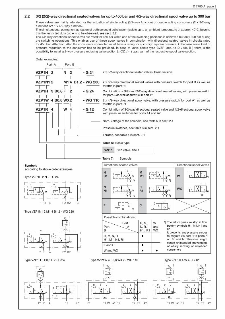
D 7785 A page 3
Table 6: Basic type
VZP 1 Twin valve, size 1
Nom. voltage of the solenoid, see table 5 in sect. 2.1
2.2 3/2 (2/2)-way directional seated valves for up to 450 bar and 4/2-way directional spool valve up to 300 bar
These valves are mainly intended for the actuation of single acting (3/2-way function) or double acting consumers (2 x 3/2-way functions ore 1 x 4/2-way function).The simultaneous, permanent actuation of both solenoid coils is permissible up to an ambient temperature of approx. 40°C, beyondthis the restricted duty cycle is to be observed, see sect. 3.2!The 4/2-way directional spool valves are rated for 450 bar when one of the switching positions is achieved but only 300 bar duringthe switching operations. This enables use of these spool valves in combination with directional seated valves in circuits rated for 450 bar. Attention: Also the consumers connected must have a rating for such high system pressure! Otherwise some kind ofpressure reduction to the consumer has to be provided. In case of valve banks type BVZP (acc. to D 7785 B ) there is the possibility to install a 2-way pressure reducing valve section (..-CZ../.- ) upstream of the respective spool valve section.
Order examples:
Port A Port B
VZP1H 2 N 2 - G 24
VZP1N1 2 M1 4 B1,2 - WG 230
VZP1H 3 B0,8 F 2 - G 24
VZP1W 4 B0,8 WX2 - WG 110
VZP1R 4 W 4 - G 12
Table 7: Symbols
Directional seated valves Directional spool valves
H
H1
N
N1
F
M
M1
R
R1
C
W
WX
1) The return pressure stop at flowpattern symbols H1, M1, N1 andR1.It prevents any pressure surgesto migrate via port R to ports Aor B, which otherwise mightcause unintended movementsof easily moving or unloadedconsumers
2 x 3/2-way directional seated valves, basic version
2 x 3/2-way directional seated valves with pressure switch for port B as well asthrottle in port P2
Combination of 3/2- and 2/2-way directional seated valves, with pressure switchfor port A as well as throttle in port P1
2 x 4/2-way directional spool valve, with pressure switch for port A1 as well as throttle in port P1
Combination of 3/2-way directional seated valve and 4/2-directional spool valvewith pressure switches for ports A1 and A2
Type VZP1H 2 N 2 - G 24
Throttle, see table 4 in sect. 2.1
Pressure switches, see table 3 in sect. 2.1
Type VZP1N1 2 M1 4 B1,2 - WG 230
Type VZP1H 3 B0,8 F 2 - G 24
Symbols
according to above order examples
1)
1) 1)
1)
Port H, M, WPort A N, R, andB H1...R1 WX
H, M, N, R '
H1, M1, N1, R1
F and C '
W and WX ' '
Possible combinations:
Type VZP1W 4 B0,8 WX 2 - WG 110 Type VZP1R 4 W 4 - G 12

D 7785 A page 4
3. Technical data3.1 General information and hydraulic data
Nomenclature, design Directional seated valve, zero leakage, with 4/3- and 3/3-way function and with 2 x 3/2-or 3/2- plus 2/2-way functions in a twin lay-out per valve bodyDirectional spool valve with 2 x 4/2-way function or combination of 4/2-way function (spool valve) and3/2-way function (seated valve) in a twin lay-out per valve body
Unit surface Zinc galvanized
Pipe connection Manifold mountingIndividual sub-plates have to be customer furnishedFor directional valve banks in parallel connection see type BVZP, acc. to D 7785 B
Ports P, P1, P2 = Inlet port (pump side)A, B = ConsumersR, R1, R2 = Return
Direction of flow Only in arrow direction in accordance with symbol
Over lapping Negative, i.e. the transition into the other switching positions is only completed at the end of stroke. Allpassages are interconnected during the switching operation, however this may be neglected becauseof the short switching time.Directional spool valves (Coding W, WX): zero
Use in the open Directional seated valve:Possible, due to good surface protection of solenoid and valve body and the pressure and moisture proof coil design. Nevertheless the valves should be protected against direct sun and direct contact withwater should be avoided.
Mass (weight) approx. kg Valves acc. to sect. 2.1: Coding E, G, P, J = 1.9 kg Coding D and O = 2.2
Valves acc. to sect. 2.2: Coding H ... R1, F and C = 2.2 kg Coding W and WX = 1.9 kg
Operating pressure Valves acc. to sect. 2.1: Port P, A, B pmax = 400 bar with VZP 1 E, D, P, G, O, J
Port R, L pmax = 20 bar
Valves acc. to sect. 2.2: Port P1(2); A1(2); B1(2) pmax = 450 bar with VZP 1 H, N, M, R, F, C
pmax = 300 bar with VZP 1 W, WX
(450 bar in achieved switching position)Port R1(2); L pmax = 20 bar
Static overload capacity Approx. 2.5 pmax, applies to the valve in idle position only
Pressure fluid Hydraulic oil conforming DIN 51524 part 1 to 3: ISO VG 10 to 68 conforming DIN 51519Viscosity limits: min. approx. 4; max. approx. 1500 mm2/s (Viscosity during start of operation)Optimal operation: approx. 10 ... 500 mm2/sAlso suitable for biological degradable pressure fluids types HEPG (Polyalkylenglycol) and HEES (Synth.Ester) at service temperatures up to approx. +70°C
Temperature range Ambient: approx. -40 ... +80°CFluid: -25 ... +80°C, Note the viscosity rangePermissible temperature during start: -40°C (observe start-viscosity!), as long as the service tempera-ture is at least 20K (Kelvin) higher for the following operationBiological degradable pressure fluids: Observe manufacturer's specifications. Considering the compatibility with seal material not over +70°C.Attention: Observe the permissible operation time of the solenoids, see also sect. 3.2!
Flow Symbols
sect. 2.1 VZP 1 E, D, P, G, O, J 1)
sect. 2.2 VZP 1 H, N, M, R, F, C
VZP 1 W, WX
SolenoidCoding
G 24
G 12, WG 110, WG 230
All solenoids G.. and WG..
Guideline for permissible, switchable flow in lpm at
operating pressure up to approx.250 bar 400 bar 450 bar
12 8 ---
9 7 ---
9 7 5
16 16 ---(300 bar)
1) The perm. flow during switching operations may be 30...50% (G 24) or even 100 % (G 12, WG 110, and WG 230) higher, whenthe duty cycle is $ 10%, see also sect. 3.2.
add 0.3 kg per directly mountedpressure switch
L = Relief line, led pressurelessly tothe tank always (return)!

D 7785 A page 5
Note regarding valves acc. to section 2.1:
The flow in return direction Qout is lower or higher than in inflow direction Qin depending on motion direction of connected double
acting consumers with unequal area ratio (differential cylinders, e.g. acc. to DIN ISO 7181) and, therefore the corresponding
figures acc. to the |p-curve,
Fluid viscosity approx. 60 mm2/s during measurements
A stronger increase of the back pressure at viscosities above approx. 500 mm2/s
Extend Retract
Bac
kp
ress
ure|
p(b
ar)
Bac
kp
ress
ure|
p(b
ar)
Bac
kp
ress
ure|
p(b
ar)
Directional seated valves Symbols E, D, P, G, O, andJ acc. to sect. 2.1
Directional seated valves Symbols H, M, N, R, F, andC acc. to sect. 2.2
4/2-way directional spool valve Symbols W and WX acc. to sect. 2.2
Orifice B 0.8...1,4
Flow Q (lpm) Flow Q (lpm)
Flow Q (lpm)
The total back pressure is the sum of inflow and return shares
|ptotal = |pin + |pout
|p-Q-curves
The curves apply to valves including a test manifold, which features a similar lay-out forgallery P and R as illustrated in sect. 5.1 or table 5 in sect. 2.3 of D 7785 B. The backpressure for fittings have to be added. A common fitting for tube 8 mm shows approx. 1 bar at 10 lpm and 3 bar at 16 lpm.
Flow Q (lpm)
Ain
Ain
AinQin
Qin
QinQout Qout
Aout
AoutQout =
Ain
Aout
Aout

D 7785 A page 6
Protection class IP 65 (IEC 60529), with properly mounted plugIEC 70 (Co)13
Circuitry:Plug shape DIN EN 175 301-803 3-terminals + PE (gnd)
All plugs feature a cable gland (except type L5K 24)
Insulation material class H
Contact temperature max. approx. 100°C at 20°C ambient temperature and max. performance
Switch-off energy W = 0.5 Ws (guideline for max. + approx. 10% acc. to tests with nom. voltage UN)
Mounting In case of an electrical defect the twin solenoid may be removed from the valve body by undoing thefour mounting screws. Remove the armature together with the actuation parts and the armatures fromthe unscrewed solenoid body and correctly reassemble everything, together with the new coil housing,in its original position (do not interchange!).
3.2 Electric data
Solenoid Twin solenoid, wet armatureelectrical design and tests conforming DIN VDE 0580
Nom. voltage, nominal power and switching times
Coding G 12 G 24 WG 110 1) WG 230 1)X 12 X 24 X 48 X 102L 12 L 24, L5K 24 2)
Nom. voltage UN (V) 12 DC 24 DC 110 AC/48 DC 230 AC/102 DC
Nom. power PN (W) 24.5 27.4 29.8 29.6
Nom. current I20 (A) 2.04 1.14 0.62 0.29
on 70 70 110 110
off 40 40 155 155
on 50 50 70 70
off 65 65 130 130
Switchingtime(guide-line)
4/3- and 3/3-directionalseated valves acc. tosect. 2.1
3/2-, 2/2-way direct.seated valves and 4/2-way directional spoolvalves acc. to sect. 2.2
1) Solenoids equipped with plugs including a double one-way rectifiercircuit feature coils 48 V DC (WG 110) or 102 V DC (WG 230), see also circuitry.
Switching frequency Approx. 2000/h, approx. evenly distributed
Duty cycle The permissible duty cycle of switching position a, b ora+b with alternating or simultaneously operated solenoidsmay be estimated for applications with continuos cyclesby %EDa + %EDb ≤ 100 k.
The factor k in accordance with the diagram below takesinto account the ambient fluid and the oil temperature.
Ambient temperatur (°C)
Fac
tor
(k)
Example 1: VZP1 H2 N2 - G 24 (sect. 2.2, example 1)
Example 2: VZP1 G22 - G 24Only alternating actuation of a or b usually makes recalculation usually superfluous. With actuation mode a + b acc. to above scheme.
Ambient temperature of < 40°C Ambient temp. > 40°C, e.g. 52°C
%EDa + %EDb = 100 x 2 = 200 %EDa + %EDb = 100 x 1.6 = 160
each single coil may be operated each single coil may beoperated with with 100% ED (100 + 100 = 200) max. 80% ED (80 + 80 = 160) or with a differing
distribution with a %ED sum of 160
DC-voltage DC-voltageCoding G.. Coding L5K 24 2) Coding WG..
2) Plug coding L5K, features LED's and a lead 5 m,for detailed specifications see D 7163.
Solenoid viewedfrom top

D 7785 A page 7
These ports are not requiredwith VZP 1 P and J
When mountedat port BWhen mounted at port A
4. Unit dimensionsAll dimensions are in mm and are subject to change without notice!
4.1 4/3 (4/4)- or 3/3 (3/4)-directional seated valves acc. to sect. 2.1
Type VZP 1 E, G, D, and O
Manual emergency
actuation
Hole pattern of
the manifold
(view from top)
Type VZP 1 P and J
Version with pressure switch (for missing data see pamphlet D 5440)
Manualemergencyactuation
O-rings NBR 90 Sh:8.73x1.78 3.68x1.78
PortsA, B, P, R
M6, 11 deep
Port L
Actuation aid(do not useany sharp-edged parts)
Cable gland (coding G.., WG.. and L..)
Cable gland
Stampedon top
roundedor flat end
Socket head screws ISO 4762M 6x45 (valve E,G,P, and J)M 6x50 (valve D and O)-12.9 zinc galvanizedmax. torque 13 Nm
Prepared for retrofittingof a pressure switch.
Type H B h h1
VZP1E a. G 110 35 35 21.5
VZP1D a. O 115 39 40 18.5
VZP1P a. J 110 35 35 21.5
app
rox.
27
app
rox.
61
approx. 75
approx. 35
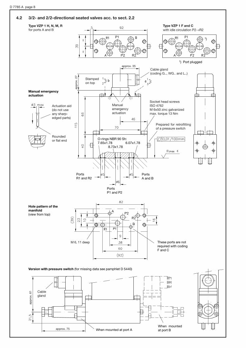
D 7785 A page 8
Manual emergency
actuation
Version with pressure switch (for missing data see pamphlet D 5440)
O-rings NBR 90 Sh:7.65x1.78 6.07x1.78
8.73x1.78
Ports R1 and R2
Ports P1 and P2
Ports A and B
These ports are notrequired with codingF and C
When mountedat port BWhen mounted at port A
1) Port plugged
1)
Hole pattern of the
manifold
(view from top)
Manualemergencyactuation
Actuation aid(do not useany sharp-edged parts)
Cable gland(coding G.., WG.. and L..)
Cablegland
Stampedon top
Roundedor flat end
Socket head screws ISO 4762M 6x50 zinc galvanizedmax. torque 13 Nm
4.2 3/2- and 2/2-directional seated valves acc. to sect. 2.2
Type VZP 1 H, N, M, R
for ports A and BType VZP 1 F and C
with idle circulation P2→R2
M 6, 11 deep
Prepared for retrofittingof a pressure switch
app
rox.
61
approx. 75
app
rox.
27
approx. 35
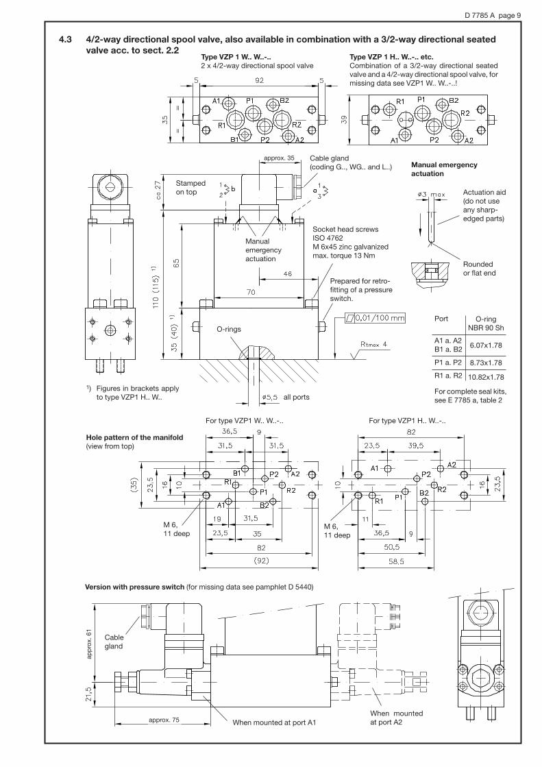
D 7785 A page 9
Manual emergency
actuation
Version with pressure switch (for missing data see pamphlet D 5440)
O-rings
all ports
For type VZP1 W.. W..-.. For type VZP1 H.. W..-..
When mountedat port A2When mounted at port A1
Hole pattern of the manifold
(view from top)
Manualemergencyactuation
Actuation aid(do not useany sharp-edged parts)
Cablegland
Stampedon top
Roundedor flat end
Socket head screws ISO 4762M 6x45 zinc galvanizedmax. torque 13 Nm
4.3 4/2-way directional spool valve, also available in combination with a 3/2-way directional seated
valve acc. to sect. 2.2Type VZP 1 W.. W..-..
2 x 4/2-way directional spool valveType VZP 1 H.. W..-.. etc.
Combination of a 3/2-way directional seatedvalve and a 4/2-way directional spool valve, formissing data see VZP1 W.. W..-..!
1) Figures in brackets applyto type VZP1 H.. W..
M 6, 11 deep
M 6, 11 deep
Port
A1 a. A2B1 a. B2
P1 a. P2
R1 a. R2
For complete seal kits,see E 7785 a, table 2
O-ring NBR 90 Sh
6.07x1.78
8.73x1.78
10.82x1.78
Cable gland(coding G.., WG.. and L..)
Prepared for retro-fitting of a pressureswitch.
approx. 35
approx. 75
app
rox.
61

D 7785 A page 10
Twin solenoid, housing surface zinc galvanized
Terminals for plug, 3 pins + PE, DIN EN 175 301-803
Valve body, housing surface zinc galvanized
Functional valve seat parts hardened and ground
Bearing quality steel, DIN 5401 class I (ISO 3290G5)
Consumer sides A and B prepared for retrofitting of a pressure switch type DG 3.. as standard
Fine screen filter element, protecting the functional valve parts from sporadically washed up coarse contamina-tion (wire mesh 0.25x0.16 DIN 4189 made from stainless wire).Seated valves (sect. 2.1) flow pattern E, D: in ports P, A, and B
flow pattern G, O: in ports A and Bflow pattern P: in ports P and Aflow pattern J: in port A
Seated valves (sect. 2.2) flow pattern H, M, W: in ports P1 and P2
Check valve type ER 12 acc. to D 7325Seated valves (sect. 2.1) flow pattern G, O: in PSeated valves (sect. 2.2) flow pattern N, R, WX: in ports P1 and P2
Orifice (optional) with inflow sided fine screen filter element, protecting the orifice from sporadically washed upcoarser contamination particles (wire mesh 0.25x0.16 DIN 4189 made from stainless wire).
flow pattern E, D, P: in port Pflow pattern H, M, W: in ports P1 and P2
Order coding for a throttle complete with filter element:B 0.8 = 7785 021B 1.0 = 7785 022B 1.2 = 7785 023B 1.4 = 7785 024
When several valves are operating in parallel, the return pressure stop prevents pressure surges out of the com-mon return pipe from entering unoperated, unloaded or easily moving consumers, when there is a connectionA→R1 or B→R2. Thus preventing uncontrolled movements.Only for ball seated directional valves (sect. 2.2), with flow pattern H1, N1, M1, R1: in ports R1 and R2
5. Appendix5.1 Schematic cross sectional views
4/3-way directional seated valve (cone seated valve) 2 x 3/2-way directional seated valves (ball seated valve)
example VZP1 G22-G... example VZP1 H2 M2-G...
1
2
7 78
8
1
2
33
4
4
5
6
6
7
9
10 10
D
C
B
A
@
?
>
=
<
;

D 7785 A page 11
Symbols (see sect. 2.1 and 2.2)
F, C 2/2-way function (directional seated valve, together with an other 3/2-way directional valve)
H, N, M, R 3/2-way function (directional seated valve, together with an other 2/2-, 3/2- or 4/2-way directional valve)
P, J 3/3-way function (directional seated valve)
E, G, D, O 4/3-way function (directional seated valve)
W, WX 4/2-way function (directional spool valve, together with an other 3/2- or 4/2-way directional valve)
6. Type overview
Order examples: VZP1 G 22 - G 24
VZP1 D 45 B1,2 - WG 230
VZP1 H 12 B1,0 M 14 B0,8 - G 12
Nominal voltage (see sect. 2.1, table 5)
G 12, G 24, WG 110, and WG 230
X 12, X 24, X 48, and X 102
L 12, L 24 and L5K24
Additional elements (see sect. 2.1 and 2.2)1 Return pressure stop optional for 3/2-way directional valves
(symbols H, N, M, R)2 Prepared for retrofitting of a pressure switch
(type DG 3. acc. to D 5440)with 2/2-, 3/2-, 4/2- or 3/3-way directional valves (symbols F, C, H, N, M, R, W, WX, P, J)
22 Prepared for retrofitting of two pressure switches (type DG 3. acc. to D 5440)with 4/3-way directional valves (symbols E, G, D, O)
3 ... 7 Pressure switch (DG 3. acc. to D 5440) in the consumer portA (A1) or B (A2, P)with 2/2-, 3/2-, 4/2- or 3/3-way directional valves (symbols F, C, H, N, M, R, W, WX, P, J)
33 ... 77 Two pressure switches (DG 3. acc. to D 5440) in the consumerports A and B with 4/3-way directional valves (symbols E, G, D, O) also available 32, 27 etc.
B.. Orifice insert Ø0.8; Ø1.0; Ø1.2; Ø1.4 mm (symbols E, D, P, H, M, W)
Basic valve type and size
VZP 1

HAWE HYDRAULIK SE
STREITFELDSTR. 25 • 81673 MÜNCHEN
2.1
Clamping modules type SMD 2 and NSMD 2 for actuating hydraulic clamping devices
D 7787Clamping modules (N)SMD 2
April 1998-01
Flow Qmax = 25 lpm
Operation pressure pmax = 120 bar
' One valve for the control of functions, clampingpressure and monitoring of the clamping pressure
' One adjustment element for both clamping pressureand monitoring of the clamping pressure(either manual or electro-proportional)
' The clamping pressure is safely controlled even withlow clamping pressure
' The pressure is controlled directly at the consumerport
' A special protective circuit supervises the switchingposition of the directional valve
' The pressure reduction applies either for both con-sumer ports (A and B) or for (A) only
' Connection hole pattern DIN 24340-A6 with typeNSMD 2
1. General information
This complete control unit is designed as a manifold mounting valve which is suitable for the actuation of hydraulic clamping de-vices, such as draw-in collets (hollow or massive) at CNC-lathes. A solenoid actuated 4/3- or 4/2-way directional valve and a 3-waypressure reducing valve with integrated pressure switch are housed in a common body.
The 3-way pressure reducing valve reduces the existing pressure in gallery P (primary side) down to the clamping pressure (sec-ondary side). The especially shaped spool of the directional valve creates a control passage to the pressure reducing valve accord-ing to the respective switching position. The micro switch integrated into the pressure reducing valve (monitoring of the clampingpressure) triggers a signal at a certain difference to the set pressure. When the setting of the pressure reducing valve is altered, thepressure switch will follow automatically still maintaining this predefined difference. This feature is unique and makes any readjust-ment of the pressure switch unnecessary.
The clamping module was designed in such a way that the pressure switch gives always a clear acknowledgment signal or super-visory signal over the complete adjustment range. This is accomplished by a switch-over of the pressure switch mode independentof the clamping pressure setting. In the lower adjustment range both the clamping pressure and the flow are supervised. This makessure that the (clamping pressure acknowledgment) signal, triggered by the pressure switch, takes place only after the draw-in col-let is in its final position and the clamping pressure is reached. Therefore the clamping module can supervise the complete clamp-ing procedure (start and end), detect any pressure loss due to a defect (e.g. line rupture, pump malfunction). The curves in sect. 4.1 illustrate the relations of the pressure where a signal is triggered, the flow and the clamping pressure
Several flow patterns (4/3- and 4/2-way) are available for this directional valve, see sect. 3.1 and 3.2. The pressure reduction including pressure monitoring can be opted for consumer ports A and B or for port A only. The internal connection of thecontrol gallery and the respective consumer port is provided only shortly before the final position of the spool is achieved. Beforethis the control gallery is connected to the reflow gallery. This makes sure that both, clamping pressure acknowledgment and pres-sure monitoring, take place only if the directional valve has achieved the selected switching position.
Attention: Take into account the safety regulations in section 6!
Selection criteria: ' Flow patternsl (section 3.1)
' Clamping pressure range (section 2 and page 7)
' Type of pressure adjustment (section 3.2)
' Possibilities for influencing the consumer velocity
(avail. orifices, see sect. 2 and additional functions, see sect. 3.3)
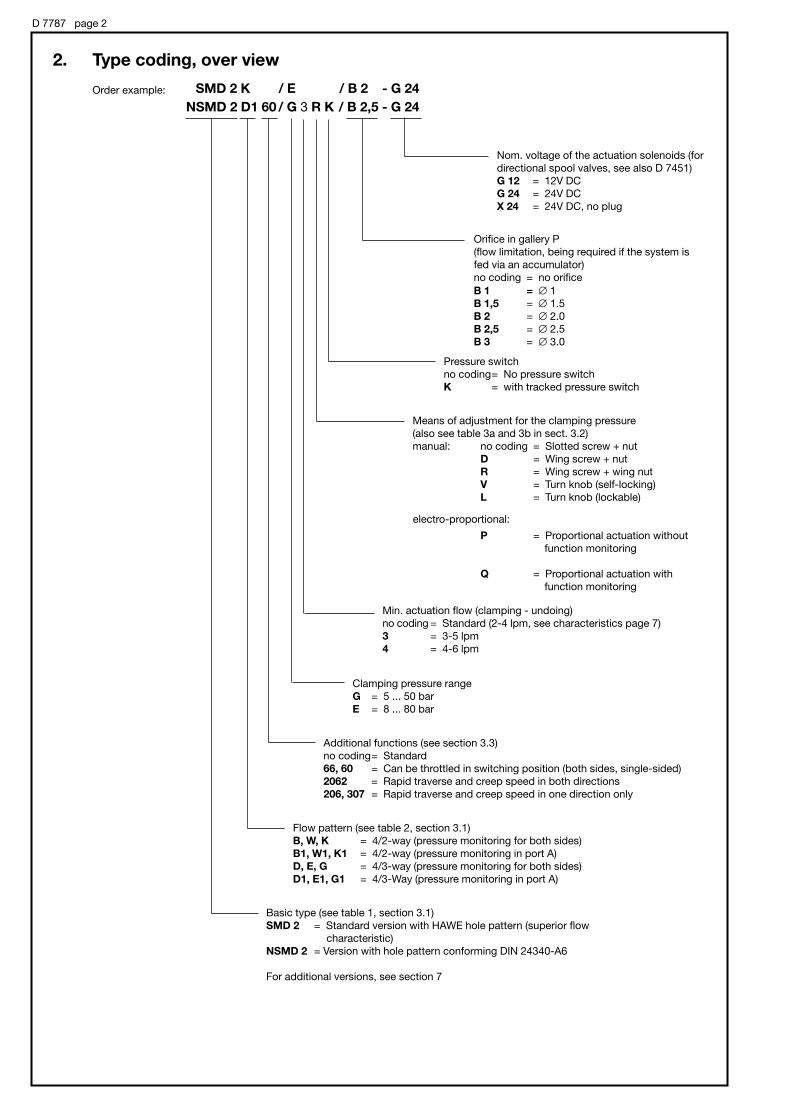
D 7787 page 2
2. Type coding, over view
Order example: SMD 2 K / E / B 2 - G 24
NSMD 2 D1 60 / G 3 R K / B 2,5 - G 24
Nom. voltage of the actuation solenoids (for
directional spool valves, see also D 7451)
G 12 = 12V DC
G 24 = 24V DC
X 24 = 24V DC, no plug
Means of adjustment for the clamping pressure
(also see table 3a and 3b in sect. 3.2)
manual: no coding = Slotted screw + nut
D = Wing screw + nut
R = Wing screw + wing nut
V = Turn knob (self-locking)
L = Turn knob (lockable)
P = Proportional actuation without
function monitoring
Q = Proportional actuation with
function monitoring
electro-proportional:
Basic type (see table 1, section 3.1)
SMD 2 = Standard version with HAWE hole pattern (superior flow
characteristic)
NSMD 2 = Version with hole pattern conforming DIN 24340-A6
For additional versions, see section 7
Orifice in gallery P
(flow limitation, being required if the system is
fed via an accumulator)
no coding = no orifice
B 1 = # 1
B 1,5 = # 1.5
B 2 = # 2.0
B 2,5 = # 2.5
B 3 = # 3.0
Pressure switch
no coding= No pressure switch
K = with tracked pressure switch
Clamping pressure range
G = 5 ... 50 bar
E = 8 ... 80 bar
Min. actuation flow (clamping - undoing)
no coding = Standard (2-4 lpm, see characteristics page 7)
3 = 3-5 lpm
4 = 4-6 lpm
Flow pattern (see table 2, section 3.1)
B, W, K = 4/2-way (pressure monitoring for both sides)
B1, W1, K1 = 4/2-way (pressure monitoring in port A)
D, E, G = 4/3-way (pressure monitoring for both sides)
D1, E1, G1 = 4/3-Way (pressure monitoring in port A)
Additional functions (see section 3.3)
no coding= Standard
66, 60 = Can be throttled in switching position (both sides, single-sided)
2062 = Rapid traverse and creep speed in both directions
206, 307 = Rapid traverse and creep speed in one direction only

D 7787 page 3
3. Available versions, main data3.1 Selection tables
Order examples: SMD 2 G / E - G 24
NSMD 2 K K / B 2,5/ G R - G 24
Table 1: Basic type, connection hole pattern
Coding
(type and
size)
Connection hole
pattern (manifold
mounting) 1)
Flow
Qmax
Operation
pressure
pmax
SMD 2
NSMD 2
standard with HAWE
hole pattern (superior
flow characteristic)
hole pattern conf.
DIN 24340-A
25 l/min 120 bar
1) For nom. size,
see dimen-
sional draw-
ings in sect. 5
Table 2: Flow pattern symbols
Suited for type Coding and flow pattern
4/3-way 4/2-way
SMD 2
NSMD 2
Version without pressure switch
The symbols below must be completed with the flow pattern symbols above. Illustrations below are with pressure switch (coding K).
Version with throttle (coding B... )
and pressure switch (coding K)
D
E
G
D
E
G
D1
E1
G1
D1
E1
G1
B
B1
B
B1
W
W1
W
W1
K
K1
K
K1
4/3-way:
Coding D, E, G
and D1, E1, G1
4/2-way:
Coding B and B1 Coding W and W1 Coding K and K1
Orifice in gallery P
(For avail. diameter, see section 2)
Pressure switch
no coding = without
K = with tracked pressure switch

D 7787 page 4
3.2 Actuations for adjustment of the clamping pressure
Order example NSMD 2 K / G K / B 2,5 - G 24R
NSMD 2 K / G K / B 2,5 - G 24P
Table 3a: Manually adjustable adjustment device
Table 3b: Electro-proportional actuation
Coding
no coding
D
R
V
L
P
Q
Description (for illustrations, see unit dimensions sect. 5)
Slotted screw + nut
Wing screw + nut
Wing screw + wing nut
Turn knob (self-locking)
Turn knob (lockable)
The adjustment knob can only be manipulated, if the key is plugged in.
The turn knob is disengaged when the key is removed, disabling
(arbitrary) alternation of the pressure setting.
electro-proportional adjustment
electro-proportional adjustment
with additional function supervisioning
Coding, description, detailed flow pattern symbol
P Without function monitoring
Functional description
With function monitoringQ
The clamping module type (N) SMD 2 can be adjusted
manually and electro-proportional by means of a directly
mounted ancillary block. Thus enabling electro-proportional control
of the pressure at ports A or B, within the respective pressure range.
The system can therefore be operated either from the control panel
of the machine or directly from an external control
system such as SPS, CNC, PC. An additional safety function main-
taines the pressure setting even if the power supply fails.
The electro-proportional ancillary block consists a piloting pressure
reducing valve ; , a check valve < , a control piston = applying
force on the spring > of the 2-way pressure reducing ? valve in theclamping module.
The piloting pressure reducing valve generates a proportional
control pressure which is lower than the one apparent in the pres-
sure gallery. This control pressure acts on the piston, pre-loading a
spring which loads the control spool of the 2-way pressure reduc-
ing valve.
Safety function:
The additional 3/2-way function of the piloting pressure reducing
valve has to open up the check valve, enabling free flow from the
pressure reducing valve to the control piston, before the proportional
pressure regulation actually takes place. In case of a power
failure (e.g. failure of the electronics or cable disruption) the piston
of the piloting pressure reducing valve will jump back in its initial
position, the check valve will close and lock in the pressure appar-
ent at the control piston.
The clamping pressure will drop only approx. 4% if this should hap-
pen.
Function monitoring:
An additional pressure switch in the control line to the check valve
supervises the function of the complete control electronics and the
piloting pressure reducing valve.
Electrical control:
A proportional amplifier is necessary for the control e.g. type EV1M2
(D 7831/1) or EV1G1 (D 7837).
Flow pattern symbols
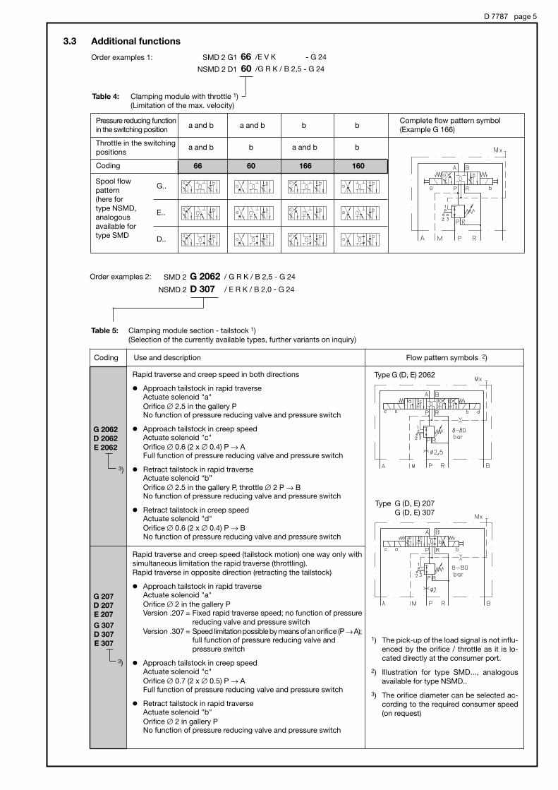
D 7787 page 5
Order examples 1: SMD 2 G1 /E V K - G 2466
Order examples 2:
NSMD 2 / E R K / B 2,0 - G 24D 307
SMD 2 / G R K / B 2,5 - G 24G 2062
3.3 Additional functions
Table 4: Clamping module with throttle 1)
(Limitation of the max. velocity)
Table 5: Clamping module section - tailstock 1)
(Selection of the currently available types, further variants on inquiry)
Pressure reducing function
in the switching position
Throttle in the switching
positions
Coding 66 60 166 160
Spool flow
pattern
(here for
type NSMD,
analogous
available for
type SMD
G..
E..
D..
a and b a and b b b
a and b b a and b b
Complete flow pattern symbol
(Example G 166)
Coding Use and description Flow pattern symbols 2)
G 2062
D 2062
E 2062
G 307
D 307
E 307
G 207
D 207
E 207
Rapid traverse and creep speed in both directions
' Approach tailstock in rapid traverseActuate solenoid "a"
Orifice # 2.5 in the gallery PNo function of pressure reducing valve and pressure switch
' Approach tailstock in creep speedActuate solenoid "c"
Orifice # 0.6 (2 x # 0.4) P → AFull function of pressure reducing valve and pressure switch
' Retract tailstock in rapid traverseActuate solenoid “b”
Orifice # 2.5 in the gallery P, throttle # 2 P → BNo function of pressure reducing valve and pressure switch
' Retract tailstock in creep speedActuate solenoid "d"
Orifice # 0.6 (2 x # 0.4) P → BNo function of pressure reducing valve and pressure switch
Rapid traverse and creep speed (tailstock motion) one way only with
simultaneous limitation the rapid traverse (throttling).
Rapid traverse in opposite direction (retracting the tailstock)
' Approach tailstock in rapid traverseActuate solenoid "a"
Orifice # 2 in the gallery PVersion .207 = Fixed rapid traverse speed; no function of pressure
reducing valve and pressure switch
Version .307 = Speed limitation possible by means of an orifice (P →A);full function of pressure reducing valve and
pressure switch
' Approach tailstock in creep speedActuate solenoid "c"
Orifice # 0.7 (2 x # 0.5) P → AFull function of pressure reducing valve and pressure switch
' Retract tailstock in rapid traverseActuate solenoid "b"
Orifice # 2 in gallery PNo function of pressure reducing valve and pressure switch
NSMD 2 D1 /G R K / B 2,5 - G 2460
3)
3)
1) The pick-up of the load signal is not influ-
enced by the orifice / throttle as it is lo-
cated directly at the consumer port.
2) Illustration for type SMD..., analogous
available for type NSMD..
3) The orifice diameter can be selected ac-
cording to the required consumer speed
(on request)
Type G (D, E) 2062
Type G (D, E) 207
G (D, E) 307

D 7787 page 6
4. Further parameters4.1 General and hydraulic
Type coding SMD 2 or NSMD 2 see section 3
Design Clamping module (combination of directional spool valve, pressure reducing valve a. tracked
pressure switch)
Installed position any
Ports P = pressure inlet
R = reflow
A, B = consumers
M = for pressure gauge (on the mounting area)
Mx = for pressure gauge (top side of the valve)
Port size P, R, A, B and M = NW see hole patterns section 5
Mx = G 1/8
Surface termination All surfaces corrosion inhibiting gas nitrided
Mass (weight) approx. kg Basic type
SMD 2
NSMD 2
Spool coding
D.. to K1..
B(1) and W(1)
manual
2.7
2.2
P and Q
3.8
3.3
Actuation
electro-proportional
Version ..2062 + 1.1 kg
Version ..207, ..307 + 0.6 kg
Operation pressure P = max. 120 bar
A, B, M, Mx = acc. to the pressure range
R = 20 bar
Pressure fluid Hydraulic fluid (DIN 51524 table 1 to 3); ISO VG 10 to 68 (DIN 51519)
Viscosity range: min. 4; max. 1500 mm2/s
Optimal operation range: 10...500 mm2/s
Also suitable are biologically degradable pressure fluids of the type HEPG (Polyalkylenglycol) and
HEES (synth. Ester) at operation temperatures up to +70°C.
Temperatures Ambient: -40...+60°C
Oil: -25...+80°C, (Note: Viscosity range!)
Start temperature down to -40°C are allowable (Note: Viscosity range!), as long as the operation
temperature during consequent running is at least 20K (Kelvin) higher.
Biodegradable pressure fluids: Pay attention to manufacturer's information. With regard to the
compatibility with sealing materials do not exceed +70°C.
/p-Q-curve
Oil viscosity during measurement approx. 60 mm2/s
SMD 2 NSMD 2
Flow Q (l/min)Flow Q (l/min)
Back p
ressure
|
p (b
ar)
Back p
ressure
|p
(b
ar)

D 7787 page 7
Clamping pressure / trigger pressure - curve
(Pressure ranges E and G)
Clamping pressure / trigger flow - curve
(Pressure ranges E and G) - standard version
Trig
ger
pre
ssure
(b
ar)
1)
Cla
mp
ing
pre
ssure
(b
ar)
Cla
mp
ing
pre
ssure
(b
ar)
Trig
ger
flo
w (l/m
in) 1
)
Clamping pressure (bar) Clamping pressure (bar)
Oil viscosity during measurement approx. 60 mm2/s
Example:
A clamping pressure of 11 bar will result in a trigger pressure of $ 11 bar during clamping whereas the resulting trigger pressure will
be % 9.2 bar during undoing. The trigger flow is % 2 lpm during clamping and $ 4 lpm during undoing. This means that the contactswitch will trigger a signal, if either if the work piece is clamped and the clamping pressure is achieved (no more cylinder movement)
or the flow drops below 2 lpm. A signal will be triggered during undoing if a flow of 4 lpm is exceeded or the clamping pressure
drops below 9.2 bar.
Pressure range of G = 5 ... 50 bar
Pressure
range
G
E
Pressure range of E = 8 ... 80 bar
Flow Q (l/min)Flow Q (l/min)
clam
ping
undoi
ng
clamping
undoing
1) System pressure when adjusting the
pressure range G ppu = 70 bar
pressure range E ppu = 100 bar
The trigger flow changes insignificantly in dependence of the
system pressure.
Trigger pressure is the pressure at which the pressure switch triggers a signal at a definite clamping pressure.
Trigger flow is the flow which must flow through the valve (at a definite clamping pressure) enabling the pressure switch to trigger
a signal.
Attention: The maximum leakage must be smaller than the flow necessary for "undoing".
It is possible to recalibrate the clamping pressure / trigger flow - curve. For setting (by HAWE) and order coding, see
sect. 2 “min. trigger flow ”).

D 7787 page 8
4.2 Electrical data
electro-proportional
control:
Solenoid
Nom. voltage UN
Coil resistance R20 ()
Current, cold I20 (A)
Nom. current IN (A)
Power, cold P20 (W)
Nominal power PN (W)
Relative duty cycle
Electrical connection
Protection class DIN 40050
Nec. dither frequency
Pressure switch
Pressure setting (bar)
Pressure resistance (bar)
Switch
switching performance (VA)
max. current (V)
Protection class
Switching frequency
Mechanical service life
Diaphragm material
12V DC
6
2.0
1.26
24
9.5
24V DC
24
1.0
0.63
24
9.5
Co. Suco type: 0166 41503 1 059
30
up to 300
NO-contact
100
42
IP 65; pins IP 00
200 / min
106 cycles
NBR
100% ED
DIN 43650 B (industrial standard)
IP 65
100 ... 150 Hz
conforming VDE 0580
Control via electronic
intensifier
e.g. type: EV1G1-12/24 (D 7837)
type: EV1M1-12/24 (D 7831/1)
Min. current: The solenoid current should be set via the Imin - poten-
tiometer in such a way, that the requested min. pressure
pmin % 5 bar (system pressure 5 ... 50 bar) or pmin % 10 bar
(system pressure 10 ... 80 bar) is achieved.
Max. current: Imax must not exceed the nom. current IN of the solenoid.
Adjustment in-
structions for min.
and max. current:
Function
monitoring:
Consumer pressure /
solenoid current - curve
Directional spool
valve and pres-
sure switch:
Solenoid
Nom. voltage UN
Nominal power PN (W)
Relative duty cycle
Device connector
Protection class DIN 40050
Pressure switch
Mechanical service life
Resistor load
Inductive load
Circuitry of the pressure switch
12V DC
24.4
24V DC
24.4
110V AC
24.4
230V AC
24.4
100% ED (duty cycle) at ambient temperature < 40°C
DIN 43650 A Pg9
Solenoid IP 65, plug IP 65 (plug fitted)
Co. Burgess type F1T8-ZBK
107 cycles
up to 30V DC 5A up to 15V DC 10A
up to 30V DC 3A up to 15V DC 10A
Idle position 1-2
Switching position 1-3
conforming VDE 0580
f = 150 Hz
f = 100 Hz
Co
nsum
er
pre
ssure
p A
, B
(bar)
Current I (A)
24V DC
12V DC
f & dither frequency
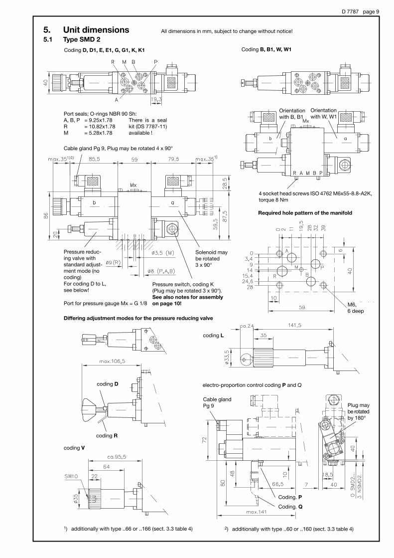
D 7787 page 9
5. Unit dimensions5.1 Type SMD 2
All dimensions in mm, subject to change without notice!
Coding D, D1, E, E1, G, G1, K, K1
Orientation
with B, B1
Orientation
with W, W1
Port for pressure gauge Mx = G 1/8
Solenoid may
be rotated
3 x 90°
Pressure switch, coding K
(Plug may be rotated 3 x 90°).
See also notes for assembly
on page 10!
Pressure reduc-
ing valve with
standard adjust-
ment mode (no
coding)
For coding D to L,
see below!
Port seals; O-rings NBR 90 Sh:
A, B, P = 9.25x1.78
R = 10.82x1.78
M = 5.28x1.78
There is a seal
kit (DS 7787-11)
available !
Differing adjustment modes for the pressure reducing valve
coding D
coding R
coding V
coding L
electro-proportion control coding P and Q
Coding. P
Coding. Q
Required hole pattern of the manifold
Cable gland Pg 9, Plug may be rotated 4 x 90°
Cable gland
Pg 9
M6,
6 deep
Coding B, B1, W, W1
Plug may
be rotated
by 180°
1) additionally with type ..66 or ..166 (sect. 3.3 table 4) 2) additionally with type ..60 or ..160 (sect. 3.3 table 4)
4 socket head screws ISO 4762 M6x55-8.8-A2K,
torque 8 Nm

D 7787 page 10D 7787
Coding D, D1, E, E1, G, G1, K, K1 Coding B, B1
Coding W, W1
Port for pressure gauge Mx = G 1/8
Solenoid may be
rotated 3 x 90°
Pressure switch, coding K
(Plug may be rotated 3 x 90°).
Port seals; O-rings NBR 90 Sh:
P, R, A, B = 9.25x1.78
M = 2.90x1.78
There is a seal kit (DS 7787-12) available !
Required hole pattern of the manifold
5.2 Type NSMD 2
Cable gland Pg 9, Plug may be rotated 4 x 90°
Pressure reducing valve,
here with adjustment
mode D. For other ad-
justment modes, see
type SMD 2 on page 9.
M5, 6 deep
Installation of the pressure switch
The plug is provided with a rubber seal, tightening
the screw (thread M3) with a torque of 25...30 Nm
ensures proper sealing.
Procedure if no torque wrench is handy: Screw in the
screw until the plug contacts the surface and turn
the screw 1.5 turns more.
Attention: Overtightening of the screw may cause
mistriggering of the contact switch!
4 socket head screws
ISO 4762 M5x95-12.9 galvanized
torque 6 Nm
1) additionally with type ..66 or ..166 (sect. 3.3 table 4)
2) additionally with type ..60 or ..160 (sect. 3.3 table 4)

5.3 Clamping module sections for the tailstock
D 7787 page 11
Type SMD 2 G2062 / ...
Type SMD 2 .207 / ...
SMD 2 .307 / ...
For missing dimensions see sect. 5.1 !
Velocity limitation for
“ Approach tailstock in rapid traverse ”
(throttle P → A),no actuation with version .207/..
For missing dimensions see sect. 5.1 !
See also "Installation of
the pressure switch" on
page 10!
See also "Installation of
the pressure switch" on
page 10!
D 7787 page 12
6. Notes for the safety
The following notes for the safety should be observed when doing the layout for the machinery or the control system as well as the
later use of it. They should be added to the corresponding documentation also, if necessary.
' Operator protection classification:Category 2 (conforming DIN EN 954-1) under the prerequisite of a cyclical supervision (testing) of the micro switch installed in
the pressure switch. This can take place e.g. at every operation of the directional valve.
The following notes are basis for this statement:
The micro switch incorporated in the pressure switch is used as a "switch for the operator protection". This usually takes a re-
lays lift off system (according to EN 60947-5-1: 1991, sect. 3)
The utilized micro switch does not fulfill these requirements (like a switch conforming DIN VDE 0630).
Nevertheless the " Berufsgenossenschaftlichen Instituts für Arbeitssicherheit Fachbereich 5, Maschinenschutz/Steuerung-
stechnik" (official German approval institute for operator safety) specifies in a letter dated 25.09.97, that a comparable safety can
be achieved with such a "less reliable" device (micro switch) by means of cyclical supervision.
' Function safety of the pressure switch:Correct grounding of the valve is required (operator safety)
(The micro switch won't trigger a signal no matter if it fails or if it detects "No clamping pressure")
' Travel dependent stroke control for the collet:A travel dependent stroke control (e.g. by means of a limit switch) is still required for the collet as any mechanical blocking would
let the clamping pressure rise and the pressure switch would trigger an acknowledge signal. Such a blocking may be caused by
e.g. swarf or incorrect positioning of the work piece in the collet
' Control of the release movement of the collet:The clamping modules are usually equipped with pressure switches for consumer ports A and B and the flow pattern symbols
B1, W1 etc. are the only exception, where the pressure is monitored only on one side. Therefore the following must be observed:
Internal clamping: The control for the machine tool must cope with the situation that the "clamping pressure" will rise although
the cylinder for the collet reaches its mechanical stop during a release sequence. Therefore this acknowledged signal from the
pressure switch must not be sensed by the control system under this condition (misinterpretation).
External clamping: Under this condition the cylinder would have the same direction of movement but this time the acknowledged
signal from the pressure switch has to be sensed by the control system as it is a real clamping movement.
' Installation of the pressure switchThe plug is provided with a rubber seal, tightening the screw (thread M3) with a torque of 25...30 Nm ensures proper sealing.
Procedure if no torque wrench is handy: Screw in the screw until the plug contacts the surface and turn the screw 1.5 turns more.
Attention: Overtightening of the screw may cause mistriggering of the contact switch!
The valves are supplied with a tag ex-works which gives the same information and this shouldn't be removed.

D 7787 page 13
7. Circuit examples and possible combinations
Example 1: HK43LDT/1M - Z Z2,7/9,8 - AN21F2 - D45 - F50 -BA2 - NSMD2K/GRK/0 - 1 - G24
Compact hydraulic power pack
with connection block
type HK43LDT/1M - Z Z2,7/9,8 -
- AN21F2 - D45 - F50
Clamping module with sub-plate
type NSMD2K/GRK/0 - G24
Travel stop
monitoring
Clamping device
Stand-still monitoring
Releasable double
check valve
Compact hydraulic power
pack (D 7600-4)
with connection blocks
(Sk 7881 a. Sk 7788)
Clamping module

D 7787 page 14
Example 2: HK43L/1M - Z9,8 - AL21F2 - F60/70 - 2 -BA2
Compact hydraulic power
pack with connection block
type HK43L/1M - Z9,8 -
- AL21F2 - F60/70 - 2
- SMD2K/GRK/B2,5/0 -
- SMD2 D307/GRK/B2/0 - 11 - G24
Clamping module with sub-plate
type SMD2 D307/GRK/B2/0 - 11 - G24Clamping module with sub-plate
type SMD2K/GRK/B2,5/0
Tailstock sleeve
Travel stop monitoring Clamping device
Stand-still monitoring
Releasable check
valve
Releasable double
check valve
Compact hydraulic power pack (D 7600-4)
with connection blocks (D 6905 AF/1 and Sk 7788) Clamping modules
End plate
coding 11

D 7787 page 15
Example 3: HKF438LD/1M - Z11,3 - AL21D D10 - F70/80 - 2 -BA2
Compact hydraulic power pack with connection blocks
type HKF438LD/1M - Z11,3 - AL21D D10 - F70/80 - 2
- BA2 - SMD2K/E/B2,5/0
- SMD2K/E/B2,5/0 -- BVZP1F - W2B1,2 W2B1,2/0 - CZ5/20/5 - WN1H/0/22 - 1 - G24
Valve bank
type BVZP1F - W2B1,2 W2B1,2 /0 - CZ5/20/5 - WN1H/0/22 - 1 - G24
Valve bank
BA2 A5 -
- SMD2K/GRK/B3/0
- SMD2D207/GRK/B2/0 - 1 - G24
Compact hydraulic power pack
(D 7600-4) with connection blocks
(Sk 7881 and Sk 7788)Clamping module and valve
bank BVZP1 (D 7785 B)

Directional seated valves type VP 1
zero leakage, intended for general hydraulic applications and grease lubing systems
D 7915Directional seated valves
type VP 1
May 2009-01
HAWE HYDRAULIK SESTREITFELDSTR. 25 • 81673 MÜNCHEN
2.2
© 1999 by HAWE Hydraulik
Flow Qmax = 15 lpm
Operation pressure pmax = 400 bar
1. General informationThe valves type VP 1 are zero leakage, seated cone valves available as 2/2-, 3/2- and 4/2-way directional valves.The internal pressure balance enables an arbitrary flow direction and maximum pressure for all ports.The essential internal parts operate maintenance-free in the medium and are hardened and ground.The actuation is separated from the hydraulic fluid, therefore any interaction between control elements and the pressure fluid is prevented, i.e. a temperature dependant fluid viscosity won't harm the movement of the control elements, side effect is that gumming due to excessive fluid temperature is prevented.Gumming or sticking caused by higher temperature cannot occur.The individual manifold mounting valves (2/2- and 3/2-way functions) feature the same connection hole pattern and actuation as thedirectional valves sizes 1 acc. to D 7300, i.e. all connection blocks and actuations listed there may be utilized.Main field of application for these valves are lube systems especially when lubricants with high viscosity e.g. oil or grease are used.Any other fluid with similar viscosity may be suited as well, as long as it is compatible with the seal material.
Note: Observe restriction, when outside use is intended. The valve has to be protected from intruding moisture.
Individual valve Individual valve with connection
block for pipe connection

D 7915 page 2
2. Available versions, main data
Order examples: VP 1 - R - D
VP 1 - W - 3/4 - G 24
Table 1: Basic type and size
Table 2: Flow pattern symbols
Table 4: Optional connection connection block for direct pipe mounting
Table 3: Actuation modes
VP 1 Flow Qmax = 15 lpm
Oper. pressure pmax = 400 bar
R S Z G W 1)
Cod-ing
1/4
3/8
1/2
3/4
Ports A, B, C, P, R (ISO 228/1)(BSPP)
1/4
3/8
1/2
3/4
Suited forflow patternsymbol
R, S, Z, G
R, S, Z
W
Flow pattern symbols
R, S Z G W
Note: Valves with flow pattern R, S and Z can be also combined withconnections blocks intended for directional seated valves size 1acc. to D 7300.
1) Only available with solenoid actuation
For main data also
see section 2.2.1
UN = 12V DC
UN = 24V DC
UN = 110V AC, 50/60 Hz (98V DC) 2)
UN = 230V AC, 50/60 Hz (205V DC) 2)
Symbols
Solenoid
Hydraulic Pneumatic
pin
Manual
roller
Mechanical
Control pressure: pSt min = 12 bar
pSt max = 700 bar
Control pressure: pSt min = 4 bar
pSt max = 15 bar
Actuation force: 25 ... 28 N
Actuation force: 51 ... 57 N
Actuation force: 25 ... 28 N
Actuation torque: 63 Ncm
For othervoltage, seesect. 2.2.1
Hydraulic
Pneumatic
Mechanical(roller)
Mechanical(pin)
Manual(lever)
Manual(turn knob)
A 12
A 24
---
---
N 12
N 24
---
---
UN = 12V DC
UN = 24V DC
UN = 110V AC, 50/60 Hz (98V DC) 2)
UN = 230V AC, 50/60 Hz (205V DC) 2)
GM 12
GM 24
WGM 110 1)
WGM 230 1)
UN = 24V DCG 24 EX
XM 12
XM 24
XM 98
XM 205
LM 12
LM 24
---
---
Coding
Central plug(serie)
Central plugwith adapterwithout std.plug
Central plugwith adapterwith std.plug
coil with std. plug
Explosion proof
coil without std. plug
coil with std. plug and LED
2) DC-solenoid (98V DC, 205V DC) with bridgerectifier in the plug
H
P
K
T
F
D
lever turn knob
G 12
G 24
WG 110 2)
WG 230 2)
Solenoidstandard
Solenoidwith replaceablecoil
UN = 24V DCG 24 EX
H
P
K
T
F
D

D 7915 page 3
2.1 Further parameters
General and hydraulic parameters
Bac
kp
ress
ure|
p(b
ar)
Bac
kp
ress
ure|
p(b
ar)
Bac
kp
ress
ure|
p(b
ar)
Bac
kp
ress
ure|
p(b
ar)
Flow Q (lpm)
Coding R and S
Coding G Coding W
Coding Z
Flow Q (lpm)
Flow Q (lpm)Flow Q (lpm)
Fluid viscosity during testsapprox.. 60 mm2/s
Nomenclature 2/2-, 3/2- and 4/2-way directional valve
Design Seated cone valve
Mounting and Manifold mounting, optional via connection block, see dimensional drawings at sect. 3.1 and3.3
Installed position Any; Best Vertically with actuation upwards
Flow direction Any, conf. flow pattern symbol in table 2
Over lapping negative (transverse of one into the other switching position is gradual and only completed whenthe final position is achieved). All passages are interconnected during the switching operation(3/2-way directional valves).
Permissible operation pressure pmax = 400 bar, All ports are pressure resistant up to pmax
Static over load capacity approx. 2 x pmax (applies to valves in idle position)
Permissible flow Qmax = 15 lpm; Observe the area ratio with double acting consumers (differential cylinders) as
the reflow might be higher than the inflow.
Pressure fluid Hydraulic oil conf. DIN 51524 part 1 to 3: ISO VG 10 to 68 conf. DIN 51519Viscosity limits: min. approx. 4, max. approx. 800 mm2/sOptimal operation: approx. 10 ... 200 mm2/sAlso suitable for biological degradable pressure fluids types HEPG (Polyalkylenglycol) andHEES (Synth. Ester) at service temperatures up to approx. +70 °CGrease, based on mineral or synthetic oils, with NLGI-classification 000 ... 2 acc. to DIN 51818up to operation temperature of approx. +70°C.
Temperature range Ambient: approx. -40 ... +80 C; Fluid: -25 ... +80°C, Note the viscosity rangeRestriction for version with ex-proof solenoid:
Ambient: -35 ... +40°C; Fluid: max. 70°CPermissible temperature during start: -40°C (observe start-viscosity!), as long as the servicetemperature is at least 20K higher for the following operationBiological degradable pressure fluids: Observe manufacturer's specifications. Considering thecompatibility with seal material not over +70 °C.Attention: Observe the restrictions regarding the perm. duty cycles of the solenoids in
sect. 2.2.1 !
|p-Q curves (guideline)
Basic valve complete with actuation:
Actuation mode
R, S, Z 0.7 0.5 0.4 0.4 0.4 0.4 0.4
G 1.0 0.8 0.7 0.7 0.7 0.7 0.7
W 1.0 --- --- --- --- --- ---
Mass (weight) approx. kg
Flowpatternsymbols
Connection block(without valve):
Coding 1/4 = 0.5 3/8 = 0.51/2 = 1.03/4 = 1.2
Sole-noid
Hy-draulic
Pneu-matic
Mechanical(roller) (pin)
Manual(lever) (turn
knob)

D 7915 page 4
2.2 Actuation modes2.2.1 Solenoid actuation (standard)
All solenoids are manufactured and tested conforming DIN VDE 0580.
The given device sockets are automati-cally contained in the valve coding. For other plugs e.g. with clamp diode,economy circuits or LED's, see D 7163.
Curves in the margin apply only to nonneighboring valves!Loovers should be provided when thesevalves are installed in control cabinets!General rule for valve banks and ambienttemperature above 40°C: It is advisable tolocate at least one unactuated valve be-tween valves actuated simultaneously orfor longer periods. Otherwise neighboringvalves would hinder heat dissipation andheat each other up.
1) Only with adaptor, see sect. 2,table 2.
Relative duty cycle
Plugs and circuitry DC-voltage AC-voltage
G 24A 24N 24L 2424V DC
20
0.83
G 12A 12N 12L 1212V DC
20
1.7
Coding
Nom. voltage
Nominal power
Current
GM 12XM 12LM 12
12V DC
26.2
2.2
GM 24XM 24LM 24
24V DC
26
1.1
WGM 110 1)------
110V AC(50/60 Hz)
20
0.2
WGM 230 1)------
230V AC(50/60 Hz)
20
0.1
G 24 EX------
24V DC
23
0.9
Switching time (reference value) On: approx. 100 ms, Off: 50 ms (G..) and 125 ms (WG..)
Switching/hour approx. 2000, approximately evenly distributed
Protection class IP 54 acc. to IEC 60529 (plug properly mounted)IP 65 acc. to IEC 60529 (plug properly mounted)IP 67 acc. to IEC 60529 with explosion-proof solenoid
G.., A.., N.., L..:GM.., XM.., LM..:G..EX:
Insulation material class F
Contact temperature approx. 98°C, with ambient temperature 20°C
Switch-off energy 0.24 Ws (max. guideline figure + approx. 10% acc. to measurements at UN and 20°C)
Relative duty cycle 100% ED (stamping on the solenoid), but observe the max. duty cycle !
Relative duty cycle duringoperation(100% ED stamping on thesolenoid)
Relative duty cycle %ED-5 min Continuous operation
Am
bie
nt
tem
per
atu
re
U(°
C)
Coding G... Coding WG..
Terminal atthe solenoid
Hirschmann plug MSD 1(G..)
Adaptor + plug AMSD 1-MSD 3 + MSD 4-209 P10
Note: The electric data for G and WG solenoids are only guideline and may very slightly depend onmanufacture.
Electrical data for explosion-proof solenoids
ATEX-Certificate of conformity TÜV-A-03 ATEX 0017 XCoding II 2 G Ex d IIB + H2 T4
II 2 D Ex mbD 21 T135°C Oper. duration 100% EDDuty cycle IP 67 (IEC 60529)Nom. voltage UN 24 V DC
Power PN 23 W
Restrictions for use:
Ambient temperature -35 ... +40°Cmax. fluid temperature +70°Cel. protection against overload(conf. IEC 60127) IF < 1.6-A-T
Surface coating Housing galvanically zinc coatedCoil and connection cavity are moulded
Electrical connection 3x0.5 mm2
Cable length 3 m, Option 10 m (cable ÖLFLEX-440P ® Co. LAPP, D-70565 Stuttgart)
Attention : Protect the complete valve against direct sun light.Observe the operation manuals B 03/2004 and B ATEX!Electrical lay-out and testing conforming EN 60079, VDE 0170-1, VDE 0170-5
Note:
Only 40 % ED are permissible ifthe valves are neighboring, it isadditionally recommended thatneighboring valves are not actu-ated simultaneously.
)ED(%100T
tt einr ⋅=
PE 1 2 Housing
UN
PN (W)
IN (A)
T (operation cycle period)
t on
WG 230 ------
230V AC
30.2
0.1
WG 110------
110V DC
28.6
0.2
Time
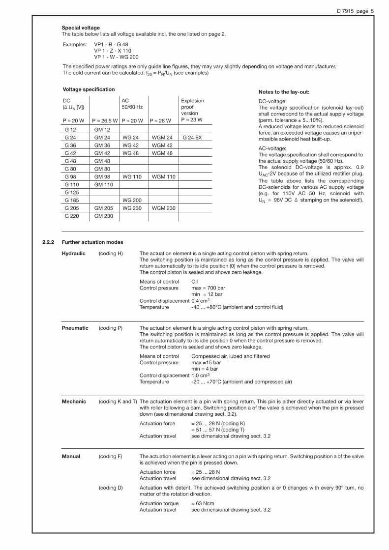
D 7915 page 5
Special voltage
The table below lists all voltage available incl. the one listed on page 2.
Notes to the lay-out:
DC-voltage:The voltage specification (solenoid lay-out)shall correspond to the actual supply voltage(perm. tolerance ± 5...10%).A reduced voltage leads to reduced solenoidforce, an exceeded voltage causes an unper-missible solenoid heat built-up.
AC-voltage:The voltage specification shall correspond tothe actual supply voltage (50/60 Hz).The solenoid DC-voltage is approx. 0.9 UAC-2V because of the utilized rectifier plug.
The table above lists the corresponding DC-solenoids for various AC supply voltage(e.g. for 110V AC 50 Hz, solenoid with UN = 98V DC & stamping on the solenoid!).
Examples: VP1 - R - G 48VP 1 - Z - X 110VP 1 - W - WG 200
The specified power ratings are only guide line figures, they may vary slightly depending on voltage and manufacturer. The cold current can be calculated: I20 = PN/UN (see examples)
G 12
G 24
G 36
G 42
G 48
G 80
G 98
G 110
G 125
G 185
G 205
G 220
GM 12
GM 24
GM 36
GM 42
GM 48
GM 80
GM 98
GM 110
GM 205
GM 230
WG 24
WG 42
WG 48
WG 110
WG 200
WG 230
WGM 24
WGM 42
WGM 48
WGM 110
WGM 230
G 24 EX
P , 26,5 W
DC (& UN [V])
P , 20 W
Voltage specification
P , 28 W
AC 50/60 Hz
P , 20 W
ExplosionproofversionP , 23 W
2.2.2 Further actuation modes
Hydraulic (coding H) The actuation element is a single acting control piston with spring return.The switching position is maintained as long as the control pressure is applied. The valve will return automatically to its idle position (0) when the control pressure is removed.The control piston is sealed and shows zero leakage.
Means of control OilControl pressure max = 700 bar
min = 12 barControl displacement 0.4 cm3
Temperature -40 ... +80°C (ambient and control fluid)
Pneumatic (coding P) The actuation element is a single acting control piston with spring return.The switching position is maintained as long as the control pressure is applied. The valve will return automatically to its idle position 0 when the control pressure is removed.The control piston is sealed and shows zero leakage.
Means of control Compessed air, lubed and filteredControl pressure max =15 bar
min = 4 barControl displacement 1.0 cm3
Temperature -20 ... +70°C (ambient and compressed air)
Mechanic (coding K and T) The actuation element is a pin with spring return. This pin is either directly actuated or via leverwith roller following a cam. Switching position a of the valve is achieved when the pin is presseddown (see dimensional drawing sect. 3.2).
Actuation force = 25 ... 28 N (coding K)= 51 ... 57 N (coding T)
Actuation travel see dimensional drawing sect. 3.2
Manual (coding F) The actuation element is a lever acting on a pin with spring return. Switching position a of the valveis achieved when the pin is pressed down.
Actuation force = 25 ... 28 NActuation travel see dimensional drawing sect. 3.2
(coding D) Actuation with detent. The achieved switching position a or 0 changes with every 90° turn, no matter of the rotation direction.
Actuation torque = 63 NcmActuation travel see dimensional drawing sect. 3.2

D 7915 page 6
3. Unit dimensions
All dimensions in mm, subject to change without notice !
3.1 Valve (illustration with solenoid actuation)
Symbol
R and S
Symbol G
Symbol Z
Symbol W
Adapter may bemounted, rotatedby 22.5° 2) or 180°
Press down the so-lenoid pin hiddenunder the rubbercap, max. actua-tion force 80 (N)
Sealing of the ports:
Coding R, S and Z: A, B and C = O-ring 6.07x1.78 NBR 90 ShCoding G: A, B, C and D = O-ring 8.73x1.78 NBR 90 ShCoding W: A, B, R and P = O-ring 6.07x1.78 NBR 90 Sh
Manual emergency actuation
Cablegland
app
rox.
127
app
rox.
116
app
rox.
117
1) This dimension depends onthe manufacturer and may beup to 11 mm longer acc. to DIN EN 175 301-803 A.
2) Not all angled positions arepossible, when the valves areneighboring
Versions with replaceable coil Explosion-proof solenoid
1)
app
rox.
84
app
rox.
84

3.2 Further actuation modes
Cam for roller leverStart direction
Do not use as astop!
Do not useas a stop!
M5,6.5 deep
Idle
trav
el
Do not useas a stop!
Switching position 0
Switchingposition a
Coding H Coding P Coding T
Arrangement with flow pattern R, S and Z
Coding K
Arrangement with flow pattern R, S and Z
Coding F
Arrangement with flow pattern R, S and Z
Arrangement withflow pattern G and W
Arrangement with flow pattern G and W
Arrangement with flow pattern G and W
Coding D
a/f 27
D 7915 page 7
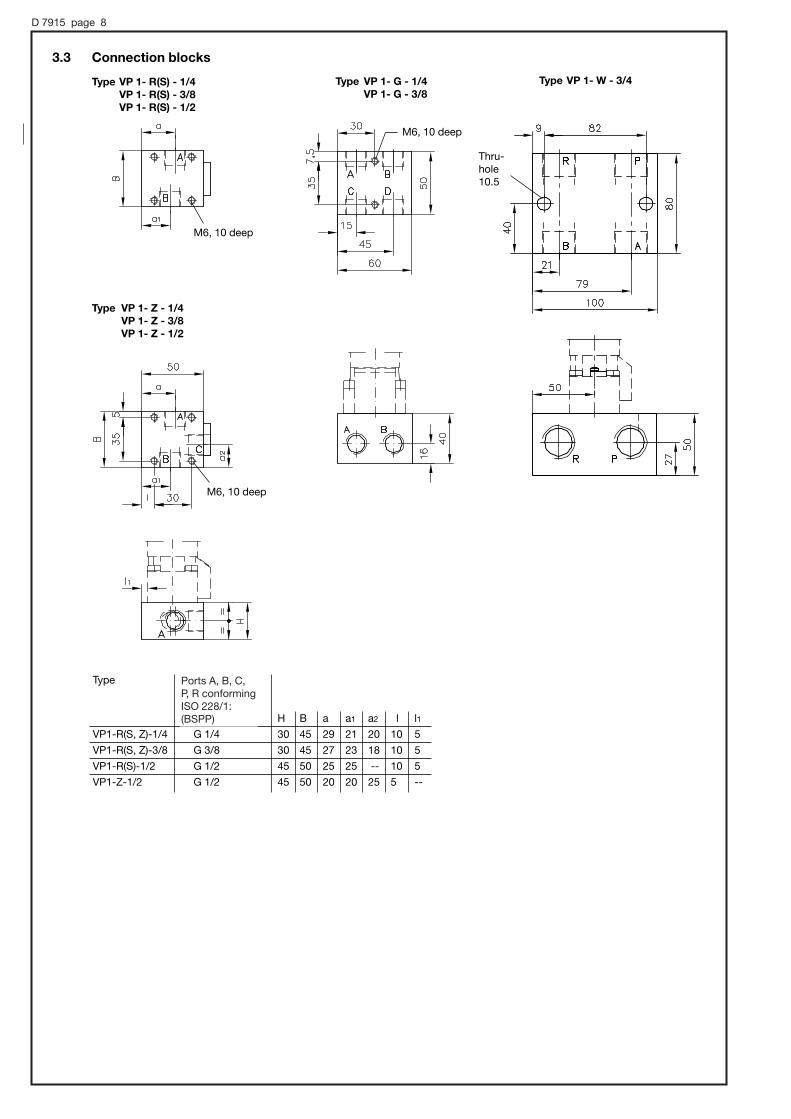
D 7915 page 8
3.3 Connection blocks
Type VP 1- R(S) - 1/4
VP 1- R(S) - 3/8
VP 1- R(S) - 1/2
Type VP 1- Z - 1/4
VP 1- Z - 3/8
VP 1- Z - 1/2
Type VP 1- W - 3/4Type VP 1- G - 1/4
VP 1- G - 3/8
M6, 10 deep
M6, 10 deep
M6, 10 deep
Thru-hole10.5
Type
H B a a1 a2 l l1
VP1-R(S, Z)-1/4 G 1/4 30 45 29 21 20 10 5
VP1-R(S, Z)-3/8 G 3/8 30 45 27 23 18 10 5
VP1-R(S)-1/2 G 1/2 45 50 25 25 -- 10 5
VP1-Z-1/2 G 1/2 45 50 20 20 25 5 --
Ports A, B, C, P, R conformingISO 228/1:(BSPP)

3/2- and 2/2-way cartridge valve type BVEfor any flow direction, zero leakage,
all ports pressure resistant
July 2012-02
HAWE HYDRAULIK SESTREITFELDSTR. 25 • 81673 MÜNCHEN
2.2
© 1999 by HAWE Hydraulik
D 7921Directional seated cartridge
valve type BVE
Flow Qmax = 300 lpmPerm. pressure pmax = 500 bar
Cartridge valve Version with connection block
Additional valves with same function:o Type EM, EMP D 7490/1o Type BVG 1, BVP 1 D 7765 (Qmax = 20 lpm, pmax = 400 bar)o Type NBVP 16 D 7765 N (Qmax = 20 lpm, pmax = 400 bar)o Type BVG 3, BVP 3 D 7400 (Qmax = 60 lpm, pmax = 315 bar)
1. GeneralThe solenoid actuated 2/2- and 3/2-way directional valves type BVE are designed as seated cone valves. All ports are equally pressure resistant due to the internal pressure compensation.The valve returns automatically into its idle position because of the spring return, while not actuated. The valves are completely made of steel, with all functional internal components being hardened, permanently lubed by the hydraulic fluid. As these valves are designed as cartridge valve, installation is most simple and quick.The solenoid coil can be easily replaced, without opening the hydraulic system e.g. when a different voltage is required.There are also individual connection blocks available for these valve, enabling direct pipe connection.
BVE 1
BVE 3
BVE 5
Flow
Qmax(lpm)
20
70
300
Pressure
pmax
(bar)
500
400
400
Symbols
R S Z
2. Available versions, main data
Order example: BVE 3 Z - B 2,5 - G 24 - 1/2
Table 3, see page 2
Table 3 and 3a, see page 3
Table 2,see page 2
Table 4, see page 3
Type BVE 5 only with symbol R
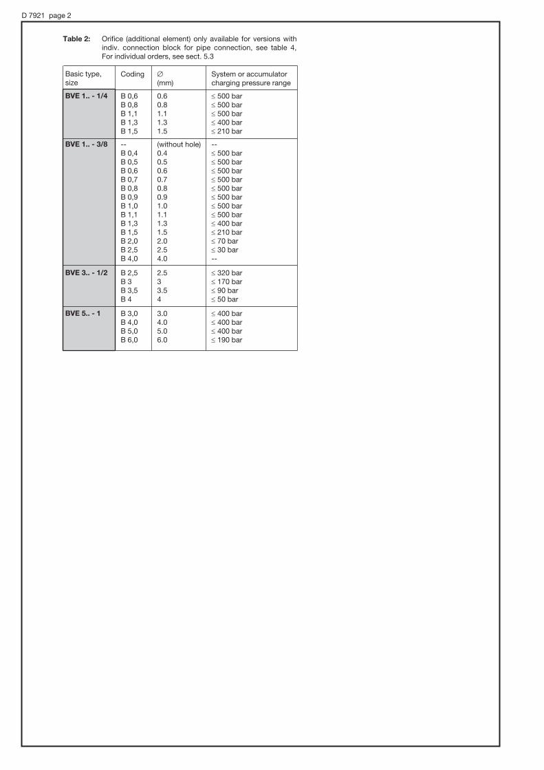
D 7921 page 2
Coding # System or accumulator (mm) charging pressure range
B 0,6 0.6 ≤ 500 barB 0,8 0.8 ≤ 500 barB 1,1 1.1 ≤ 500 barB 1,3 1.3 ≤ 400 barB 1,5 1.5 ≤ 210 bar
-- (without hole) --B 0,4 0.4 ≤ 500 barB 0,5 0.5 ≤ 500 barB 0,6 0.6 ≤ 500 barB 0,7 0.7 ≤ 500 barB 0,8 0.8 ≤ 500 barB 0,9 0.9 ≤ 500 barB 1,0 1.0 ≤ 500 barB 1,1 1.1 ≤ 500 barB 1,3 1.3 ≤ 400 barB 1,5 1.5 ≤ 210 barB 2,0 2.0 ≤ 70 barB 2,5 2.5 ≤ 30 barB 4,0 4.0 --
B 2,5 2.5 ≤ 320 barB 3 3 ≤ 170 barB 3,5 3.5 ≤ 90 barB 4 4 ≤ 50 bar
B 3,0 3.0 ≤ 400 barB 4,0 4.0 ≤ 400 barB 5,0 5.0 ≤ 400 barB 6,0 6.0 ≤ 190 bar
Basic type,size
BVE 1.. - 1/4
BVE 1.. - 3/8
BVE 3.. - 1/2
BVE 5.. - 1
Table 2: Orifice (additional element) only available for versions with indiv. connection block for pipe connection, see table 4, For individual orders, see sect. 5.3

D 7921 page 3
Basic type, Coding Description Ports A, B and Csize (ISO 228/1) (BSPP)
BVE 1 - 1/4 For pipe connection G 1/4 - 3/8 G 3/8 - P For manifold mounting --
BVE 3 - 1/2 For pipe connection G 1/2
BVE 5 - P For manifold mounting --
- 1 For pipe connection G 1
Coding Description
without standard
B Actuation lock (only available for symbol R), for notes regarding use, see sect. 5.2
T with detent
Table 3: Actuation solenoidNote: o The specified protection class is only valid when the plug is properly mounted. o Type BVE 5 only 24V DC
Coding and nom. voltage 12V DC 24V DC 110 V 230 V 50/60 Hz 50/60 Hz BVE 1 BVE 3 BVE 5
Protection class (IEC 60529)
Electrical connection
G 12 G 24 WG 110 WG 230
X 12 X 24 X 98 X 205
L 12 L 24 -- --
L 5 K.. L 5 K.. -- --
L 10 K.. L 10 K..
AMP 12 AMP 24 -- --
-- M 24 -- --
-- DT 24 -- --
o
o
o
o
o
o
o
o
o
o
o
o
o
o (only 24 V)
o (only 24 V)
IP 65
(IP 65)
IP 65
IP 65
IP 65
IP 65
IP 67
DIN EN 175 301-803 A with plug
DIN EN 175 301-803 A without plug
DIN EN 175 301-803 A with LED-plug
DIN EN 175 301-803 A with LED-plug and 5 or 10 m cable
Co. AMP Junior Timer
M12x1
DEUTSCH
Table 4: Indiv. connection block
Connection pattern G.., X.., L.. AMP.. M..
Table 3a: Actuation solenoid options (only type BVE 1)

D 7921 page 4
3. Additional parameters3.1 General and hydraulic
Installed position Any
Negative (transition from one to the other valve position is only completed in the respective end position). All ports are interconnected until the end position is achieved.
Operating pressure see table 1
Material and surface treatment Steel, DIN 50979-Fe ZnNi 8 BVE 1 and BVE 5 Steel, zinc galvanized / gas nitrided BVE 3
Mass (weight) Basic type Cartridge valve Indiv. connection block
BVE 1 0.5 kg + 0.8 kg BVE 3 0.7 kg + 0.7 kg BVE 5 3.8 kg + 3.8 kg
Hydraulic fluid Hydraulic oil acc. to DIN 51524 table 1 to 3; ISO VG 10 to 68 acc. to DIN 51519Viscosity range: min. approx. 4; max. approx. 1500 mm2/sOptimal operation range: approx. 10 ... 500 mm2/s
Also suitable are biologically degradable pressure fluids type HEPG (Polyalkylenglykol) and HEES (synth. ester) at operation temperatures up to approx. +70°C.
Temperature Ambient: approx. -40 ... +80°C Fluid: -25 ... +80°C, pay attention to the viscosity range! Start temperature down to -40°C
are allowable (Pay attention to the viscosity range during start!), as long as the opera-tion temperature during subsequent running is at least 20K higher. Biological degradable pressure fluids: Pay attention to manufacturer‘s information. With regard to the compatibility with sealing materials do not exceed +70°C.
Flow limitation It is necessary to limit the flow down to the permissible range depending on the system pressure via throttles (see sect. 2). This applies to all circuits fed by an accumulator or when connected to high pressure circuits fed by high delivery pumps.
The orifice must be located on the accumulator side always. With valves version ..Z.. these should be installed in port C. For more detailed information, see table 2, section 2
|p-Q-curve
Over lapping at 3/2-waydirectional valves
Bac
k p
ress
ure
|p
(bar
)B
ack
pre
ssure
|p
(bar
)
Bac
k p
ress
ure
|p
(bar
)B
ack
pre
ssure
|p
(bar
)
Flow Q (lpm)
Flow Q (lpm) Flow Q (lpm)
Flow Q (lpm)
Ölviksosität während der Messung ca. 60 mm2/s
Orifice (add. element)
Basic valves

D 7921 page 5
3.2 Electrical data
Protection class
Connector and connection
Switching times approx. ms
Switchings / h
Insulation material class
On 50 ... 60 (type BVE 5 approx. 100 ms)Off 50 ... 60 (type BVE 5 approx. 100 ms) approx. 2000 (rather even distributed)
F; Contact temperature approx. 85...95°C (solenoid housing) with an ambient temperature of 20°C.Classification F permits a max. winding temperature of approx. 150°C; This won‘t be exceeded if the guideline figures for %ED are observed during operation. The thermal load of the coil may be reduced when an economy circuit is employed.
Depending on actuation solenoid, see table 3
Depending on actuation solenoid, see table 3
DC-voltage AC-voltage
G.. AMP.. L.. WG 110..
X.. G.. EX
M..
Relative duty cycle: 100% ED (Specification on the solenoid)
Reference value and restriction in the operation
Required connectors
Coding AMP.. Co. AMP Junior 2-pole, Coding 1
Coding G.., X.., L.. DIN EN 175 301-803 A
Cut-off energy
Additional solenoid voltagesType BVE 1, BVE 3
Guideline for max: approx. < 10 Ws + approx. 10% when measuring at UN
48V DC80V DC
Ambient temperature U °C
%E
D S
3-5
min
Nom. voltage UN 12V DC 24V DC 98V DC 205V DC
Nom. power PN BVE 1 26.2 W 26.5 W (30 W) 24.8 W 28 W BVE 3 35.1 W 32.7 W 31.4 W 30.2 W BVE 5 63 W
Nom. current IN BVE 1 2.34 A 1.17 A 0.28 A 0.14 A BVE 3 2.5 A 1.4 A 0.33 A 0.16 A BVE 5 4.76 A 2.45 A 0.63 A 0.33 A
Electrical data for ex-proof solenoids
ATEX-Certificate of conformity TÜV-A 03ATEX 0017 XCoding O II 2 G Ex d IIB + H2 T4 O II 2 D Ex mbD 21 T135°COper. duration 100% EDDuty cycle IP 67 (IEC 60529)Nom. voltage UN 24 V DCPower PN 23 WRestrictions for use:
Ambient temperature -35 ... +40°Cmax. fluid temperature +70°Cel. protection against overload (conf. IEC 60127) IF < 1.6 A-TSurface coating Housing galvanically zinc coated Coil and connection cavity are moulded
Attention: Protect the complete valve against direct sun light.
Observe the operation manuals B 03/2004 and B ATEX!Electrical lay-out and testing conforming EN 60079, VDE 0170-1, VDE 0170-5

D 7921 page 6
All dimensions in mm, subject to change without notice! 4. Unit dimensions4.1 Cartridge valve type BVE 1
Mounting hole for type BVE 1 Z
Type BVE 1 Z Type BVE 1 R, BVE 1 S
Mounting hole for type BVE 1 R, BVE 1 S
Detail at “X” Detail at “Y”
Rounded edge
Seal between coil and nut
Seal between coil and valve cartridge
Seal between coil and valve cartridge
Manual emergency actuation Manual emergency actuation
Seal between coil and nut
rotatable rotatable
a/f 24 70 Nm
a/f 24 70 Nm
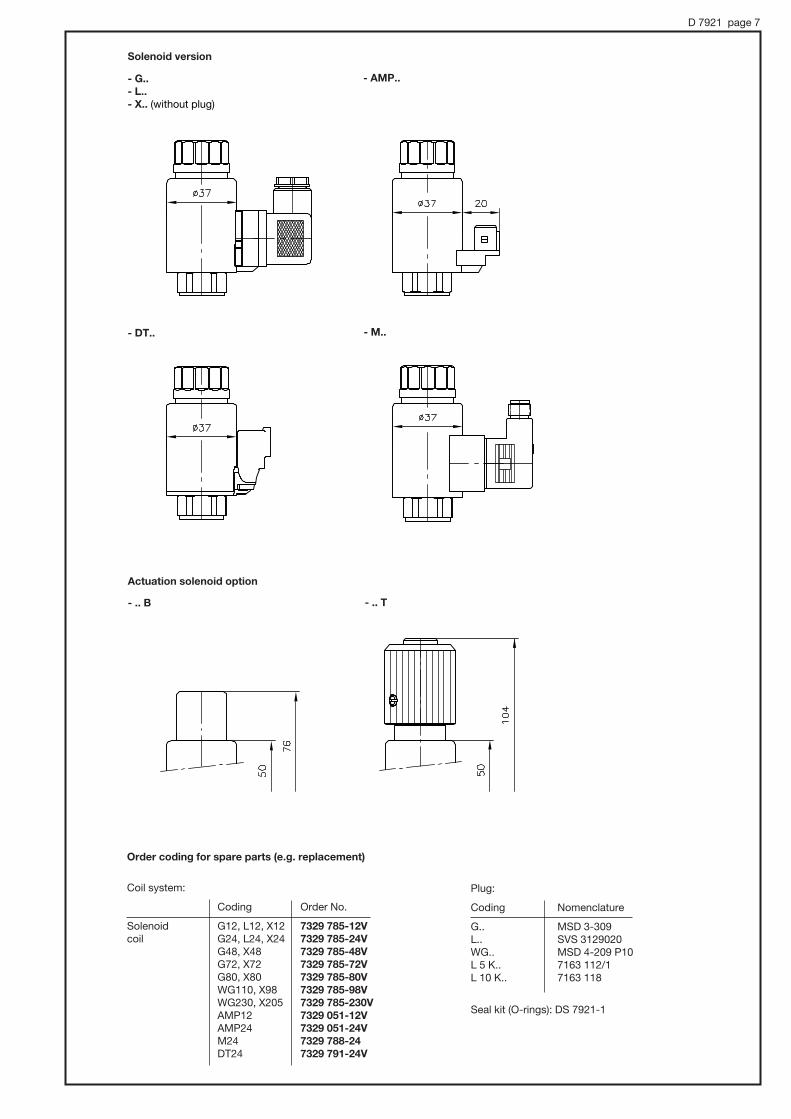
D 7921 page 7
Coil system:
Coding Order No.
Solenoid G12, L12, X12 7329 785-12V
coil G24, L24, X24 7329 785-24V
G48, X48 7329 785-48V
G72, X72 7329 785-72V
G80, X80 7329 785-80V
WG110, X98 7329 785-98V
WG230, X205 7329 785-230V
AMP12 7329 051-12V
AMP24 7329 051-24V
M24 7329 788-24
DT24 7329 791-24V
Plug:
Coding Nomenclature
G.. MSD 3-309L.. SVS 3129020WG.. MSD 4-209 P10L 5 K.. 7163 112/1L 10 K.. 7163 118
Seal kit (O-rings): DS 7921-1
Solenoid version
- G..
- L..
- X.. (without plug)
- AMP..
- DT..
Order coding for spare parts (e.g. replacement)
- M..
- .. B
Actuation solenoid option
- .. T

D 7921 page 8
Version with indiv. connection block
Type BVE 1 Z - ... - 1/4
BVE 1 Z - ... - 3/8
Type BVE 1 R - ... - P
BVE 1 S - ... - P
Type BVE 1 R - ... - 1/4
BVE 1 R - ... - 3/8
BVE 1 S - ... - 1/4
BVE 1 S - ... - 3/8
Ports conforming ISO 228/1 (BSPP):A, B and C = G 1/4 or G 3/8
Ports conforming ISO 228/1 (BSPP):A and B = G 1/4 or G 3/8
Hole pattern
O-ring 7.65x1.78 AU

D 7921 page 9
4.2 Cartridge valve type BVE 3
O-ring 21x3.53Polyurethane 95 Sh
O-ring 17.12x2.62NBR 90 Sh
Mounting hole for type BVE 3 Z
Mounting hole for type BVE 3 R and S
1) This groove improves the flow characteristic, but is not necessary for proper function
Manual emergency actuationa/f 19 max. 40 Nm
Detail at “X”
Order coding for spare parts (e.g. replacement)
Coil system:
Coding Order No.
Solenoid G12, L12, X12 7177 720-12V
coil G24, L24, X24 7177 720-24V
G48, X48 7177 720-48V
G72, X72 7177 720-72V
G80, X80 7177 720-80V
WG110, X98 7177 720-98V
WG230, X205 7177 720-205V
Cable gland
app
rox.
34
approx. 34.5
app
rox.
70.5
Reaming depth 5.5+0.2
Reaming depth 5.5+0.2
Plug:
Coding Nomenclature
G.. MSD 3-309L.. SVS 3129020WG.. MSD 4-209 P10
Seal kit (O-rings): DS 7921-3
1)
1)
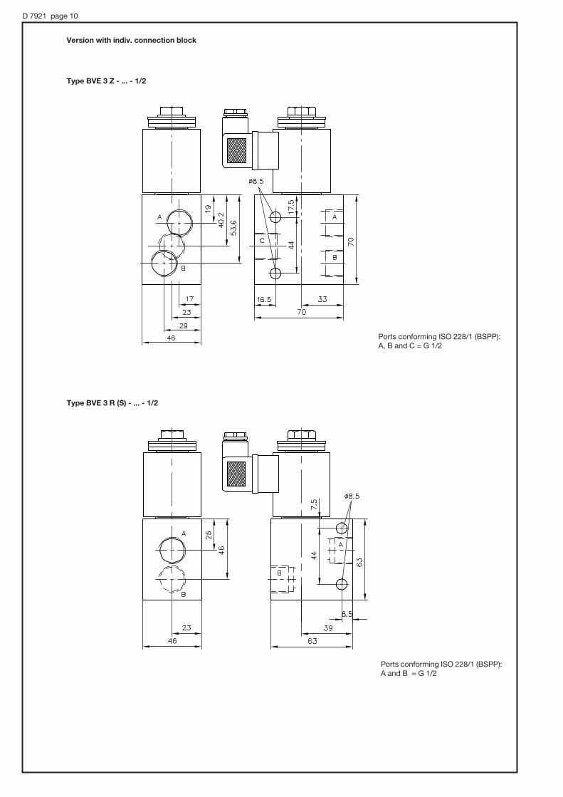
D 7921 page 10
Ports conforming ISO 228/1 (BSPP):A, B and C = G 1/2
Ports conforming ISO 228/1 (BSPP):A and B = G 1/2
Type BVE 3 Z - ... - 1/2
Type BVE 3 R (S) - ... - 1/2
Version with indiv. connection block

D 7921 page 11
4.3 Cartridge valve type BVE 5
Mounting hole
Manual emergency
a/f 50 200 Nm
Detail at “X” Detail at “Y”Rounded edge
Order coding for spare parts (e.g. replacement)
Coil system:
Coding Order No.
Solenoid G24, L24, X24 7750 563-G24
coil
rotatable
deep
Plug:
Coding Nomenclature
G.. MSD 3-309L.. SVS 3129020L 5 K.. 7163 112/1L 10 K.. 7163 118
Seal kit (O-rings): DS 7921-5

D 7921 page 12
Version with indiv. connection block
Type BVE 5 - ... - P
Hole pattern
M12, 20 deep
90 Nm
Type BVE 5 - ... - 1

D 7921 page 13
Actuation aid(do not use any sharp-edged parts)
5.1 Manual emergency actuation
5. Appendix
The valve may be actuated by pressing down the brass bolt visible from above by means of a steel pin or a screw driver etc.
Attention: Any pressure at B puts a load on the brass pin, which results in a pressure dependent counter force. The pin diameter with type BVE 1 and 3 is #3 mm, i.e. 100 bar & 70 N; whereas it is #4 mm with type BVE 5, i.e. 100 bar & 125 N !
5.2 Actuation solenoid option B used as actuation lock (see table 3a)
This actuation lock may be used as safety device e.g. during maintenance works or initial operation / set-up operation.
o Standard operation - Solenoid (coil) is mounted - The locking nut fixes the coil at the armature tube - Actuation is unlocked - Valve can be actuated via the solenoid
o Maintenance works / initial operation - Solenoid (coil) is not mounted - The locking nut is only lightly screwed onto the armature tube - Valve is fixed in working state
Standard operation Maintenance works / initial operation
Locking nut

D 7921 page 14
Coding # Order coding (mm)
-- (without hole) 7406 012 a B 0,6 0.6 7406 012 bB 0,8 0.8 7406 012 c B 1,1 1.1 7406 012 dB 1,3 1.3 7406 012 f B 1,5 1.5 7406 012 h
-- (without hole) 7400 003 aB 0,4 0.4 7400 003 kB 0,5 0.5 7400 003 lB 0,6 0.6 7400 003 d B 0,7 0.7 7400 003 mB 0,8 0.8 7400 003 eB 0,9 0.9 7400 003 nB 1,0 1.0 7400 003 oB 1,1 1.1 7400 003 g B 1,3 1.3 7400 003 hB 1,5 1.5 7400 003 c B 2,0 2.0 7400 003 fB 2,5 2.5 7400 003 iB 4,0 4.0 7400 003 b
B 2,5 2.5 7405 014 bB 3 3.0 7405 014 c B 3,5 3.5 7405 014 dB 4 4.0 7405 014 e
-- (without hole) 7750 562 -0.0B 3,0 3.0 7750 562 -3.0B 4,0 4.0 7750 562 -4.0B 5,0 5.0 7750 562 -5.0B 6,0 6.0 7750 562 -6.0
for type
BVE 1.. - 1/4
BVE 1.. - 3/8
BVE 3.. - 1/2
BVE 5 - 1..
Blenden
Mounting holes in the manifold may be blocked if required by tapped plugs e.g. if uniform manufactured manifolds should be equipped with or without cartridge valves depending on application.
for type Order coding
BVE 1 7750 181BVE 3 Sk 7405 260 bBVE 5 7750 524
BVE 1 7750 191BVE 3 Sk 7405 260 aBVE 5 7750 526
BVE 1 7750 181BVE 3 Sk 7405 260 c
BVE 1 7750 171BVE 3 Sk 7405 260 d
Tapped plug
5.3 Options
Tapped plugs
Basic type a/f h
BVE 1 24 12.5
BVE 3 30 18.5
BVE 5 50 20
a/f

Directional spool valve banks type SWS
Directly solenoid actuated (on/off or proportional)
D 7951Directional spool valve banks
type SWS
March 1999-02
HAWE HYDRAULIK SESTREITFELDSTR. 25 • 81673 MÜNCHEN
2.1
Flow Qmax = 25 lpm
Operation pressure pmax = 315 bar
1. General information
The directional valve banks type SWS are a refined version of type SWR. Basic function is the directional control of hydraulic consumers (cylinders, motors). But this new concept enables also the incorporation of additional functions for each individual valve section on both the pump (check or throttle valves) and the consumer side (over-center, shock, or check valves).The actuation is carried out via pressure tight, single acting solenoids which act directly on the valve spool.A variety of connection blocks (featuring pressure and return ports) as well as end plates offer solutions to many applications.
Order examples
Example 1:Combination with compact-hydraulic powerpack
Example 2:Valve bank withproportional-flowcontrol valve inthe connectionblock
Example 3:Lifting module forreach trucks
HK 448/1 - Z12.3 - AS1F2/120 - SWS2F - G06 /MP /DW /2AN130 BN80
- W /M /R /2
- D /MF /0 /2AL4B140 BL4C140 -1 - G24
SWS2 SE22F-A6 - G12 /MP /DW /2AS250 BS310
- D06 /M /DW /2AL320
- B /M /Q /2 -1 - G24 - 300
HMT34DH - 1/220 - 90F - D12 /MPF/DW/2AL4B200 BL4C200
- G /M /0 /02
- G /M /0 /02 - G24
Hydraulic circuit and illustration acc. to example 1
Pre
-rel
ease
A_
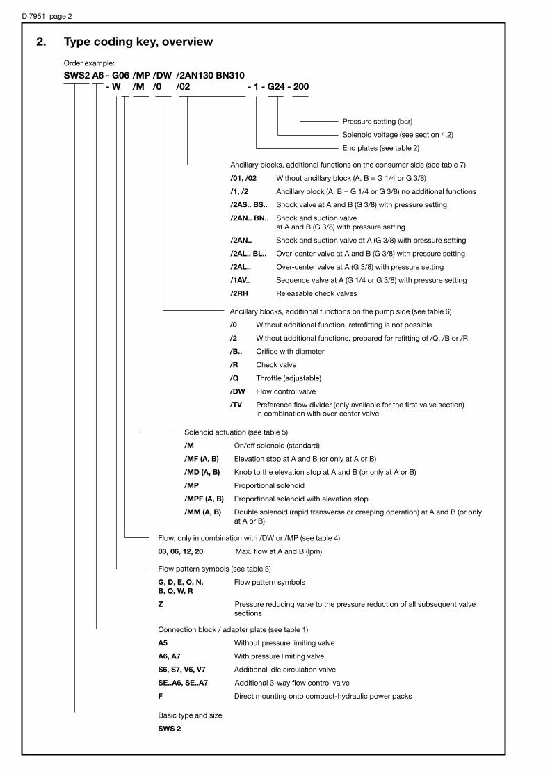
D 7951 page 2
2. Type coding key, overview
Order example:
SWS2 A6 - G06 /MP /DW /2AN130 BN310
- W /M /0 /02 - 1 - G24 - 200
Pressure setting (bar)
Solenoid voltage (see section 4.2)
End plates (see table 2)
Ancillary blocks, additional functions on the consumer side (see table 7)
/01, /02 Without ancillary block (A, B = G 1/4 or G 3/8)
/1, /2 Ancillary block (A, B = G 1/4 or G 3/8) no additional functions
/2AS.. BS.. Shock valve at A and B (G 3/8) with pressure setting
/2AN.. BN.. Shock and suction valve at A and B (G 3/8) with pressure setting
/2AN.. Shock and suction valve at A (G 3/8) with pressure setting
/2AL.. BL.. Over-center valve at A and B (G 3/8) with pressure setting
/2AL.. Over-center valve at A (G 3/8) with pressure setting
/1AV.. Sequence valve at A (G 1/4 or G 3/8) with pressure setting
/2RH Releasable check valves
Ancillary blocks, additional functions on the pump side (see table 6)
/0 Without additional function, retrofitting is not possible
/2 Without additional functions, prepared for refitting of /Q, /B or /R
/B.. Orifice with diameter
/R Check valve
/Q Throttle (adjustable)
/DW Flow control valve
/TV Preference flow divider (only available for the first valve section)in combination with over-center valve
Solenoid actuation (see table 5)
/M On/off solenoid (standard)
/MF (A, B) Elevation stop at A and B (or only at A or B)
/MD (A, B) Knob to the elevation stop at A and B (or only at A or B)
/MP Proportional solenoid
/MPF (A, B) Proportional solenoid with elevation stop
/MM (A, B) Double solenoid (rapid transverse or creeping operation) at A and B (or onlyat A or B)
Flow, only in combination with /DW or /MP (see table 4)
03, 06, 12, 20 Max. flow at A and B (lpm)
Flow pattern symbols (see table 3)
G, D, E, O, N, Flow pattern symbolsB, Q, W, R
Z Pressure reducing valve to the pressure reduction of all subsequent valve sections
Connection block / adapter plate (see table 1)
A5 Without pressure limiting valve
A6, A7 With pressure limiting valve
S6, S7, V6, V7 Additional idle circulation valve
SE..A6, SE..A7 Additional 3-way flow control valve
F Direct mounting onto compact-hydraulic power packs
Basic type and size
SWS 2

D 7951 page 3
3. Available versions, main data3.1 Connection blocks, adapter plates, and end plates
Basic type and sizeFlow Qmax = 25 lpm
Pressure pmax = 315 bar
For valve sectionssee sect. 3.2
SWS 2 A6 - G/M/0/02 - 1 - G 24 - 200
For actuation solenoids G 12 to WG 230, see sect. 4.2
Table 1: Connection block, adapter plate
P (pump port) and R (return port) = G 3/8 DIN ISO 228/1 (BSPP)M (Port for pressure gauge) = G 1/4 DIN ISO 228/1 (BSPP)
Coding
5
6
7
6
7
Pressurelimitingvalve 1)
No pres-sure limit-ing valve
Tool ad-justable
Manuallyadjustable
Tool ad-justable
Manuallyadjustable
Idle circula-tion valveacc. to D 7490/1
without
EM 21SIdle cir-culationwhiledeener-gized
6
7
F
Tool ad-justable
Manuallyadjustable
Direct mounting ontocompact-hydraulicpower packsMP acc. to D 7200HHK acc. to D 7600-...HC acc. to D 7900
3-way flow control valvewith metering throttleclosed, while deener-gized (Regulation range start-ing from approx. 0.1 lpmup to the respectivespecified max figure e.g.30 F & Qmax = 30 lpm)
Is to be directlymounted onto con-nection block A(AS,AV)1, and 2 (3, 4)acc. to D 6905 A.
EM 21VIdle cir-culationwhile en-ergized
Symbole
A
S3)
V3)
30 F
22 F
15 F
10 F
SE 6 F3) 4/18 F 2)
3/26 F 2)3/7 F 2)3 F
1) The spring dome of the pressure limiting valve is made of zinc pressure die-cast (standard). The (optional) steel spring dome should beused, wherever pressure surges of more than 20 ... 25 bar could occur in the return duct. This must be specified in uncoded text.
2) Metering throttle with non-linear characteristic and specification of the fine control block and the max. flow at completely open metering throttle
3) There is also an end plate available featuring a (optionally proportional) by-pass valve (type 31 E or 31 EP acc. to table 2)
Desired pressure setting (bar)available pressure ranges:
(0) ... 80 bar(0) ... 160 bar(0) ... 315 bar
Specification is superfluous withconnection block A5 and adapterplate F
Pressure specifi-cation deter-mines the spring
= ..6 = ..7
S 6 and S 7 V 6 and V 7
A 5 A 6 and A 7
Order example:
A 6andA 7
Tool ad-justable
Table 2: End plates
Coding
1
2
3
25 E
21 E
21 EP
31 E
31 EP
Flow pattern symbols 2 3
1
25 E 21 E 21 EP
31 E 31 EP
Brief description
Standard
Additional pump and return port (P1, R1 = G 3/8)
Additional pump port P1, P2 and return port R1 (G 1/2)
Switchable additional return port A (G 3/8)
Switchable additional pump outlet port to the supply for further valve banks
Like 21 E, but with prop. valve to the step-less quantity dosage (e.g. for a smooth start or for pumps)
End plate with idle circulation valve (e.g.as alternative for connection blocks)
Like 31 E, but with prop. valve (e.g. to prevent start jumps)
Order example: SWS 2 SE 22F-A6-...-200
With preference flow devider, for flow patternsymbol and order example see table 6
... / TV ...

D 7951 page 4
3.2 Valve sections3.2.1 Directional spool valves
Order example: SWS2 A6 - G /M /0 /02
- D06 /MP/DW/2AS180 BS180 - 1 -G24 - 200
Table 3: Flow pattern symbols
Table 4: FlowAttention: Only in connection with coding /MP(table 5) and/or /DW (table 6)!
Table 5: Solenoid version
Flow pattern symbolsG D E O N B Q W R K
Coding 03 06 12 20 without
Flow 3 6 12 20 ---QA, B max (lpm)
Coding
/M
/MF
/MFA
/MFB
/MD
/MDA
/MDB
/MP
/MPF
/MMD
/MMA
/MMB
Brief description
On/off solenoid
On/off solenoid with eleva-tion stop (set screw) for Aand B (/MF), for A (/MFA) orfor B (/MFB)
On/off solenoid with eleva-tion stop (turn knob) for Aand B (/MD), for A (/MDA) orfor B (/MDB)
Proportional solenoid
Proportional solenoid with elevation stop
Double solenoid for rapidtransverse/creeping opera-tion for A and B (/MM), for A(/MMA) or for B (/MMB)
A d d i t i o n a lfunctions onthe consumerside (table 7)
A d d i t i o n a lfunctions onthe pumpside (table 6)
Solenoid ver-sion (table 5)
Flow patternsymbol (table3 and 4)
Table 6: Pump sided additional function
Coding
/0
/2
/B..
/R
/Q
/DW
/TV
Brief description
Without additional function, retro-fitting is not possible
Without additional functions, pre-pared for refitting of /Q, /B or /R
Orifice with -# (mm)
Check valve
Throttle (adjustable)
Flow control valve (retrofitting is notpossible), for a load independentflow limitation, most advantageousin combination with /MP(F) table 5and coding for flow acc. to table 4
Preference flow devider with a de-fined for this consumer. Attention:This is only available for the first valvesection (this feature is housed in theconnection block) and in combinationwith over-center valve (/2AL.. BL..)acc. to table 7, see order example
Flow pattern symbols
/0/2
/B0../B1..
/R /Q
/DW /TV
For basic type, size,actuation solenoid,end plate, and pres-sure setting, seesect. 3.1
Additional func-tions on the pumpside (table 6)
Flow (table 4)
Additional functionson the consumerside (table 7)
Order example:SWS 2 -D06/MP/TV/2AL4D180 BL4D180
-G/M/0/2-31EP-G24

D 7951 page 5
Table 7: Additional functions on the consumer side
Brief description
Without additional function (no connection block), cannot be combined with additional functions acc.to table 6
Without additional function, ports in the ancillary block
Shock and suction valve, with pressure specification for A and B or A only
Shock valves for A and B
Sequence valve for the consumer port A
Over-center valve (example: /2AL4C200 BL4B180) for A and B or A only
4 = Release ration
Valve version (flow dependent)A = appr. 20 lpmB = appr. 14 lpmC = appr. 10 lpmD = appr. 6 lpm
Pressure setting max. 380 bar
Double check valve (Release ration 1 : 2.5)
Coding
/01
/02
/1
/2
/2AN.. BN..
/2AN..
/2AS.. BS..
/1AV..
/2AL... BL...
/2AL...
/2RH
Tapped portsA and B
G 1/4
G 3/8
G 1/4
G 3/8
G 3/8
G 3/8
G 1/4
G 3/8
G 3/8
Flow pattern symbols
/01 and /02
/1 and /2 /2AN... BN... /2AS... BS... /2AL... BL...
/2AN...
/2RH
/1AV... /2AL...

D 7951 page 6
Valves coding Z are always set for max. pressure at HAWE, if a specification is missing in the order. When a specific pressure setting is desired, thus should be specified in the order coding in uncoded text.
Example: SWS 2 A6 - .. Z3 ... - 1 - G 24 - 210, Z3 set for 100 bar
The order coding for spares or storing is as follows:
ADM 22 PA for Z1; ADM 22 PC for Z2; ADM 22 PD for Z3; ADM 22 PF for Z4
ADM 22 PAR for Z5; ADM 22 PCR for Z6; ADM 22 PDR for Z7; ADM 22 PFR for Z8
Sub-plate for pressure reducing valve HAWE-No. 7451 004
3.2.2 Intermediate sections
Pressure reducing valve
Order example and flowpattern symbol
The valve can be ordered anywhere between the directionalspool valve sections. All subsequent spool valve sections receive only pressure fluid with the set pressure (secondarypressure), independent of the higher system pressure upstream. Coding Z1 ... Z8 may be added any position within the complete valve bank coding, see order example inthe margin.
SWS 2 A7 - G/M/R/02
-Z3
-D/M/0/02 - 1 -G24 - 250
Primaryside up to250 bar
Pressurereducingvalve
Secondaryside up to130 bar
250 bar
30 to 130 barTable 8: Pressure reducing valve
Adjustablepressure range1) from ... to(bar)
Coding
Tool ad-justable
Manuallyadjustable
160 ... 250
60 ... 160
30 ... 130
10 ... 30
Z 1
Z 2
Z 3
Z 4
Z 5
Z 6
Z 7
Z 8
Pressure specifications corresponding to theorder example
pA(B) - QA(B) - curve (tendency)
, -10 ... -15%of the pres-sure settingd e p e n d i n gon pressurerange
1) Pressure setting (monitored by a pressure gauge) atQA(B) = 0 lpm (Consumer on the secondary side in
stop position)
Intermediate section with flow limitation for all subsequent functions
Intermediate section with proportional 3-way flow control valve
Order example: SWS 2 A6 - G/M/R/02
- ZSB 15
- D/M/0/02 - 1 - G 24 - 200
CodingBasic type Metering throttle
22 F
15 F
ZSE 10 F
6 F
4/18 F
3/26 F
3/7 F
3 F
Brief description
A inter-section with a 3 way-proportional-flow control valve is usedto limit the flow for all subsequent valve sectionsA bypass nozzle prevents blocking of the 3 way flow control valvewhen all valves are closed.The control characteristics corresponds is like with connectionblocks type SWS 2 SE.. (see table 1 and curve in sect. 4.1).
Flow pattern symbol correspondingthe order example
ZSB ...
Intermediate section featur-ing a drop-rate braking valve type SB 1 acc. to D 6920pressure pmax = 315 bar
Adjustable response flow 2.5 ... 35 lpm
200 bar
Flow patternsymbol

D 7951 page 7
4. Additional parameter4.1 General and hydraulic data
Design Directional spool valve
Surface protection Spool valve housing nitrous hardened, solenoid zinc galvanized
Installed position Any, for fastening see dimensional drawings in section 5.1 ++
Pipe connection Pipe thread DIN ISO 228/1 (BSPP)
Port coding P = Pressurized fluid inlet port (pump) G 3/8A, B = Consumer G 3/8 or G 1/4 (dep. on type)R = Return port G 3/8M = Port for pressure gauge G 1/4
Flow direction In accordance with arrow direction in the flow pattern symbols; It is not permissible to reversethe flow direction !
Over lapping Positive
Operation pressure pmax = 315 bar (all ports)
Flow Flow Qmax = 25 lpm; Permissible return flow approx. 50 lpm
(The piston side of a differential cylinder should be connected to A, if the return exceeds 25 lpm)
Hydraulic fluid: Fluids acc. to DIN 51524 table 1 to 3; ISO VG 10 to 68 acc. to DIN 51519Viscosity range: min. approx. 4; max. approx. 1500 mm2/sOptimal operation range: approx. 10...500 mm2/sAlso suitable are biologically degradable pressure fluids of the type HEPG (Polyalkylenglycol) andHEES (synth. Ester) at operation temperatures up to approx. +70°C.HETG (seed oil) is not suited.
Temperature Ambient: approx. -40...+80°C; Fluid: -25...+80°C, pay attention to the viscosity range! Start temperature down to -40°C are allowable (Pay attention to the viscosity range during start!),as long as the operation temperature during subsequent running is at least 20K higher. Biological degradable pressure fluids: Pay attention to manufacturer's information. With regardto the compatibility with sealing materials do not exceed +70°C.Restrictions for version with ex-proof solenoid!
Max. contamination Conforming 18/14 ISO 4406
Mass (weight) Spool valve (incl. actuation)
Coding appr. kg
G, D, E, O, N 1.8
B, Q, W, R, K 1.3
Connection blocks
Coding appr. kg
A 5 0.8
A 6, A 7 1.5
S 6, S 7, V 6, V 7 1.8
F 0.8
SE 2.6
Ancillary blocks
Coding appr. kg
/1. /2 0.5
others 1.0
Intermediate sections
Coding appr. kg
Z1 ... Z 8 1.5
ZSB 1.1
ZSE 2.0
|p-Q curveThe characteristics apply toall spool valve sections, nomatter where they are in-stalled within the valve bank.The measurable deviationsare insignificant.
Bac
k p
ress
ure
|p
(bar
)
Bac
k p
ress
ure
|p
(bar
)Flow pattern codingG, D, E, Q, O, N
Flow pattern codingB, W, R, K
Flow Q (lpm) Flow Q (lpm)
Eff
ectiv
e co
nsu
mer
flo
wQ
A in
% o
f Q
A m
ax
(see
sel
ectio
n t
able
)
Control current ISt in % in IN
These curves always apply to one flow direction only P→R (idle circula-tion), P→A(B) or A(B)→R. The total back pressure ( |ptotal) with 4/3- or 4/2-
way directional valves is taken at P. It consists of an inflow share (|pin) and
an outflow share (|pout). Important: Consumers with unequal area ration(e.g. differential cylinders) show uneven flow at the consumer ports, i.e. also (|pin) and (|pout) won't be equal regardless of the direction of move-ment!
Q-I curve for proportionalflow control valve (connectionblock)
Viscosity during the measur-ing approx. 60 mm2/s
in
outinreturn
A
AQQ =
in
outoutinreturn
A
Appp ∆+∆=∆
Qreturn Qreturn
Aout
AoutAin
Qin Qin
Ain

D 7951 page 8
4.2 Solenoid
Electrical data (/M... table 5)
Grayplug
Blackplug
A DIN 43650 Pg 9 (see also D 7163)
Coding G (...V DC) is only available with gray orblack plugsCoding WG (..V AC) is only available with blackplug, featuring an internal bridge rectifier circuit
Circuitry(valid for solenoida and b)
DC-voltage Coding G... Coding L...
AC-voltage Coding WG..
Plug
Relative dutycycle
Switching times (refer-ence value)
Switching operations
Protection class DIN40050
Insulation material class
Surface temperature
Mounting
On: approx. 60 ... 70 ms Off: approx. 30 ... 60 ms
approx. 3600 switchings / h
Solenoid IP 54, connection area IP 65 (device socket in assembled state)
F
approx. 85°C at 20°C ambient temperature
The solenoid can be simply removed after slackening the knurled nut, easing replacement in case of anelectrical defect.
100% EDStamping on thesolenoid
Operation:At ambient temperature (°C)
Duty cycle (%)
< 40
100
60
approx. 60
80
approx. 40
2) These solenoids are intended to be connected via a cus-tomer furnished bridge rectifier to mains 50/60Hz.: G 98 for mains 110V AC; G 205 for mains 230V AC
Solenoid Manufactured and tested conforming VDE 0580, operating pressure resistant in the pressure fluidReference value for nom. power PN , 24.4 W * approx. 6% dep. on nom. voltage UN and brand
Coding G 12 G 24 G 24 EX G 48 G 80 G 98 G 205 WG 110 WG 230X 12 X 24 1) X 48 X 80 X 98 X 205L 12 L 24 2) 2)
Nom. voltage UN 12V DC 24V DC 24V DC 48V DC 80V DC 98V DC 205V DC 110V AC 230V AC
50/60Hz 50/60Hz
Nom. power PN (W) 28 28 23.6 28 28 28 28 28 28
Nom. current I20 (A) 2.34 1.17 1.0 0.58 0.35 0.28 0.14 0.28 0.14
Solenoid Conforming VDE 0580
Nom. voltage UN 12V DC 24V DC
Coil resistance R20 6.0 Ω 24.0 Ω
Current , cold I20 2.5 A 1.25 A
Nom. current IN , 70% of I20 1.35 A 0.88 A
Power , cold 30 W 30 W
Nominal power 21 W 21 W
Recom. dither frequency 50 ... 150 Hz
Dither amplitude 20 ... 40% of IN
Relative duty cycle 100% ED (ref. temp. 11 = 50°C)
Electrical connection DIN 43650 B (industrial standard)
Protection class DIN 40050 Solenoid IP 54, connection area IP 65 (device socket inassembled state)
P R x I20 20 202
=
P R x IN = 20 202
Proportiona solenoid (/MP.. table 5): 1) Ex-proof solenoid
ATEX-Certificate of conformity TÜV-A 03ATEX 0017 XCoding II 2 G Ex d IIB + H2 T4
II 2 D Ex mbD 21 T135°CDuty cycle IP 67 (IEC 60529) Restrictions for use:
Ambient temperature -35 ... +40°Cmax. fluid temperature +70°Cel. protection against overload (conf. IEC 60127) IF < 1,6 A-T
Surface coating Housing galvanically zinc coatedCoil and connection cavity aremoulded
Electrical connection 3x0,5 mm2
Cable length 3 m, Option 10 m (cable ÖLFLEX-440P ® Co. LAPP, D-70565 Stuttgart)
Attention : Protect the complete valve against direct sun light.Observe the operation manuals B 03/2004 and B ATEX!Electrical lay-out and testing conforming EN 60079, VDE 0170-1,VDE 0170-5

D 7951 page 9
5. Unit dimensions
All dimensions in mm, subject tochange without notice !
Coding A 5 Coding A 6, A 7
Coding S(V) 6, S(V) 75.1 Connection blocks and adapter plates
Ancillary block(sect. 5.3)
Connectionblock (sect. 5.1)
Cablegland Pg 9
Double solenoid Coding /MM
Solenoid coding /MD(A, B)
Solenoid coding /M Solenoid coding /MPF
Solenoid coding /MP
M 6, 6 deep M 6, 6 deep
Provisionfor a leadseal
Manual emergencyactuation
Solenoid (ex-proof version)Coding G 24 ex
Directional spool valveEnd plate (sect. 5.3)
max
. 91
(man
ual
ly a
dju
stab
le)
max
. 80
(to
ol a
dju
stab
le)
app
rox.
87
app
rox.
76.5 ap
pro
x.159
app
rox.
103.5
app
rox.
70
app
rox.
80.5

D 7951 page 10
5.2 End plates
Coding 1 Coding 2 Coding 3 Coding 25 E Coding 21 E(EP)
31 E(EP)
Coding F Coding SE ... F
M 6, 6 deep
Connection block directlymounted onto the pump
Ports DIN ISO228/1 (BSPP):
R = R e t u r nport G 3/8
M = Port forpressuregauge G 3/8
Ports DIN ISO228/1 BSPP):
P, R = G 3/8M = G 1/4
Cablegland Pg 9
M 6, 6 deep
Ports DIN ISO 228/1 (BSPP):
A, P and R = G 3/8 with coding 2, 25 E, 21 E(P) and 31 E(P)
P1, P2, R1 = G 1/2 with coding 3
1)
1) Ports P and R areblocked with tappedplugs for 31 E(EP)
app
rox.
77
app
rox.
31
app
rox.
78.5
app
rox.
77
app
rox.
77
app
rox.
90.5
approx. 13
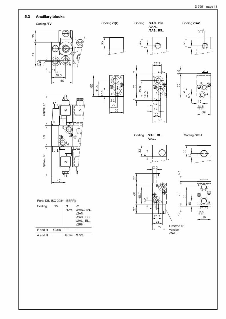
D 7951 page 11
5.3 Ancillary blocks
Coding /1(2) Coding /2AN.. BN..
/2AN..
/2AS.. BS..
Coding /2AL.. BL..
/2AL..
Coding /1AV..
Coding /2RH
Coding /TV
Ports DIN ISO 228/1 (BSPP):
Coding /TV /1 /2/1AV.. /2AN.. BN..
/2AN/2AS.. BS../2AL.. BL../2RH
P and R G 3/8 --- ---
A and B G 1/4 G 3/8
Omitted atversion/2AL...
app
rox.
87
app
rox.
87

D 7951 page 12
Coding Z 1 ... Z 8 Coding ZSECoding ZSB
5.4 Intermediate sections
app
rox.
108
app
rox.
77
app
rox.
105.5
app
rox.
88.5