Shop Manual - A Few Words About Safety
106
0-1 dummyhead dummyhead How to use this manual How to use this manual A Few Words About Safety SERVICE INFORMATION The service and repair information contained in this manual is intended for use by qualified, professional technicians. Attempting service or repairs without the proper training, tools, and equipment could cause injury to you and/or others. It could also damage this Honda product or create an unsafe condition. This manual describes the proper methods and procedures for performing service, maintenance, and repairs. Some procedures require the use special tools. Any person who intends to use a replacement part, service procedure, or a tool that is not recommended by Honda must determine the risks to their personal safety and the safe operation of this product. If you need to replace a part, use Honda Genuine parts with the correct part number or an equivalent part. We strongly recommend that you do not use replacement parts of inferior quality. For Your Customer’s Safety Proper service and maintenance are essential to the customer’s safety and the reliability of this product. Any error or oversight while servicing this product can result in faulty operation, damage to the product, or injury to others. For Your Safety Because this manual is intended for the professional service technician, we do not provide warnings about many basic shop safety practices (e.g., Hot parts-wear gloves). If you have not received shop safety training or do not feel confident about your knowledge of safe servicing practices, we recommend that you do not attempt to perform the procedures described in this manual. Some of the most important general service safety precautions are given below. However, we cannot warn you of every conceivable hazard that can arise in performing service and repair procedures. Only you can decide whether or not you should perform a given task. Important Safety Precautions Make sure you have a clear understanding of all basic shop safety practices and that you are wearing appropriate clothing and using safety equipment. When performing any service task, be especially careful of the following: • Read all of the instructions before you begin, and make sure you have the tools, the replacement or repair parts, and the skills required to perform the tasks safely and completely. • Protect your eyes by using proper safety glasses, goggles, or face shields anytime you hammer, drill, grind, or work around pressurized air, pressurized liquids, springs, or other stored-energy components. If there is any doubt, put on eye protection. • Use other protective wear when necessary, for example gloves or safety shoes. Handling hot or sharp parts can cause severe burns or cuts. Before you grab something that looks like it can hurt you, stop and put on gloves. • Protect yourself and others whenever you have equipment hoisted in the air. Anytime you lift this product with a hoist, make sure that the hoist hook is securely attached to the product. Make sure the engine is off before you begin any servicing procedures, unless the instruction tells you to do otherwise. This will help eliminate several potential hazards: • Carbon monoxide poisoning from engine exhaust. Be sure there is adequate ventilation whenever you run the engine. • Burns from hot parts. Let the engine and exhaust system cool before working in those areas. • Injury from moving parts. If the instruction tells you to run the engine, be sure your hands, fingers and clothing are out of the way. Gasoline vapors and hydrogen gasses from batteries are explosive. To reduce the possibility of a fire or explosion, be careful when working around gasoline or batteries. • Use only a nonflammable solvent, not gasoline, to clean parts. • Never store gasoline in an open container. • Keep all cigarettes, sparks, and flames away from the battery and all fuel-related parts. Improper service or repairs can create an unsafe condition that can cause your customer or others to be seriously hurt or killed. Follow the procedures and precautions in this manual and other service materials carefully. Failure to properly follow instructions and precautions can cause you to be seriously hurt or killed. Follow the procedures and precautions in this manual carefully.
-
Upload
khangminh22 -
Category
Documents
-
view
0 -
download
0
Transcript of Shop Manual - A Few Words About Safety

0-1
dummyheaddummyhead
How to use this manualHow to use this manual
A Few Words About SafetySERVICE INFORMATIONThe service and repair information contained in this manual is intended for use by qualified, professional technicians. Attemptingservice or repairs without the proper training, tools, and equipment could cause injury to you and/or others. It could also damagethis Honda product or create an unsafe condition.
This manual describes the proper methods and procedures for performing service, maintenance, and repairs. Some proceduresrequire the use special tools. Any person who intends to use a replacement part, service procedure, or a tool that is notrecommended by Honda must determine the risks to their personal safety and the safe operation of this product.
If you need to replace a part, use Honda Genuine parts with the correct part number or an equivalent part. We strongly recommendthat you do not use replacement parts of inferior quality.
For Your Customer’s SafetyProper service and maintenance are essential to the customer’s safety and the reliability of this product. Any error or oversightwhile servicing this product can result in faulty operation, damage to the product, or injury to others.
For Your SafetyBecause this manual is intended for the professional service technician, we do not provide warnings about many basic shop safetypractices (e.g., Hot parts-wear gloves). If you have not received shop safety training or do not feel confident about your knowledgeof safe servicing practices, we recommend that you do not attempt to perform the procedures described in this manual.
Some of the most important general service safety precautions are given below. However, we cannot warn you of everyconceivable hazard that can arise in performing service and repair procedures. Only you can decide whether or not you shouldperform a given task.
Important Safety PrecautionsMake sure you have a clear understanding of all basic shop safety practices and that you are wearing appropriate clothing andusing safety equipment. When performing any service task, be especially careful of the following:
• Read all of the instructions before you begin, and make sure you have the tools, the replacement or repair parts, and the skillsrequired to perform the tasks safely and completely.
• Protect your eyes by using proper safety glasses, goggles, or face shields anytime you hammer, drill, grind, or work aroundpressurized air, pressurized liquids, springs, or other stored-energy components. If there is any doubt, put on eye protection.
• Use other protective wear when necessary, for example gloves or safety shoes. Handling hot or sharp parts can cause severeburns or cuts. Before you grab something that looks like it can hurt you, stop and put on gloves.
• Protect yourself and others whenever you have equipment hoisted in the air. Anytime you lift this product with a hoist, make surethat the hoist hook is securely attached to the product.
Make sure the engine is off before you begin any servicing procedures, unless the instruction tells you to do otherwise. This willhelp eliminate several potential hazards:
• Carbon monoxide poisoning from engine exhaust. Be sure there is adequate ventilation whenever you run the engine. • Burns from hot parts. Let the engine and exhaust system cool before working in those areas. • Injury from moving parts. If the instruction tells you to run the engine, be sure your hands, fingers and clothing are out of the way.
Gasoline vapors and hydrogen gasses from batteries are explosive. To reduce the possibility of a fire or explosion, be careful whenworking around gasoline or batteries.
• Use only a nonflammable solvent, not gasoline, to clean parts. • Never store gasoline in an open container. • Keep all cigarettes, sparks, and flames away from the battery and all fuel-related parts.
Improper service or repairs can create an unsafe condition that can cause your customer or others to be seriously hurt or killed.
Follow the procedures and precautions in this manual and other service materials carefully.
Failure to properly follow instructions and precautions can cause you to be seriously hurt or killed.
Follow the procedures and precautions in this manual carefully.

CONTENTS
dummyheaddummyhead
SPECIFICATIONS 1
SERVICE INFORMATION 2
MAINTENANCE 3
TROUBLESHOOTING 4
COVER 5
FUEL SYSTEM 6
CONTROL SYSTEM 7
IGNITION SYSTEM 8
STARTING SYSTEM 9
PUMP 10
ENGINE REMOVAL/INSTALLATION 11
CRANKCASE 12
CYLINDER HEAD 13
MUFFLER 14
INDEX

0-3
dummyheaddummyhead
How to use this manual
INTRODUCTIONThis manual covers the service and repair procedures for Honda WX10T water pump.
All information contained in this manual is based on the latest product information available at the time of printing. We reserve theright to make changes at anytime without notice.
No part of this publication may be reproduced, stored in a retrieval system, or transmitted, in any form, by any means, electronic,mechanical, photocopying, recording, or otherwise, without prior written permission of the publisher. This includes text, figures, andtables.
As you read this manual, you will find information that is preceded by a symbol. The purpose of this message is to helpprevent damage to this Honda product, other property, or the environment.
SAFETY MESSAGESYour safety, and the safety of others, are very important. To help you make informed decisions, we have provided safety messagesand other safety information throughout this manual. Of course, it is not practical or possible to warn you about all the hazardsassociated with servicing these products. You must use your own good judgment.
© Honda Motor Co., Ltd.SERVICE PUBLICATION OFFICE
Date of Issue: September 2014
You will find important safety information in a variety of forms, including: • Safety Labels – on the product. • Safety Messages – preceded by a safety alert symbol and one of three signal words, DANGER, WARNING, or CAUTION.
These signal words mean:
You WILL be KILLED or SERIOUSLY HURT if you don’t follow instructions.
You CAN be KILLED or SERIOUSLY HURT if you don’t follow instructions.
You CAN be HURT if you don’t follow instructions. • Instructions – how to service these products correctly and safely.
ALL INFORMATION, ILLUSTRATIONS, DIRECTIONS AND SPECIFICATIONS INCLUDED IN THIS PUBLICATION ARE BASED ON THE LATEST PRODUCT INFORMATION AVAILABLE AT THE TIME OF APPROVAL FOR PRINTING. Honda Motor Co., Ltd. RESERVES THE RIGHT TO MAKE CHANGES AT ANY TIME WITHOUT NOTICE AND WITHOUT INCURRING ANY OBLIGATION WHATSOEVER. NO PART OF THIS PUBLICATION MAY BE REPRODUCED WITHOUT WRITTEN PERMISSION. THIS MANUAL IS WRITTEN FOR PERSONS WHO HAVE ACQUIRED BASIC KNOWLEDGE OF MAINTENANCE ON Honda products.

0-4
dummyheaddummyhead
How to use this manual
SERVICE RULES • Use Honda Genuine or Honda-recommended parts and lubricants or their equivalents. Parts that do not meet Honda’s design
specifications may damage the unit. • Use the special tools designed for the product. • Install new gaskets, O-rings, etc. when reassembling. • When torquing bolts or nuts, begin with larger-diameter or inner bolts first and tighten to the specified torque diagonally, unless
a particular sequence is specified. • Clean parts in cleaning solvent upon disassembly. Lubricate any sliding surfaces before assembly. • After assembly, check all parts for proper installation and operation. • Many screws used in this machine are self-tapping. Be aware that cross-threading or overtightening these screws will strip the
threads and ruin the hole.
Use only metric tools when servicing this unit. Metric bolts, nuts and screws are not interchangeable with non-metric fasteners. Theuse of incorrect tools and fasteners will damage the unit.
SYMBOLSThe symbols used throughout this manual show specific service procedures. If supplementary information is required pertaining tothese symbols, it will be explained specifically in the text without the use of the symbols.
Replace the part(s) with new one(s) before assembly.
Use the recommend engine oil, unless otherwise specified.
Use molybdenum oil solution (mixture of the engine oil and molybdenum grease in a ratio of 1:1).
Use multi-purpose grease (lithium based multi-purpose grease NLGI #2 or equivalent).
Use marine grease (water resistant urea based grease).
Apply a locking agent. Use a medium strength locking agent unless otherwise specified.
Apply sealant.
Use automatic transmission fluid.
x ( ) Indicates the diameter, length, and quantity of metric bolts used.page 1-1 Indicates the reference page.

0-5
dummyheaddummyhead
How to use this manual
ABBREVIATIONSThroughout this manual, the following abbreviations are used to identify the respective parts or systems.
Abbreviated term
Full term
ACG AlternatorAPI American Petroleum InstituteApprox. ApproximatelyAssy. AssemblyATDC After Top Dead CenterATF Automatic Transmission FluidATT AttachmentAVR Auto Voltage RegulatorBAT BatteryBDC Bottom Dead CenterBTDC Before Top Dead CenterBARO Barometric PressureCKP Crankshaft PositionComp. CompleteCMP Camshaft PositionCYL CylinderDLC Data Link ConnectorD-AVR Digital Auto Voltage RegulatorEBT Engine Block TemperatureECT Engine Coolant TemperatureECM Engine Control ModuleEMT Exhaust Manifold TemperatureEOP Engine Oil PressureEX ExhaustF Front or ForwardGND GroundHO2S Heated Oxygen sensorIAB Intake Air BypassIAC Idle Air ControlIAT Intake Air TemperatureI.D. Inside diameterIG or IGN IgnitionIN IntakeINJ InjectionL. LeftMAP Manifold Absolute PressureMIL Malfunction Indicator LampO.D. Outside DiameterOP Optional PartPGM-FI Programmed-Fuel InjectionP/N Part NumberQty QuantityR. RightSAE Society of Automotive EngineersSCS Service Check SignalSTD StandardSW SwitchTDC Top Dead Center
BI Black G Green Br Brown Lg Light greenY Yellow R Red O Orange P PinkBU Blue W White Lb Light blue Gr Gray

1-1
1
dummytext
1. SPECIFICATIONS
SERIAL NUMBER LOCATION ················· 1-2
SPECIFICATIONS·································· 1-2
PERFORMANCE CURVE ························ 1-4
DIMENSIONAL DRAWINGS ···················· 1-5

1-2
dummyheaddummyhead
SPECIFICATIONSSPECIFICATIONS
SERIAL NUMBER LOCATIONThe engine serial number [1] is located on the cylinder barrel.The frame serial number [2] is located on the frame.Refer to these numbers when ordering parts and when making technical inquiries.
SPECIFICATIONSDIMENSIONS AND WEIGHTS
[1]
[2]
Model WX10TDescription code WAGTType A/COverall length 340 mm (13.4 in)Overall width 220 mm (8.7 in)Overall height 295 mm (11.6 in)Dry weight 6.1 kg (13.4 lbs)Operating weight 6.5 kg (14.3 lbs)

1-3
dummyheaddummyhead
SPECIFICATIONS
ENGINE
WATER PUMP
Engine model GX25TDescription code GCALTType 4 stroke, OHC, single cylinderDisplacement 25 cm3 (1.5 cu–in)Bore x stroke 35.0×26.0 mm (1.38 x 1.02 in)Compression ratio 8.0±0.5Ignition system Transistor magneto ignitionIgnition timing B.T.D.C. 30°±2°Spark plug CMR5H (NGK)Lubrication system Pumping spray systemOil capacity 0.08 liter (0.08 US qt, 0.07 Imp qt)Recommended oil A type SAE 10W – 30 API service classification SJ or later
C type SAE 10W – 30 API service classification SE or higherCooling system Forced airStarting system Recoil starterStopping system Ignition primary circuit groundCarburetor Diaphragm typeAir cleaner Semi-dry typeBreather system Reed valve typeFuel tank capacity 0.53 liter (0.021 US gal, 0.018 Imp gal)Fuel used Unleaded gasoline with a pump octane rating 86 or higher
Model WX10TType Self priming centrifugal pumpDrive system Direct connection engineSuction port diameter 25 mm (1.0 in)Discharge port diameter 25 mm (1.0 in)Maximum total head 37 m (121 ft)Maximum suction head 8 m (26.2 ft)Maximum discharge capacity 120 liters
(31.7 US gal, 26.4 Imp gal) /minMaximum discharge pressure 359 kPa (52 psi)Maximum self-feed time 80 sec at 5 m (16.4 ft)Approx. operating hours(at max discharge) 0.9 Hr.

1-4
dummyheaddummyhead
SPECIFICATIONS
PERFORMANCE CURVE
DISCHARGE CAPACITY
TOTA
L H
EA
D L
IFT
10
20
30
(m)
50 100 (Liters/min)
40
150
10 20 30 (US gal/min)
10 20 30 (Imp gal/min)
20
40
60
80
100
120
(feet)

1-5
dummyheaddummyhead
SPECIFICATIONS
DIMENSIONAL DRAWINGS
295
(11.
6 in
)
220 (8.7 in)
Unit: mm (in)
340 (13.4 in)

MEMO
dummyheaddummyhead

2-1
2
dummytext
2. SERVICE INFORMATION
MAINTENANCE STANDARDS ················· 2-2
TORQUE VALUES ································· 2-3
LUBRICATION & SEAL POINT ················ 2-4
TOOLS ················································ 2-5
HARNESS AND TUBE ROUTING ············· 2-6

2-2
dummyheaddummyhead
SERVICE INFORMATIONSERVICE INFORMATION
MAINTENANCE STANDARDSENGINE
Unit: mm (in)
PUMPUnit: mm (in)
Part Item Standard Service limitEngine Idle speed 4,100 ± 200 min-1 (rpm) –
Cylinder compression 0.90 MPa (9.2 kgf/cm2, 131 psi)/2.000 min-1 (rpm) –
Cylinder Sleeve I.D. 35.000 - 35.015 (1.3780 – 1.3785) 35.100 (1.3819)Piston Skirt O.D. 34.970 - 34.990 (1.3768 – 1.3776) 34.900 (1.3740)
Piston-to-cylinder clearance 0.010 - 0.045 (0.0004 – 0.0018) 0.120 (0.0047)Piston pin bore I.D. 8.010 - 8.026 (0.3154 – 0.3160) 8.060 (0.3173)
Piston pin Pin O.D. 7.994 - 8.000 (0.3147 – 0.3150) 7.950 (0.3130)Piston pin-to-piston pin bore clearance 0.010 - 0.032 (0.0004 – 0.0013) 0.070 (0.0028)
Piston rings Ring side clearance Top/second 0.015 - 0.056 (0.0006 – 0.0022) 0.120 (0.0047)Ring end gap Top/second 0.10 - 0.25 (0.004 – 0.010) 0.60 (0.024)Ring width Top/second 0.970 - 0.990 (0.0382 – 0.0390) 0.920 (0.0362)
Connecting rod Small end I.D. 7.978 - 7.989 (0.3141 – 0.3145) –Cylinder barrel Barrel I.D. (Cam pulley bearing) 4.000 - 4.018 (0.1575 – 0.1582) 4.050 (0.1594)Valves Valve clearance IN 0.08 ± 0.02 (0.003 ± 0.001) –
EX 0.11 ± 0.02 (0.004 ± 0.001) –Valve stem O.D. IN 3.470 - 3.485 (0.1366 – 0.1372) 3.400 (0.1339)
EX 3.435 - 3.450 (0.1352 – 0.1358) 3.380 (0.1331)Valve guide I.D. IN/EX 3.500 - 3.518 (0.1378 – 0.1385) 3.560 (0.1402)Guide-to-stem clearance
IN 0.015 - 0.048 (0.0006 – 0.0019) 0.098 (0.0039)EX 0.050 - 0.083 (0.0020 – 0.0033) 0.120 (0.0047)
Valve spring free length 20.66 (0.8621) 20.00 (0.787)Campulley Cam height 21.897 - 22.297(0.8621 – 0.8778) 21.797 (0.8581)
Campulley I.D. 4.020 - 4.050 (0.1583 – 0.1594) 4.100 (0.1614)Campulleyshaft O.D. 3.990 - 4.000 (0.1571 – 0.1575) 3.950 (0.1555)
Carburetor Main jet # 34 –Spark plug Gap 0.60 - 0.70 (0.024 – 0.028) –Ignition coil Air gap 0.2 - 0.4 (0.01 – 0.02) –
Primary resistance 0.585 - 0.715 Ω –Secondary resistance 4.77 - 5.83 kΩ –
Engine P.T.O. shaft
Shaft O.D. 11.966 - 11.984 (0.4711 – 0.4718) 11.800 (0.4646)
Part Item Standard Service limitPump Impeller Clearance 0.70 - 1.00 (0.028 – 0.039) –

2-3
dummyheaddummyhead
SERVICE INFORMATION
TORQUE VALUESENGINE
PUMP
STANDARD TORQUE VALUESENGINE
FRAME
Item Thread Dia. (mm)Torque values
RemarkN·m kgf·m lbf·ft
Spark plug M10×1.0 11.8 1.2 9Fan cover bolt M5×0.8 6.4 0.65 4.7Lower crankcase bolt M5×0.8 (CT) 6.4 0.65 4.7 CT (Cutting Thread)
indicates a self-tapping bolt.
Recoil starter pulley M6×1.0 6.4 0.65 4.7Flywheel nut M7×1.0 14.7 1.5 11Ignition coil bolt M4×0.7 3.9 0.40 2.9Oil outlet valve screw M4×0.7 3.0 0.31 2.2Adjusting screw lock nut M5×0.5 4.9 0.50 3.6Top cover bolt M5×0.8 3.0 0.31 2.2Muffler stud bolt M5×0.8 4.4 0.45 3.2
Item Thread Dia. (mm)Torque values
RemarkN·m kgf·m lbf·ft
Impeller M8×1.25 6.9 0.70 5.1Casing cover bolt M5×0.8 5.0 0.51 3.7
Item Thread Dia. (mm)Torque values
N·m kgf·m lbf·ftScrew 3 mm 1.0 0.10 0.7
4 mm 2.1 0.21 1.5Bolt and nut 4 mm 3.4 0.35 2.5
5 mm 5.4 0.55 4.06 mm 9.8 1.00 7.2
CT (Cutting threads) flange bolt (Retightening) 5 mm 5.9 0.60 4.4
Item Thread Dia. (mm)Torque values
N·m kgf·m lbf·ftScrew 4 mm 2.1 0.21 1.5
5 mm 4.3 0.44 3.26 mm 9.0 0.92 6.6
Bolt and nut 5 mm 5.3 0.54 3.96 mm 10 1.0 78 mm 22 2.2 1610 mm 34 3.5 2512 mm 54 5.5 40
Flange bolt and nut 5 mm 5.3 0.54 3.96 mm 12 1.2 98 mm 27 2.7 2010 mm 40 4.1 30
SH (Small head) flange bolt 6 mm 9.0 0.92 6.6CT (Cutting threads) flange bolt (Retightening) 5 mm 5.4 0.55 4.0
6 mm 12 1.2 9

2-4
dummyheaddummyhead
SERVICE INFORMATION
LUBRICATION & SEAL POINTENGINE
Material Location RemarksMolybdenum disulfide oil(mixture of the engine oil and molybdenum grease in a ratio of 9:1)
Piston outer surfacePiston ringsPiston pin outer surfaceCylinder barrel inner surface
Engine oil Each ball bearing rolling surface Cam pulley cam profile and journalCam pulley decompressor pin whole surfaceCam pulley gear teethValve lifter shaft whole surface and journalValve lifter slipperValve stem sliding surfaceValve spring whole surfaceO–ringFlywheel nut threads and seating surface
Multi-purpose grease Oil seal lipRecoil starter case (Recoil starter reel sliding area)
Liquid sealant(ThreeBond® #1216E, Hondabond HT or equivalent)
Cylinder barrel and the lower crankcase mating surfaces
Locking agent (ThreeBond® #1322N, Hondalock 2 or equivalent)
Shroud mounting socket bolt

2-5
dummyheaddummyhead
SERVICE INFORMATION
TOOLSPiston base07VPF-ZM3010B
Push rod07VPF-ZM3020A
Guide07VPF-ZM3030A
Rocker arm replacement tool070PF-Z0HA100
Mechanical seal installer07965-415000A
Attachment, 24 x 26 mm07746-0010700
Pilot, 12 mm07746-0040200
Driver07749-0010000
Attachment, 28 x 30 mm07946-1870100
Vacuum gauge07APJ-YB3A100
BAR
1
0.825
30
0
20
0.6 0.4
0.2
0100 x kPa" Hg

2-6
dummyheaddummyhead
SERVICE INFORMATION
HARNESS AND TUBE ROUTING
HIGH TENSION CORD
STOP SWITCH CORD
SHROUD
SHROUD
STOP SWITCH CORD
SHROUD
STOP SWITCH CORD
GROOVE

2-7
dummyheaddummyhead
SERVICE INFORMATION
FUEL FEED TUBE
FUEL RETURN TUBE
TUBE CLIP
FUEL TANK
TUBE CLIP
CARBURETOR
VIEWED FROM LOWER SIDE:
TUBE CLIP
CARBURETOR
5 - 6 mm
(0.20 - 0.24 in)

MEMO
dummyheaddummyhead

3-1
3
dummytext
3. MAINTENANCE
TOOL··················································· 3-2
MAINTENANCE SCHEDULE ··················· 3-3
ENGINE OIL LEVEL CHECK/CHANGE······ 3-4
AIR CLEANER CHECK/CLEANING ·········· 3-5
SPARK PLUG CHECK/ADJUSTMENT ······ 3-6
SPARK PLUG REPLACEMENT ··············· 3-6
SPARK ARRESTER CLEANING ·············· 3-7
IDLE SPEED CHECK/ADJUSTMENT ········ 3-7
VALVE CLEARANCE CHECK/ADJUSTMENT··························· 3-8
COMBUSTION CHAMBER CLEANING······ 3-9
FUEL TANK/FUEL FILTER CLEANINGFUEL TUBES CHECK ···························· 3-9
IMPELLER CHECK ······························ 3-10
IMPELLER CLEARANCE CHECK ·········· 3-11
PUMP INLET VALVE CHECK ················ 3-12
PUMP VACUUM TEST·························· 3-13

3-2
dummyheaddummyhead
MAINTENANCEMAINTENANCE
TOOLCleaning brush(commercially available)
Vacuum tester07APJ-YB3A100
25
30
10.8
BAR
100 x Kpa
"Hg
0.60.4
0.2
0 20
15

3-3
dummyheaddummyhead
MAINTENANCE
MAINTENANCE SCHEDULE
(1) Service more frequently when used in dusty areas.
(2) For commercial use, log hours of operation to determine proper maintenance intervals.
ITEM Perform at every indicated month or operating hour interval, whichever comes first.
REGULAR SERVICE PERIOD (2)
Refer to
pageEachuse
First month
or10 hrs.
Every3
months or
25 hrs.
Every 6
monthsor
50 hrs.
Everyyearor
100 hrs.
Everytwo
yearsor
300 hrs.
Engine oil Check level 3-4Change 3-4
Air cleaner Check 3-5Clean (1) 3-5
Spark plug Check–adjust 3-6Replace 3-6
Spark arrester (applicable types)
Clean 3-7
Engine cooling fins Clean -Nuts, bolts, fasteners Check
(Retighten if necessary)
-
Idle speed Check–adjust 3-7Valve clearance Check–adjust 3-8Combustion chamber Clean After every 300 hours(3) 3-9Fuel filter Clean 3-9Fuel tank Clean 3-9Fuel tube Check Every 2 years (Replace if necessary) 3-9Oil tube Check Every 2 years (Replace if necessary) 12-3Impeller Check 3-10Impeller clearance Check 3-11Pump inlet valve Check 3-13

3-4
dummyheaddummyhead
MAINTENANCE
ENGINE OIL LEVEL CHECK/CHANGECHECKPlace the water pump on a level surface.
Remove the oil filler cap [1] and verify the oil level is atthe top of the oil filler neck [2].
If the oil level is low, fill with recommended oil to the topof the oil filler neck (page 3-4).
Check that the oil filler packing [3] is in good condition;replace it if necessary.
Install and tighten the oil filler cap securely.
CHANGEDrain the oil in the engine while the engine is warm.Warm oil drains quickly and completely.
Check that the fuel tank cap [1] is tightened securely.
Remove the oil filler cap [2].
Tilt the engine toward the oil filler cap side and drain theused oil in a suitable container. Dispose of used engineoil in a manner that is compatible with the environment.We suggest you take used oil in a sealed container toyour local recycling center or service station forreclamation. Do not throw it in the trash, pour it into theground, or down a drain.
Fill with recommended oil to the upper level.
Tighten the oil filler cap.
[1]
[3] [2]
Used engine oil contains substances that have been identified as carcinogenic.
If repeatedly left in contact with the skin for prolonged periods, it may cause skin cancer.
Wash your hands thoroughly with soap and water as soon as possible after contact with used engine oil.
ENGINE OIL CAPACITY:0.08 Liters (0.08 US qt, 0.07 lmp qt)
RECOMMENDED OIL:A type:SAE 10W-30API service classification: SJ or laterC type:SAE 10W-30API service classification: SE or higher
[2]
[1]
SAE VISCOSITY GRADES
AMBIENT TEMPERATURE

3-5
dummyheaddummyhead
MAINTENANCE
AIR CLEANER CHECK/CLEANINGCHECKA dirty air cleaner will restrict air flow to the carburetor,reducing engine performance. If the engine is operatedin dusty areas, clean the air cleaner more often thanspecified in the MAINTENANCE SCHEDULE.
Remove the air cleaner cover [1] and air cleanerelement [2].
Inspect the air cleaner element for holes or tears, andreplace if damaged.
Installation is in the reverse order of removal.
CLEANINGClean the element [1] in warm soapy water [2], rinseand allow to dry thoroughly, or clean with a high flashpoint solvent and allow to dry.
Dip the element in clean engine oil [3] and squeeze outall the excess oil.
• Excess oil will restrict air flow through the foamelement and may cause the engine to smoke atstartup.
• Do not twist to squeeze oil from the air cleanerelement. Twisting the element can damage it.
[1]
[2]
[1] [2]
[3]
Squeeze and dry Squeeze
thoroughly
Wash Dip

3-6
dummyheaddummyhead
MAINTENANCE
SPARK PLUG CHECK/ADJUSTMENTRemove the spark plug (page 3-6).
Clean the spark plug [1] electrodes with a wire brush [2]or special plug cleaner.
Check the following and replace if necessary.
– Insulator [3] and sealing washer [4] for damage– Center electrode [5] and side electrode [6] for wear– Burning condition, coloration
Measure the plug gap with a wire-type feeler gauge.
If the measurement is out of the specification, adjust bybending the side electrode.
Install the spark plug (page 3-6).
SPARK PLUG REPLACEMENTREMOVAL
Remove the top cover (page 5-2).
Disconnect the spark plug cap [1] and remove the sparkplug [2].
• Clean around the spark plug base with compressedair before removing the spark plug and be sure thatno debris is allowed to enter into the combustionchamber.
INSTALLATIONInstall and hand tighten the spark plug to the cylinderbarrel.
Tighten the spark plug to the specified torque.
Connect the spark plug cap.
RECOMMENDED SPARK PLUG:CMR5H (NGK)
PLUG GAP: 0.60 – 0.70 mm (0.024 – 0.028 in)
[1] [2]
[6][3]
[4]
[5]
The muffler becomes very hot during operation and remains hot for a while after stopping the engine.
Touching a hot muffler can severely burn you.
Allow the muffler to cool before proceeding.
RECOMMENDED SPARK PLUG:CMR5H (NGK)
TORQUE:11.8 N·m (1.2 kgf·m, 9 lbf·ft)
[1]
[2]

3-7
dummyheaddummyhead
MAINTENANCE
SPARK ARRESTER CLEANING(Applicable types)
Remove the top cover (page 5-2).
Remove the two screws (4 x 6 mm) [1] from the sparkarrester [2], and remove the spark arrester from themuffler.
Check for carbon deposits around the exhaust port andspark arrester. Clean if necessary, with a wire brush [1].
Replace the spark arrester if there are any breaks ortears.
Installation is in the reverse order of removal.
IDLE SPEED CHECK/ADJUSTMENTRemove any hoses attached to the suction anddischarge ports.
Remove the housing fill plug.
Running the engine with the housing dry will damagethe pump.
Fill the housing with water and reinstall the fill plug.
Use a tachometer with graduations of 50 min-1 (rpm) orsmaller that will accurately indicate 50 min-1 (rpm)change.
Start the engine and then move the throttle lever to theidle position.
Allow it to warm up to normal operating temperature.Then, adjust the idle speed by turning the throttle stopscrew [1] right or left.
Once completed, drain the water from the housing.
The muffler becomes very hot during operation and remains hot for a while after stopping the engine.
Touching a hot muffler can severely burn you.
Allow the muffler to cool before proceeding.
[1]
[2]
[1]
IDLE SPEED: 4,100 ± 200 min-1 (rpm)
[1]

3-8
dummyheaddummyhead
MAINTENANCE
VALVE CLEARANCE CHECK/ADJUSTMENT
Valve clearance inspection and adjustment must beperformed with the engine cold.
Remove the top cover (page 5-2).
Disconnect the spark plug cap from the spark plug.
Remove the two socket bolts [1] and head cover [2].
• Engine oil can leak out when removing the headcover. Catch the leaking oil with a suitable materialand wipe up the area immediately.
Set the piston at top dead center of the compressionstroke. Align the " " mark [1] on the cam pulleywith the cylinder head center [2].
If the exhaust valve and intake valve are opened, alignthe mark on the starter pulley with the mark on the fancover again by rotating the engine 360°.
Insert a feeler gauge [1] between the valve rocker arm[2] and valve stem [3] to measure the valve clearance.
If adjustment is necessary, proceed as follows.
Loosen the valve adjusting lock nut [4] and adjust thevalve clearance by turning the adjusting screw [5] rightor left.
Hold the valve adjusting screw and tighten the valveadjusting screw lock nut to the specified torque.
Recheck the valve clearance, and if necessary, readjustthe clearance.
Install the head cover and top cover.
[1]
[2]
[1]
[2]
VALVE CLEARANCE:IN: 0.08 ± 0.02 mmEX: 0.11 ± 0.02 mm
TORQUE:4.9 N·m (0.50 kgf·m, 3.6 lbf·ft)
[1]
[4]
[5]
[2][3]

3-9
dummyheaddummyhead
MAINTENANCE
COMBUSTION CHAMBER CLEANINGPrepare a cylinder of thick paper or equivalent material,with a diameter large enough to fit against the inner wallof the cylinder, and insert it into the cylinder forprotection.
Attach a commercially available cleaning brush [1] to anelectric drill and clean the combustion chamber.
• Clean the combustion chamber when the valveshave been installed in the cylinder block.
• Be sure to insert thick paper into the cylinder toprotect the inner wall of the cylinder when cleaningthe combustion chamber.
• Do not press the cleaning brush with force againstthe combustion chamber.
FUEL TANK/FUEL FILTER CLEANINGFUEL TUBES CHECK
Remove the fuel tank [1] (page 6-2).
Remove the following from the fuel tank.
– Fuel tank cap [2]– Fuel tube [3]– Fuel filter [4]– Grommet [5]
FUEL TANK CLEANINGWash inside the fuel tank with nonflammable solvent toremove any foreign material and water from the tank.
FUEL TUBES CHECKCheck the fuel tube and grommet for deterioration,hardening, cracks or signs of leakage.
Replace if necessary.
[1]
Gasoline is highly flammable and explosive. You can be burned or seriously injured when handling fuel. • Keep heat, sparks and flame away. • Handle fuel only outdoors. • Wipe up spills immediately.
[2]
[1]
[4][3]
[5]

3-10
dummyheaddummyhead
MAINTENANCE
FUEL FILTER CLEANINGClean the fuel filter [1] with solvent and allow it to drythoroughly.
Replace the fuel filter if it is contaminated.
Installation is in the reverse order of removal.
After Installation, check for any sign of fuel leakage.
IMPELLER CHECKRemove the volute case [1] (page 10-4).
Check the volute [1] and impeller [2] for damage orexcessive wear and replace if necessary.
[1]
[1]
[2]

3-11
dummyheaddummyhead
MAINTENANCE
IMPELLER CLEARANCE CHECKRemove the volute case [1] (page 10-4).
Measure the depth [2] of the volute case by using thedepth gauge or vernier caliper.
Measure the height of the impeller vanes [1] from thecasing cover [2].
[1][2]
[1]
[2]

3-12
dummyheaddummyhead
MAINTENANCE
Subtract the height of the impeller [1] from the depth ofthe volute case [2] to obtain the impeller clearance [3].
If the clearance is not within specification, adjust theclearance by adding or removing adjuster shims [4](page 10-5).
PUMP INLET VALVE CHECKRemove the inlet pipe [1] (page 10-3).
Check the pump inlet valve [2] for damage or excessivewear and replace if necessary.
IMPELLER CLEARANCE:0.70 ‒ 1.00 mm (0.028 – 0.039 in)
SHIM THICKNESS: 0.3 mm (0.012 in)
[1][2]
[3]
[4]
[1]
[2]

3-13
dummyheaddummyhead
MAINTENANCE
PUMP VACUUM TESTTest ProcedureInstall thread tape or sealant to the vacuum gaugeand install in the base plate.
Position a garden hose [1] so a steady stream ofwater flows into the discharge port during the test.
Start the engine, position the throttle lever in theFAST position and allow the engine to warm up forseveral minutes.
Adjust the throttle lever to the maximum position.
Position the vacuum tester [2] against the suctionport to obtain the vacuum reading.
MINIMUM VACUUM: 22 in.Hg at sea level
Vacuum reading will decrease by approximately 1in.Hg per 1000 ft increase in elevation.
Shut off the engine and confirm the vacuum gaugereading remains steady. This verifies the intakeflapper is sealing.
Test ResultsIf the vacuum gauge does not remain steady aftershutting off the engine, remove any fittings from thesuction port (if installed) and retest. If the vacuumgauge is still unsteady, disassemble and inspect theflapper for wear or damage.
A vacuum reading below 22 in.Hg (at sea level)indicates a problem with the pump. If the vacuumreading is low, inspect the:
• Impeller and volute for damage or wear • Impeller/volute clearance • Mechanical seal for damage • Pump case housing and O-rings for damage or leaks
If the pump does not prime, but the vacuum reading isgood, there is likely an air leak in the suction hose orfittings, or the suction head is too high.
[2]
[1]
25
30
10.8
BAR
100 x Kpa
"Hg
0.60.4
0.2
0 20
15

3-14
dummyheaddummyhead
MAINTENANCE

4-1
4
dummytext
4. TROUBLESHOOTING
BEFORE TROUBLESHOOTING ··············· 4-2
ENGINE TROUBLESHOOTING ················ 4-2
WATER PUMP TROUBLESHOOTING······· 4-5

4-2
dummyheaddummyhead
TROUBLESHOOTINGTROUBLESHOOTING
BEFORE TROUBLESHOOTING • Check that the connectors are connected securely. • Check for sufficient fresh fuel in the fuel tank. • Read the circuit tester's operation instructions carefully, and observe the instructions during inspection.
ENGINE TROUBLESHOOTINGHARD STARTING
Check whether the fuel is reaching the carburetor by pushing the primer bulb.
Fuel reached the carburetor
Check for blockage of the fuel tube or fuel filter (page 3-9).Check for blockage and wear of the carburetor diaphragm or valve (page 6-5).
Not reaching to carburetor
Remove the spark plug and check for wet or fouled electrode.
Normal
Clean the electrode and restart, taking care that the choke is not closed too much.If flooding is severe, check the carburetor float valve.
Wet
Dry Check for blockage in the carburetor (page 6-5).
Perform the spark test (page 8-8).
Spark
Perform the IGNITION SYSTEM TROUBLESHOOTING (page 8-3).
No spark
Check the cylinder compression (page 13-10).
Normal
Abnormal
Install the spark plug and start the engine according to the starting procedure.
Check the valve clearance (page 3-8), and then perform the cylinder compression test.If the cylinder compression is too high, remove carbon deposits in the combustion chamber (page 3-9).If the cylinder compression is too low, check the following.- Valve spring free length (page 13-11)- Valve face irregularly worn (page 13-5)- Decompressor operation (page 13-10)- Piston ring side clearance (page 12-11)- Piston ring width (page 12-12)- Piston ring end gap (page 12-12)- Piston skirt O.D. (page 12-10)- Cylinder sleeve I.D. (page 12-10)- Piston-to-cylinder clearance (page 12-10)

4-3
dummyheaddummyhead
TROUBLESHOOTING
POOR PERFORMANCE AT LOW SPEED
Clean or replace the air cleaner element (page 3-5).
Clogged or saturatedCheck the air cleaner element (page 3-5).
Clean
Check the spark plug (page 3-6).
Normal
Inspect the spark plug and adjust the spark plug gap (page 3-6). Replace if necessary (page 3-6).
Abnormal
Check the fuel tube (page 3-9). Straighten the fuel tube if it is bent or pinched.Replace if necessary (page 6-2).
Check around the air intake joint and carburetor; replace the insulator and/or gasket if necessary.
Check for secondary air leak.
Clean or replace the fuel filter (page 6-2).Check the fuel filter (page 3-9).
Disassemble and clean; replace if necessary (page 6-5).
Check the carburetor (page 6-5).
Check the cylinder compression (page 13-10). Check the valve clearance (page 3-8), and then perform the cylinder compression test.If the cylinder compression is too high, remove carbon deposits in the combustion chamber (page 3-9).If the cylinder compression is too low, check the following.- Valve spring free length (page 13-11)- Valve face irregularly worn (page 13-5)- Decompressor operation (page 13-10)- Piston ring side clearance (page 12-11)- Piston ring width (page 12-12)- Piston ring end gap (page 12-12)- Piston skirt O.D. (page 12-10)- Cylinder sleeve I.D. (page 12-10)- Piston-to-cylinder clearance (page 12-10)
Normal
Abnormal
Air leaking
No air leaking
Clogged or saturated
Clean
Normal
Abnormal
Normal
Abnormal
Install the spark plug and start the engine according to the starting procedure.

4-4
dummyheaddummyhead
TROUBLESHOOTING
POOR PERFORMANCE AT HIGH SPEED
Clean or replace the air cleaner element (page 3-5).
Clogged or saturatedCheck the air cleaner element (page 3-5).
Clean
Check the spark plug (page 3-6).
Normal
Inspect the spark plug and adjust the spark plug gap (page 3-6). Replace if necessary (page 3-6).
Abnormal
Check the fuel tube (page 3-9). Straighten the fuel tube if it is bent or pinched.Replace if necessary (page 6-2).
Abnormal
Normal
Disassemble and clean; replace if necessary (page 6-5).
Check the carburetor (page 6-5).
Normal
Abnormal
Install the spark plug and start the engine according to the starting procedure.

4-5
dummyheaddummyhead
TROUBLESHOOTING
WATER PUMP TROUBLESHOOTING
Priming water too low.
Mechanical seal damaged.
Suction head too great.
Strainer clogged. Clean out.
Suction hose leak.
Strainer damaged.
Move pump closer to water source.
Suction hose damaged.
Inlet valve damaged.
Replace (page 10-5).
Fill pump housing with water.
Won‘t prime
Replace (page 10-3).
Replace (page 10-3).
Replace.
Impeller clearance excessive. Replace worn or damaged parts. Adjust (page 3-11).
Impeller or volute case damaged.
Throttle lever not in fast. Move lever to fast.
Confirm fitting is secure and gasket is present.
Perform a vacuum test (page 3-11).
22 in.Hg or higher
Less than 22 in.Hg
Replace (page 10-6).

4-6
dummyheaddummyhead
TROUBLESHOOTING
Suction hose air leak.
Strainer clogged.
Impeller or volute case damaged.
Impeller clearance excessive.
Replace (page 10-3).
Mechanical seal damaged.
Suction hose damaged.
Check coupling for proper gasket.Tighten parts.
Discharge volume or pressure too low
Clean out.
Replace.
Replace worn or damaged parts.Adjust (page 3-11).
Lift head too high. Reduce discharge head.
Pump RPM too low. Move throttle lever fast position.Check throttle lever adjustment(page 7-4).
Suction/discharge hoses too long. Correct.
Suction head too great. Move pump closer to water source.
Replace (page 10-6).
Mounting bolts loose.
Strainer clogged or damaged.
Suction head too high.
Tighten mounting bolts.Noise or vibration
Clean or replace.
Correct.
Suction hose too long. Correct.
Suction hose collapsed. Replace with proper reinforced hose.
Debris inside pump. Disassemble, inspect, and remove debris.

5-1
5
dummytext
5. COVER
TOP COVER REMOVAL/INSTALLATION ····················· 5-2

5-2
dummyheaddummyhead
COVERCOVER
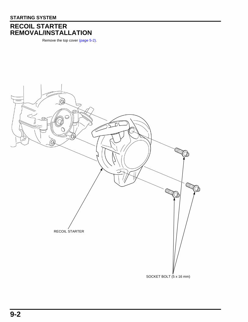
TOP COVER REMOVAL/INSTALLATION
TOP COVER
TOP COVER BOLT

6-1
6
dummytext
6. FUEL SYSTEM
FUEL TANK REMOVAL/INSTALLATION ····················· 6-2
AIR CLEANER REMOVAL/INSTALLATION ····················· 6-3
CARBURETOR REMOVAL/INSTALLATION ····················· 6-4
CARBURETOR DISASSEMBLY/ASSEMBLY···················· 6-5
METERING LEVER ADJUSTMENT··········· 6-6

6-2
dummyheaddummyhead
FUEL SYSTEMFUEL SYSTEM
FUEL TANK REMOVAL/INSTALLATION
Remove the recoil starter (page 9-2).
Remove the engine from engine bed (page 11-2).
Drain the fuel completely from fuel tank and fuel tube.
Gasoline is highly flammable and explosive. You can be burned or seriously injured when handling fuel.
• Keep heat, sparks, and flame away. • Handle fuel only outdoors. • Wipe up spills immediately.
FUEL FEED TUBE (A type)
CHECK:Check for deterioration, cracks or clogs.
FUEL TUBE GROMMET
INSTALLATION:
Install the fuel return tube [1] into the grommet [2] to the dimensions shown.
INSPECTION:
Inspect the grommet for deterioration or cracks.
FUEL TANK
FUEL TUBE
CHECK:Check for deterioration, cracks or clogs.
TUBE CLIP (C type)
TANK MOUNTING RUBBER (3)
FUEL TANK CAP
FUEL RETURN TUBECHECK:Check for deterioration, cracks or clogs.
TUBE CLIP (C type)
103 ± 3 mm(4.1 ± 0.1 in)
[1]
[2]
TUBE CLAMP (A type)
TUBE CLAMP (A type)
CHECK:Check for deterioration, cracks or clogs.
FUEL FEED TUBE (C type)
CHECK:Check the clogs or damage.
FUEL FILTER
TUBE CLIP
TUBE CLIP

6-3
dummyheaddummyhead
FUEL SYSTEM
AIR CLEANER REMOVAL/INSTALLATION
BREATHER TUBE
COLLAR (2)
AIR CLEANER COVER
AIR CLEANER ELEMENT
AIR CLEANER CASE
NUT (5 mm)(2)
OIL TRAP PLATE
INSTALLATION:
Before installing the breather line check for deterioration or damage. Replace if necessary.
SHORT
LONG
CYLINDER BARREL SIDE
AIR CLEANER CASE SIDE
INSTALLATION:Before installation, clean inside the case with compressed air.
CLEANING: page 3-5

6-4
dummyheaddummyhead
FUEL SYSTEM
CARBURETOR REMOVAL/INSTALLATION
Remove the air cleaner (page 6-3).
Gasoline is highly flammable and explosive. You can be burned or seriously injured when handling fuel.
• Keep heat, sparks, and flame away. • Handle fuel only outdoors. • Wipe up spills immediately.
INSULATOR PACKING
CARBURETOR PACKING
CARBURETOR
INSULATOR
O-RING(14.8 x 2.4 mm)
INSTALLATION:Install the insulator with the groove facing toward the carburetor.
TUBE CLIP (C TYPE) TUBE CLAMP (A TYPE)

6-5
dummyheaddummyhead
FUEL SYSTEM
CARBURETOR DISASSEMBLY/ASSEMBLY
Tampering is a violation of Federal and California law.
Remove the carburetor (page 6-4).
Before disassembly, clean the outside of the carburetor.
Gasoline is highly flammable and explosive. You can be burned or seriously injured when handling fuel.
• Keep heat, sparks, and flame away. • Handle fuel only outdoors. • Wipe up spills immediately.
PRIMER BULB COVER
INLET NEEDLE VALVE
CARBURETOR BODY
SCREW (2) SWIVEL
O-RING
METERING LEVER PIN SCREW
BULB COVER SCREW (4)
METERING DIAPHRAGM GASKET
ASSEMBLY:Check for worn valve seat [1], valve or weak spring before assembly.
[1]
REPLACE OK
METERING LEVER PIN
METERING LEVER
METERING LEVER SPRING
INLET SCREEN
ASSEMBLY:Remove dust and other foreign material from the screen before assembly.
PUMP DIAPHRAGM
CHECK:Replace if necessary.
PUMP BODY
ASSEMBLY:Wash the passage with nonflammable solvent to remove dust and other foreign material before assembly.Do not clean by blowing air.
PRIMER BULB
CHECK:Replace if necessary.
ASSEMBLY:After assembly, check for any sign of fuel leakage.
AIR PURGE BODY
METERING DIAPHRAGM
CHECK:Replace if necessary.
PUMP GASKET
PUMP SPRING
MAIN JET
ASSEMBLY:Before assembling, clean thoroughly with low-pressure compressed air.
ASSEMBLY:Before assembling, clean thoroughly with low-pressure compressed air.
THROTTLE BODY

6-6
dummyheaddummyhead
FUEL SYSTEM
METERING LEVER ADJUSTMENTInstall the metering lever spring [1], inlet needle valve[2], metering lever [3], metering lever pin [4] andmetering lever pin screw on the pump body [5].
Measure the gap between the metering lever surfaceand the pump body surface.
If the measurement is outside the specification, adjustby bending the metering lever.
METERING LEVER HEIGHT: 1.18 ‒ 1.50 mm (0.046 - 0.059 in)
[3]
[5]
1.18 - 1.50 mm(0.046 - 0.059 in)
[1] [2]
[4]

7-1
7
dummytext
7. CONTROL SYSTEM
CONTROL BASE/ENGINE STOP SWITCH REMOVAL/INSTALLATION ····················· 7-2
ENGINE STOP SWITCH INSPECTION ······ 7-3
THROTTLE LEVER ADJUSTMENT··········· 7-4

7-2
dummyheaddummyhead
CONTROL SYSTEMCONTROL SYSTEM
CONTROL BASE/ENGINE STOP SWITCH REMOVAL/INSTALLATION
Remove the air cleaner (page 6-3).
CONTROL LEVER
SOCKET BOLT (5 x 16 mm)
INSTALLATION:Clean the socket bolt threads and apply thread lock (ThreeBond® #1322N, Hondalock 2 or equivalent) to the threads.
ADJUSTING SCREW SPRING
INSTALLATION:
Install the end of the throttle rod [1] into round hole [2] side of the carburetor.
THROTTLE ROD
[1]
[2]
SOCKET BOLT (5 x 10 mm)
ENGINE STOPSWITCH
LEVER SPRING
CONTROL LEVER WASHER
NUT (6 mm)
CORD CLIP
SCREW (5 x 25 mm) CONTROL LEVER
SPACER
CONTROL BASE
INSTALLATION:Note the installation direction.

7-3
dummyheaddummyhead
CONTROL SYSTEM
ENGINE STOP SWITCHREMOVAL/INSTALLATIONREMOVAL
Raise the tab [1] with a screwdriver, and remove theengine stop switch [2].
INSTALLATION
Align the projection [1] on the control base [2] with thegroove [3] in the engine stop switch [4].
Bend the tab as shown.
ENGINE STOP SWITCH INSPECTIONRemove the engine stop switch connector [1].
Check the continuity between the terminals at eachswitch position.
If the correct continuity is not obtained, replace theengine stop switch (page 7-2).
[1]
[2]
[2]
[1][4]
[3]
Switch position ContinuityON NoOFF Yes
[1]

7-4
dummyheaddummyhead
CONTROL SYSTEM
THROTTLE LEVER ADJUSTMENTRemove the air cleaner cover (page 6-3).
Move the throttle lever [1] slowly by pushing it down tothe "HIGH SPEED" side until it brings the carburetorthrottle valve [2] to the position where the clearance atthe stopper [3] is 0.5 - 1.0 mm (0.02 - 0.04 in).
Check that the adjusting screw [4] end is in contact withthe stopper or the throttle lever. If it is not, adjust byturning the adjusting screw. [3]
[1]
[2]
[4]

8-1
8
dummytext
8. IGNITION SYSTEM
TOOLS ················································ 8-2
SYSTEM DIAGRAM ······························· 8-3
IGNITION SYSTEM TROUBLESHOOTING ···························· 8-3
IGNITION COIL REMOVAL/INSTALLATION ····················· 8-4
FAN COVER/ENGINE P.T.O.SHAFT/FLYWHEEL REMOVAL/INSTALLATION···· 8-5
IGNITION COIL AIR GAP CHECK/ADJUSTMENT··························· 8-7
SPARK TEST········································ 8-8
IGNITION COIL INSPECTION ·················· 8-8
ENGINE P.T.O.SHAFT INSPECTION········· 8-9
RADIAL BALL BEARING (6001) REPLACEMENT ···································· 8-9

8-2
dummyheaddummyhead
IGNITION SYSTEMIGNITION SYSTEM
TOOLSPilot, 12 mm07746-0040200
Driver07749-0010000
Attachment, 28 x 30 mm07946-1870100

8-3
dummyheaddummyhead
IGNITION SYSTEM
SYSTEM DIAGRAM
IGNITION SYSTEM TROUBLESHOOTINGNO OR WEAK SPARK AT SPARK PLUGCheck the following before troubleshooting:
– Loose connectors– Spark plug (page 3-6)
Bl
Bl
SPARK PLUG IGNITION COIL ENGINE STOP SWITCH
ENGINE STOP SWITCH
IG E
OFF
ON
Bl BlackY Yellow
Bu BlueG GreenR RedW White
Br BrownO OrangeLb Light blueLg Light greenP PinkGr Gray
Check for continuity between the engine stop switch cord connectors.Replace if necessary.
Check the engine stop switch (page 7-3). Replace the engine stop switch (page 7-2).
Check the ignition coil (page 8-8). Replace the ignition coil (page 8-4).
Normal
Abnormal
Abnormal
Normal

8-4
dummyheaddummyhead
IGNITION SYSTEM
IGNITION COIL REMOVAL/INSTALLATION
Remove the top cover (page 5-2).
• Route the engine wire harness and high-tensioncode properly (page 2-6).
• After installation, check the ignition coil air gap (page 8-7).
IGNITION COIL
HIGH TENSION CORDSOCKET BOLT (4 x 14 mm)
3.9 N·m (0.40 kgf·m, 2.9 lbf·ft)

8-5
dummyheaddummyhead
IGNITION SYSTEM
FAN COVER/ENGINE P.T.O. SHAFT/FLYWHEEL REMOVAL/INSTALLATION
Remove the ignition coil (page 8-4).
Remove the casing cover (page 10-5).
14.7 N·m (1.5 kgf·m, 11 lbf·ft)
FAN COVER
(Threads and seating surface)NUT (7 mm)
SOCKET BOLT (5 x 20 mm) (3)
FLYWHEEL
ENGINE P.T.O. SHAFT
BOLT (6 x 22 mm) (2)
RADIAL BALL BEARING(6001) (Rolling surface)
6.4 N·m (0.65 kgf·m, 4.7 lbf·ft)

8-6
dummyheaddummyhead
IGNITION SYSTEM
ENGINE P.T.O. SHAFT REMOVAL/INSTALLATION
• To avoid flywheel fan blade damage, position thestrap wrench fulcrum at the flywheel magnetic parts.
Holding the flywheel [1] with a commercially availablestrap wrench [2], remove the bolt (6 x 22 mm) [3] andremove the P.T.O. shaft [4].
Installation is in the reverse order of removal.
FLYWHEEL REMOVAL/INSTALLATIONREMOVAL
• To avoid flywheel fan blade damage, position thestrap wrench fulcrum at the flywheel magnetic parts.
Remove the engine P.T.O.shaft (page 8-6).
Holding the flywheel [1] with a commercially availablestrap wrench [2], remove the nut (7 mm) [3] from theflywheel.
Remove the flywheel [1] using a commercially availableflywheel puller [2].
• Do not remove the flywheel by tapping it with ahammer.
[4]
[2]
[3]
[1]
[2]
[1] [3]
[2]
[1]

8-7
dummyheaddummyhead
IGNITION SYSTEM
INSTALLATION
• Clean the tapered part of dirt, oil, grease and otherforeign material before installation.
• Be sure that there is no washer or other foreignmaterial on the magnetic part.
Be sure that the woodruff key is set in the key grooveproperly.
Holding the flywheel [1] with a commercially availablestrap wrench [2], tighten the nut (7 mm) [3] to thespecified torque.
Install the engine P.T.O. shaft (page 8-6).
IGNITION COIL AIR GAP CHECK/ADJUSTMENT
Remove the top cover (page 5-2).
Insert the feeler gauge [1] of proper thickness betweenthe ignition coil [2] and the flywheel [3].
• Check the clearance at the magnet part of theflywheel.
If measured clearance is out of specification, adjust theair gap.
Loosen the two socket bolts (4 x 14 mm) [1].
Insert the feeler gauge of proper thickness between theignition coil [2] and magnet part [3] of the flywheel.
Push the ignition coil firmly against the magnet part ofthe flywheel and tighten the two socket bolts (4 x 14mm) to the specified torque.
Remove the feeler gauge.
Install the top cover (page 5-2).
TORQUE: 14.7 N·m (1.5 kgf·m, 11 lbf·ft)
[1]
[3]
[2]
IGNITION COIL AIR GAP:0.2 – 0.4 mm (0.01 – 0.02 in) [2]
[3]
[1]
TORQUE: 3.9 N·m (0.40 kgf·m, 2.9 lbf·ft)
[2]
[1]
[3]

8-8
dummyheaddummyhead
IGNITION SYSTEM
SPARK TEST
Check for the following before conducting the sparktest.
• Faulty spark plug • Loose spark plug cap • Water in the spark plug cap (leaking the ignition coil
secondary voltage) • Loose ignition coil connector
Disconnect the spark plug cap [1] from the spark plug[2].
Connect a known-good spark plug [3] to the spark plugcap and ground the spark plug to the air exhaustguide[4].
Turn the engine stop switch to "ON" position.
Crank the engine by pulling the recoil starter and checkwhether sparks jump across the electrodes.
IGNITION COIL INSPECTIONRemove the top cover (page 5-2).
PRIMARY SIDEDisconnect the ignition coil connector [1].
Measure the resistance of the primary coil by attachingone ohmmeter probe to the ignition coil connector andthe other at the iron core [2].
If measured resistance is out of specification, replacethe ignition coil.
SECONDARY SIDEMeasure the resistance of the secondary coil byattaching one ohmmeter probe to the spark plug cap [1]and the other at the iron core [2].
If measured resistance is out of specification, replacethe ignition coil.
[1]
[4]
[2]
[3]
RESISTANCE: 0.585 ‒ 0.715 Ω
[1]
[2]
RESISTANCE: 4.77 ‒ 5.83 kΩ
[2]
[1]

8-9
dummyheaddummyhead
IGNITION SYSTEM
ENGINE P.T.O. SHAFT INSPECTIONMeasure the engine P.T.O.shaft [1] bearing O.D.
If the measurement is less than the service limit,replace the engine P.T.O. shaft and fan cover bearing(6001) as a set (page 8-9).
RADIAL BALL BEARING (6001) REPLACEMENT
INSTALLATIONApply oil to the inner surface and the outer surface of anew radial ball bearing [1].
Press the radial ball bearing in the fan cover [2] usingthe special tools.
STANDARD: 11.966 ‒ 11.984 mm (0.4711 ‒ 0.4718 in)
SERVICE LIMIT: 11.800 mm (0.4646 in) [1]
TOOLS:Attachment, 28 x 30 mm [3] 07946-1870100Pilot, 12 mm [4] 07746-0040200Driver [5] 07749-0010000 [2]
[1]
[3]
[4]
[5]

MEMO
dummyheaddummyhead

9-1
9
dummytext
9. STARTING SYSTEM
RECOIL STARTER REMOVAL/INSTALLATION ····················· 9-2
STARTER PULLEYREMOVAL/INSTALLATION ····················· 9-3
RECOIL STARTER DISASSEMBLY/ASSEMBLY···················· 9-4
9-2
dummyheaddummyhead
STARTING SYSTEMSTARTING SYSTEM
RECOIL STARTER REMOVAL/INSTALLATION
Remove the top cover (page 5-2).
RECOIL STARTER
SOCKET BOLT (5 x 16 mm)

9-3
dummyheaddummyhead
STARTING SYSTEM
STARTER PULLEYREMOVAL/INSTALLATION
Remove the recoil starter (page 9-2).
Remove the fuel tank (page 6-2).
STARTER PULLEY
INSTALLATION:Holding the recoil starter pulley [1] in the same manner as on disassembly, tighten the flywheel [2] to the specified torque.
REMOVAL:Holding the flywheel [1] with commercially available strap wrench [2], remove the recoil starter pulley [3] with a driver or equivalent tool
[1]
[2]
[3]
[4]
[1]
[2]
14.7 N·m (1.5 kgf·m, 11 lbf·ft)

9-4
dummyheaddummyhead
STARTING SYSTEM
RECOIL STARTER DISASSEMBLY/ASSEMBLY
DISASSEMBLYRemove the recoil starter (page 9-2).
The recoil spring is wound under high tension and when released from the groove will cause sudden unwinding.
Sudden unwinding can cause severe lacerations.
Wear gloves and eye protection during this procedure and take care not to allow the spring to come out.
RECOIL STARTER REEL
SWING ARM
RECOIL STARTER SPRING
RECOIL STARTER CASE
STARTER GRIP
SWING ARM COLLOR
SET SCREW
(Recoil starter reel sliding area)
RECOIL STARTER ROPE
(Recoil starter reel sliding area)

9-5
dummyheaddummyhead
STARTING SYSTEM
ASSEMBLYInsert the hook on the outer side of the spring [1] intothe groove [2] inside the starter reel [3]. Carefully windthe recoil starter spring [4] inside the starter reel.
Pass the starter rope [1] through the starter reel [2] andtie the rope so that it can be untied easily by pulling it asshown.
Wind the starter rope around the recoil starter reel inthe direction of the arrow.
Position the end of the starter rope [1] at the cutout [2]in the starter reel [3].
Install the starter reel [1] on the starter case [2] so thatthe spring [3] inner hook [4] is hooked to the case tab[5].
[4]
[1]
[2][3]
[2]
[1]
[2]
[1]
[3]
[4]
[3]
[2][5]
[1]

9-6
dummyheaddummyhead
STARTING SYSTEM
Secure the starter reel [1] with the set screw [2].
• Make sure to align the groove [3] of the swing armcollar [4] with the swing arm [5].
Hold the starter case [1] and rotate the starter reel [2]three turns in the direction of the arrow for preliminarywinding.
Pass the starter rope [1] end through the case [2] andpull it outwards.
Pass the starter rope through the starter grip [3] and tiethe rope so that it can be untied easily by pulling it asshown.
Pull the starter grip several time to make sure the swingarm [4] operates properly.
[5]
[4]
[2]
[1]
[3]
[2]
[1]
[1]
[4]
[2]
[3]

10-1
10
dummytext
10. PUMP
TOOLS ·············································· 10-2
INLET PIPE/OUTLET PIPE REMOVAL/INSTALLATION ··················· 10-3
CASING/VOLUTE CASEREMOVAL/INSTALLATION ··················· 10-4
IMPELLER/CASING COVER REMOVAL/INSTALLATION ··················· 10-5
MECHANICAL SEAL REPLACEMENT ···· 10-6

10-2
dummyheaddummyhead
PUMPPUMP
TOOLSAttachment, 24 x 26 mm07746-0010700
Driver07749-0010000
Mechanical seal installer07965-415000A

10-3
dummyheaddummyhead
PUMP
INLET PIPE/OUTLET PIPE REMOVAL/INSTALLATION
OUTLET PIPE
BOLT (6 x 20 mm) (4)
INLET PIPE
BOLT (6 x 20 mm) (3)
OUTLET PACKING
FILLER CAP
INLET VALVE
INSTALLATION:Check the inlet valve for breakage or excessive wear damage. Align the tab [1] on the inlet valve with the groove [2] of the inlet pipe.
[1] [2]ALIGN
O-RING(23.7 x 3.5 mm)
INSTALLATION:Install in desired position. Three options to choose from.

10-4
dummyheaddummyhead
PUMP
CASING/VOLUTE CASEREMOVAL/INSTALLATION
VOLUTE CASE
O-RING (140 x 3.5 mm)
O-RING (36.5 x 5.7 mm)
INSTALLATION:Check the mating surface for damage and nicks.
INSPECTION:Inspect the inside for excessive wear or damage.
DRAIN CAP
BOLT (6 x 25 mm) (4)
CASING
O-RING(23.7 x 3.5 mm)
TORQUE:Tighten in a diagonal pattern in multiple steps to the proper torque.

10-5
dummyheaddummyhead
PUMP
IMPELLER/CASING COVER REMOVAL/INSTALLATION
Remove the engine and pump from engine bed (page 11-2).
Remove the volute case (page 10-4).
Remove the ignition coil (page 8-4).
CASING COVER ALUMINUM SEALING WASHER (5 mm) (4)
SOCKET BOLT (5 x 35 mm) (4)
ADJUSTER SHIMRUBBER RING/CERAMIC RING
5.0 N·m (0.51 kgf·m, 3.7 lbf·ft)
INSTALLATION: Insert a rod of O.D. 5 - 6 mm (0.20 - 0.24 in) [1] into the gap in the cylinder barrel [2], and lock the flywheel [3] by setting the rod on the flywheel weight [4] and on the projection [5] on the cylinder barrel as shown.Holding flywheel locked, tighten the impeller to the specified torque.
REMOVAL: Insert a rod of O.D. 8 - 10 mm (0.30 - 0.40 in) [1] between the flywheel [2] weight [3] and fan cover [4] and lock the flywheel as shown.Holding flywheel locked, remove the impeller.
[1]
[3]
[1]
[2][4]
6.9 N·m (0.70 kgf·m, 5.1 lbf·ft)
[2]
[3]
[5]
[4]
INSPECTION: Inspect the impeller vanes for excessive wear or damage. Replace if necessary.
After installation, check the impeller clearance: (page 3-11)

10-6
dummyheaddummyhead
PUMP
MECHANICAL SEAL REPLACEMENTDrive out the mechanical seal [1] from the inside usingthe special tools.
Place the seal onto the seal driver [1] and bolt [2].
Put the bolt through the casing cover [3].
Install the back up plate [4] with the B side facing thecasing cover and install the washer [5] and nut [6].
Tighten until the seal is fully seated.
• Be careful not to damage the sliding surface of themechanical seal.
After installing, check to be sure the seal is fully seatedand is not tilted in the casing cover.
Install a new rubber ring [1] over a new ceramic ring [2].
• Be careful not to damage the sliding surface of theceramic ring.
Apply soapy water around the rubber ring. Install therubber ring/ceramic ring assembly into the impeller [3]carefully with the rubber ring facing the impeller until itis fully seated.
TOOLS:Driver handle [2] 07749-0010000Attachment, 24 x 26 mm [3] 07746-0010700
[1]
[2]
[3]
TOOLS:Mechanical seal installer 07965-415000A
[5] [6]
[2][1]
[3] [4]
[3]
[2][1]

11-1
11
dummytext
11. ENGINE REMOVAL/INSTALLATION
ENGINE REMOVAL/INSTALLATION······· 11-2

11-2
dummyheaddummyhead
ENGINE REMOVAL/INSTALLATIONENGINE REMOVAL/INSTALLATION
ENGINE REMOVAL/INSTALLATION
INSTALLATION:Check for cracking, deformation or other damage before installation.Install by aligning with the hole in the frame.
HANDLE
FRAME BED
BOLT (6 x 14 mm) (2)
NUT (6 mm) (4)
SCREW (6 x 10 mm) (4)
BOLT (6 x 14 mm) (2)
BOTTOM RUBBER (4)

12-1
12
dummytext
12. CRANKCASE
TOOLS ·············································· 12-2
LOWER CRANKCASE/SHROUD REMOVAL/INSTALLATION ··················· 12-3
CRANKSHAFT/PISTON REMOVAL/INSTALLATION ··················· 12-6
CRANKSHAFT/PISTON INSPECTION····12-10

12-2
dummyheaddummyhead
CRANKCASECRANKCASE
TOOLSPiston base07VPF-ZM3010B
Push rod07VPF-ZM3020A
Guide07VPF-ZM3030A

12-3
dummyheaddummyhead
CRANKCASE
LOWER CRANKCASE/SHROUD REMOVAL/INSTALLATION
Drain the engine oil (page 3-4).
Remove the engine (page 11-2).
Remove the following:
– Control base (page 7-2)– Carburetor (page 6-4)– Fuel tank (page 6-2)– Muffler (page 14-2)– Flywheel (page 8-6)– Starter pulley (page 9-3)
BOLT (5 x 58 mm) (2)
SHROUD
OIL FILLER CAP PACKING
O-RING (12.3 x 2.4 mm)
SOCKET BOLT (5 x 16 mm) (2)
TUBE CLIP (D12)
TUBE CLIP (D13)
OIL TUBE
SOCKET BOLT (5 x 30 mm) (4)SOCKET BOLT (5 x 20 mm) (2)
SPRING PIN (4 x 10 mm)
SCREW (4 x 8 mm) (2)
6.4 N·m (0.65 kgf·m, 4.7 lbf·ft)6.4 N·m (0.65 kgf·m, 4.7 lbf·ft)
3.0 N·m (0.31 kgf·m, 2.2 lbf·ft)
INSTALLATION:Inspect for cracks or deterioration before installation.
OIL FILLER CAP
OIL OUTLET VALVE PLATE
LOWER CRANKCASE
INSTALLATION:Clean the socket bolt threads and apply thread lock (ThreeBond® #1322N, Hondalock 2 or equivalent) to the threads.

12-4
dummyheaddummyhead
CRANKCASE
LOWER CRANKCASE REMOVAL/INSTALLATIONREMOVAL
Remove the two socket bolts (5 x 20 mm) and foursocket bolts (5 x 30 mm).
Insert the screw driver or equivalent tool into the recess[1] as shown, and remove the lower crankcase from thecylinder barrel.
INSTALLATION
Clean the inside of the crankcase and remove foreignmaterial.
Clean the mating surfaces of the cylinder barrel and thelower crankcase [1] using a degreasing cleaning agentand clean shop towel.
Apply a bead [2] [Φ1.0 – 1.5 mm (Φ0.04 – 0.06 in)] ofthe liquid sealant (ThreeBond® 1216E, Hondabond HTor equivalent) to the mating surface with the lowercrankcase.
Install the lower crankcase on the cylinder barrel.Assemble within 3 minutes after applying the liquidgasket.
Loosely tighten each two socket bolts (5 x 20 mm) andfour socket bolts (5 x 30 mm) then tighten to thenumbered sequence.
Wait for approximately 60 minutes after assemblybefore filling oil and starting the engine.
CARBURETOR SIDE: MUFFLER SIDE:
[1] [1]
[1]
[2]
TORQUE: 6.4 N·m (0.65 kgf·m, 4.7 lbf·ft) 5
6
1
2
3
4

12-5
dummyheaddummyhead
CRANKCASE
SHROUD INSTALLATIONSet the two bolts (5 x 58 mm) [1] on the shroud [2].Take care not to allow the bolt heads to protrude fromthe shroud when installing on the cylinder barrel.
OIL TUBE INSTALLATIONInstall the oil tube and the tube clamp (D12) [1] andtube clamp (D13) [2] with the " UP" mark [3] of theoil tube facing toward the cylinder.
• Do not interchange the clamps. • Be sure that the tube and the shroud do not come
into contact.
[2]
[1]
[1]
[2][3]

12-6
dummyheaddummyhead
CRANKCASE
CRANKSHAFT/PISTON REMOVAL/INSTALLATION
Remove the lower crankcase (page 12-3).
Remove the cam pulley (page 13-4).
TIMING BELT
CRANKSHAFT(Bearing rolling surface)
INSTALLATION:Check that the belt is not worn or cracked. Do not bend or twist the belt.
" " MARK
(Apply to the lip)
OIL SEAL (12 x 24 x 5 mm)
OIL SEAL (10 x 20 x 5 mm)
(Apply to the lip)
PISTON PIN(Outer surface)
CARBURETOR SIDE:
MUFFLER SIDE:
(Outer surface)
INSTALLATION:·Install the top ring and second ring with the""mark facing up.·Do not interchange the top ring and the second ring.·After assembly, check for smooth movement of the piston ring.·Stagger the piston ring end gaps 120° apart. Do not align with the piston pin. ·Space the side rail end gaps at least 10 mm (0.4 in) apart. Coat the oil ring with oil after assembly.
TOP RING
SECOND RING
SIDE RAIL
SIDE RAIL
SPACEROIL RING (COMBINATION RING)
""MARK
10 mm (0.4 in)
120°120°
120°
TOP RING
SECOND RING
INSTALLATION:Install with the " " on the piston head facing the carburetor side.
OIL RING (COMBINATION RING)
10 mm (0.4 in)
PISTON
PISTON RING

12-7
dummyheaddummyhead
CRANKCASE
PISTON PIN REMOVAL/ INSTALLATIONREMOVAL
Insert the special tool (push rod) into the piston pin withthe crankshaft timing belt drive pulley [1] upward asshown.
Set the cutout part [1] of the special tool (piston base) inthe clearance [2] between the connecting rod [3] andthe piston as shown.
• Be sure that the connecting rod small end issecurely set in the cutout of the special tool (pistonbase).
Remove the piston pin [6] from the connecting rod usinga hydraulic press.
TOOL:Push rod [2] 07VPF-ZM3020A
[1]
[2]
TOOL:Piston base [4] 07VPF-ZM3010BPush rod [5] 07VPF-ZM3020A
[4]
[2][1]
[3]
[5]
[6]
Approx.gap:1.5 mm(0.060 in)

12-8
dummyheaddummyhead
CRANKCASE
INSTALLATION
Slide the piston pin [1] over the special tool (push rod)and install the special tool (guide).
Set the piston over the connecting rod so that thecrankshaft oil slinger [1] comes at the right side with the" " mark [2] on the piston head toward you as shown.
Apply oil to the piston pin [1] and assemble the pistonpin with special tools attached as shown.
With the timing belt drive pulley [2] up, align the pistonpin hole with the connecting rod [3] hole and insert thespecial tool (guide) into the piston pin hole.
Set the cutout part [4] of the special tool (piston base) inthe clearance between the connecting rod and thepiston as shown.
• Be sure that the connecting rod small end issecurely set in the cutout of the special tool (pistonbase).
Using a hydraulic press to press the piston pin into theconnecting rod until the piston pin extendsapproximately 1.5 mm (0.060 in) above the piston pin.
Remove the special tools from the piston pin.
TOOL:Push rod [2] 07VPF-ZM3020AGuide [3] 07VPF-ZM3030A
[1]
[2]
[3]
[2]
[1]
TOOL:Piston base [5] 07VPF-ZM3010BPush rod [6] 07VPF-ZM3020AGuide [7] 07VPF-ZM3030A
[4]
[1]
[6]
[3]
[7]
[1]
Approx.gap:1.5 mm(0.060 in)
[5][2]

12-9
dummyheaddummyhead
CRANKCASE
After assembling the piston pin [1], move theconnecting rod [2] from side-to-side and make sure thegap from the piston pin end to the piston [3] end isequal at the right and left sides.
If the right and left gaps are not equal, raise or lowerpiston pin as needed.
CRANKSHAFT INSTALLATIONInstall the timing belt [1] on the timing gear [2] of thecrankshaft. When installing, pay attention to thedirection of the letter [3] on the timing belt as shown inthe picture.
• Replace worn or cracked timing belt. Do not bend ortwist the timing belt.
Install the crankshaft [4] in the cylinder barrel [5].
Apply a bead of Hondabond HT liquid gasket to thecylinder barrel (page 12-4) specifically to the matingsurface of the lower crankcase. Install the lowercrankcase on the cylinder barrel.
Install the cam pulley [6] and timing belt in the cylinderbarrel (page 13-4).
CRANKSHAFT OIL SEAL (10 x 20 x 5 mm/12 x 24 x 5 mm)INSTALLATIONApply grease to the lip of the oil seal [1].
Set the oil seal on the crankshaft [2].
Install crankshaft by aligning the oil seal projection [3]with the groove [4] in the cylinder barrel.
Install the lower crankcase (page 12-4).
[1]
[2]
[3]
Approx. gap:1.5 mm(0.060 in)
Approx. gap:1.5 mm(0.060 in)
[1]
[3]
[2] [4]
[5]
[6]
[1]
[2]
[3]
[4]

12-10
dummyheaddummyhead
CRANKCASE
CRANKSHAFT/PISTON INSPECTIONOIL SLINGERCheck the oil slinger [1] of the crankshaft for damageand deformation. Replace the crankshaft if it isdamaged or deformed.
CYLINDER SLEEVE I.D.Measure and record the cylinder I.D. at three levels inboth the “X” axis (perpendicular to crankshaft) and the“Y” axis (parallel to crankshaft). Take the maximumreading to determine cylinder wear and taper.
If the measurement is more than the service limit,replace the crankcase set, piston, and rings.
PISTON SKIRT O.D.Measure and record the piston O.D. at a point 10 mm(0.4 in) from the bottom of the skirt and 90 degrees tothe piston pin bore.
If the measurement is less than the service limit,replace the piston and rings. Do not hone the cylinder.
PISTON-TO-CYLINDER CLEARANCESubtract the piston skirt O.D. from the cylinder sleeveI.D. to obtain the piston-to-cylinder clearance.
If the calculated clearance is more than the service limit,replace the piston and recheck the clearance.
If the clearance is still more than the service limit withthe new piston, replace the crankcase set. Do not honethe cylinder.
[1]
STANDARD: 35.000 – 35.015 mm(1.3780 – 1.3785 in)
SERVICE LIMIT: 35.100 mm (1.3819 in)
X
Y
MIDDLE
BOTTOM
TOP
STANDARD: 34.970 – 34.990 mm(1.3768 – 1.3776 in)
SERVICE LIMIT: 34.900 mm (1.3740 in)
90°
10 mm (0.4 in)
STANDARD: 0.010 – 0.045 mm(0.0004 – 0.0018 in)
SERVICE LIMIT: 0.120 mm (0.0047 in)

12-11
dummyheaddummyhead
CRANKCASE
PISTON PIN BORE I.D.Measure and record the piston pin bore I.D. of thepiston.
If the measurement is more than the service limit,replace the piston.
PISTON PIN O.D.Measure and record the piston pin O.D. at three points(both ends and middle). Take the minimum reading todetermine piston pin O.D.
If the measurement is less than the service limit,replace the piston pin.
PISTON PIN-TO-PISTON PIN BORE CLEARANCESubtract the piston pin O.D. from the piston pin boreI.D. to obtain the piston pin-to-piston pin boreclearance.
If the calculated clearance is more than the service limit,replace the piston pin and recheck the clearance.
If the clearance is still more than the service limit withthe new piston pin, replace the piston.
PISTON RING SIDE CLEARANCEMeasure the clearance between each piston ring andring groove of the piston using feeler gauge.
If the calculated clearance is more than the servicelimit, replace the piston rings (top, second, oil) as a setand recheck the clearance.
If the clearance is still more than the service limit withthe new piston ring, replace the piston.
STANDARD: 8.010 – 8.026 mm(0.3154 – 0.3160 in)
SERVICE LIMIT: 8.060 mm (0.3173 in)
STANDARD: 7.994 – 8.000 mm(0.3147 – 0.3150 in)
SERVICE LIMIT: 7.950 mm (0.3130 in)
STANDARD: 0.010 – 0.032 mm (0.0004 – 0.0013 in)
SERVICE LIMIT: 0.070 mm (0.0028 in)
STANDARD:Top/Second: 0.015 – 0.056 mm
(0.0006 – 0.0022 in)SERVICE LIMIT:Top/Second: 0.120 mm (0.0047 in)

12-12
dummyheaddummyhead
CRANKCASE
PISTON RING WIDTHMeasure each piston ring width.
If any of the measurements is less than the servicelimit, replace the piston rings (top, second, oil) as a set.
Do not hone the cylinder.
PISTON RING END GAPBefore inspection, check whether the cylinder sleeveI.D. is within the specification (page 12-10).
Put the piston ring in the cylinder and then use thepiston crown to push the ring down. This will make the piston ring horizontal so ring end gapcan be measured.
Measure each piston ring [1] end gap using a feelergauge.
If any of the measurements is more than the servicelimit, replace the piston rings (top, second, oil) as a set.
Do not hone the cylinder.
CONNECTING ROD SMALL END I.D.Measure the connecting rod small end I.D.
If the measurement is more than the service limit,replace the crankshaft.
STANDARD:Top/Second: 0.970 – 0.990 mm
(0.0382 – 0.0390 in)SERVICE LIMIT:Top/Second: 0.920 mm (0.0362 in)
STANDARD:Top/Second: 0.10 – 0.25 mm
(0.004 – 0.010 in)SERVICE LIMIT:Top/Second: 0.60 mm (0.024 in) [1]
STANDARD: 7.978 – 7.989 mm (0.3141 – 0.3145 in)
SERVICE LIMIT: Replace if exceeding the standard value.

13-1
13
dummytext
13. CYLINDER HEAD
TOOL················································· 13-2
CYLINDER HEAD COVER/CAM PULLEY REMOVAL/INSTALLATION ··················· 13-3
ROCKER ARM/VALVES REMOVAL/INSTALLATION ··················· 13-5
CYLINDER COMPRESSION CHECK······13-10
CYLINDER HEAD/VALVES INSPECTION ·····································13-10

13-2
dummyheaddummyhead
CYLINDER HEADCYLINDER HEAD
TOOLRocker arm replacement tool070PF-Z0HA100

13-3
dummyheaddummyhead
CYLINDER HEAD
CYLINDER HEAD COVER/CAM PULLEY REMOVAL/INSTALLATION
Remove the following:
– Spark plug (page 3-6)– Top cover (page 5-2)– Fan cover (page 8-5)
TIMING BELT
HEAD INNER COVER
HEAD COVER SEAL
HEAD COVER
SOCKET BOLT (5 x 12 mm) (2)
BREATHER TUBE
CAM PULLEY SHAFT
SCREW (4 x 12 mm) (2)
CAM PULLEY
BREATHER FILTER
HEAD COVER GROMMET
(Profile and journal)
(Whole surface)
INSTALLATION:Check that the belt is not worn or cracked. Do not bend or twist the belt.
INSPECTION: (page 13-11)

13-4
dummyheaddummyhead
CYLINDER HEAD
CAM PULLEY REMOVAL/ INSTALLATIONRemove the following:
– Spark plug (page 3-6)– Head cover (page 13-3)– Fan cover (page 8-5)
Set the piston at top dead center (TDC) of thecompression stroke.
When the piston is at TDC of the compression stroke,the flywheel " " mark [1] will align with the fancover bolt hole [2]. Also, the cam pulley alignmentmarks [3] will be positioned as shown.
Push the cam pulley shaft [1] out from the valve springside using a pin approximately 2 mm in diameter.
• Be careful not to let the cam pulley shaft fall into thecrankcase.
Remove the timing belt [1] from the cam pulley [2], andremove the cam pulley.
Installation is in the reverse order of removal. Makesure the alignment marks on the cam pulley and theflywheel are aligned.
[1]
[2]
[3]
[1]
[2]
[1]

13-5
dummyheaddummyhead
CYLINDER HEAD
ROCKER ARM/VALVES REMOVAL/INSTALLATION
Remove the cam pulley (page 13-3).
Remove the crankshaft (page 12-6).
SPARK PLUG
INTAKE VALVE LIFTER
VALVE SPRING (2)
VALVE STEM SEAL(Intake valve only)
(Whole surface)
EXHAUST VALVE LIFTER
VALVE SPRING RETAINER (2)
(Sliding surface)INTAKE VALVE
INSTALLATION:Do not interchange with the exhaust valve.
11.8 N·m (1.2 kgf·m, 8.7 lbf·ft)
INTAKE VALVE ROCKER ARM
EXHAUST VALVE ROCKER ARM
ADJUSTING SCREW (2)
ADJUSTING SCREW LOCK NUT (2)
4.9 N·m (0.50 kgf·m, 3.6 lbf·ft)
Do not remove the valve spring retainers while the lower crankcase is installed, or the valves will drop into the cylinder.
REMOVAL:Push down and slide the retainer to the side, so the valve stem slips through the hole at the slide of the retainer.
Viewed from clutch side.
REMOVAL/INSTALLATION:(page 13-6)
Do not interchange with the exhaust valve rocker arm.
Do not reuse after removing.
(Sliding surface)
INSTALLATION:Do not interchange with the intake valve.Before installation, remove the carbon deposits and inspect the valve.
EXHAUST VALVE
Do not reuse after removing.
REMOVAL/INSTALLATION:(page 13-6)
Do not interchange with the exhaust valve rocker arm.
Do not reuse after removing.
Viewed from recoil starter side.
REMOVAL/INSTALLATION:(page 13-6)
Do not interchange with the intake valve rocker arm.
Do not reuse after removing.
Viewed from recoil starter side.
REMOVAL/INSTALLATION:(page 13-6)
Do not interchange with the intake valve rocker arm.
Do not reuse after removing.
Viewed from clutch side.

13-6
dummyheaddummyhead
CYLINDER HEAD
ROCKER ARM/VALVE LIFTER REMOVAL/INSTALLATIONREMOVAL
Remove the adjusting screw lock nuts [1] and removethe adjusting screws [2] from the rocker arms [3].
Remove the cam pulley (page 13-4).
Tighten the holder bolt [1] of the special tool fully asshown.
Set the special tool on the cylinder head over the rockerarm and valve lifter that you are going to take apart, andtighten the bolt (5 mm) [3] to the cylinder head coverinstallation boss [4] by hand.
Do not tighten the bolt (5 mm) using a wrench.
Tighten the push rod [1] of the special tool by hand untilthe tip of the push rod comes to the center of the valvelifter shaft [2]. Move the special tool left and right andcheck that it can be moved slightly.
Using a 14 mm wrench [1], tighten the push rod [2] untilthe shaft of the valve lifter goes out from the rocker arm[3].
Loosen the push rod and remove the bolt (5 mm) [4],and then remove the special tool.
The valve lifters and rocker arms cannot be reused afterthey are pressed apart. Always replace with new parts.
[3]
[2]
[1]
TOOL:Rocker arm replacement tool [2] 070PF-Z0HA100
[1]
[2]
[4]
[3]
It should be able to move slightly in this direction.(Or the cylinder head cover installation boss will be damaged)
[1]
[2]
[1]
[2]
[3]
[4]

13-7
dummyheaddummyhead
CYLINDER HEAD
INSTALLATION
Install the new valve lifter [1] on the cylinder head andbring the valve lifter in contact with the installation guiderib [2] of the cylinder head.
Push the new rocker arm [3] into the shaft of the valvelifter by hand while holding the valve lifter in the positionand holding the rocker arm against the installationguide rib [4] of the cylinder head.
• Check the valve lifter for inlet side and exhaust sidebefore installation. Do not interchange them.
• Check the rocker arm for "IN" or "EX" marks beforeinstallation. Do not interchange them.
Set the projection [1] of the valve lifter [2] in contact withthe installation guide rib [3] of the cylinder head.
Set the rocker arm [4] in contact with the installationguide rib [5] of the cylinder head.
Check that the projection on the valve lifter and therocker arm are in contact with the installation guide ribof the cylinder head.
EXHAUST VALVE ROCKER ARM
INTAKE VALVE ROCKER ARM
INTAKEVALVE LIFTER
EXHAUSTVALVE LIFTER
Viewed from the flywheel side:
Viewing cylinder head right down:
[1]
[2]
[3]
[4]
[1]
[4]
[5]
[2]
[3]

13-8
dummyheaddummyhead
CYLINDER HEAD
Install the holder bolt [1] of the special tool in thedirection as shown.
Install the adapter [3] on the tip of the push rod [4] thatis set on the special tool.
Install the special tool on the cylinder head so that thebolt (5 mm) [5] sets in the center of the long hole in thespecial tool as shown.
Tighten the bolt (5 mm) against the cylinder head covermounting boss by hand.
• Set the bolt (5 mm) in the center of the long hole. • Do not tighten the bolt (5 mm) using a wrench.
Bring the projection on the valve lifter [1] and the rockerarm [2] to come in contact with the cylinder headpositioning ribs [3].
Bring the clearance A [4] and B [5] to be equal bymoving the valve lifter and rocker arm right and left.
While holding the valve lifter and rocker arm in theposition, tighten the holder bolt [6] by hand until itcontacts the valve lifter. Tighten the push rod [7] byhand until the adapter [8] contacts the rocker arm.
After installing the special tool, check that the bolt (5mm) [9] is in the center of the long hole [10] in the tool.
Note that the cylinder head cover mounting boss can bedamaged by tightening the push rod with the bolt (5mm) not in the center but on either side in the long hole.Be sure that the bolt is in the center of the long holesecurely.
Using a 14 mm wrench [1], tighten the push rod [2] untilthe rocker arm [3] comes to the cylinder head coverinstallation part. [4]
TOOL:Rocker arm replacement tool [2] 070PF-Z0HA100
[1]
[2]
[4]
[3]
[5]
[1]
[2]
[3]
[6]
[8]
[10]
[3]
[9]
[4] [5][7]
[4][1]
[2]
[2]
[3]
[3]

13-9
dummyheaddummyhead
CYLINDER HEAD
Loosen the push rod [1] and tighten the holder bolt [2]by hand until the valve lifter [3] contacts the cylinderhead cover mounting boss [4]. Be sure that the bolt (5mm) [5] is in the center of the long hole in the specialtool.
Note that the cylinder head cover mounting boss can bedamaged by tighten the push rod with the bolt (5 mm)not in the center but on either side in the long hole. Besure that the bolt is in the center of the long holesecurely.
Using a 14 mm wrench, retighten the push rod [1] untilthe adapter [2] comes to the shaft of the valve lifter [3].Loosen the push rod and remove the bolt (5 mm) [4],and then remove the special tool.
Measure the clearance between the rocker arm and thecylinder head, and make sure if the clearance are withinthe specification.
If the clearance is over the specification, the rocker armis not correctly installed to the valve lifter. Install thespecial tool again, and tighten the push rod until therocker arm is completely pressed onto the shaft of thevalve lifter.
Inject the oil as shown. Lift the lifter by finger andrelease the lifter, and make sure it operates by thelifter’s weight.
Install the adjusting screws and the adjusting screwlock nuts to the rocker arms.
Install the cam pulley (page 13-4).
Adjust the valve clearance (page 3-8).
[1]
[4]
Loosen Tighten
[2]
[5]
[3]
[1]
[4]
[3]
[2]
Tighten
Rocker arm and cylinder head clearance:0.15 – 0.65 mm (0.006 – 0.026 in)
0.15 mm - 0.65 mm (0.006 - 0.026 in)

13-10
dummyheaddummyhead
CYLINDER HEAD
CYLINDER COMPRESSION CHECKWarm the engine to normal operating temperature.
Turn the engine stop switch to the OFF position.
Make sure the choke is open.
Drain the fuel from the fuel tank.Drain the fuel from the carburetor by pushing thecarburetor primer pump.
Remove the spark plug cap from the spark plug.Remove the spark plug using a spark plug wrench.
Pull the recoil starter several times to expel unburnedgas.
Attach a commercially available compression gauge [1]to the spark plug hole.
Open the throttle all the way and pull the recoil starterforcefully until the gauge reading stops rising.
CYLINDER HEAD/VALVES INSPECTION
DECOMPRESSORMove the decompressor arm with your finger.
Make sure the decompressor weight [1] operatessmoothly.
Check that the decompressor moves and automaticallyreturns back to its original position.
If the decompressor is faulty, replace the cam pulley asan assembly.
CAM HEIGHTMeasure the cam height.
If the measurement is less than the service limit,replace the cam pulley.
CYLINDER COMPRESSION:0.9 MPa (9.2 kgf/cm2, 130.9 psi) / 2,000 min-1 (rpm)
[1]
[1]
STANDARD: 21.897 – 22.297 mm(0.8621 – 0.8778 in)
SERVICE LIMIT: 21.797 mm (0.8581 in)

13-11
dummyheaddummyhead
CYLINDER HEAD
CAM PULLEY SHAFT O.D.Measure the cam pulley shaft O.D. at three points (bothends and middle). Take the minimum reading todetermine cam pulley shaft O.D.
If the measurement is less than the service limit,replace the cam pulley shaft.
CAM PULLEY I.D.Measure the cam pulley I.D.
If the measurement is more than the service limit,replace the cam pulley.
CAM PULLEY AND VALVE LIFTERCheck for damage or wear of the cam [1], cam pulleyand the cam contact section [2] of the valve lifter.
If the cam is abnormally worn or damaged, replace thecam pulley and valve lifter.
VALVE SPRING FREE LENGTHMeasure the free length of the valve spring.
If the measured length is less than the service limit,replace the valve spring.
STANDARD: 3.990 – 4.000 mm(0.1571 – 0.1575 in)
SERVICE LIMIT: 3.950 mm (0.1555 in)
STANDARD: 4.020 – 4.050 mm(0.1583 – 0.1594 in)
SERVICE LIMIT: 4.100 mm (0.1614 in)
[1]
[2]
STANDARD: 20.66 mm(0.813 in)
SERVICE LIMIT: 20.00 mm (0.7874 in)

13-12
dummyheaddummyhead
CYLINDER HEAD
VALVE STEM O.D.Inspect each valve for bending or abnormal stem wear.
Measure and record each valve stem O.D.
If the measurement is less than the service limit,replace the valve (page 13-5).
VALVE GUIDE I.D.Measure and record each valve guide I.D.
If the measured valve guide I.D. is more than theservice limit, replace the crankcase set.
VALVE STEM-TO-GUIDE CLEARANCESubtract each valve stem O.D. from the correspondingvalve guide I.D. to obtain the stem-to-guide clearance.
If the calculated clearance is more than the service limit,replace the valves and recheck the clearance.If the clearance is still more than the service limit withthe new valve, replace crankcase set.
CYLINDER BARREL (Cam pulley shaft bearing I.D.)Measure the cam pulley shaft bearing I.D.
If the measurement is more than the service limit,replace the crankcase set.
STANDARD:IN: 3.470 – 3.485 mm (0.1366 – 0.1372 in)EX: 3.435 – 3.450 mm (0.1352 – 0.1358 in)SERVICE LIMIT:IN: 3.400 mm (0.1339 in)EX: 3.380 mm (0.1331 in)
STANDARD: 3.500 – 3.518 mm(0.1378 – 0.1385 in)
SERVICE LIMIT: 3.560 mm (0.1402 in)
STANDARD:IN: 0.015 – 0.048 mm (0.0006 – 0.0019 in)EX: 0.050 – 0.083 mm (0.0020 – 0.0033 in)SERVICE LIMIT:IN: 0.098 mm (0.0039 in)EX: 0.120 mm (0.0047 in)
STANDARD: 4.000 – 4.018 mm(0.1575 – 0.1582 in)
SERVICE LIMIT: 4.050 mm (0.1594 in)

13-13
dummyheaddummyhead
CYLINDER HEAD
ROCKER ARM AND INSTALLATION RIB CLEARANCERemove the adjusting screw lock nuts [1] and removethe adjusting screws [2] from the rocker arms.
Open the rocker arm to the outside and check that thereis no clearance between the rocker arm [1] andinstallation guide rib [2], and the projection of the valvelifter [3] and installation guide rib [4].
If there is a clearance between the rocker arm andinstallation guide rib, replace the rocker arm and valvelifter (page 13-5) and check the cam pulley.
[2]
[1]
[3]
[4]
[2]
[1]

13-14
dummyheaddummyhead
CYLINDER HEAD
CYLINDER HEAD INNER COVERCheck the oil return passage of the cylinder head innercover for restrictions.
If they are restricted, clean with the compressed air. OIL RETURN PASSAGES
INSIDE OUTSIDE

14-1
14
dummytext
14. MUFFLER
MUFFLER REMOVAL/INSTALLATION···· 14-2 EXHAUST PIPE STUD BOLT REPLACEMENT ·································· 14-3

14-2
dummyheaddummyhead
MUFFLERMUFFLER
MUFFLER REMOVAL/INSTALLATION
Remove the top cover (page 5-2).
The muffler becomes very hot during operation and remains hot for a while after stopping the engine.
Touching a hot muffler will severely burn you.
Allow the muffler to cool before proceeding.
AIR EXHAUST GUIDE
NUT (5 mm) (2)
MUFFLER
HEX BOLT (5 x 10 mm)
INSTALLATION:After removing any carbondeposits from the muffler,install using a plastic hammer.
Do not tap on the muffler sealflange [1] to avoid damaging this part.
[1]
SPARK ARRESTER
SCREW (4 x 6 mm) (2)

14-3
dummyheaddummyhead
MUFFLER
EXHAUST PIPE STUD BOLT REPLACEMENT
Remove the muffler (page 14-2).
Remove the stud bolts [1] from cylinder barrel.
Install the stud bolts and tighten to the specified torque.
Check the specified length.
TORQUE:4.4 N·m (0.45 kgf·m, 3.2 lbf·ft)
SPECIFIED LENGTH: 42 mm (1.7 in)
42 mm (1.7 in) [1]

MEMO
dummyheaddummyhead

15-1
15
dummytext
INDEXAAIR CLEANER CHECK/CLEANING ··························3-5AIR CLEANER REMOVAL/INSTALLATION ················6-3B
BEFORE TROUBLESHOOTING ······························4-2C
CARBURETOR DISASSEMBLY/ASSEMBLY··············6-5 CARBURETOR REMOVAL/INSTALLATION ···············6-4CASING/VOLUTE CASE
REMOVAL/INSTALLATION ······························10-4COMBUSTION CHAMBER CLEANING ·····················3-9CONTROL BASE/ENGINE STOP SWITCH
REMOVAL/INSTALLATION ································7-2CRANKSHAFT/PISTON INSPECTION ·················· 12-10CRANKSHAFT/PISTON
REMOVAL/INSTALLATION ······························12-6CYLINDER COMPRESSION CHECK···················· 13-10CYLINDER HEAD COVER/CAM PULLEY
REMOVAL/INSTALLATION·······························13-3CYLINDER HEAD/VALVES INSPECTION·············· 13-10D
DIMENSIONAL DRAWINGS····································1-5E
ENGINE OIL LEVEL CHECK/CHANGE ·····················3-4ENGINE P.T.O.SHAFT INSPECTION························8-9ENGINE REMOVAL/INSTALLATION ······················11-2ENGINE STOP SWITCH INSPECTION ·····················7-3ENGINE TROUBLESHOOTING ·······························4-2EXHAUST PIPE STUD BOLT REPLACEMENT·········14-3F
FAN COVER/ENGINE P.T.O.SHAFT/FLYWHEEL REMOVAL/INSTALLATION·····································8-5FUEL TANK REMOVAL/INSTALLATION ···················6-2FUEL TANK/FUEL FILTER CLEANING ·····················3-9HHARNESS AND TUBE ROUTING ····························2-6I
IDLE SPEED CHECK/ADJUSTMENT························3-7IGNITION COIL AIR GAP CHECK/ADJUSTMENT ·······8-7IGNITION COIL INSPESTION ·································8-8IGNITION COIL REMOVAL/INSTALLATION···············8-4IGNITION SYSTEM TROUBLESHOOTING ················8-3IMPELLER CHECK ·············································3-10IMPELLER CLEARANCE CHECK ··························3-11IMPELLER/CASING COVER
REMOVAL/INSTALLATION·······························10-5INLET PIPE/OUTLET PIPE
REMOVAL/INSTALLATION·······························10-3
L
LOWER CRANKCASE/SHROUD REMOVAL/INSTALLATION ······························ 12-3
LUBRICATION & SEAL POINT ································2-4M
MAINTENANCE SCHEDULE···································3-3MAINTENANCE STANDARDS ································2-2MECHANICAL SEAL REPLACEMENT ···················· 10-6METERRING LEVER ADJUSTMENT························6-6MUFFLER REMOVAL/INSTALLATION···················· 14-2P
PERFORMANCE CURVE ·······································1-4PUMP INLET VALVE CHECK································ 3-12R
RADIAL BALL BEARING (6001) REPLACEMENT ·······8-9 RECOIL STARTER DISASSEMBLY/ASSEMBLY·········9-2RECOIL STARTER REMOVAL/INSTALLATION··········9-3ROCKER ARM/VALVES
REMOVAL/INSTALLATION······························· 13-5S
SERIAL NUMBER LOCATION·································1-2SPARK ARRESTER CLEANING ······························3-7SPARK PLUG CHECK/ADJUSTMENT ······················3-5SPARK PLUG REPLACEMENT ·······························3-6SPARK TEST ·······················································8-8SPECIFICATIONS·················································1-2STARTER PULLEY REMOVAL/INSTALLATION··········9-3SYSTEM DIAGRAM
IGNITION SYSTEM ···········································8-3THROTTLE LEVER ADJUSTMENT ··························7-4TOOL
MAINTENANCE ················································3-2CRANKCASE ················································· 12-2CYLINDER HEAD ··········································· 13-2IGNITION SYSTEM ···········································8-2PUMP ··························································· 10-2SERVICE INFORMATION···································2-5
TOP COVER REMOVAL/INSTALLATION ··················5-2TORQUE VALUES ················································2-3
V
VACUUM TEST ·················································· 3-13VALVE CLEARANCE CHECK/ADJUSTMENT ············3-8W
WATER PUMP TROUBLESHOOTING ······················4-5
INDEX