A FEW WORDS ABOUT SAFETY - PrecisionUSA
75
A FEW WORDS ABOUT SAFETY SERVICE INFORMATION The service and repair information contained in this manual is intended for use by qualified, professional technicians. Attempting service or repairs without the proper training, tools, and equipment could cause injury to you or others. It could also damage the water pump or create an unsafe condition. This manual describes the proper methods and procedures for performing service, maintenance, and repairs. Some procedures require the use of special tools. Any person who intends to use a replacement part, service procedure, or a tool that is not recommended by Honda, must determine the risks to their personal safety and the safe operation of the pump. If you need to replace a part, use Honda Genuine parts with the correct part number, or an equivalent part. We strongly recommend that you do not use replacement parts of inferior quality. For Your Customer’s Safety Proper service and maintenance are essential to the customer’s safety and the reliability of the pump. Any error or oversight while servicing a pump can result in faulty operation, damage to the pump, or injury to others. For Your Safety Because this manual is intended for the professional service technician, we do not provide warnings about many basic shop safety practices (e.g., Hot parts – wear gloves). If you have not received shop safety training or do not feel confident about your knowledge of safe servicing practices, we recommend that you do not attempt to perform the procedures described in this manual. Some of the most important general service safety precautions are given below. However, we cannot warn you of every conceivable hazard that can arise in performing service and repair procedures. Only you can decide whether or not you should perform a given task. Important Safety Precautions • Make sure you have a clear understanding of all basic shop safety practices and that you are wearing appropriate clothing and using safety equipment. When performing any service task, be especially careful of the following: Read all of the instructions before you begin, and make sure you have the tools, the replacement or repair parts, and the skills required to perform the tasks safely and completely. Protect your eyes by using proper safety glasses, goggles, or face shields anytime you hammer, drill, grind, or work around pressurized air or liquids, and springs or other stored-energy components. If there is any doubt, put on eye protection. Use other protective wear when necessary, for example, gloves or safety shoes. Handling hot or sharp parts can cause severe burns or cuts. Before you grab something that looks like it can hurt you, stop and put on gloves. • Make sure the engine is off before you begin any servicing procedures, unless the instructions tell you to do otherwise. This will help eliminate several potential hazards: Carbon monoxide poisoning from engine exhaust. Be sure there is adequate ventilation whenever you run the engine. Burns from hot parts. Let the engine and exhaust system cool before working in those areas. Injury from moving parts. If the instruction tells you to run the engine, be sure your hands, fingers, and clothing are out of the way. • Gasoline vapors are explosive. To reduce the possibility of a fire or explosion, be careful when working around gasoline. Use only a nonflammable solvent, not gasoline, to clean parts. Never drain or store gasoline in an open container. Keep all cigarettes, sparks, and flames away from all fuel-related parts. WARNING Improper service or repairs can create an unsafe condition that can cause your customer or others to be seriously hurt or killed. Follow the procedures and precautions in this manual and other service materials carefully. WARNING Failure to properly follow instructions and precautions can cause you to be seriously hurt or killed. Follow the procedures and precautions in this manual carefully.
-
Upload
khangminh22 -
Category
Documents
-
view
4 -
download
0
Transcript of A FEW WORDS ABOUT SAFETY - PrecisionUSA

A FEW WORDS ABOUT SAFETYSERVICE INFORMATION
The service and repair information contained in this manual is intended for use by qualified, professional technicians. Attempting service or repairs without the proper training, tools, and equipment could cause injury to you or others. It could also damage the water pump or create an unsafe condition.
This manual describes the proper methods and procedures for performing service, maintenance, and repairs. Some procedures require the use of special tools. Any person who intends to use a replacement part, service procedure, or a tool that is not recommended by Honda, must determine the risks to their personal safety and the safe operation of the pump.
If you need to replace a part, use Honda Genuine parts with the correct part number, or an equivalent part. We strongly recommend that you do not use replacement parts of inferior quality.
For Your Customer’s Safety
Proper service and maintenance are essential to the customer’s safety and the reliability of the pump. Any error or oversight while servicing a pump can result in faulty operation, damage to the pump, or injury to others.
For Your Safety
Because this manual is intended for the professional service technician, we do not provide warnings about many basic shop safety practices (e.g., Hot parts – wear gloves). If you have not received shop safety training or do not feel confident about your knowledge of safe servicing practices, we recommend that you do not attempt to perform the procedures described in this manual.
Some of the most important general service safety precautions are given below. However, we cannot warn you of every conceivable hazard that can arise in performing service and repair procedures. Only you can decide whether or not you should perform a given task.
Important Safety Precautions
• Make sure you have a clear understanding of all basic shop safety practices and that you are wearing appropriate clothing and using safety equipment. When performing any service task, be especially careful of the following:
Read all of the instructions before you begin, and make sure you have the tools, the replacement or repair parts, and the skills required to perform the tasks safely and completely.
Protect your eyes by using proper safety glasses, goggles, or face shields anytime you hammer, drill, grind, or work around pressurized air or liquids, and springs or other stored-energy components. If there is any doubt, put on eye protection.
Use other protective wear when necessary, for example, gloves or safety shoes. Handling hot or sharp parts can cause severe burns or cuts. Before you grab something that looks like it can hurt you, stop and put on gloves.
• Make sure the engine is off before you begin any servicing procedures, unless the instructions tell you to do otherwise. This will help eliminate several potential hazards:
Carbon monoxide poisoning from engine exhaust. Be sure there is adequate ventilation whenever you run the engine.
Burns from hot parts. Let the engine and exhaust system cool before working in those areas.
Injury from moving parts. If the instruction tells you to run the engine, be sure your hands, fingers, and clothing are out of the way.
• Gasoline vapors are explosive. To reduce the possibility of a fire or explosion, be careful when working around gasoline.
Use only a nonflammable solvent, not gasoline, to clean parts.
Never drain or store gasoline in an open container.
Keep all cigarettes, sparks, and flames away from all fuel-related parts.
WARNINGImproper service or repairs can create an unsafe condition that can cause your customer or others to be seriously hurt or killed.
Follow the procedures and precautions in this manual and other service materials carefully.
WARNINGFailure to properly follow instructions and precautions can cause you to be seriously hurt or killed.
Follow the procedures and precautions in this manual carefully.

Revised: April 2012 (PSV61TDP00E2) i
WDP30X
INTRODUCTIONThis manual covers service and repair procedures for the Honda WDP30X, K1, and K2 diaphragm pumps.
All information contained in this manual is based on the latest product information available at the time of printing. We reserve the right to make changes at any time without notice.
No part of this publication may be reproduced, stored in a retrieval system, or transmitted, in any form by any means, electronic, mechanical, photocopying, recording, or otherwise, without prior written permission of the publisher. This includes text, figures, and tables.
As you read this manual, you will find information that is preceded by a symbol. The purpose of this message is to help prevent damage to the pump, other property, or the environment.
SAFETY MESSAGES
Your safety and the safety of others are very important. To help you make informed decisions, we have provided safety messages and other safety information throughout this manual. Of course, it is not practical or possible to warn you about all the hazards associated with servicing this pump. You must use your own good judgement.
You will find important safety information in a variety of forms, including:
• Safety Labels – on the pump.
• Safety Messages – preceded by a safety alert symbol and one of three signal words: DANGER, WARNING, or CAUTION.
These signal words mean:
You WILL be KILLED orSERIOUSLY HURT if you don’tfollow instructions.
You CAN be KILLED orSERIOUSLY HURT if you don’tfollow instructions.
You CAN be HURT if you don’tfollow instructions.
• Instructions – how to service this pump correctly and safely.
American Honda Motor Co., Inc.Service Communications Department
NOTICE
DANGER
WARNING
CAUTION
CONTENTS SPECIFICATIONS 1
SERVICE INFORMATION 2
MAINTENANCE 3
AIR CLEANER/CARBURETOR 4
RECOIL STARTER/FUEL TANK 5
MUFFLER 6
STARTER PULLEY/IGNITION COIL/ FLYWHEEL 7
CAM PULLEY/LOWER CRANKCASE 8
CRANKSHAFT/PISTON/CYLINDER BLOCK/VALVES 9
CASE/DIAPHRAGM 10
GEARBOX 11
FRAME/WHEELS 12
INDEX 13

ii Revised: April 2012 (PSV61TDP00E2)
WDP30X

Date of Issue: April 2008 1-1
WDP30X 1. SPECIFICATIONS
1. SPECIFICATIONS
• DIMENSIONS, WEIGHTS, AND CAPACITIES
• WATER PUMP
• GEARBOX
1. SPECIFICATIONS . . . . . . . . . . . . . . . . . . . . . . . 1-1 3. DIMENSIONAL DRAWINGS . . . . . . . . . . . . . . . 1-4
2. PERFORMANCE CURVE . . . . . . . . . . . . . . . . . 1-3 4. WIRING DIAGRAM . . . . . . . . . . . . . . . . . . . . . . 1-5
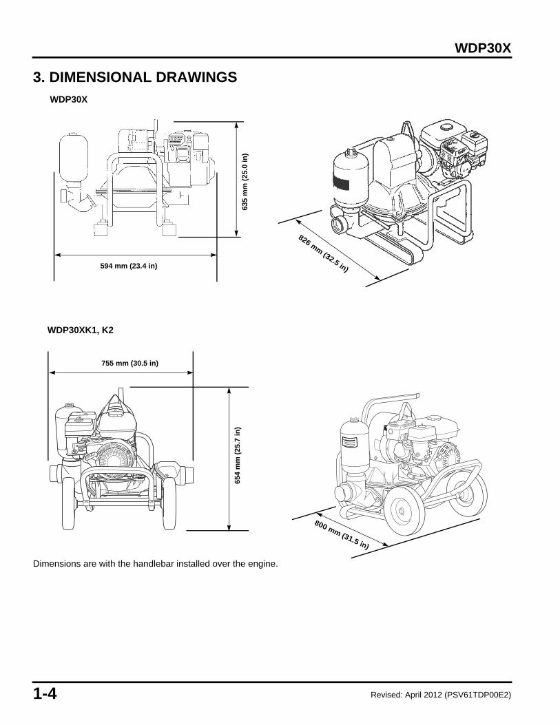
Model WDP30X WDP30XK1 WDP30XK2Type ATDescription code WZCAOverall length 826 mm (32.5 in) 800 mm (31.5 in)Overall width 594 mm (23.4 in) 775 mm (30.5 in)Overall height 635 mm (25.0 in) 654 mm (25.7 in)Dry weight 54.4 kg (120 lbs) 73.9 kg (163 lbs)Fuel tank capacity 2.0 (0.53 US gal)Engine oil capacity 0.56 (0.59 US qt)
Type Diaphragm with spring-type connecting rodSuction port diameter 3 in NPTDischarge port diameter 3 in NPTMaximum total head 15 m (50 ft)Maximum suction head (dry) 4.9 m (16 ft)Maximum suction head (after priming pump housing)
7.3 m (24 ft)
Maximum discharge capacity 302 /min (80 gpm)Self-priming time 20 sec. at 6.1 m (20 ft)Maximum solid size 60 mm (2.4 in)Diaphragm Neoprene with nylon clothValves Neoprene with cast iron inserts
Pump operating frequency 73 strokes/min @ 3,150 rpmGear reduction 43:1Pump stroke 70.4 mm (2.77 in)Gearbox oil capacity 0.8 (0.8 US qt)
Revised: April 2012 (PSV61TDP00E2)

1-2 Date of Issue: April 2008
WDP30X
• ENGINE
Engine model GX120K1QX2 GX120UT1QX2 GX120UT2QX2Description code GCAAT GCAGT GCBMTEngine type 4-stroke, overhead-valve, single-cylinder inclined by 25°Displacement 118 cm³ (7.2 cu in)Bore x stroke 60 x 42 mm (2.4 x 1.7 in)Compression ratio 8.5: 1Maximum governed speed 3,000 ~ 3,150 min-1 (rpm)Ignition system Transistorized magneto ignitionIgnition timing 25° B.T.D.C.(fixed) 20 + 3° B.T.D.C.
300 ~ 4,200 min-1 (rpm)Spark plug BPR6ES (NGK)Lubrication system Splash typeOil capacity 0.56 (0.59 US qt)Cooling system Forced airStarting system Recoil starterStopping system Ignition primary circuit groundCarburetor Horizontal-type, butterfly valveAir cleaner Dual element typeFuel used Unleaded gasoline with a pump octane number 86 or higherFuel tank capacity 2.0 (0.53 US gal)
Revised: April 2012 (PSV61TDP00E2)
Date of Issue: April 2008 1-3
WDP30X
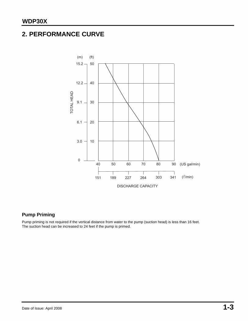
2. PERFORMANCE CURVE
Pump Priming
Pump priming is not required if the vertical distance from water to the pump (suction head) is less than 16 feet. The suction head can be increased to 24 feet if the pump is primed.
TOTA
L H
EA
D
0
10
20
30
40
50
40 50 60 70 80
DISCHARGE CAPACITY
(�/min)
(US gal/min)
151 189 227 264
3.0
6.1
9.1
12.2
15.2
(m) (ft)
90
303 341
1-4 Date of Issue: April 2008
WDP30X
3. DIMENSIONAL DRAWINGS
Dimensions are with the handlebar installed over the engine.
654
mm
(25
.7 in
)
800 mm (31.5 in)
594 mm (23.4 in)
755 mm (30.5 in)
635
mm
(25
.0 in
)826 mm (32.5 in)
WDP30X
WDP30XK1, K2
Revised: April 2012 (PSV61TDP00E2)

Date of Issue: April 2008 1-5
WDP30X
4. WIRING DIAGRAM
SPARK PLUG
IGNITION SWITCH
OIL ALERT UNIT
OIL LEVEL SWITCH
BL
BLY
BL BLACK
Y YELLOW
IGNITION CONTROL MODULE
Y

1-6 Date of Issue: April 2008
WDP30X

Date of Issue: April 2008 2-1
WDP30X 2. SERVICE INFORMATION
1. SERVICE RULES• Use Honda Genuine parts or their exact equivalent. Lower quality parts can damage the pump or reduce its
performance.
•
• Install new gaskets, O-rings, and seals during assembly.
• This pump uses metric fasteners and SAE (nonmetric) fasteners. Metric bolts, nuts, and screws are not interchangeable with nonmetric fasteners. The use of incorrect tools and fasteners may damage the pump.
• When tightening nuts and bolts, begin with the larger-diameter or inner bolts, and tighten diagonally to the specified torque values, unless a particular tightening sequence is specified.
• When tightening self-tapping screws, be especially careful to avoid cross-threading or overtightening.
• Clean parts in nonflammable solvent after disassembly.
• Lubricate sliding surfaces before assembly.
• After assembly, check parts installation and operation.
2. SYMBOLS USED IN THIS MANUALAs you read this manual, you may find the following symbols with the instructions.
1. SERVICE RULES. . . . . . . . . . . . . . . . . . . . . . . . 2-1 5. TORQUE VALUES . . . . . . . . . . . . . . . . . . . . . . . 2-4
2. SYMBOLS USED IN THIS MANUAL. . . . . . . . . 2-1 6. TOOLS . . . . . . . . . . . . . . . . . . . . . . . . . . . . . . . . 2-5
3. SERIAL NUMBER LOCATIONS . . . . . . . . . . . . 2-2 7. TROUBLESHOOTING . . . . . . . . . . . . . . . . . . . . 2-7
4. MAINTENANCE STANDARDS . . . . . . . . . . . . . 2-3
A special tool is required to perform the procedure.
(Commercially available)
Commercially available tools are distinguished by the words (commercially available). They are not available through the American Honda Parts Department. Most commercially available tools shown in this shop manual can be ordered through the Honda Power Equipment (P/E) Tool and Equipment program by calling (888) 424-6857. Refer to the Tool and Equipment program catalog for a complete tool listing.
Apply grease
Apply oil
O x O (O) x () Indicates the diameter, length, and quantity of metric flange bolts used.
P. O-O P. - Indicates the reference page.

2-2 Date of Issue: April 2008
WDP30X
3. SERIAL NUMBER LOCATIONS
There are two serial numbers, one for the engine and one for the frame. Always refer to these numbers when ordering parts and when making technical inquiries.
ENGINE SERIAL NUMBER
FRAME SERIAL NUMBER
Date of Issue: April 2008 2-3
WDP30X
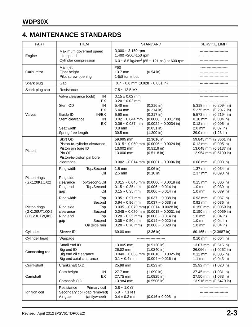
4. MAINTENANCE STANDARDSPART ITEM STANDARD SERVICE LIMIT
EngineMaximum governed speedIdle speedCylinder compression
3,000 ~ 3,150 rpm1,400 +200/-150 rpm6.0 ~ 8.5 kg/cm2 (85 ~ 121 psi) at 600 rpm
---------------------------------------------------------------------
CarburetorMain jetFloat heightPilot screw opening
#6013.7 mm (0.54 in)1-5/8 turns out
--------------------------------------------------------------------
Spark plug Gap 0.7 ~ 0.8 mm (0.028 ~ 0.031 in) -----------------------
Spark plug cap Resistance 7.5 ~ 12.5 k -----------------------
Valves
Valve clearance (cold) INEX
Stem OD INEX
Guide ID IN/EXStem clearance IN
EXSeat widthSpring free length
0.15 ± 0.02 mm0.20 ± 0.02 mm5.48 mm (0.216 in)5.44 mm (0.214 in)5.50 mm (0.217 in)0.02 ~ 0.044 mm (0.0008 ~ 0.0017 in) 0.06 ~ 0.087 mm (0.0024 ~ 0.0034 in)0.8 mm (0.031 in)30.5 mm (1.200 in)
----------------------------------------------
5.318 mm (0.2094 in)5.275 mm (0.2077 in)5.572 mm (0.2194 in)0.10 mm (0.004 in)0.12 mm (0.005 in)2.0 mm (0.07 in)29.0 mm (1.28 in)
Piston
Skirt ODPiston-to-cylinder clearancePiston pin bore IDPin ODPiston-to-piston pin bore clearance
59.985 mm (2.3616 in)0.015 ~ 0.060 mm (0.0006 ~ 0.0024 in)13.002 mm (0.5119 in)13.000 mm (0.5118 in)
0.002 ~ 0.014 mm (0.0001 ~ 0.0006 in)
59.845 mm (2.3561 in)0.12 mm (0.005 in)13.048 mm (0.5137 in)12.954 mm (0.5100 in)
0.08 mm (0.003 in)
Piston rings(GX120K1QX2)
Ring width Top/SecondOil
Ring side clearance Top/Second/OilRing end Top/Secondgap Oil
1.5 mm (0.06 in)2.5 mm (0.10 in)
0.015 ~ 0.045 mm (0.0006 ~ 0.0018 in)0.15 ~ 0.35 mm (0.006 ~ 0.014 in)0.15 ~ 0.35 mm (0.006 ~ 0.014 in)
1.37 mm (0.054 in)2.37 mm (0.093 in)
0.15 mm (0.006 in)1.0 mm (0.039 in)1.0 mm (0.039 in)
Piston rings(GX120UT1QX2, GX120UT2QX2)
Ring width TopSecond
Ring side Topclearance SecondRing end Topgap Second
Oil (side rail)
0.95 ~ 0.97 mm (0.037 ~ 0.038 in)0.94 ~ 0.96 mm (0.037 ~ 0.038 in)0.035 ~ 0.070 mm) (0.0014~0.0028 in)0.045 ~ 0.080 mm (0.0018 ~ 0.0031 in)0.20 ~ 0.35 mm) (0.008 ~ 0.014 in)0.35 ~ 0.50 mm (0.014 ~ 0.020 in)0.20 ~ 0.70 mm) (0.008 ~ 0.028 in)
0.93 mm (0.037 in)0.92 mm (0.036 in)0.150 mm (0.0059 in)0.150 mm (0.0059 in)1.0 mm (0.04 in)1.0 mm (0.04 in)1.0 mm (0.04 in)
Cylinder Sleeve ID 60.00 mm (2.36 in) 60.165 mm (2.3687 in)
Cylinder head Warpage ----------------------- 0.10 mm (0.004 in)
Connecting rod
Small end IDBig end IDBig end oil clearanceBig end axial clearance
13.005 mm (0.5120 in)26.02 mm (1.0240 in)0.040 ~ 0.063 mm (0.0016 ~ 0.0025 in)0.1 ~ 0.4 mm (0.004 ~ 0.016 in)
13.07 mm (0.515 in)26.066 mm (1.0262 in)0.12 mm (0.005 in)1.1 mm (0.043 in)
Crankshaft Crankshaft O.D. 25.98 mm (1.023 in) 25.92 mm (1.020 in)
CamshaftCam height IN
EXCamshaft O.D.
27.7 mm (1.090 in)27.75 mm (1.0925 in)13.984 mm (0.5506 in)
27.45 mm (1.081 in)27.50 mm (1.083 in)13.916 mm (0.5479 in)
Ignition coilResistance Primary coilSecondary coil (cap removed)Air gap (at flywheel)
0.8 ~ 1.0 5.9 ~ 7.1 k0.4 ± 0.2 mm (0.016 ± 0.008 in)
---------------------------------------------------------------------
Revised: April 2012 (PSV61TDP00E2)

2-4 Date of Issue: April 2008
WDP30X
5. TORQUE VALUES
Use standard torque values for fasteners that are not listed above.(CT) Indicates a self-tapping bolt.
STANDARD TORQUE VALUES
SPECIAL FASTENERS THREAD DIAMETER x PITCH mm
TORQUEN•m kg-m ft-lb
Connecting rod bolt 7 x 1.0 12 1.2 8.7Cylinder head bolt 8 x 1.25 24 2.4 18Flywheel nut 14 x 1.5 (special) 74 7.5 55Rocker arm pivot lock nut 6 x 0.5 10 1.0 7Rocker arm pivot stud 8 x 1.25 (special) 24 2.4 18Crankcase cover bolt 6 x 1.0 (CT) 12 1.2 9Air cleaner wing nut 6 x 1.0 9 0.9 6.5Muffler mounting nut 8 x 1.25 24 2.4 18Oil drain bolt 10 x 1.25 18 1.8 13Fuel tank flange nut 6 x 1.0 10 1.0 7Sediment cup 24 x 1.0 3.9 0.4 2.9Diaphragm connecting rod bolt 10 x 1.5 54 5.4 40
Diaphragm upper case nut 12 x 1.75 47 4.7 35Diaphragm connecting rod nut 12 x 1.75 47 4.7 35
Engine mounting bolt 5/16-18 x 1.5 in 19 2 14
STANDARD FASTENERS THREAD DIAMETERTORQUE
N•m kg-m ft-lb
Screw 5 mm 3.9 0.4 2.9 6 mm 8.8 0.9 6.5
Bolt and nut
5 mm 4.9 0.5 3.6 6 mm 9.8 1.0 7.2 8 mm 21 2.1 1510 mm 34 3.5 2512 mm 54 5.5 40
Flange bolt and nut 6 mm 12 1.2 8.7 8 mm 26 2.7 2010 mm 39 4.0 29

Date of Issue: April 2008 2-5
WDP30X
6. TOOLS
a. SPECIAL
ITEM TOOL NAME TOOL NUMBER APPLICATION
1 Carburetor float level gauge 07401-0010000 Carburetor float level inspection
2 Attachment, 52 x 55 mm 07746-00010400 Crankshaft bearing 6205, 62/22 installation
3 Driver, 40 mm ID 07746-0030100 Driver for attachments 4 and 5
4 Attachment, 25 mm ID 07746-0030200 Timing gear installation
5 Attachment, 30 mm ID 07746-0030300 Governor drive gear installation
6 Pilot, 22 mm ID 07746-0040100 Crankshaft bearing 62/22 installation
7 Driver 07749-0010000 Driver for tool 2
8 Valve guide driver, 5.5 mm 07942-8920000 Valve guide removal/installation
9 Valve guide reamer, 5.5 mm 07984-200000D Valve guide ID reaming
2-6 Date of Issue: April 2008
WDP30X
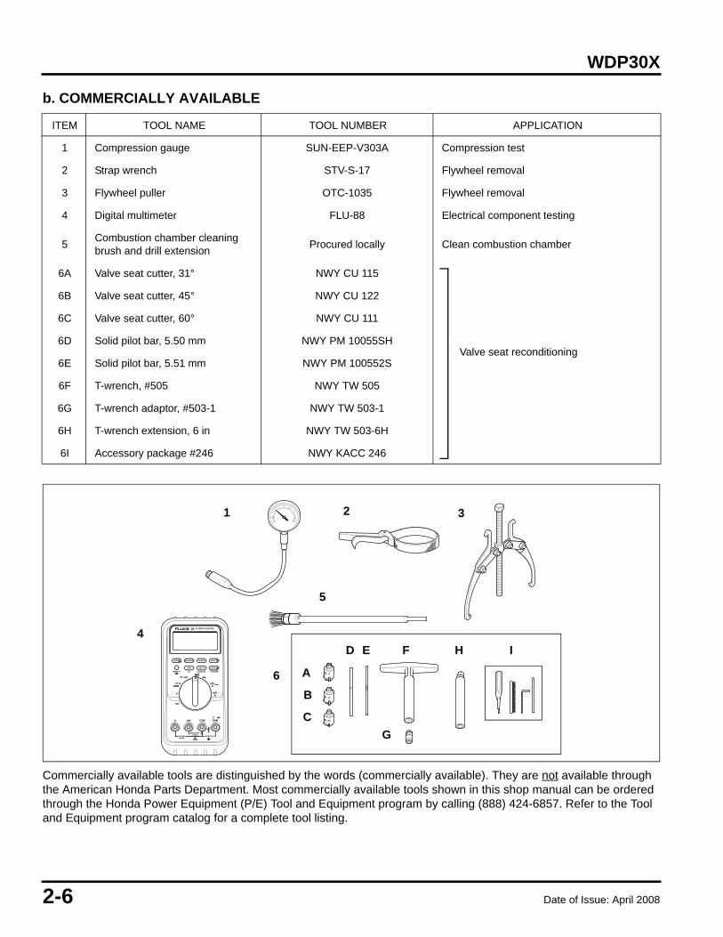
b. COMMERCIALLY AVAILABLE
Commercially available tools are distinguished by the words (commercially available). They are not available through the American Honda Parts Department. Most commercially available tools shown in this shop manual can be ordered through the Honda Power Equipment (P/E) Tool and Equipment program by calling (888) 424-6857. Refer to the Tool and Equipment program catalog for a complete tool listing.
ITEM TOOL NAME TOOL NUMBER APPLICATION
1 Compression gauge SUN-EEP-V303A Compression test
2 Strap wrench STV-S-17 Flywheel removal
3 Flywheel puller OTC-1035 Flywheel removal
4 Digital multimeter FLU-88 Electrical component testing
5 Combustion chamber cleaning brush and drill extension Procured locally Clean combustion chamber
6A Valve seat cutter, 31° NWY CU 115
Valve seat reconditioning
6B Valve seat cutter, 45° NWY CU 122
6C Valve seat cutter, 60° NWY CU 111
6D Solid pilot bar, 5.50 mm NWY PM 10055SH
6E Solid pilot bar, 5.51 mm NWY PM 100552S
6F T-wrench, #505 NWY TW 505
6G T-wrench adaptor, #503-1 NWY TW 503-1
6H T-wrench extension, 6 in NWY TW 503-6H
6I Accessory package #246 NWY KACC 246
10A MAXFUSED
400mA MAXFUSED
mAA
mAA
V
VRPM
1000V MAX!
RPMCOMmAA
� �
�
OFF
mV
V�
ZERO
SMOOTH TRIGGER+-
MIN MAX RANGE
AUTOMOTIVE METER
RPM %DUTY
HOLD
ALERT
Hz ms-PULSE
H
60°
45°
31°
21
5
6
3
4
G
H
C
B
A
D E F I

Date of Issue: April 2008 2-7
WDP30X
7. TROUBLESHOOTING
a. HARD STARTING
• COMPRESSION TEST 1. Remove the spark plug and install a compression gauge
(commercially available) in the spark plug hole.2. Pull the recoil starter several times with the recoil starter
and measure cylinder compression.
1. Check fuel level. NO FUEL IN TANK Refuel.
SUFFICIENT FUEL IN TANK
2. Remove spark plug and inspect (P. 3-5).
WET • Clean and install plug, then restart engine.
• Check carburetor for flooding.
DRY
3. Check spark plug operation(P. 2-8).
WEAK OR NO SPARK • See IGNITION SYSTEM TROUBLESHOOTING (P. 2-8).
• Check ignition coil air gap(P. 7-2).
GOOD SPARK
4. Check choke adjustment or throttle adjustment (P. 3-8).
CHOKE PARTIALLY OPEN Adjust cable/linkage to close choke.
CHOKE CLOSED
5. Compression check (see below). ABNORMAL COMPRESSION • Check for incorrect valve clearance.
• Check for heavy carbon deposits in combustion chamber.
• Check for defective valves or valve seats.
• Check for worn piston rings, piston, or cylinder.
NORMAL COMPRESSION
6. Remove and clean carburetor (P. 4-3).
7. Install spark plug and restart engine.
Compression 6.0 ~ 8.5 kg/cm2 (85 ~ 121 psi)at 600 rpm
COMPRESSION GAUGE(Commercially available)

2-8 Date of Issue: April 2008
WDP30X
b. IGNITION SYSTEM
• SPARK TEST 1. Remove the spark plug, attach it to the spark plug cap,
and ground the side electrode against the cylinder head cover.
2. Turn the ignition switch to the ON position. Pull the starter grip and check to see if sparks jump across the electrodes.
Engine does not start with the ignition switch in the ON position.
1. Test the spark plug (see below).
NO SPARK
2. Check again with a new spark plug.
SPARKS • Faulty spark plug.• Install new spark plug (P. 3-5).
NO SPARK
3. Disconnect the black wire from the engine stop switch and recheck.
SPARKS • Faulty engine stop switch.• Replace the engine stop switch
(P. 5-4).
NO SPARK
• Defective ignition coil.• Replace the ignition coil (P. 7-1).
WARNINGGasoline is highly flammable and explosive. If ignited, gasoline can burn you severely.
Before testing the spark plug:
• Be sure there is no spilled fuel near the engine.• Place the spark plug away from the spark plug hole.• Unburnt gas can ignite if it is left in the cylinder.• Loosen the carburetor drain screw to drain the
carburetor thoroughly. Pull the recoil starter several times to release the unburnt gas from the cylinder before test.
Date of Issue: April 2008 2-9
WDP30X
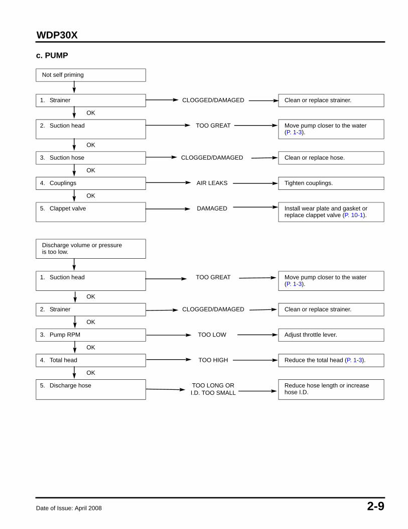
c. PUMP
Not self priming
1. Strainer CLOGGED/DAMAGED Clean or replace strainer.
OK
2. Suction head TOO GREAT Move pump closer to the water (P. 1-3).
OK
3. Suction hose CLOGGED/DAMAGED Clean or replace hose.
OK
4. Couplings AIR LEAKS Tighten couplings.
OK
5. Clappet valve DAMAGED Install wear plate and gasket or replace clappet valve (P. 10-1).
Discharge volume or pressureis too low.
1. Suction head TOO GREAT Move pump closer to the water (P. 1-3).
OK
2. Strainer CLOGGED/DAMAGED Clean or replace strainer.
OK
3. Pump RPM TOO LOW Adjust throttle lever.
OK
4. Total head TOO HIGH Reduce the total head (P. 1-3).
OK
5. Discharge hose TOO LONG OR I.D. TOO SMALL
Reduce hose length or increase hose I.D.

2-10 Date of Issue: April 2008
WDP30X
Date of Issue: April 2008 3-1
WDP30X 3. MAINTENANCE
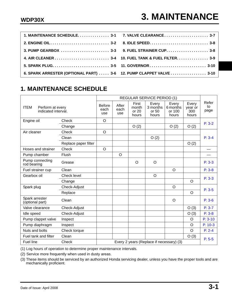
1. MAINTENANCE SCHEDULE
(1) Log hours of operation to determine proper maintenance intervals.(2) Service more frequently when used in dusty areas.(3) These items should be serviced by an authorized Honda servicing dealer, unless you have the proper tools and are
mechanically proficient.
1. MAINTENANCE SCHEDULE. . . . . . . . . . . . . . . 3-1 7. VALVE CLEARANCE. . . . . . . . . . . . . . . . . . . . . 3-7
2. ENGINE OIL . . . . . . . . . . . . . . . . . . . . . . . . . . . . 3-2 8. IDLE SPEED. . . . . . . . . . . . . . . . . . . . . . . . . . . . 3-8
3. PUMP GEARBOX . . . . . . . . . . . . . . . . . . . . . . . 3-3 9. FUEL STRAINER CUP. . . . . . . . . . . . . . . . . . . . 3-8
4. AIR CLEANER . . . . . . . . . . . . . . . . . . . . . . . . . . 3-4 10. FUEL TANK & FUEL FILTER. . . . . . . . . . . . . . . 3-9
5. SPARK PLUG. . . . . . . . . . . . . . . . . . . . . . . . . . . 3-5 11. GOVERNOR . . . . . . . . . . . . . . . . . . . . . . . . . . . 3-10
6. SPARK ARRESTER (OPTIONAL PART) . . . . . 3-6 12. PUMP CLAPPET VALVE . . . . . . . . . . . . . . . . . 3-10
REGULAR SERVICE PERIOD (1)Refer
topage
ITEM Perform at everyindicated interval.
Beforeeachuse
After each use
Firstmonth or 20hours
Every3 months
or 50hours
Every6 months
or 100hours
Everyyear or
300hours
Engine oil Check OP. 3-2
Change O (2) O (2) O (2)Air cleaner Check O
P. 3-4Clean O (2)Replace paper filter O (2)
Hoses and strainer Check O —Pump chamber Flush O —Pump connecting rod bearing Grease O O P. 3-3
Fuel strainer cup Clean O P. 3-8Gearbox oil Check level O
P. 3-3Change O
Spark plug Check-Adjust OP. 3-5
Replace OSpark arrester(optional part) Clean O P. 3-6
Valve clearance Check-Adjust O (3) P. 3-7Idle speed Check-Adjust O (3) P. 3-8Pump clappet valve Inspect O P. 3-10Pump diaphragm Inspect O P. 10-3Nuts and bolts Check torque O P. 2-4Fuel tank and filter Clean O (3)
P. 5-5Fuel line Check Every 2 years (Replace if necessary) (3)
3-2 Date of Issue: April 2008
WDP30X
2. ENGINE OIL
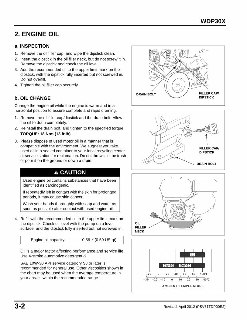
a. INSPECTION
1. Remove the oil filler cap, and wipe the dipstick clean.2. Insert the dipstick in the oil filler neck, but do not screw it in.
Remove the dipstick and check the oil level.3. Add the recommended oil to the upper limit mark on the
dipstick, with the dipstick fully inserted but not screwed in. Do not overfill.
4. Tighten the oil filler cap securely.
b. OIL CHANGE
Change the engine oil while the engine is warm and in a horizontal position to assure complete and rapid draining.
1. Remove the oil filler cap/dipstick and the drain bolt. Allow the oil to drain completely.
2. Reinstall the drain bolt, and tighten to the specified torque.TORQUE: 18 N•m (13 ft•lb)
3. Please dispose of used motor oil in a manner that is compatible with the environment. We suggest you take used oil in a sealed container to your local recycling center or service station for reclamation. Do not throw it in the trash or pour it on the ground or down a drain.
4. Refill with the recommended oil to the upper limit mark on the dipstick. Check oil level with the pump on a level surface, and the dipstick fully inserted but not screwed in.
Oil is a major factor affecting performance and service life. Use 4-stroke automotive detergent oil.
SAE 10W-30 API service category SJ or later is recommended for general use. Other viscosities shown in the chart may be used when the average temperature in your area is within the recommended range.
CAUTIONUsed engine oil contains substances that have been identified as carcinogenic.
If repeatedly left in contact with the skin for prolonged periods, it may cause skin cancer.
Wash your hands thoroughly with soap and water as soon as possible after contact with used engine oil.
Engine oil capacity 0.56 (0.59 US qt)
DRAIN BOLT
FILLER CAP/DIPSTICK
DRAIN BOLT FILLER CAP/DIPSTICK
OIL FILLER NECK
–20 0 20 40 60 80 1000F
–30 –20 –10 0 10 20 30 400C
AMBIENT TEMPERATURE
Revised: April 2012 (PSV61TDP00E2)

Date of Issue: April 2008 3-3
WDP30X
3. PUMP GEARBOX
a. CONNECTING ROD GREASE
Remove the plastic access plug. Disconnect the spark plug cap and pull the starter grip until the grease nipple is visible in the access opening.
Wipe the grease nipple to prevent dirt from getting into the bearing and using a manual grease gun, pump one or two strokes of general purpose grease into the bearing.
Reinstall the access plug and connect the spark plug cap.
b. OIL LEVEL CHECK
Check the gearbox oil level with the engine stopped and on a level surface.
S/N WZCA-6000001~6000824: Remove the oil plug and check that the oil level is to the bottom of the oil plug.
S/N WZCA-6000825 ~ later: Remove the oil filler cap/dipstick and check that the oil level is at the upper limit mark on the dipstick.
c. OIL CHANGE
Change the gearbox oil while the gearbox is warm to assure complete and rapid draining.
Remove the two 8 x 15 mm bolts and washers from the connecting rod cover.
Place a suitable container under the gearcase and remove the drain bolt from the lower end of the gearbox.
Replace the drain bolt and washer and fill the gearbox as described above.
NOTICEAvoid getting gear oil on the diaphragm. Drain oil into a drain pan to prevent oil from running down the pump case onto the diaphragm. If gear oil comes in contact with the diaphragm, it will be damaged.
Recommended grease NLGI #2
Recommended oil SAE 80W-90 GL5 gear oil
Gearbox capacity 0.8 (0.8 US qt)
CONNECTING ROD COVER
OIL FILLER CAP/DIPSTICK
8 x 15 mm BOLT and WASHER (2)
OIL FILLER CAP/DIPSTICK
UPPER LIMIT
LOWER LIMIT
WASHER
DRAIN BOLT
PLASTIC ACCESS COVER
OIL PLUG
WASHER

3-4 Date of Issue: April 2008
WDP30X
4. AIR CLEANER
CLEANING
A dirty air filter will restrict air flow to the carburetor, reducing engine performance. If the engine is operated in dusty areas, clean the air filter more often than specified in the MAINTENANCE SCHEDULE.
NOTICEOperating the engine without an air filter or with a damaged air filter will allow dirt to enter the engine, causing rapid engine wear. This type of damage is not covered by the DISTRIBUTOR’S LIMITED WARRANTY.
1. Remove the air cleaner cover nut and then remove the air cleaner cover.
2. Loosen the wing nut and remove the air cleaner elements and the air cleaner elbow packing. Separate the elements and carefully check them for holes or tears and replace if damaged. Check the air cleaner elbow packing for deterioration or damage.
3. Foam element:Clean the element in warm soapy water, rinse and allow to dry thoroughly, or clean with a high flash point solvent and allow to dry thoroughly. Dip the element in clean engine oil and squeeze out all the excess oil.
Excess oil will restrict air flow through the foam element and may cause the engine to smoke at startup.
4. Paper element:Tap the element lightly several times on a hard surface to remove excess dirt or blow compressed air [207 kPa (30 psi or less)] through the filter from the inside out. Never try to brush the dirt off; brushing will force dirt into the fibers.
5. Wipe dirt from the inside of the air cleaner housing and cover, using a moist rag. Be careful to prevent dirt from entering the air duct leading to the carburetor.
6. Reinstall the air cleaner elbow packing and the air cleaner elements. Tighten the wing nut.
7. Reinstall the air cleaner cover and tighten the nut.
AIR CLEANERCOVER NUT
AIR CLEANERCOVER
AIR CLEANERELBOW PACKING
AIR CLEANER FOAM AND
PAPER
ELEMENTS
WING NUT
SOLVENT ENGINE OIL
SQUEEZE THOROUGHLY
FOAM ELEMENT
PAPER ELEMENT

Date of Issue: April 2008 3-5
WDP30X
5. SPARK PLUG
INSPECTION
NOTICEAn incorrect spark plug can cause engine damage. Use the recommended spark plug or an exact equivalent.
1. Visually inspect the spark plug. Discard the plug if the insulator is cracked or chipped.
2. Measure the plug gap with a wire-type gauge. If necessary, adjust the gap by bending the side electrode.
3. Make sure the sealing washer is in good condition and replace if necessary.
4. Install the plug finger-tight to seat the washer, then tighten with a plug wrench.New plug: tighten 1/2 turn after the sealing washer seats.
Reused plug: tighten 1/8 ~ 1/4 turn after the washer seats.
NOTICEA loose spark plug can overheat and damage the engine. Overtightening can damage the threads in the cylinder head.
5. Install the spark plug cap.
Recommended spark plug NGK BPR6ES
Spark plug gap 0.7 ~ 0.8 mm (0.028 ~ 0.031 in)
0.7~ 0.8 mm(0.028 ~ 0.031 in)
SEALINGWASHER

3-6 Date of Issue: April 2008
WDP30X
6. SPARK ARRESTER (OPTIONAL PART)If the engine has been running, the muffler will be very hot. Allow the muffler to cool before servicing the spark arrester.
CLEANING
The spark arrester must be serviced every 100 hours to keep it functioning as designed.
1. Remove the two 8 mm nuts and remove the muffler from the cylinder head.
2. Remove the 4 mm screw from the spark arrester and remove the spark arrester from the muffler.
3. Use a stiff brush to remove carbon deposits from the spark arrester screen. Be careful not to damage the spark arrester screen.
4. Inspect the spark arrester for breaks and holes. Replace if necessary.
5. Install the spark arrester and muffler in the reverse order of removal.
5 mm SCREW (4)
8 mm NUT (2)
4 mm SCREW
MUFFLER
SPARK ARRESTER
SPARK ARRESTER SCREEN
MUFFLER PROTECTOR

Date of Issue: April 2008 3-7
WDP30X
7. VALVE CLEARANCE
INSPECTION/ADJUSTMENT
Valve clearance inspection and adjustment must be performed with the engine cold.
1. Remove the four cylinder head cover bolts, cylinder head cover gasket, and cover.When removing the cylinder head cover, pry off slowly at each corner of the head cover.
NOTICEUsing too much force can deform the cylinder head cover. The cylinder head cover must be replaced if it is deformed.
2. Set the piston at top dead center of the compression stroke (both valves fully closed). The triangular mark on the starter pulley will align with the top hole on the fan cover when the piston is at top dead center of the compression stroke and the exhaust stroke.
3. Insert a feeler gauge between the rocker arm and the valve to measure valve clearance.
4. If adjustment is necessary:a. Hold the rocker arm pivot and loosen the rocker arm
pivot lock nut.
b. Turn the rocker arm pivot to obtain the specified clearance.
c. Retighten the rocker arm pivot lock nut while holding the rocker arm pivot.
d. Recheck valve clearance after tightening the rocker arm pivot lock nut.
5. Apply liquid gasket (Hondabond 4, Three Bond 1207, or equivalent) to the cylinder head cover installation surface, and install the cylinder head cover.
Standard valve clearance (cold)
IN 0.15 ± 0.02 mm
EX 0.20 ± 0.02 mm
To increase valve clearance: screw out.To decrease valve clearance: screw in.
ROCKER ARM PIVOTLOCK NUT
FEELER GAUGE
ROCKER ARM
ROCKER ARM PIVOT
ALIGN
CYLINDER HEADCOVER GASKET
CYLINDER HEAD COVER
CYLINDER HEAD BOLT (4)
TOP HOLE
TRIANGLE MARK

3-8 Date of Issue: April 2008
WDP30X
8. IDLE SPEED
a. PILOT SCREW
The pilot screw is fitted with a limiter cap that prevents excessive enrichment of the air-fuel mixture in order to comply with emissions regulations.
Do not attempt to remove the limiter cap for pilot screw adjustment. The limiter cap cannot be removed without breaking the pilot screw.
b. THROTTLE STOP SCREW
With the engine at normal operating temperature, turn the throttle stop screw to obtain the specified idle speed.
9. FUEL STRAINER CUP
CLEANING
1. Turn off the fuel valve and remove the fuel strainer cup and O-ring.
2. Wash the strainer cup in nonflammable or high flash point solvent.
3. Install the O-ring and sediment cup. Tighten the sediment cup to the specified torque.TORQUE: 3.9 N•m (2.9 lb•ft)
4. After cleaning and assembly, check for leaks. Be sure there is no spilled fuel before starting the engine.
Standard idle speed 1,400 ± 150 rpm
WARNINGGasoline is highly flammable and explosive.You can be burned or seriously injured when handling fuel.• Keep heat, sparks and flame away.• Handle fuel only outdoors.• Wipe up spills immediately.
THROTTLE STOP SCREW
FUELSTRAINERCUPO-RING
OFF
FUEL VALVE
CUP FILTER
Align
K2
Date of Issue: April 2008 3-9
WDP30X
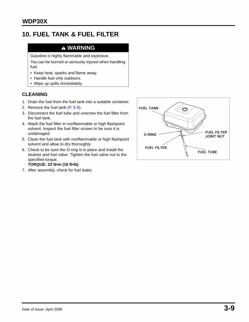
10. FUEL TANK & FUEL FILTER
CLEANING
1. Drain the fuel from the fuel tank into a suitable container.2. Remove the fuel tank (P. 5-5).3. Disconnect the fuel tube and unscrew the fuel filter from
the fuel tank.4. Wash the fuel filter in nonflammable or high flashpoint
solvent. Inspect the fuel filter screen to be sure it is undamaged.
5. Clean the fuel tank with nonflammable or high flashpoint solvent and allow to dry thoroughly.
6. Check to be sure the O-ring is in place and install the strainer and fuel valve. Tighten the fuel valve nut to the specified torque.TORQUE: 22 N•m (16 ft•lb)
7. After assembly, check for fuel leaks.
WARNINGGasoline is highly flammable and explosive.You can be burned or seriously injured when handling fuel.• Keep heat, sparks and flame away.• Handle fuel only outdoors.• Wipe up spills immediately.
O-RING
FUEL TANK
FUEL FILTER
FUEL FILTERJOINT NUT
FUEL TUBE

3-10 Date of Issue: April 2008
WDP30X
11. GOVERNOR
ADJUSTMENT
1. Remove the fuel tank.2. Loosen the pinch bolt and nut, and then move the
governor arm so that the throttle is completely open.3. Rotate the governor arm shaft as far as it will go in the
direction that it was just turned by the governor arm, and retighten the pinch bolt and nut.
4. Reinstall the fuel tank.5. Start the engine and warm it up fully, and bring the
engine to its standard speed with the throttle lever. Adjust the throttle control screw so that the throttle cannot be moved past this point.
12. PUMP CLAPPET VALVE
INSPECTION
Inspect the clappet valves. If they are worn, torn, or damaged, replace them. If the case sealing surface is damaged or cannot be cleaned, an optional stainless steel wear plate and paper gasket can be installed.
Maximum speed 3,000 ~ 3,150 rpm
THROTTLE CONTROL SCREW
GOVERNOR ARM GOVERNOR ARM SHAFT
PINCHBOLT/NUT
CLAPPET VALVE
STAINLESS STEEL WEAR PLATE (optional)
PAPER GASKET(optional)
Revised: April 2012 (PSV61TDP00E2)

Date of Issue: April 2008 4-1
WDP30X 4. AIR CLEANER/CARBURETOR
1. AIR CLEANER
REMOVAL/INSTALLATION
1. AIR CLEANER . . . . . . . . . . . . . . . . . . . . . . . . . . 4-1 2. CARBURETOR . . . . . . . . . . . . . . . . . . . . . . . . . 4-3
P. 3-4
P. 3-4
4-2 Date of Issue: April 2008
WDP30X
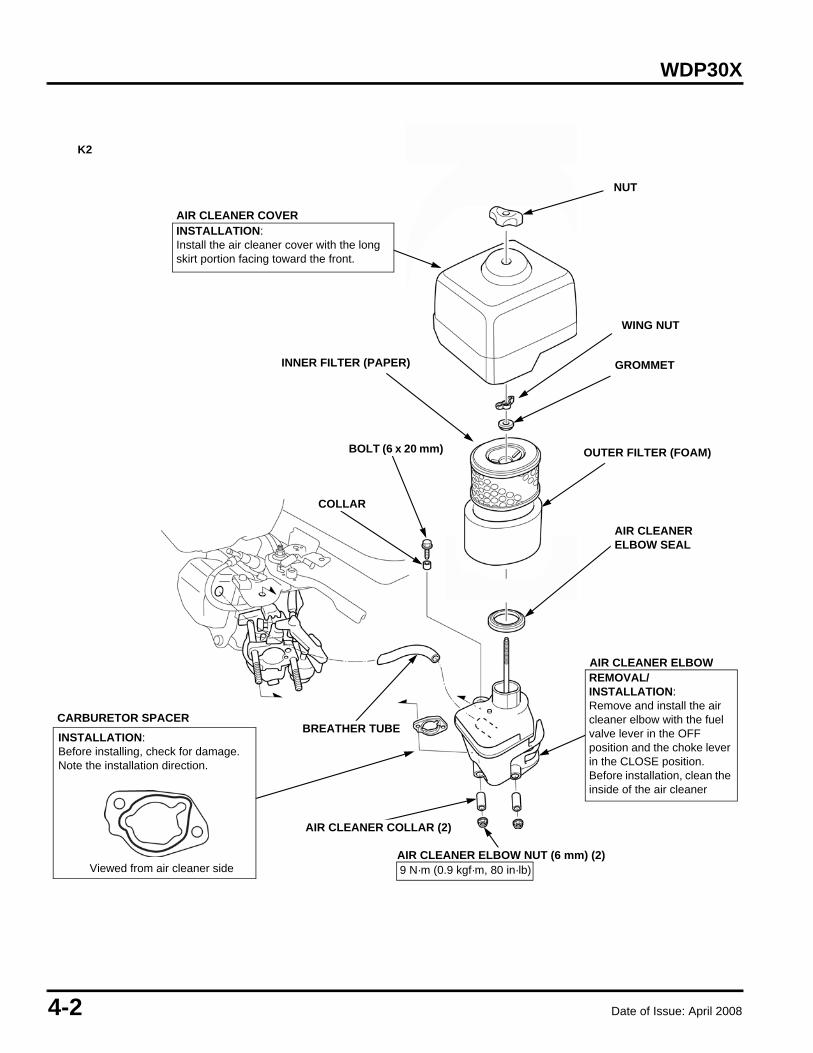
9 N·m (0.9 kgf·m, 80 in·lb)Viewed from air cleaner side
INSTALLATION:Before installing, check for damage.Note the installation direction.
CARBURETOR SPACER
AIR CLEANER ELBOW
AIR CLEANER COVER
NUT
INSTALLATION:Install the air cleaner cover with the long skirt portion facing toward the front.
WING NUT
GROMMET
BREATHER TUBE
COLLAR
BOLT (6 x 20 mm)
INNER FILTER (PAPER)
OUTER FILTER (FOAM)
AIR CLEANERELBOW SEAL
AIR CLEANER ELBOW NUT (6 mm) (2)
AIR CLEANER COLLAR (2)
REMOVAL/INSTALLATION:Remove and install the air cleaner elbow with the fuel valve lever in the OFF position and the choke lever in the CLOSE position.Before installation, clean the inside of the air cleaner
K2

Date of Issue: April 2008 4-3
WDP30X
2. CARBURETOR
a. REMOVAL/INSTALLATION
ASSEMBLY:
INSULATOR GASKET
SPARK PLUG WIRE
CARBURETOR GASKET
THROTTLE RETURN SPRING
GOVERNOR RODFUEL TUBE

4-4 Date of Issue: April 2008
WDP30X
b. DISASSEMBLY/ASSEMBLY
CLEANING: P. 4-5
REPLACEMENT: P. 4-5
CLEANING: P. 3-8
#60
REPLACEMENT: P. 4-4
ASSEMBLY:
ASSEMBLY:
ASSEMBLY:
ASSEMBLY:
ASSEMBLY:
P. 3-8
P. 4-5
P. 4-4
P. 4-5
Date of Issue: April 2008 4-5
WDP30X
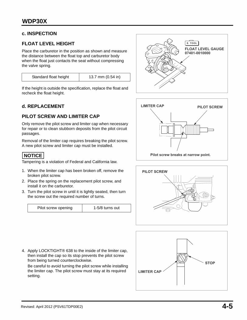
c. INSPECTION
FLOAT LEVEL HEIGHT
Place the carburetor in the position as shown and measure the distance between the float top and carburetor body when the float just contacts the seat without compressing the valve spring.
If the height is outside the specification, replace the float and recheck the float height.
d. REPLACEMENT
PILOT SCREW AND LIMITER CAP
Only remove the pilot screw and limiter cap when necessary for repair or to clean stubborn deposits from the pilot circuit passages.
Removal of the limiter cap requires breaking the pilot screw. A new pilot screw and limiter cap must be installed.
NOTICETampering is a violation of Federal and California law.
1. When the limiter cap has been broken off, remove the broken pilot screw.
2. Place the spring on the replacement pilot screw, and install it on the carburetor.
3. Turn the pilot screw in until it is lightly seated, then turn the screw out the required number of turns.
4. Apply LOCKTIGHT® 638 to the inside of the limiter cap, then install the cap so its stop prevents the pilot screw from being turned counterclockwise.Be careful to avoid turning the pilot screw while installing the limiter cap. The pilot screw must stay at its required setting.
Standard float height 13.7 mm (0.54 in)
Pilot screw opening 1-5/8 turns out
Pilot screw breaks at narrow point.
LIMITER CAP PILOT SCREW
FLOAT LEVEL GAUGE07401-0010000
PILOT SCREW
STOP
LIMITER CAP
Revised: April 2012 (PSV61TDP00E2)
4-6 Date of Issue: April 2008
WDP30X
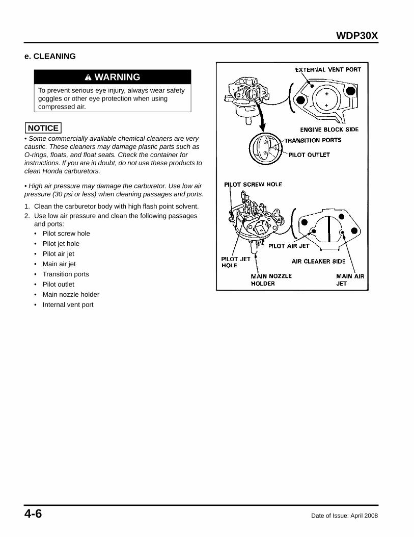
e. CLEANING
NOTICE• Some commercially available chemical cleaners are very caustic. These cleaners may damage plastic parts such as O-rings, floats, and float seats. Check the container for instructions. If you are in doubt, do not use these products to clean Honda carburetors.
• High air pressure may damage the carburetor. Use low air pressure (30 psi or less) when cleaning passages and ports.
1. Clean the carburetor body with high flash point solvent.2. Use low air pressure and clean the following passages
and ports:• Pilot screw hole• Pilot jet hole• Pilot air jet• Main air jet• Transition ports• Pilot outlet• Main nozzle holder• Internal vent port
WARNINGTo prevent serious eye injury, always wear safety goggles or other eye protection when using compressed air.

Date of Issue: April 2008 5-1
WDP30X 5. RECOIL STARTER/FUEL TANK
1. RECOIL STARTER
a. REMOVAL/INSTALLATION
b. DISASSEMBLY
1. RECOIL STARTER . . . . . . . . . . . . . . . . . . . . . . 5-1
2. FAN COVER. . . . . . . . . . . . . . . . . . . . . . . . . . . . 5-4
3. FUEL TANK . . . . . . . . . . . . . . . . . . . . . . . . . . . . 5-5
WARNING• Wear gloves and eye protection.• During assembly, take care not to allow the return spring to come out.
RECOIL STARTER ASSEMBLYINSTALLATION:Remove dirt and debris beforeinstallation.ASSEMBLY: P. 5-2
6 x 10 (3)
6 x 12 (4)
FAN COVER
P. 5-2
RATCHET (2)WASHER
FRICTION SPRING
STARTERCASE
STARTERGRIP
RETURN SPRING
STARTER REEL
RATCHET SPRING (2)
RATCHET COVER
COVER BOLT
RECOIL STARTER ROPEASSEMBLY:Check the rope for fraying orwear before installation.
5-2 Date of Issue: April 2008
WDP30X
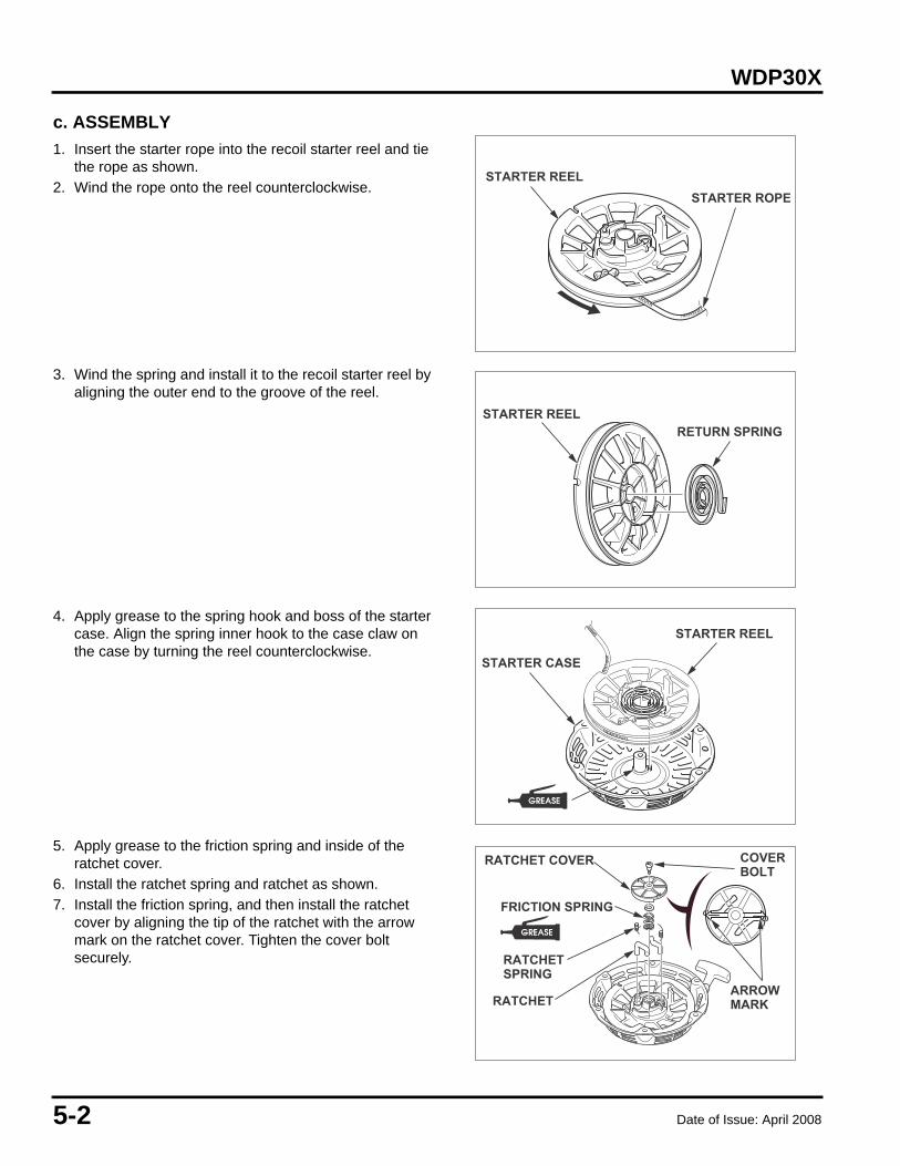
c. ASSEMBLY
1. Insert the starter rope into the recoil starter reel and tie the rope as shown.
2. Wind the rope onto the reel counterclockwise.
3. Wind the spring and install it to the recoil starter reel by aligning the outer end to the groove of the reel.
4. Apply grease to the spring hook and boss of the starter case. Align the spring inner hook to the case claw on the case by turning the reel counterclockwise.
5. Apply grease to the friction spring and inside of the ratchet cover.
6. Install the ratchet spring and ratchet as shown.7. Install the friction spring, and then install the ratchet
cover by aligning the tip of the ratchet with the arrow mark on the ratchet cover. Tighten the cover bolt securely.
STARTER REELSTARTER ROPE
STARTER REELRETURN SPRING
STARTER REEL
STARTER CASE
RATCHET COVER COVERBOLT
ARROWMARK
FRICTION SPRING
RATCHETSPRING
RATCHET
�
�

Date of Issue: April 2008 5-3
WDP30X
8. Turn the reel three full turns counterclockwise to preload the return spring.
9. Pass the rope through the starter case hole and starter grip, and knot the end of the rope as shown.
10.Check the operation of the ratchet by pulling the starter rope out several times.
STARTER GRIP
CASE HOLE

5-4 Date of Issue: April 2008
WDP30X
2. FAN COVER
REMOVAL/INSTALLATION
From oil level switch
YELLOWYELLOW
From ignition coil
OIL ALERT UNIT
ENGINE SWITCH
BLACK
Retaining clip
Date of Issue: April 2008 5-5
WDP30X
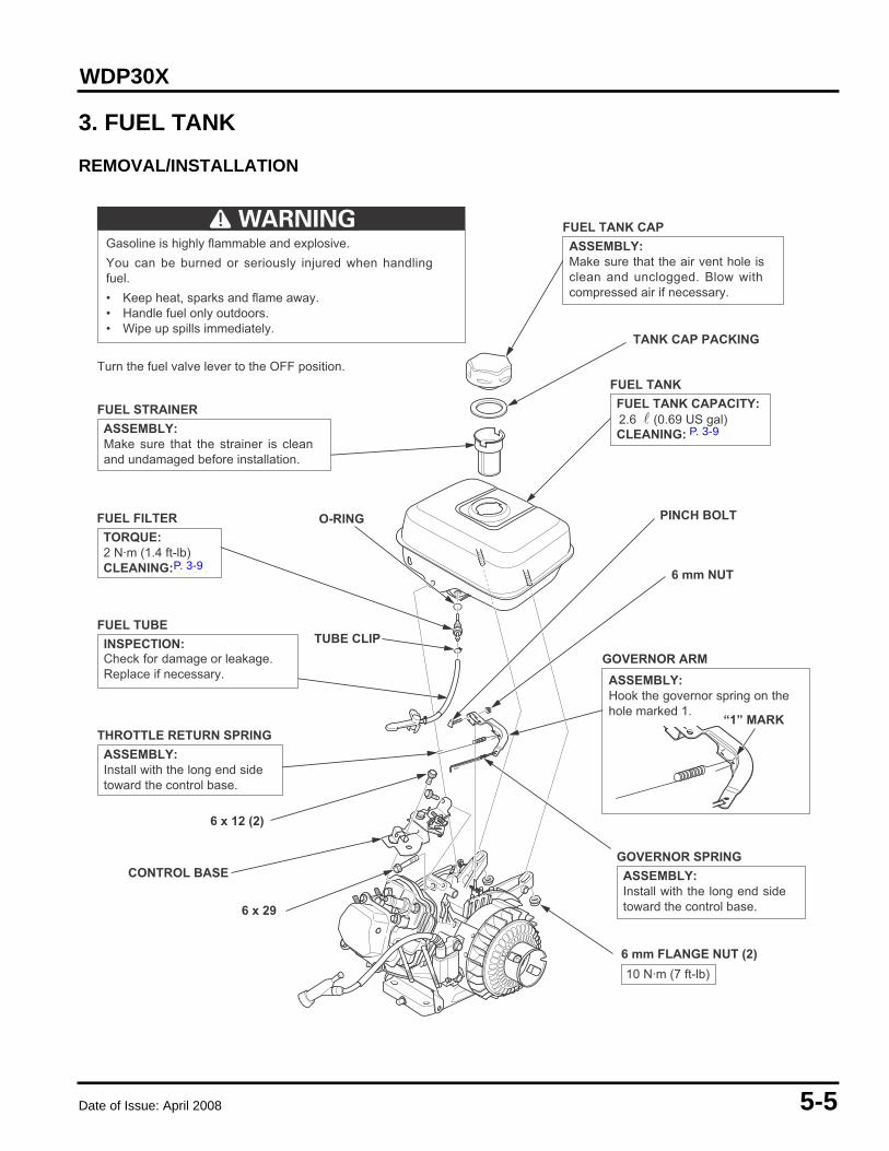
3. FUEL TANK
REMOVAL/INSTALLATION
GOVERNOR ARMASSEMBLY:Hook the governor spring on thehole marked 1.
FUEL TANKFUEL TANK CAPACITY:
CLEANING:
FUEL FILTERTORQUE:2 N·m (1.4 ft-lb)CLEANING: P. 3-9
FUEL STRAINERASSEMBLY:Make sure that the strainer is cleanand undamaged before installation.
FUEL TUBEINSPECTION:Check for damage or leakage.Replace if necessary.
THROTTLE RETURN SPRINGASSEMBLY:Install with the long end sidetoward the control base.
FUEL TANK CAPASSEMBLY:Make sure that the air vent hole isclean and unclogged. Blow withcompressed air if necessary.
GOVERNOR SPRINGASSEMBLY:Install with the long end sidetoward the control base.
6 mm FLANGE NUT (2)
TANK CAP PACKING
PINCH BOLT
“1” MARK
6 x 29
CONTROL BASE
6 x 12 (2)
O-RING
TUBE CLIP
6 mm NUT
Gasoline is highly flammable and explosive.You can be burned or seriously injured when handlingfuel.• Keep heat, sparks and flame away.• Handle fuel only outdoors.• Wipe up spills immediately.
Turn the fuel valve lever to the OFF position.
10 N·m (7 ft-lb)
2.6 � (0.69 US gal) P. 3-9P. 3-9
P. 3-9

5-6 Date of Issue: April 2008
WDP30X
FUEL FILLER CAP REMOVAL/INSTALLATIONTurn the fuel level gauge (1) to align the fuel filler cap tether hole (2)with the cutout (3) of the fuel filler neck, and then remove the fuelfiller cap (4).
Before installing, check the air vent hole of the fuel filler cap for clogs.If necessary, clean it using low-pressure compressed air.Set the fuel tank cap to the fuel filler neck by aligning the projections(5) of the cap with the cutouts of the fuel filler neck and fuel levelgauge, and then turn the fuel tank cap clockwise 180 degrees to lockit.
FUEL TANK JOINT
FUEL TANK BOLT (6 x 29 mm)
FUEL FILLER CAP
O-RING
FUEL TANK
FUEL TUBECHECK:Check for deterioration or cracks.
FUEL FILLER CAP PACKINGCHECK:Check for deterioration or cracks.
FUEL TANK NUT (6 mm) (2)10 N·m (1.0 kgf·m, 89 in·lb)
10 N·m (1.0 kgf·m, 7 lbf·ft)
CHECK:Check the screen of the fuel tank joint for clogs or damage.
2 N·m (0.2 kgf·m, 18 lin·lb)
K2
(2)
(3)
(5)
(1)
(4)
Revised: April 2012 (PSV61TDP00E2)

Date of Issue: April 2008 6-1
WDP30X 6. MUFFLER
1. MUFFLER
DISASSEMBLY/ASSEMBLY
1. MUFFLER. . . . . . . . . . . . . . . . . . . . . . . . . . . . . . 6-1
CAUTIONThe engine and muffler become very hot during operation, and they remain hot for a while after operation. Be sure that the engine is cold before muffler removal/installation.
MUFFLERASSEMBLY:Install the muffler after removingthe carbon deposits with a plastichammer.
UPPER MUFFLER PROTECTOR5 x 8 mm SELF-TAPPING SCREW (4)
4 x 6 mmSELF-TAPPING SCREW
8 mm HEX NUT (2)24 N·m (17 ft-lb)
SPARK ARRESTER (optional)CLEANING: P. 3-6
MUFFLER GASKETDo not reuse.
P. 3-6

6-2 Date of Issue: April 2008
WDP30X

Date of Issue: April 2008 7-1
WDP30X 7. FLYWHEEL/IGNITION COIL
1. FLYWHEEL/IGNITION COIL
a. DISASSEMBLY/ASSEMBLY
1. FLYWHEEL/IGNITION COIL . . . . . . . . . . . . . . . 7-1
6 x 25 (2)
SIDE PLATE
6 x 20
14 mm SPECIAL NUT75 N·m (7.5 kgf·m, 54 lbf·ft)
IGNITION COILADJUSTMENT: P. 7-2INSPECTION: P. 7-2
COOLING FANDISASSEMBLY/ASSEMBLY:When disassembling and assembling,take care not to damage the fan blade.Attach by aligning the four lugs onthe rear side of the fan with thesmall holes in the flywheel.
BLACK LEADASSEMBLY:Insert securely into the tworibs on the crankcase asshown.
FLYWHEELDISASSEMBLY:• Remove the ignition coil before removing
the flywheel.• Do not hit the flywheel with a hammer.
Remove with a commercially available6-inch puller. Avoid the magnet sectionwhen attaching the puller.
ASSEMBLY:Clean the crankshaft tapered surfacebefore installation.
WOODRUFF KEYASSEMBLY:After installing the flywheel,check to be sure that thewoodruff key is still in itsslot on the crankshaft.
HIGH TENSION CORDASSEMBLY:Check for cracked or damaged insulationand replace if necessary.
STARTER PULLEYDISASSEMBLY:Attach by aligning the lug (A) on thepulley with the small hole (B) at thecenter of the flywheel.
FLYWHEEL PULLER(Commercially available)
(A)(B)
P. 7-2P. 7-2

7-2 Date of Issue: April 2008
WDP30X
b. ADJUSTMENT
IGNITION COIL
Adjustment is required only when the ignition coil or the flywheel has been removed.
1. Loosen the ignition coil bolt.2. Insert the feeler gauge between the ignition coil and
flywheel.3. Push the ignition coil firmly against the flywheel and
tighten the ignition coil bolt. Remove the feeler gauge.
c. INSPECTION
IGNITION COIL
<Primary side>Measure the resistance of the primary coil by attaching one ohmmeter lead to the ignition coil’s primary (black) lead while touching the other lead to the iron core.
<Secondary side>Remove the spark plug cap. Measure the resistance of the secondary side of the coil by attaching one ohmmeter lead to the ignition coil terminal and the other lead at the spark plug cap end.
Specified clearance 0.2 ~ 0.6 mm (0.008 ~ 0.024 in
Primary side resistance 0.8 ~ 1.0
Secondary side resistance 5.9 ~ 7.1 k
0.2~ 0.6 mm(0.008 ~ 0.024 in)
FLYWHEEL
IGNITION COIL
Date of Issue: April 2008 7-3
WDP30X
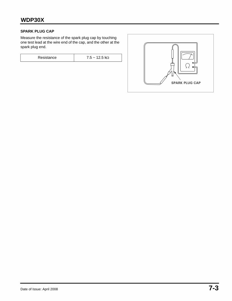
SPARK PLUG CAP
Measure the resistance of the spark plug cap by touching one test lead at the wire end of the cap, and the other at the spark plug end.
Resistance 7.5 ~ 12.5 k
SPARK PLUG CAP

7-4 Date of Issue: April 2008
WDP30X

Date of Issue: April 2008 8-1
WDP30X 8. CYLINDER HEAD/VALVES
1. CYLINDER HEAD/VALVES
a. REMOVAL/INSTALLATION
1. CYLINDER HEAD/VALVES. . . . . . . . . . . . . . . . 8-1
CYLINDER HEAD GASKET
CYLINDER HEAD COVER GASKET
CYLINDER BLOCK
6 x 12 (4)
CYLINDERHEAD COVER
6 x 12 (2)
SHROUD
DOWEL PIN (2)
CYLINDER HEADREMOVAL/INSTALLATION:• Before installation, remove any
carbon deposits from the com-bustion chamber and inspectthe valve seats.
• Measure the cylinder compres-sion after assembly.
DISASSEMBLY/ASSEMBLY:P. 8-2
SPARK PLUGADJUSTMENT: P. 3-5
8 x 55 (4)TORQUE:24 N•m (18 ft-lb)REMOVAL/INSTALLATION:Loosen and tighten the bolts in acrisscross pattern in 2 ~ 3 steps. P. 3-5
P. 8-2

8-2 Date of Issue: April 2008
WDP30X
b. DISASSEMBLY/ASSEMBLY
VALVE SPRING RETAINER (2)DISASSEMBLY:Push down and slide the retainer to theside, so the valve stem slips through thehole at the side of the retainer.ASSEMBLY:The exhaust valve retainer has a largercenter recess than the intake valve retainer,so it can accept the valve rotator.
Do not remove the valve spring retainerswhile the cylinder head is installed, or thevalves will drop into the cylinder.
CLIP(EX side only)
PUSH ROD GUIDE
ROCKER ARMPIVOT (2)
VALVE STEM SEAL(Intake valve only)
PUSH ROD (2)ASSEMBLY:Check both ends for wear, andcheck the rod for straightness.Be sure the rod ends are firmlyseated in the lifters.
VALVE SPRING (2)INSPECTION:P. 8-3
CYLINDER HEADINSPECTION: P. 8-3
INTAKE VALVEASSEMBLY:Do not interchange withthe exhaust valve.INSPECTION: P. 8-4VALVE HEAD DIAMETER: 22 mm (0.87 in)
EXHAUST VALVEASSEMBLY:Before installation, removecarbon deposits and inspectthe valve. Do not interchange with theintake valve.INSPECTION: P. 8-4VALVE HEAD DIAMETER: 19 mm (0.75 in)
VALVE ROTATOR(Exhaust valve only)
ASSEMBLY:If the valve rotator is notinstalled, the exhaust valvemay drop into the cylinderwhen starting the engine.
ROCKER ARM PIVOT LOCK NUT (2)
VALVE GUIDE (2)REPLACEMENT: P. 8-5
ROCKER ARM (2)ASSEMBLY:Before installing, checkfor wear on the surfacesthat contact the pivotbolt, push rod, and rockerarm pivot.
ROCKER ARM PIVOT STUD (2)24 N•m (17 ft-lb)
10 N•m (7 ft-lb)
P. 8-4
P. 8-3
P. 8-5
P. 8-4
P. 8-3
Date of Issue: April 2008 8-3
WDP30X
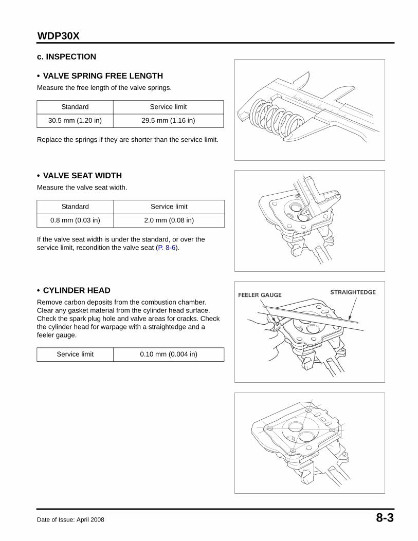
c. INSPECTION
• VALVE SPRING FREE LENGTHMeasure the free length of the valve springs.
Replace the springs if they are shorter than the service limit.
• VALVE SEAT WIDTHMeasure the valve seat width.
If the valve seat width is under the standard, or over the service limit, recondition the valve seat (P. 8-6).
• CYLINDER HEADRemove carbon deposits from the combustion chamber. Clear any gasket material from the cylinder head surface. Check the spark plug hole and valve areas for cracks. Check the cylinder head for warpage with a straightedge and a feeler gauge.
Standard Service limit
30.5 mm (1.20 in) 29.5 mm (1.16 in)
Standard Service limit
0.8 mm (0.03 in) 2.0 mm (0.08 in)
Service limit 0.10 mm (0.004 in)
FEELER GAUGESTRAIGHTEDGE

8-4 Date of Issue: April 2008
WDP30X
• VALVE STEM O.D.Inspect each valve for face irregularities, bending, or abnormal stem wear. Replace the valve if necessary. Measure and record each valve stem O.D.
Replace the valves if their O.D. is smaller than the service limit.
• VALVE GUIDE I.D.Ream the valve guides to remove any carbon deposits before measuring.
Measure and record each valve guide I.D.
Replace the guides if they are over the service limit (P. 8-5).
• GUIDE-TO-STEM CLEARANCESubtract each valve stem O.D. from the corresponding guide I.D. to obtain the guide-to-stem clearance.
If the guide-to-stem clearance exceeds the service limit, determine if the new guide with standard dimensions would bring the clearance within tolerance. If so, replace any guide as necessary and ream to fit. If the guide-to-stem clearance exceeds the service limit with new guides, replace the valves as well.
Recondition the valve seats whenever the valve guides are replaced (P. 8-6).
Standard Service limit
IN 5.48 mm (0.216 in) 5.318 mm (0.2094 in)
EX 5.45 mm (0.215 in) 5.275 mm (0.2077 in)
Standard Service limit
5.50 mm (0.217 in) 5.572 mm (0.2194 in)
Standard Service limit
IN 0.020 ~ 0.044 mm (0.0008 ~ 0.0017 in) 0.10 mm (0.004 in)
EX 0.050 ~ 0.077 mm (0.0019 ~ 0.0030 in) 0.12 mm (0.005 in)
VALVE GUIDEREAMER, 5.5 mm07984-200000D

Date of Issue: April 2008 8-5
WDP30X
d. VALVE GUIDE REPLACEMENT
1. Chill the replacement valve guides in the freezer section of a refrigerator for about an hour.
2. Use a hot plate or oven to heat the cylinder head evenly to 150°C (300°F).
NOTICE• Do not use a torch to heat the cylinder head; warpage of the cylinder head may result.
• Do not get the head hotter than 150°C (300°F); excessive heat may loosen the valve seats.
3. Remove the heated cylinder head from the hot plate and support it with wooden blocks. Drive the valve guides out of the head from the combustion chamber side.
NOTICEWhen driving the valve guides out, be careful not to damage the head.
4. Remove the new valve guides from the refrigerator one at a time as needed.
5. Install the new valve guides from the valve spring side of the cylinder head.Exhaust side: Drive the exhaust valve guide until the clip
is fully seated as shown.
Intake side: Drive the intake valve guide to the specified height (measured from the top of the valve guide to cylinder casting as shown).
6. After installation, inspect the valve guide for damage. Replace the guide if damaged.
CAUTIONTo avoid burns, use heavy gloves when handling the heated cylinder head.
IN valve installation height 3.0 mm (0.12 in)
3.0 mm (0.36 in)INTAKE:
EXHAUST:CLIP
VALVE GUIDEDRIVER, 5.5 mm07942-8920000
VALVE GUIDEDRIVER, 5.5 mm07942-8920000

8-6 Date of Issue: April 2008
WDP30X
• VALVE GUIDE REAMINGFor best results, be sure the cylinder head is at room temperature before reaming valve guides.
1. Coat the reamer and valve guide with cutting oil.
2. Rotate the reamer clockwise through the valve guide the full length of the reamer.
3. Continue to rotate the reamer clockwise while removing it from the valve guide.
4. Thoroughly clean the cylinder head to remove any cutting residue.
5. Check the valve guide bore; it should be straight, round, and centered in the valve guide. Insert the valve and check operation. If the valve does not operate smoothly, the guide may have been bent during installation. Replace the valve guide if it is bent or damaged.
6. Check the valve guide-to-stem clearance (P. 8-4).
e. VALVE SEAT RECONDITIONING
1. Thoroughly clean the combustion chamber and valve seats to remove carbon deposits.Apply a light coat of Prussian Blue or erasable felt-tipped marker ink to the valve face.
2. Insert the valve, and snap it closed against its seat several times. Be sure the valve does not rotate on the seat. The transferred marking compound will show any area of the seat that is not concentric.
Follow the instructions of the valve seat cutter manufacturer.
3. Using a 45° cutter, remove enough material to produce a smooth and concentric seat.Turn the cutter clockwise, never counterclockwise.Continue to turn the cutter as you lift it from the valve seat.
4. Use the 31° and 60° cutters to narrow and adjust the valve seat so that it contacts the middle of the valve face. The 31° cutter removes material from the top edge (contact too high).
The 60° cutter removes material from the bottom edge (contact too low). Be sure that the width of the finished valve seat is within specification.
CONTACT TOO HIGH
CONTACT TOO LOW
VALVE GUIDEREAMER, 5.5 mm07984-200000D
60°
31°
Date of Issue: April 2008 8-7
WDP30X
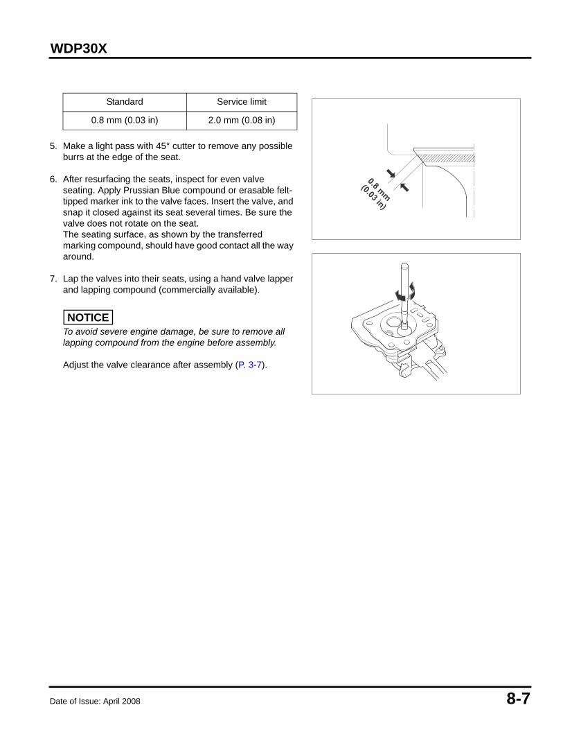
5. Make a light pass with 45° cutter to remove any possible burrs at the edge of the seat.
6. After resurfacing the seats, inspect for even valve seating. Apply Prussian Blue compound or erasable felt-tipped marker ink to the valve faces. Insert the valve, and snap it closed against its seat several times. Be sure the valve does not rotate on the seat.The seating surface, as shown by the transferred marking compound, should have good contact all the way around.
7. Lap the valves into their seats, using a hand valve lapper and lapping compound (commercially available).
NOTICETo avoid severe engine damage, be sure to remove all lapping compound from the engine before assembly.
Adjust the valve clearance after assembly (P. 3-7).
Standard Service limit
0.8 mm (0.03 in) 2.0 mm (0.08 in)
0.8 mm(0.03 in)

8-8 Date of Issue: April 2008
WDP30X
Date of Issue: April 2008 9-1
WDP30X 9. CRANKCASE COVER/CRANKSHAFT/PISTON
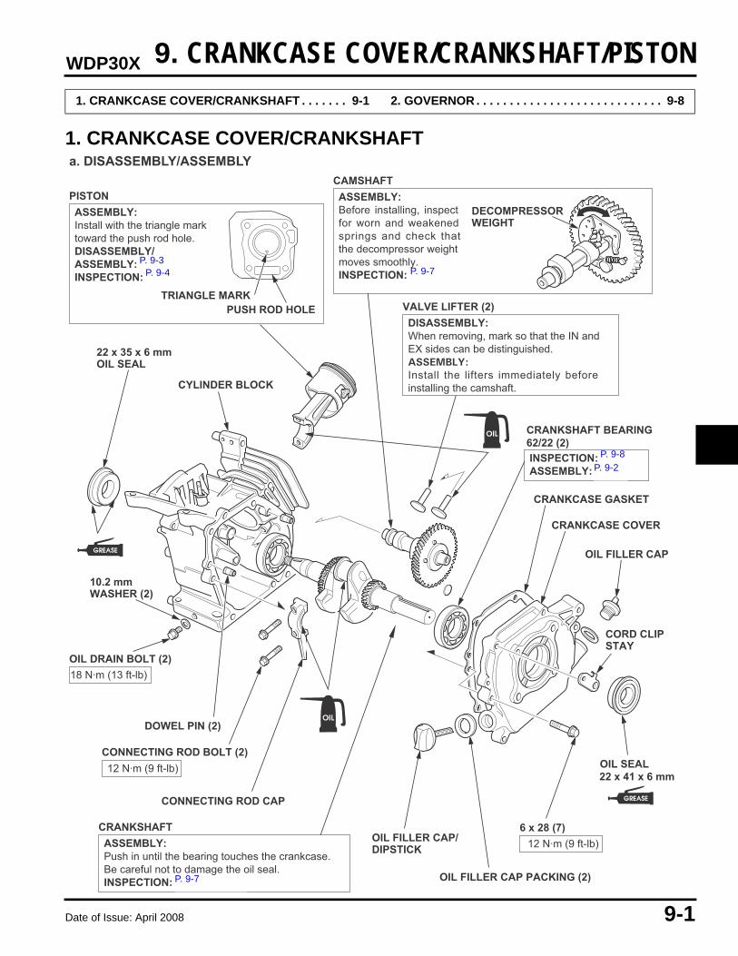
1. CRANKCASE COVER/CRANKSHAFT
1. CRANKCASE COVER/CRANKSHAFT . . . . . . . 9-1 2. GOVERNOR . . . . . . . . . . . . . . . . . . . . . . . . . . . . 9-8
a. DISASSEMBLY/ASSEMBLY
22 x 35 x 6 mmOIL SEAL
OIL FILLER CAP/DIPSTICK
10.2 mm WASHER (2)
CRANKCASE GASKET
CRANKCASE COVER
OIL FILLER CAP
CORD CLIPSTAY
OIL FILLER CAP PACKING (2)
CONNECTING ROD CAP
DOWEL PIN (2)
CYLINDER BLOCK
PISTONASSEMBLY:Install with the triangle mark toward the push rod hole.DISASSEMBLY/ASSEMBLY: P. 9-2INSPECTION: P. 9-4
CAMSHAFTASSEMBLY:Before installing, inspectfor worn and weakenedsprings and check thatthe decompressor weightmoves smoothly.INSPECTION: P. 9-7
VALVE LIFTER (2)DISASSEMBLY:When removing, mark so that the IN andEX sides can be distinguished.ASSEMBLY:
Install the lifters immediately beforeinstalling the camshaft.
CRANKSHAFT BEARING62/22 (2) INSPECTION: P. 9-8ASSEMBLY: P. 9-2
CRANKSHAFTASSEMBLY:Push in until the bearing touches the crankcase.Be careful not to damage the oil seal.INSPECTION: P. 9-6, 9-7
CONNECTING ROD BOLT (2)12 N·m (9 ft-lb)
OIL DRAIN BOLT (2)
6 x 28 (7)
TRIANGLE MARK
DECOMPRESSORWEIGHT
18 N·m (13 ft-lb)
12 N·m (9 ft-lb)
PUSH ROD HOLE
22 x 41 x 6 mmOIL SEAL
�
�
�
�
P. 9-3P. 9-4 P. 9-7
P. 9-8P. 9-2
P. 9-7

9-2 Date of Issue: April 2008
WDP30X
• CRANKSHAFT BEARINGASSEMBLY:
Oil the circumference of the bearing, and install the bearing with the following special tools.
Driver 07749-0010000
Attachment, 52 x 55 mm 07746-0010400
Pilot, 22 mm 07746-0040100
• TIMING GEAR/GOVERNOR DRIVE GEARDISASSEMBLY:
Mark a line on the crankshaft and timing gear.Set a commercially available bearing puller plate on the bottom part of the governor drive gear, and remove the crankshaft and timing gear using a hydraulic press.
Remove the governor drive gear in the same way.
ASSEMBLY:
• TIMING GEAR
Using the old gear for reference, make a mark at the same position on the new gear.
Using a hydraulic press, driver, and attachment (special tools), press the new gear onto the crankshaft.
Driver, 40 mm I.D. 07746-0030100
Attachment, 25 mm I.D. 07746-0030200
• GOVERNOR DRIVE GEAR
Use a hydraulic press and the special tools shown below to press in a new governor drive gear.
Driver, 40 mm I.D. 07746-0030100
Attachment, 30 mm I.D. 07746-0030300

Date of Issue: April 2008 9-3
WDP30X
• PISTON
PISTON RINGSASSEMBLY:• Install all rings with the markings facing up.• Be sure that the top and second rings are not interchanged.• Check that rings rotate smoothly after installation.• Space the piston ring end gaps 120 degrees apart, and do not
align any gap with the piston pin bore.
INSPECTION: P. 9-4
TOP RING(CHROME PLATED)
SECOND RING
OIL RING(COMBINATION RING)
120°
120°
10 mm (0.4 in)
10 mm (0.4 in)SIDE RAIL (2)SPACER OIL RING
SECOND RING
TOP RING
MARKING
120°
CONNECTING RODASSEMBLY:Install the connecting rod withthe long end toward the triangle-marked side of the piston.INSPECTION: P. 9-5
PISTON
PISTON PIN
PISTON PIN CLIP (2)ASSEMBLY:• Install by setting one end of
the clip in the piston groove,holding the other end withlong needle-nose pliers, androtating the clip in.
• Do not align the end gap ofthe clip with the cutout inthe piston pin bore.
PISTONPIN CLIP
CUT OUT
�
�
��
P. 9-5

9-4 Date of Issue: April 2008
WDP30X
b. INSPECTION
• CYLINDER I.D.Measure and record the cylinder I.D. at three levels in both the “X” axis (perpendicular to crankshaft) and the “Y” axis (parallel to crankshaft). Take the maximum reading to determine cylinder wear and taper.
• PISTON SKIRT O.D.Measure and record the piston O.D. at a point 10 mm (0.4 in) from the bottom of the skirt and 90° to the piston pin bore.
• PISTON -TO-CYLINDER CLEARANCE
• PISTON RING WIDTH
• PISTON RING SIDE CLEARANCE
Standard Service limit60.0 mm (2.36 in) 60.165 mm (2.3687 in)
Standard Service limit59.985 mm (2.3616 in) 59.845 mm (2.3561 in)
Standard Service limit0.015 ~ 0.050 mm
(0.0006 ~ 0.0020 in) 0.12 mm (0.005 in)
K1QX2 Standard Service limitTop/
Second 1.5 mm (0.059 in) 1.37 mm (0.054 in)
Oil 2.5 mm (0.098 in) 2.37 mm (0.093 in)
UT1(2)QX2 Standard Service limit
Top 0.95 ~ 0.97 mm (0.037 ~ 0.038 in)
0.93 mm (0.037 in)
Second 0.94 ~ 0.96 mm (0.037 ~ 0.038 in)
0.92 mm (0.036 in)
K1QX2 Standard Service limitTop/
Second/Oil0.015 ~ 0.045 mm
(0.0006 ~ 0.0019 in)0.15 mm (0.006 in)
UT1(2)QX2 Standard Service limit
Top 0.035 ~ 0.070 mm (0.0014 ~ 0.0028 in)
0.150 mm (0.0059 in)
Second 0.045 ~ 0.080 mm (0.0018 ~ 0.0031 in)
0.150 mm (0.0059 in)
10 mm (0.39 in)
Revised: April 2012 (PSV61TDP00E2)

Date of Issue: April 2008 9-5
WDP30X
• PISTON RING END GAP
Use the top of the piston to position the ring horizontally in the cylinder.
• PISTON PIN O.D.
• PISTON PIN BORE I.D.
• PISTON-TO-PISTON PIN BORE CLEARANCE
• CONNECTING ROD SMALL END I.D.
K1QX2 Standard Service limitTop
Second0.2 ~ 0.4 mm
(0.008 ~ 0.016 in) 1.0 mm (0.04 in)
Oil 0.15 ~ 0.35 mm(0.008 ~ 0.014 in) 1.0 mm (0.04 in)
UT1(2)QX2 Standard Service limit
Top 0.20 ~ 0.35 mm (0.008 ~ 0.014 in) 1.0 mm (0.04 in)
Second 0.35 ~ 0.50 mm(0.014 ~ 0.020 in) 1.0 mm (0.04 in)
Oil 0.20 ~ 0.70 mm(0.008 ~ 0.028 in) 1.0 mm (0.04 in)
Standard Service limit
13.00 mm (0.51 in) 12.954 mm (0.5100 in)
Standard Service limit
13.002 mm (0.5119 in) 13.048 mm (0.5137 in)
Standard Service limit
0.002 ~ 0.014 mm(0.0001 ~ 0.0006 in) 0.08 mm (0.003 in)
Standard Service limit
13.005 mm (0.5120 in) 13.07 mm (0.515 in)
PISTON RING
Revised: April 2012 (PSV61TDP00E2)

9-6 Date of Issue: April 2008
WDP30X
• CONNECTING ROD BIG END I.D.
• CRANKPIN O.D.
• CONNECTING ROD BIG END SIDE CLEARANCE
• CONNECTING ROD BIG END OIL CLEARANCE1. Clean all oil from the crankpin and connecting rod big end
surfaces.
2. Place a piece of plastigauge on the crankpin, install the connecting rod and cap, and tighten the connecting rod bolts to the specified torque.
TORQUE: 12•m (1.2 kg•m, 9 ft•lb)
Do not rotate the crankshaft while the plastigauge is in place.
Original size - Standard Service limit
26.02 mm (1.024 in) 26.066 mm (1.0262 in)
Undersize - Standard Service limit
25.770 ~ 25.783 mm (1.0146 ~ 1.0151 in) 25.816 mm (1.0164 in)
Standard Service limit
25.98 mm (1.023 in) 25.92 mm (1.020 in)
Standard Service limit
0.1 ~ 0.7 mm (0.004 ~ 0.028 in) 1.1 mm (0.043 in)
CONNECTINGROD BOLTS (2)

Date of Issue: April 2008 9-7
WDP30X
3. Remove the connecting rod and measure the plastigauge.
4. If the clearance exceeds the service limit, replace the connecting rod and recheck the clearance.
• CAMSHAFT CAM HEIGHT
• CAMSHAFT O.D.
• CAMSHAFT HOLDER I.D.
Standard Service limit
0.040 ~ 0.063 mm0.0016 ~ 0.0025 in) 0.12 mm (0.005 in)
Standard Service limit
IN 27.70 mm (1.090 in) 27.45 mm (1.081 in)
EX 27.75 mm (1.093 in) 27.50 mm (1.083 in)
Standard Service limit
13.984 mm (0.5506 in) 13.916 mm (0.5479 in)
Standard Service limit
14.0 mm (0.55 in) 14.048 mm (0.5531 in)
PLASTIGAUGE SCALE
PLASTIGAUGE

9-8 Date of Issue: April 2008
WDP30X
• CRANKSHAFT BALL BEARING FREE PLAY 1. Clean the bearing in solvent and dry it.2. Spin the bearing by hand and check for play. Replace the
bearing if it is noisy or has excessive play.
2. GOVERNOR
PLAY
PLAY
RADIALAXIAL
DISASSEMBLY/ASSEMBLY
GOVERNOR WEIGHT (2)ASSEMBLY:Check that the weights move freely.
GOVERNOR WEIGHT HOLDERASSEMBLY:• Before installation, check for
wear and damage of the gear.• Be sure to install the governor
weight before install ing thecrankshaft.
6 mm PLAIN WASHER
GOVERNOR WEIGHT PIN (2)
6 mm THRUST WASHER
GOVERNOR ARM SHAFT
LOCK PINASSEMBLY:• Install the lock pin immediately after
installing the governor arm shaft, andmove the shaft over against the governorslider.• The lock pin must be installed with the
straight side of the pin against thegroove in the shaft.
CLIP (2)ASSEMBLY:Install firmly into the shaft groove.
6 mm PLAIN WASHERASSEMBLY:Install inside the case.
GOVERNOR SLIDERASSEMBLY:Spread the governor weights to install theslider; then check to be sure the slidermoves smoothly.

Date of Issue: April 2008 10-1
WDP30X 10. CASE/DIAPHRAGM
1. CASE/DIAPHRAGM
a. DISASSEMBLY/ASSEMBLY
1. CASE/DIAPHRAGM. . . . . . . . . . . . . . . . . . . . . 10-1
12 x 1.75 mm NUT (4)47 N•m (35 lb·ft)
12 mm FLAT WASHER (4)
3 in DISCHARGE PORT
CLAPPET VALVE (2)ASSEMBLY: • Discharge side valve is installed
with the flat side facing the case.• Suction side valve is installed with the flat side facing the port.
STAINLESS STEEL WEAR PLATE and PAPER GASKET (2) (optional)Install if clappet valve sealing surfacesare damaged, worn, or not sealing properly.
12 x 1.75 mm NUT (4)ASSEMBLY:Apply Hondalock to stud threads.TORQUE:27 N•m (20 lb·ft)
PUMP CASE MOUNTING STUD (4)
12 mm FLAT WASHER (4)
CONNECTING RODASSEMBLY: P. 10-2
3 in SUCTION PORT
AIR CHAMBER
PLUG O-RING
AIR CHAMBER PLUG
LOWER CASE
DIAPHRAGMINSPECTION: P. 10-3INSTALLATION: P. 10-3
CONNECTING ROD FLANGE
NYLON WASHER (2)
BUSHING COVER
12 mm FLAT WASHER (4)
12 x 1.75 x 40 HEX BOLT (4)
CRANK BEARING
UPPER CASE12 x 1.75 x 50 mm HEX BOLT (4)
12 mm FLAT WASHER (4)
LOCK WASHER
CRANK
HEX BOLT
12 x 1.75 NUT (4)ASSEMBLY:Apply Hondalock to stud threads. Tighten 1/8 to 1/4 turn in an X pattern until final torque is achieved.TORQUE:47 N•m (35 lb·ft)
12 mm FLAT WASHER (4)
12 x 1.75-70 STUD (4)Apply Hondalock to threads.
10 mm LOCK WASHER
3 in NIPPLE (2)ASSEMBLY:Apply pipe thread sealant to threads.
10 x 1.5 x 20 HEX BOLT54 N•m (40 lb·ft)
FLANGE STUD (4)Apply Hondalock to threads.
To GEARBOX P. 11-1
To FRAME ASSEMBLYP. 12-1
Revised: April 2012 (PSV61TDP00E2)
10-2 Date of Issue: April 2008
WDP30X
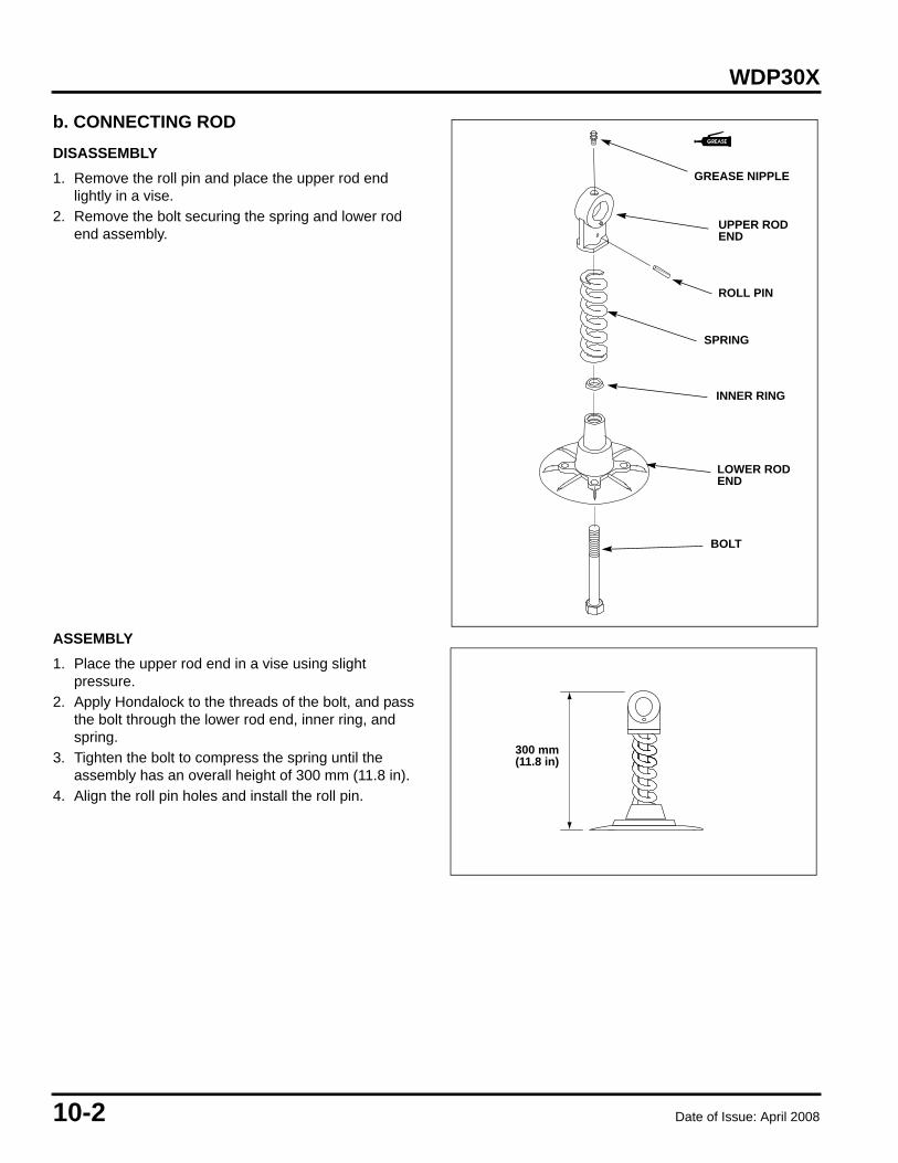
b. CONNECTING ROD
DISASSEMBLY
1. Remove the roll pin and place the upper rod end lightly in a vise.
2. Remove the bolt securing the spring and lower rod end assembly.
ASSEMBLY
1. Place the upper rod end in a vise using slight pressure.
2. Apply Hondalock to the threads of the bolt, and pass the bolt through the lower rod end, inner ring, and spring.
3. Tighten the bolt to compress the spring until the assembly has an overall height of 300 mm (11.8 in).
4. Align the roll pin holes and install the roll pin.
ROLL PIN
UPPER ROD END
SPRING
INNER RING
LOWER ROD END
BOLT
GREASE NIPPLE
300 mm (11.8 in)

Date of Issue: April 2008 10-3
WDP30X
c. DIAPHRAGM
INSPECTION
Inspect the diaphragm for cracks, tears, or damage and replace if necessary.
INSTALLATION
1. Install the connecting rod hex bolt with lock washer, bushing cover, and nylon washer into the crank arm.TORQUE: 54 N•m (40 lb•ft)
2. Pull the starter grip slowly until the diaphragm pulls up against the upper case stops.
3. Install the upper case assembly, making sure the diaphragm is centered and not pinched between the case stops.
4. Tighten the case nuts in an X pattern 1/8 to 1/4 turn until the final torque is achieved.TORQUE: 47 N•m (35 lb•ft)
NYLON WASHER
BUSHING COVER
10 mm LOCK WASHER
CRANK ARM
10 x 1.5 x 20 HEX BOLT54 N•m (40 lb·ft)
CONNECTING ROD
1
2
3
4
UPPER CASE STOP (4)
DIAPHRAGM
UPPER CASE

10-4 Date of Issue: April 2008
WDP30X
Date of Issue: April 2008 11-1
WDP30X 11. GEARBOX
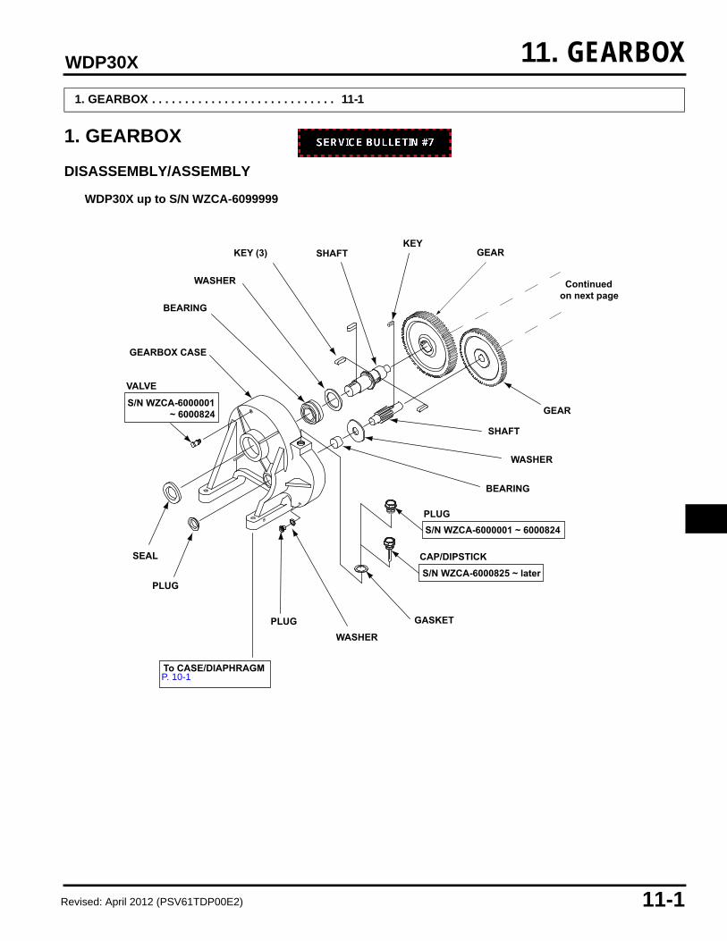
1. GEARBOX
DISASSEMBLY/ASSEMBLY
1. GEARBOX . . . . . . . . . . . . . . . . . . . . . . . . . . . . 11-1
PLUG
PLUGWASHER
GASKET
S/N WZCA-6000825 ~ later
BEARING
To CASE/DIAPHRAGMP. 10-1
S/N WZCA-6000001 ~ 6000824
CAP/DIPSTICK
PLUG
Continuedon next page
S/N WZCA-6000001 ~ 6000824
WASHER
SHAFT
GEAR
GEARKEY
KEY (3) SHAFT
WASHER
BEARING
GEARBOX CASE
VALVE
SEAL
WDP30X up to S/N WZCA-6099999
P. 10-1
Revised: April 2012 (PSV61TDP00E2)

11-2 Date of Issue: April 2008
WDP30X
SHIMNYLON WASHER (2)
BEARINGPIN
48-80-10M SEAL
PLUGS
6 x 1 x 25 mm ALLEN SCREW (10)
LIFTING BAIL
COVER
PINGASKET
BEARING
CLIP
ENGINE MOUNTINGBRACKET
ENGINE ADAPTER
5/16 x 18 x 1.5HEX BOLT (4)
5/16 in WASHER (8)
5/16 in LOCKNUT (4)
10 x 1.5 STUD (4)
15 N•m (11 ft-lb)
Fromprevious page
WDP30X up to S/N WZCA-6099999
Revised: April 2012 (PSV61TDP00E2)

Date of Issue: April 2008 11-3
WDP30X
PLUG
PLUGWASHER
GASKET
BEARING
To CASE/DIAPHRAGMP. 10-1
CAP/DIPSTICK
Continuedon next page
WASHER
SHAFT
GEAR (HELICAL)
GEAR (HELICAL)KEY
KEY (3)
SHAFT
BEARING
GEARBOX CASE
SEAL
WDP30XK1, K2 S/N WZCA-6200001 ~ later
P. 10-1
Revised: April 2012 (PSV61TDP00E2)

11-4 Date of Issue: April 2008
WDP30X
SHIM NYLON WASHER (2)
BEARING
PIN
48-80-10M SEAL
PLUG (2)
6 x 1 x 25 mm ALLEN SCREW (10)
LIFTING BAIL
COVER
PINGASKET
BEARING
CLIP
ENGINE MOUNTINGBRACKET
ENGINE ADAPTER
5/16 x 18 x 1.5HEX BOLT (4)
5/16 in WASHER (8)
5/16 in LOCKNUT (4)
15 N•m (11 ft-lb)
Fromprevious page
SCREW(8)
HELICAL PINION BEARING
PINION
WDP30XK1, K2 S/N WZCA-6200001 ~ later
Revised: April 2012 (PSV61TDP00E2)
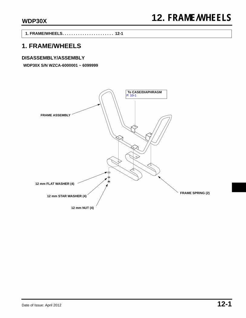
Date of Issue: April 2012 12-1
WDP30X 12. FRAME/WHEELS
1. FRAME/WHEELS
DISASSEMBLY/ASSEMBLY
1. FRAME/WHEELS. . . . . . . . . . . . . . . . . . . . . . . 12-1
12 mm NUT (4)
12 mm STAR WASHER (4)
12 mm FLAT WASHER (4)
FRAME SPRING (2)
FRAME ASSEMBLY
WDP30X S/N WZCA-6000001 ~ 6099999
To CASE/DIAPHRAGMP. 10-1P. 10-1
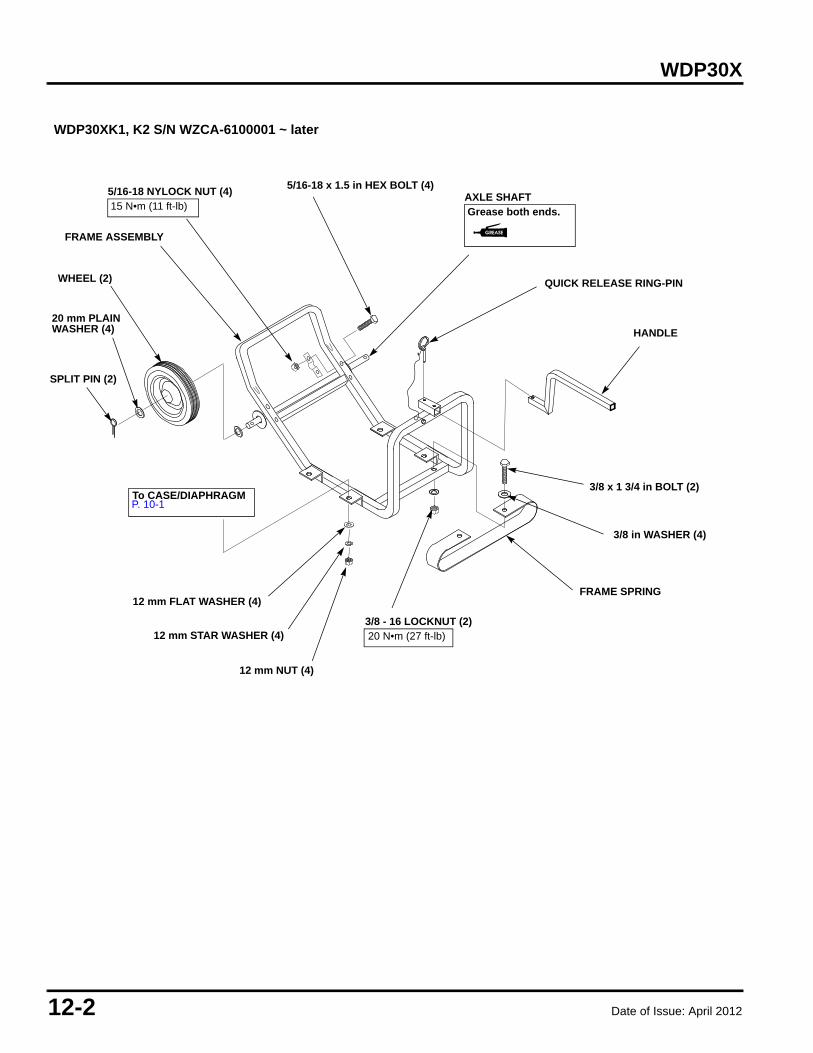
12-2 Date of Issue: April 2012
WDP30X
SPLIT PIN (2)
20 mm PLAIN WASHER (4)
WHEEL (2)
FRAME SPRING
12 mm NUT (4)
12 mm STAR WASHER (4)
12 mm FLAT WASHER (4)
HANDLE
QUICK RELEASE RING-PIN
3/8 x 1 3/4 in BOLT (2)
3/8 in WASHER (4)
3/8 - 16 LOCKNUT (2)20 N•m (27 ft-lb)
5/16-18 x 1.5 in HEX BOLT (4)5/16-18 NYLOCK NUT (4)15 N•m (11 ft-lb)
AXLE SHAFTGrease both ends.
FRAME ASSEMBLY
To CASE/DIAPHRAGMP. 10-1
WDP30XK1, K2 S/N WZCA-6100001 ~ later
P. 10-1P. 10-1
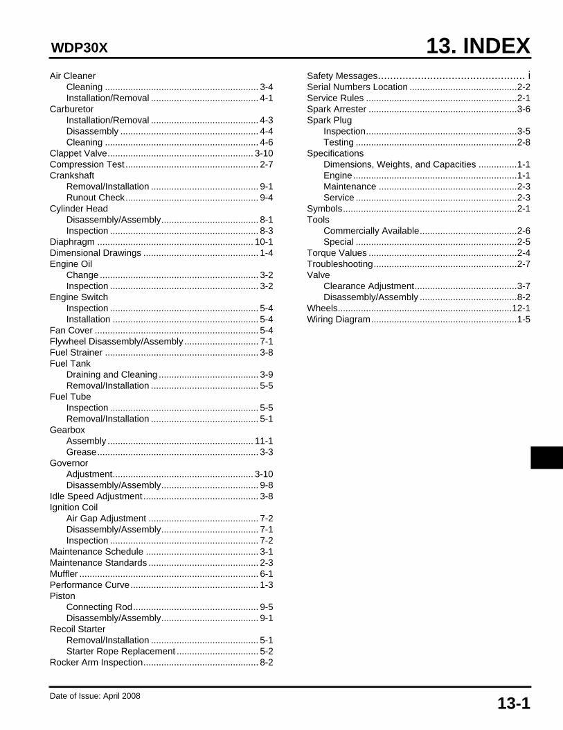
Date of Issue: April 200813-1
13. INDEXWDP30X
Air CleanerCleaning ............................................................ 3-4Installation/Removal .......................................... 4-1
CarburetorInstallation/Removal .......................................... 4-3Disassembly ...................................................... 4-4Cleaning ............................................................ 4-6
Clappet Valve......................................................... 3-10Compression Test .................................................... 2-7Crankshaft
Removal/Installation .......................................... 9-1Runout Check.................................................... 9-4
Cylinder HeadDisassembly/Assembly...................................... 8-1Inspection .......................................................... 8-3
Diaphragm ............................................................. 10-1Dimensional Drawings ............................................. 1-4Engine Oil
Change .............................................................. 3-2Inspection .......................................................... 3-2
Engine SwitchInspection .......................................................... 5-4Installation ......................................................... 5-4
Fan Cover ................................................................ 5-4Flywheel Disassembly/Assembly............................. 7-1Fuel Strainer ............................................................ 3-8Fuel Tank
Draining and Cleaning ....................................... 3-9Removal/Installation .......................................... 5-5
Fuel TubeInspection .......................................................... 5-5Removal/Installation .......................................... 5-1
GearboxAssembly ......................................................... 11-1Grease............................................................... 3-3
GovernorAdjustment....................................................... 3-10Disassembly/Assembly...................................... 9-8
Idle Speed Adjustment............................................. 3-8Ignition Coil
Air Gap Adjustment ........................................... 7-2Disassembly/Assembly...................................... 7-1Inspection .......................................................... 7-2
Maintenance Schedule ............................................ 3-1Maintenance Standards ........................................... 2-3Muffler ...................................................................... 6-1Performance Curve.................................................. 1-3Piston
Connecting Rod................................................. 9-5Disassembly/Assembly...................................... 9-1
Recoil StarterRemoval/Installation .......................................... 5-1Starter Rope Replacement ................................ 5-2
Rocker Arm Inspection............................................. 8-2
Safety Messages................................................ iSerial Numbers Location ..........................................2-2Service Rules ...........................................................2-1Spark Arrester ..........................................................3-6Spark Plug
Inspection...........................................................3-5Testing ...............................................................2-8
SpecificationsDimensions, Weights, and Capacities ...............1-1Engine................................................................1-1Maintenance ......................................................2-3Service ...............................................................2-3
Symbols....................................................................2-1Tools
Commercially Available......................................2-6Special ...............................................................2-5
Torque Values ..........................................................2-4Troubleshooting........................................................2-7Valve
Clearance Adjustment........................................3-7Disassembly/Assembly ......................................8-2
Wheels....................................................................12-1Wiring Diagram.........................................................1-5

Date of Issue: April 200813-2
WDP30X