
Shop level maintenance of inertial platforms without a ...
87
Scholars' Mine Scholars' Mine Masters Theses Student Theses and Dissertations 1971 Shop level maintenance of inertial platforms without a surveyed Shop level maintenance of inertial platforms without a surveyed site site Max E. Bott Follow this and additional works at: https://scholarsmine.mst.edu/masters_theses Part of the Electrical and Computer Engineering Commons Department: Department: Recommended Citation Recommended Citation Bott, Max E., "Shop level maintenance of inertial platforms without a surveyed site" (1971). Masters Theses. 5502. https://scholarsmine.mst.edu/masters_theses/5502 This thesis is brought to you by Scholars' Mine, a service of the Missouri S&T Library and Learning Resources. This work is protected by U. S. Copyright Law. Unauthorized use including reproduction for redistribution requires the permission of the copyright holder. For more information, please contact [email protected].
-
Upload
khangminh22 -
Category
Documents
-
view
0 -
download
0
Transcript of Shop level maintenance of inertial platforms without a ...

Scholars' Mine Scholars' Mine
Masters Theses Student Theses and Dissertations
1971
Shop level maintenance of inertial platforms without a surveyed Shop level maintenance of inertial platforms without a surveyed
site site
Max E. Bott
Follow this and additional works at: https://scholarsmine.mst.edu/masters_theses
Part of the Electrical and Computer Engineering Commons
Department: Department:
Recommended Citation Recommended Citation Bott, Max E., "Shop level maintenance of inertial platforms without a surveyed site" (1971). Masters Theses. 5502. https://scholarsmine.mst.edu/masters_theses/5502
This thesis is brought to you by Scholars' Mine, a service of the Missouri S&T Library and Learning Resources. This work is protected by U. S. Copyright Law. Unauthorized use including reproduction for redistribution requires the permission of the copyright holder. For more information, please contact [email protected].

SHOP LEVEL MAINTENANCE
OF INERTIAL PLATFORMS
WITHOUT A SURVEYED SITE
BY
MAX E. BOTT, 1931 -
A THESIS
Presented to the Faculty of the Graduate School of the
UNIVERSITY OF MISSOURI - ROLLA
In Partial Fulfillment of the Requirements for the Degree
MASTER OF SCIENCE IN ELECTRICAL ENGINEERING
1971
Approved by

ABSTRACT
The initial installation of a rotary tilt table for an aircraft
inertial navigation system test facility includes accurately aligning
the rotary tilt table to local level and true north coordinates. The
survey techniques presently employed are an encumbrance during in
stallation and complicate remote deployment. The objective of this
thesis is to determine if an inertial platform or platforms can prac
tically be used to replace the role of the survey techniques in the
rotary tilt table alignment.
ii
The construction, capability and operation of a rotary tilt table
are reviewed. The tests necessary to test and calibrate an inertial
platform are outlined, including those requiring an accurately aligned
rotary tilt table.
The basic principles of inertial platform self-alignment are stated
so a determination of the ideal behavior of the gyrocompass and level
servo loops, in the absence of error, can be later used for error models.
Typical gaussian error sources, representative of practical inertial
components are injected and assessed to determine the standard deviation
of the steady state gyrocompass and level servo loop errors for a system.
System response times are selected, such that a specific mechanization
may be evaluated for specific values of steady state error.
Test equipment and procedures are presented that outline validation
measures to be taken to ascertain that system errors are within accept
able limits. The cumulative alignment and readout errors are evaluated
to define the rotary tilt table alignment accuracy achievable with one
inertial platform The accuracy is improved by utilizing multiple iner-

iii
tial platforms. This rotary tilt table alignment is then compared to the
test requirements outlined initially.
The findings are summarized and it is concluded that it is practical
to use an inertial system (platform) to perform azimuth alignment of a
rotary tilt table and, that leveling is best accomplished using precision
spirit levels.

iv
TABLE OF CONTENTS
Page
ABSTRACT . . • . • • • • • • • . • . • . • . . . • . • • • . • . . • i i
LIST OF ILLUSTRATIONS ........•....•...•..••. vi
LIST OF TABLES . . . . . . . . . . . . . . . . . . . . . . vii
I.
II.
III.
IV.
INTRODUCTION • . • . . . . .
REVIEW OF RELATED LITERATURE
ROTARY TILT TABLE: CAPABILITIES, OPERATION AND APPLICATION.
A. CAPABILITIES AND OPERATION . . . • . • . • . . . . .
1
7
8
8
B. APPLICATION .•..••...••...••..•.•.. 10
INERTIAL PLATFORM SELF ALIGNMENT •
A. LEVELING . . . . . . .
B. GYROCOMPASSING .
14
15
21
V. SELF ALIGNMENT ERRORS . . . • . . . . . . . • . . . • . . . 25
A. ERROR SOURCES CONSIDERED • . . • . . • . • . • . • . . . 25
B. ERROR EFFECTS ON LEVELING . . . . . . • . 31
C. ERROR EFFECTS ON GYROCOMPASSING .
D. RELATIVE IMPORTANCE OF ERRORS .
36
38
VI. ROTARY TILT TABLE ALIGNMENT METHOD AND ACCURACY . . • . 44
VII.
A. INERTIAL PLATFORM VALIDATION . • .......... 44
B.
c.
D.
E.
ROTARY TILT TABLE ALIGNMENT . .
TILT TABLE ALIGNMENT ACCURACY
INCREASING THE ACCURACY OF THE TILT TABLE ALIGNMENT
ADDITIONAL ALIGNMENT ERROR CONSIDERATIONS
ALIGNMENT METHOD UTILITY . . ..••......••..
A. INERTIAL PLATFORM TEST REQUIREMENTS .•
B. ALIGNMENT METHOD EVALUATION . . . • .
53
55
56
57
61
61
64

VIII. CONCLUSIONS
BIBLIOGRAPHY .
VITA . • . .
TABLE OF CONTENTS (CONTINUED)
Page
75
78
79
v

LIST OF ILLUSTRATIONS
Figure
1.
2.
3.
4.
5.
6.
ROTARY TILT TABLE INSTALLATION . . • . . . . • . • • . • . • .
OPTICAL ALIGNMENT FIXTURE
AUTOCOLLIMATION ALIGNMENT .
ROTARY TILT TABLE . . . . •
EAST/WEST AXIS SELF LEVEL LOOP • .
NORTH/SOUTH AXIS SELF LEVEL LOOP • .
7. COMPONENTS OF EARTH RATE VECTOR SENSED BY THE LEVEL
AXIS GYROS
8. SIMPLIFIED LEVEL AXIS STABILIZATION LOOP .
9. SIMPLIFIED LEVEL AXIS DAMPED STABILIZATION LOOP .
10. SIMPLIFIED SINGLE AXIS LEVEL ALIGNMENT LOOP ••
vi
Page
3
4
4
9
16
16
17
19
19
22
11. GYROCOMPASS LOOP . . . • . • . . . . . . . . . . . . . • . . . 23
12. NORTH/SOUTH LEVELING LOOP ERROR DIAGRAM •.•.•...•... 27
13. EAST/WEST LEVEL AND GYROCOMPASS LOOP ERROR DIAGRAM . . • . . • 28
14. ACCELEROMETER BIAS MEASUREMENT • . . 46
15. VERTICAL MISALIGNMENT ANGLE DUE TO ACCELEROMETER BIAS •.•.. 47
16. TYPICAL NORTH/SOUTH LEVEL AXIS LOOP MECHANIZED FOR GYRO
17.
18.
19.
20.
DRIFT MEASUREMENT . .
STRIP CHART RECORDING OF A GYRO DRIFT MEASUREMENT
SIMPLIFIED CIRCUIT FOR AZIMUTH GYRO DRIFT MEASUREMENT •
AZIMUTH ALIGNMENT CONFIDENCE INTERVAL . . • .
LEVEL ALIGNMENT CONFIDENCE INTERVAL .
49
. 51
• 54
58
• 59

LIST OF TABLES
Table
I CHARACTERISTICS OF KEARFOTT C70 2401 005 ACCELEROMETER .•.
II CHARACTERISTICS OF KEARFOTT C70 2516 010 MINIATURE FLOATED
RATE INTEGRATING GYRO . • .
III SUMMARY OF PROBABILITIES FOR 2o ACCEPTANCE INTERVAL
IV
v
SUMMARY OF PROBABILITIES FOR lo ACCEPTANCE INTERVAL .
EVALUATION OF TILT TABLE ALIGNMENT METHOD • . • • .
vii
Page
40
41
70
72
73

1
I.
INTRODUCTION
A rotary tilt table is used as part of a repair and test facility
for a self aligning aircraft inertial navigation system because of its
ability to accurately tilt and rotate the inertial platform to various
positions to evaluate its performance. The rotary tilt table very
accurately defines a set of level and azimuth coordinates relative to its
mounting surface and, when leveled and aligned in azimuth to true north,
provides an east/north/vertical coordinate system.
The initial installation of a repair and test facility includes
accurately aligning the rotary tilt table to local level and true north
coordinates. This task presently employs survey techniques which require
considerable time and involve special equipment and personnel not normally
associated with installation of an electronic test facility~
Military users desire a portable test facility, installed in a van
or trailer, to facilitate rapid deployment to a new site. One of the
goals for this facility is that it be ready for use within a day after
arrival. The employment of survey techniques causes the time goal to be
exceeded and requires a survey crew which does not normally accompany
the deployed personnel.
The installation alignment accuracy required for a particular
rotary tilt table is dependent upon the accuracy of the inertial system
to be tested. The rotary tilt table should be aligned ten times more
accurately than the inertial system test tolerance requirements, if its
error contribution is to be neglected. The time consuming survey tech
niques are imposed because of the high accuracy required for this align
ment. As an example, the installation instructions for the AN/ASN-63

Inertial Navigation System Test Facility specify that the rotary tilt
table be aligned to within +30 arc seconds in both level and azimuth.
2
Leveling the tilt table is not particularly complicated since
spirit levels (such as the Watts TB-19 Angle Level Gage) are available
with sufficient accuracy for this requirement. The spirit level may be
placed on the adapter plate (see Figure 1) and the leveling screws on
the leveling plate adjusted until the spirit level indicates a level
condition for all azimuth angles.
True north alignment, however, requires the survey crew, normal
survey equipment, and special autocollimation equipment not commercially
available. The survey crew can use their normal equipment and tech
niques to establish a primary true north base line. The equipment and
particular procedure they use is selected according to the accuracy
specified. This primary true north base line is then transferred to
other locations by constructing first, second and third order reference
lines, each of which is perpendicular to the last.
Special equipment is required for the survey crew to align the
rotary tilt table zero degree azimuth line to the surveyed true north
reference line. It is necessary to very accurately fabricate an optical
alignment fixture, as shown in Figure 2, and to utilize mirrors, as
shown in Figure 3, to effect alignment of the entire asseMbly of Fj_gure
1 by autocollimation. This involves rotating the adapter plate relative
to the zero azimuth of the rotary tilt table until the mtrror image of
the cross-hairs in the surveyor's theodolite coincides with the actual
cross-hairs, as shown in Figure 3. The tilt table is then checked in
other attitudes and readjusted until the attitude and azimuth angles
trace the same autocollimation line.

3
Inertial Platform
Adapter Plate
Rotary Tilt Table
Leveling Plate
Barrel of Concrete
Solid Ground
I I
Figure 1 Rotary Tilt Table Installation

s
90° and 270° Mirror
E/W Mirror
Figure 2- Optical Alignment Fixture
- -
Figure 3
Optical Align Fixture
Adapter P ate
-- -- --- ---
Tilt Table
Autocollimation Alignment
4

5
The objective of this thesis is to determine if an inertial platform
can pract'ically be used to replace the role of the survey techniques
in the rotary tilt table alignment. This is to be accomplished by
using the inertial platform's self alignment and leveling capability.
Chapter III defines the rotary tilt table capabilities and outlines
the required inertial system tests which require comparison with the
tilt table angular position indication.
Chapter IV outlines the basics of the leveling and gyrocompass
servo loops used in self alignment to determine their ideal behavior
in the absence of error.
Chapter V investigates the level and gyrocompass accuracy of an
inertial system whose inertial components are operating within their
specification tolerances. Typical error sources are analyzed in the
level and gyrocompass loops to determine the system's resultant steady
state level and gyrocompass accuracy.
The rotary tilt table alignment method is outlined in Chapter VI.
This chapter first discusses the procedures and equipment that may be
used without an accurate established coordinate system to ascertain
whether the major inertial platform errors are within specified toler
ances, thus guaranteeing accuracy of a particular inertial system. Sec
ond, the alignment method utilizing an inertial platform and the
resulting alignment accuracy is discussed. Third, the use of multiple
inertial platforms to improve the tilt table alignment accuracy is
investigated.
Chapter VII investigates the utility of the rotary tilt table
alignment method. First the rotary tilt table alignment accuracy is
compared with the accuracy requirements for inertial platform tests.

Then it is evaluated on the basis of how well it identifies inertial
platforms which are in or out of specification.
6
Chapter VIII summarizes the comparison of the resulting accuracy of
the rotary tilt table alignment to the inertial platform testing require
ments. Conclusions are drawn as to whether or not a coordinate frame
defined by an inertial system or systems is a practical replacement for
the present spirit level and survey techniques.

7
II.
REVIEW OF RELATED LITERATURE
There is considerable published literature available in the area
of inertial platform design, mechanization and analysis, which is
closely related to, and essential to the analysis of this thesis topic.
The open literature surveyed concentrates primarily on the design and
analysis of inertial guidance systems, which establishes the basis for
test facility accuracy requirements. Some common alignment and test
requirements are briefly described by bibliographic reference item (4),
but no reference is made to related test facility requirements.
Bibliographic reference items (1) through (5) and (7) contain
extensive discussion on the mechanization of leveling and gyrocompass
servo loops. The effects of errors on leveling and gyrocompassing,
and methods for analysis of errors are described in reference items
(1), (3), (4) and (5).
The basic installation criteria and procedures used for rotary
tilt table installation using survey techniques, is described in
unclassified government installation procedures. Specific test toler
ances and test procedures involved in testing an inertial platform
are also described in unclassified government test procedures.
There was no existing criteria in the literature reviewed to
indicate previous work toward defining methods for, or evaluation of
using an inertial platform to accurately align a rotary tilt table for
its own test facility. The government documents give an insight to
the accuracy requirements but use survey techniques to effect the
required alignment accuracy.

8
III.
ROTARY TILT TABLE: CAPABILITIES, OPERATION AND APPLICATION
A rotary tilt table is used with the inertial platform test facil
ity because of its ability to accurately position the gyro stabilized
platform while performing the variety of tests necessary to verify
directional accuracy of an inertial navigation system. The capabilities,
operation, and application of the rotary tilt table and those tests
which utilize it and involve comparisons with its angular position indi
cation are discussed below to establish criteria for judging the tilt
table accuracy requirements.
A. Capabilities and Operation
The rotary tilt table is an accurately machined device consist
ing basically of a flat table surface, called a platen, coupled
through two axes to a rigid base. The platen is adjustable through
+360 degrees about a vertical axis and +90 degrees from level about
one horizontal axis by means of gear drives operated by handwheels.
The Swiss-made Society Genevoise, type PI-2 rotary tilt table,
shown in Figure 4, will be used for the following brief description
of construction and operation. This assembly has envelope dimen
sions of 17 inches wide by 12 5/8 inches deep and 7 inches high when
level. It has a 7 7/8 inch platen, and weighs approximately 115
pounds. The platen can be rotated continuously in either direction
through 360 degrees and can be tilted from 0 to 90° in one direction
only. It is designed to handle loads up to 55 pounds on its platen.
The platen is rotated by means of the rotation handwheel. It
is attached to a worm gear that mates with gear teeth on the bottom

Figure 4 - Rotary Tilt Table
1. Platen 2. Rotation pointer 3. Rota~ion vernier indicator
and controls 4. Rotation handwheel 5. Tilt handwheel 6. Tilt angle indicator 7. Magnifying glass
tilt indicator 8. Tilt angle vernier scale 9. Aligning block
10. Cradle locking lever 11. Cradle 12. Rotation indicator
\0

10
of the platen. One revolution of the rotation handwheel corresponds
to an angular rotation of three degrees. The rotation graduations
on the platen are in one degree increments but the platen is adjust
able to an accuracy of one minute by a vernier adjustment. Its
adjustment is further improved by a second vernier whose graduations
are in five second intervals.
The platen supporting cradle is tilted by means of the tilt
handwheel. This is also attached to a worm gear engaging gear
teeth on the cradle. The tilt angle graduations are in half de
grees. Accuracy is improved to one minute of angle by reading the
tilt angle vernier scale through the magnifying glass and refined to
15 seconds by interpolation. Two reference stops define the 0 de
gree and 90 degree positions.
B. Application
The accuracy required of the rotary tilt table and its instal
lation alignment is determined by the accuracy specified for the
particular inertial platform tests to be performed. This topic
briefly describes the inertial platform tests to be performed and
identifies error sources involved in performing the tests. In par
ticular those tests affected by the tilt table alignment accuracy
are identified.
1. Gyrocompass Test
The gyrocompass test is performed to ascertain that the
inertial platform stable element levels and gyrocompasses to
specified accuracies. This consists of comparing the inertial
platform's azimuth and level indications with the rotary tilt
table. The alignment accuracy of the rotary tilt table l~its

the accuracy to which this test can be performed. Potential
system errors that contribute to this test result are gyro
drift, accelerometer bias, latitude setting, gimbal synchros,
the external indicator, and the rotary tilt table alignment.
2. Accelerometer Bias
11
The accelerometer bias test is performed to determine that
the accelerometer bias potentiometers are adjusted for no out
put when there is no acceleration input. This is performed by
comparing the accelerometer's open loop output when subjected
to earth's gravity, first in one direction, then in the other.
The sum of the two measurements is equal to twice the accelerom
eter bias. The rotary tilt table is only used as a convenient
fixture for position adjustment since the definition of vertical
during this test is zero output from the two accelerometers
not being tested. Therefore, this test does not involve com
parison of inertial platform angle to rotary tilt table angle,
but the tilt table ability for fine adjustment is needed here.
3. Gyro Drift Test
This test is performed to ascertain whether the gyro bias
notentiometers are adjusted to eliminate inherent gyro drift.
The level axis gyros are tested by opening the stabilization
loop and allowing the gyro drift rate to drive the stable ele
ment off level. The resulting rate of change of the accelerom
eter output is then representative of the gyro drift rate. The
azimuth gyro drift is identified by opening the loop and
measuring the rate of change of azimuth. Potential system errors
that may contribute to the results of this test are latitude

setting, gimbal synchros, and external measurement equipment.
The heading of the inertial platform must be compared to the
rotary tilt table to assure that a component of earth rate is
not identified as gyro drift, thus rotary tilt table alignment
accuracy affects the results.
4. Synchro Null Tests
12
This test is performed to ascertain that the inertial plat
form synchro electrical nulls are within specified limits.
With the rotary tilt table set to zero azimuth and level, each
of the gimbal synchros angles is measured and must be within
specified tolerance. The only errors involved are the gimbal
synchros, the external measurement equipment, and the rotary
tilt table alignment.
5. Synchro Linearity Tests
This test involves rotating and tilting the inertial plat
form and comparing its angular indications to those of the
rotary tilt table. The gimbal synchros and external measure
ment equipment are the error sources involved in the results of
this test.
6. Accelerometer Scale Factor Test
This test is performed to determine if the accelerometer
produces the correct output for a known acceleration input in
the -lg to +lg range. The known acceleration inputs are the
component of gravity sensed as the stable element, caged to the
case, is tilted from 0° in successively greater angles to 90°.
The sources of error applicable to this test are the acceler
ometer, the external measurement equipment, and the rotary tilt

13
table level alignment.

I~
INERTIAL PLATFORM SELF ALIGNMENT
The basic theory of the level and gyrocompass servo loops for an
inertial platform must be discussed in order to establish mathematical
models of the leveling and gyrocompassing operations. These models
14
can then be used to establish the ideal behavior of the level and gyro
compass operations in the absence of error, which will show that self
alignment is possible.
The heart of the inertial system is the gimbal suspended stable
element which is within the inertial platform and is used to define
a three-axis coordinate system. The stable element contains either
two or three orthogonally mounted gyros to give a stable attitude in
the three axes. It contains a set of three orthogonally mounted
accelerometers to sense acceleration in any direction of the three
dimensional coordinate frame.
Initial platform self alignment uses the system's inertial in
struments (gyros and accelerometers) to sense deviation from the
desired coordinate frame. At least two noncollinear vectors are re-
quired to define a three-axis orthogonal coordinate system. For self
alignment of an earth referenced inertial system, the mass attraction
vector is used for leveling. An angular rate vector, such as the earth's
rotational vector, is used for azimuth alignment. 1 The three earth
referenced coordinates are then defined as north, east and vertical by
the sensitive axes of the three accelerometers. The north and east
accelerometers sense acceleration in the ground plane and the third
accelerometer senses vertical acceleration including the mass attraction
vector.

15
In the following discussion, it is assumed that the platform
initially has been roughly aligned to within a few degrees of the
. 1 desired orientation so that small angle approximations are val1d. This
rough alignment can be achieved by slaving the platform pitch and roll
gimbals to the attitude of the te.st surface, which is approximately
level and by slaving the azimuth gimbal to some external heading refer-
ence such as a magnetic compass corrected for local variation.
A. Leveling
Platform level may be defined as the attitude where the level
(north and east) accelerometers do not sense a component of gravity.
Simplified forms of self leveling loops are shown in Figures 5
and 6.
The east/west axis level loop is shown in Figure 5 where eE is
the platform misalignment angle about the east/west axis. A campo-
nent of gravity, g sin8E, will be sensed by the north accelerometer
when the platform is tilted about the east/west axis. This gravity
component output from the north accelerometer, approximated by
geE due to the small angle, causes torquing of the east gyro which,
in turn, drives the gimbal servo to rotate the platform about the
east/west axis until the north accelerometer output is zero. The
additional input, as illustrated by Figure 7, is the component of
earth rate sensed by the east gyro when the inertial platform is not
oriented in azimuth. Since the gyro input axis is not perpendicular
to earth rate, it senses the component of earth rate, ~ cos¢ sin~,'
which becomes an input to the loop driving it off level. For con-
sideration of error free leveling, this input can be disregarded for
systems which are aligned with north.2

16
_g!E_--- --B- ----l
\ \
North Accel.
Figure 5
r--t t
East Accel.
Figure 6
Integrator
-~ cos¢ sin.~----~
East Gyro & Gimbal
East/West Axis Self Level Loop
-----B--- _::N_--
-~ cos¢
I
I I
_l
--1 I I I I I I
1--__...;:~ In t egrator
North Gyro .J & Gimbal
~ cos¢ cos1)J
North/South Axis Self Level Loop

S1 cos¢
True North
<P = Latitude
Platform N/S Axis
~ = Azimuth misalignment
17
S"2cos¢ sin~ = Component of earth's rate sensed by E/W gyro with an azimuth misalignment
Component of earth's rate sensed by N/S gyro with an azimuth misalignment
Platform E/W Axis
Figure 7 Components of Earth Rate Vector
Sensed by the Level Axis Gyro

18
The north/south axis level loop is shown in Figure 6 where 8 N
is the platform misalignment angle about the north/south axis. A
component of gravity, -g sin8N' will be sensed by the east accel
erometer when the platform is tilted about the north/south axis.
This gravity component is approximateQ by g8 , due to the small N
angle. The east accelerometer output signal is applied to torque
the north/south gyro, which in turn, drives the gimbal servo to
rotate the platform until the east acc8lerometer output is zero.
Referring again to Figure 7, the earth rate component sensed by the
north gyro can be assumed to be the full ~cos~ vector when the
system is aligned with north and level. This loop input would drive
the loop off level about the north/south axis except that the gyro
torquing input, -~cos~, is applied to the gyro to offset the earth
rate input. Again for consideration of error free leveling, this
cancels out earth rate for systems aligned to north. This makes the
north/south level loop closely resemble the east/west level loop.
After alignment, during navigation this input is used to keep the
platform level as the earth rotates in space.
Since the north/south and the east/west leveling loops are
essentially the same, only a general mechanization of the leveling
loop will be developed here. Consider the leveling loop to be
mechanized as the typical level axis stabilization loop in the nor-
mal navigation mode of operation, as shown in Figure 8. Since the
time constant of the gimbal servo is usually small, the gyro and
3 gimbal dynamics may be represented as an integrator , thus the gyro
may be represented as shown in Figure 8. In this loop, any platform
tilt angle, ~. from the vertical will be sensed by the accelerom-

,-----1 I I
19
--------8--------- -~
A~ 1 t--=A~~1 ! 1--=-v-1~'--~-----.~1---w-~1 ! ~ ~ ~ Accelerometer First ~G-y-r-0~
Integrator Motor
Figure 8 Simplified Level Axis Stabilization Loop
~------- ---0--8 I
1 1 s
Accelerometer
1 R
1 s
yro Motor
Figure 9 Simplified Level Axis Damped Stabilization Loop
I I
68

20
eter and will result in an apparent velocity, V, which is divided
by the earth's radius, R, to give an angular rate, w. This angular
rate is applied to the gyro in the correct sense to drive the plat-
form to null e. Using the small angle approximation so that
sine = e, the equation of motion for the leveling loop can be
written as:
0
If the platform is started from rest with an angular error e0
,
then the vertical error at any time is given by:
where w0 =Jf = -3 1.. 204 x 10 rad/sec is the undamped natural
(4 .1)
(4. 2)
frequency. The stabilization loop of Figure 8 is, therefore, an
undamped low frequency servo system with a maximum bounded error
of e0
and a period of 84.4 minutes. This loop is known as the
Schuler Loop, and the period is known as the Schuler Period.
During alignment, damping is added around the first inte-
grater as shown in Figure 9 to allow the platform to attain a
steady state level condition in the presence of an initial tilt
error e0
. The transfer function for this damped loop is:
e oe (s) 0
s (s + ~) (4. 3)
s2
+ ~s + ~ eo
If oe is the step error -- (which corresponds to an initial tilt s
error e0), then applying the final value theorem, shows that the
tilt angle e damps to zero. This equation still has a natural
frequency of w = 0 1.204 x 10⁻³ rad/sec but the initial error
damps out in time.

21
Faster inertial platform leveling is achieved by increasing the
forward gain by ~,as shown in the level alignment loop in Figure
10, thus increasing the natural frequenc.y. The transfer func.tion
for this loop is as follows:
e 88 (s) s(s + K )
b
+_g_K R R
Applying the final value theorem with oe=
(4. 4)
s shows that the
initial error still damps to zero, but the natural frequency has
been increased by the factor~ and thus the time constant has
been decreased by 1/~ .
B. Gyrocompassing
The term "gyrocompassing" is used to indicate the appropriate
alignment about the local vertical (that is, azimuth alignment).
Correct azimut.h orientation may be defined as alignment of the
east/west axis perpendicular to the earth's rotation rate vector as
indicated in Figure 7. This process is accomplished by causing
rotation of the previously leveled platform until the input axis of
the east gyro no longer senses a component of the earth rate vector
(i.e. the input axis is perpendicular to the earth's rotation
4 vector) . Thus 1. the Eorth gyre will then have its input axis in the
north direction and the azimuth angle of the inertial platform
will be zero.
Figure 11 illustrates how a gyrocompass loop is mechanized
as an extension of the east/west leveling loop. The ea.st/v:est
axis level ii:g loop, as mentioned during its discussion, will be
driven off level by an input of earth rate to the east gyro. Re-

i--- -- -------D----1
I
A --!iJ V ~ 1
Accel.
I )II 1 I ~ KR I s+Kb
Damped Integrator
---------------, I
~ 1 I 1 1 -R s
Gyro
Figure 10 - Simplified Single Axis Level Alignment Loop N N

~
,-------- 0 eE -------------- -----
1 I I I I +
KR R ~ >01.+kl'"
N art h ..._______..
Accel.
sec¢ KN 1 s
Azimuth Gyro
81)!
Figure 11 - Gyrocompass Loop
~ cos¢
-- ------- -T
I I I I
I I
l ~- _j s
East Gyro
N w

24
ferring to the implementation of the gyrocompass loop in Figure 11,
if the platform is at an angle ~ from true north, the east gyro will
sense the component of earth rate -~cos~ sin~ (see Figure 7).
It is assumed that the azimuth angle is small due to rough alignment
so sin~-~. This earth rate component causes torquing of the east
gyro, driving the platform off level, causing the north accelerometer
to sense a component of gravity. The north accelerometer output
re-levels the platform and torques the azimuth gyro until the
azimuth angle, ~, is nulled out.
The transfer function for the azimuth misalignment angle ~, as
a function of the angular input 6~, for the gyrocompass is:
_1. (s) = 8~
The gains may be chosen such that the characteristic equation has
2 three equal roots • This is typical design practice. The azimuth
angular error 8~ is used to incorporate the initial azimuth mis-
alignment, ~O' by making it a step function of magnitude ~O
whereupon equation 4.5 becomes:
~ (s) ~ 0 ( s
2 + 3as + 3a2
)
Where
Applying the final value theorem to equation 4.6 shows that gyro-
compassing can damp out initial azimuth misalignment errors and
thus can perform azimuth alignment in error free systems.

25
v.
SELF ALIGNMENT ERRORS
The accuracy of an inertial platform's self alignment is limited
by erroneous initial conditions and mechanical imperfections which are
5 introduced as error inputs to the level and gyrocompass servo loops •
These error inputs are nulled by the servo loops causing the inertial
platform to orient to false level and azimuth coordinates.
A. Error Sources Considered
There are many possible sources of error and their importance
is dependent upon the particular mechanization and its application.
The error sources which are considered here to be typical for an
aircraft inertial navigation system are; initial level and azimuth
misalignment angles, latitude error, gyro drift, accelerometer bias
and interaxis coupling errors. The level and azimuth misalignment
angles, eo and ~0 respectively, refer to the initial orientation
of the platform that the servo loops are mechanized to correct.
Latitude is required to establish correct earth rate torquing;
therefore any latitude error, 6¢, results in an erroneous earth
rate input. Gyro drift, E, is an output from the gyro pickoff
synchro which was not caused by the rotation of the earth or by
movement of the vehicle over the earth's surface. Accelerometer
bias, AB' is non-zero output from an accelerometer when it is
sensing no acceleration. Interaxis coupling, A, will occur if
the principal axes of the stable element do not coincide with the
input axes of the gyros resulting in erroneous earth rate inputs.
These error sources are introduced into the level and gyro-

compass loops as constant error forcing functions, as shown in
Figures 12 and 13. The azimuth misalignment error, ~O' the lati
tude error, 8¢~ and the interaxis coupling error, A, require
further explanation since they enter the loops as a function of
an earth rate component coupled into the gyros.
26
As shown in Figure 7 the component of earth rate sensed by the
east gyro is wE = Dcos¢ sin~. With a small change in azimuth
angle, 8~, it becomes:
wE' = Dcos¢ sin(~ +8~)
= Dcos¢ sin~ coso~ + Dcos¢ cos~ sine~
and for small 8~
wE' Dcos¢ sin~+ (c~)Dcos¢ cos~
wE + (8~) cos¢ cos~.
Therefore .• if the nominal azimuth angle is zero and is in error
by 8~, then the earth rate correction input is in error by:
and sine.(~ 8~ is equal to ~O this becomes
as shown in Figure 13. Similarly, the component of earth rate
sensed by the north gyro is w = Dcos¢ cos~. N With a small change
in azimuth angle, 8~, it becomes:
wN' = Dcos¢ cos(~ + 8~)
= Dcos¢ cos~ coso~ - Dcos¢ sin~ sine~
and for small 8~
' = Dcos¢ cos~ [1 (~)~ - (c~)Dcos¢ sin~ WN
= w [1 -(.§j:) 2] ( 8~) Dcos¢ sin~ , N 2

i ------------------0-- _ell--------------- ----, I
I I
I I I I
I I
1
East Accel.
ABE
A 2 - e - rl
2
-~ rl cos~ - 6~ rl 2
sin~
cos~ + A rl sin~ e
--~
R
w0 2 ~ cos~ __j
2
-A 2 ~ cos~ a 2
I
Figure 12 - North/South Leveling Loop Error Diagram
£N
N-1 1 -s -
North Gyro 60N
N -...J

r
' I I I
------------- ---~-~---------------l I
1
Nort Acce1. ~N
~ sec¢
A 2 D sin¢ n 2
A 2 D sin¢ + A D cos¢ e e
KRE
R
sin¢ - 6¢ D cos¢
1 s
A D sin¢~ ~A_ D cos¢ I n
e:E
D cos¢
1 s
ast Gyro 8oE
Figure 13 - East/West and Gyrocompass Loop Error Di.agram N CXl

29
Therefore, if the nominal azimuth angle is zero and is in error by
o~, then the earth rate correction input is in error by
( 0''') 2 owN = - ~ ~cos~
and since o~ is equal to ~O this becomes:
-~02 ~cos~ (5.2)
2
as shown in Figure 12.
Referring again to the earth rate components shown in Figure 7,
the earth rate sensed by the east gyro is wE = ~cos~ sin~. With
a small change in latitude, o~, it becomes
= ~sin~ cos~ coso~ - ~sin~ sin~ sino~
and for small ocp
Therefore, if the nominal azimuth angle is zero, wE' is equal to
zero, indicating that latitude error has no affect on the east
gyro, as shown in Figure 13. Similarly the component of earth rate
sensed by the north gyro is wN = ~cos~ cos~. With a small change
in latitude, o~, it becomes:
w ' = ~cos(~ + o~) cos~ N
= ~cos~ cos~ coso~ - ~cos~ sin~ sino~
and for small o~
wN' = ~cos~ cos~ [1 _(o~)J- (o~)~cos~ sin~
(~_)2 = ~ - 2 ~cos~ cos~ - (o~)~cos~ sin~.
Therefore if the azimuth angle is zero and the latitude error is
o~, the latitude earth rate correction to the north gyro is in

30
error by:
(op) 2
2 ~cos~ - (o~)~sin~ (5. 3)
as shown in Figure 12. The component of earth rate sensed by the
azimuth gyro is w = - ~sin~. AZ
With a small change in latitude
8~ it becomes:
W I
AZ - ~sin(~ + o~)
ot112 - ~sin~ (1 - ~) - ~(o~) cos~
so the latitude correction for the azimuth gyro is in error by:
~sin~ - (o~) ~cos~ (5.4)
as shown in Figure 13.
Interaxis coupling errors, A, result from misalignment of the
gyros' input axes relative to the orthogonal coordinates defined
by the accelerometers. The east gyro input axis can be misaligned
in either azimuth or level angle directions. The component of
earth rate sensed by the east gyro due to azimuth misalignment is
wEl = ~cos~ sinAa. With a small variation, Aa' from a zero nominal
azimuth it behaves like an azimuth error, which results in an
earth rate error of:
(5.5)
as shown in Figure 13.
The component of earth rate sensed by the east gyro due to
level misalignment, An' is wE 2 = - ~sin~ sinAn.
small angle the earth rate error is:
Since A is a n

31
as shown in Figure 13. The component of earth rate sensed by the
north gyro due to azimuth misalignment is wNl = ~cos¢ cos¢. With
a small variation in the azimuth direction~ A ~ from a nominal zero a
azimuth it appears like an azimuth error and therefore can be
written as:
A 2 a 2 s-2cos¢ (5.7)
as shown in Figure 12. The component of earth rate sensed by the
north gyro due to level misalignment appears exactly like a negative
latitude error, thus the earth rate error may be written:
A 2 e
2 S"tcos¢ + A stsin¢ e (5.8)
as shown in Figure 12. The component of earth rate sensed by the
azimuth gyro is wAZl = -stsin¢ and with a small level misalignment
about the east/west axis it appears as a negative latitude error
and the earth rate error may be written as:
A 2 e 2 stsin¢ + A S"tcos¢
e (5.9)
as shown in Figure 13. For a small misalignment about the north/
south axis the earth rate sensed by the azimuth gyro is
and for small A the resultant earth rate error n
is:
OWAZ2 = A 2
n 2 stsin¢
as shown in Figure 13.
B. Error Effects on Leveling
(5.10)
The effects of the error sources which have been defined on

32
leveling will be investigated by introducing the error forcing
functions into the servo loops as they occur in the physical system.
The leveling loops, with error inputs, are shown in Figures 12
and 13.
The east/west level loop is tightly coupled in the gyrocompass
loops, but the north/south level loop is only loosely coupled to
azimuth for a north aligned platform, therefore the north/south
level loop can be analyzed separately and will be discussed first.
The transfer functions relating the platform north/south axis level
misalignment angle, eN, to the error inputs as obtained from
Figure 12 are as follows:
e Nl(s) ~E
2 (J.J
K ( _Q) RN g
(s + 2w0 ~) = (s + wo ~)2
e N3 (s) =
(l)J ) 2 0
~cos¢(s + 2w0~) - 2 2(s + w
0 v~)
s(s + 2w0 ..Jlf;)
~2
cos¢ 2
(s +
- (o¢)sin¢
(s) ~(s + 2w0~
(s + wo~)2
(5.11)
(5.12)
(5.13)
(5.14)
(5.15)

33
8N6 S1(s + 2w0~) (s) = A 2 (s + (),)0~)2 e --- coset> + A sincp 2 e
(5.16)
8N7 S1(s + 2w
0 JKRN)
(s) A 2 (s + (),)0~)2 a --- coscp 2
( 5. 17)
The steady state north/south axis level error caused by the
constant error inputs may be obtained by application of the final
value theorem to equations 5.11 thru 5.17 which gives:
e ABE
= Nlss g (5 .18)
e 2c:N
N2ss wo.J~
(5.19)
ljJ 2S1 coset> 0 e = N3ss wo~
(5.20)
e N4ss 0 (5. 21)
2S1[(cS~)2 coset> + (cScp) sincp] 2 e = -N5ss woJ~
(5.22)
A 2 2S1[-
e coscp + A sincp] e 2 e
N6ss = (5.23)
wo VKRN
S1A 2 coscp e = -
a N7ss
wO JKRN (5.24)
It can be seen from equations 5.18 through 5.24 that initial
tilt of the platform has no affect on the steady state level condi-
tion about the north/south axis since the level loop is designed to

34
eliminate initial tilt. The remainder of the errors do cause a
steady state off level condition at the end of alignment.
The transfer functions relating the east/west axis level mis-
alignment angle, 8E, to the error inputs are as follows (where
P = s3 + ~Es2 + wo2~s + wo2~KN~):
8 ~(s) ~N
8 _g(s) c:E
8 E3 (s)
80E
=
=
=
(KRE)(wo 2)(s + ~~)
p
s(s + KbE) p
2 s (s + KbE)
p
s(s + 8E4 KbE)
A ~cos4>(s) = p a
8E5 s(s + KbE) A ~sin4>(s) =
p n
8 s(s + KbE)(~cos¢) ~(s) = l)JO
p
8 (~cos¢)(s +~E) _§I_(s) = c:AZ p
8 (~cos¢)(s + KbE) E8
2 (s) = .A p
_g_ ~cos4> 2
(5.25)
(5.26)
(5. 2 7)
(5.28)
(5. 29)
(5.30)
(5.31)
(5.32)

35
8E9 (r.lcos¢)(s + KbE)
(s) = ~
p r.lsin¢ - o<jlr.lcos¢
( 5. 33)
8El0 (r2cos¢)(s +~E) (s)
A. 2 p (5.34)
+ r.lsin¢ +A. r.lcos¢ e
The steady state east/west axis level error caused by the con-
stant error inputs may be obtained by application of the final
value theorem to equations 5.25 through 5.34 which gives:
e Elss
e E2ss
e E3ss
8E4ss
e E5ss
e E6ss
e E7ss
e ElOss
ABN =--
=
=
=
=
=
g
0
0
0
0
0
£AZKbEcos¢
w02KRE~ A. 2
-(+) r.l (cos¢) 2KbE
wo2~ ~
o¢2 [(-z-)sin¢- (o¢)cos¢]Q~Ecos¢
A. 2 e 2
w02KRE~
(5.35)
(5.36)
(5.37)
(5.38)
( 5. 39)
(5.40)
(5.41)
(5.42)
(5. 43)
(5.44)

36
It can be seen from equations 5.35 through 5.44 that east gyro
drift, initial tilt or azimuth error, and east gyro misalignment
cause no steady state error in the east/west axis level condition.
The remainder of the errors cause a steady state off level condition
at the end of alignment.
C. Error Effects on Gyro Compassing
The effects of the error sources on gyrocompassing are investi-
gated by introducing the error forcing functions into the gyro-
compass loop as shown in Figure 13. The transfer functions relating
the azimuth misalignment angle, ~. to the error inputs are as
follows (where 3 2 2 2
p = s + ~Es + w0 KREs + w0 KRE~s-2):
~l -(s) = ~0
~2
80E (s)
~3 - (s) EE
~4 (s)
EAZ
~5 - (s) ~N
~6
A. 2
=
=
=
~ S1sin¢
2 2 s(s + KbEs + w0 KRE)
p
2 - sw0 ~~
sec¢
p
2 - wO KRE~ sec¢
p
2 2 s + KbEs + wO KRE
p
~ s(R)~ sec¢
p
2 2 s + KbEs + wO KRE
(s) p
(50 45)
(5.46)
(50 4 7)
(5.48)
(5.49)
(5.50)

37
1)!7 2 + KbEs +
2 s wO KRE (s) =
c¢2 p -
2- r.!sin¢ - (ocp)r.!cos¢ (5.51)
1)!8 - wo2KRE~ sec¢ (s) = A r.!sin¢ p n
(5.52)
1)!9 - wo2KREKN sec¢ (s) = A r.!cos¢ p a
(5.53)
1)!10 2 + 2 s ~Es + wO ~
A2 (s)
p
; r.!sin¢ + A r.!cos¢ e
The steady state azimuth error caused by the constant error
inputs are obtained by application of the final value theorem to
equations 5.45 through s.S4 which gives:
lj!lss =
1j!2ss
1j!3ss =
1j!4ss =
lj!Sss =
1j!6ss
0
0
- EE s-2
EAZ
~f.!
0
A. 2 11
2 K
N
sec¢
sin¢
c¢2 . -z s1n¢ - (o¢)cos¢
ljJ7ss =
= A Tan¢ n
= A a
(5.55)
( 5. 56)
(5. 57)
(5.58)
(5.59)
( 5. 61)
(5.62)
( 5. 63)

38
lJJlOss = (5.64)
It can be seen from equations 5.55 through 5.64 that gyro
drift, interaxis coupling, and latitude error will cause a steady
state azimuth misalignment at the end of gyrocompassing.
D. Relative Importance of Errors
Some typical system components and characteristic time con-
stants for level and gyrocompass response are selected in order to
evaluate the relative importance of the errors. This permits
evaluation of the performance of an inertial platform in aligning
a tilt table.
Typical response time for the leveling loops is ten seconds.
Selection of damping ratio is a design consideration for a par-
ticular mechanization involving a trade-off between alignment time
and accuracy. Critical damping will be assumed for this example,
whereby equation 4.4 may be written:
L s(s + ~N)
eo (s)
1 (5.65) (s + -) T
2 2w 0 JKRN where (1.) (~)KRN = w02KRN, KbN = and T= 10 seconds. T
(l/T) 2 10-2 6900 (5. 66) Then K = w-z- =
10-3)2 =
RN 0 (1. 204 X
KbN = 2w0 JKRN = (2)(1.204 X 10⁻³) J69oo = o.2o (5. 6 7)
The gyrocompass response time is chosen to be 15 minutes (900
seconds) and the design is such that the characteristic equation
of equation 4.5 has three equal roots. The last term [~ KREO~]

39
is equal to a 3 where 1 and it follows that ~E 3a ~d
T
wo 2KRE = 3a2 • Then solving for the constants where T = 900
seconds gives:
KbE = 3a = 0.00333 (5.68)
~ 3a2
2.56 (5.69) = = w 2
0
~ a3
5.07 (5.70) = =
wo2~~
For this performance analysis the component errors used will be
those of Kearfott's C70 2401 005 accelerometer as shown in Table I
and Kearfott's Alpha series floated rate integrating gyro as shown
in Table II. From Table I the accelerometer bias error is
0.00001 g and from Table II the gyro drift is 0.02 deg./hr. It
is assumed that these errors are normally distributed and the
values are la values.
It is assumed that local latitude is known within one mile
which represents an error of approximately one arc minute. In
order to evaluate interaxis coupling errors, it will be assumed that
the input axes of the gyros may deviate as much as ten arc seconds
from the principal axes of the stable element.
Assuming the inertial platform has been roughly aligned to
within one degree of north and assuming a forty degree latitude,
the resultant north/south level axis errors are derived from
equations 5.18 thru 5.24 as follows:
~E 1o-5g rad 2.06 arc sec. e = = g Nlss g
(5.71)

C70 2401 005
Scale Factor (output) 4.9475 ma/g of applied acceleration
Operating Temperature 150°F + l0°F
Linearity 5 x 10⁻⁶ g/g2
Threshold 2 x 10⁻⁷ g
Zero Stability 0.00001 g
Vibration Up to 20 g peak to 2000 cps
Storage Temp. -65°F to +200°F
Scale Factor Variation 0.03% per year
Excitation 6 volts, 3860 cps
Natural Frequency 220 cps
Frequency Response Flat to 250 cps
Shock 60 g's
Weight 4 ounces
Table I
Characteristics of Kearfott C70 2401 005 Accelerometer
40

41
C70 2516 010
Size Weight (lbs.)
1.837 dia. x 2.765 0.70
Angular Momentum (gm cm2 /sec) Gyro Gain (output/input) Transfer Function (v/ 0 input) Characteristic Time (msec.) Gimbal Freedom (degrees) Operating Temperature (°F)
*Drift (short term) ( 0 /hr) vertical *Drift (short term) ( 0 /hr) azimuth Mass Unbalance (maximum untrimmed
along each axis) ( 0 /hr/g) Fixed Torque (maximum untrimmed
at null) ( 0 /hr) Mass Unbalance Shift Max. Spread
(0 /hr/g)
Fixed Torque Shift Max. Spread ( 0 /hr) Elastic Restraint ( 0 /hr/ 0
)
Anisoelastic Error (Max. under vibratory acceleration ) ( 0 /hr/g2)
Torquer Scale Factor Maximum Torquing Rate ( 0 /hr) Torquer Linearity (% of Max. at Null)
(proportional) Signal Output (mv/ 0
)
Motor Excitation (44 cps 3 ¢) Heater Type Stabilization Time (maximum minutes) Vibration (0-2000 cycles) (g) Schock (g) Operating Life (hr) Maximum Altitude
*
100~000
5.9 .5 7 + 3 180 0.02 0.03
1.0
1.0
0.5 0.5 3.0
0.02 2°/hr./ma2 de 20~000
0.25 87 26v cycling 4 +25 +50 2,000 no limit
Drift (short term) is based on the standard deviation of 5 consecutive 1° of arc drift readings during a total elapsed time of approximately 1 hour.
Table II
Characteristics of Kearfott C70 2516 010
Miniature Floated Rate Integrating Gyro

42
8N2ss 0.4 arc sec. (5. 72)
8N3ss 0.032 arc sec. (5.73)
e = 0.0562 arc sec. (5. 74) N5ss
e N6ss 0.00935 arc sec. (5.75)
e -8 = 2.7 X 10 arc sec. (5.76) N7ss
The resultant east/west level axis steady state errors from
equations 5.33 thru 5.42 are as follows:
e Elss 2.06 arc sec. (5. 77)
e E7ss 2.68 arc sec. (5. 78)
e 3.62 -6 E8ss x 10 arc sec. (5. 79)
e E9ss 0.45 arc sec. (5.80)
e = ElOss 0.0076 arc sec. (5. 81)
The azimuth steady state errors present after gyrocompassing
is completed are derived from equations 5.55 thru 5.64 as follows:
1);3ss 6.0 arc min. (5.82)
1);4ss = 0.9 arc min. (5.83)
1);6ss = 5.12 X 10⁻⁹ arc min. (5. 84)
1);7ss 0.15 arc min. (5. 85)
1);8ss = 0.0139 arc min. (5.86)
1);9ss = 0.0166 arc min. (5. 87)
1);10ss 0.0026 arc min. (5. 88)
It is concluded from the investigation of relative importance
of errors, that gyro drift and accelerometer bias are the major
sources of 7
error • Since the errors due to latitude and initial
azimuth error are small with respect to accelerometer bias and
gyro drift, they will be neglected from further consideration.

43
Interaxis coupling errors due to gyro input axis deviation may be
neglected, but the cross coupling of azimuth gyro drift into the
east/west level loop is significant. Therefore, the standard
deviation of leveling and gyrcompoassing errors are:
e =Jr. (eN. ) 2 = 2.09 arc sec. (5.89) Nss ~ss
e =Vr.<e. )2 = 3.32 arc sec. (5.90) Ess E~ss
ljJSS = Vr.(ljJiss)2
6.07 arc min. (5.91)
when an in specification inertial platform is used.

44
VI-
ROTARY TILT TABLE ALIGNMENT METHOD AND ACCURACY
The inertial platform alignment accuracy as analyzed in Chapter V
is contingent upon inertial components performing within specified
error limits. Therefore, the procedure for using an inertial platform
to align the rotary tilt table first validates inertial platform
accuracy by ascertaining that these inertial components are performing
within their accuracy requirements. This is done without using an
aligned tilt table. The validated inertial platform is then utilized
to align the tilt table. As additional good inertial platforms are
available, they are used to obtain data on the misalignment of the tilt
table so its alignment can be improved by platform alignment error
averaging.
A. Inertial Platform Validation
The major causes of inertial platform level and gyrocompass
error have been identified as accelerometer bias and gyro drift.
In order to obtain the accuracies quoted it is necessary to appro
priately bias the accelerometers and gyros. This can be done with
the aid of the tilt table (only rough tilt table alignment is
required) and must be done prior to utilizing the inertial platform
to align the tilt table. The equipment and procedures that are
utilized to ascertain whether the accelerometer bias and gyro drift
errors are within the desired good platform limits are outlined.
1. Accelerometer Bias
Accelerometer bias is corrected by adjustment of a pot
entiometer to null the accelerometer output for zero acceleration
conditions.

45
The magnitude of accelerometer bias may be determined by
comparing the accelerometer output caused by plus one g of
acceleration to the output caused by minus one g of acceler
ation. In order to do this, it is necessary to manually man
ipulate the platform gimbals, so the gyros are disabled. The
leveling and gyrocompass loops are opened at each accelerometer
output and a digital voltmeter is connected as shown in Figure
14.
The platform gimbals are manually manipulated until the
outputs of any pair of accelerometers are zero. If these two
accelerometers are properly biased, the third accelerometer
will be vertical and, as such will sense the full one g gravity
vector. Figure 15, however, illustrates that if one or both
level axis has a bias error, the component of gravity sensed
is g cosS and the indicated acceleration would be g cosB + AB.
The platform gimbals are manually manipulated to reverse
the sense of gravity on the vertically oriented accelerometer.
The level accelerometer biases are still of the same magnitude
so the vertical accelerometer still maintains an angle of B
with respect to true vertical. Thus, the vertical accelerometer
senses -g cosS + ~·
If no accelerometer bias is present, the sum of the two
voltages (i.e. the difference in magnitude) represents 2AB'
which is equal to twice the amount of correction required for
the accelerometer bias potentiometer. Correction involves
adjustment of the potentiometer in a direction to reduce the

;-----------[]
1
Accelerometer
Figure 14
A Acc.Bias
Digital Voltmeter
Accelerometer Bias Measurement
46
1
s

g
True Vertical
I I
I I
-- -
for Level Axis Zero Output
Vertical Accelerometer Senses g cosS
,----- True Horizontal
Level Axis for Zero Accelerometer Output
47
(a) Vertical Accelerometer Up
True Horizontal
Level Axis for Zero Accelerometer Output
-\\ Vertical Accel. ~~Senses -g cosS
\
\
g i _- -'~ertical Axis
True ~ for Level Vertical ~ Accelerometer
Zero Output
(b) Vertical Accelerometer Down
Figure 15
Vertical Misalignment Angle Due to Accelerometer Bias

48
difference in magnitude of the two voltages to zero.
The other two accelerometers may be tested for bias by
manual manipulation of the gimbals in the same manner. It can
be seen that the tilt table alignment is not required for this
accelerometer biasing. The tilt table is only used as a con
venient method of rotating the platform.
2. Gyro Drift
Gyro drift is both the most common and the most signifi
cant source of error in inertial platforms. Most systems make
provision for both measurement and correction of gyro drift
with the inertial platform installed in the using vehicle.
Gyro drift is compensated by applying an electrical torque
to the gyro equal in magnitude, but opposite in direction, to
the drift producing torques. For example, if the gyro were
drifting in a clockwise direction at 0.02 deg/hr. due to a
drift producing torque, then an electrical torque equivalent
to the 0.02 deg/hr. torquing rate would be applied to the gyro
in the counter clockwise direction giving a net drift of zero
deg/hr. which causes the gyro to appear perfect (i.e. a gyro
with zero drift rate).
a. North/South Gyro
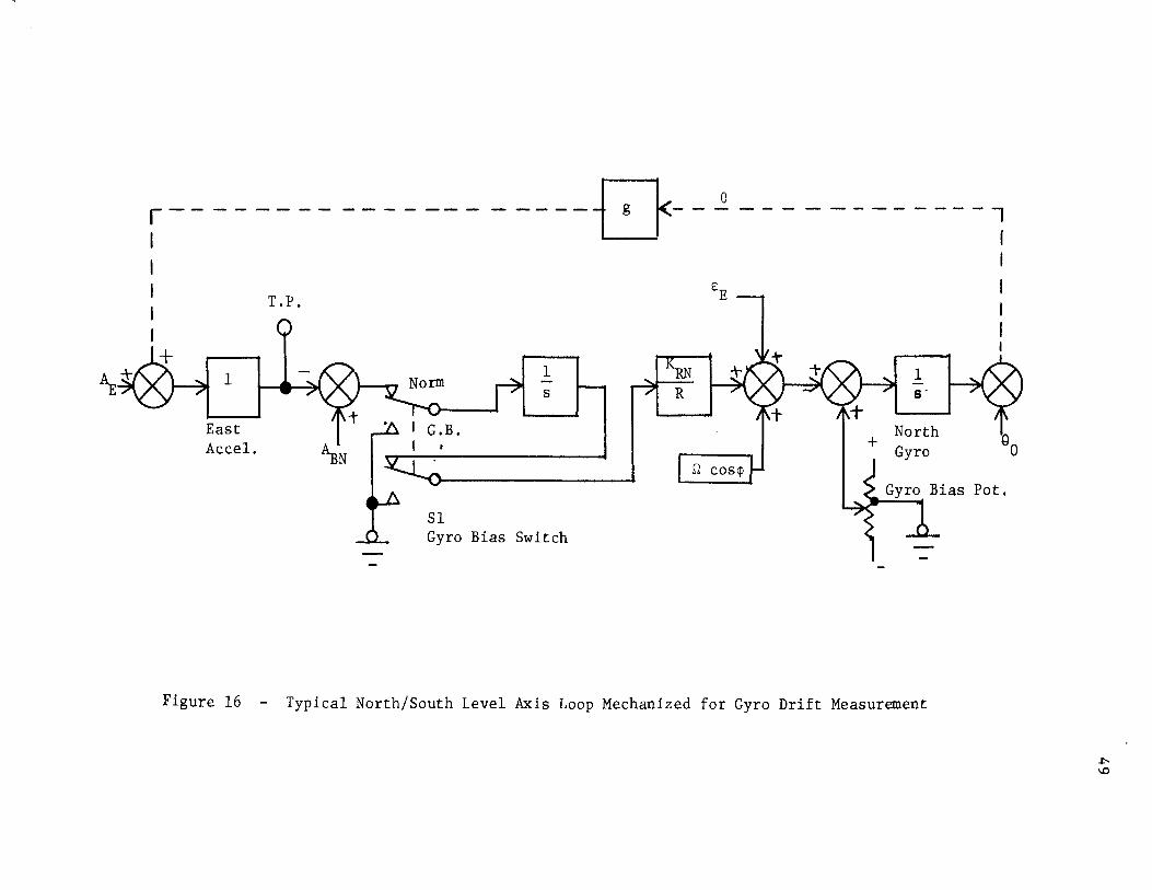
A typical north/south level axis loop mechanized to
monitor gyro drift with external equipment is shown in
Figure 16. The amount of gyro drift is measured and cor
rections made according to the following procedure:
(1) A strip chart recorder is connected to the test point
at T.P.
------------------0-- e
1
East Accel.
T.P.
1 s
Sl Gyro Bias Switch
---------..,
+
1 a·
North
I I
I I I I
~ 0
Pot.
Figure 16 - Typical North/South Level Axis Loop Mechanized for Gyro Drift Measurement
-l:\0

(2) At the completion of alignment the system is put
into the Navigate mode. The switch, Sl, is switched
from normal to the gyro bias position.
50
(3) As the gyro drifts at a given rate, E, the level
misalignment angle, e, increases which, in turn,
increases the gravity acceleration sensed by the
accelerometer, causing the voltage at T.P. to increase.
(4) The voltage change being monitored at T.P. by a strip
chart recorder, as shown in Figure 17, is converted
to drift rate in degrees per hour by using system
scale factors.
(5) The gyro bias potentiometer is then adjusted in the
appropriate direction and amount until the rate of
change of voltage at T.P. is zero.
This measurement is actually the result of all of the
rate inputs to the north gyro including the effects of
latitude error, azimuth misalignment angle and interaxis
coupling which were shown to be at least an order of mag
nitude less than the attainable gyro drift rate accuracy
in Chapter IV (i.e. affect on measuring drift is small).
A sample strip chart recording obtained during biasing
of an inertial platform is shown in Figure 17.
b. East/West Gyro
Measurement of the east/west gyro drift is complicated
due to its association with the gyrocompass loop. Any
east/west gyro drift will cause an azimuth misalignment
which will cause a component of earth rate to appear as an

~ ~
Re-zero -- --Drift 0.024 deg/hr.
I ' ~ ~
~ ~
Drift 0.032 deg/hr. ~ _. , --~
~
11 Drift 0.072 deg/hr. - ~
~
--Bias Pot. 540 Div.
J ~ ~
~ ~ ~-
I ~ ~ -
North Gyro Drift Run Litton LN-12 INS Platform Serial No. 12-3714 Scale: 0.2 mv./cm. Speed: 0.12 mm./sec.
Bi (i
Ad
Adj
ases properly set .e. zero drift)
just Pot. to 524
Adjust Pot. to 527
Adjust Pot. to 520
Dri
ust Bias Pot. to 515
ft 0.12 deg/hr.
51
T L
o Nav. mode, Schuler oop open, Re-zero trace
Recorder: Sanborn 350 with 350-1500 Low Level Preamp
Figure 17 Strip Chart Recording of a Gyro Drift Measurement

52
east/west gyro drift rate. The amount of earth rate error
introduced into the north gyro due to an azimuth reisalign-
ment angle of one degree, according to equation 5.2 is:
.. 2 lJio ~ Qcos¢ = 0.00225 deg/hr. (6.1)
The earth rate error introduced into the east gyro due to
this same one degree azimuth misalignment, according to
equation 5.1 is:
(6. 2)
Thus, the same azimuth error gives an error in measured
drift rate which is two orders of magnitude larger than
for the north gyro and precludes correct biasing of the
east gyro directly.
The east gyro is drift tested as if it were a north/
south gyro by slewing the platform 90 degrees in azimuth
and removing the azimuth gyro (gyrocompass loop) input.
Even if the azimuth accuracy is poor, the earth rate
error is reduced to acceptable levels. An azimuth mis-
alignment of one degree would inject an earth rate error of
only 0.00225 deg/hr. into the east gyro in this position,
which is well within acceptable tolerance.
c. Azimuth Gyro
The adjustment of the azimuth gyro is similar to that
of the leveJ axis gyro except that the change in the
platform azimuth angle due to gyro drift is measured instead
of an accelerometer output, since there is not an accel-

53
erometer whose output can be correlated with azimuth gyro
drift. A typical circuit for monitoring and correcting
azimuth gyro drift is shown in Figure 18. In this circuit,
the control transformer (CT) is adjusted for zero output
at the end of alignment prior to going into the gyro bias
mode. After going into the gyro bias mode, any azimuth
gyro drift results in an output from CT which is recorded
on the strip chart recorder. Again, the earth rate error
contribution is much smaller than the drift rate error and
thus can be neglected.
B. Rotary Tilt Table Alignment
The rotary tilt table alignment is performed by using an
aligned validated inertial platform to indicate when the rotary tilt
table is leveled and aligned to true north. The inertial platform
is tested and calibrated in accordance with the preceding procedure.
It is then shut down and re-aligned to minimize the errors which
build up as a function of time. After the inertial platform is
aligned it is switched to the navigate mode, after which it is ready
for use as a coordinate reference possessing the accuracies described
in Chapter V.
The entire rotary tilt table assembly is first rotated in azi
muth (by rotating the barrel) until the external readout device on
the inertial platform indicates that the rotary tilt table's zero
degree azimuth is oriented to north. Finer azimuth adjustment is
easily accomplished by tapping the edge of the barrel in the appro
priate direction with a lead hammer.
The leveling is accomplished by adjustment of the leveling

Gyro Bias Pot.
1 s
Azimuth Gyro
Azimuth Angle Synchro Transmitter
Excit.
Figure 18
Test Equipment r-------, I I I I
54
To r-------~~ Recorder
I
I
_j
Simplified Circuit for Azimuth Gyro Drift Measurement

55
screws on the leveling plate, using the north/south and east/west
axis gyro pickoff synchro readouts to define level. The gyro pick
off synchro outputs should remain at null as the inertial platform
is rotated through a complete circle. Both azimuth and level may
require readjustment several times before the rotary tilt table
alignment is complete.
C. Tilt Table Alignment Accuracy
After using one platform for alignment of the tilt table, the
total tilt table alignment error will consist of the inertial plat-
form alignment errors plus the data readout errors. The data read-
out errors occur in both the platform associated readout equipment
and the external readout devices.
The inertial platform may have the ability to level and gyro-
compass to the accuracies computed in Chapter V, however, it does
not have the ability to transmit the intelligence this accurately
to an external readout device. The gyro pickoff synchros which
are used to transmit the tilt and azimuth angles of the stable
element to the electrical interface of the inertial platform are
1 . 1 6 . 8 on y accurate to approx1mate y arc m1nutes .
Error is also possible due to the test instrument used to
display the synchro output. A very convenient and widely used
readout device is a precise angle indicator such as the Clifton
Precision Products model 394 which has an accuracy of 6 arc
minutes 8 • Better readout accuracy may be achieved if this device
is replaced by a synchro bridge such as the Theta Instrument 0
Corporation model SB-11, which is accurate to 10 arc seconds~.
Assuming the readout error values are lo values, then the

56
total level and azimuth tilt table alignment accuracies are deter-
mined by combining these readout errors with the inertial platform
alignment errors. The resulting standard deviation of the tilt
table alignment errors are:
(level)
(azimuth)
8 = 6 arc minutes ss
~ =J(6) 2 + (6) 2 = 8.5 arc minutes ss
(6.3)
(6.4)
Note that the 6 arc minute error of the gyro pickoffs becomes the
only significant level axis error source.
D. Increasing the Accuracy of the Tilt Table Alignment
The accuracy of the tilt table alignment determined by an
inertial platform has been predicated thus far upon the accuracy
of alignment of a single platform and the accuracy to which this
alignment can be identified externally. The accuracy of this align-
ment can now be improved by using the data from alignments with
several inertial platforms. If it is assumed that the tilt table
is aligned with several different platforms and that all error
sources are independent, the number of alignments with different
inertial platforms required to achieve a given probability, or con-
fidence level, y~ that the true tilt table misalignment~ ~, is
within an interval k, about the mean value determined by repeated
1. . 10
a J..gnment J..s:
(6.5)
Where the standard deviation of the alignment error for each align-
ment is a and c is the number of standard deviation intervals
required to give the required confidence level. This, then gives

the number of inertial platform alignments required to obtain a
given tilt table alignment accuracy. As an example, the number
57
of inertial platforms required to provide a confidence level of 95%
that the tilt table confidence interval will be +8.5 arc minutes
in azUnuth is as follows:
2 n = = 3. 84 ~ 4 inertial platforms (6.6)
Figure 19 illustrates how the tilt table azimuth alignment con
fidence interval for a given confidence level can be reduced by
using more inertial platforms. It illustrates that only one iner
tial platform is required for a 90% confidence level that the tilt
table misalignment is known within 15 arc minutes, whereas 780
inertial platforms would be required for a 99.9% confidence level
of a 1 arc minute confidence interval.
Figure 20 is a similar illustration showing how the tilt table
level alignment confidence interval for a given confidence level can
be reduced by using more inertial platforms. It illustrates that
only one inertial platform is required for 90% confidence that the
tilt table misalignment is within 10 arc minutes whereas 375
inertial platforms are required for 99.9% confidence level of a 1
arc minute confidence interval.
E. Additional Aligmrent Error Considerations
The use of several inertial platforms makes it necessary to
consider the accuracy of repeatability in mounting the inertial
platform to the adapter plate, and to reconsider classification
of latitude error and readout error as random errors.
The adapter plate is a very accurately fabricated device, as

58
100
10-
0 5 10 15 20 25
Confidence Interval (Arc minutes)
Figure 19 Azimuth Alignment Conficence Interval

59
1000
100
10
1 25
Confidence Interval (Arc minutes)
Figure 20 Level Alignment Confidence Interval

60
is the mounting surface of the inertial platform. A three-hole
mounting pattern is located on the mounting surface of the inertial
platform to an accuracy of +0.0001 inches, by use of a template.
The adapter plate is fabricated with threaded moveable plates,
which are located by using the same template. The inertial plat
forms are mounted using very accurately machined bolts, resulting
in a repeatability between platforms of +0.0001 inches. Assuming
a 10 inch spacing between mounting holes, this represents less than
a 20 arc second error.
The latitude error and the readout error are fixed errors for
a particular test site and test equipment, therefore they can no
longer be considered random errors. They had no significant affect
on the error computed for the inertial platform alignment, but it
should be remembered that the tilt table alignment accuracy cannot
be made better than these errors.

61
VII.
ALIGNMENT METHOD UTILITY
The utility of the tilt table alignment method proposed in the
previous chapter must be assessed. This is now done by considering the
various inertial platform test requirements and then evaluating the
performance of the aligned tilt table when performing these tests.
A. Inertial Platform Test Requirements
The requirements of particular tests are evaluated here, to
establish acceptance criteria for both azimuth and level alignment.
1. Gyrocompass Test
The purpose of the gyrocompass test is to ascertain
whether the inertial platform levels and gyrocompasses to
acceptable accuracies. The lcr accuracy, as identified at the
electrical interface, to which an in-specification inertial
platform should align per equations 6.3 and 6.4 is +6 minutes
in level and +8.5 minutes in azimuth.
2. Accelerometer Scale Factor Test
The accelerometer scale factor test is performed to
ascertain whether the accelerometers produce correct outputs
for known gravity component inputs. The accelerometers are
mounted on the inertial platform's stable element and would not
normally tilt with the outer case, but course align is accom
plished by caging the stable element in level to the outer case
and holding the inertial platform in this mode. Both the
level and azUnuth positions are displayed externally, subject to
the accumulated readout errors.

62
The rotary tilt table is initially set to the zero tilt
and zero azimuth position, and the inertial platform is ini
tially aligned and then caged to the outer case in both level
and azimuth. The output of the vertical accelerometer at this
point should be 1.0 + 0.00001 g which is the zero stability
(see Table I). The component of gravity sensed is g cos8, and
e may vary as much as 11 arc minutes around zero and stay
within this tolerance.
The rotary tilt table is then tilted to 30° 00' which puts
the north accelerometer in a 30° pitch down position and the ver
tical accelerc'J.T:€ ter 30° off vertical. The resul taut gravity
components sensed should be -g sin 30° = - O.Sg for the
north accelerometer and - g sin 60° 0. 866g for the
vertical accelerometer. The accelerometer scale factor vari
ation per Table I is 0.03% per year. Since the maximum accel
eration to be measured in this test is lg, the level angle
must be known well enough to provide 0.0003g sensitivity. The
resultant acceptable range of acceleration tolerances are
0.5 + 0.0003g for the north accelerometer and 0.866 + 0.0003g
for the vertical accelerometer. The level angle error which
would cause this value of error is that which causes the sine of
the angle to deviate 0.0003 from the value for 30° and 60°
respectively. Accordingly arc sin (0.500 + 0.0003) is 30°1.2'
and the arc sin (0.866 + 0.0003) is 60°2'. This illustrates
that a 6 arc minute error in the level angle of the rotary tilt
table is greater than the full tolerance margin for accelerometer
scale factor linearity.

The east accelerometer is tested by rotating the rotary
tilt table in azimuth by 90° such that the east accelerometer
is pitched down 30°. Then rotation of the rotary tilt table
to 180° and 270° permits testing both accelerometers for op
posite sense acceleration inputs. The tilt table can then be
tilted to 60° and the rotary tilt table rotation repeated for
another set of measurements. Throughout~ the results and
accuracy requirements accordingly will be consistent with the
result derived above.
3. Gyro Drift Test
The gyro drift test is performed to identify gyro drift
rates. The heading of the inertial platform must be compared
63
to the rotary tilt table to assure that a component of earth
rate is not identified as gyro drift. The acceptance criteria
for the gyrocompass test is sufficiently accurate for the gyro
drift test~ as has been previously shown when considering plat
form validation.
4. Synchro Null Test
The synchro null test is performed to ascertain that the
inertial platform synchro electrical nulls are within specified
limits. The rotary tilt table is adjusted to zero azimuth and
level~ and each of the gyro pickoff synchro angles is measured.
The acceptance criteria is the same as for the gyrocompass
test.
5. Synchro Linearity Test
The synchro linearity test determines that the gyro pickoff
synchros accurately indicate the correct angular position. The

64
rotary tilt table is adjusted to various angles and the external
readout of tilt table and inertial platform should agree. The
acceptance criteria is the same as for the gyrocompass test.
6. Test Requirement Summary
The inertial platform azimuth requirement is determined
by the requirements of the gyrocompass test. The lcr azimuth
accuracy established by this test is 8.5 arc minutes. The level
axis requirement is established by the accelerometer scale
factor test and the lcr accuracy requirement is 1.2 arc minutes.
B. Alignment Method Evaluation
The inertial platform test requirements as specified in the
previous section can now be utilized to evaluate the utility of the
proposed alignment method. The accelerometer scale factor test re
quires a significantly higher level accuracy than the inertial plat
form's gyro pickoffs can provide and spirit levels with the required
accuracy are available and easily utilized. Therefore, the rotary
tilt table level alignment will be accomplished by means of the
spirit level. The remainder of this utility evaluation will address
itself to the azimuth alignment of the rotary tilt table.
The acceptability of the rotary tilt table alignment accuracy
obtained by using multiple inertial platforms for alignment is
evaluated on the basis of how well it identifies good (in specifi
cation) or bad (out of specification) inertial platforms as measured
by the gyrocompass test azimuth requirements. In order to perform
this evaluation, the following probabilities are defined:

65
P (G) = Probability that a platform tests good with a perfect a
tilt table and an acceptance interval of +a.
Pa(G) =Probability that a platform tests bad with a perfect
tilt table and an acceptance interval of +a.
P (A) = Probability of accepting a platform when tested with a
p (A) a
an erroneous tilt table and an acceptance interval
of +a.
Probability of rejecting a platform when tested with
an erroneous tilt table and an acceptance interval
of +a.
The probability of accepting an inertial platform given that
it is good, Pa(AIG), and the probability of accepting a platform
given that it is bad, Pa(AjG), will be determined to evaluate the
performance of the tilt table alignment method.
defined11 :
P (AjG) is a
P (A,G) Pa(AIG) = ; (G) (7.1)
a
where P(A,G) is the joint probability of A and G. P(A!G) is
defined as follows:
P (Gj A) P (A) a a (7.2)
p (G) a
where:
p (G) a
1 - P (G) a
and:
P a (Gj A) 1 -P (A,G)
a p (A)
a
Thus from equation 7.2

66
P (A) - P (A,G) P (A!G)
a a a
1 - P (G) a
(7. 3)
Therefore, P (G), P (A) and P (A,G) need to be computed. a a a
Assuming the inertial platform errors have a normal distribu-
tion with zero mean, the following probability density function
applies:
1
ox vz; e
where x is the value of the inertial platform error, and a 2 is the X
variance of the inertial platform error. If the platform is defined
as good when the magnitude of the error is less than or equal to
some acceptance criteria, a, then:
p (G) = a
dx e
2[ N( a
) - N(O) (7.4) = a X
K2
where: N (c) 1 J_c 2
- rz;- e dK -oo
The tilt table error is assumed to be normally distributed
with zero mean and thus has the following normal probability den-
sity function:
1
a \{2; y
e
where y is the value of the tilt table error and cry2 is the variance
of the tilt table error. The total error during a test is the sum

of the platform and tilt table errors:
Z = X +Y
therefore, since the errors are independent:
where
1
a{h z
e 2a 2
z
a 2 =a 2 + a2 Z X y
Assuming the inertial platform acceptance limit once again is
+a, then
p (A) a
1
a{Z;r z
e
2 [N ( ~) - N (0)] a
z
dz
67
(7 .5)
(7. 6)
(7. 7)
(7. 8)
The joint probability, P (A,G) needs to be evaluated to complete a
the solution.
P (A,G) a
P[ (-a< X< a) and (-a< Z <a)]
since Z X+ y
P (A,G) a
p [(-a< X< a) and (-a- X) < Y < (a- X)]
= f fa-x
fx, Y (x,y) dy dx (7.9)
-a -a-x
Since X and y are independent and normal, their joint probability
density function is:

68
1 fX,Y(x,y) = ~2-TI-O--O (7.10)
X y
therefore
a K2 -P (A,G) 1 fa ox 2 (~) -a-x
..[2; e [ N - N (--) dK
a (J 0 y y
0 (7.11) X
Equation 7.11 cannot be integrated directly since N is not available
in closed form, therefore it can only be evaluate numerically by
replacing the integral with the sum:
P (A,G) = ~ .fi-1-a i=l 1_L 2TI
where: X. - a +(i - .!) f':.x l 2
2a n =
f':.x
x. l
K. = l 0
X
and f':.K f':.x 0
X
- N -a-x (--)
0 y
This numerical integration can be performed by looking up the
values of the components in a normal distribution function table
for each value of i and summing the results.
The probabilities P (AjG) and P (AjG) are computed for rotary a a
tilt table alignments using 1, 4. 16 and 64 inertial platforms to
perform the alignment and for inertial platform acceptance intervals
of +17 arc minutes (2cr) and +8.5 arc minutes (lcr). The standard

69
deviations for the rotary tilt table alignment us1·ng 1 4 16 d , , an
64 inertial platforms are as follows:
0 (8.5)
0 = X 8.5 min. = arc yl rn 1 (7.13)
0 = (8.5) 4.25 arc min.
y~ V4 ( 7. 14)
0 = (8.5) = 2.125 arc min. yl6 Vl6 (7.15)
0 = (~5) = 1. 0625 arc min. y64 {64 (7 .16)
Using the relation defined by equation 7.7, the values of o2
are:
0Zl = /72.25 + 72.25 = 12.1 (7.17)
0 Z4 =V72.25 + 18 = 9.49 ( 7. 18)
0 Zl6 = -./72.25 + 4.5 = 8.77 (7.19)
0 Z64 = V72.25 + 1.13 + 8.56 (7.20)
The probability that an inertial platform is good when tested
with a 17 arc minute (2o) acceptance interval is computed from
equation 7.4 and normal distribution function tables as follows:
P 2 (G) = 2 [N(2)- N (0) ] = 0.9544 (7.21)
Now using equation 7.8 and the normal distribution function table,
the related value of P 2 (A1)(i.e. a 2o acceptance interval and a 1
platform alignment) is:
P 2 (A1
) = 2 [ N(l.41) - N (0) ] = 0.8414 (7.22)
The probabilities of acceptance using 4, 16 and 64 platform align-
ments are computed in a similar manner and presented in Table III.
The joint probabilities for the platform being good and accept-
ed for rotary tilt table alignments using 1, 4, 16 and 64 inertial
platforms are also tabulated in Table III.

70
Platforms Used for P
2(G) P2 (A) P 2
(A,G) Alignment
1 0.9544 0.8414 0. 82 72
4 0.9544 0.9266 0.9134
16 0.9544 0.9476 0.9390
64 0.9544 0.9534 0.9492
Table III
Summary of probabilities for 2o Acceptance Interval

71
Assume that the inertial platform acceptance criteria is
reduced to 8.5 arc minutes (lo). Then from equation 7.4, p1
(G) is:
P 1 (G) = 2(0.8413 - 0.5000) = 0.6826 (7.23)
The values of cry and a2
remain as computed in equations 7.17
through 7.20, but the new integral limits for P(A) as shown in
equation 7.8 yields the following for a 1 platform alignment:
P 1 (A1 ) = 2 [ N(0.71) - N(O) ]
2 (0.7611- 0.5000) = 0.5222 (7. 24)
The probabilities of acceptance using 4, 16 and 64 platform
alignments, which are computed in the same manner, are presented
in Table IV.
The joint probabilities for the platform being good and
accepted for rotary tilt table alignments using 1, 4, 16 and 64
inertial platforms are also tabulated in Table IV.
The resulting probabilities for accepting an inertial platform,
given that it is good, P (AJG), and accepting it, given that it is a
bad, P (AJG), is computed for a 2a acceptance interval from the a
data presented in Table III. The computations for a 2a acceptance
interval using a 1 platform alignment are as follows:
P(A1 ,G)
p (G) 0.8272 0.9544
P(A1
) - P(A1
,G)
1 - P(G)
0.8667
0.8414- 0.8272 1 - 0.9544
(7.25)
0.3114 (7.26)
The probabilities of acceptance using 4, 16 and 64 platform align-
ments, which are computed in the same manner, are presented in
Table V.

72
Platforms Used for p 1 (G) p 1 (A) P l (A,G) Alignment
1 0.6826 0.5222 0.4292
4 0.6826 0.6266 0.5600
16 0.6826 0.6680 0.6290
64 0.6826 0.6778 0.6996
Table IV
Summary of Probabilities for lo Acceptance Interval

Number of 2a la Platforms Acceptance Interval· Acceptance Interval
Used for P 2 (AlG) p 2 (AI G) pl (AI G) P1 (A!G)
Alignment
1 0.8667 0.3114 0.6280 0.2932
4 0.9570 0.2894 0.8203 0.2100
16 0.9838 0.1885 0.9214 0.1220
64 0.9945 0.0921 0.9963 0.0564
P (A!G) Probability of acceptance given a good platform a
P (A!G) = Probability of acceptance given a bad platform a
Table V
Evaluation of the Tilt Table Alignment Method
73

74
The resulting probabilities for accepting an inertial platform,
given a good platform, P (A!G), and given a bad platform, p (AjG), a a
may now be computed for the lo acceptance interval from the data
presented in Table IV. The computations for the 1 platform alignment
are as follows:
pl (Al,G) P1 (A1 !G) = p (G)
1
0.4246 = -0-.-6-8-26~
=
P1
(A1
) P1
(A1
,G)
1 - P1 (G)
0.5222 - 0.4292 1 - 0.6826
0.6280
0.2932
The probabilities of acceptance using 4, 16 and 64 platform
(7.27)
(7.28)
alignments, which are computed in the same manner, are presented in
Table V for comparison with the data for the 2o acceptance interval.
Table V compares the probabilities of accepting good and bad
platforms as the number of platforms used for alignment of the
tilt table is increased. It also illustrates the affect of varying
the acceptance interval. As the number of platforms used for the
alignment increases from 1 to 4, the performance of the facility
improves very rapidly. The rate of improvement is much slower
as the number increases to 16 and then to 64. The tighter lo
acceptance interval essentially shifts 27% of the platforms from
acceptable to not acceptable status. This results in an overall
reduction in accepting both good and bad platforms. As expected,
greater tilt table accuracy is required in order to successfully
utilize the tighter tolerance.
75
VIII.
CONCLUSIONS
It has been determined that an inertial platform will self align,
and thus define a coordinate system, to predictable accuracies if its
inertial components are operating within specification tolerances and
if local latitude is known. This self aligned inertial platform can
then be used to align a rotary tilt table. The probable alignment
errors have been analyzed and specific errors determined for a par
ticular system mechanization. The alignment accuracies were improved
through use of several inertial platforms. Actual testing requirements
were evaluated to establish realistic inertial platform acceptance
interval tolerances and it was determined at this point that the
inertial platform should not be used for level alignment of the rotary
tilt table. The acceptability of the rotary tilt table azimuth align
ment was then further evaluated relative to probabilities of accepting
good (in specification) inertial platforms and rejecting bad (out of
specification) ones, when performing the gyrocompass test since its
accuracy requirement was the limiting azimuth accuracy requirement.
This comparison showed that the rotary tilt table azimuth alignment
using four inertial platforms is marginally acceptable.
The unacceptability of the level alignment of a rotary tilt table
using an inertial platform is of little consequence since leveling
the tilt table is not particularly complicated. The Watts model TB-19
Angle Level Gage is a spirit level with a bubble sensitivity of 5 arc
seconds per division. This device is of sufficient accuracy to level
the rotary tilt table to the desired accuracy of ten times better than
1.2 arc minutes, such that rotary tilt table level errors may be

76
neglected in establishing acceptable tolerances for inertial platform
tests.
The results of the azimuth alignment using four inertial platforms
shows 96% probability of accepting a good inertial platform with a 2a
acceptance interval, with a 29% probability of accepting a bad platform.
When the inertial platform acceptance interval is reduced to a, the
percentages are lower, 82% and 21%. As expected, the tighter test
tolerance requires a more accurate tilt table alignment with the
greatest effect on the acceptance of good platforms but the conditions
follow the same trend of improvement as more inertial platforms are
used for the alignment. It is concluded that a rotary tilt table
aligned using four verified inertial platforms is acceptable as an
interim alignment until the azimuth accuracy can be improved.
The azimuth accuracy of the rotary tilt table can be improved as
part of its normal use. This may be accomplished by keeping a record
of the gyrocompass test results and periodically improving the azimuth
alignment. After the initial four inertial platform alignment, it may
be used normally and then after 16 more inertial platforms have been
tested the rotary tilt table could be readjusted according to the
average azimuth misalignment as determined by the additional gyrocompass
alignments which are performed after repair and calibration.
The procedure for correcting the rotary tilt table azimuth would
be as described in Chapter VI, using the readout from an installed iner
tial platform to indicate the "difference angle" during rotary tilt
table azimuth correction. The rotary tilt table can then be used with
the confidence of a 16 inertial platform alignment as shown in Table V.
As the rotary tilt table is used for additional maintenance, a

77
running record of gyrocompass test results will eliminate the need
for periodic re-alignment and after sufficient data becomes available,
further improvement of the alignment can be accomplished.
It is, therefore, the conclusion of this thesis research that it
is practical to use inertial platforms, of the type to be tested, to
align a rotary tilt table in azimuth, but the level alignment should be
accomplished by use of a spirit level.

BIBLIOGRAPHY
1. Pitman, G.R., Inertial Guidance, John Wiley and Sons, New York, 1962.
78
2. Cannon, R.H. Jr., Alignment of Inertial Guidance Systems by Gyrocompassing - Linear Theory, Journal of Aerospace Sciences, Vol. 28, No. 11, Nov. 1961.
3. Parvin, R.H., Inertial Navigation, D. Van Nostrand Co., Princeton, New Jersey, l962.
4. Savant, C.F., Howard, C.F., Solloway, C.B., and Savant, C.A., Principles of Inertial Navigation, McGraw-Hill Book Co., New York, 1964.
5. O'Donnell, C.F., Inertial Navigation Analysis and Design, McGrawHill Book Co., New York, 1964.
6. Lichtenstein, B., Gyros Platforms Accelerometers, Kearfott Division of Precision Aerospace, Little Falls, New Jersey, 1963.
7. Thommen, D.K., and Wisehart, W.R., Fundamentals of Inertial Navigation, Digest of U.S. Naval Aviation Electronics, Oct. 1962.
8. Clifton Precision Products, Synchro Catalog and Application Data, Clifton Heights, Pennsylvania, (undated).
9. Theta Instrument Corp., Test Equipment for Servo Components, East Patterson, New Jersey, (undated).
10. Kreyzig, E., Advanced Engineering Mathematics, John Wiley and Sons, New York, 1967.
11. Miller, I., and Fruend, J.E., Probability and Statistics for Engineers, Prentice-Hall, Englewood Cliffs, New Jersey, 1965.

79
VITA
Max Eugene Batt was born on August 30, 1931 in Wayne County, Iowa.
He attended grade school and started high school in Corydon, Iowa and
continued high school in Seymour, Iowa. He attended Centerville Junior
College, Centerville, Iowa from September 1949 to March 1951 when he
enlisted in the U.S. Navy. He enrolled at Iowa State University in
Ames, Iowa in March 1955 and received a Bachelor of Science degree in
Electrical Engineering in June 1958. In July 1958 he accepted employ
ment with Mcdonnell Aircraft Corporation in St. Louis, Missouri where
he is currently located.
He has been enrolled at the University of Missouri at Rolla's
Graduate Engineering Center in St. Louis since September 1967.