Refined Solutions of Externally Induced Sloshing in Half-Full Spherical Containers
Upload
independentCategory
view
3download
0
Shear Strengthening of RC Beams withExternally Bonded FRP Composites:
Effect of Strip-Width-to-Strip-Spacing RatioAmir Mofidi1 and Omar Chaallal, M.ASCE2
Abstract: The results of an experimental and analytical investigation of shear strengthening of reinforced concrete (RC) beams with ex-ternally bonded (EB) fiber-reinforced polymer (FRP) strips and sheets are presented, with emphasis on the effect of the strip-width-to-strip-spacing ratio on the contribution of FRP (Vf ). In all, 14 tests were performed on 4,520-mm-long T-beams. RC beams strengthened in shearusing carbon FRP (CFRP) strips with different width-to-spacing ratios were considered, and their performance was investigated. In addition,these results are compared with those obtained for RC beams strengthened with various numbers of layers of continuous CFRP sheet. More-over, various existing equations that express the effect of FRP strip width and concrete-member width and that have been proposed based onsingle or double FRP-to-concrete direct pullout tests are checked for RC beams strengthened in shear with CFRP strips. The objectives of thisstudy are to investigate the following: (1) the effectiveness of EB discontinuous FRP sheets (FRP strips) compared with that of EB continuousFRP sheets; (2) the optimum strip-width-to-strip-spacing ratio for FRP (i.e., the optimum FRP rigidity); (3) the effect of FRP strip locationwith respect to internal transverse-steel location; (4) the effect of FRP strip width; and (5) the effect of internal transverse-steel reinforcementon the CFRP shear contribution. DOI: 10.1061/(ASCE)CC.1943-5614.0000219. © 2011 American Society of Civil Engineers.
CE Database subject headings: Fiber reinforced polymer; Concrete beams; Reinforced concrete; Sheets; Shear strength; Bonding.
Author keywords: Carbon-fiber-reinforced polymers; Concrete beams; Continuous sheet; Discontinuous sheet; Shear strengthening;Strip-width-to-strip-spacing ratio.
Introduction and Background
Significant interest has been shown in the use of externally bonded(EB) fiber-reinforced polymer (FRP) sheets and laminates forstrengthening and repair of existing reinforced concrete (RC)beams and slabs, especially for bridges and buildings. Becauseof its intricacy, shear strengthening of RC beams with FRP is some-what less well documented than FRP strengthening of beams inflexure and of columns (Bousselham and Chaallal 2004). Researchstudies carried out during the past decade have provided valuableoutcomes, especially concerning the effect of FRP axial rigidity onthe shear-strength enhancement of RC beams (Triantafillou 1998;Khalifa et al. 1998). On the basis of these research studies, manycodes and design guidelines (hereafter called “the guidelines”) forRC structures strengthened with EB FRP have been publishedworldwide (e.g., ACI 440.2R-08, fib-TG 9.3-01, CAN/CSAS806-02, CAN/CSA S6-06, CNR-DT200-04, and HB 305-08).However, in a statistical comparison with available experimentalresults, Lima and Barros (2007) have revealed that some of theguideline equations (ACI 440 and CNR-DT200) lead to unduly
conservative designs that use quantities of FRP materials well inexcess of what is required. Efficient and accurate FRP strengthen-ing design equations will greatly benefit the economic aspects ofFRP strengthening projects.
Based on available experimental data, Triantafillou (1998) dis-covered that FRP effective strain decreases as FRP rigidity in-creases. Khalifa and Nanni (2000) realized that increasing theamount of carbon FRP (CFRP) may not always result in a propor-tional increase in shear resistance. They noted the existence of anFRP quantity threshold beyond which further strengthening effec-tiveness is questionable. In addition, their experimental testsshowed that CFRP strips can outperform continuous CFRP sheets.Other experimental tests by Khalifa and Nanni (2002) and Zhangand Hsu (2005) confirmed these observations.
Unlike shear-strengthening methods that use FRP continuoussheets, with discontinuous FRP sheets, the quantity of FRP presentvaries with the strip-width-to-strip-spacing ratio (wf =sf ). The FRPrigidity parameter (Rf ) can be used to quantify the amount of FRPused with respect to the FRP-strip-width-to-FRP-strip-spacing ra-tio. The FRP rigidity parameter can be expressed as a function of(wf =sf ) as follows:
Rf ¼ ρf × Ef ð1a Þ
where
ρf ¼2tfbw
×wf
sfð1b Þ
In the calculation of FRP rigidity, the only variable is theFRP-strip-width-to-FRP-strip-spacing ratio (assuming that theFRP sheet characteristics and the RC beam cross-sectional dimen-sions are constants). Based on the writers’ updated database, which
1Ph.D. Candidate, Dept. of Construction Engineering, Univ. of Quebec,École de Technologie Supérieure, Montreal QC, Canada H3C 1K3. E-mail:[email protected]
2Professor of Construction Engineering, Univ. of Quebec, École deTechnologie Supérieure, 1100 Notre-Dame St. West, Montreal QC, CanadaH3C 1K3 (corresponding author). E-mail: [email protected]
Note. This manuscript was submitted on July 13, 2010; approved onMarch 24, 2011; published online on March 26, 2011. Discussion periodopen until March 1, 2012; separate discussions must be submitted for in-dividual papers. This paper is part of the Journal of Composites for Con-struction, Vol. 15, No. 5, October 1, 2011. ©ASCE, ISSN 1090-0268/2011/5-732–742/$25.00.
732 / JOURNAL OF COMPOSITES FOR CONSTRUCTION © ASCE / SEPTEMBER/OCTOBER 2011
Downloaded 24 Nov 2011 to 142.137.229.172. Redistribution subject to ASCE license or copyright. Visit http://www.ascelibrary.org
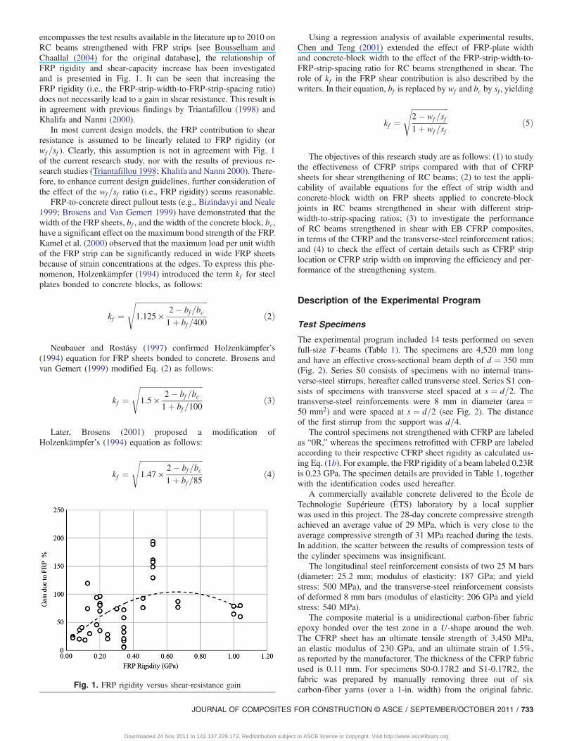
encompasses the test results available in the literature up to 2010 onRC beams strengthened with FRP strips [see Bousselham andChaallal (2004) for the original database], the relationship ofFRP rigidity and shear-capacity increase has been investigatedand is presented in Fig. 1. It can be seen that increasing theFRP rigidity (i.e., the FRP-strip-width-to-FRP-strip-spacing ratio)does not necessarily lead to a gain in shear resistance. This result isin agreement with previous findings by Triantafillou (1998) andKhalifa and Nanni (2000).
In most current design models, the FRP contribution to shearresistance is assumed to be linearly related to FRP rigidity (orwf =sf ). Clearly, this assumption is not in agreement with Fig. 1of the current research study, nor with the results of previous re-search studies (Triantafillou 1998; Khalifa and Nanni 2000). There-fore, to enhance current design guidelines, further consideration ofthe effect of the wf =sf ratio (i.e., FRP rigidity) seems reasonable.
FRP-to-concrete direct pullout tests (e.g., Bizindavyi and Neale1999; Brosens and Van Gemert 1999) have demonstrated that thewidth of the FRP sheets, bf , and the width of the concrete block, bc,have a significant effect on the maximum bond strength of the FRP.Kamel et al. (2000) observed that the maximum load per unit widthof the FRP strip can be significantly reduced in wide FRP sheetsbecause of strain concentrations at the edges. To express this phe-nomenon, Holzenkämpfer (1994) introduced the term kf for steelplates bonded to concrete blocks, as follows:
kf ¼ffiffiffiffiffiffiffiffiffiffiffiffiffiffiffiffiffiffiffiffiffiffiffiffiffiffiffiffiffiffiffiffiffiffiffiffiffiffiffi1:125 ×
2� bf =bc1þ bf =400
sð2Þ
Neubauer and Rostásy (1997) confirmed Holzenkämpfer’s(1994) equation for FRP sheets bonded to concrete. Brosens andvan Gemert (1999) modified Eq. (2) as follows:
kf ¼ffiffiffiffiffiffiffiffiffiffiffiffiffiffiffiffiffiffiffiffiffiffiffiffiffiffiffiffiffiffiffiffiffiffi1:5 ×
2� bf =bc1þ bf =100
sð3Þ
Later, Brosens (2001) proposed a modification ofHolzenkämpfer’s (1994) equation as follows:
kf ¼ffiffiffiffiffiffiffiffiffiffiffiffiffiffiffiffiffiffiffiffiffiffiffiffiffiffiffiffiffiffiffiffiffiffi1:47 ×
2� bf =bc1þ bf =85
sð4Þ
Using a regression analysis of available experimental results,Chen and Teng (2001) extended the effect of FRP-plate widthand concrete-block width to the effect of the FRP-strip-width-to-FRP-strip-spacing ratio for RC beams strengthened in shear. Therole of kf in the FRP shear contribution is also described by thewriters. In their equation, bf is replaced by wf and bc by sf , yielding
kf ¼ffiffiffiffiffiffiffiffiffiffiffiffiffiffiffiffiffiffiffiffi2� wf =sf1þ wf =sf
sð5Þ
The objectives of this research study are as follows: (1) to studythe effectiveness of CFRP strips compared with that of CFRPsheets for shear strengthening of RC beams; (2) to test the appli-cability of available equations for the effect of strip width andconcrete-block width on FRP sheets applied to concrete-blockjoints in RC beams strengthened in shear with different strip-width-to-strip-spacing ratios; (3) to investigate the performanceof RC beams strengthened in shear with EB CFRP composites,in terms of the CFRP and the transverse-steel reinforcement ratios;and (4) to check the effect of certain details such as CFRP striplocation or CFRP strip width on improving the efficiency and per-formance of the strengthening system.
Description of the Experimental Program
Test Specimens
The experimental program included 14 tests performed on sevenfull-size T-beams (Table 1). The specimens are 4,520 mm longand have an effective cross-sectional beam depth of d ¼ 350 mm(Fig. 2). Series S0 consists of specimens with no internal trans-verse-steel stirrups, hereafter called transverse steel. Series S1 con-sists of specimens with transverse steel spaced at s ¼ d=2. Thetransverse-steel reinforcements were 8 mm in diameter (area ¼50 mm2) and were spaced at s ¼ d=2 (see Fig. 2). The distanceof the first stirrup from the support was d=4.
The control specimens not strengthened with CFRP are labeledas “0R,” whereas the specimens retrofitted with CFRP are labeledaccording to their respective CFRP sheet rigidity as calculated us-ing Eq. (1b). For example, the FRP rigidity of a beam labeled 0.23Ris 0.23 GPa. The specimen details are provided in Table 1, togetherwith the identification codes used hereafter.
A commercially available concrete delivered to the École deTechnologie Supérieure (ÉTS) laboratory by a local supplierwas used in this project. The 28-day concrete compressive strengthachieved an average value of 29 MPa, which is very close to theaverage compressive strength of 31 MPa reached during the tests.In addition, the scatter between the results of compression tests ofthe cylinder specimens was insignificant.
The longitudinal steel reinforcement consists of two 25 M bars(diameter: 25.2 mm; modulus of elasticity: 187 GPa; and yieldstress: 500 MPa), and the transverse-steel reinforcement consistsof deformed 8 mm bars (modulus of elasticity: 206 GPa and yieldstress: 540 MPa).
The composite material is a unidirectional carbon-fiber fabricepoxy bonded over the test zone in a U-shape around the web.The CFRP sheet has an ultimate tensile strength of 3,450 MPa,an elastic modulus of 230 GPa, and an ultimate strain of 1.5%,as reported by the manufacturer. The thickness of the CFRP fabricused is 0.11 mm. For specimens S0-0.17R2 and S1-0.17R2, thefabric was prepared by manually removing three out of sixcarbon-fiber yarns (over a 1-in. width) from the original fabric.Fig. 1. FRP rigidity versus shear-resistance gain
JOURNAL OF COMPOSITES FOR CONSTRUCTION © ASCE / SEPTEMBER/OCTOBER 2011 / 733
Downloaded 24 Nov 2011 to 142.137.229.172. Redistribution subject to ASCE license or copyright. Visit http://www.ascelibrary.org
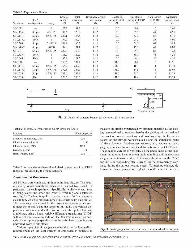
Table 2 presents the mechanical and elastic properties of the CFRPfabric as provided by the manufacturers.
Experimental Procedure
All 14 tests were conducted in three-point load flexure. This load-ing configuration was chosen because it enabled two tests to beperformed on each specimen. Specifically, while one end zoneis being tested, the other end zone is overhung and unstressed(see Fig. 2). The load is applied at a distance a ¼ 3d from the near-est support, which is representative of a slender beam (see Fig. 2).The measuring device used for the project was carefully designedto meet the objective and the scope of this study. The vertical dis-placement was measured at the position under the applied load andat midspan, using a linear variable differential transformer (LVDT)with a 100-mm stroke. In addition, LVDTs were installed on eachside of the supports perpendicular to the web plane to monitor anyundesired sway or tilt effects.
Various types of strain gauges were installed on the longitudinalreinforcement on the steel stirrups or embedded in concrete to
measure the strains experienced by different materials as the load-ing increased and to monitor thereby the yielding of the steel andthe onset of concrete cracking and crushing (Fig. 3). The straingauges on the stirrups were installed along the anticipated planeof shear fracture. Displacement sensors, also known as crackgauges, were used to measure the deformations in the CFRP sheet.These gauges were fixed vertically on the lateral faces of the spec-imens at the same location along the longitudinal axis as the straingauges on the transverse steel. In this way, the strains in the CFRPand in its corresponding steel stirrups can be conveniently com-pared during the various loading stages. To measure concrete de-formation, crack gauges were glued onto the concrete surface,
Table 1. Experimental Results
SpecimenFRP
configuration wf =sf
Load atrupture
Totalresistance
Resistance owingto concrete
Resistanceowing to steel
Resistanceowing to CFRP
Gain owingto CFRP
Deflectionloading point
kN kN kN kN kN % mm
S0-0.0R — 0 122.7 81.2 81.2 0.0 0.0 0 2.60
S0-0.12R Strips 40=115 182.6 120.9 81.2 0.0 39.7 49 6.95
S0-0.17R1 Strips 87:5=175 203.1 134.5 81.2 0.0 53.3 66 6.16
S0-0.17R2 Sheet 1 154.7 102.4 81.2 0.0 21.2 26 4.90
S0-0.20R1 Strips 53=87:5 204.9 135.7 81.2 0.0 54.5 67 5.85
S0-0.20R2 Strips 30=50 197.9 131.1 81.2 0.0 49.9 61 8.03
S0-0.23R Strips 87:5=125 227.3 150.6 81.2 0.0 69.3 85 7.23
S0-0.33R Sheet 1 181.2 120.0 81.2 0.0 38.7 48 4.20
S0-0.66R Sheet 1 183.8 121.7 81.2 0.0 40.4 50 4.10
S1-0.0R — 0 350.6 232.2 81.2 151.0 0.0 0 11.9
S1-0.17R1 Strips 87:5=175 365.9 242.3 81.2 151.0 10.1 4 17.19
S1-0.17R2 Strips 87:5=175 372.5 246.7 81.2 151.0 14.5 6 15.93
S1-0.23R Strips 87:5=125 383.4 253.9 81.2 151.0 21.7 9 15.73
S1-0.33R Sheet 1 378.3 250.6 81.2 151.0 18.4 8 15.24
Fig. 2. Details of concrete beams: (a) elevation; (b) cross section
Table 2. Mechanical Properties of CFRP Strips and Sheets
Property Fiber properties
Modulus of elasticity, GPa 230
Ultimate elongation, % 1.50
Ultimate stress, MPa 3450
Density, g=cm3 1.8
Basis weight, g=m3 230
Fig. 3. Strain gauges on transverse steel and embedded in concrete
734 / JOURNAL OF COMPOSITES FOR CONSTRUCTION © ASCE / SEPTEMBER/OCTOBER 2011
Downloaded 24 Nov 2011 to 142.137.229.172. Redistribution subject to ASCE license or copyright. Visit http://www.ascelibrary.org
midway between the support and the point of application of load-ing, at midheight of the beam web with a 45° inclination withrespect to the longitudinal axis. The load was applied using a2,000 kN-capacity MTS hydraulic jack. All tests were performedunder displacement-control conditions at a rate of 2 mm=min.
Analysis of Results
Overall Response
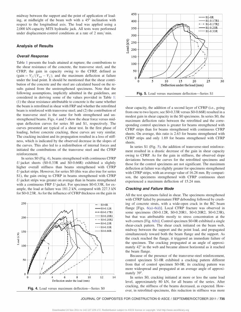
Table 1 presents the loads attained at rupture; the contributions tothe shear resistance of the concrete, the transverse steel, and theCFRP; the gain in capacity owing to the CFRP, defined as(gain ¼ Vf =ðV tot � Vf Þ; and the maximum deflection at failureunder the load point. It should be mentioned that the shear contri-bution of the concrete and the steel are calculated based on the re-sults gained from the unstrengthened specimens. Note that thefollowing assumptions, implicitly admitted in the guidelines, areconsidered in deriving some of the values provided in Table 1:(1) the shear resistance attributable to concrete is the same whetherthe beam is retrofitted in shear with FRP and whether the retrofittedbeam is reinforced with transverse steel; and (2) the contribution ofthe transverse steel is the same for both strengthened and un-strengthened beams. Figs. 4 and 5 show the shear force versus mid-span deflection curves for series S0 and S1, respectively. Thecurves presented are typical of a shear test. In the first phase ofloading, before concrete cracking, these curves are very similar.The cracking incident and its propagation resulted in a loss of stiff-ness, which is indicated by the observed decrease in the slopes ofthe curves. This also led to a redistribution of internal forces andinitiated the contributions of the transverse steel and the CFRPreinforcement.
In series S0 (Fig. 4), beams strengthened with continuous CFRPU-jacket sheets (S0-0.33R and S0-0.66R) exhibited a slightlyhigher overall stiffness than beams strengthened with CFRPU-jacket strips. However, for series S0 (this was also true for seriesS1), the gain owing to CFRP in beams strengthened with CFRPU-jacket strips was greater on average than in beams strengthenedwith a continuous FRP U-jacket. For specimen S0-0.33R, for ex-ample, the load at failure was 181.2 kN, compared with 227.3 kNfor S0-0.23R. As for the influence of CFRP thickness on the gain in
shear capacity, the addition of a second layer of CFRP (i.e., goingfrom one to two layers; see S0-0.33R versus S0-0.66R) resulted in amodest gain in shear capacity in the S0 specimens. In series S0, themaximum deflection ratio between the retrofitted and the corre-sponding control specimen is greater for beams strengthened withCFRP strips than for beams strengthened with continuous CFRPsheets. On average, this ratio is 2.63 for beams strengthened withCFRP strips and only 1.69 for beams strengthened with CFRPsheets.
In series S1 (Fig. 5), the addition of transverse-steel reinforce-ment resulted in a drastic decrease of the gain in shear capacityowing to CFRP. As for the gain in stiffness, the observed slopedeviations between the curves for the retrofitted specimens andthose for the control specimens are not significant. The maximumdeflection at failure was slightly greater for specimens strengthenedwith CFRP strips, with an average value of 16.28 mm. By compari-son, the specimens strengthened with CFRP continuous sheetexperienced a maximum deflection of 15.24 mm.
Cracking and Failure Mode
All the test specimens failed in shear. The specimens strengthenedwith CFRP failed by premature FRP debonding followed by crush-ing of concrete struts, with a wide-open crack in the RC beamflange [Figs. 6(a)–6(d)]. Local CFRP fracture was observed insome specimens (S0-0.12R, S0-0.20R1, S0-0.20R2, S0-0.23R),but that was attributable mostly to stress concentration at theweb corners [Fig. 6(b)]. Control specimen S0-0R exhibited a singleshear-crack pattern. The shear crack initiated on the beam web,midway between the support and the point load, and propagatedsimultaneously toward both the beam flange and the support. Asthe crack reached the flange, it triggered an immediate failure ofthe specimen. The cracking propagated at an angle of approxi-mately 42° in the web and became almost horizontal as it reachedthe beam flange.
Because of the presence of the transverse-steel reinforcement,control specimen S1-0R exhibited a cracking pattern differentfrom that of control specimen S0-0R; its cracking pattern wasmore widespread and propagated at an average angle of approxi-mately 39°.
In series S0, cracking initiated at more or less the same loadlevel, approximately 80 kN, for all beams of the series. Aftercracking, the stiffness of the beams decreased, as expected. How-ever, in retrofitted specimens, this reduction in stiffness was moreFig. 4. Load versus maximum deflection—Series S0
Fig. 5. Load versus maximum deflection—Series S1
JOURNAL OF COMPOSITES FOR CONSTRUCTION © ASCE / SEPTEMBER/OCTOBER 2011 / 735
Downloaded 24 Nov 2011 to 142.137.229.172. Redistribution subject to ASCE license or copyright. Visit http://www.ascelibrary.org

pronounced in beams strengthened with CFRP U-jacket strips thanin beams strengthened with continuous CFRP sheets. In the retro-fitted specimens, only one principal crack was observed in the spec-imens in series S0. For the beams strengthened with U-shapedstrips, the gain in shear capacity owing to CFRP was 66% on aver-age, compared to 31% for specimens strengthened with continuousCFRP sheets.
In strengthened beams in series S1, two parallel diagonal cracksformed between 78 and 81 kN and propagated with increasing loadfrom the support to the flange at an average angle of approximately38°. As the load was reaching its ultimate value, these two diagonalcracks merged into a single crack that progressed horizontallyin the RC beam flange. The series S1 beams strengthened byU-shaped strips achieved an average gain of 6% in shear capacityowing to FRP, compared to 8% for specimens strengthened withcontinuous CFRP sheets.
CFRP Strains
Figs. 7 and 8 present the shear force versus CFRP strain curves forseries S0 and S1, respectively. All the curves presented in thesefigures show that the CFRP did not contribute to the load-carryingcapacity in the initial stage of loading, i.e., up to an applied shearforce between 70 and 80 kN. Thereafter, the strain in the CFRPstarted to increase steadily up to a maximum value (Figs. 7 and 8),the level at which the CFRP U-jackets started to debond locally. Inseries S0, the maximum measured strain values for the CFRP strips(4,999 με on average) are significantly greater than those for theCFRP continuous sheets (3,583 με on average). For example, inbeams strengthened with CFRP strips, the strain attained 5,822 μstrains in beam S0-0.12R and 5,553 μstrains in S0-0.23R.In specimens strengthened with CFRP U-jacket sheet, the strain re-ached 2,478 μstrains in S0-0.33R and 4,688 μstrains in SB-0.66R.Finally, a comparison of Fig. 7 with Fig. 8 reveals that the maxi-mum strains achieved in the CFRP were somewhat similar for cor-responding beams of both series (except for specimen S0-0.33R
where the strain gauges might not have captured the maximum at-tained CFRP strain). However, the contribution of FRP to shearresistance is significantly greater for beams in series S0 (withno transverse-steel reinforcement) than for beams in series S1 (withtransverse-steel reinforcement) (45.9 kN versus 16.2 kN on aver-age). It must be pointed out that this strain value, like all those re-ported in this paper, is the maximum measured value, but notnecessarily the absolute maximum value, experienced by the CFRPU-jackets. The two values may differ in cases where the straingauges did not intercept the main cracks.
Transverse-Steel Strains
Curves representing the applied shear force versus the strains in thetransverse-steel reinforcement are presented in Fig. 9 for specimens
Fig. 6. Failure mode in strengthened beams: (a) S0-0.12R; (b) S0-0.17R1; (c) S1-0.23R; (d) S1-0.33R
Fig. 7. Load versus maximum strain in FRP—Series S0
736 / JOURNAL OF COMPOSITES FOR CONSTRUCTION © ASCE / SEPTEMBER/OCTOBER 2011
Downloaded 24 Nov 2011 to 142.137.229.172. Redistribution subject to ASCE license or copyright. Visit http://www.ascelibrary.org

of series S1. It should be noted that the reported transverse-steelstrain is the measured strain in the steel stirrup that achieved themaximum strain during loading.
As for CFRP, it can be observed that the steel stirrups did notcontribute to the load-carrying capacity in the initial stage of load-ing. The transverse-steel contribution to shear resistance initia-ted after the formation of diagonal cracking. In the unstrengthenedcontrol specimen S1-0R, for example, this initiation occurred atan applied shear force of approximately 77 kN, whereas for theretrofitted specimens (S1-0.17R1, S1-0.17R2, S1-0.23R, andS1-0.33R), it occurred at an applied shear force of approximately85 kN. The transverse-steel strain continued to increase with in-creasing load. For all specimens in series S1, the transverse-steelreinforcement yielded well ahead of general failure. For speci-men S1-0.17R2 (CFRP strips between the steel-stirrup loca-tions), the strain value was significantly greater than for specimenS1-0.17R1 (CFRP strips at the same locations along the longitudi-nal axis as the steel stirrups). Moreover, the strain started to in-crease at an earlier loading stage in specimen S1-0.17R2 than inspecimen S1-0.17R1.
Discussion and Analysis of Experimental Results
The first part of this section compares the efficiency of the strength-ened beams. Then the effects of certain details on the shearstrengthening of RC beams with CFRP, including CFRP stripwidths, presence of transverse steel, and CFRP strip locations,are successively presented and analyzed. A comparison of the ef-fectiveness of CFRP strips and CFRP sheets is then presented.Finally, the applicability of available equations describing the effectof strip width and concrete-block width on FRP sheets applied toconcrete-block joints in RC beams strengthened in shear with dif-ferent strip-width-to-strip-spacing ratios is examined.
Efficiency of Strengthening Systems
As shown in Table 1, the strengthened beams showed a significantincrease in shear capacity compared with the control beams. In par-ticular, the beams strengthened with externally bonded U-jacketCFRP strips and sheets were on average 43% and 33% stronger,respectively, than their corresponding control beam. This resultconfirms that externally bonded continuous CFRP sheets andCFRP strips can be used effectively to strengthen RC beams thatare deficient in shear. Table 3 compares the efficiencies achieved bythe various strengthened beams. The FRP efficiency ratio is definedas the contribution of FRP to shear resistance divided by the maxi-mum FRP tensile strength per unit length. It can be seen that theFRP efficiency ratio is superior (9.7% versus 3.3%) for the beamsof series S0 (without transverse steel) compared to that for series S1(beams with transverse steel). In addition, the FRP efficiency ratiois greater for beams strengthened with CFRP strips than for beamsstrengthened with CFRP sheets for both series (Table 3).
Effect of CFRP Strip Width (for Constant wf =sf )
The effect of strip width (for a given wf =sf ratio) can be observedby comparing the response of beams S0-0.2R1 and S0-0.2R2.These beams have a similar width-to-spacing ratio but differentFRP strip widths. The FRP in specimen S0-0.2R2 with narrowFRP strips (wf ¼ 30 mm) reached higher strains than did specimenS0-0.2R1 (5,738 με versus 3,530 με). Conversely, specimenS0-0.2R1 with wide FRP strips (53 mm) achieved a greater con-tribution of FRP to shear resistance than did specimen S0-0.2R2(54.5 kN versus 49.9 kN).
The last observation is in contrast with the findings of Kamelet al. (2000) from direct-tension tests conducted to investigate
Fig. 8. Load versus maximum strain in FRP—Series S1
Fig. 9. Load versus maximum strain in steel stirrup—Series S1
Table 3. Efficiency of FRP Using Different Strengthening Methods
Specimen
Area ofCFRP
Ultimate tensilecapacity perunit length Vf
ψf efficiencyof FRP
mm2=m kN=m kN %
S0-0.12R 77 266 39.7 14.9
S0-0.17R1 110 380 53.3 14.0
S0-0.17R2 120 414 21.2 5.1
S0-0.20R1 133 459 54.5 11.9
S0-0.20R2 132 455 49.9 11.0
S0-0.23R 154 531 69.3 13.1
S0-0.33R 220 759 38.7 5.1
S0-0.66R 440 1518 40.4 2.7
S1-0.17R1 110 380 10.1 2.7
S1-0.17R2 110 380 14.5 3.8
S1-0.23R 154 531 21.7 4.1
S1-0.33R 220 759 18.4 2.4
JOURNAL OF COMPOSITES FOR CONSTRUCTION © ASCE / SEPTEMBER/OCTOBER 2011 / 737
Downloaded 24 Nov 2011 to 142.137.229.172. Redistribution subject to ASCE license or copyright. Visit http://www.ascelibrary.org
the effect of CFRP-strip-width-to-concrete-block-width ratio forCFRP sheets bonded to concrete blocks. Those tests revealed thatfor wide FRP sheets, the maximum load per unit width of the FRPstrip can be considerably reduced by strain concentrations at theedges. It can be concluded that the effect of the strip-width-to-concrete-block-width ratio observed in the direct-tension test forCFRP strips bonded to concrete blocks does not seem to be validfor beams strengthened in shear with CFRP strips. It follows thatthe applicability of the equations that were proposed based ondirect-tension tests of CFRP strips bonded to concrete blocks[Eqs. (2)–(5)] to beams strengthened in shear with CFRP stripsis questionable.
Effect of the Presence of Internal Transverse Steel
The effect of the presence of transverse steel on the contribution ofFRP to shear resistance can be examined by comparing the resultsfor series S0 with those for series S1 (Table 1). The average gainin shear resistance owing to FRP in the specimens of series S0 is57%, compared to 7% for the beams of series S1. In particular,the presence of transverse steel resulted in a significant decreasein the contribution of FRP to shear resistance for specimensS0-0.17R1, S0-0.23R, and S0-0.33R, from 53.3, 69.3, and38.7 kN to 14.5, 21.7, and 18.4 kN, respectively. This result cor-roborates once again the findings of previous research studieson the effect of transverse steel (Chaallal et al. 2002; Pellegrinoand Modena 2002; Bousselham and Chaallal 2006; Pellegrino andModena 2006).
Effect of CFRP-Strip Location with Respect toSteel-Stirrup Location
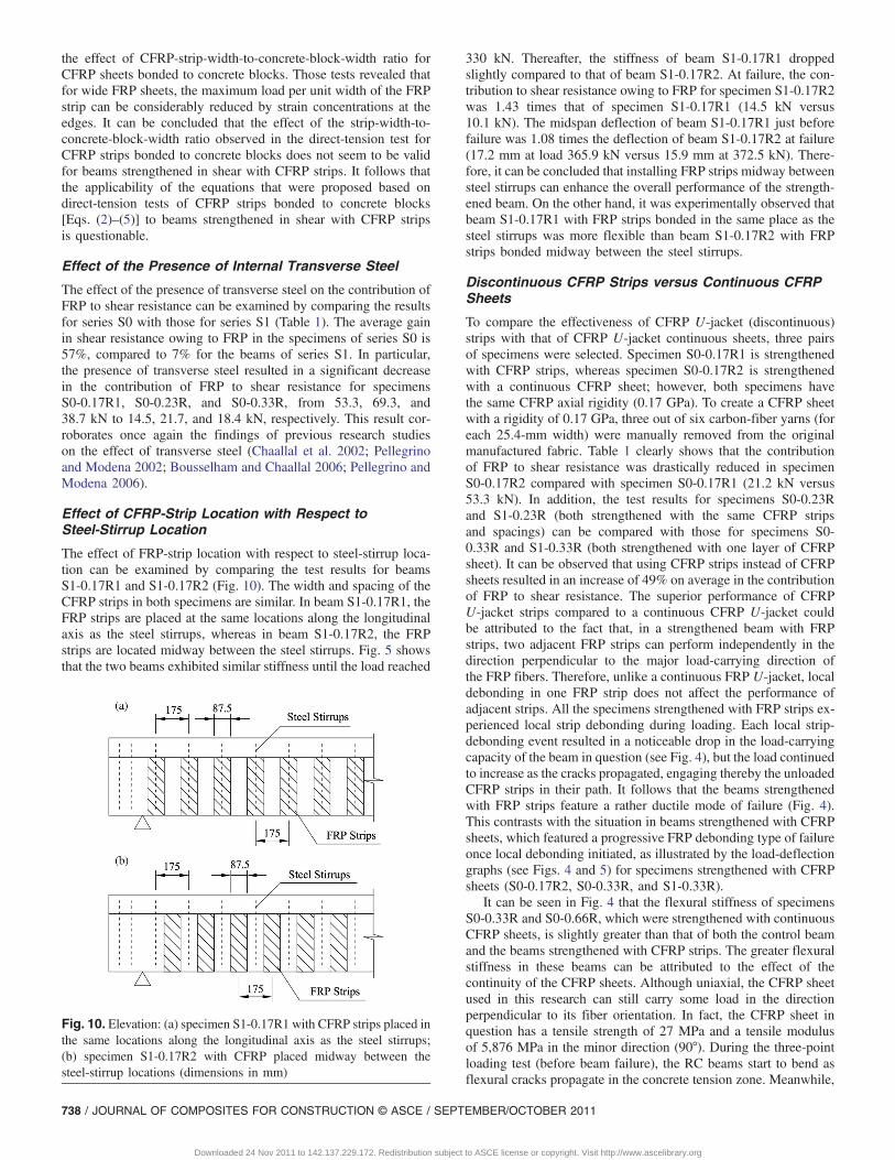
The effect of FRP-strip location with respect to steel-stirrup loca-tion can be examined by comparing the test results for beamsS1-0.17R1 and S1-0.17R2 (Fig. 10). The width and spacing of theCFRP strips in both specimens are similar. In beam S1-0.17R1, theFRP strips are placed at the same locations along the longitudinalaxis as the steel stirrups, whereas in beam S1-0.17R2, the FRPstrips are located midway between the steel stirrups. Fig. 5 showsthat the two beams exhibited similar stiffness until the load reached
330 kN. Thereafter, the stiffness of beam S1-0.17R1 droppedslightly compared to that of beam S1-0.17R2. At failure, the con-tribution to shear resistance owing to FRP for specimen S1-0.17R2was 1.43 times that of specimen S1-0.17R1 (14.5 kN versus10.1 kN). The midspan deflection of beam S1-0.17R1 just beforefailure was 1.08 times the deflection of beam S1-0.17R2 at failure(17.2 mm at load 365.9 kN versus 15.9 mm at 372.5 kN). There-fore, it can be concluded that installing FRP strips midway betweensteel stirrups can enhance the overall performance of the strength-ened beam. On the other hand, it was experimentally observed thatbeam S1-0.17R1 with FRP strips bonded in the same place as thesteel stirrups was more flexible than beam S1-0.17R2 with FRPstrips bonded midway between the steel stirrups.
Discontinuous CFRP Strips versus Continuous CFRPSheets
To compare the effectiveness of CFRP U-jacket (discontinuous)strips with that of CFRP U-jacket continuous sheets, three pairsof specimens were selected. Specimen S0-0.17R1 is strengthenedwith CFRP strips, whereas specimen S0-0.17R2 is strengthenedwith a continuous CFRP sheet; however, both specimens havethe same CFRP axial rigidity (0.17 GPa). To create a CFRP sheetwith a rigidity of 0.17 GPa, three out of six carbon-fiber yarns (foreach 25.4-mm width) were manually removed from the originalmanufactured fabric. Table 1 clearly shows that the contributionof FRP to shear resistance was drastically reduced in specimenS0-0.17R2 compared with specimen S0-0.17R1 (21.2 kN versus53.3 kN). In addition, the test results for specimens S0-0.23Rand S1-0.23R (both strengthened with the same CFRP stripsand spacings) can be compared with those for specimens S0-0.33R and S1-0.33R (both strengthened with one layer of CFRPsheet). It can be observed that using CFRP strips instead of CFRPsheets resulted in an increase of 49% on average in the contributionof FRP to shear resistance. The superior performance of CFRPU-jacket strips compared to a continuous CFRP U-jacket couldbe attributed to the fact that, in a strengthened beam with FRPstrips, two adjacent FRP strips can perform independently in thedirection perpendicular to the major load-carrying direction ofthe FRP fibers. Therefore, unlike a continuous FRP U-jacket, localdebonding in one FRP strip does not affect the performance ofadjacent strips. All the specimens strengthened with FRP strips ex-perienced local strip debonding during loading. Each local strip-debonding event resulted in a noticeable drop in the load-carryingcapacity of the beam in question (see Fig. 4), but the load continuedto increase as the cracks propagated, engaging thereby the unloadedCFRP strips in their path. It follows that the beams strengthenedwith FRP strips feature a rather ductile mode of failure (Fig. 4).This contrasts with the situation in beams strengthened with CFRPsheets, which featured a progressive FRP debonding type of failureonce local debonding initiated, as illustrated by the load-deflectiongraphs (see Figs. 4 and 5) for specimens strengthened with CFRPsheets (S0-0.17R2, S0-0.33R, and S1-0.33R).
It can be seen in Fig. 4 that the flexural stiffness of specimensS0-0.33R and S0-0.66R, which were strengthened with continuousCFRP sheets, is slightly greater than that of both the control beamand the beams strengthened with CFRP strips. The greater flexuralstiffness in these beams can be attributed to the effect of thecontinuity of the CFRP sheets. Although uniaxial, the CFRP sheetused in this research can still carry some load in the directionperpendicular to its fiber orientation. In fact, the CFRP sheet inquestion has a tensile strength of 27 MPa and a tensile modulusof 5,876 MPa in the minor direction (90°). During the three-pointloading test (before beam failure), the RC beams start to bend asflexural cracks propagate in the concrete tension zone. Meanwhile,
Fig. 10. Elevation: (a) specimen S1-0.17R1 with CFRP strips placed inthe same locations along the longitudinal axis as the steel stirrups;(b) specimen S1-0.17R2 with CFRP placed midway between thesteel-stirrup locations (dimensions in mm)
738 / JOURNAL OF COMPOSITES FOR CONSTRUCTION © ASCE / SEPTEMBER/OCTOBER 2011
Downloaded 24 Nov 2011 to 142.137.229.172. Redistribution subject to ASCE license or copyright. Visit http://www.ascelibrary.org
no signs of separation (unzipping) of the fibers were observed in theCFRP U-jacket sheet. This shows that the CFRP U-jacket sheet(unlike the FRP strips) contributes to the RC beam’s bending re-sistance. It is believed that, although the longitudinal tensile forcein the U-jacket sheet adds to the RC beam’s flexural stiffness, italso facilitates the progressive debonding process in the U-jacketonce local debonding has taken place in a particular FRP band. Asthe RC concrete beam strengthened with CFRP sheet bends andflexural cracks open up, the FRP sheet and the epoxy layer canno longer accommodate the RC beam’s deformability. At the sametime as the shear cracks start to grow, local debonding takes place inthe CFRP sheet. The horizontal strain left in the CFRP bondedlayer attributable to the difference in flexibility of the RC beamand the CFRP sheet causes the local debonding to migrate fromone fiber band to another. This causes overall CFRP U-jacket de-bonding, followed by failure of the RC beam. In this way, a localCFRP debonding event can trigger overall CFRP U-jacket debond-ing. Therefore, the RC beam’s failure is due to progressive CFRPdebonding (Fig. 6(d)).
On the other hand, as mentioned previously, the CFRP stripsdebond independently from each other because the FRP fibersin one strip cannot transfer forces to adjacent FRP strips in theFRP minor direction. Moreover, the FRP strips do not interfere withthe RC beam’s flexural behavior. Therefore, the load-carryingcapacity of the RC beam continues to increase even after local de-bonding has taken place in some FRP strips (Fig. 4).
Effect of Strip-Width-to-Strip-Spacing Ratio
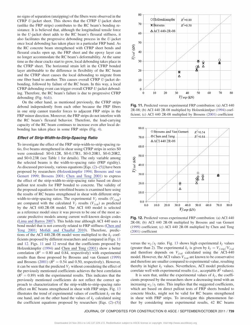
To investigate the effect of the FRP strip-width-to-strip-spacing ra-tio, five beams strengthened in shear using CFRP strips in series S0were considered: S0-0.12R, S0-0.17R1, S0-0.20R1, S0-0.20R2,and S0-0.23R (see Table 1 for details). The only variable amongthe selected beams is the width-to-spacing ratio (FRP rigidity).As discussed previously, various equations [Eqs. (2)–(5)] have beenproposed by researchers (Holzenkämpfer 1994; Brosens and vanGemert 1999; Brosens 2001; Chen and Teng 2001) to expressthe effect of the strip-width-to-strip-spacing ratio based on directpullout test results for FRP bonded to concrete. The validity ofthe proposed equations for retrofitted beams is examined here usingthe results of RC beams strengthened in shear with different strip-width-to-strip-spacing ratios. The experimental Vf results (Vf exp)are compared with the calculated Vf results (Vf cal) as predictedby the ACI 440.2R-08 model. The ACI 440 model is selectedas a reference model since it was proven to be one of the most ac-curate predictive models among current well-known design codes(Lima and Barros 2007). This holds true although ACI 440 uses abond model that is not correctly related to FRP stiffness (Chen andTeng 2001; Mofidi and Chaallal 2010). Therefore, predic-tions of the ACI 440.2R-08 model were multiplied to the kf coef-ficients proposed by different researchers and compared in Figs. 11and 12. Figs. 11 and 12 reveal that the coefficients proposed byHolzenkämpfer (1994) and Chen and Teng (2001) show a bettercorrelation (R2 ¼ 0:80 and 0.84, respectively) with experimentalresults than those proposed by Brosens and van Gemert (1999)and Brosens (2001) (R2 ¼ 0:54 and 0.50, respectively). However,it can be seen that the predicted Vf without considering the effect ofthe previously mentioned coefficients achieves the best correlation(R2 ¼ 0:89) with the experimental results. This indicates that thepreviously mentioned coefficients do not reflect the correct ap-proach to characterization of the strip-width-to-strip-spacing ratioeffect on RC beams strengthened in shear with FRP strips. Fig. 13illustrates the trend of experimental values of coefficient kf on theone hand, and on the other hand the values of kf calculated usingthe coefficient equations proposed by researchers [Eqs. (2)–(5)]
versus the wf =sf ratio. Fig. 13 shows high experimental kf values(greater than 2). The experimental kf is given by kf ¼ Vf exp=Vf caland therefore depends on Vf cal calculated using the ACI-440model. However, the ACI values Vf cal are known to be conservativeand therefore are smaller compared to experimental value, resultingthereby in higher kf values. Nevertheless, ACI model predictionscorrelate well with experimental results (i.e., acceptable R2 values).
It is seen that, unlike the experimental values of kf , the coeffi-cients proposed by the researchers show a decreasing trend with anincreasing wf =sf ratio. This implies that the suggested coefficients,which are based on direct pullout tests of FRP sheets bonded toconcrete blocks, might not be valid for RC beams strengthenedin shear with FRP strips. To investigate this phenomenon fur-ther by considering more experimental results, 42 RC beams
Fig. 11. Predicted versus experimental FRP contribution: (a) ACI 4402R-08; (b) ACI 440 2R-08 multiplied by Holzenkämfper (1994) coef-ficient; (c) ACI 440 2R-08 multiplied by Brosens (2001) coefficient
Fig. 12. Predicted versus experimental FRP contribution: (a) ACI 4402R-08; (b) ACI 440 2R-08 multiplied by Brosens and van Gemert(1999) coefficient; (c) ACI 440 2R-08 multiplied by Chen and Teng(2001) coefficient
JOURNAL OF COMPOSITES FOR CONSTRUCTION © ASCE / SEPTEMBER/OCTOBER 2011 / 739
Downloaded 24 Nov 2011 to 142.137.229.172. Redistribution subject to ASCE license or copyright. Visit http://www.ascelibrary.org
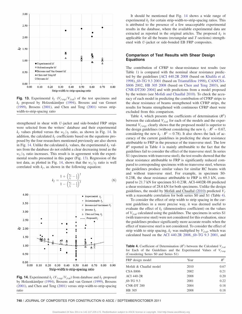
strengthened in shear with U-jacket and side-bonded FRP stripswere selected from the writers’ database and their experimentalkf values plotted versus the wf =sf ratio, as shown in Fig. 14. Inaddition, the calculated kf coefficients based on the equations pro-posed by the four researchers mentioned previously are also shownin Fig. 14. Unlike the calculated kf values, the experimental kf val-ues from the database do not exhibit a clear decreasing trend as thewf =sf ratio increases. This result is in agreement with the experi-mental results presented in this paper (Fig. 13). Regression of thetest data, as plotted in Fig. 14, shows that the wf =sf ratio is wellcorrelated with kf , as shown in the following equation:
kf ¼1þ
�wf
sf� 1
2
�2
1��wf
sf� 1
2
�2 ð6Þ
It should be mentioned that Fig. 14 shows a wide range ofexperimental kf for certain strip-width-to-strip-spacing ratios. Thisis attributed to the presence of a few unacceptable experimentalresults in the database, where the available experimental data areextracted as reported in the original articles. The proposed kf isapplicable for all the beams (rectangular and T-sections) strength-ened with U-jacket or side-bonded EB FRP composites.
Comparison of Test Results with Shear DesignEquations
The contribution of CFRP to shear-resistance test results (seeTable 1) is compared with the nominal shear resistance predic-ted by the guidelines [ACI 440.2R 2008 (based on Khalifa et al.1998), fib-TG 9.3 2001 (based on Triantafillou 1998), CAN/CSA-S806 2002, HB 305 2008 (based on Chen and Teng 2003), andCNR-DT200 2004] and with predictions from a model proposedby the writers (see Mofidi and Chaallal 2010). To check the accu-racy of each model in predicting the contribution of CFRP strips tothe shear resistance of beams strengthened with CFRP strips, theresults for beams strengthened with continuous CFRP sheet wereexcluded from this comparison.
Table 4, which presents the coefficients of determination (R2)between the calculated Vf cal for each of the models and the exper-imental Vf exp, clearly shows that the proposed model is superior tothe design guidelines (without considering the new kf : R2 ¼ 0:67,considering the new kf : R2 ¼ 0:78). It also shows the lack of ac-curacy of the current guidelines in predicting the shear resistanceattributable to FRP in the presence of the transverse steel. The lowR2 reported in Table 4 is mainly attributable to the fact that theguidelines fail to consider the effect of the transverse steel. In seriesS1 (specimens with transverse steel), the test results showed that theshear resistance attributable to FRP is significantly reduced com-pared to corresponding specimens with no transverse steel, whereasthe guidelines produce similar values for similar RC beams withand without transverse steel. For example, in specimen S0-0.23R, the shear resistance attributable to FRP is 69.3 kN, com-pared to 21.7 kN for specimen S1-0.23R. ACI-4402R-08 predicteda shear resistance of 28.6 kN for both specimens. Unlike the designguidelines, the model by Mofidi and Chaallal (2010) predicted Vfwith a reasonable correlation for both series S0 and S1 (Table 4).
To consider the effect of strip width to strip spacing in the cur-rent guidelines in a more precise way, it was deemed useful toevaluate the effect of kf (dimensionless coefficient) on the valuesof Vf cal calculated using the guidelines. The specimens in series S1(with transverse steel) were not considered for this evaluation, sincethe guidelines produce significantly more accurate results when theeffect of transverse steel is not considered. To consider the effect ofstrip width to strip spacing, kf was multiplied by Vf cal, which wascalculated based on the ACI 440.2R 2008, fib-TG 9.3 2001, and
Fig. 13. Experimental kf (Vf exp=Vf cal) of the test specimens andkf proposed by Holzenkämfper (1994), Brosens and van Gemert(1999), Brosens (2001), and Chen and Teng (2001) versus strip-width-to-strip-spacing ratio
Fig. 14. Experimental kf (Vf exp=Vf cal) from database and kf proposedby Holzenkämfper (1994), Brosens and van Gemert (1999), Brosens(2001), and Chen and Teng (2001) versus strip-width-to-strip-spacingratio
Table 4. Coefficient of Determination (R2) between the Calculated Vf calfor Each of the Guidelines and the Experimental Values of Vf exp(Considering Series S0 and Series S1)
FRP design model Year R2
Mofidi & Chaallal model 2010 0.67
CSA-S806 2002 0.21
ACI 440-2R 2008 0.20
fib-TG 9.3 2001 0.22
CNR-DT 200 2004 0.18
HB 305 2008 0.18
740 / JOURNAL OF COMPOSITES FOR CONSTRUCTION © ASCE / SEPTEMBER/OCTOBER 2011
Downloaded 24 Nov 2011 to 142.137.229.172. Redistribution subject to ASCE license or copyright. Visit http://www.ascelibrary.org
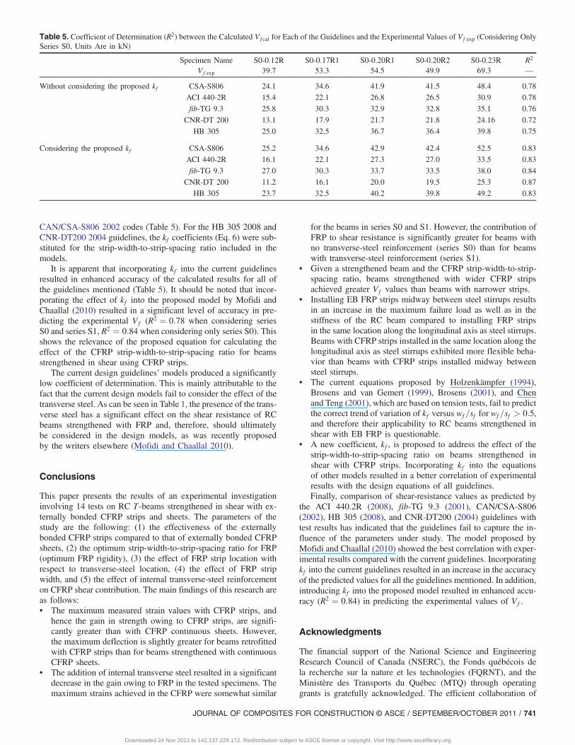
CAN/CSA-S806 2002 codes (Table 5). For the HB 305 2008 andCNR-DT200 2004 guidelines, the kf coefficients (Eq. 6) were sub-stituted for the strip-width-to-strip-spacing ratio included in themodels.
It is apparent that incorporating kf into the current guidelinesresulted in enhanced accuracy of the calculated results for all ofthe guidelines mentioned (Table 5). It should be noted that incor-porating the effect of kf into the proposed model by Mofidi andChaallal (2010) resulted in a significant level of accuracy in pre-dicting the experimental Vf (R2 ¼ 0:78 when considering seriesS0 and series S1, R2 ¼ 0:84 when considering only series S0). Thisshows the relevance of the proposed equation for calculating theeffect of the CFRP strip-width-to-strip-spacing ratio for beamsstrengthened in shear using CFRP strips.
The current design guidelines’ models produced a significantlylow coefficient of determination. This is mainly attributable to thefact that the current design models fail to consider the effect of thetransverse steel. As can be seen in Table 1, the presence of the trans-verse steel has a significant effect on the shear resistance of RCbeams strengthened with FRP and, therefore, should ultimatelybe considered in the design models, as was recently proposedby the writers elsewhere (Mofidi and Chaallal 2010).
Conclusions
This paper presents the results of an experimental investigationinvolving 14 tests on RC T-beams strengthened in shear with ex-ternally bonded CFRP strips and sheets. The parameters of thestudy are the following: (1) the effectiveness of the externallybonded CFRP strips compared to that of externally bonded CFRPsheets, (2) the optimum strip-width-to-strip-spacing ratio for FRP(optimum FRP rigidity), (3) the effect of FRP strip location withrespect to transverse-steel location, (4) the effect of FRP stripwidth, and (5) the effect of internal transverse-steel reinforcementon CFRP shear contribution. The main findings of this research areas follows:• The maximum measured strain values with CFRP strips, and
hence the gain in strength owing to CFRP strips, are signifi-cantly greater than with CFRP continuous sheets. However,the maximum deflection is slightly greater for beams retrofittedwith CFRP strips than for beams strengthened with continuousCFRP sheets.
• The addition of internal transverse steel resulted in a significantdecrease in the gain owing to FRP in the tested specimens. Themaximum strains achieved in the CFRP were somewhat similar
for the beams in series S0 and S1. However, the contribution ofFRP to shear resistance is significantly greater for beams withno transverse-steel reinforcement (series S0) than for beamswith transverse-steel reinforcement (series S1).
• Given a strengthened beam and the CFRP strip-width-to-strip-spacing ratio, beams strengthened with wider CFRP stripsachieved greater Vf values than beams with narrower strips.
• Installing EB FRP strips midway between steel stirrups resultsin an increase in the maximum failure load as well as in thestiffness of the RC beam compared to installing FRP stripsin the same location along the longitudinal axis as steel stirrups.Beams with CFRP strips installed in the same location along thelongitudinal axis as steel stirrups exhibited more flexible beha-vior than beams with CFRP strips installed midway betweensteel stirrups.
• The current equations proposed by Holzenkämpfer (1994),Brosens and van Gemert (1999), Brosens (2001), and Chenand Teng (2001), which are based on tension tests, fail to predictthe correct trend of variation of kf versus wf =sf for wf =sf > 0:5,and therefore their applicability to RC beams strengthened inshear with EB FRP is questionable.
• A new coefficient, kf , is proposed to address the effect of thestrip-width-to-strip-spacing ratio on beams strengthened inshear with CFRP strips. Incorporating kf into the equationsof other models resulted in a better correlation of experimentalresults with the design equations of all guidelines.Finally, comparison of shear-resistance values as predicted by
the ACI 440.2R (2008), fib-TG 9.3 (2001), CAN/CSA-S806(2002), HB 305 (2008), and CNR-DT200 (2004) guidelines withtest results has indicated that the guidelines fail to capture the in-fluence of the parameters under study. The model proposed byMofidi and Chaallal (2010) showed the best correlation with exper-imental results compared with the current guidelines. Incorporatingkf into the current guidelines resulted in an increase in the accuracyof the predicted values for all the guidelines mentioned. In addition,introducing kf into the proposed model resulted in enhanced accu-racy (R2 ¼ 0:84) in predicting the experimental values of Vf .
Acknowledgments
The financial support of the National Science and EngineeringResearch Council of Canada (NSERC), the Fonds québécois dela recherche sur la nature et les technologies (FQRNT), and theMinistère des Transports du Québec (MTQ) through operatinggrants is gratefully acknowledged. The efficient collaboration of
Table 5. Coefficient of Determination (R2) between the Calculated Vf cal for Each of the Guidelines and the Experimental Values of Vf exp (Considering OnlySeries S0, Units Are in kN)
Specimen Name S0-0.12R S0-0.17R1 S0-0.20R1 S0-0.20R2 S0-0.23R R2
Vf exp 39.7 53.3 54.5 49.9 69.3 —
Without considering the proposed kf CSA-S806 24.1 34.6 41.9 41.5 48.4 0.78
ACI 440-2R 15.4 22.1 26.8 26.5 30.9 0.78
fib-TG 9.3 25.8 30.3 32.9 32.8 35.1 0.76
CNR-DT 200 13.1 17.9 21.7 21.8 24.16 0.72
HB 305 25.0 32.5 36.7 36.4 39.8 0.75
Considering the proposed kf CSA-S806 25.2 34.6 42.9 42.4 52.5 0.83
ACI 440-2R 16.1 22.1 27.3 27.0 33.5 0.83
fib-TG 9.3 27.0 30.3 33.7 33.5 38.0 0.84
CNR-DT 200 11.2 16.1 20.0 19.5 25.3 0.87
HB 305 23.7 32.5 40.2 39.8 49.2 0.83
JOURNAL OF COMPOSITES FOR CONSTRUCTION © ASCE / SEPTEMBER/OCTOBER 2011 / 741
Downloaded 24 Nov 2011 to 142.137.229.172. Redistribution subject to ASCE license or copyright. Visit http://www.ascelibrary.org
John Lescelleur (senior technician) and Juan Mauricio Rios (tech-nician) at ÉTS, in conducting the tests, is acknowledged.
Notation
The following symbols are used in this paper:a = shear span;bc = width of concrete block;bf = width of bond area;bw = width of the concrete-beam cross section;d = effective depth of the concrete beam;Ef = elastic modulus of FRP in the principal fiber-orientation
direction;kf = factor related to width of the bonded plate and width of
the concrete member;Rf = FRP rigidity parameter ¼ ρf × Ef ;sf = spacing between FRP strips;tf = thickness of FRP composite;Vf = contribution of FRP to shear;
Vf cal = contribution of FRP to shear as calculated by models;Vf exp = experimental contribution of FRP to shear;V tot = total shear resistance;wf = width of an FRP strip; andρf = FRP strengthening ratio = ð2tf =bwÞ × ðwf =sf Þ.
References
American Concrete Institute (ACI). (2008). “Guide for the design and con-struction of externally bonded FRP systems for strengthening concretestructures.” Rep. No. 440 2R-08, Farmington Hills, MI.
Bizindavyi, L., and Neale, K. W. (1999). “Transfer lengths and bondstrengths for composites bonded to concrete.” J. Compos. Constr., 3(4),153–160.
Bousselham, A., and Chaallal, O. (2004). “Shear strengthening reinforcedconcrete beams with fiber-reinforced polymer: Assessment of influenc-ing parameters and required research.” ACI Struct. J., 101(2), 219–227.
Bousselham, A., and Chaallal, O. (2006). “Behavior of reinforced concreteT-beams strengthened in shear with carbon fiber-reinforced polymer—An experimental study.” ACI Struct. J., 103(3), 339–347.
Brosens, K. (2001). “Anchorage of externally bonded steel plates andCFRP laminates for the strengthening of concrete elements.” Ph.D. dis-sertation, Department of Civil Engineering, Katholieke UniversiteitLeuven, Leuven, Belgium.
Brosens, K., and van Gemert, D. (1999). “Anchorage design for externallybonded carbon fiber polymer laminates.” Proc., 4th Int. Symp. on FiberReinforced Polymer Reinforcement for Concrete Structures, ACIInternational, Baltimore, MD, 635–645.
CAN/CSA-S6-06. (2006). Canadian highway bridge design code,Canadian Standards Association, Mississauga, Canada.
CAN/CSA-S806-02. (2002). Design and construction of building compo-nents with fiber-reinforced polymer, Canadian Standards Association,Rexdale, Canada.
Chaallal, O., Shahawy, M., and Hassan, M. (2002). “Performance ofreinforced concrete T-girders strengthened in shear with carbonfiber-reinforced polymer fabric.” ACI Struct. J., 99(3), 335–343.
Chen, J. F., and Teng, J. G. (2001). “Anchorage strength models forFRP and steel plates bonded to concrete.” J. Struct. Eng., 127(7),784–791.
Chen, J. F., and Teng, J. G. (2003). “Shear capacity of FRP strengthenedRC beams: FRP debonding.” Constr. Build. Mater., 17(1), 27–41.
CNR-DT200. (2004). Guidelines for design, execution, and control ofstrengthening interventions by means of fiber-reinforced composites,National Research Council, Roma, Italy.
fib-TG 9.3. (2001). Externally bonded FRP reinforcement for RC struc-tures, International Federation for Structural Concrete, Lausanne,Switzerland.
HB 305, Oehlers, D. J., Seracino, R., and Smith, S. T. (2008). “Designguideline for RC structures retrofitted with FRP and metal plates:Beams and slabs.” HB 305-2008, Standards Australia, Sydney,Australia, ISBN 0 7337 7831 3, 73.
Holzenkämpfer, O. (1994). “Ingenieurmodelle des Verbundes GeklebterBewehrung für Betonbauteile.” Ph.D. thesis, TU Braunschweig,Germany.
Kamel, A. S., Elwi, A. E., and Cheng, J. J. R. (2000). “Experimental studyof the behavior of CFRP sheets bonded to concrete.” Proc., 3rd Int.Conf. on Advanced Composite Materials for Bridges and Structures,Canadian Society for Civil Engineering, Ottawa, 61–68.
Khalifa, A., Gold, W. J., Nanni, A., and Aziz, A. (1998). “Contributionof externally bonded FRP to shear capacity of RC flexural members.”J. Compos. Constr., 2(4), 195–203.
Khalifa, A., and Nanni, A. (2000). “Improving shear capacity of existingRC T-section beams using CFRP composites.” Cem. Concr. Compos.,22, 165–174.
Khalifa, A., and Nanni, A. (2002). “Rehabilitation of rectangular simplysupported RC beams with shear deficiencies using CFRP composites.”Constr. Build. Mater., 16, 135–146.
Lima, J. L. T., and Barros, J. A. O. (2007). “Design models for shearstrengthening of reinforced concrete beams with externally bondedFRP composites: A statistical versus reliability approach.” Proc., 8thInt. Symp. on Fiber Reinforced Polymer Reinforcement for ConcreteStructures, University of Patras, Patras, Greece.
Mofidi, A., and Chaallal, O. (2010). “Shear strengthening of RC beamswith EB FRP—Influencing factors and conceptual debonding model.”J. Compos. Constr., 10.1061/(ASCE)CC.1943-5614.0000153.
Neubauer, U., and Rostásy, F. S. (1997). Design aspects of concretestructures strengthened with externally bonded CFRP plates, ECSPublications, Edinburgh, 109–118.
Pellegrino, C., and Modena, C. (2002). “Fiber reinforced polymer shearstrengthening of RC beams with transverse steel reinforcement.”J. Compos. Constr., 6(2), 104–111.
Pellegrino, C., and Modena, C. (2006). “Fiber-reinforced polymer shearstrengthening of reinforced concrete beams: Experimental study andanalytical modeling.” ACI Struct. J., 103(5), 720–728.
Triantafillou, T. C. (1998). “Shear strengthening of reinforced concretebeams using epoxy-bonded FRP composites.” ACI Struct. J., 95(2),107–115.
Zhang, Z., and Hsu, C.-T. (2005). “Shear strengthening of reinforcedconcrete beams using carbon-fiber reinforced polymer laminates.”J. Compos. Constr., 9(2), 158–169.
742 / JOURNAL OF COMPOSITES FOR CONSTRUCTION © ASCE / SEPTEMBER/OCTOBER 2011
Downloaded 24 Nov 2011 to 142.137.229.172. Redistribution subject to ASCE license or copyright. Visit http://www.ascelibrary.org
Copyright © 2022 FDOKUMEN