SH7410 E8000 Emulator HS7410EDD82H User's Manual
464
To our customers, Old Company Name in Catalogs and Other Documents On April 1 st , 2010, NEC Electronics Corporation merged with Renesas Technology Corporation, and Renesas Electronics Corporation took over all the business of both companies. Therefore, although the old company name remains in this document, it is a valid Renesas Electronics document. We appreciate your understanding. Renesas Electronics website: http://www.renesas.com April 1 st , 2010 Renesas Electronics Corporation Issued by: Renesas Electronics Corporation (http://www.renesas.com ) Send any inquiries to http://www.renesas.com/inquiry .
-
Upload
khangminh22 -
Category
Documents
-
view
0 -
download
0
Transcript of SH7410 E8000 Emulator HS7410EDD82H User's Manual
To our customers,
Old Company Name in Catalogs and Other Documents
On April 1st, 2010, NEC Electronics Corporation merged with Renesas Technology
Corporation, and Renesas Electronics Corporation took over all the business of both companies. Therefore, although the old company name remains in this document, it is a valid Renesas Electronics document. We appreciate your understanding.
Renesas Electronics website: http://www.renesas.com
April 1st, 2010 Renesas Electronics Corporation
Issued by: Renesas Electronics Corporation (http://www.renesas.com)
Send any inquiries to http://www.renesas.com/inquiry.

Notice 1. All information included in this document is current as of the date this document is issued. Such information, however, is
subject to change without any prior notice. Before purchasing or using any Renesas Electronics products listed herein, please confirm the latest product information with a Renesas Electronics sales office. Also, please pay regular and careful attention to additional and different information to be disclosed by Renesas Electronics such as that disclosed through our website.
2. Renesas Electronics does not assume any liability for infringement of patents, copyrights, or other intellectual property rights of third parties by or arising from the use of Renesas Electronics products or technical information described in this document. No license, express, implied or otherwise, is granted hereby under any patents, copyrights or other intellectual property rights of Renesas Electronics or others.
3. You should not alter, modify, copy, or otherwise misappropriate any Renesas Electronics product, whether in whole or in part. 4. Descriptions of circuits, software and other related information in this document are provided only to illustrate the operation of
semiconductor products and application examples. You are fully responsible for the incorporation of these circuits, software, and information in the design of your equipment. Renesas Electronics assumes no responsibility for any losses incurred by you or third parties arising from the use of these circuits, software, or information.
5. When exporting the products or technology described in this document, you should comply with the applicable export control laws and regulations and follow the procedures required by such laws and regulations. You should not use Renesas Electronics products or the technology described in this document for any purpose relating to military applications or use by the military, including but not limited to the development of weapons of mass destruction. Renesas Electronics products and technology may not be used for or incorporated into any products or systems whose manufacture, use, or sale is prohibited under any applicable domestic or foreign laws or regulations.
6. Renesas Electronics has used reasonable care in preparing the information included in this document, but Renesas Electronics does not warrant that such information is error free. Renesas Electronics assumes no liability whatsoever for any damages incurred by you resulting from errors in or omissions from the information included herein.
7. Renesas Electronics products are classified according to the following three quality grades: “Standard”, “High Quality”, and “Specific”. The recommended applications for each Renesas Electronics product depends on the product’s quality grade, as indicated below. You must check the quality grade of each Renesas Electronics product before using it in a particular application. You may not use any Renesas Electronics product for any application categorized as “Specific” without the prior written consent of Renesas Electronics. Further, you may not use any Renesas Electronics product for any application for which it is not intended without the prior written consent of Renesas Electronics. Renesas Electronics shall not be in any way liable for any damages or losses incurred by you or third parties arising from the use of any Renesas Electronics product for an application categorized as “Specific” or for which the product is not intended where you have failed to obtain the prior written consent of Renesas Electronics. The quality grade of each Renesas Electronics product is “Standard” unless otherwise expressly specified in a Renesas Electronics data sheets or data books, etc.
“Standard”: Computers; office equipment; communications equipment; test and measurement equipment; audio and visual equipment; home electronic appliances; machine tools; personal electronic equipment; and industrial robots.
“High Quality”: Transportation equipment (automobiles, trains, ships, etc.); traffic control systems; anti-disaster systems; anti-crime systems; safety equipment; and medical equipment not specifically designed for life support.
“Specific”: Aircraft; aerospace equipment; submersible repeaters; nuclear reactor control systems; medical equipment or systems for life support (e.g. artificial life support devices or systems), surgical implantations, or healthcare intervention (e.g. excision, etc.), and any other applications or purposes that pose a direct threat to human life.
8. You should use the Renesas Electronics products described in this document within the range specified by Renesas Electronics, especially with respect to the maximum rating, operating supply voltage range, movement power voltage range, heat radiation characteristics, installation and other product characteristics. Renesas Electronics shall have no liability for malfunctions or damages arising out of the use of Renesas Electronics products beyond such specified ranges.
9. Although Renesas Electronics endeavors to improve the quality and reliability of its products, semiconductor products have specific characteristics such as the occurrence of failure at a certain rate and malfunctions under certain use conditions. Further, Renesas Electronics products are not subject to radiation resistance design. Please be sure to implement safety measures to guard them against the possibility of physical injury, and injury or damage caused by fire in the event of the failure of a Renesas Electronics product, such as safety design for hardware and software including but not limited to redundancy, fire control and malfunction prevention, appropriate treatment for aging degradation or any other appropriate measures. Because the evaluation of microcomputer software alone is very difficult, please evaluate the safety of the final products or system manufactured by you.
10. Please contact a Renesas Electronics sales office for details as to environmental matters such as the environmental compatibility of each Renesas Electronics product. Please use Renesas Electronics products in compliance with all applicable laws and regulations that regulate the inclusion or use of controlled substances, including without limitation, the EU RoHS Directive. Renesas Electronics assumes no liability for damages or losses occurring as a result of your noncompliance with applicable laws and regulations.
11. This document may not be reproduced or duplicated, in any form, in whole or in part, without prior written consent of Renesas Electronics.
12. Please contact a Renesas Electronics sales office if you have any questions regarding the information contained in this document or Renesas Electronics products, or if you have any other inquiries.
(Note 1) “Renesas Electronics” as used in this document means Renesas Electronics Corporation and also includes its majority-owned subsidiaries.
(Note 2) “Renesas Electronics product(s)” means any product developed or manufactured by or for Renesas Electronics.

Regarding the change of names mentioned in the document, such as Hitachi Electric and Hitachi XX, to Renesas Technology Corp.
The semiconductor operations of Mitsubishi Electric and Hitachi were transferred to Renesas
Technology Corporation on April 1st 2003. These operations include microcomputer, logic, analog
and discrete devices, and memory chips other than DRAMs (flash memory, SRAMs etc.)
Accordingly, although Hitachi, Hitachi, Ltd., Hitachi Semiconductors, and other Hitachi brand
names are mentioned in the document, these names have in fact all been changed to Renesas
Technology Corp. Thank you for your understanding. Except for our corporate trademark, logo and
corporate statement, no changes whatsoever have been made to the contents of the document, and
these changes do not constitute any alteration to the contents of the document itself.
Renesas Technology Home Page: http://www.renesas.com
Renesas Technology Corp.
Customer Support Dept.
April 1, 2003
To all our customers

SH7410 E8000 EmulatorHS7410EDD82H
User’s Manual
User’s M
anual
Rev.1.0 2000.09
Renesas Microcomputer Development Environment System


Cautions
1. Hitachi neither warrants nor grants licenses of any rights of Hitachi’s or any third party’spatent, copyright, trademark, or other intellectual property rights for information contained inthis document. Hitachi bears no responsibility for problems that may arise with third party’srights, including intellectual property rights, in connection with use of the informationcontained in this document.
2. Products and product specifications may be subject to change without notice. Confirm that youhave received the latest product standards or specifications before final design, purchase oruse.
3. Hitachi makes every attempt to ensure that its products are of high quality and reliability.However, contact Hitachi’s sales office before using the product in an application thatdemands especially high quality and reliability or where its failure or malfunction may directlythreaten human life or cause risk of bodily injury, such as aerospace, aeronautics, nuclearpower, combustion control, transportation, traffic, safety equipment or medical equipment forlife support.
4. Design your application so that the product is used within the ranges guaranteed by Hitachiparticularly for maximum rating, operating supply voltage range, heat radiation characteristics,installation conditions and other characteristics. Hitachi bears no responsibility for failure ordamage when used beyond the guaranteed ranges. Even within the guaranteed ranges,consider normally foreseeable failure rates or failure modes in semiconductor devices andemploy systemic measures such as fail-safes, so that the equipment incorporating Hitachiproduct does not cause bodily injury, fire or other consequential damage due to operation ofthe Hitachi product.
5. This product is not designed to be radiation resistant.
6. No one is permitted to reproduce or duplicate, in any form, the whole or part of this documentwithout written approval from Hitachi.
7. Contact Hitachi’s sales office for any questions regarding this document or Hitachisemiconductor products.


Preface
Thank you for purchasing the emulator for the Hitachi microcomputer SH7410.
CAUTIONRead section 3, Preparation before Use in Part I, E8000 Guide
of this user’s Manual before using the emulator product. Incorrectoperation will damage the user system, the emulator product, andthe user program.
The emulator is an efficient software and hardware development tool for systems based on Hitachimicrocomputer SH7410. By exchanging the device control board and the EV-chip board, thisemulator can also be used for other microcomputers.
This manual describes the emulator functions and operations. Please read this manual carefully inorder to gain a full understanding of the emulator’s performance. In particular, be sure to readsection 1.2, Warnings, in Part I, E8000 Guide.
A 3.5-inch system floppy disk in PC 1.44-MB format is packaged together with the EV-chipboard.
SH7410 E8000 SYSTEM
1. SYSTEM (HS7410EDD82SF)
2. PC I/F (HS8000EIW01SF)
3. DIAGNOSTIC TEST
'xx.xx.xx HITACHI
Vm.nn
Vm.nn
Vm.nn
E8000
Figure E8000 System Disk
Before using the system disk, back up it to a floppy disk according to the instructions in themanuals of the personal computer and the operating system.
Install (copy) the system disk to the personal computer connected to the emulator. For details onthe copy procedure, refer to section 3.7, System Program Installation in Part I, E8000 Guide.
Related Manuals:
SH7410EBK82H ManualSH7410EBH82H ManualLan Board ManualDescription Notes on Using the PC Interface Board (HS6000EII01H)SH Series C Compiler User’s ManualSPARC* SH Series Cross Assembler User’s ManualSPARC H Series Linkage Editor User’s ManualSPARC H Series Librarian User’s ManualIntegration Manager User’s ManualDescription Notes of Integration Manager SH7410 Definition FileSH7410 E8000 Hitachi Debugging Interface User’s Manual
Note: SPARC is a registered trademark of SPARC Intemational, INC.

IMPORTANT INFORMATION
READ FIRST
• READ this user’s manual before using this emulator product.
• KEEP the user’s manual handy for future reference.
Do not attempt to use the emulator product until you fully understand its mechanism.
Emulator Product: Throughout this document, the term “emulator product” shall be defined as the followingproducts produced only by Hitachi, Ltd. excluding all subsidiary products.
• Emulator station
• Device control board
• EV-chip board
The user system or a host computer is not included in this definition.
Purpose of the Emulator Product: This emulator product is a software and hardware development tool for systems employing theHitachi microcomputer HD6437410 (hereafter referred to as SH7410). By exchanging the devicecontrol board and EV-chip board, this emulator product can also be used for systems using otherE8000-series microcomputers. This emulator product must only be used for the above purpose.
Limited Applications: This emulator product is not authorized for use in MEDICAL, atomic energy, aeronautical orspace technology applications without consent of the appropriate officer of a Hitachi salescompany. Such use includes, but is not limited to, use in life support systems. Buyers of thisemulator product must notify the relevant Hitachi sales offices before planning to use the productin such applications.
Improvement Policy: Hitachi, Ltd. (including its subsidiaries, hereafter collectively referred to as Hitachi) pursues apolicy of continuing improvement in design, performance, and safety of the emulator product.Hitachi reserves the right to change, wholly or partially, the specifications, design, user’s manual,and other documentation at any time without notice.
Target User of the Emulator Product: This emulator product should only be used by those who have carefully read and thoroughlyunderstood the information and restrictions contained in the user’s manual. Do not attempt to usethe emulator product until you fully understand its mechanism.
It is highly recommended that first-time users be instructed by users that are well versed in theoperation of the emulator product.

LIMITED WARRANTY
Hitachi warrants its emulator products to be manufactured inaccordance with published specifications and free from defects in material and/or workmanship. Hitachi, at its option, will repair orreplace any emulator products returned intact to the factory,transportation charges prepaid, which Hitachi, upon inspection,determine to be defective in material and/or workmanship.The foregoing shall constitute the sole remedy for any breach ofHitachi’s warranty. See the Hitachi warranty booklet for details on thewarranty period. This warranty extends only to you, the originalPurchaser. It is not transferable to anyone who subsequently purchasesthe emulator product from you. Hitachi is not liable for any claim madeby a third party or made by you for a third party.
DISCLAIMER
HITACHI MAKES NO WARRANTIES, EITHER EXPRESS ORIMPLIED, ORAL OR WRITTEN, EXCEPT AS PROVIDEDHEREIN, INCLUDING WITHOUT LIMITATION THEREOF,WARRANTIES AS TO MARKETABILITY, MERCHANTABILITY,FITNESS FOR ANY PARTICULAR PURPOSE OR USE, ORAGAINST INFRINGEMENT OF ANY PATENT. IN NO EVENTSHALL HITACHI BE LIABLE FOR ANY DIRECT, INCIDENTALOR CONSEQUENTIAL DAMAGES OF ANY NATURE, ORLOSSES OR EXPENSES RESULTING FROM ANY DEFECTIVEEMULATOR PRODUCT, THE USE OF ANY EMULATORPRODUCT, OR ITS DOCUMENTATION, EVEN IF ADVISEDOF THE POSSIBILITY OF SUCH DAMAGES. EXCEPT ASEXPRESSLY STATED OTHERWISE IN THIS WARRANTY,THIS EMULATOR PRODUCT IS SOLD “AS IS ”, AND YOUMUST ASSUME ALL RISK FOR THE USE AND RESULTSOBTAINED FROM THE EMULATOR PRODUCT.

State Law:
Some states do not allow the exclusion or limitation of implied warranties or liability forincidental or consequential damages, so the above limitation or exclusion may not apply to you.This warranty gives you specific legal rights, and you may have other rights which may vary fromstate to state.
The Warranty is Void in the Following Cases:
Hitachi shall have no liability or legal responsibility for any problems caused by misuse, abuse,misapplication, neglect, improper handling, installation, repair or modifications of the emulatorproduct without Hitachi’s prior written consent or any problems caused by the user system.
All Rights Reserved:
This user’s manual and emulator product are copyrighted and all rights are reserved by Hitachi.No part of this user’s manual, all or part, may be reproduced or duplicated in any form, in hard-copy or machine-readable form, by any means available without Hitachi’s prior written consent.
Other Important Things to Keep in Mind:
1. Circuitry and other examples described herein are meant merely to indicate the characteristicsand performance of Hitachi’s semiconductor products. Hitachi assumes no responsibility forany intellectual property claims or other problems that may result from applications based onthe examples described herein.
2. No license is granted by implication or otherwise under any patents or other rights of any thirdparty or Hitachi.
Figures:
Some figures in this user’s manual may show items different from your actual system.
Limited Anticipation of Danger:
Hitachi cannot anticipate every possible circumstance that might involve a potential hazard.The warnings in this user’s manual and on the emulator product are therefore not all inclusive.Therefore, you must use the emulator product safely at your own risk.

SAFETY PAGE
READ FIRST
• READ this user’s manual before using this emulator product.
• KEEP the user’s manual handy for future reference.
Do not attempt to use the emulator product until you fully understand its mechanism.
DEFINITION OF SIGNAL WORDS
DANGER indicates an imminently hazardous situation which, if not avoided,will result in DEATH or SERIOUS INJURY to you or other people.
WARNING indicates a potentially hazardous situation which, if not avoided,could result in DEATH or SERIOUS INJURY to you or other people.
CAUTION indicates a hazardous situation which, if not avoided, may result in minor ormoderate injury to you or other people, or may result in damage to themachine or loss of the user program. It may also be used to alert againstunsafe usage.
NOTE emphasizes essential information.

WARNINGObserve the precautions listed below. Failure to do so will result
in a FIRE HAZARD and will damage the user system and theemulator product or will result in PERSONAL INJURY.The USER PROGRAM will be LOST.
1. Carefully handle the emulator product to prevent receiving anelectric shock because the emulator product has a DC powersupply. Do not repair or remodel the emulator product byyourself for electric shock prevention and quality assurance.
2. Always switch OFF the emulator and user system beforeconnecting or disconnecting any CABLES or PARTS.
3. Always before connecting, make sure that pin 1 on both sidesare correctly aligned.
4. Supply power according to the power specifications and do notapply an incorrect power voltage. Use only the provided ACpower cable. Use only the specified type of fuse.

Warnings on Emulator UsageWarnings described below apply as long as you use this emulator. Be sure to read and understandthe warnings below before using this emulator. Note that these are the main warnings, not thecomplete list.
WARNINGAlways switch OFF the emulator and user system before
connecting or disconnecting any CABLES or PARTS.Failure to do so will result in a FIRE HAZARD and will damagethe user system and the emulator product or will result inPERSONAL INJURY. The USER PROGRAM will be LOST.
WARNINGPlace the emulator station and EV-chip board so that the trace
cables are not bent or twisted. A bent or twisted cable will imposestress on the user interface leading to connection or contact failure.Make sure that the emulator station is placed in a secure position sothat it does not move during use nor impose stress on the userinterface.
HITACHIE8000
POWER
RUN
HITACHIE8000
POWER
RUN
HITACHIE8000
POWER
RUN

Rev. 1.0, 09/00, page i of xi
Contents
Part I E8000 Guide
Section 1 Overview............................................................................................31.1 Overview...........................................................................................................................31.2 Warnings...........................................................................................................................61.3 Environmental Conditions ................................................................................................71.4 Components ......................................................................................................................8
1.4.1 E8000 Emulator Station.......................................................................................81.4.2 SH7410 Device Control Board and EV-Chip Board ...........................................81.4.3 Options.................................................................................................................9
Section 2 Components .......................................................................................112.1 Emulator Hardware Components......................................................................................11
2.1.1 E8000 Station Components..................................................................................122.1.2 Device Control Board Components .....................................................................152.1.3 EV-Chip Board Components ...............................................................................16
2.2 Emulator Software Components .......................................................................................182.3 System Configuration .......................................................................................................20
2.3.1 System Configuration Using a LAN Interface.....................................................202.3.2 System Configuration Using an RS-232C or Bidirectional Parallel
Interface ...............................................................................................................212.3.3 System Configuration Using a PC Interface Board .............................................22
Section 3 Preparation before Use.......................................................................233.1 Emulator Preparation ........................................................................................................233.2 Emulator Connection ........................................................................................................25
3.2.1 Connecting the Device Control Board .................................................................253.2.2 Connecting the EV-Chip Board ...........................................................................273.2.3 Connecting the External Probe ............................................................................313.2.4 Selecting the Clock ..............................................................................................323.2.5 Connecting the System Ground ...........................................................................35
3.3 System Connection ...........................................................................................................373.3.1 PC Interface Board Specifications .......................................................................403.3.2 Switch Settings of the PC Interface Board...........................................................413.3.3 Installing the PC Interface Board.........................................................................433.3.4 Connecting the E8000 Station to the PC Interface Board....................................443.3.5 Connecting to a Personal Computer.....................................................................453.3.6 Connecting to a LAN Interface............................................................................463.3.7 System Connection Examples..............................................................................48

Rev. 1.0, 09/00, page ii of xi
3.4 Operation Procedures of Interface Software IPW.............................................................533.4.1 Installation and Initiation of Interface Software IPW..........................................533.4.2 Interface Software IPW Settings..........................................................................543.4.3 Debugging Support Functions .............................................................................57
3.5 Power-On Procedures for Emulator ..................................................................................593.5.1 Power-On Procedures for LAN Interface ............................................................593.5.2 Power-On Procedures for RS-232C Interface......................................................66
3.6 Emulator Monitor Commands ..........................................................................................673.6.1 Emulator Monitor Initiation.................................................................................673.6.2 S ...........................................................................................................................683.6.3 F ...........................................................................................................................693.6.4 L...........................................................................................................................773.6.5 T...........................................................................................................................78
3.7 System Program Installation .............................................................................................793.7.1 E8000 System Disk..............................................................................................793.7.2 Installation ...........................................................................................................80
3.8 E8000 System Program Initiation .....................................................................................873.8.1 Initiation on Emulator Monitor............................................................................873.8.2 Automatic Initiation of E8000 System Program..................................................88
Section 4 Operating Examples ..........................................................................894.1 Emulator Operating Examples ..........................................................................................894.2 Basic Examples.................................................................................................................90
4.2.1 Preparing for Connection of the LAN Host Computer ........................................904.2.2 Specifying the SH7410 Operating Mode.............................................................924.2.3 Allocating Standard Emulation Memory and Specifying Attributes ...................934.2.4 Loading the User Program...................................................................................944.2.5 Executing the Program.........................................................................................954.2.6 Setting a Software Breakpoint .............................................................................974.2.7 Executing a Single Step .......................................................................................984.2.8 Setting Hardware Break Conditions ....................................................................994.2.9 Displaying Trace Information..............................................................................100
4.3 Application Examples.......................................................................................................1024.3.1 Break with Pass Count Condition ........................................................................1024.3.2 Conditional Trace ................................................................................................1034.3.3 Parallel Mode.......................................................................................................1044.3.4 Searching Trace Information ...............................................................................106
Part II Emulator Function Guide
Section 1 Emulator Functions............................................................................1091.1 Overview...........................................................................................................................1091.2 Specification .....................................................................................................................110

Rev. 1.0, 09/00, page iii of xi
1.3 Realtime Emulation...........................................................................................................1181.3.1 Normal Mode.......................................................................................................1181.3.2 Cycle Reset Mode................................................................................................1191.3.3 Parallel Mode.......................................................................................................121
1.4 Break Function..................................................................................................................1241.4.1 Hardware Break ...................................................................................................1241.4.2 Software Break ....................................................................................................1321.4.3 Forced Break........................................................................................................136
1.5 Realtime Trace Function...................................................................................................1371.5.1 Trace Timing........................................................................................................1371.5.2 Trace Condition Setting .......................................................................................1381.5.3 Trace Display.......................................................................................................143
1.6 Single-Step Function.........................................................................................................1441.6.1 Single-Step Execution..........................................................................................1441.6.2 Setting Display Information.................................................................................1451.6.3 Termination of Single-Step Function...................................................................145
1.7 Execution Time Measurement ..........................................................................................1461.7.1 Execution Time Measurement .............................................................................1461.7.2 Subroutine Time Measurement and Number of Times Measurement .................148
1.8 Trigger Output ..................................................................................................................1521.9 SH7410 Control and Status Check....................................................................................1541.10 Emulation Monitoring Function........................................................................................1561.11 Assembly Function ...........................................................................................................158
1.11.1 Overview..............................................................................................................1581.11.2 Input Format ........................................................................................................1591.11.3 Disassembly .........................................................................................................161
Section 2 Differences between the SH7410 and the Emulator ..........................163
Section 3 SH7410 Function Support .................................................................1653.1 Operating Mode Setting ....................................................................................................1653.2 Memory Area....................................................................................................................167
3.2.1 Internal I/O Area..................................................................................................1683.2.2 External Memory Area ........................................................................................168
3.3 Other Functions.................................................................................................................1683.3.1 Low-Power Mode (Sleep and Standby) ............................................................................1683.3.2 Interrupts...........................................................................................................................1693.3.3 Control Input Signals (RES, WAIT, BREQ) ....................................................................1693.3.4 Serial Communication Interface .......................................................................................1693.3.5 16-Bit Free-Running Timer (FRT)....................................................................................1693.3.6 DMAC ..............................................................................................................................1703.3.7 Hitachi User Debugging Interface (Hitachi-UDI).............................................................1703.3.8 Bus State Controller ..........................................................................................................170
Rev. 1.0, 09/00, page iv of xi
3.3.9 System Controller (SYSC)................................................................................................170
Section 4 User System Interface........................................................................171
Section 5 Troubleshooting.................................................................................1795.1 Internal System Test..........................................................................................................1795.2 Troubleshooting Procedure...............................................................................................182
Section 6 Command Input and Display.............................................................1856.1 Command Syntax..............................................................................................................185
6.1.1 Command Input Format.......................................................................................1856.1.2 Help Function ......................................................................................................1856.1.3 Word Definition...................................................................................................186
6.2 Special Key Input..............................................................................................................1876.2.1 Command Execution and Termination ...............................................................1876.2.2 Display Control....................................................................................................1876.2.3 Command Re-entry..............................................................................................1886.2.4 Cursor Control and Character Editing .................................................................188
Section 7 Emulation Commands .......................................................................1897.1 Overview...........................................................................................................................1897.2 Emulation Commands.......................................................................................................191
7.2.1 .<register>............................................................................................................1927.2.2 ABORT................................................................................................................1957.2.3 ALIAS..................................................................................................................1967.2.4 ASSEMBLE.........................................................................................................1987.2.5 BACKGROUND_INTERRUPT..........................................................................2007.2.6 BREAK................................................................................................................2057.2.7 BREAK_CONDITION_A,B,C............................................................................2087.2.8 BREAK_CONDITION_SEQUENCE .................................................................2197.2.9 BREAK_CONDITION_UBC..............................................................................2267.2.10 BREAK_SEQUENCE .........................................................................................2327.2.11 CHECK................................................................................................................2367.2.12 CLOCK................................................................................................................2377.2.13 CONFIGURATION.............................................................................................2397.2.14 CONVERT...........................................................................................................2417.2.15 DATA_CHANGE................................................................................................2437.2.16 DATA_SEARCH.................................................................................................2457.2.17 DISASSEMBLE ..................................................................................................2477.2.18 DUMP..................................................................................................................2507.2.19 END .....................................................................................................................2547.2.20 EXECUTION_MODE.........................................................................................2557.2.21 FILL.....................................................................................................................261

Rev. 1.0, 09/00, page v of xi
7.2.22 GO........................................................................................................................2637.2.23 HELP ...................................................................................................................2727.2.24 HISTORY ............................................................................................................2757.2.25 ID .........................................................................................................................2767.2.26 MAP.....................................................................................................................2777.2.27 MEMORY ...........................................................................................................2817.2.28 MODE..................................................................................................................2847.2.29 MOVE..................................................................................................................2867.2.30 MOVE_TO_RAM ...............................................................................................2877.2.31 PERFORMANCE_ANALYSIS1-8 .....................................................................2897.2.32 QUIT....................................................................................................................2997.2.33 RADIX.................................................................................................................3007.2.34 REGISTER ..........................................................................................................3027.2.35 RESET .................................................................................................................3037.2.36 RESULT ..............................................................................................................3047.2.37 STATUS ..............................................................................................................3067.2.38 STEP....................................................................................................................3087.2.39 STEP_INFORMATION ......................................................................................3147.2.40 STEP_OVER .......................................................................................................3177.2.41 TRACE ................................................................................................................3217.2.42 TRACE_CONDITION_A,B,C ............................................................................3287.2.43 TRACE_CONDITION_SEQUENCE..................................................................3417.2.44 TRACE_DISPLAY_MODE................................................................................3497.2.45 TRACE_MODE...................................................................................................3527.2.46 TRACE_SEARCH...............................................................................................355
Section 8 Data Transfer from Host Computer Connected by RS-232C Interface............................................................................................361
8.1 Overview...........................................................................................................................3618.2 Host-Computer Related Commands .................................................................................362
8.2.1 INTFC_LOAD.....................................................................................................3648.2.2 INTFC_SAVE......................................................................................................3668.2.3 INTFC_VERIFY..................................................................................................3688.2.4 LOAD ..................................................................................................................3708.2.5 SAVE...................................................................................................................3728.2.6 VERIFY...............................................................................................................374
Section 9 Data Transfer from Host Computer Connectedby LAN Interface ...............................................................................377
9.1 Overview...........................................................................................................................3779.2 LAN Data Transfer ...........................................................................................................379
9.2.1 Setting the Data Transfer Environment ...............................................................3799.2.2 Data Transfer .......................................................................................................380

Rev. 1.0, 09/00, page vi of xi
9.2.3 Notes on FTP Interface .......................................................................................3809.3 LAN Commands ...............................................................................................................381
9.3.1 ASC......................................................................................................................3839.3.2 BIN ......................................................................................................................3849.3.3 BYE .....................................................................................................................3859.3.4 CD........................................................................................................................3869.3.5 CLOSE.................................................................................................................3879.3.6 FTP ......................................................................................................................3889.3.7 LAN .....................................................................................................................3909.3.8 LAN_HOST.........................................................................................................3919.3.9 LAN_LOAD ........................................................................................................3929.3.10 LAN_SAVE.........................................................................................................3949.3.11 LAN_VERIFY.....................................................................................................3969.3.12 LS.........................................................................................................................3989.3.13 OPEN...................................................................................................................3999.3.14 PWD.....................................................................................................................4019.3.15 ROUTER .............................................................................................................4029.3.16 STA......................................................................................................................4039.3.17 SUBNET..............................................................................................................4049.3.18 LOGOUT.............................................................................................................405
Part III Appendix
Appendix A Connectors ....................................................................................409A.1 Serial Connector................................................................................................................409A.2 Parallel Connector.............................................................................................................410A.3 LAN Connector.................................................................................................................412A.4 Serial Interface Cable........................................................................................................414
Appendix B Emulator External Dimensions and Weight..................................417
Appendix C Connecting the Emulator to the User System ...............................419C.1 Connecting to the User System.........................................................................................419
C.1.1 Connection Using the HS7410EBH82H..............................................................420C.1.2 Connection Using the HS7410EBK82H..............................................................423
C.2 User Interface Pin Assignment..........................................................................................426C.3 Precautions for User System Connection..........................................................................430
Appendix D Memory Map ................................................................................431
Appendix E ASCII Codes..................................................................................435

Rev. 1.0, 09/00, page vii of xi
Figures
Part I E8000 Guide
Figure 1.1 Emulator for the SH7410 .........................................................................................4Figure 2.1 Emulator Hardware Components .............................................................................11Figure 2.2 E8000 Station Front Panel........................................................................................12Figure 2.3 E8000 Station Rear Panel.........................................................................................13Figure 2.4 Device Control Board...............................................................................................15Figure 2.5 EV-Chip Board.........................................................................................................16Figure 2.6 Emulator Software Components ..............................................................................18Figure 2.7 System Configuration Using a LAN Interface .........................................................20Figure 2.8 System Configuration Using an RS-232C or Bidirectional
Parallel Interface ......................................................................................................21Figure 2.9 System Configuration Using a PC Interface Board..................................................22Figure 3.1 Emulator Preparation Flow Chart.............................................................................24Figure 3.2 Connecting the Device Control Board .....................................................................26Figure 3.3 Connecting Trace Cables to the E8000 Station ........................................................29Figure 3.4 Connecting Trace Cables to the EV-Chip Board......................................................30Figure 3.5 External Probe Connector ........................................................................................31Figure 3.6 Installing the Crystal Oscillator................................................................................33Figure 3.7 Connecting the System Ground................................................................................35Figure 3.8 Connecting the Frame Ground .................................................................................36Figure 3.9 Console Interface Switches ......................................................................................37Figure 3.10 Allocatable Memory Area of PC Interface Board ..................................................41Figure 3.11 PC Interface Board Switch .....................................................................................42Figure 3.12 Installing the PC Interface Board ...........................................................................43Figure 3.13 Connecting the E8000 Station to the PC Interface Board ......................................44Figure 3.14 Ethernet Interface ...................................................................................................49Figure 3.15 Cheapernet Interface ..............................................................................................50Figure 3.16 RS-232C Interface..................................................................................................51Figure 3.17 Bidirectional Parallel Interface...............................................................................52Figure 3.18 IPW Window..........................................................................................................53Figure 3.19 File Menu and Setting Menu ..................................................................................54Figure 3.20 Communication Setting Box ..................................................................................55Figure 3.21 Screen Setting Box .................................................................................................55Figure 3.22 Exit Menu...............................................................................................................56Figure 3.23 Power-On Procedures for LAN Interface...............................................................60Figure 3.24 Power-On Procedures for RS-232C Interface ........................................................66Figure 3.25 E8000 System Disk ................................................................................................79

Rev. 1.0, 09/00, page viii of xi
Part II Emulator Function Guide
Figure 1.1 Cycle Reset Mode ....................................................................................................119Figure 1.2 Trigger Signal Output Timing..................................................................................120Figure 1.3 Transition to Parallel Mode......................................................................................121Figure 1.4 Parallel Mode ...........................................................................................................122Figure 1.5 Break with Address Bus Value.................................................................................126Figure 1.6 Break with Data Bus Value ......................................................................................127Figure 1.7 Break with Read/Write .............................................................................................127Figure 1.8 Break with Delay Count Specification .....................................................................128Figure 1.9 Break with Delay Count Specification .....................................................................129Figure 1.10 Break with PC Value Specification ........................................................................130Figure 1.11 Break with Sequential Specification ......................................................................131Figure 1.12 Normal Break (Software Break).............................................................................133Figure 1.13 Sequential Break ....................................................................................................135Figure 1.14 Sequential Break (Reset Point Specification).........................................................136Figure 1.15 External Probe Signal Trace...................................................................................138Figure 1.16 Free Trace Execution .............................................................................................139Figure 1.17 Subroutine Trace Specification ..............................................................................140Figure 1.18 Trace Acquisition Condition ..................................................................................141Figure 1.19 Trace Stop Condition Specification........................................................................142Figure 1.20 Subroutine Display.................................................................................................145Figure 1.21 Normal Mode Time Measurement Range ..............................................................146Figure 1.22 Time Interval Measurement Mode 1 ......................................................................146Figure 1.23 Time Interval Measurement Mode 2 ......................................................................147Figure 1.24 Time Measurement Mode 1 ...................................................................................149Figure 1.25 Time Measurement Mode 2 ...................................................................................150Figure 1.26 Time Measurement Mode 3 ...................................................................................151Figure 1.27 Pulse Output Timing ..............................................................................................153Figure 1.28 Assembly Function.................................................................................................158Figure 4.1 Basic Bus Cycle........................................................................................................172Figure 4.2 Control Signal Timing..............................................................................................173Figure 4.3 User System Interface Circuits.................................................................................174Figure 5.1 Troubleshooting PAD ..............................................................................................183Figure 7.1 Emulation Command Description Format................................................................191Figure 7.2 Display Range Specified by Pointers .......................................................................322Figure 8.1 Description Format of Host-Computer Related Command ......................................362Figure 9.1 LAN Command Description Format ........................................................................381
Part III Appendix
Figure A.1 Serial Connector Pin Alignment at the Emulator Station ........................................409Figure A.2 Parallel Connector Pin Alignment at the Emulator Station .....................................410
Rev. 1.0, 09/00, page ix of xi
Figure A.3 LAN Connector Pin Alignment at the Emulator Station .........................................412Figure A.4 Serial Interface Cable ..............................................................................................414Figure A.5 Serial Interface Cable (Using Other Cables) ...........................................................415Figure B.1 External Dimensions and Weight of the E8000 Emulator.......................................417Figure B.2 External Dimensions and Weight of the EV-Chip Board ........................................417Figure C.1 Connection of the HS7410EBH82H........................................................................421Figure C.2 Component Installation Size Restriction .................................................................421Figure C.3 Connector Installation Location on the User System...............................................422Figure C.4 Connection of the HS7410EBK82H........................................................................424Figure C.5 Component Installation Size Restriction .................................................................424Figure C.6 Connector Installation Location on the User System...............................................425Figure C.7 Examples of Securing the Emulator Station ............................................................430Figure D.1 Memory Map for Internal CS0 Memory Mode.......................................................432Figure D.2 Memory Map for External CS0 Memory Mode......................................................433Figure E.1 ASCII Codes ............................................................................................................435
Tables
Part I E8000 Guide
Table 1.1 Environmental Conditions......................................................................................7Table 1.2 E8000 Station Components....................................................................................8Table 1.3 Device Control Board and EV-Chip Board Components.......................................8Table 1.4 Optional Component Specifications.......................................................................9Table 2.1 Contents of E8000 System Disk.............................................................................19Table 3.1 Console Interface Settings......................................................................................38Table 3.2 PC Interface Board Specifications..........................................................................40Table 3.3 Switch Settings for Memory Areas ........................................................................42Table 3.4 Personal Computer Interface Specifications ..........................................................45Table 3.5 Ethernet and Cheapernet Specifications.................................................................47Table 3.6 Recommended Transceiver and Transceiver Cable ...............................................49Table 3.7 Recommended BNC T-Type Connector and Thin-Wire Cable .............................50Table 3.8 Emulator Monitor Commands................................................................................67Table 3.9 Flash Memory Management Tool Commands.......................................................69
Part II Emulator Function Guide
Table 1.1 SH7410 Functions..................................................................................................109Table 1.2 Emulation Functions ..............................................................................................111Table 1.3 Host Computer Interface Functions .......................................................................118Table 1.4 Specifiable Hardware Break Conditions ................................................................125Table 1.5 Specifiable Conditions ...........................................................................................134

Rev. 1.0, 09/00, page x of xi
Table 1.6 Maximum Specifiable Numbers in Trace Mode ....................................................139Table 1.7 Maximum Number of Measurable Subroutines .....................................................148Table 1.8 Execution Status Display........................................................................................155Table 1.9 Operating Status Display........................................................................................156Table 1.10 Assembler Directives .............................................................................................159Table 1.11 Operand Descriptions.............................................................................................160Table 2.1 Differences between Initial Values of the SH7410 and Emulator Registers..........163Table 3.1 SH7410 Operating Mode Selection........................................................................166Table 3.2 CS0 Area Bus Width Selection ..............................................................................167Table 4.1 Bus Timing (Bus Clock: 30 MHz) .........................................................................171Table 7.1 Emulation Commands ...........................................................................................189Table 7.2 Subcommands for Line Assembly ........................................................................199Table 7.3 Causes of BACKGROUND_INTERRUPT Command Termination .....................202Table 7.4 Maximum Conditions for Each Break Type ..........................................................208Table 7.5 Specifiable Conditions (BREAK_CONDITION_A1-A8) ....................................209Table 7.6 Specifiable Conditions (BREAK_CONDITION_B1-B8) .....................................211Table 7.7 Specifiable Conditions (BREAK_CONDITION_C1-C8) .....................................213Table 7.8 Address Mask Specifications (BREAK_CONDITION_A,B,C) ............................215Table 7.9 Mask Specifications (BREAK_CONDITION_A,B,C) ..........................................215Table 7.10 Specifiable Pass Point Conditions (BREAK_CONDITION_
SEQUENCE)..........................................................................................................220Table 7.11 Address Mask Specifications (BREAK_CONDITION_SEQUENCE)..................223Table 7.12 Mask Specifications (BREAK_CONDITION_SEQUENCE)................................224Table 7.13 Specifiable Conditions (BREAK_CONDITION_UBC1) .....................................227Table 7.14 Specifiable Conditions (BREAK_CONDITION_UBC2) .....................................228Table 7.15 Mask Specifications (BREAK_CONDITION_UBC1,2) .......................................229Table 7.16 SH7410 Pin Test ....................................................................................................236Table 7.17 Saved Configuration Information...........................................................................239Table 7.18 Cycle Reset Times .................................................................................................265Table 7.19 Restrictions for Realtime Emulation Modes .........................................................266Table 7.20 Causes of GO Command Termination ...................................................................268Table 7.21 Execution Status Display .......................................................................................269Table 7.22 MEMORY Command Options ..............................................................................282Table 7.23 Operating Mode Selection Pin Status and Display ................................................285Table 7.24 Measurement Modes for Each Command ..............................................................292Table 7.25 Radix and Input Examples ....................................................................................300Table 7.26 DSR Register Setting Bits .....................................................................................302Table 7.27 Causes of STEP Command Termination ...............................................................310Table 7.28 Causes of STEP_OVER Command Termination ..................................................319Table 7.29 MA Display ...........................................................................................................324Table 7.30 R/W Display ..........................................................................................................324Table 7.31 ST Display .............................................................................................................324Table 7.32 Vcc Voltage Display .............................................................................................325

Rev. 1.0, 09/00, page xi of xi
Table 7.33 Specifiable Conditions in Each Trace Mode..........................................................330Table 7.34 Specifiable Conditions (TRACE_CONDITION_A) .............................................331Table 7.35 Specifiable Conditions (TRACE_CONDITION_B) .............................................333Table 7.36 Specifiable Conditions (TRACE_CONDITION_C) .............................................335Table 7.37 Address Mask Specifications (TRACE_CONDITION_A,B,C).............................337Table 7.38 Mask Specifications (TRACE_CONDITION_A,B,C) ..........................................337Table 7.39 Sequential Trace Stop Conditions (TRACE_CONDITION_
SEQUENCE)..........................................................................................................342Table 7.40 Address Mask Specifications (TRACE_CONDITION_SEQUENCE) ..................345Table 7.41 Mask Specifications (TRACE_CONDITION_SEQUENCE) ................................345Table 7.42 Shipment Defaults of TRACE_DISPLAY_MODE Command .............................350Table 7.43 Display of Minimum Time Stamp Unit .................................................................354Table 7.44 Specifiable Conditions (TRACE_SEARCH) ........................................................356Table 7.45 Mask Specifications (TRACE_SEARCH) ............................................................359Table 8.1 Host-Computer Related Commands ......................................................................361Table 9.1 LAN Commands ...................................................................................................378
Part III Appendix
Table A.1 Signal Names and Usage of Serial Connector........................................................409Table A.2 Signal Names of Parallel Connector.......................................................................411Table A.3 Signal Names..........................................................................................................413Table C.1 EV-Chip Boards and User Interfaces .....................................................................419Table C.2 Pin Assignment of the HS7410EBH82H ...............................................................426Table C.3 Pin Assignment of the HS7410EBK82H User Interface (USER I/F1) ..................428Table C.4 Pin Assignment of the HS7410EBK82H User Interface (USER I/F2) ..................429


Part I E8000 Guide

Rev. 1.0, 09/00, page 2 of 436

Rev. 1.0, 09/00, page 3 of 436
Section 1 Overview
1.1 Overview
This system is an efficient software and hardware development support tool for applicationsystems using the SH7410 microcomputer developed by Hitachi, Ltd. The SH7410 MCU containsthe following components on a single chip:
• DSP
• High-speed CPU
• Timer
• Serial communication interface
• SIO
• DMAC
• Hitachi-UDI (Hitachi-User-Debug-Interface) port
The emulator operates in place of the SH7410 MCU and performs realtime emulation of the usersystem. The emulator also provides functions for efficient hardware and software debugging.
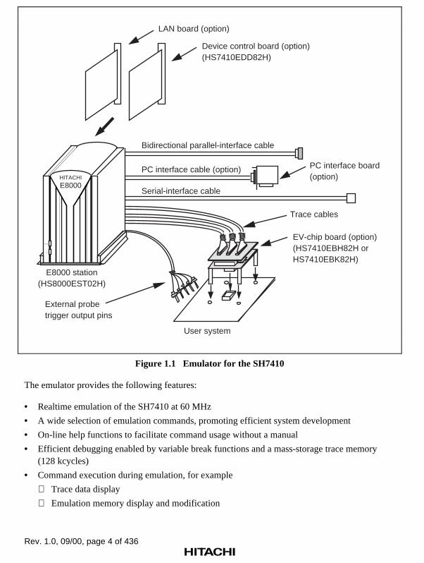
The emulator consists of an emulator (E8000) station, an SH7410 device control board, and anevaluation chip board (hereafter referred to as an EV-chip board), as shown in figure 1.1. The EV-chip board is directly installed onto the user system.
Rev. 1.0, 09/00, page 4 of 436
External probetrigger output pins
User system
Trace cables
EV-chip board (option)(HS7410EBH82H orHS7410EBK82H)
E8000 station(HS8000EST02H)
Bidirectional parallel-interface cable
Serial-interface cable
PC interface board (option)
PC interface cable (option)
LAN board (option)
Device control board (option)(HS7410EDD82H)
HITACHI
E8000
POWER
RUN
Figure 1.1 Emulator for the SH7410
The emulator provides the following features:
• Realtime emulation of the SH7410 at 60 MHz
• A wide selection of emulation commands, promoting efficient system development
• On-line help functions to facilitate command usage without a manual
• Efficient debugging enabled by variable break functions and a mass-storage trace memory(128 kcycles)
• Command execution during emulation, for example
Trace data display
Emulation memory display and modification

Rev. 1.0, 09/00, page 5 of 436
• Measurement of subroutine execution time and count for evaluating the execution efficiencyof user programs
• 4-Mbyte standard emulation memory for use as a substitute user-system memory
• An optional LAN board for interfacing with workstations, enabling high-speed downloading(1 Mbyte/min) of user programs
The LAN board contains Ethernet* (10BASE5) and Cheapernet (10BASE2) interfaces.
• SH7410 Integration Manager (option) can be loaded into the workstation to enable:
Graphic display operations in a multi-window environment
Source level debugging
Graphic display of trace information
• A PC board for interfacing with a PC, enabling high-speed downloading (1 Mbyte/min) ofuser programs
• SH7410 E8000 Hitachi Debugging Interface (option) can be loaded into the PC to enable:
Graphic display operations in a multi-window environment
Source-level debugging
Note: Ethernet is a registered trademark of Xerox Corporation.

Rev. 1.0, 09/00, page 6 of 436
1.2 Warnings
CAUTIONREAD the following warnings before using the emulator
product. Incorrect operation will damage the user system andthe emulator product. The USER PROGRAM will be LOST.
1. Check all components with the component list after unpacking the emulator.
2. Never place heavy objects on the casing.
3. Observe the following conditions in the area where the emulator is to be used:
Make sure that the internal cooling fans on the sides of the E8000 station must be at least20 cm (8”) away from walls or other equipment.
Keep out of direct sunlight or heat. Refer to section 1.3, Environmental Conditions.
Use in an environment with constant temperature and humidity.
Protect the emulator from dust.
Avoid subjecting the emulator to excessive vibration. Refer to section 1.3, EnvironmentalConditions.
4. Protect the emulator from excessive impacts and stresses.
5. Before using the emulator’s power supply, check its specifications such as power output,voltage, and frequency. For details of the power supply, refer to section 1.3, EnvironmentalConditions.
6. When moving the emulator, take care not to vibrate or otherwise damage it.
7. After connecting the cable, check that it is connected correctly. For details, refer to section 3,Preparation before Use.
8. Supply power to the emulator and connected parts after connecting all cables. Cables must notbe connected or removed while the power is on.
9. For details on differences between the SH7410 and the emulator, refer to section 2,Differences between the SH7410 and the Emulator in Part II, Emulator Function Guide.

Rev. 1.0, 09/00, page 7 of 436
1.3 Environmental Conditions
CAUTIONThe following environmental conditions must be satisfied
when using the emulator. Failure to do so will damage the usersystem and the emulator. The USER PROGRAM will be LOST.
Observe the conditions listed in table 1.1 when using the emulator.
Table 1.1 Environmental Conditions
Item Specifications
Temperature Operating: +10 to +35°C
Storage: –10 to +50°C
Humidity Operating: 35 to 80% RH, no condensation
Storage: 35 to 80% RH, no condensation
Vibration Operating: 2.45 m/s2 max.
Storage: 4.9 m/s2 max.
Transportation: 14.7 m/s2 max.
AC input power Voltage: AC100-120 V/200-240 V ± 10%
Frequency: 50/60 Hz
Power consumption: 200 VA
Ambient gases There must be no corrosive gases present.

Rev. 1.0, 09/00, page 8 of 436
1.4 Components
The emulator consists of the E8000 station, device control board, and EV-chip board. Check allcomponents after unpacking. If any component is missing, contact the sales office from which theemulator was purchased.
1.4.1 E8000 Emulator Station
Table 1.2 lists the E8000 station components.
Table 1.2 E8000 Station Components
Classification Item Quantity Remarks
Hardware E8000 station 1 Power supply, control board,and trace board are installed.
Trace cable 3 Length: 50 cm
AC power cable 1 UL cable or B5 cable
Serial cable 1 RS-232C interface
Parallel cable 1 Conforms to IEEE-P1284.
Fuse 1 Spare (3 A or T3.15Acorresponding to CE marking )
1.4.2 SH7410 Device Control Board and EV-Chip Board
Table 1.3 lists the device control board and EV-chip board components. For details, refer to eachusers manual.
Table 1.3 Device Control Board and EV-Chip Board Components
Classification Item Quantity Remarks
Hardware Device control board 1 One board, installed in theE8000 station
EV-chip board 1 Two boards, installed in theuser system
Software 3.5-inch floppy disk 1 E8000 system program

Rev. 1.0, 09/00, page 9 of 436
1.4.3 Options
In addition to the E8000 station and EV-chip board components, the options listed in table 1.4 arealso available. Refer to each option manual for details on these optional components.
Table 1.4 Optional Component Specifications
Item Model Name Specifications
LAN board HS7000ELN01H
HS7000ELN02H
• TCP/IP communications protocol
• Ethernet (10BASE5)
• Cheapernet (10BASE2)
PC interface board HS6000EII01H ISA bus

Rev. 1.0, 09/00, page 10 of 436

Rev. 1.0, 09/00, page 11 of 436
Section 2 Components
2.1 Emulator Hardware Components
The emulator consists of an E8000 station, an SH7410 device control board, and an SH7410 EV-chip board, as shown in figure 2.1. The emulator station includes a serial-interface cable (RS-232C) and a parallel-interface cable (conforms to IEEE-P1284 and is for the ECP mode) for thehost computer interface. By installing a LAN board (option), the emulator can be connected to aworkstation via the LAN interface. By installing a PC interface board (option) to a PC to be used,the emulator can be connected to the PC via the ISA bus.
External probetrigger output pins
User system
Trace cables
E8000 station(HS8000EST02H)
EV-chip board (option)(HS7410EBH82H orHS7410EBK82H)
Bidirectional parallel-interface cable
Serial-interface cable
PC interface board (option)
PC interface cable (option)
LAN board (option)
Device control board (option)(HS7410EDD82H)
HITACHI
E8000
POWER
RUN
Figure 2.1 Emulator Hardware Components

Rev. 1.0, 09/00, page 12 of 436
2.1.1 E8000 Station Components
Front Panel:
POWER1
2
E8000HITACHI
RUN
Figure 2.2 E8000 Station Front Panel
1. POWER lamp: Is lit up when the E8000 station power is on.
2. RUN lamp: Is lit up when the user program is running.
Rev. 1.0, 09/00, page 13 of 436
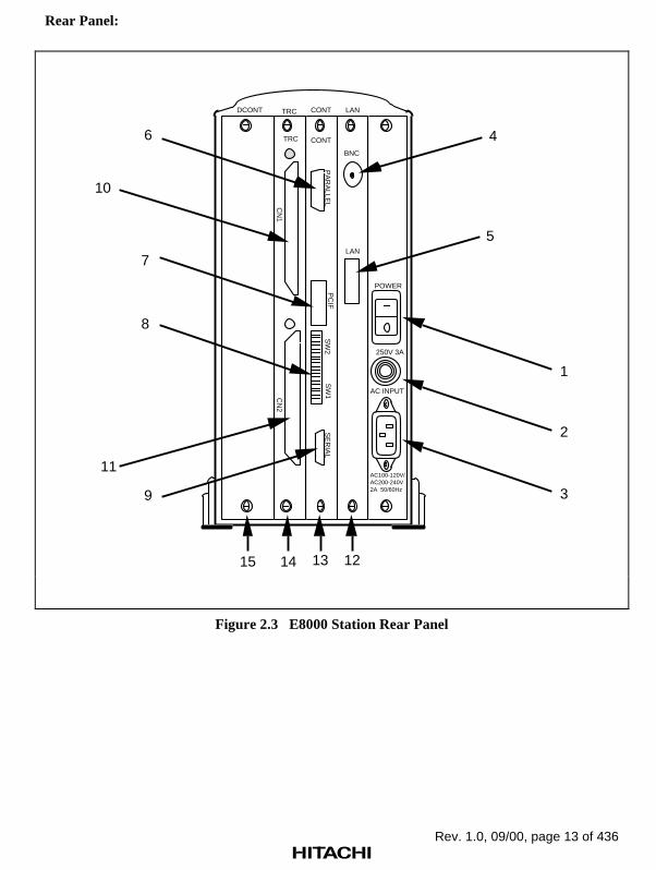
Rear Panel:
LAN
POWER
250V 3A
AC INPUT
DCONT CONTTRC
BNC
PA
RA
LLEL
LAN
AC100-120V/AC200-240V2A 50/60Hz
SE
RIA
L
CN
1C
N2
SW
2S
W1
TRC CONT
PC
IF8
1
2
3
4
5
6
7
9
11
121315 14
10
Figure 2.3 E8000 Station Rear Panel
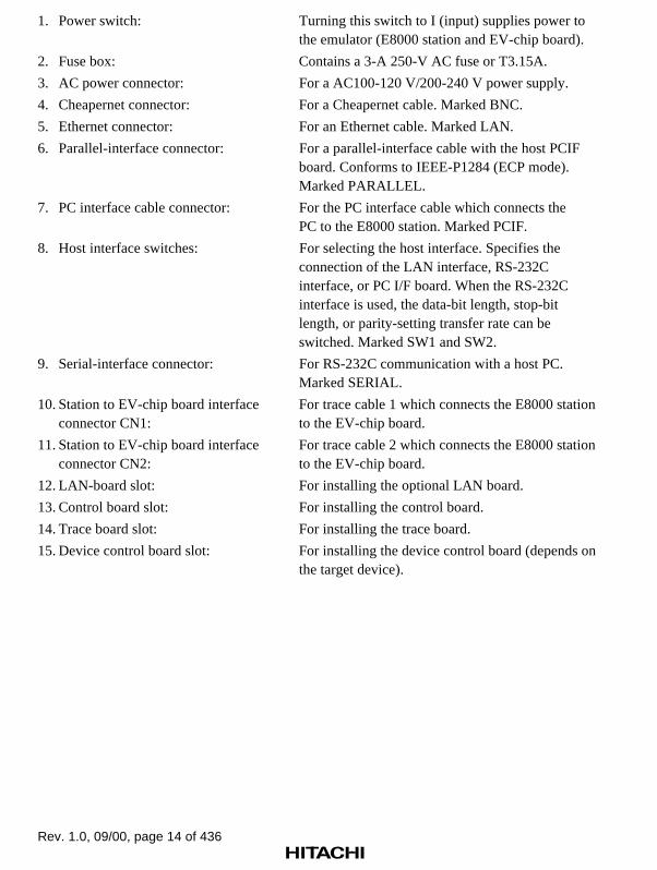
Rev. 1.0, 09/00, page 14 of 436
1. Power switch: Turning this switch to I (input) supplies power tothe emulator (E8000 station and EV-chip board).
2. Fuse box: Contains a 3-A 250-V AC fuse or T3.15A.
3. AC power connector: For a AC100-120 V/200-240 V power supply.
4. Cheapernet connector: For a Cheapernet cable. Marked BNC.
5. Ethernet connector: For an Ethernet cable. Marked LAN.
6. Parallel-interface connector: For a parallel-interface cable with the host PCIFboard. Conforms to IEEE-P1284 (ECP mode).Marked PARALLEL.
7. PC interface cable connector: For the PC interface cable which connects thePC to the E8000 station. Marked PCIF.
8. Host interface switches: For selecting the host interface. Specifies theconnection of the LAN interface, RS-232Cinterface, or PC I/F board. When the RS-232Cinterface is used, the data-bit length, stop-bitlength, or parity-setting transfer rate can beswitched. Marked SW1 and SW2.
9. Serial-interface connector: For RS-232C communication with a host PC.Marked SERIAL.
10. Station to EV-chip board interface For trace cable 1 which connects the E8000 stationconnector CN1: to the EV-chip board.
11. Station to EV-chip board interface For trace cable 2 which connects the E8000 stationconnector CN2: to the EV-chip board.
12. LAN-board slot: For installing the optional LAN board.
13. Control board slot: For installing the control board.
14. Trace board slot: For installing the trace board.
15. Device control board slot: For installing the device control board (depends onthe target device).
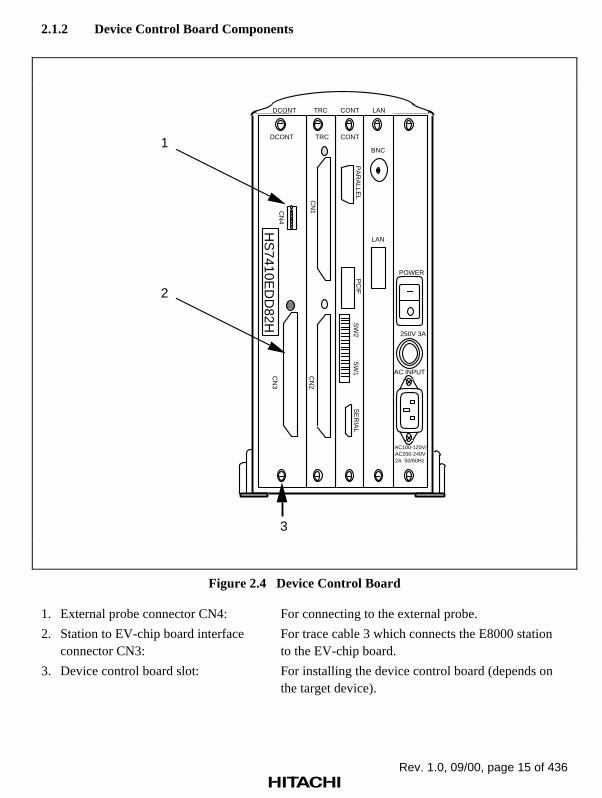
Rev. 1.0, 09/00, page 15 of 436
2.1.2 Device Control Board Components
1
2
3
LAN
POWER
250V 3A
AC INPUT
CN
4
DCONT CONTTRC
BNC
PA
RA
LLEL
LAN
AC100-120V/AC200-240V2A 50/60Hz
SE
RIA
L
CN
1C
N2
CN
3
SW
2S
W1
TRCDCONT CONT
PC
IF
HS
7410ED
D82H
Figure 2.4 Device Control Board
1. External probe connector CN4: For connecting to the external probe.
2. Station to EV-chip board interface For trace cable 3 which connects the E8000 stationconnector CN3: to the EV-chip board.
3. Device control board slot: For installing the device control board (depends onthe target device).

Rev. 1.0, 09/00, page 16 of 436
2.1.3 EV-Chip Board Components
5
Bottom viewPin-1 mark
Side view
7
8
6
Station to EV-chip boardinterface connectors
CN3
CN2
CN1
X0 X1
1
2
34
Top view
X0 X1
Figure 2.5 EV-Chip Board (HS7410EBH82H) *1
1. Station to EV-chip board interface For trace cable 3 which connects the emulator toconnector CN3: the EV-chip board.
2. Station to EV-chip board interface For trace cable 2 which connects the emulator toconnector CN2: the EV-chip board.
3. Station to EV-chip board interface For trace cable 1 which connects the emulator toconnector CN1: the EV-chip board.
4. Crystal oscillator terminals: For installing a crystal oscillator to be used asan external clock source for the SH7410.
5. User-system connector: For connecting the user system.
6. Board connector: For connecting HS7410PWB20H andHS7410PWB30H.
7. HS7410PWB20H: Includes connectors for interfacing with theE8000 station.
8. HS7410PWB30H Includes connectors (QFP-176) for interfacing with(or HS7410PWB40H*2): the user system.

Rev. 1.0, 09/00, page 17 of 436
Notes: 1. For the EV-chip board, there are a QFP176 IC socket type (HS7410EBH82H) anda two 100-pin connector type (HS7410EBK82H), which can be selected inaccordance with the user application.
2. The HS7410PWB40H has a connector (2 x 100-pin) to be connected to the usersystem.

Rev. 1.0, 09/00, page 18 of 436
2.2 Emulator Software Components
The emulator’s software components are illustrated in figure 2.6. The device control boardcontains a 3.5-inch floppy disk. The system disk files are described in table 2.1.
Interface software
C compilerCross assemblerLinkage editor
E8000 system program
Loadable file types:¥ S-type files¥ HEX-type files¥ SYSROF-type files
Personal computer
HITACHIE8000
POWER
RUN
Figure 2.6 Emulator Software Components
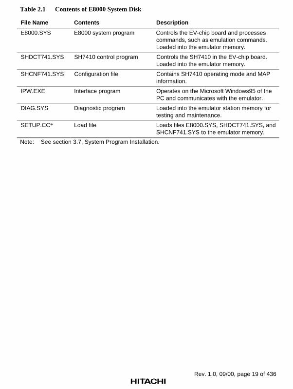
Rev. 1.0, 09/00, page 19 of 436
Table 2.1 Contents of E8000 System Disk
File Name Contents Description
E8000.SYS E8000 system program Controls the EV-chip board and processescommands, such as emulation commands.Loaded into the emulator memory.
SHDCT741.SYS SH7410 control program Controls the SH7410 in the EV-chip board.Loaded into the emulator memory.
SHCNF741.SYS Configuration file Contains SH7410 operating mode and MAPinformation.
IPW.EXE Interface program Operates on the Microsoft Windows95 of thePC and communicates with the emulator.
DIAG.SYS Diagnostic program Loaded into the emulator station memory fortesting and maintenance.
SETUP.CC* Load file Loads files E8000.SYS, SHDCT741.SYS, andSHCNF741.SYS to the emulator memory.
Note: See section 3.7, System Program Installation.

Rev. 1.0, 09/00, page 20 of 436
2.3 System Configuration
The E8000 station can be connected to the host computer via a LAN interface (optional LANboard), an RS-232C interface, a bidirectional parallel interface, or a PC interface board.
2.3.1 System Configuration Using a LAN Interface
By installing an optional LAN board in the E8000 station, the emulator can communicate with aworkstation using a LAN interface. The LAN board contains connectors for both Cheapernet(10BASE2) and Ethernet (10BASE5). The system configuration using a LAN interface is shownin figure 2.7.
E8000station
LAN
BNC
Workstation
Cheapernet Interface
E8000station
LAN
BNC
Workstation
Ethernet Interface
Figure 2.7 System Configuration Using a LAN Interface
Cheapernet Interface: This is achieved by connecting a coaxial cable (referred to as theCheapernet thin-wire cable) between the BNC connector on the LAN board and the workstation.
Ethernet Interface: This is achieved by connecting transceivers and transceiver cables betweenthe D-SUB connector on the LAN board and the workstation.
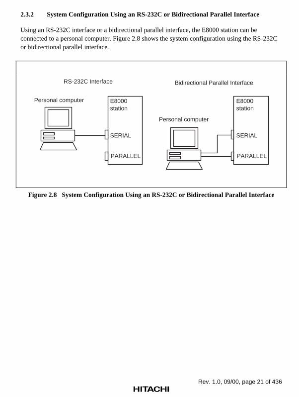
Rev. 1.0, 09/00, page 21 of 436
2.3.2 System Configuration Using an RS-232C or Bidirectional Parallel Interface
Using an RS-232C interface or a bidirectional parallel interface, the E8000 station can beconnected to a personal computer. Figure 2.8 shows the system configuration using the RS-232Cor bidirectional parallel interface.
Personal computer
RS-232C Interface Bidirectional Parallel Interface
E8000station
PARALLEL
SERIAL
Personal computer
E8000station
PARALLEL
SERIAL
Figure 2.8 System Configuration Using an RS-232C or Bidirectional Parallel Interface

Rev. 1.0, 09/00, page 22 of 436
2.3.3 System Configuration Using a PC Interface Board
The E8000 station can be connected to a personal computer via a PC interface board. Install thePC interface board to the extension slot of the ISA bus specification in a PC, and connect theinterface cable supplied with the PC interface board to the E8000 station. Figure 2.9 shows thesystem configuration using the PC interface board.
E8000 station
PCIF
Personal computer
PC interface board
Figure 2.9 System Configuration Using a PC Interface Board

Rev. 1.0, 09/00, page 23 of 436
Section 3 Preparation before Use
3.1 Emulator Preparation
CAUTIONRead the reference sections shaded in figure 3.1 and the
following warnings before using the emulator. Incorrect operationwill damage the user system and the emulator. The USERPROGRAM will be LOST.
Unpack the emulator and prepare it for use as follows:

Rev. 1.0, 09/00, page 24 of 436
Check the components against the component list.
Connect the user system and the EV-chip board.
Connect the E8000 stationand the EV-chip board.
Connect the external probe.
Select the clock.(Install the crystal oscillator.)
Connect the system ground.
Power on.
Reference:
Component list
Sec. 3.2.2
Connect the E8000 station and the device control board. Sec. 3.2.1
Sec. 3.2.3
Sec. 3.2.4
Sec. 3.2.5
Sec. 3.3.2
Sec. 3.3
Sec. 3.3.2
Sec. 3.3.3
Sec. 3.3.4
Sec. 3.3
Sec. 3.3.7
Sec. 3.3
When the LAN interface is used.When the PC interface board is used.
When the RS-232C interface cable or/and bidirectional parallel interface cable is used.
Set the console interface switch.
Set the console interface switch.
Set the console interface switch.
Connect the LAN interface cable.
Set the PC interface board switch.
Install the PC interface board.
Connect the PC interface cable.
Connect the RS-232C interface cable or/and bidirectional parallel interface cable.
Unpack the emulator.
Figure 3.1 Emulator Preparation Flow Chart

Rev. 1.0, 09/00, page 25 of 436
3.2 Emulator Connection
3.2.1 Connecting the Device Control Board
At shipment, the device control board is packed separately from the E8000 station. Connect thedevice control board to the E8000 station according to the following procedure. Also, use thefollowing procedure to connect them after remove the device control board from the E8000station to change the device control board.
WARNINGAlways switch OFF the emulator and user system before
connecting or disconnecting any CABLES. Failure to do so willresult in a FIRE HAZARD and will damage the user system andthe emulator or will result in PERSONAL INJURY. The USERPROGRAM will be LOST.
1. Check that the emulator power switch is turned off. Ensure that the power lamp on the left sideof the E8000 station’s front panel is not lit.
2. Remove the AC power cable of the E8000 station from the outlet (if the cable is connected tothe outlet).
3. Remove the back panel from the E8000 station. For the slot to which the device control boardis to be connected, DCONT is marked.
4. Connect the device control board to the E8000 station. When connecting the board, preventthe upper or lower side of the board from lifting off the connector. Alternately tighten thescrews on both sides of the board.

Rev. 1.0, 09/00, page 26 of 436
E8000 station rear panel
Device control board
LAN
POWER
250V 3A
AC INPUT
DCONT CONTTRC
PA
RA
LLEL
AC100-120V/
AC200-240V
2A 50/60Hz
SE
RIA
LS
W2
SW
1
CONT
PC
IF
CN
1C
N2
CN
4
CN
3
DCONT
HS
7410ED
D82H
TRC
Figure 3.2 Connecting the Device Control Board

Rev. 1.0, 09/00, page 27 of 436
3.2.2 Connecting the EV-Chip Board
At shipment, the EV-chip board is packed separately from the E8000 station. Use the followingprocedure to connect the EV-chip board to the E8000 station, or to disconnect them when movingthe emulator:
WARNINGAlways switch OFF the emulator and user system before
connecting or disconnecting any CABLES. Failure to do so willresult in a FIRE HAZARD and will damage the user system andthe emulator or will result in PERSONAL INJURY. The USERPROGRAM will be LOST.
1. Check that the emulator power switch is turned off. Ensure that the power lamp on the left sideof the E8000 station’s front panel is not lit.
2. Remove the AC power cable of the E8000 station from the outlet (if the cable is connected tothe outlet).

Rev. 1.0, 09/00, page 28 of 436
WARNINGWhen connecting the cable, ensure that the upper (A) or
lower (B) side of the cable does not lift off the connector. Alternately tighten the screws on both sides of the cable whilegradually pushing the cable toward the connector.Failure to do so will result in a FIRE HAZARD, damage the usersystem and emulator, and will result in PERSONAL INJURY.The USER PROGRAM will be LOST.
E8000 station
E8000 station
A
B
A
B
3. Connect the trace cables into the station to EV-chip board interface connectors (CN1, CN2,and CN3) on the E8000 station’s rear panel. Confirm that the shape of the trace-cable plugmatches that of the station to EV-chip board interface connector before connecting. Also notewhich trace cable is connected to which E8000-station connector so that the other end of thetrace cable is connected to the matching connector number on the EV-chip board. After theconnection is completed, alternately tighten the screws on both sides of the trace cable toprevent the upper or lower side of the trace cable from lifting off the connector. Figure 3.3shows how to correctly connect the trace cables to the E8000 station connectors.
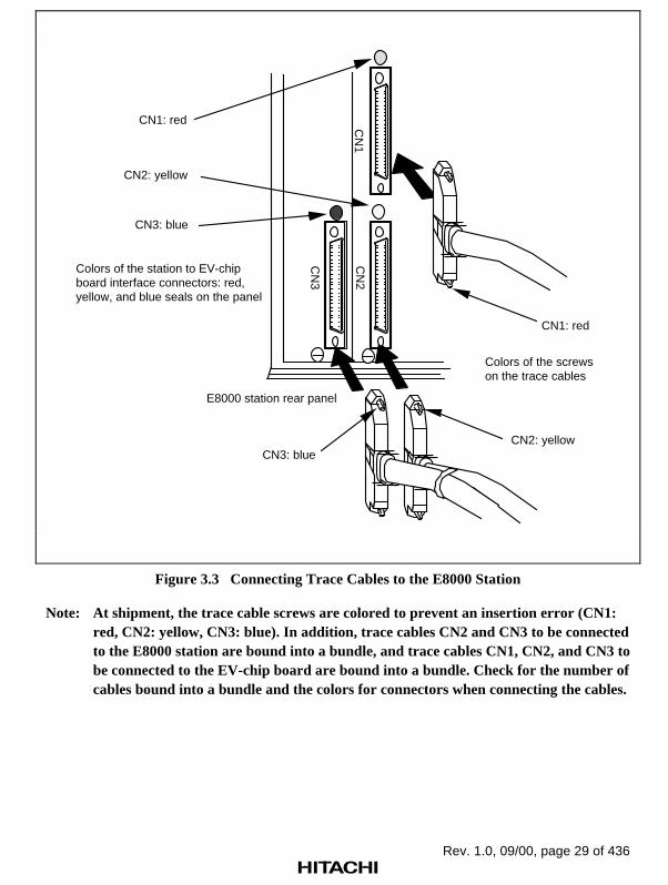
Rev. 1.0, 09/00, page 29 of 436
E8000 station rear panel
CN
1
CN
3
CN
2
CN1: red
CN2: yellow
CN3: blue
CN1: red
CN2: yellow CN3: blue
Colors of the station to EV-chipboard interface connectors: red,yellow, and blue seals on the panel
Colors of the screws on the trace cables
Figure 3.3 Connecting Trace Cables to the E8000 Station
Note: At shipment, the trace cable screws are colored to prevent an insertion error (CN1:red, CN2: yellow, CN3: blue). In addition, trace cables CN2 and CN3 to be connectedto the E8000 station are bound into a bundle, and trace cables CN1, CN2, and CN3 tobe connected to the EV-chip board are bound into a bundle. Check for the number ofcables bound into a bundle and the colors for connectors when connecting the cables.

Rev. 1.0, 09/00, page 30 of 436
WARNINGMake sure the connector shapes and numbers are correctly
matched when connecting trace cables to the station to EV-chipinterface connectors. Failure to do so will damage the connectors.
4. Connect the trace cables to the station to EV-chip board interface connectors CN1, CN2, andCN3 on the EV-chip board. Confirm that each trace cable connected to a connector on theE8000 station is also connected to its corresponding station to EV-chip board interfaceconnector on the EV-chip board. Connect the cables using the same method as in step 3.Figure 3.4 shows how to connect the trace cables to the EV-chip board interface connectors.
Station to EV-chip boardinterface connector CN1
User systemStation to EV-chip boardinterface connector CN2
Station to EV-chip boardinterface connector CN3
Trace cable CN1
Trace cable CN2
Trace cable CN3
CN3
CN2CN1
CN3: blue
CN2: yellow
CN1: red
Figure 3.4 Connecting Trace Cables to the EV-Chip Board
Note: For the connection between the EV-chip board and the user system, refer to section3, Connecting the EV-Chip Board to the User System, in the Evaluation Chip Board(HS7410EBH82H, HS7410EBK82H) User’s Manual.

Rev. 1.0, 09/00, page 31 of 436
3.2.3 Connecting the External Probe
CAUTIONCheck the external probe direction and connect the external
probe to the emulator station correctly. Incorrect connection willdamage the probe or connector.
When an external probe is connected to the emulator probe connector on the emulator station’srear panel, it enables external signal tracing and multibreak detection. Figure 3.5 shows theexternal probe connector.
Probe input 0
RUN state identification output pin
Probe input 1
Probe input 2
Probe input 3
1
2
3
4
5
Signal Name
Trigger output
Remarks
Synchronous break input pin
Trigger mode output pin
RUN/break status signal
GND
T
G
G
External probeconnector
External probe
Pin 1Pin 2
Pin 4Pin 3
Pin 5Pin 6Pin 7Pin 8
Enlarged view
CN
4
Probe Name
1
2
3
4
5
6
7
8
LAN
POWER
250V 3A
AC INPUT
CN
4
DCONT CONTTRC
BNC
PA
RA
LLEL
LAN
AC100-120V/AC200-240V2A 50/60Hz
SE
RIA
L
CN
1C
N2
CN
3
SW
2S
W1
TRCDCONT CONT
PC
IF
HS
7410ED
D82H
GND connection pin
Pin No.
Figure 3.5 External Probe Connector

Rev. 1.0, 09/00, page 32 of 436
3.2.4 Selecting the Clock
This emulator supports three types of clock for the SH7410: a crystal oscillator attached on theEV-chip board, external clock input from the user system, and the emulator internal clock. Theclock is specified with the CLOCK command.
This emulator can use a clock source of up to 60 MHz (quadruple of external clock frequency 15MHz) as the SH7410 clock input.
CLOCK command
X (Crystal oscillator: 8 to 15 MHz)
U (External clock: 1 to 33 MHz)
E (Emulator internal clock: 15 MHz)
Crystal Oscillator: A crystal oscillator is not supplied with the emulator. Use one that has thesame frequency as that of the user system. When using a crystal oscillator as the SH7410 clocksource, the frequency must be from 8 to 15 MHz. When using frequencies outside this range,supply an external clock from the user system.
WARNINGAlways switch OFF the emulator and user system before
connecting or disconnecting the CRYSTAL OSCILLATOR.Failure to do so will result in a FIRE HAZARD and will damagethe user system and emulator or will result in PERSONALINJURY. The USER PROGRAM will be LOST.
Use the following procedure to install the crystal oscillator:
1. Check that the emulator power switch is turned off. Ensure that the power lamp on the left sideof the E8000 station’s front panel is not lit.
2. Attach the crystal oscillator into the terminals on the EV-chip board (figure 3.6).
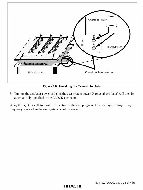
Rev. 1.0, 09/00, page 33 of 436
X1
X0
HIT
AC
HI
Crystal oscillator
Enlarged view
Crystal oscillator terminalsEV-chip board
Figure 3.6 Installing the Crystal Oscillator
3. Turn on the emulator power and then the user system power. X (crystal oscillator) will then beautomatically specified in the CLOCK command.
Using the crystal oscillator enables execution of the user program at the user system’s operatingfrequency, even when the user system is not connected.

Rev. 1.0, 09/00, page 34 of 436
External Clock: Use the following procedure to select the external clock.
WARNINGAlways switch OFF the emulator and user system before
connecting or disconnecting the EV-CHIP BOARD and the USERSYSTEM. Failure to do so will result in a FIRE HAZARD and willdamage the user system and the emulator or will result inPERSONAL INJURY. The USER PROGRAM will be LOST.
1. Check that the emulator power switch is turned off. Ensure that the power lamp on the left sideof the E8000 station’s front panel is not lit.
2. Connect the EV-chip board to the user system and supply a clock through the EXTAL pinfrom the user system.
3. Turn on the emulator power and then the user system power. U (external clock) will then beautomatically specified in the CLOCK command.
Emulator Internal Clock: Specify E (15 MHz) with the CLOCK command.
Reference:
When the emulator system program is initiated, the emulator automatically selects the SH7410clock source according to the following priority:
1. External clock when supplied from the user system
2. Crystal oscillator when attached to the EV-chip board
3. 15-MHz emulator internal clock

Rev. 1.0, 09/00, page 35 of 436
3.2.5 Connecting the System Ground
The emulator’s signal ground is connected to the user system’s signal ground via the EV-chipboard. In the E8000 station, the signal ground and frame ground are connected (figure 3.7). At theuser system, connect the frame ground only; do not connect the signal ground to the frameground.
E8000 station
Logic
Powersupply
Frame ground
Ground
Signal ground
EV-chip board
Signal line
User system
Figure 3.7 Connecting the System Ground
If it is difficult to separate the signal ground from the frame ground, insert the user system powercable and the emulator’s power cable into the same outlet (figure 3.8) so that the ground lines ofthe cables are maintained at the same ground potential.
The user system must be connected to an appropriate ground so as to minimize noise and theadverse effects of ground loops. When connecting the EV-chip board and the user system,confirm that the ground pins of the EV-chip board are firmly connected to the user system’sground.

Rev. 1.0, 09/00, page 36 of 436
Emulator power cable
User system power cable
GroundOutlet
100/120-V AC power
Figure 3.8 Connecting the Frame Ground
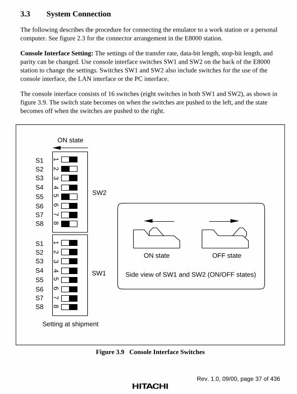
Rev. 1.0, 09/00, page 37 of 436
3.3 System Connection
The following describes the procedure for connecting the emulator to a work station or a personalcomputer. See figure 2.3 for the connector arrangement in the E8000 station.
Console Interface Setting: The settings of the transfer rate, data-bit length, stop-bit length, andparity can be changed. Use console interface switches SW1 and SW2 on the back of the E8000station to change the settings. Switches SW1 and SW2 also include switches for the use of theconsole interface, the LAN interface or the PC interface.
The console interface consists of 16 switches (eight switches in both SW1 and SW2), as shown infigure 3.9. The switch state becomes on when the switches are pushed to the left, and the statebecomes off when the switches are pushed to the right.
SW2
12
34
56
78
12
34
56
78
SW1
OFF stateON state
Side view of SW1 and SW2 (ON/OFF states)
S1S2S3S4S5S6S7S8
S1S2S3S4S5S6S7S8
ON state
Setting at shipment
Figure 3.9 Console Interface Switches

Rev. 1.0, 09/00, page 38 of 436
To change the console interface settings, turn switches S1 to S8 on or off in the console interfaceswitches SW1 and SW2. Table 3.1 lists the console interface settings and the correspondingsetting states.
Note: Be sure to turn off the power supply before changing the settings of console interfaceswitches SW1 and SW2.
Table 3.1 Console Interface Settings *1
Transfer Rate (SW2) S3 S2 S1
2400 BPS OFF OFF OFF
4800 BPS OFF OFF ON
9600 BPS OFF ON OFF (Setting at shipment)
19200 BPS OFF ON ON
38400 BPS ON OFF OFF
Stop-bit Length (SW2) S4
1 bit OFF (Setting at shipment)
2 bits ON
Bit Length (SW2) S5
7 bits OFF
8 bits ON (Setting at shipment)
Parity (SW2) S6
None OFF (Setting at shipment)
Parity ON
Even/odd Parity (SW2) S7
1 bit OFF (Setting at shipment)
2 bits ON
Note: Effective only when there is a parity.
Flow Control (Protocol) (SW2) S8
CTS, RTS OFF
X-ON/OFF ON (Setting at shipment)

Rev. 1.0, 09/00, page 39 of 436
Automatic System ProgramInitiation (Quit & Warm Start) (SW1) S4
NO OFF (Setting at shipment)
YES ON
Console/LAN/PC Interface (SW1) *2 S7 S8
Console OFF OFF (Setting at shipment)
LAN OFF ON
PC interface board ON ON
Notes: 1. Switches S1, S2, S3, S5, and S6 of SW1 are not used. Use these switches with the offstate. Console interface settings must be performed before the E8000 station power isturned on.
2. If the settings of the console interface (S7 and S8 of SW1) are incorrect, the initiation ofthe E8000 station cannot be confirmed on the screen. After turning off the E8000station power, correct the interface settings. See section 3.5, Power-On Procedure forEmulator.

Rev. 1.0, 09/00, page 40 of 436
3.3.1 PC Interface Board Specifications
Table 3.2 lists the PC interface board specifications.
Table 3.2 PC Interface Board Specifications
Item Specifications
Available personal computer ISA-bus specification PC, or compatible machine
System bus ISA-bus specification
Memory area 16 kbytes
Memory area setting Can be set at every 16 kbytes in the range from H'C0000 toH'EFFFF with a switch.

Rev. 1.0, 09/00, page 41 of 436
3.3.2 Switch Settings of the PC Interface Board
Memory-area Setting: The PC interface board uses a 16-kbyte memory area on the PC. Thememory area to be used must be allocated to the memory area on the PC with a switch on the PCinterface board. Any 16 kbytes in the range of H'C0000 to H'EFFFF can be allocated (figure3.10). Addresses to be allocated must not overlap the memory addresses of other boards. Anoverlap will cause incorrect operation.
H'C0000
H'C4000
H'C8000
H'CC000
H'D0000
H'D4000
H'D8000
H'DC000
H'E0000
H'E4000
H'E8000
H'EC000
H'EFFFF
(Setting at shipment)
Figure 3.10 Allocatable Memory Area of PC Interface Board

Rev. 1.0, 09/00, page 42 of 436
Switch Setting: A rotary switch is installed on the PC interface board (figure 3.11). The switch isused to set the memory-area allocation. Table 3.3 lists the switch setting states. The switch settingat emulator shipment is No. 4 (memory area H'D0000 to H'D3FFF).
PC interface board
SW
1
Rotary switch
01
2 3 4 5 67
89
ABCD
F
Enlarged front view
Figure 3.11 PC Interface Board Switch
Table 3.3 Switch Settings for Memory Areas
Switch Setting Memory AreaSwitchSetting Memory Area
0 H'C0000 to H'C3FFF 8 H'E0000 to H'E3FFF
1 H'C4000 to H'C7FFF 9 H'E4000 to H'E7FFF
2 H'C8000 to H'CBFFF A H'E8000 to H'EBFFF
3 H'CC000 to H'CFFFF B H'EC000 to H'EFFFF
4 (setting at shipment) H'D0000 to H'D3FFF C Not used
5 H'D4000 to H'D7FFF D Not used
6 H'D8000 to H'DBFFF E Not used
7 H'DC000 to H'DFFFF F Not used
Note: When C to F of the switch are set, memory areas cannot be allocated. Set one of 0 to B.
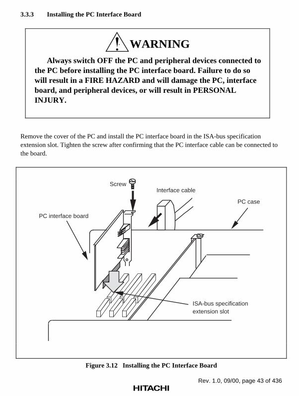
Rev. 1.0, 09/00, page 43 of 436
3.3.3 Installing the PC Interface Board
WARNINGAlways switch OFF the PC and peripheral devices connected to
the PC before installing the PC interface board. Failure to do sowill result in a FIRE HAZARD and will damage the PC, interfaceboard, and peripheral devices, or will result in PERSONALINJURY.
Remove the cover of the PC and install the PC interface board in the ISA-bus specificationextension slot. Tighten the screw after confirming that the PC interface cable can be connected tothe board.
PC case
PC interface board
Screw
ISA-bus specification extension slot
Interface cable
Figure 3.12 Installing the PC Interface Board

Rev. 1.0, 09/00, page 44 of 436
3.3.4 Connecting the E8000 Station to the PC Interface Board
WARNINGAlways switch OFF the emulator and user system before
connecting or disconnecting any CABLES. Failure to do so willresult in a FIRE HAZARD and will damage the user system andthe emulator, or will result in PERSONAL INJURY. The USERPROGRAM will be LOST.
Before using the emulator, connect the E8000 station to the PC interface board with the PCinterface cable supplied, as shown in figure 3.13.
PCPC interface board
PC interface cable
E8000 station rear panel
TRC
EML
LAN
POWER
250V 3A
AC INPUT
CONT
BNC
PA
RA
LLEL
LAN
AC100-120V/
AC200-240V
2A 50/60Hz
SE
RIA
L
CN
1
P4
CN
2
SW
2S
W1
TRC
DCONT
DCONT CONT
PC
IF
HS
7410ED
D82H
Figure 3.13 Connecting the E8000 Station to the PC Interface Board

Rev. 1.0, 09/00, page 45 of 436
3.3.5 Connecting to a Personal Computer
WARNINGAlways switch OFF the emulator and user system before
connecting or disconnecting any CABLES. Failure to do so willresult in a FIRE HAZARD and will damage the user system andthe emulator or will result in PERSONAL INJURY. The USERPROGRAM will be LOST.
This section describes how to set the personal computer interface when the emulator is connectedto a personal computer. The personal computer connector (marked SERIAL) is located on theE8000 station’s rear panel. Connecting this connector to a personal computer via the RS-232Cinterface cable enables data transfer between the emulator and the personal computer. Table 3.4lists the personal computer interface specifications.
The system program can be loaded to the E8000 station memory with the bidirectional parallelinterface. At this time, confirm that the printer driver is specified by the PC settings. Use apersonal computer to which the bidirectional parallel interface can be applied. See section 3.7,System Program Installation.
Table 3.4 Personal Computer Interface Specifications
Item Specifications
Signal level RS-232C
High: +5 to +15 V
Low: –5 to –15 V
Transfer rate 2400/4800/9600/19200/38400 bits per second (BPS)
Synchronization method Asynchronous method
Start-bit length 1 bit
Data-bit length 7/8 bits
Stop-bit length 1/2 bits
Parity Even/odd or none
Control method X-ON/X-OFF control, RTS/CTS control

Rev. 1.0, 09/00, page 46 of 436
Personal Computer Interface Settings at Emulator Start Up: When the emulator is turned on,or when the emulator system program is initiated, the personal computer interface settings aredetermined by the console interface switches in the same way as in the console interface (thecontrol method will be X-ON/X-OFF control).
Changing the Personal Computer Interface Settings: The transfer rate, data-bit length, stop-bitlength, parity, and control method can be changed with the console interface switch. For thepersonal computer connector pin assignments and signal names, refer to Appendix A, Connectors.
3.3.6 Connecting to a LAN Interface
WARNINGAlways switch OFF the emulator and user system before
connecting or disconnecting any CABLES. Failure to do so willresult in a FIRE HAZARD and will damage the user system andthe emulator or will result in PERSONAL INJURY. The USERPROGRAM will be LOST.
The LAN board for the emulator supports Ethernet (10BASE5) and Cheapernet (10BASE2)interfaces conforming to Ethernet specifications V.2.0. The LAN board communicates with aworkstation according to the TCP/IP protocol, and the workstation transfers files and commandsaccording to the FTP/TELNET protocol. The LAN board specifications at each layer of the OSImodel are as follows.
Physical and Data Link Layers: The LAN board communicates with Ethernet and Cheapernet.Table 3.5 shows the Ethernet and Cheapernet specifications.

Rev. 1.0, 09/00, page 47 of 436
Table 3.5 Ethernet and Cheapernet Specifications
Item Ethernet Cheapernet
Transfer rate 10 Mbits/second 10 Mbits/second
Maximum distancebetween segments
500 m 185 m
Maximum network length 2500 m 925 m
Maximum number ofnodes in one segment
100 30
Minimum distancebetween nodes
2.5 m 0.5 m
Network cable Diameter: 0.4 inch (1.02 cm)50-Ω shielded coaxial cable
Diameter: 0.25 inch (0.64 cm)50-Ω shielded coaxial cable(RG-58A/U)
Network connector N-type connector BNC connector
Transceiver cable Diameter: 0.38 inch (0.97 cm)Ethernet cable to be connectedto the 15-pin D-SUB connector
Network Layer:
• IP (Internet Protocol)
Transmits and receives data in datagram format.
Does not support IP options.
Does not have subnet mask functions when HS7000ELN01H is used. Supports subnetmask functions when HS7000ELN02H is used.
Does not support broadcast communications.
• ICMP (Internet Control Message Protocol)
Supports only echo reply functions.
• ARP (Address Resolution Protocol)
Calculates Ethernet addresses from IP addresses by using broadcast communications.
Transport Layer:
• TCP (Transmission Control Protocol)
Logically connects the emulator to the workstation.
• UDP (User Datagram Protocol)
Not supported.

Rev. 1.0, 09/00, page 48 of 436
Session, Presentation, and Application Layers:
• FTP (File Transfer Protocol)
The emulator operates as a client.
• TELNET (Teletype Network)
The emulator operates as a server.
Note: The emulator communicates through routers or gateways for the HS7000ELN02H,but not for the HS7000ELN01H.
3.3.7 System Connection Examples
WARNINGAlways switch OFF the emulator and user system before
connecting or disconnecting any CABLES. Failure to do so willresult in a FIRE HAZARD and will damage the user system andthe emulator or will result in PERSONAL INJURY. The USERPROGRAM will be LOST.
System configuration examples are shown below.
Ethernet Interface: The LAN board of the emulator has a 15-pin D-SUB connector for theEthernet transceiver cables. Figure 3.14 shows an example of the Ethernet system configuration.Use commercially available Ethernet transceivers and transceiver cables. Table 3.6 shows arecommended transceiver and transceiver cable.
Note: When using the LAN interface, refer to section 3.5.1, Power-On Procedure for LANInterface, and set the IP address.

Rev. 1.0, 09/00, page 49 of 436
Ethernet transceiver cables
Ethernet transceivers
Ethernet LAN board
Workstation
E8000 station rear panel
TRC LAN
POWER
250V 3A
AC INPUT
CONT
BNC
PA
RA
LLEL
LAN
AC100-120V/
AC200-240V2A 50/60Hz
SE
RIA
L
CN
1
P4
CN
3
CN
2
SW
2S
W1
TRC
DCONT
DCONT CONT
PC
IF
HS
7410ED
D82H
Figure 3.14 Ethernet Interface
Table 3.6 Recommended Transceiver and Transceiver Cable
Item Product Type Manufacturer
Transceiver HBN-200 series Hitachi Cable, Ltd.
Transceiver cable HBN-TC-100 Hitachi Cable, Ltd.
For setting up the Ethernet interface, refer to the LAN board user’s manual.

Rev. 1.0, 09/00, page 50 of 436
Cheapernet Interface: The LAN board of the emulator incorporates a transceiver and a BNCconnector for a Cheapernet interface. Figure 3.15 shows an example of the Cheapernet systemconfiguration. Use a commercially available Cheapernet BNC T-type connector with acharacteristic impedance of 50 Ω and a RG-58A/U thin-wire cable or its equivalent. Table 3.7shows a recommended BNC T-type connector and thin-wire cable.
Note: If a connector or a cable with a characteristic impedance other than 50 Ω is used, theimpedance mismatch will cause incorrect data transmission and reception.
LAN board
E8000 station rear panel
TRC LAN
POWER
250V 3A
AC INPUT
CONT
BNC
PA
RA
LLEL
LAN
AC100-120V/
AC200-240V2A 50/60Hz
SE
RIA
L
CN
1
P4
CN
3
CN
2
SW
2S
W1
TRC
DCONT
DCONT CONT
PC
IF
HS
7410ED
D82H
Cheapernet thin-wire cable
Workstation
Cheapernet BNC T-type connector
Figure 3.15 Cheapernet Interface
Table 3.7 Recommended BNC T-Type Connector and Thin-Wire Cable
Item Product Type Manufacturer
BNC T-type connector HBN-TA-JPJ Hitachi Cable, Ltd.
Thin-wire cable HBN-3D2V-LAN Hitachi Cable, Ltd.
For setting up Cheapernet, refer to the LAN board user’s manual.

Rev. 1.0, 09/00, page 51 of 436
RS-232C Interface: Figure 3.16 shows the E8000 station connected to the personal computer viaan RS-232C for a serial interface.
TRC LAN
POWER
250V 3A
AC INPUT
CONT
BNC
PA
RA
LLEL
LAN
AC100-120V/
AC200-240V2A 50/60Hz
SE
RIA
L
CN
1
P4
CN
3
CN
2
SW
2S
W1
TRC
DCONT
DCONT CONT
PC
IF
HS
7410ED
D82H
RS-232C interface cable (supplied)Personal computer E8000 station
Figure 3.16 RS-232C Interface

Rev. 1.0, 09/00, page 52 of 436
Parallel Interface: Figure 3.17 shows the E8000 station connected to a personal computer via aparallel cable for a parallel interface. When using the parallel interface, connect not only theparallel interface cable but also the RS-232C cable. It is impossible to use only the bidirectionalparallel interface cable. The parallel interface enables higher-speed installation of the systemprogram and higher-speed load, save, or verification of the user program as compared with theRS-232C interface.
TRC LAN
POWER
250V 3A
AC INPUT
CONT
BNC
PA
RA
LLEL
LAN
AC100-120V/
AC200-240V2A 50/60Hz
SE
RIA
L
CN
1
P4
CN
3
CN
2
SW
2S
W1
TRC
DCONT
DCONT CONT
PC
IF
HS
7410ED
D82H
E8000 station
Bidirectional parallel interface cable (supplied)
Personal computer
RS-232C interface cable (supplied)
Figure 3.17 Bidirectional Parallel Interface

Rev. 1.0, 09/00, page 53 of 436
3.4 Operation Procedures of Interface Software IPW
Interface software IPW is used when the emulator is connected to the host computer via the RS-232C interface. Interface software IPW runs on Microsoft Windows version 3.1 or Windows95.
3.4.1 Installation and Initiation of Interface Software IPW
Make a copy of file IPW.EXE in the system disk to a folder. The directory containing the copiedfolder will become the current directory. Double clicking the IPW icon initiates interface softwareIPW and displays the IPW window shown in figure 3.18.
Figure 3.18 IPW Window
Note: Microsoft and Windows are registered trademarks of Microsoft Corporation.
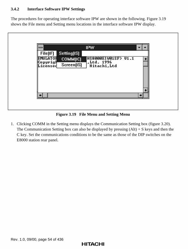
Rev. 1.0, 09/00, page 54 of 436
3.4.2 Interface Software IPW Settings
The procedures for operating interface software IPW are shown in the following. Figure 3.19shows the File menu and Setting menu locations in the interface software IPW display.
Figure 3.19 File Menu and Setting Menu
1. Clicking COMM in the Setting menu displays the Communication Setting box (figure 3.20).The Communication Setting box can also be displayed by pressing (Alt) + S keys and then theC key. Set the communications conditions to be the same as those of the DIP switches on theE8000 station rear panel.

Rev. 1.0, 09/00, page 55 of 436
Figure 3.20 Communication Setting Box
2. Selecting Screen in the Setting menu displays the Screen Setting box (figure 3.21). The ScreenSetting box can also be displayed by pressing (Alt) + S keys and then the S key.
Figure 3.21 Screen Setting Box
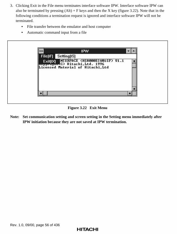
Rev. 1.0, 09/00, page 56 of 436
3. Clicking Exit in the File menu terminates interface software IPW. Interface software IPW canalso be terminated by pressing (Alt) + F keys and then the X key (figure 3.22). Note that in thefollowing conditions a termination request is ignored and interface software IPW will not beterminated.
• File transfer between the emulator and host computer
• Automatic command input from a file
Figure 3.22 Exit Menu
Note: Set communication setting and screen setting in the Setting menu immediately afterIPW initiation because they are not saved at IPW termination.

Rev. 1.0, 09/00, page 57 of 436
3.4.3 Debugging Support Functions
Interface software IPW supports the following two debugging functions.
• Automatic command input from a host computer file
• Logging acquisition
The start of automatic command input or start and end of logging acquisition can be specifiedwhen the emulator is in command input wait state (the emulator prompt is # or :).
Automatic Command Input: The file from which commands are to be input (command file) isspecified with < and <file name> when the emulator is in command input wait state. Do not inserta space between < and <file name>.
Example: :<FILENAME (RET)
Commands are sequentially read from the specified command file and transferred to the emulator.As in the following example, when the command file is specified, commands in that file aresequentially executed. Commands requiring further input, such as the MEMORY command, canbe read from a file and executed.
Example:
File contents:
f 1000000 103ffff 0;wm 1000000;1aaaaaaaa5555555512345678.d 1000000;1
Execution results:
:f 1000000 103ffff 0;1:m 1000000;1 01000000 00000000 ? aaaaaaaa 01000004 00000000 ? 55555555 01000008 00000000 ? 12345678 0100000C 00000000 ? .:d 1000000;1<ADDRESS> < D A T A > <ASCII CODE>01000000 AAAAAAAA 55555555 12345678 00000000 “....UUUU.4Vx....”01000010 00000000 00000000 00000000 00000000 “................”01000020 00000000 00000000 00000000 00000000 “................”
Rev. 1.0, 09/00, page 58 of 436
The command file reading does not terminate until the end of the file is detected, or the (CTRL) +C keys are pressed. If the (CTRL) + C keys are pressed, the command being executed isterminated and the message below is displayed. According to the input reply, command filereading is continued or terminated.
INTFC ERROR - STOP COMMAND CHAIN? (Y/N) : (a) (RET)
(a) Y: TerminateN: Continue
Logging: When logging acquisition is specified, not only are command inputs, execution results,and error messages afterwards the specification displayed on the console, but they are output tothe file specified with FILENAME.
Logging is specified with > and characters when the emulator is in command input wait state. Donot insert a space between > and characters.
• To overwrite FILENAME:
:>FILENAME (RET)
• To add to FILENAME:
:>>FILENAME (RET)
• To terminate logging to FILENAME:
:>- (RET)
To overwrite the existing file, enter Y when the following message is displayed.
INTFC ERROR - FILE ALREADY EXISTS
OVERWRITE? (Y/N) : (a) (RET)
(a) Y: Overwrites the existing file with the new fileN: Terminates command execution
Addresses during load, save, or verification cannot be logged.
Rev. 1.0, 09/00, page 59 of 436
3.5 Power-On Procedures for Emulator
The emulator power-on procedures differ in each system configuration. Power on the emulator inthe appropriate way for the system configuration, as shown below.
3.5.1 Power-On Procedures for LAN Interface
Figure 3.23 shows the power-on procedures when the LAN interface is used.

Rev. 1.0, 09/00, page 60 of 436
No
Yes
3. Power on the E8000 station.
4. Emulator monitor command input wait state
5. Select L to set the IP address of the E8000 station.
6. Define the subnet mask value with the flash memory management tool command SN (when using the LAN board (HS7000ELN02H)).
12. Execute the TELNET command on the host computer for connection to the emulator.
9. Turn off the E8000 station.
11. Power on the E8000 station.
1. Turn off (to the right) S7 and S8 in SW1 on the E8000 station rear panel.
10. Turn off (to the right) S7 and turn on (to the left) S8 in SW1 on the E8000 station rear panel.
8. Define the host computer name with the flash memory management tool command LH.
7. Define the routing information with the flash memory management tool command RTR (when using the LAN board (HS7000ELN02H)).
Test result OK?
2. Run interface software IPW.EXE on the host computer connected via the RS-232C interface.
14. Emulator monitor command input wait state
13. Initiation messages are displayed. Internal system test is executed.
14. Error message is displayed.
Figure 3.23 Power-On Procedures for LAN Interface
Rev. 1.0, 09/00, page 61 of 436
The following describes the power-on procedures when using the LAN interface.
1. Check that S7 and S8 in console interface switch SW1 on the E8000 station rear panel areturned off (to the right).
2. Run interface software IPW.EXE on the host computer connected to the emulator via the RS-232C interface.
3. Turn on the power switch at the E8000 station rear panel.
4. The emulator waits for an emulator monitor command.
5. Specify the emulator IP address.
The optional LAN board supports the TCP/IP protocol. When the host computer is connectedto the emulator via the LAN interface, the IP address (internet address) of the emulator mustbe specified with emulator monitor command L.
Press L and then the (RET) key. The set IP address is displayed. Make sure the IP address iscorrect. The 32-bit IP address, which is generally expressed in hexadecimal, is displayed infour bytes in decimal. For example, when the IP address has been specified as H'80010101 (H'represents hexadecimal), the emulator will display the IP address as follows and wait for a newIP address input.
: IP ADDRESS = 128.1.1.1 : _
Enter a new IP address to change the displayed IP address. When changing the IP address withemulator monitor command L, restart the emulator.
The host name and IP address of the emulator must be specified in the network database forthe host computer. Normally, the network management tool of the host computer is used. Fordetails, refer to the host computer user’s manual.
6. Define the subnet mask value when using the LAN board (HS7000ELN02H).
When the F command (flash memory management tool initiation) is entered while theemulator waits for an emulator monitor command, the emulator displays prompt FM> andwaits for a flash memory management tool command (refer to table 3.9).
START E8000
S:START E8000
F:FLASH MEMORY TOOL
L:SET LAN PARAMETER
T:START DIAGNOSTIC TEST
(S/F/L/T)? F(RET)
FM>
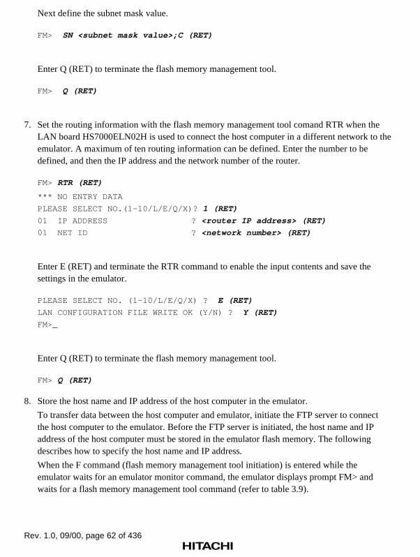
Rev. 1.0, 09/00, page 62 of 436
Next define the subnet mask value.
FM> SN <subnet mask value>;C (RET)
Enter Q (RET) to terminate the flash memory management tool.
FM> Q (RET)
7. Set the routing information with the flash memory management tool comand RTR when theLAN board HS7000ELN02H is used to connect the host computer in a different network to theemulator. A maximum of ten routing information can be defined. Enter the number to bedefined, and then the IP address and the network number of the router.
FM> RTR (RET)
*** NO ENTRY DATA
PLEASE SELECT NO.(1–10/L/E/Q/X)? 1 (RET)
01 IP ADDRESS ? <router IP address> (RET)
01 NET ID ? <network number> (RET)
Enter E (RET) and terminate the RTR command to enable the input contents and save thesettings in the emulator.
PLEASE SELECT NO. (1–10/L/E/Q/X) ? E (RET)
LAN CONFIGURATION FILE WRITE OK (Y/N) ? Y (RET)
FM>_
Enter Q (RET) to terminate the flash memory management tool.
FM> Q (RET)
8. Store the host name and IP address of the host computer in the emulator.
To transfer data between the host computer and emulator, initiate the FTP server to connectthe host computer to the emulator. Before the FTP server is initiated, the host name and IPaddress of the host computer must be stored in the emulator flash memory. The followingdescribes how to specify the host name and IP address.
When the F command (flash memory management tool initiation) is entered while theemulator waits for an emulator monitor command, the emulator displays prompt FM> andwaits for a flash memory management tool command (refer to table 3.9).

Rev. 1.0, 09/00, page 63 of 436
START E8000
S:START E8000
F:FLASH MEMORY TOOL
L:SET LAN PARAMETER
T:START DIAGNOSTIC TEST
(S/F/L/T)? F(RET)
FM>
Next enter the LH command, and the following message is displayed.
FM> LH (RET)
NO <HOST NAME> <IP ADDRESS> NO <HOST NAME> <IP ADDRESS>
01 xxxxxx xxx.xxx.xxx.xxx 02 xxxxxx xxx.xxx.xxx.xxx
03 xxxxxx xxx.xxx.xxx.xxx 04 xxxxxx xxx.xxx.xxx.xxx
05 xxxxxx xxx.xxx.xxx.xxx 06 xxxxxx xxx.xxx.xxx.xxx
07 xxxxxx xxx.xxx.xxx.xxx 08 xxxxxx xxx.xxx.xxx.xxx
09 xxxxxx xxx.xxx.xxx.xxx
E8000 IP ADDRESS = xxx.xxx.xxx.xxx
PLEASE SELECT NO.(1-9/L/E/Q/X) ? _

Rev. 1.0, 09/00, page 64 of 436
Up to nine pairs of host names and IP addresses can be specified. Input a number from 1 to 9.The emulator prompts the host name. Enter a name with up to 15 characters. After that, theemulator prompts the IP address.
PLEASE SELECT NO.(1-9/L/E/Q/X) ? 1 (RET)
01 HOST NAME xxxxxx <name of host computer> (RET)
01 IP ADDRESS xxx.xxx.xxx.xxx <IP address of host computer> (RET)
After the IP address has been specified, the emulator will prompt for another selection number.When connecting more than one host computer, continue specifying the host names and IPaddresses. To confirm the specifications, enter L (RET) as follows.
PLEASE SELECT NO.(1-9/L/E/Q/X) ? L (RET)
NO <HOST NAME> <IP ADDRESS> NO <HOST NAME> <IP ADDRESS>
01 xxxxxx xxx.xxx.xxx.xxx 02 xxxxxx xxx.xxx.xxx.xxx
03 xxxxxx xxx.xxx.xxx.xxx 04 xxxxxx xxx.xxx.xxx.xxx
05 xxxxxx xxx.xxx.xxx.xxx 06 xxxxxx xxx.xxx.xxx.xxx
07 xxxxxx xxx.xxx.xxx.xxx 08 xxxxxx xxx.xxx.xxx.xxx
09 xxxxxx xxx.xxx.xxx.xxx
E8000 IP ADDRESS = xxx.xxx.xxx.xxx
PLEASE SELECT NO.(1-9/L/E/Q/X) ? _
To terminate input, enter E, Q, or X followed by (RET).
Entering E (RET) saves the new specifications in the emulator flash memory, initiates theLAN board, and terminates LH command execution.
PLEASE SELECT NO.(1-9/L/E/Q/X) ? E (RET)
LAN CONFIGURATION FILE WRITE OK (Y/N) ? Y (RET)
FM>
Entering Q (RET) saves the new specifications in the emulator flash memory withoutinitializing the LAN board, and terminates LH command execution.
PLEASE SELECT NO.(1-9/L/E/Q/X) ? Q (RET)
LAN CONFIGURATION FILE WRITE OK (Y/N) ? Y (RET)
FM>
Entering X (RET) terminates LH command execution without saving the new specifications.
PLEASE SELECT NO.(1-9/L/E/Q/X) ? X (RET)
FM>

Rev. 1.0, 09/00, page 65 of 436
When the emulator waits for a flash memory management tool command (prompt FM>),entering Q (RET) terminates the flash memory management tool.
FM> Q (RET)
START E8000
S:START E8000
F:FLASH MEMORY TOOL
L:SET LAN PARAMETER
T:START DIAGNOSTIC TEST
(S/F/L/T) ? _
9. Turn off the E8000 station.
10. Check that S7 and S8 in console interface switch SW1 on the E8000 station rear panel areturned off (to the right) and on (to the left), respectively.
11. Turn on the power switch at the E8000 station rear panel.
12. Execute the TELNET command on the host computer.
13. The following messages are displayed and the internal system tests are executed.
E8000 MONITOR (HS8000EST02SR) Vm.nCopyright (C) Hitachi, Ltd. 1995Licensed Material of Hitachi, Ltd.
TESTING RAM 0123
14. If no error occurs, the emulator waits for an emulator monitor command.
START E8000
S:START E8000
F:FLASH MEMORY TOOL
L:SET LAN PARAMETER
T:START DIAGNOSTIC TEST
(S/F/L/T) ? _
Refer to section 3.6.1, Emulator Monitor Initiation, for details on operations after emulator power-on and section 3.8, E8000 System Program Initiation, for details on emulator system initiation.
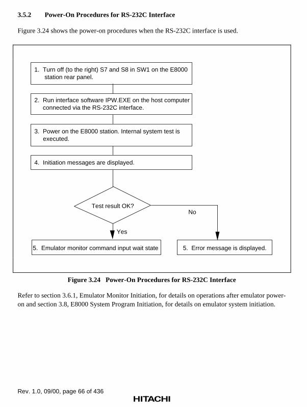
Rev. 1.0, 09/00, page 66 of 436
3.5.2 Power-On Procedures for RS-232C Interface
Figure 3.24 shows the power-on procedures when the RS-232C interface is used.
Test result OK?
Yes
No
1. Turn off (to the right) S7 and S8 in SW1 on the E8000 station rear panel.
5. Emulator monitor command input wait state 5. Error message is displayed.
4. Initiation messages are displayed.
3. Power on the E8000 station. Internal system test is executed.
2. Run interface software IPW.EXE on the host computer connected via the RS-232C interface.
Figure 3.24 Power-On Procedures for RS-232C Interface
Refer to section 3.6.1, Emulator Monitor Initiation, for details on operations after emulator power-on and section 3.8, E8000 System Program Initiation, for details on emulator system initiation.

Rev. 1.0, 09/00, page 67 of 436
3.6 Emulator Monitor Commands
3.6.1 Emulator Monitor Initiation
The emulator supports the four monitor commands listed in table 3.8. These commands initiate theE8000 system program, manage flash memory, set an IP address for LAN interface, and executethe diagnostic program. After turned on, the emulator displays the following monitor initiationmessage and waits for an emulator monitor command input.
Display Message:
E8000 MONITOR (HS8000EST02SR) Vm.nCopyright (C) Hitachi, Ltd. 1995Licensed Material of Hitachi, Ltd.
TESTING RAM 0123
START E8000 S:START E8000 F:FLASH MEMORY TOOL L:SET LAN PARAMETER T:START DIAGNOSTIC TEST (S/F/L/T) ? _
Table 3.8 Emulator Monitor Commands
Command Function Remark
S E8000 system program initiation
F Flash memory management tool initiation
L Emulator IP address setting
T Diagnostic program initiation

Rev. 1.0, 09/00, page 68 of 436
S
3.6.2 S [S] Initiates the E8000 system program
Command Format
• Initiation S (RET)
Description
• Initiation
Initiates the E8000 system program.
Example
To initiate the E8000 system program:
START E8000 S:START E8000 F:FLASH MEMORY TOOL L:SET LAN PARAMETER T:START DIAGNOSTIC TEST (S/F/L/T) ? S (RET)
SH7410 E8000 (HS7410EDD82SF) Vm.n Copyright (C) Hitachi, Ltd. 1996 Licensed Material of Hitachi, Ltd.
CONFIGURATION FILE LOADING HARD WARE REGISTER READ/WRITE CHECK FIRMWARE SYSTEM LOADING EMULATOR FIRMWARE TEST ** RESET BY E8000 ! CLOCK = EML MODE = 00 (MD4-0=1F) REMAINING EMULATION MEMORY S=4MB:

Rev. 1.0, 09/00, page 69 of 436
F
3.6.3 F [F] Initiates the flash memory management tool
Command Format
• Flash memory F (RET)
management tool
Description
• Flash memory management tool
Initiates the flash memory management tool. The flash memory management tool can use thecommands listed in table 3.9.
Table 3.9 Flash Memory Management Tool Commands
Command Function
DIR Displays system file loading status
LH Defines the host name and IP address of the host computer to beconnected
Q Terminates the flash memory management tool
RTR Defines routing information for remote network
SL Loads the E8000 system program
SN Defines the subnet mask value
Note: The RTR and SN commands can be used only when the LAN board HS7000ELN02H isused.
Example
To initiate the flash memory management tool:
START E8000 S:START E8000 F:FLASH MEMORY TOOL L:SET LAN PARAMETER T:START DIAGNOSTIC TEST (S/F/L/T) ? F (RET)FM>

Rev. 1.0, 09/00, page 70 of 436
DIR
DIR [DIR] Displays system file loading status
Command Format
• Display DIR (RET)
Description
• Display
Displays system-file loading status. Displays OK for correctly loaded system file, NG forabnormally loaded on, and NO for not loaded.
Example
To display system file loading status:
FM>DIR (RET) <FILE ID> <STATUS> SYS OK CONF OK LAN NO FIRM OK TRON NO DIAG OK INI OK MON OKFM>

Rev. 1.0, 09/00, page 71 of 436
LH
LH [LH] Defines the host name and IP address of the host computer
Command Format
• Definition LH (RET)
Description
• Definition
Defines the host name and IP address of the host computer. Enter the host name and IP addressas follows after the specified number is entered and the emulator prompts them:
PLEASE SELECT NO. (1–9/L/E/Q/X) ? <definition number> (RET)
01 HOSTNAME xxxxxx <host name> (RET)
01 IP ADDRESS xxx.xxx.xxx.xxx <IP address> (RET)
• Display
Entering L (RET) displays the list of the defined host computer.
• Initiation
Entering E (RET) saves the new specifications in the emulator flash memory, and initiates theLAN board. Entering Q (RET) saves the new specifications in the emulator flash memorywithout initializing the LAN board, and terminates LH command execution. Entering X (RET)terminates LH command execution without saving the new specifications.

Rev. 1.0, 09/00, page 72 of 436
LH
Example
To define the host name of the host computer as host and its IP address as 128.1.1.1:
FM>LH (RET) PLEASE SELECT NO.(1-9/L/E/Q/X) ? L (RET) 01 HOST NAME xxxxxx host (RET) 01 IP ADDRESS xxx.xxx.xxx.xxx 128.1.1.1 (RET) PLEASE SELECT NO.(1-9/L/E/Q/X) ? L (RET) NO <HOST NAME> <IP ADDRESS> NO <HOST NAME> <IP ADDRESS> 01 host 128.1.1.1 02 03 04 05 06 07 08 09 E8000 IP ADDRESS = xxx.xxx.xxx.xxx PLEASE SELECT NO.(1-9/L/E/Q/X) ? E (RET) LAN CONFIGURATION FILE WRITE OK (Y/N) ? Y (RET)FM>
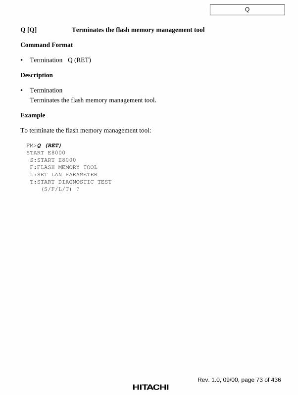
Rev. 1.0, 09/00, page 73 of 436
Q
Q [Q] Terminates the flash memory management tool
Command Format
• Termination Q (RET)
Description
• Termination
Terminates the flash memory management tool.
Example
To terminate the flash memory management tool:
FM>Q (RET)START E8000 S:START E8000 F:FLASH MEMORY TOOL L:SET LAN PARAMETER T:START DIAGNOSTIC TEST (S/F/L/T) ?

Rev. 1.0, 09/00, page 74 of 436
RTR
RTR [RTR] Defines the remote network routing information
Command Format
• Definition RTR (RET)
Description
• Definition
Defines the remote network routing information. Enter the IP address and network number asfollows after the specified number is entered and the emulator prompts them:
FM> RTR (RET)
PLEASE SELECT NO. (1–10/L/E/Q/X) ? <definition number> (RET)
IP ADDRESS ? <router IP address> (RET)
NET ID ? <network number> (RET)
• Display
Entering L (RET) displays the list of the defined host computer.
• Initiation
Entering E (RET) saves the new specifications in the emulator flash memory, and initiates theLAN board. Entering Q (RET) saves the new specifications in the emulator flash memorywithout initializing the LAN board, and terminates LH command execution. Entering X (RET)terminates LH command execution without saving the new specifications.
Example
To define router IP address 128.1.2.1 for network number 128.1.2.0 as the routing information:
FM>RTR (RET) PLEASE SELECT NO.(1-10/L/E/Q/X) ? 1 (RET) IP ADDRESS ? 128.1.2.1 (RET) NET ID ? 128.1.2.0 (RET) PLEASE SELECT NO.(1-10/L/E/Q/X) ? L (RET) NO <IP-ADDRESS> <NET-ID> NO <IP-ADDRESS> <NET-ID> 01 128.1.2.1 128.1.2.0 02 PLEASE SELECT NO.(1-10/L/E/Q/X) ? E (RET) LAN CONFIGURATION FILE WRITE OK (Y/N) ? Y (RET)FM>
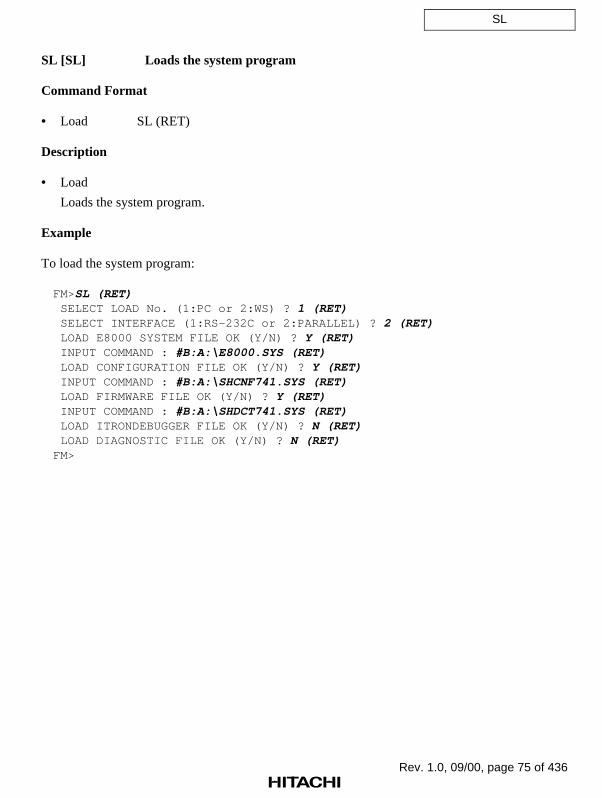
Rev. 1.0, 09/00, page 75 of 436
SL
SL [SL] Loads the system program
Command Format
• Load SL (RET)
Description
• Load
Loads the system program.
Example
To load the system program:
FM>SL (RET) SELECT LOAD No. (1:PC or 2:WS) ? 1 (RET) SELECT INTERFACE (1:RS-232C or 2:PARALLEL) ? 2 (RET) LOAD E8000 SYSTEM FILE OK (Y/N) ? Y (RET) INPUT COMMAND : #B:A:\E8000.SYS (RET) LOAD CONFIGURATION FILE OK (Y/N) ? Y (RET) INPUT COMMAND : #B:A:\SHCNF741.SYS (RET) LOAD FIRMWARE FILE OK (Y/N) ? Y (RET) INPUT COMMAND : #B:A:\SHDCT741.SYS (RET) LOAD ITRONDEBUGGER FILE OK (Y/N) ? N (RET) LOAD DIAGNOSTIC FILE OK (Y/N) ? N (RET)FM>

Rev. 1.0, 09/00, page 76 of 436
SN
SN [SN] Defines the subnet mask value
Command Format
• Definition SN <subnet mask value>;[C] (RET)
• Display SN (RET)
Description
• Definition
Defines the subnet mask value.
FM>SN <subnet mask value> (RET)
FM>
• Save
Saves the setting specifications in the E8000 station when the C option is specified.
FM>SN <subnet mask value>; C (RET)
LAN CONFIGURATION FILE WRITE OK (Y/N) ? Y (RET)
FM>
• Display
Displays the subnet mask value.
FM>SN (RET)
SUB-NET-MASK xxx. xxx. xxx. xxx (H'xx. H'xx. H'xx. H'xx)
Examples
1. To define 255.255.255.0 as the subnet mask value and save the setting specifications in theE8000 station:
FM>SN 255.255.255.0;C (RET)
LAN CONFIGURATION FILE WRITE OK (Y/N) ? Y (RET)
FM>
2. To display the subnet mask value:
FM>SN (RET)
SUB-NET-MASK 255.255.255.0 (H'FF.H'FF.H'FF.H'00)
FM>

Rev. 1.0, 09/00, page 77 of 436
L
3.6.4 L [L] Sets the emulator IP address
Command Format
• Setting L (RET)
Description
• Setting
Sets the emulator IP address.
Example
To set the IP address of the E8000 station to 128.1.1.1:
START E8000 S:START E8000 F:FLASH MEMORY TOOL L:SET LAN PARAMETER T:START DIAGNOSTIC TEST (S/F/L/T) ? L (RET)
E8000 IP ADDRESS = 0.0.0.0 : 128.1.1.1 (RET)

Rev. 1.0, 09/00, page 78 of 436
T
3.6.5 T [T] Initiates the diagnostic program
Command Format
• Initiation T (RET)
Description
• Initiation
Initiates the diagnostic program.
Example
To initiate the emulator diagnostic program:
START E8000 S:START E8000 F:FLASH MEMORY TOOL L:SET LAN PARAMETER T:START DIAGNOSTIC TEST (S/F/L/T) ? T (RET)
*** E8000 TM LOADING

Rev. 1.0, 09/00, page 79 of 436
3.7 System Program Installation
3.7.1 E8000 System Disk
The emulator contains one floppy disk.
SH7410 E8000 SYSTEM
1. SYSTEM (HS7410EDD82SF)
2. PC I/F (HS8000EIW01SF)
3. DIAGNOSTIC TEST
'xx.xx.xx HITACHI
Vm.n
Vm.n
Vm.n
E8000
Figure 3.25 E8000 System Disk
The E8000 system disk with a 1.44-Mbyte format is for PC. This floppy disk contains thefollowing six files:
• E8000.SYS
• SHCNF741.SYS
• SHDCT741.SYS
• SETUP.CC
• IPW.EXE
• DIAG.SYS
E8000.SYS, SHCNF741.SYS, and SHDCT741.SYS are system programs that must be installed tothe emulator flash memory with emulator monitor command F (flash memory management toolinitiation). SETUP.CC is a file for writing the system programs via the parallel interface.IPW.EXE is a file containing interface software that runs on Microsoft Windows95 and must beinstalled to the host computer memory.
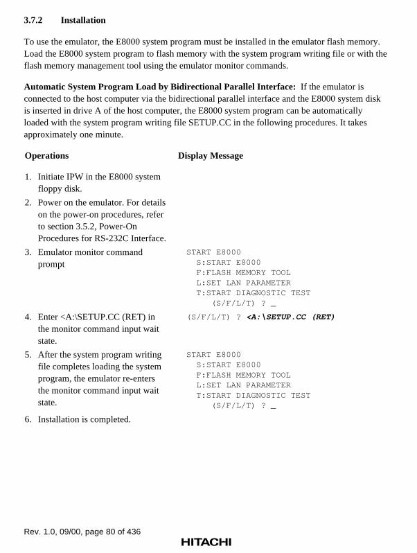
Rev. 1.0, 09/00, page 80 of 436
3.7.2 Installation
To use the emulator, the E8000 system program must be installed in the emulator flash memory.Load the E8000 system program to flash memory with the system program writing file or with theflash memory management tool using the emulator monitor commands.
Automatic System Program Load by Bidirectional Parallel Interface: If the emulator isconnected to the host computer via the bidirectional parallel interface and the E8000 system diskis inserted in drive A of the host computer, the E8000 system program can be automaticallyloaded with the system program writing file SETUP.CC in the following procedures. It takesapproximately one minute.
Operations Display Message
1. Initiate IPW in the E8000 systemfloppy disk.
2. Power on the emulator. For detailson the power-on procedures, referto section 3.5.2, Power-OnProcedures for RS-232C Interface.
3. Emulator monitor commandprompt
START E8000 S:START E8000 F:FLASH MEMORY TOOL L:SET LAN PARAMETER T:START DIAGNOSTIC TEST (S/F/L/T) ? _
4. Enter <A:\SETUP.CC (RET) inthe monitor command input waitstate.
(S/F/L/T) ? <A:\SETUP.CC (RET)
5. After the system program writingfile completes loading the systemprogram, the emulator re-entersthe monitor command input waitstate.
START E8000 S:START E8000 F:FLASH MEMORY TOOL L:SET LAN PARAMETER T:START DIAGNOSTIC TEST (S/F/L/T) ? _
6. Installation is completed.

Rev. 1.0, 09/00, page 81 of 436
Manual System Program Load by Bidirectional Parallel Interface: To use the emulator, filesE8000.SYS, SHCNF741.SYS, and SHDCT741.SYS must be installed in the emulator flashmemory.
If the emulator is connected to the host computer via the bidirectional parallel interface, the E8000system program can be loaded with the following procedures. Note that the E8000 system disk isassumed to be inserted in drive A of the host computer. It takes approximately one minute.
Operations Display Message
1. Initiate IPW in the E8000 systemfloppy disk.
2. Power on the emulator. For detailson the power-on procedures, referto section 3.5.2, Power-OnProcedures for RS-232C Interface.
3. Emulator monitor commandprompt
START E8000
S:START E8000
F:FLASH MEMORY TOOL
L:SET LAN PARAMETER
T:START DIAGNOSTIC TEST
(S/F/L/T) ? _
4. Enter F (RET) to initiate the flashmemory management tool. Theemulator displays prompt FM> andwaits for a flash memorymanagement tool command.
(S/F/L/T) ? F (RET)
FM>
5. Enter SL (RET) to load the systemprogram.
FM> SL (RET)
6. Enter 1 (RET) to select PC as thehost computer type, and 2 (RET)to select parallel interface as theinterface method.
SELECT LOAD No. (1:PC or 2:WS) ? 1 (RET)
SELECT INTERFACE (1:RS-232C or 2:PARALLEL) ?
2 (RET)
7. Enter Y (RET) to allow systemprogram E8000.SYS to be loaded.Then enter the parallel transfercommand to load E8000.SYS inthe current directory on the PC tothe emulator flash memory.
LOAD E8000 SYSTEM FILE OK (Y/N) ? Y (RET)
INPUT COMMAND : #B:A:\E8000.SYS (RET)
:COMPLETED
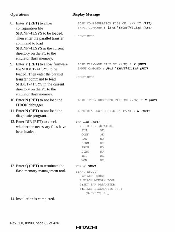
Rev. 1.0, 09/00, page 82 of 436
Operations Display Message
8. Enter Y (RET) to allowconfiguration fileSHCNF741.SYS to be loaded.Then enter the parallel transfercommand to loadSHCNF741.SYS in the currentdirectory on the PC to theemulator flash memory.
LOAD CONFIGURATION FILE OK (Y/N)? Y (RET)
INPUT COMMAND : #B:A:\SHCNF741.SYS (RET)
:COMPLETED
9. Enter Y (RET) to allow firmwarefile SHDCT741.SYS to beloaded. Then enter the paralleltransfer command to loadSHDCT741.SYS in the currentdirectory on the PC to theemulator flash memory.
LOAD FIRMWARE FILE OK (Y/N) ? Y (RET)
INPUT COMMAND : #B:A:\SHDCT741.SYS (RET)
:COMPLETED
10. Enter N (RET) to not load theITRON debugger.
LOAD ITRON DEBUGGER FILE OK (Y/N) ? N (RET)
11. Enter N (RET) to not load thediagnostic program.
LOAD DIAGNOSTIC FILE OK (Y/N) ? N (RET)
12. Enter DIR (RET) to checkwhether the necessary files havebeen loaded.
FM> DIR (RET)
<FILE ID> <STATUS>
SYS OK
CONF OK
LAN NO
FIRM OK
TRON NO
DIAG NO
INI OK
MON OK
13. Enter Q (RET) to terminate theflash memory management tool.
FM> Q (RET)
START E8000
S:START E8000
F:FLASH MEMORY TOOL
L:SET LAN PARAMETER
T:START DIAGNOSTIC TEST
(S/F/L/T) ? _
14. Installation is completed.

Rev. 1.0, 09/00, page 83 of 436
Manual System Program Load by RS-232C Interface: To use the emulator, files E8000.SYS,SHCNF741.SYS, and SHDCT741.SYS must be installed in the emulator flash memory.
If the emulator is connected to the host computer via the RS-232C interface, the E8000 systemprogram can be loaded with the following procedures. Note that the E8000 system disk is assumedto be inserted in drive A of the host computer. It takes approximately 20 minutes.
Operations Display Message
1. Initiate IPW in the E8000 systemfloppy disk.
2. Power on the emulator. For detailson the power-on procedures, referto section 3.5.2, Power-OnProcedures for RS-232C Interface.
3. Emulator monitor commandprompt
START E8000
S:START E8000
F:FLASH MEMORY TOOL
L:SET LAN PARAMETER
T:START DIAGNOSTIC TEST
(S/F/L/T) ? _
4. Enter F (RET) to initiate the flashmemory management tool. Theemulator displays prompt FM> andwaits for a flash memorymanagement tool command.
(S/F/L/T) ? F (RET)
FM>
5. Enter SL (RET) to load the systemprogram.
FM> SL (RET)
6. Enter 1 (RET) to select PC as thehost computer type, and 1 (RET)to select RS-232C (serial) interfaceas the interface method.
SELECT LOAD No. (1:PC or 2:WS) ? 1 (RET)
SELECT INTERFACE (1:RS-232C or 2:PARALLEL) ? 1 (RET)
7. Enter the directory containing thesystem file. In this example,A:\ (RET) is entered.
INPUT SYSTEM DIRECTORY : A:\ (RET)
8. Enter Y (RET) to allow systemprogram E8000.SYS to be loadedin the emulator flash memory.Then enter system program filename E8000.SYS.
LOAD E8000 SYSTEM FILE OK (Y/N) ? Y (RET)
INPUT FILE NAME : E8000.SYS (RET)
COMPLETED
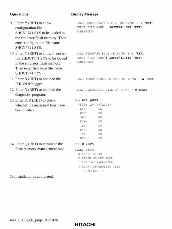
Rev. 1.0, 09/00, page 84 of 436
Operations Display Message
9. Enter Y (RET) to allowconfiguration fileSHCNF741.SYS to be loaded inthe emulator flash memory. Thenenter configuration file nameSHCNF741.SYS.
LOAD CONFIGURATION FILE OK (Y/N) ? Y (RET)
INPUT FILE NAME : SHCNF741.SYS (RET)
COMPLETED
10. Enter Y (RET) to allow firmwarefile SHDCT741.SYS to be loadedin the emulator flash memory.Then enter firmware file nameSHDCT741.SYS.
LOAD FIRMWARE FILE OK (Y/N) ? Y (RET)
INPUT FILE NAME : SHDCT741.SYS (RET)
COMPLETED
11. Enter N (RET) to not load theITRON debugger.
LOAD ITRON DEBUGGER FILE OK (Y/N) ? N (RET)
12. Enter N (RET) to not load thediagnostic program.
LOAD DIAGNOSTIC FILE OK (Y/N) ? N (RET)
13. Enter DIR (RET) to checkwhether the necessary files havebeen loaded.
FM> DIR (RET)
<FILE ID> <STATUS>
SYS OK
CONF OK
LAN NO
FIRM OK
TRON NO
DIAG NO
INI OK
MON OK
14. Enter Q (RET) to terminate theflash memory management tool.
FM> Q (RET)
START E8000
S:START E8000
F:FLASH MEMORY TOOL
L:SET LAN PARAMETER
T:START DIAGNOSTIC TEST
(S/F/L/T) ? _
15. Installation is completed.

Rev. 1.0, 09/00, page 85 of 436
Manual System Program Load by LAN Interface: To use the emulator, files E8000.SYS,SHCNF741.SYS, and SHDCT741.SYS must be installed in the emulator flash memory.
If the emulator is connected to the host computer via the LAN interface, the E8000 systemprogram can be loaded with the following procedures. Transfer all files on the system floppy diskto the host computer using the FTP before installation. For details on the transfer method, refer tothe host-computer user’s manual. It takes approximately one minute.
Operations Display Message
1. Power on the emulator. Fordetails on the power-onprocedures, refer to section 3.5.1,Power-On Procedures for LANInterface. Confirm the emulatormonitor command prompt isdisplayed.
START E8000
S:START E8000
F:FLASH MEMORY TOOL
L:SET LAN PARAMETER
T:START DIAGNOSTIC TEST
(S/F/L/T) ? _
2. Enter F (RET) to initiate the flashmemory management tool. Theemulator displays prompt FM>and waits for a flash memorymanagement tool command.
(S/F/L/T) ? F (RET)
FM>
3. Enter SL (RET) to load thesystem program.
FM> SL (RET)
4. Enter 2 (RET) to select WS asthe host computer type since theLAN interface is used.
SELECT LOAD No. (1:PC or 2:WS) ? 2 (RET)
5. Enter the host computer name. Inthis example, hostname isentered.
INPUT SYSTEM LOADING HOST NAME : hostname
(RET)
6. Enter the user name. In thisexample, username is entered.
INPUT USER NAME : username (RET)
7. Enter the password. In thisexample, password is entered.
INPUT PASS WORD : password (RET)
8. Enter the directory containing thesystem file. In this example,(RET) is entered to select thecurrent directory of the hostcomputer.
INPUT SYSTEM DIRECTORY : (RET)

Rev. 1.0, 09/00, page 86 of 436
Operations Display Message
9. Enter Y (RET) to allow systemprogram E8000.SYS to be loadedin the emulator flash memory.Then enter system program filename E8000.SYS.
LOAD E8000 SYSTEM FILE OK (Y/N) ? Y (RET)
INPUT FILE NAME : E8000.SYS (RET)
COMPLETED
10. Enter Y (RET) to allowconfiguration fileSHCNF741.SYS to be loaded inthe emulator flash memory. Thenenter configuration file nameSHCNF741.SYS.
LOAD CONFIGURATION FILE OK (Y/N) ? Y (RET)
INPUT FILE NAME : SHCNF741.SYS (RET)
COMPLETED
11. Enter Y (RET) to allow firmwarefile SHDCT741.SYS to be loadedin the emulator flash memory.Then enter firmware file nameSHDCT741.SYS.
LOAD FIRMWARE FILE OK (Y/N) ? Y (RET)
INPUT FILE NAME : SHDCT741.SYS (RET)
COMPLETED
12. Enter N (RET) to not load theITRON debugger.
LOAD ITRON DEBUGGER FILE OK (Y/N) ? N (RET)
13. Enter N (RET) to not load thediagnostic program.
LOAD DIAGNOSTIC FILE OK (Y/N) ? N (RET)
14. Enter DIR (RET) to checkwhether the necessary files havebeen loaded.
FM> DIR (RET)
<FILE ID> <STATUS>
SYS OK
CONF OK
LAN NO
FIRM OK
TRON NO
DIAG NO
INI OK
MON OK
15. Enter Q (RET) to terminate theflash memory management tool.
FM> Q (RET)
START E8000
S:START E8000
F:FLASH MEMORY TOOL
L:SET LAN PARAMETER
T:START DIAGNOSTIC TEST
(S/F/L/T) ? _
16. Installation is completed.

Rev. 1.0, 09/00, page 87 of 436
3.8 E8000 System Program Initiation
When the emulator is turned on while S4 in DIP SW1 is turned off (to the right) and a manualsystem program load method is selected, the emulator enters monitor command input wait state,and the E8000 system program must be loaded and initiated by monitor commands. If S4 in DIPSW1 has been turned on (to the left) and the automatic system program load method is selected,the E8000 system program is automatically loaded and initiated.
3.8.1 Initiation on Emulator Monitor
If S is entered, followed by (RET), when the emulator is in monitor command input wait state, theE8000 system program in the emulator flash memory is initiated.
Display at E8000 System Program Initiation:
START E8000 S:START E8000 F:FLASH MEMORY TOOL L:SET LAN PARAMETER T:START DIAGNOSTIC TEST (S/F/L/T) ? S (RET)
SH7410 E8000 (HS7410EDD82SF) Vm.n Copyright (C) Hitachi, Ltd. 1996 Licensed Material of Hitachi, Ltd.
CONFIGURATION FILE LOADING HARD WARE REGISTER READ/WRITE CHECK FIRMWARE SYSTEM LOADING EMULATOR FIRMWARE TEST ** RESET BY E8000 ! CLOCK = EML MODE = 00 (MD4-0=1F) REMAINING EMULATION MEMORY S=4MB:

Rev. 1.0, 09/00, page 88 of 436
3.8.2 Automatic Initiation of E8000 System Program
If S4 in DIP SW1 has been turned on (to the left) and the automatic system program load methodis selected, the E8000 system program is automatically loaded and initiated, and the emulatorwaits for an emulation command.
Display at Power On:
(Power on)
E8000 MONITOR (HS8000EST02SR) Vm.n Copyright (C) Hitachi, Ltd. 1995 Licensed Material of Hitachi, Ltd.
TESTING RAM 0123
SH7410 E8000 (HS7410EDD82SF) Vm.n Copyright (C) Hitachi, Ltd. 1996 Licensed Material of Hitachi, Ltd.
CONFIGURATION FILE LOADING HARD WARE REGISTER READ/WRITE CHECK FIRMWARE SYSTEM LOADING EMULATOR FIRMWARE TEST ** RESET BY E8000 ! CLOCK = EML MODE = 00 (MD4-0=1F) REMAINING EMULATION MEMORY S=4MB:
If the E8000 system program is automatically initiated without being loaded to the emulator flashmemory, after displaying an error message, the emulator enters monitor command input wait state.Make sure to load the E8000 system program to the emulator flash memory before initiation.
*** E8000 SYSTEM PROGRAM NOT FOUNDSTART E8000 S:START E8000 F:FLASH MEMORY TOOL L:SET LAN PARAMETER T:START DIAGNOSTIC TEST (S/F/L/T) ? _

Rev. 1.0, 09/00, page 89 of 436
Section 4 Operating Examples
4.1 Emulator Operating Examples
This section covers explanations on how to operate the emulator using examples. Sections 4.2,Basic Examples and 4.3, Application Examples are based on the following user program. Theseexamples assume that the emulator is connected to the host computer by a LAN interface and isused with a TELNET connection.
ADDR CODE MNEMONIC OPERAND
01001000 E00A MOV #0A,R0
01001002 E101 MOV #01,R1
01001004 E201 MOV #01,R2
01001006 D405 MOV.L 0100101C,R4
01001008 6323 MOV R2,R3
0100100A 321C ADD R1,R2
0100100C 2426 MOV.L R2,@-R4
0100100E 6133 MOV R3,R1
01001010 70FF ADD #FF,R0
01001012 8800 CMP/EQ #00,R0
01001014 8BF8 BF 01001008
01001016 0009 NOP
01001018 AFFE BRA 01001018
0100101A 0009 NOP
0100101C 0F10 .DATA.W 0100
0100101E 0000 .DATA.W FFFC
Store the user program in the host computer before initiating the emulator and download it to theemulator. In these examples, the IP address is set to 128.1.1.1.
CAUTIONIn these examples, the IP address is set to 128.1.1.1 to
128.1.1.10. For the actual host computer, an IP address availableon the network connected to the emulator must be specified. If anunavailable IP address is specified, the network will have problems.

Rev. 1.0, 09/00, page 90 of 436
4.2 Basic Examples
4.2.1 Preparing for Connection of the LAN Host Computer
The following host name and IP address are examples. Specify the actual host computer name andIP address of the host computer.
Operations Display Message
1. Specify the host name and IPaddress of the host computer towhich the emulator is to beconnected by the LAN interface.Enter the F command to initiate theflash memory management tool inthe monitor command input waitstate.
START E8000
S:START E8000
F:FLASH MEMORY TOOL
L:SET LAN PARAMETER
T:START DIAGNOSTIC TEST
(S/F/L/T) ? F (RET)
FM>_
2. Enter LH (RET) to store the hostname and IP address of the hostcomputer.
FM>LH (RET)
NO <HOST NAME> <IP ADDRESS> NO <HOST
01 02
03 04
05 06
07 08
09
E8000 IP ADDRESS = 128.1.1.1
PLEASE SELECT NO.(1-9/L/E/Q/X) ? _
3. Enter 1 as the selection number,HITACHI (RET) as the host name,and 128.1.1.10 (RET) as the IPaddress. After that, the emulatorprompts the user to select anothernumber.
PLEASE SELECT NO.(1-9/L/E/Q/X) ? 1 (RET)
01 HOST NAME HOST_A ? HITACHI (RET)
01 IP ADDRESS 128.1.1.1 ? 128.1.1.10 (RET)
PLEASE SELECT NO.(1-9/L/E/Q/X) ? _
4. Enter E (RET) to enable the settingsand to exit interactive mode.
PLEASE SELECT NO.(1-9/L/E/Q/X) ? E (RET)
5. The emulator confirms whether tosave the settings in the configurationfile with the above settings.
LAN CONFIGURATION FILE WRITE OK (Y/N) ? _
6. Enter Y (RET) to save the settings. CONFIGURATION FILE WRITE OK (Y/N) ? Y (RET)
FM>

Rev. 1.0, 09/00, page 91 of 436
7. Enter Q (RET) to terminate the flashmemory management tool and enterthe monitor command input waitstate.
FM>Q (RET)
START E8000
S:START E8000
F:FLASH MEMORY TOOL
L:SET LAN PARAMETER
T:START DIAGNOSTIC TEST
(S/F/L/T) ? _
8. Enter S (RET) to re-initiate theemulator. The emulator is re-initiated, and waits for an emulationcommand.
(S/F/L/T) ? S (RET)
SH7410 E8000 (HS7410EDD82SF) Vm.n
Copyright (C) Hitachi, Ltd. 1996
License Material of Hitachi, Ltd.
CONFIGURATION FILE LOADING
HARDWARE REGISTER READ/WRITE CHECK
FIRMWARE SYSTEM LOADING
EMULATOR FIRMWARE LOADING
EMULATOR FIRMWARE TEST
** RESET BY E8000 !
CLOCK = EML
MODE = 00 (MD4-0=1F)
REMAINING EMULATION MEMORY S=4MB
:
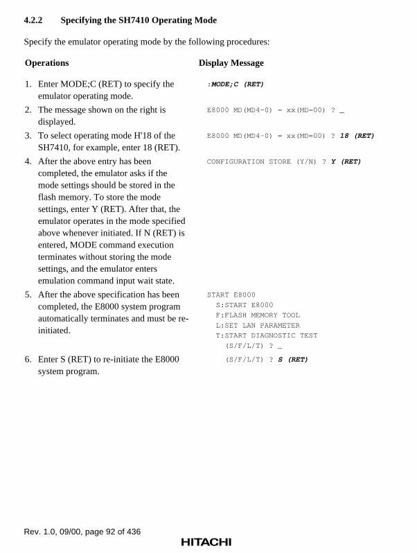
Rev. 1.0, 09/00, page 92 of 436
4.2.2 Specifying the SH7410 Operating Mode
Specify the emulator operating mode by the following procedures:
Operations Display Message
1. Enter MODE;C (RET) to specify theemulator operating mode.
: MODE;C (RET)
2. The message shown on the right isdisplayed.
E8000 MD(MD4-0) = xx(MD=00) ? _
3. To select operating mode H'18 of theSH7410, for example, enter 18 (RET).
E8000 MD(MD4-0) = xx(MD=00) ? 18 (RET)
4. After the above entry has beencompleted, the emulator asks if themode settings should be stored in theflash memory. To store the modesettings, enter Y (RET). After that, theemulator operates in the mode specifiedabove whenever initiated. If N (RET) isentered, MODE command executionterminates without storing the modesettings, and the emulator entersemulation command input wait state.
CONFIGURATION STORE (Y/N) ? Y (RET)
5. After the above specification has beencompleted, the E8000 system programautomatically terminates and must be re-initiated.
START E8000
S:START E8000
F:FLASH MEMORY TOOL
L:SET LAN PARAMETER
T:START DIAGNOSTIC TEST
(S/F/L/T) ? _
6. Enter S (RET) to re-initiate the E8000system program.
(S/F/L/T) ? S (RET)

Rev. 1.0, 09/00, page 93 of 436
4.2.3 Allocating Standard Emulation Memory and Specifying Attributes
To load the user program to memory and run the user program, allocate standard emulationmemory by the following procedures:
Operations Display Message
1. Enter MAP 1000000 10FFFFF;S(RET) to allocate standard emulationmemory to addresses H'1000000 toH'10FFFFF.
: MAP 1000000 10FFFFF;S (RET)
2. The message shown on the right,which indicates that memoryallocation has been completed isdisplayed.
REMAINING EMULATION MEMORY S=3MB
3. Enter MAP (RET) to display theattributes of all the memory areas.
: MAP (RET)
01000000-010FFFFF;S
X-ROM AREA = 00000000-00005FFF
X-RAM AREA = 0000F000-0000FFFF
Y-ROM AREA = 00010000-00015FFF
Y-RAM AREA = 0001F000-0001FFFF
INTERNAL I/O = 0C000000-0DFFFFFF
REMAINING EMULATION MEMORY S=3MB
:

Rev. 1.0, 09/00, page 94 of 436
4.2.4 Loading the User Program
Connect the emulator to the host computer using the FTP server and load the user program by thefollowing procedures. This example assumes that in host computer HITACHI, the user name isdefined as E8000 and its password as MAX60MHZ.
Operations Display Message
1. Enter FTP HITACHI (RET) to connect theemulator to the host computer using theFTP server.
: FTP HITACHI (RET)
2. The emulator asks for the user name. EnterE8000 (RET).
Username: E8000 (RET)
3. The emulator asks for the password. EnterMAX60MHZ (RET).
Password: MAX60MHZ (RET)
4. The message shown on the right, whichindicates that the emulator and the hostcomputer have been connected isdisplayed. The prompt becomes FTP>.
login command success
FTP>
5. To load program PROGRAM.MOT, enterLAN_LOAD ;S:PROGRAM.MOT (RET).This example assumes that the loadmodule is S type.
FTP> LAN_LOAD ;S:PROGRAM.MOT (RET)
6. While loading, the address to which theprogram is being loaded is displayed, asshown on the right.
LOADING ADDRESS = xxxxxxxx
7. When the program has been loaded, thestart address of the program (TOPADDRESS) and its end address (ENDADDRESS) are displayed.
TOP ADDRESS = 01001000
END ADDRESS = 0100101F
8. Entering BYE (RET) terminates theFTP server connection. The messageshown on the right is displayed.
FTP>BYE (RET)
bye command success
:

Rev. 1.0, 09/00, page 95 of 436
4.2.5 Executing the Program
Execute the loaded program by the following procedures:
Operations Display Message
1. Set the initial values of theregisters. Enter .SP (RET) toset the stack pointer (SPregister) to H'0100FFFC.
: .SP (RET)
R15(SP)=xxxxxxxx ? 0100FFFC (RET)
PC=xxxxxxxx ? _
2. The emulator asks for theprogram counter value. Enter1001000 (RET) as theprogram counter value.
PC=xxxxxxxx ? 1001000 (RET)
3. The emulator then asks forthe status register value. Inthis example, other registersneed not to be set orchanged, therefore, enter .(RET) to exit this interactivemode.
SR=xxxxxxxx ? . (RET)
4. Enter GO (RET) to executethe loaded program from theaddress pointed to by the PC.While the program isexecuted, the currentprogram counter value isdisplayed.
: GO (RET)
**PC=01001010
5. Enter the (BREAK) key toterminate program execution.
(BREAK)
PC=01001010 SR=000000F0:****000000000000****----
GBR=00000000 VBR=00000000 MACH=00000000 MACL=0000
RS=00000000 RE=00000000 MOD=00000000
R0-7 00000000 000000FF 00000011 00000000 00000000
R8-15 00000000 00000000 00000000 00000000 00000000
DSR=00000000:************************----COB-
A0G=00 A0=00000000 M0=00000000 X0=00000000 Y0=0000
A1G=00 A1=00000000 M1=00000000 X1=00000000 Y1=0000
I-TIME=D'0000H:00M:00S:000000US:000NS(00.0%)
MAX=D'0000H:00M:00S:000000US:000NS
MIN=D'0000H:00M:00S:000000US:000NS
AVE=D'0000H:00M:00S:000000US:000NS
RUN-TIME=D'0000H:00M:00S:000018US:000NS
+++:BREAK KEY
:

Rev. 1.0, 09/00, page 96 of 436
6. The contents of the programcounter, status register,control registers, generalregisters R0 to R15, and DSPregisters are displayed at GOcommand termination. RUN-TIME shows the duration ofprogram execution from GOcommand execution to(BREAK) key entry. BREAKKEY shows that executionhas been terminated becausethe (BREAK) key wasentered.
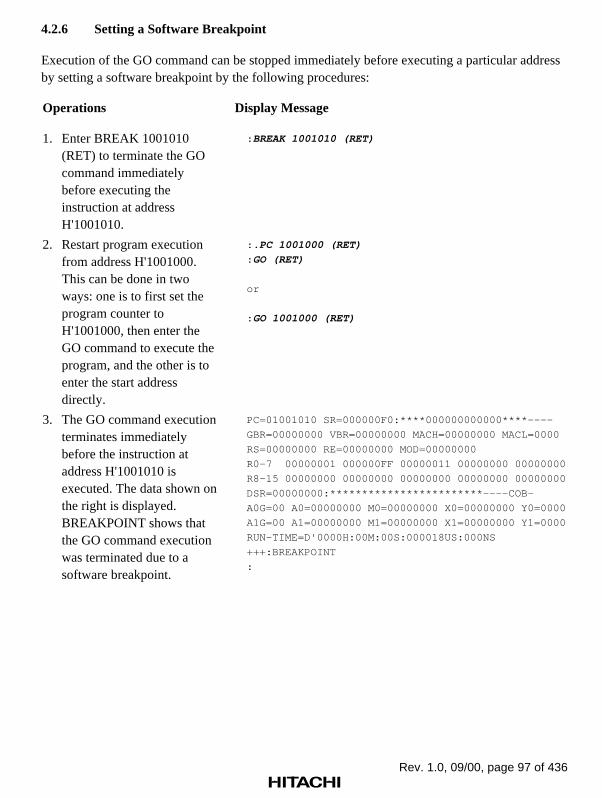
Rev. 1.0, 09/00, page 97 of 436
4.2.6 Setting a Software Breakpoint
Execution of the GO command can be stopped immediately before executing a particular addressby setting a software breakpoint by the following procedures:
Operations Display Message
1. Enter BREAK 1001010(RET) to terminate the GOcommand immediatelybefore executing theinstruction at addressH'1001010.
: BREAK 1001010 (RET)
2. Restart program executionfrom address H'1001000.This can be done in twoways: one is to first set theprogram counter toH'1001000, then enter theGO command to execute theprogram, and the other is toenter the start addressdirectly.
: .PC 1001000 (RET)
: GO (RET)
or
: GO 1001000 (RET)
3. The GO command executionterminates immediatelybefore the instruction ataddress H'1001010 isexecuted. The data shown onthe right is displayed.BREAKPOINT shows thatthe GO command executionwas terminated due to asoftware breakpoint.
PC=01001010 SR=000000F0:****000000000000****----
GBR=00000000 VBR=00000000 MACH=00000000 MACL=0000
RS=00000000 RE=00000000 MOD=00000000
R0-7 00000001 000000FF 00000011 00000000 00000000
R8-15 00000000 00000000 00000000 00000000 00000000
DSR=00000000:************************----COB-
A0G=00 A0=00000000 M0=00000000 X0=00000000 Y0=0000
A1G=00 A1=00000000 M1=00000000 X1=00000000 Y1=0000
RUN-TIME=D'0000H:00M:00S:000018US:000NS
+++:BREAKPOINT
:

Rev. 1.0, 09/00, page 98 of 436
4.2.7 Executing a Single Step
A single step can be executed using the single-step function by the following procedures:
Operations Display Message
1. The program counter points to thenext address to be executed whenthe GO command terminates.Entering STEP (RET) here executesonly a single instruction.
: STEP (RET)
2. The information shown on the rightis displayed. 01001010 ADD#FF,R0 shows the address andmnemonic code executed by theSTEP command, and STEPNORMAL END shows that single-step execution has terminated.
PC=01001012 SR=000000F0:****000000000000****
GBR=00000000 VBR=00000000 MACH=00000000 MACL
RS=00000000 RE=00000000 MOD=00000000
R0-7 00000000 00000000 00000000 00000000 00
R8-15 00000000 00000000 00000000 00000000 00
DSR=00000000:************************----COB
A0G=00 A0=00000000 M0=00000000 X0=00000000 Y
A1G=00 A1=00000000 M1=00000000 X1=00000000 Y
01001010 ADD #FF,R0
+++:STEP NORMAL END
:
3. To repeat single-step execution,enter only (RET). This can berepeated until another command isexecuted.
: (RET)
PC=01001014 SR=000000F0:****000000000000****
GBR=00000000 VBR=00000000 MACH=00000000 MACL
RS=00000000 RE=00000000 MOD=00000000
R0-7 00000000 00000000 00000000 00000000 00
R8-15 00000000 00000000 00000000 00000000 00
DSR=00000000:************************----COB
A0G=00 A0=00000000 M0=00000000 X0=00000000 Y
A1G=00 A1=00000000 M1=00000000 X1=00000000 Y
01001012 CMP/EQ #00,R0
+++:STEP NORMAL END

Rev. 1.0, 09/00, page 99 of 436
4.2.8 Setting Hardware Break Conditions
Various hardware break conditions can be specified by the following procedures:
Operations Display Message
1. Enter BREAK- (RET) to cancel thesoftware breakpoint.
: BREAK- (RET)
2. To confirm the cancellation,execute the BREAK command(enter BREAK (RET)).*** 45: NOT FOUND shows thatno software breakpoint is set.
: BREAK (RET)
***45:NOT FOUND
:
3. To specify that program executionshould terminate when data iswritten to address H'100FFF8,enterBREAK_CONDITION_UBC1A=100FFF8 W (RET).
: BREAK_CONDITION_UBC1 A=100FFF8 W (RET)
4. Enter GO 1001000 (RET) to startexecuting the program fromaddress H'1001000.
: GO 1001000 (RET)
5. When the break condition issatisfied, the information shown onthe right is displayed. BREAKCONDITION UBC1 shows thatGO command execution hasterminated because the breakcondition was satisfied.
PC=01001012 SR=000000F0:****000000000000****
GBR=00000000 VBR=00000000 MACH=00000000 MACL
RS=00000000 RE=00000000 MOD=00000000
R0-7 00000000 00000000 00000000 00000000 00
R8-15 00000000 00000000 00000000 00000000 00
DSR=00000000:************************----COB
A0G=00 A0=00000000 M0=00000000 X0=00000000 Y
A1G=00 A1=00000000 M1=00000000 X1=00000000 Y
RUN-TIME=D'0000H:00M:00S:000006US:400NS
+++:BREAK CONDITION UBC1
:

Rev. 1.0, 09/00, page 100 of 436
4.2.9 Displaying Trace Information
Trace information acquired during program execution can be displayed in various ways asfollows:

Rev. 1.0, 09/00, page 101 of 436
Operation Display Message
1. To display the instruction mnemonicinformation, enter TRACE (RET).
: TRACE (RET)
IP ADDR MNEMONIC OPERAND
*-D'000008 01001000 MOV #0A,R0
*-D'000007 01001002 MOV #01,R1
*-D'000006 01001004 MOV #01,R2
*-D'000005 01001006 MOV.L 0100101C,R4
*-D'000004 01001008 MOV R2,R3
*-D'000003 0100100A ADD R1,R2
*-D'000002 0100100C MOV.L R2,@-R4
*-D'000001 0100100E MOV R3,R1
* D'000000 01001010 ADD #FF,R0
2. To display the trace information in bus-cycle units, enter TRACE ;B (RET).
: TRACE ;B (RET)
BP AB DB MA RW STS IRQ NMI RES BRQ VCC PRB
-D'000008 01001000 E00AE101 EXT R PRG 1111 1 1 1 1 1111
-D'000007 01001004 E201D405 EXT R PRG 1111 1 1 1 1 1111
* 01001000 MOV #0A,R0
-D'000006 01001008 6323321C EXT R PRG 1111 1 1 1 1 1111
* 01001002 MOV #01,R1
* 01001004 MOV #01,R2
-D'000005 0100100C 24266133 EXT R PRG 1111 1 1 1 1 1111
* 01001006 MOV.L 0100101C,R4
* 01001008 MOV R2,R3
-D'000004 0100101C 0100FFFC EXT R DAT 1111 1 1 1 1 1111
-D'000003 01001010 70FF8800 EXT R PRG 1111 1 1 1 1 1111
* 0100100A ADD R1,R2
* 0100100C MOV.L R2,@-R4
-D'000002 01001014 8BF80009 EXT R PRG 1111 1 1 1 1 1111
* 0100100E MOV R3,R1
-D'000001 0100FFF8 00000002 EXT W DAT 1111 1 1 1 1 1111
* 01001010 ADD #FF,R0
D'000000 01001018 AFFE0009 EXT R PRG 1111 1 1 1 1 1111
3. To temporarily stop the trace informationdisplay, enter (CTRL) + S. To continuethe trace information display, enter(CTRL) + Q.(CTRL) + S and (CTRL) + Q are alsoeffective with other information displays.
: TRACE ;B (RET)
(CTRL) + S (stops trace information display) (CTRL) + Q (restarts trace information display)
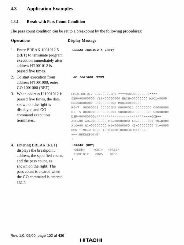
Rev. 1.0, 09/00, page 102 of 436
4.3 Application Examples
4.3.1 Break with Pass Count Condition
The pass count condition can be set to a breakpoint by the following procedures:
Operations Display Message
1. Enter BREAK 1001012 5(RET) to terminate programexecution immediately afteraddress H'1001012 ispassed five times.
: BREAK 1001012 5 (RET)
2. To start execution fromaddress H'1001000, enterGO 1001000 (RET).
: GO 1001000 (RET)
3. When address H'1001012 ispassed five times, the datashown on the right isdisplayed and GOcommand executionterminates.
PC=01001012 SR=000000F0:****000000000000****
GBR=00000000 VBR=00000000 MACH=00000000 MACL=0000
RS=00000000 RE=00000000 MOD=00000000
R0-7 00000001 000000FF 00000011 00000000 00000000
R8-15 00000000 00000000 00000000 00000000 00000000
DSR=00000000:************************----COB--
A0G=00 A0=00000000 M0=00000000 X0=00000000 Y0=0000
A1G=00 A1=00000000 M1=00000000 X1=00000000 Y1=0000
RUN-TIME=D'0000H:00M:00S:000038US:400NS
+++:BREAKPOINT
:
4. Entering BREAK (RET)displays the breakpointaddress, the specified count,and the pass count, asshown on the right. Thepass count is cleared whenthe GO command is enteredagain.
: BREAK (RET)
<ADDR> <CNT> <PASS>
01001012 0005 0005
:

Rev. 1.0, 09/00, page 103 of 436
4.3.2 Conditional Trace
The acquisition of trace information during program execution can be limited by the followingprocedures:
Operations Display Message
1. Enter BREAK - (RET) to cancelthe breakpoint set in the example ofsection 4.3.1, Break with PassCount Condition.
: BREAK - (RET)
2. Enter TRACE_CONDITION_A1A=1001010:1001014 ;R (RET) toget trace information only while theprogram counter is betweenaddresses H'1001010 andH'1001014.
: TRACE_CONDITION_A1 A=1001010:1001014;R
(RET)
3. Enter GO 1001000 (RET) to startexecuting the program, then the(BREAK) key to terminate theprogram execution.
: GO 1001000(RET )
** PC = 01001010
(BREAK)
PC=01001012 SR=000000F0:****000000000000****
GBR=00000000 VBR=00000000 MACH=00000000 MACL
RS=00000000 RE=00000000 MOD=00000000
R0-7 00000000 00000000 00000000 00000000 00
R8-15 00000000 00000000 00000000 00000000 00
DSR=00000000:************************----COB
A0G=00 A0=00000000 M0=00000000 X0=00000000 Y
A1G=00 A1=00000000 M1=00000000 X1=00000000 Y
RUN-TIME=D'0000H:00M:01S:000004US:750NS
+++:BREAK KEY
:
4. Enter TRACE ;B (RET) to displaythe trace information acquiredunder the specified condition.
: TRACE;B (RET)
BP AB DB MA RW ST IRQ NMI RES BRQ VCC PRB
–D'000039 01001010 70FF8800 EXT R PRG 1111 1 1 1 1 1111
–D'000038 01001014 88F80009 EXT R PRG 1111 1 1 1 1 1111
:
5. Enter TRACE_CONDITION_A1 -(RET) to cancel the traceacquisition condition.
: TRACE_CONDITION_A1 - (RET)

Rev. 1.0, 09/00, page 104 of 436
4.3.3 Parallel Mode
During program execution in parallel mode, the memory contents can be displayed or modified bythe following procedures:
Operations Display Message
1. After executing the GO command,enter (RET) to move to parallelmode.
: GO 1001000 (RET)
** PC = xxxxxxxx
(RET)
# (Moves to parallel mode)
2. Enter DUMP 1002000 100200F(RET) to display the memorycontents from addresses H'1002000to H'100200F in parallel mode.
#DUMP 1002000 100200F (RET)
(Dump display). . .
3. Enter MEMORY 1001019 FD(RET) to modify the memorycontents of address H'1001019 toH'FD in parallel mode.
#MEMORY 1001019 FD (RET)
# _
4. To exit from parallel mode, enterEND (RET).
#END (RET)
** PC = xxxxxxxx
5. To terminate program execution,enter the (BREAK) key.
** PC = xxxxxxxx
(BREAK)
** PC = xxxxxxxx
PC=01001012 SR=000000F0:****000000000000****
GBR=00000000 VBR=00000000 MACH=00000000 MACL
RS=00000000 RE=00000000 MOD=00000000
R0-7 00000000 00000000 00000000 00000000 00
R8-15 00000000 00000000 00000000 00000000 00
DSR=00000000:************************----COB
A0G=00 A0=00000000 M0=00000000 X0=00000000 Y
A1G=00 A1=00000000 M1=00000000 X1=00000000 Y
RUN-TIME=D'0000H:00M:03S:000034US:750NS
+++:BREAK KEY
: _

Rev. 1.0, 09/00, page 105 of 436
6. Enter DISASSEMBLE 1001000100101F (RET) to confirm that theprogram has been changed bymemory modification in parallelmode.
: DISASSEMBLE 1001000 100101F (RET)
ADDR CODE MNEMONIC OPERAND
01001000 E00A MOV #0A,R0
01001002 E101 MOV #01,R1
01001004 E201 MOV #01,R2
01001006 D405 MOV.L 0100101C,R4
01001008 6323 MOV R2,R3
0100100A 321C ADD R1,R2
0100100C 2426 MOV.L R2,@-R4
0100100E 6133 MOV R3,R1
01001010 70FF ADD #FF,R0
01001012 8800 CMP/EQ #00,R0
01001014 8BF8 BF 01001008
01001016 0009 NOP
01001018 AFFD BRA 01001016 (Changed)0100101A 0009 NOP
0100101C 0F10 .DATA.W 0101
0100101E 0000 .DATA.W 0000

Rev. 1.0, 09/00, page 106 of 436
4.3.4 Searching Trace Information
A particular part of the acquired trace information can be searched for, using theTRACE_SEARCH command as follows:
Operation Display Message
Enter TRACE_SEARCH A=1001018 (RET)to display the parts of trace information inwhich the address bus value is H'1001018.
: TRACE_SEARCH A=1001018 (RET)
BP AB DB MA RW ST IRQ NMI RES BRQ VCC PRB
–D'004088 01001018 AFFD0009 EXT R PRG 1111 1 1 1 1 1111
–D'004080 01001018 AFFD0009 EXT R PRG 1111 1 1 1 1 1111
–D'004072 01001018 AFFD0009 EXT R PRG 1111 1 1 1 1 1111
. . .

Part II Emulator Function Guide

Rev. 1.0, 09/00, page 108 of 436

Rev. 1.0, 09/00, page 109 of 436
Section 1 Emulator Functions
1.1 Overview
This emulator is a hardware and software support tool for the development of systemsincorporating the SH7410. In addition to a DSP and a high-speed CPU, the SH7410 contains atimer, serial communication interface, an SIO, a DMAC, and Hitachi-UDI (Hitachi-User-Debug-Interface) on the same chip.
Table 1.1 SH7410 Functions
Function SH7410
Maximum memory size that can be managed 64 Mbytes
Maximum external bus width 28 bits
Internal ROM 48 kbytes
Internal RAM 8 kbytes
DMAC 4 channels
Interrupt controller Five external interrupt sources (NMI and IRQ0to IRQ3)
Serial I/O (SIO) 3 channels
Serial communication interface
Asynchronous or clock synchronization
2 channels
Timer
16-bit free running timer
3 channels
I/O port
16 bits
Ports A and B
The emulator operates on the external bus clock of 60 MHz in just the same way as the SH7410on the user system and enables realtime emulation of the user system with functions fordebugging hardware and software.
The emulator consists of an emulator station and an evaluation chip board (hereafter called theEV-chip board). The EV-chip board should be connected directly to the user system.

Rev. 1.0, 09/00, page 110 of 436
1.2 Specification
The main features of the emulator are its emulation functions and its host computer interfacefunctions, as listed in tables 1.2 and 1.3, respectively.

Rev. 1.0, 09/00, page 111 of 436
Table 1.2 Emulation Functions
Command Type Command FunctionReferencesection
Realtimeemulation
GO Performs realtime emulation in thefollowing cases. The operating frequencyis 60 MHz at max.
• Executes until a hardware or softwarebreak condition is satisfied, or until the(CTRL) + C or (BREAK) key ispressed.
• Cycle-reset mode: Executes while theRES signal is sent to the SH7410 atfixed intervals. This mode is effectiveto observe waveforms after reset.
• Parallel mode: Displays trace dataand modifies memory contents duringemulation.
7.2.19
EXECUTION_MODE
Specifies execution mode. 7.2.20
Break conditionsetting
BREAK_CONDITION_UBC
Sets hardware break conditions (1).
• Normal break: Execution is forciblystopped when the specified conditionsare satisfied (a maximum of twopoints).
Address bus value or data busvalue (X/Y memory bus)
PC (program counter) value
Read/write condition
Delay/Count
Pass count specification (only forBREAK_CONDITION_UBC1)
• Mask specification for address anddata conditions
Bit-by-bit specification is enabledfor address, PC, or dataconditions.
• Specification of the satisfactionsequence up to two points
7.2.9

Rev. 1.0, 09/00, page 112 of 436
Table 1.2 Emulation Functions (cont)
Command Type Command FunctionReferencesection
Break conditionsetting (cont)
BREAK_CONDITION_A,B,C
Sets hardware break conditions (2).
• Execution is forcibly stopped when thespecified conditions are satisfied (amaximum of 24 points).
Address bus value or data busvalue
Access type
Read/write condition
Delay count (One channel)
Pass count specification (Eightchannels)
External probe value
System control signals
NOT condition
• A maximum of seven conditionspecifications and one reset-pointcondition specification
External probe trigger signal
• B channel (eight channels) and UBC(two channels) of SH7410
7.2.7
BREAK Sets software break conditions.
• Sets up to 255 breakpoints.
• Sets pass count.
7.2.6

Rev. 1.0, 09/00, page 113 of 436
Table 1.2 Emulation Functions (cont)
Command type Break FunctionReferenceSection
Trace dataacquisition anddisplay
TRACE Displays execution instruction mnemonic.
Displays the following data for each buscycle:
• Address bus value or data bus value
• Access area and status
• Instruction mnemonic
• SH7410 I/O control signals
• External probe value
• Time stamp (20 ns, 1.6 µs, 52 µs)
7.2.41
TRACE_CONDITION_A,B,C
Sets, displays, and cancels tracecondition.
• Traces data only when a condition issatisfied.
Address bus value (NOTcondition)
Read/write condition
Access type
• Stops trace when a trace stopcondition is satisfied.
Address bus value or data busvalue
Read/write condition
Access type
External probe value
System control signals
NOT condition
Delay count
• Subroutine trace
7.2.42
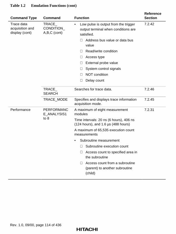
Rev. 1.0, 09/00, page 114 of 436
Table 1.2 Emulation Functions (cont)
Command Type Command FunctionReferenceSection
Trace dataacquisition anddisplay (cont)
TRACE_CONDITION_A,B,C (cont)
• Low pulse is output from the triggeroutput terminal when conditions aresatisfied.
Address bus value or data busvalue
Read/write condition
Access type
External probe value
System control signals
NOT condition
Delay count
7.2.42
TRACE_SEARCH
Searches for trace data. 7.2.46
TRACE_MODE Specifies and displays trace informationacquisition mode.
7.2.45
Performance PERFORMANCE_ANALYSIS1to 8
A maximum of eight measurementmodules
Time intervals: 20 ns (6 hours), 406 ns(124 hours), and 1.6 µs (488 hours)
A maximum of 65,535 execution countmeasurements
• Subroutine measurement
Subroutine execution count
Access count to specified area inthe subroutine
Access count from a subroutine(parent) to another subroutine(child)
7.2.31

Rev. 1.0, 09/00, page 115 of 436
Table 1.2 Emulation Functions (cont)
Command Type Command FunctionReferenceSection
Single-stepexecution
STEP,STEP_OVER,STEP_INFORMATION
Executes one step at a time, and displaysthe following.
• Instruction mnemonic
• Memory contents
• Register contents
Displays the above data for a specifiedroutine until a specified address isreached.
The above operations are performed for aspecified number of steps or until aspecified address is reached.
Specifies information to be displayedduring single-step execution.
Executes subroutine as a single step.
7.2.38,7.2.40,7.2.39
Memory access MEMORY,DUMP
Displays or modifies memory contents.
• Displays or modifies memory contentsin 1-, 2-, or 4-byte units.
• DUMP displays fixed points ofmemory contents.
7.2.27,7.2.18
MAP Specifies memory attributes in a 1-Mbyteunit.
• User memory
• Write protected
• Emulation memory
Standard: 4 Mbytes
7.2.26

Rev. 1.0, 09/00, page 116 of 436
Table 1.2 Emulation Functions (cont)
Command Type Command FunctionReferenceSection
Memory access(cont)
FILL Writes data in specified pattern. 7.2.21
DATA_SEARCH,DATA_CHANGE
Searches for and replaces data inspecified pattern.
7.2.16,7.2.15
Clock selection CLOCK • Selects emulator internal clockEML (15 MHz).
• Selects user system clock(1 to 33 MHz).
• Selects quartz oscillator of EV-chipboard (8 to 15 MHz).
7.2.12
Register access REGISTER Displays and modifies SH7410 registercontents.
7.2.34
Line assembly ASSEMBLE Assembles instruction mnemonics andspecifies memory contents.
7.2.4
Disassembly DISASSEMBLE Disassembles memory contents. 7.2.17
Execution timemeasurement
GO Measures GO command execution time.
• Measures total run time.
• Measures execution time fromBREAK_CONDITION_UBC2 conditionsatisfaction toBREAK_CONDITION_UBC1 conditionsatisfaction.
7.2.22
Test functions FILL Reads or writes the specified data to thememory.
7.2.21
CHECK Tests SH7410 input signals. 7.2.11
Command input Enables editing with cursor keys.
Copies immediately preceding line.
Copies operand of previous command.
RADIX Enables value input in binary, octal,hexadecimal, or ASCII characters.(Default can be specified.)
7.2.33
Results display RESULT Displays emulation results. 7.2.36

Rev. 1.0, 09/00, page 117 of 436
Table 1.2 Emulation Functions (cont)
Command Type Command FunctionReferenceSection
Others MOVE,MOVE_TO_RAM
Transfers memory contents.
• Memory to memory
• ROM (user system memory) tomemory
7.2.29,7.2.30
CONVERT Converts number display.
• Displays in binary, octal, decimal,hexadecimal, or fixed-point.
7.2.14
STATUS Displays emulator operating status. 7.2.37
GO Monitors emulation.
• Monitors emulation status at constantintervals and displays the emulationstatus.
7.2.22
RESET Inputs RES signal to SH7410. 7.2.35
MODE Sets and displays the SH7410 operatingmode.
7.2.28
HELP Displays all commands. 7.2.23
HISTORY Displays the history of the inputcommand.
7.2.24
ALIAS Alias function
• Defines aliases.
7.2.3
ID Displays versions of the system program. 7.2.25
ABORT Stops emulation in parallel mode. 7.2.2
END Cancels parallel mode. 7.2.19
QUIT Quits system program. 7.2.32

Rev. 1.0, 09/00, page 118 of 436
Table 1.3 Host Computer Interface Functions
Command Type Command FunctionReferenceSection
Serial interface INTFC_LOAD Loads program from host computer. 8.2.1
INTFC_SAVE Saves program in host computer. 8.2.2
INTFC_VERIFY Verifies memory contents againsthost computer files.
8.2.3
Bi-directionalparallel interface
LOAD Loads program from host computer. 8.2.4
SAVE Saves program in host computer. 8.2.5
VERIFY Verifies memory contents againsthost computer files.
8.2.6
1.3 Realtime Emulation
The emulator enables realtime emulation with a clock frequency of 60 MHz for the SH7410 withno wait states. Realtime emulation consists of the following three modes:
• Normal mode: Executes only emulation.
• Cycle reset mode: Forcibly inputs the RES signal to the SH7410 periodically.
• Parallel mode: Enables the user to display and modify memory and display trace information during user program execution.
The user can select the mode which best suits the user’s debugging needs. The following describeseach of these modes.
1.3.1 Normal Mode
Normal Mode Function: This mode executes only user program emulation. Until a breakcondition is satisfied, the emulator executes the user program. When a hardware break conditionor software break condition is satisfied, the emulator stops the program execution. When a numberof times or sequential break for the software break condition is specified, the emulator stops, onlyfor a moment, the program execution every time the specified address is passed, and then resumesprogram execution.
Normal Mode Specification: Specifying no option with the GO command sets normal mode.

Rev. 1.0, 09/00, page 119 of 436
1.3.2 Cycle Reset Mode
Cycle Reset Mode Function: The emulator inputs the RES signal to the SH7410 after a specifiedtime during realtime emulation and repeats the execution from the reset state. When the RESsignal is input to the SH7410, a low-level pulse is output to the trigger output probe concurrently.This function is useful to observe the waveform from the initial state, such as power-on-reset, to aspecified time.
User program Re-execution from reset address
RES input to the SH7410 after specified time
Program flow
TRIG
Low-level pulseis output to thetrigger outputprobe.
Figure 1.1 Cycle Reset Mode
Cycle Reset Mode Specification: Set “R=n” as a GO command option to specify cycle resetmode. For details, refer to section 7.2.22, GO.
Emulation Stop: In cycle reset mode, hardware break conditions and software break conditionsare invalid. To stop emulation, press the (CTRL) + C keys or the (BREAK) key.

Rev. 1.0, 09/00, page 120 of 436
Trigger Signal Output Timing in Cycle Reset Mode: In cycle reset mode, the RES signal isoutput to the SH7410 regardless of the SH7410 operating status when the time specified by thecommand has elapsed. Figure 1.2 shows the timing in which the TRIG signal is output to thetrigger output probe in cycle reset mode.
Time specified by the command
TRIG
(RES)
3.25 µs
Figure 1.2 Trigger Signal Output Timing

Rev. 1.0, 09/00, page 121 of 436
1.3.3 Parallel Mode
Parallel Mode Function: In parallel mode, the emulator can display and modify memory ordisplay trace information during realtime emulation. However, during memory contents display ormodification, realtime emulation cannot be performed.
Parallel Mode Specification: Parallel mode can be activated during GO command realtimeemulation by any of the following methods as shown in figure 1.3.
• Press the (RET) key
• Press the space key
• Satisfy a trace stop condition specified by the TRACE_CONDITION_A,B,C command
If any of the above occurs, the emulator will display a prompt (#) and enter parallel modecommand input wait state. Emulation, however, continues without interruption. Input the END (E)command to return to the normal mode. Input the ABORT (AB) command to stop user programexecution in the parallel mode.
Normal mode(executing
a user program)
Parallel mode(executing
a user program)
Command inputwait state
By pressing the (RET) key orspace key, or by satisfying thetrace stop condition
END command
GO command
ABORT command(BREAK) or (CTRL) + C
Figure 1.3 Transition to Parallel Mode
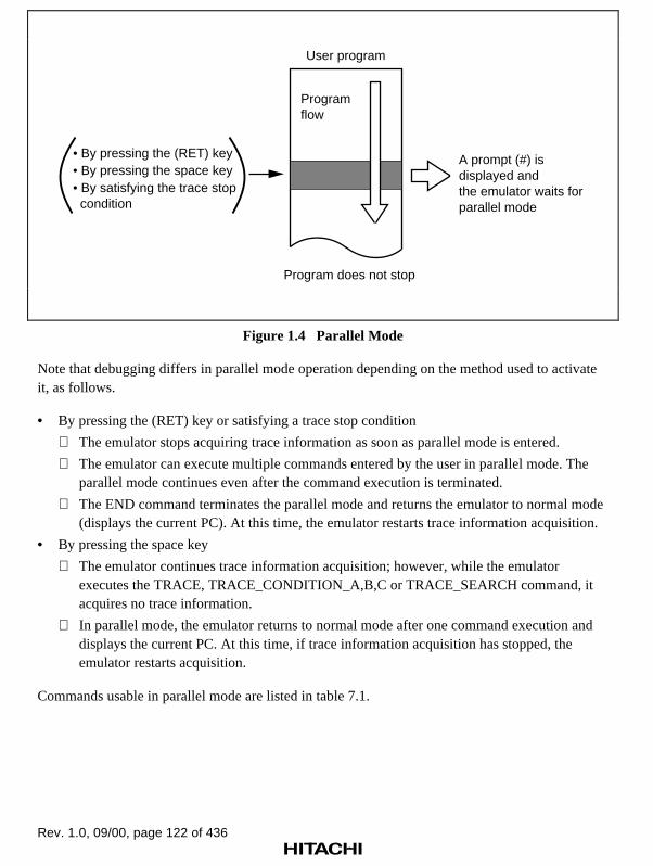
Rev. 1.0, 09/00, page 122 of 436
• By pressing the (RET) key A prompt (#) is displayed and the emulator waits for parallel mode
• By pressing the space key• By satisfying the trace stop condition
Programflow
User program
Program does not stop
Figure 1.4 Parallel Mode
Note that debugging differs in parallel mode operation depending on the method used to activateit, as follows.
• By pressing the (RET) key or satisfying a trace stop condition
The emulator stops acquiring trace information as soon as parallel mode is entered.
The emulator can execute multiple commands entered by the user in parallel mode. Theparallel mode continues even after the command execution is terminated.
The END command terminates the parallel mode and returns the emulator to normal mode(displays the current PC). At this time, the emulator restarts trace information acquisition.
• By pressing the space key
The emulator continues trace information acquisition; however, while the emulatorexecutes the TRACE, TRACE_CONDITION_A,B,C or TRACE_SEARCH command, itacquires no trace information.
In parallel mode, the emulator returns to normal mode after one command execution anddisplays the current PC. At this time, if trace information acquisition has stopped, theemulator restarts acquisition.
Commands usable in parallel mode are listed in table 7.1.

Rev. 1.0, 09/00, page 123 of 436
Notes: 1. When memory (standard emulation memory or internal I/O) is accessed with theMEMORY command, DUMP command, or DISASSEMBLE command in parallelmode, there are some restrictions with respect to user program execution.
• Standard emulation memory
When accessing standard emulation memory in parallel mode, the userprogram temporarily halts. This pause lasts for about 546 µs during usersystem clock operation. Therefore, realtime emulation cannot be performed.
• Internal ROM/RAM and I/O
When accessing internal I/O, the user program temporarily halts. This pauselasts for about 546 µs during user system clock operation. Therefore, realtimeemulation cannot be performed.
• In the above two cases, the emulator pauses at the following timing.
—MEMORY command: At each memory access
—DUMP command: In 16-byte units
—DISASSEMBLE command: In 4-byte units
2. During execution of the TRACE, TRACE_SEARCH,TRACE_CONDITION_A,B,C or TRACE_MEMOEY command, the emulatorstops trace information acquisition.
3. The emulator cannot enter parallel mode when executing emulation in thefollowing modes:
• Cycle reset mode (R option of GO command)
• Time measurement mode (I1 or I2 option of GO command)
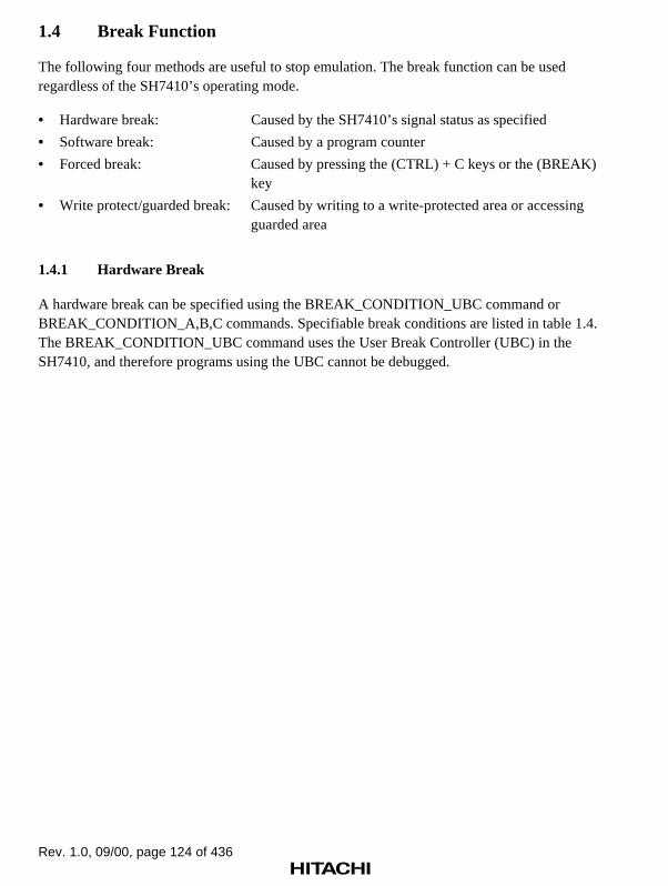
Rev. 1.0, 09/00, page 124 of 436
1.4 Break Function
The following four methods are useful to stop emulation. The break function can be usedregardless of the SH7410’s operating mode.
• Hardware break: Caused by the SH7410’s signal status as specified
• Software break: Caused by a program counter
• Forced break: Caused by pressing the (CTRL) + C keys or the (BREAK) key
• Write protect/guarded break: Caused by writing to a write-protected area or accessing guarded area
1.4.1 Hardware Break
A hardware break can be specified using the BREAK_CONDITION_UBC command orBREAK_CONDITION_A,B,C commands. Specifiable break conditions are listed in table 1.4.The BREAK_CONDITION_UBC command uses the User Break Controller (UBC) in theSH7410, and therefore programs using the UBC cannot be debugged.

Rev. 1.0, 09/00, page 125 of 436
Table 1.4 Specifiable Hardware Break Conditions
Condition
BREAK_CONDITION_UBC1
BREAK_CONDITION_UBC2
BREAK_CONDITION_A(1 to 8)
BREAK_CONDITION_B(1 to 8)
BREAK_CONDITION_C(1 to 8)
Addresscondition
O O O O O
Datacondition
O O O
Read/writecondition
O O O O
Bus cyclespecification
O O O O O
Probecondition
O O
Externalinterruptcondition
O O
Pass count O O
Delay countspecification
O
Sequentialbreak
O O
Notes: 1. Only the BREAK_CONDITION_B7 can be specified for the delay count specification.
2. O represents specifiable item.
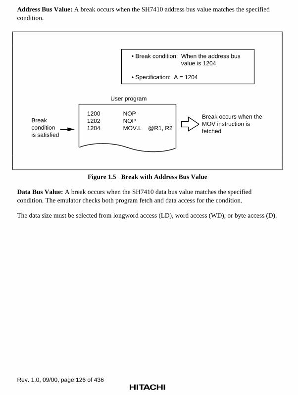
Rev. 1.0, 09/00, page 126 of 436
Address Bus Value: A break occurs when the SH7410 address bus value matches the specifiedcondition.
Break conditionis satisfied
Break occurs when the MOV instruction is fetched
User program
• Break condition: When the address bus value is 1204
• Specification: A = 1204
120012021204
NOPNOPMOV.L @R1, R2
Figure 1.5 Break with Address Bus Value
Data Bus Value: A break occurs when the SH7410 data bus value matches the specifiedcondition. The emulator checks both program fetch and data access for the condition.
The data size must be selected from longword access (LD), word access (WD), or byte access (D).

Rev. 1.0, 09/00, page 127 of 436
Break conditionis satisfied
Break occurs when the #12 is fetched
User program
• Break condition: When the data bus value is 12
• Specification: D = 12
1200120212041206
NOPNOPMOV #12, R1MOV R1, @R2
Figure 1.6 Break with Data Bus Value
Read/Write Condition: A break occurs when the SH7410’s RD and RDWR signal levels matchthe specified conditions. Usually, the read/write condition is specified together with the address ordata conditions.
Break conditionis satisfied
Break occurs when 01 is written to address @R2 (F000000)
User program
• Break condition: When writing 01 to address H'F000000
• Specification: A=F000000 W
120012021204
NOPMOV #01, R1MOV.B R1, @R2
Figure 1.7 Break with Read/Write
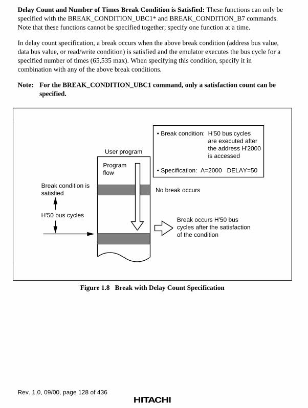
Rev. 1.0, 09/00, page 128 of 436
Delay Count and Number of Times Break Condition is Satisfied: These functions can only bespecified with the BREAK_CONDITION_UBC1* and BREAK_CONDITION_B7 commands.Note that these functions cannot be specified together; specify one function at a time.
In delay count specification, a break occurs when the above break condition (address bus value,data bus value, or read/write condition) is satisfied and the emulator executes the bus cycle for aspecified number of times (65,535 max). When specifying this condition, specify it incombination with any of the above break conditions.
Note: For the BREAK_CONDITION_UBC1 command, only a satisfaction count can bespecified.
Break occurs H'50 bus cycles after the satisfaction of the condition
Programflow
User program
No break occurs
H'50 bus cycles
Break condition is satisfied
• Break condition: H'50 bus cycles are executed after the address H'2000 is accessed
• Specification: A=2000 DELAY=50
Figure 1.8 Break with Delay Count Specification

Rev. 1.0, 09/00, page 129 of 436
In number of times break condition is satisfied specification, a break occurs when the above breakcondition (address bus value, data bus value, or read/write condition) is satisfied for a specifiednumber of times (65,535 max). When specifying this condition, specify it in combination with anyof the above break conditions.
Break occurs after the addressH'2000 is accessed for H'50 times
Program flow
Break condition issatisfied
User program
• Break condition: The address H'2000 is accessed for H'50 times
• Specification: A=2000 COUNT=50
(Branch instructions, etc.)
Figure 1.9 Break with Delay Count Specification

Rev. 1.0, 09/00, page 130 of 436
PC Value (BREAK_CONDITION_UBC1,2): A break occurs when the SH7410 programcounter (PC) value satisfies the specified condition. The break timing depends on the ;P optionsetting as follows:
• PC value without option ;P (PC=1000): Break after execution
A break occurs after the instruction at the specified address is executed.
• PC value followed by option ;P (PC=1000;P): Break before execution
A break occurs before the instruction at the specified address is executed.
Break conditionis satisfied
User program • Break condition: Break occurs after the instruction at address H'1004 is executed
• Specification: PC = 1004• At break: R0 = 2
100010021004
MOVADDADD
#0,R0#1,R0#1,R0
Break after execution
• Break condition: Break occurs before the instruction at address H'1004 is executed
• Specification: PC = 1004;P• At break: R0 =1
Break before execution
Figure 1.10 Break with PC Value Specification

Rev. 1.0, 09/00, page 131 of 436
Sequential Break Condition: In sequential break mode, a break occurs when hardware breakconditions UBC2 and UBC1 have been satisfied in that order.
When executing the user program, specify the mode option of the GO command as a sequentialbreak option (;SB). Unless the option is specified, a sequential break does not occur. In this case,a break occurs whenever each break condition is satisfied.
Specify the break condition with the BREAK_CONDITION_UBC1,2 commands. The user canspecify either of the address bus value, the data bus value, or the read/write condition in theabove.
• Sequential break mode
When break condition UBC2 and then break condition UBC1 are satisfied, a break occurs.
Note: When the sequential break option (;SB) of the GO command is specified while theBREAK_CONDITION_UBC1 or 2, or both are not specified, the error messagebelow will be output. At this time, a user program will not be executed.*** 35:CAN NOT USE THIS MODE
When break condition 1 is satisfied afterbreak condition 2, a break occurs.
User program
Programflow
Break condition2 is satisfied
Break condition1 is satisfied
• Initiation condition: User program is executed in sequential break mode from address H'2000
• Specification: GO 2000 ; SB
No break occurs
2000
Figure 1.11 Break with Sequential Specification

Rev. 1.0, 09/00, page 132 of 436
1.4.2 Software Break
The contents at the specified address are replaced with a break instruction. The program executionstops when the break instruction is executed. The replaced instruction at the address is notexecuted. After the GO command is executed, the contents at the specified address will bereplaced with a break instruction and the user program will be executed. When the user programexecution stops, the break instruction will be replaced again with the contents at the specifiedaddress. Therefore, the contents at the specified address can be accessed immediately after theuser program execution, using the DISASSEMBLE command or the DUMP command. However,note that a break instruction will be read if the memory contents at the break address are accessedin the parallel mode.
No software break must be specified immediately after a delayed branch instruction (at a slotinstruction). If specified, a slot invalid instruction interrupt will occur at the branch instructionexecution, and a break will not occur.
The software break can be performed in the following two ways:
• Normal break
• Sequential break
Normal Break: A break occurs after executing the breakpoint instruction specified with theBREAK command. At this time, the following can be specified:
• Number of break points: 255 points (max)
• Number of times the break condition is satisfied: A break occurs after executing the breakpointinstruction a specified number of times. The maximum number to specify is 65,535 (H'FFFF).
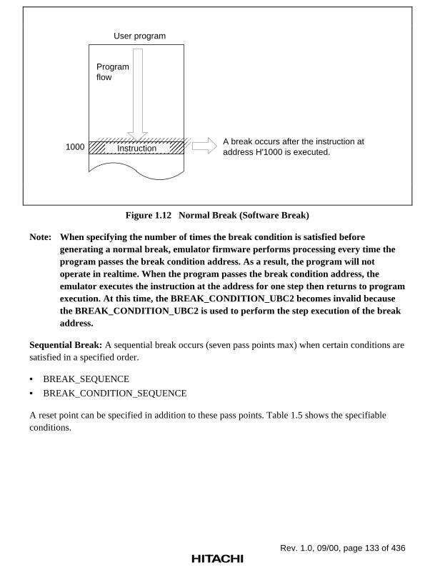
Rev. 1.0, 09/00, page 133 of 436
User program
1000 InstructionA break occurs after the instruction at address H'1000 is executed.
Programflow
Figure 1.12 Normal Break (Software Break)
Note: When specifying the number of times the break condition is satisfied beforegenerating a normal break, emulator firmware performs processing every time theprogram passes the break condition address. As a result, the program will notoperate in realtime. When the program passes the break condition address, theemulator executes the instruction at the address for one step then returns to programexecution. At this time, the BREAK_CONDITION_UBC2 becomes invalid becausethe BREAK_CONDITION_UBC2 is used to perform the step execution of the breakaddress.
Sequential Break: A sequential break occurs (seven pass points max) when certain conditions aresatisfied in a specified order.
• BREAK_SEQUENCE
• BREAK_CONDITION_SEQUENCE
A reset point can be specified in addition to these pass points. Table 1.5 shows the specifiableconditions.

Rev. 1.0, 09/00, page 134 of 436
Table 1.5 Specifiable Conditions
Condition BREAK_SEQUENCEBREAK_CONDITON_SEQUENCE
Address condition O O
Data condition O
Read/write condition O
Bus cycle specification O
Probe condition O
External interrupt condition O
Delay count specification O
O: Specifiable
If the reset point is passed, all sequential break conditions up to that point become invalid and theemulator rechecks from the first break condition.
Figure 1.13 illustrates the usual sequential break and figure 1.14 describes a sequential breakwhen a reset point is specified.

Rev. 1.0, 09/00, page 135 of 436
The break condition is satisfiedwhen instructions at addressesH'1000 and H'2000 have beenexecuted in sequence.
Programflow
User program
2000(Break condition 2)
1000(Break condition 1) No break occurs
• Break condition: The break condition is satisfied when instructions at addresses H'1000 and H'2000 have been executed in sequence.
• Specification: BREAK_SEQUENCE 1000 2000
Figure 1.13 Sequential Break

Rev. 1.0, 09/00, page 136 of 436
A break occurs when the instructionsat addresses H'1000 and H'2000have been executed in sequence.
Programflow
User program
1000(Break condition 1)
No break occurs(Wait for break condition 2)
Searches for the conditionfrom break condition 1
500(Reset point)
No break occurs(Wait for break condition 1)
2000(Break condition 2)
No break occurs(Wait for break condition 1)
1000(Break condition 1)
No break occurs(Wait for break condition 2)
2000(Break condition 2)
• Break condition: A break occurs when the instructions at addresses H'1000 and H'2000 have been executed in sequence.
• Specification: BREAK_SEQUENCE 1000 2000 BREAK_SEQUENCE 500;R
Figure 1.14 Sequential Break (Reset Point Specification)
Note: When specifying the sequential break (BREAK_SEQUENCE), emulator firmwareperforms processing every time the program passes the pass point or reset point. As aresult, the program will not operate in realtime. When the program passes the passpoint or reset point, the emulator executes the instruction at the address for one stepthen returns to program execution. Accordingly, the BREAK_CONDITION_UBC2settings are invalid at pass point or reset point execution.
1.4.3 Forced Break
Pressing the (CTRL) + C keys or the (BREAK) key stops program execution.
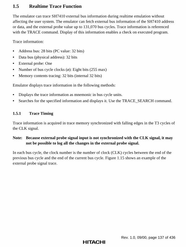
Rev. 1.0, 09/00, page 137 of 436
1.5 Realtime Trace Function
The emulator can trace SH7410 external bus information during realtime emulation withoutaffecting the user system. The emulator can fetch external bus information of the SH7410 addressor data, and the external probe value up to 131,070 bus cycles. Trace information is referencedwith the TRACE command. Display of this information enables a check on executed program.
Trace information:
• Address bus: 28 bits (PC value: 32 bits)
• Data bus (physical address): 32 bits
• External probe: One
• Number of bus cycle clocks (ø): Eight bits (255 max)
• Memory contents tracing: 32 bits (internal 32 bits)
Emulator displays trace information in the following methods:
• Displays the trace information as mnemonic in bus cycle units.
• Searches for the specified information and displays it. Use the TRACE_SEARCH command.
1.5.1 Trace Timing
Trace information is acquired in trace memory synchronized with falling edges in the T3 cycles ofthe CLK signal.
Note: Because external probe signal input is not synchronized with the CLK signal, it maynot be possible to log all the changes in the external probe signal.
In each bus cycle, the clock number is the number of clock (CLK) cycles between the end of theprevious bus cycle and the end of the current bus cycle. Figure 1.15 shows an example of theexternal probe signal trace.
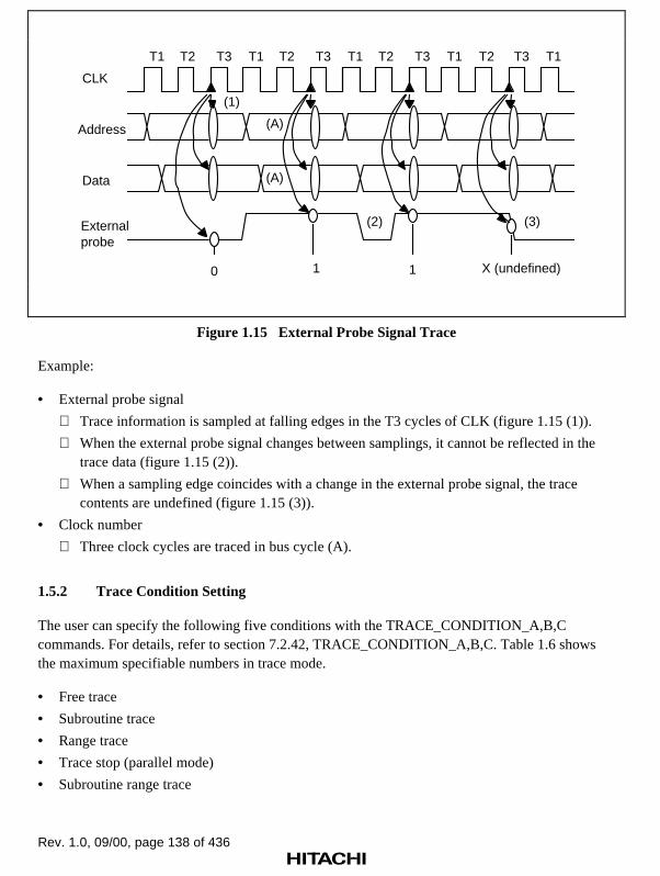
Rev. 1.0, 09/00, page 138 of 436
T1 T2 T3 T1 T2 T3 T1 T2 T3 T1 T2 T3 T1
(1)
(2) (3)
CLK
(A)
(A)
Address
Data
Externalprobe
0 1 1 X (undefined)
Figure 1.15 External Probe Signal Trace
Example:
• External probe signal
Trace information is sampled at falling edges in the T3 cycles of CLK (figure 1.15 (1)).
When the external probe signal changes between samplings, it cannot be reflected in thetrace data (figure 1.15 (2)).
When a sampling edge coincides with a change in the external probe signal, the tracecontents are undefined (figure 1.15 (3)).
• Clock number
Three clock cycles are traced in bus cycle (A).
1.5.2 Trace Condition Setting
The user can specify the following five conditions with the TRACE_CONDITION_A,B,Ccommands. For details, refer to section 7.2.42, TRACE_CONDITION_A,B,C. Table 1.6 showsthe maximum specifiable numbers in trace mode.
• Free trace
• Subroutine trace
• Range trace
• Trace stop (parallel mode)
• Subroutine range trace

Rev. 1.0, 09/00, page 139 of 436
Table 1.6 Maximum Specifiable Numbers in Trace Mode
TRACE_CONDITION_A
TRACE_CONDITION_B
TRACE_CONDITION_C Total
Subroutine trace — 8 8 16
Range trace 8 8 8 24
Subroutine rangetrace
— 4 — 4
Trace stop(Parallel mode)
8 8 8 24
Free Trace: In free trace when the user program is executed as a result of the GO, STEP, orSTEP_OVER command, tracing is carried out continuously for a maximum of the latest 131,070bus cycles until a break condition is satisfied. When no parameter is given with theTRACE_CONDITION_A,B,C commands, the default is free trace. Figure 1.16 illustrates the freetrace operation.
Note: Only external bus information can be traced at realtime. For details, refer to section1.5, Realtime Trace Function.
Programflow
Break condition issatisfied
User program
131,070bus cycles
Trace memory
Figure 1.16 Free Trace Execution
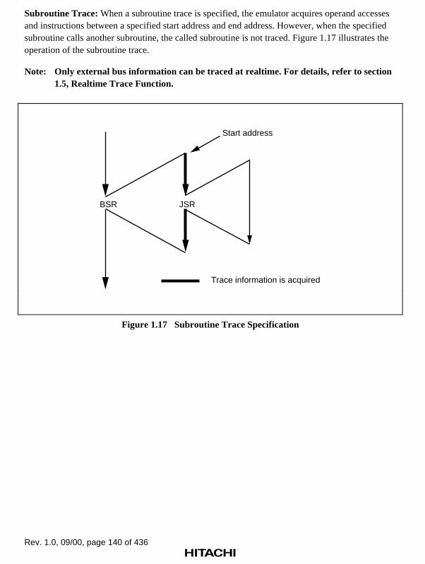
Rev. 1.0, 09/00, page 140 of 436
Subroutine Trace: When a subroutine trace is specified, the emulator acquires operand accessesand instructions between a specified start address and end address. However, when the specifiedsubroutine calls another subroutine, the called subroutine is not traced. Figure 1.17 illustrates theoperation of the subroutine trace.
Note: Only external bus information can be traced at realtime. For details, refer to section1.5, Realtime Trace Function.
BSR JSR
Start address
Trace information is acquired
Figure 1.17 Subroutine Trace Specification
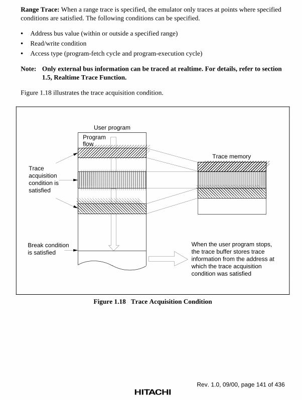
Rev. 1.0, 09/00, page 141 of 436
Range Trace: When a range trace is specified, the emulator only traces at points where specifiedconditions are satisfied. The following conditions can be specified.
• Address bus value (within or outside a specified range)
• Read/write condition
• Access type (program-fetch cycle and program-execution cycle)
Note: Only external bus information can be traced at realtime. For details, refer to section1.5, Realtime Trace Function.
Figure 1.18 illustrates the trace acquisition condition.
User program
Trace acquisition condition is satisfied
Break condition is satisfied
When the user program stops, the trace buffer stores trace information from the address at which the trace acquisition condition was satisfied
Trace memory
Program flow
Figure 1.18 Trace Acquisition Condition

Rev. 1.0, 09/00, page 142 of 436
Trace Stop (Parallel Mode): When a trace stop condition is specified, the emulator acquires traceinformation until the specified condition is satisfied. At this point, trace acquisition stops and theemulator prompts for command input in parallel mode, although realtime emulation does not stop.Refer to section 1.3.3, Parallel Mode, for details. Once the trace stop conditions have beensatisfied and the trace information has been displayed, the user can specify the trace stop conditionagain. The user can specify the following conditions.
• Address bus or data bus value
• Read/write condition
• Access type (DAT, DMA, VCF)
• External probe value
• System control signal (BREQ)
• NOT condition
• Delay count (H'1 to H'FFFF)
Figure 1.19 shows the trace stop condition specification.
Trace stop condition is satisfied
User program
Program flow
(No break occurs)
Trace memory
131,070 bus cycles
Realtime emulation continues
Figure 1.19 Trace Stop Condition Specification
Subroutine Range Trace: Trace information is acquired only when the instructions and operandsare accessed in the specified subroutine under the specified condition. The subroutine andcondition can be specified with the TRACE_CONDITION_A,B,C commands.

Rev. 1.0, 09/00, page 143 of 436
1.5.3 Trace Display
The user can display trace information using the TRACE command. There are three displayformats, as follows. When branch instruction trace is specified with the TRACE_MODEcommand, trace information for branch instruction cycles is displayed.
Instruction Display: Only the executed instruction will be displayed in mnemonics from the traceinformation.
Bus Cycle Display: Trace information is displayed in bus cycle units.
Search Display: The emulator searches for specified trace information and displays all theappropriate bus cycles. In this case, use the TRACE_SEARCH command.

Rev. 1.0, 09/00, page 144 of 436
1.6 Single-Step Function
In addition to realtime emulation, effective debugging is facilitated by the single-step function.This function displays the following information every time a program instruction is executed.
• SH7410 control registers (PC, SR, PR, GBR, VBR, MACH, MACL, RS, RE, MOD)
• SH7410 general registers (R0 to R15)
• DSP registers of SH7410 (DSR, A0G, A0, A1G, A1, M0, M1, X0, X1, Y0, Y1)
• Instruction address
• Instruction mnemonic
• Memory contents
• Termination cause
1.6.1 Single-Step Execution
Single-step execution has three modes: one in which all the instructions are displayed, one inwhich only branch instructions are displayed, and another in which instructions of a subroutineexecuted at first are displayed. To execute this function, use the STEP command, or to execute asubroutine in a single step, use the STEP_OVER command.
Displaying All Instructions: The emulator displays the specified information after everyinstruction.
Branch Instruction Display: The information is only displayed at branch instructions listedbelow.
BT, BF, BRA, BSR, JMP, JSR, BTS, BFS, BRAF, BSRF, TRAPA
Subroutine Display: When a subroutine is called, the information for the subroutine executed atfirst is displayed.

Rev. 1.0, 09/00, page 145 of 436
BSR JSR
Start address
Trace information is acquired
Figure 1.20 Subroutine Display
This function interrupts the execution state display at the JSR, BSR, or BSRF instruction in thedesignated subroutine and resumes the execution state display when the instruction placedimmediately after the JSR, BSR, or BSRF instruction is executed. After that, if another JSR, BSR,or BSRF instruction is executed, the execution state display is interrupted.
Subroutine Step Execution: When executing a JSR, BSR, or BSRF instruction, the emulatortreats the called subroutine as a single step. All other instructions are executed one at a time. Thisfunction is valid only in the user RAM or the emulation memory area.
1.6.2 Setting Display Information
The user can set the information displayed at each instruction using the STEP_ INFORMATIONcommand. For details, refer to section 7.2.39, STEP_INFORMATION.
1.6.3 Termination of Single-Step Function
The single-step function stops after executing a specified number of steps from the specified startaddress (or the current PC address). The user can stop execution by specifying a stop address.However, the specified address must be at the start of an instruction. If the second byte of aninstruction is specified (not the start of an instruction), the single-step function will not stop andexecution continues for the specified number of steps.
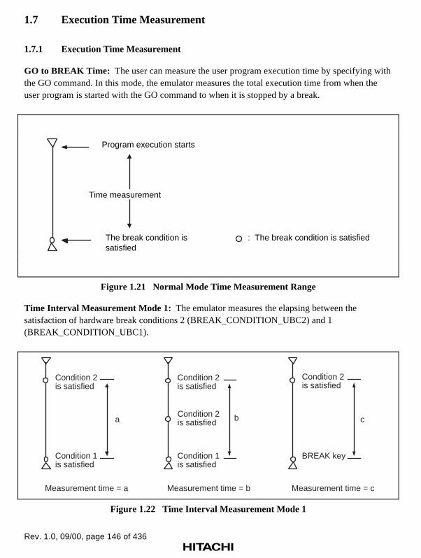
Rev. 1.0, 09/00, page 146 of 436
1.7 Execution Time Measurement
1.7.1 Execution Time Measurement
GO to BREAK Time: The user can measure the user program execution time by specifying withthe GO command. In this mode, the emulator measures the total execution time from when theuser program is started with the GO command to when it is stopped by a break.
: The break condition is satisfied
Program execution starts
The break condition is satisfied
Time measurement
Figure 1.21 Normal Mode Time Measurement Range
Time Interval Measurement Mode 1: The emulator measures the elapsing between thesatisfaction of hardware break conditions 2 (BREAK_CONDITION_UBC2) and 1(BREAK_CONDITION_UBC1).
Condition 2is satisfied
Condition 1is satisfied
a
Measurement time = a
Condition 2is satisfied
BREAK key
c
Measurement time = c
Condition 2is satisfied
Condition 1is satisfied
b
Measurement time = b
Condition 2is satisfied
Figure 1.22 Time Interval Measurement Mode 1
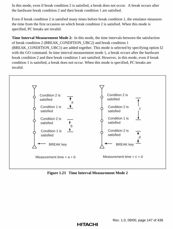
Rev. 1.0, 09/00, page 147 of 436
In this mode, even if break condition 2 is satisfied, a break does not occur. A break occurs afterthe hardware break condition 2 and then break condition 1 are satisfied.
Even if break condition 2 is satisfied many times before break condition 1, the emulator measuresthe time from the first occasion on which break condition 2 is satisfied. When this mode isspecified, PC breaks are invalid.
Time Interval Measurement Mode 2: In this mode, the time intervals between the satisfactionof break condition 2 (BREAK_CONDITION_UBC2) and break condition 1(BREAK_CONDITION_UBC1) are added together. This mode is selected by specifying option I2with the GO command. In time interval measurement mode 1, a break occurs after the hardwarebreak condition 2 and then break condition 1 are satisfied. However, in this mode, even if breakcondition 1 is satisfied, a break does not occur. When this mode is specified, PC breaks areinvalid.
Condition 2 issatisfied
Condition 2 issatisfied
Condition 1 issatisfied
Condition 1 issatisfied
BREAK key
a
b
Measurement time = a + b
Condition 2 issatisfied
Condition 1 issatisfied
Condition 2 issatisfied
Condition 2 issatisfied
BREAK key
d
Measurement time = c + d
c
Figure 1.23 Time Interval Measurement Mode 2

Rev. 1.0, 09/00, page 148 of 436
1.7.2 Subroutine Time Measurement and Number of Times Measurement
The subroutine time and number of times the subroutines are executed can be measured based onthe total program execution time by the PERFORMANCE_ANALYSIS command. Specify thesubroutine to be measured with start and end addresses. The maximum number of subroutineswhich can be measured is shown in table 1.7.
Table 1.7 Maximum Number of Measurable Subroutines
Measurement Mode Maximum Number of Measurable Subroutines
Time measurement mode 1 8
Time measurement mode 2 8
Time measurement mode 3 4
Access count to specified area 4
Number of nested subroutine calls 4
The measurement results are displayed in the following three ways:
• Numerical ratio of total execution time and specified subroutine execution time
• Bar graph indicating the ratio of total execution time and specified subroutine execution time
• Numerical value of specified subroutine execution time
For details on the PERFORMANCE_ANALYSIS command, refer to section 7.2.31,PERFORMANCE_ANALYSIS.

Rev. 1.0, 09/00, page 149 of 436
Time Measurement Mode 1: The execution time and count of the subroutine specified by thestart address and end address.
• Execution count measurement
This is counted up every time the end address of the specified subroutine is passed.
• Execution time measurement
The measurement result does not include the execution time of the subroutine called by thespecified subroutine (between the start address and end address).
Start address
End address
Time is measured.
Figure 1.24 Time Measurement Mode 1
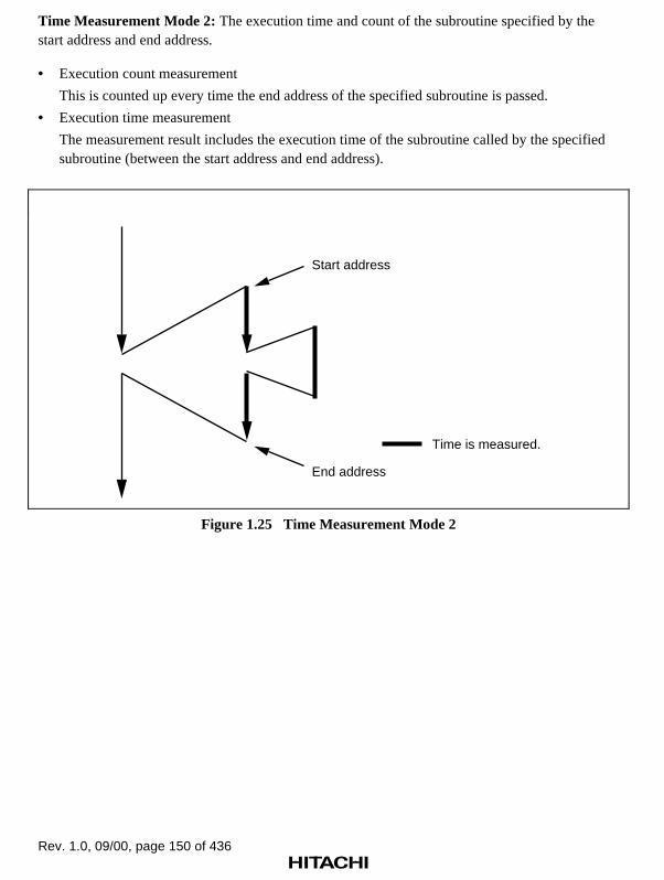
Rev. 1.0, 09/00, page 150 of 436
Time Measurement Mode 2: The execution time and count of the subroutine specified by thestart address and end address.
• Execution count measurement
This is counted up every time the end address of the specified subroutine is passed.
• Execution time measurement
The measurement result includes the execution time of the subroutine called by the specifiedsubroutine (between the start address and end address).
Start address
End address
Time is measured.
Figure 1.25 Time Measurement Mode 2

Rev. 1.0, 09/00, page 151 of 436
Time Measurement Mode 3: The execution time and count of the subroutine specified by thestart address and end address. The combination of the channels is fixed as follows:
• 1 and 2
• 3 and 4
• 5 and 6
• 7 and 8
Start address range
End address range
Figure 1.26 Time Measurement Mode 3
• Execution count measurement
This is counted up every time the end address of the specified subroutine is passed.
• Execution time measurement
The measurement starts from the program fetch cycles of the start address range and ends withthe program fetch cycles of the end address range. Accordingly, the execution time of asubroutine called during this period is included.
Specified Count Access Range: The access count from the subroutine specified by the startaddress and end address to the data in the user specification area is measured. The combination ofthe channels is the same as that for time measurement mode 3. In this case, this is measured intime measurement mode 1.
Subroutine-Call Count Measurement Mode: The access count to a subroutine (child) ismeasured during subroutine (parent) execution. The combination of the channels is the same asthat for time measurement mode 3.

Rev. 1.0, 09/00, page 152 of 436
Maximum/Minimum Subroutine Time Detection Function: This is specified in the timemeasurement mode 2 of PERFORMANCE_ANALYSIS_1,2,3,4. This measures themaximum/minimum execution time for a subroutine specified by the start address and endaddress.
Timeout Function: This compares a measured value and a user specification time during userspecified subroutine execution.
• User specification time < Measured value
User program execution breaks.
• User specification time > Measured value
Execution time is measured.
1.8 Trigger Output
During user program execution, the emulator outputs a low-level pulse from the trigger outputprobe under the following two conditions.
• Trace condition satisfaction
• Hardware break condition satisfaction
When using this pulse as an oscilloscope trigger input signal, it becomes easy to adjust the usersystem hardware. For example, wave forms can be seen when the user program goes to a specifiedpoint.
Trace Condition Satisfaction: When the trigger output is specified using the TRGB and TRGUoptions of the EXECUTION_MODE command, a low-level pulse is output from the triggeroutput probe at bus cycles corresponding to the specified condition. The trigger signal is outputfrom the end of the corresponding bus cycle until the end of the next bus cycle. If the conditionsare satisfied in consecutive bus cycles, the trigger output remains low.
Hardware Break Condition Satisfaction: During emulation, a low-level pulse is output from thetrigger output pin at the end of the bus cycle during which the hardware break condition issatisfied. The trigger signal is output from the end of the corresponding bus cycle until the end ofthe next bus cycle. If the conditions are satisfied in consecutive bus cycles, the trigger outputremains low.
Note: No pulse is output from the trigger output probe when a software break condition issatisfied. In addition, a low-level pulse output timing and pulse width differdepending on each condition.

Rev. 1.0, 09/00, page 153 of 436
CLK
T1 T2 T3 T3T1 T2 T1 T2
5.2 ns 159.2 ns
18.4 ns 53.2 ns
Address
TRIG (when the user break controller condition is satisfied)
TRIG (when the hardware breakcondition or trace conditionis satisfied)
Three statesExternal bus clock: 30 MHz
Figure 1.27 Pulse Output Timing

Rev. 1.0, 09/00, page 154 of 436
1.9 SH7410 Control and Status Check
The emulator is capable of switching the clock signal supplied to the SH7410, outputting strobesignals when the emulation memory is accessed, checking normal operation, and displaying theexecution state. This function is effective for debugging the user system hardware.
Clock Switching: The emulation clock can be supplied from the user system clock (hereafterreferred to as the user clock), the crystal oscillator installed on the emulator pod, and the internalclock (15.0 MHz). To switch the clock, refer to section 7.2.9, CLOCK, and note the following. Inaddition, refer to section 3.2.3, Selecting Clock in part I, E8000 Guide.
• When the clock is switched, the emulator inputs a RES signal to the SH7410. This initializesthe registers.
• When the user switches to the user clock and the user clock signal is not supplied, an errormessage is displayed and the internal clock is selected instead.
• When initiating the emulator system program, the emulator selects the SH7410 clockautomatically in the following order:
When an external clock is supplied from the user system, selects the user clock
When a crystal oscillator is installed to the emulator pod, selects the crystal oscillator
Selects the emulation clock (15.0 MHz)
Check of the I/O signals: The emulator checks the connection with the user system at systeminitiation. By this check, abnormalities such as short circuits of a user system interface signal canbe detected. The signals to be checked are as follows:
RES, BREQ, WAIT, IRQ0 to IRQ3, and NMI
The CHECK command can check the same signals that are checked at system initiation. Fordetails, refer to section 7.2.11, CHECK.
Emulator Execution Status Display: The emulator can display execution status informationlisted in table 1.8. To display the execution status, use the STATUS command. For details, refer tosection 7.2.37, STATUS.

Rev. 1.0, 09/00, page 155 of 436
Table 1.8 Execution Status Display
Display Command Description
MODE=xx SH7410 operating mode
RADIX=xx Radix type
BREAK=xx Number of breakpoints specified with the BREAK command
HOST=xx Host-computer interface condition
CLOCK=xx Type of clock (EML, USER, XTAL)
EML_MEM=S:xxxxxxB Remaining standard emulation memory
STEP_INFO=REG: (a)
A: (b)
SP: (c)
• Register information displayed by the STEP command
• Address range displayed by the STEP command
• Display size for stack contents
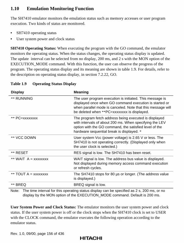
Rev. 1.0, 09/00, page 156 of 436
1.10 Emulation Monitoring Function
The SH7410 emulator monitors the emulation status such as memory accesses or user programexecution. Two kinds of status are monitored.
• SH7410 operating status
• User system power and clock status
SH7410 Operating Status: When executing the program with the GO command, the emulatormonitors the operating status. When the status changes, the operating status display is updated.The update interval can be selected from no display, 200 ms, and 2 s with the MON option of theEXECUTION_MODE command. With this function, the user can observe the progress of theprogram. The operating status display and its meaning are shown in table 1.9. For details, refer tothe description on operating status display, in section 7.2.22, GO.
Table 1.9 Operating Status Display
Display Meaning
** RUNNING The user program execution is initiated. This message isdisplayed once when GO command execution is started orwhen parallel mode is canceled. Note that this message willbe deleted when ** PC=xxxxxxxx is displayed.
** PC=xxxxxxxx The program fetch address being executed is displayedwith intervals of about 200 ms. When specifying the LEVoption with the GO command, the satisfied level of thehardware sequential break is displayed. *
** VCC DOWN User system Vcc (power voltage) is 2.65 V or less. TheSH7410 is not operating correctly. (Displayed only whenthe user clock is selected.)
** RESET RES signal is low. The SH7410 has been reset.
** WAIT A = xxxxxxxx WAIT signal is low. The address bus value is displayed.Not displayed during memory access command executionor refresh cycles.
** TOUT A = xxxxxxxx The SH7410 stops for 80 µs or longer. (The address valueis displayed.)
** BREQ BREQ signal is low.
Note: The time interval for this operating status display can be specified as 2 s, 200 ms, or nodisplay by the MON option of the EXECUTION_MODE command. Default is 200 ms.
User System Power and Clock Status: The emulator monitors the user system power and clockstatus. If the user system power is off or the clock stops when the SH7410 clock is set to USERwith the CLOCK command, the emulator executes the following operation according to theemulator status.

Rev. 1.0, 09/00, page 157 of 436
Notes: 1. If the user system power is turned off (Vcc is 2.65 V or lower), this is detectedbefore the clock stop is detected.
2. Clock stop means that only the clock stops and the user system power remains on.
• During user program execution
When the user system is turned off (Vcc is 2.65 V or lower), ** VCC DOWN is displayed.When the power is turned on again, the emulation restarts and current position of PC in theuser program is displayed.
When the clock stops (Vcc is 2.65 V or lower), USER SYSTEM NOT READY (NOCLOCK) is displayed and the emulator system program stops. To operate the emulatoragain, restart the system program.
• During command input wait state
When the user system is turned off (Vcc is 2.65 V or lower), USER SYSTEM NOTREADY (NO CLOCK) is displayed and the SH7410 operating clock is switched to theinternal 15.0-MHz clock and the emulator waits for command input. A RES signal is inputto the SH7410, and the internal registers are initialized. USER SYSTEM NOT READY(NO CLOCK) is displayed after the user system has been turned off and one command hasbeen executed.
When the clock stops (Vcc is 2.65 V or lower), USER SYSTEM NOT READY (NOCLOCK) is displayed and the emulator system terminates. Restart the emulator in order tocontinue emulation.

Rev. 1.0, 09/00, page 158 of 436
1.11 Assembly Function
1.11.1 Overview
The ASSEMBLE command enables line assembly as shown in figure 1.28.
Assembly-language source input
ASSEMBLEcommand
User memory
Write to memory
Figure 1.28 Assembly Function
Line assembly: Assembly-language source is input from the console line by line.
Refer to section 7.2.4, ASSEMBLE, for command initiation instructions.
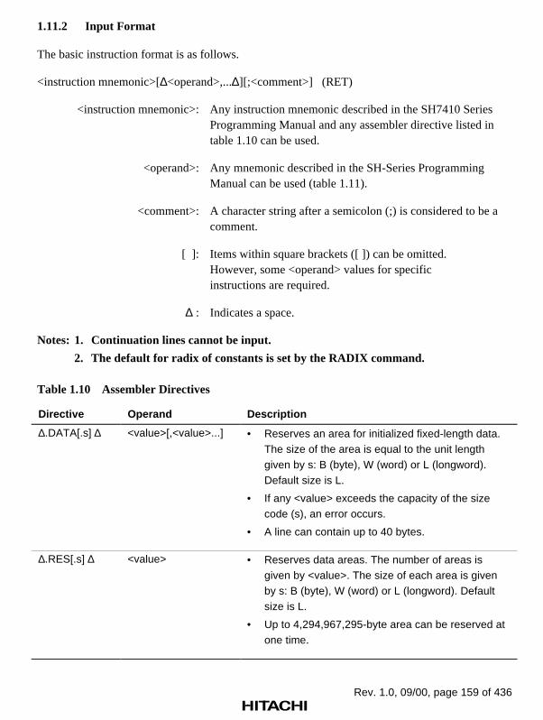
Rev. 1.0, 09/00, page 159 of 436
1.11.2 Input Format
The basic instruction format is as follows.
<instruction mnemonic>[∆<operand>,...∆][;<comment>] (RET)
<instruction mnemonic>: Any instruction mnemonic described in the SH7410 Series Programming Manual and any assembler directive listed in table 1.10 can be used.
<operand>: Any mnemonic described in the SH-Series Programming Manual can be used (table 1.11).
<comment>: A character string after a semicolon (;) is considered to be a comment.
[ ]: Items within square brackets ([ ]) can be omitted. However, some <operand> values for specific instructions are required.
∆ : Indicates a space.
Notes: 1. Continuation lines cannot be input.
2. The default for radix of constants is set by the RADIX command.
Table 1.10 Assembler Directives
Directive Operand Description
∆.DATA[.s] ∆ <value>[,<value>...] • Reserves an area for initialized fixed-length data.The size of the area is equal to the unit lengthgiven by s: B (byte), W (word) or L (longword).Default size is L.
• If any <value> exceeds the capacity of the sizecode (s), an error occurs.
• A line can contain up to 40 bytes.
∆.RES[.s] ∆ <value> • Reserves data areas. The number of areas isgiven by <value>. The size of each area is givenby s: B (byte), W (word) or L (longword). Defaultsize is L.
• Up to 4,294,967,295-byte area can be reserved atone time.

Rev. 1.0, 09/00, page 160 of 436
Table 1.11 Operand Descriptions
Format Addressing Mode Remarks
Rn Register direct Rn: General register name (SP can be specified instead of R15)
SR SR: Status register
GBR GBR: Global base register
VBR VBR: Vector base register
MACH MACH: Multiply and accumulate register
MACL MACL: Multiply and accumulate register
PR PR: Procedure register
SSR SSR: Saving status register
SPC SPC: Saving program counter
@Rn Register indirect Rn: General register name
@Rn+ Register indirect withpost-incrementation
Rn: General register name
@-Rn Register indirect withpre-decrementation
Rn: General register name
@(disp, Rn) Register indirect withdisplacement
disp:
Rn:
Displacement value
General register name
@(R0, Rn) Register indirect withindex
R0,Rn: General register name
@(disp, GBR) GBR indirect withdisplacement
disp:
GBR
Displacement value
Global base register
@(R0, GBR) GBR indirect with index R0:
GBR
General register name
Global base register
@(disp, PC) PC relative withdisplacement
disp:
PC
Displacement value
PC value within vector address table
aaaa PC relative aaaa: Address value(Usable with BF, BT, BRA, and BSRinstructions)
#imm Immediate imm: Immediate data value
Notes: 1. For the address value, immediate data value and displacement values, the formula(addition or subtraction) can be used. However, disassemble is displayed only inaddress value.
2. If the immediate data value is different from the specified operation size, an erroroccurs.

Rev. 1.0, 09/00, page 161 of 436
1.11.3 Disassembly
The emulator has a disassembly function to display user program contents in mnemonics. Thisfunction is performed with the DISASSEMBLE command and enables to debug withoutreferencing to a program list. For details, refer to section 7.2.17, DISASSEMBLE.

Rev. 1.0, 09/00, page 162 of 436

Rev. 1.0, 09/00, page 163 of 436
Section 2 Differences between the SH7410 and the Emulator
When the emulator system is initiated, or when the emulator resets the SH7410 as a result of acommand, such as the CLOCK command switching the clock or the RESET command, note thatthe general registers and part of the control registers are initialized.
Table 2.1 Differences between Initial Values of the SH7410 and Emulator Registers
Status Register Emulator SH7410
Emulator initiation PC Reset vector value Reset vector value
(power-on) R0 to R14 H'00000000 Undefined
R15 (SP) Stack pointer value Stack pointer value
SR H'000000F0 H'00000XFX *
PR H'00000000 H'00000000
VBR H'00000000 Undefined
GBR H'00000000 Undefined
MACH H'00000000 Undefined
MACL H'00000000 Undefined
DSR H'00000000 Undefined
MOD H'00000000 Undefined
RS, RE H'00000000 Undefined
A0, A1 H'00000000 Undefined
M0, M1 H'00000000 Undefined
X0, X1 H'00000000 Undefined
Y0, Y1 H'00000000 Undefined
A0G, A1G H'00 Undefined
Note: X is an undefined value.
The emulator’s user system interface is provided with pull-up resistors and a buffer, causing thesignals to be delayed slightly. Also, the pull-up resistors will change high-impedance signals tohigh-level signals. Adjust the user system hardware accordingly. Refer to section 4, User SystemInterface.
The user break controller in the SH7410 cannot be used with this emulator.
The emulator for the SH7410 can use an operating frequency of 60 MHz or lower. Note, however,that the emulator cannot use an operating frequency higher than 60 MHz. If the operatingfrequency is set to higher than 60 MHz, correct emulation cannot be guaranteed.

Rev. 1.0, 09/00, page 164 of 436
Rev. 1.0, 09/00, page 165 of 436
Section 3 SH7410 Function Support
The SH7410 has six clock modes. However, operating modes 1 and 5 (crystal oscillator) are notsupported. This section describes how the emulator supports the SH7410 functions.
Note: The crystal oscillator connected to the crystal oscillator terminals X0 and X1 on theevaluation chip board (EV-chip board) is connected to the oscillator within the EV-chip board to perform clock oscillation. This clock source is input to the EXTAL pinof the SH7410. Note that the crystal oscillator cannot be directly connected to theEXTAL and XTAL pins of the SH7410.
3.1 Operating Mode Setting
The user selects the operating mode and CS0 area bus width for the emulator with the MODEcommand, as shown in table 3.1. For details, refer to section 7.2.25, MODE.
Note: An operating mode specified using the MODE command will be valid only after theemulator is re-initiated. Therefore, the emulator must be reset after specifying anoperating mode. At this time, emulator specifications such as emulation memoryattributes and break point settings will not be saved.

Rev. 1.0, 09/00, page 166 of 436
Table 3.1 SH7410 Operating Mode Selection
Operat-ingMode MD2 MD1 MD0 Description
Mode 0 0 0 0 The external clock (1 to 20 MHz) input from the EXTALpin is used. This frequency can be multiplied by 4through the PLL circuit by setting FRQMR (bit 7: PLLO).
Mode 1 0 0 1 A crystal oscillator is used. The frequency can bemultiplied by 4 through the PLL circuit by settingFRQMR (bit 7: PLLO). *1
Mode 2 0 1 0 An external clock is input from the EXTAL pin. Thefrequency can be multiplied by 4 using the PLL circuitby setting FRQMR (bit 7: PLLO).
Mode 3 0 1 1 An external clock is input from the EXTAL pin. Thefrequency is halved by the frequency divider. While thePLL circuit is enabled, the frequency of the signal fromthe divider is multiplied by 4.
Mode 4 1 0 0 The frequency of an external clock input from theEXTAL pin is multiplied by 4 by the PLL circuit. Theclock is then output to the CKO pin. *2
Mode 5 1 0 1 A crystal oscillator is used. The waveform is shapedby the PLL circuit, and the frequency is multiplied by 4.The clock is then output to the CKO pin. *1
Notes: 1. Operating modes 1 and 5
When a crystal oscillator is connected to the SH7410, operating modes 1 and 5 cannotbe specified. When it is connected, specify mode 0, 2, 3, or 4.
2. Operating mode 4 (when using the emulator internal clock of 15 MHz)
Emulator pod internal clock input (15 MHz) x 4 = CLK output (60 MHz). The user canaccess the mode setting pin status of the user system, but this does not affect theoperating mode of the emulator.

Rev. 1.0, 09/00, page 167 of 436
Table 3.2 CS0 Area Bus Width Selection
MD4 MD3 CS0 Area Bus Width
0 0 X and Y buses (16 bits)
0 1 8 bits
1 0 16 bits
1 1 32 bits
In the emulator, the operating mode previously set is saved in the configuration file on the flashmemory of the E8000 station. At initialization, the emulator initiates the system with the operatingmode specified with the MODE command.
3.2 Memory Area
The SH7410 has a maximum of 64-Mbyte memory area. Standard emulation memory (4 Mbytes)can be set in 1-Mbyte units to the memory area. The CSn area that is not set as emulation memoryis set as user system memory. For details, refer to section 7.2.26, MAP.
• U: User system memory
• S: Standard emulation memory
The user can specify write-protected and access-prohibited areas as emulation memory.
Normally, emulation memory and user memory should not be allocated to the same CS areaconcurrently. If they are, strobe signals (RD, CSn, and WEn) are not output in that CS area.
Write-protected areas and access-prohibited areas can be allocated to the emulation memory inunits of 1 Mbyte or more.
• SW: Write-protected

Rev. 1.0, 09/00, page 168 of 436
3.2.1 Internal I/O Area
When the internal I/O area is accessed, the emulator accesses the SH7410 internal I/O, regardlessof the memory attribute set with the MAP command. The user can read from and write to theinternal I/O area with user program or emulator commands. When writing to the internal I/O areawith an emulator command (MEMORY), the following warning message is displayed and theemulator starts writing without verifying.
*** 86: INTERNAL AREA
However, the user cannot write to the internal I/O with the FILL command.
3.2.2 External Memory Area
The SH7410 external memory area can be allocated to all memory attributes supported by theemulator. Memory corresponding to the allocated attributes can be accessed with user program oremulator commands.
3.3 Other Functions
3.3.1 Low-Power Mode (Sleep and Standby)
For reduced power consumption, the SH7410 has sleep and standby modes.
The sleep and standby modes are switched using the SLEEP instruction. These modes can becleared with either the normal clearing function or with the break condition satisfaction (including(BREAK) or (CTRL) + C key input), and the program breaks. Trace information is not acquiredin sleep and standby modes.
Notes: 1. When restarting after a break, the user program will restart at the instructionfollowing the SLEEP instruction.
2. During sleep mode, if the user accesses or modifies the memory in parallel mode,the sleep mode is cleared and the user program execution continues from theinstruction following the SLEEP instruction.

Rev. 1.0, 09/00, page 169 of 436
3.3.2 Interrupts
During emulation, the user can interrupt the SH7410.
• When an interrupt is disabled by the BACKGROUND_INTERRUPT command
If an interrupt occurs while the emulator is waiting for command input, the interrupt is notprocessed. However, if an edge sensitive interrupt occurs while the emulator is waiting forcommand input, the emulator latches the interrupt and executes the interrupt processingroutine when the GO command is entered.
• When an interrupt is enabled by the BACKGROUND_INTERRUPT command
An interrupt is acceptable while the emulator is waiting for command input.
3.3.3 Control Input Signals (RES, WAIT, BREQ)
The SH7410 control input signals are RES, WAIT and BREQ. The RES, WAIT, and BREQsignals are valid during execution with either the GO command or STEP command. Therefore,while the emulator is waiting for command input, the user cannot input RES, WAIT or BREQsignals to the SH7410. The BREQ signals will not be input to the SH7410 during user programexecution when the BREQ signal is masked, that is the option BRQ = D is specified, using theEXECUTION_MODE command.
3.3.4 Serial Communication Interface
The serial communication interface signals are connected to the user system directly from theSH7410 on the emulator pod. Therefore, like the 16-bit FRT, the interface is valid during thecommand input wait state as well as emulation. For example, when writing data to the transmitdata register (SCTDR) using the MEMORY command, after the serial communication interfaceoutput has been prepared and the Transmit Data Empty (TDRE) of the Status Register (SCSSR)has been cleared, data is output to the TxD pin.
3.3.5 16-Bit Free-Running Timer (FRT)
The 16-bit FRT operates during the command input wait state as well as during emulation. Evenafter the user program has stopped when a break condition is satisfied after the user program hasbeen started with a GO command, the 16-bit FRT continues to operate. Therefore, the timer pinsare valid even when user program execution has stopped. The user can rewrite the timer registerswith the MEMORY command.

Rev. 1.0, 09/00, page 170 of 436
3.3.6 DMAC
The DMAC performs data transfer between the memory (internal or external) and a peripheraldevice (internal or external). The DMAC of the SH7410 operates during the command input waitstate as well as during emulation. When transfer is requested, the DMA transfer is performed.
3.3.7 Hitachi User Debugging Interface (Hitachi-UDI)
The Hitachi user debugging interface (Hitachi-UDI) transfers the data. The data transfer betweenthe chip and the external controller is executed by the command input from the external controller.However, the UDI cannot be used when using the E8000.
3.3.8 Bus State Controller
The SH7410 wait state controller has a programmable wait mode and a WAIT pin input mode.While the programmable wait mode is valid when the emulation memory or user external memoryis accessed, input to the user WAIT pin is valid only when user external memory is accessed.However, the EXECUTION_MODE command can be used to enable input to the user WAIT pinduring emulation memory access cycles. The refresh cycle controller operates continuously whenthe emulator is carrying out PSRAM/DRAM refresh control, even during the command input waitstate.
3.3.9 System Controller (SYSC)
The system controller, such as a watchdog timer, generates and controls clock signals for allinternal modules and external buses. The watchdog timer continues counting during the emulatorcommand wait state as well as during emulation.

Rev. 1.0, 09/00, page 171 of 436
Section 4 User System Interface
The emulator is connected to the user system with the EV-chip board. Probe signal trace andbreak can be enabled by connecting the external probe to the user system.
The trigger output probe can output a low-level pulse as an oscilloscope trigger signal. For details,refer to section 1.8, Trigger Output.
User System Interface Circuits: The circuits that interface the SH7410 in the emulator to theuser system include buffers and resistors, as described below. When connecting the emulator to auser system, adjust the user system hardware compensating for FANIN, FANOUT, andpropagation delays.
The signals which exceed the MCU AC timing values are shown in table 4.1. Other signals satisfythe MCU specifications.
Note: The values with the emulator connected, in table 4.1, are measurements for referencebut are not guaranteed values.
Table 4.1 Bus Timing (Bus Clock: 30 MHz)
Item MCU Specifications (ns) Values with Emulator Connected (ns)
tAD 15 (Max.) Satisfied
tBSD 15 (Max.) Satisfied
tCSD 15 (Max.) Satisfied
tNMIS 30 (Max.) 48.4
tRWD 15 (Max.) Satisfied
tRSD 15 (Max.) Satisfied
tRESS 30 (Max.) 60.1
tWDD 15 (Max.) Satisfied
tWED 15 (Max.) Satisfied
Adjust the hardware by taking the above into account. The basic bus cycle (three states) andcontrol signal input timing are shown in figures 4.1 and 4.2, respectively. The user systeminterface circuits connected to the user system are shown in figure 4.3.

Rev. 1.0, 09/00, page 172 of 436
RD(Read cycle)
tAD tAD
CLK
A23-A0
BS
CSn
RD/WR
D31-D0(Read cycle)
WEn(Write cycle)
tBSD tBSD
tCSD tCSD
T1
tRWD tRWD
tRSD tRSD
tRDS tRDH
tWED tWED
D31-D0(Write cycle)
tDOF
tWDHtWDD
T2 T3
Figure 4.1 Basic Bus Cycle
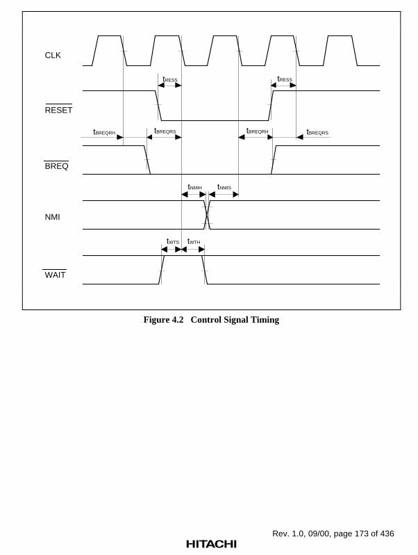
Rev. 1.0, 09/00, page 173 of 436
CLK
RESET
BREQ
tRESS
tBREQRS
tRESS
tBREQRStBREQRH
tNMIH tNMIS
NMI
tWTS tWTH
WAIT
tBREQRH
Figure 4.2 Control Signal Timing

Rev. 1.0, 09/00, page 174 of 436
SH7410 User system
A23-A0
D31-D0
STxD0-STxD2
SRCK0-SRCK2SRS0-SRS2
SRxD0-SRxD2
STCK0-STCK2STS0-STS2
FTIO0/FTOB0
FTOA0-FTOA2
SCK0-SCK1
TxD0-TxD1RxD0-RxD2
FTC0-FTC2
A23-A0
D31-D0
CS0-CS1CS2/RAS2CS3/RAS3/CERD/WRWE0-WE3CAS2-CAS3CAS1/RFSHCAS0/OE/RFSH
CS0-CS1CS2/RAS2
CS3/RAS3/CERD/WR
WE0-WE3CAS2-CAS3CAS1/RFSH
CAS0/OE/RFSH
FTIO1/FTOB1FTIO2/FTOB2
STxD0-STxD2
SRCK0-SRCK2SRS0-SRS2
SRxD0-SRxD2
STCK0-STCK2STS0-STS2
FTIO0/FTOB0
FTOA0-FTOA2
SCK0-SCK1
TxD0-TxD1RxD0-RxD2
FTC0-FTC2
FTIO1/FTOB1FTIO2/FTOB2
Figure 4.3 User System Interface Circuits
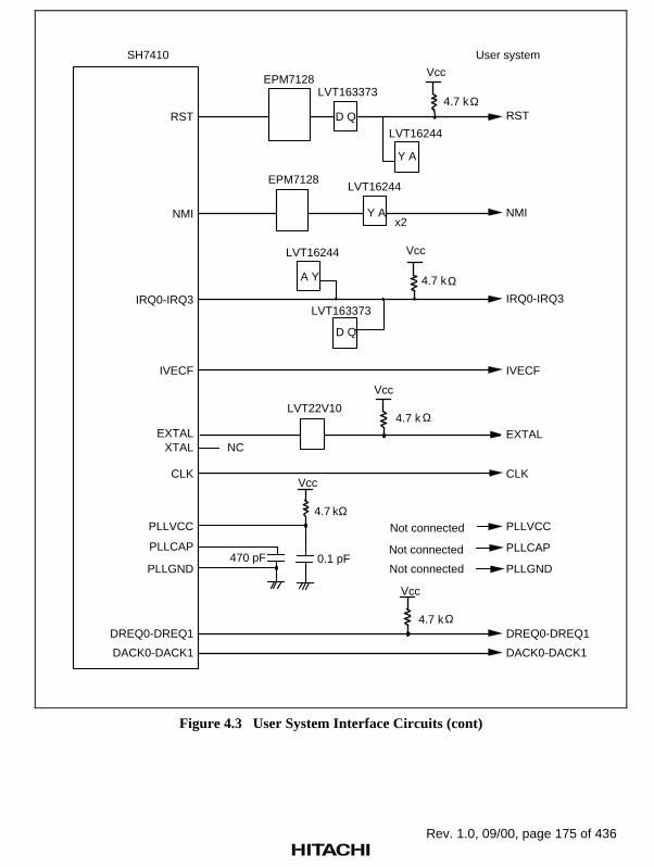
Rev. 1.0, 09/00, page 175 of 436
SH7410 User system
RST RST
LVT163373
D Q
LVT16244
A Y
4.7 k
Vcc
LVT16244
Y A
LVT163373
D Q
EPM7128
IVECF IVECF
EXTAL4.7 k
Vcc
LVT22V10
EXTALXTAL NC
CLK CLK
DREQ0-DREQ1
Vcc
4.7 kDREQ0-DREQ1
DACK0-DACK1 DACK0-DACK1
IRQ0-IRQ3 IRQ0-IRQ3
4.7 k
Vcc
NMI NMI
LVT16244
Y A
EPM7128
PLLVCC
PLLGND
PLLCAP
4.7
Vcc
0.1 pF 470 pF
PLLVCC
PLLGND
PLLCAP
Ω
Ω
Ω
x2
Ω
kΩNot connected
Not connected
Not connected
Figure 4.3 User System Interface Circuits (cont)
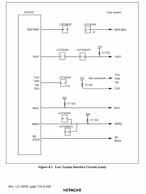
Rev. 1.0, 09/00, page 176 of 436
SH7410 User system
Vcc
4.7 k
TRST TRST
LVT16652
MD0-MD5 B A MD0-MD5
LVT16244
A Y
WAITWAIT
4.7 k
Vcc
LVT163373
D Q
LVT16244
A Y
BREQ BREQ
4.7 k
Vcc
BS BSBACK BACK
LVT16244 LVT163373
A Y D Q
TDO
TMS
TDI
TCK LVT16244
A Yx2
TDO
TMS
TDI
TCKVcc
4.7 k
x2
Ω
Ω
Ω
Ω
Not connected
Figure 4.3 User System Interface Circuits (cont)
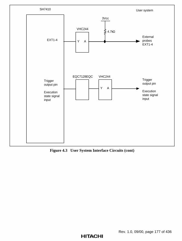
Rev. 1.0, 09/00, page 177 of 436
VHC244
3Vcc
4.7kΩ
EXT1-4 Y A
EQC7128EQC VHC244
Y A
SH7410 User system
External probesEXT1-4
Triggeroutput pin
Execution state signalinput
Triggeroutput pin
Execution state signalinput
Figure 4.3 User System Interface Circuits (cont)

Rev. 1.0, 09/00, page 178 of 436

Rev. 1.0, 09/00, page 179 of 436
Section 5 Troubleshooting
The emulator internal system test checks the emulator’s internal RAM and registers at power-onand at system program initiation.
5.1 Internal System Test
Internal System Test at Power-On: The emulator checks its internal RAM and registers atpower-on. While tests are in progress, the following messages are displayed:
E8000 MONITOR (HS8000EST02SR) Vm.nn
Copyright (C) Hitachi, Ltd. 1995 (a)
Licensed Material of Hitachi, Ltd.
TESTING (b)
RAM 0123
START E8000
S : START E8000
F : FLASH MEMORY TOOL (c)
L : SET LAN PARAMETER
T : START DIAGNOSTIC TEST
(S/F/L/T) ?
(a) Emulator monitor start message
(b) Internal RAM and registers are being tested.
A number from 0 to 3 is displayed as each of the four internal RAM blocks has beentested. If an error occurs, the address, write data, and read data are displayed as follows:
** RAM ERROR ADDR=xxxxxxxx W-DATA=xxxxxxxx R-DATA=xxxxxxxx
After RAM testing is completed, the registers are tested. No data will be displayed if anerror does not occur. If an error occurs, the following message is displayed:
*** xxxx REGISTER ERROR W-DATA=xx R-DATA=xx
xxxx: Name of emulator internal register where an error occurs
(c) The emulator monitor is in command input wait state.
Note: Operation continues if an error occurs in step (b), but the error should be investigatedaccording to section 5.2, Troubleshooting Procedure, without loading the emulator systemprogram.
Internal System Test at Emulator System Program Initiation: The emulator system programperforms internal system tests, mainly on the emulator registers, at its initiation.

Rev. 1.0, 09/00, page 180 of 436
SH7410 E8000 (HS7410EDD82SF) Vm.nn
Copyright (C) Hitachi, LTD. 1995 (a)Licensed Material of Hitachi, Ltd.
CONFIGURATION FILE LOADING (b)HARD WARE REGISTER READ/WRITE CHECK (c)FIRMWARE SYSTEM LOADING (d)EMULATOR FIRMWARE TEST (e)** RESET BY E8000 ! (f)CLOCK = EML (f)MODE = xx (MD4–0=xx) (g)FAILED AT xxxx (h)REMAINING EMULATION MEMORY S=4MB (i):_ (j)
(a) Emulator system program start message. Vm.nn indicates the version number.
(b) Configuration file is being loaded. If an invalid configuration file is assigned, the followingmessage is displayed:
*** 54:INVALID CONFIGURATION FILE
If no configuration file is contained in the memory, the following message is displayed:
*** 55:CONFIGURATION FILE NOT FOUND
Re-install the configuration file.
(c) The emulator control registers are being checked. If an error occurs, one of the followingmessages is displayed:
*** xxx REGISTER ERROR W-DATA = xxxx R-DATA = xxxx (i)
*** SHARED RAM ERROR ADDR = xxxxxx W-DATA = xxxxxxxx R-DATA = xxxxxxxx (ii)
*** BxTBM ERROR ADDR= xxxxxx W-DATA= xxxxxxxx R-DATA = xxxxxxxx (iii)
*** FIRM RAM ERROR ADDR= xxxxxx W-DATA= xxxxxxxx R-DATA = xxxxxxxx (iv)
(i) An error occurred in the register
xxx: Name of emulator internal register where an error occurs
B0TRAR, ECT, B0CNR, B0MDCNR, B0MASCR, B0CECR, B1CNR,B1MDCNR, B1MASCR, B1CECR, MAPR0, MAPR1, MAPR2, MAPR3
(ii) An error occurred in the shared RAM
(iii) An error occurred in the trace buffer memory
(iv) An error occurred in the firm RAM area
(d), (e) The device control board is being tested. If an error occurs, the following message isdisplayed:
*** INVALID FIRMWARE SYSTEM (i)
*** EMULATOR FIRMWARE NOT READY (ii)
*** FIRMWARE SYSTEM FILE NOT FOUND (iii)

Rev. 1.0, 09/00, page 181 of 436
(i) The incorrect MCU device control board is connected. Please check the MCU type anduse the appropriate emulator system program, or exchange the device control board.
(ii) The device control board is not connected correctly. Connect the device control board tothe emulator correctly.
(iii) Correct system program for the device control board is not loaded in the memory. Re-install the correct emulator system program and restart the emulator.
Note: If the (CTRL) + C keys or (BREAK) key is pressed during testing for the device controlboard, the test is aborted.
(f) The RES signal is input to the MCU, and the specified clock type is displayed.
Note: (f) is not executed if an error has occurred in step (c), (d), or (e)
(g) The MCU operating mode on the emulator and the status of user system mode selection pins.
(h) MCU pins are being checked. For details, refer to section 7.2.11, CHECK.
Note: (h) is not executed if an error has occurred in step (c), (d), or (e)
(i) The remaining emulation memory size that can be assigned.
(j) The emulator system program is initiated and the command input wait state is entered.
Emulator System Failure: If an invalid exception occurs during emulator monitor or emulatorsystem program execution, the system shuts down. No key input from the key board will bereceived but the following message is displayed:
<exception> PC=xxxxxxxx*** E8000 SYSTEM DOWN ***
If an error occurs, re-execute using another system disk. If an error still occurs, inform a Hitachisales agency of the error.

Rev. 1.0, 09/00, page 182 of 436
5.2 Troubleshooting Procedure
This section provides a troubleshooting Problem Analysis Diagram (PAD, see figure 5.1) toreduce the time taken by troubleshooting.
As you work through the diagram:
Follow the instructions that request operator assistance or intervention.
Note that “system defect” means that the emulator station is malfunctioning. Execute thediagnostic program as described in the Diagnostic Program Manual (HS7410TM82ME),and inform a Hitachi sales agency of the test results in detail because a system defect maybe caused by a number of reasons.

Rev. 1.0, 09/00, page 183 of 436
START
Emulator systemfailure?
Systemdefect
Emulator monitormessagedisplayed?
Consoleconnectedcorrectly?
Systemdefect
Connectcorrectly.
Check power supply(breaker, fuse, outlet) to emulator.
Power lampon withpower-on?
Set power supply.
Failureoccurred?
Emulator fan working ?
Breaker, fusefails again ?
Power lampdefect
Switchdefect
Defect in source power or emulator power
Correct systemprograminstalled? Re-install
correct systemprogram
No
Internal system test at power-on passed?
Systemdefect
Systemdefect
Systemprograminitiatedcorrectly?
Yes
Figure 5.1 Troubleshooting PAD
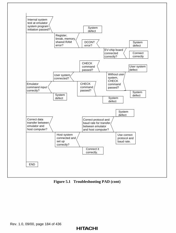
Rev. 1.0, 09/00, page 184 of 436
Internal system test at emulator system program initiation passed?
Register,break, memory,shared RAMerror?
Systemdefect
DCONT error?
EV-chip boardconnectedcorrectly?
Systemdefect
Connectcorrectly
Emulator command inputcorrectly?
User systemconnected?
Systemdefect
CHECK commandpassed?
CHECK commandpassed?
Without usersystem, CHECKcommandpassed?
Systemdefect
User systemdefect
Systemdefect
END
Correct data transfer between emulator and host computer?
Host system connected and set up correctly?
Correct protocol and baud rate for transfer between emulator and host computer?
Connect it correctly.
System defect
Use correct protocol and baud rate.
Figure 5.1 Troubleshooting PAD (cont)

Rev. 1.0, 09/00, page 185 of 436
Section 6 Command Input and Display
6.1 Command Syntax
6.1.1 Command Input Format
The emulator command format is as follows:
<command>∆<parameter>;<option> (RET)
∆: Space(RET): (RET) key
Note that each command can be specified in abbreviated form to facilitate keyboard operations.
6.1.2 Help Function
All emulator commands can be displayed by entering the HELP command. Any command inputformat can be displayed by specifying the command name as a parameter of the HELP command.
• To display all emulator commands
: HELP (RET)
<All commands are displayed in their full names and abbreviations>
• To display a command input format
: HELP∆∆<command name> (RET) <A command input format is displayed>
In this example, an abbreviation of the command name can be entered as <command name>.

Rev. 1.0, 09/00, page 186 of 436
6.1.3 Word Definition
Constants or file names can be entered as command parameters or options. Spaces (∆) or commas(,) can be inserted between words. Words are described below:
Constants: Numeric constants, character constants, and expression can be used as constants.
• Numeric constants
The following shows numeric constant formats. A radix is entered at the head of a numericconstant.
S'nnnnnnnn
S: Radix of a constant
B: Binary
Q: Octal
D: Decimal
H: Hexadecimal
X: Fixed-point
Default: Value specified with the RADIX command
nnnnnnnn: Value based on the radix (4-byte value maximum)
Example: To indicate 100 in decimal:
D'100
If the radix is omitted, the radix specified with the RADIX command is automatically used.
Example: If the radix is omitted while hexadecimal is specified with the RADIXcommand, entering 10 means H'10.
• Character constants
Enclosed with single or double quotation marks. If a single or double quotation mark is usedas data, add two sequential quotation marks.
Example 1: ' A' = H'41
Example 2: ' ' ' = H'27 (single quotation mark ')
Multiple characters can be included inside the quotation marks within the specified data size asshown below.
Example: ' AB' = H'4142 (2-byte data)

Rev. 1.0, 09/00, page 187 of 436
• Expression
An expression can be described using numeric constants, character constants, and operators.As an operator, + (addition ) or – (subtraction) can be specified.
Examples: D'10 + H'2020 – 4–1
File Name: A file name can be specified as a command parameter. The general file name formatis as follows:
<drive name>:<file name>.<extension>
6.2 Special Key Input
The emulator supports special key functions to facilitate keyboard operations. In the followingdescription, CTRL + X means pressing the CTRL and X keys simultaneously.
6.2.1 Command Execution and Termination
• Command execution (RET) Enters all characters on that line, regardless ofthe cursor position, and executes the command.
• Command termination CTRL + C, Terminates command execution. All characters(BREAK) typed so far are lost and the emulator enters
command input wait state.
6.2.2 Display Control
• Display stop CTRL + S Temporarily stops display. Resumes display byentering CTRL and Q keys.
• Display restart CTRL + Q Resumes display.
• Display 16 lines CTRL + P Effective only for the DUMP and TRACEprevious of current commands. Displays the 16 lines before thedisplay first line of the current screen and then stops.
Pressing the (RET) key resumes the display.

Rev. 1.0, 09/00, page 188 of 436
6.2.3 Command Re-entry
• Display stop CTRL + S Temporarily stops display. Resumes display byentering CTRL and Q keys.
• Display last entered CTRL + L Redisplays the last line entered. Pressing theseline keys will repeatedly redisplay up to 16 lines and
then return to the last line again.
• Display last entered <command When a period is entered after a command,command name>. the previously input parameters of that
command are displayed. If two periods areentered after a command, parameters of twocommands prior to the entered command aredisplayed. This key input is useful for executingcommands with the same parameters again.(Example) :D 1000 1010 (RET)
: Execution of another command:D. (RET):D 1000 1010: Displays the parameters specified in the previous DUMP command execution and enters command input wait state.
6.2.4 Display Control
• Move cursor CTRL + H Moves the cursor one position backwards.backwards
• Move cursor to CTRL + T Moves the cursor to the first position of theword starting word (the character following the space).position
• Delete one character CTRL + D Deletes a character at the cursor position.
• Cancel line CTRL + X Deletes the contents of the entire line.
• Advance cursor CTRL + W Moves the cursor one position forwards.
• Insert space CTRL + U Inserts a space at the cursor.
• Tab over CTRL + I Moves the cursor to the (10’s multiple + 1)thcolumn.
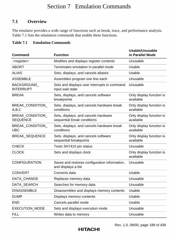
Rev. 1.0, 09/00, page 189 of 436
Section 7 Emulation Commands
7.1 Overview
The emulator provides a wide range of functions such as break, trace, and performance analysis.Table 7.1 lists the emulation commands that enable these functions.
Table 7.1 Emulation Commands
Command FunctionUsable/Unusablein Parallel Mode
.<register> Modifies and displays register contents Unusable
ABORT Terminates emulation in parallel mode Usable
ALIAS Sets, displays, and cancels aliases Usable
ASSEMBLE Assembles program one line each Unusable
BACKGROUND_INTERRUPT
Sets and displays user interrupts in commandinput wait state
Unusable
BREAK Sets, displays, and cancels softwarebreakpoints
Only display function isavailable
BREAK_CONDITION_A,B,C
Sets, displays, and cancels hardware breakconditions
Only display function isavailable
BREAK_CONDITION_SEQUENCE
Sets, displays, and cancels hardwaresequential break conditions
Only display function isavailable
BREAK_CONDITION_UBC
Sets, displays, and cancels hardware breakconditions
Only display function isavailable
BREAK_SEQUENCE Sets, displays, and cancels softwaresequential breakpoints
Only display function isavailable
CHECK Tests SH7410 pin status Unusable
CLOCK Sets and displays clock Only display function isavailable
CONFIGURATION Saves and restores configuration information,and displays a list
Unusable
CONVERT Converts data Usable
DATA_CHANGE Replaces memory data Unusable
DATA_SEARCH Searches for memory data Unusable
DISASSEMBLE Disassembles and displays memory contents Usable
DUMP Displays memory contents Usable
END Cancels parallel mode Usable
EXECUTION_MODE Sets and displays execution mode Unusable
FILL Writes data to memory Unusable
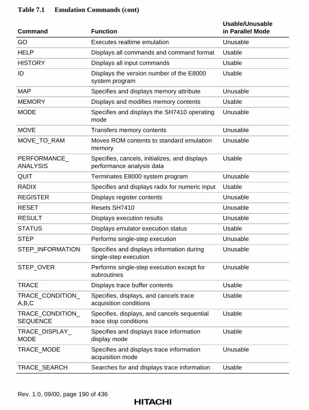
Rev. 1.0, 09/00, page 190 of 436
Table 7.1 Emulation Commands (cont)
Command FunctionUsable/Unusablein Parallel Mode
GO Executes realtime emulation Unusable
HELP Displays all commands and command format Usable
HISTORY Displays all input commands Usable
ID Displays the version number of the E8000system program
Usable
MAP Specifies and displays memory attribute Unusable
MEMORY Displays and modifies memory contents Usable
MODE Specifies and displays the SH7410 operatingmode
Unusable
MOVE Transfers memory contents Unusable
MOVE_TO_RAM Moves ROM contents to standard emulationmemory
Unusable
PERFORMANCE_ANALYSIS
Specifies, cancels, initializes, and displaysperformance analysis data
Usable
QUIT Terminates E8000 system program Unusable
RADIX Specifies and displays radix for numeric input Usable
REGISTER Displays register contents Unusable
RESET Resets SH7410 Unusable
RESULT Displays execution results Unusable
STATUS Displays emulator execution status Usable
STEP Performs single-step execution Unusable
STEP_INFORMATION Specifies and displays information duringsingle-step execution
Unusable
STEP_OVER Performs single-step execution except forsubroutines
Unusable
TRACE Displays trace buffer contents Usable
TRACE_CONDITION_A,B,C
Specifies, displays, and cancels traceacquisition conditions
Usable
TRACE_CONDITION_SEQUENCE
Specifies, displays, and cancels sequentialtrace stop conditions
Usable
TRACE_DISPLAY_MODE
Specifies and displays trace informationdisplay mode
Usable
TRACE_MODE Specifies and displays trace informationacquisition mode
Unusable
TRACE_SEARCH Searches for and displays trace information Usable

Rev. 1.0, 09/00, page 191 of 436
7.2 Emulation Commands
This section provides details of emulation commands in the format shown in figure 7.1.
Command Format
Function 1 : Command input formatFunction 2 : Command input format • • <parameter 1>: Parameter description 1 <parameter 2>: Parameter description 2 :
Function 1 Description of function 1Function 2 Description of function 2 • •
Description
Notes
Examples
Command NameFull command name
Abbr.Abbreviated command name
FunctionCommand function
Command FormatCommand input format for eachfunction
DescriptionFunction and usage in detail
NotesWarnings and restrictions forusing the command. If additionalinformation is not required, thisitem is omitted.
ExamplesCommand usage examples
Command Name
No. Command Name [Abbr.] Function
•
•
•
•
•
•
•
Figure 7.1 Emulation Command Description Format
Symbols used in the command format have the following meanings:
[ ]: Parameters enclosed by [ ] can be omitted.(a/b): One of the parameters enclosed by ( ) and separated by /, that is, either a
or b must be specified.< >: Contents shown in < > are to be specified or displayed.... : The entry specified just before this symbol can be repeated.∆ : Indicates a space. Used only for command format description.
(RET): Pressing the (RET) key.
Although italic and bold characters are used throughout this manual to indicate input, it is not usedin the command format parts of these descriptions.

Rev. 1.0, 09/00, page 192 of 436
.<register>
7.2.1 .<register> [.<register>] Modifies and displays register contents
Command Format
• Modification (direct mode) .<register>[∆<data>] (RET)
• Modification (interactive mode).<register> (RET)
<register>: System register, control register, general register, or DSP register to bemodified or displayed.
System registers: PC, PR, MACH, MACLControl registers: SR, GBR, VBR, RS, RE, MODGeneral registers: R0, R1, R2, R3, R4, R5, R6, R7, R8,
R9, R10, R11, R12, R13, R14, R15 (SP)DSP registers: DSR, A0G, A0, A1G, A1, M0, M1, X0, X1, Y0, Y1
<data>: The value to be set in the specified register
Description
• Modification
Direct mode
Sets the specified value in the specified register. SP can be specified instead of R15. MODcan be specified separately as MS and ME; 16-bit unit each.
: .<register> <data> (RET)
Interactive mode
If no data is specified on the command line with <register>, register modification isperformed in interactive mode. In this case, the emulator displays the current register valueand requests its modification. Registers are processed in the following order (andprocessing can begin at any register):
R0 to R14, R15 (SP), PC, SR, PR, GBR, VBR, MACH, MACL, RS, RE,MOD, A0G, A0, A1G, A1, M0, M1, X0, X1, Y0, Y1, DSR

Rev. 1.0, 09/00, page 193 of 436
.<register>
Display format for modifying registers in interactive mode is as follows:
:.<register> (RET) <register> =xxxxxxxx ? yyyyyyyy (RET) <register> =xxxxxxxx ? yyyyyyyy (RET) · · · · · · yyyyyyyy <data> : Inputs the value to be newly set
.: Terminates the command ^: Displays the previous register
Only (RET): Does not modify the register; displays the followingone
To display all register contents, use the REGISTER command.
Note
Registers are set as follows at emulator initiation:
R0 to R14 : H'00000000 VBR : H'00000000R15 (SP) : Power-on reset vector value GBR : H'00000000
MACH : H'00000000 MACL : H'00000000PC : Power-on reset vector value SR : H'000000F0PR : H'00000000 RS, RE : H'00000000
MOD : H'00000000 DSR : H'00000000A0G, A1G : H'00 A0, A1, M0, M1,
X0, X1, Y0, Y1 : H'00000000
If the SH7410 is reset by the emulator RESET or CLOCK command, registers are set as follows.
R0 to R14 : The value before reset VBR : H'00000000R15 (SP) : Power-on reset vector value GBR : The value before reset
MACH : The value before reset MACL : The value before resetPC : Power-on reset vector value SR : H'000000F0PR : The value before reset RS, RE : The value before reset
MOD : The value before reset DSR : H'00000000A0G, A1G : The value before reset A0, A1, M0, M1,
X0, X1, Y0, Y1 : The value before reset
Since the reset values of R0 to R14 in the SH7410 are not fixed, the initial values must be set by aprogram.
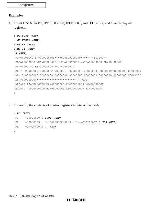
Rev. 1.0, 09/00, page 194 of 436
.<register>
Examples
1. To set H'5C60 in PC, H'FFE00 in SP, H'FF in R1, and H'11 in R2, and then display allregisters:
: .PC 5C60 (RET)
: .SP FFE00 (RET)
: .R1 FF (RET)
: .R2 11 (RET)
: R (RET)
PC=00005C60 SR=000000F0:****000000000000****----IIII00--
GBR=00000000 VBR=00000000 MACH=00000000 MACL=00000000 PR=00000000
RS=00000000 RE=00000000 MOD=00000000
R0-7 00000000 000000FF 00000011 00000000 00000000 00000000 00000000 00000000
R8-15 00000000 00000000 00000000 00000000 00000000 00000000 00000000 000FFE00
DSR=00000000:************************----COB-
A0G=00 A0=00000000 M0=00000000 X0=00000000 Y0=00000000
A1G=00 A1=00000000 M1=00000000 X1=00000000 Y1=00000000
:
2. To modify the contents of control registers in interactive mode:
: .PC (RET)
PC =00001000 ? 2000 (RET)
SR =000003F3 : ****000000000000****--MQIIII00ST ? 303 (RET)
PR =00000000 ? . (RET)
:

Rev. 1.0, 09/00, page 195 of 436
ABORT
7.2.2 ABORT [AB] Terminates emulation in parallel mode
Command Format
• Termination ABORT (RET)
Description
• Termination
Terminates GO command execution in parallel mode (prompt #), and cancels parallelmode.
When GO command execution is terminated by the ABORT command in parallel mode,BREAK KEY is displayed as the termination cause.
Example
To terminate GO command emulation in parallel mode:
: G RESET (RET)
** PC=00001022 (RET) (To enter parallel mode)#AB (RET)
PC=00005C60 SR=000000F0:****000000000000****----IIII00--
GBR=00000000 VBR=00000000 MACH=00000000 MACL=00000000 PR=00000000
RS=00000000 RE=00000000 MOD=00000000
R0-7 00000000 000000FF 00000011 00000000 00000000 00000000 00000000 00000000
R8-15 00000000 00000000 00000000 00000000 00000000 00000000 00000000 000FFE00
DSR=00000000:************************----COB-
A0G=00 A0=00000000 M0=00000000 X0=00000000 Y0=00000000
A1G=00 A1=00000000 M1=00000000 X1=00000000 Y1=00000000
RUN-TIME=D'000H:00M:03S:000409US:120NS
+++:BREAK KEY
:

Rev. 1.0, 09/00, page 196 of 436
ALIAS
7.2.3 ALIAS [ALI] Sets, displays, and cancels aliases
Command Format
• Setting ALIAS∆<alias name>∆<alias definition> (RET)
• Display ALIAS (RET)
• Cancellation ALIAS[∆]– ∆ <alias name> (RET)ALIAS[ ∆]– (RET)
<alias name>: Alias definition name<alias definition>: Alias definition contents
Description
• Setting
Sets aliases for commands. Up to 40 aliases can be set. An alias name is defined with up to 16characters and an alias definition with up to 230 characters.
: ALIAS∆∆<alias name> ∆∆ <alias definition> (RET)
• Display
Displays defined aliases as follows:
: ALIAS (RET) <alias name 1>:<alias definition 1> <alias name 2>:<alias definition 2> <alias name 3>:<alias definition 3> : :
• Cancellation
Cancels the specified alias.
: ALIAS – ∆∆<alias name> (RET)
When no alias name is specified, cancels all aliases.
: ALIAS – (RET)
Note
An alias itself cannot be included in the alias definition contents.

Rev. 1.0, 09/00, page 197 of 436
ALIAS
Examples
1. To define the alias name for the command to display the contents of register FRC0H asSHOW_FRC0H:
: ALI SHOW_FRC0H D 0D000042 @1;B (RET)
:
2. To display all defined aliases:
: ALI (RET)
SHOW_FRC0H: D 0D000042 @1;B
SHOW_FRC0L: D 0D000043 @1;B
LT: 11 test.abs
:
3. To cancel the alias with alias name LT:
: ALI– LT (RET)
:

Rev. 1.0, 09/00, page 198 of 436
ASSEMBLE
7.2.4 ASSEMBLE [A] Assembles program one line each
Command Format
• Line assembly ASSEMBLE ∆<address> (RET)
<address>: The address where the object program is to be written
Description
• Line assembly
After displaying the memory contents at the specified address, the emulator enterssubcommand input wait state. Line input in subcommand input wait state is assembled intomachine code which is written to memory. Assembly is continued until a period (finishingsubcommand) is entered. The input and output formats are as follows:
: ASSEMBLE <address> (RET)xxxxxxxx <disassemble display>xxxxxxxx ? <subcommand> (RET)xxxxxxxx ? <subcommand> (RET) : : : (a) (b)
(a) Address. When an odd address is specified, it is rounded down to aneven address.
(b) Subcommand (Input the contents shown in table 7.2).

Rev. 1.0, 09/00, page 199 of 436
ASSEMBLE
The subcommands listed in table 7.2 can be used with the ASSEMBLE command:
Table 7.2 Subcommands for Line Assembly
Subcommand Description
<assembly language statement> Assembles the input line (statement) into machine code andwrites it to the displayed address.
/[<address 1>[∆<address 2>]] Disassembles instructions from <address 1> to <address 2>and displays them. If <address 2> is omitted, the first 16instructions from <address 1> are displayed. If only a slash (/)is input, the contents from the ASSEMBLE command startaddress to the current address – 1 are disassembled.
(RET) only Increments the address (odd address + 1, even address + 2),and re-enters subcommand input wait state.
^ Decrements the address (odd address – 1, even address –2), and re-enters subcommand input wait state.
. Terminates the ASSEMBLE command.
Even if an odd address is specified, machine codes are written to memory. In that case, thefollowing warning message is displayed:
*** 82:ODD ADDRESS
Line assembly with this command can be performed only in areas CS0 to CS3 or theinternal memory areas.
Example
To perform line assembly from address H'1000:
: A 1000 (RET)
00001000 .DATA.W 0000
00001000 ? LDRS @(4,PC) (RET)
00001002 ? LDRE @(2,PC) (RET)
00001004 ? SETRC #D' 128 (RET)
00001006 ? NOP (RET)
00001008 ? PADD X0,Y0,A0 PMULS A1,X0,M0 MOVX.W @R4+,X0 MOVY.W @R6+,Y0 (RET)
0000100C ? .(RET)
:

Rev. 1.0, 09/00, page 200 of 436
BACKGROUND_INTERRUPT
7.2.5 BACKGROUND_INTERRUPT Sets and displays user interrupts in
[BI] command input wait state
Command Format
• Setting BACKGROUND_INTERRUPT [∆(E[:<loop program address>]/D)][;C] (RET)
• Display BACKGROUND_INTERRUPT (RET)
E/D: User interrupt accepting mode in command input wait stateE: Enables user interrupts in command input wait stateD: Disables user interrupts in command input wait state
(default at emulator shipment)<loop program address>: Address of the loop program for accepting user interrupts.
When omitted, the last address of internal Y-RAM area – 3C: Stores the settings as configuration information in emulator
flash memory
Description
• Setting
Enables user interrupts in command input wait state and sets the address of the loopprogram for accepting user interrupts. If the above settings are reset when user interruptshave already been enabled, even in the middle of the user interrupt processing, theemulator forcibly terminates the processing and then initiates the loop program foraccepting user interrupts again.
: BACKGROUND_INTERRUPT E (RET)
Enables user interrupts in command input wait state and sets the address of the loopprogram for accepting user interrupts. The loop program must be stored in the RAM area.If no address is specified, the address specified before is used. After setting, the loopprogram execution starts.
: BACKGROUND_INTERRUPT E:0000FFFC (RET)
Disables user interrupts in command input wait state.
: BACKGROUND_INTERRUPT D (RET)
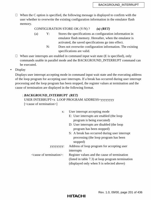
Rev. 1.0, 09/00, page 201 of 436
BACKGROUND_INTERRUPT
When the C option is specified, the following message is displayed to confirm with theuser whether to overwrite the existing configuration information in the emulator flashmemory.
CONFIGURATION STORE OK (Y/N) ? (a) (RET)
(a) Y: Stores the specifications as configuration information inemulator flash memory. Hereafter, when the emulator isactivated, the saved specifications go into effect.
N: Does not overwrite configuration information. The existingspecifications are valid.
When user interrupts are enabled in command input wait state (E is specified), onlycommands usable in parallel mode and the BACKGROUND_INTERRUPT command canbe executed.
• Display
Displays user interrupt accepting mode in command input wait state and the executing addressof the loop program for accepting user interrupts. If a break has occurred during user interruptprocessing and the loop program has been stopped, the register values at termination and thecause of termination are displayed in the following format.
: BACKGROUND_INTERRUPT (RET) USER INTERRUPT=x LOOP PROGRAM ADDRESS=yyyyyyyy
[<cause of termination>]
x: User interrupt accepting modeE: User interrupts are enabled (the loop
program is being executed)D: User interrupts are disabled (the loop
program has been stopped)S: A break has occurred during user interrupt
processing (the loop program has beenstopped)
yyyyyyyy: Address of loop program for accepting userinterrupts
<cause of termination>: Register values and the cause of termination(listed in table 7.3) at loop program termination(displayed only when S is selected above)

Rev. 1.0, 09/00, page 202 of 436
BACKGROUND_INTERRUPT
Display format is as follows:
-PC=00005C60 SR=00000000:****000000000000****--------00--
-GBR=00000000 VBR=00000000 MACH=00000000 MACL=00000000 PR=00000000
-RS=00000000 RE=00000000 MOD=00000000
-R0–7 00000000 000000FF 00000011 00000000 00000000 00000000 00000000 00000000
-R8–15 00000000 00000000 00000000 00000000 00000000 00000000 00000000 000FFE00
-DSR=00000000:************************----COB-
-A0G=00 A0=00000000 M0=00000000 X0=00000000 Y0=00000000
-A1G=00 A1=00000000 M1=00000000 X1=00000000 Y1=00000000
+++: <cause of termination>
Table 7.3 Causes of BACKGROUND_INTERRUPT Command Termination
Message Termination Cause
ILLEGAL INSTRUCTION An illegal instruction was executed.
RESET BY E8000 The emulator terminates program execution with the RESETsignal because an error has occurred in the user system.
LOOP PROGRAM ADDRESSIS NOT IN RAM
The executing address of the loop program for accepting userinterrupts is not in the RAM area; therefore, the loop programcannot be executed.
STOPPED IN INTERRUPTPROCESS
A break occurred during the user interrupt processing.
Notes
1. In command input wait state, a BRA $ or NOP instruction (instruction code: H'AFFE0009) isset to the address of the loop program for accepting user interrupts and executed. Note thefollowing:
• Do not specify the address of the loop program for accepting user interrupts in theROM area. If the specified address is in the ROM area, the loop program cannot beexecuted. Specify an address within the RAM area and enable user interrupts (selectoption E) again.
• Specify the address of the loop program for accepting user interrupts within an area thatis not used by the user program. The loop program requires a 4-byte area.
• When the address of the loop program for accepting user interrupts is specified, thememory contents before this specification are not stored. Therefore, the contents of theloop program address is a BRA $ instruction even after user interrupts are disabled orafter the loop program address is changed.
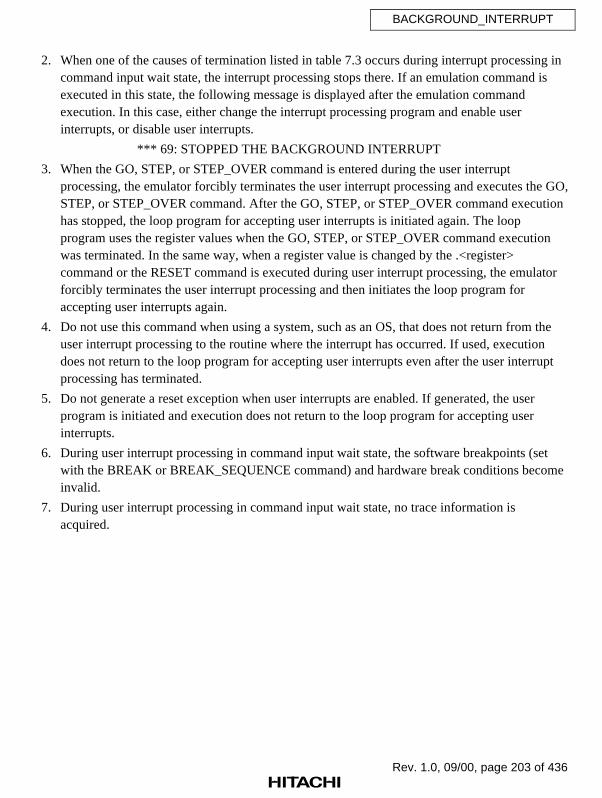
Rev. 1.0, 09/00, page 203 of 436
BACKGROUND_INTERRUPT
2. When one of the causes of termination listed in table 7.3 occurs during interrupt processing incommand input wait state, the interrupt processing stops there. If an emulation command isexecuted in this state, the following message is displayed after the emulation commandexecution. In this case, either change the interrupt processing program and enable userinterrupts, or disable user interrupts.
*** 69: STOPPED THE BACKGROUND INTERRUPT
3. When the GO, STEP, or STEP_OVER command is entered during the user interruptprocessing, the emulator forcibly terminates the user interrupt processing and executes the GO,STEP, or STEP_OVER command. After the GO, STEP, or STEP_OVER command executionhas stopped, the loop program for accepting user interrupts is initiated again. The loopprogram uses the register values when the GO, STEP, or STEP_OVER command executionwas terminated. In the same way, when a register value is changed by the .<register>command or the RESET command is executed during user interrupt processing, the emulatorforcibly terminates the user interrupt processing and then initiates the loop program foraccepting user interrupts again.
4. Do not use this command when using a system, such as an OS, that does not return from theuser interrupt processing to the routine where the interrupt has occurred. If used, executiondoes not return to the loop program for accepting user interrupts even after the user interruptprocessing has terminated.
5. Do not generate a reset exception when user interrupts are enabled. If generated, the userprogram is initiated and execution does not return to the loop program for accepting userinterrupts.
6. During user interrupt processing in command input wait state, the software breakpoints (setwith the BREAK or BREAK_SEQUENCE command) and hardware break conditions becomeinvalid.
7. During user interrupt processing in command input wait state, no trace information isacquired.

Rev. 1.0, 09/00, page 204 of 436
BACKGROUND_INTERRUPT
Examples
1. To specify the executing address of the loop program for accepting user interrupts to H'FFFC,and begin to accept user interrupts in command input wait state:
: BI E:FFFC (RET)
:
2. To display the current user interrupt accepting mode in command input wait state:
: BI (RET)
USER INTERRUPT=S LOOP PROGRAM ADDRESS=0000FFFC
-PC=00005C60 SR=00000000:****000000000000****--------00--
-GBR=00000000 VBR=00000000 MACH=00000000 MACL=00000000 PR=00000000
-RS=00000000 RE=00000000 MOD=00000000
-R0-7 00000000 000000FF 00000011 00000000 00000000 00000000 00000000 00000000
-R8-15 00000000 00000000 00000000 00000000 00000000 00000000 00000000 000FFE00
-DSR=00000000:************************----COB-
-A0G=00 A0=00000000 M0=00000000 X0=00000000 Y0=00000000
-A1G=00 A1=00000000 M1=00000000 X1=00000000 Y1=00000000
+++:ILLEGAL INSTRUCTION
:

Rev. 1.0, 09/00, page 205 of 436
BREAK
7.2.6 BREAK [B] Sets, displays, and cancels software
breakpoints
Command Format
• First level unordered list item <Level 1 unordered,1u>
• Setting BREAK∆<software breakpoint to be set>[[,<software breakpoint tobe set>]...] (RET)
• Display BREAK (RET)
• Cancellation BREAK[∆]–[<software breakpoint to be cancelled>[,<software breakpointto be cancelled>]...] (RET)
<software breakpoint to be set>: <address>[∆<number of times>]<address>: Software breakpoint address
<number of times>: How many times the specified software breakpoint isto be passed (H'1 to H'FFFF) (Default: H'1)
<software breakpoint to be cancelled>: Address of the software breakpoint to be cancelled
Note: When an odd address is specified, it is rounded down to an even address.
Description
• Setting
Sets a software breakpoint at the specified address by replacing its contents with a breakinstruction (H'0000). GO command emulation terminates when the break instruction isexecuted. (The instruction at the software breakpoint itself is not executed.) Up to fourbreakpoints can be set each time this command is issued, and a maximum of 255breakpoints can be set in total. A software breakpoint can only be set in a RAM area(including standard emulation memory) because the contents of the specified address isreplaced with a break instruction to cause a break. Do not set software breakpoints at anyof the addresses below:
• Address that holds an illegal instruction (H'0000)
• Areas other than CS0 to CS3 (excluding internal RAM and ROM areas)
• Address where the BREAK_CONDITION_UBC2 command settings are satisfied (referto the following descriptions)
• Address containing a slot delayed branch instruction (refer to the followingdescriptions)
• Address of the lower 16 bits of a 32-bit DSP instruction

Rev. 1.0, 09/00, page 206 of 436
BREAK
By specifying the number of times a breakpoint must be reached when setting thebreakpoint, program execution terminates when reaching the breakpoint for the specifiednumber of times.
Note: When multiple passes are specified for a breakpoint, the program must betemporarily stopped each time a software breakpoint is passed to update the passcount, and user program emulation continues until the number of times thebreakpoint must be passed is satisfied. As a result, realtime emulation is notperformed.
Example: To generate a break when the instruction at address 300 is executed fivetimes
: BREAK 300 5 (RET)
Software breakpoints are ignored during STEP and STEP_OVER command execution, sothe pass count is not updated at this time.
When execution starts at the address set with the BREAK command, immediately afterexecution starts, the BREAK_CONDITION_UBC2 command settings are invalidated.Therefore, even though a BREAK_CONDITION_UBC2 command setting is satisfiedimmediately after execution start, GO command execution does not terminate.
If a software breakpoint is set at a slot delayed branch instruction, a slot illegal instructioninterrupt occurs instead of terminating program execution. Make sure not to set a softwarebreakpoint at a slot delayed branch instruction.
• Display
Display format is as follows:
: BREAK (RET)<ADDR> <CNT> <PASS>xxxxxxxx yyyy zzzz(a) (b) (c)
(a) Setting address
(b) Specified pass count (hexadecimal)
(c) Value of pass counter (shows how many times the specified address has been passed atGO command termination, in hexadecimal)Note: The pass counter is cleared by the next GO command.

Rev. 1.0, 09/00, page 207 of 436
BREAK
• Cancellation
Cancels software breakpoints. Breakpoints can be cancelled in the following two ways:
Cancellation of specified software breakpoints. A maximum of four breakpoints can becancelled with one command.
: BREAK–<software breakpoint>[,<software breakpoint>]... (RET)
Cancellation of all software breakpoints.
: BREAK– (RET)
Examples
1. To set a software breakpoint at address H'100:
: B 100 (RET)
:
2. To generate a break when address H'6004 has been passed three times:
: B 6004 3 (RET)
:
3. To display set software breakpoints:
: B (RET)
<ADDR> <CNT> <PASS>
00000100 0001 0000
00006004 0003 0000
:
4. To cancel the software breakpoint at address H'100:
: B — 100 (RET)
:
5. To cancel all software breakpoints:
: B — (RET)
:
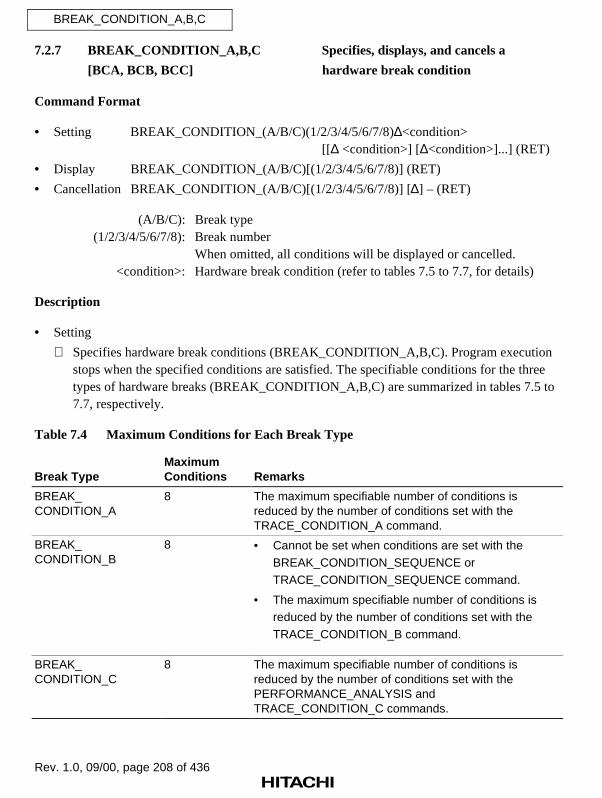
Rev. 1.0, 09/00, page 208 of 436
BREAK_CONDITION_A,B,C
7.2.7 BREAK_CONDITION_A,B,C Specifies, displays, and cancels a
[BCA, BCB, BCC] hardware break condition
Command Format
• Setting BREAK_CONDITION_(A/B/C)(1/2/3/4/5/6/7/8)∆<condition>[[∆ <condition>] [∆<condition>]...] (RET)
• Display BREAK_CONDITION_(A/B/C)[(1/2/3/4/5/6/7/8)] (RET)
• Cancellation BREAK_CONDITION_(A/B/C)[(1/2/3/4/5/6/7/8)] [∆] – (RET)
(A/B/C): Break type(1/2/3/4/5/6/7/8): Break number
When omitted, all conditions will be displayed or cancelled.<condition>: Hardware break condition (refer to tables 7.5 to 7.7, for details)
Description
• Setting
Specifies hardware break conditions (BREAK_CONDITION_A,B,C). Program executionstops when the specified conditions are satisfied. The specifiable conditions for the threetypes of hardware breaks (BREAK_CONDITION_A,B,C) are summarized in tables 7.5 to7.7, respectively.
Table 7.4 Maximum Conditions for Each Break Type
Break TypeMaximumConditions Remarks
BREAK_CONDITION_A
8 The maximum specifiable number of conditions isreduced by the number of conditions set with theTRACE_CONDITION_A command.
BREAK_CONDITION_B
8 • Cannot be set when conditions are set with theBREAK_CONDITION_SEQUENCE orTRACE_CONDITION_SEQUENCE command.
• The maximum specifiable number of conditions isreduced by the number of conditions set with theTRACE_CONDITION_B command.
BREAK_CONDITION_C
8 The maximum specifiable number of conditions isreduced by the number of conditions set with thePERFORMANCE_ANALYSIS andTRACE_CONDITION_C commands.
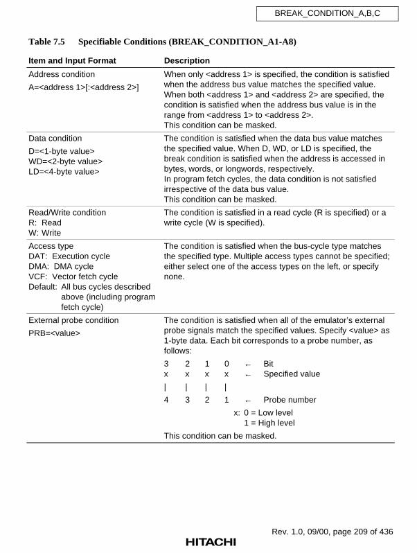
Rev. 1.0, 09/00, page 209 of 436
BREAK_CONDITION_A,B,C
Table 7.5 Specifiable Conditions (BREAK_CONDITION_A1-A8)
Item and Input Format Description
Address condition
A=<address 1>[:<address 2>]
When only <address 1> is specified, the condition is satisfiedwhen the address bus value matches the specified value.When both <address 1> and <address 2> are specified, thecondition is satisfied when the address bus value is in therange from <address 1> to <address 2>.This condition can be masked.
Data condition
D=<1-byte value>WD=<2-byte value>LD=<4-byte value>
The condition is satisfied when the data bus value matchesthe specified value. When D, WD, or LD is specified, thebreak condition is satisfied when the address is accessed inbytes, words, or longwords, respectively.In program fetch cycles, the data condition is not satisfiedirrespective of the data bus value.This condition can be masked.
Read/Write conditionR: ReadW: Write
The condition is satisfied in a read cycle (R is specified) or awrite cycle (W is specified).
Access typeDAT: Execution cycleDMA: DMA cycleVCF: Vector fetch cycleDefault: All bus cycles described
above (including programfetch cycle)
The condition is satisfied when the bus-cycle type matchesthe specified type. Multiple access types cannot be specified;either select one of the access types on the left, or specifynone.
External probe condition
PRB=<value>
The condition is satisfied when all of the emulator’s externalprobe signals match the specified values. Specify <value> as1-byte data. Each bit corresponds to a probe number, asfollows:
3 2 1 0 ← Bitx x x x ← Specified value
| | | |
4 3 2 1 ← Probe number
x: 0 = Low level1 = High level
This condition can be masked.

Rev. 1.0, 09/00, page 210 of 436
BREAK_CONDITION_A,B,C
Table 7.5 Specifiable Conditions (BREAK_CONDITION_A1-A8) (cont)
Item and Input Format Description
External interrupt condition 1
NMI [:L] or NMI: H
The condition is satisfied when the NMI signal matches thespecified level.
NMI or NMI: L: The condition is satisfied when NMI is lowNMI: H: The condition is satisfied when NMI is high
External interrupt condition 2
IRQ=<value>
The condition is satisfied when all of the IRQ signals matchthe specified values. Specify <value> as 1-byte data. Each bitcorresponds to an IRQ number, as follows:
3 2 1 0 ← Bitx x x x ← Specified value
| | | |
3 2 1 0 ← IRQ number
x: 0 = Low level1 = High level
The condition can be masked.

Rev. 1.0, 09/00, page 211 of 436
BREAK_CONDITION_A,B,C
Table 7.6 Specifiable Conditions (BREAK_CONDITION_B1-B8)
Item and Input Format Description
Address conditionA=<address 1>[:<address 2>][;NOT]
When only <address 1> is specified, the condition is satisfiedwhen the address bus value matches the specified value.When both <address 1> and <address 2> are specified, thecondition is satisfied when the address bus value is in therange from <address 1> to <address 2>.If the NOT option is specified, the condition is satisfied whenthe address bus value does not match the specified value.This condition can be masked.
Data conditionD=<1-byte value>[;NOT]WD=<2-byte value>[;NOT]LD=<4-byte value>[;NOT]
The condition is satisfied when the data bus value matchesthe specified value. When D, WD, or LD is specified, thebreak condition is satisfied when the address is accessed inbytes, words, or longwords, respectively.In program fetch cycles, the data condition is not satisfiedirrespective of the data bus value.If the NOT option is specified, the condition is satisfied whenthe data bus value does not match the specified value.This condition can be masked.
Read/Write conditionR: ReadW: Write
The condition is satisfied in a read cycle (R is specified) or awrite cycle (W is specified).
Access typeDAT: Execution cycleDMA: DMA cycleVCF: Vector fetch cycleDefault: All bus cycles described
above (including programfetch cycle)
The condition is satisfied when the bus-cycle type matchesthe specified type. Multiple access types cannot be specified;either select one of the access types on the left, or specifynone.
External probe conditionPRB=<value>
The condition is satisfied when all of the emulator’s externalprobe signals match the specified values. Specify <value> as1-byte data. Each bit corresponds to a probe number, asfollows:3 2 1 0 ← Bitx x x x ← Specified value| | | |4 3 2 1 ← Probe number
x: 0 = Low level1 = High level
This condition can be masked.

Rev. 1.0, 09/00, page 212 of 436
BREAK_CONDITION_A,B,C
Table 7.6 Specifiable Conditions (BREAK_CONDITION_B1-B8) (cont)
Item and Input Format Description
External interrupt condition 1
NMI [:L] or NMI: H
The condition is satisfied when the NMI signal matches thespecified level.
NMI or NMI: L: The condition is satisfied when NMI is lowNMI: H: The condition is satisfied when NMI is high
External interrupt condition 2
IRQ=<value>
The condition is satisfied when all of the IRQ signals matchthe specified values. Specify <value> as 1-byte data. Each bitcorresponds to an IRQ number, as follows:
3 2 1 0 ← Bitx x x x ← Specified value
| | | |
3 2 1 0 ← IRQ number
x: 0 = Low level1 = High level
The condition can be masked.
Satisfaction count specification
COUNT=<value>
<value>: H'1 to H'FFFF
The condition can be specified in combination with any of theaddress, data, read/write, access type, external probe, andexternal interrupt conditions. The complete conditioncombination is satisfied when the other specified conditionhas been satisfied for the specified number of times.
Delay count specification
DELAY=<value>
<value>: H'1 to H'7FFF
This condition can be specified in combination with any of theaddress, data, read/write, access type, external probe, andexternal interrupt conditions. The complete conditioncombination is satisfied when the specified number of buscycles has been executed after the other specified conditionis satisfied.This condition can only be specified with theBREAK_CONDITION_B7 command.

Rev. 1.0, 09/00, page 213 of 436
BREAK_CONDITION_A,B,C
Table 7.7 Specifiable Conditions (BREAK_CONDITION_C1-C8)
Item and Input Format Description
Address condition
A=<address 1>[:<address 2>]
When only <address 1> is specified, the condition is satisfiedwhen the address bus value matches the specified value.When both <address 1> and <address 2> are specified, thecondition is satisfied when the address bus value is in therange from <address 1> to <address 2>.This condition can be masked.
Access typeDAT: Execution cycleDMA: DMA cycleVCF: Vector fetch cycleDefault: All bus cycles described
above (including programfetch cycle)
The condition is satisfied when the bus-cycle type matchesthe specified type. Multiple access types cannot be specified;either select one of the access types on the left, or specifynone.
Address and data conditions are satisfied when address bus values and data bus valuesmatch the specified values. Note the following when specifying break conditions.
a. Access to a 32-bit bus area
• Longword access
Longword data is accessed in one bus cycle. Only longword data (LD) and a multipleof four can be specified as the data and address conditions, respectively.
• Word access
Word data is accessed in one bus cycle. Only word data (WD) and a multiple of twocan be specified as the data and address conditions, respectively. 32 bits must bespecified as the data bus width. Note that the data condition must be specified incombination with a specific address condition. If no address condition is specified or ifthe address is masked, the data condition will be satisfied when the address is amultiple of four.
• Byte access
Byte data is accessed in one bus cycle. Only byte data (D) can be specified as the datacondition. Both even and odd address values can be specified as the address condition.32 bits must be specified as the data bus width. Note that the data condition must bespecified in combination with a specific address condition. If no address condition isspecified or if the address is masked, the data condition will be satisfied when theaddress is a multiple of four.

Rev. 1.0, 09/00, page 214 of 436
BREAK_CONDITION_A,B,C
b. Access to a 16-bit bus area
• Longword access
Longword data is accessed in two word-access cycles. Only word data (WD) and amultiple of two can be specified as the data and address conditions, respectively. 16bits must be specified as the data bus width.
• Word access
Word data is accessed in one bus cycle. Only word data (WD) and a multiple of twocan be specified as the data and address conditions, respectively. 16 bits must bespecified as the data bus width.
• Byte access
Byte data is accessed in one bus cycle. Only byte data (D) can be specified as the datacondition. Both even and odd address values can be specified as the address condition.16 bits must be specified as the data bus width. Note that the data condition must bespecified in combination with a specific address condition. If no address condition isspecified or if the address is masked, the data condition will be satisfied when theaddress is a multiple of two.
c. Access to an 8-bit bus area
All addresses can be accessed in byte units. Longword data and word data are accessed infour byte-access cycles and two byte-access cycles, respectively. Both even and oddaddresses can be specified as the address condition. Note, however, that only byte data (D)is valid for the data condition. Eight bits must be specified as the data bus width.

Rev. 1.0, 09/00, page 215 of 436
BREAK_CONDITION_A,B,C
A bit mask in 1-bit or 4-bit units can be specified for the address condition of theBREAK_CONDITION_A,B,C command. When a bit is masked, the condition is satisfiedirrespective of its bit value. To implement the mask, specify each digit to be masked atinput as an asterisk (*). When <address 2> is not specified for an address condition,<address 1> can be consecutively masked from the lowest bit. It is not possible to maskany desired bit position. Table 7.8 shows address mask specification examples.
Example: The following condition is satisfied when the lower four bits of the addresscondition are not specified:
: BREAK_CONDITION_A1 A=H'400000* (RET)
Table 7.8 Address Mask Specifications (BREAK_CONDITION_A,B,C)
Radix Mask Unit Example Mask Position
Binary 1 bit B’01110*** Bits 2 to 0 are masked
Hexadecimal 4 bits H’000F50** Bits 7 to 0 are masked
Note: When <address 2> is not specified for an address condition, <address 1> can beconsecutively masked from the lowest bit. It is not possible to mask any desired bitposition, as shown in the following examples.
Examples:Allowed: BREAK_CONDITION_A1 A = H'10**Not allowed: BREAK_CONDITION_A1 A = H'1*00
BREAK_CONDITION_A1 A = H'100* :10**
A bit mask in 1-bit or 4-bit units can be specified for the data, IRQ, or PRB condition ofthe BREAK_CONDITION_A,B,C command. When a bit is masked, the condition issatisfied irrespective of its bit value. To implement the mask, specify each digit to bemasked at input as an asterisk (*). Table 7.9 shows these mask specification examples.
Example: The following condition is satisfied when address 3000000 is the addresscondition and bit 0 is zero in the byte data condition:
: BREAK_CONDITION_A1 A=H'3000000 D=B'*******0 (RET)
Table 7.9 Mask Specifications (BREAK_CONDITION_A,B,C)
Radix Mask Unit Example Mask Position Allowed Condition
Binary 1 bit B'01*1010* Bits 0 and 5 are masked Data (D, WD, LD), IRQ, orPRB
Hexa-decimal
4 bits H'F** 50 Bits 15 to 8 are masked Data (D, WD, LD), IRQ, orPRB

Rev. 1.0, 09/00, page 216 of 436
BREAK_CONDITION_A,B,C
If a hardware break condition is satisfied, emulation may stop after two or moreinstructions have been executed.
• Display
Displays specified conditions. The character string that was input for specifying conditionswill be displayed as it was input. If the break number is omitted, all specified breakconditions for that break type are displayed.
For BREAK_CONDITION_B1-B8 conditions, satisfaction count since the previous breakcondition was satisfied is displayed.
For BREAK_CONDITION_B7 conditions, delay count since the previous break conditionwas satisfied is displayed.
If no break condition is specified, a blank is displayed.
: BREAK_CONDITION_B (RET) BCB1 <B1 break setting> BCB2 <B2 break setting> BCB3 <B3 break setting> BCB4 <B4 break setting> BCB5 <B5 break setting> BCB6 <B6 break setting> BCB7 <B7 break setting> BCB8 <B8 break setting>

Rev. 1.0, 09/00, page 217 of 436
BREAK_CONDITION_A,B,C
• Cancellation
Cancels specified conditions. When break numbers 1 to 8 are omitted, all break conditions arecancelled.
Cancels all conditions for the BREAK_CONDITION_A command.
: BREAK_CONDITION_A – (RET)
Cancels BREAK_CONDITION_A1 conditions.
: BREAK_CONDITION_A1 – (RET)
Notes
1. When conditions have already been set with the PERFORMANCE_ANALYSIS orTRACE_CONDITION_A,B,C command, break conditions may not be set to their maximumnumber. If necessary, cancel conditions set with the above commands before setting the breakconditions.
2. When conditions have been set with the BREAK_CONDITION_SEQUENCE orTRACE_CONDITION_SEQUENCE command, and sequential break or sequential trace stopis enabled, the BREAK_CONDITION_B command cannot be used. If necessary, disablesequential break or sequential trace stop, or cancel conditions set with theBREAK_CONDITION_SEQUENCE or TRACE_CONDITION_SEQUENCE commandbefore setting the break conditions.
Examples
1. To generate a break when byte data H'10 is accessed at address H'F000000:
: BCA1 A=F000000 D=10 (RET)
:
2. To generate a break when data is written to address H'1000000:
: BCA2 A=1000000 W DAT (RET)
:
3. To generate a break when reading data in address H'2000000:
: BCB1 A=2000000 R (RET)
:

Rev. 1.0, 09/00, page 218 of 436
BREAK_CONDITION_A,B,C
4. To display the specified conditions:
: BCA (RET)
BCA1 B=F000000 D=10
BCA2 B=1000000 W DAT
BCA3
BCA4
BCA5
BCA6
BCA7
BCA8
:
5. To cancel the specified conditions:
: BCA1 — (RET)
: BCB1 — (RET)
:

Rev. 1.0, 09/00, page 219 of 436
BREAK_CONDITION_SEQUENCE
7.2.8 BREAK_CONDITION_ Sets, displays, and cancels hardware
SEQUENCE [BCS] sequential break conditions
Command Format
• Setting BREAK_CONDITION_SEQUENCE(1/2/3/4/5/6/7)∆<condition>[[∆ <condition>]...] (RET)(Pass point condition setting)
BREAK_CONDITION_SEQUENCE∆<condition>[[∆ <condition>]...];R (RET) (Sequential reset condition setting)
• Display BREAK_CONDITION_SEQUENCE (RET)
• Cancellation BREAK_CONDITION_SEQUENCE(1/2/3/4/5/6/7)[∆]– (RET)(Pass point condition cancellation)
BREAK_CONDITION_SEQUENCE[∆]–;R (RET)(Sequential reset condition cancellation)
• Enabling/ BREAK_CONDITION_SEQUENCE∆;(E/D) (RET)Disabling (Enable/disable of sequential break)
(1/2/3/4/5/6/7): Pass point number<condition>: Pass point condition
R: Sequential reset condition specificationE: Enables sequential breakD: Disables sequential break
Description
• Setting
Sets pass points to enable the break for which the pass sequence is specified (sequentialbreak). GO command emulation terminates when these pass points have been passed in thespecified sequence.
If the pass points have not been passed in the specified sequence, condition satisfactionchecking begins again from the first pass point.
When the specified reset point is passed, condition satisfaction checking begins again at thefirst pass point, even if the remaining pass points are then passed in the assigned sequence.
This command cannot be used when conditions are set with the BREAK_CONDITION_B, TRACE_CONDITION_B, or TRACE_CONDITION_SEQUENCEcommand.
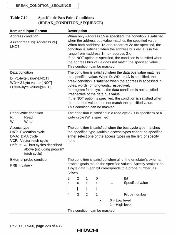
Rev. 1.0, 09/00, page 220 of 436
BREAK_CONDITION_SEQUENCE
Table 7.10 Specifiable Pass Point Conditions (BREAK_CONDITION_SEQUENCE)
Item and Input Format Description
Address condition
A=<address 1>[:<address 2>][;NOT]
When only <address 1> is specified, the condition is satisfiedwhen the address bus value matches the specified value.When both <address 1> and <address 2> are specified, thecondition is satisfied when the address bus value is in therange from <address 1> to <address 2>.If the NOT option is specified, the condition is satisfied whenthe address bus value does not match the specified value.This condition can be masked.
Data condition
D=<1-byte value>[;NOT]WD=<2-byte value>[;NOT]LD=<4-byte value>[;NOT]
The condition is satisfied when the data bus value matchesthe specified value. When D, WD, or LD is specified, thebreak condition is satisfied when the address is accessed inbytes, words, or longwords, respectively.In program fetch cycles, the data condition is not satisfiedirrespective of the data bus value.If the NOT option is specified, the condition is satisfied whenthe data bus value does not match the specified value.This condition can be masked.
Read/Write conditionR: ReadW: Write
The condition is satisfied in a read cycle (R is specified) or awrite cycle (W is specified).
Access typeDAT: Execution cycleDMA: DMA cycleVCF: Vector fetch cycleDefault: All bus cycles described
above (including programfetch cycle)
The condition is satisfied when the bus-cycle type matchesthe specified type. Multiple access types cannot be specified;either select one of the access types on the left, or specifynone.
External probe condition
PRB=<value>
The condition is satisfied when all of the emulator’s externalprobe signals match the specified values. Specify <value> as1-byte data. Each bit corresponds to a probe number, asfollows:
3 2 1 0 ← Bitx x x x ← Specified value
| | | |
4 3 2 1 ← Probe number
x: 0 = Low level1 = High level
This condition can be masked.

Rev. 1.0, 09/00, page 221 of 436
BREAK_CONDITION_SEQUENCE
Table 7.10 Specifiable Pass Point Conditions (BREAK_CONDITION_SEQUENCE) (cont)
Item and Input Format Description
External interrupt condition 1
NMI [:L] or NMI: H
The condition is satisfied when the NMI signal matches thespecified level.
NMI or NMI: L: The condition is satisfied when NMI is lowNMI: H: The condition is satisfied when NMI is high
External interrupt condition 2
IRQ=<value>
The condition is satisfied when all of the IRQ signals matchthe specified values. Specify <value> as 1-byte data. Each bitcorresponds to an IRQ number, as follows:
3 2 1 0 ← Bitx x x x ← Specified value
| | | |
3 2 1 0 ← IRQ number
x: 0 = Low level1 = High level
The condition can be masked.
Delay count specification
DELAY=<value>
<value>: H'1 to H'7FFF
This condition can be specified in combination with any of theaddress, data, read/write, access type, external probe, andexternal interrupt conditions. The complete conditioncombination is satisfied when the specified number of buscycles has been executed after the other specified conditionis satisfied.This condition can only be specified with theBREAK_CONDITION_SEQUENCE7 command.
Address and data conditions are satisfied when address bus values and data bus valuesmatch the specified values. Note the following when specifying break conditions.
a. Access to a 32-bit bus area
• Longword access
Longword data is accessed in one bus cycle. Only longword data (LD) and a multipleof four can be specified as the data and address conditions, respectively.

Rev. 1.0, 09/00, page 222 of 436
BREAK_CONDITION_SEQUENCE
• Word access
Word data is accessed in one bus cycle. Only word data (WD) and a multiple of twocan be specified as the data and address conditions, respectively. 32 bits must bespecified as the data bus width. Note that the data condition must be specified incombination with a specific address condition. If no address condition is specified or ifthe address is masked, the data condition will be satisfied when the address is amultiple of four.
• Byte access
Byte data is accessed in one bus cycle. Only byte data (D) can be specified as the datacondition. Both even and odd address values can be specified as the address condition.32 bits must be specified as the data bus width. Note that the data condition must bespecified in combination with a specific address condition. If no address condition isspecified or if the address is masked, the data condition will be satisfied when theaddress is a multiple of four.
b. Access to a 16-bit bus area
• Longword access
Longword data is accessed in two word-access cycles. Only word data (WD) and amultiple of two can be specified as the data and address conditions, respectively. 16bits must be specified as the data bus width.
• Word access
Word data is accessed in one bus cycle. Only word data (WD) and a multiple of twocan be specified as the data and address conditions, respectively. 16 bits must bespecified as the data bus width.
• Byte access
Byte data is accessed in one bus cycle. Only byte data (D) can be specified as the datacondition. Both even and odd address values can be specified as the address condition.16 bits must be specified as the data bus width. Note that the data condition must bespecified in combination with a specific address condition. If no address condition isspecified or if the address is masked, the data condition will be satisfied when theaddress is a multiple of two.
c. Access to an 8-bit bus area
All addresses can be accessed in byte units. Longword data and word data are accessed infour byte-access cycles and two byte-access cycles, respectively. Both even and oddaddresses can be specified as the address condition. Note, however, that only byte data (D)is valid for the data condition. Eight bits must be specified as the data bus width.

Rev. 1.0, 09/00, page 223 of 436
BREAK_CONDITION_SEQUENCE
A bit mask in 1-bit or 4-bit units can be specified for the address condition of theBREAK_CONDITION_SEQUENCE command. When a bit is masked, the condition issatisfied irrespective of its bit value. To implement the mask, specify each digit to bemasked at input as an asterisk (*). When <address 2> is not specified for an addresscondition, <address 1> can be consecutively masked from the lowest bit. It is not possibleto mask any desired bit position. Table 7.11 shows address mask specification examples.
Example: The following condition is satisfied when the lower four bits of the addresscondition are not specified:
: BREAK_CONDITION_SEQUENCE1 A=H'400000* (RET)
Table 7.11 Address Mask Specifications (BREAK_CONDITION_SEQUENCE)
Radix Mask Unit Example Mask Position
Binary 1 bit B'01110*** Bits 2 to 0 are masked
Hexadecimal 4 bits H'000F50** Bits 7 to 0 are masked
Note: When <address 2> is not specified for an address condition, <address 1> can beconsecutively masked from the lowest bit. It is not possible to mask any desired bitposition, as shown in the following examples.Examples:
Allowed: BREAK_CONDITION_SEQUENCE1 A = H'10**Not allowed: BREAK_CONDITION_SEQUENCE1 A = H'1*00
BREAK_CONDITION_SEQUENCE1 A = H'100* :10**
A bit mask in 1-bit or 4-bit units can be specified for the data, IRQ, or PRB condition ofthe BREAK_CONDITION_SEQUENCE command. When a bit is masked, the condition issatisfied irrespective of its bit value. To implement the mask, specify each digit to bemasked at input as an asterisk (*). Table 7.12 shows these mask specification examples.
Example: The following condition is satisfied when address 3000000 is the addresscondition and bit 0 is zero in the byte data condition:
: BREAK_CONDITION_SEQUENCE1 A=H'3000000 D=B'*******0 (RET)

Rev. 1.0, 09/00, page 224 of 436
BREAK_CONDITION_SEQUENCE
Table 7.12 Mask Specifications (BREAK_CONDITION_SEQUENCE)
Radix Mask Unit Example Mask Position Allowed Condition
Binary 1 bit B'01*1010* Bits 0 and 5 are masked Data (D, WD, LD), IRQ, orPRB
Hexa-decimal
4 bits H'F** 50 Bits 15 to 8 are masked Data (D, WD, LD), IRQ, orPRB
• Display
Displays specified pass points and reset point as follows:
: BREAK_CONDITION_SEQUENCE (RET) BCS1 xxx...x BCS2 xxx...x BCS3 xxx...x BCS4 xxx...x BCS5 xxx...x BCS6 xxx...x BCS7 xxx...x RESET xxx...x DELAY=yyyy
xxx...x: Specified conditionyyyy: Delay count specification
• Cancellation
Cancels specified pass points or a reset point.
Cancellation of pass points
: BREAK_CONDITION_SEQUENCE– (RET)
Cancellation of a reset point
: BREAK_CONDITION_SEQUENCE–;R (RET)
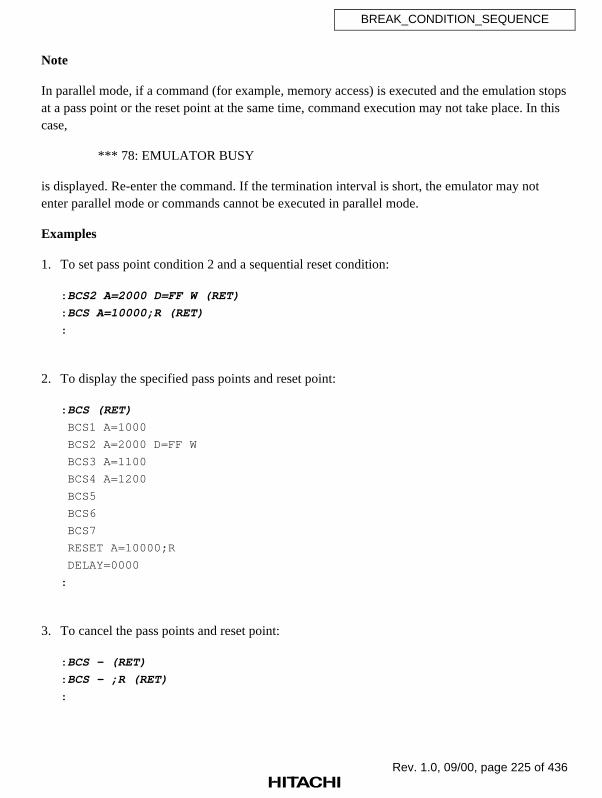
Rev. 1.0, 09/00, page 225 of 436
BREAK_CONDITION_SEQUENCE
Note
In parallel mode, if a command (for example, memory access) is executed and the emulation stopsat a pass point or the reset point at the same time, command execution may not take place. In thiscase,
*** 78: EMULATOR BUSY
is displayed. Re-enter the command. If the termination interval is short, the emulator may notenter parallel mode or commands cannot be executed in parallel mode.
Examples
1. To set pass point condition 2 and a sequential reset condition:
: BCS2 A=2000 D=FF W (RET)
: BCS A=10000;R (RET)
:
2. To display the specified pass points and reset point:
: BCS (RET)
BCS1 A=1000
BCS2 A=2000 D=FF W
BCS3 A=1100
BCS4 A=1200
BCS5
BCS6
BCS7
RESET A=10000;R
DELAY=0000
:
3. To cancel the pass points and reset point:
: BCS — (RET)
: BCS — ;R (RET)
:

Rev. 1.0, 09/00, page 226 of 436
BREAK_CONDITION_UBC
7.2.9 BREAK_CONDITION_UBC Specifies, displays, and cancels
[BCU] hardware break conditions
Command Format
• Setting BREAK_CONDITION_UBC(1/2)∆<condition>[[∆ <condition>] [∆<condition>]...] (RET)
• Display BREAK_CONDITION_UBC[(1/2)] (RET)
• Cancellation BREAK_CONDITION_UBC[(1/2)] [∆] – (RET)
(1/2): UBC break numberWhen omitted, all conditions will be displayed or cancelled.
<condition>: Hardware break condition (refer to tables 7.13 and 7.14, for details)
Description
• Setting
Specifies hardware break conditions (BREAK_CONDITION_UBC). Program executionstops when the specified conditions are satisfied. The specifiable conditions for the twokinds of hardware breaks are summarized in tables 7.13 and 7.14, respectively. TheBREAK_CONDITION_UBC conditions can also be satisfied in sequential break mode(program execution stops only when UBC1 and UBC2 settings are satisfied in thesequence of UBC2 break condition followed by UBC1 break condition). The sequentialbreak can be specified with the GO command.

Rev. 1.0, 09/00, page 227 of 436
BREAK_CONDITION_UBC
Table 7.13 Specifiable Conditions (BREAK_CONDITION_UBC1)
Item and Input Format Description
Address condition
A=<address>PC=<address>[;P]XA=<X-bus address>YA=<Y-bus address>
The condition is satisfied when the address bus valuematches the specified value.When A= is selected, the address bus in data access orprogram fetch cycles is specified, and when PC= is selected,the address bus in program fetch cycles is specified. Whenthe ;P option is specified with PC=, a break occurs beforeprogram execution at the specified address, while if the optionis omitted, a break occurs after program execution.When PC= is selected, only the satisfaction countspecification is valid.When XA= or YA= is selected, specify the address in words.This condition can be masked.
Data condition
D=<1-byte value>WD=<2-byte value>LD=<4-byte value>XD=<X-bus data value>YD=<Y-bus data value>
The condition is satisfied when the data bus value matchesthe specified value. When D, WD, or LD is specified, thebreak condition is satisfied when the address is accessed inbytes, words, or longwords, respectively.In program fetch cycles, the data condition is not satisfiedirrespective of the data bus value.When XD= or YD= is selected, specify the data value inwords.Multiple data conditions cannot be specified.This condition can be masked.
Read/Write conditionR: ReadW: Write
The condition is satisfied in a read cycle (R is specified) or awrite cycle (W is specified).
Access typeDAT: Execution cycleDMA: DMA cycleDefault: All bus cycles described
above (including programfetch cycle)
The condition is satisfied when the bus-cycle type matchesthe specified type. Multiple access types cannot be specified;either select one of the access types on the left, or specifynone.
Satisfaction count specification
COUNT=<value>
<value>: H'1 to H'FFF
This condition can be specified in combination with any of theaddress, data, read/write, and access type conditions.The complete condition combination is satisfied when theother specified condition has been satisfied for the specifiednumber of times.

Rev. 1.0, 09/00, page 228 of 436
BREAK_CONDITION_UBC
Table 7.14 Specifiable Conditions (BREAK_CONDITION_UBC2)
Item and Input Format Description
Address condition
A=<address>PC=<address>[;P]
The condition is satisfied when the address bus valuematches the specified value.When A= is selected, the address bus in data access orprogram fetch cycles is specified, and when PC= is selected,the address bus in program fetch cycles is specified. Whenthe ;P option is specified with PC=, a break occurs beforeprogram execution at the specified address, while if the optionis omitted, a break occurs after program execution.When PC= is selected, no other conditions can be specified.This condition can be masked.
Read/Write conditionR: ReadW: Write
The condition is satisfied in a read cycle (R is specified) or awrite cycle (W is specified).
Access typeDAT: Execution cycleDMA: DMA cycleDefault: All bus cycles described
above (including programfetch cycle)
The condition is satisfied when the bus-cycle type matchesthe specified type. Multiple access types cannot be specified;either select one of the access types on the left, or specifynone.
The data conditions of the BREAK_CONDITION_UBC1 break are satisfied when theaddress bus and data bus values match the specified values. The data bus (the SH7410internal bus) is always 32 bits long. Note the following when specifying break conditions.
• Longword access
Longword data is accessed in one bus cycle. Only longword data (LD) and a multipleof four can be specified as the data and address conditions, respectively.
• Word access
Word data is accessed in one bus cycle. Only word data (WD) and a multiple of twocan be specified as the data and address conditions, respectively.
• Byte access
Byte data is accessed in one bus cycle. Only byte data (D) can be specified as the datacondition. Both even and odd address values can be specified as the address condition.

Rev. 1.0, 09/00, page 229 of 436
BREAK_CONDITION_UBC
A bit mask in 1-bit or 4-bit units can be specified for the address, PC, and data conditionsof the BREAK_CONDITION_UBC1,2 command. When a bit is masked, the condition issatisfied irrespective of its bit value. To implement the mask, specify each digit to bemasked at input as an asterisk (*). Table 7.15 shows mask specification examples.
Example 1: The following condition is satisfied when the lower four bits of theaddress condition are not specified:
: BREAK_CONDITION_UBC1 A=H'400000* (RET)
Example 2: The following condition is satisfied when address 3000000 is theaddress condition and bit 0 is zero in the byte data condition:
: BREAK_CONDITION_UBC1 A=H'3000000 D=B'*******0 (RET)
Table 7.15 Mask Specifications (BREAK_CONDITION_UBC1,2)
Radix Mask Unit Example Mask Position Allowed Condition
Binary 1 bit B'01*1010* Bits 0 and 5 are masked Address, data (D, WD,LD), or PC
Hexa-decimal
4 bits H'F** 50 Bits 15 to 8 are masked Address, data (D, WD,LD), or PC
• Display
Displays specified conditions. The character string that was input for specifying conditionswill be displayed as it was input. If break numbers 1 and 2 are omitted, break conditionsfor both break types are displayed.
For BREAK_CONDITION_UBC1 break conditions, satisfaction count after the previousbreak condition was satisfied is displayed.
If no break condition is specified, a blank is displayed.
: BREAK_CONDITION_UBC (RET) BCU1 <UBC1 break setting> COUNT=xxx BCU2 <UBC2 break setting>
xxx: Satisfaction count after the condition is satisfied

Rev. 1.0, 09/00, page 230 of 436
BREAK_CONDITION_UBC
• Cancellation
Cancels specified conditions. When break numbers 1 and 2 are omitted, all break conditionsare cancelled.
Cancellation of all break conditions
: BREAK_CONDITION_UBC – (RET)
Cancellation of BREAK_CONDITION_UBC2 break conditions
: BREAK_CONDITION_UBC2 – (RET)
Notes
1. The BREAK_CONDITION_UBC2 settings are ignored when a stop address is specified withthe GO command or during STEP and STEP_OVER command execution.
2. Executing addresses containing software breakpoints (set by the BREAK orBREAK_SEQUENCE command) invalidates the BREAK_CONDITION_UBC2 settings.Make sure not to set software breakpoints at addresses where the BREAK_CONDITION_UBC2 settings are satisfied.
3. A slot delayed branch instruction cannot terminate user program execution before a PC breakoccurs; setting an execution stop condition for a PC break at a slot delayed branch instructionwill stop emulation before executing the branch destination instruction.
4. The BREAK_CONDITION_UBC1,2 settings are implemented by the SH7410 user breakcontroller. Accordingly, the SH7410 user break controller cannot be used by the user program.
Examples
1. To generate a break when byte data H'10 is accessed at address H'F000000:
: BCU1 A=F000000 D=10 (RET)
:
2. To generate a break when data is written to address H'1000000:
: BCU2 A=1000000 W DAT (RET)
:

Rev. 1.0, 09/00, page 231 of 436
BREAK_CONDITION_UBC
3. To display the specified conditions:
: BCU (RET)
BCU1 A=F000000 D=10
BCU2 A=1000000 W DAT
:
4. To cancel the specified conditions:
: BCU1 — (RET)
: BCU2 — (RET)
:

Rev. 1.0, 09/00, page 232 of 436
BREAK_SEQUENCE
7.2.10 BREAK_SEQUENCE Sets, displays, and cancels software
[BS] breakpoints with pass sequence specification
Command Format
• Setting BREAK_SEQUENCE∆<pass point>∆<pass point>[∆<pass point>[∆<pass point>[∆<pass point>[∆<pass point>[∆<pass point>]]]]] (RET) (Pass point setting)
BREAK_SEQUENCE∆<reset point>;R (RET) (Reset point setting)
• Display BREAK_SEQUENCE (RET)
• Cancellation BREAK_SEQUENCE[∆]– (RET) (Pass point cancellation)BREAK_SEQUENCE[∆]–;R (RET) (Reset point cancellation)
<pass point>: Addresses (two to seven points)R: Reset point specification
<reset point>: Address (one point)
Note: When an odd address is specified, it is rounded down to an even address.
Description
• Setting
Sets pass points to enable the break for which the pass sequence is specified (sequentialbreak). GO command emulation terminates when these pass points have been passed in thespecified sequence.
If the pass points have not been passed in the specified sequence, break checking beginsagain from the first pass point.
When the specified reset point is passed, break checking begins again at the first passpoint, even if the remaining pass points are then passed in the assigned sequence.
When pass points or a reset point are specified, the emulator temporarily stops emulationand analyzes the pass sequence at each point. Therefore, realtime emulation is notperformed.
Pass points or a reset point are ignored during STEP and STEP_OVER commandexecution. Therefore, the pass count is not updated during STEP and STEP_OVERcommand execution.

Rev. 1.0, 09/00, page 233 of 436
BREAK_SEQUENCE
Do not set a pass point or a reset point at any of the addresses below:
• Address specified with the BREAK command
• Address that holds an illegal instruction (H'0000)
• Areas other than CS0 to CS3 (excluding internal RAM and ROM areas)
• Address where BREAK_CONDITION_UBC2 settings are satisfied (refer to thefollowing description)
• Address containing a slot delayed branch instruction (refer to the following description)
• Address of the lower 16 bits of a 32-bit DSP instruction
When execution starts at the address set with the BREAK_SEQUENCE command,immediately after execution starts, the BREAK_CONDITION_UBC2 command settingsare invalidated. Therefore, even though a BREAK_CONDITION_UBC2 command settingis satisfied immediately after execution start, GO command execution does not terminate.
If a pass point is set at a slot delayed branch instruction, instead of terminating programexecution, a slot illegal instruction interrupt occurs. Make sure not to set a pass point at aslot delayed branch instruction.
• Display
Displays specified pass points and reset point as follows:
: BREAK_SEQUENCE (RET) PASS POINT NO.1 = xxxxxxxx yyyy PASS POINT NO.2 = xxxxxxxx yyyy PASS POINT NO.3 = xxxxxxxx yyyy PASS POINT NO.4 = xxxxxxxx yyyy PASS POINT NO.5 = xxxxxxxx yyyy PASS POINT NO.6 = xxxxxxxx yyyy PASS POINT NO.7 = xxxxxxxx yyyy RESET POINT = xxxxxxxx yyyy
(a) (b)
(a) Address (If nothing is specified, a blank is displayed.)
(b) Number of times passed (The number of times the pass point was passed is displayed inhexadecimal. If it exceeds H'FFFF, counting restarts from H'0. The number of timespassed is cleared by the next GO command.)

Rev. 1.0, 09/00, page 234 of 436
BREAK_SEQUENCE
• Cancellation
Cancels specified pass points or a reset point.
Cancellation of pass points
: BREAK_SEQUENCE– (RET)
Cancellation of a reset point
: BREAK_SEQUENCE–;R (RET)
Note
In parallel mode, if a command (for example, memory access) is executed and the emulation stopsat a pass point or the reset point at the same time, command execution may not take place. In thiscase,
*** 78: EMULATOR BUSY
is displayed. Re-enter the command. If the termination interval is short, the emulator may notenter parallel mode or commands cannot be executed in parallel mode.
Examples
1. To set pass points at addresses H'4000, H'4100, H'4200, and H'4300 in that order and a resetpoint at address H'2000:
: BS 4000 4100 4200 4300 (RET)
: BS 2000 ;R (RET)
:

Rev. 1.0, 09/00, page 235 of 436
BREAK_SEQUENCE
2. To display the specified pass points and reset point:
: BS (RET)
PASS POINT NO1 = 00004000 0000
PASS POINT NO2 = 00004100 0000
PASS POINT NO3 = 00004200 0000
PASS POINT NO4 = 00004300 0000
PASS POINT NO5 = 00004400 0000
PASS POINT NO6 = 00004500 0000
PASS POINT NO7 = 00004600 0000
RESET POINT = 00002000 0000
:
3. To cancel the reset point:
: BS — ;R (RET)
:
4. To cancel the pass points and reset point:
: BS — (RET)
: BS — ;R (RET)
:

Rev. 1.0, 09/00, page 236 of 436
CHECK
7.2.11 CHECK [CH] Tests SH7410 pins
Command Format
• Test CHECK (RET)
Description
• Test
Tests the status of the SH7410 pins shown in table 7.16.
Table 7.16 SH7410 Pin Test
Pin Name Error Status
RES RESET signal is fixed low.
NMI NMI signal is fixed low.
WAIT WAIT signal is fixed low.
BREQ BREQ signal is fixed low.
IRQ0 IRQ0 signal is fixed low.
IRQ1 IRQ1 signal is fixed low.
IRQ2 IRQ2 signal is fixed low.
IRQ3 IRQ3 signal is fixed low.
If an error occurs,FAILED AT <pin name>
is displayed.
Example
When the IRQ0 signal is low:
: CH (RET) FAILED AT IRQ0:
Rev. 1.0, 09/00, page 237 of 436
CLOCK
7.2.12 CLOCK [CL] Sets or displays clock
Command Format
• Setting CLOCK∆<clock> (RET)
• Display CLOCK (RET)
<clock>: One of the following clock signals:E: Emulator internal CLOCK signal (15 MHz)U: User system CLOCK signalX: Crystal oscillator CLOCK signal (8 to 15 MHz)
Description
• Setting
When clock mode 0, 2, 3, or 4 is specified as the SH7410 clock mounted on the emulator,selects emulator clock signals from the user system or from the emulator internal clock(installed in the emulator). Resets the SH7410 when a clock is selected, and consequently,internal I/O registers and control registers return to their reset values.
Displays the specified clock signal. If the user system clock (U) is specified, but the usersystem clock signal is not input, an error occurs and the emulator internal clock (E) is setinstead (when the clock mode is 0, 2, 3, or 4). At emulator initiation, the user system clock(U), crystal oscillator on the EV-chip board (X), and emulator internal clock (E) areselected in that order, and the correct clock signal is set.
• Display
Displays the current clock signal.
: CLOCK (RET) CLOCK = <used clock>
<used clock>: EML: Emulator internal clock (15 MHz) USER: User system clockX'TAL: Crystal oscillator clock (8 to 15 MHz)

Rev. 1.0, 09/00, page 238 of 436
CLOCK
Note
If U (user system clock) is specified and the following clock signal problem occurs, the E8000system program may terminate. In this case,
*** 6: USER SYSTEM NOT READYis displayed. The E8000 system program must be quit with the QUIT command and restarted.
• User system clock signal is not being received even when U is specified and the user systemclock is being used. (Vcc is supplied with no problem)
Examples
1. To use the user system clock signal:
: CL U (RET)
** RESET BY E8000 !
CLOCK = USER
:
2. To use the emulator internal clock signal:
: CL E (RET)
** RESET BY E8000 !
CLOCK = EML
:
3. To display the current clock signal:
: CL (RET)
CLOCK = EML
:
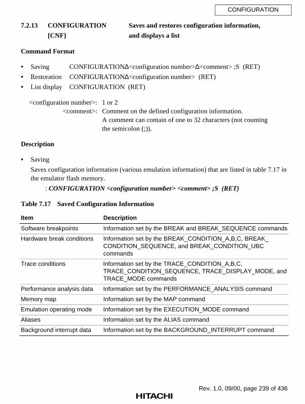
Rev. 1.0, 09/00, page 239 of 436
CONFIGURATION
7.2.13 CONFIGURATION Saves and restores configuration information,
[CNF] and displays a list
Command Format
• Saving CONFIGURATION∆<configuration number>∆<comment> ;S (RET)
• Restoration CONFIGURATION∆<configuration number> (RET)
• List display CONFIGURATION (RET)
<configuration number>: 1 or 2<comment>: Comment on the defined configuration information.
A comment can contain of one to 32 characters (not countingthe semicolon (;)).
Description
• Saving
Saves configuration information (various emulation information) that are listed in table 7.17 inthe emulator flash memory.
: CONFIGURATION <configuration number> <comment> ;S (RET)
Table 7.17 Saved Configuration Information
Item Description
Software breakpoints Information set by the BREAK and BREAK_SEQUENCE commands
Hardware break conditions Information set by the BREAK_CONDITION_A,B,C, BREAK_CONDITION_SEQUENCE, and BREAK_CONDITION_UBCcommands
Trace conditions Information set by the TRACE_CONDITION_A,B,C,TRACE_CONDITION_SEQUENCE, TRACE_DISPLAY_MODE, andTRACE_MODE commands
Performance analysis data Information set by the PERFORMANCE_ANALYSIS command
Memory map Information set by the MAP command
Emulation operating mode Information set by the EXECUTION_MODE command
Aliases Information set by the ALIAS command
Background interrupt data Information set by the BACKGROUND_INTERRUPT command
Rev. 1.0, 09/00, page 240 of 436
CONFIGURATION
• Restoration
Restores the configuration information saved in the emulator flash memory.
: CONFIGURATION <configuration number> (RET)
• List display
Displays the configuration information saved in the emulator flash memory.
: CONFIGURATION (RET) 1 <comment> 2 <comment>:
Examples
1. To save configuration information with comment CNF1:
: CNF 1 CNF1 ;S (RET)
:
2. To restore configuration information saved under configuration number 1:
: CNF 1 (RET)
:
3. To display the configuration information list:
: CNF (RET)
1 CNF1
2 ETC
:

Rev. 1.0, 09/00, page 241 of 436
CONVERT
7.2.14 CONVERT [CV] Converts data
Command Format
• Conversion CONVERT∆<data> (RET)CONVERT∆<expression> (RET)
<data>: Data to be converted<expression>: Addition or subtraction
<data>+<data>–<data> ...–<data>
Description
• Conversion
Converts data to hexadecimal, decimal, octal, binary, fixed-point, and ASCII formats.Input data is handled as 4-byte values. If there is no corresponding ASCII character(including undisplayable character), a period (.) is displayed instead.
: CONVERT <data> (RET) H'xxx...D'xxx... Q'xxx... B'xxx... xxxx (a) (b) (c) (d) (e) X'x.xxx... (f)
(a) Hexadecimal display(b) Decimal display(c) Octal display(d) Binary display(e) ASCII display(f) Fixed-point display
If the H', D', Q', B', or X' radix is not specified for <data> at data input, the radix specifiedwith the RADIX command is assumed.
Note
When an expression includes fixed-point values, the fixed-point values are converted as 4-bytevalues before the expression is converted. Therefore, the expression cannot be convertedcorrectly.
Rev. 1.0, 09/00, page 242 of 436
CONVERT
Examples
1. To convert hexadecimal data (H'7F):
: CV H'7F (RET)
H'7F D'127 Q'177 B'1111111 ....
X'0.0000000591
:
2. To convert the expression:
: CV H'31+D'16 (RET)
H'41 D'65 Q'101 B'1000001 ...A
X'0.0000000296
:

Rev. 1.0, 09/00, page 243 of 436
DATA_CHANGE
7.2.15 DATA_CHANGE [DC] Replaces memory data
Command Format
• Replacement DATA_CHANGE∆<data 1>∆<data 2>∆<start address>(∆<end address>/∆@<number of bytes>)[;[<size>][∆Y]] (RET)
<data 1>: Old data<data 2>: New data
<start address>: Start address of the memory area to be changed<end address>: End address of the memory area to be changed
<number of bytes>: The number of bytes in the memory area to be changed<size>: Length of data
B: 1 byteW: 2 bytesL: 4 bytes
Default: 1 byteY: Specify Y if a confirmation message is not necessary. If Y is
specified, data in all assigned areas is replaced without aconfirmation message.
Description
• Replacement
Replaces <data 1> in the specified memory area (set by the <start address> and <endaddress> or the <number of bytes>) with <data 2> and verifies the results.
If option Y is specified, data is replaced without confirmation messages. If option Y is notspecified, the following message is displayed whenever the data specified by <data 1> isfound.
xxxxxxxx CHANGE (Y/N) ? y (RET)
xxxxxxxx: Address where <data 1> was found.y: Y: <data 1> is replaced with <data 2>. N: Data is not replaced; continues to search for another
occurrence of the specified data. To terminate this commandbefore reaching <end address>, press the (CTRL) + C keys.

Rev. 1.0, 09/00, page 244 of 436
DATA_CHANGE
If <data 1> is not found at any point in the replacement range, the following message isdisplayed:
*** 45:NOT FOUND
Memory modification with this command can be performed only in areas CS0 to CS3 orthe internal memory areas.
Examples
1. To replace 2-byte data H'6475 in the address range from H'7000 to H'7FFF with H'5308 (withconfirmation message):
: DC 6475 5308 7000 7FFF ;W (RET)
00007508 CHANGE (Y/N) ? Y (RET)
00007530 CHANGE (Y/N) ? N (RET)
:
2. To replace 4-byte data ‘DATA’ in the address range from H'FB80 to H'FE00 with ‘DATE’(without confirmation message):
: DC ‘DATA’ ‘DATE’ FB80 FE00 ;L Y (RET)
:

Rev. 1.0, 09/00, page 245 of 436
DATA_SEARCH
7.2.16 DATA_SEARCH [DS] Searches for memory data
Command Format
• First level unordered list item <Level 1 unordered,1u>
• Search DATA_SEARCH∆<data>[∆<start address>[(∆<end address>/∆@<number of bytes>)]][;[<size>][∆N]] (RET)
<data>: Data to be searched for<start address>: Search start address (Default: H'0)<end address>: Search end address (Default: Maximum address of H'FFFFFFFF)
<number of bytes>: The number of bytes to be searched for (Default: Maximumaddress of H'FFFFFFFF (same as <end address>))
<size>: Length of data to be searched forB: 1 byteW: 2 bytesL: 4 bytes
Default: 1 byteN: Data other than the specified data is searched for
Description
• Search
Searches for <data> from the start address to the end address (or for the specified <numberof bytes>). All addresses where <data> is found are displayed.
If data is not found, the following message is displayed:
*** 45:NOT FOUND
If the N option is specified, data other than the specified <data> is searched for.
Search with this command can be performed only in areas CS0 to CS3 or the internalmemory areas.

Rev. 1.0, 09/00, page 246 of 436
DATA_SEARCH
Examples
1. To search for 1-byte data H'20 in the address range from H'FB80 to H'FF7F:
: DS 20 H'FB80 H'FF7F (RET)
0000FBFB 0000FCCD
:
2. To search for data other than 2-byte data H'0 in H'100 bytes starting from address H'1000:
: DS 0 1000 @100 ; W N (RET)
*** 45:NOT FOUND
:

Rev. 1.0, 09/00, page 247 of 436
DISASSEMBLE
7.2.17 DISASSEMBLE [DA] Disassembles and displays memory contents
Command Format
• Display DISASSEMBLE∆<start address>[(∆<end address>/∆@<number of instructions>)] (RET)
<start address>: Start address of disassembly<end address>: End address of disassembly
<number of instructions>: The number of instructions to be disassembled
Description
• Display
Disassembles the specified memory contents and displays addresses, machine codes,mnemonics, and operands in the following format. As many lines as necessary are used forthe display.
ADDR CODE MNEMONIC OPERAND<address> <machine code> <mnemonic> <operand>
If <end address> or <number of instructions> is omitted, 16 instructions are disassembledand displayed.
If there is no applicable instruction,
DATA.W xxxx
is displayed.
If <start address> is an odd address,
DATA.B xx
is displayed.

Rev. 1.0, 09/00, page 248 of 436
DISASSEMBLE
Immediately after executing this command (except when it is forcibly terminated by the(CTRL) + C keys or (BREAK) key, or by an error), pressing the (RET) key willdisassemble and display the next 16 lines of data.
Disassemble can be performed only in areas CS0 to CS3 or the internal memory areas.
Examples
1. To disassemble and display six instructions starting from address H'1000:
: DA 1000 @6 (RET)
ADDR CODE MNEMONIC OPERAND
00001000 E000 MOV #00,R0
00001002 2100 MOV.B R0,@R1
00001004 2201 MOV.W R0,@R2
00001006 430B JSR @R3
00001008 0009 NOP
0000100A 3400 CMP/EQ R0,R4
:

Rev. 1.0, 09/00, page 249 of 436
DISASSEMBLE
2. To disassemble and display 16 instructions starting from address H'1000, and to disassembleand display furthermore 16 instructions by only entering (RET):
: DA 1000 (RET) ADDR CODE MNEMONIC OPERAND 00001000 1F01 MOV.L R0,@(4,R15) 00001002 6673 MOV R7,R6 00001004 E001 MOV #1,R0 00001006 3708 SUB R0,R7 00001008 1F52 MOV.L R5,@(8,R15) 0000100A 1F43 MOV.L R4,@(C,R15) 0000100C E00A MOV #0A,R0 0000100E 6053 MOV R5,R0 00001010 1658 MOV.L R5,@(20,R6) 00001012 5568 MOV.L @(20,R6),R5 00001014 6053 MOV R5,R0 00001016 880A CMP/EQ #0A,R0 00001018 8902 BT 00001020 0000101A E001 MOV #01,R0 0000101C 380C ADD R0,R8 0000101E 0009 NOP: (RET) ADDR CODE MNEMONIC OPERAND 00001020 2100 MOV.B R0,@R1 00001022 2201 MOV.W R0,@R2 00001024 2302 MOV.L R0,@R3 : : : :
3. To disassemble and display five instructions starting from address H'2000:
: DA 2000 @5 (RET)
ADDR CODE MNEMONIC OPERAND
00002000 F80A70A2 PADD A0,M0,A0
PMULS X0,Y0,M0
MOVX.W @R4+,X0
MOVY.W @R6+,Y0
00002004 000B RTS
00002006 0009 NOP
00002008 1F01 MOV.L R0,@(4,R15)
0000200A 6673 MOV R7,R6
:

Rev. 1.0, 09/00, page 250 of 436
DUMP
7.2.18 DUMP [D] Displays memory contents
Command Format
• First level unordered list item <Level 1 unordered,1u>
• Display DUMP∆<start address>[(∆<end address>/∆[@]<number of bytes>)][;[<display unit>] (RET)
<start address>: Start address for memory dump<end address>: End address for memory dump
<number of bytes>: Size of data for memory dumpIf @ is omitted, this value is determined as <end address> or<number of bytes> according to the inequalities given below.Default is 256 bytes, as size.
End address: <start address> ≤ specified valueNumber of bytes: <start address> > specified value
<display unit>: Size of display unitB: 1-byte unitsW: 2-byte unitsL: 4-byte units
XW: 16-bit fixed-point unitsXL: 32-bit fixed-point units
Default: 1-byte units
Description
• Display
When B, W, or L is specified as <display unit>, displays a memory dump of the specifiedarea as follows:
<ADDRESS> <DATA> <ASCII CODE> xxxxxxxx xx.....................................xx "xxxx................xx" (a) (b) (c)
(a) Address
(b) Memory contents
(c) Memory contents displayed as ASCII codes. If there is no applicable ASCII code, aperiod (.) is displayed instead.

Rev. 1.0, 09/00, page 251 of 436
DUMP
If (CTRL) + P keys (hold down (CTRL), then press P) are entered during a memory dumpin 1-byte, 2-byte, or 4-byte units (B, W, or L is specified, respectively), the emulatordisplays the 256 bytes of data before the start address of the current dump, and haltscommand execution. The emulator then waits for key input, but does not display a prompt.If the (RET) key is pressed at this stage, the display scrolls through the memory contentsuntil the specified end address is reached. If instead, (CTRL) + P keys are pressed, the 256bytes of data before the start address of the last dump are displayed. If only the (RET) keyis pressed after DUMP command execution has been terminated (except for forcibletermination), the 256 bytes of data from the next address of the last dump are displayed.
When XW or XL is specified as <display unit>, displays a fixed-point memory dump ofthe specified area as follows. If (CTRL) + P keys are entered during a memory dump infixed-point units, the emulator displays 32 bytes of data (XW is specified) or 64 bytes ofdata (XL is specified) before the start address of the current dump, and halts commandexecution.
<ADDRESS> <HEX> <FIXED POINT>xxxxxxxx xxxxxxxx x.xxxxxxxxxx (a) (b) (c)
(a) Address
(b) Memory contents of address (a) in hexadecimal
(c) Memory contents of address (a) in fixed-point units
Examples
1. To display a memory dump from addresses H'0 to H'2F:
: D 0 2F (RET)
<ADDRESS> < D A T A > <ASCII CODE>
00000000 20 48 20 49 20 54 20 41 20 43 20 48 20 49 20 20 “ H I T A C H I ”
00000010 00 00 00 00 00 00 00 00 00 00 00 00 00 00 00 00 “................”
00000020 20 20 20 20 20 20 20 20 20 20 20 45 38 30 30 30 “ E8000”
:
2. To display H'20 bytes of memory dump from address H'FB80 in 4-byte units:
: D FB80 20 ;L (RET)
<ADDRESS> < D A T A > <ASCII CODE>
0000FB80 00000000 00000001 00000002 00000003 “ ................ ”
0000FB90 00000000 00000001 00000002 00000003 “ ................ ”
:
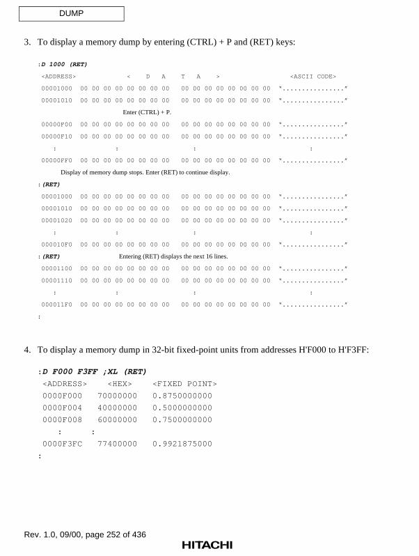
Rev. 1.0, 09/00, page 252 of 436
DUMP
3. To display a memory dump by entering (CTRL) + P and (RET) keys:
: D 1000 (RET)
<ADDRESS> < D A T A > <ASCII CODE>
00001000 00 00 00 00 00 00 00 00 00 00 00 00 00 00 00 00 “................”
00001010 00 00 00 00 00 00 00 00 00 00 00 00 00 00 00 00 “................”
Enter (CTRL) + P.
00000F00 00 00 00 00 00 00 00 00 00 00 00 00 00 00 00 00 “................”
00000F10 00 00 00 00 00 00 00 00 00 00 00 00 00 00 00 00 “................”
: : : :
00000FF0 00 00 00 00 00 00 00 00 00 00 00 00 00 00 00 00 “................”
Display of memory dump stops. Enter (RET) to continue display.
: (RET)
00001000 00 00 00 00 00 00 00 00 00 00 00 00 00 00 00 00 “................”
00001010 00 00 00 00 00 00 00 00 00 00 00 00 00 00 00 00 “................”
00001020 00 00 00 00 00 00 00 00 00 00 00 00 00 00 00 00 “................”
: : : :
000010F0 00 00 00 00 00 00 00 00 00 00 00 00 00 00 00 00 “................”
: (RET) Entering (RET) displays the next 16 lines.
00001100 00 00 00 00 00 00 00 00 00 00 00 00 00 00 00 00 “................”
00001110 00 00 00 00 00 00 00 00 00 00 00 00 00 00 00 00 “................”
: : : :
000011F0 00 00 00 00 00 00 00 00 00 00 00 00 00 00 00 00 “................”
:
4. To display a memory dump in 32-bit fixed-point units from addresses H'F000 to H'F3FF:
: D F000 F3FF ;XL (RET)
<ADDRESS> <HEX> <FIXED POINT>
0000F000 70000000 0.8750000000
0000F004 40000000 0.5000000000
0000F008 60000000 0.7500000000
: :
0000F3FC 77400000 0.9921875000
:

Rev. 1.0, 09/00, page 253 of 436
DUMP
5. To display a memory dump in 16-bit fixed-point units from addresses H'F000 to H'F3FF:
: D F000 F3FF ;XW (RET)
<ADDRESS> <HEX> <FIXED POINT>
0000F000 7000 0.87500
0000F002 4000 0.50000
0000F004 6000 0.75000
: :
0000F3FE 7740 0.99218
:

Rev. 1.0, 09/00, page 254 of 436
END
7.2.19 END [E] Cancels parallel mode
Command Format
• Cancellation END (RET)
Description
• Cancellation
Cancels parallel mode during GO command execution.
Entering the END command clears old trace information and starts storing new traceinformation.
Example
To cancel parallel mode during GO command execution:
: G (RET) ** PC=00003400 (RET) (Parallel mode entered)#M FD80 (RET) 0000FD80 00 ? FF (RET) (Command execution in parallelmode) 0000FD81 00 ? . (RET)#E (RET) (Parallel mode cancellation) ** PC=00003800:

Rev. 1.0, 09/00, page 255 of 436
EXECUTION_MODE
7.2.20 EXECUTION_MODE Specifies and displays execution mode
[EM]
Command Format
• Setting EXECUTION_MODE [∆BREQ=<BREQ option>][∆TIME=<TIME option>][∆TRGU=<TRGU option>][∆TRGB=<TRGB option>][∆MON=<MON option>][∆ECNT=<ECNT option>][∆WAIT=<WAIT option>][∆EMBW=<EMBW option>] [;C] (RET)
• Setting EXECUTION_MODE[;C] (RET)(interactive mode)
<BREQ option>: Specifies whether the BREQ (bus request) signal inputs areenabled.
E: Enables the BREQ signal inputs (default at emulator shipment)D: Disables the BREQ signal inputs
<TIME option>: Specifies the minimum time to be measured for the GO commandexecution.
1: 1.6 µs (default at emulator shipment)2: 406 ns3: 20 ns
<TRGU option>: When hardware break conditions (set by the BREAK_CONDITION_UBC(1/2) command) are satisfied, specifies whether a pulse is outputfrom the trigger output pin of the emulator without a break.
E: Outputs a trigger without a breakM: Break occurs and outputs a triggerD: Break occurs but does not output a trigger (default at emulator
shipment)<TRGB option>: When hardware break conditions (set by the BREAK_CONDITION_B
command) are satisfied, specifies whether a pulse is output from thetrigger output pin of the emulator without a break.
(1/2/3/4/5/6/7/8): Outputs a trigger when the hardware break condition set by thespecified channel of the BREAK_CONDITION_B command issatisfied, without a break
A: Outputs a trigger when any hardware break condition set by theBREAK_CONDITION_B command is satisfied without a break
D: Break occurs but does not output a trigger (default at emulatorshipment)

Rev. 1.0, 09/00, page 256 of 436
EXECUTION_MODE
<MON option>: Specifies time interval for execution status display.0: No display1: Approximately 200 ms (default at emulator shipment)2: Approximately 2 s
<ECNT option>: Specifies the mode for counting performance analysis execution.1: Counts the number of times the subroutine end address was passed
only after passing the subroutine start address first (default atemulator shipment)
2: Counts the number of times the subroutine end address was passedunconditionally
<WAIT option>: Specifies whether user wait is accepted.E: Enables user waitD: Disables user wait (default at emulator shipment)
<EMBW option>: Specifies the emulation memory bus width.1: 32-bit bus width (default at emulator shipment)2: 16-bit bus width3: 8-bit bus width
C: Stores the settings as configuration information in the emulator flashmemory.
Description
• Specification
Enables or disables the BREQ signal (bus request signal) inputs during user programexecution.
• To disable the BREQ signal inputs during emulator operation and user programexecution:
: EXECUTION_MODE BREQ=D (RET)
• To enable the BREQ signal inputs during emulator operation and user programexecution:
: EXECUTION_MODE BREQ=E (RET)

Rev. 1.0, 09/00, page 257 of 436
EXECUTION_MODE
Specifies the minimum time to be measured for GO command execution.
• To set the minimum time to 1.6 µs:
: EXECUTION_MODE TIME=1 (RET)
• To set the minimum time to 406 ns:
: EXECUTION_MODE TIME=2 (RET)
• To set the minimum time to 20 ns:
: EXECUTION_MODE TIME=3 (RET)
Specifies whether to continue program execution and whether to output a pulse from thetrigger output pin when hardware break conditions set by theBREAK_CONDITION_UBC1,UBC2 command are satisfied.
• To terminate program execution and not output a pulse when hardware breakconditions are satisfied:
: EXECUTION_MODE TRGU=D (RET)
• To terminate program execution and output a pulse when hardware break conditionsare satisfied:
: EXECUTION_MODE TRGU=M (RET)
• To continue program execution and output a pulse when hardware break conditions aresatisfied:
: EXECUTION_MODE TRGU=E (RET)
Specifies whether to continue program execution and whether to output a pulse from thetrigger output pin when hardware break conditions set by the BREAK_CONDITION_Bcommand are satisfied.
• To continue program execution and output a pulse when the hardware break conditionset by the BREAK_CONDITION_B1 command is satisfied:
: EXECUTION_MODE TRGB=1 (RET)
• To continue program execution and output a pulse when any hardware break conditionset by the BREAK_CONDITION_B command is satisfied:
: EXECUTION_MODE TRGB=A (RET)
• To terminate program execution and not output a pulse when hardware breakconditions are satisfied:
: EXECUTION_MODE TRGB=D (RET)

Rev. 1.0, 09/00, page 258 of 436
EXECUTION_MODE
Specifies time interval for execution status display during GO command execution.
• To not display PC:
: EXECUTION_MODE MON=0 (RET)
• To display PC every 200 ms:
: EXECUTION_MODE MON=1 (RET)
• To display PC every 2 s:
: EXECUTION_MODE MON=2 (RET)
Specifies the mode for counting performance analysis execution.
• To count the number of times the subroutine end address was passed only after passingthe subroutine start address first:
: EXECUTION_MODE ECNT=1 (RET)
• To count the number of times the subroutine end address was passed unconditionally:
: EXECUTION_MODE ECNT=2 (RET)
Enables or disables user wait.
• To disable user wait:
: EXECUTION_MODE WAIT=D (RET)
• To enable user wait:
: EXECUTION_MODE WAIT=E (RET)
Specifies the emulation memory bus width.
• To set the emulation memory bus width to 32 bits:
: EXECUTION_MODE EMBW=1 (RET)
• To set the emulation memory bus width to 16 bits:
: EXECUTION_MODE EMBW=2 (RET)
• To set the emulation memory bus width to eight bits:
: EXECUTION_MODE EMBW=3 (RET)

Rev. 1.0, 09/00, page 259 of 436
EXECUTION_MODE
When the C option is specified, the following message is displayed to confirm with theuser whether to overwrite the existing configuration information in the emulator flashmemory.
CONFIGURATION STORE OK (Y/N) ? (a) (RET)
(a) Y: Stores the specifications as configuration information in the emulator flash memory. Hereafter, when the emulator is activated, the saved specifications go into effect. N: Does not overwrite configuration information. The existing specifications are valid.
• Specification (interactive mode)
When all options are omitted, the current values are displayed and the emulator enters theinteractive mode. Enter the required value for each item. Enter (RET) for the item not to bemodified. To exit the interactive mode, enter a period (.). In this case, modifications beforeentering a period are valid.
: EXECUTION_MODE (RET)
BREQ=E TIME=1.6us TRGU=D TRGB=D MON=1 ECNT=1 WAIT=D EMBW=32
BREQ (D:DISABLE/E:ENABLE) ? (RET)(Displays current value)
TIME (1:1.6us/2:406ns/3:20ns) ? (RET)
TRGU (D:DISABLE/E:ENABLE/M:MULTI) ? (RET)
TRGB (A:ALL/1:B1/2:B2/3:B3/4:B4/5:B5/6:B6/7:B7/8:B8/D:DISABLE) ? (RET)
MON (0:DISABLE/1:200ms/2:2s) ? (RET)
ECNT (1:START AND END/2:END) ? (RET)
WAIT (D:DISABLE/E:ENABLE/) ? D (RET) (Disables user wait)
EMBW (1:32BIT BUS/2:16BIT BUS/3:8BIT BUS) ? (RET)
:
Examples
1. To enable the BREQ (bus request) signal inputs and store configuration information:
: EM BREQ=E;C (RET)
CONFIGURATION STORE OK(Y/N)? Y(RET)
:

Rev. 1.0, 09/00, page 260 of 436
EXECUTION_MODE
2. To display the specified values of the current emulation mode and modify them in interactivemode (command execution can be terminated by entering a period (.)):
: EM (RET)
BREQ=E TIME=1.6us TRGU=D TRGB=D MON=1 ECNT=1 WAIT=D EMBW=32
BREQ (D:DISABLE/E:ENABLE) ? (RET) (Input (RET) for no modification)
TIME (1:1.6us/2:406ns/3:20ns) ? 1 (RET) (Input 1 to set minimum measure time to 1.6 µs)
TRGU (D:DISABLE/E:ENABLE/M:MULTI) ? . (RET)
(Command is terminated and new settings become valid)
:

Rev. 1.0, 09/00, page 261 of 436
FILL
7.2.21 FILL [F] Writes data to memory
Command Format
• Write FILL∆<start address>(∆<end address>/∆@<number of bytes>)[∆<data>][;[<size>][∆N]] (RET)
<start address>: Write start address<end address>: Write end address
<number of bytes>: The number of bytes to be written<data>: Data to be written. Default is H'00.<size>: Length of data to be written
B: 1 byteW: 2 bytesL: 4 bytes
Default: 1 byteN: No verification
Description
• Write
Writes data to the specified memory area. Default value is H'00.
After data is written, it is also verified. This command can therefore be used as a memorytest. If an error occurs, the following message is displayed and processing is terminated.
FAILED AT xxxxxxxx WRITE = yy..'y..' READ = zz..'z..'
xxxxxxxx: Error addressyy..'y..': Write data (hexadecimal and ASCII characters)zz..'z..': Read data (hexadecimal and ASCII characters)
Data can be written to only areas CS0 to CS3 or the internal memory areas.
If W is specified as <size>, but the start address is odd, the lowest bit is rounded down tothe preceding even address. If L is specified as <size>, the lower bits are rounded down tobecome a multiple of four. Writing never exceeds the specified <end address>.

Rev. 1.0, 09/00, page 262 of 436
FILL
Example
To fill the entire area from addresses H'0 to H'6FFF with 1-byte data H'00:
: F 0 6FFF 0 (RET):

Rev. 1.0, 09/00, page 263 of 436
GO
7.2.22 GO [G] Provides realtime emulation
Command Format
• Execution GO[∆[<start address>][;[<break address>][∆<mode>][∆LEV]] (RET)
<start address>: Start address of realtime emulation, or the word RESET<break address>: Breakpoint address (Break occurs before the instruction at the
break address is executed.)<mode>: Emulation mode
R=<n>: Cycle reset mode; n = 1 to 12N: Temporarily invalidates break conditionsI1: Time interval measurement mode 1I2: Time interval measurement mode 2
SB: BREAK_CONDITION_UBC sequential break modeTB: Causes a break to occur at the timeout value specified
with the TIME option of the PERFORMANCE_ANALYSIS1command
LEV: Displays the satisfaction level of sequential conditions for theBREAK_CONDITION_SEQUENCE or TRACE_CONDITION_SEQUENCE command
Description
• Execution
Executes realtime emulation (user program execution) starting from the specified <startaddress>. The following data can be specified as <start address>.
: GO <address> (RET) : Executes the program from the specified address.: GO (RET) : When omitting the address, the program executes from the
address where the current PC indicates.: GO RESET (RET) : After a RESET signal input to the SH7410, PC and SP are
set to the values specified with the reset vector and programexecution starts.

Rev. 1.0, 09/00, page 264 of 436
GO
According to the <mode> specification at GO command input, the user program isexecuted in one of the following modes. If no <mode> is specified, normal emulationmode is assumed.
• Cycle reset mode (R=n; n=1 to 12)
A RESET signal is input to the SH7410 at the intervals given in table 7.18, andprogram execution continues. In this mode, all break conditions and trace conditionsare invalidated.
• Temporary invalidation of break conditions
If the N option is specified, software breakpoints (set with the BREAK orBREAK_SEQUENCE command) and hardware break conditions (set with theBREAK_CONDITION_A,B,C, BREAK_CONDITION_SEQUENCE, orBREAK_CONDITION_UBC command) are invalidated temporarily, and user programemulation continues. The breakpoints and break conditions are invalidated only withinone GO command emulation. If the N option is not specified in the next GO commandemulation, breakpoints and break conditions are validated again.
• Time interval measurement mode 1
The execution time from the point when the BREAK_CONDITION_UBC2 conditionis satisfied until the BREAK_CONDITION_UBC1 condition is satisfied is measured.
• Time interval measurement mode 2
The total execution time from the point when the BREAK_CONDITION_UBC2condition is satisfied until the BREAK_CONDITION_UBC1 condition is satisfied ismeasured. Even if these break conditions are satisfied, the program does not stop andthe execution time between BREAK_CONDITION_UBC2,1 condition satisfaction isadded to the previous measured time.
• BREAK_CONDITION_UBC sequential break mode
Realtime emulation stops only when break conditions set with the BREAK_CONDITION_UBC1,2 command are satisfied in the sequence of the BREAK_CONDITION_UBC2 condition followed by the BREAK_CONDITION_UBC1condition.
• Timeout break mode
A break occurs when the timeout or execution count condition specified with thePERFORMANCE_ANALYSIS command is satisfied.

Rev. 1.0, 09/00, page 265 of 436
GO
Table 7.18 Cycle Reset Times
Value of n Reset Interval
1 6.5 µs
2 9.8 µs
3 50 µs
4 100 µs
5 500 µs
6 1 ms
7 5 ms
8 10 ms
9 50 ms
10 100 ms
11 500 ms
12 1 s
The restrictions for each mode at emulation are listed in table 7.19.

Rev. 1.0, 09/00, page 266 of 436
GO
Table 7.19 Restrictions for Realtime Emulation Modes
Modes Restrictions
Cycle reset mode • Software breakpoints specified with the BREAK or BREAK_SEQUENCEcommand are ignored.
• Hardware break conditions specified with the BREAK_CONDITION_A,B,C,BREAK_CONDITION_SEQUENCE, or BREAK_CONDITION_UBCcommand are ignored.
• All conditions specified with the TRACE_CONDITION_A,B,C orTRACE_CONDITION_SEQUENCE command are ignored.
• Parallel mode cannot be entered.
Break prohibitionmode
• Software breakpoints specified with the BREAK or BREAK_SEQUENCEcommand are ignored.
• Hardware break conditions specified with the BREAK_CONDITION_A,B,C,BREAK_CONDITION_SEQUENCE, or BREAK_CONDITION_UBCcommand are ignored.
Time intervalmeasurementmodes 1 and 2
• Software breakpoints specified with the BREAK or BREAK_SEQUENCEcommand are ignored.
• Hardware break conditions specified with the BREAK_CONDITION_A,B,C,BREAK_CONDITION_SEQUENCE, or BREAK_CONDITION_UBCcommand are ignored.
• Conditions must be specified with the BREAK_CONDITION_UBC1,2command.
• All conditions specified with the TRACE_CONDITION_A,B,C orTRACE_CONDITION_SEQUENCE command are ignored.
• Parallel mode cannot be entered.
Sequential breakmode
• Software breakpoints specified with the BREAK or BREAK_SEQUENCEcommand are ignored.
• Conditions must be specified with the BREAK_CONDITION_UBC1,2command.
Timeout breakmode
Software breakpoints specified with the BREAK or BREAK_SEQUENCEcommand are ignored.
If <break address> is specified, realtime emulation stops when the specified address isreached. The instruction at the specified address is not executed. This specification is validfor only the current GO command emulation. BREAK_CONDITION_UBC2 commandsettings are invalid when a break address is specified.
During user program execution, program fetch addresses are displayed according to thetime interval specified with the MON option in the EXECUTION_MODE command.

Rev. 1.0, 09/00, page 267 of 436
GO
During GO command emulation, pressing the SPACE key or (RET) key enters parallelmode.
If emulation is terminated, register contents, execution time, and cause of termination aredisplayed in the following format:
PC=00005C60 SR=000000F0:****000000000000****----IIII00-- (a)
GBR=00000000 VBR=00000000 MACH=00000000 MACL=00000000 PR=00000000
RS=00000000 RE=00000000 MOD=00000000
R0–7 00000000 000000FF 00000011 00000000 00000000 00000000 00000000 00000000
R8–15 00000000 00000000 00000000 00000000 00000000 00000000 00000000 000FFE00
DSR=00000000:************************ ----COB-
A0G=00 A0=00000000 M0=00000000 X0=00000000 Y0=00000000
A1G=00 A1=00000000 M1=00000000 X1=00000000 Y1=00000000
I-TIME=D'0000H:00M:00S:000000US[:000NS] (00.0%) E-COUNT=D'00000 (b)
MAX=D'0000H:00M:00S:000000US[:000NS] (c)
MIN=D'0000H:00M:00S:000000US[:000NS] (d)
AVE=D'0000H:00M:00S:000000US[:000NS] (e)
RUN-TIME=D'0000H:00M:00S:000000US[:000NS] (f)
+++: <cause of termination> (g)
(a) The register contents at emulation termination.
(b) In time interval measurement modes 1 and 2, execution time from the point when theBREAK_CONDITION_UBC2 condition is satisfied until the BREAK_CONDITION_UBC1 condition is satisfied is displayed. In only time intervalmeasurement mode 2, the execution count during this period is also displayed.
(c) In time interval measurement modes 1 and 2, the maximum execution time from thepoint when the BREAK_CONDITION_UBC2 condition is satisfied until theBREAK_CONDITION_UBC1 condition is satisfied is displayed.
(d) In time interval measurement modes 1 and 2, the minimum execution time from thepoint when the BREAK_CONDITION_UBC2 condition is satisfied until theBREAK_CONDITION_UBC1 condition is satisfied is displayed.
(e) In time interval measurement modes 1 and 2, the average execution time from the pointwhen the BREAK_CONDITION_UBC2 condition is satisfied until theBREAK_CONDITION_UBC1 condition is satisfied is displayed.
(f) User program execution time in decimal. According to the TIME option of theEXECUTION_MODE command, the maximum measurable time is 488, 124, or 6hours, where the minimum measurement time is 1.6 µs, 406 ns, or 20 ns, respectively.If the period exceeds the maximum measurable time, it is displayed as *.
(g) Cause of termination, as listed in table 7.20.

Rev. 1.0, 09/00, page 268 of 436
GO
Table 7.20 Causes of GO Command Termination
Message Termination Cause
BREAK CONDITION UBC1 A break condition specified with the BREAK_CONDITION_UBC1command was satisfied.
BREAK CONDITION UBC2 A break condition specified with the BREAK_CONDITION_UBC2command was satisfied.
BREAK CONDITION An A break condition specified with the BREAK_CONDITION_Ancommand was satisfied (n = 1 to 8).
BREAK CONDITION Bn A break condition specified with the BREAK_CONDITION_Bncommand was satisfied (n = 1 to 8).
BREAK CONDITION Cn A break condition specified with the BREAK_CONDITION_Cncommand was satisfied (n = 1 to 8).
BREAK CONDITION UBC1,2 Multiple break conditions specified with theBREAK_CONDITION_UBC1,2 commands were satisfied.
BREAK CONDITIONA1, ... ,8
Multiple break conditions specified with the BREAK_CONDITION_A(A1 to A8) command were satisfied.
BREAK CONDITIONB1, ... ,8
Multiple break conditions specified with the BREAK_CONDITION_B(B1 to B8) command were satisfied.
BREAK CONDITIONC1, ... ,8
Multiple break conditions specified with the BREAK_CONDITION_C(C1 to C8) command were satisfied.
BREAK CONDITIONSEQUENCE
A sequential break condition specified with theBREAK_CONDITION_SEQUENCE command was satisfied.
BREAK CONDITION SB A sequential break condition specified with theBREAK_CONDITION_UBC1,2 commands was satisfied.
BREAK KEY The (CTRL) + C keys were pressed or the ABORT command wasexecuted for forcible termination.
BREAKPOINT Emulation stopped at a software breakpoint specified with theBREAK command.
BREAK SEQUENCE A condition for passing software breakpoints specified with theBREAK_SEQUENCE command was satisfied.
ILLEGAL INSTRUCTION A break instruction (H'0000) was executed.
NO EXECUTION The user program was not executed (this message is displayed onlyfor the RESULT command).
RESET BY E8000 The emulator forcibly terminates program execution with the RESETsignal because an error has occurred in the user system.

Rev. 1.0, 09/00, page 269 of 436
GO
Table 7.20 Causes of GO Command Termination (cont)
Message Termination Cause
STOP ADDRESS Emulation stopped at the break address specified with the GOcommand.
SUBROUTINE TIMEOUT The timeout condition specified with thePERFORMANCE_ANALYSIS1 command was satisfied.
SUBROUTINE COUNTOVERFLOW
The execution count limit specified with thePERFORMANCE_ANALYSIS1 command was exceeded.
TRACE BUFFEROVERFLOW
The trace buffer overflowed.
During user program execution, the SH7410 execution status is displayed. Displayedcontents are shown in table 7.21. This status is monitored every 200 ms, and if there is adifference from the previous status, the status is displayed.
Table 7.21 Execution Status Display
Display Meaning** BACK BACK signal is low.** PC=xxxxxxxx [LEV = mmmmmmm] (a) (b)(a) Program fetch address(b) Satisfaction level
During user program execution, the program fetch address isdisplayed according to the time interval specified with the MONoption in the EXECUTION_MODE command. When specifying theLEV option in the GO command, the satisfaction level of thehardware sequential break conditions is displayed.
** RESET RESET signal is low. The SH7410 has been reset.** RUNNING User program execution has started. This message is displayed
once when GO command execution starts or when parallel modeis cancelled. Note that this message will be deleted when** PC=xxxxxxxx (second message in this table) is displayed.
** TOUT A = xxxxxxxxxxxxxxxx: Address bus value
Bus cycle stops for 80 µs or more. The address bus value isdisplayed.Note that this message is also displayed when the SH7410enters sleep or standby mode and bus cycle stops for 80 µsor more.
** VCC DOWN User system Vcc (power voltage) is 2.65 V or less. The SH7410 isnot operating correctly. (Displayed only when the user clock isselected.)
** WAIT A = xxxxxxxxxxxxxxxx: Address bus value
WAIT signal is low. The address bus value is displayed. Theaddress bus value is not displayed during refresh cycles.

Rev. 1.0, 09/00, page 270 of 436
GO
If the TB option is specified, user program execution stops when the timeout value orexecution count limit specified with the PERFORMANCE_ANALYSIS1 command isexceeded.
Notes
1. When a hardware break condition (set by the BREAK_CONDITION_A,B,C command) issatisfied during program execution, the program does not terminate until at least one of theinstructions that have been already fetched is executed. If another hardware break is satisfiedbefore the user program terminates, several termination causes will be displayed. For furtherdetails, study trace information.
2. At each software breakpoint set with the BREAK command or at each pass point set with theBREAK_SEQUENCE command, the program halts at that address, the emulator analyzes thepass count and pass point of the program, and then the program continues. When the memoryaccess command processing in parallel mode occurs during this termination, memory cannotbe accessed. At this time,
*** 78: EMULATOR BUSY
is displayed, and the command should be re-input.
However, when the interval of termination is too short, the PC is not displayed, the emulatordoes not enter parallel mode, or commands may not be executed in parallel mode.
3. When the contents of a breakpoint (set by the BREAK command) have been modified by theuser program during emulation, that breakpoint will be cancelled at execution stop.
Examples
1. To reset the SH7410 and start emulation from the reset vector PC address:
: G RESET (RET)
** PC=00001130
2. To start emulation from address H'1000 and stop emulation just before address H'2020 isexecuted:
: G 1000;2020 (RET)
:

Rev. 1.0, 09/00, page 271 of 436
GO
3. To start emulation from the current PC address in sequential break mode(BREAK_CONDITION_UBC):
: G ;SB (RET)
** PC=00004250
4. To start emulation from the current PC address and modify memory contents in parallel mode:
: G (RET)
** PC=00010204
#M FEF0 (RET)
0000FEF0 FE ? FF (RET)
0000FEF1 FF ? . (RET)
#END (RET)
** PC=00011456
5. To start emulation from the current PC address and display the satisfaction level of hardwaresequential conditions:
: G ;LEV (RET)
** PC=00010204 LEV=1234---

Rev. 1.0, 09/00, page 272 of 436
HELP
7.2.23 HELP [HE] Displays all commands and command format
Command Format
• Display HELP (RET) (All commands are displayed.)HELP ∆ <command> (RET) (Command format is displayed.)
Description
• Display
Displays all emulator command names and abbreviations.

Rev. 1.0, 09/00, page 273 of 436
HELP
: HE (RET)
.<REGISTER> *AB : ABORT
*ALI : ALIAS A : ASSEMBLE
BI : BACKGROUND_INTERRUPT **B : BREAK
**BCA,1,2,3,4,5,6,7,8 : BREAK_CONDITION_A,1,2,3,4,5,6,7,8
**BCB,1,2,3,4,5,6,7,8 : BREAK_CONDITION_B,1,2,3,4,5,6,7,8
**BCC,1,2,3,4,5,6,7,8 : BREAK_CONDITION_C,1,2,3,4,5,6,7,8
**BCS,1,2,3,4,5,6,7 : BREAK_CONDITION_SEQUENCE,1,2,3,4,5,6,7
**BCU,1,2: BREAK_CONDITION_UBC,1,2 **BS : BREAK_SEQUENCE
CH : CHECK **CL : CLOCK
CNF : CONFIGURATION *CV : CONVERT
DC : DATA_CHANGE DS : DATA_SEARCH
*DA : DISASSEMBLE *D : DUMP
*E : END EM : EXECUTION_MODE
F : FILL G : GO
*HE : HELP *HT : HISTORY
*ID : ID MP : MAP
*M : MEMORY MD : MODE
MV : MOVE MR : MOVE_TO_RAM
PA,1,2,3,4,5,6,7,8 : PERFORMANCE_ANALYSIS,1,2,3,4,5,6,7,8
Q : QUIT *RX : RADIX
R : REGISTER RS : RESET
RT : RESULT *ST : STATUS
S : STEP SI : STEP_INFORMATION
SO : STEP_OVER *T : TRACE
*TCA,1,2,3,4,5,6,7,8 : TRACE_CONDITION_A,1,2,3,4,5,6,7,8
*TCB,1,2,3,4,5,6,7,8 : TRACE_CONDITION_B,1,2,3,4,5,6,7,8
*TCC,1,2,3,4,5,6,7,8 : TRACE_CONDITION_C,1,2,3,4,5,6,7,8
*TCS,1,2,3,4,5,6,7 : TRACE_CONDITION_SEQUENCE,1,2,3,4,5,6,7
*TDM : TRACE_DISPLAY_MODE TMO : TRACE_MODE
*TS : TRACE_SEARCH L : LOAD
SV : SAVE V : VERIFY
IL : INTFC_LOAD IS : INTFC_SAVE
IV : INTFC_VERIFY *#ASC : ASC
*#BIN : BIN *#BYE : BYE
*#CD : CD *#CLOSE : CLOSE
*FTP : FTP *LAN : LAN
LH : LAN_HOST #LL : LAN_LOAD
#LSV : LAN_SAVE #LV : LAN_VERIFY
*LO : LOGOUT *#LS : LS
*#OPEN : OPEN *#PWD : PWD
RTR : ROUTER *#STA : STA
SN : SUBNET
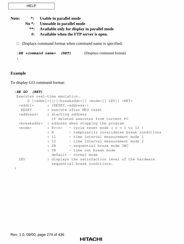
Rev. 1.0, 09/00, page 274 of 436
HELP
Note: *: Usable in parallel modeNo *: Unusable in parallel mode **: Available only for display in parallel mode #: Available when the FTP server is open.
Displays command format when command name is specified:
: HE <command name> (RET) (Displays command format)
:
Example
To display GO command format:
: HE GO (RET) Executes real-time emulation. G [<addr1>][;[<breakaddr>][ <mode>][ LEV]] <RET> <addr1> : RESET,<address> RESET : execute after MPU reset <address> : starting address if deleted executes from current PC <breakaddr> : address when stopping the program <mode> : R=<n> - cycle reset mode ( n = 1 to 12 ) : N - temporarily invalidates break conditions : I1 - time interval measurement mode 1 : I2 - time interval measurement mode 2 : SB - sequential break mode UBC : TB - time out break mode default - normal mode LEV : displays the satisfaction level of the hardware sequential break conditions.:

Rev. 1.0, 09/00, page 275 of 436
HISTORY
7.2.24 HISTORY [HT] Displays input command history
Command Format
• Display HISTORY (RET) (Displays all input commands)HISTORY <history number> (RET) (Displays the input command
of the specified history number)
<history number>: History number (1 to 16)
Description
• Display
Displays the 16 commands most recently input including the HISTORY command in theinput order.
If <history number> is entered, the command corresponding to <history number> isdisplayed as shown below and the emulator enters command input wait state. When the(RET) key is pressed, the displayed command is executed.
Note
Subcommands cannot be displayed by the HISTORY command.
Example
: HISTORY (RET) 1 MAP 2 MAP 0 FFFFFF;U 3 F 0 1000 FF 4 B 300 5 BCA1 A=104 6 HISTORY: HISTORY 5 (RET):BCA1 A=104_ ------------ Enters command input wait state
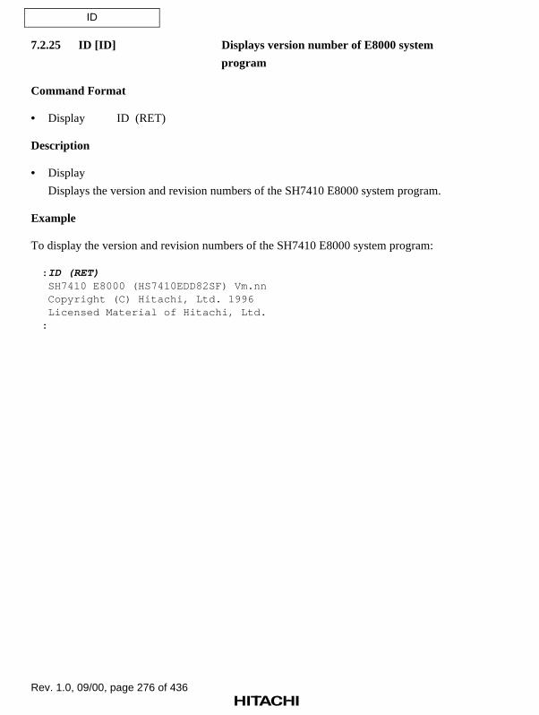
Rev. 1.0, 09/00, page 276 of 436
ID
7.2.25 ID [ID] Displays version number of E8000 system
program
Command Format
• Display ID (RET)
Description
• Display
Displays the version and revision numbers of the SH7410 E8000 system program.
Example
To display the version and revision numbers of the SH7410 E8000 system program:
: ID (RET) SH7410 E8000 (HS7410EDD82SF) Vm.nn Copyright (C) Hitachi, Ltd. 1996 Licensed Material of Hitachi, Ltd.:

Rev. 1.0, 09/00, page 277 of 436
MAP
7.2.26 MAP [MP] Specifies and displays memory attribute
Command Format
• Specification MAP∆<start address>∆<end address>;<memory attribute> (RET)
• Display MAP[∆<start address>∆<end address>] (RET)
<start address>: Start address of memory area whose attribute is to be specifiedor displayed
<end address>: End address of memory area whose attribute is to be specifiedor displayed
<memory attribute>: Memory typeU: Memory in the user system (cancels emulation memory
usage)S: Standard emulation memory in emulator
SW: Standard emulation memory in emulator with write protection
Description
• Specification
Allocates standard emulation memory to areas CS0 to CS3 in 1-Mbyte units. Theemulation memory can be write-protected by specifying SW as the memory attribute. Thestart address is rounded down to 0 or a multiple of H'100000, and the end address isrounded up to a multiple of H'100000, minus one.
: MAP 0 H'FFFFF;S (RET)
After allocation, the size of the unused standard emulation memory is displayed.
REMAINING EMULATION MEMORY S=xMB
xMB: (Standard emulation memory)
When standard emulation memory is allocated to areas CS0 to CS3, user system memoryin the same space as the allocated area cannot be accessed correctly.
To use memory in the user system, specify U for the memory attribute.
To cancel the write protection of standard emulation memory (SW), respecify S or U as thememory attribute.

Rev. 1.0, 09/00, page 278 of 436
MAP
• Display
Displays the memory attribute of the area defined by <start address> and <end address>, inthe following format:
: MAP <start address> <end address> (RET) xxxxxxxx–xxxxxxxx;y (a) ... xxxxxxxx–xxxxxxxx;y X-ROM AREA = xxxxxxxx–xxxxxxxx (b) X-RAM AREA = xxxxxxxx–xxxxxxxx (c) Y-ROM AREA = xxxxxxxx–xxxxxxxx (d) Y-RAM AREA = xxxxxxxx–xxxxxxxx (e) INTERNAL I/O = xxxxxxxx–xxxxxxxx (f) REMAINING EMULATION MEMORY S=xMB (g)
(a) Address range and memory attribute
Displays the addresses to which standard emulation memory is allocated.y: Standard emulation memory attribute
S: Standard emulation memory in emulator SW: Standard emulation memory in emulator with write protection
(b) Internal X-ROM address range
(c) Internal X-RAM address range
(d) Internal Y-ROM address range
(e) Internal Y-RAM address range
(f) Internal I/O address range
(g) Unused standard emulation memory size in hexadecimal
S=xMB (Standard emulation memory)
When no address is specified, the memory attributes of all memory areas are displayed inthe format shown above.

Rev. 1.0, 09/00, page 279 of 436
MAP
Notes
1. If there is not enough standard emulation memory to satisfy the specification, the memoryattribute is specified only for the memory area available.
2. Standard emulation memory cannot be allocated to areas other than areas CS0 to CS3.
3. A memory attribute cannot be allocated to a range which includes a reserved area.
4. An area to which emulation memory is allocated to cannot be used as user system memory.For example, if area CS0 is assigned to emulation memory, area CS0 cannot be used as usersystem memory. However, areas CS1 to CS3 can be used as user system memory.
Examples
1. To allocate standard emulation memory to the address range from H'1000000 to H'10FFFFF:
: MP 1000000 10FFFFF;S (RET)
REMAINING EMULATION MEMORY S=3MB
:
2. To allocate standard emulation memory to the address range from H'2000000 to H'20FFFFFwith write protection:
: MP 2000000 20FFFFF ;SW (RET)
REMAINING EMULATION MEMORY S=2MB
:

Rev. 1.0, 09/00, page 280 of 436
MAP
3. To display the memory address ranges and attributes of allocated standard emulation memory,the internal memory address ranges, and the internal I/O address range:
: MP (RET)
01000000-010FFFFF;S
02000000-020FFFFF;SW
X-ROM AREA = 00000000-00005FFF
X-RAM AREA = 0000F000-0000FFFF
Y-ROM AREA = 00010000-00015FFF
Y-RAM AREA = 0001F000-0001FFFF
INTERNAL I/O = 0C000000-0DFFFFFF
REMAINING EMULATION MEMORY S=2MB
:
4. To cancel write protection for the standard emulation memory allocated to the address rangefrom H'2000000 to H'20FFFFF:
: MP 2000000 20FFFFF ;S (RET)
REMAINING EMULATION MEMORY S=2MB
:

Rev. 1.0, 09/00, page 281 of 436
MEMORY
7.2.27 MEMORY [M] Displays or modifies memory contents
Command Format
• Display, modification MEMORY∆<address>[∆<data>][;[<option>][∆N]] (RET)
<address>: Address of memory area whose contents are to be displayedor modified
<data>: Data to be written to the specified address<option>: Length of display or modification units
B: 1-byte unitsW: 2-byte unitsL: 4-byte units
XW: 16-bit fixed-point unitsXL: 32-bit fixed-point units
O: Odd address; 1-byte unitsE: Even address; 1-byte units
Default: 1-byte unitsN: No verification
Description
• Display, modification
If <data> is omitted, the emulator displays memory contents at the specified address andenters input wait state of the modification data. The user can then enter data and modifymemory contents; this process can then be repeated for the next address. If option N is notspecified, the data to be modified is read and verified. Data in the internal I/O area is neververified. Memory contents are displayed, and modified data is input in the followingformat.
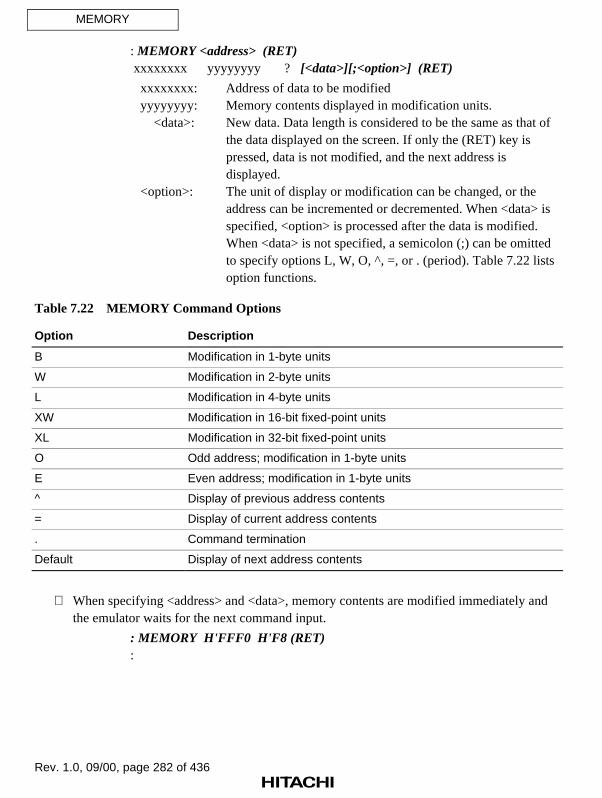
Rev. 1.0, 09/00, page 282 of 436
MEMORY
: MEMORY <address> (RET) xxxxxxxx yyyyyyyy ? [<data>][;<option>] (RET)
xxxxxxxx: Address of data to be modified yyyyyyyy: Memory contents displayed in modification units. <data>: New data. Data length is considered to be the same as that of
the data displayed on the screen. If only the (RET) key ispressed, data is not modified, and the next address isdisplayed.
<option>: The unit of display or modification can be changed, or theaddress can be incremented or decremented. When <data> isspecified, <option> is processed after the data is modified.When <data> is not specified, a semicolon (;) can be omittedto specify options L, W, O, ^, =, or . (period). Table 7.22 listsoption functions.
Table 7.22 MEMORY Command Options
Option Description
B Modification in 1-byte units
W Modification in 2-byte units
L Modification in 4-byte units
XW Modification in 16-bit fixed-point units
XL Modification in 32-bit fixed-point units
O Odd address; modification in 1-byte units
E Even address; modification in 1-byte units
^ Display of previous address contents
= Display of current address contents
. Command termination
Default Display of next address contents
When specifying <address> and <data>, memory contents are modified immediately andthe emulator waits for the next command input.
: MEMORY H'FFF0 H'F8 (RET):

Rev. 1.0, 09/00, page 283 of 436
MEMORY
Examples
1. To modify memory contents from address H'1000:
: M 1000 (RET)
00001000 00 ? FF (RET)
00001001 01 ? 10 (RET)
00001002 22 ? (RET)
00001003 00 ? 30;W (RET)
00001004 0000 ? 1234 (RET)
00001006 1100 ? ^ (RET)
00001004 1234 ? ;L (RET)
00001004 12341100 ? 12345678 (RET)
00001008 00000000 ? . (RET)
:
2. To modify memory contents from address H'8000 in 2-byte units without verification:
: M 8000 ;W N (RET)
00008000 0000 ? FF (RET)
00008002 0002 ? 1000 (RET)
00008004 FFF2 ? . (RET)
:
3. To modify memory contents from address H'F000 in 16-bit fixed-point units:
: M F000 ;XW (RET)
0000F000 0.87544 ? 0.875 (RET)
0000F002 0.45637 ? 0.5 (RET)
0000F004 0.39285 ? . (RET)
:
4. To write data H'10 to address H'FE00 without displaying the memory contents:
: M FE00 10 (RET)
:

Rev. 1.0, 09/00, page 284 of 436
MODE
7.2.28 MODE [MD] Specifies or displays SH7410 operating mode
Command Format
• Specification MODE;C (RET)
• Display MODE (RET)
Description
• Specification
Interactively specifies the SH7410 operating mode in the emulator as shown below.
: MODE;C (RET) E8000 MODE (MD4-0) xx ? (a) (RET) CONFIGURATION STORE OK (Y/N) ? (b) (RET)
(a) Operating mode. Input hexadecimal values to specify MD4 to MD0 bits.
(b) Confirmation message for configuration information storage
Y: The specified parameters are stored as configuration information in theemulator flash memory.
N: The specified parameters are not stored as configuration information andcommand execution is terminated.
If Y is input in (b), stores the settings as configuration information in the emulator flashmemory. When the emulator is initiated after configuration information storage, it emulatesin the stored operating mode. The E8000 system program terminates after the SH7410operating mode is set, and must then be re-initiated.
• Display
Displays the SH7410 operating mode in the emulator, the operating mode selection pin (MD4to MD0) status on the user system, and the operating mode setting method in the followingformat:
: MODE (RET) MODE = xx (MD4-0=nn) (a)
(a) Operating mode (xx), and operating mode selection pin status on the user system(MD4-0=nn) (refer to table 7.23).If a value other than those shown in the table is displayed as nn, the SH7410 does notoperate correctly. Check the user system. When the user system is not connected, nn isdisplayed as 1F.

Rev. 1.0, 09/00, page 285 of 436
MODE
Table 7.23 Operating Mode Selection Pin Status and Display
CS0 Area Bus Width Clock Mode
MD4 MD3 MD2 MD1 MD0 Display (nn)
Low Low Low Low Low 0
Low Low Low Low High 1
Low Low Low High Low 2
: : : : : :
High High High High High 1F
Notes
1. The emulator operating mode is specified with the MODE command, regardless of theoperating mode selection pin (MD4 to MD0) status on the user system.
2. The emulator does not support clock mode 1 or 5 of the SH7410. If clock mode 1 or 5 isselected,
*** 22: INVALID DATA
is displayed and the emulator enters operating-mode input wait state. Select clock mode 0, 2,3, or 4 with the MODE command and restart the emulator.
Examples
1. To specify the operating mode as mode 2 and store configuration information:
: MD;C (RET)
E8000 MODE (MD4-0) = 1F ? 2 (RET)
CONFIGURATION STORE OK (Y/N) ? Y (RET)
START E8000
S:START E8000
F:FLASH MEMORY TEST
L:SET LAN PARAMETER
T:START DIAGNOSTIC TEST
(S/F/L/T) ? _
2. To display the SH7410 operating mode in the emulator:
: MD (RET)
MODE = 00(MD4-0=1F)
:

Rev. 1.0, 09/00, page 286 of 436
MOVE
7.2.29 MOVE [MV] Transfers memory contents
Command Format
• Move data MOVE∆<start address>(∆<end address>/∆@<number of bytes>)∆<destination address> (RET)
<start address>: Start address of source area<end address>: End address of source area
<number of bytes>: The number of bytes to be transferred<destination address>: Start address of destination
Description
• Move data
Transfers the contents of the memory area specified with <start address> and <endaddress> or <number of bytes> to an address range starting with <destination address>.Transfer is usually performed from the <start address>. However, if <destination address>is set within the range from <start address> to <end address> or <number of bytes>,transfer is performed from the <end address> or <start address> + <number of bytes>.
Verifies the transfer. If a verification error occurs,
FAILED AT xxxxxxxx WRITE = yy 'y' READ = zz 'z'
is displayed.
xxxxxxxx: Address of erroryy 'y': Write data (hexadecimal and ASCII characters)zz 'z': Read data (hexadecimal and ASCII characters)
If areas other than the internal memory areas or areas CS0 to CS3 are included in thedestination, transfer is performed to only the internal memory areas and areas CS0 to CS3.
Example
To transfer data in the address range from H'101C to H'10FC to address H'1000:
: MV 101C 10FC 1000 (RET):

Rev. 1.0, 09/00, page 287 of 436
MOVE_TO_RAM
7.2.30 MOVE_TO_RAM Moves contents of ROM to standard emulation
[MR] memory
Command Format
• Movement MOVE_TO_RAM∆<start address>∆<end address>[;<memory attribute>] (RET)
<start address>: Start address of the ROM area to be moved<end address>: End address of the ROM area to be moved
<memory attribute>: Type of standard emulation memory to be allocatedS: Standard emulation memory
SW: Standard emulation memory with write protectionDefault: Standard emulation memory (S)
Description
• Movement
Use this command to temporarily modify ROM contents in the user system and execute themodified program. Transfers user system ROM contents to the specified standardemulation memory area where data can be modified. Data transfer to standard emulationmemory is performed in 1-Mbyte units. After data transfer, the unused standard emulationmemory area is displayed as follows:
REMAINING EMULATION MEMORY S=xMB
S=xMB (Standard emulation memory)
If there is not enough unused standard emulation memory to satisfy the specification, datatransfer is performed only for the memory area available, and command executionterminates.
Contents of only areas CS0 to CS3 and the internal memory areas can be transferred.
Refer to the MAP command, for details on write-protected area settings.

Rev. 1.0, 09/00, page 288 of 436
MOVE_TO_RAM
Example
To allocate standard emulation memory to the address range from H'0 to H'3FFFF in the usersystem ROM area and transfer ROM contents:
: MR 0 3FFFF;S (RET) REMAINING EMULATION MEMORY S=3MB:

Rev. 1.0, 09/00, page 289 of 436
PERFORMANCE_ANALYSIS
7.2.31 PERFORMANCE_ANALYSIS1-8 Specifies, cancels, initializes, and
[PA,1,2,3,4,5,6,7,8] displays performance measurement
data
Command Format
• Specification PERFORMANCE_ANALYSIS(1/2/3/4/5/6/7/8)∆<subroutine name>∆<start address>∆<end address>[∆TIME=<timeout value>][∆COUNT=<count value>;I1 (RET)
(Subroutine execution time measurement mode 1)PERFORMANCE_ANALYSIS(1/2/3/4/5/6/7/8)∆<subroutine name>
∆<start address>∆<end address>[∆TIME=<timeout value>][∆COUNT=<count value>;I2 (RET)
(Subroutine execution time measurement mode 2)PERFORMANCE_ANALYSIS(1/3/5/7)∆<subroutine name>
∆<start address range>∆<end address range>;I3 (RET)(Subroutine execution time measurement mode 3)
PERFORMANCE_ANALYSIS(1/3/5/7)∆<subroutine name>∆<start address>∆<end address>;AC=<accessed area addressrange>∆<access type> (RET)
(Area access count measurement mode)PERFORMANCE_ANALYSIS∆(1/3/5/7)∆<subroutine name>
∆<start address>∆<end address>;SC=<called subroutineaddress range> (RET)
(Subroutine call count measurement mode)
• Cancellation PERFORMANCE_ANALYSIS[(1/2/3/4/5/6/7/8)][∆]– (RET)
• Initialization PERFORMANCE_ANALYSIS∆;I (RET)
• Display PERFORMANCE_ANALYSIS[∆;(A/V)] (RET)
n: Subroutine number<subroutine name>: Name of the subroutine whose execution performance is to be
measured<start address>: Subroutine entry address<end address>: Subroutine exit address

Rev. 1.0, 09/00, page 290 of 436
PERFORMANCE_ANALYSIS
<timeout value>: Timeout value of execution time measurement. Can be setfor only the PERFORMANCE_ANALYSIS1 command.Display format: xxx[:yy[:zz[:nnnnnn]]]
xxx: Houryy: Minutezz: Second
nnnnnn: MicrosecondSpecifiable range: xxx: 0 to 999
yy: 0 to 59zz: 0 to 59
nnnnnn: 0 to 999999<specified count>: Execution count limit. Can be set for only the
PERFORMANCE_ANALYSIS1 command.Specifiable range: H'1 to H'FFFF
<start address range>: Subroutine entry address range<start address of subroutine entry range>:<end address ofsubroutine entry range>
<end address range>: Subroutine exit address range<start address of subroutine exit range>:<end address ofsubroutine exit range>
<accessed area address range>: Address range of the area which is accessed by thesubroutine<start address of range>:<end address of range>
<access type>: Bus cycle type for the specified access areaDAT: Execution cycleDMA: DMA cycle
Default: All access cycles<called subroutine address range>: Address range of the called subroutine accessed by the
calling subroutine<start address>:<end address>
I: Initializes performance measurement information.A: Displays specified subroutine addresses.V: Displays subroutine execution time and execution count in
numerical form. If V is omitted, display is in graph form.

Rev. 1.0, 09/00, page 291 of 436
PERFORMANCE_ANALYSIS
Description
• Specification
Measures the execution time and count of the specified subroutine during user programexecution initiated with the GO command. The following modes can be specified.
a. Subroutine execution time measurement mode 1
Measures the execution time and count of the subroutine defined by <start address>and <end address>. Measurement starts when an address within the range from the startaddress to the end address is prefetched, halts when an address outside the specifiedrange is prefetched, and restarts when an address within the specified range isprefetched again. The subroutine execution count is incremented every time thesubroutine end address is fetched. The execution time of subroutines called from thespecified subroutine is not included in the measurement results.
b. Subroutine execution time measurement mode 2
Measures the execution time and count of the subroutine defined by <start address>and <end address>. Measurement starts when the start address is prefetched and haltswhen the end address is prefetched. The subroutine execution count is incrementedevery time the subroutine end address is fetched. The execution time of subroutinescalled from the specified subroutine is included in the measurement results.
c. Subroutine execution time measurement mode 3
Measures the execution time and count of the subroutine defined by <start addressrange> and <end address range>. Measurement starts when an address in the startaddress range is prefetched and halts when an address in the end address range isprefetched. The subroutine execution count is incremented every time <end addressrange> is passed.
d. Area access count measurement mode
Counts the number of times the subroutine defined by <start address> and <endaddress> accesses the range specified by <accessed area address range>. Thesubroutine execution time is measured using subroutine execution time measurementmode 1.

Rev. 1.0, 09/00, page 292 of 436
PERFORMANCE_ANALYSIS
e. Subroutine call count measurement mode
Counts the number of times the subroutine defined by <subroutine name>, <startaddress>, and <end address> calls the subroutine specified by <called subroutineaddress range>. The subroutine execution time is measured using subroutine executiontime measurement mode 1.
Table 7.24 lists the measurement modes that can be specified by eachPERFORMANCE_ANALYSIS command. When break conditions or trace conditions havebeen set, subroutines may not be set to their maximum number.
Table 7.24 Measurement Modes for Each Command
Measurement Mode PA1 PA2 PA3 PA4 PA5 PA6 PA7 PA8
Subroutine execution timemeasurement mode 1
O O O O O O O O
Subroutine execution timemeasurement mode 2
O O O O O O O O
Subroutine execution timemeasurement mode 3
O X O X O X O X
Area access countmeasurement mode
O X O X O X O X
Subroutine call countmeasurement mode
O X O X O X O X
Note: O: Mode can be specified.
X: Mode cannot be specified.
Up to eight subroutines can be specified when using only subroutine execution timemeasurement mode 1 or 2 for measurement. However, only up to four subroutines can bespecified in subroutine execution time measurement mode 3, area access countmeasurement mode, and subroutine call count measurement mode.
This command cannot be executed during program execution by the STEP orSTEP_OVER command.
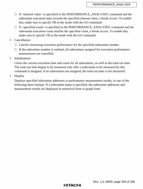
Rev. 1.0, 09/00, page 293 of 436
PERFORMANCE_ANALYSIS
If <timeout value> is specified in the PERFORMANCE_ANALYSIS1 command and thesubroutine execution time exceeds the specified timeout value, a break occurs. To enablethis, make sure to specify TB as the mode with the GO command.
If <specified count> is specified in the PERFORMANCE_ANALYSIS1 command and thesubroutine execution count reaches the specified count, a break occurs. To enable this,make sure to specify TB as the mode with the GO command.
• Cancellation
Cancels measuring execution performance for the specified subroutine number.
If the subroutine number is omitted, all subroutines assigned for execution performancemeasurement are cancelled.
• Initialization
Clears the current execution time and count for all subroutines, as well as the total run time.The total run time begins to be measured only after a subroutine to be measured by thiscommand is assigned. If no subroutines are assigned, the total run time is not measured.
• Display
Displays specified subroutine addresses or performance measurement results, in one of thefollowing three formats. If a subroutine name is specified, the subroutine addresses andmeasurement results are displayed in numerical form or graph form.

Rev. 1.0, 09/00, page 294 of 436
PERFORMANCE_ANALYSIS
Execution time ratio displayed in graph form. (No option is specified.)
: PERFORMANCE_ANALYSIS (RET)
NO NAME MODE RATE 0---10---20---30---40---50---60---70---80---90--100
1 SUBA I1 D'10.0% *****
(a) (b) (c) (d) (e)
2 SUBB I2 D'20.0% **********
3 SUBC I3 D'20.0% **********
4
5 SUBD AC D'15.0% ********
<ACCESS> D' 5.0% *** (g)
7 SUBE SC D'30.0% ***************
<CALL-SUB> D' 5.0% *** (h)
------------------------------------------------------------------------------------------------------------
TOTAL RUN-TIME = D'0000H:10M:00S:000020US[:250NS] (f)
(a) Subroutine number
(b) Subroutine name (up to 8 characters are displayed)
(c) Execution measurement mode I1: Subroutine execution time measurement mode 1 I2: Subroutine execution time measurement mode 2 I3: Subroutine execution time measurement mode 3AC: Area access count measurement modeSC: Subroutine call count measurement mode
(d) Execution time ratio as a percentage
(e) Execution time ratio in graph form (in units of 2%/asterisk, rounded up)
(f) Total run time displayed as H (hour), M (minutes), S (second), US (microsecond), andNS (nanosecond). However, when the minimum measurement time is specified as 1 µsby the TIME option of the EXECUTION_MODE command, NS display is notavailable.
(g) Execution time ratio as a percentage and in graph form for area access
(h) Execution time ratio as a percentage and in graph form for subroutine call

Rev. 1.0, 09/00, page 295 of 436
PERFORMANCE_ANALYSIS
Execution time ratio displayed in graph form. (Option A is specified.)
: PERFORMANCE_ANALYSIS ;A (RET)
NO NAME MODE ADDRESS
1 SUBA I1 00000100 00001FF0 TIME=xxxH:xxM:xxS:xxxxxxUS COUNT=nnnnnnnn
(a) (b) (c) (d) (e) (f) (g)
2 SUBB I2 00005000 00007FF0
3 SUBC I3 00010000 : 0001008F (h)
00020000 : 00020098 (i)
4
5 SUBE AC 00002030 : 0000207F
<ACCESS> FFFFFF00 : FFFFFF7F ; DAT
(j) (k)
7 SUBD SC 00020100 : 0002FFFF
<CALL-SUB> 00030000 : 00030060 (l)
------------------------------------------------------------------------------------------------------------------------
TOTAL RUN-TIME = D'0000H:10M:00S:000020US[:250NS] (m)
(a) Subroutine number
(b) Subroutine name (up to 8 characters are displayed)
(c) Time measurement modeI1: Subroutine execution time measurement mode 1I2: Subroutine execution time measurement mode 2I3: Subroutine execution time measurement mode 3
AC: Area access count measurement modeSC: Subroutine call count measurement mode
(d) Subroutine start address
(e) Subroutine end address
(f) Timeout value (displayed only when the timeout value is set with the TIME option inmode I1 or I2)
(g) Count value (displayed only when the count value is set with the COUNT option inmode I1 or I2)
(h) Start address range in subroutine execution time measurement mode 3
(i) End address range in subroutine execution time measurement mode 3
(j) Accessed area address range in area access count measurement mode
(k) Access type of accessed area in area access count measurement mode DAT: Execution cycleDMA: DMA cycle
(l) Called subroutine address range in subroutine call count measurement mode
(m) Total run time

Rev. 1.0, 09/00, page 296 of 436
PERFORMANCE_ANALYSIS
Execution time and count displayed as numerical values. (Option V is specified.)
: PERFORMANCE_ANALYSIS ;V (RET)
NO NAME MODE RATE RUN-TIME E-COUNT
1 SUBA I2 D'10.0% D'0000H:00M:05S:001000US[:250NS] D'00005
(a) (b) (c) (d) (e) (f)
MAX D'0000H:00M:05S:001000US:250NS MIN D'0000H:00M:05S:001000US:250NS
(g) (h)
AVE D'0000H:00M:05S:001000US:250NS
(I)
2 SUBB I1 D'20.0% D'0000H:00M:10S:010305US[:500NS] D'00010
AVE D'0000H:00M:05S:001000US:250NS
3 SUBC I3 D'20.0% D'0000H:00M:10S:010305US[:500NS] D'00010
AVE D'0000H:00M:05S:001000US:250NS
4
5 SUBD AC D'10.0% D'0000H:00M:05S:001000US[:250NS] D'00005
7 SUBE SC D'20.0% D'0000H:00M:10S:010305US[:500NS] D'00010
------------------------------------------------------------------------------------------------------------------------
TOTAL RUN-TIME = D'0001H:00M:50S:000020US[:250NS] (j)
(a) Subroutine number
(b) Subroutine name (up to 8 characters are displayed)
(c) Time measurement mode
I1: Subroutine execution time measurement mode 1I2: Subroutine execution time measurement mode 2I3: Subroutine execution time measurement mode 3
AC: Area access count measurement modeSC: Subroutine call count measurement mode
(d) Execution time ratio as a percentage
(e) Execution time
(f) Area access count in area access count measurement mode or subroutine call count insubroutine call count measurement mode
(g) Subroutine maximum execution time (only for the PERFORMANCE_ANALYSIS1,2,3,4 command in subroutine execution time measurement mode 2 (I2))
(h) Subroutine minimum execution time (only for the PERFORMANCE_ANALYSIS1,2,3,4 command in subroutine execution time measurement mode 2 (I2))

Rev. 1.0, 09/00, page 297 of 436
PERFORMANCE_ANALYSIS
(i) Subroutine average execution time (only for the PERFORMANCE_ANALYSIS1,2,3,4 command)
(j) Total run time displayed as H (hour), M (minutes), S (second), US (microsecond), andNS (nanosecond). However, when minimum measurement time is specified as 1 µs bythe TIME option of the EXECUTION_MODE command, NS display is not available.
Note
According to the TIME option of the EXECUTION_MODE command, the maximum measurabletime is 488, 124, or 6 hours, where the minimum measurement time is 1.6 µs,406 ns, or 20 ns, respectively.
Examples
1. To measure the execution time of subroutines SUBB (H'5000 to H'7FE0) and SUBD (H'20100to H'2FFFF) and initialize the performance measurement data:
: PA2 SUBB 5000 7FE0 ;I2 (RET)
: PA7 SUBD 20100 2FFFF ;SC=30000:30060 (RET)
: PA ;I (RET)
:
2. To display addresses of the set subroutines:
: PA ;A (RET)
NO NAME MODE ADDRESS
1 SUBA I1 00000100 00001FF0 COUNT=D'00000
2 SUBB I2 00005000 00007FF0
3 SUBC I3 00010000:0001008F
00020000:00020098
4
5 SUBE AC 00002030 0000207F
<ACCESS> FFFFFF00:FFFFFF7F;DAT
7 SUBD SC 00020100 0002FFFF
<CALL-SUB> 00030000:00030060
-------------------------------------------------------------
TOTAL RUN-TIME = D'0001H:00M:40S:022917US:000NS

Rev. 1.0, 09/00, page 298 of 436
PERFORMANCE_ANALYSIS
3. To display execution time ratio in graph form:
: PA (RET)
NO NAME MODE RATE 0---10---20---30---40---50---60---70---80---90--100
1 SUBA I1 D'10.0% *****
2 SUBB I2 D'20.0% **********
3 SUBC I3 D'20.0% **********
4
5 SUBD AC D'15.0% ********
<ACCESS> D' 5.0% ***
7 SUBE SC D'20.0% **********
<CALL-SUB> D' 5.0% ***
---------------------------------------------------------------------------
TOTAL RUN-TIME = D'0001H:00M:40S:022917US:000NS
4. To display execution time and count in numerical form:
: PA ;V (RET)
NO NAME MODE RATE RUN-TIME E-COUNT
1 SUBA I1 D'10.0% D'0000H:00M:05S:001000US:250NS D'00005
AVE D'0000H:00M:05S:001000US:250NS
2 SUBB I2 D'20.0% D'0000H:00M:10S:010305US:500NS D'00010
MAX D'0000H:00M:10S:010305US:250NS MIN D'0000H:00M:10S:010305US:250NS
AVE D'0000H:00M:10S:010305US:250NS
3 SUBC I3 D'20.0% D'0000H:00M:10S:010305US:500NS D'00010
AVE D'0000H:00M:10S:010305US:250NS
4
5 SUBD AC D'10.0% D'0000H:00M:05S:001000US:250NS D'00005
7 SUBE SC D'20.0% D'0000H:00M:10S:010305US:500NS D'00010
-----------------------------------------------------------------
TOTAL RUN-TIME = D'0001H:00M:40S:022917US:000NS
5. To cancel all registered subroutines:
: PA - (RET)
:

Rev. 1.0, 09/00, page 299 of 436
QUIT
7.2.32 QUIT [Q] Terminates E8000 system program
Command Format
• Termination QUIT (RET)
Description
• Termination
Terminates the E8000 system program and puts the emulator monitor in command inputwait state:
: QUIT (RET)START E8000 S:START E8000 F:FLASH MEMORY TOOL L:SET LAN PARAMETER T:START DIAGNOSTIC TEST (S/F/L/T) ? _
Example
To terminate the E8000 system program:
: Q (RET)START E8000 S:START E8000 F:FLASH MEMORY TOOL L:SET LAN PARAMETER T:START DIAGNOSTIC TEST (S/F/L/T) ? _

Rev. 1.0, 09/00, page 300 of 436
RADIX
7.2.33 RADIX [RX] Specifies and displays radix for numeric input
Command Format
• Specification RADIX∆<radix> (RET)
• Display RADIX (RET)
<radix>: Radix to be used for input of numeric valuesH: Hexadecimal (default at system program initiation)D: DecimalQ: OctalB: BinaryX: Fixed-point
Description
• Specification
Specifies the radix used by the emulator to interpret numbers entered on the command line.
The RADIX command sets the radix to be used for numbers entered simply as numbers.Hexadecimal is used at emulator initiation. Numbers may be entered in any radix at any time,provided that each value is prefixed with the appropriate character.
Table 7.25 Radix and Input Examples
Radix Input Example
Binary B'1010
Octal Q'2370
Decimal D'6904
Hexadecimal H'AF10
Fixed-point X'0.6634049566
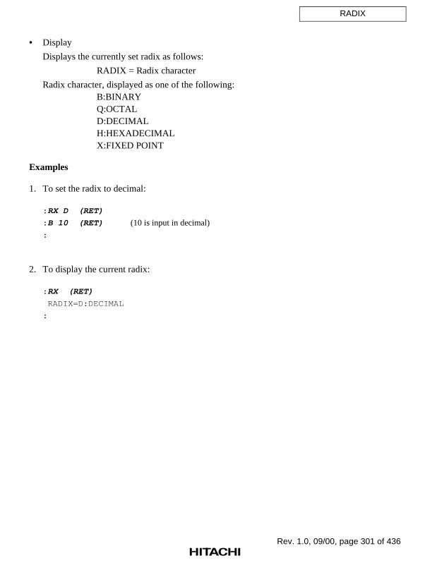
Rev. 1.0, 09/00, page 301 of 436
RADIX
• Display
Displays the currently set radix as follows:
RADIX = Radix character
Radix character, displayed as one of the following:B:BINARYQ:OCTALD:DECIMALH:HEXADECIMALX:FIXED POINT
Examples
1. To set the radix to decimal:
: RX D (RET)
: B 10 (RET) (10 is input in decimal)
:
2. To display the current radix:
: RX (RET)
RADIX=D:DECIMAL
:

Rev. 1.0, 09/00, page 302 of 436
REGISTER
7.2.34 REGISTER [R] Displays register contents
Command Format
• Display REGISTER (RET)
Description
• Display
Displays all register contents.
The DSR register setting bits (bits 3 to 1) are displayed, as shown in table 7.26.
Table 7.26 DSR Register Setting Bits
DSR Register Setting Bits
Display Bit 3 Bit 2 Bit 1 Mode
COB 0 0 0 Carry or borrow
NEG 0 0 1 Negative
ZER 0 1 0 Zero
OVF 0 1 1 Overflow
SGT 1 0 0 Signed greater than
SGE 1 0 1 Signed greater than or equal
Example
To display all register contents:
: R (RET)
PC=00005C60 SR=000000F0:****000000000000****----IIII00--
GBR=00000000 VBR=00000000 MACH=00000000 MACL=00000000 PR=00000000
RS=00000000 RE=00000000 MOD=00000000
R0-7 00000000 000000FF 00000011 00000000 00000000 00000000 00000000 00000000
R8-15 00000000 00000000 00000000 00000000 00000000 00000000 00000000 000FFE00
DSR=00000000:************************----COB-
A0G=00 A0=00000000 M0=00000000 X0=00000000 Y0=00000000
A1G=00 A1=00000000 M1=00000000 X1=00000000 Y1=00000000
:
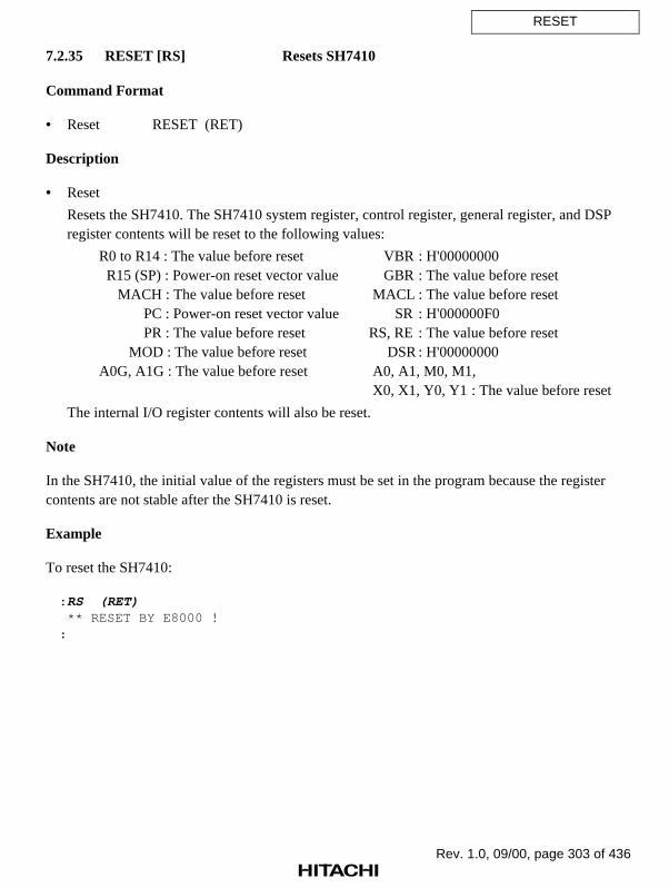
Rev. 1.0, 09/00, page 303 of 436
RESET
7.2.35 RESET [RS] Resets SH7410
Command Format
• Reset RESET (RET)
Description
• Reset
Resets the SH7410. The SH7410 system register, control register, general register, and DSPregister contents will be reset to the following values:
R0 to R14 : The value before reset VBR : H'00000000 R15 (SP) : Power-on reset vector value GBR : The value before reset MACH : The value before reset MACL : The value before reset PC : Power-on reset vector value SR : H'000000F0 PR : The value before reset RS, RE : The value before reset MOD : The value before reset DSR : H'00000000A0G, A1G : The value before reset A0, A1, M0, M1,
X0, X1, Y0, Y1 : The value before reset
The internal I/O register contents will also be reset.
Note
In the SH7410, the initial value of the registers must be set in the program because the registercontents are not stable after the SH7410 is reset.
Example
To reset the SH7410:
: RS (RET) ** RESET BY E8000 !:
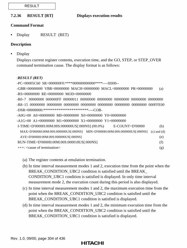
Rev. 1.0, 09/00, page 304 of 436
RESULT
7.2.36 RESULT [RT] Displays execution results
Command Format
• Display RESULT (RET)
Description
• Display
Displays current register contents, execution time, and the GO, STEP, or STEP_OVERcommand termination cause. The display format is as follows:
:RESULT (RET)
-PC=00005C60 SR=000000F0:****000000000000****----IIII00--
-GBR=00000000 VBR=00000000 MACH=00000000 MACL=00000000 PR=00000000 (a)
-RS=00000000 RE=00000000 MOD=00000000
-R0–7 00000000 000000FF 00000011 00000000 00000000 00000000 00000000 00000000
-R8–15 00000000 00000000 00000000 00000000 00000000 00000000 00000000 000FFE00
-DSR=00000000:************************----COB-
-A0G=00 A0=00000000 M0=00000000 X0=00000000 Y0=00000000
-A1G=00 A1=00000000 M1=00000000 X1=00000000 Y1=00000000
I-TIME=D'0000H:00M:00S:000000US[:000NS] (00.0%) E-COUNT=D'00000 (b)
MAX=D'0000H:00M:00S:000000US[:000NS] MIN=D'0000H:00M:00S:000000US[:000NS] (c) and (d)
AVE=D'0000H:00M:00S:000000US[:000NS] (e)
RUN-TIME=D'0000H:00M:00S:000018US[:000NS] (f)
+++: <cause of termination> (g)
(a) The register contents at emulation termination.
(b) In time interval measurement modes 1 and 2, execution time from the point when theBREAK_CONDITION_UBC2 condition is satisfied until the BREAK_CONDITION_UBC1 condition is satisfied is displayed. In only time intervalmeasurement mode 2, the execution count during this period is also displayed.
(c) In time interval measurement modes 1 and 2, the maximum execution time from thepoint when the BREAK_CONDITION_UBC2 condition is satisfied until theBREAK_CONDITION_UBC1 condition is satisfied is displayed.
(d) In time interval measurement modes 1 and 2, the minimum execution time from thepoint when the BREAK_CONDITION_UBC2 condition is satisfied until theBREAK_CONDITION_UBC1 condition is satisfied is displayed.

Rev. 1.0, 09/00, page 305 of 436
RESULT
(e) In time interval measurement modes 1 and 2, the average execution time from the pointwhen the BREAK_CONDITION_UBC2 condition is satisfied until theBREAK_CONDITION_UBC1 condition is satisfied is displayed.
(f) User program execution time in decimal. According to the TIME option of theEXECUTION_MODE command, the maximum measurable time is 488, 124, or 6hours, where the minimum measurement time is 1.6 µs, 406 ns, or 20 ns, respectively.If the period exceeds the maximum measurable time, it is displayed as *.
(g) Cause of termination.
Note
Displayed register contents show values at program termination, not the current values.
Example
To display execution results:
: RT (RET)
-PC=00005C60 SR=000000F0:****000000000000****----IIII00--
-GBR=00000000 VBR=00000000 MACH=00000000 MACL=00000000 PR=00000000
-RS=00000000 RE=00000000 MOD=00000000
-R0-7 00000000 000000FF 00000011 00000000 00000000 00000000 00000000 00000000
-R8-15 00000000 00000000 00000000 00000000 00000000 00000000 00000000 000FFE00
-DSR=00000000:************************----COB-
-A0G=00 A0=00000000 M0=00000000 X0=00000000 Y0=00000000
-A1G=00 A1=00000000 M1=00000000 X1=00000000 Y1=00000000
RUN-TIME=D'0000H:00M:00S:002241US:000NS
+++:BREAKPOINT
:

Rev. 1.0, 09/00, page 306 of 436
STATUS
7.2.37 STATUS [ST] Displays emulator execution status
Command Format
• Display STATUS (RET)
Description
• Display
Displays emulator execution status in the following format:
MODE=(a) RADIX=(b) BREAK=(c)HOST=(d) STEP_INFO=REG:(e) /A:(f) /SP:(g)CLOCK=(h) EML_MEM=S:(i)
(a) MODE=xx: SH7410 operating mode specified with the MODE command
(b) RADIX=xxx: Default input number type
BIN: BinaryOCT: OctalDEC: DecimalHEX: Hexadecimal FIX: Fixed-point
(c) BREAK=D'xxx: Number of breakpoints (decimal)
(d) HOST=x1x2x3x4x5: Interface conditions with serial port
x1: Baud rate (BPS: Bits per second)1: 2400 BPS 2: 4800 BPS 3: 9600 BPS 4: 19200 BPS 5: 38400 BPS
x2: Data length for one character8: 8 bits 7: 7 bits
x3: ParityN: None E: Even O: Odd
x4: Number of stop bits1: 1 stop bit 2: 2 stop bits
x5: Busy control methodX: X-ON/X-OFF control R: RTS/CTS control

Rev. 1.0, 09/00, page 307 of 436
STATUS
(e) STEP_INFO=REG:x1 x2 x3: Register information displayed with the STEP command
x1 1: Control register (PC, SR, PR, GBR, VBR, MACH, MACL, RS, RE,and MOD) information is displayed.
Space: No control register (PC, SR, PR, GBR, VBR, MACH, MACL, RS,RE, and MOD) information is displayed.
x2 2: General register (R0 to R15) information is displayed.Space: No general register (R0 to R15) information is displayed.
x3 3: DSP register (DSR, A0, A0G, A1, A1G, M0, M1, X0, X1, Y0, andY1) information is displayed.
Space: No DSP register (DSR, A0, A0G, A1, A1G, M0, M1, X0, X1, Y0, andY1) information is displayed.
(f) /A:xxxxxxxx-xxxxxxxx: Memory address range displayed with the STEP command
(g) /SP:xxxxxxxx: Display size of stack contents
(h) CLOCK=xxxx: Clock signal type
EML: Emulator internal clockUSER: User system clockXTAL: Crystal oscillator clock
(i) EML_MEM=S:xMB: Remaining size of standard emulation memory
xMB: Remaining size of standard emulation memory
Example
To display the emulator status:
: ST (RET) MODE=2 RADIX=HEX BREAK=D'001 HOST=38N1X STEP_INFO=REG:12/A:3 /SP: CLOCK=EML EML_MEM=S:4MB

Rev. 1.0, 09/00, page 308 of 436
STEP
7.2.38 STEP [S] Performs single-step execution
Command Format
• First level unordered list item <Level 1 unordered,1u>
• Single step STEP [∆<number of execution steps>[∆<start address>]][;[<stop PC>][∆<display option>][∆I]] (RET)
<number of execution steps>: Number of steps to be executed (H'1 to H'FFFFFFFF).Default: If <stop PC> and <display option> are specified,
H'FFFFFFFF is assumed. If not, H'1 is assumed.<start address>: Start address of single-step execution. Default is the current
PC address.<stop PC>: PC address when single-step execution is terminated.
Default is <number of execution steps>.<display option>: Specification of instructions to be displayed
J: Displays instructions and register contents onlywhen branch instructions are executed
R: Displays instructions and register contents onlywithin the opening routine
Default: Displays instructions and register contents for allexecuted instructions
I: Interrupt permission during STEP command execution

Rev. 1.0, 09/00, page 309 of 436
STEP
Description
• Single step
Performs single-step execution from <start address> to <stop PC> or from <start address>for <number of execution steps>. The type of emulation performed (described below)depends on the specified parameters and option.
In addition, register and memory contents, address, instruction mnemonic, and terminationcause are displayed in the following format:
(a) PC=00001000 SR=000000F0:****000000000000****----IIII00--
GBR=00000000 VBR=00000000 MACH=00000000 MACL=00000000 PR=00000000
RS=00000000 RE=00000000 MOD=00000000
R0-7 00000000 000000FF 00000011 00000000 00000000 00000000 00000000 00000000
R8-15 00000000 00000000 00000000 00000000 00000000 00000000 00000000 000FFE00
DSR=00000000:************************ ----COB-
A0G=00 A0=00000000 M0=00000000 X0=00000000 Y0=00000000
A1G=00 A1=00000000 M1=00000000 X1=00000000 Y1=00000000
(b) <address>:<instruction mnemonic>
(c) MEMORY
<memory contents>
(d) +++: <cause of termination>
(a) Register information(b) Address and mnemonic of the executed instruction(c) Memory contents display(d) Cause of termination (refer to table 7.27)
Information (a) and (c) is displayed according to specifications made with theSTEP_INFORMATION command. The termination cause, (d), is displayed only when theSTEP command is completed.

Rev. 1.0, 09/00, page 310 of 436
STEP
Table 7.27 Causes of STEP Command Termination
Message Termination Cause
BREAK CONDITION UBC1 A break condition specified with the BREAK_CONDITION_UBC1command was satisfied.
BREAK CONDITION An A break condition specified with the BREAK_CONDITION_Ancommand was satisfied (n = 1 to 8).
BREAK CONDITION Bn A break condition specified with the BREAK_CONDITION_Bncommand was satisfied (n = 1 to 8).
BREAK CONDITION Cn A break condition specified with the BREAK_CONDITION_Cncommand was satisfied (n = 1 to 8).
BREAK CONDITIONA1, ... ,8
Multiple break conditions specified with the BREAK_CONDITION_A(A1 to A8) commands were satisfied.
BREAK CONDITIONB1, ... ,8
Multiple break conditions specified with the BREAK_CONDITION_B(B1 to B8) commands were satisfied.
BREAK CONDITIONC1, ... ,8
Multiple break conditions specified with the BREAK_CONDITION_C(C1 to C8) commands were satisfied.
BREAK KEY The BREAK key or (CTRL) + C keys were pressed for forcibletermination.
ILLEGAL INSTRUCTION A break instruction (H'0000) was executed.
RESET BY E8000 The emulator forcibly terminates program execution with the RESETsignal because an error has occurred in the user system.
STEP NORMAL END The specified number of steps were executed.
STOP ADDRESS The instruction at <stop PC> was executed.
If <stop PC> and <display option> are omitted, instruction mnemonics and registerinformation are displayed for each step executed.
: STEP <number of execution steps> [<start address>] (RET)
Instruction mnemonics and register information are also displayed for each step when<stop PC> is specified, and single-step emulation is executed until the instruction at <stopPC> is executed.
: STEP [<number of execution steps> [<start address>]]; <stop PC> (RET)
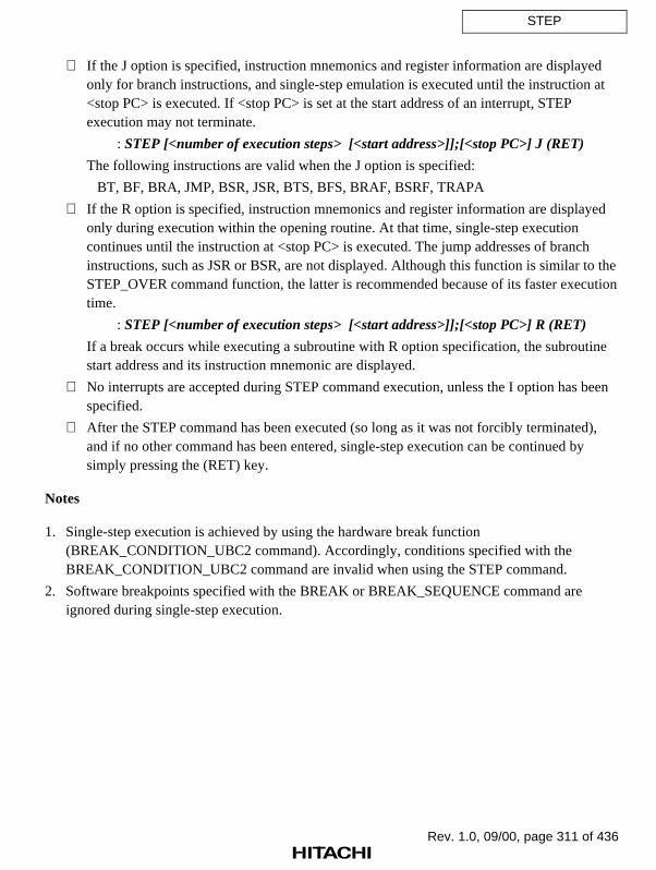
Rev. 1.0, 09/00, page 311 of 436
STEP
If the J option is specified, instruction mnemonics and register information are displayedonly for branch instructions, and single-step emulation is executed until the instruction at<stop PC> is executed. If <stop PC> is set at the start address of an interrupt, STEPexecution may not terminate.
: STEP [<number of execution steps> [<start address>]];[<stop PC>] J (RET)
The following instructions are valid when the J option is specified:
BT, BF, BRA, JMP, BSR, JSR, BTS, BFS, BRAF, BSRF, TRAPA
If the R option is specified, instruction mnemonics and register information are displayedonly during execution within the opening routine. At that time, single-step executioncontinues until the instruction at <stop PC> is executed. The jump addresses of branchinstructions, such as JSR or BSR, are not displayed. Although this function is similar to theSTEP_OVER command function, the latter is recommended because of its faster executiontime.
: STEP [<number of execution steps> [<start address>]];[<stop PC>] R (RET)
If a break occurs while executing a subroutine with R option specification, the subroutinestart address and its instruction mnemonic are displayed.
No interrupts are accepted during STEP command execution, unless the I option has beenspecified.
After the STEP command has been executed (so long as it was not forcibly terminated),and if no other command has been entered, single-step execution can be continued bysimply pressing the (RET) key.
Notes
1. Single-step execution is achieved by using the hardware break function(BREAK_CONDITION_UBC2 command). Accordingly, conditions specified with theBREAK_CONDITION_UBC2 command are invalid when using the STEP command.
2. Software breakpoints specified with the BREAK or BREAK_SEQUENCE command areignored during single-step execution.

Rev. 1.0, 09/00, page 312 of 436
STEP
3. If a delayed branch instruction is executed during single-step emulation, single-step executionstops after the instruction immediately following the delayed branch instruction is executed.Therefore, two instruction mnemonics are displayed.
4. If break conditions specified with the BREAK_CONDITION_A,B,C orBREAK_CONDITION_UBC command are satisfied, STEP execution may terminate withoutexecuting a single instruction.
Examples
1. To execute a program one step at a time, starting from the address given by the current PC:
: S (RET)
PC=00001002 SR=000000F0:****000000000000****----IIII00--
GBR=00000000 VBR=00000000 MACH=00000000 MACL=00000000 PR=00000000
RS=00000000 RE=00000000 MOD=00000000
R0-7 00000000 000000FF 00000011 00000000 00000000 00000000 00000000 00000000
R8-15 00000000 00000000 00000000 00000000 00000000 00000000 00000000 000FFE00
DSR=00000000:************************----COB-
A0G=00 A0=00000000 M0=00000000 X0=00000000 Y0=00000000
A1G=00 A1=00000000 M1=00000000 X1=00000000 Y1=00000000
00001000 MOV R0,R1
+++:STEP NORMAL END
:
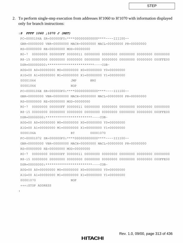
Rev. 1.0, 09/00, page 313 of 436
STEP
2. To perform single-step execution from addresses H'1060 to H'1070 with information displayedonly for branch instructions:
: S FFFF 1060 ;1070 J (RET)
PC=0000106A SR=000000F0:****000000000000****----IIII00--
GBR=00000000 VBR=00000000 MACH=00000000 MACL=00000000 PR=00000000
RS=00000000 RE=00000000 MOD=00000000
R0-7 00000000 000000FF 00000011 00000000 00000000 00000000 00000000 00000000
R8-15 00000000 00000000 00000000 00000000 00000000 00000000 00000000 000FFE00
DSR=000000000:************************----COB-
A0G=00 A0=00000000 M0=00000000 X0=00000000 Y0=00000000
A1G=00 A1=00000000 M1=00000000 X1=00000000 Y1=00000000
00001064 JMP @R0
00001066 NOP
PC=0000106E SR=000000F0:****000000000000****----IIII00--
GBR=00000000 VBR=00000000 MACH=00000000 MACL=00000000 PR=00000000
RS=00000000 RE=00000000 MOD=00000000
R0-7 00000000 000000FF 00000011 00000000 00000000 00000000 00000000 00000000
R8-15 00000000 00000000 00000000 00000000 00000000 00000000 00000000 000FFE00
DSR=00000000:************************----COB-
A0G=00 A0=00000000 M0=00000000 X0=00000000 Y0=00000000
A1G=00 A1=00000000 M1=00000000 X1=00000000 Y1=00000000
0000106A BT 00001070
PC=00001072 SR=000000F0:****000000000000****----IIII00--
GBR=00000000 VBR=00000000 MACH=00000000 MACL=00000000 PR=00000000
RS=00000000 RE=00000000 MOD=00000000
R0-7 00000000 000000FF 00000011 00000000 00000000 00000000 00000000 00000000
R8-15 00000000 00000000 00000000 00000000 00000000 00000000 00000000 000FFE00
DSR=00000000:************************----COB-
A0G=00 A0=00000000 M0=00000000 X0=00000000 Y0=00000000
A1G=00 A1=00000000 M1=00000000 X1=00000000 Y1=00000000
00001070 NOP
+++:STOP ADDRESS
:

Rev. 1.0, 09/00, page 314 of 436
STEP_INFORMATION
7.2.39 STEP_INFORMATION Specifies and displays information during
[SI] single-step execution
Command Format
• First level unordered list item <Level 1 unordered,1u>
• Specification STEP_INFORMATION[∆<register information>][∆A=<start address>[(∆<end address>/∆@<number of bytes>)]][∆SP=<stack display byte count>] (RET)
• Display STEP_INFORMATION (RET)
<register information>: Register to be displayed1: Displays PC, SR, PR, GBR, VBR, MACH, MACL,
RS, RE, and MOD2: Displays R0 to R153: Displays DSR, A0, A0G, A1, A1G, M0, M1, X0,
X1, Y0, and Y1ALL: All register information is output (default at
emulator initiation)–: No information displayed
Default: ALL<start address>: Start address of memory dump<end address>: End address of memory dump. (Default is 16 bytes of
memory beginning at <start address>.)<number of bytes>: Number of bytes of memory dump. (Default is 16 bytes.)
<stack display byte count>: Number of bytes of stack contents.

Rev. 1.0, 09/00, page 315 of 436
STEP_INFORMATION
Description
• Specification
Displays register information, executed instruction information, memory contents, and causeof termination during STEP and STEP_OVER command execution. This command alsoselects the register information and memory contents which are to be displayed.
(a) PC=00001000 SR=000000F0:****000000000000****----IIII00--
GBR=00000000 VBR=00000000 MACH=00000000 MACL=00000000 PR=00000000
RS=00000000 RE=00000000 MOD=00000000
(b) R0-7 00000000 000000FF 00000011 00000000 00000000 00000000 00000000 00000000
R8-15 00000000 00000000 00000000 00000000 00000000 00000000 00000000 000FFE00
(c) DSR=00000000:************************----COB-
A0G=00 A0=00000000 M0=00000000 X0=00000000 Y0=00000000A1G=00 A1=00000000 M1=00000000 X1=00000000 Y1=00000000
(d) 00001002 MOV #00, R0
(e) MEMORY
0000FF80 00 04 00 FF F0 00 02 00 10 00 02 00 0F 00 00 00 “................”
(f) STACK
000FFFE0 00 00 00 00 00 00 00 00 00 00 00 00 00 00 00 00 “................”
(g) +++:STEP NORMAL END
(a) System and control register information (PC, SR, PR, GBR, VBR, MACH, MACL, RS,RE, and MOD)
(b) General register information (R0 to R15)
(c) DSP register information (DSR, A0G, A1G, A0, A1, M0, M1, X0, X1, Y0, and Y1)
(d) Address and assembler instruction mnemonic of the executed instruction
(e) Memory contents display
(f) Stack contents display
(g) Cause of termination
• Display
Displays STEP information according to the specified contents. However, the address andassembler instruction mnemonic of each executed instruction are not displayed.

Rev. 1.0, 09/00, page 316 of 436
STEP_INFORMATION
Examples
1. To display only the contents of system and control registers (PC, SR, PR, GBR, VBR, MACH,MACL, RS, RE, and MOD) during STEP or STEP_OVER command execution:
: SI 1 (RET)
:
2. To display no register information during STEP or STEP_OVER command execution:
: SI - (RET)
:
3. To display memory contents from addresses H'FB80 to H'FB87 during STEP or STEP_OVERcommand execution:
: SI A=FB80 FB87 (RET)
:
4. To display contents according to the specified display information:
: SI (RET)
PC=00001004 SR=000000F0:****000000000000****----IIII00--
GBR=00000000 VBR=00000000 MACH=00000000 MACL=00000000 PR=00000000
RS=00000000 RE=00000000 MOD=00000000
R0-7 00000000 000000FF 00000011 00000000 00000000 00000000 00000000 00000000
R8-15 00000000 00000000 00000000 00000000 00000000 00000000 00000000 000FFE00
DSR=00000000:************************----COB-
A0G=00 A0=00000000 M0=00000000 X0=00000000 Y0=00000000
A1G=00 A1=00000000 M1=00000000 X1=00000000 Y1=00000000
00001002 MOV #00,R0
MEMORY
0000FF80 00 04 00 FF F0 00 02 00 10 00 02 00 0F 00 00 00 “.............”
STACK
000FFFE0 00 00 00 00 00 00 00 00 00 00 00 00 00 00 00 00 “.............”
+++:STEP NORMAL END
:

Rev. 1.0, 09/00, page 317 of 436
STEP_OVER
7.2.40 STEP_OVER Performs single-step execution except for
[SO] subroutines
Command Format
• Execution STEP_OVER [<start address>][;I] (RET)
<start address>: Start address of single-step execution. Default is the current PCaddress.
I: Interrupt permission during single-step execution
Description
• Execution
Beginning at <start address>, performs single-step execution of instructions, except forsubroutines called by the BSR, JSR, BSRF, or TRAPA instruction. If a BSR, JSR, BSRF,or TRAPA instruction is executed, acts as if the subroutine called by the BSR, JSR, BSRF,or TRAPA instruction is a single instruction. If an instruction other than BSR, JSR, BSRF,or TRAPA is executed, register contents and the executed instruction are shown after eachinstruction is executed, like in the STEP command.
If a BSR, JSR, or BSRF instruction is executed, sets a PC break before the instructionfollowing the slot delayed branch instruction for the BSR, JSR, or BSRF instruction, andexecutes the user program. (The instruction following the slot delayed branch instruction isnot executed.)
During STEP_OVER command execution, register contents can be displayed in thefollowing format. The register information and memory contents are displayed accordingto the STEP_INFORMATION command specifications.

Rev. 1.0, 09/00, page 318 of 436
STEP_OVER
(a) PC=00001004 SR=000000F0:****000000000000****----IIII00--
GBR=00000000 VBR=00000000 MACH=00000000 MACL=00000000 PR=00000000
RS=00000000 RE=00000000 MOD=00000000
R0-7 00000000 000000FF 00000011 00000000 00000000 00000000 00000000 00000000
R8-15 00000000 00000000 00000000 00000000 00000000 00000000 00000000 000FFE00
DSR=00000000:************************ ----COB-
A0G=00 A0=00000000 M0=00000000 X0=00000000 Y0=00000000
A1G=00 A1=00000000 M1=00000000 X1=00000000 Y1=00000000
(b) <address>:<instruction mnemonic>
(c) MEMORY
<memory contents>
(d) STACK
<stack contents>
(e) +++: <cause of termination>
(a) Register information
(b) Address and mnemonics of the executed instruction
(c) Memory contents display
(d) Stack contents display
(e) Cause of termination (refer to table 7.28)
After the STEP_OVER command has been executed (so long as it was not forciblyterminated), and if no other command has been entered, single-step execution can becontinued by simply pressing the (RET) key.
Software breakpoints (specified with the BREAK or BREAK_SEQUENCE command) andhardware break conditions (specified with the BREAK_CONDITION_A,B,C orBREAK_CONDITION_UBC1,2 command) are invalid during STEP_OVER commandexecution.
Interrupts are not accepted during STEP_OVER command execution, unless the I option isspecified.
If a break occurs during subroutine execution, the address and instruction mnemonics ofthe instruction calling the subroutine are displayed.

Rev. 1.0, 09/00, page 319 of 436
STEP_OVER
Table 7.28 Causes of STEP_OVER Command Termination
Message Termination Cause
BREAK KEY The (CTRL) + C keys were pressed for forcible termination.
ILLEGAL INSTRUCTION A break instruction (H'0000) was executed.
ONE STEP END Single-step execution was completed.
RESET BY E8000 The emulator forcibly terminates program execution with theRESET signal because an error occurs in the user system.
SUBROUTINE END The called subroutine has finished execution.
Notes
1. When a delayed branch instruction is executed with the STEP_OVER command, executionstops at the instruction immediately following a delayed branch instruction. Therefore, twoinstruction mnemonics are displayed.
2. Do not use this command when program execution may not return from a subroutine called bya BSR, JSR, BSRF, or TRAPA instruction.
Example
To execute the program one step at a time, starting from the address given by the current PC, andwithout displaying instructions within the called subroutine:
: SO (RET)
PC=00001002 SR=000000F0:****000000000000****----IIII00--
GBR=00000000 VBR=00000000 MACH=00000000 MACL=00000000 PR=00000000
RS=00000000 RE=00000000 MOD=00000000
R0-7 00000001 00000001 00000002 00000003 00000004 00000005 00000006 00000007
R8-15 00000008 00000009 0000000A 0000000B 00000000 0000000C 0000000D 000FFE00
DSR=00000000:************************----COB-
A0G=00 A0=00000000 M0=00000000 X0=00000000 Y0=00000000
A1G=00 A1=00000000 M1=00000000 X1=00000000 Y1=00000000
00001000 MOV R0,R1
+++:ONE STEP END
: (RET)

Rev. 1.0, 09/00, page 320 of 436
STEP_OVER
PC=00001004 SR=000000F0:****000000000000****----IIII00--
GBR=00000000 VBR=00000000 MACH=00000000 MACL=00000000 PR=00000000
RS=00000000 RE=00000000 MOD=00000000
R0-7 00000000 00000001 00000002 00000003 00000004 00000005 00000006 00000007
R8-15 00000008 00000009 0000000A 0000000B 00000000 0000000C 0000000D 000FFE00
DSR=00000000:************************----COB-
A0G=00 A0=00000000 M0=00000000 X0=00000000 Y0=00000000
A1G=00 A1=00000000 M1=00000000 X1=00000000 Y1=00000000
00001002 MOV #00,R0
+++:ONE STEP END
: (RET)
PC=00001008 SR=000000F0:****000000000000****----IIII00--
GBR=00000000 VBR=00000000 MACH=00000000 MACL=00000000 PR=00000000
RS=00000000 RE=00000000 MOD=00000000
R0-7 00000000 00000001 00000002 00000003 00000004 00000005 00000006 00000007
R8-15 00000008 00000009 0000000A 0000000B 00000000 0000000C 0000000D 000FFE00
DSR=00000000:************************----COB-
A0G=00 A0=00000000 M0=00000000 X0=00000000 Y0=00000000
A1G=00 A1=00000000 M1=00000000 X1=00000000 Y1=00000000
00001004 BSR 00002020 (Subroutine is not displayed.) 00001006 NOP
+++:SUBROUTINE END
: (RET)
PC=0000100A SR=000000F0:****000000000000****----IIII00--
GBR=00000000 VBR=00000000 MACH=00000000 MACL=00000000 PR=00000000
RS=00000000 RE=00000000 MOD=00000000
R0-7 00000000 00000001 00000002 00000003 00000004 00000005 00000006 00000007
R8-15 00000008 00000009 0000000A 0000000B 00000000 0000000C 0000000D 000FFE00
DSR=00000000:************************----COB-
A0G=00 A0=00000000 M0=00000000 X0=00000000 Y0=00000000
A1G=00 A1=00000000 M1=00000000 X1=00000000 Y1=00000000
00001008 NOP
+++:ONE STEP END
:

Rev. 1.0, 09/00, page 321 of 436
TRACE
7.2.41 TRACE [T] Displays trace information
Command Format
• First level unordered list item <Level 1 unordered,1u>
• Display TRACE[∆[–]<start pointer>[:[–]<end pointer>]][;[BP][<display information>]] (RET)
<start pointer>: Start pointer of trace display. (Default is the PTR option of theTRACE_DISPLAY_MODE command.)
<end pointer>: End pointer of trace display. (Default is the PTR option of theTRACE_DISPLAY_MODE command.)
–: Trace up until the break condition is satisfied is displayed.(This option is usually necessary, except for displaying traceinformation during delays when a delay count condition isspecified by the BREAK_CONDITION_B, BREAK_CONDITION_SEQUENCE, TRACE_CONDITION_B, orTRACE_CONDITION_SEQUENCE command.)
BP: Bus-cycle pointers specified as pointer values. Default is theinstruction pointer.
<display information>: Information to be displayedB: Displays bus-cycle information and instruction
mnemonic informationN: Displays bus-cycle information
Default: Displays instruction mnemonic information
Description
• Display
Displays trace information acquired during user program execution. Trace information isdisplayed in instruction mnemonics or in bus-cycle units, according to the specified option.
a. If option specification is omitted, displays instruction mnemonic information ininstruction units.
: TRACE (RET)
b. If the B option is specified, displays bus-cycle information and instruction mnemonicinformation in bus-cycle units.
: TRACE ;B (RET)
c. If the N option is specified, displays bus-cycle information in bus-cycle units.
: TRACE ;N (RET)

Rev. 1.0, 09/00, page 322 of 436
TRACE
The display range can be specified with pointers in bus-cycle units (bus-cycle pointer) orinstruction units (instruction pointer). The pointer value is specified as a relative valuefrom the point where a delay start condition is satisfied (see the following note). Traceinformation acquired before the delay start condition is satisfied is displayed with a minus(–). To specify a bus-cycle pointer, the BP option must be selected. The default is theinstruction pointer.
Note: When a delay count condition is specified with the BREAK_CONDITION_B, BREAK_CONDITION_SEQUENCE, TRACE_CONDITION_B, orTRACE_CONDITION_SEQUENCE command, the combination of conditions alsospecified is handled as a delay start condition. Delay starts to be counted when thedelay start condition is satisfied. When no delay start condition has been specified ortermination has been caused by another reason, the pointer value will be relative tothe latest trace information.
Trace informationOldest information
Latest information
Display start pointer
Display end pointer
Pointer
Delay count condition satisfied
–
+
Display range
Figure 7.2 Display Range Specified by Pointers
Pointer default is as follows:
a. If <start pointer> is omitted, the start pointer specified by the PTR option of theTRACE_DISPLAY_MODE command is used.
b. If <end pointer> is omitted, the end pointer specified by the PTR option of theTRACE_DISPLAY_MODE command is used.

Rev. 1.0, 09/00, page 323 of 436
TRACE
To display only instruction mnemonics of the executed instructions, uses the followingformat:
IP ADDRMNEMONIC OPERAND * [–]D'xxxxxx xxxxxxxx xx – xx xx – xx
(a) (b) (c) (d)
(a) Instruction pointer
Relative instruction location based on the instruction where a delay count condition issatisfied. An instruction pointer begins with an asterisk (*) to differentiate it from abus-cycle pointer. Although the pointer usually has a negative value (–D'xxxxxx), if adelay count condition is specified as a break or trace condition, the delay will beindicated as a positive value (D'xxxxxx).
(b) Instruction address
(c) Instruction mnemonic
(d) Instruction operand
To display trace information in bus-cycle units, uses the following format:
Time Stamp Display:
BP AB DB MA RW STS IRQ NMI RES BRQ VCC PRB TIME_STAMP
[-]D'xxxxxx xxxxxxxx xxxxxxxx xxx x xxx xxxx x x x x xxxx x xxxHxxMxxSxxxxxxUxxxN
(a) (b) (c) (d) (e) (f) (g) (h) (i) (j) (k) (l) (m)
Clock Cycle Display:
BP AB DB MA RW STS IRQ NMI RES BRQ VCC PRB CLK
[-]D'xxxxxx xxxxxxxx xxxxxxxx xxx x xxx xxxx x x x x xxxx xx
(n)
(a) Bus-cycle pointer
Number of bus cycles from an instruction where a delay count condition is satisfied. Inbus cycles which prefetch instructions, the instruction mnemonics and instructionaddresses are displayed as described above. When two instructions are executed in onebus cycle, both mnemonics are displayed along with the address of the first instruction.Although the pointer usually has a negative value (-D'xxxxxx), when a delay countcondition is specified as a break or trace condition, the delay will be indicated as apositive value (D'xxxxxx).
(b) Address bus value
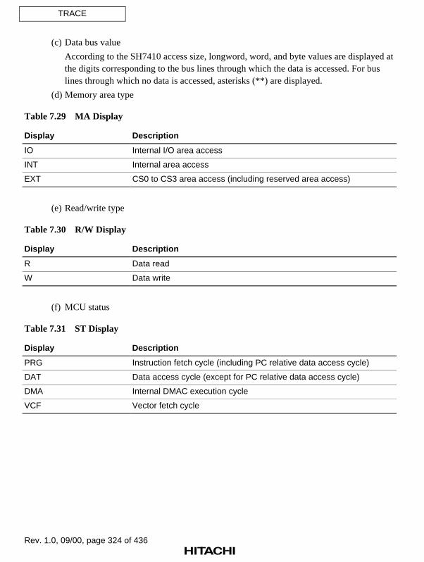
Rev. 1.0, 09/00, page 324 of 436
TRACE
(c) Data bus value
According to the SH7410 access size, longword, word, and byte values are displayed atthe digits corresponding to the bus lines through which the data is accessed. For buslines through which no data is accessed, asterisks (**) are displayed.
(d) Memory area type
Table 7.29 MA Display
Display Description
IO Internal I/O area access
INT Internal area access
EXT CS0 to CS3 area access (including reserved area access)
(e) Read/write type
Table 7.30 R/W Display
Display Description
R Data read
W Data write
(f) MCU status
Table 7.31 ST Display
Display Description
PRG Instruction fetch cycle (including PC relative data access cycle)
DAT Data access cycle (except for PC relative data access cycle)
DMA Internal DMAC execution cycle
VCF Vector fetch cycle
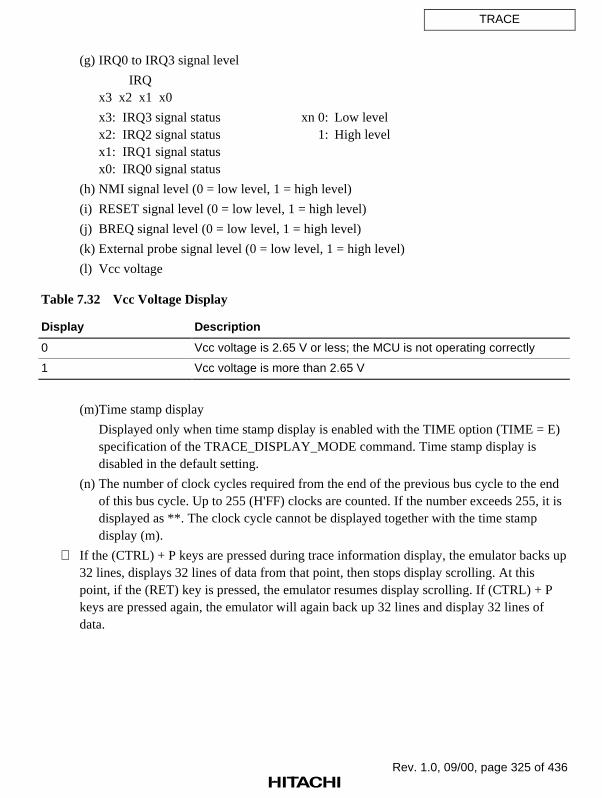
Rev. 1.0, 09/00, page 325 of 436
TRACE
(g) IRQ0 to IRQ3 signal level
IRQx3 x2 x1 x0
x3: IRQ3 signal status xn 0: Low levelx2: IRQ2 signal status 1: High levelx1: IRQ1 signal statusx0: IRQ0 signal status
(h) NMI signal level (0 = low level, 1 = high level)
(i) RESET signal level (0 = low level, 1 = high level)
(j) BREQ signal level (0 = low level, 1 = high level)
(k) External probe signal level (0 = low level, 1 = high level)
(l) Vcc voltage
Table 7.32 Vcc Voltage Display
Display Description
0 Vcc voltage is 2.65 V or less; the MCU is not operating correctly
1 Vcc voltage is more than 2.65 V
(m)Time stamp display
Displayed only when time stamp display is enabled with the TIME option (TIME = E)specification of the TRACE_DISPLAY_MODE command. Time stamp display isdisabled in the default setting.
(n) The number of clock cycles required from the end of the previous bus cycle to the endof this bus cycle. Up to 255 (H'FF) clocks are counted. If the number exceeds 255, it isdisplayed as **. The clock cycle cannot be displayed together with the time stampdisplay (m).
If the (CTRL) + P keys are pressed during trace information display, the emulator backs up32 lines, displays 32 lines of data from that point, then stops display scrolling. At thispoint, if the (RET) key is pressed, the emulator resumes display scrolling. If (CTRL) + Pkeys are pressed again, the emulator will again back up 32 lines and display 32 lines ofdata.

Rev. 1.0, 09/00, page 326 of 436
TRACE
Note
When the display is in bus-cycle units, the following message is displayed as the emulator cyclefollowing the last bus cycle of user program execution. Note that this emulator cycle does notaffect user program execution cycles.
*** E8000 ***
Examples
1. To display all trace information with only instruction mnemonics:
: T (RET)
IP ADDR MNEMONIC OPERAND
*-D'000004 00002010 JSR @R0
*-D'000003 00002012 NOP
*-D'000002 00002020 MOV.L R0,@R1
*-D'000001 00002022 NOP
*-D'000000 00002024 MOV.L R0,R4
:
2. To display bus-cycle information and instruction mnemonic information in bus-cycle units,from five instructions before the point where a delay count condition was satisfied:
: T -5;B (RET)
BP AB DB MA RW STS IRQ NMI RES BRQ VCC PRB
* 00002010 JSR @R0
* 00002012 NOP
-D'000005 00002010 400B0009 EXT R PRG 1111 1 1 1 1 1111
* 00002020 MOV.L R0,@R1
* 00002022 NOP
-D'000004 00002020 21020009 EXT R PRG 1111 1 1 1 1 1111
* 00002024 MOV R0,R4
-D'000003 00002024 6403000B EXT R PRG 1111 1 1 1 1 1111
-D'000002 0F000000 00002020 EXT W DAT 1111 1 1 1 1 1111
-D'000001 00002028 00090009 EXT R PRG 1111 1 1 1 1 1111
D'000000 *** E8000 ***
:

Rev. 1.0, 09/00, page 327 of 436
TRACE
3. To specify a display range by bus-cycle pointers, and display bus-cycle information andinstruction mnemonic information in bus-cycle units:
: T -D'20:-D'16;BP B (RET)
BP AB DB MA RW STS IRQ NMI RES BRQ VCC PRB
-D'000020 00002014 AFF40009 EXT R PRG 1111 1 1 1 1 1111
* 00002014 BRA 00002000
* 00002016 NOP
-D'000019 00002000 A0060009 EXT R PRG 1111 1 1 1 1 1111
* 00002000 BRA 00002010
* 00002022 NOP
-D'000018 00002010 400B0009 EXT R PRG 1111 1 1 1 1 1111
* 00002010 JSR @R0
* 00002012 NOP
-D'000017 00002020 21020009 EXT R PRG 1111 1 1 1 1 1111
* 00002020 MOV.L R0,@R1
* 00002022 NOP
-D'000016 00002024 6403000B EXT R PRG 1111 1 1 1 1 1111
* 00002024 MOV R0,R4
* 00002026 RTS
:
4. To specify a display range by bus-cycle pointers, and display bus-cycle information in bus-cycle units:
: T -D'20:-D'16;BP N (RET)
BP AB DB MA RW STS IRQ NMI RES BRQ VCC PRB
-D'000020 00002014 AFF40009 EXT R PRG 1111 1 1 1 1 1111
-D'000019 00002000 A0060009 EXT R PRG 1111 1 1 1 1 1111
-D'000018 00002010 400B0009 EXT R PRG 1111 1 1 1 1 1111
-D'000017 00002020 21020009 EXT R PRG 1111 1 1 1 1 1111
-D'000016 00002024 6403000B EXT R PRG 1111 1 1 1 1 1111
:

Rev. 1.0, 09/00, page 328 of 436
TRACE_CONDITION_A,B,C
7.2.42 TRACE_CONDITION_A,B,C Specifies, displays, and cancels a trace
[TCA,TCB,TCC] condition
Command Format
• Setting TRACE_CONDITION_(A/B/C)(1/2/3/4/5/6/7/8)∆S=<start address>:<end address>; ST (RET)
(Subroutine trace)TRACE_CONDITION_(A/B/C)(1/2/3/4/5/6/7/8)∆<condition>
[[∆<condition>][∆<condition>]...];R (RET) (Range trace)
TRACE_CONDITION_(A/B/C)(1/2/3/4/5/6/7/8)∆S=<start address>:<end address> ∆<condition>[[∆<condition>][∆<condition>]...];SR (RET)
(Subroutine range trace)TRACE_CONDITION_(A/B/C)(1/2/3/4/5/6/7/8)∆<condition>
[[∆<condition>][∆<condition>]...];S (RET) (Trace stop)
• Display TRACE_CONDITION_(A/B/C)[(1/2/3/4/5/6/7/8)] (RET)TRACE_CONDITION_(A/B/C) (RET)
• Cancellation TRACE_CONDITION_(A/B/C)[(1/2/3/4/5/6/7/8)] – (RET)TRACE_CONDITION_(A/B/C) – (RET)
(A/B/C): Trace condition type(1/2/3/4/5/6/7/8): Trace condition number
When omitted, all conditions will be displayed or cancelled.<start address>: Start address of subroutine<end address>: End address of subroutine
<condition>: Trace conditions to be specifiedST: Subroutine trace mode specificationR: Range trace mode specification
SR: Subroutine range trace mode specificationS: Trace stop specification

Rev. 1.0, 09/00, page 329 of 436
TRACE_CONDITION_A,B,C
Description
• Setting
Specifies a trace acquisition condition (trace mode) for user program emulation (GOcommand execution). Trace condition numbers are automatically set to trace conditions intheir specified order. The specified trace acquisition condition (trace mode) will apply fortrace acquisition following this command execution.
Free Trace: Acquires trace information during all bus cycles if no conditions have beenset with this command.
Subroutine Trace: Acquires trace information such as instructions and operands in therange (subroutine) specified by <start address> and <end address>. However, note that ifthe specified subroutine calls another subroutine, trace information on the called subroutineis not acquired.
Range Trace: Acquires trace information during bus cycles in which the specifiedcondition is satisfied.
Subroutine Range Trace: Accesses instructions and operands in the subroutine specifiedby <start address> and <end address>, and acquires trace information during bus cycles inwhich the specified condition is satisfied.
Trace Stop: Stops trace information acquisition when the specified condition is satisfied,and enters command input wait state in parallel mode. Though realtime emulationcontinues, trace information acquisition is not possible in parallel mode. If a trace stopcondition is satisfied,
** TRACE STOP **
is displayed.
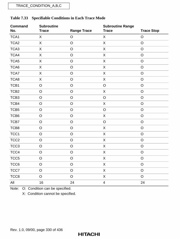
Rev. 1.0, 09/00, page 330 of 436
TRACE_CONDITION_A,B,C
Table 7.33 Specifiable Conditions in Each Trace Mode
CommandNo.
SubroutineTrace Range Trace
Subroutine RangeTrace Trace Stop
TCA1 X O X O
TCA2 X O X O
TCA3 X O X O
TCA4 X O X O
TCA5 X O X O
TCA6 X O X O
TCA7 X O X O
TCA8 X O X O
TCB1 O O O O
TCB2 O O X O
TCB3 O O O O
TCB4 O O X O
TCB5 O O O O
TCB6 O O X O
TCB7 O O O O
TCB8 O O X O
TCC1 O O X O
TCC2 O O X O
TCC3 O O X O
TCC4 O O X O
TCC5 O O X O
TCC6 O O X O
TCC7 O O X O
TCC8 O O X O
All 16 24 4 24
Note: O: Condition can be specified.
X: Condition cannot be specified.

Rev. 1.0, 09/00, page 331 of 436
TRACE_CONDITION_A,B,C
When conditions for subroutine trace, range trace, or subroutine range trace are specifiedtogether, the trace acquisition conditions for each mode are ORed. If no conditions arespecified for these modes, free trace is assumed.
When the specified trace stop condition is satisfied, trace information acquisition stops andthe emulator enters parallel mode and waits for command input. To resume traceinformation acquisition, exit parallel mode with the END command.
In range trace or trace stop mode, the items shown in tables 7.34 to 7.36 can be specified as<condition> and they can be combined by ANDing them. Several conditions can bespecified in any order.
Table 7.34 Specifiable Conditions (TRACE_CONDITION_A)
Item and Input Format Description
Address condition
A=<address 1>[:<address 2>]
When only <address 1> is specified, the condition is satisfiedwhen the address bus value matches the specified value.When both <address 1> and <address 2> are specified, thecondition is satisfied when the address bus value is in therange from <address 1> to <address 2>.This condition can be masked.
Data condition
D=<1-byte value>WD=<2-byte value>LD=<4-byte value>
The condition is satisfied when the data bus value matchesthe specified value. When D, WD, or LD is specified, thecondition is satisfied when the address is accessed in bytes,words, or longwords, respectively.In program fetch cycles, the data condition is not satisfiedirrespective of the data bus value.This condition can be masked.
Read/Write conditionR: ReadW: Write
The condition is satisfied in a read cycle (R is specified) or awrite cycle (W is specified).
Access typeDAT: Execution cycleDMA: DMA cycleVCF: Vector fetch cycleDefault: All bus cycles described
above (including programfetch cycle)
The condition is satisfied when the bus-cycle type matchesthe specified type. Multiple access types cannot be specified;either select one of the access types on the left, or specifynone.

Rev. 1.0, 09/00, page 332 of 436
TRACE_CONDITION_A,B,C
Table 7.34 Specifiable Conditions (TRACE_CONDITION_A) (cont)
Item and Input Format Description
External probe condition
PRB=<value>
The condition is satisfied when all of the emulator’s externalprobe signals match the specified values. Specify <value> as1-byte data. Each bit corresponds to a probe number, asfollows:
3 2 1 0 ← Bitx x x x ← Specified value
| | | |
4 3 2 1 ← Probe number
x: 0 = Low level1 = High level
This condition can be masked.
External interrupt condition 1
NMI [:L] or NMI: H
The condition is satisfied when the NMI signal matches thespecified level.
NMI or NMI: L: The condition is satisfied when NMI is lowNMI: H: The condition is satisfied when NMI is high
External interrupt condition 2
IRQ=<value>
The condition is satisfied when all of the IRQ signals matchthe specified values. Specify <value> as 1-byte data. Each bitcorresponds to an IRQ number, as follows:
3 2 1 0 ← Bitx x x x ← Specified value
| | | |
3 2 1 0 ← IRQ number
x: 0 = Low level1 = High level
The condition can be masked.

Rev. 1.0, 09/00, page 333 of 436
TRACE_CONDITION_A,B,C
Table 7.35 Specifiable Conditions (TRACE_CONDITION_B)
Item and Input Format Description
Address condition
A=<address 1>[:<address 2>][;NOT]
When only <address 1> is specified, the condition is satisfiedwhen the address bus value matches the specified value.When both <address 1> and <address 2> are specified, thecondition is satisfied when the address bus value is in therange from <address 1> to <address 2>.If the NOT option is specified, the condition is satisfied whenthe address bus value does not match the specified value.This condition can be masked.
Data condition
D=<1-byte value>[;NOT]WD=<2-byte value>[;NOT]LD=<4-byte value>[;NOT]
The condition is satisfied when the data bus value matchesthe specified value. When D, WD, or LD is specified, thebreak condition is satisfied when the address is accessed inbytes, words, or longwords, respectively.In program fetch cycles, the data condition is not satisfiedirrespective of the data bus value.If the NOT option is specified, the condition is satisfied whenthe data bus value does not match the specified value.This condition can be masked.
Read/Write conditionR: ReadW: Write
The condition is satisfied in a read cycle (R is specified) or awrite cycle (W is specified).
Access typeDAT: Execution cycleDMA: DMA cycleVCF: Vector fetch cycleDefault: All bus cycles described
above (including programfetch cycle)
The condition is satisfied when the bus-cycle type matchesthe specified type. Multiple access types cannot be specified;either select one of the access types on the left, or specifynone.
External probe condition
PRB=<value>
The condition is satisfied when all of the emulator’s externalprobe signals match the specified values. Specify <value> as1-byte data. Each bit corresponds to a probe number, asfollows:
3 2 1 0 ← Bitx x x x ← Specified value
| | | |
4 3 2 1 ← Probe number
x: 0 = Low level 1 = High level
This condition can be masked.

Rev. 1.0, 09/00, page 334 of 436
TRACE_CONDITION_A,B,C
Table 7.35 Specifiable Conditions (TRACE_CONDITION_B) (cont)
Item and Input Format Description
External interrupt condition 1
NMI [:L] or NMI: H
The condition is satisfied when the NMI signal matches thespecified level.
NMI or NMI: L: The condition is satisfied when NMI is lowNMI: H: The condition is satisfied when NMI is high
External interrupt condition 2
IRQ=<value>
The condition is satisfied when all of the IRQ signals matchthe specified values. Specify <value> as 1-byte data. Each bitcorresponds to an IRQ number, as follows:
3 2 1 0 ← Bitx x x x ← Specified value
| | | |
3 2 1 0 ← IRQ number
x: 0 = Low level 1 = High level
The condition can be masked.
Satisfaction count specification
COUNT=<value>
<value>: H'1 to H'FFFF
The condition can be specified in combination with any of theaddress, data, read/write, access type, external probe, andexternal interrupt conditions. The complete conditioncombination is satisfied when the other specified conditionhas been satisfied for the specified number of times.This condition can only be specified for trace stop.
Delay count specification
DELAY=<value>
<value>: H'1 to H'7FFF
This condition can be specified in combination with any of theaddress, data, read/write, access type, external probe, andexternal interrupt conditions. The complete conditioncombination is satisfied when the specified number of buscycles has been executed after the other specified conditionis satisfied.This condition can only be specified for trace stop.This condition can only be specified with the TRACE_CONDITION_B7 command.

Rev. 1.0, 09/00, page 335 of 436
TRACE_CONDITION_A,B,C
Table 7.36 Specifiable Conditions (TRACE_CONDITION_C)
Item and Input Format Description
Address condition
A=<address 1>[:<address 2>]
When only <address 1> is specified, the condition is satisfiedwhen the address bus value matches the specified value.When both <address 1> and <address 2> are specified, thecondition is satisfied when the address bus value is in therange from <address 1> to <address 2>.This condition can be masked.
Access typeDAT: Execution cycleDMA: DMA cycleVCF: Vector fetch cycleDefault: All bus cycles described
above (including programfetch cycle)
The condition is satisfied when the bus-cycle type matchesthe specified type. Multiple access types cannot be specified;either select one of the access types on the left, or specifynone.
Address and data conditions are satisfied when address bus values and data bus valuesmatch the specified values. Note the following when specifying trace conditions.
a. Access to a 32-bit bus area
• Longword access
Longword data is accessed in one bus cycle. Only longword data (LD) and a multipleof four can be specified as the data and address conditions, respectively.
• Word access
Word data is accessed in one bus cycle. Only word data (WD) and a multiple of twocan be specified as the data and address conditions, respectively. 32 bits must bespecified as the data bus width. Note that the data condition must be specified incombination with a specific address condition. If no address condition is specified or ifthe address is masked, the data condition will be satisfied when the address is amultiple of four.
• Byte access
Byte data is accessed in one bus cycle. Only byte data (D) can be specified as the datacondition. Both even and odd address values can be specified as the address condition.32 bits must be specified as the data bus width. Note that the data condition must bespecified in combination with a specific address condition. If no address condition isspecified or if the address is masked, the data condition will be satisfied when theaddress is a multiple of four.

Rev. 1.0, 09/00, page 336 of 436
TRACE_CONDITION_A,B,C
b. Access to a 16-bit bus area
• Longword access
Longword data is accessed in two word-access cycles. Only word data (WD) and amultiple of two can be specified as the data and address conditions, respectively. 16bits must be specified as the data bus width.
• Word access
Word data is accessed in one bus cycle. Only word data (WD) and a multiple of twocan be specified as the data and address conditions, respectively. 16 bits must bespecified as the data bus width.
• Byte access
Byte data is accessed in one bus cycle. Only byte data (D) can be specified as the datacondition. Both even and odd address values can be specified as the address condition.16 bits must be specified as the data bus width. Note that the data condition must bespecified in combination with a specific address condition. If no address condition isspecified or if the address is masked, the data condition will be satisfied when theaddress is a multiple of two.
c. Access to an 8-bit bus area
All addresses can be accessed in byte units. Longword data and word data are accessed infour byte-access cycles and two byte-access cycles, respectively. Both even and oddaddresses can be specified as the address condition. Note, however, that only byte data (D)is valid for the data condition. Eight bits must be specified as the data bus width.

Rev. 1.0, 09/00, page 337 of 436
TRACE_CONDITION_A,B,C
A bit mask in 1-bit or 4-bit units can be specified for the address condition of theTRACE_CONDITION_A,B,C command. When a bit is masked, the condition is satisfiedirrespective of its bit value. To implement the mask, specify each digit to be masked atinput as an asterisk (*). Table 7.37 shows address mask specification examples.
Example: The following condition is satisfied when the lower four bits of the addresscondition are not specified:
: TRACE_CONDITION_A1 A=H'400000* ;S (RET)
Table 7.37 Address Mask Specifications (TRACE_CONDITION_A,B,C)
Radix Mask Unit Example Mask Position
Binary 1 bit B'01101*** Bits 3 to 0 are masked
Hexadecimal 4 bits H'F50*** Bits 11 to 0 are masked
Note: When <address 2> is not specified for an address condition, <address 1> can beconsecutively masked from the lowest bit. It is not possible to mask any desired bitposition, as shown in the following examples.
Examples:Allowed: TRACE_CONDITION_A1 A = H'10** ;RNot allowed: TRACE_CONDITION_A1 A = H'1*00 ;R
TRACE_CONDITION_A1 A = H'100* :10** ;R
A bit mask in 1-bit or 4-bit units can be specified for the data, IRQ, or PRB condition ofthe TRACE_CONDITION_A,B,C command. When a bit is masked, the condition issatisfied irrespective of its bit value. To implement the mask, specify each digit to bemasked at input as an asterisk (*). Table 7.38 shows these mask specification examples.
Example: The following condition is satisfied when address 4000000 is the addresscondition and bit 0 is zero in the byte data condition:
: TRACE_CONDITION_A1 A=H'4000000 D=B'*******0 ;S (RET)
Table 7.38 Mask Specifications (TRACE_CONDITION_A,B,C)
Radix Mask Unit Example Mask Position Allowed Condition
Binary 1 bit B'01*1010* Bits 0 and 5 are masked Data (D, WD, LD), IRQ, orPRB
Hexa-decimal
4 bits H'F** 50 Bits 15 to 8 are masked Data (D, WD, LD), IRQ, orPRB

Rev. 1.0, 09/00, page 338 of 436
TRACE_CONDITION_A,B,C
In parallel mode, this command is executed as follows:
Parallel mode is entered by the (RET) key, or the trace stop condition is satisfied:
• This command setting is invalid during parallel mode.
• No trace information is acquired.
• As soon as parallel mode is terminated, this command setting is validated, and traceinformation acquisition starts. In this case, conditions that have been satisfied are allcleared, and the conditions are rechecked from the beginning. Old trace information isalso cleared. At this time,
*** 81:TRACE CONDITION RESET
is displayed.
Parallel mode is entered by the (SPACE) key:
• This command setting is valid.
• Trace information is acquired.
• During the following command execution, this command setting is invalid and no traceinformation is acquired:
(i) A condition is newly set with the TRACE_CONDITION_A,B,C command(ii) TRACE command(iii) TRACE_SEARCH command
As soon as the above command is terminated, this command setting is validated, andtrace information acquisition starts. In this case, conditions that have been satisfied areall cleared. Old trace information is also cleared. At this time,
*** 81:TRACE CONDITION RESET
is displayed.

Rev. 1.0, 09/00, page 339 of 436
TRACE_CONDITION_A,B,C
• Display
Displays specified conditions as follows. In addition to condition numbers, character stringsthat were input for specifying conditions will be displayed as they were input. If no tracecondition is specified, a blank is displayed.
: TRACE_CONDITION_A (RET) TCA1 A=1000 : 2000 ;R TCA2 S=5000 : 53FF ;ST TCA3 A=3000 : 4000 ;R TCA4 A=6000 : 7000 ;R TCA5 TCA6 TCA7 TCA8
• Cancellation
Cancels conditions specified with the TRACE_CONDITION_A command.
: TRACE_CONDITION_A – (RET)
Notes
1. When conditions have already been set with the PERFORMANCE_ANALYSIS orBREAK_CONDITION_A,B,C command, trace conditions may not be set to their maximumnumber. If necessary, cancel conditions set with the above commands before setting the traceconditions.
2. When conditions have been set with the BREAK_CONDITION_SEQUENCE orTRACE_CONDITION_SEQUENCE command, and sequential break or sequential trace stopis enabled, the TRACE_CONDITION_B command cannot be used. If necessary, disablesequential break or sequential trace stop, or cancel conditions set with theBREAK_CONDITION_SEQUENCE or TRACE_CONDITION_SEQUENCE commandbefore setting the trace conditions.
Examples
1. To specify a trace stop condition:
: TCA1 A=4320 ;S (RET)
:

Rev. 1.0, 09/00, page 340 of 436
TRACE_CONDITION_A,B,C
2. To specify a range trace condition:
: TCA2 A=2000:27FF ;R (RET)
:
3. To specify a subroutine range trace condition:
: TCB1 S=1000:13FF A=2000:27FF ;SR (RET)
:
4. To display specified trace conditions:
: TCA (RET)
TCA1 A=4320 ;S
TCA2 A=2000:27FF ;R
TCA3
TCA4
TCA5
TCA6
TCA7
TCA8
:
5. To cancel the trace condition specified with the TRACE_CONDITION_A3 command:
: TCA3- (RET)
:
6. To cancel all trace conditions specified with the TRACE_CONDITION_A command:
: TCA- (RET)
:

Rev. 1.0, 09/00, page 341 of 436
TRACE_CONDITION_SEQUENCE
7.2.43 TRACE_CONDITION_SEQUENCE Sets, displays, and cancels
[TCS] sequential trace stop conditions
Command Format
• Setting TRACE_CONDITION_SEQUENCE(1/2/3/4/5/6/7)∆<condition>[[∆ <condition>][∆<condition>]...] (RET)
TRACE_CONDITION_SEQUENCE∆<condition>[[∆ <condition>][∆<condition>]...];R (RET)
• Display TRACE_CONDITION_SEQUENCE (RET)
• Cancellation TRACE_CONDITION_SEQUENCE(1/2/3/4/5/6/7) – (RET)TRACE_CONDITION_SEQUENCE – ;R (RET)
• Enabling/ TRACE_CONDITION_SEQUENCE∆;(E/D) (RET)Disabling
(1/2/3/4/5/6/7): Pass point number<condition>: Pass point condition
R: Sequential reset condition specificationE: Enables sequential trace stopD: Disables sequential trace stop
Description
• Setting
Specifies sequential trace stop conditions (trace mode) for user program emulation (GOcommand execution). Up to seven pass point conditions and one sequential reset conditioncan be set. Stops trace information acquisition when the specified sequential condition issatisfied, and enters command input wait state in parallel mode. Though user programexecution continues, trace information acquisition is not possible in parallel mode. If asequential trace stop condition is satisfied,
** TRACE STOP **
is displayed.
This command cannot be used when conditions are set with the BREAK_CONDITION_B, BREAK_CONDITION_SEQUENCE, or TRACE_CONDITION_Bcommand.
The items shown in table 7.39 can be specified as <condition> and they can be combinedby ANDing them. Several conditions can be specified in any order.

Rev. 1.0, 09/00, page 342 of 436
TRACE_CONDITION_SEQUENCE
Table 7.39 Sequential Trace Stop Conditions (TRACE_CONDITION_SEQUENCE)
Item and Input Format Description
Address condition
A=<address 1>[:<address 2>][;NOT]
When only <address 1> is specified, the condition is satisfiedwhen the address bus value matches the specified value.When both <address 1> and <address 2> are specified, thecondition is satisfied when the address bus value is in therange from <address 1> to <address 2>.If the NOT option is specified, the condition is satisfied whenthe address bus value does not match the specified value.This condition can be masked.
Data condition
D=<1-byte value>[;NOT]WD=<2-byte value>[;NOT]LD=<4-byte value>[;NOT]
The condition is satisfied when the data bus value matchesthe specified value. When D, WD, or LD is specified, thecondition is satisfied when the address is accessed in bytes,words, or longwords, respectively.In program fetch cycles, the data condition is not satisfiedirrespective of the data bus value.If the NOT option is specified, the condition is satisfied whenthe data bus value does not match the specified value.This condition can be masked.
Read/Write conditionR: ReadW: Write
The condition is satisfied in a read cycle (R is specified) or awrite cycle (W is specified).
Access typeDAT: Execution cycleDMA: DMA cycleVCF: Vector fetch cycleDefault: All bus cycles described
above (including programfetch cycle)
The condition is satisfied when the bus-cycle type matchesthe specified type. Multiple access types cannot be specified;either select one of the access types on the left, or specifynone.
External probe condition
PRB=<value>
The condition is satisfied when all of the emulator’s externalprobe signals match the specified values. Specify <value> as1-byte data. Each bit corresponds to a probe number, asfollows:
3 2 1 0 ← Bitx x x x ← Specified value
| | | |
4 3 2 1 ← Probe number
x: 0 = Low level 1 = High level
This condition can be masked.

Rev. 1.0, 09/00, page 343 of 436
TRACE_CONDITION_SEQUENCE
Table 7.39 Sequential Trace Stop Conditions (TRACE_CONDITION_SEQUENCE) (cont)
Item and Input Format Description
External interrupt condition 1
NMI [:L] or NMI: H
The condition is satisfied when the NMI signal matches thespecified level.
NMI or NMI: L: The condition is satisfied when NMI is lowNMI: H: The condition is satisfied when NMI is high
External interrupt condition 2
IRQ=<value>
The condition is satisfied when all of the IRQ signals matchthe specified values. Specify <value> as 1-byte data. Each bitcorresponds to an IRQ number, as follows:
3 2 1 0 ← Bitx x x x ← Specified value
| | | |
3 2 1 0 ← IRQ number
x: 0 = Low level 1 = High level
The condition can be masked.
Delay count specification
DELAY=<value>
<value>: H'1 to H'7FFF
This condition can be specified in combination with any of theaddress, data, read/write, access type, external probe, andexternal interrupt conditions. The complete conditioncombination is satisfied when the specified number of buscycles has been executed after the other specified conditionis satisfied.This condition can only be specified with theTRACE_CONDITION_SEQUENCE7 command.
Address and data conditions are satisfied when address bus values and data bus valuesmatch the specified values. Note the following when specifying sequential trace stopconditions.
a. Access to a 32-bit bus area
• Longword access
Longword data is accessed in one bus cycle. Only longword data (LD) and a multipleof four can be specified as the data and address conditions, respectively.

Rev. 1.0, 09/00, page 344 of 436
TRACE_CONDITION_SEQUENCE
• Word access
Word data is accessed in one bus cycle. Only word data (WD) and a multiple of twocan be specified as the data and address conditions, respectively. 32 bits must bespecified as the data bus width. Note that the data condition must be specified incombination with a specific address condition. If no address condition is specified or ifthe address is masked, the data condition will be satisfied when the address is amultiple of four.
• Byte access
Byte data is accessed in one bus cycle. Only byte data (D) can be specified as the datacondition. Both even and odd address values can be specified as the address condition.32 bits must be specified as the data bus width. Note that the data condition must bespecified in combination with a specific address condition. If no address condition isspecified or if the address is masked, the data condition will be satisfied when theaddress is a multiple of four.
b. Access to a 16-bit bus area
• Longword access
Longword data is accessed in two word-access cycles. Only word data (WD) and amultiple of two can be specified as the data and address conditions, respectively. 16bits must be specified as the data bus width.
• Word access
Word data is accessed in one bus cycle. Only word data (WD) and a multiple of twocan be specified as the data and address conditions, respectively. 16 bits must bespecified as the data bus width.
• Byte access
Byte data is accessed in one bus cycle. Only byte data (D) can be specified as the datacondition. Both even and odd address values can be specified as the address condition.16 bits must be specified as the data bus width. Note that the data condition must bespecified in combination with a specific address condition. If no address condition isspecified or if the address is masked, the data condition will be satisfied when theaddress is a multiple of two.
c. Access to an 8-bit bus area
All addresses can be accessed in byte units. Longword data and word data are accessed infour byte-access cycles and two byte-access cycles, respectively. Both even and oddaddresses can be specified as the address condition. Note, however, that only byte data (D)is valid for the data condition. Eight bits must be specified as the data bus width.
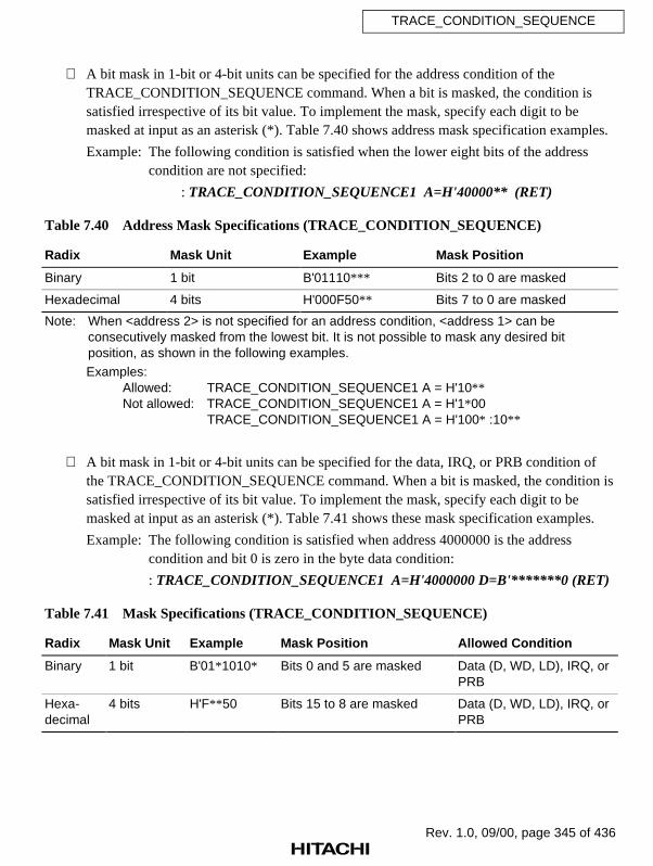
Rev. 1.0, 09/00, page 345 of 436
TRACE_CONDITION_SEQUENCE
A bit mask in 1-bit or 4-bit units can be specified for the address condition of theTRACE_CONDITION_SEQUENCE command. When a bit is masked, the condition issatisfied irrespective of its bit value. To implement the mask, specify each digit to bemasked at input as an asterisk (*). Table 7.40 shows address mask specification examples.
Example: The following condition is satisfied when the lower eight bits of the addresscondition are not specified:
: TRACE_CONDITION_SEQUENCE1 A=H'40000** (RET)
Table 7.40 Address Mask Specifications (TRACE_CONDITION_SEQUENCE)
Radix Mask Unit Example Mask Position
Binary 1 bit B'01110*** Bits 2 to 0 are masked
Hexadecimal 4 bits H'000F50** Bits 7 to 0 are masked
Note: When <address 2> is not specified for an address condition, <address 1> can beconsecutively masked from the lowest bit. It is not possible to mask any desired bitposition, as shown in the following examples.
Examples:Allowed: TRACE_CONDITION_SEQUENCE1 A = H'10**Not allowed: TRACE_CONDITION_SEQUENCE1 A = H'1*00
TRACE_CONDITION_SEQUENCE1 A = H'100* :10**
A bit mask in 1-bit or 4-bit units can be specified for the data, IRQ, or PRB condition ofthe TRACE_CONDITION_SEQUENCE command. When a bit is masked, the condition issatisfied irrespective of its bit value. To implement the mask, specify each digit to bemasked at input as an asterisk (*). Table 7.41 shows these mask specification examples.
Example: The following condition is satisfied when address 4000000 is the addresscondition and bit 0 is zero in the byte data condition:
: TRACE_CONDITION_SEQUENCE1 A=H'4000000 D=B'*******0 (RET)
Table 7.41 Mask Specifications (TRACE_CONDITION_SEQUENCE)
Radix Mask Unit Example Mask Position Allowed Condition
Binary 1 bit B'01*1010* Bits 0 and 5 are masked Data (D, WD, LD), IRQ, orPRB
Hexa-decimal
4 bits H'F** 50 Bits 15 to 8 are masked Data (D, WD, LD), IRQ, orPRB

Rev. 1.0, 09/00, page 346 of 436
TRACE_CONDITION_SEQUENCE
In parallel mode, this command is executed as follows:
Parallel mode is entered by the (RET) key, or the trace stop condition is satisfied:
• This command setting is invalid during parallel mode.
• No trace information is acquired.
• As soon as parallel mode is terminated, this command setting is validated, and traceinformation acquisition starts. In this case, conditions that have been satisfied are allcleared, and the conditions are rechecked from the beginning. Old trace information isalso cleared. At this time,
*** 81:TRACE CONDITION RESET
is displayed.
Parallel mode is entered by the (SPACE) key:
• This command setting is valid.
• Trace information is acquired.
• During the following command execution, this command setting is invalid and no traceinformation is acquired:
(i) A condition is newly set with the TRACE_CONDITION_A,B,C command(ii) A condition is newly set with the TRACE_CONDITION_SEQUENCE
command(iii) TRACE command(iv) TRACE_SEARCH command
As soon as the above command is terminated, this command setting is validated, andtrace information acquisition starts. In this case, conditions that have been satisfied areall cleared. Old trace information is also cleared. At this time,
*** 81:TRACE CONDITION RESET
is displayed.
Rev. 1.0, 09/00, page 347 of 436
TRACE_CONDITION_SEQUENCE
• Display
Displays specified conditions as follows. In addition to the display of condition numbers,character strings that were input for specifying conditions will be displayed as they were input.If no condition is specified, a blank is displayed.
: TRACE_CONDITION_SEQUENCE (RET) TCS1 A=1000 TCS2 A=3000 TCS3 A=5000 TCS4 A=1000 TCS5 A=3000 TCS6 A=6000 TCS7 RESET A=8000 DELAY=0000
• Cancellation
Cancels all specified conditions.
: TRACE_CONDITION_SEQUENCE – (RET)
Note
When conditions have been set with the PERFORMANCE_ANALYSIS or BREAK_CONDITION_A,B,C command, sequential trace stop conditions may not be set to their maximumnumber. If necessary, cancel conditions set with the above commands before setting the sequentialtrace stop conditions.
Examples
1. To specify a sequential trace stop condition:
: TCS7 A=4320 (RET)
:

Rev. 1.0, 09/00, page 348 of 436
TRACE_CONDITION_SEQUENCE
2. To display specified sequential trace stop conditions:
: TCS (RET)
TCS1 A=1000
TCS2 A=3000
TCS3 A=5000
TCS4 A=3000
TCS5 A=3000
TCS6 A=6000
TCS7 A=4320
RESET A=8000
DELAY=0000
:

Rev. 1.0, 09/00, page 349 of 436
TRACE_DISPLAY_MODE
7.2.44 TRACE_DISPLAY_MODE Specifies and displays trace information
[TDM] display mode
Command Format
• Setting TRACE_DISPLAY_MODE∆PTR=[–]<start pointer>[:[–]<end pointer>]∆<display item>=(D/E)[[∆<display item>=(D/E)]...][;C] (RET)
• Display TRACE_DISPLAY_MODE (RET)
<start pointer>: Default start pointer for trace information display and search(emulator shipment: –D'4095)
<end pointer>: Default end pointer for trace information display and search(emulator shipment: D'4095)
<display item>: Information to be displayed at trace information displayA (address bus), D (data bus), MA (memory area type),RW (read/write), ST (status), IRQ (IRQ signals),NMI (NMI signal), RES (RESET signal),BREQ (BREQ signal), VCC (VCC voltage state),PRB (external probe), TIME (time stamp), and CLK(clock cycle)
C: Stores the settings as configuration information in the emulatorflash memory
Description
• Setting
Specifies the default values of start and end pointers for trace information display andsearch which are used when the pointer values are not specified in the TRACE orTRACE_SEARCH command. Trace information in the emulator is available forapproximately 128,000 bus cycles. Use this command to specify the range of the defaultvalues when all trace information is not required. The specified pointers will function asbus-cycle pointers in the TRACE_SEARCH command, and according to the option asinstruction or bus-cycle pointers in the TRACE command. The pointer value ranges from–131070 to 131070. When exceeding this range, start and end pointers are automaticallyspecified as –131070 and 131070, respectively.
: TRACE_DISPLAY_MODE PTR = –D'2048:D'2048 (RET)

Rev. 1.0, 09/00, page 350 of 436
TRACE_DISPLAY_MODE
Sets trace items to be displayed as bus-cycle information at trace information display withthe TRACE or TRACE_SEARCH command.
: TRACE_DISPLAY_MODE∆∆zzzz = (E/D) (RET)
zzzz: Information to be displayed at trace information displayA, D, MA, RW, ST, IRQ, NMI, RES, BREQ, VCC,PRB, TIME, and CLK
E: Display is enabledD: Display is disabled
Note: TIME and CLK cannot be set as E (display enabled) at the same time.
Table 7.42 shows the default of each trace item display at emulator shipment.
Table 7.42 Shipment Defaults of TRACE_DISPLAY_MODE Command
Trace Items Default at Shipment
A, D, MA, RW, ST, IRQ, NMI, RES, BREQ, VCC, and PRB E
TIME and CLK D
When the C option is specified, the following message is displayed to confirm with theuser whether to overwrite the existing configuration information in the emulator flashmemory.
: TRACE_DISPLAY_MODE ;C (RET): CONFIGURATION STORE OK (Y/N) ? (a) (RET)
(a) Y: Stores the specifications as configuration information in the emulator flash memory. Hereafter, when the emulator is activated, the saved specifications go into effect.
N: Does not overwrite configuration information. The existing specifications are valid.

Rev. 1.0, 09/00, page 351 of 436
TRACE_DISPLAY_MODE
• Display
Displays the specified trace mode as shown below.
: TRACE_DISPLAY_MODE (RET) PTR = –D'yyyyyy : D'yyyyyy DISPLAY ITEM = zzzz zzzz ...
yyyyyy: Default values of start and end bus-cycle pointers for traceinformation display and search
zzzz: Information to be displayed at trace information displayA, D, MA, RW, ST, IRQ, NMI, RES, BREQ, VCC, PRB,TIME, and CLK
Examples
1. To set the default values of the pointers to addresses –D'10 and D'10 at trace informationdisplay:
: TDM PTR=-D'10:D'10 (RET)
:
2. To display the specified contents:
: TDM (RET)
PTR=–D'000010:D'000010
DISPLAY ITEM=A D MA RW ST IRQ NMI RES BREQ VCC PRB
:
3. To specify not to display external probe information (PRB) as bus-cycle information at traceinformation display with the TRACE or TRACE_SEARCH command:
: TDM PRB=D (RET)
:

Rev. 1.0, 09/00, page 352 of 436
TRACE_MODE
7.2.45 TRACE_MODE Specifies and displays trace information
[TMO] acquisition mode
Command Format
• Setting TRACE_MODE [∆DMA=(D/E)][ ∆REF=(D/E)][∆OVFB=(D/E)][∆TIME=(0/1/2/3)][;C] (RET)
• Display TRACE_MODE (RET)
DMA: Specifies whether trace information acquisition for DMA cycles are enabled.D: Disables trace information acquisition for DMA cyclesE: Enables trace information acquisition for DMA cycles (default at
emulator shipment)REF: Specifies whether trace information acquisition for refresh cycles are
enabled.D: Disables trace information acquisition for refresh cyclesE: Enables trace information acquisition for refresh cycles (default at
emulator shipment)OVFB: Specifies whether a break occurs when the trace buffer overflows.
D: A break does not occur when the trace buffer overflows (default atemulator shipment)
E: A break occurs when the trace buffer overflowsTIME: Specifies the minimum time stamp unit.
0: Acquires trace information on the number of clock cycles (CLK)instead of time stamp
1: 20 ns (default at emulator shipment)2: 1.6 µs3: 52 µs
C: Stores the settings as configuration information in the emulator flash memory.
Description
• Specification
Enables or disables trace information acquisition for DMA cycles.
• To enable trace information acquisition during DMA cycles:
: TRACE_MODE DMA=E (RET)
• To disable trace information acquisition during DMA cycles:
: TRACE_MODE DMA=D (RET)

Rev. 1.0, 09/00, page 353 of 436
TRACE_MODE
Enables or disables trace information acquisition for refresh cycles.
• To enable trace information acquisition during refresh cycles:
: TRACE_MODE REF=E (RET)
• To disable trace information acquisition during refresh cycles:
: TRACE_MODE REF=D (RET)
Specifies whether or not to generate a break when the trace buffer overflows.
• To generate a break when the trace buffer overflows:
: TRACE_MODE OVFB=E (RET)
• To not generate a break when the trace buffer overflows:
: TRACE_MODE OVFB=D (RET)
Specifies minimum time stamp unit.
• To acquire trace information on the number of clock cycles. The time stamp is notacquired.
: TRACE_MODE TIME=0 (RET)
• To set the minimum time stamp unit to 20 ns:
: TRACE_MODE TIME=1 (RET)
• To set the minimum time stamp unit to 1.6 µs:
: TRACE_MODE TIME=2 (RET)
• To set the minimum time stamp unit to 52 µs:
: TRACE_MODE TIME=3 (RET)
When the C option is specified, the following message is displayed to confirm with theuser whether to overwrite the existing configuration information in the emulator flashmemory.
CONFIGURATION STORE OK (Y/N) ? (a) (RET)
(a) Y: Stores the specifications as configuration information in the emulator flash memory. Hereafter, when the emulator is activated, the saved specifications go into effect.
N: Does not overwrite configuration information. The existing specifications are valid.

Rev. 1.0, 09/00, page 354 of 436
TRACE_MODE
• Display
Displays the specified trace mode in the following format:
: TRACE_MODE (RET) DMA=x REF=x OVFB=y TIME=zzzzz
x: Enables or disables trace information acquisition for DMA cyclesand refresh cyclesE: Trace information is acquiredD: No trace information is acquired
y: A break occurs when the trace buffer overflowszzzzz: Minimum time stamp unit
Table 7.43 Display of Minimum Time Stamp Unit
Display Description
CLK Acquires trace information on the number of clock cycles. Does notacquire trace information on time stamp.
20ns 20 nanoseconds
1.6us 1.6 microseconds
52us 52 microseconds
Examples
1. To set the minimum time stamp unit to 20 ns:
: TMO TIME=1 (RET)
:
2. To display the specified contents:
: TMO (RET)
DMA=E REF=E OVFB=D TIME=20ns
:

Rev. 1.0, 09/00, page 355 of 436
TRACE_SEARCH
7.2.46 TRACE_SEARCH [TS] Searches for and displays trace information
Command Format
• First level unordered list item <Level 1 unordered,1u>
• Search and TRACE_SEARCH[∆<condition>[∆<condition>...]display [;[–] <start bus-cycle pointer>[:[–]<end bus-cycle pointer>] [L]]] (RET)
<condition>: Condition governing trace information to be searched for ordisplayed. If this is omitted, the number of bus cycles and thenumber of instructions in the trace buffer are displayed.
–: Specified when searching for trace information acquired beforethe trace or break condition has been satisfied. (This option isusually necessary, except for displaying trace information duringdelays when a delay count condition is specified by theBREAK_CONDITION_B, BREAK_CONDITION_SEQUENCE,TRACE_CONDITION_B, or TRACE_CONDITION_SEQUENCEcommand.)
<start bus-cycle pointer>: Start pointer of bus cycle to be searched for or displayed.<end bus-cycle pointer>: End pointer of bus cycle to be searched for or displayed.
If both <start bus-cycle pointer> and <end bus-cycle pointer> areomitted, bus cycles are searched for or displayed according tothe pointers specified with the TRACE_DISPLAY_MODEcommand.
L: Displays the last bus-cycle information to be searched for.
Description
• Search and display
Searches for information in the trace buffer under the specified conditions, and displays allapplicable bus-cycle information. If <start bus-cycle pointer> and <end bus-cycle pointer>are specified, searches for and displays the bus-cycle information between <start bus-cyclepointer> and <end bus-cycle pointer>. Trace information is displayed in the same formatas the bus-cycle information display by the TRACE command.
If no conditions are specified, the number of bus cycles and instructions saved in the tracebuffer are displayed.
: TRACE_SEARCH (RET) INSTRUCTION NUMBER = D'xxxxxx BUS-CYCLE NUMBER = D'yyyyyy
xxxxxx: Number of instructions (decimal)yyyyyy: Number of bus cycles (decimal)

Rev. 1.0, 09/00, page 356 of 436
TRACE_SEARCH
If the L option is specified, displays only the last bus-cycle information to be searched for.
Items listed in table 7.44 can be specified for <condition>, and they can be combined byANDing them.
Table 7.44 Specifiable Conditions (TRACE_SEARCH)
Item and Input Format Description
Address condition
A=<address 1>[:<address 2>]
When only <address 1> is specified, the condition is satisfiedwhen the address bus value matches the specified value.When both <address 1> and <address 2> are specified, thecondition is satisfied when the address bus value is in therange from <address 1> to <address 2>.This condition can be masked.
Data condition
D=<1-byte value>WD=<2-byte value>LD=<4-byte value>
The condition is satisfied when the data bus value matchesthe specified value. When D, WD, or LD is specified, thecondition is satisfied when the address is accessed in bytes,words, or longwords, respectively.This condition can be masked.
Read/Write conditionR: ReadW: Write
The condition is satisfied in a read cycle (R is specified) or awrite cycle (W is specified).
Access typeDAT: Execution cycleDMA: DMA cycleVCF: Vector fetch cycleDefault: All bus cycles described
above (including programfetch cycle)
The condition is satisfied when the bus-cycle type matchesthe specified type. Multiple access types cannot be specified;either select one of the access types on the left, or specifynone.
External probe condition
PRB=<value>
The condition is satisfied when all of the emulator’s externalprobe signals match the specified values. Specify <value> as1-byte data. Each bit corresponds to a probe number, asfollows:
3 2 1 0 ← Bitx x x x ← Specified value
| | | |
4 3 2 1 ← Probe number
x: 0 = Low level 1 = High level
This condition can be masked.

Rev. 1.0, 09/00, page 357 of 436
TRACE_SEARCH
Table 7.44 Specifiable Conditions (TRACE_SEARCH) (cont)
Item and Input Format Description
Memory type condition
INT: Internal areaIO: Internal I/O areaEXT: External area
Searches for a bus cycle in which the specified memory areatype is accessed.
External interrupt condition 1
NMI [:L] or NMI: H
The condition is satisfied when the NMI signal matches thespecified level.
NMI or NMI: L: The condition is satisfied when NMI is lowNMI: H: The condition is satisfied when NMI is high
External interrupt condition 2
IRQ=<value>
The condition is satisfied when all of the IRQ signals matchthe specified values. Specify <value> as 1-byte data. Each bitcorresponds to an IRQ number, as follows:
3 2 1 0 ← Bitx x x x ← Specified value
| | | |
3 2 1 0 ← IRQ number
x: 0 = Low level 1 = High level
The condition can be masked.
RES Searches for a bus cycle in which the RESET signal is low.
Time stamp
TS=<elapsed time 1>[∆<elapsed time 2>]
Searches for the specified elapsed time.When only <elapsed time 1> is specified, searches for thetime specified with <elapsed time 1>. When both <elapsedtime 1> and <elapsed time 2> are specified, searches for thetime range specified with <elapsed time 1> and <elapsed time2>.
<elapsed time 1> = hhh[:mm[:ss[:uuuuuu]]]<elapsed time 2> = hhh[:mm[:ss[:uuuuuu]]]
hhh: Hourmm: Minute
ss: Seconduuuuuu: Microsecond
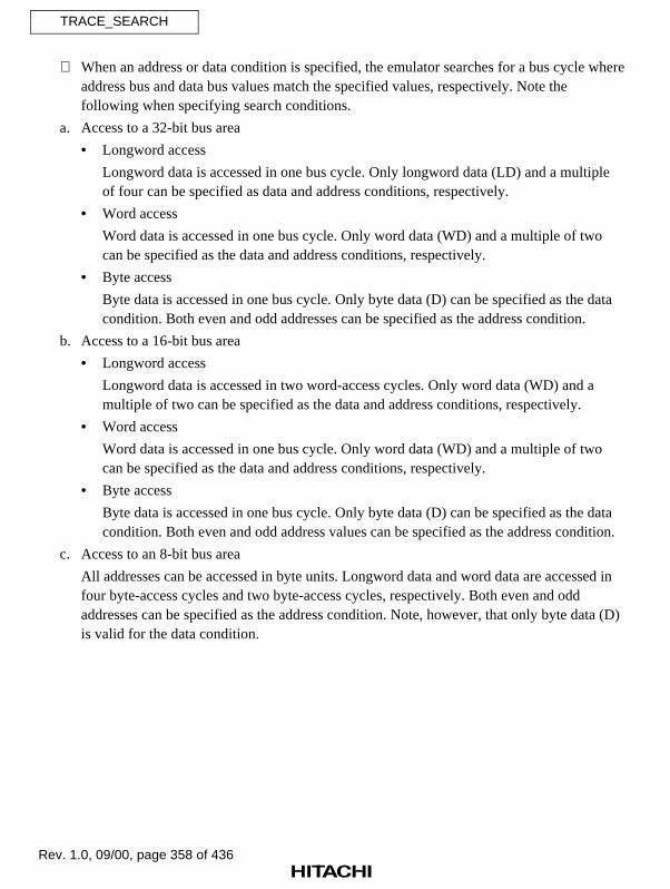
Rev. 1.0, 09/00, page 358 of 436
TRACE_SEARCH
When an address or data condition is specified, the emulator searches for a bus cycle whereaddress bus and data bus values match the specified values, respectively. Note thefollowing when specifying search conditions.
a. Access to a 32-bit bus area
• Longword access
Longword data is accessed in one bus cycle. Only longword data (LD) and a multipleof four can be specified as data and address conditions, respectively.
• Word access
Word data is accessed in one bus cycle. Only word data (WD) and a multiple of twocan be specified as the data and address conditions, respectively.
• Byte access
Byte data is accessed in one bus cycle. Only byte data (D) can be specified as the datacondition. Both even and odd addresses can be specified as the address condition.
b. Access to a 16-bit bus area
• Longword access
Longword data is accessed in two word-access cycles. Only word data (WD) and amultiple of two can be specified as the data and address conditions, respectively.
• Word access
Word data is accessed in one bus cycle. Only word data (WD) and a multiple of twocan be specified as the data and address conditions, respectively.
• Byte access
Byte data is accessed in one bus cycle. Only byte data (D) can be specified as the datacondition. Both even and odd address values can be specified as the address condition.
c. Access to an 8-bit bus area
All addresses can be accessed in byte units. Longword data and word data are accessed infour byte-access cycles and two byte-access cycles, respectively. Both even and oddaddresses can be specified as the address condition. Note, however, that only byte data (D)is valid for the data condition.

Rev. 1.0, 09/00, page 359 of 436
TRACE_SEARCH
A bit mask in 1-bit or 4-bit units can be specified for address, data, IRQ, or PRB condition.When a bit is masked, the condition is satisfied irrespective of its bit value. To implementthe mask, specify each digit to be masked at input as an asterisk (*). Table 7.45 showsmask specification examples.
Example 1: To search for a bus cycle where bit 0 is zero in the byte data condition:
: TRACE_SEARCH A=4000000 D=B'*******0 (RET)
Example 2: To search for a bus cycle where IRQ2 is zero in the IRQ condition (IRQ pins other than IRQ2 are ignored):
: TRACE_SEARCH IRQ=B'*0** (RET)
Table 7.45 Mask Specifications (TRACE_SEARCH)
Radix Mask Unit Example Mask Position Allowed Condition
Binary 1 bit B'01*1010* Bits 0 and 5 are masked Address, data (D, WD, LD),IRQ, or PRB
Hexa-decimal
4 bits H'F** 50 Bits 15 to 8 are masked Address, data (D, WD, LD),IRQ, or PRB
The display contents are the same as the bus-cycle display of the TRACE command.However, instruction mnemonics are not displayed.
If no trace information satisfies the specified condition,
*** 45: NOT FOUND
is displayed.
If there is no trace information in the trace buffer,
*** 39: BUFFER EMPTY
is displayed.

Rev. 1.0, 09/00, page 360 of 436
TRACE_SEARCH
Examples
1. To search for bus cycles where data is written to addresses from H'1000000 to H'1000050:
: TS A=F000000:F000050 W (RET)
BP AB DB MA RW ST IRQ NMI RES BRQ VCC PRB
-D'000063 01000003 ******44 EXT W DAT 1110 1 1 1 1 1111
-D'000062 01000022 ****3344 EXT W DAT 1111 1 1 1 1 1111
-D'000060 01000040 11223344 EXT W DAT 1111 1 1 1 1 1111
:
2. To search for the last bus cycle where IRQ0 is low:
: TS IRQ=B'***0 ;L (RET)
BP AB DB MA RW ST IRQ NMI RES BRQ VCC PRB
-D'000063 01000003 ******44 EXT W DAT 1110 1 1 1 1 1111
:
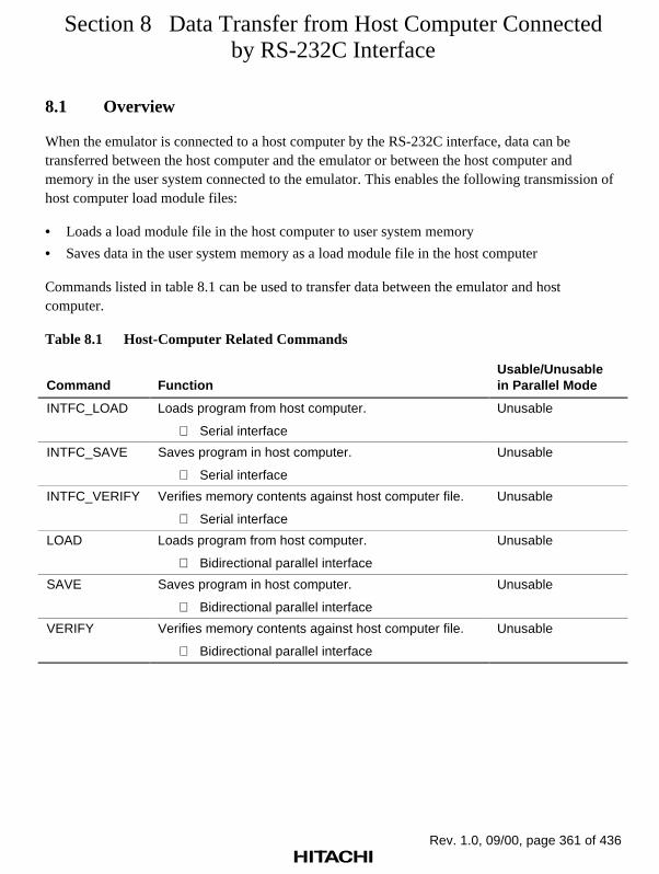
Rev. 1.0, 09/00, page 361 of 436
Section 8 Data Transfer from Host Computer Connectedby RS-232C Interface
8.1 Overview
When the emulator is connected to a host computer by the RS-232C interface, data can betransferred between the host computer and the emulator or between the host computer andmemory in the user system connected to the emulator. This enables the following transmission ofhost computer load module files:
• Loads a load module file in the host computer to user system memory
• Saves data in the user system memory as a load module file in the host computer
Commands listed in table 8.1 can be used to transfer data between the emulator and hostcomputer.
Table 8.1 Host-Computer Related Commands
Command FunctionUsable/Unusablein Parallel Mode
INTFC_LOAD Loads program from host computer.
Serial interface
Unusable
INTFC_SAVE Saves program in host computer.
Serial interface
Unusable
INTFC_VERIFY Verifies memory contents against host computer file.
Serial interface
Unusable
LOAD Loads program from host computer.
Bidirectional parallel interface
Unusable
SAVE Saves program in host computer.
Bidirectional parallel interface
Unusable
VERIFY Verifies memory contents against host computer file.
Bidirectional parallel interface
Unusable

Rev. 1.0, 09/00, page 362 of 436
8.2 Host-Computer Related Commands
This section provides details of host-computer related commands in the format shown infigure 8.1.
Command Format
Function 1 : Command input formatFunction 2 : Command input format • • <parameter 1>: Parameter description 1 <parameter 2>: Parameter description 2 :
Function 1 Description of function 1Function 2 Description of function 2 • •
Description
Notes
Examples
Command NameFull command name
Abbr.Abbreviated command name
FunctionCommand function
Command FormatCommand input format for eachfunction
DescriptionFunction and usage in detail
NotesWarnings and restrictions forusing the command. If additionalinformation is not required, thisitem is omitted.
ExamplesCommand usage examples
Command Name
No. Command Name [Abbr.] Function
•
•
•
•
•
•
•
Figure 8.1 Description Format of Host-Computer Related Command
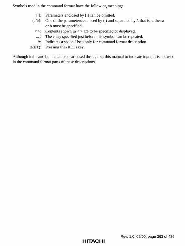
Rev. 1.0, 09/00, page 363 of 436
Symbols used in the command format have the following meanings:
[ ]: Parameters enclosed by [ ] can be omitted.(a/b): One of the parameters enclosed by ( ) and separated by /, that is, either a
or b must be specified.< >: Contents shown in < > are to be specified or displayed.... : The entry specified just before this symbol can be repeated.∆: Indicates a space. Used only for command format description.
(RET): Pressing the (RET) key.
Although italic and bold characters are used throughout this manual to indicate input, it is not usedin the command format parts of these descriptions.

Rev. 1.0, 09/00, page 364 of 436
INTFC_LOAD
8.2.1 INTFC_LOAD [IL] Loads program from host computer
— Serial interface
Command Format
• Load INTFC_LOAD[∆<offset>][;<load module type>]:<file name> (RET)
<offset>: Value to be added to the load module address<load module type>: Load module type
R: SYSROF-type load moduleS: S-type load moduleH: HEX-type load moduleM: Memory image fileE: ELF-type load module
Default: SYSROF-type load module<file name>: File name in the host computer
Description
• Load
Loads a user program from the host computer into user system memory via the serialinterface. Use interface software IPW for the host computer.
:INTFC_LOAD[;<load module type>]:<file name> (RET)
When loading is completed, the start and end addresses are displayed as follows:
TOP ADDRESS = <start address>END ADDRESS = <end address>
An offset (value to be added) can be specified for the address of an SYSROF-type, ELF-type, S-type, or HEX-type load module.
:INTFC_LOAD <offset>;S :<file name> (RET)
If an offset is specified, a load address is calculated as follows:
Load address = <load module address> + <offset>

Rev. 1.0, 09/00, page 365 of 436
INTFC_LOAD
Notes
1. The load module can be loaded only to the internal memory areas or areas CS0 to CS3.
2. Verification is not performed during load. If the program must be verified, use theINTFC_VERIFY command. For details, refer to section 8.2.3, INTFC_VERIFY.
Examples
1. To load SYSROF-type load module F11.ABS:
: IL :F11.ABS (RET)
TOP ADDRESS = 00007000
END ADDRESS = 00007FFF
:
2. To load S-type load module ST.MOT:
: IL ;S :ST.MOT(RET)
TOP ADDRESS = 00000000
END ADDRESS = 00003042
:

Rev. 1.0, 09/00, page 366 of 436
INTFC_SAVE
8.2.2 INTFC_SAVE [IS] Saves program in host computer
— Serial interface
Command Format
• Save INTFC_SAVE∆<start address>(∆<end address>/∆@<number of bytes>)[;[<load module type>][∆LF]]:<file name> (RET)
<start address>: Start memory address<end address>: End memory address
<number of bytes>: Number of bytes to be saved<load module type>: Load module type
S: S-type load moduleH: HEX-type load module
Default: S-type load moduleLF: Adds an LF code (H'0A) to the end of each record
<file name>: File name in the host computer
Description
• Save
Saves the specified memory contents in the specified load module type in a host computerfile via the serial interface. Use interface software IPW for the host computer. An S-type orHEX-type load module can be saved. An SYSROF-type or ELF-type load module cannotbe saved.
:INTFC_SAVE <start address> <end address>[;<load module type>]:<file name> (RET)
When save is completed, the start and end memory addresses are displayed as follows:
TOP ADDRESS = <start address>END ADDRESS = <end address>
When the LF option is specified, the emulator adds an LF code (H'0A) to the end of eachrecord in addition to a CR code (H'0D) in the S-type or HEX-type load module.

Rev. 1.0, 09/00, page 367 of 436
INTFC_SAVE
Notes
1. Data can be saved only in the internal memory areas or areas CS0 to CS3.
2. Verification is not performed after save. If the program must be verified, use theINTFC_VERIFY command. For details, refer to section 8.2.3, INTFC_VERIFY.
3. If the specified file name already exists, an overwrite confirmation message is displayed. If Nis entered to halt save, some unnecessary characters may be output to the following line.
Example
To save memory contents in the address range from H'7000 to H'7FFF in host computer fileF11.MOT in the S-type load module format:
: IS 7000 7FFF :F11.MOT (RET) TOP ADDRESS = 00007000 END ADDRESS = 00007FFF:

Rev. 1.0, 09/00, page 368 of 436
INTFC_VERIFY
8.2.3 INTFC_VERIFY [IV] Verifies memory contents against host
computer file
— Serial interface
Command Format
• Verification INTFC_VERIFY [∆<offset>][;<load module type>]:<file name> (RET)
<offset>: Value to be added to the address<load module type>: Load module type
R: SYSROF-type load moduleS: S-type load moduleH: HEX-type load moduleM: Memory image fileE: ELF-type load module
Default: SYSROF-type load module<file name>: File name in the host computer
Description
• Verification
Verifies data transferred from the host computer against data in memory via the serialinterface. Use interface software IPW for the host computer.
:INTFC_VERIFY[;<load module type>]:<file name> (RET)
If a verification error occurs, verification terminates immediately and the address and itscontents are displayed as follows. Note that only one verification error can be detected andits contents are displayed.
<ADDR> <FILE> <MEM>xxxxxxxx yy 'y' zz 'z'
xxxxxxxx: Verification error addressyy 'y': Load module data (in hexadecimal and ASCII characters)zz 'z': Memory data (in hexadecimal and ASCII characters)
An offset (value to be added or subtracted) can be specified for the address of an SYSROF-type, ELF-type, S-type, or HEX-type load module.
:INTFC_VERIFY <offset> ;S :<file name> (RET)
If an offset is specified, a verification address is calculated as follows:
Verification address = <load module address> + <offset>

Rev. 1.0, 09/00, page 369 of 436
INTFC_VERIFY
Note
Data can be verified only in the internal memory areas or areas CS0 to CS3.
Example
To verify SYSROF-type load module F1.ABS against the memory contents:
: IV :F1.ABS (RET) <ADDR> <FILE> <MEM> 00001012 31'1' 00'.' TOP ADDRESS = 00000000 END ADDRESS = 00003FFF:

Rev. 1.0, 09/00, page 370 of 436
LOAD
8.2.4 LOAD [L] Loads program from host computer
— Bidirectional parallel interface
Command Format
• Load LOAD[∆<offset>][;<load module type>]:<file name> (RET)
<offset>: Value to be added to the load module address<load module type>: Load module type
R: SYSROF-type load moduleS: S-type load moduleH: HEX-type load moduleM: Memory image fileE: ELF-type load module
Default: SYSROF-type load module<file name>: File name in the host computer
Description
• Load
Loads a user program from the host computer into user system memory via thebidirectional parallel interface. Use interface software IPW for the host computer totransfer the specified file to the emulator via the bidirectional parallel interface. Enter #B∆before the command to request data output to the host computer.
:#B LOAD[;<load module type>]:<file name> (RET)
When loading is completed, the start and end addresses are displayed as follows:
TOP ADDRESS = <start address>END ADDRESS = <end address>
An offset (value to be added) can be specified for the address of an SYSROF-type, ELF-type, S-type, or HEX-type load module.
:#B LOAD <offset>;S :<file name> (RET)
If an offset is specified, a load address is calculated as follows:
Load address = <load module address> + <offset>

Rev. 1.0, 09/00, page 371 of 436
LOAD
Notes
1. The load module can be loaded only to the internal memory areas or areas CS0 to CS3.
2. Verification is not performed during load. If the program must be verified, use the VERIFYcommand. For details, refer to section 8.2.6, VERIFY.
Examples
1. To load SYSROF-type load module F11.ABS:
: #B L:F11.ABS (RET)
TOP ADDRESS = 00007000
END ADDRESS = 00007FFF
:
2. To load S-type load module ST.MOT:
: #B L;S:ST.MOT (RET)
TOP ADDRESS = 00000000
END ADDRESS = 00003042
:
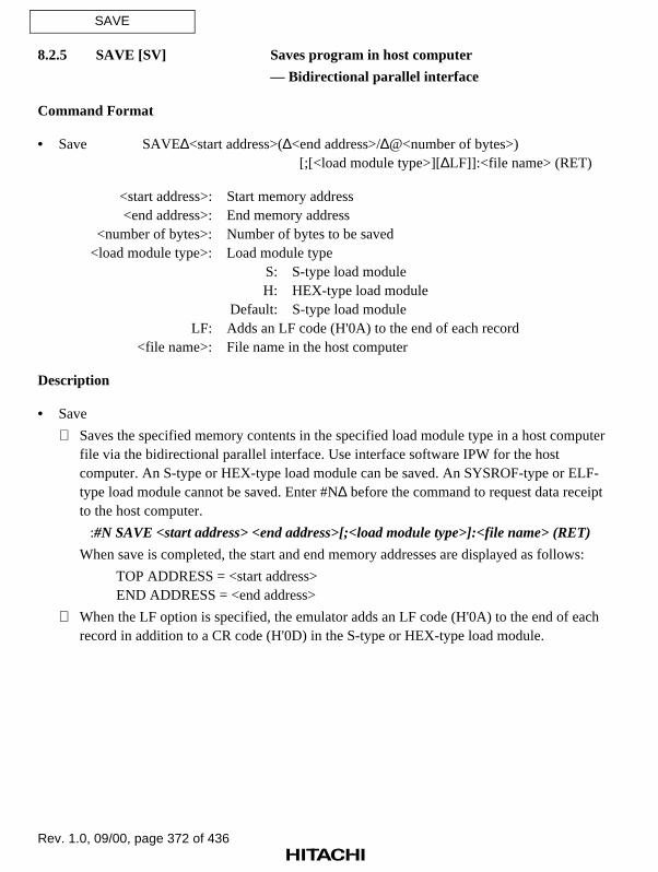
Rev. 1.0, 09/00, page 372 of 436
SAVE
8.2.5 SAVE [SV] Saves program in host computer
— Bidirectional parallel interface
Command Format
• Save SAVE∆<start address>(∆<end address>/∆@<number of bytes>)[;[<load module type>][∆LF]]:<file name> (RET)
<start address>: Start memory address<end address>: End memory address
<number of bytes>: Number of bytes to be saved<load module type>: Load module type
S: S-type load moduleH: HEX-type load module
Default: S-type load moduleLF: Adds an LF code (H'0A) to the end of each record
<file name>: File name in the host computer
Description
• Save
Saves the specified memory contents in the specified load module type in a host computerfile via the bidirectional parallel interface. Use interface software IPW for the hostcomputer. An S-type or HEX-type load module can be saved. An SYSROF-type or ELF-type load module cannot be saved. Enter #N∆ before the command to request data receiptto the host computer.
:#N SAVE <start address> <end address>[;<load module type>]:<file name> (RET)
When save is completed, the start and end memory addresses are displayed as follows:
TOP ADDRESS = <start address>END ADDRESS = <end address>
When the LF option is specified, the emulator adds an LF code (H'0A) to the end of eachrecord in addition to a CR code (H'0D) in the S-type or HEX-type load module.

Rev. 1.0, 09/00, page 373 of 436
SAVE
Notes
1. Data can be saved only in the internal memory areas or areas CS0 to CS3.
2. Verification is not performed after save. If the program must be verified, use the VERIFYcommand. For details, refer to section 8.2.6, VERIFY.
Example
To save memory contents in the address range from H'7000 to H'7FFF in host computer fileF11.MOT in the S-type load module format:
: #N SV 7000 7FFF :F11.MOT (RET) TOP ADDRESS = 00007000 END ADDRESS = 00007FFF:

Rev. 1.0, 09/00, page 374 of 436
VERIFY
8.2.6 VERIFY [V] Verifies memory contents against host
computer file
— Bidirectional parallel interface
Command Format
• Verification VERIFY [∆<offset>][;<load module type>]:<file name> (RET)
<offset>: Value to be added to the address<load module type>: Load module type
R: SYSROF-type load moduleS: S-type load moduleH: HEX-type load moduleM: Memory image fileE: ELF-type load module
Default: SYSROF-type load module<file name>: File name in the host computer
Description
• Verification
Verifies data transferred from the host computer against data in memory via thebidirectional parallel interface. Use interface software IPW for the host computer. Enter#B∆ before the command to request data output to the host computer.
:#B VERIFY[;<load module type>]:<file name> (RET)
If a verification error occurs, verification terminates immediately and the address and itscontents are displayed as follows. Note that only one verification error can be detected andits contents are displayed.
<ADDR> <FILE> <MEM>xxxxxxxx yy 'y' zz 'z'
xxxxxxxx: Verification error addressyy 'y': Load module data (in hexadecimal and ASCII characters)zz 'z': Memory data (in hexadecimal and ASCII characters)

Rev. 1.0, 09/00, page 375 of 436
VERIFY
An offset (value to be added or subtracted) can be specified for the address of an SYSROF-type, ELF-type, S-type, or HEX-type load module.
:#B VERIFY <offset> ;S :<file name> (RET)
If an offset is specified, a verification address is calculated as follows:
Verification address = <load module address> + <offset>
Note
Data can be verified only in the internal memory areas or areas CS0 to CS3.
Example
To verify SYSROF-type load module F1.ABS against the memory contents:
: #B V:F1.ABS (RET) <ADDR> <FILE> <MEM> 00001012 31'1' 00'.' TOP ADDRESS = 00000000 END ADDRESS = 00003FFF:

Rev. 1.0, 09/00, page 376 of 436

Rev. 1.0, 09/00, page 377 of 436
Section 9 Data Transfer from Host Computer Connectedby LAN Interface
9.1 Overview
The optional LAN board supports the FTP client function. This function enables the followingdata transfer between the emulator and the host computer connected via the LAN interface.
• Loads a load module file in the host computer to user system memory
• Saves data in the user system memory as a load module file in the host computer
• Transfers files between the emulator and host computer
The emulator supports the LAN commands listed in table 9.1 to transfer data between theemulator and the host computer. These commands are explained in section 9.3, LAN Commands.
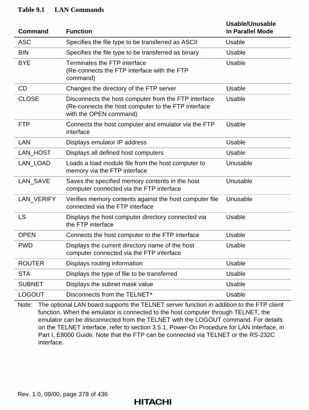
Rev. 1.0, 09/00, page 378 of 436
Table 9.1 LAN Commands
Command FunctionUsable/Unusablein Parallel Mode
ASC Specifies the file type to be transferred as ASCII Usable
BIN Specifies the file type to be transferred as binary Usable
BYE Terminates the FTP interface(Re-connects the FTP interface with the FTPcommand)
Usable
CD Changes the directory of the FTP server Usable
CLOSE Disconnects the host computer from the FTP interface(Re-connects the host computer to the FTP interfacewith the OPEN command)
Usable
FTP Connects the host computer and emulator via the FTPinterface
Usable
LAN Displays emulator IP address Usable
LAN_HOST Displays all defined host computers Usable
LAN_LOAD Loads a load module file from the host computer tomemory via the FTP interface
Unusable
LAN_SAVE Saves the specified memory contents in the hostcomputer connected via the FTP interface
Unusable
LAN_VERIFY Verifies memory contents against the host computer fileconnected via the FTP interface
Unusable
LS Displays the host computer directory connected viathe FTP interface
Usable
OPEN Connects the host computer to the FTP interface Usable
PWD Displays the current directory name of the hostcomputer connected via the FTP interface
Usable
ROUTER Displays routing information Usable
STA Displays the type of file to be transferred Usable
SUBNET Displays the subnet mask value Usable
LOGOUT Disconnects from the TELNET* Usable
Note: The optional LAN board supports the TELNET server function in addition to the FTP clientfunction. When the emulator is connected to the host computer through TELNET, theemulator can be disconnected from the TELNET with the LOGOUT command. For detailson the TELNET interface, refer to section 3.5.1, Power-On Procedure for LAN Interface, inPart I, E8000 Guide. Note that the FTP can be connected via TELNET or the RS-232Cinterface.

Rev. 1.0, 09/00, page 379 of 436
9.2 LAN Data Transfer
9.2.1 Setting the Data Transfer Environment
The optional LAN board enables data transfer between the emulator and host computer via theFTP interface. The transfer environment must be specified before starting data transfer as follows.Note that the optional LAN board supports the FTP client function only.
Procedure:
1. Specify the host computer environment, including the host computer name and IP address, tothe network database of the host computer. For details, refer to the appropriate host computer’sUser’s Manual.
2. Specify the following emulator environment:
a. Emulator IP address
Specify the emulator IP address with the emulator monitor command L. Since the emulatorIP address is written to the emulator flash memory, it needs not to be written each time theLAN interface is used. The emulator IP address can be modified as required.
b. Host computer IP address (host computer connected via FTP interface)
With the emulator monitor flash memory management tool command LH, specify thename and IP address of the host computer to be connected to the emulator via the FTPinterface when initiating the E8000 system program. Since the specified host name and IPaddress are written to the emulator flash memory, they need not to be written each time theLAN interface is used. The host computer name and IP address can be modified asrequired.

Rev. 1.0, 09/00, page 380 of 436
9.2.2 Data Transfer
Data transfer is performed by connecting the emulator to the host computer via the FTP interfaceafter the environmental settings have been completed. In the FTP interface, the optional LANboard supports only the client function. Therefore, the FTP command must be entered to theemulator and not the host computer to establish the FTP interface. Transfer data using thefollowing procedure.
Procedure:
1. E8000 system program initiation
Initiate the E8000 system program with the emulator monitor command S after confirmingthat the host computer to be connected has been defined with the emulator monitor flashmemory management tool command LH.
2. FTP connection
Connect the emulator to the designated host computer with the FTP command using the formatshown below. Enter the host computer name defined with the emulator monitor flash memorymanagement tool command LH. In addition, enter the user name and password.
:FTP <host computer name> (RET)
Username <user name> (RET)
Password <password> (RET)
login command success
FTP>
3. Transfer data using the LAN_LOAD, LAN_SAVE, or LAN_VERIFY command after the FTPinterface is established. For details, refer to the corresponding command descriptions.
9.2.3 Notes on FTP Interface
Before turning off the emulator power, the FTP interface must be terminated using the BYEcommand. Otherwise, the host computer interface processing may remain uncompleted. In thiscase, the FTP interface cannot be re-established correctly even if the emulator is re-initiated.
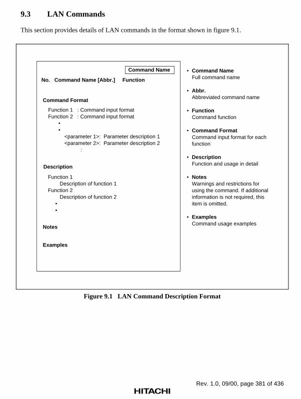
Rev. 1.0, 09/00, page 381 of 436
9.3 LAN Commands
This section provides details of LAN commands in the format shown in figure 9.1.
Command Format
Function 1 : Command input formatFunction 2 : Command input format • • <parameter 1>: Parameter description 1 <parameter 2>: Parameter description 2 :
Function 1 Description of function 1Function 2 Description of function 2 • •
Description
Notes
Examples
Command NameFull command name
Abbr.Abbreviated command name
FunctionCommand function
Command FormatCommand input format for eachfunction
DescriptionFunction and usage in detail
NotesWarnings and restrictions forusing the command. If additionalinformation is not required, thisitem is omitted.
ExamplesCommand usage examples
Command Name
No. Command Name [Abbr.] Function
•
•
•
•
•
•
•
Figure 9.1 LAN Command Description Format
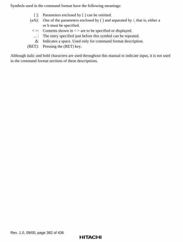
Rev. 1.0, 09/00, page 382 of 436
Symbols used in the command format have the following meanings:
[ ]: Parameters enclosed by [ ] can be omitted.(a/b): One of the parameters enclosed by ( ) and separated by /, that is, either a
or b must be specified.< >: Contents shown in < > are to be specified or displayed.... : The entry specified just before this symbol can be repeated.∆: Indicates a space. Used only for command format description.
(RET): Pressing the (RET) key.
Although italic and bold characters are used throughout this manual to indicate input, it is not usedin the command format sections of these descriptions.

Rev. 1.0, 09/00, page 383 of 436
ASC
9.3.1 ASC [ASC] Specifies the file type as ASCII
Command Format
• Setting ASC (RET)
Description
• Setting
Specifies the file type as ASCII in the FTP interface. To load an SYSROF-type load modulefile, binary must be specified with the BIN command.
Example
To set the file type as ASCII in the FTP interface:
FTP> ASC (RET) asc command successFTP>

Rev. 1.0, 09/00, page 384 of 436
BIN
9.3.2 BIN [BIN] Specifies the file type as binary
Command Format
• Setting BIN (RET)
Description
• Setting
Specifies the file type as binary in the FTP interface. This specification is required to transferfiles with the LAN_LOAD, LAN_SAVE, or LAN_VERIFY command. To load or verify anSYSROF-type load module file, binary must be specified with this command. Otherwise, atransfer error will occur. At emulator initiation, binary is the default setting.
Example
To set the file type as binary in the FTP interface:
FTP> BIN (RET) bin command successFTP>

Rev. 1.0, 09/00, page 385 of 436
BYE
9.3.3 BYE [BYE] Terminates the FTP interface
Command Format
• FTP interface termination BYE (RET)
Description
• FTP interface termination
Terminates the FTP interface and changes the prompt to a colon (:). To re-establish the FTPinterface, enter the FTP command. For details, refer to section 9.3.6, FTP.
Example
To terminate the FTP interface:
FTP> BYE (RET) bye command success:
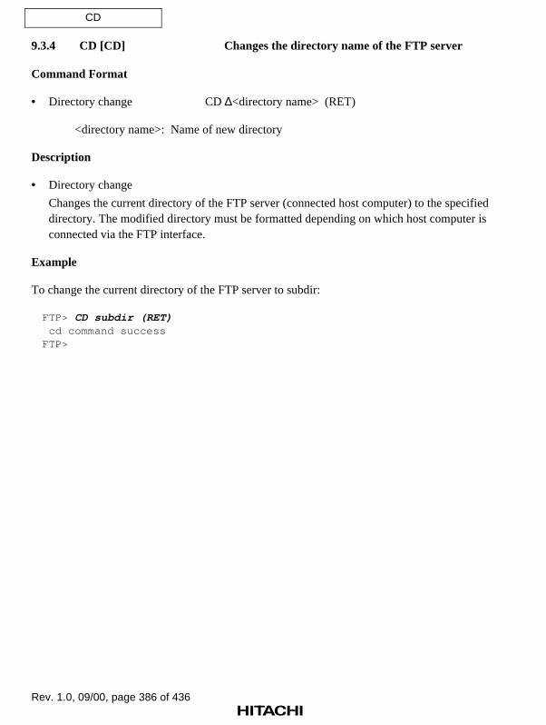
Rev. 1.0, 09/00, page 386 of 436
CD
9.3.4 CD [CD] Changes the directory name of the FTP server
Command Format
• Directory change CD ∆<directory name> (RET)
<directory name>: Name of new directory
Description
• Directory change
Changes the current directory of the FTP server (connected host computer) to the specifieddirectory. The modified directory must be formatted depending on which host computer isconnected via the FTP interface.
Example
To change the current directory of the FTP server to subdir:
FTP> CD subdir (RET) cd command successFTP>

Rev. 1.0, 09/00, page 387 of 436
CLOSE
9.3.5 CLOSE [CLOSE] Disconnects the host computer from the FTP
interface
Command Format
• FTP interface disconnection CLOSE (RET)
Description
• FTP interface disconnection
Disconnects the FTP interface from the host computer to which it is currently connected.Before changing host computers, disconnect the FTP interface with this command and re-connect with the OPEN command. For details, refer to section 9.3.13, OPEN.
Example
To disconnect the FTP interface and change the host computer to be connected:
FTP> CLOSE (RET) bye command successFTP> OPEN HOST1 (RET) Username ABC (RET) Password ****** (RET) login command successFTP>

Rev. 1.0, 09/00, page 388 of 436
FTP
9.3.6 FTP [FTP] Connects host computer and emulator via the
FTP interface
Command Format
• FTP interface connection FTP <host name> (RET)
<host name>: Name of the host computer to be connected with the FTP server(The host computer name must be already defined with theflash memory management tool.)
Description
• FTP interface connection
Connects the host computer and emulator via the FTP interface to enable data transfer withthe LAN_LOAD, LAN_SAVE, or LAN_VERIFY command. The host name specified inthis command must be defined with the flash memory management tool.
If <host name> has been defined, enter the user name and password in the followingformat. After FTP command execution, the prompt changes from a colon (:) to FTP>.Emulation commands can be executed even after FTP connection.
: FTP <host name> (RET) Username (a) (RET) Password (b) (RET) login command successFTP> (c)
(a) Enter user name.(b) Enter password.(c) An FTP> prompt is displayed after FTP connection.
Note
A password must be specified before a host computer can be connected via the FTP interface.
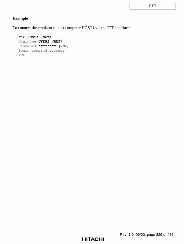
Rev. 1.0, 09/00, page 389 of 436
FTP
Example
To connect the emulator to host computer HOST1 via the FTP interface:
: FTP HOST1 (RET) Username USER1 (RET) Password ******** (RET) login command successFTP>

Rev. 1.0, 09/00, page 390 of 436
LAN
9.3.7 LAN [LAN] Displays emulator IP address
Command Format
• Display LAN (RET)
Description
• Display
Displays the emulator’s internet (IP) address stored in the emulator, in the followingformat:
: LAN (RET) E8000 INTERNET ADDRESS xxx.xxx.xxx.xxx
(a)
(a) Emulator IP address
Specify the emulator IP address with the emulator monitor command L.
Example
To display the emulator IP address:
: LAN (RET) E8000 INTERNET ADDRESS 128.1.1.10:

Rev. 1.0, 09/00, page 391 of 436
LAN_HOST
9.3.8 LAN_HOST [LH] Displays the names and IP addresses of
all defined host computers
Command Format
• Display LAN_HOST (RET)
Description
• Display
Displays the LAN host computer names and internet addresses defined in the emulator flashmemory in the following format:
: LAN_HOST (RET) NO <HOST NAME> <IP ADDRESS> NO <HOST NAME> <IP ADDRESS> 01 xxxxxx xxx.xxx.xxx.xxx 02 xxxxxx xxx.xxx.xxx.xxx 03 xxxxxx xxx.xxx.xxx.xxx 04 xxxxxx xxx.xxx.xxx.xxx 05 xxxxxx xxx.xxx.xxx.xxx 06 xxxxxx xxx.xxx.xxx.xxx 07 xxxxxx xxx.xxx.xxx.xxx 08 xxxxxx xxx.xxx.xxx.xxx 09 xxxxxx xxx.xxx.xxx.xxx
Example
To display all of the defined host computer names and IP addresses:
: LH (RET) NO <HOST NAME> <IP ADDRESS> NO <HOST NAME> <IP ADDRESS> 01 HOST1 128.1.1.1 02 HOST2 128.1.1.4 03 HOSTX 128.1.1.8 04 05 06 07 08 09:
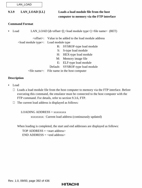
Rev. 1.0, 09/00, page 392 of 436
LAN_LOAD
9.3.9 LAN_LOAD [LL] Loads a load module file from the host
computer to memory via the FTP interface
Command Format
• Load LAN_LOAD [∆<offset>][;<load module type>]:<file name> (RET)
<offset>: Value to be added to the load module address<load module type>: Load module type
R: SYSROF-type load moduleS: S-type load moduleH: HEX-type load moduleM: Memory image fileE: ELF-type load module
Default: SYSROF-type load module<file name>: File name in the host computer
Description
• Load
Loads a load module file from the host computer to memory via the FTP interface. Beforeexecuting this command, the emulator must be connected to the host computer with theFTP command. For details, refer to section 9.3.6, FTP.
The current load address is displayed as follows:
LOADING ADDRESS = xxxxxxxx
xxxxxxxx: Current load address (continuously updated)
When loading is completed, the start and end addresses are displayed as follows:
TOP ADDRESS = <start address>END ADDRESS = <end address>

Rev. 1.0, 09/00, page 393 of 436
LAN_LOAD
An offset (value to be added) can be specified for the address of an SYSROF-type, ELF-type, S-type, or HEX-type load module.
: LAN_LOAD <offset> ;S:<file name> (RET)
If an offset is specified, a load address is calculated as follows:
Load address = <load module address> + <offset>
Notes
1. A load module file can be loaded only to the internal memory areas or areas CS0 to CS3.
2. Verification is not performed during load. If the program must be verified, use theLAN_VERIFY command. For details, refer to section 9.3.11, LAN_VERIFY.
3. Before loading an SYSROF-type load module, the file type must be changed to binary codewith the BIN command. At emulator initiation, binary code is selected as the default.However, if ASCII is selected with the ASC command, change the file type to binary codewith the BIN command before loading. For details, refer to section 9.3.2, BIN.
Example
To load an SYSROF-type load module, enter the following command line. F11.ABS indicates thehost computer file name. Before entering the LAN_LOAD command, connect the emulator to thehost computer with the FTP command:
: FTP HOST1 (RET) Username USER1 (RET) Password ******** (RET) login command successFTP> LL :F11.ABS (RET) LOADING ADDRESS 00007000 TOP ADDRESS = 00007000 END ADDRESS = 00007FFFFTP>

Rev. 1.0, 09/00, page 394 of 436
LAN_SAVE
9.3.10 LAN_SAVE [LSV] Saves the specified memory contents in the
host computer connected via the FTP interface
Command Format
• Save LAN_SAVE∆<start address>(∆<end address>/∆@<number of bytes>)[;[<load module type>][∆LF]]:<file name> (RET)
<start address>: Start memory address<end address>: End memory address
<number of bytes>: The number of bytes to be saved<load module type>: Load module type
S: S-type load moduleH: HEX-type load moduleM: Memory image file
Default: S-type load moduleLF: Adds an LF code (H'0A) to the end of each record
<file name>: File name in the host computer
Description
• Save
Saves the specified memory contents in the host computer connected via the FTP interface.An S-type, HEX-type, or M-type load module can be saved. An SYSROF-type or ELF-type load module cannot be saved. Before executing this command, connect the emulatorto the host computer with the FTP command.
The current save address is displayed as follows:
SAVING ADDRESS = xxxxxxxx
xxxxxxxx: Current save address (continuously updated)
When save is completed, the start and end memory addresses are displayed as follows:
TOP ADDRESS = <start address>END ADDRESS = <end address>

Rev. 1.0, 09/00, page 395 of 436
LAN_SAVE
When the LF option is specified, the emulator adds an LF code (H'0A) to the end of eachrecord in addition to a CR code (H'0D).
Notes
1. Data can be saved only in the internal memory areas or areas CS0 to CS3.
2. Verification is not performed after save. If the program must be verified, use theLAN_VERIFY command, if necessary. For details, refer to section 9.3.11, LAN_VERIFY.
Example
To save the memory contents in the address range from H'7000 to H'7FFF in the host computer asan S-type load module file (file name: F11.S), enter the following command line. Before enteringthe LAN_SAVE command, connect the emulator to the host computer with the FTP command:
: FTP HOST1 (RET) Username USER1 (RET) Password ******** (RET) login command successFTP>LSV 7000 7FFF :F11.S (RET) SAVING ADDRESS 00007000 TOP ADDRESS = 00007000 END ADDRESS = 00007FFFFTP>

Rev. 1.0, 09/00, page 396 of 436
LAN_VERIFY
9.3.11 LAN_VERIFY [LV] Verifies memory contents against the host
computer file connected via the FTP interface
Command Format
• Verification LAN_VERIFY [∆<offset>][;<load module type>]:<file name> (RET)
<offset>: Value to be added to the load module address<load module type>: Load module type
R: SYSROF-type load moduleS: S-type load moduleH: HEX-type load moduleM: Memory image fileE: ELF-type load module
Default: SYSROF-type load module<file name>: File name in the host computer
Description
• Verification
Verifies the file in the host computer connected via the FTP interface against data inmemory in the following format. Before executing this command, connect the emulator tothe host computer with the FTP command.
FTP> LAN_VERIFY <load module type>:<file name> (RET)
If a verification error occurs, the address and its contents are displayed as follows:
<ADDR> <FILE> <MEM>xxxxxxxx yy 'y' zz 'z'
xxxxxxxx: Verification error addressyy 'y': Load module data (in hexadecimal and ASCII characters)zz 'z': Memory data (in hexadecimal and ASCII characters)

Rev. 1.0, 09/00, page 397 of 436
LAN_VERIFY
An offset (value to be added or subtracted) can be specified for the address of an SYSROF-type, ELF-type, S-type, or HEX-type load module.
FTP> LAN_VERIFY <offset> ;S :<file name> (RET)
If an offset is specified, a verification address is calculated as follows:
Verification address = <load module address> + <offset>
Notes
1. Data can be verified only in the internal memory areas or areas CS0 to CS3.
2. Before verifying an SYSROF-type load module, the file type must be changed to binary codewith the BIN command. At emulator initiation, binary code is selected as the default.However, if ASCII is selected with the ASC command, change the file type to binary codewith the BIN command before verifying. For details, refer to section 9.3.2, BIN.
Example
To verify SYSROF-type load module file F11.ABS in the host computer against the memorycontents:
: FTP HOST1 (RET) Username USER1 (RET) Password ******** (RET) login command successFTP>LV :F11.ABS (RET) VERIFYING ADDRESS 00000C00 TOP ADDRESS = 00000000 END ADDRESS = 00000FFFFTP>

Rev. 1.0, 09/00, page 398 of 436
LS
9.3.12 LS [LS] Displays the host computer directory connected
via the FTP interface
Command Format
• Display LS [∆ <directory name>] (RET)
<directory name>: Name of host computer directory(Default: Current directory of the host computer)
Description
• Display
Displays the specified directory contents in the host computer connected via the FTP interface.If <directory name> is omitted, the current directory contents are displayed. Note that thedirectory name must be specified according to the connected host computer format.
Example
To display the contents of the host computer current directory:
FTP>LS (RET)abc.sxyzFTP>

Rev. 1.0, 09/00, page 399 of 436
OPEN
9.3.13 OPEN [OPEN] Connects the host computer to the FTP
interface
Command Format
• FTP interface connection OPEN <host name> (RET)
<host name>: Name of the host computer to be connected via the FTP interface(The host computer name must be already defined with the flashmemory management tool.)
Description
• FTP interface connection
Connects the emulator to the specified host computer via the FTP interface. This command canalso be used to change the host computer connected to the emulator. To change the hostcomputer, first disconnect the current host computer using the CLOSE command and thenconnect the new host computer using this command.
FTP>OPEN <host name> (RET) Username (a) (RET) Password (b) (RET) login command success
FTP>
(a) Enter user name.(b) Enter password.
Note
A password must be specified before a host computer can be connected via the FTP interface.

Rev. 1.0, 09/00, page 400 of 436
OPEN
Example
To disconnect the emulator from the current host computer and connect it to the new hostcomputer HOST1:
FTP>CLOSE (RET) bye command successFTP>OPEN HOST1 (RET) Username USER1 (RET) Password ******** (RET) login command successFTP>

Rev. 1.0, 09/00, page 401 of 436
PWD
9.3.14 PWD [PWD] Displays the current directory name of the host
computer connected via the FTP interface
Command Format
• Display PWD (RET)
Description
• Display
Displays the current directory name of the host computer connected via the FTP interface.
Example
To display the current directory name of the host computer connected via the FTP interface:
FTP>PWD (RET)/usr/e8000FTP>

Rev. 1.0, 09/00, page 402 of 436
ROUTER
9.3.15 ROUTER [RTR] Displays the remote network routing information
Command Format
• Display ROUTER (RET)
Description
• Display
Displays the routing information defined with the emulator monitor flash memorymanagement tool command RTR.
Note
Routing information can be defined with the emulator monitor flash memory management toolcommand RTR.
Example
To display the defined routing information:
: RTR (RET) No. IP-ADDRESS NET-ID No. IP-ADDRESS NET-ID 01 128.1.1.80 168.1.1.0 02 128.1.1.50 160.1.1.0:

Rev. 1.0, 09/00, page 403 of 436
STA
9.3.16 STA [STA] Displays the file type to be transferred
Command Format
• Display STA (RET)
Description
• Display
Displays in the following format, the file type (binary or ASCII) to be transferred by theLAN_LOAD, LAN_SAVE, or LAN_VERIFY command.
FTP>STA (RET)type mode is BINARY (Binary)
FTP>STA (RET)type mode is ASCII (ASCII)
Example
To display the file type to be transferred:
FTP>STA (RET) type mode is BINARYFTP>

Rev. 1.0, 09/00, page 404 of 436
SUBNET
9.3.17 SUBNET [SN] Displays the subnet mask value
Command Format
• Display SUBNET (RET)
Description
• Display
Displays the subnet mask value defined with the emulator monitor flash memory managementtool command SN.
: SUBNET (RET) SUBNET MASK xxx.xxx.xxx.xxx (H'yy.H'yy.H'yy.H'yy)
(a) (b)
(a) Subnet mask value (in decimal)(b) Subnet mask value (in hexadecimal)
Note
The subnet mask value can be defined with the emulator monitor flash memory management toolcommand SN.
Example
To display the defined subnet mask value:
: SN (RET) SUBNET MASK 255.255.255.128 (H'FF.H'FF.H'FF.H'80):

Rev. 1.0, 09/00, page 405 of 436
LOGOUT
9.3.18 LOGOUT [LO] Disconnects from the TELNET
Command Format
• TELNET disconnection LOGOUT (RET)
Description
• TELNET disconnection
Disconnects the emulator from the TELNET. This command is valid only when the emulatoris connected to the host computer via the TELNET interface.
Example
To disconnect the emulator from the TELNET interface:
: LO (RET)

Rev. 1.0, 09/00, page 406 of 436

Part III Appendix

Rev. 1.0, 09/00, page 408 of 436

Rev. 1.0, 09/00, page 409 of 436
Appendix A Connectors
A.1 Serial Connector
Figure A.1 shows the serial connector pin alignment in the emulator station. Table A.1 lists signalnames and their usage.
12
34
5
67
89
SE
RIA
L
Figure A.1 Serial Connector Pin Alignment at the Emulator Station
Table A.1 Signal Names and Usage of Serial Connector
Pin No. Signal name Usage
1 — Not connected
2 Receive Data (RD) Data receive line
3 Transmit Data (TD) Data transmit line
4 Data Terminal Ready (DTR) High when emulator’s power is on.
5 Ground (GND) Connected to the emulator’s frame ground.
6 Data Set Ready (DSR) Not connected
7 Request To Send (RTS) High when emulator’s power is on.
8 Clear To Send (CTS) Not connected
9 — Not connected

Rev. 1.0, 09/00, page 410 of 436
A.2 Parallel Connector
Figure A.2 shows the parallel connector pin alignment at the emulator station. Table A.2 listssignal names.
1
18
19
36
PA
RA
LLEL
Figure A.2 Parallel Connector Pin Alignment at the Emulator Station

Rev. 1.0, 09/00, page 411 of 436
Table A.2 Signal Names of Parallel Connector
Pin No. Signal Name Pin No. Signal Name
1 PeriphAck 19 SignalGround
2 Xflag 20 SignalGround
3 PeriphClk 21 SignalGround
4 nPeriphRequest 22 SignalGround
5 nAckReverse 23 SignalGround
6 Data1 (LSB) 24 SignalGround
7 Data2 25 SignalGround
8 Data3 26 SignalGround
9 Data4 27 SignalGround
10 Data5 28 SignalGround
11 Data6 29 SignalGround
12 Data7 30 SignalGround
13 Data8 (MSB) 31 SignalGround
14 nReverseRequest 32 SignalGround
15 HostClk 33 SignalGround
16 IEEE1284 active 34 SignalGround
17 HostAck 35 SignalGround
18 HostLogicHigh 36 PeripheralLogicHigh
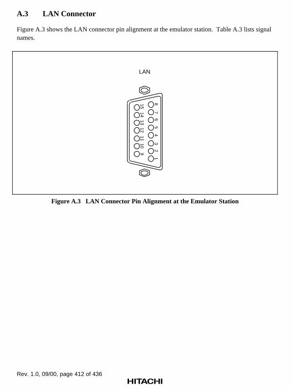
Rev. 1.0, 09/00, page 412 of 436
A.3 LAN Connector
Figure A.3 shows the LAN connector pin alignment at the emulator station. Table A.3 lists signalnames.
LAN
87
65
4
1514
1312
32
1
1110
9
Figure A.3 LAN Connector Pin Alignment at the Emulator Station
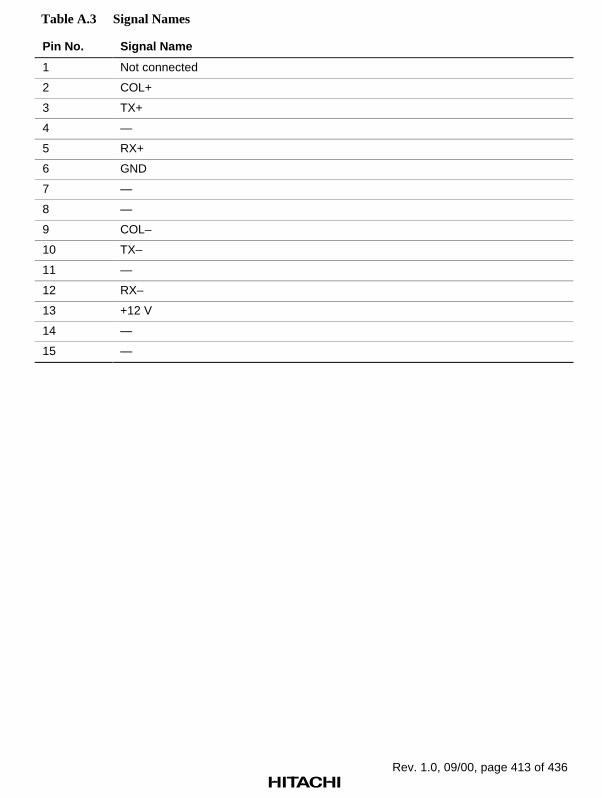
Rev. 1.0, 09/00, page 413 of 436
Table A.3 Signal Names
Pin No. Signal Name
1 Not connected
2 COL+
3 TX+
4 —
5 RX+
6 GND
7 —
8 —
9 COL–
10 TX–
11 —
12 RX–
13 +12 V
14 —
15 —

Rev. 1.0, 09/00, page 414 of 436
A.4 Serial Interface Cable
Figure A.4 shows the wiring for the serial interface cable.
RD
TD
DTR
GND
DSR
RTS
CTS
RD
TD
DTR
GND
DSR
RTS
CTS
2
3
4
5
6
7
8
2
3
4
5
6
7
8
IBM PC Emulator(serial connector)
(The numbers represent connector pin numbers.)
Figure A.4 Serial Interface Cable
Note that the serial interface cable provided may not be suitable for some host computers. In thatcase, use the wiring shown in figure A.5.

Rev. 1.0, 09/00, page 415 of 436
RD
TD
GND
RD
TD
GND
2
3
5
2
3
5
PC Emulator(serial connector)
(The numbers represent connector pin numbers.)
(a) X-ON, X-OFF control
RD
TD
GND
DSR
RTS
CTS
RD
TD
DTR
GND
RTS
CTS
2
3
5
6
7
8
2
3
4
5
7
8
PC Emulator(serial connector)
(The numbers represent connector pin numbers.)
(b) RTS, CTS control
Figure A.5 Serial Interface Cable (Using Other Cables)

Rev. 1.0, 09/00, page 416 of 436
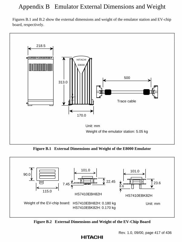
Rev. 1.0, 09/00, page 417 of 436
Appendix B Emulator External Dimensions and Weight
Figures B.1 and B.2 show the external dimensions and weight of the emulator station and EV-chipboard, respectively.
170.0
313.0500
Trace cable
Weight of the emulator station: 5.05 kg
Unit: mm
POWER
E8000
HITACHI
218.5
RUN
..
.
Figure B.1 External Dimensions and Weight of the E8000 Emulator
115.0
90.0
22.45
101.0
7.45
HS7410EBH82H
23.6
101.0
8.6
HS7410EBK82H
Weight of the EV-chip board: HS7410EBH82H: 0.180 kgHS7410EBK82H: 0.170 kg
Unit: mm
Figure B.2 External Dimensions and Weight of the EV-Chip Board

Rev. 1.0, 09/00, page 418 of 436

Rev. 1.0, 09/00, page 419 of 436
Appendix C Connecting the Emulator to the User System
C.1 Connecting to the User System
WARNINGAlways switch OFF the emulator and user system beforeconnecting or disconnecting any CABLES.Failure to do so will result in a FIRE HAZARD, and willdamage the user system or emulator or result in PERSONALINJURY. Also, the USER PROGRAM will be LOST.
The emulator is connected to the user system by using the QFP-type EV-chip board(HS7410EBH82H) or the connector-type EV-chip board (HS7410EBK82H).
Table C.1 EV-Chip Boards and User Interfaces
EV-Chip board User interface
HS7410EBH82H 176-pin QFP (NQPACK176SD)
HS7410EBK82H Specific connector (FX2-100P-1.27SVL) x 2
Note: The NQPACK176SD is manufactured by TOKYO ELETECH CORPORATION. The FX2-100P-1.27SVL is manufactured by Hirose Electric Co., Ltd.

Rev. 1.0, 09/00, page 420 of 436
C.1.1 Connection Using the HS7410EBH82H
WARNINGAlways switch OFF the emulator and user system beforeconnecting or disconnecting any CABLES.Failure to do so will result in a FIRE HAZARD, and willdamage the user system or emulator or result in PERSONALINJURY. Also, the USER PROGRAM will be LOST.
Notes: 1. For more details on the HS7410EBH82H, refer to the user’s manual supplied withthe EV-chip board.
2. This EV-chip board can only be used in combination with the specific QFP socket(NQPACK176SD).
Mount the 176-pin QFP socket (NQPACK176SD manufactured by TOKYO ELETECHCORPORATION) on the user system to connect the emulator. Pin assignment is the same as forthe actual SH7410 chip. Refer to the Pin Assignment in the SH7410 Hardware Manual.
Figure C.1 shows the connection of the HS7410EBH82H, figure C.2 shows the size restriction forthe installed components of the HS7410EBH82H, and figure C.3 shows the connector installationlocation on the user system.

Rev. 1.0, 09/00, page 421 of 436
The four corners ofHS7410PWB30H and the QFP connection part must be fixed with screws.
@
User system
HS7410PWB20H
HS7410PWB30H
Figure C.1 Connection of the HS7410EBH82H
EV-chip boardHS7410EBH82H
User system socketNQPACK176SD (TOKYO ELETECH CORPORATION)
User system board
10.2
Unit: mm
Figure C.2 Component Installation Size Restriction
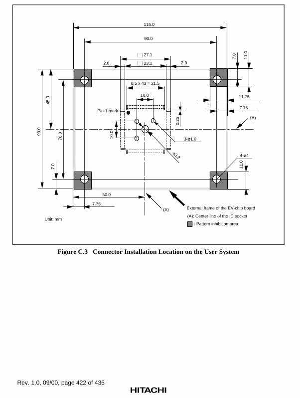
Rev. 1.0, 09/00, page 422 of 436
115.0
50.0
45.0
76.0
4-ø4
10.0
10.0
3-ø1.0
0.5 x 43 = 21.5
23.1
27.1
0.25
2.02.0
ø3.2
90.0
External frame of the EV-chip board
Pin-1 mark
90.0
7.0
7.75
7.75
(A)
(A)
11.75
11.0
11.0
7.0
(A): Center line of the IC socket
: Pattern inhibition areaUnit: mm
Figure C.3 Connector Installation Location on the User System
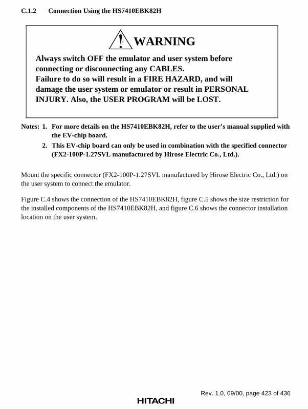
Rev. 1.0, 09/00, page 423 of 436
C.1.2 Connection Using the HS7410EBK82H
WARNINGAlways switch OFF the emulator and user system beforeconnecting or disconnecting any CABLES.Failure to do so will result in a FIRE HAZARD, and willdamage the user system or emulator or result in PERSONALINJURY. Also, the USER PROGRAM will be LOST.
Notes: 1. For more details on the HS7410EBK82H, refer to the user’s manual supplied withthe EV-chip board.
2. This EV-chip board can only be used in combination with the specified connector(FX2-100P-1.27SVL manufactured by Hirose Electric Co., Ltd.).
Mount the specific connector (FX2-100P-1.27SVL manufactured by Hirose Electric Co., Ltd.) onthe user system to connect the emulator.
Figure C.4 shows the connection of the HS7410EBK82H, figure C.5 shows the size restriction forthe installed components of the HS7410EBK82H, and figure C.6 shows the connector installationlocation on the user system.

Rev. 1.0, 09/00, page 424 of 436
User system
HS7410PWB20H
HS7410PWB40H
USER IF1
USER IF2
Connector:FX2-100P-1.27SVL(Hirose Electric Co., Ltd.)
Figure C.4 Connection of the HS7410EBK82H
EV-chip boardHS7410EBK82H
User system socketFX2-100P-1.27SVL(Hirose Electric Co., Ltd.)
User system board
10.2
Unit: mm
Figure C.5 Component Installation Size Restriction

Rev. 1.0, 09/00, page 425 of 436
2-1.9+0.1
-0
1.1
(0.8)
62.23 ± 0.1
67.31 ± 0.1
71.95 ± 0.1
43.0
3.3
3.1
P = 1.27 ± 0.05
66.5
23.5
57.5
External frame ofthe EV-chip board
Connector center line
115.0
90.0
USERIF2
USERIF1
Unit: mmTolerance: ±0.1
Figure C.6 Connector Installation Location on the User System
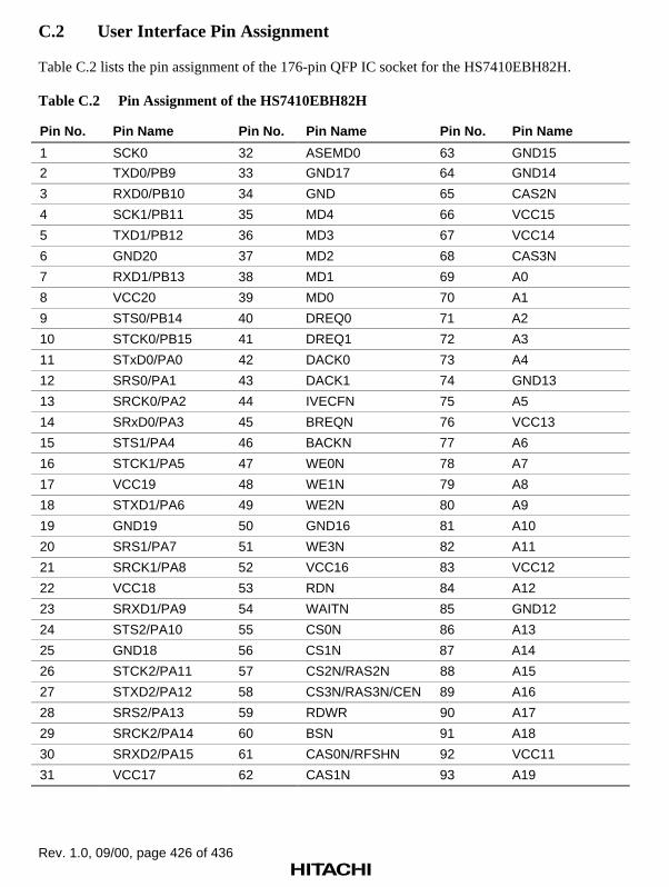
Rev. 1.0, 09/00, page 426 of 436
C.2 User Interface Pin Assignment
Table C.2 lists the pin assignment of the 176-pin QFP IC socket for the HS7410EBH82H.
Table C.2 Pin Assignment of the HS7410EBH82H
Pin No. Pin Name Pin No. Pin Name Pin No. Pin Name
1 SCK0 32 ASEMD0 63 GND15
2 TXD0/PB9 33 GND17 64 GND14
3 RXD0/PB10 34 GND 65 CAS2N
4 SCK1/PB11 35 MD4 66 VCC15
5 TXD1/PB12 36 MD3 67 VCC14
6 GND20 37 MD2 68 CAS3N
7 RXD1/PB13 38 MD1 69 A0
8 VCC20 39 MD0 70 A1
9 STS0/PB14 40 DREQ0 71 A2
10 STCK0/PB15 41 DREQ1 72 A3
11 STxD0/PA0 42 DACK0 73 A4
12 SRS0/PA1 43 DACK1 74 GND13
13 SRCK0/PA2 44 IVECFN 75 A5
14 SRxD0/PA3 45 BREQN 76 VCC13
15 STS1/PA4 46 BACKN 77 A6
16 STCK1/PA5 47 WE0N 78 A7
17 VCC19 48 WE1N 79 A8
18 STXD1/PA6 49 WE2N 80 A9
19 GND19 50 GND16 81 A10
20 SRS1/PA7 51 WE3N 82 A11
21 SRCK1/PA8 52 VCC16 83 VCC12
22 VCC18 53 RDN 84 A12
23 SRXD1/PA9 54 WAITN 85 GND12
24 STS2/PA10 55 CS0N 86 A13
25 GND18 56 CS1N 87 A14
26 STCK2/PA11 57 CS2N/RAS2N 88 A15
27 STXD2/PA12 58 CS3N/RAS3N/CEN 89 A16
28 SRS2/PA13 59 RDWR 90 A17
29 SRCK2/PA14 60 BSN 91 A18
30 SRXD2/PA15 61 CAS0N/RFSHN 92 VCC11
31 VCC17 62 CAS1N 93 A19

Rev. 1.0, 09/00, page 427 of 436
Table C.2 Pin Assignment of the HS7410EBH82H (cont)
Pin No. Pin Name Pin No. Pin Name Pin No. Pin Name
94 GND11 122 D31 150 D9
95 A20 123 D30 151 D8
96 A21 124 D29 152 D7
97 A22 125 D28 153 VCC4
98 A23 126 D27 154 VCC3
99 TDO 127 VCC7 155 D6
100 VCC10 128 D26 156 GND4
101 TDI 129 GND7 157 GND3
102 GND10 130 D25 158 D5
103 TMS 131 D24 159 D4
104 PLLGND 132 D23 160 D3
105 PLLCAP 133 D22 161 D2
106 PLLVCC 134 D21 162 D1
107 EXTAL 135 D20 163 VCC2
108 XTAL 136 VCC6 164 D0
109 TRSTN 137 D19 165 GND2
110 VCC9 138 GND6 166 FTI0/FTOB0/PB0
111 VCC8 139 D18 167 FTOA0/PB1
112 TCK 140 D17 168 FTC0/PB2
113 GND9 141 D16 169 FTI1/FTOB1/PB3
114 GND8 142 D15 170 VCC1
115 CLK 143 D14 171 FTOA1/PB4
116 NMI 144 D13 172 GND1
117 RSTN 145 VCC5 173 FTC1/PB5
118 IRQ0 146 D12 174 FTI2/FTOB2/PB6
119 IRQ1 147 GND5 175 FTOA2/PB7
120 IRQ2 148 D11 176 FTC2/PB8
121 IRQ3 149 D10

Rev. 1.0, 09/00, page 428 of 436
Tables C.3 and C.4 list the pin assignment of the 100-pin connector for the HS7410EBK82H.
Table C.3 Pin Assignment of the HS7410EBK82H User Interface (USER I/F1)
Pin No. Pin Name Pin No. Pin Name Pin No. Pin Name
1 GND 35 GND 69 GND
2 GND 36 SRS0/PA1 70 DREQ0
3 CAS3 37 SRS1/PA0 71 MD0
4 CAS2 38 GND 72 GND
5 GND 39 RXD1/PB13 73 MD3
6 BS 40 TXD1/PB12 74 MD4
7 RDWR 41 GND 75 GND
8 GND 42 TXD0/PB9 76 SRXD2/PA15
9 CS1 43 SCK0 77 SRCK2/PA14
10 CS0 44 GND 78 GND
11 GND 45 FTI2/PB6 79 STCK2/PA11
12 WE3 46 FTC1/PB5 80 STS2/PA10
13 WE2 47 GND 81 GND
14 GND 48 FTC0/PB2 82 SRS1/PA7
15 BACK 49 FTOA0/PB1 83 STXD1/PA6
16 BREQ 50 GND 84 GND
17 GND 51 Not connected 85 SRXD0/PA3
18 DACK0 52 UVCC 86 SRCK0/PA2
19 DREQ1 53 Not connected 87 GND
20 GND 54 GND 88 STCK0/PB15
21 MD1 55 CAS1 89 STS0/PB14
22 MD2 56 CAS0 90 GND
23 GND 57 GND 91 SCK1/PB11
24 MD5 58 CS3 92 RXD0/PB10
25 ASEMD0 59 CS2 93 GND
26 GND 60 GND 94 FTC2/PB8
27 SRS2/PA13 61 WAIT 95 FTOA2/PB7
28 STXD2/PA12 62 RD 96 GND
29 GND 63 GND 97 FTOA1/PB4
30 SRXD1/PA9 64 WE1 98 FTI1/PB3
31 SRCK1/PA8 65 WE0 99 GND
32 GND 66 GND 100 FTI0/PB0
33 STCK1/PA5 67 IVECF
34 STS1/PA4 68 DACK1
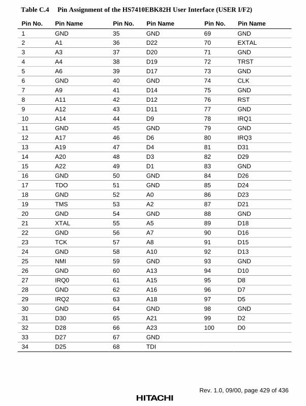
Rev. 1.0, 09/00, page 429 of 436
Table C.4 Pin Assignment of the HS7410EBK82H User Interface (USER I/F2)
Pin No. Pin Name Pin No. Pin Name Pin No. Pin Name
1 GND 35 GND 69 GND
2 A1 36 D22 70 EXTAL
3 A3 37 D20 71 GND
4 A4 38 D19 72 TRST
5 A6 39 D17 73 GND
6 GND 40 GND 74 CLK
7 A9 41 D14 75 GND
8 A11 42 D12 76 RST
9 A12 43 D11 77 GND
10 A14 44 D9 78 IRQ1
11 GND 45 GND 79 GND
12 A17 46 D6 80 IRQ3
13 A19 47 D4 81 D31
14 A20 48 D3 82 D29
15 A22 49 D1 83 GND
16 GND 50 GND 84 D26
17 TDO 51 GND 85 D24
18 GND 52 A0 86 D23
19 TMS 53 A2 87 D21
20 GND 54 GND 88 GND
21 XTAL 55 A5 89 D18
22 GND 56 A7 90 D16
23 TCK 57 A8 91 D15
24 GND 58 A10 92 D13
25 NMI 59 GND 93 GND
26 GND 60 A13 94 D10
27 IRQ0 61 A15 95 D8
28 GND 62 A16 96 D7
29 IRQ2 63 A18 97 D5
30 GND 64 GND 98 GND
31 D30 65 A21 99 D2
32 D28 66 A23 100 D0
33 D27 67 GND
34 D25 68 TDI
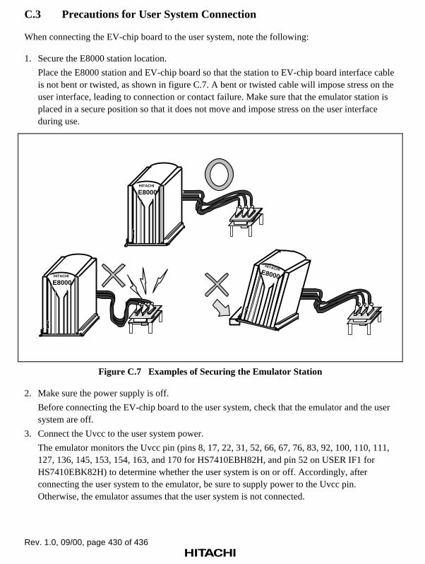
Rev. 1.0, 09/00, page 430 of 436
C.3 Precautions for User System Connection
When connecting the EV-chip board to the user system, note the following:
1. Secure the E8000 station location.
Place the E8000 station and EV-chip board so that the station to EV-chip board interface cableis not bent or twisted, as shown in figure C.7. A bent or twisted cable will impose stress on theuser interface, leading to connection or contact failure. Make sure that the emulator station isplaced in a secure position so that it does not move and impose stress on the user interfaceduring use.
HITACHI
E8000
POWER
RUN
HITACHIE8000
POWER
RUN
HITACHI
E8000
POWER
RUN
Figure C.7 Examples of Securing the Emulator Station
2. Make sure the power supply is off.
Before connecting the EV-chip board to the user system, check that the emulator and the usersystem are off.
3. Connect the Uvcc to the user system power.
The emulator monitors the Uvcc pin (pins 8, 17, 22, 31, 52, 66, 67, 76, 83, 92, 100, 110, 111,127, 136, 145, 153, 154, 163, and 170 for HS7410EBH82H, and pin 52 on USER IF1 forHS7410EBK82H) to determine whether the user system is on or off. Accordingly, afterconnecting the user system to the emulator, be sure to supply power to the Uvcc pin.Otherwise, the emulator assumes that the user system is not connected.
Rev. 1.0, 09/00, page 431 of 436
Appendix D Memory Map
The SH7410 has two memory map modes: internal CS0 memory mode and external CS0 memorymode. Figures D.1 and D.2 show the corresponding memory maps. The peripheral moduleregisters are allocated from H'0C000000 to H'0DFFFFFF regardless of memory map mode.

Rev. 1.0, 09/00, page 432 of 436
H'0000000
H'0006000
H'000F000
H'0010000
H'0016000
H'001F000
H'0020000
H'1000000
H'2000000
H'3000000
H'4000000
H'C000000*
H'D000000
H'E000000
H'FFFFFFF
Exception vector (1 kbyte)X-ROM (24 kbytes)
Y-RAM (4 kbytes)
External memory CS1 (16 Mbytes)
External memory CS2 (16 Mbytes)
External memory CS3 (16 Mbytes)
I-bus module (16 Mbytes)
P-bus module (16 Mbytes)
X-RAM (4 kbytes)
Y-ROM (24 kbytes)
Reserved
Reserved
Reserved
Reserved
Reserved
External area, burst ROM(16 Mbytes)
External area, ED0 or DRAM area (16 Mbytes)
External area, ED0, DRAM or pseudo SRAM area (16 Mbytes)
Note: When accessing H'C000000 and the subsequent addresses, do not use the commands other than the DUMP and MEMORY commands.
Figure D.1 Memory Map for Internal CS0 Memory Mode

Rev. 1.0, 09/00, page 433 of 436
H'0000000
H'0000400
H'1000000
H'2000000
H'3000000
H'4000000
H'8000000
H'8006000
H'800F000
H'8010000
H'8016000
H'801F000
H'8020000
H'C000000
H'D000000
H'E000000
H'FFFFFFF
Exception vector CS0 (1 kbyte)
External memory CS0 (16 Mbytes)
External memory CS1 (16 Mbytes)
External memory CS2 (16 Mbytes)
External memory CS3 (16 Mbytes)
I-bus module (16 Mbytes)
P-bus module (16 Mbytes)
X-ROM (24 kbytes)
Y-RAM (4 kbytes)
X-RAM (4 kbytes)
Y-ROM (24 kbytes)
Reserved
Reserved
Reserved
Reserved
Reserved
External area, burst ROM(16 Mbytes)
External area, ED0 or DRAM area (16 Mbytes)
External area, ED0, DRAM or pseudo SRAM area (16 Mbytes)
Exception vector (1 kbyte)
External area, burst ROM(16 Mbytes)
Figure D.2 Memory Map for External CS0 Memory Mode

Rev. 1.0, 09/00, page 434 of 436
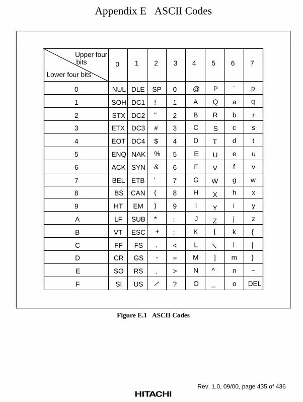
Rev. 1.0, 09/00, page 435 of 436
Appendix E ASCII Codes
Upper four bits
Lower four bits
0 1 2 3 4 5 6 7
NUL
SOH
STX
ETX
EOT
ENQ
ACK
BEL
BS
HT
LF
VT
FF
CR
SO
SI
DLE
DC1
DC2
DC3
DC4
NAK
SYN
ETB
CAN
EM
SUB
ESC
FS
GS
RS
US
SP
!
"
#
$
%
&
'
(
)
*
+
,
-
.
0
1
2
3
4
5
6
7
8
9
:
;
<
=
>
?
@
A
B
C
D
E
F
G
H
I
J
K
L
M
N
O
P
Q
R
S
T
U
V
W
X
Y
Z
[
]
^
_
a
b
c
d
e
f
g
h
i
j
k
l
m
n
o
p
q
r
s
t
u
v
w
x
y
z
|
~
DEL
0
1
2
3
4
5
6
7
8
9
A
B
C
D
E
F
`
Figure E.1 ASCII Codes

Rev. 1.0, 09/00, page 436 of 436

SH7410 E8000 Emulator HS7410EDD82H User’s Manual
Publication Date: 1st Edition, September 2000Published by: Electronic Devices Sales & Marketing Group Semiconductor & Integrated Circuits Hitachi, Ltd.Edited by: Technical Documentation Group Hitachi Kodaira Semiconductor Co., Ltd.Copyright © Hitachi, Ltd., 2000. All rights reserved. Printed in Japan.