SESAR AeroMACS Safety and Security Analysis - ICAO
258
(2 pages) ACPWGS5_IP09 - SESAR AeroMACS Safety and Security Analysis AERONAUTICAL COMMUNICATIONS PANEL (ACP) Fifth Meeting of the Surface Datalink Working Group Montreal, Canada 14-15 July 2014 Agenda Item 3: Status of relevant work by states and organisations SESAR project P15.02.07 Deliverable D08: AeroMACS Safety and Security Analysis Presented by EUROCONTROL on behalf of the SESAR P15.02.07 Partners SUMMARY This Information Paper provides the final Deliverable out of the SESAR Project P15.2.7 task addressing the AeroMACS safety and security aspects. ACTION The AeroMACS Working Group is invited to take note of the information in the deliverable and considering as required in the further development of the ICAO material (SARPs and Technical Manual). 1. INTRODUCTION: 1.1 The SESAR projects P19.16 and P15.02.07 are supporting the AeroMACS development and have undertaken various activities such as analysis, investigations, prototype building, testing and validation. A key objective of the SESAR activities is to support the standardization activities in ICAO, EUROCAE/RTCA, AEEC etc. 1.2 Project P15.02.07 involves AENA, AIRBUS, DSNA, EUROCONTROL, NATMIG, SELEX ES and THALES and INDRA is the project manager. One of the tasks in the P15.02.07 project (WA08: “Safety and Security Analysis”) performed an analysis of the AeroMACS data link system aiming to identify the impact on security and safety issues. Deliverable D08 is the outcome of this work. International Civil Aviation Organization WORKING PAPER ACP-WG-S/5 IP-09 15/07/2014
-
Upload
khangminh22 -
Category
Documents
-
view
0 -
download
0
Transcript of SESAR AeroMACS Safety and Security Analysis - ICAO
(2 pages) ACPWGS5_IP09 - SESAR AeroMACS Safety and Security Analysis
AERONAUTICAL COMMUNICATIONS PANEL (ACP)
Fifth Meeting of the Surface Datalink Working Group
Montreal, Canada 14-15 July 2014
Agenda Item 3: Status of relevant work by states and organisations
SESAR project P15.02.07 Deliverable D08: AeroMACS Safety and Security Analysis
Presented by EUROCONTROL on behalf of the SESAR P15.02.07 Partners
SUMMARY
This Information Paper provides the final Deliverable out of the SESAR Project P15.2.7 task addressing the AeroMACS safety and security aspects.
ACTION
The AeroMACS Working Group is invited to take note of the information in the deliverable and considering as required in the further development of the ICAO material (SARPs and Technical Manual).
1. INTRODUCTION:
1.1 The SESAR projects P19.16 and P15.02.07 are supporting the AeroMACS development and have undertaken various activities such as analysis, investigations, prototype building, testing and validation. A key objective of the SESAR activities is to support the standardization activities in ICAO, EUROCAE/RTCA, AEEC etc.
1.2 Project P15.02.07 involves AENA, AIRBUS, DSNA, EUROCONTROL, NATMIG, SELEX ES and THALES and INDRA is the project manager. One of the tasks in the P15.02.07 project (WA08: “Safety and Security Analysis”) performed an analysis of the AeroMACS data link system aiming to identify the impact on security and safety issues. Deliverable D08 is the outcome of this work.
International Civil Aviation Organization WORKING PAPER
ACP-WG-S/5 IP-09 15/07/2014

ACP-WGW/5 WP-09
- 2 -
1.3 The D08 deliverable is divided in two parts as follows:
• Part 1 - AeroMACS Safety and Performance Analysis
• Part 2 - AeroMACS Security Analysis
1.4 Disclaimer: P15.02.07 Deliverable has been created by AENA, AIRBUS, DSNA, EUROCONTROL, INDRA, NATMIG, SELEX and THALES for the SESAR Joint Undertaking within the frame of the SESAR Programme co-financed by the EU and EUROCONTROL. The opinions expressed herein reflects the author’s view only. The SESAR Joint Undertaking is not liable for the use of any of the information included herein.
1.5 A reprint is allowed only with the approval of SESAR Joint Undertaking (SJU) and the source has to be properly acknowledged.
2. ACTION BY THE MEETING
2.1 The AeroMACS Working Group (WGS) is invited to take note of the information in the deliverable and considering as required in the further development of the ICAO material (SARPs and Technical Manual).
AeroMACS Safety and Security Analysis
Document information
Project Title Airport Surface Datalink
Project Number 15.02.07
Project Manager INDRA
Deliverable Name AeroMACS Safety and Security Analysis
Deliverable ID D08
Edition 00.01.00
Template Version 03.00.00
Task contributors
AENA, AIRBUS, DSNA (TASK LEADER), EUROCONTROL, INDRA, SELEX ES, THALES
Abstract
This deliverable has been developed by SESAR Project 15.2.7 “Airport Surface Data
Link within WA8 “Safety and Security Analysis” that aims at performing an extensive
analysis to identify the impact on security and safety issues of the new IEEE 802e/aero
datalink.
This deliverable incorporates two separate documents that constitute the full
deliverable D08. It is divided into two parts as follows:
Part 1 - AeroMACS Safety and Performance Analysis
Part 2 - AeroMACS Security Analysis

Disclaimer
©SESAR JOINT UNDERTAKING, 2014. Created by AENA, AIRBUS, DSNA, EUROCONTROL, INDRA, NATMIG, SELEX and THALES for the SESAR Joint Undertaking within the frame of the SESAR Programme co-financed by the EU and EUROCONTROL. The opinions expressed herein reflects the author’s view only. The SESAR Joint Undertaking is not liable for the use of any of the information included herein. Reprint with approval of publisher and with reference to source code only
Project Number 15.02.07 Edition 00.01.00 D08 - AeroMACS Safety and Security Analysis
2 of 2
©SESAR JOINT UNDERTAKING, 2014. Created by AENA, AIRBUS, DSNA, EUROCONTROL, INDRA, NATMIG, SELEX ES
and THALES for the SESAR Joint Undertaking within the frame of the SESAR Programme co-financed by the EU and EUROCONTROL. Reprint with approval of publisher and the source properly acknowledged.
Authoring & Approval
Prepared By - Authors of the document.
Name & Company Position & Title Date
Nicolas Giraudon / ALTRAN for DSNA/DTI Project Contributor 17/02/2014
Marc Lannes / ALTRAN for AIRBUS Project Contributor 17/02/2014
Stéphane Tamalet / AIRBUS Project Contributor 17/02/2014
Marc Lehmann / DSNA/DTI Task Leader 17/02/2014
Slim Ben Mahmoud / ENAC for DSNA Project Contributor 17/02/2014
Nicolas Larrieu / ENAC for DSNA Project Contributor 17/02/2014
Antonio Correas / INDRA Project Contributor 08/09/2011
Stéphane Fassetta / THALES Project Contributor 26/09/2011
Reviewed By - Reviewers internal to the project.
Name & Company Position & Title Date
Roberto Agrone / SELEX ES Project Contributor 28/02/2014
Giulio Vivaldi / SELEX ES Project Contributor 28/02/2014
Philippe Charpentier / THALES Project Contributor 28/02/2014
Nikos Fistas / EUROCONTROL Project Contributor 28/02/2014
Antonio Correas / ALOT TECHNOLOGIES for EUROCONTROL
Project Contributor 28/02/2014
Aurora Sanchez Barro / AENA Project Contributor 28/02/2014
Juan Manuel Ruiz Puente / AENA Project Contributor 28/02/2014
Stéphane Tamalet / AIRBUS Project Contributor 28/02/2014
Marc Lehmann / DSNA Task Leader 28/02/2014
Pedro Castillo / INDRA Project Contributor 10/06/2013
Javier Martinez / INDRA Project Contributor 10/06/2013
Luis Santoyo Pastor / INDRA Project Contributor 28/02/2014
Hyung Woo Kim / INDRA Project Manager 26/03/2014
Reviewed By - Other SESAR projects, Airspace Users, staff association, military, Industrial Support, other organisations.
Name & Company Position & Title Date
Armin Schlereth / DFS EUROCAE WG82 Chairman Part 1: 07/03/2014 Part 2 : 07/06/2013
Honeywell ICAO contributor 10/01/2014
Approved for submission to the SJU By - Representatives of the company involved in the project.
Name & Company Position & Title Date
Giulio Vivaldi / SELEX ES Project Contributor 28/03/2014
Hyung Woo Kim / INDRA Project Manager 28/03/2014
Nikos Fistas / EUROCONTROL Project Contributor 28/03/2014
Philippe Charpentier / THALES Project Contributor 28/03/2014
Aurora Sanchez Barro / AENA Project Contributor 28/03/2014
Stéphane Tamalet / AIRBUS Project Contributor 28/03/2014
Marc Lehmann / DSNA Task Leader 28/03/2014
Jan Erik Håkegård / NATMIG Project Contributor 28/03/2014

AEROMACS - Safety Analysis
Document information
Project Title Airport Surface Datalink
Project Number 15.02.07
Project Manager INDRA
Deliverable Name AEROMACS - Safety Analysis
Deliverable ID D08.1
Edition 00.01.00
Template Version 03.00.00
Task contributors
AENA, AIRBUS, DSNA (TASK LEADER), EUROCONTROL, INDRA, SELEX ES, THALES
Abstract
This deliverable has been developed by SESAR Project 15.2.7 “Airport Surface Data
Link within WA8 “Safety and Security Analysis” that aims at performing an extensive
analysis to identify the impact on security and safety issues of the new IEEE 802e/aero
datalink.
This document consist of part 1 of the deliverable, addressing safety and performance
analysis defining the requirements to be considered to implement and operate
AeroMACS service.

Project Number 15.02.07 Edition 00.01.00 D08.1 - AEROMACS - Safety Analysis
2 of 120
©SESAR JOINT UNDERTAKING, 2014. Created by AENA, AIRBUS, DSNA, EUROCONTROL, INDRA, NATMIG, SELEX ES
and THALES for the SESAR Joint Undertaking within the frame of the SESAR Programme co-financed by the EU and EUROCONTROL. Reprint with approval of publisher and the source properly acknowledged.
Authoring (D08-Part1)
Prepared By - Authors of the document.
Name & Company Position & Title Date
Nicolas Giraudon / ALTRAN for DSNA/DTI Project Contributor 17/02/2014
Marc Lannes / ALTRAN for AIRBUS Project Contributor 17/02/2014
Stéphane Tamalet / AIRBUS Project Contributor 17/02/2014
Marc Lehmann / DSNA/DTI Task Leader 17/02/2014
Document History (D08-Part1)
Edition Date Status Author Justification
00.00.01 04/07/2011 Draft DSNA/DTI Draft deliverable submitted to WA08 contributors
00.00.02 07/10/2011 Draft DSNA/DTI New version addressing partners comments
00.00.03 03/05/2012 Draft DSNA/DTI New version including functional description of ground system and requirements apportionment
00.00.04 11/05/2012 Draft DSNA/DTI + AIRBUS
New version including apportionment of requirements to Airborne system and implementing update of WG78/Sc214 changes
00.00.05 15/05/2012 Draft DSNA/DTI Draft deliverable submitted to WA08 contributors and WG82
00.00.06 21/06/2012 Draft DSNA/DTI Draft deliverable addressing partners and WG82 comments
00.00.07 06/12/2012 Draft DSNA/DTI Draft deliverable addressing change in WG78/Sc214 additional requirements
00.00.08 17/02/2014 Draft DSNA/DTI Final draft submitted to WA08 partners and ICAO
00.00.09 26/03/2014 Draft DSNA/DTI Final version for handover addressing comments
00.01.00 28/03/2014 Final INDRA Final version for Hand-Over
Intellectual Property Rights (foreground)
This deliverable consists of SJU foreground.
Project Number 15.02.07 Edition 00.01.00 D08.1 - AEROMACS - Safety Analysis
3 of 120
©SESAR JOINT UNDERTAKING, 2014. Created by AENA, AIRBUS, DSNA, EUROCONTROL, INDRA, NATMIG, SELEX ES
and THALES for the SESAR Joint Undertaking within the frame of the SESAR Programme co-financed by the EU and EUROCONTROL. Reprint with approval of publisher and the source properly acknowledged.
Table of Contents
EXECUTIVE SUMMARY .................................................................................................................................... 7
1 INTRODUCTION .......................................................................................................................................... 8
1.1 PURPOSE OF THE DOCUMENT ................................................................................................................ 8 1.2 DOCUMENT STRUCTURE ........................................................................................................................ 8 1.3 INTENDED READERSHIP .......................................................................................................................... 9 1.4 BACKGROUND ......................................................................................................................................... 9 1.5 ACRONYMS AND TERMINOLOGY ............................................................................................................. 9
2 PREAMBLE ................................................................................................................................................ 11
2.1 SYSTEM IN ITS ENVIRONMENT .............................................................................................................. 11 2.2 CONSIDERED ENVIRONMENT ................................................................................................................ 12 2.3 DATALINK SERVICES CONSIDERED FOR THE ANALYSIS ........................................................................ 13
3 METHODOLOGY ...................................................................................................................................... 18
3.1 DEFINITION OF SAFETY AND PERFORMANCE REQUIREMENTS APPLICABLE TO ACSP AND AIRCRAFT
20 3.1.1 Definition of Safety Requirements ........................................................................................... 20 3.1.2 Definition of Performance Requirements ................................................................................ 22 3.1.3 Selection of ACSP and AC Requirements ............................................................................. 23
3.2 DEFINITION OF AEROMACS REQUIREMENTS ..................................................................................... 24 3.2.1 Description of ACSP and aircraft architecture ....................................................................... 25 3.2.2 Identification of components involved in Abnormal Events .................................................. 25 3.2.3 Allocation of Components Requirements ............................................................................... 25
4 DEFINITION OF SAFETY AND PERFORMANCE REQUIREMENTS APPLICABLE TO THE ACSP AND AIRCRAFT .................................................................................................................................... 26
4.1 DEFINITION OF ACSP AND AIRCRAFT SAFETY REQUIREMENTS ......................................................... 26 4.1.1 Identification of Operational Hazards ...................................................................................... 26 4.1.2 Identification / definition of relevant ACSP and AC Safety Requirements ......................... 34
4.2 DEFINITION OF ACSP AND AIRCRAFT PERFORMANCE REQUIREMENTS............................................. 59 4.2.1 Identification of relevant Performance Requirements in WG78 documents ...................... 59 4.2.2 Selection of applicable ACSP and AC performance requirements..................................... 60
4.3 SUMMARY OF SAFETY AND PERFORMANCE REQUIREMENTS APPLICABLE TO ACSP AND AIRCRAFT 63
5 DEFINITION OF SAFETY AND PERFORMANCE REQUIREMENTS APPLICABLE TO THE AEROMACS GROUND SYSTEM ................................................................................................................... 69
5.1 FUNCTIONAL DESCRIPTION OF THE GROUND INFRASTRUCTURE – ACSP .......................................... 69 5.1.1 Network Reference Model ........................................................................................................ 69 5.1.2 ASN: the Access Service Network .......................................................................................... 70 5.1.3 CSN: the Connectivity Service Network ................................................................................. 72 5.1.4 Communication infrastructure (ACSP) model ........................................................................ 72
5.2 ALLOCATION OF SAFETY AND PERFORMANCE REQUIREMENTS TO THE AEROMACS GROUND SYSTEM
75 5.3 SUMMARY OF SAFETY AND PERFORMANCE REQUIREMENTS & RECOMMENDATIONS APPLICABLE TO
THE AEROMACS GROUND SYSTEM ................................................................................................................ 96
6 DEFINITION OF SAFETY AND PERFORMANCE REQUIREMENTS APPLICABLE TO THE AEROMACS AIRBORNE SYSTEM ............................................................................................................. 102
6.1 FUNCTIONAL DESCRIPTION OF THE AIRCRAFT SYSTEM ...................................................................... 102 6.2 ALLOCATION OF SAFETY AND PERFORMANCE REQUIREMENTS TO THE AIRCRAFT SYSTEM
COMPONENTS ................................................................................................................................................. 103 6.2.1 Introduction and assumptions ................................................................................................ 103 6.2.2 Quantitative safety requirements ........................................................................................... 103 6.2.3 Qualitative safety requirements ............................................................................................. 108 6.2.4 Quantitative performance requirements ............................................................................... 111 6.2.5 Qualitative performance requirements .................................................................................. 112
Project Number 15.02.07 Edition 00.01.00 D08.1 - AEROMACS - Safety Analysis
4 of 120
©SESAR JOINT UNDERTAKING, 2014. Created by AENA, AIRBUS, DSNA, EUROCONTROL, INDRA, NATMIG, SELEX ES
and THALES for the SESAR Joint Undertaking within the frame of the SESAR Programme co-financed by the EU and EUROCONTROL. Reprint with approval of publisher and the source properly acknowledged.
6.3 SUMMARY OF SAFETY AND PERFORMANCE REQUIREMENTS APPLICABLE TO THE AEROMACS
AIRBORNE SYSTEM ......................................................................................................................................... 113
7 LIST OF ASSUMPTIONS ....................................................................................................................... 114
8 REFERENCES ......................................................................................................................................... 116
APPENDIX A : HAZARD CLASSIFICATION MATRIX (ED-78A) .................................................... 117
APPENDIX B : IDENTIFICATION OF OPERATIONAL HAZARDS TABLE ................................... 118
APPENDIX C : DIFFERENCES BETWEEN ISSUE I AND ISSUE M OF WG78/SC214 DOCUMENTS 119
Project Number 15.02.07 Edition 00.01.00 D08.1 - AEROMACS - Safety Analysis
5 of 120
©SESAR JOINT UNDERTAKING, 2014. Created by AENA, AIRBUS, DSNA, EUROCONTROL, INDRA, NATMIG, SELEX ES
and THALES for the SESAR Joint Undertaking within the frame of the SESAR Programme co-financed by the EU and EUROCONTROL. Reprint with approval of publisher and the source properly acknowledged.
List of tables
Table 1: Characteristics of WG78 Environment .................................................................................... 13 Table 2: Application considered for the safety analysis in WG78 environment .................................... 17 Table 3: Preliminary list of abnormal events ......................................................................................... 27 Table 4: List of Abnormal Events considered for the identification of Operational Hazards ................. 28 Table 5: List of Contexts of Use considered for the identification of Operational Hazards .................. 28 Table 6: List of External Mitigation Means considered for the identification of Operational Hazards... 30 Table 7: Relevant ACSP and AC safety requirements allocated from OH_WG78_ADSC_02 ............. 35 Table 8: Relevant ACSP and AC safety requirements allocated from OH_WG78_ADSC_03 ............. 35 Table 9: Relevant ACSP and AC safety requirements allocated from OH_WG78_ADSC_05 ............. 37 Table 10: Relevant ACSP and AC safety requirements allocated from OH_WG78_CPDLC_02 ........ 38 Table 11: Relevant ACSP and AC safety requirements allocated from OH_WG78_CPDLC_03 ........ 39 Table 12: Relevant ACSP and AC safety requirements allocated from OH_WG78_CPDLC_04 ........ 41 Table 13: Relevant ACSP and AC safety requirements allocated from OH_WG78_CPDLC_05 ........ 44 Table 14 : Relevant ACSP and AC safety requirements allocated from OH_WG78_FIS_3u .............. 45 Table 15 : ACSP and AC safety requirements allocated from OH_NEW_ALL_02 .............................. 49 Table 16 : List of Safety Requirements defined from WG78 and NEW Operational Hazards .............. 54 Table 17 : List of applicable ACSP and AC Safety Requirements ....................................................... 58 Table 18: Relevant ACSP and AC performance requirements (Availability, Continuity, and Transaction times) ..................................................................................................................................................... 60 Table 19: Selected ACSP and AC performance requirements ............................................................. 62 Table 20 : Selected ACSP and AC Requirements ................................................................................ 68 Table 21: Variation of CSN availability with regards to the number of network nodes ......................... 75 Table 22: Unit Conversion Table .......................................................................................................... 76 Table 23 : Apportionment of reliability requirement on ASN Gateway and base Station with scenario 1 (ASN Gateway & base station not redundant) – Same allocation on ASN and base station ............... 77 Table 24: Apportionment of reliability requirement on ASN Gateway and base Station with scenario 1 (ASN Gateway & base station not redundant) – MTBF of base station is fixed at 65 000 hours ........ 78 Table 25: Apportionment of reliability requirement on ASN Gateway and base Station – Variation of the MTBF of ASN Gateway with regards to the MTBF of the Base Station ......................................... 78 Table 26: Apportionment of reliability requirement on ASN Gateway and base Station with scenario 2 (ASN Gateway is redundant & base station not redundant) ................................................................. 80 Table 27: Availability requirements on ACSP & Availability recommendations on AeroMACS Ground components ........................................................................................................................................... 83 Table 28 : Requirements applicable to Airborne system and related to the availability of the AeroMACS service. ............................................................................................................................... 84 Table 29: WG78/SC214 recommendations regarding maximum duration and number of outages ..... 85 Table 30 : ACSP recommendations regarding maximum duration and number of outages ................ 87 Table 31 : Transaction Time requirements on ACSP & Availability recommendations on AeroMACS Ground components .............................................................................................................................. 91 Table 32: ED-153 SWAL Allocation matrix ........................................................................................... 92 Table 33 : Allocation of monitoring and alert requirements .................................................................. 95 Table 34: List of safety and performance requirements & recommendations applicable to the AeroMACS ground system.................................................................................................................. 101 Table 35: List of Assumptions ............................................................................................................. 115
List of figures
Figure 1 : Overview of CNS/ATM System as defined by WG78 ........................................................... 11 Figure 2 : Overview of CNS/ATM System as defined in COCR ........................................................... 12 Figure 3 : Methodology for Safety and Performance analysis .............................................................. 18 Figure 4 : Methodology for the identification of Operational Hazards ................................................... 20 Figure 5 : Methodology for the definition / Identification of relevant ACSP or AC safety requirements 21 Figure 6 : Methodology for the definition of ACSP and AC Performance Requirements ..................... 22 Figure 7 : Methodology for the selection of ACSP and AC Requirements ........................................... 23 Figure 8 : Methodology for the definition of AeroMACS Requirements ................................................ 24 Figure 9 : OH_NEW_ALL_02 – Fault tree ............................................................................................ 48
Project Number 15.02.07 Edition 00.01.00 D08.1 - AEROMACS - Safety Analysis
6 of 120
©SESAR JOINT UNDERTAKING, 2014. Created by AENA, AIRBUS, DSNA, EUROCONTROL, INDRA, NATMIG, SELEX ES
and THALES for the SESAR Joint Undertaking within the frame of the SESAR Programme co-financed by the EU and EUROCONTROL. Reprint with approval of publisher and the source properly acknowledged.
Figure 10: Network Reference Model ................................................................................................... 69 Figure 11: ASN Reference Model ......................................................................................................... 70 Figure 12: WMF ASN Profile C ............................................................................................................. 71 Figure 13 : Communication infrastructure model .................................................................................. 73 Figure 14 : ACSP availability fault tree - ASN Gateway & base station not redundant ........................ 77 Figure 15 : ACSP availability fault tree - ASN Gateway is redundant & base station not redundant ... 79 Figure 16 : Definition of availability concepts: Unplanned service outage duration, Maximum number of service unplanned outages, Maximum accumulated service unplanned outage time and Unplanned service outage notification delay ........................................................................................................... 86 Figure 17: Aircraft System Components ............................................................................................. 103

Project Number 15.02.07 Edition 00.01.00 D08.1 - AEROMACS - Safety Analysis
7 of 120
©SESAR JOINT UNDERTAKING, 2014. Created by AENA, AIRBUS, DSNA, EUROCONTROL, INDRA, NATMIG, SELEX ES
and THALES for the SESAR Joint Undertaking within the frame of the SESAR Programme co-financed by the EU and EUROCONTROL. Reprint with approval of publisher and the source properly acknowledged.
Executive summary
AeroMACS is a new aviation-dedicated transmission technology, based on the WiMAX IEEE 802.16e standard, and aiming at supporting Datalink communications. This document is the safety and performance analysis defining the requirements to be considered to implement and operate AeroMACS service.
Methodology applied for this analysis consists in three main steps:
First, the WG78/SC214 safety and performances requirements applicable to ACSP and aircraft, and suitable for AeroMACS, are defined. To that purpose, a bottom-up analysis, based on possible failures of the AeroMACS, considering the different context of use and external mitigation means, is carried-out.
Then, AeroMACS ground system requirements are declined from ACSP safety and performance requirements identified during the first step. The functional architecture of the ACSP, including the AeroMACS ground system, is defined and requirements are apportioned on the different parts of this architecture.
In the same way, AeroMACS airborne system requirements are declined from aircraft safety and performance requirements identified during the first step. The functional architecture of the aircraft, including the AeroMACS airborne system, is defined and requirements are apportioned on the different parts of this architecture.
The apportionments on AeroMACS ground system are based on assumptions regarding the architecture and the reliability of the ACSP components. Consequently, this analysis defines recommendations rather than requirements on AeroMACS ground system (only allocations coming from WG78/SC214 are considered as requirements). These recommendations are qualitative and quantitative and relates to availability, transaction time, software assurance level, monitoring and alert.
The apportionments on AeroMACS airborne system are qualitative and quantitative requirements relating to development assurance level, availability, likelihood of corruption, misdirection or loss of message, transaction time, monitoring and alert.
Project Number 15.02.07 Edition 00.01.00 D08.1 - AEROMACS - Safety Analysis
8 of 120
©SESAR JOINT UNDERTAKING, 2014. Created by AENA, AIRBUS, DSNA, EUROCONTROL, INDRA, NATMIG, SELEX ES
and THALES for the SESAR Joint Undertaking within the frame of the SESAR Programme co-financed by the EU and EUROCONTROL. Reprint with approval of publisher and the source properly acknowledged.
1 Introduction
1.1 Purpose of the document
AeroMACS is a new aviation-dedicated transmission technology based on the WiMAX IEEE 802.16e standard. The aim is to support safety and regularity of flight communications with mobile (aircraft and airport vehicles) at the airport surface. The AeroMACS technology allows MSs (Mobile Stations) such as aircraft or surface vehicles to communicate with airline operators and airport staff at three different surface zones: RAMP (where the aircraft is at the gate before departure), GROUND (the aircraft is taxing to the runway), and TOWER (until the aircraft takes-off).
NOTE: In some countries, AeroMACS can be used for communication with fixed subscribers for ATC and Airport operations.
Using a WiMAX-based technology standard is profitable for the aviation industry for many reasons. First, the standardization and deployment processes are fast and cost-effective at the opposite of a newly developed standard for the sake of airport communications. Moreover, the scientific community has been working on IEEE 802.16 standards since many years. Highly qualified certification agencies such as the WiMAX Forum are continuously looking after interoperability and technical issues related to the standard. The AeroMACS standard is currently a hot topic in datalink communications and many tests are already running their way for a future deployment. For instance, an AeroMACS profile was recently developed jointly by the RTCA SC-223 and EUROCAE WG-82 and intended to provide performance requirements for the system implementation.
This document presents an analysis of safety and performances requirements which could be applicable to the AeroMACS system as an enabler for ATC related Datalink services. This analysis is done in the frame of the SESAR project P15.2.7 which aims at developing and validating the AeroMACS system.
In order to derive safety and performances requirements or recommendations, a detailed analysis of Safety and Performance Requirements draft documentation developed by the joint Eurocae/RTCA group WG78/SC214 has been done. The requirements identified are then further apportioned to the different boxes taking part to the AeroMACS system.
NOTE: The present safety and performance analysis for AeroMACS started before P16 issued its conclusions. At that time, only two sources of information were available: COCR and WG78 draft deliverables. It was decided to base D08 of P15.2.7 on WG78 draft deliverables since it was the most complete documentation: detailed safety and performance analysis of DATALINK services were being under development. In addition, WG78/SC214 developped documentation based on EUROCAE ED-78A/ RTCA DO-264 which has also been recognized as an appropriate methodology to develop ED-120 (reference SPR for IR on DLS) and ED-122.
1.2 Document Structure
Chapter 1 is the introduction of the document
Chapter 2 is the preamble of the document, presenting the system, the environment and the Datalink services considered in the analysis
Chapter 3 presents the methodology of the safey and performance analysis.
Chapter 4 presents the results of the definition of safety and performance requirements. Particularly, paragraph 4.1 presents the results of the definition of safety requirements, paragraph 4.2 presents the results of the definition of performance requirements and paragraph 4.3 summarizes the safety and performance requirements applicable to aircraft and ACSP.
Chapter 5 presents the allocation of safety requirements on AeroMACS ground components
Chapter 6 presents the allocation of safety requirements on AeroMACS airborne components
Chapter 7 presents the list of assumptions considered during the analysis
Chapter 8 presents the references of the analysis
Project Number 15.02.07 Edition 00.01.00 D08.1 - AEROMACS - Safety Analysis
9 of 120
©SESAR JOINT UNDERTAKING, 2014. Created by AENA, AIRBUS, DSNA, EUROCONTROL, INDRA, NATMIG, SELEX ES
and THALES for the SESAR Joint Undertaking within the frame of the SESAR Programme co-financed by the EU and EUROCONTROL. Reprint with approval of publisher and the source properly acknowledged.
Appendix A present the hazard classification matrix considered for the severity classification of the operational hazards
Appendix B contains the Excel file allowing the identification of operational hazards
Appendix C lists the differences between Issue I and Issue M of WG78/SC214 documents
1.3 Intended readership
This document can be used by manufacturers developing AeroMACS system and service providers who could operate such system. Since AeroMACS can be used for ATC Datalink services, manufacturers shall pay attention to the Safety and Regularity of flight objectives which are inherent to such type of services. In this document, manufacturers and service provider will get a list of ATC Datalink services which could be supported by the AeroMACS system and derived Safety and Performance recommendations.
1.4 Background
This section identifies previous work on the subject covered by the document. A special emphasis on what is reused from another project or from past-project will be appreciated.
1.5 Acronyms and Terminology
Term Definition
AC Aircraft
ACSP Air Ground Communication Service Provision
AE Abnormal Event
APR AeroMACS Performance Requirement
AR AeroMACS Requirement
ASN Access Service Network
ASR AeroMACS Safety Requirement
ATM Air Traffic Management
ATSU Air Traffic Service Unit
CR Component Requirement
CU Context of Use
DM Downlink Message (message from the aircraft to the ground)
EMM External Mitigation Means
E-ATMS European Air Traffic Management System
OH Operational Hazard
PR Performance Requirement
Project Number 15.02.07 Edition 00.01.00 D08.1 - AEROMACS - Safety Analysis
10 of 120
©SESAR JOINT UNDERTAKING, 2014. Created by AENA, AIRBUS, DSNA, EUROCONTROL, INDRA, NATMIG, SELEX ES
and THALES for the SESAR Joint Undertaking within the frame of the SESAR Programme co-financed by the EU and EUROCONTROL. Reprint with approval of publisher and the source properly acknowledged.
Term Definition
SESAR Single European Sky ATM Research Programme
SJU SESAR Joint Undertaking (Agency of the European Commission)
SJU Work Programme The programme which addresses all activities of the SESAR Joint Undertaking Agency.
SESAR Programme The programme which defines the Research and Development activities and Projects for the SJU.
SO Safety Objectives
SOH Sector Operational Hour
SR Safety Requirement
UM Uplink message (message from the ground to the aircraft)
WG78 Working Group 78 : Standards for Air Traffic Data Communication Services
Project Number 15.02.07 Edition 00.01.00 D08.1 - AEROMACS - Safety Analysis
11 of 120
©SESAR JOINT UNDERTAKING, 2014. Created by AENA, AIRBUS, DSNA, EUROCONTROL, INDRA, NATMIG, SELEX ES
and THALES for the SESAR Joint Undertaking within the frame of the SESAR Programme co-financed by the EU and EUROCONTROL. Reprint with approval of publisher and the source properly acknowledged.
2 Preamble
The AeroMACS system should be able to support the following types of services at the airport’s surface:
- ATC communication between Aircraft and ATC centers
- AOC/AAC communication between Aircraft and Airlines operation centers
- Communication between Airport operator and Ground vehicles to optimize surface operation.
The following analysis focus on the Safety and Performance requirements related to ATC services provided to Aircraft. AOC, AAC services and communication with ground vehicles are not addressed for the following reasons:
- It is assumed that Safety (if any) and Performance requirements related to AOC and AAC services are less stringent than those related to ATC Datalink services. This assumption seems to be validated with regards to the result of the AOC Communication Study done in the frame of SESAR.
- For communication with ground vehicles, there is no clear operation concept at this moment in time, it is thus very difficult to derive any Safety and Performance requirements related to such type of services.
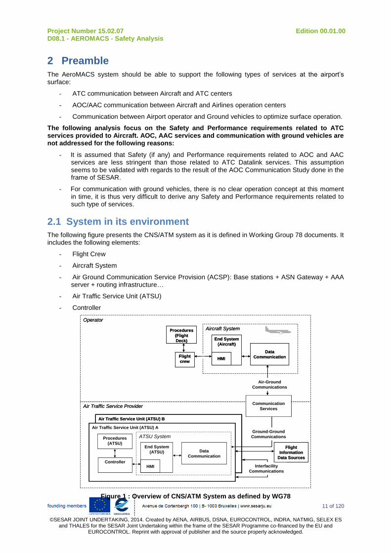
2.1 System in its environment
The following figure presents the CNS/ATM system as it is defined in Working Group 78 documents. It includes the following elements:
- Flight Crew
- Aircraft System
- Air Ground Communication Service Provision (ACSP): Base stations + ASN Gateway + AAA server + routing infrastructure…
- Air Traffic Service Unit (ATSU)
- Controller
Air Traffic Service Unit (ATSU) B
End System
(Aircraft)
Data
Communication
Air Traffic Service Unit (ATSU) A
End System
(ATSU)
Air Traffic Service Provider
Data
Communication
Aircraft System
Operator
Procedures
(ATSU)
Controller
Procedures
(Flight
Deck)
Flight
crew
Ground-Ground
Communications
HMI
HMI
Communication
Services
Interfacility
Communications
ATSU System
Air-Ground
Communications
Flight Flight
Information Information
Data SourcesData Sources
Figure 1 : Overview of CNS/ATM System as defined by WG78
Project Number 15.02.07 Edition 00.01.00 D08.1 - AEROMACS - Safety Analysis
12 of 120
©SESAR JOINT UNDERTAKING, 2014. Created by AENA, AIRBUS, DSNA, EUROCONTROL, INDRA, NATMIG, SELEX ES
and THALES for the SESAR Joint Undertaking within the frame of the SESAR Programme co-financed by the EU and EUROCONTROL. Reprint with approval of publisher and the source properly acknowledged.
The AeroMACS system is part:
- on the airborne side of the data communication domain : Antenna + AeroMACS mobile system
- on the ground side of the communication service domain (ACSP): Base stations + ASN Gateway + AAA server…
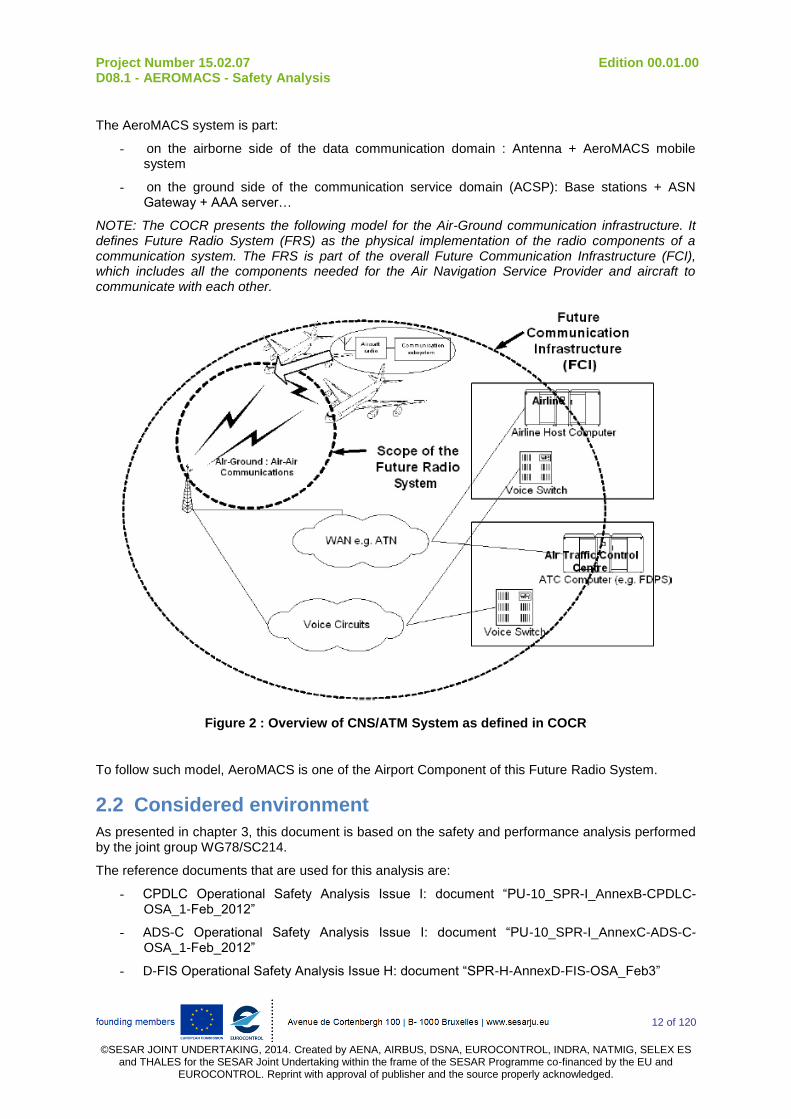
NOTE: The COCR presents the following model for the Air-Ground communication infrastructure. It defines Future Radio System (FRS) as the physical implementation of the radio components of a communication system. The FRS is part of the overall Future Communication Infrastructure (FCI), which includes all the components needed for the Air Navigation Service Provider and aircraft to communicate with each other.
Figure 2 : Overview of CNS/ATM System as defined in COCR
To follow such model, AeroMACS is one of the Airport Component of this Future Radio System.
2.2 Considered environment
As presented in chapter 3, this document is based on the safety and performance analysis performed by the joint group WG78/SC214.
The reference documents that are used for this analysis are:
- CPDLC Operational Safety Analysis Issue I: document “PU-10_SPR-I_AnnexB-CPDLC-OSA_1-Feb_2012”
- ADS-C Operational Safety Analysis Issue I: document “PU-10_SPR-I_AnnexC-ADS-C-OSA_1-Feb_2012”
- D-FIS Operational Safety Analysis Issue H: document “SPR-H-AnnexD-FIS-OSA_Feb3”
Project Number 15.02.07 Edition 00.01.00 D08.1 - AEROMACS - Safety Analysis
13 of 120
©SESAR JOINT UNDERTAKING, 2014. Created by AENA, AIRBUS, DSNA, EUROCONTROL, INDRA, NATMIG, SELEX ES
and THALES for the SESAR Joint Undertaking within the frame of the SESAR Programme co-financed by the EU and EUROCONTROL. Reprint with approval of publisher and the source properly acknowledged.
- Operational Performance Analysis Issue I: document “PU-10_SPR-I-AnnexesEFGH-OPA-1-Feb_2012”
NOTE: New issue of WG78/SC214 documents is available. Differences between this issue of the documents and the current issue (issue M) are presented in Appendix C.
“WG78 environment” for Airport domain is described in WG78 documents. The main characteristics of this environment are described below:
Characteristics in Airport Domain
Data communication
equipage 75% of aircraft are equipped with data communications
Aircraft flight duration per
sector 20.5 minutes
Average aircraft count per
sector (during busy hour)
61
(19 Ramp, 31 Ground, and 11 Tower
Peak instantaneous aircraft
count per sector
96
(30 Ramp, 48 Ground, and 18 Tower)
Aircraft handled per sector
hour 179
Table 1: Characteristics of WG78 Environment
From a safety point of view it is important to note that this environment considers the existence of sophisticated automation tools for problem detection, resolution advisories and prioritization to assist the controller.
2.3 Datalink services considered for the analysis
Aeronautical Operational Control (AOC) and AAC services are not considered in the present safety and performance analyses for the following reasons:
- AOC services are mainly used to exchange information between the aircraft and the airlines (for example to prepare / optimize the maintenance of the aircraft). They are not considered in Working Group 78 documents,
- From a safety point of view, AOC services are usually deemed less critical than ATS services. So safety requirements defined by considering the ATS services should be more stringent than safety requirements that could be defined by considering AOC services,
- From a performance point of view, it is considered that performance requirements defined in WG78 document for ATS services are sufficient to use AOC services efficiently.
WG78 documents define the following Air Traffic Services (ATS) services at the airport’s surface:
DLIC (DataLink Initiation)
o Definition: This service exchanges information between an aircraft and an ATSU to identify the data link services that are supported. The DLIC service is also used to establish a unique identity address for each aircraft initiating the connection process. It provides version and address information for all data link services including itself.
o Airport utilization: The DLIC service is executed prior to any other addressed data link service.
o Application: This service uses CM application.
ACM (ATC Communication Management)
o Definition: This service provides automated assistance to the flight crew and current and next controllers for conducting the transfer of ATC communications.
o Airport utilization: The ACM service is intended to be used in all phases of flight and surface operations
Project Number 15.02.07 Edition 00.01.00 D08.1 - AEROMACS - Safety Analysis
14 of 120
©SESAR JOINT UNDERTAKING, 2014. Created by AENA, AIRBUS, DSNA, EUROCONTROL, INDRA, NATMIG, SELEX ES
and THALES for the SESAR Joint Undertaking within the frame of the SESAR Programme co-financed by the EU and EUROCONTROL. Reprint with approval of publisher and the source properly acknowledged.
o Application: This service uses CPDLC application.
CRD (Clearance Request and Delivery)
o Definition: This service supports operational ATC data communication (clearance request, delivery and response) between the flight crew and the ground system/controller of the current data authority ATSU.
o Airport utilization: This service is intended to be used in all phases of flight and surface operations
o Application: This service uses CPDLC application.
IER (Information Exchange and Reporting)
o Definition: This service provides the capability for the controller and flight crew to exchange information (reports/confirmation messages, automatic report provided by aircraft, request for information on expected clearances...).
o Airport utilization: This service can be used in all flight phases. In practise, it is not sure that it is really used in Airport.
o Application: This service uses CPDLC and ADS-C application.
AMC (ATC Microphone Check)
o Definition: This service provides controllers with the capability to uplink an instruction to an aircraft in order for the flight crew to check that the aircraft is not blocking a given voice channel.
o Airport utilization: The ACM service is intended to be used in all phases of flight and surface operations
o Application: This service uses CPDLC application.
PR (Position Reporting)
o Definition: This service provides the controller with the capability to obtain position information from the aircraft. PR is intended only for position reports. When the aircraft sends reports associated with re-routing, these reports are sent via IER.
o Airport utilization: This service can be used in all flight phases. WG78 specifies that “typically, position reports are sent when passing waypoints on oceanic tracks”. So this service is not considered as used in Airport domain.
o Application: This service uses CPDLC and ADS-C application.
DCL (Departure Clearance)
o Definition: This service provides automated assistance for requesting and delivering departure clearances.
o Airport utilization: The DCL service is intended for use during the surface departure phase of operation.
o Application: This service uses CPDLC application.
D-TAXI (DataLink Taxi)
o Definition: This service provides communications between the flight crew and the ATSU system/controller during ground operations, and while the aircraft is approaching the airport. This service is not used to provide clearances related to active runways and take off clearances, which are provided by voice.
o Airport utilization: The D-TAXI service is intended for use during ground operations, and while the aircraft is approaching the airport.
o Application: This service uses CPDLC application.
4D-TRAD (4-Dimensional Trajectory Data Link)

Project Number 15.02.07 Edition 00.01.00 D08.1 - AEROMACS - Safety Analysis
15 of 120
©SESAR JOINT UNDERTAKING, 2014. Created by AENA, AIRBUS, DSNA, EUROCONTROL, INDRA, NATMIG, SELEX ES
and THALES for the SESAR Joint Undertaking within the frame of the SESAR Programme co-financed by the EU and EUROCONTROL. Reprint with approval of publisher and the source properly acknowledged.
o Definition: The 4DTRAD service enables the negotiation and synchronization of trajectory data between ground and air systems. This includes the exchange of 4-dimensional clearances and intent information such as lateral, longitudinal, vertical and time or speed (including uplinked constraints specified as cleared speed / time constraints which can be issued as a part of a route clearance).
o Airport utilization: During the pre-departure, the 4D-TRAD trajectory is loaded in the Flight Management System automatically. The proposed 4-D trajectory portion will be used later in the flight to facilitate negotiation of the aircraft’s final 4-D trajectory
o Application: The 4DTRAD service uses CPDLC for exchange of 4D clearances; and ADS-C for estimated trajectory downlink, from the aircraft to the ground.
IM (Interval Management)
o Definition: Currently, this service is not clearly defined in WG78.This service provides automated assistance to perform ITP (In Trail Procedures), Merging and Spacing (M&S), Crossing and Passing (C&P) or Paired Approach (PAIRAPP). , delegated separation services.
o Airport utilization: All these procedures are only performed during En Route. This service is not used in Airport domain.
OCL (Oceanic Clearance)
o Definition: This service provides the capability to request and obtain oceanic clearances from ATSUs that are not yet in control of the aircraft.
o Airport utilization: This service is not used in Airport domain (only used in En Route environment).
o Application: This service uses CPDLC application.
D-OTIS (DataLink Operational Terminal Information)
o Definition: This service provides flight crews with compiled meteorological and operational flight information for aerodromes comprised of ATIS (Automatic Terminal Information Service), NOTAM (Notice To Airmen), and VOLMET (including Aerodrome Routine Meteorological (METAR), Aerodrome Special Meteorological (SPECI), Terminal Aerodrome Forecasts (TAF) and Significant Meteorological Forecast (SIGMET)).
o Airport utilization: The overall service is available in all phases of flights including pre-departure. For the landing, “Operational Terminal Information” is necessary before the beginning of the approach procedure. The service is only used in Airport before takeoff.
o Application: This service uses FIS application.
D-RVR (DataLink Runway Visual Range)
o Definition: This service provides flight crews with Runway Visual Range (RVR) information for aerodromes during periods of low visibility.
o Airport utilization: The D-RVR service is available in all phases of flights, including pre-departure. For the landing the visual range information is necessary before the beginning of the approach procedure. This service is only used in Airport before takeoff.
o Application: This service uses FIS application.
D-HZWX (DataLink Hazardous Weather)
o Definition: This service provides flight crews with flight critical weather information which may affect the safety of aircraft operations. The D-HZWX service includes the following report types: Data Link Wind Shear (D-WS), Data Link Micro Burst (D-MB), Data Link Special Air Reports (D-SAR), Data Link Significant Meteorological Information (D-SIGMET), Data Link Wake Vortex Reports (D-WVR).
Project Number 15.02.07 Edition 00.01.00 D08.1 - AEROMACS - Safety Analysis
16 of 120
©SESAR JOINT UNDERTAKING, 2014. Created by AENA, AIRBUS, DSNA, EUROCONTROL, INDRA, NATMIG, SELEX ES
and THALES for the SESAR Joint Undertaking within the frame of the SESAR Programme co-financed by the EU and EUROCONTROL. Reprint with approval of publisher and the source properly acknowledged.
o Airport utilization: The overall service is available in all phases of flights, including pre-departure. For the landing the weather information is necessary before the beginning of the approach procedure. This service is only used in Airport before takeoff.
o Application: This service uses FIS application.
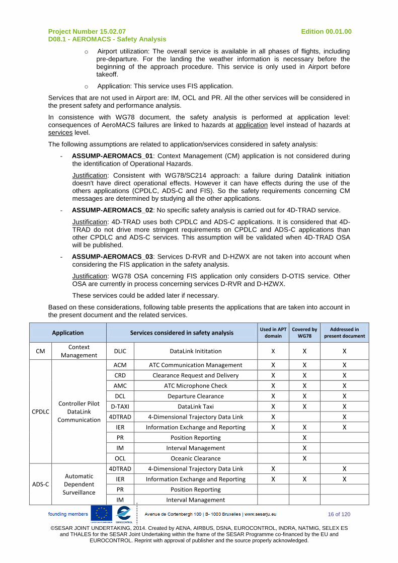
Services that are not used in Airport are: IM, OCL and PR. All the other services will be considered in the present safety and performance analysis.
In consistence with WG78 document, the safety analysis is performed at application level: consequences of AeroMACS failures are linked to hazards at application level instead of hazards at services level.
The following assumptions are related to application/services considered in safety analysis:
- ASSUMP-AEROMACS_01: Context Management (CM) application is not considered during the identification of Operational Hazards.
Justification: Consistent with WG78/SC214 approach: a failure during Datalink initiation doesn't have direct operational effects. However it can have effects during the use of the others applications (CPDLC, ADS-C and FIS). So the safety requirements concerning CM messages are determined by studying all the other applications.
- ASSUMP-AEROMACS_02: No specific safety analysis is carried out for 4D-TRAD service.
Justification: 4D-TRAD uses both CPDLC and ADS-C applications. It is considered that 4D-TRAD do not drive more stringent requirements on CPDLC and ADS-C applications than other CPDLC and ADS-C services. This assumption will be validated when 4D-TRAD OSA will be published.
- ASSUMP-AEROMACS_03: Services D-RVR and D-HZWX are not taken into account when considering the FIS application in the safety analysis.
Justification: WG78 OSA concerning FIS application only considers D-OTIS service. Other OSA are currently in process concerning services D-RVR and D-HZWX.
These services could be added later if necessary.
Based on these considerations, following table presents the applications that are taken into account in the present document and the related services.
Application Services considered in safety analysis Used in APT
domain Covered by
WG78 Addressed in
present document
CM Context
Management DLIC DataLink Inititation X X X
CPDLC Controller Pilot
DataLink Communication
ACM ATC Communication Management X X X
CRD Clearance Request and Delivery X X X
AMC ATC Microphone Check X X X
DCL Departure Clearance X X X
D-TAXI DataLink Taxi X X X
4DTRAD 4-Dimensional Trajectory Data Link X X
IER Information Exchange and Reporting X X X
PR Position Reporting X
IM Interval Management X
OCL Oceanic Clearance X
ADS-C Automatic Dependent Surveillance
4DTRAD 4-Dimensional Trajectory Data Link X X
IER Information Exchange and Reporting X X X
PR Position Reporting
IM Interval Management

Project Number 15.02.07 Edition 00.01.00 D08.1 - AEROMACS - Safety Analysis
17 of 120
©SESAR JOINT UNDERTAKING, 2014. Created by AENA, AIRBUS, DSNA, EUROCONTROL, INDRA, NATMIG, SELEX ES
and THALES for the SESAR Joint Undertaking within the frame of the SESAR Programme co-financed by the EU and EUROCONTROL. Reprint with approval of publisher and the source properly acknowledged.
Application Services considered in safety analysis Used in APT
domain Covered by
WG78 Addressed in
present document
FIS Flight Information
Service
D-OTIS DataLink Operational Terminal Information X X X
D-RVR DataLink Runway Visual Range X
D-HZWX
Data Link Hazardous Weather X
Table 2: Application considered for the safety analysis in WG78 environment
NOTE: More precisions regarding Datalink applications and services can be found in WG78/SC214 documentation.
Project Number 15.02.07 Edition 00.01.00 D08.1 - AEROMACS - Safety Analysis
18 of 120
©SESAR JOINT UNDERTAKING, 2014. Created by AENA, AIRBUS, DSNA, EUROCONTROL, INDRA, NATMIG, SELEX ES
and THALES for the SESAR Joint Undertaking within the frame of the SESAR Programme co-financed by the EU and EUROCONTROL. Reprint with approval of publisher and the source properly acknowledged.
3 Methodology
The methodology to derive Safety and Performance requirements applicable to the AeroMACS system is described below:
Definition of Safety and Performance Requirements applicable to ACSP and Aircraft
Definition of ACSP and Aircraft Safety Requirements
Identification of Operational Hazards Definition / Identification of relevant
Safety Requirements
Summary of Requirements applicable
to ACSP and Aircraft
Definition of ACSP and Aircraft Performance Requirements
Identification of relevant Performance Requirements
Selection of applicable Perfo Requirements
Definition of Aeromacs Requirements
Definition of AeroMACS ground system Requirements
Identification of ACSP architecture Allocation of safety & performance
requirements on ACSP architecture Definition of AeroMACS ground system
Requirements
Definition of AeroMACS airborne system Requirements
Identification of aircraft architecture Allocation of safety & performance
requirements on aircraft architecture Definition of AeroMACS airborne system
Requirements
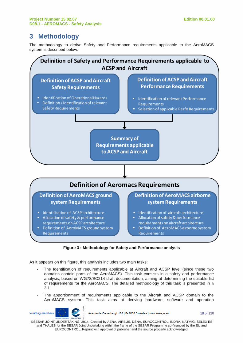
Figure 3 : Methodology for Safety and Performance analysis
As it appears on this figure, this analysis includes two main tasks:
- The Identification of requirements applicable at Aircraft and ACSP level (since these two domains contain parts of the AeroMACS). This task consists in a safety and performance analysis, based on WG78/SC214 draft documentation, aiming at determining the suitable list of requirements for the AeroMACS. The detailed methodology of this task is presented in § 3.1.
- The apportionment of requirements applicable to the Aircraft and ACSP domain to the AeroMACS system. This task aims at deriving hardware, software and operation
Project Number 15.02.07 Edition 00.01.00 D08.1 - AEROMACS - Safety Analysis
19 of 120
©SESAR JOINT UNDERTAKING, 2014. Created by AENA, AIRBUS, DSNA, EUROCONTROL, INDRA, NATMIG, SELEX ES
and THALES for the SESAR Joint Undertaking within the frame of the SESAR Programme co-financed by the EU and EUROCONTROL. Reprint with approval of publisher and the source properly acknowledged.
requirements applicable at AeroMACS level. The detailed methodology of this task is presented in § 3.2.
Project Number 15.02.07 Edition 00.01.00 D08.1 - AEROMACS - Safety Analysis
20 of 120
©SESAR JOINT UNDERTAKING, 2014. Created by AENA, AIRBUS, DSNA, EUROCONTROL, INDRA, NATMIG, SELEX ES
and THALES for the SESAR Joint Undertaking within the frame of the SESAR Programme co-financed by the EU and EUROCONTROL. Reprint with approval of publisher and the source properly acknowledged.
3.1 Definition of Safety and Performance Requirements applicable to ACSP and Aircraft
As presented on figure 3, two analyses are performed in order to determine ACSP and Aircraft Requirements: safety analysis and performance analysis. These two analysis are carried out independently to determine Safety Requirements and Performance Requirements.
The following sections presents the methodology for the definition of Safety Requirements (§ 3.1.1) and Performance Requirements (§ 3.1.2).
3.1.1 Definition of Safety Requirements
The safety analysis includes two sub-tasks:
- Identification of Operational Hazards,
- Definition of relevant Safety Requirements
The principle of these two sub-tasks is presented in the following chapters.
3.1.1.1 Identification of Operational Hazards
This task is a qualitative bottom up analysis with the purpose to identify all the Operational Hazards associated to AeroMACS. Operational Hazards are consequences, on the global ATM system, of the AeroMACS failures (Abnormal Events). Abnormal Events can have different consequences depending on the Context of Use (CU) and on the success or failure of external mitigations means (in others systems).
The principle of this task is presented on the following figure.
Identification of Operational Hazards (OH)
AEAeromacs
OHWG78_2
OHNEW_1
CU_2
CU_1
EMMfail
EMM successful
OHWG78_1
SOOH_WG78_1
SOOH_WG78_2
SO
OH_NEW_1
Figure 4 : Methodology for the identification of Operational Hazards
This identification is composed of five main sub-tasks:
- Identification of Abnormal Events at AeroMACS Level
- Identification of all Contexts of Use and External Mitigation Means associated to each Abnormal Event
- Identification of all Operational Hazards associated to each Abnormal Event
- Evaluation of severities associated to new Operational Hazards
- Definition of safety objectives associated to new Operational Hazards
The detailed methodology and the results associated to these different sub tasks are presented in § 4.1.1.

Project Number 15.02.07 Edition 00.01.00 D08.1 - AEROMACS - Safety Analysis
21 of 120
©SESAR JOINT UNDERTAKING, 2014. Created by AENA, AIRBUS, DSNA, EUROCONTROL, INDRA, NATMIG, SELEX ES
and THALES for the SESAR Joint Undertaking within the frame of the SESAR Programme co-financed by the EU and EUROCONTROL. Reprint with approval of publisher and the source properly acknowledged.
3.1.1.2 Definition / Identification of relevant ACSP and A/C Safety Requirements
Safety Requirements can be defined for the different components of the ATM system (Controller, Flight Crew, Aircraft System, Air Ground Communication System or Ground System) from the Operational Hazards / Safety Objectives identified during the previous task.
As presented in paragraph 2.1, AeroMACS is split between Aircraft System and ACSP. So, only the requirements applicable to the Aircraft system (AC) and to the Air Ground Communication System (ACSP) are considered as relevant for the AeroMACS.
The definition of the relevant ACSP or AC Safety Requirements is different depending on the kind of Operational Hazard:
- for “WG78 OH”, an allocation has already been performed by WG78. So ACSP and AC safety requirements are directly extracted from WG78 documents.
- for “NEW OH”, the complete allocation must be performed from the Operational Hazard to the different causes including ACSP or AC.
Then, for a given failure mode (eg: Loss of message or corruption of message), only the most stringent safety requirements are selected as being the applicable safety requirements.
The principle of this task is presented on the following figure.
Identification / definition of relevant ACSP or AC Safety Requirements
OHNEW_1
Event BEvent A
AEACSP
AE A/C
EMM
EMM SR
OHWG78_1
AEACSP
SR_WG78_ACSP_1
SOOH_WG78_1
WG78
AEAircraft
WG78 OH
New OH
SOOH_NEW_1
SR_WG78_AC_1
SR_NEW_ACSP_1 SR_NEW_AC_1
Most stringent
Selection of applicable requirements
SR_WG78_ACSP_1
SR_WG78_ACSP_2
SR_NEW_ACSP_1
SR_ACSP_1
Most stringentSR_WG78_AC_1
SR_WG78_AC_2
SR_NEW_AC_1
SR_AC_1
Figure 5 : Methodology for the definition / Identification of relevant ACSP or AC safety requirements
The detailed methodology and the results of this task are presented in § 4.1.2.
Project Number 15.02.07 Edition 00.01.00 D08.1 - AEROMACS - Safety Analysis
22 of 120
©SESAR JOINT UNDERTAKING, 2014. Created by AENA, AIRBUS, DSNA, EUROCONTROL, INDRA, NATMIG, SELEX ES
and THALES for the SESAR Joint Undertaking within the frame of the SESAR Programme co-financed by the EU and EUROCONTROL. Reprint with approval of publisher and the source properly acknowledged.
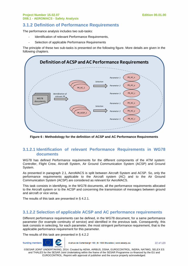
3.1.2 Definition of Performance Requirements
The performance analysis includes two sub-tasks:
- Identification of relevant Performance Requirements,
- Selection of applicable Performance Requirements
The principle of these two sub-tasks is presented on the following figure. More details are given in the following chapters.
Definition of ACSP and AC Performance Requirements
PR_ACSP_1
WG78 documents
PR_ACSP_1PR_AC_1
PR_ACSP_1PR_ACSP_1
PR_ACSP_1
Selection
Selection
Identification of relevant PR
PR_AC_x
PR_AC_y
PR_AC_z
PR_AC_x
PR_AC_y
PR_AC_z
Parameter 1
Parameter 2
Parameter 3
Parameter 1
Parameter 2
Parameter 3
Figure 6 : Methodology for the definition of ACSP and AC Performance Requirements
3.1.2.1 Identification of relevant Performance Requirements in WG78 documents
WG78 has defined Performance requirements for the different components of the ATM system: Controller, Flight Crew, Aircraft System, Air Ground Communication System (ACSP) and Ground System.
As presented in paragraph 2.1, AeroMACS is split between Aircraft System and ACSP. So, only the performance requirements applicable to the Aircraft system (AC) and to the Air Ground Communication System (ACSP) are considered as relevant for AeroMACS.
This task consists in identifying, in the WG78 documents, all the performance requirements allocated to the Aircraft system or to the ACSP and concerning the transmission of messages between ground and aircraft or vice versa.
The results of this task are presented in § 4.2.1.
3.1.2.2 Selection of applicable ACSP and AC performance requirements
Different performance requirements can be defined, in the WG78 document, for a same performance parameter (for example continuity of service) and identified in the previous task. Consequently, this task consists in selecting, for each parameter, the most stringent performance requirement, that is the applicable performance requirement for this parameter.
The results of this task are presented in § 4.2.2

Project Number 15.02.07 Edition 00.01.00 D08.1 - AEROMACS - Safety Analysis
23 of 120
©SESAR JOINT UNDERTAKING, 2014. Created by AENA, AIRBUS, DSNA, EUROCONTROL, INDRA, NATMIG, SELEX ES
and THALES for the SESAR Joint Undertaking within the frame of the SESAR Programme co-financed by the EU and EUROCONTROL. Reprint with approval of publisher and the source properly acknowledged.
3.1.3 Selection of ACSP and AC Requirements
When a safety requirement (SR) and a performance requirement (PR) have been defined for a same parameter (e.g. availability) a comparison is performed between these two requirements and the most stringent is selected as being the applicable Requirement for this parameter. This principle is presented on the following figure:
Definition of ACSP and AC Requirements
Requirement
Safety Requirement
Performance Requirement
Most stringent
Figure 7 : Methodology for the selection of ACSP and AC Requirements
The results of this task are presented in § 5.

Project Number 15.02.07 Edition 00.01.00 D08.1 - AEROMACS - Safety Analysis
24 of 120
©SESAR JOINT UNDERTAKING, 2014. Created by AENA, AIRBUS, DSNA, EUROCONTROL, INDRA, NATMIG, SELEX ES
and THALES for the SESAR Joint Undertaking within the frame of the SESAR Programme co-financed by the EU and EUROCONTROL. Reprint with approval of publisher and the source properly acknowledged.
3.2 Definition of AeroMACS Requirements
The definition of AeroMACS Requirements is carried out independently for AeroMACS ground and airborne system: ACSP requirements drive requirements on AeroMACS ground system and Aircraft requirements drive requirements on AeroMACS airborne system.
For each part (airborne and ground), the same sub-tasks are performed:
- Identification of ACSP (or Aircraft) architecture
- Allocation of ACSP (or Aircraft) requirements on the different parts of ACSP (or Aircraft), including AeroMACS ground system (or AeroMACS airborne system)
- Definition of AeroMACS ground system Requirements
The principle of these three sub-tasks is presented on the following figure. More details are given in the following chapters.
Definition of AeroMACS Requirements
AEACSP
Event XACSP Part 1
ACSP Part 2
Aeromacsground
Assumption_1
ACSPSR_1
Aeromacsground SR_1
ACSP System
ACSPPart 1
ACSPPart 2
Aeromacsground part
Aircraft System
AC Part 1
AC Part 2
Aeromacsairborne part
Assumption_2
Identification of ACSP and aircraft architecture
Allocation of ACSP and aircraft requirementsDefinition of AeroMACS requirements
AEAC
Event YAC
Part 1
ACPart 2
Aeromacsairborne
Assumption_1
ACSR_1
Aeromacsairborne SR_1
Assumption_2
Figure 8 : Methodology for the definition of AeroMACS Requirements

Project Number 15.02.07 Edition 00.01.00 D08.1 - AEROMACS - Safety Analysis
25 of 120
©SESAR JOINT UNDERTAKING, 2014. Created by AENA, AIRBUS, DSNA, EUROCONTROL, INDRA, NATMIG, SELEX ES
and THALES for the SESAR Joint Undertaking within the frame of the SESAR Programme co-financed by the EU and EUROCONTROL. Reprint with approval of publisher and the source properly acknowledged.
3.2.1 Description of ACSP and aircraft architecture
As presented on the previous figure, this task consists in identifying the architecture of classical aircraft and ACSP systems. This identification should include:
- Presentation of aircraft and ACSP sub-systems, including AeroMACS airborne sub-system and AeroMACS ground sub-system
- Presentation of the function of each sub-system
This task will be a basis for the identification of sub-systems involved in the different Abnormal Events. The detail level of this architecture must be commensurate with the desired detail-level of the AeroMA CS Requirements.
The description of ACSP architecture is presented in § 5.1.
The description of aircraft architecture is presented in § 6.1.
3.2.2 Identification of components involved in Abnormal Events
As presented on Figure 8, this task consists in identifying for each Abnormal Event:
- the different sub-systems failures that could lead to this Abnormal Event
- the combination of failures that must occur to lead to this Abnormal Event
The failures are identified on the sub-systems defined previously.
3.2.3 Allocation of Components Requirements
This task consists in performing the allocation of requirements on the different sub-systems identified previously.
In order to perform this allocation, fault tree can be constructed, for each Abnormal Event, presenting all potential contributors for this Abnormal Event (potential contributors have been identified during the previous task). Then, assumptions are made regarding the failure of others sub-systems and requirements are allocated on AeroMACS. These requirements can be:
- Quantitative requirements on AeroMA CS sub-system. These requirements are derived from the ACSP and aircraft Requirements. If these quantitative requirements seem impossible to reach, design requirements could be defined (redundancies…)
- Assurance Level on AeroMA CS sub-system. These requirements are derived from the severity of the Operational Hazard to which the Abnormal Events contributes. The methodology for the allocation of Assurance Level will be detailed later.
- Requirements regarding the transaction time in AeroMACS sub-system
- Qualitative requirements regarding the functions of the system
The results of this allocations are presented in § 5.2 for AeroMACS ground system and § 6.2 for AeroMACS airborne system.
Project Number 15.02.07 Edition 00.01.00 D08.1 - AEROMACS - Safety Analysis
26 of 120
©SESAR JOINT UNDERTAKING, 2014. Created by AENA, AIRBUS, DSNA, EUROCONTROL, INDRA, NATMIG, SELEX ES
and THALES for the SESAR Joint Undertaking within the frame of the SESAR Programme co-financed by the EU and EUROCONTROL. Reprint with approval of publisher and the source properly acknowledged.
4 Definition of Safety and Performance requirements applicable to the ACSP and Aircraft
4.1 Definition of ACSP and Aircraft Safety Requirements
In this section, first are identified the different failure cases which can be encountered at AeroMACS level.
Then, mainly based on WG78/SC214 documentation (see [1], [2], [3], [4]), the Operational Hazards to which each Abnormal Event leads are identified, depending on the Context of Use and on success or failure of the External Mitigations Means.
NOTE: This bottom-up approach aims at reviewing the draft WG78/SC214 documentation in a different way they are developed which is beneficial since some problems could pop-up.
4.1.1 Identification of Operational Hazards
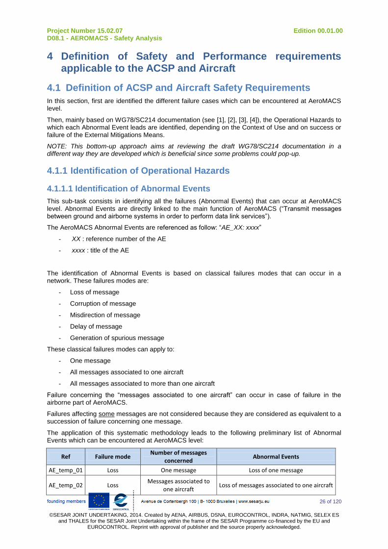
4.1.1.1 Identification of Abnormal Events
This sub-task consists in identifying all the failures (Abnormal Events) that can occur at AeroMACS level. Abnormal Events are directly linked to the main function of AeroMACS (“Transmit messages between ground and airborne systems in order to perform data link services”).
The AeroMACS Abnormal Events are referenced as follow: “AE_XX: xxxx”
- XX : reference number of the AE
- xxxx : title of the AE
The identification of Abnormal Events is based on classical failures modes that can occur in a network. These failures modes are:
- Loss of message
- Corruption of message
- Misdirection of message
- Delay of message
- Generation of spurious message
These classical failures modes can apply to:
- One message
- All messages associated to one aircraft
- All messages associated to more than one aircraft
Failure concerning the “messages associated to one aircraft” can occur in case of failure in the airborne part of AeroMACS.
Failures affecting some messages are not considered because they are considered as equivalent to a succession of failure concerning one message.
The application of this systematic methodology leads to the following preliminary list of Abnormal Events which can be encountered at AeroMACS level:
Ref Failure mode Number of messages
concerned Abnormal Events
AE_temp_01 Loss One message Loss of one message
AE_temp_02 Loss Messages associated to
one aircraft Loss of messages associated to one aircraft

Project Number 15.02.07 Edition 00.01.00 D08.1 - AEROMACS - Safety Analysis
27 of 120
©SESAR JOINT UNDERTAKING, 2014. Created by AENA, AIRBUS, DSNA, EUROCONTROL, INDRA, NATMIG, SELEX ES
and THALES for the SESAR Joint Undertaking within the frame of the SESAR Programme co-financed by the EU and EUROCONTROL. Reprint with approval of publisher and the source properly acknowledged.
Ref Failure mode Number of messages
concerned Abnormal Events
AE_temp_03 Loss Messages associated to more than one aircraft
Loss of messages associated to more than one aircraft
AE_temp_04 Corruption One message Corruption of one message
AE_temp_05 Corruption Messages associated to
one aircraft Corruption of messages associated to one
aircraft
AE_temp_06 Corruption Messages associated to more than one aircraft
Corruption of messages associated to more than one aircraft
AE_temp_07 Misdirection One message Misdirection of one message
AE_temp_08 Misdirection Messages associated to
one aircraft Misdirection of messages associated to
one aircraft
AE_temp_09 Misdirection Messages associated to more than one aircraft
Misdirection of messages associated to more than one aircraft
AE_temp_10 Delay One message Delay of one message
AE_temp_11 Delay Messages associated to
one aircraft Delay of messages associated to one
aircraft
AE_temp_12 Delay Messages associated to more than one aircraft
Delay of messages associated to more than one aircraft
AE_temp_13 Spurious Messages associated to more than one aircraft
Generation of one spurious message
AE_temp_14 Spurious Messages associated to more than one aircraft
Transmission of spurious messages to one aircraft
AE_temp_15 Spurious Messages associated to more than one aircraft
Transmission of spurious messages to more than one aircraft
Table 3: Preliminary list of abnormal events
Some Abnormal Events of this list lead to the same Operational Hazards. So, the following assumptions were made in order to reduce the number of Abnormal Events to consider for the identification of operational hazards.
- ASSUMP-AEROMACS_04: Abnormal Events concerning all the messages at AeroMACS level associated to one aircraft are always detected. These events are grouped as single event: “permanent failure to communicate with one aircraft" (Availability of use).
Justification: A failure on a message at AeroMACS level (corruption, loss…), is detected thanks to the external mitigation means such as time stamps, checksum… at upper layers. A systematic failure of the external mitigations means for all AeroMACS messages is very unlikely (the period of failure allocated by WG78 is one failure every 100 000 hours). The detection of this failure induces a clarification between controllers and flight crew. Then, following messages will be carefully watched; controllers will detect that there is a permanent failure on Datalink communication chain with the aircraft.
AE_temp_02, AE_temp_05, AE_temp_08, AE_temp_11 and AE_temp_14 are grouped together: AE_05 “Permanent failure to communicate with one aircraft”
- ASSUMP-AEROMACS_05: Abnormal Events concerning all messages at AeroMACS level associated to more than one aircraft are always detected. These events are grouped as single event:”permanent failure to communicate with more than one aircraft” (Availability of provision).
Justification: A failure on an AeroMACS message (corruption, loss…), is detected thanks to the external mitigation means such as time stamps, checksum… A systematic failure of the external mitigations means for all message is very improbable (the period of failure allocated by WG78 is one failure every 100 000 hours). The detection of this failure induces a clarification between controllers and flight crew. Then, following messages will be carefully watched; controllers will detect that there is a permanent failure on Datalink communication chain.

Project Number 15.02.07 Edition 00.01.00 D08.1 - AEROMACS - Safety Analysis
28 of 120
©SESAR JOINT UNDERTAKING, 2014. Created by AENA, AIRBUS, DSNA, EUROCONTROL, INDRA, NATMIG, SELEX ES
and THALES for the SESAR Joint Undertaking within the frame of the SESAR Programme co-financed by the EU and EUROCONTROL. Reprint with approval of publisher and the source properly acknowledged.
AE_temp_03, AE_temp_06, AE_temp_09, AE_temp_12 and AE_temp_15 are grouped together: AE_06 “Permanent failure to communicate with more than one aircraft”
So the final list of Abnormal Events that will be considered for the identification of Operational hazards is:
Ref Abnormal Events
AE_01 Loss of one message at AeroMACS level
AE_02 Corruption of one message at AeroMACS level
AE_03 Misdirection of one message at AeroMACS level
AE_04 Delay of one message at AeroMACS level
AE_05 Generation of one spurious message at AeroMACS level
AE_06 Permanent failure to communicate with one aircraft (availability of use)
AE_07 Permanent failure to communicate with more than one aircraft (availability of provision)
Table 4: List of Abnormal Events considered for the identification of Operational Hazards
4.1.1.2 Identification of all Contexts of Use and External Mitigation Means associated to each Abnormal Event
4.1.1.2.1 Identification of “Context of Use”
This subtask consists in identifying all the “Contexts of Use” associated to each Abnormal Event. “Context of Use” reflects the operational environment in which the system can be used.
The Contexts of Use are referenced as follow: “CU_XX: xxxx”
- XX : reference number of the CU
- xxxx : title of the CU
The identification of “Context of Use” is based on the context of utilization of the AeroMACS which includes:
- Application related to the message transmitted via AeroMACS
- kind of message (uplink or downlink message). Uplink messages are messages from the ground to the aircraft and downlink messages are messages from the aircraft to the ground. This definition is consistent with WG78/SC214, but not with the others deliverables of 15.2.7 (e.g. SRD).
- kind of failure (corruption of a message into another existing message or corruption into an un-existing message)
The following table presents all the Contexts of Use identified for the AeroMACS
Ref Context of Use
CU_01_a Message is related to CPDLC application
CU_01_b Message is related to ADS-C application
CU_01_c Message is related to FIS application
CU_02_a Message is an uplink message
CU_02_b Message is a downlink message
CU_03_a Downlink message is corrupted into an existing other downlink message
CU_03_b Downlink message is corrupted into an unexisting downlink message
CU_04_a Uplink message is corrupted into an existing other uplink message
CU_04_b Uplink message is corrupted into an unexisting uplink message Table 5: List of Contexts of Use considered for the identification of Operational Hazards
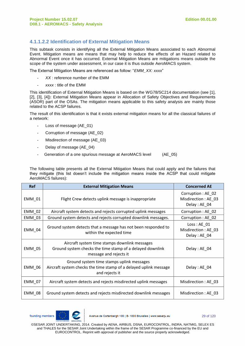
Project Number 15.02.07 Edition 00.01.00 D08.1 - AEROMACS - Safety Analysis
29 of 120
©SESAR JOINT UNDERTAKING, 2014. Created by AENA, AIRBUS, DSNA, EUROCONTROL, INDRA, NATMIG, SELEX ES
and THALES for the SESAR Joint Undertaking within the frame of the SESAR Programme co-financed by the EU and EUROCONTROL. Reprint with approval of publisher and the source properly acknowledged.
4.1.1.2.2 Identification of External Mitigation Means
This subtask consists in identifying all the External Mitigation Means associated to each Abnormal Event. Mitigation means are means that may help to reduce the effects of an Hazard related to Abnormal Event once it has occurred. External Mitigation Means are mitigations means outside the scope of the system under assessment, in our case it is thus outside AeroMACS system.
The External Mitigation Means are referenced as follow: “EMM_XX: xxxx”
- XX : reference number of the EMM
- xxxx : title of the EMM
This identification of External Mitigation Means is based on the WG78/SC214 documentation (see [1], [2], [3], [4]): External Mitigation Means appear in Allocation of Safety Objectives and Requirements (ASOR) part of the OSAs. The mitigation means applicable to this safety analysis are mainly those related to the ACSP failures.
The result of this identification is that it exists external mitigation means for all the classical failures of a network:
- Loss of message (AE_01)
- Corruption of message (AE_02)
- Misdirection of message (AE_03)
- Delay of message (AE_04)
- Generation of a one spurious message at AeroMACS level (AE_05)
The following table presents all the External Mitigation Means that could apply and the failures that they mitigate (this list doesn’t include the mitigation means inside the ACSP that could mitigate AeroMACS failures):
Ref External Mitigation Means Concerned AE
EMM_01 Flight Crew detects uplink message is inappropriate Corruption : AE_02
Misdirection : AE_03 Delay : AE_04
EMM_02 Aircraft system detects and rejects corrupted uplink messages Corruption : AE_02
EMM_03 Ground system detects and rejects corrupted downlink messages. Corruption : AE_02
EMM_04 Ground system detects that a message has not been responded to
within the expected time
Loss : AE_01 Misdirection : AE_03
Delay : AE_04
EMM_05 Aircraft system time stamps downlink messages
Ground system checks the time stamp of a delayed downlink message and rejects it
Delay : AE_04
EMM_06 Ground system time stamps uplink messages
Aircraft system checks the time stamp of a delayed uplink message and rejects it
Delay : AE_04
EMM_07 Aircraft system detects and rejects misdirected uplink messages Misdirection : AE_03
EMM_08 Ground system detects and rejects misdirected downlink messages Misdirection : AE_03
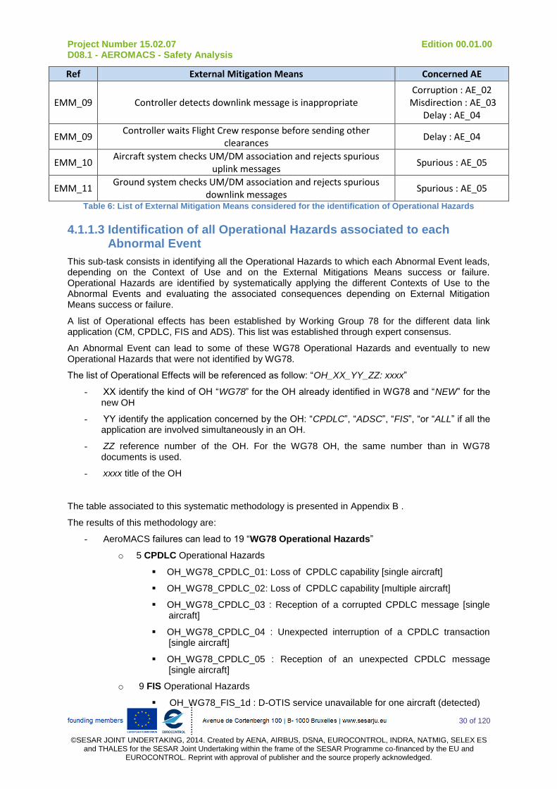
Project Number 15.02.07 Edition 00.01.00 D08.1 - AEROMACS - Safety Analysis
30 of 120
©SESAR JOINT UNDERTAKING, 2014. Created by AENA, AIRBUS, DSNA, EUROCONTROL, INDRA, NATMIG, SELEX ES
and THALES for the SESAR Joint Undertaking within the frame of the SESAR Programme co-financed by the EU and EUROCONTROL. Reprint with approval of publisher and the source properly acknowledged.
Ref External Mitigation Means Concerned AE
EMM_09 Controller detects downlink message is inappropriate Corruption : AE_02
Misdirection : AE_03 Delay : AE_04
EMM_09 Controller waits Flight Crew response before sending other
clearances Delay : AE_04
EMM_10 Aircraft system checks UM/DM association and rejects spurious
uplink messages Spurious : AE_05
EMM_11 Ground system checks UM/DM association and rejects spurious
downlink messages Spurious : AE_05
Table 6: List of External Mitigation Means considered for the identification of Operational Hazards
4.1.1.3 Identification of all Operational Hazards associated to each Abnormal Event
This sub-task consists in identifying all the Operational Hazards to which each Abnormal Event leads, depending on the Context of Use and on the External Mitigations Means success or failure. Operational Hazards are identified by systematically applying the different Contexts of Use to the Abnormal Events and evaluating the associated consequences depending on External Mitigation Means success or failure.
A list of Operational effects has been established by Working Group 78 for the different data link application (CM, CPDLC, FIS and ADS). This list was established through expert consensus.
An Abnormal Event can lead to some of these WG78 Operational Hazards and eventually to new Operational Hazards that were not identified by WG78.
The list of Operational Effects will be referenced as follow: “OH_XX_YY_ZZ: xxxx”
- XX identify the kind of OH “WG78” for the OH already identified in WG78 and “NEW” for the new OH
- YY identify the application concerned by the OH: “CPDLC”, “ADSC”, “FIS”, “or “ALL” if all the application are involved simultaneously in an OH.
- ZZ reference number of the OH. For the WG78 OH, the same number than in WG78 documents is used.
- xxxx title of the OH
The table associated to this systematic methodology is presented in Appendix B .
The results of this methodology are:
- AeroMACS failures can lead to 19 “WG78 Operational Hazards”
o 5 CPDLC Operational Hazards
OH_WG78_CPDLC_01: Loss of CPDLC capability [single aircraft]
OH_WG78_CPDLC_02: Loss of CPDLC capability [multiple aircraft]
OH_WG78_CPDLC_03 : Reception of a corrupted CPDLC message [single aircraft]
OH_WG78_CPDLC_04 : Unexpected interruption of a CPDLC transaction [single aircraft]
OH_WG78_CPDLC_05 : Reception of an unexpected CPDLC message [single aircraft]
o 9 FIS Operational Hazards
OH_WG78_FIS_1d : D-OTIS service unavailable for one aircraft (detected)

Project Number 15.02.07 Edition 00.01.00 D08.1 - AEROMACS - Safety Analysis
31 of 120
©SESAR JOINT UNDERTAKING, 2014. Created by AENA, AIRBUS, DSNA, EUROCONTROL, INDRA, NATMIG, SELEX ES
and THALES for the SESAR Joint Undertaking within the frame of the SESAR Programme co-financed by the EU and EUROCONTROL. Reprint with approval of publisher and the source properly acknowledged.
OH_WG78_FIS_2d : D-OTIS service unavailable for more than one aircraft (detected)
OH_WG78_FIS_3d : Incorrect D-OTIS report received (detected)
OH_WG78_FIS_3u : Incorrect D-OTIS report received (undetected)
OH_WG78_FIS_4d : D-OTIS report not received (detected)
OH_WG78_FIS_4u : D-OTIS report not received (undetected)
OH_WG78_FIS_5u : D-OTIS report is misdirected (undetected)
OH_WG78_FIS_6d : Spurious / unexpected D-OTIS report received (detected)
OH_WG78_FIS_6u : Spurious / unexpected D-OTIS report received (undetected)
o 5 ADS-C Operational Hazards
OH_WG78_ADSC_01 : Loss of ADS-C capability [single aircraft]
OH_WG78_ADSC_02 : Loss of ADS-C capability [multiple aircraft]
OH_WG78_ADSC_03 : Reception of incorrect ADS-C report [single aircraft]
OH_WG78_ADSC_05 : Reception of an unexpected ADS-C report [single aircraft]
OH_WG78_ADSC_07 : Loss of an ADS-C report [single aircraft]
- AeroMACS failure can lead to 2 “New Operational Hazards”
o OH_NEW_ALL_01 : Failure to exchange any message with a single aircraft (detected)
o OH_NEW_ALL_02 : Failure to exchange any message with more than one aircraft aircraft (detected)
For the WG78 Operational Hazards, definition of associated Safety Objective has already been performed by WG78. For the new Operational Hazards, the evaluation of the severity related to the effect and the definition of associated safety objective are performed in the two following paragraphs.
4.1.1.4 Evaluation of severity associated to new Operational Hazards
This sub-task consists in evaluating the effects associated to new Operational Hazards and in proposing a severity for these Operational Hazards. Consistent with WG78 analysis, the ED-78 Hazards Classification Matrix (see Appendix A) is used to evaluate the severities.
This sub-task is carried out in comparison with the severities that have been attributed by WG78. If a “new OH” has the same effects than a “WG78 OH” and the same mitigation means, the same severity is attributed to this OH. If a “new OH” has the same effect than a “WG78 OH” and if it hasn’t the same mitigation means, a more severe classification might be allocated on this “new OH”.
Two new hazards have been identified during the previous task:
- OH_NEW_ALL_01 : Failure to exchange any message with a single aircraft (detected)
- OH_NEW_ALL_02 : Failure to exchange any message with more than one aircraft (detected)
OH_NEW_ALL_01 : Failure to exchange any message with a single aircraft (detected)
This Operational Hazard is a combination of three Operational Hazards:
- OH_WG78_CPDLC_01 : Loss of CPDLC capability [single aircraft] (SC5)
- OH_WG78_FIS_1d : D-OTIS service unavailable for one aircraft (SC5)
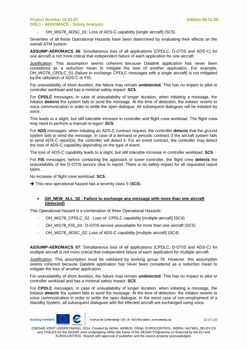
Project Number 15.02.07 Edition 00.01.00 D08.1 - AEROMACS - Safety Analysis
32 of 120
©SESAR JOINT UNDERTAKING, 2014. Created by AENA, AIRBUS, DSNA, EUROCONTROL, INDRA, NATMIG, SELEX ES
and THALES for the SESAR Joint Undertaking within the frame of the SESAR Programme co-financed by the EU and EUROCONTROL. Reprint with approval of publisher and the source properly acknowledged.
- OH_WG78_ADSC_01: Loss of ADS-C capability [single aircraft] (SC5)
Severities of all these Operational Hazards have been determined by evaluating their effects on the overall ATM system.
ASSUMP-AEROMACS_06: Simultaneous loss of all applications (CPDLC, D-OTIS and ADS-C) for one aircraft is not more critical that independent failure of each application for one aircraft.
Justification: This assumption seems coherent because Datalink application has never been considered as a reduction mean to mitigate the loss of another application. For example, OH_WG78_CPDLC_01 (failure to exchange CPDLC messages with a single aircraft) is not mitigated by the utilization of ADS-C or FIS.
For unavailability of short duration, the failure may remain undetected. This has no impact to pilot or controller workload and has a minimal safety impact: SC5.
For CPDLC messages, in case of unavailability of longer duration, when initiating a message, the initiator detects the system fails to send the message. At the time of detection, the initiator reverts to voice communication in order to settle the open dialogue. All subsequent dialogues will be initiated by voice.
This leads to a slight, but still tolerable increase in controller and flight crew workload. The flight crew may need to perform a manual re-logon: SC5.
For ADS messages, when initiating an ADS-C contract request, the controller detects that the ground system fails to send the message. In case of a demand or periodic contract, if the aircraft system fails to send ADS-C report(s), the controller will detect it. For an event contract, the controller may detect the loss of ADS-C capability depending on the type of event.
The loss of ADS-C capability leads to a slight, but still tolerable increase in controller workload: SC5.
For FIS messages, before contacting the approach or tower controller, the flight crew detects the unavailability of the D-OTIS service (due to report. There is no safety impact for all requested report types.
No increase of flight crew workload: SC5.
This new operational hazard has a severity class 5 (SC5).
OH_NEW_ALL_02 : Failure to exchange any message with more than one aircraft (detected)
This Operational Hazard is a combination of three Operational Hazards:
- OH_WG78_CPDLC_02 : Loss of CPDLC capability [multiple aircraft] (SC4)
- OH_WG78_FIS_2d : D-OTIS service unavailable for more than one aircraft (SC5)
- OH_WG78_ADSC_02: Loss of ADS-C capability [multiple aircraft] (SC4)
ASSUMP-AEROMACS_07: Simultaneous loss of all applications (CPDLC, D-OTIS and ADS-C) for multiple aircraft is not more critical that independent failure of each application for multiple aircraft.
Justification: This assumption must be validated by working group 78. However, this assumption seems coherent because Datalink application has never been considered as a reduction mean to mitigate the loss of another application.
For unavailability of short duration, the failure may remain undetected. This has no impact to pilot or controller workload and has a minimal safety impact: SC5.
For CPDLC messages, in case of unavailability of longer duration, when initiating a message, the initiator detects the system fails to send the message. At the time of detection, the initiator reverts to voice communication in order to settle the open dialogue. In the worst case of non-employment of a Standby System, all subsequent dialogues with the effected aircraft are exchanged using voice.
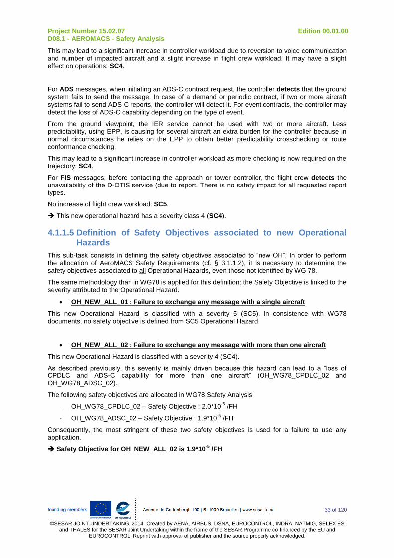
Project Number 15.02.07 Edition 00.01.00 D08.1 - AEROMACS - Safety Analysis
33 of 120
©SESAR JOINT UNDERTAKING, 2014. Created by AENA, AIRBUS, DSNA, EUROCONTROL, INDRA, NATMIG, SELEX ES
and THALES for the SESAR Joint Undertaking within the frame of the SESAR Programme co-financed by the EU and EUROCONTROL. Reprint with approval of publisher and the source properly acknowledged.
This may lead to a significant increase in controller workload due to reversion to voice communication and number of impacted aircraft and a slight increase in flight crew workload. It may have a slight effect on operations: SC4.
For ADS messages, when initiating an ADS-C contract request, the controller detects that the ground system fails to send the message. In case of a demand or periodic contract, if two or more aircraft systems fail to send ADS-C reports, the controller will detect it. For event contracts, the controller may detect the loss of ADS-C capability depending on the type of event.
From the ground viewpoint, the IER service cannot be used with two or more aircraft. Less predictability, using EPP, is causing for several aircraft an extra burden for the controller because in normal circumstances he relies on the EPP to obtain better predictability crosschecking or route conformance checking.
This may lead to a significant increase in controller workload as more checking is now required on the trajectory: SC4.
For FIS messages, before contacting the approach or tower controller, the flight crew detects the unavailability of the D-OTIS service (due to report. There is no safety impact for all requested report types.
No increase of flight crew workload: SC5.
This new operational hazard has a severity class 4 (SC4).
4.1.1.5 Definition of Safety Objectives associated to new Operational Hazards
This sub-task consists in defining the safety objectives associated to “new OH”. In order to perform the allocation of AeroMACS Safety Requirements (cf. § 3.1.1.2), it is necessary to determine the safety objectives associated to all Operational Hazards, even those not identified by WG 78.
The same methodology than in WG78 is applied for this definition: the Safety Objective is linked to the severity attributed to the Operational Hazard.
OH_NEW_ALL_01 : Failure to exchange any message with a single aircraft
This new Operational Hazard is classified with a severity 5 (SC5). In consistence with WG78 documents, no safety objective is defined from SC5 Operational Hazard.
OH_NEW_ALL_02 : Failure to exchange any message with more than one aircraft
This new Operational Hazard is classified with a severity 4 (SC4).
As described previously, this severity is mainly driven because this hazard can lead to a “loss of CPDLC and ADS-C capability for more than one aircraft” (OH_WG78_CPDLC_02 and OH_WG78_ADSC_02).
The following safety objectives are allocated in WG78 Safety Analysis
- OH_WG78_CPDLC_02 – Safety Objective : 2.0*10-5
/FH
- OH_WG78_ADSC_02 – Safety Objective : 1.9*10-5
/FH
Consequently, the most stringent of these two safety objectives is used for a failure to use any application.
Safety Objective for OH_NEW_ALL_02 is 1.9*10-5
/FH

Project Number 15.02.07 Edition 00.01.00 D08.1 - AEROMACS - Safety Analysis
34 of 120
©SESAR JOINT UNDERTAKING, 2014. Created by AENA, AIRBUS, DSNA, EUROCONTROL, INDRA, NATMIG, SELEX ES and THALES for the SESAR Joint Undertaking within the frame of the
SESAR Programme co-financed by the EU and EUROCONTROL. Reprint with approval of publisher and the source properly acknowledged.
4.1.2 Identification / definition of relevant ACSP and AC Safety Requirements
4.1.2.1 Identification of relevant ACSP and AC Safety Requirement from WG78 Operational Hazards
As mentioned previously, for all Operational Hazards identified by the WG78, the group has already performed an allocation of safety requirements on the different components of the ATM system: Controller, Flight Crew, Aircraft System, Air Ground Communication System (ACSP) and Ground System. Consequently, this task consists in identifying, in the allocation fault tree of the WG78, all the safety requirements that are relevant for the AeroMACS.
The AeroMACS is split between Aircraft System and ACSP. So, the relevant Safety Requirements are the requirements allocated to Aircraft system or ACSP and that concerns the exchange of message between ground and aircraft.
The list of relevant WG78 Safety Requirements will be referenced as follow: “SR_WG78_XX_YY_ZZ: xxxx”
- XX_YY_ZZ constitutes the reference of the cause in the WG78 fault tree
o XX: identify the part on which the safety requirement is allocated : “CP” for ACSP or “AC” for Aircraft System
o YY: identify the application associated to the fault tree : “ADSC”, “CM”, “CPDLC” or “FIS”
o ZZ : is a reference number of safety requirement
- xxxx title of the WG78 Safety Requirement
The following chapters present the relevant safety requirements defined from each WG78 OH identified in § 4.1.1.3.
4.1.2.1.1 OH_WG78_ADSC_02
The safety objective to be met for this Operational Hazard is extracted from WG78 ADS-C Operational Safety Assessment (see [3]): in Airport domain, the probability of occurrence of this hazard shall be no greater than 2*10
-5 per flight hour.
The following table presents the relevant ACSP and AC requirements identified in WG78 Safety Analysis for this Operational Hazard (in red: quantitative requirement, in green : qualitative requirements).
OH Cause WG 78 Safety Requirement
Ref Severity SO
(/FH) Cause Ref Part Failure
Kind of message
Value (/FH)
SR Ref Title
OH_WG78_ADSC_02 4 2.00E-05 WG78_CP_ADSC_01 ACSP Unavailable Any 7.60E-06 No ref The likelihood that the ACSP is unavailable shall
be less than 7.6E-06/FH
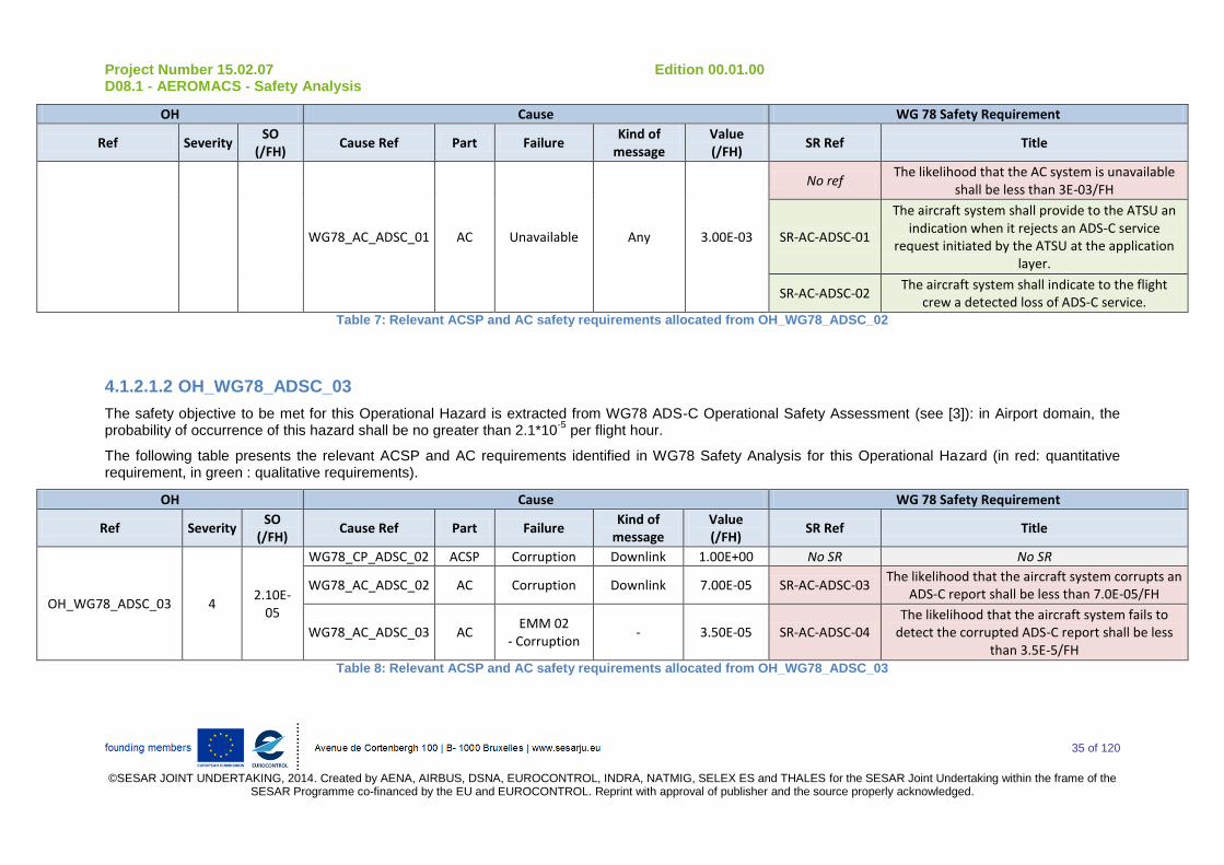
Project Number 15.02.07 Edition 00.01.00 D08.1 - AEROMACS - Safety Analysis
35 of 120
©SESAR JOINT UNDERTAKING, 2014. Created by AENA, AIRBUS, DSNA, EUROCONTROL, INDRA, NATMIG, SELEX ES and THALES for the SESAR Joint Undertaking within the frame of the
SESAR Programme co-financed by the EU and EUROCONTROL. Reprint with approval of publisher and the source properly acknowledged.
OH Cause WG 78 Safety Requirement
Ref Severity SO
(/FH) Cause Ref Part Failure
Kind of message
Value (/FH)
SR Ref Title
WG78_AC_ADSC_01 AC Unavailable Any 3.00E-03
No ref The likelihood that the AC system is unavailable
shall be less than 3E-03/FH
SR-AC-ADSC-01
The aircraft system shall provide to the ATSU an indication when it rejects an ADS-C service
request initiated by the ATSU at the application layer.
SR-AC-ADSC-02 The aircraft system shall indicate to the flight
crew a detected loss of ADS-C service. Table 7: Relevant ACSP and AC safety requirements allocated from OH_WG78_ADSC_02
4.1.2.1.2 OH_WG78_ADSC_03
The safety objective to be met for this Operational Hazard is extracted from WG78 ADS-C Operational Safety Assessment (see [3]): in Airport domain, the probability of occurrence of this hazard shall be no greater than 2.1*10
-5 per flight hour.
The following table presents the relevant ACSP and AC requirements identified in WG78 Safety Analysis for this Operational Hazard (in red: quantitative requirement, in green : qualitative requirements).
OH Cause WG 78 Safety Requirement
Ref Severity SO
(/FH) Cause Ref Part Failure
Kind of message
Value (/FH)
SR Ref Title
OH_WG78_ADSC_03 4 2.10E-
05
WG78_CP_ADSC_02 ACSP Corruption Downlink 1.00E+00 No SR No SR
WG78_AC_ADSC_02 AC Corruption Downlink 7.00E-05 SR-AC-ADSC-03 The likelihood that the aircraft system corrupts an
ADS-C report shall be less than 7.0E-05/FH
WG78_AC_ADSC_03 AC EMM 02
- Corruption - 3.50E-05 SR-AC-ADSC-04
The likelihood that the aircraft system fails to detect the corrupted ADS-C report shall be less
than 3.5E-5/FH Table 8: Relevant ACSP and AC safety requirements allocated from OH_WG78_ADSC_03
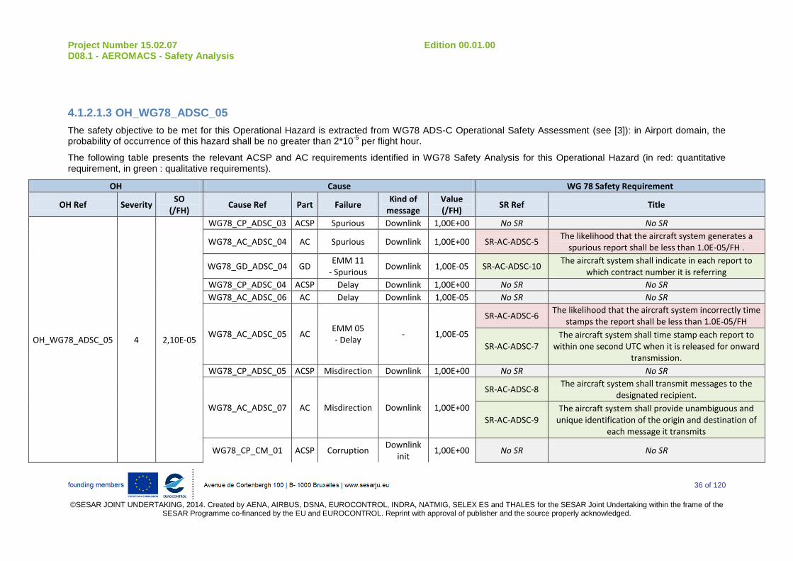
Project Number 15.02.07 Edition 00.01.00 D08.1 - AEROMACS - Safety Analysis
36 of 120
©SESAR JOINT UNDERTAKING, 2014. Created by AENA, AIRBUS, DSNA, EUROCONTROL, INDRA, NATMIG, SELEX ES and THALES for the SESAR Joint Undertaking within the frame of the
SESAR Programme co-financed by the EU and EUROCONTROL. Reprint with approval of publisher and the source properly acknowledged.
4.1.2.1.3 OH_WG78_ADSC_05
The safety objective to be met for this Operational Hazard is extracted from WG78 ADS-C Operational Safety Assessment (see [3]): in Airport domain, the probability of occurrence of this hazard shall be no greater than 2*10
-5 per flight hour.
The following table presents the relevant ACSP and AC requirements identified in WG78 Safety Analysis for this Operational Hazard (in red: quantitative requirement, in green : qualitative requirements).
OH Cause WG 78 Safety Requirement
OH Ref Severity SO
(/FH) Cause Ref Part Failure
Kind of message
Value (/FH)
SR Ref Title
OH_WG78_ADSC_05 4 2,10E-05
WG78_CP_ADSC_03 ACSP Spurious Downlink 1,00E+00 No SR No SR
WG78_AC_ADSC_04 AC Spurious Downlink 1,00E+00 SR-AC-ADSC-5 The likelihood that the aircraft system generates a
spurious report shall be less than 1.0E-05/FH .
WG78_GD_ADSC_04 GD EMM 11
- Spurious Downlink 1,00E-05 SR-AC-ADSC-10
The aircraft system shall indicate in each report to which contract number it is referring
WG78_CP_ADSC_04 ACSP Delay Downlink 1,00E+00 No SR No SR
WG78_AC_ADSC_06 AC Delay Downlink 1,00E-05 No SR No SR
WG78_AC_ADSC_05 AC EMM 05 - Delay
- 1,00E-05
SR-AC-ADSC-6 The likelihood that the aircraft system incorrectly time
stamps the report shall be less than 1.0E-05/FH
SR-AC-ADSC-7 The aircraft system shall time stamp each report to
within one second UTC when it is released for onward transmission.
WG78_CP_ADSC_05 ACSP Misdirection Downlink 1,00E+00 No SR No SR
WG78_AC_ADSC_07 AC Misdirection Downlink 1,00E+00
SR-AC-ADSC-8 The aircraft system shall transmit messages to the
designated recipient.
SR-AC-ADSC-9 The aircraft system shall provide unambiguous and
unique identification of the origin and destination of each message it transmits
WG78_CP_CM_01 ACSP Corruption Downlink
init 1,00E+00 No SR No SR

Project Number 15.02.07 Edition 00.01.00 D08.1 - AEROMACS - Safety Analysis
37 of 120
©SESAR JOINT UNDERTAKING, 2014. Created by AENA, AIRBUS, DSNA, EUROCONTROL, INDRA, NATMIG, SELEX ES and THALES for the SESAR Joint Undertaking within the frame of the
SESAR Programme co-financed by the EU and EUROCONTROL. Reprint with approval of publisher and the source properly acknowledged.
OH Cause WG 78 Safety Requirement
OH Ref Severity SO
(/FH) Cause Ref Part Failure
Kind of message
Value (/FH)
SR Ref Title
WG78_AC_CM_01 AC Corruption Downlink
init 1,00E-05
SR-AC-CM-01 The likelihood that the aircraft system sends incorrect
DLIC initiation data shall be less than 1.0E-05/FH
SR-AC-CM-02
The flight and aircraft identifiers (either the Registration Marking or the 24-bit Aircraft Address)
sent by the aircraft system, used for data link initiation correlation and ADS-C network address mapping, shall
be unique and unambiguous
WG78_CP_CM_02 ACSP Corruption Uplink init 1,00E+00 No SR No SR
WG78_AC_CM_02 AC Misdirection Uplink init 1,00E+00 No SR No SR Table 9: Relevant ACSP and AC safety requirements allocated from OH_WG78_ADSC_05
4.1.2.1.4 OH_WG78_CPDLC_02
The safety objective to be met for this Operational Hazard is extracted from WG78 CPDLC Operational Safety Assessment (see [2]): in Airport domain, the probability of occurrence of this hazard shall be no greater than 1.9*10
-5 per flight hour.
The following table presents the relevant ACSP and AC requirements identified in WG78 Safety Analysis for this Operational Hazard (in red: quantitative requirement, in green : qualitative requirements).
OH Cause WG 78 Safety Requirement
Ref Severity SO
(/FH) Cause Ref Part Failure
Kind of message
Value (/FH)
SR Ref Title
OH_WG78_CPDLC_02 4 1.90E-
05
WG78_CP_CPDLC_01 ACSP Unavailable Any 7.60E-06 No ref The likelihood that the ACSP is unavailable shall
be less than 7.6E-06/FH
WG78_AC_CPDLC_01 AC Unavailable Any 2.50E-03
No ref The likelihood that the AC system is unavailable
shall be less than 2.5E-03/FH
SR-AC-CPDLC-01 The aircraft system shall provide to the ATSU an
indication when it rejects a CPDLC service request initiated by the ATSU at the application layer.
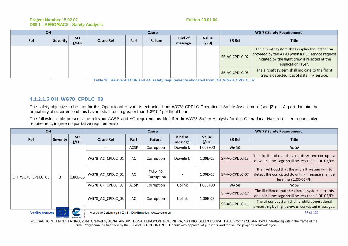
Project Number 15.02.07 Edition 00.01.00 D08.1 - AEROMACS - Safety Analysis
38 of 120
©SESAR JOINT UNDERTAKING, 2014. Created by AENA, AIRBUS, DSNA, EUROCONTROL, INDRA, NATMIG, SELEX ES and THALES for the SESAR Joint Undertaking within the frame of the
SESAR Programme co-financed by the EU and EUROCONTROL. Reprint with approval of publisher and the source properly acknowledged.
OH Cause WG 78 Safety Requirement
Ref Severity SO
(/FH) Cause Ref Part Failure
Kind of message
Value (/FH)
SR Ref Title
SR-AC-CPDLC-02
The aircraft system shall display the indication provided by the ATSU when a DSC service request
initiated by the flight crew is rejected at the application layer.
SR-AC-CPDLC-03 The aircraft system shall indicate to the flight
crew a detected loss of data link service. Table 10: Relevant ACSP and AC safety requirements allocated from OH_WG78_CPDLC_02
4.1.2.1.5 OH_WG78_CPDLC_03
The safety objective to be met for this Operational Hazard is extracted from WG78 CPDLC Operational Safety Assessment (see [2]): in Airport domain, the probability of occurrence of this hazard shall be no greater than 1.8*10
-5 per flight hour.
The following table presents the relevant ACSP and AC requirements identified in WG78 Safety Analysis for this Operational Hazard (in red: quantitative requirement, in green : qualitative requirements).
OH Cause WG 78 Safety Requirement
Ref Severity SO
(/FH) Cause Ref Part Failure
Kind of message
Value (/FH)
SR Ref Title
OH_WG78_CPDLC_03 3 1.80E-05
- ACSP Corruption Downlink 1.00E+00 No SR No SR
WG78_AC_CPDLC_01 AC Corruption Downlink 1.00E-05 SR-AC-CPDLC-13 The likelihood that the aircraft system corrupts a downlink message shall be less than 1.0E-05/FH
WG78_AC_CPDLC_02 AC EMM 02
- Corruption - 1.00E-05 SR-AC-CPDLC-07
The likelihood that the aircraft system fails to detect the corrupted downlink message shall be
less than 1.0E-05/FH
WG78_CP_CPDLC_01 ACSP Corruption Uplink 1.00E+00 No SR No SR
WG78_AC_CPDLC_03 AC Corruption Uplink 1.00E-05
SR-AC-CPDLC-17 The likelihood that the aircraft system corrupts an uplink message shall be less than 1.0E-05/FH
SR-AC-CPDLC-11 The aircraft system shall prohibit operational
processing by flight crew of corrupted messages.
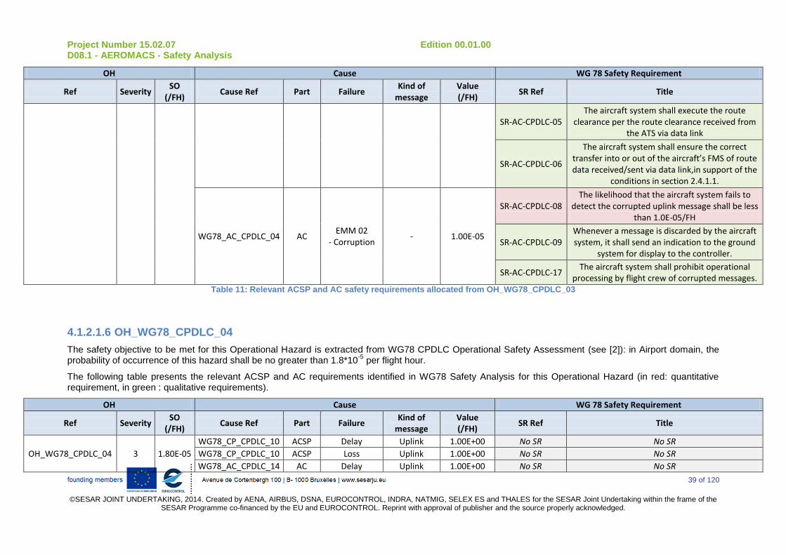
Project Number 15.02.07 Edition 00.01.00 D08.1 - AEROMACS - Safety Analysis
39 of 120
©SESAR JOINT UNDERTAKING, 2014. Created by AENA, AIRBUS, DSNA, EUROCONTROL, INDRA, NATMIG, SELEX ES and THALES for the SESAR Joint Undertaking within the frame of the
SESAR Programme co-financed by the EU and EUROCONTROL. Reprint with approval of publisher and the source properly acknowledged.
OH Cause WG 78 Safety Requirement
Ref Severity SO
(/FH) Cause Ref Part Failure
Kind of message
Value (/FH)
SR Ref Title
SR-AC-CPDLC-05 The aircraft system shall execute the route
clearance per the route clearance received from the ATS via data link
SR-AC-CPDLC-06
The aircraft system shall ensure the correct transfer into or out of the aircraft’s FMS of route data received/sent via data link,in support of the
conditions in section 2.4.1.1.
WG78_AC_CPDLC_04 AC EMM 02
- Corruption - 1.00E-05
SR-AC-CPDLC-08 The likelihood that the aircraft system fails to
detect the corrupted uplink message shall be less than 1.0E-05/FH
SR-AC-CPDLC-09 Whenever a message is discarded by the aircraft system, it shall send an indication to the ground
system for display to the controller.
SR-AC-CPDLC-17 The aircraft system shall prohibit operational
processing by flight crew of corrupted messages. Table 11: Relevant ACSP and AC safety requirements allocated from OH_WG78_CPDLC_03
4.1.2.1.6 OH_WG78_CPDLC_04
The safety objective to be met for this Operational Hazard is extracted from WG78 CPDLC Operational Safety Assessment (see [2]): in Airport domain, the probability of occurrence of this hazard shall be no greater than 1.8*10
-5 per flight hour.
The following table presents the relevant ACSP and AC requirements identified in WG78 Safety Analysis for this Operational Hazard (in red: quantitative requirement, in green : qualitative requirements).
OH Cause WG 78 Safety Requirement
Ref Severity SO
(/FH) Cause Ref Part Failure
Kind of message
Value (/FH)
SR Ref Title
OH_WG78_CPDLC_04 3 1.80E-05
WG78_CP_CPDLC_10 ACSP Delay Uplink 1.00E+00 No SR No SR
WG78_CP_CPDLC_10 ACSP Loss Uplink 1.00E+00 No SR No SR
WG78_AC_CPDLC_14 AC Delay Uplink 1.00E+00 No SR No SR
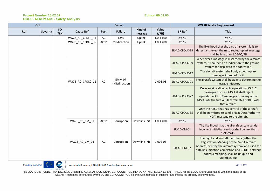
Project Number 15.02.07 Edition 00.01.00 D08.1 - AEROMACS - Safety Analysis
40 of 120
©SESAR JOINT UNDERTAKING, 2014. Created by AENA, AIRBUS, DSNA, EUROCONTROL, INDRA, NATMIG, SELEX ES and THALES for the SESAR Joint Undertaking within the frame of the
SESAR Programme co-financed by the EU and EUROCONTROL. Reprint with approval of publisher and the source properly acknowledged.
OH Cause WG 78 Safety Requirement
Ref Severity SO
(/FH) Cause Ref Part Failure
Kind of message
Value (/FH)
SR Ref Title
WG78_AC_CPDLC_14 AC Loss Uplink 1.00E+00 No SR No SR
WG78_CP_CPDLC_06 ACSP Misdirection Uplink 1.00E+00 No SR No SR
WG78_AC_CPDLC_12 AC EMM 07
- Misdirection - 1.00E-05
SR-AC-CPDLC-19 The likelihood that the aircraft system fails to
detect and reject the misdirected uplink message shall be less than 1.0E-05/FH
SR-AC-CPDLC-09 Whenever a message is discarded by the aircraft system, it shall send an indication to the ground
system for display to the controller.
SR-AC-CPDLC-12 The aircraft system shall only accept uplink
messages intended for it.
SR-AC-CPDLC-21 The aircraft system shall be able to determine the
message initiator.
SR-AC-CPDLC-22
Once an aircraft accepts operational CPDLC messages from an ATSU, it shall reject
operational CPDLC messages from any other ATSU until the first ATSU terminates CPDLC with
that aircraft.
SR-AC-CPDLC-35 Only the ATSU that has control of the aircraft
shall be permitted to send a Next Data Authority (NDA) message to the aircraft.
WG78_CP_CM_01 ACSP Corruption Downlink init 1.00E+00 No SR No SR
WG78_AC_CM_01 AC Corruption Downlink init 1.00E-05
SR-AC-CM-01 The likelihood that the aircraft system sends incorrect initialisation data shall be less than
1.0E-05/FH
SR-AC-CM-02
The flight and aircraft identifiers (either the Registration Marking or the 24-bit Aircraft
Address) sent by the aircraft system, and used for data link initiation correlation and CPDLC network
address mapping, shall be unique and unambiguous
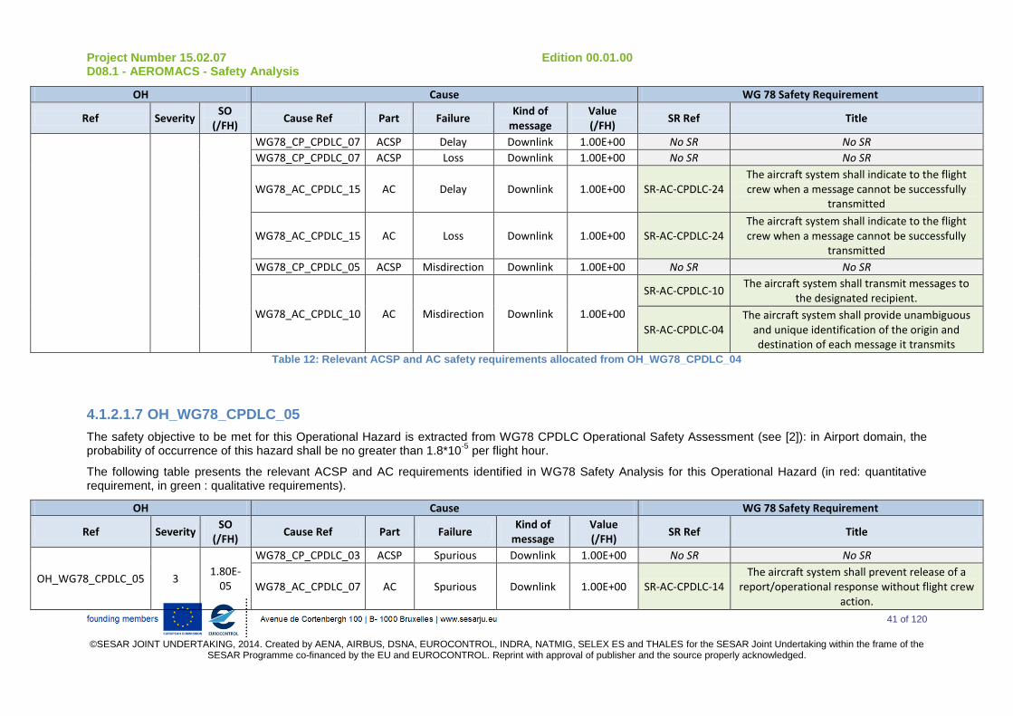
Project Number 15.02.07 Edition 00.01.00 D08.1 - AEROMACS - Safety Analysis
41 of 120
©SESAR JOINT UNDERTAKING, 2014. Created by AENA, AIRBUS, DSNA, EUROCONTROL, INDRA, NATMIG, SELEX ES and THALES for the SESAR Joint Undertaking within the frame of the
SESAR Programme co-financed by the EU and EUROCONTROL. Reprint with approval of publisher and the source properly acknowledged.
OH Cause WG 78 Safety Requirement
Ref Severity SO
(/FH) Cause Ref Part Failure
Kind of message
Value (/FH)
SR Ref Title
WG78_CP_CPDLC_07 ACSP Delay Downlink 1.00E+00 No SR No SR
WG78_CP_CPDLC_07 ACSP Loss Downlink 1.00E+00 No SR No SR
WG78_AC_CPDLC_15 AC Delay Downlink 1.00E+00 SR-AC-CPDLC-24 The aircraft system shall indicate to the flight crew when a message cannot be successfully
transmitted
WG78_AC_CPDLC_15 AC Loss Downlink 1.00E+00 SR-AC-CPDLC-24 The aircraft system shall indicate to the flight crew when a message cannot be successfully
transmitted
WG78_CP_CPDLC_05 ACSP Misdirection Downlink 1.00E+00 No SR No SR
WG78_AC_CPDLC_10 AC Misdirection Downlink 1.00E+00
SR-AC-CPDLC-10 The aircraft system shall transmit messages to
the designated recipient.
SR-AC-CPDLC-04 The aircraft system shall provide unambiguous
and unique identification of the origin and destination of each message it transmits
Table 12: Relevant ACSP and AC safety requirements allocated from OH_WG78_CPDLC_04
4.1.2.1.7 OH_WG78_CPDLC_05
The safety objective to be met for this Operational Hazard is extracted from WG78 CPDLC Operational Safety Assessment (see [2]): in Airport domain, the probability of occurrence of this hazard shall be no greater than 1.8*10
-5 per flight hour.
The following table presents the relevant ACSP and AC requirements identified in WG78 Safety Analysis for this Operational Hazard (in red: quantitative requirement, in green : qualitative requirements).
OH Cause WG 78 Safety Requirement
Ref Severity SO
(/FH) Cause Ref Part Failure
Kind of message
Value (/FH)
SR Ref Title
OH_WG78_CPDLC_05 3 1.80E-
05
WG78_CP_CPDLC_03 ACSP Spurious Downlink 1.00E+00 No SR No SR
WG78_AC_CPDLC_07 AC Spurious Downlink 1.00E+00 SR-AC-CPDLC-14 The aircraft system shall prevent release of a
report/operational response without flight crew action.
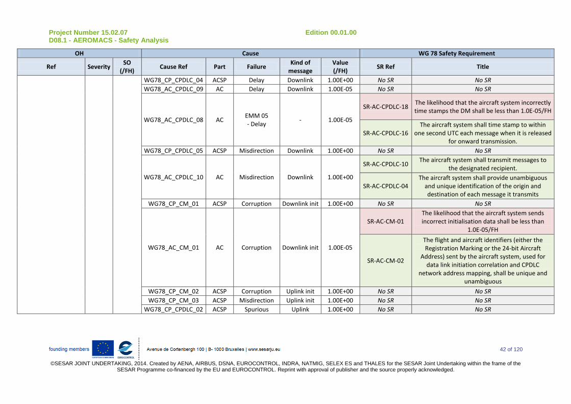
Project Number 15.02.07 Edition 00.01.00 D08.1 - AEROMACS - Safety Analysis
42 of 120
©SESAR JOINT UNDERTAKING, 2014. Created by AENA, AIRBUS, DSNA, EUROCONTROL, INDRA, NATMIG, SELEX ES and THALES for the SESAR Joint Undertaking within the frame of the
SESAR Programme co-financed by the EU and EUROCONTROL. Reprint with approval of publisher and the source properly acknowledged.
OH Cause WG 78 Safety Requirement
Ref Severity SO
(/FH) Cause Ref Part Failure
Kind of message
Value (/FH)
SR Ref Title
WG78_CP_CPDLC_04 ACSP Delay Downlink 1.00E+00 No SR No SR
WG78_AC_CPDLC_09 AC Delay Downlink 1.00E-05 No SR No SR
WG78_AC_CPDLC_08 AC EMM 05 - Delay
- 1.00E-05
SR-AC-CPDLC-18 The likelihood that the aircraft system incorrectly time stamps the DM shall be less than 1.0E-05/FH
SR-AC-CPDLC-16 The aircraft system shall time stamp to within
one second UTC each message when it is released for onward transmission.
WG78_CP_CPDLC_05 ACSP Misdirection Downlink 1.00E+00 No SR No SR
WG78_AC_CPDLC_10 AC Misdirection Downlink 1.00E+00
SR-AC-CPDLC-10 The aircraft system shall transmit messages to
the designated recipient.
SR-AC-CPDLC-04 The aircraft system shall provide unambiguous
and unique identification of the origin and destination of each message it transmits
WG78_CP_CM_01 ACSP Corruption Downlink init 1.00E+00 No SR No SR
WG78_AC_CM_01 AC Corruption Downlink init 1.00E-05
SR-AC-CM-01 The likelihood that the aircraft system sends incorrect initialisation data shall be less than
1.0E-05/FH
SR-AC-CM-02
The flight and aircraft identifiers (either the Registration Marking or the 24-bit Aircraft
Address) sent by the aircraft system, used for data link initiation correlation and CPDLC
network address mapping, shall be unique and unambiguous
WG78_CP_CM_02 ACSP Corruption Uplink init 1.00E+00 No SR No SR
WG78_CP_CM_03 ACSP Misdirection Uplink init 1.00E+00 No SR No SR
WG78_CP_CPDLC_02 ACSP Spurious Uplink 1.00E+00 No SR No SR

Project Number 15.02.07 Edition 00.01.00 D08.1 - AEROMACS - Safety Analysis
43 of 120
©SESAR JOINT UNDERTAKING, 2014. Created by AENA, AIRBUS, DSNA, EUROCONTROL, INDRA, NATMIG, SELEX ES and THALES for the SESAR Joint Undertaking within the frame of the
SESAR Programme co-financed by the EU and EUROCONTROL. Reprint with approval of publisher and the source properly acknowledged.
OH Cause WG 78 Safety Requirement
Ref Severity SO
(/FH) Cause Ref Part Failure
Kind of message
Value (/FH)
SR Ref Title
WG78_AC_CPDLC_06 AC EMM 10 - Spurious
- 1.00E-05
SR-AC-CPDLC-25
Upon receipt of an UM, containing an MRN, the likelihood of the aircraft system, not rejecting
that does not match a DM MIN shall be less than 1.E-5/FH.
SR-AC-CPDLC-20 The aircraft system shall indicate in each
response to which messages it refers
SR-AC-CPDLC-26 Each downlink message shall be uniquely
identified for a given aircraft-ATSU pair, following a sequential order
WG78_CP_CPDLC_01 ACSP Delay Uplink 1.00E+00 No SR No SR
WG78_AC_CPDLC_02 AC Delay Uplink 1.00E+00 No SR No SR
WG78_AC_CPDLC_01 AC EMM 06 - Delay
- 1.00E-05
SR-AC-CPDLC-09 Whenever a message is discarded by the aircraft system, it shall send an indication to the ground
system for display to the controller.
SR-AC-CPDLC-15
When a received message contains a time stamp that indicates the Latency Time Check value, set at equal or less than ETTRN, has been exceeded, the aircraft system shall a) discard the message
and send an indication to the Ground System for display to the controller or b) provide the
message to the flight crew with an appropriate indication.
SR-AC-CPDLC-16 The aircraft system shall time stamp to within
one second UTC each message when it is released for onward transmission
WG78_CP_CPDLC_06 ACSP Misdirection Uplink 1.00E+00 No SR No SR
WG78_AC_CPDLC_11 AC Misdirection Uplink 1.00E-05 SR-AC-CPDLC-12 The aircraft system shall only accept uplink
messages intended for it.

Project Number 15.02.07 Edition 00.01.00 D08.1 - AEROMACS - Safety Analysis
44 of 120
©SESAR JOINT UNDERTAKING, 2014. Created by AENA, AIRBUS, DSNA, EUROCONTROL, INDRA, NATMIG, SELEX ES and THALES for the SESAR Joint Undertaking within the frame of the
SESAR Programme co-financed by the EU and EUROCONTROL. Reprint with approval of publisher and the source properly acknowledged.
OH Cause WG 78 Safety Requirement
Ref Severity SO
(/FH) Cause Ref Part Failure
Kind of message
Value (/FH)
SR Ref Title
SR-AC-CPDLC-06
The aircraft system shall ensure the correct transfer into or out of the aircraft’s FMS of route data received/sent via data link, in support of the
conditions in section 2.4.1.1.
SR-AC-CM-01
The flight crew shall perform the initiation data link procedure again with any change of the
aircraft identifiers (e.g. the Flight Identification and either the Registration Marking or the
Aircraft Address)
WG78_AC_CPDLC_12 AC EMM 07
- Misdirection - 1.00E-05
SR-AC-CPDLC-19 The likelihood that the aircraft system fails to
detect and reject the misdirected uplink message shall be less than 1.0E-05/FH
SR-AC-CPDLC-09 Whenever a message is discarded by the aircraft system, it shall send an indication to the ground
system for display to the controller.
SR-AC-CPDLC-12 The aircraft system shall only accept uplink
messages intended for it.
SR-AC-CPDLC-21 The aircraft system shall be able to determine the
message initiator.
SR-AC-CPDLC-22
Once an aircraft accepts operational CPDLC messages from an ATSU, it shall reject
operational CPDLC messages from any other ATSU until the first ATSU terminates CPDLC with
that aircraft.
WG78_FC_CPDLC_01 FC - - - SR-AC-CPDLC-23 The aircraft system shall provide to the flight
crew an indication of the ATSU that has established CPDLC (CDA) service.
Table 13: Relevant ACSP and AC safety requirements allocated from OH_WG78_CPDLC_05

Project Number 15.02.07 Edition 00.01.00 D08.1 - AEROMACS - Safety Analysis
45 of 120
©SESAR JOINT UNDERTAKING, 2014. Created by AENA, AIRBUS, DSNA, EUROCONTROL, INDRA, NATMIG, SELEX ES and THALES for the SESAR Joint Undertaking within the frame of the
SESAR Programme co-financed by the EU and EUROCONTROL. Reprint with approval of publisher and the source properly acknowledged.
4.1.2.1.8 OH_WG78_FIS_3u
The safety objective to be met for this Operational Hazard is extracted from WG78 FIS Operational Safety Assessment (see [4]): in Airport domain, the probability of occurrence of this hazard shall be no greater than 2.7*10
-6 per flight hour.
The following table presents the relevant ACSP and AC requirements identified in WG78 Safety Analysis for this Operational Hazard (in red: quantitative requirement, in green : qualitative requirements).
OH Cause WG 78 Safety Requirement
OH Ref Severity SO
(/FH) Cause Ref Part Failure
Kind of message
Value (/FH)
SR Ref Title
OH_WG78_FIS_3u 3 2.70E-06
WG78_CP_DOTIS_01 ACSP Corruption Downlink 2.80E-03 SR-CP-DOTIS-01 The likelihood that the ACSP corrupts a request shall
be less than 2.8E-03/FH
WG78_AC_DOTIS_01 AC Corruption Downlink 2.80E-03 SR-AC-DOTIS-01 The likelihood that the aircraft system corrupts the request without detecting it before the request is
sent shall be less than 2.8E-03/FH
WG78_AC_DOTIS_02 AC Corruption Downlink 2.80E-03 SR-AC-DOTIS-02 The likelihood that the aircraft HMI does not display data as inserted by the flight crew shall be less than
2.8E-03/FH
WG78_CP_DOTIS_02 ACSP Corruption Uplink 2.80E-03 SR-CP-DOTIS-02 The likelihood that the ACSP corrupts a report shall be
less than 2.8E-03/FH
WG78_AC_DOTIS_05 AC Corruption Uplink 2.80E-03 SR-AC-DOTIS-05 The likelihood that the aircraft system corrupts the
report when it receives it and does not detect it shall be less than 2.8E-03/FH
WG78_AC_DOTIS_04 AC EMM 02
- Corruption - 2.80E-03 SR-AC-DOTIS-04
The likelihood that the aircraft system fails to detect and reject a corrupted report shall be less than 2.8E-
03/FH
WG78_AC_DOTIS_03 AC Corruption Uplink 1.30E-03 SR-AC-DOTIS-03 The likelihood that the aircraft system corrupts the
report after having checked the end to end integrity shall be less than 1.3E-03/FH
Table 14 : Relevant ACSP and AC safety requirements allocated from OH_WG78_FIS_3u

Project Number 15.02.07 Edition 00.01.00 D08.1 - AEROMACS - Safety Analysis
46 of 120
©SESAR JOINT UNDERTAKING, 2014. Created by AENA, AIRBUS, DSNA, EUROCONTROL, INDRA, NATMIG, SELEX ES and THALES for the SESAR Joint Undertaking within the frame of the
SESAR Programme co-financed by the EU and EUROCONTROL. Reprint with approval of publisher and the source properly acknowledged.
4.1.2.1.9 Others WG78 OH
The others WG78 Operational Hazard identified in § 4.1.1.3 are:
- OH_WG78_CPDLC_01
- OH_WG78_ADSC_01
- OH_WG78_ADSC_07
- OH_WG78_FIS_1d
- OH_WG78_FIS_3d
- OH_WG78_FIS_3u
- OH_WG78_FIS_4d
- OH_WG78_FIS_4u
- OH_WG78_FIS_5u
- OH_WG78_FIS_6d
- OH_WG78_FIS_6u
These Operational Hazards are classified with a severity 5 (SC5) and no Safety Objectives has been defined from these hazards. Consequently there is no Safety Requirement derived from these hazards.
4.1.2.2 Definition ACSP and AC Safety Requirement from NEW Operational Hazards
This sub-task consists in performing the allocation of the Safety Objectives associated to NEW Operational Hazards on the different contributors.
This allocation includes two steps:
- For each NEW Operational Hazard, a fault tree is constructed identifying all potential contributors for this Operational Hazard (including ACSP and AC failures). Safety Requirements are defined by allocating the Safety Objective on the different contributors. Working Group documents are used as references to determine the values that can reasonably be allocated on the different contributors.
- For each New Operational Hazard, relevant Safety Requirements are identified amongst all the safety requirements The AeroMACS is split between Aircraft System and ACSP. So, the relevant Safety Requirements are the requirements allocated to Aircraft system or ACSP and that concerns the exchange of message between ground and aircraft.
The list of New relevant Safety Requirements are referenced as follow: “SR_NEW_XX_YY_ZZ: xxxx”

Project Number 15.02.07 Edition 00.01.00 D08.1 - AEROMACS - Safety Analysis
47 of 120
©SESAR JOINT UNDERTAKING, 2014. Created by AENA, AIRBUS, DSNA, EUROCONTROL, INDRA, NATMIG, SELEX ES and THALES for the SESAR Joint Undertaking within the frame of the
SESAR Programme co-financed by the EU and EUROCONTROL. Reprint with approval of publisher and the source properly acknowledged.
- XX: identify the part on which the safety requirement is allocated: “CP” for ACSP or “AC” for Aircraft System
- YY: identify the application associated to the fault tree : “ADSC”, “CM”, “CPDLC” or “FIS”
- ZZ : is a reference number of the safety requirement
- xxxx title of the NEW Safety Requirement
The following chapters present the relevant safety requirements defined from each New OH identified in § 4.1.1.3.
4.1.2.2.1 OH_NEW_ALL_01
This Operational Hazard is classified with a severity 5 (SC5) and no Safety Objective has been defined from this hazard. Consequently there is no Safety Requirements derived from this hazard.
4.1.2.2.2 OH_NEW_ALL_02
This new operational hazard consists in an impossibility to exchange any data link message with more than one aircraft. The Safety Objective to be met shall be no greater than 1.9*10
-5 /FH
In order for this hazard to occur:
a) All the ground system are unavailable or
b) The ACSP is unavailable or
c) More than one aircraft system is unavailable.
The following assumption is made for the unavailability of the ground systems
- ASSUMP-AEROMACS_08: The probability that all the ground systems are unavailable is assumed to be less than 7*10-6
per flight hour.
Justification: WG78 CPDLC OSA has defined a safety requirement of 7*10-6
for the unavailability of the CPDLC ground system. A failure of all the ground system should be lower than this requirement (multiple failure should occur to induce a failure of all ground systems).
The following figure presents the fault tree of OH_NEW_ALL_02 :

Project Number 15.02.07 Edition 00.01.00 D08.1 - AEROMACS - Safety Analysis
48 of 120
©SESAR JOINT UNDERTAKING, 2014. Created by AENA, AIRBUS, DSNA, EUROCONTROL, INDRA, NATMIG, SELEX ES and THALES for the SESAR Joint Undertaking within the frame of the
SESAR Programme co-financed by the EU and EUROCONTROL. Reprint with approval of publisher and the source properly acknowledged.
Failure to exchange messages with more thanone aircraft
OH_NEW_ALL_02
All ground systems areunavailable
GD_NEW_ALL_01
ACSP is unavailable
CP_NEW_ALL_01
Aircraft system unavailable inmultiple aircraft
AC_NEW_ALL
Aircraft system isunavailable in one
aircraft
AC_NEW_ALL_01
Aircraft system isunavailable in one
aircraft
AC_NEW_ALL_01
7e-6 / FH 7e-6 / FH
1.9e-5 / FH
2.5e-3 / FH
5e-6 / FH
2.5e-3 / FH
Figure 9 : OH_NEW_ALL_02 – Fault tree
The following table presents the causes identified on ACSP and AC for this OH, the values allocated on these causes and the associated Safety Requirements (in red: quantitative requirement, in green : qualitative requirements).
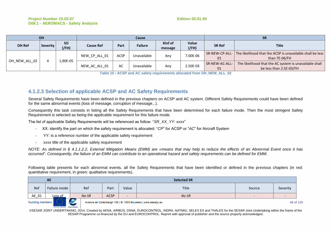
Project Number 15.02.07 Edition 00.01.00 D08.1 - AEROMACS - Safety Analysis
49 of 120
©SESAR JOINT UNDERTAKING, 2014. Created by AENA, AIRBUS, DSNA, EUROCONTROL, INDRA, NATMIG, SELEX ES and THALES for the SESAR Joint Undertaking within the frame of the
SESAR Programme co-financed by the EU and EUROCONTROL. Reprint with approval of publisher and the source properly acknowledged.
OH Cause SR
OH Ref Severity SO
(/FH) Cause Ref Part Failure
Kinf of message
Value (/FH)
SR Ref Title
OH_NEW_ALL_02 4 1,90E-05
NEW_CP_ALL_01 ACSP Unavailable Any 7.00E-06 SR-NEW-CP-ALL-
01 The likelihood that the ACSP is unavailable shall be less
than 7E-06/FH
NEW_AC_ALL_01 AC Unavailable Any 2.50E-03 SR-NEW-AC-ALL-
01 The likelihood that the AC system is unavailable shall
be less than 2.5E-03/FH Table 15 : ACSP and AC safety requirements allocated from OH_NEW_ALL_02
4.1.2.3 Selection of applicable ACSP and AC Safety Requirements
Several Safety Requirements have been defined in the previous chapters on ACSP and AC system. Different Safety Requirements could have been defined for the same abnormal events (loss of message, corruption of message...).
Consequently this task consists in listing all the Safety Requirements that have been determined for each failure mode. Then the most stringent Safety Requirement is selected as being the applicable requirement for this failure mode.
The list of applicable Safety Requirements will be referenced as follow: “SR_XX_YY: xxxx”
- XX: identify the part on which the safety requirement is allocated: “CP” for ACSP or “AC” for Aircraft System
- YY: is a reference number of the applicable safety requirement
- xxxx title of the applicable safety requirement
NOTE: As defined in § 4.1.1.2.2, External Mitigation Means (EMM) are «means that may help to reduce the effects of an Abnormal Event once it has occurred". Consequently, the failure of an EMM can contribute to an operational hazard and safety requirements can be defined for EMM.
Following table presents for each abnormal events, all the Safety Requirements that have been identified or defined in the previous chapters (in red: quantitative requirement, in green: qualitative requirements).
AE Selected SR
Ref Failure mode Ref Part Value Title Source Severity
AE_01 Loss of No SR ACSP - No SR - -
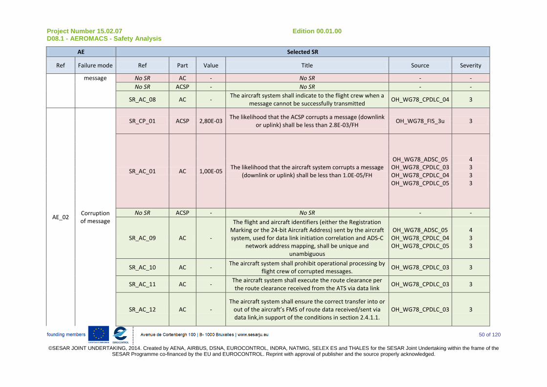
Project Number 15.02.07 Edition 00.01.00 D08.1 - AEROMACS - Safety Analysis
50 of 120
©SESAR JOINT UNDERTAKING, 2014. Created by AENA, AIRBUS, DSNA, EUROCONTROL, INDRA, NATMIG, SELEX ES and THALES for the SESAR Joint Undertaking within the frame of the
SESAR Programme co-financed by the EU and EUROCONTROL. Reprint with approval of publisher and the source properly acknowledged.
AE Selected SR
Ref Failure mode Ref Part Value Title Source Severity
message No SR AC - No SR - -
No SR ACSP - No SR - -
SR_AC_08 AC - The aircraft system shall indicate to the flight crew when a
message cannot be successfully transmitted OH_WG78_CPDLC_04 3
AE_02 Corruption of message
SR_CP_01 ACSP 2,80E-03 The likelihood that the ACSP corrupts a message (downlink
or uplink) shall be less than 2.8E-03/FH OH_WG78_FIS_3u 3
SR_AC_01 AC 1,00E-05 The likelihood that the aircraft system corrupts a message
(downlink or uplink) shall be less than 1.0E-05/FH
OH_WG78_ADSC_05 OH_WG78_CPDLC_03 OH_WG78_CPDLC_04 OH_WG78_CPDLC_05
4 3 3 3
No SR ACSP - No SR - -
SR_AC_09 AC -
The flight and aircraft identifiers (either the Registration Marking or the 24-bit Aircraft Address) sent by the aircraft system, used for data link initiation correlation and ADS-C
network address mapping, shall be unique and unambiguous
OH_WG78_ADSC_05 OH_WG78_CPDLC_04 OH_WG78_CPDLC_05
4 3 3
SR_AC_10 AC - The aircraft system shall prohibit operational processing by
flight crew of corrupted messages. OH_WG78_CPDLC_03 3
SR_AC_11 AC - The aircraft system shall execute the route clearance per the route clearance received from the ATS via data link
OH_WG78_CPDLC_03 3
SR_AC_12 AC - The aircraft system shall ensure the correct transfer into or
out of the aircraft’s FMS of route data received/sent via data link,in support of the conditions in section 2.4.1.1.
OH_WG78_CPDLC_03 3

Project Number 15.02.07 Edition 00.01.00 D08.1 - AEROMACS - Safety Analysis
51 of 120
©SESAR JOINT UNDERTAKING, 2014. Created by AENA, AIRBUS, DSNA, EUROCONTROL, INDRA, NATMIG, SELEX ES and THALES for the SESAR Joint Undertaking within the frame of the
SESAR Programme co-financed by the EU and EUROCONTROL. Reprint with approval of publisher and the source properly acknowledged.
AE Selected SR
Ref Failure mode Ref Part Value Title Source Severity
AE_03 Misdirection of message
No SR ACSP - No SR - -
No SR AC - No SR - -
No SR ACSP - No SR - -
SR_AC_13 AC - The aircraft system shall transmit messages to the
designated recipient.
OH_WG78_ADSC_05 OH_WG78_CPDLC_04 OH_WG78_CPDLC_05
4 3 3
SR_AC_14 AC - The aircraft system shall provide unambiguous and unique identification of the origin and destination of each message
it transmits
OH_WG78_ADSC_05 OH_WG78_CPDLC_04 OH_WG78_CPDLC_05
4 3 3
SR_AC_15 AC - The aircraft system shall only accept uplink messages
intended for it. OH_WG78_CPDLC_05 3
SR_AC_16 AC -
The flight crew shall perform the initiation data link procedure again with any change of the aircraft identifiers
(e.g. the Flight Identification and either the Registration Marking or the Aircraft Address)
OH_WG78_CPDLC_05 3
AE_04 Delay of message
No SR ACSP - No SR - -
No SR AC - No SR - -
No SR ACSP - No SR - -
No SR AC - No SR - -
AE_05 Spurious message
No SR ACSP - No SR - -
SR_AC_02 AC 1,00E-05 The likelihood that the aircraft system generates a spurious
report shall be less than 1.0E-05/FH . OH_WG78_ADSC_05 4
No SR ACSP - No SR - -
SR_AC_17 AC - The aircraft system shall prevent release of a
report/operational response without flight crew action. OH_WG78_CPDLC_05 3
AE_06 Availability
Use
No SR ACSP - No SR - -
No SR AC - No SR - -
No SR ACSP - No SR - -
No SR AC - No SR - -

Project Number 15.02.07 Edition 00.01.00 D08.1 - AEROMACS - Safety Analysis
52 of 120
©SESAR JOINT UNDERTAKING, 2014. Created by AENA, AIRBUS, DSNA, EUROCONTROL, INDRA, NATMIG, SELEX ES and THALES for the SESAR Joint Undertaking within the frame of the
SESAR Programme co-financed by the EU and EUROCONTROL. Reprint with approval of publisher and the source properly acknowledged.
AE Selected SR
Ref Failure mode Ref Part Value Title Source Severity
AE_07 Availability provision
SR_CP_02 ACSP 7,60E-06 The likelihood that the ACSP is unavailable shall be less
than 7.6E-06/FH
OH_WG78_ADSC_02 OH_WG78_CPDLC_02
OH_NEW_ALL_02
4 4 4
SR_AC_03 AC 2,50E-03 The likelihood that the AC system is unavailable shall be
less than 2.5E-03/FH
OH_WG78_ADSC_02 OH_WG78_CPDLC_02
OH_NEW_ALL_02
4 4 4
No SR ACSP - No SR - -
SR_AC_18 AC - The aircraft system shall provide to the ATSU an indication
when it rejects an ADS-C service request initiated by the ATSU at the application layer.
OH_WG78_ADSC_02 4
SR_AC_19 AC - The aircraft system shall indicate to the flight crew a
detected loss of ADS-C service. OH_WG78_ADSC_02 4
SR_AC_20 AC - The aircraft system shall provide to the ATSU an indication
when it rejects a CPDLC service request initiated by the ATSU at the application layer.
OH_WG78_CPDLC_02 4
SR_AC_21 AC - The aircraft system shall display the indication provided by the ATSU when a DSC service request initiated by the flight
crew is rejected at the application layer. OH_WG78_CPDLC_02 4
SR_AC_22 AC - The aircraft system shall indicate to the flight crew a
detected loss of data link service. OH_WG78_CPDLC_02 4
EMM_01
Detection of inappropriate messages by
the crew
SR_AC_33 AC The aircraft system shall provide to the flight crew an
indication of the ATSU that has established CPDLC (CDA) service.
OH_WG78_CPDLC_05 3
EMM 02 Detection of
corrupted messages
SR_AC_04 AC 1,00E-05 The likelihood that the aircraft system fails to detect the
corrupted message shall be less than 1.0E-05/FH OH_WG78_CPDLC_03 3
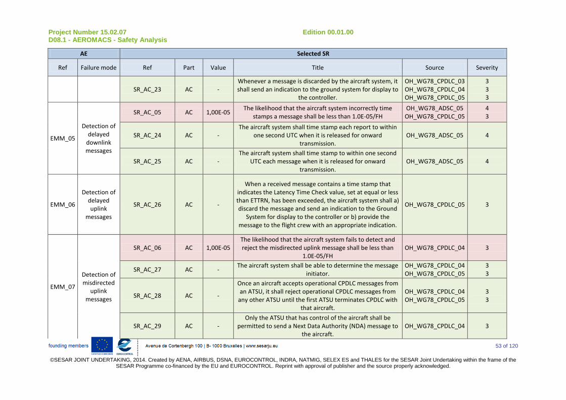
Project Number 15.02.07 Edition 00.01.00 D08.1 - AEROMACS - Safety Analysis
53 of 120
©SESAR JOINT UNDERTAKING, 2014. Created by AENA, AIRBUS, DSNA, EUROCONTROL, INDRA, NATMIG, SELEX ES and THALES for the SESAR Joint Undertaking within the frame of the
SESAR Programme co-financed by the EU and EUROCONTROL. Reprint with approval of publisher and the source properly acknowledged.
AE Selected SR
Ref Failure mode Ref Part Value Title Source Severity
SR_AC_23 AC - Whenever a message is discarded by the aircraft system, it shall send an indication to the ground system for display to
the controller.
OH_WG78_CPDLC_03 OH_WG78_CPDLC_04 OH_WG78_CPDLC_05
3 3 3
EMM_05
Detection of delayed
downlink messages
SR_AC_05 AC 1,00E-05 The likelihood that the aircraft system incorrectly time
stamps a message shall be less than 1.0E-05/FH OH_WG78_ADSC_05 OH_WG78_CPDLC_05
4 3
SR_AC_24 AC - The aircraft system shall time stamp each report to within
one second UTC when it is released for onward transmission.
OH_WG78_ADSC_05 4
SR_AC_25 AC - The aircraft system shall time stamp to within one second
UTC each message when it is released for onward transmission.
OH_WG78_ADSC_05 4
EMM_06
Detection of delayed uplink
messages
SR_AC_26 AC -
When a received message contains a time stamp that indicates the Latency Time Check value, set at equal or less than ETTRN, has been exceeded, the aircraft system shall a) discard the message and send an indication to the Ground
System for display to the controller or b) provide the message to the flight crew with an appropriate indication.
OH_WG78_CPDLC_05 3
EMM_07
Detection of misdirected
uplink messages
SR_AC_06 AC 1,00E-05 The likelihood that the aircraft system fails to detect and reject the misdirected uplink message shall be less than
1.0E-05/FH OH_WG78_CPDLC_04 3
SR_AC_27 AC - The aircraft system shall be able to determine the message
initiator. OH_WG78_CPDLC_04 OH_WG78_CPDLC_05
3 3
SR_AC_28 AC -
Once an aircraft accepts operational CPDLC messages from an ATSU, it shall reject operational CPDLC messages from
any other ATSU until the first ATSU terminates CPDLC with that aircraft.
OH_WG78_CPDLC_04 OH_WG78_CPDLC_05
3 3
SR_AC_29 AC - Only the ATSU that has control of the aircraft shall be
permitted to send a Next Data Authority (NDA) message to the aircraft.
OH_WG78_CPDLC_04 3

Project Number 15.02.07 Edition 00.01.00 D08.1 - AEROMACS - Safety Analysis
54 of 120
©SESAR JOINT UNDERTAKING, 2014. Created by AENA, AIRBUS, DSNA, EUROCONTROL, INDRA, NATMIG, SELEX ES and THALES for the SESAR Joint Undertaking within the frame of the
SESAR Programme co-financed by the EU and EUROCONTROL. Reprint with approval of publisher and the source properly acknowledged.
AE Selected SR
Ref Failure mode Ref Part Value Title Source Severity
EMM_10
Detection of spurious
uplink messages
SR_AC_07 AC 1,00E-05 The likelihood to accept a message out of context of the
current transaction shall be less than 1.E-5/FH. OH_WG78_CPDLC_05 3
SR_AC_30 AC - The aircraft system shall indicate in each response to which
messages it refers OH_WG78_CPDLC_05 3
SR_AC_31 AC - Each downlink message shall be uniquely identified for a
given aircraft-ATSU pair, following a sequential order OH_WG78_CPDLC_05 3
EMM_11
Detection of spurious downlink messages
SR_AC_32 AC - The aircraft system shall indicate in each report to which
contract number it is referring OH_WG78_CPDLC_05 3
Table 16 : List of Safety Requirements defined from WG78 and NEW Operational Hazards
Based on this table the applicable Safety Requirements for this study are (this table also presents the Operational Hazard that drives the Safety Requirements and its severity):
Applicable Safety Requirements
Ref Part Failure mode Value Title Source
SR_CP_01 ACSP Corruption of
message 2,80E-03
The likelihood that the ACSP corrupts a report shall be less than 2.8E-03/FH
OH_WG78_FIS_3u (severity 3)
SR_CP_02 ACSP Availability 7,60E-06 The likelihood that the ACSP is unavailable shall be less than 7.6E-
06/FH
OH_WG78_ADSC_02 (severity 4) OH_WG78_CPDLC_02 (severity 4)
OH_NEW_ALL_02 (severity 4)
SR_AC_01 AC Corruption of
message 1,00E-05
The likelihood that the aircraft system corrupts a message (downlink or uplink) shall be less than 1.0E-05/FH
OH_WG78_ADSC_05 (severity 4) OH_WG78_CPDLC_03 (severity 3) OH_WG78_CPDLC_04 (severity 3) OH_WG78_CPDLC_05 (severity 3)
SR_AC_02 AC Spurious message
1,00E-05 The likelihood that the aircraft system generates a spurious
report shall be less than 1.0E-05/FH . OH_WG78_ADSC_05 (severity 4)
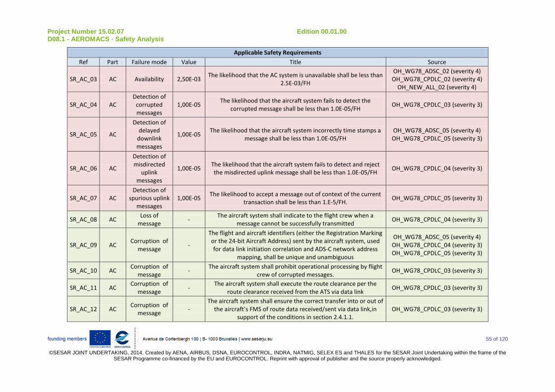
Project Number 15.02.07 Edition 00.01.00 D08.1 - AEROMACS - Safety Analysis
55 of 120
©SESAR JOINT UNDERTAKING, 2014. Created by AENA, AIRBUS, DSNA, EUROCONTROL, INDRA, NATMIG, SELEX ES and THALES for the SESAR Joint Undertaking within the frame of the
SESAR Programme co-financed by the EU and EUROCONTROL. Reprint with approval of publisher and the source properly acknowledged.
Applicable Safety Requirements
Ref Part Failure mode Value Title Source
SR_AC_03 AC Availability 2,50E-03 The likelihood that the AC system is unavailable shall be less than
2.5E-03/FH
OH_WG78_ADSC_02 (severity 4) OH_WG78_CPDLC_02 (severity 4)
OH_NEW_ALL_02 (severity 4)
SR_AC_04 AC Detection of
corrupted messages
1,00E-05 The likelihood that the aircraft system fails to detect the
corrupted message shall be less than 1.0E-05/FH OH_WG78_CPDLC_03 (severity 3)
SR_AC_05 AC
Detection of delayed
downlink messages
1,00E-05 The likelihood that the aircraft system incorrectly time stamps a
message shall be less than 1.0E-05/FH OH_WG78_ADSC_05 (severity 4) OH_WG78_CPDLC_05 (severity 3)
SR_AC_06 AC
Detection of misdirected
uplink messages
1,00E-05 The likelihood that the aircraft system fails to detect and reject the misdirected uplink message shall be less than 1.0E-05/FH
OH_WG78_CPDLC_04 (severity 3)
SR_AC_07 AC Detection of
spurious uplink messages
1,00E-05 The likelihood to accept a message out of context of the current
transaction shall be less than 1.E-5/FH. OH_WG78_CPDLC_05 (severity 3)
SR_AC_08 AC Loss of
message -
The aircraft system shall indicate to the flight crew when a message cannot be successfully transmitted
OH_WG78_CPDLC_04 (severity 3)
SR_AC_09 AC Corruption of
message -
The flight and aircraft identifiers (either the Registration Marking or the 24-bit Aircraft Address) sent by the aircraft system, used for data link initiation correlation and ADS-C network address
mapping, shall be unique and unambiguous
OH_WG78_ADSC_05 (severity 4) OH_WG78_CPDLC_04 (severity 3) OH_WG78_CPDLC_05 (severity 3)
SR_AC_10 AC Corruption of
message -
The aircraft system shall prohibit operational processing by flight crew of corrupted messages.
OH_WG78_CPDLC_03 (severity 3)
SR_AC_11 AC Corruption of
message -
The aircraft system shall execute the route clearance per the route clearance received from the ATS via data link
OH_WG78_CPDLC_03 (severity 3)
SR_AC_12 AC Corruption of
message -
The aircraft system shall ensure the correct transfer into or out of the aircraft’s FMS of route data received/sent via data link,in
support of the conditions in section 2.4.1.1. OH_WG78_CPDLC_03 (severity 3)

Project Number 15.02.07 Edition 00.01.00 D08.1 - AEROMACS - Safety Analysis
56 of 120
©SESAR JOINT UNDERTAKING, 2014. Created by AENA, AIRBUS, DSNA, EUROCONTROL, INDRA, NATMIG, SELEX ES and THALES for the SESAR Joint Undertaking within the frame of the
SESAR Programme co-financed by the EU and EUROCONTROL. Reprint with approval of publisher and the source properly acknowledged.
Applicable Safety Requirements
Ref Part Failure mode Value Title Source
SR_AC_13 AC Misdirection of message
- The aircraft system shall transmit messages to the designated
recipient.
OH_WG78_ADSC_05 (severity 4) OH_WG78_CPDLC_04 (severity 3) OH_WG78_CPDLC_05 (severity 3)
SR_AC_14 AC Misdirection of message
- The aircraft system shall provide unambiguous and unique
identification of the origin and destination of each message it transmits
OH_WG78_ADSC_05 (severity 4) OH_WG78_CPDLC_04 (severity 3) OH_WG78_CPDLC_05 (severity 3)
SR_AC_15 AC Misdirection of message
- The aircraft system shall only accept uplink messages intended
for it. OH_WG78_CPDLC_05 (severity 3)
SR_AC_16 AC Misdirection of message
-
The flight crew shall perform the initiation data link procedure again with any change of the aircraft identifiers (e.g. the Flight
Identification and either the Registration Marking or the Aircraft Address)
OH_WG78_CPDLC_05 (severity 3)
SR_AC_17 AC Spurious message
- The aircraft system shall prevent release of a report/operational
response without flight crew action. OH_WG78_CPDLC_05 (severity 3)
SR_AC_18 AC Availability - The aircraft system shall provide to the ATSU an indication when
it rejects an ADS-C service request initiated by the ATSU at the application layer.
OH_WG78_ADSC_02 (severity 4)
SR_AC_19 AC Availability - The aircraft system shall indicate to the flight crew a detected
loss of ADS-C service. OH_WG78_ADSC_02 (severity 4)
SR_AC_20 AC Availability - The aircraft system shall provide to the ATSU an indication when
it rejects a CPDLC service request initiated by the ATSU at the application layer.
OH_WG78_CPDLC_02 (severity 4)
SR_AC_21 AC Availability - The aircraft system shall display the indication provided by the ATSU when a DSC service request initiated by the flight crew is
rejected at the application layer. OH_WG78_CPDLC_02 (severity 4)
SR_AC_22 AC Availability - The aircraft system shall indicate to the flight crew a detected
loss of data link service. OH_WG78_CPDLC_02 (severity 4)
SR_AC_23 AC Detection of
corrupted messages
- Whenever a message is discarded by the aircraft system, it shall
send an indication to the ground system for display to the controller.
OH_WG78_CPDLC_03 (severity 3) OH_WG78_CPDLC_04 (severity 3) OH_WG78_CPDLC_05 (severity 3)

Project Number 15.02.07 Edition 00.01.00 D08.1 - AEROMACS - Safety Analysis
57 of 120
©SESAR JOINT UNDERTAKING, 2014. Created by AENA, AIRBUS, DSNA, EUROCONTROL, INDRA, NATMIG, SELEX ES and THALES for the SESAR Joint Undertaking within the frame of the
SESAR Programme co-financed by the EU and EUROCONTROL. Reprint with approval of publisher and the source properly acknowledged.
Applicable Safety Requirements
Ref Part Failure mode Value Title Source
SR_AC_24 AC
Detection of delayed
downlink messages
- The aircraft system shall time stamp each report to within one
second UTC when it is released for onward transmission. OH_WG78_ADSC_05 (severity 4)
SR_AC_25 AC
Detection of delayed
downlink messages
- The aircraft system shall time stamp to within one second UTC
each message when it is released for onward transmission. OH_WG78_ADSC_05 (severity 4)
SR_AC_26 AC Detection of
delayed uplink messages
-
When a received message contains a time stamp that indicates the Latency Time Check value, set at equal or less than ETTRN,
has been exceeded, the aircraft system shall a) discard the message and send an indication to the Ground System for display
to the controller or b) provide the message to the flight crew with an appropriate indication.
OH_WG78_CPDLC_05 (severity 3)
SR_AC_27 AC
Detection of misdirected
uplink messages
- The aircraft system shall be able to determine the message
initiator. OH_WG78_CPDLC_04 (severity 3) OH_WG78_CPDLC_05 (severity 3)
SR_AC_28 AC
Detection of misdirected
uplink messages
- Once an aircraft accepts operational CPDLC messages from an
ATSU, it shall reject operational CPDLC messages from any other ATSU until the first ATSU terminates CPDLC with that aircraft.
OH_WG78_CPDLC_04 (severity 3) OH_WG78_CPDLC_05 (severity 3)
SR_AC_29 AC
Detection of misdirected
uplink messages
- Only the ATSU that has control of the aircraft shall be permitted
to send a Next Data Authority (NDA) message to the aircraft. OH_WG78_CPDLC_04 (severity 3)
SR_AC_30 AC Detection of
spurious uplink messages
- The aircraft system shall indicate in each response to which
messages it refers OH_WG78_CPDLC_05 (severity 3)

Project Number 15.02.07 Edition 00.01.00 D08.1 - AEROMACS - Safety Analysis
58 of 120
©SESAR JOINT UNDERTAKING, 2014. Created by AENA, AIRBUS, DSNA, EUROCONTROL, INDRA, NATMIG, SELEX ES and THALES for the SESAR Joint Undertaking within the frame of the
SESAR Programme co-financed by the EU and EUROCONTROL. Reprint with approval of publisher and the source properly acknowledged.
Applicable Safety Requirements
Ref Part Failure mode Value Title Source
SR_AC_31 AC Detection of
spurious uplink messages
- Each downlink message shall be uniquely identified for a given
aircraft-ATSU pair, following a sequential order OH_WG78_CPDLC_05 (severity 3)
SR_AC_32 AC
Detection of spurious downlink messages
- The aircraft system shall indicate in each report to which contract
number it is referring OH_WG78_CPDLC_05 (severity 3)
SR_AC_33 AC
Detection of inappropriate messages by
the crew
- The aircraft system shall provide to the flight crew an indication
of the ATSU that has established CPDLC (CDA) service. OH_WG78_CPDLC_05 (severity 3)
Table 17 : List of applicable ACSP and AC Safety Requirements
Project Number 15.02.07 Edition 00.01.00 D08.1 - AEROMACS - Safety Analysis
59 of 120
©SESAR JOINT UNDERTAKING, 2014. Created by AENA, AIRBUS, DSNA, EUROCONTROL, INDRA, NATMIG, SELEX ES
and THALES for the SESAR Joint Undertaking within the frame of the SESAR Programme co-financed by the EU and EUROCONTROL. Reprint with approval of publisher and the source properly acknowledged.
4.2 Definition of ACSP and Aircraft Performance Requirements
4.2.1 Identification of relevant Performance Requirements in WG78 documents
This task consists in identifying, in the WG78 Performance Analysis, the performances requirements, that could be relevant for the AeroMACS (that means requirements allocated to Aircraft or ACSP and that concerns the exchange of message between ground and aircraft).
WG78 identify performances requirements in terms of:
Integrity: WG78 Performance Analysis defines end-to-end integrity requirements, for each data link application. These requirements are directly extracted from WG78 Safety Analysis. There is no specific integrity requirement from a purely performance point of view.
Consequently, these integrity requirements have already been considered during the safety analysis (cf. § 4.1) and it is not necessary to consider them again.
Availability. WG78 Performance Analysis defines end-to-end availability requirements, for each data link application. These availability requirements are expressed in terms of “availability of use” and “availability of provision”.
WG78 Performance Analysis then derives these end-to-end availability requirements on the different CNS/ATM components (Aircraft, ACSP and ATSU) using the following formula:
And
Availability is defined for each ATM component as the following ratio ,
expressed in percentage with MTSO: Mean Time to Service Outage and MTSR: Mean Time to Service Restoral.
Transaction Time (TT). WG78 Performance Analysis defines end-to-end timing requirements, for each data link application. These timing requirements are expressed in terms of:
o Normal Transaction time (TT95): it defines the time at which 95 percent of all transactions, that are initiated, are completed
o Transaction Time at 99.9% (TT99.9): it defines the time at which 99.9 percent of all transactions, that are initiated, are completed. This duration is closely linked to the continuity requirement (cf. below)
Timing requirement are defined for each function of each application: a RCP-Type (Required Communication Performance) is defined for each function with a specific end-to-end timing requirement, expressed in seconds.
WG78 Performance Analysis then derives these end-to-ends timing requirements on the different CNS/ATM components (Composition by the pilot, recognition by the controller, Aircraft, ACSP and ATSU), using statistical allocation. This allocation methodology leads to larger duration on the different components than the classical arithmetic allocation.
Continuity: WG78 Performance Analysis defines end-to-end continuity requirements, for each data link application. Continuity is associated with the required level of efficiency or usability of the data communications system. It is defined as the probability that a transaction completes within the expiration time. Consequently, continuity is closely linked to transaction time.
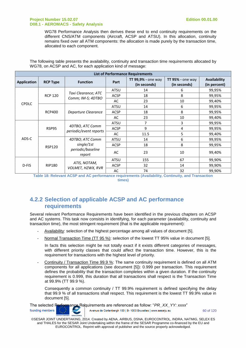
Project Number 15.02.07 Edition 00.01.00 D08.1 - AEROMACS - Safety Analysis
60 of 120
©SESAR JOINT UNDERTAKING, 2014. Created by AENA, AIRBUS, DSNA, EUROCONTROL, INDRA, NATMIG, SELEX ES
and THALES for the SESAR Joint Undertaking within the frame of the SESAR Programme co-financed by the EU and EUROCONTROL. Reprint with approval of publisher and the source properly acknowledged.
WG78 Performance Analysis then derives these end to end continuity requirements on the different CNS/ATM components (Aircraft, ACSP and ATSU). In this allocation, continuity remains fixed over all ATM components: the allocation is made purely by the transaction time, allocated to each component.
The following table presents the availability, continuity and transaction time requirements allocated by WG78, on ACSP and AC, for each application kind of message:
List of Performance Requirements
Application RCP Type Function Part TT 99,9% - one way
(in seconds) TT 95% - one way
(in seconds) Availability (in percent)
CPDLC
RCP 120 Taxi Clearance; ATC Comm; IM-S; 4DTBO
ATSU 14 6 99,95%
ACSP 18 8 99,95%
AC 23 10 99,40%
RCP400 Departure Clearance
ATSU 14 6 99,95%
ACSP 18 8 99,95%
AC 23 10 99,40%
ADS-C
RSP95 4DTBO, ATC Comm
periodic/event reports
ATSU 7 3 99,95%
ACSP 9 4 99,95%
AC 11.5 5 99,40%
RSP120
4DTBO; ATC Comm single/1st
periodic/baseline report
ATSU 14 6 99,95%
ACSP 18 8 99,95%
AC 23 10 99,40%
D-FIS RIP180 ATIS, NOTAM,
VOLMET, HZWX, RVR
ATSU 155 67 99,90%
ACSP 32 14 99,90%
AC 74 32 99,90% Table 18: Relevant ACSP and AC performance requirements (Availability, Continuity, and Transaction
times)
4.2.2 Selection of applicable ACSP and AC performance requirements
Several relevant Performance Requirements have been identified in the previous chapters on ACSP and AC systems. This task now consists in identifying, for each parameter (availability, continuity and transaction time), the most stringent requirement (that is the applicable requirement):
- Availability: selection of the highest percentage among all values of document [5].
- Normal Transaction Time (TT 95 %): selection of the lowest TT 95% value in document [5].
In facts this selection might be not totally exact if it exists different categories of messages, with different priority classes that could affect the transaction time. However, this is the requirement for transactions with the highest level of priority.
- Continuity / Transaction Time 99.9 %: The same continuity requirement is defined on all ATM components for all applications (see document [5]): 0.999 per transaction. This requirement defines the probability that the transaction completes within a given duration. If the continuity requirement is 0.999, this duration that all transactions shall respect is the Transaction Time at 99.9% (TT 99.9 %).
Consequently a common continuity / TT 99.9% requirement is defined specifying the delay that 99.9 % of all transactions shall respect. This requirement is the lowest TT 99.9% value in document [5].
The selected Performance Requirements are referenced as follow: “PR_XX_YY: xxxx”

Project Number 15.02.07 Edition 00.01.00 D08.1 - AEROMACS - Safety Analysis
61 of 120
©SESAR JOINT UNDERTAKING, 2014. Created by AENA, AIRBUS, DSNA, EUROCONTROL, INDRA, NATMIG, SELEX ES
and THALES for the SESAR Joint Undertaking within the frame of the SESAR Programme co-financed by the EU and EUROCONTROL. Reprint with approval of publisher and the source properly acknowledged.
- XX: identify the part on which the performance requirement is allocated: “CP” for ACSP or “AC” for Aircraft System
- YY: is a reference number of the selected performance requirement
- xxxx value of the performance requirement (expressed in percent for availability, and in seconds for transaction times).
The following table presents the selected ACSP and AC performance requirements (in red: quantitative requirement, in green: qualitative requirements).:
Selected Performance Requirement
Ref Part Parameter Value Title Source
PR_CP_01 ACSP Transaction Time
99,9 % (in seconds)
9 The transaction time (one way) in ACSP shall be less than
9 seconds for 99.9% of the messages Performance analysis
ADS-C - RSP 95
PR_CP_02 ACSP Transaction Time
95 % (in seconds)
4 The transaction time (one way) in ACSP shall be less than
4 seconds for 95% of the messages Performance analysis
ADS-C - RSP 95
PR_CP_03 ACSP Availability (in percent)
99,95% The availability of the ACSP shall be more than 99.95%
Performance analysis CPDLC - RCP 120 CPDLC - RCP 400 ADS-C - RSP 95
ADS-C - RSP 120
PR_CP_04 ACSP Availability (in percent)
-
The ground system shall be capable of detecting ground system failures and configuration changes that would
cause the communication service to no longer meet the requirements for the intended function.
Performance analysis
PR_CP_05 ACSP Availability (in percent)
- When the communication service no longer meets the
requirements for the intended function, the ground system shall provide indication to the controller.
Performance analysis
PR_AC_01 AC Transaction Time
99,9 % (in seconds)
11,5 The transaction time (one way)in aircraft shall be less
than 11.5 seconds for 99.9% of the ADS-C - RSP 95 messages
Performance analysis ADS-C - RSP 95
PR_AC_02 AC Transaction Time
95 % (in seconds)
5 The transaction time (one way)in aircraft shall be less
than 5 seconds for 95% of the ADS-C - RSP 95 messages Performance analysis
ADS-C - RSP 95
PR_AC_03 AC Availability (in percent)
99,40% The availability of the ADS-C aircraft system shall be more
than 99.40%
Performance analysis CPDLC - RCP 120 CPDLC - RCP 400 ADS-C - RSP 95
ADS-C - RSP 120
PR_AC_04 AC Availability (in percent)
-
The aircraft system shall be capable of detecting aircraft system failures or loss of air/ground communication that would cause the aircraft communication capability to no longer meet the requirements for the intended function.
Performance analysis
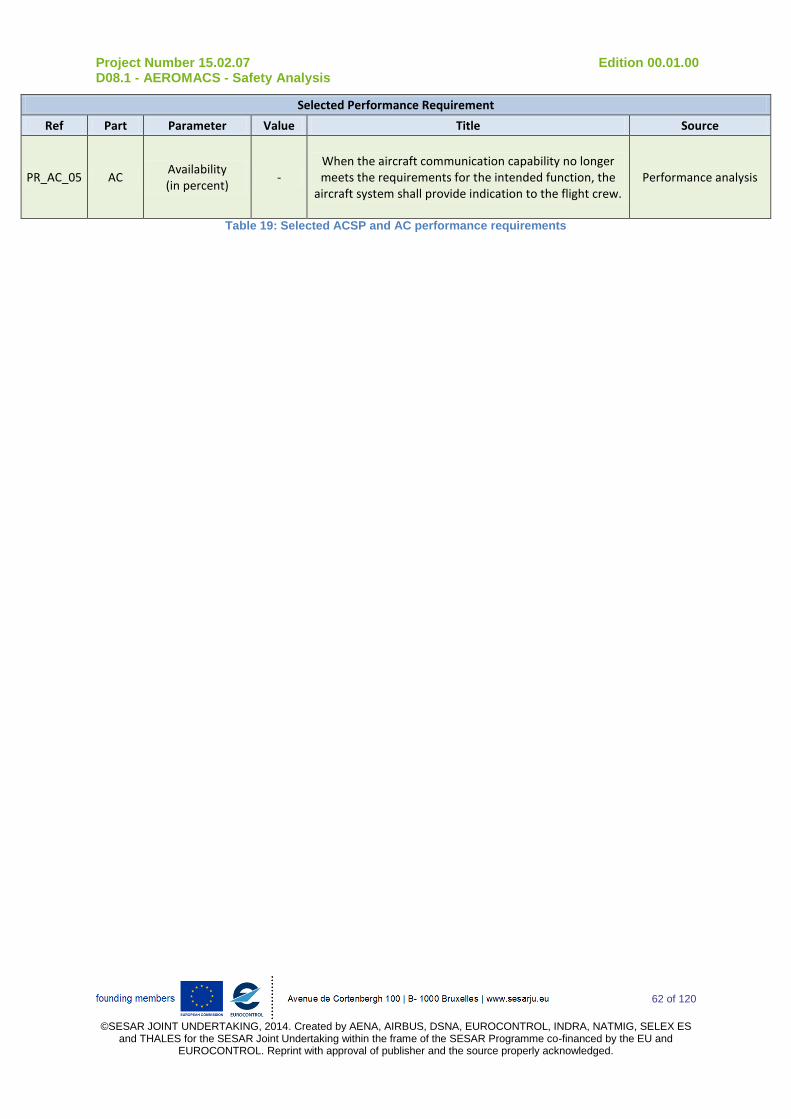
Project Number 15.02.07 Edition 00.01.00 D08.1 - AEROMACS - Safety Analysis
62 of 120
©SESAR JOINT UNDERTAKING, 2014. Created by AENA, AIRBUS, DSNA, EUROCONTROL, INDRA, NATMIG, SELEX ES
and THALES for the SESAR Joint Undertaking within the frame of the SESAR Programme co-financed by the EU and EUROCONTROL. Reprint with approval of publisher and the source properly acknowledged.
Selected Performance Requirement
Ref Part Parameter Value Title Source
PR_AC_05 AC Availability (in percent)
- When the aircraft communication capability no longer meets the requirements for the intended function, the
aircraft system shall provide indication to the flight crew. Performance analysis
Table 19: Selected ACSP and AC performance requirements
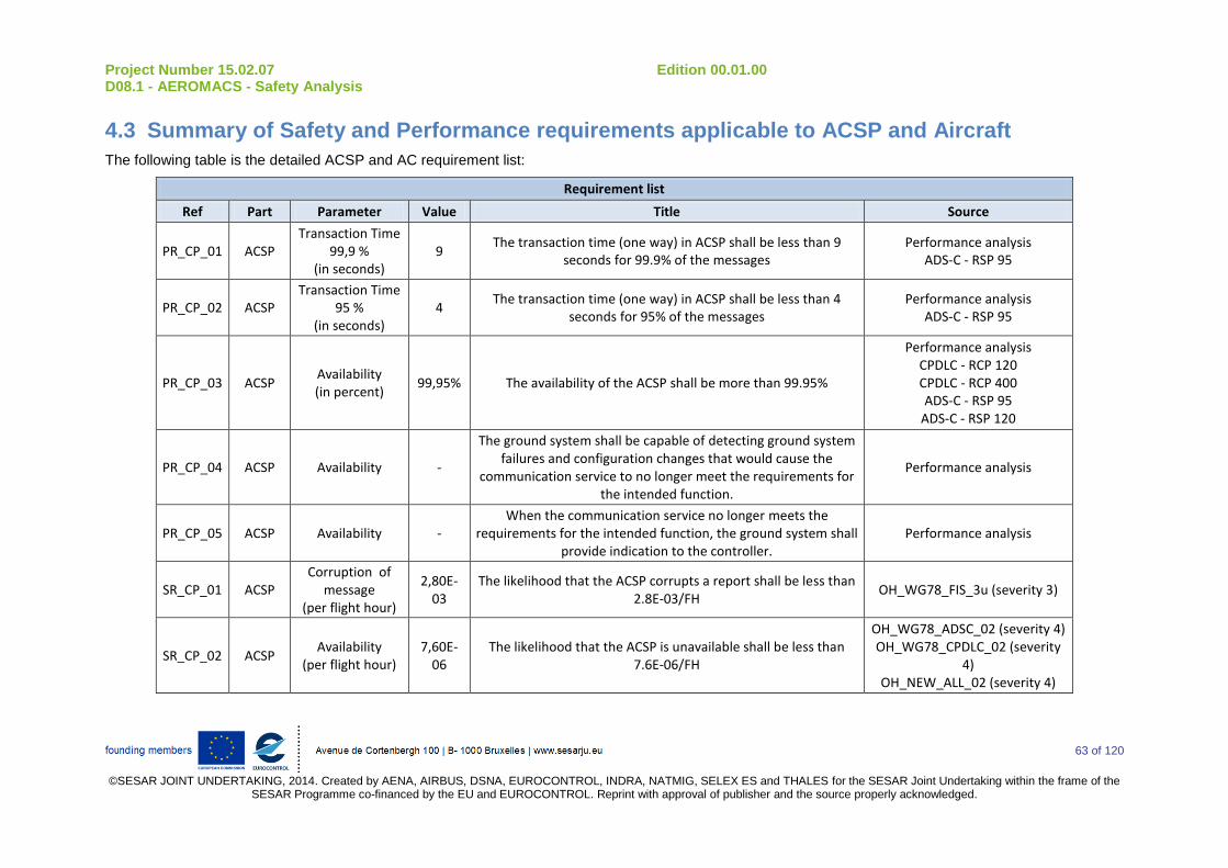
Project Number 15.02.07 Edition 00.01.00 D08.1 - AEROMACS - Safety Analysis
63 of 120
©SESAR JOINT UNDERTAKING, 2014. Created by AENA, AIRBUS, DSNA, EUROCONTROL, INDRA, NATMIG, SELEX ES and THALES for the SESAR Joint Undertaking within the frame of the
SESAR Programme co-financed by the EU and EUROCONTROL. Reprint with approval of publisher and the source properly acknowledged.
4.3 Summary of Safety and Performance requirements applicable to ACSP and Aircraft
The following table is the detailed ACSP and AC requirement list:
Requirement list
Ref Part Parameter Value Title Source
PR_CP_01 ACSP Transaction Time
99,9 % (in seconds)
9 The transaction time (one way) in ACSP shall be less than 9
seconds for 99.9% of the messages Performance analysis
ADS-C - RSP 95
PR_CP_02 ACSP Transaction Time
95 % (in seconds)
4 The transaction time (one way) in ACSP shall be less than 4
seconds for 95% of the messages Performance analysis
ADS-C - RSP 95
PR_CP_03 ACSP Availability (in percent)
99,95% The availability of the ACSP shall be more than 99.95%
Performance analysis CPDLC - RCP 120 CPDLC - RCP 400 ADS-C - RSP 95
ADS-C - RSP 120
PR_CP_04 ACSP Availability -
The ground system shall be capable of detecting ground system failures and configuration changes that would cause the
communication service to no longer meet the requirements for the intended function.
Performance analysis
PR_CP_05 ACSP Availability - When the communication service no longer meets the
requirements for the intended function, the ground system shall provide indication to the controller.
Performance analysis
SR_CP_01 ACSP Corruption of
message (per flight hour)
2,80E-03
The likelihood that the ACSP corrupts a report shall be less than 2.8E-03/FH
OH_WG78_FIS_3u (severity 3)
SR_CP_02 ACSP Availability
(per flight hour) 7,60E-
06 The likelihood that the ACSP is unavailable shall be less than
7.6E-06/FH
OH_WG78_ADSC_02 (severity 4) OH_WG78_CPDLC_02 (severity
4) OH_NEW_ALL_02 (severity 4)
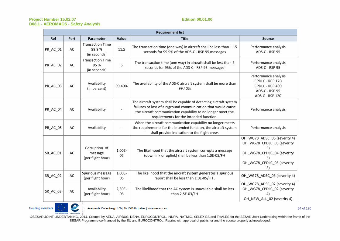
Project Number 15.02.07 Edition 00.01.00 D08.1 - AEROMACS - Safety Analysis
64 of 120
©SESAR JOINT UNDERTAKING, 2014. Created by AENA, AIRBUS, DSNA, EUROCONTROL, INDRA, NATMIG, SELEX ES and THALES for the SESAR Joint Undertaking within the frame of the
SESAR Programme co-financed by the EU and EUROCONTROL. Reprint with approval of publisher and the source properly acknowledged.
Requirement list
Ref Part Parameter Value Title Source
PR_AC_01 AC Transaction Time
99,9 % (in seconds)
11,5 The transaction time (one way) in aircraft shall be less than 11.5
seconds for 99.9% of the ADS-C - RSP 95 messages Performance analysis
ADS-C - RSP 95
PR_AC_02 AC Transaction Time
95 % (in seconds)
5 The transaction time (one way) in aircraft shall be less than 5
seconds for 95% of the ADS-C - RSP 95 messages Performance analysis
ADS-C - RSP 95
PR_AC_03 AC Availability (in percent)
99,40% The availability of the ADS-C aircraft system shall be more than
99.40%
Performance analysis CPDLC - RCP 120 CPDLC - RCP 400 ADS-C - RSP 95
ADS-C - RSP 120
PR_AC_04 AC Availability -
The aircraft system shall be capable of detecting aircraft system failures or loss of air/ground communication that would cause the aircraft communication capability to no longer meet the
requirements for the intended function.
Performance analysis
PR_AC_05 AC Availability - When the aircraft communication capability no longer meets
the requirements for the intended function, the aircraft system shall provide indication to the flight crew.
Performance analysis
SR_AC_01 AC Corruption of
message (per flight hour)
1,00E-05
The likelihood that the aircraft system corrupts a message (downlink or uplink) shall be less than 1.0E-05/FH
OH_WG78_ADSC_05 (severity 4) OH_WG78_CPDLC_03 (severity
3) OH_WG78_CPDLC_04 (severity
3) OH_WG78_CPDLC_05 (severity
3)
SR_AC_02 AC Spurious message (per flight hour)
1,00E-05
The likelihood that the aircraft system generates a spurious report shall be less than 1.0E-05/FH .
OH_WG78_ADSC_05 (severity 4)
SR_AC_03 AC Availability
(per flight hour) 2,50E-
03 The likelihood that the AC system is unavailable shall be less
than 2.5E-03/FH
OH_WG78_ADSC_02 (severity 4) OH_WG78_CPDLC_02 (severity
4) OH_NEW_ALL_02 (severity 4)

Project Number 15.02.07 Edition 00.01.00 D08.1 - AEROMACS - Safety Analysis
65 of 120
©SESAR JOINT UNDERTAKING, 2014. Created by AENA, AIRBUS, DSNA, EUROCONTROL, INDRA, NATMIG, SELEX ES and THALES for the SESAR Joint Undertaking within the frame of the
SESAR Programme co-financed by the EU and EUROCONTROL. Reprint with approval of publisher and the source properly acknowledged.
Requirement list
Ref Part Parameter Value Title Source
SR_AC_04 AC
Detection of corrupted messages
(per flight hour)
1,00E-05
The likelihood that the aircraft system fails to detect the corrupted message shall be less than 1.0E-05/FH
OH_WG78_CPDLC_03 (severity 3)
SR_AC_05 AC
Detection of delayed downlink
messages (per flight hour)
1,00E-05
The likelihood that the aircraft system incorrectly time stamps a message shall be less than 1.0E-05/FH
OH_WG78_ADSC_05 (severity 4) OH_WG78_CPDLC_05 (severity
3)
SR_AC_06 AC
Detection of misdirected
uplink messages (per flight hour)
1,00E-05
The likelihood that the aircraft system fails to detect and reject the misdirected uplink message shall be less than 1.0E-05/FH
OH_WG78_CPDLC_04 (severity 3)
SR_AC_07 AC
Detection of spurious uplink
messages (per flight hour)
1,00E-05
The likelihood to accept a message out of context of the current transaction shall be less than 1.E-5/FH.
OH_WG78_CPDLC_05 (severity 3)
SR_AC_08 AC Loss of message - The aircraft system shall indicate to the flight crew when a
message cannot be successfully transmitted OH_WG78_CPDLC_04 (severity
3)
SR_AC_09 AC Corruption of
message -
The flight and aircraft identifiers (either the Registration Marking or the 24-bit Aircraft Address) sent by the aircraft system, used for data link initiation correlation and ADS-C
network address mapping, shall be unique and unambiguous
OH_WG78_ADSC_05 (severity 4) OH_WG78_CPDLC_04 (severity
3) OH_WG78_CPDLC_05 (severity
3)
SR_AC_10 AC Corruption of
message -
The aircraft system shall prohibit operational processing by flight crew of corrupted messages.
OH_WG78_CPDLC_03 (severity 3)
SR_AC_11 AC Corruption of
message -
The aircraft system shall execute the route clearance per the route clearance received from the ATS via data link
OH_WG78_CPDLC_03 (severity 3)
SR_AC_12 AC Corruption of
message -
The aircraft system shall ensure the correct transfer into or out of the aircraft’s FMS of route data received/sent via data link,in
support of the conditions in section 2.4.1.1.
OH_WG78_CPDLC_03 (severity 3)

Project Number 15.02.07 Edition 00.01.00 D08.1 - AEROMACS - Safety Analysis
66 of 120
©SESAR JOINT UNDERTAKING, 2014. Created by AENA, AIRBUS, DSNA, EUROCONTROL, INDRA, NATMIG, SELEX ES and THALES for the SESAR Joint Undertaking within the frame of the
SESAR Programme co-financed by the EU and EUROCONTROL. Reprint with approval of publisher and the source properly acknowledged.
Requirement list
Ref Part Parameter Value Title Source
SR_AC_13 AC Misdirection of
message -
The aircraft system shall transmit messages to the designated recipient.
OH_WG78_ADSC_05 (severity 4) OH_WG78_CPDLC_04 (severity
3) OH_WG78_CPDLC_05 (severity
3)
SR_AC_14 AC Misdirection of
message -
The aircraft system shall provide unambiguous and unique identification of the origin and destination of each message it
transmits
OH_WG78_ADSC_05 (severity 4) OH_WG78_CPDLC_04 (severity
3) OH_WG78_CPDLC_05 (severity
3)
SR_AC_15 AC Misdirection of
message -
The aircraft system shall only accept uplink messages intended for it.
OH_WG78_CPDLC_05 (severity 3)
SR_AC_16 AC Misdirection of
message -
The flight crew shall perform the initiation data link procedure again with any change of the aircraft identifiers (e.g. the Flight
Identification and either the Registration Marking or the Aircraft Address)
OH_WG78_CPDLC_05 (severity 3)
SR_AC_17 AC Delay of message - The aircraft system shall indicate to the flight crew when a
message cannot be successfully transmitted OH_WG78_CPDLC_04 (severity
3)
SR_AC_18 AC Availability - The aircraft system shall provide to the ATSU an indication when
it rejects an ADS-C service request initiated by the ATSU at the application layer.
OH_WG78_ADSC_02 (severity 4)
SR_AC_19 AC Availability - The aircraft system shall indicate to the flight crew a detected
loss of ADS-C service. OH_WG78_ADSC_02 (severity 4)
SR_AC_20 AC Availability - The aircraft system shall provide to the ATSU an indication when
it rejects a CPDLC service request initiated by the ATSU at the application layer.
OH_WG78_CPDLC_02 (severity 4)
SR_AC_21 AC Availability - The aircraft system shall display the indication provided by the ATSU when a DSC service request initiated by the flight crew is
rejected at the application layer.
OH_WG78_CPDLC_02 (severity 4)
SR_AC_22 AC Availability - The aircraft system shall indicate to the flight crew a detected
loss of data link service. OH_WG78_CPDLC_02 (severity
4)
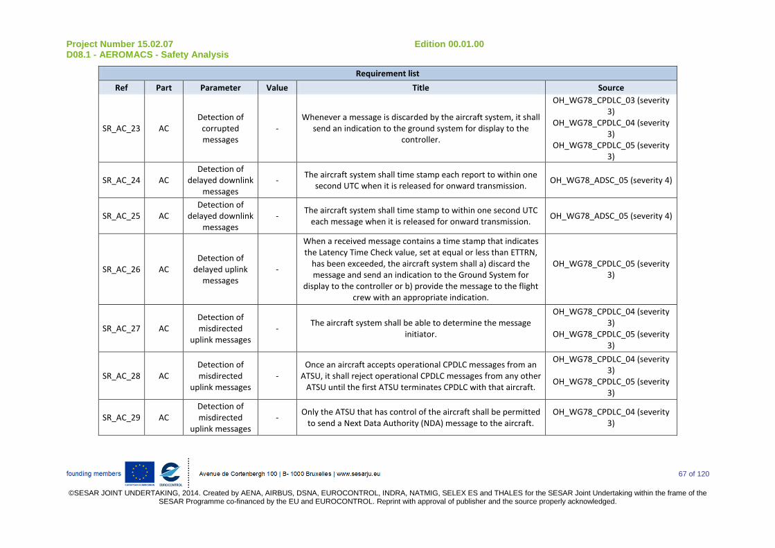
Project Number 15.02.07 Edition 00.01.00 D08.1 - AEROMACS - Safety Analysis
67 of 120
©SESAR JOINT UNDERTAKING, 2014. Created by AENA, AIRBUS, DSNA, EUROCONTROL, INDRA, NATMIG, SELEX ES and THALES for the SESAR Joint Undertaking within the frame of the
SESAR Programme co-financed by the EU and EUROCONTROL. Reprint with approval of publisher and the source properly acknowledged.
Requirement list
Ref Part Parameter Value Title Source
SR_AC_23 AC Detection of
corrupted messages
- Whenever a message is discarded by the aircraft system, it shall
send an indication to the ground system for display to the controller.
OH_WG78_CPDLC_03 (severity 3)
OH_WG78_CPDLC_04 (severity 3)
OH_WG78_CPDLC_05 (severity 3)
SR_AC_24 AC Detection of
delayed downlink messages
- The aircraft system shall time stamp each report to within one
second UTC when it is released for onward transmission. OH_WG78_ADSC_05 (severity 4)
SR_AC_25 AC Detection of
delayed downlink messages
- The aircraft system shall time stamp to within one second UTC
each message when it is released for onward transmission. OH_WG78_ADSC_05 (severity 4)
SR_AC_26 AC Detection of
delayed uplink messages
-
When a received message contains a time stamp that indicates the Latency Time Check value, set at equal or less than ETTRN,
has been exceeded, the aircraft system shall a) discard the message and send an indication to the Ground System for
display to the controller or b) provide the message to the flight crew with an appropriate indication.
OH_WG78_CPDLC_05 (severity 3)
SR_AC_27 AC Detection of misdirected
uplink messages -
The aircraft system shall be able to determine the message initiator.
OH_WG78_CPDLC_04 (severity 3)
OH_WG78_CPDLC_05 (severity 3)
SR_AC_28 AC Detection of misdirected
uplink messages -
Once an aircraft accepts operational CPDLC messages from an ATSU, it shall reject operational CPDLC messages from any other
ATSU until the first ATSU terminates CPDLC with that aircraft.
OH_WG78_CPDLC_04 (severity 3)
OH_WG78_CPDLC_05 (severity 3)
SR_AC_29 AC Detection of misdirected
uplink messages -
Only the ATSU that has control of the aircraft shall be permitted to send a Next Data Authority (NDA) message to the aircraft.
OH_WG78_CPDLC_04 (severity 3)
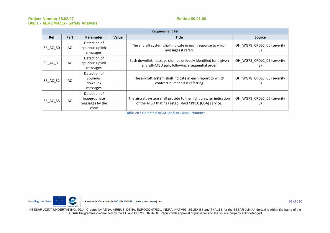
Project Number 15.02.07 Edition 00.01.00 D08.1 - AEROMACS - Safety Analysis
68 of 120
©SESAR JOINT UNDERTAKING, 2014. Created by AENA, AIRBUS, DSNA, EUROCONTROL, INDRA, NATMIG, SELEX ES and THALES for the SESAR Joint Undertaking within the frame of the
SESAR Programme co-financed by the EU and EUROCONTROL. Reprint with approval of publisher and the source properly acknowledged.
Requirement list
Ref Part Parameter Value Title Source
SR_AC_30 AC Detection of
spurious uplink messages
- The aircraft system shall indicate in each response to which
messages it refers OH_WG78_CPDLC_05 (severity
3)
SR_AC_31 AC Detection of
spurious uplink messages
- Each downlink message shall be uniquely identified for a given
aircraft-ATSU pair, following a sequential order OH_WG78_CPDLC_05 (severity
3)
SR_AC_32 AC
Detection of spurious downlink messages
- The aircraft system shall indicate in each report to which
contract number it is referring OH_WG78_CPDLC_05 (severity
3)
SR_AC_33 AC
Detection of inappropriate
messages by the crew
- The aircraft system shall provide to the flight crew an indication
of the ATSU that has established CPDLC (CDA) service. OH_WG78_CPDLC_05 (severity
3)
Table 20 : Selected ACSP and AC Requirements
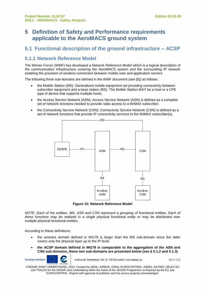
Project Number 15.02.07 Edition 00.01.00 D08.1 - AEROMACS - Safety Analysis
69 of 120
©SESAR JOINT UNDERTAKING, 2014. Created by AENA, AIRBUS, DSNA, EUROCONTROL, INDRA, NATMIG, SELEX ES
and THALES for the SESAR Joint Undertaking within the frame of the SESAR Programme co-financed by the EU and EUROCONTROL. Reprint with approval of publisher and the source properly acknowledged.
5 Definition of Safety and Performance requirements applicable to the AeroMACS ground system
5.1 Functional description of the ground infrastructure – ACSP
5.1.1 Network Reference Model
The Wimax Forum (WMF) has developed a Network Reference Model which is a logical description of the communication infrastructure covering the AeroMACS system and the surrounding IP network enabling the provision of wireless connection between mobile user and application servers.
The following three sub-domains are defined in the WMF document (see [6]) as follows:
the Mobile Station (MS): Generalized mobile equipment set providing connectivity between subscriber equipment and a base station (BS). The Mobile Station MAY be a host or a CPE type of device that supports multiple hosts,
the Access Service Network (ASN): Access Service Network (ASN) is defined as a complete set of network functions needed to provide radio access to a WiMAX subscriber.
the Connectivity Service Network (CSN): Connectivity Service Network (CSN) is defined as a set of network functions that provide IP connectivity services to the WiMAX subscriber(s).
Figure 10: Network Reference Model
NOTE: Each of the entities, MS, ASN and CSN represent a grouping of functional entities. Each of these functions may be realized in a single physical functional entity or may be distributed over multiple physical functional entities.
According to these definitions:
the avionics domain defined in WG78 is larger than the MS sub-domain since the latter covers only the physical layer up to the IP level.
the ACSP domain defined in WG78 is comparable to the aggregation of the ASN and CSN sub-domains, these two sub-domains are presented below (see § 5.1.2 and 5.1.3)

Project Number 15.02.07 Edition 00.01.00 D08.1 - AEROMACS - Safety Analysis
70 of 120
©SESAR JOINT UNDERTAKING, 2014. Created by AENA, AIRBUS, DSNA, EUROCONTROL, INDRA, NATMIG, SELEX ES
and THALES for the SESAR Joint Undertaking within the frame of the SESAR Programme co-financed by the EU and EUROCONTROL. Reprint with approval of publisher and the source properly acknowledged.
5.1.2 ASN: the Access Service Network The ASN reference model is illustrated in Figure 11. An ASN shares R1 reference point (RP) with an MS, R3 RP with a CSN and R4 RP with another ASN. The ASN consists of at least one instance of a Base Stations (BS) and at least one instance of an ASN Gateway (ASN-GW). A BS is logically connected to one or more ASN Gateways. The R4 reference point is the only RP for Control and Bearer Planes for interoperability between similar or heterogeneous ASNs. Interoperability between any types of ASNs is feasible with the specified protocols and primitives exposed across R1, R3 and R4 Reference Points. NOTE: When ASN is composed of n ASN-GWs (where n > 1), Intra ASN mobility MAY involve R4 control messages and Bearer Plane establishment.
Figure 11: ASN Reference Model
5.1.2.1 Base Stations The AeroMACS Base Station (BS) is a logical entity that embodies a full instance of the MAC and PHY layers in compliance with the AeroMACS Specifications and may host one or more access functions. A BS instance represents one sector with one frequency assignment. It incorporates scheduler functions for uplink and downlink resources. Connectivity (i.e., reachability) of a single BS to more than one ASN-GW may be required for load balancing or a redundancy option. BS is logical entity and one physical implementation of BS can have multiple BSs. It incorporates HO Control and Radio Resource Management (RRM) functions.
5.1.2.2 ASN Gateways
The ASN Gateway (ASN-GW) is a logical entity that represents an aggregation of Control Plane functional entities that are either paired with a corresponding function in the ASN (e.g. BS instance), a resident function in the CSN or a function in another ASN. The ASN-GW may also perform Bearer Plane routing or bridging function. ASN-GW implementation may include redundancy and load-balancing based on radio parameters among several ASN-GWs. ASN-GW implementations shall include load-balancing based on SLA requirements of the MSs. For every MS, a BS is associated with exactly one default ASN GW.
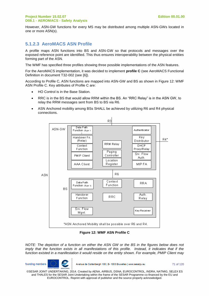
Project Number 15.02.07 Edition 00.01.00 D08.1 - AEROMACS - Safety Analysis
71 of 120
©SESAR JOINT UNDERTAKING, 2014. Created by AENA, AIRBUS, DSNA, EUROCONTROL, INDRA, NATMIG, SELEX ES
and THALES for the SESAR Joint Undertaking within the frame of the SESAR Programme co-financed by the EU and EUROCONTROL. Reprint with approval of publisher and the source properly acknowledged.
However, ASN-GW functions for every MS may be distributed among multiple ASN-GWs located in one or more ASN(s).
5.1.2.3 AeroMACS ASN Profile
A profile maps ASN functions into BS and ASN-GW so that protocols and messages over the exposed reference point are identified. This thus ensures interoperability between the physical entities forming part of the ASN.
The WMF has specified three profiles showing three possible implementations of the ASN features.
For the AeroMACS implementation, it was decided to implement profile C (see AeroMACS Functional Definition in document T32-002 (see [6]).
According to Profile C, ASN functions are mapped into ASN-GW and BS as shown in Figure 12: WMF ASN Profile C. Key attributes of Profile C are:
HO Control is in the Base Station.
RRC is in the BS that would allow RRM within the BS. An “RRC Relay” is in the ASN GW, to relay the RRM messages sent from BS to BS via R6.
ASN Anchored mobility among BSs SHALL be achieved by utilizing R6 and R4 physical connections.
Figure 12: WMF ASN Profile C
NOTE: The depiction of a function on either the ASN GW or the BS in the figures below does not imply that the function exists in all manifestations of this profile. Instead, it indicates that if the function existed in a manifestation it would reside on the entity shown. For example, PMIP Client may
Project Number 15.02.07 Edition 00.01.00 D08.1 - AEROMACS - Safety Analysis
72 of 120
©SESAR JOINT UNDERTAKING, 2014. Created by AENA, AIRBUS, DSNA, EUROCONTROL, INDRA, NATMIG, SELEX ES
and THALES for the SESAR Joint Undertaking within the frame of the SESAR Programme co-financed by the EU and EUROCONTROL. Reprint with approval of publisher and the source properly acknowledged.
not always be present in all manifestations of Profile C. However, if it is used, it shall reside on the ASN GW.
5.1.3 CSN: the Connectivity Service Network
In T32-002 (see [6]), Connectivity Service Network (CSN) is defined as follows: CSN is a set of network functions that provide IP connectivity services to the WiMAX subscriber(s). A CSN may provide the following functions:
MS IP address and endpoint parameter allocation for user sessions,
Internet access,
AAA proxy and server,
Policy and Admission Control based on user subscription profiles,
ASN-CSN tunneling support,
WiMAX subscriber billing and inter-operator settlement,
Inter-CSN tunnelling for roaming,
Inter-ASN mobility.
CSN MAY comprise network elements such as routers, AAA proxy/servers, user databases, Interworking gateway MSs. A CSN may be deployed as part of a Greenfield WiMAX NSP or as part of an incumbent WiMAX NSP.
5.1.4 Communication infrastructure (ACSP) model
The ACSP domain, as defined in WG78, covers all the functions related the communication service provided to the mobiles. The boundaries of this domain are:
The RF interface towards the aircraft.
The border router serving the ATSU domain hosting the terminal communicating equipment and the application server(s) interacting with the ATM system.
Based on the WMF functional description, the ACSP domain encompasses:
the ASN,
the CSN including visited and home networks if any,
To apportion the different requirements applicable to the ACSP domain, additional details are needed in the way the system is designed.
Nevertheless, it is not possible to describe really in detail the ground communication infrastructure since:
Additional work is needed to further identify the different function implemented at CSN level. This work will be done in other SESAR projects (e.g. P15.2.4) and at ICAO level,
The implementation of the various functions notably at CSN level will probably be very dependent upon manufacturers and service provider’s choices.
A very high level functional architecture is thus presented in this section and the derived requirements can only be considered as recommendations.
The communication infrastructure is described as below:
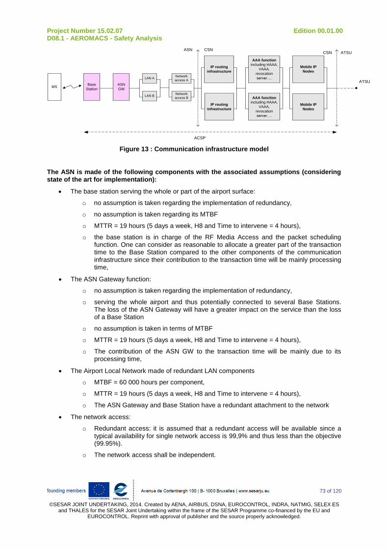
Project Number 15.02.07 Edition 00.01.00 D08.1 - AEROMACS - Safety Analysis
73 of 120
©SESAR JOINT UNDERTAKING, 2014. Created by AENA, AIRBUS, DSNA, EUROCONTROL, INDRA, NATMIG, SELEX ES
and THALES for the SESAR Joint Undertaking within the frame of the SESAR Programme co-financed by the EU and EUROCONTROL. Reprint with approval of publisher and the source properly acknowledged.
MSASN
GW
LAN ANetwork
access A
Network
access BLAN B
Base
Station
AAA function
including HAAA,
VAAA,
revocation
server….
AAA function
including HAAA,
VAAA,
revocation
server….
Mobile IP
Nodes
IP routing
infrastructure
Mobile IP
Nodes
IP routing
infrastructure
ATSU
ASN CSNCSN ATSU
ACSP
Figure 13 : Communication infrastructure model
The ASN is made of the following components with the associated assumptions (considering state of the art for implementation):
The base station serving the whole or part of the airport surface:
o no assumption is taken regarding the implementation of redundancy,
o no assumption is taken regarding its MTBF
o MTTR = 19 hours (5 days a week, H8 and Time to intervene = 4 hours),
o the base station is in charge of the RF Media Access and the packet scheduling function. One can consider as reasonable to allocate a greater part of the transaction time to the Base Station compared to the other components of the communication infrastructure since their contribution to the transaction time will be mainly processing time,
The ASN Gateway function:
o no assumption is taken regarding the implementation of redundancy,
o serving the whole airport and thus potentially connected to several Base Stations. The loss of the ASN Gateway will have a greater impact on the service than the loss of a Base Station
o no assumption is taken in terms of MTBF
o MTTR = 19 hours (5 days a week, H8 and Time to intervene = 4 hours),
o The contribution of the ASN GW to the transaction time will be mainly due to its processing time,
The Airport Local Network made of redundant LAN components
o MTBF = 60 000 hours per component,
o MTTR = 19 hours (5 days a week, H8 and Time to intervene = 4 hours),
o The ASN Gateway and Base Station have a redundant attachment to the network
The network access:
o Redundant access: it is assumed that a redundant access will be available since a typical availability for single network access is 99,9% and thus less than the objective (99.95%).
o The network access shall be independent.
Project Number 15.02.07 Edition 00.01.00 D08.1 - AEROMACS - Safety Analysis
74 of 120
©SESAR JOINT UNDERTAKING, 2014. Created by AENA, AIRBUS, DSNA, EUROCONTROL, INDRA, NATMIG, SELEX ES
and THALES for the SESAR Joint Undertaking within the frame of the SESAR Programme co-financed by the EU and EUROCONTROL. Reprint with approval of publisher and the source properly acknowledged.
NOTE: The airport power supply can be reasonably considered as redundant and offering a high quality of service.
NOTE: A 60 000 hour MTBF is deemed as a typical MTBF for a Network node.
NOTE : The network architecture for the ASN domain here above is quite simple and can be representative of the infrastructure deployed by an ACSP if this latter acts as ASN for a given airport.
In the case the ACSP outsources to the ASN operation to another entity (airport operator, local ATSP), it is likely that the ASN components will be integrated in the network of the ASN operator. The communication between the ASN and the CSN would be done through Security Gateway which would be redundant and thus would offer great QoS.
CSN is made of the following components:
AAA function and certificate revocation function:
this function can be spread over several AAA nodes acting for a given aircraft as proxy or server,
it is assumed that the failure of this function could have an impact at, at least, regional scale. Consequently, AAA operator will take necessary measures to ensure great availability and continuity of service for this function,
the contribution of the AAA function to the transaction time will be mainly due to its processing time:
Mobile IP nodes:
it is assumed that the failure of this function could have an impact at, at least, regional scale. Consequently, Mobile IP operator will take necessary measures to ensure great availability and continuity of service for this function,
the contribution of this function to the transaction time will be mainly due to its processing time
IP routing infrastructure:
this IP infrastructure ensures connectivity for an Aircraft at worldwide scale. It thus can interconnect Home and Visited Networks,
it is made of routers, security components (e.g. firewall), connected by leased lines….
it is assumed that the failure of this function could have an impact at, at least, regional scale. Consequently, the operator will take necessary measures to ensure great availability and continuity of service for this function,
the contribution of this function to the transaction time will be much less than the ASN one.
The following more detailed assumptions are taken for the CSN service:
The CSN network is made of two redundant (and totally independent) chains of communication (including the power supply), each one having the following parameters:
availability = 99,8%
MTBF = 15 000 hours
MTTR = MTTR = 19 hours (5 days a week, H8 and Time to intervene = 4 hours),
The 12 500 hour MTBF is derived considering 4 network nodes (e.g. Firewall, Firewall, Home Agent, AAA server), each having a 60 000 hour MTBF.
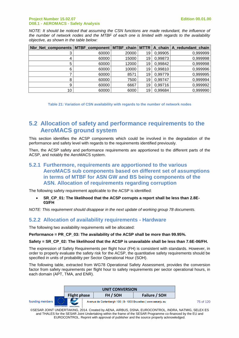
Project Number 15.02.07 Edition 00.01.00 D08.1 - AEROMACS - Safety Analysis
75 of 120
©SESAR JOINT UNDERTAKING, 2014. Created by AENA, AIRBUS, DSNA, EUROCONTROL, INDRA, NATMIG, SELEX ES
and THALES for the SESAR Joint Undertaking within the frame of the SESAR Programme co-financed by the EU and EUROCONTROL. Reprint with approval of publisher and the source properly acknowledged.
NOTE: It should be noticed that assuming the CSN functions are made redundant, the influence of the number of network nodes and the MTBF of each one is limited with regards to the availability objective, as shown in the table below:
Nbr_Net_components MTBF_component MTBF_chain MTTR A_chain A_redundant_chain
3 60000 20000 19 0,99905 0,999999
4 60000 15000 19 0,99873 0,999998
5 60000 12000 19 0,99842 0,999998
6 60000 10000 19 0,99810 0,999996
7 60000 8571 19 0,99779 0,999995
8 60000 7500 19 0,99747 0,999994
9 60000 6667 19 0,99716 0,999992
10 60000 6000 19 0,99684 0,999990
Table 21: Variation of CSN availability with regards to the number of network nodes
5.2 Allocation of safety and performance requirements to the AeroMACS ground system
This section identifies the ACSP components which could be involved in the degradation of the performance and safety level with regards to the requirements identified previously.
Then, the ACSP safety and performance requirements are apportioned to the different parts of the ACSP, and notably the AeroMACS system.
5.2.1 Furthermore, requirements are apportioned to the various AeroMACS sub components based on different set of assumptions in terms of MTBF for ASN GW and BS being components of the ASN. Allocation of requirements regarding corruption
The following safety requirement applicable to the ACSP is identified:
SR_CP_01: The likelihood that the ACSP corrupts a report shall be less than 2.8E-03/FH
NOTE: This requirement should disappear in the next update of working group 78 documents.
5.2.2 Allocation of availability requirements - Hardware
The following two availability requirements will be allocated:
Performance = PR_CP_03: The availability of the ACSP shall be more than 99.95%.
Safety = SR_CP_02: The likelihood that the ACSP is unavailable shall be less than 7.6E-06/FH.
The expression of Safety Requirements per flight hour (FH) is consistent with standards. However, in order to properly evaluate the safety risk for the ACSP, the quantitative safety requirements should be specified in units of probability per Sector Operational Hour (SOH).
The following table, extracted from WG78 Operational Safety Assessment, provides the conversion factor from safety requirements per flight hour to safety requirements per sector operational hours, in each domain (APT, TMA, and ENR).
UNIT CONVERSION
Flight phase FH / SOH Failure / SOH

Project Number 15.02.07 Edition 00.01.00 D08.1 - AEROMACS - Safety Analysis
76 of 120
©SESAR JOINT UNDERTAKING, 2014. Created by AENA, AIRBUS, DSNA, EUROCONTROL, INDRA, NATMIG, SELEX ES
and THALES for the SESAR Joint Undertaking within the frame of the SESAR Programme co-financed by the EU and EUROCONTROL. Reprint with approval of publisher and the source properly acknowledged.
APT 61 Failure/FH x 61
TMA 16 Failure/FH x 16
ENR-1 26 Failure/FH x 26 Table 22: Unit Conversion Table
Consequently, the availability safety requirement, for ACSP, in Airport environment is:
SR_CP_01: The likelihood that the ACSP is unavailable shall be less than 4.3E-04/SOH
NOTE: 1 over 4.3E-04/SOH is equivalent of the MTBF of the ACSP service over AeroMACS.
NOTE: the availability requirement coming from the performance analysis for the ACSP service over AeroMACS is 99.95%.
According to the model previously presented contributors to unavailability of the ACSP service can be due to:
an ASN failure at :
o The Base Station
o The ASN gateway
o The Airport Local Network
o The Network access
a CSN failure.
NOTE:
it is assumed that the airport power supply availability is about 100%,
it is assumed that failure at ASN and at CSN are independent.
The following formulas are reminded:
ii
i
iMTBFMTTR
MTBFA
n
i i
n
i i
i
AND
MTTRMTBF
MTTRMTBF
11
1
1
,
n
i i
AND
MTTR
MTTR
1
1
1
n
i i
OR
MTBF
MTBF
1
1
1
,
n
i i
n
i i
i
OR
MTBF
MTBF
MTTR
MTTR
1
1
1
,
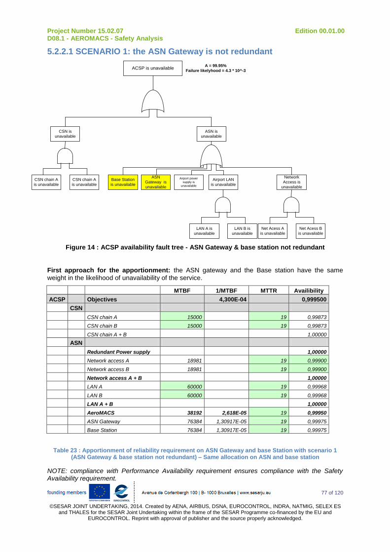
Project Number 15.02.07 Edition 00.01.00 D08.1 - AEROMACS - Safety Analysis
77 of 120
©SESAR JOINT UNDERTAKING, 2014. Created by AENA, AIRBUS, DSNA, EUROCONTROL, INDRA, NATMIG, SELEX ES
and THALES for the SESAR Joint Undertaking within the frame of the SESAR Programme co-financed by the EU and EUROCONTROL. Reprint with approval of publisher and the source properly acknowledged.
5.2.2.1 SCENARIO 1: the ASN Gateway is not redundant
ACSP is unavailable
CSN is
unavailable
CSN chain A
is unavailable
CSN chain A
is unavailable
ASN is
unavailable
Base Station
is unavailable
ASN
Gateway is
unavailable
Airport LAN
is unavailable
Network
Access is
unavailable
LAN A is
unavailable
LAN B is
unavailable
Net Acess A
is unavailable
Net Acess B
is unavailable
Airport power
supply is
unavailable
A = 99.95%
Failure likelyhood = 4.3 * 10^-3
Figure 14 : ACSP availability fault tree - ASN Gateway & base station not redundant
First approach for the apportionment: the ASN gateway and the Base station have the same weight in the likelihood of unavailability of the service.
MTBF 1/MTBF MTTR Availibility
ACSP Objectives 4,300E-04 0,999500
CSN
CSN chain A 15000 19 0,99873
CSN chain B 15000 19 0,99873
CSN chain A + B 1,00000
ASN
Redundant Power supply 1,00000
Network access A 18981 19 0,99900
Network access B 18981 19 0,99900
Network access A + B 1,00000
LAN A 60000 19 0,99968
LAN B 60000 19 0,99968
LAN A + B 1,00000
AeroMACS 38192 2,618E-05 19 0,99950
ASN Gateway 76384 1,30917E-05 19 0,99975
Base Station 76384 1,30917E-05 19 0,99975
Table 23 : Apportionment of reliability requirement on ASN Gateway and base Station with scenario 1 (ASN Gateway & base station not redundant) – Same allocation on ASN and base station
NOTE: compliance with Performance Availability requirement ensures compliance with the Safety Availability requirement.
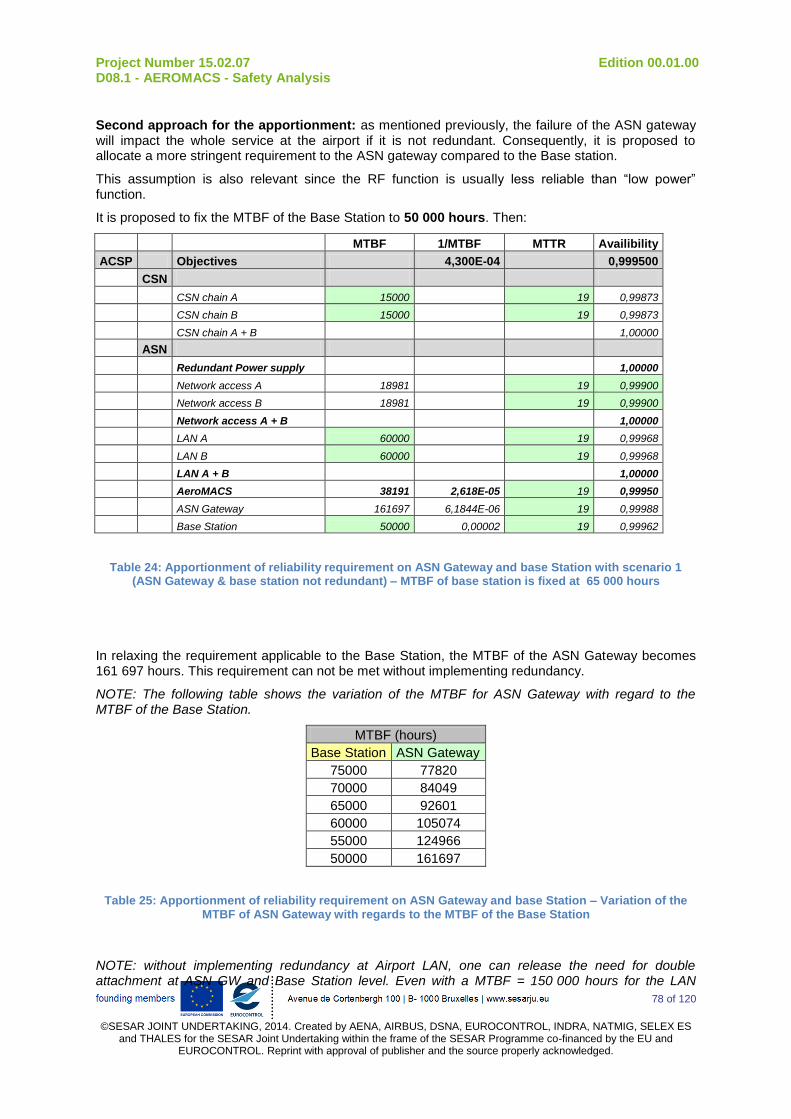
Project Number 15.02.07 Edition 00.01.00 D08.1 - AEROMACS - Safety Analysis
78 of 120
©SESAR JOINT UNDERTAKING, 2014. Created by AENA, AIRBUS, DSNA, EUROCONTROL, INDRA, NATMIG, SELEX ES
and THALES for the SESAR Joint Undertaking within the frame of the SESAR Programme co-financed by the EU and EUROCONTROL. Reprint with approval of publisher and the source properly acknowledged.
Second approach for the apportionment: as mentioned previously, the failure of the ASN gateway will impact the whole service at the airport if it is not redundant. Consequently, it is proposed to allocate a more stringent requirement to the ASN gateway compared to the Base station.
This assumption is also relevant since the RF function is usually less reliable than “low power” function.
It is proposed to fix the MTBF of the Base Station to 50 000 hours. Then:
MTBF 1/MTBF MTTR Availibility
ACSP Objectives 4,300E-04 0,999500
CSN
CSN chain A 15000 19 0,99873
CSN chain B 15000 19 0,99873
CSN chain A + B 1,00000
ASN
Redundant Power supply 1,00000
Network access A 18981 19 0,99900
Network access B 18981 19 0,99900
Network access A + B 1,00000
LAN A 60000 19 0,99968
LAN B 60000 19 0,99968
LAN A + B 1,00000
AeroMACS 38191 2,618E-05 19 0,99950
ASN Gateway 161697 6,1844E-06 19 0,99988
Base Station 50000 0,00002 19 0,99962
Table 24: Apportionment of reliability requirement on ASN Gateway and base Station with scenario 1 (ASN Gateway & base station not redundant) – MTBF of base station is fixed at 65 000 hours
In relaxing the requirement applicable to the Base Station, the MTBF of the ASN Gateway becomes 161 697 hours. This requirement can not be met without implementing redundancy.
NOTE: The following table shows the variation of the MTBF for ASN Gateway with regard to the MTBF of the Base Station.
MTBF (hours)
Base Station ASN Gateway
75000 77820
70000 84049
65000 92601
60000 105074
55000 124966
50000 161697
Table 25: Apportionment of reliability requirement on ASN Gateway and base Station – Variation of the MTBF of ASN Gateway with regards to the MTBF of the Base Station
NOTE: without implementing redundancy at Airport LAN, one can release the need for double attachment at ASN GW and Base Station level. Even with a MTBF = 150 000 hours for the LAN
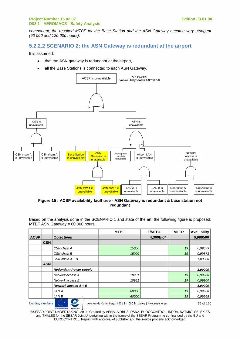
Project Number 15.02.07 Edition 00.01.00 D08.1 - AEROMACS - Safety Analysis
79 of 120
©SESAR JOINT UNDERTAKING, 2014. Created by AENA, AIRBUS, DSNA, EUROCONTROL, INDRA, NATMIG, SELEX ES
and THALES for the SESAR Joint Undertaking within the frame of the SESAR Programme co-financed by the EU and EUROCONTROL. Reprint with approval of publisher and the source properly acknowledged.
component, the resulted MTBF for the Base Station and the ASN Gateway become very stringent (90 000 and 120 000 hours).
5.2.2.2 SCENARIO 2: the ASN Gateway is redundant at the airport
It is assumed:
that the ASN gateway is redundant at the airport,
all the Base Stations is connected to each ASN Gateway.
ACSP is unavailable
CSN is
unavailable
CSN chain A
is unavailable
CSN chain A
is unavailable
ASN is
unavailable
Base Station
is unavailable
ASN
Gateway is
unavailable
Airport LAN
is unavailable
Network
Access is
unavailable
LAN A is
unavailable
LAN B is
unavailable
Net Acess A
is unavailable
Net Acess B
is unavailable
Airport power
supply is
unavailable
A = 99.95%
Failure likelyhood = 4.3 * 10^-3
ASN GW A is
unavailable
ASN GW B is
unavailable
Figure 15 : ACSP availability fault tree - ASN Gateway is redundant & base station not redundant
Based on the analysis done in the SCENARIO 1 and state of the art, the following figure is proposed: MTBF ASN Gateway = 60 000 hours.
MTBF 1/MTBF MTTR Availibility
ACSP Objectives 4,300E-04 0,999500
CSN
CSN chain A 15000 19 0,99873
CSN chain B 15000 19 0,99873
CSN chain A + B 1,00000
ASN
Redundant Power supply 1,00000
Network access A 18981 19 0,99900
Network access B 18981 19 0,99900
Network access A + B 1,00000
LAN A 60000 19 0,99968
LAN B 60000 19 0,99968
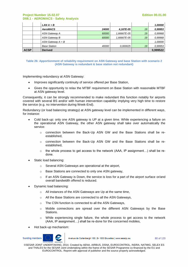
Project Number 15.02.07 Edition 00.01.00 D08.1 - AEROMACS - Safety Analysis
80 of 120
©SESAR JOINT UNDERTAKING, 2014. Created by AENA, AIRBUS, DSNA, EUROCONTROL, INDRA, NATMIG, SELEX ES
and THALES for the SESAR Joint Undertaking within the frame of the SESAR Programme co-financed by the EU and EUROCONTROL. Reprint with approval of publisher and the source properly acknowledged.
LAN A + B 1,00000
AeroMACS 24000 4,167E-05 19 0,99953
ASN Gateway A 60000 1,66667E-05 19 0,99968
ASN Gateway B 60000 1,66667E-05 19 0,99968
ASN Gateway A + B 1,00000
Base Station 40000 0,000025 19 0,99953
ACSP Derived 0,999522
Table 26: Apportionment of reliability requirement on ASN Gateway and base Station with scenario 2 (ASN Gateway is redundant & base station not redundant)
Implementing redundancy at ASN Gateway:
Improves significantly continuity of service offered per Base Station,
Gives the opportunity to relax the MTBF requirement on Base Station with reasonable MTBF at ASN gateway level.
Consequently, it can be strongly recommended to make redundant this function notably for airports covered with several BS and/or with human intervention capability implying very high time to restore the service (e.g. no intervention during Week-End).
Redundancy (or load balancing strategy) at ASN gateway level can be implemented in different ways, for instance:
Cold back-up: only one ASN gateway is UP at a given time. While experiencing a failure on the operational ASN Gateway, the other ASN gateway shall take over automatically the service:
o connection between the Back-Up ASN GW and the Base Stations shall be re-established,
o connection between the Back-Up ASN GW and the Base Stations shall be re-established,
o the whole process to get access to the network (AAA, IP assignment…) shall be re-done.
Static load balancing:
o Several ASN Gateways are operational at the airport,
o Base Stations are connected to only one ASN gateway,
o If an ASN Gateway is Down, the service is loss for a part of the airport surface or/and overall bandwidth offered is reduced.
Dynamic load balancing:
o All instances of the ASN Gateways are Up at the same time,
o All the Base Stations are connected to all the ASN Gateways,
o The CSN function is connected to all the ASN Gateways,
o Mobile connections are spread over the different ASN Gateways by the Base Stations.
o While experiencing single failure, the whole process to get access to the network (AAA, IP assignment…) shall be re-done for the concerned mobiles,
Hot back-up mechanism:

Project Number 15.02.07 Edition 00.01.00 D08.1 - AEROMACS - Safety Analysis
81 of 120
©SESAR JOINT UNDERTAKING, 2014. Created by AENA, AIRBUS, DSNA, EUROCONTROL, INDRA, NATMIG, SELEX ES
and THALES for the SESAR Joint Undertaking within the frame of the SESAR Programme co-financed by the EU and EUROCONTROL. Reprint with approval of publisher and the source properly acknowledged.
o The context of connection is maintained in each instance of the ASN Gateway function,
o Single failure at ASN Gateway level is fully transparent for the Mobiles.
5.2.2.3 SCENARIO 3: the ASN Gateway and the Base Stations are redundant at the airport
Both functions, ASN gateway and Base Station, are not impacted by single failure.
Such approach should improve the availability of the service at the airport.
Redundancy at Base Station level can be implemented in different ways, for instance:
Cold back-up: only one Base Station is UP at a given time. While experiencing a failure on the operational ASN Gateway, the other ASN gateway shall take over automatically the service:
o connection between the Back-Up Base Station and the ASN Gateway shall be re-established,
o the whole process to get access to the network (AAA, IP assignment…) shall be re-done.
Load balancing:
o All the Base Stations are Up at the same time,
o Base Stations operate on different channels,
o All the Base Stations are connected to all the ASN Gateways,
o While experiencing single failure, the whole process to get access to the network (AAA, IP assignment…) shall be re-done for the concerned mobiles on a different channel,
Hot Back-Up mechanism:
o The context of connection is maintained in each instance of the Base Station function,
o Only one transmit and receive at a given time,
o Single failure at Base Station level is fully transparent for the Mobiles, since the back-up station maintains the same context of connection and takes over the RF function.
5.2.2.4 Summary of availability requirements and recommendations
The table here below summarizes the applicable requirements or recommendations derived from the Safety and Performance requirements.
In the following table, only requirements coming from WG78/SC214 and applicable to the ACSP domain are considered as requirements (SHALL : G_Req_xx).
All other requirements are considered as recommendations (SHOULD : G_Rec_xx) since they are based on many assumptions on system design and/or maintenance organisation. Nevertheless, these assumptions are deemed reasonable with regards to the state of the art consequently manufacturers and Communication Service provider shall pay attention to them while implementing AeroMACS at a given airport.

Project Number 15.02.07 Edition 00.01.00 D08.1 - AEROMACS - Safety Analysis
82 of 120
©SESAR JOINT UNDERTAKING, 2014. Created by AENA, AIRBUS, DSNA, EUROCONTROL, INDRA, NATMIG, SELEX ES and THALES for the SESAR Joint Undertaking within the frame of the
SESAR Programme co-financed by the EU and EUROCONTROL. Reprint with approval of publisher and the source properly acknowledged.
Domain Sub-
domain Component
Related Safety and Performance
requirements Ref
shall / should
Requirements/Recommendations
ACSP - ACSP - all
components PC_CP_03 , SR_CP_02
G_Req_01 shall The availability of the ACSP service shall be more than 99.95%
- ACSP - all
components PC_CP_03 , SR_CP_02
G_Req_02 shall The likelihood that the ACSP service is unavailable shall be less than 4.3E-03/SOH
- ACSP - all
components PC_CP_03 , SR_CP_03
G_Rec_01 should
Depending on the implementation (type of redundancy), the Ground System should implement strategy to ease recovery of service in case of single failure at the following levels: -AAA, -Mobile IP, -ASN Gateway, -Base Station.
ACSP CSN
Operator Power supply
PC_CP_03 , SR_CP_02
G_Rec_02 should The power supply should be redundant.
AAA function PC_CP_03 , SR_CP_02
G_Rec_03 should The CSN function should implement redundancy at AAA level. A hot back-up or load balancing strategy should be prefered.
Mobile IP PC_CP_03 , SR_CP_02
G_Rec_04 should The CSN function should implement redundancy at Mobile IP level. A hot back-up or load balancing strategy should be prefered.
Routing and level 2
infrastructure PC_CP_03 , SR_CP_02
G_Rec_05 should The CSN function shall implement redundancy at IP network level and Local Area Network. A hot back-up should be prefered.
CSN PC_CP_03 , SR_CP_02
G_Rec_06 should The CSN operator should target an availability for the service greater than 99,9998%
CSN - all
components PC_CP_03 , SR_CP_02
G_Rec_07 should The CSN operator should target a Mean Time to Repair a system less than 19 hours.
CSN - all
components PC_CP_03 , SR_CP_02
G_Rec_08 should The CSN components should have the capability to be remotely monitored and controlled
ACSP ASN
Operator Power supply
PC_CP_03 , SR_CP_02
G_Rec_09 should The ASN operator should ensure that power supply is redundant for all ASN components
Network access PC_CP_03 , SR_CP_02
G_Rec_10 should The ASN operator should implement a redundant network access

Project Number 15.02.07 Edition 00.01.00 D08.1 - AEROMACS - Safety Analysis
83 of 120
©SESAR JOINT UNDERTAKING, 2014. Created by AENA, AIRBUS, DSNA, EUROCONTROL, INDRA, NATMIG, SELEX ES and THALES for the SESAR Joint Undertaking within the frame of the
SESAR Programme co-financed by the EU and EUROCONTROL. Reprint with approval of publisher and the source properly acknowledged.
Domain Sub-
domain Component
Related Safety and Performance
requirements Ref
shall / should
Requirements/Recommendations
Airport Local
Network PC_CP_03 , SR_CP_02
G_Rec_11 should The ASN operator should implement a redundant Airport Local Network
ASN Gateway PC_CP_03 , SR_CP_02
G_Rec_12 should The ASN Gateway MTBF should be greater than 60 000 hours
ASN Gateway PC_CP_03 , SR_CP_02
G_Rec_13 should The ASN Gateway should have a redundant access to the network
Base Station PC_CP_03 , SR_CP_02
G_Rec_14 should The Base Station should have a redundant access to the network
Base Station PC_CP_03 , SR_CP_02
G_Rec_15 should The Base Station MTBF should be greater than 50 000 hours
ASN PC_CP_03 , SR_CP_02
G_Rec_16 should The ASN operator should target an availability for the service greater than 99,95 %
ASN - all
components PC_CP_03 , SR_CP_02
G_Rec_17 should The ASN operator should target a Mean Time to Repair a system shall be less than 19 hours.
ASN - all
components PC_CP_03 , SR_CP_02
G_Rec_18 should The ASN components should have the capability to be remotely monitored and controled
ASN Gateway PC_CP_03 , SR_CP_02
G_Rec_19 should The ASN Gateway should be implemented with redundancy. The redundancy mechanism shall not require human intervention
Base Station PC_CP_03 , SR_CP_02
G_Rec_20 may The Base Station may be implemented with redundancy.
Table 27: Availability requirements on ACSP & Availability recommendations on AeroMACS Ground components
NOTE: in case, CSN is made of one or several Visited CSN in addition to the Home CSN, the requirements in the table above are applicable to the whole CSN function made on the different V-CSN plus the Home CSN. Contractual arrangements shall be establshed to ensure compliance to the safety and performance requirements.
The table below presents requirements applicable to Airborne system and related to the availability of the service.
Domain Sub-
domain Component
Related Safety and Performance
requirements Ref
shall / should
Requirements/Recommendations
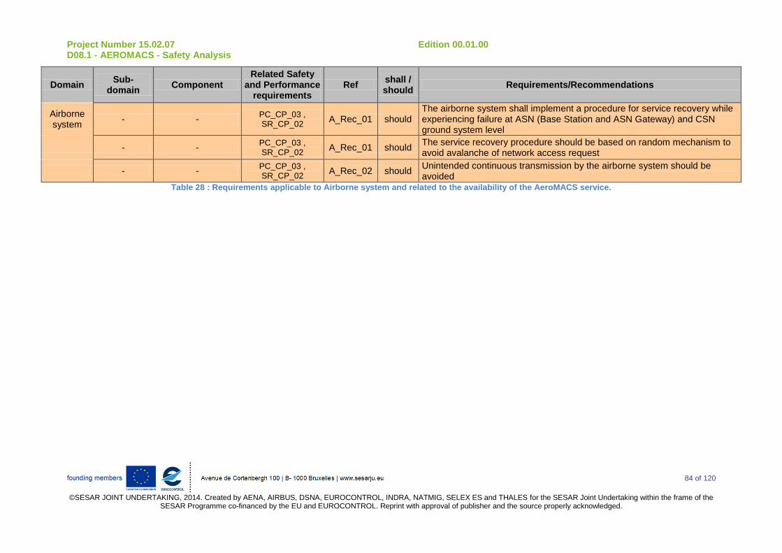
Project Number 15.02.07 Edition 00.01.00 D08.1 - AEROMACS - Safety Analysis
84 of 120
©SESAR JOINT UNDERTAKING, 2014. Created by AENA, AIRBUS, DSNA, EUROCONTROL, INDRA, NATMIG, SELEX ES and THALES for the SESAR Joint Undertaking within the frame of the
SESAR Programme co-financed by the EU and EUROCONTROL. Reprint with approval of publisher and the source properly acknowledged.
Domain Sub-
domain Component
Related Safety and Performance
requirements Ref
shall / should
Requirements/Recommendations
Airborne system
- - PC_CP_03 , SR_CP_02
A_Rec_01 should The airborne system shall implement a procedure for service recovery while experiencing failure at ASN (Base Station and ASN Gateway) and CSN ground system level
- - PC_CP_03 , SR_CP_02
A_Rec_01 should The service recovery procedure should be based on random mechanism to avoid avalanche of network access request
- - PC_CP_03 , SR_CP_02
A_Rec_02 should Unintended continuous transmission by the airborne system should be avoided
Table 28 : Requirements applicable to Airborne system and related to the availability of the AeroMACS service.
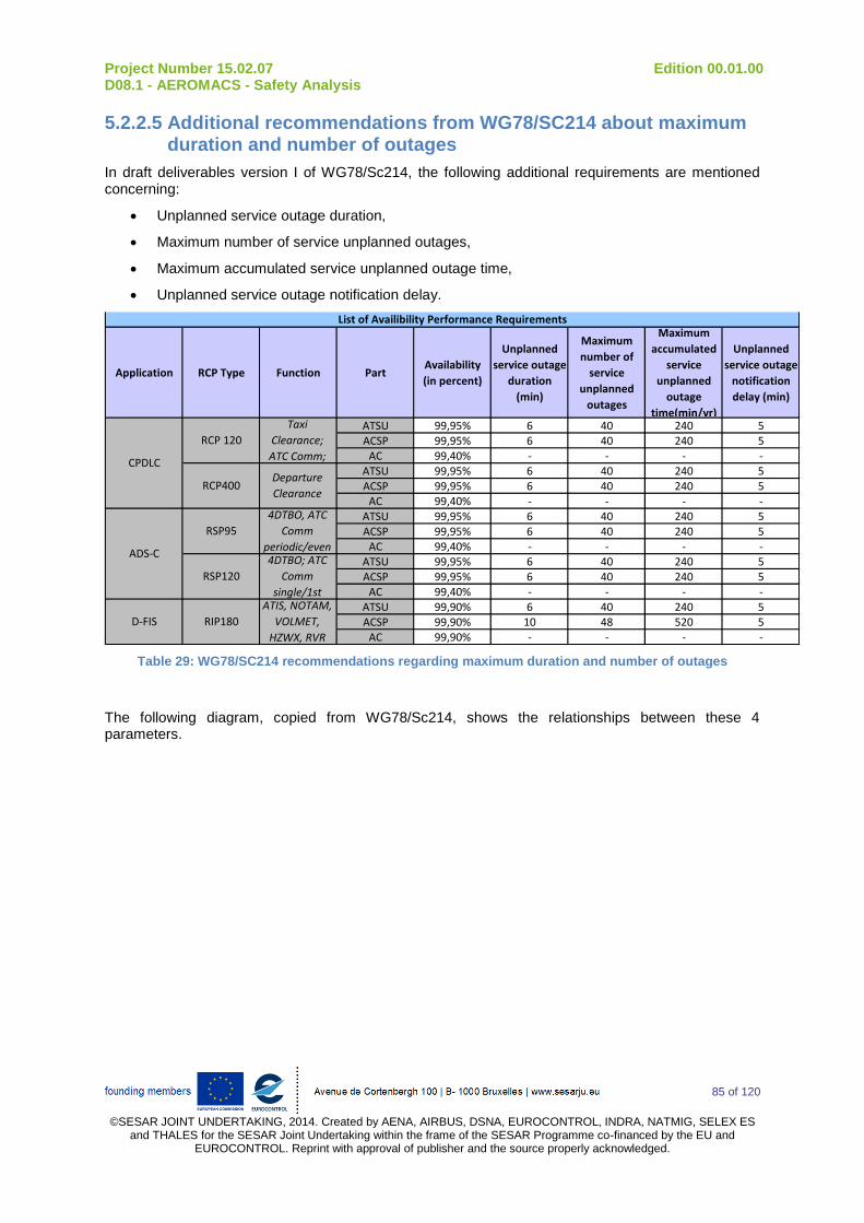
Project Number 15.02.07 Edition 00.01.00 D08.1 - AEROMACS - Safety Analysis
85 of 120
©SESAR JOINT UNDERTAKING, 2014. Created by AENA, AIRBUS, DSNA, EUROCONTROL, INDRA, NATMIG, SELEX ES
and THALES for the SESAR Joint Undertaking within the frame of the SESAR Programme co-financed by the EU and EUROCONTROL. Reprint with approval of publisher and the source properly acknowledged.
5.2.2.5 Additional recommendations from WG78/SC214 about maximum duration and number of outages
In draft deliverables version I of WG78/Sc214, the following additional requirements are mentioned concerning:
Unplanned service outage duration,
Maximum number of service unplanned outages,
Maximum accumulated service unplanned outage time,
Unplanned service outage notification delay.
Application RCP Type Function PartAvailability
(in percent)
Unplanned
service outage
duration
(min)
Maximum
number of
service
unplanned
outages
Maximum
accumulated
service
unplanned
outage
time(min/yr)
Unplanned
service outage
notification
delay (min)
ATSU 99,95% 6 40 240 5ACSP 99,95% 6 40 240 5
AC 99,40% - - - -ATSU 99,95% 6 40 240 5ACSP 99,95% 6 40 240 5
AC 99,40% - - - -ATSU 99,95% 6 40 240 5ACSP 99,95% 6 40 240 5
AC 99,40% - - - -ATSU 99,95% 6 40 240 5ACSP 99,95% 6 40 240 5
AC 99,40% - - - -ATSU 99,90% 6 40 240 5ACSP 99,90% 10 48 520 5
AC 99,90% - - - -
ATIS, NOTAM,
VOLMET,
HZWX, RVR
RSP120
4DTBO; ATC
Comm
single/1st
ADS-C
4DTBO, ATC
Comm
periodic/even
RSP95
D-FIS RIP180
List of Availibility Performance Requirements
CPDLC
RCP 120
Taxi
Clearance;
ATC Comm;
RCP400 Departure
Clearance
Table 29: WG78/SC214 recommendations regarding maximum duration and number of outages
The following diagram, copied from WG78/Sc214, shows the relationships between these 4 parameters.

Project Number 15.02.07 Edition 00.01.00 D08.1 - AEROMACS - Safety Analysis
86 of 120
©SESAR JOINT UNDERTAKING, 2014. Created by AENA, AIRBUS, DSNA, EUROCONTROL, INDRA, NATMIG, SELEX ES
and THALES for the SESAR Joint Undertaking within the frame of the SESAR Programme co-financed by the EU and EUROCONTROL. Reprint with approval of publisher and the source properly acknowledged.
Unplanned outage
begins
Notification of
restored
service
Outage
duration limit
(ODL)
Notification of
unplanned
outage delay
unplanned
outage
duration
Unplanned outage
begins
Outage
duration limit
(ODL)
Notification of
unplanned
outage delay
unplanned
outage
duration
Maximum accumulated unplanned outage time (min/yr) =
sum of unplanned outage duration over a period of time (year),
where unplanned outage duration > outage duration limit
No operational
impact
Maximum
number of
unplanned
outages > ODL
(per year)
Notification of
restored
service
Figure 16 : Definition of availability concepts: Unplanned service outage duration, Maximum number of service unplanned outages, Maximum accumulated service unplanned outage time
and Unplanned service outage notification delay
It should be noted that such additional requirements are quite dimensioning for the system compared to safety and performance requirements as presented before in the documents. Notably, the 6 minute maximum service outage requires:
the implementation of redundancy at each single node of the ACSP domain and thus at ASN Gateway and Base Station level since human intervention to change a hardware component is impossible in less than 6 minutes,
the implementation of the redundancy mechanism shall ensure service recovery (applicative data can be exchanged) while experiencing a single failure in less than 6 minutes.
NOTE: outage duration greater than 6 minutes will potentially impact regularity of flights but not safety (AeroMACS will only be used for surface non safety critical operation). Consequently, decision to implement redundancy at Base Station level should be analysed carefully.
NOTE: depending on the redundancy mechanism, service recovery does not only depend on the ground system. It may also depend on the Avionic service recovery strategy and traffic load since log-on procedure is based on a competitive access to the media.
NOTE: the 6 minute maximum service outage is based on the current Transport layer timer for the connection maintenance. Nowadays, in case no Transport message has been received for 6 minutes from the other commutating system, the Transport layer connection is down (event “Provider abort”) and there is a need to re-establish the whole connection for the Avionics system. Such re-establishment can need a human action. It is thus desirable to limit as much as possible such disconnection.
The following requirements can be derived on the ACSP domain:
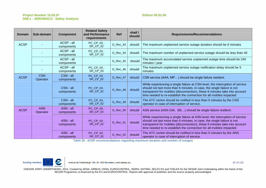
Project Number 15.02.07 Edition 00.01.00 D08.1 - AEROMACS - Safety Analysis
87 of 120
©SESAR JOINT UNDERTAKING, 2014. Created by AENA, AIRBUS, DSNA, EUROCONTROL, INDRA, NATMIG, SELEX ES and THALES for the SESAR Joint Undertaking within the frame of the
SESAR Programme co-financed by the EU and EUROCONTROL. Reprint with approval of publisher and the source properly acknowledged.
Domain Sub-domain Component Related Safety
and Performance requirements
Ref shall / should
Requirements/Recommendations
ACSP - ACSP - all
components PC_CP_03 , SR_CP_02
G_Rec_43 should The maximum unplanned service outage duration should be 6 minutes
- ACSP - all
components PC_CP_03 , SR_CP_02
G_Rec_44 should The maximum number of unplanned service outage should be less than 40
- ACSP - all
components G_Rec_45 should
The maximum accumulated service unplanned outage time should be 240 minutes / year
- ACSP - all
components PC_CP_03 , SR_CP_03
G_Rec_46 should The maximum unplanned service outage notification delay should be 5 minutes
ACSP CSN
Operator CSN - all
components PC_CP_03 , SR_CP_02
G_Rec_47 should CSN service (AAA, MP…) should be single failure resilient.
CSN - all
components PC_CP_03 , SR_CP_02
G_Rec_48 should
While experiencing a single failure at CSN level, the interruption of service should not last more than 6 minutes, in case, the single failure is not transparent for mobiles (disconnection), these 6 minutes take into account time needed to re-establish the connection for all mobiles impacted
CSN - all
components PC_CP_03 , SR_CP_02
G_Rec_49 should The ATC centre should be notified in less than 5 minutes by the CNS operator in case of interruption of service.
ACSP ASN
Operator ASN - all
components PC_CP_03 , SR_CP_02
G_Rec_50 should ASN service (ASN GW, BS…) should be single failure resilient.
ASN - all
components PC_CP_03 , SR_CP_02
G_Rec_51 should
While experiencing a single failure at ASN level, the interruption of service should not last more than 6 minutes, in case, the single failure is not transparent for mobiles (disconnection), these 6 minutes take into account time needed to re-establish the connection for all mobiles impacted
ASN - all
components PC_CP_03 , SR_CP_02
G_Rec_52 should The ATC centre should be notified in less than 5 minutes by the ANS operator in case of interruption of service.
Table 30 : ACSP recommendations regarding maximum duration and number of outages

Project Number 15.02.07 Edition 00.01.00 D08.1 - AEROMACS - Safety Analysis
88 of 120
©SESAR JOINT UNDERTAKING, 2014. Created by AENA, AIRBUS, DSNA, EUROCONTROL, INDRA, NATMIG, SELEX ES
and THALES for the SESAR Joint Undertaking within the frame of the SESAR Programme co-financed by the EU and EUROCONTROL. Reprint with approval of publisher and the source properly acknowledged.
NOTE: in case, CSN is made of one or several Visited CSN in addition to the Home CSN, the requirements in the table above are applicable to the whole CSN function made on the different V-CSN plus the Home CSN. Contractual arrangements shall be established to ensure compliance to the safety and performance requirements.
NOTE: for redundancy implementation, one can prefer to implement Hot Back-Up strategy to minimize the impact of single failure. In case cold back-up is implemented, the operator should ensure that the interruption of service (from users perspective) should be less than 6 minutes. These 6 minutes take into account the time to disconnect and reestablish the service for all mobiles impacted.
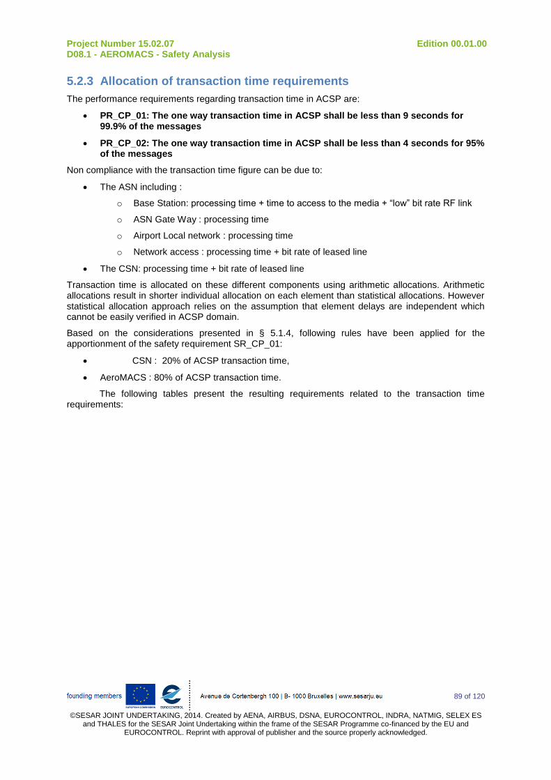
Project Number 15.02.07 Edition 00.01.00 D08.1 - AEROMACS - Safety Analysis
89 of 120
©SESAR JOINT UNDERTAKING, 2014. Created by AENA, AIRBUS, DSNA, EUROCONTROL, INDRA, NATMIG, SELEX ES
and THALES for the SESAR Joint Undertaking within the frame of the SESAR Programme co-financed by the EU and EUROCONTROL. Reprint with approval of publisher and the source properly acknowledged.
5.2.3 Allocation of transaction time requirements
The performance requirements regarding transaction time in ACSP are:
PR_CP_01: The one way transaction time in ACSP shall be less than 9 seconds for 99.9% of the messages
PR_CP_02: The one way transaction time in ACSP shall be less than 4 seconds for 95% of the messages
Non compliance with the transaction time figure can be due to:
The ASN including :
o Base Station: processing time + time to access to the media + “low” bit rate RF link
o ASN Gate Way : processing time
o Airport Local network : processing time
o Network access : processing time + bit rate of leased line
The CSN: processing time + bit rate of leased line
Transaction time is allocated on these different components using arithmetic allocations. Arithmetic allocations result in shorter individual allocation on each element than statistical allocations. However statistical allocation approach relies on the assumption that element delays are independent which cannot be easily verified in ACSP domain.
Based on the considerations presented in § 5.1.4, following rules have been applied for the apportionment of the safety requirement SR_CP_01:
CSN : 20% of ACSP transaction time,
AeroMACS : 80% of ACSP transaction time.
The following tables present the resulting requirements related to the transaction time requirements:
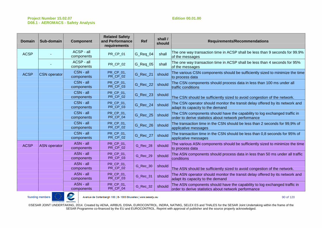
Project Number 15.02.07 Edition 00.01.00 D08.1 - AEROMACS - Safety Analysis
90 of 120
©SESAR JOINT UNDERTAKING, 2014. Created by AENA, AIRBUS, DSNA, EUROCONTROL, INDRA, NATMIG, SELEX ES and THALES for the SESAR Joint Undertaking within the frame of the
SESAR Programme co-financed by the EU and EUROCONTROL. Reprint with approval of publisher and the source properly acknowledged.
Domain Sub-domain Component Related Safety
and Performance requirements
Ref shall / should
Requirements/Recommendations
ACSP - ACSP - all
components PR_CP_01 G_Req_04 shall The one way transaction time in ACSP shall be less than 9 seconds for 99.9%
of the messages
- ACSP - all
components PR_CP_02 G_Req_05 shall The one way transaction time in ACSP shall be less than 4 seconds for 95%
of the messages
ACSP CSN operator CSN - all
components PR_CP_01, PR_CP_02
G_Rec_21 should The various CSN components should be sufficiently sized to minimize the time to process data
CSN - all
components PR_CP_01, PR_CP_03
G_Rec_22 should The CSN components should process data in less than 100 ms under all traffic conditions
CSN - all
components PR_CP_01, PR_CP_02
G_Rec_23 should The CSN should be sufficiently sized to avoid congestion of the network.
CSN - all
components PR_CP_01, PR_CP_03
G_Rec_24 should The CSN operator should monitor the transit delay offered by its network and adapt its capacity to the demand
CSN - all
components PR_CP_01, PR_CP_04
G_Rec_25 should The CSN components should have the capability to log exchanged traffic in order to derive statistics about network performance
CSN - all
components PR_CP_01, PR_CP_02
G_Rec_26 should The transaction time in the CSN should be less than 2 seconds for 99,9% of applicative messages
CSN - all
components PR_CP_01, PR_CP_02
G_Rec_27 should The transaction time in the CSN should be less than 0,8 seconds for 95% of applicative messages
ACSP ASN operator ASN - all
components PR_CP_01, PR_CP_02
G_Rec_28 should The various ASN components should be sufficiently sized to minimize the time to process data
ASN - all
components PR_CP_01, PR_CP_03
G_Rec_29 should The ASN components should process data in less than 50 ms under all traffic conditions
ASN - all
components PR_CP_01, PR_CP_02
G_Rec_30 should The ASN should be sufficiently sized to avoid congestion of the network.
ASN - all
components PR_CP_01, PR_CP_03
G_Rec_31 should The ASN operator should monitor the transit delay offered by its network and adapt its capacity to the demand
ASN - all
components PR_CP_01, PR_CP_04
G_Rec_32 should The ASN components should have the capability to log exchanged traffic in order to derive statistics about network performance

Project Number 15.02.07 Edition 00.01.00 D08.1 - AEROMACS - Safety Analysis
91 of 120
©SESAR JOINT UNDERTAKING, 2014. Created by AENA, AIRBUS, DSNA, EUROCONTROL, INDRA, NATMIG, SELEX ES and THALES for the SESAR Joint Undertaking within the frame of the
SESAR Programme co-financed by the EU and EUROCONTROL. Reprint with approval of publisher and the source properly acknowledged.
Domain Sub-domain Component Related Safety
and Performance requirements
Ref shall / should
Requirements/Recommendations
ASN - all
components PR_CP_01, PR_CP_02
G_Rec_33 should The transaction time in the ASN should be less than 7 seconds for 99,9% of applicative messages
ASN - all
components PR_CP_01, PR_CP_02
G_Rec_34 should The transaction time in the ASN should be less than 3,2 seconds for 95% of applicative messages
Base Station PR_CP_01, PR_CP_02
G_Rec_35 should The scheduler should be optimized to minimize the number of AeroMACS channels to cope with a given demand
Base Station PR_CP_01, PR_CP_02
G_Rec_36 should Coverage and capacity analysis to meet transaction time should be done per airport prior deploying Base Stations
Base Station PR_CP_01, PR_CP_02
G_Rec_37 should Base Station deployment should ensure seamless operation from user point of view while experiencing hand-over
Base Station PR_CP_01, PR_CP_03
G_Rec_38 should The transaction time in the ASN should be less than 3,2 seconds for applicative messages while experiencing hand-over procedure
Table 31 : Transaction Time requirements on ACSP & Availability recommendations on AeroMACS Ground components
NOTE: in case, CSN is made of one or several Visited CSN in addition to the Home CSN, the requirements in the table above are applicable to the whole CSN function made on the different V-CSN plus the Home CSN. Contractual arrangements shall be established to ensure compliance to the safety and performance requirements.
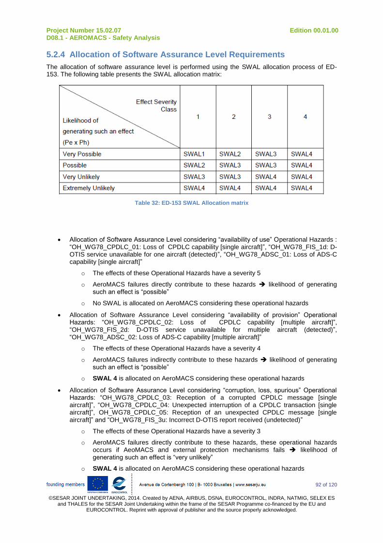
Project Number 15.02.07 Edition 00.01.00 D08.1 - AEROMACS - Safety Analysis
92 of 120
©SESAR JOINT UNDERTAKING, 2014. Created by AENA, AIRBUS, DSNA, EUROCONTROL, INDRA, NATMIG, SELEX ES
and THALES for the SESAR Joint Undertaking within the frame of the SESAR Programme co-financed by the EU and EUROCONTROL. Reprint with approval of publisher and the source properly acknowledged.
5.2.4 Allocation of Software Assurance Level Requirements
The allocation of software assurance level is performed using the SWAL allocation process of ED-153. The following table presents the SWAL allocation matrix:
Table 32: ED-153 SWAL Allocation matrix
Allocation of Software Assurance Level considering “availability of use” Operational Hazards : “OH_WG78_CPDLC_01: Loss of CPDLC capability [single aircraft]”, “OH_WG78_FIS_1d: D-OTIS service unavailable for one aircraft (detected)”, “OH_WG78_ADSC_01: Loss of ADS-C capability [single aircraft]”
o The effects of these Operational Hazards have a severity 5
o AeroMACS failures directly contribute to these hazards likelihood of generating such an effect is “possible”
o No SWAL is allocated on AeroMACS considering these operational hazards
Allocation of Software Assurance Level considering “availability of provision” Operational Hazards: “OH_WG78_CPDLC_02: Loss of CPDLC capability [multiple aircraft]”, “OH_WG78_FIS_2d: D-OTIS service unavailable for multiple aircraft (detected)”, “OH_WG78_ADSC_02: Loss of ADS-C capability [multiple aircraft]”
o The effects of these Operational Hazards have a severity 4
o AeroMACS failures indirectly contribute to these hazards likelihood of generating such an effect is “possible”
o SWAL 4 is allocated on AeroMACS considering these operational hazards
Allocation of Software Assurance Level considering “corruption, loss, spurious” Operational Hazards: “OH_WG78_CPDLC_03: Reception of a corrupted CPDLC message [single aircraft]”, “OH_WG78_CPDLC_04: Unexpected interruption of a CPDLC transaction [single aircraft]”, OH_WG78_CPDLC_05: Reception of an unexpected CPDLC message [single aircraft]” and “OH_WG78_FIS_3u: Incorrect D-OTIS report received (undetected)”
o The effects of these Operational Hazards have a severity 3
o AeroMACS failures directly contribute to these hazards, these operational hazards occurs if AeoMACS and external protection mechanisms fails likelihood of generating such an effect is “very unlikely”
o SWAL 4 is allocated on AeroMACS considering these operational hazards
Project Number 15.02.07 Edition 00.01.00 D08.1 - AEROMACS - Safety Analysis
93 of 120
©SESAR JOINT UNDERTAKING, 2014. Created by AENA, AIRBUS, DSNA, EUROCONTROL, INDRA, NATMIG, SELEX ES
and THALES for the SESAR Joint Undertaking within the frame of the SESAR Programme co-financed by the EU and EUROCONTROL. Reprint with approval of publisher and the source properly acknowledged.
AeroMACS systems shall be allocated a SWAL 4 which is equivalent to a Development Assurance Level equaled to AL5 according to ED-109 document.

Project Number 15.02.07 Edition 00.01.00 D08.1 - AEROMACS - Safety Analysis
94 of 120
©SESAR JOINT UNDERTAKING, 2014. Created by AENA, AIRBUS, DSNA, EUROCONTROL, INDRA, NATMIG, SELEX ES
and THALES for the SESAR Joint Undertaking within the frame of the SESAR Programme co-financed by the EU and EUROCONTROL. Reprint with approval of publisher and the source properly acknowledged.
5.2.5 Allocation of monitoring and alert requirements
The performance requirement regarding detection and alert in case of ACSP failures are:
PR_CP_04: The ground system shall be capable of detecting ground system failures and configuration changes that would cause the communication service to no longer meet the requirements for the intended function
PR_CP_05: When the communication service no longer meets the requirements for the intended function, the ground system shall provide indication to the controller.
These requirements are more or less directly applicable to the CSN and ASN:

Project Number 15.02.07 Edition 00.01.00 D08.1 - AEROMACS - Safety Analysis
95 of 120
©SESAR JOINT UNDERTAKING, 2014. Created by AENA, AIRBUS, DSNA, EUROCONTROL, INDRA, NATMIG, SELEX ES and THALES for the SESAR Joint Undertaking within the frame of the
SESAR Programme co-financed by the EU and EUROCONTROL. Reprint with approval of publisher and the source properly acknowledged.
Domain Sub-domain Component Related Safety
and Performance requirements
Ref shall / should
Requirements/Recommendations
ACSP - - PR_CP_04 G_Req_06 shall The ground system shall be capable of detecting ground system failures and configuration changes that would cause the communication service to no longer meet the requirements for the intended function
- - PR_CP_05 G_Req_07 shall When the communication service no longer meets the requirements for the intended function, the ground system shall provide indication to the operator.
ACSP CSN
operator CSN - all
components PR_CP_04 G_Rec_39 should
The CSN nodes should be capable of detecting CSN failures and configuration changes that would cause the communication service to no longer meet the requirements for the intended function
CSN - all
components PR_CP_05 G_Rec_40 should
When the CSN communication service no longer meets the requirements for the intended function, the CSN components should provide indication to the operator.
ACSP ASN
operator ASN - all
components PR_CP_04 G_Rec_41 should
The ASN nodes should be capable of detecting ASN failures and configuration changes that would cause the communication service to no longer meet the requirements for the intended function
ASN - all
components PR_CP_05 G_Rec_42 should
When the ASN communication service no longer meets the requirements for the intended function, the ASN components should provide indication to the operator.
Table 33 : Allocation of monitoring and alert requirements
Project Number 15.02.07 Edition 00.01.00 D08.1 - AEROMACS - Safety Analysis
96 of 120
©SESAR JOINT UNDERTAKING, 2014. Created by AENA, AIRBUS, DSNA, EUROCONTROL, INDRA, NATMIG, SELEX ES
and THALES for the SESAR Joint Undertaking within the frame of the SESAR Programme co-financed by the EU and EUROCONTROL. Reprint with approval of publisher and the source properly acknowledged.
5.3 Summary of Safety and Performance Requirements & Recommendations applicable to the AeroMACS Ground system
In the following table, only requirements coming from WG78/SC214 and applicable to the ACSP domain are considered as requirements (SHALL : G_Req_xx).
All other requirements are considered as recommendations (SHOULD : G_Rec_xx) since they are based on many assumptions on system design and/or maintenance organisation. Nevertheless, these assumptions are deemed reasonable with regards to the state of the art consequently manufacturers and Communication Service provider shall pay attention to them while implementing AeroMACS at a given airport.

Project Number 15.02.07 Edition 00.01.00 D08.1 - AEROMACS - Safety Analysis
97 of 120
©SESAR JOINT UNDERTAKING, 2014. Created by AENA, AIRBUS, DSNA, EUROCONTROL, INDRA, NATMIG, SELEX ES and THALES for the SESAR Joint Undertaking within the frame of the
SESAR Programme co-financed by the EU and EUROCONTROL. Reprint with approval of publisher and the source properly acknowledged.
Domain Sub-domain Component Related Safety
and Performance requirements
Ref shall / should
Requirements/Recommendations
ACSP - ACSP - all
components PC_CP_03 , SR_CP_02
G_Req_01 shall The availability of the ACSP service shall be more than 99.95%
- ACSP - all
components PC_CP_03 , SR_CP_02
G_Req_02 shall The likelihood that the ACSP service is unavailable shall be less than 4.3E-03/SOH
- AeroMACS components
SR_CP_02 G_Req_03 shall The AeroMACS ground component system shall be developped with the
software assurance level AL 5 in compliance with ED-109
- ACSP - all
components PR_CP_01 G_Req_04 shall The one way transaction time in ACSP shall be less than 9 seconds for
99.9% of the messages
- ACSP - all
components PR_CP_02 G_Req_05 shall The one way transaction time in ACSP shall be less than 4 seconds for 95%
of the messages
- ACSP - all
components PR_CP_04 G_Req_06 shall
The ground system shall be capable of detecting ground system failures and configuration changes that would cause the communication service to no longer meet the requirements for the intended function
- ACSP - all
components PR_CP_05 G_Req_07 shall
When the communication service no longer meets the requirements for the intended function, the ground system shall provide indication to the operator.
- ACSP - all
components PC_CP_03 , SR_CP_03
G_Rec_01 should
Depending on the implementation (type of redundancy), the Ground System should implement strategy to ease recovery of service in case of single failure at the following levels: -AAA, -Mobile IP, -ASN Gateway, -Base Station.
ACSP - all
components PC_CP_03 , SR_CP_02
G_Rec_43 should The maximum unplanned service outage duration should be 6 minutes
- ACSP - all
components PC_CP_03 , SR_CP_02
G_Rec_44 should The maximum number of unplanned service outage should be 40
- ACSP - all
components G_Rec_45 should
The maximum accumulated service unplanned outage time should be 240 minutes / year
- ACSP - all
components PC_CP_03 , SR_CP_03
G_Rec_46 should The maximum unplanned service outage notification delay should be 5 minutes
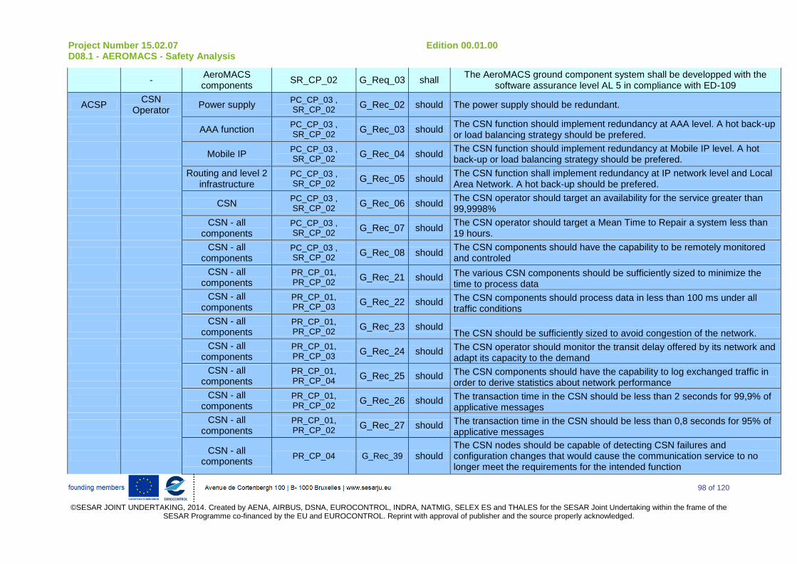
Project Number 15.02.07 Edition 00.01.00 D08.1 - AEROMACS - Safety Analysis
98 of 120
©SESAR JOINT UNDERTAKING, 2014. Created by AENA, AIRBUS, DSNA, EUROCONTROL, INDRA, NATMIG, SELEX ES and THALES for the SESAR Joint Undertaking within the frame of the
SESAR Programme co-financed by the EU and EUROCONTROL. Reprint with approval of publisher and the source properly acknowledged.
- AeroMACS components
SR_CP_02 G_Req_03 shall The AeroMACS ground component system shall be developped with the
software assurance level AL 5 in compliance with ED-109
ACSP CSN
Operator Power supply
PC_CP_03 , SR_CP_02
G_Rec_02 should The power supply should be redundant.
AAA function PC_CP_03 , SR_CP_02
G_Rec_03 should The CSN function should implement redundancy at AAA level. A hot back-up or load balancing strategy should be prefered.
Mobile IP PC_CP_03 , SR_CP_02
G_Rec_04 should The CSN function should implement redundancy at Mobile IP level. A hot back-up or load balancing strategy should be prefered.
Routing and level 2
infrastructure PC_CP_03 , SR_CP_02
G_Rec_05 should The CSN function shall implement redundancy at IP network level and Local Area Network. A hot back-up should be prefered.
CSN PC_CP_03 , SR_CP_02
G_Rec_06 should The CSN operator should target an availability for the service greater than 99,9998%
CSN - all
components PC_CP_03 , SR_CP_02
G_Rec_07 should The CSN operator should target a Mean Time to Repair a system less than 19 hours.
CSN - all
components PC_CP_03 , SR_CP_02
G_Rec_08 should The CSN components should have the capability to be remotely monitored and controled
CSN - all
components PR_CP_01, PR_CP_02
G_Rec_21 should The various CSN components should be sufficiently sized to minimize the time to process data
CSN - all
components PR_CP_01, PR_CP_03
G_Rec_22 should The CSN components should process data in less than 100 ms under all traffic conditions
CSN - all
components PR_CP_01, PR_CP_02
G_Rec_23 should The CSN should be sufficiently sized to avoid congestion of the network.
CSN - all
components PR_CP_01, PR_CP_03
G_Rec_24 should The CSN operator should monitor the transit delay offered by its network and adapt its capacity to the demand
CSN - all
components PR_CP_01, PR_CP_04
G_Rec_25 should The CSN components should have the capability to log exchanged traffic in order to derive statistics about network performance
CSN - all
components PR_CP_01, PR_CP_02
G_Rec_26 should The transaction time in the CSN should be less than 2 seconds for 99,9% of applicative messages
CSN - all
components PR_CP_01, PR_CP_02
G_Rec_27 should The transaction time in the CSN should be less than 0,8 seconds for 95% of applicative messages
CSN - all
components PR_CP_04 G_Rec_39 should
The CSN nodes should be capable of detecting CSN failures and configuration changes that would cause the communication service to no longer meet the requirements for the intended function
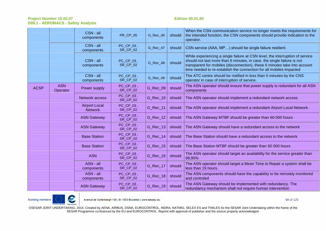
Project Number 15.02.07 Edition 00.01.00 D08.1 - AEROMACS - Safety Analysis
99 of 120
©SESAR JOINT UNDERTAKING, 2014. Created by AENA, AIRBUS, DSNA, EUROCONTROL, INDRA, NATMIG, SELEX ES and THALES for the SESAR Joint Undertaking within the frame of the
SESAR Programme co-financed by the EU and EUROCONTROL. Reprint with approval of publisher and the source properly acknowledged.
CSN - all
components PR_CP_05 G_Rec_40 should
When the CSN communication service no longer meets the requirements for the intended function, the CSN components should provide indication to the operator.
CSN - all
components PC_CP_03 , SR_CP_02
G_Rec_47 should CSN service (AAA, MP…) should be single failure resilient.
CSN - all
components PC_CP_03 , SR_CP_02
G_Rec_48 should
While experiencing a single failure at CSN level, the interruption of service should not last more than 6 minutes, in case, the single failure is not transparent for mobiles (disconnection), these 6 minutes take into account time needed to re-establish the connection for all mobiles impacted
CSN - all
components PC_CP_03 , SR_CP_02
G_Rec_49 should The ATC centre should be notified in less than 5 minutes by the CNS operator in case of interruption of service.
ACSP ASN
Operator Power supply
PC_CP_03 , SR_CP_02
G_Rec_09 should The ASN operator should ensure that power supply is redundant for all ASN components
Network access PC_CP_03 , SR_CP_02
G_Rec_10 should The ASN operator should implement a redundant network access
Airport Local
Network PC_CP_03 , SR_CP_02
G_Rec_11 should The ASN operator should implement a redundant Airport Local Network
ASN Gateway PC_CP_03 , SR_CP_02
G_Rec_12 should The ASN Gateway MTBF should be greater than 60 000 hours
ASN Gateway PC_CP_03 , SR_CP_02
G_Rec_13 should The ASN Gateway should have a redundant access to the network
Base Station PC_CP_03 , SR_CP_02
G_Rec_14 should The Base Station should have a redundant access to the network
Base Station PC_CP_03 , SR_CP_02
G_Rec_15 should The Base Station MTBF should be greater than 50 000 hours
ASN PC_CP_03 , SR_CP_02
G_Rec_16 should The ASN operator should target an availability for the service greater than 99,95%
ASN - all
components PC_CP_03 , SR_CP_02
G_Rec_17 should The ASN operator should target a Mean Time to Repair a system shall be less than 19 hours.
ASN - all
components PC_CP_03 , SR_CP_02
G_Rec_18 should The ASN components should have the capability to be remotely monitored and controled
ASN Gateway PC_CP_03 , SR_CP_02
G_Rec_19 should The ASN Gateway should be implemented with redundancy. The redundancy mechanism shall not require human intervention
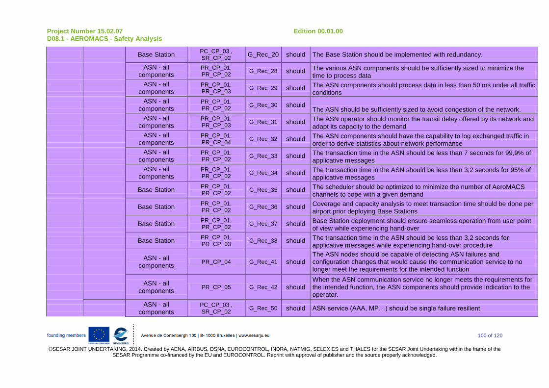
Project Number 15.02.07 Edition 00.01.00 D08.1 - AEROMACS - Safety Analysis
100 of 120
©SESAR JOINT UNDERTAKING, 2014. Created by AENA, AIRBUS, DSNA, EUROCONTROL, INDRA, NATMIG, SELEX ES and THALES for the SESAR Joint Undertaking within the frame of the
SESAR Programme co-financed by the EU and EUROCONTROL. Reprint with approval of publisher and the source properly acknowledged.
Base Station PC_CP_03 , SR_CP_02
G_Rec_20 should The Base Station should be implemented with redundancy.
ASN - all
components PR_CP_01, PR_CP_02
G_Rec_28 should The various ASN components should be sufficiently sized to minimize the time to process data
ASN - all
components PR_CP_01, PR_CP_03
G_Rec_29 should The ASN components should process data in less than 50 ms under all traffic conditions
ASN - all
components PR_CP_01, PR_CP_02
G_Rec_30 should The ASN should be sufficiently sized to avoid congestion of the network.
ASN - all
components PR_CP_01, PR_CP_03
G_Rec_31 should The ASN operator should monitor the transit delay offered by its network and adapt its capacity to the demand
ASN - all
components PR_CP_01, PR_CP_04
G_Rec_32 should The ASN components should have the capability to log exchanged traffic in order to derive statistics about network performance
ASN - all
components PR_CP_01, PR_CP_02
G_Rec_33 should The transaction time in the ASN should be less than 7 seconds for 99,9% of applicative messages
ASN - all
components PR_CP_01, PR_CP_02
G_Rec_34 should The transaction time in the ASN should be less than 3,2 seconds for 95% of applicative messages
Base Station PR_CP_01, PR_CP_02
G_Rec_35 should The scheduler should be optimized to minimize the number of AeroMACS channels to cope with a given demand
Base Station PR_CP_01, PR_CP_02
G_Rec_36 should Coverage and capacity analysis to meet transaction time should be done per airport prior deploying Base Stations
Base Station PR_CP_01, PR_CP_02
G_Rec_37 should Base Station deployment should ensure seamless operation from user point of view while experiencing hand-over
Base Station PR_CP_01, PR_CP_03
G_Rec_38 should The transaction time in the ASN should be less than 3,2 seconds for applicative messages while experiencing hand-over procedure
ASN - all
components PR_CP_04 G_Rec_41 should
The ASN nodes should be capable of detecting ASN failures and configuration changes that would cause the communication service to no longer meet the requirements for the intended function
ASN - all
components PR_CP_05 G_Rec_42 should
When the ASN communication service no longer meets the requirements for the intended function, the ASN components should provide indication to the operator.
ASN - all
components PC_CP_03 , SR_CP_02
G_Rec_50 should ASN service (AAA, MP…) should be single failure resilient.
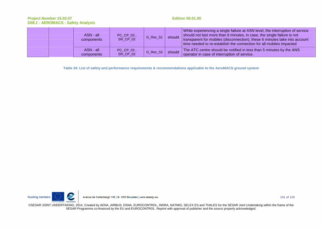
Project Number 15.02.07 Edition 00.01.00 D08.1 - AEROMACS - Safety Analysis
101 of 120
©SESAR JOINT UNDERTAKING, 2014. Created by AENA, AIRBUS, DSNA, EUROCONTROL, INDRA, NATMIG, SELEX ES and THALES for the SESAR Joint Undertaking within the frame of the
SESAR Programme co-financed by the EU and EUROCONTROL. Reprint with approval of publisher and the source properly acknowledged.
ASN - all
components PC_CP_03 , SR_CP_02
G_Rec_51 should
While experiencing a single failure at ASN level, the interruption of service should not last more than 6 minutes, in case, the single failure is not transparent for mobiles (disconnection), these 6 minutes take into account time needed to re-establish the connection for all mobiles impacted
ASN - all
components PC_CP_03 , SR_CP_02
G_Rec_52 should The ATC centre should be notified in less than 5 minutes by the ANS operator in case of interruption of service.
Table 34: List of safety and performance requirements & recommendations applicable to the AeroMACS ground system
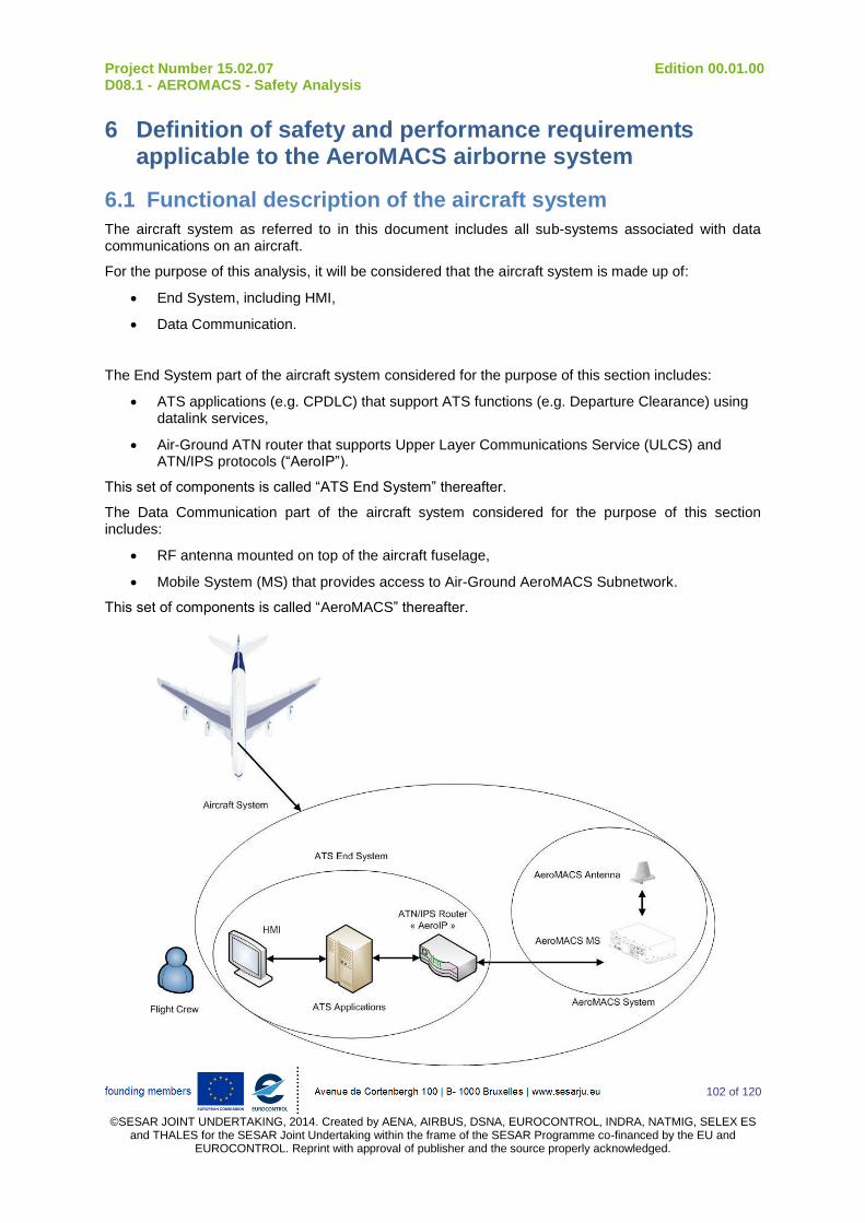
Project Number 15.02.07 Edition 00.01.00 D08.1 - AEROMACS - Safety Analysis
102 of 120
©SESAR JOINT UNDERTAKING, 2014. Created by AENA, AIRBUS, DSNA, EUROCONTROL, INDRA, NATMIG, SELEX ES
and THALES for the SESAR Joint Undertaking within the frame of the SESAR Programme co-financed by the EU and EUROCONTROL. Reprint with approval of publisher and the source properly acknowledged.
6 Definition of safety and performance requirements applicable to the AeroMACS airborne system
6.1 Functional description of the aircraft system
The aircraft system as referred to in this document includes all sub-systems associated with data communications on an aircraft.
For the purpose of this analysis, it will be considered that the aircraft system is made up of:
End System, including HMI,
Data Communication.
The End System part of the aircraft system considered for the purpose of this section includes:
ATS applications (e.g. CPDLC) that support ATS functions (e.g. Departure Clearance) using datalink services,
Air-Ground ATN router that supports Upper Layer Communications Service (ULCS) and ATN/IPS protocols (“AeroIP”).
This set of components is called “ATS End System” thereafter.
The Data Communication part of the aircraft system considered for the purpose of this section includes:
RF antenna mounted on top of the aircraft fuselage,
Mobile System (MS) that provides access to Air-Ground AeroMACS Subnetwork.
This set of components is called “AeroMACS” thereafter.
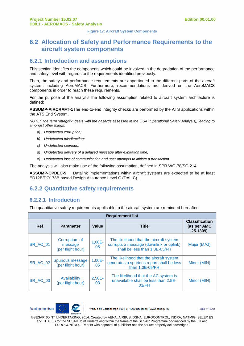
Project Number 15.02.07 Edition 00.01.00 D08.1 - AEROMACS - Safety Analysis
103 of 120
©SESAR JOINT UNDERTAKING, 2014. Created by AENA, AIRBUS, DSNA, EUROCONTROL, INDRA, NATMIG, SELEX ES
and THALES for the SESAR Joint Undertaking within the frame of the SESAR Programme co-financed by the EU and EUROCONTROL. Reprint with approval of publisher and the source properly acknowledged.
Figure 17: Aircraft System Components
6.2 Allocation of Safety and Performance Requirements to the aircraft system components
6.2.1 Introduction and assumptions
This section identifies the components which could be involved in the degradation of the performance and safety level with regards to the requirements identified previously.
Then, the safety and performance requirements are apportioned to the different parts of the aircraft system, including AeroMACS. Furthermore, recommendations are derived on the AeroMACS components in order to reach these requirements.
For the purpose of the analysis the following assumption related to aircraft system architecture is defined:
ASSUMP-AIRCRAFT-1 The end-to-end integrity checks are performed by the ATS applications within the ATS End System.
NOTE: The term “integrity” deals with the hazards assessed in the OSA (Operational Safety Analysis), leading to amongst other things:
a) Undetected corruption;
b) Undetected misdirection;
c) Undetected spurious;
d) Undetected delivery of a delayed message after expiration time;
e) Undetected loss of communication and user attempts to initiate a transaction.
The analysis will also make use of the following assumption, defined in SPR WG-78/SC-214:
ASSUMP-CPDLC-5 Datalink implementations within aircraft systems are expected to be at least ED12B/DO178B based Design Assurance Level C (DAL C)..
6.2.2 Quantitative safety requirements
6.2.2.1 Introduction
The quantitative safety requirements applicable to the aircraft system are reminded hereafter:
Requirement list
Ref Parameter Value Title Classification (as per AMC
25.1309)
SR_AC_01 Corruption of
message (per flight hour)
1,00E-05
The likelihood that the aircraft system corrupts a message (downlink or uplink)
shall be less than 1.0E-05/FH Major (MAJ)
SR_AC_02 Spurious message
(per flight hour) 1,00E-
05
The likelihood that the aircraft system generates a spurious report shall be less
than 1.0E-05/FH Minor (MIN)
SR_AC_03 Availability
(per flight hour) 2,50E-
03
The likelihood that the AC system is unavailable shall be less than 2.5E-
03/FH Minor (MIN)

Project Number 15.02.07 Edition 00.01.00 D08.1 - AEROMACS - Safety Analysis
104 of 120
©SESAR JOINT UNDERTAKING, 2014. Created by AENA, AIRBUS, DSNA, EUROCONTROL, INDRA, NATMIG, SELEX ES
and THALES for the SESAR Joint Undertaking within the frame of the SESAR Programme co-financed by the EU and EUROCONTROL. Reprint with approval of publisher and the source properly acknowledged.
Requirement list
Ref Parameter Value Title Classification (as per AMC
25.1309)
SR_AC_04
Detection of corrupted messages
(per flight hour)
1,00E-05
The likelihood that the aircraft system fails to detect the corrupted message
shall be less than 1.0E-05/FH Major (MAJ)
SR_AC_05
Detection of delayed downlink
messages (per flight hour)
1,00E-05
The likelihood that the aircraft system incorrectly time stamps a message shall
be less than 1.0E-05/FH Major (MAJ)
SR_AC_06
Detection of misdirected uplink
messages (per flight hour)
1,00E-05
The likelihood that the aircraft system fails to detect and reject the misdirected uplink message shall be less than 1.0E-
05/FH
Major (MAJ)
SR_AC_07
Detection of spurious uplink
messages (per flight hour)
1,00E-05
The likelihood to accept a message out of context of the current transaction shall
be less than 1.E-5/FH. Major (MAJ)
6.2.2.2 Loss of datalink capability
The safety requirement regarding availability of aircraft system is:
SR_AC_03: The likelihood that the AC system is unavailable shall be less than 2.5E-03/FH
The potential causes for this failure condition to occur are: a) The ATS End System is unable to provide ATS functions, or b) Dependant systems of AeroMACS make it inoperative, or c) The AeroMACS MS itself is unable to provide datalink services
The figure below provides the fault tree for this failure condition and allocation to the system components:
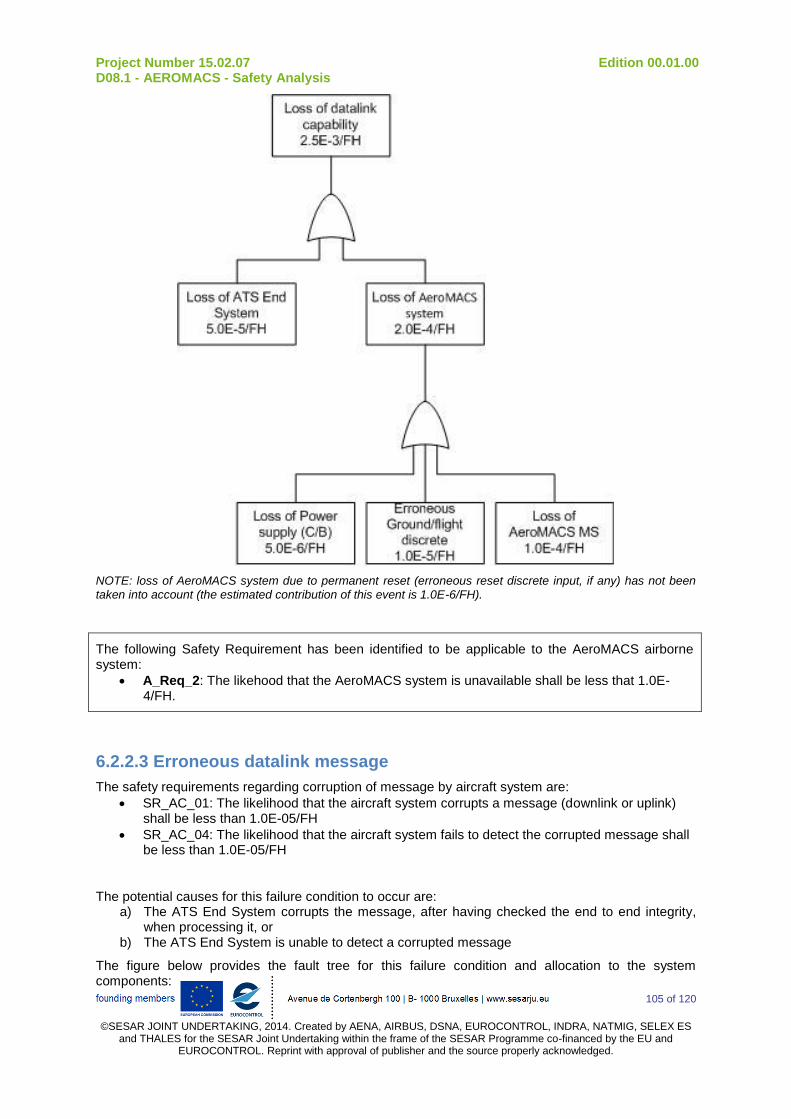
Project Number 15.02.07 Edition 00.01.00 D08.1 - AEROMACS - Safety Analysis
105 of 120
©SESAR JOINT UNDERTAKING, 2014. Created by AENA, AIRBUS, DSNA, EUROCONTROL, INDRA, NATMIG, SELEX ES
and THALES for the SESAR Joint Undertaking within the frame of the SESAR Programme co-financed by the EU and EUROCONTROL. Reprint with approval of publisher and the source properly acknowledged.
NOTE: loss of AeroMACS system due to permanent reset (erroneous reset discrete input, if any) has not been taken into account (the estimated contribution of this event is 1.0E-6/FH).
The following Safety Requirement has been identified to be applicable to the AeroMACS airborne system:
A_Req_2: The likehood that the AeroMACS system is unavailable shall be less that 1.0E-4/FH.
6.2.2.3 Erroneous datalink message
The safety requirements regarding corruption of message by aircraft system are:
SR_AC_01: The likelihood that the aircraft system corrupts a message (downlink or uplink) shall be less than 1.0E-05/FH
SR_AC_04: The likelihood that the aircraft system fails to detect the corrupted message shall be less than 1.0E-05/FH
The potential causes for this failure condition to occur are: a) The ATS End System corrupts the message, after having checked the end to end integrity,
when processing it, or b) The ATS End System is unable to detect a corrupted message
The figure below provides the fault tree for this failure condition and allocation to the system components:
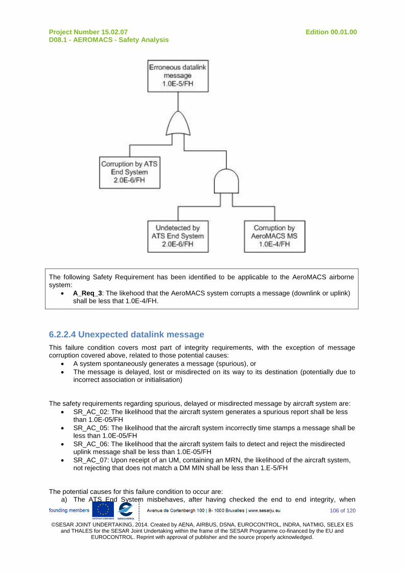
Project Number 15.02.07 Edition 00.01.00 D08.1 - AEROMACS - Safety Analysis
106 of 120
©SESAR JOINT UNDERTAKING, 2014. Created by AENA, AIRBUS, DSNA, EUROCONTROL, INDRA, NATMIG, SELEX ES
and THALES for the SESAR Joint Undertaking within the frame of the SESAR Programme co-financed by the EU and EUROCONTROL. Reprint with approval of publisher and the source properly acknowledged.
The following Safety Requirement has been identified to be applicable to the AeroMACS airborne system:
A_Req_3: The likehood that the AeroMACS system corrupts a message (downlink or uplink) shall be less that 1.0E-4/FH.
6.2.2.4 Unexpected datalink message
This failure condition covers most part of integrity requirements, with the exception of message corruption covered above, related to those potential causes:
A system spontaneously generates a message (spurious), or
The message is delayed, lost or misdirected on its way to its destination (potentially due to incorrect association or initialisation)
The safety requirements regarding spurious, delayed or misdirected message by aircraft system are:
SR_AC_02: The likelihood that the aircraft system generates a spurious report shall be less than 1.0E-05/FH
SR_AC_05: The likelihood that the aircraft system incorrectly time stamps a message shall be less than 1.0E-05/FH
SR_AC_06: The likelihood that the aircraft system fails to detect and reject the misdirected uplink message shall be less than 1.0E-05/FH
SR_AC_07: Upon receipt of an UM, containing an MRN, the likelihood of the aircraft system, not rejecting that does not match a DM MIN shall be less than 1.E-5/FH
The potential causes for this failure condition to occur are: a) The ATS End System misbehaves, after having checked the end to end integrity, when
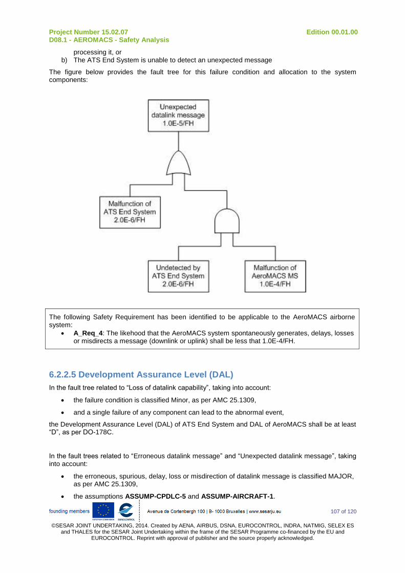
Project Number 15.02.07 Edition 00.01.00 D08.1 - AEROMACS - Safety Analysis
107 of 120
©SESAR JOINT UNDERTAKING, 2014. Created by AENA, AIRBUS, DSNA, EUROCONTROL, INDRA, NATMIG, SELEX ES
and THALES for the SESAR Joint Undertaking within the frame of the SESAR Programme co-financed by the EU and EUROCONTROL. Reprint with approval of publisher and the source properly acknowledged.
processing it, or b) The ATS End System is unable to detect an unexpected message
The figure below provides the fault tree for this failure condition and allocation to the system components:
The following Safety Requirement has been identified to be applicable to the AeroMACS airborne system:
A_Req_4: The likehood that the AeroMACS system spontaneously generates, delays, losses or misdirects a message (downlink or uplink) shall be less that 1.0E-4/FH.
6.2.2.5 Development Assurance Level (DAL)
In the fault tree related to “Loss of datalink capability”, taking into account:
the failure condition is classified Minor, as per AMC 25.1309,
and a single failure of any component can lead to the abnormal event,
the Development Assurance Level (DAL) of ATS End System and DAL of AeroMACS shall be at least “D”, as per DO-178C.
In the fault trees related to “Erroneous datalink message” and “Unexpected datalink message”, taking into account:
the erroneous, spurious, delay, loss or misdirection of datalink message is classified MAJOR, as per AMC 25.1309,
the assumptions ASSUMP-CPDLC-5 and ASSUMP-AIRCRAFT-1.
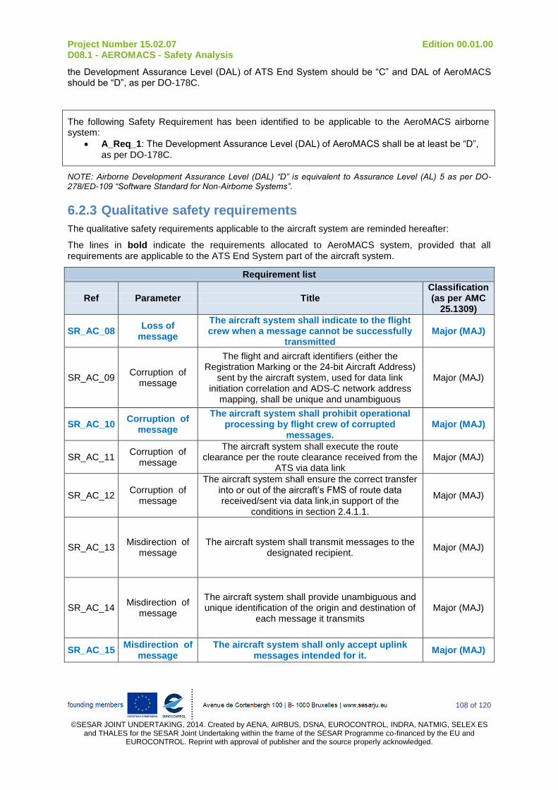
Project Number 15.02.07 Edition 00.01.00 D08.1 - AEROMACS - Safety Analysis
108 of 120
©SESAR JOINT UNDERTAKING, 2014. Created by AENA, AIRBUS, DSNA, EUROCONTROL, INDRA, NATMIG, SELEX ES
and THALES for the SESAR Joint Undertaking within the frame of the SESAR Programme co-financed by the EU and EUROCONTROL. Reprint with approval of publisher and the source properly acknowledged.
the Development Assurance Level (DAL) of ATS End System should be “C” and DAL of AeroMACS should be “D”, as per DO-178C.
The following Safety Requirement has been identified to be applicable to the AeroMACS airborne system:
A_Req_1: The Development Assurance Level (DAL) of AeroMACS shall be at least be “D”, as per DO-178C.
NOTE: Airborne Development Assurance Level (DAL) “D” is equivalent to Assurance Level (AL) 5 as per DO-278/ED-109 “Software Standard for Non-Airborne Systems”.
6.2.3 Qualitative safety requirements
The qualitative safety requirements applicable to the aircraft system are reminded hereafter:
The lines in bold indicate the requirements allocated to AeroMACS system, provided that all requirements are applicable to the ATS End System part of the aircraft system.
Requirement list
Ref Parameter Title Classification (as per AMC
25.1309)
SR_AC_08 Loss of
message
The aircraft system shall indicate to the flight crew when a message cannot be successfully
transmitted Major (MAJ)
SR_AC_09 Corruption of
message
The flight and aircraft identifiers (either the Registration Marking or the 24-bit Aircraft Address)
sent by the aircraft system, used for data link initiation correlation and ADS-C network address
mapping, shall be unique and unambiguous
Major (MAJ)
SR_AC_10 Corruption of
message
The aircraft system shall prohibit operational processing by flight crew of corrupted
messages. Major (MAJ)
SR_AC_11 Corruption of
message
The aircraft system shall execute the route clearance per the route clearance received from the
ATS via data link Major (MAJ)
SR_AC_12 Corruption of
message
The aircraft system shall ensure the correct transfer into or out of the aircraft’s FMS of route data received/sent via data link,in support of the
conditions in section 2.4.1.1.
Major (MAJ)
SR_AC_13 Misdirection of
message The aircraft system shall transmit messages to the
designated recipient. Major (MAJ)
SR_AC_14 Misdirection of
message
The aircraft system shall provide unambiguous and unique identification of the origin and destination of
each message it transmits Major (MAJ)
SR_AC_15 Misdirection of
message The aircraft system shall only accept uplink
messages intended for it. Major (MAJ)

Project Number 15.02.07 Edition 00.01.00 D08.1 - AEROMACS - Safety Analysis
109 of 120
©SESAR JOINT UNDERTAKING, 2014. Created by AENA, AIRBUS, DSNA, EUROCONTROL, INDRA, NATMIG, SELEX ES
and THALES for the SESAR Joint Undertaking within the frame of the SESAR Programme co-financed by the EU and EUROCONTROL. Reprint with approval of publisher and the source properly acknowledged.
Requirement list
Ref Parameter Title Classification (as per AMC
25.1309)
SR_AC_16 Misdirection of
message
The flight crew shall perform the initiation data link procedure again with any change of the aircraft
identifiers (e.g. the Flight Identification and either the Registration Marking or the Aircraft Address)
Major (MAJ)
SR_AC_17 Delay of message
The aircraft system shall indicate to the flight crew when a message cannot be successfully
transmitted Major (MAJ)
SR_AC_18 Availability The aircraft system shall provide to the ATSU an
indication when it rejects an ADS-C service request initiated by the ATSU at the application layer.
Minor (MIN)
SR_AC_19 Availability The aircraft system shall indicate to the flight
crew a detected loss of ADS-C service. Minor (MIN)
SR_AC_20 Availability The aircraft system shall provide to the ATSU an
indication when it rejects a CPDLC service request initiated by the ATSU at the application layer.
Minor (MIN)
SR_AC_21 Availability
The aircraft system shall display the indication provided by the ATSU when a DSC service request
initiated by the flight crew is rejected at the application layer.
Minor (MIN)
SR_AC_22 Availability The aircraft system shall indicate to the flight
crew a detected loss of data link service. Minor (MIN)
SR_AC_23 Detection of
corrupted messages
Whenever a message is discarded by the aircraft system, it shall send an indication to the ground
system for display to the controller. Major (MAJ)
SR_AC_24 Detection of
delayed downlink messages
The aircraft system shall time stamp each report to within one second UTC when it is released for
onward transmission. Minor (MIN)
SR_AC_25 Detection of
delayed downlink messages
The aircraft system shall time stamp to within one second UTC each message when it is released for
onward transmission. Minor (MIN)
SR_AC_26 Detection of
delayed uplink messages
When a received message contains a time stamp that indicates the Latency Time Check value, set at equal or less than ETTRN, has been exceeded, the
aircraft system shall a) discard the message and send an indication to the Ground System for display
to the controller or b) provide the message to the flight crew with an appropriate indication.
Major (MAJ)
SR_AC_27 Detection of misdirected
uplink messages
The aircraft system shall be able to determine the message initiator.
Major (MAJ)
SR_AC_28 Detection of misdirected
uplink messages
Once an aircraft accepts operational CPDLC messages from an ATSU, it shall reject operational CPDLC messages from any other ATSU until the first ATSU terminates CPDLC with that aircraft.
Major (MAJ)
SR_AC_29 Detection of misdirected
uplink messages
Only the ATSU that has control of the aircraft shall be permitted to send a Next Data Authority (NDA)
message to the aircraft. Major (MAJ)

Project Number 15.02.07 Edition 00.01.00 D08.1 - AEROMACS - Safety Analysis
110 of 120
©SESAR JOINT UNDERTAKING, 2014. Created by AENA, AIRBUS, DSNA, EUROCONTROL, INDRA, NATMIG, SELEX ES
and THALES for the SESAR Joint Undertaking within the frame of the SESAR Programme co-financed by the EU and EUROCONTROL. Reprint with approval of publisher and the source properly acknowledged.
Requirement list
Ref Parameter Title Classification (as per AMC
25.1309)
SR_AC_30 Detection of
spurious uplink messages
The aircraft system shall indicate in each response to which messages it refers
Major (MAJ)
SR_AC_31 Detection of
spurious uplink messages
Each downlink message shall be uniquely identified for a given aircraft-ATSU pair, following a sequential
order Major (MAJ)
SR_AC_32
Detection of spurious downlink
messages
The aircraft system shall indicate in each report to which contract number it is referring
Major (MAJ)
SR_AC_33
Detection of inappropriate
messages by the crew
The aircraft system shall provide to the flight crew an indication of the ATSU that has established
CPDLC (CDA) service. Major (MAJ)
To summarize, the AeroMACS system shall:
a) Indicate a detected loss of datalink services (SR_AC_08, SR_AC_19, SR_AC_22)
b) Only accept uplink messages intended for the aircraft (SR_AC_15)
c) Prohibit operational processing of corrupted messages (SR_AC_10)
d) Indicate when a message cannot be successfully transmitted (SR_AC_17)
The following Safety Requirements have been identified to be applicable to the AeroMACS airborne system:
A_Req_5: The AeroMACS system shall indicate a detected loss of datalink services.
A_Req_6: The AeroMACS system shall only accept uplink messages intended for the aircraft.
A_Req_7: The AeroMACS system shall prohibit operational processing of corrupted messages.
A_Req_8: The AeroMACS system shall indicate when a message cannot be successfully transmitted.
6.2.3.1 RF interferences with other CNS systems
One particular case of malfunction of AeroMACS MS is the inadvertent activation during flight (due for example to erroneous Ground/Flight condition), in this situation:
The minimum required isolation from AeroMACS transmission (fundamental emission) is 43 dB (refer to document “Aircraft installation & Operational aspects of the AeroMACS”), i.e. a minimum distance of 0.7 meter@5120 MHz
The minimum required isolation from AeroMACS transmission (spurious & broadband noise emissions) is 118 dB. However, considering a minimum reduction of 70 dB below 2 GHz for AeroMACS emissions, the minimum required isolation is 48 dB, i.e. a minimum distance of 1.2 meter@5120 MHz

Project Number 15.02.07 Edition 00.01.00 D08.1 - AEROMACS - Safety Analysis
111 of 120
©SESAR JOINT UNDERTAKING, 2014. Created by AENA, AIRBUS, DSNA, EUROCONTROL, INDRA, NATMIG, SELEX ES
and THALES for the SESAR Joint Undertaking within the frame of the SESAR Programme co-financed by the EU and EUROCONTROL. Reprint with approval of publisher and the source properly acknowledged.
Taking into account that the minimum distance with the AeroMACS antenna will be 1.5 meter (5 feet), the inadvertent activation during flight of AeroMACS has no effect on others CNS systems.
6.2.4 Quantitative performance requirements
The quantitative performance requirements applicable to the aircraft system are reminded hereafter:
Requirement list
Ref Parameter Value Title
PR_AC_01 Transaction Time
99,9 % (in seconds)
11,5 The transaction time (one way) in aircraft shall be less than 11.5 seconds for 99.9% of the ADS-C - RSP 95 messages
PR_AC_02 Transaction Time
95 % (in seconds)
5 The transaction time (one way) in aircraft shall be less than
5 seconds for 95% of the ADS-C - RSP 95 messages
PR_AC_03 Availability (in percent)
99,40% The availability of the ADS-C aircraft system shall be more
than 99.40%
6.2.4.1 Transaction Time (Continuity)
The performance requirements regarding transaction time of message by aircraft system are:
PR_AC_01: The transaction time (one way) in aircraft shall be less than 11.5 seconds for 99.9% of the ADS-C - RSP 95 messages
PR_AC_02: The transaction time (one way) in aircraft shall be less than 5 seconds for 95% of the ADS-C - RSP 95 messages
Transaction time is allocated on the different components using arithmetic distribution. The following table presents the results of this allocation:
Objective (one-way transmission) (downlink or uplink)
ATS End System
Interface between ATS End System and AeroMACS
AeroMACS system
TT(95%): 5 sec 4 sec 500 msec 500 msec
TT (99.9%): 11.5 sec 10 sec 500 msec 1 sec
The following Performance Requirements have been identified to be applicable to the AeroMACS airborne system:
A_Req_9: The delay introduced by the AeroMACS system for a one-way transmission (downlink or uplink) shall be less than 500 msec.
Project Number 15.02.07 Edition 00.01.00 D08.1 - AEROMACS - Safety Analysis
112 of 120
©SESAR JOINT UNDERTAKING, 2014. Created by AENA, AIRBUS, DSNA, EUROCONTROL, INDRA, NATMIG, SELEX ES
and THALES for the SESAR Joint Undertaking within the frame of the SESAR Programme co-financed by the EU and EUROCONTROL. Reprint with approval of publisher and the source properly acknowledged.
6.2.4.2 Availability
The performance requirement regarding availability of aircraft system is:
PR_AC_03: The availability of the ADS-C aircraft system shall be more than 99.40%
With an average use of aircraft system of 2.5 hours/flight, the quantitative performance requirement is computed as follows:
Probability of loss of aircraft system = (1 - AAIRCRAFT)/(flight duration) = (1 – 0.994)/2.5 = 2.4E-3/FH
This probability of loss of aircraft system is commensurate with the likelihood defined in SR_AC_03 (“The likelihood that the AC system is unavailable shall be less than 2.5E-03/FH”).
Thus the fault tree and allocations of section “Loss of datalink capability” remain valid, and Safety requirement A_Req_2 is still applicable for Performance.
The following Performance Requirements have been identified to be applicable to the AeroMACS airborne system:
A_Req_2: The likehood that the AeroMACS system is unavailable shall be less that 1.0E-4/FH.
6.2.5 Qualitative performance requirements
The qualitative performance requirements applicable to the aircraft system are reminded hereafter:
Requirement list
Ref Parameter Title
PR_AC_04 Availability
The aircraft system shall be capable of detecting aircraft system failures or loss of air/ground communication that would cause the aircraft
communication capability to no longer meet the requirements for the intended function.
PR_AC_05 Availability When the aircraft communication capability no longer meets the
requirements for the intended function, the aircraft system shall provide indication to the flight crew.
To summarize, the AeroMACS system shall:
a) Indicate a detected loss of datalink services
b) Indicate when a message cannot be successfully transmitted
The following Performance Requirements have been identified to be applicable to the AeroMACS airborne system:
A_Req_5: The AeroMACS system shall indicate a detected loss of datalink services.
A_Req_8: The AeroMACS system shall indicate when a message cannot be successfully transmitted.

Project Number 15.02.07 Edition 00.01.00 D08.1 - AEROMACS - Safety Analysis
113 of 120
©SESAR JOINT UNDERTAKING, 2014. Created by AENA, AIRBUS, DSNA, EUROCONTROL, INDRA, NATMIG, SELEX ES
and THALES for the SESAR Joint Undertaking within the frame of the SESAR Programme co-financed by the EU and EUROCONTROL. Reprint with approval of publisher and the source properly acknowledged.
6.3 Summary of Safety and Performance Requirements applicable to the AeroMACS airborne system
The following Safety and Performance Requirements have been identified to be applicable to the AeroMACS airborne system:
A_Req_1: The Development Assurance Level (DAL) of AeroMACS shall be at least be “D”, as per DO-178C.
A_Req_2: The likelihood that the AeroMACS system is unavailable shall be less that 1.0E-4/FH.
A_Req_3: The likelihood that the AeroMACS system corrupts a message (downlink or uplink) shall be less that 1.0E-4/FH.
A_Req_4: The likelihood that the AeroMACS system spontaneously generates, delays, losses or misdirects a message (downlink or uplink) shall be less that 1.0E-4/FH.
A_Req_5: The AeroMACS system shall indicate a detected loss of datalink services.
A_Req_6: The AeroMACS system shall only accept uplink messages intended for the aircraft.
A_Req_7: The AeroMACS system shall prohibit operational processing of corrupted messages.
A_Req_8: The AeroMACS system shall indicate when a message cannot be successfully transmitted.
A_Req_9: The delay introduced by the AeroMACS system for a one-way transmission (downlink or uplink) shall be less than 500 msec.

Project Number 15.02.07 Edition 00.01.00 D08.1 - AEROMACS - Safety Analysis
114 of 120
©SESAR JOINT UNDERTAKING, 2014. Created by AENA, AIRBUS, DSNA, EUROCONTROL, INDRA, NATMIG, SELEX ES and THALES for the SESAR Joint Undertaking within the frame of the
SESAR Programme co-financed by the EU and EUROCONTROL. Reprint with approval of publisher and the source properly acknowledged.
7 List of assumptions List of Assumptions
Ref Phase Assumption Jutification
ASSUMP-AEROMACS_01
Services / Application
Context Management (CM) application is not considered during the identification of Operational Hazards.
Consistent with WG78/SC214 approach: a failure during Datalink initiation doesn't have direct operational effects. However it can have effects during the use of the others applications (CPDLC, ADS-C and FIS). So the safety requirements concerning CM messages are determined by studying all the other applications.
ASSUMP-AEROMACS_02
Services / Application
No specific safety analysis is carried out for 4D-TRAD service
4D-TRAD uses both CPDLC and ADS-C applications. It is considered that 4D-TRAD do not drive more stringent requirements on CPDLC and ADS-C applications than other CPDLC and ADS-C services. This assumption will be validated when 4D-TRAD OSA will be published.
ASSUMP-AEROMACS_03
Services / Application
Services D-RVR and D-HZWX are not taken into account when considering the FIS application in the safety analysis.
WG78 OSA concerning FIS application only considers D-OTIS service. Others OSA are currently in process concerning services D-RVR and D-HZWX.
ASSUMP-AEROMACS_04
Definition of AE
Abnormal Events concerning all the messages at AeroMACS level associated to one aircraft are always detected. These events are grouped as single event: “permanent failure to communicate with one aircraft" (Availability of use).
A failure on a message at AeroMACS level (corruption, loss…), is detected thanks to the external mitigation means such as time stamps, checksum… at upper layers. A systematic failure of the external mitigations means for all AeroMACS messages is very unlikely (the period of failure allocated by WG78 is one failure every 100 000 hours). The detection of this failure induces a clarification between controllers and flight crew. Then, following messages will be carefully watched; controllers will detect that there is a permanent failure on Datalink communication chain with the aircraft.

Project Number 15.02.07 Edition 00.01.00 D08.1 - AEROMACS - Safety Analysis
115 of 120
©SESAR JOINT UNDERTAKING, 2014. Created by AENA, AIRBUS, DSNA, EUROCONTROL, INDRA, NATMIG, SELEX ES and THALES for the SESAR Joint Undertaking within the frame of the
SESAR Programme co-financed by the EU and EUROCONTROL. Reprint with approval of publisher and the source properly acknowledged.
List of Assumptions
Ref Phase Assumption Jutification
ASSUMP-AEROMACS_05
Definition of AE
Abnormal Events concerning all messages at AeroMACS level associated to more than one aircraft are always detected. These events are grouped as single event:”permanent failure to communicate with more than one aircraft” (Availability of provision).
A failure on an AeroMACS message (corruption, loss…), is detected thanks to the external mitigation means such as time stamps, checksum… A systematic failure of the external mitigations means for all message is very improbable (the period of failure allocated by WG78 is one failure every 100 000 hours). The detection of this failure induces a clarification between controllers and flight crew. Then, following messages will be carefully watched; controllers will detect that there is a permanent failure on Datalink communication chain.
ASSUMP-AEROMACS_06
Evaluation of severity
Simultaneous loss of all applications (CPDLC, D-OTIS and ADS-C) for one aircraft is not more critical than independent failure of each application for one aircraft.
This assumption must be validated by working group 78. However, this assumption seems coherent because Datalink application has never been considered as a reduction mean to mitigate the loss of another application. For example, OH_WG78_CPDLC_01 (failure to exchange CPDLC messages with a single aircraft) is not mitigated by the utilization of ADS-C or FIS.
ASSUMP-AEROMACS_07
Evaluation of severity
Simultaneous loss of all applications (CPDLC, D-OTIS and ADS-C) for one aircraft is not more critical that independent failure of each application for one aircraft.
This assumption must be validated by working group 78. However, this assumption seems coherent because Datalink application has never been considered as a reduction mean to mitigate the loss of another application.
ASSUMP-AEROMACS_08
Allocation of SR The probability that all the ground systems are unavailable is assumed to be less than 7*10-6 per flight hour.
WG78 CPDLC OSA has defined a safety requirement of 7*10-6 for the unavailability of the CPDLC ground system. A failure of all the ground system should be lower than this requirement (multiple failure should occur to induce a failure of all ground systems).
ASSUMP-AIRCRAFT-1 AeroMACS
airborne system Allocation
The end-to-end integrity checks are performed by the ATS applications within the ATS End System.
Consistent with current architectures
Table 35: List of Assumptions
Project Number 15.02.07 Edition 00.01.00 D08.1 - AEROMACS - Safety Analysis
116 of 120
©SESAR JOINT UNDERTAKING, 2014. Created by AENA, AIRBUS, DSNA, EUROCONTROL, INDRA, NATMIG, SELEX ES
and THALES for the SESAR Joint Undertaking within the frame of the SESAR Programme co-financed by the EU and EUROCONTROL. Reprint with approval of publisher and the source properly acknowledged.
8 References
[1] Data Communications Safety and Performance Requirements - Annex A Operational Safety Analysis Approach – Issue I, 1
st February 2012 – WG78/SC214
[2] Data Communications Safety and Performance Requirements - Annex B CPDLC Operational Safety Analysis – Issue I, 1
st February 2012 – WG78/SC214
[3] Data Communications Safety and Performance Requirements - Annex C ADS-C Operational Safety Analysis – Issue I, 1
st February 2012 – WG78/SC214
[4] Data Communications Safety and Performance Requirements - Annex D FIS Operational Safety Analysis – Issue H, 3
rd February 2010 – WG78/SC214
[5] Data Communications Safety and Performance Requirements - Annex EFGH Operational Performance Analysis – Issue I, 1
st February 2012 – WG78/SC214
[6] WiMAX Forum Network Architecture – Stage 2 Architecture Tenets, Reference Model and Reference Points- Ref T32-002 Release 1.0 Version 4 - February 03, 2009 T32-002 –
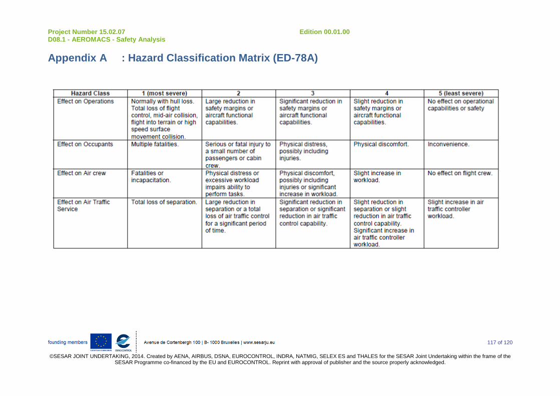
Project Number 15.02.07 Edition 00.01.00 D08.1 - AEROMACS - Safety Analysis
117 of 120
©SESAR JOINT UNDERTAKING, 2014. Created by AENA, AIRBUS, DSNA, EUROCONTROL, INDRA, NATMIG, SELEX ES and THALES for the SESAR Joint Undertaking within the frame of the
SESAR Programme co-financed by the EU and EUROCONTROL. Reprint with approval of publisher and the source properly acknowledged.
Appendix A : Hazard Classification Matrix (ED-78A)
Project Number 15.02.07 Edition 00.01.00 D08.1 - AEROMACS - Safety Analysis
118 of 120
©SESAR JOINT UNDERTAKING, 2014. Created by AENA, AIRBUS, DSNA, EUROCONTROL, INDRA, NATMIG, SELEX ES
and THALES for the SESAR Joint Undertaking within the frame of the SESAR Programme co-financed by the EU and EUROCONTROL. Reprint with approval of publisher and the source properly acknowledged.
Appendix B : Identification of Operational Hazards table
The table associated to this systematic methodology is presented in the following file:
Identification of Operational Hazards - V1R0.xlsx
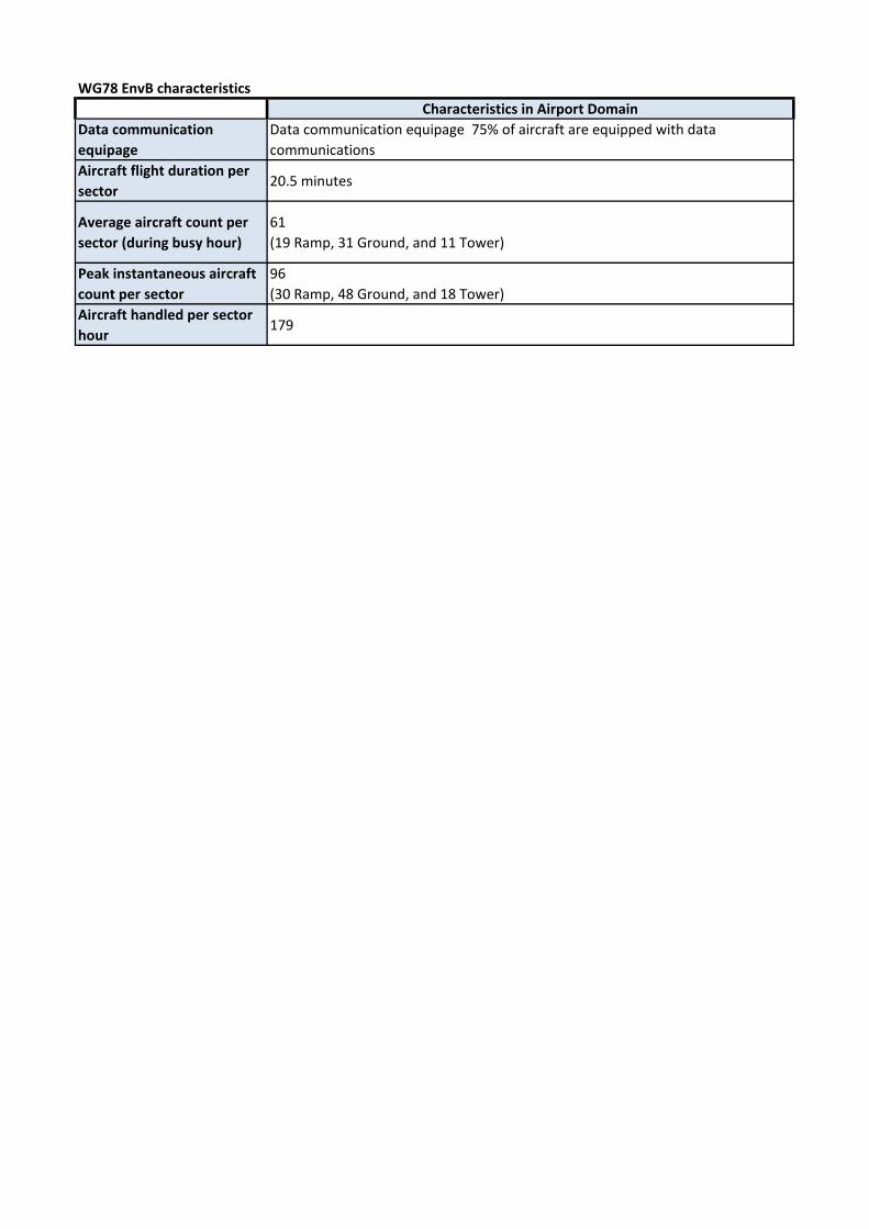
WG78 EnvB characteristics
Characteristics in Airport Domain
Data communication
equipage
Data communication equipage 75% of aircraft are equipped with data
communications
Aircraft flight duration per
sector 20.5 minutes
Average aircraft count per
sector (during busy hour)
61
(19 Ramp, 31 Ground, and 11 Tower)
Peak instantaneous aircraft
count per sector
96
(30 Ramp, 48 Ground, and 18 Tower)
Aircraft handled per sector
hour179

Applications - Services
Used in APT
domain
Covered by
WG78
Adressed in present
documentJustification
CMContext
ManagementDLIC DataLink Inititation X X X
ACM ATC Communication Management X X X
CRD Clearance Request and Delivery X X X
AMC ATC Microphone Check X X X
DCL Departure Clearance X X X
D-TAXI DataLink Taxi X X X
4DTRAD 4-Dimensional Trajectory Data Link X X
IER Information Exchange and Reporting X X X
PR Position Reporting X Chapter 2 page 16 : Separation Assurance, only in ENR-2
IM Interval Management X Chapter 2 page 16 : Separation Assurance, only in TMA and ENR-1
OCL Oceanic Clearance X
4DTRAD 4-Dimensional Trajectory Data Link X X
IER Information Exchange and Reporting X X X
PR Position Reporting Chapter 2 page 16 : Separation Assurance, only in ENR-2
IM Interval Management Chapter 2 page 16 : Separation Assurance, only in TMA and ENR-1
D-OTIS DataLink Operational Terminal Information X X X
D-RVR DataLink Runway Visual Range X
D-HZWX Data Link Hazardous Weather X
Services considered in safety analysis
FISFlight Information
Service
Controller Pilot
DataLink
Communication
CPDLC
Automatic
Dependent
Surveillance
ADS-C
Application
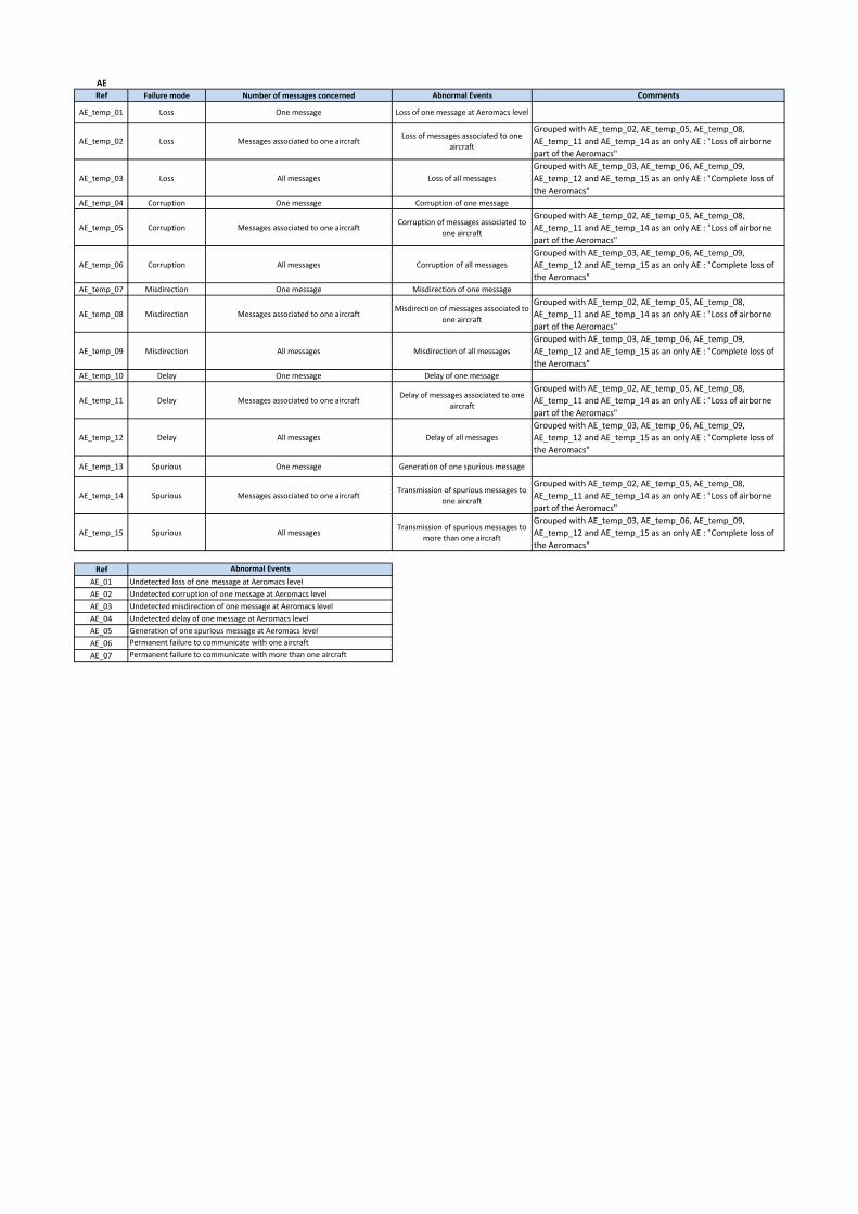
AE
Ref Failure mode Number of messages concerned Abnormal Events Comments
AE_temp_01 Loss One message Loss of one message at Aeromacs level
AE_temp_02 Loss Messages associated to one aircraftLoss of messages associated to one
aircraft
Grouped with AE_temp_02, AE_temp_05, AE_temp_08,
AE_temp_11 and AE_temp_14 as an only AE : "Loss of airborne
part of the Aeromacs"
AE_temp_03 Loss All messages Loss of all messages
Grouped with AE_temp_03, AE_temp_06, AE_temp_09,
AE_temp_12 and AE_temp_15 as an only AE : "Complete loss of
the Aeromacs"
AE_temp_04 Corruption One message Corruption of one message
AE_temp_05 Corruption Messages associated to one aircraftCorruption of messages associated to
one aircraft
Grouped with AE_temp_02, AE_temp_05, AE_temp_08,
AE_temp_11 and AE_temp_14 as an only AE : "Loss of airborne
part of the Aeromacs"
AE_temp_06 Corruption All messages Corruption of all messages
Grouped with AE_temp_03, AE_temp_06, AE_temp_09,
AE_temp_12 and AE_temp_15 as an only AE : "Complete loss of
the Aeromacs"
AE_temp_07 Misdirection One message Misdirection of one message
AE_temp_08 Misdirection Messages associated to one aircraftMisdirection of messages associated to
one aircraft
Grouped with AE_temp_02, AE_temp_05, AE_temp_08,
AE_temp_11 and AE_temp_14 as an only AE : "Loss of airborne
part of the Aeromacs"
AE_temp_09 Misdirection All messages Misdirection of all messages
Grouped with AE_temp_03, AE_temp_06, AE_temp_09,
AE_temp_12 and AE_temp_15 as an only AE : "Complete loss of
the Aeromacs"
AE_temp_10 Delay One message Delay of one message
AE_temp_11 Delay Messages associated to one aircraftDelay of messages associated to one
aircraft
Grouped with AE_temp_02, AE_temp_05, AE_temp_08,
AE_temp_11 and AE_temp_14 as an only AE : "Loss of airborne
part of the Aeromacs"
AE_temp_12 Delay All messages Delay of all messages
Grouped with AE_temp_03, AE_temp_06, AE_temp_09,
AE_temp_12 and AE_temp_15 as an only AE : "Complete loss of
the Aeromacs"
AE_temp_13 Spurious One message Generation of one spurious message
AE_temp_14 Spurious Messages associated to one aircraftTransmission of spurious messages to
one aircraft
Grouped with AE_temp_02, AE_temp_05, AE_temp_08,
AE_temp_11 and AE_temp_14 as an only AE : "Loss of airborne
part of the Aeromacs"
AE_temp_15 Spurious All messagesTransmission of spurious messages to
more than one aircraft
Grouped with AE_temp_03, AE_temp_06, AE_temp_09,
AE_temp_12 and AE_temp_15 as an only AE : "Complete loss of
the Aeromacs"
Ref
AE_01 Undetected loss of one message at Aeromacs level
AE_02 Undetected corruption of one message at Aeromacs level
AE_03 Undetected misdirection of one message at Aeromacs level
AE_04 Undetected delay of one message at Aeromacs level
AE_05 Generation of one spurious message at Aeromacs level
AE_06
AE_07
Abnormal Events
Permanent failure to communicate with one aircraft
Permanent failure to communicate with more than one aircraft
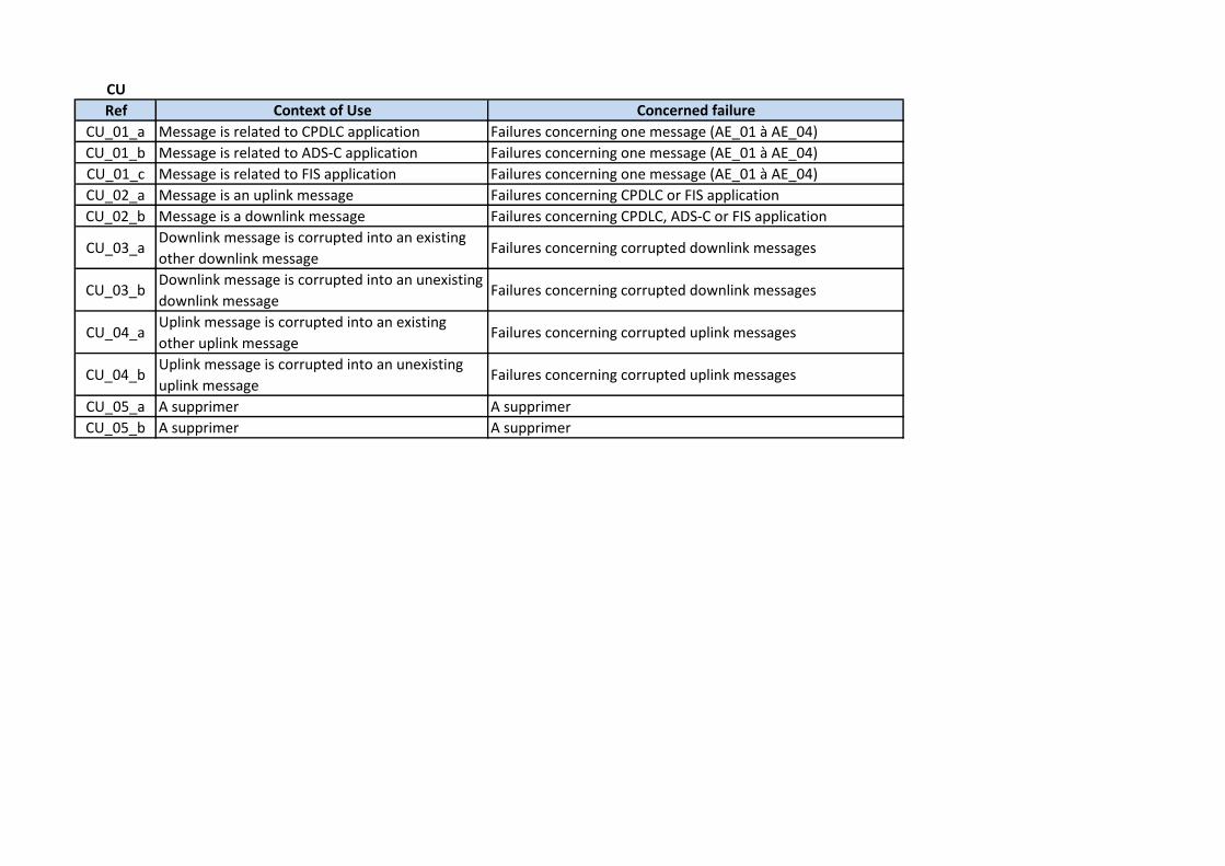
CU
Ref Context of Use Concerned failure
CU_01_a Message is related to CPDLC application Failures concerning one message (AE_01 à AE_04)
CU_01_b Message is related to ADS-C application Failures concerning one message (AE_01 à AE_04)
CU_01_c Message is related to FIS application Failures concerning one message (AE_01 à AE_04)
CU_02_a Message is an uplink message Failures concerning CPDLC or FIS application
CU_02_b Message is a downlink message Failures concerning CPDLC, ADS-C or FIS application
CU_03_aDownlink message is corrupted into an existing
other downlink messageFailures concerning corrupted downlink messages
CU_03_bDownlink message is corrupted into an unexisting
downlink messageFailures concerning corrupted downlink messages
CU_04_aUplink message is corrupted into an existing
other uplink messageFailures concerning corrupted uplink messages
CU_04_bUplink message is corrupted into an unexisting
uplink messageFailures concerning corrupted uplink messages
CU_05_a A supprimer A supprimer
CU_05_b A supprimer A supprimer

EMM
Ref External Mitigation Means Concerned failure
EMM_01 Flight Crew detects uplink message is inappropriate
Corruption : AE_02
Misdirection : AE_03
Delay : AE_04
EMM_02Aircraft system detects and rejects corrupted uplink
messagesCorruption : AE_02
EMM_03Ground system detects and rejects corrupted downlink
messages.Corruption : AE_02
EMM_04Ground system detects that a message has not been
responded to within the expected time
Loss : AE_01
Misdirection : AE_03
Delay : AE_04
EMM_05
Aircraft system time stamps downlink messages
Ground system checks the time stamp of a delayed downlink
message and rejects it
Delay : AE_04
EMM_06
Ground system time stamps uplink messages
Aircraft system checks the time stamp of a delayed uplink
message and rejects it
Delay : AE_04
EMM_07Aircraft system detects and rejects misdirected uplink
messages Misdirection : AE_03
EMM_08Ground system detects and rejects misdirected downlink
messages Misdirection : AE_03
EMM_09 Controller detects downlink message is inappropriate
Corruption : AE_02
Misdirection : AE_03
Delay : AE_04
EMM_10Aircraft system checks UM/DM association and rejects
spurious uplink messages Spurious : AE_05
EMM_11Ground system checks UM/DM association and rejects
spurious downlink messages Spurious : AE_05
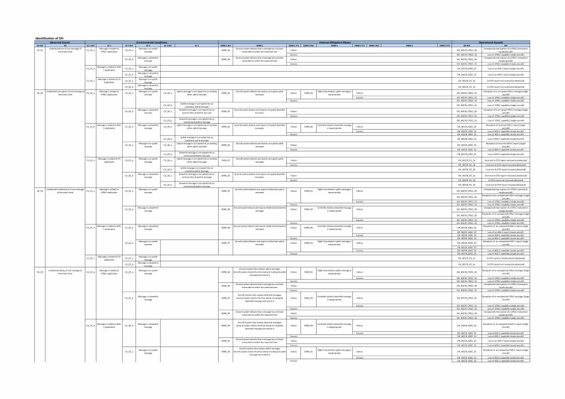
Identification of OH
AE Ref AE EC 1 Ref EC 1 EC 2 Ref EC 2 EC 3 Ref EC 3 EMM 1 Ref EMM 1 EMM 1 F/S EMM 2 Ref EMM 2 EMM 2 F/S EMM 3 Ref EMM 3 EMM 3 F/S OH Ref OH
AE_01Undetected loss of one message at
Aeromacs levelCU_01_a
Message is related to
CPDLC applicationCU_02_a
Message is an uplink
messageEMM_04
Ground system detects that a message has not been
responded to within the expected timeFailure OH_WG78_CPDLC_04
Unexpected interruption of a CPDLC transaction
[single aircraft]
Success OH_WG78_CPDLC_01 Loss of CPDLC capability [single aircraft]
CU_02_bMessage is a downlink
messageEMM_04
Ground system detects that a message has not been
responded to within the expected timeFailure OH_WG78_CPDLC_04
Unexpected interruption of a CPDLC transaction
[single aircraft]
Success OH_WG78_CPDLC_01 Loss of CPDLC capability [single aircraft]
CU_01_bMessage is related to ADS-
C applicationCU_02_a
Message is an uplink
messageOH_WG78_ADSC_07 Loss of an ADS-C report [single aircraft]
CU_02_bMessage is a downlink
messageOH_WG78_ADSC_07 Loss of an ADS-C report [single aircraft]
CU_01_cMessage is related to FIS
applicationCU_02_a
Message is an uplink
messageOH_WG78_FIS_4u D-OTIS report not received (undetected)
CU_02_bMessage is a downlink
messageOH_WG78_FIS_4u D-OTIS report not received (undetected)
AE_02Undetected corruption of one message at
Aeromacs levelCU_01_a
Message is related to
CPDLC applicationCU_02_a
Message is an uplink
messageCU_04_a
Uplink message is corrupted into an existing
other uplink messageEMM_02
Aircraft system detects and rejects corrupted uplink
messagesFailure EMM_01
Flight Crew detects uplink message is
inappropriateFailure OH_WG78_CPDLC_03
Reception of a corrupted CPDLC message [single
aircraft]
Success OH_WG78_CPDLC_01 Loss of CPDLC capability [single aircraft]
Success OH_WG78_CPDLC_01 Loss of CPDLC capability [single aircraft]
CU_04_bUplink message is corrupted into an
unexisting uplink messageOH_WG78_CPDLC_01 Loss of CPDLC capability [single aircraft]
CU_02_bMessage is a downlink
messageCU_03_a
Downlink message is corrupted into an
existing other downlink messageEMM_03
Ground system detects and rejects corrupted downlink
messages.Failure OH_WG78_CPDLC_03
Reception of a corrupted CPDLC message [single
aircraft]
Success OH_WG78_CPDLC_01 Loss of CPDLC capability [single aircraft]
CU_03_bDownlink message is corrupted into an
unexisting downlink messageOH_WG78_CPDLC_01 Loss of CPDLC capability [single aircraft]
CU_01_bMessage is related to ADS-
C applicationCU_02_b
Message is a downlink
messageCU_04_a
Uplink message is corrupted into an existing
other uplink messageEMM_03
Ground system detects and rejects corrupted downlink
messages.Failure EMM_09
Controller detects downlink message
is inappropriateFailure OH_WG78_ADSC_03
Reception of incorrect ADS-C report [single
aircraft]
Success OH_WG78_ADSC_01 Loss of ADS-C capability [single aircraft]
Success OH_WG78_ADSC_01 Loss of ADS-C capability [single aircraft]
CU_04_bUplink message is corrupted into an
unexisting uplink messageOH_WG78_ADSC_01 Loss of ADS-C capability [single aircraft]
CU_02_aMessage is an uplink
messageCU_04_a
Uplink message is corrupted into an existing
other uplink messageEMM_02
Aircraft system detects and rejects corrupted uplink
messagesFailure OH_WG78_ADSC_03
Reception of incorrect ADS-C report [single
aircraft]
Success OH_WG78_ADSC_01 Loss of ADS-C capability [single aircraft]
CU_03_bDownlink message is corrupted into an
unexisting downlink messageOH_WG78_ADSC_01 Loss of ADS-C capability [single aircraft]
CU_01_cMessage is related to FIS
applicationCU_02_a
Message is an uplink
messageCU_04_a
Uplink message is corrupted into an existing
other uplink messageEMM_02
Aircraft system detects and rejects corrupted uplink
messagesFailure OH_WG78_FIS_3u Incorrect D-OTIS report received (undetected)
Success OH_WG78_FIS_3d Incorrect D-OTIS report received (detected)
CU_04_bUplink message is corrupted into an
unexisting uplink messageOH_WG78_FIS_3d Incorrect D-OTIS report received (detected)
CU_02_bMessage is a downlink
messageCU_03_a
Downlink message is corrupted into an
existing other downlink messageEMM_03
Ground system detects and rejects corrupted downlink
messages.Failure OH_WG78_FIS_3u Incorrect D-OTIS report received (undetected)
Success OH_WG78_FIS_4d D-OTIS report not received (detected)
CU_03_bDownlink message is corrupted into an
unexisting downlink messageOH_WG78_FIS_3d Incorrect D-OTIS report received (detected)
AE_03Undetected misdirection of one message
at Aeromacs levelCU_01_a
Message is related to
CPDLC applicationCU_02_a
Message is an uplink
messageEMM_07
Aircraft system detects and rejects misdirected uplink
messagesFailure EMM_01
Flight Crew detects uplink message is
inappropriateFailure OH_WG78_CPDLC_04
Unexpected interruption of a CPDLC transaction
[single aircraft]
OH_WG78_CPDLC_05Reception of an unexpected CPDLC message [single
aircraft]
Success OH_WG78_CPDLC_01 Loss of CPDLC capability [single aircraft]
Success OH_WG78_CPDLC_01 Loss of CPDLC capability [single aircraft]
CU_02_bMessage is a downlink
messageEMM_08
Ground system detects and rejects misdirected downlink
messagesFailure EMM_09
Controller detects downlink message
is inappropriateFailure OH_WG78_CPDLC_04
Unexpected interruption of a CPDLC transaction
[single aircraft]
OH_WG78_CPDLC_05Reception of an unexpected CPDLC message [single
aircraft]
Success OH_WG78_CPDLC_01 Loss of CPDLC capability [single aircraft]
Success OH_WG78_CPDLC_01 Loss of CPDLC capability [single aircraft]
CU_01_bMessage is related to ADS-
C applicationCU_02_b
Message is a downlink
messageEMM_08
Ground system detects and rejects misdirected downlink
messagesFailure EMM_09
Controller detects downlink message
is inappropriateFailure OH_WG78_ADSC_05
Reception of an unexpected ADS-C report [single
aircraft]
OH_WG78_ADSC_07 Loss of an ADS-C report [single aircraft]
Success OH_WG78_ADSC_01 Loss of ADS-C capability [single aircraft]
Success OH_WG78_ADSC_01 Loss of ADS-C capability [single aircraft]
CU_02_aMessage is an uplink
messageEMM_07
Aircraft system detects and rejects misdirected uplink
messagesFailure EMM_01
Flight Crew detects uplink message is
inappropriateFailure OH_WG78_ADSC_05
Reception of an unexpected ADS-C report [single
aircraft]
OH_WG78_ADSC_07
Success OH_WG78_ADSC_01 Loss of ADS-C capability [single aircraft]
Success OH_WG78_ADSC_01 Loss of ADS-C capability [single aircraft]
CU_01_cMessage is related to FIS
applicationCU_02_a
Message is an uplink
messageOH_WG78_FIS_5u D-OTIS report is misdirected (undetected)
CU_02_bMessage is a downlink
messageOH_WG78_FIS_4u D-OTIS report not received (undetected)
AE_04Undetected delay of one message at
Aeromacs levelCU_01_a
Message is related to
CPDLC applicationCU_02_a
Message is an uplink
messageEMM_06
Ground system time stamps uplink messages
Aircraft system checks the time stamp of a delayed uplink
message and rejects it
Failure EMM_01Flight Crew detects uplink message is
inappropriateFailure OH_WG78_CPDLC_05
Reception of an unexpected CPDLC message [single
aircraft]
Success OH_WG78_CPDLC_01 Loss of CPDLC capability [single aircraft]
Success OH_WG78_CPDLC_01 Loss of CPDLC capability [single aircraft]
EMM_04Ground system detects that a message has not been
responded to within the expected timeFailure OH_WG78_CPDLC_04
Unexpected interruption of a CPDLC transaction
[single aircraft]
Success OH_WG78_CPDLC_01 Loss of CPDLC capability [single aircraft]
CU_02_bMessage is a downlink
messageEMM_05
Aircraft system time stamps downlink messages
Ground system checks the time stamp of a delayed
downlink message and rejects it
Failure EMM_09Controller detects downlink message
is inappropriateFailure OH_WG78_CPDLC_05
Reception of an unexpected CPDLC message [single
aircraft]
Success OH_WG78_CPDLC_01 Loss of CPDLC capability [single aircraft]
Success OH_WG78_CPDLC_01 Loss of CPDLC capability [single aircraft]
EMM_04Ground system detects that a message has not been
responded to within the expected timeFailure OH_WG78_CPDLC_04
Unexpected interruption of a CPDLC transaction
[single aircraft]
Success OH_WG78_CPDLC_01 Loss of CPDLC capability [single aircraft]
CU_01_bMessage is related to ADS-
C applicationCU_02_b
Message is a downlink
messageEMM_05
Aircraft system time stamps downlink messages
Ground system checks the time stamp of a delayed
downlink message and rejects it
Failure EMM_09Controller detects downlink message
is inappropriateFailure OH_WG78_ADSC_05
Reception of an unexpected ADS-C report [single
aircraft]
Success OH_WG78_ADSC_01 Loss of ADS-C capability [single aircraft]
Success OH_WG78_ADSC_01 Loss of ADS-C capability [single aircraft]
EMM_04Ground system detects that a message has not been
responded to within the expected timeFailure OH_WG78_ADSC_07 Loss of an ADS-C report [single aircraft]
Success OH_WG78_ADSC_01 Loss of ADS-C capability [single aircraft]
CU_02_aMessage is an uplink
messageEMM_06
Ground system time stamps uplink messages
Aircraft system checks the time stamp of a delayed uplink
message and rejects it
Failure EMM_01Flight Crew detects uplink message is
inappropriateFailure OH_WG78_ADSC_05
Reception of an unexpected ADS-C report [single
aircraft]
Success OH_WG78_ADSC_01 Loss of ADS-C capability [single aircraft]
Success OH_WG78_ADSC_01 Loss of ADS-C capability [single aircraft]
Abnormal Events Environmental Conditions External Mitigation Means Operational Hazards

EMM_04Ground system detects that a message has not been
responded to within the expected timeFailure OH_WG78_ADSC_07 Loss of an ADS-C report [single aircraft]
Success OH_WG78_ADSC_01 Loss of ADS-C capability [single aircraft]
CU_01_cMessage is related to FIS
applicationCU_02_a
Message is an uplink
messageEMM_01 Flight Crew detects uplink message is inappropriate Failure OH_WG78_FIS_6u
Spurious/unexpected D-OTIS report received
(undetected)
Success OH_WG78_FIS_6dSpurious/unexpected D-OTIS report received
(detected)
CU_02_bMessage is a downlink
messageEMM_01 Flight Crew detects uplink message is inappropriate Failure OH_WG78_FIS_4u D-OTIS report not received (undetected)
Success OH_WG78_FIS_6dSpurious/unexpected D-OTIS report received
(detected)
AE_05Generation of one spurious message at
Aeromacs levelCU_01_a
Message is related to
CPDLC applicationCU_02_a
Message is an uplink
messageEMM_10
Aircraft system checks UM/DM association and rejects
spurious uplink messagesFailure EMM_01
Flight Crew detects uplink message is
inappropriateFailure OH_WG78_CPDLC_05
Reception of an unexpected CPDLC message [single
aircraft]
Success OH_WG78_CPDLC_01 Loss of CPDLC capability [single aircraft]
Success OH_WG78_CPDLC_01 Loss of CPDLC capability [single aircraft]
CU_02_bMessage is a downlink
messageEMM_11
Ground system checks UM/DM association and rejects
spurious downlink messagesFailure EMM_09
Controller detects downlink message
is inappropriateFailure OH_WG78_CPDLC_05
Reception of an unexpected CPDLC message [single
aircraft]
Success OH_WG78_CPDLC_01 Loss of CPDLC capability [single aircraft]
Success OH_WG78_CPDLC_01 Loss of CPDLC capability [single aircraft]
CU_01_bMessage is related to ADS-
C applicationCU_02_a
Message is an uplink
messageEMM_10
Aircraft system checks UM/DM association and rejects
spurious uplink messagesFailure EMM_01
Flight Crew detects uplink message is
inappropriateFailure OH_WG78_ADSC_05
Reception of an unexpected ADS-C report [single
aircraft]
Success OH_WG78_ADSC_01 Loss of ADS-C capability [single aircraft]
Success OH_WG78_ADSC_01 Loss of ADS-C capability [single aircraft]
CU_02_bMessage is a downlink
messageEMM_11
Ground system checks UM/DM association and rejects
spurious downlink messagesFailure EMM_09
Controller detects downlink message
is inappropriateFailure OH_WG78_ADSC_05
Reception of an unexpected ADS-C report [single
aircraft]
Success OH_WG78_ADSC_01 Loss of ADS-C capability [single aircraft]
Success OH_WG78_ADSC_01 Loss of ADS-C capability [single aircraft]
CU_01_cMessage is related to FIS
applicationCU_02_a
Message is an uplink
messageEMM_01 Flight Crew detects uplink message is inappropriate Failure OH_WG78_FIS_6d
Spurious/unexpected D-OTIS report received
(detected)
Success OH_WG78_FIS_6dSpurious/unexpected D-OTIS report received
(detected)
CU_02_bMessage is a downlink
messageEMM_01 Flight Crew detects uplink message is inappropriate Failure OH_WG78_FIS_6d
Spurious/unexpected D-OTIS report received
(detected)
Success OH_WG78_FIS_6dSpurious/unexpected D-OTIS report received
(detected)
AE_06Permanent failure to communicate with
one aircraftOH_NEW_ALL_01
Failure to exchange any message with a single
aircraft
AE_07Permanent failure to communicate with
more than one aircraftOH_NEW_ALL_02
Failure to exchange any message with more than
one aircraft
Failure Failure Failure
Success Success Success
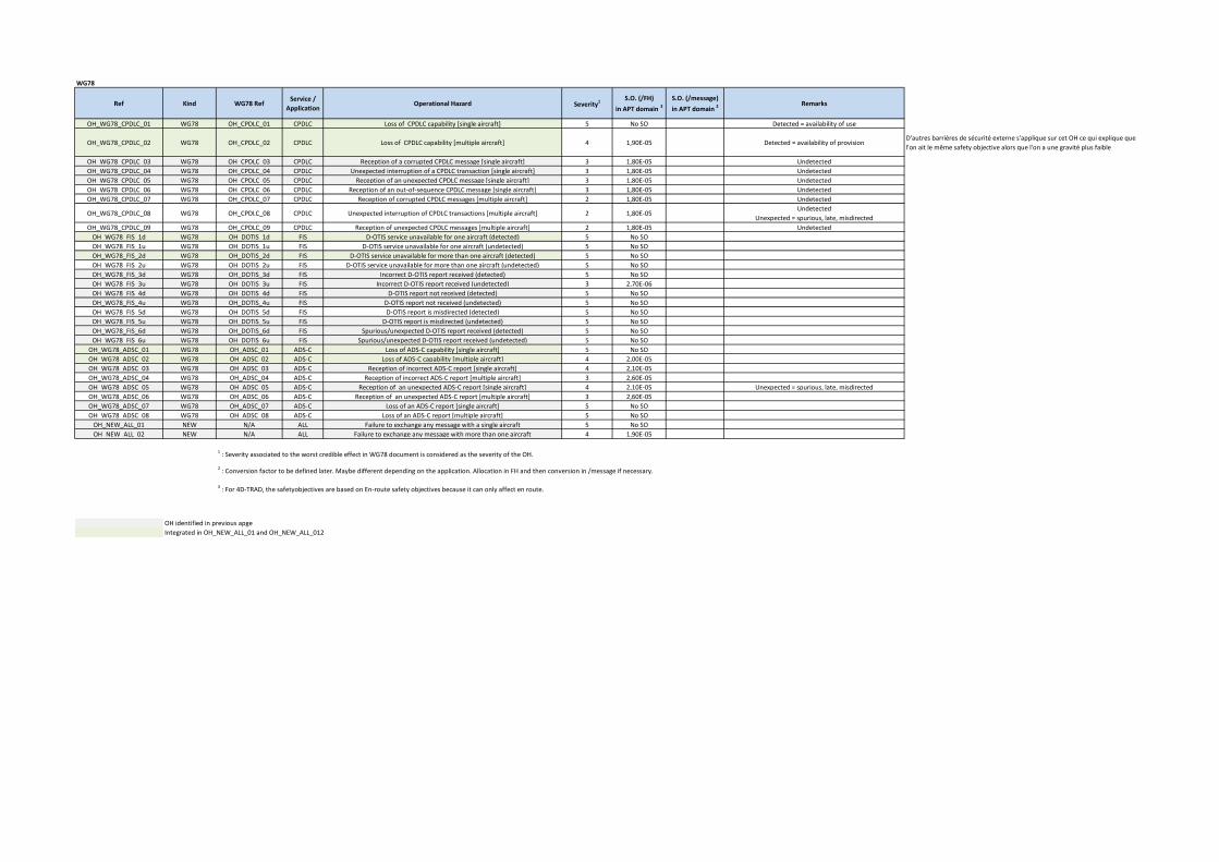
WG78
Ref Kind WG78 RefService /
ApplicationOperational Hazard Severity1
S.O. (/FH)
in APT domain 3
S.O. (/message)
in APT domain 2Remarks
OH_WG78_CPDLC_01 WG78 OH_CPDLC_01 CPDLC Loss of CPDLC capability [single aircraft] 5 No SO Detected = availability of use
OH_WG78_CPDLC_02 WG78 OH_CPDLC_02 CPDLC Loss of CPDLC capability [multiple aircraft] 4 1,90E-05 Detected = availability of provisionD'autres barrières de sécurité externe s'applique sur cet OH ce qui explique que
l'on ait le même safety objective alors que l'on a une gravité plus faible
OH_WG78_CPDLC_03 WG78 OH_CPDLC_03 CPDLC Reception of a corrupted CPDLC message [single aircraft] 3 1,80E-05 Undetected
OH_WG78_CPDLC_04 WG78 OH_CPDLC_04 CPDLC Unexpected interruption of a CPDLC transaction [single aircraft] 3 1,80E-05 Undetected
OH_WG78_CPDLC_05 WG78 OH_CPDLC_05 CPDLC Reception of an unexpected CPDLC message [single aircraft] 3 1,80E-05 Undetected
OH_WG78_CPDLC_06 WG78 OH_CPDLC_06 CPDLC Reception of an out-of-sequence CPDLC message [single aircraft] 3 1,80E-05 Undetected
OH_WG78_CPDLC_07 WG78 OH_CPDLC_07 CPDLC Reception of corrupted CPDLC messages [multiple aircraft] 2 1,80E-05 Undetected
OH_WG78_CPDLC_08 WG78 OH_CPDLC_08 CPDLC Unexpected interruption of CPDLC transactions [multiple aircraft] 2 1,80E-05Undetected
Unexpected = spurious, late, misdirected
OH_WG78_CPDLC_09 WG78 OH_CPDLC_09 CPDLC Reception of unexpected CPDLC messages [multiple aircraft] 2 1,80E-05 Undetected
OH_WG78_FIS_1d WG78 OH_DOTIS_1d FIS D-OTIS service unavailable for one aircraft (detected) 5 No SO
OH_WG78_FIS_1u WG78 OH_DOTIS_1u FIS D-OTIS service unavailable for one aircraft (undetected) 5 No SO
OH_WG78_FIS_2d WG78 OH_DOTIS_2d FIS D-OTIS service unavailable for more than one aircraft (detected) 5 No SO
OH_WG78_FIS_2u WG78 OH_DOTIS_2u FIS D-OTIS service unavailable for more than one aircraft (undetected) 5 No SO
OH_WG78_FIS_3d WG78 OH_DOTIS_3d FIS Incorrect D-OTIS report received (detected) 5 No SO
OH_WG78_FIS_3u WG78 OH_DOTIS_3u FIS Incorrect D-OTIS report received (undetected) 3 2,70E-06
OH_WG78_FIS_4d WG78 OH_DOTIS_4d FIS D-OTIS report not received (detected) 5 No SO
OH_WG78_FIS_4u WG78 OH_DOTIS_4u FIS D-OTIS report not received (undetected) 5 No SO
OH_WG78_FIS_5d WG78 OH_DOTIS_5d FIS D-OTIS report is misdirected (detected) 5 No SO
OH_WG78_FIS_5u WG78 OH_DOTIS_5u FIS D-OTIS report is misdirected (undetected) 5 No SO
OH_WG78_FIS_6d WG78 OH_DOTIS_6d FIS Spurious/unexpected D-OTIS report received (detected) 5 No SO
OH_WG78_FIS_6u WG78 OH_DOTIS_6u FIS Spurious/unexpected D-OTIS report received (undetected) 5 No SO
OH_WG78_ADSC_01 WG78 OH_ADSC_01 ADS-C Loss of ADS-C capability [single aircraft] 5 No SO
OH_WG78_ADSC_02 WG78 OH_ADSC_02 ADS-C Loss of ADS-C capability [multiple aircraft] 4 2,00E-05
OH_WG78_ADSC_03 WG78 OH_ADSC_03 ADS-C Reception of incorrect ADS-C report [single aircraft] 4 2,10E-05
OH_WG78_ADSC_04 WG78 OH_ADSC_04 ADS-C Reception of incorrect ADS-C report [multiple aircraft] 3 2,60E-05
OH_WG78_ADSC_05 WG78 OH_ADSC_05 ADS-C Reception of an unexpected ADS-C report [single aircraft] 4 2,10E-05 Unexpected = spurious, late, misdirected
OH_WG78_ADSC_06 WG78 OH_ADSC_06 ADS-C Reception of an unexpected ADS-C report [multiple aircraft] 3 2,60E-05
OH_WG78_ADSC_07 WG78 OH_ADSC_07 ADS-C Loss of an ADS-C report [single aircraft] 5 No SO
OH_WG78_ADSC_08 WG78 OH_ADSC_08 ADS-C Loss of an ADS-C report [multiple aircraft] 5 No SO
OH_NEW_ALL_01 NEW N/A ALL Failure to exchange any message with a single aircraft 5 No SO
OH_NEW_ALL_02 NEW N/A ALL Failure to exchange any message with more than one aircraft 4 1,90E-05
OH identified in previous apge
Integrated in OH_NEW_ALL_01 and OH_NEW_ALL_012
1 : Severity associated to the worst credible effect in WG78 document is considered as the severity of the OH.
2 : Conversion factor to be defined later. Maybe different depending on the application. Allocation in FH and then conversion in /message if necessary.
3 : For 4D-TRAD, the safetyobjectives are based on En-route safety objectives because it can only affect en route.

New OH
Ref OH Operational Hazard Operational Effects Severity Safety Objective Remarks
OH_NEW_ALL_01 Failure to exchange any message with a single aircraft cf. OH_WG78_01, OH_WG78_16, OH_NEW_01 and OH_NEW_04 5 No SO
OH_NEW_ALL_02 Failure to exchange any message with all aircrafts cf. OH_WG78_02, OH_WG78_17, OH_NEW_05 and OH_NEW_06 3 1,90E-05

Definition of SR (1)
OH Ref SeveritySO
(/FH)Cause Ref Part Failure
Kinf of
message
Value
(/FH)SR Ref Kind of SR Title Remarks
OH_NEW_ALL_01 5 No SO
NEW_CP_ALL_01 ACSP Unavailable Any 7,00E-06 SR-NEW-CP-ALL-01 QuantitativeThe likelihood that the ACSP is unavailable shall be less than
7E-06/FH
NEW_AC_ALL_01 AC Unavailable Any 2,50E-03 SR-NEW-AC-ALL-01 QuantitativeThe likelihood that the AC system is unavailable shall be less
than 2.5E-03/FHOH_WG78_ADSC_01 5 No SO No SR
WG78_CP_ADSC_01 ACSP Unavailable Any 7,00E-06 No ref QuantitativeThe likelihood that the ACSP is unavailable shall be less than
7E-06/FH
No ref QuantitativeThe likelihood that the AC system is unavailable shall be less
than 3E-03/FH
SR-AC-ADSC-01 QualitativeThe aircraft system shall provide to the ATSU an indication
when it rejects an ADS-C service request initiated by the
ATSU at the application layer.
SR-AC-ADSC-02 QualitativeThe aircraft system shall indicate to the flight crew a
detected loss of ADS-C service.WG78_CP_ADSC_02 ACSP Corruption Downlink 1,00E+00 No SR No SR No SR
WG78_AC_ADSC_02 AC Corruption Downlink 7,00E-05 SR-AC-ADSC-03 QuantitativeThe likelihood that the aircraft system corrupts an ADS-C
report shall be less than 7.0E-05/FH
WG78_AC_ADSC_03 ACEMM 02
- Corruption- 3,50E-05 SR-AC-ADSC-04 Quantitative
The likelihood that the aircraft system fails to detect the
corrupted ADS-C report shall be less than 3.5E-5/FH
WG78_CP_ADSC_03 ACSP Spurious Downlink 1,00E+00 No SR No SR No SR
WG78_AC_ADSC_04 AC Spurious Downlink 1,00E+00 SR-AC-ADSC-5 QuantitativeThe likelihood that the aircraft system generates a spurious
report shall be less than 1.0E-05/FH .
WG78_GD_ADSC_04 GDEMM 11
- SpuriousDownlink 1,00E-05 SR-AC-ADSC-10 Qualitative
The aircraft system shall indicate in each report to which
contract number it is referringWG78_CP_ADSC_04 ACSP Delay Downlink 1,00E+00 No SR No SR No SRWG78_AC_ADSC_06 AC Delay Downlink 1,00E-05 No SR No SR No SR
SR-AC-ADSC-6 QuantitativeThe likelihood that the aircraft system incorrectly time
stamps the report shall be less than 1.0E-05/FH
SR-AC-ADSC-7 QualitativeThe aircraft system shall time stamp each report to within
one second UTC when it is released for onward
transmission. WG78_CP_ADSC_05 ACSP Misdirection Downlink 1,00E+00 No SR No SR No SR
SR-AC-ADSC-8 QualitativeThe aircraft system shall transmit messages to the
designated recipient.
SR-AC-ADSC-9 QualitativeThe aircraft system shall provide unambiguous and unique
identification of the origin and destination of each message
it transmitsWG78_CP_CM_01 ACSP Corruption Downlink init 1,00E+00 No SR No SR No SR
SR-AC-CM-01 QuantitativeThe likelihood that the aircraft system sends incorrect DLIC
initiation data shall be less than 1.0E-05/FH
SR-AC-CM-02 Qualitative
The flight and aircraft identifiers (either the Registration
Marking or the 24-bit Aircraft Address) sent by the aircraft
system, used for data link initiation correlation and ADS-C
network address mapping, shall be unique and
unambiguousWG78_CP_CM_02 ACSP Corruption Uplink init 1,00E+00 No SR No SR No SRWG78_AC_CM_02 AC Misdirection Uplink init 1,00E+00 No SR No SR No SR
OH_WG78_ADSC_07 5 No SO - - - - - No SR No SR No SROH_WG78_CPDLC_01 5 No SO - - - - - No SR No SR No SR
WG78_CP_CPDLC_01 ACSP Unavailable Any 7,00E-06 No ref QuantitativeThe likelihood that the ACSP is unavailable shall be less than
7E-06/FH
No ref QuantitativeThe likelihood that the AC system is unavailable shall be less
than 2.5E-03/FH
SR-AC-CPDLC-01 QualitativeThe aircraft system shall provide to the ATSU an indication
when it rejects a CPDLC service request initiated by the
ATSU at the application layer.
SR-AC-CPDLC-02 Qualitative
The aircraft system shall display the indication provided by
the ATSU when a DSC service request initiated by the flight
crew is rejected at the application layer.
SR-AC-CPDLC-03 QualitativeThe aircraft system shall indicate to the flight crew a
detected loss of data link service.- ACSP Corruption Downlink 1,00E+00 No SR No SR No SR
WG78_AC_CPDLC_01 AC Corruption Downlink 1,00E-05 SR-AC-CPDLC-13 QuantitativeThe likelihood that the aircraft system corrupts a downlink
message shall be less than 1.0E-05/FH
WG78_AC_CPDLC_02 ACEMM 02
- Corruption- 1,00E-05 SR-AC-CPDLC-07 Quantitative
The likelihood that the aircraft system fails to detect the
corrupted downlink message shall be less than 1.0E-05/FH
WG78_CP_CPDLC_01 ACSP Corruption Uplink 1,00E+00 No SR No SR No SR
SR-AC-CPDLC-11 QuantitativeThe likelihood that the aircraft system corrupts an uplink
message shall be less than 1.0E-05/FH
SR-AC-CPDLC-17 QualitativeThe aircraft system shall prohibit operational processing by
flight crew of corrupted messages.
SR-AC-CPDLC-05 QualitativeThe aircraft system shall execute the route clearance per
the route clearance received from the ATS via data link
OH
2,10E-054OH_WG78_ADSC_03
1,80E-053OH_WG78_CPDLC_03
2,00E-054OH_WG78_ADSC_02
1,90E-05OH_NEW_ALL_02 4
Downlink 1,00E+00
WG78_AC_ADSC_01 AC Unavailable Any 3,00E-03
Cause SR
2,50E-03AnyUnavailableACWG78_AC_CPDLC_011,90E-054OH_WG78_CPDLC_02
WG78_AC_CM_01 1,00E-05Downlink initCorruptionAC
2,10E-054OH_WG78_ADSC_05
WG78_AC_ADSC_05 ACEMM 05
- Delay- 1,00E-05
WG78_AC_ADSC_07 AC Misdirection
1,00E-05UplinkCorruptionWG78_AC_CPDLC_03 AC
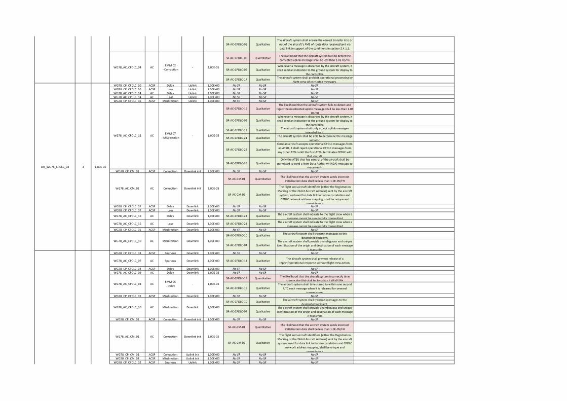
SR-AC-CPDLC-06 Qualitative
The aircraft system shall ensure the correct transfer into or
out of the aircraft’s FMS of route data received/sent via
data link,in support of the conditions in section 2.4.1.1.
SR-AC-CPDLC-08 QuantitativeThe likelihood that the aircraft system fails to detect the
corrupted uplink message shall be less than 1.0E-05/FH
SR-AC-CPDLC-09 QualitativeWhenever a message is discarded by the aircraft system, it
shall send an indication to the ground system for display to
the controller.
SR-AC-CPDLC-17 QualitativeThe aircraft system shall prohibit operational processing by
flight crew of corrupted messages.WG78_CP_CPDLC_10 ACSP Delay Uplink 1,00E+00 No SR No SR No SRWG78_CP_CPDLC_10 ACSP Loss Uplink 1,00E+00 No SR No SR No SRWG78_AC_CPDLC_14 AC Delay Uplink 1,00E+00 No SR No SR No SRWG78_AC_CPDLC_14 AC Loss Uplink 1,00E+00 No SR No SR No SRWG78_CP_CPDLC_06 ACSP Misdirection Uplink 1,00E+00 No SR No SR No SR
SR-AC-CPDLC-19 QualitativeThe likelihood that the aircraft system fails to detect and
reject the misdirected uplink message shall be less than 1.0E-
05/FH
SR-AC-CPDLC-09 QualitativeWhenever a message is discarded by the aircraft system, it
shall send an indication to the ground system for display to
the controller.
SR-AC-CPDLC-12 QualitativeThe aircraft system shall only accept uplink messages
intended for it.
SR-AC-CPDLC-21 QualitativeThe aircraft system shall be able to determine the message
initiator.
SR-AC-CPDLC-22 Qualitative
Once an aircraft accepts operational CPDLC messages from
an ATSU, it shall reject operational CPDLC messages from
any other ATSU until the first ATSU terminates CPDLC with
that aircraft.
SR-AC-CPDLC-35 QualitativeOnly the ATSU that has control of the aircraft shall be
permitted to send a Next Data Authority (NDA) message to
the aircraft.WG78_CP_CM_01 ACSP Corruption Downlink init 1,00E+00 No SR No SR No SR
SR-AC-CM-01 QuantitativeThe likelihood that the aircraft system sends incorrect
initialisation data shall be less than 1.0E-05/FH
SR-AC-CM-02 Qualitative
The flight and aircraft identifiers (either the Registration
Marking or the 24-bit Aircraft Address) sent by the aircraft
system, and used for data link initiation correlation and
CPDLC network address mapping, shall be unique and
unambiguousWG78_CP_CPDLC_07 ACSP Delay Downlink 1,00E+00 No SR No SR No SRWG78_CP_CPDLC_07 ACSP Loss Downlink 1,00E+00 No SR No SR No SR
WG78_AC_CPDLC_15 AC Delay Downlink 1,00E+00 SR-AC-CPDLC-24 QualitativeThe aircraft system shall indicate to the flight crew when a
message cannot be successfully transmitted
WG78_AC_CPDLC_15 AC Loss Downlink 1,00E+00 SR-AC-CPDLC-24 QualitativeThe aircraft system shall indicate to the flight crew when a
message cannot be successfully transmittedWG78_CP_CPDLC_05 ACSP Misdirection Downlink 1,00E+00 No SR No SR No SR
SR-AC-CPDLC-10 QualitativeThe aircraft system shall transmit messages to the
designated recipient.
SR-AC-CPDLC-04 QualitativeThe aircraft system shall provide unambiguous and unique
identification of the origin and destination of each message
it transmitsWG78_CP_CPDLC_03 ACSP Spurious Downlink 1,00E+00 No SR No SR No SR
WG78_AC_CPDLC_07 AC Spurious Downlink 1,00E+00 SR-AC-CPDLC-14 QualitativeThe aircraft system shall prevent release of a
report/operational response without flight crew action.
WG78_CP_CPDLC_04 ACSP Delay Downlink 1,00E+00 No SR No SR No SRWG78_AC_CPDLC_09 AC Delay Downlink 1,00E-05 No SR No SR No SR
SR-AC-CPDLC-18 QuantitativeThe likelihood that the aircraft system incorrectly time
stamps the DM shall be less than 1.0E-05/FH
SR-AC-CPDLC-16 QualitativeThe aircraft system shall time stamp to within one second
UTC each message when it is released for onward
transmission. WG78_CP_CPDLC_05 ACSP Misdirection Downlink 1,00E+00 No SR No SR No SR
SR-AC-CPDLC-10 QualitativeThe aircraft system shall transmit messages to the
designated recipient.
SR-AC-CPDLC-04 QualitativeThe aircraft system shall provide unambiguous and unique
identification of the origin and destination of each message
it transmitsWG78_CP_CM_01 ACSP Corruption Downlink init 1,00E+00 No SR No SR No SR
SR-AC-CM-01 QuantitativeThe likelihood that the aircraft system sends incorrect
initialisation data shall be less than 1.0E-05/FH
SR-AC-CM-02 Qualitative
The flight and aircraft identifiers (either the Registration
Marking or the 24-bit Aircraft Address) sent by the aircraft
system, used for data link initiation correlation and CPDLC
network address mapping, shall be unique and
unambiguousWG78_CP_CM_02 ACSP Corruption Uplink init 1,00E+00 No SR No SR No SRWG78_CP_CM_03 ACSP Misdirection Uplink init 1,00E+00 No SR No SR No SR
WG78_CP_CPDLC_02 ACSP Spurious Uplink 1,00E+00 No SR No SR No SR
3OH_WG78_CPDLC_04 1,80E-05
1,80E-053OH_WG78_CPDLC_03
OH_WG78_CPDLC_05 3 1,80E-05
WG78_AC_CPDLC_10 AC Misdirection Downlink
WG78_AC_CPDLC_12
WG78_AC_CM_01
1,00E-05UplinkCorruptionWG78_AC_CPDLC_03 AC
WG78_AC_CPDLC_04 ACEMM 02
- Corruption- 1,00E-05
1,00E+00
1,00E-05-EMM 07
- MisdirectionAC
1,00E-05Downlink initCorruptionAC
ACWG78_AC_CPDLC_08
WG78_AC_CPDLC_10 AC Misdirection Downlink 1,00E+00
1,00E-05Downlink initCorruptionACWG78_AC_CM_01
1,00E-05-EMM 05
- Delay
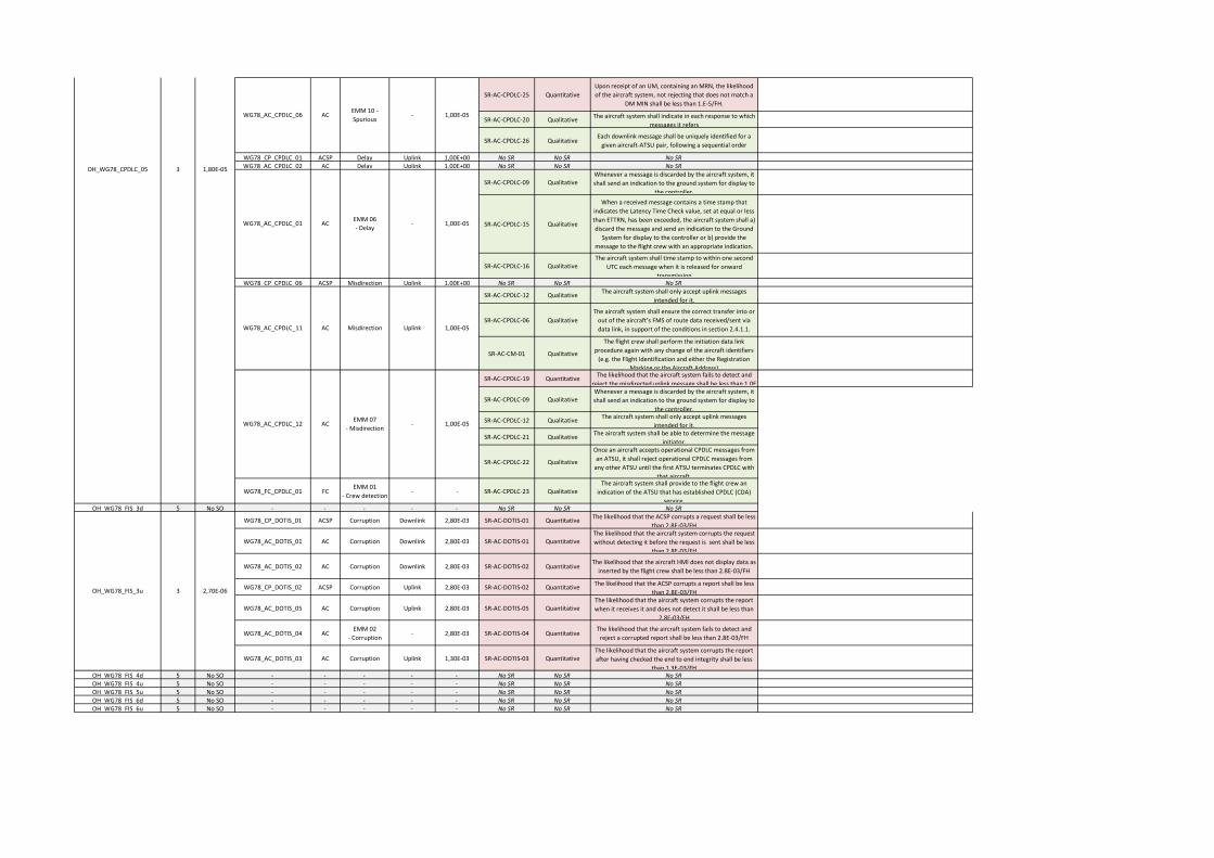
SR-AC-CPDLC-25 Quantitative
Upon receipt of an UM, containing an MRN, the likelihood
of the aircraft system, not rejecting that does not match a
DM MIN shall be less than 1.E-5/FH.
SR-AC-CPDLC-20 QualitativeThe aircraft system shall indicate in each response to which
messages it refers
SR-AC-CPDLC-26 QualitativeEach downlink message shall be uniquely identified for a
given aircraft-ATSU pair, following a sequential order
WG78_CP_CPDLC_01 ACSP Delay Uplink 1,00E+00 No SR No SR No SRWG78_AC_CPDLC_02 AC Delay Uplink 1,00E+00 No SR No SR No SR
SR-AC-CPDLC-09 QualitativeWhenever a message is discarded by the aircraft system, it
shall send an indication to the ground system for display to
the controller.
SR-AC-CPDLC-15 Qualitative
When a received message contains a time stamp that
indicates the Latency Time Check value, set at equal or less
than ETTRN, has been exceeded, the aircraft system shall a)
discard the message and send an indication to the Ground
System for display to the controller or b) provide the
message to the flight crew with an appropriate indication.
SR-AC-CPDLC-16 QualitativeThe aircraft system shall time stamp to within one second
UTC each message when it is released for onward
transmission WG78_CP_CPDLC_06 ACSP Misdirection Uplink 1,00E+00 No SR No SR No SR
SR-AC-CPDLC-12 QualitativeThe aircraft system shall only accept uplink messages
intended for it.
SR-AC-CPDLC-06 Qualitative
The aircraft system shall ensure the correct transfer into or
out of the aircraft’s FMS of route data received/sent via
data link, in support of the conditions in section 2.4.1.1.
SR-AC-CM-01 Qualitative
The flight crew shall perform the initiation data link
procedure again with any change of the aircraft identifiers
(e.g. the Flight Identification and either the Registration
Marking or the Aircraft Address)
SR-AC-CPDLC-19 QuantitativeThe likelihood that the aircraft system fails to detect and
reject the misdirected uplink message shall be less than 1.0E-
SR-AC-CPDLC-09 QualitativeWhenever a message is discarded by the aircraft system, it
shall send an indication to the ground system for display to
the controller.
SR-AC-CPDLC-12 QualitativeThe aircraft system shall only accept uplink messages
intended for it.
SR-AC-CPDLC-21 QualitativeThe aircraft system shall be able to determine the message
initiator.
SR-AC-CPDLC-22 Qualitative
Once an aircraft accepts operational CPDLC messages from
an ATSU, it shall reject operational CPDLC messages from
any other ATSU until the first ATSU terminates CPDLC with
that aircraft.
WG78_FC_CPDLC_01 FCEMM 01
- Crew detection- - SR-AC-CPDLC-23 Qualitative
The aircraft system shall provide to the flight crew an
indication of the ATSU that has established CPDLC (CDA)
service.OH_WG78_FIS_3d 5 No SO - - - - - No SR No SR No SR
WG78_CP_DOTIS_01 ACSP Corruption Downlink 2,80E-03 SR-AC-DOTIS-01 QuantitativeThe likelihood that the ACSP corrupts a request shall be less
than 2.8E-03/FH
WG78_AC_DOTIS_01 AC Corruption Downlink 2,80E-03 SR-AC-DOTIS-01 QuantitativeThe likelihood that the aircraft system corrupts the request
without detecting it before the request is sent shall be less
than 2.8E-03/FH
WG78_AC_DOTIS_02 AC Corruption Downlink 2,80E-03 SR-AC-DOTIS-02 QuantitativeThe likelihood that the aircraft HMI does not display data as
inserted by the flight crew shall be less than 2.8E-03/FH
WG78_CP_DOTIS_02 ACSP Corruption Uplink 2,80E-03 SR-AC-DOTIS-02 QuantitativeThe likelihood that the ACSP corrupts a report shall be less
than 2.8E-03/FH
WG78_AC_DOTIS_05 AC Corruption Uplink 2,80E-03 SR-AC-DOTIS-05 QuantitativeThe likelihood that the aircraft system corrupts the report
when it receives it and does not detect it shall be less than
2.8E-03/FH
WG78_AC_DOTIS_04 ACEMM 02
- Corruption- 2,80E-03 SR-AC-DOTIS-04 Quantitative
The likelihood that the aircraft system fails to detect and
reject a corrupted report shall be less than 2.8E-03/FH
WG78_AC_DOTIS_03 AC Corruption Uplink 1,30E-03 SR-AC-DOTIS-03 QuantitativeThe likelihood that the aircraft system corrupts the report
after having checked the end to end integrity shall be less
than 1.3E-03/FHOH_WG78_FIS_4d 5 No SO - - - - - No SR No SR No SROH_WG78_FIS_4u 5 No SO - - - - - No SR No SR No SROH_WG78_FIS_5u 5 No SO - - - - - No SR No SR No SROH_WG78_FIS_6d 5 No SO - - - - - No SR No SR No SROH_WG78_FIS_6u 5 No SO - - - - - No SR No SR No SR
OH_WG78_FIS_3u 3 2,70E-06
OH_WG78_CPDLC_05 3 1,80E-05
1,00E-05
1,00E-05-EMM 10 -
SpuriousAC
WG78_AC_CPDLC_01 ACEMM 06
- Delay-
WG78_AC_CPDLC_06
WG78_AC_CPDLC_12 ACEMM 07
- Misdirection- 1,00E-05
1,00E-05UplinkMisdirectionACWG78_AC_CPDLC_11
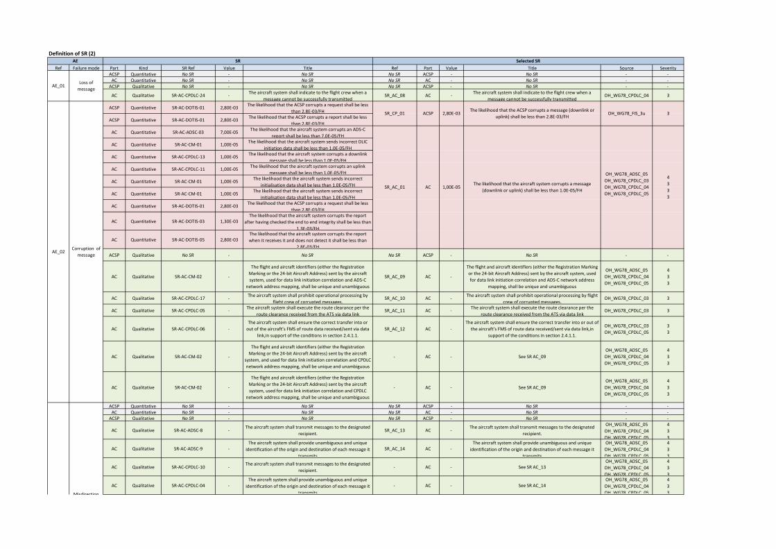
Definition of SR (2)
Ref Failure mode Part Kind SR Ref Value Title Ref Part Value Title Source SeverityACSP Quantitative No SR - No SR No SR ACSP - No SR - -
AC Quantitative No SR - No SR No SR AC - No SR - -ACSP Qualitative No SR - No SR No SR ACSP - No SR - -
AC Qualitative SR-AC-CPDLC-24 -The aircraft system shall indicate to the flight crew when a
message cannot be successfully transmittedSR_AC_08 AC -
The aircraft system shall indicate to the flight crew when a
message cannot be successfully transmittedOH_WG78_CPDLC_04 3
ACSP Quantitative SR-AC-DOTIS-01 2,80E-03The likelihood that the ACSP corrupts a request shall be less
than 2.8E-03/FH
ACSP Quantitative SR-AC-DOTIS-01 2,80E-03The likelihood that the ACSP corrupts a report shall be less
than 2.8E-03/FH
AC Quantitative SR-AC-ADSC-03 7,00E-05The likelihood that the aircraft system corrupts an ADS-C
report shall be less than 7.0E-05/FH
AC Quantitative SR-AC-CM-01 1,00E-05The likelihood that the aircraft system sends incorrect DLIC
initiation data shall be less than 1.0E-05/FH
AC Quantitative SR-AC-CPDLC-13 1,00E-05The likelihood that the aircraft system corrupts a downlink
message shall be less than 1.0E-05/FH
AC Quantitative SR-AC-CPDLC-11 1,00E-05The likelihood that the aircraft system corrupts an uplink
message shall be less than 1.0E-05/FH
AC Quantitative SR-AC-CM-01 1,00E-05The likelihood that the aircraft system sends incorrect
initialisation data shall be less than 1.0E-05/FH
AC Quantitative SR-AC-CM-01 1,00E-05The likelihood that the aircraft system sends incorrect
initialisation data shall be less than 1.0E-05/FH
AC Quantitative SR-AC-DOTIS-01 2,80E-03The likelihood that the ACSP corrupts a request shall be less
than 2.8E-03/FH
AC Quantitative SR-AC-DOTIS-03 1,30E-03The likelihood that the aircraft system corrupts the report
after having checked the end to end integrity shall be less than
1.3E-03/FH
AC Quantitative SR-AC-DOTIS-05 2,80E-03The likelihood that the aircraft system corrupts the report
when it receives it and does not detect it shall be less than
2.8E-03/FH
ACSP Qualitative No SR - No SR No SR ACSP - No SR - -
AC Qualitative SR-AC-CM-02 -
The flight and aircraft identifiers (either the Registration
Marking or the 24-bit Aircraft Address) sent by the aircraft
system, used for data link initiation correlation and ADS-C
network address mapping, shall be unique and unambiguous
SR_AC_09 AC -
The flight and aircraft identifiers (either the Registration Marking
or the 24-bit Aircraft Address) sent by the aircraft system, used
for data link initiation correlation and ADS-C network address
mapping, shall be unique and unambiguous
OH_WG78_ADSC_05
OH_WG78_CPDLC_04
OH_WG78_CPDLC_05
4
3
3
AC Qualitative SR-AC-CPDLC-17 -The aircraft system shall prohibit operational processing by
flight crew of corrupted messages.SR_AC_10 AC -
The aircraft system shall prohibit operational processing by flight
crew of corrupted messages.OH_WG78_CPDLC_03 3
AC Qualitative SR-AC-CPDLC-05 -The aircraft system shall execute the route clearance per the
route clearance received from the ATS via data linkSR_AC_11 AC -
The aircraft system shall execute the route clearance per the
route clearance received from the ATS via data linkOH_WG78_CPDLC_03 3
AC Qualitative SR-AC-CPDLC-06 -
The aircraft system shall ensure the correct transfer into or
out of the aircraft’s FMS of route data received/sent via data
link,in support of the conditions in section 2.4.1.1.
SR_AC_12 AC -
The aircraft system shall ensure the correct transfer into or out of
the aircraft’s FMS of route data received/sent via data link,in
support of the conditions in section 2.4.1.1.
OH_WG78_CPDLC_03
OH_WG78_CPDLC_05
3
3
AC Qualitative SR-AC-CM-02 -
The flight and aircraft identifiers (either the Registration
Marking or the 24-bit Aircraft Address) sent by the aircraft
system, and used for data link initiation correlation and CPDLC
network address mapping, shall be unique and unambiguous
- AC - See SR AC_09
OH_WG78_ADSC_05
OH_WG78_CPDLC_04
OH_WG78_CPDLC_05
4
3
3
AC Qualitative SR-AC-CM-02 -
The flight and aircraft identifiers (either the Registration
Marking or the 24-bit Aircraft Address) sent by the aircraft
system, used for data link initiation correlation and CPDLC
network address mapping, shall be unique and unambiguous
- AC - See SR AC_09
OH_WG78_ADSC_05
OH_WG78_CPDLC_04
OH_WG78_CPDLC_05
4
3
3
ACSP Quantitative No SR - No SR No SR ACSP - No SR - -AC Quantitative No SR - No SR No SR AC - No SR - -
ACSP Qualitative No SR - No SR No SR ACSP - No SR - -
AC Qualitative SR-AC-ADSC-8 -The aircraft system shall transmit messages to the designated
recipient.SR_AC_13 AC -
The aircraft system shall transmit messages to the designated
recipient.
OH_WG78_ADSC_05
OH_WG78_CPDLC_04
OH_WG78_CPDLC_05
4
3
3
AC Qualitative SR-AC-ADSC-9 -The aircraft system shall provide unambiguous and unique
identification of the origin and destination of each message it
transmits
SR_AC_14 AC -The aircraft system shall provide unambiguous and unique
identification of the origin and destination of each message it
transmits
OH_WG78_ADSC_05
OH_WG78_CPDLC_04
OH_WG78_CPDLC_05
4
3
3
AC Qualitative SR-AC-CPDLC-10 -The aircraft system shall transmit messages to the designated
recipient.- AC - See SR AC_13
OH_WG78_ADSC_05
OH_WG78_CPDLC_04
OH_WG78_CPDLC_05
4
3
3
AC Qualitative SR-AC-CPDLC-04 -The aircraft system shall provide unambiguous and unique
identification of the origin and destination of each message it
transmits
- AC - See SR AC_14OH_WG78_ADSC_05
OH_WG78_CPDLC_04
OH_WG78_CPDLC_05
4
3
3
Selected SR
ACSR_AC_01 1,00E-05The likelihood that the aircraft system corrupts a message
(downlink or uplink) shall be less than 1.0E-05/FH
OH_WG78_ADSC_05
OH_WG78_CPDLC_03
OH_WG78_CPDLC_04
OH_WG78_CPDLC_05
4
3
3
3
SR_CP_01 ACSP 2,80E-03The likelihood that the ACSP corrupts a message (downlink or
uplink) shall be less than 2.8E-03/FHOH_WG78_FIS_3u 3
AE_03Misdirection
of message
AE_01Loss of
message
AE SR
AE_02Corruption of
message
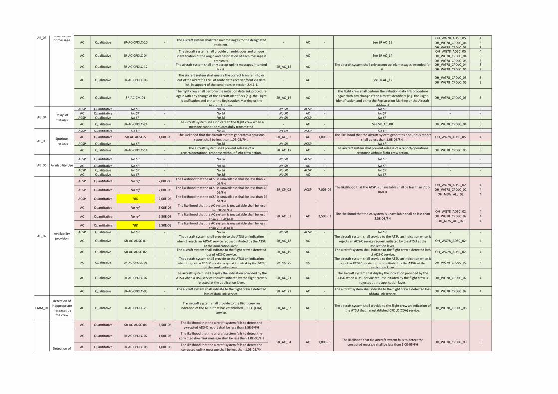
AC Qualitative SR-AC-CPDLC-10 -The aircraft system shall transmit messages to the designated
recipient.- AC - See SR AC_13
OH_WG78_ADSC_05
OH_WG78_CPDLC_04
OH_WG78_CPDLC_05
4
3
3
AC Qualitative SR-AC-CPDLC-04 -The aircraft system shall provide unambiguous and unique
identification of the origin and destination of each message it
transmits
- AC - See SR AC_14OH_WG78_ADSC_05
OH_WG78_CPDLC_04
OH_WG78_CPDLC_05
4
3
3
AC Qualitative SR-AC-CPDLC-12 -The aircraft system shall only accept uplink messages intended
for it.SR_AC_15 AC -
The aircraft system shall only accept uplink messages intended for
it.
OH_WG78_CPDLC_04
OH_WG78_CPDLC_05
3
3
AC Qualitative SR-AC-CPDLC-06 -
The aircraft system shall ensure the correct transfer into or
out of the aircraft’s FMS of route data received/sent via data
link, in support of the conditions in section 2.4.1.1.
- AC - See SR AC_12OH_WG78_CPDLC_03
OH_WG78_CPDLC_05
3
3
AC Qualitative SR-AC-CM-01 -
The flight crew shall perform the initiation data link procedure
again with any change of the aircraft identifiers (e.g. the Flight
Identification and either the Registration Marking or the
Aircraft Address)
SR_AC_16 AC -
The flight crew shall perform the initiation data link procedure
again with any change of the aircraft identifiers (e.g. the Flight
Identification and either the Registration Marking or the Aircraft
Address)
OH_WG78_CPDLC_05 3
ACSP Quantitative No SR - No SR No SR ACSP - No SR - -AC Quantitative No SR - No SR No SR AC - No SR - -
ACSP Qualitative No SR - No SR No SR ACSP - No SR - -
AC Qualitative SR-AC-CPDLC-24 -The aircraft system shall indicate to the flight crew when a
message cannot be successfully transmitted- AC - See SR_AC_08 OH_WG78_CPDLC_04 3
ACSP Quantitative No SR - No SR No SR ACSP - No SR - -
AC Quantitative SR-AC-ADSC-5 1,00E-05The likelihood that the aircraft system generates a spurious
report shall be less than 1.0E-05/FH .SR_AC_02 AC 1,00E-05
The likelihood that the aircraft system generates a spurious report
shall be less than 1.0E-05/FH .OH_WG78_ADSC_05 4
ACSP Qualitative No SR - No SR No SR ACSP - No SR - -
AC Qualitative SR-AC-CPDLC-14 -The aircraft system shall prevent release of a
report/operational response without flight crew action.SR_AC_17 AC -
The aircraft system shall prevent release of a report/operational
response without flight crew action.OH_WG78_CPDLC_05 3
ACSP Quantitative No SR - No SR No SR ACSP - No SR - -
AC Quantitative No SR - No SR No SR AC - No SR - -ACSP Qualitative No SR - No SR No SR ACSP - No SR - -
AC Qualitative No SR - No SR No SR AC - No SR - -
ACSP Quantitative No ref 7,00E-06The likelihood that the ACSP is unavailable shall be less than 7E-
06/FH
ACSP Quantitative No ref 7,00E-06The likelihood that the ACSP is unavailable shall be less than 7E-
06/FH
ACSP Quantitative TBD 7,00E-06The likelihood that the ACSP is unavailable shall be less than 7E-
06/FH
AC Quantitative No ref 3,00E-03The likelihood that the AC system is unavailable shall be less
than 3E-03/FH
AC Quantitative No ref 2,50E-03The likelihood that the AC system is unavailable shall be less
than 2.5E-03/FH
AC Quantitative TBD 2,50E-03The likelihood that the AC system is unavailable shall be less
than 2.5E-03/FHACSP Qualitative No SR - No SR No SR ACSP - No SR - -
AC Qualitative SR-AC-ADSC-01 -The aircraft system shall provide to the ATSU an indication
when it rejects an ADS-C service request initiated by the ATSU
at the application layer.
SR_AC_18 AC -The aircraft system shall provide to the ATSU an indication when it
rejects an ADS-C service request initiated by the ATSU at the
application layer.
OH_WG78_ADSC_02 4
AC Qualitative SR-AC-ADSC-02 -The aircraft system shall indicate to the flight crew a detected
loss of ADS-C service.SR_AC_19 AC -
The aircraft system shall indicate to the flight crew a detected loss
of ADS-C service.OH_WG78_ADSC_02 4
AC Qualitative SR-AC-CPDLC-01 -The aircraft system shall provide to the ATSU an indication
when it rejects a CPDLC service request initiated by the ATSU
at the application layer.
SR_AC_20 AC -The aircraft system shall provide to the ATSU an indication when it
rejects a CPDLC service request initiated by the ATSU at the
application layer.
OH_WG78_CPDLC_02 4
AC Qualitative SR-AC-CPDLC-02 -
The aircraft system shall display the indication provided by the
ATSU when a DSC service request initiated by the flight crew is
rejected at the application layer.
SR_AC_21 AC -
The aircraft system shall display the indication provided by the
ATSU when a DSC service request initiated by the flight crew is
rejected at the application layer.
OH_WG78_CPDLC_02 4
AC Qualitative SR-AC-CPDLC-03 -The aircraft system shall indicate to the flight crew a detected
loss of data link service.SR_AC_22 AC -
The aircraft system shall indicate to the flight crew a detected loss
of data link service.OH_WG78_CPDLC_02 4
EMM_01
Detection of
inappropriate
messages by
the crew
AC Qualitative SR-AC-CPDLC-23 -
The aircraft system shall provide to the flight crew an
indication of the ATSU that has established CPDLC (CDA)
service.
SR_AC_33 AC -The aircraft system shall provide to the flight crew an indication of
the ATSU that has established CPDLC (CDA) service.OH_WG78_CPDLC_05 3
AC Quantitative SR-AC-ADSC-04 3,50E-05The likelihood that the aircraft system fails to detect the
corrupted ADS-C report shall be less than 3.5E-5/FH
AC Quantitative SR-AC-CPDLC-07 1,00E-05The likelihood that the aircraft system fails to detect the
corrupted downlink message shall be less than 1.0E-05/FH
AC Quantitative SR-AC-CPDLC-08 1,00E-05The likelihood that the aircraft system fails to detect the
corrupted uplink message shall be less than 1.0E-05/FH
OH_WG78_CPDLC_03 3SR_AC_04 AC 1,00E-05The likelihood that the aircraft system fails to detect the
corrupted message shall be less than 1.0E-05/FH Detection of
corrupted
messages
2,50E-03
The likelihood that the ACSP is unavailable shall be less than 7.6E-
06/FH
The likelihood that the AC system is unavailable shall be less than
2.5E-03/FH
EMM 02
ACSP
AC
SR_CP_02
SR_AC_03
7,00E-06
4
4
4
AE_07Availability
provision
AE_06 Availability Use
OH_WG78_ADSC_02
OH_WG78_CPDLC_02
OH_NEW_ALL_02
OH_WG78_ADSC_02
OH_WG78_CPDLC_02
OH_NEW_ALL_02
4
4
4
AE_05Spurious
message
AE_04Delay of
message
AE_03Misdirection
of message

AC Quantitative SR-AC-DOTIS-04 2,80E-03The likelihood that the aircraft system fails to detect and reject
a corrupted report shall be less than 2.8E-03/FH
AC Qualitative SR-AC-CPDLC-09 -Whenever a message is discarded by the aircraft system, it
shall send an indication to the ground system for display to
the controller.
SR_AC_23 AC -Whenever a message is discarded by the aircraft system, it shall
send an indication to the ground system for display to the
controller.
OH_WG78_CPDLC_03
OH_WG78_CPDLC_04
OH_WG78_CPDLC_05
3
3
3
AC Qualitative SR-AC-CPDLC-17 -The aircraft system shall prohibit operational processing by
flight crew of corrupted messages.- AC - SR_AC_10 OH_WG78_CPDLC_03 3
AC Quantitative SR-AC-ADSC-6 1,00E-05The likelihood that the aircraft system incorrectly time stamps
the report shall be less than 1.0E-05/FH
AC Quantitative SR-AC-CPDLC-18 1,00E-05The likelihood that the aircraft system incorrectly time stamps
the DM shall be less than 1.0E-05/FH
AC Qualitative SR-AC-ADSC-7 -The aircraft system shall time stamp each report to within one
second UTC when it is released for onward transmission. SR_AC_24 AC -
The aircraft system shall time stamp each report to within one
second UTC when it is released for onward transmission. OH_WG78_ADSC_05 4
AC Qualitative SR-AC-CPDLC-16 -The aircraft system shall time stamp to within one second UTC
each message when it is released for onward transmission. SR_AC_25 AC -
The aircraft system shall time stamp to within one second UTC
each message when it is released for onward transmission. OH_WG78_ADSC_05 4
AC Qualitative SR-AC-CPDLC-09 -Whenever a message is discarded by the aircraft system, it
shall send an indication to the ground system for display to
the controller.
- AC - See SR AC_25OH_WG78_CPDLC_03
OH_WG78_CPDLC_04
OH_WG78_CPDLC_05
3
3
3
AC Qualitative SR-AC-CPDLC-15 -
When a received message contains a time stamp that indicates
the Latency Time Check value, set at equal or less than ETTRN,
has been exceeded, the aircraft system shall a) discard the
message and send an indication to the Ground System for
display to the controller or b) provide the message to the flight
crew with an appropriate indication.
SR_AC_26 AC -
When a received message contains a time stamp that indicates
the Latency Time Check value, set at equal or less than ETTRN, has
been exceeded, the aircraft system shall a) discard the message
and send an indication to the Ground System for display to the
controller or b) provide the message to the flight crew with an
appropriate indication.
OH_WG78_CPDLC_05 3
AC Qualitative SR-AC-CPDLC-16 -The aircraft system shall time stamp to within one second UTC
each message when it is released for onward transmission - AC - See SR AC_28 OH_WG78_CPDLC_05 3
AC Quantitative SR-AC-CPDLC-19 1,00E-05The likelihood that the aircraft system fails to detect and reject
the misdirected uplink message shall be less than 1.0E-05/FHSR_AC_06 AC 1,00E-05
The likelihood that the aircraft system fails to detect and reject
the misdirected uplink message shall be less than 1.0E-05/FHOH_WG78_CPDLC_04 3
AC Qualitative SR-AC-CPDLC-09 -Whenever a message is discarded by the aircraft system, it
shall send an indication to the ground system for display to
the controller.
- AC - See SR AC_18OH_WG78_CPDLC_03
OH_WG78_CPDLC_04
OH_WG78_CPDLC_05
3
3
3
AC Qualitative SR-AC-CPDLC-12 -The aircraft system shall only accept uplink messages intended
for it.- AC - SR_AC_15
OH_WG78_CPDLC_04
OH_WG78_CPDLC_05
3
3
AC Qualitative SR-AC-CPDLC-21 -The aircraft system shall be able to determine the message
initiator.SR_AC_27 AC -
The aircraft system shall be able to determine the message
initiator.
OH_WG78_CPDLC_04
OH_WG78_CPDLC_05
3
3
AC Qualitative SR-AC-CPDLC-22 -
Once an aircraft accepts operational CPDLC messages from an
ATSU, it shall reject operational CPDLC messages from any
other ATSU until the first ATSU terminates CPDLC with that
aircraft.
SR_AC_28 AC -
Once an aircraft accepts operational CPDLC messages from an
ATSU, it shall reject operational CPDLC messages from any other
ATSU until the first ATSU terminates CPDLC with that aircraft.
OH_WG78_CPDLC_04
OH_WG78_CPDLC_05
3
3
AC Qualitative SR-AC-CPDLC-35 -Only the ATSU that has control of the aircraft shall be
permitted to send a Next Data Authority (NDA) message to the
aircraft.
SR_AC_29 AC -Only the ATSU that has control of the aircraft shall be permitted
to send a Next Data Authority (NDA) message to the aircraft.OH_WG78_CPDLC_04 3
AC Qualitative SR-AC-CPDLC-09 -Whenever a message is discarded by the aircraft system, it
shall send an indication to the ground system for display to
the controller.
- AC - See SR AC_25OH_WG78_CPDLC_03
OH_WG78_CPDLC_04
OH_WG78_CPDLC_05
3
3
3
AC Qualitative SR-AC-CPDLC-12 -The aircraft system shall only accept uplink messages intended
for it.- AC - SR_AC_15 OH_WG78_CPDLC_05
3
3
AC Qualitative SR-AC-CPDLC-21 -The aircraft system shall be able to determine the message
initiator.- AC - See SR AC_31 OH_WG78_CPDLC_05
3
3
AC Qualitative SR-AC-CPDLC-22 -
Once an aircraft accepts operational CPDLC messages from an
ATSU, it shall reject operational CPDLC messages from any
other ATSU until the first ATSU terminates CPDLC with that
aircraft.
- AC - See SR AC_32 OH_WG78_CPDLC_053
3
AC Quantitative SR-AC-CPDLC-25 1,00E-05
Upon receipt of an UM, containing an MRN, the likelihood of
the aircraft system, not rejecting that does not match a DM
MIN shall be less than 1.E-5/FH.
SR_AC_07 AC 1,00E-05
Upon receipt of an UM, containing an MRN, the likelihood of the
aircraft system, not rejecting that does not match a DM MIN shall
be less than 1.E-5/FH.
OH_WG78_CPDLC_05 3
AC Qualitative SR-AC-CPDLC-20 -The aircraft system shall indicate in each response to which
messages it refersSR_AC_30 AC -
The aircraft system shall indicate in each response to which
messages it refersOH_WG78_CPDLC_05 3
AC Qualitative SR-AC-CPDLC-26 -Each downlink message shall be uniquely identified for a given
aircraft-ATSU pair, following a sequential orderSR_AC_31 AC -
Each downlink message shall be uniquely identified for a given
aircraft-ATSU pair, following a sequential orderOH_WG78_CPDLC_05 3
EMM_11Detection of
spurious AC Qualitative SR-AC-ADSC-10 -
The aircraft system shall indicate in each report to which
contract number it is referringSR_AC_32 AC -
The aircraft system shall indicate in each report to which contract
number it is referringOH_WG78_CPDLC_05 3
OH_WG78_CPDLC_03 3
SR_AC_05 AC 1,00E-05The likelihood that the aircraft system incorrectly time stamps a
message shall be less than 1.0E-05/FH
OH_WG78_ADSC_05
OH_WG78_CPDLC_05
4
3
SR_AC_04 AC 1,00E-05The likelihood that the aircraft system fails to detect the
corrupted message shall be less than 1.0E-05/FH
EMM_10
Detection of
spurious uplink
messages
EMM_07
Detection of
misdirected
uplink
messages
EMM_06
Detection of
delayed uplink
messages
EMM_05
Detection of
delayed
downlink
messages
Detection of
corrupted
messages
EMM 02
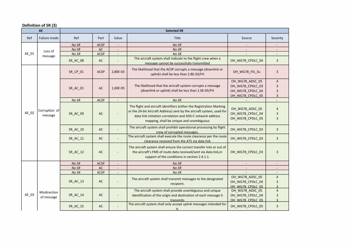
Definition of SR (3)
Ref Failure mode Ref Part Value Title Source Severity
No SR ACSP - No SR - -No SR AC - No SR - -No SR ACSP - No SR - -
SR_AC_08 AC -The aircraft system shall indicate to the flight crew when a
message cannot be successfully transmittedOH_WG78_CPDLC_04 3
No SR ACSP - No SR - -
SR_AC_09 AC -
The flight and aircraft identifiers (either the Registration Marking
or the 24-bit Aircraft Address) sent by the aircraft system, used for
data link initiation correlation and ADS-C network address
mapping, shall be unique and unambiguous
OH_WG78_ADSC_05
OH_WG78_CPDLC_04
OH_WG78_CPDLC_05
4
3
3
SR_AC_10 AC -The aircraft system shall prohibit operational processing by flight
crew of corrupted messages.OH_WG78_CPDLC_03 3
SR_AC_11 AC -The aircraft system shall execute the route clearance per the route
clearance received from the ATS via data linkOH_WG78_CPDLC_03 3
SR_AC_12 AC -
The aircraft system shall ensure the correct transfer into or out of
the aircraft’s FMS of route data received/sent via data link,in
support of the conditions in section 2.4.1.1.
OH_WG78_CPDLC_03 3
No SR ACSP - No SR - -No SR AC - No SR - -No SR ACSP - No SR - -
SR_AC_13 AC -The aircraft system shall transmit messages to the designated
recipient.
OH_WG78_ADSC_05
OH_WG78_CPDLC_04
OH_WG78_CPDLC_05
4
3
3
SR_AC_14 AC -The aircraft system shall provide unambiguous and unique
identification of the origin and destination of each message it
transmits
OH_WG78_ADSC_05
OH_WG78_CPDLC_04
OH_WG78_CPDLC_05
4
3
3
SR_AC_15 AC -The aircraft system shall only accept uplink messages intended for
it.OH_WG78_CPDLC_05 3
AE
AE_01Loss of
message
AE_02
AC
Corruption of
message
Selected SR
SR_CP_01 ACSP 2,80E-03The likelihood that the ACSP corrupts a message (downlink or
uplink) shall be less than 2.8E-03/FHOH_WG78_FIS_3u 3
SR_AC_01 1,00E-05The likelihood that the aircraft system corrupts a message
(downlink or uplink) shall be less than 1.0E-05/FH
OH_WG78_ADSC_05
OH_WG78_CPDLC_03
OH_WG78_CPDLC_04
OH_WG78_CPDLC_05
4
3
3
3
AE_03Misdirection
of message
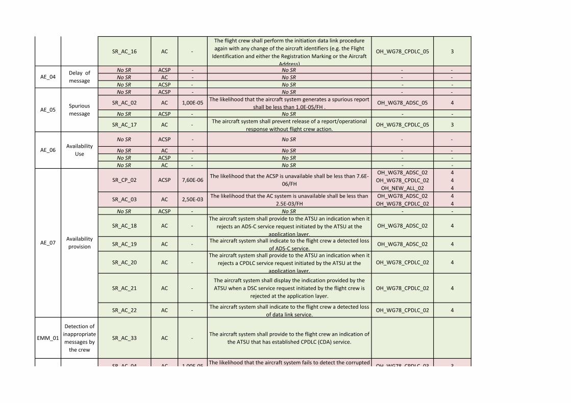
SR_AC_16 AC -
The flight crew shall perform the initiation data link procedure
again with any change of the aircraft identifiers (e.g. the Flight
Identification and either the Registration Marking or the Aircraft
Address)
OH_WG78_CPDLC_05 3
No SR ACSP - No SR - -No SR AC - No SR - -No SR ACSP - No SR - -No SR ACSP - No SR - -
SR_AC_02 AC 1,00E-05The likelihood that the aircraft system generates a spurious report
shall be less than 1.0E-05/FH .OH_WG78_ADSC_05 4
No SR ACSP - No SR - -
SR_AC_17 AC -The aircraft system shall prevent release of a report/operational
response without flight crew action.OH_WG78_CPDLC_05 3
No SR ACSP - No SR - -
No SR AC - No SR - -No SR ACSP - No SR - -No SR AC - No SR - -
No SR ACSP - No SR - -
SR_AC_18 AC -The aircraft system shall provide to the ATSU an indication when it
rejects an ADS-C service request initiated by the ATSU at the
application layer.
OH_WG78_ADSC_02 4
SR_AC_19 AC -The aircraft system shall indicate to the flight crew a detected loss
of ADS-C service.OH_WG78_ADSC_02 4
SR_AC_20 AC -The aircraft system shall provide to the ATSU an indication when it
rejects a CPDLC service request initiated by the ATSU at the
application layer.
OH_WG78_CPDLC_02 4
SR_AC_21 AC -
The aircraft system shall display the indication provided by the
ATSU when a DSC service request initiated by the flight crew is
rejected at the application layer.
OH_WG78_CPDLC_02 4
SR_AC_22 AC -The aircraft system shall indicate to the flight crew a detected loss
of data link service.OH_WG78_CPDLC_02 4
EMM_01
Detection of
inappropriate
messages by
the crew
SR_AC_33 AC -The aircraft system shall provide to the flight crew an indication of
the ATSU that has established CPDLC (CDA) service.
AC 1,00E-05The likelihood that the aircraft system fails to detect the corrupted
message shall be less than 1.0E-05/FH OH_WG78_CPDLC_03 3
AC 2,50E-03The likelihood that the AC system is unavailable shall be less than
2.5E-03/FH
OH_WG78_ADSC_02
OH_WG78_CPDLC_02
4
4
ACSP 7,60E-06The likelihood that the ACSP is unavailable shall be less than 7.6E-
06/FH
OH_WG78_ADSC_02
OH_WG78_CPDLC_02
OH_NEW_ALL_02
4
4
4
SR_AC_04
SR_CP_02
SR_AC_03
AE_03Misdirection
of message
AE_04Delay of
message
AE_05Spurious
message
EMM 02
Detection of
corrupted
messages
AE_06Availability
Use
AE_07Availability
provision

SR_AC_23 AC -Whenever a message is discarded by the aircraft system, it shall
send an indication to the ground system for display to the
controller.
OH_WG78_CPDLC_03
OH_WG78_CPDLC_04
OH_WG78_CPDLC_05
3
3
3
SR_AC_24 AC -The aircraft system shall time stamp each report to within one
second UTC when it is released for onward transmission. OH_WG78_ADSC_05 4
SR_AC_25 AC -The aircraft system shall time stamp to within one second UTC
each message when it is released for onward transmission. OH_WG78_ADSC_05 4
EMM_06
Detection of
delayed
uplink
messages
SR_AC_26 AC -
When a received message contains a time stamp that indicates the
Latency Time Check value, set at equal or less than ETTRN, has
been exceeded, the aircraft system shall a) discard the message
and send an indication to the Ground System for display to the
controller or b) provide the message to the flight crew with an
appropriate indication.
OH_WG78_CPDLC_05 3
SR_AC_06 AC 1,00E-05The likelihood that the aircraft system fails to detect and reject the
misdirected uplink message shall be less than 1.0E-05/FHOH_WG78_CPDLC_04 3
SR_AC_27 AC -The aircraft system shall be able to determine the message
initiator.
OH_WG78_CPDLC_04
OH_WG78_CPDLC_05
3
3
SR_AC_28 AC -
Once an aircraft accepts operational CPDLC messages from an
ATSU, it shall reject operational CPDLC messages from any other
ATSU until the first ATSU terminates CPDLC with that aircraft.
OH_WG78_CPDLC_04
OH_WG78_CPDLC_05
3
3
SR_AC_29 AC -Only the ATSU that has control of the aircraft shall be permitted to
send a Next Data Authority (NDA) message to the aircraft.OH_WG78_CPDLC_04 3
SR_AC_07 AC 1,00E-05Upon receipt of an UM, containing an MRN, the likelihood of the
aircraft system, not rejecting that does not match a DM MIN shall
be less than 1.E-5/FH.
OH_WG78_CPDLC_05 3
SR_AC_30 AC -The aircraft system shall indicate in each response to which
messages it refersOH_WG78_CPDLC_05 3
SR_AC_31 AC -Each downlink message shall be uniquely identified for a given
aircraft-ATSU pair, following a sequential orderOH_WG78_CPDLC_05 3
EMM_11
Detection of
spurious
downlink
messages
SR_AC_32 AC -The aircraft system shall indicate in each report to which contract
number it is referringOH_WG78_CPDLC_05 3
4
3
EMM_07
Detection of
misdirected
uplink
messages
SR_AC_05 AC 1,00E-05The likelihood that the aircraft system incorrectly time stamps a
message shall be less than 1.0E-05/FH
OH_WG78_ADSC_05
OH_WG78_CPDLC_05
EMM_05
Detection of
delayed
downlink
messages
AC 1,00E-05The likelihood that the aircraft system fails to detect the corrupted
message shall be less than 1.0E-05/FH OH_WG78_CPDLC_03 3SR_AC_04
EMM_10
Detection of
spurious
uplink
messages
EMM 02
Detection of
corrupted
messages
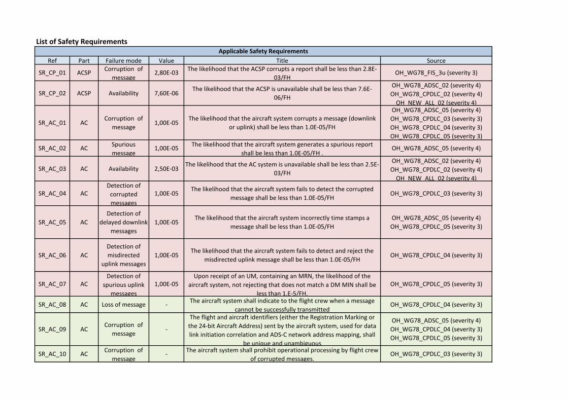
List of Safety Requirements
Ref Part Failure mode Value Title Source
SR_CP_01 ACSPCorruption of
message2,80E-03
The likelihood that the ACSP corrupts a report shall be less than 2.8E-
03/FHOH_WG78_FIS_3u (severity 3)
SR_CP_02 ACSP Availability 7,60E-06The likelihood that the ACSP is unavailable shall be less than 7.6E-
06/FH
OH_WG78_ADSC_02 (severity 4)
OH_WG78_CPDLC_02 (severity 4)
OH_NEW_ALL_02 (severity 4)
SR_AC_01 ACCorruption of
message1,00E-05
The likelihood that the aircraft system corrupts a message (downlink
or uplink) shall be less than 1.0E-05/FH
OH_WG78_ADSC_05 (severity 4)
OH_WG78_CPDLC_03 (severity 3)
OH_WG78_CPDLC_04 (severity 3)
OH_WG78_CPDLC_05 (severity 3)
SR_AC_02 ACSpurious
message1,00E-05
The likelihood that the aircraft system generates a spurious report
shall be less than 1.0E-05/FH .OH_WG78_ADSC_05 (severity 4)
SR_AC_03 AC Availability 2,50E-03The likelihood that the AC system is unavailable shall be less than 2.5E-
03/FH
OH_WG78_ADSC_02 (severity 4)
OH_WG78_CPDLC_02 (severity 4)
OH_NEW_ALL_02 (severity 4)
SR_AC_04 ACDetection of
corrupted
messages
1,00E-05The likelihood that the aircraft system fails to detect the corrupted
message shall be less than 1.0E-05/FH OH_WG78_CPDLC_03 (severity 3)
SR_AC_05 AC
Detection of
delayed downlink
messages
1,00E-05The likelihood that the aircraft system incorrectly time stamps a
message shall be less than 1.0E-05/FH
OH_WG78_ADSC_05 (severity 4)
OH_WG78_CPDLC_05 (severity 3)
SR_AC_06 AC
Detection of
misdirected
uplink messages
1,00E-05The likelihood that the aircraft system fails to detect and reject the
misdirected uplink message shall be less than 1.0E-05/FHOH_WG78_CPDLC_04 (severity 3)
SR_AC_07 ACDetection of
spurious uplink
messages
1,00E-05Upon receipt of an UM, containing an MRN, the likelihood of the
aircraft system, not rejecting that does not match a DM MIN shall be
less than 1.E-5/FH.
OH_WG78_CPDLC_05 (severity 3)
SR_AC_08 AC Loss of message -The aircraft system shall indicate to the flight crew when a message
cannot be successfully transmittedOH_WG78_CPDLC_04 (severity 3)
SR_AC_09 ACCorruption of
message-
The flight and aircraft identifiers (either the Registration Marking or
the 24-bit Aircraft Address) sent by the aircraft system, used for data
link initiation correlation and ADS-C network address mapping, shall
be unique and unambiguous
OH_WG78_ADSC_05 (severity 4)
OH_WG78_CPDLC_04 (severity 3)
OH_WG78_CPDLC_05 (severity 3)
SR_AC_10 ACCorruption of
message-
The aircraft system shall prohibit operational processing by flight crew
of corrupted messages.OH_WG78_CPDLC_03 (severity 3)
Applicable Safety Requirements

SR_AC_11 ACCorruption of
message-
The aircraft system shall execute the route clearance per the route
clearance received from the ATS via data linkOH_WG78_CPDLC_03 (severity 3)
SR_AC_12 ACCorruption of
message-
The aircraft system shall ensure the correct transfer into or out of the
aircraft’s FMS of route data received/sent via data link,in support of
the conditions in section 2.4.1.1.
OH_WG78_CPDLC_03 (severity 3)
SR_AC_13 ACMisdirection of
message-
The aircraft system shall transmit messages to the designated
recipient.
OH_WG78_ADSC_05 (severity 4)
OH_WG78_CPDLC_04 (severity 3)
OH_WG78_CPDLC_05 (severity 3)
SR_AC_14 ACMisdirection of
message-
The aircraft system shall provide unambiguous and unique
identification of the origin and destination of each message it
transmits
OH_WG78_ADSC_05 (severity 4)
OH_WG78_CPDLC_04 (severity 3)
OH_WG78_CPDLC_05 (severity 3)
SR_AC_15 ACMisdirection of
message- The aircraft system shall only accept uplink messages intended for it. OH_WG78_CPDLC_05 (severity 3)
SR_AC_16 ACMisdirection of
message-
The flight crew shall perform the initiation data link procedure again
with any change of the aircraft identifiers (e.g. the Flight Identification
and either the Registration Marking or the Aircraft Address)
OH_WG78_CPDLC_05 (severity 3)
SR_AC_17 ACSpurious
message-
The aircraft system shall prevent release of a report/operational
response without flight crew action.OH_WG78_CPDLC_05 (severity 3)
SR_AC_18 AC Availability -The aircraft system shall provide to the ATSU an indication when it
rejects an ADS-C service request initiated by the ATSU at the
application layer.
OH_WG78_ADSC_02 (severity 4)
SR_AC_19 AC Availability -The aircraft system shall indicate to the flight crew a detected loss of
ADS-C service.OH_WG78_ADSC_02 (severity 4)
SR_AC_20 AC Availability -The aircraft system shall provide to the ATSU an indication when it
rejects a CPDLC service request initiated by the ATSU at the application
layer.
OH_WG78_CPDLC_02 (severity 4)
SR_AC_21 AC Availability -The aircraft system shall display the indication provided by the ATSU
when a DSC service request initiated by the flight crew is rejected at
the application layer.
OH_WG78_CPDLC_02 (severity 4)
SR_AC_22 AC Availability -The aircraft system shall indicate to the flight crew a detected loss of
data link service.OH_WG78_CPDLC_02 (severity 4)
SR_AC_23 ACDetection of
corrupted
messages
-Whenever a message is discarded by the aircraft system, it shall send
an indication to the ground system for display to the controller.
OH_WG78_CPDLC_03 (severity 3)
OH_WG78_CPDLC_04 (severity 3)
OH_WG78_CPDLC_05 (severity 3)
SR_AC_24 AC
Detection of
delayed downlink
messages
-The aircraft system shall time stamp each report to within one second
UTC when it is released for onward transmission. OH_WG78_ADSC_05 (severity 4)
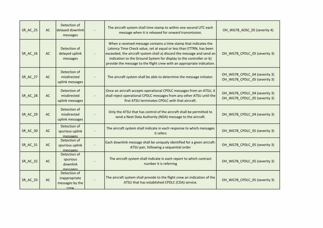
SR_AC_25 AC
Detection of
delayed downlink
messages
-The aircraft system shall time stamp to within one second UTC each
message when it is released for onward transmission. OH_WG78_ADSC_05 (severity 4)
SR_AC_26 AC
Detection of
delayed uplink
messages
-
When a received message contains a time stamp that indicates the
Latency Time Check value, set at equal or less than ETTRN, has been
exceeded, the aircraft system shall a) discard the message and send an
indication to the Ground System for display to the controller or b)
provide the message to the flight crew with an appropriate indication.
OH_WG78_CPDLC_05 (severity 3)
SR_AC_27 AC
Detection of
misdirected
uplink messages
- The aircraft system shall be able to determine the message initiator.OH_WG78_CPDLC_04 (severity 3)
OH_WG78_CPDLC_05 (severity 3)
SR_AC_28 AC
Detection of
misdirected
uplink messages
-
Once an aircraft accepts operational CPDLC messages from an ATSU, it
shall reject operational CPDLC messages from any other ATSU until the
first ATSU terminates CPDLC with that aircraft.
OH_WG78_CPDLC_04 (severity 3)
OH_WG78_CPDLC_05 (severity 3)
SR_AC_29 AC
Detection of
misdirected
uplink messages
-Only the ATSU that has control of the aircraft shall be permitted to
send a Next Data Authority (NDA) message to the aircraft.OH_WG78_CPDLC_04 (severity 3)
SR_AC_30 ACDetection of
spurious uplink
messages
-The aircraft system shall indicate in each response to which messages
it refersOH_WG78_CPDLC_05 (severity 3)
SR_AC_31 ACDetection of
spurious uplink
messages
-Each downlink message shall be uniquely identified for a given aircraft-
ATSU pair, following a sequential orderOH_WG78_CPDLC_05 (severity 3)
SR_AC_32 AC
Detection of
spurious
downlink
messages
-The aircraft system shall indicate in each report to which contract
number it is referringOH_WG78_CPDLC_05 (severity 3)
SR_AC_33 AC
Detection of
inappropriate
messages by the
crew
-The aircraft system shall provide to the flight crew an indication of the
ATSU that has established CPDLC (CDA) service.OH_WG78_CPDLC_05 (severity 3)
Project Number 15.02.07 Edition 00.01.00 D08.1 - AEROMACS - Safety Analysis
119 of 120
©SESAR JOINT UNDERTAKING, 2014. Created by AENA, AIRBUS, DSNA, EUROCONTROL, INDRA, NATMIG, SELEX ES
and THALES for the SESAR Joint Undertaking within the frame of the SESAR Programme co-financed by the EU and EUROCONTROL. Reprint with approval of publisher and the source properly acknowledged.
Appendix C : Differences between issue I and issue M of WG78/SC214 documents
The present safety and performance analysis is based on issue I of WG78/SC214 documents. At the moment this document is delivered, the current version of the WG78/SC214 document is issue M.
This appendix presents a brief analysis of the differences between the two issues and some first analysis of potential impact on AeroMACS design. It has to be noticed that WG78 deliverables have still to be reviewed in order to address merged European and US approach on ATN Baseline 2.
General remarks
Flight Information Services are no longer in the perimeter of the WG78 / SC214.
Remarks regarding the Safety Analysis
Severities of some Operational Hazards have been modified. Particularly, severities of hazards « Loss of ADS-C capability [multiple aircraft] - undetected » and « Loss of CPDLC capability [multiple aircraft] - undetected » have been reassessed from 4 to 3.
For CPDLC hazard, “undetected loss of CPDLC capability for multiple aircraft”, the severity is 3 in release M (instead of 4 in release I) only for Separation Assurance function which is only used in En-Route Domain. AeroMACS being used only for airport operation, this modification should thus not impact on AeroMACS design.
For ADS-C hazard, “undetected loss of ADS-C capability for multiple aircraft”, the severity is 3 in release M (instead of 4 in release I) only for 4D-TBO and for ATC Com function (for the effect “Significant reduction in safety margins and separation”). ADS-C application supports the following services: 4-Dimensional Trajectory Data Link (4DTRAD), Information Exchange and Reporting (IER) and Position Reporting (PR). These services, apart from the establishment of the ADS-C contract, will likely not be used while the aircraft is on the ground. Consequently, this modification of effect severity should not impact AeroMACS design.
Safety Requirements are only derived on Aircraft System, ATS Provider and Operator: there is no longer safety requirements apportioned to the ACSP, it is considered as a part of ATS Provider.
Remarks regarding Performance Analysis
No significant modification for AeroMACS design.

Project Number 15.02.07 Edition 00.01.00 D08.1 - AEROMACS - Safety Analysis
120 of 120
©SESAR JOINT UNDERTAKING, 2014. Created by AENA, AIRBUS, DSNA, EUROCONTROL, INDRA, NATMIG, SELEX ES
and THALES for the SESAR Joint Undertaking within the frame of the SESAR Programme co-financed by the EU and EUROCONTROL. Reprint with approval of publisher and the source properly acknowledged.
-END OF DOCUMENT-

AEROMACS - Security Analysis
Document information
Project Title Airport Surface Datalink
Project Number 15.02.07
Project Manager INDRA
Deliverable Name AEROMACS - Security Analysis
Deliverable ID D08.2
Edition 00.01.00
Template Version 03.00.00
Task contributors
AENA, AIRBUS, DSNA (TASK LEADER), EUROCONTROL, INDRA, SELEX ES, THALES
Abstract
This deliverable has been developed by SESAR Project 15.2.7 “Airport Surface Data
Link within WA8 “Safety and Security Analysis” that aims at performing an extensive
analysis to identify the impact on security and safety issues of the new IEEE 802e/aero
datalink.
This document consist of part 2 of the deliverable, and WiMAX security is addressed to
derive guidance at standardisation, implementation and deployment phases of the
AeroMACS system.

Project Number 15.02.07 Edition 00.01.00 D08.2 - AEROMACS - Security Analysis
2 of 112
©SESAR JOINT UNDERTAKING, 2014. Created by AENA, AIRBUS, DSNA, EUROCONTROL, INDRA, NATMIG, SELEX ES
and THALES for the SESAR Joint Undertaking within the frame of the SESAR Programme co-financed by the EU and EUROCONTROL. Reprint with approval of publisher and the source properly acknowledged.
Authoring (D08-Part2)
Prepared By - Authors of the document.
Name & Company Position & Title Date
Slim Ben Mahmoud / ENAC for DSNA Project Contributor 17/02/2014
Nicolas Larrieu / ENAC for DSNA Project Contributor 17/02/2014
Antonio Correas / INDRA Project Contributor 17/02/2014
Stéphane Fassetta / THALES Project Contributor 17/02/2014
Document History (D08-Part2)
Edition Date Status Author Justification
00.00.01 15/02/2011 Draft ENAC Draft deliverable describing the Security analysis methodology
00.00.02 08/03/2011 Draft ENAC Draft addressing partners comments
00.00.03 11/04/2011 Draft INDRA Draft contribution on section 3
00.00.04 08/07/2011 Draft THALES Draft contribution on section 4
00.00.05 17/08/2011 Draft ENAC Draft simulations results regarding risk propagation
00.00.06 22/05/2012 Draft ENAC Final simulations results incorporating suggested additional simulation scenarios
00.00.07 12/11/2012 Draft ENAC Draft deliverable including simulations results on risk propagation
00.00.08 13/05/2013 Draft ENAC Draft deliverable including analysis of Wimax system and end-to-end security vulnerabilities
00.00.09 15/11/2013 Draft ENAC
Draft deliverable addressing partners comments, WG82 comments, including annex on comparison between Radius and Diameter, CVSS datagram description, algorithm diagram. Draft disseminated to ICAO.
00.00.10 26/03/2014 Draft ENAC Final version for handover addressing ICAO comments
00.01.00 27/03/2014 Final INDRA Version for handover
Intellectual Property Rights (foreground)
This deliverable consists of SJU foreground.

Project Number 15.02.07 Edition 00.01.00 D08.2 - AEROMACS - Security Analysis
3 of 112
©SESAR JOINT UNDERTAKING, 2014. Created by AENA, AIRBUS, DSNA, EUROCONTROL, INDRA, NATMIG, SELEX ES
and THALES for the SESAR Joint Undertaking within the frame of the SESAR Programme co-financed by the EU and EUROCONTROL. Reprint with approval of publisher and the source properly acknowledged.
Table of Contents
EXECUTIVE SUMMARY .................................................................................................................................... 7
1 INTRODUCTION .......................................................................................................................................... 8
1.1 DOCUMENT STRUCTURE ................................................................................................................ 8 1.2 INTENDED READERSHIP ................................................................................................................. 9 1.3 ACRONYMS AND TERMINOLOGY .................................................................................................. 9
2 BACKGROUND ON WIMAX ................................................................................................................... 15
2.1 WIMAX PROTOCOL ARCHITECTURE.......................................................................................... 15 2.2 WIMAX NETWORK REFERENCE MODEL ................................................................................... 15
3 WIMAX SECURITY FEATURES ............................................................................................................. 18
3.1 WIMAX PRIVACY SUBLAYER SECURITY.................................................................................... 18 3.1.1 PKM WEAKNESSES ................................................................................................................. 18 3.1.2 MANAGEMENT TRAFFIC WEAKNESSES ........................................................................... 20 3.1.3 MULTICAST AND BROADCAST SERVICE WEAKNESSES ............................................. 21 3.1.4 HANDOVER WEAKNESSES ................................................................................................... 22
3.2 WIMAX NETWORK SECURITY ....................................................................................................... 22 3.2.1 DHCP SECURITY ...................................................................................................................... 23 3.2.2 MOBILE IP SECURITY ............................................................................................................. 24
3.3 AEROMACS KEY GENERATION TREE ........................................................................................ 28 3.4 AEROMACS SECURITY TAXONOMY ........................................................................................... 29
4 A QUANTITATIVE NETWORK RISK ASSESSMENT MODEL BASED ON RISK PROPAGATION APPLIED TO AEROMACS NETWORK .......................................................................... 32
4.1 AN ALTERNATIVE RISK ASSESSMENT METHODOLOGY ...................................................... 32 4.1.1 RISK MANAGEMENT STANDARDS AND METHODS ....................................................... 32 4.1.2 QUANTITATIVE AND QUALITATIVE RISK ASSESSMENT APPROACHES .................. 33 4.1.3 NETWORK RISK PROPAGATION CONCEPT ..................................................................... 34 4.1.4 RELATED WORK ...................................................................................................................... 34
4.2 PRESENTATION OF THE QUANTITATIVE NETWORK RISK ASSESSMENT MODEL
BASED ON RISK PROPAGATION .............................................................................................................. 34 4.2.1 TERMINOLOGY ......................................................................................................................... 34 4.2.2 RISK PARAMETERS ................................................................................................................ 35 4.2.3 RISK ASSESSMENT PROCESS ............................................................................................ 39
4.3 APPLICATION TO AEROMACS NETWORK ................................................................................. 41 4.3.1 TRAFFIC FLOW SPECIFICATION ......................................................................................... 41 4.3.2 ATS .............................................................................................................................................. 42 4.3.3 AOC.............................................................................................................................................. 43 4.3.4 VEHICULAR SERVICES .......................................................................................................... 45 4.3.5 MANAGEMENT .......................................................................................................................... 45 4.3.6 Characterization of data volume exchanged per pair of nodes ........................................... 46 4.3.7 NODE INTERCONNEXION MATRIX...................................................................................... 50
4.4 RISK ANALYSIS SCENARIOS ........................................................................................................ 53 4.4.1 ISOLATED AEROMACS SCENARIO WITH OPERATIONAL SERVER VULNERABILITIES ................................................................................................................................... 53 4.4.2 ISOLATED AEROMACS EXTENDED SCENARIOS............................................................ 69 4.4.3 END-TO-END AEROMACS SCENARIO ................................................................................ 79
5 REFERENCES ........................................................................................................................................... 89
APPENDIX A INTRODUCTION TO CVSS ............................................................................................. 92
APPENDIX B RISK ASSESSMENT PROCESS ALGORIGRAM ....................................................... 93
APPENDIX C AAA RADIUS AND DIAMETER IMPLEMENTATION ................................................. 94
A.1 GENERAL OVERVIEW OF AAA .............................................................................................................. 94 A.1.1 AAA Architecture ........................................................................................................................ 94 A.1.2 AAA Process Flow Chart .......................................................................................................... 95

Project Number 15.02.07 Edition 00.01.00 D08.2 - AEROMACS - Security Analysis
4 of 112
©SESAR JOINT UNDERTAKING, 2014. Created by AENA, AIRBUS, DSNA, EUROCONTROL, INDRA, NATMIG, SELEX ES
and THALES for the SESAR Joint Undertaking within the frame of the SESAR Programme co-financed by the EU and EUROCONTROL. Reprint with approval of publisher and the source properly acknowledged.
A.1.3 AAA Concepts ............................................................................................................................ 97 A.2 AAA MECHANISMS ............................................................................................................................... 98 A.3 AAA PROTOCOLS ................................................................................................................................. 98 A.4 RADIUS ............................................................................................................................................. 101 A.5 DIAMETER ........................................................................................................................................ 103 A.6 COMPARISON BETWEEN RADIUS AND DIAMETER PROTOCOLS ................................................... 104
A.6.1 Formal Verification of RADIUS and DIAMETER Protocols................................................ 105 A.6.2 Vulnerability Statistics.............................................................................................................. 106 A.6.3 Comparison Summary Between RADIUS and DIAMETER Protocols ............................. 108
A.7 AAA ARCHITECTURES ........................................................................................................................ 109 A.7.1 AAA Components ..................................................................................................................... 109 A.7.2 AAA Services ............................................................................................................................ 109 A.7.3 AAA in AeroMACS: Conclusions ........................................................................................... 110
APPENDIX D SESAR PAPER AT ICAO ACP WG W ........................................................................ 111
Project Number 15.02.07 Edition 00.01.00 D08.2 - AEROMACS - Security Analysis
5 of 112
©SESAR JOINT UNDERTAKING, 2014. Created by AENA, AIRBUS, DSNA, EUROCONTROL, INDRA, NATMIG, SELEX ES
and THALES for the SESAR Joint Undertaking within the frame of the SESAR Programme co-financed by the EU and EUROCONTROL. Reprint with approval of publisher and the source properly acknowledged.
List of tables
Table 1: WiMAX Reference Point Interface Description ....................................................................... 17 Table 2: AeroMACS security Taxonomy ............................................................................................... 31 Table 3: Terminology ............................................................................................................................ 35 Table 4: Function and class values matrix for Aeronautical Network Nodes ........................................ 36 Table 5: COCR Quantitative Value Mapping ........................................................................................ 39 Table 6: Specification of ATS traffic flows ............................................................................................. 43 Table 7: Specifications of AOC traffic flows .......................................................................................... 44 Table 8: Specifications of Vehicular Service Traffic Flows ................................................................... 45 Table 9: Specifications of Management Traffic flows ........................................................................... 46 Table 10: Amount of Data Exchanged between Nodes Pair per Service - Part 1 ................................ 48 Table 11: Amount of Data Exchanged Between Nodes Pair per Service - Part 2 ................................ 49 Table 12 : Amount of Data Exchanged Between Nodes Pair per Service - Part 3 ............................... 50 Table 13: Total Amount of Data Exchanged Between Nodes .............................................................. 52 Table 14: Simulation parameters .......................................................................................................... 59 Table 15: Vulnerability CVSS statistics ................................................................................................. 60 Table 16: Propagated risk values for all nodes ..................................................................................... 63 Table 17: Node risk statisctics .............................................................................................................. 64 Table 18: EAP vs. RSA Vulnerability Statistics ..................................................................................... 66 Table 19: Node risk statistics (EAP vs. RSA) ....................................................................................... 68 Table 20 : Simulation parameters (without operational server vulnerabilities) ..................................... 70 Table 21: Updated Vulnerability CVSS statistics .................................................................................. 71 Table 22: Updated Individual risk results .............................................................................................. 72 Table 23: Updated Propagated Risk Results ........................................................................................ 72 Table 24: Updated Network and Node Risk Results ............................................................................ 73 Table 25: Simulation parameters (Scenario with Two ASN GWs)........................................................ 76 Table 26: Updated Individual Risk Values (Isolated Scenario With 2 ASN GWs) ................................ 76 Table 27: Updated Propagated risk values (2 ASN GWs) .................................................................... 77 Table 28: Updated Node risk values (2 ASN GWs) .............................................................................. 78 Table 29: Simulation parameters (Integrated AeroMACS Topology) ................................................... 80 Table 30: Updated Vulnerability CVSS statistics (Integrated Network topology) ................................. 82 Table 31: Updated Individual Risk Values (Integrated Scenario) ......................................................... 84 Table 32: Updated Propagated risk values (Integrated Scenario) ........................................................ 85 Table 33: Updated Network Risk Values (Integrated Scenario) ........................................................... 86 Table 34: RADIUS Packet Fields ........................................................................................................ 102 Table 35: Distribution of all FreeRADIUS Vulnerabilities by CVSS Scores ........................................ 107 Table 36: Comparative Summary between RADIUS and DIAMETER Protocols ............................... 108
List of figures
Figure 1: WiMAX Protocol stack ........................................................................................................... 15 Figure 2: WiMAX Network Reference Model ........................................................................................ 16 Figure 3: Attack on the authorization phase of the PKMv2 protocol ..................................................... 19 Figure 4: DHCP Key Management using a DHCP Relay ..................................................................... 24 Figure 5: Mobile IP registration – PMIP Case ....................................................................................... 26 Figure 6: Mobile IP Key Management – PMIP Case ............................................................................ 27 Figure 7: Mobile IP registration – CMIP Case ....................................................................................... 28 Figure 8 : AeroMACS Key Generation Tree ......................................................................................... 29 Figure 9: AeroMACS Network Topology : Extended Isolated Scenario ............................................... 54 Figure 10 : Vulnerability CVSS score distribution for all nodes ............................................................ 60 Figure 11: Individual risks for all network nodes ................................................................................... 61 Figure 12: Individual risk evolution as a function of the number of vulnerabilities for all nodes. .......... 62 Figure 13: Propagated risk evaluation as function of connected nodes for all network nodes ............. 63 Figure 14: Percentage of network risk per node risk ............................................................................ 64 Figure 15: ASN Gateway propagated risk contribution per connected node ........................................ 65 Figure 16: Vulnerability CVSS Score Distribution for EAP and RSA .................................................... 66 Figure 17: Individual risk for base stations and the ASN Gateway (EAP vs. RSA) .............................. 67

Project Number 15.02.07 Edition 00.01.00 D08.2 - AEROMACS - Security Analysis
6 of 112
©SESAR JOINT UNDERTAKING, 2014. Created by AENA, AIRBUS, DSNA, EUROCONTROL, INDRA, NATMIG, SELEX ES
and THALES for the SESAR Joint Undertaking within the frame of the SESAR Programme co-financed by the EU and EUROCONTROL. Reprint with approval of publisher and the source properly acknowledged.
Figure 18: Propagated risk for all nodes (EAP vs RSA) ....................................................................... 67 Figure 19: Percentage of network risk per node risk (EAP vs. RSA) ................................................... 68 Figure 20: AeroMACS Network Topology : extended Isolated Scenario .............................................. 70 Figure 21: Comparison of CVSS score distribution (with and without operational server vulnerabilities .............................................................................................................................................................. 71 Figure 22: Comparison of Propagated Risks as a Function of the Number of Connected Nodes (with and without operational server vulnerabilities) ...................................................................................... 73 Figure 23 : Comparison of the Percentage of network risk per node risk (With and Without Operational Server Vulnerabilities) ........................................................................................................................... 74 Figure 24: The New Isolated Network Topology using Two ASN Gateways ........................................ 75 Figure 25: Comparison of Network Risk Values ................................................................................... 79 Figure 26: Integrated AeroMACS Network Topology ........................................................................... 81 Figure 27: WiMAX Forum NWG end-to-end Network Model ................................................................ 82 Figure 28: Final Comparison of CVSS Scores Distribution .................................................................. 82 Figure 29: Final Comparison of Total Number of Vulnerabilities .......................................................... 83 Figure 30 : Final Comparison of Average CVSS Score ........................................................................ 83 Figure 31: Final Comparison of Network Risk Values .......................................................................... 87 Figure 32: Final Comparison of the Percentage of Network Risk per Node Risk ................................. 87 Figure 33: CVSS Metrics and Framework ............................................................................................ 92 Figure 34: Risk Assessment Process Algorigram ................................................................................. 93 Figure 35: General AAA Architecture .................................................................................................... 94 Figure 36: AAA Architecture Model for Mobility .................................................................................... 95 Figure 37: AAA Protocol Architecture Using EAP ................................................................................. 96 Figure 38: AAA Process Flow Chart ..................................................................................................... 97 Figure 39: AAA Concepts Taxonomy .................................................................................................... 99 Figure 40: RADIUS AAA Architecture ................................................................................................. 101 Figure 41: RADIUS Packet Format ..................................................................................................... 102 Figure 42: DIAMETER Packet format ................................................................................................. 104 Figure 43: AVISPA Backend Results for RADIUS .............................................................................. 106 Figure 44: FreeRADIUS Vulnerabilities by Type ................................................................................ 107 Figure 45: Vulnerability Distribution by CVSS Scores ........................................................................ 107

Project Number 15.02.07 Edition 00.01.00 D08.2 - AEROMACS - Security Analysis
7 of 112
©SESAR JOINT UNDERTAKING, 2014. Created by AENA, AIRBUS, DSNA, EUROCONTROL, INDRA, NATMIG, SELEX ES
and THALES for the SESAR Joint Undertaking within the frame of the SESAR Programme co-financed by the EU and EUROCONTROL. Reprint with approval of publisher and the source properly acknowledged.
Executive summary
In this deliverable, WiMAX security is addressed to derive guidance at standardisation, implementation and deployment phases of the AeroMACS system.
First, WiMAX security features are analysed considering WiMAX security framework integrated into the MAC layer (i.e. Privacy sublayer) and the WiMAX interworking security, meaning the security mechanisms used in addition to the built-in WiMAX MAC security. Guidances are provided to mitigate WiMAX intrinsic vulnerabilities to be considered during AeroMACS standardization activities.
Then, a quantitative risk assessment methodology for network security based on risk propagation is described and applied to the AeroMACS deployment scenarios. The proposed methodology estimates the network risk level quantitatively based on several criteria such as the complexity of the conducted attack, or its impact within the network. Vulnerability statistics on WiMAX systems issued from the NVD public database are used within the methodology throughout the CVSS impact scores. The AeroMACS security is analyzed using the risk assessment methodology, the experimental results highlighted several weaknesses of the AeroMACS system in an isolated network topology (i.e. without additional security features), meaning that the system needs more considerations from a security point of view. Following several guidance’s drawn after the preliminary results, the AeroMACS network topology has been improved step by step in order to reduce the network security risk. Guidance arising from this risk assessment on AeroMACS should be considered by manufacturers and network operators in order to reduce the network security risk.

Project Number 15.02.07 Edition 00.01.00 D08.2 - AEROMACS - Security Analysis
8 of 112
©SESAR JOINT UNDERTAKING, 2014. Created by AENA, AIRBUS, DSNA, EUROCONTROL, INDRA, NATMIG, SELEX ES
and THALES for the SESAR Joint Undertaking within the frame of the SESAR Programme co-financed by the EU and EUROCONTROL. Reprint with approval of publisher and the source properly acknowledged.
1 INTRODUCTION
AeroMACS is a new aviation-dedicated transmission technology based on the WiMAX IEEE 802.16e standard. The aim is to support safety and regularity of flight communications with mobile (aircraft and airport vehicles) at the airport surface. The AeroMACS technology allows MSs (Mobile Stations) such as aircraft or surface vehicles to communicate with airline operators and airport staff at three different surface zones: RAMP (where the aircraft is at the gate before departure), GROUND (the aircraft is taxing to the runway), and TOWER (until the aircraft takes-off).
Note: In some countries, AeroMACS can be used for communication with fixed subscribers for ATC and Airport operations.
Using a WiMAX-based technology standard is profitable for the aviation industry for many reasons. First, the standardization and deployment processes are fast and cost-effective at the opposite of a newly developed standard for the sake of airport communications. Moreover, the scientific community has been working on IEEE 802.16 standards since many years. Highly qualified certification agencies such as the WiMAX Forum are continuously looking after interoperability and technical issues related to the standard. The AeroMACS standard is currently a hot topic in datalink communications and many tests are already running their way for a future deployment. For instance, an AeroMACS profile was recently developed jointly by the RTCA SC-223 and EUROCAE WG-82 and intended to provide performance requirements for the system implementation.
In this document, the WiMAX technology and its security features are presented and a security analysis is provided on AeroMACS deployment scenarios. The goal is to introduce some basic networking concepts and discuss the security issues that may be faced when the technology will be deployed as an Aeronautical system. The security features defined in the WiMAX standard are explained, then a network security risk assessment is conducted.
Risk assessment is generally considered as the core of the computational framework in a risk management process for a network information system. Usually, it is conducted based on threat likelihood and impact, which are respectively the probability of occurrence of a threat and potential damages resulting from it on the system. A threat is the possibility for an intruder to violate the privacy of a system. This process is mandatory and crucial for the protection of interconnected systems that provide various services to their clients or users. As the involved factors (likelihood, impact) can be modeled in many ways, numerous risk assessment techniques have already been proposed. Mostly, these risk assessment methods are based on subjective factors such as qualitative expert investigation. In addition, these methods could be not perfectly adapted to complex network infrastructure for which it is not easy to deduce exactly the total risk of the infrastructure, even if we can evaluate this risk node by node. In fact, apart from individual vulnerabilities, the interconnected nodes can seriously compromise global network security. Indeed, many endogenous and exogenous factors have to be analyzed in order to determine as accurately as possible the risk level for the whole network. On the one hand, the global network risk can be very low even if the risk to a single node is very high (this node is isolated from the rest of the network and does not communicate with many other nodes). On the other hand, the security of the whole network can be heavily compromised by nodes, which have strong interconnections, and data flow exchanges with the rest of the network even if those nodes have individually a low network risk.
Considering all these factors, a new approach is proposed in this document for AeroMACS network security assessment that measures quantitatively the network risk level based on critical aspects such as the impact of a successful attack on a node and the risk propagation of that attack within the network.
Note: the guidance’s derived from the present analysis should also be considered as preliminary inputs by SESAR Project 15.2.4 to analyze security from an end-to-end perspective considering all the access networks foreseen in the Future Communication Infrastructure.
1.1 DOCUMENT STRUCTURE
This report is structured as follow:
Project Number 15.02.07 Edition 00.01.00 D08.2 - AEROMACS - Security Analysis
9 of 112
©SESAR JOINT UNDERTAKING, 2014. Created by AENA, AIRBUS, DSNA, EUROCONTROL, INDRA, NATMIG, SELEX ES
and THALES for the SESAR Joint Undertaking within the frame of the SESAR Programme co-financed by the EU and EUROCONTROL. Reprint with approval of publisher and the source properly acknowledged.
The first part of the deliverable discussed the security issues related to the WiMAX protocol from two points of view: the first one takes into considerations the security weaknesses of the protocol itself, at the MAC layer where the security framework has been defined. The second point of view refers to the interworking security issues that could be faced when the AeroMACS is connected to other COTS nodes such as DHCP or AAA servers.
The second part of the deliverable addresses these security issues from a third point of view, namely risk assessment of vulnerabilities inherited from those security flaws and implementation issues.
Both parts should provide guidances to secure AeroMACS infrastructure to be considered during system standardization and implementation phases.
In addition, some specific AeroMACS issues are addressed in ANNEX and are relevant for implementation and standardization:
Annex C: Comparison between Radius and Diameter AAA protocols: according to WiMAX Forum, both protocols can be used to secure WiMAX. A choice is required to ensure interoperability.
Annex D: this annex refers to a working paper submitted to ICAO by SESAR P15.2.7 to discuss the different EAP methods foreseen in WiMAX AAA framework: EAP TLS, EAP TTLS and EAP AKA. To ensure interoperability, one must be selected. In addition, are provided some preliminary information regarding a potential solution to provide authentication and authorization capabilities at service levels (ATC, AOC, Airport operations) based on AAA architecture.
1.2 INTENDED READERSHIP
This document is the final deliverable of the security task related to the SESAR 15.2.7 WP. The intended readership includes (but is not limited to) people involved in:
Security task related to SESAR or new aeronautical data link technologies (e.g. ICAO ACP members);
AeroMACS standardization such as RTCA SC-223 and EUROCAE WG-82 members;
Manufacturers of AeroMACS system,
ASN and CSN operators,
Risk assessment in network security.
1.3 ACRONYMS AND TERMINOLOGY
Term Definition
AAA Authentication Authorization Accounting
ACD Aircraft Control Domain
ACK Acknowledgment
ACP Aeronautical Communication Panel
AEROMACS Aeronautical Mobile Airport Communication System
AES Advanced Encryption Standard
AISD Airline Information Service Domain
Project Number 15.02.07 Edition 00.01.00 D08.2 - AEROMACS - Security Analysis
10 of 112
©SESAR JOINT UNDERTAKING, 2014. Created by AENA, AIRBUS, DSNA, EUROCONTROL, INDRA, NATMIG, SELEX ES
and THALES for the SESAR Joint Undertaking within the frame of the SESAR Programme co-financed by the EU and EUROCONTROL. Reprint with approval of publisher and the source properly acknowledged.
Term Definition
AK Authentication Key
ALE Annual Loss Expectancy
AOC Airline Operational Communications
AOPCL Airport Operation Centers Clearance
APC Airline Passenger Communications
APT Airport
ARINC Aeronautical Radio Corporation
ARR Arrival
ASN Access Service Network
ATC Air Traffic Communications
ATM Air Traffic Management
ATS Air Traffic Services
AUTH-INVALID Authentication Invalid
BS Base Station
BSID Base Station Identifier
CC Common Criteria
CCTA Central Computer and Telecommunications Agency
CID Connection Identifier
CMAC Cipher-based Message Authentication Code
COA Care of Address
COCR Communications Operating Concept and Requirements
COTS Commerial Of The Shelf
CPS Common Part Sublayer
CRAMM Risk Analysis and Management Method
CS Convergence Sublayer
CSN Connection Service Network
CVSS Common Vulnerability Scoring System
DBPC_REQ Downlink Burst Profile Change Request
Project Number 15.02.07 Edition 00.01.00 D08.2 - AEROMACS - Security Analysis
11 of 112
©SESAR JOINT UNDERTAKING, 2014. Created by AENA, AIRBUS, DSNA, EUROCONTROL, INDRA, NATMIG, SELEX ES
and THALES for the SESAR Joint Undertaking within the frame of the SESAR Programme co-financed by the EU and EUROCONTROL. Reprint with approval of publisher and the source properly acknowledged.
Term Definition
DEP Departure
DFS Dynamic Frequency Selection
DHCP Dynamic Host Configuration Protocol
DLC Departure Clearance
DNS Domain Name Server
DOS Denial of Service
EAP Extended Authentication Protocol
EBIOS Expression des Besoins et Identification des Objectifs de Sécurité
EMSK Extended Master Session Key
ETSI European Telecommunications Standards Institute
EUROCAE European Organization for Civil Aviation Equipment
FA Foreign Agent
FBSS Fast Base Station Switching
FH Frequency Hopping
FL Forward Link
FPC Fast Power Control
FTP File Transfer Protocol
GKEK Group Key Encryption Key
GRE Generic Routing Encapsulation
GTEK Group Traffic Encryption Key
GW Gateway
H-NSP Home Network Service Provider
HA Home Agent
HHO Hard Handover
HMAC Hash-based Message Authentication Code
HTTP Hyper Text Transfer Protocol
ICAO International Civil Aviation Organization
IDS Intrusion Detection System

Project Number 15.02.07 Edition 00.01.00 D08.2 - AEROMACS - Security Analysis
12 of 112
©SESAR JOINT UNDERTAKING, 2014. Created by AENA, AIRBUS, DSNA, EUROCONTROL, INDRA, NATMIG, SELEX ES
and THALES for the SESAR Joint Undertaking within the frame of the SESAR Programme co-financed by the EU and EUROCONTROL. Reprint with approval of publisher and the source properly acknowledged.
Term Definition
IEEE Institute of Electrical and Electronics Engineers
IFE In-Flight entertainment
IP Internet Protocol
IPSEC IP Security
ISO International Organization for Standardization
KEK Key Encryption Key
LAN Local Area Network
MAC Message Authentication Code
MANET Mobile Adhoc Network
MBRA Multicast and Broadcast Rekeying Algorithm
MD5 Message Digest 5
MDHO Macro Diversity Handover
MIP Mobile IP
MOB_ASC-REP Mobile Association Report
MOB_NBR-ADV Mobile Neighbor Advertisement
MS Mobile Station
MSID Mobile Station Identifier
MSK Master Secret Key
NAP Network Access Provider
NBR-ADV Neighbor Advertisement
NGN Next
NIST National Institute of Standards and Technology
NSP Network Service Provider
NVD National Vulnerability Database
NWG Network Working Group
OCTAVE Operationally Critical Threat Asset and Vulnerability Evaluation
OFDM Orthogonal frequency-division multiplexing
OSI Open Systems Interconnection

Project Number 15.02.07 Edition 00.01.00 D08.2 - AEROMACS - Security Analysis
13 of 112
©SESAR JOINT UNDERTAKING, 2014. Created by AENA, AIRBUS, DSNA, EUROCONTROL, INDRA, NATMIG, SELEX ES
and THALES for the SESAR Joint Undertaking within the frame of the SESAR Programme co-financed by the EU and EUROCONTROL. Reprint with approval of publisher and the source properly acknowledged.
Term Definition
P2MP Point to Multi Point
PDU Payload Data Unit
PHY Physical Layer
PID Priority Identifier
PIESD Passenger Information and Entertainment Services Domain
PKI Public Key Infrastructure
PKM Privacy Key Management
PKM-REQ PKM Request
PMIP Proxy Mobile IP
QOS Quality of Service
QPSK Quadrature phase-shift keying
RADIUS Remote Authentication Dial-In User Service
REG-REQ Registration Request
RES-CMD Reset Command
RFC Request For Comment
RL Return Link
RNG-REQ Ranging Request
RNG-RSP Ranging Response
RP Reference Point
RSA Rivest Shamir Aldman
RTCA Radio Technical Commission for Aeronautics
SA Security Association
SAID SA Identifier
SAP Service Access Point
SDU Service Data Unit
SESAR Single European Sky ATM Research Program
SFA Service Flow Authorization
SGKEK Sub Group Key Encryption Key

Project Number 15.02.07 Edition 00.01.00 D08.2 - AEROMACS - Security Analysis
14 of 112
©SESAR JOINT UNDERTAKING, 2014. Created by AENA, AIRBUS, DSNA, EUROCONTROL, INDRA, NATMIG, SELEX ES
and THALES for the SESAR Joint Undertaking within the frame of the SESAR Programme co-financed by the EU and EUROCONTROL. Reprint with approval of publisher and the source properly acknowledged.
Term Definition
SIM Subscriber Identity Module
SITA Société Internationale des Télécommunications Aéronautiques
SLA Service Level Agreement
SRQC Service based Risk Quantitative Calculation
SS Subscriber Station
TEK Traffic Encryption Key
TLS Transport Layer Security
TMA Terminal Aera
UL-MAP Uplink MAP
URL Uniform Resource Locator
V-NSP Visited-Network Service Provider
WIMAX Worldwide Interoperability for Microwave Access
WLAN Wireless Local Area Network
WP Working Package
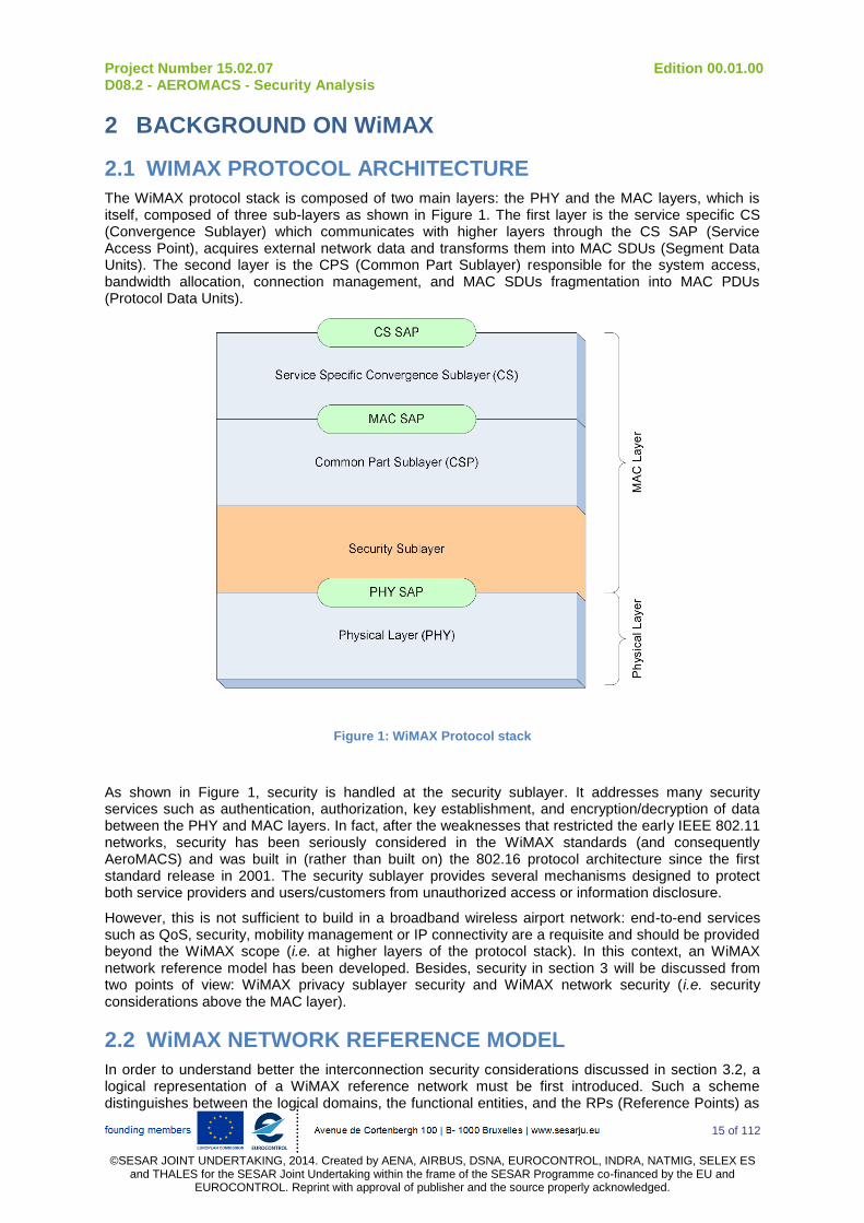
Project Number 15.02.07 Edition 00.01.00 D08.2 - AEROMACS - Security Analysis
15 of 112
©SESAR JOINT UNDERTAKING, 2014. Created by AENA, AIRBUS, DSNA, EUROCONTROL, INDRA, NATMIG, SELEX ES
and THALES for the SESAR Joint Undertaking within the frame of the SESAR Programme co-financed by the EU and EUROCONTROL. Reprint with approval of publisher and the source properly acknowledged.
2 BACKGROUND ON WiMAX
2.1 WIMAX PROTOCOL ARCHITECTURE
The WiMAX protocol stack is composed of two main layers: the PHY and the MAC layers, which is itself, composed of three sub-layers as shown in Figure 1. The first layer is the service specific CS (Convergence Sublayer) which communicates with higher layers through the CS SAP (Service Access Point), acquires external network data and transforms them into MAC SDUs (Segment Data Units). The second layer is the CPS (Common Part Sublayer) responsible for the system access, bandwidth allocation, connection management, and MAC SDUs fragmentation into MAC PDUs (Protocol Data Units).
Figure 1: WiMAX Protocol stack
As shown in Figure 1, security is handled at the security sublayer. It addresses many security services such as authentication, authorization, key establishment, and encryption/decryption of data between the PHY and MAC layers. In fact, after the weaknesses that restricted the early IEEE 802.11 networks, security has been seriously considered in the WiMAX standards (and consequently AeroMACS) and was built in (rather than built on) the 802.16 protocol architecture since the first standard release in 2001. The security sublayer provides several mechanisms designed to protect both service providers and users/customers from unauthorized access or information disclosure.
However, this is not sufficient to build in a broadband wireless airport network: end-to-end services such as QoS, security, mobility management or IP connectivity are a requisite and should be provided beyond the WiMAX scope (i.e. at higher layers of the protocol stack). In this context, an WiMAX network reference model has been developed. Besides, security in section 3 will be discussed from two points of view: WiMAX privacy sublayer security and WiMAX network security (i.e. security considerations above the MAC layer).
2.2 WiMAX NETWORK REFERENCE MODEL
In order to understand better the interconnection security considerations discussed in section 3.2, a logical representation of a WiMAX reference network must be first introduced. Such a scheme distinguishes between the logical domains, the functional entities, and the RPs (Reference Points) as
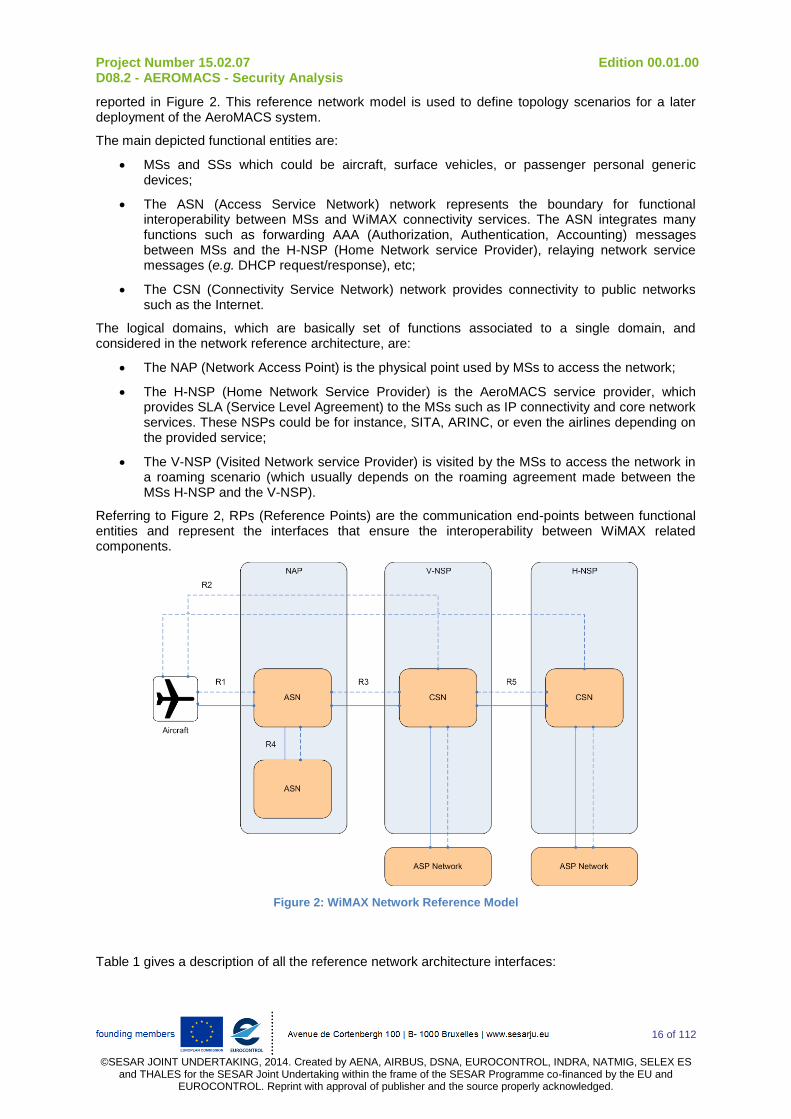
Project Number 15.02.07 Edition 00.01.00 D08.2 - AEROMACS - Security Analysis
16 of 112
©SESAR JOINT UNDERTAKING, 2014. Created by AENA, AIRBUS, DSNA, EUROCONTROL, INDRA, NATMIG, SELEX ES
and THALES for the SESAR Joint Undertaking within the frame of the SESAR Programme co-financed by the EU and EUROCONTROL. Reprint with approval of publisher and the source properly acknowledged.
reported in Figure 2. This reference network model is used to define topology scenarios for a later deployment of the AeroMACS system.
The main depicted functional entities are:
MSs and SSs which could be aircraft, surface vehicles, or passenger personal generic devices;
The ASN (Access Service Network) network represents the boundary for functional interoperability between MSs and WiMAX connectivity services. The ASN integrates many functions such as forwarding AAA (Authorization, Authentication, Accounting) messages between MSs and the H-NSP (Home Network service Provider), relaying network service messages (e.g. DHCP request/response), etc;
The CSN (Connectivity Service Network) network provides connectivity to public networks such as the Internet.
The logical domains, which are basically set of functions associated to a single domain, and considered in the network reference architecture, are:
The NAP (Network Access Point) is the physical point used by MSs to access the network;
The H-NSP (Home Network Service Provider) is the AeroMACS service provider, which provides SLA (Service Level Agreement) to the MSs such as IP connectivity and core network services. These NSPs could be for instance, SITA, ARINC, or even the airlines depending on the provided service;
The V-NSP (Visited Network service Provider) is visited by the MSs to access the network in a roaming scenario (which usually depends on the roaming agreement made between the MSs H-NSP and the V-NSP).
Referring to Figure 2, RPs (Reference Points) are the communication end-points between functional entities and represent the interfaces that ensure the interoperability between WiMAX related components.
Figure 2: WiMAX Network Reference Model
Table 1 gives a description of all the reference network architecture interfaces:

Project Number 15.02.07 Edition 00.01.00 D08.2 - AEROMACS - Security Analysis
17 of 112
©SESAR JOINT UNDERTAKING, 2014. Created by AENA, AIRBUS, DSNA, EUROCONTROL, INDRA, NATMIG, SELEX ES
and THALES for the SESAR Joint Undertaking within the frame of the SESAR Programme co-financed by the EU and EUROCONTROL. Reprint with approval of publisher and the source properly acknowledged.
RP Interface Functionality
R1 Between MSs and BSs Air interface
R2 Between MSs and the CSN IP host configuration, IP mobility, Authentication, Authorization
R3 Between the ASN and the CSN Mobility management, Authentication, Authorization, tunneling
R4 Between ASNs Mobility management, ASNs interworking
R5 Between CSNs Roaming and interworking between the V-NSP and the H-NSP
Table 1: WiMAX Reference Point Interface Description
Project Number 15.02.07 Edition 00.01.00 D08.2 - AEROMACS - Security Analysis
18 of 112
©SESAR JOINT UNDERTAKING, 2014. Created by AENA, AIRBUS, DSNA, EUROCONTROL, INDRA, NATMIG, SELEX ES
and THALES for the SESAR Joint Undertaking within the frame of the SESAR Programme co-financed by the EU and EUROCONTROL. Reprint with approval of publisher and the source properly acknowledged.
3 WiMAX SECURITY FEATURES
Even if the WiMAX security sublayer relies on several security protocols and constitutes a complex and heterogeneous security framework, security weaknesses still exist and an end-to-end WiMAX network should be strengthened by using other security mechanisms.
The WiMAX security is then divided into two categories:
The WiMAX security framework integrated into the MAC layer (i.e. Privacy sublayer);
The WiMAX interworking security, meaning the security mechanisms used in addition to the built-in WiMAX MAC security.
These two categories of WiMAX security features are analyzed in this part of the document in order to derive guidance’s for AeroMACS standardization and implementation.
It has to be noted that the end-to-end communication infrastructure integrating the AeroMACS system as an Access network was not fully defined at the time this document is issued. The analysis done in this document is based on WiMAX Forum documentation assuming it will be deemed relevant for the Aeronautical world.
3.1 WiMAX PRIVACY SUBLAYER SECURITY
The WiMAX security weaknesses proper to the MAC privacy sublayer can be categorized as the following:
PKMv2 weaknesses;
Management traffic weaknesses;
Multicast and broadcast service weaknesses;
Handover weaknesses1.
3.1.1 PKM WEAKNESSES
The second version of the PKM protocol tries to overlap vulnerabilities found in the original version of the protocol (i.e. PKMv1 defined in the early versions of the WiMAX IEEE 802.16 standard) but still, some of them remains exploitable in PKMv2.
The possible attacks on the second version of the PKM protocol are:
Attacks on the authorization phase: the aim of these attacks is to impersonate both legitimate MS and BS in two different sessions, in order to lead to a denial of access (meaning the BS does not authorize the legitimate MS accessing the network while it should accept it). This is typically an interleaving attack
2 where the MS is used as an oracle and the
attacker impersonates, first a legitimate MS toward the BS, then a legitimate BS toward the MS (which is called also a rogue BS attack). Figure 3 shows how this interleaving attack on the authorization phase of the PKMv2 protocol is possible:
1 Handover weaknesses could be placed in the AeroMACS network security section, but the described
vulnerabilities are relevant to design issues in the handover management scheme provided in the AeroMACS
MAC layer.
2 A masquerade attack that uses information derived from ongoing or previous authenticate exchanges.
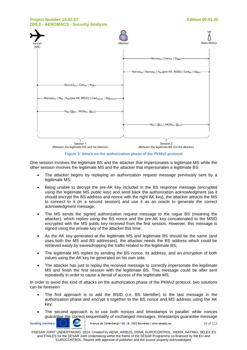
Project Number 15.02.07 Edition 00.01.00 D08.2 - AEROMACS - Security Analysis
19 of 112
©SESAR JOINT UNDERTAKING, 2014. Created by AENA, AIRBUS, DSNA, EUROCONTROL, INDRA, NATMIG, SELEX ES
and THALES for the SESAR Joint Undertaking within the frame of the SESAR Programme co-financed by the EU and EUROCONTROL. Reprint with approval of publisher and the source properly acknowledged.
Figure 3: Attack on the authorization phase of the PKMv2 protocol
One session involves the legitimate BS and the attacker that impersonates a legitimate MS while the other session involves the legitimate MS and the attacker that impersonates a legitimate BS:
The attacker begins by replaying an authorization request message previously sent by a legitimate MS;
Being unable to decrypt the pre-AK key included in the BS response message (encrypted using the legitimate MS public key) and send back the authorization acknowledgment (as it should encrypt the BS address and nonce with the right AK key), the attacker attracts the MS to connect to it (in a second session) and use it as an oracle to generate the correct acknowledgment message;
The MS sends the signed authorization request message to the rogue BS (meaning the attacker), which replies using the BS nonce and the pre-AK key concatenated to the MSID encrypted with the MS public key received from the first session. However, this message is signed using the private key of the attacker this time;
As the AK key generated at the legitimate MS and legitimate BS should be the same (and uses both the MS and BS addresses), the attacker needs the BS address which could be retrieved easily by eavesdropping the traffic related to the legitimate BS;
The legitimate MS replies by sending the BS nonce, its address, and an encryption of both values using the AK key he generated on his own side;
The attacker has just to replay the received message to correctly impersonate the legitimate MS and finish the first session with the legitimate BS. This message could be after sent repeatedly in order to cause a denial of access of the legitimate MS.
In order to avoid this kind of attacks on the authorization phase of the PKMv2 protocol, two solutions can be foreseen:
The first approach is to add the BSID (i.e. BS Identifier) to the last message in the authorization phase and encrypt it together to the BS nonce and MS address using the AK key;
The second approach is to use both nonces and timestamps in parallel: while nonces guarantee the correct sequentiality of exchanged messages, timestamps guarantee message

Project Number 15.02.07 Edition 00.01.00 D08.2 - AEROMACS - Security Analysis
20 of 112
©SESAR JOINT UNDERTAKING, 2014. Created by AENA, AIRBUS, DSNA, EUROCONTROL, INDRA, NATMIG, SELEX ES
and THALES for the SESAR Joint Undertaking within the frame of the SESAR Programme co-financed by the EU and EUROCONTROL. Reprint with approval of publisher and the source properly acknowledged.
freshness even if the attacker tries to synchronize his clock with the legitimate MS or the legitimate BS.
Attacks on the SA-TEK three-way handshake phase: The SA-TEK three-way handshake phase of PKMv2 is secure in it self, but it is still possible to conduct a replay attack on the first message (i.e. the SA-TEK challenge) of the protocol. Adding timestamps to the SA-TEK challenge message would be sufficient to protect against this replay attack.
3.1.2 MANAGEMENT TRAFFIC WEAKNESSES
During the Initial network entry many critical parameters are negotiated between the MS and BS. From a security point of view the entire procedure is extremely receptive to violations since all the security measures contemplated by the specification have not taken place and important negotiation parameters are transmitted in clear text.
The network entry procedure, executed by a MS to attach itself to a corresponding BS is not protect at all allowing several attacks:
The RNG-REQ (Ranging Request) and RNG-RSP (Ranging Response) messages are not encrypted neither authenticated, then an attacker is able to listen to these messages and forge false RNG-REQ (e.g. by modifying the preferred downlink burst profile) and RNG-RSP (e.g. by setting the MS emission power to the minimum, which forces it to repeatedly trigger the ranging procedure from the beginning in order to reach the BS) messages to mislead the MSs which are unable to authenticate the source of the sending node;
The WiMAX technology allows two different connectivity modes: the Point to Multi-Point (P2MP) mode where a MS can reach a BS in one hop, and a Mesh mode (similar to Ah-hoc networks) where MSs are connected together and packets are sent hop-by-hop until they reach the BS. In the Mesh connectivity mode, when a MS is about to enter the network, it listens for a network descriptor message to generate a list of potential neighbors and available BSs to connect with, then select a sponsoring node. This node will be responsible for tunneling the PKM-REQ (authentication request) and REG-REQ (registration request) messages from the new MS to respectively the BS and the registration node. Then, it forwards back the received response messages to the MS which is able to establish direct connections with it neighbors. In this topology, common vulnerabilities known in MANETs and sensor networks (e.g. Sybil attacks, Sinkhole attacks) are likely to occur. Indeed, the network descriptor message is not encrypted neither authenticated which open the path to several attacks. For instance, a malicious node can claim a shorter path to the BS in order to be the sponsoring node and create a sinkhole attack in order to attract all the network traffic to it.
Besides, many other management messages are not authenticated:
MOB_NBR-ADV (Mobile Neighbor Advertisement) message is sent by the anchored BS currently linked to the MS in order to give a map of the neighbor BSs. An attacker could send false characteristics of the neighbor BSs to the MS in order to re-directed the MS to a rogue BS or to deny it from accessing the network;
FPC (Fast Power Control) messages sent by the BS to ask the MS to adjust its transmission power could be forged by an attacker to force the MS transmission power to its minimum or to conduct a water torture attack. In order to reach the BS, the MS needs then to send repeatedly cumulated power adjustment messages. If the attack is conducted on several MSs at the same time, it could induce packet collisions in the uplink bandwidth request contention slots. Another consequence is a drain of the MS battery preventing it from communicating with the BS;
DBPC-REQ (Downlink Burst Profile Change Request) messages sent by the BS to the MS to adjust the burst profile in order to cope with a variation of the distance between them (caused by the MS node mobility) could be forged by an attacker to modify the encoding scheme used by the BS and preventing the communication between them;
AUTH-INVALID (Authentication invalid) messages are sent by the BS to the MS if the shared AK key lifetime is no longer valid or if some management messages (containing HMAC or
Project Number 15.02.07 Edition 00.01.00 D08.2 - AEROMACS - Security Analysis
21 of 112
©SESAR JOINT UNDERTAKING, 2014. Created by AENA, AIRBUS, DSNA, EUROCONTROL, INDRA, NATMIG, SELEX ES
and THALES for the SESAR Joint Undertaking within the frame of the SESAR Programme co-financed by the EU and EUROCONTROL. Reprint with approval of publisher and the source properly acknowledged.
CMAC digests) in the authorization phase are not correctly authenticated. An attacker could forge such a message and send it the MS to deny it from accessing the network;
MOB_ASC-REP (Mobile Association Report) messages are composed of an aggregation of all the neighbor BS identities that are likely to be connected to a MS when it performs a handover operation. This message is sent by the current (serving) BS to the MS, which chooses the best candidate to be the following (target) BS. An attacker could forge such a message with false information (e.g. unavailable services) in order to mislead the MS and prevents it from being anchored to the best BS candidate.
These unauthenticated management messages should then use some integrity protection techniques (e.g. HMAC, CMAC digest) or key agreement protocols such as Diffie-Hellman early in the initial ranging procedure. For some management messages, despite the fact they are authenticated, attacks may occur. For instance, the RES-CMD (Reset Command) message is sent by the BS to MSs that do not respond in order to ask them resetting their MAC state machine. As the message is authenticated, instead of sending a forged RES-CMD message, the attacker will force the BS to send itself the message. This is accomplished by synchronizing with the network and getting the UL-MAP (Uplink MAP) message, which contains a set of information that defines the entire access for all MSs during a scheduling interval. Thus, the attacker is able to choose a CID (Connection Identifier) and a burst profile related to the target MS. Then, it transmits a signal at the time scheduled for that node with transmission power strength higher than the one used by the legitimate MS, which force the BS sending the RES-CMD. The attacker is obviously able to repeat this procedure several times in order to prevent a stable connection to the MS in the network.
3.1.3 MULTICAST AND BROADCAST SERVICE WEAKNESSES
Multicast and broadcast services have several weaknesses that can be classified as it follows:
Attacks on the GTEK multicast group keys: Multicast and broadcast messages are encrypted and authenticated using a symmetric shared key GTEK (Group Traffic Encryption Key) between a BS and all MSs belonging to the same group: this is an issue in the sense that any MS may impersonate the original BS by forging false multicast or broadcast messages and sending them to other MSs in the same group. The same attack is likely to happen when the BS wants to update the GTEK keys of all members of a multicast group: the BS sends the GTEK keys by encrypting it using the shared GKEK key. When received, each MS decrypts the message using the shared GKEK and update the used GTEK. Since the GKEK key is known by all the members of the multicast group, a malicious MS is able to distribute a false GTEK key with a valid encryption and authentication code, which forces the remaining MSs to update their active and valid GTEK key with a forged and false GTEK key. The direct consequence is that when the BS sends an encrypted message to the multicast group, MSs will be unable to decrypted it because their use a different GTEK key. However this vulnerability will be avoided when the legitimate BS sends the group key update message to update the current GTEK of the multicast group. In order to mitigate these vulnerabilities, the GTEK should be distributed separately by the BS to each MS securely using the shared KEK key. Another alternative would be to sign the key update message used to distribute the GTEK. Secure distribution and key management in multicast groups have been widely investigated and several solutions could be used to avoid such weaknesses in the AeroMACS (e.g. the group-based key distribution algorithm proposed in [21]);
Attacks on the MBRA protocol: The MBRA (Multicast and Broadcast Rekeying Algorithm) does not guarantee forward and backward secrecy:
o Attack on Backward Secrecy: When a new MS joins the multicast group, it receives the GTEK key from the BS and is able to decrypt all the previous messages that were multicasted in the group using the same GTEK key (but only if the GTEK lifetime is still valid when the MS joins the group);
o Attack on Forward Secrecy: After leaving a multicast group, a MS remains able to receive the next GKEK (Group Key Encryption Key) and/or decrypt the next GTEK key while it should not be allowed to have such capabilities.
If the GTEK lifetime is optimized, it should help avoiding such backward and forward secrecy attacks. The default value is 12 hours while the standard recommends a value ranging between 30 minutes to
Project Number 15.02.07 Edition 00.01.00 D08.2 - AEROMACS - Security Analysis
22 of 112
©SESAR JOINT UNDERTAKING, 2014. Created by AENA, AIRBUS, DSNA, EUROCONTROL, INDRA, NATMIG, SELEX ES
and THALES for the SESAR Joint Undertaking within the frame of the SESAR Programme co-financed by the EU and EUROCONTROL. Reprint with approval of publisher and the source properly acknowledged.
7 days. A low value should be privileged in order to renew the GTEK key as much as possible but induces an additional overhead on the anchor BS. [21] proposed a solution based on a hierarchy of Sub-Groups KEKs (SGKEKs) where MSs are regrouped into equal size sub-groups.
3.1.4 HANDOVER WEAKNESSES
Three different handover schemes are provided within the AeroMACS specifications, namely:
Hard Handover (HHO): This is probably the simplest AeroMACS handover scheme where the MS communicates with a single BS at a time (i.e. establishes a connection with the following BS only if it breaks the previous connection with the old BS). In this handover scheme, the BS broadcasts periodically a NBR-ADV (Neighbor Advertisement) message which includes information about the neighbor BSs. When the connection with the following BS has been established, the MS is required to restart all the procedures related to ranging, authentication, and registration which could not be adapted for ATS since continuity of service is critical ;
Macro Diversity Handover (MDHO): In this case, the MS is able to connect to several BSs instead of a single one. The set of BSs involved in the handover scheme (and called a diversity set) share MAC-context based information (e.g. encryption or authentication keys) used by the established connections. All the BSs in the diversity set send data to the MS which perform selection diversity;
Fast Base Station Switching (FBSS): This the same handover scheme as MDHO except that the BS are not required to maintain the connection with the MS, meaning data are exchanged only with the anchor BS.
For each handover scenario, three different security settings are allowed by the WiMAX specifications and defined by two Handover optimizations bits in the RNG-RSP (Ranging Response) message. These security settings are the following:
Bit_1=0 and Bit_2=0: Re-authentication and three-way TEK handshake are required. From a security point of view, this configuration provides the best protection against backward and forward secrecy attacks;
Bit_1=1 and Bit_2=0: Re-authentication is not needed but TEKs are updated for all SAs (Security Associations), meaning that TEKs will be updated during the handover but the AK key will remains the same. Since the AK key is used to derive the KEK key and then obtain the corresponding TEKs, an impersonated BS could use the unchanged AK to determine the updated TEK of the following BSs;
Bit_1=1 and Bit_2=1: neither re-authentication nor three-way TEK handshake are required, meaning that the MS keeps using the same TEKs established with the serving BS. This is obviously awkward in the case a malicious MS has impersonated the serving BS, it could comprise all the previous and following BSs.
In handover schemes, a trade-off between QoS and security should be discussed in order to provide a good protection against security attacks while latency (which is a crucial metric in operational traffic, essentially ATS) should be minimized.
3.2 WiMAX NETWORK SECURITY
From a security point of view, the central element of an WiMAX network is probably the AAA server which performs many functionalities beyond its main purposes (meaning authentication, authorization, and accounting). Indeed, the AAA server is widely used to supply user related information like QoS parameters or ASN network configuration, but it is also involved in IP mobility procedures (such as handover procedures) or even IP host configuration. DHCP is also important from a security point of view because some attacks can be conducted, but fortunately could be avoided as depicted in the following sub-sections.
Project Number 15.02.07 Edition 00.01.00 D08.2 - AEROMACS - Security Analysis
23 of 112
©SESAR JOINT UNDERTAKING, 2014. Created by AENA, AIRBUS, DSNA, EUROCONTROL, INDRA, NATMIG, SELEX ES
and THALES for the SESAR Joint Undertaking within the frame of the SESAR Programme co-financed by the EU and EUROCONTROL. Reprint with approval of publisher and the source properly acknowledged.
3.2.1 DHCP SECURITY
In a WiMAX network, the DHCP protocol can be configured in two ways using either a DHCP proxy or a DHCP relay. Note that the DHCP protocol is solicited when the first packet sent by the MS is a DHCP_DISCOVER frame:
When using a DHCP proxy, the ASN answers to the DHCP_REQUEST frame sent by the MS and assign him the IP address. In most cases, if a seamless handover is required, meaning that the session has to be kept alive, the assigned IP address should be the same before and after the handover. In order to do this, the MS puts the IP address he was already using in a specific option of the DHCP_DISCOVER frame. However, the DHCP_DISCOVER frames are not signed (i.e. unauthenticated) which means that a malicious MS could be trying to obtain the IP address of a legitimate MS. In order to avoid this security issue, the AAA server is involved in the IP address assignment procedure, meaning that the effective IP address to be assigned to the MS will be included into a specific RADIUS
3 (Remote Authentication Dial In
User Service) attribute, part of the ACCESS_ACCEPT packet coming from the AAA server in the CSN;
When using a DHCP relay, the ASN does not answer to the MS but forwards the request to a remote server. If the DHCP relay does not know the IP address of the remote server, this information has to be included in a RADIUS attribute when received by the ASN at the end of the authentication (note that the remote server must be the same one used by the MS to be authenticated for the first time). Using a DHCP relay to communicate with a remote DHCP server is a tricky procedure as far as both integrity and packet authentication are not provided, leading to several attacks such as DNS spoofing (this can be done by modifying the DNS server address in order to redirect MSs to fake URLs) or Man-in-The-Middle attacks by changing the default gateway address. In order to address this security issue, the DHCP protocol introduces a security extension [22] to authenticate the frames exchanged between the DHCP relay agent and the DHCP server using a pre-configured symmetric key between them. This key, called DHCP_RK is used to derive other keys to secure each single session. In order to dynamically redirect the DHCP_REQUEST frames, the DHCP_RK must be also dynamically moved into the DHCP relay and the DHCP server when need. In order to do so, the AAA server is once again involved using RADIUS attributes. Figure 4 shows the DHCP protocol key exchange when a DHCP relay is used:
3 Note that RADIUS is considered as the in-facto by-default AAA server to be used in the AeroMACS network,
however this should be discussed further, specially for security purposes.
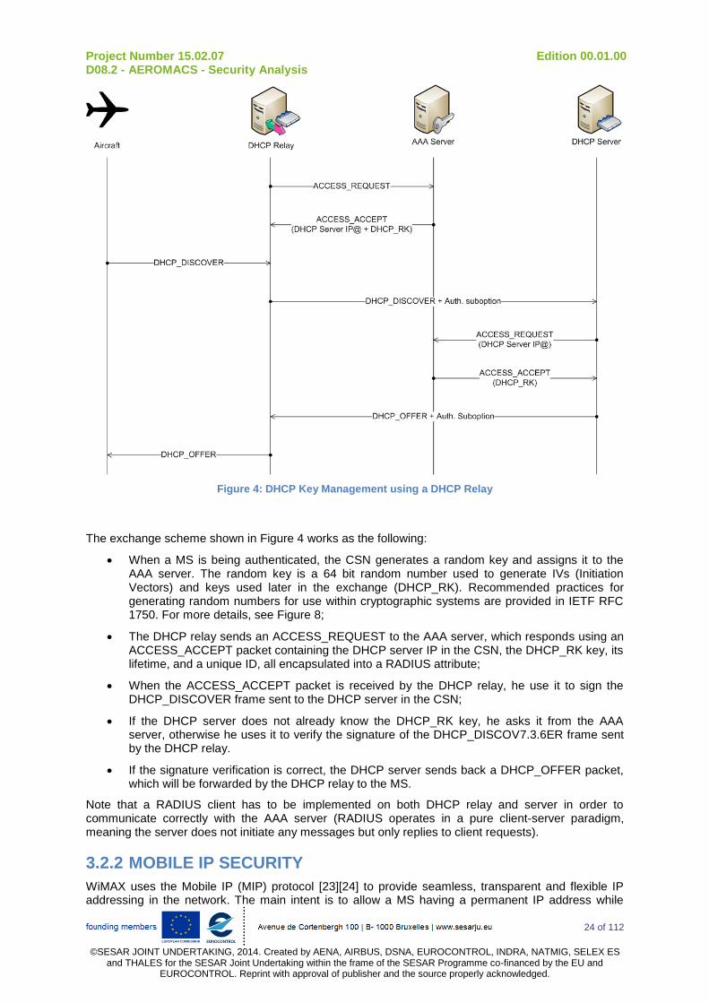
Project Number 15.02.07 Edition 00.01.00 D08.2 - AEROMACS - Security Analysis
24 of 112
©SESAR JOINT UNDERTAKING, 2014. Created by AENA, AIRBUS, DSNA, EUROCONTROL, INDRA, NATMIG, SELEX ES
and THALES for the SESAR Joint Undertaking within the frame of the SESAR Programme co-financed by the EU and EUROCONTROL. Reprint with approval of publisher and the source properly acknowledged.
Figure 4: DHCP Key Management using a DHCP Relay
The exchange scheme shown in Figure 4 works as the following:
When a MS is being authenticated, the CSN generates a random key and assigns it to the AAA server. The random key is a 64 bit random number used to generate IVs (Initiation Vectors) and keys used later in the exchange (DHCP_RK). Recommended practices for generating random numbers for use within cryptographic systems are provided in IETF RFC 1750. For more details, see Figure 8;
The DHCP relay sends an ACCESS_REQUEST to the AAA server, which responds using an ACCESS_ACCEPT packet containing the DHCP server IP in the CSN, the DHCP_RK key, its lifetime, and a unique ID, all encapsulated into a RADIUS attribute;
When the ACCESS_ACCEPT packet is received by the DHCP relay, he use it to sign the DHCP_DISCOVER frame sent to the DHCP server in the CSN;
If the DHCP server does not already know the DHCP_RK key, he asks it from the AAA server, otherwise he uses it to verify the signature of the DHCP_DISCOV7.3.6ER frame sent by the DHCP relay.
If the signature verification is correct, the DHCP server sends back a DHCP_OFFER packet, which will be forwarded by the DHCP relay to the MS.
Note that a RADIUS client has to be implemented on both DHCP relay and server in order to communicate correctly with the AAA server (RADIUS operates in a pure client-server paradigm, meaning the server does not initiate any messages but only replies to client requests).
3.2.2 MOBILE IP SECURITY
WiMAX uses the Mobile IP (MIP) protocol [23][24] to provide seamless, transparent and flexible IP addressing in the network. The main intent is to allow a MS having a permanent IP address while
Project Number 15.02.07 Edition 00.01.00 D08.2 - AEROMACS - Security Analysis
25 of 112
©SESAR JOINT UNDERTAKING, 2014. Created by AENA, AIRBUS, DSNA, EUROCONTROL, INDRA, NATMIG, SELEX ES
and THALES for the SESAR Joint Undertaking within the frame of the SESAR Programme co-financed by the EU and EUROCONTROL. Reprint with approval of publisher and the source properly acknowledged.
moving from one point of access to another, especially in roaming scenarios. Using DHCP allows the MS to keep a session alive and the same IP address before and after a handover, but this works in one way, meaning that the other communication party will receive IP packets but its responses will be routed to the home network of the MS. The MIP protocol is then used to forward these packets from the home network to the visited network.
When using the MIP protocol, a MS has two IP addresses:
a home address (also called Home of Address – HOA) which is the IP address assigned by the Home Agent (HA) in the home network. This address remains fixed while the MS is roaming and is always used as long as the MS remains under its home network coverage;
a Care of Address (COA) given to the MS by a Foreign Agent (FA) in the visited network. After receiving the COA address, the MS sends a REGISTRATION_REQUEST (Mobile IP RRQ) to his HA that contains its COA address, needed to reach the MS in the visited network. The HA confirms the reception by sending back a REGISTRATION_REPLY (Mobile IP RRP). When the MS is communicating from the visited network with a correspondent end entity, it uses a direct route from the visited network to reach the destination. However, when the correspondent node wants to communicate with that MS, it has to sends the IP packets using the MS home address. When the HA receives these packets, he looks to the associated COA address, sends the packets to the adequate FA, which finally forwards the packets to the MS.
Security issues related to MIP depend on how Mobile IP is supported on the MS side. There are two kinds of MIP support on the MS:
Proxy MIP (PMIP): used for MSs that are not MIP compliant but still need persistent connections and seamless roaming when moving from a home network to a visited network. In this case, a third party entity called PMP Mobility Manager is in charge of handling the Mobile IP registration procedure for the MS toward the FA by intercepting the DHCP_DISCOVER frame sent by the MS (in order to get the COA address in the visited network), and performs the MIP registration with the HA. When the registration is finished, the PMIP Mobility Manager uses the DHCP protocol to assign the COA IP address to the MS. Again, the AAA server is involved in this procedure as the PMIP Mobility Manager receives several information (such as the MS HOA or the HA IP address) encapsulated in specific RADIUS attributes. Figure 5 shows all the logical entities involved when a MS is PMIP compliant:

Project Number 15.02.07 Edition 00.01.00 D08.2 - AEROMACS - Security Analysis
26 of 112
©SESAR JOINT UNDERTAKING, 2014. Created by AENA, AIRBUS, DSNA, EUROCONTROL, INDRA, NATMIG, SELEX ES
and THALES for the SESAR Joint Undertaking within the frame of the SESAR Programme co-financed by the EU and EUROCONTROL. Reprint with approval of publisher and the source properly acknowledged.
Figure 5: Mobile IP registration – PMIP Case
When a MS receives beaconing traffic from a foreign network it wants to access, he starts an authentication process with the H-NSP as depicted in Figure 6:
The authenticator4 (which is co-located with the PMIP Mobility Manager) intercepts the
ACCESS_REQUEST sent by the MS and forwards it to the Home AAA server;
The AAA server sends back an ACCESS_ACCEPT packet that contains information needed by the authenticator to contact the HA (i.e. IP address) and encrypt the MIP registration messages (i.e. the Master Session or MSK key produced by the AAA server);
The authenticator communicates the MSK key to the PMIP Mobility Manager, which uses it later to derive the MIP_RK and the HA_RK keys needed to generate respectively the MS_HA key (to secure the MIP_RRQ message) and the FA_HA key (to secure the messages between the FA and the HA agents). Note that there is no need in this case for the MS_FA key because the MS and the FA are located in the same ASN. The complete AeroMACS key generation tree is detailed later;
The PMIP Mobility Manager is now able to proceed to a Mobile IP registration on behalf of the MS by sending a signed MIP_RRQ packet to the HA using the MN_HA key;
In order to verify the MIP_RRQ packet signature and continue the Mobile IP registration process, the HA sends an ACCESS_REQUEST packet to the AAA server asking for the needed keys (i.e. MN_HA and HA_RK keys);
The AAA server responds with an ACCESS_ACCEPT RADIUS packet that contains the required keys for the signature verification.
4 PKMv2 uses the IEEE 802.1X port-based access control standard which defines three basic roles that performs
the authentication: a supplicant which is the client, an authenticator located in the ASN, and an
authentication server (the AAA server) located in the CSN.
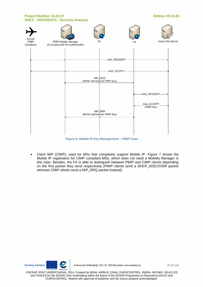
Project Number 15.02.07 Edition 00.01.00 D08.2 - AEROMACS - Security Analysis
27 of 112
©SESAR JOINT UNDERTAKING, 2014. Created by AENA, AIRBUS, DSNA, EUROCONTROL, INDRA, NATMIG, SELEX ES
and THALES for the SESAR Joint Undertaking within the frame of the SESAR Programme co-financed by the EU and EUROCONTROL. Reprint with approval of publisher and the source properly acknowledged.
Figure 6: Mobile IP Key Management – PMIP Case
Client MIP (CMIP): used for MSs that completely support Mobile IP. Figure 7 shows the Mobile IP registration for CMIP compliant MSs, which does not need a Mobility Manager in this case. Besides, the FA is able to distinguish between PMIP and CMIP clients depending on the first packet they send respectively (PMIP clients send a DHCP_DISCOVER packet whereas CMIP clients send a MIP_RRQ packet instead):
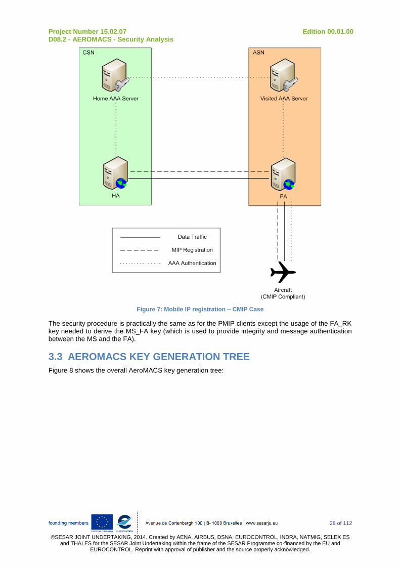
Project Number 15.02.07 Edition 00.01.00 D08.2 - AEROMACS - Security Analysis
28 of 112
©SESAR JOINT UNDERTAKING, 2014. Created by AENA, AIRBUS, DSNA, EUROCONTROL, INDRA, NATMIG, SELEX ES
and THALES for the SESAR Joint Undertaking within the frame of the SESAR Programme co-financed by the EU and EUROCONTROL. Reprint with approval of publisher and the source properly acknowledged.
Figure 7: Mobile IP registration – CMIP Case
The security procedure is practically the same as for the PMIP clients except the usage of the FA_RK key needed to derive the MS_FA key (which is used to provide integrity and message authentication between the MS and the FA).
3.3 AEROMACS KEY GENERATION TREE
Figure 8 shows the overall AeroMACS key generation tree:

Project Number 15.02.07 Edition 00.01.00 D08.2 - AEROMACS - Security Analysis
29 of 112
©SESAR JOINT UNDERTAKING, 2014. Created by AENA, AIRBUS, DSNA, EUROCONTROL, INDRA, NATMIG, SELEX ES
and THALES for the SESAR Joint Undertaking within the frame of the SESAR Programme co-financed by the EU and EUROCONTROL. Reprint with approval of publisher and the source properly acknowledged.
Figure 8 : AeroMACS Key Generation Tree
Two keys are generated into the MS and the AAA server after a successful EAP authentication:
The MSK (Master Session Key) key is derived by the AAA server and sent to the authenticator using an ACCESS_ACCEPT packet. This key is used by the AeroMACS privacy sub-layer at the MAC layer to generate the keys needed by the PKMv2 framework (left branch of the tree in Figure 8);
The EMSK (Extended Master Session Key) key used to generate MIP sessions keys (right branch of the tree), namely the MS_HA and FA_RK keys:
o The MS_HA key will be sent to the HA when the HA sends an ACCESS_REQUEST packet to the server;
o The FA_RK key will be sent to the authenticator and used to generate the MS_FA session key when the MS is CMIP compliant (remind that the MS_FA key is not needed when the MS is PMIP compliant).
The DHCP_RK and HA_RK keys are not related to the MSK nor the EMSK keys as far as the (FA-HA) and (DHCP relay - DHCP server) paths do not depend on the MS authentication. Both keys are generated by the AAA server and sent respectively to the DHCP server and the HA when they are needed.
3.4 AEROMACS SECURITY TAXONOMY
In Table 2, a summary of possible security attacks on AeroMACS is provided through a taxonomy showing characteristics of those attacks and likely solutions to be used or privileged in order to face them.
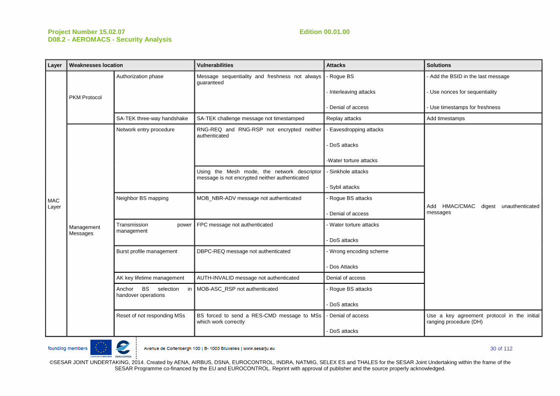
Project Number 15.02.07 Edition 00.01.00 D08.2 - AEROMACS - Security Analysis
30 of 112
©SESAR JOINT UNDERTAKING, 2014. Created by AENA, AIRBUS, DSNA, EUROCONTROL, INDRA, NATMIG, SELEX ES and THALES for the SESAR Joint Undertaking within the frame of the
SESAR Programme co-financed by the EU and EUROCONTROL. Reprint with approval of publisher and the source properly acknowledged.
Layer Weaknesses location Vulnerabilities Attacks Solutions
MAC Layer
PKM Protocol
Authorization phase Message sequentiality and freshness not always guaranteed
- Rogue BS
- Interleaving attacks
- Denial of access
- Add the BSID in the last message
- Use nonces for sequentiality
- Use timestamps for freshness
SA-TEK three-way handshake SA-TEK challenge message not timestamped Replay attacks Add timestamps
Management Messages
Network entry procedure RNG-REQ and RNG-RSP not encrypted neither authenticated
- Eavesdropping attacks
- DoS attacks
-Water torture attacks
Add HMAC/CMAC digest unauthenticated messages
Using the Mesh mode, the network descriptor message is not encrypted neither authenticated
- Sinkhole attacks
- Sybil attacks
Neighbor BS mapping MOB_NBR-ADV message not authenticated - Rogue BS attacks
- Denial of access
Transmission power management
FPC message not authenticated - Water torture attacks
- DoS attacks
Burst profile management DBPC-REQ message not authenticated - Wrong encoding scheme
- Dos Attacks
AK key lifetime management AUTH-INVALID message not authenticated Denial of access
Anchor BS selection in handover operations
MOB-ASC_RSP not authenticated - Rogue BS attacks
- DoS attacks
Reset of not responding MSs BS forced to send a RES-CMD message to MSs which work correctly
- Denial of access
- DoS attacks
Use a key agreement protocol in the initial ranging procedure (DH)

Project Number 15.02.07 Edition 00.01.00 D08.2 - AEROMACS - Security Analysis
31 of 112
©SESAR JOINT UNDERTAKING, 2014. Created by AENA, AIRBUS, DSNA, EUROCONTROL, INDRA, NATMIG, SELEX ES and THALES for the SESAR Joint Undertaking within the frame of the
SESAR Programme co-financed by the EU and EUROCONTROL. Reprint with approval of publisher and the source properly acknowledged.
Multicast and Broadcast Services
GTEK multicast group key sharing
- GTEK keys are symmetrically used in the same multicast group
- GTEK keys are updated and encrypted using a shared GKEK key
- Rogue BS attacks
- DoS attacks
- Distribute the GTEK key separately using the shared KEK key.
- BS must sign key update messages
- Group-based key distribution algorithms
MBRA protocol - GTEK and GKEK keys lifetime not optimized Backward/forward secrecy attacks - Optimize GTEK/GKEK key lifetime
- Use a hierarchy of sub-GKEKs
Network Layer
DHCP Protocol
DHCP Proxy DHCP_DISCOVER not authenticated IP@ impersonation Use ACCESS_ACCEPT to deliver IP@
DHCP Relay DHCP_DISCOVER and DHCP_OFFER not authenticated
- DNS Spoofing
- MITM attacks
Use auth. sub-option in DHCP + AAA attributes
Mobile IP Protocol
MIP registration procedure MIP_RRQ and MIP_RRP not authenticated
PMIP manager forwards the MIP registration
- Denial of access
- DoS attacks
Use the AEE (Authentication Enabling Extension) in MIP_RRQ/MIP_RRP
Handover Schemes
Handover optimization bits Re-authentication and/or TEK three-way handshake are not required in the [01] and [11] bit configuration
- Backward and forward secrecy attacks
- DoS attacks
Use the [00] bit configuration (Re-authentication and TEK handshake are required)
Table 2: AeroMACS security Taxonomy

Project Number 15.02.07 Edition 00.01.00 D08.2 - AEROMACS - Security Analysis
32 of 112
©SESAR JOINT UNDERTAKING, 2014. Created by AENA, AIRBUS, DSNA, EUROCONTROL, INDRA, NATMIG, SELEX ES
and THALES for the SESAR Joint Undertaking within the frame of the SESAR Programme co-financed by the EU and EUROCONTROL. Reprint with approval of publisher and the source properly acknowledged.
4 A QUANTITATIVE NETWORK RISK ASSESSMENT MODEL BASED ON RISK PROPAGATION APPLIED TO AEROMACS NETWORK
In this part of the document, we apply to the AeroMACS infrastructure a new approach for network security assessment that measures quantitatively the network risk level based on critical aspects such as the impact of a successful attack on a node and the risk propagation of that attack within the network. This method helps in analyzing easily different scenarios of implementation in order to derive guidances for manufacturers and AeroMACS future operators.
The proposed evaluation approach helps in comparing security policies in order to define an optimal policy and thus improve the global security of the network. This approach can also help administrators to estimate the effect of any topological change in the network architecture (e.g. adding or deleting a node) on the security of the global system. All the parameters involved in the network risk measurement are explained and quantified: threat likelihood, risk impact (i.e. cost of damages), individual network risk (i.e. specific to a single node), and the total risk induced by the interconnection between the network components. The proposed security assessment framework is original as most existing methodologies and tools only identify vulnerabilities and evaluate risk in a given network node by node. They do not consider the relations between nodes. The results obtained are usually quite specific and it is difficult to apply the findings to others networks or fields of application.
Note: The risk assessment methodology has been conducted on AeroMACS using real statistics and vulnerability data about WiMAX implementation (and other network nodes) from the National Vulnerability Database (NVD) published by the National Institute of Standards and Technology (NIST)
5. The NVD provides information about vulnerabilities such as type, severity class and score,
extended description, products and versions affected, etc. To be more specific, it uses the NVD Common Vulnerability Scoring System (CVSS)
6 (which is basically a database containing scores for
each vulnerability) combined with the well-known network vulnerability scanning tool NESSUS7 to
build the assessment security framework. For further information on CVSS scores, refer to annex A.
This part of the document is structured as follows:
First, a survey of existing risk assessment methodologies is provided. Their advantages and drawbacks are discussed in order to introduce the new methodology;
Secondly, a detailed description of the proposed methodology is provided;
Finally, the methodology is applied to several AeroMACS implementation scenarios in order to derive recommendations for manufacturers and ASN/CSN operators to secure the AeroMACS network.
4.1 AN ALTERNATIVE RISK ASSESSMENT METHODOLOGY
4.1.1 RISK MANAGEMENT STANDARDS AND METHODS
Risk assessment process is a mandatory step in traditional risk management methods such as CCTA Risk Analysis and Management Method (CRAMM), Operationally Critical Threat, Asset, and
5http://web.nvd.nist.gov/view/vuln/search
6 http://www.first.org/cvss
7 http://www.nessus.org/

Project Number 15.02.07 Edition 00.01.00 D08.2 - AEROMACS - Security Analysis
33 of 112
©SESAR JOINT UNDERTAKING, 2014. Created by AENA, AIRBUS, DSNA, EUROCONTROL, INDRA, NATMIG, SELEX ES
and THALES for the SESAR Joint Undertaking within the frame of the SESAR Programme co-financed by the EU and EUROCONTROL. Reprint with approval of publisher and the source properly acknowledged.
Vulnerability Evaluation (OCTAVE)[1] or “Expression des Besoins et Identification des Objectifs de Sécurité” (EBIOS)[2]. These risk management tools are compliant with information security standards proposed by the International Organization for Standardization (ISO)5. ISO defined lots of standards related to information security such as ISO 15408 (also known as Common Criteria - CC) [3] which is basically a certification framework able to evaluate information security. Based on this standard, ISO 27001 has been introduced in 2005 [4] to provide guidance for designing an information security management system. In this global process of security management, the risk assessment process has been specified with ISO 27005 [5] but it still relies on qualitative risk evaluation.
Those standards and methods are related to information security in general and thus, are perfectly well suited to a specific context such as aeronautical area. This is one reason why Aeronautical Radio Incorporated (ARINC) introduced in 2005 [6] a risk management framework for aeronautical information and network security (i.e. document entitled ARINC 811). ARINC 811 provides additional guidance to deal with physical and operational constraints of aeronautical hardware and software assets relative to companies, airports, aircraft or flights.
The risk assessment approaches used in the risk management methods mentioned above are mostly static and evaluate damage produced by threats qualitatively, making results somehow subjective. In the next subsection, are presented the advantages of quantitative over qualitative approaches, and then the most significant models that use formal representations in network security risk assessment are presented.
4.1.2 QUANTITATIVE AND QUALITATIVE RISK ASSESSMENT APPROACHES
As it has been underlined before, risk assessment can be performed either qualitatively or quantitatively. Typically, qualitative risk techniques lack of theoretical bases. These models rely on security specialist’s expertise and, usually questionnaires are used to gather their opinions like in [7]. This is an essential issue as security expertise costs money to companies. Also, data collection process is considered complex, as it requires much time and effort. Finally, the qualitative results could not be substantially evaluated because of their subjective nature. Indeed, these measures are mostly based on a ranking scale: it is then possible to compare two security levels (for instance, between high and low) but impossible to estimate the distance between these measures (for instance, between two security levels ranked as high).
Quantitative risk assessment allows a more granular analysis of risk events compared to qualitative techniques. In fact, a plethora of parameters involved in the risk assessment process can be used and designed in many ways thanks to mathematical and theoretical models. The results are accurate and can be understood easily by administrators and engineers in order to enhance the security of the network. Automated tools are developed for this purpose and present the advantage of accelerating the assessment process and avoiding some computation errors. These errors may occur with qualitative techniques, which are usually performed manually.
Quantitative risk assessment techniques can be used either for preventive risk analysis, or reactive risk analysis depending on the context of the study. Preventive risk analyses often rely on the Annual Loss Expectancy (ALE)[8]. ALE is the expected monetary loss that can be expected for an asset due to a risk over one year period. As ALE is an important feature that can be used directly in cost-benefit analysis, quantitative risk assessment methods are considered more relevant than qualitative ones (note that ALE is out of scope of this report). Reactive risk analysis is generally conducted to define a set of countermeasures when an alert corresponding to an attack is triggered by a monitoring system, using, for instance, an Intruder Detection System (IDS). For this purpose, several decision criteria are used and modeled in various ways. The most prominent models are detection and reaction cost models (number of security countermeasures to deploy, percentage of intrusion into the supervised network, monetary or processing resources required to face an attack, etc), attack models (scenarios-based or tree-based graphs, etc), threat impact models (impact distribution laws, impact progression over the network, etc), and so on. Some examples of such mathematical and formal models can be found respectively in [9], [10] and [11].
Project Number 15.02.07 Edition 00.01.00 D08.2 - AEROMACS - Security Analysis
34 of 112
©SESAR JOINT UNDERTAKING, 2014. Created by AENA, AIRBUS, DSNA, EUROCONTROL, INDRA, NATMIG, SELEX ES
and THALES for the SESAR Joint Undertaking within the frame of the SESAR Programme co-financed by the EU and EUROCONTROL. Reprint with approval of publisher and the source properly acknowledged.
4.1.3 NETWORK RISK PROPAGATION CONCEPT
When an attack occurs on a network node, it is highly likely that the intruder will try to attack the interconnected nodes when this is allowed by the network topology. The attacker would be able to do so if there are some system assets that could help him to break into a connected node. These assets could be applications, services (intruded on an associated port), user logins (e.g. root privilege access), or database access accounts. Furthermore, the dependency between these system facilities implies some kind of transitivity in the network risk propagation process: if a node i has some vulnerabilities, it might transmit its correlative risk to a connected node j. This risk will propagate to the different nodes connected with node j.
4.1.4 RELATED WORK
There are lots of studies about network and information security risk quantification. [12] gives out hierarchical threat assessment models for network security and quantify the information system security parameters. [13] prompts a service-based risk quantitative calculation method (SRQC) for Next Generation Networks (NGN), which includes a layered risk assessment model (quantification of assets, vulnerabilities, threats and risk). [14] proposed a three-dimensional security architecture model in NGN and focused on threat, vulnerability, stability and survivability parameters. [15] used a multi-criteria decision making algorithm to weight the security parameters used in the risk evaluation process. However, authors asked some security experts to give values to these weights, which make the model somehow subjective and unsuitable with others environments. [16] proposed a security metric framework combined with NVD databases to quantify the most relevant security risk parameters used in the assessment procedure. The authors made a considerable effort to model some specific parameters such as vulnerabilities, but they did not cover most of network security attributes. [17] and [18] proposed some evaluation methods by formalizing and modeling attacks to find out how intruders proceed, and illustrate all the likely paths from origins to targets.
[19] and [20] proposed two risk assessment approaches for network information systems based on node correlation. These are two of the few studies that take into account node dependency and risk propagation concepts. However, all the risk parameters are not well-defined in both papers: there are no indications on how some of these parameters are computed, which lead to some misunderstanding of the global assessment process. For instance, it has been told that likelihood is estimated on the analysis of attack frequency and complexity without any additional details. Also, authors said that attack impacts are evaluated based on analysis of severity results. They chose to let users decide about the ranking of these baseline risk parameters, which is totally subjective and incompatible with a quantitative risk assessment methodology. Also, as both studies emphasize their efforts on network risk assessment, rough assumptions have been made for host risk assessments (i.e. individual risk for each node)..
4.2 PRESENTATION OF THE QUANTITATIVE NETWORK RISK ASSESSMENT MODEL BASED ON RISK PROPAGATION
4.2.1 TERMINOLOGY
Table 3 shows the nomenclature used in the quantitative network risk assessment model:
Notation Description
FunctionValuei Function value of a node i
ClassValuei Class value of a node i
Valuei Total value of a node i
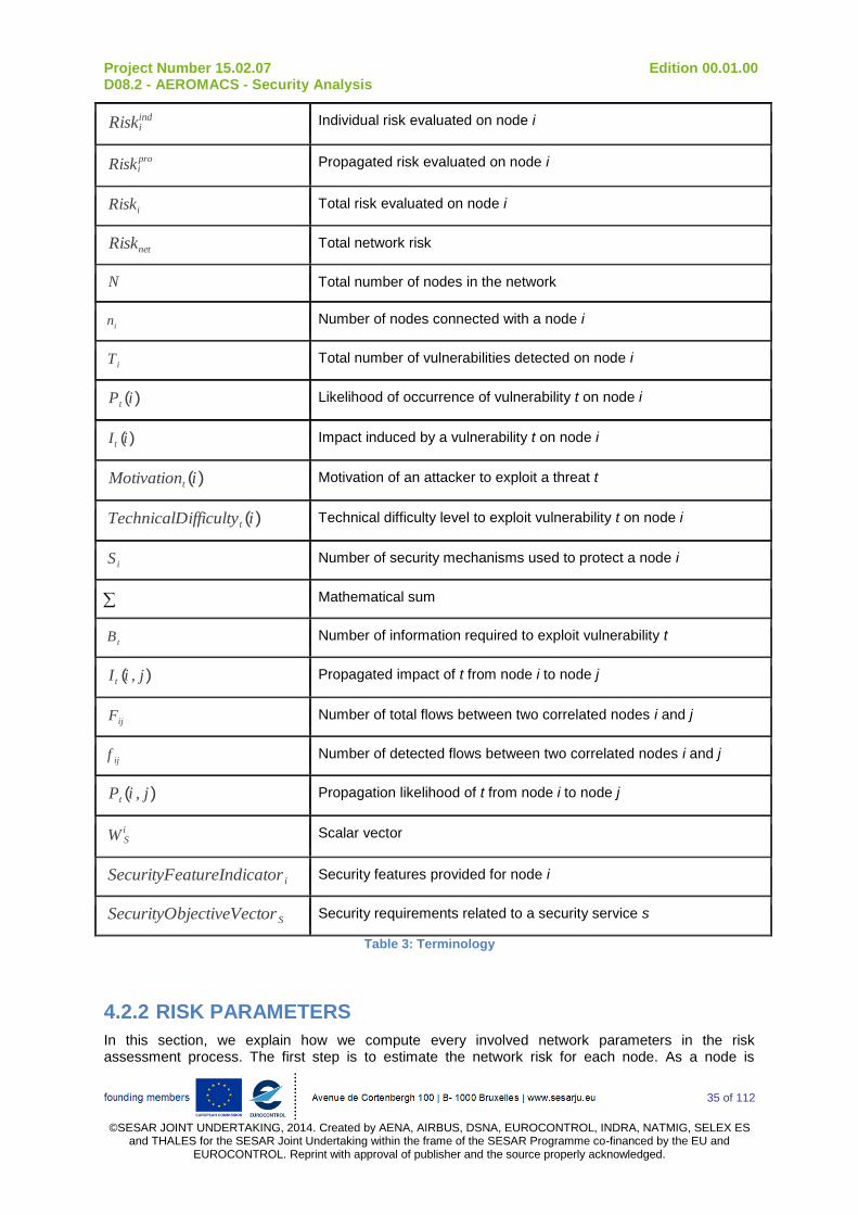
Project Number 15.02.07 Edition 00.01.00 D08.2 - AEROMACS - Security Analysis
35 of 112
©SESAR JOINT UNDERTAKING, 2014. Created by AENA, AIRBUS, DSNA, EUROCONTROL, INDRA, NATMIG, SELEX ES
and THALES for the SESAR Joint Undertaking within the frame of the SESAR Programme co-financed by the EU and EUROCONTROL. Reprint with approval of publisher and the source properly acknowledged.
Riskiind
Individual risk evaluated on node i
Riskipro
Propagated risk evaluated on node i
Riski Total risk evaluated on node i
Risknet Total network risk
N Total number of nodes in the network
ni
Number of nodes connected with a node i
T i Total number of vulnerabilities detected on node i
Pt (i) Likelihood of occurrence of vulnerability t on node i
It (i) Impact induced by a vulnerability t on node i
Motivationt (i) Motivation of an attacker to exploit a threat t
TechnicalDifficultyt (i) Technical difficulty level to exploit vulnerability t on node i
S i Number of security mechanisms used to protect a node i
Mathematical sum
Bt
Number of information required to exploit vulnerability t
It (i , j)
Propagated impact of t from node i to node j
Fij Number of total flows between two correlated nodes i and j
f ij Number of detected flows between two correlated nodes i and j
Pt (i , j)
Propagation likelihood of t from node i to node j
W Si
Scalar vector
SecurityFeatureIndicator i Security features provided for node i
SecurityObjectiveVectorS Security requirements related to a security service s
Table 3: Terminology
4.2.2 RISK PARAMETERS
In this section, we explain how we compute every involved network parameters in the risk assessment process. The first step is to estimate the network risk for each node. As a node is
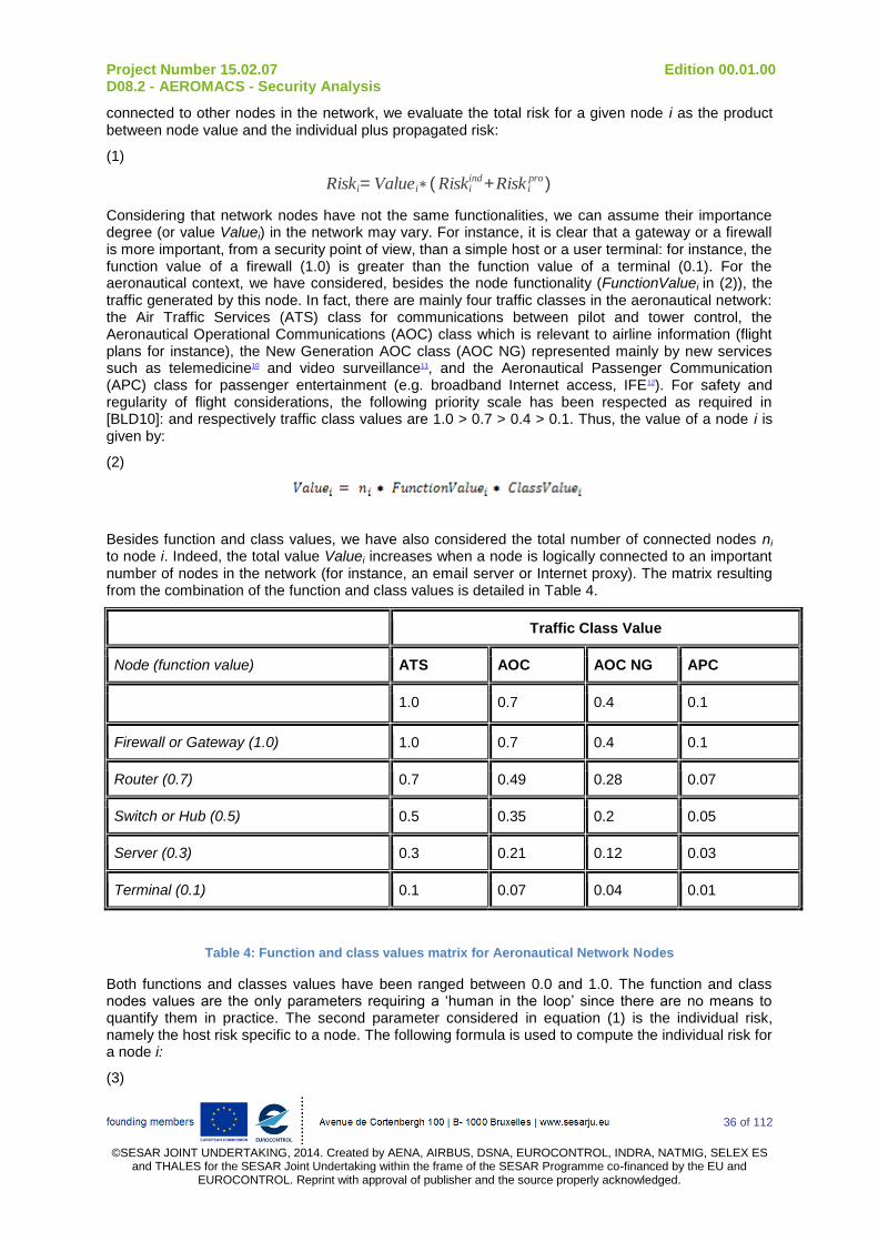
Project Number 15.02.07 Edition 00.01.00 D08.2 - AEROMACS - Security Analysis
36 of 112
©SESAR JOINT UNDERTAKING, 2014. Created by AENA, AIRBUS, DSNA, EUROCONTROL, INDRA, NATMIG, SELEX ES
and THALES for the SESAR Joint Undertaking within the frame of the SESAR Programme co-financed by the EU and EUROCONTROL. Reprint with approval of publisher and the source properly acknowledged.
connected to other nodes in the network, we evaluate the total risk for a given node i as the product between node value and the individual plus propagated risk:
(1)
Riski= Valuei∗ ( Riskiind+Risk i
pro)
Considering that network nodes have not the same functionalities, we can assume their importance degree (or value Valuei) in the network may vary. For instance, it is clear that a gateway or a firewall is more important, from a security point of view, than a simple host or a user terminal: for instance, the function value of a firewall (1.0) is greater than the function value of a terminal (0.1). For the aeronautical context, we have considered, besides the node functionality (FunctionValuei in (2)), the traffic generated by this node. In fact, there are mainly four traffic classes in the aeronautical network: the Air Traffic Services (ATS) class for communications between pilot and tower control, the Aeronautical Operational Communications (AOC) class which is relevant to airline information (flight plans for instance), the New Generation AOC class (AOC NG) represented mainly by new services such as telemedicine10 and video surveillance11, and the Aeronautical Passenger Communication (APC) class for passenger entertainment (e.g. broadband Internet access, IFE12). For safety and regularity of flight considerations, the following priority scale has been respected as required in [BLD10]: and respectively traffic class values are 1.0 > 0.7 > 0.4 > 0.1. Thus, the value of a node i is given by:
(2)
Besides function and class values, we have also considered the total number of connected nodes ni to node i. Indeed, the total value Valuei increases when a node is logically connected to an important number of nodes in the network (for instance, an email server or Internet proxy). The matrix resulting from the combination of the function and class values is detailed in Table 4.
Traffic Class Value
Node (function value) ATS AOC AOC NG APC
1.0 0.7 0.4 0.1
Firewall or Gateway (1.0) 1.0 0.7 0.4 0.1
Router (0.7) 0.7 0.49 0.28 0.07
Switch or Hub (0.5) 0.5 0.35 0.2 0.05
Server (0.3) 0.3 0.21 0.12 0.03
Terminal (0.1) 0.1 0.07 0.04 0.01
Table 4: Function and class values matrix for Aeronautical Network Nodes
Both functions and classes values have been ranged between 0.0 and 1.0. The function and class nodes values are the only parameters requiring a ‘human in the loop’ since there are no means to quantify them in practice. The second parameter considered in equation (1) is the individual risk, namely the host risk specific to a node. The following formula is used to compute the individual risk for a node i:
(3)

Project Number 15.02.07 Edition 00.01.00 D08.2 - AEROMACS - Security Analysis
37 of 112
©SESAR JOINT UNDERTAKING, 2014. Created by AENA, AIRBUS, DSNA, EUROCONTROL, INDRA, NATMIG, SELEX ES
and THALES for the SESAR Joint Undertaking within the frame of the SESAR Programme co-financed by the EU and EUROCONTROL. Reprint with approval of publisher and the source properly acknowledged.
For each node, the total number of vulnerabilities Ti and the estimated impact It relative to a specific vulnerability t (namely, the t
th threat identified on that node) are gathered using the NESSUS
8
vulnerability scanning tool. In practice, NESSUS provides a set of known vulnerabilities stored in the CVSS database. Among the output information, we retrieve the score (i.e. impact) associated to each vulnerability occurring on that node. These scores are ranged from 1 to 10. The number of vulnerabilities Ti is a simple addition on the existing vulnerability for that node.
The likelihood Pt(i) represents the possibility that attacks associated with the vulnerability t are conducted. The likelihood of occurrence evaluation is driven by an existing threat analysis methodology [24] proposed by the European Telecommunications Standards Institute (ETSI). However, as the likelihood values are qualitative, we slightly modified this part of the methodology in order to quantify the involved parameters. Indeed, as described in [24], the evaluation of the likelihood is based on two factors: the technical difficulties that have to be resolved and the motivation for an attacker to carry out an attack.
The methodology associates three values to the likelihood function: (1) unlikely, if the motivation for conducting an attack is low (e.g. no financial interest or technical challenges) and there are strong technical difficulties to overcome (e.g. major unknowns to achieve the attack); (2) possible, if the motivation is moderate (e.g. reasonable financial gains) and the technical difficulties are solvable (e.g. information required to exploit the vulnerability are available); and (3) likely, if there is a high attacker motivation (e.g. inducing a denial of service on the network, important financial gains) and technical difficulties are almost inexistent (e.g. no security protection). In our algorithm, we made some modifications in the ETSI likelihood evaluation process to replace the qualitative values by quantitative values. First, the likelihood is computed using the motivation and technical difficulties values as shown in equation (4):
(4)
In fact, we think that likelihood of occurrence of a vulnerability t increases when the motivation also increases; otherwise, the likelihood decreases when the technical difficulties that must be resolved increase. The motivation for an attacker to exploit a vulnerability t on a node i is:
(5)
The equation (5) shows that the motivation increases when the node value is important and when the number of known vulnerabilities is high. Finally, technical difficulties get stronger when security features (e.g. Firewalls) are reinforced (e.g. increasing their number of enhancing the security policies) or the number of information required to exploit a vulnerability t is high:
(6)
8 Note that any scanning tool providing the same features than NESSUS can be used.
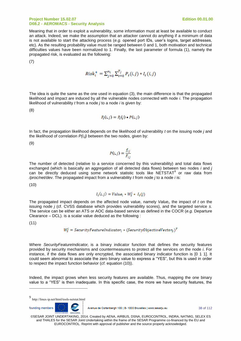
Project Number 15.02.07 Edition 00.01.00 D08.2 - AEROMACS - Security Analysis
38 of 112
©SESAR JOINT UNDERTAKING, 2014. Created by AENA, AIRBUS, DSNA, EUROCONTROL, INDRA, NATMIG, SELEX ES
and THALES for the SESAR Joint Undertaking within the frame of the SESAR Programme co-financed by the EU and EUROCONTROL. Reprint with approval of publisher and the source properly acknowledged.
Meaning that in order to exploit a vulnerability, some information must at least be available to conduct an attack. Indeed, we make the assumption that an attacker cannot do anything if a minimum of data is not available to start the attacking process (e.g. opened port IDs, user’s logins, target addresses, etc). As the resulting probability value must be ranged between 0 and 1, both motivation and technical difficulties values have been normalized to 1. Finally, the last parameter of formula (1), namely the propagated risk, is evaluated as the following:
(7)
The idea is quite the same as the one used in equation (3), the main difference is that the propagated likelihood and impact are induced by all the vulnerable nodes connected with node i. The propagation likelihood of vulnerability t from a node j to a node i is given by:
(8)
In fact, the propagation likelihood depends on the likelihood of vulnerability t on the issuing node j and the likelihood of correlation P(i,j) between the two nodes, given by:
(9)
The number of detected (relative to a service concerned by this vulnerability) and total data flows exchanged (which is basically an aggregation of all detected data flows) between two nodes i and j can be directly deduced using some network statistic tools like NETSTAT
9 or raw data from
/proc/net/dev. The propagated impact from a vulnerability t from node j to a node i is:
(10)
The propagated impact depends on the affected node value, namely Valuei, the impact of t on the issuing node j (cf. CVSS database which provides vulnerability scores), and the targeted service s. The service can be either an ATS or AOC data-based service as defined in the COCR (e.g. Departure Clearance – DCL). is a scalar value deduced as the following :
(11)
Where SecurityFeatureIndicatori is a binary indicator function that defines the security features provided by security mechanisms and countermeasures to protect all the services on the node i. For instance, if the data flows are only encrypted, the associated binary indicator function is [0 1 1]. It could seem abnormal to associate the zero binary value to express a “YES”, but this is used in order to respect the impact function behavior (cf. equation (10)).
Indeed, the impact grows when less security features are available. Thus, mapping the one binary value to a “YES” is then inadequate. In this specific case, the more we have security features, the
9 http://linux-ip.net/html/tools-netstat.html
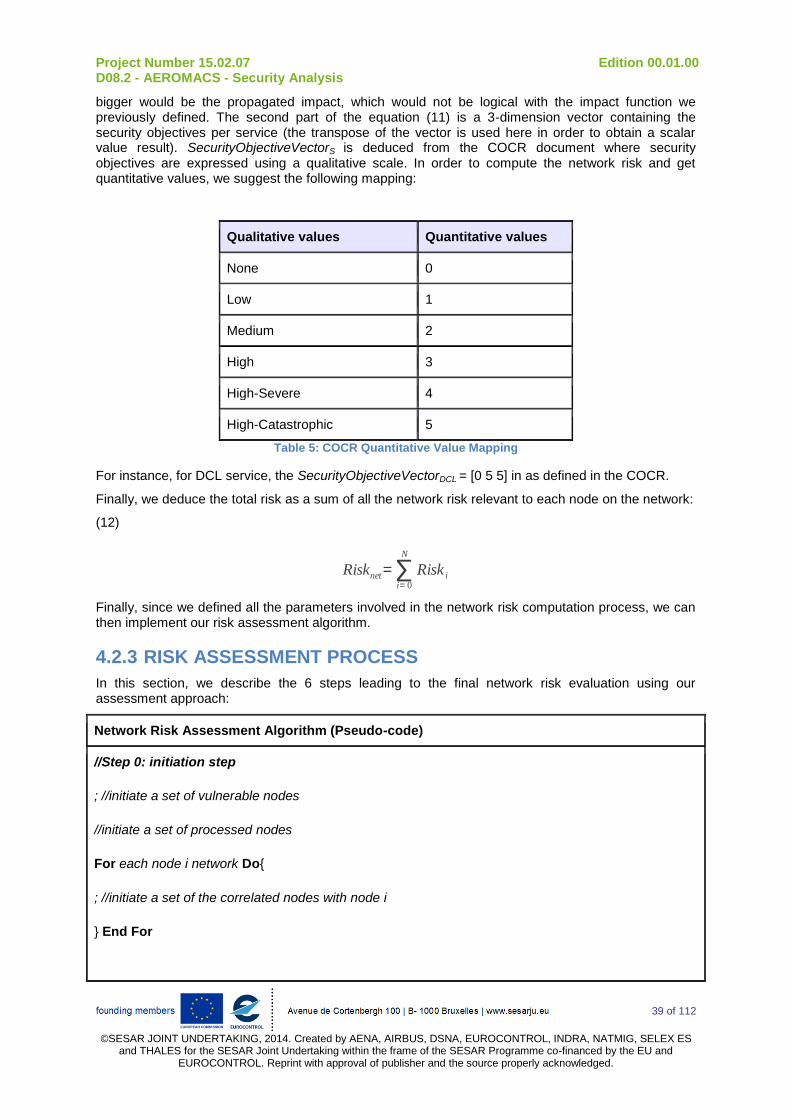
Project Number 15.02.07 Edition 00.01.00 D08.2 - AEROMACS - Security Analysis
39 of 112
©SESAR JOINT UNDERTAKING, 2014. Created by AENA, AIRBUS, DSNA, EUROCONTROL, INDRA, NATMIG, SELEX ES
and THALES for the SESAR Joint Undertaking within the frame of the SESAR Programme co-financed by the EU and EUROCONTROL. Reprint with approval of publisher and the source properly acknowledged.
bigger would be the propagated impact, which would not be logical with the impact function we previously defined. The second part of the equation (11) is a 3-dimension vector containing the security objectives per service (the transpose of the vector is used here in order to obtain a scalar value result). SecurityObjectiveVectorS is deduced from the COCR document where security objectives are expressed using a qualitative scale. In order to compute the network risk and get quantitative values, we suggest the following mapping:
Qualitative values Quantitative values
None 0
Low 1
Medium 2
High 3
High-Severe 4
High-Catastrophic 5
Table 5: COCR Quantitative Value Mapping
For instance, for DCL service, the SecurityObjectiveVectorDCL = [0 5 5] in as defined in the COCR.
Finally, we deduce the total risk as a sum of all the network risk relevant to each node on the network:
(12)
Risknet= ∑i= 0
N
Risk i
Finally, since we defined all the parameters involved in the network risk computation process, we can then implement our risk assessment algorithm.
4.2.3 RISK ASSESSMENT PROCESS
In this section, we describe the 6 steps leading to the final network risk evaluation using our assessment approach:
Network Risk Assessment Algorithm (Pseudo-code)
//Step 0: initiation step
; //initiate a set of vulnerable nodes
//initiate a set of processed nodes
For each node i network Do{
; //initiate a set of the correlated nodes with node i
} End For
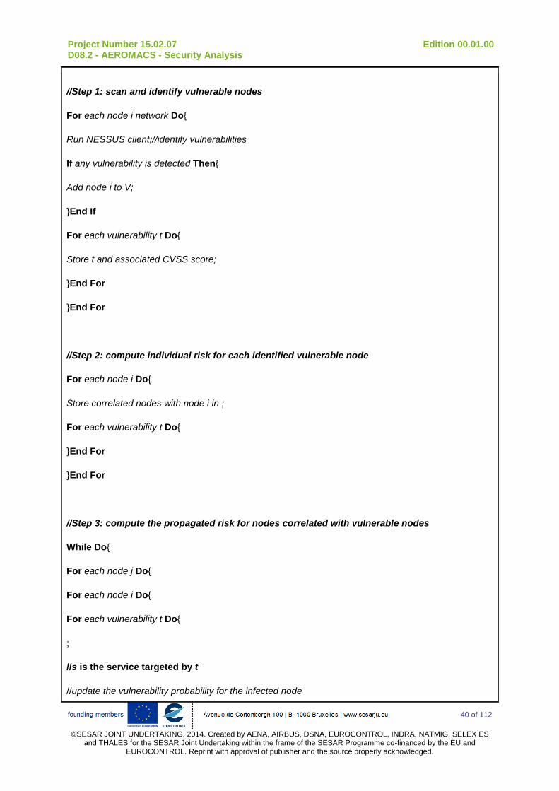
Project Number 15.02.07 Edition 00.01.00 D08.2 - AEROMACS - Security Analysis
40 of 112
©SESAR JOINT UNDERTAKING, 2014. Created by AENA, AIRBUS, DSNA, EUROCONTROL, INDRA, NATMIG, SELEX ES
and THALES for the SESAR Joint Undertaking within the frame of the SESAR Programme co-financed by the EU and EUROCONTROL. Reprint with approval of publisher and the source properly acknowledged.
//Step 1: scan and identify vulnerable nodes
For each node i network Do{
Run NESSUS client;//identify vulnerabilities
If any vulnerability is detected Then{
Add node i to V;
}End If
For each vulnerability t Do{
Store t and associated CVSS score;
}End For
}End For
//Step 2: compute individual risk for each identified vulnerable node
For each node i Do{
Store correlated nodes with node i in ;
For each vulnerability t Do{
}End For
}End For
//Step 3: compute the propagated risk for nodes correlated with vulnerable nodes
While Do{
For each node j Do{
For each node i Do{
For each vulnerability t Do{
;
//s is the service targeted by t
//update the vulnerability probability for the infected node

Project Number 15.02.07 Edition 00.01.00 D08.2 - AEROMACS - Security Analysis
41 of 112
©SESAR JOINT UNDERTAKING, 2014. Created by AENA, AIRBUS, DSNA, EUROCONTROL, INDRA, NATMIG, SELEX ES
and THALES for the SESAR Joint Undertaking within the frame of the SESAR Programme co-financed by the EU and EUROCONTROL. Reprint with approval of publisher and the source properly acknowledged.
If Then{
//update the probability of occurrence of vulnerability t
}End If
}End For
If the node i and Then{
Store node i in V; // this node is now infected and must be treated
}End If
}End For
Copy node j to NVD and remove it from V; //this node has been processed
}End For
}End While
//Step 4: compute the total risk for each node in the network
For each node i network Do{
}End For
//Step 5: compute the whole network risk level
For each node i network Do{
}End For
Note: In annex, an algorigram presents this risk assessment process.
4.3 APPLICATION TO AEROMACS NETWORK
4.3.1 TRAFFIC FLOW SPECIFICATION
Traffic flows are grouped according to the nature of the service and the affected network entities. In the following sections, a classification of the services extracted from COCR (ATC, AOC and NET) is performed. In addition, access network management flows are considered, according to WiMAX profile and NWG specifications.

Project Number 15.02.07 Edition 00.01.00 D08.2 - AEROMACS - Security Analysis
42 of 112
©SESAR JOINT UNDERTAKING, 2014. Created by AENA, AIRBUS, DSNA, EUROCONTROL, INDRA, NATMIG, SELEX ES
and THALES for the SESAR Joint Undertaking within the frame of the SESAR Programme co-financed by the EU and EUROCONTROL. Reprint with approval of publisher and the source properly acknowledged.
For each service, a set of information is given in order to describe its features that can be used in risk analysis:
Security level: a description of the needs in terms of confidentiality, integrity and/or availability according to COCRv2, or to a different hypothesis when stated specifically;
End to end: an indication of the nodes that represent the communication ends of the flow (source and/or destination, depending on the flow directionality). It also indicates whether the service is unicast (one to one) or multicast/broadcast (one to many);
Direction: an indication of the directionality of the flow. It can be unidirectional, originated in Ground or Air domains, or bidirectional;
Traffic volume: the volume of traffic generated by the aggregated instances of services of this class. It considers that every service of the class is instantiated once. It is calculated as sum(#messages per dialog * message size in Bytes * 8);
Traffic pattern: an indication on whether the traffic is periodic (messages are sent in a deterministic frequency) or bursty (non predictable pattern of message transmission). Periodic services are assumed to be executed during the whole simulation time (departure + arrival = 65 minutes according to COCRv2).
4.3.2 ATS
Air Traffic Service (ATS) are executed by Air Traffic Management Systems and Aircraft. They may be instantiated in any of the operational APT areas (RAMP, GROUND or TOWER) at both arrival and departure phases. They support safety-critical traffic control operations and clearances.
For the purpose of the security analysis, the different traffic flows identified can be classified as follow:
ATS addressed: represents the majority of ATS that are addressed between Air traffic controller and Aircraft and generate a bidirectional message exchange used for aircraft control and monitoring on the surface.
ATC SURV: refers to the specific ATC surveillance service. This service, when active, generates a message periodically from the aircraft that informs the ground system on the latest surveillance events.
ATS multicast: represents a set of ATS that instantiate between the Air traffic controller and a group of subscribers. These services are used to send reports to the aircrafts, but the services are bidirectional as they include an ACK message from the aircraft.
Service name
Security level End to end Direction Traffic volume (bits)
Traffic pattern
ATS addressed
Confidentiality (low)
Integrity (high-severe)
Availability (high-severe)
ATC server
ATC client
G<->A 99592 (FL)
86848 (RL)
Bursty
ATC SURV Confidentiality (low)
Integrity (high-severe)
Availability (medium)
ATC server
ATC client
G<-A 530400 (RL) Periodic (2 s/msg)
ATS multicast
Integrity (high-severe) ATC server G<->A 75336 (FL) Bursty
Project Number 15.02.07 Edition 00.01.00 D08.2 - AEROMACS - Security Analysis
43 of 112
©SESAR JOINT UNDERTAKING, 2014. Created by AENA, AIRBUS, DSNA, EUROCONTROL, INDRA, NATMIG, SELEX ES
and THALES for the SESAR Joint Undertaking within the frame of the SESAR Programme co-financed by the EU and EUROCONTROL. Reprint with approval of publisher and the source properly acknowledged.
Availability (medium) Group (ATC client)
14760 (RL)
Table 6: Specification of ATS traffic flows
4.3.3 AOC
Air Operation Control (AOC) services are executed by Airline Controller and Aircraft. Most of them are instantiated while the aircraft is in the RAMP area, but some of them can also be present in the phase of the flights (while taxiing, or in TMA and En-route). They support monitoring and operation services that provide aircraft maintenance and boarding actions.
The different traffic flows identified are the following:
A/C report: represents the services that are instantiated in Aircraft and generate reports and logs to the ground AOC (CABINLOG, FLTLOG, FLTJOURNAL, LOADDOC). The nature of these services is informative, and so they need to guarantee a certain level of confidentiality.
A/C monitoring: represents the services that are instantiated in Aircraft and generate monitoring or operation messages that provide the ground AOC with quick information on the aircraft status in order to undertake the appropriate actions (DOOR, HANDLING, PREFLT-INS, AUTOLAND-REG). These services affect safety and regularity of flight, and thus integrity and availability are critical aspects. These services are not defined by COCR, but, due to their direct effect on traffic control, these services are granted the same security needs as addressed ATC services.
Controller notification: refers to the services instantiated in the ground AOC that send an order or notification to the aircraft (UPLIB, NOTAM, NOTOC, AIRWORTH). These can combine reports and air operation data.
AOC bidirectional: refers to the majority of services executed between Airlines Operation Centre and aircraft or handling vehicle and manage most of the AOC flight operations in surface (AOCDLL, FLTPLAN, LOADSHT, WXGRAPH, WXTEXT, EFF, FLOWCON, SWCONF, and TAKEOF-CALC).
FOQA: the specific Flight Operations Quality Assurance is a method for gathering flight data and providing to the ground AOC for its treatment, analysis and monitoring. The information sent by the aircraft after a flight is variable and generally of considerable size. As FOQA is not an implemented service yet, best information on security levels required can be extracted from the COCR, in which there is an insistence on preserving Confidentiality and Integrity over the service.
ECHARTS: the specific Electronic Charts Update is a service by which ground AOC sends the aircraft the updated Navigation Maps after a certain number of flights. Charts have a big size and are thus not generally updated in a single turn-around phase. There is no security information for this future service yet, so the security levels from FOQA are translated here since both services transmit flight data for the crew or operators.
Technical log updates: includes the TECHLOG and ACLOG services that are used to request the aircraft to check the status of the aircraft technical log and update it in the maintenance base if necessary. These services must be done quickly and reliably since remedial actions may need to be taken according to the log information.
WXRT: The specific Real-time Weather Reports for Met Office is used by the aircraft to periodically derive the environment on which it is operating, and send it to ground AOC.
Service name
Security level End to end Direction Traffic volume (bits)
Traffic pattern
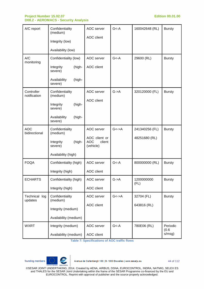
Project Number 15.02.07 Edition 00.01.00 D08.2 - AEROMACS - Security Analysis
44 of 112
©SESAR JOINT UNDERTAKING, 2014. Created by AENA, AIRBUS, DSNA, EUROCONTROL, INDRA, NATMIG, SELEX ES
and THALES for the SESAR Joint Undertaking within the frame of the SESAR Programme co-financed by the EU and EUROCONTROL. Reprint with approval of publisher and the source properly acknowledged.
A/C report Confidentiality (medium)
Integrity (low)
Availability (low)
AOC server
AOC client
G<-A 160042648 (RL) Bursty
A/C monitoring
Confidentiality (low)
Integrity (high-severe)
Availability (high-severe)
AOC server
AOC client
G<-A 29600 (RL) Bursty
Controller notification
Confidentiality (medium)
Integrity (high-severe)
Availability (high-severe)
AOC server
AOC client
G->A 320120000 (FL) Bursty
AOC bidirectional
Confidentiality (medium)
Integrity (high-severe)
Availability (high)
AOC server
AOC client or AOC client (vehicle)
G<->A 241340256 (FL)
48251680 (RL)
Bursty
FOQA Confidentiality (high)
Integrity (high)
AOC server
AOC client
G<-A 800000000 (RL) Bursty
ECHARTS Confidentiality (high)
Integrity (high)
AOC server
AOC client
G->A 1200000000 (FL)
Bursty
Technical log updates
Confidentiality (medium)
Integrity (medium)
Availability (medium)
AOC server
AOC client
G<->A 32704 (FL)
643816 (RL)
Bursty
WXRT Integrity (medium)
Availability (medium)
AOC server
AOC client
G<-A 780E06 (RL) Periodic (0.6 s/msg)
Table 7: Specifications of AOC traffic flows
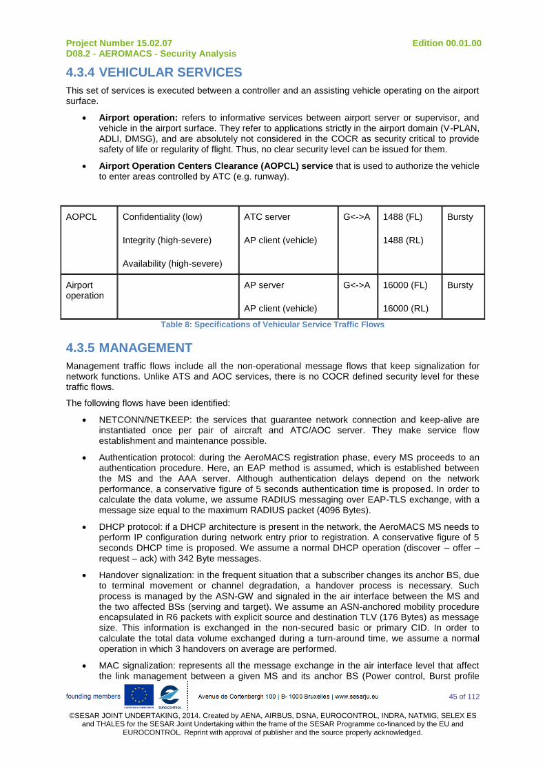
Project Number 15.02.07 Edition 00.01.00 D08.2 - AEROMACS - Security Analysis
45 of 112
©SESAR JOINT UNDERTAKING, 2014. Created by AENA, AIRBUS, DSNA, EUROCONTROL, INDRA, NATMIG, SELEX ES
and THALES for the SESAR Joint Undertaking within the frame of the SESAR Programme co-financed by the EU and EUROCONTROL. Reprint with approval of publisher and the source properly acknowledged.
4.3.4 VEHICULAR SERVICES
This set of services is executed between a controller and an assisting vehicle operating on the airport surface.
Airport operation: refers to informative services between airport server or supervisor, and vehicle in the airport surface. They refer to applications strictly in the airport domain (V-PLAN, ADLI, DMSG), and are absolutely not considered in the COCR as security critical to provide safety of life or regularity of flight. Thus, no clear security level can be issued for them.
Airport Operation Centers Clearance (AOPCL) service that is used to authorize the vehicle to enter areas controlled by ATC (e.g. runway).
AOPCL Confidentiality (low)
Integrity (high-severe)
Availability (high-severe)
ATC server
AP client (vehicle)
G<->A 1488 (FL)
1488 (RL)
Bursty
Airport operation
AP server
AP client (vehicle)
G<->A 16000 (FL)
16000 (RL)
Bursty
Table 8: Specifications of Vehicular Service Traffic Flows
4.3.5 MANAGEMENT
Management traffic flows include all the non-operational message flows that keep signalization for network functions. Unlike ATS and AOC services, there is no COCR defined security level for these traffic flows.
The following flows have been identified:
NETCONN/NETKEEP: the services that guarantee network connection and keep-alive are instantiated once per pair of aircraft and ATC/AOC server. They make service flow establishment and maintenance possible.
Authentication protocol: during the AeroMACS registration phase, every MS proceeds to an authentication procedure. Here, an EAP method is assumed, which is established between the MS and the AAA server. Although authentication delays depend on the network performance, a conservative figure of 5 seconds authentication time is proposed. In order to calculate the data volume, we assume RADIUS messaging over EAP-TLS exchange, with a message size equal to the maximum RADIUS packet (4096 Bytes).
DHCP protocol: if a DHCP architecture is present in the network, the AeroMACS MS needs to perform IP configuration during network entry prior to registration. A conservative figure of 5 seconds DHCP time is proposed. We assume a normal DHCP operation (discover – offer – request – ack) with 342 Byte messages.
Handover signalization: in the frequent situation that a subscriber changes its anchor BS, due to terminal movement or channel degradation, a handover process is necessary. Such process is managed by the ASN-GW and signaled in the air interface between the MS and the two affected BSs (serving and target). We assume an ASN-anchored mobility procedure encapsulated in R6 packets with explicit source and destination TLV (176 Bytes) as message size. This information is exchanged in the non-secured basic or primary CID. In order to calculate the total data volume exchanged during a turn-around time, we assume a normal operation in which 3 handovers on average are performed.
MAC signalization: represents all the message exchange in the air interface level that affect the link management between a given MS and its anchor BS (Power control, Burst profile

Project Number 15.02.07 Edition 00.01.00 D08.2 - AEROMACS - Security Analysis
46 of 112
©SESAR JOINT UNDERTAKING, 2014. Created by AENA, AIRBUS, DSNA, EUROCONTROL, INDRA, NATMIG, SELEX ES
and THALES for the SESAR Joint Undertaking within the frame of the SESAR Programme co-financed by the EU and EUROCONTROL. Reprint with approval of publisher and the source properly acknowledged.
configuration, etc). This information is exchanged in the non-secured basic or primary CID. A 2-way message exchange with 10 Bytes message on average is assumed.
Service name Security level End to end Direction Traffic volume (bits)
Traffic pattern
NETCONN / NETKEEP
ATC/AOC server
ATC/AOC client
G<->A 401 (FL)
389 (RL)
Bursty
Authentication protocol
AAA server
MS
G<->A 98304 (FL)
65536 (RL)
Bursty
DHCP protocol DHCP server
MS
G<->A 5472 (FL)
5472 (RL)
Bursty
Handover signalization
ASN-GW
2 BS
MS
G<->A 8448 (FL)
8448 (RL)
Bursty
MAC signalization
BS
MS
G<->A 62400000 (FL)
62400000 (RL)
Periodic (0.005s/mg)
Table 9: Specifications of Management Traffic flows
4.3.6 Characterization of data volume exchanged per pair of nodes
The table below displays the total volume exchanged between two contiguous nodes of the topology. The size of the volume is given in bits, on a per service manner. A total simulation time of 46.5 (DEP) + 18.5 (ARR) minutes is assumed as chosen for phase 2 High Density airport is used.
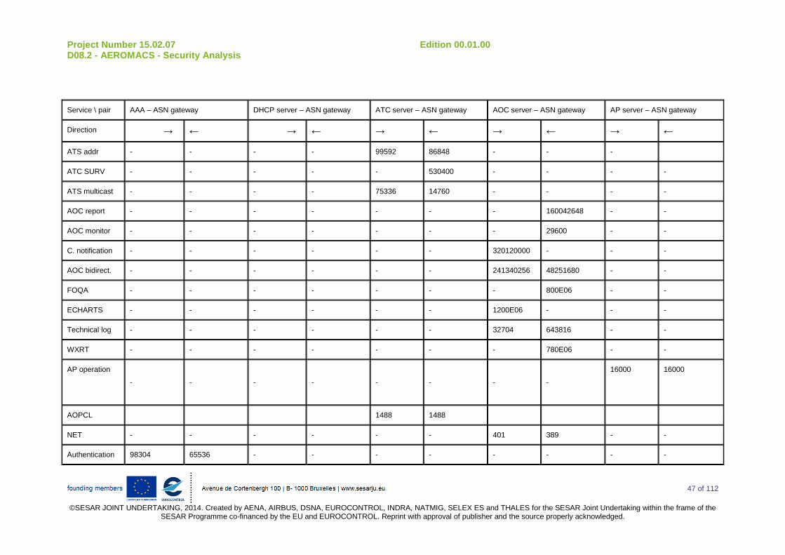
Project Number 15.02.07 Edition 00.01.00 D08.2 - AEROMACS - Security Analysis
47 of 112
©SESAR JOINT UNDERTAKING, 2014. Created by AENA, AIRBUS, DSNA, EUROCONTROL, INDRA, NATMIG, SELEX ES and THALES for the SESAR Joint Undertaking within the frame of the
SESAR Programme co-financed by the EU and EUROCONTROL. Reprint with approval of publisher and the source properly acknowledged.
Service \ pair AAA – ASN gateway DHCP server – ASN gateway ATC server – ASN gateway AOC server – ASN gateway AP server – ASN gateway
Direction → ← → ← → ← → ← → ←
ATS addr - - - - 99592 86848 - - -
ATC SURV - - - - - 530400 - - - -
ATS multicast - - - - 75336 14760 - - - -
AOC report - - - - - - - 160042648 - -
AOC monitor - - - - - - - 29600 - -
C. notification - - - - - - 320120000 - - -
AOC bidirect. - - - - - - 241340256 48251680 - -
FOQA - - - - - - - 800E06 - -
ECHARTS - - - - - - 1200E06 - - -
Technical log - - - - - - 32704 643816 - -
WXRT - - - - - - - 780E06 - -
AP operation - - - - - - - -
16000
16000
AOPCL 1488 1488
NET - - - - - - 401 389 - -
Authentication 98304 65536 - - - - - - - -
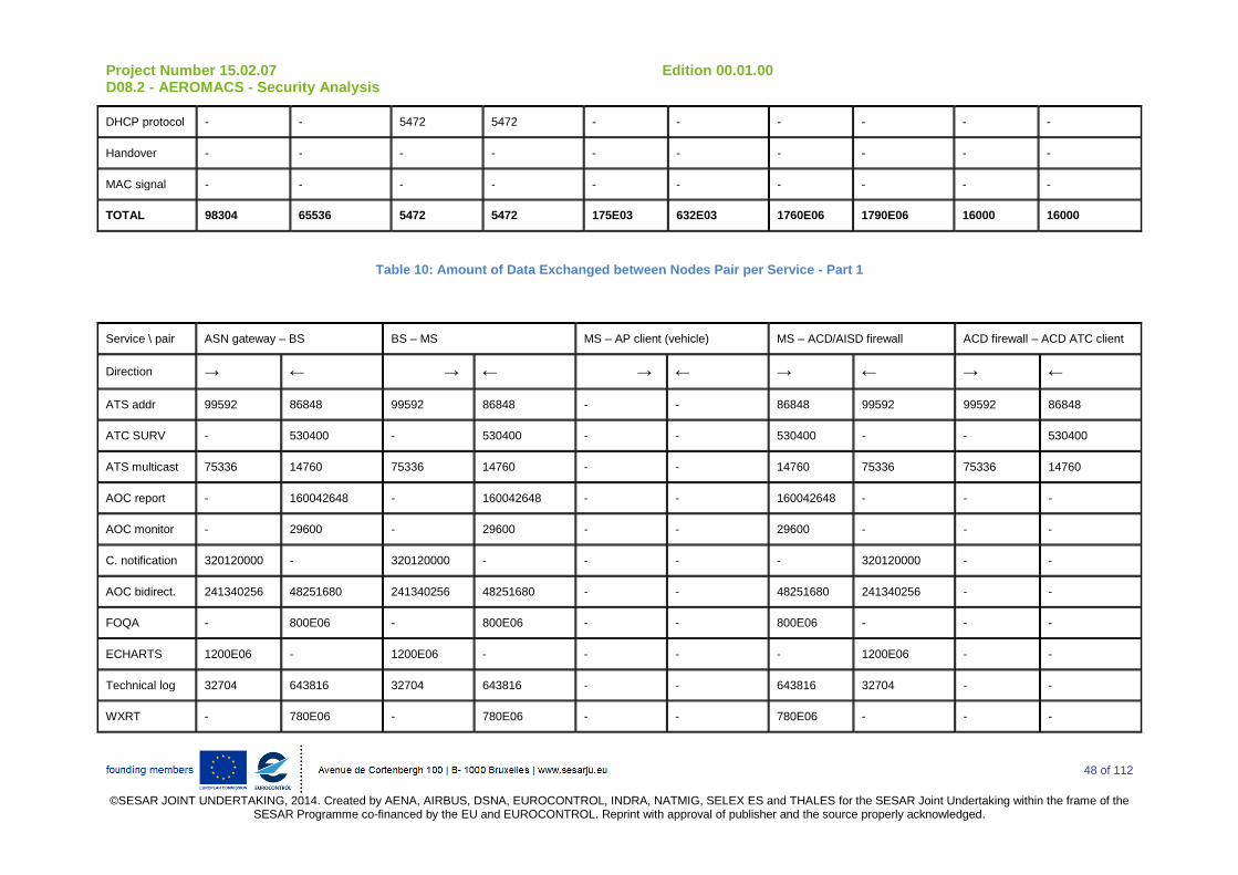
Project Number 15.02.07 Edition 00.01.00 D08.2 - AEROMACS - Security Analysis
48 of 112
©SESAR JOINT UNDERTAKING, 2014. Created by AENA, AIRBUS, DSNA, EUROCONTROL, INDRA, NATMIG, SELEX ES and THALES for the SESAR Joint Undertaking within the frame of the
SESAR Programme co-financed by the EU and EUROCONTROL. Reprint with approval of publisher and the source properly acknowledged.
DHCP protocol - - 5472 5472 - - - - - -
Handover - - - - - - - - - -
MAC signal - - - - - - - - - -
TOTAL 98304 65536 5472 5472 175E03 632E03 1760E06 1790E06 16000 16000
Table 10: Amount of Data Exchanged between Nodes Pair per Service - Part 1
Service \ pair ASN gateway – BS BS – MS MS – AP client (vehicle) MS – ACD/AISD firewall ACD firewall – ACD ATC client
Direction → ← → ← → ← → ← → ←
ATS addr 99592 86848 99592 86848 - - 86848 99592 99592 86848
ATC SURV - 530400 - 530400 - - 530400 - - 530400
ATS multicast 75336 14760 75336 14760 - - 14760 75336 75336 14760
AOC report - 160042648 - 160042648 - - 160042648 - - -
AOC monitor - 29600 - 29600 - - 29600 - - -
C. notification 320120000 - 320120000 - - - - 320120000 - -
AOC bidirect. 241340256 48251680 241340256 48251680 - - 48251680 241340256 - -
FOQA - 800E06 - 800E06 - - 800E06 - - -
ECHARTS 1200E06 - 1200E06 - - - - 1200E06 - -
Technical log 32704 643816 32704 643816 - - 643816 32704 - -
WXRT - 780E06 - 780E06 - - 780E06 - - -
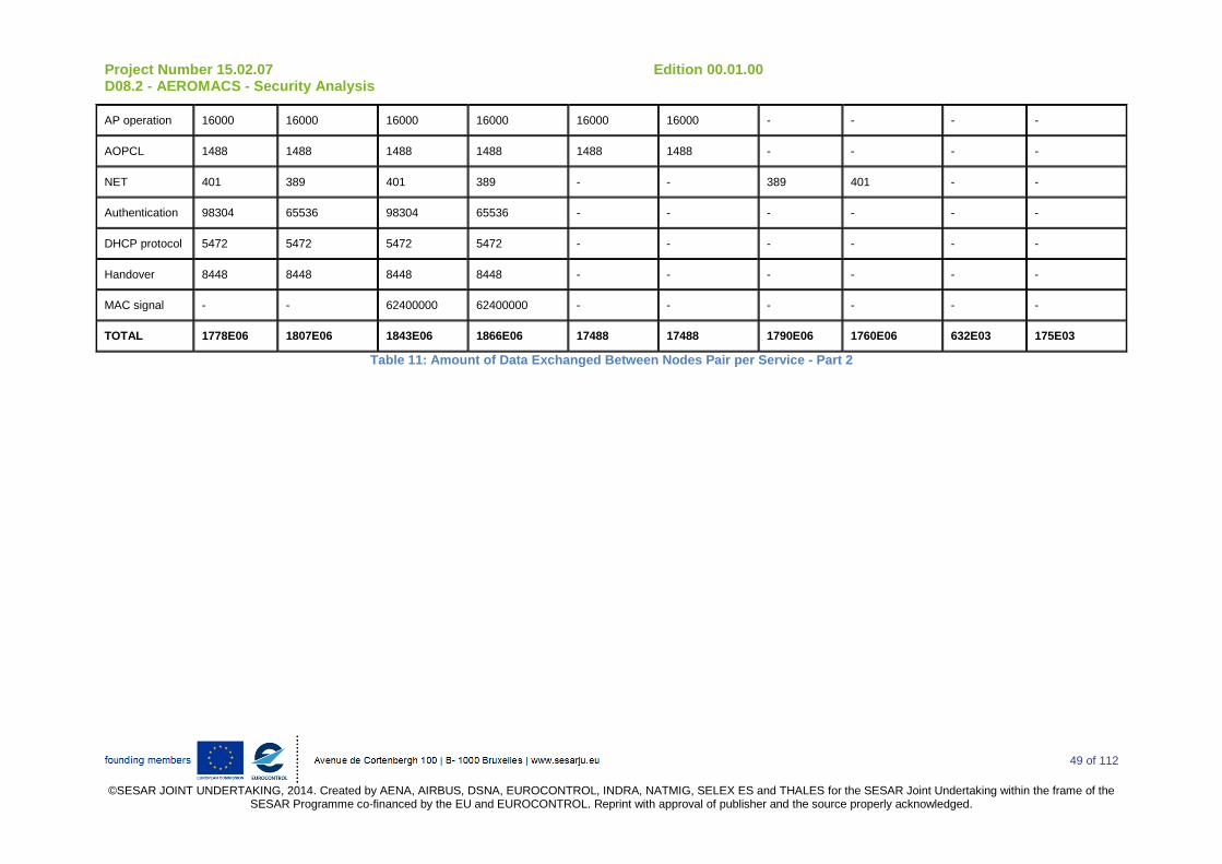
Project Number 15.02.07 Edition 00.01.00 D08.2 - AEROMACS - Security Analysis
49 of 112
©SESAR JOINT UNDERTAKING, 2014. Created by AENA, AIRBUS, DSNA, EUROCONTROL, INDRA, NATMIG, SELEX ES and THALES for the SESAR Joint Undertaking within the frame of the
SESAR Programme co-financed by the EU and EUROCONTROL. Reprint with approval of publisher and the source properly acknowledged.
AP operation 16000 16000 16000 16000 16000 16000 - - - -
AOPCL 1488 1488 1488 1488 1488 1488 - - - -
NET 401 389 401 389 - - 389 401 - -
Authentication 98304 65536 98304 65536 - - - - - -
DHCP protocol 5472 5472 5472 5472 - - - - - -
Handover 8448 8448 8448 8448 - - - - - -
MAC signal - - 62400000 62400000 - - - - - -
TOTAL 1778E06 1807E06 1843E06 1866E06 17488 17488 1790E06 1760E06 632E03 175E03
Table 11: Amount of Data Exchanged Between Nodes Pair per Service - Part 2
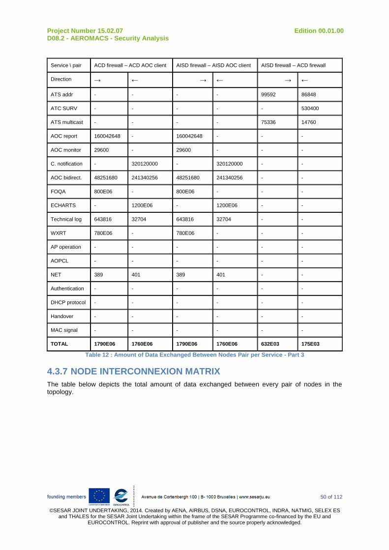
Project Number 15.02.07 Edition 00.01.00 D08.2 - AEROMACS - Security Analysis
50 of 112
©SESAR JOINT UNDERTAKING, 2014. Created by AENA, AIRBUS, DSNA, EUROCONTROL, INDRA, NATMIG, SELEX ES
and THALES for the SESAR Joint Undertaking within the frame of the SESAR Programme co-financed by the EU and EUROCONTROL. Reprint with approval of publisher and the source properly acknowledged.
Service \ pair ACD firewall – ACD AOC client AISD firewall – AISD AOC client AISD firewall – ACD firewall
Direction → ← → ← → ←
ATS addr - - - - 99592 86848
ATC SURV - - - - - 530400
ATS multicast - - - - 75336 14760
AOC report 160042648 - 160042648 - - -
AOC monitor 29600 - 29600 - - -
C. notification - 320120000 - 320120000 - -
AOC bidirect. 48251680 241340256 48251680 241340256 - -
FOQA 800E06 - 800E06 - - -
ECHARTS - 1200E06 - 1200E06 - -
Technical log 643816 32704 643816 32704 - -
WXRT 780E06 - 780E06 - - -
AP operation - - - - - -
AOPCL - - - - - -
NET 389 401 389 401 - -
Authentication - - - - - -
DHCP protocol - - - - - -
Handover - - - - - -
MAC signal - - - - - -
TOTAL 1790E06 1760E06 1790E06 1760E06 632E03 175E03
Table 12 : Amount of Data Exchanged Between Nodes Pair per Service - Part 3
4.3.7 NODE INTERCONNEXION MATRIX
The table below depicts the total amount of data exchanged between every pair of nodes in the topology.

Project Number 15.02.07 Edition 00.01.00 D08.2 - AEROMACS - Security Analysis
51 of 112
©SESAR JOINT UNDERTAKING, 2014. Created by AENA, AIRBUS, DSNA, EUROCONTROL, INDRA, NATMIG, SELEX ES and THALES for the SESAR Joint Undertaking within the frame of the
SESAR Programme co-financed by the EU and EUROCONTROL. Reprint with approval of publisher and the source properly acknowledged.
Tx / Rx AAA DHCP server
ATC server
AOC server
AP server
ASN gateway
BS MS AP client
ACD firewall
AISD firewall
ACD ATC client
ACD AOC client
AISD AOC client
AAA - - - - 98304 - - - - - - - -
DHCP server - 5472
ATC server - 175E03
AOC server - 1760E06
AP server - 16000
ASN gateway
65536 5472 632E03 1790E06 16000 - 1778E06
BS 1807E06 - 1843E06
MS 1866E06 - 17488 1790E06 1790E06
AP client 17488 -
ACD10
firewall 1760E06 - 175E03 632E03 1790E06
AISD firewall 1760E06 632E03 - 1790E06
ACD ATC cli 175E03 -
ACD AOC cli 1760E06 -
10
ACD, AISD are airborne domains according to ARINC 664. More details can be found in section 4.4.1.1.1.2.2.1

Project Number 15.02.07 Edition 00.01.00 D08.2 - AEROMACS - Security Analysis
52 of 112
©SESAR JOINT UNDERTAKING, 2014. Created by AENA, AIRBUS, DSNA, EUROCONTROL, INDRA, NATMIG, SELEX ES and THALES for the SESAR Joint Undertaking within the frame of the
SESAR Programme co-financed by the EU and EUROCONTROL. Reprint with approval of publisher and the source properly acknowledged.
AISD AOC cli 1760E06 -
Table 13: Total Amount of Data Exchanged Between Nodes

Project Number 15.02.07 Edition 00.01.00 D08.2 - AEROMACS - Security Analysis
53 of 112
©SESAR JOINT UNDERTAKING, 2014. Created by AENA, AIRBUS, DSNA, EUROCONTROL, INDRA, NATMIG, SELEX ES and
THALES for the SESAR Joint Undertaking within the frame of the SESAR Programme co-financed by the EU and EUROCONTROL. Reprint with approval of publisher and the source properly acknowledged.
4.4 RISK ANALYSIS SCENARIOS
In this section, different risk analysis scenarios are presented:
Section 4.4.1: Isolated AeroMACS scenario with operational server vulnerabilities. Operational servers are non-COTS servers, designed for operational services (mainly ATC and AOC services). Isolated means that the basic topology assumes the existence of a standalone service network supported by an AeroMACS access network in the airport. Consequently, all the services are provided by components inside the AeroMACS network (AAA, DHCP, and application servers) and placed within the airport backbone;
Section 4.4.2.1: Isolated AeroMACS scenario without operational server vulnerabilities. This is the same scenario as the one above except that vulnerabilities related to operational servers are not considered;
Section 4.4.2.2: Isolated AeroMACS scenario without operational server vulnerabilities using Two ASN Gateways. In this scenario, the results of previous simulations are retained and 2 AeroMACS gateways are deployed in the ASN instead of one;
Section 4.4.3: End-to-End AeroMACS scenario. Finally, the overall architecture is considered, including non-AeroMACS devices such as firewalls and home agents.
At the end of this section, a comparison is made between all the results.
4.4.1 ISOLATED AEROMACS SCENARIO WITH OPERATIONAL SERVER VULNERABILITIES
4.4.1.1 NETWORK TOPOLOGY
Figure 9 depicts the isolated AeroMACS network topology, three main portions can be identified, namely the AeroMACS ASN, the AeroMACS Core Service Network (CSN), and the mobile stations (aircraft or surface vehicles). This basic topology assumes the existence of a standalone service network supported by an AeroMACS access network in the airport. Consequently, all the services are provided by components inside the airport network (AAA, DHCP and application servers) and placed within the airport backbone.
The AeroMACS (additionally to the AAA server) segment is the only system supporting security features and the AAA server will be directly reachable through a dedicated gateway between the AeroMACS network and the others Airport networks. The APC server of the Figure 9 refers to the AirPort Communications server (and not to the Airline Passenger Communication Server as it is the case in other documents).

Project Number 15.02.07 Edition 00.01.00 D08.2 - AEROMACS - Security Analysis
54 of 112
©SESAR JOINT UNDERTAKING, 2014. Created by AENA, AIRBUS, DSNA, EUROCONTROL, INDRA, NATMIG, SELEX ES and
THALES for the SESAR Joint Undertaking within the frame of the SESAR Programme co-financed by the EU and EUROCONTROL. Reprint with approval of publisher and the source properly acknowledged.
Figure 9: AeroMACS Network Topology : Extended Isolated Scenario
4.4.1.1.1 NODE SPECIFICATION
In this section, a description of the different nodes identified in the topology is given from a point of view of security. That is, the security measures that can be implemented are given per node. If there are options, these will be specified in a later stage when defining the scenarios. The nodes can be split up in three sections according to the section of the topology they are part of:
AeroMACS ASN: BS, MS, ASN-GW. This is the focus of the study as it makes reference to the logical devices used for AeroMACS radio communication that support ATC/AOC services.
Airborne network: the number of nodes and connections that are part of the A/C communications infrastructure. This part is relevant to aircraft.
Ground network: the set of devices and connections that compose the airport network, extensible to the WAN connectivity. The ground network includes the AeroMACS gateways, the AeroMACS base stations, and the surface vehicles.
4.4.1.1.1.1 AEROMACS GROUND INFRASTRUCTURE
4.4.1.1.1.1.1 BASE STATION
4.4.1.1.1.1.1.1 NODE DEFINITION
The Base Station (BS) manages the radio link with Mobile Stations (MS) in the coverage area of the Access Service Network (ASN). It controls and assists all the procedures at local level to ensure link connectivity, service flow creation and signal quality. It relays the data path from the user side to the network, together with the related security methods. It manages security at local level and relays to the authenticator in the network.
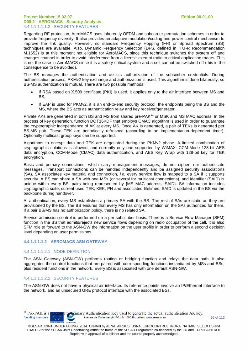
Project Number 15.02.07 Edition 00.01.00 D08.2 - AEROMACS - Security Analysis
55 of 112
©SESAR JOINT UNDERTAKING, 2014. Created by AENA, AIRBUS, DSNA, EUROCONTROL, INDRA, NATMIG, SELEX ES and
THALES for the SESAR Joint Undertaking within the frame of the SESAR Programme co-financed by the EU and EUROCONTROL. Reprint with approval of publisher and the source properly acknowledged.
4.4.1.1.1.1.1.2 SECURITY FEATURES
Regarding RF protection, AeroMACS uses inherently OFDM and subcarrier permutation schemes in order to provide frequency diversity. It also provides an adaptive modulation/coding and power control mechanism to improve the link quality. However, no standard Frequency Hopping (FH) or Spread Spectrum (SS) techniques are available. Also, Dynamic Frequency Selection (DFS, defined in ITU-R Recommendation M.1652) is at this moment not eligible for AeroMACS, since this technique switches the system off and changes channel in order to avoid interference from a license-exempt radio to critical application radars. This is not the case in AeroMACS since it is a safety-critical system and a cell cannot be switched off (this is the consequence to be avoided).
The BS manages the authentication and assists authorization of the subscriber credentials. During authentication process, PKMv2 key exchange and authorization is used. This algorithm is done bilaterally, so BS-MS authentication is mutual. There are two possible methods:
If RSA based on X.509 certificate (PKI) is used, it applies only to the air interface between MS and BS;
If EAP is used for PKMv2, it is an end-to-end security protocol, the endpoints being the BS and the MS, where the BS acts as authentication relay and key receiver/generator.
Private AKs are generated in both BS and MS from shared pre-PAK11
or MSK and MS MAC address. In the process of key generation, function DOT16KDF that employs CMAC algorithm is used in order to guarantee the cryptographic independence of AK at every MS. Once AK is generated, a pair of TEKs is generated per BS-MS pair. These TEK are periodically refreshed (according to an implementation-dependent timer). Optionally multicast group keys can be supported.
Algorithms to encrypt data and TEK are negotiated during the PKMv2 phase. A limited combination of cryptographic solutions is allowed, and currently only one supported by WiMAX: CCM-Mode 128-bit AES data encryption, CCM-Mode (CMAC) data authentication, and AES Key Wrap with 128-bit key for TEK encryption.
Basic and primary connections, which carry management messages, do not cipher, nor authenticate messages. Transport connections can be handled independently and be assigned security associations (SA). SA associates key material and connection, i.e. every service flow is mapped to a SA if it supports security. A BS can share a SA with one MSs (or several for multicast connections), and identifier (SAID) is unique within every BS, pairs being represented by {MS MAC address, SAID}. SA information includes cryptographic suite, current used TEK, KEK, PN and associated lifetimes. SAID is updated in the BS via the backbone during handover.
At authentication, every MS establishes a primary SA with the BS. The rest of SAs are static as they are provisioned by the BS. The BS ensures that every MS has only information on the SAs authorized for them. If a pair BS/MS has no authorization policy, there is no related SA.
Service admission control is performed on a per-subscriber basis. There is a Service Flow Manager (SFM) function in the BS that admits/rejects new service flows depending on radio occupation of the cell. It is also SFM role to forward to the ASN-GW the information on the user profile in order to perform a second decision level depending on user permissions.
4.4.1.1.1.1.2 AEROMACS ASN GATEWAY
4.4.1.1.1.1.2.1 NODE DEFINITION
The ASN Gateway (ASN-GW) performs routing or bridging function and relays the data path. It also aggregates the control functions that are paired with corresponding functions instantiated by MSs and BSs, plus resident functions in the network. Every BS is associated with one default ASN-GW.
4.4.1.1.1.1.2.2 SECURITY FEATURES
The ASN-GW does not have a physical air interface. Its reference points involve an IP/Ethernet interface to the network, and an unsecured GRE protocol interface with the associated BSs.
11
Pre-PAK is a random Pre-Primary Authentication Key used to generate the actual authentication AK key.
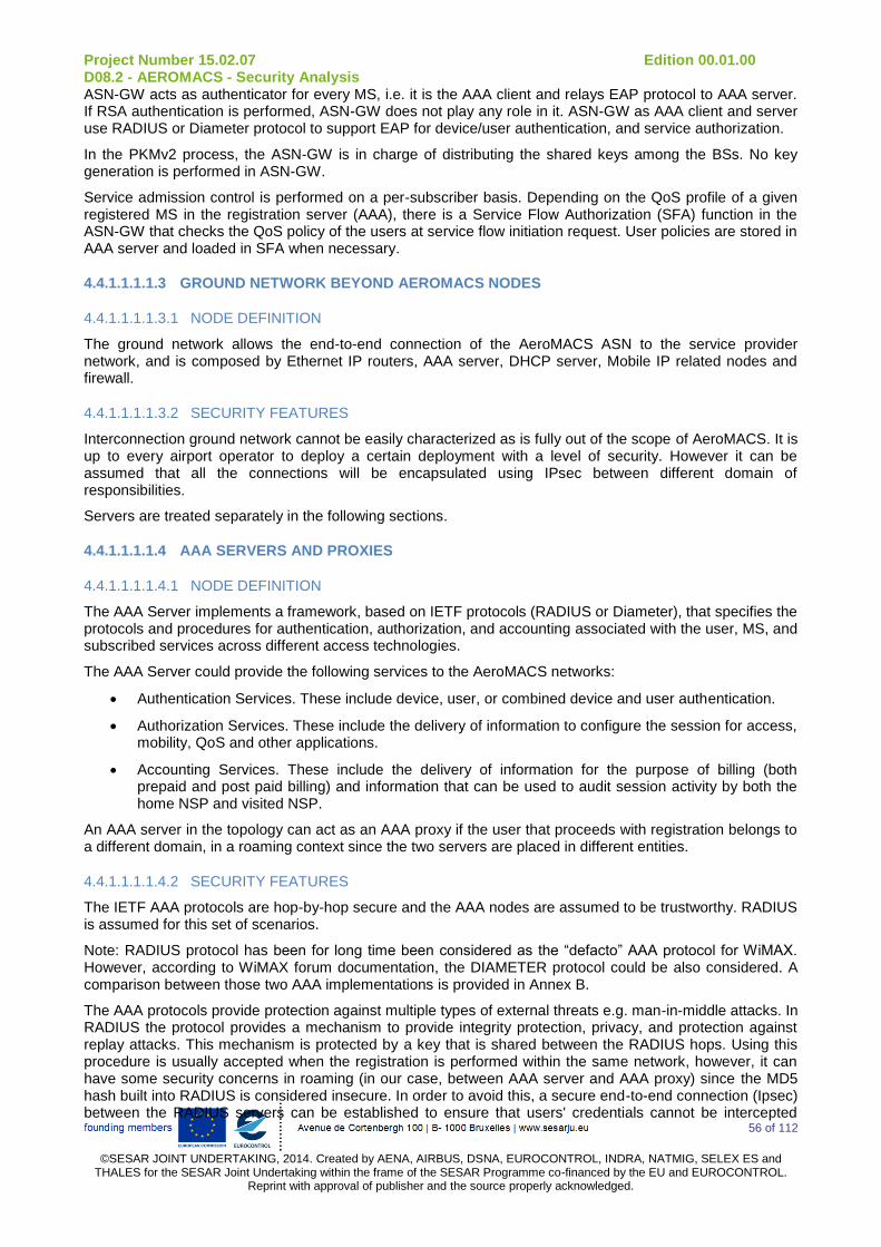
Project Number 15.02.07 Edition 00.01.00 D08.2 - AEROMACS - Security Analysis
56 of 112
©SESAR JOINT UNDERTAKING, 2014. Created by AENA, AIRBUS, DSNA, EUROCONTROL, INDRA, NATMIG, SELEX ES and
THALES for the SESAR Joint Undertaking within the frame of the SESAR Programme co-financed by the EU and EUROCONTROL. Reprint with approval of publisher and the source properly acknowledged.
ASN-GW acts as authenticator for every MS, i.e. it is the AAA client and relays EAP protocol to AAA server. If RSA authentication is performed, ASN-GW does not play any role in it. ASN-GW as AAA client and server use RADIUS or Diameter protocol to support EAP for device/user authentication, and service authorization.
In the PKMv2 process, the ASN-GW is in charge of distributing the shared keys among the BSs. No key generation is performed in ASN-GW.
Service admission control is performed on a per-subscriber basis. Depending on the QoS profile of a given registered MS in the registration server (AAA), there is a Service Flow Authorization (SFA) function in the ASN-GW that checks the QoS policy of the users at service flow initiation request. User policies are stored in AAA server and loaded in SFA when necessary.
4.4.1.1.1.1.3 GROUND NETWORK BEYOND AEROMACS NODES
4.4.1.1.1.1.3.1 NODE DEFINITION
The ground network allows the end-to-end connection of the AeroMACS ASN to the service provider network, and is composed by Ethernet IP routers, AAA server, DHCP server, Mobile IP related nodes and firewall.
4.4.1.1.1.1.3.2 SECURITY FEATURES
Interconnection ground network cannot be easily characterized as is fully out of the scope of AeroMACS. It is up to every airport operator to deploy a certain deployment with a level of security. However it can be assumed that all the connections will be encapsulated using IPsec between different domain of responsibilities.
Servers are treated separately in the following sections.
4.4.1.1.1.1.4 AAA SERVERS AND PROXIES
4.4.1.1.1.1.4.1 NODE DEFINITION
The AAA Server implements a framework, based on IETF protocols (RADIUS or Diameter), that specifies the protocols and procedures for authentication, authorization, and accounting associated with the user, MS, and subscribed services across different access technologies.
The AAA Server could provide the following services to the AeroMACS networks:
Authentication Services. These include device, user, or combined device and user authentication.
Authorization Services. These include the delivery of information to configure the session for access, mobility, QoS and other applications.
Accounting Services. These include the delivery of information for the purpose of billing (both prepaid and post paid billing) and information that can be used to audit session activity by both the home NSP and visited NSP.
An AAA server in the topology can act as an AAA proxy if the user that proceeds with registration belongs to a different domain, in a roaming context since the two servers are placed in different entities.
4.4.1.1.1.1.4.2 SECURITY FEATURES
The IETF AAA protocols are hop-by-hop secure and the AAA nodes are assumed to be trustworthy. RADIUS is assumed for this set of scenarios.
Note: RADIUS protocol has been for long time been considered as the “defacto” AAA protocol for WiMAX. However, according to WiMAX forum documentation, the DIAMETER protocol could be also considered. A comparison between those two AAA implementations is provided in Annex B.
The AAA protocols provide protection against multiple types of external threats e.g. man-in-middle attacks. In RADIUS the protocol provides a mechanism to provide integrity protection, privacy, and protection against replay attacks. This mechanism is protected by a key that is shared between the RADIUS hops. Using this procedure is usually accepted when the registration is performed within the same network, however, it can have some security concerns in roaming (in our case, between AAA server and AAA proxy) since the MD5 hash built into RADIUS is considered insecure. In order to avoid this, a secure end-to-end connection (Ipsec) between the RADIUS servers can be established to ensure that users' credentials cannot be intercepted
Project Number 15.02.07 Edition 00.01.00 D08.2 - AEROMACS - Security Analysis
57 of 112
©SESAR JOINT UNDERTAKING, 2014. Created by AENA, AIRBUS, DSNA, EUROCONTROL, INDRA, NATMIG, SELEX ES and
THALES for the SESAR Joint Undertaking within the frame of the SESAR Programme co-financed by the EU and EUROCONTROL. Reprint with approval of publisher and the source properly acknowledged.
while being proxied across the non-trusted network, IPsec is not part of the RADIUS protocol and the decision on a specific protection method remains a deployment-specific decision. We will assume IPSec is only used for the connection between AAA proxy and AAA server, not inside the airport network.
RADIUS uses a number of data stores. These include the user’s identity store, policy stores, and an accounting store that contains accounting information collected for a period of time. These stores must be secured and maintained but the decision on specific mechanisms is manufacturer Dependant.
4.4.1.1.1.1.5 DHCP SERVER
4.4.1.1.1.1.5.1 NODE DEFINITION
Each AeroMACS MS owns a univocal IP address, it is the main way for the network to identify it and the only way for the MS to send & receive data. In the AeroMACS Network Entry procedure the last phase is the “establish IP connectivity”. To obtain an IP address the MS shall find the right DHCP Server and once located the DHCP server it will assign a unique IP address to the MS.
Even in scenarios where IPv6 architecture is deployed and auto configuration is used, a DHCP server is still present and used for DNS allocation. When IPv6 will be analyzed for AeroMACS network, this scenario will be considered. In this study, the existence of a DHCP server is assumed.
4.4.1.1.1.1.5.2 SECURITY FEATURES
The standard procedure to obtain an IP address is quite insecure. The DHCP client (MS) broadcast discovery messages (DHCPDISCOVER) containing own MAC address and DHCP servers respond by offering (DHCPOFFER) to lease an IP address and other TCP/IP settings that the MS can use to communicate on the network. The client responds (DHCPREQUEST) to the first lease offer it receives and the server acknowledges (DHCPACK) the request and marks the address as leased in its DHCP database. In AeroMACS there are two different DHCP deployment modes possible:
DHCP proxy is in the ASN, in the ASN-GW for the FAD;
DHCP relay in the ASN (in the ASN-GW for the FAD) and DHCP server is located in the CSN.
In the first case the ASN-GW receives the DHPC Discover from the MS and it will answer directly. In this case the DHCP Server is the ASN-GW. On air the communication is protected with radio encryption and on R6 only if the GRE tunnels are ciphered (e.g. with IPSEC).
In the second case the DHCP relay sends messages to the external DHCP server, it is in the CSN, on R3 interface. This interface is insecure and not standardized in AeroMACS networks and it could be protected using IPSec.
The DHCP Server has a pool of IP addresses to manage and these IP Addresses are allocated to the AeroMACS MSs. This pool must be secured and maintained but the decision on specific mechanisms is manufacturer Dependant.
4.4.1.1.1.2 AIRBORNE TOPOLOGY
4.4.1.1.1.2.1 AEROMACS MOBILE STATION
4.4.1.1.1.2.1.1 NODE DEFINITION
Mobile Station (MS) is the subscriber side of the service flows in the air interface. It is also a host or a CPE supporting multiple hosts. The link connectivity and resource allocation for every MS are managed by the corresponding BS. An MS can initiate a network entry or handover, but final decision and authorization comes from BS.
4.4.1.1.1.2.1.2 SECURITY FEATURES
Regarding RF protection, AeroMACS uses inherently OFDM and subcarrier permutation schemes in order to provide frequency diversity. It also provides an adaptive modulation/coding and power control mechanism to improve the link quality. However, this improvement has a limit (most robust modulation scheme can be QPSK1/2, and transmitted power is limited by regulation in airport). At a signal loss, MS stores the operational information and tries to reacquire the lost channel for a while (implementation-dependent). If no
Project Number 15.02.07 Edition 00.01.00 D08.2 - AEROMACS - Security Analysis
58 of 112
©SESAR JOINT UNDERTAKING, 2014. Created by AENA, AIRBUS, DSNA, EUROCONTROL, INDRA, NATMIG, SELEX ES and
THALES for the SESAR Joint Undertaking within the frame of the SESAR Programme co-financed by the EU and EUROCONTROL. Reprint with approval of publisher and the source properly acknowledged.
re-acquisition is possible, it performs a complete re-entry to the system by scanning for possible channels with reachable BSs.
The MS performs authentication with the BS (if RSA used) or with AAA server (if EAP is used). During authentication process, PKMv2 key exchange and authorization is used that provides mutual authentication. There are two possible methods:
If EAP is used for PKMv2, both device and user authentication are possible. EAP is an end-to-end security protocol. For device authentication, X.509 over EAP-TLS is used. For user authentication, either EAP-AKA or EAP-TTLS are used. Also, EAP-SIM, EAP-PEAP are optionally supported. MS normally checks the revocation status of AAA server X.509 certificate at the time of authentication in order to provide end-to-end authentication.
If RSA based on X.509 certificate (PKI) is used, only device authentication is possible, there are no user authentication related procedures. RSA applies only to the air interface between MS and BS.
If user and device credentials are distinct and both need to be authenticated, either a tunnelling EAP method (EAP-TTLS) or a credential combining can be used in a single EAP session. However, this is only feasible if the AAA server for user and device authentication is the same. If AAA servers that authenticate user and device are different, a double authentication must be used. In current standard, only RSA+EAP is supported. In IEEE802.16e standard, also EAP+authenticated EAP and RSA+authenticated EAP are possible.
During authentication, MS receives the shared keys pre-PAK or MSK from BS in order to generate the AK and TEK together with its MAC address. In the process of key generation, function DOT16KDF that employs CMAC algorithm is used in order to guarantee the cryptographic independence of AK at every MS. At every TEK refresh, the MS requests the BS for the new key.
Optionally multicast group keying can be supported. For group multicast connections, shared keys are generated among all MSs. Also GKEK (from which GTEK is generated) is sent to all MSs. Multicast connections must use different SA than unicast connections.
Basic and primary connections, which carry management messages, do not cipher, nor authenticate messages. Transport connections can be handled independently and be assigned security associations (SA). Security Association (SA) associates key material and connection, i.e. every CID is mapped to a SAID if it supports security. Every MS must be able to support at least 2 transport SAs according to WiMAX. SA information includes current cryptographic suite, used TEK, KEK, PN and associated lifetimes. SAID is updated in the MS by the target BS during handover.
Every MS establishes a primary SA with the BS. The rest of SAs are static as they are provisioned by the BS. If a pair BS/MS has no authorization policy, there is no related SA.
4.4.1.1.1.2.2 AIRBORNE TOPOLOGY BEYOND THE AEROMACS MOBILE STATION
4.4.1.1.1.2.2.1 NODE DEFINITION
The airborne topology can be divided in three domains. ACD (Aircraft Control Domain), AISD (Airline Information Service Domain) and PIESD (Passenger Information and Entertainment Services Domain) are the three main domains in the aircraft. From a security point of view, they are represented from left to right, left being the most secure domain and right less secure domain. The ACD is the heart of the aircraft, it contains the most critical functions of the aircraft and that is why it is much more secure than AISD and PIESD.
There are two possible ways to connect AeroMACS inside the aircraft:
Option 1: AeroMACS is connected to the ACD;
Option 2: AeroMACS is connected to the AISD.
4.4.1.1.1.2.3 SECURITY FEATURES
The onboard router does not implement security functions, the latters are provided by firewalls. Firewalls filter flows passing through them. But, an important thing to know is that firewalls always allow flow going from the most secured domain to a less secure domain (e.g. ACD to AISD). This is called segregation between domains and the main reason why there is two way of connection of the AeroMACS to the aircraft.
For example, communications between ACD and AISD are very restricted in the way AISD to ACD, the firewall between both domains filters every packet going from AISD to ACD but not all coming from ACD to
Project Number 15.02.07 Edition 00.01.00 D08.2 - AEROMACS - Security Analysis
59 of 112
©SESAR JOINT UNDERTAKING, 2014. Created by AENA, AIRBUS, DSNA, EUROCONTROL, INDRA, NATMIG, SELEX ES and
THALES for the SESAR Joint Undertaking within the frame of the SESAR Programme co-financed by the EU and EUROCONTROL. Reprint with approval of publisher and the source properly acknowledged.
AISD. This is the same between sub-domains Flight Domain and Flight IS Domain. Others firewalls also implement rules of filtering, firewalls that are implemented inside routers with connection of AeroMACS filter flows coming from the ground. Moreover, a security feature that is not shown in the figure is robustness of the applications inside the ACD.
The only router able to support an encrypted connection (type is not defined nowadays) is the AISD router, option 2, which is the embedded router connected to the AISD domain (as it is the case for the all the embedded domains such as the ACD for instance).
4.4.1.2 SIMULATION INPUTS
Table 14 summarizes the main simulation inputs that we used in this study:
Node ID Function value
Class value
# Connected nodes
# security protection
# vulnerabilities
Base Stations 1 1 3 / 4 / 5 8 1
Aircraft 0.7 1 1 2 0
Surface vehicles 0.7 1 1 2 0
AAA Server 0.3 1 1 3 20
DHCP Server 0.3 1 1 1 64
ASN Gateway 0.3 1 14 2 1
ATS Server 0.3 1 1 1 47
AOC Server 0.3 0.7 1 1 47
APC Server 0.3 0.1 1 1 13
Table 14: Simulation parameters
Function values and class values are explained in section 4.2.2. Number of connected nodes and security protections are derived from the topologies all the partners agreed on. Number of vulnerabilities is based on realistic hypothesis made for COTS products from the NVD database.
4.4.1.3 VULNERABILITY STATISTICS
The following table illustrates the repartition of the CVSS score for each node in the network (please note that the terminology and taxonomy used in the NVD database has been respected):
CVSS score Number of total vulnerabilities Percentage
[0,1] 0 0%
[1,2] 2 0.995%
[2,3] 1 0.498%
[3,4] 0 0%
[4,5] 7 3.483%
[5,6] 11 5.473%
[6,7] 4 1.990%
[7,8] 111 55.224%
[8,9] 0 0%
[9,10] 65 32.338%

Project Number 15.02.07 Edition 00.01.00 D08.2 - AEROMACS - Security Analysis
60 of 112
©SESAR JOINT UNDERTAKING, 2014. Created by AENA, AIRBUS, DSNA, EUROCONTROL, INDRA, NATMIG, SELEX ES and
THALES for the SESAR Joint Undertaking within the frame of the SESAR Programme co-financed by the EU and EUROCONTROL. Reprint with approval of publisher and the source properly acknowledged.
Total 201 -
Average score 7.938
Table 15: Vulnerability CVSS statistics
The most part of the scores are ranked in the [7,8] NVD CVSS interval (and represent 55.224% of the total vulnerability scores). The maximum CVSS scores ranked between 9 and 10 are in most cases relative to the DHCP server node, which explains why this node has the highest individual risk value among the network. The average CVSS score has been measured to 7.938.
0
20
40
60
80
100
120
2 17
11
4
111
65
[0,1]
[1,2]
[2,3]
[3,4]
[4,5]
[5,6]
[6,7]
[7,8]
[8,9]
[9,10]
CVSS Score
Nu
mb
er
of V
uln
era
bilitie
s
Figure 10 : Vulnerability CVSS score distribution for all nodes
4.4.1.4 INDIVIDUAL RISK RESULTS
Project Number 15.02.07 Edition 00.01.00 D08.2 - AEROMACS - Security Analysis
61 of 112
©SESAR JOINT UNDERTAKING, 2014. Created by AENA, AIRBUS, DSNA, EUROCONTROL, INDRA, NATMIG, SELEX ES and
THALES for the SESAR Joint Undertaking within the frame of the SESAR Programme co-financed by the EU and EUROCONTROL. Reprint with approval of publisher and the source properly acknowledged.
0
1
2
3
4
5
6
7
0,23 0,3 0,38 0,5
1,64
6,62
3,22 3,22
0,46
Base_Station_1
Base_Station_7
Base_Station_9
Aircraft_1
Vehicle_1
ASN_Gateway
AAA_Server
DHCP_Server
ATS_Server
AOC_Server
APC_Server
Stations
Ind
ivid
ua
l R
isk
Figure 11: Individual risks for all network nodes
As we can see in the Figure 11, base stations and ASN Gateway individual risks are relatively low because there is only a single vulnerability for these nodes. Despite having the same specific vulnerability (CVE-2008-1542), there is a difference (evaluated from 0.075 to 0.15) between Base_Station_8, Base_Station_9 and the seven first base stations individual risks. This is mainly due to the higher number of connected nodes of Base_Station_8 and Base_Station_9, which increases their node values. Another interesting fact is that APC_Server and ASN Gateway individual risks are nearly close (respectively 0.5 and 0.46) despite a big difference in the number of intrinsic vulnerabilities on each of them (respectively 1 and 13). Indeed, we shall expect a higher individual risk for the APC_Server node as long as it has more vulnerabilities, however the ASN Gateway compensates the gap with the highest node value in the network (equal to 14) whereas the APC_Server, giving it functionality and traffic class value is the lowest one (equal to 0.03). The DHCP_Server node is the most vulnerable node in the network, and consequently has the highest individual risk out there (assessed to 6.62). The FreeRadius server is the most vulnerable node in the network with 64 vulnerabilities and very high CVSS scores: 92.12% of these them have top CVSS score (meaning 10, the highest score in the NVD database). Even the lowest CVSS score is relatively high (9.3) if we compared to base stations or ASN Gateway vulnerability scores (respectively 7.5 and 5.0). Finally AAA_Server, ATS and AOC servers, regarding the assumptions made in the inputs, are quite logical and get medium individual risk values due to a considerable number of intrinsic vulnerabilities. Except the ASN Gateway individual risk value which is considerably impacted by the high value of the node, all the individual risk values we measured seem to grow with the number of exploitable vulnerabilities per node taken from the NVD database (according the the different vulnerabilities provided by the inputs):
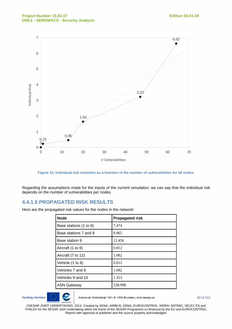
Project Number 15.02.07 Edition 00.01.00 D08.2 - AEROMACS - Security Analysis
62 of 112
©SESAR JOINT UNDERTAKING, 2014. Created by AENA, AIRBUS, DSNA, EUROCONTROL, INDRA, NATMIG, SELEX ES and
THALES for the SESAR Joint Undertaking within the frame of the SESAR Programme co-financed by the EU and EUROCONTROL. Reprint with approval of publisher and the source properly acknowledged.
0 10 20 30 40 50 60 70
0
1
2
3
4
5
6
7
00,23
0,46
1,64
3,22
6,62
# Vulnerabilities
Ind
ivid
ua
l R
isk
Figure 12: Individual risk evolution as a function of the number of vulnerabilities for all nodes.
Regarding the assumptions made for the inputs of the current simulation; we can say that the individual risk depends on the number of vulnerabilities per nodes.
4.4.1.5 PROPAGATED RISK RESULTS
Here are the propagated risk values for the nodes in the network:
Node Propagated risk
Base stations (1 to 6) 7.474
Base stations 7 and 8 9.965
Base station 9 12.456
Aircraft (1 to 6) 0.812
Aircraft (7 to 12) 1.082
Vehicle (1 to 6) 0.812
Vehicles 7 and 8 1.082
Vehicles 9 and 10 1.353
ASN Gateway 538.998

Project Number 15.02.07 Edition 00.01.00 D08.2 - AEROMACS - Security Analysis
63 of 112
©SESAR JOINT UNDERTAKING, 2014. Created by AENA, AIRBUS, DSNA, EUROCONTROL, INDRA, NATMIG, SELEX ES and
THALES for the SESAR Joint Undertaking within the frame of the SESAR Programme co-financed by the EU and EUROCONTROL. Reprint with approval of publisher and the source properly acknowledged.
DHCP and AAA server 1.2
ATS server 0.398
AOC server 0.750
APC server 0.135
Table 16: Propagated risk values for all nodes
The propagated risk results are mainly impacted by the importance of the connected node number parameter in the algorithm. For instance, we have made assumptions regarding the topology of this scenario for the base stations: the first 6 base stations are connected to three nodes (i.e. one aircraft, one vehicle, and the ASN gateway), base stations 7 and 8 are connected to four nodes (+ another vehicle) and the last base station to five nodes. The remaining parameters (security protection, offered service, exchanged data, of NVD vulnerabilities) are always the same. However, the propagated risk values are slightly different (ranging from 7.474 to 12.456) because of different correlation density in the network.
The propagated risk for the aircraft also deserves to be deeply discussed. Indeed, as we can see, it is not the same for the 6 first aircraft (equal to 0.812) as the 6 last ones (equal to 1.082). However, the justification does not lay in the connected node parameter this time as far as all aircraft are connected to a single base station. The difference between propagated risk for the aircraft (assessed to 0.27) is due to intrinsic vulnerabilities and the individual risk specific to the base station to which the aircraft is connected to. DHCP, AAA, ATS, AOC, and APC servers have all low propagated risk values (ranging from 0.135 to 1.2) because all of them are connected to a single node (the ASN gateway) which has a very low individual risk (equal to 0.5).
As we can see, the most important result in this simulation is the propagated risk value of the ASN gateway, which supersedes all the remaining nodes. This is likely due to a high node correlation for the ASN gateway: as far as it is the 'core' of the topology where all node exchanges have to pass through the gateway, it is logically impacted by the other nodes and their specific vulnerabilities. The concept of propagated risk lies in the importance of the connected node number parameter as we can see in the following figure:
Figure 13: Propagated risk evaluation as function of connected nodes for all network nodes
4.4.1.6 NODE AND NETWORK RISK RESULTS
The node risk of the ASN Gateway is hardly impacted by the high-propagated risk of the node (cf. the formula of node risk evaluation). Besides, the high node value of the ASN Gateway plays a major role in the

Project Number 15.02.07 Edition 00.01.00 D08.2 - AEROMACS - Security Analysis
64 of 112
©SESAR JOINT UNDERTAKING, 2014. Created by AENA, AIRBUS, DSNA, EUROCONTROL, INDRA, NATMIG, SELEX ES and
THALES for the SESAR Joint Undertaking within the frame of the SESAR Programme co-financed by the EU and EUROCONTROL. Reprint with approval of publisher and the source properly acknowledged.
growth of the node risk value: even the highest node risk (which is relevant to the Base Station 9) is 117 times smaller than the ASN Gateway node risk.
Consequently, as the network risk is given by the sum of the node risk, the network risk is mainly represented by the ASN Gateway node risk as we can see in the following chart:
96,12%
3,88%
ASN_Gateway remaining_nodes
Figure 14: Percentage of network risk per node risk
The detailed node risk repartition compared to the network risk is given in the following table:
Node Node risk % of network risk
All base stations 284,866 3,63%
All aircraft 8,337 0,11%
All vehicles 6,821 0,09%
AAA server 0,851 0,01%
DHCP server 2,346 0,03%
ATS server 1,085 0 ,01%
AOC server 0,833 0,01%
APC server 0,017 0%
ASN Gateway 7552,98 96,12%
Table 17: Node risk statisctics
Here is the contribution (%) of each connected node with the ASN_Gateway propagated risk:
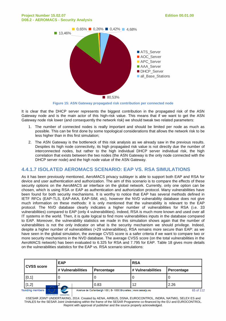
Project Number 15.02.07 Edition 00.01.00 D08.2 - AEROMACS - Security Analysis
65 of 112
©SESAR JOINT UNDERTAKING, 2014. Created by AENA, AIRBUS, DSNA, EUROCONTROL, INDRA, NATMIG, SELEX ES and
THALES for the SESAR Joint Undertaking within the frame of the SESAR Programme co-financed by the EU and EUROCONTROL. Reprint with approval of publisher and the source properly acknowledged.
0,42%0,26%0,65%13,46%
80,53%
4,68%
ATS_Server
AOC_Server
APC_Server
AAA_Server
DHCP_Server
all_Base_Stations
Figure 15: ASN Gateway propagated risk contribution per connected node
It is clear that the DHCP server represents the biggest contribution in the propagated risk of the ASN Gateway node and is the main actor of this high-risk value. This means that if we want to get the ASN Gateway node risk lower (and consequently the network risk) we should tweak two related parameters:
1. The number of connected nodes is really important and should be limited per node as much as possible. This can be first done by some topological considerations that allows the network risk to be less higher than in this first simulation;
2. The ASN Gateway is the bottleneck of this risk analysis as we already saw in the previous results. Despites its high node connectivity, its high propagated risk value is not directly due the number of interconnected nodes, but rather to the high individual DHCP server individual risk, the high correlation that exists between the two nodes (the ASN Gateway is the only node connected with the DHCP server node) and the high node value of the ASN Gateway.
4.4.1.7 ISOLATED AEROMACS SCENARIO: EAP VS. RSA SIMULATIONS
As it has been previously mentioned, AeroMACS privacy sublayer is able to support both EAP and RSA for device and user authentication and authorization. The aim of this scenario is to compare the effects of these security options on the AeroMACS air interface on the global network. Currently, only one option can be chosen, which is using RSA or EAP as authentication and authorization protocol. Many vulnerabilities have been found for both security mechanisms. It is worthy to notice that EAP has several methods defined in IETF RFCs (EAP-TLS, EAP-AKA, EAP-SIM, etc), however the NVD vulnerability database does not give much information on these methods: it is only mentioned that the vulnerability is relevant to the EAP protocol. The NVD database clearly indicates a higher number of vulnerabilities for RSA (i.e. 33 vulnerabilities) compared to EAP (only 4 vulnerabilities). Indeed, RSA is much more known and used over all IT systems in the world. Then, it is quite logical to find more vulnerabilities inputs in the database compared to EAP. Moreover, the vulnerability statistics we made in this simulation shows again that the number of vulnerabilities is not the only indicator on what is the security mechanism we should privilege. Indeed, despite a higher number of vulnerabilities (+29 vulnerabilities), RSA remains more secure than EAP: as we have seen in the global simulation, the average CVSS score is a safer criteria if we want to compare two or more security mechanisms in the NVD database. The average CVSS score (on the total vulnerabilities in the AeroMACS network) has been evaluated to 6.325 for RSA and 7.795 for EAP. Table 18 gives more details on the vulnerabilities statistics for the EAP vs. RSA scenario simulations:
CVSS score EAP RSA
# Vulnerabilities Percentage # Vulnerabilities Percentage
[0,1] 0 0 0 0
[1,2] 2 0.83 12 2.26

Project Number 15.02.07 Edition 00.01.00 D08.2 - AEROMACS - Security Analysis
66 of 112
©SESAR JOINT UNDERTAKING, 2014. Created by AENA, AIRBUS, DSNA, EUROCONTROL, INDRA, NATMIG, SELEX ES and
THALES for the SESAR Joint Undertaking within the frame of the SESAR Programme co-financed by the EU and EUROCONTROL. Reprint with approval of publisher and the source properly acknowledged.
[2,3] 1 0.415 11 2.072
[3,4] 0 0 10 1.883
[4,5] 7 2.905 107 20.151
[5,6] 31 12.863 121 22.787
[6,7] 4 1.66 24 4.52
[7,8] 121 50.207 161 30.32
[8,9] 0 0 0 0
[9,10] 75 31.12 85 16.008
Total 241 - 531 -
Average Score 7.795 6.325
Table 18: EAP vs. RSA Vulnerability Statistics
[0,1] [1,2] [2,3] [3,4] [4,5] [5,6] [6,7] [7,8] [8,9] [9,10]
0
20
40
60
80
100
120
140
160
180
EAP
RSA
CVSS Score
Nu
mb
er
of V
uln
era
bilitie
s
Figure 16: Vulnerability CVSS Score Distribution for EAP and RSA
However, the average CVSS score should be weighted accordingly to the individual risk values obtained after the simulation. Indeed, Figure 17 shows the individual risk values updated for the base stations and the ASN Gateway (all the remaining nodes are not represented since there is no change to notice on them). The higher number of vulnerabilities for RSA makes naturally the individual risk higher than EAP for both base stations and the ASN Gateway (+16.35 and +14.8 respectively for RSA and EAP). These results suggest first that the number of vulnerabilities remains important parameters because the individual risk is computed as a sum of likelihood of occurrence of a threat and its impact on the total number of vulnerabilities: since RSA has much more inputs in the NVD database, the individual risk relevant to EAP is lower.

Project Number 15.02.07 Edition 00.01.00 D08.2 - AEROMACS - Security Analysis
67 of 112
©SESAR JOINT UNDERTAKING, 2014. Created by AENA, AIRBUS, DSNA, EUROCONTROL, INDRA, NATMIG, SELEX ES and
THALES for the SESAR Joint Undertaking within the frame of the SESAR Programme co-financed by the EU and EUROCONTROL. Reprint with approval of publisher and the source properly acknowledged.
Base_Station_1 ASN_Gateway
0
2
4
6
8
10
12
14
16
18
20
2,0293,330
18,38 18,13
EAP
RSA
Ind
ivid
ua
l R
isk
Figure 17: Individual risk for base stations and the ASN Gateway (EAP vs. RSA)
As a conclusion, if we want to take the risk individually by node, it is clear that EAP should be used for authentication and authorization in the AeroMACS nodes. However, the propagated risk results should be also considered to effectively make final guidances on the use of EAP or RSA protocols.
Base StationsAircrafts
VehiclesAAA_Server
DHCP_ServerATS_Server
AOC_ServerAPC_Server
0
20
40
60
80
100
120
140
160
180
200
33,19
7,32 7,32 7,99 7,99 7,77 5,00 0,90
180,67
66,34 66,34
43,51 43,51 42,32
27,20
4,90
EAP
RSA
Pro
pa
ga
ted
Ris
k
Figure 18: Propagated risk for all nodes (EAP vs RSA)
Figure 18 shows the propagated risk values using EAP or RSA protocols for all network nodes (except the ASN Gateway which has a very big propagated risk value and is not represented for clarity matters).
The same comments for the individual risks remain true here: the EAP authentication protocol induces a lower propagated risk compared to the RSA protocol. The ASN Gateway is still the bottleneck in both sub-scenarios since it has the largest propagated risk among all the network nodes (1042.64 and 2499.87 respectively for EAP and RSA). It still has the biggest contribution in the global network risk (either for EAP or RSA) as illustrated in Table 19:

Project Number 15.02.07 Edition 00.01.00 D08.2 - AEROMACS - Security Analysis
68 of 112
©SESAR JOINT UNDERTAKING, 2014. Created by AENA, AIRBUS, DSNA, EUROCONTROL, INDRA, NATMIG, SELEX ES and
THALES for the SESAR Joint Undertaking within the frame of the SESAR Programme co-financed by the EU and EUROCONTROL. Reprint with approval of publisher and the source properly acknowledged.
Node % of network risk
EAP RSA
All base stations 6.867% 14.509%
All aircraft 0.386% 1.310%
All vehicles 0.322% 1.091%
AAA server 92.118% 82.888%
DHCP server 0.03% 0.038%
ATS server 0.135% 0.0755%
AOC server 0.081% 0.0546%
APC server 0.053% 0.030%
ASN Gateway 0% 0%
Table 19: Node risk statistics (EAP vs. RSA)
Figure 19: Percentage of network risk per node risk (EAP vs. RSA)
4.4.1.8 PRELIMINARY GUIDANCES
Even if the results of this first scenario should be discussed again regarding the end-to-end AeroMACS topology simulation results, we can already draw the big lines of the guidances that should allow us to decrease the risk level for the different network nodes:
1. Implementation guidances: Network nodes should be chosen wisely with a minimum of intrinsic vulnerabilities. IP COTS nodes (AAA Server, DHCP Server) should be discussed regarding the number of the exploitable vulnerabilities and their respective CVSS scores. It could be interesting to establish a state-of-the-art of the potentially usable IP nodes (particularly the DHCP server node), classify them by number of vulnerabilities and CVSS scores and see how the individual risk per node is affected. The nodes to be preferred are obviously the nodes with the lowest individual risks. Also the simulations of the RSA vs. EAP scenario showed that EAP induces a lower risk (individual, propagated, and network risk) for the isolated AeroMACS topology.
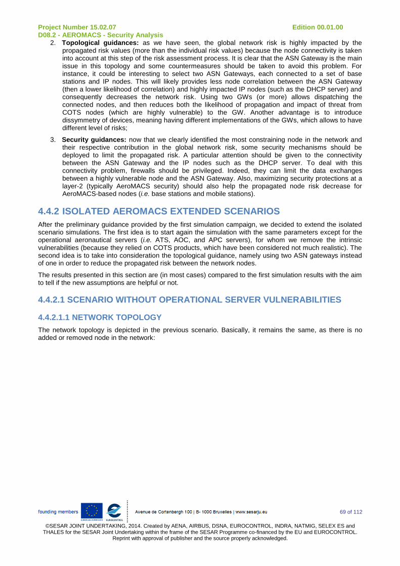
Project Number 15.02.07 Edition 00.01.00 D08.2 - AEROMACS - Security Analysis
69 of 112
©SESAR JOINT UNDERTAKING, 2014. Created by AENA, AIRBUS, DSNA, EUROCONTROL, INDRA, NATMIG, SELEX ES and
THALES for the SESAR Joint Undertaking within the frame of the SESAR Programme co-financed by the EU and EUROCONTROL. Reprint with approval of publisher and the source properly acknowledged.
2. Topological guidances: as we have seen, the global network risk is highly impacted by the propagated risk values (more than the individual risk values) because the node connectivity is taken into account at this step of the risk assessment process. It is clear that the ASN Gateway is the main issue in this topology and some countermeasures should be taken to avoid this problem. For instance, it could be interesting to select two ASN Gateways, each connected to a set of base stations and IP nodes. This will likely provides less node correlation between the ASN Gateway (then a lower likelihood of correlation) and highly impacted IP nodes (such as the DHCP server) and consequently decreases the network risk. Using two GWs (or more) allows dispatching the connected nodes, and then reduces both the likelihood of propagation and impact of threat from COTS nodes (which are highly vulnerable) to the GW. Another advantage is to introduce dissymmetry of devices, meaning having different implementations of the GWs, which allows to have different level of risks;
3. Security guidances: now that we clearly identified the most constraining node in the network and their respective contribution in the global network risk, some security mechanisms should be deployed to limit the propagated risk. A particular attention should be given to the connectivity between the ASN Gateway and the IP nodes such as the DHCP server. To deal with this connectivity problem, firewalls should be privileged. Indeed, they can limit the data exchanges between a highly vulnerable node and the ASN Gateway. Also, maximizing security protections at a layer-2 (typically AeroMACS security) should also help the propagated node risk decrease for AeroMACS-based nodes (i.e. base stations and mobile stations).
4.4.2 ISOLATED AEROMACS EXTENDED SCENARIOS
After the preliminary guidance provided by the first simulation campaign, we decided to extend the isolated scenario simulations. The first idea is to start again the simulation with the same parameters except for the operational aeronautical servers (i.e. ATS, AOC, and APC servers), for whom we remove the intrinsic vulnerabilities (because they relied on COTS products, which have been considered not much realistic). The second idea is to take into consideration the topological guidance, namely using two ASN gateways instead of one in order to reduce the propagated risk between the network nodes.
The results presented in this section are (in most cases) compared to the first simulation results with the aim to tell if the new assumptions are helpful or not.
4.4.2.1 SCENARIO WITHOUT OPERATIONAL SERVER VULNERABILITIES
4.4.2.1.1 NETWORK TOPOLOGY
The network topology is depicted in the previous scenario. Basically, it remains the same, as there is no added or removed node in the network:
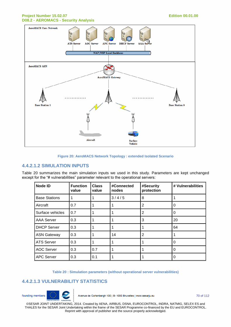
Project Number 15.02.07 Edition 00.01.00 D08.2 - AEROMACS - Security Analysis
70 of 112
©SESAR JOINT UNDERTAKING, 2014. Created by AENA, AIRBUS, DSNA, EUROCONTROL, INDRA, NATMIG, SELEX ES and
THALES for the SESAR Joint Undertaking within the frame of the SESAR Programme co-financed by the EU and EUROCONTROL. Reprint with approval of publisher and the source properly acknowledged.
Figure 20: AeroMACS Network Topology : extended Isolated Scenario
4.4.2.1.2 SIMULATION INPUTS
Table 20 summarizes the main simulation inputs we used in this study. Parameters are kept unchanged except for the “# vulnerabilities” parameter relevant to the operational servers:
Node ID Function value
Class value
#Connected nodes
#Security protection
# Vulnerabilities
Base Stations 1 1 3 / 4 / 5 8 1
Aircraft 0.7 1 1 2 0
Surface vehicles 0.7 1 1 2 0
AAA Server 0.3 1 1 3 20
DHCP Server 0.3 1 1 1 64
ASN Gateway 0.3 1 14 2 1
ATS Server 0.3 1 1 1 0
AOC Server 0.3 0.7 1 1 0
APC Server 0.3 0.1 1 1 0
Table 20 : Simulation parameters (without operational server vulnerabilities)
4.4.2.1.3 VULNERABILITY STATISTICS
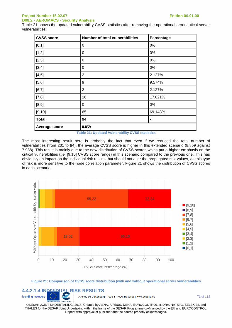
Project Number 15.02.07 Edition 00.01.00 D08.2 - AEROMACS - Security Analysis
71 of 112
©SESAR JOINT UNDERTAKING, 2014. Created by AENA, AIRBUS, DSNA, EUROCONTROL, INDRA, NATMIG, SELEX ES and
THALES for the SESAR Joint Undertaking within the frame of the SESAR Programme co-financed by the EU and EUROCONTROL. Reprint with approval of publisher and the source properly acknowledged.
Table 21 shows the updated vulnerability CVSS statistics after removing the operational aeronautical server vulnerabilities:
CVSS score Number of total vulnerabilities Percentage
[0,1] 0 0%
[1,2] 0 0%
[2,3] 0 0%
[3,4] 0 0%
[4,5] 2 2.127%
[5,6] 9 9.574%
[6,7] 2 2.127%
[7,8] 16 17.021%
[8,9] 0 0%
[9,10] 65 69.148%
Total 94 -
Average score 8.859
Table 21: Updated Vulnerability CVSS statistics
The most interesting result here is probably the fact that even if we reduced the total number of vulnerabilities (from 201 to 94), the average CVSS score is higher in this extended scenario (8.859 against 7.938). This result is mainly due to the new distribution of CVSS scores which put a higher emphasis on the critical vulnerabilities (i.e. [9,10] CVSS score range) in this scenario compared to the previous one. This has obviously an impact on the individual risk results, but should not alter the propagated risk values, as this type of risk is more sensitive to the node correlation parameter. Figure 21 shows the distribution of CVSS scores in each scenario:
0 10 20 30 40 50 60 70 80 90 100
17,02
55,22
69,15
32,34
[9,10]
[8,9]
[7,8]
[6,7]
[5,6]
[4,5]
[3,4]
[2,3]
[1,2]
[0,1]
CVSS Score Percentage (%)
Wit
ho
ut
Op
. ser
ver
Vu
ln.
S1
wit
h O
p. s
erv
er v
uln
.
Figure 21: Comparison of CVSS score distribution (with and without operational server vulnerabilities
4.4.2.1.4 INDIVIDUAL RISK RESULTS

Project Number 15.02.07 Edition 00.01.00 D08.2 - AEROMACS - Security Analysis
72 of 112
©SESAR JOINT UNDERTAKING, 2014. Created by AENA, AIRBUS, DSNA, EUROCONTROL, INDRA, NATMIG, SELEX ES and
THALES for the SESAR Joint Undertaking within the frame of the SESAR Programme co-financed by the EU and EUROCONTROL. Reprint with approval of publisher and the source properly acknowledged.
Except for the operational servers, individual risk results are not altered. Indeed, beside the number of connected nodes (with is taken into account in the node value parameter), there is no consideration for node correlation in the individual risk. That being said, removing the operational server vulnerabilities does not have any impact on the other individual risk results relevant to remaining network nodes (even those directly connected to them such as the ASN GW).
Node ID Individual risk
Base stations (1 to 6) 0.23
Base stations 7 and 8 0.3
Base station 9 0.38
Aircraft (all) 0
Vehicle (all) 0
ASN Gateway 0.5
DHCP server 6.62
AAA server 1.64
ATS server 0
AOC server 0
APC server 0
Table 22: Updated Individual risk results
4.4.2.1.5 PROPAGATED RISK RESULTS
Removing the operational server vulnerabilities undeniably has a impact on the propagated risk values for all nodes in the network. As we can see, updated propagated risk values have decreased compared to values in Table 16:
Node Propagated risk
Base stations (1 to 6) 5.471
Base stations 7 and 8 8.012
Base station 9 9.586
Aircraft (1 to 6) 0.355
Aircraft (7 to 12) 0.941
Vehicle (1 to 6) 0.355
Vehicles 7 and 8 0.670
Vehicles 9 and 10 0.941
ASN Gateway 417.013
DHCP and AAA server 0.66
ATS server 0.182
AOC server 0.551
APC server 0.054
Table 23: Updated Propagated Risk Results
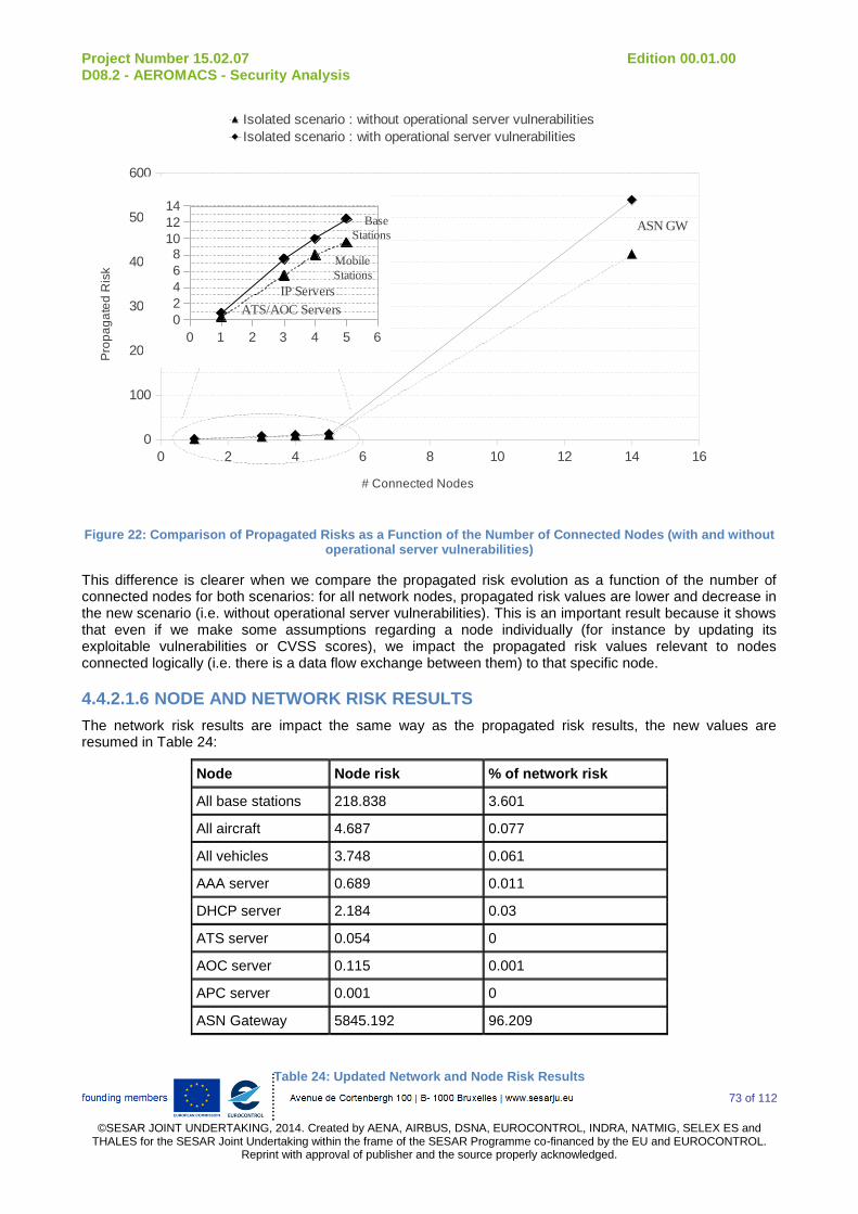
Project Number 15.02.07 Edition 00.01.00 D08.2 - AEROMACS - Security Analysis
73 of 112
©SESAR JOINT UNDERTAKING, 2014. Created by AENA, AIRBUS, DSNA, EUROCONTROL, INDRA, NATMIG, SELEX ES and
THALES for the SESAR Joint Undertaking within the frame of the SESAR Programme co-financed by the EU and EUROCONTROL. Reprint with approval of publisher and the source properly acknowledged.
0 2 4 6 8 10 12 14 16
0
100
200
300
400
500
600
Isolated scenario : without operational server vulnerabilities
Isolated scenario : with operational server vulnerabilities
# Connected Nodes
Pro
pa
ga
ted
Ris
k
ASN GW
0 1 2 3 4 5 6
0
2
4
6
810
12
14
ATS/AOC Servers
IP Servers
Mobile
Stations
Base
Stations
Figure 22: Comparison of Propagated Risks as a Function of the Number of Connected Nodes (with and without operational server vulnerabilities)
This difference is clearer when we compare the propagated risk evolution as a function of the number of connected nodes for both scenarios: for all network nodes, propagated risk values are lower and decrease in the new scenario (i.e. without operational server vulnerabilities). This is an important result because it shows that even if we make some assumptions regarding a node individually (for instance by updating its exploitable vulnerabilities or CVSS scores), we impact the propagated risk values relevant to nodes connected logically (i.e. there is a data flow exchange between them) to that specific node.
4.4.2.1.6 NODE AND NETWORK RISK RESULTS
The network risk results are impact the same way as the propagated risk results, the new values are resumed in Table 24:
Node Node risk % of network risk
All base stations 218.838 3.601
All aircraft 4.687 0.077
All vehicles 3.748 0.061
AAA server 0.689 0.011
DHCP server 2.184 0.03
ATS server 0.054 0
AOC server 0.115 0.001
APC server 0.001 0
ASN Gateway 5845.192 96.209
Table 24: Updated Network and Node Risk Results
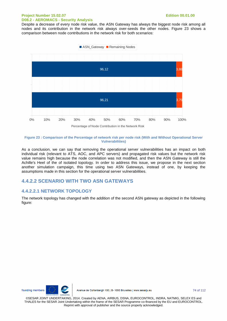
Project Number 15.02.07 Edition 00.01.00 D08.2 - AEROMACS - Security Analysis
74 of 112
©SESAR JOINT UNDERTAKING, 2014. Created by AENA, AIRBUS, DSNA, EUROCONTROL, INDRA, NATMIG, SELEX ES and
THALES for the SESAR Joint Undertaking within the frame of the SESAR Programme co-financed by the EU and EUROCONTROL. Reprint with approval of publisher and the source properly acknowledged.
Despite a decrease of every node risk value, the ASN Gateway has always the biggest node risk among all nodes and its contribution in the network risk always over-seeds the other nodes. Figure 23 shows a comparison between node contributions in the network risk for both scenarios:
0% 10% 20% 30% 40% 50% 60% 70% 80% 90% 100%
96,21
96,12
3,79
3,88
ASN_Gateway Remaining Nodes
Percentage of Node Contribution in the Network Risk
Figure 23 : Comparison of the Percentage of network risk per node risk (With and Without Operational Server Vulnerabilities)
As a conclusion, we can say that removing the operational server vulnerabilities has an impact on both individual risk (relevant to ATS, AOC, and APC servers) and propagated risk values but the network risk value remains high because the node correlation was not modified, and then the ASN Gateway is still the Achille's Heel of the of isolated topology. In order to address this issue, we propose in the next section another simulation campaign, this time using two ASN Gateways, instead of one, by keeping the assumptions made in this section for the operational server vulnerabilities.
4.4.2.2 SCENARIO WITH TWO ASN GATEWAYS
4.4.2.2.1 NETWORK TOPOLOGY
The network topology has changed with the addition of the second ASN gateway as depicted in the following figure:

Project Number 15.02.07 Edition 00.01.00 D08.2 - AEROMACS - Security Analysis
75 of 112
©SESAR JOINT UNDERTAKING, 2014. Created by AENA, AIRBUS, DSNA, EUROCONTROL, INDRA, NATMIG, SELEX ES and
THALES for the SESAR Joint Undertaking within the frame of the SESAR Programme co-financed by the EU and EUROCONTROL. Reprint with approval of publisher and the source properly acknowledged.
Figure 24: The New Isolated Network Topology using Two ASN Gateways
This topological amendment will likely reduce the correlation between a single ASN Gateway and connected nodes, as it has been considered as the central hub and point of failure in the first topology. With the introduction of a second ASN Gateway and removing the operational server vulnerabilities, the risk values should decrease.
4.4.2.2.2 SIMULATION INPUTS
Table 25 summarizes the main simulation inputs that we used in this study. The impact of the new topology resulting from the integration of a second ASN gateway implies many changes:
Servers behind the backbone are now connected to two ASN gateways (instead of only one);
The node correlation for ASN gateways is now reduced to 9 (or 10 depending on the connected BSs) instead of 14 in the first simulation;
The assumptions made for operational servers in the previous simulation (i.e. no COTS vulnerabilities) are maintained.
Node ID Function value
Class value
#Connected nodes
#Security protection
# Vulnerabilities
Base Stations 1 1 3 / 4 / 5 8 1
Aircraft 0.7 1 1 2 0
Surface vehicles 0.7 1 1 2 0
AAA Server 0.3 1 2 3 20
DHCP Server 0.3 1 2 1 64
ASN Gateway 1 0.3 1 9 2 1
ASN Gateway 2 0.3 1 10 2 1

Project Number 15.02.07 Edition 00.01.00 D08.2 - AEROMACS - Security Analysis
76 of 112
©SESAR JOINT UNDERTAKING, 2014. Created by AENA, AIRBUS, DSNA, EUROCONTROL, INDRA, NATMIG, SELEX ES and
THALES for the SESAR Joint Undertaking within the frame of the SESAR Programme co-financed by the EU and EUROCONTROL. Reprint with approval of publisher and the source properly acknowledged.
ATS Server 0.3 1 2 1 0
AOC Server 0.3 0.7 2 1 0
APC Server 0.3 0.1 2 1 0
Table 25: Simulation parameters (Scenario with Two ASN GWs)
4.4.2.2.3 VULNERABILITY STATISTICS
Same as the vulnerability statistics in the previous scenario.
4.4.2.2.4 INDIVIDUAL RISK RESULTS
As for the individual risk results in the previous scenario, the altered values are relevant to nodes that have been impacted by the new topology. Then, the individual risk results remain the same for all nodes except the IP servers (i.e. AAA and DHCP servers) and both ASN Gateways:
Node ID Individual risk
Base stations (1 to 6) 0.23
Base stations 7 and 8 0.3
Base station 9 0.38
Aircraft (all) 0
Vehicle (all) 0
ASN Gateway 1 0.32
ASN Gateway 2 0.29
DHCP server 13.24
AAA server 3.26
ATS server 0
AOC server 0
APC server 0
Table 26: Updated Individual Risk Values (Isolated Scenario With 2 ASN GWs)
As we can see in Table 26, the ASN GW risk values are lower compared to the scenario with one Gateway: indeed, the vulnerabilities (and their respective scores) are the same whereas the node connectivity has decreased (from 14 to either 9 or 10). The difference between the individual risk values for the two ASN Gateways is due to the number of connected nodes.
Moreover, we can see that the IP server individual risk values have doubled compared to the scenario with just one ASN Gateway: the DHCP and AAA servers where connected to one node (which is the ASN GW) while in the second scenario they are connected to two nodes (both ASN Gws). As all the parameters relevant to IP servers have not changed except the node connectivity ni, which is taken into account in the likelihood of occurrence of a threat formula (c.f. The first deliverable for more details), the individual risks have been multiplied by a factor of 2.
Quantitatively speaking, these new individual risk values show that globally, the risk is getting higher: we added an additional node and the intrinsic risk for IP servers has increased. But conclusions should be drawn after analyzing the propagated risk results, and more importantly, the overall network risk. That's why these results should be confronted to the propagated risk values (and later the node risk values) presented in the following section.
4.4.2.2.5 PROPAGATED RISK RESULTS

Project Number 15.02.07 Edition 00.01.00 D08.2 - AEROMACS - Security Analysis
77 of 112
©SESAR JOINT UNDERTAKING, 2014. Created by AENA, AIRBUS, DSNA, EUROCONTROL, INDRA, NATMIG, SELEX ES and
THALES for the SESAR Joint Undertaking within the frame of the SESAR Programme co-financed by the EU and EUROCONTROL. Reprint with approval of publisher and the source properly acknowledged.
As expected, adding another ASN Gateway makes the propagated risk values increase or decrease, depending on the node correlation in the new topology as shown in Table 27:
Node Propagated risk
Base stations (1 to 4) 4.469
Base stations 5 and 6 4.589
Base stations 7 and 8 6.062
Base station 9 7.518
Aircraft (1 to 4) 0.316
Aircraft 5 and 6 0.329
Aircraft (7 to 12) 0.549
Vehicle (1 to 6) 0.754
Vehicles 7 and 8 0.549
Vehicles 9 and 10 0.754
ASN Gateway 1 268.21
ASN Gateway 2 260.019
DHCP and AAA server 0.691
ATS server 0.250
AOC server 0.785
APC server 0.093
Table 27: Updated Propagated risk values (2 ASN GWs)
Unlike the previous simulation scenarios, base stations 1 to 6 do not have the same propagated risk values. Indeed, base stations 5 and 6 are connected to the ASN GW 2 (with a higher node correlation), which explains the higher propagated risk values for these base stations compared to base stations 1 to 4 (connected to the first ASN GW 1). Propagated risk values for base stations 7 to 9 have also decreased.
The observation is made for the propagated risk values relevant to the aircraft 1 to 6. In the previous scenarios, as they were connected to the same GW, they have the same propagated risk values (cf. Also tables 3 and 8), but in this case, despites having the same node correlation, aircraft 5 and 6 have slightly different propagated risk values as they are connected to the second GW.
Note that the DHCP and AAA server propagated risk values are the only results that have increased because of the higher node correlation in this scenario (two instead of one). For the ASN GWs, ss the node correlation has decreased (from 14 nodes to 9 and 10) in this scenario compared to the previous one, it is quite logical to obtain a lower propagated risk for both ASN GWs.
As a summary, propagated risk values relevant to nodes behind the backbone (belonging to the AeroMACS core network) have slightly increased whereas those relevant to nodes in the AeroMACS access service network have significantly decreased. These unbalanced changes in the propagated risk values have an impact on the network risk results as depicted in the next sub-section.
4.4.2.2.6 NODE AND NETWORK RISK RESULTS
Table 28 resumes the values for the node risks of all nodes in the new topology:
Node Node risk

Project Number 15.02.07 Edition 00.01.00 D08.2 - AEROMACS - Security Analysis
78 of 112
©SESAR JOINT UNDERTAKING, 2014. Created by AENA, AIRBUS, DSNA, EUROCONTROL, INDRA, NATMIG, SELEX ES and
THALES for the SESAR Joint Undertaking within the frame of the SESAR Programme co-financed by the EU and EUROCONTROL. Reprint with approval of publisher and the source properly acknowledged.
Base stations (1 to 4) 14.082
Base stations 5 and 6 14.433
Base stations 7 and 8 25.449
Base station 9 39.469
Aircraft (1 to 4) 0.221
Aircraft 5 and 6 0.230
Aircraft (7 to 12) 0.384
Vehicle (1 to 6) 0.221
Vehicles 7 and 8 0.384
Vehicles 9 and 10 0.527
ASN Gateway 1 725.031
ASN Gateway 2 780.927
DHCP server 8.358
AAA server 2.370
ATS server 0.15
AOC server 0.329
APC server 0.00
Table 28: Updated Node risk values (2 ASN GWs)
As expected, the node risk values have substantially decreased compared to those relevant to scenarios using a single GW, except for nodes in the AeroMACS core network (namely servers), but their respective contributions in the network risk are not really significant to be emphasized. Figure 24 shows a comparison between the network risk values for the three different simulations conducted at this stage of the study:
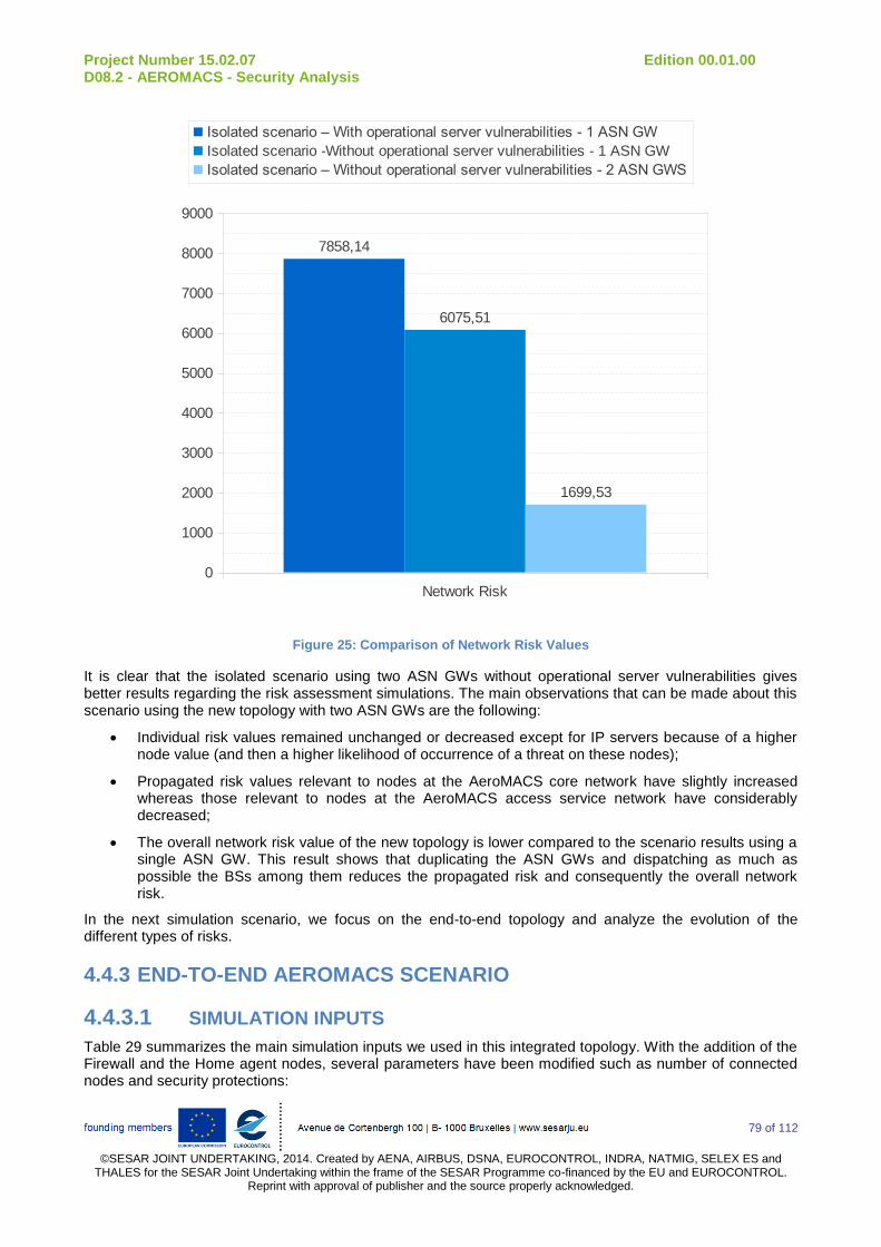
Project Number 15.02.07 Edition 00.01.00 D08.2 - AEROMACS - Security Analysis
79 of 112
©SESAR JOINT UNDERTAKING, 2014. Created by AENA, AIRBUS, DSNA, EUROCONTROL, INDRA, NATMIG, SELEX ES and
THALES for the SESAR Joint Undertaking within the frame of the SESAR Programme co-financed by the EU and EUROCONTROL. Reprint with approval of publisher and the source properly acknowledged.
Network Risk
0
1000
2000
3000
4000
5000
6000
7000
8000
9000
7858,14
6075,51
1699,53
Isolated scenario – With operational server vulnerabilities - 1 ASN GW
Isolated scenario -Without operational server vulnerabilities - 1 ASN GW
Isolated scenario – Without operational server vulnerabilities - 2 ASN GWS
Figure 25: Comparison of Network Risk Values
It is clear that the isolated scenario using two ASN GWs without operational server vulnerabilities gives better results regarding the risk assessment simulations. The main observations that can be made about this scenario using the new topology with two ASN GWs are the following:
Individual risk values remained unchanged or decreased except for IP servers because of a higher node value (and then a higher likelihood of occurrence of a threat on these nodes);
Propagated risk values relevant to nodes at the AeroMACS core network have slightly increased whereas those relevant to nodes at the AeroMACS access service network have considerably decreased;
The overall network risk value of the new topology is lower compared to the scenario results using a single ASN GW. This result shows that duplicating the ASN GWs and dispatching as much as possible the BSs among them reduces the propagated risk and consequently the overall network risk.
In the next simulation scenario, we focus on the end-to-end topology and analyze the evolution of the different types of risks.
4.4.3 END-TO-END AEROMACS SCENARIO
4.4.3.1 SIMULATION INPUTS
Table 29 summarizes the main simulation inputs we used in this integrated topology. With the addition of the Firewall and the Home agent nodes, several parameters have been modified such as number of connected nodes and security protections:

Project Number 15.02.07 Edition 00.01.00 D08.2 - AEROMACS - Security Analysis
80 of 112
©SESAR JOINT UNDERTAKING, 2014. Created by AENA, AIRBUS, DSNA, EUROCONTROL, INDRA, NATMIG, SELEX ES and
THALES for the SESAR Joint Undertaking within the frame of the SESAR Programme co-financed by the EU and EUROCONTROL. Reprint with approval of publisher and the source properly acknowledged.
Node ID Function value
Class value
# Connected nodes
# security protection
# vulnerabilities
Base Stations 1 1 3 / 4 / 5 8 1
Aircraft 0.7 1 1 2 0
Surface vehicles 0.7 1 1 2 0
AAA Server 0.3 1 2 4 20
DHCP Server 0.3 1 1 2 64
ASN Gateway 1 0.3 1 5 3 1
ASN Gateway 2 0.3 1 6 3 1
ATS Server 0.3 1 1 2 0
AOC Server 0.3 0.7 1 2 0
APC Server 0.3 0.1 1 2 0
Home Agent 1 1 2 1 4
Firewalls 1 1 2 / 3 / 6 1 1
Table 29: Simulation parameters (Integrated AeroMACS Topology)
4.4.3.2 NETWORK TOPOLOGY
As we can see in Figure 26, we added to the previous network topology (which contains two ASN GWs):
A mobile IP Home Agent (HA) node that essentially handles the following tasks:
o Registration of mobile stations;
o Routing and forwarding of mobile station traffic.
Firewalls (FW) to provide protection to:
o ASN GWs at the entry of the AeroMACS ASN;
o Operational and IP servers;
The Home Agent.
Note that with the introduction of the HA to support IP mobility, the data flow exchanges have completely been reevaluated mainly because of the mobile IP subscriber (could be an aircraft of a surface vehicle) registration process as it follows:
1. The ASN GW sends the subscriber registration request from the mobile station to the mobile IP HA. The sought ASN GW is obviously the one connected to concerned mobile stations;
2. HA requests that the AAA server (which is now directly connected to the HA node) send the cryptographic keys for the Mobile IP session. The HA announces to the AAA server that it would like to source IP session-based accounting messages;
3. The AAA server agrees to use IP session-based accounting, provides the requested cryptographic keys, and sends the AAA-Session-ID for this session;
4. The HA replies to the Mobile IP registration request.

Project Number 15.02.07 Edition 00.01.00 D08.2 - AEROMACS - Security Analysis
81 of 112
©SESAR JOINT UNDERTAKING, 2014. Created by AENA, AIRBUS, DSNA, EUROCONTROL, INDRA, NATMIG, SELEX ES and
THALES for the SESAR Joint Undertaking within the frame of the SESAR Programme co-financed by the EU and EUROCONTROL. Reprint with approval of publisher and the source properly acknowledged.
Figure 26: Integrated AeroMACS Network Topology
Note that the network topology provided in Figure 26 has been provided to match as close as possible the WiMAX end-to-end network model provided by the WiMAX Forum Network Working Group (NWG) as shown in Figure 27:
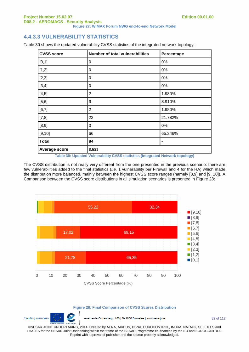
Project Number 15.02.07 Edition 00.01.00 D08.2 - AEROMACS - Security Analysis
82 of 112
©SESAR JOINT UNDERTAKING, 2014. Created by AENA, AIRBUS, DSNA, EUROCONTROL, INDRA, NATMIG, SELEX ES and
THALES for the SESAR Joint Undertaking within the frame of the SESAR Programme co-financed by the EU and EUROCONTROL. Reprint with approval of publisher and the source properly acknowledged.
Figure 27: WiMAX Forum NWG end-to-end Network Model
4.4.3.3 VULNERABILITY STATISTICS
Table 30 shows the updated vulnerability CVSS statistics of the integrated network topology:
CVSS score Number of total vulnerabilities Percentage
[0,1] 0 0%
[1,2] 0 0%
[2,3] 0 0%
[3,4] 0 0%
[4,5] 2 1.980%
[5,6] 9 8.910%
[6,7] 2 1.980%
[7,8] 22 21.782%
[8,9] 0 0%
[9,10] 66 65.346%
Total 94 -
Average score 8.651
Table 30: Updated Vulnerability CVSS statistics (Integrated Network topology)
The CVSS distribution is not really very different from the one presented in the previous scenario: there are few vulnerabilities added to the final statistics (i.e. 1 vulnerability per Firewall and 4 for the HA) which made the distribution more balanced, mainly between the highest CVSS score ranges (namely [8,9] and [9, 10]). A Comparison between the CVSS score distributions in all simulation scenarios is presented in Figure 28:
0 10 20 30 40 50 60 70 80 90 100
21,78
17,02
55,22
65,35
69,15
32,34
[9,10]
[8,9]
[7,8]
[6,7]
[5,6]
[4,5]
[3,4]
[2,3]
[1,2]
[0,1]
CVSS Score Percentage (%)
Without Op. server Vuln.
S1
with Op. server vuln.
Figure 28: Final Comparison of CVSS Scores Distribution

Project Number 15.02.07 Edition 00.01.00 D08.2 - AEROMACS - Security Analysis
83 of 112
©SESAR JOINT UNDERTAKING, 2014. Created by AENA, AIRBUS, DSNA, EUROCONTROL, INDRA, NATMIG, SELEX ES and
THALES for the SESAR Joint Undertaking within the frame of the SESAR Programme co-financed by the EU and EUROCONTROL. Reprint with approval of publisher and the source properly acknowledged.
The total number of vulnerabilities has naturally increased with the addition of the HA and Firewalls as shown in Figure 29:
Total Number of Vulnerabilities
0
50
100
150
200
250
201
94 101
Isolated Scenario – With Operational Server Vulnerabilities – 1 GW
Isolated Scenario – Without Operational Server Vulnerabilities – 2 GWs
Integrated Scenario – Without Operational Server Vulnerabilities – 2 GWs
Figure 29: Final Comparison of Total Number of Vulnerabilities
The results are quite expected and relevant to the assumptions made in each scenario. However, the most interesting part is probably the comparison between the average CVSS scores which seems to evolve at the opposite of the total number of vulnerabilities: when the total number of vulnerabilities increases, the average CVSS score is likely decreasing as we can see in the results presented in Figure 30:
Average CVSS Score
7,4
7,6
7,8
8
8,2
8,4
8,6
8,8
9
7,938
8,860
8,651
Isolated Scenario – With Operational Server Vulnerabilities – 1 GW
Isolated Scenario – Without Operational Server Vulnerabilities – 2 GWs
Integrated Scenario – Without Operational Server Vulnerabilities – 2 GWs
Figure 30 : Final Comparison of Average CVSS Score

Project Number 15.02.07 Edition 00.01.00 D08.2 - AEROMACS - Security Analysis
84 of 112
©SESAR JOINT UNDERTAKING, 2014. Created by AENA, AIRBUS, DSNA, EUROCONTROL, INDRA, NATMIG, SELEX ES and
THALES for the SESAR Joint Undertaking within the frame of the SESAR Programme co-financed by the EU and EUROCONTROL. Reprint with approval of publisher and the source properly acknowledged.
This result is important as it helps the security managers choosing the adequate COTS products when it comes to implement their solution and designing the network. In the next sections, we analyze the final individual, propagated, and network risk results, and compare them to the previous scenarios.
4.4.3.4 INDIVIDUAL RISK RESULTS
As presented in Table 31, the individual risk results are practically the apparition of the HA and Firewalls, but also values relevant to nodes for which the node connectivity or the security protection parameter has changed (taken into account respectively in the value of the node and the likelihood of occurrence of a threat):
Node ID Individual risk
Base stations (1 to 6) 0.23
Base stations 7 and 8 0.3
Base station 9 0.38
Aircraft (all) 0
Vehicle (all) 0
ASN Gateway 1 0.24
ASN Gateway 2 0.18
DHCP server 12.99
AAA server 3.07
ATS server 0
AOC server 0
APC server 0
Home Agent 1.88
Firewall 1 3.9
Firewalls (2 to 6) 5.85
Firewalls 7 and 8 11.7
Table 31: Updated Individual Risk Values (Integrated Scenario)
The nodes in the AeroMACS access service network have not been impacted by the addition of the new nodes, except the ASN Gateways protected by a firewall at the entry of the sub-network. However, all nodes in the AeroMACS CSN have either the number of security protections increased (because of the addition of the firewalls), or the number of connected nodes decreased. Firewalls do not have the same individual risk values because they are connected to the same nodes (depending where there are deployed and what node they protect).
Nevertheless, the DHCP server remains the most vulnerable node in the network mainly because of its high and critical COTS vulnerabilities. The individual risk values for the ASN Gateways have also decreased because their lower value in this scenario (connected to a lower number of nodes compared to the previous scenarios. Unlike the propagated or the network risk, it is useless here to compare the values between the different nodes because individual risks characterize the node itself, and are not related to the topological assumptions made in each simulation. However, the individual risks slightly vary, depending on the connected nodes.
Comparison is more relevant for propagated and network risk results where the addition of the firewalls is going to reduce the data flow exchanges between connected nodes (and consequently the likelihood of propagation of threats between them). The node connectivity has been also impacted because of the

Project Number 15.02.07 Edition 00.01.00 D08.2 - AEROMACS - Security Analysis
85 of 112
©SESAR JOINT UNDERTAKING, 2014. Created by AENA, AIRBUS, DSNA, EUROCONTROL, INDRA, NATMIG, SELEX ES and
THALES for the SESAR Joint Undertaking within the frame of the SESAR Programme co-financed by the EU and EUROCONTROL. Reprint with approval of publisher and the source properly acknowledged.
deployment of Firewalls at the entry of the AeroMACS access service network: in this way, ASN GWs are connected to a lower number of nodes and should have their propagated risk values decreased.
4.4.3.5 PROPAGATED RISK RESULTS
As expected, adding the Firewalls to the integrated AeroMACS topology has the advantage to get lower propagated risk values for the connected nodes as shown in the following table:
Node Propagated risk
Base stations (1 to 4) 2.429
Base stations 5 and 6 2.576
Base stations 7 and 8 5.587
Base station 9 5.911
Aircraft (1 to 4) 0.093
Aircraft 5 and 6 0.095
Aircraft (7 to 12) 0.121
Vehicle (1 to 6) 0.093
Vehicles 7 and 8 0.121
Vehicles 9 and 10 0.394
ASN Gateway 1 87.225
ASN Gateway 2 79.452
DHCP server 0.341
AAA server 0.215
ATS server 0.056
AOC server 0.221
APC server 0.008
Home Agent 0.216
Firewall 1 0.015
Firewalls (2 to 6) 15.120
Firewalls 7 and 8 45.781
Table 32: Updated Propagated risk values (Integrated Scenario)
The most important part here is obviously the decrease of the ASN Gateway propagated risk values, which are no more the points of failure of the integrated topology. Indeed, the addition of the firewalls changed completely the connectivity between nodes. In one hand, Firewalls are deployed now between the servers and the ASN Gateways, reducing the connectivity from 9 and 10 to respectively 5 and 6. In the other hand, data flows are reduced, inducing a lower likelihood of propagated between nodes.
4.4.3.6 NODE AND NETWORK RISK RESULTS
The following table resumes the final node risk results for the integrated AeroMACS scenario:
Node Propagated risk
Base stations (1 to 4) 2.429
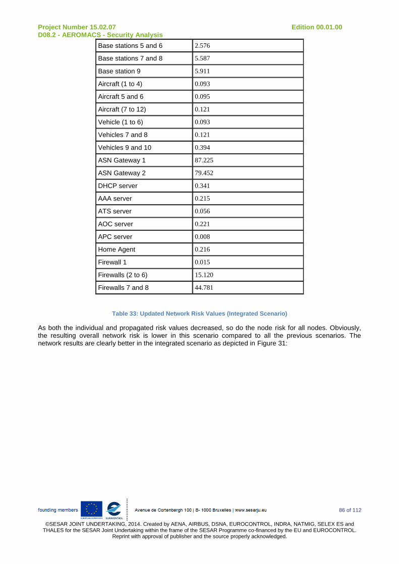
Project Number 15.02.07 Edition 00.01.00 D08.2 - AEROMACS - Security Analysis
86 of 112
©SESAR JOINT UNDERTAKING, 2014. Created by AENA, AIRBUS, DSNA, EUROCONTROL, INDRA, NATMIG, SELEX ES and
THALES for the SESAR Joint Undertaking within the frame of the SESAR Programme co-financed by the EU and EUROCONTROL. Reprint with approval of publisher and the source properly acknowledged.
Base stations 5 and 6 2.576
Base stations 7 and 8 5.587
Base station 9 5.911
Aircraft (1 to 4) 0.093
Aircraft 5 and 6 0.095
Aircraft (7 to 12) 0.121
Vehicle (1 to 6) 0.093
Vehicles 7 and 8 0.121
Vehicles 9 and 10 0.394
ASN Gateway 1 87.225
ASN Gateway 2 79.452
DHCP server 0.341
AAA server 0.215
ATS server 0.056
AOC server 0.221
APC server 0.008
Home Agent 0.216
Firewall 1 0.015
Firewalls (2 to 6) 15.120
Firewalls 7 and 8 44.781
Table 33: Updated Network Risk Values (Integrated Scenario)
As both the individual and propagated risk values decreased, so do the node risk for all nodes. Obviously, the resulting overall network risk is lower in this scenario compared to all the previous scenarios. The network results are clearly better in the integrated scenario as depicted in Figure 31:

Project Number 15.02.07 Edition 00.01.00 D08.2 - AEROMACS - Security Analysis
87 of 112
©SESAR JOINT UNDERTAKING, 2014. Created by AENA, AIRBUS, DSNA, EUROCONTROL, INDRA, NATMIG, SELEX ES and
THALES for the SESAR Joint Undertaking within the frame of the SESAR Programme co-financed by the EU and EUROCONTROL. Reprint with approval of publisher and the source properly acknowledged.
Network Risk
0
1000
2000
3000
4000
5000
6000
7000
8000
9000
7858,14
6075,51
1699,53
698,05
Isolated scenario – With operational server vulnerabilities - 1 ASN GW
Isolated scenario -Without operational server vulnerabilities - 1 ASN GW
Isolated scenario – Without operational server vulnerabilities - 2 ASN GWS
Integrated scenario – Without operational server vulnerabilities – 2 ASN GWS
Figure 31: Final Comparison of Network Risk Values
Also, the ASN GW contribution in the network risk is now more balanced than in the previous scenario as shown in figure:
0 10 20 30 40 50 60 70 80 90 100
96,12
96,21
42,66
33,83
3,88
3,79
11,39
31,95
45,95
34,22
ASN Gateway 1 ASN Gateway 2 Remaining Nodes
Figure 32: Final Comparison of the Percentage of Network Risk per Node Risk
Project Number 15.02.07 Edition 00.01.00 D08.2 - AEROMACS - Security Analysis
88 of 112
©SESAR JOINT UNDERTAKING, 2014. Created by AENA, AIRBUS, DSNA, EUROCONTROL, INDRA, NATMIG, SELEX ES and
THALES for the SESAR Joint Undertaking within the frame of the SESAR Programme co-financed by the EU and EUROCONTROL. Reprint with approval of publisher and the source properly acknowledged.
In conclusion, this figure summarizes the approach we had in our work and in the simulation campaign: at each step, we tried to enhance the results by making the adequate assumptions and by learning what should be learnt from the previous simulation results, using the risk methodology as a decision making tool. It was quite useful to reduce the network risk from 7858.14 (first scenario) to 698.05 (last scenario), showing that our predictions, guidance, and assumptions were rightly done.
4.4.3.7 FINAL GUIDANCES
The risk propagation approach we relied on in this study shows that recommendations made after the first simulation campaign (i.e. the isolated scenario – with operational server vulnerabilities) are justified and effective. The network risk has been divided by a factor of 11, which is a significant and substantial gain in term of security. The guidance’s we made in section 4.4.1.8 remain obviously effective and applicable. However, the duplication of the GW seems to have the heavier impact on the performances. The number of GWs to be deployed should be considered according to the network size and the overall number of connected nodes (BS, aircraft, surface vehicles). COTS products should be also chosen wisely, and a survey of the related vulnerabilities should be conducted uninterruptedly. Firewalls are also the best ways to avoid unwanted risk propagation between nodes, which is the main reason for high-risk levels measured in the first simulation.

Project Number 15.02.07 Edition 00.01.00 D08.2 - AEROMACS - Security Analysis
89 of 112
©SESAR JOINT UNDERTAKING, 2014. Created by AENA, AIRBUS, DSNA, EUROCONTROL, INDRA, NATMIG, SELEX ES and
THALES for the SESAR Joint Undertaking within the frame of the SESAR Programme co-financed by the EU and EUROCONTROL. Reprint with approval of publisher and the source properly acknowledged.
5 References
[1] C. J. Alberts and A. J. Dorofee, Managing Information Security Risks: The OCTAVE Approach. 2002.
[2] DCSSI, “EBIOS : Introduction, démarche, techniques, outillage.” 2004.
[3] ISO, “ISO/IEC 15408: Common Criteria for Information Technology Security Evaluation.” 1999.
[4] ISO, “ISO/IEC 27001: Information Technology, security techniques, information security management systems requirements.” 2005.
[5] ISO, “ISO/IEC 27005: Information Technology, Information Security Techniques, Information Security Risk Management.” 2008.
[6] M. L. Olive, R. T. Oishi, and S. Arentz, “Commercial Aircraft Information Security : an Overview of Arinc Report 811,” in 25th Digital Avionics Systems Conference, 2006 IEEE/AIAA, 2006, pp. 1–12.
[7] S. P. Bennett and M. P. Kailay, “An application of qualitative risk analysis to computer security for the commercial sector,” in Proc. Eighth Annual Computer Security Applications Conf., 1992, pp. 64–73.
[8] Microsoft, “The Security Risk Management Guide.” 2004.
[9] A. Barth, B. I. P. Rubinstein, M. Sundararajan, J. C. Mitchell, D. X. Song, and P. L. Bartlett, “A Learning-Based Approach to Reactive Security,” CoRR, vol. abs/0912.1, 2009.
[10] J. M. Wing, “Scenario Graphs Applied to Network Security,” in Information Assurance, Burlington: Morgan Kaufmann, 2008.
[11] G. Lao and L. Wang, “The Quantification Management of Information Security Risk,” in Proc. 4th Int. Conf. Wireless Communications, Networking and Mobile Computing WiCOM ’08, 2008, pp. 1–4.
[12] X. Chen and Q. Zheng, “Quantitative Hierarchical Threat Evaluation Model for Network Security,” Journal of Software, vol. 17, no. 4, pp. pp.885–897, Apr. 2006.
[13] Y. Danfeng, Y. Fangchun, and L. Yu, “Service-based quantitative calculation of risk for NGN,” in Proc. 2nd IEEE Int. Conf. Broadband Network & Multimedia Technology IC-BNMT ’09, 2009, pp. 306–310.
[14] R. Huang, D. Yan, and F. Yang, “Research of security metric architecture for Next Generation Network,” in Network Infrastructure and Digital Content, 2009. IC-NIDC 2009. IEEE International Conference on, 2009, pp. 207–212.
[15] T. Yongli, X. Guoai, and Y. Yixian, “Information Security Management Measurement Model based on AHP,” Journal of Liaoning Technical University, vol. 27, 2008.
[16] M. S. Ahmed, E. Al-Shaer, and L. Khan, “A Novel Quantitative Approach For Measuring Network Security,” in Proc. INFOCOM 2008. The 27th Conf. Computer Communications. IEEE, 2008, pp. 1957–1965.
[17] Q. Meng, M. H. Dong, Y. Li, and Z. W. Ming, “Network Security Analysis Model based on Logic Exploitation Graph,” in Computer Engineering, 2009, vol. 9, pp. 147–149.
[18] L. Jing, “Risk Evaluation Process Model of Information Security,” in Proc. Int. Conf. Measuring Technology and Mechatronics Automation ICMTMA ’09, 2009, vol. 2, pp. 321–324.
[19] S. S. Yau and X. Zhang, “Computer network intrusion detection, assessment and prevention based on security dependency relation,” in Proc. Twenty-Third Annual Int. Computer Software and Applications Conf. COMPSAC ’99, 1999, pp. 86–91.
[20] Y.-Z. Zhang, B.-X. Fang, and X.-C. Yun, “A risk assessment approach for network information system,” in Machine Learning and Cybernetics, 2004. Proceedings of 2004 International Conference on, 2004, vol. 5, pp. 2949 – 2952 vol.5.
[21] H. Li, G. Fan, and J. Qiu, “GKDA: A group-based key distribution algorithm for WiMAX MBS security,” Advances in Multimedia Information Processing, pp. 310–318, 2006.
[22] Y. T’Joens, C. Hublet, and P. D. Schrijver, “DHCP reconfigure extension,” no. 3203. IETF, Dec-2001.
[23] C. Perkins, “IP Mobility Support for IPv4,” no. 3344. IETF, Aug-2002.

Project Number 15.02.07 Edition 00.01.00 D08.2 - AEROMACS - Security Analysis
90 of 112
©SESAR JOINT UNDERTAKING, 2014. Created by AENA, AIRBUS, DSNA, EUROCONTROL, INDRA, NATMIG, SELEX ES and
THALES for the SESAR Joint Undertaking within the frame of the SESAR Programme co-financed by the EU and EUROCONTROL. Reprint with approval of publisher and the source properly acknowledged.
[24] ETSI, “Telecommunications and Internet Protocol Harmonization Over Networks (TIPHON) Release 4; Protocol Framework Definition; Methods and Protocols for Security; Part 1: Threat Analysis.” 2003.
[25] C. Perkins, “IP Mobility Support,” no. 2002. IETF, Oct-1996.
[26] P. Eronen, T. Hiller, and G. Zorn, “Diameter Extensible Authentication Protocol (EAP) Application,” no. 4072. IETF, Aug-2005.
[27] C. Rigney, S. Willens, A. Rubens, and W. Simpson, “Remote Authentication Dial In User Service (RADIUS),” no. 2865. IETF, Jun-2000.
[28] B. Aboba and P. Calhoun, “RADIUS (Remote Authentication Dial In User Service) Support For Extensible Authentication Protocol (EAP),” no. 3579. IETF, Sep-2003.
[29] D. Durham, J. Boyle, R. Cohen, S. Herzog, R. Rajan, and A. Sastry, “The COPS (Common Open Policy Service) Protocol,” no. 2748. IETF, Jan-2000.
[30] J. D. Case, M. Fedor, M. L. Schoffstall, and J. Davin, “Simple Network Management Protocol (SNMP),” no. 1157. IETF, May-1990.
[31] C. Neuman, T. Yu, S. Hartman, and K. Raeburn, “The Kerberos Network Authentication Service (V5),” no. 4120. IETF, Jul-2005.
[32] B. Lloyd and W. Simpson, “PPP Authentication Protocols,” no. 1334. IETF, Oct-1992.
[33] W. Simpson, “PPP Challenge Handshake Authentication Protocol (CHAP),” no. 1994. IETF, Aug-1996.
[34] D. Simon, B. Aboba, and R. Hurst, “The EAP-TLS Authentication Protocol,” no. 5216. IETF, Mar-2008.
[35] J. Arkko and H. Haverinen, “Extensible Authentication Protocol Method for 3rd Generation Authentication and Key Agreement (EAP-AKA),” no. 4187. IETF, Jan-2006.
[36] P. Funk and S. Blake-Wilson, “Extensible Authentication Protocol Tunneled Transport Layer Security Authenticated Protocol Version 0 (EAP-TTLSv0),” no. 5281. IETF, Aug-2008.
[37] C. Rigney, “RADIUS Accounting,” no. 2139. IETF, Apr-1997.
[38] W. Townsley, A. Valencia, A. Rubens, G. Pall, G. Zorn, and B. Palter, “Layer Two Tunneling Protocol ``L2TP’',” no. 2661. IETF, Aug-1999.
[39] S. Krishnan, D. Thaler, and J. Hoagland, “Security Concerns with IP Tunneling,” no. 6169. IETF, Apr-2011.
[40] [16] K. Zeilenga, “Lightweight Directory Access Protocol (LDAP): Technical Specification Road Map,” no. 4510. IETF, Jun-2006.
[41] W. Forum, “Network Architecture Stage 3: Detailed Protocols and Procedures,” vol. 05, 2010.
[42] Armando, D. Basin, Y. Boichut, Y. Chevalier, L. Compagna, J. Cuellar, P. H. Drielsma, P. C. Heam, J. Mantovani, S. Modersheim, D. von Oheimb, M. Rusinowitch, J. S. Santiago, M. Turuani, and L. Vigano, “The AVISPA Tool for the automated validation of internet security protocols and applications,” in Proceedings of CAV 2005: 17th International Conference on Computer Aided Verification, 2005.
[43] R. M. Needham and M. D. Schroeder, “Using encryption for authentication in large networks of computers,” Commun. ACM, vol. 21, no. 12, pp. 993–999, Dec. 1978.
[44] G. Lowe, “An attack on the Needham-Schroeder public-key authentication protocol,” Information Processing Letters, vol. 56, no. 3, pp. 131–133, 1995.
[45] M. Burrows, M. Abadi, and R. Needham, “A logic of authentication,” ACM TRANSACTIONS ON COMPUTER SYSTEMS, vol. 8, pp. 18–36, 1990.
[46] Y. Chevalier, L. Compagna, J. Cuellar, P. H. Drielsma, J. Mantovani, S. Modersheim, and L. Vigneron, “A High Level Protocol Specification Language for Industrial Security-Sensitive Protocols,” in Austrian Computer Society, 2004.

Project Number 15.02.07 Edition 00.01.00 D08.2 - AEROMACS - Security Analysis
91 of 112
©SESAR JOINT UNDERTAKING, 2014. Created by AENA, AIRBUS, DSNA, EUROCONTROL, INDRA, NATMIG, SELEX ES and
THALES for the SESAR Joint Undertaking within the frame of the SESAR Programme co-financed by the EU and EUROCONTROL. Reprint with approval of publisher and the source properly acknowledged.
[47] D. Basin, S. Modersheim, and L. Vigano, “Technical Report No. 450 OFMC: A Symbolic Model-Checker for Security Protocols.” 2004.
[48] D. A. Basin, “Lazy Infinite-State Analysis of Security Protocols,” in Proceedings of the International Exhibition and Congress on Secure Networking - CQRE (Secure) ’99, 1999, pp. 30–42.
[49] A. Armando and L. Compagna, “SATMC: A SAT-Based Model Checker for Security Protocols,” in Logics in Artificial Intelligence, 2004, pp. 730–733.
[50] O. K. Boichut Y. P.-C. Heam and F. Oehl, “Improvements on the Genet and Klay Technique to Automatically Verify Security Protocols,” in In Proceedings of Int. Ws. on Automated Verification of Infinite-State Systems (AVIS’2004), joint to ETAPS'04, Barcelona (Spain), 2004.
[51] V. Fajardo, Ed., J. Arkko, J. Loughney, and G. Zorn, Ed., « Diameter Base Protocol », no. 6733, IETF, October 2012.
[52] M. Schiffman, “A Complete Guide to the Common Vulnerability Scoring System (CVSS).” Jun-2005.
[53] M. S. Ben Mahmoud, N. Larrieu, and A. Pirovano, “Quantitative risk assessment to enhance aeromacs security in SESAR,” in 2012 Integrated Communications, Navigation and Surveillance Conference, 2012, pp. C7–1–C7–15.

Project Number 15.02.07 Edition 00.01.00 D08.2 - AEROMACS - Security Analysis
92 of 112
©SESAR JOINT UNDERTAKING, 2014. Created by AENA, AIRBUS, DSNA, EUROCONTROL, INDRA, NATMIG, SELEX ES and
THALES for the SESAR Joint Undertaking within the frame of the SESAR Programme co-financed by the EU and EUROCONTROL. Reprint with approval of publisher and the source properly acknowledged.
Appendix A Introduction to CVSS
CVE (Common Vulnerabilities and Exposures) is a dictionary of publicly known information security vulnerabilities and exposures. CVE’s common identifiers enable data exchange between security products and provide a baseline index point for evaluating coverage of tools and services. One of the most important component of CVE databases is the CVSS (Common Vulnerability Scoring System) which is a universal means to asset a vulnerability impact and help in finding the right countermeasures. It can be seen as an aggregation of several metrics and formulas to solve the problem of multiplicity and incompatibility between vulnerability scoring systems used in the IT industry as shown in Figure 33.
Figure 33: CVSS Metrics and Framework
Indeed, every day, several vulnerabilities are discovered for products and technologies used across world-wide networks and systems. All the actors involved in the use, development, or maintenance of such technologies have to be aware of those vulnerabilities and need a common way to communicate efficiently about them.
Historically, product vendors used own proprietary scoring systems to asset the severity of the discovered vulnerabilities, however past experience has shown that for the same vulnerability, and using different scoring systems by these actors, the impact is not the same which involves a significant uncertainty in the evaluation of vulnerability impacts.
The CVSS scoring system has been then developed to unique, open, usable, and understandable framework for all the IT actors. This framework relies on a set of metrics and equations designed to be complete, accurate, and easy to use by everyone as shown in Figure 33. For more details about CVSS, refer to [52].

Project Number 15.02.07 Edition 00.01.00 D08.2 - AEROMACS - Security Analysis
93 of 112
©SESAR JOINT UNDERTAKING, 2014. Created by AENA, AIRBUS, DSNA, EUROCONTROL, INDRA, NATMIG, SELEX ES and
THALES for the SESAR Joint Undertaking within the frame of the SESAR Programme co-financed by the EU and EUROCONTROL. Reprint with approval of publisher and the source properly acknowledged.
Appendix B Risk Assessment Process Algorigram
Begin
Variable Init.
Scan and Identify Vulnerable Nodes
Compute Individual Risk
Compute Propagation Risk
Compute total Risk
Compute the Network risk
Last
Node?
Last
Node?
Last
Node?
No
No
No
End
Step 0
Step 2
Step 3
Step 4
Step 5
Step 1
Figure 34: Risk Assessment Process Algorigram
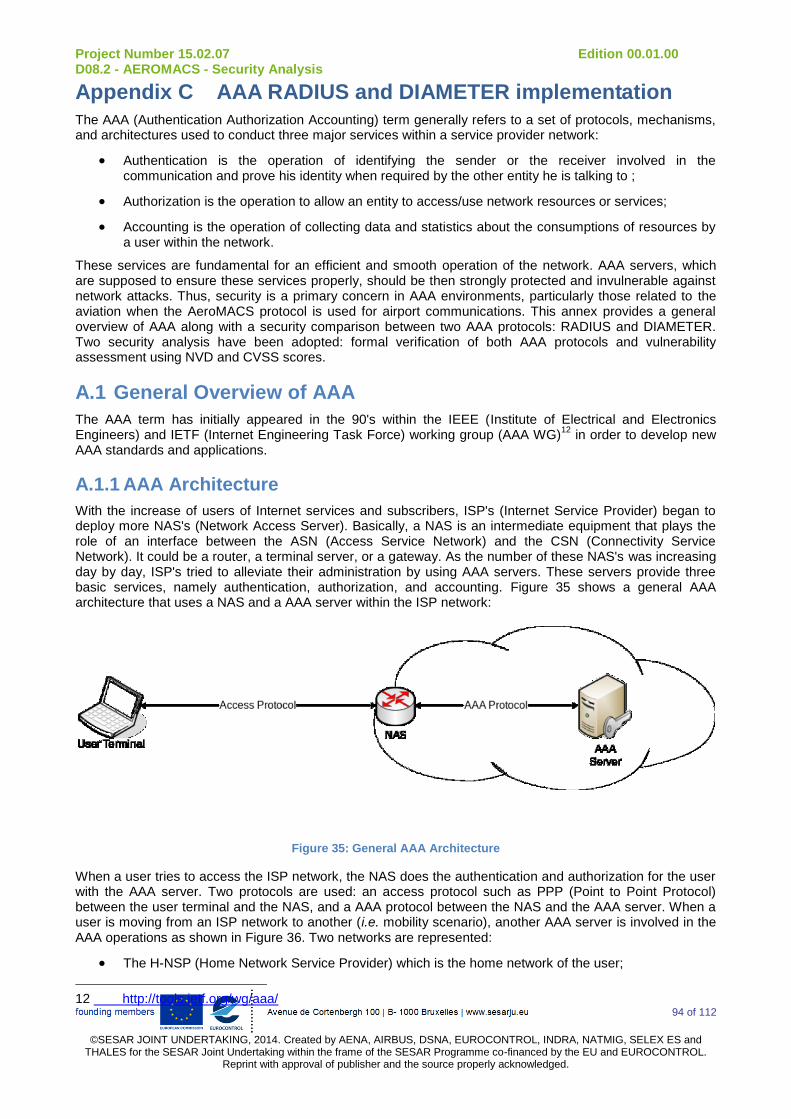
Project Number 15.02.07 Edition 00.01.00 D08.2 - AEROMACS - Security Analysis
94 of 112
©SESAR JOINT UNDERTAKING, 2014. Created by AENA, AIRBUS, DSNA, EUROCONTROL, INDRA, NATMIG, SELEX ES and
THALES for the SESAR Joint Undertaking within the frame of the SESAR Programme co-financed by the EU and EUROCONTROL. Reprint with approval of publisher and the source properly acknowledged.
Appendix C AAA RADIUS and DIAMETER implementation
The AAA (Authentication Authorization Accounting) term generally refers to a set of protocols, mechanisms, and architectures used to conduct three major services within a service provider network:
Authentication is the operation of identifying the sender or the receiver involved in the communication and prove his identity when required by the other entity he is talking to ;
Authorization is the operation to allow an entity to access/use network resources or services;
Accounting is the operation of collecting data and statistics about the consumptions of resources by a user within the network.
These services are fundamental for an efficient and smooth operation of the network. AAA servers, which are supposed to ensure these services properly, should be then strongly protected and invulnerable against network attacks. Thus, security is a primary concern in AAA environments, particularly those related to the aviation when the AeroMACS protocol is used for airport communications. This annex provides a general overview of AAA along with a security comparison between two AAA protocols: RADIUS and DIAMETER. Two security analysis have been adopted: formal verification of both AAA protocols and vulnerability assessment using NVD and CVSS scores.
A.1 General Overview of AAA
The AAA term has initially appeared in the 90's within the IEEE (Institute of Electrical and Electronics Engineers) and IETF (Internet Engineering Task Force) working group (AAA WG)
12 in order to develop new
AAA standards and applications.
A.1.1 AAA Architecture
With the increase of users of Internet services and subscribers, ISP's (Internet Service Provider) began to deploy more NAS's (Network Access Server). Basically, a NAS is an intermediate equipment that plays the role of an interface between the ASN (Access Service Network) and the CSN (Connectivity Service Network). It could be a router, a terminal server, or a gateway. As the number of these NAS's was increasing day by day, ISP's tried to alleviate their administration by using AAA servers. These servers provide three basic services, namely authentication, authorization, and accounting. Figure 35 shows a general AAA architecture that uses a NAS and a AAA server within the ISP network:
Figure 35: General AAA Architecture
When a user tries to access the ISP network, the NAS does the authentication and authorization for the user with the AAA server. Two protocols are used: an access protocol such as PPP (Point to Point Protocol) between the user terminal and the NAS, and a AAA protocol between the NAS and the AAA server. When a user is moving from an ISP network to another (i.e. mobility scenario), another AAA server is involved in the AAA operations as shown in Figure 36. Two networks are represented:
The H-NSP (Home Network Service Provider) which is the home network of the user;
12 http://tools.ietf.org/wg/aaa/

Project Number 15.02.07 Edition 00.01.00 D08.2 - AEROMACS - Security Analysis
95 of 112
©SESAR JOINT UNDERTAKING, 2014. Created by AENA, AIRBUS, DSNA, EUROCONTROL, INDRA, NATMIG, SELEX ES and
THALES for the SESAR Joint Undertaking within the frame of the SESAR Programme co-financed by the EU and EUROCONTROL. Reprint with approval of publisher and the source properly acknowledged.
The V-NSP (Visited Network Service Provider) which is the visited network in a roaming scenario.
The NAS could be for instance, a router, a gateway, or a WAP (Wireless Access Point), depending on the access protocol as described in Figure 35. Note that depending on the AAA protocol used within the V-NSP, the AAA client could be merged with the NAS. AAA clients could be:
a relay agent routes the access request sent by the user;
a redirection agent asks the AAA client to redirect the traffic to another IP address if the VAAA server IP address is no longer valid;
a translation agent translates the access request sent by the user is the AAA server does not use the same AAA protocol as the AAA client.
Figure 36: AAA Architecture Model for Mobility
When the user tries to access the V-NSP (message 1), his request is handled by the NAS then sent toward the HAAA server. After receiving the request (message 2), the AAA agent sends it the VAAA server (message 3), which is unable to authenticate the user as it does not registered in the V-NSP. Thus, it sends it the HAAA server (message 4), and then the access response is sent hop-by-hop to the user terminal (messages 5, 6, 7, and 8). Note that an EP (Enforcement Point) could be merged with the NAS. This EP is basically responsible for applying the control access techniques used in the V-NSP. Besides, IP mobility [25] is usually used in such mobility scenarios above access protocols (e.g. WiMAX, AeroMACS).
A.1.2 AAA Process Flow Chart
Figure 37 shows a high abstraction level data flow diagram of AAA operations:
Registration: or enrolment is the process of subscribing the entity to the services offered by the NSP. Several information are given to the subscriber for later use such as IP addresses (e.g. NAS,
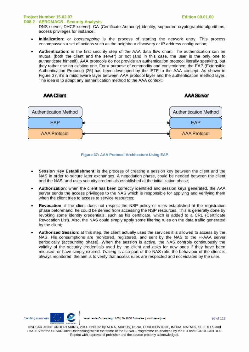
Project Number 15.02.07 Edition 00.01.00 D08.2 - AEROMACS - Security Analysis
96 of 112
©SESAR JOINT UNDERTAKING, 2014. Created by AENA, AIRBUS, DSNA, EUROCONTROL, INDRA, NATMIG, SELEX ES and
THALES for the SESAR Joint Undertaking within the frame of the SESAR Programme co-financed by the EU and EUROCONTROL. Reprint with approval of publisher and the source properly acknowledged.
DNS server, DHCP server), CA (Certificate Authority) identity, supported cryptographic algorithms, access privileges for instance;
Initialization: or bootstrapping is the process of starting the network entry. This process encompasses a set of actions such as the neighbour discovery or IP address configuration;
Authentication: is the first security step of the AAA data flow chart. The authentication can be mutual (both the client and the server) or not (and in this case, the user is the only one to authenticate himself). AAA protocols do not provide an authentication protocol literally speaking, but they rather use an existing one. For a purpose of commodity and convenience, the EAP (Extensible Authentication Protocol) [26] has been developed by the IETF to the AAA concept. As shown in Figure 37, it's a middleware layer between AAA protocol layer and the authentication method layer. The idea is to adapt any authentication method to the AAA context;
Figure 37: AAA Protocol Architecture Using EAP
Session Key Establishment: is the process of creating a session key between the client and the NAS in order to secure later exchanges. A negotiation phase, could be needed between the client and the NAS, and uses security credentials established at the initialization phase;
Authorization: when the client has been correctly identified and session keys generated, the AAA server sends the access privileges to the NAS which is responsible for applying and verifying them when the client tries to access to service resources;
Revocation: if the client does not respect the NSP policy or rules established at the registration phase beforehand, he could be denied from accessing the NSP resources. This is generally done by revoking some identity credentials, such as his certificate, which is added to a CRL (Certificate Revocation List). Also, the NAS could simply apply some filtering rules on the data traffic generated by the client;
Authorized Session: at this step, the client actually uses the services it is allowed to access by the NAS. His consumptions are monitored, registered, and sent by the NAS to the H-AAA server periodically (accounting phase). When the session is active, the NAS controls continuously the validity of the security credentials used by the client and asks for new ones if they have been misused, or have simply expired. Tracing is also part of the NAS role: the behaviour of the client is always monitored; the aim is to verify that access rules are respected and not violated by the user.
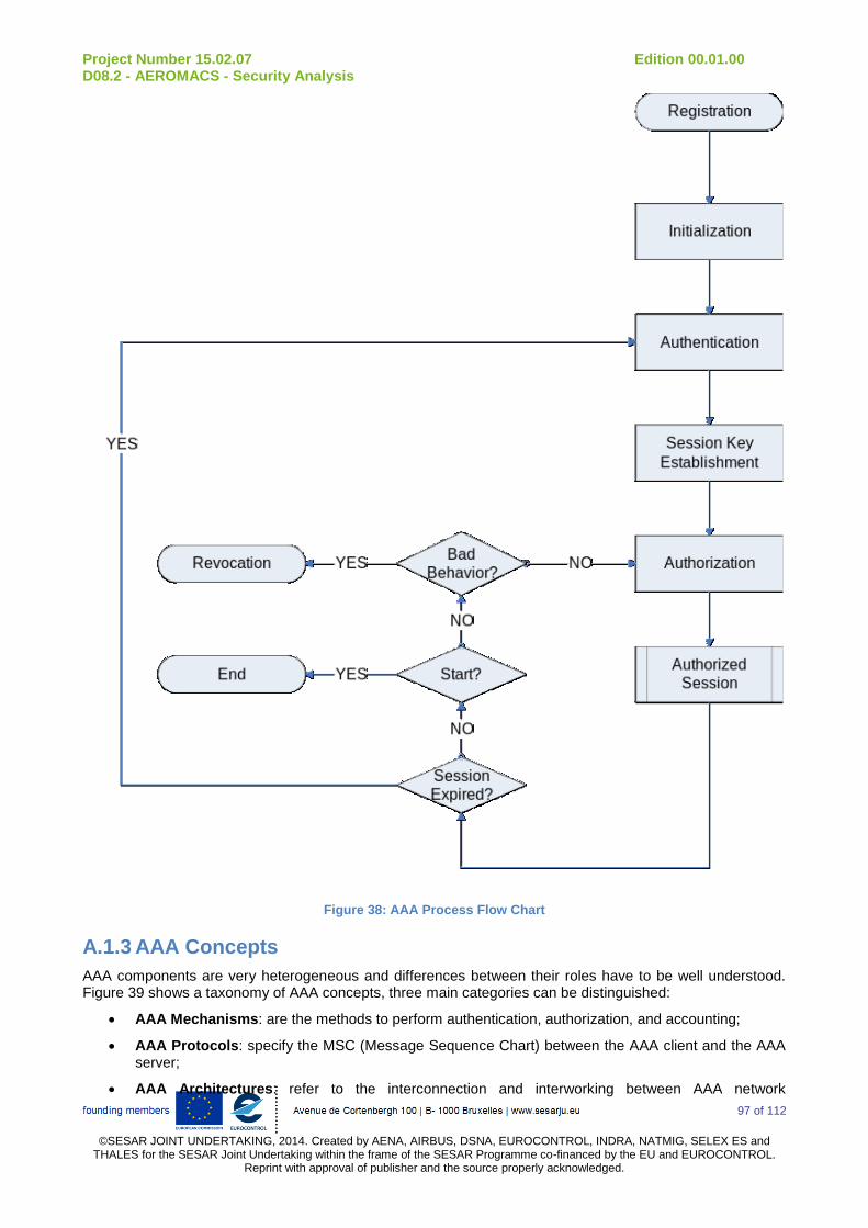
Project Number 15.02.07 Edition 00.01.00 D08.2 - AEROMACS - Security Analysis
97 of 112
©SESAR JOINT UNDERTAKING, 2014. Created by AENA, AIRBUS, DSNA, EUROCONTROL, INDRA, NATMIG, SELEX ES and
THALES for the SESAR Joint Undertaking within the frame of the SESAR Programme co-financed by the EU and EUROCONTROL. Reprint with approval of publisher and the source properly acknowledged.
Figure 38: AAA Process Flow Chart
A.1.3 AAA Concepts
AAA components are very heterogeneous and differences between their roles have to be well understood. Figure 39 shows a taxonomy of AAA concepts, three main categories can be distinguished:
AAA Mechanisms: are the methods to perform authentication, authorization, and accounting;
AAA Protocols: specify the MSC (Message Sequence Chart) between the AAA client and the AAA server;
AAA Architectures: refer to the interconnection and interworking between AAA network

Project Number 15.02.07 Edition 00.01.00 D08.2 - AEROMACS - Security Analysis
98 of 112
©SESAR JOINT UNDERTAKING, 2014. Created by AENA, AIRBUS, DSNA, EUROCONTROL, INDRA, NATMIG, SELEX ES and
THALES for the SESAR Joint Undertaking within the frame of the SESAR Programme co-financed by the EU and EUROCONTROL. Reprint with approval of publisher and the source properly acknowledged.
components.
A.2 AAA Mechanisms
AAA mechanisms are divided into three categories:
Authentication mechanisms: the credentials used to make the entity authentication could be of different natures such as IP address, MAC (Medium Access Control) address, IMSI (Internet Mobile Subscriber Identity), or IMEI (International Mobile Equipment Identity) for instance, different authentication mechanisms classes exist:
Knowledge-based mechanisms;
Cryptography-based mechanisms;
Biometrics-based mechanisms;
Secure tokens-based mechanisms.
Authorization mechanisms: As for authentication mechanisms, authorization mechanisms could be of different natures:
Authentication-based mechanisms which means that correct authentication of an entity implies its authorization to access the NSP services;
Credential-based mechanisms which mean that credentials initially negotiated as shown in Figure 38.
Accounting mechanisms: covers either collection of data from monitoring systems or storage of these data into accounting records. Depending on the data structure used within the NSP network, those records are triggered and generated periodically according to one or several metrics (e.g. IP packets). In such a case, records are called IPDRs (IP Detail Record).
A.3 AAA Protocols
Several AAA protocols have been defined; the most relevant and world-wide used are those discussed within the IETF AAA WG, namely RADIUS (Remote Authentication Dial-In User Service) [27] [28] DIAMETER [26]. AAA Protocols could be categorized into two families:
Protocols developed specifically for AAA context such as RADIUS and DIAMETER;
Protocols developed for others purposes but could be used or adapted to the AAA context such as COPS (Common Open Policy Service) [29] SNMP (Simple Network Management Protocol) [30] or Kerberos [31] (these protocols are out of scope of this document).
If PPP is the data link technology used for the network access, several authentication protocols could be used, the most common are:
PAP (PPP Password Authentication Protocol) [32];
CHAP (PPP Challenge Handshake Authentication Protocol) [32];
EAP which could itself rely on different authentication credentials:
EAP-TLS which is a device-based authentication using X.509 certificates [34];
EAP-AKA which is a SIM Card [35] based authentication;
EAP-TTLS, which is use both X.509 certificates and password [36].
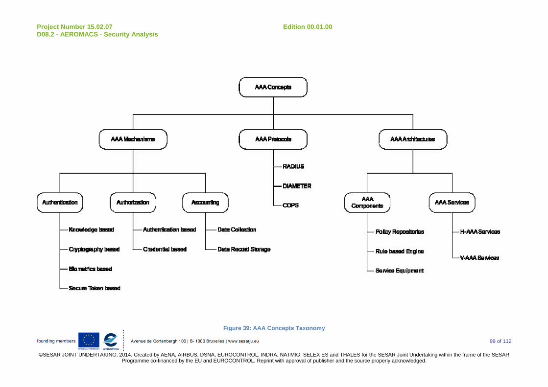
Project Number 15.02.07 Edition 00.01.00 D08.2 - AEROMACS - Security Analysis
99 of 112
©SESAR JOINT UNDERTAKING, 2014. Created by AENA, AIRBUS, DSNA, EUROCONTROL, INDRA, NATMIG, SELEX ES and THALES for the SESAR Joint Undertaking within the frame of the SESAR
Programme co-financed by the EU and EUROCONTROL. Reprint with approval of publisher and the source properly acknowledged.
Figure 39: AAA Concepts Taxonomy
Project Number 15.02.07 Edition 00.01.00 D08.2 - AEROMACS - Security Analysis
100 of 112
©SESAR JOINT UNDERTAKING, 2014. Created by AENA, AIRBUS, DSNA, EUROCONTROL, INDRA, NATMIG, SELEX ES and THALES for the SESAR Joint Undertaking within the frame of the SESAR
Programme co-financed by the EU and EUROCONTROL. Reprint with approval of publisher and the source properly acknowledged.

Project Number 15.02.07 Edition 00.01.00 D08.2 - AEROMACS - Security Analysis
101 of 112
©SESAR JOINT UNDERTAKING, 2014. Created by AENA, AIRBUS, DSNA, EUROCONTROL, INDRA, NATMIG, SELEX ES and
THALES for the SESAR Joint Undertaking within the frame of the SESAR Programme co-financed by the EU and EUROCONTROL. Reprint with approval of publisher and the source properly acknowledged.
A.4 RADIUS
RADIUS is probably the most used AAA server in today networks. It has been originally designed to support dial-up connections, but over time, it has been adapted to several context and environments. From an architecture point of view, RADIUS is a pure client-server paradigm, meaning it relies on client requests and server responses to work. In a RADIUS-based AAA architecture, the NAS plays the role of the RADIUS client which make the authentication and authorization on behalf the user toward the RADIUS server. Those servers could also play the role of RADIUS clients toward other RADIUS servers (i.e. proxy clients). Messages exchanged between the RADIUS client and servers are authenticated using a pre-shared key and users password sent in those messages are encrypted. RADIUS messages carry AAA information encoded in type length value fields called attributes or AVPs (Attribute Value Pairs). AVPs contain several information such as IP addresses, user password, or user name. These AVPs can be defined by vendors selling RADIUS equipment.
Accounting was not initially planned as a RADIUS server, but it has been added later in protocol amendments [37]. The NAS forwards an ACCOUTING-REQUEST (with an AVP called Acct-Status-Type with a value equal to START) message to the RADIUS server as soon as the connection has been established. Then it begins accounting process by collecting information such as input/output packets, session lifetime, and session termination. When the session is finished, the NAS sends an ACCOUTING-REQUEST (Acct-Status-Type = STOP) message to the RADIUS server to finish the accounting process. RADIUS might also be used to establish VPNs (Virtual Private Networks) in order to enhance the network security. Tunnelling protocols such as L2TP (Layer 2 Tunnelling Protocol) [38] or IPSec (IP Security) [39] could be used to create tunnels through IP networks and carry PPP connections.
Figure 40 shows a AAA architecture similar to Figure 35 but adapted to the RADIUS protocol. The user asks the NAS that supports a RADIUS client to access the network services. Using the PPP protocol, the NAS collects the information needed by the RADIUS server (e.g. user name and password) and then forwards an encrypted ACCESS-REQUEST message using UDP
13 (User Diagram Protocol) to the server (authentication
phase). Other AVPs may be added such as the NAS port ID or its IP address. Then, the RADIUS server checks the validity of these information using authentication mechanisms such as CHAP, EAP, PAP, or by comparing them with its own local database. Note also that these information could be possibly stored into external sources such as Active Directories or LDAP (Lightweight Directory Access Protocol) [40] servers.
Figure 40: RADIUS AAA Architecture
If the users or the passwords are not recognized, the RADIUS server sends back an ACCESS-REJECT message to the NAS with an optional text field indicating the reason for the access failure (authorization phase). The NAS then notifies the end user of the RADIUS server decision. If the user credentials are correct, an ACCESS-ACCEPT message is sent to the NAS along with a request for additional information about the user to complete the network connection such as a valid IP address for the end user (in this case
13 RADIUS uses ports 1812 and 1813 respectively for authentication and accouting (or ports 1645 and 1646 for
older versions of the protocol).
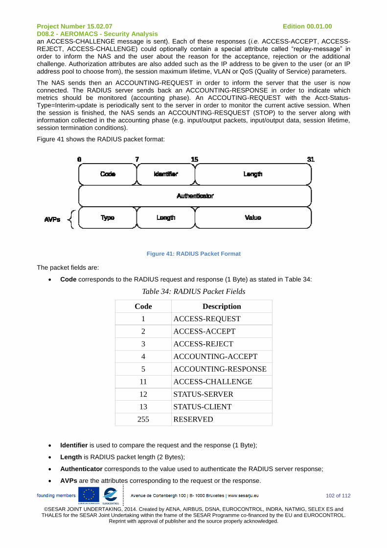
Project Number 15.02.07 Edition 00.01.00 D08.2 - AEROMACS - Security Analysis
102 of 112
©SESAR JOINT UNDERTAKING, 2014. Created by AENA, AIRBUS, DSNA, EUROCONTROL, INDRA, NATMIG, SELEX ES and
THALES for the SESAR Joint Undertaking within the frame of the SESAR Programme co-financed by the EU and EUROCONTROL. Reprint with approval of publisher and the source properly acknowledged.
an ACCESS-CHALLENGE message is sent). Each of these responses (i.e. ACCESS-ACCEPT, ACCESS-REJECT, ACCESS-CHALLENGE) could optionally contain a special attribute called “replay-message” in order to inform the NAS and the user about the reason for the acceptance, rejection or the additional challenge. Authorization attributes are also added such as the IP address to be given to the user (or an IP address pool to choose from), the session maximum lifetime, VLAN or QoS (Quality of Service) parameters.
The NAS sends then an ACCOUNTING-REQUEST in order to inform the server that the user is now connected. The RADIUS server sends back an ACCOUNTING-RESPONSE in order to indicate which metrics should be monitored (accounting phase). An ACCOUTING-REQUEST with the Acct-Status-Type=Interim-update is periodically sent to the server in order to monitor the current active session. When the session is finished, the NAS sends an ACCOUNTING-RESQUEST (STOP) to the server along with information collected in the accounting phase (e.g. input/output packets, input/output data, session lifetime, session termination conditions).
Figure 41 shows the RADIUS packet format:
Figure 41: RADIUS Packet Format
The packet fields are:
Code corresponds to the RADIUS request and response (1 Byte) as stated in Table 34:
Table 34: RADIUS Packet Fields
Code Description
1 ACCESS-REQUEST
2 ACCESS-ACCEPT
3 ACCESS-REJECT
4 ACCOUNTING-ACCEPT
5 ACCOUNTING-RESPONSE
11 ACCESS-CHALLENGE
12 STATUS-SERVER
13 STATUS-CLIENT
255 RESERVED
Identifier is used to compare the request and the response (1 Byte);
Length is RADIUS packet length (2 Bytes);
Authenticator corresponds to the value used to authenticate the RADIUS server response;
AVPs are the attributes corresponding to the request or the response.

Project Number 15.02.07 Edition 00.01.00 D08.2 - AEROMACS - Security Analysis
103 of 112
©SESAR JOINT UNDERTAKING, 2014. Created by AENA, AIRBUS, DSNA, EUROCONTROL, INDRA, NATMIG, SELEX ES and
THALES for the SESAR Joint Undertaking within the frame of the SESAR Programme co-financed by the EU and EUROCONTROL. Reprint with approval of publisher and the source properly acknowledged.
A.5 DIAMETER
DIAMETER is the successor of RADIUS and has been defined to mainly deal with RADIUS weaknesses (see section A.6.2.2 for more details about advantages and drawbacks of each AAA protocol). Indeed, RADIUS has been originally designed for small networks, which is, by now, out-of-date considering the wide networks and the heterogeneity of the used technologies and protocols. DIAMETER is then a lightweight and scalable P2P (Peer to Peer) AAA protocol. Indeed, unlike RADIUS, which is a client-server protocol, DIAMATER is a peer-based protocol, meaning every entity is a client and a server at the same time. The protocol relies on TCP (Transmission Control Protocol) (unlike RADIUS which uses UDP) or SCTP (Stream Control Transmission Protocol) and uses AVPs to exchange information between the DIAMETER peers. The DIAMETER protocol is continuously improved and currently it supports RADIUS-based peers, EAP, IP Mobility, etc.
DIAMETER has been improved over time to deal with RADIUS inherent limitations. Scalability is probably the most important improvement as RADIUS AVPs were initially limited to 255 Bytes. Beside, RADIUS component, such as a NAS RADIUS client, was unable to handle more than 255 messages before an acknowledgement was necessary. DIAMETER supports much larger AVPs length and uses a reliable transport protocol to establish the connection between the peers. It uses either TCP (Transmission Control Protocol) or SCTP (Stream Control Transmission Protocol), which are obviously more reliable than UDP, which is used by RADIUS. Besides, a DIAMETER server is able to send unsolicited commands to the client when needed (e.g. ask the NAS to perform additional accounting functions), which is impossible when RADIUS. The second purpose behind the design of DIAMETER is the support of mobility and roaming scenarios (see Figure 36). RADIUS has support for mobility (based on implicit possibility of forwarding requests). RADIUS mobility architectures rely on a network of trusted RADIUS servers by proxy chains. However, DIAMETER brings a more sophisticated support of mobility (e.g. discovery of DIAMETER peers, IP mobility). DIAMETER supports also CMS (Cryptographic Message Syntax) data within AVPs for security purposes. CMS are like SA (Security Association) in IPSec: they are established by two peers through agents in order to provide authentication, integrity, and confidentiality. Besides, CMSs are able to carry the X.509 certificates.
The DIAMETER packet format is presented in Figure 42:
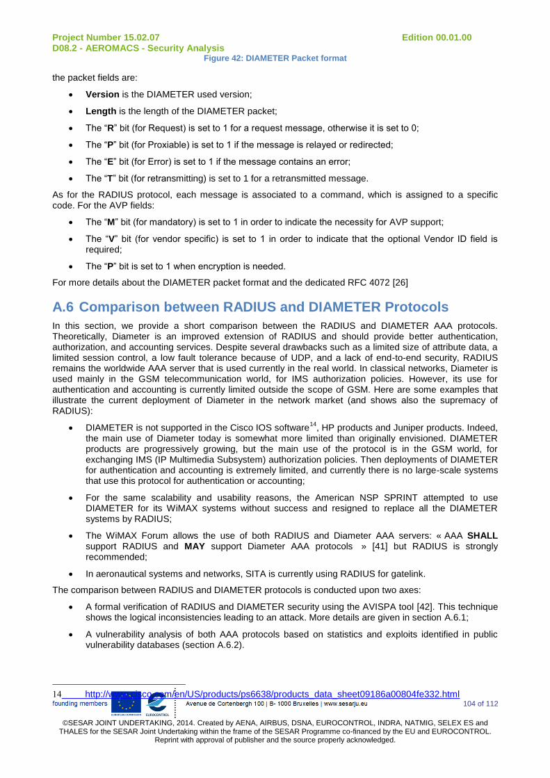
Project Number 15.02.07 Edition 00.01.00 D08.2 - AEROMACS - Security Analysis
104 of 112
©SESAR JOINT UNDERTAKING, 2014. Created by AENA, AIRBUS, DSNA, EUROCONTROL, INDRA, NATMIG, SELEX ES and
THALES for the SESAR Joint Undertaking within the frame of the SESAR Programme co-financed by the EU and EUROCONTROL. Reprint with approval of publisher and the source properly acknowledged.
Figure 42: DIAMETER Packet format
the packet fields are:
Version is the DIAMETER used version;
Length is the length of the DIAMETER packet;
The “R” bit (for Request) is set to 1 for a request message, otherwise it is set to 0;
The “P” bit (for Proxiable) is set to 1 if the message is relayed or redirected;
The “E” bit (for Error) is set to 1 if the message contains an error;
The “T” bit (for retransmitting) is set to 1 for a retransmitted message.
As for the RADIUS protocol, each message is associated to a command, which is assigned to a specific code. For the AVP fields:
The “M” bit (for mandatory) is set to 1 in order to indicate the necessity for AVP support;
The “V” bit (for vendor specific) is set to 1 in order to indicate that the optional Vendor ID field is required;
The “P” bit is set to 1 when encryption is needed.
For more details about the DIAMETER packet format and the dedicated RFC 4072 [26]
A.6 Comparison between RADIUS and DIAMETER Protocols
In this section, we provide a short comparison between the RADIUS and DIAMETER AAA protocols. Theoretically, Diameter is an improved extension of RADIUS and should provide better authentication, authorization, and accounting services. Despite several drawbacks such as a limited size of attribute data, a limited session control, a low fault tolerance because of UDP, and a lack of end-to-end security, RADIUS remains the worldwide AAA server that is used currently in the real world. In classical networks, Diameter is used mainly in the GSM telecommunication world, for IMS authorization policies. However, its use for authentication and accounting is currently limited outside the scope of GSM. Here are some examples that illustrate the current deployment of Diameter in the network market (and shows also the supremacy of RADIUS):
DIAMETER is not supported in the Cisco IOS software14
, HP products and Juniper products. Indeed, the main use of Diameter today is somewhat more limited than originally envisioned. DIAMETER products are progressively growing, but the main use of the protocol is in the GSM world, for exchanging IMS (IP Multimedia Subsystem) authorization policies. Then deployments of DIAMETER for authentication and accounting is extremely limited, and currently there is no large-scale systems that use this protocol for authentication or accounting;
For the same scalability and usability reasons, the American NSP SPRINT attempted to use DIAMETER for its WiMAX systems without success and resigned to replace all the DIAMETER systems by RADIUS;
The WiMAX Forum allows the use of both RADIUS and Diameter AAA servers: « AAA SHALL support RADIUS and MAY support Diameter AAA protocols » [41] but RADIUS is strongly recommended;
In aeronautical systems and networks, SITA is currently using RADIUS for gatelink.
The comparison between RADIUS and DIAMETER protocols is conducted upon two axes:
A formal verification of RADIUS and DIAMETER security using the AVISPA tool [42]. This technique shows the logical inconsistencies leading to an attack. More details are given in section A.6.1;
A vulnerability analysis of both AAA protocols based on statistics and exploits identified in public vulnerability databases (section A.6.2).
14 http://www.cisco.com/en/US/products/ps6638/products_data_sheet09186a00804fe332.html
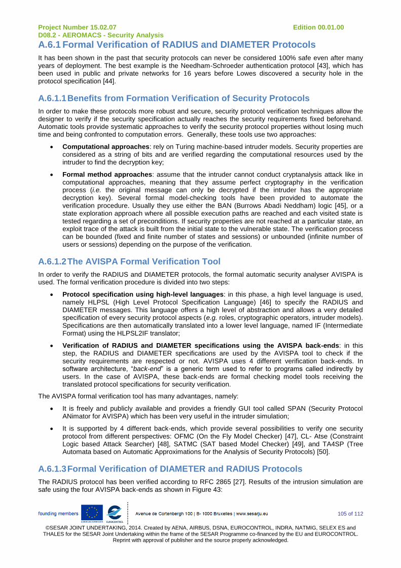
Project Number 15.02.07 Edition 00.01.00 D08.2 - AEROMACS - Security Analysis
105 of 112
©SESAR JOINT UNDERTAKING, 2014. Created by AENA, AIRBUS, DSNA, EUROCONTROL, INDRA, NATMIG, SELEX ES and
THALES for the SESAR Joint Undertaking within the frame of the SESAR Programme co-financed by the EU and EUROCONTROL. Reprint with approval of publisher and the source properly acknowledged.
A.6.1 Formal Verification of RADIUS and DIAMETER Protocols
It has been shown in the past that security protocols can never be considered 100% safe even after many years of deployment. The best example is the Needham-Schroeder authentication protocol [43], which has been used in public and private networks for 16 years before Lowes discovered a security hole in the protocol specification [44].
A.6.1.1 Benefits from Formation Verification of Security Protocols
In order to make these protocols more robust and secure, security protocol verification techniques allow the designer to verify if the security specification actually reaches the security requirements fixed beforehand. Automatic tools provide systematic approaches to verify the security protocol properties without losing much time and being confronted to computation errors. Generally, these tools use two approaches:
Computational approaches: rely on Turing machine-based intruder models. Security properties are considered as a string of bits and are verified regarding the computational resources used by the intruder to find the decryption key;
Formal method approaches: assume that the intruder cannot conduct cryptanalysis attack like in computational approaches, meaning that they assume perfect cryptography in the verification process (i.e. the original message can only be decrypted if the intruder has the appropriate decryption key). Several formal model-checking tools have been provided to automate the verification procedure. Usually they use either the BAN (Burrows Abadi Neddham) logic [45], or a state exploration approach where all possible execution paths are reached and each visited state is tested regarding a set of preconditions. If security properties are not reached at a particular state, an exploit trace of the attack is built from the initial state to the vulnerable state. The verification process can be bounded (fixed and finite number of states and sessions) or unbounded (infinite number of users or sessions) depending on the purpose of the verification.
A.6.1.2 The AVISPA Formal Verification Tool
In order to verify the RADIUS and DIAMETER protocols, the formal automatic security analyser AVISPA is used. The formal verification procedure is divided into two steps:
Protocol specification using high-level languages: in this phase, a high level language is used, namely HLPSL (High Level Protocol Specification Language) [46] to specify the RADIUS and DIAMETER messages. This language offers a high level of abstraction and allows a very detailed specification of every security protocol aspects (e.g. roles, cryptographic operators, intruder models). Specifications are then automatically translated into a lower level language, named IF (Intermediate Format) using the HLPSL2IF translator;
Verification of RADIUS and DIAMETER specifications using the AVISPA back-ends: in this step, the RADIUS and DIAMETER specifications are used by the AVISPA tool to check if the security requirements are respected or not. AVISPA uses 4 different verification back-ends. In software architecture, “back-end” is a generic term used to refer to programs called indirectly by users. In the case of AVISPA, these back-ends are formal checking model tools receiving the translated protocol specifications for security verification.
The AVISPA formal verification tool has many advantages, namely:
It is freely and publicly available and provides a friendly GUI tool called SPAN (Security Protocol ANimator for AVISPA) which has been very useful in the intruder simulation;
It is supported by 4 different back-ends, which provide several possibilities to verify one security protocol from different perspectives: OFMC (On the Fly Model Checker) [47], CL- Atse (Constraint Logic based Attack Searcher) [48], SATMC (SAT based Model Checker) [49], and TA4SP (Tree Automata based on Automatic Approximations for the Analysis of Security Protocols) [50].
A.6.1.3 Formal Verification of DIAMETER and RADIUS Protocols
The RADIUS protocol has been verified according to RFC 2865 [27]. Results of the intrusion simulation are safe using the four AVISPA back-ends as shown in Figure 43:
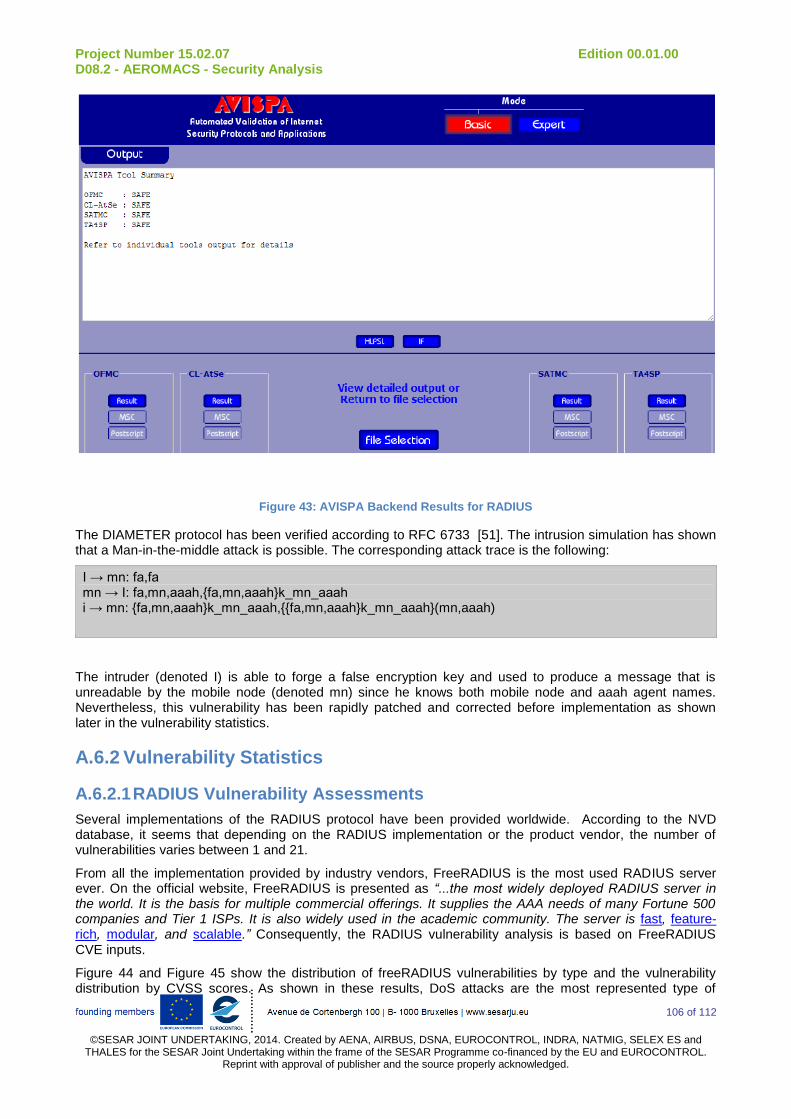
Project Number 15.02.07 Edition 00.01.00 D08.2 - AEROMACS - Security Analysis
106 of 112
©SESAR JOINT UNDERTAKING, 2014. Created by AENA, AIRBUS, DSNA, EUROCONTROL, INDRA, NATMIG, SELEX ES and
THALES for the SESAR Joint Undertaking within the frame of the SESAR Programme co-financed by the EU and EUROCONTROL. Reprint with approval of publisher and the source properly acknowledged.
Figure 43: AVISPA Backend Results for RADIUS
The DIAMETER protocol has been verified according to RFC 6733 [51]. The intrusion simulation has shown that a Man-in-the-middle attack is possible. The corresponding attack trace is the following:
I → mn: fa,fa mn → I: fa,mn,aaah,{fa,mn,aaah}k_mn_aaah i → mn: {fa,mn,aaah}k_mn_aaah,{{fa,mn,aaah}k_mn_aaah}(mn,aaah)
The intruder (denoted I) is able to forge a false encryption key and used to produce a message that is unreadable by the mobile node (denoted mn) since he knows both mobile node and aaah agent names. Nevertheless, this vulnerability has been rapidly patched and corrected before implementation as shown later in the vulnerability statistics.
A.6.2 Vulnerability Statistics
A.6.2.1 RADIUS Vulnerability Assessments
Several implementations of the RADIUS protocol have been provided worldwide. According to the NVD database, it seems that depending on the RADIUS implementation or the product vendor, the number of vulnerabilities varies between 1 and 21.
From all the implementation provided by industry vendors, FreeRADIUS is the most used RADIUS server ever. On the official website, FreeRADIUS is presented as “...the most widely deployed RADIUS server in the world. It is the basis for multiple commercial offerings. It supplies the AAA needs of many Fortune 500 companies and Tier 1 ISPs. It is also widely used in the academic community. The server is fast, feature-rich, modular, and scalable.” Consequently, the RADIUS vulnerability analysis is based on FreeRADIUS CVE inputs.
Figure 44 and Figure 45 show the distribution of freeRADIUS vulnerabilities by type and the vulnerability distribution by CVSS scores. As shown in these results, DoS attacks are the most represented type of

Project Number 15.02.07 Edition 00.01.00 D08.2 - AEROMACS - Security Analysis
107 of 112
©SESAR JOINT UNDERTAKING, 2014. Created by AENA, AIRBUS, DSNA, EUROCONTROL, INDRA, NATMIG, SELEX ES and
THALES for the SESAR Joint Undertaking within the frame of the SESAR Programme co-financed by the EU and EUROCONTROL. Reprint with approval of publisher and the source properly acknowledged.
attacks. CVSS scores are not really high as shown in the vulnerability distribution by CVSS scores (only one vulnerability ranked in [9 – 10]). Then, the distribution of the CVSS score is more balanced on low scores than high scores, which means that the weighted average CVSS score will have a medium criticality. The weighted average CVSS score is a good indicator of the security related to an IT product as it combines all the vulnerabilities (meaning their total number) and their relative CVSS scores.
Figure 44: FreeRADIUS Vulnerabilities by Type
Figure 45: Vulnerability Distribution by CVSS Scores
Table 35 gives a deeper insight of FreeRADIUS vulnerabilities and their distribution using CVSS score. The weighted average CVSS score is equal to 6.9, which is considered as a medium score.
Table 35: Distribution of all FreeRADIUS Vulnerabilities by CVSS Scores
CVSS Score Number of Vulnerabilities Percentage (%)
[0 - 1] 0 0 %
[1 - 2] 0 0 %

Project Number 15.02.07 Edition 00.01.00 D08.2 - AEROMACS - Security Analysis
108 of 112
©SESAR JOINT UNDERTAKING, 2014. Created by AENA, AIRBUS, DSNA, EUROCONTROL, INDRA, NATMIG, SELEX ES and
THALES for the SESAR Joint Undertaking within the frame of the SESAR Programme co-financed by the EU and EUROCONTROL. Reprint with approval of publisher and the source properly acknowledged.
[2 - 3] 0 0 %
[3 - 4] 0 0 %
[4 - 5] 2 9.5 %
[5 - 6] 9 42.9 %
[6 - 7] 2 9.5 %
[7 - 8] 7 33.3 %
[8 - 9] 0 0 %
[9 - 10] 1 4.8 %
Total Number of Vulnerabilities 21
Weighted Average CVSS Score 6.9
A.6.2.2 DIAMETER Vulnerability Assessments
There is no vulnerability publicly known on DIAMETER protocol implementations. Searching on CVE databases for DIAMETER vulnerabilities forwards to a Wireshark (a network traffic analyser) vulnerability, which is related to the DIAMETER packet dissector implemented in Wireshark (CVE-2012-2393). Consequently, this is absolutely not a DIAMETER security issue, which means that practically, DIAMETER has no vulnerability to be quoted in this section. This is probably due to the fact that DIAMETER is poorly implemented compared to RADIUS, which is massively used in the industry.
A.6.3 Comparison Summary Between RADIUS and DIAMETER Protocols
Table 36 summarises the characteristics of both AAA protocols as discussed earlier:
Table 36: Comparative Summary between RADIUS and DIAMETER Protocols
RADIUS Diameter
Operation Paradigm Client-Server Peer to Peer
Packet Formats Figure 41 Figure 42
Transport Protocol UDP TCP and SCTP
Proxies and Agents Proxies Relay Agents, Proxy Agents,
Redirection Agents, Translation Agents
Authentication Mechanisms NAI, CHAP, PAP, EAP NAI, CHAP, PAP, EAP
Authorization Mechanisms Authentication-based,
Credential-based
Authentication-based,
Credential-based
Accounting Mechanisms Real-time, timestamps,
dynamic accounting
Real-time, timestamps, dynamic
accounting
Authorization without
Authentication
Possible Supported
Server-initiated Messages No (work in progress) Yes
Error Messages No Yes
Compatibility Low (only with other
RADIUS versions)
High (RADIUS and Diameter)
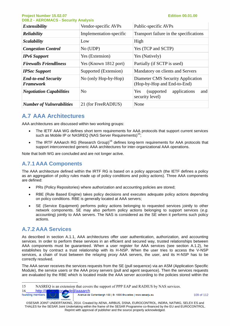
Project Number 15.02.07 Edition 00.01.00 D08.2 - AEROMACS - Security Analysis
109 of 112
©SESAR JOINT UNDERTAKING, 2014. Created by AENA, AIRBUS, DSNA, EUROCONTROL, INDRA, NATMIG, SELEX ES and
THALES for the SESAR Joint Undertaking within the frame of the SESAR Programme co-financed by the EU and EUROCONTROL. Reprint with approval of publisher and the source properly acknowledged.
Extensibility Vendor-specific AVPs Public-specific AVPs
Reliability Implementation-specific Transport failure in the specifications
Scalability Low High
Congestion Control No (UDP) Yes (TCP and SCTP)
IPv6 Support Yes (Extension) Yes (Natively)
Firewalls Friendliness Yes (Known 1812 port) Partially (if SCTP is used)
IPSec Support Supported (Extension) Mandatory on clients and Servers
End-to-end Security
Framework
No (only Hop-by-Hop) Diameter CMS Security Application
(Hop-by-Hop and End-to-End)
Negotiation Capabilities No Yes (supported applications and
security level)
Number of Vulnerabilities 21 (for FreeRADIUS) None
A.7 AAA Architectures
AAA architectures are discussed within two working groups:
The IETF AAA WG defines short term requirements for AAA protocols that support current services such as Mobile IP or NASREQ (NAS Server Requirements)
15;
The IRTF AAAarch RG (Research Group)16
defines long-term requirements for AAA protocols that support interconnected generic AAA architectures for inter-organizational AAA operations.
Note that both WG are concluded and are not longer active.
A.7.1 AAA Components
The AAA architecture defined within the IRTF RG is based on a policy approach (the IETF defines a policy as an aggregation of policy rules made up of policy conditions and policy actions). Three AAA components are defined:
PRs (Policy Repositories) where authorization and accounting policies are stored;
RBE (Rule Based Engine) takes policy decisions and executes adequate policy actions depending on policy conditions. RBE is generally located at AAA servers;
SE (Service Equipment) performs policy actions belonging to requested services jointly to other network components. SE may also perform policy actions belonging to support services (e.g. accounting) jointly to AAA servers. The NAS is considered as the SE when it performs such policy actions.
A.7.2 AAA Services
As described in section A.1.1, AAA architectures offer user authentication, authorization, and accounting services. In order to perform these services in an efficient and secured way, trusted relationships between AAA components must be guaranteed. When a user register for AAA services (see section A.1.2), he establishes by contract a trust relationship with its H-NSP. When the user tries to access the V-NSP services, a chain of trust between the relaying proxy AAA servers, the user, and its H-NSP has to be correctly resolved.
The AAA server receives the services requests from the SE (pull sequence) via an ASM (Application Specific Module), the service users or the AAA proxy servers (pull and agent sequence). Then the services requests are evaluated by the RBE which is located inside the AAA server according to the policies stored within the
15 NASREQ is an extension that covers the support of PPP EAP and RADIUS by NAS services.
16 http://irtf.org/concluded/aaaarch

Project Number 15.02.07 Edition 00.01.00 D08.2 - AEROMACS - Security Analysis
110 of 112
©SESAR JOINT UNDERTAKING, 2014. Created by AENA, AIRBUS, DSNA, EUROCONTROL, INDRA, NATMIG, SELEX ES and
THALES for the SESAR Joint Undertaking within the frame of the SESAR Programme co-financed by the EU and EUROCONTROL. Reprint with approval of publisher and the source properly acknowledged.
PR. Policy conditions are evaluated by consulting other AAA servers and the SE status: requests are sent to other AAA servers first, then to the ASM which is needed to enforce policy actions. The role of the ASM is then to configure the SE in order to provide a service.
A.7.3 AAA in AeroMACS: Conclusions
The analysis provided in this Annex shows that from a strict security point of view, DIAMETER is more secure compared to RADIUS. Indeed, RADIUS messages are not protected originally (i.e. without security extensions) whereas DIAMETER uses CMS to protect its messages.
However, if other considerations have to be taken into account (e.g. operability, interconnection with existing AAA-equipped devices, existing implementations), it seems that RADIUS is recommended. The vulnerability study provided here shows that some implementations have minor vulnerabilities that can be patched and corrected easily, which makes the use of RADIUS more receivable.
Project Number 15.02.07 Edition 00.01.00 D08.2 - AEROMACS - Security Analysis
111 of 112
©SESAR JOINT UNDERTAKING, 2014. Created by AENA, AIRBUS, DSNA, EUROCONTROL, INDRA, NATMIG, SELEX ES and
THALES for the SESAR Joint Undertaking within the frame of the SESAR Programme co-financed by the EU and EUROCONTROL. Reprint with approval of publisher and the source properly acknowledged.
Appendix D SESAR Paper at ICAO ACP WG W
SESAR P15.2.7 submitted at ICAO ACP WG-W a paper to address the need for an appropriate AAA framework for AeroMACS to be chosen for standardisation.
In addition, the working paper proposed a solution to provide services from different application domains to the same AeroMACS mobile station. Indeed, the standard WiMAX forum procedure does not provide such capabilities to the AeroMACS subscribers (a MS is able to use services supplied by its home CSN only). An AeroMACS MS could receive services from different Application Domains and it is necessary that the MS is authenticated from each of them. The MS is authenticated by its Home CSN using the standard WiMAX Forum procedure and in this way it is able to use services supplied directly by the Home CSN. The WMF Forum procedures do not consider additional authentication procedures for services supplied from other Application Domains.
In order to get more information, the reader can find the paper at: http://legacy.icao.int/anb/panels/acp/wg/w/wgw4/ACP-WGW04-WP18_AAA_v10.doc

Project Number 15.02.07 Edition 00.01.00 D08.2 - AEROMACS - Security Analysis
112 of 112
©SESAR JOINT UNDERTAKING, 2011. Created by AENA, AIRBUS, DSNA, EUROCONTROL, INDRA, NATMIG, SELEX ES
and THALES for the SESAR Joint Undertaking within the frame of the SESAR Programme co-financed by the EU and EUROCONTROL. Reprint with approval of publisher and the source properly acknowledged.
-END OF DOCUMENT-