Service Manual - Stephenson Equipment
104
Service Manual Axle 113 ASM-0005E September 2013
-
Upload
khangminh22 -
Category
Documents
-
view
1 -
download
0
Transcript of Service Manual - Stephenson Equipment

Service Manual
Axle 113
ASM-0005ESeptember 2013


CONTENTS
INTRODUCTION ................................................................................................................................ 5
SPECIFICATIONS ..............................................................................................................................7DEFINITION OF VIEWPOINTS .................................................................................................................................... 7
DATA PLATE .............................................................................................................................................................. 7
CONVERSION TABLES ................................................................................................................................................... 8
TORQUE SPECIFICATIONS ............................................................................................................................................ 9
COARSE PITCH ......................................................................................................................................................... 9
FINE PITCH ................................................................................................................................................................ 9
WHEEL NUT TIGHTENING TORQUES ...................................................................................................................... 10
MAINTENANCE ................................................................................................................................................................ 11
MAINTENANCE POINTS ............................................................................................................................................ 11
MAINTENANCE INTERVALS ...................................................................................................................................... 12
ADJUSTMENT AND CHECKS .................................................................................................................................... 12
LUBRICANT & SEALANT SPECIFICATIONS ............................................................................................................. 13
SAFETY PRECAUTIONS ...................................................................................................................15
PLANETARY REDUCTION AND AXLE SHAFT ................................................................................ 17EXPLODED VIEW ............................................................................................................................................................. 17
DISASSEMBLY ................................................................................................................................................................ 18
ASSEMBLY ...................................................................................................................................................................... 22
SPECIAL TOOLS .............................................................................................................................................................. 25
T1 ............................................................................................................................................................................... 25
T2 ............................................................................................................................................................................... 26
T3 ............................................................................................................................................................................... 26
BRAKE WEAR CHECK PROCEDURE .............................................................................................. 27SPECIAL TOOLS .............................................................................................................................................................. 28
T1 ............................................................................................................................................................................... 28
SERVICE BRAKE ............................................................................................................................... 29EXPLODED VIEW ............................................................................................................................................................. 29
DISASSEMBLY ................................................................................................................................................................ 30
ASSEMBLY ...................................................................................................................................................................... 31
SPECIAL TOOLS .............................................................................................................................................................. 34
T1 ............................................................................................................................................................................... 34
SERVICE BRAKE AND NEGATIVE PARKING BRAKE ....................................................................35EXPLODED VIEW ............................................................................................................................................................. 35
RELEASE ......................................................................................................................................................................... 36
ADJUSTMENT ................................................................................................................................................................. 37
DISASSEMBLY ................................................................................................................................................................ 38
ASSEMBLY ...................................................................................................................................................................... 41
SPECIAL TOOLS .............................................................................................................................................................. 46
T1 ............................................................................................................................................................................... 46
DIFFERENTIAL UNIT ........................................................................................................................ 47EXPLODED VIEW ............................................................................................................................................................. 47
DISASSEMBLY ................................................................................................................................................................ 48
ASSEMBLY ...................................................................................................................................................................... 50
SPECIAL TOOLS .............................................................................................................................................................. 53
T1 ............................................................................................................................................................................... 53
T2 ............................................................................................................................................................................... 54
BEVEL PINION WITH SUPPORT BRAKING DISK ...........................................................................55EXPLODED VIEW ............................................................................................................................................................. 55
DISASSEMBLY ................................................................................................................................................................ 56
ASSEMBLY ...................................................................................................................................................................... 59
SPECIAL TOOLS .............................................................................................................................................................. 64
T1 ............................................................................................................................................................................... 64
T2 ............................................................................................................................................................................... 65
T3 ............................................................................................................................................................................... 66
T4 ............................................................................................................................................................................... 67
3Dana Holding CorporationASM-0005E - 113 Axle Service Manual

FLANGED BEVEL PINION ................................................................................................................ 69EXPLODED VIEW ............................................................................................................................................................. 69
DISASSEMBLY ................................................................................................................................................................ 70
ASSEMBLY ...................................................................................................................................................................... 72
SPECIAL TOOLS .............................................................................................................................................................. 77
T1 ............................................................................................................................................................................... 77
T2 ............................................................................................................................................................................... 78
T3 ............................................................................................................................................................................... 78
HYDRAULIC DIFFERENTIAL LOCK .................................................................................................79EXPLODED VIEW ............................................................................................................................................................. 79
DISASSEMBLY ................................................................................................................................................................ 80
ASSEMBLY ...................................................................................................................................................................... 85
SPECIAL TOOLS .............................................................................................................................................................. 89
T1 ............................................................................................................................................................................... 89
T2 ............................................................................................................................................................................... 89
LIMITED SLIP DIFFERENTIAL UNIT ................................................................................................ 91EXPLODED VIEW ............................................................................................................................................................. 91
DISASSEMBLY ................................................................................................................................................................ 92
ASSEMBLY ...................................................................................................................................................................... 94
NORMAL DIFFERENTIAL UNIT ........................................................................................................95EXPLODED VIEW ............................................................................................................................................................. 95
DISASSEMBLY ................................................................................................................................................................ 96
ASSEMBLY ...................................................................................................................................................................... 99
SPECIAL TOOLS .............................................................................................................................................................. 101
T1 ............................................................................................................................................................................... 101
T2 ............................................................................................................................................................................... 101
T3 ............................................................................................................................................................................... 102
4 Dana Holding Corporation ASM-0005E - 113 Axle Service Manual
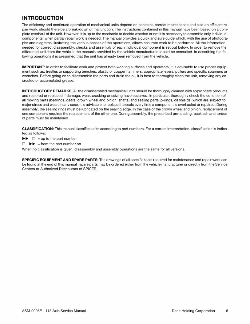
INTRODUCTIONThe efficiency and continued operation of mechanical units depend on constant, correct maintenance and also on efficient re-
pair work, should there be a break-down or malfunction. The instructions contained in this manual have been based on a com-
plete overhaul of the unit. However, it is up to the mechanic to decide whether or not it is necessary to assemble only individual
components, when partial repair work is needed. The manual provides a quick and sure guide which, with the use of photogra-
phs and diagrams illustrating the various phases of the operations, allows accurate work to be performed.All the information
needed for correct disassembly, checks and assembly of each individual component is set out below. In order to remove the
differential unit from the vehicle, the manuals provided by the vehicle manufacturer should be consulted. In describing the fol-
lowing operations it is presumed that the unit has already been removed from the vehicle.
IMPORTANT: In order to facilitate work and protect both working surfaces and operators, it is advisable to use proper equip-
ment such as: trestles or supporting benches, plastic or copper hammers, appropriate levers, pullers and specific spanners or
wrenches. Before going on to disassemble the parts and drain the oil, it is best to thoroughly clean the unit, removing any en-
crusted or accumulated grease.
INTRODUCTORY REMARKS: All the disassembled mechanical units should be thoroughly cleaned with appropriate products
and restored or replaced if damage, wear, cracking or seizing have occurred. In particular, thoroughly check the condition of
all moving parts (bearings, gears, crown wheel and pinion, shafts) and sealing parts (o-rings, oil shields) which are subject to
major stress and wear. In any case, it is advisable to replace the seals every time a component is overhauled or repaired. During
assembly, the sealing rings must be lubricated on the sealing edge. In the case of the crown wheel and pinion, replacement of
one component requires the replacement of the other one. During assembly, the prescribed pre-loading, backlash and torque
of parts must be maintained.
CLASSIFICATION: This manual classifies units according to part numbers. For a correct interpretation, classification is indica-
ted as follows:
= up to the part number
= from the part number on
When no classification is given, disassembly and assembly operations are the same for all versions.
SPECIFIC EQUIPMENT AND SPARE PARTS: The drawings of all specific tools required for maintenance and repair work can
be found at the end of this manual ; spare parts may be ordered either from the vehicle manufacturer or directly from the Service
Centers or Authorized Distributors of SPICER.
5Dana Holding CorporationASM-0005E - 113 Axle Service Manual

6 Dana Holding Corporation ASM-0005E - 113 Axle Service Manual

SPECIFICATIONS
DEFINITION OF VIEWPOINTS
DATA PLATE
1 - Type and model unit - modification index
2 - Serial number
3 - Lubricant
MFG. BY CLARK-HURTH COMPONENTS S.P.A.38062 Arco (Trento)
MADE IN ITALY
3
21
7Dana Holding CorporationASM-0005E - 113 Axle Service Manual

CONVERSION TABLES
CONVERSION TABLES
UNITS OF PRESSURE
1 ATM=1 BAR=105 PA=14.4 PSI
UNIT OF WEIGHT
UNITS OF TORQUE
N daN kN kg lbs
1N 1 0,1 0,001 0,102 0,225
1daN 10 1 0,01 1,02 2,25
1kN 1000 100 1 102 225
1kg 9,81 0,981 0,00981 1 2,205
N·m daN·m kN·m kg·m lb·in
1N·m 1 0,1 0,001 0,102 8,854
1daN·m 10 1 0,01 1,02 88,54
1kN·m 1000 100 1 102 8854
1kg·m 9,81 0,981 0,00981 1 86,8
1 lb·in 0,1129 0,01129 0,0001129 0,01152 1
8 Dana Holding Corporation ASM-0005E - 113 Axle Service Manual

TORQUE SPECIFICATIONS
TORQUE SPECIFICATIONS
COARSE PITCH
FINE PITCH
SIZE OF BOLT TYPE OF BOLT
8.8 8.8 + Loctite 270 10.9 10.9 + Loctite 270 12.9 12.9 + Loctite 270
M6 x 1 mm 9,5 – 10,5 N·m 10,5 – 11,5 N·m 14,3 – 15,7 N·m 15,2 – 16,8 N·m 16,2 – 17,8 N·m 18,1 – 20 N·m
M8 x 1,25 mm 23,8 – 26,2 N·m 25,6 – 28,4 N·m 34,2 – 37,8 N·m 36,7 – 40,5 N·m 39 – 43 N·m 43,7 – 48,3 N·m
M10 x 1,5 mm 48 – 53 N·m 52 – 58 N·m 68 – 75 N·m 73 – 81 N·m 80 – 88 N·m 88 – 97 N·m
M12 x 1,75 mm 82 – 91 N·m 90 – 100 N·m 116 – 128 N·m 126 – 139 N·m 139 – 153 N·m 152 – 168 N·m
M14 x 2 mm 129 – 143 N·m 143 – 158 N·m 182 – 202 N·m 200 – 221 N·m 221 – 244 N·m 238 – 263 N·m
M16 x 2 mm 200 – 221 N·m 219 – 242 N·m 283 – 312 N·m 309 – 341 N·m 337 – 373 N·m 371 – 410 N·m
M18 x 2,5 mm 276 – 305 N·m 299 – 331 N·m 390 – 431 N·m 428 – 473 N·m 466 – 515 N·m 509 – 562 N·m
M20 x 2,5 mm 390 – 431 N·m 428 – 473 N·m 553 – 611 N·m 603 – 667 N·m 660 – 730 N·m 722 – 798 N·m
M22 x 2,5 mm 523 – 578 N·m 575 – 635 N·m 746 – 824 N·m 817 – 903 N·m 893 – 987 N·m 974 – 1076 N·m
M24 x 3 mm 675 – 746 N·m 732 – 809 N·m 950 – 1050 N·m 1040 – 1150 N·m 1140 – 1260 N·m 1240 – 1370 N·m
M27 x 3 mm 998 – 1103 N·m 1088 – 1202 N·m 1411 – 1559 N·m 1539 – 1701 N·m 1710 – 1890 N·m 1838 – 2032 N·m
M30 x 3,5 mm 1378 – 1523 N·m 1473 – 1628 N·m 1914 – 2115 N·m 2085 – 2305 N·m 2280 – 2520 N·m 2494 – 2757 N·m
SIZE OF BOLT TYPE OF BOLT
8.8 8.8 + Loctite 270 10.9 10.9 + Loctite 270 12.9 12.9 + Loctite 270
M8 x 1 mm 25,7 – 28,3 N·m 27,5 – 30,5 N·m 36,2 – 39,8 N·m 40 – 44 N·m 42,8 – 47,2 N·m 47,5 – 52,5 N·m
M10 x 1,25 mm 49,4 – 54,6 N·m 55,2 – 61 N·m 71,5 – 78,5 N·m 78 – 86 N·m 86 – 94 N·m 93 – 103 N·m
M12 x 1,25 mm 90 – 100 N·m 98 – 109 N·m 128 – 142 N·m 139 – 154 N·m 152 – 168 N·m 166 – 184 N·m
M12 x 1,5 mm 86 – 95 N·m 94 – 104 N·m 120 – 132 N·m 133 – 147 N·m 143 – 158 N·m 159 – 175 N·m
M14 x 1,5 mm 143 – 158 N·m 157 – 173 N·m 200 – 222 N·m 219 – 242 N·m 238 – 263 N·m 261 – 289 N·m
M16 x 1,5 mm 214 – 236 N·m 233 – 257 N·m 302 – 334 N·m 333 – 368 N·m 361 – 399 N·m 394 – 436 N·m
M18 x 1,5 mm 312 – 345 N·m 342 – 378 N·m 442 – 489 N·m 485 – 536 N·m 527 – 583 N·m 580 – 641 N·m
M20 x 1,5 mm 437 – 483 N·m 475 – 525 N·m 613 – 677 N·m 674 – 745 N·m 736 – 814 N·m 808 – 893 N·m
M22 x 1,5 mm 581 – 642 N·m 637 – 704 N·m 822 – 908 N·m 903 – 998 N·m 998 – 1103 N·m 1078 – 1191 N·m
M24 x 2 mm 741 – 819 N·m 808 – 893 N·m 1045 – 1155 N·m 1140 – 1260 N·m 1235 – 1365 N·m 1363 – 1507 N·m
M27 x 2 mm 1083 – 1197 N·m 1178 – 1302 N·m 1520 – 1680 N·m 1672 – 1848 N·m 1834 – 2027 N·m 2000 – 2210 N·m
M30 x 2 mm 1511 – 1670 N·m 1648 – 1822 N·m 2138 – 2363 N·m 2332 – 2577 N·m 2565 – 2835 N·m 2788 – 3082 N·m
9Dana Holding CorporationASM-0005E - 113 Axle Service Manual

TORQUE SPECIFICATIONS
WHEEL NUT TIGHTENING TORQUES Wheel nut tightening torques recommended from rim's O.E.M. with reference to the quality of the rim's material.
**RIM MATERIAL ST 52 IS RECOMMENDED BY DANA ON AXLE APPLICATION. IT IS THE OPTIMUM MATE-RIAL FOR TIGHTENING THE RIM TO THE HUB.
*THE TORQUE FIGURE ON NUT AND STUD COUPLING MUST BE RELATED ON STUD MATERIAL QUALITY (DANA AXLE ARE 10.9 ONLY).
WHEEL NUT TIGHTENING TORQUES
CHARACTERISTICS ILLUSTRATION WHEEL STUD THREAD
RECOMMENDED WHEEL NUTS TORQUE
RIM MATERIAL QUALITY
ST 37 **ST 52
WHEEL NUTS WITH INTEGRATE
SPHERICAL COLLAR
M18 x 1,5 mm 330 N·m 460 N·m
M20 x 1,5 mm 490 N·m 630 N·m
M22 x 1,5 mm 630 N·m 740 N·m
FLAT COLLAR WHEEL NUTS WITH SEPARATE
SPHERICAL LOCK WASHER
M18 x 1,5 mm 270 N·m 360 N·m
M20 x 1,5 mm 360 N·m 450 N·m
M22 x 1,5 mm 460 N·m 550 N·m
WHEEL NUTS WITH IN-TEGRATE SEAT
CAPTIVE WASHER
M18 x 1,5 mm 260 N·m 360 N·m
M20 x 1,5 mm 350 N·m 500 N·m
M22 x 1,5 mm 450 N·m 650 N·m
NOTE:The wheel nut tightening torque is related only on nut thread and stud thread dry. (Without oil or any lubricant).
NOTE:The wheel nut tightening torque takes into consideration not only the nut + stud characteristics, but also the quality of the rim material.
THE DANA OFFICIAL TIGHTENING TORQUE TABLE, THAT IS INCLUDE IN EACH SERVICE MANUAL, SHOWS THE TORQUE FIGURE RELATED TO THE BOLT CHARACTERISTIC ONLY .
DANA OFFICIAL TIGHTENING TORQUE TABLE
NUT MATERIAL QUALITY 8.8 & 10.9 STUD MATERIAL QUALITY 10.9 *ALLOW TIGHT TORQUE
M18 x 1,5 mm M18 x 1,5 N·m 442 ÷ 489 N·m
M20 x 1,5 mm M20 x 1,5 N·m 613 ÷ 677 N·m
M22 x 1,5 mm M22 x 1,5 N·m 822 ÷ 908 N·m
10 Dana Holding Corporation ASM-0005E - 113 Axle Service Manual

MAINTENANCE
MAINTENANCE
MAINTENANCE POINTS
1 - Oil filling plug
2 - Oil draining plug
3 - Check level plug
4 - Check brake disc wear
Minimum thickness between counter discs is 5.2 mm.
NOTE:For details see BRAKE WEAR CHECK PROCEDURE p. 27
Oil charge and check level plug
1
2
34 4
2
1 3
11Dana Holding CorporationASM-0005E - 113 Axle Service Manual

MAINTENANCE
MAINTENANCE INTERVALS
If working in severe duty conditions half intervals should be used
* Initially after 100 working hours
** When it starts sounding noisy
According to DIN 51825 level KP2K-30 (NLGI #2) or KP3K-20 (NLGI #3); ASTM D4950 NLGI #2 GC-LB
ADJUSTMENT AND CHECKS
* Initially after 100 working hours
** Initially after 10 working hours
OPERATION FREQUENCY LUBRICANTS
Check levelsDifferential Monthly SAE85W90 (API GL4 - MIL L-2105)
With additives for oil-bath brakes
SAE85W90 (API GL5 - MIL 2105-B)
With additives for oil-bath brakes, for units
presenting hypoid crown wheel and pinion
and/or self-locking differential gear
Planetary reduction Every 200 hours
Oil change
Differential Every 800 hrs *
Planetary reduction Every 1000 hrs *
L.S. Differential Every 700 hrs */**
OPERATION MEMBER LUBRICANTS CONDITIONS FREQUENCY
Greasing
King Pin Tapered BearingsNLGI 2 EP or NLGI 3 EP*
Normal work
Severe duty
Weekly
Daily
Seals
King Pin Bushings NLGI 2 EP or NLGI 3 EP*
w/Moly AdditiveTrunnion Bushings
UNIT OPERATION FREQUENCY SERVICE BRAKE CIRCUIT
Negative brake Adjustment Every 1000 hours*Only for mineral oil use e.g. ATF Dexron II. Make
sure that master cylinder seals are suitable for mine-
ral oil.
Service brake Adjustment Every 500 hours
Wheel nuts Tightening Every 200 hours**
12 Dana Holding Corporation ASM-0005E - 113 Axle Service Manual

MAINTENANCE
LUBRICANT & SEALANT SPECIFICATIONS1 - Locking, sealing and lubricating materials referred to in this manual are the same used in the shop-floor.
2 - The table below gives an account of the typical applications of each single material, in order to facilitate replacement with
similar products marketed by different brand names with different trade marks.
LOCTITE 242Anaerobic product apt to prevent the loosening of screws, nuts and plugs. Used for medium-strength locking. Before using it,
completely remove any lubricant by using the specific activator.
LOCTITE 243The oleocompatible alternative to 242. Does not require the activation of lubricated surfaces.
LOCTITE 270Anaerobic product for very-high strength locking of screws and nuts. Before using it, completely remove any lubricant by using
the specific activator.
To remove parts, it may be necessary to heat them at 80° C approximately.
LOCTITE 275Anaerobic product suitable for high-strength locking and sealing of large threaded parts, bolts and stud bolts, for pipe sealing
and for protecting parts against tampering; suitable for sealing coupling surfaces with a maximum diametrical clearance of 0.25
mm.
LOCTITE 510Anaerobic product for the hermetic sealing of flanged units and screw holes communicating with fluids. Can seal clearances
between flanges up to 0.2 mm.
LOCTITE 577Quick anaerobic sealant for sealing threaded portions of conical or cylindrical unions up to M80. Before using it, remove any
lubricant with the specific activator. After polymerisation, disassembly may result rather difficult, so heating may be necessary
for larger diameters.
LOCTITE 638Anaerobic adhesive for fast and high-strength gluing of cylindrical metal joints (hub on shaft). Can glue together parts with cle-
arance ranging between 0.1 and 0.25 mm.
LOCTITE 648Anaerobic adhesive for fast and medium-strength gluing of cylindrical metal joints (hub on shaft). Can glue together parts with
radial clearance below 0.1 mm.
AREXONS (REPOSITIONABLE JOINTING COMPOUND FOR SEALS)Solvent-based sealing compound for elastic seals, drying through evaporation. Used for sealing the outer diameter of sealing
rings for rotating shafts with outer metal reinforcement.
SILICONESemi-fluid adhesive material used for sealing and filling and to protect components from environmental and physical elements.
Polymerises with non-corrosive dampness.
TECNO LUBE/101 (SILICONE-BASED GREASE)Highly adhesive synthetic grease, with silicone compounds added.
Applied to adjustment screws with hole communicating with oil-type fluids.
Used when frequent adjusting is required.
MOLIKOTE (DOW CORNING)Lubricating compound containing molybdenum disulphide, used to lubricate articulation pins and to prevent sticking and oxi-
dation of parts that are not lubricated on a regular basis.
(LITHIUM-BASED) GREASEApplied to bearings, sliding parts and used to lubricate seals or parts during assembly.
13Dana Holding CorporationASM-0005E - 113 Axle Service Manual

MAINTENANCE
14 Dana Holding Corporation ASM-0005E - 113 Axle Service Manual
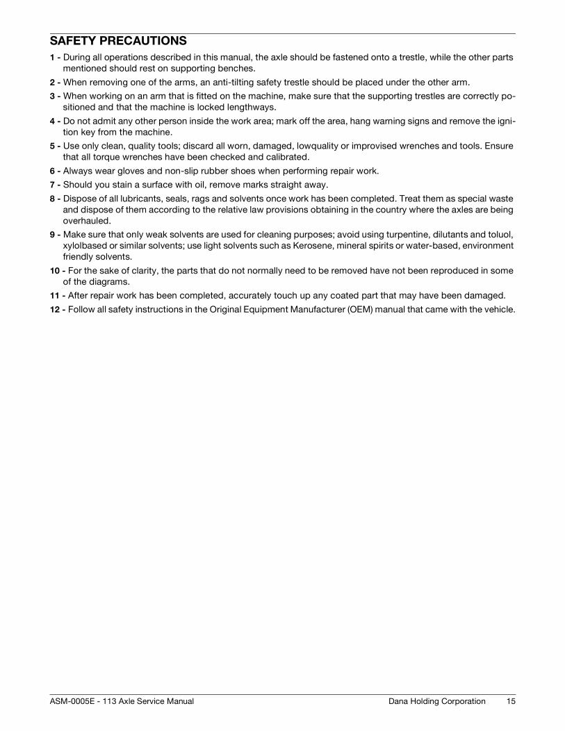
SAFETY PRECAUTIONS1 - During all operations described in this manual, the axle should be fastened onto a trestle, while the other parts
mentioned should rest on supporting benches.
2 - When removing one of the arms, an anti-tilting safety trestle should be placed under the other arm.
3 - When working on an arm that is fitted on the machine, make sure that the supporting trestles are correctly po-
sitioned and that the machine is locked lengthways.
4 - Do not admit any other person inside the work area; mark off the area, hang warning signs and remove the igni-
tion key from the machine.
5 - Use only clean, quality tools; discard all worn, damaged, lowquality or improvised wrenches and tools. Ensure
that all torque wrenches have been checked and calibrated.
6 - Always wear gloves and non-slip rubber shoes when performing repair work.
7 - Should you stain a surface with oil, remove marks straight away.
8 - Dispose of all lubricants, seals, rags and solvents once work has been completed. Treat them as special waste
and dispose of them according to the relative law provisions obtaining in the country where the axles are being
overhauled.
9 - Make sure that only weak solvents are used for cleaning purposes; avoid using turpentine, dilutants and toluol,
xylolbased or similar solvents; use light solvents such as Kerosene, mineral spirits or water-based, environment
friendly solvents.
10 - For the sake of clarity, the parts that do not normally need to be removed have not been reproduced in some
of the diagrams.
11 - After repair work has been completed, accurately touch up any coated part that may have been damaged.
12 - Follow all safety instructions in the Original Equipment Manufacturer (OEM) manual that came with the vehicle.
15Dana Holding CorporationASM-0005E - 113 Axle Service Manual

16
MAINTENANCE
Dana Holding Corporation ASM-0005E - 113 Axle Service Manual

PLANETARY REDUCTION AND AXLE SHAFT
EXPLODED VIEW
19
3
1718
1
2
7
10
9
11
1213
21 20
16
15
14
45
6
17Dana Holding CorporationASM-0005E - 113 Axle Service Manual

DISASSEMBLY
DISASSEMBLY
FIGURE 1: Remove oil level plug (1) and drain oil.
FIGURE 2: Remove the planetary cover capscrews (2).
FIGURE 3: Using two screwdrivers or two levers inserted in
the slots provided, disjoin the planetary cover (3) away from
the wheel hub (16).
1
1
23
3
FIGURE 4: Remove the cover (3).
FIGURE 5: Remove the sun gear (6).
FIGURE 6: Remove the planetary gear (5) snap rings (4).
use an eye-bolt to liftuse an eye-bolt to lift
3
6
4
5
18 Dana Holding Corporation ASM-0005E - 113 Axle Service Manual

DISASSEMBLY
FIGURE 7: Remove the planetary gears (5).
FIGURE 8: Insert air pressure to maintain the brake discs in
the correct position.
FIGURE 9: Remove the axle shaft (19).
5
19
FIGURE 10: Using an extractor, remove the seal ring (21) and
guide ring (20).
NOTE:Mark the direction of assembly of snap ring.
FIGURE 11: Loosen and remove the nuts (7).
FIGURE 12: Remove the safety flange (9).
21
20
7
9
19Dana Holding CorporationASM-0005E - 113 Axle Service Manual

DISASSEMBLY
FIGURE 13: Using two screwdrivers or two levers inserted in
the slots provided, disengage the crown wheel (11) from the
hub (16). Remove the crown (11).
FIGURE 14: Remove the snap ring (13) from the crown (12).
FIGURE 15: Remove the crown flange (11).
11
16
13
11
FIGURE 16: With the help of a plastic hammer, shift the hub
(16) and the external bearing (13).
FIGURE 17: Remove the seal ring (18) from the hub (16).
NOTE:Mark the direction of assembly.
The seal ring may not be reused.
FIGURE 18: Remove the internal bearing (8).
use an eye-bolt to liftuse an eye-bolt to lift
18
16
CAUTION
8
20 Dana Holding Corporation ASM-0005E - 113 Axle Service Manual

DISASSEMBLY
FIGURE 19: Remove the external thrust blocks of bearings
(14) and (17), using a pin driver.
NOTE:Hammer in an alternate sequence to prevent clamping and deformation of the thrust blocks.
21Dana Holding CorporationASM-0005E - 113 Axle Service Manual

ASSEMBLY
ASSEMBLY
FIGURE 20: Position the wheel hub (16) under a press; lubri-
cate the seat of the bearing cones (14)(17) and, using tool T1
(See drawing T1 p. 25), install the bearing cup of the bearing
cone (14)(17).
FIGURE 21: Fit the bearing (17) and seal ring (18) into the in-
ternal thrust block.
FIGURE 22: Apply a jointing compound for seals to the outer
surface of the sealing ring (18).
Position the sealing ring (18) in the hub (16).
NOTE:Check that the ring (18) is correctly oriented.
T117
17
18
16
FIGURE 23: Position tool T2 (See drawing T2 p. 26) and press
the sealing ring (19) into its seat.
Check the flatness of seal ring.
Install the seal ring, taking care to maintain the predefined
distance of 7.00 mm ± 0.5.
FIGURE 24: Install the wheel hub (16).
If assembly is difficult, use a punch with a suitable diameter
to seat it.
NOTE:Move the bearing cone to the limit stop by hammering lightly all around the edge.
T2
CAUTION
use an eye-bolt to liftuse an eye-bolt to lift
16
22 Dana Holding Corporation ASM-0005E - 113 Axle Service Manual

ASSEMBLY
FIGURE 25: Install the external bearing cone (14).
NOTE:Using a plastic hammer, drive the bearing cone to the li-mit stop by lightly hammering around the edge.
FIGURE 26: Install the crown wheel flange (11).
Insert the snap ring (13) in order to fix the flange (11) in the
crown (13).
FIGURE 27: Fit the complete crown flange (11).
NOTE:In order to fasten the flange (11), use a plastic hammer and alternately hammer on several equidistant points.
13
11
13
11
FIGURE 28: Install the security flange (9).
FIGURE 29: Coat the nuts (7) with Loctite 242 and tighten
them.
Tighten nuts (7) in two stages, using the criss-cross method.
Initial torque wrench setting: 330 N·m
Final torque wrench setting: 385 N·m
FIGURE 30: Lubricate and fit the seal ring (21) and guide ring
(20) onto tool T3 (See drawing T3 p. 26);
install the rings into the arm.
Pay particular attention to the direction of assembly of the
rings.
9
330 - 385 NmLoctite 242
T3
Lubricate
CAUTION
23Dana Holding CorporationASM-0005E - 113 Axle Service Manual

ASSEMBLY
FIGURE 31: Grease sealing face of axleshaft (19).
Install the axle shaft (19) making sure it is properly engaged in
the braking disks and in the differential unit.
NOTE:Be very careful not to damage the seal ring (21).
FIGURE 32: Replace the o-ring (15).
Lubricate the o-ring before fitting.
FIGURE 33: Accurately check the orientation.
19
O-ringO-ring
15
FIGURE 34: Insert the planetary gears (5) into the cover (3).
Lock gears (5) into position by installing the snap rings.
FIGURE 35: Fit the planetary carrier cover (3) onto the hub
(16).
Check that the o-ring is in good condition and in position.
FIGURE 36: Lock the planetary carrier cover (3) by tightening
the screws (2).
Torque wrench setting for screws: 182 - 202 N·m.
Install the oil-level plug (1).
Torque wrench setting for screws: 90 N·m
5
use an eye-bolt to liftuse an eye-bolt to lift
3
CAUTION
40 - 50 Nm
3
2
1
24 Dana Holding Corporation ASM-0005E - 113 Axle Service Manual

SPECIAL TOOLS
SPECIAL TOOLS
T1
P/N: 910.06.3265
184
29
14
30∞
178
148
R2
14
Ø Ø
Write code 910.06.3265
Ø 93
16M
- 0,10
- 0,1
+ +0,1 0
5 x45
∞
184
184
184
184
184
40Ø
25Dana Holding CorporationASM-0005E - 113 Axle Service Manual

SPECIAL TOOLS
T2
T3
P/N: 910.06.2366
10
0.8
154Ø
140Ø
178Ø
189Ø
205Ø
-0,2+0,1
16M
144Ø
Write code 910.06.2366
70 -0
,214
x15
∞3
6.5 30
P/N: 910.06.4434
16M
3 x45
∞3 x
15∞
120
66.5Ø
1010
6,3
139,
3
58
15
37Ø
Write code 910.06.4434
+0.2
+0.2
26 Dana Holding Corporation ASM-0005E - 113 Axle Service Manual

BRAKE WEAR CHECK PROCEDURE
Perform all operations on both arms.
FIGURE 1: Remove the inspection plug.
FIGURE 2: Apply the parking brake (or have someone hold
the service brake) and with either brake applied, check the di-
stance between discs using tool T1 (See drawing T1 p. 28).
Minimum distance: 5,2 mm
Replace the braking disks and the intermediate disks on
both sides if necessary.
See SERVICE BRAKE p. 29 and SERVICE BRAKE AND NE-
GATIVE PARKING BRAKE p. 35.
FIGURE 3: Checking brake distance with the T1 go / no-go
gauge.
CAUTION
T1
CAUTION
FIGURE 4: Install the inspection plug.
Torque wrench setting for screws: 35 - 50 N·m.
35 - 50 N·m
27Dana Holding CorporationASM-0005E - 113 Axle Service Manual

SPECIAL TOOLS
SPECIAL TOOLS
T1
32
32
32
32
10 5.4
25
45°
110
160
25
1
5.2
45°
8
1
28 Dana Holding Corporation ASM-0005E - 113 Axle Service Manual

SERVICE BRAKE
EXPLODED VIEW
1011 12
13
1415
1617
18
1
9
65
87
32
2
3
4
29Dana Holding CorporationASM-0005E - 113 Axle Service Manual
DISASSEMBLY
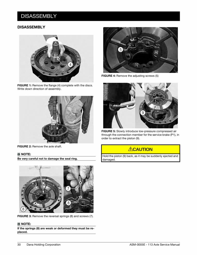
DISASSEMBLY
FIGURE 1: Remove the flange (4) complete with the discs.
Write down direction of assembly.
FIGURE 2: Remove the axle shaft.
NOTE:Be very careful not to damage the seal ring.
FIGURE 3: Remove the reversal springs (8) and screws (7).
NOTE:If the springs (8) are weak or deformed they must be re-placed.
4
8
7
8
FIGURE 4: Remove the adjusting screws (5)
FIGURE 5: Slowly introduce low-pressure compressed air
through the connection member for the service brake (P1), in
order to extract the piston (9).
Hold the piston (9) back, as it may be suddenly ejected and
damaged.
5
9
CAUTION
30 Dana Holding Corporation ASM-0005E - 113 Axle Service Manual

ASSEMBLY
ASSEMBLY
FIGURE 6: Insert the stroke automatic regulation springs (6);
place them in line with the piston (9).
FIGURE 7: Fit o-ring (11)(16) and back-up ring (10)(17) onto
the piston (11).
Lubricate the piston and the o-rings and install the unit into
the arm.
9
O-ringO-ring
Back up ringBack up ring
FIGURE 8: Using a plastic hammer, install the piston (9) into
the arm.
NOTE:Lightly hammer all around the edge in an alternate se-quence.
FIGURE 9: Fit the adjusting screws (5).
Apply Loctite 270 to the thread.
Torque wrench setting: 5 - 7 N·m
FIGURE 10: Fit the reversal springs (8) on the piston (9).
Apply LOCTITE 242 to the thread of the screw.
Tighten with torque wrench setting of 5 - 7 N·m
9
10-15 NmLoctite 270
5
8
75 - 7 NmLoctite 242
31Dana Holding CorporationASM-0005E - 113 Axle Service Manual

ASSEMBLY
FIGURE 11: Grease sealing face “A” of axle-shaft .
NOTE:Be very careful not to damage the snap ring.
FIGURE 12: Insert the brake discs in the right sequence.
NOTE:The first brake disc (3) to be inserted must be of steel ma-terial.
FIGURE 13: The second brake disc (2) to be inserted must be
of friction material.
AALubricateLubricate
3
fi rst disc
2
second disc
FIGURE 14: Install the flange (4) on the arm.
FIGURE 15: Insert the intermediate disk (1).
Before installing the last brake disc and the intermediate disc,
spread grease over the contact surfaces to hold them in po-
sition while mounting on the central housing.
FIGURE 16: Check integrity and position of the cylinder's o-
ring.
Up sideUp side
4
greasegrease
O-ringO-ring
32 Dana Holding Corporation ASM-0005E - 113 Axle Service Manual
ASSEMBLY
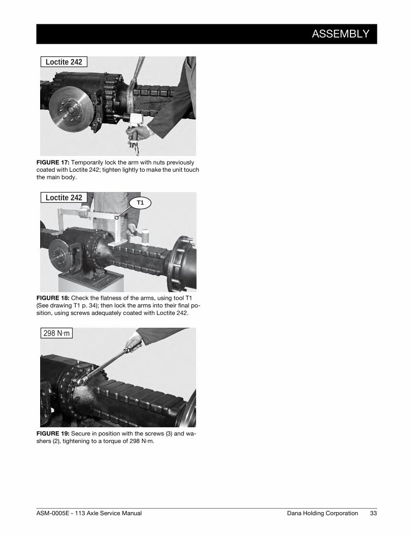
FIGURE 17: Temporarily lock the arm with nuts previously
coated with Loctite 242; tighten lightly to make the unit touch
the main body.
FIGURE 18: Check the flatness of the arms, using tool T1
(See drawing T1 p. 34); then lock the arms into their final po-
sition, using screws adequately coated with Loctite 242.
FIGURE 19: Secure in position with the screws (3) and wa-
shers (2), tightening to a torque of 298 N·m.
Loctite 242
T1Loctite 242
298 N·m
33Dana Holding CorporationASM-0005E - 113 Axle Service Manual

SPECIAL TOOLS
SPECIAL TOOLS
T1
P/N: 910.06.2363
20
20
50
20 3.2 3.2
Do not paint
150
130
0.1 A A
200
Write code 910.06.2363
5050
960
34 Dana Holding Corporation ASM-0005E - 113 Axle Service Manual

SERVICE BRAKE AND NEGATIVE PARKING BRAKE
EXPLODED VIEW
1
23
18
4
17
56
7
8
16
910
1514
19
20
2122
23
2
2526
29
28 27
30
30
11
12
13
35Dana Holding CorporationASM-0005E - 113 Axle Service Manual

RELEASE
RELEASE
FIGURE 1: Loosen nuts (22) of screws (23) provided for the
mechanical and manual release of the braking units, then
move the nuts backwards by approximately 8 mm.
FIGURE 2: Tighten screws (23) so as to fasten them onto the
pressure plate (16).
FIGURE 3: Using a wrench, tighten the screws (23) in an al-
ternate sequence by 1/4 turn at a time so as to compress the
Belleville washers (1) and disengage the braking disks.
Tighten maximum by one turn.
2122
23
23
CAUTION
36 Dana Holding Corporation ASM-0005E - 113 Axle Service Manual
ADJUSTMENT
ADJUSTMENT
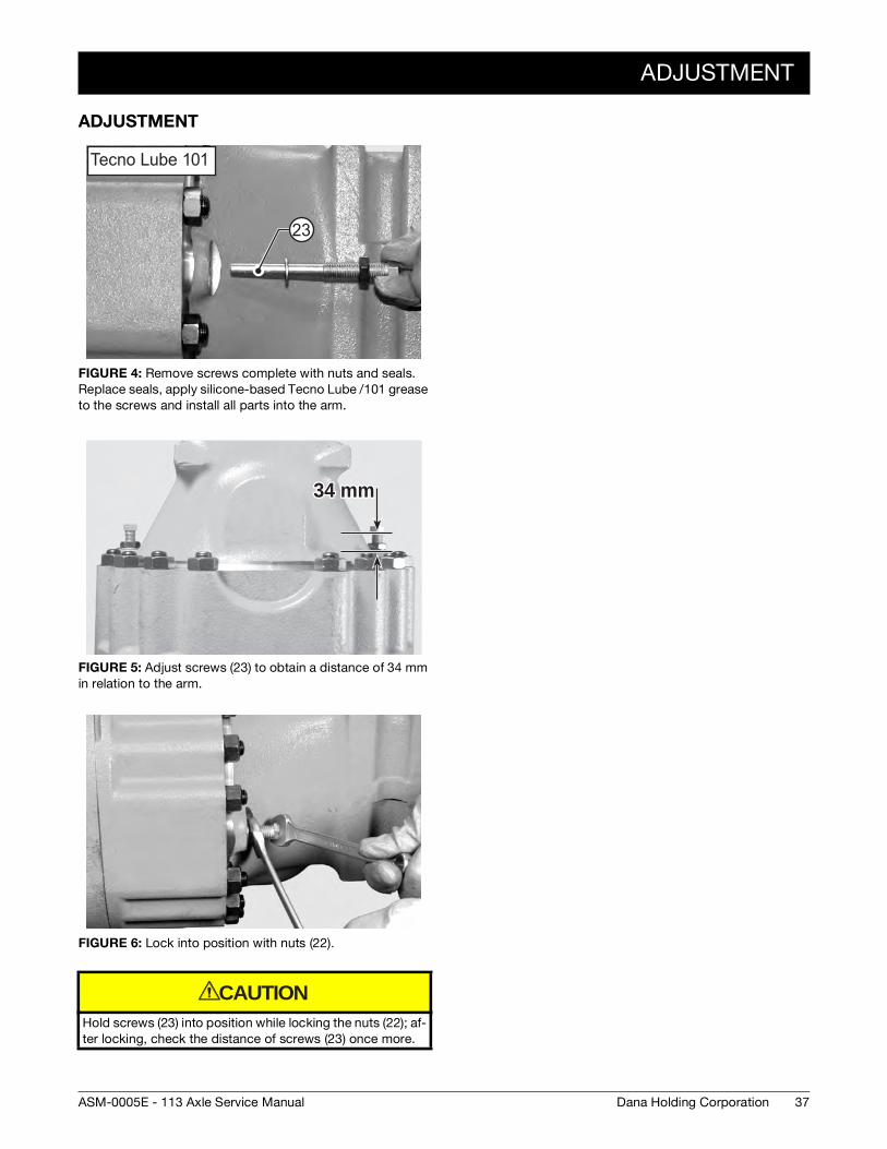
FIGURE 4: Remove screws complete with nuts and seals.
Replace seals, apply silicone-based Tecno Lube /101 grease
to the screws and install all parts into the arm.
FIGURE 5: Adjust screws (23) to obtain a distance of 34 mm
in relation to the arm.
FIGURE 6: Lock into position with nuts (22).
Hold screws (23) into position while locking the nuts (22); af-
ter locking, check the distance of screws (23) once more.
Tecno Lube 101
23
34 mm34 mm
CAUTION
37Dana Holding CorporationASM-0005E - 113 Axle Service Manual

DISASSEMBLY
DISASSEMBLY
FIGURE 7: Remove fastening screws from the reduction unit.
FIGURE 8: Disjoin the entire reduction unit from the axle and
place it on a bench.
FIGURE 9: Connect an external pump to the union piece “P1“
of the negative brake and introduce a pressure of 21 - 35 bar
to eliminate the pressure of the Belleville washers (1).
use eye-bolts to liftuse eye-bolts to lift
21-35 Bar
P1
B2B1
P2
FIGURE 10: If axle is positioned on an overhaul bench, place
a safety anti-tilting stand “B” under the arm that remains con-
nected and block wheels, if any.
FIGURE 11: Sling the arm to be removed and connect it to a
hoist. Remove the retainer screws and relative washers.
FIGURE 12: Remove arm together with brakes and axle
shafts; lay down the arm vertically.
Release pressure.
BB
38 Dana Holding Corporation ASM-0005E - 113 Axle Service Manual

DISASSEMBLY
FIGURE 13: Remove braking discs (11)(12), noting down di-
rection of assembly.
NOTE:If disks are not to be replaced, avoid changing their posi-tion.
FIGURE 14: Remove the flange (13) complete with the discs.
Write down direction of assembly.
FIGURE 15: Remove spacer-braking discs (19) and shims
(20), noting down direction of assembly.
NOTE:Build a stack of washers and check the measurement.
11
13
19 20
FIGURE 16: Remove the adjusting screws (14) from the
counterwasher (16).
FIGURE 17: Remove the reversal springs (9) and screws (10).
NOTE:If the springs (9) are weak or deformed they must be re-placed.
FIGURE 18: Write down the order of assembly and remove
the counterwasher (16).
16
14
16
39Dana Holding CorporationASM-0005E - 113 Axle Service Manual

DISASSEMBLY
FIGURE 19: Loosen the fixing screws (29) in an alternate
manner and remove them.
FIGURE 20: Remove the brake cylinder (17).
FIGURE 21: Move the cylinder (17) outwards while suppor-
ting the Belleville washers (1).
Remove the Belleville washers (1) and write down direction of
assembly.
17
17
1
FIGURE 22: Slowly introduce low-pressure compressed air
through the connection member for the service brake (P2), in
order to extract the piston (25).
Hold the piston (25) back, as it may be suddenly ejected and
damaged.
FIGURE 23: Slowly introduce low-pressure compressed air
through the connection member for the negative brake (P1),
in order to extract the piston (3).
Hold the piston (3) back, as it may be suddenly ejected and
damaged. Write down the order of assembly.
25
CAUTION
3
CAUTION
40 Dana Holding Corporation ASM-0005E - 113 Axle Service Manual

ASSEMBLY
ASSEMBLY
FIGURE 24: ATTENTION: The o-rings always have to be as-
sembled from the pressure facing side.
FIGURE 25: Fit o-ring (2) and (4) and anti-extrusion ring (18)
onto the piston (3).
FIGURE 26: Check the position of the anti-extrusion (18) and
o-rings (2) and (4).
Lubricate the piston and the o-rings and install the unit (3) into
the cylinder (17) .
Back up ringBack up ring
O-ringO-ring
18
2
3
17
FIGURE 27: Using a plastic hammer, install the piston (3) into
the cylinder (17).
NOTE:Lightly hammer all around the edge in an alternate se-quence.
FIGURE 28: Fit o-ring (27) and anti-extrusion ring (26) onto
the piston (25).
FIGURE 29: ATTENTION: The o-rings always have to be as-
sembled from the pressure facing side.
3
25
Back up ringBack up ring
O-ringO-ring
41Dana Holding CorporationASM-0005E - 113 Axle Service Manual
ASSEMBLY
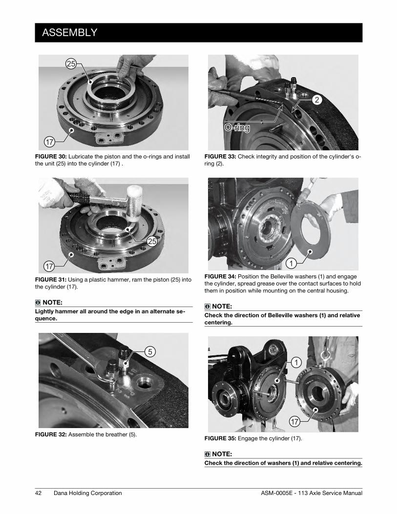
FIGURE 30: Lubricate the piston and the o-rings and install
the unit (25) into the cylinder (17) .
FIGURE 31: Using a plastic hammer, ram the piston (25) into
the cylinder (17).
NOTE:Lightly hammer all around the edge in an alternate se-quence.
FIGURE 32: Assemble the breather (5).
25
17
25
17
5
FIGURE 33: Check integrity and position of the cylinder's o-
ring (2).
FIGURE 34: Position the Belleville washers (1) and engage
the cylinder, spread grease over the contact surfaces to hold
them in position while mounting on the central housing.
NOTE:Check the direction of Belleville washers (1) and relative centering.
FIGURE 35: Engage the cylinder (17).
NOTE:Check the direction of washers (1) and relative centering.
O-ringO-ring
2
1
17
1
42 Dana Holding Corporation ASM-0005E - 113 Axle Service Manual
ASSEMBLY
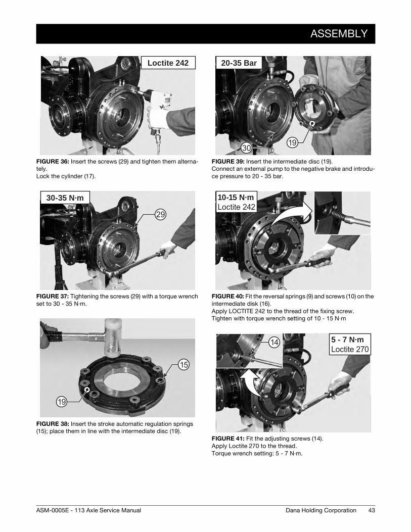
FIGURE 36: Insert the screws (29) and tighten them alterna-
tely.
Lock the cylinder (17).
FIGURE 37: Tightening the screws (29) with a torque wrench
set to 30 - 35 N·m.
FIGURE 38: Insert the stroke automatic regulation springs
(15); place them in line with the intermediate disc (19).
Loctite 242
30-35 N·m
29
15
19
FIGURE 39: Insert the intermediate disc (19).
Connect an external pump to the negative brake and introdu-
ce pressure to 20 - 35 bar.
FIGURE 40: Fit the reversal springs (9) and screws (10) on the
intermediate disk (16).
Apply LOCTITE 242 to the thread of the fixing screw.
Tighten with torque wrench setting of 10 - 15 N·m
FIGURE 41: Fit the adjusting screws (14).
Apply Loctite 270 to the thread.
Torque wrench setting: 5 - 7 N·m.
20-35 Bar
1930
10-15 N·mLoctite 242
5 - 7 N·mLoctite 270
14
43Dana Holding CorporationASM-0005E - 113 Axle Service Manual

ASSEMBLY
FIGURE 42: Take the measurement from the surface of the
intermediate disk to the cover sealing surface with 20 - 35 bar
of pressure introduced.
EXAMPLE: 30,6 mm
FIGURE 43: Put the brake disc pack including the shim under
a press, load with 1000 kg and take the measure “V”.
EXAMPLE: V = 52,9 mm
FIGURE 44: Arm fix quote = 85 mm
X
V 1000Kg
Arm fi x quote = 85mmArm fi x quote = 85mm
FIGURE 45: S = 85 mm - ( x + y + v ) = Thickness of shims to
insert under the shim washer.
EXAMPLE: 85 mm - (30,6 + 52,9 + 1) = S = 0,5 mm
FIGURE 46: Insert under the shim washer a thickness of
shims (20).
FIGURE 47: Slightly lubricate the braking disks (11) and (12)
and fit them in the arm following the correct sequence; orient
them so that the oil circulation holes and the marks “B” are
perfectly lined up.
S = 85mm - (x + y + v) S = 85mm - (x + y + v)
Y=brake gapY=brake gap
20S
20S 11
BB11
44 Dana Holding Corporation ASM-0005E - 113 Axle Service Manual
ASSEMBLY
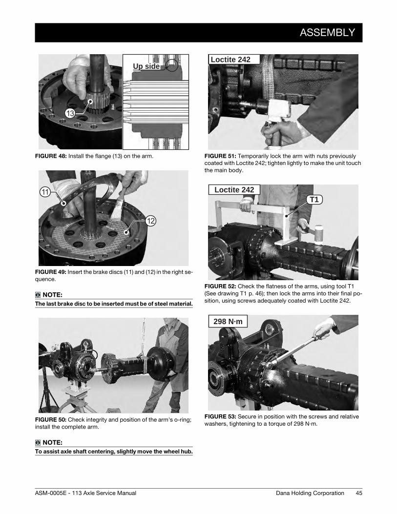
FIGURE 48: Install the flange (13) on the arm.
FIGURE 49: Insert the brake discs (11) and (12) in the right se-
quence.
NOTE:The last brake disc to be inserted must be of steel material.
FIGURE 50: Check integrity and position of the arm's o-ring;
install the complete arm.
NOTE:To assist axle shaft centering, slightly move the wheel hub.
Up sideUp side
13
12
11
FIGURE 51: Temporarily lock the arm with nuts previously
coated with Loctite 242; tighten lightly to make the unit touch
the main body.
FIGURE 52: Check the flatness of the arms, using tool T1
(See drawing T1 p. 46); then lock the arms into their final po-
sition, using screws adequately coated with Loctite 242.
FIGURE 53: Secure in position with the screws and relative
washers, tightening to a torque of 298 N·m.
Loctite 242
T1Loctite 242
298 N·m
45Dana Holding CorporationASM-0005E - 113 Axle Service Manual

SPECIAL TOOLS
SPECIAL TOOLS
T1
P/N: 910.06.2363
20
20
50
20 3.2 3.2
Do not paint
150
130
0.1 A A
200
Write code 910.06.2363
5050
960
46 Dana Holding Corporation ASM-0005E - 113 Axle Service Manual

DIFFERENTIAL UNIT
EXPLODED VIEW
6
6
5
5
99
11
13
14
15
12
10
8
7
2
2
1
1
3
3
4
4
7
16
17
19
18
1820
22
26 27
28
23
23
24
25
25
26
26
20
22
29
18
19
47Dana Holding CorporationASM-0005E - 113 Axle Service Manual

DISASSEMBLY
DISASSEMBLY
FIGURE 1: Sling the arm to be removed and connect it to a
hoist.
Remove the retainer screws and washers.
FIGURE 2: Only if need removing or adjusting.
Mark the position of the ring nuts (3). Remove screws (1) and
ring nut checks (2).
FIGURE 3: Only if need removing or adjusting.
Using tool T1 (See drawing T1 p. 53), loosen and remove the
ring nuts (3).
NOTE:Accurately remove any trace of sealant from the threads of ring nuts and intermediate covers.
1
2
T1
3
FIGURE 4: Tighten two safety M16 studs in the main body.
Loosen and remove the check screws (6) of intermediate co-
ver (7) on ring gear side.
FIGURE 5: Disjoin the cover (7) crown side.
FIGURE 6: Remove the cover and studs.
6
7
48 Dana Holding Corporation ASM-0005E - 113 Axle Service Manual

DISASSEMBLY
FIGURE 7: Extract the whole differential unit (28).
FIGURE 8: Tighten two safety M16 studs in the main body.
Loosen and remove the check screws (6) of intermediate co-
ver (4) on ring gear side.
FIGURE 9: Remove the snap ring (13).
28
6
7
13
FIGURE 10: Remove the cap (14).
FIGURE 11: If the bearings need replacing, extract the exter-
nal thrust blocks of the bearings (4) from middle cover (7).
NOTE:Accurately check the o-ring (9).
14
O-ringO-ring
9
4
7
49Dana Holding CorporationASM-0005E - 113 Axle Service Manual

ASSEMBLY
ASSEMBLY
FIGURE 12: Only if bearings are replaced: Insert the thrust
blocks of the bearings (4) into the intermediate covers (7).
Pay particular attention; position a shim with adequate dia-
meter in order to engage the internal ring of bearing without
engaging the cage.
FIGURE 13: Thoroughly check the condition of the o-ring (9).
FIGURE 14: Fit the intermediate cover (7) on opposite side of
ring gears: lock cover with screws (6) coated with Loctite 242.
Tighten screws to a torque of 129 - 143 N·m.
4
7
CAUTION
O-ringO-ring
9
129 - 143 N·mLoctite 242
6 7
FIGURE 15: Position the differential unit (28) in the central
body with the help of a bar and fit the middle cover.
FIGURE 16: Tighten the two safety screws “C” into the main
body (11) and install the intermediate cover (7).
FIGURE 17: Tighten screws (6) to a torque of 129 - 143 N·m.
28
11 7
CC
129 - 143 N·mLoctite 242
6
50 Dana Holding Corporation ASM-0005E - 113 Axle Service Manual

ASSEMBLY
FIGURE 18: Only if ring nuts have been removed.
Tighten the ring nut (3) on gear ring side until clearances
between pinion and gear ring are zeroed. Then, loosen by
about 1/4 turn.
FIGURE 19: Only if ring nuts have been removed:
Preload bearings with ring nut (26) on non-gear ring side in or-
der to increase the torque of the pinion.
FIGURE 20: Apply torque meter TM to pinion nut and check
that torque will increase by 20 - 40 Ncm as a result of diffe-
rential bearing preload.
Example: pinion torque: 120 - 180 Ncm
Pinion + differential torque: 140 - 190 Ncm.
In the case of used bearings, check thrust torque; in the
case of new bearings, check continuous torque.
T1
3
T1
TM
CAUTION
FIGURE 21: Introduce a dial indicator “A” with long tracer throu-
gh the hole provided for the cap.Position the tracer on the side of
a tooth of the gear ring, approximately 5 mm from the outer rim;
preload by about 1 mm and zero the comparator.
As you hold the pinion in position, move the gear ring manually in
both directions to check clearance between pinion and gear ring.
Standard clearance: 0,25 - 0,35 mm
FIGURE 22: Adjusting clearance between pinion and gear ring.
To INCREASE: loosen the ring nut on gear ring side and tighten
the ring nut on non-gear ring side by the same measure.
To DECREASE: perform the same operations inversely.
To rotate ring nuts, use special wrench T1 (See drawing T1 p. 53).
FIGURE 23: Install in correct position the safety plate (2).
Gap = 0,25 - 0,35 mm
A
T1
T1
1
2
51Dana Holding CorporationASM-0005E - 113 Axle Service Manual

ASSEMBLY
FIGURE 24: Engage screw (1) in the slot next to the holes pro-
vided for the check screws.
Coat screws with Loctite 270 and tighten to a torque of 11 N·m.
FIGURE 25: Using a driver, fit the cap (14) and secure with
the snap ring (13).
FIGURE 26: Check that the positioning of the sealing ring on
the arm is intact; install the complete arm.
Lock it into position using two facing screws and washers.
11 N·mLoctite 270
1413
FIGURE 27: Temporarily lock the arm with screws previously
coated with Loctite 242; tighten lightly to make the unit touch
the main body.
FIGURE 28: Check the flatness of the arms, using tool T2
(See drawing T2 p. 54); then lock the arms into their final po-
sition, using screws adequately coated with Loctite 242.
Loctite 242
298 N·m
52 Dana Holding Corporation ASM-0005E - 113 Axle Service Manual

SPECIAL TOOLS
SPECIAL TOOLS
T1
P/N: 910.04.2369
100
1015
10
Ø120
2590
+0,1
-
2 x4
5∞5
x45∞
40Ø - 0,15- 0,1
5 x1
5∞
Usare chiave a bussolaUSAG 235 3/4" EN n∞27UNI-ISO 2725 - DIN 3124Use square drive socketUSAG 235 3/4" EN #27 UNI-ISO 2725 - DIN 3124
Write code 910.04.2369
102Ø
95Ø
+0,1-
+0,1-
+0,1-
13 - 0,2+
53Dana Holding CorporationASM-0005E - 113 Axle Service Manual

SPECIAL TOOLS
T2
P/N: 910.06.2363
20
20
50
20 3.2 3.2
Do not paint
150
130
0.1 A A
200
Write code 910.06.2363
50
50
960
54 Dana Holding Corporation ASM-0005E - 113 Axle Service Manual
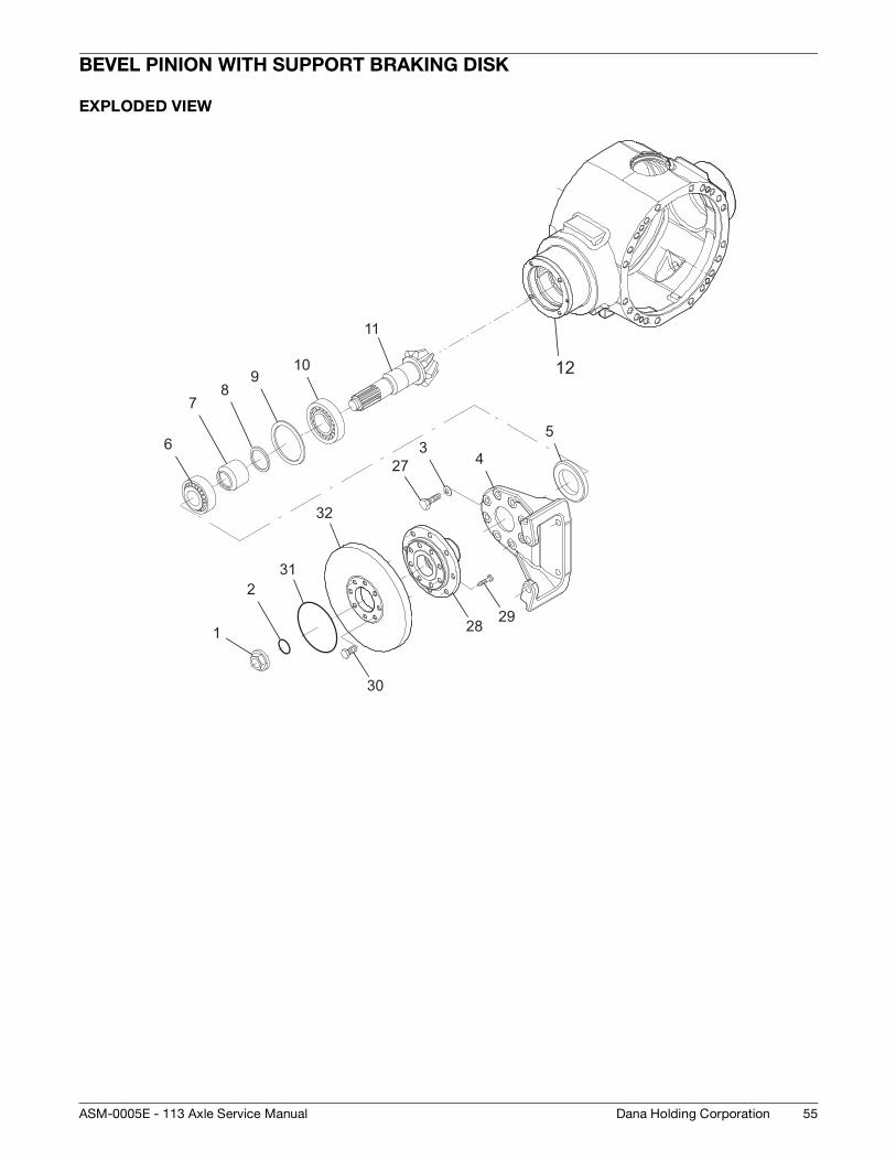
BEVEL PINION WITH SUPPORT BRAKING DISK
EXPLODED VIEW
12
1
2
34
56
78
910
11
27
28 29
30
31
32
55Dana Holding CorporationASM-0005E - 113 Axle Service Manual

DISASSEMBLY
DISASSEMBLY
FIGURE 1: Remove the intermediate cover and the whole dif-
ferential unit.
For details, see DIFFERENTIAL UNIT p. 47.
FIGURE 2: Remove the snap ring.
FIGURE 3: Remove the cap
FIGURE 4: Draw out the screw (30) and remove the disk (32).
FIGURE 5: Position tool T4 (See drawing T4 p. 67), so as to
avoid pinion rotation. Loosen and remove the nut (1); also re-
move the o-ring (2).
FIGURE 6: Remove the flange (28).
32
30
T4
2 1
12
56 Dana Holding Corporation ASM-0005E - 113 Axle Service Manual

DISASSEMBLY
FIGURE 7: Remove the retainer screws (23) and washers (3).
FIGURE 8: Remove the brake support (4).
NOTE:Write down assembly direction.
FIGURE 9: Remove the sealing ring (5).
23
4
5
FIGURE 10: Extract the pinion (11) complete with the internal
bearing cone (10), the spacer (7) and calibrated spacer (8).
NOTE:The bearing cups of the bearing cones remain in the cen-tral body.
FIGURE 11: Refer and keep to the positions marked during
disassembly.
FIGURE 12: Using a puller and a press, remove the inner be-
aring cone (10) from the pinion (11).
11
78
11
10
57Dana Holding CorporationASM-0005E - 113 Axle Service Manual

DISASSEMBLY
FIGURE 13: Remove the bearing cup of the tail bearing cone
(6).
FIGURE 14: Remove the bearing cup of the internal bearing
cone (10) as well as the shim washers (8).
6
8
10
58 Dana Holding Corporation ASM-0005E - 113 Axle Service Manual

ASSEMBLY
ASSEMBLY
FIGURE 15: Reset a centesimal digital depth gauge on a ca-
librated block (whose known thickness is 20 mm.).
FIGURE 16: With a calibrated block on a faceplate, allow the
bearing cone to set by rotating them in both directions and by
applying a vertical thrust position the calibrated block on the
external bearing cups.
Check overall thickness of bearing. D = 42,25 mm
FIGURE 17: Check nominal dimension “INT” as marked on
the pinion. Add up to or subtract from “INT” the variation in-
dicated as “Y” to obtain the actual center distance “I”.
EXAMPLE: I = (INT - Y) = 153 - 0,1 = 152,9 mm
20 mm calibrated block20 mm calibrated block
D = bearing cone ticknessD = bearing cone tickness
D
10
YY
FIGURE 18: Calculate calibrated shim “S” for insertion under
the bearing cup of the inner bearing cone using the following
formula:
S = 196 - (I + D) where: 196 = fixed dimension
I = actual pinion center distance
D = Total bearing thickness;
EXAMPLE: S = 196 - (152,9 + 42,25) = 0,85 mm
FIGURE 19: Using special tool T2 (See drawing T2 p. 65).
Partially insert the bearing cup of the bearing cones (6) and
(10) and shims (9).
FIGURE 20: Connect the tension rod to the press and move
the bearing cup of bearing cones (6) and (10) into the seats.
Disconnect the press and remove the tension rod.
NOTE:Before starting the next stage, make sure that the bearing cup has been completely inserted into its seat.
Shims “S”Shims “S”9
T2
T2
T2
59Dana Holding CorporationASM-0005E - 113 Axle Service Manual

ASSEMBLY
FIGURE 21: CALCULATING PINION BEARINGS ROLLING
TORQUE
Introduce tool T1 (See drawing T1 p. 64) complete with bea-
rings (6) and (10) into the central housing; tighten by hand un-
til to eliminate the axial gap.
FIGURE 22: Introduce the tracer of a dial indicator into either
side hole of tool T1 (See drawing T1 p. 64).
FIGURE 23: Remove the comparator and take out tool and
bearing cone kits from the main body.
Reinstall every part, also introducing a spacer (7) and thicker
calibrated spacer between bearing cones (10) and (6). Tighten
the entire pack by hand.
T1 106
T1
A
6
10
7
FIGURE 24: Introduce the dial indicator into either side hole
of tool T1 (See drawing T1 p. 64). Reset the comparator with
a preload of about 3 mm.
FIGURE 25: Deviation “H” must be added to a set value of
0,10 mm to obtain calibrated shim “S1” (8) for insertion
between pinion (6) and spacer (7).
Dimension “S1” must be rounded off to the higher 5/100.
EXAMPLE: S1=H+X= 1,8 + 0,1 = 1,9 mm
FIGURE 26: Position the internal bearing (10) and the pinion
(11) under a press; force the bearing onto the pinion.
H = A - B = 1,9 mm
T1
B
S1=H+X H= A-B X = fi x value 0,10 mm
8
11
10
60 Dana Holding Corporation ASM-0005E - 113 Axle Service Manual

ASSEMBLY
FIGURE 27: Insert spacer (7) and two calibrated spacers “S1”
(8).
FIGURE 28: Fit the pinion (11), calibrated spacer “S1” (9) and
spacer (7) in the main body (12).
FIGURE 29: Heat the external bearing cone (6) to a tempera-
ture of about 212 F° [100 C°] and fit it on to the pinion (11) so
as to complete the pack as shown above.
78
S1777777777777777
888888888888888
S1S1
7
8
12
9
7
100°
6
11
6
FIGURE 30: Install the flange (28) onto the pinion (11) without
the sealing ring.
FIGURE 31: Apply torque wrench to the ring nut (1) and spe-
cial tool T4 (See drawing T4 p. 67) to the pinion (11).
Lock the wrench T4 (See drawing T4 p. 67) and rotate the pi-
nion using a dynamometric wrench, up to a minimum requi-
red torque setting of 880 - 1100 N·m.
FIGURE 32: Apply onto the pinion (11) the bar-hold and with
the help of a torque meter, check the torque of the pinion (11).
Torque: 120 - 180 Ncm
28
T4
880 - 1100 N·m
TM
61Dana Holding CorporationASM-0005E - 113 Axle Service Manual
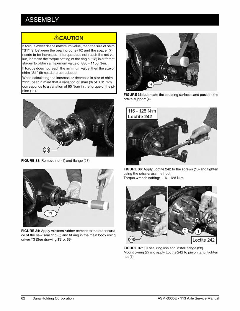
ASSEMBLY
If torque exceeds the maximum value, then the size of shim
“S1” (9) between the bearing cone (10) and the spacer (7)
needs to be increased. If torque does not reach the set va-
lue, increase the torque setting of the ring nut (3) in different
stages to obtain a maximum value of 880 - 1100 N·m.
If torque does not reach the minimum value, then the size of
shim “S1” (9) needs to be reduced.
When calculating the increase or decrease in size of shim
“S1”, bear in mind that a variation of shim (9) of 0.01 mm
corresponds to a variation of 60 Ncm in the torque of the pi-
nion (11).
FIGURE 33: Remove nut (1) and flange (28).
FIGURE 34: Apply Arexons rubber cement to the outer surfa-
ce of the new seal ring (5) and fit ring in the main body using
driver T3 (See drawing T3 p. 66).
CAUTION
28
T3
FIGURE 35: Lubricate the coupling surfaces and position the
brake support (4).
FIGURE 36: Apply Loctite 242 to the screws (13) and tighten
using the criss-cross method.
Torque wrench setting: 116 - 128 N·m
FIGURE 37: Oil seal ring lips and install flange (28).
Mount o-ring (2) and apply Loctite 242 to pinion tang; tighten
nut (1).
9
116 - 128 N·mLoctite 242
1Loctite 24228
2 1
62 Dana Holding Corporation ASM-0005E - 113 Axle Service Manual

ASSEMBLY
FIGURE 38: Apply wrench to the ring nut (1) and special tool
T4 (See drawing T4 p. 67) to the pinion (11).
Lock the wrench T4 (See drawing T4 p. 67) and rotate the pi-
nion using a dynamometric wrench, up to a minimum requi-
red torque setting of 880 - 1100 N·m.
FIGURE 39: Install disk (3) and keep it into position with
screws (19) and nuts (4).
FIGURE 40: Tighten using a torque wrench to a torque of 128
- 142 N·m.
880 - 1100 N·m
128 - 142 N·m 30
FIGURE 41: Using a driver, fit the cap and position it in its se-
cure with the snap ring.
FIGURE 42: Re-install the differential unit and the intermedia-
te cover.
For details, see DIFFERENTIAL UNIT p. 47.
If the crown and pinion has been replaced, reinstate clea-
rances.
CAUTION
63Dana Holding CorporationASM-0005E - 113 Axle Service Manual

SPECIAL TOOLS
SPECIAL TOOLS
T1
P/N: 910.04.2374
0.8
0.8
0.8
0.8
0.80.8
(221)
0.8
20
M16
x1,5
15∞
70
3 x15∞
3 x15∞
119 +0,1- 44 +0,02-
20Ø
- 0,
2 -
0,1
1 x45∞ 1 x45∞
Ø60Ø6
40
70
1 x45∞ 1 x45∞M
16x1
,5
38+0,1-
+0,1-
3 x15∞
- 0,050
Ø50
- 0,
05 -
0,02
20+0
,1 0
Ø
30+0
,1
-
Write code 910.04.2374
Write code 910.04.2374
670
- 0,1
40Ø
- 0,
05 -
0,02
64 Dana Holding Corporation ASM-0005E - 113 Axle Service Manual

SPECIAL TOOLS
T2
P/N: 910.04.2377+0
,1
-
40
M18x1,5
2 x1
5∞
19,50
- 0,15 Ø
550
495
+0,1
-
Ø
35
30+0
,1
-
M18x1,5
0.1
Write code 910.04.2377
40
Ø
0.8
40
80
45∞
Ø
Ø
0 - 0,1
R2
30∞
19,5
Ø+0,2+0,1
10
94
2 x4
5∞
70+0
,1
-
Writ
e co
de 9
10.0
4.23
77
R2
1 x45∞
65
Ø
0.830∞ R2
R2
45∞
50
75
Ø+0,2+0,1
35
Ø
2 x45∞
1 x45
∞
Ø
R5
8
19,5
Ø+0,2+0,1
2 x1
5∞
109+0,1 -
89
Ø+0,1 -
45+0
,1
-
101
Ø0 - 0,1
Writ
e co
de 9
10.0
4.23
77
A +
B
AB
65Dana Holding CorporationASM-0005E - 113 Axle Service Manual

SPECIAL TOOLS
T3
P/N: 910.04.1688
0.8
140
125
35
10
45∞
99 80 40 8850
910.04.1688- Input flange seal - per 113-176-213-276
2
ØØØØ 61,6
Ø
+0,1-
2 x45∞
2 x15∞ 1 x45∞
2
16
+ 0,1 0
+ 0,1 0
Ø108
Ø
+0,1
- +0,1
- - 0,1 0
+ 0,1 + 0,2
Riportare codice
910.04.1688
66 Dana Holding Corporation ASM-0005E - 113 Axle Service Manual

SPECIAL TOOLS
T4
P/N: 910.99.0002
Dettaglio X
A A
45
15 10
5x45
195
230
45∞
54
12,5
160
132
74 40
Sez. A-A
Write code 910.99.0002
Dettaglio X
67Dana Holding CorporationASM-0005E - 113 Axle Service Manual

SPECIAL TOOLS
68 Dana Holding Corporation ASM-0005E - 113 Axle Service Manual

FLANGED BEVEL PINION
EXPLODED VIEW
161514
131211
5
4
3
67
2
1
16
18
69Dana Holding CorporationASM-0005E - 113 Axle Service Manual

DISASSEMBLY
DISASSEMBLY
FIGURE 1: Remove the retainer screws (6) and washers (7).
FIGURE 2: Remove shims (11) and pinion support (5).
Refer and keep to the positions marked during disassembly.
FIGURE 3: Stop wrench and rotate the pinion so as to release
and remove the ring nut (2).
6
11
5
T1
FIGURE 4: Remove pinion ring nut (2).
FIGURE 5: Position the cover under a press, extract the pi-
nion (18) complete with the internal bearing (16), the spacer
(15), and shims (14).
NOTE:The thrust blocks of the bearings remain in the central body (5).
FIGURE 6: Remove sealing ring (13) and bearing (4).
2
5 18
4
70 Dana Holding Corporation ASM-0005E - 113 Axle Service Manual
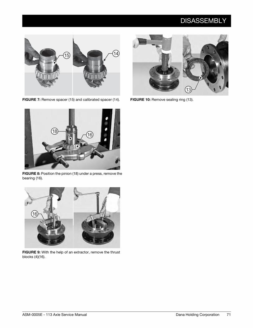
DISASSEMBLY
FIGURE 7: Remove spacer (15) and calibrated spacer (14).
FIGURE 8: Position the pinion (18) under a press, remove the
bearing (16).
FIGURE 9: With the help of an extractor, remove the thrust
blocks (4)(16).
15 14
1816
16
FIGURE 10: Remove sealing ring (13).
13
71Dana Holding CorporationASM-0005E - 113 Axle Service Manual

ASSEMBLY
ASSEMBLY
FIGURE 11: Lubricate the outer surface of the new sealing
ring (13) and fit it onto the cover (5) using tool T2 (See drawing
T2 p. 78) .
FIGURE 12: Using tool T3 (See drawing T3 p. 78), insert the
thrust blocks of bearing (4)(16).
FIGURE 13: Introduce a spacer (15) and thicker calibrated
spacer between bearings. Reset the depth gauge on pinion
bearings (4)(16) and pinion spacer arranged (15) as in the fi-
gure above.
T2
5
13
T3
4 16
15
4
A
FIGURE 14: Using a surface plate, position the pinion sup-
port (5) on the outer bearing (16) and then insert the outer be-
aring (4) in the pinion support (5).
FIGURE 15: Arrange accurately the pinion bearings.
FIGURE 16: Insert depth gauge “DDG” into pinion support (5)
and measure variation “H” in relation to the zero setting per-
formed back at Figure 13.
H = 1,8 mm
16
5 4
B
5
72 Dana Holding Corporation ASM-0005E - 113 Axle Service Manual

ASSEMBLY
FIGURE 17: Heat the inner bearing (16) to about 212 F° [100
C°] and fit it to the pinion (18).
FIGURE 18: Deviation “H” must be added to a set value of
0,10 mm to obtain calibrated shim “S1” (14) for insertion
between inner bearing cone (4) and spacer (15).
Dimension “S1” must be rounded off to the higher 5/100.
EXAMPLE: S1=H+X= 1,8 + 0,1 = 1,9 mm
FIGURE 19: Insert spacer (15) and two calibrated spacers
“S1” (14).
100°
16
18
19
S1=H+X H= A-B X = fi x value 0,10 mm
1514
FIGURE 20: Oil seal ring lips.
FIGURE 21: Insert the cover (5).
FIGURE 22: Heat the outer bearing (2) to about 212 F° [100
C°] and fit into the pinion (1).
5
100°
5
4
73Dana Holding CorporationASM-0005E - 113 Axle Service Manual
ASSEMBLY
FIGURE 23: Insert spacer (3).
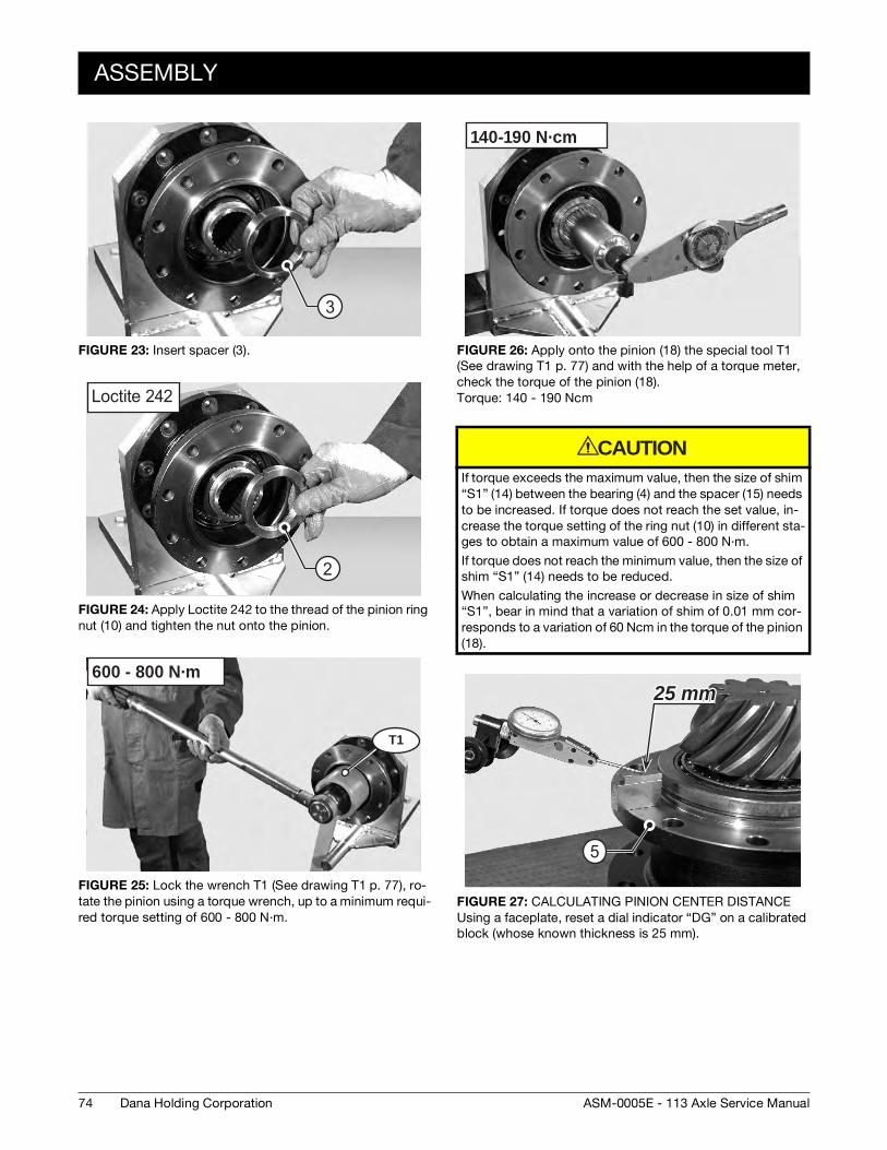
FIGURE 24: Apply Loctite 242 to the thread of the pinion ring
nut (10) and tighten the nut onto the pinion.
FIGURE 25: Lock the wrench T1 (See drawing T1 p. 77), ro-
tate the pinion using a torque wrench, up to a minimum requi-
red torque setting of 600 - 800 N·m.
3
Loctite 242
2
T1
600 - 800 N·m
FIGURE 26: Apply onto the pinion (18) the special tool T1
(See drawing T1 p. 77) and with the help of a torque meter,
check the torque of the pinion (18).
Torque: 140 - 190 Ncm
If torque exceeds the maximum value, then the size of shim
“S1” (14) between the bearing (4) and the spacer (15) needs
to be increased. If torque does not reach the set value, in-
crease the torque setting of the ring nut (10) in different sta-
ges to obtain a maximum value of 600 - 800 N·m.
If torque does not reach the minimum value, then the size of
shim “S1” (14) needs to be reduced.
When calculating the increase or decrease in size of shim
“S1”, bear in mind that a variation of shim of 0.01 mm cor-
responds to a variation of 60 Ncm in the torque of the pinion
(18).
FIGURE 27: CALCULATING PINION CENTER DISTANCE
Using a faceplate, reset a dial indicator “DG” on a calibrated
block (whose known thickness is 25 mm).
140-190 N·cm
CAUTION
25 mm25 mm
5
74 Dana Holding Corporation ASM-0005E - 113 Axle Service Manual
ASSEMBLY
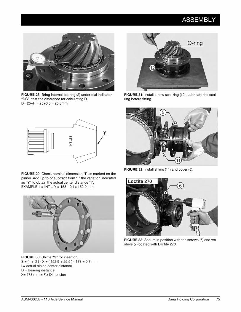
FIGURE 28: Bring internal bearing (2) under dial indicator
“DG”, test the difference for calculating D.
D= 25+H = 25+0,5 = 25,8mm
FIGURE 29: Check nominal dimension “I” as marked on the
pinion. Add up to or subtract from “I” the variation indicated
as “Y” to obtain the actual center distance “I”.
EXAMPLE: I = INT ± Y = 153 - 0,1= 152,9 mm
FIGURE 30: Shims “S” for insertion:
S = ( I + D ) - X = ( 152,9 + 25,5 ) - 178 = 0,7 mm
I = actual pinion center distance
D = Bearing distance
X= 178 mm = Fix Dimension
INT
153
YY
FIGURE 31: Install a new seal-ring (12). Lubricate the seal
ring before fitting.
FIGURE 32: Install shims (11) and cover (5).
FIGURE 33: Secure in position with the screws (6) and wa-
shers (7) coated with Loctite 270.
O-ringO-ring
12
11
5
Loctite 2706
75Dana Holding CorporationASM-0005E - 113 Axle Service Manual

ASSEMBLY
FIGURE 34: Using the criss-cross method tighten to torque
of 129 - 143 N·m.
FIGURE 35: Install a new seal-ring (1).
Lubricate the seal ring before fitting.
FIGURE 36: Re-fit the reduction unit onto the axle. Fasten the
support planes (turn flange to assist assembly).
Insert nuts by applying LOCTITE 242.
Tighten nuts using a torque wrench setting of 129 - 143 N·m.
129 - 143 N·m
O-ringO-ring
1
129 - 143 N·mLoctite 242
76 Dana Holding Corporation ASM-0005E - 113 Axle Service Manual

SPECIAL TOOLS
SPECIAL TOOLS
T1
P/N: 910.04.2377
0.8
0.8
112
Ø
57,5
h7Ø
45∞
30
90
16
88Ø
x15∞ 5
85,5+
0,2
0
11
R2
7- 0,20
+ 0,
20
Ø92
,5 Ø93
13,5
9∞
100
300
204020
Usa
re c
hiav
e a
buss
ola
US
AG
235
3/4
" EN
n∞
27
UN
I-IS
O 2
725
- DIN
312
4U
se s
quar
e dr
ive
sock
etU
SA
G 2
35 3
/4" E
N #
27
UN
I-IS
O 2
725
- DIN
312
4
Writ
e co
de 9
10.0
4.09
26
10 5
57,5
50
100
15x15∞ 5
45∞
- 0,15
- 0,1
Ø
30Ø N
ota
B -
Not
e B
:B
runi
to -
Bur
nish
edN
ota
A - N
ote
A :
Nitr
urat
o - N
itrur
ed
Mat
eria
le -
Mat
eria
l: ve
di n
ota
B -
see
note
BA
ccia
io -
Ste
el C
40 E
N10
083
Acc
iaio
- S
teel
39N
iCrM
o3 E
N10
083-
1M
ater
iale
- M
ater
ial:
vedi
not
a A
- see
not
eA
Acc
iaio
- S
teel
39N
iCrM
o3 E
N10
083-
1M
ater
iale
- M
ater
ial:
vedi
not
a A
- see
not
eA
SC
AN
ALA
TO -
SP
LIN
E58
x53
DIN
548
2N
∞ D
enti
- Tee
th n
∞ Z
= 27
Mod
ulo
- Mod
ul m
= 2
Ang
olo
di p
ress
ione
- P
ress
ure
angl
e a=
30∞
Sco
st. p
rofil
o - A
dden
dum
mod
. xm
= - 0
,518
Dia
met
ro ru
lli -
Pin
s di
amet
er Ø
3,5
Quo
ta ru
lli -
Mea
surin
g bt
w p
ins
Md=
59,
55-5
9,60
77Dana Holding CorporationASM-0005E - 113 Axle Service Manual

SPECIAL TOOLS
T2
T3
P/N: 910.04.1691
1.6
1.6
103
12,2
25
3x1
5∞ 2
x45∞
M16
Ø - 0,10
- 0,10
11+0
,1-
90Ø+ 0,1
0
125Ø- 0,4- 0,6
P/N: 910.04.1690
0.8
124,
5
65 40
19,5
60
R2
45∞
45∞
R2
45∞
30∞
R2
10
90
115
118
65
Ø
+0,1-
Ø Ø
Ø
Ø Ø -
0,1
0
+ 0
,1 +
0,2
2 x45
∞
- 0,
1 0
2 x45∞
78 Dana Holding Corporation ASM-0005E - 113 Axle Service Manual

HYDRAULIC DIFFERENTIAL LOCK
EXPLODED VIEW
10
4
7
2
9
11
12
15
13
14
6
5
3
8
1
9
16
17
18
19 20
44
4422
23
24
2526
28
313233
29
41
3027
3940
36 3735
3438
41
4342
21
79Dana Holding CorporationASM-0005E - 113 Axle Service Manual

DISASSEMBLY
DISASSEMBLY
FIGURE 1: Remove the arms.
For details, see SERVICE BRAKE AND NEGATIVE PARKING
BRAKE p. 35.
FIGURE 2: Remove both guard (1) and differential-lock indi-
cator (2).
FIGURE 3: Tighten two safety studs (M16) in two opposing
holes in the main body (3).
Loosen and remove the screws (4).
11
3
4
FIGURE 4: Connect to a hoist and remove the whole brake
cylinders (5).
FIGURE 5: Remove screws (6) and safety stops (7) from
adjustment ring nuts (8).
FIGURE 6: Only if locking piston seal is replaced: make posi-
tional match marks across the adjustment ring nut on non-
gear ring side.
Loosen the ring nut (8) by about 6 mm (4 turns).
5
8
7
6
8
80 Dana Holding Corporation ASM-0005E - 113 Axle Service Manual

DISASSEMBLY
FIGURE 7: Loosen and remove check screws (9) from inter-
mediate cover (10).
FIGURE 8: Introduce low-pressure compressed air through
connection and make sure that the lock control piston comes
out at end of stroke.
Remove safety studs, rotate cover (10) to an angle of about
45° and remove cover.
FIGURE 9: Tighten two safety studs (M16) in the main body.
Loosen and pull out check screws (9) from intermediate cover
(11) on gear ring side.
10
9
10
911
FIGURE 10: Support the differential unit and disconnect in-
termediate cover (11) from main body (3).
Remove cover (11).
FIGURE 11: Remove the differential unit by using tool T1 (See
drawing T1 p. 89); position the unit on a workbench.
FIGURE 12: Remove the snap ring (12) and locking cap (13).
NOTE:Replace the cap at each disassembly.
113
T1
13
12
81Dana Holding CorporationASM-0005E - 113 Axle Service Manual

DISASSEMBLY
FIGURE 13: CONTROL DISASSEMBLY
As you hold piston (14) in position, loosen check nut (15) of
fork (16).
Remove nut (15) and spring washer (21).
FIGURE 14: Remove fork (16).
NOTE:Write down direction of installation and thoroughly in-spect pad for wear.
FIGURE 15: Loosen piston stop ring nut (17); remove ring nut
and spring (18).
211514
16
16
17
18
17
FIGURE 16: Remove piston (14) complete with o-ring (19)
and guide pad (21).
NOTE:Replace pad and o-ring at each disassembly.
FIGURE 17: If bearings need replacing, remove the outer
thrust blocks of bearings (44) from intermediate covers (10)
and (11).
FIGURE 18: DISASSEMBLING THE BRAKE PISTON
Gently introduce low-pressure compressed air through the
connection of the working brake line and eject the whole pi-
ston (22).
NOTE:Replace seals (23) and (24) and anti-extrusion rings at each disassembly.
19
20
14
1044
11
22
82 Dana Holding Corporation ASM-0005E - 113 Axle Service Manual
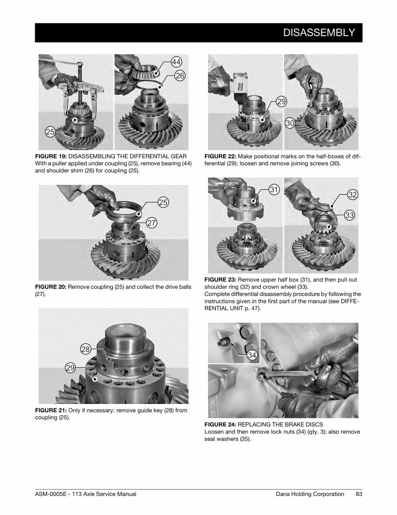
DISASSEMBLY
FIGURE 19: DISASSEMBLING THE DIFFERENTIAL GEAR
With a puller applied under coupling (25), remove bearing (44)
and shoulder shim (26) for coupling (25).
FIGURE 20: Remove coupling (25) and collect the drive balls
(27).
FIGURE 21: Only if necessary: remove guide key (28) from
coupling (25).
25
44
26
27
25
28
29
FIGURE 22: Make positional marks on the half-boxes of dif-
ferential (29); loosen and remove joining screws (30).
FIGURE 23: Remove upper half box (31), and then pull out
shoulder ring (32) and crown wheel (33).
Complete differential disassembly procedure by following the
instructions given in the first part of the manual (see DIFFE-
RENTIAL UNIT p. 47).
FIGURE 24: REPLACING THE BRAKE DISCS
Loosen and then remove lock nuts (34) (qty. 3); also remove
seal washers (35).
29
30
3132
33
34
83Dana Holding CorporationASM-0005E - 113 Axle Service Manual

DISASSEMBLY
FIGURE 25: Remove screws (36), springs (37), and pressure
plate (38).
Proceed by removing the brake discs.
(For details, see SERVICE BRAKE AND NEGATIVE PARKING
BRAKE p. 35 in the first part of the manual).
36
37
38
84 Dana Holding Corporation ASM-0005E - 113 Axle Service Manual

ASSEMBLY
ASSEMBLY
FIGURE 26: ONLY IF DIFFERENTIAL HAS BEEN DISASSEM-
BLED
Assemble the differential unit (29). For details, see DIFFE-
RENTIAL UNIT p. 47 in the first part of the manual. Put the
guide key (28) of coupling (25) in place.
FIGURE 27: Grease the ball slots and fit in the balls (27), cou-
pling (25) and shoulder shim (26).
FIGURE 28: Heat bearing (44) to approximately 194 F° [194
F° [90 C°]] and install on the differential.
NOTE:Make sure that the bearing is securely engaged.
28
29
25 26
27
44
FIGURE 29: ASSEMBLING LOCK CONTROL
Fit o-ring (19) and guide ring (20) onto piston (14).
Lubricate the seals and introduce the unit in tool T2 (See dra-
wing T2 p. 89).
FIGURE 30: Place tool T2 (See drawing T2 p. 89) on the inter-
mediate cover (10) and push piston (14) into its seat.
FIGURE 31: Fit spring (18) and ring nut (17) on piston (14).
Tighten the ring nut by a few turns, apply a coat of Loctite 242
to the ring nut and tighten to a torque of maximum 50 N·m
using a torque wrench.
T2
14
19 20
T2
1410
17
18
14
85Dana Holding CorporationASM-0005E - 113 Axle Service Manual

ASSEMBLY
FIGURE 32: Fit fork (16) on piston (14) and make sure fork
orientation is correct.
NOTE:Microswitch activation cam "A" must face upwards.
FIGURE 33: Secure fork (16) with washer (21) and nut (15).
FIGURE 34: As you hold piston (14) in position, lock the nut
(15) with a torque wrench.
Tightening torque: 225 - 230 N·m.
16
15
21
16
1415
FIGURE 35: ASSEMBLING THE BRAKE PISTON
Fit o-rings (23), (24) and anti-extrusion rings (39) and (40) on
piston (22).
NOTE:Thoroughly check the positioning of anti-extrusion rings (39) and (40). Lubricate the seals and introduce piston (22) into cylinder (5).
FIGURE 36: INSTALLATION
Using tool T1 (See drawing T1 p. 89), introduce the whole dif-
ferential (3) into the main body (29).
522
T1
3
29
86 Dana Holding Corporation ASM-0005E - 113 Axle Service Manual

ASSEMBLY
FIGURE 37: Tighten two safety studs in the main body (3) and
install the intermediate cover (11). Lock in position with
screws "V" tightened to a matching torque.
Tightening torque: 130 - 143 N·m.
NOTE:Check the condition of the o-ring (41).
FIGURE 38: Introduce low-pressure compressed air through
connection and make sure that the lock control piston comes
out at the end of stroke.
Rotate the intermediate cover (10) to an angle of about 45°;
engage the fork (16) in the lock control coupling (25).
NOTE:Check the condition of the o-ring (41).
V�
��
3
41
V9
11
V
��
��
��
��41
16
10
25
FIGURE 39: As you hold the fork in position (16), rotate the
intermediate cover into its final position (10).
To lock into position, tighten two safety studs in two oppo-
sing holes.
FIGURE 40: Clear any compressed air and finally move the
intermediate cover (10) into its seat.
Lock into position with nuts ("V" tightened to matching tor-
que.
Tightening torque: 130 - 143 N·m.
FIGURE 41: If necessary, adjust differential clearances.
(See DIFFERENTIAL UNIT p. 47).
Install the cap (13) and snap ring (12).
10
��
�V
V
10
9V
V
13
12
87Dana Holding CorporationASM-0005E - 113 Axle Service Manual

ASSEMBLY
FIGURE 42: Fit the differential-lock indicator (2) complete
with the o-ring (42) and the retainer ring (43).
Install the arms. (See SERVICE BRAKE AND NEGATIVE PAR-
KING BRAKE p. 35).
2 42 43
12.5 mm
88 Dana Holding Corporation ASM-0005E - 113 Axle Service Manual

SPECIAL TOOLS
SPECIAL TOOLS
T1
T2
P/N: 2370
4260Ø
3050
10
50
300
50
30
45°
250
5 x 30 °
Ø45
12
250
150
Ø30
-- 0.
2--
0.3
P/N: 2376
0.8
3
0.2
Ø50
1.5 x 45 °
+ 0.
1+
0.05
Ø35
Ø30
0.2
Ø40
15
45
10°
89Dana Holding CorporationASM-0005E - 113 Axle Service Manual

SPECIAL TOOLS
90 Dana Holding Corporation ASM-0005E - 113 Axle Service Manual

LIMITED SLIP DIFFERENTIAL UNIT
EXPLODED VIEW
3
10
4
7
9
11
12
15
13
14
1
5
6
2
3
6
8
12
1314
91Dana Holding CorporationASM-0005E - 113 Axle Service Manual

DISASSEMBLY
DISASSEMBLY
FIGURE 1: Remove the whole differential unit (2) from the
main body (1).
(For details, see DIFFERENTIAL UNIT p. 47).
The following section includes clutch replacement procedu-
res only; for gear ring replacement, see DIFFERENTIAL
UNIT p. 47.
FIGURE 2: Using a puller, remove bearing (3).
1
2
CAUTION
3
FIGURE 3: Make positional match marks on the half boxes of
the differential gear (2); loosen and pull out joining screws (4).
FIGURE 4: Remove the upper half box (5) and pull out shims
(6) and clutch pack (7).
If the clutch pack does not need replacing, avoid swapping
discs position.
FIGURE 5: Remove the crown wheel (8) and planetary gears
set (9).
4
2
6
7
5
CAUTION
8
9
92 Dana Holding Corporation ASM-0005E - 113 Axle Service Manual

DISASSEMBLY
FIGURE 6: Remove the 2nd planetary gear (10).
FIGURE 7: Remove the 2nd clutch pack (11) and shim set (6).
If the clutch pack does not need replacing, avoid swapping
discs position.
10
11
6
CAUTION
93Dana Holding CorporationASM-0005E - 113 Axle Service Manual
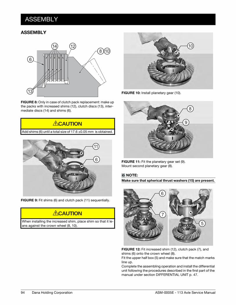
ASSEMBLY
ASSEMBLY
FIGURE 8: Only in case of clutch pack replacement: make up
the packs with increased shims (12), clutch discs (13), inter-
mediate discs (14) and shims (6).
Add shims (6) until a total size of 17.6 ±0.05 mm is obtained.
FIGURE 9: Fit shims (6) and clutch pack (11) sequentially.
When installing the increased shim, place shim so that it le-
ans against the crown wheel (8, 10).
�
�� ��
�
��13
6
14 128 10
CAUTION
11
6
CAUTION
FIGURE 10: Install planetary gear (10).
FIGURE 11: Fit the planetary gear set (9).
Mount second planetary gear (8).
NOTE:Make sure that spherical thrust washers (15) are present.
FIGURE 12: Fit increased shim (12), clutch pack (7), and
shims (6) onto the crown wheel (8).
Fit the upper half box (5) and make sure that the match marks
line up.
Complete the assembling operation and install the differential
unit following the procedures described in the first part of the
manual under section DIFFERENTIAL UNIT p. 47.
10
8
9
5
6
7
94 Dana Holding Corporation ASM-0005E - 113 Axle Service Manual
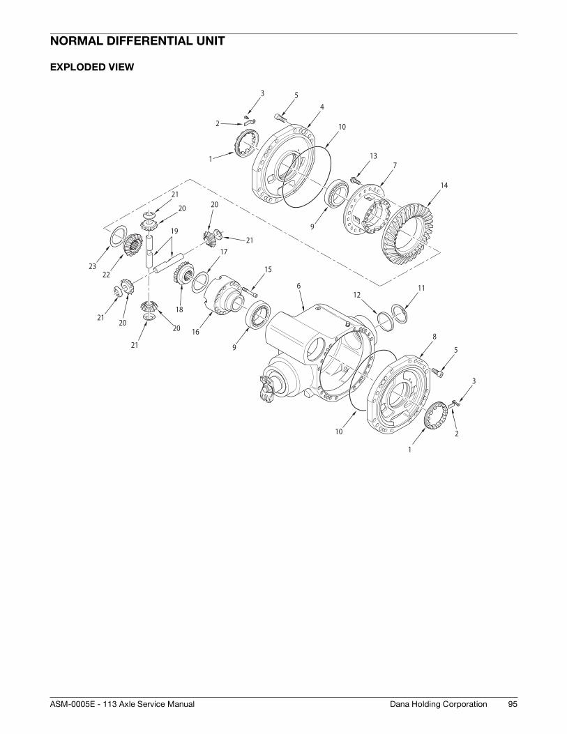
NORMAL DIFFERENTIAL UNIT
EXPLODED VIEW
1
2
3 54
10
9
137
14
2223
21
20
19
2120
20
21
21
20
18
17
16
15
9
6 1112
10
8
5
1
3
2
95Dana Holding CorporationASM-0005E - 113 Axle Service Manual

DISASSEMBLY
DISASSEMBLY
FIGURE 1: Remove the differential unit (7) and place it on a
workbench.
NOTE:Use the tool T2 (See drawing T2 p. 101) to ease removal.
FIGURE 2: If bearings need replacing, remove the outer
thrust blocks of bearings (9) from intermediate covers (4) and
(8).
NOTE:Carefully check the o-rings (10).
FIGURE 3: Remove snap ring (11) and cap (12).
NOTE:Replace cap at each disassembly.
T2
7
109
12
11
FIGURE 4: DISASSEMBLY
Using two levers, lift bearing (9) on ring gear side by about 8
mm.
FIGURE 5: Loosen and remove the check screws (13) of ring
gear (14).
NOTE:The screws must be replaced at each disassembly.
FIGURE 6: Remove the ring gear (14).
NOTE:If necessary, use a plastic hammer.
9
13
14
14
96 Dana Holding Corporation ASM-0005E - 113 Axle Service Manual

DISASSEMBLY
FIGURE 7: Using a puller, remove bearings from ring gear (9)
side.
NOTE:Fit puller in connection with the slots provided.
FIGURE 8: Using a separator and a puller, remove bearing
from non ring gear side.
FIGURE 9: Loosen and remove check screws (15) from diffe-
rential box (16).
NOTE:The screws must be replaced at each disassembly.
9
9
15
16
FIGURE 10: Remove half-box (16).
Write down reference marks for joining the two halves.
FIGURE 11: Remove shoulder (17) and first planetary gear
(18).
FIGURE 12: Remove shafts (19), complete with planetary ge-
ars (20) and spherical shoulder washers (21).
16
CAUTION
17
18
21
20
19
97Dana Holding CorporationASM-0005E - 113 Axle Service Manual
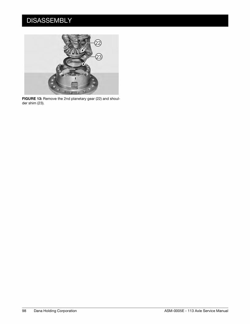
DISASSEMBLY
FIGURE 13: Remove the 2nd planetary gear (22) and shoul-
der shim (23).
22
23
98 Dana Holding Corporation ASM-0005E - 113 Axle Service Manual

ASSEMBLY
ASSEMBLY
FIGURE 14: Install the shoulder shim (23) and planetary gear
(22) into the half-box (7).
FIGURE 15: Install the planetary gears (20) and spherical
shoulder washers (21) onto the shafts (19).
Install the assemblies in the half-box (7).
FIGURE 16: Install the planetary gear (18) and shoulder ring
(17).
22
23
21
20
19
17
18
FIGURE 17: Mount the locking half-box (16) onto the half-box
(7) and lock it with screws (15) coated with Loctite 270.
Tighten by hand.
1 - The match marks on the two half-boxes must corre-
spond.
2 - Use only new screws.
FIGURE 18: Mount the ring gear (14) and fasten it to the dif-
ferential box (7) with screws (13) tightened provisionally by
hand.
Use only new screws.
16
7
15
CAUTION
13
7
14
CAUTION
99Dana Holding CorporationASM-0005E - 113 Axle Service Manual
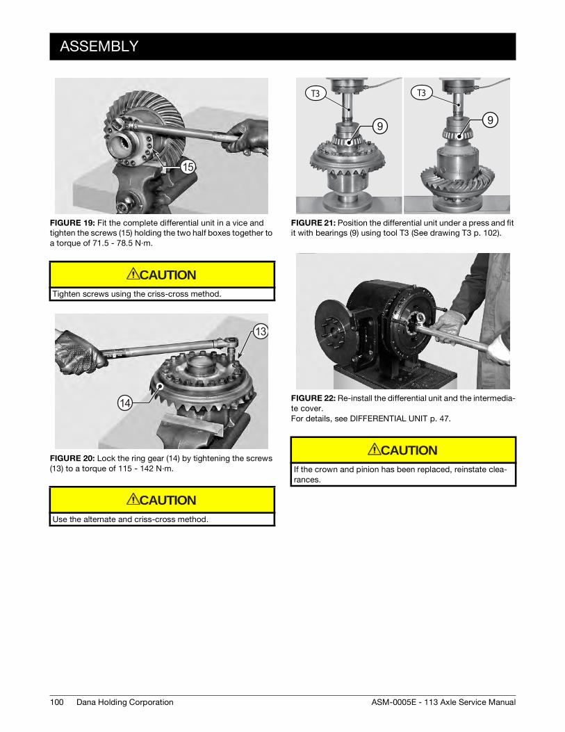
ASSEMBLY
FIGURE 19: Fit the complete differential unit in a vice and
tighten the screws (15) holding the two half boxes together to
a torque of 71.5 - 78.5 N·m.
Tighten screws using the criss-cross method.
FIGURE 20: Lock the ring gear (14) by tightening the screws
(13) to a torque of 115 - 142 N·m.
Use the alternate and criss-cross method.
15
CAUTION
14
13
CAUTION
FIGURE 21: Position the differential unit under a press and fit
it with bearings (9) using tool T3 (See drawing T3 p. 102).
FIGURE 22: Re-install the differential unit and the intermedia-
te cover.
For details, see DIFFERENTIAL UNIT p. 47.
If the crown and pinion has been replaced, reinstate clea-
rances.
T3 T3
9 9
CAUTION
100 Dana Holding Corporation ASM-0005E - 113 Axle Service Manual

SPECIAL TOOLS
SPECIAL TOOLS
T1
T2
P/N: 910.99.0001
170
20 10
40Ø
16M
R 2
R 4
45 ∞
22Ø
P/N: 2370
4260Ø
3050
10
50
300
50
30
45°
250
5 x 30 °
Ø45
12
250
150
Ø30
-- 0.
2--
0.3
101Dana Holding CorporationASM-0005E - 113 Axle Service Manual

SPECIAL TOOLS
T3
P/N: 2371
Ø30
Ø93
10
155
30
x45 °3
x45 °1.5
R10
Ø82
5
100
102 Dana Holding Corporation ASM-0005E - 113 Axle Service Manual


For product inquiries or support,
visit www.dana.com or call 419-887-6445
For other service publications,
visit www.SpicerParts.com/literature.asp
For online service parts ordering,
visit www.SpicerParts.com/order.asp
Copyright 2013 Dana Holding Corporation
All content is subject to copyright by Dana and may not
be reproduced in whole or in part by any means,
electronic or otherwise, without prior written approval.
THIS INFORMATION IS NOT INTENDED FOR SALE OR
RESALE, AND THIS NOTICE MUST REMAIN ON ALL
COPIES.