İPG MAGİSTR HAZIRLIĞI - 070 - 960 - 30 - 70 İlkin Anlayışlar
Upload
khangminh22Category
view
2download
0
Service Manual
MTX100
MPEG Recorder & Player
070-A835-52
This document applies for product serial numberJ310101 and above.
WarningThe servicing instructions are for use by qualifiedpersonnel only. To avoid personal injury, do notperform any servicing unless you are qualified todo so. Refer to all safety summaries prior toperforming service.
www.tektronix.com

Copyright © Tektronix, Inc. All rights reserved.
Tektronix products are covered by U.S. and foreign patents, issued and pending. Information in this publication supercedes
that in all previously published material. Specifications and price change privileges reserved.
Tektronix, Inc., P.O. Box 500, Beaverton, OR 97077
TEKTRONIX and TEK are registered trademarks of Tektronix, Inc.

WARRANTY
Tektronix warrants that the products that it manufactures and sells will be free from defects in materials and workmanship
for a period of one (1) year from the date of shipment. If a product proves defective during this warranty period, Tektronix,
at its option, either will repair the defective product without charge for parts and labor, or will provide a replacement in
exchange for the defective product.
In order to obtain service under this warranty, Customer must notify Tektronix of the defect before the expiration of the
warranty period and make suitable arrangements for the performance of service. Customer shall be responsible for
packaging and shipping the defective product to the service center designated by Tektronix, with shipping charges prepaid.
Tektronix shall pay for the return of the product to Customer if the shipment is to a location within the country in which the
Tektronix service center is located. Customer shall be responsible for paying all shipping charges, duties, taxes, and any
other charges for products returned to any other locations.
This warranty shall not apply to any defect, failure or damage caused by improper use or improper or inadequate
maintenance and care. Tektronix shall not be obligated to furnish service under this warranty a) to repair damage resulting
from attempts by personnel other than Tektronix representatives to install, repair or service the product; b) to repair
damage resulting from improper use or connection to incompatible equipment; c) to repair any damage or malfunction
caused by the use of non-Tektronix supplies; or d) to service a product that has been modified or integrated with other
products when the effect of such modification or integration increases the time or difficulty of servicing the product.
THIS WARRANTY IS GIVEN BY TEKTRONIX IN LIEU OF ANY OTHER WARRANTIES, EXPRESS OR
IMPLIED. TEKTRONIX AND ITS VENDORS DISCLAIM ANY IMPLIED WARRANTIES OF
MERCHANTABILITY OR FITNESS FOR A PARTICULAR PURPOSE. TEKTRONIX’ RESPONSIBILITY TO
REPAIR OR REPLACE DEFECTIVE PRODUCTS IS THE SOLE AND EXCLUSIVE REMEDY PROVIDED TO
THE CUSTOMER FOR BREACH OF THIS WARRANTY. TEKTRONIX AND ITS VENDORS WILL NOT BE
LIABLE FOR ANY INDIRECT, SPECIAL, INCIDENTAL, OR CONSEQUENTIAL DAMAGES IRRESPECTIVE
OF WHETHER TEKTRONIX OR THE VENDOR HAS ADVANCE NOTICE OF THE POSSIBILITY OF SUCH
DAMAGES.


MTX100 MPEG Recorder & Player Service Manual i
Table of Contents
General Safety Summary vii. . . . . . . . . . . . . . . . . . . . . . . . . . . . . . . . . . .
Service Safety Summary ix. . . . . . . . . . . . . . . . . . . . . . . . . . . . . . . . . . . .
Preface xi. . . . . . . . . . . . . . . . . . . . . . . . . . . . . . . . . . . . . . . . . . . . . . . . . . .Manual Structure xi. . . . . . . . . . . . . . . . . . . . . . . . . . . . . . . . . . . . . . . . . . . . . . . .Manual Conventions xii. . . . . . . . . . . . . . . . . . . . . . . . . . . . . . . . . . . . . . . . . . . . . .Finding Other Information xii. . . . . . . . . . . . . . . . . . . . . . . . . . . . . . . . . . . . . . . . .Contacting Tektronix xiii. . . . . . . . . . . . . . . . . . . . . . . . . . . . . . . . . . . . . . . . . . . . .
Introduction xv. . . . . . . . . . . . . . . . . . . . . . . . . . . . . . . . . . . . . . . . . . . . . .Performance Check Interval xv. . . . . . . . . . . . . . . . . . . . . . . . . . . . . . . . . . . . . . . .Strategy for Servicing xv. . . . . . . . . . . . . . . . . . . . . . . . . . . . . . . . . . . . . . . . . . . . .Tektronix Service Offerings xvi. . . . . . . . . . . . . . . . . . . . . . . . . . . . . . . . . . . . . . . .
Specifications
Product Overview 1-1. . . . . . . . . . . . . . . . . . . . . . . . . . . . . . . . . . . . . . . . .
Specifications 1-3. . . . . . . . . . . . . . . . . . . . . . . . . . . . . . . . . . . . . . . . . . . . .Performance Conditions 1-3. . . . . . . . . . . . . . . . . . . . . . . . . . . . . . . . . . . . . . . . . . .Functional Specifications 1-3. . . . . . . . . . . . . . . . . . . . . . . . . . . . . . . . . . . . . . . . . .Electrical Specifications 1-4. . . . . . . . . . . . . . . . . . . . . . . . . . . . . . . . . . . . . . . . . . .Mechanical (Physical) Characteristics 1-17. . . . . . . . . . . . . . . . . . . . . . . . . . . . . . . .Environment Characteristics 1-17. . . . . . . . . . . . . . . . . . . . . . . . . . . . . . . . . . . . . . .Certifications and Compliances 1-18. . . . . . . . . . . . . . . . . . . . . . . . . . . . . . . . . . . . .
Operating Information
Installation 2-1. . . . . . . . . . . . . . . . . . . . . . . . . . . . . . . . . . . . . . . . . . . . . . .Supplying Operating Power 2-1. . . . . . . . . . . . . . . . . . . . . . . . . . . . . . . . . . . . . . . .Operating Environment 2-3. . . . . . . . . . . . . . . . . . . . . . . . . . . . . . . . . . . . . . . . . . .Applying and Interrupting Power 2-4. . . . . . . . . . . . . . . . . . . . . . . . . . . . . . . . . . . .Repackaging Instructions 2-5. . . . . . . . . . . . . . . . . . . . . . . . . . . . . . . . . . . . . . . . . .Installed Options 2-6. . . . . . . . . . . . . . . . . . . . . . . . . . . . . . . . . . . . . . . . . . . . . . . . .
Operating Instructions 2-7. . . . . . . . . . . . . . . . . . . . . . . . . . . . . . . . . . . . .Display Elements 2-7. . . . . . . . . . . . . . . . . . . . . . . . . . . . . . . . . . . . . . . . . . . . . . . .Basic Menu Operation 2-9. . . . . . . . . . . . . . . . . . . . . . . . . . . . . . . . . . . . . . . . . . . .About the Data Output Source 2-12. . . . . . . . . . . . . . . . . . . . . . . . . . . . . . . . . . . . . .
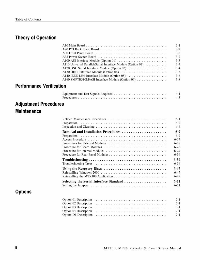
Table of Contents
ii MTX100 MPEG Recorder & Player Service Manual
Theory of Operation
A10 Main Board 3-1. . . . . . . . . . . . . . . . . . . . . . . . . . . . . . . . . . . . . . . . . . . . . . . . .A20 PCI Back Plane Board 3-2. . . . . . . . . . . . . . . . . . . . . . . . . . . . . . . . . . . . . . . .A30 Front Panel Board 3-2. . . . . . . . . . . . . . . . . . . . . . . . . . . . . . . . . . . . . . . . . . . .A35 Power Switch Board 3-2. . . . . . . . . . . . . . . . . . . . . . . . . . . . . . . . . . . . . . . . . .A100 ASI Interface Module (Option 01) 3-3. . . . . . . . . . . . . . . . . . . . . . . . . . . . . .A110 Universal Parallel/Serial Interface Module (Option 02) 3-4. . . . . . . . . . . . .A120 BNC Serial Interface Module (Option 03) 3-4. . . . . . . . . . . . . . . . . . . . . . . .A130 DHEI Interface Module (Option 04) 3-5. . . . . . . . . . . . . . . . . . . . . . . . . . . .A140 IEEE 1394 Interface Module (Option 05) 3-6. . . . . . . . . . . . . . . . . . . . . . . .A160 SMPTE310M/ASI Interface Module (Option 06) 3-8. . . . . . . . . . . . . . . . . .
Performance Verification
Equipment and Test Signals Required 4-1. . . . . . . . . . . . . . . . . . . . . . . . . . . . . . . .Procedures 4-3. . . . . . . . . . . . . . . . . . . . . . . . . . . . . . . . . . . . . . . . . . . . . . . . . . . . . .
Adjustment Procedures
Maintenance
Related Maintenance Procedures 6-1. . . . . . . . . . . . . . . . . . . . . . . . . . . . . . . . . . . .Preparation 6-2. . . . . . . . . . . . . . . . . . . . . . . . . . . . . . . . . . . . . . . . . . . . . . . . . . . . .Inspection and Cleaning 6-4. . . . . . . . . . . . . . . . . . . . . . . . . . . . . . . . . . . . . . . . . . .
Removal and Installation Procedures 6-9. . . . . . . . . . . . . . . . . . . . . . . . .Preparation 6-9. . . . . . . . . . . . . . . . . . . . . . . . . . . . . . . . . . . . . . . . . . . . . . . . . . . . .Access Procedure 6-17. . . . . . . . . . . . . . . . . . . . . . . . . . . . . . . . . . . . . . . . . . . . . . . .Procedures for External Modules 6-18. . . . . . . . . . . . . . . . . . . . . . . . . . . . . . . . . . . .Procedure for Board Modules 6-22. . . . . . . . . . . . . . . . . . . . . . . . . . . . . . . . . . . . . .Procedure for Internal Modules 6-27. . . . . . . . . . . . . . . . . . . . . . . . . . . . . . . . . . . . .Procedure for Rear Panel Modules 6-36. . . . . . . . . . . . . . . . . . . . . . . . . . . . . . . . . . .
Troubleshooting 6-39. . . . . . . . . . . . . . . . . . . . . . . . . . . . . . . . . . . . . . . . . . .Troubleshooting Trees 6-39. . . . . . . . . . . . . . . . . . . . . . . . . . . . . . . . . . . . . . . . . . . .
Using the Recovery Discs 6-47. . . . . . . . . . . . . . . . . . . . . . . . . . . . . . . . . . .Reinstalling Windows 2000 6-47. . . . . . . . . . . . . . . . . . . . . . . . . . . . . . . . . . . . . . . .Reinstalling the MTX100 Application 6-49. . . . . . . . . . . . . . . . . . . . . . . . . . . . . . . .
Selecting the Serial Interface Standard 6-51. . . . . . . . . . . . . . . . . . . . . . . .Setting the Jumpers 6-51. . . . . . . . . . . . . . . . . . . . . . . . . . . . . . . . . . . . . . . . . . . . . . .
Options
Option 01 Description 7-1. . . . . . . . . . . . . . . . . . . . . . . . . . . . . . . . . . . . . . . . . . . .Option 02 Description 7-1. . . . . . . . . . . . . . . . . . . . . . . . . . . . . . . . . . . . . . . . . . . .Option 03 Description 7-1. . . . . . . . . . . . . . . . . . . . . . . . . . . . . . . . . . . . . . . . . . . .Option 04 Description 7-1. . . . . . . . . . . . . . . . . . . . . . . . . . . . . . . . . . . . . . . . . . . .Option D1 Description 7-1. . . . . . . . . . . . . . . . . . . . . . . . . . . . . . . . . . . . . . . . . . . .

Table of Contents
MTX100 MPEG Recorder & Player Service Manual iii
Electrical Parts List
Diagrams
Diagrams 9-1. . . . . . . . . . . . . . . . . . . . . . . . . . . . . . . . . . . . . . . . . . . . . . . . .
Diagrams of the Optional Modules 9-7. . . . . . . . . . . . . . . . . . . . . . . . . . .A100 ASI Interface Module (Option 01) 9-7. . . . . . . . . . . . . . . . . . . . . . . . . . . . . .A110 Universal Parallel/Serial Interface Module (Option 02) 9-8. . . . . . . . . . . . .A120 BNC Serial Interface Module (Option 03) 9-9. . . . . . . . . . . . . . . . . . . . . . . .A130 DHEI Interface Module (Option 04) 9-10. . . . . . . . . . . . . . . . . . . . . . . . . . . .A140 IEEE1394/ASI Interface Module (Option 05) 9-11. . . . . . . . . . . . . . . . . . . . .A160 SMPTE310M/ASI Interface Module (Option 06) 9-12. . . . . . . . . . . . . . . . . .
Mechanical Parts List
Parts Ordering Information 10-1. . . . . . . . . . . . . . . . . . . . . . . . . . . . . . . . . . . . . . . . .Using the Replaceable Parts List 10-2. . . . . . . . . . . . . . . . . . . . . . . . . . . . . . . . . . . .

Table of Contents
iv MTX100 MPEG Recorder & Player Service Manual
List of Figures
Figure 1-1: Timing diagram of the DVB-SPI, universal parallel/serial, and
BNC serial interfaces 1-16. . . . . . . . . . . . . . . . . . . . . . . . . . . . . . . . . . .
Figure 2-1: Rear panel power connector 2-4. . . . . . . . . . . . . . . . . . . . . . .
Figure 2-2: Front panel ON/STBY switch 2-5. . . . . . . . . . . . . . . . . . . . . .
Figure 2-3: Elements of the Play screen 2-8. . . . . . . . . . . . . . . . . . . . . . . .
Figure 2-4: Front panel showing the menu controls 2-9. . . . . . . . . . . . . .
Figure 2-5: Display states of the menu commands 2-10. . . . . . . . . . . . . . .
Figure 2-6: 10 key Pad 2-11. . . . . . . . . . . . . . . . . . . . . . . . . . . . . . . . . . . . . .
Figure 4-1: Equipment connection for verifying the internal clock frequency
4-4
Figure 4-2: Equipment connections for verifying the external clock/refer-
ence input 4-5. . . . . . . . . . . . . . . . . . . . . . . . . . . . . . . . . . . . . . . . . . . . .
Figure 4-3: Equipment connection for verifying the external trigger input.
4-8
Figure 4-4: Initial equipment connection for verifying the SPI interface . . .
4-10
Figure 4-5: Second equipment connection for verifying the SPI interface . .
4-13
Figure 4-6: Initial equipment connection for verifying the ASI interface. . .
4-15
Figure 4-7: Second equipment connections for verifying the ASI interface .
4-17
Figure 4-8: Third equipment connection for verifying the ASI interface . . .
4-18
Figure 4-9: Fourth equipment connection for verifying the ASI interface . .
4-20
Figure 4-10: Initial equipment connection for verifying the universal
parallel/serial interface 4-22. . . . . . . . . . . . . . . . . . . . . . . . . . . . . . . . . .
Figure 4-11: Second equipment connection for verifying the Universal
parallel/serial interface 4-25. . . . . . . . . . . . . . . . . . . . . . . . . . . . . . . . . .
Figure 4-12: Third equipment connection for verifying the universal
parallel/serial interface 4-31. . . . . . . . . . . . . . . . . . . . . . . . . . . . . . . . . .
Figure 4-13: Equipment connection for verifying the EVENT output 4-33
Figure 4-14: Initial equipment connection for verifying the BNC serial
interface 4-34. . . . . . . . . . . . . . . . . . . . . . . . . . . . . . . . . . . . . . . . . . . . . .
Figure 4-15: Second equipment connection for verifying the BNC serial
interface 4-36. . . . . . . . . . . . . . . . . . . . . . . . . . . . . . . . . . . . . . . . . . . . . .
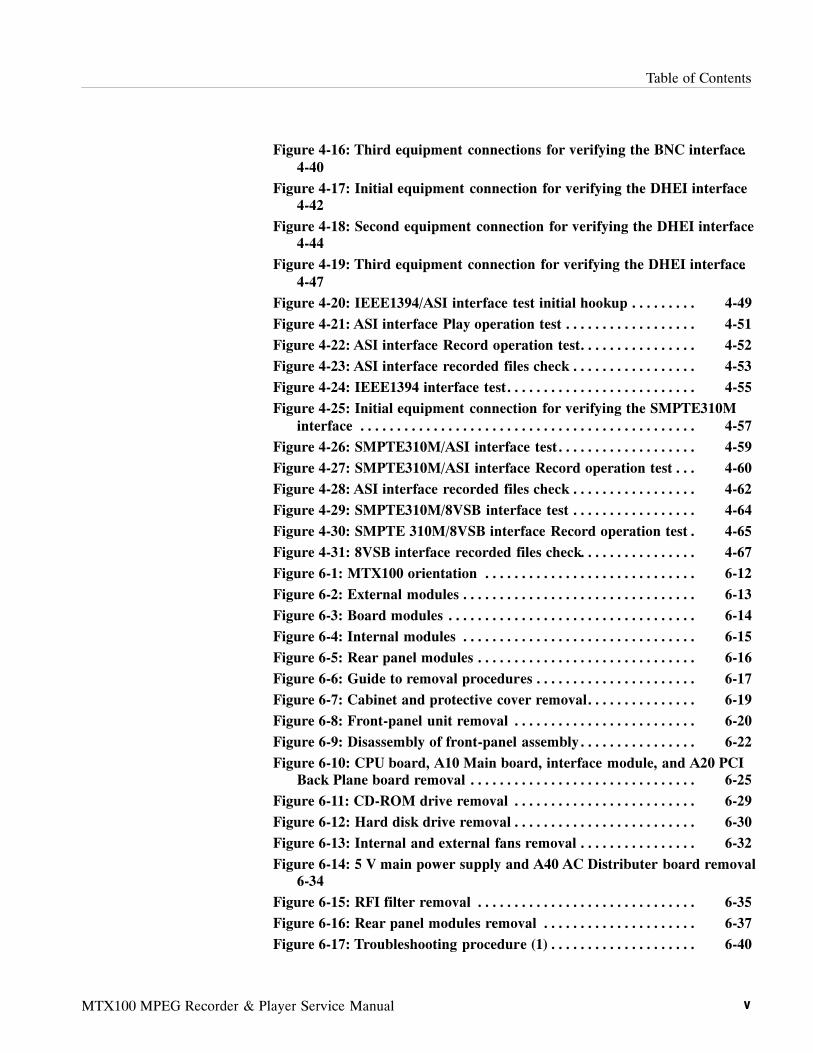
Table of Contents
MTX100 MPEG Recorder & Player Service Manual v
Figure 4-16: Third equipment connections for verifying the BNC interface.
4-40
Figure 4-17: Initial equipment connection for verifying the DHEI interface
4-42
Figure 4-18: Second equipment connection for verifying the DHEI interface
4-44
Figure 4-19: Third equipment connection for verifying the DHEI interface.
4-47
Figure 4-20: IEEE1394/ASI interface test initial hookup 4-49. . . . . . . . .
Figure 4-21: ASI interface Play operation test 4-51. . . . . . . . . . . . . . . . . .
Figure 4-22: ASI interface Record operation test 4-52. . . . . . . . . . . . . . . .
Figure 4-23: ASI interface recorded files check 4-53. . . . . . . . . . . . . . . . .
Figure 4-24: IEEE1394 interface test 4-55. . . . . . . . . . . . . . . . . . . . . . . . . .
Figure 4-25: Initial equipment connection for verifying the SMPTE310M
interface 4-57. . . . . . . . . . . . . . . . . . . . . . . . . . . . . . . . . . . . . . . . . . . . . .
Figure 4-26: SMPTE310M/ASI interface test 4-59. . . . . . . . . . . . . . . . . . .
Figure 4-27: SMPTE310M/ASI interface Record operation test 4-60. . .
Figure 4-28: ASI interface recorded files check 4-62. . . . . . . . . . . . . . . . .
Figure 4-29: SMPTE310M/8VSB interface test 4-64. . . . . . . . . . . . . . . . .
Figure 4-30: SMPTE 310M/8VSB interface Record operation test 4-65.
Figure 4-31: 8VSB interface recorded files check 4-67. . . . . . . . . . . . . . . .
Figure 6-1: MTX100 orientation 6-12. . . . . . . . . . . . . . . . . . . . . . . . . . . . .
Figure 6-2: External modules 6-13. . . . . . . . . . . . . . . . . . . . . . . . . . . . . . . .
Figure 6-3: Board modules 6-14. . . . . . . . . . . . . . . . . . . . . . . . . . . . . . . . . .
Figure 6-4: Internal modules 6-15. . . . . . . . . . . . . . . . . . . . . . . . . . . . . . . .
Figure 6-5: Rear panel modules 6-16. . . . . . . . . . . . . . . . . . . . . . . . . . . . . .
Figure 6-6: Guide to removal procedures 6-17. . . . . . . . . . . . . . . . . . . . . .
Figure 6-7: Cabinet and protective cover removal 6-19. . . . . . . . . . . . . . .
Figure 6-8: Front-panel unit removal 6-20. . . . . . . . . . . . . . . . . . . . . . . . .
Figure 6-9: Disassembly of front-panel assembly 6-22. . . . . . . . . . . . . . . .
Figure 6-10: CPU board, A10 Main board, interface module, and A20 PCI
Back Plane board removal 6-25. . . . . . . . . . . . . . . . . . . . . . . . . . . . . . .
Figure 6-11: CD-ROM drive removal 6-29. . . . . . . . . . . . . . . . . . . . . . . . .
Figure 6-12: Hard disk drive removal 6-30. . . . . . . . . . . . . . . . . . . . . . . . .
Figure 6-13: Internal and external fans removal 6-32. . . . . . . . . . . . . . . .
Figure 6-14: 5 V main power supply and A40 AC Distributer board removal
6-34
Figure 6-15: RFI filter removal 6-35. . . . . . . . . . . . . . . . . . . . . . . . . . . . . .
Figure 6-16: Rear panel modules removal 6-37. . . . . . . . . . . . . . . . . . . . .
Figure 6-17: Troubleshooting procedure (1) 6-40. . . . . . . . . . . . . . . . . . . .

Table of Contents
vi MTX100 MPEG Recorder & Player Service Manual
Figure 6-18: Troubleshooting procedure (2) 6-41. . . . . . . . . . . . . . . . . . . .
Figure 6-19: Troubleshooting procedure (3) 6-42. . . . . . . . . . . . . . . . . . . .
Figure 6-20: Troubleshooting procedure (4) 6-43. . . . . . . . . . . . . . . . . . . .
Figure 6-21: Troubleshooting procedure (5) 6-44. . . . . . . . . . . . . . . . . . . .
Figure 6-22: A20 PCI Back Plane board view 6-45. . . . . . . . . . . . . . . . . .
Figure 6-23: Location of the JP9 connector 6-51. . . . . . . . . . . . . . . . . . . .
Figure 9-1: MTX100 block diagram 9--3. . . . . . . . . . . . . . . . . . . . . . . . . .
Figure 9-2: MTX100 interconnect diagram 9--5. . . . . . . . . . . . . . . . . . . .
Figure 9-3: A100 ASI Interface module connections 9-7. . . . . . . . . . . . .
Figure 9-4: A110 Universal Parallel/Serial Interface module connections. . .
9-8
Figure 9-5: A120 BNC Interface module connections 9-9. . . . . . . . . . . .
Figure 9-6: A130 DHEI Interface module connections 9-10. . . . . . . . . . .
Figure 9-7: A140 IEEE1394/ASI Interface module connections 9-11. . . .
Figure 9-8: A160 SMPTE310M/ASI Interface module connections 9-12.
Figure 10-1: Cabinet 10-5. . . . . . . . . . . . . . . . . . . . . . . . . . . . . . . . . . . . . . .
Figure 10-2: Front panel unit 10-7. . . . . . . . . . . . . . . . . . . . . . . . . . . . . . . .
Figure 10-3: Internal modules (1) 10-9. . . . . . . . . . . . . . . . . . . . . . . . . . . .
Figure 10-4: Internal modules (2) 10-11. . . . . . . . . . . . . . . . . . . . . . . . . . . .
Figure 10-5: Internal modules (3) 10-13. . . . . . . . . . . . . . . . . . . . . . . . . . . .
Figure 10-6: CD-ROM unit 10-14. . . . . . . . . . . . . . . . . . . . . . . . . . . . . . . . . .
Figure 10-7: Hard Disk Drive unit 10-15. . . . . . . . . . . . . . . . . . . . . . . . . . . .
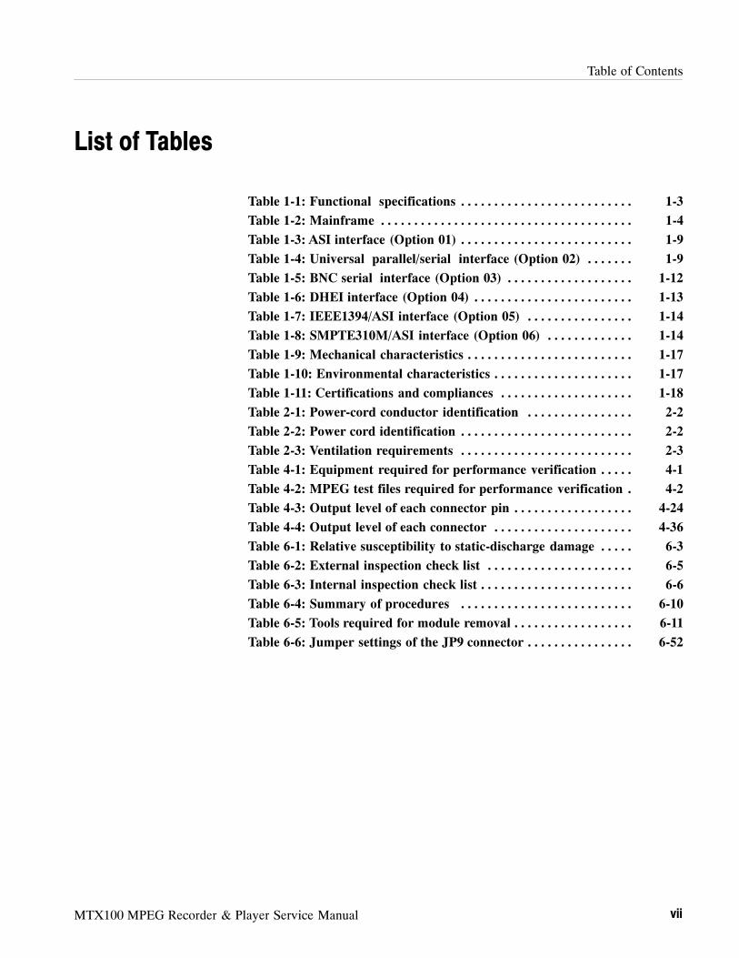
Table of Contents
MTX100 MPEG Recorder & Player Service Manual vii
List of Tables
Table 1-1: Functional specifications 1-3. . . . . . . . . . . . . . . . . . . . . . . . . .
Table 1-2: Mainframe 1-4. . . . . . . . . . . . . . . . . . . . . . . . . . . . . . . . . . . . . .
Table 1-3: ASI interface (Option 01) 1-9. . . . . . . . . . . . . . . . . . . . . . . . . .
Table 1-4: Universal parallel/serial interface (Option 02) 1-9. . . . . . .
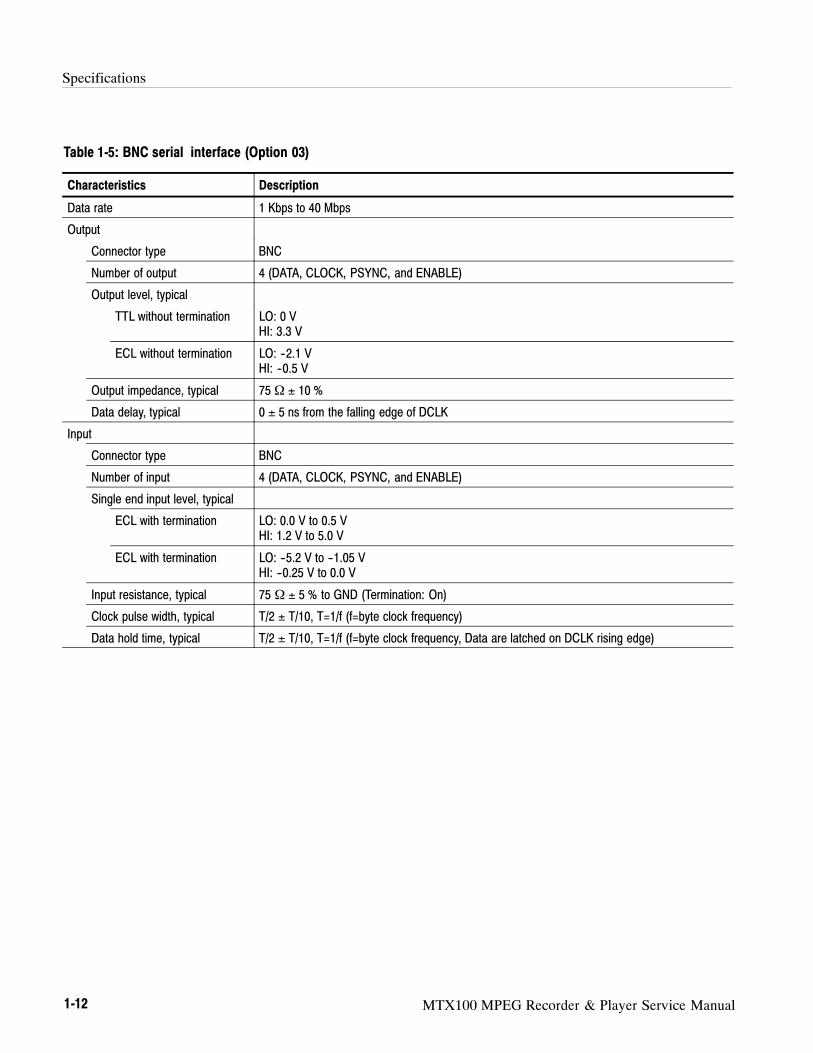
Table 1-5: BNC serial interface (Option 03) 1-12. . . . . . . . . . . . . . . . . . .
Table 1-6: DHEI interface (Option 04) 1-13. . . . . . . . . . . . . . . . . . . . . . . .
Table 1-7: IEEE1394/ASI interface (Option 05) 1-14. . . . . . . . . . . . . . . .
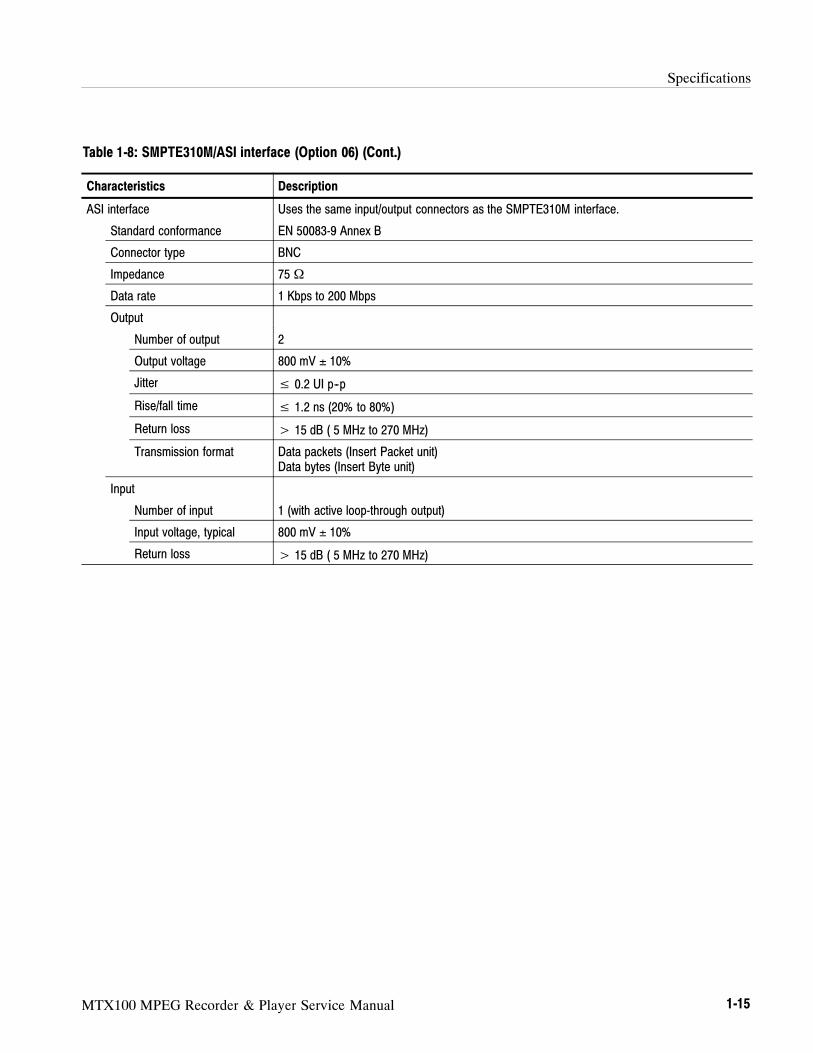
Table 1-8: SMPTE310M/ASI interface (Option 06) 1-14. . . . . . . . . . . . .
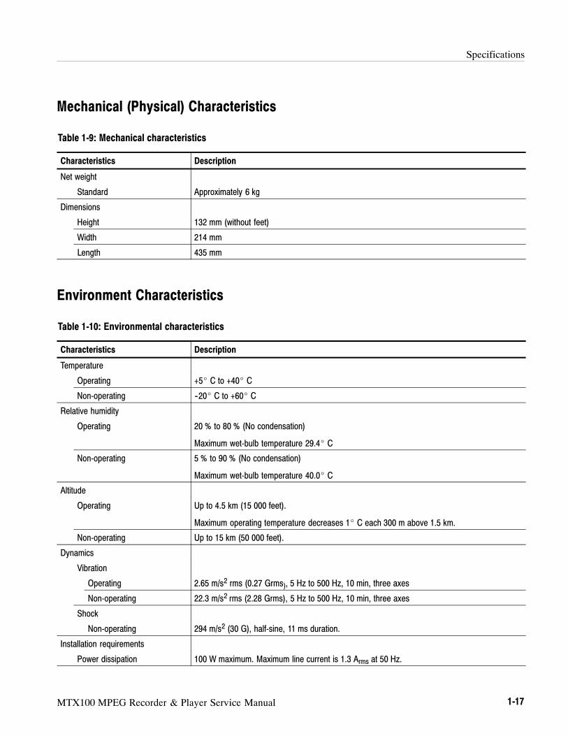
Table 1-9: Mechanical characteristics 1-17. . . . . . . . . . . . . . . . . . . . . . . . .
Table 1-10: Environmental characteristics 1-17. . . . . . . . . . . . . . . . . . . . .
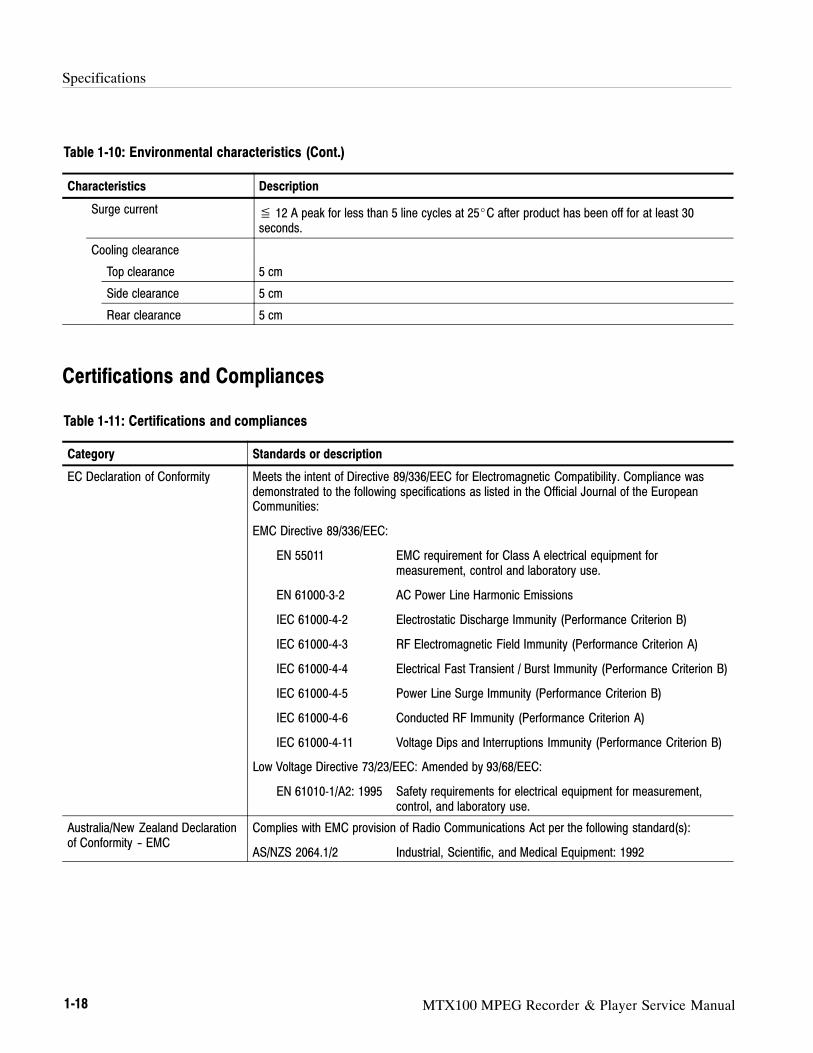
Table 1-11: Certifications and compliances 1-18. . . . . . . . . . . . . . . . . . . .
Table 2-1: Power-cord conductor identification 2-2. . . . . . . . . . . . . . . .
Table 2-2: Power cord identification 2-2. . . . . . . . . . . . . . . . . . . . . . . . . .
Table 2-3: Ventilation requirements 2-3. . . . . . . . . . . . . . . . . . . . . . . . . .
Table 4-1: Equipment required for performance verification 4-1. . . . .
Table 4-2: MPEG test files required for performance verification 4-2.
Table 4-3: Output level of each connector pin 4-24. . . . . . . . . . . . . . . . . .
Table 4-4: Output level of each connector 4-36. . . . . . . . . . . . . . . . . . . . .
Table 6-1: Relative susceptibility to static-discharge damage 6-3. . . . .
Table 6-2: External inspection check list 6-5. . . . . . . . . . . . . . . . . . . . . .
Table 6-3: Internal inspection check list 6-6. . . . . . . . . . . . . . . . . . . . . . .
Table 6-4: Summary of procedures 6-10. . . . . . . . . . . . . . . . . . . . . . . . . .
Table 6-5: Tools required for module removal 6-11. . . . . . . . . . . . . . . . . .
Table 6-6: Jumper settings of the JP9 connector 6-52. . . . . . . . . . . . . . . .

Table of Contents
viii MTX100 MPEG Recorder & Player Service Manual
MTX100 MPEG Recorder & Player Service Manual ix
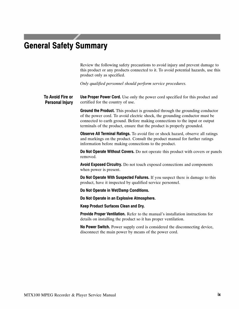
General Safety Summary
Review the following safety precautions to avoid injury and prevent damage tothis product or any products connected to it. To avoid potential hazards, use thisproduct only as specified.
Only qualified personnel should perform service procedures.
Use Proper Power Cord. Use only the power cord specified for this product andcertified for the country of use.
Ground the Product. This product is grounded through the grounding conductorof the power cord. To avoid electric shock, the grounding conductor must beconnected to earth ground. Before making connections to the input or outputterminals of the product, ensure that the product is properly grounded.
Observe All Terminal Ratings. To avoid fire or shock hazard, observe all ratingsand markings on the product. Consult the product manual for further ratingsinformation before making connections to the product.
Do Not Operate Without Covers. Do not operate this product with covers or panelsremoved.
Avoid Exposed Circuitry. Do not touch exposed connections and componentswhen power is present.
Do Not Operate With Suspected Failures. If you suspect there is damage to thisproduct, have it inspected by qualified service personnel.
Do Not Operate in Wet/Damp Conditions.
Do Not Operate in an Explosive Atmosphere.
Keep Product Surfaces Clean and Dry.
Provide Proper Ventilation. Refer to the manual’s installation instructions fordetails on installing the product so it has proper ventilation.
No Power Switch. Power supply cord is considered the disconnecting device,disconnect the main power by means of the power cord.
To Avoid Fire orPersonal Injury
General Safety Summary
x MTX100 MPEG Recorder & Player Service Manual
Terms in this Manual. These terms may appear in this manual:
WARNING. Warning statements identify conditions or practices that could result
in injury or loss of life.
CAUTION. Caution statements identify conditions or practices that could result in
damage to this product or other property.
Terms on the Product. These terms may appear on the product:
DANGER indicates an injury hazard immediately accessible as you read themarking.
WARNING indicates an injury hazard not immediately accessible as you read themarking.
CAUTION indicates a hazard to property including the product.
Symbols on the Product. The following symbols may appear on the product:
CAUTIONRefer to Manual
WARNINGHigh Voltage
DoubleInsulated
Protective Ground(Earth) Terminal
Not suitable forconnection to
the public telecom-munications network
Symbols and Terms

MTX100 MPEG Recorder & Player Service Manual xi
Service Safety Summary
Only qualified personnel should perform service procedures. Read this ServiceSafety Summary and the General Safety Summary before performing any serviceprocedures.
Do Not Service Alone. Do not perform internal service or adjustments of thisproduct unless another person capable of rendering first aid and resuscitation ispresent.
Disconnect Power. To avoid electric shock, disconnect the mains power by meansof the power cord or, if provided, the power switch.
Use Care When Servicing With Power On. Dangerous voltages or currents mayexist in this product. Disconnect power, remove battery (if applicable), anddisconnect test leads before removing protective panels, soldering, or replacingcomponents.
To avoid electric shock, do not touch exposed connections.

Service Safety Summary
xii MTX100 MPEG Recorder & Player Service Manual

MTX100 MPEG Recorder & Player Service Manual xiii
Preface
This is the service manual for the MTX100 MPEG Recorder & Player. Thismanual contains information needed to service an MTX100 to the module level.
Manual Structure
This manual is divided into sections, such as Specifications and Theory ofOperation. Further, some sections are divided into subsections, such as ProductDescription and Removal and Installation Procedures.
Sections containing procedures also contain introductions to those procedures.Be sure to read these introductions because they provide information needed todo the service correctly and efficiently. The following are brief descriptions ofeach manual section.
Specifications contains a description of the MTX100 and the characteristicsthat apply to it.
Operating Information includes general information and operatinginstructions.
Theory of Operation contains circuit descriptions that support service to themodule level.
Performance Verification contains procedures for confirming that anMTX100 functions properly and meets warranted characteristics.
Adjustment Procedures contains a statement explaining that no adjustment isneeded for the MTX100.
Maintenance contains information and procedures for performing preventiveand corrective maintenance on an MTX100. These instructions includecleaning, module removal and installation, and fault isolation to the modulelevel.
Options contains descriptions of available options for the MTX100.
Electrical Parts List contains a statement referring you to the MechanicalParts List section, where both the electrical and mechanical modules arelisted.
Diagrams contains block diagrams and interconnection diagrams of theMTX100 and the optional interface modules.
Mechanical Parts List includes a table of all replaceable modules, theirdescriptions, and their Tektronix part numbers.

Preface
xiv MTX100 MPEG Recorder & Player Service Manual
Manual Conventions
This manual uses certain conventions that you should become familiar with.
Some sections of the manual contain procedures for you to perform. To keepthose instructions clear and consistent, this manual uses the followingconventions:
Names of front panel controls and menus appear in the same case (initialcapitals, all uppercase, etc.) in the manual as is used on the MTX100 frontpanel and menus.
Instruction steps are numbered unless there is only one step.
Bold text refers to specific interface elements that you are instructed toselect, click, or clear.
Example: To power on the MTX100, press the ON/STBY switch.
Italic text refers to document names or sections. Italics are also used inNOTES, CAUTIONS, and WARNINGS.
Example: The Diagrams section, beginning on page 9-1, includes a blockdiagram and an interconnect diagram.
Throughout this manual, any replaceable component, assembly, or part of theMTX100 is referred to generically as a module. In general, a module is anassembly (like a circuit board), rather than a component (like a resistor or anintegrated circuit). Sometimes a single component is a module. For example, thechassis of the MTX100 is a module.
Symbols and terms related to safety appear in the Safety Summary near thebeginning of this manual.
Finding Other Information
Other documentation for the MTX100 includes:
The MTX100 MPEG Recorder & Player User Manual contains a tutorial toquickly describe how to operate the MTX100. It also includes an in-depthdiscussion on how to more completely use the MTX100 features.
Modules
Safety

Preface
MTX100 MPEG Recorder & Player Service Manual xv
Contacting Tektronix
Phone 1-800-833-9200*
Address Tektronix, Inc.Department or name (if known)14200 SW Karl Braun DriveP.O. Box 500Beaverton, OR 97077USA
Web site www.tektronix.com
Sales support 1-800-833-9200, select option 1*
Service support 1-800-833-9200, select option 2*
Technical support Email: [email protected]
1-800-833-9200, select option 3*
6:00 a.m. -- 5:00 p.m. Pacific time
* This phone number is toll free in North America. After office hours, please leave avoice mail message.Outside North America, contact a Tektronix sales office or distributor; see theTektronix web site for a list of offices.

Preface
xvi MTX100 MPEG Recorder & Player Service Manual

MTX100 MPEG Recorder & Player Service Manual xvii
Introduction
This manual contains information needed to properly service the MTX100MPEG Recorder & Player, as well as general information critical to safe andeffective servicing.
To prevent personal injury or damage to the MTX100, consider the followingbefore attempting service:
The procedures in this manual should be performed only by a qualifiedservice person.
Read the General Safety Summary and the Service Safety Summary,beginning on page ix.
Read Installation in section 2, Operating Information.
When using this manual for servicing be sure to follow all warnings, cautions,and notes.
Performance Check Interval
Generally, the performance check described in section 4, Performance Verifica-tion, should be done every 12 months. In addition, a performance check isrecommended after module replacement.
If the MTX100 does not meet performance criteria, repair is necessary.
Strategy for Servicing
Throughout this manual, the term “module” refers to any field-replaceablecomponent, assembly, or part of the MTX100.
This manual contains all the information needed for periodic maintenance of theMTX100 (Examples of such information are procedures for checking perfor-mance).
Further, it contains all information for corrective maintenance down to themodule level. To isolate a failure to a module, use the fault isolation proceduresfound in Troubleshooting, part of section 6, Maintenance. To remove and replaceany failed module, follow the instructions in Removal and Installation Proce-dures, also part of section 6. After isolating a faulty module, replace it with afully-tested module obtained from the factory. Section 10, Mechanical PartsList, contains part number and ordering information for all replaceable modules.
Introduction
xviii MTX100 MPEG Recorder & Player Service Manual
Tektronix Service Offerings
Tektronix provides service to cover repair under warranty as well as otherservices that may provide a cost-effective answer to your service needs.
Whether providing warranty repair service or any of the other services listedbelow, Tektronix service technicians are well trained to service the MTX100.They have access to the latest information on improvements to the MTX100 aswell as the latest new options.
Tektronix warrants this product for one year from date of purchase. The warrantyappears after the title page in this manual. Tektronix technicians providewarranty service at most Tektronix service locations. The Tektronix productcatalog lists all worldwide service locations or you can visit our web site forservice information: www.tektronix.com.
Tektronix supports repair to the module level by providing Module Exchange.
Module Exchange. This service reduces down-time for repair by allowing you toexchange most modules for remanufactured ones. Each module comes with a90-day service warranty.
For More Information. Contact your local Tektronix service center or salesengineer for more information on any of the repair or adjustment services justdescribed.
Warranty Repair Service
Self Service
MTX100 MPEG Recorder & Player Service Manual 1-1
Product Overview
The MTX100 MPEG Recorder & Player generates and captures MPEG-2transport streams that are compliant with ATSC, DVB, and ARIB standards.
The MTX100 provides the following features:
Data rate: 200 Mbps maximum; 1 Kbps minimum
Hierarchy display of the stored or captured transport stream
188, 204, 208 byte packet-length, S-TMCC, M-TMCC and non transportstream (TS) output formats
Real-time updating of transport stream time stamps and time tables (PCR,PYS/DTS, TOT/TDT/STT, and continuity_counter value)
PCR jitter insertion
Trigger capture
CD-ROM drive for downloading user-created data
Optional ASI, universal parallel/serial, BNC serial, and DHEI interfaceavailable
The MTX100 includes the ReMux application software that provides thecapability to create a transport stream of super frame structure defined in theISDB-S systems from an MPEG2 transport stream.

Product Overview
1-2 MTX100 MPEG Recorder & Player Service Manual

MTX100 MPEG Recorder & Player Service Manual 1-3
Specifications
Tables 1-1 through 1-10 list the functional, electrical, mechanical, and environ-mental characteristics of the MTX100. Table 1-11 lists the national andinternational standards to which the MTX100 complies.
All listed specifications are guaranteed unless labeled with “typical”. Typicalspecifications are provided for your convenience but are not guaranteed.
Performance Conditions
The electrical characteristics listed on the following pages are valid under thefollowing conditions:
The MTX100 must be in an environment where the temperature, altitude,humidity, and vibration conditions are within the operating limits describedin Table 1-10 on page 1-17.
The MTX100 must have a warm-up period of at least 20 minutes.
The MTX100 must be operating at an ambient temperature between+5 C to +40 C, unless otherwise noted.
Functional Specifications
Table 1-1: Functional specifications
Characteristics Description
System configuration
System OS Windows 2000 Professional
CPU 850 MHz Pentium III processor
System memory 768 MB
Display 640 x 480 VGA resolution with 256 K colors
Storage device
Hard disk drive 40 GB IDE HDD
CD-ROM drive PC compatible half height IDE CDROM drive
Expansion slot 1 - PCI slot

Specifications
1-4 MTX100 MPEG Recorder & Player Service Manual
Electrical Specifications
Table 1-2: Mainframe
Characteristics Description
Output rate in Play mode
Hard disk ≥120 Mbps
RAM ≥200 Mbps
Record rate in Record mode
Hard disk ≥120 Mbps (File size:< 4 GB, Just after disk format operation)
≥90 Mbps (File size: 33 GB, Just after disk format operation)
RAM ≥200 Mbps
Internal reference clock For Output_clock, PCR/PTS/DTS, Packet operation timing, and TDT/STT time.
Reference clock 27 MHz ± 1 ppm
External reference/clock input
Connector type BNC
Input impedance, typical 50 Ω
Reference input
Frequency 10, 27 MHz
Input level, typical 2.0 Vp-p to 4.0 Vp-p (Sine wave)1.0 Vp-p to 3.0 Vp-p (Square wave)
Input offset, typical 2 V ± 0.5 V
Clock input
Frequency 160 kHz to 25 MHz (Parallel clock)1.28 MHz to 64 MHz (Serial clock)
Input level, typical 1.0 V to 3.0 V
Input offset, typical 2 V ± 0.5 V
External trigger input
Connector type BNC
Input impedance, typical 1 kΩ
Threshold level Rising and falling edges are programmable.
>3.5 V (high level)
<1.0 V (low level)
PLL
Frequency 64 MHz to 128 MHz, Locked to reference clock
Output clock 64 MHz maximum (serial clock)25 MHz maximum (parallel clock)
Output rate 200 Mbps maximum1 Kbps minimum

Specifications
MTX100 MPEG Recorder & Player Service Manual 1-5
Table 1-2: Mainframe (Cont.)
Characteristics Description
PLL divide ratio
(Internal and externalreference, 27 MHz)
Output Clock = (X / (Y * Z) ) * 27 MHz
512< X< 131071
3400< Y< 6000 (3400 is the best value.)
2≤ Z≤ 65536
(External clock)Parallel clock
(160 kHz≤ f≤ 25 MHz)
27 MHz--500 Hz≤ fref ≤ 27 MHz+500 Hz
8≤ Y≤ 16383 fcmp=Clock/(2*Y), 10kHz≤ fcmp ≤ 40 kHz
512≤ X≤ 131071 fref (Typical 27 MHz)=fcmp*X/2
Serial clock
(1.28 MHz≤ f≤ 64 MHz)8≤ Y≤ 16383 fcmp=Clock/(16*Y), 10kHz≤ fcmp ≤ 40 kHz
512≤ X≤ 131071 fref (Typical 27 MHz)=fcmp*X/2
P/N and Jitter (serial clock) < --104 dBc/Hz at 21.455707 MHz +20 kHz (RBW=300 Hz)
DVB-SPI interface
Connector type D-sub, 25 pin
Data rate 1 Kbps to 200 Mbps
Pin assignments 1 DCLK2 GND3 to 10 DATA 7 to DATA 011 DVALID12 PSYNC13 Shield14 DCLK15 GND16 to 23 DATA 7 to DATA 024 DVALID25 PSYNC
Output
Output level, typical 330 mV to 550 mV (termination: internal 100Ω. external 100 Ω), bus LVDS with 50 Ωtermination
Offset 1.1 V to 1.5 V
Output resistance, typical 100 Ω, between differential outputs (output off)
Data delay, typical ± 5 ns from the falling edge of DCLK
Input
Input level, typical > +100 mV,< --100 mV, (RI+)--(RI--) with 100 Ω termination
Input resistance, typical 100 Ω (between differential inputs)
Clock pulse width, typical T/2 ± T/10, T=1/f (f=byte clock frequency)
Data hold time, typical T/2 ± T/10, T=1/f (f=byte clock frequency, Data are latched on DCLK rising edge)
Specifications
1-6 MTX100 MPEG Recorder & Player Service Manual
Table 1-2: Mainframe (Cont.)
Characteristics Description
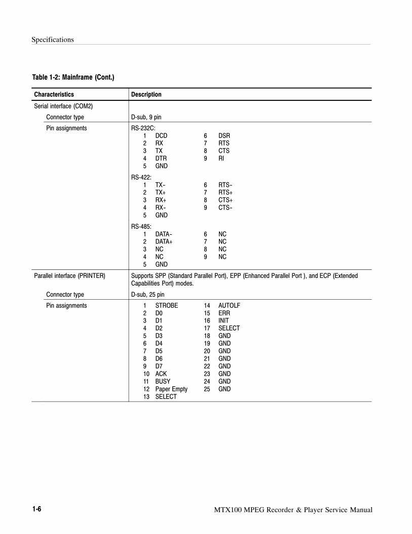
Serial interface (COM2)
Connector type D-sub, 9 pin
Pin assignments RS-232C:1 DCD 6 DSR2 RX 7 RTS3 TX 8 CTS4 DTR 9 RI5 GND
RS-422:1 TX-- 6 RTS--2 TX+ 7 RTS+3 RX+ 8 CTS+4 RX-- 9 CTS--5 GND
RS-485:1 DATA-- 6 NC2 DATA+ 7 NC3 NC 8 NC4 NC 9 NC5 GND
Parallel interface (PRINTER) Supports SPP (Standard Parallel Port), EPP (Enhanced Parallel Port ), and ECP (ExtendedCapabilities Port) modes.
Connector type D-sub, 25 pin
Pin assignments 1 STROBE 14 AUTOLF2 D0 15 ERR3 D1 16 INIT4 D2 17 SELECT5 D3 18 GND6 D4 19 GND7 D5 20 GND8 D6 21 GND9 D7 22 GND10 ACK 23 GND11 BUSY 24 GND12 Paper Empty 25 GND13 SELECT
Specifications
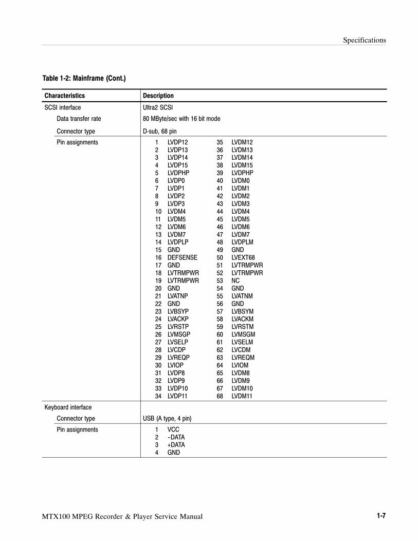
MTX100 MPEG Recorder & Player Service Manual 1-7
Table 1-2: Mainframe (Cont.)
Characteristics Description
SCSI interface Ultra2 SCSI
Data transfer rate
Connector type
80 MByte/sec with 16 bit mode
D-sub, 68 pin
Pin assignments 1 LVDP12 35 LVDM122 LVDP13 36 LVDM133 LVDP14 37 LVDM144 LVDP15 38 LVDM155 LVDPHP 39 LVDPHP6 LVDP0 40 LVDM07 LVDP1 41 LVDM18 LVDP2 42 LVDM29 LVDP3 43 LVDM310 LVDM4 44 LVDM411 LVDM5 45 LVDM512 LVDM6 46 LVDM613 LVDM7 47 LVDM714 LVDPLP 48 LVDPLM15 GND 49 GND16 DEFSENSE 50 LVEXT6817 GND 51 LVTRMPWR18 LVTRMPWR 52 LVTRMPWR19 LVTRMPWR 53 NC20 GND 54 GND21 LVATNP 55 LVATNM22 GND 56 GND23 LVBSYP 57 LVBSYM24 LVACKP 58 LVACKM25 LVRSTP 59 LVRSTM26 LVMSGP 60 LVMSGM27 LVSELP 61 LVSELM28 LVCDP 62 LVCDM29 LVREQP 63 LVREQM30 LVIOP 64 LVIOM31 LVDP8 65 LVDM832 LVDP9 66 LVDM933 LVDP10 67 LVDM1034 LVDP11 68 LVDM11
Keyboard interface
Connector type USB (A type, 4 pin)
Pin assignments 1 VCC2 --DATA3 +DATA4 GND
Specifications
1-8 MTX100 MPEG Recorder & Player Service Manual
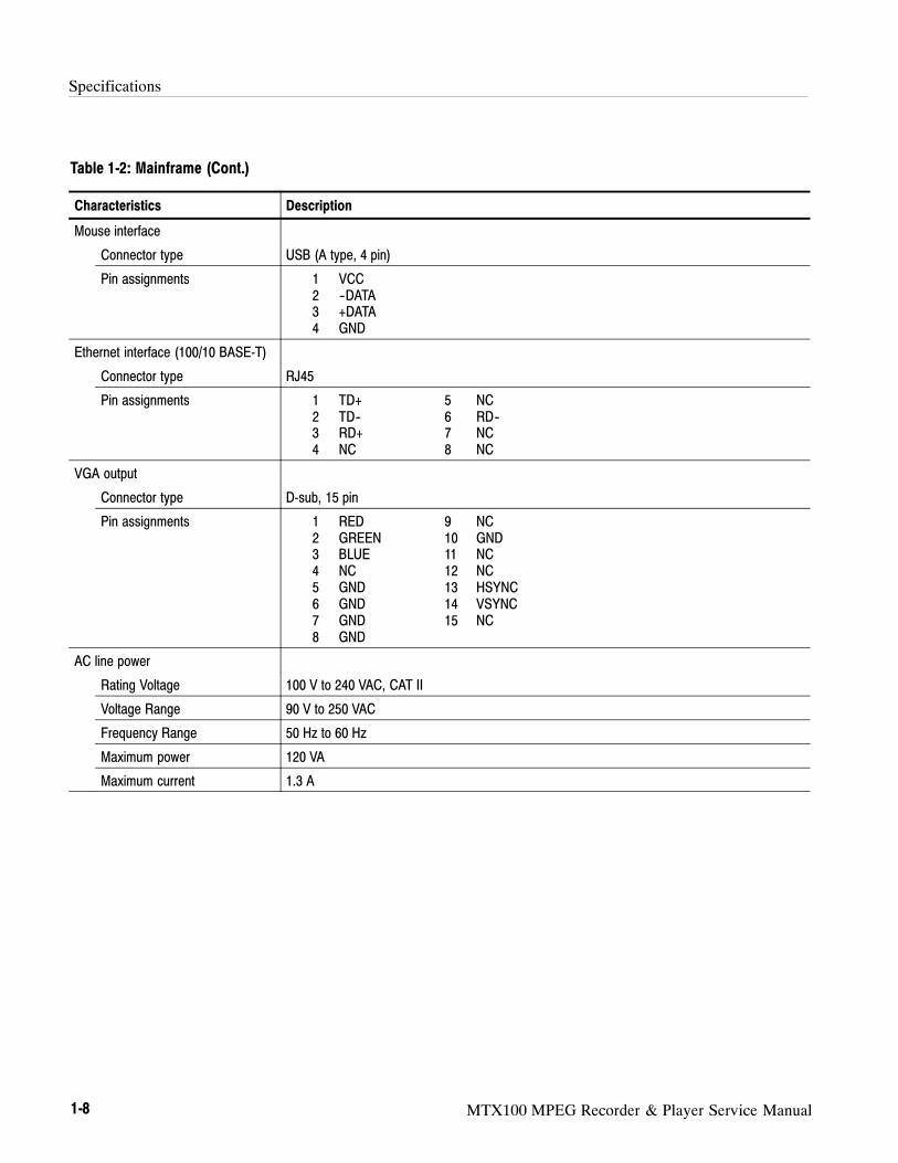
Table 1-2: Mainframe (Cont.)
Characteristics Description
Mouse interface
Connector type USB (A type, 4 pin)
Pin assignments 1 VCC2 --DATA3 +DATA4 GND
Ethernet interface (100/10 BASE-T)
Connector type RJ45
Pin assignments 1 TD+ 5 NC2 TD-- 6 RD--3 RD+ 7 NC4 NC 8 NC
VGA output
Connector type D-sub, 15 pin
Pin assignments 1 RED 9 NC2 GREEN 10 GND3 BLUE 11 NC4 NC 12 NC5 GND 13 HSYNC6 GND 14 VSYNC7 GND 15 NC8 GND
AC line power
Rating Voltage 100 V to 240 VAC, CAT II
Voltage Range 90 V to 250 VAC
Frequency Range 50 Hz to 60 Hz
Maximum power 120 VA
Maximum current 1.3 A
Specifications
MTX100 MPEG Recorder & Player Service Manual 1-9
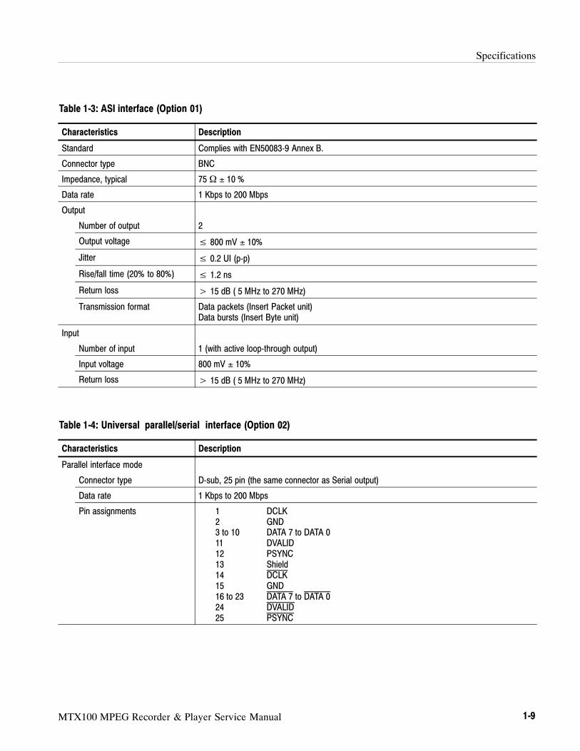
Table 1-3: ASI interface (Option 01)
Characteristics Description
Standard Complies with EN50083-9 Annex B.
Connector type BNC
Impedance, typical 75 Ω ± 10 %
Data rate 1 Kbps to 200 Mbps
Output
Number of output 2
Output voltage ≤ 800 mV ± 10%
Jitter ≤ 0.2 UI (p-p)
Rise/fall time (20% to 80%) ≤ 1.2 ns
Return loss > 15 dB ( 5 MHz to 270 MHz)
Transmission format Data packets (Insert Packet unit)Data bursts (Insert Byte unit)
Input
Number of input 1 (with active loop-through output)
Input voltage 800 mV ± 10%
Return loss > 15 dB ( 5 MHz to 270 MHz)
Table 1-4: Universal parallel/serial interface (Option 02)
Characteristics Description
Parallel interface mode
Connector type D-sub, 25 pin (the same connector as Serial output)
Data rate 1 Kbps to 200 Mbps
Pin assignments 1 DCLK2 GND3 to 10 DATA 7 to DATA 011 DVALID12 PSYNC13 Shield14 DCLK15 GND16 to 23 DATA 7 to DATA 024 DVALID25 PSYNC
Specifications
1-10 MTX100 MPEG Recorder & Player Service Manual
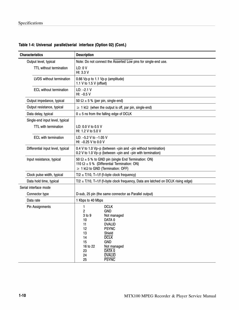
Table 1-4: Universal parallel/serial interface (Option 02) (Cont.)
Characteristics Description
Output level, typical Note: Do not connect the Asserted Low pins for single-end use.
TTL without termination LO: 0 VHI: 3.3 V
LVDS without termination 0.66 Vp-p to 1.1 Vp-p (amplitude)1.1 V to 1.5 V (offset)
ECL without termination LO: --2.1 VHI: --0.5 V
Output impedance, typical 50 Ω ± 5 % (per pin, single-end)
Output resistance, typical ≥ 1 kΩ (when the output is off, par pin, single-end)
Data delay, typical 0 ± 5 ns from the falling edge of DCLK
Single-end input level, typical
TTL with termination LO: 0.0 V to 0.5 VHI: 1.2 V to 5.0 V
ECL with termination LO: --5.2 V to --1.05 VHI: --0.25 V to 0.0 V
Differential input level, typical 0.4 V to 1.0 Vp--p (between +pin and --pin without termination)0.2 V to 1.0 Vp--p (between +pin and --pin with termination)
Input resistance, typical 50 Ω ± 5 % to GND pin (single End Termination: ON)110 Ω ± 5 % (Differential Termination: ON)
≥ 1 kΩ to GND (Termination: OFF)
Clock pulse width, typical T/2 ± T/10, T=1/f (f=byte clock frequency)
Data hold time, typical T/2 ± T/10, T=1/f (f=byte clock frequency, Data are latched on DCLK rising edge)
Serial interface mode
Connector type D-sub, 25 pin (the same connector as Parallel output)
Data rate 1 Kbps to 40 Mbps
Pin Assignments 1 DCLK2 GND3 to 9 Not managed10 DATA 011 DVALID12 PSYNC13 Shield14 DCLK15 GND16 to 22 Not managed23 DATA 024 DVALID25 PSYNC

Specifications
MTX100 MPEG Recorder & Player Service Manual 1-11
Table 1-4: Universal parallel/serial interface (Option 02) (Cont.)
Characteristics Description
Output level, typical Note: Do not connect the Asserted Low pins for single-end use.
TTL without termination LO: 0 VHI: 3.3 V
LVDS without termination 0.66 Vp-p to 1.1 Vp-p (amplitude)1.1 V to 1.5 V (offset)
ECL without termination LO: --2.1 VHI: --0.5 V
Output impedance, typical 50 Ω ± 5 % (per pin, single-end)
Output resistance, typical ≥ 1 kΩ (when the output is off, par pin, single-end)
Data delay, typical 0 ± 5 ns from the falling edge of DCLK
Single-end input level, typical
TTL with termination LO: 0.0 V to 0.5 VHI: 1.2 V to 5.0 V
ECL with termination LO: --5.2 V to --1.05 VHI: --0.25 V to 0.0 V
Differential input level, typical 0.4 V to 1.0 Vp--p (between +pin and --pin without termination)0.2 V to 1.0 Vp--p (between +pin and --pin with termination)
Input resistance, typical 50 Ω ± 5 % to GND pin (Single End Termination: On)110 Ω ± 5 % (Differential Termination: On)
≥ 1 kΩ to GND pin (Termination: Off)
Clock pulse width, typical T/2 ± T/10, T=1/f (f=byte clock frequency)
Data hold time, typical T/2 ± T/10, T=1/f (f=byte clock frequency, data are latched on DCLK rising edge)
Event output (EVENT OUT)
Connector type BNC
Output level, typical TTL without termination
LO:< 0.4 V
HI: > 2.4 V
Output impedance, typical 50 Ω
Specifications
1-12 MTX100 MPEG Recorder & Player Service Manual
Table 1-5: BNC serial interface (Option 03)
Characteristics Description
Data rate 1 Kbps to 40 Mbps
Output
Connector type BNC
Number of output 4 (DATA, CLOCK, PSYNC, and ENABLE)
Output level, typical
TTL without termination LO: 0 VHI: 3.3 V
ECL without termination LO: --2.1 VHI: --0.5 V
Output impedance, typical 75 Ω ± 10 %
Data delay, typical 0 ± 5 ns from the falling edge of DCLK
Input
Connector type BNC
Number of input 4 (DATA, CLOCK, PSYNC, and ENABLE)
Single end input level, typical
ECL with termination LO: 0.0 V to 0.5 VHI: 1.2 V to 5.0 V
ECL with termination LO: --5.2 V to --1.05 VHI: --0.25 V to 0.0 V
Input resistance, typical 75 Ω ± 5 % to GND (Termination: On)
Clock pulse width, typical T/2 ± T/10, T=1/f (f=byte clock frequency)
Data hold time, typical T/2 ± T/10, T=1/f (f=byte clock frequency, Data are latched on DCLK rising edge)

Specifications
MTX100 MPEG Recorder & Player Service Manual 1-13
Table 1-6: DHEI interface (Option 04)
Characteristics Description
Standard Complies with SCTE DVS/110
Connector type HD-22, 26 pin
Data rate 1 Kbps to 40 Mbps
Pin assignments Duplex expansion Out:1 PROTGND 14 RSVD2 SENSEAOR 15 PDATABI--3 PSYNCAO-- 16 PSYNCBI--4 PDATAO-- 17 SENSEBIR5 PCLKAO+ 18 RSVD6 PCLKAO+ 19 REFCLKBI+7 REFCLKAO+ 20 REFCLKBI--8 REFCLKAO-- 21 PCLKBI+9 SIGND 22 PCLKBI--10 RSVD 23 PDATABI+11 SENSEAOL 24 PSYNCBI--12 PSYNCAO+ 25 SENSEBIL13 PDATAO+ 26 RSVD
Duplex expansion In:1 PROTGND 14 RSVD2 SENSEAIR 15 PDATABO--3 PSYNCAI-- 16 PSYNCBO--4 PDATAI-- 17 SENSEBOR5 PCLKAI+ 18 RSVD6 PCLKAI-- 19 REFCLKBO+7 REFCLKAI+ 20 REFCLKBO--8 REFCLKAI-- 21 PCLKBO+9 SIGND 22 PCLKBO--10 RSVD 23 PDATABO+11 SENSEAIL 24 PSYNCBO+12 PSYNCAI+ 25 SENSEBOL13 PDATAI+ 26 RSVD
Output
Output level, typical --1.8 V to -- 0.9 V (ECL, without termination)
Output resistance, typical 410 Ω ± 5 %
Data delay, typical 0 ± 3 ns from the falling edge of DCLK
Input
Input level, typical > 0.5 Vp--p (between +pin and --pin)
Input resistance, typical 120 Ω ± 5 % (between +pin and --pin)

Specifications
1-14 MTX100 MPEG Recorder & Player Service Manual
Table 1-7: IEEE1394/ASI interface (Option 05)
Characteristics Description
IEEE1394 interface
Standard conformance IEEE Std 1394-1995 IEEE Standard for High Performance serial Bus
Number of connectors 2
Serial interface rate S-400
ASI interface
Standard conformance EN 50083-9 Annex B
Connector type BNC
Impedance, typical 75 Ω ± 10%
Data rate 1 Kbps to 200 Mbps
Input vlotage, typical 800 mV
Output voltage 800 mV ± 10%
Return loss > 15 dB ( 5 MHz to 270 MHz)
Table 1-8: SMPTE310M/ASI interface (Option 06)
Characteristics Description
SMPTE310M interface Uses the same input/output connectors as the ASI interface.
Standard conformance SMPTE310M
Connector type BNC
Impedance 75 Ω
Data rate 19.392658 Mbps (8 VSB, 188 bytes packet size)
Output
Number of output 2
Output voltage 800 mV ± 10%
Jitter ≤ 0.2 UI p--p
Rise/fall time 0.4 ns≤ A≤ 5.0 ns (20% to 80%)
Frequency range, typical ± 3%
Input
Number of input 1 (with active loop-through output)
Input voltage, typical 800 mV ± 10%
Frequency range, typical ± 3%
Specifications
MTX100 MPEG Recorder & Player Service Manual 1-15
Table 1-8: SMPTE310M/ASI interface (Option 06) (Cont.)
Characteristics Description
ASI interface Uses the same input/output connectors as the SMPTE310M interface.
Standard conformance EN 50083-9 Annex B
Connector type BNC
Impedance 75 Ω
Data rate 1 Kbps to 200 Mbps
Output
Number of output 2
Output voltage 800 mV ± 10%
Jitter ≤ 0.2 UI p--p
Rise/fall time ≤ 1.2 ns (20% to 80%)
Return loss > 15 dB ( 5 MHz to 270 MHz)
Transmission format Data packets (Insert Packet unit)Data bytes (Insert Byte unit)
Input
Number of input 1 (with active loop-through output)
Input voltage, typical 800 mV ± 10%
Return loss > 15 dB ( 5 MHz to 270 MHz)

Specifications
1-16 MTX100 MPEG Recorder & Player Service Manual
188 bytes
DATA 0--7
DCLK
PSYNC
DVALID
DATA 0--7
DCLK*
DATA 0--7
DCLK*
Output data delay Input clock pulse width
Input data hold time
Th
T/2 T/10
T (f/1)
5 ns 5 ns
* In the universal parallel/serial and BNC serial interfaces,the polarity of DCLK can be inverted.
Th = T/2 T/10: DVB-SPI and universal parallel interfaces
Th = T/5 T/10: universal serial and BNC serial interfaces
Transition period
Figure 1-1: Timing diagram of the DVB-SPI, universal parallel/serial, and BNC serial interfaces
Specifications
MTX100 MPEG Recorder & Player Service Manual 1-17
Mechanical (Physical) Characteristics
Table 1-9: Mechanical characteristics
Characteristics Description
Net weight
Standard Approximately 6 kg
Dimensions
Height 132 mm (without feet)
Width 214 mm
Length 435 mm
Environment Characteristics
Table 1-10: Environmental characteristics
Characteristics Description
Temperature
Operating +5 C to +40 C
Non-operating --20 C to +60 C
Relative humidity
Operating 20 % to 80 % (No condensation)
Maximum wet-bulb temperature 29.4 C
Non-operating 5 % to 90 % (No condensation)
Maximum wet-bulb temperature 40.0 C
Altitude
Operating Up to 4.5 km (15 000 feet).
Maximum operating temperature decreases 1 C each 300 m above 1.5 km.
Non-operating Up to 15 km (50 000 feet).
Dynamics
Vibration
Operating 2.65 m/s2 rms (0.27 Grms), 5 Hz to 500 Hz, 10 min, three axes
Non-operating 22.3 m/s2 rms (2.28 Grms), 5 Hz to 500 Hz, 10 min, three axes
Shock
Non-operating 294 m/s2 (30 G), half-sine, 11 ms duration.
Installation requirements
Power dissipation 100 W maximum. Maximum line current is 1.3 Arms at 50 Hz.
Specifications
1-18 MTX100 MPEG Recorder & Player Service Manual
Table 1-10: Environmental characteristics (Cont.)
Characteristics Description
Surge current 12 A peak for less than 5 line cycles at 25C after product has been off for at least 30seconds.
Cooling clearance
Top clearance 5 cm
Side clearance 5 cm
Rear clearance 5 cm
Certifications and Compliances
Table 1-11: Certifications and compliances
Category Standards or description
EC Declaration of Conformity Meets the intent of Directive 89/336/EEC for Electromagnetic Compatibility. Compliance wasdemonstrated to the following specifications as listed in the Official Journal of the EuropeanCommunities:
EMC Directive 89/336/EEC:
EN 55011 EMC requirement for Class A electrical equipment formeasurement, control and laboratory use.
EN 61000-3-2 AC Power Line Harmonic Emissions
IEC 61000-4-2 Electrostatic Discharge Immunity (Performance Criterion B)
IEC 61000-4-3 RF Electromagnetic Field Immunity (Performance Criterion A)
IEC 61000-4-4 Electrical Fast Transient / Burst Immunity (Performance Criterion B)
IEC 61000-4-5 Power Line Surge Immunity (Performance Criterion B)
IEC 61000-4-6 Conducted RF Immunity (Performance Criterion A)
IEC 61000-4-11 Voltage Dips and Interruptions Immunity (Performance Criterion B)
Low Voltage Directive 73/23/EEC: Amended by 93/68/EEC:
EN 61010-1/A2: 1995 Safety requirements for electrical equipment for measurement,control, and laboratory use.
Australia/New Zealand Declarationof Conformity -- EMC
Complies with EMC provision of Radio Communications Act per the following standard(s):
AS/NZS 2064.1/2 Industrial, Scientific, and Medical Equipment: 1992

Specifications
MTX100 MPEG Recorder & Player Service Manual 1-19
Table 1-11: Certifications and compliances (Cont.)
Category Standards or description
Safety Complies with the following safety standards/regulations:
UL 3111-1, First Edition Standard for electrical measuring and test equipment.
CAN/CSA C22.2 No.1010.1-92 Safety requirements for electrical equipment formeasurement, control, and laboratory use.
EN 61010-1/A2:1995 Safety requirements for electrical equipment formeasurement, control, and laboratory use.
Installation (Overvoltage) Category Terminals on this product may have different installation (overvoltage) category designations. Theinstallation categories are:
CAT III Distribution-level mains (usually permanently connected). Equipment at this level istypically in a fixed industrial location.
CAT II Local-level mains (wall sockets). Equipment at this level includes appliances,portable tools, and similar products. Equipment is usually cord-connected.
CAT I Secondary (signal level) or battery operated circuits of electronic equipment.
Pollution Degree A measure of the contaminates that could occur in the environment around and within a product.Typically the internal environment inside a product is considered to be the same as the external.Products should be used only in the environment for which they are rated.
Pollution Degree 2 Normally only dry, nonconductive pollution occurs. Occasionally atemporary conductivity that is caused by condensation must be expected.This location is a typical office/home environment. Temporarycondensation occurs only when the product is out of service.
IEC Characteristics Equipment type:
Test and MeasuringInstallation Category II (as defined in IEC 61010-1, Annex J)Pollution Degree 2 (as defined IEC 61010-1)Safety Class 1 (as defined in IEC 61010-1, Annex H)--grounded product

Specifications
1-20 MTX100 MPEG Recorder & Player Service Manual

MTX100 MPEG Recorder & Player Service Manual 2-1
Installation
This Operating Information contains installation and operating informationrelated to the servicing of this instrument.
Supplying Operating Power
NOTE. Read all information and heed all warnings in this subsection before
connecting the MTX100 to a power source.
WARNING. AC POWER SOURCE AND CONNECTION. The MTX100 operates
from a single-phase power source. It has a three-wire power cord and two-pole,
three-terminal grounding type plug. The voltage to ground (earth) from either
pole of the power source must not exceed the maximum rated operating voltage,
250 volts.
Before making connection to the power source, be sure the MTX100 has a
suitable two-pole, three-terminal grounding-type plug.
GROUNDING. This instrument is safety Class 1 equipment (IEC designation).
All accessible conductive parts are directly connected through the grounding
conductor of the power cord to the grounded (earthing) contact of the power
plug.
WARNING. The power input plug must be inserted only in a mating receptacle
with a grounding contact where earth ground has been verified by a qualified
service person. Do not defeat the grounding connection. Any interruption of the
grounding connection can create an electric shock hazard.
For electric shock protection, the grounding connection must be made before
making connection to the instrument’s input or output terminals.
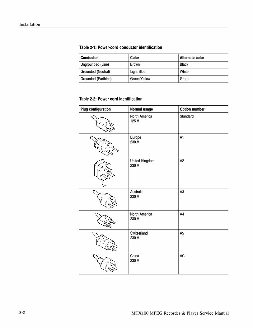
A power cord with the appropriate plug configuration is supplied with eachMTX100. Table 2-1 gives the color-coding of the conductors in the power cord.If you require a power cord other than the one supplied, refer to Table 2-2, Powercord identification.
Power Cord Information
Installation
2-2 MTX100 MPEG Recorder & Player Service Manual
Table 2-1: Power-cord conductor identification
Conductor Color Alternate color
Ungrounded (Line) Brown Black
Grounded (Neutral) Light Blue White
Grounded (Earthing) Green/Yellow Green
Table 2-2: Power cord identification
Plug configuration Normal usage Option number
North America125 V
Standard
Europe230 V
A1
United Kingdom230 V
A2
Australia230 V
A3
North America230 V
A4
Switzerland230 V
A5
China230 V
AC

Installation
MTX100 MPEG Recorder & Player Service Manual 2-3
The MTX100 operates with any line voltage from 100--240 VACRMS with anyline frequency from 50--60 Hz. Before plugging the cord into the outlet, be surethat the line voltage is in the proper range.
Operating Environment
The following environmental requirements are provided to ensure properoperation and long instrument life.
Operate the MTX100 where the ambient air temperature is from +5 C to+40 C with no disc in the CD-ROM drive. Store the MTX100 in ambienttemperatures from --20 C to +60 C with no disc in the CD-ROM drive. Afterstorage at temperatures outside the operating limits, allow the chassis to stabilizeat a safe operating temperature before applying power. See Table 2-3 forventilation requirements.
Table 2-3: Ventilation requirements
Characteristics Specifications
MTX100 ambient temperatures from +5° C to +40° C
MTX100 relative humidity from 20% to 80%
Clearance on top 5.0 cm (2in)
Clearance on left side 5.0 cm (2in)
Clearance on right side 5.0 cm (2in)
Clearance in rear 5.0 cm (2in)
NOTE. If you are installing the instrument in a dedicated rack, refer to the
instruction sheet that comes with the rackmounting kit for proper installation
procedures.
When the MTX100 is mounted in a 19-inch rack, verify that there is at least one
unit of clearance above the MTX100.
Operating Voltage
Operating Temperature

Installation
2-4 MTX100 MPEG Recorder & Player Service Manual
Applying and Interrupting Power
Consider the following information when you power on or power off theMTX100, or when external power loss occurs.
Connect the proper power cord from the rear panel power connector to the powersystem. Refer to Table 2-2 for power cord identification.
Power connector
Figure 2-1: Rear panel power connector
CAUTION. The instrument does not have a principal power switch. When you
connect the power cable to the AC line connector, power is applied to the power
supply standby circuit of the instrument.
Press the ON/STBY switch on the lower left side of the front panel to power onthe instrument. Refer to Figure 2-2.
Connect Power Cable
Power On

Installation
MTX100 MPEG Recorder & Player Service Manual 2-5
ON/STBY switch
Figure 2-2: Front panel ON/STBY switch
To power off the MTX100, press the ON/STBY switch.
If you connect the USB mouse and keyboard provided with the instrument to theUSB connectors, you can shutdown the instrument by using the Shutdowncommand from the File menu. In the shutdown process, all of the instrumentsettings are saved.
Repackaging Instructions
If you ship the MTX100, pack it in the original shipping carton and packingmaterial. If the original packing material is not available, package the instrumentas follows:
1. Obtain a corrugated cardboard shipping carton with inside dimensions atleast 15 cm (6 inches) taller, wider, and deeper than the instrument. Theshipping carton must be constructed of cardboard with 170 kg (375 pound)test strength.
2. If you are shipping the instrument to a Tektronix field office for repair, attacha tag to the instrument showing the instrument owner and address, the nameof the person to contact about the instrument, the instrument type, and theserial number.
Power Off

Installation
2-6 MTX100 MPEG Recorder & Player Service Manual
3. Wrap the instrument with polyethylene sheeting or equivalent material toprotect the finish.
4. Cushion the instrument in the shipping carton by tightly packing dunnage orurethane foam on all sides between the carton and the MTX100. Allow7.5 cm (3 in) on all sides, top, and bottom.
5. Seal the shipping carton with shipping tape or an industrial stapler.
Installed Options
Your instrument may be equipped with one or more instrument options. Exceptfor the line-cord options described by Table 2-2 on page 2-2, all options arelisted and described in Section 7, Options. For further information and prices ofinstrument options, see your Tektronix Products catalog or contact yourTektronix Field Office.
MTX100 MPEG Recorder & Player Service Manual 2-7
Operating Instructions
Before servicing the MTX100, read the following operating instructions. Theseinstructions are at the level appropriate for servicing the MTX100. The usermanual contains complete operator instructions.
Display Elements
There are two types of screens to operate the MTX100; Play screen and Recordscreen.
Play screen is used to output the selected stream. When you power on theinstrument, this screen will display the last screen showing, previous topowering down.
Record screen is used to record the input stream. When you press the RECbutton or select the Record command from the File menu while the Playscreen is displayed, the screen switches to the Record screen.
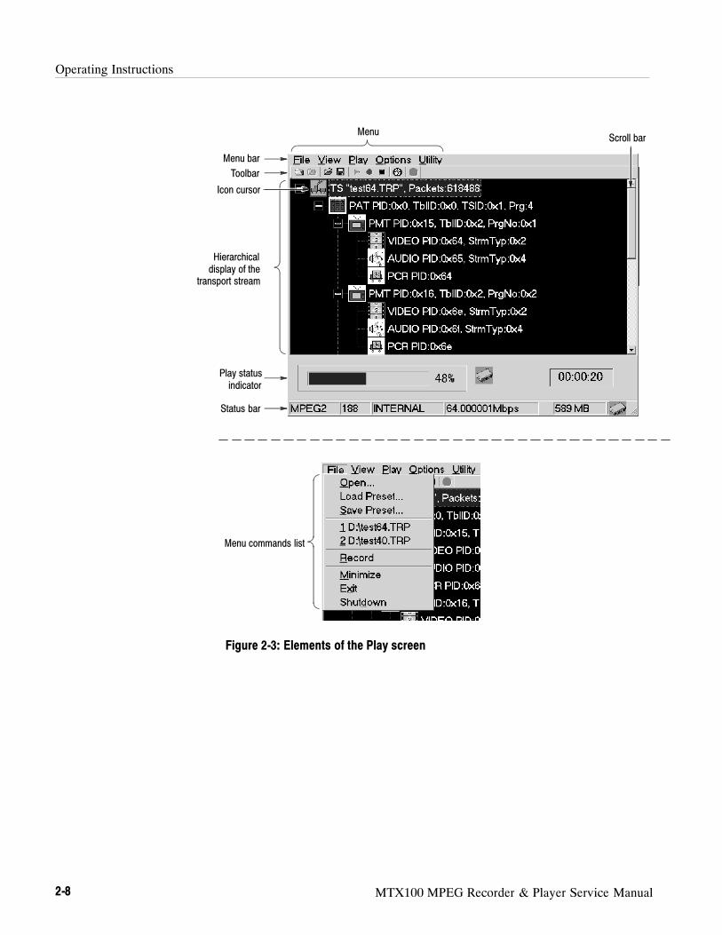
Figure 2-3 shows the location of display elements of the Play screen. The displayelements of the Record screen is the same as that of the Play screen.
Operating Instructions
2-8 MTX100 MPEG Recorder & Player Service Manual
Menu bar
Status bar
Menu commands list
Icon cursor
Hierarchicaldisplay of the
transport stream
Scroll bar
Toolbar
Play statusindicator
Menu
Figure 2-3: Elements of the Play screen

Operating Instructions
MTX100 MPEG Recorder & Player Service Manual 2-9
Basic Menu Operation
This section describes the basics of using the MTX100’s menu and the methodsfor entering numeric input in the various dialog boxes.
The menus are displayed in the menu bar at the top of the Play or Record screen.You can operate these menus using the front panel MENU button, ESC button,TAB button, ENTER button, and the arrow buttons (see Figure 2-4).
MENU button
TAB button ENTER button
Arrow buttons
ESC button
Figure 2-4: Front panel showing the menu controls
Accessing Menu Commands. To access any menu command, press the MENUbutton. When you press the MENU button, the File menu command list firstopens.
Use the up () or down () arrow button to move through the command list.Press the ENTER button to execute the selected command.
Use the left () or right () arrow button to select the desired menu. Press theESC button to close the command list temporarily.
Press the MENU button again to close the menu command list.

Operating Instructions
2-10 MTX100 MPEG Recorder & Player Service Manual
NOTE. When you press the left arrow button while the File menu is displayed or
when you press the right arrow button while the Utility menu is displayed, the
command list for window operation of the MTX100 application is displayed.
Display States of the Menu Commands. The menu commands can have thefollowing three display states as shown in Figure 2-5:
A command followed by “” indicates a corresponding submenu will bedisplayed after you press the ENTER button or the right () arrow button.
A command followed by “...” indicates that a corresponding dialog box willopen after you press the ENTER button.
If a command name is only displayed, the command will be executed afteryou press the ENTER button.
A corresponding dialog box will bedisplayed when this command is executed
A corresponding submenu will bedisplayed
The displayed command will be executedimmediately
Figure 2-5: Display states of the menu commands
You can enter numeric values in displayed dialog boxes by using the 10 key Pador by using the arrow buttons.
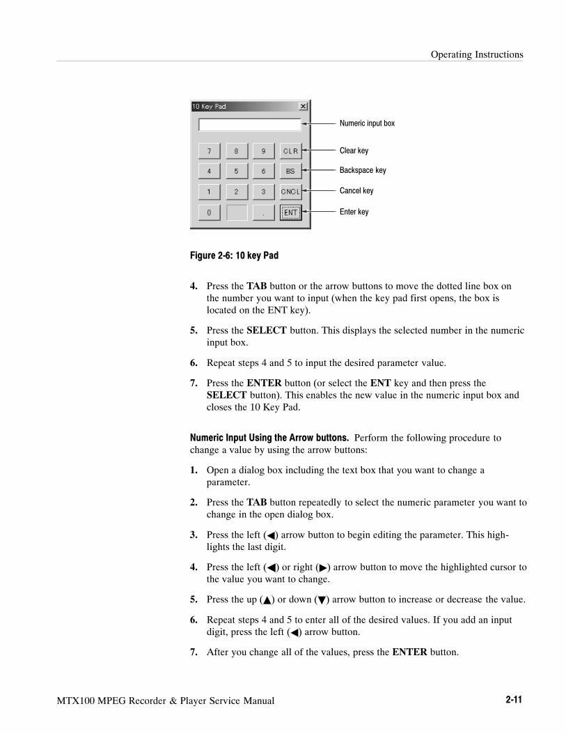
Numeric Input Using the 10 Key Pad. Perform the following procedure to inputnumeric values by using the 10 Key Pad. Figure 2-6 shows the 10 key Pad.
1. Open a dialog box including the text box in which you want to change aparameter.
2. Press the TAB button repeatedly to select (highlight) the numeric parameteryou want to change in the open dialog box.
3. Press the SELECT button to open the 10 Key Pad (see Figure 2-6).
Numeric Input
Operating Instructions
MTX100 MPEG Recorder & Player Service Manual 2-11
Numeric input box
Clear key
Backspace key
Cancel key
Enter key
Figure 2-6: 10 key Pad
4. Press the TAB button or the arrow buttons to move the dotted line box onthe number you want to input (when the key pad first opens, the box islocated on the ENT key).
5. Press the SELECT button. This displays the selected number in the numericinput box.
6. Repeat steps 4 and 5 to input the desired parameter value.
7. Press the ENTER button (or select the ENT key and then press theSELECT button). This enables the new value in the numeric input box andcloses the 10 Key Pad.
Numeric Input Using the Arrow buttons. Perform the following procedure tochange a value by using the arrow buttons:
1. Open a dialog box including the text box that you want to change aparameter.
2. Press the TAB button repeatedly to select the numeric parameter you want tochange in the open dialog box.
3. Press the left () arrow button to begin editing the parameter. This high-lights the last digit.
4. Press the left () or right () arrow button to move the highlighted cursor tothe value you want to change.
5. Press the up () or down () arrow button to increase or decrease the value.
6. Repeat steps 4 and 5 to enter all of the desired values. If you add an inputdigit, press the left () arrow button.
7. After you change all of the values, press the ENTER button.
Operating Instructions
2-12 MTX100 MPEG Recorder & Player Service Manual
About the Data Output Source
When you output the selected stream data, you can select either the hard disk orthe RAM as an output source. This subsection describes the operation of theMTX100 when each output source is selected.
When you select the RAM as an output source, the MTX100 performs thefollowing:
When data output rate is less than or equal to 120 Mbps, the MTX100outputs the first stream data while transferring the data from the hard disk tothe RAM and then continuously outputs the data from the RAM usinglooping methods.
When data output rate is more than 120 Mbps, the MTX100 continuouslyoutputs a stream data from the RAM using looping methods after the data iscompletely transferred from the hard disk to the RAM.
If you select the RAM as an output source, you cannot output the data over theRAM free space for the data output. This RAM free space is displayed on thestatus bar.
If you select the hard disk (Disk) as an output source, the MTX100 alwaysoutputs the selected stream data from the hard disk regardless of the data outputrate. When the reading speed of the hard disk cannot overtake the data outputrate, the error message “Error: Output Buffer Empty” appears.
Use the Source command in the Play menu to select the output source.
You can see the currently selected output source in the status bar.
RAM
Hard Disk

MTX100 MPEG Recorder & Player Service Manual 3-1
Theory of Operation
This section describes the basic operation of the major circuit blocks or modulesin the MTX100. The Diagrams section, beginning on page 9-1, includes a blockdiagram and an interconnect diagram.
A10 Main Board
The A10 Main board consists of the following six blocks:
The PCI interface consists of a target and an initiator. In the target, the controlport of the A10 Main board is mapped. The initiator has two DMA controllerswhich read the data from and write the data to the system RAM.
The FIFO consists of two 8-MB SDRAMs. Each of the SDRAMs is used foroutputing and recording a stream data respectively. This FIFO is used tocompensate for non-realtime operation of Windows 2000.
The TS controller consists of PSYNC Generator, DVALID Generator, PCRCounter, PCR DTS/PTS Inserter, and the peripheral circuit.
The interrupt controller sends the following interruption signals to the CPU:External Trigger, Play FIFO Empty, Record FIFO Full, and 100 ms timer.
The TS clock generator consists of two types of clock generators for streamoutput: Low Band clock generator and High Band clock generator. The LowBand clock generator generates the clock signal ranges from 64 MHz to 96 MHz.The High Band clock generator generates the clock signal ranges from 96 MHzto 128 MHz. The output signals of these clock generators are divided by thedividing circuit, and they are output as a serial or parallel clock.
The reference clocks consist of 27 MHz TCXO and half-divided output of54 MHz clock generator. These clocks are used to compare the frequency of theTS Clock Generator.
PCI Interface
Mega FIFO
TS Controller
Interrupt Controller
TS Clock Generator
Reference Clocks
Theory of Operation
3-2 MTX100 MPEG Recorder & Player Service Manual
A20 PCI Back Plane Board
The A20 PCI Back Plane board consists of the following connectors andcircuitries:
The connectors J400 and J410 are the system slots and are used to insert theCPU board. The connectors J420 and J430 are the PCI card slots for the A10Main board and the optional interface module.
The POWER_SW line is connected to the power switch on the front panel.When the power switch is pressed, the line causes K200 to go on. When K200 ison, +5 V main power is also on, and its status is sent to BIOS on the A20 CPUboard. When the power switch is pressed again, its status is sent to BIOS and theK200 turns off. The +5 V main power is off when the K200 is off. This circuitincludes a +5 V to +12 V DC-DC converter, a --12 V power supply, and a +3.3 Vpower supply.
There are four connectors in the interconnect circuit: J130, J140, J160, and J170.J130 is used to connect the board to the LCD interface on the CPU board. J140is used to connect the board to COM1 on the CPU board. J160 is used to connectthe board to the USB connectors on the A35 Power Switch board. J170 is used toconnect the board to the A30 Front Panel board. This circuit also has a RS-232Clevel converter.
A30 Front Panel Board
The A30 Front Panel board consists of the front panel processor circuit, videoinverter circuit, rubber contact switches, three connectors, and two LEDs.
A35 Power Switch Board
The A35 Power Switch board is connected to the A20 PCI Back Plane boardthrough the A30 Front Panel board. There are two USB connectors on this board.
PCI and ISA Connectors
ATX Power Control Circuit
Interconnect Circuit

Theory of Operation
MTX100 MPEG Recorder & Player Service Manual 3-3
A100 ASI Interface Module (Option 01)
The A100 ASI Interface module consists of the following five blocks:
The local bus interface communicates with the A10 Main board. There are twosets of 16-bit signal lines for Rx and Tx: 8-bit data lines for single-end connec-tion, 4-bit control lines for single-end connection, and 4-bit control lines fordifferential connection. These lines are connected to the A10 Main board inone-on-one.
The FPGA consists of an FIFO and PCI interface. The FIFO is used to output astream data in packet mode. In this mode, a stream data from the A10 Mainboard is stored in it, and then the data is output in synchronism with the PSYNCsignal. In the burst mode, the FIFO is used only to synchronize with the clocksignal. There is a 32-bit resistor in the PCI interface and it controls the boardoperation.
The HOTLink transmitter converts parallel signals from the FIFO to a serialsignal. The converted signal is output to the BNC connectors through the cabledrivers.
The signal applied to the BNC connector is equalized by the cable equalizer, andis converted to parallel signals by the HOTLink receiver. In addition, theequalized signal is applied to the cable driver, and is output to the ASI throughoutput.
The regulator supplies power for internal circuitry in the FPGA.
Local Bus Interface
FPGA
HOTLink transmitter andCable Drivers
Cable Equalizer andHOTLink Receiver
2.5 V Regulator
Theory of Operation
3-4 MTX100 MPEG Recorder & Player Service Manual
A110 Universal Parallel/Serial Interface Module (Option 02)
The A110 Universal Parallel/Serial Interface module consists of the followingsix blocks:
The local bus interface communicates with the A10 Main board. There are twosets of 16-bit signal lines for Rx and Tx: 8-bit data lines for single-end connec-tion, 4-bit control lines for single-end connection, and 4-bit control lines fordifferential connection. These lines are connected to the A10 Main board inone-on-one.
The FPGA consists of an 8-bit-to-1-bit shift register for parallel to serialconversion, a 1-bit-to-8-bit shift register for serial to parallel conversion, and aPCI interface. The shift registers are not used in the parallel data input/outputmode. There is a 32-bit resistor in the PCI interface. It controls the boardoperation.
The pin drivers convert output signals from the FPGA into the signals with theselected level. Two drivers par 1 bit are always working: two drivers are used fordifferential mode and one driver is used for single-end mode.
The receivers use two comparator par 1 bit. One is used to receive a single-endsignal and the other is used to receive a differential signal. Either of thecomparators is disabled in operation and is in hold mode.
The D/A converter is used to set the amplitude and offset of the output signal. Italso sets the threshold voltage of the comparator for single-end receiving.
The regulator supplies power for internal circuitry in the FPGA.
A120 BNC Serial Interface Module (Option 03)
The A120 BNC Serial Interface module consists of the following six blocks:
The local bus interface communicates with the A10 Main board. There are twosets of 16-bit signal lines for Rx and Tx: 8-bit data lines for single-end connec-tion, 4-bit control lines for single-end connection, and 4-bit control lines fordifferential connection. These lines are connected to the A10 Main board inone-on-one.
Local Bus Interface
FPGA
Pin Drivers
Receivers
D/A Converter
2.5 V Regulator
Local Bus Interface

Theory of Operation
MTX100 MPEG Recorder & Player Service Manual 3-5
The FPGA consists of an 8-bit-to-1-bit shift register for parallel to serialconversion, a 1-bit-to-8-bit shift register for serial to parallel conversion, and aPCI interface. There is a 32-bit register in the PCI interface. It controls the boardoperation.
The pin drivers convert output signals from the FPGA into the signals withselected level.
Each of the receivers uses a comparator par 1 bit.
The D/A converter is used to set the amplitude and offset of the output signal. Italso sets the threshold voltage of the comparators.
The regulator supplies power for internal circuitry in the FPGA.
A130 DHEI Interface Module (Option 04)
The A130 DHEI Interface module consists of the following five blocks:
The local bus interface communicates with the A10 Main board. There are twosets of 16-bit signal lines for Rx and Tx: 8-bit data lines for single-end connec-tion, 4-bit control lines for single-end connection, and 4-bit control lines fordifferential connection. These lines are connected to the A10 Main board inone-on-one.
The FPGA consists of an 8-bit-to-1-bit shift register for parallel to serialconversion, a 1-bit-to-8-bit shift register for serial to parallel conversion, and aPCI interface. There is a 32-bit resistor in the PCI interface. It controls the boardoperation.
The drivers drive the output signals from the FPGA.
Each of the receivers uses one comparator par one input to receive a differentialsignal.
The regulator supplies power for internal circuitry in the FPGA.
FPGA
Pin Drivers
Receivers
D/A Converter
2.5 V Regulator
Local Bus Interface
FPGA
Drivers
Receivers
2.5 V Regulator

Theory of Operation
3-6 MTX100 MPEG Recorder & Player Service Manual
A140 IEEE 1394 Interface Module (Option 05)
Two operational modes are available to output data stored in the MTX100:Packet mode and Byte mode.
Difference between Packet and Byte Modes. Data rate of the ASI interface is up to216 Mbps, and the data with rate lower than 216 Mbps is transmitted intermit-tently. The Data Valid signal, which indicates the location in which the dataexists, is also sent together with the data, it is possible to reconfigure thereceived data as a serial data string from the intermittently transmitted data.
When the data rate from the MTX100 storage (hard disk or RAM) is lower than216Mbps, it is possible to select whether to sparsely output all the data or tooutput the data on packet-by-packet basis as the ASI output. The first mode inwhich the data is sparsely output is called Byte mode, and the second mode inwhich the data is output on packet-by-packet basis is called Packet mode.
In Byte mode, the data sent from A10 board is output as they are. In Packetmode, the data processing is required. The data is organized into a packet withinthe Link chip and then output. The Packet controller is not used in this process.The Packet controller must be set to Byte mode.
In through mode where the data is sent from the ASI input to the ASI output, thedata does not pass through the packet controller circuit and are output with thesame timing as the ASI input.
Packet Mode Operation. The FIFO shift register is used to output the data onpacket-by-packet basis. This FIFO has 9 bit of width, and its depth is 512 stages.The content of 9 bit width is 8 bit for data, and 1 bit for Sync Bit. The Sync Bitindicates the location of sync pattern (47h) in the data.
The data sent from A10 board is fed to the FIFO. The FIFO output port searchesfor a Sync Bit. When a Sync Bit is detected, data output from the FIFO isstopped, and the data that follows the Sync Bit is stored to the FIFO.
The FIFO input port also searches for a Sync Bit. When the port detects a SyncBit of the next packet, it sends the detection to the read-out controller at theFIFO output port. When the FIFO output port receives the Sync Bit detectionsignal from the input port, the output port reads out the signals until the nextpacket Sync Bit is detected. The data rate of FIFO input port is equal to the datatransfer rate of MTX100, and that of output port is 216 Mbps (with the clock of27 MHz), which is used for the ASI output.
Packet Controller

Theory of Operation
MTX100 MPEG Recorder & Player Service Manual 3-7
The partial transport stream is a bit stream generated by removing the transportpackets unrelated with selected audio/video program(s) from MPEG-2 transportpackets. In transmitting/receiving multiple numbers of audio/video programswith lower data rate through a high-speed data line, the packets in a singleaudio/video program are transmitted as intermittent packets compressed alongthe time axis. In this case, the period of time between the packets has somemeaning. When recording the data in the MTX100, all the packets are recordedas a serial data. When reproduced such data, the time information betweenpackets are lost and the data becomes a serial data.
To resolve the problem mentioned above, the period of time between thereceived packets are measured, and the timing information is added before theSync byte of each packet as 4 bytes data. In reproducing the data, the timinginformation located before the next packet is derived after the packet is output.The next packet is output after waiting for the period of time as written in thisfour bytes data.
Partial TS Controller 1. The Partial TS Controller 1 picks up 4 bytes of datalocated before sync byte from the data stream sent from A10 board, and countsdown the value written in this 4 bytes data with 27 MHz clock. When the countbecomes zero, the controller starts the processing on the next packet. Whilewaiting for the next sync byte, the controller outputs Busy signal to stop theoperation of A10 board. The size of packet possible to be handled by Partial TSController 1 is fixed to 192 bytes/packet (188 + 4). When sending packets ofother sizes, turn the Partial TS processing off. This board uses only 24 bits out of32 bits (4 bytes) of Time Stamp information. The upper 8 bits are ignored.
Partial TS Controller 2. This controller performs the operation reversal to that ofPartial TS Controller 1. It counts the period of time between the packets beingreceived with 27 MHz clock, and adds the result of counting to the top of thenext packet as the time information of 4 bytes. Because a 24 bit counter is used,the first one byte of 4 bytes data becomes zero. While 4 bytes information isoutput, the controller stops input of packets. The controller has the FIFO shiftregister of 9 bit x 256 to retain the data during the suspension period.
Although the packets received from IEEE1394 or from ASI contain Sync Pattern(47h), the 47h may be contained within data or the 47h may lack because of anerror. The sync detector reconfigures information indicating the sync locationand delivers the information to the next block together with the data. In theoutput circuit of IEEE1394, the packets are generated based upon this synclocation information. In the Partial TS Controller, the measurements of timeinterval between packets are performed based upon this information.
Partial TS Controller
Sync Detector

Theory of Operation
3-8 MTX100 MPEG Recorder & Player Service Manual
Sync Detector 1. The Sync Detector 1 produces sync location information to bedelivered to IEEE1394 output circuit. This information is also used for thepurpose to send the received packet size to the application. This circuit iscompatible with the packet sizes of 188, 204, and 208. After repeated confirma-tion that ”47h” is located at the same location (188, 204, or 208) for five (5)times, the circuit starts to output the sync location information. When the circuitfailed to find the location of ”47h” for three consecutive times, it stops output-ting the sync location information. The circuit sends information of 1, 2, or 3 tothe application when the packet size is 188, 204, or 208, respectively. Otherwise,it sends information of zero (0). This information is needed to use the throughmode for the IEEE1394 output.
Sync Detector 2. This circuit produces the sync location information to bedelivered to Partial TS Control 2 circuit. The circuit is compatible only with thepacket size of 188 bytes/packet. Should a packet having a size other than 188bytes/packet be input even if Partial TS processing is specified, the circuit stopsthe output to A10 board.
A160 SMPTE310M/ASI Interface Module (Option 06)
The SMPTE310M format supports data with bit rate of 8-VSB (19.39 Mbps).Because the SMPTE310M uses Biphase-mark coding, a clock with twofold ofthe data bit rate (i.e., 40MHz) is required for decoding and encoding processes.The receiver passes the received data signal through a delay line to generate aclock signal with twofold of the data bit rate from the received data signal itself.The transmitter receives the clock signal with twofold of the data bit rate fromA10 board for data encoding. Because this optional board is unable to recognizethe difference of data bit rates, the current data bit rate must be specified fromthe application.
Difference between Packet and Byte Modes. Data rate of the ASI interface is up to216 Mbps, and the data with rate lower than 216 Mbps are transmitted intermit-tently. The Data Valid signal, which indicates the location in which the dataexists, is also sent together with the data, it is possible to reconfigure thereceived data as a serial data string from the intermittently transmitted data.
When the data rate from the MTX100 storage (hard disk or RAM) is lower than216Mbps, it is possible to select whether to sparsely output all the data or tooutput the data in packet-by-packet basis as the ASI output. The first mode inwhich the data is sparsely output is called Byte mode, and the second mode inwhich the data is output in packet-by-packet basis is called Packet mode. In Bytemode, the data sent from A10 board are output as they are. In Packet mode, thedata processing is required.
SMPTE310M

Theory of Operation
MTX100 MPEG Recorder & Player Service Manual 3-9
Packet Mode Operation. The FIFO shift register is used to output the data onpacket-by-packet basis. This FIFO has 9 bit of width, and its depth is 512 stages.The content of 9 bit width is 8 bit for data, and 1 bit for Sync Bit. The Sync bitindicates the location of sync pattern (47h) in the data.
The data sent from A10 board is fed to the FIFO. The FIFO output port searchesfor a Sync Bit. When a Sync Bit is detected, data output from the FIFO isstopped, and the data that follows the Sync Bit is stored in the FIFO.
The FIFO input port also searches for a Sync Bit. When the port detects a SyncBit of the next packet, it sends the detection to the read-out controller at theFIFO output port. When the FIFO output port receives the Sync Bit detectionsignal from the input port, the output port reads out the signals until the nextpacket Sync Bit is detected. The data rate of FIFO input port is equal to the datatransfer rate of MTX100, and that of output port is 216 Mbps (with the clock of27 MHz), which is used for the ASI output.
When receiving the SMPTE310M or ASI data, both the enabling and 27 MHzclock signal are delivered to the A10 board. The option 06 can convert the datafrom SMPTE310M into ASI, however it is unable to convert the ASI data intothe SMPTE310M format.
To transmit data of SMPTE310M format, enabling signal and clock signal(approximately 77.56 MHz) for encoding the Biphase-mark are required. Whentransmitting the data of ASI format, enabling signal, signal indicating thelocation of sync bit, and transport stream clock are generated from the A10board.
A10 Board I/O

Theory of Operation
3-10 MTX100 MPEG Recorder & Player Service Manual

MTX100 MPEG Recorder & Player Service Manual 4-1
Performance Verification
This section provides procedures that verify the performance of the MTX100.These tests confirm performance and functionality when the following condi-tions are met:
The MTX100 must be operating in an environment that is within theoperating limits described in Table 1-10 on page 1-17.
The MTX100 and test equipment must have had a warm-up period of at least20 minutes.
Equipment and Test Signals Required
Table 4-1 lists the test equipment required to perform all of the performanceverification procedures. The table identifies examples of recommendedequipment and lists the required precision where applicable. If you substituteother test equipment for the examples listed, the equipment must meet or exceedthe listed tolerances.
Table 4-1: Equipment required for performance verification
Item No. Minimum requirements Recommended equipment
Frequency counter 1 Frequency range: 0.1 Hz to 1250 MHzPrecision: 7 digits or higher
ANRITSU MF 1603A or Tektronix DC5009
MPEG recorder & player 1 Data rate: 200 MbpsSPI, ASI, Universal parallel/serial, BNCserial, DHEI, and SMPTE310M interfaces
Tektronix MTX100 Option 01, 02, 03, 04,and 06
Data generator 1 Frequency: 40 M clock patternAmplitude: 3 V
Tektronix DG2030 or Tegam PG502
Oscilloscope 1 Bandwidth: 1 GHz or higher Tektronix TDS784D
Tuner 1 BS Digital Panasonic TU-BHD100
MPEG test system 1 Master Client application Tektronix MTS300 option LV(or the MTSF3LV upgrade) and MTS215
75 Ω to 50 Ω minimum lossattenuator
1 Bandwidth: 1 GHzAmplitude precision: --3 dB
Tektronix AMT75
75 Ω precision termination 1 Tektronix part number 011-0163-00
Probe 1 X 1 Tektronix P6101B
BNC cable 1 Impedance: 50 ΩLength: 42 inches
Tektronix part number 012-0057-01
BNC cable 4 Impedance: 75 ΩLength: 42 inches
Tektronix part number 012-0074-00

Performance Verification
4-2 MTX100 MPEG Recorder & Player Service Manual
Table 4-1: Equipment required for performance verification (Cont.)
Item Recommended equipmentMinimum requirementsNo.
High definition cable 1 26-pin, D-type for DHEI interface option 04 GI/Motorola 415406-003
i-Link cable 1 2 m ------
Parallel interface cable 1 25-pin, D-type Tektronix part number 012-A220-00,(supplied with the MTX100)
The MTX100 is shipped from the factory with sample MPEG test files loaded onthe hard disk. Two of these files are required to perform the performanceverification procedures. Table 4-2 lists the required test files and the performanceverification tests that require these files.
Table 4-2: MPEG test files required for performance verification
File name Performance verification tests
test40.TRP SPI Interface, ASI Interface (Option 01 only), Universal Parallel/SerialInterface (Option 02 only), BNC Serial Interface (Option 03 only), andDHEI Interface (Option 04 only)
test64.TRP Internal Clock Frequency and External Clock/Reference Input
TS1394.TRP IEEE1394 Interface (Option 05 only)
8VSB_test.TRP SMPTE310M Interface (Option 06 only)

Performance Verification
MTX100 MPEG Recorder & Player Service Manual 4-3
Procedures
The following conventions are used in the performance verification procedures:
Each test lists the characteristic that is being tested and the equipmentrequired to perform the test.
Each test contains complete setup instructions, which allows you to performeach test individually or in order.
The equipment connection illustrations are specific to the recommendedequipment (equipment nomenclature is labeled). If you are using substituteequipment, the location of your signal connections may vary from those inthe illustrations.
NOTE. Before you perform the performance verification procedures, be sure that
the MTX100 is operating in an environment that is within the operating limits
described in Table 1-10 on page 1-17.
In addition, the MTX100 and the test equipment must be warmed up for at least
20 minutes to ensure accurate test results.
The performance verification procedures appear in the following order:
1. Internal clock frequency
2. External clock/reference input
3. External trigger input
4. SPI interface
5. ASI interface (Option 01 only)
6. Universal parallel/serial interface (Option 02 only)
7. BNC serial interface (Option 03 only)
8. DHEI interface (Option 04 only)
9. IEEE1394/ASI interface (Option 05 only)
10. SMPTE310M/ASI interface (Option 06 only)

Performance Verification
4-4 MTX100 MPEG Recorder & Player Service Manual
This test verifies the frequency of the MTX100’s internal clock. The followingequipment and MPEG test signal is required for this test:
Frequency counter
Probe
test64.TRP MPEG test signal
Perform the following procedure to verify the internal clock frequency of theMTX100:
1. Connect the probe to the input of the frequency counter, and then attach theprobe tip to pin 1 of the SPI IN/OUT connector on the MTX100 as shown inFigure 4-1.
Frequency counter (MF 1603A)
Probe
MTX100 rear panel
131
14 25
Figure 4-1: Equipment connection for verifying the internal clock frequency
2. Set the frequency counter to the frequency measurement mode (if necessary),and then set the Gate Time to > 0.2 s.
3. Open the test64.TRP file on the MTX100.
a. Select Open from the File menu.
b. In the resulting Select File dialog box, select the test64.TRP file, andthen press the ENTER button.
4. Press the PLAY button on the MTX100 to start the signal output of thetest64.TRP file.
5. Verify that the indicator at the left side of the PLAY button is illuminated.
6. Set the frequency counter to trigger on the input, and then confirm that thedisplayed frequency is within the range of 7.999992 MHz to 8.000008 MHz.
7. Press the STOP button on the MTX100 to stop the signal output, and thenremove the probe tip from the SPI IN/OUT connector.
Internal Clock Frequency

Performance Verification
MTX100 MPEG Recorder & Player Service Manual 4-5
This test confirms that the external clock/reference input (CLK/REF IN input) onthe MTX100 is functioning correctly. The following equipment and MPEG testsignal is required for this test:
MPEG test system
Data generator
50 Ω BNC cable
Parallel interface cable
test64.TRP MPEG test signal
Perform the following procedure to verify that the external clock/reference input(CLK/REF IN input) on the MTX100 is functioning correctly:
1. Use the 50 Ω BNC cable to connect the CLK/REF IN connector on theMTX100 to the CH0 connector on the front panel of the data generator asshown in Figure 4-2.
2. Use the parallel interface cable to connect the SPI IN/OUT connector on theMTX100 to the SPI (LVDS) 3 IN connector on the rear panel of the MPEGtest system as shown in Figure 4-2.
50Ω BNC cable
Parallel interface cable
MPEG test system rear panel (MTS300 Opt. LV)
MTX100 rear panel
Data generator (DG2030)
Figure 4-2: Equipment connections for verifying the external clock/reference input
External Clock/ReferenceInput

Performance Verification
4-6 MTX100 MPEG Recorder & Player Service Manual
3. Set the data generator controls as indicated below:
Internal clock frequency 20 MHz on DG2030 or 10 MHz on PG502. . . . .Output pattern data Clock pattern. . . . . . . . .Output High level 3.0 V. . . . . . . . . .Output Low level 1.0 V. . . . . . . . . . .
4. Open the test64.TRP file on the MTX100.
a. Select Open from the File menu.
b. In the resulting Select File dialog box, select the test64.TRP file, andthen press the ENTER button.
5. Set Update to On from the Play menu on the MTX100.
6. Select Clock from the Play menu on the MTX100 to open the Clock dialogbox.
7. Select ExtRef 10 in the Clock dialog box, and then press the ENTERbutton.
8. Press the START/STOP button on the data generator to start the pattern dataoutput.
9. Press the PLAY button on the MTX100 to start the signal output of thetest64.TRP file.
10. Verify that the indicator at the left side of the PLAY button is illuminated.
11. Double-click theMaster Client icon in the Tektronix MPEG Test Systemprogram group window on the MPEG test system to start the application.
12. Select Connect locally from theMaster menu to connect to the local ServerManager.
13. Select I/O #3 in the Port Manager panel, right click, and then selectAssign Analysis Server from the shortcut menu.
14. Select the Analysis Server icon (I/O #3), right click, and then select StartAnalysis from the short cut menu.
15. Select the Analysis Server icon, right click, and then select Launch ExpertClient. The Expert Client applications Window opens.
16. Verify that the hierarchic view is displayed on the screen and that no errormessages appear. In addition, verify that the transmission rate is 64 Mbpsand that the transport stream packet size is 188 bytes.

Performance Verification
MTX100 MPEG Recorder & Player Service Manual 4-7
17. Change the clock source setting on the MTX100 and internal clockfrequency setting on the data generator with the following and repeat step 16.
Clock Source setting (MTX100) Internal Clock Frequency setting
ExtRef 27 54 MHz (DG2030) / 27 MHz (PG502)
Ext P Clk 16 MHz (DG2030) / 8 MHz (PG502)
Ext S Clk 128 MHz (DG2030) / 64 MHz (PG502)
18. Select the Analysis Server icon (I/O #3), right click, and then select StopAnalysis from the shortcut menu.
19. Select Clock from the Play menu on the MTX100 to open the Clock dialogbox.
20. Select Internal in the Clock dialog box, and then press the ENTER button.
21. Press the STOP button on the MTX100 to stop the signal output.
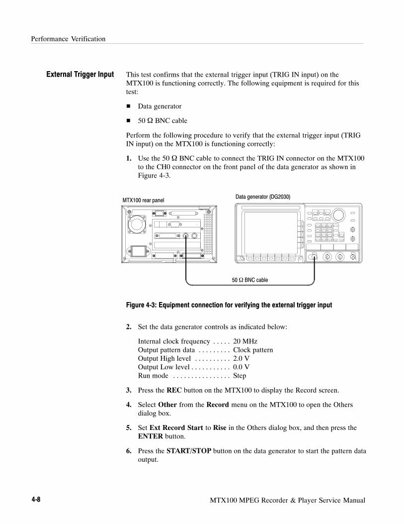
Performance Verification
4-8 MTX100 MPEG Recorder & Player Service Manual
This test confirms that the external trigger input (TRIG IN input) on theMTX100 is functioning correctly. The following equipment is required for thistest:
Data generator
50 Ω BNC cable
Perform the following procedure to verify that the external trigger input (TRIGIN input) on the MTX100 is functioning correctly:
1. Use the 50 Ω BNC cable to connect the TRIG IN connector on the MTX100to the CH0 connector on the front panel of the data generator as shown inFigure 4-3.
50Ω BNC cable
MTX100 rear panelData generator (DG2030)
Figure 4-3: Equipment connection for verifying the external trigger input
2. Set the data generator controls as indicated below:
Internal clock frequency 20 MHz. . . . .Output pattern data Clock pattern. . . . . . . . .Output High level 2.0 V. . . . . . . . . .Output Low level 0.0 V. . . . . . . . . . .Run mode Step. . . . . . . . . . . . . . . .
3. Press the REC button on the MTX100 to display the Record screen.
4. Select Other from the Record menu on the MTX100 to open the Othersdialog box.
5. Set Ext Record Start to Rise in the Others dialog box, and then press theENTER button.
6. Press the START/STOP button on the data generator to start the pattern dataoutput.
External Trigger Input

Performance Verification
MTX100 MPEG Recorder & Player Service Manual 4-9
7. Press the STEP/EVENT button twice on the data generator and verify thatthe indicator at the left side of the REC button on the MTX100 is illumi-nated.
8. Select Other from the Record menu on the MTX100 to open the Othersdialog box.
9. Set Ext Record Start to Fall in the Others dialog box, and then press theENTER button.
10. Repeat step 7.
11. Press the START/STOP button on the data generator to stop the pattern dataoutput.
12. Press the PLAY button on the MTX100 to display the Play screen.
This test verifies that transport stream data is correctly output from and recordedthrough the SPI IN/OUT connector on the MTX100. The following equipmentand MPEG test signal is required for this test:
MPEG recorder & player (MTX100 Option 01)
MPEG test system
Parallel interface cable
test40.TRP MPEG test signal
Perform the following procedure to verify that transport stream data is correctlyoutput from and recorded through the SPI IN/OUT connector on the MTX100:
1. Use the parallel interface cable to connect the SPI IN/OUT connector on theMTX100 to the SPI IN/OUT connector on the MPEG recorder & player asshown in Figure 4-4.
SPI Interface

Performance Verification
4-10 MTX100 MPEG Recorder & Player Service Manual
Parallel interface cable
MTX100 rear panel
MPEG recorder & player(MTX100 Option 01)
Figure 4-4: Initial equipment connection for verifying the SPI interface
Checking the Play Operation.
2. Open the test40.TRP file on the MTX100.
a. Select Open from the File menu.
b. In the resulting Select File dialog box, select the test40.TRP file, andthen press the ENTER button.
3. In the Play menu on the MTX100, make the following settings:
Data rate 120 Mbps. . . .Update Off. . . . . .Source Disk. . . . . .
4. Press the REC button on the MPEG recorder & player to display the recordscreen.
5. In the Record menu on the MPEG recorder & player, make the followingsettings:
Source SPI. . . . . .Record size 100 MBytes. .Target RAM. . . . . .
6. Press the PLAY button on the MTX100 to start the signal output of the test40.TRP file.
7. Verify that the hierarchic view is displayed on the screen of the MPEGrecorder & player. In addition, verify that the bit rate display is 120 Mbps.
8. Select Save from the File menu on the MPEG recorder & player to open theSave As dialog box.
Performance Verification
MTX100 MPEG Recorder & Player Service Manual 4-11
9. In the dialog box, enter SPI120MD for the file name that is used to save thetest file, and then press the ENTER button.
10. Press the REC button on the MPEG recorder & player to record the test file.
11. Change the MTX100 settings as follows:
Data rate 200 Mbps. . . .Source RAM. . . . . .
12. Verify that the hierarchic view is displayed on the screen of the MPEGrecorder & player. In addition, verify that the bit rate display is 200 Mbps.
13. Select Save from the File menu on the MPEG recorder & player to open theSave As dialog box.
14. In the dialog box, enter SPI200MR for the file name that is used to save thetest file, and then press the ENTER button.
15. Press the REC button on the MPEG recorder & player to record the test file.
16. Press the STOP button on the MTX100 to stop the stream output.
Checking the Record Operation.
17. Press the REC button on the MTX100 to display the Record screen.
18. In the Record menu on the MTX100, make the following settings:
Source SPI. . . . . .Record size 4000 MBytes. .Target Disk. . . . . .
19. Press the PLAY button on the MPEG recorder & player to display the Playscreen.
20. In the Play menu on the MPEG recorder & player, make the followingsettings:
Data rate 120 Mbps. . . .Update Off. . . . . .Source RAM. . . . . .
21. Open the SPI120MD file on the MPEG recorder & player.
a. Select Open from the File menu.
b. In the resulting Select File dialog box, select the SPI120MD file, andthen press the ENTER button.
22. Press the PLAY button on the MPEG recorder & player to start the signaloutput of the file.

Performance Verification
4-12 MTX100 MPEG Recorder & Player Service Manual
23. Verify that the hierarchic view is displayed on the screen of the MTX100. Inaddition, verify that the bit rate display is 120 Mbps.
24. Select Save from the File menu on the MTX100 to open the Save As dialogbox.
25. In the dialog box, enter SPI120MD for the file name that is used to save thetest file, and then press the ENTER button.
26. Press the REC button on the MTX100 to record the SPI120MD file.
27. Press the STOP button on the MPEG recorder & player to stop the streamoutput.
28. Change the data rate settings of the MPEG recorder & player to 200 Mbps.
29. Change the MTX100 settings as follows:
Record size 100 Mbyte. .Source RAM. . . . . .
30. Open the SPI200MR file on the MPEG recorder & player.
a. Select Open from the File menu.
b. In the resulting Select File dialog box, select the SPI200MR file, andthen press the ENTER button.
31. Press the PLAY button on the MPEG recorder & player to start the signaloutput of the file.
32. Verify that the hierarchic view is displayed on the screen of the MTX100. Inaddition, verify that the bit rate display is 200 Mbps.
33. Select Save from the File menu on the MTX100 to open the Save As dialogbox.
34. In the dialog box, enter SPI200MR for the file name that is used to save thetest file, and then press the ENTER button.
35. Press the REC button on the MTX100 to record the SPI200MD file.
36. Press the STOP button on the MPEG recorder & player to stop the streamoutput.

Performance Verification
MTX100 MPEG Recorder & Player Service Manual 4-13
Checking the Recorded Files.
37. Disconnect the parallel interface cable from the SPI IN/OUT connector onthe MPEG recorder & player, and then connect the parallel interface cable tothe SPI (LVDS) 3 IN connector on the MPEG test system as shown inFigure 4-5.
Parallel interface cable
MTX100 rear panel
MPEG test system rear panel (MTS300 Opt. LV)
Figure 4-5: Second equipment connection for verifying the SPI interface
38. Press the PLAY button on the MTX100 to display the Play screen.
39. Change Update to On from the Play menu on the MTX100.
40. Open the SPI120MD file on the MTX100.
a. Select Open from the File menu.
b. In the resulting Select File dialog box, select the SPI120MD file, andthen press the ENTER button.
41. Press the PLAY button on the MTX100 to start the signal output of the file.
42. Double-click theMaster Client icon in the Tektronix MPEG Test Systemprogram group window on the MPEG test system to start the application.
43. Select Connect locally from theMaster menu to connect to the local ServerManager.
44. Select I/O #3 in the Port Manager panel, right click, and then selectAssign Analysis Server from the shortcut menu.
45. Select the Analysis Server icon (I/O #3), right click, and then select StartAnalysis from the short cut menu.

Performance Verification
4-14 MTX100 MPEG Recorder & Player Service Manual
46. Select the Analysis Server icon, right click, and then select Launch ExpertClient. The Expert Client applications Window opens.
47. Verify that the Hierarchic view is displayed on the screen and that no errormessages appear. In addition, verify that the transmission rate is 40 Mbpsand that the transport stream packet size is 188 bytes.
48. Press the STOP button on the MTX100 to stop the stream output.
49. Open the SPI200MR file on the MTX100.
a. Select Open from the File menu.
b. In the resulting Select File dialog box, select the SPI200MR file, andthen press the ENTER button.
50. Press the PLAY button on the MTX100 to start the signal output of the file.
51. Verify that the hierarchic view is displayed on the screen and that no errormessages appear. In addition, verify that the transmission rate is 40 Mbpsand that the transport stream packet size is 188 bytes.
52. Press the STOP button on the MTX100 to stop the stream output.

Performance Verification
MTX100 MPEG Recorder & Player Service Manual 4-15
This test verifies that transport stream data is correctly output from and isrecorded through the ASI interface on the MTX100 Option 01. The followingequipment and MPEG test signal is required for this test:
MPEG recorder & player (MTX100 Option 01)
MPEG test system
Oscilloscope
Two 75 Ω BNC cables
75 Ω to 50 Ω minimum loss attenuator
test40.TRP MPEG test signal
Perform the following procedure to verify that transport stream data is outputfrom and is recorded through the SPI IN/OUT connector on the MTX100Option 01:
Checking the Output Signals.
1. Use the 75 Ω BNC cable and the 75 Ω to 50 Ω minimum loss attenuator toconnect the ASI OUT 1 connector on the MTX100 Option 01 to theoscilloscope CH1 input as shown in Figure 4-6.
Oscilloscope (TDS784D)
75Ω BNC cable75Ω to 50Ω
minimum loss attenuator
MTX100 Option 01 rear panel
Figure 4-6: Initial equipment connection for verifying the ASI interface
ASI Interface (Option 01Only)

Performance Verification
4-16 MTX100 MPEG Recorder & Player Service Manual
2. Set the oscilloscope controls as indicated below:
Displayed channel CH1. . . . .Vertical scale 200 mV/div. . . . . . . . .Horizontal scale 500 ps/div. . . . . . .Horizontal position Center. . . .Acquire mode Average 64. . . . . . . .Trigger mode Auto. . . . . . . . .Trigger level 0 V. . . . . . . . .Trigger source CH1. . . . . . . .Trigger position 50%. . . . . . .Trigger slope Rising Edge. . . . . . . . .Input coupling DC. . . . . . . .Input impedance 50 Ω. . . . . .Measure Amplitude, Rise Time, Fall Time. . . . . . . . . . . . .Level Setup Histogram High Ref 80%, Low Ref 20%.
3. Open the test40.TRP file on the MTX100 Option 01.
a. Select Open from the File menu.
b. In the resulting Select File dialog box, select the test40.TRP file, andthen press the ENTER button.
4. Press the PLAY button on the MTX100 Option 01 to start the signal outputof the test40.TRP file.
5. Use the oscilloscope to measure that the amplitude, rise and fall times are asfollows.
Amplitude: 740 mV to 860 mVRise and fall time:≤ 1.2 ns
6. Move the BNC cable connection from the ASI OUT 1 connector to the ASIOUT 2 connector on the MTX100 Option 01 and then repeat step 5.
7. Move the BNC cable connection from ASI OUT 2 connector to the throughoutput of the ASI IN connector.
8. Connect the ASI OUT 1 connector to the ASI IN connector on the MTX100Option 01 using the 75 Ω BNC cable.
9. Set Through Out to On from ASI I/F menu on the MTX100 Option 01 andthen repeat step 5.
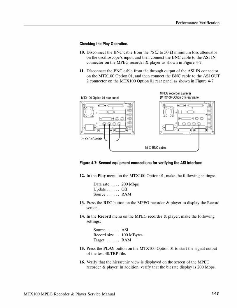
Performance Verification
MTX100 MPEG Recorder & Player Service Manual 4-17
Checking the Play Operation.
10. Disconnect the BNC cable from the 75 Ω to 50 Ω minimum loss attenuatoron the oscilloscope’s input, and then connect the BNC cable to the ASI INconnector on the MPEG recorder & player as shown in Figure 4-7.
11. Disconnect the BNC cable from the through output of the ASI IN connectoron the MTX100 Option 01, and then connect the BNC cable to the ASI OUT2 connector on the MTX100 Option 01 rear panel as shown in Figure 4-7.
75Ω BNC cable
MTX100 Option 01 rear panel
MPEG recorder & player(MTX100 Option 01) rear panel
75Ω BNC cable
Figure 4-7: Second equipment connections for verifying the ASI interface
12. In the Play menu on the MTX100 Option 01, make the following settings:
Data rate 200 Mbps. . . .Update Off. . . . . .Source RAM. . . . . .
13. Press the REC button on the MPEG recorder & player to display the Recordscreen.
14. In the Record menu on the MPEG recorder & player, make the followingsettings:
Source ASI. . . . . .Record size 100 MBytes. .Target RAM. . . . . .
15. Press the PLAY button on the MTX100 Option 01 to start the signal outputof the test 40.TRP file.
16. Verify that the hierarchic view is displayed on the screen of the MPEGrecorder & player. In addition, verify that the bit rate display is 200 Mbps.

Performance Verification
4-18 MTX100 MPEG Recorder & Player Service Manual
17. Select Save from the File menu on the MPEG recorder & player to open theSave As dialog box.
18. In the dialog box, enter ASItest for the file name that is used to save the testfile, and then press the ENTER button.
19. Press the REC button on the MPEG recorder & player to record the test file.
20. Move the BNC cable connection from the ASI OUT 2 connector to thethrough output of the ASI IN connector.
21. Verify that the hierarchic view is displayed on the screen of the MPEGrecorder & player. In addition, verify that the bit rate display is 200 Mbps.
22. Select Save from the File menu on the MPEG recorder & player to open theSave As dialog box.
23. In the dialog box, enter Looptest for the file name that is used to save thetest file, and then press the ENTER button.
24. Press the REC button on the MPEG recorder & player to record the test file.
25. Press the STOP button on the MTX 100 Option 01 to stop the streamoutput.
26. Disconnect the two BNC cables from the MTX100 Option 01 and MPEGrecorder & player.
Checking the Record Operation.
27. Use a 75 Ω BNC cable to connect the ASI OUT1 connector on the MPEGrecorder & player to the ASI IN connector on the MTX100 Option 01 asshown in Figure 4-8.
75Ω BNC cable
MTX100 Option 01 rear panel
MPEG recorder & player(MTX100 Option 01) rear panel
Figure 4-8: Third equipment connection for verifying the ASI interface

Performance Verification
MTX100 MPEG Recorder & Player Service Manual 4-19
28. Press the REC button on the MTX100 Option 01 to display the Recordscreen.
29. In the Record menu on the MTX100 Option 01, make the followingsettings:
Source ASI. . . . . .Record size 100 MBytes. .Target RAM. . . . . .
30. Press the PLAY button on the MPEG recorder & player to display the Playscreen.
31. In the Play menu on the MPEG recorder & player, make the followingsettings:
Data rate 200 Mbps. . . .Update Off. . . . . .Source RAM. . . . . .
32. Open the ASItest file on the MPEG recorder & player.
a. Select Open from the File menu.
b. In the resulting Select File dialog box, select the ASItest file, and thenpress the ENTER button.
33. Press the PLAY button on the MPEG recorder & player to start the signaloutput of the file.
34. Verify that the hierarchic view is displayed on the screen of the MTX100Option 01. In addition, verify that the bit rate display is 200 Mbps.
35. Select Save from the File menu on the MTX100 Option 01 to open the SaveAs dialog box.
36. In the dialog box, enter ASItest for the file name that is used to save the testfile, and then press the ENTER button.
37. Press the REC button on the MTX100 Option 01 to record the ASItest file.
38. Press the STOP button on the MPEG recorder & player to stop the streamoutput.
39. Open the Looptest file on the MPEG recorder & player.
a. Select Open from the File menu.
b. In the resulting Select File dialog box, select the Looptest file, and thenpress the ENTER button.
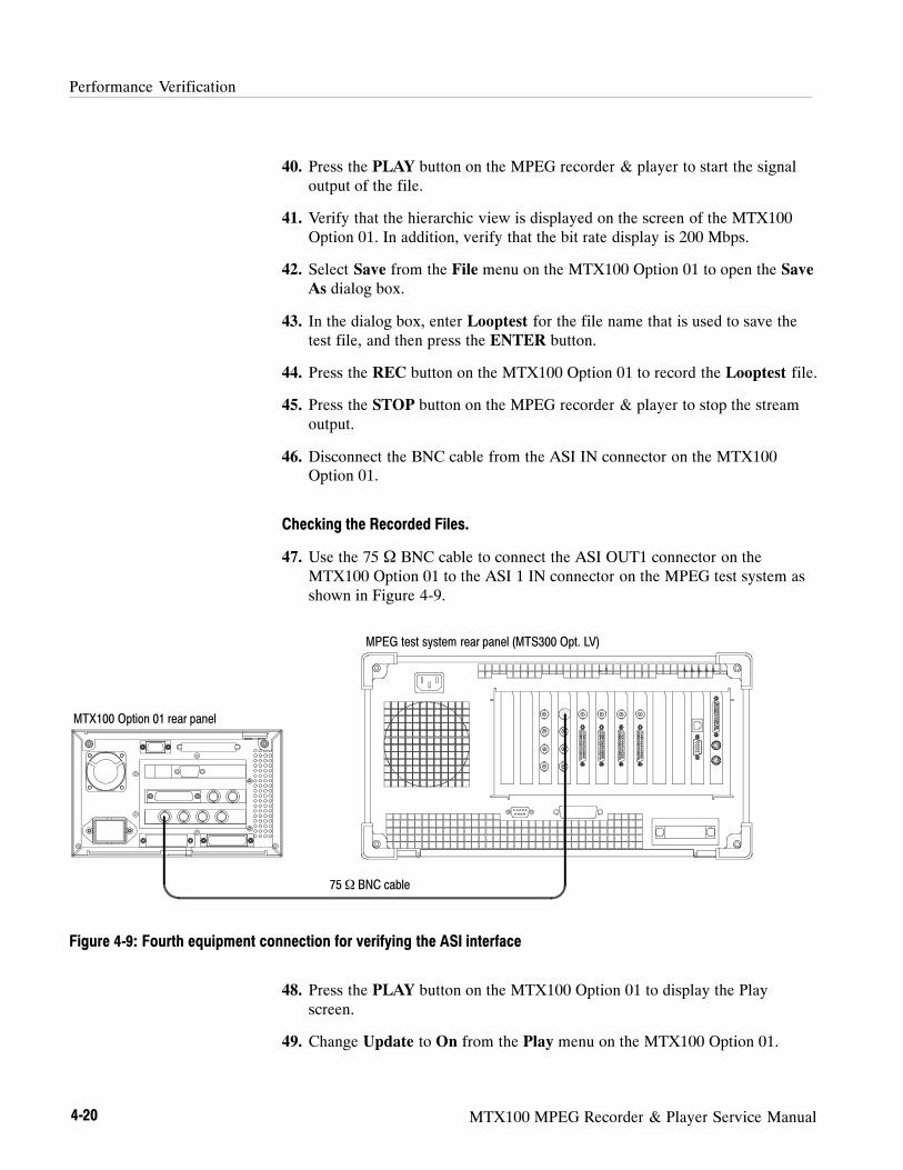
Performance Verification
4-20 MTX100 MPEG Recorder & Player Service Manual
40. Press the PLAY button on the MPEG recorder & player to start the signaloutput of the file.
41. Verify that the hierarchic view is displayed on the screen of the MTX100Option 01. In addition, verify that the bit rate display is 200 Mbps.
42. Select Save from the File menu on the MTX100 Option 01 to open the SaveAs dialog box.
43. In the dialog box, enter Looptest for the file name that is used to save thetest file, and then press the ENTER button.
44. Press the REC button on the MTX100 Option 01 to record the Looptest file.
45. Press the STOP button on the MPEG recorder & player to stop the streamoutput.
46. Disconnect the BNC cable from the ASI IN connector on the MTX100Option 01.
Checking the Recorded Files.
47. Use the 75 Ω BNC cable to connect the ASI OUT1 connector on theMTX100 Option 01 to the ASI 1 IN connector on the MPEG test system asshown in Figure 4-9.
MPEG test system rear panel (MTS300 Opt. LV)
75Ω BNC cable
MTX100 Option 01 rear panel
Figure 4-9: Fourth equipment connection for verifying the ASI interface
48. Press the PLAY button on the MTX100 Option 01 to display the Playscreen.
49. Change Update to On from the Play menu on the MTX100 Option 01.
Performance Verification
MTX100 MPEG Recorder & Player Service Manual 4-21
50. Open the ASItest file on the MTX100 Option 01.
a. Select Open from the File menu.
b. In the resulting Select File dialog box, select the ASItest file, and thenpress the ENTER button.
51. Press the PLAY button on the MTX100 Option 01 to start the signal outputof the file.
52. Double-click theMaster Client icon in the Tektronix MPEG Test Systemprogram group window on the MPEG test system to start the application.
53. Select Connect locally from theMaster menu to connect to the local ServerManager.
54. Select I/O #1 in the Port Manager panel, right click, and then selectAssign Analysis Server from the shortcut menu.
55. Select the Analysis Server icon (I/O #1), right click, and then select StartAnalysis from the short cut menu.
56. Select the Analysis Server icon, right click, and then select Launch ExpertClient. The Expert Client applications Window opens.
57. Verify that the hierarchic view is displayed on the screen and that no errormessages appear. In addition, verify that the transmission rate is 40 Mbpsand that the transport stream packet size is 188 bytes.
58. Press the STOP button on the MTX100 Option 01 to stop the stream output.
59. Open the Looptest file on the MTX100 Option 01.
a. Select Open from the File menu.
b. In the resulting Select File dialog box, select the Looptest file, and thenpress the ENTER button.
60. Press the PLAY button on the MTX100 Option 01 to start the signal outputof the file.
61. Verify that the hierarchic view is displayed on the screen and that no errormessages appear. In addition, verify that the transmission rate is 40 Mbpsand that the transport stream packet size is 188 bytes.
62. Press the STOP button on the MTX100 Option 01 to stop the stream output.

Performance Verification
4-22 MTX100 MPEG Recorder & Player Service Manual
This test verifies that transport stream data is correctly output from and isrecorded through the Universal Parallel/Serial interface on the MTX100 Option02. The following equipment and MPEG test signal is required for this test:
MPEG recorder & player (MTX100 Option 02)
MPEG test system
Oscilloscope
Probe
50 Ω BNC cable
Parallel interface cable
test40.TRP MPEG test signal
Perform the following procedure to verify that transport stream data is outputfrom and is recorded through the UNIVERSAL IN/OUT connector on theMTX100 Option 02:
Checking the Output Signals.
1. Connect the probe to the oscilloscope CH1 input as shown in Figure 4-10.
MTX100 Option 02 rear panel Oscilloscope (TDS784D)
Probe
14 25
131
Figure 4-10: Initial equipment connection for verifying the universal parallel/serial interface
Universal Parallel/SerialInterface (Option 02 Only)
Performance Verification
MTX100 MPEG Recorder & Player Service Manual 4-23
2. Set the oscilloscope controls as indicated below:
Displayed channel CH1. . . . .Vertical scale 1 V/div. . . . . . . . .Horizontal scale 200 ns/div. . . . . . .Horizontal position Center. . . .Acquire mode Average 2. . . . . . . .Trigger mode Auto. . . . . . . . .Trigger level 0 V. . . . . . . . .Trigger source CH1. . . . . . . .Trigger position 50%. . . . . . .Trigger slope Rising Edge. . . . . . . . .Input coupling DC. . . . . . . .Input impedance 50 Ω. . . . . .Measure Amplitude. . . . . . . . . . . . .
3. Press the PLAY button on the MTX100 Option 02 to display the Playscreen.
4. Open the test40.TRP file on the MTX100 Option 02.
a. Select Open from the File menu.
b. In the resulting Select File dialog box, select the test40.TRP file, andthen press the ENTER button.
5. Select Clock from the Play menu on the MTX100 Option 02 to open theClock dialog box.
6. Set Data Rate to 10 Mbps in the Clock dialog box, and then press theENTER button.
7. Set Level to ECL from the Univ I/F menu on the MTX100 Option 02.
8. Press the PLAY button on the MTX100 Option 02 to start the signal outputof the test40.TRP file.
9. Attach the probe tip to pin 1 of the UNIVERSAL IN/OUT connector on theMTX100 Option 02.
10. Use the oscilloscope to measure that the ECL high and low levels of pin 1are as follows.
High level: --0.5 VLow level: --2.1 V
11. Move the probe tip attachment from pin 1 to pin 14, and measure that theECL high and low levels correspond to the values shown in Table 4-3.
12. Repeat step 11 for all other pins.
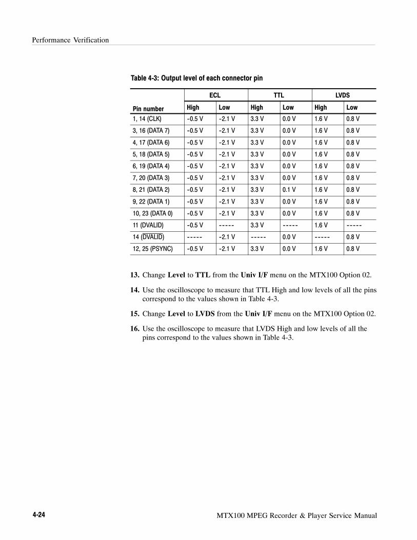
Performance Verification
4-24 MTX100 MPEG Recorder & Player Service Manual
Table 4-3: Output level of each connector pin
ECL TTL LVDS
Pin number High Low High Low High Low
1, 14 (CLK) --0.5 V --2.1 V 3.3 V 0.0 V 1.6 V 0.8 V
3, 16 (DATA 7) --0.5 V --2.1 V 3.3 V 0.0 V 1.6 V 0.8 V
4, 17 (DATA 6) --0.5 V --2.1 V 3.3 V 0.0 V 1.6 V 0.8 V
5, 18 (DATA 5) --0.5 V --2.1 V 3.3 V 0.0 V 1.6 V 0.8 V
6, 19 (DATA 4) --0.5 V --2.1 V 3.3 V 0.0 V 1.6 V 0.8 V
7, 20 (DATA 3) --0.5 V --2.1 V 3.3 V 0.0 V 1.6 V 0.8 V
8, 21 (DATA 2) --0.5 V --2.1 V 3.3 V 0.1 V 1.6 V 0.8 V
9, 22 (DATA 1) --0.5 V --2.1 V 3.3 V 0.0 V 1.6 V 0.8 V
10, 23 (DATA 0) --0.5 V --2.1 V 3.3 V 0.0 V 1.6 V 0.8 V
11 (DVALID) --0.5 V ---------- 3.3 V ---------- 1.6 V ----------
14 (DVALID) ---------- --2.1 V ---------- 0.0 V ---------- 0.8 V
12, 25 (PSYNC) --0.5 V --2.1 V 3.3 V 0.0 V 1.6 V 0.8 V
13. Change Level to TTL from the Univ I/F menu on the MTX100 Option 02.
14. Use the oscilloscope to measure that TTL High and low levels of all the pinscorrespond to the values shown in Table 4-3.
15. Change Level to LVDS from the Univ I/F menu on the MTX100 Option 02.
16. Use the oscilloscope to measure that LVDS High and low levels of all thepins correspond to the values shown in Table 4-3.

Performance Verification
MTX100 MPEG Recorder & Player Service Manual 4-25
Checking the Play Operation.
1. Use the parallel interface cable to connect the UNIVERSAL IN/OUTconnector on the MTX100 Option 02 to the UNIVERSAL IN/OUTconnector on the MPEG recorder & player as shown in Figure 4-11.
Parallel interface cable
MTX100 Option 02 rear panel
MPEG recorder & player(MTX100 Option 02) rear panel
Figure 4-11: Second equipment connection for verifying the Universal parallel/serialinterface
2. Press the PLAY button on the MTX100 Option 02 to display the Playscreen.
3. In the Play menu on the MTX100 Option 02, make the following settings:
Data rate 200 Mbps. . . .Update Off. . . . . .Source RAM. . . . . .
4. In the Univ I/F menu on the MTX100 Option 02, make the followingsettings:
Level LVDS. . . . . . .Format Parallel. . . . . .
5. Press the REC button on the MPEG recorder & player to display the Recordscreen.
6. In the Record menu on the MPEG recorder & player, make the followingsettings:
Source Univ I/F. . . . . .Record size 100 MBytes. .Target RAM. . . . . .

Performance Verification
4-26 MTX100 MPEG Recorder & Player Service Manual
7. In the Univ I/F menu on the MPEG recorder & player, make the followingsettings:
Level LVDS. . . . . . .Format Parallel. . . . . .Receive Differential. . . . .Termination On. .
8. Press the PLAY button on the MTX100 Option 02 to start the signal outputof the test 40.TRP file.
9. Verify that the hierarchic view is displayed on the screen of the MPEGrecorder & player. In addition, verify that the bit rate display is 200 Mbps.
10. Select Save from the File menu on the MPEG recorder & player to open theSave As dialog box.
11. In the dialog box, enter UNIpara for the file name that is used to save thetest file, and then press the ENTER button.
12. Press the REC button on the MPEG recorder & player to record the test file.
13. Press the STOP button on the MTX100 Option 02 to stop the stream output.
14. Change Data Rate to 40 Mbps from the Play menu on the MTX100Option 02.
15. Change Format to Serial from the Univ I/F menu on the MTX100Option 02.
16. Press the REC button on the MPEG recorder & player to display the Recordscreen.
17. Change Format to Serial from the Univ I/F menu on the MPEG recorder &player.
18. Press the PLAY button on the MTX100 Option 02 to start the signal outputof the test 40.TRP file.
19. Verify that the hierarchic view is displayed on the screen of the MPEGrecorder & player. In addition, verify that the bit rate display is 40 Mbps.
20. Select Save from the File menu on the MPEG recorder & player to open theSave As dialog box.
21. In the dialog box, enter UNIseri for the file name that is used to save the testfile, and then press the ENTER button.
22. Press the REC button on the MPEG recorder & player to record the test file.
23. Press the STOP button on the MTX100 Option 02 to stop the stream output.

Performance Verification
MTX100 MPEG Recorder & Player Service Manual 4-27
Checking the Record Operation.
24. Press the REC button on the MTX100 Option 02 to display the Recordscreen.
25. In the Record menu on the MTX100 Option 02, make the followingsettings:
Source Univ I/F. . . . . .Record size 100 MBytes. .Target RAM. . . . . .
26. In the Univ I/F menu on the MTX100 Option 02, make the followingsettings:
Level LVDS. . . . . . .Format Parallel. . . . . .Receive Differential. . . . .Termination On. .
27. Press the PLAY button on the MPEG recorder & player to display the Playscreen.
28. In the Play menu on the MPEG recorder & player, make the followingsettings:
Data rate 200 Mbps. . . .Update Off. . . . . .Source RAM. . . . . .
29. In the Univ I/F menu on the MPEG recorder & player, make the followingsettings:
Level LVDS. . . . . . .Format Parallel. . . . . .
30. Open the UNIpara file on the MPEG recorder & player.
a. Select Open from the File menu.
b. In the resulting Select File dialog box, select the UNIpara file, and thenpress the ENTER button.
31. Press the PLAY button on the MPEG recorder & player to start the signaloutput of the file.
32. Verify that the hierarchic view is displayed on the screen of the MTX100Option 02. In addition, verify that the bit rate display is 200 Mbps.
33. Select Save from the File menu on the MTX100 Option 02 to open the SaveAs dialog box.

Performance Verification
4-28 MTX100 MPEG Recorder & Player Service Manual
34. In the dialog box, enter UNIpara for the file name that is used to save thetest file, and then press the ENTER button.
35. Press the REC button on the MTX100 Option 02 to record the UNIparafile.
36. Press the STOP button on the MPEG recorder & player to stop the streamoutput.
37. Change Format to Serial from the Univ I/F menu on the MTX100Option 02.
38. Change Data Rate to 40 Mbps from the Play menu on the MPEG recorder& player.
39. Change Format to Serial from the Univ I/F menu on the MPEG recorder &player.
40. Open the UNIseri file on the MPEG recorder & player.
a. Select Open from the File menu.
b. In the resulting Select File dialog box, select the UNIseri file, and thenpress the ENTER button.
41. Press the PLAY button on the MPEG recorder & player to start the signaloutput of the file.
42. Verify that the hierarchic view is displayed on the screen of the MTX100Option 02. In addition, verify that the bit rate display is 40 Mbps.
43. Select Save from the File menu on the MTX100 Option 02 to open the SaveAs dialog box.
44. In the dialog box, enter UNIseri for the file name that is used to save the testfile, and then press the ENTER button.
45. Press the REC button on the MTX100 Option 02 to record the UNIseri file.
46. Press the STOP button on the MPEG recorder & player to stop the streamoutput.
Performance Verification
MTX100 MPEG Recorder & Player Service Manual 4-29
Checking signal acquisition for ECl and TTL Levels.
47. In the Play menu on the MPEG recorder & player, make the followingsettings:
Data rate 200 Mbps. . . .Update Off. . . . . .Source RAM. . . . . .
48. In the Univ I/F menu on the MPEG recorder & player, make the followingsettings:
Level ECL. . . . . . .Format Parallel. . . . . .
49. In the Univ I/F menu on the MTX100 Option 02, make the followingsettings:
Level ECL. . . . . . .Format Parallel. . . . . .Receive Differential. . . . .Termination On. .
50. Open the test40.TRP file on the MPEG recorder & player.
a. Select Open from the File menu.
b. In the resulting Select File dialog box, select the test40.TRP file, andthen press the ENTER button.
51. Press the PLAY button on the MPEG recorder & player to start the signaloutput of the test40.TRP file.
52. Verify that no Non-TS and No Signal messages appear on the screen of theMTX100 Option 02. In addition, the hierarchic view and the bit rate aredisplayed correctly.
53. Change Receive to Single from the Univ I/F menu on the MTX100 Option02, and then repeat step 52.
54. Change Level to TTL from the Univ I/F menu on the MPEG recorder &player.
55. Change Level to TTL and Receive to Differential from the Univ I/F menuon the MTX100 Option 02, and then repeat step 52.
56. Change Receive to Single from the Univ I/F menu on the MTX100 Option02, and then repeat step 52.
57. Change Data Rate to 40 Mbps from the Play menu on the MPEG recorder& player.

Performance Verification
4-30 MTX100 MPEG Recorder & Player Service Manual
58. Change Level to ECL and Format to Serial from the Univ I/F menu on theMPEG recorder & player.
59. In the Univ I/F menu on the MTX100 Option 02, make the followingsettings:
Level ECL. . . . . . .Format Serial. . . . . .Receive Differential. . . . .
60. Repeat step 52.
61. Change Receive to Single from the Univ I/F menu on the MTX100 Option02, and then repeat step 52.
62. Change Level to TTL from the Univ I/F menu on the MPEG recorder &player.
63. Change Level to TTL and Receive to Differential from the Univ I/F menuon the MTX100 Option 02, and then repeat step 52.
64. Change Receive to Single from the Univ I/F menu on the MTX100 Option02, and then repeat step 52.
65. Press the STOP button on the MPEG recorder & player to stop the streamoutput.
66. Disconnect the parallel interface cable from the MTX100 Option 02 andMPEG recorder & player.

Performance Verification
MTX100 MPEG Recorder & Player Service Manual 4-31
Checking the Recorded Files.
67. Use the parallel interface cable to connect the SPI IN/OUT connector on theMTX100 Option 02 to the SPI (LVDS) 3 IN connector on the MPEG testsystem as shown in Figure 4-12.
Parallel interface cable
MTX100 Option 02 rear panel
MPEG test system rear panel (MTS300 Opt. LV)
Figure 4-12: Third equipment connection for verifying the universal parallel/serial interface
68. Press the PLAY button on the MTX100 Option 02 to display the Playscreen.
69. Change Update to On from the Play menu on the MTX100 Option 02.
70. Change Level to LVDS and Format to Parallel from the Univ I/F menu onthe MTX100 Option 02.
71. Open the UNIpara file on the MTX100 Option 02.
a. Select Open from the File menu.
b. In the resulting Select File dialog box, select the Unipara file, and thenpress the ENTER button.
72. Press the PLAY button on the MTX100 Option 02 to start the signal outputof the file.
73. Double-click theMaster Client icon in the Tektronix MPEG Test Systemprogram group window on the MPEG test system to start the application.
74. Select Connect locally from theMaster menu to connect to the local ServerManager.

Performance Verification
4-32 MTX100 MPEG Recorder & Player Service Manual
75. Select I/O #3 in the Port Manager panel, right click, and then selectAssign Analysis Server from the shortcut menu.
76. Select the Analysis Server icon (I/O #3), right click, and then select StartAnalysis from the short cut menu.
77. Select the Analysis Server icon, right click, and then select Launch ExpertClient. The Expert Client applications Window opens.
78. Verify that the hierarchic view is displayed on the screen and that no errormessages appear. In addition, verify that the transmission rate is 40 Mbpsand that the transport stream packet size is 188 bytes.
79. Press the STOP button on the MTX100 Option 02 to stop the stream output.
80. Open the UNIseri file on the MTX100 Option 02.
a. Select Open from the File menu.
b. In the resulting Select File dialog box, select the UNIseri file, and thenpress the ENTER button.
81. Press the PLAY button on the MTX100 Option 02 to start the signal outputof the file.
82. Verify that the hierarchic view is displayed on the screen and that no errormessages appear. In addition, verify that the transmission rate is 40 Mbpsand that the transport stream packet size is 188 bytes.
83. Disconnect the parallel interface cable from the MTX100 Option 02 and theMPEG test system.
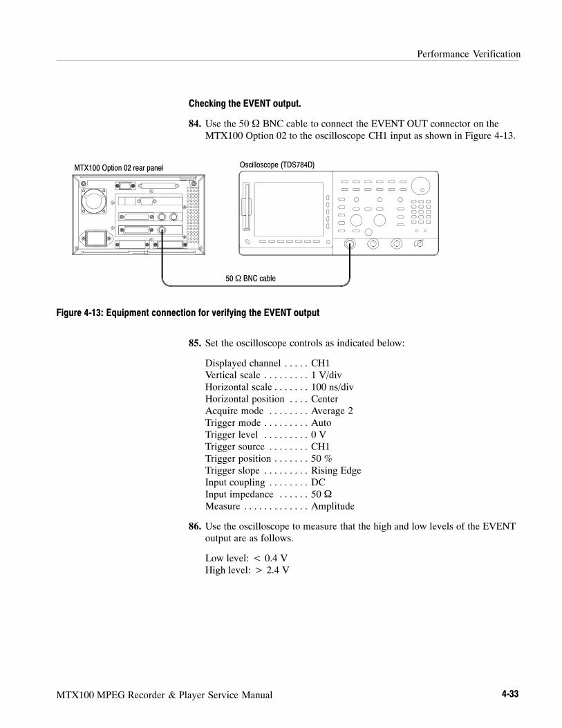
Performance Verification
MTX100 MPEG Recorder & Player Service Manual 4-33
Checking the EVENT output.
84. Use the 50 Ω BNC cable to connect the EVENT OUT connector on theMTX100 Option 02 to the oscilloscope CH1 input as shown in Figure 4-13.
MTX100 Option 02 rear panel Oscilloscope (TDS784D)
50Ω BNC cable
Figure 4-13: Equipment connection for verifying the EVENT output
85. Set the oscilloscope controls as indicated below:
Displayed channel CH1. . . . .Vertical scale 1 V/div. . . . . . . . .Horizontal scale 100 ns/div. . . . . . .Horizontal position Center. . . .Acquire mode Average 2. . . . . . . .Trigger mode Auto. . . . . . . . .Trigger level 0 V. . . . . . . . .Trigger source CH1. . . . . . . .Trigger position 50 %. . . . . . .Trigger slope Rising Edge. . . . . . . . .Input coupling DC. . . . . . . .Input impedance 50 Ω. . . . . .Measure Amplitude. . . . . . . . . . . . .
86. Use the oscilloscope to measure that the high and low levels of the EVENToutput are as follows.
Low level: < 0.4 VHigh level: > 2.4 V

Performance Verification
4-34 MTX100 MPEG Recorder & Player Service Manual
This test verifies that transport stream data is correctly output from and isrecorded through the BNC serial interface on the MTX100 Option 03. Thefollowing equipment and MPEG test signal is required for this test:
MPEG recorder & player (MTX100 Option 03)
MPEG test system
Oscilloscope
Four 75 Ω BNC cables
Parallel interface cable
test40.TRP MPEG test signal
Perform the following procedure to verify that transport stream data is correctlyoutput from and is recorded through the BNC serial interface on the MTX100Option 03:
Checking the Output Signals.
1. Use the 75 Ω BNC cable to connect the DATA connector on the MTX100Option 03 to the oscilloscope CH1 input as shown in Figure 4-14.
Oscilloscope (TDS784D)
75Ω BNC cable
MTX100 Option 03 rear panel
Figure 4-14: Initial equipment connection for verifying the BNC serial interface
BNC Serial Interface(Option 03 Only)
Performance Verification
MTX100 MPEG Recorder & Player Service Manual 4-35
2. Set the oscilloscope controls as indicated below:
Displayed channel CH1. . . . .Vertical scale 1 V/div. . . . . . . . .Horizontal scale 25 ns/div. . . . . . .Horizontal position Center. . . .Acquire mode Average 64. . . . . . . .Trigger mode Auto. . . . . . . . .Trigger level 0 V. . . . . . . . .Trigger source CH1. . . . . . . .Trigger position 50%. . . . . . .Trigger slope Rising Edge. . . . . . . . .Input coupling DC. . . . . . . .Input impedance 50 Ω. . . . . .
3. Press the PLAY button on the MTX100 Option 03 to display the Playscreen.
4. Open the test40.TRP file on the MTX100 Option 03.
a. Select Open from the File menu.
b. In the resulting Select File dialog box, select the test40.TRP file, andthen press the ENTER button.
5. Select Clock from the Play menu on the MTX100 Option 03 to open theClock dialog box.
6. Set the Data Rate to 10 Mbps in the Clock dialog box, and then press theENTER button.
7. Set Level to ECL from the BNC I/F menu on the MTX100 Option 03.
8. Press the PLAY button on the MTX100 Option 03 to start the signal outputof the test40.TRP file.
9. Use the oscilloscope to measure that the ECL high and low levels of theDATA output are as follows.
High level: --0.5 VLow level: --2.1 V
10. Move the BNC cable connection from the DATA connector to the CLOCKconnector, and measure that the ECL high and low levels of the CLOCKoutput correspond to the values shown in Table 4-4.
11. Repeat step 10 for the PSYNC and ENABLE outputs.
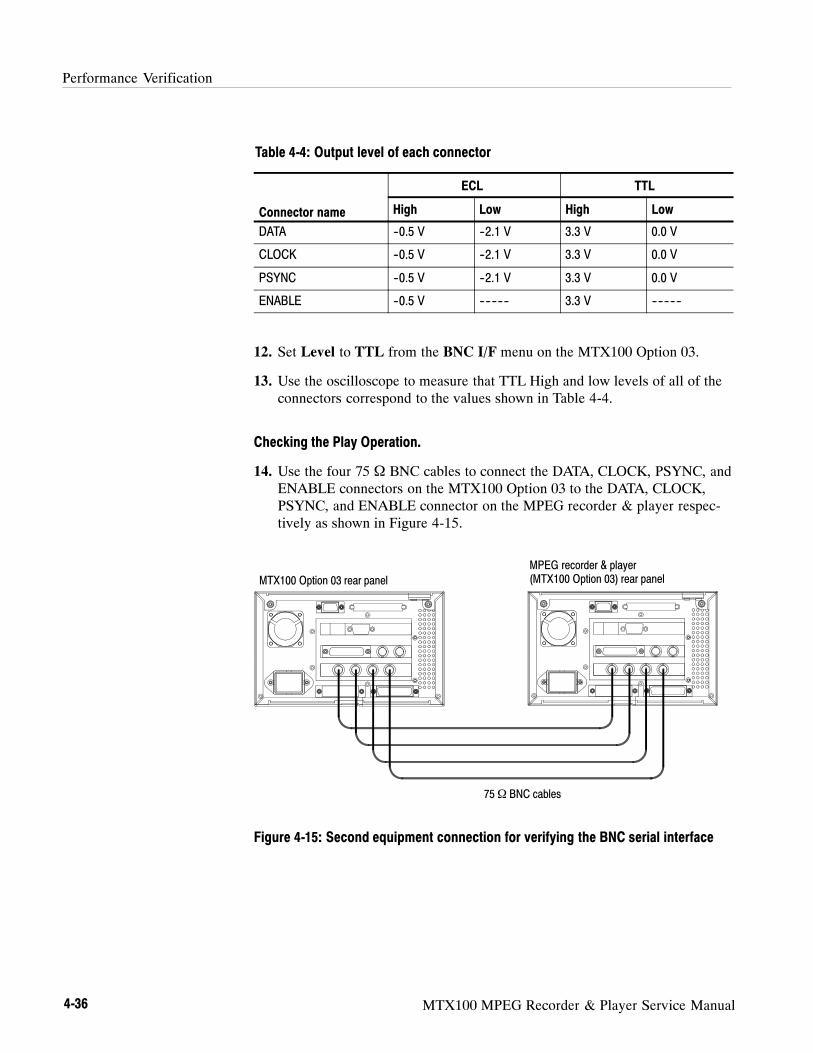
Performance Verification
4-36 MTX100 MPEG Recorder & Player Service Manual
Table 4-4: Output level of each connector
ECL TTL
Connector name High Low High Low
DATA --0.5 V --2.1 V 3.3 V 0.0 V
CLOCK --0.5 V --2.1 V 3.3 V 0.0 V
PSYNC --0.5 V --2.1 V 3.3 V 0.0 V
ENABLE --0.5 V ---------- 3.3 V ----------
12. Set Level to TTL from the BNC I/F menu on the MTX100 Option 03.
13. Use the oscilloscope to measure that TTL High and low levels of all of theconnectors correspond to the values shown in Table 4-4.
Checking the Play Operation.
14. Use the four 75 Ω BNC cables to connect the DATA, CLOCK, PSYNC, andENABLE connectors on the MTX100 Option 03 to the DATA, CLOCK,PSYNC, and ENABLE connector on the MPEG recorder & player respec-tively as shown in Figure 4-15.
75Ω BNC cables
MTX100 Option 03 rear panel
MPEG recorder & player(MTX100 Option 03) rear panel
Figure 4-15: Second equipment connection for verifying the BNC serial interface

Performance Verification
MTX100 MPEG Recorder & Player Service Manual 4-37
15. In the Play menu on the MTX100 Option 03, make the following settings:
Data rate 40 Mbps. . . .Update Off. . . . . .Source RAM. . . . . .
16. Set Level to ECL from the BNC I/F menu on the MTX100 Option 03.
17. Press the REC button on the MPEG recorder & player to display the recordscreen.
18. In the Record menu on the MPEG recorder & player, make the followingsettings:
Source BNC I/F. . . . . .Record size 100 MBytes. .Target RAM. . . . . .
19. Set Level to ECL from the BNC I/F menu on the MPEG recorder & player.
20. Press the PLAY button on the MTX100 Option 03 to start the signal outputof the test 40.TRP file.
21. Verify that the hierarchic view is displayed on the screen of the MPEGrecorder & player. In addition, verify that the bit rate display is 40 Mbps.
22. Select Save from the File menu on the MPEG recorder & player to open theSave As dialog box.
23. In the dialog box, enter BNCecl for the file name that is used to save the testfile, and then press the ENTER button.
24. Press the REC button on the MPEG recorder & player to record the appliedtest file.
25. Set Level to TTL from the BNC I/F menu on the MTX100 Option 03.
26. Set Level to TTL from the BNC I/F menu on the MPEG recorder & player.
27. Verify that the hierarchic view is displayed on the screen of the MPEGrecorder & player. In addition, verify that the bit rate display is 40 Mbps.
28. Select Save from the File menu on the MPEG recorder & player to open theSave As dialog box.
29. In the dialog box, enter BNCttl for the file name that is used to save the testfile, and then press the ENTER button.
30. Press the REC button on the MPEG recorder & player to record the appliedtest file.
31. Press the STOP button on the MTX100 Option 03 to stop the stream output.

Performance Verification
4-38 MTX100 MPEG Recorder & Player Service Manual
Checking the Record Operation.
32. Press the REC button on the MTX100 Option 03 to display the Recordscreen.
33. In the Record menu on the MTX100 Option 03, make the followingsettings:
Source BNC I/F. . . . . .Record size 100 MBytes. .Target RAM. . . . . .
34. In the BNC I/F menu on the MTX100 Option 03, make the followingsettings:
Level ECL. . . . . . .Use Psync Off. . .
35. Press the PLAY button on the MPEG recorder & player to display the Playscreen.
36. In the Play menu on the MPEG recorder & player, make the followingsettings:
Data rate 40 Mbps. . . .Update Off. . . . . .Source RAM. . . . . .
37. Set Level to ECL from the BNC I/F menu on the MPEG recorder & player.
38. Open the BNCecl file on the MPEG recorder & player.
a. Select Open from the File menu.
b. In the resulting Select File dialog box, select the BNCecl file, and thenpress the ENTER button.
39. Press the PLAY button on the MPEG recorder & player to start the signaloutput of the file.
40. Verify that the hierarchic view is displayed on the screen of the MTX100Option 03. In addition, verify that the bit rate display is 40 Mbps.
41. Select Save from the File menu on the MTX100 Option 03 to open the SaveAs dialog box.
42. In the dialog box, enter BNCecl for the file name that is used to save the testfile, and then press the ENTER button.
43. Press the REC button on the MTX100 Option 03 to record the test file.
Performance Verification
MTX100 MPEG Recorder & Player Service Manual 4-39
44. Press the STOP button on the MPEG recorder & player to stop the streamoutput.
45. Set Level to TTL from the BNC I/F menu on the MTX100 Option 03 andthe MPEG recorder & player.
46. Open the BNCttl file on the MPEG recorder & player.
a. Select Open from the File menu.
b. In the resulting Select File dialog box, select the BNCttl file, and thenpress the ENTER button.
47. Press the PLAY button on the MPEG recorder & player to start the signaloutput of the file.
48. Verify that the hierarchic view is displayed on the screen of the MTX100Option 03. In addition, verify that the bit rate display is 40 Mbps.
49. Select Save from the File menu on the MTX100 Option 03 to open the SaveAs dialog box.
50. In the dialog box, enter BNCttl for the file name that is used to save the testfile, and then press the ENTER button.
51. Press the REC button on the MTX100 Option 03 to record the BNCttl file.
52. Press the STOP button on the MPEG recorder & player to stop the streamoutput.
53. Disconnect all of the BNC cables from the MTX100 Option 03 and MPEGrecorder & player.
Checking the Recorded Files.
54. Use the parallel interface cable to connect the SPI IN/OUT connector on theMTX100 Option 03 to the SPI (LVDS) 3 IN connector on the MPEG testsystem as shown in Figure 4-16.

Performance Verification
4-40 MTX100 MPEG Recorder & Player Service Manual
Parallel interface cable
MTX100 Option 03 rear panel
MPEG test system rear panel (MTS300 Opt. LV)
Figure 4-16: Third equipment connections for verifying the BNC interface
55. Press the PLAY button on the MTX100 Option 03 to display the Playscreen.
56. Change Update to On from the Play menu on the MTX100 Option 03.
57. Open the BNCecl file on the MTX100 Option 03.
a. Select Open from the File menu.
b. In the resulting Select File dialog box, select the BNCecl file, and thenpress the ENTER button.
58. Press the PLAY button on the MTX100 Option 03 to start the signal outputof the file.
59. Double-click theMaster Client icon in the Tektronix MPEG Test Systemprogram group window on the MPEG test system to start the application.
60. Select Connect locally from theMaster menu to connect to the local ServerManager.
61. Select I/O #3 in the Port Manager panel, right click, and then selectAssign Analysis Server from the shortcut menu.
62. Select the Analysis Server icon (I/O #3), right click, and then select StartAnalysis from the short cut menu.
63. Select the Analysis Server icon, right click, and then select Launch ExpertClient. The Expert Client applications Window opens.
Performance Verification
MTX100 MPEG Recorder & Player Service Manual 4-41
64. Verify that the hierarchic view is displayed on the screen and that no errormessages appear. In addition, verify that the transmission rate is 40 Mbpsand that the transport stream packet size is 188 bytes.
65. Press the STOP button on the MTX100 Option 03 to stop the stream output.
66. Open the BNCttl file on the MTX100 Option 03.
a. Select Open from the File menu.
b. In the resulting Select File dialog box, select the BNCttl file, and thenpress the ENTER button.
67. Press the PLAY button on the MTX100 Option 03 to start the signal outputof the file.
68. Verify that the hierarchic view is displayed on the screen and that no errormessages appear. In addition, verify that the transmission rate is 40 Mbpsand that the transport stream packet size is 188 bytes.
69. Press the STOP button on the MTX100 Option 03 to stop the stream output.
This test verifies that transport stream data is correctly output from and isrecorded through the DHEI interface on the MTX100 Option 04. The followingequipment and MPEG test signal is required for this test:
MPEG recorder & player (MTX100 Option 04)
MPEG test system
High definition interface cable, GI/Motorola (415406-003)
Parallel interface cable
test40.TRP MPEG test signal
Perform the following procedure to verify that transport stream data is correctlyoutput from and is recorded through the DHEI interface on the MTX100Option 04:
Checking the Play Operation Using EXPANSION OUT.
1. Use the high definition interface cable to connect the EXPANSION OUTconnector on the MTX100 Option 04 to the EXPANSION IN connector onthe MPEG recorder & player as shown in Figure 4-17.
DHEI Interface (Option 04Only)

Performance Verification
4-42 MTX100 MPEG Recorder & Player Service Manual
High definition interface cable
MTX100 Option 04 rear panel
MPEG recorder & player(MTX100 Option 04) rear panel
Figure 4-17: Initial equipment connection for verifying the DHEI interface
2. Open the test40.TRP file on the MTX100 Option 04.
a. Select Open from the File menu.
b. In the resulting Select File dialog box, select the test40.TRP file, andthen press the ENTER button.
3. In the Play menu on the MTX100 Option 04, make the following settings:
Data rate 40 Mbps. . . .Update Off. . . . . .Source RAM. . . . . .
4. Press the REC button on the MPEG recorder & player to display the Recordscreen.
5. In the Record menu on the MPEG recorder & player, make the followingsettings:
Source DHEI. . . . . .Record size 100 MBytes. .Target RAM. . . . . .
6. Set Input Port to Expansion In from the DHEI I/F menu on the MTX100Option 04.
7. Press the PLAY button on the MTX100 Option 04 to start the signal outputof the test 40.TRP file.
8. Verify that the hierarchic view is displayed on the screen of the MPEGrecorder & player. In addition, verify that the bit rate display is 40 Mbps.
9. Select Save from the File menu on the MPEG recorder & player to open theSave As dialog box.

Performance Verification
MTX100 MPEG Recorder & Player Service Manual 4-43
10. In the dialog box, enter DHEIout for the file name that is used to save thetest file, and then press the ENTER button.
11. Press the REC button on the MPEG recorder & player to record theDHEIout file.
12. Press the STOP button on the MTX100 Option 04 to stop the stream output.
Checking the Record Operation Using EXPANSION OUT.
13. Press the REC button on the MTX100 Option 04 to display the Recordscreen.
14. In the Record menu on the MTX100 Option 04, make the followingsettings:
Source DHEI. . . . . .Record size 100 MBytes. .Target RAM. . . . . .
15. Set Input Port to Expansion Out from the DHEI I/F menu on theMTX100 Option 04.
16. Press the PLAY button on the MPEG recorder & player to display the Playscreen.
17. In the Play menu on the MPEG recorder & player, make the followingsettings:
Data rate 40 Mbps. . . .Update Off. . . . . .Source RAM. . . . . .
18. Open the DHEIout file on the MPEG recorder & player.
a. Select Open from the File menu.
b. In the resulting Select File dialog box, select the DHEIout file, and thenpress the ENTER button.
19. Press the PLAY button on the MPEG recorder & player to start the signaloutput of the file.
20. Verify that the hierarchic view is displayed on the screen of the MTX100Option 04. In addition, verify that the bit rate display is 40 Mbps.
21. Select Save from the File menu on the MTX100 Option 04 to open the SaveAs dialog box.
22. In the dialog box, enter DHEIout for the file name that is used to save thetest file, and then press the ENTER button.

Performance Verification
4-44 MTX100 MPEG Recorder & Player Service Manual
23. Press the REC button on the MTX100 Option 04 to record the DHEIoutfile.
24. Press the STOP button on the MPEG recorder & player to stop the streamoutput.
Checking the Play Operation Using EXPANSION IN.
25. Move the high definition interface cable connection from EXPANSIONOUT connector to the EXPANSION IN connector on the MTX100 Option04 as shown in Figure 4-18.
26. Move the high definition cable connection from EXPANSION IN connectorto the EXPANSION OUT connector on the MPEG recorder & player asshown in Figure 4-18.
High definition interface cable
MTX100 Option 04 rear panel
MPEG recorder & player(MTX100 Option 04) rear panel
Figure 4-18: Second equipment connection for verifying the DHEI interface
27. Press the PLAY button on the MTX100 Option 04 to display the Playscreen.
28. Open the test40.TRP file on the MTX100 Option 04.
a. Select Open from the File menu.
b. In the resulting Select File dialog box, select the test40.TRP file, andthen press the ENTER button.
29. In the Play menu on the MTX100 Option 04, make the following settings:
Data rate 40 Mbps. . . .Update Off. . . . . .Source RAM. . . . . .
Performance Verification
MTX100 MPEG Recorder & Player Service Manual 4-45
30. Press the REC button on the MPEG recorder & player to display the Recordscreen.
31. In the Record menu on the MPEG recorder & player, make the followingsettings:
Source DHEI. . . . . .Record size 100 MBytes. .Target RAM. . . . . .
32. Set Input Port to Expansion out from the DHEI I/F menu on the MPEGrecorder & player.
33. Press the PLAY button on the MTX100 Option 04 to start the signal outputof the test 40.TRP file.
34. Verify that the hierarchic view is displayed on the screen of the MPEGrecorder & player. In addition, verify that the bit rate display is 40 Mbps.
35. Select Save from the File menu on the MPEG recorder & player to open theSave As dialog box.
36. In the dialog box, enter DHEIin for the file name that is used to save the testfile, and then press the ENTER button.
37. Press the REC button on the MPEG recorder & player to record the DHEIinfile.
38. Press the STOP button on the MTX100 Option 04 to stop the stream output.
Checking the Record Operation Using EXPANSION IN.
39. Press the REC button on the MTX100 Option 04 to display the Recordscreen.
40. In the Record menu on the MTX100 Option 04, make the followingsettings:
Source DHEI. . . . . .Record size 100 MBytes. .Target RAM. . . . . .
41. Select Input Port Expansion in from the DHEI I/F menu on theMTX100 Option 04.
42. Press the PLAY button on the MPEG recorder & player to display the Playscreen.
Performance Verification
4-46 MTX100 MPEG Recorder & Player Service Manual
43. In the Play menu on the MPEG recorder & player, make the followingsettings:
Data rate 40 Mbps. . . .Update Off. . . . . .Source RAM. . . . . .
44. Open the DHEIin file on the MPEG recorder & player.
a. Select Open from the File menu.
b. In the resulting Select File dialog box, select the DHEIin file, and thenpress the ENTER button.
45. Press the PLAY button on the MPEG recorder & player to start the signaloutput of the file.
46. Verify that the hierarchic view is displayed on the screen of the MTX100Option 04. In addition, verify that the bit rate display is 40 Mbps.
47. Select Save from the File menu on the MTX100 Option 04 to open the SaveAs dialog box.
48. In the dialog box, enter DHEIin for the file name that is used to save the testfile, and then press the ENTER button.
49. Press the REC button on the MTX100 Option 04 to record the DHEIin file.
50. Press the STOP button on the MPEG recorder & player to stop the streamoutput.
51. Disconnect the high definition cable from the MTX100 Option 04 and theMPEG recorder & player.

Performance Verification
MTX100 MPEG Recorder & Player Service Manual 4-47
Checking the Recorded Files.
52. Use the parallel interface cable to connect the SPI IN/OUT connector on theMTX100 Option 04 to the SPI (LVDS) 3 IN connector on the MPEG testsystem as shown in Figure 4-19.
Parallel interface cable
MTX100 Option 04 rear panel
MPEG test system rear panel (MTS300 Opt. LV)
Figure 4-19: Third equipment connection for verifying the DHEI interface
53. Press the PLAY button on the MTX100 Option 04 to display the Playscreen.
54. Change Update to On from the Play menu on the MTX100 Option 04.
55. Open the DHEIout file on the MTX100 Option 04.
a. Select Open from the File menu.
b. In the resulting Select File dialog box, select the DHEIout file, and thenpress the ENTER button.
56. Press the PLAY button on the MTX100 Option 04 to start the signal outputof the file.
57. Double-click theMaster Client icon in the Tektronix MPEG Test Systemprogram group window on the MPEG test system to start the application.
58. Select Connect locally from theMaster menu to connect to the local ServerManager.
59. Select I/O #3 in the Port Manager panel, right click, and then selectAssign Analysis Server from the shortcut menu.

Performance Verification
4-48 MTX100 MPEG Recorder & Player Service Manual
60. Select the Analysis Server icon (I/O #3), right click, and then select StartAnalysis from the short cut menu.
61. Select the Analysis Server icon, right click, and then select Launch ExpertClient. The Expert Client applications Window opens.
62. Verify that the hierarchic view is displayed on the screen and that no errormessages appear. In addition, verify that the transmission rate is 40 Mbpsand that the transport stream packet size is 188 bytes.
63. Press the STOP button on the MTX100 to stop the stream output.
64. Open the DHEIin file on the MTX100 Option 04.
a. Select Open from the File menu.
b. In the resulting Select File dialog box, select the DHEIin file, and thenpress the ENTER button.
65. Press the PLAY button on the MTX100 Option 04 to start the signal outputof the file.
66. Verify that the hierarchic view is displayed on the screen and that no errormessages appear. In addition, verify that the transmission rate is 40 Mbpsand that the transport stream packet size is 188 bytes.
67. Press the STOP button on the MTX100 Option 04 to stop the stream output.
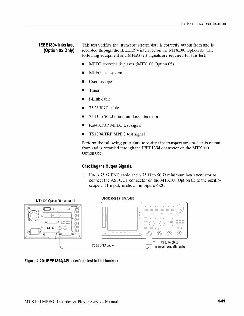
Performance Verification
MTX100 MPEG Recorder & Player Service Manual 4-49
This test verifies that transport stream data is correctly output from and isrecorded through the IEEE1394 interface on the MTX100 Option 05. Thefollowing equipment and MPEG test signals are required for this test:
MPEG recorder & player (MTX100 Option 05)
MPEG test system
Oscilloscope
Tuner
i-Link cable
75 Ω BNC cable
75 Ω to 50 Ω minimum loss attenuator
test40.TRP MPEG test signal
TS1394.TRP MPEG test signal
Perform the following procedure to verify that transport stream data is outputfrom and is recorded through the IEEE1394 connector on the MTX100Option 05:
Checking the Output Signals.
1. Use a 75 Ω BNC cable and a 75 Ω to 50 Ω minimum loss attenuator toconnect the ASI OUT connector on the MTX100 Option 05 to the oscillo-scope CH1 input, as shown in Figure 4-20.
Oscilloscope (TDS784D)
75Ω BNC cable75Ω to 50Ω
minimum loss attenuator
MTX100 Option 05 rear panel
Figure 4-20: IEEE1394/ASI interface test initial hookup
IEEE1394 Interface(Option 05 Only)

Performance Verification
4-50 MTX100 MPEG Recorder & Player Service Manual
2. Set the oscilloscope controls as indicated below:
Displayed channel CH1. . . . .Vertical scale 200 mV/div. . . . . . . . .Horizontal scale 500 ps/div. . . . . . .Acquire mode Average 64. . . . . . . .Trigger mode Auto. . . . . . . . .Trigger level 0 V. . . . . . . . .Trigger source CH1. . . . . . . .Trigger position 50%. . . . . . .Trigger slope Rising Edge. . . . . . . . .Input coupling DC. . . . . . . .Input impedance 50 Ω. . . . . .Measure Amplitude, Rise Time, Fall Time. . . . . . . . . . . . .Level Setup Histogram High Ref 80%, Low Ref 20%.
3. Open the test40.TRP file on the MTX100 Option 05.
a. Select Open from the File menu.
b. In the resulting Select File dialog box, select the test40.TRP file, andthen push the ENTER button.
4. Push the PLAY button on the MTX100 Option 05 to start the signal outputof the test40.TRP file.
5. Use the oscilloscope to verify that the amplitude, rise and fall times arewithin the following range.
Amplitude: 740 mV to 860 mVRise and fall time:≤ 1.2 ns

Performance Verification
MTX100 MPEG Recorder & Player Service Manual 4-51
Checking the Play Operation.
6. Disconnect the BNC cable from the 75 Ω to 50 Ω minimum loss attenuatoron the oscilloscope input connector, and then connect the BNC cable to theASI IN connector on the rear panel of MPEG recorder & player, as shown inFigure 4-21.
75Ω BNC cable
MPEG recorder & player(MTX100 Option 01) rear panelMTX100 Option 05 rear panel
Figure 4-21: ASI interface Play operation test
7. In the Play menu on the MTX100 Option 05, make the following settings:
Data rate 200 Mbps. . . .Update Off. . . . . .Source RAM. . . . . .
8. Push the REC button on the MPEG recorder & player to display the Recordscreen, and then make the following settings:
Source ASI. . . . . .Record size 100 MBytes. .Target RAM. . . . . .
9. Push the PLAY button on the MTX100 Option 05 to start the signal outputof the test 40.TRP file.
10. Verify that the hierarchic view is displayed on the screen of the MPEGrecorder & player. In addition, verify that the bit rate indicates 200 Mbps.
11. Select Save from the File menu on the MPEG recorder & player to open theSave As dialog box.
12. In the dialog box, enter ASItest for the file name that is used to save the testfile, and then push the ENTER button.
13. Push the REC button on the MPEG recorder & player to record the test file.
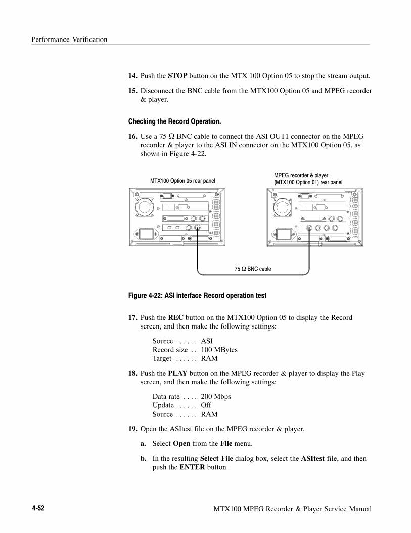
Performance Verification
4-52 MTX100 MPEG Recorder & Player Service Manual
14. Push the STOP button on the MTX 100 Option 05 to stop the stream output.
15. Disconnect the BNC cable from the MTX100 Option 05 and MPEG recorder& player.
Checking the Record Operation.
16. Use a 75 Ω BNC cable to connect the ASI OUT1 connector on the MPEGrecorder & player to the ASI IN connector on the MTX100 Option 05, asshown in Figure 4-22.
75Ω BNC cable
MPEG recorder & player(MTX100 Option 01) rear panelMTX100 Option 05 rear panel
Figure 4-22: ASI interface Record operation test
17. Push the REC button on the MTX100 Option 05 to display the Recordscreen, and then make the following settings:
Source ASI. . . . . .Record size 100 MBytes. .Target RAM. . . . . .
18. Push the PLAY button on the MPEG recorder & player to display the Playscreen, and then make the following settings:
Data rate 200 Mbps. . . .Update Off. . . . . .Source RAM. . . . . .
19. Open the ASItest file on the MPEG recorder & player.
a. Select Open from the File menu.
b. In the resulting Select File dialog box, select the ASItest file, and thenpush the ENTER button.

Performance Verification
MTX100 MPEG Recorder & Player Service Manual 4-53
20. Push the PLAY button on the MPEG recorder & player to start the signaloutput of the file.
21. Verify that the hierarchic view is displayed on the screen of the MTX100Option 05. In addition, verify that the bit rate indicates 200 Mbps.
22. Select Save from the File menu on the MTX100 Option 05 to open the SaveAs dialog box.
23. In the dialog box, enter ASItest for the file name that is used to save the testfile, and then push the ENTER button.
24. Push the REC button on the MTX100 Option 05 to record the ASItest file.
25. Push the STOP button on the MPEG recorder & player to stop the streamoutput.
26. Disconnect the BNC cable from the ASI IN connector on the MTX100Option 05.
Checking the Recorded Files.
27. Use a 75 Ω BNC cable to connect the ASI OUT connector on the MTX100Option 05 to the ASI 1 IN connector on the MPEG test system, as shown inFigure 4-23.
MPEG test system rear panel (MTS300 Opt. LV)
75Ω BNC cable
MTX100 Option 05 rear panel
Figure 4-23: ASI interface recorded files check
28. Push the PLAY button on the MTX100 Option 05 to display the Play screen.
29. Change Update to On from the Play menu on the MTX100 Option 05.
Performance Verification
4-54 MTX100 MPEG Recorder & Player Service Manual
30. Open the ASItest file on the MTX100 Option 05.
a. Select Open from the File menu.
b. In the resulting Select File dialog box, select the ASItest file, and thenpush the ENTER button.
31. Push the PLAY button on the MTX100 Option 05 to start the signal outputof the file.
32. Double-click theMaster Client icon in the Tektronix MPEG Test Systemprogram group window on the MPEG test system to start the application.
33. Select Connect locally from theMaster menu to connect to the local ServerManager.
34. Select I/O #1 in the Port Manager panel, right click, and then selectAssign Analysis Server from the shortcut menu.
35. Select the Analysis Server icon (I/O #1), right click, and then select StartAnalysis from the short cut menu.
36. Select the Analysis Server icon, right click, and then select Launch ExpertClient. The Expert Client applications Window opens.
37. Verify that the hierarchic view is displayed on the screen and that no errormessages appear. In addition, verify that the transmission rate is 40 Mbpsand that the transport stream packet size is 188 bytes.
38. Push the STOP button on the MTX100 Option 05 to stop the stream output.

Performance Verification
MTX100 MPEG Recorder & Player Service Manual 4-55
Checking the IEEE1394 Output Signals
1. Use a 75 Ω BNC cable to connect the ASI OUT1 connector on the MPEGrecorder & player to the ASI IN connector on the MTX100 Option 05, asshown in Figure 4-24.
2. Use an i-Link cable to connect the IEEE1394 port #1 on the MTX100Option 05 to the IEEE1394 port of the Tuner.
75Ω BNC cable
MPEG recorder & player(MTX100 Option 01) rear panelMTX100 Option 05 rear panel
BS/CS tuner
i-Link cable
Figure 4-24: IEEE1394 interface test
3. Push the REC button on the MPEG Option 05 to display the Record screen,and then make the following settings:
Record > Source ASI/1394. . . . . . . . . . .ASI/1394 > Input Port ASI. . . . . .ASI/1394 > Partial TS ON. . . . . .ASI/1394 > 1394Mode PtoP Connect.... . . . . .
4. The IEEE1394 dialog box appears.
5. Select the name of connected Tuner, such as TU-BHD100, from theInstrument pull-down menu, and then select the Connect button.
6. Verify that the i-Link lamp of Tuner lights when you click the OK button.
7. Push the PLAY button on the MPEG recorder & player to start the signaloutput of the TS1394.TRP file.
8. Verify the following on the Record screen:
a. Partial TS and 192 are displayed on the Status bar.
b. The hierarchic structure is properly displayed in the Hierarchy Display.

Performance Verification
4-56 MTX100 MPEG Recorder & Player Service Manual
9. Open the ASItest file on the MTX100 Option 05.
a. Select Open from the File menu.
b. In the resulting Select File dialog box, select the ASItest file, and thenpush the ENTER button.
10. Push the REC button on the MTX100 Option 05 to record the ASItest file(Over Write).
11. Change the MTX100 Option 05 to PLAY Mode.
12. Click the PtoP Connect button to disconnect the IEEE1394 connection.
13. Disconnect the i-Link cable from the IEEE1394 port #1 connector and thenconnect it to the IEEE1394 port #2 connector on the MTX100 Option 05.
14. Click the PtoP Connect button to establish the IEEE1394 connection.
15. Push the PLAY button to activate the signal output.
16. Verify that Partial TS and 192 are displayed on the Status bar.
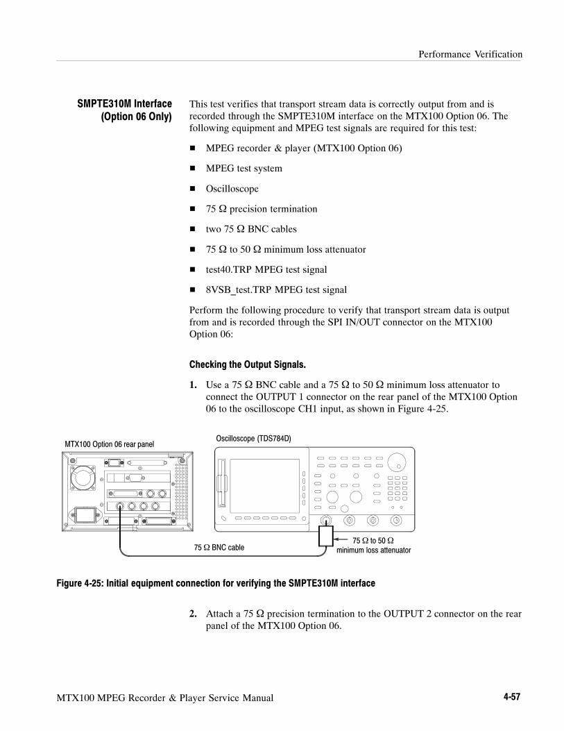
Performance Verification
MTX100 MPEG Recorder & Player Service Manual 4-57
This test verifies that transport stream data is correctly output from and isrecorded through the SMPTE310M interface on the MTX100 Option 06. Thefollowing equipment and MPEG test signals are required for this test:
MPEG recorder & player (MTX100 Option 06)
MPEG test system
Oscilloscope
75 Ω precision termination
two 75 Ω BNC cables
75 Ω to 50 Ω minimum loss attenuator
test40.TRP MPEG test signal
8VSB_test.TRP MPEG test signal
Perform the following procedure to verify that transport stream data is outputfrom and is recorded through the SPI IN/OUT connector on the MTX100Option 06:
Checking the Output Signals.
1. Use a 75 Ω BNC cable and a 75 Ω to 50 Ω minimum loss attenuator toconnect the OUTPUT 1 connector on the rear panel of the MTX100 Option06 to the oscilloscope CH1 input, as shown in Figure 4-25.
Oscilloscope (TDS784D)
75Ω BNC cable75Ω to 50Ω
minimum loss attenuator
MTX100 Option 06 rear panel
Figure 4-25: Initial equipment connection for verifying the SMPTE310M interface
2. Attach a 75 Ω precision termination to the OUTPUT 2 connector on the rearpanel of the MTX100 Option 06.
SMPTE310M Interface(Option 06 Only)
Performance Verification
4-58 MTX100 MPEG Recorder & Player Service Manual
3. Set the oscilloscope controls as indicated below:
Displayed channel CH1. . . . .Vertical scale 200 mV/div. . . . . . . . .Horizontal scale 1 ns/div. . . . . . .Trigger position 30%. . . . . . .Acquire mode Average 64. . . . . . . .Trigger mode Auto. . . . . . . . .Trigger source CH1. . . . . . . .Trigger slope Rising Edge. . . . . . . . .Input coupling DC. . . . . . . .Input impedance 50 Ω. . . . . .Measure Amplitude, Rise Time, Fall Time. . . . . . . . . . . . .Level Setup Histogram High Ref 80%, Low Ref 20%.
4. Set the MTX100 Option 06 output to ASI.
ASI/310M > Port : 8VSB
5. Use the oscilloscope to measure that the amplitude, rise and fall times are asfollows.
Amplitude: 740 mV to 860 mVRise and fall time:≤ 1.2 ns
6. Move the BNC cable connection from the OUTPUT 1 connector to theOUTPUT 2 connector on the MTX100 Option 06.
7. Remove the 75 Ω precision termination from the OUTPUT 2 connector, andthen attach it to the OUTPUT 1 connector.
8. Repeat step 5.
9. Remove the 75 Ω precision termination from the OUTPUT 1 connector.
10. User another 75 Ω BNC cable to connect the OUTPUT 1 connector and theINPUT connector on the MTX100 Option 06.
11. Disconnect the BNC cable from the OUTPUT 2 connector, and then connectit to the through output of INPUT connector.
12. Repeat step 5.

Performance Verification
MTX100 MPEG Recorder & Player Service Manual 4-59
Checking the ASI Play Operation.
13. Disconnect the BNC cable from the 75 Ω to 50 Ω minimum loss attenuatoron the oscilloscope input, and then connect it to the INPUT connector on theMPEG recorder & player.
14. Disconnect the BNC cable from the through output of the INPUT connector,and then connect it to the OUTPUT 2 connector on the MTX100 Option 06,as shown in Figure 4-26.
75Ω BNC cable
MTX100 Option 06 rear panel
MPEG recorder & player(MTX100 Option 06) rear panel
75Ω BNC cable
Figure 4-26: SMPTE310M/ASI interface test
15. In the Play menu on the MTX100 Option 06, make the following settings:
Data rate 200 Mbps. . . .Update Off. . . . . .Source RAM. . . . . .
16. Push the REC button on the MPEG recorder & player to display the Recordscreen, and then make the following settings:
Source ASI/310M. . . . . .Record size 100 MBytes. .Target RAM. . . . . .
17. Push the PLAY button on the MTX100 Option 06 to start the signal outputof the test 40.TRP file.
18. Verify that the hierarchic view is displayed on the screen of the MPEGrecorder & player. In addition, verify that the bit rate indicates 200 Mbps.
19. Select Save from the File menu on the MPEG recorder & player to open theSave As dialog box.

Performance Verification
4-60 MTX100 MPEG Recorder & Player Service Manual
20. In the dialog box, enter Out2test for the file name that is used to save thetest file, and then push the ENTER button.
21. Push the REC button on the MPEG recorder & player to record the test file.
22. Move the BNC cable connection from the OUTPUT 2 connector to thethrough output of the INPUT connector on the MTX100 Option 06.
23. Verify that the hierarchic view is displayed on the screen of the MPEGrecorder & player. In addition, verify that the bit rate indicates 200 Mbps.
24. Select Save from the File menu on the MPEG recorder & player to open theSave As dialog box.
25. In the dialog box, enter Looptest for the file name that is used to save thetest file, and then push the ENTER button.
26. Push the REC button on the MPEG recorder & player to record the test file.
27. Push the STOP button on the MTX 100 Option 06 to stop the stream output.
28. Disconnect the two BNC cables from the MTX100 Option 06 and MPEGrecorder & player.
Checking the ASI Record Operation.
29. Use a 75 Ω BNC cable to connect the OUTPUT 1 connector on the MPEGrecorder & player to the INPUT connector on the MTX100 Option 06, asshown in Figure 4-27.
75Ω BNC cable
MTX100 Option 06 rear panelMPEG recorder & player(MTX100 Option 06) rear panel
Figure 4-27: SMPTE310M/ASI interface Record operation test

Performance Verification
MTX100 MPEG Recorder & Player Service Manual 4-61
30. Push the REC button on the MTX100 Option 06 to display the Recordscreen, and then make the following settings:
Source ASI/310M. . . . . .Record size 100 MBytes. .Target RAM. . . . . .
31. Push the PLAY button on the MPEG recorder & player to display the Playscreen, and then make the following settings:
Data rate 200 Mbps. . . .Update Off. . . . . .Source RAM. . . . . .
32. Open the Out2test file on the MPEG recorder & player.
a. Select Open from the File menu.
b. In the resulting Select File dialog box, select the Out2test file, and thenpush the ENTER button.
33. Push the PLAY button on the MPEG recorder & player to start the signaloutput of the file.
34. Verify that the hierarchic view is displayed on the screen of the MTX100Option 06. In addition, verify that the bit rate indicates 200 Mbps.
35. Select Save from the File menu on the MTX100 Option 06 to open the SaveAs dialog box.
36. In the dialog box, enter Out2test for the file name that is used to save thetest file, and then push the ENTER button.
37. Push the REC button on the MTX100 Option 06 to record the Out2test file.
38. Push the STOP button on the MPEG recorder & player to stop the streamoutput.
39. Open the Looptest file on the MPEG recorder & player.
a. Select Open from the File menu.
b. In the resulting Select File dialog box, select the Looptest file, and thenpush the ENTER button.
40. Push the PLAY button on the MPEG recorder & player to start the signaloutput of the file.
41. Verify that the hierarchic view is displayed on the screen of the MTX100Option 06. In addition, verify that the bit rate indicates 200 Mbps.

Performance Verification
4-62 MTX100 MPEG Recorder & Player Service Manual
42. Select Save from the File menu on the MTX100 Option 01 to open the SaveAs dialog box.
43. In the dialog box, enter Looptest for the file name that is used to save thetest file, and then push the ENTER button.
44. Push the REC button on the MTX100 Option 06 to record the Looptest file.
45. Push the STOP button on the MPEG recorder & player to stop the streamoutput.
46. Disconnect the BNC cable from the INPUT connector on the MTX100Option 06.
Checking the Recorded Files.
47. Use a 75 Ω BNC cable to connect the OUTPUT1 connector on the MTX100Option 06 to the ASI 1 IN connector on the MPEG test system as shown inFigure 4-28.
MPEG test system rear panel (MTS300 Opt. LV)
75Ω BNC cable
MTX100 Option 06 rear panel
Figure 4-28: ASI interface recorded files check
48. Push the PLAY button on the MTX100 Option 06 to display the Play screen.
49. Change Update to On from the Play menu on the MTX100 Option 06.
50. Open the Out2test file on the MTX100 Option 06.
a. Select Open from the File menu.
b. In the resulting Select File dialog box, select the Out2test file, and thenpush the ENTER button.

Performance Verification
MTX100 MPEG Recorder & Player Service Manual 4-63
51. Push the PLAY button on the MTX100 Option 06 to start the signal outputof the file.
52. Double-click theMaster Client icon in the Tektronix MPEG Test Systemprogram group window on the MPEG test system to start the application.
53. Select Connect locally from theMaster menu to connect to the local ServerManager.
54. Select I/O #1 in the Port Manager panel, right click, and then selectAssign Analysis Server from the shortcut menu.
55. Select the Analysis Server icon (I/O #1), right click, and then select StartAnalysis from the short cut menu.
56. Select the Analysis Server icon, right click, and then select Launch ExpertClient. The Expert Client applications Window opens.
57. Verify that the hierarchic view is displayed on the screen and that no errormessages appear. In addition, verify that the transmission rate is 40 Mbpsand that the transport stream packet size is 188 bytes.
58. Push the STOP button on the MTX100 Option 06 to stop the stream output.
59. Open the Looptest file on the MTX100 Option 06.
a. Select Open from the File menu.
b. In the resulting Select File dialog box, select the Looptest file, and thenpush the ENTER button.
60. Push the PLAY button on the MTX100 Option 06 to start the signal outputof the file.
61. Verify that the hierarchic view is displayed on the screen and that no errormessages appear. In addition, verify that the transmission rate is 40 Mbpsand that the transport stream packet size is 188 bytes.
62. Push the STOP button on the MTX100 Option 06 to stop the stream output.
63. Disconnect the BNC cable from the INPUT connector on the MTX100Option 06.
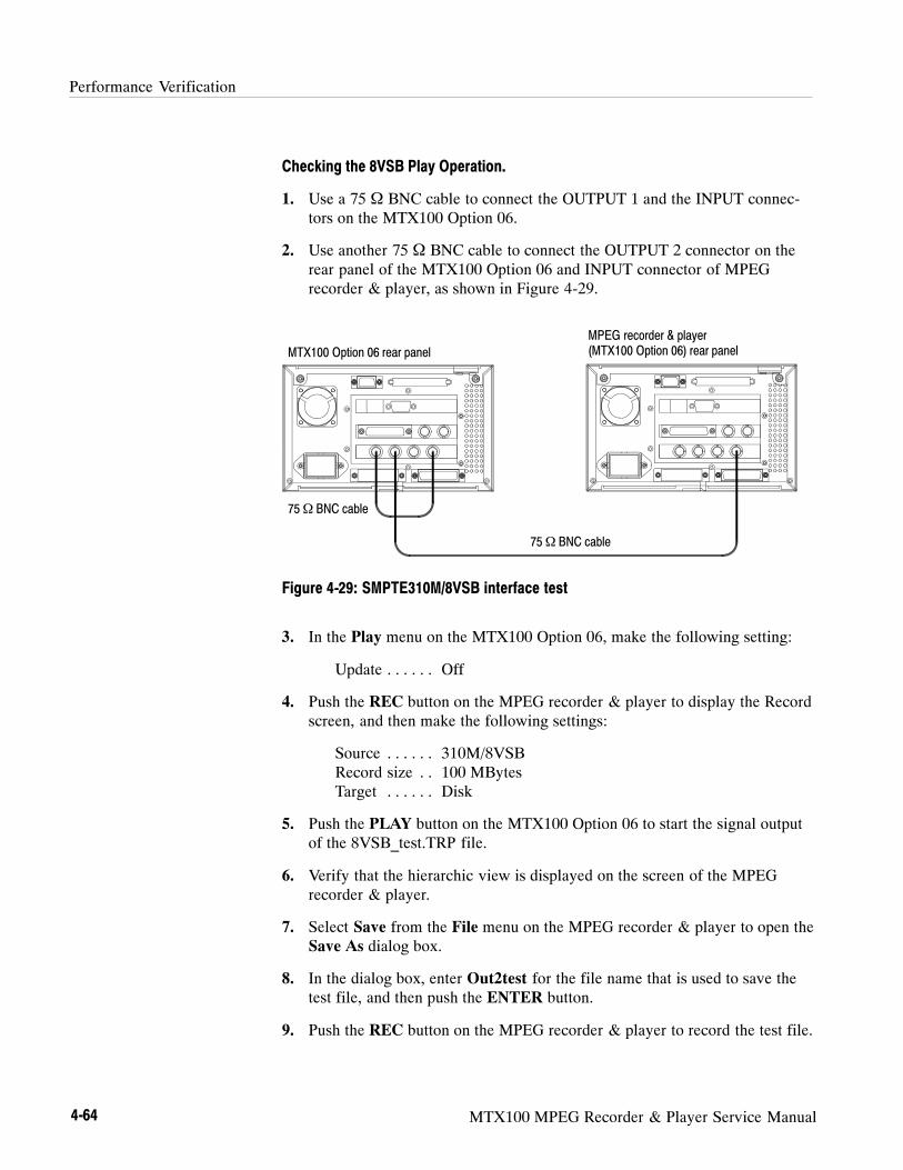
Performance Verification
4-64 MTX100 MPEG Recorder & Player Service Manual
Checking the 8VSB Play Operation.
1. Use a 75 Ω BNC cable to connect the OUTPUT 1 and the INPUT connec-tors on the MTX100 Option 06.
2. Use another 75 Ω BNC cable to connect the OUTPUT 2 connector on therear panel of the MTX100 Option 06 and INPUT connector of MPEGrecorder & player, as shown in Figure 4-29.
75Ω BNC cable
MTX100 Option 06 rear panel
MPEG recorder & player(MTX100 Option 06) rear panel
75Ω BNC cable
Figure 4-29: SMPTE310M/8VSB interface test
3. In the Play menu on the MTX100 Option 06, make the following setting:
Update Off. . . . . .
4. Push the REC button on the MPEG recorder & player to display the Recordscreen, and then make the following settings:
Source 310M/8VSB. . . . . .Record size 100 MBytes. .Target Disk. . . . . .
5. Push the PLAY button on the MTX100 Option 06 to start the signal outputof the 8VSB_test.TRP file.
6. Verify that the hierarchic view is displayed on the screen of the MPEGrecorder & player.
7. Select Save from the File menu on the MPEG recorder & player to open theSave As dialog box.
8. In the dialog box, enter Out2test for the file name that is used to save thetest file, and then push the ENTER button.
9. Push the REC button on the MPEG recorder & player to record the test file.
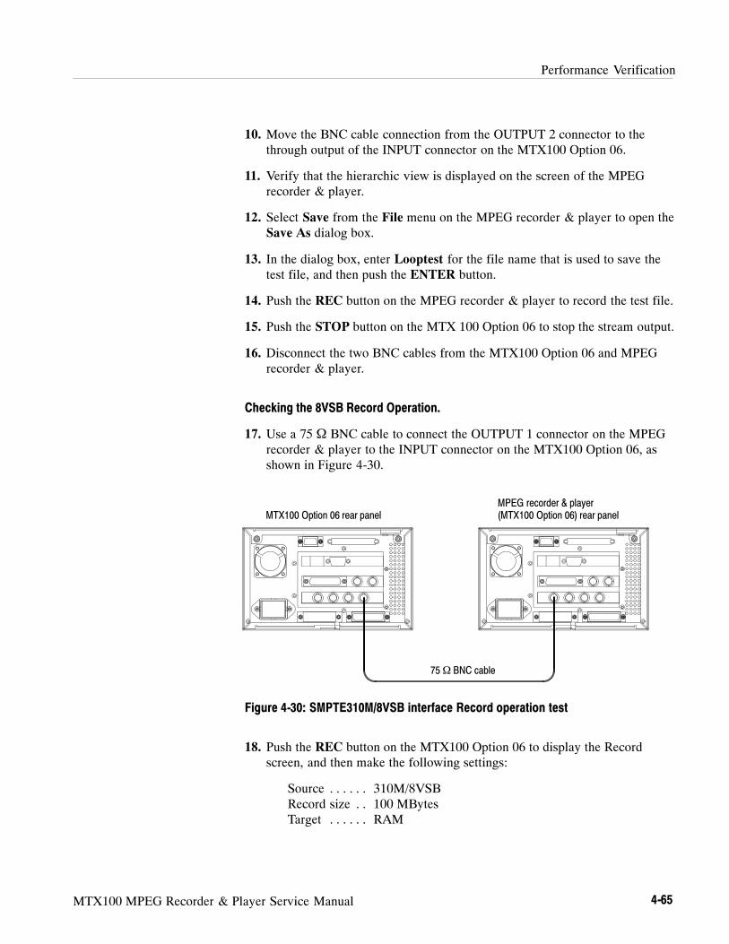
Performance Verification
MTX100 MPEG Recorder & Player Service Manual 4-65
10. Move the BNC cable connection from the OUTPUT 2 connector to thethrough output of the INPUT connector on the MTX100 Option 06.
11. Verify that the hierarchic view is displayed on the screen of the MPEGrecorder & player.
12. Select Save from the File menu on the MPEG recorder & player to open theSave As dialog box.
13. In the dialog box, enter Looptest for the file name that is used to save thetest file, and then push the ENTER button.
14. Push the REC button on the MPEG recorder & player to record the test file.
15. Push the STOP button on the MTX 100 Option 06 to stop the stream output.
16. Disconnect the two BNC cables from the MTX100 Option 06 and MPEGrecorder & player.
Checking the 8VSB Record Operation.
17. Use a 75 Ω BNC cable to connect the OUTPUT 1 connector on the MPEGrecorder & player to the INPUT connector on the MTX100 Option 06, asshown in Figure 4-30.
75Ω BNC cable
MTX100 Option 06 rear panelMPEG recorder & player(MTX100 Option 06) rear panel
Figure 4-30: SMPTE310M/8VSB interface Record operation test
18. Push the REC button on the MTX100 Option 06 to display the Recordscreen, and then make the following settings:
Source 310M/8VSB. . . . . .Record size 100 MBytes. .Target RAM. . . . . .

Performance Verification
4-66 MTX100 MPEG Recorder & Player Service Manual
19. Push the PLAY button on the MPEG recorder & player to display the Playscreen, and then make the following settings:
Update Off. . . . . .
20. Open the Out2test file on the MPEG recorder & player.
a. Select Open from the File menu.
b. In the resulting Select File dialog box, select the Out2test file, and thenpush the ENTER button.
21. Push the PLAY button on the MPEG recorder & player to start the signaloutput of the file.
22. Verify that the hierarchic view is displayed on the screen of the MTX100Option 06.
23. Select Save from the File menu on the MTX100 Option 06 to open the SaveAs dialog box.
24. In the dialog box, enter Out2test for the file name that is used to save thetest file, and then push the ENTER button.
25. Push the REC button on the MTX100 Option 06 to record the Out2test file.
26. Push the STOP button on the MPEG recorder & player to stop the streamoutput.
27. Open the Looptest file on the MPEG recorder & player.
a. Select Open from the File menu.
b. In the resulting Select File dialog box, select the Looptest file, and thenpush the ENTER button.
28. Push the PLAY button on the MPEG recorder & player to start the signaloutput of the file.
29. Verify that the hierarchic view is displayed on the screen of the MTX100Option 06.
30. Select Save from the File menu on the MTX100 Option 01 to open the SaveAs dialog box.
31. In the dialog box, enter Looptest for the file name that is used to save thetest file, and then push the ENTER button.
32. Push the REC button on the MTX100 Option 06 to record the Looptest file.
33. Push the STOP button on the MPEG recorder & player to stop the streamoutput.

Performance Verification
MTX100 MPEG Recorder & Player Service Manual 4-67
34. Disconnect the BNC cable from the INPUT connector on the MTX100Option 06.
Checking the Recorded Files.
35. Use a 75 Ω BNC cable to connect the OUTPUT1 connector on the MTX100Option 06 to the ASI 1 IN connector on the MPEG test system, as shown inFigure 4-31.
MPEG test system rear panel (MTS300 Opt. LV)
75Ω BNC cable
MTX100 Option 06 rear panel
Figure 4-31: 8VSB interface recorded files check
36. Push the PLAY button on the MTX100 Option 06 to display the Play screen.
37. Change Update to On from the Play menu on the MTX100 Option 06.
38. Open the Out2test file on the MTX100 Option 06.
a. Select Open from the File menu.
b. In the resulting Select File dialog box, select the Out2test file, and thenpush the ENTER button.
39. Push the PLAY button on the MTX100 Option 06 to start the signal outputof the file.
40. Double-click theMaster Client icon in the Tektronix MPEG Test Systemprogram group window on the MPEG test system to start the application.
41. Select Connect locally from theMaster menu to connect to the local ServerManager.

Performance Verification
4-68 MTX100 MPEG Recorder & Player Service Manual
42. Select I/O #1 in the Port Manager panel, right click, and then selectAssign Analysis Server from the shortcut menu.
43. Select the Analysis Server icon (I/O #1), right click, and then select StartAnalysis from the short cut menu.
44. Select the Analysis Server icon, right click, and then select Launch ExpertClient. The Expert Client applications Window opens.
45. Verify that the hierarchic view is displayed on the screen and that no errormessages appear. In addition, verify that the transmission rate is19.392 Mbps and that the transport stream packet size is 188 bytes.
46. Push the STOP button on the MTX100 Option 06 to stop the stream output.
47. Open the Looptest file on the MTX100 Option 06.
a. Select Open from the File menu.
b. In the resulting Select File dialog box, select the Looptest file, and thenpush the ENTER button.
48. Push the PLAY button on the MTX100 Option 06 to start the signal outputof the file.
49. Verify that the hierarchic view is displayed on the screen and that no errormessages appear. In addition, verify that the transmission rate is19.392 Mbps and that the transport stream packet size is 188 bytes.
50. Push the STOP button on the MTX100 Option 06 to stop the stream output.
MTX100 MPEG Recorder & Player Service Manual 5-1
Adjustment Procedures
The MTX100 does not require any adjustments.

Adjustment Procedures
5-2 MTX100 MPEG Recorder & Player Service Manual

MTX100 MPEG Recorder & Player Service Manual 6-1
Maintenance
This section contains the information needed to do periodic and correctivemaintenance on the MTX100. The following subsections are included:
Preparation— Introduction plus general information on preventing damageto internal modules when doing maintenance.
Inspection and Cleaning— Information and procedures for inspecting theMTX100 and cleaning its external and internal modules.
Removal and Installation Procedures— Procedures for the removal ofdefective modules and replacement of new or repaired modules.
Troubleshooting— Information for isolating and troubleshooting failedmodules. Included is troubleshooting trees.
Using the Recovery Discs— Procedures for reinstalling the Windows 2000operating system and the MTX100 application if the MTX100 does not boot.
Selecting the Serial Interface Standard— Procedures for setting the serialinterface standard (RS-232C, RS-422, or RS-485) for COM2 port on the rearpanel.
Related Maintenance Procedures
The following sections contain information and procedures related to mainte-nance.
Section 2, Operating Information, covers instructions useful when operatingthe MTX100 in order to troubleshoot it.
Section 3, Theory of Operation, contains a circuit description at the moduleor block level.
Section 4, Performance Verification, contains procedures that may be usefulin isolating problems to modules by testing the MTX100 performance.
Section 9, Diagrams, contains a block diagram using individual modules asblocks and an interconnection diagram showing connections between themodules.
Section 10, Mechanical Parts List, lists all field replaceable modules by partnumber.

Maintenance
6-2 MTX100 MPEG Recorder & Player Service Manual
Preparation
Before servicing this product, read the Safety Summary and Introduction at thefront of the manual and the ESD information below.
CAUTION. Static discharge can damage any semiconductor component in the
MTX100.
When performing any service which requires internal access to the MTX100,adhere to the following precautions to avoid damaging internal modules and theircomponents due to electrostatic discharge (ESD).
1. Minimize handling of static-sensitive modules.
2. Transport and store static-sensitive modules in their static protectedcontainers or on a metal rail. Label any package that contains static-sensitivemodules.
3. Discharge the static voltage from your body by wearing a grounded antistaticwrist strap while handling these modules. Perform service of static-sensitivemodules only at a static-free work station.
4. Nothing capable of generating or holding a static charge should be allowedon the work station surface.
5. Handle circuit boards by the edges when possible.
6. Do not slide the modules over any surface.
7. Avoid handling modules in areas that have a floor or work-surface coveringcapable of generating a static charge.
Preventing ESD
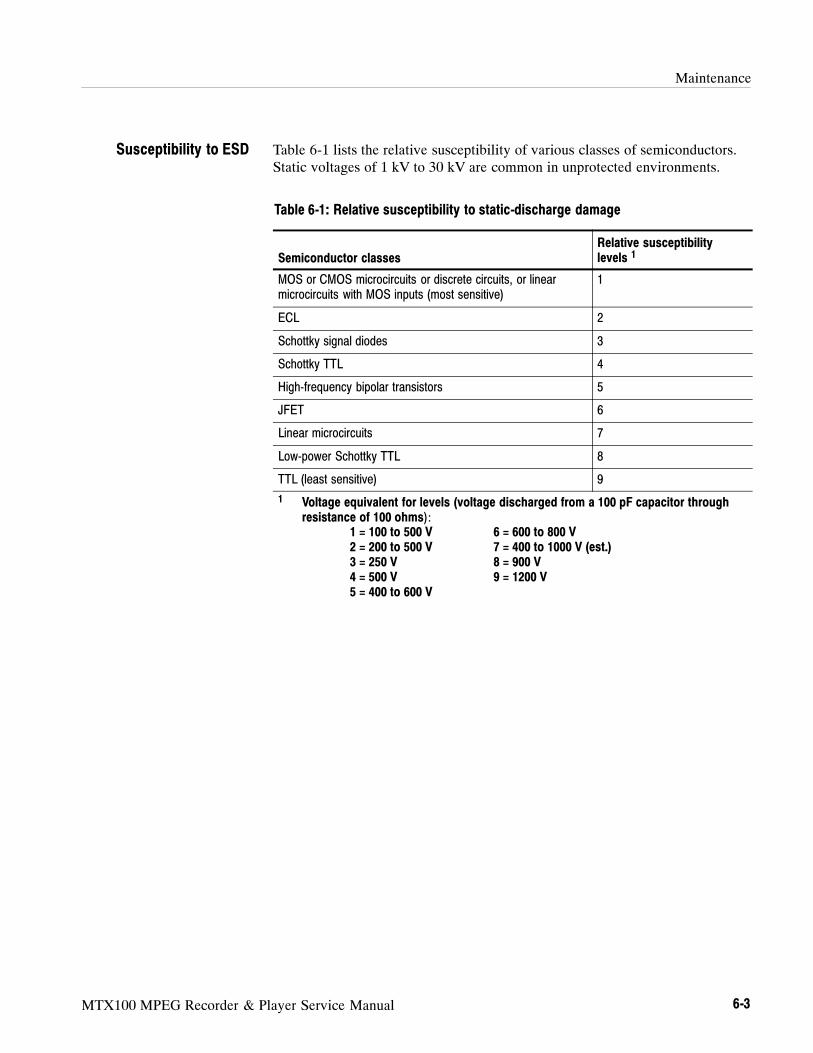
Maintenance
MTX100 MPEG Recorder & Player Service Manual 6-3
Table 6-1 lists the relative susceptibility of various classes of semiconductors.Static voltages of 1 kV to 30 kV are common in unprotected environments.
Table 6-1: Relative susceptibility to static-discharge damage
Semiconductor classesRelative susceptibilitylevels 1
MOS or CMOS microcircuits or discrete circuits, or linearmicrocircuits with MOS inputs (most sensitive)
1
ECL 2
Schottky signal diodes 3
Schottky TTL 4
High-frequency bipolar transistors 5
JFET 6
Linear microcircuits 7
Low-power Schottky TTL 8
TTL (least sensitive) 9
1 Voltage equivalent for levels (voltage discharged from a 100 pF capacitor throughresistance of 100 ohms):
1 = 100 to 500 V 6 = 600 to 800 V2 = 200 to 500 V 7 = 400 to 1000 V (est.)3 = 250 V 8 = 900 V4 = 500 V 9 = 1200 V5 = 400 to 600 V
Susceptibility to ESD

Maintenance
6-4 MTX100 MPEG Recorder & Player Service Manual
Inspection and Cleaning
Inspection and Cleaning describes how to inspect for dirt and damage. It alsodescribes how to clean the exterior and interior of the MTX100. Inspection andcleaning are done as preventive maintenance. Preventive maintenance, whendone regularly, may prevent the MTX100 from malfunctioning and enhance itsreliability.
Preventive maintenance consists of visually inspecting and cleaning theMTX100 and using general care when operating it.
How often preventative maintenance should be performed depends on theseverity of the environment in which the MTX100 is used. A proper time toperform preventive maintenance is just before the MTX100 adjustment.
The cabinet helps keep dust out of the MTX100, and is needed to meet EMI andcooling requirements. The cabinet should be in place when operating theMTX100. The MTX100’s front cover protects the front panel and display fromdust and damage. Install the front cover when storing or transporting theMTX100.
Inspect and clean the MTX100 as often as operating conditions require. Thecollection of dirt on components inside can cause them to overheat and break-down. (Dirt acts like an insulating blanket, preventing efficient heat dissipation.)Dirt also provides an electrical conduction path that could cause an MTX100failure, especially under high-humidity conditions.
CAUTION. Avoid the use of chemical cleaning agents that might damage the
plastics used in this MTX100. Use only deionized water when cleaning the menu
buttons or front-panel buttons. Use an ethyl alcohol solution as a cleaner and
rinse with deionized water.
Inspection — Exterior. Inspect the outside of the MTX100 for damage, wear, andmissing parts, using Table 6-2 as a guide. An MTX100 that appears to have beendropped or otherwise abused should be checked thoroughly to verify correctoperation and performance. Immediately repair defects that could cause personalinjury or lead to further damage to the MTX100.
General Care
Inspection and CleaningProcedures

Maintenance
MTX100 MPEG Recorder & Player Service Manual 6-5
Table 6-2: External inspection check list
Item Inspect for Repair action
Cabinet, front panel,and cover
Cracks, scratches, deformations,damaged hardware or gaskets.
Repair or replace defectivemodule.
Front-panel buttons Missing, damaged, or loosebuttons.
Repair or replace missing ordefective buttons.
Connectors Broken shells, cracked insulation,and deformed contacts. Dirt inconnectors.
Repair or replace defectivemodules. Clear or wash out dirt.
Accessories Missing items or parts of items,bent pins, broken or frayedcables, and damaged connec-tors.
Repair or replace damaged ormissing items, frayed cables, anddefective modules.
Cleaning Procedure — Exterior. To clean the MTX100 exterior, perform thefollowing steps:
1. Remove loose dust on the outside of the MTX100 with a lint free cloth.
2. Remove remaining dirt with a lint free cloth dampened in a general purposedetergent-and-water solution. Do not use abrasive cleaners.
3. Clean the light filter protecting the monitor screen with a lint-free clothdampened with a gentle, general purpose detergent-and-water solution.
CAUTION. To prevent getting moisture inside the MTX100 during external
cleaning, use only enough liquid to dampen the cloth or applicator.

Maintenance
6-6 MTX100 MPEG Recorder & Player Service Manual
Inspection — Interior. To access the inside of the MTX100 for inspection andcleaning, refer to the Removal and Installation Procedures in this section.
Inspect the internal portions of the MTX100 for damage and wear, using Table6-3 as a guide. Defects found should be repaired immediately.
CAUTION. To prevent damage from electrical arcing, ensure that circuit boards
and components are dry before applying power to the MTX100.
Table 6-3: Internal inspection check list
Item Inspect for Repair action
Circuit boards Loose, broken, or corrodedsolder connections. Burnedcircuit boards. Burned, broken, orcracked circuit-run plating.
Remove failed module andreplace with a fresh module.
Resistors Burned, cracked, broken, blis-tered condition.
Remove failed module andreplace with a fresh module.
Solder connections Cold solder or rosin joints. Resolder joint and clean withisopropyl alcohol.
Capacitors Damaged or leaking cases.Corroded solder on leads orterminals.
Remove damaged module andreplace with a fresh module fromthe factory.
Semiconductors Loosely inserted in sockets.Distorted pins.
Firmly seat loose semiconduc-tors. Remove devices that havedistorted pins. Carefully straight-en pins (as required to fit thesocket), using long-nose pliers,and reinsert firmly. Ensure thatstraightening action does notcrack pins, causing them tobreak off.
Wiring and cables Loose plugs or connectors.Burned, broken, or frayed wiring.
Firmly seat connectors. Repair orreplace modules with defectivewires or cables.
Chassis Dents, deformations, and dam-aged hardware.
Straighten, repair, or replacedefective hardware.
Maintenance
MTX100 MPEG Recorder & Player Service Manual 6-7
Cleaning Procedure — Interior. To clean the MTX100 interior, perform thefollowing steps:
1. Blow off dust with dry, low-pressure, deionized air (approximately 9 psi).
2. Remove any remaining dust with a lint-free cloth dampened in ethyl alcoholand rinse with warm deionized water. (A cotton-tipped applicator is usefulfor cleaning in narrow spaces and on circuit boards.)
STOP. If, after performing steps 1 and 2, a module is clean upon inspection, skip
the remaining steps.
3. If steps 1 and 2 do not remove all the dust or dirt, the MTX100 may be spraywashed using a solution of ethyl alcohol by performing steps 4 through 8.
4. Gain access to the parts to be cleaned by removing easily accessible shieldsand panels (see Removal and Installation Procedures).
5. Spray wash dirty parts with the ethyl alcohol and wait 60 seconds for themajority of the alcohol to evaporate.
6. Use hot (120 F to 140 F) deionized water to thoroughly rinse them.
7. Dry all parts with low-pressure, deionized air.
8. Dry all components and assemblies in an oven or drying compartment usinglow-temperature (125 F to 150 F) circulating air.
Lubrication. There is no periodic lubrication required for the MTX100.
Maintenance
6-8 MTX100 MPEG Recorder & Player Service Manual

MTX100 MPEG Recorder & Player Service Manual 6-9
Removal and Installation Procedures
This subsection contains procedures for removal and installation of all mechani-cal and electrical modules. Any electrical or mechanical module, assembly, orpart listed in Section 10 of this manual is a module.
Preparation
WARNING. Before performing this or any other procedure in this manual, read
the Safety Summary found at the beginning of this manual. Also, to preventpossible injury to service personnel or damage to the MTX100’s components,
read Installation in Section 2, and Preventing ESD in this section.
This subsection contains the following items:
Preparatory information that you need to properly perform the proceduresthat follow.
List of tools required to remove and disassemble all modules.
Four module locator diagrams for finding the External modules (see Figure6-2, on page 6-13), Board modules (see Figure 6-3, on page 6-14), Internalmodules (see Figure 6-4, on page 6-15), and Rear Panel modules (see Figure6-5, on page 6-16) in the MTX100.
Procedures for removal and reinstallation of the electrical and mechanicalmodules.
A disassembly procedure for removal of all the major modules from theMTX100 at one time and for reassembly of those modules into the MTX100.Such a complete disassembly is normally only done when completelycleaning the MTX100. (Instructions for doing the actual cleaning are foundunder Inspection and Cleaning at the beginning of this section.)
Module disassembly procedures.
WARNING. Before performing any procedure in this subsection, disconnect the
power cord from the line voltage source. Failure to do so could cause serious
injury or death.
Section 10 lists all modules.List of Modules
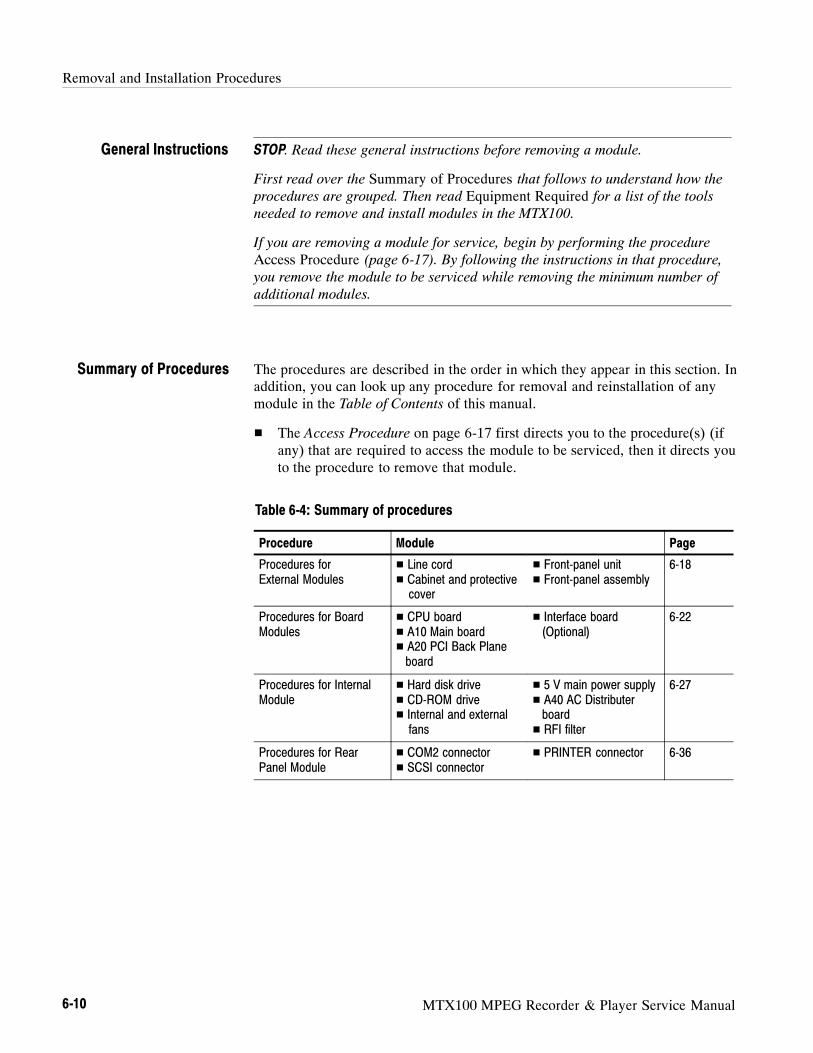
Removal and Installation Procedures
6-10 MTX100 MPEG Recorder & Player Service Manual
STOP. Read these general instructions before removing a module.
First read over the Summary of Procedures that follows to understand how the
procedures are grouped. Then read Equipment Required for a list of the toolsneeded to remove and install modules in the MTX100.
If you are removing a module for service, begin by performing the procedure
Access Procedure (page 6-17). By following the instructions in that procedure,you remove the module to be serviced while removing the minimum number of
additional modules.
The procedures are described in the order in which they appear in this section. Inaddition, you can look up any procedure for removal and reinstallation of anymodule in the Table of Contents of this manual.
The Access Procedure on page 6-17 first directs you to the procedure(s) (ifany) that are required to access the module to be serviced, then it directs youto the procedure to remove that module.
Table 6-4: Summary of procedures
Procedure Module Page
Procedures forExternal Modules
Line cord Cabinet and protectivecover
Front-panel unit Front-panel assembly
6-18
Procedures for BoardModules
CPU board A10 Main board A20 PCI Back Planeboard
Interface board(Optional)
6-22
Procedures for InternalModule
Hard disk drive CD-ROM drive Internal and externalfans
5 V main power supply A40 AC Distributerboard RFI filter
6-27
Procedures for RearPanel Module
COM2 connector SCSI connector
PRINTER connector 6-36
General Instructions
Summary of Procedures

Removal and Installation Procedures
MTX100 MPEG Recorder & Player Service Manual 6-11
Equipment Required.Most modules in this MTX100 can be removed with ascrewdriver handle mounted with a size #2, Phillips tip. Use this tool whenever aprocedure step instructs you to remove or install a screw unless a different size
screwdriver is specified in that step. All equipment required to remove andreinstall each module is listed in the first step of its procedure.
Table 6-5: Tools required for module removal
ItemNo. Name Description
Tektronix partnumber
1 Screwdriver handle Accepts Phillips-driver bits
2 #1 Phillips tip Phillips-driver bit for #1 sizescrew heads
3 #2 Phillips tip Phillips-driver bit for #2 sizescrew heads
4 Screwdriver handle Accepts Torx-driver bits
5 T-15 Torx tip Torx-driver bit for T-15 sizescrew heads
6 Nut driver, 1/4 inch Standard tool
7 Nut driver, 7 mm Standard tool
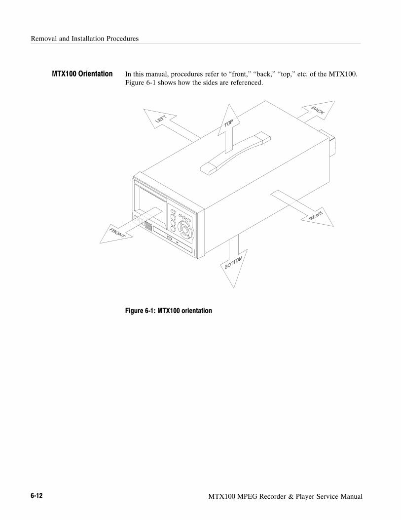
Removal and Installation Procedures
6-12 MTX100 MPEG Recorder & Player Service Manual
In this manual, procedures refer to “front,” “back,” “top,” etc. of the MTX100.Figure 6-1 shows how the sides are referenced.
Figure 6-1: MTX100 orientation
MTX100 Orientation
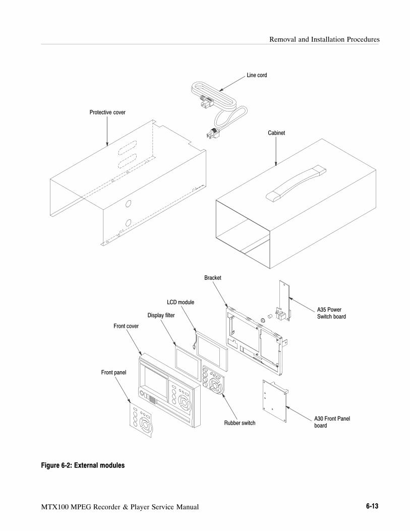
Removal and Installation Procedures
MTX100 MPEG Recorder & Player Service Manual 6-13
Protective cover
Line cord
Cabinet
Front cover
LCD module
Bracket
A35 PowerSwitch board
A30 Front Panelboard
Front panel
Rubber switch
Display filter
Figure 6-2: External modules

Removal and Installation Procedures
6-14 MTX100 MPEG Recorder & Player Service Manual
A20 PCI Back Plane board
Interface Module (Optional)
CPU board
A10 Main board
Figure 6-3: Board modules

Removal and Installation Procedures
MTX100 MPEG Recorder & Player Service Manual 6-15
5 V main power supply
CD-ROM drive
Hard disk drive
External fan
Internal fan
A40 AC Distributer board
RFI filter
Figure 6-4: Internal modules

Removal and Installation Procedures
6-16 MTX100 MPEG Recorder & Player Service Manual
COM2 connector SCSI connector
PRINTER connector
Figure 6-5: Rear panel modules

Removal and Installation Procedures
MTX100 MPEG Recorder & Player Service Manual 6-17
Access Procedure
When you have identified the module to be removed for service, read GeneralInstructions found on page 6-10. Then use the flowchart in Figure 6-6 todetermine which procedures to use for removing the module. The removalprocedures end with installation instructions.
Isthe modulein Figure6-2?
Yes
No
Locate the module tobe removed inFigure 6-2 to 6-5.
Procedures for External ModulesLine cord p.6-18Cabinet and protective cover p.6-18Front panel unit p.6-20Front panel assembly p.6-21
Do the procedures, LineCord and Cabinet on
page 6-18.
Isthe modulein Figure6-3?
Yes
Procedures for Board ModulesCPU board p.6-23A10 Main board p.6-24Optional interface module p.6-26A20 PCI Back Plane board p.6-26
No
Procedures for Internal ModulesHard disk drive p.6-29CD-ROM drive p.6-28Internal and external fans p.6-315 V main power supply p.6-32A40 AC Distributer board p.6-33RFI filter p.6-34No
Isthe modulein Figure6-4 ?
Yes
Procedures for Rear Panel ModulesCOM2 connector p.6-36SCSI connector p.6-36PRINTER connector p.6-37
Figure 6-6: Guide to removal procedures

Removal and Installation Procedures
6-18 MTX100 MPEG Recorder & Player Service Manual
Procedures for External Modules
Do the Access Procedure (page 6-17) before doing any procedure in this group.This group contains the following procedures:
Line Cord
Cabinet and Protective Cover
Front-Panel Unit
Front-Panel Assembly
1. Assemble equipment and locate modules to be removed: You need noequipment. Locate the line cord in the location diagram External modules,Figure 6-2, page 6-13.
2. Orient the instrument: Set the MTX100 so its bottom is down on the worksurface and its rear is facing you.
3. Remove line cord: Find the line cord on the rear panel. Grasp the plug andpull the line cord and clamp away to complete the removal. Reverseprocedure to reinstall.
1. Assemble equipment and locate modules to be removed:
a. You need a screwdriver with a T-15 Torx tip (Items 4 and 5).
b. Locate the modules to be removed in the locator diagram External
modules, Figure 6-2, page 6-13.
2. Orient instrument: Set the MTX100 so its bottom is down on the worksurface and its rear is facing you.
3. Disconnect line cord: Unplug the line cord from its receptacle at the rearpanel.
4. Remove cabinet and protective cover: See Figure 6-7.
a. Use a screwdriver with a T-15 Torx tip to remove the two screwssecuring the cabinet to the MTX100.
b. Grasp the right and left edges of the cabinet toward the back. Push thechassis rear panel, toward the front of the MTX100, to separate it fromthe cabinet.
c. Slide the cabinet off the MTX100. Take care not to bind or snag thecabinet on internal cabling as you remove it.
d. Pull the protective cover out and away from the instrument.
Line Cord
Cabinet and ProtectiveCover
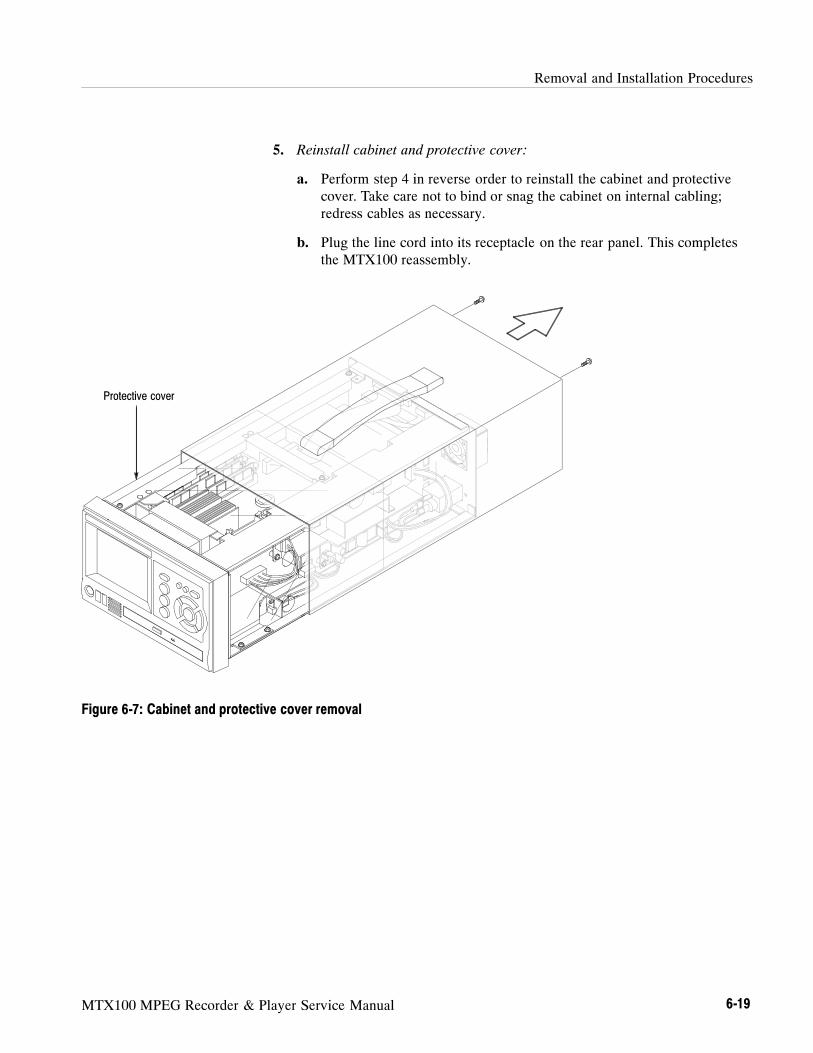
Removal and Installation Procedures
MTX100 MPEG Recorder & Player Service Manual 6-19
5. Reinstall cabinet and protective cover:
a. Perform step 4 in reverse order to reinstall the cabinet and protectivecover. Take care not to bind or snag the cabinet on internal cabling;redress cables as necessary.
b. Plug the line cord into its receptacle on the rear panel. This completesthe MTX100 reassembly.
Protective cover
Figure 6-7: Cabinet and protective cover removal
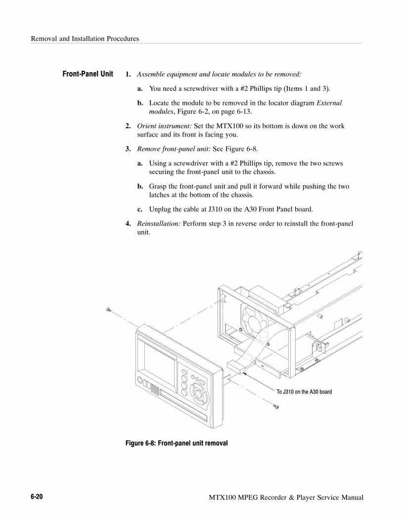
Removal and Installation Procedures
6-20 MTX100 MPEG Recorder & Player Service Manual
1. Assemble equipment and locate modules to be removed:
a. You need a screwdriver with a #2 Phillips tip (Items 1 and 3).
b. Locate the module to be removed in the locator diagram External
modules, Figure 6-2, on page 6-13.
2. Orient instrument: Set the MTX100 so its bottom is down on the worksurface and its front is facing you.
3. Remove front-panel unit: See Figure 6-8.
a. Using a screwdriver with a #2 Phillips tip, remove the two screwssecuring the front-panel unit to the chassis.
b. Grasp the front-panel unit and pull it forward while pushing the twolatches at the bottom of the chassis.
c. Unplug the cable at J310 on the A30 Front Panel board.
4. Reinstallation: Perform step 3 in reverse order to reinstall the front-panelunit.
To J310 on the A30 board
Figure 6-8: Front-panel unit removal
Front-Panel Unit

Removal and Installation Procedures
MTX100 MPEG Recorder & Player Service Manual 6-21
1. Assemble equipment and locate modules to be removed:
a. You need a screwdriver with a size #1 Phillips tip (Items 1 and 3).
b. Locate the module to be removed in the locator diagram External
modules, Figure 6-2, on page 6-13.
2. Remove the front cover: See Figure 6-9.
a. Press the two latches at the bottom of the front cover to release it fromthe front cover bracket.
b. Pull the front cover forward, away from the front cover bracket.
3. Remove the A30 Front Panel board: See Figure 6-9.
a. Use a screwdriver with a #1 Phillips tip to remove the four screwssecuring the A30 Front panel board to the front cover bracket.
b. Unplug the cable from the A35 Power Switch board at J300.
c. Lift the board away.
4. Remove the A35 Power Switch board: See Figure 6-9.
a. Use a screwdriver with a #1 Phillips tip to remove the two screwsecuring the A35 Power switch board to the front cover bracket.
b. Unplug the cables from the A30 Front Panel board at the J100 and fromthe LCD module.
c. Lift the board away.
5. Now hand disassemble the front-panel assembly components usingFigure 6-9 as a guide. Reverse the procedure to reassemble.
6. Reinstallation: Perform steps 2 through 5 in reverse order to reinstall thefront-panel assembly.
Front Panel Assembly
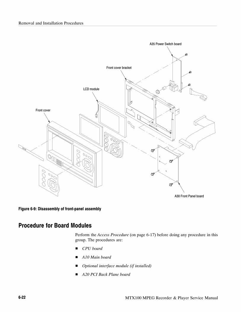
Removal and Installation Procedures
6-22 MTX100 MPEG Recorder & Player Service Manual
A35 Power Switch board
A30 Front Panel board
Front cover bracket
LCD module
Front cover
Figure 6-9: Disassembly of front-panel assembly
Procedure for Board Modules
Perform the Access Procedure (on page 6-17) before doing any procedure in thisgroup. The procedures are:
CPU board
A10 Main board
Optional interface module (if installed)
A20 PCI Back Plane board
Removal and Installation Procedures
MTX100 MPEG Recorder & Player Service Manual 6-23
1. Assemble equipment and locate modules to be removed:
a. You need a screwdriver with a #2 Phillips tip (Items 1 and 3).
b. Locate the board in the locator diagram Board modules, Figure 6-3,on page 6-14.
2. Orient the instrument: Set the MTX100 so its bottom is down on the worksurface and its left side is facing you.
3. Remove the board retainers: See Figure 6-10.
a. Remove the two screws securing the board retainers to the chassis.
b. Lift the retainers away from the chassis.
4. Remove the top frame with shield bracket: See Figure 6-10.
a. Remove the four screws securing the top frame with shield bracket to thechassis.
b. Lift the top frame with shield bracket up and away from the chassis.
5. Remove the CPU board: See Figure 6-10.
a. Unplug these cables. See Figure 6-10.
The cable from the A20 PCI Back Plane board at J1.
The cable from the A20 PCI Back Plane board at J2.
The cable from the hard disk drive at J3.
The cable from the A50 Disk I/F Board at J4.
The cable from the A20 PCI Back Plane board at J6.
The cable from the PRINTER connector at J7.
The cable from the A20 PCI Back Plane board at J8.
The cable from the COM2 connector at J9.
The cable from the SCSI connector at J12.
The cable from the A20 PCI Back Plane board at J15.
The cable from the A20 PCI Back Plane board at J23 and 24.
b. Remove the two screws securing the board bracket to the chassis. SeeFigure 6-10.
c. Grasp the board and slide it out.
CPU Board

Removal and Installation Procedures
6-24 MTX100 MPEG Recorder & Player Service Manual
6. Reinstallation: Do steps 3 and 5 in reverse order to reinstall the CPU board.
1. Assemble equipment and locate modules to be removed:
a. You need a screwdriver with a #2 Phillips tip (Items 1 and 3).
b. Locate the board in the locator diagram Board modules, Figure 6-3,on page 6-14.
2. Orient the instrument: Set the MTX100 so its bottom is down on the worksurface and its left side is facing you.
3. Remove the board retainers: See Figure 6-10.
a. Remove the two screws securing the board retainers to the chassis.
b. Lift the retainers away from the chassis.
4. Remove the top frame with shield bracket: See Figure 6-10.
a. Remove the four screws securing the top frame with shield bracket to thechassis.
b. Lift the top frame with shield bracket up and away from the chassis.
5. Remove the A10 Main board: See Figure 6-10.
a. Unplug these cables.
The cable from the PRINTER connector at J7 on the CPU board.
The cable from the hard disk drive at J3 on the CPU board.
The cable from the A50 Disk I/F Board at J4 on the CPU board.
b. If an optional interface module is installed, unplug the cable from theinterface module.
c. Remove the two screws securing the board bracket to the chassis. SeeFigure 6-10.
d. Grasp the board and slide it out.
6. Reinstallation: Do steps 3 and 5 in reverse order to reinstall the A10 Mainboard.
A10 Main Board

Removal and Installation Procedures
MTX100 MPEG Recorder & Player Service Manual 6-25
Top frame
A20 PCI Back Plane board
CPU board
A10 Main board
Optional interface module
Board retainer
Shield bracket
Board retainer
Figure 6-10: CPU board, A10 Main board, interface module, and A20 PCI Back Plane board removal

Removal and Installation Procedures
6-26 MTX100 MPEG Recorder & Player Service Manual
1. Assemble equipment and locate modules to be removed:
a. You need a screwdriver with a #2 Phillips tip (Items 1 and 3).
b. Locate the board in the locator diagram Board modules, Figure 6-3,page 6-14.
2. Orient the instrument: Set the MTX100 so its bottom is down on the worksurface and its left side is facing you.
3. Remove the board retainers: See Figure 6-10.
a. Remove the two screws securing the board retainers to the chassis.
b. Lift the retainers away from the chassis.
4. Remove the top frame with shield bracket: See Figure 6-10.
a. Remove the four screws securing the top frame with shield bracket to thechassis.
b. Lift the top frame with shield bracket up and away from the chassis.
5. Remove the interface module: See Figure 6-10.
a. Unplug these cables.
The cable from the PRINTER connector at J7 on the CPU board.
The cable from the hard disk drive at J3 on the CPU board.
The cable from the A50 Disk I/F Board at J4 on the CPU board.
b. Unplug the cable from the A10 Main board.
c. Remove the two screws securing the board bracket to the chassis. SeeFigure 6-10.
d. Grasp the board and slide it out.
6. Reinstallation: Do steps 3 and 5 in reverse order to reinstall the interfacemodule.
1. Assemble equipment and locate modules to be removed:
a. You need a screwdriver with a #1 Phillips tip (Items 1 and 2).
b. Locate the board in the locator diagram Board modules, Figure 6-3,page 6-14.
2. Orient the instrument: Set the MTX100 so its bottom is down on the worksurface and its left side is facing you.
Optional Interface Module
A20 PCI Back Plane Board

Removal and Installation Procedures
MTX100 MPEG Recorder & Player Service Manual 6-27
3. Remove the A20 PCI Back Plane board: See Figure 6-10.
a. Remove the CPU board as described on page 6-23.
b. Remove the A10 Main board as described on page 6-24.
c. Remove the interface module as described on page 6-26 (if needed).
d. Unplug these cables.
The cable from the A40 AC Distributer board at J40.
The cable from the 5 V main power supply at J50.
The cable from the external fan at J200.
The cable from the internal fan at J205.
The cable from the A30 Front Panel board at J170.
e. Remove the nine screws securing the A20 PCI Back Plane board to thechassis.
f. Lift the board up and away from the chassis.
4. Reinstallation: Do step 3 in reverse order to reinstall the interface module.
Procedure for Internal Modules
Perform the Access Procedure (on page 6-17) before doing any procedure in thisgroup. The procedures are:
CD-ROM drive
Hard disk drive
Internal and external fans
5 V main power supply
A40 AC Distributer board
RFI filter
Removal and Installation Procedures
6-28 MTX100 MPEG Recorder & Player Service Manual
1. Assemble equipment and locate modules to be removed:
a. You need a screwdriver with a #1 Phillips tip (Items 1 and 2).
b. Locate the CD-ROM drive in the locator diagram Internal modules,
Figure 6-4, page 6-15.
2. Orient the instrument: Set the MTX100 so its bottom is down on the worksurface and its front is facing you.
3. Remove the CD-ROM drive: See Figure 6-11.
a. Remove the front-panel unit as described on page 6-20.
b. Unplug the cables from the A20 PCI Back Plane board and from theCPU board.
c. Remove the two screws securing the CD-ROM mount bracket to thechassis.
d. Lift up the CD-ROM drive with the bracket and A50 Disk I/F boardfrom the chassis.
4. Remove the CD-ROM drive from the bracket and the board: Remove thefour screws securing the CD-ROM drive to the bracket and the board.
5. Reinstallation: Perform steps 3 and 4 in reverse order to reinstall theCD-ROM drive.
CD-ROM Drive

Removal and Installation Procedures
MTX100 MPEG Recorder & Player Service Manual 6-29
CD-ROM drive unit
A50 Disk I/F board
CD-ROM mount bracket
From J4 on theCPU board
From J40 on the A20PCI Back Plane board
Figure 6-11: CD-ROM drive removal
1. Assemble equipment and locate modules to be removed:
a. You need a screwdriver with a #1 Phillips tip (Items 1 and 2).
b. Locate the hard disk drive in the locator diagram Internal modules,
Figure 6-4, page 6-15.
2. Orient the instrument: Set the MTX100 so its bottom is down on the worksurface and its left side is facing you.
3. Remove the hard disk drive: See Figure 6-12.
a. Remove the CPU board as described on page 6-23.
b. Remove the A10 Main board as described on page 6-24.
c. Remove the interface module as described on page 6-26 (if needed).
Hard Disk Drive

Removal and Installation Procedures
6-30 MTX100 MPEG Recorder & Player Service Manual
d. Unplug these cables.
The cable from J60 on the A20 PCI Back Plane board.
The cable from J3 on the CPU board.
e. Remove the two screws securing the hard disk drive bracket to thechassis.
f. Lift up the hard disk unit with bracket from the chassis.
4. Remove the hard disk drive from the bracket: Remove the four screwssecuring the hard disk drive to the bracket.
5. Reinstallation: Perform steps 3 and 4 in reverse order to reinstall the harddisk drive.
Hard disk drive unit
To J3 on the CPU board
To J60 on the A20 PCIBack Plane board
Figure 6-12: Hard disk drive removal
Removal and Installation Procedures
MTX100 MPEG Recorder & Player Service Manual 6-31
1. Assemble equipment and locate modules to be removed:
a. You need a screwdriver with a #1 Phillips tip (Items 1 and 2).
b. Locate the fans in the locator diagram Internal modules, Figure 6-4,page 6-15.
2. Orient the instrument: Set the MTX100 so its bottom is down on the worksurface and its front is facing you.
3. Remove the internal fan: See Figure 6-13.
a. Remove the front-panel unit as described on page 6-20.
b. Unplug the cable from J205 on the A20 PCI Back Plane board.
c. Remove the four screws securing the fan to the chassis.
d. Lift the fan up out of the chassis.
4. Reinstallation: Perform step 3 in reverse order to reinstall the internal fan.
5. Remove the external fan: See Figure 6-13.
a. Set the MTX100 so its bottom is down on the work surface and its rearis facing you.
b. Unplug the cable from J200 on the A20 PCI Back Plane board.
c. Remove the four screws securing the fan and fan cover to the chassis.
6. Reinstallation: Perform step 5 in reverse order to reinstall the external fan.
Internal and External Fans
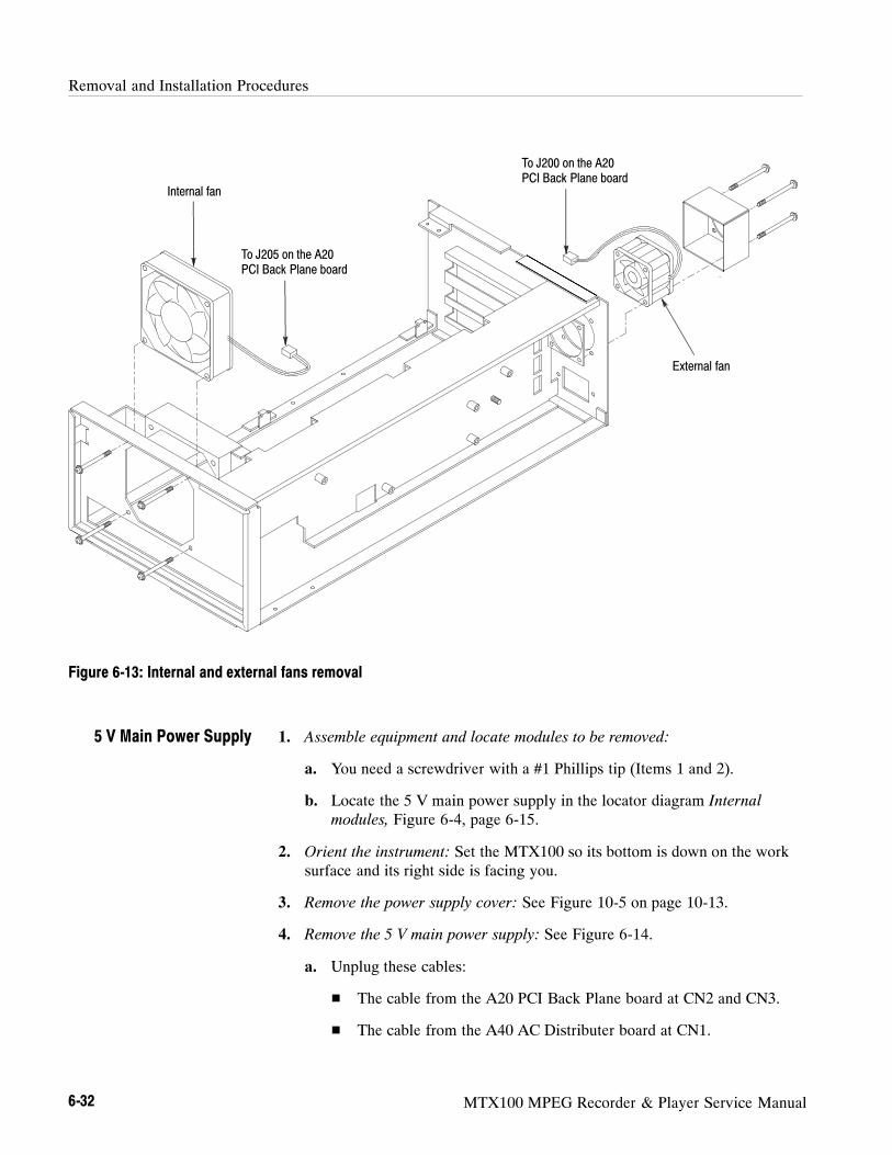
Removal and Installation Procedures
6-32 MTX100 MPEG Recorder & Player Service Manual
Internal fan
External fan
To J205 on the A20PCI Back Plane board
To J200 on the A20PCI Back Plane board
Figure 6-13: Internal and external fans removal
1. Assemble equipment and locate modules to be removed:
a. You need a screwdriver with a #1 Phillips tip (Items 1 and 2).
b. Locate the 5 V main power supply in the locator diagram Internal
modules, Figure 6-4, page 6-15.
2. Orient the instrument: Set the MTX100 so its bottom is down on the worksurface and its right side is facing you.
3. Remove the power supply cover: See Figure 10-5 on page 10-13.
4. Remove the 5 V main power supply: See Figure 6-14.
a. Unplug these cables:
The cable from the A20 PCI Back Plane board at CN2 and CN3.
The cable from the A40 AC Distributer board at CN1.
5 V Main Power Supply

Removal and Installation Procedures
MTX100 MPEG Recorder & Player Service Manual 6-33
b. Remove the four screws securing the 5 V main power supply to thechassis.
5. Reinstallation: Perform step 4 in reverse order to reinstall the 5 V mainpower supply.
1. Assemble equipment and locate modules to be removed:
a. You need a screwdriver with a #1 Phillips tip (Items 1 and 2).
b. Locate the A40 AC Distributer board in the locator diagram Internal
modules, Figure 6-4, page 6-15.
2. Orient the instrument: Set the MTX100 so its bottom is down on the worksurface and its right side is facing you.
3. Remove the power supply cover: See Figure 10-5 on page 10-13.
4. Remove the A40 AC Distributer board: See Figure 6-14.
a. Unplug these cables:
The cable from the A20 PCI Back Plane board at J120.
The cable from the 5 V main power supply at J110.
The cable from the RFI filter at J100.
b. Remove the three screws securing the A40 AC Distributer board to thechassis.
5. Reinstallation: Perform step 4 in reverse order to reinstall the A40 ACDistributer board.
A40 AC Distributer Board

Removal and Installation Procedures
6-34 MTX100 MPEG Recorder & Player Service Manual
5 V main power supply
To J50 on the A20 PCIBack Plane board
To J40 on the A20 PCIBack Plane board
To J110 on the A40AC Distributer board
A40 AC Distributer board
To J120 on the A50Disk I/F board
J40J50
Figure 6-14: 5 V main power supply and A40 AC Distributer board removal
1. Assemble equipment and locate modules to be removed:
a. You need a screwdriver with a #1 Phillips tip (Items 1 and 2), anda 7 mm nut driver (item 7).
b. Locate the RFI filter in the locator diagram Internal modules, Figure 6-4,page 6-15.
2. Orient the instrument: Set the MTX100 so its bottom is down on the worksurface and its rear is facing you.
RFI filter

Removal and Installation Procedures
MTX100 MPEG Recorder & Player Service Manual 6-35
3. Remove the power supply cover: See Figure 10-5 on page 10-13.
4. Remove the RFI filter: See Figure 6-15.
a. Unplug the two cables from the RFI filter.
b. Use a 7 mm nut driver to remove the nut securing the ground lead to thechassis.
c. Remove the two screws securing the RFI filter to the chassis.
d. Pull the RFI filter away.
5. Reinstallation: Perform step 4 in reverse order to reinstall the RFI filter.
RFI filter
Ground lead
To J100 on the A40AC Distributer board
Figure 6-15: RFI filter removal

Removal and Installation Procedures
6-36 MTX100 MPEG Recorder & Player Service Manual
Procedure for Rear Panel Modules
Perform the Access Procedure (on page 6-17) before doing any procedure in thisgroup. The procedures are:
COM2 connector
SCSI connector
PRINTER connector
1. Assemble equipment and locate modules to be removed:
a. You need a screwdriver with a 1/4 inch nut driver (Items 1 and 6).
b. Locate the connector in the locator diagram Rear Panel modules, Figure6-5, page 6-16.
2. Orient the instrument: Set the MTX100 so its bottom is down on the worksurface and its rear is facing you.
3. Remove the COM2 connector: See Figure 6-16.
a. Unplug the cable from J9 on the CPU board.
b. Use a 1/4 inch nut driver to unscrew the two hex-headed mounting postssecuring the connector to the chassis. Pull the connector away.
4. Reinstallation: Perform step 3 in reverse order to reinstall the COM2connector.
1. Assemble equipment and locate modules to be removed:
a. You need a screwdriver with a 1/4 inch nut driver (Items 1 and 6).
b. Locate the connector in the locator diagram Rear Panel modules, Figure6-5, page 6-16.
2. Orient the instrument: Set the MTX100 so its bottom is down on the worksurface and its rear is facing you.
3. Remove the SCSI connector: See Figure 6-16.
a. Unplug the cable from J7 on the CPU board.
b. Use a 1/4 inch nut driver to unscrew the two hex-headed mounting postssecuring the connector to the chassis. Pull the connector away.
4. Reinstallation: Perform step 3 in reverse order to reinstall the SCSIconnector.
COM2 Connector
SCSI Connector

Removal and Installation Procedures
MTX100 MPEG Recorder & Player Service Manual 6-37
1. Assemble equipment and locate modules to be removed:
a. You need a screwdriver with a 1/4 inch nut driver (Items 1 and 6).
b. Locate the connector in the locator diagram Rear Panel modules, Figure6-5, page 6-16.
2. Orient the instrument: Set the MTX100 so its bottom is down on the worksurface and its rear is facing you.
3. Remove the PRINTER connector: See Figure 6-16.
a. Unplug the cable from J7 on the CPU board.
b. Use a 1/4 inch nut driver to unscrew the two hex-headed mounting postssecuring the connector to the chassis. Pull the connector away.
4. Reinstallation: Perform step 3 in reverse order to reinstall the PRINTERconnector.
COM2 connectorSCSI connector
PRINTER connector
To J7 on CPU board
To J9 on CPU board
To J12 on CPU board
Figure 6-16: Rear panel modules removal
PRINTER Connector

Removal and Installation Procedures
6-38 MTX100 MPEG Recorder & Player Service Manual
MTX100 MPEG Recorder & Player Service Manual 6-39
Troubleshooting
This subsection contains information about troubleshooting trees designed toisolate faulty modules in the MTX100.
Troubleshooting Trees
Figures 6-17 through 6-21 show the troubleshooting procedure of the MTX100.

Troubleshooting
6-40 MTX100 MPEG Recorder & Player Service Manual
To (A), page 6-42.
Start
Yes
NoDoes theMTX100 power
on?
Yes
NoDoes
Windows 2000start upnormally?
Yes
NoDoesthe LCD
display light?To (B), page 6-44.
1
Press the ON/STBY powerswitch on the front panel.
Yes
No
Doesthe MTX100
application startup normally?
To (C), page 6-44.
Replace the CPU board.
Replace the hard disk drive.
Make the BIOS setting again.
No
Check that the A10 Main board andthe interface module are securelyinstalled into the card slots.
Yes
Are the version ofthe A10 Main board and
the optional interface moduledisplayed in the Status
dialog box?
Replace the A20 PCI Back Planeboard.
Replace the interface module.
Figure 6-17: Troubleshooting procedure (1)
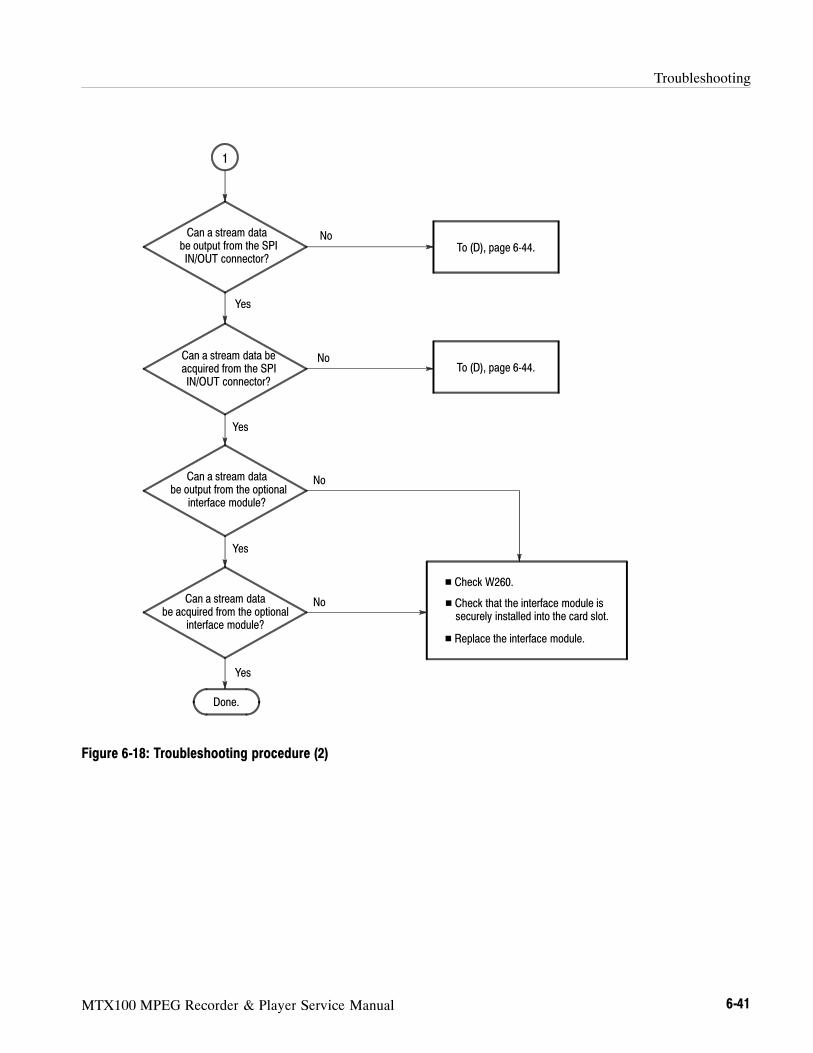
Troubleshooting
MTX100 MPEG Recorder & Player Service Manual 6-41
No
Yes
No
Yes
NoCan a stream databe output from the SPIIN/OUT connector?
To (D), page 6-44.
Yes
1
Done.
Can a stream data beacquired from the SPIIN/OUT connector?
Can a stream databe output from the optional
interface module?
Yes
NoCan a stream databe acquired from the optional
interface module?
To (D), page 6-44.
Check W260.
Replace the interface module.
Check that the interface module issecurely installed into the card slot.
Figure 6-18: Troubleshooting procedure (2)

Troubleshooting
6-42 MTX100 MPEG Recorder & Player Service Manual
(A)
NoDoes the relay click
sound hear?
Yes
If the 5 V line is faulty, replace the5 V Main Power Supply.
If the line other than 5 V is faulty,replace the A20 PCI Back Planeboard.
Check W170 and W190.
Check the 5 V Sub Power Supplymodule on the A40 AC Distributerboard.
Check +5 V, +3.3 V, +12 V, and --12V lines at pins 1, 3, 5, and 7 of J210on the A20 PCI Back Plane board(see Figure 6-22).
No
Remove the CPU board, A10 Mainboard, or optional interface modulefrom the A20 PCI Back Plane board,and then check the voltage of J210.
Are all of thevoltages at pins 1, 3,5, and 7 of J210
correct?
Yes
Replace the board or module that isremoved in the previous step.
Is any board ormodule connected tothe A20 PCI Back
Plane?
Yes
No
Figure 6-19: Troubleshooting procedure (3)

Troubleshooting
MTX100 MPEG Recorder & Player Service Manual 6-43
NoAre any imagesdisplayed on the
monitor?
Yes
Check W170 and W180.
Replace the A20 PCI Back Planeboard or A30 Front panel board.
Replace the CPU board.
(B)
Does the backlightlight ?
Yes
No Check W170 and W190.
Replace the A35 Power switchboard.
Connect a VGA monitor to theVGA connector on the rearpanel.
Replace the LCD module.
Figure 6-20: Troubleshooting procedure (4)

Troubleshooting
6-44 MTX100 MPEG Recorder & Player Service Manual
No
Yes
(C)
Reinstall the MTX100 application.
The COM 1 port is faulty.
Check W140 and W170.
Have the LEDs on thefront panel gone off?
No
Yes
(D)
Select RAM for the output source orrecord target, and then check that astream data can be output or recordednormally.
Replace the internal Hard disk drive.
Does the HDD accessindicator light?
Replace the A10 Main board.
Reinstall the Windows 2000operating system and the MTX100application.
Connect a SCSI hard disk drive tothe SCSI connector, and then checkthat a stream data can be output orrecorded normally.
Replace the A30 Front Panel board.
Figure 6-21: Troubleshooting procedure (5)

Troubleshooting
MTX100 MPEG Recorder & Player Service Manual 6-45
J310J170
J130
J400
J60
J160
J210
J140
J410
J420
J430
Front
Figure 6-22: A20 PCI Back Plane board view

Troubleshooting
6-46 MTX100 MPEG Recorder & Player Service Manual

MTX100 MPEG Recorder & Player Service Manual 6-47
Using the Recovery Discs
In the event the MTX100 does not boot, you can reboot the MTX100 by usingthe recovery discs provided with the instrument. Use the procedures in thissection to reinstall the Windows 2000 operating system and the MTX100application software.
Reinstalling Windows 2000
NOTE. Before beginning this procedure, connect the keyboard and mouse
provided with the instrument to the front-panel USB connectors.
Perform the following procedure to reinstall the Windows 2000 operatingsystem:
1. Insert theWindows 2000 Professional Operating System Recovery Disc
into the CD-ROM drive.
2. Turn off and then turn on the instrument. The MTX100 runs from the disc.
The Power Quest EasyRestore End User License Agreement dialog boxappears.
3. Press any key. The first dialog box of Easy Restore appears.
4. Press the TAB key to move to the Continue button, and then press theEnter key. The first Warning dialog box appears.
NOTE. The mouse is disabled in this step.
5. Press the Enter key. The second Warning dialog box appears.
6. Press the Enter key. The Entire and Copying Progress bars appear.
7. When A:\> appears at the upper left corner of the screen, simultaneouslypress the Control + Alt + Delete keys to restart the instrument, and thenimmediately press the eject button of the CD-ROM drive.
TheWindows 2000 Professional Setup dialog box appears.
8. Click Next.
The Licence Agreement dialog box appears.
Using the Recovery Discs
6-48 MTX100 MPEG Recorder & Player Service Manual
9. Read the agreement. When you agree to the content, select I accept thisagreement, and then click Next.
The Regional Settings dialog box appears.
10. Check that the settings are correct for your locate. If necessary, click the firstCustomize button to change system or user locate settings, and click thesecond Customize button to change the keyboard layout.
11. Click Next.
The Personalize Your Software dialog box appears.
12. Type your name and organization. You must type in a name, but theorganization text box is optional.
13. Click Next.
The Your Product Key dialog box appears.
The Product Key, or Product ID number, is the bar code number on thesticker that is located on the side of the instrument cabinet.
14. Type your Product Key, and then click Next.
The Computer Name and Administrator Password dialog box appears.
A suggested name for the instrument appears in the Computer name textbox that you can change or accept. The computer name is used to identifythe instrument on a network, and it must be unique to the network. It can beup to 15 characters in length.
The Administrator password text box is used to enter the administratorpassword. This password is pre-defined asMTX100 at the factory. There-fore, you do not need to enter the password. Even if you enter a passwordother than MTX100, it is disabled.
15. Click Next.
The Date and Time Settings dialog box appears.
16. Check that the settings are correct for your date, time, and time zone, thenclick Next.
The Network Settings dialog box appears. You may choose whether to usetypical or custom settings. Consult your network administrator if you need toadd custom settings at this point.

Using the Recovery Discs
MTX100 MPEG Recorder & Player Service Manual 6-49
17. Click Next to accept the default typical settings.
TheWorkgroup or Computer Domain dialog box appears. You may add aworkgroup name, but it is not required. Consult your network administratorif you need to add a computer domain.
18. Click Next.
The Completing the Windows 2000 Setup Wizard dialog box appears.
19. Click Finish.
When you click Finish, the instrument restarts automatically. TheWelcome
to the Network Identification Wizard dialog box appears.
20. Click Next.
The Users of This Computer dialog box appears.
You can change settings as indicated on the screen or enter a user passwordfor the name entered earlier in the setup. If you click the second optionbutton, you do not need to enter a password when you logon to the instru-ment.
21. Click Next.
The Completing the Network Identification Wizard dialog box appears.
22. Click Finish. The Getting Started with Windows 2000 dialog box appears.
23. Click Exit to close the dialog box.
Reinstalling the MTX100 Application
Perform the following procedure to reinstall the MTX100 application software:
1. Insert theMTX100 Application Software Recovery Disc into the CD-ROM drive.
2. Double-click the D: drive icon (Substitute your CD-ROM drive letter if it isdifferent than D).
3. Double-click the Setup.exe icon. This installs the MTX100 applicationsoftware.

Using the Recovery Discs
6-50 MTX100 MPEG Recorder & Player Service Manual
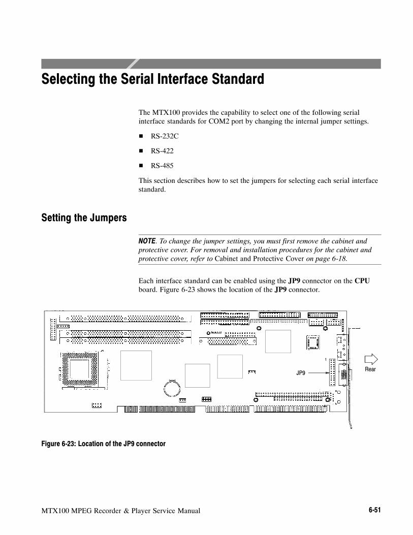
MTX100 MPEG Recorder & Player Service Manual 6-51
Selecting the Serial Interface Standard
The MTX100 provides the capability to select one of the following serialinterface standards for COM2 port by changing the internal jumper settings.
RS-232C
RS-422
RS-485
This section describes how to set the jumpers for selecting each serial interfacestandard.
Setting the Jumpers
NOTE. To change the jumper settings, you must first remove the cabinet and
protective cover. For removal and installation procedures for the cabinet and
protective cover, refer to Cabinet and Protective Cover on page 6-18.
Each interface standard can be enabled using the JP9 connector on the CPUboard. Figure 6-23 shows the location of the JP9 connector.
JP9
1
Rear
Figure 6-23: Location of the JP9 connector
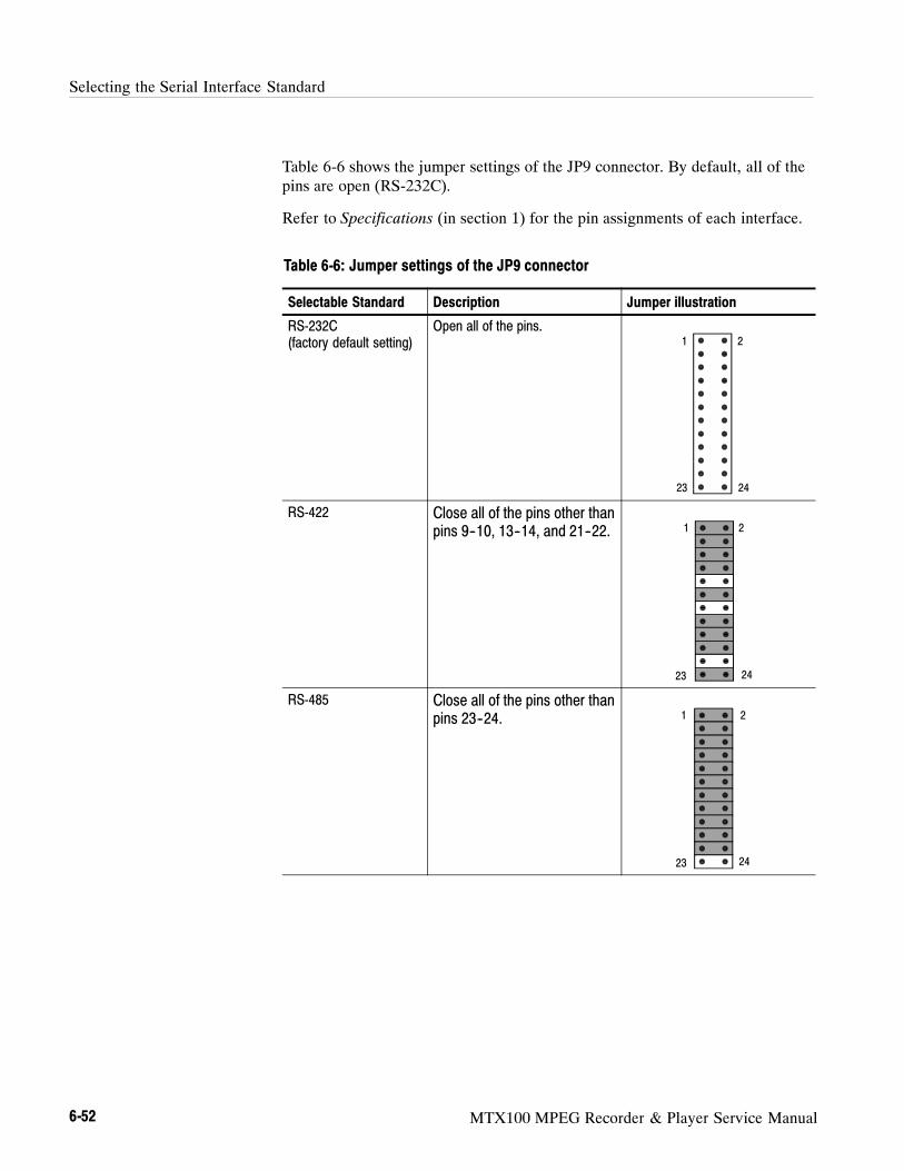
Selecting the Serial Interface Standard
6-52 MTX100 MPEG Recorder & Player Service Manual
Table 6-6 shows the jumper settings of the JP9 connector. By default, all of thepins are open (RS-232C).
Refer to Specifications (in section 1) for the pin assignments of each interface.
Table 6-6: Jumper settings of the JP9 connector
Selectable Standard Description Jumper illustration
RS-232C(factory default setting)
Open all of the pins.1
2423
2
RS-422 Close all of the pins other thanpins 9--10, 13--14, and 21--22. 1
24
2
23
RS-485 Close all of the pins other thanpins 23--24. 1
24
2
23

MTX100 MPEG Recorder & Player Service Manual 7-1
Options
This section describes options that are available for the MTX100.
The following options are available:
Options Description
Option 01(ASI Interface)
The MTX100 is equipped with the ASI (AsynchronousSerial Interface) interface when this option is specified.
Option 02(Universal Parallel/Serial Interface)
The MTX100 is equipped with the universal parallel/serialinterface when this option is specified.
Option 03(BNC Serial Interface)
The MTX100 is equipped with the BNC serial interfacewhen this option is specified.
Option 04(DHEI Interface)
The MTX100 is equipped with the DHEI (Digital HeadendEquipment Interface) interface when this option isspecified.
Option 05(IEEE1394/ASI Interface)
The MTX100 is equipped with the IEEE1394/ASIinterface when this option is specified.
Option 06(SMPTE310M/ASI Interface)
The MTX100 is equipped with the SMPTE310M/ASIinterface when this option is specified.
Option D1(Test data report)
A calibration data test result report comes with theMTX100 when this option is specified.
Options and Accessories
7-2 MTX100 MPEG Recorder & Player Service Manual

MTX100 MPEG Recorder & Player Service Manual 8-1
Electrical Parts List
The modules that make up this instrument are often a combination of mechanicaland electrical subparts. Therefore, all replaceable modules are listed in section10, Mechanical Parts List. Refer to that section for part numbers when usingthis manual.
Electrical Parts List
8-2 MTX100 MPEG Recorder & Player Service Manual

MTX100 MPEG Recorder & Player Service Manual 9-1
Diagrams
This section contains the following diagrams:
Block diagram of the MTX100
Interconnect diagram of the MTX100
Block diagrams show the modules and functional blocks in the MTX100.Interconnect diagrams show how the modules in the MTX100 connect together.

Diagrams
9-2 MTX100 MPEG Recorder & Player Service Manual
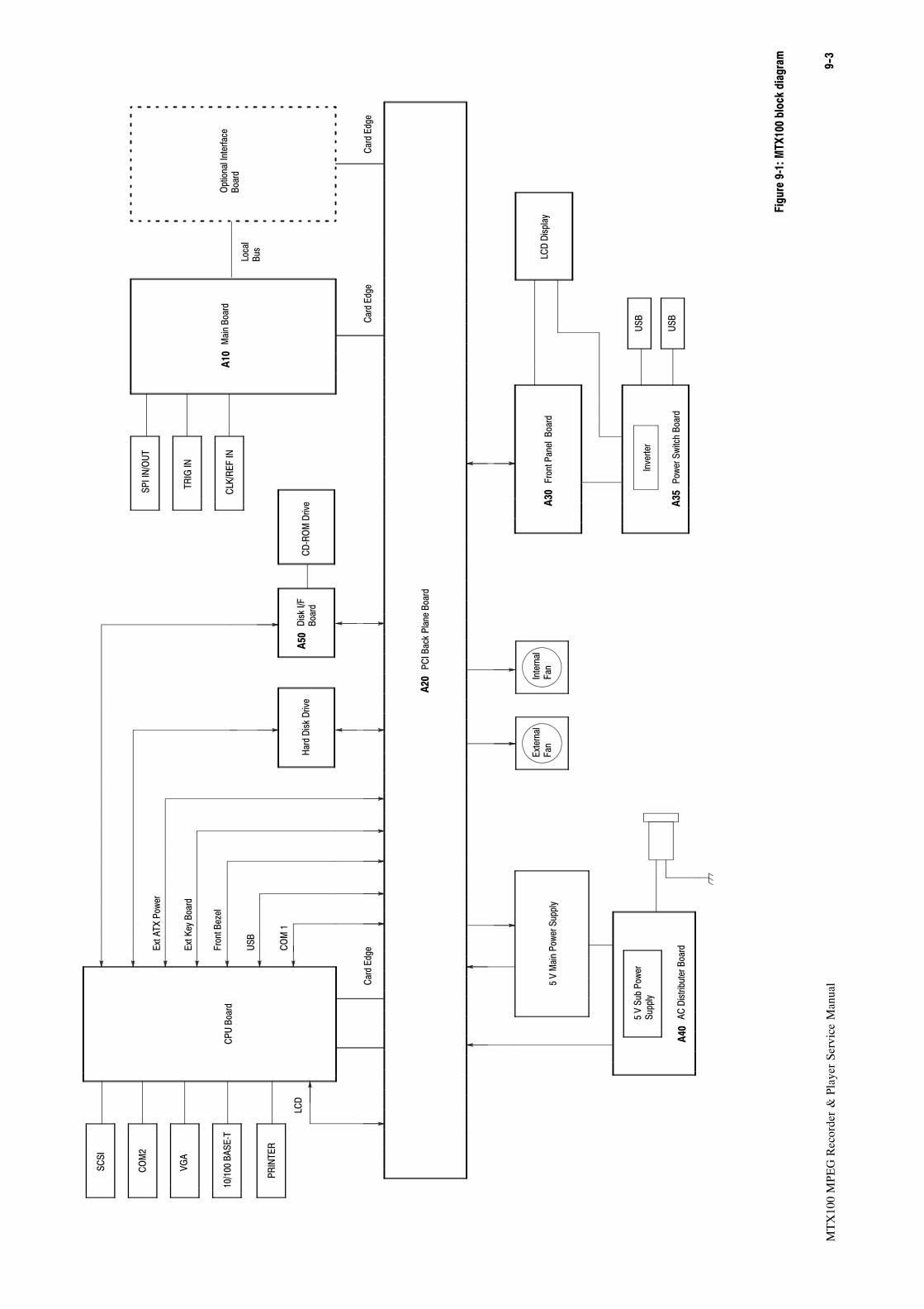
9--3
MTX100MPEGRecorder&PlayerServiceManual
CPUBoard
PCIBackPlaneBoard
A20
External
Fan
Internal
Fan
5VMainPowerSupply
PowerSwitchBoard
A35
FrontPanelBoard
A30
LCDDisplay
ACDistributerBoard
A40
5VSubPower
Supply
Inverter
USB
USB
SCSI
COM2
10/100BASE-T
VGA
MainBoard
A10
OptionalInterface
Board
DiskI/F
Board
A50
CD-ROMDrive
HardDiskDrive
CardEdge
CardEdge
CardEdge
SPIIN/OUT
TRIGIN
CLK/REFIN
Local
Bus
PRINTER
LCD
COM1
USB
FrontBezel
ExtKeyBoard
ExtATXPower
Figure9-1:MTX100blockdiagram

9--4
MTX100MPEGRecorder&PlayerServiceManual

9--5
MTX100MPEGRecorder&PlayerServiceManual
Board
PCIBackPlaneBoard
A20
External
Fan
Internal
Fan
5VMainPowerSupply
PowerSwitchBoard
A35
FrontPanelBoard
A30
LCDDisplay
ACDistributerBoard
A40
5VSubPower
Supply
Inverter
USB
USB
SCSI
COM2
10/100BASE-T
VGA
MainBoard
A10
OptionalInterfaceModule
(seeFigures9-3to9-6)
DiskI/F
Board
A50
CD-ROMDrive
HardDiskDrive
CardEdge
CardEdge
CardEdge
SPIIN/OUT
TRIGIN
CLK/REFIN
Local
Bus
W200
W205
22
J200
J205
W05010
J50
W010
W020
W030
1
2
2
2
2
W040J40
W17060J170
10
W190
27W180
W0604
W0702
J60
J40
40W110
J4 J340
W100
CPU
W260
80
68W230
9
W220
PRINTER
25W210
J12
J9 J7
J310
J300
J320
J100
J700
J600
W240
W250
J6
W13044
J15 J2 J1
J23andJ24 J8
J140
J160
J120
J300
J150
6W150 5
W300 6
W120 7
W160
10
W140
J420
J430
J130
J400
J410
J120
J110
J100
J100
J120
CN2
CN3
CN1
J110
Figure9-2:MTX100interconnectdiagram

9--6
MTX100MPEGRecorder&PlayerServiceManual

MTX100 MPEG Recorder & Player Service Manual 9-7
Diagrams of the Optional Modules
This section contains the interconnect diagrams of the optional interface
modules.
A100 ASI Interface Module (Option 01)
Figure 9-3 shows the A100 ASI Interface module and how it interconnects with
the A20 PCI Back Plane board and the A10 Main board.
Card Edge
W260
80
J420 J430
PCI Back Plane BoardA20
Main BoardA10
J500
J502
J404
J400
ASI OUT 1
ASI OUT 2
ASI IN
ASI THRU
ASI Interface moduleA100
J310J110
Figure 9-3: A100 ASI Interface module connections

Diagrams of the Optional Modules
9-8 MTX100 MPEG Recorder & Player Service Manual
A110 Universal Parallel/Serial Interface Module (Option 02)
Figure 9-4 shows the A110 Universal Parallel/Serial Interface module and how it
interconnects with the A20 PCI Back Plane board and the A10 Main board.
Card Edge
W260
80
J420 J430
PCI Back Plane BoardA20
Main BoardA10
J1110EVENT OUT
UNIVERSALIN/OUT
Universal Parallel/SerialInterface module
A110
J310J110
J1100
Figure 9-4: A110 Universal Parallel/Serial Interface module connections

Diagrams of the Optional Modules
MTX100 MPEG Recorder & Player Service Manual 9-9
A120 BNC Serial Interface Module (Option 03)
Figure 9-5 shows the A120 BNC serial interface module and how it intercon-
nects with the A20 PCI Back Plane board and the A10 Main board.
Card Edge
W260
80
J420 J430
PCI Back Plane BoardA20
Main BoardA10
J500
J502
J504
J506
DATA
CLOCK
PSYNC
ENABLE
BNC Serial Interface moduleA120
J310J110
Figure 9-5: A120 BNC Interface module connections
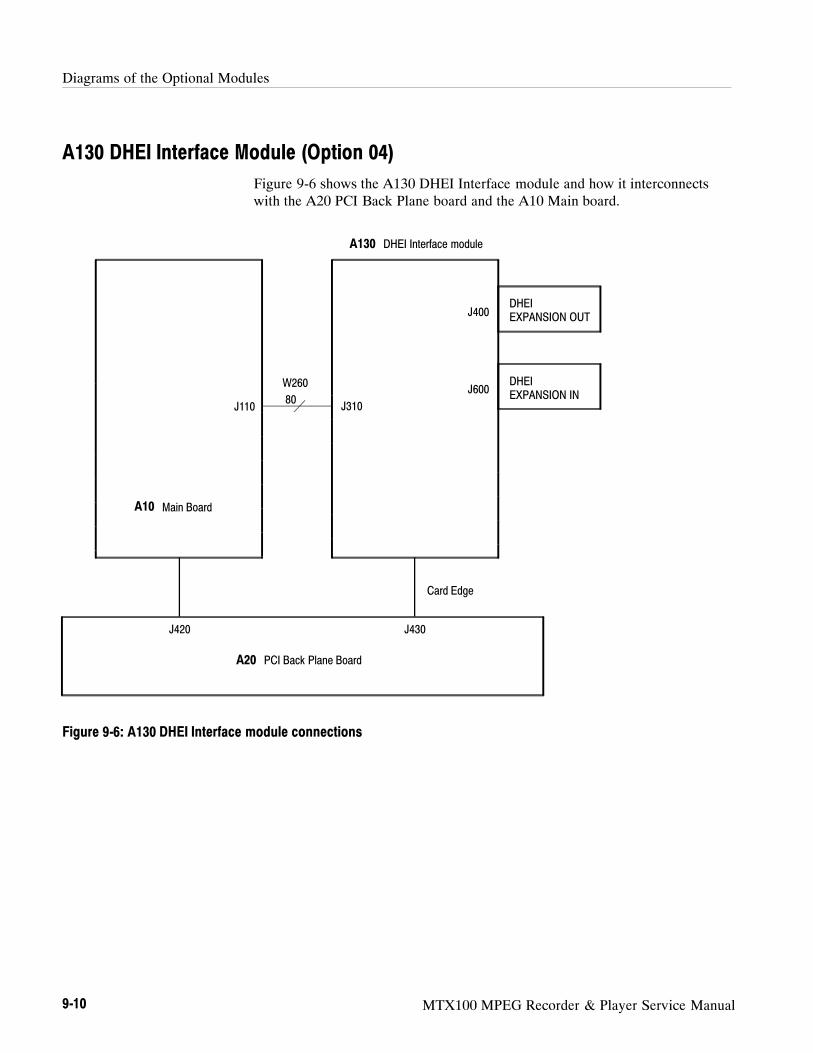
Diagrams of the Optional Modules
9-10 MTX100 MPEG Recorder & Player Service Manual
A130 DHEI Interface Module (Option 04)
Figure 9-6 shows the A130 DHEI Interface module and how it interconnects
with the A20 PCI Back Plane board and the A10 Main board.
Card Edge
W260
80
J420 J430
PCI Back Plane BoardA20
Main BoardA10
DHEIEXPANSION OUT
DHEI Interface moduleA130
J310J110
DHEIEXPANSION IN
J400
J600
Figure 9-6: A130 DHEI Interface module connections

Diagrams of the Optional Modules
MTX100 MPEG Recorder & Player Service Manual 9-11
A140 IEEE1394/ASI Interface Module (Option 05)
Figure 9-7 shows the A140 IEEE1394/ASI Interface module and how it
interconnects with the A20 PCI Back Plane board and the A10 Main board.
Card Edge
W260
80
J420 J430
PCI Back Plane BoardA20
Main BoardA10
J300
J302
J400
J402
ASI OUT
ASI IN
IEEE1394/ASI Interface moduleA140
J500J110
IEEE1394 4 pin
IEEE1394 4 pin
Figure 9-7: A140 IEEE1394/ASI Interface module connections

Diagrams of the Optional Modules
9-12 MTX100 MPEG Recorder & Player Service Manual
A160 SMPTE310M/ASI Interface Module (Option 06)
Figure 9-8 shows the A160 SMPTE310M/ASI Interface module and how it
interconnects with the A20 PCI Back Plane board and the A10 Main board.
Card Edge
W260
80
J420 J430
PCI Back Plane BoardA20
Main BoardA10
J400
J410
J600
J610
Signal IN
Signal Loopout
Signal OUT
Signal OUT
SMPTE310M/ASI Interface moduleA160
J500J110
Figure 9-8: A160 SMPTE310M/ASI Interface module connections

MTX100 MPEG Recorder & Player Service Manual 10-1
Mechanical Parts List
This section contains a list of the replaceable modules for the MTX100. Use thislist to identify and order replacement parts.
Parts Ordering Information
Replacement parts are available through your local Tektronix field office orrepresentative.
Changes to Tektronix products are sometimes made to accommodate improvedcomponents as they become available and to give you the benefit of the latestimprovements. Therefore, when ordering parts, it is important to include thefollowing information in your order:
Part number (see Part Number Revision Level below)
Instrument type or model number
Instrument serial number
Instrument modification number, if applicable
If you order a part that has been replaced with a different or improved part, yourlocal Tektronix field office or representative will contact you concerning anychange in part number.
Change information, if any, is located at the rear of this manual.
Tektronix part numbers contain two digits that show the revision level of thepart. For most parts in this manual, you will find the letters XX in place of therevision level number.
670- 7918- 03
Part Number Revision Level
670- 7918-XX
Revision Level May Show as XX
When you order parts, Tektronix will provide you with the most current part foryour product type, serial number, and modification (if applicable). At the time ofyour order, Tektronix will determine the part number revision level needed foryour product, based on the information you provide.
Part Number RevisionLevel

Mechanical Parts List
10-2 MTX100 MPEG Recorder & Player Service Manual
Modules can be serviced by selecting one of the following three options. Contactyour local Tektronix service center or representative for repair assistance.
Module Exchange. In some cases you may exchange your module for a reman-ufactured module. These modules cost significantly less than new modules andmeet the same factory specifications. For more information about the moduleexchange program, call 1--800--833--9200. Outside North America, contact aTektronix sales office or distributor; see the Tektronix web site for a list ofoffices: www.tektronix.com
Module Repair and Return. You may ship your module to us for repair, after whichwe will return it to you.
New Modules. You may purchase replacement modules in the same way as otherreplacement parts.
Using the Replaceable Parts List
This section contains a list of the mechanical and/or electrical components thatare replaceable for the MTX100. Use this list to identify and order replacementparts. The following table describes each column in the parts list.
Parts list column descriptions
Column Column name Description
1 Figure & Index Number Items in this section are referenced by figure and index numbers to the exploded viewillustrations that follow.
2 Tektronix Part Number Use this part number when ordering replacement parts from Tektronix.
3 and 4 Serial Number Column three indicates the serial number at which the part was first effective. Column fourindicates the serial number at which the part was discontinued. No entries indicates the part isgood for all serial numbers.
5 Qty This indicates the quantity of parts used.
6 Name & Description An item name is separated from the description by a colon (:). Because of space limitations, anitem name may sometimes appear as incomplete. Use the U.S. Federal Catalog handbookH6--1 for further item name identification.
7 Mfr. Code This indicates the code of the actual manufacturer of the part.
8 Mfr. Part Number This indicates the actual manufacturer ’s or vendor’s part number.
Abbreviations conform to American National Standard ANSI Y1.1--1972.
Module Servicing
Abbreviations

Mechanical Parts List
MTX100 MPEG Recorder & Player Service Manual 10-3
The table titled Manufacturers Cross Index shows codes, names, and addressesof manufacturers or vendors of components listed in the parts list.
Manufacturers cross index
Mfr.code Manufacturer Address City, state, zip code
S3109 FELLER 72 VERONICA AVEUNIT 4
SUMMERSET NJ 08873
TK0191 TEKTRONIX JAPAN PO BOX 5209TOKYO INTERNATIONAL
TOKYO JAPAN 100--31
TK2432 UNION ELECTRIC 15/F #1, FU--SHING N. ROAD TAIPEI, TAIWAN ROC
2W733 BELDEN CORPORATION 2200 US HIGHWAY 27 SOUTHPO BOX 1980
RICHMOND IN 47375--0010
80009 TEKTRONIX INC 14150 SW KARL BRAUN DRPO BOX 500
BEAVERTON, OR 97077--0001
Mfr. Code to ManufacturerCross Index

Mechanical Parts List
10-4 MTX100 MPEG Recorder & Player Service Manual
Replaceable parts list
Fig. &
index
number
Tektronix part
number
Serial no.
effective
Serial no.
discont’d Qty Name & description
Mfr.
code Mfr. part number
10--1--1 348--1644--00 7CM
SHLD GASKET,ELEK:CONDUCTIVE URETHANE FORMW/ADHESIVE TAPE [UC--3E0414]
80009
--2 348--1644--00 10CM
SHLD GASKET,ELEK:CONDUCTIVE URETHANE FORMW/ADHESIVE TAPE [UC--3E0414]
80009
--3 200--A520--00 1 COVER,PC:AIR FLOW,AROUND CHASSIS,POLYCARBONATE,MTX100
80009
--4 161--0216--00 1 CABLE ASSY,PWR,:3,18 AWG,2.5M L,BLACKSAFETYCONTROLLED (STANDARD ACCESSORY)
TK2432 ORDER BY DESC
--5 390--A083--01 1 CABINET ASSY:17XX AL 80009
--6 211--0720--01 2 SCREW,MACHINE:6--32X0.50,PNH,STL ZN--CM1,T15TORX,W/SLOT
80009
--7 335--1018--00 1 LABEL WARNING 80009
--8 334--3388--01 1 MARKER,IDENT:MKD TEKTRONIX JAPAN, LTD. MADE INJAPAN
80009

Mechanical Parts List
MTX100 MPEG Recorder & Player Service Manual 10-5
7
3
5
4
6
1
8
2
Figure 10-1: Cabinet

Mechanical Parts List
10-6 MTX100 MPEG Recorder & Player Service Manual
Replaceable parts list
Fig. &
index
number
Tektronix part
number
Serial no.
effective
Serial no.
discont’d Qty Name & description
Mfr.
code Mfr. part number
10--2--1 334--A581--00 1 MARKER,IDENT:MKD MTX100,POLYCARBONATE,TO.25 80009
--2 200--A519--00 1 COVER,FRONT:ABS,TV GRAY,WITH CONDUCTIVE 80009
--3 378--A048--00 1 FILTER,LCD:ACRYL,MTX100 80009
--4 119--B114--00 1 LCD MODULE:4 INCH,TFT,VGA [LTMO4C380K] 80009
--5 407--A669--01 1 BRACKET,ASSY:FRONT COVER,STL & SST,MTX100 80009
--6 366--A046--00 1 PUSH BUTTON,POWER:SILVER GRAY,ABS 80009
--7 384--A222--00 1 EXTENSION SHAFT:POWER BUTTON,POLYACETAL,MTX100 80009
--8 671--B121--XX 1 CIRCUIT BD ASSY:A35 POWER SW,389--B130--01 WIRED 80009
--9 211--0871--00 3 SCREW,MACHINE:M3X6MM L,PNH,STL,ZN PL,CROSSREC,W/FLAT(7MM OD) & LOCK WASHER
80009
--10 174--B918--00 1 CA ASSY,SP,ELEC:10,26AWG,11CM L,W/CONN(JST) 80009
--11 174--B917--00 1 CA ASSY,SP,ELEC:60,30AWG,15CML,FLAT,W/CONN(YAMAICHI)
80009
--12 348--1644--00 6CM
SHLD GASKET,ELEK:CONDUCTIVE URETHANE FORMW/ADHESIVE TAPE [UC--3E0414]
80009
--13 259--A002--01 1 FLEX CIRCUIT:A60,LCD I/F 80009
--14 671--B120--XX 1 CIRCUIT BD ASSY:A30 FRONT PANEL,389--B129--01 WIRED 80009
--15 211--0871--00 4 SCREW,MACHINE:M3X6MM L,PNH,STL,ZN PL,CROSSREC,W/FLAT(7MM OD) & LOCK WASHER
80009
--16 260--A148--00 1 SWITCH,RUBBER:SILICON,FRONT PANEL 80009
--17 333--A437--00 1 PANEL,FRONT:KEYBOARD,MTX100,POL YCARBONATE,TO.25 80009

Mechanical Parts List
MTX100 MPEG Recorder & Player Service Manual 10-7
1
1715
14
5
11
10
9
4
13
A35
A30
16
8
3
67
12
2
Figure 10-2: Front panel unit
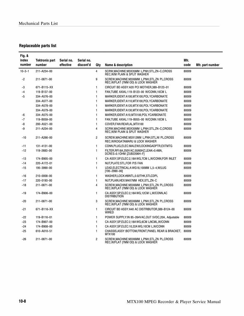
Mechanical Parts List
10-8 MTX100 MPEG Recorder & Player Service Manual
Replaceable parts list
Fig. &
index
number
Tektronix part
number
Serial no.
effective
Serial no.
discont’d Qty Name & description
Mfr.
code Mfr. part number
10--3--1 211--A234--00 4 SCRW,MACHINE:M3X35MM L,PNH,STL,ZN--C,CROSSREC,W/M PLAIN & SPLIT WASHER
80009
--2 211--0871--00 9 SCREW,MACHINE:M3X6MM L,PNH,STL,ZN PL,CROSSREC,W/FLAT (7MM OD) & LOCK WASHER
80009
--3 671--B115--XX 1 CIRCUIT BD ASSY:A20 PCI MOTHER,389--B123--01 80009
--4 119--B137--00 1 FAN,TUBE AXIAL:119--B123--00 W/CONN,10CM L 80009
--5 334--A576--00 1 MARKER,IDENT:A100,MTX100,POL YCARBONATE 80009
334--A577--00 1 MARKER,IDENT:A110,MTX100,POLYCARBONATE 80009
334--A578--00 1 MARKER,IDENT:A120,MTX100,POL YCARBONATE 80009
334--A579--00 1 MARKER,IDENT:A130,MTX100,POL YCARBONATE 80009
--6 334--A575--00 1 MARKER,IDENT:A10,MTX100,POLYCARBONATE 80009
--7 119--B059--00 1 FAN,TUBE AXIAL:119--B055--00 W/CONN.10CM L 80009
--8 200--A521--00 1 COVER,FAN:REAR,AL,MTX100 80009
--9 211--A234--00 4 SCRW,MACHINE:M3X35MM L,PNH,STL,ZN--C,CROSSREC,W/M PLAIN & SPLIT WASHER
80009
--10 211--A266--00 2 SCREW,MACHINE:M3X12MM L,PNH,STL,NI PL,CROSSREC,W/KOGATAMARU & LOCK WASHER
80009
--11 131--4131--00 1 CONN,PLUG,ELEC:MALEW/LOCKINGADPTR,EXTMTG 80009
--12 119--2683--00 1 FILTER,RFI:6A,250VAC,50/60HZ,LEAK=0.4MA,DCRES=0.1OHM [ZUB2206H--F]
80009
--13 174--B905--00 1 CA ASSY,SP,ELEC:2,18AWG,7CM L,W/CONN,FOR INLET 80009
--14 220--A172--01 1 NUT,PLATE:STL,FOR P/S FAN 80009
--15 195--3990--00 1 LEAD,ELECTRICAL:AWG18,100MM L,5--4,W/LUG[195--2990--00]
80009
--16 210--0008--00 1 WASHER,LOCK:#8INTL,0.02THK,STLCDPL 80009
--17 220--0193--00 1 NUT,PLAIN,HEX:M4X7MM HEX,STL,ZN--C 80009
--18 211--0871--00 4 SCREW,MACHINE:M3X6MM L,PNH,STL,ZN PL,CROSSREC,W/FLAT (7MM OD) & LOCK WASHER
80009
--19 174--B906--00 1 CA ASSY,SP,ELEC:2,18AWG,12CM L,W/CONN,ACDISTRIBUTION
80009
--20 211--0871--00 3 SCREW,MACHINE:M3X6MM L,PNH,STL,ZN PL,CROSSREC,W/FLAT (7MM OD) & LOCK WASHER
80009
--21 671--B116--XX 1 CIRCUIT BD ASSY:A40 AC DISTRIBUTOR,389--B124--00WIRED
80009
--22 119--B116--01 1 POWER SUPPLY:IN 85--264VAC,OUT 5VDC,20A, Adjustable 80009
--23 174--B907--00 1 CA ASSY,SP,ELEC:2,18AWG,6CM L/9CML,W/CONN 80009
--24 174--B908--00 1 CA ASSY,SP,ELEC:10,22AWG,10CM L,W/CONN 80009
--25 610--A010--51 1 CHASSIS,ASSY :BOTTOM,FRONT,PANEL REAR & BRACKET,MTX100
80009
--26 211--0871--00 2 SCREW,MACHINE:M3X6MM L,PNH,STL,ZN PL,CROSSREC,W/FLAT (7MM OD) & LOCK WASHER
80009

Mechanical Parts List
MTX100 MPEG Recorder & Player Service Manual 10-9
2
3
1
CD-ROM driveSee Figure 10-6 fordetailed view
4
5
6
7
8
9
10
11
12
13
18
19
2021
2324
22
25
26
16
15
17
14
A20
A40
Figure 10-3: Internal modules (1)

Mechanical Parts List
10-10 MTX100 MPEG Recorder & Player Service Manual
Replaceable parts list
Fig. &
index
number
Tektronix part
number
Serial no.
effective
Serial no.
discont’d Qty Name & description
Mfr.
code Mfr. part number
10--4--1 211--0871--00 2 SCREW,MACHINE:M3X6MM L,PNH,STL,ZN PL,CROSSREC,W/FLAT (7MM OD) & LOCK WASHER
80009
--2 174--B919--00 1 CA ASSY,SP,ELEC:25,28AWG,15CM L,FLAT,W/CONN (D--SUBTO 2X13) & PULL TAB
80009
--3 214--3903--01 2 SCREW,JACK:4--40X0.312 EXT THD,4--40 INT THD,0.1888HEX,STEEL,CAD PLATE
80009
--4 210--A015--00 2 WASHER,LOCK:#3,SPLIT ,STL MFZN--C 80009
--5 210--A007--00 2 WASHER,PLAIN:#3,6MM OD,STL MFZN--C,KOGATAMARU 80009
--6 174--B920--00 1 CA ASSY,SP,ELEC:9,28AWG,12CM L,FLAT,W/CONN (D--SUBTO 2X5) & PULL TUB
80009
--7 386--A850--00 1 PLATE:BRANK,D--SUB,25CONN,STL 80009
--8 211--0661--00 2 SCR,ASSEM WSHR:4--40X0.25,PNH,STL ZN--CM1,POZIDRIVMACHINE
80009
--9 214--3903--01 2 SCREW,JACK:4--40X0.312 EXT THD,4--40 INT THD,0.1888HEX,STEEL,CAD PLATE
80009
--10 210--A015--00 2 WASHER,LOCK:3,SPLIT ,STL MFZN--C 80009
--11 210--A007--00 2 WASHER,PLAIN:#3.6MM OD.STL MFZN--C,KOGATAMARU 80009
--12 129--A591--00 2 SPACER,POST:4--40X0.189 EXT THD,2--56X0.142 INTTHD,0.187 HEX [NHS--01#NT]
80009
--13 174--B921--00 1 CA ASSY,SP,ELEC:68,30AWG,19CM L,FLAT,W/CONN(YAMAICHI),SCSI
80009
--14 407--A672--00 1 BRACKET,CKT BD:GUIDE FOR PCI CARD,STL,MTX100 80009
--15 211--0871--00 2 SCREW,MACHINE:M3X6MM L,PNH,STL,ZN PL,CROSSREC,W/FLAT (7MM OD) & LOCK WASHER
80009
--16 174--B911--00 1 CA ASSY,SP,ELEC:40,28AWG,27CM L,FLAT,W/CONN & PULLTUB
80009
--17 174--4116--00 1 CA ASSY,SP,ELEC:4,18AWG,15CM L,W/CONN FOR HDD,W77 80009
--18 174--B910--00 1 CA ASSY,SP,ELC:40,28AWG,27CM L,FLAT,IULTRAATA,W/CONN & PULL TUB
80009

Mechanical Parts List
MTX100 MPEG Recorder & Player Service Manual 10-11
4
3
2
1
Hard disk driveSee Figure 10-7for detailed view
85
10
6
7
12
11
9
13
14
1517
18
16
Figure 10-4: Internal modules (2)

Mechanical Parts List
10-12 MTX100 MPEG Recorder & Player Service Manual
Replaceable parts list
Fig. &
index
number
Tektronix part
number
Serial no.
effective
Serial no.
discont’d Qty Name & description
Mfr.
code Mfr. part number
10--5--1 211--0871--00 3 SCREW,MACHINE:M3X6MM L,PNH,STL,ZN PL,CROSSREC,W/FLAT (7MM OD) & LOCK WASHER
80009
--2 333--A444--00 1 PANEL,PCI:BLANK,STL,MTX100 80009
--3 174--B914--00 1 CA ASSY,SP,ELEC:10,28AWG,11CM L,FLAT,W/CONN 80009
--4 174--B913--00 1 CA ASSY,SP,ELEC:10,28AWG,11CM L,FLAT,W/CONN 80009
--5 174--B915--00 1 CA ASSY,SP,ELEC:6,26AWG,7CM L,W/CONN (JST,PH TO XH) 80009
--6 174--B916--00 1 CA ASSY,SP,ELEC:7,26AWG,7CM L,W/CONN,2X4 TO 1X7 80009
--7 174--B925--01 1 CA ASSY,SP,ELEC:5,26AWG,25CM L,W/CONN (JST) 80009
--8 211--0871--00 3 SCREW,MACHINE:M3X6MM L,PNH,STL,ZN PL,CROSSREC,W/FLAT (7MM OD) & LOCK WASHER
80009
--9 343--A349--00 2 RETAINER,CKT BD:STL,MTX100 80009
--10 211--0871--00 2 SCREW,MACHINE:M3X6MM L,PNH,STL,ZN PL,CROSSREC,W/FLAT (7MM OD) & LOCK WASHER
80009
--11 211--0871--00 4 SCREW,MACHINE:M3X6MM L,PNH,STL,ZN PL,CROSSREC,W/FLAT (7MM OD) & LOCK WASHER
80009
--12 343--A350--01 1 RETAINER,CONN:SCSI & IDE,SST,MTX100 80009
--13 211--0871--00 3 SCREW,MACHINE:M3X6MM L,PNH,STL,ZN PL,CROSSREC,W/FLAT (7MM OD) & LOCK WASHER
80009
--14 407--A673--02 1 BRACKET:SHIELD,AL,MTX100 80009
--15 426--A193--03 1 FRAME,TOP:FRAME ASSY,STL,MTX100 80009
--16 343--A352--01 1 RETAINER,CKT BD:MEMORY BD,SST,MTX100 80009
--17 211--0871--00 1 SCREW,MACHINE:M3X6MM L,PNH,STL,ZN PL,CROSSREC,W/FLAT (7MM OD) & LOCK WASHER
80009
--18 211--0871--00 2 SCREW,MACHINE:M3X6MM L,PNH,STL,ZN PL,CROSSREC,W/FLAT (7MM OD) & LOCK WASHER
80009
--19 174--4946--00 1 CA ASSY,SP,ELEC:6,28AWG,25CM L,FLAT,W/CONN 80009
--20 119--6932--00 1 CPU CARD:PICMG(ISA/PCI9,SKT370,CELERON/PENIII,300--800MHZ,W/LAN/LCD/SCSI,W/O SOUND [C17BMO]
80009
--21 671--B114--XX 1 CIRCUIT BD ASSY:A10 MAIN I/O,389--B122--01 WIRED 80009
--22 671--B139--XX 1 CIRCUIT BD ASSY:A100 ASI,389--B142--01 WIRED 80009
671--B140--XX 1 CIRCUIT BD ASSY:A110 UNIVERSAL PARALLEL/SERIALIF,389--B143--01 WIRED
80009
671--B141--XX 1 CIRCUIT BD ASSY:A120 BNC SERIAL IF,389--B144--01 WIRED 80009
671--B142--XX 1 CIRCUIT BD ASSY:A130 DHEI,389--B145--01 WIRED 80009
671--B246--XX 1 CIRCUIT BD ASSY:A140 IEEE1394,389--B237--XX WIRED 80009
671--B277--XX 1 CIRCUIT BD ASSY:A160 SMPTE310M,389--B270--XX WIRED 80009
--23 174--B924--00 1 CA ASSY,SP,ELEC:80,30AWG,5CM L,FLAT,W/CONN 80009
--24 276--0357--00 1 CORE,EM:FERARITE, EMI 80009
--25 348--1656--00 7 GASKET, SHEILD: CONDUCTIVE URETHANE FORM 80009
--26 335--1079--00 1 MARKER, IDENT: MKD WARNING, POWER LINE 80009

Mechanical Parts List
MTX100 MPEG Recorder & Player Service Manual 10-13
Replaceable parts list (Cont.)
Fig. &
index
number Mfr. part number
Mfr.
codeName & descriptionQty
Serial no.
discont’d
Serial no.
effective
Tektronix part
number
--27 200--4863--00 1 COVER: POWER SUPPLY, AL, MTX100 80009
--28 211--0871--00 4 SCREW,MACHINE:M3X6MM L,PNH,STL,ZN PL,CROSSREC,W/FLAT (7MM OD) & LOCK WASHER
80009
Front panel unitSee Figure 10-2 fordetailed view
2
8
9
10
18
13
14
15
16
17
3
45
6
71
23
19
12
11
20
2122 A10
24
11
25
28
26
27
11
Figure 10-5: Internal modules (3)

Mechanical Parts List
10-14 MTX100 MPEG Recorder & Player Service Manual
Replaceable parts list
Fig. &
index
number
Tektronix part
number
Serial no.
effective
Serial no.
discont’d Qty Name & description
Mfr.
code Mfr. part number
10--6--1 119--B199--00 1 CD--ROM DRIVE UNIT:12/8CM,CD/CD--ROM [CD--224E--C93] 80009
--2 211--0871--00 2 SCREW,MACHINE:M3X6MM L,PNH,STL,ZN PL,CROSSREC,W/FLAT(7MM OD) & LOCK WASHER
80009
--3 671--B119--XX 1 CIRCUIT BD ASSY:A50 DISK I/F,389--B127--01 WIRED 80009
--4 211--A269--00 4 SCREW,MACHINE:M2X4MM L,PNHSTL ZN--C,CROSSREC,W/FLAT (6MM OD) WASHER
80009
--5 407--A663--03 1 BRACKET:CD--ROM MOUNT,AL,MTX100 80009
5
1
2
3
4
A50
Figure 10-6: CD-ROM unit

Mechanical Parts List
MTX100 MPEG Recorder & Player Service Manual 10-15
Replaceable parts list
Fig. &
index
number
Tektronix part
number
Serial no.
effective
Serial no.
discont’d Qty Name & description
Mfr.
code Mfr. part number
10--7--1 211--0511--00 4 SCREW,MACHINE:6--32X0.5,PNH,STL ZN--CM1,POZIDRIV 80009
--2 210--0949--00 4 WASHER,FLAT:0.141 IDX0.5 0DX0.062,BRSNP 80009
--3 129--1527--00 4 SPACER,SLEEVE:7.5MM LX4MM ID X5.3MM OD,STL,MFZN--C [3382309--40075]
80009
--4 214--4924--00 4 PAD,CUSHIONING:14.3MM DIAX8MM H,POLYURETHANE[G--411--6]
80009
--5 119--B144--00 1 HARD DISK UNIT:40GB,3.5INCH,ATA--100[IC35L040AVER07--01]
80009
--6 407--A659--00 1 BRACKET:HDD MOUNT,AL,MTX100 80009
1
2
3
5
6
4
Figure 10-7: Hard Disk Drive unit

Mechanical Parts List
10-16 MTX100 MPEG Recorder & Player Service Manual
Replaceable parts list
Compo-
nent
number
Tektronix
part number
Serial no.
effective
Serial no.
discont’d Qty Name & description
Mfr.
code
Mfr.
part number
STANDARD ACCESSORIES
070--A834--XX 1 MANUAL,TECH,USER,MTX100 TK0191
062--A275--XX 1 SOFTWARE PKG:WINDOWS2000 PROFESSIONALRECOVERY,CD--ROM
80009
062--A276--XX 1 SOFTWARE PKG:SAMPLE STREAM,CD--ROM 80009
062--A279--XX 1 SOFTWARE PKG:MTX100 APPLICATION RECOVERY 80009
012--A220--00 1 CABLE,INTCON:D--SUB 25,MALE TO MALE,STR,TWIST,2ML,SCREW 4--40
TK0191
119--B145--00 1 POINTER ASSY:OPTICAL MOUSE,USB [D6600016WHEELMOUSE OPTICAL]
80009
119--B146--00 1 KEYBOARD:USB [PD--KB200W/U] 80009
200--3897--00 1 COVER,FRONT:1700F02 80009
---- -- -- -- -- -- -- -- -- -- 1 CABLE ASSY,PWR,:3,18 AWG,2.5M L,BLACKSAFETYCONTROLLED (STANDARD CABLE--SEE FIG 10--1--4)
80009
161--0215--00 1 CABLE ASSY,PWR,:3,1.0MM SQ,220V/10A,2.5M(OPTION A1--EUROPEAN)
S3109 198--010
161--0066--10 1 CABLE ASSY,PWR,:3,1.0MM SQ,240 V/10A,2.5 M(OPTION A2--UNITED KINGDOM)
S3109 209010
161--0066--11 1 CABLE ASSY,PWR,:3,1.0MM SQ,,240V/10A,2.5M(OPTION A3--AUSTRALIAN)
S3109 198--010
161--0066--12 1 CABLE ASSY,PWR,:3,18 AWG,240/10A,98 INCH L(OPTION A4--NORTH AMERICAN)
2W733 ORDER BY DESC
161--0154--00 1 CABLE ASSY,PWR,:3.0 X 0.75,6A,220V ,2.5M L(OPTION A5--SWITZERLAND)
S3109 ORDER BY DESC
161--0304--00 1 CABLE ASSY,PWR,:3,1.0MM SQ,,240V/10A,2.5M(OPTION AC--CHINA)
S3109 198--010
OPTIONAL ACCESSORIES
070--A835--XX 1 MANUAL,TECH:SERVICE,MTX100 TK0191
---- -- -- -- -- -- -- -- -- -- 1 1700F05 SIDE--BY--SIDE RACK ADAPTER 80009
---- -- -- -- -- -- -- -- -- -- 1 1700F06 BRANK PANEL 80009
Copyright © 2022 FDOKUMEN