service manual model 113a frosty factory of america inc ...
24
1 SERVICE MANUAL MODEL 113A FROSTY FACTORY OF AMERICA INC. RUSTON, LA. 71270 (800)544-4071 All technical data, pictures and drawings contained in this manual are not binding on the manufacturer nor can the manufacturer be held liable for any modifications to the machine in whole or in part. Rev. 03/18/05 rf.
-
Upload
khangminh22 -
Category
Documents
-
view
0 -
download
0
Transcript of service manual model 113a frosty factory of america inc ...
1
SERVICE MANUAL MODEL 113A FROSTY FACTORY OF AMERICA INC.
RUSTON, LA. 71270 (800)544-4071
All technical data, pictures and drawings contained in this manual are not binding on the manufacturer nor can the manufacturer be held liable for any modifications to the machine in whole or in part.
Rev. 03/18/05 rf.
2
TABLE OF CONTENTS 1.0 INTRODUCTION 1.1 Use of the Manual 1.2 Preliminary Inspection 1.3 Description 1.4 Dimensions 2.0 LOCATION AND INSTALLATION 2.1 Safety Precautions 2.2 Installation 3.0 OPERATION 3.1 Machine Controls 3.2 The Product You Serve 3.3 Product Consistency 3.4 Start Up 3.5 Freeze Time 4.0 MAINTENANCE 4.1 Cleaning 4.2 Re-Assembly 4.3 Preventative Maintenance 4.4 Extended Storage 4.5 Troubleshooting 4.6 Rear Cylinder and Drive Assembly Parts List 4.7 Torque Consistency Control 4.8 Faceplate/Faucet Assembly 4.9 Float Switch
4.9a Thermostat Assemblies 4.10 Using the Cleaning Brushes 4.11 Beater Bar Spring and Seal Installation 4.12 Beater Seal Assembly 4.13 Ceramic Seal Removal and Re-installation
5.0 SPARE PARTS LIST 6.0 WIRE DRAWING 7.0 ELECTRICAL SCHEMATIC 8.0 FACTORY ASSISTANCE
3
SECTION 1 INTRODUCTION
1.1 USE OF THIS MANUAL Your service manual has been prepared as a guide to help you get the most from your Petite Sorbeteer. It contains information about the installation and operation of your machine. The manual also contains instructions for service and care. The manual should be read carefully by the operator of the Petite Sorbeteer to become familiar with the machine and the correct operating procedures described within. The following notations are used throughout the manual to bring important facts to your attention: “Warning” - This notation is used whenever the personal safety of the operator(s) might
be jeopardized, if procedures are not followed correctly. “Caution” - This notation is used whenever the operator may receive or cause injury if
not observed. “Notice” - This notation is used to bring important information to your attention that
will enhance the performance of your machine.
CAUTION RISK OF ELECTRICAL SHOCK.
DISCONNECT POWER BEFORE SERVICING UNIT.
CAUTION MOVING PARTS
DO NOT OPERATE UNIT WITH PANELS REMOVED
WARNING DO NOT INSERT ANY OBJECTS
INTO CYLINDER OR HOPPER WHILE MACHINE IS RUNNING!
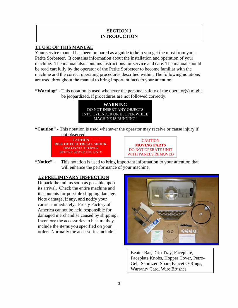
Beater Bar, Drip Tray, Faceplate, Faceplate Knobs, Hopper Cover, Petro-Gel, Sanitizer, Spare Faucet O-Rings, Warranty Card, Wire Brushes
1.2 PRELIMINARY INSPECTION Unpack the unit as soon as possible upon its arrival. Check the entire machine and its contents for possible shipping damage. Note damage, if any, and notify your carrier immediately. Frosty Factory of America cannot be held responsible for damaged merchandise caused by shipping. Inventory the accessories to be sure they include the items you specified on your order. Normally the accessories include :
4
(54.6cm) 21.5”
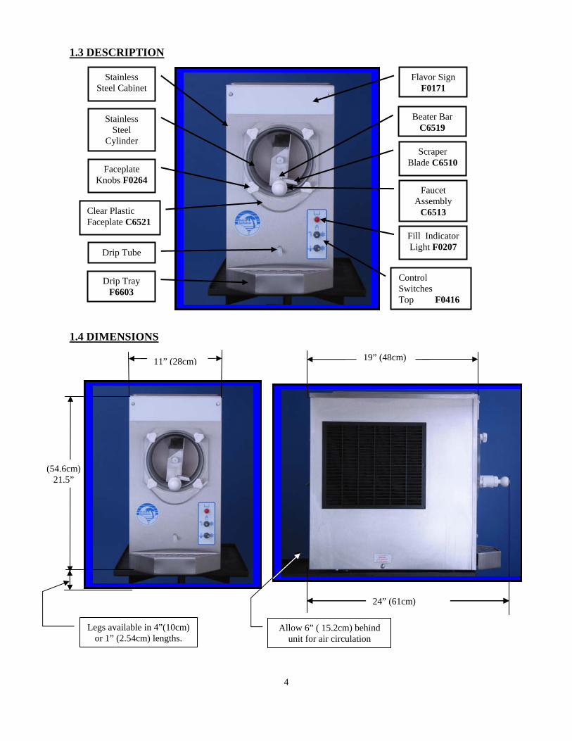
1.3 DESCRIPTION
Stainless Steel Cabinet
Stainless Steel
Cylinder
Faceplate Knobs F0264
Clear Plastic Faceplate C6521
Drip Tube
Flavor Sign F0171
Control Switches Top F0416
Beater Bar C6519
Faucet Assembly
C6513
Fill Indicator Light F0207
Drip Tray F6603
Scraper Blade C6510
11” (28cm)
1.4 DIMENSIONS
Legs available in 4”(10cm) or 1” (2.54cm) lengths.
Allow 6” ( 15.2cm) behind unit for air circulation
24” (61cm)
19” (48cm)
5
SECTION 2
LOCATION & INSTALLATION
2.1 SAFETY PRECAUTIONS Do not attempt to operate your Petite Sorbeteer until the safety precautions and operating instructions in this manual are read completely and are thoroughly understood. 2.2 INSTALLATION Placing your Petite Sorbeteer in a highly visible area will enhance sales. CAUTION: Do not attempt to share the dedicated electrical outlet with any other
appliance; this will cause the circuit breaker to trip. 1. Remove the machine from the shipping container. 2. Place the unit on a sturdy platform able to hold the weight of the machine when full
of product. (Usually about 150 #) 3. Level the machine by turning the adjustable part of the leg. The machine must be level
front to back as well as left to right. 3. Air-cooled condensers must have correct ventilation. Air intake is at the rear of the
machine and discharge is through the sides. 8” clearance is required on both sides and at the back. In addition, all Petite Sorbeteers require 6” clearance above the machine.
NOTICE: Locating the unit in direct sunlight, near cooking equipment or any high
heat area will reduce the performance of your machine. CAUTION: Extended operations under severe heat condition can damage the
cooling system. NOTICE: Establishments that serve beverages from frozen drink machines must
clean and sanitize them according to the procedures established by the regulating agencies having jurisdiction.
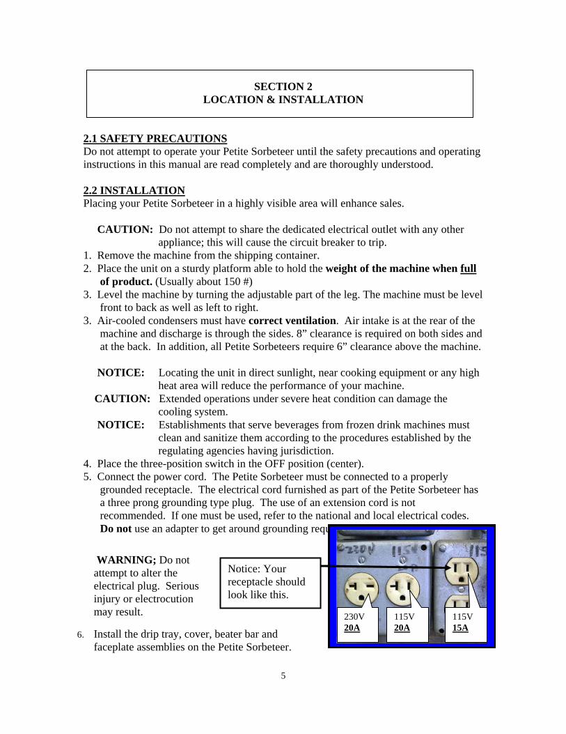
4. Place the three-position switch in the OFF position (center). 5. Connect the power cord. The Petite Sorbeteer must be connected to a properly
grounded receptacle. The electrical cord furnished as part of the Petite Sorbeteer has a three prong grounding type plug. The use of an extension cord is not recommended. If one must be used, refer to the national and local electrical codes. Do not use an adapter to get around grounding requirements.
WARNING; Do not attempt to alter the electrical plug. Serious injury or electrocution may result.
Notice: Your receptacle should look like this.
115V 20A
230V 20A
115V 15A
6. Install the drip tray, cover, beater bar and faceplate assemblies on the Petite Sorbeteer.
6
SECTION 3 OPERATION
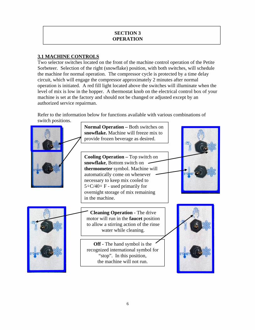
3.1 MACHINE CONTROLS Two selector switches located on the front of the machine control operation of the Petite Sorbeteer. Selection of the right (snowflake) position, with both switches, will schedule the machine for normal operation. The compressor cycle is protected by a time delay circuit, which will engage the compressor approximately 2 minutes after normal operation is initiated. A red fill light located above the switches will illuminate when the level of mix is low in the hopper. A thermostat knob on the electrical control box of your machine is set at the factory and should not be changed or adjusted except by an authorized service repairman. Refer to the information below for functions available with various combinations of switch positions.
Normal Operation – Both switches on snowflake. Machine will freeze mix to provide frozen beverage as desired.
Cleaning Operation - The drive motor will run in the faucet position to allow a stirring action of the rinse
water while cleaning.
Off - The hand symbol is the recognized international symbol for
“stop”. In this position, the machine will not run.
Cooling Operation – Top switch on snowflake, Bottom switch on thermometer symbol. Machine will automatically come on whenever necessary to keep mix cooled to 5ºC/40º F - used primarily for overnight storage of mix remaining in the machine.
7
3.2 THE PRODUCT YOU SERVE The Petite Sorbeteer will produce a fine grain, semi-frozen slush when the proper mix is used. When measured with a refractometer, the proper mix will measure 12 to 18 “brix”. Too little sugar in the mix will cause larger ice crystals to form. Too much sugar will lengthen the freeze time. CAUTION: Any attempt to freeze water only will cause severe damage to your
machine. NOTICE: Do not add sugar directly into the machine, as some of it will settle and
result in an improper mix. FRUIT JUICES with at least 32 grams of sugar per 8-oz. serving will freeze well in the Petite Sorbeteer. They will remain stable during the freezing process while retaining their natural color and flavor. NEUTRAL BASES are used to produce a neutral frozen cocktail base. A wide variety of different drinks can be created from one neutral base by the addition of various flavors. Most brands of neutral bases specify a mixture of four parts water to one part neutral base. However, before use in the Petite Sorbeteer, be sure the “brix” level is 12 to 18. The amount of ALCOHOL in the recipe will affect the freezing process. As a rule of thumb, for the mix to freeze properly, the recipe should contain no more than 25 percent alcohol. Suggestion for optimum production and sales: 1) Use the finest ingredients available. 2) Test the product before serving it. 3) Keep the machine clean - ALWAYS! 3.3 PRODUCT CONSISTENCY
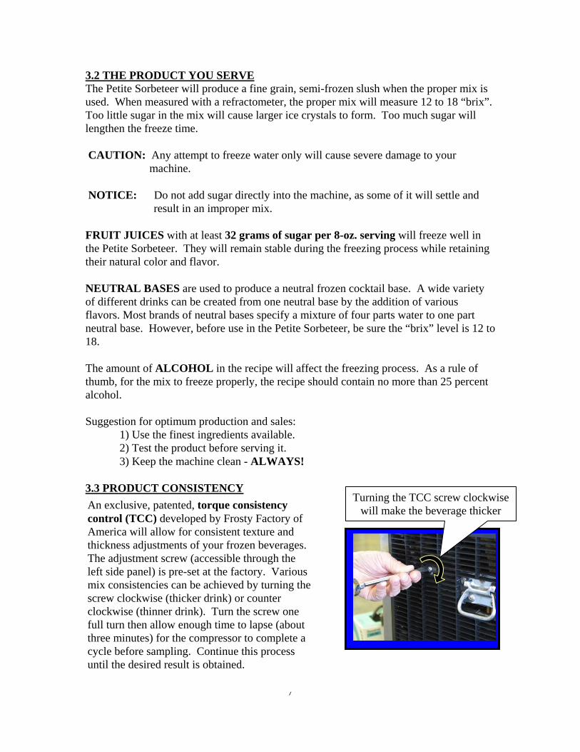
An exclusive, patented, torque consistency control (TCC) developed by Frosty Factory of America will allow for consistent texture and thickness adjustments of your frozen beverages. The adjustment screw (accessible through the left side panel) is pre-set at the factory. Various mix consistencies can be achieved by turning the screw clockwise (thicker drink) or counter clockwise (thinner drink). Turn the screw one full turn then allow enough time to lapse (about three minutes) for the compressor to complete a cycle before sampling. Continue this process until the desired result is obtained.
Turning the TCC screw clockwise will make the beverage thicker
8
3.4 START UP NOTICE: Before start-up, be sure the machine has been sanitized in accordance
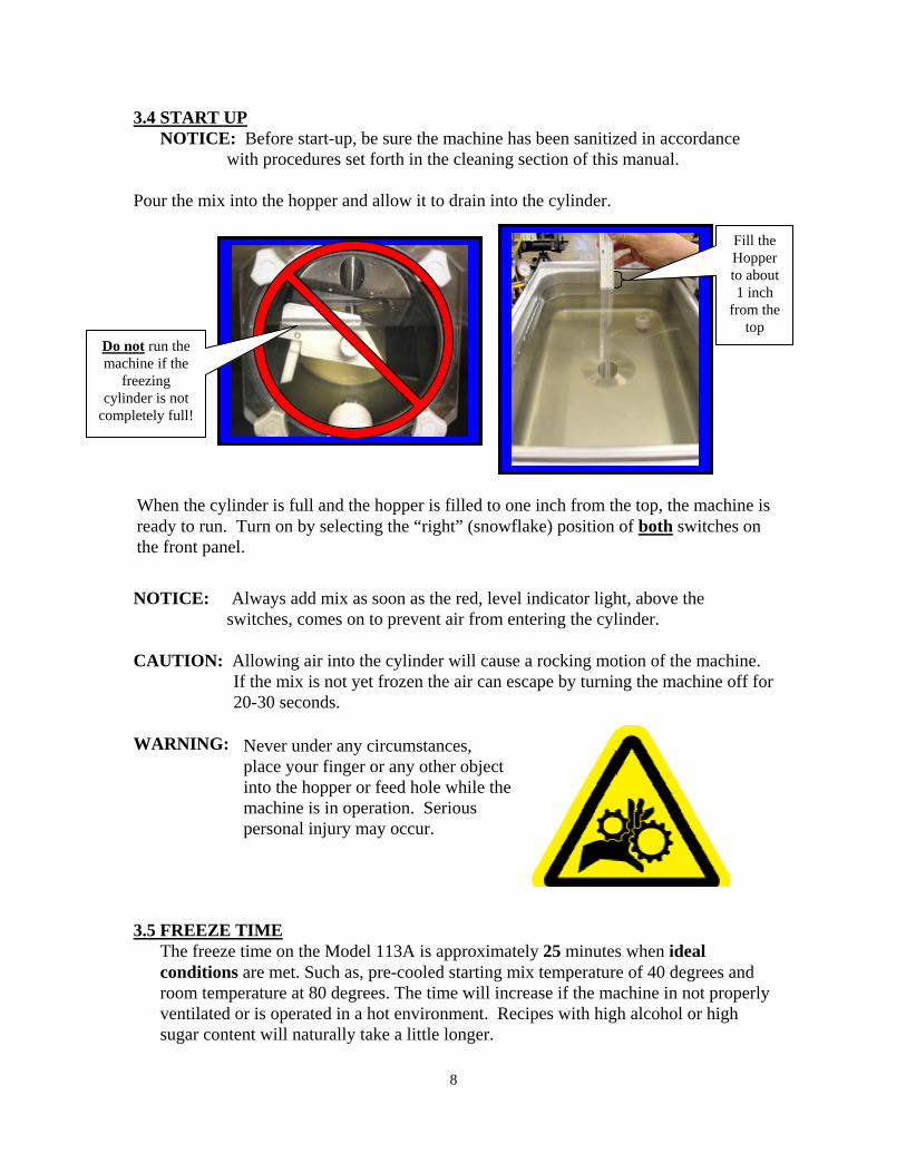
with procedures set forth in the cleaning section of this manual. Pour the mix into the hopper and allow it to drain into the cylinder.
NOTICE: Always add mix as soon as the red, level indicator light, above the
switches, comes on to prevent air from entering the cylinder. CAUTION: Allowing air into the cylinder will cause a rocking motion of the machine.
If the mix is not yet frozen the air can escape by turning the machine off for 20-30 seconds.
WARNING:
3.5 FREEZE TIME
The freeze time on the Model 113A is approximately 25 minutes when ideal conditions are met. Such as, pre-cooled starting mix temperature of 40 degrees and room temperature at 80 degrees. The time will increase if the machine in not properly ventilated or is operated in a hot environment. Recipes with high alcohol or high sugar content will naturally take a little longer.
Never under any circumstances, place your finger or any other object into the hopper or feed hole while the machine is in operation. Serious personal injury may occur.
When the cylinder is full and the hopper is filled to one inch from the top, the machine is ready to run. Turn on by selecting the “right” (snowflake) position of both switches on the front panel.
Fill the Hopper to about 1 inch
from the top
Do not run the machine if the
freezing cylinder is not
completely full!
9
SECTION 4 MAINTENANCE
4.1 CLEANING
The following cleaning procedure should be used for initial start-up and on an as needed basis to comply with the minimum cleaning and sanitizing frequencies specified by the federal, state or local regulatory agency having jurisdiction.
NOTICE: Do not put hands or foreign matter into mix. (3) Pour two gallons of cool (75ºF.) water into the hopper. Clean the hopper and feed
hole. Place upper switch in “faucet” position to let the machine stir for 2 minutes. Turn machine “OFF”, drain and dispose of the rinse water. Repeat until water is clear.
CAUTION: Do not pour hot water into a cold or cool machine as it can crack the cylinder and destroy the machine.
NOTICE: Do not unscrew faucet body from faceplate to clean. (Leak free service after disturbing the Teflon seal cannot be assured). (7) All parts removed during the above steps plus the drip tray and insert can now be
cleaned in your warm (100º F) sanitized solution. Rinse all parts in clean rinse water and allow to air-dry before re-assembly.
(8) Parts may also be placed into a dishwasher for cleaning. HOWEVER, Do not “heat-dry” as this will warp the plastic faceplate and cause it leak upon reassembly.
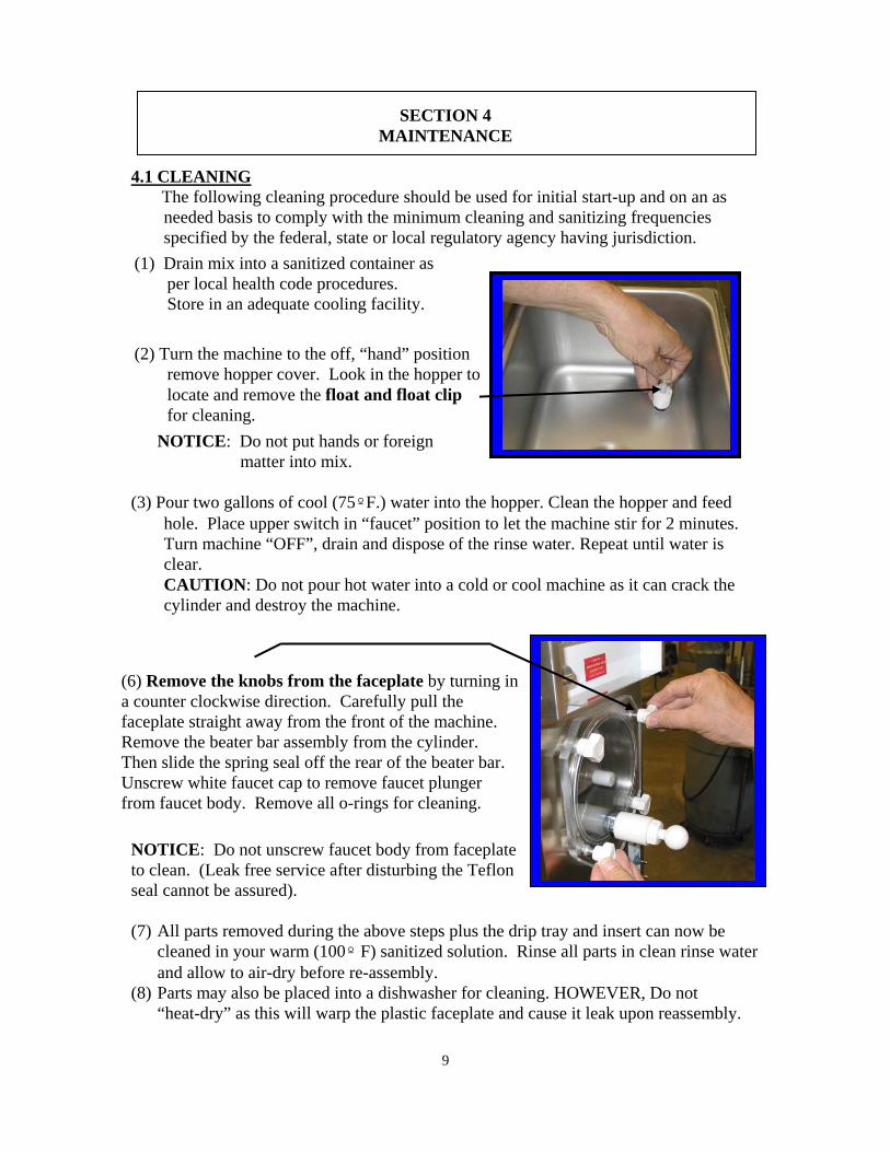
(2) Turn the machine to the off, “hand” position remove hopper cover. Look in the hopper to locate and remove the float and float clip for cleaning.
(6) Remove the knobs from the faceplate by turning in a counter clockwise direction. Carefully pull the faceplate straight away from the front of the machine. Remove the beater bar assembly from the cylinder. Then slide the spring seal off the rear of the beater bar. Unscrew white faucet cap to remove faucet plunger from faucet body. Remove all o-rings for cleaning.
(1) Drain mix into a sanitized container as per local health code procedures. Store in an adequate cooling facility.
10
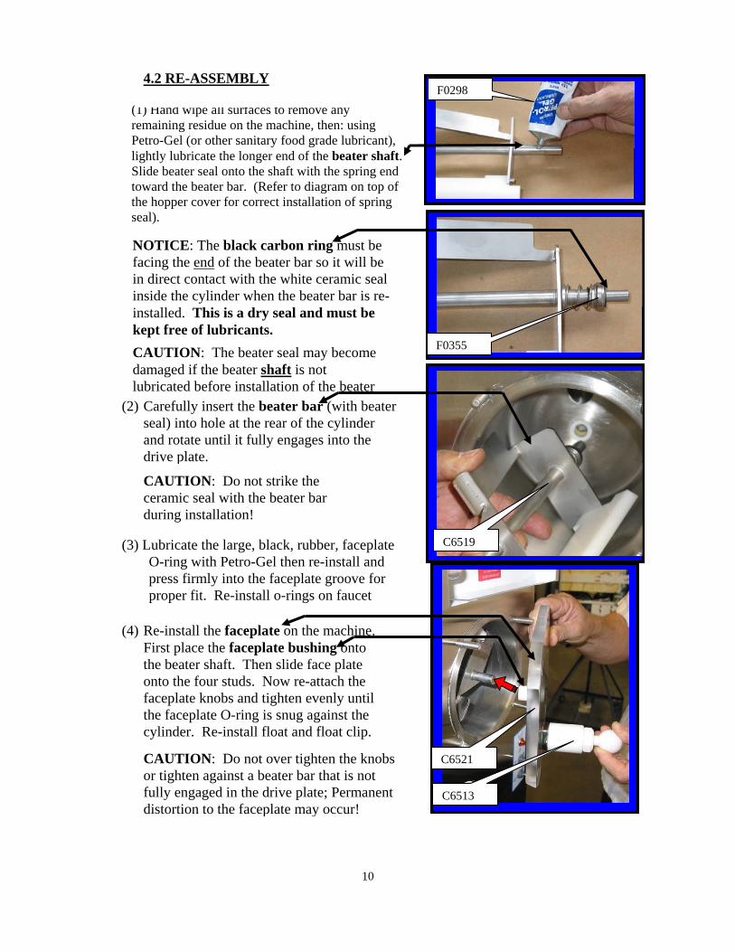
(1) Hand wipe all surfaces to remove any remaining residue on the machine, then: using Petro-Gel (or other sanitary food grade lubricant), lightly lubricate the longer end of the beater shaft. Slide beater seal onto the shaft with the spring end toward the beater bar. (Refer to diagram on top of the hopper cover for correct installation of spring seal).
NOTICE: The black carbon ring must be facing the end of the beater bar so it will be in direct contact with the white ceramic seal inside the cylinder when the beater bar is re-installed. This is a dry seal and must be kept free of lubricants. CAUTION: The beater seal may become damaged if the beater shaft is not lubricated before installation of the beater
l(2) Carefully insert the beater bar (with beater seal) into hole at the rear of the cylinder and rotate until it fully engages into the drive plate.
CAUTION: Do not strike the ceramic seal with the beater bar during installation!
(3) Lubricate the large, black, rubber, faceplate O-ring with Petro-Gel then re-install and press firmly into the faceplate groove for proper fit. Re-install o-rings on faucet
(4) Re-install the faceplate on the machine. First place the faceplate bushing onto the beater shaft. Then slide face plate onto the four studs. Now re-attach the faceplate knobs and tighten evenly until the faceplate O-ring is snug against the cylinder. Re-install float and float clip.
CAUTION: Do not over tighten the knobs or tighten against a beater bar that is not fully engaged in the drive plate; Permanent distortion to the faceplate may occur!
4.2 RE-ASSEMBLY F0298
F0355
C6519
C6521
C6513
11
(5) Mix two gallons of warm water with one 2 oz. packet of sanitizer. (6) Pour two gallons of solution into hopper. Clean the hopper and feed hole with a
clean sanitized brush. (7) Place upper switch in “faucet” position. Let solution stir for 5 minutes. Turn upper
switch “OFF” (hand position), Drain all solution. (DO NOT RINSE!) (8) Pour product into hopper. Replace hopper cover. Place both switches in right
(snowflake) position when ready to freeze product. 4.3 PREVENTATIVE MAINTENANCE It is recommended that a maintenance schedule be followed to keep the machine clean and operating properly. WARNING: never attempt to repair or perform maintenance on machine until the main
electrical power has been disconnected. A. DAILY
The exterior of the machine should be kept clean at all times to preserve the luster of the stainless steel. A mild alkaline cleaner is recommended. Use a soft cloth or sponge to apply the cleaner.
B. WEEKLY (1) Check O-rings and rear seal for excessive wear and replace if necessary. (2) Clean the drip tray and front of the freezer with a soap solution. C. MONTHLY CAUTION: Air-cooled condensers must have proper air circulation. Failure to clean
the condenser on a regular basis may result in serious damage and could void the warranty.
(1) Visually inspect the condenser for dirt by shining a light through the coil from the inside of the condenser.
(2) If the condenser is dirty, place a wet towel over the outside of the condenser. (3) Using compressed air or a CO2 tank, blow out the dirt from the inside of the
condenser. Most of the dirt will cling to the wet towel. (4) An alternative method of cleaning the condenser is to use a condenser brush and
vacuum. NOTICE: If the condenser is not kept clean, loss of refrigeration efficiency will
result, causing extended run time or soft product consistency. 4.4 EXTENDED STORAGE Refer to the following steps for storage of the machine over any long shutdown period: (1) Turn the three position switch to the OFF (center) position. (2) Disconnect (unplug) from the electrical supply source. (3) Clean thoroughly with a warm detergent all parts that come in contact with the mix.
Rinse in clean water and dry all parts. Do not sanitize. Petite Sorbeteer parts can be left disassembled until ready for use.
NOTICE: Do not let the cleaning solution stand in the hopper or in the cylinder during the shutdown period.
12
4,5 TROUBLESHOOTING 1. Machine does not run when turned on.___________________________________
A. Be sure that the plug is properly installed in wall outlet. B. Check and reset circuit breaker if necessary. C. Be sure that no other appliances are sharing the circuit. D. If problem remains, call service repairman.
2. Beater motor starts but compressor doesn’t start ___________________________ A. Both switches must be in the right (Snowflake) position. B. Allow approximately one or two minutes for time delay to respond. C. Check that the machine has been properly leveled. D. If necessary adjust TCC screw. E. If problem causes circuit breaker to trip, call service repairman.
3. Mix dripping from drip tube.___________________________________________ A. Spring seal on beater bar is dirty or improperly installed. Remove, clean and re-install spring seal
assembly according to instructions and diagram on top of the hopper cover. B. Ceramic seal (inside the freezing cylinder) is dirty or loose. Clean ceramic seal. If loose re-install
as necessary. Also check that the carbon ring on the seal is not chipped, cracked, dirty or greasy. Replace seal if necessary.
4. Unit runs but product does not freeze to desired consistency.________________ A. Check recipe for proper amount of sugar. B. Check tension of TCC screw, if necessary turn clockwise to increase thickness of drink. C. Check unit for adequate ventilation. (At least 8” clearance required on the sides and 6” at the
rear). D. Check the condenser to see if it has become clogged with lint, dust etc. Clean as necessary. E. Be sure that the cylinder is full of mix. F. If problem remains, call service repairman.
5. Fill light is on when hopper is full of product._____________________________ A. Remove and re-install float with two dots facing up. (See pg. 16)
B. If float is stuck, clean float and stem and re-assemble. 6. No product comes out when faucet handle is pulled while unit is running.______
A. Frozen product is blocking “feed hole”. Turn machine off then clear ice plug from feed hole. WARNING: Never place fingers in the “feed hole” as serious personal injury may occur. B. Mix is frozen solid. Low sugar content, product separation or cylinder not full.
7. Compressor starts and stops intermittently ________________________________ A. Check to see that the fan is turning freely. B. Check the condenser to be sure that it is not clogged with lint or dust. C. If the on/off time is 30 seconds or longer, this is normal if product is frozen and no product has
been pulled in a while. D. If the problem is causing the breaker to trip, call service repairman.
8. Unit continues to run when switched to stand-by___________________________ A. Have qualified technician remove back panel and reset thermostat. (Turn all the way off then turn
all the way on again.) B. If problem remains call service repairman.
9. Beater bar does not turn_______________________________________________ A. Mix is frozen solid. Low sugar content, product separation or cylinder not full. B. Drive coupling stripped. Drive coupling needs to be replaced C. Faulty motor. Replace motor
13
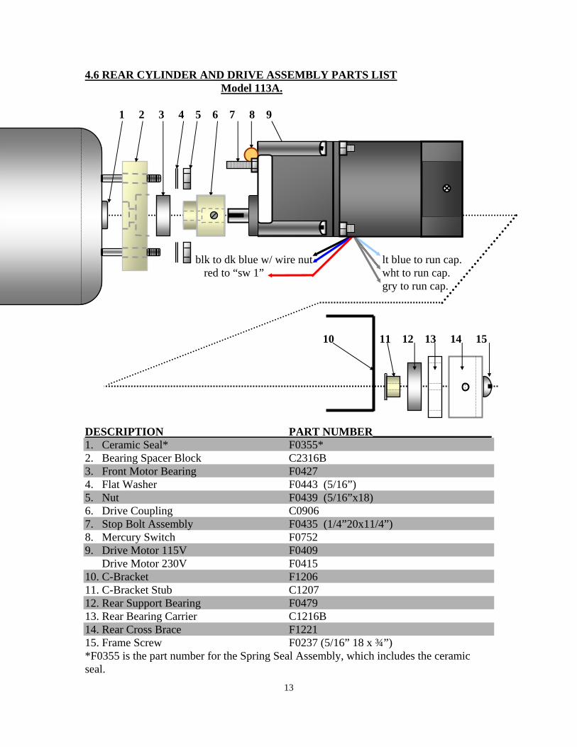
4.6 REAR CYLINDER AND DRIVE ASSEMBLY PARTS LIST Model 113A.
1 2 3 4 5 6 7 8 9
blk to dk blue w/ wire nut lt blue to run cap. red to “sw 1” wht to run cap. gry to run cap. 10 11 12 13 14 15 DESCRIPTION PART NUMBER_____________________ 1. Ceramic Seal* F0355* 2. Bearing Spacer Block C2316B 3. Front Motor Bearing F0427 4. Flat Washer F0443 (5/16”) 5. Nut F0439 (5/16”x18) 6. Drive Coupling C0906 7. Stop Bolt Assembly F0435 (1/4”20x11/4”) 8. Mercury Switch F0752 9. Drive Motor 115V F0409 Drive Motor 230V F0415 10. C-Bracket F1206 11. C-Bracket Stub C1207 12. Rear Support Bearing F0479 13. Rear Bearing Carrier C1216B 14. Rear Cross Brace F1221 15. Frame Screw F0237 (5/16” 18 x ¾”) *F0355 is the part number for the Spring Seal Assembly, which includes the ceramic seal.
14
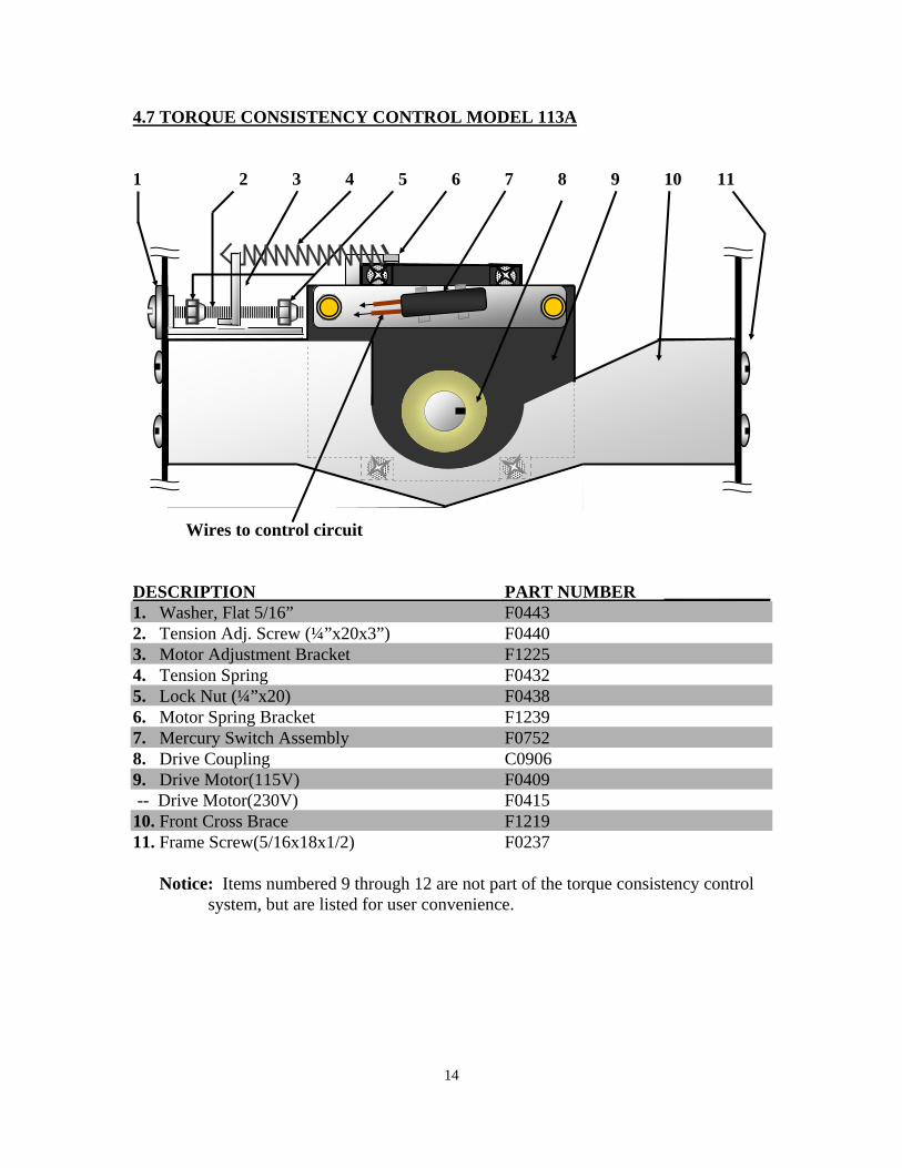
4.7 TORQUE CONSISTENCY CONTROL MODEL 113A
1 2 3 4 5 6 7 8 9 10 11 Wires to control circuit DESCRIPTION PART NUMBER ____________ 1. Washer, Flat 5/16” F0443 2. Tension Adj. Screw (¼”x20x3”) F0440 3. Motor Adjustment Bracket F1225 4. Tension Spring F0432 5. Lock Nut (¼”x20) F0438 6. Motor Spring Bracket F1239 7. Mercury Switch Assembly F0752 8. Drive Coupling C0906 9. Drive Motor(115V) F0409 -- Drive Motor(230V) F0415 10. Front Cross Brace F1219 11. Frame Screw(5/16x18x1/2) F0237 Notice: Items numbered 9 through 12 are not part of the torque consistency control system, but are listed for user convenience.
15
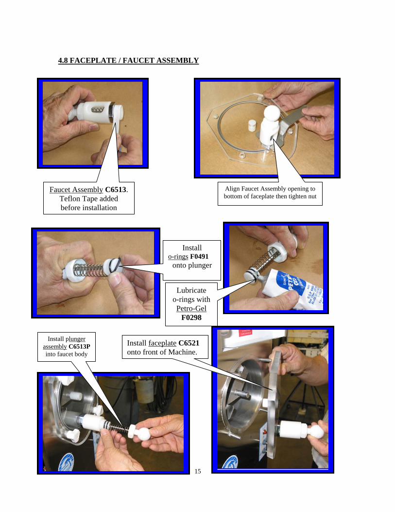
4.8 FACEPLATE / FAUCET ASSEMBLY
Faucet Assembly C6513. Teflon Tape added before installation
Lubricate o-rings with Petro-Gel
F0298
Install plunger assembly C6513P into faucet body
Install faceplate C6521 onto front of Machine.
Install o-rings F0491
onto plunger
Align Faucet Assembly opening to bottom of faceplate then tighten nut
16
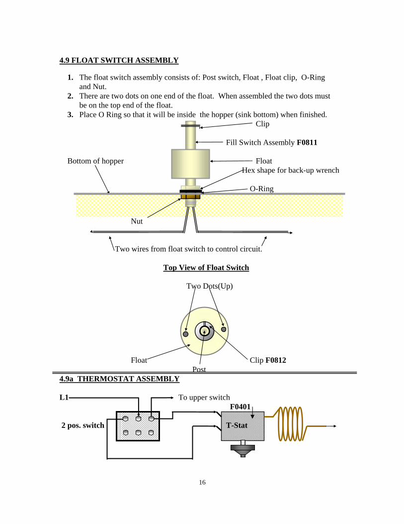
4.9 FLOAT SWITCH ASSEMBLY
1. The float switch assembly consists of: Post switch, Float , Float clip, O-Ring and Nut. 2. There are two dots on one end of the float. When assembled the two dots must be on the top end of the float. 3. Place O Ring so that it will be inside the hopper (sink bottom) when finished. Clip Fill Switch Assembly F0811 Bottom of hopper Float Hex shape for back-up wrench O-Ring Nut Two wires from float switch to control circuit.
Top View of Float Switch Two Dots(Up) Float Clip F0812 Post
4.9a THERMOSTAT ASSEMBLY
L1 To upper switch F0401 2 pos. switch T-Stat
17
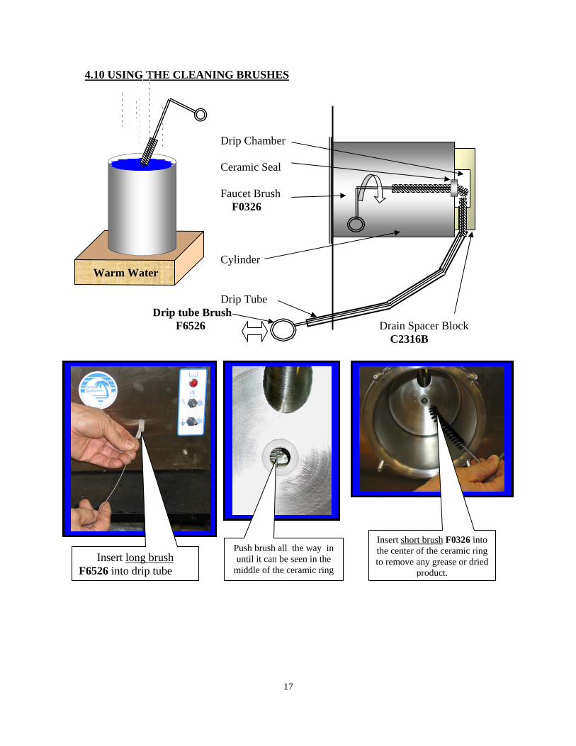
4.10 USING THE CLEANING BRUSHES
Drip Chamber
Ceramic Seal
Faucet Brush F0326
Cylinder Warm Water
Drip Tube
Drip tube Brush F6526 Drain Spacer Block
C2316B
Insert long brush F6526 into drip tube
Insert short brush F0326 into the center of the ceramic ring to remove any grease or dried
product.
Push brush all the way in until it can be seen in the
middle of the ceramic ring
18
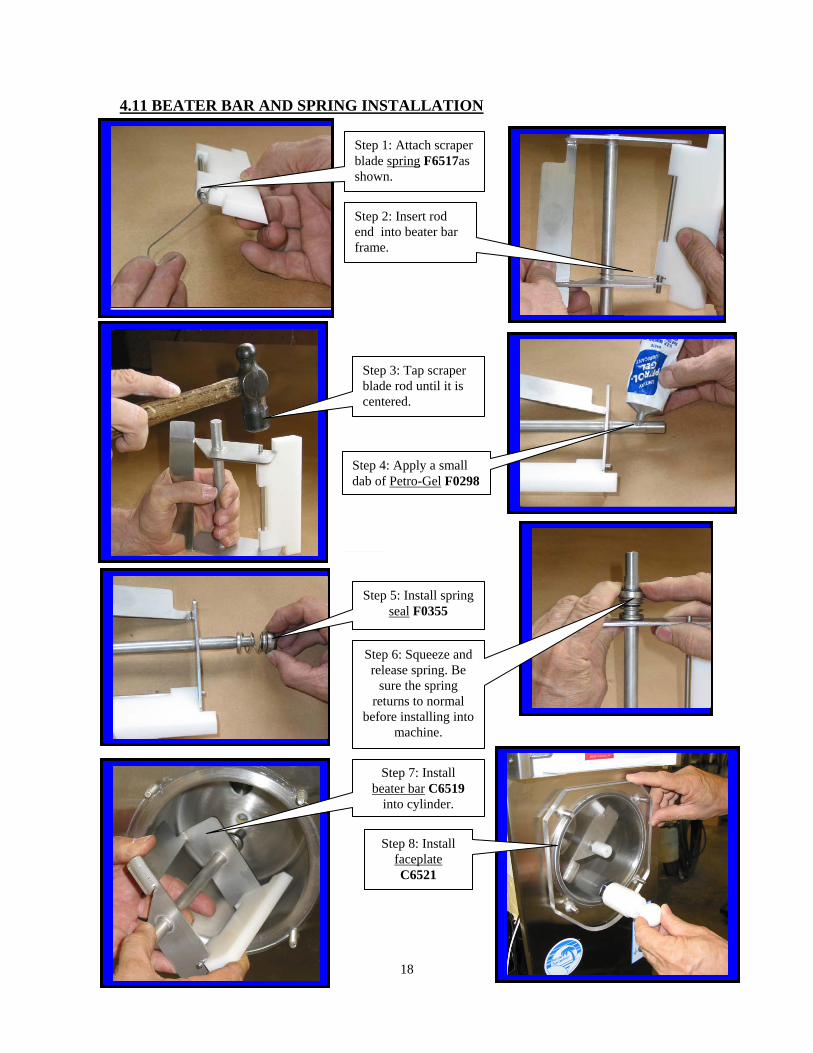
4.11 BEATER BAR AND SPRING INSTALLATION
.
Step 1: Attach scraper blade spring F6517as shown.
Step 2: Insert rod end into beater bar frame.
Step 4: Apply a small dab of Petro-Gel F0298
Step 3: Tap scraper blade rod until it is centered.
Step 5: Install spring seal F0355
Step 7: Install beater bar C6519
into cylinder.
Step 6: Squeeze and release spring. Be
sure the spring returns to normal
before installing into machine.
Step 8: Install faceplate C6521
19
4.12 BEATER BAR SEAL ASSEMBLY 1. Using Petro-Gel (or other sanitary food grade lubricant), lightly lubricate the longer
end of the beater shaft. Slide beater seal onto the shaft with the spring end toward the beater bar. (Refer to diagram in this section of your manual or on top of the hopper cover for correct installation of spring seal).
2. The black carbon ring must be facing the end of the beater bar so it will be in direct contact with the white ceramic seal inside the cylinder when the beater bar is re-installed. This is a dry seal and must be kept free of lubricants. Lube the beater bar shaft ONLY!
3. The beater seal may become damaged if the beater shaft is not lubricated before installation of the beater seal.
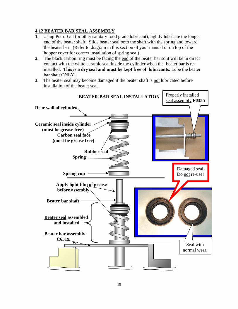
BEATER-BAR SEAL INSTALLATION
Rear wall of cylinder
Ceramic seal inside cylinder (must be grease free) Carbon seal face (must be grease free)
Rubber seal
Spring
Spring cup
Apply light film of grease before assembly Beater bar shaft
Beater seal assembled and installed
Beater bar assembly C6519
Damaged seal. Do not re-use!
Seal with normal wear.
Properly installed seal assembly F0355
20
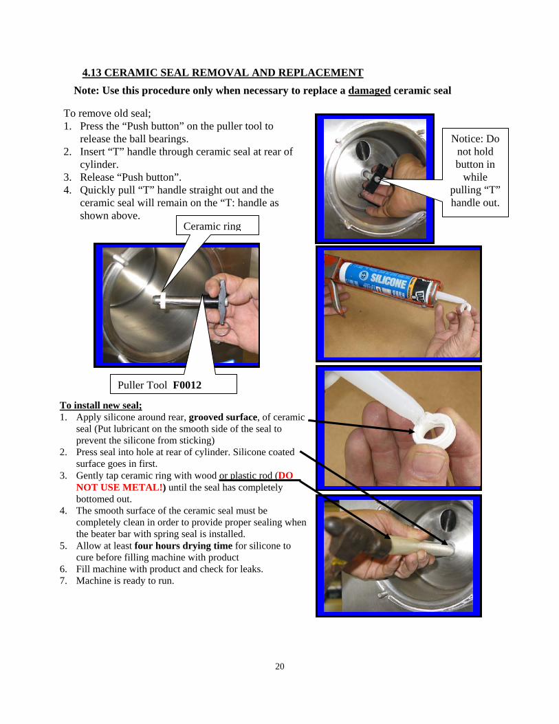
To remove old seal; 1. Press the “Push button” on the puller tool to
release the ball bearings. 2. Insert “T” handle through ceramic seal at rear of
cylinder. 3. Release “Push button”. 4. Quickly pull “T” handle straight out and the
ceramic seal will remain on the “T: handle as shown above.
4.13 CERAMIC SEAL REMOVAL AND REPLACEMENT
To install new seal; 1. Apply silicone around rear, grooved surface, of ceramic
seal (Put lubricant on the smooth side of the seal to prevent the silicone from sticking)
2. Press seal into hole at rear of cylinder. Silicone coated surface goes in first.
3. Gently tap ceramic ring with wood or plastic rod (DO NOT USE METAL!) until the seal has completely bottomed out.
4. The smooth surface of the ceramic seal must be completely clean in order to provide proper sealing when the beater bar with spring seal is installed.
5. Allow at least four hours drying time for silicone to cure before filling machine with product
6. Fill machine with product and check for leaks. 7. Machine is ready to run.
Notice: Do not hold button in
while pulling “T” handle out.
Puller Tool F0012
Ceramic ring
Note: Use this procedure only when necessary to replace a damaged ceramic seal
21
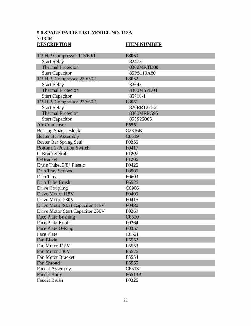
5.0 SPARE PARTS LIST MODEL NO. 113A 7-13-04 DESCRIPTION ITEM NUMBER 1/3 H.P Compressor 115/60/1 F8050 Start Relay 82473 Thermal Protector 8300MRTD88 Start Capacitor 85PS110A80 1/3 H.P. Compressor 220/50/1 F8052 Start Relay 82645 Thermal Protector 8300MSPD91 Start Capacitor 85710-1 1/3 H.P. Compressor 230/60/1 F8051 Start Relay 820RR12E86 Thermal Protector 8300MRPG95 Start Capacitor 855S22065 Air Condenser F5551 Bearing Spacer Block C2316B Beater Bar Assembly C6519 Beater Bar Spring Seal F0355 Bottom, 2-Position Switch F0417 C-Bracket Stub F1207 C-Bracket F1206 Drain Tube, 3/8” Plastic F0426 Drip Tray Screws F0905 Drip Tray F6603 Drip Tube Brush F6526 Drive Coupling C0906 Drive Motor 115V F0409 Drive Motor 230V F0415 Drive Motor Start Capacitor 115V F0430 Drive Motor Start Capacitor 230V F0369 Face Plate Bushing C6520 Face Plate Knob F0264 Face Plate O-Ring F0357 Face Plate C6521 Fan Blade F5552 Fan Motor 115V F5553 Fan Motor 230V F5576 Fan Motor Bracket F5554 Fan Shroud F5555 Faucet Assembly C6513 Faucet Body F6513B Faucet Brush F0326
22
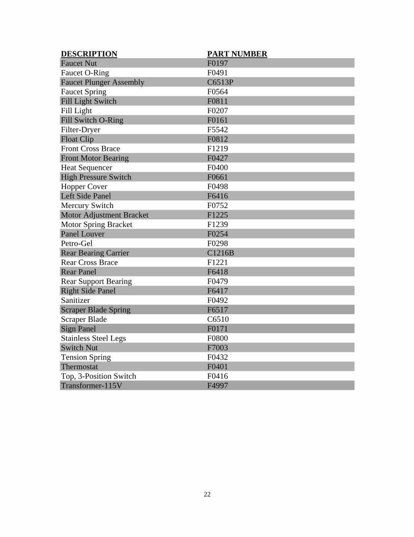
DESCRIPTION PART NUMBER Faucet Nut F0197 Faucet O-Ring F0491 Faucet Plunger Assembly C6513P Faucet Spring F0564 Fill Light Switch F0811 Fill Light F0207 Fill Switch O-Ring F0161 Filter-Dryer F5542 Float Clip F0812 Front Cross Brace F1219 Front Motor Bearing F0427 Heat Sequencer F0400 High Pressure Switch F0661 Hopper Cover F0498 Left Side Panel F6416 Mercury Switch F0752 Motor Adjustment Bracket F1225 Motor Spring Bracket F1239 Panel Louver F0254 Petro-Gel F0298 Rear Bearing Carrier C1216B Rear Cross Brace F1221 Rear Panel F6418 Rear Support Bearing F0479 Right Side Panel F6417 Sanitizer F0492 Scraper Blade Spring F6517 Scraper Blade C6510 Sign Panel F0171 Stainless Steel Legs F0800 Switch Nut F7003 Tension Spring F0432 Thermostat F0401 Top, 3-Position Switch F0416 Transformer-115V F4997
23
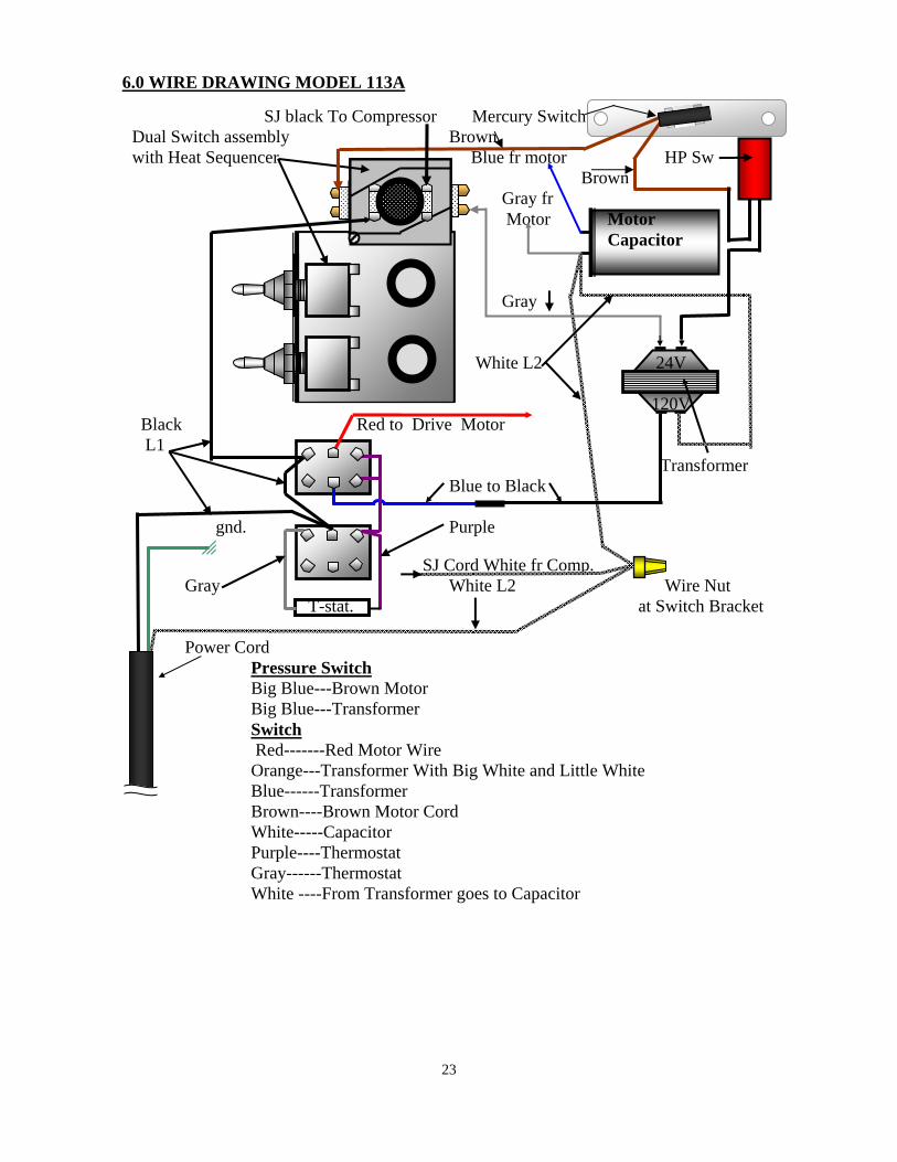
SJ black To Compressor Mercury Switch Dual Switch assembly Brown with Heat Sequencer Blue fr motor HP Sw Brown Gray fr Motor Motor Capacitor Gray White L2 24V 120V Black Red to Drive Motor L1 Transformer Blue to Black gnd. Purple o SJ Cord White fr Comp. Gray White L2 Wire Nut T-stat. at Switch Bracket Power Cord Pressure Switch Big Blue---Brown Motor Big Blue---Transformer Switch
Red-------Red Motor Wire Orange---Transformer With Big White and Little White Blue------Transformer Brown----Brown Motor Cord White-----Capacitor Purple----Thermostat Gray------Thermostat
White ----From Transformer goes to Capacitor
6.0 WIRE DRAWING MODEL 113A
24
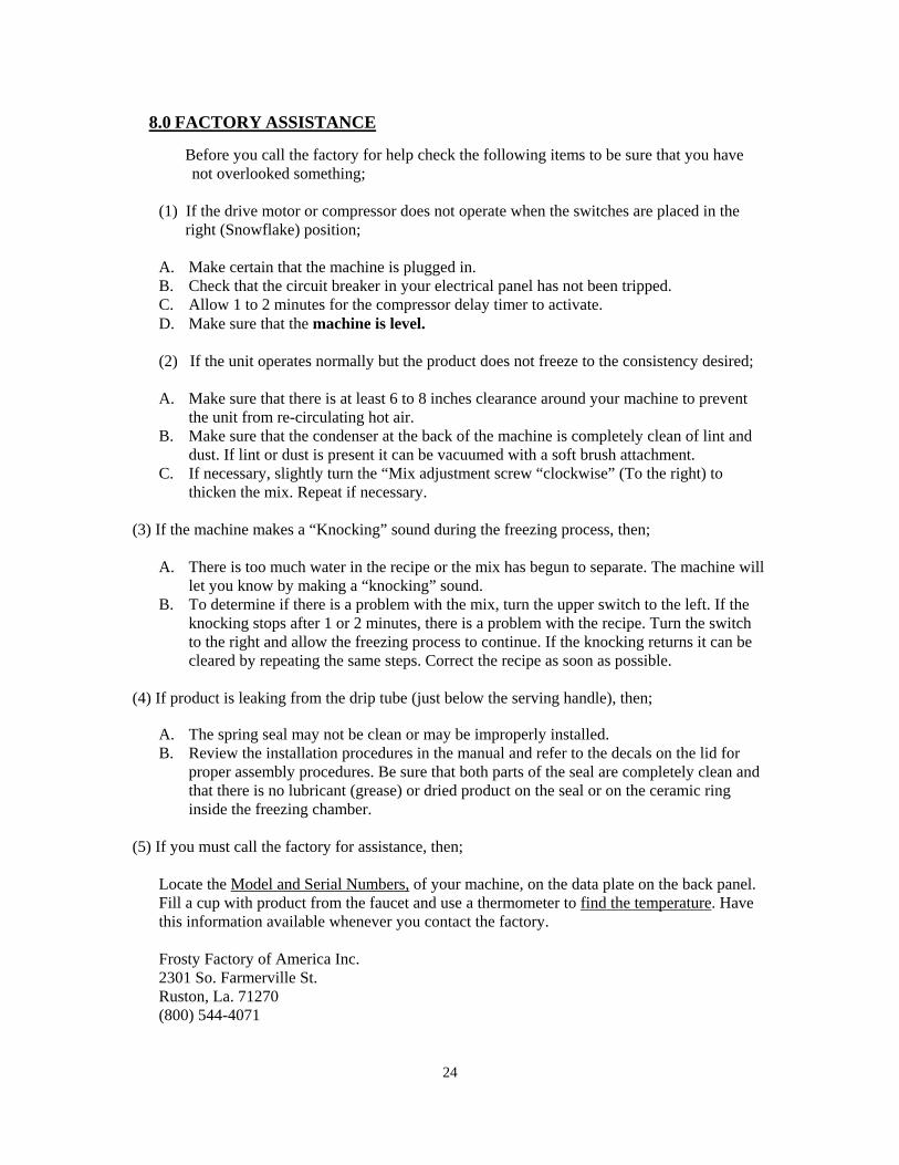
Before you call the factory for help check the following items to be sure that you have not overlooked something;
(1) If the drive motor or compressor does not operate when the switches are placed in the
right (Snowflake) position; A. Make certain that the machine is plugged in. B. Check that the circuit breaker in your electrical panel has not been tripped. C. Allow 1 to 2 minutes for the compressor delay timer to activate. D. Make sure that the machine is level. (2) If the unit operates normally but the product does not freeze to the consistency desired; A. Make sure that there is at least 6 to 8 inches clearance around your machine to prevent
the unit from re-circulating hot air. B. Make sure that the condenser at the back of the machine is completely clean of lint and
dust. If lint or dust is present it can be vacuumed with a soft brush attachment. C. If necessary, slightly turn the “Mix adjustment screw “clockwise” (To the right) to
thicken the mix. Repeat if necessary.
(3) If the machine makes a “Knocking” sound during the freezing process, then; A. There is too much water in the recipe or the mix has begun to separate. The machine will
let you know by making a “knocking” sound. B. To determine if there is a problem with the mix, turn the upper switch to the left. If the
knocking stops after 1 or 2 minutes, there is a problem with the recipe. Turn the switch to the right and allow the freezing process to continue. If the knocking returns it can be cleared by repeating the same steps. Correct the recipe as soon as possible.
(4) If product is leaking from the drip tube (just below the serving handle), then;
A. The spring seal may not be clean or may be improperly installed. B. Review the installation procedures in the manual and refer to the decals on the lid for
proper assembly procedures. Be sure that both parts of the seal are completely clean and that there is no lubricant (grease) or dried product on the seal or on the ceramic ring inside the freezing chamber.
(5) If you must call the factory for assistance, then;
Locate the Model and Serial Numbers, of your machine, on the data plate on the back panel. Fill a cup with product from the faucet and use a thermometer to find the temperature. Have this information available whenever you contact the factory. Frosty Factory of America Inc. 2301 So. Farmerville St. Ruston, La. 71270 (800) 544-4071
8.0 FACTORY ASSISTANCE