September 21, 1973 - adams
238
September 21, 1973 SAFETY EVALUATION REPORT BY THE DIRECTORATE OF LICENSING U.S. ATOMIC ENERGY COMMISSION IN THE MATTER OF CONSOLIDATED EDISON COMPANY OF NEW YORK, INC. INDIAN POINT NUCLEAR GENERATING UNIT NO. 3 DOCKET NO. 50-286 A
-
Upload
khangminh22 -
Category
Documents
-
view
2 -
download
0
Transcript of September 21, 1973 - adams

September 21, 1973
SAFETY EVALUATION REPORT
BY THE
DIRECTORATE OF LICENSING
U.S. ATOMIC ENERGY COMMISSION
IN THE MATTER OF
CONSOLIDATED EDISON COMPANY OF NEW YORK, INC.
INDIAN POINT NUCLEAR GENERATING UNIT NO. 3
DOCKET NO. 50-286
A

i
TABLE OF CONTENTS
Page
1.0 INTRODUCTION ............................... ................ 1-1
1.1 General Background ...................................... 1-1
1.2 General Plant Description ............................. 1-31.3 Comparison with Similar Facility Designs ............. 1-5 -
1.4 Identification of Agents and Contractors ............. 1-61.5 Summary of Principal Review Matters .................. 1-61.6 Facility Modifications Required as a Consequence
of Regulatory Staff Review ........................... 1-8
2.0 SITE CHARACTERISTICS .......................................... 2-12.1 Geography and Demography ................................ 2-12.2 Nearby Industrial, Transportation and Military
Facilities ............................................ 2-42.3 Meteorology ............................................. 2-62.4 Hydrology ...................................... ......... 2-152.5 Geology, Seismology, and Foundation Engineering ...... 2-21
3.0 DESIGN CRITERIA - STRUCTURES, COMPONENTS, EQUIPMENT, ANDSYSTEMS .................................................... 3-13.1 Conformance with AEC General Design Criteria .... ; .... 3-13.2 Classification of Structures, Components and Systems. 3-13.3 Wind and Tornado Criteria ............................... 3-23.4 Water Level (Flood) Design Criteria .................. 3-33.5 Missile Protection Criteria ............................. 3-43.6 Protection Against Dynamic Effects Associated with
the Loss-of-Coolant Accident ......................... 3-53.7 Seismic Design .......................................... 3-53.8 Design of Category I Structures ........................ 3-83.9 Mechanical Systems and Components ...................... 3-9
3.9.1 Dynamic System Analysis and Testing .......... 3-9
3.9.2 Category I Components Outside of theReactor Coolant Pressure Boundary ........... 3-11
3.10 Seismic Qualification of Category I Instrumentationand Electrical Equipment .............................. 3-12
4.0 REACTOR ........................................................ 4-14.1 Summary Description ..................................... 4-1
4.2 Mechanical Design of Reactor Vessel Internals .......... 4-14.3 Nuclear Design .......................................... 4-24.4 Thermal and Hydraulic Design ........................... 4-6

Ui
TABLE OF CONTENTS (Cont'd)
Page
5.0 REACTOR COOLANT SYSTEM ......................................... 5-15.1 Summary Description ...................................... 5-15.2 Integrity of Reactor Coolant Pressure Boundary ....... 5-15.3 Reactor Vessel Material Surveillance Program ......... 5-55.4 LeakageDetection System ................................. 5-75.5 Pump Flywheel Integrity .................................. 5-85.6 Evaluation of the Integrity of the Reactor Vessel .... 5-85.7 Loose Parts Monitor ...................................... 5-10
6.0 ENGINEERED SAFETY FEATURES ..................................... 6-16.1 General ................................................... 6-16.2 Containment Systems ...................................... 6-2
6.2.1 Containment Functional Design ............... 6-26.2.2 Containment Heat Removal Systems ............. 6-66.2.3 Containment Isolation Systems ................ 6-96.2.4 Combustible Gas Control Systems .............. 6-106.2.5 Leakage Testing Program ...................... 6-12
6.3 Emergency Core Cooling System (ECCS) .................... 6-136.3.1 Design Bases ..................................... 6-136.3.2 System Design .................................... 6-136.3.3 Performance Evaluation ....................... 6-16
6.4 Auxiliary Feedwater System .............................. 6-196.5 Fuel Densification ....................................... 6-246.6 Post Loss-of-Coolant Accident Protection (PLOCAP) .... 6-31
7.0 INSTRUMENTATION AND CONTROL SYSTEMS ............................ 7-17.1 General ............................................... 7-17.2 Reactor Trip System ...................................... 7-17.3 Initiation and Control of Engineered Safety
Feature Systems ........................................ 7-27.4 Systems Required for Safe Shutdown ................... 7-67.5 Safety-Related Display Instrumentation ............... 7-77.6 RHR System Interlocks .................................... 7-77.7 Control Systems Not Required for Safety .............. 7-87.8 Seismic, Radiation, and Environmental Qualification.. 7-87.9 Common Mode Failures and Anticipated Transients
Without Scram .......................................... 7-9
8.0 ELECTRIC POWER ................................................. 8-18.1 General ................................................... 8-18.2 Offsite Power ....................... ......... ........ 8-18.3 Onsite Power ............................................. 8-2
8.3.1 A-C Power Systems ................................. 8-28.3.2 D-C Power Systems ................................. 8-3

iii
TABLE OF CONTENTS (Cont'd)
Page
8.4 Separation and Identification of Redundant Protectionand Emergency Power Systems ........................... 8-4
8.5 Diesel Fuel Oil System ................................... 8-5
9.0 AUXILIARY SYSTEMS ........................................... 9-19.1 Fuel Storage Systems and Handling Systems ............ 9-1
9.1.1 New Fuel Storage ................................. 9-19.1.2 Spent Fuel Storage ............................... 9-29.1.3 Spent Fuel Pool Cooling and Cleanup System... 9-39.1.4 Handling Systems ................................. 9-4
9.2 Water Systems ............................................ 9-8
9.2.1 Station Service Water System ................. 9-89.2.2 Cooling System for Reactor Auxiliaries ....... 9-109.2.3 Condensate Storage Facilities ................ 9-10
9.3 Process Auxiliaries ...................................... 9-119.3.1 Compressed Air System ........................... 9-119.3.2 Process Sampling System ......................... 9-12
9.3.3 Chemical, Volume Control, and LiquidPoison Systems ................................. 9-13
9.3.4 Gross Failed Fuel Detection System ........... 9-149.4 Air Conditioning, Heating, Cooling, and Ventila-
tion Systems ........................................... 9-159.4.1 Control Room ..................................... 9-15
9.4.2 Auxiliary Building and Radwaste Area ......... 9-159.4.3 Fuel Storage Building ........................... 9-16
9.5 Other Auxiliary Systems .................................. 9-169.5.1 Fire Protection Systems ......................... 9-169.5.2 Communication Systems ............................ 9-179.5.3 Diesel Generator Fuel Oil Storage and
Transfer System ................................ 9-189.5.4 Diesel Generator Cooling Water System ........ 9-199.5.5 Diesel Generator Starting System ............. 9-21
10.0 STEAM AND POWER CONVERSION SYSTEM .............................. 10-110.1 Summary Description ................................... 10-110.2 Turbine Generator ........................................ 10-110.3 High Energy Line Rupture Outside Containment ......... 10-210.4 Other Features of Steam and Power Conversion System.. 10-11

iv
TABLE OF CONTENTS (Cont'd)
Page
11.0 RADIOACTIVE WASTE MANAGEMENT ............... .................. 11-111.1 Design Objective and Criteria ............ ........... . .11-111.2 Liquid Waste ................. ....................... .. 11-3
11.2.1 Reactor Coolant Treatment System ............ .. 11-411.2.2 Liquid Waste Disposal System .... ........... .. 11-611.2.3 Steam Generator Blowdown.. ..................... 11-711.2.4 Liquid Waste Summary.. ......................... 11-8
11.3 Gaseous Wastes ................. ...................... .. 11-911.3.1 Waste Gas Processing ........... ............... 11-11
11.3.2 Containment Purge .......... ................ .. 11-1211.3.3 Condenser Air Ejector .......... .............. .. 11-1311.3.4 Steam Generator Blowdown ..... ............. .. 11-1411.3.5 Primary Auxiliary Building Ventilation ........ .. 11-1511.3.6 Turbine Building Ventilation.. ....... ...... .. 11-1611.3.7 Fuel Storage Building Ventilation . ... ...... .. 11-1611.3.8 Gaseous Waste Summary .......................... 11-17
11.4 Solid Wastes ............... ....................... .. 11-1811.5 Design ...................... .... . . . ... 11-2011.6 Process and Area Radiation Monitoring Systems ........ .. 11-2011.7 Personnel Protection ............. ................... .. 11-2211.8 Radiological Environmental Monitoring ...... .......... .. 11-2311.9 Conclusions ................ ....................... .. 11-24
12.0 RADIATION PROTECTION ................. ...................... .. 12-112.1 Shielding .................. ........................ .. 12-112.2 Ventilation ................. ....................... .. 12-112.3 Health Physics Program.. . .............................. 12-3
13.0 CONDUCT OF OPERATIONS ................... ................. 13-113.1 Plant Organization and Staff Qualifications ... ....... .. 13-113.2 Emergency Planning ..... .................. ....... .. 13-313.3 Safety Review and Audit ............ ................. .. 13-513.4 Plant Procedures ............... ..................... .. 13-613.5 Industrial Security .............. ................... .. 13-6
14.0 INITIAL TESTS AND OPERATION ............ .................. .. 14-1
15.0 ACCIDENT ANALYSES ................ ....................... .. 15-115.1 General .................. ......................... .. 15-115.2 Iodine Removal Equipment ......... ................. ... 15-2
15.2.1 Spray .... .................... ........... 15-215.2.2 Charcoal Filters ........... ................. .. 15-3
15.3 Radiological Consequences of Postulated .... ..........Accidents ................ ....................... .. 15-4
15.4 Control Room Doses ............... .................... .. 15-4
V
TABLE OF CONTENTS (Cont'd)
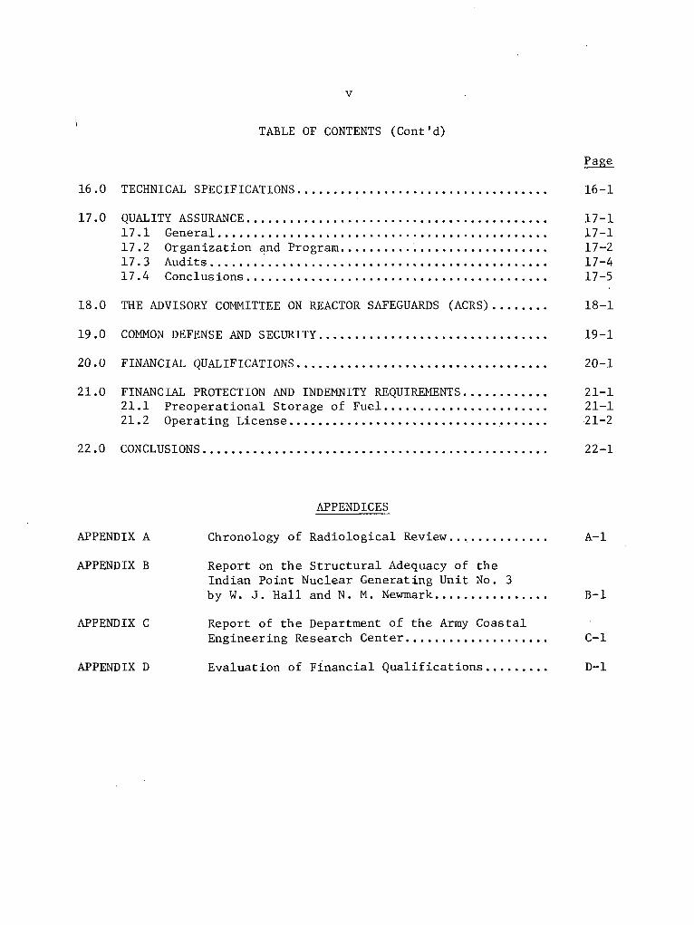
16.0 TECHNICAL SPECIFICATIONS ..................................
17.0 QUALITY ASSURANCE .........................................17.1 General .............................................17.2 Organization and Program .............................17.3 Audits ..............................................17.4 Conclusions .........................................
18.0 THE ADVISORY COMMITTEE ON REACTOR SAFEGUARDS (ACRS) .......
19.0 COMMON DEFENSE AND SECURITY ...............................
20.0 FINANCIAL QUALIFICATIONS ..................................
21.0 FINANCIAL PROTECTION AND INDEMNITY REQUIREMENTS ...........21.1 Preoperational Storage of Fuel ......................21.2 Operating License ....................................
22.0 CONCLUSIONS ...............................................
Page
16-1
17-117-117-217-417-5
18-1
19-1
20-1
21-121-121-2
22-1
APPENDIX A
APPENDIX B
APPENDIX C
APPENDIX D
APPENDICES
Chronology of Radiological Review..............
Report on the Structural Adequacy of theIndian Point Nuclear Generating Unit No. 3by W. J. Hall and N. M. Newmark ................
Report of the Department of the Army CoastalEngineering Research Center ....................
Evaluation of Financial Qualifications .........
A-1
B-1
C-I
D-1
vi
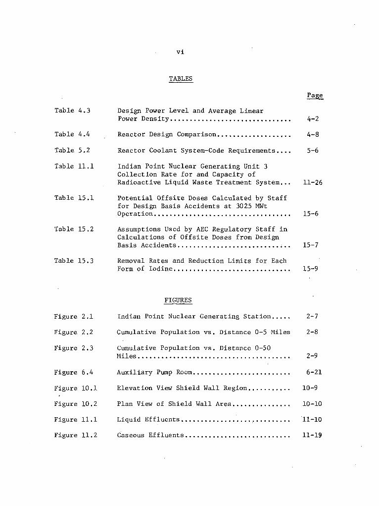
TABLES
Table 4.3
Table
Table
Table
4.4
5.2
11.1
Design Power Level and Average LinearPower Density ...............................
Reactor Design Comparison ...................
Reactor Coolant System-Code Requirements ....
Indian Point Nuclear Generating Unit 3Collection Rate for and Capacity ofRadioactive Liquid Waste Treatment System...
Potential Offsite Doses Calculated by Stafffor Design Basis Accidents at 3025 MWtOperation ...................................
Assumptions Used by AEC Regulatory Staff inCalculations of Offsite Doses from DesignBasis Accidents ............................
Removal Rates and Reduction Limits for EachForm of Iodine ..............................
Page
4-2
4-8
5-6
11-26
15-6
15-7
15-9
Table 15. 1
Table 15.2
Table 15.3
Figure
Figure
Figure
Figure
Figure
Figure
Figure
Figure
2.1
2.2
2.3
6.4
10.1
10.2
11.1
11.2
FIGURES
Indian Point Nuclear Generating Station .....
Cumulative Population vs. Distance 0-5 Miles
Cumulative Population vs. Distance 0-50Miles .......................................
Auxiliary Pump Room .........................
Elevation View Shield Wall Region ...........
Plan View of Shield Wall Area ...............
Liquid Effluents ................... ! .........
Gaseous Effluents ............................
2-7
2-8
2-9
6-21
10-9
10-10
11-10
11-19

vii
ABBREVIATIONS
a-c
ACI
ACRS
AEC
AFP
AISC
ANS
ANSI
ASCE
ASME
ASTM
BIT
BTU/hr-ft2
CA
CARCFS
cc
cfs
CFR
CSS
DBA
d-c
Ak, Ap
At
alternating current
American Concrete Institute
Advisory Committee on Reactor Safeguards
United States Atomic Energy Commission
auxiliary feed pump
American Institute of Steel Construction
American Nuclear Society
American National Standards Institute
American Society of Civil Engineers
American Society of Mechanical Engineers
American Society for Testing and Materials
boron injection tank
British Thermal Units per hour per square foot
wake factor
containment air recirculation cooling and filtration system
cubic centimeter
cubic feet per second
Code of Federal Regulations
containment spray system
design basis accident
direct current
reactivity change
temperature change or difference

viii
DNB departure from nucleate boiling
DNBR departure from nucleate boiling ratio
ECCS emergency core cooling system
ESF engineered safety features
OF degrees Fahrenheit
FSAR final safety analysis report
ft feet
ft 2 square feet
ft 3 cubic feet
fps feet per second
fq total peaking factor
fz axial peaking factor
g gravitational acceleration, 32.2 feet per second per second
GDC AEC General Design Criteria for Nuclear Power Plants
gpm gallons per minute
HEPA high efficiency particulate air
IEEE Institute of Electrical and Electronics Engineers
in inch
km kilometer
kV kilovolt
kW kilowatt
kW/ft kilowatts per foot
lb pound
LOCA loss-of-coolant accident

ix
LPZ low population zone
m meter
2m square meters
mph miles per hour
m/s meters per second
MLLW mean low low water
MSL mean sea level
MWe megawatts electrical
MWt megawatts thermal
mrem one thousandth of a rad equivalent man
NaOH sodium hydroxide
NDT nil ductility transition
NOAA National Oceanic and Atmospheric Administration
NPSH net positive suction head
NSSS nuclear steam supply system
nvt neutron fluence, neutrons per square centimeter
PAB primary auxiliary building
PLOCAP post loss-of-coolant accident protection
PMF probable maximum flood
PMH probable maximum hurricane
ppm parts per million
PSAR preliminary safety analysis report
psf pounds per square foot
psi pounds per square inch
x
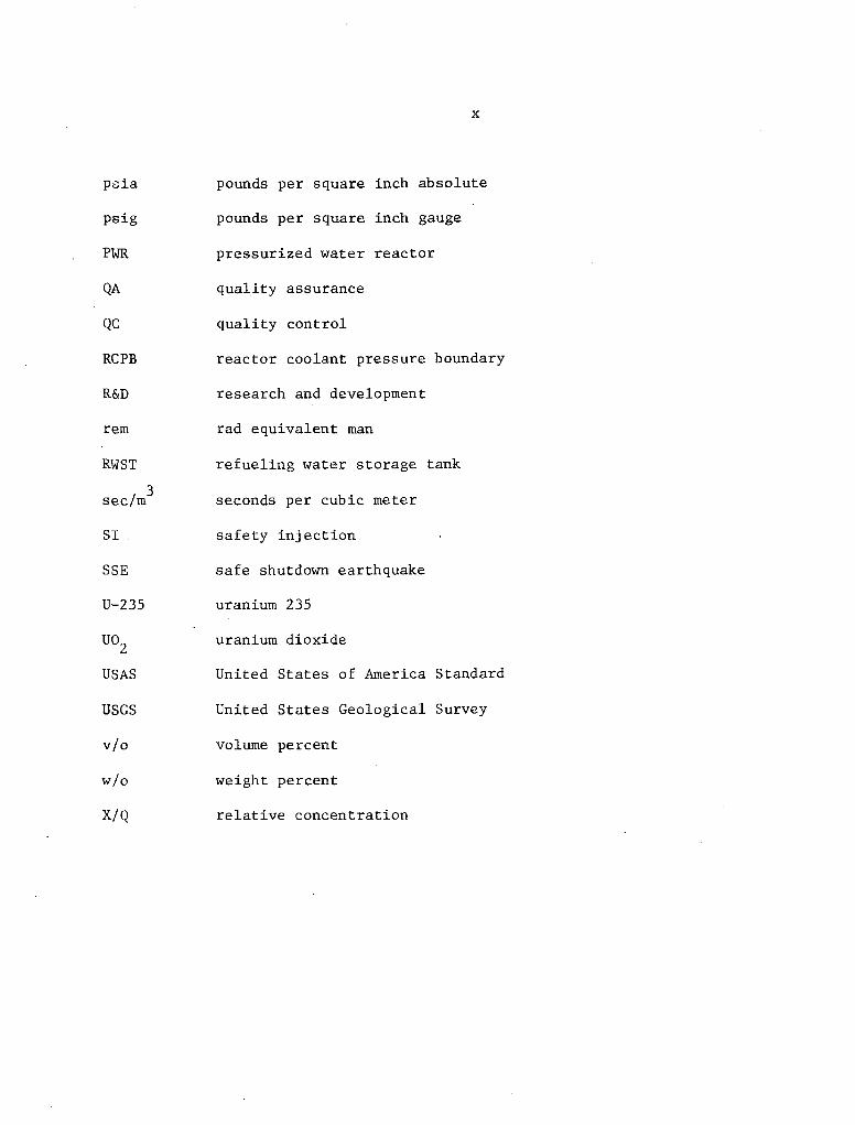
psia pounds per square inch absolute
psig pounds per square inch gauge
PWR pressurized water reactor
QA quality assurance
QC quality control
RCPB reactor coolant pressure boundary
R&D research and development
rem rad equivalent man
RWST refueling water storage tank
sec/mi3 seconds per cubic meter
SI. safety injection
SSE safe shutdown earthquake
U-235 uranium 235
UO 2 uranium dioxide
USAS United States of America Standard
USGS United States Geological Survey
v/o volume percent
w/o weight percent
X/Q relative concentration
1-1
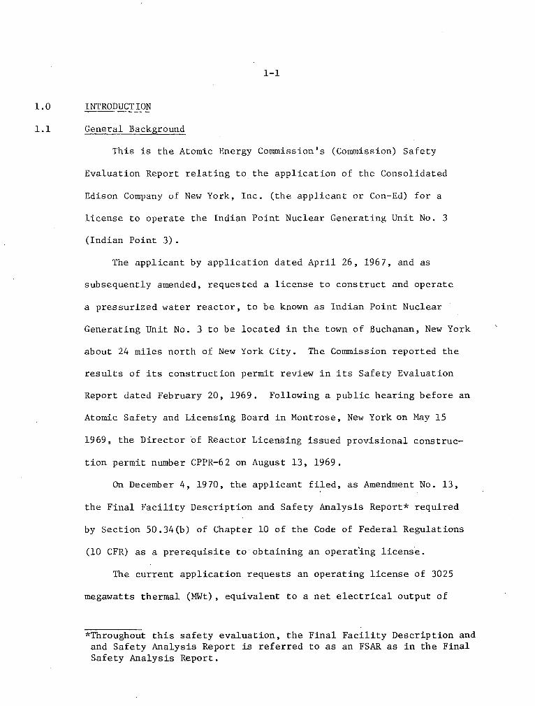
1.0 INTRODUCTION
1.1 General Background
This is the Atomic Energy Commission's (Commission) Safety
Evaluation Report relating to the application of the Consolidated
Edison Company of New York, Inc. (the applicant or Con-Ed) for a
license to operate the Indian Point Nuclear Generating Unit No. 3
(Indian Point 3).
The applicant by application dated April 26, 1967, and as
subsequently amended, requested a license to construct and operate
a pressurized water reactor, to be known as Indian Point Nuclear
Generating Unit No. 3 to be located in the town of Buchanan, New York
about 24 miles north of New York City. The Commission reported the
results of its construction permit review in its Safety Evaluation
Report dated February 20, 1969. Following a public hearing before an
Atomic Safety and Licensing Board in Montrose, New York on May 15
1969, the Director of Reactor Licensing issued provisional construc-
tion permit number CPPR-62 on August 13, 1969.
On December 4, 1970, the applicant filed, as Amendment No. 13,
the Final Facility Description and Safety Analysis Report* required
by Section 50.34(b) of Chapter 10 of the Code of Federal Regulations
(10 CFR) as a prerequisite to obtaining an operat'ing license.
The current application requests an operating license of 3025
megawatts thermal (MWt), equivalent to a net electrical output of
*Throughout this safety evaluation, the Final Facility Description and
and Safety Analysis Report is referred to as an FSAR as in the FinalSafety Analysis Report.

.1-2
about 965 megawatts. This is the same power level requested in the
initial application.
The radiological safety review with respect to a decision con-
cerning issuance of an operating license for Indian Point 3 has been
based on the applicant's Final Safety Analysis Report (Amendment 13)
and subsequent Supplements one through 21 inclusive, all of which
are available at the Atomic Energy Commission's Public Document
Room at 1717"H Street, N. W., Washington, D. C. and at the Hendrick
Hudson Free Library, 31 Albany Post Road, Montrose, New York. In
the course of the review of the material submitted, numerous meetings
were held with the applicant, the nuclear steam system supplier,
Westinghouse Electric Corporation and the applicant's architect-engineer,
United Engineers and Constructors, to discuss the plant design,
construction, and the proposed operation. As a consequence, addi-
tional information was requested which the applicant provided in
certain of the supplements. A chronology of the principal actions
relating to the processing of the application is attached as Appendix
A to this Safety Evaluation Report.
This Safety Evaluation Report summarizes the results of the
radiological safety review of Indian Point 3 performed by the
Commission's Regulatory staff.
This Safety Evaluation Report also delineates the scope of the
technical details considered in evaluating the radiological safety

1-3
aspects of the proposed operation of the Indian Point 3 facility.
In accordance with the provisions of i0 CFR Part 50, Appendix D of
the Commission's regulations, a Draft and a Final Environmental
Statement will set forth the considerations of the environmental
impact of the proposed operation of the Indian Point 3 facility.
1.2 General Plant Description
The Indian Point 3 facility utilizes a nuclear steam supply
system incorporating a pressurized water reactor and a four-loop
reactor coolant system. Thereactor core is composed of fuel rods
made of slightly enriched uranium dioxide pellets enclosed in
Zircaloy tubes with welded end plugs that are grouped and supported
into assemblies. The mechanical control rods consist of clusters
of stainless steel-clad silver-indium-cadmium alloy absorber rods
that are inserted into Zircaloy guide tubes located within the fuel
assemblies. The core fuel is loaded in three regions, each utilizing
fuel of a different enrichment of U-235, with new fuel being introduced
into the outer region, moved inward at successive refuelings, and
removed from the inner region to spent fuel storage. Water will serve
as both the moderator and the coolant, and will be circulated through
the reactor vessel and core by four vertical, single stage,
centrifugal pumps, one located in the cold leg of each loop.
The reactor and reactor coolant system will operate at a pressure
of 2250 psia with a nominal reactor inlet temperature of 543'F and
a nominal outlet temperature of 600.4*F. The reactor coolant water

1-4
will be circulated through the four steam generators to produce
saturated steam and then be returned back to the pumps to repeat
the cycle. An electrically heated pressurizer connected to
the hot leg piping of one of the loops will establish and maintain
the reactor coolant pressure and provide a surge chamber and a water
reserve to accommodate reactor coolant volume change during operation.
The steam that is generated in the steam generators will be utilized
to drive a four element tandem compound turbine and will be condensed
in a radial flow single pass deaerating condenser. Cooling water
drawn from the Hudson River will be pumped through the tubes of the
condenser to remove the heat from, and thus condense, the steam
after it has passed through the turbine. The condensate will then
be pumped back to the steam generator to be heated for another cycle.
The reactor will be controlled by a coordinated combination of
a soluble neutron absorber (boric acid) and mechanical control rods
whose drive shafts penetrate the top head of the reactor vessel.
The control system will allow the plant to accept step load changes
of 10 percent and ramp load changes of 5 percent per minute over the
range of 15 to 100 percent of full power under normal operating
conditions. Plant protection systems that automatically initiate
appropriate action whenever a monitored condition approaches pre-
established limits are provided. These protection systems will
act to shut down the reactor, close isolation valves, and initiate
operation of the engineered safety features should any or all of

1-5
these actions be required. Supervision and control of both the
nuclear steam supply system and the steam and power conversion
system will be accomplished from the control room.
The nuclear steam supply system is housed in a steel lined
reinforced concrete cylindrical structure. The control building,
the spent fuel pit, and the primary auxiliary building are all
Category I*.structures. The safety injection pumps, the containment
spray pumps, the spray additive tank and boric acid tanks are among
the equipment housed in the primary auxiliary building.
The plant is capable of being supplied with electrical power
from two independent 138 kV feeders and two 13.8 kV underground feeders
and is provided with independent and redundant onsite emergency power
supplies capable of supplying power to shut down the plant safely or
to operate the engineered safety features in the event of an accident
and a loss of offsite power sources.
1.3 Comparison with Similar Facility Designs
Many features of the design of Indian Point 3 are similar to
those we have evaluated and approved previously for other nuclear
power plants now under construction or in operation. To the extent
feasible and appropriate, we have made use of our previous evaluations
of those features that were shown to be substantially the same as those
previously considered. Where this has been done, the appropriate
sections of this report identify the other facilities involved. Our
*Category I structures are defined in Section 3.2 of this SafetyEvaluation Report.
1-6
Safety Evaluation Reports for these other facilities have been pub-
lished and are available for public inspection at the Atomic Energy
Commission's Public Document Room at 1717 H Street, N. W., Washington,
D. C.
1.4 Identification of Agents and Contractors
The Westinghouse Electric Corporation (Westinghouse) is furnishing
the nuclear steam supply system for Indian Point 3, including the first
fuel loading, and is also furnishing the turbine generator set. For
those items of the plant included within its scope of supply, Westinghouse
has also acted as procurement agent. Westinghouse had contracted with
United Engineers and Constructors as the architect engineer. Construction
of the plant was performed by United Engineers until December 1969,
when this function was assumed by WEDCO, a wholly owned subsidiary
of Westinghouse.
Quirk, Lawler, and Matusky was the applicant's principal consultant
for hydrological studies while Environmental Analysts, Inc. prepared
population estimates for the applicant. The Research Division
of New York University was the applicant's meteorological consultant.
1.5 Summary of Principal Review Matters
The evaluation performed by the staff included a review
of. the information submitted by the applicant particularly with regard
to the following matters:
We evaluated the population density and use characteristics
of the site environs, and the physical characteristics of the site,
1-7
including seismology, meteorology, geology and hydrology to establish
that these characteristics had been determined adequately and had been
given appropriate consideration in the final design of the plant, and
that the site characteristics are in accordance with the Commission's
siting criteria (10 CFR Part 100), taking into consideration the
design of the facility, including the engineered safety features
provided.
We evaluated the design, fabrication, construction, and testing
and performance characteristics of the plant structures, systems, and
components important to safety to determine that they are in accord
with the Commission's General Design Criteria, Quality Assurance
Criteria, Regulatory Guides, and other appropriate rules, codes and
standards, and that any departures from these criteria, codes, and
standards have been identified and justified.
We evaluated the expected response of the facility to various
anticipated operating transients and to a broad spectrum of accidents,
and determined that the potential consequences of a few highly
unlikely postulated accidents (design basis accidents) would exceed
those of all other accidents considered. Conservative analyses were
performed of these design basis accidents to determine that the calcu-
lated potential offsite doses that might result in the very unlikely
event of their occurrence would not exceed the Commission's guidelines
for site acceptability given in 10 CFR Part 100.
1-8
We evaluated the applicant's engineering and construction organi-
zations, plans for the conduct of plant operations, including the
proposed organization, staffing and training program, the plans for
industrial security, and the plans for emergency actions to be taken
in the unlikely event of an accident that might affect the general
public, to determine that the applicant is technically qualified to
safely operate the plant.
We evaluated the design of the systems provided for control of
the radiological effluents from the plant to determine that these
systems are capable of controlling the release of radioactive wastes
from the facility within the limits of the Commission's regulations,
and that the equipment provided is capable of being operated by the
applicant in such a manner as to reduce radioactive releases to
levels that are as low as practicable.
We evaluated the financial position of the applicant to determine
that the applicant is financially qualified to operate Indian Point
3.V
1.6 Facility Modifications Required as a Consequence of Regulatory StaffReview
As a consequence of the staff review, a number of design changes
and emergency plan changes were made to Indian Point 3. These modifi-
cations are discussed in greater detail within the body of this
Safety Evaluation Report. The principal changes which were made are as
follows:

1-9
(1) The seismic instrumentation program has been augmented (see
Section 3).
(2) The safety injection system has been redesigned to meet the
single failure criterion (see Section 7).
(3) Interlocks have been placed on the residual heat removal system
to prevent possible over-pressurization of this system (see
Section 7).
(4) Design modifications to prevent premature initiation of the
recirculation phase following a postulated loss-of-coolant
accident (see Section 7).
(5) Design modifications to eliminate the need for automatic trans-
fers between redundant d-c power sources (see Section. 8).
(6) Modifications to the emergency diesel fuel oil transfer pumps
(see Section 8).
(7) Provision of additional gaseous and particulate monitors to the
radwaste area, the control room, and the fuel handling and
storage area (see Section 12).
(8) Expanded emergency plans to include letters of agreement from
the Coast Guard, medical support facilities, and the Penn
Central Railroad (see Section 13).
(9) A more rapid method of alerting appropriate officials has been
developed in the case of a radiological emergency (see Section 13).
(10) Numerous design changes have been required for protection against
postulated high energy line breaks outside of the containment
(see Sections 6 and 10).

2-1
2.0 SITE CHARACTERISTICS
2.1 Geography and Demography
The Indian Point facility is situated on a 239-acre tract of
land located in Westchester County, New York on the east bank of
the Hudson River. The three-unit nuclear facility is located
approximately 2-1/2 miles southwest of Peekskill, New York and 24
miles north of the New York City boundary line.
The Indian Point nuclear facility is surrounded on all sides
by high ground ranging in elevation from 600 to 1000 feet above sea
level. Across the Hudson River, which varies in width between 4500
and 5000 feet in the vicinity of the plant site, the west bank is'
flanked by steep heavily wooded slopes of the Dunderberg and West
Mountains to the northwest (elevations 1086 feet and 1257 feet,
respectively) and 'the Buckberg Mountains to the west-southwest
(elevation 793 feet).
The closest cities with populations exceeding 25,000 are Newburgh,
New York (1970 population of 26,219, a decrease of 15% since 1960),
and White Plains, New York (1970 population of 50,220 a 0.5% decrease
since 1960), both located approximately 17 miles from the Indian
Point site. The area within five miles of the site has a population
of 18,130 based on the 1970 census data. The projected population for
the year 2010 is approximately 74,000 persons. The closest schools
are located about one mile to the south and east of the site. Figures

2-2
2.2 and 2.3 show the 1970 population and predicted cumulative popula-
tion data for the year 2010 relevant to the Indian Point nuclear
facility.
At the present time the land surrounding the Indian Point site is
residential with large areas devoted to parklands and a military
reservation. A gypsum plant is adjacent to the southwest border of
the Indian Point site. Northeast of the site, just within the 1100
meter low population zone radius, is a second industrial area on the
shoreline of Lent's Cove. The closest commercial airport is at White
Plains, New York, 17 miles south of the station. Minor seaplane
activity occurs at Green's Cove, about 1.5 miles south of the plant.
The Hudson River in the area of the site is used for commercial
ship and barge traffic and for pleasure boating. For recreation,
there are several sections of the Palisades Interstate Park on the
west bank, and fishermen's landings, parks and beaches are on the
east bank of the Hudson River.
The Hudson River is not used for drinking water purposes below
the plant site due to salt water intrusion in the tidal estuary.
The nearest municipal intake of the Hudson River is that for the
City of New York, which is located about 22 miles upriver from the
Indian Point site, in the vicinity of Chelsea, New York. Four
industrial plants within five miles of the site use water from the
Hudson River for industrial purposes and one plant uses a well for
its source of industrial water.

2-3
In a report prepared by Environmental Analysts, Inc. in June
1972, the population data submitted by the applicant was updated
based on the 1970 census, and population projections were made through
the year 2010. Based on this report there have been no significant
demographic changes in the area of the site as described in our
February 20, 1969 Safety Evaluation Report.
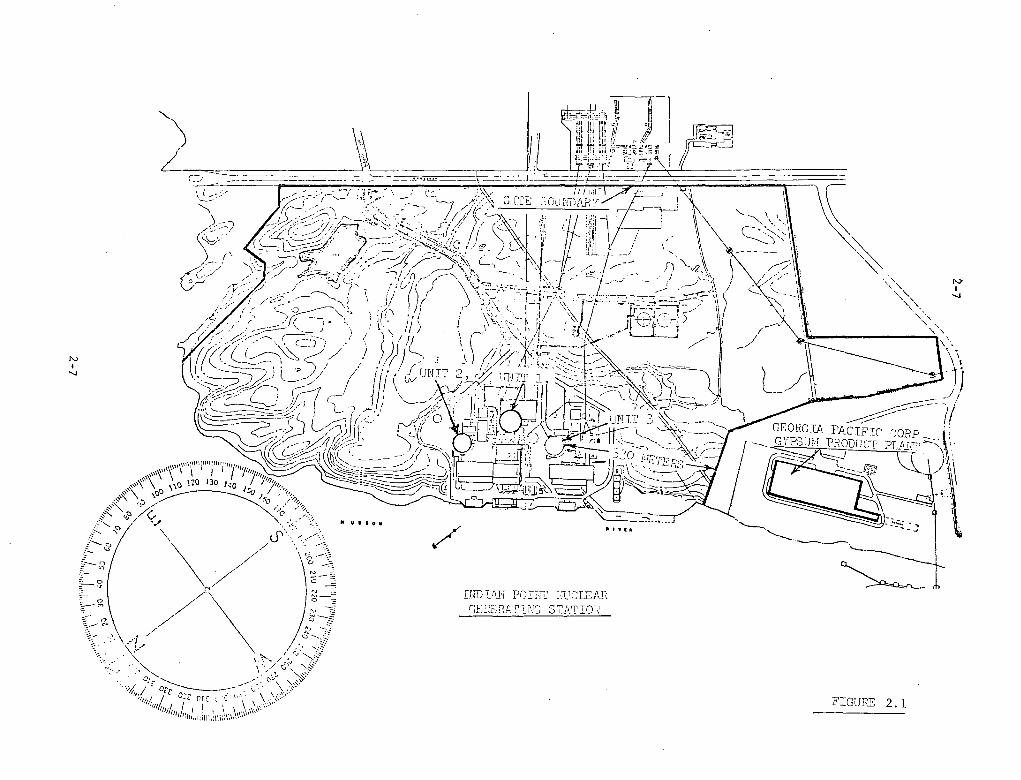
The minimum exclusion distance as provided by the applicant
for Indian Point 3 is 350 meters from the centerline of the reactor
and 330 meters from the outer surface of the containment building
to the nearest property line (Figure 2.1). The outer edges of the
cities of Newburgh and White Plains, New York, are the nearest
boundaries of densely populated geographic centers containing more
than 25,000 persons, and both are located approximately 17 miles
from the plant site. However, based on projected populations, the
outer boundary of the more densely populated section of the City
of Peekskill was chosen by the applicant during the construction
permit stage of review as the population center. The nearest
boundary of Peekskill is 0.63 mile to the northeast; however, the
nearest residential area of Peekskill is 0.85 mile to the east.
The applicant has selected a low population zone having an outer
boundary of 0.67 mile (1100 meters). On the basis that (1) the
population within the proposed low population zone is small
(approximately 50 people) and (2) the area of Peekskill in the
area of the nuclear plant is of a general industrial nature, the

2-4
staff at the time of the construction permit review concurred in
the applicant's selection of the low population zone.
Based on the 10 CFR Part 100 definitions of the population center
distance, the exclusion area and low population zone distances (for
which adequate emergency plans have been developed), on our analysis
of the onsite meteorological data from which dilution factors were
calculated for various time periods (Section 2.3), and on the
calculated potential radiological dose consequences of design basis
accidents (Section 15.0), we have concluded that the exclusion area
radius is acceptable from the standpoint of computed doses from all
of the design basis accidents analyzed when the reactor is operated
at the proposed power level of 3025 MWt.
2.2 Nearby Industrial, Transportion and Military Facilities
New York State Route 9, which passes through Peekskill and
Buchanan, is located on the east bank of the Hudson River and
Route 9W and the Palisades Interstate Parkway on the west bank of the
Hudson River. A Penn Central railroad line passes within 0.85 mile
of the Indian Point 3 containment structure on the east bank of the
Hudson River; on the west bank, a line of the Penn Central Railroad
passes approximately one mile from the Indian Point site. Two
natural gas lines cross the Hudson River and pass about 620 feet
from the Indian Point 3 containment structure. Based on previous
staff reviews, failures of these gas lines will not impair the safe
operation of Indian Point 3.
":,

2-5
About 600 to 800 commercial barges and ships on the Hudson
River pass by the Indian Point site each year. The cargoes consist
of petroleum products, dry goods, and molasses. The applicant has
indicated that no river traffic shipment of toxic materials or
explosives currently pass the site. No new environmental hazards
have been identified since the construction permit review of this
plant.
The staff has reviewed the question of airport proximity to
nuclear power plants in various other licensing cases. On the basis
of these studies, we conclude that the Indian Point site is suffi-
ciently far from an airport of significant size that the probability
of a crash at the site is essentially that associated with general
overflights and that the Indian Point facility need not be designed
or operated with special provisions to protect the facility against
the effects of an aircraft crash.
The military installations in the area include the New York State
Military Reservation (Camp Smith) and the West Point Military Reserva-
tion. Camp Smith is about two miles and West Point is about six miles
from Indian Point 3.
The closest industry to the Indian Point site is the Georgia
Pacific gypsum plant located approximately 0.3 mile southwest of
the Indian Point 3 containment structure. Oil, gas, gasoline, and
molasses storage facilities are located just outside of the 1100
meter low population zone for this facility.

2-6
Because of the distance that separates these'military and
industrial facilities and because of experience gained in the
operation of Indian Point 1 at the same site, we have concluded
that these facilities will not affect the safe operation of
Indian Point 3.
2.3 Meteorology
The plant is in a general climatic region which is primarily
continental in character, but is subjected to some modification by
marine air which can penetrate the site area. The general regional
topography ranges from hilly to mountainous. Locally, the plant
site lies along the Hudson River in a bowl surrounded on almost
all sides by high ground ranging from 600 to 1000 feet above sea
level. This topography decisively influences meteorological condi-
tions in the valley in the following ways:
a. Orientation of the valley ridges channels the airflow.
b. The wind speeds in the valley tend to be lower than in open
level terrain.
c. Differential heating of the hillsides and the plain at the mouth
of the valley create local air circulation (e.g., diurnally-
regulated up-and-down valley flow).
The measured prevailing winds show the influence of valley
channelling. This channelling effect is not as pronounced during
the winter months due to generally stronger westerly airflow aloft.
C-, ___
,~ I>'-
-5N!
-. j
|-j
- v 1ea
b 7 .1.1.
GF.7EAD RGSTA.ToI,.,
FIGURE 2. 1

2-8
CUMULATIVE POPULATION VS. DISTANCE 0-5 MILES
d -
5-I0...~~
oo
I !........ "",..............
-F I 1: 3
) ... . .- n
II
.- ..... .... I- .-- ... "-. - .--
. . . . . . . . . . .. . . . . . . . 7 0i
*1
.--. 2-i--I-.
/n/D i
/
DISTAN-CE., (:.;2LES) FIGURE 2.2

2-9
CUMULATIVE POPULATION VS. DISTANCE 0-50 MILES
5-_
9--
-i• ~~~........... - ..
- I ,.-. --
~Ii .T IA
r. :77
U!~IT
I
. . . . . . . ....... I....
._.lx. i____._--
9T-7-,
1_.. ..3 _
o
/
... .....- .. - ..- .• . .... . ; .... .
i ., 4- 7.' /, I
LI- -. 1
.. .... •- ....-...-......• .-. _ _ .. / . ..-- 2 ._-- ...... ../._- 4 -,
. . ... ..... / .I- - - ... ..
. _ .... - •. . .• -.... .,1- ....._
_::_ :. I:I.. _, : .... i...
_ _ ... . .. - ..... 1- .. . - _-_--- _
.. ........... t-.:...i..... .....4 .... " "I1-." .' .7 -• .-; '..- .- _ -
.i.....,....... i.. ....i.. ....
V ... .. -- ,.... . ..i .. . . ..
... -... - ... ... . . -...... .
i... -:...-! - i.- -
.. . . .I . . . ! . . . . . .
.. ..... . . . . . .... ... -- - "
i ........ .............. i..... -
............. ...... ;... .
- 1
________ ________ , ____
. .. . .. . .. . .. . .. . ......
..
I!t
19/ - - 10 s" /0 13- 20 a5' 30 :35,~ 00C p ' Y
FIGURE 2.3

2-10
Several meteorological studies of atmospheric diffusion
conditions have been based on onsite data. The initial onsite
meteorological measurement program was conducted during the years
1956 and 1957. The program consisted of measurements of wind
speed and temperature taken on a 300-foot tower. Data on the joint
frequency distribution of wind direction and speed were taken at
the 100-foot level and vertical temperature differences between the
150- and 7-foot levels were measured. These data were presented in
exhibit L-5 for Indian Point 1 (Docket No. 50-3). The total joint
frequency data recovery for this period is not now known because
the data were presented as fractions of recovered data and the
original records were not kept.
Another meteorological study was conducted during the years
1969 and 1970. This study was conducted primarily to describe the
diurnal wind direction reversals in the Hudson River valley. Measure-
ments of wind and temperature were made on a 100-foot tower in the
same location as the now dismantled 300-foot tower and at other
stations along the Hudson River located within five miles of the site.
Data collected in this program were taken for the period November 26,
1969 - October 1, 1970, with recovery rate near 80%. Joint frequency
distributions of wind direction and speed by vertical temperature
difference class were not presented in this study. However, the
applicant concluded that the annual average statistics of wind
direction and speed, and of vertical temperature difference were

2-11
substantially the same as the 1956-1957 data, thereby indicating
that meteorological conditions are reasonably consistent from year
to year. Diurnal valley flow wind reversals were found whenever the
winds aloft were very light.
More recent data were acquired by the applicant during the years
1970 - 1972 utilizing the 100-foot tower. These data provided the
basis for making a meteorological analysis of the site in accordance
with current staff practices and verified the representativenes of
of the 1956-57 data.
It is the Regulatory staff's practice to utilize for offsite dose
calculations meteorological data that have been collected for at least
one continuous year with a data recovery rate of at least 90%. Due to
numerous equipment failures, the applicant's meteorological data
recovery rate was often below 90% during the 1970-1972 years.
Consequently, for use in its accident analyses, a composite year
of data was constructed by the staff where the recovery rate was 95%.
This composite year consisted of January-July 1970, August 1971,
September-October 1972, and November-December 1970.
Additional modifications of the applicant's data were made to
have the data conform with present staff methods. The applicant
recorded wind speeds and directions at the 100-foot elevation, while
temperatures were measured at the 95-foot and 7-foot levels. The
wind speed measurements were adjusted by the staff to represent wind

2-12
speeds at a level of 33 feet (the height assumed for ground level
release calculations) by use of a power law extrapolation. The
temperature difference between the readings at the 95-foot and
7-foot levels were extrapolated to temperature differences simula-
ting recording instruments at 150-foot and 30-foot levels. This new
vertical temperature difference calculated by the staff utilized a
logarithmic method to extrapolate the measured vertical temperature
difference.
Additional data were submitted by the applicant in support of
other meteorological models. In Supplement 14 of the FSAR, the
applicant presented an analysis of diffusion conditions using the
"split sigma model" to allow for greater wind meander, a procedure
to allow for diffusion to the distance of the actual site boundary
by direction instead of the minimum site boundary, a procedure to
allow for the effect of averaging diffusion conditions over a
two-hour period, and a turbulent building wake diffusion model
developed from New York University wind tunnel tests. The applica-
tion of any one of these four meteorological models would result in
significant reductions in the calculated off-site doses. Although
the staff felt that these meteorological models have some merit,
they were not accepted at this time. Among the reasons for not
accepting these proposed meteorological models was the concern that
the instruments that recorded the basic data were not sufficiently

2-13
accurate in the wind speed range of interest. Additional studies using
more accurate instruments and conditions simulating winds below 4 mph
may be acceptable to the staff at some future date.
We concluded that the applicant did not provide sufficient
justification for the use of these meteorological models for evaluating
the radiological consequences of accidents at this site; consequently
we used our own, more conservative meteorological models.
Utilizing standard staff practices, an evaluation of the meteor-
ological diffusion characteristics of the site was made for both
accident analysis and routine release analysis purposes.
The evaluation of the calculated offsite doses resulting from
radioactive releases due to postulated accidents requires calculations
of the relative concentration, X/Q, for the first 30 days following an
assumed accident. The impact of routine radioactive releases requires
calculations of an annually averaged X/Q. These relative concentrations
were then incorporated into dose analyses.
Accident dose analyses utilize calculated X/Q values which
vary with time. The staff uses its most conservative assumptions
when calculating the X/Q values for the first eight hours following
an assumed accident. Additional credit is given for diffusion and
spread of the gaseous plume for time periods beyond the first eight
hours.
The calculated dose at the minimum exclusion radius (330 meters)
at the end of the first two hours and the 30 day dose at the low
population zone (1100 meters) must be within 10 CFR Part 100 limits.

2-14
In the evaluation of the diffusion of short term (0-2 hr) acci-
dental releases from the plant, a ground level release was assumed
with a building wake factor, cA, of 1000 square meters. The relative
concentration, X/Q, using the composite year of data (1970-1972), which
is exceeded 5% of the time was calculated to be 1.8x10⁻³ sec/m3 at the
minimum exclusion radius of 330 meters. This relative concentration is
equivalent to a dispersion condition produced by Pasquill type F
stability and a wind speed of 0.7 meters/second with the building wake
effect being limited to a factor of three over the diffusion condition
produced by a point source. A similar analysis of the 1956-57 data
tends to confirm these results. Our meteorological consultant, the
National Oceanic and Atmospheric Administration (NOAA), has calculated
a similar X/Q value and the applicant estimates a value which is 40%
lower (less conservative) than ours.
In addition to calculating the X/Q values utilized in the two-
hour dose at the exclusion radius, the staff calculated X/Q values
for the 30-day dose at the outer boundary of the low population zone
(LPZ). Using the diffusion models presented in Regulatory Guide 1.4,
"Assumptions Used for Evaluating the Potential Radiological Consequences
of a Loss of Coolant Accident for Pressurized Water Reactors", and the
onsite meteorological data, the staff calculated X/Q values at the LPZ
of 4.7xi0-4 sec/m3 for the 0-8 hour period, 1.4x10⁻⁴ sec/m3 for the
8-24 hour period, 6.5xi0-5 sec/m3 for the 1-4 day period and 2.2xi0-5
sec/m3 for the 4-30 day period. The applicant has presented values
which are in essential agreement with the staff's values for the first

2-15
24 hours but are a factor of two to three less for the time period
from one to 30 days.
In our evaluation of the diffusion conditions associated with
routine effluent release, the maximum annual average relative
concentration, 2.6x.10- 5 .sec/m3 , was calculated to the south-southwest
of the plant at the site boundary (330 meters). Both the applicant
and our meteorological consultant (NOAA) have presented values which
are in essential agreement with ours.
As discussed in Section 11.0 of this Safety Evaluation Report,
concerning effluent releases, the maximum annual average concentration
at a location seven miles south of the plant is 2.4xi0-7 sec/m3.
We have concluded that the composite year of data presented in the
FSAR provides a reasonable basis for estimating atmospheric diffusion
conditions during accidental and routine gaseous effluent releases
from the plant. It is not expected that subsequent data collection
and analysis will change our estimates significantly because the
data from the years 1956, 1957, and 1969 confirm the climatic repre-
sentativeness of the data for the composite year.
2.4 Hydrology
The plant is located on the east bank of the Hudson River and
is affected by ocean tides as modified by estuary effects between
the site and the ocean. Runoff from precipitation-type floods, storm
effects along the coastline, or a combination of these types of events
can cause local high water levels. Such situations are common along

2- 16
estuaries such as the Hudson River. Similarly, low water levels are
affected by tides, runoff, and cyclonic type storms such as hurri-
canes which can depress water levels by essentially blowing water
downstream. Normal maximum tidal flows at the site, in both the
upstream and downstream directions, vary between 250,000 and 300,000
cubic feet per second (cfs). Plant grade is about elevation 15.3
feet above mean sea level datum (MSL). The intake structure at
elevation 15.0 ft. MSL is of the outdoor type with the safety-related
service water pumps located landward of the circulating water pumps.
Other safety-related facilities are more landward of the intake
structure.
The Hudson River is used for water supply in the area., but only
for industrial cooling purposes near the site. The river is used
for public water supply some 30 miles upstream at Poughkeepsie,
and may be used as a supplemental New York City source at Chelsea
(22 miles upstream of the plant) during drought conditions. Ground
water in the area is generally used for industrial and commercial
purposes, with some limited residential usage on the west side of
the river at Stony Point.
Floods from both runoff and hurricane-induced mechanisms have
occurred in the area. The highest historical water level in the plant
vicinity occurred in 1950 when a water level of 7.4 feet MSL was
recorded about one-half mile downstream of the site.

2-17
The potential for site flooding from precipitation events,
hurricanes, upstream dam failures, and from combinations thereof has
been investigated by the applicant and evaluated by the staff. Water
levels at the site for a probable maximum flood (PMF), a probable
maximum hurricane (PMH) surge, coincident precipitation-type floods
and hurricanes, and dam failures during various floods have been
estimated. A PMF or a PMH is considered the upper limit of potential
flooding that can reasonably be expected to occur at this particular
site. The applicant's analyses of flooding events indicate that the
worst such event reasonably possible would be the coincident occurrence
of the runoff from a precipitation-type flood approximately half as
severe as a PHE timed to occur with the worst conditions produced by
a surge from a hurricane approximately half as severe as a PMH, and
an arbitrarily assumed failure of a large upstream dam. This estimate
of the water level at the site for such an event is elevation 15.0 feet
MSL, and includes an allowance of 1.0 foot for coincident wave action.
The individual occurrence of either a PMF or a PMH, however, were each
estimated by the applicant to produce water levels at the site of 14.0
feet MSL and 14.5 feet MSL, respectively. Each estimate contains an
allowance of 1.0 foot for coincident wind-generated wave action. Based
upon a comparison of the applicant's estimates with similar determinations
at other locations in the Northeastern U.S. and upon a review of the

2-18
applicant's computational techniques, we concur with the applicant
in the estimates of water levels at the site for these events,
exclusive of the allowances provided for coincident wind-generated
wave action.
We have independently estimated wind-generated wave action
coincident with either a PMF, a PMH, or other reasonably extreme
combinations of less severe events. Our analysis~was based upon an
analytical technique developed by the Corps of Engineers using a
postulated 45 mile per hour overwater wind speed as the cause of such
wave action. To assure that the plant will be safely shut down before
wave action could cause a loss of function of service water pumps,
the Technical Specifications require plant shutdown for water levels
approaching 15 feet MSL and appropriate emergency procedures to
protect service water pumps.
At the request of the staff, the applicant has analyzed the
capability of local site drainage, including the roofs of safety.-
related structures, to store and/or pass the runoff from precipita-
tion events as severe as could be produced by a local probable
maximum storm. Although such facilities would undoubtedly overflow
during severe rainstorms, the analysis has indicated that no loss of
safety-related functions from such an event is anticipated.
The applicant has arbitrarily assumed the failure of upstream
dams coincident with floods of a severity approximately half

2-19
that of a PMF and has determined that water levels at the site would
be somewhat less severe than would be produced by a PMF or PMH as
discussed above. On the basis of our review, we agree.
The water levels which could be produced from tsunamis at the
site, are considered to be substantially less than those which can
be produced from a PMF, PMH, dam failures, or reasonable combinations
of such flood producing mechanisms.
Ice-induced flooding at the site to levels approaching those
estimated for a PMF, or PMH, dam failures, or reasonable combinations
of such flood producing mechanisms, are not considered credible
because of the adjacent extremely wide and relatively deep river
channel.
The complete loss-of-cooling water at the Indian Point site is
not considered credible because water can reach the site -from both
upstream and downstream sources.
The potential exists for minor flooding in the vicinity of the
outdoor intake structure that could be produced by wave action,
coincident with severe river flood levels. The staff has required
the applicant to provide for such extreme conditions by instituting
plant shutdown for water levels approaching elevation 15 feet MSL
and to protect the service water pumps in such situations.
Low water levels are influenced by both droughts and tides.
Extreme low water levels are caused primarily by severe wind storms,

2-20
such as hurricanes, where storm winds tend to blow estuary water
downstream. The safety-related effects of low water levels at the
site are related to the ability of the service water pumps to provide
a continuous water supply. The applicant has shown in the FSAR that
the service water pumps, located in the outdoor intake structure at
elevation 15.0 MSL, reach to elevation 18.5 feet below MSL. Mean
low water, based on published U. S. Coast and Geodetic Survey records,
is approximately elevation 1.5 feet below MSL. The Coastal Engineering
Research Center's records of the 1932 and 1959 historical low water
levels at New York City have been extrapolated to the site by use of
U. S. Coast and Geodetic Survey tide difference inference techniques
to indicate that low water levels at the site of approximately
elevation 5.5 feet below MSL have been experienced. The 13-foot
difference between the apparent historical low water level and the
service water intake is considered by the staff to provide adequate
assurance of a dependable safety-related water supply.
Ground water occurs in both unconsolidated surficial deposits,
and the fractures and solution channels in the underlying bedrock.
The surficial deposits range in thickness from a few feet in hills
to several hundred feet in the valley flood plains. General surficial
deposit ground water movement at riverbank locations is considered to
be toward the river, except where high well pumping rates are employed
(which are not expected at the site), or during relatively short
periods of high river levels. Use of ground water within five miles

2-21
of the site has been reported by the applicant in several categories;
public water supply and commercial, industrial, and private use. The
only public water supply use within five miles is at Stony Point across
the river where water is drawn from shallow wells at a rate of about
550 gallons per minute. Most of the rest of the local wells take
water from the deeper bedrock aquifer. Within two to three miles of
Indian Point, almost all wells have been abandoned and connections have
been made to public water supply systems. We have reviewed the
potential for contamination of ground water sources from the plant and
have concluded that such contamination is highly unlikely because of
the direction of ground water movement and the very limited use of
ground water in the plant vicinity.
2.5 Geology, Seismology, and Foundation Engineering
.The staff has completed its review of the geology, seismology,
and foundation engineering matters relating to Indian Point 3 and
has concluded that the site foundation conditions are acceptable for
the facility. This conclusion is based on reports from our consultants,
the U. S. Geological Survey (USGS) and the National Oceanic and
Atmospheric Administration (NOAA), formerly the U. S. Coast and
Geodetic Survey. These reports are included as Appendices D and E,
respectively, in the Safety Evaluation Report issued on February
20, 1969.

2-22
The U.S. Geological Survey stated that "There are no known active
faults or other young geologic structures in the area that could be
expected to localize earthquakes in the immediate vicinity of the
site. Although several ancient faults occur in the area, none appears
to have been tectonically active since glacial times, or for at least
the past several hundred thousand years."
Likewise, in its evaluation of the seismological aspects of
the site, the U. S. Coast and Geodetic Survey (now NOAA) stated
that "based on the review of the seismic history of the site
and the related geologic considerations, the Coast and Geodetic
Survey believes that the applicant's proposal to use 0.10g for
represen ting earthquake disturbances likely to occur within the
lifetime of the facility to be adequate. The [Coast and Geodetic]
Survey agrees with the applicant that 0.15g would provide adequate
basis for designing protection against loss of function of components
important to safety."
With regard to the ground which supports the structures at Indian
Point 3, the applicant's geological consultant concluded that there
were no cavernous conditions within the bedrock at the site. It based
this conclusion on detailed studies of two nearby quarries and borings
drilled at the site. The applicant reported that when excavations were
made for Units 1, 2, and 3 cavernous conditions were not encountered.
This conclusion is supported by a representative from the U.S. Geological
Survey who visited the site and orally reported that there-were no
cavernous conditions.

2-23
The staff has also reviewed various aspects of the foundations
for Units 1, 2 and 3. The applicant stated that "The Unit No. 1
structures are now at least 12 years old and there has never been
any evidence of settlement cracking or other settlement related problems.
The same can be said for recently completed Unit No. 2 structures." No
evidence of settlement related problems has been observed with the
Indian Point 3 structures during their construction.
Based on the performance of these foundations and the earlier
reports of the USGS and NOAA, the foundation conditions at Indian Point
are acceptable.

3-1
3.0 DESIGN CRITERIA - STRUCTURES, COMPONENTS, EQUIPMENT, AND SYSTEMS
3.1 Conformance with AEC General Design Criteria
The Indian Point 3 plant was designed and is being constructed
on the basis of the proposed General Design Criteria, published
July 11, 1967. Construction of the plant was partially completed and
the Final Facility Description and Safety Analysis Report had been
filed (filed on December 4, 1970) when the Commission published its
revised General Design Criteria in February 1971 and the present
version of the criteria in July 1971. As a result, we did not require
the applicant to reanalyze the plant on the basis of the revised
criteria. However, our technical review assessed the plant against
the General Design Criteria now in effect and we have concluded that
the plant design conforms to the intent of these newer criteria.
3.2 Classification of Structures, Components and Systems
The applicant has classified the seismic design of plant structures,
components and systems into three principal categories. Class I* includes
those structures, components and systems whose failure might cause or in-
crease the severity of a loss-of-coolant accident, or result in an
uncontrolled release of significant amounts of radioactivity, and those
structures, components and systems essential to safe shutdown and
isolation of the reactor. Class II includes those structures, components
and systems that are important to reactor operation, but not essential
* In this Safety Evaluation Report, the staff utilizes the words Category I as
equivalent to the applicant's seismic Class I notation.

3-2
to safe reactor shutdown and whose failure would not result in the
release of significant amounts of radioactivity. Class III includes
those structures, systems and components that are not directly related
to reactor operation or containment. In addition, some structures
have a mixed classification when they are basically a Class II or
Class III designation, but contain components or systems of a Class
I or Class II designation.
We find these classifications to be acceptable and we have concluded
that the applicant placed all safety-related structures, systems, and
components in their appropriate category.
3.3 Wind and Tornado Criteria
The applicant has considered the effects of tornado loads in the
design of Category I structures. Tornado wind loading was taken
as a 300 mph tangential wind traveling with a translational velocity
of 60 mph. Also considered as a separate and combined loading
condition is a 3 psi pressure drop external to the structure.
The wind loading and pressure drop parameters are consistent with
the generally accepted criteria used for nuclear power plants. ASCE
Paper No. 3269 was utilized to determine the loads resulting from
these wind and tornado effects. We have concluded that in the design
of the facility, the methods of converting wind and tornado velocities
into forces on the structures are in accordance with the state-of-the-
art and are acceptable.

3-3
3.4 Water Level (Flood) Design Criteria
The applicant established that the most severe flooding condition
corresponds to a water elevation of 15 feet above mean .sea level (MSL).
This elevation is lower by three inches than the critical elevation
at which water would start seeping into the lowest of the plant
buildings.
As discussed in Section 2.4 of this report, the staff concluded
that flooding levels under the most extreme conditions could reach
a level of 15.0 feet MSL, exclusive of wind-generated wave action.
Wind-generated wave action could raise the flooding level above
plant grade in the vicinity of the service water pumps.
In the event of wind-generated wave action in conjunction with
extreme flooding conditions, the plant will still be protected. In
this unlikely event, the plant will be shut down in accordance with
the Technical Specifications, and the service water pump area will
be protected. Other areas, such as the diesel generator area, will
not require additional protection from the wind-generated waves in
that these waves rapidly dissipate once they strike land. Calculations
have shown that the plant intake structure can bear a hydraulic
load associated with 21 feet of water. Therefore, we have concluded
that the intake structure can withstand the additional hydraulic load
produced by wind-generated waves.
Consequently, the combination of the elevation of the plant
structures,, the load-bearing capability of the intake structure,
3-4
and the Technical Specification requirements on plant operation and
service water pump protection, result in acceptable conditions to
protect the plant against flooding.
3.5 Missile Protection Criteria
Various structures at the Indian Point 3 site have been designed
and constructed to withstand the effects of tornado-generated missiles.
Among these structures are the primary auxiliary building, the control
room, the containment, the diesel generator building, the cable
tunnels, and the waste hold-up tank pit.
The tornado generated missiles include a spectrum of possible
items that could be dislodged during tornadic winds and become
missiles. The missiles assumed by the applicant include two horizontal
missiles: a four inch by twelve inch by twelve foot wooden plank
traveling end-on at 300 mph and an automobile weighing two tons with
a contact area of 20 ft 2 traveling not more than 25 feet off the ground
at 50 mph, and two vertical missiles: a four inch by twelve inch by
twelve foot wooden plank at 90 mph and a passenger car weighing two
tons at 17 mph less than 25 feet above the ground. We find that the
missile criteria utilized by the applicant are adequate on the basis
that they have been used on previous plants.
The effects of missiles generated inside of the containment
have also been considered. The reactor coolant system is protected
by a three foot thick concrete shield wall which encloses the reactor
3-5
coolant loop and the pressurizer. A two foot thick concrete operating
floor provides additional protection against internally generated
missiles. The effects of missiles generated by the fracture of con-
trol rod drive mechanisms have also been considered. A structure over
the control rod drive mechanisms has been provided to block any such
potential missiles. We have concluded that the measures taken to
provide protection against internally generated missiles are acceptable.
3.6 Protection Against Dynamic Effects Associated with the Loss-of-Coolant.Accident
The applicant has provided protection against pipe whip in
accordance with the criteria in Regulatory Guide 1.46 "Protection
Against Pipe Whip Inside Containment". The piping/support systems
have been dynamically analyzed by the time-history method for each
postulated break.
We conclude that the applicant has provided adequate pipe whip
restraints to protect against postulated breaks, both longitudinal
and circumferential at specified locations within the reactor coolant
pressure boundary and in the main steam and feedwater systems.
3.7 Seismic Design
We and our consultant, Nathan M. Newmark Consulting Engineering
Services, have reviewed and evaluated the seismic design input criteria
employed by the applicant with reference to structures, systems and
components. The seismic loads are based on horizontal ground
accelerations of 0.10 g for the Operating Basis Earthquake and 0.15 g
3-6
for the safe shutdown earthquake with vertical accelerations equal
to two-thirds the horizontal ground accelerations. The consultant's
report is attached as Appendix B.
The seismic design response spectra curves were presented in
the application for a construction permit and found acceptable. The
modified earthquake time histories used for component equipment
design were adjusted in amplitude and frequency to envelope the
response spectra specified for the site. We and our seismic design
consultant conclude that the seismic input criteria proposed by the
applicant provides an acceptable basis for seismic design.
The modal response multi-degree-of-freedom method and the
normal mode-time history method are used for the analysis of all
Category I structures, systems and components. The vibratory
motions and the associated mathematical models account for the
soil-structure interaction and the coupling of all coupled
Category I structures and plant equipment. Governing response
parameters have been combined by the square root of the sum of the
squares to obtain the modal maximums when the modal response
spectrum method is used. The absolute sum of responses is used for
closely spaced frequencies. Horizontal and vertical floor spectra
inputs used for design and test verification of structures, systems
and components were generated by the normal mode-time history method.
Torsional loads have been adequately accounted for in the seismic

3-7
analysis of the Category I structures. Vertical ground accelerations
were assumed to be 2/3 of the horizontal ground accelerations and the
horizontal and vertical effects were combined simultaneously. Constant
vertical load factors were employed only where analysis showed suffi-
cient vertical amplifications in the seismic system being analyzed.
We and our consultant have reviewed the information provided by
the applicant and find the seismic system and subsystem dynamic
analysis methods and procedures used by the applicant acceptable.
As part of the review of Indian Point 3, the staff concluded that
the applicant's seismic instrumentation program required augmentation.
In response to the staff's requirement for additional seismic instru-
mentation the applicant has added three peak shock recorders on
the containment base mat in a tri-axial-arrangement. The applicant
also added recording accelerographs on one steam generator, one
reactor coolant pump, and on the pressurizer. A plan for the
utilization of any acquired seismic data will be developed before
an operating license is issued.
We conclude that the type, number, location and utilization of
strong motion accelerographs to record seismic events and to provide
data on the frequency, amplitude and phase relationship of the seismic
response of the containment structure correspond to the recommendations
of Regulatory Guide 1.12, "Instrumentation for Earthquakes" and is acceptable.
3-8
3.8 Design of Category I Structures
The review and evaluation of the Category I structures included
the structural foundations, the containment, the auxiliary building,
the control room, the intake structure, and a portion of the pump-
house. The structures were built from a composite of structural
steel and reinforced concrete members. In general, the structures
were designed as continuous systems. The various structural com-
ponents that were integrated into the continuous structures consist of
slabs, walls, beams, and columns.
The analyses were based on elastic analysis procedures with the
design being executed using the working stress design method and
the ultimate strength design method. The design method for reinforced
concrete followed that of ACI 318-63, with the use of specific loading
combinations applicable to nuclear power plant design conditions.
For the structural steel the AISC Specifications were utilized.
The loading combinations used for the design of the structures
included normal dead and live loads, accident loads, wind and tornado
loads, the flood loads, the missile loads and the earthquake loads.
The applicant has specified and utilized numerous loading
combinations for the normal loading conditions as well as for the
severe loading conditions that include the accident, the tornado
and/or the safe shutdown earthquake.
3-9
3.9
3.9.1
As a result of the review and evaluation of the criteria and the
procedures related to the design and construction, we conclude that
the Category I structures have been acceptably designed and constructed.
Mechanical Systems and Components
Dynamic System Analysis and Testing
The staff has reviewed the effects of dynamic loads on the
Indian Point 3 reactor coolant pressure boundary and on the reactor
internal structures.
Because of the similarities of the Indian Point 3 design to
Indian Point 2, the applicant has designated Indian Point 2 as the
prototype plant from which preoperational vibration test results are
applicable in evaluating the design adequacy of the reactor internal
structures of the Indian Point 3 plant. A vibrational test program
was conducted at Indian Point 2 which included various operational
flow transients up to a temperature and pressure of 530'F and 2200 psi,
respectively. The response characteristics of vibratory strain,
acceleration, and pressure signals were analyzed in terms of major
frequency components for obtaining modal contributions and to define
the dynamic behavior under flow induced excitations. These test results
were reported in Topical Report WCAP-7879, "Four Loop PWR Internals
Assurance and Test Program." The staff has reviewed this topical report
and has concluded that the vibration testing program conducted at the
3-10
Indian Point 2 plant acceptably demonstrates the integrity of the
Indian Point 2 reactor internals to withstand flow-induced vibrations
under normal operating conditions. The staff also concluded that
these tests on Indian Point 2 serve as a prototype for other four
loop Westinghouse plants, similar in design to Indian Point 2, in-
cluding Indian Point 3. Thus, only a confirmatory preoperational
vibration test in accordance with Regulatory Guide 1.20 will be
conducted on Indian Point 3. On the basis of the applicability of
the Indian Point 2 tests and conformance to Regulatory Guide 1.20,
we have concluded that the vibration test.program is acceptable.
The reactor internal structures must also withstand the loadings
associated with the simultaneous occurrence of a LOCA and a safe shut-
down earthquake (SSE). The applicant has applied the results of Topical
Report WCAP-7822 "Indian Point Unit No. 2, Reactor Internals Mechanical
Analysis for Blowdown Excitation" to demonstrate the capabilities of
the Indian Point 3 reactor internals. The staff has reviewed this
topical report including the mathematical models, analytical procedures
and methods, allowable stress criteria, and allowable deflection and
stability criteria. The staff concludes that the topical report is
acceptable and applicable to Indian Point 3. The staff also concludes
that the Indian Point 3 reactor internals will withstand the simultaneous
occurrence of LOCA and SSE loadings within design limits.

3-11
The consequences of vibration in other parts of the reactor
coolant pressure boundary (RCPB) have been considered by the staff.
In accordance with the provisions of USAS B31.1.0, a vibration
operational test program will be performed during startup and initial
operations. This test program will verify that the piping and
piping restraints within the RCPB have been designed to withstand
the dynamic effects of valve closures, pump trips and other anticipated
events which could cause significant vibrations. These tests will
simulate transients that are expected to be experienced during reactor
operation and will demonstrate that the requirements of USAS B31.1.0
to minimize vibrations have been met.
3.9.2 Category I Components Outside of the Reactor Coolant Pressure Boundary
All safety-related systems, components, and equipment outside of
the reactor coolant pressure boundary are Category I and are designed
to sustain normal loads, anticipated transients and one half of the
safe shutdown earthquake (SSE) within the appropriate code allowable
stress limits. These same systems, components, and equipment are also
designed to sustain the SSE within stress limits which are comparable to
those associated with the emergency operating condition category of
current component codes. We have concluded that these stress criteria
provide an acceptable margin of safety for Category I systems and
components outside of the RCPB which may be subjected to seismic
loadings.

3-12
3.10 Seismic Qualification of Category I Instrumentation and ElectricalEquipment
A seismic qualification program for all Category I instrumentation
and electrical equipment was implemented to confirm that (1) in the
event of a safe shutdown earthquake, this equipment will function
properly during the earthquake and following the post-accident
operation, and (2) the support structures for this equipment are
adequately designed to withstand the seismic disturbance. The
operability of the instrumentation and electrical equipment was
ensured by testing. The design adequacy of the supports was
assured by either analysis or testing. The results of these tests
and analyses are described in Topical Report WCAP 7397-L "Seismic
Testing of Electrical and ControlEquipment". We have evaluated
this report and conclude that it is acceptable and applicable to
Indian Point 3.
Additional information on this subject is given in Section 7.8
of this Safety Evaluation Report.

4-1
4.0 REACTOR
4.1 Summary Description
The Indian Point 3 core is similar to that of the Zion Unit 1
core and consists of 193 fuel assemblies with 204 fuel rods per
assembly. The active heat transfer surface area for each plant is
approximately 52,000 ft. 2 The proposed initial power level for the
Indian Point 3 core is 3025 megawatts thermal (MWt) as compared to
3250 MWt for the Zion Unit 1 core. A comparison of the Indian Point
3 and the Zion Unit 1 thermal hydraulic, and core mechanical and
nuclear design parameters is given in Table 4.4.
4.2 Mechanical Design of Reactor Vessel Internals
For normal design loads of mechanical, hydraulic and thermal
origin, including anticipated plant transients and the operational
basis earthquake, the reactor internals were designed to -the stress
limit criteria of Article 4 of the ASME Boiler and Pressure Vessel
Code Section III, 1965 Edition.
The reactor internal components have been designed to withstand
the loads calculated to result from a loss-of-coolant accident (LOCA),
the safe shutdown earthquake (SSE) and the combination of these
postulated events, utilizing the criteria described in Section 14.3.3
of the FSAR, and in Topical Report WCAP-7822, "Indian Point Unit
No. 2 Reactor Internals Mechanical Analysis for Blowdown Excitation".
These criteria are consistent with the comparable Code emergency and
faulted operating condition category limits and the criteria which

4-2
have been accepted for all recently licensed plants. Accordingly,
we have concluded that these design criteria are acceptable.
4.3 Nuclear Design
The nuclear design of the Indian Point 3 reactor is essentially
the same as that for Indian Point 2 and Zion Units 1 and 2 previously
reviewed by the staff and found acceptable. The design power level
and average linear power density for Indian Point 3 is intermediate
to Indian Point 2 and Zion as shown in Table 4.3 below. Our con-
clusions concerning the adequacy of the nuclear design presented
in the Safety Evaluations for the above cited four-loop Westinghouse
designed reactors apply to Indian Point 3 in most areas. These
include design bases, reactivity control provisions, reactivity
coefficients, nuclear design methods, and the general concept of
reliance on ex-core neutron detectors for power level and power
distribution monitoring andsafety system functions.
TABLE 4.3
Design Power Level and Average Linear Power Density
Average Linear
Plant Power Level (MWt) Power Density (kW/ft)
Indian Point 2 2760 5.7
Indian Point 3 3025 6.2
Zion 1 and 2 3250 6.7
4-3
We have examined the effects of fuel densification on the core
power monitoring requirements and have concluded that Indian Point
3's system of reliance on ex-core neutron detectors is acceptable.
This conclusion is based on the fact that the largest total
peaking factor, FQ, expected during operation of this nuclear
power plant is smaller than the peaking factor (and its associated
power level) which meets emergency core cooling acceptance criteria.
This comparison is discussed below.
Fuel densification has been observed in some Westinghouse
manufactured fuel. Densified fuel can result in local power
spikes, greater stored energy in the fuel, and a reduced heat
transfer capability within the fuel. (See Section 6.5 of this
Safety Evaluation for a more complete dis.cussion). The effects of
fuel densification on the operation of Indian Point 3 have been calcu-
lated. It was determined that the core can be operated with densified
fuel at a power level of 3025 MWt, and an FQ, of 2.56, and will meet
the AEC's emergency core cooling acceptance criteria.
In a separate series of calculations, the total peaking factor,
FQ, with densified fuel, was calculated for numerous operating condi-
tions. To be conservative, this group of calculated FQ's was calcu-
lated for many extreme control rod configurations not expected under
usual operating conditions. These calculated values of FQ have
been correlated with the percent of axial offset. Axial offset
is defined as the percent of the difference between the power levels

4-4
of the top and bottom halves of the core, divided by their sum.
The correlation shows that FQ < 2.56 when the axial offset is in
the range of -14 to +12 percent. The axial offset of the Indian
Point 3 core is determined from measurements made by the ex-core
detectors. To account for ex-core detector uncertainty the Technical
Specifications limit the measured axial offsets from -11 to +9
percent when the core is at the design power level.
On the basis that the largest F value that satisfies emergency
core cooling limits equals or exceeds any FQ value allowed by the
Technical Specifications, the use of ex-core monitors satisfies
the core power monitoring requirements.
The reactor is protected against uncontrolled axial xenon
oscillations. It is predicted to be stable against azimuthal
oscillations. This will be verified by tests in Indian Point 2
and/or Zion 1.
We conclude that these measures and those described in the FSAR
assure that FQ limits will be maintained and allow safe operation
of the reactor at the design power level of 3025 MWt.
In addition to the provisions required for power maldistribution
detection, control, and protection, a limited number of fixed in-core
neutron detectors have been included in the Indian Point 3 design.
Such detectors have also been included in the Indian Point 2 and
H. B. Robinson reactors. The fixed in-core detector system consists

4-5
of eight flux thimbles located symmetrically (radially and axially)
throughout the core. Each thimble will have four miniature detectors
(small argon filled, highly enriched U235 fission chambers) with a
sensitive length of about one inch and will be about 0.15 inch in
diameter. Individual detectors have a design limit of about121
3 x nvt.
The detectors will provide input to a computer. The readings
for each detector will be time averaged for one minute, and the
computer will compute the following:
a. Mean power level seen by each detector string.
b. Axial offset seen by each string.
c. Core mean power level.
d. Core mean axial offset.
e. Radial quadrant tilt factors for the eight quadrants which describe
the tilted power distribution curve for each detector string.
The computer will print out an alarm message whenever:
a. Any of the 8 mean power levels exceeds its limit.
b. Any of the 8 radial tilting factors exceeds its limit.
c. Any of the 8 axial offsets exceeds its limit.
d. The core mean axial offset exceeds its limit.
There is no safety requirement for these detectors, but their
existence and use will provide extra assurance that power distribu-
tion limits are maintained.
4-6
4.4 Thermal and Hydraulic Design
The core thermal and hydraulic design parameters for Indian
Point 3 and Zion Unit 1 are presented in Table 4.4 to facilitate
comparison of these two reactors. The design criteria for prevention
of fuel damage are the same for both reactors. The first criterion is
that the minimum local DNBR, calculated using the Westinghouse W-3
correlation*, be maintained greater than 1.3 for steady state and
anticipated transient conditions. The second criterion is that fuel
melting will not occur for all steady state and anticipated transients.
We have reviewed the methods of analyses and the results of
core thermal hydraulic performance for a spectrum of limiting
anticipated transients presented in the FSAR. These include Loss of
Coolant Flow (FSAR Section 14.1.6), Loss of External Electrical Load
(FSAR Section 14.1.8) and Excessive Load Increase (FSAR Section 14.1.11).
For all of these anticipated transients, the minimum DNBR during the
transients is well above 1.3 using appropriate assumptions regarding
initial power distribution. Additional analyses of core performance
during transients have been presented in WCAP-7306, "Reactor Protection
System Diversity in Westinghouse Pressurized Water Reactors" which
is applicable to Indian Point 3.
*The Westinghouse W-3 correlation is used to predict the heat flux and
location where departure from nucleate boiling is predicted to occur.
4-7
On the basis of the applicant's ability to calculate power
distribution, ability to verify these calculations experimentally
with incore instrumentation, the adequacy of the W-3 correlation,
the results of analyses for both the steady state and transient
cases of interest, and a suitable margin between the minimum
calculated DNBR and 1.3, we have concluded that the reactor thermal
and hydraulic design is acceptable.

4-8
TABLE 4.4
REACTOR DESIGN COMPARISON*
THERMAL AND HYDRAULIC DESIGN PARAMETERS Indian Point 3 Zion Station
Performance CharacteristicsReactor Core Heat Output, MWtReactor Core Heat Output, Btu/hrSystem Pressure, PSIAMinimum DNBR at Nominal Conditions
Coolant FlowTotal Flow Rate, lb/hrAverage Velocity Along Fuel Rods, ft/secAverage Mass Velocity, lb/hr-ft 2
Coolant Temperature, OF
Nominal InletAverage in CoreAverage in VesselNominal Outlet of Hot Channel
Heat Transfer at 100% Power 2Active Heat Transfer, Surface Area, ftAverage Heat Flux, Btu/hr-ft
2
Maximum Heat Flux, Btu/hr-ft 2
Average Thermal Output, kW/ft
Maximum Clad Temperature, OFClad Surface at Nominal PressureClad Average at Rated Power
Fuel Central Temperature, OFMaximum at 100% Power
CORE MECHANICAL DESIGN PARAMETERS
302510324 x 106
22502.21
136.3 x 10⁶
15.62.54 x 106
325011090 x
22502.02
10 6
135.0 x 10⁶
15.32.52 x 106
542.6573.0571.5633.5
52,200193,000539,0006.2
657715
4100
530.2564.8563.2631.7
52,200207,900579,6006.7
657720
4250
Fuel AssembliesDesign RCC Canless
15 x 15193204
RCC Canless15 x 15193204
Number of Fuel AssembliesUO2 Rods per Assembly
*As originally presented in the FSAR

4-9
TABLE 4.4
REACTOR DESIGN COMPARISON (Cont'd)
CORE MECHANICAL DESIGN PARAMETERS Indian Point 3 Zion Station
Overall Dimensions, in.Number of Grids per Assembly
Fuel RodsNumberOutside Diameter, in.Clad Thickness, in.Clad Material
8.426 x 8.4267
39,3720.4220.0243Zircaloy-4
UO Sintered0.100
8.426 x 8.4267
39,3720.4220.0243Zircaloy-4
UO Sintered0.600
Fuel PelletsMaterialLength, in.
Fuel Enrichment, w/o U-235Region 1Region 2Region 3
Rod Cluster Control AssembliesNumber of Clusters, Full/Part LengthNumber of Control Rods per Cluster
NUCLEAR DESIGN PARAMETERS
2.252.803.30
53/820
2.252.803.30
53/820
Hot Channel Factors
Heat FluxNuclear, F EEngineerin , ETotal
Enthalpy RiseNNuclear,FAH EEngineering, FAH
2.721.032.80
1.581.01
2.711.032.79
1.581.01
5-1
5.0 REACTOR COOLANT SYSTEM
5.1 Summary Description
The reactor coolant system includes a reactor vessel and four
coolant loops connected in parallel to the reactor vessel. Each
loop contains a circulating pump and a steam generator. The
pressurizer, the pressurizer relief tank connecting piping, and
instrumentation necessary for operational control are also part of
the reactor coolant system.
5.2 Integrity of Reactor Coolant Pressure Boundary
Components of the reactor coolant pressure boundary are Category I
and are built to meet the requirements of the codes and standards
specified in 10 CFR 50.55a, except that the pumps are designed to an
equivalent acceptable standard. The stress limit criteria specified
for the normal and upset operating condition categories of the
applicable codes apply for normal loads, anticipated transients and
the Operational Basis Earthquake. Under the loads calculated to
result from the Design Basis Accident, the safe shutdown earthquake
and the combination of these postulated events, the components of the
reactor coolant pressure boundary are designed to the applicable
emergency and faulted operating condition limits of the appropriate
codes, or where explicit limits are not provided in the codes, to
the criteria of Appendix A of the FSAR. The criteria of
Appendix A, as modified by Supplement 12 of the FSAR, are consistent

5-2
with comparable current code criteria. We have concluded that these
criteria are acceptable for components of the reactor coolant
pressure boundary.
Table 5.2 lists the Code requirements to which the reactor
coolant system has been designed and fabricated.
To assure compliance with the safety and design criteria, ferritic
materials of pressure retaining components of the reactor coolant pres-
sure boundary must exhibit adequate fracture toughness properties under
normal reactor operating conditions, system hydrostatic tests, and
during transient conditions to which the system may be subjected. We
have reviewed materials testing and the operating limitations proposed
by the applicant and find them acceptable.
The applicant has stated in the FSAR, Amendment Nos. 23 and 24,
Supplement Nos. 9 and 10, respectively, that acceptance testing for
ferritic materials was performed in accordance with the requirements
of the ASME Boiler and Pressure Vessel Code, Section III (1971 Edition,
including Addenda through Summer 1972). Dropweight NDT data have been
obtained for the reactor vessel material.
In establishing the operating pressure and temperature limitations
during heatup, cooldown, and inservice hydrostatic tests of the system,
the applicant has followed the recommendations of Appendix G, "Protection
Against Non-Ductile Failure," of the 1972 Summer Addenda of the ASME Code,
Section III.

5-3
We have reviewed the specific heatup, cooldown, and
hydrostatic test limitation curves applicable to Indian Point 3
and conclude they meet the current fracture toughness Regulatory
staff requirements. These curves form the basis for the heatup
and cooldown limits included in the Technical Specifications.
We conclude that the planned operation of the reactor coolant
system in conformance with the Technical Specification limits will
assure adequate margins of safety.
Stainless steel that has been sensitized has an increased
susceptibility to stress corrosion cracking. The applicant has
shown in FSAR, Appendix 4D, and Amendment Nos. 21 and 23, Supplement
Nos. 7 and 9, respectively, that significant sensitization of all
nonstabilized austenitic stainless steel within the reactor coolant
pressure boundary was avoided through materials selection and control
of welding and heat treating processes. The precautions included:
(1) use of approved procedures for welding and verification of
them by periodic quality control checks; (2) use of low heat input
procedures during shop and field welding operations; (3) check of
core structures by the Strauss test; (4) not allowing use of wrought
furnace sensitized stainless steel, and (5) limiting interpass
temperatures during welding to 350'F maximum. Where stainless steel
safe ends were welded to the vessel, the weld preparation of both

5-4
the safe end and the nozzle were built up with Inconel. We
conclude that the steps taken to avoid sensitization of austenitic
stainless steel during the fabrication period are acceptable.
Selected-welds and weld heat-affected zones must be inspected
periodically to assure continued integrity of the reactor coolant
pressure boundary during the service lifetime of the plant. The
applicant has stated in Amendment No. .21 that the inservice inspection
program for the reactor coolant pressure boundary will comply with
Section XI of the ASME Boiler and Pressure Vessel Code, "Rules for
In-Service Inspection of Reactor Coolant Systems," 1970 Edition.
Access for inservice inspection was provided in the design and
arrangement of pressure-containing components. Section 4.2 of the
Technical Specifications lists the inservice inspection requirements
for Indian Point 3.
The facility was constructed to allow either external or internal
inspection of the reactor vessel using a remotely operable inspection
tool capable of performing inspections of vessel surfaces, and
circumferential, longitudinal, and nozzle welds.
We conclude that the access provisions and planning for inservice
inspection are acceptable. The provisions of the AEC Guideline,
"Inservice Inspection Requirements for Nuclear Power Plants Constructed
with Limited Accessibility for Inservice Inspection," (January 31, 1969)
have been satisfied.
5-5
The applicant has provided, for inservice inspection, access
to the Group B and C fluid systems, such as the engineered safety
systems, reactor shutdown systems, cooling water systems, and the
radioactive waste treatment systems outside the limits of the reactor
coolant pressure boundary. The applicant stated in Amendment No. 22
that when ASME Section XI of the Boiler and Pressure Vessel Code is
revised to include additional system requirements in the above areas,
that these requirements will be evaluated for application to Indian
Point 3. We conclude that the planning for an inservice inspection
program for the Group B and C fluid systems is acceptable.
5.3 Reactor Vessel Material Surveillance Program
A material surveillance program is required to monitor changes
in the fracture toughness properties of the reactor vessel beltline
material induced by neutron radiation.
The applicant has shown in the FSAR, Amendment Nos. 21 and 23,
Supplement Nos. 7 and 9, that the proposed materials surveillance
program, although differing in minor details, is technically
equivalent to the requirements of the Commission's Appendix H, 10
CFR Part 50, 50.55(a). The only significant difference is that to
obtain the optimum relationship between the integrated neutron flux
seen by the vessel wall and the capsules, the capsules will have to be

5-6
TABLE 5.2
REACTOR COOLANT SYSTEM - CODE REQUIREMENTS
The edition of the ASME Code, Section III and addenda to which the majorcomponents in the Reactor Coolant System are designed and fabricated are:
Component Code Edition Class Applicable Addenda
Reactor Vessel 1965 A Summer 1965 and CodeCases 1332, 1335,1339, 1359
Rod Drive Mechanism 1965 A Summer 1966
Rod Drive Mechanism (part-length) 1965 A Summer 1967
Steam Generators - Tube side 1965 A Summer 1966
- Shell side 1965 A Summer 1966
Pressurizer 1965 A Summer 1966
Pressurizer Relief Tank 1965 C Summer 1966
Pressurizer Safety Valves 1965 Summer 1966
Reactor Coolant Pump Volute - Designed per ASME III Article 4.
In addition the reactor coolant pipe was designed to ANSI B31.1 -1955.

5-7
rotated from one location to the other during the service life of
the vessel. The program is acceptable with respect to the number of
capsules, number and type of specimens, and retention of archive
material. The proposed withdrawal and rotation schedule will provide
adequate monitoring of radiation effects occurring in the vessel
material..
We have concluded that the reactor vessel material surveillance
program will adequately provide for monitoring neutron induced changes
in the fracture toughness of the reactor vessel material and is
acceptable.
5.4 Leakage Detection System
The leakage detection system provided for the reactor coolant
pressure boundary includes diverse leak detection methods, has
sufficient sensitivity to measure small leaks including such leakage
from small through-wall flaws, and has suitable control room alarms
and readouts. The major components of the system are the containment
atmosphere particulate and gaseous radioactivity monitors, main air
recirculation unit condensate coil collection and measurement system,
and level indicators on the containment sump. Indirect indication of
leakage can be obtained from the containment humidity, pressure and
temperature indicators.
We have reviewed the design and sensitivity of the leakage
detection systems and have concluded that the systems have the

5-8
capability to detect leakage from small through-wall flaws in the
reactor coolant pressure boundary and are acceptable.
5.5 Pump Flywheel Integrity
The loss of pump flywheel integrity, which could result in
high energy missiles and excessive vibration of the reactor coolant
pump assembly, has been minimized by the use of a suitable material,
adequate design and inspection.
The design, fabrication, and preservice and inservice inspections
for the pump flywheels presented in Amendment No. 21 are in general
accord with AEC Regulatory Guide 1.14, "Reactor Coolant Pump Flywheel
Integrity." Therefore, we conclude that the design, fabrication, and
inspection of the flywheels are acceptable.
5.6 Evaluation of the Integrity of the Reactor Vessel
During installation of the reactor vessel at the site, a hoist
failed, and the vessel was dropped. A reinspection of the vessel
was performed, which involved dimensional checks, visual examination,
and nondestructive examination by magnetic particle, liquid penetrant,
and ultrasonic methods. The results obtained from the nondestructive
examinations subsequently served as a basis for assessment of possible
damage to the vessel using stress analysis and fracture mechanics
criteria.
A report prepared by Oak Ridge National Laboratory entitled,
"Summary Report and Reinspection and Appraisal of the Indian Point
5-9
Unit No. 3 Reactor Pressure Vessel Subsequent to Hoist Failure on
January 12, 1971," covering the above incident and the subsequent
reinspection and evaluation was reviewed by the Regulatory staff.
Our review of the report revealed that the nondestructive examina-
tion techniques which were used were equal to or better than those
specified by the ASME Boiler and Pressure Vessel Code, Section III,
and in fact permitted a more comprehensive examination than that
originally performed using the Code specified methods. No rejectable
defects were disclosed as a result of the above indicated inspection,
even though additional discontinuities were shown to be present in
excess of those originally reported.
Appendix "C" of the ORNL report, which is in two parts, con-
tains an assessment of the effects of this incident based on stress
analysis and fracture mechanics. This appendix has been reviewed and
evaluated.
The procedure in the first part of this appendix is inappropriate
due to assumptions made relating to the stress, the imposed stress
intensity, and the toughness. In the second part the toughness value
that was used agrees well with an estimated lower bound reference
toughness from the ASME Code, Section III, Appendix G, 1972 Summer
Addenda. We believe that the calculated maximum bending stress is
realistic. A critical flaw depth of approximately four inches was cal-
culated. Our independent calculations, performed according to the

5-10
procedures of Welding Research Council Bulletin No. 175, PVRC
Recommendations on Toughness Requirements for Ferritic Materials,
August 1972, confirm the results of this calculation. Further, using
conservative assumptions, we have estimated that a four-inch deep
flaw, assumed to exist in the most deleterious location and orientation,
would have grown less than 0.001 inch due to this incident.
We concur with the findings of the report that no rejectable
defects were disclosed, and that any existing flaws would not have
been significantly extended as a consequence of this incident. There
was no mechanical damage to the reactor vessel and, therefore, its
integrity was not impaired by the drop which resulted from the hoist
failure. On this basis we conclude that the Indian Point 3 pressure
vessel is acceptable for its intended service.
5.7 Loose Parts Monitor
Occasionally, miscellaneous items such as nuts, bolts, etc.,
have become loose parts within reactor coolant systems. In addition
to causing operational inconvenience, such loose parts can damage
other components within the system or be an indication of undue wear
or vibration. For such reasons, the staff has encouraged applicants
over the past several years to support programs designed to develop
effective, on-line loose parts monitoring. For the past few years
we have required each applicant for an operating license of a PWR
plant to initiate a program, or to participate in an ongoing program,
5-11
the objective of which is the development of a functional, loose
parts monitoring system within a reasonable period of time. We
will require this applicant to commit to a similar undertaking.
It is of interest to note that prototype loose parts monitoring
systems have been developed and are presently in operation or being
installed at several plants. None, however, are plants utilizing a
Westinghouse nuclear steam supply system. We will be evaluating the
experience gained with these systems as it becomes available to us.

6-1
6.0 ENGINEERED SAFETY FEATURES
6.1 General
The purpose of the various engineered safety features is to
provide a complete and consistent means of assuring that the public
will be protected from excessive exposure to radioactive materials
should a major accident occur in the plant. In this chapter we discuss
the reactor containment system, the emergency core cooling system, the
auxiliary feedwater system, fuel densification, and the post loss-of-
coolant accident protection system. Certain of these systems have
functions for normal plant operations as well as serving as engineered
safety features.
Systems and components designated as engineered safety features
are designed to be capable of assuring safe shutdown of the reactor
under the adverse conditions of the various postulated design basis
accidents described in Section 15 of this report. They are designed,
therefore, to Category I standards and they must function even with
complete loss of offsite power. Components and systems are provided
in sufficient redundancy so that a single failure of any component or
system will not result in the loss of the capability to achieve safe
shutdown of the reactor. The instrumentation systems and emergency
power systems are designed for the same seismic and redundancy require-
ments as the systems they serve. These systems will be described in
Sections 7 and 8 of this report, respectively.
6-2
6.2 Containment Systems
6.2.1 Containment Functional Design
The Indian Point 3 containment is a steel-lined, reinforced con-
crete structure with a net free volume of approximately 2,610,000 ft 3 .
The containment houses the reactor and primary coolant system, including
the pressurizer and steam generators, and certain components of other
engineered safety features provided for the facility. The containment
is designed for an internal pressure of 47 psig and a temperature of
271 0 F.
We have evaluated the containment system in comparison to the
Commission's General Design Criteria stated in Appendix A to 10 CFR
Part 50 of the Commission's Regulations and, in particular, to Criteria
16 and 50. As a result of our evaluation, we have concluded that the
calculated pressure and temperature conditions resulting from a design
basis loss-of-coolant accident will not exceed the design conditions
of the containment structure. The highest calculated containment
pressure and temperature are about 44 psig and 268'F, respectively,
which are calculated for the loss-of-coolant accident resulting from
a postulated double-ended rupture of a pump suction pipe in the reactor
coolant system.
The applicant has described the results and methods used to analyze
the containment pressure response for a number of design basis loss-
of-coolant accidents in FSAR Supplement 12. Break locations

6-3
and sizes were varied to determine that the double-ended pipe rupture
at the pump suction of the reactor coolant system results in the highest
containment pressure. As discussed below, we have reviewed these
analyses, and verified by our own analyses that the methods used by
the applicant were acceptably conservative.
The applicant has analyzed the containment pressure response from
postulated loss-of-coolant accidents in the following manner. Mass
and energy release rates were calculated using the SATAN V, LOCTA and
REFLOOD computer codes. TThese mass and energy addition rates were then
used as inputs to the COCO computer program, which is used by the
applicant to calculate the containment pressure response. The SATAN V
computer code was used by the applicant to determine the mass and energy
addition rates to the containment during the blowdown phase of the
accident; i.e., the phase of the accident during which most of the
energy contained in the reactor coolant system, including the primary
coolant, metal, and core stored energy, is released to the containment.
To obtain a conservatively high energy release rate to the containment
during the blowdown phase, the applicant extended the time that the
core would remain in nucleate boiling. The LOCTA computer program
was used to calculate this energy release. The calculational approach
used by the applicant assumes that more energy would be transferred to
the containment for containment analyses than for emergency core

6-4
cooling studies. This additional energy release from the core will
increase the containment pressure. Both the SATAN V computer code
and the LOCTA computer code have been accepted by the AEC for cal-
culating energy release during a LOCA.
During the core reflood phase of the accident, mass and energy
release rates were calculated by the applicant using the computer code
REFLOOD. The analyses of the reflood phase of the accident are important
with regard to pipe ruptures of the reactor coolant system cold legs,
since the steam and entrained liquid carried out of the core for these
break locations pass through the steam generators and represent an
additional energy source. The steam and entrained water leaving the
core and passing through the steam generators will be evaporated and/or
superheated to the temperature of the steam generator secondary fluid.
Results of the FLECHT* experiments indicate that the carryout
fraction of fluid leaving the core during reflood is about 80% of
the incoming flow to the core. The rate of energy release to the
containment during this phase is proportional to the flow rate into
the core. The rupture of the cold leg at the pump suction results in
the highest mass flow through the core, and thus through the steam
generators. We have compared the mass and energy release to the con-
tainment during the reflood phase of the accident using our FLOOD com-
puter code with that predicted by the applicant using the REFLOOD
*FLECHT - Full Length Emergency Cooling Heat Transfer.

6-5
computer code. The results of this comparison indicate equivalent
predictions of energy release. Therefore, we have accepted the REFLOOD
computer code as a realistic method of computing core reflood for this
plant.
We have analyzed the containment pressure response for a double-
ended rupture in the suction leg of the reactor coolant system using
the CONTEMPT-LT computer code which includes the energy addition to
the containment from the steam generators. In our analysis, we assumed
the core is quenched at the 10-foot elevation, whereas the applicant
assumed that entrainment continued until the quench front reached the
8-foot elevation. Consequently, in our analysis the energy release was
greater and the containment pressure slightly higher. We calculated
a peak containment pressure of about 44 psig as compared to 40 psig
calculated by the applicant using the COCO computer code.
We conclude that the maximum containment pressure is conservatively
calculated to be below the design pressure (47 psig) of the containment
structure.
The applicant has analyzed the pressure response of the contain-
ment interior compartments, such as the reactor vessel cavity and steam
generator compartments, to postulated loss-of-coolant accidents. The
applicant calculates peak differential pressures of 600 psi in the
reactor cavity and 6.4 psi in a steam generator compartment, and has
designed these compartments accordingly. The reactor cavity is

6-6
designed for a pressure of 1000 psi, and the steam generator
compartments are designed for a pressure of 7 psi. We have per-
formed similar calculations and our results are in agreement with
the applicant's. We, therefore, conclude that the design pressures
of the compartments are acceptable.
6.2.2 Containment Heat Removal Systems
The Containment Spray System (CSS) and the Containment Air Recircu-
lation Cooling and Filtration System (CARCFS) are provided to reduce
the containment pressure and remove fission products from the contain-
ment atmosphere following a loss-of-coolant accident. Any of the
following combinations of equipment will provide adequate heat removal
capability:
(1) Both spray trains of the CSS.
(2) All five fan-cooler units of the CARCFS.
(3) One spray train of the CSS and three fan-cooler units of
the CARCFS.
The CSS, which consists of two separate spray trains of equal
capacity, is designed as a Category I system. Missile protection of
system components is provided by direct shielding and by physical
separation of duplicate equipment. The containment sump screen
assemblies, through which the containment spray flows prior to
recirculation, are designed to prevent debris from entering the
spray system which could clog the spray nozzles.

6-7
The CSS includes a system for injecting sodium hydroxide into the
spray water to enhance iodine removal from the containment atmosphere
if fission products are released from the core following an accident.
The sodium hydroxide enters the spray water system through eductors.
The motive fluid for the spray additive eductors is the borated water
supplied from the discharge of the spray pumps. The spray additive
tank contains enough sodium hydroxide to bring the entire post-accident
containment water inventory to a pH of 8.3. Provision has been made
for monitoring and adjusting the pH of the recirculating cooling water.
A high containment pressure signal will automatically actuate the
CSS. The system pumps and valves can also be manually operated from
the control room. The spray pumps initially take suction from the
refueling water storage tank. When the water in the tank reaches a
low level, a switchover from injection to recirculation is manually
initiated. During the recirculation phase, spray water is supplied
by redundant recirculation pumps located within the containment.
These recirculation pumps take suction from the recirculation sump.
Environmental qualification tests have been performed on the recir-
culation pump motors in simulated accident environments more severe
than would be expected for postulated loss-of-coolant accidents.
Backup recirculation capability is provided by the redundant residual
heat removal pumps located outside the containment, which take
suction from the containment sump. At the time the recirculation
phase is initiated, sufficient water has been delivered to the

6-8
containment to provide the required net positive suction head to
the recirculation pumps. The residual heat exchangers cool the
spray water during the recirculation phase.
The Containment Air Recirculation Cooling and Filtration System
(CARCFS) is designed to remove heat from the containment to prevent
the containment design pressure from being exceeded and remove fission
products from the containment atmosphere if they are released following
a loss-of-coolant accident. The CARCFS consists of five equal capa-
city air handling units. All components of the CARCFS, except the
filter sections of the air handling units, are part of the Containment
Ventilation System which removes heat from the containment under normal
plant operating conditions. Under accident conditions, a portion of
the air flow passes through the filter sections before being mixed with
the main stream and cooled. Receipt of a safety injection signal will
automatically place the CARCFS in operation. The system can also be
manually operated from the control room.
The CARCFS is designed as a Category I system. The air handling
units, the air flow distribution header, and the service water cooling
piping are located outside the primary concrete shield for missile
protection and at an elevation that precludes flooding under loss-of-
coolant accident conditions. All system components are protected
against the differential pressure that may occur during the rapid
pressure rise in the containment following a loss-of-coolant
accident. Environmental qualification tests simulating accident

6-9
environments have been performed on the fan motors in the air handling
units to assure that they will perform satisfactorily under post-
accident conditions. The CARCFS equipment, including fans, cooling
coils, damper doors, filters, and ducting, is accessible for inspection
and maintenance during normal plant operation. The system is designed
to permit functional testing of components periodically and after
component maintenance.
We have reviewed the containment heat removal systems for con-
formance with General Design Criteria 38, 39 and 40, and have found
them to be acceptable.
6.2.3 Containment Isolation Systems
The Containment Isolation System is designed to isolate the con-
tainment atmosphere from the outside environment under accident condi-
tions. Double barrier protection, in the form of closed-systems and/or
isolation valves, is provided so that no single valve or piping failure
can result in loss of containment integrity. Lines penetrating the
containment, up to and including the second isolation barrier, are
designed to the same seismic criteria as the containment and are con-
sidered to be extensions of containment. Isolation valves inside con-
tainment are protected against missiles which could be generated under
loss-of-coolant accident conditions.
The automatic isolation valves are tripped closed by one of two
containment isolation signals. The first signal is derived from the
safety injection signal and closes most of the automatic isolation

6-10
valves. These valves are in process lines that have no post-accident
safety function or would not result in damage to equipment if isolated.
The second isolation signal is derived from actuation of the contain-
ment spray system. The valves closed by this signal are in lines
which provide cooling water and seal water to the reactor coolant pumps.
We have reviewed the isolation valve arrangements for conformance
to General Design Criteria 54, 55, 56, and 57, and conclude that the
design meets the intent of these criteria.
6.2.4 Combustible Gas Control Systems
Following a loss-of-coolant accident, hydrogen may accumulate
inside the containment. The major sources of hydrogen generation
include: (1) a chemical reaction between the fuel rod cladding and
the steam in contact with the cladding, (2) corrosion of aluminum by
the alkaline spray solution, and (3) radiolytic decomposition of the
cooling water in the reactor core and the containment sumps. The
generation of sufficient hydrogen could lead to potentially combustible
mixtures in the containment.
The applicant's analysis of post-LOCA hydrogen generation, which
is based on AEC Regulatory Guide 1.7, "Control of Combustible Gas
Concentrations in Containment Following a Loss-of-Coolant Accident,"
indicates that the hydrogen concentration will not reach the lower
flammability limit of 4 v/o until 23 days after the accident. Our
analysis of hydrogen generation in the containment confirms the appli-
cant's results.

6-11
To preclude the accumulation of combustible gas mixtures following
a LOCA; a hydrogen recombination system is provided. The Category I
Hydrogen Recombination System consists of two redundant flame
recombiner units. Either unit will be capable of maintaining the hydro-
gen concentration in the containment below the lower flammability limit.
A separate control station will be provided for each recombiner unit.
Provision has been made to functionally test the Hydrogen Recombination
System during normal plant operation and the testing frequency is
included in the Technical Specifications.
Hydrogen gas must be supplied to the flame recombiner system as
fuel, and oxygen gas must eventually be supplied to the containment to
replace the oxygen consumed in the recombination process. Since hydro-
gen and oxygen are not kept at the site in large quantities, bulk gas
would have to be brought to the site. The applicant has stated that
sufficient hydrogen and oxygen can be brought to the site in about five
days following a loss-of-coolant accident. At this time, the hydrogen
concentration in the containment would be about 2.6 v/o.
A sampling system has been provided to permit monitoring of the
combustible gas concentrations in the containment atmosphere following
a loss-of-coolant accident. Sample lines originate in each air handling
unit of the Containment Air Recirculation Cooling and Filtration System.
The CARCFS, with only three of the five air handling units operating,

.6-12
is capable of mixing the containment atmosphere. Therefore, hydrogen
stratification should not occur in the containment and the samples
taken will be representative of the containment atmosphere.
The applicant has also provided a backup purge system that is
capable of maintaining the hydrogen concentration in the containment
below 3 v/o. The purged containment air would be filtered and
exhausted from the plant stack.
Based on our review of the systems provided for combustible gas
control following a loss-of-coolant accident, we have concluded that
the systems meet the recommendations of AEC Regulatory Guide 1.7 and
are, therefore, acceptable.
6.2.5 Leakage Testing Program
Leakage testing of the reactor primary containment and associated
components is intended to provide preservice and periodic verification
of the leaktight integrity of the containment.
The applicant has stated in the FSAR in Section 5.1.7 that the
primary reactor containment and its components have been designed so
that periodic integrated leakage rate testing can be conducted at a
test pressure corresponding to the calculated peak accident pressure.
Penetrations, including personnel and equipment hatches, airlocks,
and isolation valves, have been designed to provide individual leak
testing at calculated peak accident pressure.
We have reviewed the provisions for leakage testing and conclude
that the containment system will permit containment leakage rate
6-13
testing in compliance with "Reactor Containment Leakage Testing for
Water Cooled Power Reactors," 10 CFR 50, Appendix J, and is acceptable.
6.3 Emergency Core Cooling System (ECCS)
6.3.1 Design Bases
The basic design and layout of the emergency core cooling system
for the Indian Point 3 plant are similar to those developed and approved
for the Zion and Indian Point 2 plants. The design bases are
to prevent fuel and cladding damage that would interfere with adequate
emergency core cooling and to mitigate the amount of clad-water
reaction for any break size in the primary coolant system up to a
double ended rupture of the largest primary coolant line. These
requirements are intended to be met even with the minimum effective-
ness of the ECCS, that is, operation assumed without offsite power
and with only two of the three onsite diesel generators operable.
6.3.2 System Design
The emergency core cooling system consists of a high-head safety
injection system, a low-head safety injection system, and an accumula-
tor injection system.
The three high-head safety injection pumps deliver water to two
separate discharge headers. The flow from each header is then injected
into each of the four cold legs of the reactor coolant system.
As shown in Figure 6.2-1 of the FSAR, the high-head safety pumps
deliver borated water to one of these discharge headers. The boron

6-14
injection tank is located on the discharge side of the high-head pumps
to minimize the time to insert negative reactivity into the core.
Should one of the three high-head pumps fail to operate, water would
still be pumped through the boron injection tank and then on to one of
the discharge headers. As discussed in Section 7 of this report, the
system was modified as a consequence of the staff review so that it
now meets our single failure criterion.
Four passively activated accumulators are provided to reflood the
core during the loss-of-coolant accidents resulting from intermediate
or large size breaks. The four accumulators discharge through the low
head safety injection lines to the four cold legs of the primary system.
During normal operation, the accumulators are isolated from the primary
coolant system by two check valves in series. A normally open gate
valve is also located in the lines between each accumulator and the
cold leg piping. In order to assure that the gate valve will be open
when operation of the accumulator is required, the design includes auto-
matic valve opening on a Safety Injection signal. There is a valve
position indication in the control room, and audible alarms sound when
the valve is not fully open. Each cold leg is connected to one ac-
cumulator by a 10-inch line.
The boron injection tank is located on one of the high head
SIS delivery lines, and is normally isolated via motor operated isola-
tion valves. Appropriate safety injection system activation signals

6-15
will place the boron injection tank on line for delivery, and the
system design is such that two-of-three high head pumps could
discharge through the boron injection tank.
Two residual heat removal pumps provide low-head safety injection
emergency coolant flow which recovers the core following blowdown.
These residual heat removal pumps take suction from the refueling
water storage tank. Only one of these residual heat removal pumps is
required to meet the design objectives of the low-head injection system,
therefore, this system can tolerate a failure of an active component.
By proper valve arrangements the low-head system can be directed
to discharge to the core through two of the hot legs. However,
premature injection through the hot legs is prevented by the Technical
Specifications that require locking off of the power to the valves
controlling injection flow through the hot legs.
At the end of the injection phase the emergency core cooling system
is then aligned for the recirculation phase. Two modes of operation
are possible during the recirculation phase. One mode of operation
establishes a flow path that is completely internal to the containment,
the other mode circulates sump water outside of the containment. The
internal recirculation loop utilizes the recirculation pumps which
draw water from the recirculation sump. This water is cooled in the
residual heat exchangers and then pumped to the core and the
containment sprays. The cycle is completed when the spray water
falls to the containment floor and the ECCS water spills out of the
break and then flows to the sump.

6-16
If the primary system break is small, the reactor coolant pressure
at the end of the injection phase may be above the shut-off head of the
recirculation pumps. Under these circumstances the external recircula-
tion mode will be used. In this cooling mode, water is taken from
containment sump by the residual heat removal pumps, cooled, and then
injected into the core by way of the high head safety injection pumps.
Care has been taken to minimize possible radiation effects due to
this external recirculation path. Discharges from pressure relieving
devices are collected in closed systems and radioactive leakage from
pumps, flanges, and seals in this external loop has been limited to
999 cubic centimeters per hour. The staff has calculated that the
dose at the exclusion distance from this leakage is about 0.1 rem
(Thyroid) during the first two hours following a LOCA.
6.3.3 Performance Evaluation
On June 29, 1971, the AEC issued an Interim Policy Statement-/
containing interim acceptance criteria for the performance of emergency
core cooling systems for light-water cooled nuclear power reactors. A
public rule making hearing on the Interim Acceptance Criteria for
Emergency Core Cooling Systems for Light-Water Cooled Nuclear Power
Reactors has been held.
In accordance with the Interim Policy Statement, the performance
of the emergency core cooling system is judged to be acceptable if
the course of the loss-of-coolant accident is limited as follows:
-1/36 Federal Register, 12247.
6-17
1. The calculated maximum fuel element cladding temperature does
not exceed 2,300 *F.
2. The amount of fuel element cladding that reacts chemically with
water or steam does not exceed 1 percent of the total amount of
cladding in the reactor.
3. The clad temperature transient is terminated at a time when the
core geometry is still amenable to cooling, and before the clad-
ding is so embrittled as to fail during or after quenching.
4. The core temperature is reduced and decay heat is removed for an
extended period of time, as required by the long-lived radio-
activity remaining in the core.
Indian Point 3 has been analyzed using the Westinghouse Evaluation
Model specified in Appendix A, Part 3 of the Interim Policy Statement
The results of the analyses of the ECCS performance capability are
provided in Amendments 6, 9, and 19 to the FSAR.
The applicant presented the results of analyses of calculated peak
clad temperatures for a spectrum of pipe break sizes up to and including
the double-ended rupture of the largest coolant pipe. The calculated
peak clad temperatures, assuming normal plant operation, at 102% of the
ultimate power level of 3216 MWt are as follows:

6-18
Break Size and Type
Double Ended Hot Leg(Guillotine)
Double Ended Cold Leg(Guillotine)
Double Ended Cold Leg
(Split)
0.6 Double Ended Cold Leg(Guillotine)
0.6 Double Ended Cold Leg(Split)
3.0 ft2 Cold Leg(Split)
0.5 ft2 Cold Leg(Split)
Peak Clad Temperature ('F)
1034
2003
1995
1604
1924
1664
1124
The results of the analyses indicated that for each of the assumed
pipe breaks, the total core metal-water reaction is less than 1%. The
maximum hot-spot metal water reaction is 2.3%, and the total core metal-
water reaction is less than 0.1%. Therefore, no significant amount of
cladding would become embrittled and the core geometry would be preserved.
As a result, the core would remain amenable to cooling and the-long-term
removal of decay heat would be carried out effectively by the emergency
core cooling system.
On the basis of our evaluation, we consider that the predicted func-
tional performance of the Indian Point 3 ECCS for the full spectrum of

6-19
break sizes is in accord with the Commission's Interim Policy Statement
and satisfies the Interim Acceptance Criteria for Emergency Core Cooling
Systems.
The above analyses do not include the effects of fuel densification.
This topic is discussed in Section 6.5 of this report.
We have reviewed the applicant's analysis of the consequences of
small breaks requiring the operation of the emergency core cooling
system. The peak clad temperature associated with the spectrum of small
breaks analyzed occurs at the 3.5 inch break size, and is only 1200'F.
In view of the relatively low peak clad temperature for the worst case
small break, we conclude that the information provided by the applicant
provides reasonable assurance that the ECCS performance is adequate to
accommodate small breaks.
6.4 Auxiliary Feedwater System
The auxiliary feedwater system removes heat from the secondary
system whenever there is a loss of normal feedwater. Normal feedwater
can be lost by pipe breaks, pump failures, valve malfunctions, or loss
of offsite power. The auxiliary feedwater system also influences the
fuel cladding peak temperature following a small break in the primary
coolant system.
Auxiliary feedwater is supplied by two motor-driven auxiliary
feedwater pumps and one steam turbine-driven auxiliary pump. Each
motor-driven pump will deliver 400 gpm (at a head of 3200 feet) and the
6-20
steam turbine-driven pump will supply 800 gpm (at a head of 3300 feet).
These pumps draw their water from the condensate storage tank and
have an alternate supply of water stored in a 1.5 million gallon tank.
A third supply of auxiliary feedwater is a city water system that
is piped into the auxiliary feedwater pump room. (See Section 9.2
of this report for a further description of the condensate storage
facilities.) Electric power for the two motor-driven auxiliary feed-
water pumps is automatically obtained from the diesel generators in the
event of a loss of offsite power.
Several modifications have been made to this system in order to.
give it additional protection in the unlikely event of high energy
line breaks outside of the containment. The auxiliary feedwater lines
are directly connected into the feedwater system and experience the
same pressure as the feedwater system. The staff had a concern that
a break in an auxiliary feedwater line within the room that houses
the motor-driven and the steam turbine-driven auxiliary feedwater
pumps might result in back flow from the feedwater system and could
possibly flood these three pumps. Because of this concern, the applicant
put check valves in the piping that connects the discharge side of
these pumps with the normal feedwater system. These check valves
are located outside of the auxiliary feedwater pump room and prevent
backflow from the feedwater system into the auxiliary feedwater
system. (See Figure 6.4)

p LAJT
WJ 0 fR.TH
100 GAL PWOSPtwATE
4 A~~LiFEED TAQJc5
co)zc TOO
Hi :.. . AFLOOrZ
8 r60 L- E8 a3I FEEDc- A
t* t'OJrz..AlIL u9 IUTn U M E LTAT 101- ELECTM I CA.L
C FiulI rzy AI U)C 14 ph!. WuE L
AuxF Ll4)C2M
F~EP-WAITC-2 Pu&&P
X

6-22
Another modification made by the applicant as a result of our
review is additional protection of the electric motor-driven
auxiliary feedwater pumps from a high temperature-high humidity environ-
ment. The staff postulated that a break in the steam supply to the
steam turbine-driven auxiliary feedwater pump might result in temperature
and humidity conditions in the pump room for which the electric motor-
driven pumps were untested. These motor-driven pumps are "drip-proof,"
but their operability at elevated temperatures and in a steam environ-
ment has not been demonstrated. Consequently, the applicant has installed
two redundant valves in the steam supply line to the auxiliary feedwater
turbine-driven pump. These valves are outside of the room that houses
the auxiliary feedwater pumps. Each valve is signaled to close auto-
matically on high temperature in the pump room. Each valve has its own
separate temperature sensor. There is control room indication of each
valve's position, and an alarm will sound upon closure. Operation of
these valves would limit the temperature and humidity rise in the pump
room due to a break in the steam supply to the steam turbine auxiliary
feedwater pump.
The applicant has examined the consequences of pipe ruptures in
the vicinity of the auxiliary feedwater pumps which might cause flooding
in the pump room. The applicant has modified the drainage capabilities
of the pump room to prevent water levels from reaching a depth of 14
inches off the floor from such postulated breaks. At the 14-inch level,
6-23
water would begin to touch the bottom of the electric motor-driven
auxiliary feedwater pumps. The applicant has also installed pipe
restraints on feedwater lines in the room above the auxiliary feed-
water room. This was done to eliminate any concrete from the pump
room roof falling onto the pumps as a result of whipping of the
pipes after a postulated pipe rupture.
The staff has reviewed these modifications and found them
acceptable.
Because of the important role of the auxiliary feedwater system
following a loss of feedwater and also following small breaks in the
primary coolant system, the staff has reviewed the design criteria that
this system meets. The applicant supplied a list of these design
criteria in Supplement 20 of the FSAR.
The principal design criteria of the auxiliary feedwater system
are that (1) the distribution piping is Category I throughout, (2) the
system can withstand a single failure and still meet its performance
requirements, (3) the pumps are driven by diverse principles - two are
electric driven pumps and one is steam driven, (4) the auxiliary feed-
water pumps are automatically started by safety injection signals or
by a plant trip concurrent with loss of offsite power, and (5) one
electric driven pump has sufficient capacity to limit the steam
generator water level from dropping below 10 feet above the steam
generator tube sheet. One electric driven auxiliary feedwater pump
has enough capacity to limit the primary coolant heat up after a loss

6-24
of offsite power so that primary water is not expelled through
the pressurizer relief valve.
In view of the design modifications that the applicant has
made to limit the consequences of pipe whip, flooding, and
temperature and pressure transients in the pump room, and in
view of the design criteria that were in effect at the time of the
construction permit, we have concluded the design of the auxiliary
feedwater system, as modified, is acceptable.
We have also made an independent analysis of the auxiliary
feedwater system's capability to remove decay heat following a loss
of offsite power. Based on our analysis, one electric driven
auxiliary feedwater pump has the capacity to meet the design criteria
of maintaining at least ten feet of water above the steam generator
tube sheet and preventing the primary coolant system from discharging
liquid from the pressurizer relief valve after a loss of offsite
power.
6.5 Fuel Densification
The fuel in current Westinghouse reactors is uranium oxide, UO2 ,
in the form of pellets. In the manufacturing process the UO2 powder
is compacted into pellets and sintered to form a ceramic-like solid.
The as-manufactured pellets have densities less than the maximum
theoretical density of void-free UO The void volume is distributed
in small voids or pores throughout the pellet.
Some Westinghouse fuel has experienced densification after
irradiation. Densification occurs as a result of high temperature
6-25
changes in the micro-structure of the oxide in the hotter central
regions of the pellets and as a result of the disappearance or
annihilation of small pores from the oxide matrix during irradiation.
Densification of fuel causes a decrease in the volume of the fuel
pellet with corresponding changes in the pellet radius and length.
There are three principal effects associated with fuel densification:
(1) A decrease in the pellet length will cause the linear heat
generation rate to increase by an amount in direct proportion to
the percentage decrease in pellet length.
(2) A decrease in the pellet length can lead to generation of axial
gaps within the fuel column, resulting in increased local neutron
flux and the generation of local power spikes.
(3) A decrease in the pellet radius increases the radial clearance
between the fuel pellet and fuel rod cladding, causing a decrease
in the gap thermal conductance and, consequently, in the capability
to transfer heat across the radial gap. This decrease in heat
transfer capability will cause the stored energy in the fuel
pellet to increase. A decrease in radial gap conductance also
will degrade the heat transfer capability of the fuel-rod during
various transient and accident conditions.
In summary, the effects of fuel densification cause the fuel rod
to contain more stored energy, increase the linear heat generation
rate of the pellet, decrease the heat transfer capability of the fuel
rod and create the potential for a local power spike in any fuel rod.

6-26
To assess the safety implications of fuel densification, all
of these effects were evaluated for the Indian Point 3 reactor under
all modes of reactor operation.
Prior to initiating the staff review of the effect of densifica-
tion on the Indian Point 3 fuel, the staff completed a detailed review
of fuel densification effects in connection with Point Beach Unit 2
(Docket No. 50-301) which also has a Westinghouse nuclear steam
supply system. As a result of that review, we concluded that
Westinghouse analytical techniques conservatively predict the effects
of fuel densification and are generally applicable to other Westing-
house designed plants. The bases for our conclusions stated below,
including results of staff calculations, were presented in the
additional testimony prepared for the Point Beach Unit 2 hearing.
The applicant has used the methods developed by Westinghouse for
Point Beach Unit 2 to evaluate effects of densification at Indian
Point 3.
Using the previously approved methods, a determination was made
of how rapidly the fuel densified, the clad creepdown, the time
required for unsupported clad tubing to flatten (time-to-collapse),
and the effects of fuel densification on gap conductance. These
determinations are discussed below.
Examinations of density changes in irradiated fuel by Westing-
house have shown that, for exposure times of less than 14 hours of
power operation, no temperature-dependent densification has occurred,
but that after 2000 hours of reactor operation-fuel densification
has probably been completed.

6-27
The properties of the UO2 pellets in reactor fuel assemblies are
dependent on the many variables which exist in the manufacturing pro-
cess. We considered how the manufacturing process could affect densi-
fication and concluded that we are unable to attribute densification to
the control of one or more process parameters at this time. Therefore,
until further irradiation data are accumulated, it will be assumed that
all fuel will densify to an extent consistent with present observations.
Westinghouse examined the effects of initial density, peak power,
burnup, fission rate and internal gas pressure on the densification
process. The only clear conclusions that can be drawn at this time
are that there is increased fuel column shrinkage with decreased
initial density and the assumption should be made that axial shrinkage
is greater than radial shrinkage.
Because of these unknowns the evaluation model specified by the
staff conservatively requires the assumption of instantaneous
densification.
Cladding creepdown is the term used to indicate the phenomenon
which affects the geometry of the gap between the fuel pellets and
the cladding.
The applicant's creep model (Westinghouse Report E-PA-475, "Clad
Creep Model," Westinghouse Proprietary, October 1972) was normalized
to match the measurements of fuel rods which had been subjected to
reactor operating conditions. These fuel rods had physical character-
istics similar to those of the Indian Point 3 prepressurized fuel
6-28
rods, and the environmental conditions were similar to those expected
for the Indian Point 3 plant. On this basis we conclude that the
cladding creepdown calculation method utilized for Indian Point 3 is
acceptable.
Time-to-collapse is the term used to indicate the time required
for an unsupported clad tubing to become dimensionally unstable and
flatten into the axial gap volume caused by the fuel pellet
densification. The data on which the Westinghouse collapse model is
based were for cladding which is similar to that used for Indian
Point 3. Using the previously approved time-to-collapse model, the
applicant calculates that there will be no collapsed rods during the
first fuel cycle.
Gap conductance is a measure of the ability to transfer heat from
the fuel pellet to the cladding. The effect of densification is to
increase the radial gap between the fuel pellet and the cladding, thus
decreasing the gap conductance and increasing the fuel pellet stored
energy. The staff has established guidelines for calculating the gap
conductance used in analyzing the behavior of the fuel for all modes
of reactor operation. Westinghouse has followed these guidelines in
developing an acceptable model for the prediction of the gap conductance.
This model has been used for the Indian Point 3 plant, and includes the
effects of initial diametral gap size, the amount of fill and fission

6-29
gas (pressure and chemical composition) in the gap, the amount of
densification, the surface roughness of the fuel and clad and their
material properties, and, in the case of fuel-to-clad contact, the
contact pressure.
In summary, the staff's review of the applicant's densification
methods concludes that:
(1) The time to collapse method used by Westinghouse for the
Indian Point 3 plant is acceptable.
(2) An acceptable calculational method has been used to
describe the cladding creepdown effect that tends to
increase gap conductance with lifetime.
(3) The Westinghouse calculations of gap conductance used
in the performance analysis are acceptable.
Having demonstrated that the previously approved Westinghouse
fuel densification models are applicable to Indian Point 3, the appli-
cant then determined how fuel densification would affect the operation
of Indian Point 3. A preliminary report filed by the applicant on
April 2, 1973 and a final report to be filed, address the effects of
fuel densification on the operation of Indian Point 3.
The effects of fuel densification on overpower transient limits,
on the departure from nucleate boiling (DNB) limits, and the loss-of-
coolant accident limits were presented by the applicant in its April 2,
6-30
1973 preliminary report. This fuel densification report utilized a
total peaking factor, FQ, of 2.56. Of the three limits examined by
the applicant, the loss-of-coolant accident limit established the
most restrictive linear heat generation rate. In order to remain
within the 2300'F temperature limit required by the Interim Policy
Statement the peak linear heat generation rate, with fuel densifi-
cation, is 16.8 kW/ft. By comparison, the peak linear heat genera-
tion rate without fuel densification effects is listed in Table
3.2.2-1 of the FSARas 17.5 kW/ft.
Analyses of the effects of fuel densification on the loss-of-
coolant accident limit presented in the preliminary report were
based upon the double-ended rupture of a primary system cold leg.
This particular break was selected because it had the highest fuel
clad temperature of all break sizes analyzed and reported in the
FSAR. (See Section 6.3 of this Safety Evaluation Report). It is
assumed that when densification effects are conside-red---for-other
sized breaks, this break will still result in a higher fuel clad
temperature than any other sized break. The final submittal will
examine other sized breaks to verify that the cold leg break is
still limiting. The final report will also review the effects
of fuel densification of the loss-of-flow transient, steam line
rupture, control rod ejection and other accidents and transients.
Analyses of similar Westinghouse nuclear plants indicate that
6-31
these other transientsand accidents will not result in peak linear
heat generation rates lower than that set by the cold leg break. The
staff will review the final report to verify this.
The Indian Point 3 reactor design parameters have been compared to
the Zion plant and many of these parameters are listed in Table
4.4-1 of this report. This comparison is useful because the two
plants are quite similar and the effects of fuel densification on the
Zion plant has been reviewed by the staff. The plants are quite
similar except that Indian Point 3 has a 7% lower rated power (3025
MWt vs 3250 MWt), has a higher initial fuel density and a higher
initial fuel pressurization. The control rod patterns are different.
6.6 Post Loss-of-Coolant Accident Protection (PLOCAP)
The possibility of reactor vessel failure as a result of thermal
shock caused by emergency core cooling action in the unlikely event
of a LOCA during the later portions of plant life was discussed during
the construction permit phase of our review. The injection of cold
water into a hot reactor pressure vessel raises the possibility that
a vessel embrittled by irradiation and having a small internal defect
could fail. During the construction permit review the applicant committed
to the development of an additional engineered safety feature, the
post loss-of-coolant accident protection (PLOCAP) system, which would
6-32
provide a means of covering and cooling the core in the event reactor
vessel integrity is lost. A conceptual design of a PLOCAP system was
submitted which subsequently was integrated into the existing ECCS in
such a manner that capability of the ECCS to meet its design objectives
would be maintained.
Recent analyses by the reactor vendor indicate that cold water
injection toward the end of the vessel's service life might cause
defects of the maximum allowable size to grow, but the vessel would
not be expected to fail under these conditions.
Additional data needed to resolve the thermal shock problem are
expected to be provided by the Oak Ridge National Laboratory Heavy
Section Steel Technology (HSST) Program. Since the reactor vessel
materials will not be significantly changed by irradiation during the
initial five years of operation, no thermal shock problem will exist
before the HSST program is completed and the final data analyzed.
Fracture toughness of the vessel material will be monitored by
testing of the surveillance samples withdrawn from the reactor at
specified intervals. The Indian Point 3 surveillance program is in
compliance with the intent of Appendix H of 10 CFR Part 50.55 A.
The design of Indian Point 3 has the capability of annealing the
reactor vessel in place to permit partial recovery of fracture
toughness properties.

6-33
The applicant has provided in the design of Indian Point 3 all
equipment and structural requirements such as space to accommodate
cavity flood tanks; the cavity sump and piping are in place as are
the cavity flood pump cubicles and associated piping. Should it be
deemed necessary, equipment to complete the PLOCAP system can be
procured and installed without major revision of the station.
We have concluded that it is not necessary to provide an
operational system such as PLOCAP at this time and that the provisions
made in the design of Indian Point 3 for future installation of PLOCAP
are acceptable.

7-1
7.0 INSTRUMENTATION AND CONTROL SYSTEMS
7.1 General
The instrumentation and control systems for Indian Point 3
have been evaluated against the Commission's General Design Criteria
as published July 1971 and the Institute of Electrical and Electronics
Engineers Standard, IEEE 279, "Criteria for Nuclear Power Plant
Protection Systems," dated August 1968.
The evaluation of the Indian Point 3 plant was accomplished
by comparing its design with that of the previously evaluated Indian
Point 2 plant. In addition to the information in the FSAR various
electrical diagrams were reviewed to determine that the final design
conforms to the design criteria.
7.2 Reactor Trip System
The design of the reactor trip system is virtually identical to
*that of Indian Point 2. The basic design has been reviewed extensively
in the past and we conclude that the design for Indian Point 3 is
acceptable.
During our review we considered the adequacy of reactor protec-
tion for operation with less than four coolant loops in service. When
operating with one of the coolant loops out of service, the reactor
is normally automatically limited to 60% of rated power. However,
by manual adjustment of several protection system setpoints, adequate
reactor protection can be provided for operation up to 75% of rated
power. We have concluded that this aspect of the design does

7-2
not conform to the requirements of IEEE Std 279-1968. However, since
the need for manual adjustments during reactor power operation is
expected to arise infrequently and the Technical Specifications will
require adjustment of overtemperature AT setpoints prior to increasing
the power level limit, we have concluded that the design is acceptable
for the Indian Point 3 plant.
7.3 Initiation and Control of Engineered Safety Feature Systems
The design of the protection systems for initiation and control
of the operation of the engineered safety feature systems is functionally
identical to the design for Indian Point 2. The basic design has been
reviewed extensively in the past and we consider it to be accept-
able. Therefore, our review of the Indian Point 3 design concentrated
on those aspects of the design that differ from those of Indian Point 2.
We have reviewed the capability for testing the engineered safety
feature circuits during reactor power operation. As a result of our
review the design has been changed to permit more complete testing
of the circuits during reactor operation. To prevent actuation of the
associated engineered safety feature systems during the tests, operation
of certain circuits is blocked. The continuity of the circuits that
are not operational during the tests is verified using permanently
installed equipment. Use of an ohmmeter is not necessary. Since
automatic initiation of one train of engineered safety feature equipment
is disabled during these tests, it is necessary to test the two logic
trains one at a time. As a result of our review, separate annunciators

.7-3
have been installed on the main control board to provide unique
identification of the logic train being tested. Manual initiation of
safety injection is not blocked during these tests. We have concluded
that this testing capability is acceptable.
We have reviewed the procedure and circuits used to change
operation of the safety injection system from the injection phase to
the recirculation phase following a loss-of-coolant accident. To
facilitate the change in operating modes of the system, a series of
eight switches are provided and these would be operated in a sequence
depending on whether the high pressure injection pumps were needed in
the recirculation phase. The original design was such that premature
operation of certain recirculation switches could prevent operation of
redundant safety injection system components. As a result of our review,
the design was modified to prevent the loss of redundant functions
due to the malpositioning of any single recirculation switch while
there is a safety injection signal present. We have concluded that
this approach is acceptable, but we have not completed confirmation of
the necessary circuit changes. Prior to the issuance of the operating
license, we will review the applicable schematic diagrams to verify
that no single malpositioned recirculation switch will disable
redundant functions when a safety injection signal is present.
We also requested that the applicant re-examine the adequacy of
the information available to the reactor operator during the change-
over to the recirculation phase. The original procedure required

7-4
that the operator manipulate the recirculation switches in either of
two sequences depending on the indicated flow in three out of four low
pressure injection lines. With the original design of the power
supplies for these flow instruments, a single failure could result
in loss of two flow instruments. We informed the applicant of our
requirement that there must be sufficient information available to
the operator to complete correctly the change-over following a loss-
of-coolant accident, even in the event of any single failure.
In Supplement 18 of the FSAR the applicant stated that flow
indication from only two of the four low pressure injection lines
was sufficient to meet this system's original design criterion. This
original design criterion required that there be a measured flow of
at least 600 gpm through the low pressure injection lines and this
criterion is met with just two flow meters. Procedures have been
modified to allow the operator to manipulate the recirculation switches
based on just two flow meter readings. Based on these revised
procedures and the original design criterion for the use of this
system, no single power supply failure would result in insufficient
information for the operator.
The original design of the Indian Point 3 safety injection system
did not meet the single failure criterion. Safety injection pumps
31, 32 and 33, as shown in Figure 6.2-1 of the FSAR, were designed to
provide flow down high pressure injection lines 16 and 56. The
original design assigned pump 31 to line 56 and pump 33 to line 16.
If either pump 31 or 33 failed to start, its pumping requirements

7-5
were then to be accomplished by pump 32. This required automatic
closure of valve 851A or 851B, depending on which pump failed.
This design did not meet the single failure criterion in that
it relied upon a failed piece of equipment to generate a signal to
initiate the operation of valve 851A or 851B.
In response to our requirement that the system be designed in
accordance with the single failure criterion, the existing automatic
control circuits were removed. An additional orifice was installed
on line 56 to balance the flow distribution to both injection headers.
The modified system can tolerate the failure of any one of the
three safety injection pumps and will still provide adequate flow
down each high pressure injection line without requiring any auto-
matic valve motion. We conclude that the modified system now meets
the single failure criterion and is acceptable.
We reviewed the design to assure that all operating bypasses
conform to the requirements of IEEE Std 279-1968. At our request,
an additional bypass switch was installed to provide assurance that
no single failure would result in a bypass of the low pressurizer
pressure/low pressurizer level signal in both safety injection logic
trains. On this basis, we conclude that the modified design is
acceptable.
We conclude that the design of the protection systems for
initiation and control of the engineered safety feature systems
conforms to the requirements of the Commission's General Design
Criteria and IEEE Std 279-1968 and is therefore acceptable.

7-6
7.4 Systems Required for Safe Shutdown
The instrumentation and control systems provided for safe shutdown
have been reviewed, and on the basis that the design meets all applicable
criteria we have concluded that their design is acceptable. The
controls for the service water system were found acceptable, provided
the essential header is isolated from the conventional header during
reactor operation. The Technical Specifications require that this
condition exist during reactor operation.
During a meeting on May 31, 1973, the applicant provided the staff
with further information on the design criteria of the auxiliary
feedwater system. Based on the applicant's statements, the auxiliary
feedwater system meets the single failure criterion. This design
criterion, as well as the other design criteria that apply to the
auxiliary feedwater system, were documented in Supplement 21 to the
FSAR. Based on these statements, we find the criteria for the
instrumentation and control of the auxiliary feedwater system
acceptable. The confirmation of the implementation of these design
criteria will be done when the electrical schematics for this system
are submitted by the applicant and prior to issuance of the operating
license.
We have reviewed the instrumentation and controls provided
outside the control.room and determined that they are identical to
those provided for Indian Point 2 and are acceptable.
7-7
7.5 Safety-Related Display Instrumentation
We have reviewed the instrumentation systems that provide infor-
mation to enable the operator to perform required safety functions
throughout all operating conditions of the plant and to monitor the
course of accidents. We have concluded that the safety-related
display instrumentation is acceptable.
7.6 RHR System Interlocks
During the review of this application, the staff took the
position that additional protection of the low pressure Residual Heat
Removal (RHR) System from possible over-pressurization was required.
Motor operated valves 730 and 731 are used to isolate the suction line
of the low pressure RHR system from the high pressure reactor coolant
system. A letter was issued by the staff on May 2, 1973 to the
applicant stating our requirements to automatically close RHR system
valves 730 and 731 whenever the primary system pressure exceeded the
RHR design pressure. The staff also required independent interlocks
on these valves to prevent their opening whenever the primary
system pressure exceeded the RHR system design pressure. Both the
interlocks and the automatic closure of these valves were to be
designed to meet the single failure criterion.
The applicant responded to the staff requirements in a letter
dated May 25, 1973. The staff has reviewed the criteria proposed
for the design modifications to be incorporated into the RHR system
and finds them acceptable. Confirmation of the implementation of
7-8
these criteria will be obtained when the electrical schematics
for this system are submitted by the applicant prior to issuance
of the operating license.
7.7 Control Systems Not Required for Safety
The applicant has stated that the functional design of the
reactor control systems for Indian Point 3 is the same as that
for Indian Point 2 with the exception of minor changes in equipment.
We have reviewed the design and changes and have concluded that
such equipment changes have not changed the functional design
or degraded the safety of. this plant and have concluded that these
control systems are acceptable.
7.8 Seismic, Radiation, and Environmental Qualification
The seismic design criterion for the reactor protection system
and engineered safety feature circuits requires that the equipment
not lose its capability to perform the required safety functions
during or following a safe shutdown earthquake. We have reviewed the
type tests performed to demonstrate conformance with the seismic design
criteria and have concluded that the seismic qualification program
is acceptable.
The design criterion for safety-related equipment installed inside
the containment structure is that the equipmentshall be capable of
functioning under the post-accident temperature, pressure, humidity
and radiation conditions for the time periods required. We have
£
7-9
reviewed the type tests performed to demonstrate conformance with
these design criteria and have concluded that the environmental and
radiation qualification program is acceptable.
7.9 Common Mode Failures and Anticipated Transients Without Scram
In connection with our review of potential common mode failures,
we have considered the need for means of preventing common mode
failures from negating protective functions and of possible design
features to make tolerable the consequences of failure of scram
during anticipated transients. This concern is applicable to all
light water cooled power reactors.
This problem is being studied on a generic basis. If the pro-
bability of any of the events considered is determined to be
sufficiently high to warrant consideration as a design basis for
plants having a nuclear steam supply system similar to Indian Point 3,
suitable design modifications to reduce the probabilities or to limit
the consequences to acceptable levels may be necessary.

8-1
8.0 ELECTRIC POWER
8.1 General
The design of the safety-related electric power systems for Indian
Point 3 is similar to that for Indian Point 2. Therefore, our review
concentrated on those aspects of the design that have changed since
our evaluation of Indian Point 2 and those aspects of the design
affected by changes in regulatory requirements.
8.2 Offsite Power
Two 138 kilovolt (kV) circuits connect the Buchanan switchyard
to the Millwood Substation which is connected to the Consolidated
Edison, Niagara Mohawk, and Connecticut Light and Power transmission
networks. Two additional 138 kV lines, using separate routes from
the first two lines, connect the Buchanan switchyard to the Orange
and Rockland system.
Two 138 kV circuits connect the Indian Point station and the
Buchanan switchyard. These circuits carry the output power from
Indian Point 1 and supply power to the station auxiliary transformers
for Indian Point 2 and Indian Point 3. The normal source of power for
startup of Indian Point 3 and the preferred source of power in the
event of an accident is the station auxiliary transformer. A second
source of offsite power is available to Indian Point 3 via two
underground 13.8 kV circuits from the Buchanan switchyard. In addition
to power from the transmission network, power is available from two

8-2
gas turbine generators, one located in the Buchanan substation and
one located on the Indian Point site, which can be connected to the
13.8 kV circuits.
We have concluded that the offsite power system provides two
physically independent circuits that connect with the onsite power
distribution system in accordance with General Design Criterion 17
and is acceptable.
8.3 Onsite Power
8.3.1 A-C Power Systems
The original design of the onsite emergency power supply for
Unit No. 3 employed four 480 V buses energized upon loss of normal
power by three diesel generators, two of which were required to
furnish energy to engineered safety features. The applicant had
proposed an automatic system of cross-connecting sources and loads.
Both the ACRS and the AEC staff believed that the onsite power sources
needed greater independence, at least to the extent that they could
not be connected together with automatically operated devices.
Consequently design modifications were made so that the emergency
a-c power is now supplied by three physically and electrically
independent diesel generator sets. The redundant engineered safety
feature and safe shutdown loads are arranged in three groups, each
group powered from its assigned diesel generator in the event of
loss of offsite power. Any two of the three load groups and their

8-3
associated diesel-generator sets are adequate to mitigate the conse-
quences of an accident. No manual or automatic interconnections or
transfers are necessary. We have concluded that the design of the
onsite a-c power system is in conformance with Regulatory Guide 1.6
"Independence Between Redundant Safety (Onsite) Power Sources and
Between Their Distribution Systems" and Regulatory Guide 1.9 "Selection
of Diesel Generator Set Capacity for Standby Power Supplies" and with
IEEE Std. 308 and is acceptable.
8.3.2 D-C Power Systems
The applicant originally proposed the use of two d-c power systems
and automatic transfer devices to supply power to the three engineered
safety feature load groups. We concluded that such a design could
unduly compromise the independence of redundant safety systems. To meet
our requirements, the applicant modified the design to eliminate
the need for automatic transfers between redundant power sources.
This was accomplished by the addition of a third d-c power system.
We have concluded that the modified design of the d-c power
system is compatible with the a-c power system, meets the regulatory
positions of Regulatory Guide 1.6, and is acceptable.
As a result of the changes in the design of the onsite d-c
power systems discussed above, the instrument power supplies will
be changed. We have informed the applicant of our requirement that
*the power supplies for the protection system must be designed in
8-4
accordance with IEEE Std 279-1968. Prior to issuance of the operating
license, we will review the design changes to assure that the require-
ments of IEEE Std 279-1968 are met.
8.4 Separation and Identification of Redundant Protection and EmergencyPower Systems
We have reviewed the means used to provide physical separation
between redundant protection and emergency power systems.
The diesel generators and their local panels are located in three
separate rooms of a Category I structure. Two batteries are located in
separate battery rooms with no other equipment. The third battery
(and its associated equipment), which was added to comply with our
requirement, is located in the room with the diesel generator to which
it supplies power. The applicant has examined the environmental
conditions associated with this location and has found that operation
of the battery and the diesel generator will not be adVersely affected
at this location. We have concluded that this location is acceptable.
The criteria used for the installation of cables and cable
trays require a minimum of one foot between redundant circuits spaced
either horizontally or vertically except that a minimum of three feet
is required between redundant heavy power circuits spaced vertically.
Where these distances are not provided, fire barriers are installed
between redundant circuits. Two electric cable tunnels are provided
between the control building and the containment penetration area, and
separation is provided by locating redundant channels on opposite sides
of the tunnels.

8-5
The identification methods used to distinguish between safety and
non-safety equipment and between redundant channels of safety systems
are color and numeric codes.
We have concluded that the identification and separation of redundant
protection and emergency power systems is comparable to recently licensed
operating plants and is acceptable on that basis.
8.5 Diesel Fuel Oil System
We reviewed the design of the power and control systems for the
diesel fuel oil system and concluded that the design originally proposed
by the applicant was unacceptable. Specifically, all three fuel oil
transfer pumps were powered from non-safety buses, their power supplies
would have been disconnected in the event of a loss of offsite power,
and the control system was vulnerable to single failures. To meet
our requirements, the system was modified so that the control system
would meet the single failure criterion. Two fuel oil transfer pumps
were powered from safety-related load centers that are automatically
energized by the diesel generators. A new power supply for the third
pump was added and designed in accordance withthe requirements of
IEEE Std 308. With the addition of this new power supply the diesel
fuel transfer system can sustain a single failure and still supply an
adequate amount of oil. (See Section 9.5 of this report.) On the
basis that the power supply for the fuel transfer system meets the
requirements of IEEE Std. 308 we conclude that the control and power
systems are acceptable.

9.-1
9.0 AUXILIARY SYSTEMS
9.1 Fuel Storage Systems and Handling Systems
The new fuel storage pool and the spent fuel storage pool are
located in a Category I structure. The insertion and removal of
fuel assemblies from the reactor vessel into the storage building is
accomplished under borated water which serves as a transparent shield
and cooling medium.
9.1.1 New Fuel Storage
New fuel assemblies are stored in a dry vault within the Fuel
Storage Building which has capacity for one-third of a full core
loading, with each fuel assembly located on a center-to-center spacing
of 21 inches. Should the dry vault inadvertently be flooded with
unborated water, the maximum keff for new fuel at this spacing will
not exceed 0.90, a value well below criticality. Each new fuel assembly,
for initial fueling and subsequent refueling, will move from the dry
vault to the spent fuel storage pool, and then through a horizontal
transfer tube into the refueling cavity within the reactor containment
building, prior to insertion into the reactor.
We have reviewed the new fuel storage and handling facility and
conclude that:
(1) Gravity drainage has been provided to handle inadvertent
water flooding.
(2) That such flooding would not result in a critical assembly.
9-2
(3) The hatch covering the storage area has sufficiently strong
lifting lugs.
(4) The in-place hatches can support all expected loads
(5) The air-motor driven conveyor car which transfers new (and
spent) fuel between the reactor cavity pool and the spent
fuel storage pool has been used successfully in numerous
operating reactors and can be expected to give reliable
operation in this facility.
On this basis, we conclude that the new fuel storage vault is
acceptable.
9.1.2 Spent Fuel Storage
The spent fuel storage pool is capable of accepting and storing
one and one-third spent cores from the reactor. It is constructed of
reinforced concrete and has a stainless steel liner. The spent fuel
center-to-center spacing is designed to prevent the keff from exceeding
0.90 in unborated water. However, water in the fuel pool will be
borated to the same concentration as the water in the refueling water
storage tank which contains 1.4 weight percent boric acid.
There are no gravity drains in the spent fuel storage pool.
Cooling water inlet and outlet connections are located such that
failure of any pipeline will not completely drain the fuel pit and a
minimum of seven feet of water would remain on top of the stored fuel
elements. The control room operator receives a low level alarm upon
loss of pool water and can initiate remedial action.

9-3
The spent fuel storage pool's capability to withstand tornado
generated missiles (see Section 3.5 of this report) has been reviewed
by the staff. If the design tornado missile of an automobile traveling
25 feet above the ground should strike the concrete Category I struc-
ture housing the spent fuel pool, it would not cause damage to the
pool. If the design tornado missile consisting of a four inch by
twelve inch by twelve foot wooden plank should strike the metal siding
portion of the building surrounding the Category I spent fuel pool,
it could penetrate the siding. However, it has been calculated that
such a wooden missile could not sink through all of the 26 feet of
water that covers the spent fuel to cause any significant damage to
the stored fuel.
Based on the above we conclude that the spent fuel storage pool
meets the tornado generated missile criteria and is acceptable.
9.1.3 Spent Fuel Pool Cooling and Cleanup System
The spent fuel pool cooling loop removes the residual heat from
the fuel stored in the spent fuel pool, and consists of a pump, heat
exchanger, filter, demineralizer, piping, valves and instrumentation.
Approximately five percent of loop flow circulates through a de-
mineralizer and filter, for water purification. The system is a
non-redundant, non-seismic designed system; however, failure of this
system will not compromise plant safety. The normal makeup water
supply to the pool is from a non-seismic designed system which uses
the Primary Makeup Water Storage Tank as the source.

9-4
We have reviewed the system configuration, piping, pump capacity,
demineralizer capacity, and heat dissipation capability and find that
the system features are comparable to other licensed nuclear power
plants. In the event of a loss of pool water there are other available
sources of make-up water nearby, such as the fire protection system,
which can be hooked up in a timely manner.
We conclude that the spent fuel cooling and cleanup system is
acceptable on the basis that there are alternate sources of water
that can be used if the normal cooling system should fail.
9.1.4 Handling Systems
The major handling systems are located within the containment
building and in the fuel storage building. A gantry type polar crane
is used within the containment building for handling heavy loads such
as shield plugs, the reactor vessel head, and the upper and lower
vessel internals. Lighter loads, such as a fuel element and those
loads requiring more sensitive positioning, are handled in the contain-
ment by a rectilinear bridge and trolley manipulator.
We have evaluated all phases of polar crane operation. Of
particular concern was the inadvertent dropping of the shield plugs,
head, and upper and lower vessel internals onto the reactor vessel.
The applicant has provided results of calculations to verify that the
shear stress of all supports and piping would not be exceeded if these
heavy objects were dropped on them.

9-5
A rectilinear bridge and trolley manipulator, running on rails at
the edge of the reactor cavity, is equipped with a long tube and
pneumatic gripper which inserts and withdraws fuel assemblies from the
core. The transfer system from the reactor cavity to the spent fuel
storage pool moves each fuel assembly on a conveyor car mounted on
tracks. The conveyor car is driven by an air motor through the
transfer tube connecting the reactor cavity to the spent fuel storage
pool.
Within the fuel storage building lighter loads are carried by a
monorail hoist while heavier loads are handled by an overhead bridge
crane.
The spent fuel pool bridge is a wheel-mounted walkway which
carries an electric monorail hoist on an overhead structure. A
handling tool suspended from the hoist moves the spent fuel with the
tool length designed to limit maximum lift of spent fuel to a safe
shielding depth. We have determined that the design uplift capacity
of the hoist is less than the uplift strength of the fuel, and the
spent fuel racks. If the spent fuel should become stuck in the fuel
rack, the hoist lift capacity is insufficient to damage the fuel, or
the racks.
The spent fuel building is equipped with an overhead bridge crane
for movement of the spent fuel shipping cask. Spent fuel is moved by
the monorail hoist from the spent fuel rack to the shipping cask. The
loaded spent fuel shipping cask is moved from the end of the pool to
9-6
the decontamination area and thence to a flatbed trailer by use of
the overhead bridge crane. The spent fuel pool overhead bridge crane
is equipped with mechanical stops to prevent crane movement over the
spent fuel pool area.
An assumed fuel cask drop by the overhead bridge crane into the
spent fuel cask loading area was analyzed for the worst drop condi-
tion. The worst drop condition in terms of pool structural damage
is a drop in a perfectly vertical position starting from an elevation
of five feet above the pool surface, or 43 feet above the pool bottom.
The cask velocity on striking the one-inch cask wear plate on the
pool bottom is 40 ft/sec. This wear plate covers the 1/4 inch thick
pit liner. Liner penetration would occur and the concrete beneath the
liner would crack from this cask drop. Water would be expected to
slowly flow through the punctured liner and fill the cracks in the
concrete. The pit is 24 feet below surrounding grade and is founded on
solid rock which limits the leakage rate through the punctured liner.
The makeup water capacity is expected to meet any leakage which might
occur. Since there is no other equipment on the pool bottom, damage
by the dropped cask would be limited to the liner, the concrete below
the liner, and the wear plate.
The applicant has provided guide rolls on the manipulator crane
and trolley to prevent horizontal movement. Anti-rotation bars prevent
each wheel from lifting from the rail.

9-7
Mechanical stops on the overhead bridge crane, which can only be
removed by administrative control, assure that movement of the spent
fuel cask by the fuel storage building crane is confined to certain
areas, thereby avoiding travel over the spent fuel storage area.
As required in the Technical Specifications, test loads and
functional checkouts of all of the cranes will be made throughout
the life of the plant. In addition, the applicant has stated that
the crane operator will be certified in accordance with Chapters 2
and 3, Operation, Overhead and Gantry Cranes, USAS B30.2.0 - 1967.
On the basis of our review of the various handling systems, we
conclude that they are acceptable. This conclusion is based on the
following;
(I) The right tool is assigned to the right job.
(2) Both mechanical stops and administrative procedures will
prevent heavy masses from being carried over the spent fuel.
(3) Various mechanical devices have been installed to minimize
the likelihood of the manipulator crane falling into the
pool.
(4) Conservative analyses indicate that the consequences of
dropping heavy objects within the containment and within the
fuel storage building will not compromise safety.
At the present time Indian Point 3 has a 40 ton capacity,
Category III, overhead crane. We have been advised by the applicant
that it may purchase an overhead crane with an approximate load
9-8
carrying capability of 70 tons and may also purchase a heavier fuel
cask. Should a new crane be purchased, the staff will review the
necessity of having the crane and its support structures built to
Category I criteria.
9.2 Water Systems
9.2.1 Station Service Water System
The station service water system is a Category I design composed
of two independent headers, whose pumps can be powered from the
diesel generators. The two headers operate on a split system, one
termed nuclear because it supplies the essential nuclear components,
and the other termed conventional because it supplies less essential
components. One of the three nuclear service water pumps and two of
the three conventional service water pumps are operating during normal
conditions. By manual valve operation, essential loads can all be
carried by the nuclear header, or all can be transferred and carried
by the conventional header.
The nuclear header loads are:
(1) The containment fan cooler units and motor coolers.
(2) The diesel generator water and lube oil jacket coolers.
(3) The instrument air compressor cooling system.
(4) The nuclear service water pump strainer blowdown.
(5) The turbine oil coolers.
(6) The generator hydrogen seal oil coolers,

9-9
(7) The boiler feed pump oil cooler.
(8) The radiation sample mixing nozzle.
The conventional header loads are the component cooling heat
exchangers and the conventional service water pump strainer blowdown
as well as other plant services. The component cooling heat exchangers
and strainer blowdown services are considered less essential loads on
the system only in the sense that cooling water to the component cooling
heat exchangers is not required during the injection phase of a loss-of-
coolant accident. Because of the heat capacity of the water in the
component cooling system, the temperature rise rate of this system
without the use of the component cooling heat exchanger is about 5°F
per hour. Consequently the water temperature would only increase by
a few degrees before the recirculation mode is initiated. We find
this acceptable because the peak component cooling system water
temperature would be significantly below any system temperature limits.
Be service water pumps are located in a Category I designed
intake structure and can take suction from any of four separate
intakes, any one of which is capable of supplying the service water
emergency requirements. A debris wall is provided, a coarse screen,
and finally a fine traveling bank screen. For winter operation, warm
water is circulated ahead of the coarse screen and electric heaters
are provided to the driving head of the traveling screen to prevent
icing of screen panels. Water is supplied from the Hudson River.]

9-10
9.2.2 Cooling System for Reactor Auxiliaries
The component cooling system is a closed loop designed to:
(1) Remove residual and sensible heat from the reactor coolant
system via the residual heat removal loop following a
loss-of-coolant accident, and also during plant shutdown.
(2) Cool the letdown flow to the chemical and volume control
system during power operation.
(3) Provide cooling to dissipate waste heat from various primary.
plant components.
The component cooling system is a Category I design. During normal
operation, two component cooling pumps and one component cooling heat
exchanger provide sufficient heat removal. A backup pump is provided
which provides 50 percent flow capacity and a redundant heat exchanger
provides a 100 percent backup service. All three pumps and both heat
exchangers are utilized to remove residual and sensible heat during
plant shutdown. In the event of failure of a pump or heat exchanger,
safe shutdown is not affected, but the cooldown period is extended.
We conclude the system design is adequate for long-term accident
cooling and is acceptable.
9.2.3 Condensate Storage Facilities
The single condensate water storage facility is a 600,000
gallon water tank built to Category I design. The tank is connected
to a diffusing pipe inside the condenser shell for makeup purposes on
low water level signal. An isolating signal will secure the storage

9-11
tank from the condenser when the tank level reaches 360,000 gallons.
This ensures a condensate reserve for 24 hours of operation of the
auxiliary feedwater pumps in order to maintain hot shutdown conditions
following a turbine trip at full power. The storage tank and piping
system to the auxiliary feedwater pumps is a Category I design and
similar in capacity to those used in other PWR type reactor plants.
We conclude that the design of the condensate storage facility is
acceptable.
9.3 Process Auxiliaries
9.3.1 Compressed Air System
Instrument air and station service compressed air operate as
two separate systems. The capability does exist, however, for the
service air system to back-up the instrument air system. The
instrument air system is equipped with refrigerant dryers and dessi-
cant dryers to maintain instrument quality conditions, and reduce
the air dewpoint compatible with the lowest expected outdoor tempera-
ture. In the event of service air introduction into the instrument
air system, the air passes through two liquid oil prefilters, and two
oil vapor prefilters. Components essential to plant safety, which
are serviced by the instrument air systems, are provided with back-up
dry nitrogen cylinders to assure safe shutdown action of the component
in the event of failure of the instrument air systems. The components
having dry nitrogen cylinders are the auxiliary boiler feed pump
9-12
control valve, the steam dump valves to atmosphere, the service
water supply valves to the conventional plant, the containment
building penetration and weld channel pressurization system.
We have concluded that the instrument and service air systems
are acceptable on the basis that a backup system is provided in the
event of failure of the instrument air system.'
9.3.2 Process Sampling System
The process sampling system provides liquid samples for both
chemical and radiochemical analyses. Basically, the sample lines
originate from two sources. One source is inside the containment
and consists of high. temperature and high pressure lines that come
from the pressurizer, the reactor coolant system, and the steam
generator blowdown lines. The other source is outside containment,
and consists of low temperature and low pressure lines which come
from the auxiliary coolant system and the chemical and volume control
system.
The sample lines inside containment are all isolated by manual
valves and a second air-operated fail-closed valve. Only the sample
line from the recirculating pump discharge is equipped with remote
manual valves inside containment followed by two manual valves outside
the containment. This provision enables sampling following a loss-
of-coolant accident and loss of service air.
We conclude the system design is acceptable.

9-13
9.3.3 Chemical, Volume Control, and Liquid Poison Systems
The chemical and volume control system is designed to:
(1) Adjust the concentration of chemical neutron absorber for
reactivity control.
(2) Maintain a proper water inventory in the reactor coolant system.
(3) Provide seal water for the reactor coolant pump shaft seals.
(4) Process coolant effluent for reuse of boric acid and reactor
make-up water.
(5) Maintain a proper concentration of corrosion inhibiting
chemicals in the coolant.
(6) Maintain coolant and corrosion activities within design levels.
The system is also used to fill and hydrotest the reactor coolant system.
The system consists of letdown coolers, flow controls, boron
meter, purification demineralizer prefilter, purification demineral-
izer, purification filters, charging pumps, reactor coolant pump seal
coolers, and a volume control tank. We have reviewed the system to
assure that redundant components and alternate flow paths exist in
order to permit equipment maintenance and assure operability.
We have verified that any charging pump and boric acid transfer
pump can be operated from the onsite diesel generator power on loss
of offsite a-c power. The system is capable of making the core sub-
critical with no rods inserted in less than sixteen minutes.

9-14
The chemical and Volume control system is similar to systems used
in previously licensed reactor plants of this type. We conclude the
system design is acceptable.
9.3.4 Gross Failed Fuel Detection System
A Gross Failed Fuel Detector CGFFD) has been installed on the ho+
leg of one of the reactor coolant loops. This system is similar to
those installed in other PWR's, including Indian Point 2, and is
described in Section 11.2 of the FSAR.
The GFFD samples primary coolant activity from one of the hot
legs. Whenever the coolant activity exceeds a preset value by 20,000
counts per minute, an alarm will go off alerting the operator to a
significant increase in primary coolant activity. The set point value
is determined from the frequent radiochemical analyses made of the
primary coolant. The set point value will however always correspond
to coolant activity levels below technical specification limits. Should
the alarm sound, the operator can rapidly make another radiochemical
analysis of the primary coolant. It is estimated that this analysis can
be accomplished in one half an hour.
Experience with GFFD systems is limited at this time. Nonetheless
the staff concludes that this system has the potential for detecting
abrupt gross failures of a fuel element and meets the intent of the
recommendations of the January 15, 1969 ACRS letter which called for
a means for early detection of abrupt gross fuel failures.

9-15
9.4 Air Conditioning, Heating, Cooling, and Ventilation Systems
9.4.1 Control Room
The control room air conditioning., heating, and ventilation
system is designed to maintain 75'F dry bulb temperature and 50%
relative humidity, and permit cleanup of airborne particulate
radioactivity after a LOCA. (See Section 15 of this report for
control room doses after a LOCA.)
The control room air conditioning system is a Category I
design capable of taking its power from the diesel generator bus.
We have evaluated the system to assure functional capability,
especially during a loss-of-offsite power accompanying a loss-of-
coolant accident. The system is similar to those of other previously
licensed reactor plants of this type. We conclude that the system
is acceptable.
9.4.2 Auxiliary Building and Radwaste Area
The primary auxiliary building ventilation system serves to
circulate filtered air through various rooms of the building to remove
equipment heat, and control the flow of radioactivity from low activity
to potentially higher activity areas. Air is exhausted from each of
the building compartments through ductwork designed to sweep the room
as it travels to the room exhaust register. Air flows to the exhaust
plenum and discharges through roughing filters, HEPA and charcoal
filters before discharge to the plant vent.

9-16
The system is similar to those of prior reactor plants of this
type. We conclude the system design is acceptable. (See Section 11
of this report for further information.)
9.4.3 Fuel Storage Building
The fuel storage building ventilation system is supplied from
louvered ceiling tempering fan units which are interlocked with the
exhaust fans for quick closure in the event high radiation levels are
detected in the building. The exhaust system draws air from the pool
surface and ceiling areas which exhaust to a plenum equipped with a
roughing filter, HEPA and charcoal filter, before discharge to the
plant vent. Within the plant vent is a 50,000 cubic feet per minute
dilution fan actuated by a high radiation alarm. This fan exhausts
from the auxiliary building, radwaste area, and fuel storage building.
The system is similar to those of prior plants of this type.
We conclude the system design is acceptable. (See Section 11 of this
report for further information.)
9.5 Other Auxiliary Systems
9.5.1 Fire Protection Systems
There are three basic fire fighting systems for Indian Point 3:
water, carbon dioxide and foam-water. The water supply is from a
1,500,000 gallon onsite storage tank whose source is the Catskill
water supply. The water system is an extension of the Indian Point 1
system for yard hydrant protection. Portions of the fire system
within Indian Point 3 are designed to Category I criteria. These

9--17
areas are the diesel generator building, electrical tunnel from the
control building to the containment building and the primary auxiliary
building. The fire protection system is designed to applicable portions
of the Nuclear Energy Property Insurance Association and the National
Underwriters Codes for Standards.
The water system is connected as a loop system to permit water
flow in either direction. Hose reels are located in the turbine
building, and temperature controlled deluge watersprays are located
at the main transformers and the station auxiliary transformer.
The foam-water system is a separate electric thermostat actuated
deluge system serving the hydrogen seal oil unit, boiler feed pump
oil console, lube oil storage tank, and lube oil reservoir.
Portable carbon dioxide extinguishers serve the diesel generator
rooms, backing up the water system, and also serve the primary auxil-
iary building, turbine hall, control building, fan house, electrical
tunnel, fuel storage building, waste holdup tank pit, auxiliary feed
pump building, containment building and electrical penetration tunnel.
We have concluded the fire protection system design is acceptable.
9.5.2 Communication Systems
The intra-plant communication systems are the page-party public
address system and the Bell telephone system. The page-party system
is powered from a motor control center which can be connected to the
diesel generator bus. The system can be merged with the Indian Point
1 and Indian Point 2 systems. Page channels and party channels are

9-18
controlled from the control room which. has the capability to transmit
page and party conversations through loudspeakers located throughout
the plant and site. In the primary, or nuclear area, handset stations
allow usage of two party-line channels for conversing with the control
room.
We have concluded that the communications system is acceptable.
9.5.3 Diesel Generator Fuel Oil Storage and Transfer System
The three onsite diesel generator sets are separated, independent
of function, and each has its own 7700 gallon underground fuel storage
tank. Each tank is equipped with a vertical fuel oil transfer pump
which, through one of two redundant headers, automatically and inde-
pendently fills the day tank for the diesel it serves following a
start signal from the day tank. Manual header valving allows any
transfer pump to supply fuel to the day tanks of all three diesel
generators. Each storage tank has an alarm level to alert the
operator to refill the tank from an outside source. The entire
transfer system is designed to seismic Category I requirements.
To comply with our requirements, the applicant has placed all
three transfer pumps on emergency power supply buses, rather than
only two pumps which had been proposed earlier. With respect to the
latter arrangement, in the event of loss of off-site power, only two
transfer pumps would have been connected to an essential power supply.
With all three transfer pumps powered from essential buses, approxi-
mately 93 hours of diesel fuel is available. In the event of failure
of a single transfer pump, up to 62 hours operation is available.

9-19-
When the diesel fuel in the 7700 gallon storage tanks is exhausted
additional supplies can be obtained both on site and immediately
adjacent to the site. Two 30,000 gallon tanks on site and one 200,000
gallon tank at the Consolidated Edison Buchanan site store fuel oil
that is compatible with the diesel generators. The Technical
Specifications require that the oil stored in these tanks be compatible
with the diesels and that at least seven days of fuel supply for Indian
Point 3 be available. Since these large storage tanks are not directly
piped into the 7700 gallon underground fuel storage tanks, provisions
have been made to transfer the oil in the larger tanks to the underground
tanks. The applicant has a contract with a local company to supply an
oil truck, on a priority basis, to effect this transfer if necessary.
Oil transfer hoses with the appropriate fittings are installed near
the outlets of these large storage tanks to facilitate this transfer.
Adequate space is available around the storage facilities to place an
oil truck there while it is being filled.
Based on the above considerations, we have concluded that the
diesel oil storage capacity needed for Indian Point 3 is acceptable.
9.5.4 Diesel Generator Cooling Water System
The service water supply to the diesel generator lube oil and
jacket water coolers is shown in Figure 9.6-1 of the FSAR. Cooling
water flow to the diesels is required when the plant is on emergency
power. This cooling is normally accomplished through the nuclear
service water system, with the conventional service water system
9-20
acting as a backup. Should the ten inch line in the nuclear service
water. system break or should the ten inch valve in this line inadvert-
ently close, then all three diesels would eventually be inadequately
cooled. The applicant has estimated that in approximately one hour
the diesels would overheat and fail unless adequate cooling was
restored. The bases for this estimate will be incorporated into the
FSAR and reviewed by the staff.
Diesel failure can be prevented by switching over from the nuclear
service water system to the conventional service water system. The
operator is alerted to inadequate diesel cooling by an alarm in the
control room. This alarm sounds when the flowmeter in the common
discharge line of these three diesels measures less than 1000 gpm.
The operator would then manually valve off the appropriate sections of
the nuclear service water system and valve on the backup conventional
service water system. The valves that must be opened or closed to
affect this switchover are readily accessible, near the control room,
and of four to ten inches in diameter. Depending on the break loca-
tion, between two and seven valves must be repositioned. The conven-
tional service water system has adequate capacity to supply the water
valved off from the nuclear service water system.
Final acceptance of this method of coping with this type of
failure in the nuclear header depends upon justification of the one
hour estimate during which the diesels can supply the necessary

9-21
emergency power without degradation. We have informed the applicant
that suitable modifications will be made to the service water system
if this estimate cannot be supported. Resolution of this matter will
be the subject of a supplement to this Safety Evaluation.
9.5.5 Diesel Generator Starting System
Each diesel generator is automatically started by two redundant
air motors, each air motor served from a common storage tank and
compressor system. The piping and electrical service is arranged
so manual transfer between diesel units of starting air is possible.
Each air storage tank has sufficient air for four starts. Since this
is consistent with previously approved systems, we have concluded
that the diesel generator starting system for Indian Point 3 is
acceptable.
10-1
10.0 STEAM AND POWER CONVERSION SYSTEM
10.1 Summary Description
The steam and power conversion system is of conventional design,
similar to the designs used in previously approved plants. The
system will remove the heat energy from the reactor coolant in four
steam generators and convert it to electrical energy in the turbine
driven generator. The condenser will transfer unusable heat in the
cycle to the condenser cooling water. Upon loss of full load, the
system will dissipate the energy in the reactor coolant through
by-pass valves to the condenser and through the power operated
valves to the atmosphere.
Steam generated on the secondary side of the steam generators
will sequentially pass through the double flow high pressure turbine,
moisture separators and reheaters, three double flow low pressure
turbines and to three single pass, divided water box type condensers.
The condensate and feedwater system will return the condensate
to the steam generators after passing it through five stages of feed
heating.
10.2 Turbine Generator
The turbine is a four element, tandem-compound, six-flow exhaust
type, 1800 RPM unit. It has a warranted rating of 1,021,793 kWe
gross and a generator rating of 1,125,600 kva. The generator is

10-2
direct coupled and hydrogen cooled. The turbine is similar to
turbines in previously approved plants.
10.3 High Energy Line Rupture Outside Containment
In December 1972, the applicant was asked by the staff to assess
the consequences of postulated pipe failures outside of containment
including failure of the main steam and feedwater lines. The
applicant has conducted its assessment for Indian Point 3 utilizing
criteria and guidelines provided by the staff. The basic criteria
require that:
1. Protection be provided for equipment necessary to shut down
the reactor and maintain it in a safe shutdown condition,
assuming a concurrent and unrelated single active failure of
protection equipment, from all effects resulting from ruptures
in pipes carrying high-energy fluid, up to and including a
double-ended rupture of such pipes, where the temperature and
pressure conditions of the fluid exceed 200'F and 275 psig.
Breaks should be assumed to occur in those locations specified
in the staff pipe whip criteria. The rupture effects on equip-
ment to be considered include pipe whip, structural (including
the effects of jet impingement) and environmental.
2. Protection be provided for equipment necessary to shut down the
reactor and maintain it in a safe shutdown condition, assuming
a concurrent and unrelated single active failure of protection
10-3
equipment, from the environmental and structural effects
(including the effects of jet impingement) resulting from a
single open crack at the most adverse location in pipes carrying
high-energy fluid routed in the vicinity of this equipment,
where the temperature and pressure conditions of the fluid
exceed 200*F and 275 psig. The size of the cracks should be
assumed to be 1/2 the pipe diameter in length and 1/2 the wall
thickness in width.
The applicant responded to this by meeting with the staff and
by submitting reports on May 14, 1973 and June 8, 1973, describing
its findings and the resultant plant modifications.
It is convenient to divide the applicant's responses into two
piping groups. The first group includes large pipes such as main
steam lines, feedwater lines, and auxiliary feedwater lines. These
large pipes often require massive pipe restraints to prevent signifi-
cant damage to structures and nearby pipes and valves should these
pipes fail. They are characterized by having high mass and energy
effluxes, if broken, which could produce significant pressure and
temperature increases within the structures that surround them. The
second group of pipes includes smaller sized high-energy lines such
as steam generator blowdown lines, letdown lines, charging lines,
sample lines, auxiliary steam lines and nitrogen lines. Some of
these lines do require pipe restraints to limit their motion in the
event of a postulated break, but in general their greatest damage
potential lies in affecting cable trays and electrical equipment.

10-4
With regard to the group of larger high-energy lines, the staff
reviewed their piping layout. All the steam and feedwater lines run
directly from the containment to the turbine building passing through
only one significant intermediate enclosure. The control room,
emergency diesel generators, and the primary auxiliary building
which houses most of the engineered safety features are all separated
from the steam feedwater and auxiliary feedwater lines by a considerable
distance and would not be affected by any rupture of one of these
larger lines.
Between the turbine building and the containment is the pipe
bridge and the auxiliary feed pump (AFP) building. Pipe ruptures
within the pipe bridge area will not prevent the safe shutdown of the
plant. The AFP building is shown in Figures 10.1 and 10.2 and also
in Figure 6.4. The lower two rooms of the AFP building are concrete
enclosures with thick walls and roofs, while the upper portions of the
AFP building are made of light weatherproofing material. Pressure
transients in the lower concrete rooms result in peak pressures
significantly below the pressure retaining capability of these rooms.
Should a pipe rupture in the upper portion of the AFP building, the
light weatherproofing material would be blown off at pressures well
below the structural capabilities of this area. The staff has made
its own independent analyses of these pressure transients and has
concluded that no pressure transients within the AFP building due
to high energy line breaks would result in overstressing any portion
of this structure or prevent the safe shutdown of the plant.
10-5
The possible loss of essential equipment, jet impingement effects,
and pipe whip effects were also reviewed. The staff has concluded
that no high energy line break within the AFP building would cause
the loss of equipment in a manner to prevent safe shutdown and
that the effects of jet impingement are negligible.
Pipe whip effects were also reviewed using the break location
criteria specified by the AEC December 1972 letter. Thirty-two different
postulated break locations were identified. Pipe whip effects were
first calculated using a very conservative static loading method.
A dynamic loading analysis was then made on main steam line 24 at
the inlet to the first elbow outside the containment. This location
was selected as the one which most clearly shows the response of the
restraint systems. The results of the more precise dynamic analysis
method showed that the static analysis method was considerably more
conservative. Both the static and dynamic methods showed that the
Indian Point 3 pipe restraints were adequately designed to prevent
pipe whip. The staff reviewed the dynamic analysis method used by
the applicant and found it acceptable. The staff also deter-
mined that the applicant had properly applied the break location
criteria given in the AEC's December 1972 letter.
Some modifications to the AFP building were made as a consequence
of this review.
The applicant calculated that the pressure and temperature in
the concrete room that houses the auxiliary feedwater pumps would be
10-6
0.9 psig and 213'F, respectively, if there were a break in the
steam supply to the steam turbine auxiliary feedwater pump. Since
the electric driven pumps have never been tested in this kind of an
environment, precautions were taken to prevent breaks in this turbine
supply line from possibly affecting the electric motor driven
auxiliary feedwater pumps. Two independent sensors will initiate
action which will automatically shut valves in the steam turbine
supply line if a high temperature occurs in the pump room. The staff
has concluded that this modification is acceptable. In order to
prevent flooding of the pump room by a broken auxiliary feedwater
line within the pump room, check valves were installed in all the
auxiliary feedwater lines. These check valves are located outside of
the pump room and prevent backflow from the main feedwater system
should an auxiliary feedwater line fail. The staff accepts this
modification.
Another modification was the installation of three foot-long
steel beams (16WF71) under each of the feedwater lines in the upper
concrete room. The purpose of these beams. is to prevent any broken
feedwater line from impacting on the roof of the pump room with
possible concrete spalling below. Analysis indicates that the
calculated shear in the concrete roof of the pump room would be
below the allowable shear, should a broken feedwater line strike

10-7
the three-foot steel beam. Installation of these steel sections
therefore prevents spalling of concrete onto the pumps and is
acceptable.
In May 1973, the applicant committed to placing pipe whip
restraints on the main feed lines in the upper concrete room. The
purpose of these restraints is to provide additional protection for
the auxiliary feedwater lines that are routed through this room. The
staff finds this acceptable.
In summary,
(1) Breaks in a steam line or feedwater line outside of the auxiliary
feed pump (AFP) building will not prevent safe shutdown.
(2) Breaks in high energy lines within the AFP building will not
cause the loss of essential equipment and will not over-
pressurize any section of the AFP building.
(3) Jet impingement effects have been found to be negligible and
pipe whip restraints are adequate to prevent one broken high
energy line from rupturing another.
(4) Design modifications have been made to prevent (a) flooding in
the pump room, (b) concrete spalling, (c) interactions between
a failed steam supply of the turbine AFP and the electric
driven auxiliary feed pumps, and (d) loss of the auxiliary
feedwater lines due to pipe whip of a feedwater line.

10-8
The possible effects of pipe whip, impingement, or high pressure
and temperatures resulting from a postulated failure of any of the
smaller high energy lines were investigated for the Control Building,
the Diesel Generator Building, the Fuel Storage Building, the Turbine
Building, and the Primary Auxiliary Building (PAB). Only the PAB
required design modifications. The Control Room has essentially no
high energy lines and the Diesel Generator Building's only high
energy lines are the starting air lines whose failure would not damage
Class I equipment. The Fuel Storage Building contains some auxiliary
steam lines whose failure would not result in damage to the spent
fuel pit. Failures of steam or feedwater lines within the Turbine
Building will not prevent safe shutdown and will not cause the
destruction of this large, highly ventilated building. Approximately
75 feet separate the nearest high energy line in the Turbine Building
and the Control Building. This distance eliminates any concern about
pipe whip and jet effects were found to produce negligible loads on
the Control Building.
Design modifications that have been required as a result of
the review of the smaller high energy lines include the addition of
pipe restraints to portions of the steam generator blowdown lines,
shielding around cable trays to eliminate jet impingement effects
and an alarm system to prevent overheating of the penetration area
because of a ruptured letdown line, steam generator blowdown line,
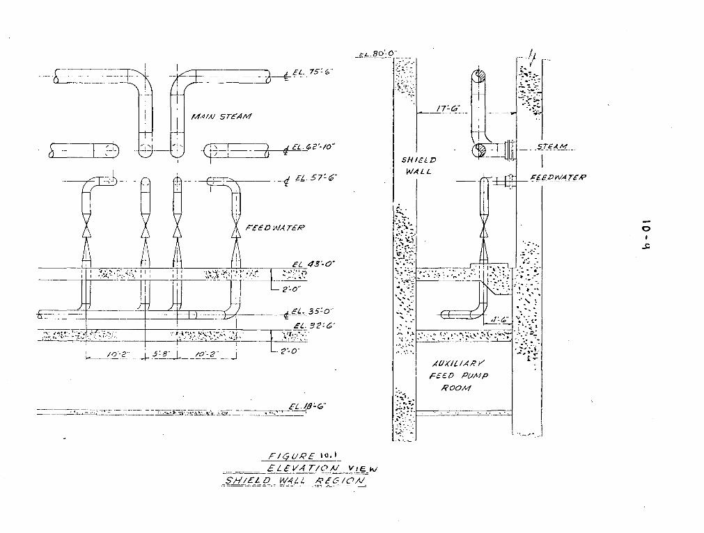
I14,41Nt STEc4M
___ EL. 62-10"
tL.800
AS FZ) W4 7
0
__-__ . ,.,--_. ._. .-.-- __.
FIC761,qE 10.1_____..ELEV' T/AICSA-'/ELVDW4L4 A',Ec/IcW

ftIAA/T AJORTHJ
CDNTAINt-1NT I3U/LDINC7
65AFETY VALVE-0
1.570P ý Chl~Ck VALVC-5
0
0.57OPý CE-1Ck VALVE5
__r..5H/IELD WALL EL. 80'-0"E 13*+61. 72 1
55'- o"
0
rb

10-11
sample line, or auxiliary steam line. The staff has reviewed these
design modifications and finds them acceptable.
10.4 Other Features of Steam and Power Conversion System
Three divided box, single pass condensers will maintain turbine
back pressure for all normal operating conditions including the
period of time when the turbine steam bypass valves are in operation.
The hot well capacity will provide a 5.5-minute holdup time for the
condensate when operating at rated load.
Normal water level in the condenser hot well is maintained by the
condensate makeup and surge systems. The makeup system connects the
condenser to the Category I 600,000 gallon condensate storage tank.
Automatic valves operate to maintain condenser water level. Should
the amount of water within the condensate storage tank decrease to
360,000 gallons, the condensate storage tank will be automatically
isolated. This 360,000 gallons of water ensures a 24-hour reserve
for the auxiliary feedwater pumps to hold the plant at hot shutdown
following a trip from full power.
We have concluded that the designs of the main condensers and
condensate storage tank are acceptable.
One four-element, two-stage air ejector with separate inter-
condenser and common aftercondenser is provided to withdraw non-
condensible gases from and maintain a vacuum on each condenser.
The ejectors use main steam, reduced in pressure by a regulating
10-12
valve. In the event the air ejector exhaust radiation monitors
reveal a high activity, the non-condensible exhaust gases will not
be vented to the atmosphere but routed to the containment for
ultimate passage through roughing filters, HEPA filters, and charcoal
filters. Because of this feature, we have concluded that the main
condenser evacuation system is acceptable.
To prevent overpressure in the steam generators on a turbine
trip with reactor trip, without main steam safety valve operation,
twelve turbine steam bypass valves open to discharge steam to the
main condenser.
During startup, hot standby service and physics testing, the
same steam bypass system can be manually actuated from the pressure
controller to effect a simulated load on the reactor plant.
We have concluded that protection against system overpressure
is acceptable.
The circulating water system is composed of six circulating
water pumps, each providing 140,000 gpm. They are each in an
individual pump well, thus tying a section of the condenser to an
individual pump. Upon discharge from the condenser, the combined
pump flow is directed to a canal.
The condensate and feedwater system supplies 13,823,282 pounds
of feedwater per hour to four steam generators at a turbine load of

10-13
1022 MW(e). Three one-third capacity condensate pumps take suction
from condenser hot wells.
Two one-half size feed pumps take suction from the condensate
delivered from three stages of feed heating, and deliver it through
one more stage of feed heating and feedwater regulating valves to
the steam generators.
Each steam generator has two bottom blowdown connections for
shell solids concentration control. Each blowdown line has a manual
shutoff valve and two diaphragm operated trip valves. Blowdown dis-
charges through a throttle valve to a flash tank where the water is
cooled prior to discharge to the circulating water discharge canal.,
or through the liquid waste treatment system if radiation levels are
high in the blowdown. (See Section 11 of this Safety Evaluation for
further discussion.)
We have concluded that the condensate, feedwater, circulating
water, and steam bypass atmospheric relief, and steam generator
blowdown systems are acceptable.
11-1
11.0 Radioactive Waste Management
11.1 Design Objective and Criteria
The radioactive waste management systems for Indian Point
3 are designed to provide for the controlled handling and treat-
ment of radioactive liquid, gaseous, and solid wastes. The
applicant's design objective for these systems is to restrict
the amount of radioactivity released from normal plant operation
to unrestricted areas to within the limits set forth in 10 CFR
Part 20.
The Technical Specifications issued as part of the operating
license require the applicant to maintain and use existing plant
equipment to achieve the lowest practicable releases of radioactive
materials to the environment in accordance with the requirements of
10 CFR Part 20 and 10 CFR Part 50. The applicant is also required
to maintain radiation exposures to In-plant personnel and the general
public "as low as practicable" in conformance with the requirements
of 10 CFR Part 20.
Our evaluation of the design and expected performance of the
waste management systems for Indian Point 3 is based on the
following design objectives:
Liquids
(1) Provision to treat liquid radioactive waste to control
the expected releases of radioactive materials in liquid
11-2
effluents to the environment to less than 5 Ci/yr/unit,
excluding tritium and dissolved noble gases.
(2) The calculated annual average radiation exposure to
the whole body or any organ of an individual at or
beyond the site boundary not to exceed 5 mrem.
(3) Concentration of radioactive materials in liquid
effluents prior to dilution in the environment not
to exceed the limits in 10 CFR Part 20, Appendix B,
Table II, Column 2.
Gaseous
(1) Provisions to treat gaseous radioactive waste to limit
the expected release of radioactive material in gaseous
effluent from principal release points so that the
annual average radiation exposure to the whole body
or any organ of an individual at or beyond the site
boundary not to exceed 5 mrem.
(2) Provisions to treat radioiodine released in gaseous
effluent from principal release points so that the
annual average thryoid dose to a child through the
pasture-cow-milk pathway be less than 15 mrem. For
Indian Point 3 the estimated thyroid dose is evaluated
at the location of the nearest actual cow, approximately
seven miles south of the site.
11-3
Solid
(1) Provisions to solidify all liquid waste from normal
operation including anticipated operational occurrences
prior to shipment to a licensed burial ground.
(2) Containers and method of packaging to meet the re-
quirements of 10 CFR Part 71 and applicable Department
of Transportation regulations.
The following sections present our evaluation of the liquid,
gaseous, and solid waste treatment systems, the design codes and
quality assurance criteria, and the radiation monitoring of process
effluents and of in-plant areas. Our evaluation also considered
radioactive effluent releases for combined operation of Indian
Point 1, 2, and 3. Each unit is provided with separate waste
treatment systems except for the steam generator blowdown and
laundry treatment systems located at Indian Point 1 which are
shared by Units 1, 2, and 3.
11.2 Liquid Waste
The liquid waste treatment system is divided into three
main systems:
(1) The reactor coolant treatment system, which includes
the chemical and volume control system and the boron
recycle system.
(2) The liquid waste disposal system.
(3) The steam generator blowdown treatment system.

11-4
These systems serve only Indian Point 3. When the steam generator
blowdown contains radioactivity above a predetermined value, it
will be processed at Indian Point 1 along with the blowdown from
Indian Point 1 and 2. The laundry and hot shower wastes are also
processed at Indian Point 1. The collection rates and system
capacities are presented in Table 11-1. The liquid effluents will
be continously monitored before discharging through the circulating
water duct to the Hudson River. If the radioactivity exceeds a
predetermined value, the discharge will be automatically stopped
by a valve on the discharge line.
11.2.1 Reactor Coolant Treatment System
The reactor coolant treatment system will collect and process
deaerated liquids from shim bleed, equipment leaks and excess let-
down flows. During normal operation the reactor coolant will be
let down continuously and processed at a nominal rate of 75 gpm
in the chemical and volume control systems (CVCS) to maintain
coolant quality. This letdown stream will be processed through
redundant deep-mixed-bed demineralizers to remove corrosion and
fission products and returned to the reactor coolant system.
Part of this stream, the shim bleed, will be processed through
the boron recycle system. The excess letdown and the containment
equipment leaks will also be processed through the boron recycle
system. These streams will be collected in the reactor coolant
drain tank and the CVCS holdup tank. They will be batch processed

11-5
through redundant cation demineralization, gas stripping, and
evaporation equipment. The evaporator condensate will be pro-
cessed through an aniondemineralizer-to principally remove
iodine and routed to one of two monitor tanks for sampling and
analysis. Condensate will either be sent to the primary water
tank for reuse in the reactor or released to the environment. The
condensate can also be processed in the liquid waste disposal
system. The boric acid concentrate from the evaporator will be
filtered and then collected in the concentrate holding tank for
sampling and analysis. The concentrate will either be sent to
the boric acid tanks for reuse, or sent to the solid waste
system for offsite disposal.
In our evaluation we estimated that approximately 15,000
gallons per day of shim bleed, excess letdown and equipment leaks
will be collected. These wastes will be processed through the
boric acid demineralizers and evaporators and we estimate a
release of 0.035 Ci/yr of radioactivity, excluding tritium and
dissolved gases. The applicant did not estimate the radioactivity
released from this source. The processing capacity will be
43,000 gallons per day when using both evaporators. Our estimate
assumed one-day holdup for decay and 10% release of the processed
effluent to the environment. The liquid effluent will be continously
monitored during its release to the environment.

11-6
11.2.2 Liquid Waste Disposal System
The liquid waste disposal system will collect and batch
process aerated radioactive liquid wastes from equipment, floor
and chemical drains. The system equipment includes collection and
monitoring tanks, a filter, and a two-gpm evaporator. These
wastes will be collected in the waste holdup and chemical drain
tanks, then filtered, and evaporated. The evaporator condensate
will be collected in one of two monitor tanks, sampled and
analyzed. The condensate that meets specification will be
returned to the reactor water storage tank for reuse or discharged
to the Hudson River. Condensate not meeting the required quality
will be recycled to the waste holdup tank for further treatment.
The evaporator concentrate and spent filters will be sent to the
solid waste system.
In our evaluation we estimated that approximately 140 gallons
per day of equipment drain effluent and 330 gallons per day of
floor and chemical drain effluents will be processed by the two-gpm
waste evaporator. We assumed one-day holdup for decay, 10% release
from equipment drain effluents, and 100% release of the condensate
from the floor and chemical drain effluents. Our calculations
showed that approximately 2 Ci/yr of radioactivity, excluding
tritium and dissolved gases, will be released. The applicant
estimated that approximately 2 Ci/yr of radioactivity, excluding
tritium, would be released from this system.

11-7
11.2.3 Steam Generator Blowdown
The secondary coolant will be blown down from the steam
generator at 10 gpm to maintain chemical purity. As shown in
Figure 11-1, the blowdown from the Indian Point 3 steam generators
can be directed to the treatment system installed at Indian Point 1
or can be directed to the steam generator blowdown flash tank
installed at Indian Point 3. The steam generator blowdown flash
tank at Indian Point 3 is intended to process only low level
activity wastes. Wastes discharged from this tank would enter
the environment without treatment. A continous beta-gamma monitor
will measure the radioactivity of the secondary coolant that enters
the blowdown flash tank. When the radioactivity in the secondary
coolant exceeds a predetermined value, the monitor will activate
an alarm and automatically close isolation valves on the blowdown
and sampling lines. The blowdown stream from Indian Point 3 will then
be routed manually to the Indian Point 1 blowdown treatment system.
A composite sample of the liquid releases from the blowdown flash
tank will be taken daily and analyzed for isotopic composition.
The blowdown treatment system at Indian Point 1 is designed to
handle blowdown simultaneously from all three units. This treat-
ment system at Indian Point 1 consists of redundant filters and
deep-mixed-bed demineralizers, with a total capacity of 132 gpm.
Blowdown from Indian Point 3 can be diverted to the Indian Point
1 treatment system independent of any power generation at Indian
Point 1. The effluent from the demineralizer will be discharged

11-8
to the Hudson River. If the radioactivity in the demineralizer
effluent exceeds a preset value, it will activate an alarm re-
quiring appropriate action. Composite samples of the demineralizer
effluent are taken daily and analyzed for isotopic composition.
Based on our evaluation, approximately 10 gpm blowdown from
Indian Point 3 will be processed in the Indian Point 1 treatment
system, resulting in an estimated release of 1.7 Ci/yr of radio-
active material, excluding tritium and dissolved gases. With a
50-gpm blowdown rate, the applicant estimated the release rate to
be 7.5 Ci/yr. The 132 gpm capacity of the Indian Point 1 system
will therefore be adequate to process 50 gpm blowdown rates from
Indian Point 1, 2 and 3. We conclude that this system has adequate
capability and is acceptable.
11.2.4 Liquid Waste Summary
The total radioactivity in the liquid effluent released from
Indian Point 3 to the environment was estimated by the applicant
to be 9.6 Ci/yr, excluding tritium and 610 Ci/yr of tritium.
Based on our evaluation, we calculate an annual release of radio-
active material in the liquid effluent will be approximately
3.8 Ci/yr excluding tritium and 350 Ci/yr of tritium.
In our evaluation we calculated the radiation doses to an
individual in unrestricted areas from the aquatic food chain and

11-9
swimming would be less than 5 mrem to the whole body and less
than 5 mrem to the thyroid. Our radiation dose calculations
considered the combined operations of Units 1, 2 and 3 at the
Indian Point ste. All radioactive liquid wastes will be con-
tinously monitored before discharge. Assuming a circulating
water flow rate at Indian Point I of 320,000 gpm and at Indian
Point 2 and 3 of 870,000 gpm the radioactivity concentration
released to the Hudson River will be less than 1% of the limits
specified in 10 CFR Part 20.
The liquid waste treatment system has been designed to
collect, process, and store waste from operation with the equivalent
of 1 percent fission product inventory releases from failed fuel
rods to the primary coolant. We have concluded that the liquid
waste treatment system will be. capable of producing liquid
effluents which we consider as low as practicable and therefore
is acceptable.
11.3 Gaseous Wastes
The gaseous wastes treatment system for Indian Point 3
include the waste gas processing, the condenser air ejector and
the steam generator blowdown vent systems along with the contain-
ment purge, and the fuel storage, turbine and auxiliary building
ventilation systems. These systems for Indian Point 3 are in-
dependent of Indian Point 1 and 2, except for the steam generator
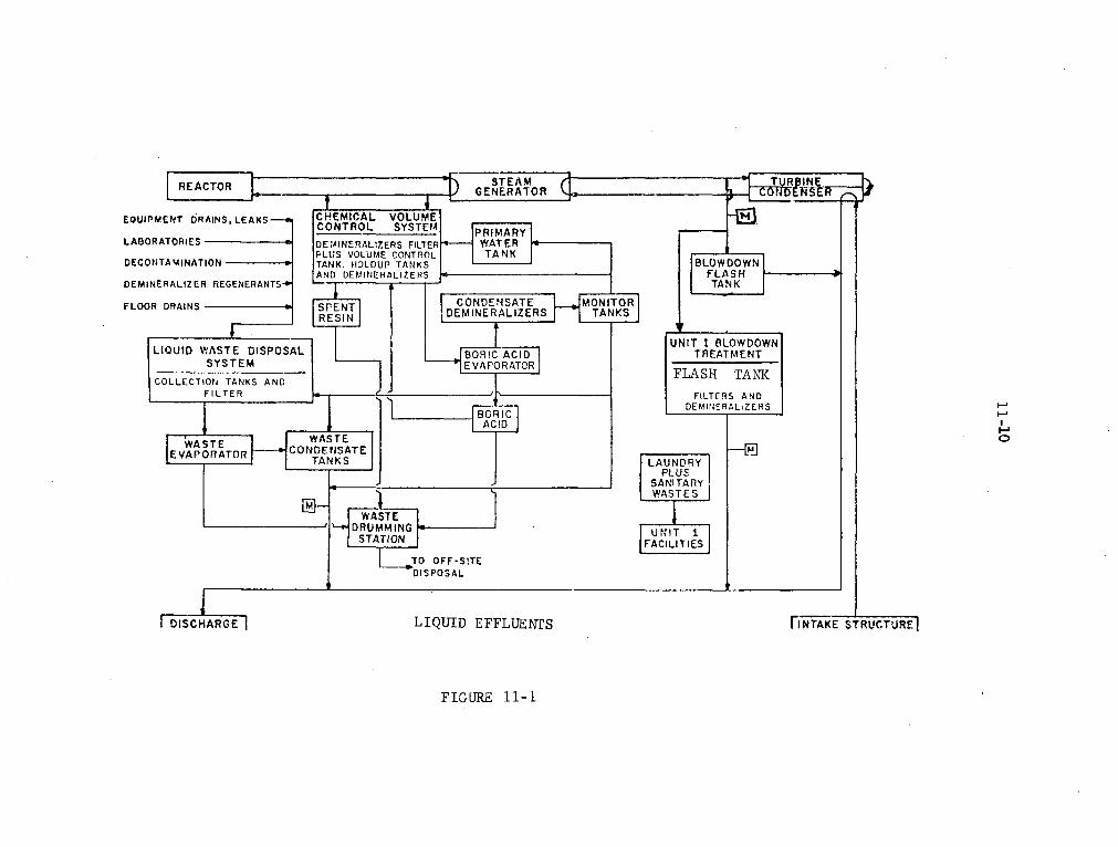
BORIC DEMP41ERALIZERS -
0
LAUNDRYPLUS
_____________ ANITARYWASTES
AC ILITIEES
IFF-SITEOSAL
?UID EFFLUENTS FINTAKE STRUCTURE]
FIGURE 11-1
11-11
blowdown system. Steam generator blowdown containing radioactivity
above a predetermined level will be processed at Indian Point 1.
The gaseous releases from all systems will be monitored except
ventilation air released from the turbine building. The gases
released from the waste gas processing system, the containment
purge, the condenser air ejector and the auxiliary building ven-
tilation will be discharged through the plant vent. Ventilation
air from the turbine building will be discharged from the turbine
building roof.
11.3.1 Waste Gas Processing
The waste gas processing system will collect and treat
radioactive gases from the reactor coolant treatment system.
These sources include the shim bleed gas stripper, holdup tank cover
gases, equipment vents, and gases generated from sampling. The
primary source of radioactivity is from degassing the shim bleed
in the boron recovery system.
The gas processing system includes redundant compressors and
four 525 ft3 and six 40 ft3 storage tanks. The waste gases will
be pumped to one of the tour storage tanks and recycled to the CVCS
holdup tanks to provide cover gas during emptying operations. A
second tank will be available as backup. When 110 psig pressure
is reached in the inservice tank, the feed will be automatically
switched to the backup tank. Prior to cold shutdown of the
reactor, the reactor coolant will be degassed and the gas will
be distributed among the six 40 ft 3 storage tanks.
11-12
Some hydrogen is also present in the gas released from the
CVCS system. To prevent hydrogen-oxygen explosions, the process
equipment vent system operates at positive pressure so as to
minimize inleakage of air. In addition, no air or aerated liquids
will be present in equipment that vents to this system. The
storage tank gas will be automatically sampled and analyzed for
hydrogen and oxygen. An alarm will alert the operator when the
hydrogen concentration exceeds 2%.
The waste gas storage tanks have sufficient capacity to
holdup gases for 45 days for radioactivity decay. Before release
to the environemnt, the gas will be sampled and analyzed. During
discharge at a controlled rate through the plant vent, the gas
will be continuously monitored. Radioactivity releases above a
predetermined value will automatically close a valve on the
discharge line. Based on a holdup time of 45 days, the applicant
estimated releases of 2000 Ci/yr of noble gases. Based on our
evaluation assuming 45 days holdup, we calculate an average annual
release rate of 1500 Ci/yr of noble gases.
11.3.2 Containment Purge
The containment purge system will process radioactive gases
that build up in the containment atmosphere as a result of leaks
from the primary system. In our evaluation we considered that the
containment atmosphere will be purged four times per year. The
equipment used for containment purging includes prefilters, HEPA

11-13
filters and charcoal adsorbers. The filters and the exhaust
fan will be shared with the primary auxiliary building ventila-
tion system. Before purging, we assumed the air in the contain-
ment will be recirculated for 16 hours through an internal
cleanup system consisting of HEPA filters and charcoal adsorbers.
The containment air will then be purged through the HEPA filters,
charcoal adsorbers and released through the plant vent. The
applicant has estimated the radioactivity released from four
purges per year to be 88 Ci/yr of noble gases and 0.00014 Ci/yr
of iodine-131.
Based on our evaluation, assuming four purges/yr and 16
hours internal recirculation before purging, we calculate a
release of 88 Ci/yr of noble gases and 0.026 Ci/yr of iodine-131.
This shared system is acceptable since, during normal operations
the exhaust fans provide a negative pressure in the exhaust
plenum. This will prevent the cross. flow between the contain-
ment and the primary auxiliary building. If the exhaust fan fails,
the associated supply fan will automatically be shut down to
prevent cross ventilation flow between these buildings.
11.3.3 Condenser Air Ejector
Gaseous radioactivity, along with noncondensable gases in
the secondary coolant, will be removed from the turbine condenser
by the air ejectors. Leakage in the steam generator from the

11-14
primary to the secondary system will result in some radioactivity
in the secondary system coolant. The gases from the condenser
will pass through the steam jet ejectors, will be monitored, and
then be released through the plant vent. The applicant has cal-
culated. that the activity released from the condenser air ejector
will be 1300 Ci/yr of noble gases and 0.065 Ci/yr of iodine-131.
Based on our evaluation the radioactivity release will be
580 Ci/yr of noble gases and 0.13 Ci/yr of iodine-131 from this
source.
11.3.4 Steam Generator Blowdown
At Indian Point 3 the steam generator blowdown will go to
Indian Point 3 flash tank at a rate of 10 gpm. From the flash
tank the steam vapor will be released without monitoring from a
rooftop vent. When the radioactivity in the secondary coolant is
above a predetermined value the blowdown will be automatically
stopped and manually diverted to the blowdown flash tank at
Indian Point 1. The blowdown system at Indian Point 1 will also
receive the blowdowns from Indian Point 1 and 2. The vent from
Indian Point 1 flash tank will be vented to the Indian Point 1
turbine condenser. The radioactivity released from Indian Point 1
condenser will be monitored and discharged through the Indian
Point 1 stack. When the Indian Point 1 condenser is shut down

11-15
.the vapor will be released from the Indian Point 1 flash tank
through an unmonitored rooftop vent. The applicant considered
6 weeks/year for this direct release and estimated a release of
0.13 Ci/yr of iodine-131 from this source.
Based on the past operating experience of Indian Point 1,
we estimated that the blowdown vapor from Indian Point 3 would
be directly released to the atmosphere for approximately 17
weeks per year. We calculated that this would release 0.16 Ci/yr
of iodine-131. The applicant has been advised that capability
for continuous monitoring of the blowdown effluent is required prior
to initial startup of Indian Point 3.
11.3.5 Primary Auxiliary Building Ventilation
The atmosphere in the primary auxiliary building will contain
radioactivity from equipment leaks. The ventilation system for
this building will include pre-filters, HEPA filters and charcoal
adsorbers. The filters and exhaust systems will be shared with
the containment purge system. The ventilation system is designed
to flow from clean to potentially more contaminated areas. The
applicant estimated that the radioactivity released-will be
approximately 1300 Ci/yr of noble gases and less than 0.001 Ci/yr
of iodine-131. Based on our evaluation we estimate 580 Ci/yr of
noble gases and 0.05 Ci/yr of iodine-131.
11-16
11.3.6 Turbine Building Ventilation
Steam leaks from the secondary coolant system will release
some radioactivity into the turbine building atmosphere. This
will be discharged without monitoring to the environment through
11 roof-mounted exhaust fans. The applicant has estimated that
the radioactivity released from this source will be 0.01 Ci/yr of
iodine-131. Based on our evaluation, we estimate a release of
approximately 0.04 Ci/yr of iodine-131.
11.3.7 Fuel Storage Building Ventilation
The Fuel Storage Building Ventilation System will include
HEPA filters and charcoal adsorbers. Normally exhaust air will
be processed through HEPA filters and discharged through the
monitored plant vent. However, when the radioactivity is above
a predetermined value, the ventilation exhaust air will be
automatically diverted through the charcoal adsorbers prior to
being released.
The applicant did not estimate the radioactivity release
through.the ventilation system under normal conditions. In our
evaluation we determined that the radioactivity released from
this building under normal conditions will be negligible. An
analysis of radioactivity releases due to a fuel handling accident
is. given in Section 15 of this report.
11-17
11.3.8 Gaseous Waste Summary
The applicant has estimated the radioactivity in the
gaseous effluents released from Indian Point 3 will be 5500 Ci/yr
of noble gases and 0.16 Ci/yr of iodine-131. For the combined
operation of Indian Point 1, 2 and 3, the applicant's estimated
releases are 11,000 Ci/yr of noble gases and 0.32 Ci/yr of iodine-131.
The applicant also estimated that radiation doses to an individual
at or beyond the site boundary from the combined operation will
be 2.4 mrem/yr to the whole body and 1.4 mrem/yr to the thyroid
from inhalation.
Based on our evaluation of the gaseous waste systems, we
calculated that the radioactivity released from Indian Point 3
during normal operation will be 2700 Ci/yr of noble gases and
0.41 Ci/yr of iodine-131. For the combined operation of Indian
Point 1, 2, and 3 we calculated the radioactivity release will
be 6600 Ci/yr of noble gases and 0.88 Ci/yr of iodine-131. Based
on the combined operation of Indian Point 1, 2 and 3 we calculated
the annual average radiation doses at the site boundary will be
less than 5 mrem to the whole body and less than 5 mrem to the
thyroid from inhalation. We calculated that the radiation dose
to a child's thyroid will be less than 15 mrem per year based on
the grass-cow-milk pathway for radioiodine for the nearest actual
cow, seven miles south of the site. The dose calculations were

11-18
based on a maximum annual average relative concentration of
2.4 x 10⁻⁷ sec/m3 for Indian Point 2 and 3 and 5.1 x 10⁻⁸ sec/mr3
for Indian Point 1. Subject to the installation of continuous
monitoring capability prior to initial startup we conclude that
the release of radioiodine in gaseous effluents are as low as
practicable and are acceptable.
11.4 Solid Wastes
The sources of solid radioactive wastes will include spent
demineralizer resins, evaporator concentrates, filters, and
miscellaneous items such as contaminated clothing, gloves, shoe
covers, glassware and paper. The solid waste disposal system
*is designed to package all solid wastes in 55-gallon drums. A
facility will be provided for loading spent resin and evaporator
concentrates. A hydraulic baler will be used for the miscellaneous
wastes. The filled drums will be stored in a shielded area of the
drumming room. The spent demineralizer resins after approximately
six months storage will be slurried into shielded filter units
within 55-gallon drums. The filtrate will be returned to the
waste holdup tank. The evaporator concentrates will be pumped
into 55-gallon drums containing vermiculite and cement for
solidification. The miscellaneous solid waste, clothing, paper
and glassware will be compressed in 55-gallon drums. The appli-

elm)
CONTAINMENT VENTILATION
VENT. ).
AIREJECTOR OUTSIDE AIR SPENT
AUXMILIARY PO 3001 1TURBINE SBUILDING FUEL STORAGE BUILDING
CONDENSER ROOF
STEAM 11 BI ROOF VENTILATORSGENERATOR . RADIATION ( 61,000 ct. EACH)
S MONITOR
OuOUTSI AIRPNT TURBINE BUILDING 10 WALL EXHAUST FANS
(SODNTANK, TO HUDSON RIVER WASTE TANKS FILTEROUTSIDE AIR ROOM. PENETRATION
UNIT 3 13LOWDOWN SYSTEM ROOM,WASTEEVAPORATOR ETC. P 69.200 . . m
----Nil ROLE "I "YOIOGENINOBLE GA9 PE .CVL[
[•F._ACTOf COLAER I JANK jj WASTE HANDLING EOUIPMENT GASEOUS RADWASTE
~SEW§ E-V-A 'POATOR -ACK E
L~ EVAPPAG-O[DO IC CID EVAORAOR | /'•"'I ]A-HIGH-EFFICIENCY PARTICULATE TILTER
RVoLUAECONTRCL TANK BASEMENT _O | C-CHARCOAL AOSORBERC"CSy CHEMICAL VWO LUIE CONTROL ST•'ENI
AUXILIARY BUILDING VENTILATION
GASEOUS EFFLUENTS
FIGURE 11-2

11-20
cant has estimated that approximately 150 drums of spent
resins and evaporator concentrate waste will be packaged and
shipped each year. Based on the experience of operating
reactors, we estimate that approximately 1000 drums containing
4900 Ci of radioactivity will be shipped from Indian Point 3
per year. All solid wastes will be packaged and shipped to a
licensed burial ground in accordance with AEC and Department of
Transportation regulations. We conclude that the solid waste
system will have adequate capacity and is acceptable.
11.5 Design
The radioactive waste treatment systems will be designed
and fabricated in accordance with acceptable codes and standards.
The reactor coolant drain tank, waste filter, the spent resin
storage tank, and the gas decay tanks will be designed to ASME III,
Class C. The piping code will be USAS-B31.1. The equipment will
be located in a Category I (seismic) structure. We have concluded
that the equipment and piping designs of the radwaste systems are
acceptable.
-11.6 Process and Area Radiation Monitoring Systems
The process radiation monitoring systems will be designed
to provide information regarding radioactivity levels in effluents
released to the environment.
The liquid effluents in the discharge line from the waste
condensate tanks will be monitored continuously. The monitor will
11-21
automatically terminate the discharge if the radioactivity
concentration exceeds predetermined values. A similar system
will monitor the secondary coolant activity in the steam generators
that will automatically stop the blowdown when the activity exceeds
a predetermined value. The component cooling loop of the auxiliary
coolant system and the essential service water system will be
monitored for any primary coolant leakage into these systems.
The circulating water discharge will be continuously sampled and
analyzed.
The gaseous effluent in the plant vent will be continuously
monitored for gross radioactivity, particulates, and radioiodine.
The plant vent provides the discharge path for the gas decay tanks,
the containment purge, the condenser air ejector and the ventilation
systems for the primary auxiliary building and the fuel storage
building. Radiation levels above a predetermined value will
automatically stop the discharge from the gas decay tanks and
activate the auxiliary dilution air supply to the plant vent. A
similar monitoring system will serve the containment to control
the purge and entry operations. Radiation levels in the contain-
ment above a predetermined value will automatically stop the purge.
A continuous monitor will measure the gross radioactivity in
the effluent from the turbine condenser air ejector. Radioactivity
in the gas decay tanks will be measured during the filling operation,
and will alarm when the inventory limit is reached.

11-22
The air exhausted from the 11 roof-mounted exhaust fans
on the turbine building will not be monitored for radioactivity
since the building is not tight and therefore gases are exhausted
from many places.
The area radiation monitoring system will be designed to
provide information on radiation fields in the various areas of
the plant for personnel protection. Monitor locations will include
the control room containment, in-core instrumentation area, spent
fuel building, sampling room changing pump room, and drumming
station. If a radiation level rises above a predetermined value,
an alarm will be sounded locally and in the control room.
Monitoring systems will detect, indicate, annunciate and/or
record the levels of radioactivity to verify compliance with
existing regulations to keep radiation levels within the plant
and in unrestricted areas as low as practicable.
11.7 Personnel Protection
The personnel protection programs will be established to
maintain exposure to plant personnel to levels as low as practicable.
These programs include radiation shielding, area access control,
area and personnel monitoring and protective clothing. The
applicant's design objective for radiation shielding for normal
operation is to maintain whole body dose rates for all controlled
access areas of the plant to less than 1.25 rem per calendar year,

11-23
assuming continuous occupancy and the equivalent of 1 percent
fission product inventory releases from failed fuel rods into
the primary coolant. The plant will be zoned into six radiation
areas for personnel occupancy control. These range from continuous
access at less than 0.1 mrem/hr maximum radiation to controlled
access at greater than 15 mrem/hr.
Personnel monitoring equipment will be provided for all
personnel at the plant. Records showing radiation exposures
of all personnel at the plant will be maintained by the applicant.
The records will contain at least a monthly tabulation of readings
from beta-gamma-neutron film badges or their equivalent. Protective
clothing and respiratory protective equipment will be available for
the protection of personnel, when required.
We conclude that the personnel protection systems satisfy
* the requirements of existing regulations as pertains to exposure
of individuals to radiation, and are acceptable.
11.8 Radiological Environmental Monitoring
-A radiological environmental monitoring program has been
in effect at the Indian Point site since 1958. Consequently,
more than fifteen years of baseline data will be available prior
to Indian Point 3 start up which can be used to predict and evaluate
the potential effects of plant operation.

11-24
The Indian Point 3 monitoring program includes sampling
of airborne particulates and radioiodines, lake and well water,
drinking water, Hudson River water, Hudson River bottom sediments,
soil, aquatic and land vegetation, milk and Hudson River fish.
The program also includes gamma spectroscopy of drinking water,
Hudson River water and lake water. Tritium analysis is performed
on drinking water. Airborne particulates are sampled at 21
stations which are located generally within 3 miles of the plant.
In addition, direct measurements of gamma background are made
annually at selected areas within a 5 mile radius of the plant.
Thermoluminescent dosimeters are also located at specified
offsite locations as well as a number of points on the site
perimeter, for the purpose of measuring ambient radiation levels.
The program conforms with Regulatory Guide 1.41 for measuring
and reporting radioactivity in the environs of nuclear power
plants and is acceptable.
11. 9 Conclusions
We have concluded that the Indian Point 1 steam generator
flash tank vent monitoring equipment will not satisfy the
guidelines of Regulatory Guide 1.21 and General Design Criterion
64 and is not acceptable. The applicant has been informed that
a monitoring system will be required to measure direct releases
from the Indian Point 1 blowdown flash tank.

11-25
Subject to installing the above flash tank vent
monitoring system prior to initial startup, we have concluded
that the radioactive waste management systems will satisfy
the as low as practicable guidelines of 10 CFR Parts 20 and 50,
that the system is designed in accordance with acceptable codes
and standards, and that the area monitoring system is similar
to other monitoring systems previously accepted.
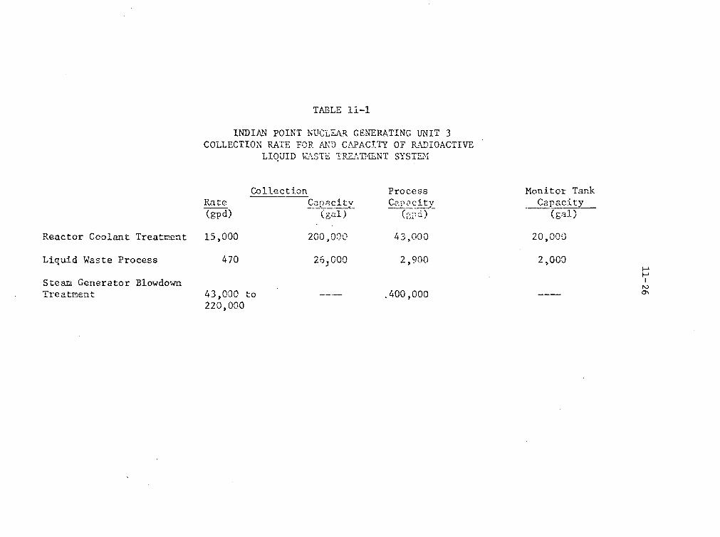
TtBLE ii-i
INDIAIN POINT NUCLEARR CENERATING UNIT 3COLLECTION RATE FOR. AN\D CZAPACITY` OF RADIOACTIVE
LIQUID WýA.STE TP2.'AT'P,,NT SYSTEM
Rate(gpd)
CollectionC1citv
(gal)
ProcessCapacicty
Monitor TankCapacity
(gal)
Reactor Coolant Treatment 15,000 200 •000
2 6 0,00
43, 000
2,900
20,000
2,000Liquid Waste Process
Steam Generator BlowdownTreatment
470H-I
0"'43,000 to220,000
.400,000
12-1
12.0 RADIATION PROTECTION
12.1 Shielding
The radiation shielding is designed and the expected personnel
occupancy factors are such as to allow plant operation at the maximum
calculated power levels with 1.0% fuel defects without exceeding
radiation doses permitted by 10 CFR Part 20 for both occupational and
non-occupational personnel. The, shielding for the Indian Point 3
plant is similar to other pressurized water reactors, from which
considerable operating data have been obtained. On the basis of our
comparison of the Indian Point 3 shielding design with that of other
such plants, we conclude that the shielding is adequate to protect
the health and safety of the public and operating personnel.
12.2 Ventilation
The Indian Point 3 station ventilation system is designed to
provide a suitable environment for operations personnel. The primary
Auxiliary Building Ventilation System allows control of flow direc-
tion of airborne radioactivity from low activity areas to higher
activity areas in accordance with recommended practice. Also, the
Control Room Air Conditioning, Heating, and Ventilation System is
designed to permit removal of airborne particulate radioactivity from
the air entering the air conditioned control room. The Ventilation
system is designed to vent all compartments potentially containing
airborne radioactivity to the outside.

12-2
The gaseous and particulate radioactivity monitoring system is
designed to provide radiation detection equipment to provide adequate
information and warning to assure that personnel exposures do not
exceed 10 CFR 20 limits and to meet the intent of 10 CFR 50, Appendix
A, Criterion 64 on monitoring radioactivity releases. The functions
of the system are to warn operating personnel of any radiation health
hazard that might develop and to give early warning of a plant mal-
function which might lead to an airborne inhalation hazard.
During the review of the Indian Point 3 design the staff noted
that airborne gaseous and particulate radioactivity were monitored
continuously only in the plant vent, the containment system and the
air ejector off-gas system. These fixed monitoring stations function
primarily to monitor effluent releases and plant processes and are
not effective in assuring in-plant control of personnel exposures.
In-plant monitoring for radioactivity in air at Indian Point 3 was
to be principally performed by portable gas and particulate monitors.
The staff felt that this system did not meet the intent of
Section C.3K of Regulatory Guide 8.8 "Information Relevent to Main-
taining Occupational Radiation Exposures As Low As Practicable -
(Nuclear Reactors)."
In June, 1973 the staff issued a letter to the applicant requiring
that ficed gaseous and particulate monitors with remote read-out
provisions be installed in the radwaste area, the control room, and
in the fuel handling and storage area. In a letter dated June 25, 1973

12-3
to Mr. D. B. Vassallo of the AEC, Mr. William J. Cahill, Jr. of
Consolidated Edison stated that these monitors will be installed
at the locations required by the AEC.
The addition of these fixed monitors, coupled with the Health
Physics procedures on the use of the portable air and gas monitors,
resulted in an adequate air monitoring program for plant personnel.
12.3 Health Physics Program
Radiation protection operating experience gained at Indian Point
1 and Indian Point 2 will be used to benefit the planned radiation
safety program of Indian Point 3. The personnel monitoring program,
the protective equipment that will be supplied to operations and
maintenance personnel, and the portable radiation monitoring equipment
and laboratory equipment available for day-to-day use are designed to
assure that occupational exposures are maintained within the established
guidelines of 10 CFR 20. The administrative controls and procedures,
as well as the organization and staffing for carrying them out, are
appropriate for implementing the rules and regulations set forth in
10 CFR 20. As a result of these factors, we conclude that the Health
Physics program is acceptable.

13-1
13.0 CONDUCT OF OPERATIONS
13.1 Plant Organization and Staff Qualifications
The Indian Point Station staff, for Units 1, 2, and 3, will
consist of approximately 380 full-time employees. The station is under
the onsite supervision of the Manager, Nuclear Power Generation Depart-
ment who reports to the Assistant Vice President, Power Generation
Department, who in turn reports to the Executive Vice President, Central
Operations. The Manager of the Nuclear Power Generation Department has
the general responsibility for administering all phases of operation,
training, and maintenance of the facility. The Station Manager for
Operation and Maintenance and the Manager for Nuclear Services report
to the Manager of the Nuclear Generation Department.
Approximately 275 people are under the direction of the Station
Manager for Operation and Maintenance. About 130 of these people are
assigned to the plant engineer and the remaining people are distributed
among three Chief Engineers. Each Chief Engineer is responsible for
administering all phases of Operation for one of the nuclear generation
units. Also reporting to the Station Manager for Operation and Main-
tenance are five General Watch Foremen, each licensed as a Senior
Reactor Operator for one of the units, who are responsible for facility
operation on a shift-to-shift basis.
The Chief Engineer for Unit 3 has a staff of approximately
40 people, including an Operational Engineer who is responsible for

13-2
day-to-day operation of Unit 3.' Reporting to the Operational
Engineer is a Watch Foreman, who has a Senior Reactor Operator license,
a Senior Reactor Operator and Reactor Operator, both of whom are
licensed as Reactor Operators, and three Nuclear Plant Operators.
In addition, a Health Physics Technician is assigned to each shift
as a shared function for all three units.
The Manager, Nuclear Services, is responsible for providing the
staff services of training, technical engineering, and radiation
safety. Three Directors report to the Manager, Nuclear Services.
They are the Director of Nuclear Training, the Director of Technical
Engineering, and the Director of Radiation Safety. These three
Directors have staffs of 12, 40, and 30 persons, respectively.
The applicant has conducted a training program to train shift
supervisory and control room personnel to operate Unit 3. A major
feature of the training program provides that obtaining a license for
Unit 2 be a prerequisite for Unit 3 licensed operating personnel
for the initial plant staff. This will be followed by a three-month
familiarization program to learn the differences between Unit 2
and Unit 3.
The key non-shift supervisory personnel and technical staff are
currently performing their respective job functions for Units 1 and 2.
Their job responsibilities are being expanded to include Unit 3.
13-3
The qualifications of key supervisory personnel with regard to
educational background, experience and technical specialties have been
reviewed except as noted below and are in general conformance with
those defined in ANSI N18.1, "Selection and Training of Nuclear Power
Plant Personnel." Personnel have not as yet been assigned to the
positions of the Reactor Operator and Watch Foremen. The AEC staff
will review the qualifications of the Watch Foremen as they become
available to confirm that the intent of ANSI N18.1 has been met.
Technical support for the plant staff is available from the home
office Departments of Mechanical Engineering, General Engineering,
Electrical Engineering, Civil Engineering and the Office of Environ-
mental Affairs. Additional technical support during the startup test
program will be provided by WEDCO, a wholly owned subsidiary of
Westinghouse Electric Corporation.
We have concluded that the organizational structure, the training,
and qualifications of the staff for Indian Point are is adequate to
provide an acceptable operating staff and technical support for the
safe operation of the facility.
13.2 Emergency Planning
. The applicant has established an organization for coping with
emergencies. The plan includes written agreements, liaison and
communications with appropriate local, State and Federal agencies that
13-4
have responsibilities for coping with emergencies. The applicant has
defined categories of incidents, including criteria for determining
when protective measures should be considered and for the notification
of offsite support groups. Arrangements have been made by the appli-
cant to provide for medical support in the event of a radiological
incident or other emergencies. Provisions for periodic training for
both plant personnel and offsite emergency organizations have been
included in the Emergency Plan. Most elements of this plan are
currently in effect for Units 1 and 2.
Numerous improvements to the Consolidated Edison's Emergency
Plan were brought about by the AEC staff during its review of Unit
3. These improvements include:
(1) A more rapid method of estimating offsite doses in case of an
emergency. Emergency alerts can now be issued for information
available to the operator in the control room rather than
waiting for the results of an offsite survey.
(2) The Emergency Plan has been augmented to include notification
of the Penn Central Railroad in case of an emergency.
(3) Additional letters of agreement. from medical support facilities
and the Coast Guard have been acquired. These groups could
potentially participate in case of an emergency.
We have reviewed the augmented Emergency Plan and conclude that
it meets the criteria of Appendix E of 10 CFR 50, and that adequate

13-5
arrangements have been made to cope with the possible consequences
of the accidents at the site, and that there is reasonable assurance
that such arrangements will be satisfactorily implemented in the
unlikely event that they are needed.
13.3 Safety Review and Audit
The safety review and audit function for Indian Point 3
will be conducted by the Nuclear Facilities Safety Committee. This
committee was established in 1962 and has been performing that
function since then for Unit 1 and subsequently .for Unit 2. The
Nuclear Facilities Safety Committee is advisory to the Executive
Vice President, and the President and Chairman of the Board and
provides corporate management with a review and audit capability
to verify that-organizational checks and balances are functioning
to assure continued safe operation and design adequacy of the
plant. In a letter dated April 12, 1973, from William J. Cahill, Jr.,
Vice President of Consolidated Edison of New York, to Mr. R. C.
DeYoung, Directorate of Licensing, U. S. Atomic Energy Commission,
the applicant has assured the AEC staff that the Nuclear Facilities
Safety Committee will function in accordance with the requirements
of ANSI N18.7 "Standard for Administrative Control for Nuclear Power
Plants," Sections 3.0 through 4.4.
Details of responsibility and authority of the review and audit
functions are given in Section 6 of the Technical Specifications.

13-6
We conclude that the applicant's plans for the Safety.Review and
Audit functions are acceptable.
13.4 Plant Procedures
Plant operations are to be performed in accordance with written
and approved operating and emergency procedures. Areas covered include
normal startup, operation and shutdown, abnormal conditions and emer-
gencies, refueling, maintenance, surveillance, testing, and radiation
control. All procedures and changes thereto will be reviewed prior
to implementation by the applicant. Safety-related procedures will
be given a thorough review by the Unit 3 Operating Staff. These
procedures then require the approval of the Unit 3 Chief Engineer
after review and comment by the Nuclear Facility Safety Committee.
We conclude that the provisions for preparation, review, approval,
and use of written procedures are satisfactory.
13.5 Industrial Security
The applicant has submitted a description of its Industrial
Security Plan for protection of the Indian Point Nuclear Power Station
Unit 3 from industrial sabotage. The information was submitted as
proprietary information and is withheld from public disclosure
pursuant to Section 2.790 of the Commission's regulations. We have
reviewed the program and conclude that adequate security provisions
have been made for Indian Point Unit 3, and that it meets the intent
and principles of Safety Guide No. 17.
14-1
14.0 INITIAL TESTS AND OPERATION
The initial startup, including preoperational checkout of equip-
ment, functional and system tests, fuel loading, initial criticality
and power operation will be performed by the regular plant staff.
Technical assistance will be provided by WEDCO and Westinghouse. The
WEDCO and Westinghouse personnel will assist in writing procedures,
interpreting test results and any problems that may arise during the
testing program.
We have reviewed the applicant's preoperational and startup
testing program and conclude that it is in general accord with the
AEC publications "Guide for the Planning of Preoperational Testing
Programs" and "Guide for the Planning of Initial Startup Programs."
The program will provide an adequate basis to confirm the safe
operation of the plant and is therefore acceptable.

15-1
15.0 ACCIDENT ANALYSES
15.1 General
The applicant has analyzed reactor performance for normal steady-
state plant operation 4nd for anticipated operational transients on
the basis of the initial core power level of 3025 megawatts thermal
(MWt).
The postulated design basis accidents analyzed for offsite radio-
logical consequences by the applicant are the same as those analyzed
for previously licensed PWR plants, including a steam line break
accident, a steam generator tube-rupture accident, a loss-of-coolant
accident, a fuel-handling accident, and a rupture of a radioactive
gas-storage tank in the gaseous radioactive waste treatment system.
On the basis of our experience with the evaluation of the steam-
line break, the steam generator tube rupture, and radioactive gas-
storage tank rupture accidents for PWR plants of similar design, we
have concluded that the consequences of these accidents can be con-
trolled by limiting the permissible primary and secondary coolant
system radioactivity concentrations and the permissible inventory of
radioactivity in a gas storage tank so that potential offsite doses
are small. We will include limits in the Technical Specifications
on primary and secondary coolant radioactivity concentrations and on
the radioactivity in a gas storage tank such that the potential two-hour
15-2
doses at the exclusion radius that we calculate for these accidents
are well below the 10 CFR Part 100 guideline values.
15.2 Iodine Removal Equipment
15.2.1 Spray
An internal recirculation containment spray system is pro-
vided to remove heat from the containment atmosphere and to remove
iodine which may be present in the containment following a loss-
of-coolant accident. Initially, the two containment spray pumps
take suction on the refueling water storage tank and deliver water
to spray nozzles inside containment. Each pump has a design
capacity of 2600 gpm. Concentrated sodium hydroxide solution is
added at the suction of the spray pumps in quantities sufficient
to maintain a pH of at least 9.3 in the water in the containment
spray. Sodium hydroxide in the containment spray water will
scavenge elemental radioiodine from the containment atmosphere.
When the refueling water storage tank is exhausted, a portion of
the recirculation flow provided for continued core cooling is
diverted to the containment spray headers.
To calculate the total iodine removal constant for the pro-
posed system, we made conservative assumptions regarding liquid
film mass resistance and drop coalescence. Consistent with the
conclusions of WASH-1233,* we assumed that 4% of the iodine in the
*WASH-1233 "Review of Organic Iodine Formation Under Accident
Conditions in Water-Cooled Reactors" Published by the AEC, October,1972.
15-3
containment atmosphere is in the form of organic iodides and 5% in
a particulate form. Experiments have shown that sodium hydroxide
spray solutions are not efficient in the removal of organic iodides;
therefore, we assumed no reduction of the organic iodides by the
containment spray.
We calculated an elemental iodine removal constant of 9.85
hr-1 A two-hour reduction factor for the iodine accident dose at
the exclusion area boundary of 5.2 and a thirty-day reduction factor
for the iodine accident dose at the outer boundary of the low popu-
lation zone of 8.8 was calculated as a result of iodine removal
by the chemical additive sprays. Table 15.3 of this report lists
removal rates and reduction limits for each form of iodine and
the dose reduction factors due to the use of the sprays and filters.
15.2.2 Charcoal Filters
The air handling system (1) will remove heat from the contain-
ment in the post-accident environment and (2) will reduce the iodine
concentration in the containment atmosphere by the use of charcoal
filters. Five air handling units are provided. In each unit, a
fan draws air through a moisture separator, cooling coils, roughing
filters and high efficiency particulate air (H1EPA) filters at a
flow rate of approximately 24,000 cfm under post-accident conditions.
Charcoal filters are located at the fan discharge header. They are
isolated by butterfly valves. Under accident conditions, these
valves are automatically opened by the high containment pressure
signal and a flow rate of 8,000 cfm is diverted through these

15-4
filters. Three of the five air handling units will operate even
if normal offsite power is lost. This was assumed in our analyses.
Under this circumstance, approximately 150% of the free volume of the
containment is processed through the charcoal filters each hour.
Research performed to date using impregnated charcoals of
various manufacturers indicates that at 100% relative humidity the
removal efficiency decreases to about 70% for methyl iodide and
to about 99% for elemental and particulate iodine. The staff
assumes a value of 30% for methyl iodide and 90% for elemental
and particulate iodine for the purposes of site and engineered
safety feature evaluation. Together, the spray and filters reduce
the overall two-hour iodine accident dose at the exclusion area
boundary by a factor of 6.4 and the thirty-day overall iodine accident
dose at the outer boundary of the low population zone by a factor of 20.
15.3 Radiological Consequences of Postulated Accidents
The postulated design basis accidents analyzed by the applicant
and by us for offsite radiological consequences are the same as those
analyzed for previously licensed PWR plants of similar design. The
offsite doses calculated by the staff for these accidents are presented
in Table 15.1 and the assumptions used are listed in Table 15.2 of this
report. All doses are within 10 CFR Part 100 guideline values.
15.4 Control Room Doses
The applicant has met the requirements of General Design Criterion
19 of Appendix A to 10 CFR Part 50 by use of adequate concrete shielding

15-5
around the control room and by filtering inlet air to the control room
during emergencies. Under emergency conditions the air in the control
room is recirculated and filtered through redundant 2,000 cfm clean
up trains which consist of HEPA filters and two inch-deep charcoal beds.
About 200 cfm of make-up air is added upsteam of the filter trains to
assure control room pressurization. The units are automatically
activated upon accident or high radiation signals.
The staff has calculated the potential radiation doses to control
room personnel following a LOCA. The resulting doses are within the
requirements set by General Design Criterion 19.
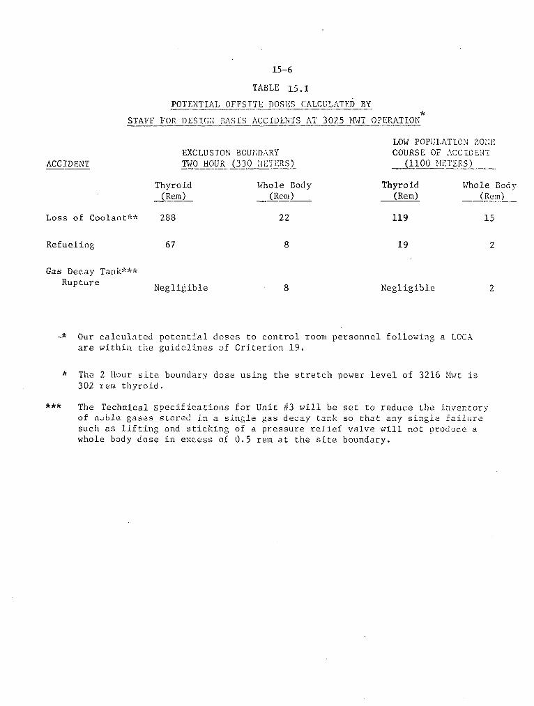
15-6
TABLE 15.1
POTENTIAL OFFSITE DOSES CALCULATED BY
STAFF FOR DESIGN BASIS ACCIDENTS AT 3025 MWT OPEPRATION
EXCLUSION BOUNDARYTWO HOUR (330 >IETERS)
LOW POPULATION ZONECOURSE OF ACCIDENT
(1100 METERS)ACCIDENT
Thyroid(Rem)
Whole Body
(Rem)
22
Thyroid(Rem)
Whole Body(Rem)
Loss of Coolant** 288 119 15
Refueling 67 8 19 2
Gas Decay Tank***Rupture
Negligible 8 Negligible 2
-* Our calculated potential doses to control room personnel following a LOCA
are within the guidelines of Criterion 19.
The 2 Hour site boundary dose using the stretch power level of 3216 Mwt is
302 rem thyroid.
*** Tlhe Technical Specifications for Unit #3 will be set to reduce the inventory
of nuble gases stored in a single gas decay tank so that any single failuresuch as lifting and sticking of a pressure relief valve will not produce a
whole body dose in excess of 0.5 rem at the site boundary.
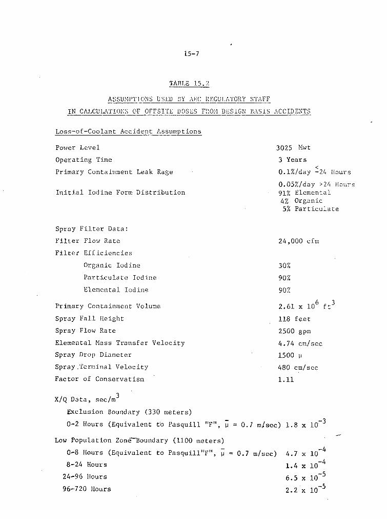
15-7
TABLE 15. 2
ASSUMPTIONS USED BY AEC REGULATORY STAFF
IN CALCULATIONS OF OFFSITE DOSES FROMn. DESIGN' BASIS ACCIDENTS
Loss-of-Coolant Accident Assumptions
Power Level
Operating Time
Primary Containment Leak Rage
Initial Iodine Form Distribution
3025 Mwt
3 Years
0.1%/day -24 Hours
0.05%/day >24 Hours91% Elemental4% Organic5% Particulate
Spray Filter Data:
Filter Flow Rate
Filter Efficiencies
Organic Iodine
Particulate Iodine
Elemental Iodine
24,000 cfm
30%
90%
90%
Primary Containment Volume
Spray Fall Height
Spray Flow Rate
Elemental Mass Transfer Velocity
Spray Drop Diameter
Spray.Terrinal Velocity
Factor of Conservatism
X/Q Data, sec/mi3
Exclusion Boundary (330 meters)
0-2 Hours (Equivalent to Pasquill "F", 11
2.61 x 106 ft 3
118 feet
2500 gpm
4.74 cm/sec
1500 P
480 cm/sec
i1.1
=0.1 in/sec) 1.8 x 10O-
Low Population Zone-Boundary (1100 meters)
0-8 Hours (Equivalent to Pasquill"F", P = 0.7 m/sec)
8-24 Hours
24-96 Hours
96-720 Hours
4.7 x 10⁻⁴
1.4 x 10⁻⁴
6.5 x 10⁻⁵
2.2 x 10⁻⁵
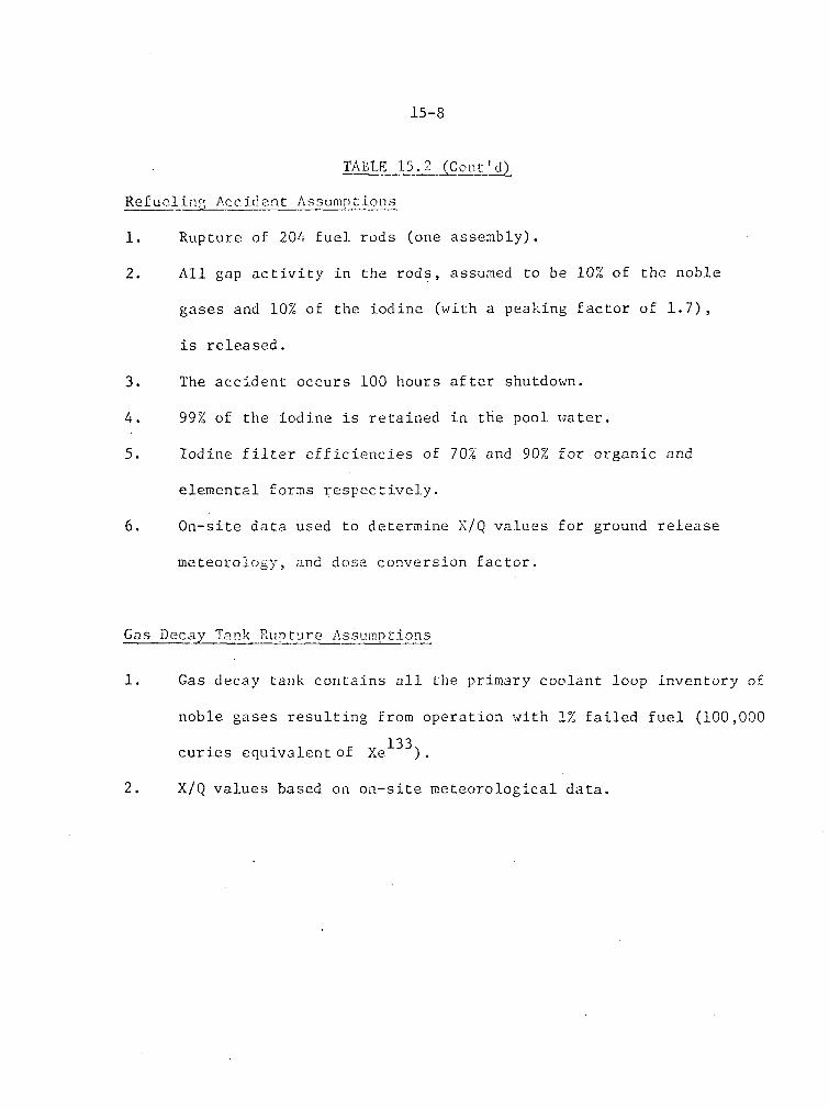
15-8
TALT 15.2 Cont'd
Refucliný Accident Assumptions
1. Rupture of 204 fuel rods (one assembly).
2. All gap activity in the rods, assumed to be 10% of the noble
gases and 10% of the iodine (with a peaking factor of 1.7),
is released.
3. The accident occurs 100 hours after shutdown.
4. 99% of the iodine is retained in the pool water.
5. Iodine filter efficiencies of 70% and 90% for organic and
elemental forms respectively.
6. On-site data used to determine X/Q values for ground release
meteorology, and dose conversion factor.
Gas Decay Tank Rupture Assumptions
1. Gas decay tank contains all the primary coolant loop inventory of
noble gases resulting from operation with 1% failed fuel (100,000
curies equivalent of Xe 13).
2. X/Q values based on on-site meteorological data.

15-9
TABLE 15.3
REMOVAL RATES AND REDUCTION LIMITS
FOR EACH FORM OF IODINE
Time Period, Hours
0-0.448
0.448-5.13
5.13-10.28
10.28-10.75
10.75-46.36
16.36-720
Elemental
10.3
0.447
0.447
0.447
0
0
-1Iodine Removal Rates, Hrs.
Particulate Organic
0.897 0.149
0.897 0.149
0.447 0.149
0 0.149
0 0.149
0 0
Reduction Limits
100Sprays
Filters
100
10,000 1,000 1,000
DOSE REDUCTION FACTORS DUE TO USE OF
SPRAYS + INTERNAL FILTERS
Time
0 - 2 Hours
0 - 30 Days
Thyroid
6.4
20
Whole Body
1.4
1.5

16-1
16.0 TECHNICAL SPECIFICATIONS
The Technical Specifications in a license define certain features,
characteristics, and conditions governing operation of a facility that
cannot be changed without prior approval of the AEC. We reviewed the
proposed Technical Specifications in detail and have held a number of
meetings with the applicant to discuss their contents. Modifications
to the proposed Technical Specifications submitted by the applicant
were made to describe more clearly the allowed conditions for plant
operation. The finally approved Technical Specifications will be made
part of the operating license. Included will be sections covering
safety limits and limiting safety system settings, limiting conditions
for operation, surveillance requirements, design features, and adminis-
trative controls. On the basis of our review, we conclude that normal
plant operation within the limits of the Technical Specifications will
not result in potential offsite exposures in excess of the 10 CFR
Part 20 limits. Furthermore, the limiting conditions for operation
and surveillance requirements will assure that necessary engineered
safety features will be available in the event of malfunctions within
the plant.
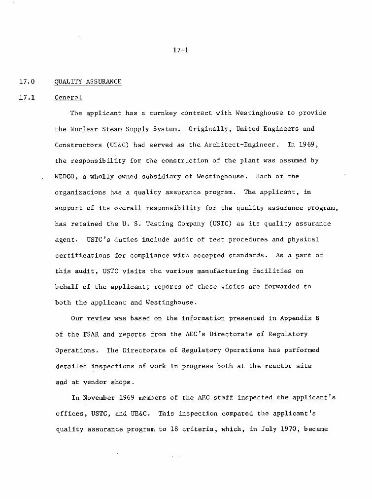
17-1
17.0 QUALITY ASSURANCE
17.1 General
The applicant has a turnkey contract with Westinghouse to provide
the Nuclear Steam Supply System. Originally, United Engineers and
Constructors (UE&C) had served as the Architect-Engineer. In 1969,
the responsibility for the construction of the plant was assumed by
WEDCO, a wholly owned subsidiary of Westinghouse. Each of the
organizations has a quality assurance program. The applicant, in
support of its overall responsibility for the quality assurance program,
has retained the U. S. Testing Company (USTC) as its quality assurance
agent. USTC's duties include audit of test procedures and physical
certifications for compliance with accepted standards. As a part of
this audit, USTC visits the various manufacturing facilities on
behalf of the applicant; reports of these visits are forwarded to
both the applicant and Westinghouse.
Our review was based on the information presented in Appendix B
of the FSAR and reports from the AEC's Directorate of Regulatory
Operations. The Directorate of Regulatory Operations has performed
detailed inspections of work in progress both at the reactor site
and at vendor shops.
In November 1969 members of the AEC staff inspected the applicant's
offices, USTC, and UE&C. This inspection compared the applicant's
quality assurance program to 18 criteria, which., in July 1970, became

17-2
Appendix B to 10 CFR Part 50. It was found that the applicant's
quality assurance program was in general accord with the then
developing Appendix B to 10 CFR Part 50.
During the construction phase other inspections have been held by
the Directorate of Regulatory Operations. Any deficiencies uncovered
by these inspections have been communicated to the applicant. The
Directorate of Regulatory Operations will assure satisfactory resolution
of all deficiencies prior to the issuance of an operating license.
In addition to reviewing the applicant's QA program for the
construction of this facility, we reviewed the applicant's ability
to comply with the requirements of Appendix B to 10 CFR Part 50 for
the operational phase of Indian Point 3. This review was based on
Appendix B to the FSAR, supplemented by information in Supplements 10
and 15 to the FSAR, and letters of commitment from the applicant,
dated April 12, 1973 and June 28, 1973. This review is discussed
below.
17.2 Organization and Program
Responsibility and authority to define and direct the QA Program
is assigned by the applicant to its Vice-President for Quality
Assurance and Reliability (QA&R) who reports directly to the Executive
Vice-President, Central Operations. Reporting to the Vice-=President of
QA&R are a Director of Quality Assurance and a Director of Quality
Standards and Reliability. On the staff of the Director of Quality
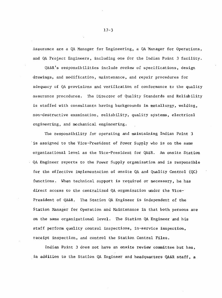
17-3
Assurance are a QA Manager for Engineering, a QA Manager for Operations,
and QA Project Engineers, including one for the Indian Point 3 facility.
QA&R's responsibilities include review of specifications, design
drawings, and modification, maintenance, and repair procedures for
adequacy of QA provisions and verification of conformance to the quality
assurance procedures. The Director of Quality Standards and Reliability
is staffed with consultants having backgrounds in metallurgy, welding,
non-destructive examination, reliability, quality systems, electrical
engineering, and mechanical engineering.
The responsibility for operating and maintaining Indian Point 3
is assigned to the Vice-President of Power Supply who is on the same
organizational level as the Vice-President for QA&R. An onsite Station
QA Engineer reports to the Power Supply organization and is responsible
for the effective implementation of onsite QA and Quality Control (QC)
functions. When technical support is required or necessary, he has
direct access to the centralized QA organization under the Vice-
President of QA&R. The Station QA Engineer is independent of the
Station Manager for Operation and Maintenance in that both persons are
on the same organizational level. The Station QA Engineer and his
staff perform quality control inspections, in-service inspection,
receipt inspection, and control the Station Central Files.
Indian Point 3 does not have an onsite review committee but has,
in addition to the Station QA Engineer and headquarters QA&R staff, a

17-4
Nuclear Facilities Safety Committee (NFSC) responsible for advising
the Executive Vice-President of Central Operations on safety aspects
of the applicant's nuclear power facilities.
Based on our review of the applicant's organizational arrangements
for the QA Program for Operations we conclude that adequate control,
independence, authority, and management involvement are provided and
that the QA organization is acceptable for the operational phase.
As part of our review, we requested the applicant to indicate its
compliance with the provisions of AEC Regulatory Guide 1.33 "Quality
Assurance Program Requirements (Operation)". The applicant had already
committed to Appendix A of Regulatory Guide 1.33 and to ANSI N 45.2,
but had not committed to ANS 3.2, draft 8. (now ANSI N 18.7) which is
also part of AEC Regulatory Guide 1.33. In a letter dated April 12,
1973, the applicant stated its intent to implement both the requirements
and recommendations of Section 4.0 of ANS 3.2, to evaluate the remaining
sections of the standard, and to respond to the staff on these remaining
sections by July 1, 1973.
In a letter dated June 28, 1973, from William Cahill, the applicant
committed to the remaining sections of ANS 3.2 draft No. 8 with one minor,
acceptable exception.
17.3 Audits
The Nuclear Facility Safety Committee (NFSC) will provide an
independent review and audit of operations. This will include audits

17-5
of the adequacy and implementation of all procedures used in the
operation, maintenance, and environmental monitoring of each of its
nuclear power plants not less than once a year. QA&R will audit
compliance with this program and shall be responsible for assuring
that necessary corrective actions are implemented. QA&R will also
monitor maintenance, modification, and repair activities, principally
through the inspection efforts of the onsite QA Engineer. QA&R prepares
and distributes a monthly report which identifies significant con-
ditions adverse to quality, corrective actions taken, and reports these
to appropriate levels of management.
Based on our review of the Indian Point 3 audit program and the
applicant's commitment to implement both the recommendations and the
requirements of Section 4 of ANS 3.2, draft 8, we conclude that these
audits will provide acceptable management attention to quality and
safety related activities during the operational phase and will meet
the requirements of Appendix B to 10 CFR 50.
17.4 Conclusions
We conclude that the QA Program for Indian Point 3 described in the
FSAR, as amended, complies with the requirements of Appendix B to
10 CFR Part 50 and is acceptable for the operational phase of this
facility.

18-1
18.0 THE ADVISORY COMMITTEE ON REACTOR SAFEGUARDS IACRS)
The application for an operating license for the Indian Point
Nuclear Generating Unit No. 3 is being reviewed by the ACRS. We intend
to issue a Supplement to this Safety Evaluation after the Committee's
report to the Commission relative to its review is available. The
Supplement will append a copy of the Committee's report and will
address the significant comments made by the Committee, and will also
describe steps taken by the staff to resolve any issues raised as a
result of the Committee's review. The Supplement will also describe
the resolution of those issues raised by the staff review that are not
completely resolved at this time.
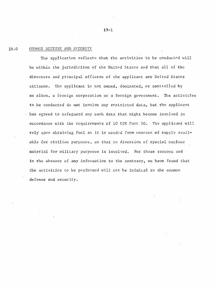
19-1
19.0 COH0MN DEFENSE AND SECURITY
The application reflects that the activities to be conducted will
be within the jurisdiction of the United States and that all of the
directors and principal officers of the applicant are United States
citizens. The applicant is not owned, dominated, or controlled by
an alien, a foreign corporation or a foreign government. The activities
to be conducted do not involve any restricted data, but the applicant
has agreed to safeguard any such data that might become involved in
accordance with the requirements of 10 CFRPart 50. The applicant will
rely upon obtaining fuel as it is needed from sources of supply avail-
able for civilian purposes, so that no diversion of special nuclear
material for military purposes is involved. For these reasons and
in the absence of.any information to the contrary, we have found that
the activities to be performed will not be inimical to the com-mon
defense and security.

20-1
20.0 FINANCIAL QUALIFICATIONS
The Commission's regulations which relate to financial data and
information required to establish financial qualifications for an
applicant for a facility operating license are 10 CFR 50 Part 33(f)
and 10 CFR 50, Appendix C. We have reviewed the financial information
presented in the application and have concluded that the applicant
is financially qualified to operate Indian Point 3. A detailed
discussion of.the basis for our conclusion is presented in Appendix
D of this report.
21-1
21.0 FINANCIAL PROTECTION AND INDEMNITY REQUIREMENTS
Pursuant to the financial protection and indemnification pro-
visions of the Atomic Energy Act of 1954, as amended (Section 170 and
related sections of the Commission's regulations), the Commission has
issued regulations in 10 CFR Part 140. These regulations set forth
the Commission's requirements with regard to proof of financial pro-
tection by, and indemnification of, licensees for facilities such as
power reactors under 10 CFR Part 50.
21.1 Preoperational Storage of Nuclear Fuel
The Commission's regulations in 10 CFR Part 140 require that each
holder of a construction permit under 10 CFR Part 50, who is also to
be the holder of a license under 10 CFR Part 70 authorizing the owner-
ship and possession for storage only of special nuclear material at
the reactor construction site for future use as fuel in the reactor
(after issuance of an operating license under 10 CFR Part 50), shall,
during the interim storage period prior to licensed operation, have
and maintain financial protection in the amount of $1,000,000 and
execute an indemnity agreement with the Commission. Proof of financial
protection is to be furnished prior to, and the indemnity agreement
executed as of, the effective date of the 10 CFR Part 70 license.
Payment of an annual indemnity fee is required.
The applicant is, with respect to Indian Point 3, subject to
the foregoing requirements.

21-2
The applicant has furnished to the Commission proof of financial
protection in the amount of $95,000,000 in the form of Nuclear Energy
Liability Insurance Association policy (Nuclear Energy Liability
Policy, facility form) No. NF-100 and a Mutual Atomic Energy Liability
Underwriters policy (Nuclear Energy Liability Policy, facility form)
No. MF-29, to cover operations of Indian Point Units 1 and 2.
Further, the applicant executed Indemnity Agreement No. B-19 with
the Commission as of January 12, 1962. At such time as a pertinent
license is issued for preoperational fuel storage for Indian Point 3,
the Indemnity Agreement will be amended to cover that preoperational
fuel storage. The applicant will be required to pay the annual indemnity
fee applicable to preoperational fuel storage in addition to the
indemnity fees it is presently paying.
21.2 Operating License
Under the Commission's regulations, 10 CFR Part 140, a license
authorizing the operation of a reactor may not be issued until proof of
financial protection in the amount required for such operation has been
furnished, and an indemnity agreement covering such operation (as
distinguished from preoperational fuel storage only) has been executed.
The amount of financial protection which must be maintained for reactors
which have a rated capacity of 100,000 electrical kilowatts or more is
the maximum amount available from private sources, i.e., the combined
capacity of the two nuclear liability insurance pools, which amount is

21-3
currently $95 million. Accordingly, no license authorizing operation
of Indian Point 3 will be issued until proof of financial protection
in the requisite amount has been received and the requisite indemnity
agreement amended.
We expect that, in accordance with the usual procedure, the
nuclear liability insurance pools will provide, several days in advance
of anticipated issuance of the operating license document, evidence
in writing, on behalf of the applicant, that the present coverage has
been appropriately amended to include the new facility, to meet the
requirements of the Commission's regulations for *reactor operation.
The amount of financial protection required for a reactor having the
rated capacity of this facility would be $95 million. The applicant
is currently provided with this amount of financial protection in
connection with Indian Point 1 and 2. The applicant will be required
to pay an annual fee for operating license indemnity as provided in
our regulations, at the rate of $30 per each thousand kilowatts of
thermal capacity authorized in its operating license.
On the basis of the above considerations, we conclude that the
presently applicable requirements of 10 CFR Part 140 have been satisfied
and that, prior to issuance of the operating license, the applicant will
be required to comply with the provisions of 10 CFR Part 140 applicable

21-4
to operating licensees, including those as to proof of financial
protection in the requisite amount and as to execution of an appro-
priate indemnity agreement with the Commission.

22-1
22.0 CONCLUSIONS
Based on our evaluation of the application as set forth above,
it is our position that upon favorable resolution of the outstanding
matters described in Section 6.5, Section 9.2 and Section 11, we will
be able to conclude that:
(1) The application for facility license filed by the applicant dated
April 26, 1967, as amended (Amendments 1 through 31 of the original
application and Amendments 1 and 2 of the Amended and Substituted
Application) complies with the requirements of the Atomic Energy
Act of 1954, as amended (Act), and the Commission's regulations
set forth in 10 CFR Chapter 1.
(2) The construction of the Indian Point Nuclear Generating Unit No. 3
(the facility) has proceeded and there is reasonable assurance that
it will be complete, in conformity with Provisional Construction
Permit No. CPPR-62, the application as amended, the provisions of
the Act, and the rules and regulatibns of the Commission.
(3) The facility will operate in conformity with the application as
amended, the provisions of the Act, and the rules and regulations
of the Commission .
(4) There is reasonable assurance (i) that the activities authorized
by the operating license can be conducted without endangering the
health and safety of the public, and (ii) that such activities will
be conducted in compliance with the regulations of the Commission
set forth in 10 CFR Part 1.

22-2
(5) The applicant is technically and financially qualified to engaged
in the activities authorized by an operating license in accordance
with the regulations of the Commission set forth in 10 CFR Part I.
(6) The issuance of an operating license for the facility will not be
inimical to the common defense and security or to the health and
safety of the public.
Prior to final consideration of the matter of the issuance of an
operating license to the applicant for the Indian Point 3, the unit
must be completed in conformity with the construction permit, the
application, the Act, and the rules and regulations of the Commission.
Such completeness of construction as is required for safe operation
at the authorized power level must be verified by the Commission's
Directorate of Regulatory Operations prior to issuance of a license.
Further, before an operating license is issued, the applicant will
be required to satisfy the applicable provisions of 10 CFR Part 140.

Appendix A
Chronology of Radiological Review
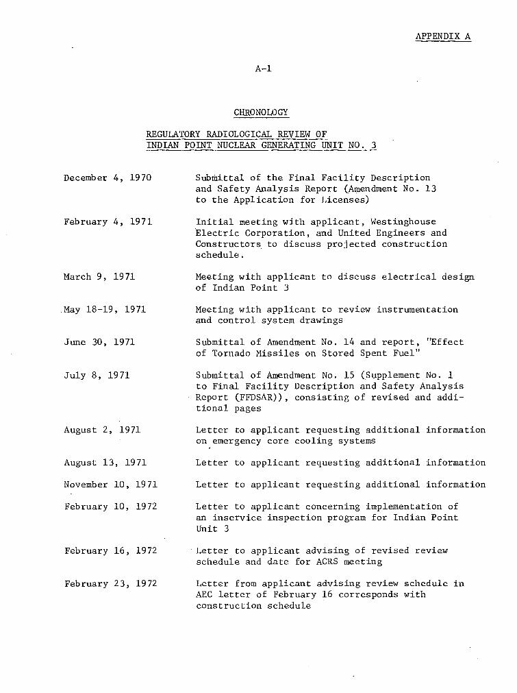
APPENDIX A
A-i
CHRONOLOGY
REGULATORY RADIOLOGICAL REVIEW OFINDIAN POINT NUCLEAR GENERATING UNIT NO. 3
December 4, 1970
February 4, 1971
March 9, 1971
May 18-19, 1971
June 30, 1971
July 8, 1971
August 2, 1971
August 13, 1971
November 10, 1971
February 10, 1972
February 16, 1972
February 23, 1972
Submittal of the Final Facility Descriptionand Safety Analysis Report (Amendment No. 13to the Application for Licenses)
Initial meeting with applicant, WestinghouseElectric Corporation, and United Engineers andConstructors to discuss projected constructionschedule.
Meeting with applicant to discuss electrical designof Indian Point 3
Meeting with applicant to review instrumentationand control system drawings
Submittal of Amendment No. 14 and report, "Effectof Tornado Missiles on Stored Spent Fuel"
Submittal of Amendment No. 15 (Supplement No. 1to Final Facility Description and Safety AnalysisReport (FFDSAR)), consisting of revised and addi-tional pages
Letter to applicant requesting additional informationon emergency core cooling systems
Letter to applicant requesting additional information
Letter to applicant requesting additional information
Letter to applicant concerning implementation ofan inservice inspection program for Indian PointUnit 3
Letter to applicant advising of revised reviewschedule and date for ACRS meeting
Letter from applicant advising review schedule inAEC letter of February 16 corresponds withconstruction schedule
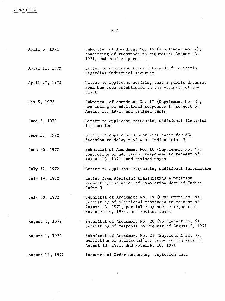
,kPPENDIX A
A-2
April 3, 1972
April 11, 1972
April 27, 1972
May 5, 1972
June 5, 1972
June 19, 1972
June 30, 1972
July 12, 1972
July 19, 1972
July 30, 1972
August 1, 1972
August 1, 1972
Submittal of Amendment No. 16 (Supplement No. 2),consisting of responses to request of August 13,1971, and revised pages
Letter to applicant transmitting draft criteriaregarding industrial security
Letter to applicant advising that a public documentroom has been established in the vicinity of theplant
Submittal of Amendment No. 17 (Supplement No. 3),consisting of additional responses to request ofAugust 13, 1971, and revised pages
Letter to applicant requesting additional financialinformation
Letter to applicant summarizing basis for AECdecision to delay review of Indian Point 3
Submittal of Amendment No. 18 (Supplement No. 4),consisting of additional responses to request ofAugust 13, 1971, and revised pages
Letter to applicant requesting additional information
Letter from applicant transmitting a petitionrequesting extension of completion date of IndianPoint 3
Submittal of Amendment No. 19 (Supplement No. 5),consisting of additional responses to request ofAugust 13, 1971, partial response to request ofNovember 10, 1971, and revised pages
Submittal of Amendment No. 20 (Supplement No. 6),consisting of response to request of August 2, 1971
Submittal of Amendment No. 21 (Supplement No. 7),consisting of additional responses to requests ofAugust 13, 1971, and November 10, 1971
Issuance of Order extending completion dateAugust 14, 1972
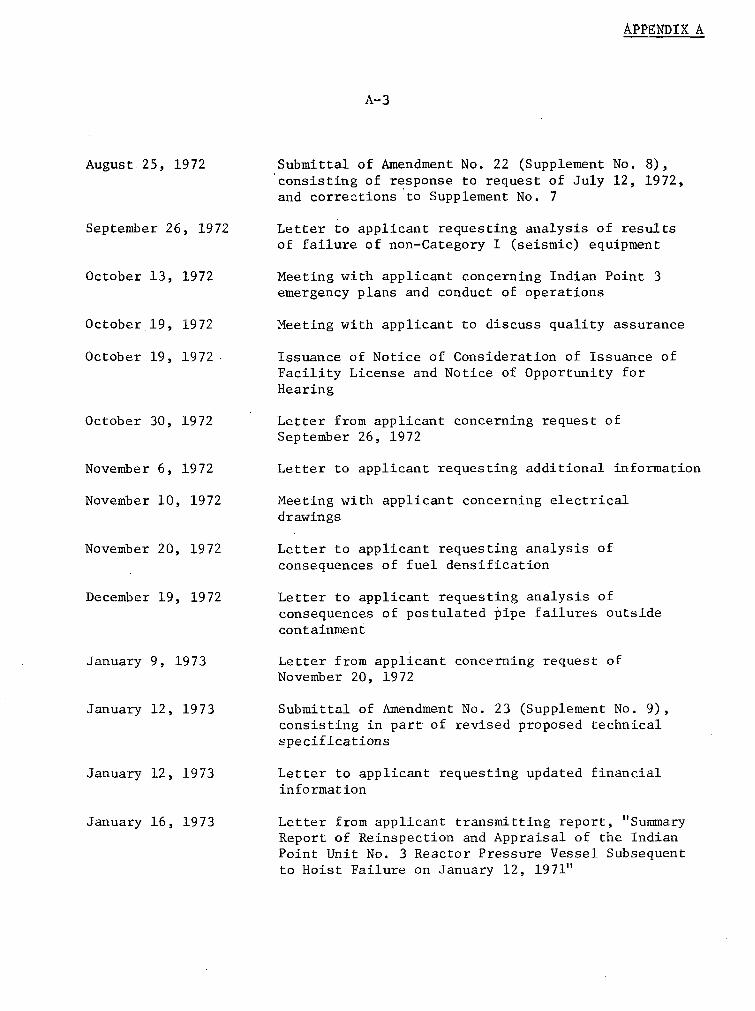
APPENDtX A
A-3
August 25, 1972
September 26, 1972
October 13, 1972
October 19, 1972
October 19, 1972
October 30, 1972
November 6, 1972
November 10, 1972
November 20, 1972
December 19, 1972
January 9, 1973
January 12, 1973
January 12, 1973
January 16, 1973
Submittal of Amendment No. 22 (Supplement No. 8),consisting of response to request of July 12, 1972,and corrections to Supplement No. 7
Letter to applicant requesting analysis of resultsof failure of non-Category I (seismic) equipment
Meeting with applicant concerning Indian Point 3emergency plans and conduct of operations
Meeting with applicant to discuss quality assurance
Issuance of Notice of Consideration of Issuance ofFacility License and Notice of Opportunity forHearing
Letter from applicant concerning request ofSeptember 26, 1972
Letter to applicant requesting additional information
Meeting with applicant concerning electricaldrawings
Letter to applicant requesting analysis ofconsequences of fuel densification
Letter to applicant requesting analysis ofconsequences of postulated pipe failures outsidecontainment
Letter from applicant concerning request ofNovember 20, 1972
Submittal of Amendment No. 23 (Supplement No. 9),consisting in part of revised proposed technicalspecifications
Letter to applicant requesting updated financialinformation
Letter from applicant transmitting report, "SummaryReport of Reinspection and Appraisal of the IndianPoint Unit No. 3 Reactor Pressure Vessel Subsequentto Hoist Failure on January 12, 1971"

APPENDIX A
A-4
January 19, 1973
January 22, 1973
January 23, 1973
January 24, 1973
January 31, 1973
February 6, 1973
February 12, 1973
February 16, 1973
February 20, 1973
February 23, 1973
February 28, 1973
March 2, 1973
March 5, 1973
March 16, 1973
Submittal of Amendment No. 24 (Supplement No. 10),consisting of partial response to request ofNovember 6, 1972, and Industrial Security Plan
Letter to applicant requesting additional information
Letter from applicant responding to request ofSeptember 26, 1972
Letter to applicant transmitting errata sheet forletter of December 19, 1972
Submittal of Amendment No. 25 (Supplement No.consisting of partial response to request ofNovember 6, 1972, and revised pages
11) ,
Meeting with applicant to discuss high energy fluidlines
Letter from N. M. Newmark transmitting commentson the structural adequacy of Indian Point 3
Submittal of Amendment No. 26 (Supplement No. 12),consisting of partial response to request ofNovember 6, 1972
Submittal of Amendment No. 27, consisting offinancial information
Meeting with applicant to discuss electrical modifica"tions required by AEC letter of January 22, 1973
Notice of Hearing
Submittal of Amendment No. 28 (Supplement No. 13),consisting of operating staff resumes, meteorologicaldata, and response to request of January 22, 1973
Meeting with applicant concerning site meteorology
Submittal of Amendment No. 29 (Supplement No. 14),consisting of additional meteorology data, andrevised pages

APPENDIX A
A-5
March 22, 1973
March 27, 1973
March 30, 1973
March 30, 1973
April 2, 1973
April 3, 1973
April 9, 1973
April 9, 1973
April 16, 1973
April 23, 1973
April 27, 1973
May 2, 1973
May 4, 1974
May 8, 1973
Letter to applicant requesting information onmechanical and instrumentation, control, andelectrical systems
Submittal of Amendment No. 30 (Supplement No. 15),consisting of revised and additional pages andinformation regarding quality assurance programfor post-construction phase
Letter to applicant requesting information on thequality assurance program for Indian Point 3
Letter to applicant requesting information relatingto a control design deficiency
Letter from applicant in response to request ofJanuary 22, 1973
Letter from applicant transmitting proprietaryand nonproprietary reports on fuel densification
Submittal of Amendment No. 31 (Supplement No. 16),consisting of revised pages and the IndustrialSecurity Plan
Letter from applicant in response to request ofMarch 22, 1973
Submittal of Revised and Substituted Application forLicenses to Atomic Safety and Licensing Board., et al
Meeting with applicant concerning effluent treatment
Submittal of Amendment No. 1 (Supplement No. 17),consisting of emergency plans and revised pages
Letter to applicant regarding low pressure piping
Letter to applicant advising that Industrial SecurityPlan transmitting April 9 will be withheld frompublic disclosure and returning January 19 versionof plan
Submittal of Amendment No. 2 (Supplement No. 18),consisting of corrected pages

APPENDIX k.
A-6
May 14, 1973
May 18, 1973
May 21, 1973
May 25, 1973
May 31, 1973
June 6, 1973
June 8, 1973
June 11, 1973
June 20, 1973
June 27, 1973
June 28, 1973
June 28, 1973
July 5, 1973
July 6, 1973
Letter from applicant transmitting report, "Analysisof High Energy Lines," in response to request ofJanuary 24, 1973
Letter from applicant transmitting to staff theAmended and Substituted Application to FSAR, datedApril 13, 1973
Letter to applicant concerning current schedule forreview of application
Letter from applicant in response to request ofMay 2, 1973
Meeting with applicant to discuss emergency core
cooling systems
Submittal of Amendment No. 3 (Supplement No. 19),
consisting of revised pages for FSAR and Security Plan
Letter from applicant transmitting report, "Dynamic
Analysis of a Postulated Main or Feedwater Line PipeBreak Outside Containment"
Letter to applicant regarding airborne gaseous and
particulate monitoring system
Letter from applicant in response to AEC letter ofMay 21, 1973, transmitting proposed revised schedule
Letter from applicant in response to AEC letter ofMarch 30, 1973
Letter from applicant transmitting nonproprietaryelectrical drawings
Letter from applicant in response to AEC letter ofMarch 30, 1973
Letter to applicant requesting review of therefueling water storage tank system design
Submittal of Amendment No. 4 (Supplement No. 20),consisting of corrected pages for FSAR

APPENDIX A
A-7
July 11, 1973
July 19, 1973
July 24, 1973
August 17, 1973
August 24, 1973
August 31, 1973
September 7, 1973
September 14, 1973
Meeting with ACRS Subcommittee
Letter to applicant stating that proprietary reportson fuel densification will be withheld from publicdisclosure
Letter from applicant in response to AEC letter ofMarch 30, 1973, concerning control design deficiency
Letter from applicant transmitting proprietary andnonproprietary versions of report on fuel densifi-cation
Submittal of Amendment No. 5 (Supplement No. 21)consisting of corrected pages
Letter from applicant in response to request ofJuly 5, 1973, requesting extension of time forsubmittal of information
Letter from applicant providing supplemental informa-tion to its April 2, 1973 and May 2, 1973 letters
Letter to applicant concerning the startup test program

Appendix B
Report on the Structural Adequacy of the
Indian Point Nuclear Generating Unit No. 3
by W. J. Hall and N. M. Newmark
fl-i APPI•Drx 2
NATHAN M. NEWMARK
CONSULTING ENGINEERING SERVICES 1114 CIVIL ENGINEERING BUILDING
URBANA. ILLINOIS 61801
12 February 1973
Mr. R. R. MaccaryAssistant Director for EngineeringOffice of Technical ReviewDirectorate of LicensingU.S. Atomic Energy CommissionWashington, D.C. 20545
Re: Contract No. AT(49-5)-2667CommentaryFinal ReportIndian Point Nuclear Generating Unit No. 3Consolidated Edison Company of New York, Inc.AEC Docket No. 50-286
Dear Mr. Maccary:
Dr. N. M. Newmark and I have reviewed the Final SafetyAnalysis Report for the Indian Point Nuclear Generating Unit No. 3and are transmitting herewith 8 signed copies of our Commentary andFinal Report.
Since we have previously visited the Indian Point Nuclear 2
unit which is constructed along the same lines as Indian Point No. 3,it probably will not be necessary for us to visit this facility butwe will await instructions from your personnel in this regard.
Sincerely yours,
W. J. Hall
Pg
Enclosure
cc: N. M. Newmark

APPENDIX BNATHAN M. NEWMARK S-2
CONSULTING ENGINEERING SERVICES 1114 CIVIL ENGINEERING BUILDING
URBANA, ILLINOIS 61801
12 February 1973
COMMENTARY
ON
STRUCTURAL ADEQUACY
OF THE
INDIAN POINT NUCLEAR GENERATING UNIT NO. 3
CONSOLIDATED EDISON COMPANY OF NEW YORK, INC.
AEC Docket No. 50-286
by W. J. Hall and N. M. Newmark
1. Introduction
This report is based on information presented in the Indian Point
Nuclear Generating Unit No. 3 FSAR and the Supplements thereto (Ref. 1) and
on discussions with personnel of the AEC Directorate of Licensing. Specific
items are singled out for discussion herein, and no attempt is made to review
the basis of the seismic design criteria as reported in our PSAR review for
this plant (Ref. 2) or in our related FSAR review for Indian Point Nuclear
Generating Unit No. 2 (Ref. 3).
2. Foundations
The major facility structures for Indian Point Nuclear Generating
Unit No. 3 are described as being founded directly on competent bedrock, and
on the basis of the information available to us the foundation conditions
appear acceptable for the seismic hazards noted.
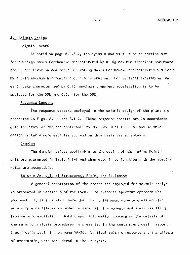
S-3 APPENDIX
3. Seismic Design
Seismic Hazard
As noted on page 5.1.2-4, the dynamic analysis is to be carried out
for a Design Basis Earthquake characterized by O.15g maximum transient horizontal
ground acceleration and for an Operating Basis Earthquake characterized similarly
by a O.1g maximum horizontal ground acceleration. For vertical excitation, an
earthquake characterized by O.lOg maximum transient acceleration is to be
employed for the DBE and 0.05g for the OBE.
Response Spectra
The response spectra employed in the seismic design of the plant are
presented in Figs. A.l-l and A.M-2. These response spectra are in accordance
w th the state-of-the-art applicable to the time that the PSAR and seismic
design criteria were established, and on this basis are acceptable.
Damping
The damping values applicable to the design of the Indian Point 3
unit are presented in Table A.l-l and when used in conjunction with the spectra
noted are acceptable.
Seismic Analysis of Structures, Piping and Equipment
A general description of the procedures employed for seismic design
is presented in Section 5 of the FSAR. The response spectrum approach was
employed. It is indicated there that the containment structure was modeled
as a simple cantilever in order to ascertain the moments and shear resulting
from seismic excitation. Additional information concerning the details of
the seismic analysis procedures is presented in the containment design report,
§pecifically beginning on page 5A-26. Vertical seismic response and the effects
of overturning were considered in the analysis.

APzNDtX B B-e
For items other than the major structures, the general procedure
employed in the dynamic analysis is described in Appendix A beginning on page
A.3-10. It is indicated there that all Class I piping 6 inches in diameter
or larger, together with the 2-inch diameter high-head safety injection lines,
were dynamically analyzed for seismic response. Additional information is
presented in the answer to Question 5.16, where there is listed for Class I
piping and other auxiliary equipment the specific methods of analysis which
were employed in the design. It is noted there and in the answer to Question
5.21 that equivalent static coefficients were used for the analysis design of
piping less than 6-inch diameter. The answer to Question 5.36 states that the
use of equivalent static coefficients is only employed for piping and equipment
items after it has been demonstrated that such an approach, when checked against
rigorous dynamic analyses, gives conservative results. This approach is in
accordance with the state-of-the-art applicable to this design.
The answer to Question 5.20 indicates that floor response spectra
were employed in the design of equipment and piping and the general approach
analyzed in derivation of the floor response spectra is described in the
Answer to Question 4.32.
Buried Piping
The design criteria applicable generally to buried piping or other
piping located outside the containment structure appear on page A.3-9 and again
in the Answer to Questions 5.19 and 5.35. On the assumption that the. design
approach did consider the problem of providing adequately for stresses and
deformations at support points as suggested in the Answer to Question 5.35,
We believe the approach to be adequate.

'S- 5 APPIYDIX 2
Design Stresses
The design stress approach employed for Class I structures is
described in Section 5, and the stress tabulations presented in the containment
report, Section 5A, are helpful in demonstrating the adequacy of the design
approach employed for Class I structures.
For piping, the procedures associated with techniques outlined in
Topical Report WCAP-7287 were employed, but the Answer to Question 4.29
indicates that only elasticanalyses were used with the cited stress limits.
This approach is in line with the state-of-the-art applicable to this design.
Class I Controls and Instrumentation
The general procedures to be employed in the design and review of
critical controls and instrumentation are presented in the Answer to Question
5.29.. On the assumption that criteria of the type described in Report
WCAP-7397-L and Supplements thereto are applicable, we bel ieve that the
design procedures adopted for the critical controls and instrumentation
will be acceptable.
REFERENCES
I. "Final Facility Description and Safety Analysis Report -- Indian PointNuclear Generating Unit No. 3, Consolidated Edison Company of New York,Inc., Vol. 1-6 and Amendments 14-16, 19-21, 23 and Supplements 10 and 11",AEC Docket No. 50-286, 1971-72.
2. Newmark, N. M., W. J. Hall and A. J. Hendron, "Adequacy of the StructuralCriteria for Indian Point Nuclear Generating Unit No. 3, ConsolidatedEdison Company of New York, Inc.", AEC Docket No. 50-286, 20 Dec. 1968.
3. Newmark, N. M. and W. J. Hall, "Report to the AEC Regulatory Staff --Structural Adequacy of Indian Point Nuclear Generating Unit No. 2,Consolidated Edison Company of New-York, Inc.", AEC Docket No. 50-247,August 1970.
Ar~yIA4&'e
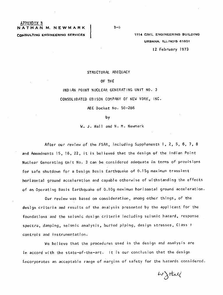
AOPENDIX nNATHAN M. NEWMARK I B-6
COPNSULTING ENGINEERING SERVICES 1114 CIVIL ENGINEERING BUILDING
URBANA. ILLINOIS 61801
12 February 1973
STRUCTURAL ADEQUACY
OF THE
INDIAN POINT NUCLEAR GENERATING UNIT NO. 3
CONSOLIDATED EDISON COMPANY OF NEW YORK, INC.
AEC Docket No. 50-286
by
W. J. Hall and N. M. Newmark
After our review of the FSAR, including Supplements 1, 2, 5, 6, 7, 8
and Amendments 15, 16, 22, it is believed that the design of the Indian Point
Nuclear Generating Unit No. 3 can be considered adequate in terms of provisions
for safe shutdown for a Design Basis Earthquake of O.15g maximum transient
horizontal ground acceleration and capable otherwise of withstanding the effects
of an Operating Basis Earthquake of O.lOg maximum horizontal ground acceleration.
Our review was based on consideration, among other things, of the
design criteria and results of the analysis presented by the applicant for the
foundations and the seismic design criteria including seismic hazard, response
spectra, damping, seismic analysis, buried piping, design stresses, Class I
controls and instrumentation.
We believe that the procedures used in the design and analysis are
in accord with the state-of-the-art. It is our conclusion that the design
incorporates an acceptable range of margins of safety for the hazards considered.

Appendix C
Report of the Department of the Army
Coastal Engineering Research Center

C-I
DEPARTMENT OF THE ARMY-'," ,COASTAL. ENGINEERING RESEARCH CENTER
52'01 LITTLE FALLS ROAD. N.W.
WASHINGTON, D.C. 20016
CEREN-DE 28 March 1973
Dr. J. M. HendrieDep. Director for Technical Review '•
Directorate of LicensingfLLvU. S. Atomic Energy CommissionWashington, D. C. 20545 APR4 1!
U.S. ATOMIC F1
I•'ucia~ry
Dear Dr. Hendrie:
Reference is made to your letters regarding Docket Nos. 50-247, 286, 342and 343, Consolidated Edison Company of New York's Indian Point NuclearGenerating Units 2, 3, 4 and 5, and our letter dated 21 November 1969.
Pursuant to our arrangements, Mr. R. A. Jachowski of my staff has con-tinued to review all information pertaining to the application for anoperating license for Unit 3 (Docket No. 50-286) and to advise your staffon the acceptability of the applicant's implementation of the design basesstill water level in which we have previously concurred in the referencedletter. Our review has included consideration of the storm surge associatedwith Probable Maximum and Standard Project Hurricanes, and wind-generated.wave analyses associated with severe water levels.
We agree with your staff that wind-generated wave activity associated withsevere water levels such as that resulting from the PM]- surge could exceedplant grade in the vicinity of the intake structures by several feet, andthat with appropriate emergency procedures should be developed so as toprotect essential structures from flooding.
Since yf yours,
THO 'DIKE S E JRActing Director

Appendix D
Evaluation of Financial Qualifications

APPENDIX D D-I
FINANCIAL QUALIFICATIONS
The Commission's regulations which relate to the financial data and
information required to establish financial qualifications for applicants
for operating licenses are 10 CFR 50.33(f) and 10 CFR 50, Appendix C.
The basic application of Consolidated Edison Company of New York
(Con Ed), Amendments No. 9, 12, 27,. the amendment of April 13, 1973,
and the accompanying certified annual financial statements of the
applicant provide the financial information required by the Commission's
regulations. This information includes the estimated annual costs of
operating the Indian Point Nuclear Generating Unit No. 3 for a five-year
period plus the estimated cost of permanently shutting down the
facility and maintaining it in a safe shutdown condition.
Our evaluation of the financial data submitted by the applicant,
summarized below, provides reasonable assurance that the applicant
possesses or can obtain the necessary funds to meet the requirements
of 10 CFR 50.33(f) to operate the Indian Point Nuclear Generating
Unit No. 3, and if necessary permanently shut down the facility and
maintain it in a safe shutdown condition.
Indian Point Nuclear Generating Unit No. 3 will be used to augment
the applicant's present electrical generating capacities. Operating
revenues will provide the funds to cover cost of operations. The
costs of operating for the five-year period 1975-79 are presently
estimated by the applicant to be (in millions of dollars) $72.4;
$74.1; $71.7; $72.5; and $73.5 in that order. These costs include
amounts for operation and maintenance, fuel, insurance, depreciation,
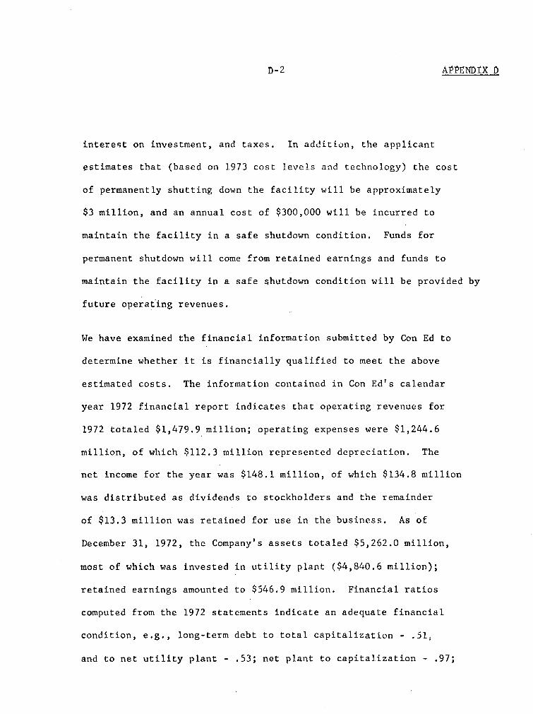
D-2 APPENDIX 1)
interest on investment, and taxes. In addition, the applicant
estimates that (based on 1973 cost levels and technology) the cost
of permanently shutting down the facility will be approximately
$3 million, and an annual cost of $300,000 will be incurred to
maintain the facility in a safe shutdown condition. Funds for
permanent shutdown will come from retained earnings and funds to
maintain the facility in a safe shutdown condition will be provided by
future operating revenues.
We have examined the financial information submitted by Con Ed to
determine whether it is financially qualified to meet the above
estimated costs. The information contained in Con Ed's calendar
year 1972 financial report indicates that operating revenues for
1972 totaled $1,479.9 million; operating expenses were $1,244.6
million, of which $112.3 million represented depreciation. The
net income for the year was $148.1 million, of which $134.8 million
was distributed as dividends to stockholders and the remainder
of $13.3 million was retained for use in the business. As of
December 31, 1972, the Company's assets totaled $5,262.0 million,
most of which was invested in utility plant ($4,840.6 million);
retained earnings amounted to $546.9 million. Financial ratios
computed from the 1972 statements indicate an adequate financial
condition, e.g., long-term debt to total capitalization - .51,
and to net utility plant - .53; net plant to capitalization - .97;
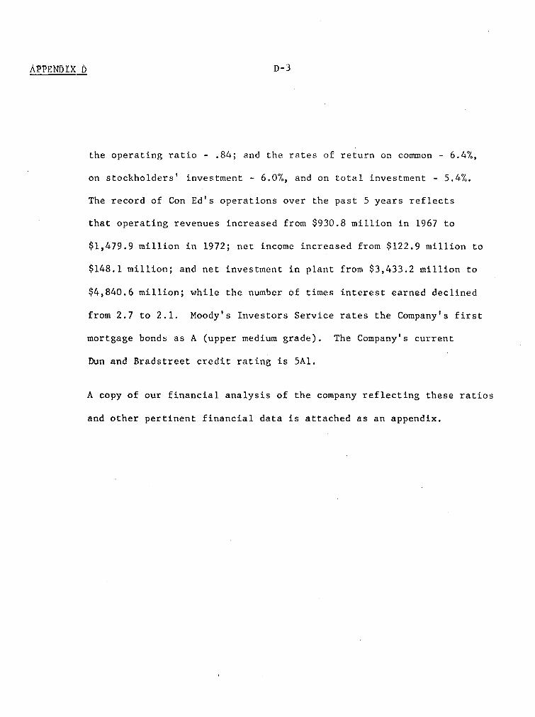
APPENDIX D D-3
the operating ratio - .84; and the rates of return on common - 6.4%,
on stockholders' investment - 6.0%, and on total investment - 5.4%.
The record of Con Ed's operations over the past 5 years reflects
that operating revenues increased from $930.8 million in 1967 to
$1,479.9 million in 1972; net income increased from $122.9 million to
$148.1 million; and net investment in plant from $3,433.2 million to
$4,840.6 million; while the number of times interest earned declined
from 2.7 to 2.1. Moody's Investors Service rates the Company's first
mortgage bonds as A (upper medium grade). The Company's current
Dun and Bradstreet credit rating is 5Al.
A copy of our financial analysis of the company reflecting these ratios
and other pertinent financial data is attached as 'an appendix.
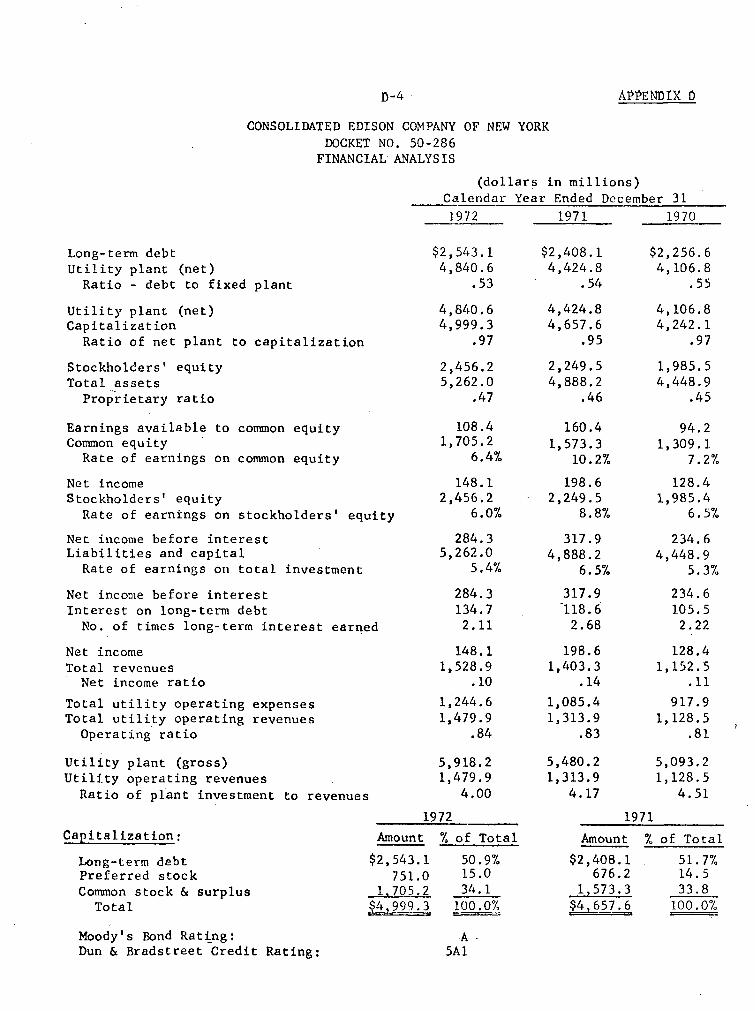
D-4 D-4 APP9NflTX 0
CONSOLIDATED EDISON COMPANY OF NEW YORKDOCKET NO. 50-286
FINANCIAL ANALYSIS
(dollars in millions)
Calendar Year Ended December 31
Long-term debtUtility plant (net)
Ratio - debt to fixed plant
Utility plant (net)Capitalization
Ratio of net plant to capitalization
Stockholders' equityTotal assets
Proprietary ratio
Earnings available toCommon equity
Rate of earnings on
Net incomeStockholders' equity
Rate of earnings on
common equity
common equity
stockholders' equity
1.972
$2,543.14,840.6
.53
4,840.64,999.3
.97
2,456.25,262.0
.47
108.41,705.2
6.4%
148.12,456.2
6.0%
284.35,262.0
5.4%
284.3134.72.11
148.11,528.9
.10
1,244.61,479.9
.84
5,918.21,479.9
4.00
1971
$2,408.14,424.8
.54
4,424.84,657.6
.95
2,249.54,888.2
.46
160.41,573.3
10.2%
198.62,249.5
8.8%
317.94,888.2
6.5%
317.9118.6
2.68
198.61,403.3
.14
1,085.41,313.9
.83
5,480.21,313.9
4.17
1970
$2,256.64,106.8
.55
4,106.84,242.1
.97
1,985.54,448.9
.45
94.21,309. 1
7.2%
128.41,985.4
6.5%
234.64,448.9
5.3%
234.6105.52.22
128.41,152.5
.11
917.91,128.5
.81
5,093.21,128.5
4.51
Net income before interestLiabilities and capital
Rate of earnings on total investment
Net income before interestInterest on long-term debt
No. of times long-term interest earned
Net incomeTotal revenues
Net income ratio
Total utility operating expensesTotal utility operating revenues
Operating ratio
Utility plant (gross)Utility operating revenues
Ratio of plant investment to revenues
Capitalization:
Long-term debtPreferred stockCommon stock & surplus
Total
1972
A-mount % of Total
$2,543.1 50.9%751.0 15.0
170L.2 34.1$4,999.3 100.0%
1971
Amount % of Total
$2,408.1 51.7%676.2 14.5
1,i573.3 33.8ý 4 5ýL, 100.0%
Moody's Bond Rating:Dun & Bradstreet Credit Rating:
A5AI