
Sep - World Radio History
84
-
Upload
khangminh22 -
Category
Documents
-
view
3 -
download
0
Transcript of Sep - World Radio History


/41DCOLINWe Trade Me,*)
THE RELIABLE
SOLDERING INSTRUMENT!
SEND COUPON FOR LATEST LEAFLET
ADCOLA PRODUCTS LTDADCOLA HOUSEGAUDEN ROADLONDON SW401-622 0291/3
I NAME
ADDRESS
P E170
ORGAN TRANSISTORSZTX300 . . 1/11 ZT1701 . . 22/6 ZS170 .. 1/11ZTX302 .. 3/- ZT3055 .. 20/6 0C28.. .. 19/-ZT44 .. .. 12/9 KR54 .. 27/6 ACY2I .. 5/4ZT1613 7/9 KR56 .. 24/9 ACY22 .. 4/-ZT1700 .. 17/9 ZRI2 .. 16/9 OAZ203 .. 12/-
Mullard LA2300 9/5All above transistors direct from manufacturer.Unmarked silicon planar transistors suitable for use in dividercircuits: -1/6 each or £5 per 100.
LIGHT-SENSITIVE DEVICESGIANT -SIZE SELENIUM SOLAR CELLS -PRODUCE UP TO6MA FROM DAYLIGHT! 67mm diameter 10/- 'each. 50mm ,37mm. 2 for I0/-.Transistors similar to OCP71 2/- each.ORP12 CADMIUM SULPHIDE LIGHT-SENSITIVE RESISTORS9/- each. Light-sensitive diodes 10/- per dozen.
WIRE -WOUND RESISTORSMains dropper type. Up to 30 watts. Some multi -tapped. Fractionof normal price! 10/- per dozen.
MULLARD POLYESTER CAPACITORS FAR BELOW COSTPRICE! 000IAF 400V 3d., 0.0015AF 400V 3d., 0.0018AF 400V 3d.,0.0022AF 400V 3d., 0.01AF 400V 3d., 0.15AF 160V 6d., 0.22AF 160V6d., 0.27AF 160V 6d., 11.4F 125V 1/-.
RECORD PLAYER CARTRIDGES. COMPLETE WITHNEEDLES GP67/2 Mono 15/-, GP9I/3 Compatible £1, GP93/1Crystal Stereo 25/-, GP94/1 Ceramic 30/-.
TRANSISTORISED SIGNAL INJECTOR KIT 10/-.SIGNAL TRACER KIT 10/-. CAR REV. COUNTER KIT 10/-.
VEROBOARD24 x 1" 0.15 matrix 1/3 17 .. 14/834 x 24" 0.15 matrix 3/3 34 x 24" 0.1 matrix 4/234 x 34" 0.15 matrix 3/11 34 ;< 34" 0.1 matrix 4/95 x 24" 0.15 matrix 3/11 5 x 24" 0.1 matrix 4/75 x 34" 015 matrix 5/6 5 / 34" 0.1 matrix 5/6
17 x 2+" 0.15 matrix 11/ -Spot Face Cutter 7/6. Pin Insert Tool 9/6. Terminal Pins 3/6 for 36.Special Offer! Spot Face Cutter and 5 24 x 1" boards 9/9 only.
PAPER CONDENSERS. Mixed bags 0-00IAF to 51.cF, 12/6 per 100.SILVER -MICA, Ceramic, Polystyrene Condensers. Well assorted.Mixed types and values, 10/- per 100.RESISTORS. Mixed types and values, 4 to 1 watt. 616 per 100. 55/-per 1,000. Wire -wound resistors. 1 watt to 10 watts. Mixed values.20 for 10/-.TRANSISTORS. Mixed, unmarked, mainly O.K. 7/6 for 50.
12 VOLT TRANSISTORISED FLUORESCENT LIGHTS. HALFNORMAL PRICE.8 Watt 12" tube. Reflector type £2.19.6. 15 watt 18" Batten type £3.19.6.IDEAL FOR CAMPING OR CARAVAN HOLIDAYS! A BRIGHTLIGHT FOR VERY LITTLE CURRENT!
ELECTROLYTIC CONDENSERS0.25AF 3 volt 4AF 4 volt 10AF 25 volt 64AF 9 volt1AF 6 volt 4AF 12 volt 20AF 6 volt 100AF 9 volt1µF 20 volt 4µF 25 volt 25AF 6 volt 320AF 4 volt1.25AF 16 volt 5AF 6 volt 25AF 12 volt 320AF 10 volt2AF 3 volt 6AF 6 volt 25AF 25 volt 400AF 6.4 volt2AF 350 volt 8AF 3 volt 30µF 6 volt All at 1/- each.2SAF 16 volt 8AF 12 volt 30AF 10 volt 20 assorted3AF 25 volt 8AF 50 volt 50AF 6 volt (our selection)3.2AF 64 volt 10AF 6 volt 64AF 2.5 volt 101-.
Orders by post to:G. F. MILWARD, DRAYTON BASSETT, NEAR TAMWORTH,
STAFFS.
Please include suitable amount to cover post and, packing. Minimumorder 10/-. Stamped addressed envelope must accompany anyenquiries.
For customers in Birmingham area goods may be obtained fromRock Exchanges, 231 Alum Rock Road, Birmingham 8.

why theMOLTIMINOR
is It's still an Avometeryet fits in the pocket/heldeasily in one hand
Still Has a d.c. sensitivity of10 ,000n/V
N Measures up to 25kV and 25Awith optional accessories
best tr8rac.onformsto
mini miterGet your own Multimeter
today (complete with plastic case,leads, instruction booklet and
a full year's guarantee)from your local supplier, or ask for
details direct from Avo.
Avo LimitedAvocet House, Dover, KentTelephone: Dover 2626Telex: 96283
62S

A FAST EASY WAYTO LEARN BASIC RADIOAND ELECTRONICS
*Build as you learn with the exciting newTECHNATRON Outfit! No mathematics.No soldering-but you learn the practical way.
Now you can learn basic Radio and Electronics at home-thefast, modern way. You can give yourself the essential technical'know-how' sooner than you would have thought possible-read circuits, assemble standard components, experiment,build . . . and enjoy every moment of it. B.I.E.T's SimplifiedStudy Method and the remarkable new TECHNATRON Self-Build Outfit take the mystery out of the subject-make learn-ing easy and interesting.
Even if you don't know the first thing about Radio now,you'll build your own Radio set within a month or so!
. . . and what's more,YOU'LL UNDERSTANDEXACTLY WHAT YOUARE DOING. The Tech-natron Outfit contains every-thing you need, from tools totransistors ... even a versatileMultimeter which we teachyou how to use. You needonly a little of your sparetime, the cost is surprisinglylow and the fee may be paidby convenient monthly instal-ments. You can use theequipment again and again-and it remains your ownproperty.You LEARN-but it's asfascinating as a hobby,Among many other interest-ing experiments, the Radioset you build-and it's a goodone-is really a bonus; this isfirst and last a teachingCourse. But the training is asrewarding and interesting asany hobby. It could be thespringboard for a career inRadio and Electronics orprovide a great new, spare -time interest.
A 14 -year -old could under-stand and benefit from thisCourse-but it teaches thereal thing. Bite -size lessons-wonderfully clear and easy tounderstand, practical projectsfrom a burglar -alarm to asophisticated Radio set . . .here's your chance to masterbasic Radio and Electronics,even if you think you're a`non -technical' type. And, ifyou want to carry on to moreadvanced work, B.I.E.T. hasa fine range of Courses up toA.M.I.E.R.E. and City andGuilds standards.Send now for free 132 -page book.Like to know more about thisintriguing new way to learnRadio and Electronics? Fillin the coupon and post ittoday. We'll send you fulldetails and a 132 -page book-`ENGINEERING OP-PORTUNITIES'-Free andwithout any obligation.
BRITISH INSTITUTE OFENGINEERING TECHNOLOGYDept. MB, Aldermaston Court,
Aldermaston, Berkshire.
I To:ALDERMAST
11.1.E.T.,
ON,
Dept. 3711, ALDERMASTON COURT, IBERKS.
I would like to know more about yourPractical Radio & Electronics Course. Please Isend me full details and FREE 132 -page book
address
age
POST
AX/PONtf6OWI
name
,VALVES SAME DAY SERVICE
- NEW! TESTED! GUARANTEED!
SETS g15,o,184.5Or T1101.9Viy944. VA .1 01)4961: al196 1, ,4D1.92. ar .
OZ4 4/11 2022 13/6 DIC96 10/6 PCL85 9/- UC92 19-1A7GT 7/6 20P3 11/9 DL35 61- E1.84 4/9 PCL86 8/- UCC84 7/91H5GT 7/3 20P4 18/6 DL92 5/9 EL90 6/- PENA4 12/6 UCC86 8/91N6GT 7/9 251,60T 5/- 131,94 8'- EL500 16/6 PEN36C15/- UCP80 8[8125 6/9 25740111/8 01.90 7/- 21180 7/6 PFL20012/6 1:CH42 0/9186 4/3 30C1 8/6 DY86 51 EBRO 7/6 PL36 9/9 UCH81 5/91T4 8/9 30015 13/- D187 5/9 E1184 6/6 P1.81 7/8 UCL82 7/3364 5/9 30C17 16/- EABC80 8/6 EA187 7/6 P1.82 7/- CCU'S 1113V4 5/- 30C18 11/8 EAF42 8!9 EY51 7/6 PL83 71- CF41 10/115U40 4/6 30E5 18/- EB91 2/3 LI 89 6/6 PLBI 803 UF80 7/-523GT 5/9 30FL1 13/9 EBC33 8/- EZ40 7/8 PL500 13/- UF85 0/067.441 7/6 30FL12 14/8 EBC41 9/9 EZ4I 73 PL504 1318 UF89 IA6/301.2 191- 3023.14 12/- EBFOO 6/9 2280 4/6 PL608 23/8 1:141 10/86AL5 8/3 30L1 6/8 EBF89 6/3 EMI 4/9 PL802 14/6 1:1.44 110/-131.X6 3/5 30116 14/- ECC81 8/9 0Z32 8/9 P1184 7/9 ULU 71-8.2Q6 4/9 301.17 15/5 ECC82 4/9 0Z34 9/9 2X26 10/5 U3184 7/-6,126 4/- 3024 12/- ECC83 7/- KT61 8;9 2731 6/6 1.17416A176 4/6 30P12 18/9 ECC85 5/9 KT66 16/- PY32 10/-
1/3UY85 /9
6BA6 4/6 301'19 12/- 200804 12/- 31E140015l- PY33 10/- VP4B 19/-6526 4/9 30PL1 13/9 ECF80 7/- N78 14/9 PY81 5/8 VP1321 31/ -MI6 7/- 30PL13 15/0 ECF82 5/9 PABC80 7/- P182 513 277 3106BW6 18/- 30PL14 15/8 ECH35 6,- PC86 10/8 P183 5/9 AC107 3/56219 8/5 351.6GT 8/8 ECH42 10/8 PC88 10/3 P188 8/9 AC127 5/58214 9/- 35W4 4/8 ECH81 6/9 PC96 8/8 PY800 7/6 .AD140 736F23 14/3 39Z4GT 5/- ECH84 7/8 PC97 11/11 PY801 8/9 A2100 791-6270 2/6 6063 12/6 ECL80 6/9 PC900 8/- R19 6/6 .42116 3/-8280 4/3 AC/VP210/- ECL82 8/9 PCC84 6/6 R20 12/6 AF116 3/-8218 5/- AZ31 9/8 ECL83 2/- PCC80 8,6 TH211' 9/9 AF117 Alt6V6GT 6/5 B729 12/6 ECL86 8/3 PCC88 919 1:25 13/- AF124 73624 4/3 001835 10/- E237.9 6/6 PCC89 10/6 1.28 12/- A2135 8/66X6GT 5/9 CL39 18/6 2239 4/9 PCC189 11/6 1:47 18/6 A2128 7/-7/27 7/- CY31 6/9 EF41 10/9 PCF80 6/6 049 18/6 AF127 3/8706 6/9 DAC32 7/8 EF80 4'9 PCF82 6/6 062 CO 0026 9/97Y4 6/6 DAF91 4/3 EP85 8- PCF86 918 078 4/3 0044 8/81021 14/- DAF96 6/6 EF86 6,3 PCF20013/8 1.191 12/6 GCBS 8/310P13 15/6 1)233 7/9 EF89 5/3 PCF800 13/6 173411 12/8 0071 11/111214118 33/- DF91 2/9 EF91 3/8 PCF801 8/9 1:801 19/8 0072 9/512AT7 3/9 DF96 6/6 EF94 9/6 PCF802 9/5 1:4BC80 6/9 0075 AM12A176 4/9 DH77 4;,_ EF183 8/- PCF80511/6 17A242 9/5 0081 8/312AI:7 4/9 . EF184 5/6 PCF80812i- 11141 6/600811) 8/312AX7 4/9 0232 4,. 21190 6/3 903.82 7/- 013041 8/8 0082 23122EIGT 7/- 111C91 5/9 EL33 8/9 PCL83 9/- 1-BF80 6/6 0082D 11/1119BI:16017/6 1)292 9/8 EL34 10/3 PC184 7/6 1.:BF89 6/9 00170 Al
READERS RADIO (P.E.)85 TORQUAY GARDENS, REDBRIDGE, ILFORD,
ESSEX. Tel. 01-550 7441Postage on I valve 9d. extra. On 2 valves or more, postage 61. per
valve extra. Any Parcel Insured against Damage in Transit 6d. extra.
,,,...e.,
..,-7r
(..3-ocKinvins High Fidelity -,..
New Edition -Now OutThinking of High Fidelity-first read Goodmans 28 page High FidelityManual. It contains interesting articles on Stereo; an Introduction to HighFidelity; Stage -built systems; as well as full details of Goodmans HighFidelity audio products.
.....
Send for your free copyPlease send me a free copy of Goodmans Manual
NameAddree-q
P.E.9
Goodmans Loudspeakers Limited' Axiom Works, Wembley, Middlesex. Tel: 01-9021200
626

a complete stereosystem for 28 gns!
MEMThe new Duo general purpose two way speaker system is beautifullyfinished in polished teak veneer, with matching vynair grille. It isIdeal for wall or shelf mounting either upright or hori Ily.Type I SPECIFICATION: Impedance 10 ohms. It incorporates Goodmanshigh flux 6 x 4in speaker and 2f in tweeter. Teak finish 12 x 61. x Su in.4 guineas each, P. & P. 7/6. Type 2 as Type I. Size 17f x 101. x 61in.,Incorporating Elac 10f x 6fin., 10,000 lines and 2fin. tweeter. 3 ohmsimpedance Teakns. + 7/6 P. & P. Garrard Changers from L'7.19.6. P. & P. 7/6.Cover and finish Plinth 14.15.0, P. & P. 7/6.
52-1Tdie& 9 GNSIntegrated Transistor Stereo Amplifier + 716 P. & P.The Duette is a good quality amplifier, attractively styled and finished.It gives superb reproduction previously associated with amplifierscosting far more. SPECIFICATION: R.M.S. power output: 3W perchannel into 10 ohms speakers. Input Sensitivity: Suitable for medium orhigh output crystal cartridges and tuners. Crosstalk better than 30dB at1Kc/s. Controls: 4 -position selector switch (2 pos. mono and 2 pos. stereo)dual ganged volume control. Ton* Control: Treble lift and cut. Separateon/off switch. A preset balance control.
THE RELIANT
SOLID-STATE
GENERAL
PURPOSE AMPLIFIER
Specifications: Output: IOW R.M.S. Output impedance: 3 to 4 ohms.Inputs: I. Xtal mic 10mV; 2. Gram/radio 250mV. Tone controls: Treblecontrol range +12dB at 10KHz; Bass control range +13dB at 100Hz.Frequency response (with tone controls central): Minus 3dB points are 20Hzand 40KHz. Signal to noise ratio: better than -60dB. Transistors: 4 siliconPlanar,.type and 3 Germanium type. Mains input: 220-250V a.c. Size of chassis10fin long, 41in wide x 24in deep. A.c. Mains, 200-250V. For use with Std.or L.P. records, musical instruments, all makes of pick-ups and mikes. Separatebass and treble lift control. Two inputs with control for gram and mike.Built and tested. 8 x Sin speaker to suit: Price 14/6 plus 1/6 P. & P. Crystalmike to suit: 12/6 plus 1/6 P. & P. Mk. I as above, less teak case 5/ gns. +7/6 P. & P.
RELIANT Mk, II SIGNS -- 7/6 P. & P. In teak -finished case
POCKET MULTI -METERSize 34 x 24 x liin. Meter size 24 x lain. Sensitivity1,000 O.P.V. on both a.c. and d.c. volts. 0-15, 0-150, 0-1,000d.c. current 0-150mA. Resistance 0.100kohms. Completewith test prods, battery and full instructions, 42/6. P. & P.3/6. FREE GIFT for limited period only. 30W ElectricSoldering Iron Value 15/- to every purchaser of the PocketMulti -Meter.
OURPRICE12 for 30/ -Postage 4/6extra
G.E.C. 13 amp surfacemounting switched socketsin brown. Listed at 6/6.
12Cij forPo21/-
stage4l6
W. & D. 13 ampflush sockets ingreen.
CYLDON 2 TRANSISTORU.H.F. TUNER. BRANDNEW. COMPLETE WITH
CIRCUIT DIAGRAM
£2.10.0 ± 1/. P. & P.
Wh.46tee
13+ GNSP. & P.7/6Specification: Sensitivities for IOW output at IKHz. Tape heed: 3mV(at 3+ i.p.s.). Meg. P.U.: 2mV. Ger. P.U.: BOmV. Radio: 100mV. Aux.:100mV. Tape/Rec. output: 100mV. Equalisation for each input is correct towithin ± 2dB (R.I.A.A.) from 20Hz to 20KHz. Tone control range: Bass ±13dBat 60Hz. Treble ± 14d13 at 15KHz. Total distortion: (for IOW output) <1.5%.Signal noise: <-60dB. A.C. mains 200-250V. Size 124in long, 4fin deep,2fin high. Teak finished case.
t-.4.-Z;CAOLGAteeIntegrated High Fidelity Transistor Stereo AmplifierSPECIFICATIONS: Output: IOW per channel into 3 to 4 ohms speakers(20W monoral). Input: 6 position rotary selector switch (3 pos. mono and3 pos. stereo). P.U., Tuner, Tape and Tape Rec. out. Sensitivities: All Inputs100mV into IBM ohm. Frequency eee : 40Hz-20KHz +2db. Tonecontrols: Separate bass and treble controls TREBLE 13db lift and cut[at 15KHz]. BASS 15db lift and 25db cut [at 60Hz]. Volume controls:Separate for each channel. A.C. mains input: 200-240V. 50-60Hz. Size:124 x 6 x 2fin in teak finished case. Built and tested. P. & P. 7/6,
Viscount Mark II for use with magnetic pick-ups, specification as above. Fullyequalised for magnetic pick-ups. Suitable for cartridges with minimumoutput of 4mV/cm/sec. at I kc. Input impedance 47k. IS Ens. + 7/6 P. & P.
13-1 GNS7/6 P. & P.
SPECIAL OFFER !Complete stereo systems comprising BALFOUR 4 speed auto playerwith stereo head, 2 duo speaker systems, size 12- x w x St', Plinth(less cover) and the DUETTO stereo amplifier. All above items 19 One+ 20/. P. & P.
Price £5.5.0
HE DORSET (600mW Output)7 -transistor fully tunable M.W.-L.W. superhetportable -with baby alarm facility. Set ofparts. The latest modulised arid pre-alighmenttechniques make this simple to build. Sizes:12 x 8 x Sin. MAINS POWER PACK KIT:9/6 extra.Plus 7/6 P. & P. Circuit 2/6 FREE WITH PARTS.
THE ELEGANT SEVEN Mk. III (350mW Output)7 -transistor fully tunable M.W.-L.W.portable. Set of parts. Complete withall components, including ready etchedand drilled printed circuit board -backprinted for foolproof construction.MAINS POWER PACK KIT: 9/6 extra.
Price £4.9.6 -1- 7/6 P. & P.Circuit
2/6 FREE WITH PARTS.
50 WATT AMPLIFIERA.C. MAINS 200-250VAn extremely reliable general purposeamplifier -with six electronicallymixed inputs. Suitable for use with:mica, guitars, gram, tuner, organs, etc.Separate bass and treble controls.Output impedance 3, 8 and 15 ohms.
Price27GNS+20/- P.&P.
B.S.R. TD2 TAPEDECK
This tape deck takes 5finspools complete with two -track heads. Size 13ain longby akin wide.
£8.19.6 Plus 7/6 P. & P.
THREE -IN -ONE HI -Fl 10 WATT SPEAKERA complete Loud Speaker system on 01111frame, combining three matched ceramicmagnet speakers with a low loss cross -overnetwork. Peak handling power IOW.Impedance IS ohms. Flux density 11,000gauss. Resonance 40-60c/s. Frequencyrange 50c1s to 20kc/s. Size 13i in8, in . 4 -kin. By famous manufacturer.List price O. Our price 74/6 plus 5/-P. & P. Similar speaker to the aboveminus tweeters in 3 & IS ohms 44/6 +5/-P. & P.
RADIO & TV COMPONENTS (ACTON) LIMITEDGoods not despatched outside U.K. Terms C.W.O. All enquiries s.a.e. ALL ORDERS BY POST TO OUR ACTON ADDRESS
21d High Street, Acton, London, W.3 also at 323 Edgware Road, London, W.2
627

the world's most advanced high-fidelity amplifierThis remarkable amplifier has been in production for some months, and now that wehave caught up with the backlog of orders, we can supply the IC.10 promptly. We wishto apologise for the delay in reaching full production, which was due to circumstancesbeyond our control. We hope that now you can purchase the IC.10 without difficulty,you will enjoy to the full the great possibilities this unique Sinclair device offers.
The Sinclair IC.10 is the World's first monolithic integratedcircuit high fidelity power amplifier and pre -amplifier. Thecircuit itself, which has an output power of 10 watts, is achip of silicon only a twentieth of an inch square by onehundredth of an inch thick. This tiny chip contains 13transistors (including two power types), 2 diodes, i zenerdiode and 18 resistors, all of which are formed simultane-ously in the silicon by a series of diffusions. The chip isencapsulated in a solid plastic package which holds themetal heat sink and connecting pins.Monolithic I.C.'s were originally developed for use incomputer and space applications where their extraordinarytoughness and reliability were even more important thantheir minute size. These same advantages make them idealfor linear applications such as audio amplifiers, but hither-to they have been confined to low power applications. TheIC.10 thus represents a very exciting advance. Not only isit far more rugged and reliable than any previous amplifier,it also has considerable performance advantages. Themost important are complete freedom from thermal run-
away due to the close thermal coupling between the outputtransistors and the bias diodes and very low level ofdistortion.
The IC.10 is primarily intended as a full performance highfidelity power and pre -amplifier, for which application itonly requires the addition of the usual tone and volumecontrols and a battery or mains power supply. However,the IC.10 is so designed that it may be used simply inmany other applications including car radios, electronicorgans, servo amplifiers (it is d.c. coupled throughout), etc.
The photographic masks required for producing mono-lithic I.C.'s are expensive but once made, the circuits canbe produced with complete uniformity and at very low cost.So we are able to sell the IC.10 at a price far below that ofthe components for a conventional amplifier of com-parable power. At the same time, we give a 5 year uncon-ditional guarantee on each IC.10 knowing that every unitwill work as perfectly as the original and do so for a life-time.
SinclairSINCLAIR RADIONICS LIMITED, 22 NEWMARKET ROAD, CAMBRIDGE.
628
Telephone 0223 52996

111WA1T ENURE 011ERATHNOM AMPLIFIER
SpecificationsPower Output 10 watts peak, 5 watts R.M.S.
continuous.Frequency response 5Hz to 100kHz + 1dB.Total harmonic distortion Less than 1% at full output.Load impedance 3 to 15 ohms.Power gain 110dB (100,000,000,000 times) total.Supply voltage 8 to 1-8 volts.
Size 1 x 041 x 0.2 inches.Sensitivity 5mV.Input impedance Adjustable externally up to
2.5M ohms for above sensitivity.
si Circuit DescriptionThe circuit diagram of the IC.10 is shown on the right.The first three transistors are used in the pre -amp andthe remaining 10 in the power amplifier. The outputstage operates in class AB with closely controlledquiescent current which is independent of tempera-ture. A high level of overall negative feedback is usedround both sections and the amplifier is completelyfree from cross -over distortion at all supply voltages.Thus battery operation is eminently satisfactory.
ConstructionThe monolithic I.C. chip is bonded onto a gold platedarea on the heat sink bar which runs through the pack-age. Wires are then welded between the I.C. and thetops of the pins which are also gold plated in thisregion. Finally the complete assembly is encapsulatedin solid plastic which completely protects the circuit.The final device is so rugged that it can be droppedthirty feet on to concrete without any effect on per-formance. The circuit will also work perfectly at alltemperatures from well below zero to above the boilingpoint of water.
SINCLAIR RADIONICS LIMITED,22 NEWMARKET ROAD, CAMBRIDGE
Telephone 0223 52996
ABOVE SHOWS ACTUALSIZE OF IC -10.TO RIGHT, VIEW OFAMPLIFIER MAGNIFIED625 TIMES
I ApplicationsEach IC.10 is sold with a very comprehensivemanual giving circuit and wiring diagrams fora large number of applications in addition tohigh fidelity uses. These include publicaddress, loud hailers, use in cars, inter-com.,stabilised power supplies, electronic organs,oscillators, volt meters, tape recorders,solar cell amplifier, radio receivers.The transistors in the IC.10 have cut offfrequencies greater than 500MHz so the pre -amp section can be used as an R.F. and I.F.amplifier making it possible to build completeradio receivers without any additionaltransistors.
SINCLAIR
10-10The complete IC -10 with the manualand 5 year guaran-tee costs just
59'6Post free
ORDER FORM AND MORE SINCLAIRDESIGNS OVERLEAF
629

SINCLAIR Z.12 12 WATT INTEGRATEDHI-FI AMPLIFIER &PRE AMP
12 watts R.M.S. continuous sinewave output
This is the recommended amplifier for thoserequiring greater power than that provided by theIC.10. This eight transistor amplifier is the mostsuccessful of its kind ever designed. It has anexcellent power to size ratio and is easily adaptedto a wide variety of applications. The Z.12 per-forms satisfactorily from a wide range of voltagesand it can easily be run from car batteries. Thistrue 12 watt amplifier comes to you ready built,tested and guaranteed together with usefulmanual of circuits and instructions for matchingthe Z.12 to your precise requirements. Two maybe used for stereo, when the Sinclair Stereo 25will be found the ideal control unit for use with it.
Size-3in 1fin z 1 tin. Class B Ultralinear Output: Frequencyresponse from 15 to 15,000Hz ±1dB: Output suitable for loud-speakers from 3 to 15 ohms impedance. Two 3 ohm speakersmay be used in parallel: Input 2mV into 2K ohms: Output12 watts R.M.S. continuous sine wave (24 watts peak); 15 wattsmusic power (30 watts peak) Power requirements 6-20V d.c.from battery or PZ.4 Mains Supply Unit. Ready built, tested andguaranteed.
89/6
SINCLAIR STEREO 25De Luxe Pre -amp and Control Unit to use withZ.12 Stereo assemblies. Switched inputs for PU(equalised to R.I.A.A. curve from 50 to 20,000Hz±1dB), Radio and auxiliary. Supplied ready builtwith very attractive solid brushed and polishedaluminium front panel. Control knobs for Bass/Treble/Volume/Balance/Input are solid alumin-ium. Size -61 x 2f x 2fin plus knobs. Built,tested and guaranteed.
£9.19.6
SINCLAIR PZ4STABILISED MAINS POWER SUPPLY UNITHeavy duty transistorised power supply unit todeliver 18V d.c. at 1.5A. Designed specially foruse with two Z.12 or IC.10 Amplifiers togetherwith Stereo 25. Built, tested and guaranteed.
99/6
SINCLAIR RADIONICS LIMITED, 22 NEWMARKET ROAD, CAMBRIDGE. Telephone 0223 52996630

, .min mar-
MICROMATICBritain's smallest radio
This fantastic little British pocketreceiver is available in kit form tobuild for yourself or ready built,tested and guaranteed. Its range andselectivity must be experienced to bebelieved; its power and qualityeverything you could want. TheMicromatic tunes over the mediumwaveband and has A.G.C. to counter-act fading from distant stations.Bandpass tuning makes reception ofRadio 1 easier; in fact, you will findyour Micromatic performing whereother sets cannot be heard at all.The neat black case with aluminiumfront panel and tuning control givethe Micromatic elegantly modernappearance.
High quality mag-netic earpiece
Choice of manystations
Plays anywhereKit with ear-piece, solderand instruc-tions. + lid P.T.
Surcharge
Built, testedandguaranteed.
49/6
59/6+ Ill P.T.Surcharge
Mallory Mercury CellsRM.675 (2 reqrd.) each2/9.
SINCLAIR Q.14the most challenging loudspeakerdesign in yearsIt is more than a matter of saving money when you choose theQ.14. This is the loudspeaker that delights experts and criticsalike for its fine forward quality, its clarity and exceptionaladaptability. Designed on original lines and from unusualmaterials, the Q.14 will easily carry up to 14 watts and has verysmooth response from 60 to 16,000Hz. Size-9tin square41in deep, with matt black finish and solid aluminium barembellishment. Input impedance -8 ohms.The Q.14 costs about a quarter of what you might expect to payfor a good stereo speaker system. A pair used with two Z.12sand the Stereo 25 will give you superb high fidelity to standcomparison with far costlier equipment.Try the 0.14 in your own home withoutdelay. If it does not delight you, send itback and your money including cost ofpostage will be refunded in full. + 2111 P.T. Surcharge
THE SINCLAIR Q.14 LOUDSPEAKER has a seamless sealed acoustic pressure chamber contouredto ensure forward sounding presence and wide dispersal of sound. The driver unit employs a massiveceramic magnet, special cone suspension and aluminium speech coil resulting in brilliant transientresponse. The input Impedance of 8 ohms makes the Q.14 particularly suitable for use with transistoramplifiers. It can be used as a bookshelf speaker, a corner reflect or flush mounted on anyappropriate flat surface, etc.
GUARANTEE Should you not be completely satisfied with your purchase when youreceive It from us, your money will be refunded in full at once and withoutquestion.Full service facilities available to all purchasers.
ORDER FORM BRINGS PROMPT DELIVERY SENT TO YOU POST PAID
I. To: SINCLAIR RADIONICS LIMITED, 22 NEWMARKET ROAD, CAMBRIDGE.I Please send
SINCLAIR RADIONICS LIMITEDROAD,
CAMBRIDGE 0223 52996For which I enclose cash/cheque/money order.22 NEWMARKET PE 96.9i
NAME
£7.19.6
ADDRESS
MIMEO MON =NM OMM OM. MI= .11= .111M OMR MEM .1 IMM /MO M. WOO
631

Bargain-Car Radios. Our Price 9 gns.Negative or positive earth (switched) fullytransistorised (12V) medium and longwaves. Speaker and fitting kit supplied atno extra cost. P/P 5/-.
DULCI HI-FI UNITSThe Dulci range of tuners and amplifiersoffer exceptional quality at a sensibleprice.Amplifiers: 207 and 207M. Tuners:FMT7 and FMT7s.SEND NOW FOR FULL DETAILS
Sonotone 9TA and 9TA/HC. Diamond Cart-ridge brand new, boxed in manufacturers'carton 49/6 plus 2/6 p/p.Acos GP 91-1 and GP91-3 stereo compatible cartridges, new insealed manufacturers' cartons 22/6 plus2/6 p/p.
BASF TAPE 25% OFF5in 600ft 14/- 900ft. 19/-
5iin 900ft. 19/- 1200ft. 24/-
7in 1200ft.24/- 1800ft 35/-
1200ft. 30/-
1800ft.39/-
2400ft. 57/-
P/P 2/- per reel-over £5 FREE
TRIO Stereo Moving Magnet Cart-ridge Model AD78K. Diamond StereoLP Stylus. Frequency response 20-20,000c/s output. 7mV tracking pressure2 grammes ± 05 grm. Fully guaranteed.Price 85/- p/p free. Bargain-Changer decks at lowestprices ever
GARRARDBeautiful teak 1025 £8.0.0plinth andperspex 2025 £8.10.6cover to suit AT60 Mk. 11 £12.19.8these units SP25 Mk. 11 £12.0.05 Gns.
Free 3500 with Son9TA.HC diam.
cart. £10.19.8Add 10/- p/p for each Garrard unit
HI -Fl SPEAKERK12TC-12in 12 watt
Offers an exceptionally smooth andextended response, with very low levelof distortion from the specially designedtwin diaphragms.Frequency Response: 30-16,000Hz.Impedance: 15-160HmOUR SPECIAL PRICE
PLUS P/P 6/6 97/6 BARGAIN - Speakers, Hi-Fi -The Baker Selhurst Stalwart. 12inround, 15 watt rating, 12,000 lines gauss,15 ohms, response 45-13,000c/s. Bassresonance 40-50c/s, solid aluminiumchassis. Our price £5.9.6. p/p 6/6
SPEAKER ENCLOSURESType: INFINITE BAFFLEModel 8: Bin plus 3 in tweeterModel 138: 13in x 8in EMI
Both £4.19.6 eachModel 1012: 10in or 12in, plus 4in tweeter
£7.19.6All enclosures are in oiled teak, fullybuilt.Please add 8/. p/p on each enclosure BARGAIN - Speakers. Hi-Fi -The Baker Selhurst Guitar Group 25,12in round, 25 watt rating, 12,000 gauss,15 ohms, response 30-10,000c/s, solidaluminium chassis, heavy duty cone.Our price £5.9.8. 18/136/6
The greatest HI -Fl Budget system today -can't be beaten-price or quality anywhere-look at these great features-thencompare.Teleton F2000 tuner amp.AM -FM with multiplex de-coder and A.F.C.-2 x 5Wchannels R.M.S. BassVolume Treble Balancecontrols, a truly outstand- s. d.ing unitGarrard SP 25 Mk II Trans-cription deckTeleton SA 1003 matchingspeaker enclosuresSonotone 9 TA Diamond
43
15
9
1
11
5
0
11
0
Cartridge 4 2 0Plinth and Perspex cover 7 0 0
£78 19Exclusively offered by WALDONthe remarkably low price of 63 gns.
11
at
E.M.I. HI-FI SPEAKERSSET 450: 13 / 8 with two built-in tweeters andcross -over unit. Our Price 69/6. 3 or 15 ohm,10W, 40-13,000Hz.SET 850: 6lin bass plus 31in tweeter and cross-over unit. 8 ohm, 10W, 65-20,000Hz. 79/6.SET 250: 5in heavy duty bass plus 3in tweeterand cross -over unit. 8 ohm, 6W, 80-20,000Hz. 65/ -
Add 5/6 p/p for each speaker set
WALDON ELECTRONICS, 707 Blackburn Road, Bolton, Lancs. Bolton 54280
aver for ComponentsSelection from our range of STOCK transistors
ACT'S 4/5 BCI84L 3/2 TIS50 3/9 2N2924ACYI9 5/3 BC2I2L 3/9 2N696 4/9 2N2926ACY20 4/6 BC2I3L 3/9 2N697 5/- 2N3053ACY21 4/11 BC2I4L 4/- 2N706 3/3 2N3055ACY22 2/10 BCY70 5/4 2N1132 10/9 2N3702ASY27 6/2 BCY7I 10/4 2N1302 3/11 2N3703ASY26 13/- BCY72 416 2N1303 3/11 2N3704ASY28 6/2 BD121 18/- 2N1304 5/- 2N3705ASY29 8/- BFY50 5/- 2N1305 5/- 2N3707BC107 3/3 BFY5 I 4/6 2N1306 6/5 2N3708BCIOB 3!- BFY52 5/- 2NI307 6/S 2N3819BC109 3/3 BSY95A 3/11 2N1308 9/6 2N3820BC1132L 3/2 TIS44 1/9 2N1309 9/6 2N4058BCI83L 2/5 TIS49 2/6 2N2906 13/- 2N4059
31-44/
6/819/63/63/33/93/44-2//59/-
10/94163/5
Linear Integrated Circuits in stockG.E. Type PA230 Low Level Amplifier 21/-G.E. Type PA234 I Watt Audio Amplifier 23/-G.E. Type PA237 2 Watt Audio Amplifier 34/ -RCA Type CA3020 f Watt Wide Band Amplifier 32/ -RCA Type CA3035 Ultra High Gain Amplifier 30/-Mullard Type TAA263 General Purpose A.F. Amplifier 15/9Mullard Type TAA3I0 Record/Playback Pre -Amplifier 32/-Mullard Type TAA320 MOS FET with Bipolar Transistor 13/5G.E. Type 2N5306 Darlington Pair 11/6G.E. Type 013T1 Programmable Unigunction Transistor 10/B
Add If- each to the above for data sheets for i.c. if required. Datasheets may be purchased separately at 1/6 each post free.
PROFESSIONAL COMPONENTS AT REALISTIC PRICES!Send NOW for our COMPONENTS CATALOGUE. at only 2/- postfree. This catalogue is packed with information on a host of un-to -the -minute components by leading manufacturers. Included areInternational Rectifier Products, Resistors, Capacitors, Veroboard,Plugs and Sockets, Switches, etc.Please note that all goods supplied by us are brand new and guaranteed tofully conform to the manufacturer's published specifications.DISCOUNTS: Order value of [5-10%; Order value over [l0-15%.Cash with order please. Post and packing 1/6 per order.
"Overseas Orders Welcome"
ELECTRONICSc,,t LA., . ^,. P,l
11-il,,,,.-1 in _F .,l)i
BUILD YOUR CIRCUITS
on
VEROBOARD-the Universal Wiring Board-obtainable from your local RetailerTrade enquiries to:NORMAN ROSE (ELECTRICAL) LTD.8 St. Chad's Place, Gray's Inn Road, London, W.C.1Technical enquiries to:VERO ELECTRONICS LTD.Industrial Estate, Chandler's Ford, Hants
Carr. freeNo. I. Capacity 18 gauge mild steel x 36in. wideNo. 1. Capacity 18 gauge mild steel x 24in. wide 12.0.0No. 3. Capacity 16 pug. mild steel x 18in. wide ... .. 18.0.0Also new beach models. Capacities 48in. x 18 gauge 140. 36.in.x 18 gauge127.10.0. 24in. x 16 gauge 126.10.0. Carriage free.End folding attachments for radio chassis. Tray and Box making for 36in.model. 5/6 per ft. Other models 3/6. The two smaller models will formflanges. As supplied to Government Departments, Universities, Hospitals.
One year's guarantee. Money refunded if net satisfied. Send for details.
A. S. MIXER, Foiftag Make Meth, Upper Goatee St., iletimondwike, Yodo. Necluswitie3197
PARKERS SHEET
METAL FOLDING
MACHINES
HEAVY VICE
MODELSWith Bevelled Former Bars
632

NEVER BUILT A KIT BEFORE?Why not build one of these?
Solid -State Stereo FM Tuner/Amplifier, AR -17. 7 watts musicpower -per -channel. 28 transistor,7 diode circuitry. 6 position sourceswitch. Wonderful value andstyling.Kit K/AR-17 £39.0.0. Carr. 11/-.Walnut or teak cabinet £3.10.0.extra.
Solid -State VVM, IM -17. Forthe hobbyist. Tests home or carelectrics, etc. 4 AC, 4 DC, 4 Res.ranges. Battery powered. Portable.Kit K/IM-17 £12.18.0. Carr. 6/-.
High performance Car Radio,Cr-1. 4 watts output will drive twospeakers. 12V pos. or 12V neg.supply. Tastefully styled.Kit K/CR-1 (less Spkr.) £12.12.0.Carr 5/-.8x 5in. speaker £1.2.0. extra.
Hobby Tool Kit, TK-1. Excellentlow cost set comprising:-SolonSoldering Iron, 1 oak diagonalcutters, 1 pair needle nosedpliers, 3 sizes of screw -driver.Only £2.4.0. Carr. paid.
Low-cost 4 Band Receiver,GR-64. Covers 1MHz-30MHz in 3SW Bands. Plus 550kHz-1620kHzAM band. Features bandspreadtuning. 5in. Speaker.Kit K/GR-64 £22.8.0. Carr. 9/-.
Low Cost Solid -State MonoAmplifier, AA -18. The ideal basicaudio amplifier. 4 watts musicpower output. Gram, Tape orRadio inputs. Modern cleanstyling.Kit K/AA-18 £11.10.0. Carr. 5/-.
Practicalelectronics the easy way!Leisure time takes on a new sparkle, a new interest when you add the creativefun you get from building a Heathkit model. Get the thrill of personalachievement when you switch on and realise that you've done somethingyou doubted you could ever do. Your first step is FREE! just simply sendfor the latest Heathkit catalogue and see what a wide choice of models of /we offer. What ever yoUr requirement, be it Hi-Fi, Audio, a Portable ev / ,,e, ;,,i)1/4-
Radio, a Record Player, Amateur Radio, a SW Receiver, a Test lnstru- 40>./<zze.se
ment or Educational Equipment ... There is something for every- .v, eA. ,§'0 ,c3c5
one. And we are adding to our wide range continuously. Get your ,c4e-, ec1/4 ,1/4,?>.
Free catalogue today.44, / 12. CP.
F3F:AT Ea Pr I ',Pi
,/ e tz:>0 '1/4-e'// c:1/4- s1/4
DAYSTROM LIMITED / 4413" .:zs4, <.Gloucester GL2 6EE England / pTel.: Glos. 29451 Telex 43216 / 4.r Pp
/
633

A LONG COOL LIFEfor your valuable components with theS.D.C. DeC range of SOLDERLESS breadboards
S-DeC
T-DeC
µ-DeC
Available as single packs with accessories andcontrol panel @ 29/6d or the DeCSTOR doublepack containing 2 S-DeCs, accessories, controlpanel, all in a plastic storage container. Only 67/6d.A 4 DeC pack is available, only 117/6d.
Now available to the amateur. 208 connection points.38 independent junctions. Accommodates I.Cs usingstandard carriers. Three times the capability for onlytwice the price! Unit pack with control panel 50/-d.
Primarily for use with integrated circuits; furtherdetails on request.
T-DeCs, S-DeCs and Accessories are all obtainable
from leading suppliers throughout the U.K.
In case of difficulty complete the coupon and
mail without delay, Post to:
S.D.C. Electronics (Sales) Ltd.,34, Arkwright, Astmoor Industrial Estate, 1./cldressRuncorn, Cheshire. Tel: Runcorn 5041
Please send me:
I
I
I
I
T-DeC
T-DeC Pack S-DeC Single PackDeCSTOR Pack 4-DeC Pack
Tick here if you require further details of the pi-DeCI enclose PO/Cheque/Money Order value £ / / d.Money refunded if not satisfied.
Name
I
I
I
IIMARTIN IS HIGH-FIDELITY
The first and still the mostsatisfactory unit assembly system
STEREO CONTROLASSEMBLY
ONLY FROM MARTINCover the widest possible range ofrequirements. They are available forMono, and can be doubled up forconversion to stereo, or as completestereo units. 3 ohm and 15 ohmsystems. Special pre -amp for low out-put pick-ups. Escutcheon panels tosuit the arrangement you choose.Tuner is styled to match.
Start by sending for leaflets at once
MARTIN ELECTRONICS LTD.
For many years now Martin Electronicshave been producing highly efficientand dependable prefabricated module -type units for simple assembly intoreasonably priced high fidelity systems.Many purchased at the time of theintroduction of the Martin Audiokitsystem are in regular use to this day,completely justifying our claims foryears of trouble -free service. Nosystem gives you wider flexibility inthe choice of units available thanMartin and all equipment conformsprecisely to stated specification.
AMPLIFIER SYSTEMS UNITS INCLUDE: 5 -stage input selector
Pre -amp tone controls 10 watt amp. (3 ohms)
10 watt amp. (15 ohms) Mains power supply F.M. Tuner
Trade enquiries invited154/5 NIGH STREET, BRENTFORDMIDDLESEX. ISLieworth 1161/2
When new units are introduced, theyare designed for adding to those pro-duced so far, making it easy andeconomical to extend and improveyour existing Martin Audiokit set-up.Anyone can assemble Martin equip-ment with ease and the fore -knowledgethat when finished, he will bepossessed of a true hi -fl assembly ofthe very best kind which looks andsounds completely professional inevery way-and MARTIN AUDIO -KITS remain as ever, the units thathave true add -on -ability.
TUNERS RECORDERS
MARTIN ELECTRONICS154 High Street, Brentford,Middlesex
Please send Recordakitlf.M. Tuner/AudiokitHi -Fl Leaflets. (Strike out items not wanted)
Name
Address
P.E. 9/69
634

SENSATIONAL STEREO OFFERS!\ ' '
SAVEUP TO
33'73 oOFF OURSTEREO
SYSTEMS
,,,..a rT zi,ffli',`,Iii17/11711
As Britain's Largest Specialists ourtremendous purchasing powerenables us to offer you the famousmakes -G d, Goldring, Rogers,Dacca, Wharfedale, Arena, Philips,etc. - at unbelievably low prices.We offer 30 Hi-Fi Stereo Systemsutilising these famous makes allshowing substantial savings off ournormal list prices.Every Nusound Stereo System is completewith all leads, plugs, etc., fully guaranteedand backed by 100% Nusound after -salesservice.Illustrated literature and technical datasent by return of post (Dept. PE/ST).
24 OXFORD ST., LONDON, W.ITel. 01-580 1638, 4639, 5755
50 yards Tottenham Court Road TubeOpen 6 days a week
FOR INACCESSIBLE CONTACTS-Morethan just a cleaner. KONTAKT 60
guarantees perfect cleaning ofcontacts chemically in accordance
with today's technology.KONTAKT offers the following ad-vantages: -
1 Dissolves oxides and sulphidesthe safe way without attackingcontact substances.
2. Contains carefully selected sol-vents which do not attack plasticswhereas they do dissolve re-sinified contact greases and dirt.
3. Contains no silicone.4. Contains a light lubricant in order
to avoid the contact paths beingcorroded.
5. Prevents further oxidationsetting in.
6. Prevents "creep" currents.Because of these outstanding propertiesKONTAKT 60 is one of the best andmost popular contact cleansing agentsin the world.
Users include: Rolls Royce Ltd., C.E.G.B., South of ScotlandElectricity Board, Trinity House Workshops, Kolster Brandes,Mullard, Plessey Cos., etc.OTHER KONTAKT PRODUCTS ARE:70 Protective Lacquer 80 Special Siliconized Polish72 Insulating Spray 100 Antistatic Agent For Plastics75 Cold Spray For Fault Location 101 Dehydration FluidWrite (or full details of above complete range of Kontakt products to:-
SPECIAL PRODUCTS DISTRIBUTORS LIMITED81 Piccadilly, London, W.l 01-629 9556
The most accuratepocket size
CALCULATORin the world
The 66 inch OTIS KING scales giveyou extra accuracy. Write todayfor free booklet, or send 82/6 forthis invaluable spiral slide ruleon approval with money backguarantee if not satisfied.CARBIC LTD. (Dept. PEN-)54 Dunclonald Road, London, S.W.19
ELECTRONICS LIMITED
Service with theme/ touchMainline Electronics is a new Service for users ofelectronic equipment and components in the fieldof experimental work.Backed by one of Europe's leading Distributorsand enjoying the support of the Industry, MainlineElectronics specialises in quality components fromleading manufacturers. These products are char-acterised by excellent materials and workman-ship, proved reliability and known performance.Service is the watchword of Mainline Electronics'activities. The company not only supplies the rightcomponents at the right price but, also suppliesthe necessary data through the data service pub-lished in the component guide.
Your CompleteProfessional Guide to
Componentsand PricesSend today for Europe's finest, mostup-to-date and most comprehensivePrice List of Semi -conductors and
\associated components, with detailsof manufacturers full applicationdata.
411 74/-Post Free
Get this invaluablereference now - toRCA- IR-SGS -Emihus - Semitron- CCL- Plessey -Morganite - Litesoldto name but a few.
A DOZEN OF THE BEST
RCA
mim au. LTD
Morin
HIVAC =0-JR.
ta&saki
ICZYSINITC14 RELAYS
70 Watts of AudioMainline introduce a trio of ampli-fiers the Mainline '12', Mainline'25', Mainline '70'.The design of these audio ampli-fiers was the result of SGS andRCA combining their tremendousresources to produce these quasicircuits.Each Kit complete with circuitdiagram contains all semiconduc-tors - resistors - capacitors andprinted circuit board.
Mainline 1 2A-E7.0.0.Prices: Mainline 25A-£8.5.0.
Mainline 70A--£1 0.1 0.0.
Mainline Electronics Limited,Thames Avenue, WINDSOR, Berkshire.
(A member of the ECS Group of Companies) 635

CAR LIGHT FLASHERSHeavy duty lightflasher employs acondenser dis-charge principleoperating on electtro mechanicalrelay. (As inset.)Housed in strongplastic case.Flashing ratebetween 60-120
per minute. 12 volt DC operation. Maxi-mum load 6 amps. Size 2 11/16" dia. x 4'.Supplied brand new at a fraction oforiginal cost. 0/8 each P. & P. 2/6. (3 for17/5 P. AP. 4/6).
R209 MK II COMMUNICATION RECEIVER11 valve high grade communication receiversuitable for tropical use. 1-20 Mc/s on 4 bands.AM/CW/FM operation. Incorporates precisionvernier driver, BFO. Aerial trimmer, internalspeaker and 12 V d.c. internal
power sup-. Sup-
plied inexcellentcondition,fully testedand checked
£15Carr. 20/ -
TYPE 13A DOUBLE BEAMOSCILLOSCOPES
An excellent general pur-pose D/B oscilloscope.T.B. 2 cis -700 kc/s.Bandwidth 2-5 Mchr.Sensitivity 33 mV/CM.Operating voltage 0/110/200/250 V. a.c. Suppliedin excellent working con-dition. 122.10.0. Or corn.plete with all accessories,probe, leads, lid, etc.025. Carriage 30/ --
MA RCON I CT44/TF956 AFABSORPTIONWATTMETER
1 p/ivatt to 6 watts.620. Carr. 20/-.
SOLARTRON CD. 1016 OSCILLOSCOPEDouble beam. d.c. To 5 Me/s. Excel-lent condition. 165 each. Carr. 20/-.
CLASS D WAVEMETERSA crystal controlled hetero-dyne frequency metercovering 1-7-8 Mc/a.Operation on 6V d.c.Ideal for amateur use.Available in good used con-dition. 25.19.5. Carr. 7/6.Or brand new with acces-aories. 67.19.6. Carr. 7/6.
CLASS D WAVEMETERS No. 2Crystal controlled. 1.2-19 Mc/a. Mainsor 12V d.c. operation. Complete withcalibration charts. Excellent condition.212.10.0. Carr. 30/-.
TO -2 PORTABLEOSCILLOSCOPEA general purpose lowcost economy oscillo-scope for everyday use.Y amp. Bandwidth2 CPS -1 MHZ. Inputimp. 2 meg 25 P.F.Illuminated scale. tintube. 115 e 180230mm. Weight 81b.220/240V ac. Suppliedbrand new with hand-book 122.10.0. Carr. 10/..
SOLARTRON CO.7118.2 OSCILLOSCOPESDouble beam. D.C. to 9Mcia. Perfectorder. MM. Carr. 50/-.
TRANSISTORISED L.C.R. A.C.MEASURING BRIDGE
A new portablebridge offering ex-cellent range andaccuracy at lowcoat. Ranges: R.1 fl -11-1 meg°6 Ranges ±1%.L.1 pH - 1 1 1HENRYS 6 Ran-ges -2%. C. 10pF±1110mFd. 6
Ranges k2%. TURNS RATIO 1:1/1000-1 :11100. 6 Ranges 1%. Bridge voltage at1,000 cps. Operated from 9 volts. 100p.A.Meter indication. Attractive 2 tone metalcase. Size 70 v 6 x 21n. 620. P. & P. 0/-.
UNR-80 4 -BAND COMMUNICATIONRECEIVERCovering 550 1We-30 Me/s. Incorporates BFO. Built-inspeaker and phone jack. Metal cabinet. Operation 220/240V. ..C. Supplied brand new, guaranteed withinstructions. Carr. 7/6 13 gns.
LAFAYETTE SOLID STATE NUN RECEIVER5 HAND AM/CW/SSE AMATEUR AND SHORTWAVE 150 kc/s-400 he/s and 560 kels-114) Me/sP E T host end S mechanical Alters Hugedial Product detector Variable BFO Noiselimiter D meter 241n. Bandspread 22.09a.c./121, Le. nag. earth operation RP raincontrol. Sim 1Mn x OlIu x 'gin, Weight 1816.EXCEPTIONAL VALVE. S46, Carr. 10/, LA.E.for full details.
TRIO COMMUNICATIONRECEIVER MODEL 9R-59DE
4 band receiver covering 550Ke/s to 30Me/..continuous and electrical bandspread on 10, 15,20,40 and 80 metre.. 8 valve plus 7 diode circuit.4/8 ohm output and phone lack. SSII-CW ANL Variable BFO S meter Sep. bandspreaddial IF 445Kc/s Audio output 1.15W. Variable RF and AF gain controls. 1151250VA.C. Mains. Beautifully designed. Size: 7 x 15 x
101n. With instruction manual and service data. 242.10.0, carriage paid.TRIO COMMUNICATION TYPE HEADPHONES. Normally 01.19.6.OUR PRICE 63.16.0 if purchased with above receiver.
TRIO JR-500SE 10-80 MetreAMATEUR RECEIVERCovers all the amateur bands in 7 separate rangesbetween 3.6 and 29-71fc/s, 7 valves, 2 transistorsand 5 diodes plus 8 crystal.: output 8 and500 ohm and 5,000 ohm phone jack, Crystalcontrolled oscillator. Variable BFO, VFO.AVC. ANL. S meter. SSB-CW. Stand-by switch.Special double gear dial drive with direct readingdown to 1kHz. Remote control socket for con-nection to a transmitter. Audio output 1W115/250V a.c. mains. Superb modern styling. Size
x 13 x 101n. with instruction manual andservice data. 2112.10.0. Carr. Paid.
TRIO TS 610AMATEUR TRANSCEIVER
with speaker and mains P.S.U.1212. IN STOCK!
SPECIAL BONUS TRW MID Matching Brisker Mate and TRIO H64OFFER! Communication Headphones. Normal Value 110.7.0,
FREE OF CHARGE with every JR.60061C porchased.
HAMMARLUND SP600JXCOMMUNICATION RECEIVER
High quality proferwional dual conversion communicationreceivers. Few available again in this country at areasonable price. Frequency range 540 Kc/s-54 Mcis in6 bands, variable tuning or 6 channel crystal controlled.2-5 watt output Into 600 ohm.. Input 110/230V a.c.20 valve circuit incorporating: Xtal filter, B.F.O., A.N.L.,Xtal calibrator, S meter etc. Size 19 x 12 x 22in.(List £520.1 Offered in excellent condition fully tested and checked. 6100 each.
RCA COMMUNICATIONRECEIVER AR88DLatest release by ministry BRAND NEW inoriginal cases. 110-250V ex. operation. Frequency in 6 Bands. 635Kcis-32Me/s continuous.Output impedance 2.5-600 ohms. Incorporatingcrystal filter, noise limiter, variable BFO, variableselectivity, etc. Price 987.10.0. Carr. £2.
LAFAYETTE PF-60 SOLID STATE VHF FM RECEIVER
A completely new transistorised receiver covering152-174 Mc/s. Fully tuneable or crystal controlled(not supplied) for fixed frequency operation. In.corporate. 4 INTEGRATED CIRCUITS. Builtin speaker and illuminated dial. Squelch and vol-ume controls. Tape recorder output. 715 0 aerialinput. Headphone lack. Operation 230V. A.C.,12V. D.C. Neg. earth. 437.10.0. Carr. 10/-.
50µA 27/650-0-50µA I16/ -100µA 35/-100.0.100µA 32/6200µA 211/6500µA 17/9
CLEAR PLASTIC PANEL METERSFleet grade quality Moving Coll panel meters.Type MR 38P. far/an square fronts.500-0.500µA 116/- 50mA 25/-1mA INV-1.0.1mA ....251114-- IbOmAi'A 26/-2mA 25/-
25/-26/- 300mA26/760mA
'510mmitA
16/-161- 3V. D...: 25/-1 amp
2 amp vii_. 10V. D.05 amp20mA
150V. D.C....25/-300V. D.C.. .151/500V.7150V. D.C....25/-15V. A.0 25/-50V. A.0 .. 26/-150V. A.C 251-300V. A.C 26/-500V. A.C 25/-25/- SOY. D.0 251- 8 meter ImA.211/6
151- 100V. VU meter....5916Full range of other sizes in stock. Send Lae. for leaflet.
25/ -
Variable Voltage TRANSFORMERSBrand new, guaranteed and carriage paid.High quality construction. Input 230 V 50-60 cycles.Output full variable from 0 260 V. Bulk quantltie. available.1 amp. -65.10.0.- 2.5 amp. -$6.15.0: 6 amp. -I9.16.0;8 amp. -1114.10.11; 10 amp. -1111.10.0; 12 amp. -1121.0.0;20 amp. --1132.0.0.
AVOMETER MOVEMENTS
Spare movements for Model 8 or 9. (Fittedwith Model 9 scale) or basis for any multi -meter. Brand Nerland Boxed 119/6P & P 3/6.
T.E.40HIGH SENSITIVITYA.C. VOLTMETER
10 meg. Input 10 ranges:.01 / .003 / 1 / .3 / 1 /3 / 10 / 30 / 100 / 300V.R.M.S. 4c/s.--1.2Me/..Decibels -40 to -1-60.111.Supplied brand newcomplete with leads andinstructions. Operation230V a.c. 217.10.0.Carr. 6/..
LELAND MODEL 27 BEATFREQUENCY OSCILLATORSFrequency 0.20 KO, on 2 ranges. Output500 n or bk 0. Operation 200/250V. A.C.Supplied in perfect order 219/10/-. Carr.10/-.
TE-65 VALVE VOLTMETERHigh quality instrumentwith 28 ranges. D.c. volts1-5-1,500V. A.c. volts1-5-1,500V. Resistanceup to 1,000 megohma.220/240V an. operation.Complete with probe andinstructions. 117.10.0.P. & P. 6/-. AdditionalProbes available: R.F.
H.V. 42/6.
COSSOR 1049 DOUBLE BEAMOSCILLOSCOPES
D.c. coupled. Band width lkcis. Perfectorder. MIL Carr. 30/,
AM/FM SIGNAL GENERATORSOscillator Test No.2. A high qualityprecision instru-ment made for theministry by Airinee.Frequency *over-age 20-80Mc/s. AMC.W./FM. Incor-
porates precision dial, level meter, precisionattenuator 1µV-100mV. Operation fromI2V d.c. or 0/110/200/260V a.c. Size12 x 80 x gin. Supplied In brand newcondition complete with all connectorsfully tested. 145. Carr. 20/-.
GEARED MAINS MOTORSParalux type SD19 230/250V a.c. Re-versible. 30 RPM. 40 lb in. Completewith capacitor. Excellent condition.99/6. Carr 10/-.
TN -16A Translate /tdSignal Generator. 6 ranges400 kHz -30 mHz. AnInexpensive instrumentfor the handyman. Oper-ates on 9v battery. Wide,easy to read scale.800 kHz modulation.gloat x 30in. Completewith instructions andleads. 17.19.6. P.AP. 4/-.
FIELD =Largos= TYPE LGenerator ringing, metal eases. Operatesfrom two 1.5v. batteries (not supplied).Excellent condition. 14.10.0, per pair.Carr. 10/-.
AUTO TRANSFORMERS0/115/230v. Step up or step down.
rullaVudg.12.6. P. & P. 316300 W. 12.7.6, P. & P. 416boo W. suck P. & F. 6/6moo W. S6.10.0. P. & P. 7/6
1,600 W. CALL P. a P. 8/67,500 W. 615.10.0. P. & P. 20/-
G. W. SMITH& CO (RADIO) LTD.
Also see oppos. page
636

C.
Goo
NEW CATALOGUENearly 200 pages giving fulldetails of a comprehensive rangeof COMPONENTS, TESTEQUIPMENT, COMMUNICA-TION EQUIPMENT AND HI-FIEQUIPMENT.Each section greatly enlarged andfully illustrated. Thousands ofitems many at bargain prices.FREE DISCOUNT COUPONSVALUE 10',
SENO NOW- 0.411Y rts PePr
GARRARDFULL CURRENT RANGE OFFERED, BRAND NEW AND GUARANTEED AT FANTASTICSAVINGS
SRP22 Stereo 15.10.6 51.55 111.19.61025 Mono 17,10,0 A70 MK', 112.10.0* 1022 Stereo 1715.0 AT6OEK 1 1 218. 5.0.2035 Stereo 27,19,6 581.65 114.14.0 2026T/C AP75 617.17.0Mono/Stereo 18.17.6 401 ENE 7.6
.3000 Stereo 29.19.6 SL75 228.10.0SP25 MKII 111.19.6 SL95 235 0 0
Carriage/insursoce 7/6 extra any model. WB4Bases 18.19.6. Perspex covers 18.10.0. Speelal offer base and cover available for thesemodels at 14.15.0. Carr. 5/-. Full range of Garrard accessories available.
LAFAYETTE LA -224T TRANSISTOR STEREO AMPLIFIER19 transistors, 8 diodes, 111F music power, 30Wat 80. Response 30-20,000 ± 2dB at 1W. Dis-tortion I% or less. Inputs 3mV and 250inV.Output 3-160. Separate L and R volume con-trols. Treble and bass control. Stereo phone Jack.Brushed aluminium, gold anodised extruded frontpanel with complementary metal case. Size 1013 9/16 x 7 13/16in. Operation 115/230V. A.C.DM. Carriage 7/6.
MULTIMETERS for EUERY par,00selTE-51. NEW 20,0000/VOLT MULTIMETER withaverload protection andmirror scale. 0/8/60/120/1,200V cc. 0/3/30/60/300/600/3,000V d.c. 0.60µA/12/300mA d.c. 0/60K/6 meg.ohm. 92/6. P. A P. 2/6.
MODEL AS -100D.100E 0 /VOLT. Sin.,mirror scale. Built-in meter protection.0 / 3 / 12 / 60 / 120 /300 / 800 / 1,200Vd.c. 0/6/30/120/300/600V cc. 0/10ft A /6/60/300MA/12 Amp.0/2K / 200K / 2M /200M O. -20 to+17dB. 112.10.0.P. A P. 3/6.
MODEL TE-90 50.000O.P.V. MIRROR SCALEOVERLOAD PROTECTION0/3/12030 1300 / 600 / 1.200Vd.c. 0M/30/120/300/1,200Vd.c. 0,03/6/60/600MA d.c.16k / 160k f/ / 16/1611 ft .-20 to +63dB. 17.10.0.P. a P. 3/-.
MODEL TE-70. 30,000O.P.V. 0/3/15/60/300/600/1,200V. d.c. 0/8/30 / 120 / 600 / 1,200V.a.c. 0/30µA 13/30 /300551,. 0/16K/160K/1.6M / 16megohm.15.10.0. P. A P. 3/-.
ARF-100 COMBINED AF-RFSIGNAL GENERATOR
A.F. SINE WAVE20-200,000 c/s.Square wave 20-30,000 c/s. 0/P.HIGH IMP. 21V.P/P800 0 3.8 V. P/P.TF 100 kc/s-300Me/s. Variable R.F.
attenuation int/ext. modulation. Incorpor-ates dual purpose meter to monitor AF out-put and % mod. on R.F. 220/240 V it.e.180.0.0. Carr. 7/6.
TE-20RF SIGNAL GENERATORAccurate wide range signal generator cover-
ing 120 kc/s-260Mcie on 6 bands.Directly calibratedvariable R.F. at-tenuator. Operation200/240V cc.Brand new with in-struction. 115.0.0.P. & P. 7/6. S.A.E.for details.
PEAK -SOUND PRODUCTSFull range of Amplifiers, Kits, Speakers instock.TE22 SINE SQUARE WAVE
AUDIO GENERATORSSine: 20c/s to200 Kc/s on 4bands. Square:20c/s to 30Kc/s.Output imped-ance 5,000 ohms.200/250V. A.C.Supplied brandnew and guaran-teed with instruc-
tion manual and lea: a 116.10.0. Carr. 7/6.MARCONI TF142E DISTORTION FACTOR
METERSExcellent condition. Fully tested. 120.Carr. 15/-.LAFAYETTE TE46 RESISTANCE,
CAPACITY ANALYSER2pF-2,000 mid2 ohms -200megohms. Alsochecks impe-dance, turnsratio, insula-tion, 200/250V
Brand New 117.10.0.Carr. 7/8.ADVANCE TEST EQUIPMENTBrand new and boned in original sealed cartons.V81.76 VALVE VOLTMETER R. F. measure-
ments in excess of 100/dc s and d.c.measurements op to 100V withaccuracy of ± 2% d.c. range 300 MVto 1kV cc. range 30051V to 300VRES. Resistance -02-500310.Price 272.
V/1.78 A.C. MILLIVOLT METER. Tranfts-torieed 1 MV -300V. Frequency leisto 1 Me/s. Price 255.
VM.79 UHF MILLIVOLT METER. Tran-sistorised. A.c. range 1018V -8V.D.c. current range 0-01µ/A-0.3MA.Resistance 1 ohm -10 megohms.Price 1125.
HIE AUDIO SIGNAL GENERATOR.16c/1-50kc,s. sine or square wave.Price 230.
JIB AUDIO SIGNAL GENERATOR.15c/1-50ke/s. Price M.
321B AUDIO SIGNAL GENERATOR. Asper SIB except fitted with outputmeter. Price 235.
TTIS TRANSISTOR TESTER. 437.10.0Carriage 10/- per item.
MODEL ZQM TRANSISTOR CHECKERIt has the fullest capacity forchecking on A, B and Ico.Equally adaptable forchecking diodes, etc.Spec.: A: 0.7-0-9967.B: 5-200. Ice: 0-50microamps 0-5 mA.Resistance for diode200 0-1 MO. Suppliedcomplete with instruc-tions, battery and lead. 25.19.6. P. A P. 2/6.
SONOTRONIC PORTABLE OSCILLOSCOPESEx -govt. scope, general purpose; 31n. c.r.t.Maim operated. Fully tested andchecked. 212.10.0. Carr. 7/6.8OLATRON MONITOR OSCILLOSCOPE
TYPE 101An extremely high quality oscilloscopewith time base of 1Oµ/sec to 20m/sec.Internal Y amplifier. Separate mainspower supply 200/250V. Supplied inemcelient condition with cables, probe, etc., asreceived from Ministry. 18.19.6.Carr.301-.
MODEL PT -84.1,000 0.P.V.0/10/50 / 250 / 500 /1,000V a.c. andd.c. 0/1/100/500niA d.c. 0/100KO We. P. AP.1/6.
TE-900 20,0000VOLT GIANT
MULTIMETERrein. full view meter. 2colour scale, overloadprotection. 0/2.5/10/250/1,000/5,000V cc.0/25/12.5/10/50/250 / 1,000 / 5,000Vd.c. 0 / 50µA / 110 /100 I 1100inA 10AIi.c. 20K 1 200K 120MO. 115. P. & P. 15/..
MODEL TE-10A.Volt, 5/25/50/260/500/2,500V, d.c. 10 1 50 / 100 / 500 /1,000V. a.c. 0/504A/2.5mA./260mA. li.C. 0/6106megohm. -20 to +22dB.10-0, 100 mid. t 0 0 100-0.1mid. 89/6. P. * P. 2(6.
PROFESSIONAL 20,000 O.P.V.LAB. TESTER
Automaticoverload pro-tection, mir-ror scale.Ranges: 1/10/60 / 250 / 500 /
1.000 volts, d.c. and a.c 0-500µA,10inA, 250mA. Current: 0/20K, 200K.2 megohm. Decibels: -20 to +22dB.15.19.6. P. a P. 2/6.
MODEL TE 80. 20,000O.P.V.0 / 10 / 50 ! 100 I 500 11.000V. a.c. 0/5/25/501250 / 500 / 1,000V d.c.0.5µA. 5/50/600m A/0/6K/60/K/600K /6 Meg.64.17.6. P. & P. 3/-.
MODEL TE12. 20,000O.P.V. 0/0.6/30/120/600/1,200 / 3,000 / 6,000W1/6/30/120/600/1,200V a.c.0 / 60/1A / 6 / 60 / 60051A.0 / 6K / 600K / 6nieg./60.Megohm 50PF MFD25.19,8. P. A P. 3/6.
* TRANSISTORISED FM TUNER *6 TRANSISTORHIGH QUALITY,TUNER. SIZEONLY 6x4 x2fIn.3 I.F. stages.Double tuned (Re-criminator. Ampleoutput to teed moltamplifiers. Oyer-
.ites on 9V battery. Coverage 88-108 Mc/s.Ready built ready for use. Fantastic valuefor money. 21.7.6. P. & P. 2/6.Stereo multiplex adaptors 99/6.
TRANSISTORISEDTWO-WAY TELEPHONEINTERCOMOperative over amazinglylong distance,. Separate calland press to talk buttons,2 -wire connection. 1000rs ofapplications. Beautifully- fin-ished in ebony. Suppliedcomplete with batteries andwall brackets.16.19.6. P. & P. 3/6.
SINCLAIR EQUIPMENTZ12 12 watt amplifier, 89;6
PZ4 Power Supply Unit 69,6Stereo 26 Preamp., 29.19.8
Q14 Speakers, 17.19.6Mieromatie Radio Kit,
49/8. Built 69/6IC/l0 59/9
ALL POST PAID
SPECIAL OFFERTwo Z10 Amps., PZ4 Power Supply, Stereo25 Preamplifier, 122, or with two Q14speakers, 287.
NEW SINCLAIR 2000 SYSTEM35 watt Integrated Amplifier 229. Carr, 5/.Self powered F.M. Tuner. 225. Carr. 51-,
ECHO HS -606 STEREOHEADPHONES
Wonderfully com-fortable. Light-weight adjustablevinyl headband.Ott. cable andstereo jack plug.25-17,000 cps. 8oho, imp. 67/6P.
TE111.DECADERESISTANCEATTENUATORVariable range0-111dB. Con-nections. I:n.balanced T and Bridge T. Impedance6000 range (04,111 10) + (1,111 10)+10 + 20 + 30 + 40,111. Frequency:sic. w 200kHz -3dB). Accuracy:0.05,18. +indication silt 0.01. Maxi-munt input less than 4W (50V). Built In6000 load resistance with internal/external switch. Brand new 127.10.0.P. a P. 5/-.
RECORDING HEADSReuter I -track. As fitted to Collar° Mk. IVand Studio Decks. High imp. record playback, low imp. erase. Brand new. 19/11pair. COSMOCORD 5 -track heads. Highimp. record/playback 65/-. Low imP.erase 20/-. MARRIOTT 1 -track heads.High imp. record/playback 65/-. Low imp.erase 20/-. Post extra.
AMERICAN TAPEFirst grade quality American tapes.Brand new Discount on quantities.3M. 225tt. L.P. acetate 31631m. 6001t. T.P. mylar 10/ -5in. 600ft. std. plastic 8/6Sin. 900ft. L.P. acetate 101-5in. 1,200ft. D.P. mylar 15/-5in. 1,800ft. T.P. mylar 2225f in. 1,200ft. L.P. acetate ...... IllOlin. 1,200ft. L.P. mylar 16/-51 in. 1,800ft. D.P. mylar 22/6blip. 2,400ft. L.P. mylar 89/67in. 1,200ft. std. acetate 12/6Tin. 1,800ft. L.P. acetate 15/-7in. 1,800ft. L.P. mylar 20,-7M. 2,400ft. D.P. mylat 217in. 3,600ft. T.P. mylar 45/ -Postage 2/-. Over 13 post paid.
MAXELL TAPE CASSETTESCO0.10/3; C90. 14/3; C120. 19/6. Post extra
(RADIO) LIMITED3and 34, LISLE STREET, 01-437 8204LEICESTER SQ,,LONDON,W.0 2 01-437 9155
311 EDGWARE RD ,LONDON,W.2 Ot-262 0387(ALL MAIL ORDERS TO:- 3,115LE STREET, LEICESTER SQUARE LONDON, W.C.2)
9 cm. to6 p.m. Mon. toSat. (EdgwareRoad dayThurs.) Tradesupplied.
637

MODEL 15
MICROSOLDERINGINSTRUMENT
EXTREME VERSATILITYRange of 8 interchangeable bits,
from 3/64" (.0471 to 3/16', includingnew non -wearing PERMATIPS.
ULTRA -SMALL SIZELength 71". Weight -} oz.
Max. handle dia. 7/16'.
EXTRA -HIGH PERFORMANCEHeating time 90 secs. Max. bit temp.
390°C. Loading 15 watts-equalsnormal 30/40 watt iron.
ALL VOLTAGES
The ADAMIN range includes five othermodels (5, 8, 12, 18 and 24 watts), Ther-mal strippers (PVC and PTFE) and aDe -Soldering Tool. Please ask forcolour catalogue A/37.
LIGHT SOLDERING
DEVELOPMENTS LTD.28 Sydenham Rd., Croydon, CR9 2LL
Telephone 01488 11589 1 4559
638
prepare nowfor tomorrow's
worldToday there is a huge demand for technologistssuch as electronics, nuclear and computer systemsengineers, radio and television engineers, etc. Inthe future, there will be even more such importantpositions requiring just the up-to-date, advancedtechnical education which CREI, the Home StudyDivision of McGraw-Hill Book Co., can provide.
CREI Study Programmes are directly related to theproblems of industry including the latest tech-nological developments and advanced ideas. Theindividual tuition given by the CREI panel ofexperts in each specialised field is comparable intechnological content with that of technicalcolleges.
Take the first step to a better job now-enrol withCREI, the specialists in Technical Home StudyEducation.
CREI Programmes are available in:Electronic Engineering Technology * Industrial Electronicsfor Automation *Computer Systems Technology * NuclearEngineering * Mathematics for Electronics Engineers *Television Engineering * Radar and Servo Engineering *City and Guilds of London Institute: Subject No. 49 andAdvanced Studies No. 300.
alE7)CREI (London), Walpole House,173-176 Sloane Street, London S.W.1.A Subsidiary of McGraw-Hill Inc.
Post this coupon today for a better future
C.R.E.I. (London), Walpole House. 173-176 Sloane Street, London S.W.1"Please send me (without obligation) details of your Educational Programmes I
I please tickI
IMy interest is City and Guilds D General 0
Name
Address
i II Electronics experience II- PE17j

Ell-PRE-PAKLIMITEDFULLY TESTED AND MARKED
AC107 3/- 0C170 3/-AC126 2/6 0C171 4/-ACI 27 2/6 0C200 3/6AC128 2/6 0C201 7/-AC176 5/- 20301 2/6ACYI7 3/- 20303 2/6AFII4 4/- 2N7 I I 10/-AFII5 3/6 2N1302-3 4/-AFI 16 3/6 2N1304-5 5/-AFI 17 3/6 2N1306-7 6/-AF239 12/6 2N1308-9 8/-AF186 10/- 2N3844A 5/-AF139 10/- PowerBFY50 4/- TransistorsBSY25 7/6 0C20 10/-BSY26 3/- 0C23 10/-BSY27 3/- 0C25 8/-BSY28 3/- 0C26 5/-BSY29 3/- 0C28 7/6BSY95A 3/- 0C35 5/-0C41 2/6 0C36 7/60C44 2/6 ADI49 10/-0C45 2/6 AUYIO 30/-0071 2/6 2N3055 15/-0072 2/6 Diodes0073 3/6 AAY42 2/-0031 2/6 0A95 2/ -°CBI D 2/6 0A70 1/90083 4/- 0A79 1/90C139 2/6 0A81 1/90C140 3/6 1N914 1/6
FREE!PACKS OF YOUR OWN CHOICE UP TOTHE VALUE OF 10/- WITH ORDERS
OVER £4
TRY OUR X PAKS FORUNEQUALLED VALUE
XA PAKGermanium PNP type niters, equivalents toa large part of the OC range, i.e. 44, 45,71, 72,B I, etc.
PRICE U PER 1000
POST & PACKING 4/6 U.K.
XB PAKSilicon TO -.11) CAN type transistors NPN/PNPmixed lots with equivalents to 0C200-1,2N706a,BSY27/29, BSY95A.
PRICE 14.5.0 PER 500PRICE U PER 1000
POST & PACKING 2/6 U.K.
XC PAKSilicon diodes miniature glass types, finished blackwith polarity marked, equivalents to 0A200,0A202, BAY31.39 and OKI°, etc.
PRICE [4.10.0 PER 1000
POST & PACKING 2/6 U.K.
ALL THE ABOVE UNTESTED PACKS HAVEAN AVERAGE OF 75% OR MORE GOOD SEMI-CONDUCTORS. FREE PACKS SUSPENDEDWITH THESE ORDERS. ORDERS MUST NOTB E LESS THAN THE MINIMUM AMOUNTSQUOTED PER PACK.
Huge Clearance ofUHF/VHF TUNER UNIT REJECTS
Stocks almost exhausted! Place your orders now ! ! !FANTASTIC TRANSISTOR VALUE
TU. 2. CONTAINING 2 AFI 's & 2 AFI78's. PRICE 10/- EACH UNIT. P & PTU. 3. CONTAINING 2 AF186's & 2 AFI78's. 2/6d.
PLUS WAVEBAND SLIDER SWITCH. PRICE 12/6 EACH UNIT. I EACH UNIT
Al! the Units have many other components, e.g., Capacitors, Resistors, Coils, and TuningCondensers, etc. ALL TUNER UNITS ARE SUPPLIED WITH CONNECTION DATA.
SPECIALOFFER
Bi
GlitIRECTIFIERS
uDGE
maw d "PBep
GEY` 541-
LIST PRICE581-
48 'IC)".,..15 ");
i.,221111
...p
M
NEW UNMARKED UNTESTED PAKSB78 12 Intergrated Circuits, Data 1 0/_
and Circuits of types.supplied with orders
B80 8 pDattra.1 TNr;p4s.. tSil.icnh
TO -5 can
BB2 10 0C45, °COI° and0081 Trans. Mullardglass type
10/-
BS3 200 Trans. manufacturer's rejects in/.all types NPN, PNP, Si!. and "/Germ.
B84 100 Silicon l30 -7l - sto I0/uvgz0.)Al
866 150 High quality Germ. 10/.Diodes. Mm. glass type
B86 50 Sil. Diodes sub. min.I N914 and I N916 types 1 0/'
087 100 aerOn4P4140-Cr'-an,Trans.
136650 Sil.q Tvr atnos 'Ott I 0/2N706A, BSY95A, etc.
860 10 7 Watt Zener DiodesMixed Voltages 10/ -
PRE-PAK. N.605 POWERTRANSISTOR EQUIVALENT5/- eachTO NKT301-2-3-4COMPLIMENTARY SETNPN/PNP GERM, TRANS. air
NEW TESTED AND GUARANTEED PAKS
O 2 4 113h000roef lirWuucCitit:en"1"c. 1
BIS C ASY66 Bidirectional Trans. 10/..Simultaneous 2 way signalB77 2 AD161-A0162 NPN/PNP 10/.
Trans. Comp. Output. Pair
O 79 4 ',"°,104";:is.,'):r*.;p°.'gilner.r. I0/-13131 in Reed Switches, mixed types 10/1.` large and small .
1189Light ReP5
Light Sensitive Cells. 0/.a. s. 40011 Park I M 0
891 8 eN4Tvialt6CloPrOlti?fGerm. 10/.
B92 4 NPN. Sil. Trans. A06=BSX20, 2N2369 500 MHz,360mW
I0/-
1393 5 ZTy11173 ifirapripsi.peaueirvr.n I0/ -B94 6 Trans.NpN SLP41a,rmaroaErpittoaxial
BSY38 or BC108I0/ -
B96 C 2N3136 PNP Sil. Trans.TO -18, HFE 100-300 I.C.600mA. 200 MHz
I0/-
898 10 XBI 12 and X8IO2 equiv. to I 0/ACI26, ACI56, 0081/2,0071/2, NKT271, etc.
99200 Capacitors, Electrolytics in/.
paper, silver mica, etc. Post and `./packing. this Pak 2/6
RETURN OF THE UNBEATABLE P.I PAK.
NOW GREATER VALUE THAN EVER
FULL OF SHORT LEAD SEMICONDUCTORSAND ELECTRONIC COMPONENTS, APPROX.170. WE GUARANTEE AT LEAST 30 REALLYHIGH QUALITY FACTORY MARKED TRAN-SISTORS PNP AND NPN, AND A HOST OFDIODES AND RECTIFIERS MOUNTED ONPRINTED CIRCUIT PANELS. IDENTIFICATIONCHART SUPPLIED TO GIVE SOME INFORMA-
TION ON THE TRANSISTORS.
PLEASE ASK FOR PAK P.1 ONLY 10/v2/- P. & P. on this Pak.
Make a Rev. Counter for your Car. The'TACHO BLOCK'. This encapsulated blockwill turn any 0-1mA meter into a linearand accurate rev.counter for any car. 0 -each
FREE CATALOGUE AND LISTSfor: -
ZENER DIODESTRANSISTORS, RECTIFIERS
FULL PRE-PAK LISTS& SUBSTITUTION CHART
MINIMUM ORDER 10/- CASH WITHORDER PLEASE. Add 1/- post and packingper order. OVERSEAS ADD EXTRA FORAIRMAIL.
THERE IS ONLY ONEBI-PRE-PAK LTDBEWARE OF IMITATIONS
FREE! A WRITTEN GUARANTEE WITH ALL OUR TESTED SEMICONDUCTORS
BI -PRE -MK LTD DTELPEEPHONETA, 222SOUTHEND224 WEST R(0702)
46344OAD,
WESTCLIFF-ON SEA, ESSEX
639

If it'scomponentsyou're after...
POST THIS COUPON NOWwith cheque or P.O. for 12/-
... you need the
HOME RADIOCATALOGUE
Its the finest, most comprehensive Catalogue we have everproduced-this latest edition. It has 330 pages, over 8,000items listed, over 1,500 of them illustrated. Everything for thekeen constructor-including tools and test gear. With eachCatalogue we supply a 30 -page Price Supplement, a bookmarkgiving electronic abbreviations, and an order form. All foronly 8/6d plus 3/6d post, packing and insurance. Moreover,every catalogue contains 6 vouchers, each worth 1/- whenused as directed.
Please write your Name and Address in block capitals
Name
Address
The price of 12f- applies only to cataloguespurchased by customers residing in U.K.
640
HOME RADIO (Components) LTD., Dept. PE,234-240 London Road, Mitcham, CR4 3HD, Surrey

VOL 5 No. 9PRACTICAL
September 1969 ELECTRONICSFEELING THE PULSE
AN obsession with facts and figures threatens to becomea national malaise. Like, for instance, those
monthly balance of payments figures. Yet we arewitnessing just the beginning of the deluge of data of allkinds we will have to contend with as the computerpopulation continues its rapid rate of growth. For thecomputer, above all, has created a statistician's dreamworld.
In contrast to this perpetual "feeling of the pulse" is theoccasional examination which, covering a longer period oftime, is more meaningful in its revelations. Like theAnnual Statistical Survey of the Electronic Industrypublished in July by the Electronics Economic Develop-ment Committee.
This survey shows that the gross output of the industrywas valued at over £1,000 million, nineteen per cent abovethe 1967 level.
In the capital equipment sector, we read, the majorgrowth was in the U.K. computer market. (From£98 million in 1967 to £136 million in 1968.) Unfor-tunately, the home based computer manufacturers couldnot keep pace with this demand, and a greater proportionof the market had to be supplied by imported equipment.
The survey suggests that the defence market, although ofmajor importance, will decline in future years. Outstand-ing achievements have been made by firms producing andmarketing radar and navigational aids, particularly inexports, which have increased 42 per cent in this group.
In other sectors of the industry the balance of trade is notalways so good. In the case of consumer goods, importshave actually increased. This tendency is likely to con-tinue, especially in view of the coming colour television on625 lines.
Active components also show, on balance, a tradedeficit. In spite of greatly expanded home production,imports rose by over 30 per cent. On the other hand,U.K. firms did export 32 per cent more than in the previousyear.
Finally, in reading through the survey, it is satisfying tosee the inclusion of amateur electronics in a chart showingthe structure of the U.K. electronics industry.
Amateur electronics is indicated as one of the con-sumers ("domestic final demand") for (1) home producedcomponents and (2) imported components. No values, itis stated, can be assigned to any of these different sectionsof the market. Perhaps this deficiency will be rectified ona later occasion. The figures should be interesting andinstructive, for though relatively very small, the amateurshare of the market is going to increase steadily in thefuture. At least that is our prediction-and made withoutthe aid of a computer!
THIS MONTH
CONSTRUCTIONAL PRO ECTS
ANALOGUE SERVOSYSTEM 642
CINE-TAPE SYNCHRONISER 660
P.E. ORGAN -5 668
INSULATION ANDDIODE TEST SET 675
SPECIAL SERIES
MODEL RAILWAYLOGIC SYSTEMS -1 652
COLD CATHODE TUBES -4 685
GENERAL FEATURES
INGENUITY UNLIMITED 656
NEWS AND COMMENT
EDITORIAL 641
AUDIO TRENDS 648
SPACEWATCH 665
ELECTRONORAMA 666
NEWS BRIEFS 647, 682
MARKET PLACE 673
BOOK REVIEWS 694
Our October issue will be published onF. E. Bennett-Editor Monday, September 15
IPC Magazines Limited 1969. Copyright in all drawings, photographs and articles published in PRACTICAL ELECTRONICS is fullyprotected, and reproduction or imitations In whole or in part are expressly forbidden.
All reasonable precautions are taken by PRACTICAL ELECTRONICS to ensure that the advice and data given to readers are reliable..We cannot, however, guarantee it, and we cannot accept legal responsibility for it. Prices quoted are those current as we go to press.
Subscription Rates including postage for one year, to any part of the world, 42s.All correspondence intea.d for the Editor should be addressed to Tower House, Southampton St., London, W.C.2. Phone: 01-836 4363.Address correspondence regarding advertisements to Advertising Manager, Fleetway House, Farringdon St., London, E.C.4. Phone
01-236 BOW

NALOGUI SERVO SYSTEMFOR RADIO CONTROL
MOST modellers who own single channel radiocontrol equipment often require a unit to add to
their existing system to make it more comprehensive.Simple units, consisting of a transmitter, receiver and anactuator are particularly popular because of theirversatility and low price compared with completeproportional units. Various units have already beendescribed in the past in this magazine, giving details ofequipment for model control.
Model control receivers are often very critical inoperation because of the high radio frequency used.This is the point at which most would-be constructorsget into difficulties, and in the end it is often cheaper trpurchase ready-made equipment. Such equipment canbe obtained for as little as ten pounds, compared withdigital systems costing over one hundred pounds.
This article describes a cheap addition for a singlechannel system providing a function that comparesfavourably with far more complex systems. It utilisestwo servo amplifiers described in an article by MrJ. Tennant in the December 1967 issue of P.E.(unfortunately this issue is now unobtainable).
BASIC OPERATION OF THE SYSTEMThe only necessary modification to existing equip-
ment is the addition of a pulser to the transmittermodulation system. The pulse frequency must becontinuously variable between 3 and 10 pulses persecond, with a centre frequency of 6 pulses per second.The mark to space ratio of these pulses must also becontrollable./
A simple pulser suitable for this application may beconstructed using an astable multivibrator as the pulsegenerating device, followed by an amplifying stage.
However a far better pulser can be made using aunijunction transistor sawtooth generator, followed bytwo stages to square off the waveform, and vary, themark to space ratio. The advantages of this type isthat it is more stable in operation, and there is practic-ally no interaction between controls.
The receiver used in the construction of this articlemust incorporate a relay-this is common in ready-made receivers-for this reason the pulse rate use inthis design is very low.
Conventional practice with this type of pulse systemis to use a "Galloping Ghost" actuator, employing anelectric motor driving a spring loaded gear systemproviding mechanical control. Although this methodsounds good in theory, this type of actuator has amarked disadvantage; the power supplied by theelectric motor is quite low, and therefore it can only beused for small models. The system described here usesfeed -back servos and thus overcomes the low powerproblem.
DECODERVariation of the mark to space ratio causes the relay
(RLA1 in Fig. 1) to vary the brightness of the bulb LP1.This variation in brightness is received by the photocellX1 the resistance of which is correspondingly varied,thus controlling the bias applied to the base of TR6.The mark to space ratio servo amplifier consists oftransistors TR6 to 10, which differentiate this bias andfeed it to motor M01. This motor is ganged to VR4which varies the feed back to the amplifier, and hencethe motor drives the servo to a position dictated bythe bias.
The purpose of the lamps and photocells (LP1, 2and Xl, 2) might not seem obvious. However, as stated,
642

R2
VR
3R
4
4750
4.7
kA
k0.
kA
art =
isT
RH
111
2146
97
0071
SE
RV
O A
MP
LIF
IER
2M
otor
of S
ervo
pie
d to
VR
6 vi
a jo
arin
egtim
_r
-II
I
II
I
-1I I
R7 ke47
X1
II
Tr/
1
PF
Pt I
40I
TR
4T
R9
I
.11 1
TR
600
41
VR
4I
R5
0020
2
Fig
. 1.
The
com
plet
e ci
rcui
t dia
gram
of t
he a
nalo
gue
serv
o sy
stem

this system does not use high frequency pulsing tech-niques. Consequently considerable smoothing of theinput signal is necessary. Capacitance and resistancejunctions were tried, but damped the movement of theservos to such an extent that they were practicallyinoperative. Eventually a system using lamps andbulbs was evolved and this is described here. It issurprisingly accurate, sensitive and reliable and, incomparison with other analogue circuits, it is alsoless complex. The two electrolytic capacitors C2 andC3 provide further smoothing of the input signal.
Bulbs do tend to consume a large amount of power,and this can be a problem when the supply is in theform of dry batteries; however, the bulbs used in thesystem are low wattage types so the power consumed isnot too great. A resistor is incorporated in series witheach bulb, to reduce the current so that the bulb glowsdimly. At this point the power consumed is about60mA at 4 volts. The mark to space ratio is nominally
This shows all the modules necessary for a completeinstallation. They are : the receiver, the electronicservo control and the two servos
50-50, therefore the bulb is only on for half the timeperiod; consequently power consumption is roughlyhalved. The system is therefore quite economical onpower.
The purpose of DI and D2 in series with LP1 is toprevent unwanted current flowing back through D3and interfering with the operation of the rate decoderwhen the polarity of the relay is reversed. Diodes usedfor DI and D2 in the prototype were subminiaturesilicon types; almost any good small silicon diodes canbe used.
RATE SERVO FUNCTIONThe rate decoder provides the second servo function;
this consists of a monostable multivibrator whichprovides a pulse independent of the mark to space ratioof RLA1. The time constant of this circuit is given bythe equation 0.7.C1.Rx seconds. Now the centre pulserate frequency of the transmitter is 6 pulses per second,therefore if we time the monostable circuit to give aA of a second pulse when the relay is connected, thiswill mean that TR3 is switched on for s second, andswitched off for 111 of a second. This means that the
output from TR3 collector will have a mark to spaceratio of 50-50.
It is a characteristic of a monostable circuit that thepulse output time is independent of the pulse inputtime, consequently the rate decoder will not respond tovariations in mark to space ratio from the receiverrelay (RLA1). If the pulse frequency of the transmitteris increased, then TR3 is switched on for a longer periodthan it is switched off. This will mean that the bulbLP2 will glow more brightly, and vice -versa if the pulserate is decreased. Hence, variations in the lightintensity of LP2 control the rate servo motor via X2 ina similar manner as that with the mark to space servo.
SERVOSA useful start when constructing the electronics of the
system is to have the servo motors already made up;this is because most of the decoder circuitry is set upusing the servos as the standard. The servos used in
Mighty Midget motor Aralditedto S.R.Ib2 board
Gears and worm%%tem sunnedwith motor
Jlllld a e11 jk11111111111111
WormMotorco lions
gew
Output arm
S.R.B.P board
Arm support bradat
Potentiometer support.1"-- bracket
VR1/4
gear--eaeL ).
Potentiaretter spindk /
Fig. 2. Basic construction of the servo using aMighty Midget motor
the prototype were constructed from "Mighty Midget"electric motors coupled through Ripmax 40/1 reductionworm gears to the feedback potentiometer and thefinal output drive, see Fig. 2. This motor which canbe obtained from most model shops strikes a happymedium between reliability and cost-it could, at thetime of writing be purchased for about El .
The current drawn by the motor is quite small, andit will operate from a low voltage supply. Typicalcurrent ratings are 150mA running, and 250mAstalled; it is therefore within the capabilities of theamplifier output transistors. When purchased, themotor is complete with a 6/1 nylon reduction gearalready fixed. This gear has a countershaft speed ofbetween 600 and 800 r.p.m., consequently, after thewormgear drive, the servo takes about 2 seconds tocomplete the full travel of 180 degrees.
CONSTRUCTIONAL DETAILSOnce the servos have been constructed and are
running smoothly, construction of the electronics canbegin. Details of the printed circuit boards for theunit are given in Figs. 3 and 4.
644

Two different wiring boards are used in the system,and when each has been etched and drilled, using aif inch drill, soldering work can begin. Due to thesize of the lands on the board a soldering iron with asmall bit is necessary. Multicore 22 gauge solder ispreferable as this is much more convenient to work with.The printed wiring board for the servo amplifiers shouldbe wired up first; this has two amplifiers on it side byside. Four resistors are used for each amplifier, andthese should be soldered in first.
One channel should be selected, and the transistorsfor this channel soldered in. It may be necessary,before inserting the input transistor (TR6 or TR13) tosolder in the signal input lead, this is made 6inlong. When the transistors for one of the amplifiershave been inserted, then all the remaining leads for theamplifier are soldered to the board. A 50 kilohmpotentiometer should now have its wiper connected tothe signal input lead, and the two outside connectionssoldered to the positive and negative output leads.
VR5/X2AMPLIFIER
-VI
AMPLIFIER 2V 2/X1
TR16
Vt
wipeVR4
I
Fig. 3. Layout and wiring of the servo amplifierboard. The board is shown full size
COMPONENTS . . . .
The servo motor is then connected to the drivetransistors and to the centre tap of two 4.5V batteriesor a 7.2V Deac pack. Next connect the positiveand negative terminals of the battery pack to theappropriate points. When this has been done theservo should move to some point on its travel and stopin that position. If this happens, turning the 50 kilohmpotentiometer should cause the servo motor to move toanother position and stop again. If this does nothappen disconnect the battery and try reversing themotor contacts.
Assuming the amplifier circuit is working correctlythe potentiometer, motor and battery can be removed,and construction of the other channel can be carried outin a similar manner, testing the circuit by the samemethod. If it is noticed that either servo motor travelsmore quickly in one direction than in the other, then itmay be that the output transistors are incorrectlymatched. Transistors TR9, 10, 16 and 17 must befitted with finned heat sinks.
TR6 TROVe -it i KAI 6
ND. contact
Fig. 4. Layout and wiring of the decoder board.The board is shown full size
ResistorsR I 47 fl +W (see text) R8R2 +7k f2 R9R3 10k0 RIOR4 +71c12 RI 1R5 +7k +-W RI2R6 330 +W (see text)R7 +71(11
All 10°/, + watt carbon (except where stated)
+71a21E14.7k i2+7k124-71(11
R13 1 knR14RIS +71(12RI6 47011+W
PotentiometersVRI 10ki2 carbon lin.VR2 101(0 skeleton presetVR3 50k1 (any linear potentiometer to find
value of Rx)VR4 10ki-2 carbon Iin.VR5 10ki2 skeleton preset
CapacitorsCI 4/1F elect. 6V
SemiconductorsDI, 2 0A200 (2 off, see text)D3 0A81XI, 2 RPY28 light dependent resistor
(2 off, Mullard)TRI, 2, 8, 15 0071 (4 off)TR3 2G382TR4, I I 0C202 (2 off)TRS, 7, 12, 14 OCI41 (4 off)TR6, 9, 13, 16 0084 (4 off)TRIO, 17 2N697 (2 off)
MiscellaneousMOI, 2 "Mighty Midget" motors and gears (two
off-see text)LP I, 2 6V, 0.1A bulbs (two off)BYI, 2 Centre tapped 7.2V 500DKZ Deac. bat-
tery pack or two +5V batteries (see text)Copper clad s.r.b.p. board (Ilin x Ijin, 2 off)22 s.w.g. aluminium for case (51in x 5iin)Finned heat sinks (4 off)
645

DECODER CONSTRUCTIONHaving established the operation of the servos;
construction of the decoder can begin. After makingsure that the printed circuit board is clean, solder inVR5, then transistor TR3 and so on proceeding downthe side of the board to Rx. At the holes for thisresistor two wires should be soldered in and connectedto R16 and the 50 kilohm potentiometer which wasused for setting up the servos (VR3).
After this has been done and all parts of the decoderare in place, the bulbs and photocells can be positioned.Start with LP2 and the photocell X2. The RPY28 isflat in structure, and the leadout wires protrude fromthe underside; these wires should be positioned in theappropriate holes at the end of the board, so that thecentre of the photocell stands about half a centimetreabove the board.
A piece of thin stout connecting wire is soldered tothe body of the bulb LP2 and inserted through a hole inthe board as shown. The glass part of the bulb shouldbe vertically above the photocell, with the element abovethe centre of the photocell. A 33 ohm watt resistoris soldered to the bulb, and to the circuit board (seeFig. 4). Do not insert LPI, D1, D2, VR5 or X1 yet.The necessary connecting wires can now be soldered in.Connect the relay of the receiver to VR1 wiper and tothe positive end of the diode D3. Switch on thetransmitter and start the receiver relay pulsing.
Connect a 7.2 volt Deac supply or two 4.5 volt drybatteries in series (whichever supply is to be used) to therespective supply rails of the decoder, noting the currentthat is flowing; it should be in the region of 50mA,pulsing in time with the relay. If LP2 does not flashtry adjusting the 50 kilohm potentiometer (VR3). Ifit still does not work, it may be that the load resistorin series with the bulb is too great in value. Removethe bulb and put a milliameter across the bulb connec-tions; it should register about 40mA at 4 volts. Ifthere is no current, check over the circuit for faults-check that the diode and supply polarity is correct.
As a last resort remove TR3, connect a voltmeteracross the positions occupied by TR3 base and emitter,and check that there is a series of pulse's Of about 3 to 4volts at this point. If this is happening then it may bethat TR3 is defunct. If these pulses are not comingthrough then the monostable circuit is not working-check TR1 and 2. No trouble should in fact beencountered with this circuit as it is a simple one.
SETTING UP PROCEDUREAssuming now that the decoder circuit is working
correctly, set the transmitter control stick to its neutralposition, then adjust the 50 kilohm potentiometer(VR3) until lamp LP2 appears to be on and off forequal periods; a more accurate value of this resistance(Rx) can be found by moving the mark to space controlon the transmitter. Any variation of the mark to spacecontrol should not produce a perceptible variation inbrightness of the bulb, however variation in pulse ratewill have a marked effect in the brightness of the bulb.
If everything is operating correctly, potentiometerVR2 and photocell X1 may be soldered in. Another
watt resistor is positioned in the hole next to VR5;the value in the prototype was found to be 47 ohms,although this may vary according to the characteristicsof diodes DI and D2. Diode D2 has its negative endconnected to the board, and its positive end connectedto RI. The leads of the diode and resistor are clipped
The electronics for the control system partiallyinstalled in the case
short, care being taken not to overheat the componentsduring soldering. This done, diode DI can be con-nected to the bulb at its negative end, and into theappropriate hole at its positive end. Connect the centretap of the relay to the positive end of DI and the nor-mally open contact of the 'relay to the negative supplyrail; the normally closed contact is connected todiode D3.
Switch on the transmitter and receiver and both bulbsshould start flashing. If LP1 does not flash, check thatthe diodes are connected correctly and also that thereare no other wiring faults. If LPI still does not flash,try decreasing the load resistor (R1); if this has no effectremove the bulb and check for voltage and current asbefore.
It may be that the forward resistance of the diodes istoo high and there is not quite sufficient current to lightthe lamp, in which case the diodes will have to beSubstitut9d. If LP2 stops flashing when LP1 starts, thisis due to the back resistance of the diodes DI and 3being too low. Again the diodes will have to besubstituted.
Once the decoder circuit is working correctly it canbe linked to the amplifiers constructed previously.Connect up the amplifier I input to the junction betweenVR5 and X2 and amplifier 2 input to the junctionbetween VR2 and X 1 .
Adjust VR2 and VR5 to their centre positions but donot turn on the transmitter yet. Switch on the supplyto the amplifiers and decoder; the lamps should notflash but the servo motors should both travel to a pointand stop. If this happens, cover one of the photocells;this should cause the appropriate servo to move to anew position; when the covering is removed the servoshould return to its original position. Repeat theprocedure for the other unit.
646

MArFAIAL:22S.M.G. ALUMINIUM
Fig. S. The case used to house the prototype unit.Servo output wires are led out of the two slots atthe left hand side. The opposite single slot carriesthe supply leads and relay connections. All externalconnections should be protected from the case bysuitable grommets
The transmitter can now be switched on. Once this isdone the bulbs should flash as before. Cover bothphotocells and lights, so that the light from one bulbdoes not interfere with that from the other. Movingthe mark to space control on the transmitter shouldproduce a corresponding movement in the mark tospace servo; if the movement is biased to one side, thenthe servo can be centred by VR2. (The load resistor inseries with the bulb is varied until the bulb just glows.)
When the mark to space servo has been set up, thefrequency servo can be aligned. VR5 should be usedto centre the servo so that there is equal travel oneither side of the centre frequency position. The50 kilohm potentiometer (VR3), which is still in thecircuit, is now adjusted more finely until there is nointerference from the mark to space ratio control.This done, the potentiometer and R16 can be removedfrom the circuit, and their resistance value which gavethis balance point measured; this can be done withan ordinary ohmmeter. A watt resistor (Rx) of thisvalue is then inserted in place of potentiometer VR3and R16.
All that remains is for the circuit to be tidied up, anda case, and cover for the bulbs and photocells made.Details of a case are given in Fig. 5; this should be madefrom 22 gauge aluminium insulated on the inside with aplastics covering material to protect against shortcircuits.
The lamp housing used in the prototype was madefrom celluloid. This was formed into a suitable shape,and glued with balsa cement. Two coats of blackpolystyrene paint were applied on the outside, and acoat of silver on the inside to provide a better reflectivesurface.
The weight of the complete system including thecases was found to be approximately 15 ounces.
NEWS BRIEFSLaser Light Strikes Moon
SHORTLY after the Apollo I l astronauts landed on theMoon, giant "pancakes" of laser light, two and a half
miles across and ten feet thick, were arranged to striketheir landing area and bounce off a special reflector in ascientific experiment designed to provide precise answers toage-old questions about the Moon.
The "pancakes" represent pulses of high -power laserlight, one one -hundred -millionth (ten billionths) of asecond in duration, fired from a rangefinder telescope on anArizona mountain top-a rangefinder so precise it is able tomeasure the relative Earth to moon distance to within oneand a half metres.
Dr. Renne S. Julian, senior scientist at Hughes AircraftCompany, California, which built the rangefinder systemfor the U.S. Air Force Cambridge. Research Laboratories,said the ability to measure the range with such precisionwill provide valuable information about the lunar orbit, themoon's size, its true shape and its libration (rocking). Itwill also provide information about the mass distributionof the Earth and the movement of Earth land masses, or"continental drift".
The NASA retro-reflector placed on the Moon can beused by any country that wishes to use the device. It hasbeen reported that Russia has a lunar rangefinderoperating, and France and other countries are at work onsimilar devices.
Protected Instrument LandingAIRFIELDS in the United Kingdom will be the first to use
the new CPILS (correlation protected instrumentlanding system) as a result of a development contractawarded to Plessey Radar by the Ministry of Technology.The new system-being developed from an idea originatingat RAE-will greatly improve the operational reliability ofaircraft instrument landing systems.
The equipment being developed is the ground and air-borne equipment for a microwave glide -path system. Thiscombines all the advantages of conventional ILS currentlyin use at airports throughout the world, with greateraccuracy and complete freedom from interference and siteeffects.
Unlike other proposed instrument landing systems fromthe U.S.A., U.K. and France, this system is fully com-patible with existing ILS and therefore more likely tosucceed in world-wide exploitation. Existing flight -deckinstrumentation can be used, the only changes necessary inthe aircraft being the addition of a smaller antenna and aminor modification to the receiver.
CPILS will meet the needs of airports where full auto -land facilities are required as well as those of less well -endowed airports where expense and siting difficultiespreclude conventional ILS.
Degrees and the Practising EngineerWILL a university degree become the only accepted
qualification for professional engineers? Alreadythere are ominous signs that this is so; for example thereare efforts to hold the Higher National Diploma andCertificate to the "technician" level.
A determined fight against this tendency is being con-ducted by The Society of Engineers, as was announced bytheir President W. G. Taylor at a recent meeting. Othermembers of the Society also voiced their fears that manypractising engineers would be excluded from any Registerof Engineers that may be compiled in the future.
One industrialist has stated that students who haveattained a good HNC turn out to be better than manygraduates after they have received one or two years'training in the laboratory. This view is believed to befairly widely held in industry.
647

0 audioHi'; MATH'S riCst
By F. C. Judd
44
DURING the few months prior to the Annual AudioFestival (this year in October and now called the
International Audio and Photocine Fairs) news ofanything really new or of special technical interest isusually pretty scarce.
It appears at the moment however, that unit hi fisystems will be very much in evidence at the forth-coming fair, but one wonders whether this idea is notreally degenerating into a trend toward "glorified"radiograms. Already some unit systems comprising aradio tuner, an amplifier and a record player are beingmade available all in one box. The small bookshelftype loudspeakers classified as hi fi might just as well beincluded.
NEW AUDIO EXHIBITION ANNOUNCEDNews has been released that a second hi fi exhibition
is now to be staged and run by the Federation of BritishAudio Promotions Limited, at which only "top per-formance" hi fi audio equipment that performs to, orbetter than, a minimum acceptable standard will bedisplayed and demonstrated.
The exhibition is to be held in the Skyways Hotelnear the London Heathrow Airport from April 23 to 26,1970, with the 23rd strictly reserved for the trade andtechnical press only. Each exhibitor, who may be aBritish or foreign manufacturer or U.K. distributor ofequipment made outside the U.K., will have an identicaland completely sound -proofed room for demonstrationpurposes, with separate rooms for static displays oftheir products. Tickets will be made available to thepublic via hi fi dealers and various other sources.
An exhibition of hi fi equipment with an agreedminimum performance standard ("only the best inaudio" quote the organisers) is a very good idea, butwho is going to draw that very thin line between"acceptable" and "unacceptable"?
We have no performance standard in this country likethe German DIN 45-500 for domestic audio equipment
which could be adopted. The German standard isgenerally regarded in this country as not quite goodenough for strictly hi fi and is perhaps one good reasonwhy a British standard should be established anyway.
Another and equally good reason is because the term"hi fi", which at one time really did mean high fidelity,is now freely used to describe the sound reproductionqualities of anything ranging from a cheap transistorradio to genuine top performance audio equipment.Meanwhile, the full range of fidelity audio equipmentby British and foreign manufacturers will be displayedand demonstrated at the combined International Audioand Photocine Fairs at Olympia from October 16 to 22.
LOW NOISE TUNERS AND AMPLIFIERSAudio manufacturers and particularly the Japanese are
now using field effect transistors with (pardon the pun)considerable effect, especially in a.m./f.m. tuners.
A tuner of Japanese origin, which I had the oppor-tunity of testing recently, featured f.e.t.'s in the r.f.stages with a very great reduction in noise level andincreased sensitivity. Completely noise free stereocould be obtained with an indoor aerial some 20miles from the London (Wrotham) transmitter. Thisis something I have not found possible with other tunersnot using f.e.t.'s.
Goodmons "Music Suite" complete stereo system
With the help of modern low noise transistors, asignal-to-noise ratio of 60dB or better is now fairlycommonplace in top quality amplifiers and is the sort offigure that should be looked for, even with inputs forlow sensitivity pick-up cartridges and tape heads whichhave a high degree of bass lift for equalisation.
One amplifier which performs quite well in thisrespect is the Nikko TRM 120 which has a rated outputpower of some 42 watts r.m.s. per channel or a com-bined music power from both channels of 120 watts.Not only is the output power genuine, but the amplifieralso has a signal-to-noise ratio of around 60dB for allinputs.
For those who want "life size" sound and really highfidelity performance, this is the amplifier. It retails at£95 (equivalent to about 16/- per watt music power).
648

311..Ara,slice3r'sNEW LASKY'S SCOOPTHE WORLD'S SMALLEST 6 TRANSISTOR TWO WAVE-BAND RADIO RECEIVERFROM RUSSIATHE ASTRAD ORIONMade to the highest Russian space-age standard-this remarkable micro -size set measures only15 x 1 A x 5* in. yet it contain. 6 transistor.and other components combined in a photoetched circuit, only 3 x in.; tuning capacitor,ferrite rod (or core) aerial, battery. wavebandselection, switch, etc. Output to a high Im-pedance, crystal earpiece, giving ample volume(automatically adjusted) and clear tone. Brieftech. spec. Waveband coverage - Mediumwave 595 to 1605kc/s, Long wave 150kcia to408ke/s. Sensitivity: 35mV max. Selectivity -10dE (at 30kc/. de -tuning). Power consumption4mA max. Power source: 1 x 1.4V Mercurybattery (Mallory type RM625 or equivalent).
NOTE: The battery we supply with theOrion is a rechargeable type. Chargerunits will shortly be available enablingyou to recharge the battery from ACmatzo 220/240V supply. Price 19/6, postfree if ordered now with radio -otherwise5/-. If you purchase your charger nowwe will forward as soon as stocks strive.
The Orion is supplied fully built and tested complete with battery., left and right fittingearphone supporta and attractive black and ivory plastic presentation/carrying case(matching the Orion). Never miss your favourite music, sport, news -the Orion is anIdeal gift for all, providing a constant source of enjoyment without disturbing others.
LASKY'S PRICE 39/6 Spareoattery 3/6
/FM Model5025
60,000 O.P.V. Multitester suitable for allprofessional and educational noes. Features57 measurement ranges (±2% accuracy onfull scale DC). High speed range selection,polarity reversal switch and overload meterprotection circuit. SPEC.: DC/V ranges: 0.125to 1,000V in 12 ranges (0.25 to 500V at5011/0.P.V.). AC/V rang.: 1.5V to 1,000Vin10 ranges (1.5 to 500V at 5K/0 P.V.). DCcurrent: 25/LA to 10A; resistance: 0 to 10Mohms. Decibels: -20 to +81.5dB in 10ranges. Operates on 2 x 1.5V 1.77 type bat-teries: Size 61 x 51 x 24 in. Complete withleads and battery.
I..LASKY'S PRICE £13.10.0 Posr Si -
5P.25 Mk II4 -speed singleplayer -less cartridge
LASKY'S PRICE £11.19.6 Post
AIITOCHANGERS1025 less cartridge .. 16 91025 with (1C1121 mono cart-
ridge (Stereo Compat) 1911095T0 with (1C1121 mono
cartridge (Stereo Compat) 17 1951.52 with J2006 stereo
cartridge .. 511 1951.66 less cartridge....114 15AVM Mk. II less cartridge .. 113 5
5275 less cartridge 128 1051.96 less cartridge ....132 0A70 Mk. II less cartridge .. 113 19B.S.R.IIA-47 less cartridge .. 15 9
SINGLE PLAYERSAP75 with AD78K magneticcartridge......121 0 0
AP75 less cartridge .. . 118 10 0SEP22 Mains model less cart-
ridge . 16 12 10£11022 Battery model less
cartridge .. 17 15 3
TRANSCRIPTION DECKS 401 128 10 0
GARRARD BASES:WB1 U. 6. 11; WB4 Mk. II 55. 8. 11;WB6 PC 8. 11.CLEARVIEW PIDISPEX COVERS:SPC1 13.6. 0; SPC4 Mk. 1114. 6. 6.
Postage on all above1/ -
extra
DEISM BOARD HITSNEW EXPERIMENTALAND EDUCATIONAL CIRCUITSYSTEMThe DEISM BOARD systemenables the young experimenterand electronics hobbyist to producea wide range of transistor circuitsof Increasing sophistication -without soldering or the use of anytools at all I Basically the systemcomprises a slotted circuit boardinto which plug-in components andbridge pieces are set to produce upto 30 different circuits. The com-ponents are encapsulated in trans-parent plastic blocks bearing theappropriate circuit symbol andvalue thus enabling even the THESE ARE JUST A FEW OF THEcomplete novice to visually grasp CIRCUITS YOU CAN BUILD IN MINUTES:the fundamentals of circuitry after VARIOUS RADIO RECEIVERS, AMPL !-only a few moments study. In PIERS, MORSE CODE PRACTICEaddition each DENSHI BOARD DEVICE, CONTINUITY TESTER.KIT comes complete with an 80 SIGNAL INJECTOR, SIGNAL TRACER,Page manual of circuits and data. WIRELESS MICROPHONE, ETC., ETC.DENSHI BOARD KIT SR -IA comprises:Base board; tuner block; 4 resistors; choke coil; transformer; 2SA transistor for RF;2 diodes; 3 capacitors; battery block; worse key; antenna lead; crystal earphone;various bridge and connecting pieces and 80 page manual. This kit permits the buildingof 16 basis airman
LASKY'S PRICE £4.19.6 Post 3,16
DENSHI BOARD KIT SR -2A as SR -IA but with the followingadditional parts:2811 transistor for AF; 2 resistors; 1 capacitor; crystal microphone; test probes;electrode; additional connecting pieces; 9V battery. This kit permits the building of 30 circuits
LASKY'S PRICE £7.2.6 Post 3/6
EXCLUSIVE FIRST THE I C-403INTEGRATED CIRCUIT AMPLIFIERMODULEAVAILABLENOW !These tiny modules -size only 25 x 10 x 5 millimetres -represent the moat amazing breakthrough in circuitdesign since the introduction of the transistor. The actual circuit -no bigger than a pin-head --is encapsulated In solid plastic fused with the heatsink and connecting pins to makean almost indestructible unit. The IC -403 is an integrated power and pre -amplifier requiringonly the addition of tone and volume controls, power source and speaker to form a com-plete audio amplifier of SW output. Originally developed for computer and space projects -there are many applications for these unique devices, wherever high efficiency and ultracompact size is required, i.e. miniature P.A. and audio amplifiers, intercoms, electronicorgans, tape recorders, etc. etc.SPECIFICATION (ratings at 20'C): Output power typically 3W from 250mV Input.Frequency response 20 Hz to 80K11z± 3dB. Power snip. distortion 0-3% (at 1W, 400H.).Pre -amp. gain 24dB. Power amp. gain 26dB. Max operating voltage 21V. Min. operatingload 7.5. Noise level -75/1B. Pre -amp. input imp. 2m/ohms. Pre -amp and power amp.D.C. Input current 50N.A.THE IC403 IS AVAILABLE FROM STOCK EXCLUSIVELY FROM LASKY'S-COMP. WITH INS. DATA AND SUGGESTED CIRCUIT APPLICATIONS
LASKY'S PRICE 52/6 Post2/6
--ass- MO /MI 111.111.NiMo
I GET YOUR LASKY'S AUDIO-TRONICS PICTORIAL16 colour pages in large 16 X llin. format packed with 1,000's of items from our 1
vast stocks. Radio, Electronics, Test equipment, Components, etc., etc. aannd for post only and lactation on Oar regular mailing /At. (5/. overseas)
MEI /MI 11110 INN MEI MEM OM MNLas 's Radio 3r_. -xxi. 1 -lb oa cl_ ES NO'
I mgh harm. Audio centresui /23 3271 42-45 TOTTENHAM CT. RD.. LONDON. W.1
ri3fi 20B opo, 1 p .
B. ches
207 EDGWARE ROAD, LONDON,W.2
33 TOTTENHAM CT. RD, LONDON, W.1
152.3 FLEET STREET, LONDON, E C.4 L. 01353 3.-',3*1 118 EDGWARE ROAD, LONDON, W.2 Tel 01 723 9789
ALL MAIL ORDERS AND CORRESPONDENCE TO: 3-15 CAVELL STREET, TOWER HAMLETS, LONDON, E.1
nt,0 - 177
PEP asTel 01-790 4821
649

DE LUXE STEREO AMPLIFIERA c. mains200-240 volts.
Vsing heavyduty fullyisolatedniains trans-former withfull waverectification
giving, ade quote smoothing
with negligible hum.Valve line up: -2
ECL86 Triode Pentodes.EDO) as full wave rectifier. Two dual potentiometers
are provided for bass and treble control, giving bass andtreble boost and cut. A dual volume control is used.Balance of the left and right hand channels can beadjusted by means of a separate "balance" control fittedat the rear of the chassis. Input sensitivity is approxi-mately 300m/v for full peak output of 4 watts per channel(8 watts mono), into 3 ohm speakers. Full negativefeedback in a carefully calculated circuit, allows highvolume levels to be used with negligible distortion.Supplied complete with knobs, chassis size 1 lin. w x 4in. a.Overall height including valves Sin. Ready built andtested to a high atandard. Pries 8 gas. P. & P. 8/-.
TRANSISTOR STEREO 8 + 8 MK IINow using Silicon Transistors in first five stages on eachchannel resulting in even lower noise level with improvedsensitivity. A really first-class Hi-Fi Stereo Amplifier Kit.roes 14 transistors giving 8 watts push pull output perchannel (16W mono). Integrated pre -amp. with Bass,Treble and Volume controls. Suitable for use withCeramic or Crystal cartridges. Output stage for anyspeakers from 3 to 15 ohms. Compact design, all partesupplied including drilled metal work. Cir-Kit board,attractive front panel, knobs, wire, solder, nuts, bolts -no extras to buy. Simple step by step instructions enableany constructor to build an amplifier to be proud of.Brief specification: Freq. response 4.. 3dB. 20-20,000c/s.Bass boost approx. to +12,1B. Treble cut approx. to-16dB. Negative feedback 1&111 over main amp.Power requirements 25V at 06 amp.PRICES: AMPLIFIER KIT 610.10.0; POWER PACKKIT 18.0.0; CABINET 61.0.0. All Post Free.Circuit diagram, construction details and parts list (freewith kit) 1/6. (S.A.E.).
I,)SPECIAL PURCHASE!RNLI 4 -SPEED PLAYER
Heavy 81 in. metal turntable.Low flutter performance 200/250 V shaded motor (90 Vtap). Complete with latesttype lightweight pick-up armand mono cartridge with t/ostylii for LP/78. ONLY68/-. P. & P. 0/6.
4 -SPEED RECORD PLAYER BARGAINSMains models. All brand new in maker's packing.B.S.R. 0A25 with latest mono compatible cart... 26.19.6
All plus Carriage and Packing 61.LATEST GARRARD MODELS. All types available I026,2025, 5P25. 8000. AT60 etc. Send S.A.E. for Latest Prices!PLINTH intrrs cut out for Garrard Models 1025, 2055,2000, 3000, AT60, 5P23. With Transparent Plastic cover.OUR PRICE 6 gas. complete. P. & P. 816.
SONOTOKE STAHC compatible Stereo Cartridge withdiamond stylus 60/-. P. & P. 2/..LATEST RONETTE T/O Stereo Compatible Cartridge forEP/LP/Stereo/78. 32/6. P. & P.2/LATEST ROSETTE T/O Mono Compatible Cartridge forEP/LP/78 mono or stereo records on mono equipment.30/-. P. & P. 2/-.FEW ONLY: AC06 HIGH -0 Mono Cartridge for EP andLP. Only 10/-. P. a P. 2,-.
HIGH GAIN 4 TRANSISTOR
AMPLIFIER EIT E-111-1 7;bl, 1PRINTED CIRCUIT
Type TA141 Peak output in excess ,1of 11 watts. All stan-dard Britishcomponents. Built onprinted circuit panel size 6 3in. --"\" Generous size Driver and Output Transformers. Output transformer tapped for 3 ohm and 15 ohmspeakers. Transistors ((IET114 or 2.1 Mullard AC1213Dand matched pair of AC128 o/p). 9 volt operation. Everything supplied, wire, battery clips, solder, etc. Comprehensive easy to follow instructions and circuitdiagram 2/6 (Free with Kit). All parts sold separately.SPECIAL PRICE 45/-. P. & P. 3/-.Also ready built and tested, 52/6. P. le P. 3/-.
S -VALVE AUDIOAMPLIFIER HASS MK II
Designed for Hi-Fi reproduc-tion of records. A.C. Mainsoperatibn. Ready built onplated heavy gauge metalchassis, size itin w.. 41n. d.4fin h. Incorporates ECC83,EL84, EZ80 valves. Heavyduty, double wound mainstransformer and output trans-former matched for 3 ohm
speaker. Separate volume control and now with improvedwide range tone controls giving bass and treble lift andcut. Negative feedback line. Output 41 watts. Frontpanel can be detached and leads extended for remotemounting of controls. Complete with knobs, valves, etc.,wired and tested for only/S.15AP. & P. 6/,
10/14 WATT 111-F1AMPLIFIER EITA stylishly finishedmonaural amplifier,with an output of14 watts front 2EL84s in push-pull.Super reproductionof both music andspeech, with negli-gible hum. SeparateInputs for mike andgram allow recordsand announcements 'to follow each other. tFully shrouded section wound output transformer tomatch 3-1513 speaker and 2 independent volume controls,and separate bass and treble controls are provided givinggood lift and cut. Valve I ine-lip 2 EL84e, ECC83, EF86 andEZ80 rectifier. Simple instruction booklet Si (Free withparts). All parts sold separately. ONLY 57.9,6. P. & P. 8/6.Also available ready built and tested complete with std.input sockets, 09.6.0. P. & P. 8/6.
LOUDSPEAKER BARGAINSNu. 3 ohm. 16/-. P. & P. 3/.. 7 .4in. 3 ohm. 81/. P & P4/-. 10 ..(fizi. 3 ohm. 87/4. P. & P. 6/-. E.M.I. 8 .51n.3 ohm. with high flux magnet 21/-. P. & P. 4/-. E.M.I.131 Sin. 3 ohm. with high flux ceramic magnet 42/-(15 ohm 46/4. P. & P. 6/.. E.M.I. 13 . 8in. 3 or 15 ohm.with two inbuilt tweeters and crossover network 4 gnuP. & P. 6/..BRAND NEW. 121n. 15W HID Speakers. 3 or 15 ohms.Current production by well.known British maker. Nowwith HUM& ceramic ferrobar magnet assembly 55.10.0.P. & P. 7/6. Guitar models: 25w. SS; 35w. 18.8.0.
Mn. HEAVY DUTY TWEETERS. Powerful cera-mic magnet. Available in 3 nr 8 ohms 15/- rack: 13 ohms18/11 each. P. & P. 2/6.181n. "RA" TWIN CONE LOUDSPEAKER. In watts peakhandling. 3 or 15 ohm, 87/8 P. & P. 6/-
86 OHM SPEAKERS31in. 14/, P. & P. 2/6; 7 4in. 21/-. P. a P. 4/,VTIAIR AID REIM SPEAKERS AND CABINETFABRICS app. 54in. wide. Usually 35/ y.1., our price 18/6yd. length. 1'. & P. 2/6 (min. 1 yd.). N.A.E. for samples.
NEW! HSL.700 MONOTRANSISTOR AMPLIFIER
A really highfidelity monaural amplifierwith perfor-mance charac-teristics to snitthe most dis-criminating lis-tener. 6 tran-sistor circuitwith integratedpreamplifierassembled onspecial printedsub panel.AD161-AD162 operating insymmetrical complementarypair. Output transformer coupled to 3 ohm and 15 ohmspeaker sockets. Standard phono input sockets. Fullwave bridge rectifier power supply for a.c. mains 200-240v. Controls: bass, treble, volume/on/oft. Fonctionselector for PU1, PU2, tape, radio. The HSL.700 isstrongly constructed on rigid steel chassis bronze hammerenamel finish. size 91 v 5 41in. high.Pettormana
Sensitivity-PL'l-bOni/v,56K input impedance.
PU2-110m/v, 1 meg input impedance.Tape-110m/v, 1 meg Input impedance.Radio-110m/v, 1 meg input impedance.
Output power measured at 1Kc--6.2 watts EMS into3 ohms, 68 watts EMS into 15 ohm. Overall frequencyresponse 300-181Ccls: Continuously variable tonecontrol.: Bass. +8/1b to -12.1b at 100c/s. Treble,+10db to -10,1b at 10Kels.The BSL.700 has been designed for true high fidelityreproduction front radio tuner, gramophone fleck and taperecorder pre amp but is also capable of being used inconjunction with a guitar by connecting to PU1 socketand the peak output power will then be in the region of15 watts.Supplied ready built and tested, complete with knobs,attractive anodised aluminium front escutcheon panel, longspindles (ean be cut to suit your homing requirements) fullcircuit diagram and operating instructions.
OUR SPECIAL PRICE 1E7. 1 9.6. P. & P. 7/6.
HIGH IMPEDANCE CRYSTAL STICK NIKES. OURPRICE 21/-. P. & P. 110.CARBON MIKE INSERTS. Brand New. 21(0. dia. 5/..P. It P. 1/6.
QUALITY RECORD PLAYER AMPLIFIER MK II.4 top-quality record player amplifier employing heavyduty double wound mai. transformer, ECC83, EL84,EZ80 valves. Separate Bass, Treble and Volume control..Complete with output transformer matched for 3 ohmspeaker. Size 71n. w. 3 d. 611. Ready built and tested.PRICE 75/-, P. & P. 6/, ALSO AVAILABLE.:mountedon board with output transformer and speaker ready tofit into cabinet below. PRICE 97/8. P. & P. 7/G.DE LUXE QUALITY PORTABLE R/P CABINET MK II
Uncut motor board size let 12in., clearance 2 in. below.511n. above. Will take above amplifier and any B.S.E. orGARRARD changer or Single Player (except ATM) andSP25). Size 18 15 -flin. PRICE 79/6. P. a P. 918.
BRAND MEW MULTI -RATIO MAINS TRANSFORMERSGiving 13 alternatives. Primary: 0-210-240v. Secondarycombinations: 0-5-10-15-20-25-30-35-40-60v. haltwat eat 1 amp. or 10-0-10, 20-0-20, 30-0-30v. at 2 ampsfull wave. Size 3'h..< 31w x 3'd. Price WO P. & P. 6/-.MAINS TRANSFORMER. Primary 200-240V twoseparate 1 wave secondaries giving approx. 16V at1 amp and 20V at 1.2 amp; secs. can be connected inseries for 36V at 1.5 amp. Ideal for transistor powersupplies. Drop through mounting. Stack size 25 35Its. DV, P. & P. 6/-.MAINS TRANSFORMER. For transistor power supplies.Pri. 200/240V. See. 9-0-9 at 500mA. 111-, P. * 2)6.Pri. 200/240V. Stec. 12-0-12 at 1 amp. 14/S. P. & P. 2/6.PM. 200/240V. Kee. 10-0-10 at 2 amp. 11/6. P. & P. 3/6.
Open all day SaturdayEarly closing Wed. 1 p.m..1 few minnlex front Smith WimbledonTube Station
HARVERSON SURPLUS CO. LTD.170 HIGH ST., MERTON, LONDON, S.W.19I Tel. 01-5403985
SEND STAMPED ADDRESSED ENVELOPE WITH ALL ENQUIRIES
(Please write clearly)
mr.....ega..TO Po TAIGAS.P. & P. OK OVERSEAS ORDERSCHARGED EXTRA.
SEND S.A.E. WENTWORTH RADIO 01-449 3087FOR NEW STOCK 104 SALISBURY ROADLIST HIGH BARNETACYI7 717 MATIOO 7/9 NKT2 I 3 6/- NKT274 5/-ACY 18 4/6 MATIOI 8/6 NKT2 I 4 3/9 MKT275 4/-ACYI9 5/- 2N355 7/6 NKT2I5 4/9 NKT277 5/ -ACY20 4)9 2N3881-1 816 NKT2I6 10/- NKT405 14/9ACY21 5/- 2N404 5/- NKT2I 7 10/6 NKT406 13/6ACY22 5/- 2N696 5/- NKT2I9 5/6 NKT674F 6/-AFI 16 2/9 2N697 5/- NKT229 5/3 NKT7I 3 5/3AFI 17 2/9 2N706 5/3 NKT237 II/3 NKT717 8/3A5139 716 2N706A 3j3 NKT240 5/3 NKT773 4/9AF259 7/6 2N708 3/9 NKT241 5/- NKT791 5/9BC107 4/- 2N709 11/9 N KT242 31- NKT10339 6/6BC108 3/9 2N914 5/9 N KT243 13/6 NKT10419 5/-BC109 4/- 2N9 1 6 7/6 NKT244 3/3 NKT12389 10/60C44 2/6 2N9 I A Ill- NKT245 4/- NKTI 3329 51-0C45 I/8 2N929 71- NKT261 4/3 CARBON0070 4/6 2N930 ..4/r NKT262 4/3 RESISTORS *Wm007 I0072
2/32/6
2NI1312N I 132 .."-12/9 NKT264 4/3 VALVE 3d each
0074 3/9 2N3391 6/- NKT271 4/- HOLDERS 6d and fd0075 3/9 2N339I A 6/9 NKT272 4/- each
ORGAN BUILDERS!Use our bistable dividers for your
tone sources and cut your costs bymore than half.
A small printed board with fourcomplete transistor dividers will costyou only 18/6 including postage sowhy pay more?
Removed from working equipment,each circuit is meticulously inspectedand tested before dispatch.Just send a S.A.E. for free details to:
Roger Allen13 Millways
Great Totham, Essex
650

Japanese Nikko TRMI20 stereo amplifier
Its U.K. distributors are Howland West Limited,2 Park End, South Hill Park, London, N.W.3.
MUSIC SUITEThose .who are looking for something less powerful
and much more compact may find the new Goodmans"Music Suite" more to their liking. This comprisesthree matching items which include the latest Goodmans3000 integrated stereo tuner amplifier, their 3025 recordplayer complete with pick-up arm and cartridge and apair of 3005 loudspeakers all for £140 9s 4d.
This hi fi system will be in the shops by the time thisarticle appears in print and will be featured at theforthcoming "Audio and Photocine Fairs".
The tuner amplifier features include preset tuning andpush button station selection, automatic frequencycontrol, a built-in stereo decoder, 12 watts r.m.s. outputpower per channel, inputs for pick-up and tape, and asocket for stereo headphones with automatic speakermuting.
LOW DISTORTION POWER AMPLIFIERMODULES
Home constructors will be interested in the transistorpower amplifier modules available from WelbrookEngineering and Electronics Limited. The makersclaim a distortion level of not greater than 0.1 per centat all output levels, which is achieved by a specialWelbrook circuit design.
These power stage modules which are used in theWelbrook integrated stereo amplifiers, are rated for15 watts r.m.s. into 8 ohms or 10 watts r.m.s. into15 ohms and require an input signal of 100mV for fulloutput. Power requirements are 45V at 0.7A per
module. The Modules cost £8 each or two modules(for stereo) £15. Details from Welbrook Engineeringand Electronics Limited, Brooks Street, Stockport,Cheshire.
RECORD PLAYER KITA kit of parts for building a record transcription unit
should also prove attractive to construction mindedhi fi enthusiasts. This is the Sugden kit for buildingtheir well-known Connoiseur BD1 record turntablewhich caters for 331 and 45 r.p.m. discs and costs£11 13s 5d.
It will accommodate any of the popular pick-uparms and the only tools required for assembly are ascrewdriver and pliers. Further details can be obtainedfrom A. R. Sugden and Co. Ltd., Market Street,Brighouse, Yorks.
NEW TUNER AMPLIFIEROne final item is a new hi fi stereo tuner amplifier
from Telefunken called the "Concertino". The tunersection covers the v.h.f./f.m. and short, medium andlong wave bands and features a pre -tuned stationselection system, an electronic tuning indicator andstereo decoder.
The makers claim 22 watts music power (15 wattsr.m.s.) per channel and an overall performance to theGerman DIN 45-500 standard. The amplifier catersfor pick-up and tape inputs, and has a conventionalactive tone control system, for bass and treble. Price£103 19s Od. Distributed in the U.K. by A.E.G.(Great Britain) Limited, 27 Chancery Lane, London,W.C.2.
Telefunken "Concertino" stereo tuner amplifier
d oala 6' 0 0 C, 0
MIPUNKEN
651

Model railway is just one of severalexamples in which logic switching circuitscan be fully exploited. This is the first ofa short series describing these circuits andhow they can be usefully employed to takeover much of the complex operations of alarge scale model railway system
AMODEL railway layout can eventually reach a sizeand complexity where it is more than a full time
job to keep all trains and ancillaries running smoothly.Naturally, an excess of automation can take all the funout of the hobby from the modelling angle, so it is theintention of this series to present a system which wouldbe acceptable to the model enthusiast and electronicsgadgeteer alike.
All the ideas to be described make use of simplestandard switching circuits. These circuits comprisethe bistable, the monostable, a relay buffer, the inverter,the AND gate, the oa gate, the divider, the shift register,and a motor control amplifier. The circuits have beendesigned to be straightforward and reliable and to usethe minimum variety of components in an attempt tokeep the cost within reasonable limits.
Constructional details are deliberately omittedbecause the final form of construction will depend onthe complexity of the system to be used. It is expectedthat anyone contemplating the making of a logic systemwill be able to use established methods (to choice) ofmodular construction.
LOGIC SWITCHINGA logic sequence in electronics may be considered as a
series of switching functions to give a particular resultfor a particular set of input conditions and a pre-determined set of operating instructions which areincorporated by the designer. Consider the circuitshown in Fig. 1.1a. The voltage across R may be either12V when Si is closed or zero when Si is open. Thuswe have two definite states whereby we can answer the
By P. GOODESstatement "SI is open" by "true" or "false". It isnormal in logic circuitry to represent these two states by1 and 0 on paper, and electronically they may berepresented by "voltage" and "no voltage", positive ornegative. This is purely arbitrary but in this discussionit has been decided that -12V should be represented by1 and zero represented by 0. A transistor may beconsidered to have two definite states, first when it isfully conducting, i.e. the collector voltage is approxi-mately zero, and the transistor is thus effectively a shortcircuit. The second state is when the transistor is cutoff so that no current flows through the transistor andthe collector voltage to all intents and purposes is equalto the supply voltage (see Fig. 1.1b).
This then forms the basic electronic switch andvarious operations may be performed by inter-connecting these switches in different ways. Pulses aretransmitted throughout the control circuit and thedifferent elements prepared according to their charac-teristics, i.e. 1 or 0.
Fig. 1.1a. Simpleelectrical switchingcircuit
Fig. 1.1b. Simpletransistor switchingcircuit
652

LOGIC CIRCUIT SYMBOLS
BS
INPUT
BS
OUTPUT
INPUT
MS
OUTPUT OUTPUT
INPUT OUTPUT
AND GATE (digit in circle Indicates number of inputs)
BISTABLE ACTING AS BINARY DIVIDERB
INPUT OR GATE
BISTABLEINVERTER
I ITI.F7T-I OUTPUT
OUTPUT
A B C RING OF 3 SCALER (tugger from one source)
INPUT OUTPUT
MONOSTABLEINPUTS
RELAY BUFFEROUTPUTS
RING OF 3 (trigger for each section)
A number of standard circuits are employed. Abrief description of these circuits is given here.
BISTABLE CIRCUITThe circuit in Fig. 1.2 comprises two switches with
their inputs and outputs cross -connected. AssumeTR1 is conducting (state 0) and TR2 is cut off (state 1)due to TR1 collector voltage being at OV (base -emitterjunction is reverse biased). A negative trigger pulseapplied to the base of TR2 causes it to startconducting and its collector voltage to rise. This riseis amplified and inverted by TR1 and fed back via C2and R3 to assist the trigger in driving TR2 on. Thisregenerative effect finally results in the state where TR1is cut off (state 1) and TR2 is conducting hard (state 0).Thus on receipt of a trigger pulse the output at TR2collector has changed from 1 to 0 and the output fromTR1 collector has changed from 0 to 1. The circuitwill remain in this condition until a negative pulse isapplied to the base of TR1 when the circuit will revertback to its original condition.
BINARY DIVIDERThe binary divider performs in a similar manner to
the bistable described above, except that it may betriggered back and forth from a common pulse input.See Fig. 1.3. Diodes DI and D2 perform the functionof steering the positive spike of the differentiated inputpulse to the transistor which is hard on, thereby cuttingit off. Thus for every two pulses coming in, one comesout, i.e. the circuit has divided the incoming pulse trainfrequency by two.
MONOSTABLE CIRCUITThe circuit in Fig. 1.4 may be used for generating a
fairly accurate time delay or a pulse of a particularwidth. As can be seen the circuit is similar to thebistable, but one of the resistor coupling networks isreplaced by a capacitor resistor network. InitiallyTR2 is conducting due to the base bias via R3, itscollector voltage holding TR1 base sufficiently close toOV for TR1 to be cut off. A negative trigger pulse (1)applied to TR1 base causes a rise in voltage at its
R2 R1
1kfl
OUTPUTA
C2 470pF Ct 470pF
R3 10kfl
TR1
RS10kI1
D1 D2
R4 10kft
TR2
R610kfl
INPUT RESET RESETB INPUT
-1211
OUTPUTB
R7 Fig. 1.2. Bistable switch with two22fl inputs and two outputs
OV
R72211 Fig. 1.3. Binary divider (divide by two)
653

Fig. 1.6. Three -inputOR gate and logictable
Fig. 1 4. Monostable with two outputs
AU. DIODES0A81
I5 O.
OUTPUT
-12V
ALL DIODESOMR
OUTPUT
10kil
-12Y
3 -INPUT 'AND -GATE 3-INPUT0R` GATE
A B C D A B C
0 0 0 0 0
0 0 0 0
0 0 0 0 0
0 0 0
0 0 0
0 0
0 0 0 0 0 0 0
Fig. 1.5. Three -inputAND gate and logictable
RELAY BUFFER
Fig. 1.7. Relay buffer stage. RI may be replaced by a 10capacitor, for single shot buffer, R1 to be short circuit when,used with AND gate
collector. This is coupled via Cl to TR2 base whichamplifies and inverts, assisting in driving TR1 hard on;hence TR2 cuts off. Capacitor Cl then discharges at atime constant C1/23, and TR2 base voltage falls until itstarts conducting. The collector of TR2 rises, cuttingoff TR1; the initial state is reached once more andremains so until another trigger pulse is received.
AND GATEThe AND gate for negative pulses is shown in Fig. 1.5.
If any one input (A), (B) or (C) is at OV then its associateddiode is forward biased (i.e. an effective short circuit)and output (D) assumes this potential of OV. However,if all three inputs are at a voltage of -V volts, then eachdiode is reversed biased, representing a resistance ofapproximately 100 kilohms, and the output is approxi-mately -V. An analogy may be drawn here to thesimple circuit also shown in Fig. 1.5, where the output isnegative only if all three switches are open. If any oneis closed the output adopts OV. This may be rep-resented by the 1-0 notation bearing in mind thatnegative is represented by 1, and OV is represented by 0.
OR GATEThe OR gate is shown in Fig. 1.6. If any one input
(A), (B) or (C) goes negative, then the output at (D) isnegative. The output is at OV only if all inputs are atOV. Here again an analogy may be drawn to a simpleswitching circuit as shown and the results are drawn upin the associated table.
RELAY BUFFERThis is a simple amplifier (Fig. 1.7) with an emitter
follower at the input to offer a fairly high input resis-tance to the rest of the circuit. The output is usedto operate a 230a relay when the input is 1. It may beturned into a single shot buffer by replacing R1 by a0.330 capacitor, in which case the relay operates andthen falls out even if the 1 is maintained at the input.
The single shot unit is used in many cases where therelay is employed to operate a "points" motor cbil."Points" motor coils tend to get rather hot whenpermanently connected to the supply.
The diode across the relay coil acts as a transientsuppressor to protect the transistor.
RING OF THREE SCALERThe ring of three scaler (or shift register) shown in
Fig. 1.8 performs a similar function to a bistable exceptthat it has three stable states whereas the bistable hasonly two.
Any one transistor (say TR I) can be off, i.e. in state 1and this holds the other two transistors hard on. SinceTR1 collector is at about -12V this means that diodeDI is forward biased via RIO. When a 0 trigger isapplied to the input line, D1 passes this to the capacitorC2. Diodes D2 and D3 do not conduct this pulse sincethey are reverse biased. Thus the 0 trigger is passedonly to the base of TR2, cutting off TR2, causing TR1and TR3 to conduct hard and biasing diode D2 readyfor the next 0 pulse which will cut off TR3. Thus theimpulses at the input cause each transistor in turn toadopt a 1 state.
The circuit may be used as a sequence counter oralternatively as a straightforward "divide -by -three"circuit.
The principle may be extended for use as a ring of fivescaler by adding on transistors and inserting resistors toensure that each base is connected to any collector via aresistor.
654

TRIGGER -12V
R7
2.1kn
C2
DI R8111.0
R3101111.
TR2
2. kA
C3500pF
D2 R9 03-0A81 11d1 0A81..
R510kfl
R610k11
Fig. 1.8. Ring of three scaler
The circuit may be triggered from independentsources. In this case the triggering circuitry, D1 to D3,R10 to R12, Cl to C3 may be omitted and eachtransistor is triggered via diodes connected in a similarmanner to the rest.
MOTOR CONTROL AMPLIFIERIn the circuit shown in Fig. 1.9 when input (A) is at
zero, TR1 is cut off with approximately -12V on itscollector. This causes TR2 and TR3 to be conductinghard and power to be applied to the motor. When a Iinput is applied to input (A), TR1 starts conducting hardcausing TR2 and TR3 to cut off; thus the motor stops.Diode D2 is included in the motor circuit and acts as aquench on the back end of the motor when it stops.Resistor R4 acts as a dummy load, when there is nomotor to be run.
When a straightforward stop or start action isrequired, input (A) is used. When used in conjunctionwith a slow down circuit, input (B) is used.
The speed of the motor may be adjusted by varyingthe supply to the amplifier by means of the rheostat onthe ordinary train controller. If a separate unregulatedd.c. supply is used, a base biasing arrangement on TR1will control the motor speed.
Transistor TR3 should be mounted on a small heat -sink, and in the author's model a piece of aluminium
in x 2fin x was found to suffice.
SLOW DOWN/SPEED UPThis circuit (Fig. 1.10) is basically a very simple
version of the Miller integrator. It is controlled bysome other circuit (e.g. monostable or bistable) and
-12V
Fig. 1.10. Miller integrator used toslow down or speed up a motor
RI1041
INPUT
2 2k11
OV
TO -VE SIDE OF TRAINCONTROLLER ORUNREGULATEDD.C. SUPPLY
INPUT
Di R20A81 3.3ktL
0INPUT
B
OV
_L
R1
1.5k.O.
TR10071
R347.11
TR2OC 83
Fig. 1.9. Motor control amplifier
TO MOTOR
generates a rather poor ramp voltage. Normally thereis a 1 at the input which means that thc collector is at 0volts. When a 0 is applied at the input the transistortries to cut off, but is slowed down by the feedback viaC1. This causes the collector voltage to fall with arelationship to time. As the transistor cuts off, C2charges via DI.
When the input returns to 1, Cl discharges quicklyand the collector of TR1 returns to OV. Dl is nowreversed biased and C2 has to discharge via R3 in serieswith the input resistance of the motor control amplifier.Capacitors Cl and C2 are selected values depending onexternal circumstances, for example, length of train,length of isolated sections in the signalling system andso on. Remember that Cl will basically determine theslowing down rate of the train and C2 the speed-uptime. The author used 25,uF for Cl and C2 and afairly realistic effect was obtained.
The circuit may be used also to stop a train in astation for a given length of time by triggering from amonostable with a time constant equivalent to the timerequired to stop in the station.
INVERTERThis is a very simple one transistor amplifier (Fig.
1.11). When the input is 1, TR1 conducts hard causinga 0 in the output. When the input goes to 0, TR1 cutsoff and a 1 output results. Thus where we did have a Iwe now have a 0 and vice versa. RI may alternativelybe connected from the base to - I 2V as in Fig. 1.12. Aswitch connected between base and OV will give a 0output when open and a 1 output when closed.
Next month: Interlocking Signalling Systems-12V-12V
OUTPUT
TR1
OV
Fig. 1.11. Simple one transistoramplifier used as an inverter
OUTPUT
OV
Fig. 1.12. Alternative bias andswitching arrangement= of theinverter
655

UNLIMITEDA selection of readers' suggested circuits. It should be emphasised thatthese designs have not been proven by us. They will at any rate stimulatefurther thought.This is YOUR page and any idea published will be awarded payment accord-ing to its merit.
STOCKS AND SHARES
IENCLOSE two ideas for giving an added interest toyour recent article on an Electronic Stockmarket
game published in the December 1968 issue.
Bank Raid InsuranceThe first addition to the game is a simple timing
circuit which is used as a bank raid insurance.The time delay of the circuit shown in Fig. 1 is
approximately 2 minutes, but this can be variedaccording to the value of capacitor Cl which can be anyvalue from 500pF to 5,000gF depending on how longthe games usually last. The relay RLA can be anysensitive 8-9V type with one set of make contacts.
The extra capacitor C2 and switch S3 shown dotted inthe circuit diagram can be included to double the lengthof the insurance period if over three people are playing.
-J=L- SZ
Fig. 1. Circuit -diagram of the bank raid insurance
ov
Fig. 2. The neon indicator arrangement for the electronicdice
Fig. 3. Switching circu't for the electronic dice
The rules for the insurance are quite simple, and uponthrowing a three a player may, if he wishes, forfeit histurn to transact or transfer his cash to his bank andinstead "buy" insurance by pressing S2 and startingthe timer. This insurance lasts until the lamp isextinguished and then the player is again vulnerableto a bank raid. Only one player may use this insuranceat one time.
Electronic DiceThe final addition to the game is a completely
automatic electronic dice. The circuit is shown inFigs. 2 and 3 and when Si is pressed the neon lightrapidly in turn for 2-8 seconds. The "throw" lights upfor approximately 2 seconds, then the circuit switchesitself off.
The neon bulbs can be arranged in a hexagon in aspace on the Stockmarket top, with the circuit com-ponents mounted on the underside or installed in aseparate case.
The relays used in the dice are 12V types with two setsof make and two break contacts. The neons are 65Vminiature glass types and an ideal supply is a transistorinverter which gives 80-100 volts at approximately5 milliamps or less, as the neons require very littlepower.
Andrew Copsey,Pudsey, Yorks.
656

:1114egalli4ELECTRONIC COMPONENTS EiirPJ41111491413113311013120141311513221/012.30220339A213742139121371291385.41.2N3I8A5
24912N4912/4706294706A29470247112147114214124WHO
131
2011322141101214110.12911304
2N2911I305
3062411072413142141313214161329421474721102141160DONAIN7.392142366941946442424%I43342242925274D.
Yellow
Rad2.343053ram.,2143065
1N32N3703703
1N370429437012143706203107211370421294377
10
43 0
214271124381923433302440543144071N0060294406120406229441542144256250187301425034
2/- AC10731-. ACI26114 ACI3724 AC1211
2/62/6
A AC176C187
4/-3/1 h\IYIS75/- AC11851- AC71951- 4020
ACY22
6/- 4.01496/- 4016144 401623/- 401140
AF1024/- AFI14 AFI 1574 AF116
AF 11747124
04 4712474 4427414 AF IN
1/-Anil071%5/- AFZ 11AA AMA64 4.5727
31- 4572138/- AS7296/6 ASZ21
IV12/- AL/1106 44115
14/- 114006/6 114,7315/6 BA73117/6 KIOF
KIM6)6 BC 10845/- BC1095/6 SCI 13
BC1142/- SCI 152/- SC1163//- -
ICBCII 25IS281- 1CI26
151- 1C134151- 11C14741- 1C1404/- BCI54CIN
44 S4/- BCY302/- 0031
SCY37.01- 1C1333/- 10Y344/- 403114/- 9/413001- SC7N
.11g75,1
11C771/. 8072
4/ KVA41-94 801298/4 4012111/6 50114
21/-11314315154
11/4 BFIN
14 1V11/4//: 113171
7/6 111110211- NMI
8F111454 SEWS)314 SEWN4/4 BFW03/8 BFW6041- IFX132/4 53529
151- 011011/4 SIFYSI6/_ SFY5161- 4E753
114 55X20181- 1352(11
4/4 1151954 3/4 0C444/4 STA36/600 0C454/4 15/- 0071
16/6 47100 1/- OCT/6/- 137010 erl 0034/- BYZIO 004
15/- 117112 OCN32/- 117213 9/- 0077111- GEY102 4/- OCBID11/9 GETI03 4/6 00325/1 017113 1/- 002115/8 GE1573 7/6 003
4/4 0340319* 4/- °CS.414 MATIOD 9/- 0C11311/- MAY101 5/6 003919/6 MAY120 5/1 0C142
3/0 1447121 0C1143/- 9130102 9/- 0C17024 7491103 111- OC1713/- 917I04 8/- 00002/9 MN 103 3/- OC2012/9: 141(7116 INS 00712/9 NMI) 164 0C20314 9110161 4 0005)- 144,1162 4/34 0005
144- N31264 4/3 0006134 041(7071 4/3 00079/- 141(7272 4/3 0013 10/3
51- 141(1734 4/3 014940 111-
141- NKY276 3/6 ORP6I141- 141(7716 1/6 0803 9/-51- NI(7311 5/6 10631 Ttf4/- NKY403 15/- 50636 i4µ4/- 141(1405 111- 31638 /It!6/- 14131713 14 SZIOC 75/-
11/- N1(7773 5/4 SVC1 37/4910774 3/4 Q46
91- OAS 3/9 9346416/- One] 14 0405A 1/1:0
4/1 0610 116 ECN1614 0473 1/6 EC401 71'
11/- OAT 1/6 CI It2714 0A111 1/6 C400
13/4 CA15 1/6 20 11 46411/3 0490 14 20473
4/4 0691 1 3.6401ONS I/O4 402113 1
14 OA= 2/- 2030I301 02202 21- 41411 27/-104 0A21033/- 0A7.201 3/6 40361 1
39/6 042202 3/6 ST140 3/-17/- 042206 34 5T141 0/-014 OAZ207 7/-9/- 042241 1/6
15/- 042142 3/49/- 042143 H -U 042146 2/47/4 047.10 346/- 042170 3/67/- 042.171 2/4
7/6OCI9 5)-
4 OC20 24/-7/6 0016/6 003 15//:6/11 0C144/8 0C251/5 0064/- CCM6/- 0029 15/-61- OC30
3/3 006 13/-11/- 0C41 2/641- OC42
3/4/--3/-11-
11!
214
3/-4123/-4/-4/-
2/-
7/-
://:
11/67/6
CHEAPEST EVERSOLID-STATE SALEMIST VALUE IN BRITAIN10 BEY50/1/2 Type NPN TO 5 Planar. Tested. encoded .. 10/-40 Silicon Planar Transistors. TO -18 cue. NPN end PNP mixed.
Similar 7405A, P146.A. au. Not tested or coded. Guaranteedminimum 50% good .. . 10/-
10 Silicon Planar PNP 3 watt similar %X40 2N2904/A, etc.TESTED. Not Todd ..
30 Silicon Planar Transistors. cue. NPN type similar80I07/8/9 range. Not tested or coded. Guaranteed minimum5Ba good
3 ton Power Transiston similar so BUT I I. TO -3 case. Nettested or coded. Gold plated each 30/-
20 Germanium Transistors 213718. Case 00-2. Fully testedto makers specifications PNP. Equal to 0071 range. Notcoded .. I0/-
25 Silicon NPN VHF Transistors. TO -113 case. Similar to 811027,etc.Not tested or coded 10/-
20 Sillson Planar Transiston. Plank type. NPN. Similar to2343705/7 range. Nu tested or coded. Guaranteed tnI011,1017150e good
20 Silicon Planar Transistors. Plastic type. PNP. Similar to2N3702. Non tested or coded. Guaranteed minimum 50%
Mt10/-
16 n Rectifiers. TOp-Hai.oue...75Orni. fa`.100-1.,030Guaranteed minimum BO% good.. 10/-
12 Silicon Avalanche Rectifiers. Top -Hat case I/O amp qs. op co1,20o plv. Guarardeed minimum 03% good .. .. 10/-
15 Silicon Epinal& Planar Diodes -Sub -miniature. Type 5019Massey. Exact substitute for IN914. etc. IOW. perfect. No
30 Part node Top -Hat Rectifiers (top connection broken, butplenty room to wider) 750rnA up to 030 pm. Guaranteed
minlmion 03%, good - .. .
2137I B and SDI, are Manufacturers' tested dukes.Other on -coded stock are given type numbers as a guide only.Money refunded If not satisfied.All above packs poet free in UK.EXPORT SPECIAL: 10% of the above SALE goods are reserved forexport until August 1%9.
10/-
101-
101-
10/-
NI-
S.DeCs Single "DeC' 07thaccinaorip and 3707NO mon1M1
"1.-DeC" oontains thvo "DeCtr.component tray. accessorleAanalw book all pecked In aunt -Wye plank boo 69/0"4-DeC" kit contains four "DeCs",accessories, manual.... 117/6
BOOKS PROM STOCK"General Electric Transistor Manual", 660 pegs of- data anddrenkS 29/4"RCA T renaletor Manual". 554 min includes SCR 01«540 116 -"Designers Guide to British Transistors". Excellent data booklists over 1,000 common types plus computer selected substitu-tion chart X/
(ADD 2/6 POST 6 PACKING FOR ALL BOOKS)NEONSSignal 04000 for many typos W decant type "N"Price IH each or N/- doxenMBA INKS. Suitable for 2 x 005. etc. As used In com-mercial equipment. Type IOD 6/ALUMINIUM CHASSIS6 x 4 x Vin with reinforced corners 6/9 each (P. 6 P. (/6).Ally panel to AL 14 %. Pau. pawn us On, 2/-. Many othersues in stock up co 12 x 8 x 24in (see catalogue)
XLINEX-161 Wen Atoxiillet Mt -
Sinn 311/-
X--171 Burro Alum NI_X-441 *aX-741 Men.Oftfaxer 29)-0-141 Ft* (1500.)111-
Geffetutatfleatons asoiletss.rif
MODULESYOU CAN
OPEN!
SILICON RECTIFIERS Al(
MV 2007A 750mA 2 Amp 10 Amp50 6d If- -
100 9d IA 22/3/3 4/6
200 1/3400 2/-6008001000
2/9 8/-2/6 4/-3/- 4/6 9/63/9 5/- 11/3
6/- 6/6 14/-
THYRISTORS SCRs
MVSO
100200300400603800
IA 3A7/6 3/-
10/-8/6 -9/6 12/6
10A7/6
10/-12/6
F5/-201 -
30A25/-
51/-60/-
100A20/-
35/-
45/-
ZENER DIODES
Watt 10% Tolerance --Voltages:3-0 4.7 7.5 12 ALL3.3 5.1 4-2 13 ONE3.6 5-6 9-I IS PRICE.3.9 6.2 10 16
4-3 6-8 II 3/6 ea.See IR Panel for 1 watt types.Full range S watt also In stock
WV /8/9512/9
2113819 r 8 /-
2N2648 jruim I 0/-
11 LOGIC
54 7-11 12-5WAX 11/- 9/6 11/11
31914 11/- 9/6 8/4cd.923 14/- 12/6 11/9S page Data and Circuitsankle 2/6LoLarger quantity prices (100+
1.000-, on application)
CRS3/40AfSTE SIMI MAIM11111NSTA SPIV NA 12A
5+ Ill- MO+ 184
SC41044,17137/-
TD716 12/-
13F1801Vaw pi -
LINEAR AMP. IC' S
CAXGtO watt output 9 voltsupply 30/6(price includes free circuit (orGuitar/PA Amplifier!!)
TAA263 Tiny Muliard linearonly 17/6 -dui on request
CA3012 Wide band withbulk in regulation 27/6
CA3014 3 stage amp. withDarlington output 32/6
SL701 Plessey lin. amp forPE 3100110 IS)
20055 115 wan
few NM NMI
A+ 13,- IN+ 11/ -
ULTRASONIC
15/- TRANSDUCERS
2N2926 2 /-
2144871,6/9BUY. BSA 11214i, ETC.
Operate at *Acts. Can beused for remote control sr -terns without obits or elec-tronic links. Type 1404 trans-ducers can transmit and
receive.FEE: With each pair our
mplete transmitter and re-ceiver circuit.PRICE 0.19.0 Pair (sold onlyIn pairs)
SOLAR CELLS82M 0-2-04 volts 2mA 511.014.. type 12/6
B3M vole (d, 14-2tmA Selenium type 15/-SIM 0-3-04 oohs (n?10-14.A Silicon 19/-
5411 123-04 vole a 25-40mA Silicon 33/6
SOLAR DRIVE MOTOREP50A Runs from sunlight activity on S420 cells (.680*) 19/6
PHOTOCONDUCTIVE CELLCSI20 20V 0-4 watt dark Res 110kohms MM. R @ 1090 w 7-2k R
tre I ECIF C = 800 ohms 19/11
SOLAR CELL KITSO 0190 Contains 4 Selenium plutocel)s and free 24 pip
handbook 9/11
K-421 Super asnartnient of 7 cells, 3 Selenium. 2 Silicon and2 Cadmium Sulphide plus 24 page manual fa*
TRANSISTOR KITSO 0(00 Contains 2 audio and I RF transistor plus free
manual 88/4
O 0184 Contains audio, RE, and power cruel:non, Silicon totercell and germanium diode. With FREE manual 33/6
SILICON RECTIFIER KITS00175 Contains 4 100 Hy amp diodes 9/11
00176 Contains 2 200 ply amp diodes Sill1213177 Cordains 2 403 piv amp diodet 9/11
ALL INCLU FREE 24 PAGE MANUAL
ZENER DIODESAvailable in the following volts"as with a dissipetion of I Watt andtolerance on 10%. All supplied with free manual describing manyinteresting rojects.341V, 4.7V, 4V. 64V, 8-2V, 10V. I2V, 15V, I0V.21211, VV.ALL ONE PRICE: 7/11
ZENER KITDDI70 Bargain pack-conteins 5 populer I Bea diodes plus free
project manual 114
TRANSIStOR SUBSTITUTIONOur TRW{ to TRIO{ Me ere universal replacements for over700 lEDEC (2N-) types. Prices In our FREE Catalogue.FULL SEMICONDUCTOR CENTRE USTINGS. DOZENS OfINTERESTING DEVICES IN OUR CATALOGUE.
COMPONENTSRESISTORS* OR 4 WATT 51/4 LOW NOM CARSONPILN10, 11. 13 10. 22. 27. 33. 39. 47. 54, 61, 01 ram, and dao.doa( 10. ..101 1.03). 10300 M0 m< 8-2 Mogohms(101/4 to 406.01. PRICES: I -2S, 4426-14, 14, 1to 03*, 24 (yourunman * and/or * wan ansal)SKELETON PRES1T POTS. 20% 761. Lifts, Low near.Awlabla in 004410muni or standard sits. mooned orrartical. ICO. 250. 500 16, 2.56. 56. 1014256. 506. 100.1505001, 1 940. Mae, 5 910. NEW POLICE: IF ...It of totyseta. of II wens IB-.g uclitoverIC CAYACITORI 01.114.0.
Daiweleassooll(allwmos la pf)IV 5 31 64 113 130 400640 6.4 25 10 100 200 32010V 4 16 32 64 123 20016V 23 10 30 40 10 12S
207 14 12.5 25 SO 10
40V 1 4 I II 32 30NV 044 2.5 5 10 20 32Prim I 14 3/2 3/- I/1 IDMIN. POLY CAPAUTORS. Printed elrexte typo2500 44..00416y. 0.01, 0015. 0021, 74 ad. 0.033. 0063.N each. 0113.610. N.101,010410 11516 14085111 FLUX COATED2/16 A NIA V/ 14 516. 33 31:6 3/11. N x Sin, a*
1144,416/_.5AAGAMI PACK el 13 Meese lack. ail good km pa 01,
411:10ARD FIN Nab* Nla x 7.114. 3/0VIROPINS Sae 012in. 36 piaraa 3/-VIRO.CUTT11,/- awd. Fr. somplo Nom
F1051(
(rat ?HAT
LST. 7aRaTwc°""go'Essa
Priem oumed are con,.,. m Mna eoing to
cond"."..aoanm"ofrari4"boar"'Mmtloctuv""'rert'.4.161641Umi-eneritinp 22d an 2.4224 to our SO /441acmaNt
=PT 4NOT 06741.t.akt":.",aonions. Now o0*03eg5.ew6b4. MN -1411.
Pert and Puking (Mmt dam) I/. pm ardor.Ratail aml Trads, tuppliN. Expert on...PIXIIInflarly mamma..'no Ne. ass -an
657

RD STPREMIER-----23, TOTTENHAM COURT ROAD, LONDON, W.1 Tel:01-636 3451 fl 73:1JMIN717-1 1
TRANSISTOR STEREO AMPLIFIER MULTI TESTERS HI-FI STEREOMODEL 2500
An excellent ten tram,........ sietor Hi -Fl stereo.." r. sh I amplifier. Output 5....AZ. "it P 0. - watts per channel. In.
i rr,...---- puts for pick-up; tape-..1 and radio tuner. Also
tor direct
(:.MODEL D14. A really versatile Metre-meat that makes a handy pocket size tool.Measure. a.c. or d.c. voltage in three rangesof 0-15-150-1,000 volts. Resistance0-100,000 ohms. Current 0-150mA d.c.Size only: 3: '. 21 . 1 lin. Complete withbattery, test lead. and 49 ig P. & Pinstructions. / - 2/6.
,
HEADPHONES(,-,00,011".-. Designed to the highestposible standard. Fitted
- a... kZ , 21in speaker units with111.ki-FFF '. soft padded ear muffs.
Nil ' Adjustable headband.8 ohm impedance. Com.plots with litt lead andhas tape output socket recording. Controls:
Bass Treble, Volume, Selector, Power on/off and Stereo/Mono switch. Housed in black metal case with teak
brushed
stereo jack ping.- ----- -- - 59/6 P. & P.
wood ends and attractive aluminium frontpanel. Size 12" 5 i " 31" high. PRICE 214.19.8.Carr. 7,6. (This amplifier is used in our Budget StereoSystem as advertised last month, available at 39 ans.Carr. :15 -.1
room ME MODEL. With wide -..weMIPPOIllean angle, jewelled meter movement, ceramic,r, tong -life, low -lose switching, tough impactihrt. -,.1. reeistine ease. Sensitnity 20,000 ohms/
volt d.c. 10,000 ohms/volt ac.
MONO HEADPHONES 2,000 ohm 14/6 P. & P. 2/6.STEREO STETHOSCOPE BET Low imp. 26/-P. & P.2/-.MONO STETHOSCOPE SET Low imp. 10/8 P. & P. 2/-.
SPECIAL OFFER OFSHORE
STEREO CARTRIDGESLook at out special wises]
113D List 68.10.6. Premier Price 0.19.6144-5 List 614.9.1. Premier Price 111.11.0
' 1"5a"' ,.......y
19 Ranges: 05-25.50-250-500-2,500 voltsLc. 0-10-50-100-500-1,000 volts a.c.
0-50µA-2.5mA-250mA d.c. 0-6,000 ohms-it niegohms, 10g.. µ1,0001 mF-1 mF.-20 to -1-22,111. Complete battery, tert
P.lead and £4.19.6 3p.61.instructions.
MONO GRAM AMPLIFIERn watt. output. 'Uses EL84 valve, double wound mainstransformer. Ideal for use with any record deck. Volume/on/off and tone controls on flying leads. Output Impedance3ohms. Size overall Ohm. x tif Ind 's slab. a.c. 200/240V.OONLY E. P. & P. 6/-.
1144C List 612.19.5. Premier Price 810.10.0M44E List 617.8.4, Premier Price 113.19.61156E List 620.16.1. Premier Price 116.19.6175-6 List 417.8.4. Premier Price 115.19.61752 List 625.18.10. Premier Price 121.0.0
Post and Packing 1,6 each
4
" V E RITO N E " RECORDING TAPESPECIALLY MANUFACTURED DI U.S.A. PROM EXTRA STRONGPEE -STRETCHED MATERIAL. TEE QUALITY IS UNEQUALLED.TEN81LI8ED to ensure the most permanent base. Highly resistant to break-
TAPE" PREMIER "
CASSETTES
, . ,, SPECIAL PURCHASE(
EKCO "EXPLORER" CAR RADIO
age, moisture, heat, cold or hutnidlty. High polished splice free finish. Smoothoutput throughout the entire audio range. Double wrapped -attractively boxed.1,P8 3" 250' P.V.C. 5/6 D11 sr 1600' POLYESTER 22/6
:..
..'"...i,___,EligiIP1-Frustrated Export Order I A truly dependableandoselective car radio giving world-wide reception, 9 tram
sister. 12r. Pos. or Neg. earth operation. 9 wave.bande-M.W. 185-570 metres and 8 S.W. bands, 3.2Mc/s-17.9 Mc/s (90, 60, 49, 41, 31, 25, 19, 16 MetreBands). Size 2' h. -. 7' w. '< 51' d. Original price L3. 5 .
OUR 21 DNS.PRICE P. & P. 7;6.
(Suitable Philips Speaker, baffle and brackets 0.18.0.P & P. 5,,-.)
TT3 r 450' POLYESTER 7/6 TT6 or NOW POLYESTER 87/6DT3 81` 600' POLYESTER 11/0 8P7 7' 1200' P.V.C. 12/6SP6 o' 600' P.V.C. 8/6 LP7 r 1800' P.V.C. 15/-LPS 5- 1100. P.V.C. 10h DT7 7' 2400' POLYESTER 25/-DTI 5' 1200' POLYESTER 15i- TT7 7- 3600' POLYESTER b0'-LPG 51" 1200' P.V.C. 12/6
TAPE SPOOLS 3- 7/-, 6', 51'. 7' 1/9. TAPE CAM 5', sr, 7' 2/6.Post and Packing 3" li--, 5", 51' 1/6, 7' 21-. (3 reels mad over Poet k'ree.)
C60C90C120P.
.
( 0,:ta. ) 7/6(:),..) 12/6(1.21. ) 17/6
& P. 1/-.
The New Picture-Book'way of learning
BAS IC ELECTRICITY (5voLs)ELECTRON ICS (6vois)
You'll find it easy to learn with this out-standingly successful NEW PICTORIALMETHOD-the essential facts are explainedin the simplest language, one at a time, andeach is illustrated by an accurate, cartoon -type drawing. The books are based on
The series will be ofexceptional value in
training mechanics andtechnicians in Elec-tricity, Radio and
Electronics.
WHAT READERS SAY"I am highly delighted with the books; Ididn't know a complicated subject could be soeasily presented."
J, K., Earlsfield.
"d am pleased to say how understandable books are. I havenow quite a sound knowledge of Electronics., 'P. S., Southgate.
"I know your Manuals will prove invaluable for my training andcareer as a technician."J. L., S. Shields.
A TECH -PRESS PUBLICATION
the latest research into simplified learningtechniques. This has proved that thePICTORIAL APPROACH to learning is thequickest and soundest way of gaining masteryover these subjects.
TO TRY IT, IS TO PROVE IT
1 To TM SELRAY BOOK CO., 60 HAYES HILL, HAYES, BROMLEY, KENT BR2 7116
Please send me WITHOUT OBLIGATION TO PURCHASE, one of theMI above sets on 7 DAYS FREE TRIAL, I will either return set, carriagemg in good condition within 7 days or send the following amounts. BASIC.0 ELECTRICITY 75/-. Cash Price or Down Payment of 20/- followed by 3
fortnightly payments of 20- each. BASIC ELECTRONICS 90/-. Cash Price or Down Payment of 20/- followed by 4 fortnightly payments of 20/-. each. This offer applies to UNITED KINGDOM ONLY. Overseas
customers cash with order, prices as above.
Tick Set required (Only one set allowed on free trial)
BASIC ELECTRICITY n BASIC ELECTRONICS riPrices include Postage and Packing.
- Signature(If under 22 signature required of parent or guardian)
111 NAMEBLOCK LETTERSFULL POSTALADDRESS
658

UNIJUNCTION SUBSTITUTE
emitter
6012
basal
Fig. I. Substitute for a unifunction transistor comparedwith the ma/unction transistor symbol on the right
MANY experimenters have doubtless seen circuitswhich make use of a unijunction transistor (u.j.t.)
and, not having a device of this type to hand, havefought shy of attempting to build this circuit.
A simple substitute for the unijunction transistor isshown in Fig. 1; the corresponding connections are asindicated.
Both transistors should be silicon, but the actualtypes used are not critical. I have had success withBSY95A, 2N929, 2N706 and BSY27 for TR1 and0C200 and 0C202 for TR2.
When the emitter of TR1 is less positive than the base,neither transistor conducts, but when this emitterbecomes more positive than the base 2, TR1 starts toconduct, so supplying current to TR2 base. This turnson TR2, which provides current for the base of TR1,causing TR1 to conduct harder. Very soon bothtransistors conduct heavily, and the impedance betweenemitter and base -1 falls to a low value, thereby re-producing the unijunction's characteristic.
Fig. 2. Simple unifunction oscillatorfrequency of operation of MHz
circuit with a
One of many applications of this substitute uni-junction is in the oscillator circuit shown in Fig. 2,which has a frequency of operation of 1kHz. Capa-citor Cl charges via RI, until the unijunction fires, sorapidly disbharging C1. The cycle of operation thenrepeats.
Other uses are in timers and as trigger units forthyristors.
LIGHT METER
THE circuit in Fig. 1 was designed to detect the smallcolour change of various chemical indicators when
responding to an extremely weak substance.When the intensity of light in the vicinity of the
OCP71 changes, the pitch of the output tone from thespeaker also changes. The output tone is producedby the action of Cl charging through VR1 until itreaches a certain potential, when it then switches theunijunction "on" allowing the capacitor to dischargethrough the loudspeaker; this cycle of operations isthen repeated.
Any change in the intensity of the light falling on theOCP71 gives a variation in its resistance which leaksaway part of the accumulated charge present at Cl andalters the output tone pitch. The greater the lightintensity the, more current leaked away and the lowerthe output pitch. The light sensitivity of the circuit iscontrolled by potentiometer VR2.
To set up the circuit the OCP71 is disconnected andVR1 adjusted over its whole resistance range. Atmaximum resistance a slow clicking will be heard; asthe resistance is decreased the clicking rate rises until atone is heard; this continues to rise until it disappearswhen the unijunction is switched on and Cl is beingpermanently discharged. Slowly increase the resist -
J. N. Watt,Camberley,
Surrey.
Fig. I. Circuit diagram of the light meter and transistorwiring connection details
ance until a tone is once more heard and adjust thecontrol for the highest pitch. Reconnect the OCP71in the circuit and the instrument is ready for use. Thebase of the OCP71 is left disconnected.
According to lighting conditions and the setting ofVR2, a tone may or may not be heard when the OCP71is reconnected. In either case, this control should beadjusted for the lowest tone for maximum sensitivityin the lighting conditions present.
Clive Woods,Leicester.
659

GIN! TAP
By G.M. FARRER
/"INE PROJECTORS and tape
equipments to be found in many homes t s, ait is frequently the case that the cine enthusiast only reduce the projector speed to sync. Fortunately,likes to add sound effects- c# commentary to his silent the majority of projectors have a normal speed of 18films.
When attempting to rji' the tape recorder. taneousty with the pro' r problems of synchronismappear. All these ca(according to the natur*-the film reaches its end e(lack of synchronism can beso bad as to spoil the vwing.
Several ideas on synchronism have beenpublished in several azines, but most of those usingplain tape are not alis some positiveprecisely to film s
Electronic contrnism, one obviousthe circuit on its
perhaps two of the most
tolerated to some degreef the subject) but by the time
s acceptable. What is requireds of locking the tape speed
of value in assisting this synchro-ice being the flip-flop. However,has certain limitations and in this
article a more accurate method is described whichgives synchronism of better than two frames in 200 feetof film.
SPROCiCETEO, TAPEMost movie
-sprocketedis availableinterested inperforationrecorder'
contibrfOr
will already be familiar with thetape known as "Cinetape". Thisthree types, but the one we arewn as "Type A", which has 16
*inches. With the necessary tapetransistor circuitry; the tape can1 pulses per second to act as a
In this connection it must be mentioned that it isvital that the projector's normal running speed is inexcess of 16 frames per second, as the synchroniser will
frames.
PROJECTOR PULSESIt is necessary to carry out certain modifications to
the pro or in order to use most synchronising devicesand this is no exception. Access must be gained tothe inten the projector so that the main motor wirecan bei The other modification is the fitting ofa pair of con which will provide one pulse for everyframe of film. This is usually fairly easy to provide;the shutter operating shaft is generally the point used tofit the contact. These modifications will be describedmore fully later.,
Having obtelned the required pulses from theprojector, they are ted, together with the pulses fromthe tape recorder, to the synchroniser, which thenoperates in the following manner.
A lamp, situated close to the sprocketed tape,provides energy to phototransistor TRI. The outputtriggers TR2" into conduction. TR2 and TR3 forming aSchmitt trigger. The square wave output from TR3is differentiated by C2 and it9 to give positive andnegative pips at the. junction with D 1. This diodelargely removes the positive going pips to switch onTR4.
Transistors TR4 and TR5 are made up as a flip-flopso that, when TR4 is on. TR5 is off. A negative goingpulse appears at TR5 collector and switches on

Although TR7 is normally in a non -conducting state,due to R19 being returned to a positive voltage, it isswitched on by the negative pulse from TR6. Sufficientpower is made available for TR7 to operate the reedrelay RLA, its contacts providing a relative shortcircuit to the control resistor in the motor circuit.
Capacitor C5 is held charged through R16 and R17until the contacts on the projector are closed to providea rapid short circuit across C5 and R17. Now C5discharges through R17 and feeds a negative going pipto TR5 base by way of D2. This action is similar tothat given by the Schmitt trigger, but by electro-mechanical means.
CONTROL CIRCUITThe arrival of the pip at TR5 base will switch on TR5
again and switch off TR6 and TR7. Consequently therelay coil is de -energised, the short circuit removed fromthe control resistor and the motor restored to its con-trolled speed.
The other components in the control circuit, Ll, L2,C7, C8, and R20, act as a transient suppression circuit tominimise radio interference. The inductors LI andL2 have a sufficiently low d.c. resistance to be ignored inthe control function.
It should now be seen that the tape pulse switches onthe relay and the projector pulse switches it off again.This action continues all the time the unit is running,but if the projector speed increases slightly, the lengthof time that the relay holds on will be shorter due to theearlier arrival of the projector pulse.
If the projector speed drops then the reverse actiontakes place and thereby synchronism will be maintained.On the prototype, synchronism is held to less than twoframes error in 200 feet of film.
R147k0
R4101111
113
15k11(SEETEXT)
CI
330pF
R6 27kfl
TR2 TR30071 0071
R8
C0.00202
RIO1.5110
R5 R7 R933011 101111 101111
LAMPLP1 ADJACENT
TO TR1
TR1OCP71
PHOTO TRANSISTOR (ON TAPE DECK)
C3
330pF
TR40071
14DI 0A81
33Rkf112
TO MOTOR
The finished synchroniser incorporating transistor stagesTR2 to TR7
Since the projector motor receives its power as aseries of pulses, it is rather too much to expect a steadydrive to be obtained unless the relay contacts have somepartial by-pass. This is provided by resistor R21,which must have a power rating of about 10 watts asunder some conditions a large proportion of the motorpower is dissipated here.
The value of this resistor will be dependent to a largeextent on the motor characteristics so that only a guidecan be given. A probable figure will lie between 3 and6 kilohms, but will need to be found by experiment.
C4
330pF
TR50071
D2 OMRI333k11
TO CONTACTS ON PROJECTOR
4
RI5 R161.5kf1 10kfl
C5
0.002pF
RI710111
R18IRA
TR60077
1119
1.21111
TR70081
-12V
R21
CONTROLRESISTOR
TO MOTORSWITCH
PROJECTOR y C8CONTROL T 0.0050SOCKET
CONTROL RESISTOR IS MOUNTED IN PROJECTOR
RLA
1
r750
Fig. I. Complete circuit of the synchroniser. LPI and TRI are mounted on the tape deck
661

ABCOEFGHIJK 1.14 NPILKJ.INGIF EOCISA
T RU.
TR1/c
TR1/11
MOUNTING HOLES
Re
COAX TO JACK PLUG(TO PROJ. CONTACTS)
Fig. 2. Component layout and underside wiring of Board I (Schmitt trigger) later fitted in the synchronizer box
A C 0 E F H J It
o o 0 0 0 0 0 0 0 00
0R 3 R 4
TR4 0 IRSOtt
MOUNTING 'HOLES OV
N P
R16
PNMLKJIHGF feel! Aoon000000000lpooe-4 o o o
0 0 0 0 0 0 0 0 0 0 0 0 0
0 0 0 0 0 0 0 0 0 0 0 0
.., 0 0 0 0 0 0 0 0 0r 0 0 0
0
00
0 0
41,..Z
0 6s.0
0 0 0 - 0 0 0 0 0 00 0 0 0 0 0 0 0 0 0 0
Fig. 3. Component layout and underside wiring of Board 2 (flip-flop) later fitted in the synchronizer box
CORRECT OPERATIONAn indication of correct operation is by listening for
a steady ticking from the relay contacts, or by fittingtemporarily, or even perhaps permanently, a smallmains voltage neon lamp across the reed contacts togive a regular flashing when operation is correct.
The other resistor which may require adjustment isR3, whose nominal value is 15 kilohms. It may befound that this value is correct, but due to, gain spreadsof transistors it may be necessary to choose a slightlyhigher or lower value here to obtain correct working ofthe Schmitt trigger circuit. In this connection anoscilloscope is very useful here.
If the collector of TR3 is monitored whilst the taperecorder is running with a length of "Cinetape", a goodsteady square wave at this point indicates a correct setup. Usually quite small changes in R3 (a potentio-meter can be temporarily connected for this) have a
Interior of the synchroniser box showing the Schmitt triggerand flip-flop
1
2
3
4
5
6
7
1
2
3
4
S
7
great effect due to direct coupling of the circuit, so goslowly. Values of 10 and 20 kilohms should be theoutside limits required here.
If an oscilloscope is not available, then proceed asfollows. A high resistance test meter should be con-nected across R8, and the "Cinetape" drawn slowly pastthe light scanning head. Correct operation is nowshown by a sharp rise and fall of meter reading as thelight pulses reach the OCP71. Once again, proceedslowly with R3 changes.
When first testing this unit, it is most important tohave a correctly aligned scanning head (0CP71 andassociated lamp). Obtain correct operation of theSchmitt trigger circuit before attempting to connect theprojector or set the value of R21.
PERFORATED BOARDSThe actual construction of the synchroniser should
present no difficulty as it follows quite normal lines.Component layout and wiring diagrams for perforatedboards are shown in Figs. 2, 3, 4 and 5. The layout isin no way critical.
The prototype was, in fact, built in three separateunits while the reed unit is mounted inside the projectoritself. This way, the mains connections are kept tidilyin the projector, although a further switch had to befitted to enable normal operation to be achieved.
The method used will be dictated to some extent, ofcourse, by the space available inside the projector andalso how far one wishes to go in this project.
RELAYThe relay coil was wound on a former made up from
a length of s.r.b.p. or other insulated tubing (fairly thinwalled) with two square end plates of the same materialmade up as shown in Fig. 6. The plates are securedwith Araldite.
662

TOM+ TO -12V
Fig. 4. Layout and wiring of components on the reed relayboard, to be mounted in the projector
ov
+ev
1714.R15
etc
-121/
MOUNTING HOLES
ABC DTO REED COIL
E F GH HGF E DC BA0 0 EV 2
RIB R19 D
TR6 TR70
0
0 0
0 00
o o 0 o
0
3 0 0 0 0 0
4 0 0 0 e0 0 41-*5 0 0 0 0 0
6 0 0 0 0 07 0 o 0 0 o 0 0
Fig. 5. Component layout and wiring of the switching unit(Board 3). This board may be made larger if desired toinclude the reed relay
Wind about 10,000 turns (or as many as needed tofill the bobbin) of 41 s.w.g.enamelled copper wire on tothe former using a hand drill and long bolt. The coilformer is fitted on to the bolt which is held in the drillchuck. If the gear ratio of the drill is determined firstby counting the teeth on the gears, it is then easy tocount the number of turns of the handle required togive approximately 10,000 turns of the chuck. Layerwinding is not necessary but care must be taken not toallow turns to ride up and cause heaping of wire in onepoint. A layer of thin non -adhesive tape and thickerlead -out wires will prevent later damage to coil. Thereed switch should slide comfortably into the coil centrewith the end contacts protruding. These may besoldered to pins on the circuit board to hold theassembly in place.
PROJECTOR MODSComing now to the projector modifications, which is
the most difficult part, it cannot be stressed too strongly
Typical set-up of projector, tape recorder and synchroniser
COMPONENTS. . . .
ResistorsRI 47k f2 RI2R2 4.7k f2 R13R3 15k f2 (see text) R14R4 10k II RI 5R5 330 f2 R16R6 27k II RI7R7 10k C2 RI8R8 4.7k f2 R19R9 10k II R20RIO 1-5k S2 R2IRI I 10k LI
All t 10%, -,t-W carbon except R21
CapacitorsCI 330pFC2 0-002p.FC3 330pF mica or ceramicC4 330pFCS 0.002p.FC6 12i.cF elect. 25VC7 0.1µF paper 600V d.c. or metal foilC8 0.005pf f 400V d.c., 250V a.c.
33k1233k fl
Ok.5k nOk f2Okk CI.2k f20f2
3k f2 to 6k f2IOW wirewound(see text)
InductorsLI and L2 2 amp television suppressor chokes
TransistorsTR I OCP7I phototransistorTR2, 3, 4, 5 0071 or 0075 (4 off)TR6 0077TR7 0081
DiodesDI, 2, 3 0A81 (3 off)
Reed RelayRLA Coil wound from 41 s.w.g. wire (see text)
Reed XS2 (Hivac) or type 2RSR (Radiospares)with normal open contacts
MiscellaneousJack plug and socket 2.5mmMains plug and socket 2 -pin (e.g. P345)
or 3 -pin (e.g. Type P438) (Bulgin)Perforated s.r.b.p. (see drawings)Metal case
that great care must be taken with insulation here, asmains voltages will be present. Never work on theprojector while it is connected to the mains supply.
First locate the main motor lead and cut it. Thislead must supply the motor only and not be a commonlead to motor and lamp. If in any doubt, it would beadvisable to consult either your photographic dealer orthe manufacturer for guidance.
Having located and cut the required lead, the twoends should be taken to a mains rating socket fitted insome convenient position on the projector. The sizeand shape of this socket will depend on the spaceavailable but two suggestions are given in the com-ponents list, one being flat, the other round.
It may also be convenient to fit the control resistorinto the projector adjacent to this point, but if so, bearin mind that it can get very hot, so it needs plenty ofroom for ventilation. Two plugs could be obtained tofit this socket. One is used to connect to the synchro-niser; the other is fitted with a shorting link so that itmay be inserted in place of the control plug for normaloperation.
663

REED SWITCHINSERT '
PLASTICS ORs.r.,p. TUBE(INTERNAL DIA.0.25in TO SLIDEOVER REED)
1314
Malainallaneg~1
IRE SECTION
COIL FORMER
t.
0
-__END PLATES SECUREDWITH ARALDITE
Fig. 6. Construction of reed relay coil former
BOLTED TO %Ilk')
TO JACK SOCKET
srbpINSULATION
PHOSPHOR BRONZE
FIXING SCREW(FIX TO PROJECTOR
WHEREVER CONVENIENT)
SLIGHTLY "SPOON -CONTACTEND OF PHOSPHOR BRONZELEAF TO GIVE GOODCONTACT
PLASTIC SLEEVINGINSULATION FIXEDTO PROJECTOR SHAFT
Fig.7. Construction of the pulsing contact to befitted to the projector near the sprocket spindle
APPROX.
14"
INTERNAL DIA
SLOT CUTTHROUGH
[ 3
V -TOFFCUT
ALADDIN TYPE COIL FORMER(MODIFIED AS ABOVE).THIS HAS THEREQUIRED SMOOTH EXTERIOR SURFACETO ENABLE TAPE TO RUN WITHTHE LEAST FRICTION,
OPEN TOP PLUGGEDWITH PLASTICENE
RELATIVE POSITIONOF TAPE
PERFORATIONS
ALIGN SENSITIVEAREA OF OCP71(TR1) TO SLOT
LEADS TOSYNC UNIT
Fig. 8. Construction of the phototransistor housingand its relationship to the tape
TRANSISTOR ASSEMBLY
TAPE RUN LAMP IN SMALL_SHIELDED HOLDERSLOT ENABLES BEAMTO SCAN TAPE
Fig. 9. Plan view of the positions of phototransistor,lamp, and Cinetape
The "pulse" contact is made from a piece of phosphorbronze strip and is insulated from the projector framewith a piece of s.r.b.p. This contact must not have anycontact with the motor wiring, or case, or anything elseexcept the 2.5mm jack tip connection. The sleeveconnection on the jack should be connected to a part ofthe projector frame that is in contact with the shaft usedfor the pulse contact. Details are shown in Fig. 7.
OTHER USEFUL HINTSIt was found very satisfactory to use a length of small
diameter co -axial cable for the 2.5mm jack plug connec-tion to the synchroniser. The wires linking the motorwith the reed relay control circuit should have thickinsulation; mains cable would be suitable here.
The suppressor components should be fitted close tothe reed relay to be most effective, so that these com-ponents will be in the synchroniser box if this is wherethe relay is fitted.
The tape recorder and synchroniser must, ofnecessity, be located close together, but the taperecorder and projector may be placed anywhere con-venient, as the length of connection between them,within reason, does not affect the operation.
The prototype unit is powered by a small mainspower supply unit, so the lamp supply was derived fromthis by using the 12 volt negative and 8 volt positivelines. The 20 volts so produced were found to besufficient for the 28 volt bulb used. This lamp must berun from a d.c. source. If a.c. is used, the fluctuationsof brilliance at mains frequency would cause spuriouspulses to appear at TR1 and affect the operation.
Exact details of photo -transistor and lamp assemblyare not given as tape decks vary greatly in their design.A small plate to attach to the deck, upon which the lampand OCP71 are assembled, can be made to individualrequirements. Suggestions are shown in Figs. 8 and 9.
One small point about maintenance of consistentoperation, which came to light during early tests: theslot in the OCP71 housing must be kept free of tapedust, otherwise erratic running of the projector willresult. An occasional light brushing will keep it clean.
When the complete synchroniser is set up satis-factorily, it may be fitted into a case and connected up.Start marks should be made on both tape and film,which are lined up when subsequent runs are made.Projector and tape deck are then switched on simul-taneously and should remain in synchronism asdescribed earlier.
664

THE BIRTH OF A NEWPLANET
The asteroid belt which circles thesun and lies between the orbits ofMars and Jupiter has been wellstudied over many years. It is madeup of groups or families which lie inwell-known orbits. One of these,the family Flora, has been studiedvery closely by Dr Alfven of theRoyal Institute of Technology inSweden. The individual members ofthis group have been very accurately
APOLLO I I
observed and it seems that the orbitsof the three distinct sub groups that itcomprises have a special significance.In each sub group the individualmembers each of the group havealmost identical orbits.
Dr Alfven points out that thiswould not be possible if there hadbeen an explosion of a large body, norcould it result from the focusingeffect of Jupiter's gravitational field.This is at variance with the widelyheld view that the asteroids were thedebris of a former planet. Thestructure of the asteroid belt asrevealed by Alfven's work is incom-patible with such a possibility. Henow tends to support the view that itis possible that in fact the belt of unitsis a planet in the process of formation.This theory has many supporters nowincluding Prof. Hoyle.
It is thought that the asteroids arean intermediate stage of planetaryformation by the accretion of inter-stellar dust grains. This is of somesignificance since it is a means bywhich any star can collect a planetarysystem. It could mean that most ofthe stars which are like our sun willhave planets like the solar systemand doubtless some of them could becapable of supporting life as we knowit.
A NEW AERIAL FOR SPACEVEHICLES
Goodyear Aerospace havedeveloped an unusual type of aerialfor use in space. It is a dish shapedreflector consisting of a number ofhinged "petals" framed with Bondo-lite. This is extremely light in weightthough rigid and is formed of ahoneycomb sandwich of aluminium.It can be folded up to about a quarterof its full size and can fit inside avehicle nose cone in a similar mannerto an umbrella. When it is opened inspace an aerial of 30 feet in diameter
is available. This is the largest dishever designed for orbiting vehicles.
MARTIAN ATMOSPHEREAt the McDonald Observatory of
the University of Texas astronomershave obtained the first conclusiveproof of water on Mars. The amountof water vapour measured wasequivalent to a film of liquid water0.05mm thick in the southernhemisphere and about half that in thenorthern. Although the frozen caps
- By Frank W. Hyde
have been said to consist of carbondioxide, this latest assessmentindicates quite definitely that there isa considerable amount of water ice.The clouds sometimes seen also tendto confirm this view.
JUPITER AQUIRES MORESATELLITES
In 1967 L. Wilson of the Universityof London Observatories and E. L. G.Bowell of the Meudon Observatory inFrance put forward the propositionthat there was an undiscoveredsatellite associated with Jupiter.
It is not always possible to devise amethod of checking the calculationsin matters of this kind. However thedecametre radiation from Jupiter hasprovided one method of doing this.E/ K. Bigg of the Radio PhysicsObservatory of Sydney applied atechnique of record checking whichhe developed in 1964 with regard tothe effect of the satellite "10" on thedecametre radiations. He has foundin the case of the predicted satellite ofWilson and Bowel( a very significantcorrelation of a modulation periodwhich must be regarded as confirma-tion of the existence of this thirteenthsatellite. It is also significant thatBigg found evidence of anotherpossible satellite in the records.
From this examination also hefound a very strong confirmation ofthe effect of satellite "V" known asamalthea. This particular item is ofspecial interest to the writer for in1964 in discussions with Bigg about"10" the writer put forward the ideaof the important influence on theradiation from Jupiter by amalthea.Later in a special interview withPatrick Moore in "The Sky at Night"programme the writer demonstratedthe reasons for this influence. It istherefore gratifying to have con-firmation of the hypothesis from suchan important and independent source.
The success of this method of usingthe planet's own radiation willencourage more intense investigationof Saturn and Uranus for thedecametric radiation.
At the moment there is nocertainty of radiation in this regionfor these two planets, though there issome reason to believe that there isradiation from Saturn. If the deca-metric radiation can be detected thenthe same technique could be used forthe confirmation of possible satellites,not yet discovered but stronglysuspected, at least in the case ofSaturn.
GERMANY IN SPACEAn agreement between America
and Germany in a joint space researchprogramme has been signed by thetwo countries. There are two mainprojects of which Helios is theprinciple and most ambitious. Thereare to be two solar probes and each ofthese is to fly past the sun at a distanceof approximately 50 million kilo-metres off the sun. There are to beten experiments aboard each time.
The first of the probes which willweigh about 210kg will be launchedon January 4, 1974. This will be putinto trans -solar orbit by an atlas -centaur rocket provided by NASA.After travelling for 95 days theprobe will pass within 0.3 astro-nomical units of the sun; it will thengo behind the sun for 185 days andreach the limit of its path. Thenreturning toward the earth it will gointo solar orbit.
Communications will be tested asnever before in this event, for theprobe will be twice the solar distancefrom control on the earth. Theradiation to which the probe will beexposed in this circuit will be some tentimes greater than that received onEarth and special precautions will beneeded to protect instruments fromthe heat.
HELIOS DESIGNThere are two designs being
prepared for Helios, one by ERNORaumfahrttechnik GmbH in Bremenand one by Messerschmitt-Bolkow inMunich. It may be that the twodesigns will be combined when thetenders are finalised. Germany willbe responsible for the developmentand control of the probe itself and forseven of the ten experiments aboardeach. The other three experimentswill come from Goddard SpaceFlight Center in a collaboration unitof American, Australian and Italianscientists.
The primary object of the probes isto provide new information about theprocesses on the sun by the study ofthe solar wind, cosmic radiation andcosmic dust as well as the electricand magnetic fields. There will alsobe study of the cosmic radiation fromdistant systems and the chemicalcomposition of interplanetary dustand micrometeorites.
665

Interplas '89PLAsncs are used for many electronie-applica-Cons and some of these were displayed at the
Interplas '69 exhibition recently. Many circuitboards and modules were displayed and anastounding variety of cabinets, front panels,switches, knobs and other ancillary electroniccomponents.
Manufacture of plastics parts is a fast expandingbusiness and electronics is in turn playing its partin automating machines and processes. Bipelinjection moulding machines will be availablewith solid state controls after October 1 and allthe Bipel injection machines displayed atInterplas were fitted with the system.
The photograph shows a technician using a testunit to check circuitry in the control console for aninjection moulding machine. The control systemuses Norbit logic control modules mounted onplug-in circuit cards. The modules are encapsu-lated in plastics.
BBC Mobile Colour TV Demonstration UnitTHE BBC's Mobile Colour Demonstration Unit with
Tricia Madden, is touring the country this Summer,giving demonstrations of colour television at HolidayCamps and other venues where large captive audiencescan be guaranteed. With the added "selling power" ofBBC -1 and ITV programmes appearing in colour later thisyear, it is hoped that the demonstrations will help to pushsales of colour sets.
The pictures show the unit with mast extended, and theinterior of the vehicle. A comprehensive tool kit iscarried to cope with all emergencies' The left-hand rackcontains sound apparatus; in background are u.h.f.receivers, distribution amplifiers picture monitors andsystems control panel. Right foreground: base of tele-scopic mast atop control box which houses servo motor.
666

Britain's First Concrete T.V. Tower
BarraB.B.C.-2 and I.T.A. u.h.f. Yorkshire
transmissions will share the existing 300ft B.B.C.aerial mast at Emley Moor in the autumn as aninterim measure, until the completion of a newjoint tower, 1,080ft high, late in 1970. The newtower will be of self-supporting reinforced con-crete of exponentially tapered section, similar indesign (but much higher) to that built in SouthAfrica in 1961.
The decision to adopt concrete construction, asopposed to steel, has resulted from research intoerection time, cost and service coverage and has nobearing on the collapse of the old tubular steel mastin March. (The enquiry into this incident has notbeen completed; fatigue tests are being carried outon the metal structure.)
The new tower will carry all television channelsfor I.T.A. and B.B.C., and will serve as a G.P.O.microwave link. Outside broadcasts can also bepicked up and redistributed via the microwaveequipment room at 900ft. Above this point alattice steel construction 180ft high will be erectedfor carrying the transmitting aerials.
On completion, the 300ft mast and the 675ftSwedish mast will be dismantled.
A scale model of the new Emley Moor tower nextto the existing steel masts (right). The G.P.O.microwave aerials are shown at about the "100fthigh" position on the tower
!WM to Data Logger
Fortthoselaboratories and workshops that
possess a digital voltmeter, Solartron ElectronicGroup have now produced a box that can convertit, with a readout device, to a data logger.
The Data Transfer Unit is the first device toconvert the digital output from a digital voltmeterinto a form that can be accepted by a teleprinter,digital printer typewriter or magnetic recorder fordirect logging. Consequently the user can goaway and leave this set-up to take voltage readingsfor him, automatically, at any preset time interval,and write them down.
Reliability is inbuilt by using integrated circuitsand flexible wiring cards with printed circuit fibreglass plug-in boards.
The photograph above shows on opentop rear view of the Solartron DTUshowing the printed circuit boardsplugged into a motherboard and theflexible printed wiring to the rearpanel input and output plugs. Thelower photograph shows a researchworker demonstrating the simplicityof operation of the DTU using adigital voltmeter and strip printer
667

By Alan Douglas, Sen. Mem. I.E.E.E.
MANY readers will know that a musical sound con-sists of a fundamental pitch note plus some
harmonics or overtones. Harmonics are mathe-matically related frequencies; overtones, or partialsare not so related. All can exist together.
BASIC VOICESIn most musical instruments, the harmonic texture,
loudness, noise and other factors are constantlychanging, even during the playing of a single note. Butan organ is a sustained tone instrument, so the verycomplex factors associated with orchestral instrumentsare greatly simplified. It is for this reason that theorgan is a poor imitator of orchestral instruments, andmuch more suited to the production of the soundsassociated with simple pipes or tubes.
The church or concert organ is 'really based ondiapasons and flutes, with other stops to artificiallyintroduce powerful harmonics.
The theatre organ is based on the tibia, which ismerely an exaggerated flute. Although reed stops areprovided on the larger organs, to produce more har-monics, there is more concentration on string -likesounds which are extremely rich in harmonics, but lowin amplitude. The net combination of strings, tibiasand flutes tends to sound rather tubby, but takes on acuriously liquid and attractive sound when modulatedby a tremulant. In short, the less harmonic the sound,the more one depends on the tremulant-or vibrato, asit is commonly called on electronic instruments.
SQUARE WAVE LIMITATIONIt is clear then that there is going to be some tonal
limitation if we decide on a theatre organ type of speci-fication, and this is further dependent on the kind ofwaveform supplied by the generators; for no onewaveform will form all sounds equally well, unless it bea multiplicity of sine waves for additive synthesis.Multiple waveform generators are expensive, andappeal more to the professional organists than to theaverage home performer.
As we have said, this organ uses a single squarewaveform for all its effects, and so we must accept thelimitations imposed. However, we have considered thecase of the average house, where a larger and morepowerful organ might not be welcome, whilst at thesame time the limited resources of the very smallorgans would soon be exhausted. It is indeed verydifficult to try and strike a balance and it is impossibleto please everyone.
We said in Part One that if all the playing facilitieswere put in at the start, the way would be open forfuture modifications; and this is perhaps the best wayto look at it.
The constructor will be able to make tonal alterationsafter a little experience is gained and a number ofalternative tone circuits will be given later. After all,there are only four basic types of organ tones and themany dozens of variations are only in degree or pitchrange. In saying this, we do not of course includepercussion, sustain, reverberation, glide or rhythmcircuits which are now popular.
SUBTRACTIVE FILTERSIt might be opportune here to expound a little on the
principles underlying the various kinds of subtractivefilter. Suppose that we have an initial waveform whichcontains 40 harmonics. Evidently this will mean manyoctaves in addition to the fundamental pitch. Ofcourse, if they were pure octaves, then it would onlymake the sound very bright and perhaps shrill, but stilla pure note. But in this band are many other frequen-cies, if the wave is square, and these will nearly all beodd harmonics. In Fig. 5.1 is shown a symmetricalsquare wave of the kind produced by the dividers.The accompanying graph illustrates the relative ampli-tudes, compared to the fundamental, of a representativenumber of constituent odd harmonics.
f 2f
I CYCLE
4fHz
8f 10f
Fig. S. I . Harmonic intensity of a symmetrical squarewave. If the square wave is asymmetric the har-monic content alters
20f
668

The square wave itself is not an objectionable sound,but if more than one is combined, the harmonics canbeat together and form sum and difference tones whichare not concordant; and as we must be tuned to theequally tempered scale, there will be bound to bediscords.
The presence of such discords has been proved to beonly objectionable in certain kinds of sounds; in others,the discords actually heighten the effect-as in atrumpet stop in a pipe organ.
It is also found that if the fundamental pitch isremoved, or greatly reduced in strength, that theharmonics do not sound so unpleasant. But in caseswhere the fundamental must predominate, as in flutetones, many harmonics produce discords. These areremoved as far as possible by low pass filters. Thetibia and diapason groups also require severe pruningof the upper harmonics. String -like tones requireexactly the reverse, partial or complete removal of thefoundation tones. All reed -like sounds are based onresonance methods, where a tuned LC circuit is excitedfirst by its principal resonant frequency, and sub-sequently by harmonics of that frequency.
The width of the resonant band is controlled by theQ or sharpness of tuning of the circuits, which may bearranged to either accept or reject the resonance. Soreally all tone circuits are quite simple, and withadjustable L, C and R elements they can all be explored.
T.A R=20ki1 C=3,200pF
B it -20k11 C=1,600pF
Fig. 5.2. Simple low pass RC filter section with re-sponse curves showing effect of varying capacitancewith fixed resistance
27
Fig. 5.3. Effect of varying low pass filter time con-stant on a square wave
LOW PASS FILTERSA simple single stage low pass filter with its response
for differing values of capacitance is shown in Fig. 5.2.The time constant of the section shown is CR, and to
ensure suppression of the higher harmonics at somepoint on the slope, CR must be at least five timesgreater than the time for the width of the incomingpulse. By varying this time constant, most con-veniently done by adding sections of differing values tothe first section, one can produce, from a square wave,effects as in Fig. 5.3. Note that the majority of theunwanted harmonics are brought down to a very lowlevel.
However, this effect will clearly not be uniform overthe whole keyboard and if complete harmonic sup-pression is required, then there must be several differenttime constants over the range of notes employed, sincethe frequency range exceeds 30 : 1.
But is complete suppression really desirable? Somesay yes, some say no.
TAILORING THE HARMONICSThe author contends that traces of upper harmonics
give character to even a flute tone, for whilst a pipeorgan open metal flute is commonly fundamental andsecond harmonic, an orchestral flute can contain up to8 harmonics-and few would deny that this latter is amore lively sound. Therefore in this organ we haveallowed harmonics to appear in 16, 8, 4 and 2ft tones bycareful grading of the time constants of the six low passfilter circuits used. Allied to this is the question ofwhich is the most important part of the keyboard wherethe maximum effect is required? Here we subdue thebottom octave of the 16ft tibia (a tibia is really only apowerful flute; in pipe organs it is made of wood whichgives it a duller tone than metal); we also reduce thebottom of the 8ft flutes but not so much, and the 4ftand 2ft registers are virtually untouched except for thevery highest harmonics.
If one required a completely smooth and "sweet"sound from a flute, then one filter per octave would bethe minimum number required. Some organs filterevery five or six notes and a few of the larger ones filteron every single note. It is clear that it is quite easy towork out the time constants if the frequencies areaccurately known.
IMPORTANCE OF BEING IN TUNEIn assuming the simple filters above, it is imperative
that the organ be in tune. Very small departures fromthis condition bring about unpleasant results. This, bythe way, is why we do not have a twelfth or 2Ift stop.Unless this is sinusoidal, it produces a rasping effect andto eliminate this, it has to be reduced in volume so thatit cannot fulfil its function as a brightener at all. Witha sine wave organ, it is a valuable stop; with a har-monically rich wave, the effect is better obtained fromother stops.
669

Fig. 5.4. Simple highpass filter sectionwhich removes thelower fequenciesand passes thehigher ones.
048I I
200
2.521
1.65
1450-6
300Hz
3.0
400
Fig. 5.5. Effect of varyinghigh pass filter time con-stant in a square wove
2.6
1435
1.25
0.35
0.1
500
Fig. 5.7. A more exact analysis of the FrenchHorn formant where the figures above theordinates indicate relative amplitudes
Fig. 5.8. Parallel resonant filter withshunted, potentiometer, adjustmentof which can both reduce the totalresponse and broaden the resonancepeak
OBOE
TRUMPET
TROMBONE
A
FRENCH HORN130 260 520 1040
880FREQUENCY, Hz
Fig. 5.6. Formants for four orchestralinstruments
Hz
Fig. 5.9. The effect of shunting the resonant LC cir-cuit with increasing resistance. Curve 1, the resis-tance is negligible; Curve 3, the resistance hasincreased considerably with a broadening of theresponse curve
PITCH AMPLIFIERSThe low pass filters employed consist of from two to
four cascaded sections having various time constants.Since every shunt capacitor has its charging time con-trolled by a series resistor, and of course there are anti -robbing resistors as well in all the filters for this organ,there must be attenuation of the signal. Thus weapply a preamplifier for every pitch-but not everystop-and feed from the tone filters into a post ampli-fier (see Fig. 1.1). Incidentally, the output capacitorsfrom these preamps are graded in some cases to furthercontrol the frequency pass band.
The tibias, 16, 8, 4 and 2ft and the flutes 8ft and 4ftare the stops using the low pass filters. Nevertheless,they all sound slightly different and this is how itshould be, though they are all flutes. The charac-teristics, therefore, of this class of sound are strong lowernotes and weak upper harmonics. We can get areasonable approximation to pipe tone from thesecircuits.
STRING TONESThe next most important sound is the organ string or
viole tones. It must be admitted that even in the bestpipe organs, these sounds are nothing like orchestral
strings. This is evident, as they must operate on afixed wind pressure, whilst strings under the influence ofa bow continually change in character.
These sounds are very attractive and useful, so weprovide five of them. Since it has become standardpractice to include string tones on the accompanimentmanual, we find the high pass filter in use here.
HIGH PASS FILTERSThe action of the high pass network is the exact
reverse of the flute filters; we want to take away thefundamental tones and leave a lot of harmonics, thoughat a reduced loudness. Fortunately, the ear does notattempt to analyse the structure of such complex sounds,so the problem is made easier and simple filters suffice;in fact, they are all single section filters.
Because of the low power involved, we simply rely onthe extremely high reactance of the very small seriescapacitors, so that the filter becomes a capacitiveattenuator, having values of megohms. The circuitis shown in Fig. 5.4 and the effect on a square wave inFig. 5.5.
This filtering does perhaps make the extreme bassnotes a little thin, but string filters are notoriouslydifficult and it is thought that the circuit values shown
670

006 \---111--
Fig. 5.10. Series resonant circuit
1.0
0.X
Hz
Fig. 5.11. Typical response curvefor series resonant circuit
60
740ui
0.i 20
0100 1000
FREQUENCY, Hz
PIPE TUNED TO 262 Hz
8000
Fig. 5.12. Central analysis of pipe organ trumpet
will satisfy most constructors. One can of course goto six pipe organs and hear six quite different qualitiesof string sound from stops of the same name. Thegreat thing is to avoid what is commonly called a wirysound. We have 16ft, 8ft and 4ft strings on the solomanual, and 8ft and 4ft on the lower one.
This brings us to the final and most controversial kindof filters, the resonant circuits. These are widelyemployed in electronic organs to simulate reed or brassinstrument kinds of sounds.
FORMANTSIt was found, during research into the sound pro-
ducing mechanism of orchestral instruments in thelatter part of the last century, that no matter what notewas played on, say, an oboe, a French horn or atrumpet, a certain band of frequencies always appearedand this was called a formant. It is evident that if weproduce a circuit which will resonate over the formantband, and add fundamental tones to it, we can imitatesome of the instruments having this property.
To illustrate this, we show the formant bands for fourinstruments, the oboe, trumpet, trombone and Frenchhorn in Fig. 5.6. Fig. 5.7 gives a more detailed formant
analysis of the latter instrument. The numbers abovethe ordinates indicate relative amplitudes compared tothe fundamental.
RESONANT CIRCUITSA parallel -tuned circuit as shown in Fig. 5.8 will
suffice for the resonant, or formant, band and this maybe tuned by a capacitor as required. The coil shouldhave a moderate Q, in the 20 to 100 range, because thenthe band can be broadened or narrowed by the variableresistor across it as in Fig. 5.9 and the sharpness orflatness of the formant can be reasonably imitated.
There are cases, however, when for special effects wewant to take away a resonant band. For this a seriesresonant circuit is needed of the form shown in Fig.5.10. In referring to the resonance curve of Fig. 5.11it can be seen that the impedance falls to a relativelylow value at the resonant frequency which means thatthe circuit functions as a selective shunt for a band offrequencies.
In the organ filter coils are wound on ferrite cores;this prevents any external field which would result incrosstalk and signal pickup in other parts of the tonecircuits.
The Q value should not be too high, since the voltageacross the coil at resonance is approximately Q timesthe impressed voltage. The capacitors to earth incircuits used for formants have values which not onlytune the coils properly, but act as high -frequency shuntsto earth for the higher harmonics which we do not want.But in fact there is some harmonic leakage which doesnot seem to impair the effect.
Spectral analysis of pipe organ reeds shows manyharmonics outside those really required and the pipe istuned to emphasise the fundamental; but still verymany of the reed harmonics sound, as exemplified inFig. 5.12, which is a spectral analysis of a pipe organtrumpet.
Next month we start the construction of the toneforming circuits.
Note: A few readers have experienced difficulty inaligning the Kimber-Allen keyboard with the Harmonicsswitch assemblies (see last month's article). If purchasing aKimber-Allen keyboard, constructors are advised to makesure that a close match can be achieved. It may be necessaryto cut slots to clear the dolly springs.
671

F.LECTRONICS
FREE!CIREKITSAMPLE IN NEXTMONTHS PRACTICALELECTRONICS
Instructions for using this constructional aid in a special feature article
AND THESE IMPORTANT FEATURESP.E. WIDEBAND H.F.COMMUNICATIONSRECEIVER
An unconventional triple conversion design for single side -band and double sideband reception. Advanced techniquesincluding " up conversion " are incorporated in this receiverwhich covers the frequency range 2MHz to 28MHz. A built-,in crystal comparator ensures accurate alignment. Optionalarrangements for local oscillator and other unusual featuresadd to the versatility of this forward -looking design. It iseminently suited to the requirements of radio hamsand others with a serious interest in high frequencycommunications.The first article in this constructional series appears in theOctober issue.
AUDIO GENERATOR
An indispensable accessory for audio enthusiasts. Neatmodern styling makes this unit a most suitable companionfor the hi -fl equipment in the lounge, or an impressiveaddition to the workshop test gear. It is a self-containedbattery operated instrument covering frequencies from15Hz to 200kHz, with low distortion sine or square waveoutput through a calibrated attenuator.The free sample of Cir-kit is adequate for building one ofPRAicia=tRoNicsthe two modules which make up the audio generator.
ON SALE MONDAY SEPTEMBER 15 ORDER YOUR COPY NOW ! 3/-
672

MARKETPLACE
Items mentioned in this feature are usuallyavailable from electronic equipment and com-ponent retailers advertising in this magazine.However. where a full address is given,enquiries and orders should then be made directto the firm concerned.
TEST GEARTwo new products are announced
from Eagle Products. They are theEPIOOLN multimeter/transistor testerand a 30kV probe, type numberDC30.
Both items are particularly suitablefor the service engineer and EP100LNfeatures a 100,000 ohms per voltmovement which combines with aspecial socket for quick transistorchecks.
The brief technical specification forthe multimeter is: d.c. volts 0.12 to600V f.s.d. in seven' ranges; a.c.volts 6 to 600V f.s.d. in four ranges;d.c. current 12µA to 12A f.s.d. in five
10 kilohms to10 megohms in three ranges; and adecibel range of -20dB to +18dB.
The range of the transistor tester is:/co 0-12µA; hib 0-0.9965; and hie0-280.
The DC30 probe, for use with theEP100LN meter and other models,allows a range of up to 30kV to bemeasured. It is ideally suited forcolour television service work wherecorrect e.h.t. voltages are very critical.
The price of the EP100LN is£16 16s, the DC30 £3 lOs and moredetails of all Eagle products can beobtained from B. Adler and Sons(Radio) Ltd., Coptic Street, London,W.C.1.
MUSICAL NOTESSome months ago we mentioned
the "Mister Bassman" musicalaccompaniment instrument fromD.E.W. Ltd., Ringwood Road, Fern -down, Dorset.
This company is now producing animproved Mk II Model B2 that can betuned to any key by a single knob, sothat a player used to the key of C, forinstance, can accompany a groupplaying in such awkward keys asE -flat, B -flat, etc. whilst still using hiswell -learned technique of footworkin C.
Apart from an 8ft to 16ft octavechange footswitch there is another forfoot -off sustain with a variable timerange of 0,5 to 5 seconds.
The price of the Model B2 is £37plus lOs carriage.
TOOLSTwo tools for the toolbox are the
Bib Model 3 wire stripper and cutterand the "King Klik" riveting tool.Both these new models are claimed tobe improved versions of previousmodels, and the King Klik riveter hasjust gained recognition from theCouncil of Industrial Design.
The new riveter is excellent for anychassis work, still required in certaincases, and can be used were only onesurface is accessible. The tool workswith a plier action and has a swivelturret to take *in and Ain diameterrivets.
The "King Klik" riveter is availablesingularly or in kit form whichincludes back-up plates, rivets and aninstruction leaflet from RivetingSystems Ltd., Todmorden, Lancs.
The only obvious difference be-tween the Bib Model 3 and previouswire strippers is the cutting aperturesetting arrangement. The aperturesetting for different diameter wires isnow simply adjusted by a slidingscrew set in one of the handles.
Manufactured by Multicore SoldersLtd., each wire stripper is packed onan instruction card and the recom-mended retail price is 5s 6d.
FIBRE OPTICSThe advance of fibre optics is
providing many solutions in industryto old problems, and in certaininstances cuts manufacturing andmaintenance costs by the eliminationof bulbs, hardware and wiring.
A new company has been formedcalled Fibre Light, and they havebeen appointed as authorised dis-tributors of "Teknis" continuouslengths of glass fibre optic non -coherent light guides, in quantities ofless than 1,000ft. The fibres arecontained within a flexible p.v.c.sheath and the 0.013in multi -fibrebundle is capable of transmittinglight over distances of up to 12ft.
The fibre can be used for pipinglight from one lamp to remote areasrequiring illumination, or be used toinfluence a remotely mounted photo-cell of any changes of light intensity.There are numerous other applica-tions and is already being used incars, computers, security systems andliquid level sensing.
Obviously there are many otherapplications that will spring to themind of the ingenious experimenter.An introductory 5ft length is avail-able from Fibre Light, Teknis House,Stoke Road, Guildford, Surrey, price19s 6d including postage and packing.
"King Klik"riveter fromRiveting Systems
Mk 11 Mister Baumanmarketed by D.E.W.
673

FOR THE WORKSHOPThere are several interesting pro-
ducts this month worthy of considera-tion for the workshop or laboratory.The first of these is the new Speedreaddirect readout micrometer made byGKN Shardlow Metrology Ltd., PetreStreet, Sheffield, S4 8LY.
Two versions are available, theImperial measurement (inches)systemand the Continental metric system.Each instrument is precision madeand the precise measurement isshown numerically in windows on thebarrel of the micrometer. A con-ventional vernier scale, for those wholike doing it the hard way, is alsoincorporated to give measurements tofiner limits.
At the moment the micrometers areavailable in size Oin to lin (reading to0.0001in) and 0 to 25mm (reading to0.01mm, equivalent to 0.0004in).
Another measuring instrument thatslide rule users will appreciate is theOtis King spiral slide rule marketedby Carbic Ltd., 54, Dundonald Road,London, S.W.19.
The instrument is in telescopicform and measures only 6in in lengthwhen closed and 10in fully extended.There are two models, K and L, formultiplication, division, and loga-rithms. Model K is for multiplica-tion and division, while model L alsogives logarithms enabling it to beused for roots and powers.
Both models cost £4 2s 6d post freeand a leather carrying case is availableat 8s 9d extra.
Numerous times when working inthe workshop the need to cut holes ofvarious shapes and sizes in varyingmaterials is reached and how best totackle this problem has to be over-come.
Although we have not had thepleasure of trying the Adel nibblingtool being marketed by West HydeDevelopments, this would seem to be amost suitable product for cuttingholes in chassis and cabinet panels.Suitable for card, p.v.c., aluminium,copper and steel the Adel nibblingtool cuts almost any shaped hole andworks on the punch and die principle,claimed not to distort or "wrinkle"the material.
The tool is easily operated by hand,will cut up to 16 gauge aluminium or18 gauge steel and is priced at 59s 6dplus 3s posting and packing. Sparepunches cost 32s 6d plus 2s 6d postingand packing from West HydeDevelopments Ltd., 30, High Street,Northwood, Middlesex.
Having enough mains power out-lets is another problem for the work-shop and Abbey Electrical SystemsLtd. produce a fairly large range ofexcellent distribution outlets for theworkshop. Already completely wiredand factory tested the 13A outletBusboards, as they are called, areavailable in eight different com-binations.
All units are completely insulatedfor maximum safety and fitted with a
674
mains indicator light. Intended forportable or static use the boards areclaimed to be lightweight andvirtually unbreakable under normalconditions of use.
Other uses for the mains outletboards, apart from the workshop, arefor offices, garages, public addresssystems and photographic studios.
More details and prices are avail-able from Abbey Electrical SystemsLtd., 95, Victoria Street, St Albans,Herts.
COMPONENT BOXESStorage space kir components is
always at a premium in any workshopand the new plastics storage casesfrom S. Leboff (Fobel) Ltd., HydeHouse, The Hyde, Edgware Road,Colindale, N.W.9, should be a usefuladdition to. any workshop.
Called Fobel "Storaboxes" theyare available in three different sizes,each 5in long. The main feature ofthese boxes is that they can be inter-locked side by side or one on top of
the other, enabling a combination ofdifferent sizes to be made up ifrequired. The boxes can also beattached to a wall or shelf.
A single box and drawer withremovable partition retails at 2s 6d,and a large box with two drawerssubdivided by partitions retails at8s 11d.
WORKSHOP LIGHTA new panoramic batten bulb
holder has been announced by RockElectrical Accessories Ltd. Calledthe Monolink this holder would bevery useful in the workshop and canbe tilted at an angle of 45 degrees inmost directions via a ball and socketjoint.
The base of the bulb holder alsoconstitutes the ceiling rose and issimply wired up and screwed in placeof the existing ceiling rose. Fulldetails can be obtained from RockElectrical Accessories Ltd., RockWorks, 6 Commerce Road,Brentford, Middlesex.
Monolink adjustable ceiling light fromRock Electrical Accessories
Speedread micrometerproduced by GKNShardlow Metrology
Interlocking storage boxesmanufactured by S. Leboff (Fobel)
Adel nibblingtool from WestHyde Develop-ments
Carbic OtisKing spiralslide rule

THIS circuit was developed to help check thecharacteristics of the "surplus untested" diodes that
are at present remarkably cheap in bulk lots. Theresulting test set can be used for a number of applica-tions-details are given in the text.
The components used are not costly and the proto-type was built mainly from spare parts. By carryingout stage by stage tests during construction, the perform-ance available from the particular components used
can be checked.The high voltage supply around which the test set
has been designed has also proved useful as an e.h.t.generator for oscilloscopes and insulation testers. Thebasic principles involved in the design of this supplywill be described first and then constructional details ofthe tester will be given. By following this method it ishoped that constructors will be able to understand theoperation of the supply and thus be able to use thedesign for a wide variety of applications.
pa7-3
.111111,
By D. H. King
-J
TRANSFORMER ACTIONIf a sinusoidal supply is available, then a transformer
will transform the supply up or down as required, theoutput voltage being sinusoidal in waveform. It isoften forgotten though that it is the changing inputcurrent that produces the changing magnetic flux, and itis the rate of change of this flux that induces the voltageinto the secondary winding (and into the primary as aback e.m.f.) from which the secondary current isavailable. Thus a sinusoidal waveform is not necessaryto drive a voltage step-up transformer; a near squarewave primary current will produce high secondaryvoltages and will also result in less power loss in thecurrent switching device.
The waveforms shown in Fig. 1 give the comparisonbetween part of a 50Hz sine wave and a square wavechanging in, say, 100 microseconds, by the same amountof current in a primary winding. The faster changingcurrent induces the larger voltage in the secondary.
A simple transistor oscillator of the form shown inFig. 2 will work quite well but has two distinct dis-advantages. Firstly, the performance often variesenormously between use off load or with a loadedsecondary because when off load the feedback is largerthan when loaded, hence a promising secondary highvoltage dies miserably when asked to supply more thana milliamp or two. Secondly, the switch, in this instancethe transistor, is handling neither sine nor square wavebut an unknown complex waveform that will give anunknown but probably low working efficiency. Becauseof these factors, a 100 per cent working design is difficultto achieve unless very tight specifications are maintainedfor all components.
The frequency of the supply determines the numberof turns per volt required for a particular core crosssection, so that if the frequency is increased above thelowest for which the transformer was designed, then somay the input voltage be increased in the same ratio.For example, a typical small valve output transformer,designed to handle down to approximately 80Hz, has aratio of about 80 to 1 and produces 2 to 3 volts to feedthe loudspeaker speech coil.
Now if this transformer is fed at 5,000Hz it willaccept considerably higher voltages without saturatingso that an input of up to 9V may be applied to theprimary (the winding that was the secondary when used
675

0
0
a
Time
Current
1Voltage
b
d
Fig. I (a). Half cycle of a 50Hz sine wave current lasting10ms. (b) Same change of current as in (a) lasting 0.1ms.(c) Induced e.m.f. in coil as a result of (a). (d) Inducede.m.f. in coil as a result of (b); approximately 40 times theamplitude of (c)
Fig. 2. A simpletransistor oscillator
Current mA40- (b)
0.5
Fig. 3. Comparative volt drop for:(a) a 200o, SOOpLA meter(b) a typical germanium junction(c) a typical silicon junction
Fig. 4. Example ofa non -symmetricala.c. wevaform
Fig. 5a. Simple halfwave rectifier system
Ti
(b)
Fig. Sb. A peak to peakrectifier system
Fig. Sc. A seven stage voltage multiplier system with an offload voltage approximately seven times that obtained fromthe circuit of Fig. Sa. Diodes are reversed for a positiveearth system
as an output transformer) giving 500 to 700V at thesecondary. Smoothing problems are also reduced atthe higher frequencies, since where one would need a10,uF reservoir capacitor for a 50Hz rectifier system,1/IF will have the same effect at 500Hz and at 5,000Hzonly 0.1,uF need be used ; both capacitance and physicalbulk are reduced.
TRANSISTORSThe transistor driving the transformer will have to
handle the peak currents that are switched-possibly anampere or more in spite of the average current beingmeasured at a much lower value; also, the high backe.m.f. induced into the primary will be considerablyhigher than the low voltage supply used -60V has beenmeasured at the collector during the switch -off periodeven though only a 5V supply was being used. Thismeans that there is a strong chance of collector -emitterbreakdown if a low voltage transistor is used but ifthe supply voltage is increased slowly during testing thenthe start of breakdown is seen on the supply ammeterand the supply may be switched off or reduced beforethe transistor suffers permanently.
It is worth remembering that whilst conducting, agermanium junction diode or the base -emitter junctionin a transistor will drop about 0.3V (the barrier voltage)while silicon devices will drop from 0.6V to 1.0V.
With less voltage than this across the junction, thecurrent flow through the junction will be effectivelyzero so that these voltage drops may be usefully em-ployed (a) to identify the junction material, germaniumor silicon; (b) to replace a low voltage Zener diodewhere the exact voltage is not critical; (c) to give agood indication of correct functioning of transistorsin amplifiers (see Fig. 3).
RECTIFIER SYSTEMSThe half wave rectifier and reservoir capacitor action
is well known, but a peculiarity of single endedoscillator fed transformers is that the secondary wave-form will probably not be of equal amplitude above andbelow the electrical zero axis. Considering the wave-form shown in Fig. 4 as the voltage at point "A"relative to the chassis in Fig. 5a, then the voltage storedon the reservoir capacitor CI will be twice that obtainedwhen the rectifier Dl, or the secondary winding of T1, isreversed. This also accounts for disappointing resultswhen using simple feedback oscillators of the typeshown in Fig. 2.
The voltage doubler system is thus seen to "double"the voltage obtained from a half wave system onlyif the positive and negative peaks are of the sameamplitude, otherwise the system might be better knownas a peak to peak rectifier system (Fig. 5b), this being itsreal action.
For really high voltages of a kilovolt or more avoltage multiplier ladder is recommended so that a lowd.c. supply and fairly low voltage components may beused to obtain the final high voltage at small cost.
VOLTAGE MULTIPLIERConsider a succession of half cycles, preferably
square wave, and starting with the "live" end of thetransformer (Fig. 5c) as positive relative to the chassis.
(1) D2 conducts to charge C3 to the peak positivevoltage.
(2) D3 conducts to charge C4 to the sum of thewinding peak negative voltage and thevoltage stored on C3.
676

Front panel of the prototype, showing positioning of all switches, VRI, MI andthe test terminals
Fig. 6. The basic oscillator circuit used in the final supplysystem. TI supplies the voltage multiplier
(3) C3 is recharged via D2. The voltage stored onC4 is lifted or pumped via D4 on to C5,which now has the peak to peak voltagestored on it.
(4) C4 is recharged via D3 to the peak to peakvoltage. D5 is pumped so that C5 chargesto the peak to peak voltage.
This continues for as long as you can afford to housethe mounting heap of diodes and capacitors. The finalresult is that, apart from C3 which is charged to thepositive going peak voltage, all other capacitors anddiodes must withstand the peak to peak voltage (whichmay be fairly low) but a final voltage is obtained whichis the sum of all the voltages stored on one of the stacksof capacitors.
The effective capacitance of the series arrangement ofcapacitors is smaller than each individual capacitanceand all the output must be supplied by the stored charges,so do hot hope for too large a current at, say, 2kV.One milliamp at 2kV represents a load of 2W and thetransformer must be able to transfer this amount ofpower, while the switching transistor will be handling alow voltage but proportionately high current peaks,allowing for an effciency of between 25 and 40 per cent.
FINAL SUPPLY CIRCUITTransistors TR1 and TR2 (Fig. 6) are a conventional
astable multivibrator circuit, guaranteed to oscillate ifthe transistors are half good and the components nearto the suggested values. The output is not a true squarewave, but TR2 collector is switching pretty rapidlybetween effectively zero and the full supply voltage.TR4 cannot be fed directly with this voltage swingbecause the base -emitter junction of TR4 would notallow TR2 collector to rise higher than about 0.3V (fora germanium transistor TR4) and so the oscillationwould be uncertain. TR4 is therefore fed from anemitter follower (TR3) and the 22 ohm emitter resistorR7 ensures that the leakage through TR4 is a minimumwhen TR3 is turned off.
Transistor TR4 would still clamp TR2 collectorvoltage to a low value via TR3 emitter -base junction, soa Zener diode, Dl is inserted. DI may be either a lowvoltage Zener diode of about 1.5V less than the d.c.supply used, or a suitable number of silicon diodes usedin their forward conducting sense. The result is thatTR4 base is not turned on until TR2 collector has risenby at least two or three volts towards the supply linevoltage. If only a 1.5V supply is used, omit DI.
Transistors TR1, TR2 and TR3 are pnp low -currenttypes of 10mA 10V minimum ratings, either germaniumor silicon as available; a wide range of cheap devices issuitable. TR4 is a power type, to handle up to 2Acollector current and of as high a voltage rating as ischeaply available, say NKT406, 0C28 or 0C36.
Transformer Ti is a small valve output type, whichshould not be damaged since there may be up to akilovolt between primary and secondary windings if theinput voltage is increased too fast during testing Thewinding ratio is not particularly important, but thehigher the ratio, then the fewer the stages of multipli-cation that will be needed for the final high voltage.The transformer used in the prototype had a ratio of40 to 1 but much higher ratios can be used if cheaplyavailable; a higher ratio would require fewer multiplierstages to attain the same voltage.
677

TR2
CONSTRUCTION AND TESTINGThe TR1, TR2, TR3 circuit was constructed on
perforated board as shown (Fig. 7), producing a simplelayout of the components on the two sides, a tagboard is equally suitable. Before joining TR4 base toR7, connect the circuit so far built to the d.c. supply andlisten to the output across R7 with an earpiece, orcheck with an oscilloscope that the frequency is in theregion of 5,000Hz and squarish. A voltmeter acrossR7 should show the average voltage of 0.2 to 0.3V,indicating a peak drive voltage for TR4 of twice thatamount, assuming a nearly square waveform at thispoint.
The free air dissipation of TR4 will be about 1.5Wand so TR4 will need no heat sink unless an attempt ismade to obtain a large output power. Thus themounting of TR4 is simplified by bolting down to thecircuit board; connect the base to R7. With thetransformer secondary feeding a rectifier and capacitoronly, and a voltmeter across the capacitor (as Fig. 5a),increase the d.c. supply in small steps. The voltmeterwill show the peak voltage available, probably about300V from a supply of only a few volts, while an ammeterin the supply circuit will give warning of TR4 break-down if the supply voltage is increased too far.
TR3
x
Fig. 7. Layout and wiring of the oscillator board.Ti are mounted separately
TRI
TR4 and
Reverse the connections from the secondary windingof TI, switch on to the same voltage supply as beforeand note the d.c. voltage produced. This voltage willdiffer from that noted before and the sum of the twooutput voltages indicates the secondary peak to peakvoltage induced for the particular d.c. input used.
There will probably be a healthy whistle (or even ashriek) coming from the core of the transformer; this isnot dangerous and may be quietened by carefulclamping, squeezing or ,waxing of the core.
Now build the voltage multiplier ladder network(Fig. 9) stage by stage; the size of board used willdepend upon the size of the capacitors and upon thenumber of stages that prove to be needed. It issuggested that each time a stage of a capacitor and adiode is added, the resultant voltage is measured acrossa loading resistor that will draw a milliamp or two whenconnected between the chassis and the top of the latestcapacitor to be added.
One faulty or leaky component causes the wholemultiplier system to fail ; do not forget to dischargeeach capacitor when you switch off during testing-thevoltmeter will do for this-otherwise you will bereminded when you handle or go to modify the circuit.A bleeder resistor will be fitted finally, of course.
View of the rear of the prototype showing originalpositioning of components. Size of case and layoutdepend on the components used and the number ofmultiplier stages required
COMPONENTSThe resistors are INV types for the transistor circuit,
but on the high voltage side of the circuit remember thatthere are maximum voltage ratings to observe as well asthe wattage rating to calculate. For 1, and 1Wresistors these maximum voltages are about 250, 350,500 and 750V respectively. If the normal carboncomposition types are used, and the maximum voltage isexceeded for any length of time, you may expect theresistance to vary unpredictably.
The diodes are low current rating types, having ap.i.v. rating to suit the particular circuit, so one of the"bulk" suppliers is suggested, assuming that a diodetester is not already available to test the characteristicsof cheaper diodes.
Capacitors must be new, or tested to above their finalworking voltage for zero leakage; it is well worth whilechecking carefully through the various advertisementpages in this magazine to compare the economics ofusing a few high voltage diodes and capacitors with ahigh ratio transformer (100 to 1), or using rather morelower voltage components, with a slightly lower ratiotransformer, at less total cost (and possibly greaterreliability).
TYPICAL EFFICIENCYThis will depend very much upon the individual
components used; one circuit using a peak to peakrectifier systerti, was fed from 6V and the followingnoted:
Input current 0.14A Output 900V into voltmeter(20,uA)
Input current 0.19A Output 600V into 218.41-1
(0.3mA)Input current 0.28A Output 500V into 390k0
(1.3mA)Another circuit with a seven stage multiplier, also fedfrom 6V:
Input current 05A Output 1,600V into 3MS-2(about 0.5mA)
TEST SET CIRCUITA simplified block diagram and functions of the
tester are shown in Fig. 8. The high voltage generatorhas already been described; the TR1, TR2, TR3 circuit
678

Fig. So. Basic circuit of the insulation and diode test set
Sri
Fig. 86. Circuit for lowvoltage checking
Fig. 8c. Circuit for highvoltage check onleakage
is fed from 6V immediately upon switching on, but TR4is fed via a simple series regulator thus giving fullcontrol of the output from zero to maximum voltage.
Switches Si and S4 (Fig. 8b) are used first for simplediode or continuity checks enabling open or short circuitdiodes to be rejected and the diode polarity to be con-firmed, since the cathode (+ ve) end of the diode connec-ted to the positive test terminal should show zerocurrent. Only 1.5V is used rather than the available 6Vso that low voltage Zener diodes are not rejected. S4will have the full test voltage across it at all times butsince it is switching negligible currents, a normal toggleor biased type should operate satisfactorily at up toabout 2kV. Any leakage will be seen on the meter, sothis is self -checking.
The high voltage generator is energised by S2 as longas SI is not operated; S2 must be spring biased to theOFF position so that there is no chance of accidents-even though the output current is limited. The volt-meter multiplier resistance is altered by S3 which alsoshunts the test terminals with Zener diodes or smallneons in the lower voltage positions to avoid damage tothe meter (Fig. 9). The Zeners and neons are notnecessary initially however, and may be added after therest of the unit is working and available to test thecharacteristics of these safety devices.
R2 R3 R4 R610kCL 101,0 11,11 470C1 C2
0-01pF 0.011iF
TR1 TR22N4285 2N4285
* SEE COMPONENTS LIST
1.5
1.0
'Leakage'current in
mA0.
TR32N4285
RSMEI
D8*
C4-C9=025)1F
CS
VR1
500-10001)
TR5NKT406
PRIMARY g(SEE TEXT) g
R72211
C6
A
C4
D2*
C3TI 0.25µF gm.
C9
VIA
C7
V2*
C5
VX*
OO
TR4NKT406
118*
500V
SOU
09*
010*
011*
R9
100k11
Fig. 9. The complete circuit diagram of the insulation and diode test set
0.1 0.2 0.3 0.4 0.5
Seale reading in mA
Fig. 10. Graph showing the effect of adding R12 (390 n) tothe 500µA, 190 SI meter; "a" without R12, "b" with R12-no alteration of first half of scale linearity
D12
SK1
54
SK2 913 5K3
RIO900k11.
R11
2M0
S5 R12
15i011
013OAS OAS
C)5000
MEL
To switch the meter movement across either D12 orD13, S5 is incorporated. D12 and DI3 are germaniumjunction types -0A5 were used in the prototype but agermanium transistor base -emitter junction would doas well. Inclusion of these diodes ensures that thecircuits are never left open as the meter is switched over,yet the meter when connected across a diode, "robs" thediode of its turn -on voltage and so all the current flowsthrough the meter alone (see Fig. 3). R12 was added todecrease the sensitivity of the meter at full scale and yetleave the low scale readings unaltered to show small
679

VI V2 V3 Vt
BY2 (+ve)
1l It
TO TR5( ) TO TR5(c) TO R8
COMPONEResistorsRIR2 10k SIR3 10k clR4 lkR5 lkR6 47 S1R7 22 SIR8 47kfl to 100kSI (see text)R9 100k SI 4.2%, 1WRIO 900k 12 ±2%, fWRI I 2M S/ +2%, 4WR12 390 SZ selected to suit meter and D13RI3 IMO IW
All ±20%, kW carbon except wh
PotentiometerVR I 500-1000 SI wirewound
CapacitorsCI 0,01µf polystyreneC2 0,011.i.F polystyrene
C3-9 0,251.4F paper 600V (7 off)
SemiconductorsDI Low voltage Zener (see text)
D2-8 600V p.i.v. silicon miniature (7 off, see text)D9-11 Zener diodes, total voltage 50--60V (3 off)D12, 13 OAS germanium diode (2 off)TRI, 2, 3 2N4285 or any low current pnp type
(3 off, see text)TR4, 5 NKT406, 0C28 or 0C36 (2 off, see text)
SwitchesSI DPDT biasedS2 SPST biasedS3 2 -pole 3 -wayS4 DPDT biasedSS SPOT biased J
toggle, yaxley or GPO1000 type
TR2 e
sc
OSCILLATORBOARD'
TO VR1
BY2 (+ve)
Fig. I I. Layout and wiring of the complete test set. Theboard must be made big enough to accommodate asmany voltage multiplier stages as are required; it Is
mounted behind the front panel (top) on four pillars.Wiring shown dotted is on the underside of the board
BY1/BY2
TO S4/ R9
CA,
/ C61 "[III
TR5CS
*-411,1111111 1111
TO VR1 C4 "'-WIPER Illr
+ D2
UllJJ11q111_10
MiscellaneousVI -Vx Neons. total striking voltage about 500VMI 500i.i.A moving coil meterTI Small high ratio valve output transformer (see
text)BY I. 2 High power I.5V U2 battery (4 off)SKI, 2 Insulated terminals (2 off, red and black)SK3 Wander plug socketPerforated s.r.b.p. board fin ItinLaminated plastics boardSolder pinsMounting pillars (4 off)12 way tag strip (2 off)Control knobMetal case (size depends on components used)
680

COMPUTER MULTI -CORE CABLE12 14/0076 copper cores, each one insulated bycoloured P.V.C. then separately screened, the 12metal braided cores laid together and P.V.C.covered overall making a cable just nutter lie.dia. but quite pliable. Price 7/6 per ft. Any lengthcut.
FLEX BARGAINSSCREENED 8 CORE FLEXEach core 14/0076 copper P.V.C. insulated andcoloured, the 3 cores laid together and metalbraided overall. Price 93.15 -per 100y11 coil.16 AMP 3 CORE NON -KINK FLEE70/0076 insulated coloured cores, protected bytough rubber sheath, then black cotton braidedwith white tracer. A normal domestic flex asfitted to 3Kw. firm. Regular price 3/6 per yd.50yol. coil. 14.10 or cut to your length 2/6 per yd.10 AMP 3 CORE NON -KINK FLEXAs above but cores are 28/0076 copper. Normalprice 2/6 per yd. 100yd. coil 67.10 or cot to yourlength 1/9 per yd.6 AMP 2 CORE FLEXAs above, but 2 cores each 23/0076 as used forvacuum cleaners, electric blankets, etc., 39/6100yd. coil.
15 Amp FOOTSWITCHSuitable for sewing ma-chine motor, drillingmachine or in fact to switchany job where both handsare to be left free. Rated at13.4. 250V. Price 22/6.
3 DIGIT COUNTERFor tape recorder or otherapplication, re-settable by de-pressing button. Price 8/8.
TRANSDUCERMade by AC08. reference No.1.D.1001. For measuring vibration,etc., to be used in conjunction with"0" Meter. Regular price £6, Ourprice 49/6. Brand new and unused.
ISOLATION SWITCH20A D.P. 250V. Ideal to control waterheater or any other appliance. NeonIndicator shows when current is on, 4/6.VV. per dozen.
_Ws LIGHT CELLAlmost zero resistant in sun-light Increases to 10K. ohms
in dark or dull light, epoxy resin sealed. Sizeapprox. ].in. dia. by tin thick. Rated at 500MW.wire ended. 8/8 with circuit.
INSTRUMENT BUZZER6-12V, adjustable tone, a very neat metal casedU.S.A. made unit approx. 11< fin. thick. 6/6each.
12 VOLT SOLENOIDFor energizing Reed Switches, etc.,size approx. 11 In. long by If in.diameter. Hole through solenoidapprox. Do. 8/8 each.
MINIATUREWAFER SWITCHES
2 pole, 2 way -4 pole, 2 way --3 pole, 3 way -4 pole, 3 way- 2pole, 4 way -3 pole, 4 way -2 pole,6 way -1 pole, 12 way. All at 8/8each. 36/. dozen, your assortment.
WATERPROOF KEATINGEMMET
26 yards length 70W. Self-regulatingtemperature control. 10/- post free.
AC FANSmall but verypowerful mainsmotor with 5f"blades. Ideal forcooling equip-ment or as extrac-tor. Silent but veryefficient. 17/6, poet4/6. MOUnts fromback or front withSBA screws.
DRILL CONTROLLERElectronically changesspeed from approximately
10 revs. to maximum. Fullpower at all speeds by finger-tip control. Kit includes all
parts, case, everything and full In-struction. 19/6 plus 216 post andinsurance. Or available made upes/s plus 2/6 post.
500W IMMERSION HEATERFor small process tanks, etc., 200/240V,4f in. into tank, 21in. outside of tank,dia. approx. 1 in., chrome plated 14/S.Post and insurance 4/6.
THE FULL-FI STEREO SIXThe amplifier
sensation of the yearYou will he amazed at thefullness of reproduction andat the added qualities yourrecords or tuner willreproduce. Built Into metalcabinet elegantly styledand teak finished to blend
with modern furnishing., this amplifier uses anintegrated solid state circuit with an output power of 6 watts R.M.S. splitover the two channels. The amplifier Is ideal for use with normal pick-upsanti tuners, it has a double wound mains transformer anti ganged volumeand tone controls -also switching for Mono to Stereo, tuner or pick-up.Other controls include "treble lift :Ind cut", "balance" awl separate mainson/off switch.Price is 19.9.0 plus 7/6 post and insurance.Speakers (with tweeters) in oiled teak linieh cabinets to match antpliher.£2.2.0 pair.
COMBINATION DIAL SWITCH
3 separate settings of the dial are necessary before this can beswitched on or off. Combinations can be changed asrequired. A useful switch for security or novelty. Coll -(acts rated at IA. 36/. each.
ELECTRIC CLOCK WITH 20 AMP SWITCHMade by Smith's these units Are as fitted tomany top quality cookers to control the oven.The clock is mains driven and frequency con-trolled so it la extremely accurate. The twosmall dials enable switch on and off times to beaccurately set -moo on the left Is anothertimer or alarm -thin may be set in minutes upto 4 hours. At the end of the period a bell willsound. Ideal for switching on tape recorders.Offered at only a fraction of the regular price --only 46/., less than the valve of the clock alone 0481.0"8.114.0001.11-poet and Insurance 2/9.
NICAD RECHARGEABLE BATTERIESaxv 500mA size 11 1 lin. dia. type ref. DKZ500 reallypowerful will deliver amp for 1 Tour. Regular price 32/6 ourprice 17/6 each. New and guaranteed. Other voltages avail-able, single cell 1-2V 8/8. 5 cell 6V 29/6. 10 cell 12V AV-.
THIS MONTH'S SNIPHorstmann "Time and Set" Switch
A 15A switch). Just the thing if you want to come home to awarm house without it costing you a fortune. You can delaythe switch on time of your electric fires, etc., up to 14 hoursfrom setting time or you can use the switch to give a booston period of up to 3 hours. Equally suitable to controlprocessing. Regular price probably around 116. Specialsnip price 29/8, post and insurance 4/6.
MOTORISED CAM SWITCHMade by the iO11101118 meter company Chamberlain andHookhant, these have a nornml mains 200-240V motor whichdrives a ratchet mechanism so geared to give one ratchetaction per minute on a wheel with 60 teeth thus a completerevolution of the cant takes place in one hour. The ciliaoperates 8 switches (6 changeover and 2 on/off thus 480circuit changes per hour are possible). Contacts, rated at 15amps have been set for certain switch combinations but can,no doubt, be altered to suit a special job. Also other switchwafers or devices can be attached to the shaft which extendsapproximately one inch. 47/6, poet and insurance 4/6.
DISTRIBUTION PANELSJust what you need for work bench or lab. 413 amp sockets, in metal box to take standard
13 amp fused plugs. Supplied compete with 6 feet of heavy cable and 13 ampplug. Similar panels advertised at U. Our price 39/6, plus 3/6 post anti insurance.
(11 Opportunity to re -equip your house or workshop, or if a
a a contractor, to stock up for future jobs. We offer bakelite13A sockets for flash or surface nionnting made by thefamous G.E.C. company and listed from 6/6 each.
YOU CAN HAN N A BOX OF 12 flush type 24/-, eurface type NA post andinsurance 4/6 (Gross or more carr. free.)
HI Fl BARGAINFULL Fl 12 -INCH LOUDSPEAKER. This is undoubtedly oneof the finest loudspeakers that we have ever offered, producedby one of the country's most famous makers. It has a die-castmetal frame and Is strongly reconmiended for Hl.Fi load andRhythm Guitar and public address.Flux Density 11,000 gauss -Total Flux 44,000 Maxwells -Power Handling 15 watts R.M.S. Cone Moulded fibre-Freq.response 30-10,000 c.p.s.--epecify 3 or 15 ohnts-Main re-sonance 60 c.p.s.-Chasals diam. 12 in.-121in, over mountinglugs -Baffle hole llin. diam.-Mounting holes 4, holes-lin.diam. on pitch circle ll jin. diatn.-OVerall height Olin. A £6speaker offered for only 18.9.0 plus 7/6 p. R p. Don't iniaa thisoffer. 15in. 30 watt race.
INDICATOR LAMP 12V BLOWERPanel mounting, consists of neon Heavy duty motor with centrifugallamp in red Plastic lens with blower coupled to one end. Idealresistor in leads for main. opera- for car heater. 12/6 plus 4/6 poet.lion. 2/0 each, 24/- dozen.
G.E.C. 13A SOCKETS
Where postage is not stated then ordersover £3 are post free. Below £3 add 2/9.Semiconductors add 1/- post. Over £1post free. S.A.E. with enquiries please.
RADIO STETHOSCOPEEasiest way to Malt Ind -traces signal from aerialto speaker -when signal stop. you've found thefault. Use It on Radio, TV,amplifier, anything -com-plete kit comprises two specialtransistors and all parts Mehl -ding probe tube and crystalearpiece. 22/111 -twin etetho-set instead of earpiece 11/ -extra -post and ins. 2/9.
MAINS TRANSISTOR POWER PACKDesigned to operate transistor sets and amplifiers.Adjustable output 6v., ilt 12 volts for up to500mA (Class B working). Takes the place of anyof the following batteries: PP1, PP3, PP4, PFC.PP7, PP9, and others. Kit comprises: mainstransformer rectifier, smoothing and load Tadao...condensers and instructions. Real *nip at only16/6 plus 3/6 postage.
PROTECT VALUABLE DEVICESFrom thermal run-way or overheat-ing. Thyristors, rec-tifiers, transistors,etc., which use heat -sinks can easily beprotected; simplymake the contact
thermostat partof the heat -rink.Motors and equip-ment generally,
catt also be adequately protectedby having thermostats in stra-tegic spots on the casing. Our
contact thermostat has a calibrated dial for settingbetween 90'-190-F. or with the dial rento.vol rangesetting is between SW to a00 F. Price 10/
TELESCOPICAERIAL
for portable, car radioor transmitter. Chronic pla-
000110. ted- six sections, extends front7./ to 47in. Hole in bottom for RBA
screw. 7/6.
REED SWITCHSuitable for donna of different applications, suckas burglar alarms, conveyor belt switching. Theseare simply glass encased switches which can beoperated by a passing permanent magnet coil. Aspecial buy enables us to offer these at 9/II each, al.24/ dozen. Suitable magnets are 1/- each.
5A, 3 PIN SWITCHSOCKETS
An excellent opportunity to makethat bench dis board you haveneeded or to stock up for futurejobs. This month we offer 6 Britishmade (Hicraft) bakelite flushmounting shuttered 5A switchsockets for only 10/- plus 3/6 poetand insurance. (20 boxes poetfree.)
MOVING COIL METER BARGAINPanel meters are always being needed and theyare jolly solidly when you have to buy them In ahurry-eo you should take advantage of this offer:tin. moving coil flush mounting meters only 6/S.These are actually R.F. meters and cost about 22each but if you don't want them for R.F. then allyou have to do is to remove the thermocoupleand you will have a 2-3 ntA. meter which you canmake into almost anything by adding shunts orseries resistor. New awl unused.
MAINS MOTORPrecision made - asused in record decksand tape recorders -Ideal also for extractorfans, blower, heater,etc. New and perfect.Crr-:-;:'..r. foirl_fliroart oeachne %en.
y c Snip at 9/6. Postagec(.......
ordered. 12 andMow- over post free.
Sin x 5in PRINTED CIRCUIT BOARDIdeal for dozens of projects. Heavy- copper on Asheet, 1/6 each or 16/- per doses..
HEAVY DUTYMAINS TRANSFORMER
30V, 37A. Primary tapped 200/240 in 10V steps.A really beautiful "C" core transformer. Made byParmeko, impregnated and varnished. Weightapprox. 50 lb, she approx. Sin. wide, Olin. deepand 811n. high. Metal trained for free standing andfitted with E.S. screen. Probably priced 140-430from Parmeko. Ex equipment, but perfect. WAeach, carriage paid.
ELECTRONICS (CROYDON) LTDDept. PE, 286 London Road, Croydon CRO 2TH
Also 102/3 Tamworth Road, Croydon
681

leaks. Fig. 10 shows the effect of this resistor used witha 500#A meter of 190 ohm internal resistance, but theeffect will vary according to the particular diode andmeter used.
The meter used was scaled 0-500 and so the voltageranges chosen were 50, 500 and 1,500V. A moresensitive meter movement would load the circuit lessbecause of the higher value resistors used in the volt-meter circuit and would also show up leakage morereadily; a less sensitive meter is not recommended forthe same reasoning.
CONSTRUCTIONAL DETAILSThe high voltage unit can be built up on a sheet of
laminated plastics-perforated board is as convenient-while the meter, switches, voltage control and terminalsare fitted to the front aluminium panel of the unit. Thehigh voltage board (Fig. 11) is supported on pillarsbehind the front panel with all the interconnectingwires grouped together at one side so that the two partsmay be "hinged" apart easily, without disconnecting,for testing or modification.
Do not try to miniaturise or cramp the layout; veryclose spacing could lead to unexpected leaks. Spaceshould be found in the completed unit for a row ofseries connected high power U2 type cells so that thetester is self contained.
USE OF UNITCapacitor or insulation test: the chosen test voltage is
applied; after allowing time for a capacitor to chargeup, there should be zero leakage. An electrolyticcapacitor may be expected to leak considerably and willnot test satisfactorily with this tester since a ten minuteforming period should be allowed first. If a current isindicated, the leakage resistance may be simply cal-culated from R = test voltage/leak current. The 1 meg-ohm resistor on the front panel is fitted because the finalsub -circuits of electrical installations should have an
' insulation in excess of 1 megohm at 500V and a directcomparison can be quickly made if meter accuracy is indoubt.
Zener diode test: using the low voltage range the testvoltage is increased until 0.5 to 1.5mA is indicated; theZener breakdown voltage is now read from the meterby using S5, and it will be seen that this voltage will staynearly constant as the current is varied from maximumto zero.
Rectifier diode test: increase the test voltage untilleakage is indicated, then read off the test voltage. Arule of thumb for permissible leakage is to allow for onethousandth or 0.1 per cent of the forward current to leakat the maximum reverse voltage. If desired, a graph ofleakage current against reverse voltage may be drawnto show the breakdown characteristics.
SAFETYThe maximum current available at the test terminals,
under any conditions, is limited to 1.5mA by R8; thenormal body resistance, hand to hand, lies between10,000 and about 50,0008 so that the highest voltagethat will be across a careless or accidental body shouldnot exceed about 75V. Adjust R8 so that 1.5mA is themaximum available current. Never be careless withcapacitors that have just been tested at a high voltage andnot allowed time to discharge; the shock may not killyou, but by tripping over a stool you may easily breakan arm or leg!
NEWS BRIEFS
Earth Station CommunicatesTHE FIRST Earth station for satellite communication in the
Middle East and Africa was officially opened atBahrain on July 14. The inaugural telephone call wasmade by the Ruler of Bahrain, H.H. Sheikh Isa binSulman Al-Kalifa to H.R.H. the Duke of Edinburgh.Sheikh Isa made the call from the new Earth station before300 guests. Prince Phillip received the call at WindsorCastle.
The station, owned and operated by Cable and WirelessLtd., operates via the Intelsat III satellite stationed in orbitover the Indian Ocean and provides the States of theArabian Gulf with direct links to the worldwide satellitesystem.
Bahrain is the third station to line up with the IndianOcean satellite, following the U.K. and Japan. During thenext 18 months Hong Kong, Germany, India, Indonesia,Italy, Kenya, Kuwait, Pakistan, Singapore and Spain areall expected to be using the satellite.
Computer ControlNOWADAYS computers are being used to control many
processes and people. Two recently announcedsystems are a planned installation by Cable and Wireless toprocess passengers at Hong Kong's Kai Tak airport and aninstallation at the Port of New York Authority's £250million World Trade Center (the world's highest building).
The Kai Tak system will help the processing ofpassengers, baggage and freight and will be especiallyuseful when the "jumbo jets" come into service. Manyother computerised control systems are already in opera-tion around the world but this latest Cable and Wirelessproject will be different because it will offer individual andconfidential processing to all airlines. The system willoperate 24 hours a day and is planned to come into servicein the autumn of 1970.
Costing nearly £3 millions, the installation at the WorldTrade Center is designed around a Honeywell DDP 516real-time processor which will be linked to more than6,500 sensors situated in and around the building. Thecomputer which, in addition to its 16,384 word corememory, has a 196,000 word disc memory, will scanthe sensors, extract the pertinent values and compare themwith other variables or pre-set numerical limits. It willalso make analyses of trends, efficiencies and operatingprofiles, taking into consideration, not only the con-ditions inside the World Trade Center, but also thoseoutside the building at four different elevations. Monitor-ing temperature, humidity, wind direction and speed atthese different points is necessary because the height of thebuilding is such that it could be sunny on floor 110 butfoggy at ground level!
Reconnaissance System Flown
THECOMBINED radar, infra -red linescan and camera pod
designed by EMI Electronics for the Royal Air ForcePhantom aircraft had its first flight trial recently.
The pod was attached below the belly of a trials Phantomwhich was flown from the Hawker Siddeley Aviation Ltd.airfield at Holme on Spalding Moor in Yorkshire.
The aircraft flew at 400 knots at low level and in excessof Mach 1.3 at medium level. No difficulty wasexperienced and further trials are now proceeding.
The revolutionary reconnaissance system will enterservice with the R.A.F. early in 1971.
682

LINCIAIR OPTRONICS LTDSee our vast range ofElectronic Components
and Accessoriesat our enlarged
Component Centre25 Tottenham Court Road
MAINS KEYNECTORSAVES TIME -SAFELY!
One MAWS Keynector" instantly andsafely connects electrical appliances tomains supply without the use of a plug. Anumbez of tppliances may be usedsimultaneously rip to the full 13 moprating of this device. A red light glowswhen "live". The Keyinector" is fusedand has Its own robust switch whichis interlocked to prevent connection.when "live".Therttionife to hmayorro. servicemen.Ateoronsfrotort, rte.
39/6 r's_.P.VIP AIRCRAFT HAIMCOEVERTOR.When placed within lin.of a MW band radio fullcoverage of VHF Air-craft Band 108-16Me/..can be obtained. AIPtransistor, 9V batteryoperation. Fully tunable181in. x 7 .section tele-scopic aerial. Size 4 , If.mil lin. 79/6. P. & P. 3/6.
MODEM MAIDLIVI MOTORkNo. 1531.2. Voltage 112y.
Current 400mA. Torque12g.cm. Body sloe
If' , long x 1" dia.Shaft -4," longn' dia . Ideal for
...-.., small model. and. toys. 5/6 each.
P. 2 P. 1/3 3 for 11/-- P. & P. 2/6.
D13DPI0Tla(With soft rubber
A- Q.:1r
earpiece.. Impedance8-16 ohms. Frequency
response 23-13,000cps.With lead and stereoPlug.Only 59/5. P. & P. 3/6.
11W ITICHRO/MONOHEADPHONES.SD11-7. Soft rubberearpieces with slideswitch for mono/stereo listening aluiInd. vol. contrble.Impedance 8-16 ohmFreq. response 2.5-15,000epa. With leadand stereo plug.118.8.9. P. & P. 3/6.
Vim= SYR-CHRONOIIIIMOTOR um!-.... Brand New. MainsO voltage (200/250V),
1 rev. per hour.
S Cr, '' Precision movement(enclosed In case).
I.& V...) self starting, silentI running. Shaft
complete withknurled damping
nut. Overall dimensions: 21in Mani..2111n deep (Including shaft). Shaft Mani.Ain. 27/0. P. & P. 3/6.
--11-TONEE RECORDING TAPEJ1001 rJ1002 r11003 5'
11005 51'11006 51"11007 7'11008 7'11009 7'11010 7'
BRITISH NA= TOP QUALITYLong Play PVC 225ft 5/6 F. X P. 1/2Triple Play Poly 600ft 10/6 P. & P. 1/2Long Play PVC 000ft 111/- & P. 1/8Double Play Poly 1200ft 16/- P. & P. 1/8Long Play PVC 1200ft 11/I P. d P. 2/ -Double Play Poly 1800ft 111/0 P. & P. 2/ -Standard Play PVC 120012 111/6 P. & P. 2/6Long Play PVC 1800ft 17/6 P. & P. 2/6Double Play Poly 2400ft 116/- P. & P. 2/6Triple Play Poly 3600ft 500- P. & P. 2/6
AUTO WOUND TRANSFORMERSAll winding voltage ratings and tappings 0-115-200-220-240V, except MT1130-115-210-240V
BiasMT113 20W 2I .< 1 ji. x 11inMT84 72W 21 x 21 x 2110MT4 150W 31 x 21 x 3in.MT65 200W 3Ix 41 x 4inMT66 300W 4 X 4 A 31InMTI 10 400W 41 x 41' 4inMT67 1100W 5j x 4 ,.. 41inMT83 -50W 4) x 64 %alioMT84 1000W 41 x 61 x IiIin
1500W 1114, x 61 x 61inMT94 1750W 5 A x 61 x 61inMT95 2000W 7 x 6/ x 81inMT73 3000W 61 x 71 x filbi
Weight1 lox
lib 14oz3Ih4lb61b
tub12Ib1316161b28Ib3111)401b451b Buz
LOW VOLTAGE 12V RANGEPrimary 200-250V; secondary 12VMT111 0.51 3 x 21 x 11in 12ozWill 2A 21 x 21 x 21in libMT69 4A 31 x 21 x 21in 2Ib 4ozMT70 61 4 x 3 x 311.1 316 120,MT72 10A 31:< 41 x 4in tilb SozItT115 20A 41 x 41 x 4in Illb laozMT187 301 51 x 41 x 41in 16Ib 12.02
Price12/6 (P. & P. 2/6)2119 (P. & P. 4/6)331- (P. & P. 6/-)39/8 IP. & P. 6/-)59/4 (P. & P. 9/-)86/- (P. & P. 10/-)611/- (P. & P. 10/6)0517 (P. & P. 10/6)
142/2 (Carr. extra)17016 (Carr. extra)1951- (Carr. extra)21112 (Carr. extra)300/- (Carr. extra)
15/3 (P. A P. 2/6)191- (P. & P. 3/9)EP- (P. Is P. 6/-139/- (P. & P. 6/-)21/- (P. 2 P. 9/-)951- (P. & P. 9/-)
1110(- (P. & P. 13/61
LOW VOLTAGE 24V RANGEPrimary 200/250V; secondary 24VMT68 IA 21)(21 x21 1)b 705 um (P. & P. 4/61
MT114 SA 21 0 3 x 3in, 31b 6oz 88/- (P. & P. 6/-1
MT72 SA 4 x 31 x 31In Sib 12oz 53/10(P. & P. 6/-1MTI7 81 4f x 31 x en 7W 8oz 72/7 (P. & P. 9/-)MT115 101 41 0 4/ x 4in nib 13oz 06/- (P. & P. 11/-)LOW VOLTAGE 30V RANGEPrimary 200/250V; secondary tapped 12-15-20-24-30VMT112 0-5A 31 x 2* x lit in lib 40. 17/4 (P. Sr P. 3/9)MT79 IA 21 x 21 x 21in SIb Di- (P. & P. IC-)
M1`20 31 4 , 31 x3Iin 41b fins 44/6 (P. & P. 6/-)KT61 6A 41 A 31 Nein filb 8oz 110/9 (P. & P. 9/-)MT88 8A 51 <31 x 41in 9Ib 6oz 99/4 (P. 2 P. 11/-)MT89 10A 55 <4 x 41in 1216 2oz 102/6 (P. & P. 11/-)LOW VOLTAGE SOV RANGEPrimary 200-250V; secondary tapped 19-25-33-40-50VMT102 061 21 x 21 x 21in lib lloz 21/9 (P. & P. 6/-)MT104 9A 4 x 3/ 0 Win Sib 45/9 P. & P. 6/-)MT106 4A 41041 04 9Ib 4oz 77/- (P. & P. 9/-)MT118 8.4 51 x 5I x 41in 18I6 Son 112/- (P. & P. 13/6)MT119 10A 61 x 41 x Olin 1916 12oz 166/- (P. ar P. 15/61
LOW VOLTAGE 60V RANGEPrimary 200/280V; secondary tapped 24-30-40-48-60VMT124 0-56 31221 x21in Slb dos 94/- (P. & P. 6/-)MT127 4 x31 x3fin 5Ib Box 52/10(P- & P. 6/-)MTI23 !II 41 x 31):4111n 10I6 box 96/- (P. & P. 11/-)MT122 10A 61 x 5 x6110 23Ib 2oz 152/- (Carr. extra)MAINS H.T. RANGE
MTS 41M118 6AMT86 61MT48 7AMT146 8A 31 x4x 41n Sib 4oz 75/- (P. & P.MT49 I/A 41 x 31 x 4in 71b 8oz 09/- (P. & P.MT147 101 4123124in 91b 3oz 106/- (P. & P.MTN 1261 51 x 41 x 41 In I llb 14oz 126/- (P. & P.Amperages are d.e. with nomhutl selenium brklge rectifiersMAINS ISOLATING RANGE also available
7oz
Son400
905
Bins PricsP&PMT1AT 260-0-260V 8031A 6-3V 3-51 5/6.3V IA 31 x 3 31n 381- 6/-NT6AT. 230-0-220V IONIA 6-3V NSA 6/6-3V 11 4x SI> 31in 3813 0/-MT110 250-0-250V 120MA 6-3V 3.616/6-3V IA 4, 4 ,31in 44/9 6/-MTI1AT 300-0-300V 100/11 62V 2111 5/62V IA 4 31 x 31in 37/9 6/-MT12AT 300-0-300V 120MA 6.3V 4A. II/62V IA 4 x 31 0 3111) 46/2 91-MT3SAT 300-0-300V 150 6.3V 4A 5/6.3V IA 4 <4 x 31in 59/4 9/-MT2AT 350-0-350V 80 6-3V 3.5A 5/6V lA 4 x 3) x 31in 38/6 6/-MT7 350-0-320V 100 6-3V 3-11A 5/6-3V IA 4 x 31 N 311n 42/4 6/-11T8 350-0-350V 120 62V 36.4 6/63V IA 4 z 31 Slin 60/- 6/ -
BATTERY CHARGER TYPESPrimary voltage 200-250V; secondary 6-12VMT77 IA 21 x 2f x21in 1lb 6oz 16/- (P. & P.MT45 1.51 21 x 21 021in lib 9oz 21/9 (P. & P.MT46 2A SI x 21 x 21in 2Ib 4oz 26/4 (P. 2 P.MT47 9A 4x3x311n 3lb 8oz 26/4 (P. & P.
4x2f x3fin 31b lloz 33/- (P. A P.x31 x 31in Sib 4oz 42/- (P. 2 F.
4 x 31 x S)in alb 12oz 42/- (P. & P.4 x 4 x Win 6Ib 50/7 (P. & P.
Visit our Brand NewHi-Fi Demonstration Room,
Tape, Record Bar andScientific Show of
Microscopes, Binoculars,Telescopes and Watches at18 Tottenham Court Road
In leather case.20,000 opv. AC volts10, DO, 250, 1,000V.DC. volts 5-25, 125,500,2.500V. D.C. Cur-rent 0-50µA, 0-250niAResistance 0-60K, 0-6Megohni. Decibel.-20 to +22dB. sizeof meter 44 3105/-. P. x P. 3/6.
SHMA 62D MULTI -TESTER 20,000 o.p.r.DC voltage: 6-26-60-2/10-600-2-6K (20,000 ohms pervolt). AC Voltage: 10-511-100400 1000 volts (10,000ohms per volt). DC Cur-rent: 0-50µA, 0.2.61nA, 0-960mA. Resistance: 041K.0.6Mg (300 ohm and 301at centre scale). Capacitance: lOpf. b, 001odd, 00141 to -1µF. Decibels: -20 to+22,1B. Size 41 34 lin. Complete withrose 77/-. P. * P. 3/6.
British made
sulderless breadboard panels, for fastreliable component connections.Mingle Dees. One 8-DeC with ControlPanel, Jig and Accessories for solderiessconnections to controls, etc., with booklet"Projects on 8-DeC" giving constructiondetails for a variety of circuits. 29/6.P. & P. 2/6.4-DeC KIT. Four 8-11eCe wth two ControlPanels, Jigs anti Accessories and, the book let "Projects on 8-DeC" all contained instrong attractive plastic case. Ideal for theprofessional neer. 25.17.11. P. 4 P. 3/6.
ti It P22 less cartridge SS. 9.61025 Stereo/Mono with cart 16.19.112025 Stereo/Mono with cart 17.10.630008 Stereo/Mono with cart. 19.10.630001) Stereo/Mono with cart 510.19.6HP25 less cartridge 111.19.88P25 with Decca Derma cart. 217. 4.0SL65 less cartridge 111.19.88145 with Decca Deram cart. 117. 4201.65 less cartridge Di 9.4Covers for above 1111.19.5Bases for above 0.19.9AP76 Tess cartridge 618.11.0SL76 less cartridge 22S. 7.081.95 less cartridge 626.111.6Blues for above 14.19.1SPECIAL OFFER Ifirsts less cart., with base 213.10.0P. & P. Decks 12/8, Cover 4/0, Base 4/6.P. & P. Deck/Cover/Base 17/-.
MINIATURE SOLDERING IRONBritish made and designed for use withtransistor circuitry but ideal for manyother uses. A.C. 240V, 18W. Length7 Ain, tin slide on bit. Price 32/6.P. & P. 2/
LINO -AIR OPTRONICS LTD18, 25 & 53 TOTTENHAM COURT ROAD, LONDON W.1.
Telephone: 01-580 2255 4532 7679Shops open 9-6 pm. Monday to Saturday. Thursday until 7 pm
683

VARIABLE VOLTAGE TRANSFORMERSINPUT 230/240y. A.C. 50/60- 1 LIGHT SENSITIVE SWITCHOUTPUT VARIABLE 0-260v. I .
BRAND NEW Kit of parts, including ORP12 Cad -4 50 Keenest prices in the country. I mium Sulphide Photocell, Relay,AMPS All Types (and Spares) from i Transistor and Circuit, etc., 6-12
to 50 amp. from stock. I volt D.C. op. price 25/. plus 2/6SHROUDED TYPE
- P. & P. ORP 12 including circuit,I amp. £5. 10. 0. 2.5 amps, 1 10/6 each, plus 1/- P. & P.E6. IS. 0. 4 amps, E9. 0. 0. I A.C. MAINS MODEL Incorporates5 amps, E9. 15. 0. 8 Mains Transformer, Rectifier and special
=AMPE14, 10. 0. 10 amps, 1E18. 10. 0. 1 relay with 3, 5 amp mains c/o contacts.12 amps, f21. 0. 0. 15 amps, Price inc. circuit 47/6 plus 2/6 P. & P.
IE3.10.0. 125. 0. 0. 20 amps, 637. 0. 0, LIGHT SOURCE AND PHOTOE92. 0. 0, Precision engineered37.5 amps, £72. 0. 0. 50 amps, 1 CELL MOUNTINGOPEN TYPE (Panel Mounting)
III light source with focusible'. amp, £3. 10. 0. I amp, £5. 10. 0. 1 lens assembly and ventilate2,'; amps, Eh. 12. 6. 1 lamp housing, to take MBC bu . SeparatePORTABLE TYPE I photo cell mounting assembly for ORP. 12PORTABLE TYPE 1.5 amp. portable fitted metal case, or similar cell. Both units are single holevoltmeter, lamp, switch, etc. L9.5.0.
L9. 5. 0. Similar to above 2.5 amp. 111.7.6.I fixing. Price per pair £2.15.0. P. & P. 3/6.
220-240 voltsL.T. TRANSFORMERS All primaries 1 NEW M(57)EL HIGH FREQUENCY
TRANSISTORISEDType No. Sec. Taps Price Carr. I MORSE OSCILLATORI 30, 32, 34, 36 v. at 5 amps. C4j5/0 6/- I Adjustable tone control. Fitted with2 30, 40, 50 v. at 5 amps C6/5/0 6/63 10, 17, 18 v. at 10 amps. L4/1010 4/64 6, 12 v. at 20 amps. £511716 6/65 17, 18, 20 v. at 20 amps. i6/12/6 6/66 6, 12, 20 v. at 20 amps. C6/5/0 7/67 24 v. at 10 amps. L4/15/0 5/68 4, 6, 24, 32 v. at 12 amps. . E6110/0 6/6
STROBE! STROBE! STROBE!Build a Strobe Unit, using the latest type Xenonwhite light flash tube. Solid state timing and trigger-ing circuit. 230/250v. A.C. operation.
EXPERIMENTERS ECONOMY KITi to 36 Flash per sec. All electronic components includ-ing Veroboard S.C.R. Unijunction Xenon Tube -in.-
structions L5.5.0 plus 5.- P. & P.
NEW INDUSTRIAL KITIdeally suitable for schools, laboratories._ etc. Roller tinprinted circuit. New trigger coil. plastic thyristor and1-80 f.p.s. Price 9 gns. 7/6 P. & P.HY-LYGHT STROBEThis strobe has been designed and produced in responseto wide public demand, for use in large rooms, halls andthe photographic field. It has four times the light outputat 30 f.p.s. and utilizes a silica plug-in tube for longerlife expectancy, printed circuit for easy assembly, also aspecial trigger coil and output capacitor. Light outputapprox 4 joules. Price 110.17.6. P. & P. 7/6.
100 WATT POWER RHEOSTATS (NEW)
AVAILABLE IN THE FOLLOWING VALUES1 ohm, 10 a.; 5 ohm, 4.7 a.; 10 ohm, 3 a.;
25 ohm, 2 a.; SO ohm, 1.4 a; 100 ohm, I a..250 ohm, .7 a.; SOO ohm, .45 a.; 1,000 ohm,280 inA; 1,500 ohm, 230 mA; 2,500 ohm, .2 a. Diameter3iin. Shaft length /in., dia. it in. All at 27/6 each.
1111 SM
moving coil speaker, also earpiece forI personal monitoring. Complete with morse
key 45/;.elus 3/6 P. & P.
MINIATURE UNISELECTOR SWITCHEx -Equipment3 banks of 11 positions plus
1homing bank. 40 ohm coil.24.36 v. D.C. operation.Tested. 22/6, plus 2/6 P.& P.
NEM MMi 11=1.MD.M.11101M MM. SIM
DEMONSTRATIONTRANSFORMER
(STENZYL TYPE)Two separate removablecoils tapped at O. 110.220volts, and 6. 12.36 voltsrespectively. A com-
posite apparatus designed forI class demonstration. Electro magnetic
induction, jumping ring, induction lamp,relationship between field intensity andampere turns, induction melting, are justIa few of the possible experiments. New
I modified model. E14.10.0, P. & P. 10/-.
RELAYSNew SIEMENS, PLESSEY, etc. mini-ature plug in relays complete withbase, at highly COMPETITIVE PRICESCoil Working
ti Voltage Contacts Price280 6.12 2 c/o 14/6280 9 -18 4 c/o 1516700 12-24 2 c/o 1216700 16.24 4 c/o 15/6700 16-24aM 2B 12/6
1250 20 -40 2 clo H.D. 12/62500 30-50 2 c/o H.D. 12/69000 40-70 2 c/o 101-
H.D. Heavy Duty. POST PAIDP. & P. 1j6. 1 ...... .....
ohm, 21/, P. & P. 1/6. : 230 volt AC Coil. Three c/o50 WATT. 1/5/10/25/50/100/250 i 500;1,000/1,500/2,500 f SEALED RELAYS
25 WATT. 10/25/50/100/250/50011,000/1,500/2,500 15 amp. contacts. 17/6d. postohm, 14/6. P. & P. 1/6. paid. LONDEX 4 c/o 3 amp
PARVALUX TYPE $D19 230/BOVEIT- A.C.;7., contacts. 1816 inc.base. postI .
REVERSIBLE GEARED MOTOR. MM. ...MINIATURE RELAYS
- 30-36 D.C. operation. 2 c/o. 500 M.A. con -Itacts. 3,200 0M. coil. Size only I ' ,',. ' I:.
es,6 post paid.
mwwi ,r sem ,ii MEN MEN II! MR SM IIM M
30 r.p.m.401b. ins. Position of drivespindle adjustable to 3 different angles.Mounted on substantial cast aluminiumbase. Ex -equipment. Tested and in firstclass running order. A really powerfulmotor offered at a fraction of makers'price. 6 GNs. P. & P. 10'..
*AdNICKEL CADMIUM BATTERY Sintered CadmiumType 1.2 v. 7AH. Size: height 31 in., width 21 I.& in.Weight: approx. 13 oz. Ex-R.A.F.-Tested. 1216. P. & P. 2:6.1.2 volt 35 AH 30/- each plus 4/- P. & P..v., mi.., .misr mimas wan. IMMei gm es
DRY REED SWITCHES
'AVO' MODEL 47AEx -Admiralty in good condition,complete with instructions, leads
I and case. L911916, P. & P. 10,-.
'AVO' MODEL 48A
2 I amp Dry Reeds (makes contacts). Mounted in 870 aohm 9-18 v. coil. Size 3" 3k" New. Price 8/6 pper pair. Post Paid. Six of the above mentioned units 1(12 Reeds). Fitted in metal box. Size 4" 3k" ..:
Mfg. by Elliott Bros. New. 45/- each. Post Paid.
Ex -Admiralty in good condition with instruc-tions. leads, plus D.C. Shunts for 120 Ampand 480 Amp. A.C. Transformer for 60 Amp.and 240 Amp. Multiplier for 3600 volt. Corn.nlete outfit in fitted case. 115/0/0, P. & P. 10/-.
INSULATEDww. w WM Mim NMI ME.
TERMINALSAvailable in red, white, yellowblack, blue and green..
New 17/. per doz. 21- P. & P.11. Mmal. MEI imiM MMIN Man NMI MEMEL MIIM MM.& MIL AMM M/01 INWMO
SERVICE TRADING COAll Mail Orders -Also Callers -Ample Parking Space Personal callers only
57 BRIDGMAN ROAD, LONDON, W.4 Phone 995 1560 9 LITTLE NEWPORT ST.SHOWROOM NOW OPEN CLOSED SATURDAY LONDON, W.C.2. Tel. GER 0576
PRACTICAL
INTEGRATED CIRCUITSConstructional projects in
microelectronics forthe amateur experimenter
by A. J. McEvoy & L. McNamara18J- Postage 1/ -
RADIO AND TELEVISION SER-VICING 1968-69 MODELS, by J. Harris.80/, Postage 4/6.110 SEMICONDUCTOR PROJECTSFOR THE HOME CONSTRUCTOR,by R. M. Marston. 18/-. Postage 1/-.RADIO COMMUNICATION HAND-BOOK, by R.S.G.B. 63/-. Postage 4/6.TRANSISTOR RADIO SERVICINGMADE EASY, by Wayne Lemons. 20/-.Postage If-.AMATEUR SSB RADIO GUIDE, byHarry D. Hooton. 30/-. Postage 1/-.THE RADIO AMATEUR'S HAND-BOOK, by A.R.R.L. 45/-. Postage 4/6.THE HI-FI AND TAPE RECORDERHANDBOOK, by G. J. King. 40/,Postage 1/6.SERVICING WITH THE OSCILLO-SCOPE, by G. J. King. 28/, Postage 1/..CATALOGUE, 2/-.
THE MODERN BOOK CO.BRITAIN'S LARGEST STOCKIST
of British and American Technical Books19-21 PRAED STREET
LONDON, W.2Phone: PADdington 4185Closed Saturday I p.m.
4 -STATION INTERCOM
Z7/15/0Solve your communica-tion problems with this
4 -Station Transistor Intercom ayetem (1 master and3 Subs), in de -luxe plastic cabinets for desk or wallmounting. Call/talk/listen from Easter to Gabs andSubs to Easter. Ideally suitable for Business, Sur-gery, Schools, Hospital, Office and Home. Operateson one 9V battery. On/off switch. Volume control.Complete with 3 connecting wires each 66ft. andother accessories. P. it P. 7/6.
MAINS INTERCOMNo batteries -no wires. Just plug in the mains forinstant two-way, loud and clear communication.On/off switch and volume control. Price 12 gas.P
INTERCOM/BABYALARM
65/ -Same as 4 -Station Intercom for two-way instantcommunication. Ideal as Baby Alarm and DoorPhone. Complete with 66ft. connecting wire.Battery 2/6. P. S/1'. 4/6.
7i-enis,st..,TREPRONI AMR/Fla
59/6Why not boostbusiness effi-
ciency with this incredible De -Luxe Telephone &alai-Ser. Take down long telephone messages or conversewithout holding the handset. A useful office aid. On/off switch. Volume control. Battery 2,6 extra. P. & P.3/6. Full price refunded if not satisfied in 7 days.
WEST LONDON DIRECT SUPPLIES (PE/3)109 KENSINGTON 1110H STREET, LONDON, W.8
684

COLD CATHODETUBES By J. B.Dance m.sc.
ARC DISCHARGE TUBESCOLD cathode gas filled glow trigger tubes and their
circuits were discussed last month. However,there are a number of other types of gas filled devicewhich can be switched to the conducting state by theapplication of a triggering pulse to a starter electrode.Some of these tubes operate in the glow dischargeregion, whilst others operate in the arc region where amuch greater current flows.
ARC DISCHARGE TUBESThe flash tube operates in the arc discharge mode, but
can be used only under pulsed conditions. Flash tubesare used in stroboscopes, electronic flash equipment forphotography, and in doped crystal lasers.
Some of the tubes used for stroboscopic purposeshave an internal triggering electrode, whereas thetriggering electrode of most types of flash tubes designedfor photographic and laser applications consists of awire secured to the outside of the tube.
Another type of arc discharge tube is used as aprotective device; when the potential between thetrigger and cathode of such a tube becomes muchhigher than normal, the tube fires and this prevents thevoltage surge from damaging other equipment.
FLASH TUBESThe operation of a flash tube involves the rapid
discharge of a capacitor through the tube. The basiccircuit is shown in Fig. 4.1. Both the main capacitor,
RI
Fig. 4.1. A simple flash tube circuit
Cl, and the triggering capacitor, C2, charge from thepower supply through the resistor RI.
When they are adequately charged, switch SI may beclosed so that a pulse of current flows from C2 throughthe transformer winding. This results in a highpotential (typically some kilovolts) being developedacross the secondary winding of the transformer.
This high potential is applied to the external trigger-ing electrode and distorts the electric field in the gas somuch that ions are formed and the main discharge isinitiated. The main capacitor, CI, then dischargesthrough the flash tube.
The energy stored in this capacitor is 1C1 V2 where Vis the potential across it. If the potential across Clbefore the flash occurs is V1 and that after the flash isV2, the energy given up by the capacitor is-C( Vt2 - V22). The efficiency of such tubes is quitehigh.
A photographic flash tube is normally filled witheither argon or with a mixture of krypton and xenon,since these gas fillings produce a flash which has aspectral energy distribution very similar to that ofdaylight. Although this energy distribution actuallychanges with time (becoming more red towards the endof the flash), the overall distribution is very similar tothat of daylight.
Fairly long tubes are normally used for photographicand laser work, since this enables a greater efficiency tobe obtained. In order that a reasonably long tube canbe manufactured in a comparatively compact form,flash tubes are often manufactured in the form of ahelix or a U -shape.
The duration of the flash from a tube is typically ofthe order of one hundred microseconds for tubesoperating at a few kilovolts, but is about a millisecondfor low voltage tubes. If the inductance and resistancein series with a high voltage tube is reduced to theabsolute minimum, flashes of less than ten micro-seconds can be obtained.
The amount of power which can be passed to a tubeis limited. If an excessive amount of power is dissipatedin a tube, gas may be evolved from the walls of the tubeor some parts of the tube may be damaged. The tubemay then fail to operate when a further trigger pulse isapplied.
English Electric flash tube type XL604 with the trigger electrode wire round the outside of the tube
685

STROBOTRONThe electrode structure of a typical flash tube designed
for stroboscopic purposes is shown in Fig. 4.2. Thistype of tube employs an internal triggering electrode,GI, which consists of a wire entering the cup shapedcathode, K. The anode is some distance away from theother electrodes.
A positive potential (about 100 volts) is applied toG2. If a suitable negative going pulse (about 40 to100 volts) is then applied to GI, the tube will fire. Thecurrent rises rapidly to about 5 amps, but the dischargeceases when the anode to cathode voltage falls to about20 volts, this being the potential required to maintainthe arc discharge.
Tubes of this type are known as "Neostrons"(Ferranti) or "Strobotrons" (Sylvania).
The arc discharge tubes discussed above cannot beoperated in such a way that a continuous currentflows, since such a current would damage them per-manently. Another type of triggered tube known as an"Arcotron" was developed by the Cerberus Companyof Switzerland in 1961.
Arcotron tubes can pass a continuous current of afew amperes and can be used to replace hot cathodethyratron tubes or thyristors. However, it is under-stood that these tubes are no longer recommended foruse in currently designed equipment and they will nottherefore be discussed further. A special type of arcdischarge tube is being manufactured by the CerberusCompany for use in the ignition system of Wankelrotary engines.
GLOW THYRATRONThe glow thyratron, developed a few years ago, is very
similar to the common trigger tube, but the discharge isinitiated by the controlled introduction of ions from anauxiliary discharge into the main gap. The auxiliarydischarge takes place continuously when the tube isoperational, the introduction of the ions being con-trolled by the potential applied to a grid.
Glow thyratrons have the advantage that theyrequire a very much smaller control voltage than normaltrigger tubes, but their input impedance is much smaller.They are therefore especially suitable for use withtransistor circuits. Glow thyratrons have pure metalcathodes and therefore the tubes have close tolerances, along life and are very reliable when correctly used.
The electrode structure of the glow thyratron isshown in Fig. 4.3. The auxiliary discharge takes placebetween the auxiliary cathode, denoted HK ("Hilfs-kathode"), and the main cathode K. The auxiliarycathode HK is normally connected via a currentlimiting resistor to a source of negative potential and themain cathode (which is usually at approximately earthpotential) acts as the anode for the auxiliary discharge.
Some electrons from the auxiliary discharge penetratethrough a hole in the cathode into the space betweenthe latter and the grid, G. In this space the electricfield strength is a function of both the grid and theanode voltages.
If the grid is sufficiently negative with respect to thecathode, the electrons passing through the hole in itare quickly decelerated and return to the cathode.
If, however, this negative grid voltage is reduced, theelectrons are accelerated by the field from the anode(which, to some extent, penetrates through the holesin the grid). They therefore pass into the grid -anodespace and create ions by the avalanche effect discussedin previous articles. A discharge is thus initiatedbetween the main cathode and anode.
As in the case of the trigger tube, the glow thyratronis not affected by changes of grid potential once it hasbeen switched to the conducting state. The anodevoltage must be reduced in order to return the tube tothe initial state where the main gap is non -conducting.
FIRING CHARACTERISTICThe firing characteristic of a glow thyratron is shown
in Fig. 4.4. This curve shows the conditions requiredfor main gap conduction in a tube, through which anauxiliary discharge current of 160pA is passing andwhich is being used in circuit with a 220 kilohm gridresistor. The curve does not apply once the main gaphas been switched to conduction.
At points on the lower left parts of the graph thetube will not fire across the main gap. As the grid
A
2 Anode
Fig. 4.2 (left). Sectional viewthrough a stroboscope tube
K
Supportingmire insideglass skeve
............ ID HK
Ceramicdisc
.4
-.
K
Gt
-...ot'
40 I1
-,.,, 4
Glowtype
Electrodeof thetron
Fig. 4.3. Circuitof a glow thyratron
thyratronGT21 (left)
structureglow thyra-
(right)
symbol
1111
1110.11
i., 7 r.1tt,,.' '
VA f
400
300
-..
200
.
100V-1.-
G
-e -6 -4 -2 0 2 4 6 e
Fig. 4.4. Typical firing characteristic of a glowthyratron
686

DE LUXE PLAYERSPORTABLE CABINET As illus-trated. To St standard 7K IPlayer or autochanger. -RCS AMPLIFIER 3 WATT.Ready made arid tested.This is a 2 -stage unit using atriode pentode condensercoupled valve, giving3 watts outputinto a 3 ohmloudspeaker.Tone and volumecontrols mounted oncbaals with knob". Supplied Postwith loudspeaker and valve UCL82. 5'6 eachFrequency reeponse 50-12,000 cps. itemSensitivity 200mV, 59/6SINGLE PLAYERS MONO AUTOCHANGERS MONOEMI Junior Mains 22.19.8 Balfour Princess £5.19.8Garrard SRP213 ... 26.19.8 BSRSuperalim UA25 28.19.8Garrard SP25 MlH 114.19.6 MA70 Transcription 213.19.8
Garrard AT80 MkII 113.19.6All fitted LP/78 stylii and pickup cartridge complete.Stereo/mono pickups 20/- ex ra except 3000.
GARRARD TEAKWOOD BASE WB.1. Ready AS/.cut out for monnting 1026, 3000, SP25, AT60, etc.GARRARD PLASTIC COVER SPC.1 for WB.1BASE. Durable tinted attractive appearance.
PICK-UP ARM Complete with E.M.I. LP -78 XTAL Stylii 2916XTAL 0P07 17(6; Stereo Ceramic 35/-. Powerpoint 58 151
CRYSTAL MIKE INSERTS13" dia. 8/8; ACOS 12" dia. 9/8. BM3, 1" din. 9,6QUALITY RIBBON MIKE WITH GOOSENECK 511.11.0
PORTABLE TRANSISTOR
AMPLIFIER PLUS
DYNAMIC MICROPHONEA self-contained follyPortable Mini p.a. system.Many uses - ideal forParties, or as a BabyAlarm, Intercom, Tele-phone or Record PlayerAmplifier, etc. Attractive rexinecoveted cabinet, size 12 , 9 4in., withPowerful 7 4in. speaker and four transistor one wa tpower amplifier plus ultra sensitive microphone. Uses PP9battery. Brand new in Makers'carton with lull makers" Only 90 Poolguarantee. World famous make. Free
WEYRAD R50 - TRANSISTOR COILSRA2W 8 in. Ferrite Aerial I Spare Cores 8d.WWI car aerial coil .... 12/61 Driver Trans. LFDT4 9:8Osc, P50/1AC 5/4 Printed Circuit, PCA1 .. 918I.F. P50/2CC 470 Ice/. .. 5/7 J.H. Tuning Gang .... 10133rd I,F. P500CC 6/- Weyrad BookletTelescopic Chrome Aerials Sin. extends to 23in. 5.'-.Ferrite Rods Only 8 lin. 4,-. 6 Lin. 5!-.
VOLUME CONTROLS I 80ohm Coax 8d. yd.
Long spindles. Midget Size BRITISH AERIALITE6 K. ohm. to 2 Meg. LOG or AERAXIAL-AIR SPACEDLIN. 1:8 3,-. D.P. Si- 40 yd. 20,-; 80 yd. 30,-.STEREO 145 10/6, D.P. 14/8 FRINGE LOW LOSS! IAEdge 5K. S.P. Transistor, 5/-. Ideal 825 linesWIRE -WOUND 3 -WATT POTS.] WIRE -WOUND 3 -WATTT.V. Type. Knurled Knob. STANDARD SIZE POTS.Value. 10 n to 30 K., A I LONG LE 7Carbon 30 K to meg.
AI 50 OHMS
SPINto
D1
/400
K. ' / VEROBOARD 0.15 MATRIX
/. Sin. 3/8. 21 x Olin, 8/2. 31 Glin. 3/8. 31 Sin. 5 2.EDGE CONNECTORS 16 way 5/-: 24 way 7/8.
PINS 38 per packet 3/4, PACE CUTTERS 7/6.S.R.B.P. Board 0.15 MATRIX 21in. wide 8d. per lin., Olin,wide 9d. per lin.; bin. wide 1/- per lin. (up to 17in.).LEAP. undefiled 4in. Board 10 Sin. 81-.BLANK ALUMINIUM CHASSIS. 18 cw.g. 21in. sides,y ism 9 x 7in., 8/8; 11 3in., aid; 7in. 743113 x 9in., 9/14 14 xllin., 12/8; 15 x 14in., 15/-.ALUMINIUM PANELS lif ..w.g. 12 12in. 6/6; 14 gin.5,13; 12 x Sin. 4/6; 10 7in. 316; 13, bin. 213; 8 4in 1"6.
Q MAX CHASSIS CUTTERComplete: a die, a punch, an Allen screw and key
lin. 18/- ;in. 17'6 Liu. 19/6 llin. 24/- 2,3-s in. 44:3lin. 18)- lin. 19/8 15th. 20/8 29/- 21in. 57/3fin. 18/9 1 &in. 19/8 lfin. 21/6 2in. 39/- ltn. sq. 36/8WAVE -CHANGE SWITCHES WITH LONG SPINDLES.2 p. 2 -way, or 2 p. 6 -way, or 3 p. 4 -way 4/8 each.1 p. 12 -way, or 4 p. 2 -way, or 4 p. 3 -way, 4/6 each.Wavechange "%SMUTS" 1 p. 12 -way, 2 p. 6 -way, 3 p. 4 -way4 p. 3 -way. 8 p. 2 -way. 1 wafer 12/, 2 wafer 181-.3 tollwaer 24,-.4 wafer 30-, 5 wafer 30;-. Extra wafers 8/- each up o maxTOGGLE SWITCHES, sp.2/8; sp. dt. 3/8; dp. 3/8; dp. dt. 4/6
ALL PURPOSE HEADPHONESH.R. HEADPHONES 2000 ohms Super Sensitive.. 35/ -LOW RESISTANCE HEADPHONES 3-5 ohms.... 39/6DE LUXE PADDED STEREO PHONES 8 ohms 79/8
"THE INSTANT"BULK TAPEERASER ANDRECORDINGHEADDEMAGNETISER2001250 v. A.C. Leaflet S.A.E Post pie 42/6
Minimum Post and Packing 2,6. RETURN OF POST DESPATCH. HI-FI STOCKISTS. CUSTOMERS FREE CAR PARK. CALLERS WELCOME.
BARGAIN STEREO/MONO SYSTEMAttractive Slim PLAYER CABINET with B.S.R. StereoAutochanger 4 + 4 AMPLIFIER and TWO matched81 in. LOUDSPEAKERS. Carr. 10'6 £19.19.6(Only 4 pairs of wires to join).
NEW TUBULAR ELECTROLYTICS CAN TYPES, ,- 8 1300V 96
4.350V 2'3 250/25V .. 211 18/600V 12'881450V . 2'3 500/25V .. 4:- 16+18/500V 7 618/450V .. 31- 8+8/450V 3,6 32 +32/250V 3,632,455V .. 3/9 +16/4501 3.9 50 +50/350V25/25V . 1'9 18 +16,050V 45 80 +100/330V 11,850/50V 2,'- 32 +32/350V 4/13 32+32+ 321350v.813SUB -MIN, ELECTROLYTIC& 1, 2, 4, 5. 8, 16. 25, SO, 50, 100,250mF 15V 2!-; 500. 1000mF 12V 313; 2000mF 25V 7:-.CERAMIC. 500V 1pF to 0.01mF, 9d.PAPER 35011-01 9d. 0.5 21; Iral 3:-; 2m1 150V 3 -.500V-0.001 to 0.05 9d; 0.1 1/-; 0-25 1/6; 05 3,'-.1,000V-0001. 00022, 00047, 0-01, 0.02, 116; 0 047, 04, 2 6.SILVER MICA. Close tolerance 190.5-500pF 3.1-; 560-2,200pF2,1-; 2,700-5,800pF 318; 6,800pF-0-01, mfd 6/-; eachTWIN GANG. "0-0' 208pF+17110. 1011; 3851F, minia-ture 10;'-; 500pF standard with trimmers, 12,8; 5000midget less trimmers. 713; 500p1 slow motion, standard 9/-:small 3 -gang 500pF 19,6. Single "0" 365p1 7/6. Twin 10,6.SHORT WAVE. Single 10pF, 25p1, SOpF, 75pF, 100pF,160pF, 200pF, 10/6 each.TUNING. Solid dielectric. 10091. 300pF, 500pF, 7 - each.TRIMMERS. Compression 30, 50, 70pP, 1/-; 100pF150pF. 1/3 250pF. 113; 800pF, 750pF, 119; 10001. 216.CONTACT COOLED 'wave 60mA 7/8; SSmA 916. BY 10010'-,Full wave Bridge 75mA 10/-; 150mA 19/8; TV rests.NEON PANEL INDICATORS 250v. AC/DC 3/6.RESISTORS. Preferred values, 10 ohms to 10 meg.
w., w., 1 w., 20% 3d.; 11 w. Sd.; 2 w, 1/-; 1 w. 10% 6(1.HIGH STABILITY. 1 w. 1% 10 ohms to 10 meg., 2/-.Ditto 5%. Preferred values 10 ohms to 22 meg., 9d.
5 watt ) 0.5 to 8.2 3 w. (-10 watt WIRE-WOUNDohm RESISTORS15 watt f 10 ohms to 8,800 ohms
1031, 15K, 20K, 25K, 138E, 10117. 3 -FULL WAVE BRIDGE CHARGER RECTIFIERS:6 or 12v. outputs. 1' amp. 8.9; 2a., 11,3; 4a., 17, 0CHARGER TRANSFORMERS. P. & P. 5;-. Input 200;250v.for 6 or 12v., 11 amps., 17/6; 2 amps., 21/-; 4 amps., 30,' -
BRAND NEW TRANSISTORS 6/- each0071, 0072, 0081, 0C44, 0C45, 00171, 0C170, AF117.
REPANCO TRANSISTOR TRANSFORMERS.MAT 100 7/9; MAT 101 8:8; MAT 120 7/9; MAT 1218/6.TT45. Push Pull Drive, 9:1 CT, 81-. TT46 Output, CTS:1TT49. Interstage, 4'5:1. TT52 Output 3 ohms, 20:1. 6,'-.TT23, 4 PAIR 10 watt Amp. Transformers and circuit 35/,
TRANSISTOR MAINS POWER PACKS. FULL WAVE9 volt 500mA. Sine 41 21 2in. Metal case. A0/6Crackle finish. Output terminals. On/off switch. -'Half Wave 9 volt 50mA. Size 21 Lin. Snap terminals 32,89 volt 500mA. TRANSFORMER ONLY. 21 12 1018
230-260v. A.C. Mainswith Meter. Supplies 6-9-12v. 1 amp D.C.
MAINS TRANSFORMERS Pos5!- each
250-0-250 50 mA. 6.3 v. 2 amps, centre tapped 1916250-0-250 SO mA. 6.3 v. 3.5 a. 6.3 v. 1 a, or 5 v. 2 a. 30;-350-0-350 80 mA. 8.3 v. 3.5 a. 6.3 v. 1 a, or 5 v. 2 a. 35/-300-0-300 v. 120 mA., 6.3 v. 4 a. C.T.; 8.3 v. 2 a. 45,' -MINIATURE 200 v. 20 mA., 8.3 v. 1 a. 21 2 1 lin. 12/8MIDGET 220 v. 45 mA., 8.3 v. 2 a. 21 21 2in. .. 17/6HEATER TRANS. 8.3 v. 11 a., 8/6; 8.3 v. 4 a. 12/6Ditto tapped sec. 1.4 v., 2. 3, 4, 5, 6.3 v. 11 amp. 1216GENERAL PURPOSE LOW VOLTAGE. Outputs 3, 4. 5.6, 8, 9, 10. 12, 15, 18, 24 and 30 v. at 2 a. 30/-1 amp., 6, 8, 10, 12, 18, 18, 20, 24, 30, 36, 40, 48 .80, 35/ -AUTO TRANSFORMERS 0-115-230 v. Input/Output,60w. 18/6; 150w. 30/-; 500w. 0213: 1000w. 195/-.
COAXIAL PLUG 1;3. PANEL SOCKETS 1'3. LINE 2,OUTLET BOXES. SURFACE OR FLUSH 4/8.BALANCED TWIN FEEDERS 1,'- yd. 80 ohms or 300 ohms.JACK SOCKET Std. open -circuit 2/8. closed circuit 416;Chrome Lead Socket 7/8. Phono Plugs 1/-. Phono Socket 11,JACK PLUGS Std. Chrome 3/-; 3.5inm Chrome 2/8. DINSOCKETS Chassis 3 -pin 1/8; 5 -pin DIN SOCKETS Lead3 -pin 3/8; 5 -pin 5,1-. DIN PLUGS 3 -Din 3/8; 5 -Pin 51-.
T.S.L. LOUDSPEAKERCROSSOVER HLP2.2 -way crossover for 8 or 15 ohmspeakers and tweeters. 3 phonoinput/output socket..
Made to sell OUR PRICE77/6at 421, Post 2;6.
Tape Spools 218. Tape Splicer 5,-. Leader Tape 4,8.Reuter Tape Heads for Collar() models 2 track 211- pair.
MINI -MODULELOUDSPEAKER KIT10 WATT 551. CARRIAGE 5 -
Triple speaker system combining on ready cut baffie.1 in. chipboard 15 in. 82 in. Separate Bass. Middleand Treble loudspeakers and crossover condenser. Theheavy duty 5in. Bass Woofer unit has a low resonancecone. The Mid -Range unit is specially designed to adddrive to the middle register and the tweeter recreates thetop end of the musical spectrum. Total response20-15,000 cps. Full instructions for 3 or 8 ohm.TEAK VENEERED BOOKSHELF ENCLOSURE.16 30
Lo:litrini- Srod ailydeaignedabove. E4. 15.0 Poet 5:-
BAKER I2in. "SUPERB"LOUDSPEAKERSuitable for all Hi-Fi Systems.Provides rich clear reproductionof the deepest bass and remark-able efficiency in the upperregister. Response 20-17,000cps. "Baker"double conewith special "Ferroba" ceramicmagnet. Flux density 16.500gauss. Bass resonance 22-26cps, 20 watts rating. Voice coil8 ohms or 15 ohms.
L it Post ." Free
48 -page Enclosure Manual5/9 post paid.LOUDSPEAKER CABINET WADDING 18in wide, VWBAKER " GROUP SOUND " SPEAKERS -POST FREE
2Mit 6gns.' Group 50''Group 25 ' Group 35'55wi:tt 81g ns 50trilitt 18gns
ALL MODELS "BAKER SPEAKERS" IN STOCK
Goodman' Tweeter 31in 3 ohm 35' -,EMI 21in S ohm 17/8.Horn Tweeters 2-18keis, 10W 15 ohm 29:8. Crossover 16/6.LOUDSPEAKERS P.M. 3 OHMS. 21in, Sin. 4in, Sin. 7': 41n.1713 each; 61in 22/6: 8 Sin, 21,-; 8 : 21in 211-; 10'-:81u.50/-; 10in. or 12in. Double cone 3 or 15 ohm 3916.EMI. Double Cone 13; , Sin, 3 or 15 ohm models, 451-.DITTO with twin tweeters and /Lover 3 or 8 or 15 ohm 7916.SPECIAL OFFER! 8 ohm, 21in; 8 :.; 4in; 80 ohm. Min, 21in15/6 EACH 25 ohm, 6 4in; 35 ohm, Sin;
TYPE 15 ohm, 7;t 4in., 0 Sin.Sio LOUDSPEAKER UNITS 3 ohm 2716; 15 ohm 30,'-;8 in. De Luxe Ceramic 3 ohm 45-; 15 ohm 50/-.Sin LOUDSPEAKER. TWIN CONE 3 ohm 35,-.S in.'WOOFER. 8 watts max. 20-10,000 cps. 8 or 15 ohm. 3916.OUTPUT TRANS. EL84 etc. 4,6; MIKE TRANS. 50:1 819.SPEAKER COVERING MATERIALS. Samples Large S.A.E.
1969GRAMCHASSIS
' -Post 7,6
Three Waveband': Five Valves: ECH131, EF89,Long, Ned., Short. Gram. EBC81. EL84, EZ80.12 -month guarantee. AC. 200-250v. Ferrite Aerial5 'watts 3 ohm. Chassis 131in. 7in. 5in. dial else13in. 4in. Two pilot Lamps. Four Knobs. E 1 1.18Aligned calibrated. Chassis isolated from mainsDE LUXE STEREO GRAM CHASSIS V.H.F., MW, SW19-50m, SW 613-180m. Magic eye, push buttons, £22.106 valve plus rect. Size 15 7; Stn. high.
LVE HOLDERS. 13d.; CERAMIC 1/-; C S
ALL EAGLE PRODUCTSSUPPLIED AT LOWEST PRICES.
45 -PAGE EAGLE CATALOGUE 5'-. Pont free.
BARGAIN AM TUNER. Medium Wave. 79/6Transistor Superhet. Ferrite aerial. 9 volt.
glIngLIMET=Igablia. 17/5BARGAIN 4 CHANNEL TRANSISTOR MIXER. Addmusical highlights and sound effects to recordings. Willmix Microphone, records, tape and toner with 59/6separate controls into single output. 9 volt.
BARGAIN FM TUNER 88-108 Mels Six Transistor. Readybuilt. Printed Circuit. Calibrated slide dial £6.19.6tuning. Size 6 4 21in. 9 volt.
BARGAIN 3 WATT AMPLIFIER. 4 Transistor A0/6Posh -Pull Ready built, with volume control. 9v.
* RADIO BOOKS * (Postage 9d.)Practical Transistor Receivers 5/ -Practical Stereo Handbook 3/8Supersensitive Transistor Pocket RadioHigh Fidelity Speaker Enclosures and Plans 5/ -Radio Valve Guide, Book. 1, 2. 3, or 4 ea. 5/- No.6 ea. 6/-T.V. Fault Finding 405'825 lines 8/8Shortwave Transistor Receivers 5/ -Transistor Communication Sets 8/ -Modern Transistor Circuits for Beginners 7/0Sub -Miniature Transistor Receivers 5/ -Wireless World Radio Valve Data 9/8At y glance valve equivalents 6/ -PAL Colour T.V. by Mallard 1213Receive foreign T.V. programmes by simple mochacationsb/-Transistor Circuit. Radio -Controlled Models 7/6
MANUFACTURERS SURPLUS! 25/ -TAPE RECORDER CABINET. Grey/Red orGrey 2 -tone. Rexine covered. Size 15 12 x 51in. POST FREEPOCKET MOVING COIL / MULTIMETER. 9/60-1,000 A.C./D.C. ohms 0 to 100k, etc. -SUPERIOR MOVING COIL MULTIMETER 9/60-2-500v. D.C. 20,000 ohms per volt, 0-1,000v. &C.Ohms 0 to 6 meg. 50 Microamps (Full list Meters SAX.)
BRAND NEW QUALITYEXTENSION LOUDSPEAKERHandsome plastic cabinet, 20ft, lead andadaptors. For any radio, intercom, taperecorder. etc. 3 to 15 ohm.Size: 71' . 51" ; 3". Post 2, 6 30/.
RADIO COMPONENT SPECIALISTS 337 WHITEHORSE ROAD, WEST CROYDONList 1/-. Written guarantee with every purchase. (Export: Remit cash and extra postage.) Buses 133,68 pass door. S.R. Stn. Se/blest. TOL 01-684-1665
687
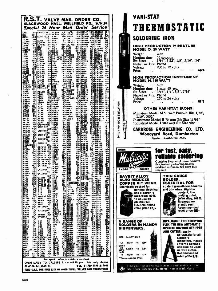
R.S.T. VALVE MAIL ORDER CO.BLACKWOOD HALL, WELLFIELD RD., S.W.16Special 24 Hour Mail Order Service
AZ3I 10/- KT81(7C6) UCL82 6/9 I2AX7 6/32N2147 12/6 1151880 9/-CIC 20/- 22/6 1/01.33 I0/- 12BA6 1/- 142100 15/0 GET885 41-CY30 12/6 KT81(011C) UF41 10/61213E6 6/3 N2369A 4/6 GEX64 2/8
DAF91 4/6DAF96 7/6
36/-me__-".
13F89 7/4111.41 ID-
13E1 20/-12E701 7/-
7(2398 30/-N2904 10/-
0E11641 115/-04331 9/0,,,
Dee" "./-DF91 4/ -KYW61 816KTW62 10/-
UL84 7/-UU13 21/-
12K801 IV-12Q701 6/-
N2904412/82N2926 6/3
046M 3/004611 3/8
DF96 7/6DH3/91 f
MIA 17/0,., -."'. 118-UU7 21/-1.71.78 21/-
2011 206-2094 20/-
27(3819 12/-28002 20/-
047M 6/6802987 4/-
1077 4/9 PC138 11/8 11Y41 8/8 20P9 20/- 28003 12/- 806002 4/-
07(91 6/- PC88 11/8PC97 8/9
11185 5/6VP4B 29/-
29Z4 8/320601 8/-
28004 11/-28009 48/-
4K9A 22/8JKIOA 16/-
DE92 9/- PC900 8/6 VR106/30 6/8 210801 8/6 28008 20/- 37(1013 16/-DE96 719 P0084 6/6 VR150/30 0/- 30015 15/- 28012 50/- 3819A 22/6DI.66 25/- p0089 10/6 W81 12/6 30C17 16/- 28012A 66/- .021A 1218DL92 6/3 900189 10/6 X81 45/- 30018 DV- 28013 K836A 9/-01.94 6.2.9 P0F80 0/9 7(66 16/- 30F9 17/- 28018 601- MAT1O1 8/081'38 G. PCF88 91- Z319 25/- 30911 16/- 28108 60/- MAT120 7/901810 12/6 PCF801 9/9 Z709 23/- 309112 19/- 28301 12/6 7(E7128 6/-01.818 30/- 909802 9/9 Z80313 16/- 301.'114 16/6 28320 9/- E7(7142 13/-0.1319 30/- P09806 13/- 0A2 6/- 30115 171- 28702 12/- E7(7211 6/-DV/43" 7/6 PC1.82 7/9 0B2 et- 30L17 I7/- 461 45/- NE1214 4/-DY86 6/- PCL133 10/3 OCS 5/8 30912 16/- AC107 10/- 177(7916 7/6
DY87 5/- PCL84 816 09A 4/6 30919 16/- AC126 6/6 NKT217 6/-E88CC 12/- PC1.85 9/3 11330T 7/3 30PL1 10/- AC127 7/0 N7(T2I8 13/-51809 PCL138 9/3 1CP31 18 3091.13 18/6 AC128 6/6 NICT221 6/6.,..17/9.
g182CC .41. PEEB4 20/- IRIS 6/- 30P114 111/- AC176 7/6 7(7(1223 6/-EABC80 6/8 PEN4SDD 2021 8/8 361.13 9/- ACY17 7/6 NK1224 4/0EAF42 10/- 12/- 2E26 201- 351401 9/- ACY113 5/3 7(7(7225 3/8_EB91,.. 3.1; PFL200 14/- 3A0 12/6 30W4 4/6 ACY19 6/6 7(E7227 5/6...,,,,"'.., P136 10/9 31328 40/- 36Z401 8/6 ACY20 6/- NKT228 6....1,.
4.,__,..-....,. ti* PL81 8/- 3045 615/- 5005 6/3 ACY21 6/- EKT261 5/-...-."' 4/9 PL82 8/8 4X160A 95/- 500080 31/- ACY22 3/8 EK7265 9/658980 7/6 P1.94 7/- 67(407 10/8 80 7/6 ACY29 4/6 N8T274 41-E8983 9/- P1.500 14/0 61740 5/0 85AI 20/- AD140 16/- 7(7(1304 8/-10989 6/8 PX4 14/- 5V408/- 86A2 7/3 AD161 11/- NKT352 8/-90121 12/- 9X25 12/8 5230T 6/- 90AG 45/- AF114 6/6 NKT404 12/0EBL31 27/6 PYS2 10/9 57.4G 7/- 90AV 45/- AF119 6/8 NKT462 12/6ECC33 .60- PY33 10/9 8/301.2 15/- 9001 12/- A9118 6/- N111875 6/-ECC40 17/6 py81 13/9 OAKS 6/- 9000 251- AF117 6/8 7(7(7676 5/-BCC81 8/7 PY82 4/9 6AK6 12/6 90CV 26/- A9118 10/- NKT877 6/-E0063 0/9 PY83 7/- 8A1.6 8/- 100B2 11/6 A9126 6/3 N81078 6/-ECC83 6/3 PY800 9/6 6A2613 3/6 15083 8/8 AF178 12/6 NET713 7/8ECC26 BI- Py801 9/6 6ANS 10/- 801 9/6 AF188 17/6 EKT777 8/-ECC88 7/6 PZ30 10/- 8AQ4 4/- 803 361- AFY19 22/6 0A2 8/3ECF80 8/6 QQV02/846/- 6AQ6 8/3 807 9/- A8220 7/6 0A7 4/-201,82 6/8 QQVO3/10 6A813 8/- 811 35/- A8Z91 12/6 OAIO 3/-50135 11/6 27/8 8A87 161- 813 76/- A1023 301- 0A47 3/-ECH42 11/- QQV03/20 6AT6 4/9 866A 16/- ATZIO 30/- 0A70 2/-5001 5/9 102/- 6A176 6/- 872A 4716 AUY10 39/8 0A79 203E0183 8/6 QQW01/15 OB4G 20/- 5651 7/3 BC107 7/8 0A81 2/050180 5/9 103/- 6BA6 5/- 5654 8/- BC108 6/- 0A86 2/8E01.82 71- QQV06140 65E8 6/- 5072 7/- BC109 7/8 0A80 4/-
E310/ 90/- 68116 9/- 3687 10/- BCY31 13/8 GA91 2/0ECL80 9/-3 QQV6/10 0B36 9/- 5891 25/- Beim 7/6 0A200 3/3ECLL80030/- 70/- 687(4 21/6 5749 10/- BCY34 6/- 0A202 4/8EFL 20/- Q870/20 6/6 13/3/46 7/6 5763 121- BCY39 24/- 0A210 7/65F37A 7/-5939 8/-
Q875/20 6/6Q876/60 20/-
613Q74 7/-811117 17/-
6842 86/-6963 10/-
BCY40 12/-MCMII 61-
OAZ200 11/-OAZ201 10/-
5941 10/- Q883/3 7/3 6BR8 12/0 6057 10/- 130111 27/8 0A2202 8/65980 4/3EF86 6/65989 0/65991 2/9
Q092/10 4/-Q825/10 5/6Q8109/4510/-Q8150/15 8/
6887 25/-813W6 14/60gw7 13/-604 5/-
6058 l0/-8099 Pit-6060 6/-,6061 12/-
50712 32/-BFY61 3/689152 4/8HMO 21/8
061204 8/6OAZ208 8/60AZ208 0/00AZ222 9/6
EF92 2/6 Q8150/30 6/- 6CB6 6/- kill,- 9/6 0AZ224 10/-5998 19/-59183 8/6
Q8150/3820/- 600811 24/-6086 7/6
,,,,,,..6062.... 1-6064 7/-
28127B8228 5/-gem 7/6
0AZ226 101-010243 4/6
59184 7/- Q0150/45 6CL6 8/0 6065 9/- 99y63 7/6 0A7(2413 4/0EF804 21/- 20/- 11CW4 12/- 6667 10/-, BfitY95A 5/6 08=90 9)6EFF60 10/-ER90 7/6E133 12/67(1.34 10/6
08110/0020/8
Q81209 7/3QV03-12 12/-
6D4 19/-6DK6 16-69-23 16/_6F24 14/-
6080 `",-6096 8/-6146 27/6,9003 .1-
B8%82 40/-131188 19/6BTY95100R
140/-
0AZ292 9/0°C10 20/-0019 7/00020 15/-5141 10/6
5142 10/6
EL" 91-5184 4/9
QV04-7 12/6Q906.25 9/-..QV°6-2') '.'"R10 ' 16/-
6929 10t-6928 14/-6932 2/9
TRANSISTORS17(21 3/8/3722 9/-
BY100 6/687114 15/-BYZ11 9/6
0029 10/-0033 11/80024 15/-
5185 7 9E188 8/3
R17 8/-R18 7/6
8460 4/-846 3/6
17(429 12/61E1192 17/6
B1212 12/-BYZ13 7/6
0026 9/-0026 71-
EL90 8/3 R19 7/9 6370 6/- 1/43085 13/9 BYZ18 15/- 0028 12/-E1,95 8/6 R05/500 80/- 67(3 2/9 18113 4/6 007131312/6 0029 16/-EL360 24/-51600 20/8
8130 40/-28130P 40/-
67(7 1/9811711 2/-
18131 4/3113420R 12/0
0064 / 67(707 2/6
0039 13/60036 1216
EL821 7/6 8P41 518 .688C 3/- 2162 4/3 881/05 7/6 0041 6/-EL822 16/- 8P61 5/- 61.9G 7/9 20210 12/6 07102 3/6 0042 BI -
BUM 201- STV280/40 6Q70 6/- 20309 5/- 07103 3/6 0043 9/-E1134 211- 25/- 6/- 90281 51- Cv425 3/6 0C44 4/-E1180 7/6 STV280/80 6847M 7/- 20382 6/- 072226 20/- 004491 5/6
BM81 8/3E/484 7/6
aa/_8E2150 12/6
681707 6/-685i707 5/6
2(1401 5/-20402 6/-
072268 25/-012290 6/-
0045 3/6004526 4/ -
32 245/- 6112150A 6V60 4/6 20403 10/6 072919 2/6 0046 5/5EY51 7/6 12/6 67(4 418 20414 6/- 071782 30/- 0047 ye5781 7/- 1719 35/- 67(511 4/6 20415 6/- 077183 30/- 0057 10/-EY83 8/6 1724 24/- 6X60T 6/- 20418 6/0 00003 3/6 0068 17/6mots 9/- uga 19/0 786 1116 A11417 61- 00190 9/9 0059 18/6gyg6 7/- u26 ma 7B7 7/6 2E247 9/0 DD226A 7/6 0070 4I-E to5Z412A1
9/60191 13/917301 12/6
705 22/6706 16/-
28274 9/627(410 3/6
EW99 5/-GE77 51-
0071 2/60072 11/-
)3Z80 0/6 13404 7/6 787 '8/8 2/4555 12/6 0E78 8/- 0073 7/6EZ81 5/6 U801 23/6 787 45/2 2E586 7/6 0E116 7/3 0074 61 -Gm 67/6 um1080 6/6 7Y4 8/6 2E599 12/6 0E/20 10/- 0075 C -O230 10/- ITAF42 10/8 1091 14/9 2E696 10/- 0E188 6/- 0076 5/-8232 10/- 155041 9/3 101.13 13/6 2E897 12/8 0E1102 6/- 0077 8/-0Z34 11/- 1,5081 9/3 1153 70/- 2N700A 6/6 051114 4/- 0078 9/-0Z37 16/- 17/3980 7/- 12AC6 10/- 2371040 20/- 0E1115 9/- 0081 8/-863 18/- 1187119 7/6 12A06 11/-281132 19/6 0E1116 15/- 008113 3/-11141DD 13/6 110066 7/6 19A56 9/6 27(1301 6/6 01621271 61- 0081026 31-7(161 17/6 801221 9/6 12AT6 4/9 2211304 6/- GE1872 6/- 003126 6/67(18* 20- 1/0542 10/6 196.1'7 6/- 2(2062 7/6 0ET874 61- 0081Z 9/-K167 45/- 17C1281 7/- 12.6177 5/9 2172068 20/- 051871 6/- 0082 6/ -
Postage 6d. valve, transistors post freeOPEN DAILY TO CALLERS 9 a.m.-5.30 p.m. No early closingC.W.O. No C.O.D. T.I. 01-769 0199 & NMSEND S.A.E. FOR FREE LIST OF 6,000 TYPES, VALVES AND TRANSISTORS
VARI-STAT
THERMOSTATICSOLDERING IRON
HIGH PRODUCTION MINIATUREMODEL D. 50 WATTWeight .. 2 oz.Heating time 50 secondsBit Sizes .. 1/16", 3/32", 1/8', 3/16", 1/4"Nickel or Iron PlatedVoltage . 250 to 12 voltsPrice .. 60/6
HIGH PRODUCTION INSTRUMENTMODEL H. 150 WATTWeight .. 6 oz.Heating time 1 min. 45 sec.Bit Sizes .. 3/16", 1/4', 3/8", 7/16"Nickel or Iron PlatedVoltage .. 250 to 24 voltsPrice . .. 87/6
OTHER VARI-STAT IRONS:Miniature Model M 50 watt Push -in Bits 1/32",
1/16', 3/32"Instrument Model B 70 watt Bit Size 11/64"Industrial Model I 500 watt Bit Size 5/8"
CARDROSS ENGINEERING CO. LTD.Woodyard Road, Dumbarton
Phone: Dumbarton 2655
for fast, easy,reliable solderingContains 5 cores of non -corrosiveflux, instantly cleaning heavilyoxidised surfaces. No extra fluxrequired.
SAVBIT ALLOYALSO REDUCESCOPPER BIT WEAR.Ecomically packed for
general electricaland electronicsoldering. 90 ft.18 gauge onplastic reel.Recommendedretail price 15/-
A RANGE OFSOLDERS IN HANDYDISPENSERS.
REF. ALLOY SWG
4A 60/40Size 5
(111ustra-Savbitted)
15 60/40
18
18
22
2/6*
2/P
3/-*Recommended Price
THIN GAUGESOLDER,ESSENTIAL FORsoldering small componentsand thin wires. High tin
content, lowmelting point,60/40 alloy, 202 ft.22 gauge onplastic reel.Recommendedretail price 15/ -
INVALUABLE FOR STRIPPINGFLEX, THE NEW AUTOMATICOPENING BIB WIRE STRIPPERAND CUTTER, easily
adjustable for allstandarddiameters. Plasticcovered handlescan also be usedas wire cutter.Recommendedretail price 818
From Electrical and Hardwat shops It unobtainable. write to'
CAt, Multicore Solders Ltd., Memel Hempstead, Herts
688

voltage is made less negative at an anode potential ofbetween 200 and 450 volts, the tube will fire as theoperating point on the graph crosses the curve.
It is also possible to fire the main gap by increasingthe anode voltage, but this has little practical applicationthe anode voltage, but this has little practicalapplication. At positive grid voltages, the firingcharacteristic rises again somewhat, since the electronstend to pass to the grid instead of to the anode.
There are some small tolerances in the actual positionof the firing characteristic from tube to tube, variationsof up to 1 volt in the grid potential required to fire thetube being permissible. Temperature effects on thefiring characteristic are generally fairly small (less than0.5 volt change in the grid potential at which firingoccurs over the range -30 to +90 degrees C).
However, if the glow thyratron becomes hot due to afairly large anode dissipation, the grid voltage must bereduced a little more than normally before the tube can
Fig. 4.5. A glow thyratron used to control a relay
VR1 RI
1014a 220181
R3 Ci R4
470 10011 pka
R2
470kd
RLA®
VI
DI
50mA,
C3jr
2pFmumm /8400V021,64
R6
1214a6121
C4
pF
Fig. 4.6. Delay circuit using the thyratron
022C0
A.
0
330ka
RI82
be made to conduct again. The magnitude of theauxiliary current has little effect on the firing point.However, the flow of grid current results in the firingpoint being dependent on the value of the grid resistorused.
The glow thyratron has the advantage of a shortionisation time, partly because ions are always presentin the tube from the auxiliary discharge. When thegrid of the tube is switched suddenly from -10 volts tozero, the typical ionisation time lies between 0.5 micro-second, for an anode supply voltage of 400, and 200microseconds for an anode voltage of 200.
The deionisation time varies over a range of about400 to 1,200 microseconds for anode currents ofbetween 5 and 40mA and supply voltages in the range300 to 400.
Some typical circuits published by the manufacturersof the glow thyratron are given below. The tube hasbeen allocated the coding GT21.
RELAY CONTROLThe circuit in Fig. 4.5 may be used to operate a relay
from a very sensitive pair of small contacts, which couldnot themselves pass the current required to operate therelay directly. Only a low voltage appears across therelay contacts and no sparking therefore occurs. Thusthe amount of wear on the small contacts is negligible.Even if the 'contacts have a resistance of severalthousand ohms, the circuit will function satisfactorily.
During the negative half cycles of the mains supply, anegative potential is applied to the tube anode, the diodeD1 will conduct so that capacitor Cl becomes charged.During the next half cycle of the main supply voltage,when the anode of the tube is made positive with respectto the cathode, the grid is held negative with respect tothe cathode by some of the charge from Cl whichpasses to C2. The tube does not therefore strike in themain gap.
Capacitor Cl also supplies the current required by theauxiliary cathode HK via the 1.2 megohm currentlimiting resistor.
When the control contacts are closed, the gridpotential becomes little different from that of thecathode potential owing to the resistance valuesemployed. Thus the glow thyratron fires on the halfcycles of the mains supply voltage during which itsanode is positive.
The use of the alternating mains supply voltage in thisway ensures that the tube is extinguished at the end ofeach half cycle and also eliminates the cost of a mainstransformer. However, it must not be forgotten thatone of the contacts is connected directly to one side ofthe mains. An isolating transformer must be used ifthe contacts are likely to be touched by a person or anearthed object.
The current passing through the relay consists ofhalf -wave rectified pulses at the mains supply frequency.In order that the relay contacts shall not "chatter", therelay should contain a suitable number of shorted turns.Alternatively a capacitor of value about lauF may beconnected across the relay to supply a current duringthe half cycles when the tube is not conducting.
The voltage across the open contacts cannot exceed13 volts and the maximum current which passes throughthe contacts is 100AA. The open contacts should havean insulation resistance of not less than 0.5 megohm.A DELAY CIRCUIT
A circuit for producing time delays is shown inFig. 4.6. When the control contacts S1 are closed,capacitor Cl commences to charge via the resistorchain. When the potential across Cl is great enough,the glow thyratron tube fires on each half cycle of themains supply voltage during which its anode is positivewith respect to its cathode.
The time delay may be altered by changing the valueof Cl or VR1, since this alters the time required for Clto charge to the firing voltage. The contacts RLA1 areused to discharge capacitor C1.
As in the case of the circuit in Fig. 4.5, the auxiliarycathode negative supply voltage and the quiescentnegative grid potential are obtained by half -waverectification of the mains supply by means of diode D2.
689

COINCIDENCE CIRCUITA simple coincidence circuit is shown in Fig. 4.7.
The glow thyratron is in the non -conducting state if oneor more of the inputs A, B or C is at zero volts withrespect to the cathode, owing to the negative potentialapplied to the grid of the tube via R3. If, however, allof the inputs are at a positive potential of not less than6V (at input impedances of not more than 15 kilohms)the tube fires and the relay is energised.
This type of circuit may be used with a countingcircuit to form a batch counter, which initiates anoperation at any pre -determined number of counts.
PHOTOELECTRIC CONTROLThe circuit in Fig. 4.8 may be used when it is desired
to energise a relay when the light falling on a photodiodeincreases above a certain level. As the light intensityfalls, the circuit will cause the relay to be de -energisedagain. However, the circuit incorporates a "switchinginterval", that is the level of illumination at which therelay becomes de -energised is less than that at which itbecomes energised. This avoids the possibility of thecircuit repeatedly switching itself on and off as the levelof illumination rises and falls by very small amounts.
The diode Dl ensures that the grid of the glowthyratron never becomes appreciably positive. Thediode D2 provides a half wave rectified supply for theauxiliary cathode and the grid bias voltage to hold thetube in the non -conducting state.
In the circuit in Fig. 4.8, the photocell X1 has ahigh resistance when the level of illumination is low. Anegative potential is therefore applied to the grid of theglow thyratron. When light falls onto the photocell,however, its resistance falls to a value which is muchsmaller than that of the 6.8 megohm resistor in serieswith it. Thus the voltage across the cell (and hence thegrid to cathode voltage) becomes small and the tubefires.
The photodiode used should pass a dark current ofnot more than 25 microamps and when illuminatedshould pass not less than 50,1tA. Suitable diodes arethe Texas H11 or the Siemens TP51 II. The diode D1should have a peak inverse voltage rating of at least50 volts and a maximum reverse current of 5/tA. TheTexas 15130 or the Mullard 0A200 are suitable. Thediode D2 should have a peak inverse voltage rating ofat least 700 volts and should be able to pass a forwardcurrent of 5mA.
The relay should have a suitable number of shortedturns or alternatively a suitable capacitor must beplaced across it. The switching interval may beeliminated by connecting the relay between points 1 and2 and by short-circuiting the points 3 and 4 (Fig. 4.8).
If it is desired to use the circuit for switching atrelatively high levels of illumination, R3 and R2 shouldbe reduced in value.
ELECTRONIC TOUCH BUTTONThe GK11 electronic touch button is another unique
type of trigger tube. It is operated by the touch of aperson's finger on an external trigger electrode, which isattached to the outside of the tube. It may, forexample, be used as a touch button for calling a. lift.
When the appropriate touch button is touched,the tube is switched to the conducting state and remainsilluminated until the anode to cathode voltage isreduced below the maintaining voltage for this gapwhich, in the case of a lift call button, would occurwhen the lift arrived at the floor in question. Touchbuttons can also be used in various types of instruments.
The construction of the GKI I is shown in Fig. 4.9.The tube itself contains an internal anode and cathode,the trigger electrode being connected to the touch plateby means of a small spring.
A high resistivity transparent material such aspolythene must be employed between the touch plateand the .front mounting panel. The red glow from aconducting tube passes through this material whichacts as a lens.
Fig. 4.7. Thyratron coincidence circuit
VIFit
2
Fig. 4.8. The relay is energised when the photocell isilluminated
Touch buttontype Girl I
Touchplate
Contactspring
Front plate
Shield
K
Fig. 4.9. Section of atouch button housing
690

VALUE ALL THE WAYINTEGRATED
CIRCUITSit PAM MONOLITHIC
DIGITAL MECUM(10 lead 10-11)
BP305A, 6 -Input ANDgate, 9/4 each,
BP314A, 7 Input. NORgate, 181 each.
BP316A, Dual 3 -InputNOR gate, 11/11 each.
BP316A, Dual 2 -InputNOR gate (expandable),5/4 each.
BP320A, J -K -Binary ele-ment. 11/11 each.
BP392A, Dual 3 -Input ORgate, OM each.
El -PAL MONOLITHICAnnum.(TO -11 5 lead)
BP709C, Operational amp-lifier, IV- each.
BP701C, Operational amp-lifier (with Zener out-put). 12/6 each.
BP702C, Operational amp-lifier (with direct out-put). 12/S each.
SPOOL Wide band ampli-fier, 13/- each.
BP621, Logarithmic wideband amp., 14/- each.
BP210C, General purposeamplifier (T0-5 8 lead).(voltage or current amp.),12/5 each.
LC. Operational Amplifierwith Zener output.Type 701C. Ideal for P.R.Projects. 8 Lead TO -5 case.Full data.
Our price 12/6 each6 off 11/- each. Large Qty.Prices quoted for.
OTHER moiounueDEVICES
BP424, Zero voltage switch,11/6 each.
This device is a monolithicI.C. that acts as combinedthreshold detector andtrigger circuit (or control-ling a trier. It is designedto pulse the gate of athyrietor at the point ofzero supply voltage, andtherefore eliminate radiofrequency interferencewhen need with resistiveloads.D131)1 Silicon Unilateral
Switch 10/- each.A Silicon Planar, mono-lithic integrated circuithazing thyristor electricalcharacteristic., but with ananode gate and a built -In"Zener" diode betweengate and cathode. Fulldata and application cir-cuits available on request.
PAIRMULDalttao)WEL
INTEGRATED CIRCUITSEpoxy case 213-5 leadtemp. range 10°C. to 65°C.UL900, Buffer, 111/11 each.UL914, Dual two -input
gate, 10/8 each.UL923 3 -K -flip-flop, 14/ -
each.Complete data and circuitsfor the Fairchild I.0.'savailable in booklet formpriced 1/11.
IIIILLARD LC.AIIPLIFIERS
TAA243, Operational amp-lifier. 70/- each.
TAA263, Linear AF ampli.Iter, MO each.
TAA299. General purposeamplifier, 11/- each.CAMEO 2_41___ALINEARINTEGRATEDmums
Audio Power Amplifier,SO/- each.
Owing to the mass of I.C.printed matter often re-quired by customers inconnection with the I.C.'sthemselves we ask you tohelp us in the cost ofreproducing this literature'by adding Is. towardssame. This is only neces-sary when a number ofdifferent sheetsare required.
MI. tram. suitable forP.R. Organ. Metal TO -18Nut. ETZ200 1/- each.Any Qty.
ADI6I NPR
AD 162 PNP
MATCHED COMPLE-MENTARY PAIRSOF GERM. POWERTRANSISTORS.For mains driven out-put stages of Amplifiersand Radio receivers.OUR LOWEST PRICEOF 12/0 PER PAIR
HIGH POWER SILI-CON PLANAR TRAN-SISTORSTEXAS 2S034 NPNTO -3.
VCB100 Ic 4.4IT. 15M/cs
VCE1110 Ptot. 40WWEBS hFE(min.)
60 Price15/- each
FREEOat 10/- Pack of yourown choke tree withorders valued 24 or over.
SEMICONDUCTORHANDBOOK(VOLUME 2)
with introduction tobasic circuits, registeredtransistor and diodetypes, full specifications.Eleven languages includ-ing English, Dutch,French, German.Swedish, Spanish andItalian.240 pages of semicon-ductor information.Price 1$/I. Money re-funded if not fullysatisfied.
NPN DIFFUSEDSILICON PHOTO -DUO -DIODE TYPE18701 (2N2172) for TapeReadout, high switchingand measurement indi-cators, 50V, 260mW.OUR PRICE 10/ -EACH,60 OR OVER 8/6 EACH,FULL DETAILS.
KING OF THE PAKS Unequalled Value and Quality
SUPER PAKS N SEPT:CONDUCTORSSatisfaction GUARANTEED in Every Pak, or money back.Pak No.Ul 120 Glass Sub -min. General Purpose Germanium Diodes 111/-U2 60 Mixed Germanium Transistors AF/RF 10/-U3 76 Germanium Gold Bonded Diodes aim. OAS, 0A47 10/-U4 40 Germanium Transistors like 0081, AC128 10/-U5 60 200mA Sub -min. 811. Diodes 10/-176 40 Silicon Planar Transistors NPN elm. BSY96A, 2N706 111/-U7 16 Silicon Rectifiers Top -Hat 760ariA up to 1,000V 10/-
50 MI. Planar Diodes 260mA OA/200/202 111/-USI 20 Mixed Volta 1 watt Zener Diodes 111/ -VII 30 PNP Silicon Planar Transistors TO -6 ehn. 2N1132 111/-U12 19 Silicon Rectifiers EPDXY BY126/127 10/-U13 30 PNP-NPN St. Transistors 00200 t 28104 10/-U14 150 Mixed Silicon and Germanium Diodes 10/-1116 90 NPN Silicon Planar Transistors TO -S sire. 2N697 10/-U16 10 9 -Amp Silicon Rectifiers Stud Type up to 1000 PIV 10/-1117 30 Germanium PNP AF Transistors TO -6 like ACY 17.22 10/-1718 8 6 -Amp Silicon Rectifiers BYZ13 Type up to 600 PIV 10/-1119 30 Silicon NPN Transistors like BC108 15/-U20 12 1.5 -amp Silicon Rectifiers Top -Hat up to 1,000 PIV 10/-U21 30 A.F. Germanium alloy Transistors 2G300 Series a 0071 10/-U22 10 1 -amp Glass MM. Silicon Rectifiers High Volts 10/-U23 30 Madt's like MAT Seri e. PNP Transistors 10/-U24 20 Germanium 1 -amp Rectifiers GJM up to 300 PIV 15/-U25 26 30011c/. NPN Silicon Transistors 2N708, BSY27 15/-U26 30 Fast Switching Silicon Diodes like IN914 Micro -min 1111/-
17214 Experimenters' Assortment of Integrated Circuits, untestedGates, Flip -Flops, Registers, etc., 8 Assorted Pieces
U29 10 1 amp SCH's TO -6 can up to 600 PIV CRS1/26-600
U30 16 Plastic Silicon Planar trans. NPN 2N2924 -2N2926 15/-U31 20 Oil. Planar NPN trans. low noise Amp 2N3707
U32 25 Zener diodes 400mW DO7 case mixed Volta, 3-18
U33 15 Plastic case 1 amp Silicon rectifiers 1N4000 eerie.U34 30 Oil. PNP alloy trans. TO -5 BCY26, 219302/4
1135 25 Oil. Planar trans. PNP TO -18 2N2906U36 26 Oil. Planar NPN trans. TO -5 BEE60/61/52U37 30 OIL alloy trans -SO -2 PNP. 00200 25329
1738 20 Feat Switching MI. trans. NPN, 400Mc/s 2N3011I:39 90 RF Germ. PNP trans. 2NI303/5 TO -5 111/-
SW-
111/-
111/-
11/-10/ -
U40 10 Dual trans. 6 lead TO -5 2N2060 111/-
U41 30 RF Germ. trans. TO -1 OC46 NKT72 101-
U42 10 VHF Germ. PNP trans. TO 1 NKT667 AF117 10/ -
Code Nos. mentioned above are given as a guide to the type of device inthe Pak. The devices themselves are normally unmarked
SIL. G.P. DIODES300mW 30 10/-25PIV (Min.) 100 25/-Sub -Min. 500 uFully Tested 1,000 IllIdeal for Organ Builders.
CADMIUM CELLSORM ORP61 8/- each ORPI2 5/6
PULL RANGE OP VIM DIODESVOLTAGE RANGE 2-1115.400mW (DO -7 Case) 2/4 each1-5W (Top -Hat) 8/5 eachlOW (190-10 Stud) 5/- eachAll fully tested 6% tol. and markedstate voltage required.
TRANSISTOR UM BOOR52 pages of cross references fortrans. and diode., types includeBritish, European. American andJapanese. Specially imported byBI-PAK 10/- each
BRAND NEW TEXASGERM. TRANSISTORS
Coded and GuaranteedPak No. EQ VT.T1 8 2G3710 0071T2 8 2G374 0076T3 .8 203744A OCUIDT4 8 20381A 0081TB 8 26382T °C82 ..T. 8 20344A 0C44T7 8 20346.4 °Cab ..T8 8 20378 0078T9 8 26999A 2N1302TlO 8 20417 AF117
10/-10/-101-10/-10/-10/-10/-10/-10/ -
PRINTED CIRCUITSEX -COMPUTER
Packed with semiconductors andcomponents, 10 boards give aguaranteed 30 trans. and 30diodes. Our price 10 boards 10/-.Plus 2/- P. a P.
GERM. =TIP= SINGLE-PHASE BRIDGE. Mullard type.GEX541-B.P. Output Vita. 48V.Output I.C. 5A. List Price 58/-.OUR PRICE 12/6 EACH.
IMMO SPE UL. DUAL TRANS.CODE D1699 TEXAS. OURPRICE 5/- each.
120 PCB NIXIE DRIVER TRAN-SISTOR Sim. BSX21 a 0407.2N1893 FULLY TESTED ANDCODED ND120. 1-24 5/5 each.TO -5 NPN 25 up 5/- each.
PLEASE NOTE. To avoid anyfurther Increased Postal Charges toour Customers and enable us tokeep our "By Return Postalservice" which le second to none,we have re -organized and stream-lined our Despatch Order Depart-ment and we now request you toBend all your orders together withyour rendttance, direct to ourWarehouse and Despatch Depart-ment, postal address: 111 -PAILSEINICONDUCTORS, DewtehDept., P.O. BOX 5, WARE,HERTS. Postage and picking still
/- -r order. Minimum order 10 -
PET'S9N 38192N 3820MPF105
10/-115/-11/-
OCP71 Type ... 5/11
QUALITY -TESTED PAKS6 Matched Trans. 0044/46/81/81D .... 10/-
90 Red Spot AF Trans. PIPE 15-16 White Spot BF Trans. PNP 10I-
6 Silicon Recta. 3 A 100-400 PIV2 10 A Silicon Recta. 100 PIV2 OC1 140 Trans. NPN Switching 10/-1 19 A SCR 100 PIV 10/-3 811. Trans. 28303 PNP 15-4 Zener Diodes 240mW 3-12V 111/-3 200 Mc/s Oil. Trans. NPN B8Y96/27 111/-3 Muer Diodes 1W 33V 6% Tol 10/-4 High Current Trans. 0042 Beivt.. 10/-2 Power Trandstors 1 0026 1 0036
-
W-O Silicon
OC75 Transistors 111/400 PIE.1160mA UV -
41 Power Trans. 0020 100V 10/-
10 0A202 Oil. Modes Sub -min Mb.2 Low Noise Trans. NPN 2N929/30 W.1 811. Trans. NPN VCB 100 ZT86 14N-8 0A81 Diodes MI -4 0072 Tramiston 10/.4 0077 Transistors 10/-4 811. Recta 400 PIV 600mA 10/.5 GET884 Trans. Eqvt. 0044 1111/ -IS GET883 Trans. Eqvt. 0046 Mi.2 2N708 Sit. Trans. 300Mc/s NPN 10/-3 0T31 LF Low Noise Germ Trans. 15/-6 IN914 Oil Diodes 75 PIV 711anA Mb.8 OA% Germ. Diodes Sub-olle. INGO 101-3 NPN Germ. Trans. NKT773 Eqvt 18/-2 0022 Power Trans. Germ 111/-2 0025 Power Trans. Germ. IL -4 AC128 Trans. PNP High Gain 10/-4 AC127/198 Comp. pair PNP/NPN 10/.8 2N1307 PNP Switching Tram 10/-7 CG62H Germ. Diodes Eqvt. 0A71 1111/..
3 AF116d
Trans. W.12 Assorte GTypeerm. Diodes Marked 11/-4 AC126 Germ. PNP Trans. 10/-4 Silicon Recta 100 PIV 750mA MI -3 A0081
Trans.Tram.
ans. ININ-
7 -3 00171 Traps. IN -5 2N2926 811. Epoxy Trans. /*/-7 0071 Type Trans lel-9 28701 8T ram. Texas 10/-3 12 Volt Zener 400mW 10/-2 10 A 600 PIV Sil. Recta. 1846E 18/-3 BC108 511. NPN High Gain Trans. 10/-1 2N910 NPN 811. Trans. VCB 180 15/-2 1000 PIV 811. Rect. 1.5 A R53810 AF 1111/-3 BSY95A SU. .NPN 2001Ic/s W.3 00200 811 Trans. 151-2 GET800 Low Noise Germ. Trans.1 AF139 PNP High Freq. Trans.3 NPN Trans. 1 ST141 t 28T1404 MadVe 2 MAT100 It 2MAT1203 Madt'e 2 MAT101 it 1 MAT19I 10/-4 OCAS Germ. Trans. AF 111/-3 AC127 NPN Germ. Trays. 10/.1 2N3906 Oil. PNP Trans. Motorola .. 111/-2 811. Power Recta BYZ13 15/-1 fill. Power Trans. NPN 100Mc/s
TK901A DV -6 Zener Diodes 3-151/ Sub -min. VW -I 2N1132 PNP Epitaxial Planar Oil. 15/-3 2N697 &Okuda' Planar Trans. 811... 11/-4 Germ. Power Trans. Eqvt. 0016 16/-1 Unijunction Trans. 2N2646 15/-2 Oil. Trans. 200Me/s 80Vcb ZT83/84 . 11/-1 Tunnel Diode AEY11 1050 Me/s 15/-2 2N27I2 S11. Epoxy Planar HFE226 ...16/-8 BY100 Type MI. Recta. SW -
26 811. and Germ. Trans. Mixed, allmarked, New 10/-
1/-10/-
15-15/-10/-
UNIJUNCTIONVT4S, Eqvt. 2N2646.Nun. TI843. BEN3000
7/6 EACH26-99 5/- 100 UP 4/ -
TESTED SCR'SP1V IA 7A 16A 30A25 - 7/5 - 20/-50 7/5 10/11 85/-
100 15/- 15/- 45/-900 MS 11/- SW- 55/-30011/- RV- -400 17/8 10/- 10/- 11111-500 SW- 40/- 45/- 55/-600 - 40/- -SIL.RECTS. TESTED
PIV 760mA 3A 10A 30A60 1/- 1/5 4/8 S/8
100 1/8 1/5 415 11/-200 1/9 4/- 4/9 15-300 1/5 4/5 WS 15/-400 5/5 5/5 7/5 55/-500 5/- 6/- 8/S 801-600 5/5 5/5 0/- 87/-800 5/5 7/5 11/- 401-
1000 5/- 5/5 12/0 55/-1200 - -
IIP
BINPAK
500 CHESHAM HOUSE150 REGENT STRUTLONDON, W.1
KING OF THE PAKS BI-PAK rii6PANIFWYt Title MONEY BACK
691

TECHNICALTRAINING
in radio televisionand electronics
Whether you are a newcomer to radio and elec-tronics, or are engaged in the industry and wishto prepare for a recognized examination, ICScan further your technical knowledge andprovide the specialized training so essentialto success. ICS have helped thousands ofambitious men to move up into higher paidjobs -they can help you too I Why not fill inthe coupon below and find out how?
Many diploma and examination courses available,including expert coaching for:
C. & G. Telecommunication Techns'. Carts. C. & G. Electronic Servicing R.T.E.B. Radio'T.V. Servicing Certificate Radio P.M.G. Certs. in Radiotelegraphy General Certificate of Education, etc.
Examination Students coached until successful
NEW SELF -BUILD RADIO COURSES
Learn as you build. You can learn both the theory andpractice of valve and transistor circuits, and servicingwork while building your own 5 -valve receiver, transistorportable, and high-grade test instruments, incl. pro-fessional -type valve volt meter -all under expert tuition.Transistor Portable available as separate course.
POST THIS COUPON TODAY
for full details of ICS courses in Radio, T.V. and Electronics
INTERNATIONAL CORRESPONDENCE SCHOOLS
Dept. 151, Intertext House, Stewarts Rd., London, S.W.8
Please send me the ICS prospectus -free and without Iobligation.(state Subject or Exam.)
NAME
ADDRESS
9/89
INTERNATIONAL CORRESPONDENCE SCHOOLS
SEMICONDUCTORSBRAND NEW AND FULLY GUARANTEED
1N91 4 16 2N2904 8/- CY IIN916 1//
A6 2N2904A 8/- ACY I
89
15010 3/- 2N2905 8I- ACY20r6002201 43/16
2N2906 81- ACY222N2905A 8/- ACY21
15015 51- 2N2906A 81- ACY2815113 31- 2N2907 8/-15120 2/6
ADI40
1512N2907A 81- AD 149
1513021
2/6 2N2923 5/-1$131
11 2N2924 5/-
1$44 2/-2N2925 5/62N292615132 2/6
2200330021 44/I-- Green 3:- Yellow 2/9
2 4;- Orange 2/6220333712N3011 5/-
2N696 5/- 2N3053 6/62N697 3/- 2N3054 12/62N698 4/6 2N3055 19/62N706 2/6 2N3702 4/-2N706A 2/6 2N3703 4/62N706 4/- 2N3704 5/62N929 5/6 2N3705 4/61N930 6/6 2N3706 4/62N1090 6/6 2N3107 4/-2N1091 6/6 2N3708 4/-2N I 131 9/6 2N3709 4/-2N1132 9/6 2N3710 4/62N 1302 4/6 2N371 I 4/-2N I 303 4/6 2N3819 9/-2N1304 516 2N3820 23/6211305 5/6 2N3823 17/62N I306 6/6 2N4058 6/62N 1307 6/6 2N4059 5/-2N1308 8/- 2N4060 5/-1NI309 8/- 2N4061 51-2N1507 5/6 2N4062 6/62N1613 6/6 26/42542N1711 6/6 2N4255 8/6 BC1252N1889 8/- 2N4284 3:6 BC14721,11893 8/- 2N4285 3/6 BC 1482N2102 13/6 2N4286 3/6 BC 14926.12147 17/6 2N4287 3/6 BC1672N1148 12/6 2N4288 3/6 BC1682142160 1416 2N4289 5' BC16921421 5/6 2N4291 3/6 BC2 1 2L2N2 193A 516 2N4292 3/6 BCY302N21 94A S/6 2N40361 12/6 BCY3 12N2217 6/- 2N40362 14/6 BCY3226/2218 6/- 2N4289 5/- BCY33
2N2219 6/-3N128 1816 BCY34
2N2220 5/- AAZI3 2/- BCY38_ AAZI5 2/6 BCY39
1142221 31- AAZ 17 2/6 BCY402N2722 S/- AC107 8;6 BCY422N2368 6/6 AC1262N2369 7/6 ACI 27 3/- BCY542N2369A 5/- ACI 28 4/-2N2539 4/6 AC176 6/- BCY712N2540 4/6 ACI87 12/- BCY722N2646 11/6 AC188 12/- B0121N2696 6/6 ACY17 S/- 1313121
ADI61ADI62AFI 14AFI 16AF I 17AFII8AF124AF127AF139AF181AF186AF239AFZ 12ASY26ASY27ASY28ASY29AS Z20ASZ21BAX13BAX16BAY318AY38BC1078C108BC I09BCI 13BC116
9/6 BCI 18
5/- B131245/- BF1154/- 13E117St- BF1674/- BF1734/- BF 180
8178 /1'1 B6 BB FFF 191441
7/6 BFXI2BFXI 3
St- BFX29
125//-6 :FFXX335°
5! BFX43BFX44BFX84BFX85
I1/- BFX86BFX87
5/6 BFX8885/6 BFY10
BFY11BEY 17BFY I8BFY19BEY4 IB FY4313FY50
18FFY551Y134Y7776 9/6
BEY90 12/6162//66, F21)(3(2190 65/166
6/613131X221 8/-10/6
43116- BBsSxX2287 160//6-
5/- BS X 9 10/6j3_31/1,666,
51- BSY29 4/67/6 BSY38 4/64/6 BSY39 416
5/6 BSY53 9/-
1/16 SySY10950A 431/66
6/6 BYXIO 5/6
7/*BYZ 10 9/-
* BYZ I I 7/69/6 BYZ 12 61-5/- BYZ I 3 5/-316 M3480 20/6
I9/- M1481 27/6
4/62162/91/63/6363/63/6
12/- M1490 22/64/6 MI491 29/610/6 MPF102 8/66/6 MPFI03 716716 MPFI04 7169/- MPFI05 8/-8/67;66/65/65/6
12/611/6
19/68/68/691-
10/-11/-
10/-51-4/64/64/64/6416
10/-13/64/64/64/6
NKT0013 8/6NKT2I6 10/6NKT2I7 816NKT261 416NKT262 4/6NKT264 416NKT27I 4/6NKT272 416NKT274 4/6NKT275 4/6NKT281 5/6NKT403NKT404 12/6NKT405 15/-NKT613 616NKT674 SI-NKT677 5/-N1(7713 5/6NKT773 5/6NK1781 6/-NKT20329
8/6NKT80111
15/6NKT80112
19/6NKT80113
2216OAS 2160A9 2/-0A70 1160A73 21-0A79 1/9OAB I 1/60A85 1/60A90 1160A9 I0A950A2000A2020C26
0C350C28
0C360C440c45007 I
OC750072
Oat!00830C8ID0C139OC1400C200OC201
16I/62/-2/-4/6
6/66/6
616
2//62/6264/64-4//63/-6/66/65/65/6
RECORDING
TAPES
Fully Guaranteed
7' STD 1,200' 7/37' L/P 1,800' 12/37' D/P 2,400' 19/-
STD 900' 6/65 ' L/P 1,200' 9/-5 D/P 1,800' 14/95' STD 600' 5/35' P 900' 7/35' D
L//P1,200' 10/9
3' D/P 185' 2/33' L/P 225' 3/-3' DIP 300' 4/-7' D/P Concorde
3,000' 33/6Spools: Be 6/3, 7'2/6, 56' 2/3, 5' 2/3,
1/9. 3' 9d,26." 1/10.
Post and Packing up to3 reels 2/9, otherwise4/6.
SPEAKERS (3 ohm)10' x 6' 37/6,
x 4' 23/6,9' x 5' 19/6.7' x 4' 15/6,5' x 3'12/63' 9/6, 5' 14/6,9' 27/6, 12' 39/6.
Post and Packing 1/6
SEND 6d. STAMP FORCATALOGUEP.P. for Components1/6 per order
THYRISTORSI AMP: 50V 51-, 100V 5/6, 200V 7/-, 400V 9/6.3 AMP: SOV 6/-, 100V 7/6, 200V 8/-, 400V 10/-.ZENERS. If WATT 2.7-33V 4/6
400m/w 3.0-33V 5/ -
INTEGRATED CIRCUITS-R.C.A.CA3005 30/ , CA3011 20/-, CA3012 25/-,CA3013 30/-, CA3014 30/-, CA3018 251-,CA3019 25/-, CA3020 27/6. CA3021 42/6,CA3022 35/-, CA3023 32/6, CA3026 21/6,CA3028A 25 CA3028B 35F, CA3035 351-,CA3036 20/,FAIRCHILDL900, 914 111- L923 14/ -DATA SHEETS FOR RCA DEVICES 2/- per type
Presets std., boric. or yen.Potentiometers, Log/LinMFD V Price MFD V Price
I 15 116 25 10 1/640 I/9 25 25 11615 1/6 25 50 116
350 2/0 32 15 1/6-5 16 1/9 32 450 1/6
15 116 40 6.4 1/640 4/9 40 16 1/6
350 2/3 50 12 1/615 1/6 50 25 1/6
4 6.4 1/9 50 SO 2/-18 116 64 25 1/640 1/6 80 6.4 1/6
450 3/- 80 16 I/6IS 1/6 100 6.4 1/6
I 25 1/6 100 12 1/6I 5 25 1/9 100 25 1/6I le 116 100 50 2/62 64 1/6 125 4 1/6
MFD200200250250320400500
500500640
10001000100010002000200025005000
1/63/3 each
V Price64 1/916 2/-25 2/950 3/9
160 2/91 1/6
6 2/6
5025
4/9319
16 3/612 3/916 4/-
25 5/-50 9/-25 8/650 12/625 9/625 12/6
VEROBOARD36' x 28', 3/631 x 36', 4/3Cutter 9/-3r x 5' S/617' x 38' 161-
x 24.4/3
RESISTORSI watt 10%, 4d.
watt 5%, 5d.and I watt, 6d.
3 watt, 5%, 1/65 watt X-I watt Metal Oxide, 1/9
A. MARSHALL & SON20 CRICKLEWOOD BROADWAY, LONDON. N.W.2
01-432 0161/2/3 CALLERS WELCOME
692

CIRCUITSThe basic circuit for the electronic touch button is
shown in Fig. 4.10. The tube does not strike whennothing is touching the touch plate, since the yectifiedmains voltage is below the striking voltage of the maingap of the tube.
If a person's finger is placed on the touch plate,however, a capacitive current passes between thecathode and the touch plate. Enough ions are formedto initiate a discharge in the main gap and henceenergise the relay. The tube can control an anodecurrent of over 10mA.
BYX10
Toteliplate
Fig. 4.10. The touch button controls a relay
srx10
KF11
Fig. 4.11. Time delay circuitusing a touch button
0vA.C.
+150k
Fig. 4.12. On -off touchcontrol circuit
Even if the person touching the touch plate is wearinggloves, the capacitance can exceed 5pF; this is quiteadequate to cause the tube to fire. Any earthed objector any object with a large capacitance to earth can beused to cause the tube to strike.
Once the tube has fired, the touch plate will have nofurther effect. The anode voltage must be reduced inorder to cause the tube to return to the non -conductingstate. This may be accomplished by interrupting theanode current by a switch, by operating the tube froman alternating supply, or by extinguishing the tube withthe aid of a second touch button (or other trigger tube)arranged in a bistable circuit. This last method isillustrated in Figs. 4.11 and 4.12.
TIME DELAY CIRCUITWhen the GKF11 assembly in Fig. 4.11 is touched,
the relay will be energised and the GKF11 will glow fora predetermined time interval, after which the GR15tube will ignite and the GKF11 will be extinguished.The relay may be used to carry out any desired opera-tion.
When the GKF11 is touched and fired, a negativegoing pulse appears at its anode and is applied via C2to the anode of the GR15 trigger tube. The latter isextinguished by the pulse. Contacts RLA1 are part ofthe relay and open when the relay is energised. Capaci-tor Cl commences to charge via the resistor chain.
After the preset time interval, the potential across thiscapacitor is great enough to cause the GR15 tube tofire. A negative pulse appears at the anode of this tubeand is applied to the anode of the GKF11 via C2.The GKF11 is thus extinguished, the relay de -energised,and the circuit returned to its initial state. ContactsRLA1 close so that Cl discharges through R3.
The time for which the relay is energised is deter-mined by the charging time of capacitor Cl. Thisdepends on the value of Cl and the setting of VR1.For a given value of Cl, alteration of the resistor settingwill change the time interval by a factor of up to ten.The time for which the relay is energised is given by theapproximate formula:
t = 1.1(0-47 + R)C1where R, is the value of the variable resistor VR1 inmegohms and C1 is in microfarads.
"ON/OFF" TOUCH CIRCUITThe circuit in Fig. 4.12 is a bistable touch operated
circuit, whereas that in Fig. 11 is a monostable one.When either of the touch button tubes in Fig. 4.12 istouched, that tube will conduct (if it is not already in theconducting state) and the other tube will beextinguished.
When the tube VI is touched, the relay will beenergised and will remain energised until the V2 istouched. The state of the circuit is shown by the glowemitted from the tube which was touched last. Whenone tube is switched to the conducting state, a negativepulse is developed at its anode which is passed throughthe anode coupling capacitor to extinguish the othertube.
OTHER DEVICESMany other types of triggered tube are available,
including those for protecting equipment from highvoltage surges. However, it is felt that the typesdiscussed above are those of direct interest to theamateur experimenter.Next month: Decade counting tubes
693

[dIBOON
SOLDERING HANDBOOKBy B. M. AllenPublished by Iliffe Books Ltd.120 pages, 8f in x 6in. Price 45s.
THE AUTHOR of this "practical manual for industryand laboratory" is senior works chemist at
Multicore Solders Ltd., and this immediately stampsthe work with authority. This most comprehensive andup-to-date book on the subject of soldering is dividedinto three parts. Part One is intended for the operatorand deals with making a joint. All the essentials arehere in word and diagram, and to hammer home thevital points, these are spelt out in capitals at the endof each section. Part Two is intended for the designerand engineer and it enlarges on methods and materials(i.e. solders and fluxes) for particular jobs. Part Threecomprises a collection of data concerning materialsand specifications.
Soldering is a subject generally taken much forgranted. Yet, seemingly, thousands of people must beguilty of adopting undesirable methods-quite un-wittingly! For example: in dealing with electroniccircuit assembly, and emphatic warning is given againstthe use of "side -cutters" when shortening wires aftersoldering. We are told that the pinching action of thesecutters may seriously damage the component orweaken a soldered joint. The recommendation is that ifwires must be cut after soldering, then cutters with ashearing action like the Bib stripper should be used.Perhaps this is aimed specifically at industrial operators.No doubt in vital apparatus destined for a trip intospace, this question of shock or stress on wires orcomponents, however minute, may be a very seriousmatter.
This example does illustrate the thoroughgoingtechniques preached by this book. It sets out to des-cribe the perfectionist approach. If the methods givenare followed, then the overall reliability of electronicequipment must be greatly enhanced.
F.E.B.
THE ELECTRONIC MUSICAL INSTRUMENTMANUALBy Alan DouglasPublished by Sir Isaac Pitman & Sons Ltd.372 pages, 81in x 5+in. Price 55sAPART from the theramin, no novelty instruments
are contained in this handbook. It is really aboutelectronic organs written by a man whose name issynonymous with this subject and who, of course,designed the P.E. Organ. Whilst this singularity ofchoice might belie the title, there is a very good reason,for it is in the electronic organ that we find the circuitsof tonal synthesis of almost every instrument includingthe percussion family.
The first two chapters, which are short, deal appro-priately enough with the physics of sound and music.From here on, the treatment is entirely electronic in thedissection and presentation of organ circuitry.
In common with most of the circuits in this hand-book, practicality abounds. In the large chapter on thefrequency generation, division and tone forming, thereare many working examples, fully annotated, andfeaturing both valves and transistors as active elements.It might be added, besides the more conventional typesof sine, square and sawtooth generators presented,there are the electromagnetic, electrostatic and photo-electric forms, all of which add up to a very compre-hensive treatment of this fascinating subject.
In the subject of division, passive tone forming andamplification, the same liberality of example abounds,and in consequence the complete tyro will experience noqualms when attempting the copius chapter-Commer-cial Electronic Instruments, where complete consoleinset circuits, bearing such resounding pedigrees asHammond, Wurlitzer and Baldwin are available forinspection, backed up by a very informative text.
A final chapter on experimental methods departs fromthe essentially commercial orientated subject matter,and presents the reader with some guidelines in experi-mental techniques, both in tone production andrealisation.
The handbook is made complete with useful appen-dices, glossary and bibliography.
G.G.
QUESTIONS AND ANSWERS ON COLOURTELEVISIONBy J. A. ReddihoughPublished by Newnes-Butterworths108 pages, 64in x 44in. Price lOs
FOR THOSE about to embark on colour televisionservicing, or for the radio enthusiast wishing to
broaden his knowledge, this pocket book is a valuableaddition to the Newnes Q and A series. The contentsare presented in easily understood terms with shortexplanations of colour derivation, separation, trans-mission reception, decoding and display.
It is adequately illustrated and has an index of terms,circuitry, and explanations. Difficulties in obtainingoptimum colour resolution through convergenceadjustments are described in a special chapter, withguidance on how one can set up the controls for bestresults.
A great deal of information is packed into this smallbook, none of which is superfluous to the knowledgerequired in understanding colour television.
M.A.C.
TAPE RECORDING YEAR BOOK -9th editionPublished by Tape Recording Magazine88 pages, 94in x 6in. Price lOs 6dBEING limited to only one branch of electronics, this
Yearbook contains 30 pages of details of tapeequipments. The remainder of the space is devoted toarticles written by well-known authors, the law inrelation to recordings, details of competitions, table oftape playing times, glossary of terms, and lists of taperecording clubs and manufacturers.
694

0 l P7:7771:1aLimImo
a new 4-way method of mastering
ELECTRONICSby doing and seeing . . .
1 OWN andHANDLE a
complete range of present-day ELECTRONIC PARTSand COMPONENTS
.,411
VA7S
2 BUILDand USE
a modern and profes-sional CATHODE RAYOSCILLOSCOPE
3 READ andDRAW and
UNDERSTANDCIRCUIT DIAGRAMS
6A
CIO
13
pie820
CARRY OUT OVER 40 EXPERIMENTS ON BASIC ELECTRONICCIRCUITS AND SEE HOW THEY WORK . . . INCLUDING . .
VALVE EXPERIMENTS TRANSISTOR EXPERIMENTS AMPLIFIERS OSCILLATORS SIGNAL TRACER
PHOTO ELECTRIC CIRCUIT COMPUTER CIRCUIT BASIC RADIO RECEIVER ELECTRONIC SWITCH SIMPLE TRANSMITTER
A.C. EXPERIMENTS D.C. EXPERIMENTS SIMPLE COUNTER TIME DELAY CIRCUIT SERVICING PROCEDURES
This new style course will enable anyone to really understand electronics by a modern, practical and visual method-no maths, and a minimum of theory-no previous knowledge:required. It will also enable anyone to understand howto test, service and maintain all types of Electronic equipment, Radio and TV receivers, etc.- - -
POST NOW 1- - - - -I
L
To: BRITISH NATIONAL RADIO SCHOOL, READING, BERKS. Please I
F send your free Brochure, without obligation, to:
NAME
we do not employ representativesI
[for
BLOCK CAPS IBROCHURE II
i1 or write if you prefer not to cut page I ADDRESS PLEASE P.E. 9 ILime 1.== UM. J. IMII/ /MN fmt OW 111111
695

BUILD YOURSELF A QUALITY TRANSISTORRADIO FULL AFTER SALES SERVICE !
ROAMER 7' SEVEN WAVEBAND
PORTABLEI FULLY TUNABLE WAVE BANDS-MWI, MW2, LW, SW1, SW2, SW3 and Trawler Band.Extra Medium waveband provides easier tuning of Radio Luxembourg, etc. Built in ferriterod aerial for Medium and Long Waves. 5 Section 22in chrome plated telescopic aerial forShort Waves-can be angled and rotated for peak S.W. listening. Socket for Car Aerial.Powerful push-pull output. 7 transistors and two diodes including Micro -Alloy R.F.Transistors. Famous make 7 x 4in P.M. speaker. Air spaced ganged tuning condenser.Volume/on/off control, wave change switches and tuning control. Attractive case with carryinghandle. Size 9 x 7 y 4in approx. First grade Total building coats Parts price list andcomponents. Easy to follow instructions and £5.19.6 P. & P. easy build plans 3/-diagrams make the Roamer 7 a pleasure to build. 7/6 (FREE with parts).
Personal Earpiece with switched socket for private listening, 5/- extra.
"NEW LOOK" ILISLODY BIZNED. AND LONG WAVES. WITH
SPEAKER AND EARPIECE6 transistors And 2 (Hales. Push-pull output, tuning condeneer,high " Q " ferrite rod aerial,311n speaker. and personal earpiecewith switched socket for privatelistening, 61 x 4 21n. TotalBuilding Costs WS. E. & P. 4/3.Plans and parts list 2/- (freewith parts).
TRANSONA FIVENEED. AND LONG AND TRAWLERRAND to approx. 60 metres111TH SPEAKER AND EAR-PIECE. 6 transistors and 2diode., ferrite rod aerial, tuningcondenser, volume control, movingcoil speaker. 61 41 slin. TotalMalang Cub 47/I. P. & P.3/9. Plans and Parts list 1/6 (treewith parts).
111111111111111EMENI
POCKET PMNEED. and LOBE WAVES ANDTRAWLER BAND to approx. 50metres. WITH SPEAKER ANDEARPIECE. 6 transistors and 2diodes, ferrite rod aerial, toningcondenser, moving coil speaker, etc.61 v 11 r. 31in. Total millingCosta 44/6. P. a P. 3/6. Plansand Parts list 1/6 (free with parts).
SOPER SEMI=D. LONG AND TRAWLERBAND. 7 transistors and 2diodes. Sin speaker, 2 R.F.stages, push-pull output, etc.71 v 61 < 111n. Total BuildingCosta 011/11. P. & F. 4/6. Plansand parts list 3/. (free withparts). Personal Earpiece withswitched socket for privatelistening, al- extra.
ROAN= SIXS WAVEBANDS -- WWI, INWS,1111, SRS, LW AND TRAWLERBAND. 6 transistors and 2 diodes.Ferrite rod and telescopic aerials.Sin speaker. Top grade cornponents. Size 75 x 51 x 111a.Toga milling Cats TO/d. P. & P.4/6. Plans and parts Ilat 2/.(free with parts).
DEPT. PE9, 61a HIGH STREET, BEDFORD 0234 52367Callers side entrance Stria Shoe Shop. Ooan 10-1, 2.30-4.30 Monday. Friday 9.12.30 Saturday
S
GEATRONIX LIMITEDEDUCATIONAL ELECTRONIC EQUIPMENT
MANUFACTURERS OF
NORKITA new HOBBY for the automation age
* Simple building bricks to build yourown ELECTRONIC BRAINS.
* Easy to understand handbooks toguide you.
* Learn about LOGIC, BINARY arith-metic and BOOLEAN algebra.
* Modules are rapidly assembled anddismantled to use again.
* Make machines that play games,control model railways, etc. andcontrol automatic machines of anydescription.
NORKIT JUNIOR- (as shown)
£8 . 16 . 0
NORKIT SENIOR £17 . 12.0Handbooks supplied for each kitor available separately 6/- each
LOGIC DEMONSTRATION UNIT TYPEA new teaching aid for rapidly setting upand demonstrating logic circuits. StackablePatching leads are used to interconnect logicsymbols on a mimic diagram. The symbolsare connected to appropriate componentsinside the unit. Switches and pushbuttonsare provided to simulate Input conditionsand outputs are indicated by lamps and anaudible alarm.
LDU.1
£68 . . 0
Telephone: SOUTHEND 62521
696
GEATRONIX LTD 28 REDSTOCK RD., SOUTHEND-ON-SEA, ESSEX

NEW PRICES ON NEW COMPONENTSRESISTORSHigh stability, carbon film, low noise. Capless construction, moleculartermination bonding.Dimensions (mm): Body; 1W; 8 2.8
PM; 10 4.3Leads; 35
107 ranges; 10 Ohms to 10 Megohms (E12 Renard Series)5% ranges; 4.7 Ohms to I Megohm (E24 Renard Series)
Prices-per Ohmic value.W
2d4; each116
10 off 25 off off3/3
100W 1 10/4
5% 24d 1/9 3/8 11/8'W.i 107 lid 1/9 3/8 11/7
1W 5°2 3d 2/- 4/ 12/10
CAPACITORSSubminiature Polyester film, Modular for P.C. mounting. Hard epoxyresin encapsulation. Radial leads.
± 100% tolerance. 100 Volt Working.Prices-per Capacitance value (µF)
each 10 off 25 off 100 off0.001, 0.002, 0.005, 0.01, 0.02 .. 6d 4/3 8/4 30/-
.. .. 8d 6/- 12/6 41/8.. .. .. 10d 7/1 15/6 51/-
0.2 .. .. 1/2 10/- 20/10 68/60.5.. .. . .. .. 2/- 17/6 37/6 I25/-Polystyrene film, Tubular, Axial leads. Unencapsulated.
±5% or ± Irit tolerance. 160 Volt Working.Prices-per Capacitance value (NAF)
10, 12, 15, 18,22, 27, 33, 39, 47, 56, 68,82, 100,120, 180, 220, 270, 330, 390 ..470, 560, 680, 820, 1,000, 1,500 ..2,200, 3,300, 4,700, 5,600 ..6,800, 8,200, 10,000, 15,000 ..
Polystyrene film, Tubular, Axial leads.Resin encapsulation.
each 10 off 25 off 100 off
5d 3/7 7/9 24/-6d 4/- 8/8 26/87d 5/- 10/10 33/48d 6/- 13/- 40/-9d 6/9 18/- 45/4
Professional Grade. Hard Epoxy
± 1% tolerance. 100 Volt Working.Prices --per Capacitance value (µµF)-except where stated)
each 10 off 25 off100, 120, 150, 180 .. 1/3 10/2 21/2220, 270, 330, 390, 470, 560, 680,
1,000, 1,200, 1,500,2,200,2,7003,300, 3,900, 4,700, 5,600 ..6,800, 8,200, 10,000, 12,00015,000, 18,000 ..22,000, 27,00033,000,39,00047,000, 56,00068,000 ..82,000 ..0.1AF0.12pF0.15AF0.18AF0.22pF0.27pF0.33AF0.39AF0.47AF, 0.5AF.
POTENTIOMETERS (Carbon)Miniature, fully enclosed, rear tags, carbon brush wiper. Long life, lownoise. Body dia., fin. Spindle, I in. fin. 1W at 70°C. +20% PI,4.-3o0A. PI Lin. 100 Ohms to 10 Megohms, Log. 5 Kohms to 5 Megohms.Prices-per ohmic value. each 10 off 25 off 100 off
2/3 20/- 45/10 186/8
GANGED STEREO POTENTIOMETERS (Carbon)W at 70°C. Long Spindle.
Logarithmic and Linear: 5k + 5k to I M 1M.
8/- 70/- 162/6 575/-Prices per ohmic value each 10 off 25 off 100 off
SKELETON PRE-SET POTENTIOMETERS (Carbon)High quality pre-sets suitable for printed circuit boards of 0.1 in. P.C.M.100 Ohms to 5 Megohms (Linear only).Miniature: 0-3W at 70°C. +20% below PI, ±30% above }M. Horizontal(0-7in. x 0.4in. P.C.M.) or Vertical (0-41n. 02in. P.C.M.).Subminiature: 0-1W at 70°C. +20% below 2.5M, ±30% above.Prices-per ohmic value each 10 off 25 off 100 off
Miniature (0.3W) 1/- 8/9 18/9 66/8Subminiature (0.IW) 10d 7/I 14/7 46/8
100 off64/6
1/3 10/8 - 23/I 71/-1/6 13/10 29/11 92/-1/9 14/1 31/- 96/-1/9 15/2 32/10 101/-2/- 1S/11 34/9 107/42/3 17/3 37/10 115/-2/6 20/1 43/6 133/92/9 22/I 47/10 147/43/- 24/9 53/8 165/43/3 26/I 56/6 173/93/6 27/5 59/4 182/83/9 30/3 65/10 202/-4/3 34/2 73/7 228/-5/- 37/10 81/11 252/36/- 47/- 101/10 313/46/9 53/9 116/8 358/47/3 58/10 126/11 390/-7/9 65/- 140/10 433/49/9 75/2 137/7 500/ -
JACK PLUGSfin. Type P1. Standard. Screened. Heavily chromed.lin. Type SE/PI. Side -entry version of type Pl.lin. Type P2. Standard. Unscreened. Unbreakable moulded cover.in. Type P3. Tip -Ring -Sleeve Stereo version of Type Pl.in. Type P4. Tip -Ring -Sleeve Stereo version of Type P2.
3-5mm Type PS. Standard. Screened. Aluminium cover.3.5mm Type P6. Standard. Unscreened. Unbreakable moulded cover.Prices- each 10 off 25 off 100 off
Pl. 3/- 26/8 62/6 233/4SE/PI. 3/6 30/10 66/8 280/-P2. 2/6 23/4 54/2 200/-P3. 6/6 60/- 137/6 500/-P4. 6/2 56/6 127/6 455/-P5. 2/2 19/2 43/9 158/4P6. 1/8 I5/- 33/4 116/8
JACK SOCKETSfin. Type S3. Stereo version for use with P3 or P4 plugs.}in. Type S.5. Standard. Moulded body. Chrome insert.3.5mm Type S.6. Standard. Moulded body. Chrome insert.Available with make or break contacts on Tip, Ring and Sleeve.Prices- each 10 off 2.5 off
53 3/3 30/- 68/9S5 2/9 25/- 56/8S6 1/6 13/4 33/4
ELECTROLYTIC CAPACITORS (Mullard). -10% to -1 50%.Subminiature (all values in pF)4V 8 32 64 125 2506-4V 6.4 25 50 100 20010V 4 16 32 64 12516V 2.5 10 20 40 8025V 1.6 6-4 12.5 25 5040V I 4 8 1664V 0.64 2.5 5 10Price 1/4 1/3 1/2 If -Small (all values in AF)4V6.4V10VI6V25V40V64VPrice
80064040025016010064
1/6
1,250 2,0001,000 1,600
640 1,000400 640250 400160 250100 1602/- 2/6
100 off250/-216/8
400320200125so
32 5020 32
I/1 1/2
3,2002,5001,6001,000
6404002503/ -
POLYESTER CAPACITORS (Mullard)Tubular, 10%, 160V: 0.01, 0.015, 0-022AF, 7d. 0 033, 0-047AF, 8d. 0-068,0.1 F, 9d. 0.15AF, I Id. 0-22µF, 1/-. 0.33AF, 1/3. 0-47AF, 1/6. 0-68pF,
2/3. 1pF, 2/8.
400V: 1,000, 1,500, 2,200.3,300, 4,700pF, 6d. 6,800pF, 0.01, 0-015, 0-02.2pF.7d. 0.033AF, ed. 0.047AF, 9d. 0.068, 0.10F, I Id. 0-15AF, 1/2. 0.22pF,1/6. 0-33µF, 2/3. 0.47/iF, 2/8.
Modular, metallised. P.C. mounting, 20%, 250V: 0.01, 0-015, 0.022uF, 7d.0.033, 0047pF, 8d. 0.068, 0.1µF, 51/41. 0.15AF, I Id. 0.22AF, 1/-. 0.33/4F, I/S.0.47µF, 1/8. 0-68µF, 2/3. 1µF, 2/9.
SEMICONDUCTORS: OAS, °A81, 1/9. 0C44, 0C45, 0071, 0081,OC8ID, 0082D, 2/-. 0070, 0072, 2/3. AC107, 0075, OCI70, OC171,2/6. AF115, AF116, AFI 17, ACY19, ACY21, 3/3. OC140, 4/3. 0C200,5/-. 0C139, 5/3. 0C25, 7/-. 0C35, 8/-. 0C23, 0C28, 8/3.
SILICON RECTIFIERS (0-5A): 170 P.I.V., 2/9. 400 P.I.V., 3/-. 800P.I.V., 3/3. 1,250 P.I.V., 3/9. 1,500 PIN., 4/-. (0.75A): 200 P.I.V., 1/6.400 P.I.V., 2/-. 800 P.I.V., 3/3. (6A): 200 P.1.V., 3/-. 400 P.I.V., 4/-.600 P.I.V., 5/-. 800 P.I.V., 6/-.
SWITCHES (Chrome finish, Silver contacts): 3A 250V, 6A 125V.Push Buttons: Push -on or Push -off 5/-. Toggle Switches: SP/ST, 3/6.SP/DT, 3/9. SP/DT (with centre position) 4/-. DP/ST, 4/6. DP/DT, 5/ -
ROTARY SWITCHES (Wafer)High quality. Rear tags. Long spindle, 1" Dia.I p/12w, 2p/6w, 3p/4w, 4p/3w, 2p/3w.Prices- each 10 offAll Types 4/6 38/4
PRINTED CIRCUIT BOARD (Vero).0.15in Matrix: 3fin x 2fin, 3/3. 5fin x 2Iin, 3/11. 3}in x 3fin, 3/11.Sin x 3fin, 5/6.0.1 Matrix: 3fin x 2fin, 4/-. Sin x 2fin, 4/6. 3fin x 3fin, 4/6. 5in x 3fin,5/3.
25 off 100 off83/4 283/4
Send S.A.E. for January, 1969 Catalogue
DUXFORD ELECTRONICS (PE)97/97A MILL ROAD, CAMBRIDGE
Telephone: CAMBRIDGE (0223) 63687(Visit us-at our new Mail Order, Wholesale & Retail Premises) MINIMUM ORDER VALUE 5/- C.W.O. Post and Packing 1/6
697

DIOTRANIvvp.0ABSALEOEHXE5RTsS
TEL.: WARE 3442
EX -COMPUTER PANELS I.B.M. Sizetin. x 4in. with TRANSISTORS, DIODES,RESISTORS. CAPACITORS, etc. Over4 million already Sold out to the Trade.70,000 only left at our Ridiculous Price ofEl per 100 panels or CM par 1,000 panels.plus carriage 6f- per 100 panels.
Post and Packing costs Sr. continually rising.Please add 1/- towards same. CASH WITHORDER PLEASE
OVERSEAS QUOTATIONS BY RETURNSHIPMENTS TO ANYWHERE IN THEWORLD
OVER 3 MILLION SILICON ALLOY & GERVERYMTRANSISTORS AVAILABLE FORIMIf-If. TESTED TRANSISTORSQty. Qty. Qty. Qty. each ONE PRICE ONLY PNP. NPN. each
TRANSISTORS Price Price Price Price SILICON PLANAR 1/- EACHType and Construction 100 500 1,000 10,000A I Germ. A.F. NPN TO -I -ACI27, NKT773, ACIS7, ASY86 £3.10 LIS £25 E200
BC108 2N696 2N1132 2N2220 2S733BC109 2N697 2N1613 2N3707 2N3391
A 2 Germ. A.F. PNP TO -5 =ACYI7-21, NKT237-245 II 0 LS 140 13E750 21706 2N17I1 2N3711 T1S44A 3 Germ. A.F. PNP TO -I -AC128, NKT271, 2G381 LI f.3 ES 140 8E751 2N708 2N2904 25102 2N2906A 4 Germ. R.F. PNP TO -I -0C44-45, NK172/125, ASYS4 L1.10 44.10 0.10 160 BFX84 2N929 2N2905 25103 2N2907A 5 Germ. R.F. PNP TO -S ,=2N1303, NKTI64-7, 20301-3 11.10 14.10 £7.10 360 BFX86 2N930 2N2924 25104 2N2696A 6 Germ. V.H.F. PNP TO -I -AFI 16-7, KNT667, 2G417 0.10 L15 E25 1100 13FX811 2N1131 2N2926 25732 2N3702A 7 Assorted Germ. A.F.-R.F. PNP mixed cans, general purpose ISs. 12.10 L4 /32 2N3703A 8 Germ. A.F. 50.2 PNP =2G37I-89, ACY27-3I, 0071-75 £2 £7.10 /12.10 1100 From Manufacturers' Over -runs -Unmarked Plastic andA 9 Sil. Alloy PNP TO -S =25301-5, BCY17-29. BCY30-34 0 L7.10 L11.10 1100 Metal cases. Devices similar to above Nos.A10 Sil. Alloy PNP SO -2 =25321-325. 0C200-205 0 L7.10 112.10 1100
GERM. PNP AND NPN TRANSISTORS FULLYAl to A7 Guaranteed 80% Good usable Transistors ideal for low cost production work and experimentaluse. A8 to A10 are all perfect devices, factory tested, no open or short circuit Transistors in these lots. TESTED. UNMARKED SIMILAR TO 1/6 EACH
ACI25 ACY22 ACY36 NKT677 0081 2G381BRAND NEW FULLY TESTED EPDXY CASE THYRISTORS (S.C.R's) AC126 ACY27 NKTI41 NKT713 0082 20382UNIJUNCTION TRANSISTORS. Type T1543 and TESTED, BRAND NEW AND ACI27 ACY28 NKTI42 NKT773 2G301 2G399ABEN 3000 and replacement for 2N2646. Full data available. CODED: TO -S CASE ACI28 ACY29 NKT212 0C44 20302LOWEST PRICE AVAILABLE ANYWHERE. 100 off 4/- . PIV Amp EachType No. ACI30 ACY30 NKT213 0C45 20303each ../.2.0; 500 off 3/6 each a:, £87.10; 1,000 off 3/- each .. 2N1595 50 . 7/6 ACY19 ACY31 NKT214 0071 20308 116£150. Sample devices 7/- each on request. 2N15% 100
2N1597 200.. 11/-
10/6ACY20 ACY34 NKT2I5 0071 20371ACY21 ACY35 NKT271 0075 20374 each
QUALITY SILICON PLANAR DIODES. 2N1598 300..
14/ -.HIGHSUB -MINIATURE DO.7 Glass Type, suitable replacements 2N1599 400 - 15/ -for 0A200, 0A202, BAY38, 15130, 55040. 200,000 to clear BTX30-580 500 22/6 POWER TRANSISTORSat 14 per 1,000 pieces. GUARANTEED 80% GOOD. BTX30-600 600 . . 251- 0C25 0C35 NKT403 ASZI7 ..
0C26 ADI30 NKT404 7130V 30/SILICON PLANAR PLASTIC TRANSISTORS.
TO -4B CASE (STUD)Type No. PIV Amp Each
0C28 ADI40 NK7405 713028 eachoc.29 ADI49 NKT452 7130292N3708A Vc830 Hfe 20-60. All marked fully tested and
guaranteed. I off 1/6 each; 100 off 10d. each; 500 off 9d.2N682 50 16
- - 12/---2N683 100 16 . 15/ -
Manufacturers' Surplus Germ. A.F. All similar to above.each; 1,000 off nel. each. 2N685 200 16 .. 19/6
214687 300 16 25/6 TRANSISTOR EQVT. BOOKTO -5 METAL CAN SILICON PLANAR TRANSIS- 2N688 400 16 .. 32/6 2500 cross references of transistors -British, European,TORS. VERY HIGH QUALITY 79% good type. 2N697, 2N689 500 16 47/6 American and Japanese. A must for every transistor user.SFY51, 2N1893. £8 per SOO pieces. 11340 for 1,000 pieces. 2N690 600 16 . 50/- Exclusively distributed by DIOTRAN SALES. 1S/- EACH.
214691 700 162N692 800 16-FULLY TESTED DEVICES AND QUALITY Sub -Min. PlasticGUARANTEED -SURPLUS TO REQUIREMENTS TO -46 CASE (STUD) I Amp Sil. Rect. Vast mixed lototsubminiature
0A202 Silicon Diode. Fully Coded. Type No. PIV Amp Each Type No. MV Each glass diodes. Comprising ofISO PIV 250mA Qty. Price [30 per 1,000 pieces. 2N1771 50 4.7 . 9/- IN4001 50 .. 113 Silicon, Germ., Point ContactORPI2 Cadmium Sulphide Cell. 2N1772 100 4.7 .. 916 IN4002 100 .. 116 and Gold Bonded types plus1-24 9/. each; 25-99 71- each; 100-999 6/- each; 1,000 up 2N1774 200 4.7 . 12/6 1N4003 200 .. 2/- some Zeners. 500,000 available5/6 each. Made in Holland. 2NI776 300 4-7 .. 1616 1N4004 400 .. 2/9 at Lowest of Low Price.BY100 SIL. RECT'S 800 PIV 550mA. 2NI777 400 4.7 19/- IN4005 600 .. 3/3 1,000 pieces 0.0.0. 5,000 pieces1-49216 each; 50-992/3 each; 100-999 2/- each; 1,000 up 2N1778 500 4.7 . 25/6 IN4006 800 .. 3/9 113.10.0. 10,000 pieces £23,1/10 each. Fully Coded. 1st Qlty. 2N2619 600 4.7 .. 30/- IN4007 1,000 . 4/9
YOUR CORTINA CAN
DELIVER 144 11.11.11.1Enough power to reach 6o m.p.h. in under tenseconds ! How can she do it ? Easy .. . whenshe's been fitted with a 3 -litre V6 Ford Zodiacengine. And that simple conversion could costyou as little as one third of the price of a newbig-engined baby.Profit from our experience at PRACTICALMOTORIST. After only a few minor bodymodifications, we successfully shoehorned thislarge -capacity power unit in with safety. Nowshe really knows her way about on our traffic- PRACTICALpacked highways, and she's ready any time toget herself adapted for racing, rallying, hillclimbing and sprints.Read the two-part case -history of our compact" extra -delivery " V6 Cortina, starting in theSeptember issue.
onstSeptember issue OUT NOW ! 2/6
698

STEREOGRAM CABINET £19An elegant nomogram Cabinet Inmodern Veneered Mahogany and
data cowered Frost PanelBLACK LEATHERETTE SIDE PANELS
Dimensions: 32" x 174, x 2-. Speakerpositions for Twin 10"x r Speakers
SPEAKERS 6/62"-75 CI. 21? -35f1. P. & P. 2/6.ACOS MILS. 35/- STANDARDSTICK MIC. 2gns. P. & P. 3/6.ASSORTED CONDENSERS
10/. for 50. P. & P. 7/6.ASSORTED RESISTORS
10/- for 50. P. & P. 4/6.ASSORTED CONTROLS
10/. for 25. P. & P. 7/6.TRANSISTORS
MULLARD MATCHEDOUTPUT KIT
9/- 008 I D-2 °CBI 's.P. & P. FREE.
FERRITE RODS 3/66", 8" x i" complete with
LW /MW COILS. P. & P. FREE.
17in.-£11.10.0 carr.so/-I9in. SLIM -LINE
FERGUSON 24 gns.TWO-YEAR GUARANTEE
EX -RENTAL. TELEVISIONS
- mFREE ILLUSTRATED
LIST OF TELEVISIONS
WIDE RANGE OF MODELSSIZES AND PRICES
DEMONSTRATIONS DAILY
RECORD PLAYER CABINET49/6.
Cloth covered. Size 165' v 14r ye'Takes any modern autochanger.
P. & P. 7/6.
SINGLE PLAYER CABINETS15/6. P. & P. 7/6.TRANSISTOR CASES 19/6.Cloth covered, many colours.Size 94, X 61"X 34'. P. & P. 3/6.Similar cases in plastic 7/6.
TWO -YEAR GUARANTEEDREGUNNED TUBES
70° & 90° I4in.-49/6, 17in.-9916, 2Iin.-99/6. 110° I7in.,I9in. & 21 in. -99/6. 23° (notbonded) -119/6. ExchangedBowls. Carr. 10/6.
DUKE 8r. CO. (LONDON) LTD.621/3 Romford Road, Manor Park, 2.12Phone 01-478 6001-2-3 Stamp for Free List.
ELECTRMI:UtEVERYTHING BRAND NEW AND TO SPEC. NO SURPLUS
SPECIALIST
SUPPLIERS OFTRANSISTORSIN TYPES TO SUIT ALMOST ALL APPLICATIONS
COMPETITIVE PRICES HIGH QUALITY COMPONENTS FOR
TRANSISTOR CIRCUITS
PEAK SOUND AS ADVERTISED CATALOGUE Our latest 1969 catalogue is packed
with up-to-the-minute items and invaluableInformation. Send 1/6 for your copy now.
DISCOUNTS 10% on orders for components for£3 or more. 15% on orders for components for£10 or more.
POSTAGE on orders for £1, add If-. FREE onorders for LI or over. Overseas orderswelcome-Carriage charged at cost.
ELECTROVALUE(DEPT. PE), 32a ST. JUDES RD., ENGLEFIELD GREEN, EGHAM, SURREY
Telephone: Egham 5533 (STD 0784-3)
Mit atit* tt t Asoapt,
001 41
41114r1
and work atthe nerve centresof civil aviationThe National Air Traffic Control Service, a Department of theBoard of Trade, needs Radio Technicians to install and maintain thevery latest electronic aids at Civil Airports such as Heathrow,Gatwick
and Stansted, Air Tfaffic Control Centres, Radar Stations andspecialist establishments.
This is responsible demanding work (for which you will getfamiliarisation training) involving communications, computers, radarand data extraction, automatic landing systems and closed-circuittelevision and it offers excellent prospects with ample opportunitiesto study for higher qualifications in this fast -expanding field.
If you are 19 or over, with practical experience in at least one ofthe main branches of telecommunications, fill in the coupon now.
Starting salary is £915 at (19)to £1,189 (at 25 or over): scale maximum£1,372 (higher rates at Heathrow), and some posts attract shift -dutypayments. From January 1970 these rates will be increased to £985,
£1,295, £1,500 respectively. The annual leave allowance is good andthere is a non-contributory pension scheme for established staff,
Complete this coupon for full details and application form:To: A. J. Edwards, C. Eng.. M.I.E.E., M.I.E.R.E., Room 705. The Adelphi,John Adam Street, London WC2, marking your envelope 'Recruitment'.Name
Address
PEMI
Not applicable to residents outside the United Kingdom.
NATIM National Air Traffic Control Service
699

Practical Electronics Classified Advertisements
MISCELLANEOUS
GLASS FIBRE OPTICLIGHT GUIDES
0031" DIA. TOTAL FIBRE BUNDLE HELDWITHIN P.V.C. SLEEVING
s' 10' 15' 25' 50' STRICTLY19/6 34/6 47/6 72/3 132/3 CWOFIBRELIGHT, Dept. PEA31 STOKE ROAD, GUILDFORD, SURREY
PROJECT BUILDERS note --Having troubleobtaining special components? We willendeavour to supply ALL parts for yourproject, specials, e.g., coils, p.c. boards, etc., aswell as standard items. SRY ELECTRONICS,11 Rosedene Ave., Croydon, CRO 3DN.01-684 0402.
WANTED. Somebody to construct about threemetal detectors. Possibility of further orders.Terms to be negotiated. Contact--CHAIT,Flat 6, 170 Highgate Rd., London, N.W.5.Gulliver 8395.
ROBOTSSynthetic Animals with "BRAINS" of theirown. The NEW range of projects include:an electronic 'animal' which "LEARNS",an Electro Chemical device capable of"REPRODUCING" itself! Other projectsSURE TO INTRIGUE YOU are an audiotransmitter/receiver which has quite anamazing range and requires NO LICENCE;also a machine which " recognizes " itself,and an electronic dog whistle, etc., etc.HOSTS OF EASY -TO -CONSTRUCT pro-jects, for anyone with a basic knowledgeof Electronics.SEND 2/6 for your list --NOW!
To: ' BOFFIN PROJECTS'incorporating
BIONIC DESIGNS, 4 CUNLIFFE RD.STONELEIGH, EWELL, SURREY
Designed by GERRY BROWN andJOHN SALMON and presented
on T.V.
Sand I/. forSTATE OF THE ARTISTS LIST OFComps and full data, applications on latest dc/uhf low noise N/FET. 2N5245, I0/- ea. alsoSprague 'UNICIRCUIT. ULN2 I I IA, d.i.l. for
FM/SSE der, 60db wdebnd ampilim, etc.41.10.6 ea. C.W.O. 6d. 1.1% per order to:
T. ADVISER2 Crown Acre, Brockenhurst, Hants
PROFESSIONALLY MADE CONTROL PANELSfrom 4d. sq. in. 16/18 gauge aluminium, cut,drilled, spray painted and legend. Send fullsize drawing for quotation. C. S. CONDUIT, 7Millbrook, Salisbury, Wilts.
6 OR 12 VOLTFLUORESCENT LIGHTS
12 ins. 8 Watt tube ample light for caravan,tent, etc. Fully transistorised, low battery drain.Unbeatable at £2.19.6 post paid.or in kit form 50/ -SALOP ELECTRONICS23 Wads Cop, Shrewsbury. B.A.E. for lists
HI-FI loudspeaker systems for the homeconstructor, cabinet kits, the new range ofPeerless speakers, speaker kit systems andcross -over networks. BAF wadding, speakerfabric (samples on request) and all othernecessary components. Send 5d in stamps to:AUDIOSCAN, Dept. PE, 4 Princes Square,Harrogate, Yorks.
RATES : 1/3 per word (minimum 12words). Box No. 1/6 extra.
Advertisements must be prepaida ndaddressed to Advertisement Manager,
"Practical Electronics"IPC MAGAZINES LTD.,
Fleetway House, Farringdon Street,London, E.C.4
MISCELLANEOUS (continued)
BRAND NEW. Sangamo Weston DomesticTime Switches, Model 8.302, in maker's boxes.Normally £4.14. Special offer, without plug,£3 +5/- p. dt p. Hurry, only 40 available.E.P.H. Co., 17 Cambridge Road, EllesmerePort, Wirral, Cheshire.
BUILD IT in a DEWBOX quality cabinettin x 21in x any length. DEW LTD.,Ringwood Road, Ferndown, Dorset. S.A.E.for leaflet. Write now-right now.
ETCHED PRINTED CIRCUIT BOARD KITS.Full instructions. 19/6, c.w.o. CIR-CUITETCH, 12 Cambridge Rd., St. Albans,Herts.
MUSICAL MIRACLES. Send S.A.E. for detailsof Rhythm Modules, Versatile Bass -pedal unit,self-contained with unique effects, kits forwaa-waa pedals. Also new 50,1A meters 25/ -post paid. HURRY! D.E.W. LTD. 254 Ring-wood Road, Ferndown, Dorset,
UFO DETECTOR CIRCUITS, data. 10s. (refund-able). Paraphysical Laboratory (UFOObservatory), Downton. Wilts.
ELECTRONIC SOLITAIRE. Build this gamefrom complete kit. Over 32,000 combinations.Hours of intrigue, relaxing, challenging! Fullkit and instructions 55/-. Educates in binarylogic. D.E.W. LTD., 254 Ringwood Road,Ferndown, Dorset.
ONE OFF PRINTED CIRCUIT BOARDS.Cheaply math, to customers' requirements.Send s.a.e. for details: D. R. MANN, 12Randolph St., Nottm.
CLEARING LABORATORY, scopes, V.T.V.M's,V.O.M's, H.S. recorders, transcriptionturntables, electronic testmeters, calibrationunits, P.S.U.'s, pulse generators, D.C. null -potentiometers, bridges, spectrum analysers,voltage regulators, sig-gens, M/C relays,components, etc. Lower Heeding 236.
SERVICE SHEETS
LARGE SUPPLIEROF
SERVICE SHEETST.V., RADIO, TRANSISTORS, TAPES, CAR RADIOS
Only 5/- each, plus LARGE S.A.E.(Uncrossed P.O.'s please, returned
If service sheets not available.)FREE TV FAULT TRACING CHART OR TV
LIST ON REQUEST
C. CARANNA71 BEAUFORT PARK, LONDON, N.W.I I
MAIL ORDER ONLY
SERVICE SHEETS (continued)
SERVICE SHEETS (1925-69) for televisions,radios, transistors, tape recorders, recordplayers, etc., by return post, with free fault-finding guide. Prices from 1/-. Over 8,000models available. Please send S.A.B. with allorders/enquiries. HAMILTON RADIO, 54London Road, Bexhill, Sussex.
SERVICE SHEETS, Radio, TV, 5,000 models.List 1/6. S.A.E. enquiries. TELRAY, 11.Maudland Bank, Preston.
RADIO TELEVISION, over 8,000 Models.JOHN GILBERT TELEVISION, lb Shep-herds Bush Rd., London, W.6. SHE 8441.
FOR SALE -
118,000 IN VOUCHERS GIVEN AWAY. See freeCat. for details. Tools, Materials, Mechanical,Electrical, thousands of interesting items.WHISTON, Dept. PVB, New Mills, StockportSK12 41IL.
MORSE "REV ! !FACT NOT FICTION. If you start RIGHTyou will be reading amateur and commercial Morsewithin a mouth (normal progress to be expected,.
Using scientifically prepared 3 -speed records youautomatically learn to recognise the code RHYTHMwithout translating. You can't help It, it's aa easy aslearning a tune. 18 W.P.M. In 4 weeks guaranteed.
For details and course C.O.D. ring 8.T.D. 01-660 2896or send 8d. stamp for explanatory booklet to:osnso (Box 19), 45 GREEN LANE, PURLEY, SURREY
WANTED ALL COPIES PRACTICAL ELEC-TRONICS, any condition. List quantity, andprice wanted. Box 21.
"PRACTICAL ELECTRONICS", first to latest-£9. McGILL, 48 Shannon Rd., Hull, York-shire.
E.H.T. RECTIFIERS, K8/30 5/-. X3/50 7/6.K3/100 12/6. Oluf 6kV 4/6. Power RheostatL25W 5 ohms 10/-. Vib. pack 6V -220V.30/-. P. & P. 1/6. S.A.E. for list BOURDONCAMPS, 41 Higher Compton Road, Plymouth,Devon. Tel. 0752 77974.
BOOKS AND PUBLICATIONS
SURPLUS HANDBOOKS19 set Circuit and Notes 6/6 P:P. 6d1155 set Circuit and Notes 6/6 P.P. 6dH.R.O. Technical Instructions 5/6 P.P. 6d38 set Technical Instructions 5/6 P.P. 6d46 set Working Instructions 5/6 P.P. 6d88 set Technical Instructions 7/- P.P. 6dBC. 221 Circuit and Notes 5/6 P.P. 6dWavemeter Class CI Tech. blur 5/6 P.P. 6d18 set Circuit and Notes- 5/6 P.P. 6dBC.1000 (31 set) Circuit & Notes 5/6 P.P. 6dCR.I00/B.28 Circuit and Notes 10/- P.P. 9dR.107 Circuit and Notes 7/- P.P. 6dA.R.88D. Instruction Manual I8/- P.P. 6d62 set Circuit and Notes 6/6 P.P 6d52 set Sender & Receiver Circuits 7/6. post freeCircuit Diagrams- 5/- each post free.R.I 116/A, R.1224/A, R.1355, R.F. 24, 25, & 26.A.I134, T.I154, CR.300, BC.342, BC.312.BC.348.1.E.M.P. BC.624. 22 set.Resistor Colour Code Indicator... 2/6 P.P. 6dS.A.E. with all enquiries please.Postag.e rates apply to U.K. only.
Mail order only to:Instructional Handbook SuppliesDept. P.E., Talbot House, 28 Talbot Gardens
Leeds 8
700

EDUCATIONAL RECEIVERS AND COMPONENTS
GET INTO ELECTRONICS-big opportunitiesfor trained men. Learn the practical way withlow-cost Postal Training, complete with equip-ment. A.M.T.E.R.E., R.T.E.B., City & Guilds,Radio, T/V, Telecoms., etc. For FREE 100 -page book, write Dept. 856K, CHAMBERSCOLLEGE, 148 Holborn, London, E.C.1.
CITY & GUILDS AND R.T.E.B. EXAMS.Specialised ICS home -study course will ensuresuccess. For details of wide range of exam. anddiploma courses in Radio, T.V. and Electronics,also new practical courses with kits, write toICS (Dept. 577), Intertext House, StewartsRoad, London, S.W.8.
RADIO & TELEVISION SERVICINGRADAR THEORY & MAINTENANCETELECOMMUNICATIONSThis private College provides efficient theoretical and practicaltraining in the above subjects. One-year day courses are availablefor beginners and shortened courses for men who have hadprevious training. Write for details to:-The Secretary, London Electronics College, 20 PenywernRoad, Earls Court, London, S.W.5. Tel. 01-373 8721
TECHNICAL TRAINING in Radio, TV &Electronics thro' world-famous ICS. Fordetails of proven home -study courses write:ICS, Dept. 561, Intertext House, StewartsRoad, London, S.W.8.
SITUATIONS VACANT
A.M.I.E.R.E., A.M.S.E. (Elec.), City &Guilds, G.C.E., etc., on "Satisfaction or Refundof Fee" terms. Wide range of Home StudyCourses in Electronics, Computers, Radio,T.V., etc. 132 -page Guide-FREE. Pleasestate subject of interest. BRITISHINSTITUTE OF ENGINEERING TECH-NOLOGY (Dept. 124K), Aldermaston Court,Aldermaston, Berks.
RADIO TECHNICIANSA number of suitably qualified
candidates are required for unestab-lished posts, leading to permanent andpensionable employment (in Chelten-ham and other parts of the UK,including London). There are alsoopportunities for service abroad.
Applicants must be 19 or over andbe familiar with the use of Test Gear,and have had practical Radio/Electronicworkshop experience. Preference wiltbe given to such candidates who canalso offer " 0 " Level GCE passes inEnglish Language, Maths and/orPhysics, or hold the City and GuildsTelecommunications Technician Inter-mediate Certificate or equivalenttechnical qualifications. Aicnowledgeof electro-mechanical equipment willbe an advantage.
Salary. Scale is from £915 at 19to £1,189 at 25 (highest pay on entry)rising to £1,372. (These scales arebeing further increased at 1.1.70).Posts are unestablished, but oppor-tunities exist for establishment andalso advancement to higher grades upto £2,145 with a few posts carryingstill higher salaries.
Annual Leave allowance of 3 weeks3 days rising to 4 weeks 2 days.Normal Civil Service sick leaveregulations apply.
Application forms available from:Recruitment Officer (RT/54)Government Communications HeadquartersOakley, Priors RoadCheltenham, Glos. GL52 51L1
ENGINEERS. A technical certificate orqualification will bring you security and muchbetter pay. Elem. and adv. private postalcourses for C.Eng., A.M.I.E.R.E., A.M.S.E.(Mech. & Else.), City & Guilds, A.M.I.M.I.,A.I.O.B. and G.C.E. exams. Diploma coursesin all branches of Engineering-Mech., Elec.,Auto, Electronics, Radio, Computers,Draughts., Building, etc. For full details writefor FREE 132 -page guide. BRITISHINSTITUTE 0+' ENGINEERING TECH-NOLOGY (Dept. 125K), Aldermaston Court,Aldermaston, Berks.
TAPE RECORDERS
TAPES TO DISC-using finest professionalequipment -45 r.p.m. 22/-. S.A.E. leaflet,DEROY, High Bank, Hawk Street, Carnforth.Lancs.
RECEIVER PANELS MW/LW. Size 8 x 31n. Sixtransistors, 0C44, 0C45 (2 off), OC81D, 0081. (2 o8).
watt output, contains all resistors, capacitors, I.F.transformers, osc. coil and transistors but will requireferrite aerial, tuning capacitor, wavechange switch,and volume control, supplied with connecting data,as brand new, made by famous British mans.lecturer, ONLY 32/6 post paid.TUNING CAPACITORS (Brand new and boxed).345pF + 165pF with two 20pF sections for F.M.tuner, size 21 x 2 x 11 in. ONLY 4/6 each or el -for two. 325pF + 375pF with two 20pF sectionsfor F.M. tuner, size 21 x It x ONLY 4/6 eachor 8/- for two.VOLUME CONTROLS. 5k log. with S.P. switch,tin dia. spindle. 2/- each (new).DISC CERAMIC CAPACITORS. 04)2niF 500v.w.wire ended, 1,800pF 1.000v.w. wire ended, 0.047mF30v. w. P.C. type, all 111- doz.Thyristorli. 400 P.I.Y. at 5 amp. ideal for drillspeed controls. 12/6 each.TRANSISTORS. GT45B equiv. to 0C45, 0071, etc.(BRAND NEW marked). 1/8 each, 12/- doz.TRANSFORMERS. 250V a.c. input, 22 volts at1 amp. output. 11/- post paid.TAG STRIPS. 41in long with 9 insulated tags and2 earth tags. 4d. each, 8/- doz.MIXED BAG. Silver mica and ceramic capacitors,approx. 150 items 10/- bag. Approx. 250 for 16/-.SX633 SILICON DIODES. Unmarked 300 P.I.V. at
amp. tested 9d. each, 5/- doz.ELECTROLYTICS. 32 + 32mF 250 V.NV 2/- each.TRANSISTOR. Single tuned 4701fc/ii 1.F. trans-formers, 1(6 each, 4 for 3/-.VALVE. 465Kcht I.F. transformers *sq., 1 Inhigh, some 215 high, 21- each.HUNTS. .25mF. 350v.w. .< iin, brand new, wireended, 6d. each, 4/- doz.TELEVISION mains dropper resistors-send forlist. 12.7 Mc/s and 13.125 Me/a MC6/11 xtals.tested, ex.equipment, 4/6 each.ALL ITEMS PLUS 1/6 POSTAGE UNLESSSTATED. MAIL ORDER ONLY
S.A.E. FOR LISTS
A. J. H. ELECTRONICS59 WAYERLEY ROAD, THE KENT
RUGBY, WARWICKSHIRERUGBY 71066
TECHNICAL TRAINING byIN RADIO, TELEVISION ANDELECTRONIC ENGINEERING'Cs
First-class opportunities in Radio and Electronics await the I C S trained man.Let I C S train YOU for a well -paid post in this expanding field,I C S courses offer the keen, ambitious man the opportunity to acquire, quickly andeasily, the specialized training so essential to success. Diploma courses in Radio/TV Engineering and Servicing, Electronics, Computers, etc. Expert coaching for:
C. & G. TELECOMMUNICATION TECHNICIANS' CERTS.C.& G. ELECTRONIC SERVICING,R.T.E.B. RADIO AND TV SERVICING CERTIFICATE.RADIO AMATEURS' EXAMINATION.P.M.G. CERTIFICATES IN RADIOTELEGRAPHY.
Examination Students Coached until Successful.NEW SELF -BUILD RADIO AND ELECTRONIC COURSESBuild your own 5 -valve receiver, transistor portable, signal generator, multi -meter and valve volt meter-all under expert guidance.POST THIS COUPON TODAY and find out how I C S can help YOU in yourcareer. Full details of I C S courses in Radio, Television and Electronics will besent to you by return mail.
MEMBER OF THE ASSOCIATION OF BRITISH CORRESPONDENCE COLLEGES
INTERNATIONAL
CORRESPONDENCE
SCHOOLS
A WHOLE WORLDOF KNOWLEDGE
AWAITS YOU !
International Correspondence Schools(Dept. 152), Intertext House, Stewart Road,
London, S.W.8.
I NAMEBlock Capitals Please
ADDRESS
L. mos. ow* 4m111
-8/69
701

RECEIVERS AND COMPONENTS(continued)
RECEIVERS AND COMPONENTS(continued)
RECEIVERS AND COMPONENTS(continued)
R & R RADIO51 Burnley Road, Rawtenstall
Rossendale, LancsTel.: Rossendale 3152
VALVES BOXED, TESTED & GUARANTEED43F80 31- PCC84 31- PY8I 3/6'EBF89 3/6 PCF80 3/- PY82 3/-ECC82 3/- PCF82 3/6 UI91 4/6ECL80 31- PCL82 4/- 6F23 5/-EF80 1)6 PCL83 4/- 30F5 2/6EF85 3!- PL36 5/- 30L15 5/-EY86 4/- PL8 I 4/- 30P12 416EZ40 4/6 PL83 41- 30C15 5/-EBC4I 4/6 PY33 51- 50CD6G 7/6Transistor Audio Pack, 2G339A, 2038I A, 2G371B
101- each post 6d.POST, ONE VALVE 9d. TWO TO SIX 6d.
OVER SIX POST PAID.
TRANSISTORISED REVERBERATIONSix transistor circuit, all components£7.10.0. post free. (Case 341- extra, P. & P.2/6). Circuit and construction details 1/ -(free with kit).TRANSISTORISED SIGNAL INJECTOR 19/6P. & P. I i6. Catalogue of components etc.1/-. Wilsic Electronics Ltd, 6 Copley Road,Doncaster, Yorks.
TRANSISTOR PANELSINTEGRATED CCT'S TAKEN FROMPANELSA - Quad 21/P Gate 51- With CircuitB- Dual 4 I/P Gate 5/- and PinC - Dual 2 Level Gate 5/- ConnectionsD - Dual " D" Flip Flop 5/-F - Single I/P Gate 5/- Post Paid
EX GOVMT. RECEIVER R,209 covering1-20 mus 12V D.C. Input [12.10.0 Post Paid(Tested).
50 VARIOUS TRANSISTORS on Panels15/- Post Paid.20-0C45 LI20-0076 LI40-TK28c i I
COMPUTER PANELS with 40 sil. pnp ornpn transistors, Diodes and res., 22/6 Post Paid.
COMPUTER PANELS WITH SEMI-CONDUCTORS. Postage 6d per panel6-0C42 or GET875 + 24-0A81 .... 7/6
24-A1678 (V405A) 550 mc/s PNP + 24Diodes 15/-
4-0C170 + 2-0C139 + 2-0C42 7/69-ASZ20 + I -T2040 + 27 Diodes 7/64-0C42 + 6-GET875 + Diodes . 7/62-0C170 + 1-2G306 + 0C42. 4/-5-0C23 + 15-0A10 25/-6-2N388 2-2G403 + 2-T2040 8/613-ASZ20 + 80 Diodes 7)66-ASZ2 I + 15-0A91 6/-9-SB240 + 18-0A47 10/-
12-20106 + 24 Diodes 9/68-0072 + 8-0A10 10/-6-2N388 7/66-0076 + 8-0A10 7/6
12-2N388 10/-12-A1678 (V405A) 550 riles PNP + 22
Diodes I0/-36 -0A5 6/-6.-GET872 + 8-0A10 5/-4-0C42 31-2-ASZ20 + 80 Diodes 9/64--GET872 + 8-0A10 3 for 12/-4-2G106 + I -2N2410 4/-2-0C42 + 8-0A47 3/-2-GET872 + 4-0A I 0 + RF Chokes 3 for I0/-
24-Sil. h.f. Transistors 15/-3-GET872 + 3-GEX541, ETC. 22/63-0C23 + 6-0A10 + 2-0A5 16/ -
TEST CARDS. 6 transistors 20 for 20/-ELECTROLYTICS 25,000 Cl I2V, 16.000I2V, 15,000 41 10y, 10,000 ti 30V, 4,000 ®60V, 3,000 A etov, 2,000 On 50V, 1,200 ® 180V,8/6 Post Paid.
ZENER DIODES -2.4. 2-7. 3-6. 4.75, 5.25,5.75, 62, 613, 7.5, 13. IS, 16, 18, 20, 27, 30, 33volts. 3/6 each, mostly I watt
POLYSTYRENE CAPACITORS. 125V, 18,22, 120, 220, 270,330,390,560, 820, 1,000,1,200,1,800, 2,200, 2,700, 3,300, 3,900, 4,700, 5,600,6,800, 8,200, 0.01, 0-012,0.015, 2/6 dog. Post/Packing, I),BRAND NEW BOXED CHASSIS contain.ing 2-0C35, 2-0C29 12 WW resistors 2.3/..Postage 1/6
NEW CROSS RADIO6 OLDHAM ROAD, MANCHESTER 4
TAPEMR BRAD. la /A2 -TRACK /` pairERASE
li-SPRAINEUL 39/6 pair
MICHIGAN REC./PLAYKED. IMP.4 -TRACK
37/w
HEADSREUTER - COLLARO
4 -TRACK 15/BOGEN ERASEUL218/13 27/64 -TRACKCOSMOCORD ERASE
4 -TRACK 15/-TRANSISTORISED FM TUNER6 TRANSISTOR HIGH QUALITY TUNER.SIZE ONLY 6in x 4in x 2Iin 3 I.F. stage.. Doubletuned discriminator. Ample output to feed moatamplifiers. Operates on OV battery. Coverage88-10814c/8. Ready built ready for £6.7.0use. Fantastic value for moneySUB -MIN. TRANSISTOR LW/MW/FM TUNERSimilar to above. Complete with aerial, il4tuners, dial and Instructions
TUNER DULCI FMT7S STEREO £23COMPACT TRANSISTOR FM TUNEROiled Walnut cabinet, brushed gold front ,-panel, vertical styling, internal batteries 3.U i U6PM MULTIPLEX STEREO ADAPTORPrinted circuit biscuit, 4 trans. 6 E4. 19.6diodes DV with full instructions
LOUDSPEAKERS12'TWIN CONE 10watt PEAK 15 igiohm III,
12' 25 watt, 15 ohm,GUITAR SPEAKER25.13K 26.7.0
10" 10 watt, 15 ohm, 2. 40 ,,,hrnCERAMIC - 49/6MAGNET 21- 80 .h. 6/6
CABINET Teak 235x134a91;,eonten).12/6Ieg.f.T.peRd.an,..;99or Amplifier, etc.4 pole changeover, ideal for models.
RELAYS 14,,.!1'2,,I, I4x'3r,,,I;/.0048in,9-24v, 185 ohm10/.
TWEETER 3" 16 ohm,10W C11.10.3kG, 25/
Horn type HI-Fi 18,000 cis
CROSSOVER NETWORK I4/-3kcis, 16 or 3 ohm
MULTIMETERS 1 cialaR,..21/6from 32/- 14 Amp. P/P
2/6/12 volt3/
SUPER SILICON RECT. T.V., etc., 1,200 PIV800mA. 15/.. or complete with Mate. resistor,condenser. 8/8; 400 PIV 11W 6A, 13/-; 200 PIV 14W6A, 8/-. BY100 type, 6 for 10/-.
Jumper lead 6'. Croc clips to Phono plug 7/6and Std. Jack AdaptorTRANSISTORS2N3638A 5/-, 2N3643 6/6, AC138 5/-, AC141 5/-,ACY20 318, ACY21 4/-, AD140 5/-, AF178 11/8,AF186 10/-, BC108 3/-, BC109 3/-, BCY33 4/6,73111817/-. SIKT213 5/8, NKT226 6/6, 0A91 1/6,OAZ270 5/6, 0C35 5/-, 0C45 2/-, 008113 2/3, 0C-824/-, 0C200 3/3.GET103-113-.118-119-887-889-890-896-7-8 I/ -CHANGER DECKSITA25 USE with template, Mono. List 213.19.6UA25 ROE with template, Stereo. List 67.9.81025 Garrard with template, Mono. List 27.7.61025 Garrard with template, Stereo. List 67.17.8PLINTH in simulated teak. Complete with£41UClearview rigid perspex cover for 1025.P/P on Decks or Plinth and Cover 7/6SWITCH ROTARY RECIPROCATING 4 ,Position, 15amp. Single hole fixing, with 3/6instructions. List 14/7C60 CASSETTE 10/8. COO 14/3. 3 Post freeStamped envelope for full selection and bargainoffers in MULTIMETERS, RADIOS, BABYALARMS, INTERCOMS, WALKIE-TALKIES,RECTIFIERS, SINCLAIR, DULCI, AND EAGLELists. UNDER £1-P. & P. 64., £1 to £3-1/6,over £3-2/6. C.O.D. 3/6. MAIL ORDER ONLY.
DURHAM SUPPLIES367 KENSINGTON STREETBRADFORD 8, YORKSHIRE
INTEGRATED CIRCUITS at lowest price.GE Type PA234 1 Watt Audio Amplifier.Few only at 17/6 each inc. data P. & P. C.W.O.JEF ELECTRONICS, 12 York Drive,Grappenhall, Warrington, Lancs. Mail orderonly.
COMPONENTSSamples from our catalogue:- Geared motors300rpin-lr/24H from 7/6, ISv. 300mw. Zeners3)-, 10K + 10K 2% ganged pots 20/-7220ohm 200 watt resistors 7/6, 6d. stamp forcatalogue.
F. HOLFORD & CO.6 Imperial Square. Cheltenham
BRAND NEW MINIATURE ELECTROLYTICS,15/16 volt, 0-5 200mfds. 8/- dozen, 1 watt 5%carbon film resistors, 10 ohms -1 megohm 1/6dozen. Minimum order 7/6 postage 1/-. TheC.R. SILTPPLY CO., 127 Chesterfield Rd.,Sheffield, 88 ORN.
NEW VHF KITReceives Television Sound. Ambulances, Aircraft, Radio2, 3 and 4 on VHF, etc.Thin nov01 little set will give you endless hours ofpleasure and can be built in one evening. The Kit corneawith easy to follow instructions and circuit. Powered by9v Battery. Complete with built in Jack Plug Socketfor use with Earphones or Amplifier.
ONLY 57/-. P. & P. FREE U.K. ONLYPostal Orders. Cheques to
Dept. P.E.1Galleon Trading Co., 298A Lodge Lane, Romlord, Essex
WE ARE BREAKING UP
COMPUTERSEX COMPUTER PRINTED CIRCUITPANELS tin x 4in packed with semi-conductors and top quality resistors,capacitors, diodes, etc. Our price, 10 boards10/, P. & P. 2/-. With a guaranteed mini-mum( of 35 transistors.
SPECIAL BARGAIN PACK. 25 boardsfor LI. P. & P. 3/6. With a guaranteedminimum of 85 transistors. 100 boards 65/-.P. & P. 7/6. With a guaranteed minimum of350 transistors.
GIANT PANELS. 54in x 4in, min. 20transistors, 9 x 56' µH inductors, resistors,diodes, etc. 3 for El. P. & P. 2/,PANELS with 2 power transistors sim. to0C28 on each board +components. 2 boards(4 0.0C28) 10/, P. & P. 2/-.
TRIM POTS. On tin x 4in boards +Ta capsand other components. 10011, 50011, 15K.,20K. State requirements. 5 boards 10/-.P. P. 2/-.
NPN GERMANIUM TOS I WATTPOWER TRANSISTORS. On small heatsink, on 2in x 4in panel. 5 for 10/-. P. & P.2)-.
POWER TRANSISTORS. Sim. to 2NI74ex-eqt. On Finned Heat Sink (10D). 4 for El.P. & P. 5/..
DIODES. Ex eqpt., Silicon, ISO PIV, 10 amp.4 for 10/-. 150 Ply, 20 amp. 4 for El. Postfree.
OVERLOAD CUT OUTS. Panel mount-ing in the following values ... 5/- each. 2, 3,4, 10 amp. P. & P. II-.
MINIATURE GLASS NEONS, 12/6 doz.P. & P. II-.
PAPST FANS. Powerful Extractor/Blowerfans. 230/250V. 100 c.f.m., 2,800 r.p.m. 35/-4-5/6 P. & P. each.
MICRO SWITCHES. Miniature buttontype. 10/- doz. P. & P. 1/6.
TOGGLE SWITCHES LONG ARM.Ex eqpt., SPST 13/6 doz., DPST 15/- doz.,DPDT 22/6 doz. P. & P. all types 2/- doz.
NEW SPRAGUE. 0-22µF 250V smallcapacitors. 5/- doz. P. & P. II-.
NEW SPRAGUE ELECTROLYTICS.4)IF 150V. 5/-doz. P. & P. 1/-.
LARGE CAPACITY ELECTROLYTICS.4.4in, 2in diam. Screw terminals.7/6 post free.4,000mF 72V d.c. wkg.10,000mF 25V d.c. wkg.25,000mF 12V d.c. wkg.
KEYTRONICS, 52 Earls Court RoadLondon, W.8. Mail order only
ORGAN BUILDERS: 282, 2.28-1.2d, 28/-;170, 188-1.2d, 17/-; 92, 1008-1.2d, 9/-;253 4700pf. encap. polystyrene -lid, 232/-;72, 0-luf polyester -5-5d, 33/-; 12 Vinkora(LA2300)-7/-, 84/-. Available separately or390/-- lot. All Mullard. L.E.C., 304 AveryHill Road, London, S.E.9. 'Postage, Packing2/6.
702

ELECTRICAL
GRAND CLEARANCE SALE
EVERYTHING MUST GOPRECISION METERS. Brand newand boxed, size 32in sq. Type 1, 0-500VFSD. Type 2, 0-150mA. Fullyguaranteed. Moving coil movement.List £3.5. Our price 30/- each, p.p. 2/6.Two for 55/-, post free.TANK AERIALS. Fully interlockingcopper plated, one foot sections. Idealfor scooter aerials or for TX/RX work.Six sections 4/6, p.p. 1/6. 12 sectionsfor 10/-, post free.RADIATION METERS. Pocket type.Brand new in maker's cartons. Only 9/6each, p.p. 1/6. Two for 17/6, post free.STANDARD DESK TELE-PHONES. Not new but working. Only19/6 each, p.p. 5/-. Two for 35/-,carr. 5/-.TELEPHONE DIALS. Only 6/- each.Four for £1, post free.TELEPHONE EXCHANGES.PMBX TYPE. Ex -GPO, in good con-dition and ready to use. Cord type,£12.10, carr. 50/-. Cordless type£15, car!, 15/-.SMOOTHING UNITS. Excellentlymade pieces of equipment. 12V or 24Vd.c. input gives a fully smoothed, fullyregulated d.c. output. Robust metalcase. Brand new in maker's cartons.Price 55/-, p.p. 5/-.MINIATURE 1 fin moving coilspeakers. Only 3/6 each, p.p. 1/-.36/- per doz., post free.HEAVY DUTY POWER SUPPLYUNITS. Famous manufacture. Input200/250V 50 cycles a.c. Output 250Vd.c. at 175mA, 6.3V/12V at 4 amps.Robust rack mounting cabinet. List £42,brand new and boxed, 59/6, carr. 10/-,TANNOY MIKES (heavy duty). Idealfor P.A. work. Complete with highquality moving coil headphones. Only19/6 each, p.p. 5/-.MONSTER CONSTRUCTORS'PARCEL. Two 12in dia. moving coilspeakers. One 12V heavy duty DPDTswitching _relay. Up to 20 amp switch-ing plus many low current contacts.Twelve wire wound resistors. Onebrand new parachute complete withfull cords. Over 100 sq. ft of silkymaterial. One 5ft whip aerial. Twelveelectrolytic condensers. Twelve smallplastic boxes suitable for containingyour transistorised units. One tele-phone dial. One miniature 10 henry60mA smoothing choke. Ail for 35/-,carr. 5/-.PRINTED CIRCUIT TOP BANDSUPERHET CHASSIS. Usesstandard components. Complete withcircuit. Only 15/-. post free.0-9-30V TRANSFORMERS. Mainsinput. Output at 4 amps. Only 9/6each, p.p. 2/6. Two for £1, post free.Fully guaranteed.MINIATURISED TRANSIS-TORISED BFO UNIT. A miniaturetunable B.F.O. unit that will enableyour set to receive CW or SSB. Com-pact single hole fixing. This unit willfit anywhere. Ideal for all Ex -Govt.Communication and CommercialReceivers. Complete with fittinginstructions. Only 39/6, p.p. 2/6.
;;;GLOBE SCIENTIFIC LTD
BEST EVER 200/240 VOLT" MAINS"SUPPLY FROM 12 VOLT CAR BATTERYExclusive World Scoop Purchase. The fabulousMk.2D American Heavy Duty DynamotorUnit with a Massive 220 watt output andgiving the most Brilliant 200/240 volt Pert:Ilimance of all time. Marvellous for Television,Drills, Power Tools, Mains Lighting, ACFl cent Lighting and all 200/240 voltUniversal AC/DC mains equipment. Made attremendous cost for U.S.A. Govt. by Delco-Remy. This magnificent machine is unobtain-able elsewhere. Brand New and Fully Tested.Only 14.19,6 + 10/6 postage. C.O.D. withpleasure, refund guarantee. Please send S.A.E.for illustrated details.Dept. PE, STANFORD ELECTRONICS
Rear Derby Road, North PromenadeBLACKPOOL, Lancashire
BATTERY ELIMINATORSThe ideal way of running your TRANSISTORRADIO, RECORD PLAYER, TAPE RECORDER,AMPLIFIER, etc. Types available: 6v, 9v, 12v,18v (single output) 39/6 each. P. & P. 2/9.9v 9v; 6v + 6v; or 41v + 4}v (two sepoutputs) 42/6 each. P. & P. 2/9. Please stateoutput required. All the above units arecompletely isolated from mains by doublewound transformer ensuring 100% safety.
R.C.S. PRODUCTS (RADIO) LTD.(Dept. P.E.), 31 Oliver Road, London, E.17
GLASS FIBRE OPTICFLEXIBLE LIGHT PIPE now available inany length. 150+ glass fibres in 0.080 in. diam.P.V.C. sheath with 3 times lower loss thanplastic fibre.Used like wire but to convey light to remote orinaccessible positions for inspection, panel in-dicators, photo -electric and other applications.Prices per ft. (Post free) I - 9, 5/-; 10 -49. 4/-;50 - 249, 3/, Enquiries S.A.E.
SYSTEM 696 & CO.IS BELL RD., EAST MOLESEY, SURREY
Buy with confidence and get results.
Refund if not delighted.RHYTHM GENERATOR. rio silicon tran-sistors and 119 diodes. Finger lip selection ofseven instruments in nine basic rhythms in anysequence. Self contained in an attractive case14x 13 x 74in. Retails at over L74. Our priceonly E66.9.6. + 10/6 P. & P. & Ins. S.A.E. forillustrated leaflet.REVERBERATION AMPLIFIER. Selfcontained transistorised battery operated. Anentirely different approach to sound repro-duction. Normally sound reproduction from asingle course has a flat one dimensional effect.With this, proper sound delay through re-verberation, tones are created with a trulythird dimension for concert hall originality.Two controls adjust volume and reverberation.Simply plug microphone, guitar, etc., in and theoutput into your amplifier. Supplied in abeautiful walnut cabinet 74 x3 x 44in. L10.4.0.P. & P. & Ins. 6/-.POWER CONTROLLER. Power at yourfinger tips. Not just half wave control but fullwave. One variable control gives zero to fullpower. Uses latest ISamp 3kw triac and specialtriggering device. Complete with box, powersocket, etc. Ideal for flood lights, fires motors,etc. In kit form 16.9.6., ready built 19.4.6. + 5/6P. & P.VOX SWITCH KIT. This sound operatedswitch is ideal for mobile T.X. work taperecorder switching, etc., etc., you speak itswitches. High & med. imp. inputs. A.F. takeoff point. Drives your 12 volt relay. 42/6,P. & P. 2/6.METRONOME KIT. Variable beat, listenwhilst you play and keep in the groove. Easy tobuild, pocket size with personal mini earphone.25/. P. & P. 2/6.MORSE OSCILLATOR KIT. P.C. board,transistors, high stab. components batterycarrier, ear piece. Adj. tone. Just attach yourkey. Drives phones or speaker. 15/6. P. & P.2/-.Free lists with every order. For lists only sendI /- P.O. (deductable from first order).
AUDIO EFFECTS5 SHAW LANE, HALIFAX
NEW RANGE BBC 2 AERIALSAll U.H.F. aerials row fitted with tilting bracketand 4 element grid reflectors.
Loft Mounting Arrays, 7 element, 27/11.11 element, 45/-. 14 element, 52/6. 18 element,611/-. Wall Mounting with Cranked Arm,7 element, 66/-. 11 element, 67/, 14 element,75/-. 18 element, 82/6. Mast Mounting withtin. clamp. 7 element, 42/6; 11 element, 55/-;14 element, 62/, 18 element. 711/-. chimneyMounting Ahays, Complete, 7 element,12/6; 11 element. 86/-; 14 element, 87/6;18 element,85/-. Complete assembly instructions with everyunit. Low Loss Cable, 1/6 yd. U.H.F. Pre -amrequitedmsrom 75/-.
State clearly channel numberon all orders.
BBC ITV AERIALSBBC (Band 1). Telescopicloft, 25/-. External S/D,
12", 22.15.11.ITV (Band 3). 3 element loftsum
element,80/-.
56/,5 Waal) ent, 411/-.
3 element, 47/6. 5 element, hint7
CombinedM BBC/FTV.1+7Loft
1+3. ,Om Wall mounting 1+3, 67/6;1+5,7587//.6.; DUMMY 1+3. CM
FM transistor pasemps,13/-.
COMBINED BECI-ITV-BBC: AERIALS1+3+9, 70/. 1+5+9, 80-/. 1+5+14, MN1+7+14, 100/-. Loft mounting only. Specialleaflet available.
F.M. (Band 2). Loft S/D, 15/-, "H". 32/8, 3element, 55/-. External units available. Cam.cable, 8d. yd. C0 -ax. Plugs, 1/4. Outlet boxes. 51-.Diplexer Crossover Bona ,13/S. C.W.O. or C.O.D.P. & P. 6/, Send 6d. stamps for Illustrated lists.
CALLERS WELCOME
OPEN ALL DAY SATURDAY
K.V.A. ELECTRONICS (Dept. P.E.)40.41 Monarch Parade
London Road, Mitcham, Surrey01.648 4884
CRESCENT RADIO LTD.(electronic component specialists)
For all regular components try40 Mayes Road, Wood Green, NMFor surplus components and equipment tryII Mayes Road, Wood Green, N.n
COMPONENT BARGAINS500K fl Log Pots with Good
Spindle .. 1/6 eachIOMFD 6 volt Miniature Type.. 8/- per doz68 n W/W. 5 watt Resistors .. 9/- per dotCarpenter Polarized Relay No.
4H4(z)MK2 10/- each5K di D.P. Transistor Pot .. 2/6 each8MFD 3 volt Miniature Type .. 4/6 per dos-047MFD 160 volt Mullard Type 4/6 per dosVarley Relay VP/2 700 i1 .. 6/- eachOCI9 Power Transistor .. 5/- eachPack of 50 Unmarked, Untested
Transistors . .. 10/6 per pack!MFD 275V Small Type Capaci-tors I /- each
500MFD 6 volt Transistor Capa-citors .. . .. 10d each
I inch Spun Aluminium Stan-dard Spindle Knob .. 2/6 each
24 inch 25 n Loudspeaker .. 5/6 each24 inch 80 n Loudspeaker .. 5/6 each100MFD 6 volt Miniature Type 9d each4 Way Standard Connecting
Blocks 6d. each047 750 volt Capacitors .. 3/6 per dot
MODEL MOTORSSmall Motors for the Model Maker, etc.
12 volt 9,000 RPM .. .. 4/6 each3 volt 4.900 RPM .. 2/11 each
BARGAIN COMPUTER BOARDSAssorted Components mounted on boards allwith long tags. Ideal for breaking down andexperimenting with. Take advantage ofbulk purchase
I Board 2/- each20 Boards .. 20/-
PRI N TED CIRCUIT BOARD8 x 6 inch One Sided Board .. 2/- each
CASSETTESAll B.A.S.F. Types: C60 .. 13/6 each
C90 .. 19/6 eachC120 .. 25/- each
With our new premises in Mayes Road we cannow offer an even wider selection of com-ponents for the home constructor andenthusiast.POSTAGE WITH ORDER PLEASE; P.S.Our new catalogue is now available at 1/6 percopy
DEPT. P.8.38, EMMEN% MODS 1
703

.1`
SC C YOURL ,) . COMPLETE SUPPLIER
196 Regent Road, SALFORD 5, Lancashire
TELEPHONE 061-872 5187(Member of the Harrop Industrial Group)
C.W.O. please 1/- tr. & p. for orders of components under LIOrders of Lektrokit: 2/- handling charge on orders under LI
5/- handling charge on orders under L5
RESISTORS: All brand new. Hi -Stab, low noise, 5% tel. carbon film.W 612 series 47 ohm to ION, 2d. each or 15/- per 100 of one value. {W
E24 series 4.7 ohm to 10M, Id. each or 15/- per 100 of one value. W liseries 2.2 ohm to 3.9 ohm, 114. each. I W Ell series 10 ohm to IOM. (10%tot.). 3d. each. 3W-wirewound--0.5 ohm to 12 ohm, 1/6 each. 5W-wirewound-IS ohm to 8.2kohm, 1/9 each. S.E.S. Pre -Pack gives you 5 offeach, 5% resistors from 4.7 ohm to IN either k or 4. watt. 65 differentvalues (612) -ONLY a Ile. 6d. ....NOW -4W carbon fIlm 5%, El2 series10 ohm to I00kohm, 2d. each.PRE-SETS: Min. skeleton carbon track, low noise with good stability;Values -Lin: lk, 2.5k, 5k, etc., to 5M; Log: 5k, 10k, 25k, etc, to IMehm,only 10d. each. Sub -Min skeleton Lin. track: lk, 2.5k. 5k, etc., to SM, only11d. each. Slider pre -seta wirewound IW rating Lin: 10 ohm to 5k. 2/3 each.3W wirewound fully enclosed Lin. tracks. 10 ohm to 30k, 3/11.POTENTIOMETERS: Min. enclosed, carbon track and wiper contact only2/6; Values -Lin: 1k, 2.5k, 5k, etc., to ION; Log: 5k, 10k, 25k, etc.. toSielehm. Min. with double -polo switch, insulated spindles only 5/6. Values-Lin: 15k, 50k, 100k; Log: 3k. 5k 10k, 250k, 500k, I N. 2M. 3W wirewoundLin. tracks 50 ohm to 100kohm, 7/4 each.CAPACITORS: New genuine Mullard Elect rolytics
(Min.)6.4V 6-4 25 SO 100 200 320 640 1,00(0Sma11.1600) 1,50010V 4 16 32 64 125 200 400 640 1,000 1,60016V 2.5 10 20 40 80 125 250 400 640 1,00025V 1.6 6.4 12.5 24 50 80 160 250 400 64040V 1 4 8 16 32 50 100 160 250 40064V 0.64 2,5 5 10 20 32 64 100 160 250Prices: I!- 10d. each 1/3 1/6 1/9 2/6
(Large) (Multi pies)2.5V 90040V 500
1,900250 2,,250000 4,000 6,400 500V 8-8/4F 6/6
1 2,500 4,000 500V 16-16aF 7/664V 320 500 800 1,600 2,500 350V 32-32,0F 9/3Prices: 5/- 6/6 8/- 12/6 15/- 350V 50-50µF 9/ -(all values in Micrefarads)
Mullard Miniature Metallised Polyester 250V. 0.01, 0.015, 0.02.2, 0.033,0-047, 04166/.0, 6d. each. 0-1, 0 -IS 02.20F, 7d. each.Mullard Polyester Film and Foil 400V. 0-001, 0.0015, 0.0022, 0.0033. 0.0047,0-0068, etc., to 0.033/0, 6d. each. 0-047 to 0.1pF, lid. each. 0.15j:F, 10d.0-22,uF 1/-. 0.33e. 1/6. 0.47µF, 1/9.Disc Ceramics SOOV, 1,000, 4,700pF, 5d. each. Silver Mica, 1% col.500V 2.2pF to F, If- each . Polystyrene 160V, 100-1 5d. each.T' FLOW-Bead" antalums (polarised) 35V. 0.47, 0-68, 100, 2 6 each. 2-2,3.3, +7, 6.firiF, 3/4 each. 20V 100F, I5V 224:F, 10V 33µF, 6V /cF, 3/9 each.Low Voltage bisc Ceramics 20V-0.01, 0-022, 0.047/0, 10d. each. 0.1, 0.22,1/3 each. Midget Tubular Ceramics -0002, 0.003µF, 10d. each.SEMICONDUCTORS: All New and UnusedMillard; 0A5,4/6. OAS! 3/4; 0A2022/3; QC7I 4/-; 0072 4/6; 0C44 7/9;0C45 6/-; BC107, 109 3/9 each; 15C1015 3/6; BFY51 4/6; MPF 105 9/6.Silicon Rectifiers -(0.5A) 400piv 2/9; 900piv 3/-; 1.500 pin 3/6; (1.2A)400piv 800piv 7/-; 1,500piv 7/6; (2.5A) 400piv 6/6; 900psv7/6; 1,500piv10/6. 11.2A and 2 -SA types are stud mounted -Anode). ...NOW -2142924 /6; 2N2926 (Brown or Red) 2/6, (Orange) 2/9, (Yellow) (Green)3/3; 2N3643 6/6; 2N3794, 2N4289 4/- each; I N4148 1/6.SWITCHES: 100 series-SPST 3/11; SPDT 3/11 ; DPST 4/6; DPDT 4/8. 400series SPST 3/2; SPOT 3/6; SPOT (with centre position) 3/11. Series 500 -push -to -make or push -to -break 3/11 each (push buttons available in whit**red, black, green). Slide Switch 3/4; Wave Change switches 5/9 each.Miniature "Matra -Switch" also available -Shafts 5/-; Wafers 5/4 each.PLUGS AND SOCKETS: Min. Plugs (black or red) lid. MM. Sockets to fit7d. Banana Plugs (black or red) 9d. 4inm Sockets to fit (black, red, green)9d. Co -Ax Plugs In. Co -Ax Sockets I Id. Sub -Min Jack Plugs and Sockets2/- each. MM. Jack Plugs and Sockets 3/- each. Recorder Plugs 3 -way 2/7Sway 3/-. Recorder Sockets 3 -way 1/2, 5 -way 1/4.
WIRE: Min. Stranded (available in 10 colours) 3d. yd. Solid Core 3d. yd.14/0.0076in. Stranded 4d yd. Min. Mains Lead 1/3 yd. Min. Microphonecable 1/6 yd. Co -Ax cable 1/3 yd.LAMPS: MM. Wire Ended Noons 2/-; Panel Neon Indicator 6/4; PilotLight +12V bulb Si-; Min. Flange Light +12V bulb 11/-.SOLDERING IRONS: A.N.T.E.X. CN240 15W mains operated, small,32/6. E240 20W mains operated, specially shaped handle, 35/-.
..Spare bitsand elements available. Also stands for above irons, 11/6 each. .NOW-SOLDER by Multicore-at Reduced Prices to Everyone! Size A-Approx.20ft coil 60/40 Alloy 22 s.w.g. in dispenser. Recommended retail price3/-, OUR PRICE 2/9. Size e--Approx. 200(c reel 60/40 Alloy 22 s.w. -individually packed. Recommended retail price 15/-, OUR PRICE 11/6.BIB Wire Strippers: strips insulation without nicking wire. Recommendedretell price 4/6, OUR PRICE 4/-.LEKTROK1T: Chassis construction system -the professional look to &homeconstruction. Parts to build a chassis x 4fin.-2 chassis rails 1/10 each.2 side places 4/4 each. Front panel covered in crack -proof paint) 8/3.Perforated cover 5/5. 2 plain covers 4/ each. 4 rubber feet 9d. 7 boardsavailable each 4f x 4in.-Thus 2 boards fit above chassis. Plain perforatedaluminium board 2/2. Aluminium board drilled for 6 valveholders B7G,88A, B9A, 2/6. Aluminium board drilled for 2 valveholders internationaloctal, UX4, etc.. 2/4. 0-lin. perforated grid SRBP board, 2/9. Veroboards&lin. and Oain. 6/6 each. Cloverleaf aluminium board 6/-. (Cloverleaflead through, fid. each. Pins for SRBP board 4/6 100.)
For full details of all our stocks send 3/6 for our bright explanatory 120 pagecatalogue, or 6d. stamp for Data Sheets.
PHOTOELECTRIC KITCONTENTS: 9 P.C. Chem& Boards, Chen:kale, Etching Manual, Infra -Bed Photo -translator, Latching Belay, 2 Tranewtors Condenser., Balaton, OSLO Control.Terminal Block. Elegant Case. Screw., etc. In fad everything you need to build aSteady -Light Photelliwitelc/Counter/Burglar Alarm, etc. (Project No. 1) which can bemodified for modulated -light operation.
4(o
PHOTOELECTRICMIGL. /1.1-41.1(mvuueu KAY rvm
INVISIBLE BEAM OPTICAL KIT
PHOTOELECTRIC KIT
39/6Postage and Pack. 2/6 (UK)
Commonwealth:TITIBFACE NAIL 3/6
AIR MAIL 61.0.0Australia, New Zealand
S. Africa, Canada and U.S.A.Also Essential Data Circuits
and Plans for Building10 Advanced Designs
Everything needed (except plywood) for building: 1 Invisible -Beam Projector and1 Photocell Receiver (ea illustrated). Suitable for all Photoelectric Burglar Alarms,Counter,, Door Openers. etc.CONTENTS: 2 lenses, 9 mirrors, 2 46 -degree wooden blocks, Infra -red filter, projectorlamp holder, building plans, performance data, etc. Price URI Postage and Pack.1/6 (U.K.). Commonwealth: Surface Mail Si-; Air Mall 6/-.
LONG RANGE INVISIBLE BEAM OPTICAL KITCONTENTS: As above. Twice the range of standard kit. Larger Lenses, Filter,etc. Price 241/6. Postage mid Pack. 1/6 (U.K.). Commonwealth: Surface Bail2(6. Air Mall 10/,
JUNIOR PHOTOELECTRIC KITVersatile Invisible -beam, Belay -leer, Steady -light Photo -Switch, Btaglar Alarm.Door Opener, Counter, etc., for the Experimenter.CONTENTS: Infra -Bed Sensith,e Phototranolator, 3 Transistors, Chassis, PlasticCase. Raiders. Screws, etc. Full 81se Plans, 1i:drachma, Data Sheet "10 AdvancedPhotoelectric Designs".Price 19/6. Postage and Pack. (U.K.). Commonwealth 3/.; Air Mail 4/-.JUNIOR OPTICAL KITCONTENTS: 2 Lens, Inhered Filter, Lampholder, Bracket, Plane, etc. &very -thins (except plywood) to build 1 miniature invielble beam projector and photocellreceiver for use with Junior Photoelectric Kit.Price 10/6. Post andPsok. 1/6 (U.K.). Commonwealth: SurtemeMall2/-; Air Mahal.
YORK ELECTR IC8333 YORK ROAD, LONDON, S.W.11
Beef a B.S.E. for Pill &tear, , a kid isseription sal PANorreplis et a0 Mt. and al52 Ball, Eleetresie cal Phetarisetrier Prolsets Areothiet.
YUKAIK SO PROFESS/0/VAL 7/16SELF- SPIDX WAWA/ AEROSOL WAY -
Get these ab-dryiifg GREY HAMMERNow/ OR BLACK weaviete(CRACKLE) /in/sites
Token Aerosol spraykit contains 16 on. fine quality. durable easy instantspray. No stove baking required. Hammers available in grey. blue, gold.bronze. Mod Eggshell Black Wrinkle (Crackle) all at 1 Sil 1 at ourCOMM.' or M
ernil I. carriage paid. par push.button self -spray tan. Also
Durable, heat and water resistant Black Matt finish (12 oss. self -spraycans only) 13/11 carriage paid.SPECIAL OFFER: I can plus optional transferable snap.on vigor handle(value 5/..) for 113/11. carriage paid. Choice of 13 self -spray plain oakumand printer (Motor car quality) also available.
Othate YukonOryang Avenel,.le are et NO.ore. mid
Zane Chrernete,lear (mew,00.0,0Mta.: Grey. Woe.
and Gas
Mass endows cheque or crossed P.O. for total amount direct to.
DEID7: K/ 5 TUKAN, 307a, EDGWARE ROAD, LONDON, W.2.We supply many Government Departments. Municipal Authoritim. Institutesand leading Industrial Organisatiorn-We can supply you too.
Open all day Saturday. Closed Thursday afternoons.
1 2in. 44 SUPERB" f 15The exceptional quality and performance ofthe "Superb" brings truly exceptionalsound from a single loudspeaker,recreating the musical spectrum virtually flat±5db. 20 to 17,000 c.p.s. The unit consistsof the latest 'double cone, woofer andtweeter cone together with a massive Baker"FERROBA" magnet assembly having a fluxdensity of 16,500 gauss and a total flux of176,000 Maxwells. Bass resonance 22-26c.p.s. Rated 20 watts. Voice coils available8 or 15 ohms. Suitable for all High FidelitySystems. A high quality loudspeakerproviding clear reproduction of thedeepest bass and highest treble.
Further details and48 page EndosureManual 5/9 post paidBensharn Manor Road Passage, Thornton Meath, Surrey. 01-684-1665
Baker Reproducers Ltd
704

VALUABLE NEW HANDBOOK
fort 10 AMBITISTKEE ENGINEERS
Have you had your copy of " Engineering Opportunities " ?The new edition of "ENGINEERING OPPOR-TUNITIES" is now available-without charge-to all who are anxious for a worthwhile post inEngineering. Frank, informative and completelyup to date, the new "ENGINEERING OPPOR-TUNITIES" should be in the hands of everyperson engaged in any branch of the Engineeringindustry, irrespective of age, experience or training.
On 'SATISFACTION ORREFUND OF FEE' terms
This remarkable book gives details of examinationsand courses in every branch of Engineering,Building, etc., outlines the openings available anddescribes our Special Appointments Department.
WHICH OFYOUR PET
ELECTRONIC ENG.Advanced Electronic Eng.-Gen.. Electronic Eng.-Ap-plied Electronics - PracticalElectronics - Radar Tech.-Frequency Modulation -Transistors.
ELECTRICAL ENG.Advanced Electrical Eng.-General Electrical Eng. -Installations -Draughtsman-ship - Illuminating Eng. -Refrigeration - Elem. Elec.Science - Elec. Supply -Mining Elec. Eng.CIVIL ENG.Advanced Civil Eng.-General Civil Eng. - Muni-cipal Eng. - Structural Eng.-Sanitary Eng.-Road Eng.- Hydraulics - Mining -1Vater Supply- Petrol Tech.
THESE ISSUBJECT?RADIO & T.V. ENG.Advanced Radio - GeneralRadio-Radio &TV Servicing- TV Engineering - Tele-communications - SoundRecording - Automation -Practical Radio - RadioAmateurs' Examination.MECHANICAL ENG.Advanced Mechanical Eng.-Gen. Mech. Eng.-Mainten-ance Eng. - Diesel Eng. -Press Tool Design - SheetMetal Work - Welding -Eng. Pattern Making -Inspection- Draughtsmanship- Metallurgy - ProductionEng.
AUTOMOBILE ENG.Advanced Automobile Eng.-General Auto. Eng. - Auto.Maintenance - Repair -Auto. Diesel Maintenance --Auto. Electrical Equipment-Garage Management.
THIS BOOK TELLS YOU* HOW to get a b paid, more
ing job.* HOW to qualify for rapid promotion.* HOW to put some letters after your name
and become a key man . . . quickly andeasily.
* HOW to benefit from our free Advisoryand Appointments Depts.
* HOW you can take advantage of thechances you are now missing.
* HOW, irrespective of your age, educationor experience, YOU can succeed in anybranch of Engineering.
164 PAGES OF EXPERTCAREER - GUIDANCE
PRACTICAL
EQUIPMENTBasic Practical and Theme -tic Courses for beginners inElectronics, Radio,T.V., Etc.,A.M.I.E.R.E. City & Guilds
Radio Amateurs' Exam.R.T.E.B. CertificateP.M.G. CertificatePractical Electronics
Electronics EngineeringPractical Radio
Radio &Television ServicingAutomation
INCLUDING
TOOLSThe specialist Elec-tronics Division ofB.LE.T.NOW offers you areal laboratory train-ing at home withpractical equipment.Ask for details.
B.I.E.T.You are bound to benefit from reading"ENGINEERING OPPORTUNI-TIES" - send for your copy now-FREE and without obligation.
WE HAVE A WIDE RANGE OF COURSES IN OTHER SUBJECTS IN-CLUDING CHEMICAL ENG., AERO ENG., MANAGEMENT, INSTRU-MENT TECHNOLOGY, WORKS STUDY, MATHEMATICS, ETC.Which qualification would increase your earning power?A.M.I.E.R.E., B.Sc.(Eng.), A.M.S.E., A.M.I.P.E., A.R.I.B.A.,A.I.O.B., A.M.I.Ex., A.R.I C.S., M.R.S.H., A.M.I.E.D., A.M.I.Mun.E., C.ENG.,CITY & GUILDS, GEN. CERT. OF EDUCATION, ETC.
BRITISH INSTITUTE OF ENGINEERING TECHNOLOGY316A ALDERMASTON COURT, ALDERMASTON, BERKSHIRE
TO B.I.E.T., 3I6A ALDERMASTON COURT,
I ALDERMASTON, BERKSHIRE.
Please send me a FREE copy of "ENGINEERINGsOPPORTUNITIES." I am interested in (state subject,
or career).
INAME'ADDRESS
IWRITE IF YOU PREFER NOT TO CUT THIS PAGE
THE B.I.E.T. IS THE LEADING INSTITUTE OF ITS KIND IN THE WORLDPublished approximately on the 15th of each month by IPC Magazines Limited, Tower House, Southampton Street, London, W.C.2. Printed in England by The Chapel River Prem.Andover. Hants. Sole Agents for Australia and New Zealand --Gordon & Gotch (A/sia) Ltd.: South Africa-Central News AgencyLtd. Rhodesia, Malawi and Zambia-KingatonsLtd. East Africa-Stationery and Office Supplies Ltd. Subscription Rate (including postage): For one year to any part of the world iffi 2e. Od.Practical Electronics is sold subject to the following conditions, namely, that it shall not, without the written consent of the Publishers first given, be lent, resold, hired out orotherwise disposed of by way of Trade at more than the recommended selling price shown on the cover, and that it shall not be lent, resold or hired out or otherwise disposed of in amutilated condition or in any unauthorised cover by way of Trade, or affixed to or as part of any publication or advertising, literary or pictorial matter whatsoever.

tNes,ANos LEADING COMPONENT&EQUIPMENT CENTRESSOLID STATE-HIGHAUDIO EQUIPMENTMono or Stereo Audio, Equipment dmel-oiled from Dinsdale Mk.11-each unit orsystem will compare favourably withother professional equipment sellingat much higher prices.
COMPLETE SYSTEMSFROM
M15.5.0THE FINEST VALUE IN HIGH FIDELITY-CHOOSE A SYSTEM TO SUIT YOURNEEDS AND SAVE POUNDS
All units available
SEND FOR FREE BROCHUREDEMONSTRATIONS DAILY AT
FIDELITY
___--------,------------,--.. !.." 1,
. ' ill V ..
i '
separately
(No. 21) TODAY!gOr EDGWARE ROAD
ELECTRONIC ORGANS IZ:?,:g1T.Y:,':4141"-'The MAYFAIR Acclaimed by everyoneA completely new development in Deters. terms waiwkiePortable electronic musical menu. COMPLETE KITm.nu and a new field for the home ....,011, -14-constructor. The 'MAYFAIR. pro- 14,7=3:4111l. daces a multitude of the most e,,j,,, ,,,,,,, riy",,,,or sounds with a wide range Denead mete ma THE MAYFAIR 9,-.;or ton colours 10011.10 for CIASSiC 12 monthly paymeole ofor popular mut, The organ le Le. totaimmee BROCHURE 1,fully polyphonic, that Is full cords can be played ever the entire keyboard. Supplied as eaut of pansincludes 165 transistors, printed circuit panels. special fully sprung and depth of touch ...fed keyboard,attractive vynair covered cabinet with any handle.
A complete deeded end mustreted construction manual A provided with circuits andhat Al/ new may be purchased separately All parts supplied we fully gu aaaaa toed Full
* Yr:GROSVENOR -laThe Grosvenor is designed for the more ambitious musician andhese much wider renge than most commercial organs. It comprisestwo four -octave (49 note) keyboards and a thin...note pedal AG.' ' 'board. It has four pitches (i.e., 811, 4ft, 2ft, 111) on the upper or solokeyboard, three pitches (..,16ft,8fLAft)op the lower or accompani- -- OW/.me. keyboard, two pitches li.e.,16ft.8ft),on the pedal board. Variablesustain on the solo keyboard and variable vibrato an both keyboards. Iipt.I:a:snt7oicrzoi72:9%t .tonrideif,00r,moien.g ,nun,ii.%1p0eydtc;os,,i.n.feocrltoii
unit. All components and kit sections are available separatelyIncluding the Oak Console at L85.18.0.
manual isA detailed
which
full partsafter sales
,
,,,;t,-;...7"7'''' _
.
rae. 7. `
M
for completelistening satisfactionor10010 either the-
INTEGRATEDTRANSISTOR AMPLIFIERS
MAN 13 WATTS MONO OR 12 WATTS STEREOWe ere pleased to offer two new designs with the choice of eithermono or stereo systems. These BRITISH DESIGNED UNITSfavour the user in so many ways with fantastic power andquality with far greater adaptability, with freedom for battery ormains operation.
MA7 MONO ..81:41=11...MA.6 .O.PZ.O.N.t.
18.10.0 EITHER MODEL £16.10.0 ....Illustrated leaflets 12 and 14 FREE on fewest
complete and illustrated construction providedwith circuits and full pens list. All items mell W Ourchoed ;4 iseparately. All pans suppIied ere fully guaranteed. Full after salessenece and advice freely ...Sable. THE GROsVENO. IOna built the 'MAYFAIR' or 'GROSVENOR' will thenprovide years of enjoyable entertainment. KITS PROM E220.....srallablCall ,n Sae Mein for yourself. BROCHURE MB
PRACTICAL ELECTRONICS-ELECTRONIC ORGAN KITthis area.
ORGAN COMPONENTS: COMPLETE RANGE IN STOCK. NAND 61 NOTE KEYBOARDS 2 TO e PAIRGOLD CONTACTS COILS ANDCHOKES REVERBERATION SPRINGS AND UNITS STOP TABS ANDASSEMBLIES PEDAL BOARDS RHODIUM AND GOLD CLAD WIRE, ALSO PRINTED CIRCUITS ETC.COMPLETE RANGES FOR TRANSISTORISED ORGANS. ASK FOR NEW PRICE LISTS WITH DETAILSLEAFLET 9E1 ALL ENQUIRIES TO: ORGAN DEPT. --MR. ELVINS
onpush-pullferritewithstations.TOTAL
f"-DO IT YOURSELF
PAW .LW PORTABLENew printed circuit design withlull power output. Fully tunable
both myrIlw Sands. 7 transistors plus diode,circuit. Fitted 5 inch speaker, large
aerial and Mullarcl transistors. Easy to buildterrific results. AU local end Continental
COST 26.15.6. P.P. 4/6TO BUILD Send for Brochure I
NEW MODELS SCOOP! STARR RECORD PLAYERDeck. Plays M. 45, 7 rec..9 volt operated. With monocartridge. Brand new. As
\ r 4 illustratedPost 5/6
WATTOkla \ AMPLIFIERifff 9 volt, 5 transistor unit C04114
plate with yeume control.. Output to 3 ohms. Ideal for
use with Starr Record Deck.
..._. 45/- POst 31 -Send for leaflet 2
NOMBREXTRANSISTORISED
( iTest Equipment
PRICEMODEL C . d29s R.F. Generator 21 0
29a Ktal R.F. Generator 29 1030 Audio Generator 19 1031 R.F. Generator 12 1092 C.R. Bridge 10 1033 Inductance Bridge 211 0
LeafletNo.-3524
26
29
-QUALITY CAR RADIOS
A precorion eregin.r. car radio the perfect company Mrlong hours ran Iino road. Has 0040 gush-Outton op...on for
Het.. selmtion and Photo@ of Medium or Longwe,. Ne , Output of M watts ....... crisp. toe gualks
ad
andsound even al hyes motoring speeds. tai sue fun se.ersores d inetructrone.
EARTH PRICE [MIER pp. Mila Amos OAS. out wrath mnsis MW/LW
w
BUILD A QUALITYTAPE RECORDER
To sat Me NM ast el sour MAGNAVOX DECK. you need aMARTIN RECORDAKIT. Thl comprises spwcial ffigliduality (I valve amptiller and oreAnin. shies nom. MY. 1111.1d on MI Pnil. circuit twar0-in fact Wary-thing needed down to the Mat strew f0R DARING ASUPERB TAPE RECORDER, which. An. Ovid mii cooppan twourabirmte inetrommte cosh. twor as much..you nwd no experience or hirchnNal elill to bring thle aboutTHE INSTRUCTIONS MANUAL MAKES BUILDING EASYAND SUCCESS ASSURED
0.111..,,.....-
.
Tr.. 39 R9 9Y. 22/11
commis.: Oeck. Ample.. catimat we apeale..,mMICROPHONE I in 1E00 It, tape, spare spool.ALL UNITS VAILAIA SEPARATELY. TorlAreASK FOR BROCHURE IL Vs. as.
VHF FM SUPERHET TUNER MKIIa 4 DIODES . 300 Kers
BANDWIDTH . PRINTED CIRCUIT CONSTRUCTION. HIGH FIDELITY REPRODUCTION MONO AND STEREO
popular VHF FM Tunernow us. throughout the
LONG LIFENEW-MALLORY.5-1AuLLAROMERCURY BATTERIES
50",', OFF LIST PRICES-itm,2,1$ volts UN wan 0{111 PRICE Si- Nob
IMAM NM nal% GS ailedadli al L Sia11 'dia.
f.GARRARDRECORDDECKS
ALL BRANDNEW athuge savings
r a
2025 Mono/Stereo SKS 25 8 8
3000 LM Mono/Stereo 9 TAMC 9 19SP25 Mk II . 11 19AT60 Mk II 13 0
SL55
AP75 19
11 190
5L65 . la505 . 29 0
SL95 . 36 0
Ago Mk II 12 12B.S.R. UA25 Mono 6 19B.S.R. MA65 .. 9 19B.S.R. 6.70 12 12B.S.R. MA75 16 6
401 Garrard 28 10Carriage/Packing 7 ieo. all modeis Complete range Ptaccessories avallade. Sandlot New 8 page broehures16 17
country for quality receptionof monophonic's.. with thedecodersterWhonic Woad-cm.. Them is . 449ht..,...ffut .t-V.F...., FM. E,...1l'i;...,;,...' 70;;..,,77=PARTY TOTAL NIT SILVIA r 1
DECODER As...e.iCASINET EOM ASK FOR LEAFLET 3.
OUR PRICE 10/- eachEasily split into eight 1.3.. ctes.
SIZE
.00\Ilrml
HIGH CAPACITY and LONG
LIFE are rewiredOUSNOTES AVAILABLE.
TRANSISTORSMANUFACTURERS-DISTRIBUTORS
We publreh a OM IliAll-COMBUCTORBULLETIN lotting over DM different devices Ia..
SO in medium to Ape quantities at KEEN
PRICES coupled with PROMPT DELIVERIES.TO OBTAIN YOUR COPY. WRITE TO US Ion Como.,He.. Notepaper please) requesting our SEMI-CONDUCTOR BULLETIN. For TELEPHONE 000TATION3,PHONE (OD TBIICOPM Ex MI) 723 0401 Dan. A
We purchase medium to large quantities of
Transistors and Devices at to Manufacturersand Distributors' requiremeno.Write or Phone Er. A
TRANSISTORS-cSEMICONDUCTOR.z,
COMPLETELY NEW 1969 LIST OF1000 types. Send for your FREE COPYTODAY. (list 36)S.C.R.'s from 5/-Field Effect Transistors from 7/6POWER' Transistors from 5/-Diodes and Rectifiers from 1/-
HI -Fl equipment tosuit EVERYPOCfullytrated UE
VISIT OUR NEW HI -Fl CENTRE at 309AND SAVE UP TO E 30 ON SEPARATEfor all leading makes
AMPLIFIERS
TUNERS
DECKS
EDGWARE ROADUNITS OR THE SYSTEM OF YOUR CHC
N US CATALCOMPLETELY NEW Sth EDITION MEW -
--The most COMPREHENSIVE-CONCISE-CLEAR COMPONENTSCATALOGUE
Complete with 101- worth discount vouchersFREE WITH EVERY COPYSPEAKERSe 32 pages of transistors and semi -conductor OMTakOr
MICROPHONES - _TEST EQUIPMENTHEADPHONES l.
etc. ----__.--
devices, valves and crystals.. 210 pages of components and equipment.. 70 pages of microphones, decks and Hi-Fi
equipment.
All withITerrific Savings
.....,
it will PAY YOU COMPLETE SYSTEMS from E46-L200!to pay us a VISIT I SEND FOR NEW 8 -PAGE ILLUSTRATED HI -Fl LIST 16 17
6,500 ITEMS320 BIG PAGES send
today78
6 Postetc 2/-
HENRy,sOPEN MON.-SAT. 9 ic.m -6 p.m. THURS. 9 owe -I oen.
303 Edgware Road, London, W.2. Mail Order Dept.all types of Components, Organ Dept. (01) 723-100819309 Edgware Road, London, W.2. High FidelitySales. P A and Test Equipment, Record Deckspm 723-6963

![ESOPS] - World Radio History](https://static.fdokumen.com/doc/165x107/631e25131aedb9cd850f9e54/esops-world-radio-history.jpg)