SEMESTER V - KTU
145
SEMESTER V NAVAL ARCHITECTURE AND SHIP BUILDING
-
Upload
khangminh22 -
Category
Documents
-
view
0 -
download
0
Transcript of SEMESTER V - KTU

SEMESTER V
NAVAL ARCHITECTURE AND SHIP BUILDING
SBT301 SHIP DYNAMICS CATEGORY L T P CREDIT
PCC 3 1 0 4
Preamble: The knowledge of the ships dynamic behaviour is inevitable to be a graduate engineer. This subject provides a comprehensive understanding of the behaviour of a ship in different sea-keeping and manoeuvring conditions.
Prerequisite: NIL
Course Outcomes: After the completion of the course the student will be able to
CO 1 Develop the understanding of concepts of Seakeeping and Manoeuvring. CO 2 Use the basic concept of wave spectrum to ship response calculations. CO 3 Relate the various dynamic responses of ship to irregular sea waves. CO 4 Evaluate the controllability of a ship. CO 5 Acquire knowledge on Hydrodynamic derivatives and Rudder Design. CO 6 Understand the ship design considerations for Seakeeping and Manoeuvring.
Mapping of course outcomes with program outcomes
PO 1
PO 2
PO 3
PO 4
PO 5
PO 6
PO 7
PO 8
PO 9
PO 10
PO 11
PO 12
CO 1
3 1 1
CO 2
3 2 2 1
CO 3
3 2 1
CO 4
2 2 1
CO 5
2 2 2 2 2 1
CO 6
3 1
Assessment Pattern
Bloom’s Category Continuous Assessment Tests
End Semester Examination
1 2 Remember 15 15 20 Understand 25 25 40 Apply 10 10 40 Analyse Evaluate Create
NAVAL ARCHITECTURE AND SHIP BUILDING
Mark distribution
Total Marks
CIE ESE ESE Duration
150 50 100 3 hours
Continuous Internal Evaluation Pattern:
Attendance : 10 marks Continuous Assessment Test (2 numbers) : 25 marks Assignment/Quiz/Course project : 15 marks End Semester Examination Pattern: There will be two parts; Part A and Part B. Part A contain 10 questions with 2 questions from each module, having 3 marks for each question. Students should answer all questions. Part B contains 3 questions from each module of which student should answer any two. Each question carries 7 marks and can have maximum 4 sub-divisions, if needed. Course Level Assessment Questions
Course Outcome 1 (CO1): Develop the understanding of concepts of Seakeeping and Manoeuvring.
1. Which of the ship motions are oscillatory?
2. Which of the ship motions are non-oscillatory?
3. What is meant by heading of a ship in waves?
Course Outcome 2 (CO2): Use the basic concept of wave spectrum to ship response calculations.
1. What is spectral density and RAO?
2. A 75 m long ship cruising at 20 knots encounters a progressive deep water wave with the same length and period of 8 seconds at 135 degrees with respect to the direction of travel of the ship. Calculate the wave number, wave celerity, frequency of encounter, effective wave length and effective period?
3. Compare the different standard wave spectrums commonly used?
Course Outcome 3 (CO3): Relate the various dynamic responses of ship to irregular sea waves.
1. Determine the significant wave height of the given wave spectrum:
ωs-1 0.25 0.50 0.75 1.00 1.25 1.50 1.75 2.00 2.25 2.5 2.75
Sζ
(ω) m2s
0 0.228 0.229 0.094 0.035 0.016 0.063 0.028 0.014 0.001 0.0006
NAVAL ARCHITECTURE AND SHIP BUILDING

2. What are the equations of motion for Roll, Pitch and Heave?
3. Explain the various derived responses of a ship?
Course Outcome 4 (CO4): Evaluate the controllability of a ship.
1. What are the factors affecting safe navigation?
2. Derive the condition for control fixed stability of a ship.
3. How is the different turning trails carried out?
Course Outcome 5 (CO5): Acquire knowledge on Hydrodynamic derivatives and Rudder Design.
1. What are the experimental techniques to determine the hydrodynamic derivatives?
2. Hoe are the hydrodynamic derivatives computed in the design phase?
3. Design a rudder by determining its geometry, stock location and the steering gear torque.
Course Outcome 6 (CO6): Understand the ship design considerations for Seakeeping and Manoeuvring.
1. What are the design considerations for seakeeping?
2. What is the effect of hull configuration on straight line stability of ship?
3. Explain the concept of seakeeping for various unconventional ships?
NAVAL ARCHITECTURE AND SHIP BUILDING
Model Question paper
APJ ABDUL KALAM TECHNOLOGICAL UNIVERSITY
FIFTH SEMESTER B. TECH DEGREE EXAMINATION, XXXX 20XX
Course Code: SBT301
SHIP DYNAMICS
Max. Marks: 100 Duration: 3 Hours
PART A
Answer all questions, each carries 3 marks.
1) How are the 6 degrees of freedom related to Sea-keeping and Manoeuvring?
2) A ship is advancing at a speed of 25 knots in a regular wave-field of wave-length 200m. Determine the encounter periods for heading angles π, 2π/3, π/3 and 0 radians?
3) Differentiate between slamming and deck wetness.
4) What is gyroscopic stabilisation?
5) Diagrammatically represented the closed loop system to control the direction of motion of a ship.
6) Write down the step by step procedure for Zig Zag Manoeuvring.
7) Mention the simplest empirical relations used to determine the various hydrodynamic derivatives.
8) Name any 6 types of rudder arrangements.
9) What are the IMO standards for 1st and 2nd overshoot angles in 10o/10o Zig Zag Manoeuvring?
10) What are the design considerations for various hull characteristic coefficients?
PART B
Answer any two full questions from each module, each question carries 7 marks.
Module 1
11) A 75 m long ship cruising at 20 knots encounters a progressive deep water wave with the same length and period of 8 seconds at 135 degrees with respect to the direction of travel of the ship. Calculate the wave number, wave celerity, frequency of encounter, effective wave length and effective period.
12) a) What is the concept of wave spectrum? (3)
b) Name four standard spectrums. (2)
NAVAL ARCHITECTURE AND SHIP BUILDING

c) What are the assumptions used in strip theory. (2)
13) Explain wave spectrum, with suitable SI units and diagrams.
Module 2
14) What is the significance of relative motions on ship’s performance?
15) Determine the significant wave height of the given wave spectrum:
ωs-1 0.25 0.50 0.75 1.00 1.25 1.50 1.75 2.00 2.25 2.5 2.75
Sζ
(ω) m2s
0 0.228 0.229 0.094 0.035 0.016 0.063 0.028 0.014 0.001 0.0006
16) a) Write the expression for free rolling of a ship, explain the terms in the equation. (3)
b) Derive the expression for natural roll frequency and roll natural period. (4)
Module 3
17) Derive the condition for directional straight line stability of a ship.
18) Derive the linearized equations of motion for sway and yaw motions.
19) Derive the condition for turning ability of a ship.
Module 4
20) List the manoeuvring devices other than rudders.
21) Describe various types of rudders with sketches? How many of them are balancing?
22) Explain any one method for experimental determination of hydrodynamic derivatives.
Module 5
23) Describe spiral manoeuvre for a trimaran.
24) Explain the aspects of ship dynamics which needs to be considered in ship design.
25) What are the design features that affect pitch and heave motions?
NAVAL ARCHITECTURE AND SHIP BUILDING

Syllabus Module 1
Introduction to Seakeeping, Wind Generated Waves, Regular Wave Theory, Wave Spectrum, Types of Spectra, Ship in Regular Waves, Equations of Motion, Ship-Wave Encounter, Strip Theory. Module 2
Ship in Seaway and Dynamic Effects, Pitch and Roll in Irregular Waves, RAO, Ship Motion Control- Control of Roll and Pitch, Active and Passive Stabilizers, Derived Responses: Slamming, Deck Wetness, Relative Motions, Sea-Sickness. Added Resistance, Powering in Waves, Wave Loads. Module 3
Introduction to Maneuverability: The Control Loop, Path Keeping, Various Types of Directional Stability, Basic Hydrodynamics and Motion Equations of a Maneuvering Body, Control Fixed Stability Indexes, Turning Trials, Heel and Speed Loss During Turn, Zig Zag Manoeuver, Spiral Manoeuver, Pull Out Manoeuver. Module 4
Experimental Determination of Hydrodynamic Derivatives (Straight Line Test, Rotating Arm Technique, Planar Motion Mechanism), Theoretical Computation of Hydrodynamic Derivatives. Rudder: Types, Geometry, Hydrodynamics of Flow around Rudder. Maximum Rudder Deflection Angle and Deflection Rate, Rudder Stock Location. Module 5
Design Considerations for Sea Keeping: Seakeeping Performance Criteria and Ship Seaway Responses, Factors Affecting Pitching, Heaving and Rolling. Controllability in the Ship Design Spiral, Effect of Hull Configuration on Controls-Fixed Stability. General Seakeeping of High Performance Ships. IMO Maneuvering Standards.
Text Books 1. Lewis E.U; Principles of Naval Architecture (2nd Revision) Vol. III 1989; SNAME, New
York. 2. Bhattacharya. R, Dynamics of Marine vehicles, Wiley Inter Science, New York, 1978.
Reference Books 1. R. J. M. Lloyd; Sea keeping: Ship Behaviour in Rough Weather; John Wiley & Sons. 2. Anthony F. Molland and Stephen R. Turnock; Marine Rudders and Control Surfaces -
Principles, Data, Design and Applications, 2007; Butterworth-Heinemann. 3. Edward M. Lewandowski; The Dynamics of Marine Craft - Maneuvering and Sea
keeping, 2004; World Scientific Publishing Co. Pte. Ltd. 4. H.E Saunders; Hydrodynamics in Ship Design, 1957, Vol. I, II, III; the Society of Naval
Architects and Marine Engineers. 5. Odd M Faltinsen; Hydrodynamics of High Speed Marine Vehicles; Cambridge University
Press. 6. Rawson and Tupper; Basic Ship Theory Vol. II; Butterworth-Heinemann, 2001.
NAVAL ARCHITECTURE AND SHIP BUILDING
7. Tristan Perez; Ship Motion Control, Course Keeping and Roll Stabilization Using Rudder and Fins, 2005; Springer.
Course Contents and Lecture Schedule No Topic No. of
Lectures 1 Module 1 1.1 Introduction to Seakeeping, Wind Generated Waves, Regular
Wave Theory 3
1.2 Wave Spectrum, Types of Spectra, Ship in Regular Waves. 3 1.3 Equations of Motion, Ship-Wave Encounter, Strip Theory. 3 2 Module 2 2.1 Ship in Seaway and Dynamic Effects, Pitch and Roll in Irregular
Waves, RAO. 3
2.2 Ship Motion Control- Control of Roll and Pitch, Active and Passive Stabilizers.
2
2.3 Derived Responses: Slamming, Deck Wetness, Relative Motions, Sea-Sickness.
2
2.4 Added Resistance, Powering in Waves, Wave Loads. 2 3 Module 3 3.1 Introduction to Maneuverability: The Control Loop, Path Keeping,
Various Types of Directional Stability. 2
3.2 Basic Hydrodynamics and Motion Equations of a Maneuvering Body, Control Fixed Stability Indexes.
3
3.3 Turning Trials, Heel and Speed Loss During Turn. 2 3.4 Zig Zag Manoeuver, Spiral Manoeuver, Pull Out Manoeuver. 2 4 Module 4 4.1 Experimental Determination of Hydrodynamic Derivatives
(Straight Line Test, Rotating Arm Technique, Planar Motion Mechanism).
2
4.2 Theoretical Computation of Hydrodynamic Derivatives. 2 4.3 Rudder: Types, Geometry, Hydrodynamics of Flow Around
Rudder 2
4.4 Maximum Rudder Deflection Angle and Deflection Rate, Rudder Stock Location.
3
5 Module 5 5.1 Design Considerations for Sea Keeping: Seakeeping Performance
Criteria and Ship Seaway Responses, Factors Affecting Pitching, Heaving and Rolling.
3
5.2 Controllability in the Ship Design Spiral, Effect of Hull Configuration on Controls-Fixed Stability.
2
5.3 General Seakeeping of High Performance Ships. 2 5.4 IMO Maneuvering Standards. 2
NAVAL ARCHITECTURE AND SHIP BUILDING

SBT303 STRUCTURAL DESIGN OF SHIPS CATEGORY L T P CREDIT PCC 3 1 0 4
Preamble: To provide an overview of functional requirement of ship structures and to impart knowledge on various structural components of ships., to understand various structural arrangements in a ship, to design ship structure using class rules and to prepare structural drawings and supporting documentation Prerequisites: SBT 203
Course Outcomes: After the completion of the course the student will be able to:
CO 1 Acquire knowledge on shipbuilding materials and their properties, transition from wood to modern day metallic and non metallic materials
CO 2 Acquire knowledge on Classification Societies, Rules promulgated by class societies, Longitudinal Strength, Transverse Strength, Local Strength.
CO 3 Understand the concepts such as longitudinal framing system, transverse framing system, combined framing system, basic structural components - primary stiffeners, secondary stiffeners, stringers, brackets
CO 4 Understand the ship structure anatomy – Bottom structure, side structure, shell expansion, deck structure, bulkheads, tanks, end structures. Understand structural response of ships to various loads.
CO 5 Acquire knowledge of ship structural drawing standards, apply class rules for structural design
CO 6 Acquire knowledge of structure of specialised vessels CO 7 Preparation of practical ship drawings
Mapping of Course Outcomes against Program Outcomes
PO 1
PO 2
PO 3
PO 4
PO 5
PO 6
PO 7
PO 8
PO 9
PO 10
PO 11
PO 12
CO 1
3 1 1 1
CO 2
3 1 2 2 1
CO 3
3 3 2 2 2 1
CO 4
3 3 3 2 2
CO 5
3 3 3 2 2
CO 6
3 1 1 1
CO 7
2 1 1
NAVAL ARCHITECTURE AND SHIP BUILDING

Assessment Pattern
Bloom’s Category Continuous Assessment Tests
End Semester Examination
1 2 Remember 10 10 15 Understand 10 10 35 Apply 10 10 50 Analyse 10 10 Evaluate 10 10 Create
Mark Distribution
Total Marks CIE ESE ESE Duration
150 50 100 3 hours Continuous Internal Evaluation Pattern:
Attendance : 10 marks Continuous Assessment Test (2 numbers) : 25 marks Assignment/ Drawings/Quiz : 15 marks End Semester Examination Pattern: There will be two parts; Part A and Part B. Part A contains 10 questions, with 2 questions from each module, having 3 marks each. Students should answer all questions. Part B contains 3 questions from each module, of which student should answer any 2. Each question can have maximum 4 sub-divisions and carry 7 marks. Course Level Assessment Questions
Course Outcome 1 (CO 1):
1. Explain the physical properties of shipbuilding steels.
2. Discuss the use of non ferrous and non metallic materials for ship structures
3. How does the chemical composition of ships affect the structural behaviour? Explain with reference to Carbon Equivalent
Course Outcome 2 (CO 2):
1. Describe the evolution of classification societies and their present role in ship structural design
2. How is longitudinal strength of a ship quantified? How are the class rules helpful in this process?
3. Explain the factors influencing transverse strength of surface ships.
NAVAL ARCHITECTURE AND SHIP BUILDING

Course Outcome 3 (CO 3):
1. With the help of neat sketches, explain longitudinal framing system on ships.
2. Distinguish between primary and secondary stiffeners of ships.
3. Draw the structural connections between primary and secondary stiffeners for a longitudinally stiffened ship, highlighting the continuity requirement of structures.
Course Outcome 4 (CO 4):
1. Draw the bottom structure of a container ship
2. Explain the midship structure of a bulk carrier with suitable sketches.
3. Explain the concept of effective breadth and effective width in ship structures.
Course Outcome 5 (CO 5):
1. Assignment for designing the midship section of a conventional ship.
2. Explain the use of class rules in ship structural design.
3. What are the main considerations in structural design of bulkheads in surface ships?
Course Outcome 6 (CO 6):
1. Draw the structural configuration of a double hull submarine with sketches.
2. Explain the different tank configurations and the respective structural design considerations for LNG carriers.
3. Explain the difference in the approaches between structural design of monohull ships and multihull ships.
Course Outcome 7 (CO 7):
1. Explain the considerations in preparing structural drawings for submission to classification societies.
2. Explain the process of preparing the shell expansion drawing of a ship.
3. How would you prepare the structural drawing of a main transverse bulkhead?
NAVAL ARCHITECTURE AND SHIP BUILDING

Model Question paper
APJ ABDUL KALAM TECHNOLOGICAL UNIVERSITY FIFTH SEMESTER B.TECH DEGREE EXAMINATION
Course Code: SBT303 Course Name: STRUCTURAL DESIGN OF SHIPS
Max. Marks: 100 Duration: 3 Hours PART A
Answer all questions, each carries3 marks. Marks
1 Define the following a) sheer strake b) garboard strake c) doubler plate ( 3)
2 State the difference between Type A and Type b doors used in ships (3 )
3 State difference between superstructure and deckhouse (3 )
4 State the role of stern tube in ships (3)
5 Name any three castings used in foreword end or aft end structure of ships (3)
6 What special structural arrangements are found in midship structure of a
passenger vessel
(3)
7 Explain special type of materials used in the construction of a LNG Carrier and
state their properties
(3)
8 Explain the importance of overflow pipe in design of tank top deck (3)
9 Explain special type of materials used in the construction of a submarine and
state their properties
(3)
10 Define the terms “pressure hull” and “outer hull”, with respect to a submarine. (3)
PART B Module I
Answer any two full questions, each carries 7 marks. 11 Explain the following physical properties of shipbuilding steels -
σy, σULT, E, G, υ, hardness, toughness. Use stress-strain diagram wherever applicable.
(7)
12 What are the critical roles of classification societies in structural design of ships?
(7)
13 State the difference between local strength and global strength of ships. Name and sketch any three members which contribute to global and local strength
(7)
Module II
Answer any two full questions, each carries 7 marks. 14 Explain and sketch a transversely framed double bottom structure marking all
its parts.
(7)
15 Name and sketch any two structural members used for countering the
additional stresses introduced due to
NAVAL ARCHITECTURE AND SHIP BUILDING
(a) Racking
(b) Hogging and sagging
(c) Dry docking
(2)
(3)
(2)
16 Describe the structural arrangement of ships shell plating with all primary and
secondary structural members.
(7)
Module III
Answer any two full questions, each carries 7 marks. 17 Classify different types of watertight doors used in ships based on construction
and operation.
(7)
18 Sketch a typical watertight transverse bulkhead of a cargo ship, showing all
structural arrangements. Indicate suitable scantlings as per regulations and
explain how the stipulated strength is achieved.
(7)
19 Explain the structural details of shaft tunnel in an ocean going vessel. (7)
Module IV Answer any two full questions, each carries 7 marks.
20 Sketch and explain working of a side rolling type hatch cover used in a cargo
vessel.
(7)
21 Describe the construction of stern tube with the aid of a diagram. (7)
22 a)
b)
Explain the structural arrangement of bulbous bows used in ships.
Describe the structural features of chain locker in ships.
(4)
(3)
Module V
Answer any two full questions, each carries 7 marks. 23 Sketch and explain the details of midship section of an ocean going
longitudinally framed oil tanker.
(7)
24 Explain the shell expansion of a ship. What are the data required for preparing this drawing?
(7)
25 Explain the major differences of structural design approaches between monohull and multihull ships
(7)
****
NAVAL ARCHITECTURE AND SHIP BUILDING
Syllabus
Module 1
Shipbuilding materials – Transition from wood to modern materials, Properties of Steel, stress-strain diagrams, higher tensile steel – properties and application, Aluminium alloys – properties and applications, proof stress, non metallic materials – GRP and FRP
Role of Classification Societies, Longitudinal Strength, Transverse Strength, Local Strength.
Framing System- Longitudinal Framing, Transverse Framing, Combined Framing, Basic Structural Components- primary Stiffeners, Secondary stiffeners, Stringers, Brackets
Module 2
Bottom Construction- Functions; Keel- Flat, Duct, Bar, single bottom and double bottom, Inner Bottom Plating, Floors, Transversely Framed Double Bottom, Longitudinally Framed Double Bottom, Additional Stiffening in the Pounding Region, Testing of Double-Bottom Compartments, Foundations
Shell Plating- Bottom Shell Plating, Side Shell Plating. Additional Stiffening for Panting, Strengthening for Navigation in Ice, Bilge keel Module 3
Ship Structural drawing, Design and drawing of Midship section using Class rules Bulkheads- Spacing of Watertight Bulkheads, Construction of Watertight Bulkheads, Testing of Watertight bulkheads, Watertight Doors. Tanks- Deep Tanks, Construction of Deep Tanks, Testing of Deep Tanks, Topside Tanks, shaft tunnel Module 4
Decks and superstructure- Deck plating, Deck Stiffening, Spacing of Hold Pillars, Pillar Construction, Hatch Coamings, Hatch covers, bulwarks, Forecastle, Bridge Structures, Poop Structure, Superstructures in Passenger Ship, Weather tight Doors. Fore End Structure- Stem, Bulbous Bows, Chain Locker, Hawse Pipes, Bow Thruster Units. Aft End Structure - Stern Construction, Stern Frame; Rudders- Rudder Construction; Steering Gear; Stern tube, Shaft Bossing, P and ‘A’ Brackets Module 5 Shell expansion – design and drawing
Structural Design Features of Specialised Vessels - Submarines, LNG Carrier, multihull ships
NAVAL ARCHITECTURE AND SHIP BUILDING
Text Books
1. D J Eyres and G J Bruce; Ship Construction, Butterwoth Heinemann, 2012. 2. Evans J H; Ship Structural Design Concepts, Cornel Maritime Press, 1983. 3. Chalmers, D W, Design of Ships’ Structures’, HMSO, 1993.
Reference Books
1. Y Bai; Marine Structural Design; 2003, Elsevier, 2. Yasuhisa Okumoto et al; Design of Ship Hull Structures - A Practical Guide for
Engineers, Springer Course Contents and Lecture Schedule Topic Hours
1. Shipbuilding Materials and Framing Systems 1.1 Shipbuilding materials – Transition from wood to modern materials,
Properties of Steel, stress-strain diagrams, higher tensile steel – properties and application, Aluminium alloys – properties and applications, proof stress, non metallic materials – GRP and FRP
2
1.2 Role of Classification Societies, Longitudinal Strength, Transverse Strength, Local Strength. 2
1.3 Framing System- Longitudinal Framing, Transverse Framing, Combined Framing, Basic Structural Components- primary Stiffeners, Secondary stiffeners, Stringers, Brackets
2
2 Bottom and Side Shell Structure 2.1 Bottom Construction- Functions; Keel- Flat, Duct, Bar, single bottom and
double bottom, Inner Bottom Plating, Floors, Transversely Framed Double Bottom, Longitudinally Framed Double Bottom, Additional Stiffening in the Pounding Region, Testing of Double-Bottom Compartments, Foundations
4
2.2 Shell Plating- Bottom Shell Plating, Side Shell Plating. Additional Stiffening for Panting, Strengthening for Navigation in Ice, Bilge keel
2
3 Structural Drawings, Bulkheads and Tanks
3.1 Ship Structural drawing, Design and drawing of Midship section using Class rules
8
3.2 Bulkheads- Spacing of Watertight Bulkheads, Construction of Watertight Bulkheads, Testing of Watertight bulkheads, Watertight Doors.
2
3.3 Tanks- Deep Tanks, Construction of Deep Tanks, Testing of Deep Tanks, Topside Tanks, shaft tunnel
2
4 Decks, Superstructure and End Structures
4.1 Decks and superstructure- Deck plating, Deck Stiffening, Spacing of Hold Pillars, Pillar Construction, Hatch Coamings, Hatch covers, bulwarks, Forecastle, Bridge Structures, Poop Structure, Superstructures in Passenger Ship, Weather tight Doors.
3
3
NAVAL ARCHITECTURE AND SHIP BUILDING

4.2 Fore End Structure- Stem, Bulbous Bows, Chain Locker, Hawse Pipes, Bow Thruster Units. Aft End Structure - Stern Construction, Stern Frame; Rudders- Rudder Construction; Steering Gear; Stern tube, Shaft Bossing, P and ‘A’ Brackets
3
5 Shell expansion, Specialised Ships 5.1 Shell expansion – design and drawing 8
5.2 Structural Design Features of Specialised Vessels - Submarines, LNG Carrier, multihull ships
3
****
NAVAL ARCHITECTURE AND SHIP BUILDING

SBT305 STRENGTH OF SHIPS-I CATEGORY L T P CREDIT
PCC 3 1 0 4
Preamble: The objective of the course is to impart theoretical knowledge in strength of ships structures and also to familiarize with design and optimization of ship structures. Prerequisite: Nil
Course Outcomes: After the completion of the course the student will be able to:-
CO 1 Explain the various types of loads acting on ship structure in a seaway. CO 2 Explain the global response of hull girder in terms of longitudinal bending and sheer. CO 3 Analyse transverse section of a ship using Moment Distribution Method and Matrix
methods. CO 4 Explain the development of wave bending moment and torsional moment in a
seaway. CO 5 Understand the design of longitudinal, transverse and corrugated bulkheads.
Mapping of course outcomes with program outcomes
PO 1
PO 2
PO 3
PO 4
PO 5
PO 6
PO 7
PO 8
PO 9
PO 10
PO 11
PO 12
CO 1
3 2 1
CO 2
3 2 1
CO 3
3 2 2 1
CO 4
2 1 1 1
CO 5
2 2 1
Assessment Pattern
Bloom’s Category Continuous Assessment Tests
End Semester Examination
1 2
Remember 5 5 10 Understand 15 15 30 Apply 10 10 20 Analyse 20 20 40
NAVAL ARCHITECTURE AND SHIP BUILDING
Evaluate Create
Mark distribution
Total Marks
CIE ESE ESE Duration
150 50 100 3 hours
Continuous Internal Evaluation Pattern:
Attendance : 10 marks Continuous Assessment Test (2 numbers) : 25 marks Assignment/Quiz/Course project : 15 marks End Semester Examination Pattern: There will be two parts; Part A and Part B. Part A contain 10 questions with 2 questions from each module, having 3 marks for each question. Students should answer all questions. Part B contains 3 questions from each module of which student should answer any two. Each question can have maximum 3 sub-divisions and carry 7 marks. Course Level Assessment Questions
Course Outcome 1 (CO1):
1. What are the various dynamic forces acting on a ship structure in a sea way? 2. With sketches explain the loads acting on ship structure in sea way. Whar are the
typical faiure modes observed in a ship structure? 3. Differeniate between hogging and sagging condition in ship structure.
Course Outcome 2 (CO2):
1. Explain the method to calculate shear flow for a given ship’s cross section. 2. A box shaped barge of uniform cross section is 32m long and displaces 352 tonnes
when empty, is divided by transverese bulkheads into four equal compartments. Cargo is loaded in each compartment as:
Compartment 1: 176 tonnes, Compartment 2: 272 tonnes, Compartment 3: 224 tonnes, Compartment 4: 192 tonnes. Construct load, SF and BM curves for the given condition.
3. With the help of neat sketches, explain the application of beam theory to longitudinal strength calculation of ships.
4. Which part of ship structure is subjected to maximum bending stress? Why?
NAVAL ARCHITECTURE AND SHIP BUILDING

Course Outcome 3 (CO3):
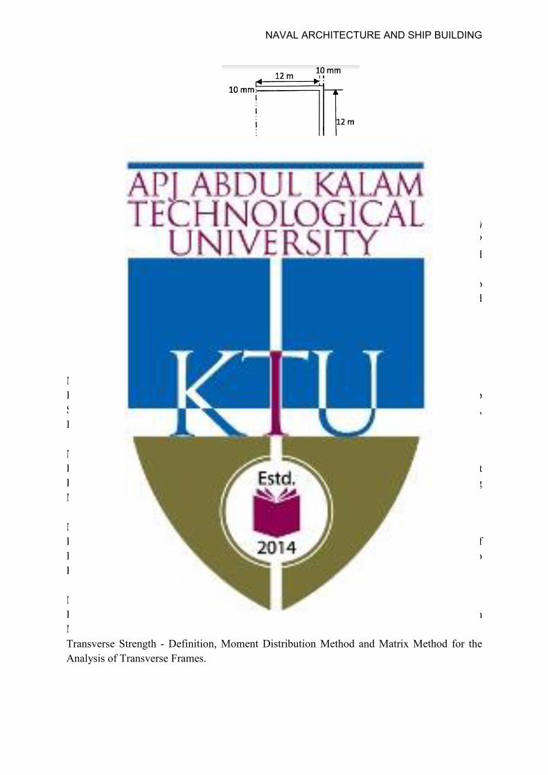
1. Calculate the bending stress at the top and bottom section of the section shown below, when subjected to bending moment of 11,500 t-m.The thickness of the side shell, inner and outer bottom is 12mm and all other plates are 10 mm
2. Calculate the section modulus and bending stress at deck and bottom for the given ships
cross section (assume 15 mm thickness for all members and bending moment is 15000 NM).
3. Calculate the shear flow and shear stress at deck side and bottom members for the given
ships cross section (assume the applied shear force is 2000 N)
Course Outcome 4 (CO4):
1. Explain the slamming phenomina and development of whipping stresses with supporting sketches.
2. Explain the condition of a ship in an oblique wave, which will produce maximum torsional moment with a sketch.
3. Explain the procedure for obtaining bending moment spectrum from wave spectrum with supporting sketches.
Course Outcome 5 (CO5):
1. What are the loads which are to be considered for design of a transverse bulkhead? Also explain the design procedure of transverse bulkheads with suitable sketches and necessary equations.
NAVAL ARCHITECTURE AND SHIP BUILDING
2. What are the advantages of corrugated bulkheads over other types bulkheads? Also explain the design procedure for corrugated bulkheads with suitable sketches and necessary equations.
3. With the help of neat sketches, explain the construction of watertight bulkheads.
Model Question paper
APJ Abdul Kalam Technological University Fifth Semester B.Tech Degree Examination
SBT305 Strength of Ships- 1
PART A Answer ALL questions. Each question carries 3 marks.
(3x10 = 30Marks) 1. What are the various dynamic forces acting on a ship structure in a sea way? 2. Explain the development of thermal loads on ships structure. 3. Define shear flow with suitable example. Why is relevant in strength of ships
calculations? 4. List down the assumptions in simple beam theory and explain their applicability on
ship girder. 5. What are the different methods for transverse strength analysis of ship structure? 6. Explain the various modes of failure of a ship structure in a sea way. 7. Sketch and mark any six transverse strength members in ships structure. 8. Define absolute stiffness and distribution factor in context of moment distribution
method. 9. Explain the functions of bulkhead in a ship structure. 10. List out the factors that affect the positioning of collision bulkhead. What is its
relevance?
PART B Answer any two complete questions from each module.
MODULE I (7x2=14 Marks)
11. Withillustrative sketches, explain the various loads acting on ship structure in sea way.
12. Differeniate between hogging and sagging condition in a ship structure. 13. Explain with necessary equations and sketches, the idealization of ships structure as
box girder. What are the advantages with this idealisation?
MODULE II (7x2 = 14 Marks)
14. Draw a typical weight curve for an ocean going vessel. Explain the method to develop a stepped weight curve.
NAVAL ARCHITECTURE AND SHIP BUILDING
15. A box shaped barge of uniform cross section is 32 m long and displaces 352 tonnes when empty, is divided by transverse bulkheads into four equal compartments. Cargo is loaded in each compartment as: Compartment 1: 176 tonnes, Compartment 2: 272 tonnes, Compartment 3: 224 tonnes and Compartment 4: 192 tonnes. Construct load, SF and BM curves for given condition.
16. With the help of neat sketch, explain the application of beam theory to longitudinal strength calculation of ships
MODULE III
(7x2=14 Marks) 17. Explain the forces on a ship structure due to slamming and development of whipping
stresses with supporting sketches. 18. Explain the condition of a ship in an oblique wave, which will produce maximum
torsional moment with a sketch. 19. Explain the procedure for obtaining bending moment spectrum from wave spectrum
with supporting sketches.
MODULE IV (7x2=14 Marks)
20. Calculate the bending stress at the top and bottom structure of the section shown below, when subjected to bending moment of 11,500 t-m.The thickness of the side shell, inner and outer bottom is 12mm and all other plates are 10 mm.
21. Calculate the section modulus and bending stress at deck and bottom for the given
ships cross section (assume 15 mm thickness for all members and bending moment is 15000 NM).
22. Calculate the shear flow and shear stress at deck side and bottom members for the
given ships cross section (assume the applied shear force is 2000 N)
NAVAL ARCHITECTURE AND SHIP BUILDING
MODULE V
(7x2=14 Marks) 23. What are the loads which are to be considered for design of a transverse bulkhead?
Also explain the design procedure of transverse bulkheads with suitable sketches and necessary equations.
24. What are the advantages of corrugated bulkheads over other types of bulkheads? Also explain the design procedure of a corrugated bulkhead with suitable sketches and necessary equations.
25. With the help of neat sketches explain the construction of watertight bulkheads.
Syllabus
Module – I (9 hours) Introduction to Strength of Ships - List of Forces Acting on a Ship, Distortion of Ship Structure, Function of Ship Structure, Design Procedure of Ship Structure, Modes of Failure, Idealization of Ship as Hull Girder. Module – II (9 hours) Loads and Moments Acting on Ship Structures in Still Water, Weight and Weight Distribution, Buoyancy and Buoyancy Distribution, Load Curve, Shear Force Curve, Bending Moment Curve, and Deflection Curve, Effect of Thermal Loads. Module – III (9 hours) Loads in a Seaway- Moments Due to Regular Waves and Oblique Waves, Representation of Irregular Seaway, Short Term and Long Term Distribution of Loads, Spectral Approach to Response of Ship Structures, Effect of Slamming and Shipping of Green Seas. Module – IV (9 hours) Longitudinal Strength - Definition, Application of Beam Theory and Hull-Girder Section Modulus, Calculation of Shear Stress Distribution in Cross Section. Transverse Strength - Definition, Moment Distribution Method and Matrix Method for the Analysis of Transverse Frames.
NAVAL ARCHITECTURE AND SHIP BUILDING
Module –V (9 hours) Design of Bulkheads- Design of Transverse Bulkheads, Design of Longitudinal Bulkheads, Design of Corrugated Bulkheads. Text Books
1. Lewis E. U.; Principles of Naval Architecture, Society of Naval Architectures and Marine Engineers, 1989.
2. Owen Hughes; Ship Structural Design, John Wiley & Sons, 1983. 3. Tupper E. C.; Introduction to Naval Architecture, ELSEVIER, 5Ed., 2013
Reference Books
1. Muckle W.; Strength of Ship’s Structures, Edward Arnold, 1967. 2. Practical Ship Design; DGM Watson; Elsevier Ocean Engineering Book Series 2002. 3. Y Bai; Marine Structural Design, Elsevier 2013. 4. Alaa Mansour, Don Liu, Principles of Naval Architecture Series: Strength of ships
and ocean structures, SNAME, New Jersey, 2008. 5. Owen. F. Hughes and Jeom Kee Paik – Ship Structural Analysis and Design,
SNAME, New York. 2008. 6. Mohammed Shama – Torsion and Shear Stresses in Ships, Springer - Verlag, 2010. 7. Mohammed Shama – Buckling of Ship Structures, Springer - Verlag, 2013. 8. Yasuhisa Okumoto – Design of Ship Hull Structures- A practical guide for Engineers,
Springer –Verlag, 2009. 9. Yasuhisa Okumoto, Yu Takeda, Masaki Mano, Tetsuo Okada; Design of Ship Hull
Structures, Springer, 2010 10. Chandrasekaran Srinivasan; Advanced Marine Structures, Springer, 2010.
Course Contents and Lecture Schedule
No Topic No. of Lectures
1 Module – I 1.1 Introduction to Strength of Ships - List of Forces Acting on a Ship,
Distortion of Ship Structure, Function of Ship Structure, Design Procedure of Ship Structure, Modes of Failure, Idealization of Ship as Hull Girder.
9
2 Module – II 2.1 Loads and Moments Acting on Ship Structures in Still Water,
Weight and Weight Distribution, Buoyancy and Buoyancy Distribution, Load Curve, Shear Force Curve, Bending Moment Curve, and Deflection Curve, Effect of Thermal Loads
9
3 Module – III 3.1 Shiploads in a Seaway - Moments due to Regular Waves and
Oblique Waves, Representation of Irregular Seaway, Short Term and Long Term Distribution of Loads, Spectral Approach to
8
NAVAL ARCHITECTURE AND SHIP BUILDING

Response of Ship Structures, Effect of Slamming and Shipping of Green water on ship structure.
4 Module – IV 4.1 Longitudinal Strength - Definition, Application of Beam Theory
and Hull-Girder Section Modulus, Calculation of Shear Stress Distribution in a Cross Section.
6
4.2 Transverse Strength - Definition, Moment Distribution Method and Matrix Method for the Analysis of Transverse Frames.
6
5 Module – V 5.1 Design of Bulkheads - Design of Transverse Bulkheads, Design of
Longitudinal Bulkheads, Design of Corrugated Bulkheads. 8
NAVAL ARCHITECTURE AND SHIP BUILDING

SBT307 ELECTRICAL TECHNOLOGY AND INSTRUMENTATION
CATEGORY L T P CREDIT PCC 3 1 0 4
Preamble: This course is added in the curriculum to provide the learners with a proper understanding of the basic working principles, construction, characteristics and applications of DC and AC machines which are commonly used in ships and shipyards. This course will act as a foundation to learn the course named ‘electrical systems in ships and shipyards’ in the higher semester.
Prerequisite: Nil
Course Outcomes: After the completion of the course the student will be able to:
CO 1
Discern the basic working principle, construction, types, performance characteristics and applications of DC generators.
CO 2
Discern the basic working principle, construction, types, performance characteristics and applications of DC motors.
CO 3
Compare the basic working principle, construction, types, performance characteristics and applications of AC and DC machines.
CO 4
Explain the basic working principle, construction, types, losses, efficiency and applications of transformers.
CO 5
Identify the basic principles of instrumentation, measurement standards and types of errors in instruments and measurements.
Mapping of course outcomes with program outcomes
PO 1
PO 2
PO 3
PO 4
PO 5
PO 6
PO 7
PO 8
PO 9
PO 10
PO 11
PO 12
CO 1
3 2 1
CO 2
3 2 1
CO 3
3 2 1
CO 4
3 2 1
CO 5
3 2 1
NAVAL ARCHITECTURE AND SHIP BUILDING
Tests 1 2
Remember 10 10 20 Understand 20 20 40 Apply 20 20 40 Analyse Evaluate Create
Mark distribution
Total Marks
CIE ESE ESE Duration
150 50 100 3 hours
Continuous Internal Evaluation Pattern:
Attendance : 10 marks Continuous Assessment Test (2 numbers) : 25 marks Assignment/Quiz/Course project : 15 marks
End Semester Examination Pattern: There will be two parts; Part A and Part B. Part A contain 10 questions with 2 questions from each module, having 3 marks for each question. Students should answer all questions. Part B contains 3 questions from each module of which student should answer any two. Each question can have maximum 3 sub-divisions and carry 7 marks.
Course Level Assessment Questions
Course Outcome 1 (CO1):
1. A shunt generator delivers 195 A at terminal p.d of 250 V. The armature resistance and shunt field resistance are 0.02 Ω and 50 Ω respectively. The generator has an efficiency of 94.2%. Find (i) total losses (ii) copper losses (iii) stray losses (iv) constant losses (v) emf generated (vi) electrical and mechanical efficiencies
2. How would you use OCC of DC generators to find the critical resistance and critical speed
3. State in your own words condition for Self Excitation of DC generators.
Assessment Pattern
Bloom’s Category Continuous Assessment End Semester Examination
NAVAL ARCHITECTURE AND SHIP BUILDING

Course Outcome 2 (CO2)
1. How would you show that starters are necessary for DC motors?
2. How would you compare DC motors on the basis of operating characteristics?
3. What would result if DC series motor is started without loading and why?
Course Outcome 3(CO3):
1. What is slip of a three phase induction motor?
2. Explain what is happening when capacitor is used in auxiliary winding of single phaseinduction motors.
3. What are the advantages of having excitation for an alternator on rotor?
Course Outcome 4 (CO4):
1. Explain what is happening in a transformer under no load with a phasor diagram.
2. How is transformers classified according to construction?
3. What approach would you use to find the core and copper losses in a transformer.
Course Outcome 5 (CO5):
1. How would you explain Standards and Calibration in instrumentation.
2.What is meant by strain gauge?
3. How would you show your understanding of electromechanical transducer.
NAVAL ARCHITECTURE AND SHIP BUILDING
Model Question paper
APJ ABDUL KALAM TECHNOLOGICAL UNIVERSITY FIFTH SEMESTER B. TECH DEGREE EXAMINATION
Course Code: SBT307 ELECTRICAL TECHNOLOGY AND INSTRUMENTATION
Max. Marks: 100 Duration: 3 Hours
PART A
Answer all questions. All questions carry 3 marks each Marks
1 What are the losses occurring in a DC machine? (3) 2 How would you classify DC generators based on excitation? (3) 3 How would you explain the operating characteristics of DC shunt motor? (3) 4 Explain what is happening when load on DC motor is increased and decreased.
(3)
5 How would you explain the working of three phase induction motor? (3) 6 What is slip? Why does it occur? (3) 7 What is the main idea of equivalent circuit of a transformer? (3) 8 Explain what is happening when transformer is loaded? (3) 9 What is meant by standards and calibration in instrumentation? (3) 10 What is a strain gauge? State any 2 uses. (3)
PART B
Module I
Answer any two questions in full. Each question carries 7 marks.
11 A shunt generator delivers 195 A at a terminal pd of 250V.The armature resistance and shunt field resistance are 0.02Ω and 50Ω respectively.The iron and friction losses are equal to 950W.Find mechanical ,electrical and commercial efficiencies.
(7)
12 With the help of neat sketch explain the construction and working principle of a DC generator?
(7)
13 How would you use the load on DC generators to plot the internal and external characteristics?
(7)
Module II
Answer any two questions in full. Each question carries 7 marks.
NAVAL ARCHITECTURE AND SHIP BUILDING

14 How would you show your understanding of electrical, mechanical and speed characteristics of DC series motors?
(7)
15 What approach would you use to relate torque and current in a DC motor? (7)
16 How would you use brake test to find the efficiency of a DC motor? Also plot the efficiency curve.
(7)
Module III
Answer any two questions in full. Each question carries 7 marks.
17 With the help of neat sketch explain the construction and working principle and types of three phase induction motors?
(7)
18 How would you start a single phase induction motor with improved power factor?
(7)
19 With the help of neat sketch explain the construction and working principle and types of an alternator.
(7)
Module IV
Answer any two questions in full. Each question carries 7 marks.
20 How would you predetermine the efficiency of a transformer? (7)
21 With the help of neat sketch explain the construction and working principle and types of a transformer.
(7)
22 Explain the various losses occurring in transformers and how would you reduce it?
(7)
Module V
Answer any two questions in full. Each question carries 7 marks.
23 Explain the types of instruments used in measurements. (7)
24 Explain the different types of errors occurring in measurements. (7)
25 With the aid of a neat sketch explain the working of LVDT. (7)
NAVAL ARCHITECTURE AND SHIP BUILDING

D.C. Generator: Working principle, construction, types, O.C.C., Condition for SelfExcitation, Field Critical Resistance, Critical Speed, Load Characteristics ofGenerators; Losses; Efficiency, Applications in ships and shipyards.
Module 2
D.C. Motors: Working principle, construction, types, Back EMF; necessity of starter, Speedof DC motors; Brake Test; Torque Equation, efficiency, Performance and operatingcharacteristics of Shunt, Series and Compound Motors; Applications in ships and shipyards.
Module 3
AC Machines: Three Phase Induction Motor: Working principle, construction, types; slip, performance characteristics and efficiency, Single Phase Induction Motor -working, Types-split phase and capacitor start, alternators-working, construction, types, Applications in ships and shipyards.
Module 4
Transformer: Construction, Working principle, Types, EMF Equation, No Load Current-phasor diagram, transformer on load, Equivalent Circuit, losses and Efficiency, O.C. and S.C test, Cooling of Transformer, Applications in ships and shipyards.
Module 5
Introduction to Instrumentation: Classification of Instruments, Standards and Calibration, Types of Errors, Strain Gauge, L.V.D.T. (Linear Variable Differential Transformer), Application of various instruments in shipbuilding.
Text Books
1. Dr. P. S. Bimbra; Electrical Machinery; Khanna Publishers .
2. J. B. Gupta; Theory and principles of Electrical Machines; S. K.Kataria and Sons Tex.
Reference Books
1. A.K.Sawhney; Electrical and Electronic Measurements and Instrumentation; DhanpatRai.2. Alexander Langsdorf A. S.; Theory of AC Machinery; Mc-Graw Hill.3. James.W.Dally, William.F. Riley, Kenneth G. McConnell; Instrumentation forEngineering Measurement.4. Say M.G.; Performance and Design of AC Machines; ELBS.5. William D. Cooper, A.D. Helfrick; Electronic Instrumentation and MeasurementTechniques; Prentice Hall.
Module 1 Syllabus NAVAL ARCHITECTURE AND SHIP BUILDING
Course Contents and Lecture Schedule
No Topic No. of Lectures 1 Module 1
D.C. Generator1.1 Working principle, construction, types 3 1.2 O.C.C., Condition for Self Excitation, Field Critical Resistance,
Critical Speed2
1.3 Load Characteristics of Generators; 2 1.4 Losses; Efficiency, Applications in ships and shipyards. 2 2 Module 2
D.C. Motors2.1 Working principle, construction, types 2 2.2 Back EMF; necessity of starter, Speed of DC motor 2 2.3 Brake Test, Torque Equation, efficiency 2 2.4 Performance and operating characteristics of Shunt, Series and
Compound Motors; Applications in ships and shipyards. 3
3 Module 3 AC Machines
3.1 Three Phase Induction Motor: Working principle, construction, types; slip
3
3.2 performance characteristics and efficiency 1 3.3 Single Phase Induction Motor -working, Types-split phase and
capacitor start 3
3.4 alternators-working, construction, types, Applications in ships and shipyards.
2
4 Module 4 Transformer
4.1 Construction, Working principle, Types 3 4.2 No Load Current-phasor diagram, on load,Equivalent Circuit 2 4.3 losses and Efficiency, O.C. and S.C test 2 4.4 Cooling of Transformer, Applications in ships and shipyards. 2 5 Module 5
Introduction to Instrumentation 5.1 Classification of Instruments 3 5.2 Standards and Calibration, Types of Errors 3 5.3 Strain Gauge, L.V.D.T. (Linear Variable Differential
Transformer), Application of various instruments in shipbuilding. 3
NAVAL ARCHITECTURE AND SHIP BUILDING
SBL331 STRENGTH OF MATERIALS LAB CATEGORY L T P CREDIT
PCC 0 0 3 2
Preamble: This lab is mainly focused to study various types of failures occurring in service life of ductile metals and to study the properties of various materials under various working conditions on day to day basis.
Prerequisite: SBT203 Mechanics of solids
Course Outcomes: After the completion of the course the student will be able to:
CO 1 Apply knowledge in the area of testing of materials and components of structural elements experimentally.
CO 2 Able to note down relevant readings and perform calculations while an experiment is in progress thereby correlating theoretical concepts of materials and their practical implications.
CO 3 Understand with the arrangement and conduct of experiments in the Material Testing laboratory environment.
CO 4 Able to comprehend the factors responsible for variation between theoretical and experimental results pertaining to the domain of Material Science.
CO 5 Undertake the testing of materials when subjected to different types of loading.
Mapping of course outcomes with program outcomes
PO 1
PO 2
PO 3
PO 4
PO 5
PO 6
PO 7
PO 8
PO 9
PO 10
PO 11
PO 12
CO 1 2 CO 2 3 3 2 2 2 CO 3 2 1 2 CO 4 2 1 2 2 CO 5 3 1 2 2 1
Assessment Pattern
Mark distribution
Total Marks
CIE ESE ESE Duration
150 75 75 2.5 hours
NAVAL ARCHITECTURE AND SHIP BUILDING
Continuous Internal Evaluation Pattern:
Attendance - 15 marks Continuous Assessment - 30 marks Internal Test (Immediately before the second series test) - 30 marks End Semester Examination Pattern: The following guidelines should be followed regarding award of marks (a) Preliminary work - 15 Marks (b) Implementing the work/Conducting the experiment - 10 Marks (c) Performance, result and inference (usage of equipment’s and troubleshooting) - 25 Marks (d) Viva voce - 20 marks (e) Record - 5 Marks General instructions: Practical examination to be conducted immediately after the second series test covering entire syllabus given below. Evaluation is a serious process that is to be conducted under the equal responsibility of both the internal and external examiners. The number of candidates evaluated per day should not exceed 20. Students shall be allowed for the University examination only on submitting the duly certified record. The external examiner shall endorse the record.
SYLLABUS
LIST OF EXPERIMENTS (Minimum 12 are mandatory)
1. Tests on Open Coiled Spring Equipment: Spring Testing Machine, Vernier Calliper. 2. Tests on Closed Coiled Spring Equipment: Spring Testing Machine, Vernier Calliper. 3. Bending Test on Wooden Beams Using U. T. M. Equipment: Universal Testing Machine, Deflection Gauges, Measuring Tape. 4. Verification of Clerk Maxwell's Law of Reciprocal Deflection and Determination of Young’s Modulus ‘E’ for Steel. Equipment: Apparatus for verification of Clerk Maxwell’s Law of Reciprocal Theorem, Deflection gauges, Weights, Scale, Vernier Calliper. 5. Torsion Pendulum Test for M.S. wires. Equipment: Torsion Pendulum, Cylindrical Weights, Stop Watch. 6. Torsion Pendulum Test for Aluminium Wires. Equipment: Torsion Pendulum, Cylindrical Weights, Stop Watch.
NAVAL ARCHITECTURE AND SHIP BUILDING
7. Torsion Pendulum Test for Brass Wires. Equipment: Torsion Pendulum, Cylindrical Weights, Stop Watch. 8. Tension Test Using U. T. M. on M. S. Rod. Equipment: Universal Testing Machine, Deflection gauges, Measuring Tape, Vernier Calliper. 9. Tension Test Using U. T. M. on High Tensile Steel rod. Equipment: Universal Testing Machine, Deflection gauges, Measuring Tape, Vernier Calliper. 11. Compression test on concrete specimen. Equipment: Compression Testing Machine. 12. Compression test on brick. Equipment: Compression Testing Machine. 13. Torsion Test on M. S. Rod. Equipment: Torsion Testing Machine, Vernier Calliper. 14. Impact Test Using Izod Apparatus and Charpy. Equipment: Charpy/ Izod Impact Testing Machine. 15. Impact Test Using Charpy Apparatus Equipment: Charpy/ Izod Impact Testing Machine.
Reference Books
1. Crandall, Dahl and Lardner, “AN introduction to the mechanics of solids “, McGraw-hill 1978.
2. S. P. Timoshenko, “History of strength of materials”, Dover publications, 1953.
NAVAL ARCHITECTURE AND SHIP BUILDING
SBL333 MARINE HYDRODYNAMICS AND HYDRAULIC MACHINERIES LAB
CATEGORY L T P CREDIT PCC 0 0 3 2
Preamble: This lab is mainly focused to study various types of marine hydrodynamics experiments which should be done during ship design stage as well as various hydraulic machineries found onboard ship.
Prerequisite: SBT205 Mechanics of Fluids
LAB Course Outcomes: After the completion of the course the student will be able to:
CO 1 Apply knowledge in the area of marine hydrodynamics and hydraulic machinery experimentally.
CO 2 Able to note down relevant readings and perform calculations while an experiment is in progress thereby correlating theoretical concepts of marine hydrodynamics and their practical implications on ship.
CO 3 Understand with the arrangement and conduct of experiments in the Marine Hydrodynamics & Hydraulic Machinery laboratory.
CO 4 Able to comprehend the factors responsible for variation between theoretical and experimental results pertaining to the domain of Marine Hydrodynamics & Hydraulic Machinery.
CO 5 Undertake the performance characteristic tests on various hydraulic machineries.
Mapping of course outcomes with program outcomes
PO 1
PO 2
PO 3
PO 4
PO 5
PO 6
PO 7
PO 8
PO 9
PO 10
PO 11
PO 12
CO 1 2 CO 2 3 3 2 2 2 CO 3 2 1 2 CO 4 2 1 2 2 CO 5 3 1 2 2 1
Assessment Pattern
Mark distribution
Total Marks
CIE ESE ESE Duration
150 75 75 2.5 hours
NAVAL ARCHITECTURE AND SHIP BUILDING

Continuous Internal Evaluation Pattern:
Attendance - 15 marks Continuous Assessment - 30 marks Internal Test (Immediately before the second series test) - 30 marks End Semester Examination Pattern: The following guidelines should be followed regarding award of marks (a) Preliminary work - 15 Marks (b) Implementing the work/Conducting the experiment - 10 Marks (c) Performance, result and inference (usage of equipment’s and troubleshooting) - 25 Marks (d) Viva voce - 20 marks (e) Record - 5 Marks General instructions: Practical examination to be conducted immediately after the second series test covering entire syllabus given below. Evaluation is a serious process that is to be conducted under the equal responsibility of both the internal and external examiners. The number of candidates evaluated per day should not exceed 20. Students shall be allowed for the University examination only on submitting the duly certified record. The external examiner shall endorse the record.
SYLLABUS
LIST OF EXPERIMENTS (Minimum 12 are mandatory)
1. Performance Characteristic Tests on Pelton Wheel (Load test & best speed). Equipment: Pelton Wheel Turbine Test Rig.
2. Performance Characteristic Tests on Francis Turbine (Load test & best gate opening). Equipment: Francis Turbine Test Rig.
3. Performance Characteristic Tests on Kaplan Turbine (Load test & best gate, vane angle opening). Equipment: Kaplan Turbine Test Rig.
4. Performance characteristic Tests on Single Stage, Multi Stage Centrifugal Pumps at Constant Speed & at Variable Speed. (Actual & predicted curves). Equipment: Centrifugal Pump Test Rig.
5. Performance Characteristic Tests on Self-priming, Jet, Airlift and Deep Well Pumps. Equipment: Self Priming Pump Test Rig.
6. Performance Characteristic Tests on Hydraulic Ram. Equipment: Hydraulic Ram Test Rig.
7. Performance Characteristic Tests on Reciprocating Pump at Constant Speed. Equipment: Reciprocating Pump Test Rig.
8. Performance Characteristic Tests on Gear Pump. Equipment: Gear Oil Pump Test Rig.
9. Performance Characteristic Tests on Screw Pump.
NAVAL ARCHITECTURE AND SHIP BUILDING

Equipment: Screw Pump Test Rig. 10. Impact of Water jet on Flat Plate.
Equipment: Impact of Jet on Vane Apparatus. 11. Impact of Water jet on Curved Plate.
Equipment: Impact of Jet on Vane Apparatus. 12. Prediction of Ship Hull Resistance.
Equipment: Ship Design Software / test facilities. 13. Prediction of Propeller Performance.
Equipment: Ship Design Software / test facilities. 14. Prediction of Ship Resistance Using Data Obtained from Model Test.
Equipment: Ship Design Software / test facilities. 15. Study of Roll Decay Tests and Calculation of Roll Period.
Equipment: Ship Design Software / test facilities. 16. Prediction of Sea Keeping Characteristics.
Equipment: Ship Design Software / test facilities. 17. Study on Open Water Tests.
Equipment: Ship Design Software / test facilities. 18. Study on Manoeuvring Performance of Ships.
Equipment: Ship Design Software / test facilities.
Reference Books
1. R. K. Bansal; Fluid Mechanics and Hydraulic Machines; Laxmi Publications.
2. Edward V. Lewis; Principles of Naval Architecture Volume II & III.
NAVAL ARCHITECTURE AND SHIP BUILDING

SEMESTER V MINOR
NAVAL ARCHITECTURE AND SHIP BUILDING
SBT381 RESISTANCE OF SHIPS CATEGORY L T P CREDIT
VAC 3 1 0 4
Preamble: The goal of this course is to expose students to the concept of Resistance of ships, Prediction of Resistance of ships, and to estimate machinery power required to attain the specified speed. Also it is intended to impart knowledge on various types of high speed crafts and to familiarize with its design methods. Prerequisite: Nil
Course Outcomes: After the completion of the course the student will be able to
CO 1 Discern various components of resistance of ships. CO 2 Understand the concepts of Viscous resistance. CO 3 Understand the concepts of wave resistance. CO 4 Estimate resistance of ships and effective power using statistical / methodical series
/model tests. CO 5 Identify the effect of shallow water on ship resistance. Also understand the relation
between ship hull and resistance. CO 6 Familiarize with various high speed crafts and identify its design speciality.
Mapping of course outcomes with program outcomes
PO 1
PO 2
PO 3
PO 4
PO 5
PO 6
PO 7
PO 8
PO 9
PO 10
PO 11
PO 12
CO 1
2 2 2
CO 2
3 2 1 1
CO 3
3 2 1 1
CO 4
3 3 2 1 1
CO 5
2 1 1 1
CO 6
2 2 1
NAVAL ARCHITECTURE AND SHIP BUILDING
Assessment Pattern
Bloom’s Category Continuous Assessment
Tests End Semester Examination 1 2
Remember 10 10 20 Understand 20 20 40 Apply 20 20 40 Analyse Evaluate Create
Mark distribution
Total Marks
CIE ESE ESE Duration
150 50 100 3 hours
Continuous Internal Evaluation Pattern:
Attendance : 10 marks Continuous Assessment Test (2 numbers) : 25 marks Assignment/Quiz/Course project : 15 marks End Semester Examination Pattern: There will be two parts; Part A and Part B. Part A contain 10 questions with 2 questions from each module, having 3 marks for each question. Students should answer all questions. Part B contains 3 questions from each module of which student should answer any two. Each question can have maximum 3 sub-divisions and carry 7 marks.
Course Level Assessment Questions
Course Outcome 1 (CO1):
1. Define resistance of a ship in a seaway. 2. List down various components of resistance while ship is in seaway. 3. Define frictional resistance and how it is determined
Course Outcome 2 (CO2)
1. Define viscous resistance and understand the history of formulation
2. Identify the various frictional lines
NAVAL ARCHITECTURE AND SHIP BUILDING
3. Understand the effect of hull roughness and application of modern paints to prevent fouling
Course Outcome 3 (CO3)
1. Define wave resistance
2. Understand the concept of wave interference and hump and hollow formation
3. Identify the use of bulbous bow
Course Outcome 4 (CO4):
1. A 6 m model of a 180 m long ship is towed in a model basin at a speed of 1.61 m/s. The towing pull is 20 N. The wetted surface area of the model is 4 m2. Estimate the corresponding speed for the ship in knots and the effective power PE, assuming resistance coefficients to be independent of scale for simplicity.
2. The full-scale ship is 140 m long and has speed of 15 knot and the model length is 4.9 m.
The resistance is measured to 19 N in the model basin. Following the ITTC’57 approach, what is the predicted full-scale resistance? The wetted surface area of the full-scale ship is 3300 m2. The density of sea water is 1025 kg/m3, and that of fresh water 1000 kg/m3, νm = 1.14 x 10⁻⁶ m2/s, for fresh water, νs = 1.19 x 10⁻⁶ m2/s for sea water. Use a correlation coefficient of cA = 0.0004.
3. A ship model (scale λ = 23) was tested in fresh water with: RTm = 104.1 N, Vm = 2.064 m/s, Sm =10.671 m2, Lm = 7.187 m, ρm = 1000 kg/m3, ρs = 1026 kg/ m3, νm = 1.14 x 10⁻⁶ m2/s, νs = 1.19 x 10⁻⁶ m2/s. What is the prediction for the total calm-water resistance in sea water of the full-scale ship following ITTC'57? Assume cA = 0.0002.
Course Outcome 5 (CO5):
1. Describe the effects of shallow water on draft, trim and resistance.
2. Sketch the wave pattern of a ship in shallow water for
a. Sub critical speeds
b. Near critical speeds
c. Super critical speeds
3. Write short notes on different types of ships bow and its effects on resistance.
Course Outcome 6 (CO6):
1. Write a note on the resistance of a planning crafts.
NAVAL ARCHITECTURE AND SHIP BUILDING
2. Write short notes on wake effects in multi-hull vessels.
3. Which component of resistance is more dominant in high speed crafts and why?
Model Question paper
Model Question paper
APJ ABDUL KALAM TECHNOLOGICAL UNIVERSITY FIFTH SEMESTER B. TECH DEGREE EXAMINATION, XXXX 20XX
Course Code: SBT381 Course Name: RESISTANCE OF SHIPS
Max. Marks: 100 Duration: 3 Hours
PART A (Answer all questions, each carries 3 Marks)
Question
Number
Mark
s
1 What is the difference between Calm water resistance, Trial resistance and Service resistance of a ship?
(3)
2 Define Froude’s number and Reynold’s number. (3) 3 A 20,000 t displacement ship has a speed of 15.5 knots. Determine corresponding
speed of a similar ship having displacement of 16,000 t. (3)
4 Write down Froude’s Frictional Formulae and explain all the terms in the equation.
(3)
5 What is the difference between still air resistance and wind resistance? How they are estimated?
(3)
6 How does a bulbous bow help to decrease wave making resistance? (3) 7 The residuary resistance of a 105 m long ship running at 16 knots in sea water is
250 kN. Calculate the corresponding speed and residuary resistance of a similar ship of 112 m length running at same Froude’s number in fresh water.
(3)
8 Explain why wind tunnel testing is not feasible for predicting the resistance of a ship unlike a submarine?
(3)
9 Explain why high speed ships have low CB values and low speed ships have high CB values?
(3)
10 Write short notes on wake effects in multi-hull vessels. (3) PART B
(Answer any two full questions from each modules, each full question carries 7 Marks) MODULE I
11 Explain the terms Geometric similarity, Kinematic similarity and Dynamic (7)
NAVAL ARCHITECTURE AND SHIP BUILDING
similarity with reference to ship model testing for determination of water resistance.
12 Prove that the residuary resistance of geometrically similar ships running at the same Froude’s number are in the ratio of their mass displacements.
(7)
13 A Define Residuary Resistance and Total Resistance of a ship. (3) 13 A What are the components of resistance experienced by a deeply submerged
submarine in ideal fluid? Justify your answer. (4)
MODULE II 14 Explain effect roughness in ship resistance. (7) 15 The frictional resistance of a ship in fresh water at 3 m/s is 11N/m2. The ship has
a wetted surface area of 2500 m2 and the frictional resistance is 72% of the total resistance and varies as (speed)1.92. If the effective power is 110 kW, calculate speed of the ship.
(7)
16 A ship has a length of 140 m and wetted surface of 3600 m2. Calculate the frictional resistance at the design speed of 15 knots. Density of water=1025 kg/m3 and coefficient of kinematic viscosity is 1.181 x 10⁻⁶.
(7)
MODULE III 17 Explain Kelvin wave pattern with help of a neat figure. (7) 18 A ship model with a scale of λ=23 was tested in fresh water with RTM = 104.1 N,
Vm = 2.064 m/s, Sm 10.671 m2, Lm = 7.18 m. What is the prediction of total calm water resistance sea water of full scale ship following ITTC’57? Both model and ship investigated at a temperature of 15°C. Assume CA = 0.0002.
(7)
19 A Write short notes on wave braking and spray resistance. (3) 19 B Explain why the plot of wave making resistance as a function of ship velocity.
Show local maxima and minima called humps and hollows. (4)
MODULE IV 20 Draw a neat sketch of a towing tank and explain the functions of various
components of the tank. (7)
21 Explain how the resistance of a ship can be estimated at the design stage using Guldhammer and Harvald charts.
(7)
22 What is turbulence stimulation in model testing? Describe any two methods used for turbulence stimulation in resistance model tests.
(7)
MODULE V 23 Write a note on the resistance of a planning crafts. (7) 24 Describe the effects of shallow water on draft, trim and resistance. (7) 25 Explain how you will get the shallow water resistance curve from the deep water
resistance curve using Schlichting’s method. (7)
NAVAL ARCHITECTURE AND SHIP BUILDING
Syllabus
Module 1
Introduction - Definition of resistance and effective power, brief history – Newton, Euler, Leonardo da Vinci, Chapman, D’Alembert, Beaufoy, Hall brothers etc. Reech and W. Froude, Components of ship resistance, Dimensional analysis, Laws of comparison - geometrical, dynamical and kinematical similarity, Newton’s, Froude’s and Reynold’s law, model ship correlation. Module 2
Viscous resistance – Froude’s plank experiments. R.E. Froude’s formula for f. Reynolds number. Boundary layer theory. Laminar and turbulent flow. Turbulence stimulation. Blasius and Prandtl-Karman lines. Other friction lines: Schoenherr, Prandtl-Schlichting, Hughes, and others. Form resistance – Hughes, Lap-Troost, Granville. ITTC line. Grigson’s formulation. Effect of roughness. Nikuradse’s pipe experiments. Roughness allowance. Bowden’s formula. Fouling. Anti-fouling paints, SPC paints, banning of TBT. Module 3 Wave Resistance: Kelvin wave pattern. Ship waves. Wave interference – humps and hollows. Theoretical methods. Comparison with experiments. Bulbous bows. Other Resistance Components: Eddy resistance and boundary layer separation. Wave breaking resistance and vortex resistance. Appendage drag. Air and wind resistance.
Module 4
Determination of resistance - Model Testing: Ship model tanks. Model size. Turbulence stimulation. Blockage. Ship model correlation., methodological series data; Statistical analysis of resistance data, Guldhammer Harvald’s method, Holtrop and Mennen method, Van Oortmerssen method, Application of CFD in ship resistance Module 5
Design Considerations - Effect of trim, Effect of Shallow Water: Schlichting’s method. Landweber’s extension, Reltion between hull form and resistance. Introduction to hydrodynamics of High Speed Craft and Advanced Marine Vehicles- Introduction, Resistance of Planing Crafts, Catamarans, SWATH, Hydrofoil Crafts.
NAVAL ARCHITECTURE AND SHIP BUILDING

Text Books
1. J.P. Ghose, R.P. Gokarn; Basic Ship Propulsion, First edition, KW Publishers Pvt Ltd, 2015.
2. Eric Tupper; Introduction to Naval Architecture, Fifth edition, Butterworth Heinemann, 2013.
Reference Books 1. 1. D.G.M. Watson; Practical Ship Design; Volume I and II, Elsevier Ocean Engineering
Book Series, 2002.
2. Lewis, E.U.; Principles of Naval Architecture, SNAME, 1988.
3. Rawson and Tupper; Basic Ship Theory, Fifth Edition, Butterworth-Heinemann, 2001.
4. Lars Larsson & Hoyte C.; The Principles of Naval Architecture Series: Ship Resistance and Flow, The Society of Naval Architects and Marine Engineers, 2010.
Course Contents and Lecture Schedule
No Topic No. of Lectures
1 Module 1 1.1 Introduction -Definition of resistance and effective power, brief history
– Newton, Euler, Leonardo da Vinci, Chapman, D’Alembert, Beaufoy, Hall brothers etc. Reech and W. Froude,
2
1.2 Components of Resistance: Simplification of difficult problem. Components assumed to be independent. Different components 2
1.3 Laws of Similarity: Use of models. Need for similarity laws. Geometrical, kinematic and kinetic similarity. Force ratios. Dimensional analysis. Practical application in ship resistance. Froude similarity and model testing.
3
2 Module 2 2.1 Viscous Resistance: Froude’s plank experiments. R.E. Froude’s formula
for f. Reynolds number. Boundary layer theory. Laminar and turbulent flow. Turbulence stimulation. Blasius and Prandtl-Karman lines. Other friction lines: Schoenherr, Prandtl-Schlichting, Hughes, and others.
3
2.2 Form resistance – Hughes, Lap-Troost, Granville. ITTC line. Grigson’s formulation. 2
2.3 Effect of roughness. Nikuradse’s pipe experiments. Roughness allowance. Bowden’s formula. Fouling. Anti-fouling paints, SPC paints, banning of TBT.
2
3 Module 3
NAVAL ARCHITECTURE AND SHIP BUILDING

3.1 Wave Resistance: Kelvin wave pattern. Ship waves. Wave interference – humps and hollows. Theoretical methods. Comparison with experiments. Bulbous bows.
3
3.2 Other Resistance Components: Eddy resistance and boundary layer separation. Wave breaking resistance and vortex resistance. Appendage drag. Air and wind resistance.
4
4 Module 4 4.1 Model Testing: Ship model tanks. Model size. Turbulence stimulation.
Blockage. Ship model correlation 3
4.2 methodological series data; Statistical analysis of resistance data, Guldhammer Harvald’s method, Holtrop and Mennen method, van Oortmerssen method
3
4.3 Application of CFD in ship resistance 2 5 Module 5 5.1 Design Considerations - Effect of trim, Effect of Shallow Water:
Schlichting’s method. Landweber’s extension, Reltion between hull form and resistance
4
5.2 Introduction to hydrodynamics of High Speed Craft and Advanced Marine Vehicles- Introduction, Resistance of Planing Crafts, Catamarans, SWATH, Hydrofoil Crafts
3
NAVAL ARCHITECTURE AND SHIP BUILDING

SEMESTER V HONOURS
NAVAL ARCHITECTURE AND SHIP BUILDING
Preamble: This course imparts advanced principles and conditions of stability of ships. It will help the students to familiarize solving of advanced Naval Architecture stability problems. Moreover, it will give them an idea about various ship motions in seaway and how to effectively control them. It will also provide them deep insight about the advanced concepts of manoeuvrability.
Prerequisite: SBT204 - STABILITY OF SHIPS AND SUBMARINES
Course Outcomes: After the completion of the course the student will be able to
CO 1 Gain knowledge about various damage stability concepts and perform damage stability calculations.
CO 2 Understand the concept of Second-Generation Stability and Direct Stability Assessment.
CO 3 Have an understanding about various stability criteria for Warships. CO 4 Explain the ship motions in seaway and perform seakeeping analysis. CO 5 Explain the advanced concepts of controllability of ships and carry out rudder
design.
Mapping of course outcomes with program outcomes
PO 1
PO 2
PO 3
PO 4
PO 5
PO 6
PO 7
PO 8
PO 9
PO 10
PO 11
PO 12
CO 1
2 2
CO 2
2 2 1
CO 3
2 2 1
CO 4
3 3 2
CO 5
3 3 3 1
Assessment Pattern
Bloom’s Category Assessment Tests End Semester Examination 1 2
Remember 10 10 20 Understand 20 20 40 Apply 20 20 40 Analyse
SBT393 ADVANCED SHIP STABILITY AND DYNAMICS CALCULATIONS
CATEGORY L T P CREDIT VAC 3 1 0 4
NAVAL ARCHITECTURE AND SHIP BUILDING
Evaluate Create
Mark distribution
Total Marks
CIE ESE ESE Duration
150 50 100 3 hours
Continuous Internal Evaluation Pattern:
Attendance : 10 marks Continuous Assessment Test (2 numbers) : 25 marks Assignment/Quiz/Course project : 15 marks End Semester Examination Pattern: There will be two parts; Part A and Part B. Part A contain 10 questions with 2 questions from each module, having 3 marks for each question. Students should answer all questions. Part B contains 3 questions from each module of which student should answer any two. Each question can have maximum 4 sub-divisions and carry 7 marks.
Course Level Assessment Questions
Course Outcome 1 (CO1):
1. Explain probabilistic concept for damage stability calculation. 2. Explain deterministic concept for damage stability calculation.
Course Outcome 2 (CO2):
1. Draw a Multi-tiered structure of the second generation intact stability criteria. 2. Define first and second level stability assessment for all failure modes
Course Outcome 3(CO3):
1. Explain the formula for calculating the Heeling lever during different operational conditions and define its stability criteria.
Course Outcome 4 (CO4):
1. Explain ship motions in regular waves. 2. Explain ship motions in irregular waves.
NAVAL ARCHITECTURE AND SHIP BUILDING

Course Outcome 5 (CO5):
1. Describe three ways in which a ship’s slow speed manoeuvrability can be improved. 2. Briefly describe the various common types of rudder. 3. A small 9.14 m pleasure craft you own is very difficult to steer. In particular the
smallest amount of wind or sea makes it almost impossible to keep on course. While the boat is out of the water for the winter, what modification could you make to the hull to improve its manoeuvring characteristics?
4. A ship with LBP = 152.4 m, B = 14 m, and T = 6 m is being designed for good manoeuvrability (i.e., short response times and minimum overshoot). Estimate a suitable rudder area for this ship. What would constrain the dimensions of this rudder from being larger?
Model Question paper
APJ ABDUL KALAM TECHNOLOGICAL UNIVERSITY FIFTH SEMESTER B. TECH DEGREE EXAMINATION, XXXX 20XX
Course Code: SBT393 Course Name: ADVANCED SHIP STABILITY AND DYNAMICS CALCULATIONS
Max. Marks: 100 Duration: 3 Hours
PART A
(Answer all questions, each carries 3 Marks) Question Number
Marks
1 Explain the difference between Deterministic and Probabilistic method for damage stability calculation?
(3)
2 How ships are declared safe according to PS regulations?
(3)
3 What are the different failure modes to be considered for IMO Second Generation Intact Stability Criteria?
(3)
4
Explain the concept of Parametric Rolling.
(3)
5 Write the formula for calculating Heeling Caused by High-Speed
Turning and explain its terms.
(3)
6 Explain the stability criteria for ships performing a Bollard Pull.
(3)
7 What are the effects of slamming in ships? (3)
NAVAL ARCHITECTURE AND SHIP BUILDING
8 How does deck wetness occur?
(3)
9
10
What are the maximum Environmental conditions prescribed by IMO for conducting manoeuvring trials? Draw a figure showing the Forces acting on a rudder section.
(3)
(3)
PART B (Answer any two full questions from each module, each full question carries 7 Marks)
MODULE I 11 Explain probabilistic concept for damage stability calculation. (7)
12 Explain deterministic concept for damage stability calculation.
(7)
13 Define the following terms: a) Required Subdivision Index b) Attained Subdivision Index c) Pi Factor d) Si Factor
(7)
MODULE II 14 Draw a Multi-tiered structure of the second generation intact stability
criteria.
(7)
15 Define the following terms and its effect on ship Stability: a) Parametric Roll b) Pure Loss of Stability c) Dead Ship Stability d) Excessive Acceleration
(7)
16 Define first and second level stability assessment for Parametric Rolling.
(7)
MODULE III
17 Explain the formula for calculating the Heeling lever during the lifting of heavy weights and define its stability criteria.
(7)
18 Explain the formula for calculating the Heeling lever during Bollard Pull condition and define its stability criteria.
(7)
19 Explain the formula for calculating the Heeling lever during crowding of passengers on one side of the ship and define its stability criteria.
(7)
NAVAL ARCHITECTURE AND SHIP BUILDING

MODULE IV
20 Draw the Block Diagram of a Ship with roll stabiliser fins. (7) 21 What are the different methods used for roll stabilisation? (7) 22 Explain the term MSI? (7)
MODULE V
23 A small 9.14m pleasure craft you own is very difficult to steer. In particular the smallest amount of wind or sea makes it almost impossible to keep on course. While the boat is out of the water for the winter, what modification could you make to the hull to improve its manoeuvring characteristics?
(7)
24
A ship with LBP = 152.4m, B = 14 m, and T = 6m is being designed for good manoeuvrability (i.e., short response times and minimum overshoot).
a) Estimate a suitable rudder area for this ship. b) What would constrain the dimensions of this rudder from being
larger?
(7)
25
Describe using a sketch the stages of a ship’s turn. Why does a ship slow down when it turns?
(7)
NAVAL ARCHITECTURE AND SHIP BUILDING

Syllabus
Module 1
Stability Assessment Methods (Deterministic and Probabilistic)
History of the Development of the Probabilistic Methodology, Permeability, Damage Stability Calculations - Damage Extent, IMO Requirements, Probabilistic Damage Stability (Probabilistic Concept, Zone Damage, ANNEX 22 of SOLAS), Regulations According to SOLAS 2009, (Subdivision Length, Calculation Method, Longitudinal Subdivision, Regulations, Required Subdivision Index R, Attained Subdivision Index A, Calculation of the pi Factor, Calculation of the si Factor, Calculation of the νi Factor)
Module 2
Second Generation Stability Methodology
The IMO Second Generation Intact Stability Criteria - Parametric Roll first and second levels, Pure Loss of Stability first and second levels, Dead Ship Stability first and second levels, Excessive Acceleration first and second levels.
Direct Stability Assessment (DSA)
General Requirements, Parametric Roll and Excessive Acceleration, Pure Loss of Stability, Surf-Riding and Broaching-to, Dead Ship Condition.
Module 3
Warship Stability
Intact Stability Criteria for Combatants and Auxiliaries: Intact Stability, Stability in Beam Winds, Stability Under Icing, Heeling Caused by High-Speed Turning, Lifting of Heavy Weights, Crowding of Passengers on One Side, Water on Deck, Stability in Harbour, Stability during Dry docking, Stability of Ships Performing a Bollard Pull.
DAMAGE STABILITY CRITERIA FOR COMBATANTS, DAMAGE STABILITY CRITERIA FOR AUXILIARIES.
Module 4
Seakeeping
Regular water waves – definition of ship motions – single degree of freedom motions in regular waves – uncoupled heave, pitch and roll motions – coupled heave and pitch motions – irregular waves - description of long crested waves by 2D spectrum – ship motions in 2D irregular waves – description of short-crested sea – ship motions in 3D irregular waves – dynamic effects – deck wetness, slamming, relative motions, sea-sickness etc. – added resistance in waves – roll stabilization.
NAVAL ARCHITECTURE AND SHIP BUILDING
Module 5
Manoeuvring
Types of directional stability - linear equations of motions in horizontal plane – hydrodynamic derivatives – stability index – standard manoeuvres – turning circle, zigzag, pullout and spiral manoeuvres – roll during turn – experimental determination of hydrodynamic derivatives – straight-line, rotating arm and PMM experiments – description of control surface (rudder) – control derivatives.
Textbooks
1. Philip A. Wilson, Basic Naval Architecture, Ship Stability.2. Principles of Naval Architecture, Vol III, edited by Edward V Lewis3. Introduction in Ship Hydrodynamics, by J M J Journee & Jacob Pinkster, Delft
University of Technology
Reference Books
1. Seakeeping: Ship Behaviour in Rough Weather, by A R J M Lloyd.2. Ministry of Defence, Defence Standard 02-900 Part 4.3. IMO SOLAS Consolidated Edition: 2020.
Course Contents and Lecture Schedule
No Topic No. of Lectures
1 MODULE 1 1.1 History of the Development of the Probabilistic Methodology,
Permeability 1
1.2 Damage Stability Calculations - Damage Extent, IMO Requirements 2 1.3 Probabilistic Damage Stability (Probabilistic Concept, Zone Damage,
ANNEX 22 of SOLAS) 2
1.4 Regulations According to SOLAS 2009 3 2 MODULE 2 2.1 The IMO Second Generation Intact Stability Criteria - Parametric Roll
first and second levels 1
2.2 Pure Loss of Stability first and second levels 1 2.3 Dead Ship Stability first and second levels 1 2.4 Excessive Acceleration first and second levels. 1
2.5 Direct Stability Assessment (DSA): General Requirements, 1
2.6 Parametric Roll and Excessive Acceleration 1 2.7 Pure Loss of Stability, Surf-Riding and Broaching-to, Dead Ship 2
NAVAL ARCHITECTURE AND SHIP BUILDING

Condition.
3 MODULE 3 3.1 INTACT STABILITY CRITERIA FOR COMBATANTS AND
AUXILIARIES: Intact Stability 1
3.2 Stability in Beam Winds, Stability Under Icing 1 3.3 Heeling Caused by High-Speed Turning, Lifting of Heavy Weights 1 3.4 Crowding of Passengers on One Side, Water on Deck 1 3.5 Stability in Harbour, Stability during Dry docking 1 3.6 Stability of Ships Performing a Bollard Pull 1 3.7 DAMAGE STABILITY CRITERIA FOR COMBATANTS 1 3.8 DAMAGE STABILITY CRITERIA FOR AUXILIARIES 1 4 MODULE 4 4.1 Regular water waves, definition of ship motions 2 4.2 single degree of freedom motions in regular waves, uncoupled heave,
pitch and roll motions 3
4.3 coupled heave and pitch motions, irregular waves 1 4.4 Description of long crested waves by 2D spectrum, ship motions in 2D
irregular waves, description of short-crested sea 3
4.5 ship motions in 3D irregular waves, dynamic effects – deck wetness, slamming, relative motions, sea-sickness etc.
2
4.6 Added resistance in waves, roll stabilization. 1
5 MODULE 5 5.1 Types of directional stability 1 5.2 Linear equations of motions in horizontal plane 3 5.3 Hydrodynamic derivatives 1 5.4 Stability index 1 5.5 Standard manoeuvres – turning circle, zigzag, pullout and spiral
manoeuvres 1
5.6 Concept of nonlinear derivatives 1 5.7 Experimental determination of hydrodynamic derivatives– straight-line,
rotating arm and PMM experiments 3
5.8 Description of control surfaces (rudder) 1 5.9 Control derivatives 1
NAVAL ARCHITECTURE AND SHIP BUILDING

SEMESTER VI
NAVAL ARCHITECTURE AND SHIP BUILDING
SBT302 SHIP DESIGN- I CATEGORY L T P CREDIT
PCC 3 1 0 4
Preamble: The objective of the course is to provide the learners an understanding of various methodologies in design of ship’s hull and general arrangement and also the various international regulations applicable to design of ships.
Prerequisite: Nil
Course Outcomes: After the completion of the course the student will be able to
CO 1 Discern various techno-economical aspects in ship design. CO 2 Explain various design methodologies which are being used in design of ships. CO 3 Explain the types of ships and specific design approaches followed in their design. CO 4 Apply the ship design methodologies to develop hull forms of typical merchant
ships. CO 5 Understand the regulations pertinent in ship design.
Mapping of course outcomes with program outcomes
PO 1
PO 2
PO 3
PO 4
PO 5
PO 6
PO 7
PO 8
PO 9
PO 10
PO 11
PO 12
CO 1
3 1 1
CO 2
3 1 1 1
CO 3
3 1 1
CO 4
2 2 2 2
CO 5
2 1 2
Assessment Pattern
Bloom’s Category Continuous Assessment Tests
End Semester Examination
1 2 Remember 10 10 10 Understand 20 20 30 Apply 20 20 60 Analyse Evaluate Create
NAVAL ARCHITECTURE AND SHIP BUILDING
Mark distribution
Total Marks
CIE ESE ESE Duration
150 50 100 3 hours
Continuous Internal Evaluation Pattern:
Attendance : 10 marks Continuous Assessment Test (2 numbers) : 25 marks Assignment/Quiz/Course project : 15 marks End Semester Examination Pattern: There will be two parts; Part A and Part B. Part A contain 10 questions with 2 questions from each module, having 3 marks for each question. Students should answer all questions. Part B contains 3 questions from each module of which student should answer any two. Each question can have maximum 3 sub-divisions and carry 7 marks. Course Level Assessment Questions
Course Outcome 1 (CO1):
1. List and explain the role of marine industries in sustainable development of Global Maritime Sector.
2. Explain various cost elements involved in ship design. 3. Define RFR and explain its appliation in ship design.
Course Outcome 2 (CO2):
1. Differentiate between preliminary ship design and detailed ship design with the help of a design spiral. What are the various activities involved in the stages?
2. Explain the importance of parent ship data in ship design process. 3. What do you mean by concept design in Naval Architecture? Explain with a suitable
example.
Course Outcome 3 (CO3):
1. Explain what you mean by CD in ship design. Give approximate ranges of CD values for a) General Cargo Ship b) Panamax Bulk Carrier C) Ocean going Tanker
2. Explain the owner’s requirement for a typical Warships and a Merchant ship. What is the importance of owner’s requirement in ship design?
3. Explain the process of main dimension fixing of a merchant ship with aid of any one example.
NAVAL ARCHITECTURE AND SHIP BUILDING

Course Outcome 4 (CO4):
1. What do you mean by mission analysis?
2. Differentiate between the dead weight and volume carriers. Compare the design steps involved in both cases.
3. Fix main dimension of 70000dwt bulk carrier with 16.5 trial speed, given the following approximate relationships
Course Outcome 5 (CO5):
1. Explain ILLC. Why is the minimum freeboard requirement for Type A and Type B ships?
2. Explain the intact and damage stability criteria for design of a merchant ship.
3. Differentiate between GRT and NRT.
NAVAL ARCHITECTURE AND SHIP BUILDING

Model Question paper
APJ Abdul Kalam Technological University Sixth Semester B.Tech Degree Examination
SBT302 Ship Design 1
PART A Answer ALL questions. Each question carries 3 marks.
(3x10 = 30Marks) 1. Explain the term containerisation in shipping. What are the various costs involved in
ship design? 2. What is the relevance of Owner’s requirements in ship design? Write down a typical
owners requirements for a Container ship. 3. Explain the difference in owner’s requirements for Warships and Merchant ships. 4. List down the various components in lightship weight and dead weight of a ship. 5. Explain the activities involved in the concept design stage of a ship. 6. Draw a neat sketch of a design spiral and mark the various ship design activities. 7. Explain the importance of bulbous bow in the ship design. 8. Explain the line distortion method for generation of a ship’s hull. 9. Explain the influence of Breadth on the stability of a ship. 10. What are the major seaworthiness factors to be considered in ship design?
PART B
Answer any two complete questions from each module. MODULE I
(7x2=14 Marks) 11. List and explain the role of marine industry in sustainable development of Global
Maritime Sector. 12. Define RFR and explain its application in ship design. 13. Explain the various cost elements to be considered involved in a ship design.
MODULE II
(7x2 = 14 Marks) 14. What you mean by CD in ship design? Give approximate ranges of CD values for a)
General Cargo Ship b) Panamax Bulk Carrier C) Ocean going Tanker. 15. Explain the process of fixing main dimensions of a merchant ship with one example. 16. What are the weight components under Lightship and Dead weight of a ship? How do
you estimate them during a preliminary design exercise?
MODULE III (7x2=14 Marks)
17. Fix main dimension of 70000dwt bulk carrier with 16.5 trial speed, given the following approximate relationship
NAVAL ARCHITECTURE AND SHIP BUILDING

18. Differentiate between dead weight and volume carriers. What are the differences in the design of these vessels?
19. Explain the importance of parent ship data collection in main dimension fixing. How do you proceed with a new design when parent vessel data are not available?
MODULE IV
(7x2=14 Marks) 20. List down various series data used for hull form development? Explain any one of
them with illustrative diagrams. 21. Sketch and explain various stern profiles used in ships. What are their relative merits
and demerits? 22. With help of neat sketches explain different types of bulbous bow fitted in ocean
going ships.
MODULE V (7x2=14 Marks)
23. Explain the importance of L, B and T in the sea keeping performance of a ship. 24. Explain the intact and damaged stability criteria applicable in the design of a
merchant ship? 25. “Volume carriers have more freeboard compared to dead weight carriers having same
displacement”. Validate this statement with explanations.
NAVAL ARCHITECTURE AND SHIP BUILDING
Syllabus
Module – I (8 hours) Introduction – General aspects of Marine Activities, Transportation of cargoes, Marine services & Operations, Marine Industries. Economics in Ship Design – Economic criteria, Initial cost, Operating cost, RFR, Owners requirements. Module – II (9 hours) Methods of ship design – Design using basic type ships, Design using coefficients, Design using iteration methods, Design spiral, Design categories (dead-weight carrier, capacity carrier, linear dimension ship). Ship parameters – displacement, displacement coefficient, displacement equation, volume equation, solution of the cubic equation. Module – III (11 hours) Ship dimensions - length, breadth, depth, draught, form coefficients, Shape of the hull Mass estimation - lightship mass – steel mass, outfit mass, engine plant mass, dead weight. General Arrangement - Subdivision of Ship’s Hull, Arrangement of Spaces, Arrangement of Tanks, Superstructure and Deckhouses, Arrangement of Engine Plants, Cargo Handling Capacity, Hold capacity and stowage factor. Module – IV (9 hours) Design of hull form – conventional method of lines, distortion of existing forms, stem and stern contours, Bulbous Bow. Module –V (8 hours) Effect of form on Ship’s performance, Freeboard and load line regulation Stability - Stability booklet, IMO Regulations, Checks on stability and trim, watertight integrity, damage stability criteria. Tonnage measurement – International, Suez Canal, Panama Canal regulations. Effect of design on behaviour of ships in sea and Powering. Text Books
1. D.G.M. Watson; Practical Ship Design; Elsevier Ocean Engineering Book Series 2002.
2. Robert Taggart; Ship Design & Construction; SNAME,1980
Reference Books
1. Lewis, E.U; ‘Principles of Naval Architecture’ (2ndRev.) Vol. III, 1989, SNAME New York
2. Schneekluth, H; Ship Design for Efficiency and Economy, Butterworths, 1987 3. Taggart; Ship Design and Construction, SNAME, 1980.
NAVAL ARCHITECTURE AND SHIP BUILDING
4. Thomas Lamb, Ship Design and construction, SNAME, 2003. 5. Apostolos Papanikolaou, Ship Design: Methodologies of Preliminary Design,
SNAME, 2014. 6. Antony F Molland, A Guide to ship design, construction and operation, SNAME,
2008 7. Misra S.C.; Design Principles of Ships and Marine Structures, CRC Press, 2016 8. DGM Watson, Practical Ship Design, Elsevier Ocean Engineering Book Series 2002 9. Myung-II Roh, Kyu-Yeul Lee; Computational Ship Design, Springer, 2018.
Course Contents and Lecture Schedule
No Topic No. of Lectures 1 Module – I 1.1 Introduction – General aspects of Marine Activities,
Transportation of cargoes, Marine services & Operations, Marine Industries
4
1.2 Economics in Ship Design – Economic criteria, Initial cost, Operating cost, RFR, Owners requirements
4
2 Module – II 2.1 Methods of ship design – design using basic type ships, Design
using coefficients, Design using iteration methods, Design spiral, Design categories (dead-weight carrier, capacity carrier, and linear dimension ship).
5
2.2 Ship parameters – displacement, displacement coefficient, displacement equation, volume equation, solution of the cubic equation
4
3 Module – III 3.1 Ship dimensions – length, breadth, depth, draught, form
coefficients, Shape of the hull 4
3.2 Mass estimation - lightship mass – steel mass, outfit mass, engine plant mass, dead weight.
2
3.3 General Arrangement: Subdivision of Ship’s Hull, Arrangement of Spaces, Arrangement of Tanks, Superstructure and Deckhouses, Arrangement of Engine Plants, Cargo Handling Capacity, Hold capacity and stowage factor
5
4 Module – IV 4.1 Design of hull form – conventional method of lines, distortion of
existing forms, stem and stern contours, Bulbous Bow. 9
5 Module – V 5.1 Effect of form on Ship’s performance, Freeboard and load line
regulations, Stability – stability booklet, IMO Regulations, Checks on stability, trim, Watertight integrity, damage stability criteria.
4
5.2 Tonnage measurement – international, Suez Canal, Panama Canal regulations. Effect of design on behaviour of ships in sea and Powering
4
NAVAL ARCHITECTURE AND SHIP BUILDING

SBT304 STRENGTH OF SHIPS - II CATEGORY L T P CREDIT PCC 3 1 0 4
Preamble: The syllabus is designed to pass on knowledge about the various aspects of many important properties such as strength, torsion, vibration etc in ships. Discussions about this begins with the 3-D modelling of ship structures which further elevates to other topics such as analysis of plates and shells, superstructures, bulkheads, plastic theory and gets a closure with vibration analysis and different methods to control vibration in ships.
Prerequisite: NIL
Course Outcomes: After the completion of the course the student will be able to
CO 1 Understand the different types of plates and the various theories associated with it. CO 2 Carry out bulkhead analysis and understand how buckling occurs in shells. CO 3 Find shear centre and shear flow for beams with different cross-sections. CO 4 Perceive the different types of limit state analysis CO 5 Differentiate between launching, docking, grounding and collision. CO 6 Explain damped and undamped vibrations.
Mapping of course outcomes with program outcomes
PO 1
PO 2
PO 3
PO 4
PO 5
PO 6
PO 7
PO 8
PO 9
PO 10
PO 11
PO 12
CO 1
3 1 1
CO 2
3 1 2
CO 3
3 2
CO 4
3 2
CO 5
3 2 2
CO 6
3 2 1
Assessment Pattern
Bloom’s Category Continuous Assessment Tests
End Semester Examination
1 2 Remember 10 10 20 Understand 20 20 40 Apply 20 20 40 Analyse
NAVAL ARCHITECTURE AND SHIP BUILDING
Evaluate Create
Mark distribution
Total Marks
CIE ESE ESE Duration
150 50 100 3 hours
Continuous Internal Evaluation Pattern:
Attendance : 10 marks Continuous Assessment Test (2 numbers) : 25 marks Assignment/Quiz/Course project : 15 marks End Semester Examination Pattern: There will be two parts; Part A and Part B. Part A contain 10 questions with 2 questions from each module, having 3 marks for each question. Students should answer all questions. Part B contains 3 questions from each module of which student should answer any two. Each question can have maximum 4 sub-divisions and carry 7 marks.
Course Level Assessment Questions
Course Outcome 1 (CO1):
1. Derive the equation of deflection, for a plate subjected to large deflection
2. State Kirchoff’s assumptions in plate theory.
3. Assume that a plate is stiffened only in y-direction. Derive its equation for deflection.
Course Outcome 2 (CO2)
1. What are the uses of a bulkhead?
2. Explain Membrane Theory of shells.
3. Explain buckling of stiffened cylindrical shell.
Course Outcome 3 (CO3):
1. Locate the shear centre for the above C-Section whose, IZ =52.7 X 104 mm4. All dimensions are in mm.
NAVAL ARCHITECTURE AND SHIP BUILDING

2. If a load passes through shear centre of a cross-section, the cross-section will rotate. True or False? Justify your answer.
3. Explain torsion of thin-walled multiple sections.
Course Outcome 4 (CO4): 1. What is accidental limit state?
2. Explain serviceability limit state
3. Enumerate on fatigue limit state.
Course Outcome 5 (CO5):
1. Explain the following:
(a) End Launch
(b) Airbag Launch
(c) Float-out Launch
2. How important is docking of a ship? Explain.
3. What is grounding and collision of ships?
Course Outcome 6 (CO6):
1. Describe the given system, in terms of vibration.
2. What is damping of a system?
3. What is the difference between a free and forced vibration?
NAVAL ARCHITECTURE AND SHIP BUILDING
Model Question paper
APJ ABDUL KALAM TECHNOLOGICAL UNIVERSITY SIXTH SEMESTER B. TECH DEGREE EXAMINATION, XXXX 20XX
Course Code: SBT304
Course Name: STRENGTH OF SHIPS-II
Max. Marks: 100 Duration: 3 Hours
PART A
(Answer all questions, each carries 3 Marks) Question Number
Marks
1 2 3 4 5 6 7 8 9 10
What are the different classifications of plate? What are the different types of buckling in a stiffened panel? State Kirchoff’s assumptions for the linear analysis of thin shells. List out the advantages of a shell structure that owe to its wide applications. Explain the Shear Centre concept. What is Shear Flow? Explain grounding of ships. Give the expression for ultimate load (Pult) of a simply supported beam with a concentrated load ‘P’ at the centre. How are vibrations classified? What holds responsible for both ‘internal’ and ‘external’ excitations in a ship?
(3) (3) (3) (3)
(3) (3) (3)
(3) (3)
(3)
PART B
(Answer any two full questions from each module, each full question carries 7 Marks) MODULE I
11 State the equilibrium method used in the analysis of buckling of thin plates.
(7)
12 Derive the deflection equation of a singly stiffened panel subjected to elastic buckling.
(7)
13 Derive the field equation for plate bending of a laterally loaded plate subjected to small deflection.
(7)
MODULE II 14 Define the following concept with respect to buckling of shells:
(a) Snap-through buckling (b) Upper critical load
(2) (2)
NAVAL ARCHITECTURE AND SHIP BUILDING
(c) Lower critical load (d) Critical load of a real shell
(2) (1)
15
16
With the help of a neat diagram, explain the analysis carried out on a bulkhead. Derive the general equation for vertical deflection in a cylindrical shell, using bending theory.
(7)
(7)
MODULE III 17 Elaborate on torsional loading of ships. (7) 18 Derive the Bredt-Batho formula for a thin-walled tube. (7) 19 For both symmetrical and asymmetrical section, explain, ‘Free warping
in open sections’.
(7)
MODULE IV 20 Explain the role of superstructure in influencing the longitudinal
strength of a ship. (7)
21 Explain docking and the 3 distinct phases involved. (7) 22 Explain damages and collapse of ship structures with the help of two
examples.
(7)
MODULE V 23 How can and what are the preventive measures adopted to control ship
vibrations? (7)
24 State and explain the different sources of vibration. (7) 25 Explain undamped forced vibration for a single degree of system. (7)
NAVAL ARCHITECTURE AND SHIP BUILDING
Syllabus
Module 1- ANALYSIS OF PLATES
3-D Modelling of ship structures, Different types of plates, Kirchoff’s theory, Small deflection analysis of thin plates- Transverse and combined loads; Rectangular simply supported plates with lateral loading, Navier solution for simply supported rectangular plates, Large deflection analysis Buckling of thin plates- Equilibrium Method, Analysis of stiffened plates, Buckling of Stiffened Plates.
Module 2 - ANALYSIS OF SUBMARINE STRUCTURES
Introduction to General Shell Theory, Membrane theory of cylindrical shells, Bending theory equations of cylindrical shells, Analysis of stiffened cylindrical shells, Buckling of shells- Equilibrium Method, Buckling of stiffened cylindrical shell, Analysis of Bulkhead- Beam analysis.
Module 3 - TORSION OF SHIP’S HULL
Shear Centre- Definition, Determination and properties; Torsion of thin-walled tube- Shear flow calculation, Torsion of thin-walled multiple sections, Torsion of prismatic thin-walled beams- St. Venant’s Torsional constant, Shear stress distribution in open and closed sections, Warping-Free Warping-Restrained Warping in open and closed sections, Torsional Loading on ships.
Module 4 - ULTIMATE AND LONGITUDINAL STRENGTH ANALYSIS
Limit states- Ultimate, Serviceability, Fatigue, Accidental limit states; Applications of Plastic Theory of Ships Structures, Basics of plastic theory and definitions, Safety factors, Damage and collapse of ship structures, Ultimate strength of Hull girder, Application of FEM for Ultimate Strength Analysis.
Launching, Docking, Grounding and collision; Influence of Super Structure on Longitudinal Strength.
Module 5 - VIBRATION ANALYSIS
Classification of Vibration, Introduction to Hull Structure Vibration, Modes of Hull Structure Vibration, Sources of Vibration, Measures for Control of Vibration, Vibration Analysis of Beams, Boundary Conditions in Hull Structure Vibration.
Text Books
1. Owen Hughes, Jeom Kee Paik, “Ship Structural Analysis and Design”, The Society of Naval Architects and Marine Engineers, 2010.
2.Stephen.P. Timoshenko, S. Woinowsky-Kreiger, “Theory of Plates and Shells”, Tata McGraw Hill Education Private Limited, Second Edition, 2010.
NAVAL ARCHITECTURE AND SHIP BUILDING
3. Mohamed Shama, “Torsion and Shear Stresses in Ships”, Springer, 2010.
Reference Books
1. Tupper E.C., “Introduction to Naval Architecture”, Elsevier Butterworth Heinemann, 4th edition, 2004.
2.Muckle.W., Strength of Ships’ Structures, Edward Arnold, 1967.
3. Yong Bai, Wei-Liang Jin, “Marine Structural Design”, Elsevier, 2nd edition, 2015.
4. Yasuhisa Okumoto et al, “Design of Ship Hull Structures- A Practical Guide for Engineers, Springer, 1st edition, 2009.
Course Contents and Lecture Schedule
No Topic No. of Lectures
1 ANALYSIS OF PLATES 1.1 3-D Modelling of ship structures 1 1.2 Different types of plates, Kirchoff’s theory 1 1.3 Small deflection analysis of thin plates- Transverse and
combined loads 2
1.4 Rectangular simply supported plates with lateral loading 1 1.5 Navier solution for simply supported rectangular plates 1 1.6 Large deflection analysis Buckling of thin plates- Equilibrium
Method 1
1.7 Analysis of stiffened plates, Buckling of Stiffened Plates 2 2 ANALYSIS OF SUBMARINE STRUCTURES 2.1 Introduction to General Shell Theory 2 2.2 Membrane theory of cylindrical shells 1 2.3 Bending theory equations of cylindrical shells 2 2.4 Analysis of stiffened cylindrical shells 1 2.5 Buckling of shells- Equilibrium Method 1 2.6 Buckling of stiffened cylindrical shell 1 2.7 Analysis of Bulkhead- Beam analysis 1 3 TORSION OF SHIP’S HULL 3.1 Shear Centre- Definition, Determination and properties 1 3.2 Torsion of thin-walled tube- Shear flow calculation 2 3.3 Torsion of thin-walled multiple sections 1 3.4 Torsion of prismatic thin-walled beams- St. Venant’s Torsional
constant 1
3.5 Shear stress distribution in open and closed sections 1 3.6 Warping-Free Warping-Restrained Warping in open and closed
sections 2
3.7 Torsional Loading on ships 1 4 ULTIMATE AND LONGITUDINAL STRENGTH ANALYSIS
NAVAL ARCHITECTURE AND SHIP BUILDING
4.1 Limit states- Ultimate, Serviceability, Fatigue, Accidental limit states
1
4.2 Applications of Plastic Theory of ships structures 1 4.3 Basics of plastic theory and definitions, Safety factors 1 4.4 Damage and collapse of ship structures 1 4.5 Ultimate strength of Hull girder 1 4.6 Application of FEM for Ultimate Strength Analysis 2 4.7 Launching, Docking, Grounding and collision 1 4.8 Influence of Super Structure on Longitudinal Strength 1 5 VIBRATION ANALYSIS 5.1 Classification of Vibration 1 5.2 Introduction to Hull Structure Vibration 1 5.3 Modes of Hull Structure Vibration 2 5.4 Sources of Vibration 1 5.5 Measures for Control of Vibration 2 5.6 Vibration Analysis of Beams 1 5.7 Boundary Conditions in Hull Structure Vibration 1
NAVAL ARCHITECTURE AND SHIP BUILDING
Preamble: This course imparts basic knowledge on Marine Engineering. It will help the students to familiarize with various Marine Machineries and systems used onboard ships and it will also help them to get a basic knowledge on the layout of an Engine Room. The course content has been developed to meet the requirement of Naval Architecture and Shipbuilding Engineering branch students.
Prerequisite: NIL
Course Outcomes: After the completion of the course the student will be able to
CO 1 Understand the relation between Marine Engineering and Naval Architecture. CO 2 Demonstrate knowledge of variousmarine machineries and systems onboard ships. CO 3 Understand importance of various marine machineries onboard ships. CO 4 Understand the working of various deck machineries and steering systems. CO 5 Make efficient Engine Room Arrangement while considering the IMO/MARPOL
regulations.
Mapping of course outcomes with program outcomes
PO 1
PO 2
PO 3
PO 4
PO 5
PO 6
PO 7
PO 8
PO 9
PO 10
PO 11
PO 12
CO 1
1 2
CO 2
2 2
CO 3
2 2
CO 4
3 3
CO 5
3 3 2
Assessment Pattern
Bloom’s Category Continuous Assessment Tests
End Semester Examination
1 2 Remember 10 10 20 Understand 20 20 40 Apply 20 20 40
SBT306 MARINE ENGINEERING CATEGORY L T P CREDIT
PCC 3 1 0 4
NAVAL ARCHITECTURE AND SHIP BUILDING

Analyse Evaluate Create
Mark distribution
Total Marks
CIE ESE ESE Duration
150 50 100 3 hours
Continuous Internal Evaluation Pattern:
Attendance : 10 marks Continuous Assessment Test (2 numbers) : 25 marks Assignment/Quiz/Course project : 15 marks End Semester Examination Pattern: There will be two parts; Part A and Part B. Part A contain 10 questions with 2 questions from each module, having 3 marks for each question. Students should answer all questions. Part B contains 3 questions from each module of which student should answer any two. Each question can have maximum 4 sub-divisions and carry 7 marks.
Course Level Assessment Questions
Course Outcome 1 (CO1):
1. What are the responsibilities of a Marine Engineer? 2. What are the ‘joint’ responsibilities of a Marine Engineer and a Naval Architect?
Explain. 3. Explain the role of a Naval architect in the Maritime Industry.
Course Outcome 2 (CO2)
1. What is the purpose of a Bilge system in a ship? 2. Explain the working of a Biological Sewage Treatment Plant in a Ship. Draw suitable
sketches. 3. Explain with the aid of a diagram, the working of a fresh water-cooling system of a
marine propulsion engine.
Course Outcome 3(CO3):
1. What are the machineries used onboard for handling dry break bulk cargoes? 2. Explain Turbochargers in Marine-Diesel Engines with the aid of a neat sketch.
NAVAL ARCHITECTURE AND SHIP BUILDING
3. Explain with a neat sketch an anchor handling windlass.
Course Outcome 4 (CO4):
1. Which type of pump is required in the hydraulic system of a steering gear? Why? Explain the operating principle of a radial cylinder pump with relevant figures.
2. How do we arrive at the required size for a ship’s equipment such as anchors, anchor chains and mooring ropes? Explain.
Course Outcome 5 (CO5):
1. A fast passenger ship has the requirement of 20,000 kW of power to achieve a speed of 20 knots. You have the choice of either a twin-screw propulsion or a single screw propulsion. Suggest a suitable propulsion machinery system and justify your choice, comparing it with alternate systems with regard to technical aspects. Provide suitable sketches of engine room to supplement your answer.
2. Draw the engine room layout showing various floors of a general cargo vessel, fitted with a medium speed diesel engine as the prime mover.
Model Question paper
APJ ABDUL KALAM TECHNOLOGICAL UNIVERSITY SIXTH SEMESTER B. TECH DEGREE EXAMINATION, XXXX 20XX
Course Code: SBT306 Course Name: MARINE ENGINEERING
Max. Marks: 100 Duration: 3 Hours
PART A
(Answer all questions, each carries 3 Marks) Question Number
Marks
1 Enumerate any three roles each, played by a Marine Engineer and Naval Architect in the Maritime Industry.
(3)
2 What are the job responsibilities of a Marine Engineer? Describe any three.
(3)
3 Explain Turbochargers in Marine-Diesel Engines with the aid of a neat sketch.
(3)
4 Explain the process of Supercharging and why it is important to Ship-
NAVAL ARCHITECTURE AND SHIP BUILDING
engines?
(3)
5 What is the purpose of a Bilge system in a ship?
(3)
6 Classify different types of pumps used in ships.
(3)
7 Write a short note on steering gear testing.
(3)
8 Explain with a neat sketch an anchor handling windlass.
(3)
9
10
Describe the various types of ship stabilizing systems. Draw power transmission system of a tanker ship.
(3)
(3)
PART B (Answer any two full questions from each module, each full question carries 7 Marks)
MODULE I 11 Explain the role of a Naval architect in the Maritime Industry. (7)
12 What are the ‘joint’ responsibilities of a Marine Engineer and a Naval
Architect? Explain.
(7)
13 Draw a neat sketch showing the general arrangement of a Bulk Carrier.
(7)
MODULE II 14 Explain the working of a Biological Sewage Treatment Plant in a Ship.
Draw suitable sketches.
(7)
15 Draw a medium speed four stroke diesel engine and label its components.
(7)
16 Explain with the aid of a diagram the working of a Vacuum Distillation Plant on a Ship. What is the use of a Salinometer?
(7)
MODULE III 17 Draw ballast system for a bulk carrier and explain how ballasting and
de-ballasting is carried out.
(7)
18 Explain with the aid of a diagram, the working of a fresh water-cooling system of a marine propulsion engine.
(7)
NAVAL ARCHITECTURE AND SHIP BUILDING

19 What are the lubricating systems employed in two-stroke marine-diesel engines? Draw the schematic of the lubricating oil system.
(7)
MODULE IV 20 Explain the procedure of lowering of lifeboats using lifeboat davits. (7) 21 With a neat sketch explain the two-ram steering gear arrangement. (7) 22 Explain bulk cargo handling equipment using sketches. (7)
MODULE V
23 Draw the engine room layout showing various floors of a general cargo vessel, fitted with a medium speed diesel engine as the prime mover.
(7)
24 Explain the fitting and the demounting of a keyed propeller with suitable sketches.
(7)
25 Describe various ship stabilizing systems. Explain with suitable Sketches.
(7)
NAVAL ARCHITECTURE AND SHIP BUILDING
Syllabus Module 1
Role of Marine Engineers; Need of Knowledge on Marine Engineering for a Naval Architect; Relation between Marine Engineering & Naval Architecture; General Arrangement of Machineries Onboard Various Ship Types.
Module 2
Types and Functions of Main Propulsion System: Main Engine- Diesel Engine, Steam Turbine, Electric Propulsion; Diesel Engine Components; Scavenging; Supercharging; Starting & Reversing; Hazards and Maintenance of Diesel Engine. Auxiliary Machinery: List & Functions; Auxiliary Engines; Air Compressor; Pumps; Boilers; Purifiers; Valves; Heat Exchangers; Oily Water Separators; Incinerators; Sewage Treatment Plant; Fresh Water Generator.
Module 3
Pumps & Piping System: Types of Pumps for Various Requirements, their Characteristics and Application in Ships; Centrifugal Pumps; Gear Pumps; Screw Pumps and Reciprocating Pumps; Care and Maintenance of Pumps; Piping Arrangement for Steam; Bilge; Ballast and Oil Fuel Systems; Lube Oil and Cooling System with Various Fittings; Domestic Fresh Water and Sea Water Hydrophore System.
Module 4
Deck Machineries: Deck Cranes; Windlasses; Mooring Winches; Anchors and Anchor Chains; Lifeboats Lowering Mechanism; Cargo Handling Equipment. Steering Gear: Operation and Constructional Details of Various Types of Steering Machinery.
Module 5
Shafting and Propellers: Stern Tubes and Glands, Oil Lubricated Stern Tubes; Shaft Seals; Shaft Alignment; Thrust Block; Reduction Gearing; Propeller Types and Construction Details; Maintenance and Operation of Marine Propellers; Ship Stabilizers. Engine Room Layout: Layout of Main and Auxiliary Machinery in Engine Rooms of Different Ships, IMO/MARPOL regulations. Textbooks 1. Harrington; R.L. Marine Engineering; SNAME; New York. 2. Taylor D.A.; Introduction to Marine Engineering; Butterworths; London.
NAVAL ARCHITECTURE AND SHIP BUILDING

Reference Books 1.D.K.Sanyal; Principles & Practices of Marine Diesel Engines, A Bhantarkar Pub., 1981.2.H.D. Mc George; Marine Auxiliary Machinery, Elsevier, 1999.3.Reed’s General Engineering Knowledge for Marine Engineers, Adlard Coles Nautical,1986.
Course Contents and Lecture Schedule
No Topic No. of Lectures
1 MODULE 1 1.1 Role of Marine Engineers. 1 1.2 Need of Knowledge on Marine Engineering for a Naval Architect. 1 1.3 Relation between Marine Engineering & Naval Architecture. 2 1.4 General Arrangement of Machineries Onboard Various Ship Types. 3 2 MODULE 2 2.1 Main Engine- Diesel Engine, Steam Turbine 1 2.2 Electric Propulsion; Diesel Engine Components 1 2.3 Scavenging; Supercharging; Starting & Reversing 1 2.4 Hazards and Maintenance of Diesel Engine. 1 2.5 Auxiliary Machinery: List & Functions 1 2.6 Auxiliary Engines; Air Compressor; Pumps 2 2.7 Boilers; Purifiers; Valves; Heat Exchangers; 2 2.8 Oily Water Separators; Incinerator. 1 2.9 Sewage Treatment Plant; Fresh Water Generator. 1 3 MODULE 3 3.1 Types of Pumps for Various Requirements, their Characteristics and
Application in Ships 2
3.2 Centrifugal Pumps; Gear Pumps; 1 3.3 Screw Pumps and Reciprocating Pumps; 1 3.4 Care and Maintenance of Pumps; Piping Arrangement for Steam; 2 3.5 Bilge; Ballast and Oil Fuel Systems; 2 3.6 Lube Oil and Cooling System with Various Fittings; 1 3.7 Domestic Fresh Water and Sea Water Hydrophore System. 1 4 MODULE 4 4.1 Deck Cranes; Windlasses; 1 4.2 Mooring Winches; Anchors and Anchor Chains; 2 4.3 Lifeboats Lowering Mechanism; Cargo Handling Equipment 2 4.4 Operation and Constructional Details of Various Types of Steering
Machinery 1
5 MODULE 5 5.1 Stern Tubes and Glands, Oil Lubricated Stern Tubes; 1 5.2 Shaft Seals; Shaft Alignment; 1
NAVAL ARCHITECTURE AND SHIP BUILDING

5.3 Thrust Block; Reduction Gearing; 1 5.4 Propeller Types and Construction Details; 1 5.5 Maintenance and Operation of Marine Propellers; Ship Stabilizers. 1 5.6 IMO/MARPOL regulations. 2 5.7 Engine Room Layout: Layout of Main and Auxiliary Machinery in
Engine Rooms of Different Ships. 2
NAVAL ARCHITECTURE AND SHIP BUILDING
SBT308 COMPREHENSIVE COURSE WORK
Category L T P Credit Year of Introduction
PCC 1 0 0 1 2019
Preamble: The course is designed to ensure that the student have firmly grasped the foundational knowledge in Naval Architecture and Shipbuilding engineering familiar enough with the technological concepts. It provides an opportunity for the students to demonstrate their knowledge in various Naval Architecture and Shipbuilding engineering related subjects.
Pre-requisite: Nil
Course outcomes: After the course, the student will able to:
CO1 Learn to prepare for a competitive examination
CO2 Comprehend the questions in Naval Architecture field and answer them with confidence.
CO3 Communicate effectively with faculty in scholarly environments.
CO4 Analyze the comprehensive knowledge gained in basic courses in the field of Naval Architecture and Shipbuilding Engineering.
Mapping of course outcomes with program outcomes.
PO 1
PO 2
PO 3
PO 4
PO 5
PO 6
PO 7
PO 8
PO 9
PO 10
PO 11
PO 12
CO 1
3 1 1 2 1
CO 2
3 1 2 3 1
CO 3
3 1 1 2 3 1
CO 4
3 3 1 2 1
Assessment pattern
Bloom’s Category
End Semester Examination
(Marks)
NAVAL ARCHITECTURE AND SHIP BUILDING
Remember 25 Understand 15 Apply 5 Analyze 5 Evaluate Create
End Semester Examination Pattern:
A written examination will be conducted by the University at the end of the sixth semester. The written examination will be of objective type similar to the GATE examination.Syllabus for the comprehensive examination is based on following five Naval Architecture and Shipbuilding engineering core courses.
SBT 202 - Resistance and Propulsion of Ships
SBT 204 - Stability of Ships and Submarines
SBT 301 - Ship Dynamics
SBT 303 - Structural Design of Ships
SBT 305 - Strength of Ships 1
The written test will be of 50 marks with 50 multiple choice questions (10 questions from each module) with 4 choices of 1 mark each covering all the five core courses. There will be no negative marking. The pass minimum for this course is 25. The course should be mapped with a faculty and classes shall be arranged for practicing questions based on the core courses listed above. Written examination : 50marks Total : 50 marks
Course Level Assessment and Sample Questions: 1. The mass of a ship without cargo, fuel, stores, water, crew, that a ship carry is
(A) Deadweight (B) Lightweight (C) Displacement (D) Tonnage
2. The purpose of providing camber is to (A) Improve the aesthetics of the ship (B)To drain off water from deck easily (C)Reduce the volume of water coming on deck (D) Help drain tanks to bilges
NAVAL ARCHITECTURE AND SHIP BUILDING
3. Curves of immersed cross-sectional area of a ship plotted against draught for each transverse section is known as
(A)Cross curves of stability (B)Displacement curves (C) Hydrostatic curves (D)Bonjean curves
4. Which of the following must be provided in a shaft tunnel? (A) A watertight door at the engine room bulkhead. ‘ (B) Escape trunk at the aft end (C) A tunnel well for drainage (D) All of the above
5. Following is not an assumption of linear strip theory (A) Motions are small and linear with respect to wave amplitude. (B) Length is much greater than beam (C) Water depth is much smaller than wavelength (D) The hull has no effect on the incident waves
6. Beams are cambered to (A) increase their strength (B) provide drainage from the decks (C) relieve deck stress (D) All of the above
7. Which part of the ship will have maximum value of “Floodable Length”? (A) Aft End (B) Midship region (C) Near the collision bulkhead (D) Forward end
8. Which of the following does not affect appendage resistance? (A) Bilge keel (B) Stabiliser Fins (C) Rudder (D) Anti roll tanks
9. If the main stiffeners of the hull run from side to side, the arrangement is called a (A) Transversely framed structure (B) Longitudinally framed structure (C) Vertically framed structure (D) None of the above
10. Doors in watertight bulkheads can be (A)Sliding type only (B)Hinged type only (C)Sliding type or hinged (D) None of the above
11. When a hatchway is cut into the deck of a vessel, the corners (A)are squared
NAVAL ARCHITECTURE AND SHIP BUILDING

(B)are rounded (C) are flattened (D)can be any shape
11. According to SOLAS, a bulkhead capable of preventing the passage of smoke and flame for onehour would be classified as a/an
(A) A-60 (B) B-60 (C) C-60 (D) D-60. 12. 'Angle of Loll’ can be corrected using which of the following method?
(A) Removing weights above the COG of ship (B) Shifting weights below the COG of ship (C) Removing free surface (D) All of the above
13. A barge of uniform rectangular cross section is of 60 m length, 12 m wide and 8 m deep and is floating at an even keel draft of 3 m in salt water. Calculate the Block Coefficient.
(A) 10 (B) 0.5 (C) 1 (D) 100 14. Flooding of a forward compartment (symmetric to centre line) will cause: -
(A) Sinkage and Trim (B) Trim and Heel (C) Sinkage and Heel (D) Sinkage, Trim and Heel
15. The centre of floatation is defined as: - (A) Centroid of underwater volume (B) Centroid of water plane (C) Centre of gravity of ship (D) Vertical centre of buoyancy of ship
Course Code: SBT308
Comprehensive Course Work MODULE 1- Resistance and Propulsion of Ships
Components of ship resistance, Dimensional analysis, Laws of comparison -geometrical, dynamical and kinematical similarity, Newton’s, Froude’s and Reynolds’s law, Model-ship correlation. Viscous and Wave making resistance, wave breaking resistance, bulbous bows and their effects. Determination of resistance -residuary resistance, effect of hull form on resistance, methodological series data; Guldhammer Harvald’s method, Holtrop and Mennen method, van Oortmerssen method. Air and wind resistance, Resistance of appendages, Added resistance in waves, resistance in shallow water and in canals. Propeller as a thrust producing mechanism, Propeller theories, Interaction between hull and propeller- Wake and wake fraction, Resistance augment and thrust deduction factor, propulsive efficiency in open water and behind conditions, hull efficiency, QPC, transmission efficiency, effects and prevention of cavitation. Design of
NAVAL ARCHITECTURE AND SHIP BUILDING

propellers, Propeller strength, Model testing for resistance and propulsion – Tank testing facilities, Laws of comparison, open water tests, self-propulsion tests, Ship standardisation trials. Special types of propellers, Other propulsion devices - Vertical axis propellers, Water jet propulsion, Sail, Paddlewheels. Hydrodynamics of High-Speed Craft and Advanced Marine Vehicles.
MODULE 2 - Stability of Ships and Submarines
Potential energy and equilibrium; Stability of ships, Equal volume Inclinations shift of C.O.B. due to inclinations, C.O.B curve, metacentre, pro-metacentre, metacentric radius and height, metacentric curve, surface of flotation, curve of flotation, righting moment and righting lever, Heeling Moments, Effect of superstructure on stability. Transverse stability: - GM0, GZ at small angles of inclinations, wall sided ships; Stability due to addition, removal and transference of weight, suspended weight and free surface of liquids, Stability while docking and grounding, Inclining experiment. Large angle stability -GZ-curve, characteristics, static equilibrium criteria, Methods for finding the GZ-curve, Cross curves of stability, diagram of dynamical stability, dynamical stability criteria. Longitudinal stability: – Trim, longitudinal metacentre and centre of flotation,moment to change trim, trimming moment; trim calculations. Flooding calculation, Floodable length and Factor of Subdivision, Compartment Standard, Damage Stability –Lost Buoyancy and Added Weight Methods; Deterministic and Probabilistic Approach, Stability in Waves. Intact and damage stability rules. Stability criteria in weather condition. Stability of Submarines, Equilibrium Conditions, Transverse and Longitudinal Stability of a Submerged body, Items of Weight & its Relations, Moment diagram, Equilibrium Polygon.
MODULE 3 - Ship Dynamics
Seakeeping, Wind Generated Waves, Regular Wave Theory, Wave Spectrum, Types of Spectra, Ship in Regular Waves, Equations of Motion, Ship-Wave Encounter, Strip Theory. Ship in Seaway and Dynamic Effects, Pitch and Roll in Irregular Waves, RAO, Ship Motion Control, Active and Passive Stabilizers, Derived Responses: Slamming, Deck Wetness, Relative Motions, Sea-Sickness. Added Resistance, Powering in Waves, Wave Loads. Maneuverability: The Control Loop, Path Keeping, Various Types of Directional Stability, Basic Hydrodynamics and Motion Equations of a Maneuvering Body, Control Fixed Stability Indexes, Turning Trials, Heel and Speed Loss During Turn, Zig Zag, Spiral and Pull Out Manoeuver. Experimental and Theoretical Determination of Hydrodynamic Derivatives. Types, Geometry, Hydrodynamics of Flow around Rudder. Maximum Rudder Deflection Angle and Deflection Rate, Rudder Stock Location.Design Considerations for Sea Keeping: Seakeeping Performance Criteria and Ship Seaway Responses, Factors Affecting Pitching, Heaving and Rolling. Controllability in the Ship Design Spiral, Effect of Hull Configuration on Controls-Fixed Stability. General Seakeeping of High-Performance Ships. IMO Maneuvering Standards.
NAVAL ARCHITECTURE AND SHIP BUILDING

MODULE 4 - Structural Design of Ships
Different Shipbuilding materials, Role of Classification Societies,Local Strength, DifferentFraming Systems, Basic Structural Components- primary and Secondary stiffeners, Stringers, Brackets. Bottom Construction- Types, Functions; Keel- Flat, Duct, Bar, single bottom and double bottom, Inner Bottom Plating, Floors, Transversely and Longitudinally Framed Double Bottom, Additional Stiffening in the Pounding Region, Testing of Double-Bottom Compartments, Foundations. Bottom and Side Shell Plating. Additional Stiffening for Panting, Strengthening for Navigation in Ice, Bilge keel, Ship Structural drawing, Design and drawing of Midship section using Class rules. Spacing, Construction and Testingof Watertight Bulkheads, Watertight and Weather tight Doors.Construction and Testing of deep tanks, Topside Tanks, shaft tunnel. Decks and superstructure, Fore and Aft End Structures, Shell expansion – design and drawing, Structural Design Features of Specialized Vessels.
MODULE 5 - Strength of Ships 1
Introduction to Strength of Ships - Forces Acting on a Ship, Distortion of Ship Structure, Function and Design Procedure of Ship Structure, Modes of Failure, Idealization of Ship as Hull Girder. Loads and Moments Acting on Ship Structures in Still Water, Weight and Weight Distribution, Buoyancy and Buoyancy Distribution, Load Curve, Shear Force, Bending Moment and Deflection Curves, Effect of Thermal Loads. Loads in a Seaway- Moments Due to Regular Waves and Oblique Waves, Representation of Irregular Seaway, Short and Long-Term Distribution of Loads, Spectral Approach to Response of Ship Structures, Effect of Slamming and Shipping of Green Seas. Longitudinal Strength - Definition, Application of Beam Theory and Hull-Girder Section Modulus, Calculation of Shear Stress Distribution in Cross Section. Transverse Strength - Definition, Moment Distribution Method and Matrix Method for the Analysis of Transverse Frames. Design of Transverse Bulkheads, Longitudinal Bulkheads and Corrugated Bulkheads.
NAVAL ARCHITECTURE AND SHIP BUILDING

SBL332 CAD/CAM LAB CATEGORY L T P CREDIT
PCC 0 0 3 2
Preamble: This lab aims at familiarising the students with the use of Computer Aided Design and Analysis Software, Finite Element Analysis, related software and various commands associated with it.
Prerequisite: NIL.
Course Outcomes: After the completion of the course the student will be:
CO 1 Familiar in 3D Modelling with at least one CAD Package. CO 2 Familiar with FEA of simple structures/ components. CO 3 Able to understand and model the different types of joints, valves, coupling methods
etc. CO 4 Familiar with the user interface of design and analysis software. CO 5 Learn to design and carry out scientific experiments as well as accurately record and
analyze the results of such experiments. CO 6 Function as a member of a team, communicate effectively and engage in further
learning and problem solving.
Mapping of course outcomes with program outcomes
PO 1
PO 2
PO 3
PO 4
PO 5
PO 6
PO 7
PO 8
PO 9
PO 10
PO 11
PO 12
CO 1
2 2 2
CO 2
3 3 2 2 2
CO 3
3 1 2
CO 4
2 1 1 2
CO 5
3 3 2 1 2 2
CO 6
2 1 2 2 1
Assessment Pattern
Mark distribution
Total Marks
CIE ESE ESE Duration
150 75 75 2.5 hours
NAVAL ARCHITECTURE AND SHIP BUILDING
Continuous Internal Evaluation Pattern:
Attendance : 15 marks Continuous Assessment : 30 marks Internal Test (Immediately before the second series test) : 30 marks End Semester Examination Pattern: The following guidelines should be followed regarding award of marks (a) Preliminary work : 15 Marks (b) Implementing the work/Conducting the experiment : 10 Marks (c) Performance, result and inference (usage of tools and trouble shooting) : 25 Marks (d) Viva voce : 20 marks (e) Record : 5 Marks General instructions: Practical examination to be conducted immediately after the second series test covering entire syllabus given below. Evaluation is a serious process that is to be conducted under the equal responsibility of both the internal and external examiners. The number of candidates evaluated per day should not exceed 20. Students shall be allowed for the University examination only on submitting the duly certified record. The external examiner shall endorse the record.
SYLLABUS
LIST OF EXPERIMENTS (Minimum 12 are mandatory)
1) Study of a Computer Aided Design Software (AutoCAD/ Creo Parametric etc).
2) Study of Interactive Computer Graphics.
3) Exercise problems in 3D modelling of simple objects (minimum 5) to get familiarized with the commands.
4) Assembly of a protected type flange coupling.
5) Assembly of a Knuckle Joint.
6) Assembly of a Plummer Block.
7) Assembly of a Screw Jack.
8) Assembly of a 4-way tool post.
9) Assembly of a Feed Check Valve.
10) Assembly of a RANS Bottom Valve.
11) Assembly of a Lathe Tail Stock.
12) Assembly of Oldham’s Coupling.
13) Study of Finite Element Software (ANSYS, NASTRAN etc).
NAVAL ARCHITECTURE AND SHIP BUILDING

14) Stress/Deflection Analysis of a Simply Supported Beam with Point Loads, Uniformly Distributed Loads and Uniformly Varying Loads.
15) Stress/Deflection Analysis of a Cantilever Beam with Point Loads, Uniformly Distributed Loads and Uniformly Varying Loads.
EQUIPMENT REQUIRED:
(a) For items 01 to 12 - AutoCAD/Creo Parametric etc.
(b) For items 13 to 15 - ANSYS, NASTRAN etc.
Reference Books
1. P.I. Varghese, “Machine Drawing”, V.I.P Publishers.
2. S. Ramamrutham, R. Narayanan, “Strength of Materials”, Dhanpat Rai Publishing Co, 2008.
3. Edward Angel, Dave Shreiner, “Interactive Computer Graphics, A Top-down Approach with Shader-based OpenGL”, Addison-Wesley, 2012.
4. G. Ramamurty, “Applied Finite Element Analysis”, I.K. International Publishing House Pvt. Limited, 2013.
NAVAL ARCHITECTURE AND SHIP BUILDING

SBL334 ELECTRICAL ENGINEERING LAB CATEGORY L T P CREDIT
PCC 0 0 3 2
Preamble: This lab is mainly focused to provide an exposure to the fundamentals of devices commonly used in carrying out experiments pertaining to the domain of electrical engineering. Prerequisite: NIL.
Course Outcomes: After the completion of the course the student will be able to:
CO 1 Understand the setting up of various experiments in an electrical engineering laboratory environment.
CO 2 Carryout load test on DC machines and evaluate their performance. CO 3 Carryout load test on AC motors and evaluate their performance. CO 4 Carryout load test on transformers and evaluate their performance. CO 5 Apply the theoretical knowledge gained in the class room with the physical world.
Mapping of course outcomes with program outcomes
PO 1
PO 2
PO 3
PO 4
PO 5
PO 6
PO 7
PO 8
PO 9
PO 10
PO 11
PO 12
CO 1
3 2 1
CO 2
3 2 1 2 1
CO 3
3 2 1 2 1
CO 4
3 2 1 2 1
CO 5
3 2 2
Assessment Pattern
Mark distribution
Total Marks
CIE ESE ESE Duration
150 75 75 2.5 hours
NAVAL ARCHITECTURE AND SHIP BUILDING

Continuous Internal Evaluation Pattern:
Attendance : 15 marks Continuous Assessment : 30 marks Internal Test (Immediately before the second series test) : 30 marks End Semester Examination Pattern: The following guidelines should be followed regarding award of marks (a) Preliminary work : 15 Marks (b) Implementing the work/Conducting the experiment : 10 Marks (c) Performance, result and inference (usage of equipments and trouble shooting) : 25 Marks (d) Viva voce : 20 marks (e) Record : 5 Marks General instructions: Practical examination to be conducted immediately after the second series test covering entire syllabus given below. Evaluation is a serious process that is to be conducted under the equal responsibility of both the internal and external examiners. The number of candidates evaluated per day should not exceed 20. Students shall be allowed for the University examination only on submitting the duly certified record. The external examiner shall endorse the record.
SYLLABUS
LIST OF EXPERIMENTS (Minimum 10 are mandatory)
1. Study of 3-point and 4-point starters for D.C machines. 2. OCC of self-excited D.C machines. 3. OCC of separately excited D.C machine. 4. Load test on shunt generator. 5. Brake test on D.C shunt motors. 6. Brake test on D.C series motors. 7. Brake test on D.C compound motors. 8. Load test on single phase transformer. 9. O.C and S.C tests on single phase transformers. 10. Load test on three phase squirrel cage induction motor. 11. Load test on three phase slip ring induction motor 12. Load test on single phase induction motor.
NAVAL ARCHITECTURE AND SHIP BUILDING

Reference Books
1. B.L. Thereja, “Textbook of Electrical Technology: Volume 1&2”, 3rd edition, S. Chand Publishers, 2018.
2. Pruthviraja. L, “Elements of Electrical Engineering”, 1st edition, Dreamtech Press, 2020.
3. D.P. Kothari, “Basic Electrical Engineering”, 4th edition, Mc-Graw Hill Publishers, 2019.
4. Vincent Del Toro, “Electrical Engineering Fundamentals”, 2nd Edition, Pearson education India, 2015.
NAVAL ARCHITECTURE AND SHIP BUILDING

SEMESTER VI PROGRAM ELECTIVE I
NAVAL ARCHITECTURE AND SHIP BUILDING
Preamble: This course imparts the knowledge on the structure, properties, heat treatment and mechanical property evaluation of various metals and non-metals so as to select the appropriate material for shipbuilding. The course content has been developed to meet the requirement of Naval Architecture and Shipbuilding Engineering branch students.
Prerequisite: NIL
Course Outcomes:After the completion of the course the student will be able to
CO 1 Identify different crystallographic structures and crystal imperfections in solids. CO 2 Discern the different types of phase diagrams and properties of various ferrous and
non-ferrous materials. CO 3 Apply the knowledge to select a suitable heat treatment process for various materials
according to the desired properties. CO 4 Distinguish between different strengthening mechanisms and failure modes. CO 5 Differentiate various test setups to find mechanical properties of the given material. CO 6 Identify the recent trends and developments in the field of material science.
Mapping of course outcomes with program outcomes
PO 1
PO 2
PO 3
PO 4
PO 5
PO 6
PO 7
PO 8
PO 9
PO 10
PO 11
PO 12
CO 1
3 2 1
CO 2
3 2 1
CO 3
3 3 1
CO 4
3 2 1
CO 5
3 2 2
CO 6
3 3 3
Assessment Pattern
Bloom’s Category Continuous Assessment Tests
End Semester Examination
1 2 Remember 10 10 20 Understand 20 20 40
SBT312 MATERIAL SCIENCE CATEGORY L T P CREDIT
PEC 2 1 0 3
NAVAL ARCHITECTURE AND SHIP BUILDING

Apply 20 20 40 Analyse Evaluate Create
Mark distribution
Total Marks
CIE ESE ESE Duration
150 50 100 3 hours
Continuous Internal Evaluation Pattern:
Attendance : 10 marks Continuous Assessment Test (2 numbers) : 25 marks Assignment/Quiz/Course project : 15 marks End Semester Examination Pattern: There will be two parts; Part A and Part B. Part A contain 10 questions with 2 questions from each module, having 3 marks for each question. Students should answer all questions. Part B contains 3 questions from each module of which student should answer any two. Each question can have maximum 4 sub-divisions and carry 7 marks.
Course Level Assessment Questions
Course Outcome 1 (CO1):
1. How we are making crystal defects useful in producing materials with the desired properties? Explain with an example.
2. Explain the variation of atomic packing factor with respect to different Crystal lattices.
3. Explain the influence of crystal structure in mechanical properties of materials.
Course Outcome 2 (CO2)
1. Explain the importance of Iron-carbon equilibrium Diagram in producing various steels.
2. Explain the phase diagram of a Binary isomorphous alloy system. 3. What are the various types of phase diagrams? Explain.
Course Outcome 3(CO3):
1. Suggest a heat treatment procedure for producing a cylindrical steel shaft with a softer core and harder outer surface.
NAVAL ARCHITECTURE AND SHIP BUILDING
2. Suggest a heat treatment method to improvise the tensile strength of a steel plate that contains more amount of alloying elements.
3. Explain any one heat treatment method that involves the formation of bainite.
Course Outcome 4 (CO4):
1. What are the differences between age hardening and strain hardening? 2. Compare the mechanisms of ductile fracture and brittle fracture. 3. Explain the influence of recovery, Recrystallization and grain growth processes in the
mechanism of slip and twinning.
Course Outcome 5 (CO5):
1. Explain the experimental procedure for determining the fatigue life of a mild Steel specimen.
2. What are the limitations of creep test? 3. What are the advantages and disadvantages of non-destructive testing techniques?
Course Outcome 6 (CO6): (it will be evaluated through assignments)
1. What are shape memory alloys? How it can be used in Shipbuilding? 2. What are self-healing alloys? Give some examples for self-healing alloys. 3. Explain the influence of nanotechnology in modern Shipbuilding.
Model Question paper
APJ ABDUL KALAM TECHNOLOGICAL UNIVERSITY SIXTH SEMESTER B. TECH DEGREE EXAMINATION, XXXX 20XX
Course Code: SBT312 Course Name: MATERIAL SCIENCE
Max. Marks: 100 Duration: 3 Hours
PART A
(Answer all questions, each carries 3 Marks) Question Number
Marks
1 What are the main differences between crystalline and amorphous solids? Explain with the help of a diagram showing the structure of these solids.
(3)
2 Differentiate between primary and secondary bonds in solids. (3) 3 Draw an iron-carbon equilibrium diagram and mark the different phase
changes according to temperature and composition. (3)
4 Explain the main features of the following micro constituents in an iron-carbon equilibrium diagram.
i) Austenite
(3)
NAVAL ARCHITECTURE AND SHIP BUILDING
ii) Ferrite iii) Ledeburite
5 How is case hardened specimen different from quenched specimen? Explain.
(3)
6 Generally Heat treatment of materials is conducted for both softening and hardening purpose. Explain any one of the heat treatment method used for softening the material.
(3)
7 Draw the diagram of a cylindrical specimen that undergone i) Completely ductile fracture ii) Shear fracture iii) Brittle fracture
(3)
8 Draw the stress strain curve for a brittle material under tensile loading and explain the main characteristics of brittle fracture.
(3)
9 With stress-time graphs explain the different types of fatigue loading arrangements for a fatigue test.
(3)
10 Differentiate between NDTs and DTs with examples. (3)
PART B (Answer any two full questions from each modules, each full question carries 7 Marks)
MODULE I 11 A What are secondary bonds in solids? Explain the different types of
secondary bonds with necessary sketches. (5)
11 B What are molecular crystals? Explain the properties of a molecular crystal.
(2)
12 A What are bravais lattices? How many bravais lattices are there? Name the different bravais lattices.
(3)
12 B Draw the crystal structure of an HCP lattice and find the number of atoms, atomic radius and atomic packing factor (APF) of an HCP lattice.
(4)
13 A What are Miller indices? Explain the main features of Miller indices. (3) 13 B Calculate the Miller indices of the plane which makes an intercept of
0.5 with x axis, parallel to y and z axes. (2)
13 C Find the inter-planar spacing for a plane in the lead crystal with the above Miller indices and having a lattice parameter of 0.495 nm.
(2)
MODULE II
14 A Define an isomorphousbinary alloy system with some examples. (3) 14 B Draw the phase diagram of a binary isomorphous system and explain
the lever rule for an isomorphous system. (4)
15 Explain the influence of various alloying elements in engineering properties of steel.
(7)
16 A Explain Eutectic, Eutectoid, Peritectic and Peritectoid reactions with suitable examples.
(4)
16 B Explain the importance and objectives of a phase diagram. Also explain (3)
NAVAL ARCHITECTURE AND SHIP BUILDING

its types.
MODULE III
17 A Name the different types of carburizing techniques. (2) 17 B What are the parameters that must be considered before finalizing a
particular type of carburizing technique? (2)
17 C What are the major mechanical parts that can be case hardened by carburizing?
(1)
17 D Explain any one type of carburizing technique with its advantages and disadvantages.
(2)
18 A Define Heat treatment. (1) 18 B What are the main purposes of conducting heat treatment of a metal? (2)
18 C Explain the heat treatment processes Martempering and Austempering. What are the advantages and disadvantages of these processes?
(4)
19 A What is induction hardening? Explain the procedure for conducting induction hardening with a neat diagram.
(3)
19 B Why is high frequency current used for induction hardening? Explain the different techniques employed for producing high frequency currents for Induction hardening.
(2)
19 C What are the advantages and disadvantages of induction hardening? (2)
MODULE IV
20A Explain the recovery process and its mechanism in a cold worked material.
(4)
20 B Define polygonisation in recovery process. (1) 20 C Describe the different parameters that influence there crystallisation
temperature. (2)
21 A Define age hardening and explain the requirements for an age hardening alloy.
(2)
21 B Explain the procedure for age hardening. (2) 21 C Explain the age hardening mechanism with a neat sketch. (3) 22 A What is twinning of a material? Draw the twinning of an FCC lattice. (2) 22 B With a neat diagram explain the mechanism of twinning (3) 22 C Explain the different types of twins. (2)
MODULE V
23 A Identify the below given machine. Copy the given diagram and mark its major parts.
(4)
NAVAL ARCHITECTURE AND SHIP BUILDING
23 B Can tension test be conducted on this equipment? What are the ASTM
measurements of a tensile test specimen? Draw the rough sketch of the specimen and mark its major dimensions
(3)
24 A With a neat diagram explain the objective, experimental setup and experimental procedure for a creep test.
(5)
24 B Explain the influence of the following parameters in hardness test results i) Rate of cooling ii) Composition of the test material
(2)
25 With the help of neat sketches explain any four NDT techniques (7)
Syllabus
Module 1 – CRYSTALLOGRAPHY
Classification of Materials, Engineering properties of materials, Structure of different Solid materials, BCC, FCC & HCP Structures- Atomic Packing factor-Miller Indices, crystallographic direction and plane, Types of Bonds and their influence on Engineering properties, various materials used in shipbuilding. Solid Solution, Types of Solid Solution, Crystal imperfections - point defects, line defects – Edge dislocation, Screw dislocation, surface defects and volume defects.
Module 2-PHASE DIAGRAMS AND VARIOUS TYPES OF STEELS
Introduction to Phase Diagram, Gibbs phase Rule, Binary equilibrium diagram, Isomorphus system - Tie Line Rule and Lever Rule, Eutectic; Eutectoid, Peritecticand PeritectoidPhase Diagrams, Iron-carbon equilibrium Diagram, Effect of alloying additions on steel, Types of steel, Classification Society Rules on selecting ship building materials.
Module 3- HEAT TREATMENT
Importance of Heat Treatment – Time Temperature Transformation diagram, Types of Heat treatment Processes – different types of Annealing process, Normalising, Quenching and Tempering of steel. – Hardenability- Grossman’s critical diameter, Jominy end quench test –
NAVAL ARCHITECTURE AND SHIP BUILDING
Austempering, Martempering, Case hardening- Carburising, Nitriding, Cyaniding, Carbonitriding, Flame and Induction hardening.
Module 4- DEFORMATIONS AND FAILURE OF MATERIALS
Elastic, Anelastic and Viscoelastic Behaviour, Mechanisms of Plastic and Elastic deformations, Mechanisms of Slip and Twinning, Recovery, Recrystallization and Grain growth- Strengthening Mechanisms- Strain hardening, Precipitation hardening, Refinement of Grain, solid solution strengthening, Types of Fracture-, Ductile and Brittle fracture- Griffith’s theory.
Creep - Mechanisms of Creep- Creep resistant materials, Fatigue Failure- SN curve- Factors affecting fatigue life, prevention of fatigue failure.
Module 5-TESTING OF MATERIALS
Destructive Tests: Tensile test- Stress Strain curves for Ductile and Brittle materials, Proof Stress, Yield point phenomenon - compression and shear loads, Hardness tests, Impact tests, Fatigue and creep test, Fracture toughness tests. Non-destructive tests: Visual testing, Ultrasonic testing, Radiography testing, Eddy Current testing, Magnetic Particle testing, Acoustic Emission testing, Liquid Penetrant testing, Leak testing.
Text Books 1. Material Science and metallurgy, 2nd edition, O P Khanna, Dhanpatrai& co publishers, 2014.
2. An Introduction to Engineering materials, BK Agarwal, McGraw Hill publishers, 2017.
3. Materials Science and Engineering a first course, 6th edition, V Raghavan, PHI publishers, 2015.
4. Materials Science, R S Khurmi, S Chand Publishers, 2013.
Reference Books
1.Materials Science and Engineering an introduction, 9th edition, William D Callister Jr., Wiley publishers, 2018
2.Introduction to Materials Science for Engineers; 8th Edition James F. Shackelford, Pearson publishers (2014)
3.Elements of Materials Science and Engineering, 6th edition, LH Van Vlack, Pearson publishers, 2002
4.Foundations of Materials Science and Engineering; 5th Edition William F. Smith and JavadHashemi, McGraw-Hill Education, 2009
NAVAL ARCHITECTURE AND SHIP BUILDING
Course Contents and Lecture Schedule
No Topic No. of Lectures
1 CRYSTALLOGRAPHY 1.1 Classification of Materials, Engineering properties of materials 1 1.2 Structure of different Solid materials, BCC, FCC & HCP Structures 1 1.3 Atomic Packing factor, Miller Indices, crystallographic direction and
plane. 1
1.4 Types of Bonds and their influence on Engineering properties, various materials used in shipbuilding.
1
1.5 Solid Solution, Types of Solid Solution. 1 1.6 Crystal imperfections - point defects. 1 1.7 Line defects-Edge dislocation, Screw dislocation, surface defects and
volume defects. 1
2 PHASE DIAGRAMS AND VARIOUS TYPES OF STEELS 2.1 Introduction to Phase Diagram, Gibbs phase Rule, Binary equilibrium
diagram 1
2.2 Isomorphus system - Tie Line Rule and Lever Rule 1 2.3 Eutectic; Eutectoid, Peritecticand PeritectoidPhase Diagrams 1 2.4 Iron-carbon equilibrium Diagram 2 2.5 Effect of alloying additions on steel, Types of steel 1 2.6 Classification Society Rules on selecting ship building materials. 1 3 HEAT TREATMENT 3.1 Importance of Heat Treatment – Time Temperature Transformation
diagram 1
3.2 Types of Heat treatment Processes – different types of Annealing process 1 3.3 Normalising, Quenching and Tempering of steel. 1 3.4 Hardenability- Grossman’s critical diameter 1 3.5 Jominy end quench test – Austempering, Martempering 1 3.6 Case hardening- Carburising, Nitriding, Cyaniding 1 3.7 Carbonitriding, Flame and Induction hardening. 1 4 DEFORMATIONS AND FAILURE OF MATERIALS 4.1 Elastic, Anelastic and Viscoelastic Behaviour 1 4.2 Mechanisms of Plastic and Elastic deformations, Mechanisms of Slip and
Twinning 1
4.3 Recovery, Recrystallization and Grain growth 1 4.4 Strengthening Mechanisms- Strain hardening, Precipitation hardening,
Refinement of Grain, solid solution strengthening 1
4.5 Types of Fracture-, Ductile and Brittle fracture- Griffith’s theory. 1 4.6 Creep - Mechanisms of Creep- Creep resistant materials 1 4.7 Fatigue Failure- SN curve- Factors affecting fatigue life, prevention of
fatigue failure. 1
NAVAL ARCHITECTURE AND SHIP BUILDING

5 TESTING OF MATERIALS 5.1 Destructive Tests: Tensile test- Stress Strain curves for Ductile and
Brittle materials, Proof Stress, Yield point phenomenon - compression and shear loads.
2
5.2 Hardness and Impact tests 1 5.3 Fatigue and creep test, Fracture toughness tests. 1 5.4 Non-destructive tests: Visual testing, Ultrasonic testing 1 5.5 Radiography testing, Eddy Current testing 1 5.6 Magnetic Particle testing, Acoustic Emission testing 1 5.7 Liquid Penetrant testing, Leak testing. 1
NAVAL ARCHITECTURE AND SHIP BUILDING
Preamble: The increased human activities in ocean have a very serious impact on the in the marine environment. This course content has been developed forimparting knowledge in Naval Architecture and Shipbuilding Engineering branch students on marine pollution, sources of pollution, control measures, regulations etc.
Prerequisite: NIL
Course Outcomes:After the completion of the course the student will be able to
CO 1 Understand different sources of marine pollution, their impact on the marine environment
CO 2 Apply the knowledge to select a suitable method to control themarine pollution in different operating conditions
CO 3 Discern different sources of pollution from ships and floating structures. CO 4 Apply various strategies and methods for marine pollution recovery to minimise
impact of pollution in the marine environment. CO 5 Understand role of various international and regional rules and regulations for
marine environmental protection in design of ships. CO 6 Identify the recent trends and developments in the field of marine pollution control.
Mapping of course outcomes with program outcomes
PO 1
PO 2
PO 3
PO 4
PO 5
PO 6
PO 7
PO 8
PO 9
PO 10
PO 11
PO 12
CO 1
2 2 1
CO 2
3 3 1
CO 3
3 3 1
CO 4
3 3 1
CO 5
2 2 2
CO 6
2 2 3
SBT322 MARINE POLLUTION, CONTROL AND RECOVERY SYSTEMS
CATEGORY L T P CREDIT PEC 2 1 0 3
NAVAL ARCHITECTURE AND SHIP BUILDING
Assessment Pattern
Bloom’s Category Continuous Assessment Tests
End Semester Examination
1 2 Remember 10 10 20 Understand 20 20 40 Apply 20 20 40 Analyse Evaluate Create
Mark distribution Total Marks
CIE ESE ESE Duration
150 50 100 3 hours
Continuous Internal Evaluation Pattern:
Attendance : 10 marks Continuous Assessment Test (2 numbers) : 25 marks Assignment/Quiz/Course project : 15 marks End Semester Examination Pattern: There will be two parts; Part A and Part B. Part A contain 10 questions with 2 questions from each module, having 3 marks for each question. Students should answer all questions. Part B contains 3 questions from each module of which student should answer any two. Each question can have maximum 4 sub-divisions and carry 7 marks.
Course Level Assessment Questions
Course Outcome 1 (CO1):
1. Elucidate and illustrate the pathways of marine pollution. 2. What are the different pollutants emitted into marine environment from a Handy sized
bulk carrier? 3. What are the different pollutions created in marine environment due to the operation
of a Port?
NAVAL ARCHITECTURE AND SHIP BUILDING
Course Outcome 2 (CO2)
1. How to control acidification in oceanic waters? 2. How to mitigate Eutrophication in ocean environment? 3. What are the measures to prevent noise pollution in marine environment?
Course Outcome 3(CO3):
1. What are the different types of pollutants emitted from a FPSO? 2. Adopting a single technology cannot implement the complete or Ultimate Green
shipping. Justify this statement by elucidating different technologies that has to be adopted in Shipbuilding to obtain the Ultimate Green ships by reducing the pollutant emission from ships.
3. What are the different problems associated with improper ballast management in ships?
Course Outcome 4 (CO4):
1. Explain the role of sulphur scrubber in pollution prevention? 2. Why bilge water management is important to reduce marine pollution? 3. What are the different categories of noxious liquid substances in ships? What are the
major features of these substances?
Course Outcome 5 (CO5):
1. What is IMOs polar code? Explain 2. What are the current emission limits of NOx and greenhouse gases from ships to
different areas according to IMO regulations? 3. What are the desired properties of Heavy Fuel Oil according to ISO 8217:2010?
Course Outcome 6 (CO6): (it will be evaluated through assignments)
1. What is IMSB code amendment came into force in 1st January 2019? Explain. 2. Elucidate IMO regulation 2020. 3. Explain the role of microbes in oil pollution control.
NAVAL ARCHITECTURE AND SHIP BUILDING

Model Question paper
APJ ABDUL KALAM TECHNOLOGICAL UNIVERSITY SIXTH SEMESTER B. TECH DEGREE EXAMINATION, XXXX 20XX
Course Code: SBT322 Course Name: MARINE POLLUTION, CONTROL AND RECOVERY SYSTEMS
Max. Marks: 100 Duration: 3 Hours
PART A (Answer all questions, each carries 3 Marks)
Question Number
Marks
1 Give any six examples for persistent organic pollutants (POPs). (3)
2 Arrange any six different greenhouse gases based on their warming potential in ascending order.
(3)
3 What are the documents that have to be keep on-board in all merchant Ships?
(3)
4 What is UNCLOS? What are its key features? (3)
5 What are the desired properties of Heavy Fuel Oil according to ISO 8217:2010?
(3)
6 What are the current emission limits of NOx and greenhouse gases from ships to different areas according to IMO regulations?
(3)
7 What are the different categories of noxious liquid substances in ships? What are the major features of these substances?
(3)
8 What is ISPP certificate? What is the validity period of this certificate? What are the different surveys that have to be carried out to obtain ISPP certificate?
(3)
9 What are the different classifications of paints based on the vehicle types used on it?
(3)
10 What is TBT and Why was it banned from their usage in ships? (3)
NAVAL ARCHITECTURE AND SHIP BUILDING
PART B
(Answer any two full questions from each modules, each full question carries 7 Marks)
MODULE I
11 Explain the impact of coastal pollution on agriculture by focusing on eutrophication phenomenon.
(7)
12 Adopting a single technology cannot implement the complete or Ultimate Green shipping. Justify this statement by elucidating different technologies that has to be adopted in Shipbuilding to obtain the Ultimate Green ships.
(7)
13 How the Global warming and sea level rise affect the human life? Explain.
(7)
MODULE II
14 What is International Maritime Dangerous Goods Code (IMDG)? Explain the different dangerous goods labels and dangerous goods certificate for the cargo.
(7)
15 Explain the different annexes and the key regulations of each annexe in MARPOL.
(7)
16 A What is IMOs polar code? Explain (1)
16 B What are the environmental requirements for a polar code? (3)
16 C What is the ISPS Code? Explain. (3)
MODULE III
17 A What is a Ship's Energy Efficiency management plan? (1)
17 B Explain the key features SEEMP. (3)
17 C How to implement SEEMP in ships? Explain. (3)
18 A Explain the classification of different Marine scrubbers. (2)
18 B Explain the operational principle of a scrubber system in ships. (3)
18 C What are the factors influencing the selection of a particular type of scrubber system for a ship?
(2)
19 A What is the definition of volatile organic compounds according to the central Pollution Control Board of India?
(1)
NAVAL ARCHITECTURE AND SHIP BUILDING
19 B How VOC is generated in ships and what are their impacts? (3)
19 C Explain the different Emission control methods of volatile organic compounds.
(3)
MODULE IV
20 A Draw a sewage treatment plant (STP) used in ships and mark its major components.
(4)
20 B Explain the operation of STPs. (3)
21 A What is Ship-to-Ship Transfer (STS)? (2)
21 B What are requirements and regulations to Carry Out Ship-to-Ship Transfer?
(5)
22 Elucidate the design and operation of an oily water separator in Ships with the aid of necessary sketches.
(7)
MODULE V
23 A What are the different mechanisms for the weathering of oil? Explain with necessary sketches.
(5)
23 B Explain the different grades of oils according to the weathering characteristics.
(2)
24 What are the different techniques used to clean up an oil spill at open sea, in a harbour and in riverine areas? Illustrate and elucidate the different equipment for the oil spillage.
(7)
25 What are the different after effects of shipbreaking to the worker's health and the working environment? Explain.
(7)
NAVAL ARCHITECTURE AND SHIP BUILDING
Syllabus
Module 1– INTRODUCTION TO MARINE POLLUTION Definition of Marine Pollution, Types of Marine Pollution, Various Sources of Marine Pollution,Marine Pollution in the Coastal Zone.
Concerns and Consequences of Marine Pollution - Global Warming, Sea Level Changes, Carbon Emissivity and Green Shipping Biodiversity
Module 2-INTERNATIONAL CONVENTIONS AND STANDARDS IMO, MARPOL, MEPC, SOLAS, UNCLOS, London Convention.
Documentation and Certificates On-board Ships and Other Floating Production Systems, HNS (Hazardous and Noxious Substances), Regulations for the control of harmful substances carried by sea in packaged form, The International Maritime Dangerous Goods (IMDG) Code.
Module 3-AIR POLLUTION AND ITS CONTROL Prevention of Air pollution from Ships: Emissions from Ships Engines, Fuel Oil Quality, IMO Marine Engine Regulations, Requirements for Survey and Issuance of International Air Pollution Prevention Certificate (IAPP).
Ozone Depleting Substances, Volatile Organic Compounds from Cargo Tanks.
Methods to Reduce Air Pollution from Ships, Emission Control Areas, Energy Efficiency Design Index (EEDI), Ship Energy Efficiency Management Plan (SEEMP), Special Areas.
Module 4- WATER POLLUTION AND ITS CONTROL Prevention of Pollution by Oil: IMO Regulations on Oil Pollution, Segregated Ballast Tanks, Oily Water Separator, Oil Tanker Safety and Pollution Prevention, Escort Tugs for Tankers.
Definition of Sewage, Garbage,Prevention of Pollution from Sewage, Garbage and Noxious Liquid Substances in Bulk, Ship’s Equipment and Systems for the Control of Sewage Discharge, Requirements for Survey and Issuance of International Sewage Pollution Prevention Certificates (ISPP)
Categories of Noxious Liquid Substances, Discharge Provisions and Standards.
Causes of Pollution from Ballast Water, Ballast Water Management (BWM) Convention; Bilge Water/Waste Oil Management
Module 5 –OTHER SOURCES OF POLLUTION AND RECOVERY SYSTEMS Dismantling of maritime structures and ships; occupational health and hazards.
Marine Paints and Pollution: VOC Content, Anti Fouling Paints.
Legal Issues in Marine Pollution: Insurance and Compensation.
NAVAL ARCHITECTURE AND SHIP BUILDING

Introduction to Marine Oil Pollution Recovery Systems: Types of Recovery Systems, Skimming Systems, Oil storage system, Treatment of pollutant after recovery.
Text Books
1. Judith S Weis; Marine Pollution, Oxford University Press, 2014
2. R.B. Clark, C. Frid & M. Atttrill; Marine Pollution (4th Edition); Oxford SciencePublications, 1997.
3. RicardoBeiras; Marine Pollution, Elsevier, 2018.
Reference Books
1.Basel Convention on the Control of Trans boundary Movements of Hazardous Wastes andtheir Disposal, 8th October, 2005.
2.Guidelines on the Application of Provisions of the International Convention, MARPOL 73-78; Russian Maritime Register, 2015.
3.Jean Marie Massin; Marine Pollution, Vol. 6; Plenum Press, 2004.
4.Obert E.F; Internal Combustion Engines & Air pollution, Hopper & Row Pub., New York.,1984.
Course Contents and Lecture Schedule
No Topic No. of Lectures
1 INTRODUCTION TO MARINE POLLUTION 1.1 Definition of Marine Pollution, Types of Marine Pollution, 1 1.2 Various Sources of Marine Pollution,Marine Pollution in the Coastal
Zone. 2
1.3 Concerns and Consequences of Marine Pollution - Global Warming 1 1.4 Sea Level Changes 1 1.5 Carbon Emissivity and Green Shipping Biodiversity 2 2 INTERNATIONAL CONVENTIONS AND STANDARDS 2.1 IMO, MARPOL, MEPC, SOLAS, UNCLOS, London Convention. 3 2.2 Documentation and Certificates On-board Ships and Other Floating
Production Systems 1
2.3 HNS (Hazardous and Noxious Substances) 1 2.4 Regulations for the control of harmful substances carried by sea in
packaged form 1
2.5 The International Maritime Dangerous Goods (IMDG) Code. 1 3 AIR POLLUTION AND ITS CONTROL 3.1 Prevention of Air pollution from Ships: Emissions from Ships Engines 1
NAVAL ARCHITECTURE AND SHIP BUILDING
3.2 Fuel Oil Quality, IMO Marine Engine Regulations 1 3.3 Requirements for Survey and Issuance of International Air Pollution
Prevention Certificate (IAPP). 1
3.4 Ozone Depleting Substances, Volatile Organic Compounds from Cargo Tanks.
1
3.5 Methods to Reduce Air Pollution from Ships, Emission Control Areas 1 3.6 Energy Efficiency Design Index (EEDI) 1 3.7 Ship Energy Efficiency Management Plan (SEEMP), Special Areas. 1 4 WATER POLLUTION AND ITS CONTROL 4.1 Prevention of Pollution by Oil: IMO Regulations on Oil Pollution,
Segregated Ballast Tanks 1
4.2 Oily Water Separator, Oil Tanker Safety and Pollution Prevention, Escort Tugs for Tankers.
1
4.3 Definition of Sewage and Garbage, Prevention of Pollution from Sewage, Garbage and Noxious Liquid Substances in Bulk
1
4.4 Ship’s Equipment and Systems for the Control of Sewage Discharge, Requirements for Survey and Issuance of International Sewage Pollution Prevention Certificates (ISPP)
1
4.5 Categories of Noxious Liquid Substances, Discharge Provisions and Standards.
1
4.6 Causes of Pollution from Ballast Water, Ballast Water Management (BWM) Convention
1
4.7 Bilge Water/ Waste Oil Management 1
5 OTHER SOURCES OF POLLUTION AND RECOVERY SYSTEMS 5.1 Dismantling of maritime structures and ships; occupational health and
hazards. 2
5.2 Marine Paints and Pollution: VOC Content, Anti Fouling Paints. 1 5.3 Legal Issues in Marine Pollution: Insurance and Compensation. 1 5.4 Introduction to Marine Oil Pollution Recovery Systems 1 5.5 Types of Recovery Systems, Skimming Systems, 1 5.6 Oil storage system, Treatment of pollutant after recovery. 1
NAVAL ARCHITECTURE AND SHIP BUILDING
SBT332 APPLIED THERMODYNAMICS CATEGORY L T P CREDIT
PEC 2 1 0 3 Preamble: The goal of this course is to impart knowledge on the fundamental concepts and laws of thermodynamics, introduce the various thermodynamic processes & cycles, impart knowledge on the properties of pure substances, introduce the principle of operation of steam nozzles, turbines and internal combustion engines. Prerequisite: Nil
Course Outcomes: After the completion of the course the student will be able to
CO 1 Understand basic concepts of the laws governing thermodynamic processes. CO 2 Demonstrate understanding of the concept of entropy and appreciate its significance. CO 3 Demonstrate understanding of the concepts of availability and irreversibility. CO 4 Apply the various gas power cycles and properties of pure substances in real
thermodynamics problems. CO 5 Relate the characteristics of steam nozzles and steam turbines. CO 6 Acquire knowledge about the principle and operation of internal combustion engines.
Mapping of course outcomes with program outcomes
PO 1
PO 2
PO 3
PO 4
PO 5
PO 6
PO 7
PO 8
PO 9
PO 10
PO 11
PO 12
CO 1
2 2 2
CO 2
2 2 1
CO 3
3 2 1
CO 4
3 2 1
CO 5
3 2 1
CO 6
3 2 1
NAVAL ARCHITECTURE AND SHIP BUILDING
Assessment Pattern
Bloom’s Category Continuous Assessment
Tests End Semester Examination 1 2
Remember 10 10 20 Understand 20 20 40 Apply 20 20 40 Analyse Evaluate Create
Mark distribution
Total Marks
CIE ESE ESE Duration
150 50 100 3 hours
Continuous Internal Evaluation Pattern:
Attendance : 10 marks Continuous Assessment Test (2 numbers) : 25 marks Assignment/Quiz/Course project : 15 marks End Semester Examination Pattern: There will be two parts; Part A and Part B. Part A contain 10 questions with 2 questions from each module, having 3 marks for each question. Students should answer all questions. Part B contains 3 questions from each module of which student should answer any two. Each question can have maximum 2 sub-divisions and carry 7 marks.
Course Level Assessment Questions
Course Outcome 1 (CO1):
1. Discuss the limitations of first law of thermodynamics.
2. Second law of thermodynamics is often called a directional law. Why?
3. Explain Joule-Kelvin effect. What is the significance of the inversion curve?
NAVAL ARCHITECTURE AND SHIP BUILDING
Course Outcome 2 (CO2)
1. An adiabatic vessel contains 2 kg of water at 25°C. B paddle – wheel work transfer, the temperature of water is increased to 30°C. If the specific heat of water is assumed to be constant at 4.186 kJ/kg K, find the entropy change of the universe.
2. Two kilograms of water at 80°C is mixed adiabatically with 3 kg of water at 30°C in a constant pressure process at 1 atm. Find the increase in entropy of the total mass of water due to the mixing process.
3. An iron block of unknown mass at 85°C is dropped into an insulated tank that contains 0.1 m3 of water at 20°C. At the same time a paddle-wheel driven by a 200 W motor is activated to stir the water. Thermal equilibrium is established after 20 minutes when the final temperature is 24°C. Determine the mass of the iron block and the entropy generated during this process.
Course Outcome 3 (CO3)
1. Explain the concept of available and unavailable energy. When does the system become dead?
2. 8 kg of air at 650 K and 5.5 bar pressure is enclosed in a closed system. If the atmosphere temperature and pressure are 300 K and 1 bar respectively, determine:
i. Availability if the system goes through the ideal work producing process.
ii. The availability and effectiveness if the air is cooled at constant pressure to atmospheric temperature without bringing it to complete dead state. Take cv = 0.718 kJ/kg K; cp = 1.005 kJ/kg K.
3. A vapour, in a certain process, while condensing at 400° C, transfers heat to water at 200°C. The resulting steam is used in a power cycle which rejects heat at 30 C.
What is the fraction of the available energy in the heat transferred from the process vapour at 400°C that is lost due to the irreversible heat transfer at 200°C?
Course Outcome 4(CO4):
1. With help of p-v and T-s diagrams compare the cold air standard otto, diesel and dual combustion cycles for same maximum pressure and maximum temperature. 2. The swept volume of a diesel engine working on dual cycle is 0.0053 m3 and clearance volume is 0.00035 m3. The maximum pressure is 65 bar. Fuel injection ends at 5 per cent of the stroke. The temperature and pressure at the start of the compression are 80°C and 0.9 bar. Determine the air standard efficiency of the cycle. Take γ for air = 1.4. 3. Find the dryness fraction, specific volume and internal energy of steam at 7 bar and enthalpy 2550 kJ/ kg.
NAVAL ARCHITECTURE AND SHIP BUILDING

Course Outcome 5 (CO5):
1. The inlet conditions to a steam nozzle are 10 bar and 250 C. The existing pressure is 2 bar. Assuming isentropic expansion and negligible velocity, determine:
i) The throat area ii) The exit velocity iii) The exit area of the nozzle
2. Steam at 10.5 bar and 0.95 dryness is expanded through a convergent divergent nozzle. The pressure of steam leaving the nozzle is 0.85 bar. Find
i) Velocity of steam at throat for maximum discharge, ii) The area at exit iii) Steam discharge if the throat area is 1.2cm2. Assume the flow is isentropic and
there are no friction losses. Take n= 1.135.
3. At a particular stage of a reaction turbine, the mean blade speed is 60 m/sec and the steam pressure is 3.5 bar with a temperature of 175. The identical fixed and moving blades have inlet angles 30° and outlet angle of 20°. Determine
i) The blade height if it is 1/10 of the blade ring diameter for a flow rate of 13.5 kg/sec.
ii) The power developed by a pair iii) The specific enthalpy drops if the stage efficiency is 85%
Course Outcome 6 (CO6):
1. Describe the phenomenon of detonation or knocking in S.I. engines. How can it be controlled?
2. A single-cylinder four-stroke gas engine has a bore of 180 mm and stroke of 340 mm and is governed on hit-and-miss principle. When running at 400 r.p.m. at full load, indicator cards are taken which give a working loop mean effective pressure of 6.4 bar, and a pumping loop mean effective pressure of 0.36 bar. Diagrams from the dead cycle give a mean effective pressure of 0.64 bar. The engine was run light at the same speed (i.e., with no load), and a mechanical counter recorded 46 firing strokes per minute. Calculate:
i) Full load brake power. ii) Mechanical efficiency of the engine.
3. The average indicated power developed a C.I. engine is 13 kW/ m3 of free air induced per minute. The engine is a three-litre four-stroke engine running at 3500 r.p.m., and has a volumetric efficiency of 81%, referred to free air condition of 1.013 bar and 15°C. It is proposed to fit a blower, driven mechanically from the engine. The blower has an isentropic efficiency of 72% and works through a pressure ratio of 1.72. Assume that at the end of
NAVAL ARCHITECTURE AND SHIP BUILDING
induction the cylinders contain a volume of charge equal to the swept volume, at the pressure and temperature of the delivery from the blower. Calculate the increase in brake power to be expected from the engine. Take all mechanical efficiencies as 78%.
Model Question paper
APJ ABDUL KALAM TECHNOLOGICAL UNIVERSITY SIXTH SEMESTER B. TECH DEGREE EXAMINATION, XXXX 20XX
Course Code: SBT332 Course Name: APPLIED THERMODYNAMICS
Max. Marks: 100 Duration: 3 Hours
PART A
(Answer all questions, each carries 3 Marks) Question Number
Marks
1 What is a quasi-static process? (3) 2 Explain clearly the difference between a non-flow and a steady flow
process (3)
3 Enumerate the conditions which must be fulfilled by a reversible process. Give some examples of ideal reversible processes.
(3)
4 Give an expression for entropy changes for an open system. (3) 5 Draw and explain a p-T (pressure-temperature) diagram for a pure
substance. (3)
6 What is a cycle? What is the difference between an ideal and actual cycle?
(3)
7 State the factors on which nozzle efficiency depends. (3) 8 Explain difference between an impulse and reaction turbine. (3) 9 Explain with suitable sketches the working of a four-stroke otto engine. (3) 10 What are the causes of knock in C.I. engines? (3)
PART B (Answer any two full questions from each modules, each full question carries 7 Marks)
MODULE I 11 A cylinder contains 1 kg of a certain fluid at an initial pressure of 20
bar. The fluid is allowed to expand reversibly behind a piston according to a law pV2 = constant until the volume is doubled. The fluid is then cooled reversibly at constant pressure until the piston regains its original position, heat is then supplied reversibly with the piston firmly locked in position until the pressure rises to the original value of 20 bar. Calculate the net work done by the fluid, for an initial volume of 0.05
(7)
NAVAL ARCHITECTURE AND SHIP BUILDING
m3. 12 1 kg of ethane (perfect) gas is compressed from 1.1 bar, 27°C according
to a law pV1.3 = constant, until the pressure is 6.6 bar. Calculate the heat flow to or from the cylinder walls. Given : Molecular weight of ethane = 30, cp = 1.75 kJ/kg K.
(7)
13 10 kg of fluid per minute goes through a reversible steady flow process. The properties of fluid at the inlet are: p1 = 1.5 bar, ρ1 = 26 kg/m3, C1 = 110 m/s and u1 = 910 kJ/kg and at the exit are p2 = 5.5 bar, ρ2 = 5.5 kg/m3, C2 = 190 m/s and u2 = 710 kJ/kg. During the passage, the fluid rejects 55 kJ/s and rises through 55 metres. Determine:
i) The change in enthalpy (Δ h), ii) Work done during the process (W).
(7)
MODULE II 14 A Derive an expression for the efficiency of the reversible heat engine. (4) 14 B Find the co-efficient of performance and heat transfer rate in the
condenser of a refrigerator in kJ/h which has a refrigeration capacity of 12000 kJ/h when power input is 0.75 kW.
(3)
15 Air at 20°C and 1.05 bar occupies 0.025 m3. The air is heated at constant volume until the pressure is 4.5 bar, and then cooled at constant pressure back to original temperature. Calculate:
i) The net heat flow from the air. ii) The net entropy change. iii) Sketch the process on T-s diagram.
(7)
16 Calculate the decrease in available energy when 20 kg of water at 90°C mixes with 30 kg of water at 30°C, the pressure being taken as constant and the temperature of the surroundings being 10°C. Take cp of water as 4.18 kJ/kg K.
(7)
MODULE III 17 A quantity of steam at 10 bar and 0.85 dryness occupies 0.15 m3.
Determine the heat supplied to raise the temperature of the steam to 300°C at constant pressure and percentage of this heat which appears as external work. Take specific heat of superheated steam as 2.2 kJ/kg K.
(7)
18 In a single-heater regenerative cycle the steam enters the turbine at 30 bar, 400°C and the exhaust pressure is 0.10 bar. The feed water heater is a direct contact type which operates at 5 bar. Find:
i) The efficiency and the steam rate of the cycle. ii) The increase in mean temperature of heat addition, efficiency
and steam rate as compared to the Rankine cycle (without regeneration).
Pump work may be neglected.
(7)
19 Explain briefly Brayton cycle. Derive expression for optimum pressure ratio.
(7)
NAVAL ARCHITECTURE AND SHIP BUILDING
MODULE IV 20 Steam at a pressure of 15 bar and dryness fraction 0.97 is discharged
through a convergent-divergent nozzle to a back pressure of 0.2 bar. The mass flow rate is 9 kg/kWh. If the power developed is 220 kW, determine:
i) Throat pressure. ii) Number of nozzles required if each nozzle has a throat of
rectangular cross-section of 4mm x 8 mm. iii) If 12% of the overall isentropic enthalpy drop reheats by friction
the steam in divergent portion find the cross-section of the exit rectangle.
(7)
21 Derive the expression for maximum blade efficiency in a single-stage impulse turbine.
(7)
22 In a reaction turbine, the blade tips are inclined at 35° and 30° in the Direction of motion. The guide blades are of the same shape as the moving blades, but reversed in direction. At a certain place in the turbine, the drum diameter is 1 metre and the blades are 10 cm high. At this place, the steam has a pressure of 1.75 bar and dryness 0.935. If the speed of this turbine is 250 r.p.m. and the steam passers through the blades without shock, find the mass of steam flow and power developed in the ring of moving blades.
(7)
MODULE V 23 Explain difference between
i) Pre-ignition ii) Auto-ignition iii) Detonation
(7)
24 The compression curve on the indicator diagram for a gas engine follows the law pV1.3 = constant. At two points on the curve at 1/4 stroke and 3/4 strobe the pressures are 1.4 bar and 3.6 bar respectively. Determine the compression ratio of the engine. Calculate the thermal efficiency and the gas consumption per I.P. hour, if the relative efficiency is 0.4 and the gas has the calorific value of 18800 kJ/m3
(7)
25 A six-cylinder, four-stroke Cl engine is tested against a water brake dynamometer for which B.P. = WN/17 x 10° in kW, where W is the brake load in newton and N +is the speed of the engine in the r.p.m. The air consumption was measured by means of a sharp edged orifice. During the test following observations were taken:
Bore = 10 cm Stroke = l4 cm Speed = 2500 rpm. Broke load = 480N. Barometer reading = 76 cm of Hg
(7)
NAVAL ARCHITECTURE AND SHIP BUILDING
Orifice diameter = 33 cm Coefficient of discharge of orifice = 0.62 Pressure drop across orifice = I4 cm of Hg Room temperature = 85°C Fuel consumption 2 0.32 kg/min.
Calculate the following:
i) The volumetric efficiency; ii) The brake mean effective pressure (b.m.e.p.); iii) The engine torque; iv) The brake specific fuel consumption (b.s.f.c.).
Syllabus
Module 1
Fundamentals & Zeroth Law: Introduction, Basic Definitions, Zeroth law of Thermodynamics, Ideal Gas Equation of State. First Law: Closed System Undergoing a Cycle, Closed System Undergoing a Change of State, Internal Energy of a System, Expansion Work, Ideal Gas Processes- Isobaric, Isochoric, Isothermal, Adiabatic and Polytropic, Work Done and Heat Added in Different Process, First Law Applied to One Dimensional Steady Flow Process, Flow Energy, Steady Flow Energy Equation.
Module 2
Second Law: Various Statements and their Equivalence, Reversible Process and Reversible Cycles, Carnot Cycle, Corollaries of the Second Law Concepts of Entropy: Clausius Inequality, Concept of Entropy, Calculation of Change in Entropy in Various Thermodynamic Processes, Third law of Thermodynamics, Availability and Irreversibility: Available and Unavailable Energy, Decrease in Available Energy When Heat is Transferred Through a Finite Temperature Difference, Availability in Non-Flow Systems, Availability in Steady-flow Systems, Irreversibility Module 3 Properties of Pure Substances: p-V, p-T, T-S Diagram for a Pure Substance, Critical Point and Triple Point, Saturation States, Liquid Vapour Mixtures, Dry, Wet and Superheated Steam, Use of Steam Table and Mollier Diagram,
NAVAL ARCHITECTURE AND SHIP BUILDING

Basic Steam Power Cycles: Carnot Cycle, Rankine Cycle, Modified Rankine Cycle, Regenerative Cycle. Gas Power Cycles: Carnot Cycle, Brayton Cycle, Ericcson Cycle, Sterling Cycle etc., Air Standard Cycles, Otto Diesel, Dual and Joule Cycle, Evaluation of Thermal Efficiency and Mean Effective Pressure Module 4
Steam Nozzles: Mass Flow Rate, Throat Pressure for Maximum Discharge, Throat Area, Effect of Friction, Super Saturated Flow. Steam Turbines: Common Types of Turbines, Difference between Impulse and Reaction Turbines, Impulse Turbines- Velocity Triangles, Work Done, Expression for their maximum efficiency, Reaction Turbines - Velocity Triangles, Degree of Reaction, Condition for Maximum Efficiency
Module 5
Internal Combustion Engines: Classification of I.C. Engines, Principle of Operation of Spark Ignition and Compression Ignition Engines. Two Stroke and Four Stroke, Stages of Combustion in S.I. and C.I Engines, Knocking and Detonation, Factors Controlling Knock and Detonation, Methods of Preventing Knocking and Detonation, Supercharging, Performance of I.C. Engines.
Text Books
1. Holman, J.P.; Thermodynamics; McGraw Hill; 2004. 2. P.K. Nag; Engineering Thermodynamics; Tata McGraw Hill; 5th Edition; 2013. Data Book (Approved for use in the examination) 1. C.P Kothandaraman; Steam Tables with Mollier Diagram; New Age International Publishers; 2015. 2. R. S. Khurmi; Steam Tables with Mollier Diagram; S. Chand Publications; 2008. 3. S. Domkundwar; Steam Tables with Mollier Diagram; Dhanpat Rai & Sons. Reference Books 1. Moran J., Shapiro N. M.; Fundamentals of Engineering Thermodynamics; Wiley; 5th edition; 2006 2. P.L. Ballaney; Thermal Engineering- Engineering Thermodynamics and Energy Conversion Techniques; Khanna Publishers; 5th Edition, 2010.
NAVAL ARCHITECTURE AND SHIP BUILDING
3. Yunus A. Cengal, Michael A. Boles; Thermodynamics - An Engineering Approach (SI Units); McGraw Hill; 7th Edition; 2011
Course Contents and Lecture Schedule No Topic No. of
Lectures 1 Module 1 1.1 Fundamentals: Introduction, Basic Definitions (System, Control Volume,
Work, Heat Property, Process etc.) 1
1.2 Zeroth Law: Ideal Gas Equation of State, thermometer and thermometric property, Reversible and Irreversible processes, Energy work and heat 2
1.3 First Law: Closed System Undergoing a Cycle, Closed System Undergoing a Change of State, Internal Energy of a System, Expansion Work, Ideal Gas Processes- Isobaric, Isochoric, Isothermal, Adiabatic and Polytropic, Work Done and Heat Added in Different Process, First Law Applied to One Dimensional Steady Flow Process, Flow Energy, Steady Flow Energy Equation
4
2 Module 2 2.1 Second Law: Various Statements and their Equivalence, Reversible
Process and Reversible Cycles, Carnot Cycle, Corollaries of the Second Law,
3
2.2 Concepts of Entropy: Clausius theorem, Clausius Inequality, Concept of Entropy, Calculation of Change in Entropy in Various Thermodynamic Processes, Third law of Thermodynamics.
2
2.3 Availability and Irreversibility: Available and Unavailable Energy, Decrease in Available Energy When Heat is Transferred Through a Finite Temperature Difference, Availability in Non-flow Systems, Availability in Steady-flow Systems, Irreversibility
2
3 Module 3 3.1 Properties of Pure Substances: p-V, p-T, T-S Diagram for a Pure
Substance, Critical Point and Triple Point, Saturation States, Liquid Vapour Mixtures, Dry, Wet and Superheated Steam, Use of Steam Table and Mollier Diagram,
2
3.2 Basic Steam Power Cycles: Rankine Cycle, Modified Rankine Cycle, Regenerative Cycle. 3
3.3 Gas Power Cycles: Carnot Cycle, Brayton Cycle, Ericcson Cycle, Sterling Cycle etc., Air Standard Cycles, Otto Diesel, Dual and Joule Cycle, Evaluation of Thermal Efficiency and Mean Effective Pressure
4
4 Module 4 4.1 Steam Nozzles: Mass Flow Rate, Throat Pressure for Maximum
Discharge, Throat Area, Effect of Friction, Super Saturated Flow. 3
NAVAL ARCHITECTURE AND SHIP BUILDING

4.2 Steam Turbines: Common Types of Turbines, Difference between Impulse and Reaction Turbines, Impulse Turbines- Velocity Triangles, Work Done, Expression for their maximum efficiency, Reaction Turbines- Velocity Triangles, Degree of Reaction, Condition for Maximum Efficiency
4
5 Module 5 5.1 Internal Combustion Engines: Classification of I.C. Engines, Principle
of Operation of Spark Ignition and Compression Ignition Engines. Two Stroke and Four Stroke, Stages of Combustion in S.I. and C.I Engines, Knocking and Detonation, Factors Controlling Knock and Detonation, Methods of Preventing Knocking and Detonation, Supercharging, Performance of I.C. Engines
8
NAVAL ARCHITECTURE AND SHIP BUILDING
SBT342 INLAND WATER TRANSPORTATION CATEGORY L T P CREDIT
PEC 2 1 0 3
Preamble: This course conveys the knowledge onhow inland water transport works, the present scenario and the future scope of inland water transport in India and preliminary design of different types of vessels used in inland water ways. Students get familiarized with different systems and equipments available onboard inland vessels and also the rules regarding the construction of vessel.
Prerequisite: NIL
Course Outcomes: After the completion of the course the student will be able to
CO 1 Identify different components of inland water transport and National waterways in India.
CO 2 Understand the different types of vessels used in inland water ways and their characteristics.
CO 3 Apply the theoretical knowledge and standard formulae to do the preliminary design of inland water vessels.
CO 4 Identify the types of hull forms used in inland water transport andapply thestandard procedures and formulae to determine the stability, resistance and propulsion characteristics of inland vessels.
CO 5 Understand the various cargo handling equipment, fire fighting system, life saving system, piping system, mooring system, anchoring system and super structure arrangement of inland vessels.
CO 6 Identify the materials used for inland vessel construction and understand the methods and standards of construction of inland vessel.
Mapping of course outcomes with program outcomes
PO 1
PO 2
PO 3
PO 4
PO 5
PO 6
PO 7
PO 8
PO 9
PO 10
PO 11
PO 12
CO 1
3 1
CO 2
3 1
CO 3
3 3 3 2 2 2
CO 4
3 2 2 1 2
CO 5
3 1
CO 6
3 1
NAVAL ARCHITECTURE AND SHIP BUILDING
Assessment Pattern
Bloom’s Category Continuous Assessment Tests
End Semester Examination
1 2 Remember 10 10 20 Understand 20 20 40 Apply 20 20 40 Analyse Evaluate Create
Mark distribution
Total Marks
CIE ESE ESE Duration
150 50 100 3 hours
Continuous Internal Evaluation Pattern:
Attendance : 10 marks Continuous Assessment Test (2 numbers) : 25 marks Assignment/Quiz/Course project : 15 marks End Semester Examination Pattern: There will be two parts; Part A and Part B. Part A contain 10 questions with 2 questions from each module, having 3 marks for each question. Students should answer all questions. Part B contains 3 questions from each module of which student should answer any two. Each question can have maximum 4 sub-divisions and carry 7 marks.
Course Level Assessment Questions
Course Outcome 1 (CO1):
1. With the help of neat diagram, explain first three National waterways in India.
2. What are the different components of inland water transport?
3. Differentiate between National water way 3 and 5 with a neat diagram
Course Outcome 2 (CO2)
1. What is River Sea vessels meant for and how it is classified?
2. What are the different types of barges and write down the functions of each?
NAVAL ARCHITECTURE AND SHIP BUILDING

3. Differentiate between pusher tug and tug boat?
Course Outcome 3(CO3):
1. How locks and gates affect the dimension of inland vessel?
2. Explain the procedure to fix the preliminary dimensions of inland vessel.
3. What are the minimum spaces needed in ship forward and aft as per hydrodynamic requirements?
Course Outcome 4 (CO4):
1. What is shallow water effect? How it can be avoided?
2. What are the different types of hull forms used in inland vessel? Write down the advantage of each.
3. Explain the procedure to find out the CG of Inland vessel.
Course Outcome 5 (CO5):
1. What are the different types of portable fire extinguishers? How each one differs from others in its application?
2. What is equipment number and how it is used to design the anchor system in ship?
3. Draw a figure to show the berthing lines in ship and write down the functions of each.
Course Outcome 6 (CO6):
1. What are the rules regarding freeboard construction in inland vessel?
2. What are the rules regarding the location of bulkhead in inland vessel?
3. Explain the motor compartment construction in inland vessels as per KIV rules.
NAVAL ARCHITECTURE AND SHIP BUILDING

Model Question paper
APJ ABDUL KALAM TECHNOLOGICAL UNIVERSITY
SIXTH SEMESTER B.TECH DEGREE EXAMINATION, DECEMBER 2018
Course Code: SBT342
Course Name: INLAND WATER TRANSPORTATION
Max. Marks: 100 Duration: 3 Hours
PART A
Answer all questions, each carries 3 marks Marks
1 What does Inland Water Transportation mean? (3)
2 What is last mile connectivity? Write down its importance in inland water
transportation. (3)
3 Define low draught and low wash. (3)
4 Differentiate between barges and ships. (3)
5 What is the use of locks and gates? Will it affect the dimension of the Inland
Vessels? (3)
6 What are the advantages of chine hull form? (3)
7 List various types of cargo handling equipment onboard. (3)
8 Define mooring of the vessel alongside? (3)
9 List the materials used for constructing inland vessels? Why are these materials preferred? (3)
10 How are inland vessels constructed? (3)
PART B
Module I
Answer any two full questions, each carries 7 marks.
11 State and explain inland waterways in India. (7)
12 Explain the factors affecting development of inland water transportation
in India. (7)
13 What are the factors to be considered for declaring waterway as National
Waterway? Explain. (7)
NAVAL ARCHITECTURE AND SHIP BUILDING
Module II
Answer any two full questions, each carries 7 marks.
14 What is intermodal transportation? How will you choose between different
modes? Explain. (7)
15 Explain dumb barges, pusher tugs and self propelled vessels. (7)
16 What is river sea vessel? How are they classified? Explain. (7)
Module III
Answer any two full questions, each carries 7 marks.
17 What are the factors affecting dimensions of inland vessels? Explain with
examples. (7)
18 Explain various design phases in developing an inland vessel. (7)
19 How will you estimate the main dimensions of a container vessel? Explain with
an example. (7)
Module IV
Answer any two full questions, each carries 7 marks.
20 When a mass of 20 tonnes is shifted 15 m transversely across the deck of a ship of 8000 tonnes displacement, it causes deflection of 20 cm in a plumb line 4 m long. If the KM = 7 m, calculate the KG. (7)
21 Explain the Fire fighting appliances kept onboard an inland cargo vessel as per KIV 2010 Rules. (7)
22 What is resistance? What are the types of resistances which affects the Inlandvessels performance? Explain in detail. (7)
Module V
Answer any two full questions, each carries 7 marks.
23 Explain the KIV rules to be followed while constructing accommodation space for a passenger vessel. (7)
24 What are fuel tanks? Explain the rules regarding fuel tank construction and fuelpiping system. (7)
25 Explain the techniques used for constructing inland vessels. (7)
NAVAL ARCHITECTURE AND SHIP BUILDING
Syllabus
Module 1 -Introduction Inland Waterways and their Peculiarities, Characteristics of Inland Water Transport, Components of Inland Water Transport, Importance of inland water transport, Inland Water Authority of India, Inland Water Transport in India, Classification of Inland Waterways.
Module 2-Classification of Inland Vessels
KIV Rules, Special Type Vessels, River-Sea Vessels, Dumb Barges, Flotilla/ Pusher Tugs. Intermodal transportation – with Sea, Road and Rail; Low Draught and Low Wash, Self-Propelled Vessels. Module 3-Preliminary Design
Dimensional Restrictions of Waterways, Bridges, Bends, Locks and Gates.
Design using Empirical Relations – Weight Estimation
Chine Hull Forms, Development of Hull Forms, Round Bilge, Multihull, Stability of Inland Vessels, Heel test.
Resistance and Propulsion of Inland Vessels; Special Features – Tunnels, Shrouded Propeller. Shallow Water Effect - Determination of Shallow Water Resistance. Module 4-General Arrangement Cargo Handling & Equipment on Board Systems – Piping Systems, Fire Fighting Appliances, Life Saving Appliances.
Super Structure Arrangements, Mooring and Anchoring. Module 5 - Structural Design Rules of Construction -Bulkheads, Sides and rails, freeboard, Motor tank construction, fuel tank, fuel pipe arrangement, Bilge piping, bailing arrangement. Passenger accommodation, Open launches and decked launches Materials of Construction, Standards. Methods of Construction and Production Technologies.
Text Books
1. Kerala Inland Vessel Rules, 2010; Directorate of Ports, Govt. of Kerala. 2. Recommendations on Harmonized Europe- Wide Technical Requirements for Inland
Navigation Vessels, Resolution No. 61, Economic Commission for Europe, Inland Transport Committee, United Nations, 2011.
3. Rules and Regulations for the construction of Inland Waterways ships; IRS, January 1997.
NAVAL ARCHITECTURE AND SHIP BUILDING

Reference Books
1. Christa sys, Therry Vanelslander: Future Challenges for Inland Navigation, University press Antwerp.
2. Gregor Tarjan; Catamarans - the complete guide for cruising sailors, McGraw Hill Publications.
3. Inland Vessels Act 1917, Ministry of Law and Justice, Gov. of India. 4. Report of the Working Party on the Standardization of Technical and Safety
Requirements of Inland Navigation, Economic Commission for Europe, Inland Transport Committee, United Nations, 2013.
5. Safety Code for Passenger Ships Operating Solely in U.K. Categorised Waters, Merchant Shipping Notice MSN 1823 (M), The Maritime & Coastguard Agency, U.K., 2010.
Course Contents and Lecture Schedule
No Topic No. of Lectures
1 Introduction 1.1 Inland Waterways and their Peculiarities 1 1.2 Characteristics of Inland Water Transport 1 1.3 Components of Inland Water Transport 1 1.4 Importance of inland water transport 1 1.5 Inland Water Authority of India, Inland Water Transport in India,
Classification of Inland Waterways 3
2 Classification of Inland Vessels 2.1 KIV Rules 4 2.2 River-Sea Vessels, Dumb Barges, Flotilla/ Pusher Tugs 2 2.3 Intermodal transportation – with Sea, Road and Rail 1 2.4 Low Draught and Low Wash, Self-Propelled Vessels 1 3 Preliminary Design 3.1 Dimensional Restrictions of Waterways, Bridges, Bends, Locks
and Gates 1
3.2 Design using Empirical Relations – Weight Estimation 1
3.3 Chine Hull Forms, Development of Hull Forms, Round Bilge, Multihull
1
3.4 Stability of Inland Vessels, Heel test. 1 3.5 Resistance and Propulsion of Inland Vessels 2 3.6 Tunnels, Shrouded Propeller 1 3.7 Shallow Water Effect - Determination of Shallow Water
Resistance 1
NAVAL ARCHITECTURE AND SHIP BUILDING
4 General Arrangement 4.1 Cargo Handling & Equipment on Board Systems 1 4.2 Piping Systems 1 4.3 Fire Fighting Appliances 1 4.4 Life Saving Appliance 1 4.5 Super Structure Arrangements 1 4.6 Mooring and Anchoring 2 5 Structural Design. 5.1 Rules of Construction. 3 5.2 Materials of Construction, Standards 2 5.3 Methods of Construction and Production Technologies 2 .
NAVAL ARCHITECTURE AND SHIP BUILDING

SEMESTER VI MINOR
NAVAL ARCHITECTURE AND SHIP BUILDING
SBT382 PROPULSION OF SHIPS CATEGORY L T P CREDIT
VAC 3 1 0 4
Preamble: The goal of this course is to expose students to the concept of Resistance and Propulsion of ships, Prediction of Resistance of ships, and to estimate machinery power required to attain the specified speed. Also it is intended to impart knowledge on various types of marine propellers and to familiarize with propeller design methods. Prerequisite: Nil
Course Outcomes: After the completion of the course the student will be able to
CO 1 Outline the geometry of a screw propeller. CO 2 Describe the phenomena of cavitation and its effects on propellers. CO 3 Understand the various forces acting on a propeller and estimate the strength. CO 4 Design propeller using various methodical series/ design charts/ model experiments. CO 5 Explain the principle of operation of various unconventional propulsive devices
Mapping of course outcomes with program outcomes
PO 1
PO 2
PO 3
PO 4
PO 5
PO 6
PO 7
PO 8
PO 9
PO 10
PO 11
PO 12
CO 1
3 1 1
CO 2
2 1
CO 3
3 2 2 1 1
CO 4
3 2 2 2 1
CO 5
2 1
Assessment Pattern
Bloom’s Category Continuous Assessment Tests
End Semester Examination
1 2 Remember 10 10 20 Understand 20 20 40 Apply 20 20 40 Analyse
NAVAL ARCHITECTURE AND SHIP BUILDING
Evaluate Create
Mark distribution
Total Marks
CIE ESE ESE Duration
150 50 100 3 hours
Continuous Internal Evaluation Pattern:
Attendance : 10 marks Continuous Assessment Test (2 numbers) : 25 marks Assignment/Quiz/Course project : 15 marks End Semester Examination Pattern: There will be two parts; Part A and Part B. Part A contain 10 questions with 2 questions from each module, having 3 marks for each question. Students should answer all questions. Part B contains 3 questions from each module of which student should answer any two. Each question can have maximum 2 sub-divisions and carry 7 marks. Course Level Assessment Questions
Course Outcome 1 (CO1):
1. Draw the geometry of a screw propeller and mark its parts.
2. Explain the importance of rake and skew in propeller performance.
3. Define QPC and explain various efficiencies in the propeller design.
Course Outcome 2 (CO2)
1. Describe the effects of Cavitation in the performance of propeller in a ship.
2. Explain different types of Cavitation. What is a super cavitating propeller?
3. Explain the importance of cavitation number and application of cavitation tunnel.
Course Outcome 3 (CO3)
1. A three-bladed propeller of 3.0 m diameter has a thrust of 360 kN and a torque of 300 kN m. Determine the bending moments due to thrust and torque in the root section at 0.3 m radius, assuming that the thrust and torque are uniformly distributed between this radius and the propeller blade tip.
NAVAL ARCHITECTURE AND SHIP BUILDING

2. Explain the procedures for determining propeller blade strength. 3. How are the stresses in a propeller blade affected by (a) the mass of the blade, (b) the propeller rpm, (c) the rake of the blade and (d) its skew, the thrust and torque being fixed?
Course Outcome 4(CO4):
1. Explain the purpose and procedure of Self Propulsion Test.
2. Design a propeller using methodological series data.
3. Differentiate between open water tests and self-propulsion tests.
4. A survey vessel has a 10 ft. diameter, B 5-90 propeller with a pitch of 10 ft. The propeller speed is 200 rpm, the boat speed is 20 knots, and the thrust reduction factor (t) is 0.12, wake fraction (w) is 0.18, and the relative rotational efficiency ηR is 1.0. The propeller operates as indicated by the Wageningen (Troost) Series B propeller charts. Determine:
a. Thrust b. Shaft torque c. EHP of the boat d. The propeller shaft power (delivered power) PD e. The (Quasi) PC or ηD
The propeller is also tested at zero ship speed (bollard pull) and it is found that the engine limits the torque to 50,000 lbf ft. Determine:
f. The propeller rpm and thrust at this condition
Course Outcome 5 (CO5):
1. With help of diagrams explain water jet propulsion and mark its parts.
2. Describe working principle and advantages of ducted propeller.
3. What are the advantages of vertical axis propeller?
NAVAL ARCHITECTURE AND SHIP BUILDING
Model Question paper
Model Question paper
APJ ABDUL KALAM TECHNOLOGICAL UNIVERSITY SIXTH SEMESTER B. TECH DEGREE EXAMINATION, XXXX 20XX
Course Code: SBT382 Course Name: PROPULSION OF SHIPS
Max. Marks: 100 Duration: 3 Hours
PART A
(Answer all questions, each carries 3 Marks) Question Number
Marks
1 On a sketch of a screw propeller, indicate the following : boss, blade, root, tip, face, back, leading edge and trailing edge
(3)
2 Define pitch and pitch angle of the helix and obtain an expression for the pitch angle.
(3)
3 How does cavitation occur on ship propellers? (3) 4 What is the function of nozzle in a propeller? (3) 5 What is the main difference between the design of propellers for
merchant ships and the design of propellers for tugs and trawlers? (3)
6 Neatly draw a typical Kt -Kq diagram for a screw propeller and explain the parameters.
(3)
7 Why are the speed trials of a ship carried out? (3) 8 How does the number of blades in a propeller affect the occurrence of
unsteady forces at certain frequencies? (3)
9 Compare the salient features of CPP and FPP (3) 10 Explain the application Vertical Axis Propeller in ships (3)
PART B (Answer any two full questions from each modules, each full question carries 7 Marks)
MODULE I 11 The cylindrical polar coordinates (r, θ, z) of the trailing edge of a flat
faced propeller blade radial section are (1500 mm, -30 , - 400 mm). If the pitch of the propeller is 3.0 m, and the expanded blade width is 2000 mm, determine the coordinates of the leading edge.
(7)
12 A propeller of 5.0 m diameter and 1.1 effective pitch ratio has a speed of advance of 7.2 m per sec when running at 120 rpm. Determine its slip ratio. If the propeller rpm remains unchanged, what should be the speed of advance for the propeller to have (a) zero slip and (b) 100 per cent slip?
(7)
13 Why is the propeller efficiency derived from the axial momentum (7)
NAVAL ARCHITECTURE AND SHIP BUILDING
theory called an “ideal efficiency”? In which condition will this efficiency be 100 percent?
MODULE II 14 A ship moving at a speed of 18.0 knots is propelled by a gas turbine of
shaft power 10000 kW at 5400 rpm. The turbine is connected to the propeller through 45:1 reduction gearing. The losses in the gearing and shafting are 5 per cent. The propeller has a thrust of 900 kN, and the wake fraction and thrust deduction fraction are 0.250 and 0.200 respectively. Determine the delivered power, the thrust power and the effective power, as well as the propeller torque.
(7)
15 Explain how the hull and the propeller of a ship interact with each other (7) 16 List the types of cavitation observed in ship propellers, and explain how
to prevent this phenomena. (7)
MODULE III 17 Why are diagrams more convenient to use in propeller design than KT
– KQ diagrams? (7)
18 Explain Geometrical, Kinematic and Dynamic Similarities in open water model tests of propellers by using dimensional analysis.
(7)
19 List various methodical series of propellers and their applications. Describe briefly how the Bp-Δ charts can be used to design the most optimum propeller when the engine power, RPM and reduction gear ratio are given.
(7)
MODULE IV 20 Explain the procedures for determining propeller blade strength. (7)
21 A ship has an engine of rating 5000 kW brake power at 120 rpm directly connected to a propeller of 5.0 m diameter and 1.0 pitch ratio. Determine the maximum rpm at which the engine may be run in the dock trials if the maximum rated torque of the engine is not to be exceeded. The propeller has a KQ of 0.0600 at J = 0. The shafting efficiency is 0.970 and the relative rotative efficiency 1.030 (thrust identity).
(7)
22 What is open water tests and open water Diagram? What is the purpose of Self Propulsion test for a propeller?
(7)
MODULE V 23 Explain super cavitating propellers and its application in ships. (7) 24 Discuss the components of the overall efficiency of a waterjet
propulsion system. (7)
25 Explain the geometrical aspects of controllable pitch propellers. What is the application of CPP during ship operation?
(7)
NAVAL ARCHITECTURE AND SHIP BUILDING
Syllabus
Module 1
Introduction - Propeller as a thrust producing mechanism; historical development; Screw propeller-screw propeller geometry, sections, propeller drawing, construction details. Propeller Theories - Momentum theory, Blade element theory, Circulation theory Module 2 Interaction between hull and propeller- Wake and wake fraction, Resistance augment and thrust deduction factor, propulsive efficiency in open water and behind conditions, hull efficiency, quasi propulsive coefficient, transmission efficiency. Cavitation – Definition, effects and prevention. Module 3 Design of propellers – Propeller families and series, Presentation of data, Kt-Kq diagrams, Design charts- Bp-δ, Use of charts in propeller design and performance study, Propeller drawing.
Module 4
Propeller strength - Materials and their qualities, strength calculation. Model testing for resistance and propulsion – Tank testing facilities, Laws of comparison, open water tests, self-propulsion tests, Ship standardisation trials.
Module 5
Special types of propellers - Shrouded propellers, Controllable Pitch propellers, Super Cavitating propellers. Other propulsion devices - Vertical axis propellers, Water jet propulsion, Sail, Paddle wheels.
Text Books
1 1. J.P. Ghose, R.P. Gokarn; Basic Ship Propulsion, First edition, KW Publishers Pvt Ltd, 2015. 2. Eric Tupper; Introduction to Naval Architecture, Fifth edition, Butterworth Heinemann, 2013.
NAVAL ARCHITECTURE AND SHIP BUILDING
Reference Books 1. D.G.M. Watson; Practical Ship Design; Volume I and II, Elsevier Ocean EngineeringBook Series,2002.2. Lewis, E.U.; Principles of Naval Architecture, SNAME, 1988.3. Rawson and Tupper; Basic Ship Theory, Fifth Edition, Butterworth-Heinemann, 20014. Lars Larsson & Hoyte C.; The Principles of Naval Architecture Series: Ship Resistanceand Flow, TheSociety of Naval Architects and Marine Engineers, 2010
Course Contents and Lecture Schedule
No Topic No. of
Lectures 1 Module 1 1.1 Propeller as a thrust producing mechanism - Screw propeller
Description, propeller Geometry, Blade Sections, Pitch, Non-dimensional Geometric Parameters
3
1.2 Propeller Theories - Momentum theory, Blade element theory, Circulation theory 4
2 Module 2 2.1 Interaction between hull and propeller - Wake and wake fraction,
Resistance augment and thrust deduction factor, propulsive efficiency in open water and behind conditions, hull efficiency, quasi propulsive coefficient, transmission efficiency.
4
2.2 Cavitation - Its effects and prevention: The Phenomenon of Cavitation, Cavitation Number, Types of Propeller Cavitation, Effects of Cavitation, Prevention of Cavitation, Cavitation Criteria
3
3 Module 3 3.1 Design of propellers – Propeller families and series, Presentation of
data, Kt-Kq diagrams, Design charts- Bp-δ, Use of charts in propeller design and performance study, Propeller drawing. 8
4 Module 4 4.1 Propeller strength - Materials and their qualities, strength calculation. 3 4.2 Model testing for resistance and propulsion – Tank testing facilities,
Laws of comparison, open water tests, self-propulsion tests, Ship standardisation trials.
4
5 Module 5 5.1 Special types of propellers- Shrouded propellers, Controllable Pitch
propellers, Super Cavitating propellers. 4
5.2 Other propulsion devices - Vertical axis propellers, Water jet propulsion, Sail, Paddle wheels. 3
NAVAL ARCHITECTURE AND SHIP BUILDING

SEMESTER VI HONOURS
NAVAL ARCHITECTURE AND SHIP BUILDING
SBT394 DYNAMIC ANALYSIS OF SHIP STRUCTURES
CATEGORY L T P CREDIT
VAC 3 1 0 4
Preamble: This is course is part of honours courses offered in VI semester. This course conveys the knowledge of forces and moments acting on a ship and its response at sea, Vibration of machineries and ship structures, Dynamic analysis of ship structures at different loading conditions and Ships structural safety and rational design. Students get familiarized with the Finite element analysis of ship structures through lectures and practical sessions
Prerequisite: SBT305: Strength of ships I
Course Outcomes: After the completion of the course the student will be able to
CO 1 Explain the forces and moments acting on ships at sea. CO 2 Explain the dynamic response of ship structures in a seaway. CO 3 Identify the vibration of machineries and structures and explain the modes of
vibrations as well as strategies for reducing vibrations. CO 4 Understand the application of finite element analysis in design of ship structures and
apply the knowledge by conducting FEM analysis of small ship structural models. CO 5 Explain the concepts of ship structural safety and rational design.
Mapping of course outcomes with program outcomes
PO 1
PO 2
PO 3
PO 4
PO 5
PO 6
PO 7
PO 8
PO 9
PO 10
PO 11
PO 12
CO 1
3 3
CO 2
3 3
CO 3
3 3
CO 4
3 3 3 3 3 2 2
CO 5
3 3 1
Assessment Pattern
Bloom’s Category Continuous Assessment Tests
End Semester Examination
1 2 Remember 10 10 20 Understand 20 20 40 Apply 20 20 40
NAVAL ARCHITECTURE AND SHIP BUILDING
Analyse Evaluate Create
Mark distribution
Total Marks
CIE ESE ESE Duration
150 50 100 3 hours
Continuous Internal Evaluation Pattern:
Attendance : 10 marks Continuous Assessment Test (2 numbers) : 25 marks Assignment/Quiz/Course project : 15 marks End Semester Examination Pattern: There will be two parts; Part A and Part B. Part A contain 10 questions with 2 questions from each module, having 3 marks for each question. Students should answer all questions. Part B contains 3 questions from each module of which student should answer any two. Each question can have maximum 4 sub-divisions and carry 7 marks. Course Level Assessment Questions
Course Outcome 1 (CO1):
1. Write down the equation of motion of SDOF system with a neat diagram.
2. Define the term added mass and moment of inertia of a floating body.
3. With a neat diagram show the six degrees of freedom in ship.
Course Outcome 2 (CO2)
1. Define the term RAO and write down its significance.
2. Differentiate between active and passive roll stabilization system in ships.
3. What are the dynamic effects encountered by the ship while propagating through the sea?
Course Outcome 3 (CO3):
1. Define the term resonance. What are the steps to be taken to avoid resonance?
2. What is signature of ship in terms of vibration?
NAVAL ARCHITECTURE AND SHIP BUILDING

3. With the help of neat diagram draw the modes of structural vibration in horizontal and vertical plane.
Course Outcome 4 (CO4):
1. What are the preliminary checks to be done while performing a Finite element analysis of a ship model?
2. What are the engineering model checks to be done while performing a Finite element analysis of a ship model?
3. What are the finite element model checks to be done while performing a Finite element analysis of a ship model?
Course Outcome 5 (CO5):
1. What is the significance of fatigue in ship structure? How it can be avoided?
2. What is the significance of buckling in ship structure? How it can be avoided?
3. What is slamming? What are the factors that contribute slamming in ships?
Model Question paper
APJ ABDUL KALAM TECHNOLOGICAL UNIVERSITY
SIXTH SEMESTER B.TECH DEGREE EXAMINATION, DECEMBER 20__
Course Code: SBT394
Course Name: DYNAMIC ANALYSIS OF SHIP STRUCTURES
Max. Marks: 100 Duration: 3 Hours
PART A
Answer all questions, each carries 3 marks Marks
1 Write down the equation of motion of SDOF system with a neat diagram. (3)
2 Define the term added mass and moment of inertia of a floating body. (3)
3 Differentiate between slamming and panting in ships. (3)
4 Define the term racking in ships with a neat diagram. (3)
5 Define the term resonance. What are the steps to be taken to avoid resonance? (3)
6 What is shock mount in terms of vibration? (3)
NAVAL ARCHITECTURE AND SHIP BUILDING
7 What are the preliminary checks to be done while performing a Finite element analysis of a ship model? (3)
8 What are the Engineering model checks to be done while performing a Finite element analysis of a ship model? (3)
9 Write down the forces acting on the bulkhead with a neat diagram and list the assumptions. (3)
10 Define the term fatigue. What is its significance in ships? (3)
PART B
Module I
Answer any two full questions, each carries 7 marks.
11 What is strip theory? How do you apply this method to determine the amplitude of roll motions? Use equations and sketches as required. (7)
12 Explain the equation of ship’s motion considering six degree of freedoms. Illustrate the effect of hydrodynamic damping on the motion amplitude with the help of sketches. (7)
13 Write down the coupled linear pitch and heave motion of ship at forward speed. Explain the relevance of various assumptions made. (7)
Module II
Answer any two full questions, each carries 7 marks.
14 Explain about roll motion stabilization system used in ships. (7)
15 Explain about the dynamic effects encountered by the ship while propagating through the sea? (7)
16 Explain about hogging and sagging in ship with the help of neat diagram. (7)
Module III
Answer any two full questions, each carries 7 marks.
17 With the help of sketches explain the modes of structural vibration in horizontal and vertical planes. What are steps can be taken to avoid resonance during service? (7)
18 Propeller is one of the main sources of vibration of ship structures. Explain how this issue is addressed during design of propulsion system. (7)
19 Explain the following with respect to ship’s vibration:- a. Shock mounts b. Signature of ships (7)
NAVAL ARCHITECTURE AND SHIP BUILDING

Module IV
Answer any two full questions, each carries 7 marks.
20 Explain in details about the preliminary checks to be done while performing
structural analysis of a ship model using FEM. (7)
21 Explain in details about the Engineering model check to be done while performing
structural analysis of a ship model using FEM. (7)
22 Explain in details about the finite model check to be done while performing
structural analysis of a ship model using FEM. (7)
Module V
Answer any two full questions, each carries 7 marks.
23 Explain the procedure of FEA modelling and analysis of transverse bulkhead forming boundary of a crude oil tank in a ship. Clearly state the forces acting on the bulkhead and the assumptions (7)
24 Explain the procedure of FEA modelling and analysis of main engine foundation in a ship. Clearly state the forces acting on the bulkhead and the assumptions. (7)
25 What are the steps to be taken regarding safety of ship structure in a seaway? Explain an approach to evaluate the safety of ships while in service. (7)
Syllabus
Module 1 Equations of motion for SDOF systems, time and frequency domain solutions, Numerical examples of SDOF systems – oscillations of floating bodies, added mass and moment of inertia, and hydrodynamic damping – Exciting forces and moments due to waves – Strip theory for slender bodies – Symmetric & unsymmetric coupled motions – Effect of forward speed-3D effects
Module 2
Dynamic effects – Roll and pitch damping devices – probabilistic approach- Introduction to random response theory – Random response of linear systems under wave loading, directional spectra for waves Probabilistic design criteria – General motion analysis of floating bodies, time and frequency domain approaches. Response Amplitude Operator (RAO)
NAVAL ARCHITECTURE AND SHIP BUILDING
Module 3
Introduction to mechanical vibration with a focus on vibration of marine machinery and the dynamic response of marine structures. Single degree of freedom system - free vibration, energy methods, response to harmonic excitation, response to arbitrary inputs, multi degree of freedom system – natural frequencies and mode shapes, response to harmonic excitation, frequency response function, onboard source of vibration, vibration measurement techniques and instrumentation.
Module 4 Finite element analysis- Assessment methodology for finite element analysis, Preliminary calculation, Engineering model, Finite element model, Finite element result check, Conclusion. Laboratory exercises of structure analysis of small model using FEM.
Module 5 Introduction to ship structural safety and rational design, Local strength analysis, elastic, plastic and ultimate strength of plating, Limit states analysis, frames and grillages, buckling of columns, plates and fatigue in ships.
Text Books
1. Ship Structural Analysis and design, Owen F. Hughes and Jeom Kee Paik withDominique Béghin, John B. Caldwell, Hans G. Payer and Thomas E. Schellin,2010 The Society of Naval Architects and Marine Engineers.
2. Marine Structural Design, Y Bai, Elsevier Science Ltd 2003
References
1. Guidelines for Evaluation of Marine Finite Element Analyses, 2019, Editors: Dr.E.D. Wang, Mr. J.S. Bone, Dr. M. Ma, and Mr. A. Dinovitzer, Ship StructureCommittee Report No 475
2. Elementary Beam Theory and the Ship Girder, GW White, 1979, StanfordMaritime London
Course Contents and Lecture Schedule
No Topic No. of Lectures
1 Module 1 1.1 Equations of motion for SDOF systems, time and frequency
domain solutions, Numerical examples of SDOF systems 3
1.2 Oscillations of floating bodies, added mass and moment of inertia, and hydrodynamic damping
1
1.3 Exciting forces and moments due to waves, Strip theory for slender bodies
2
1.4 Symmetric & unsymmetric coupled motions, Effect of forward 2
NAVAL ARCHITECTURE AND SHIP BUILDING
speed-3D effects 2 Module 2 2.1 Dynamic effects – Roll and pitch damping devices – probabilistic
approach 2
2.2 Introduction to random response theory – Random response of linear systems under wave loading, Directional spectra for waves
3
2.3 Probabilistic design criteria – General motion analysis of floating bodies, time and frequency domain approaches. Response Amplitude Operator (RAO)
3
3 Module 3 3.1 Dynamic response of marine structures 1 3.2 Single degree of freedom system, free vibration, energy methods, 1
3.3 Response to harmonic excitation, response to arbitrary inputs 1 3.4 Multi degree of freedom system – natural frequencies and mode
shapes 2
3.5 Response to harmonic excitation, frequency response function 2 3.6 Onboard source of vibration, vibration measurement techniques
and instrumentation. 1
4 Module 4 4.1 Assessment methodology for finite element analysis, Preliminary
calculation 1
4.2 Engineering models, Finite element models 2 4.3 Finite element result checks 2 4.4 Laboratory exercises of structure analysis of small models. 4 5 Module 5 5.1 Introduction to ship structural safety and rational design 1 5.2 Local strength analysis, elastic, plastic and ultimate strength of
plating, frames and grillages, Limit states analysis. 4
5.3 Buckling of columns, plates and fatigue in ships. 4 .
NAVAL ARCHITECTURE AND SHIP BUILDING