Selection and Application Guide for Panelboards - Siemens
88
usa.siemens.com/panelboards Panelboards Selection and application guide
-
Upload
khangminh22 -
Category
Documents
-
view
4 -
download
0
Transcript of Selection and Application Guide for Panelboards - Siemens

usa.siemens.com/panelboards
Panelboards Selection and application guide

1
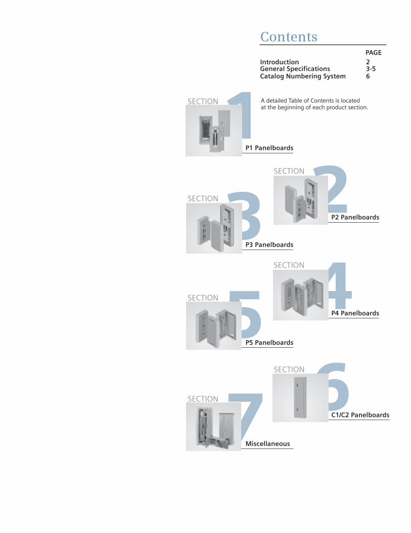
ContentsPAGE
Introduction 2 General Specifications 3-5Catalog Numbering System 6
SECTION
P1 Panelboards
2SECTION
P2 Panelboards3SECTION
P3 Panelboards
4SECTION
P4 Panelboards5SECTION
P5 Panelboards
6SECTION
C1/C2 Panelboards7Miscellaneous
A detailed Table of Contents is located at the beginning of each product section.
SECTION

2
This new generation of products from Siemens offers the highlevel of engineering and innovation you’ve come to expect fromthe leader in power distribution technology. The “P Series” line ofpanelboards offers a stepped approach to power distribution.
Additional strength has been added to an already rugged anddurable panelboard family. Engineered specifically to providemaximum flexibility, the new designs simplify wiring and reducematerial requirements making them easier to install and lesscostly than competitive products. At the heart of the product line is the extensive research and technology found amongSiemens circuit protection devices – both fusible switches andmolded case circuit breakers.
The line is anchored by the innovative P1. Featuring the industry’smost flexible designs, the P1 virtually eliminates common errors, such as feed direction, and main lug versus main breaker.Increasing distribution is simplified by the ability to add feed-thrulugs. The Revised P1 design introduced in January 2015 has addedextended Circuits up to 66 and has available smaller Enclosureswith no Subfeed option for added flexibility.
Subsequent steps in the P Series offer increased capacity andmore design options:
• The highly flexible P2 provides options to fit the most demanding specifications.
• Sized more like a lighting panel, the P3 packs the power of a distribution panel in a space-saving, highly flexible design.
• The P4 is a mid-sized distribution panel that allows both fusible and circuit breaker branch and main devices.
• The powerful P5 anchors the high end of the series. With larger fusible and circuit breaker branch and main devices, the
venerable P5 delivers maximum power and flexibility to larger distribution systems.
Siemens also offers a number of specialty panels, like columnpanels. Don’t see a panel to meet your requirements? Ask yourSiemens representative about our custom capabilities.
Features Overview P Series lighting panel features include Fas-Latch trim, which ispopular among installers; the jacking screw system, that permitsadjustments even after wiring has been installed; our exclusivesplit neutral, and more. Many panelboards have the capability ofmixing and matching breakers of different sizes and ratings – orchanging from main lug to main breaker, or adding subfeedbreakers without changing the box size. Other models accept a wide range of fuse types, including Siemens exclusive Vacu-Break® technology.
Table G-1 – Key Panelboard Features
Introduction
RP1 P2 P3 P4 P5
Lighting and Appliance Applications(Pre 2008NEC) • • • • • Power Panelboard Applications — • • • •Convertible From Top Feed To Bottom Feed Or Vice Versa • — — — —Change From Main Lug To Main Breaker Or
• — — — —Add Subfeed Without Changing Enclosure Size 3
Space-Saving, Horizontally Mounted Main Breaker Up To 250 Amps Up To 250 Amps Up To 250 Amps • •Short-Circuit Rating Label Giving Performance Level • • • • •Standard Aluminum Ground Assembly • • • • •Blank End-Walls Standard 1 • • • • •Bolted Current-Carrying Parts • • • • •Split Neutral • • • • •Connection Accessible From Front • • • • •Screw-Type Mechanical Lugs • • • • •Time-Reducing Wing Nuts To Secure Interior Without Tools • • • • •Main and Branch Devices Connected With
• • • • •Case-Hardened HardwareFlush Lock, Concealed Door Hinges/Trim Screws • • • — —Symmetrical Interior Mounting Studs
• • • • •To Eliminate Upside-Down Mounting of Box Interior Height Adjustment For Flush Applications • • • • •Mix and Match Fusible Switch Circuit Breaker Capability — — — • •Shallow Depth 5.75” 5.75” 7.75” 10.00” 12.75”Accepts A Wide Range Of Fuse Types — — — • •Accepts Vacu-Break Fusible Switch — — — • •Accepts A Wide Range Of Circuit Breakers • • • • •Accepts ACCESSTM Communications Tie-In 2 — • • • •Optional Compression Lugs • • • • •
• Standard1 KO’s available on P1 and P2 – 5.75” Deep x 20” Wide
boxes and P3 7.75” deep X 24” wide boxes.
2 Panelboards equipped with Siemens Sensitrip® circuit breakers or Power Meters can be integrated into Siemens ACCESS™ Electrical Monitoring System.
3 For Revised P1, only when Subfeed Space is selected,Interior Part Number ends with "T". When "N" is atend there is no Subfeed Space available.

3
General Specifications
Class CTL Panelboards (when applicable)Class CTL panelboards incorporate physical features which, in conjunction with the physical size, configuration, or other meansprovided in Class CTL circuit breakers, are designed to prevent the installation of more over current protective poles than thenumber for which the device is designed and rated, per UL 67 and National Electrical Code (NEC) NFPA70.
Service Entrance EquipmentWhen a panelboard is used as service entrance equipment, itmust be located near the point of entrance of building supplyconductors. In a main lugs only panel, the number of breakers or switches directly connected to the main bus must be limited to six. In a panel having a main breaker or main switch, the number of circuits are not limited except as may be providedunder other panelboard requirements, i.e., lighting andappliance branch circuit panelboards. Also, panels must include a connector for bonding and grounding neutral conductor.
Panelboard Code Data (where applicable)Lighting and appliance branch circuit panelboards were includedin editions of the National Electrical Code prior to 2008. TheNEC no longer distinguishes between lighting and appliancepanelboards and power panelboards; therefore, eliminating the42 circuit branch circuit limitation. Adoption of this code varyby a state or local jurisdiction. Consult the local code authoritiesto determine if this has been adopted in that area.
Integrated Equipment Short Circuit RatingThe term “Integrated Equipment Short Circuit Rating” refers to the application of series connected circuit breakers in a combinationthat allows some breakers to have lower individual interrupting ratings than the available fault current. This is permitted as long as the series combination has been tested and certified by UL.
StandardsNEC: 2014 (where accepted) NEMA: PB1UL: 67, 50 and 50E. Listed by Underwriter’s Laboratories, Inc.,
under “Panelboards” File #E2269, and #E4016. Meets Federal Specification W-P-115c.
Wire ConnectorsStandard wire connectors in Siemens panels are suitable for copperor aluminum cables rated 60/75 degree. Copper main lugs are aprice-added option for most panel types and some Circuit Breakers(check with Siemens sales for availability). It should be noted thatmost copper lugs will only accept copper cables. Some applications,100% rated devices in particular, require that the cable and connectors be rated 90 degree but are sized to the 75 degree tables.
Standard ground connectors are also suitable for copper or aluminum wire. Ground connector assemblies (EGK, IGK) have (7) 1/0 max. and (15) #6 max. connections. The 1/0 holes are
capable of connecting up (3) #10 max. wires. The #6 holes canaccept up to (2) #12 max. wires. Copper ground assemblies(ECGK, ICGK) are rated for copper wire only and have the samewiring capacity as the Al/Cu connectors.
Standard neutrals, like standard main lugs, are also rated for copper or aluminum wire. The neutral cross bar material followsthe selection bus. Copper neutral lugs are rated for copper cableonly and available as a price added option.
Lug DataSpace Required for Mounting of Double Panels
Use two or more panelboards with feed-thru or subfeed lugswhen:1. Lighting and appliance panelboards are required with
more than 42 circuits in areas where the zone code has not been accepted.
2. More circuit mounting space is required than is provided in the largest box size.
Feed-Thru Lugs Subfeed Lugs or Double Lugs
Feed-thru lugs are mounted at the opposite end of the main busfrom the main lugs or main breaker and are used to connect twoor more panelboards to the incoming feeder. The feeder cablesare brought into Panelboard 1 and connected to the main lugs or main breaker. Cables interconnecting the two panelboards areconnected to the feed-thru lugs in Panelboard1 and are carriedover the main lugs in Panelboard 2. This arrangement could bereversed with the main lugs located at the top and the feed-thrulugs at the bottom of the panel. Subfeed lugs are mounteddirectly beside the main incoming lugs and are used to connecttwo or more panelboards to the incoming feeder. The feedercables are brought into Panelboard 1 and connected to the mainlugs. Another set of cables that are the same size are connectedto the subfeed lugs of Panelboard 1 and are carried over the main lugs of Panelboard 2.
Note: P1 panelboards do not have subfeed lugs available. If thisconfiguration is needed, move to a P2 or P3 panelboard.
Shown mounted in wall Shown mounted on surface of wall
Wall Wall
Fig. G-1 Fig. G-2

General Specifications
B
Circuit Breaker Lighting Panel Type P1
Circuit Breaker Lighting or Distribution Panel Types P2/P3
Circuit Breaker Distribution Panel Type P4/P5
Fusible Switch Distribution Panel Type P4/P5
Bussing SequenceInteriors are designed to accommodate top or bottom feed.Regardless of which is specified, the uppermost pole is always on “A” phase; the second pole down is always on “B” phase, and the third pole down is always on ”C” phase (assuming 3Ø panel).
As standard, branch breakers shall be mounted at the top of the panel with “spaces” at the bottom, regardless of the directionpanel is fed.
All breakers have bolted connections except plug-in type. Thepanel design provides bracing up to 200,000A IR UL short circuit rating. Case-hardened, high performance, thread rollingscrews are used on branch bus.
Table G2 – Panelboard Ratings
Description P1 Revised P2 P3 P4 P5
Max. Voltage 480Y/277V AC Max.600Y/347V AC 8
600V AC Max.500V DC Max.
600V AC Max.500V DC Max.
600V AC Max.500V DC Max.
600V AC Max.500V DC Max.
System 1-Phase, 2-wire1-Phase, 3-wire3-Phase, 3-wire3-Phase, 4-wire
1-Phase, 2-wire1-Phase, 3-wire3-Phase, 3-wire3-Phase, 4-wire
1-Phase, 2-wire1-Phase, 3-wire3-Phase, 4-wire3-Phase, 3-wire
1-Phase, 3-wire3-Phase, 4-wire3-Phase, 3-wire
1-Phase, 3-wire3-Phase, 4-wire3-Phase, 3-wire
MainsMain LugsMain BreakerMain Switch
125A-400A100A-400A —
125A-600A100A-600A—
250A-800A225A-600A—
400A-1200A400A-800A—
800A-1200A800A-1200A200A-1200A
Circuits 18, 30, 42, 54, 66 18, 30, 42, 54, 6678, 90 1
— — —
Branch Ratings 15-125A 15-400A 15-400A 15-800A MCCB30-200A Fusible
15-1200A MCCB30-1200 Fusible
Branch Disconnect Devices
BL, BLH, HBL, BQD,BQD6, BLE, BLEH, BLF2, BLHF2, HBLF2, BLFB, BLHFB, BAF2, BAFH2, HBAF2, BGL, NGB 7, HGB 7, LGB 7
BL, BLH, HBL, BQD, BQD6, QJ25, QJH25, QJ2H5, QR25, QRH25, HQR25, HQR2H5, ED2, ED4, HED4, ED6, BLE, BLEH, BLF2, BLHF2, HBLF2, BLFB, BLHFB, BAF2, BAFH2, HBAF2, BGL, NGB, HGB, LGB
BL, BLH, HBL, BQD, BQD6, QJ26, QJH26, QJ2H6, QR26, QRH26, HQR26, HQR2H6, ED2, ED4, HED4, ED6, BLHF, BAF2, BAFH2, HBAF2, BGL, NGB, HGB, LGB, NEB, HEB
All 15-600A MCCBs, VL MG at 800A and 30-200A VB switches
All 15-1200A MCCBs, 30-600A VB switches and 400-1200A HCP switches
SubfeedCircuit Breakers 2 3
ED2, ED4, ED6, HED4, HED6, QJ2, QJH2, QJ2H, QR2, QRH2, HQR2, HQR2H, FD6, HFD6, FXD6, HFXD6
JD6, HJD6, JXD6, HJXD6, FD6, HFD6,FXD6, HFXD6
JD6, HJD6, JXD6, FD6, HFD6, FXD6, HFXD6
— —
Enclosure HeightsInches ± (mm)
26, 32, 38, 44, 50, 56 @250A (660, 813, 965, 1118, 1270, 1422) 56, 62, 68, 74 @400A (1422, 1575, 1727, 1880)
26, 32, 38, 44, 50, 56,62, 68, 74(660-1880)
56, 62, 68, 74, 80(1422-2032)
60, 75, 90(1524, 1905, 2286)
60, 75, 90(1524, 1905, 2286)
StandardTrims
Fas-Latch ± 1 PieceSurface or Flush
Fas-Latch ± 1 PieceSurface or Flush
Fas-Latch ± 1 PieceSurface or Flush
Four Piece 4
Surface or FlushFour Piece 4
Surface or Flush
T
1 Functional pricing is based on circuits shown. However, the panel can be figured with less circuits.
2 P1 can have max. 1 subfeed breaker when SubfeedSpace is available. P2 and P3 can have up to (2) FD subfeed breakers.
3 JD and FD breakers are mounted vertical.Limitations apply.
4 Trim ring provided for flush applications.5 A maximum of (4) QJ/QR breakers may be mounted
in a P2 Panel and are single mounted.
6 A maximum of (6) QJ/QR breakers may be mounted in a P3 panel and are twin mounted.
7 P1 panels with xGB breakers are limited to xGB branch devices only. BL and BQD frames may not be mixed in this panel type.
8 Factory assembled P1 has capability of 600Y/347V AC system when proper breakersare installed.
4

General Specifications
5
Table G3 – Typical Panelboard Modifications
Table G4 – UL Fuse Classes1
1 Per UL 67. 2 Fuses do not prohibit the use of Class H type fuse in switch.
InterruptingClass Amperes Volts Ratings (kA) l2t, li Circuits
H 1-600 250 and 600V or less AC 10 — Less than 10,000A Available
K5 2 1-600 250 and 600V or less AC 100l•t – RK5 up to 100A,
Feeder circuitsli – RK5 up to 100A
J 1-600 600V or less 200 l•t – Low, li – Low Feeder circuits (motor load small %) RK1 1/10 - 600 600V or less and 250V or less 200 l•t – Slightly >J, li – Slightly > J Feeder circuits (motor load small %)
RK5 1/10 - 600 600V or less and 250V or less 200 l•t – > RK-1, li – > RK-1 Motor starting currents a factor
T 1 - 800, 300 and 600V or less AC To 200 l•t – Low, li – Low Non-Motor loads1 - 1200
L 601 - 1200 600V or less 200 l•t – Low, li – Low Mains, feeder circuits
Description
Lighting and Distribution Panelboards Distribution Panelboards
P1 P2 P3 P4 P5
Box
Type 1 Standard (20" W)
Standard(20" W)
Standard(24" W) Standard Standard
Type 1 Enclosure with Hood P • • • •Type 1 w/Gasket between box and front • • • — —Type 2 Enclosure - Drip Tight (this is not available) — — — — —Type 3R/12 • • • • •Type 4, 4X (size varies by type/material) • • • • •Wider Box (check w/factory for custom options not shown) • (24”W) • (24”W) • (custom) • (custom) • (custom)Deeper Box (check w/factory for custom options not shown) — • (7.75”D) • (custom) • (custom) • (custom)
Front
Front with Door Standard Standard Standard • •4-piece Front — — — Standard Standard4-piece Front w/Hinged Gutter Covers — — — • •Hinged-to-Box Front • • • (see Door-in-Door) (see Door-in-Door)Door-in-Door Front • • • • •Common Front (custom - multi section applications) • (custom) • (custom) • (custom) — —Special Locks • (custom) • (custom) • (custom) • (custom) • (custom)Nameplate (mounting provisions provided as Std - P1/P2/P3) - Nameplate text is configured in COMPAS with limitations. • • • • •
Interior
Aluminum Equipment Ground Bar Standard Standard Standard Standard StandardCopper Equipment Ground Bar • • • • •Insulated Equipment Ground (CU or AL) • • • • •Subfeed Lugs — • • • •Feed-Thru Lugs • • • • •Split Bus — • • • •Compression Lugs • • • • •Copper Lugs • • • • •200% Neutral • • • 400 - 600A 400 - 600ATemperature Rated - Aluminum1 Standard Standard Standard Standard StandardTemperature Rated - Copper 1 • • • • •750 Ampere / in. - Aluminum — • • • •1000 Ampere / in. - Copper — • • • •
Copper Plating Tin Tin Std./Silver Opt.
Tin Std./Silver Opt. Silver Silver
Remote Control Switches External Mounted • • • •
Time Clocks External Mounted • • • •
Circuit Breaker Shunt Trips • • • • •R, J and T Fuse Clips — — — • •
All aluminum bus is tin-plated. • Available as an option. — Not Available

6
Catalog Numbering System
1 Standard bussing in P1, P2 and P3 panels is tin-plated for aluminum and copper. Standard bus is temperature rated to the maximum amperage in the panel.
2 Not available for Revised P1 xGB interiors.
B
Feed Location T = Top B = Bottom
Voltage and System*C = 208Y/120 3Ø 4 W Wye AC - All R = 415/240 3Ø 4 W Wye AC - AllE = 480Y/277 3Ø 4 W Wye AC - All S = 440/250 3Ø 4 W Wye AC - AllD = 240 3Ø 3 W Delta AC - All L = 600/347 3Ø 4 W Wye AC - AllF = 480 3Ø 3 W Delta AC - All T = 230 3Ø 3 W Delta AC - AllG = 600 3Ø 3 W Delta AC - P2, P3, P4, P5 W = 380 3Ø 3 W Delta AC - P2, P3, P4, P5I = 347 3Ø 3 W Delta AC P2, P3, P4, P5 1 = 24V DC 1-Pole Branches Only - P2, P3, P4, P5B = 240/120 3Ø 4 W Delta BØ High Leg AC - P2, P3, P4, P5 2 = 24V DC 2-Pole Branches Only - P2, P3, P4, P5Q = 240/120 3Ø 4 W Delta CØ High Leg AC - P2, P3, P4, P5 3 = 48V DC 1-Pole Branches Only - P2, P3, P4, P5A = 120/240 1Ø 3 W Grounded Neutral AC - All P4 = 48V DC 2-Pole Branches Only - P2, P3, P4, P5H = 120 1Ø 2 W Grounded Neutral AC - P2, P3, P4, P5 5 = 125V DC 1-Pole Branches Only - P2, P3, P4, P5J = 240 1Ø 2 W No Neutral AC - All N = 125V DC 2-Pole Branches Only - P2, P3, P4, P5Y = 125 1Ø 2 W Grounded Neutral AC - P2, P3, P4, P5 O = 125/250V DC 2-Pole Branches Only - P2, P3, P4, P5Z = 500 2W DC - P2, P3, P4, P5 P = 125/250V DC 2 & 3-Pole Branches - P2, P3, P4, P5K = 220/127 3Ø 4 W Wye AC - All U = 120V AC 3Ø3W - AllM = 380/220 3Ø 4 W Wye AC - All V = 240V 3Ø3W Grounded B Phase - P2, P3, P4, P5
Type of PanelP1, P2, P3, P4, P5
MountingS = SurfaceF = Flush. Flush trims extend 1 1/2" beyond the base box dimensions on P1, P2 and P3 and 2" on P4 and P5 panels.
Circuits or Enclosure HeightP1 – 18, 30, 42, 54, 66 P3 – 56, 62, 68, 74, 80P2 – 18, 30, 42, 54, 66, 78, 90 P4, P5 – 60, 75, 90
Main Lug (ML), Main Breaker(See Main Breaker Table coding below), Main Switch (MS)
Amperage 100–400A = P1 250 – 800A = P3100–600A = P2 400 –1200A = P4, P5
Main Breaker Coding
Catalog Numbering System
*For any voltage system not listed, check with sales for availability.
Subfeed Space Indicator (for P1 only) T = Subfeed Space Included N = No Subfeed Space 2
Bus Bus BusCode Material Plating P11 P2 P3 P4 P5A Temp rated Al. Tin-Plated • • • • •B 750A/sq. in. Al. Tin-Plated • • • • •C Temp rated Cu. Tin-Plated • n/a n/a n/a n/aE Temp rated Cu. Silver-Plated n/a optional optional • •F Temp rated Cu. Tin-Plated n/a • • • •G 1000A/sq. in. Cu. Tin-Plated n/a • • optional optionalH 1000A/sq. in. Cu. Silver-Plated n/a optional optional • •
CodeBreakerType Code
BreakerType Code
BreakerType Code
BreakerType Code
BreakerType Code
BreakerType Code
BreakerType Code
BreakerType
BL BL H1 HHFD6 SC SCJD6 S2 SHLD6 S5 SHMD6 SD SHND6H M5 HMG N7 NNG
BH BLH H3 HHFXD6 SX SHJD6 SL SLD6 S6 SHMD6H SN SND6 M2 HMX N1 NNXBR BLR G2 HGB SY SHJD6H QJ QJ2 SM SMD6 AY SND6H M8 HMY N4 NNYHB HBL G3 LGB SJ SJD6 Q2 QJ2H AX SMD6H J6 HJG M6 LMG QR QR2BQ BQD NB NGB SH SJD6H QH QJH2 CN CND6 J7 HJX M3 LMX Q4 QRH2B6 BQD6 CJ CJD6 CL CLD6 C9 CMD6 C6 CND6H J5 HJY M9 LMY Q5 HQR2CE CED6 6H HHJD6 HH HHLD6 CH CMD6H HN HND6 J9 LJG M4 NMG Q6 HQR2HE4 ED4 H9 HHJXD6 XH HHLXD6 HM HMD6 HT HNXD6 J3 LJX M1 NMX Q7 QR2-MCSE6 ED6 H6 HJD6 HL HLD6 HR HMXD6 HX HNXD6H J8 LJY M7 NMYH4 HED4 H5 HJXD6 HO HLXD6 HS HMXD6H ND ND6 L3 LLK N8 HNGCF CFD6 H7 HJXD6H HP HLXD6H MD MD6 NX NXD6 J2 NJG N2 HNXFD FD6 J6 JD6 L6 LD6 MX MXD6 NT NXD6H J1 NJX N5 HNYFX FXD6 JD JXD2 LX LXD6 MH MXD6H SR SCND6 J4 NJY N9 LNGHF HFD6 JX JXD6 LH LXD6H SO SCMD6 ST SCND6H L2 HLK N3 LNXH2 HFXD6 JH JXD6H S1 SCLD6 SQ SCMD6H AD SHND6 L7 NLK N6 LNY
• Indicates default for this bus type.
2

SEC
TIO
N1
Description PageGeneral Information 1-2
Selection and Application 1-2Application 1-3 – 1-6
Main Breaker Panel Size Selector 1-3Main Breaker Selection 1-3Main Lugs Size Selector 1-4Branch Circuit Breakers 1-4Subfeed Breakers 1-5Breaker Mounting Kits 1-5Lug Kits 1-5Main Breaker Gutter Dimensions 1-6Main Lug End Gutter Dimensions 1-6
Side Gutter Wiring Space 1-6Branch Breaker Side Gutters 1-6
Typical Catalog Numbers 1-7Main Lugs Only 1-7Main Circuit Breaker 1-7Standard Enclosures 1-7
Standard Modifications 1-8Connector Modifications 1-9
Compression Lugs 1-9Enclosure Modifications 1-9Remote Switch Modifications 1-9
Dimensions 1-10
P1 Panelboards

1-2
Type P1 Panelboards
P1 panelboards are pre-engineered to accept the most commonmodifications without increasing box height. The enclosure sizeis determined by the number of circuits as shown in the Main LugTable P1-5 or the Main Circuit Breaker Table P1-3. All P1 Revisedmain lug or main breaker panelboards have space built-in toaccept either feed-thru lugs equal to the panel rating, one sub-feed circuit breaker up to 250 amperes or a surge suppressor(TVSS) without increasing box height. (When ordered with sub-feed, space indicated by a “T” at end of nterior number).
Note the following features, all found in the innovative P1lighting panelboards:• Symmetrical Interiors - No top or bottom! To change from
top to bottom (or vice-versa), simply invert the interior. The deadfront labeling is always right-side up.
• First in the Industry Ratings of 125 through 400A main lug and main breaker. Field convertible from main lug to main breaker and vice versa – with no increase in enclosure height.
• Field adaptability of feed-thru lugs or subfeed circuit breaker without increasing enclosure size.
• Neutral system is field upgradeable to 200% capacity – another industry first.
• Five circuit sizes means only three box heights, regardless of main configuration through 250 amp and an additional four circuit versions-- and boxes available at 400 amps.
• Suitable for use as service entrance given compliance with NEC.
• Bonding provisions are shipped with each panel.• 240V and 480Y / 277V for versions utilize identical boxes
and fronts.
Enclosure – Standard Type 1 enclosure is 20" wide x 5.75" deep. Box Height is determined only by the number of circuits, not by main lug or main circuit breaker. See chart P1-5 for box height.
Voltage – 480Y/277 Vac max.
Amperage – 400 amp max.
Short Circuit Rating – 200 KAIC max. symmetrical or equal to the lowest rated device installed unless a series rating is indicated. Panels with subfeed or feed-thru lugs without a main device, circuit breaker or fusible unit, are limited to a three-cycle rating. The three-cycle rating for the P1 panel is limited to 22 KAIC. Note that the main device may be mountedremote from the panel.
Bussing – The P1 panel meets the majority of the marketsbussing requirements. The standard bussing is temperature rated aluminum. The rating is per the requirements of UL 67– the standard for panelboards. All aluminum bussing is tin-plated.Optional bussing for the P1 panel is temperature rated copper.The copper bus option for this panel is tin-plated.
Weight – ApproximateTotal panelboard weight when filled with a normal quantity ofbreakers and accessories is about 3 lbs. (1 kg) per inch (54g permm) of box height
Selection and Application
Table P1-2 – Trim Material Gauge
Table P1-1 – Box Material Gauge
3 Easy Steps for Selecting a Siemens P1 Panelboard
Determine voltage, system, amperageand interrupting rating of branchdevices, and modifications if any.
Example for standard lighting panelboard:
Amperage 250AVoltage 208Y/120VSystem 3Ø4WMain Main LugBranches 10K AIR, 42-20/1Modifications NoneFeed Location TopMounting Surface
Step 1 Step 2
Create a catalog number by followingthe Panelboard Catalog NumberingSystem on page 6. The BL branch breakerswere selected from the branch breakerselection table on page 1-4.
1-P1C42ML250ATST42-20/1 BL
Select enclosure size by the number of circuits as shown in the panelboarddimensional chart on page 1-6.
1-P1C42ML250ATST42-20 BLBox size – 44” high
Step 3
A unique feature of P1 panels is that theycan accommodate either feed-thru lugs or one subfeed circuit breaker (up to250A) without any addition to boxheight. For our example changing thebranch circuits to 39-20/1 and 1-125/3,we have the following:
1-P1C42ML250ATST39-20/1 BL1-125/3 QJ2/QR2 Box size – 44” high
The QJ2/QR2 subfeed was selected fromthe table of subfeed breakers on page 1-5. The box height remains the same.
20” (250A) 26, 32, 38, 44, 50, 56 #14(400A) 56, 62, 68, 74
Width Height (inches) Gauge Steel
20” (250A) 26, 32, 38, 44, 50, 56 #16(400A) 56, 62, 68, 74

1-3
ApplicationType P1 Panelboards SE
CTI
ON
1
MaxAmpere rating
MainBreakerTypes
Connections suitable for Cu or Al
Max #PolesFT 1
Max #PolesNFT
Dimensions in inches (mm)
Unit SpaceBox HeightB
Weight inLbs. (kg)
FTA
NFTA
100BL2, BLH2,HBL2, BQD2
#8-#6 AWG Cu or Al#8-6 AWG Cu or #8-4 AWG Al#8-#1 AWG Cu or #6-#1/0 AWG Al
18 – 9 26 (661) 90 (41)18 30 9 15 32 (813) 105 (48)30 42 15 21 38 (965) 120 (55)42 54 21 27 44 (1118) 135 (61)54 66 27 33 50 (1270) 150 (67)66 – 33 – 56 (1423) 165 (73)
125
NGB2, HGB2, LGB2
15-30 amp: #14-#6 Cu or #12-#6 Al35-125 amp: #6-1/0 Cu #4-2/0 Al
18 – 9 26 (661) 95 (43)
ED2, ED4
ED6, HED4HED6
#14-#10 AWG Cu or #12-10 AWG Al
#3-3/0 Cu or #1-2/0 Al#3-3/0 Cu or #1-2/0 Al
18 30 9 15 32 (813) 110 (50)30 42 15 21 38 (965) 125 (57)42 54 21 27 44 (1118) 140 (64)54 66 27 33 50 (1270) 155 (71)66 – 33 – 56 (1423) 170 (78)
225
QJ2, QJH2,QJ2HQR2, QRH2, HQR2, HQR2H
#6 AWG-300 Kcmil (Cu) or #4 AWG-300 Kcmil (Al)
18 – 9 26 (661) 95 (43)
18 30 9 15 32 (813) 110 (50)
30 42 15 21 38 (965) 125 (57)
250FXD6, FD6,HFD6, HFXD6
#6 AWG-350 Kcmil (Cu) or #4 AWG-350 Kcmil (Al)
42 54 21 27 44 (1118) 140 (64)54 66 27 33 50 (1270) 155 (71)66 – 33 – 56 (1423) 170 (78)
400JD6, JXD6,HJD6,HJXD6
3/0-500 Kcmil (Cu) or 4/0-500 Kcmil (Al)
– 30 – 15 56 (1423) 172 (78)30 42 15 21 62 (1575) 190 (86)42 54 21 27 68 (1728) 208 (95)54 66 27 33 74 (1880) 226 (104)
T
/
Ampere ratingBreakerTypes
Max. Ir (kA) at MainBreakerCode Additional Trip Values240 AC 480/277V AC
100
BL (STD) 10 – BL 15, 20, 25, 30, 35, 40, 45, 50, 60, 70, 80, 90, 100BLH 22 – BH 15, 20, 25, 30, 35, 40, 45, 50, 60, 70, 80, 90, 100HBL 65 – HB 15, 20, 25, 30, 35, 40, 45, 50, 60, 70, 80, 90, 100BQD 65 14 BQ 15, 20, 25, 30, 35, 40, 45, 50, 60, 70, 80, 90, 100
125
NGB (STD) 100 25 NB3 50, 60, 70, 80, 90, 100, 110, 125HGB 100 35 G23 50, 60, 70, 80, 90, 100, 110, 125LGB 100 65 G33 50, 60, 70, 80, 90, 100, 110, 125ED4 (STD) 65 25 E4 50, 60, 70, 80, 90, 100, 110, 125HED4 42 42 H4 50, 60, 70, 80, 90, 100, 110, 125
225QJ2 (STD) 10 – QJ 60, 70, 80, 90, 100, 110, 125, 150, 175, 200, 225QJH2 22 – QH 60, 70, 80, 90, 100, 110, 125, 150, 175, 200, 225QJ2H 42 – Q2 60, 70, 80, 90, 100, 110, 125, 150, 175, 200, 225
225
QR2 10 – QR 100, 110, 125, 150, 175, 200, 225QRH2 25 – Q4 100, 110, 125, 150, 175, 200, 225HQR2 65 – Q5 100, 110, 125, 150, 175, 200, 225HQR2H 100 – Q6 100, 110, 125, 150, 175, 200, 225
250
FXD6 (STD) 65 35 FX 70, 80, 90, 100, 110, 125, 150, 175, 200, 225, 250FD6 65 35 FD 70, 80, 90, 100, 110, 125, 150, 175, 200, 225, 250HFD6 100 65 HF 70, 80, 90, 100, 150, 175, 200, 225, 250HFXD6 100 65 H2 70, 80, 90, 100, 110, 125, 150, 175, 200, 225, 250
400
JXD2 65 – JD 300, 400JXD6 (STD) 65 35 JX 200, 225, 250, 300, 350, 400JD6 65 35 J6 200, 225, 250, 300, 350, 400HJD6 100 65 H6 200, 225, 250, 300, 350, 400HJXD6 100 65 H5 200, 225, 250, 300, 350, 400
3
Note: Main breakers use breaker connectors. For sizes, see breaker connector chart. 400 amp main breaker panel has wire bending space for 600 kcmil cables as standard.Use 750 Kcmil lug if 600 Kcmil cable is to be used.1 400A 66 circuit only available with non-feed thru versions.2 BL, BLH, HBL, BQD, and xGB mount in unit space and count in max. # of poles.
Table P1-4 – Main Breaker Selection
Table P1-3 – Main Breaker Panel Size Selector

1-4
ApplicationType P1 Panelboards
Table P1-6 – Branch Circuit Breakers
1 Two-pole breaker is one phase and neutral. Three-pole is two phases and neutral.2 P1 panel with xGB branch devices will not accept BL or BQD frames in the same panel as branch devices.3 The New Revised P1 (18 circuit 250A only) is limited to 100A per connection (200A per pair) when installing Branch Breakers across from one another. All other
configurations allow 125A per connection max. (250A per pair max.) NOTE: BL, HBL and BQD breakers are mounted in common mountings in 3” or (6) pole increments.
Max. Interrupting Rating (kA)Breaker NumberType of Poles 120V 120/240V 240V 277V 480/277V Available Trip Values
1 10 — — — — 15, 20, 25, 30, 35, 40, 45, 50, 55, 60, 70BL 2 — 10 — — — 15, 20, 25, 30, 35, 40, 50, 60, 70, 80, 90, 100
3 — — 10 — — 15, 20, 25, 30, 35, 40, 50, 60, 70, 80, 90, 100BLR 2 — — 10 — — 15, 20, 30, 40, 50, 60, 70, 90, 100
BL, HID 1 10 — — — — 15, 20, 302 — 10 — — — 15, 20, 301 — 22 — — — 15, 20, 30, 40, 50, 55, 60, 70
BLH 2 — 22 — — — 15, 20, 30, 40, 50, 60, 70, 90, 1003 — — 22 — — 15, 20, 30, 40, 50, 60, 70, 80, 90, 1001 — 65 — — — 15, 20, 30, 40, 50
HBL 2 — 65 — — — 15, 20, 30, 40, 50, 60, 703 — — 65 — — 15, 20, 30, 40, 50, 60, 70, 80, 90, 100
BLF1 10 — — — — 15, 20, 302 — 10 — — — 15, 20, 30, 40, 50, 60
BLHF 1 22 — — — — 15, 20, 302 — 22 — — — 15, 20, 30, 40, 50, 60
BG 1 2 10 — — — — 15, 20, 303 — 10 — — — 15, 20, 30
BLE1 10 — — — — 15, 20, 302 — 10 — — — 15, 20, 30, 40, 50, 60
BLEH 1 22 — — — — 20, 302 — 22 — — — 15, 20, 30, 40, 50, 60
BAF 1 10 — — — — 15, 20BAFH 1 22 — — — — 15, 20
1 — 65 — 14 — 15, 20, 25, 30, 35, 40, 50, 60, 70, 80, 90, 100BQD 2 — 65 — — 14 15, 20, 25, 30, 35, 40, 50, 60, 70, 80, 90, 100
3 — — 65 — 14 15, 20, 25, 30, 35, 40, 50, 60, 70, 80, 90, 1001 100 — — 25 — 15, 20, 25, 30, 35, 40, 50, 60, 70, 80, 90, 100, 1253
NGB 2 3 2 — 100 100 — 25 15, 20, 25, 30, 35, 40, 50, 60, 70, 80, 90, 100, 1253
3 — 100 100 — 25 15, 20, 25, 30, 35, 40, 50, 60, 70, 80, 90, 100, 1253
1 100 — — 35 — 15, 20, 25, 30, 35, 40, 50, 60 70, 80, 90, 100, 1253
HGB 2 3 2 — 100 100 — 35 15, 20, 25, 30, 35, 40, 50, 60 70, 80, 90, 100, 1253
3 — 100 100 — 35 15, 20, 25, 30, 35, 40, 50, 60 70, 80, 90, 100, 1253
1 100 — — 65 — 15, 20, 25, 30, 35, 40, 50, 60 70, 80, 90, 100, 1253
LGB 2 3 2 — 100 100 — 65 15, 20, 25, 30, 35, 40, 50, 60 70, 80, 90, 100, 1253
3 — 100 100 — 65 15, 20, 25, 30, 35, 40, 50, 60 70, 80, 90, 100, 1253
Dimensions in Inches (mm)Maximum Max # Max #Ampere Poles Poles FT NFT Box Height Weight in MLO ConnectorsRating NFT NFT A A B” lbs. (kg) Suitable for Cu or Al
18 – 9 26 (661) 90 (41)18 30 9 15 32 (813) 105 (48)
125 30 42 15 21 38 (965) 120 (55)(or) 42 54 21 27 44 (1118) 135 (61)250 54 66 27 33 50 (1270) 150 (68)
66 — 33 — 56 (1422) 165 (75)— 30 — 15 56 (1422) 120 (55)
40030 42 15 21 62 (1575) 135 (61)42 54 21 27 68 (1728) 150 (68)54 66 27 33 74 (1880) 165 (75)
Table P1-5 – Main Lugs Size Selector
(2) #3/0-250 kcmil or(1) #3/0-600 kcmil
(1) #6 AWG - 350 kcmil(CU or AL)

1-5
ApplicationType P1 Panelboards
Table P1-7 – Subfeed Breakers
Original P1 Revised P1Amp Catalog Catalog Rating Breaker Frames Service Number Number
100A BQD 3 Phase MBKBC3100A BL, BLH, HBL 1 Phase MBKBL1
3 Phase MBKBL3 125A NGB, HGB, LGB 1 Phase MBKNB1
3 Phase MBKNB3
125ED4, ED6, HED4, HED6 1 Phase MBKED1 MBKED1A
3 Phase MBKED3 MBKED3A
225QJ2, QJH2, QJ2H 1 Phase MBKQJ1 MBKQJ1A
3 Phase MBKQJ3 MBKQJ3A225A2 QR2, QRH2, HQR2, 1 Phase MBKQR1 MBKQR1A
HQR2H 3 Phase MBKQR3 MBKQR3A
250FXD6, FD6, HFD, HFXD6 1 Phase MBKFD1 MBKFD1A
3 Phase MBKFD3 MBKFD3A
4001 JXD6, JD6, 1 Phase MBKJD1 MBKJD1AHJD6, HJXD6 3 Phase MBKJD3 MBKJD3A
Table P1-8 – Breaker Mounting KitMain or Subfeed w/o Breaker Table P1-10 – Copper Neutral Lug Kits – 250A
Table P1-11 – 200% Neutral Lug Kits – 250A
Original P1 Revised P1No. of Catalog CatalogCircuits Description Number Number
18 42NLK18 N/A
30 42NLK30 42NLK30A42 42NLK42 42NLK42A54, 66 — 42NLK54A
Table P1-12 – 200% Neutral Lug Kits – 400A
1 400 amp kit is for main—only not allowed for subfeed breaker.2 Although QR is rated 250A, it is limited to 225A in panelboard.3 Back-fed occupies branch space.
Original Revised P1Amp Catalog CatalogRating Material Wire Range Service Number Number
Al (1) #6 AWG- 1 Phase MLKA1 MLKA1A350 Kcmil (Cu or Al) 3 Phase MLKA3 MLKA3A
250 Cu (1) #6 AWG- 1 Phase MLKC1 MLKC1A350 Kcmil (Cu or Al) 3 Phase MLKC3 MLKC3A
AL (2) 1/0 - 250 Kcmil 1 Phase 4MLKA1 4MLKA1A
400 or (1) #2 AWG 600 Kcmil 3 Phase 4MLKA3 4MLKA3ACu (2) 1/O - 4/0 1 Phase 4MLKC1 4MLKC1A
or (1) 1/0 600 Kcmil 3 Phase 4MLKC3 4MLKC3A(1) AL 1/0-750 Kcmil 1 Phase — 4MLKA1B(2) AL/CU 250 kcmil
400 AL max.(max. (1) 600 Kcmil 3 Phase — 4MLKA1B wire)
Table P1-9 – Lug Kits Main or Feed-Thru
SEC
TIO
N1
Use Back-fedMain LabelKit # MBKBFA 3(includes"MAIN" labeland instructions)
2 or 4 Branch Neutral Strips, 1 Main600 kcmil Neutral Lug, Hardware
Original P1 Revised P1No. of Catalog CatalogCircuits Description Number Number
18 2NLK18 Use 30 ckt kit
30 2NLK30 LNLK30A42 2NLK42 LNLK42A54, 66 — L NLK54A
2 or 4 Branch Neutral Strips, 1 Main Neutral Lug, Hardware
Original P1 Revised P1No. of Catalog CatalogCircuits Description Number Number
18 CNLK18 Use 30 ckt kit
30 CNLK30 CNLK30A42 CNLK42 CNLK42A54, 66 — CNLK54A
2 or 4 Branch Neutral Strips, 1 Main Neutral Lug, Hardware
Table P1-10A – 2/0 Neutral Lug Kits – 250A and 400A
Original P1 Revised P1No. of Catalog CatalogCircuits Description Number Number
18 — Use 30 ckt kit
30 — LNLK30A42 — LNLK42A54, 66 — LNLK54A
2 or 4 Branch Neutral Strips, Hardware
NOTES: Original P1 kits will not work with Revised P1 starters if the chart shows different part numbers for each.Revised P1 kits will not work with Original P1 starters if the chart shows differentpart numbers for each.
Max. Interrupting Rating (kA)Breaker NumberType of Poles 240V 480Y/277V Available Trip Values
QJ2 2, 3 10 — 60, 70, 80, 90, 100, 110, 125, 150, 175, 200, 225QJH2 2, 3 22 — 60, 70, 80, 90, 100, 110, 125, 150, 175, 200, 225QJ2H 2, 3 42 — 60, 70, 80, 90, 100, 110, 125, 150, 175, 200, 225QR2 2, 3 10 — 100, 110, 125, 150, 175, 200, 225 QRH2 2, 3 25 — 100, 110, 125, 150, 175, 200, 225 HQR2 2, 3 65 — 100, 110, 125, 150, 175, 200, 225 HQR2H 2, 3 100 — 100, 110, 125, 150, 175, 200, 225 ED4 2, 3 65 18 15, 20, 25, 30, 35, 40, 45, 50, 55, 60, 70, 80, 90, 100, 110, 125 HED4 2, 3 100 42 15, 20, 25, 30, 35, 40, 45, 50, 55, 60, 70, 80, 90, 100, 110, 125FXD6 2, 3 65 35 70, 80, 90, 100, 110, 125, 150, 175, 200, 225, 250FD6 2, 3 65 35 70, 80, 90, 100, 110, 125, 150, 175, 200, 225, 250HFD6 2, 3 100 65 70, 80, 90, 100, 110, 125, 150, 175, 200, 225, 250HFXD6 2, 3 100 65 70, 80, 90, 100, 110, 125, 150, 175, 200, 225, 250

1-6
ApplicationType P1 Panelboards
Fig P1-1 Table P1-15 – Side Gutter Wiring Space Inches (mm) (Fig P1-1)
Reference Panel PanelLetter Width 20” Width 24”
Optional
A 2 6.375 (162) 8.375 (213)B 2 5.500 (140) 7.500 (191)C 2 5.000 (127) 7.000 (178)D 1 6.125 (156) 8.125 (206) E 1 6.500 (165) 8.500 (216)F 1 5.250 (133) 7.250 (184)
Table P1-13 – Main Breaker Gutter Dimensions Inches (mm)
Max. Interrupting Rating (kA) Neutral Location
Main Breaker 20” wide box 24” wide box 20” wide box
BL, BLH, HBL, BQD 2 8.500 (216) 3 10.500 (267) 3 10.500 (267)NGB, HGB, LGB 2 8.000 (203) 3 10.000 (254) 3 10.500 (267)ED2, ED4, ED6, HED4 6.125 (156) 8.125 (206) 10.500 (267)QJ2, QJH2, QJ2H 6.500 (165) 8.500 (216) 10.500 (267)QR2, QRH2, HQR2, HQR2H 6.500 (165) 8.500 (216) 10.500 (267) FD6, FXD6, HFD6, HFXD6 5.250 (133) 7.250 (184) 10.500 (267)JD6, JXD6 1 15.000 (381) 15.000 (381) 26.500 (674)
Table P1-14 – Main Lug End Gutter Dimensions Inches (mm)
Amp End Gutter Neutral Location
Rating 20” wide box 24” wide box 20” wide box 24” wide box
125 9.500 (242) 9.500 (242) 10.500 (267) 10.500 (267)250 9.500 (242) 9.500 (242) 10.500 (267) 10.500 (267)400 25.500 (648) 25.500 (648) 26.750 (680) 26.750 (680)
1 JD frame mounted vertically. 2 For Revised P1, use Side Gutter Wiring Specs Table P1-15. These are back-fed main breakers.3 These dimensions are for Original P1 as a reference only, not for Revised P1.
Panel Width20 in. (508 mm)
NOTE: Feed-thru lug and neutral wire bending space is 15.000” and 16.250” respectively on 400A panel.
Table P1-16 – Miscellaneous Parts and Accessories
CatalogNumber Description
EBF1 NEB/HEB Filler PlateP1SCRWS Package of 42 breaker mounting screws for P1DFFP1 1” Branch circuit filler plate (suitable for replacing QF3 in P1
thru P5 Panelboards and Switchboards)P1CONBPHCU1 Connector Kit – 6 pcs. B-phase CopperP1CONBPHAL1 Connector Kit – 6 pcs. B-phase Aluminum P1CONBPHAL1 Connector Kit – 6 pcs. B-phase AluminumP1CONACPHCU1 Connector Kit – 6 pcs. A or C-phase CopperP1CONACPHAL1 Connector Kit – 6 pcs. A or C-phase Aluminum MBKORFK P1/Revised P1 Filler for 1PH/3PH QR. Horizonal mount only. SEBKRP1V12 FD, QJ, QR Service Entrance Barrier Kit (Revised P1)SEBKRP1V22 ED Service Entrance Barrier Kit (Revised P1)SEBKRP1V32 BQD Service Entrance Barrier Kit (Revised P1 - back-fed)SEBKRP1V42 xGB Service Entrance Barrier Kit (Revised P1) - back-fedSEBKRP1P2P3V12 JD, LD Service Entrance Barrier Kit (RP1, P1, P2, P3)
CatalogNumber Description
BK1 Bonding Kit for 400A max. Original P1 PanelsBK1A Bonding Kit for 400A max. Revised P1 PanelsBK2 Bonding Kit for S1/S2 400 & 600BK3 Bonding Kit for S3 PanelIMK1 Interior Adjusting Kit11-1824-01 Directory Card Holder12-1110-01 Directory CardMCHK Metal Card Holder Kit NEMA PB1.13 NEMA Instruction Book 11-506-01NBK03 Number Strips 1-42. Stick-on type: Use w/P1 series PanelsNBK04 Number Strips 43-84. Stick-on type: Use w/P1series PanelsNBK05 Number Strips 85-126. Stick-on type: Use w/P1series PanelsNBK06 Number Strips 127-168. Stick-on type: Use w/P1series PanelsEGK AL Ground Bus 44 ConnectionsECGK CU Ground Bus 44 ConnectionsIGK Insulated AL Gound BusICGK Insulated CU Gound BusEWK1 End Wall Kit with Knockouts (20”W x 5.75” DP)EWK2 End Wall Kit with Knockouts (24”W x 7.75” DP)
1 Subfeed mounting limit 1 per panel.2 For all Revised P1 panels using BL/BQD or xGB
breakers as mains in back-fed position, use this chart for wiring space.
1 Replacement parts.2 Factory installed and Field installable Service Entrance Barrier kits are now available as
required by UL67 (In COMPAS, you must select Service Entrance Required.) 3 Can be downloaded at no charge from webiste: link

1-7
Typical Catalog NumbersType P1 Panelboards
Table P1-18 – Main Circuit Breaker
Table P1-19 – Standard Enclosures
SEC
TIO
N1
B
Shown with Standard Mains, Top Fed and Surface TrimCatalog number is for aluminum main bus. For optional coppermain bus change “A” in position 11 to “C”.
Panels are top feed, surface mounted. For bottom feed, change“T” in position 12 to “B”. For flush mounting, change “S” in position 13 to “F”.
Replace fifth and sixth position in panelboard catalog number,with alternate main breaker code. Use price adders from mainbreaker selection table. Horizontally mounted.
Note: Original P1 was produced until mid 2014 and in July the revised P1 was introduced. All interior numbers that end with "T" or "N" are the new Revised interiors."T" atend of catalog number indicates there is a Subfeed area available. "N" at end of catalog number indicates there is no Subfeed area available.
1 For all products without subfeed space - change "T" at end to "N" and reduce box size by 6".
2 No sub-feed space only for 400A 66 circuit.3 BL/BQD/GB Type Mains are only available as Back-Fed. No
kits are available for use in Main or Sub-feedspace. (GB Type includes NGB, HGB and LGB Breakers). These breakers take up branch circuit space.
4 xGB interiors are not available as Non-Feed-Thru,without Subfeed Space.
Main Lug Only Original P1–Subfeed Space
Revised P1–Subfeed Space 1, 3
Original P1–Subfeed Space
Revised P1–Subfeed Space 1, 3
Original P1–Subfeed Space
Revised P1–Subfeed Space 1, 3, 4
Max Panel Amp Rating
Max 1-Pole Circuits
BoxHeight (in)
208Y/120V 3-Phase, 4-Wire Catalog #
208Y/120V 3-Phase, 4-Wire Catalog #
120/240V 1-Phase, 3-Wire Catalog #
120/240V 1-Phase, 3-Wire Catalog #
480Y/277V 3-Phase, 4-Wire Catalog #
480Y/277V 3-Phase, 4-Wire Catalog #
125
18 32 P1C18ML125ATS P1C18ML125ATST P1A18ML125ATS P1A18ML125ATST P1E18ML125ATS P1E18ML125ATST30 38 P1C30ML125ATS P1C30ML125ATST P1A30ML125ATS P1A30ML125ATST P1E30ML125ATS P1E30ML125ATST42 44 P1C42ML125ATS P1C42ML125ATST P1A42ML125ATS P1A42ML125ATST P1E42ML125ATS P1E42ML125ATST54 50 N/A P1C54ML125ATST N/A P1A54ML125ATST N/A P1E54ML125ATST66 56 N/A P1C66ML125ATST N/A P1A66ML125ATST N/A P1E66ML125ATST
250
18 32 P1C18ML250ATS P1C18ML250ATST P1A18ML250ATS P1A18ML250ATST P1E18ML250ATS P1E18ML250ATST30 38 P1C30ML250ATS P1C30ML250ATST P1A30ML250ATS P1A30ML250ATST P1E30ML250ATS P1E30ML250ATST42 44 P1C42ML250ATS P1C42ML250ATST P1A42ML250ATS P1A42ML250ATST P1E42ML250ATS P1E42ML250ATST54 50 N/A P1C54ML250ATST N/A P1A54ML250ATST N/A P1E54ML250ATST66 56 N/A P1C66ML250ATST N/A P1A66ML250ATST N/A P1E66ML250ATST
400
18 56 P1C18ML400ATS — P1A18ML400ATS — P1E18ML400ATS —30 62 P1C30ML400ATS P1C30ML400ATST P1A30ML400ATS P1A30ML400ATST P1E30ML400ATS P1E30ML400ATST42 68 P1C42ML400ATS P1C42ML400ATST P1A42ML400ATS P1A42ML400ATST P1E42ML400ATS P1E42ML400ATST54 74 — P1C54ML400ATST — P1A54ML400ATST — P1E54ML400ATST66 2 74 2 — P1C66ML400ATSN2 — P1A66ML400ATSN 2 — P1E66ML400ATS 2
Box Catalog Number
Height Type 1 Standard Trim(in.) Box Surface Flush Type 3R Type 3R/12
26 B26 S26B F26B NR26 WP2632 B32 S32B F32B NR32 WP3238 B38 S38B F38B NR38 WP3844 B44 S44B F44B NR44 WP4050 B50 S50B F50B NR50 WP5056 B56 S56B F56B NR56 WP5662 B62 S62B F62B NR62 WP6268 B68 S68B F68B NR68 WP6874 B74 S74B F74B NR74 WP74
Table P1-17 – Main Lugs Only
100
18 32 P1C18BL100ATS P1C18BL100ATST P1A18BL100ATS P1A18BL100ATST P1E18BD100ATS P1E18BD100ATST
30 38 P1C30BL100ATS P1C30BL100ATST P1A30BL100ATS P1A30BL100ATST P1E30BD100ATS P1E30BD100ATST42 44 P1C42BL100ATS P1C42BL100ATST P1A42BL100ATS P1A42BL100ATST P1E42BD100ATS P1E42BD100ATST54 50 — P1C54BL100ATST — P1A54BL100ATST — P1E54BD100ATST66 56 — P1C66BL100ATST — P1A66BL100ATST — P1E66BD100ATST
125 3
18 32 P1C18NB125ATS P1C18NB125ATST P1A18NB125ATS P1A18NB125ATST P1E18NB125ATS P1E18NB125ATST30 38 P1C30NB125ATS P1C30NB125ATST P1A30NB125ATS P1A30NB125ATST P1E30NB125ATS P1E30NB125ATST42 44 P1C42NB125ATS P1C42NB125ATST P1A42NB125ATS P1A42NB125ATST P1E42NB125ATS P1E42NB125ATST54 50 — P1C54NB125ATST — P1A54NB125ATST — P1E54NB125ATST66 56 — P1C66NB125ATST — P1A66NB125ATST — P1E66NB125ATST
225
18 32 P1C18QJ225ATS P1C18QJ225ATST P1A18QJ225ATS P1A18QJ225ATST P1E18FX225ATS P1E18FX225ATST30 38 P1C30QJ225ATS P1C30QJ225ATST P1A30QJ225ATS P1A30QJ225ATST P1E30FX225ATS P1E30FX225ATST42 44 P1C42QJ225ATS P1C42QJ225ATST P1A42QJ225ATS P1A42QJ225ATST P1E42FX225ATS P1E42FX225ATST54 50 — P1C54QJ225ATST — P1A54QJ225ATST — P1E54FX225ATST66 56 — P1C66QJ225ATST — P1A66QJ225ATST — P1E66FX225ATST
250
18 32 P1C18FX250ATS P1C18FX250ATST P1A18FX250ATS P1A18FX250ATST P1E18FX250ATS P1E18FX250ATST30 38 P1C30FX250ATS P1C30FX250ATST P1A30FX250ATS P1A30FX250ATST P1E30FX250ATS P1E30FX250ATST42 44 P1C42FX250ATS P1C42FX250ATST P1A42FX250ATS P1A42FX250ATST P1E42FX250ATS P1E42FX250ATST54 50 — P1C54FX250ATST — P1A54FX250ATST — P1E54FX250ATST66 56 — P1C66FX250ATST — P1A66FX250ATST — P1E66FX250ATST
400
18 56 P1C18JX400ATS — P1A18JX400ATS — P1E18JX400ATS —30 62 P1C30JX400ATS P1C30JX400ATST P1A30JX400ATS P1A30JX400ATST P1E30JX400ATS P1E30JX400ATST42 68 P1C42JX400ATS P1C42JX400ATST P1A42JX400ATS P1A42JX400ATST P1E42JX400ATS P1E42JX400ATST54 74 — P1C54JX400ATST — P1A54JX400ATST — P1E54JX400ATST
66 2 74 2 — P1C66JX400ATSN 3 — P1A66JX400ATSN 2 — P1E66JX400ATSN 2

Standard ModificationsType P1 Panelboards
ConnectorAmp Rating Type Cu/Al Range
250 Al/Cu (1)–#6 AWG- Mechanical 350 kcmilCu (1)–#6 AWG-Mechanical 350 kcmilAl/Cu (1)–#6 AWG-Compression 350 kcmil
400 Al/Cu (1)–#3/0 AWG-AWG Mechanical 250 kcmil or
(1)–#3/0 AWG-600 kcmil
Cu (1)–#2-600 kcmilAl/Cu (1) 400-600Compression kcmil
DescriptionTime Clock (1-or 2-Pole, Single or Double Throw Contacts; 3-Pole Single Throw)277V Maximum with Plain DialOptions:
Astronomical DialAn Omitting DeviceReserve Power or CarryoverSpace and Mounting Provisions Only
1-8
TEYTEU1Cat 60LL803LL806
All fi t Fast-Latch Front
Yale 47 (NYC)National C413ABeck Lock 7-pin tumblerSouthco 1/4 F astenerCorbin 1001 FAB7
Special non-Fast-Latch
±
/
/ /
/
Panel OptionsEnclosures• Extra gutter to sides or ends of the can• 24" wide boxes• Hinged trims• Door-in-door trims• Screw to the box trimsª Piano hinge trims• Painted boxes• Custom colors • Increase gauge trims and boxes• Stainless steel trims and boxes, Type 1• Type 1 enclosures (Std 16 Gage / Optional 14 or 12 Gage)
Panel Modifications• Main Bus
Standard main bus is tin-plated aluminum. For copper main bus, add from the table for each panel. Includes copper neutralcross bar. For copper neutral branch lugs, see miscellaneous.
• Compression lug for MLO1
• Contactor mains - Mount in 23" enclosure ahead of panel.- Asco 920 through 225 amps 3
- Asco 911 through 150 amps 3
- Siemens LEN through 30 amps 3
• Branch and main breaker accessories - Handle blocks- Handle locks
• Feed-thru lugs 1
Cannot be used in conjunction with TVSS or subfeed breakers. Do not add height to the panel.
Note: Specify copper or aluminum cable.
• 200% neutral 1
• Copper lugs, mechanical line and branch neutral 1
• NEMA 3R/12 enclosures• NEMA 4 enclosures• NEMA 4X enclosures • Special Keyed Locks (Keys are not supplied)
• Panel skirts • Gaskets between trim and box
• Bus mounted TVSS 1
• Service entrance labeling• Grounding of Panelboards
Ground Bars except for brazed to box are shipped with the panel interior factory mounted.- Non-Insulated Equipment Ground Bar – Standard- Copper Non-Insulated Ground Bar- Al Insulated Equipment Ground Bar- Cu Insulated Equipment Ground Bar- Ground Bar Brazed to Box (recommended for painted boxes)
• Shunt Trip on Main or Branch BL2, BLH2, HBL2, BQD2, xGB2 as branch use 1” unit space for shunt trip.
• Remote control switches – 480V AC max. mounted in a 23” enclosure to be cable connected to the panel.
• Time Clocks – mounted in a 23” enclosure to be cable connected to the panel. Sangamo, Tork or Paragon time clock can be supplied and mounted in panelboard cabinet.
1 Do not increase panel or enclosure size2 Accessories on 1" pole breakers (BL, BQD, xGB, ED) will take 1” unit space.3 External to the panel, supplied in a separate enclosure.
QJ2, QJ2H, QJH2, QR2, QRH2, HQR2, HQR2H, ED2, ED4, ED6, HED4, HED6,HHED6, FD6, FXD6, HFD6, HFXD6, JXD6, JD6, HJD6, HJXD6

1-9
Connector ModificationsType P1 Panelboards
Enclosure ModificationsNEMA-4–Water Tight, Dust Tight, SteelEnclosure (Actual NEMA-4 enclosure islarger than standard Type 1 enclosre. Seechart below for reference tomapproximateactual size.)
Compression Lugs
Table P1-21
NEMA-4X For Type P1Water Tight, Dust Tight and Corrosion Resistant(consult plant to verify actual enclosure size)
SEC
TIO
N1
Table P1-24 – Applications for a Remote Switch
Switch Type Modification
920 Mounts in 23” relay cabinet as a main onlyLEN 30A mounts in 23” relay cabinet as a mai n only
Table P1-25 – Remote Control Switch Modification
Description
Auxiliary Contacts (mounted, not wired) 2-Wire Control
Table P1-23 – Control Power Transformer
Size VA Relay
0,1 502 753 1504 250
– – –
–
– –
StyleAmpRating
BreakerType
CompressionConnectors
Box HeightAddition
MLO
125N/A (1) #4 AWG - 350 kcmil None
250
400 N/A(1) 250-600 kcmil or(2) #3/0 AWG - 250 kcmil(custom option)
None
Main Breaker
125 ED4, ED6, HED4 (1) #12-1/0 AWG Box must go to 24” wide
225 QJ2, QJH2, QJ2H, QR2,QRH2, HQR2, HQR2H
(1) #6 AWG - 350 kcmilCu or AI
Box must go to 24” wide for all breakers
250 FXD6, HFD6 (1) #6 AWG - 350 kcmilCu or AI
Box must go to 24” wide for all breakers
NOTE: Standard compression lugs used for P1 panels are range taking lugs and require a particular crimping tool (tool is Hubbel Versa Crimp VC6) to accommodate the range. Consult factory for information. 200% neutral not available with compression lugs. NGB breakers cannot accommodate compressions lugs
/
Standard Box Height(in inches)
Actual NEMA 4Enclosure Size
H W D
32 32 20 8
38 42 30 8
44 48 36 8
56 60 36 10
±
/
/ /
/
Note: Larger NEMA 4 enclosures are not available.
/
CatalogNumber
Enclosure – Stainless SteelSize (inches) (304SS is sandard)
H W D H W D
B4X26 26 20 5.75
B4X32 32 20 5.75
B4X38 38 20 5.75
B4X44 44 20 5.75
B4X50 50 20 5.75
B4X56 56 20 5.75
B4X62 62 20 5.75
B4X68 68 20 5.75
B4X74 74 20 5.75
±
/
/ /
/
/
Enclosure FiberglassSize (inches)
H H W D
B 36 30 8
36 30 8
48 36 12
48 36 12
60 36 12
60 36 12
±
/
/ /
/
Remote Switch Modifications
Table P1-22
Note: Standard compression lugs used for P1 panels are range taking lugs and require a particular crimping tool (tool is Hubbel Versa Crimp VC6) to accommodate the range. Consult factory for information. 200% neutral not available with compression lugs. xGB breakers cannot accommodate compression lugs.
Table P1-20 – Lugs
Note: 316SS is available as an option – must be specified.

1-10
Dimensions Type P1 Panelboards
Type 1 BoxBox is symmetrical
50 in.26 in.,[1270][ 660 ]
74 in.[1880]
,
,
y
e 3R and 3R/12 Box
50 in.26 in.,[1270][ 660 ]
74 in.[1880]
,
,
1 Dimensions are interior of the box. Add 5/8” to width for absolute dimension. Add 1/8” to height for absolute dimension.
Dimensions shown in inches and millimeters [ ].
Type 3R and 3R/12 Box
P2 PanelboardsDescription Page General Information 2-2
Selection and Application 2-2Application 2-3 – 2-5
Panel Unit Space To Box Height Requirements 2-3Main Lug Connectors 2-3 Branch Breaker Side Gutters 2-3Main Breaker Selection 2-4Subfeed Breakers 2-4 Branch Circuit Breakers 2-5Branch Neutral Connections 2-5
Typical Catalog Numbers 2-6Main Lugs Only 2-6Main Circuit Breakers 2-6
Standard Modifications 2-7Box Size Additions For Optional Features 2-8
Connector Modifications 2-9 – 2-10Compression Lugs 2-9Enclosure Modification 2-10Remote Switch Modifications 2-10
Dimensions 2-11Kits and Accessories 2-13
SEC
TIO
N2

2-2
P2 Panelboards
Flexibility is the hallmark of the P2 panel. This panel offers a widearray of factory-assembled options to meet virtually any lightingpanel application. The ability to mix breaker frames within theunit space up to 225 amps will also meet certain distributionpanel requirements in a much smaller package. Bussing optionsfor the P2 vary from a typical temperature rating of 750 A/Si aluminum, to 1000 A/Si copper. Standard bussing in the P2 panel is tin-plated. Silver-plated copper is offered as an option.Integrated time clocks, bus mounted contactors (as mains or sub mains), split bus, and subfeed lugs (up to 400 amps) are just a few of the options available in this unique panel.
Like a lighting panel, P2 is set up around 18, 30, 42, 54, 66, 78,and 90 circuit configurations. It will also allow the user to configure the panel to the smallest possible size. The P2 panelstarts with 9" of unit space (18 circuits of 1" pole breakers).Breakers mounted in unit space can be mixed and matched to meet customer requirements. All 1" pole breakers (BL, BQD, EDframes) are mounted in 3" or 6" pole increments. Breaker frames,above 125 amps, are mounted in 6" single breaker mountings.As an example of a minimum panel, (6) 20 amp 1-pole BL breakers (3" of unit space) and a 3-pole 225 amp QJ breaker(6" of unit space) equaling 9" of unit space can be configured in a P2 panel without any extra provisions or space required. FD 250amp and JD 400 amp breakers are mounted as subfeed breakersoutside of unit space.
Another unique feature of the P2 panel is that blank unit spacecan be added to allow for future expansions or modifications. Anyexpansions or modifications must be in 3" increments. BL, BQD,and ED frame breakers have 3" or 6" pole kits, and can be mixedin unit space by these increments. Breakers of the same framecan cross from one mounting to another if contiguous. QR framebreakers are mounted in 6" increments for two- and three pole,single mounted units. Changes in the unit spacelength for BL,BQD, or ED frame breakers require an addition deadfront, centerstrip kit. Check with sales or the factory for additional unit space kits.
Main Lug / Main BreakerEnclosure – Standard Type 1 enclosure is 20" wide x 5.75" deep X. Box Height is determined by main device and unit space.See charts for box height.
Voltage – 600 Vac Max.250 Vdc Max.
Amperage – 600 amp Max.
Short circuit rating – 200 KAIC Max. symmetrical or equal to thelowest rated device installed unless a series rating is indicated.Panels with subfeed or feed-thru lugs without a main device, circuit breaker or fusible unit, are limited to a three-cycle rating.The three-cycle rating for the P2 panel is limited to 22 KAIC. Notethat the main device may be mounted remote from the panel.
Bussing – The P2 panel has more options to meet marketrequirements. The standard bussing is temperature rated aluminum. The rating is per the requirements of UL 67 – the standard for panelboards. All aluminum bussing is tin-plated.Optional bussing for the P2 panel is: 750 A/Si aluminum, temperature rated copper, and 1000 A/Si copper. The copper bus option for this panel is tin-plated.
Weight – ApproximateTotal panelboard weight when filled with a normal quantity of breakers and accessories is about 3 lbs. (1 kg) per inch (54g per mm) of box height.
Dimensions in inches (mm) Gauge SteelWidth Height Box Front20” 26 - 74 #16 #14(508) (660, 1880)
Table P2-1 – Gauge Steel of Boxes Fronts, Surface and Flush
Selection and Application
Determine configuration required.
Example:Amperage 250AVoltage 208Y/120VSystem 3Ø4WMain Main LugBus Material ASI
rated aluminumInterrupt Rating 10 KaBranch Devices (6) 20 amp,1-pole
(1) 225 amp, 3-poleFeed Location TopMounting Surface
Step 1 Step 2Create a catalog number by following theCatalog Numbering System on page 6.Note that the number of circuits number(4th and 5th position) will be 18 for thosepanels with 6-18 circuits, 30 for thosepanels with 19-30 circuits, 42 for thosepanels 31 to 42 circuits and 54 for thosepanels 43 to 54 circuits. The most costeffective 20 amp 1-pole breaker for thisapplication would be BL. However, a myriad of other breakers with options may be used in the P2 panel. The most cost effective 225 amp breaker for thisapplication is the QJ2/QR2.
Step 3Determine the enclosure size. The matrix onpage 2-3 shows the enclosure sizes based on the amperage, main device and unitspace required.
Check with sales or the factory for otheroptions as we will be adding to our capabilities.
Based on the above P2C18ML250ATS(6) BL 20 amp 1-Pole(1) QJ2/QR2 225 amp 3-pole
2-3
ApplicationType P2 Panelboards
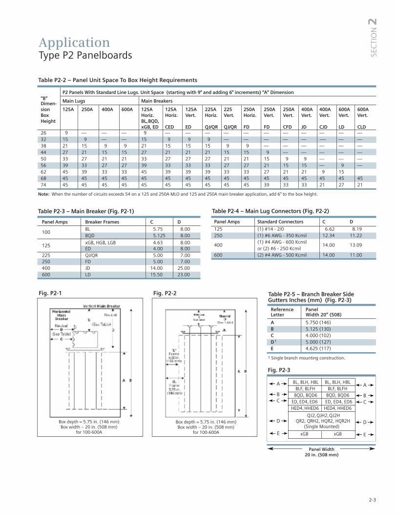
Table P2-2 – Panel Unit Space To Box Height Requirements
P2 Panels With Standard Line Lugs. Unit Space (starting with 9" and adding 6" increments) “A” Dimension“B” Main Lugs Main BreakersDimen-sion 125A 250A 400A 600A 125A 125A 125A 225A 225 250A 250A 250A 400A 400A 600A 600ABox Horiz. Horiz. Vert. Horiz. Vert. Horiz. Vert. Vert. Vert. Vert. Vert. Vert.Height BL,BQD,
xGB, ED CED ED QJ/QR QJ/QR FD FD CFD JD CJD LD CLD26 9 — — — 9 — — — — — — — — — — —32 15 9 — — 15 9 9 9 — — — — — -— — —38 21 15 9 9 21 15 15 15 9 9 — — — — — —44 27 21 15 15 27 21 21 21 15 15 9 — — — — —50 33 27 21 21 33 27 27 27 21 21 15 9 9 — — —56 39 33 27 27 39 33 33 33 27 27 21 15 15 — 9 —62 45 39 33 33 45 39 39 39 33 33 27 21 21 9 1568 45 45 45 45 45 45 45 45 45 45 45 45 45 45 45 4574 45 45 45 45 45 45 45 45 45 45 39 33 33 21 27 21
Table P2-4 – Main Lug Connectors (Fig. P2-2)
Panel Amps Standard Connectors C D
125 (1) #14 - 2/0 6.62 8.19250 (1) #6 AWG - 350 Kcmil 12.34 11.22
400(1) #4 AWG - 600 Kcmil
14.00 13.09or (2) #6 - 250 Kcmil
600 (2) #4 AWG - 500 Kcmil 14.00 11.00
Table P2-3 – Main Breaker (Fig. P2-1)
Panel Amps Breaker Frames C D
100BL 5.75 8.00BQD 5.125 8.00
xGB, HGB, LGB 4.63 8.00125
ED 4.00 8.00225 QJ/QR 5.00 7.00250 FD 5.00 7.00400 JD 14.00 25.00600 LD 15.50 23.00
Fig. P2-3
Fig. P2-1 Fig. P2-2
Box depth = 5.75 in. (146 mm) Box width – 20 in. (508 mm)
for 100-600A
Box depth = 5.75 in. (146 mm) Box width – 20 in. (508 mm)
for 100-600A
Table P2-5 – Branch Breaker Side Gutters Inches (mm) (Fig. P2-3)
Reference PanelLetter Width 20” (508)
A 5.750 (146)B 5.125 (130)C 4.000 (102)D1 5.000 (127)E 4.625 (117)
1 Single branch mounting construction.
BL, BLH, HBL BL, BLH, HBLBLF, BLFH BLF, BLFH
BQD, BQD6 BQD, BQD6 ED, ED4, ED6 ED, ED4, ED6HED4, HHED6 HED4, HHED6
A
Panel Width20 in. (508 mm)
QJ2,QJH2,QJ2HQR2, QRH2, HQR2, HQR2H
(Single Mounted)
A
B BC C
D D
Note: When the number of circuits exceeds 54 on a 125 and 250A MLO and 125 and 250A main breaker application, add 6” to the box height.
E E
SEC
TIO
N2
xGB xGB

2-4
ApplicationType P2 Panelboards
Table P2-6 – Main Breaker Selection1
1 Interchangeable trip main breakers are mounted at top of panel only.
2 Vertically mounted3 Twin mounted subfeed breakers are mounted at bottom of panelboard
only and adds 24" to the panel height. 4 Subfeed breaker is mounted at
bottom of panelboard only. 400 amp subfeed breaker adds 30" to the panel height (only for use with MLO).
Table P2-7 – Subfeed Breakers
Mounting Position Maximum Interrupting
Breaker When Used As Subfeed Breaker Rating (kA) Symmetrical
Type Vertical Ampere Ratings For Load 240V AC 480V AC 600V DC
FD63, FXD6 Twin/Single 70 - 250 65 35 18HFD63, HFXD6 Twin 70 - 250 100 65 25JD6 4, JXD6 Single 200 - 400 65 35 25HJD6 4, HJXD6 Single 200 - 400 100 65 35
AmpereRating
BreakerType
Max. Interrupting Rating (kA) Ref.Catalog No. Available Trip Values240V 480V 600V
100
BL 10 — — BL 15, 20, 25, 30, 35, 40, 50, 60, 70, 80, 90, 100HBL 65 — — HB 15, 20, 25, 30, 35, 40, 50, 60, 70, 80, 90, 100BQD 65 14 — BQ 15, 20, 25, 30, 35, 40, 50, 60, 70, 80, 90, 100BLH 22 — — BH 15, 20, 25, 30, 35, 40, 50, 60, 70, 80, 90, 100ED4 65 18 — E4 15, 20, 25, 30, 35, 40, 50, 60, 70, 80, 90, 100NGB 100 25 14 NB 15, 20, 25, 30, 35, 40, 50, 60, 70, 80, 100HGB 100 35 14 G2 15, 20, 25, 30, 35, 40, 50, 60, 70, 80, 100LGB 100 65 14 G3 15, 20, 25, 30, 35, 40, 50, 60, 70, 80, 100ED6 100 25 14 E6 15, 20, 25, 30, 35, 40, 50, 60, 70, 80, 90, 100HED4 100 42 — H4 15, 20, 25, 30, 35, 40, 50, 60, 70, 80, 90, 100HHED6 100 65 18 HA 15, 20, 25, 30, 35, 40, 50, 60, 70, 80, 90, 100CED6 2 200 200 100 CE 15, 20, 25, 30, 35, 40, 50, 60, 70, 80, 90, 100
125
NGB 100 25 14 NB 110, 125HGB 100 35 14 G2 110, 125LGB 100 65 14 G3 110, 125ED4 65 18 — E4 125ED6 65 25 18 E6 125HED4 100 42 — H4 125HHED6 100 65 18 HA 125CED62 200 200 100 CE 125
225
QJ2 10 — — QJ 60, 70, 80, 90, 100, 110, 125, 150, 175, 200, 225QJH2 22 — — QH 60, 70, 80, 90, 100, 110, 125, 150, 175, 200, 225QJ2H 42 — — Q2 60, 70, 80, 90, 100, 110, 125, 150, 175, 200, 225QR2 10 — — QR 100, 110, 125, 150, 175, 200, 225QRH2 25 — — Q4 100, 110, 125, 150, 175, 200, 225HQR2 65 — — Q5 100, 110, 125, 150, 175, 200, 225HQR2H 100 — — Q6 100, 110, 125, 150, 175, 200, 225FD6 65 35 18 FD 70, 80, 90, 100, 110, 125, 150, 175, 200, 225FXD6 65 35 18 FX 70, 80, 90, 100, 110, 125, 150, 175, 200, 225HFD6 100 65 25 HF 70, 80, 90, 100, 110, 125, 150, 175, 200, 225HFXD6 100 65 25 H2 70, 80, 90, 100, 110, 125, 150, 175, 200, 225CFD62 200 200 100 CF 70, 80, 90, 100, 110, 125, 150, 175, 200, 225
250
FD6 65 35 18 FD 250FXD6 65 35 18 FX 250HFD6 100 65 35 HF 250HFXD6 65 35 25 H2 250CFD62 200 150 1 00 CF 50
400
JXD62 65 35 25 JX 200, 225, 250, 300, 350, 400JD62 65 35 35 J6 200, 225, 250, 300, 350, 400HJXD62 100 65 35 H6 200, 225, 250, 300, 350, 400HJD62 100 65 35 H5 200, 225, 250, 300, 350, 400SJD62 65 35 25 SJ 200, 300, 400SHJD62 100 65 35 S2 200, 300, 400CJD62 200 200 100 CJ 200, 300, 400SCJD62 200 200 100 SC 200, 300, 400
600
LXD62 65 35 25 LX 450, 500, 600LD62 65 35 25 L6 250, 300, 350, 400, 450, 500, 600HLXD62 100 65 35 HL 250, 300, 350, 400, 450, 500, 600HLD62 100 65 35 HO 250, 300, 350, 400, 450, 500, 600SLD62 65 35 25 SL 300, 400, 500, 600SHLD62 100 65 35 S6 300, 400, 500, 600CLD62 200 150 100 CL 300, 400, 500, 600SCLD6 200 150 100 C6 300, 400, 500, 600
W
Note: When ED4, ED6,HED4, QJ2, QJH2, QJ2H, QR2, QRH2,HQR2,HQR2H, FD6,HFD6, or FXD6 framemain breaker, verticallymounted, is required,price as a main breakerpanel and add from the table for the main breaker mounting.

2-5
ApplicationType P2 Panelboards
Table P2-8 – Branch Circuit Breakers
Branch Device LimitationsLighting and appliance branch circuit panelboards were includedin editions of the National Electrical Code prior to 2008. By application rule (408.15 in all versions of the NEC prior to 2008),lighting and appliance panels are limited to 42 installed circuits.Each overcurrent device pole counts as a circuit.
Table P2-9 – Branch Neutral Connections
Wire Range Max. Number of Connections Max. Amps 3
#14-#6 48 65 #14-1/0 56 125#6 - 350 Kcmil 4 250(1) #4-600 Kcmil 1 400or (2) #6-250 Kcmil
11-Pole HED 4 15–30A Rated 65kA 35 through 100A Rated 25kA.2 Two pole breaker is one phase and neutral. Three pole is two phase and neutral.3 Based on 75 degree copper.4 2-pole only (or) two outer poles of 3-pole breaker.
NOTE: QJ/QR Breakers are single mounted in unit space and take 6" of unit space.Limited to (4) per panel max. xGB, BL, HBL, BLH and BQD breakers are mounted in common mountings in 3" or (6) pole increments. ED4, ED6, HED4 and HHED6 breakers are mounted in common mountings in 3" or (6) pole increments."
SEC
TIO
N2
Max.AmpRating
Bolt-OnBreakerType Amps
Availability Maximum Interrupting Rating (kA)
1-Pole 2-Pole 3-Pole 120V AC 120/240V AC 240V AC 277V AC 480V AC 600V AC 250V DC
100
15–60 P P P 10 — — — — — —BL 70 P P P — 10 — — — — —
80–100 — P P — — 10 — — — —15–60 P P P — 22 — — — — —
BLH 70 P P P — 22 — — — — —80–100 — P P — — 22 — — — —
HBL15–55 P P P — 65 — — — — —
60–100 — P P — 65 — — — — —BL, HID 15–30 P P — 10 10 — — — — —
BLR (240V)15–60 — P — — — 10 — — — —
70–100 — P — — — 10 — — — —
BLE (GFCI)15–30 P P — 10 — — — — — —40–60 — P — — 10 — — — — —
BLEH20–30 P — — 22 — — — — — —15–60 P P — — 22 — — — — —
BLF (GFCI)15–30 P P — 10 — — — — — —40–60 P P — — 10 — — — — —
BLHF (GFCI)15–30 P P — 22 — — — — — —40–60 P P — — 22 — — — — —
HBLF2 (GFCI) 15–30 P — — 65 — — — — — —BGL2 15–30 — P P 10 10 — — — — —BAF 15–20 P P — 10 — — — — — —BAFH 15–20 P P — 22 — — — — — —
BQD15–60 P P P — 65 — 14 — — 14
70–100 P P P — 65 — — 14 — 14
125
15–60 P P P 100 100 100 25 25 14 144
NGB 70–100 P P P 100 100 100 25 25 14 144
110–125 — P P 100 100 100 25 25 14 144
15–60 P P P 100 100 100 35 35 14 144
HGB 70–100 P P P 100 100 100 35 35 14 144
110–125 — P P 100 100 100 35 35 14 144
15–60 P P P 100 100 100 65 65 14 144
LGB 70–100 P P P 100 100 100 65 65 14 144
110–125 — P P 100 100 100 65 65 14 144
15–60 P P P 65 — — 22 — — —ED4 70–100 P P P — — 65 — 18 — 30
110–125 — P P — — 65 — 18 — —15–60 — P P — — 65 — 25 18 30
ED6 70–100 — P P — — 65 — 25 18 —110–125 — P P — — 65 — 25 18 —
15–60 P P P — — 65 — 42 18 30HED4a 70–100 P P P — — 65 — 42 18 —
110–125 — P P — — 65 — 42 18 —
225
QJ2 60–225 — P P — — 10 — — — —QJH2 60–225 — P P — — 22 — — — —QJ2H 60–225 — P P — — 42 — — — —QR2 100–225 — P P — — 10 — — — —QRH2 100–225 — P P — — 25 — — — —HQR2 100–225 — P P — — 65 — — — —HQR2H 100–225 — P P — — 100 — — — —

2-6
Typical Catalog NumbersType P2 Panelboards
Table P2-10 – Main Lugs Only
Table P2-11 – Main Circuit Breaker
Maximum Maximum Box Catalog Number Catalog Number Catalog NumberPanel 1-pole HeightAmp Rating Circuits Inches 3Ø4W 208Y/120V 1Ø3W 120/240V 3Ø4W 480Y/277V
18 26 P2C18ML125ATS P2A18ML125ATS P2E18ML125ATS30 32 P2C30ML125ATS P2A30ML125ATS P2E30ML125ATS42 38 P2C42ML125ATS P2A42ML125ATS P2E42ML125ATS
125 54 56 P2C54ML125ATS P2A54ML125ATS P2E54ML125ATS66 62 P2C66ML125ATS P2A66ML125ATS P2E66ML125ATS78 68 P2C78ML125ATS P2A78ML125ATS P2E78ML125ATS90 74 P2C90ML125ATS P2A90ML125ATS P2E90ML125ATS18 32 P2C18ML250ATS P2A18ML250ATS P2E18ML250ATS30 38 P2C30ML250ATS P2A30ML250ATS P2E30ML250ATS42 44 P2C42ML250ATS P2A42ML250ATS P2E42ML250ATS
250 54 56 P2C54ML250ATS P2A54ML250ATS P2E54ML250ATS66 62 P2C66ML250ATS P2A66ML250ATS P2E66ML250ATS78 68 P2C78ML250ATS P2A78ML250ATS P2E78ML250ATS90 74 P2C90ML250ATS P2A90ML250ATS P2E90ML250ATS18 38 P2C18ML400ATS P2A18ML400ATS P2E18ML400ATS30 44 P2C30ML400ATS P2A30ML400ATS P2E30ML400ATS42 50 P2C42ML400ATS P2A42ML400ATS P2E42ML400ATS
400 54 56 P2C54ML400ATS P2A54ML400ATS P2E54ML400ATS66 62 P2C66ML400ATS P2A66ML400ATS P2E66ML400ATS78 68 P2C78ML400ATS P2A78ML400ATS P2E78ML400ATS90 74 P2C90ML400ATS P2A90ML400ATS P2E90ML400ATS18 38 P2C18ML600ATS P2A18ML600ATS P2E18ML600ATS30 44 P2C30ML600ATS P2A30ML600ATS P2E30ML600ATS42 50 P2C42ML600ATS P2A42ML600ATS P2E42ML600ATS
600 54 56 P2C54ML600ATS P2A54ML600ATS P2E54ML600ATS66 62 P2C66ML600ATS P2A66ML600ATS P2E66ML600ATS78 68 P2C78ML600ATS P2A78ML600ATS P2E78ML600ATS90 74 P2C90ML600ATS P2A90ML600ATS P2E90ML600ATS
18 26 P2C18BL100ATS P2A18BL100ATS P2E18BL100ATS100 30 32 P2C30BL100ATS P2A30BL100ATS P2E30BL100ATS
42 38 P2C42BL100ATS P2A42BL100ATS P2E42BL100ATS30 32 P2C30NB125ATS P2A30NB125ATS P2E30NB125ATS42 38 P2C42NB125ATS P2A42NB125ATS P2E42NB125ATS
125 54 56 P2C54NB125ATS P2A54NB125ATS P2E54NB125ATS66 62 P2C66NB125ATS P2A66NB125ATS P2E66NB125ATS78 68 P2C78NB125ATS P2A78NB125ATS P2E78NB125ATS90 74 P2C90NB125ATS P2A90NB125ATS P2E90NB125ATS18 32 P2C18QR225ATS P2A18QR225ATS P2E18FX225ATS30 38 P2C30QR225ATS P2A30QR225ATS P2E30FX225ATS42 44 P2C42QR225ATS P2A42QR225ATS P2E42FX225ATS
2251 54 56 P2C54QR225ATS P2A54QR225ATS P2E54FX225ATS66 62 P2C66QR225ATS P2A66QR225ATS P2E66FX225ATS78 68 P2C78QR225ATS P2A78QR225ATS P2E78FX225ATS90 74 P2C90QR225ATS P2A90QR225ATS P2E90FX225ATS18 38 P2C18FX250ATS P2A18FX250ATS P2E18FX250ATS30 44 P2C30FX250ATS P2A30FX250ATS P2E30FX250ATS
250 42 50 P2C42FX250ATS P2A42FX250ATS P2E42FX250ATS54 62 P2C54FX250ATS P2A54FX250ATS P2E54FX250ATS66 68 P2C66FX250ATS P2A66FX250ATS P2E66FX250ATS78 74 P2C78FX250ATS P2A78FX250ATS P2E78FX250ATS18 50 P2C18JX400ATS P2A18JX400ATS P2E18JX400ATS30 56 P2C30JX400ATS P2A30JX400ATS P2E30JX400ATS
400 42 62 P2C42JX400ATS P2A42JX400ATS P2E42JX400ATS54 68 P2C54JX400ATS P2A54JX400ATS P2E54JX400ATS66 74 P2C66JX400ATS P2A66JX400ATS P2E66JX400ATS18 56 P2C18LX600ATS P2A18LX600ATS P2E18LX600ATS
600 30 62 P2C30LX600ATS P2A30LX600ATS P2E30LX600ATS42 68 P2C42LX600ATS P2A42LX600ATS P2E42LX600ATS54 74 P2C54LX600ATS P2A54LX600ATS P2E54LX600ATS
1 QJ series was available prior to QR.

2-7
Standard ModificationsType P2 Panelboards
P2 Panel OptionsEnclosures• Extra gutter to sides or ends of the can• 24" wide boxes• Hinged trims• Door-in-door trims• Screw to the box trims• Trim mounted devices (Devices mounted and wired
to the trim should also have hinged trim specified)• Pilot lights • Toggle switches• Push buttons
• Painted boxes• Custom colors • Increase gauge trims and boxes• Stainless steel trims and boxes, Type 1
Panel Modifications• Main Bus
Standard main bus is temperature rated tin-plated aluminum. Bus options are 750 A/Si aluminum, tin-plated temperature rated copper tin-plated standard – silver optional. 1000 A/Si copper tin-plated standard – silver optional. Includes copper neutral cross bar. For copper neutral branch lugs, see miscellaneous.
• Split bus adds 6” to unit space• Compression lug for MLO • Compression lugs on Main breaker (may require
extra width or length on enclosure). • Contactor mains or submain
• Asco 920 through 225 amps. Adds 12” unit space as main, 15” unit space as submain.
• Asco 911 through 150 amps. Adds 21” unit space.• Siemens LEN through 30 amps. Adds 12” unit space.
Makes box 10" deep.• Control power transformers (contact engineering for extra
gutter requirements)• Branch and main breaker accessories
• Handle blocks• Handle locks• Aux. Contacts 1
• UVR 1
• Feed-thru lugs• 200% neutral• Copper lugs, mechanical• Bus mounted TVSS• Service entrance labeled
Type P2 Panelboards are factory labeled suitable for use as service entrance equipment when NEC requirements are met. A panelboard cannot have more than six main disconnects, unless it is a lighting and appliance branch panelboard. Lighting and appliance branch panelboards are limited to two main disconnects. Factory installed and Field installable Service Entrance Barrier kits are now available as required by UL67. (In COMPAS, you must select Service Entrance Required.)
1 Accessories on 1" pole breakers (BL, BQD, ED) will take unit space
• Aluminum trims and boxes, Type 1• NEMA 3R enclosures• NEMA 3R/12 enclosures• NEMA 4 enclosures• NEMA 4X enclosures• Special keyed locks
• TEY • LL803• TEU1 • LL806• Cat 60 • Yale
• Gasketing trim to box• Meters (Contact application engineering for space
requirements)• Panel Skirts
• Grounding of panelboards Ground Bars, except brazed-to-box, are shipped with thepanel interior factory mounted.
• Non-Insulated Equipment Ground Bar – Standard• Copper Non-Insulated Ground Bar• Al Insulated Equipment Ground Bar• Cu Insulated Equipment Ground Bar• Ground Bar Brazed to Box (recommended for
painted boxes)• Shunt Trip on Main or Branch
BL, BLH, HBL, ED2, ED4, HED4, HED6, HHED6 uses 1” unitspace for shunt trip. All may be used on mains or subfeeds.
• Remote control switches – 480V AC max. mounted in a 23” enclosure to be cable connected to the panel.
• Time Clocks – mounted in a 23” enclosure to be cable connected to the panel. Sangamo, Tork or Paragon time clock can be supplied and mounted in panelboard cabinet.
QJ2, QJ2H, QJH2, QR2, QRH2, HQR2, HQR2H, ED2, ED4, ED6, HED4,HED6, HHED6, FXD6, HFD6, JXD6, JD6, HJD6, HJXD6
DescriptionTime Clock (1-or 2-Pole, Single or Double Throw Contacts; 3-Pole Single Throw)277V Maximum with Plain DialOptions –
Astronomical DialAn Omitting DeviceReserve Power or CarryoverSpace and Mounting Provisions Only
SEC
TIO
N2

Standard ModificationsType P2 Panelboards
Table P2-12 – Box Size Additions (In.) For Optional Features on MLO Applications
2-8
Split bus is paired with feed-thru lugs by default. Feed-thru lugs are to feed the section after the split.
NOTE: N/A = OPTION NOT AVAILABLE*Min. Box Size, corresponding to 9" of Unit Space.
*Min. Box Size 26" 32" 38" 38" 26" 32" 32" 32" 38" 38" 44" 50" 50" 62" 56" 62"200% Neutral 0 0 6 (all) 6 (all) 0 0 0 N/A 0 N/A 0 0 0 0 0 0(lug type)Std. Lugs 0 0 0 0 0 0 0 0 0 0 0 0 0 0 0 0(100% Neut. PNL) CU Lugs (100% 6 6 6 0 N/A N/A 0 N/A 0 N/A 0 0 0 0 0 0Neut. PNL)Comp Lugs 6 6 6 6 N/A N/A 0 N/A 0 N/A 0 0 0 0 0 0(100% Neut. PNL)
Feed-thruStandard Lugs 6 6 12 12 6 6 6 N/A 6 N/A 6 6 12 12 12 12Feed-thru Cu Lugs 6 6 12 N/A N/A N/A 6 N/A 6 N/A 6 6 12 12 N/A N/AFeed-thru
Comp Lugs 6 12 12 N/A N/A N/A 6 N/A 6 N/A 12 12 12 12 N/A N/ASubfeed Standard
Lugs 0 6 6 N/A — — — — — — — — N/A — — —Split Bus 6 6 6 6 6 6 6 N/A 6 N/A 6 6 6 6 6 6(1) FD Subfeed N/A 12 12 12 N/A N/A N/A N/A N/A 12 12 12 12 12 12 12(Horizontal Mtg.)(2) FD Subfeed N/A 24 24 24 N/A N/A N/A N/A N/A 24 24 24 24 N/A N/A N/A(Vertical Mtg.)
SPD 12 12 12 12 12 12 12 12 12 12 12 12 12 12 12 12
Main Lugs Main Breakers
125A 250A 400A 600A 125A 125A 125A 225A 225A 225A 250A 250A 400A 400A 600A 600A Options Horiz. Horiz. Vert. Horiz. Vert. Horiz. Vert. Vert. JD CJD LD CLD BL, BQD, QJ QJ ED, xGB CED ED QR QR FD FD CFD
2-9
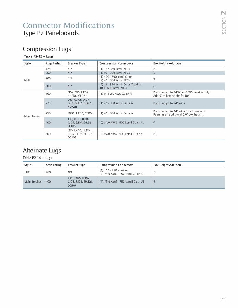
Connector ModificationsType P2 Panelboards
Style Amp Rating Breaker Type Compression Connectors Box Height Addition
125 N/A (1) #6 - 350 kcmil Al/Cu 6250 N/A (1) #6 - 350 kcmil Al/Cu 6
(1) 400 - 600 kcmil Cu or6MLO
400 N/A(2) #6 - 350 kcmil Al/Cu
600 N/A (2) #6 - 350 kcmil Cu or Cu/Al or 6400 - 600 kcmil Al/Cu
100 ED4, ED6, HED4 (1) #14-2/0 AWG Cu or Al Box must go to 24”W for CED6 breaker only HHED6, CED61 Add 6” to box height for NØQJ2, QJH2, QJ2H,
225 QR2, QRH2, HQR2, (1) #6 - 350 kcmil Cu or Al Box must go to 24” wideHQR2H
250 FXD6, HFD6, CFD6, (1) #6 - 350 kcmil Cu or AlBox must go to 24” wide for all breakers
Main BreakerRequires an additional 6.0” box height
JD6, JXD6, HJD6, 400 CJD6, SJD6, SHJD6, (2) #1/0 AWG - 500 kcmil Cu or AL 9
SCJD6
LD6, LXD6, HLD6,600 CJD6, SLD6, SHLD6, (2) #2/0 AWG - 500 kcmil Cu or Al 6
SCLD6
Compression LugsTable P2-13 – Lugs
SEC
TIO
N2
Style Amp Rating Breaker Type Compression Connectors Box Height Addition
MLO 400 N/A(1) 250 - 350 kcmil or
6(2) #3/0 AWG - 250 kcmil Cu or Al
JD6, JXD6, HJD6,Main Breaker 400 CJD6, SJD6, SHJD6, (1) #3/0 AWG - 750 kcmill Cu or Al 6
SCJD6
Alternate LugsTable P2-14 – Lugs

2-10
Connector ModificationsType P2 Panelboards
Enclosure Modifications
Remote Switch Modifications
Standard Actual NEMABox Height Enclosure SizeInches H W D 32 32 20 838 42 30 844 48 36 856 60 36 10
Enclosure Modification NEMA 4 for Type P2 Water Tight and Dust Tight, Steel Enclosure (consult plant to verifyenclosure size)
Table P2-18 – Applications for a Remote Switch
Switch Type Modification
ASCO 920 30 to 225A – Add 12” to MLO box heightASCO 9111 ≤ 225A – Add 21” to the box height. >225A is not available in P2
LEN 60A to 100A adds 6” to the box height with a min. depth of 7.75”200A adds 6” to the box height with a min. depth of 10.00”
1 >225A is recommended for use in a P4 panel.
.Table P2-19 – Remote Control Switch Modification
DescriptionAuxiliary Contacts (mounted not wired) Ea. 2-Wire Control
Table P2-17 – Control Power Transformer
Size VA
0,1 502 753 1504 250
Table P2-15
NEMA-4X For Type P2 Water Tight, Dust Tight and Corrosion Resistant(consult plant to verify enclosure size)
Enclosure - Stainless Steel Enclosure - Stainless Steel andand Steel with Epoxy Coating Steel with Epoxy Coating1
Box HeightInches H W D H W D
26 26 36 30 832 32 36 30 838 38 48 36 1244 44 48 36 1250 50 20 5.75 60 36 1256 56 60 36 1262 62 — — —68 68 — — —74 74 — — —
Table P2-16
1 Limited to the sizes shown.
Note: Larger NEMA 4 enclosures are not available.

2-11
DimensionsType P2 Panelboards
Type 1 BoxBox is symmetrical
Type 3R and 3R/12 Box
1
1
1
1
SEC
TIO
N2
2
1
2
1
1 Dimensions are interior of the box. Add 5/8” to width for absolute dimension. Add 1/8” to height for absolute dimension.
2 See table P2-12 to match ratings with height.
Dimensions shown in inches and millimeters [ ].

2-12
DimensionsType P2 Panelboards
A B C Standard Box Size
17.94 18.00 16.75 26H 20W 5.75D
23.94 24.00 22.75 32H 20W 5.75D
29.94 30.00 28.75 36H 20W 5.75D
35.94 36.00 34.75 44H 20W 5.75D
41.94 42.00 40.75 50H 20W 5.75D
47.94 48.00 46.75 56H 20W 5.75D
53.94 54.00 52.75 62H 20W 5.75D
59.94 60.00 58.75 68H 20W 5.75D
65.94 66.00 64.75 74H 20W 5.75D

Kits and AccessoriesType P2 Panelboards
Table P2-20 – Standard Enclosures
Options For Type 1 TrimsItems must be ordered as manual line item on Spartanburg.Hinged trim – Replace “B” suffix with “H”Door-in-door – Replace “B” suffix with “D”Screw to Box – Replace "B" suffix with "C"Metal card holder – Replace “B” suffix with “M” on standard trim, add “M” suffix on optional trims
Option For 24” Wide Enclosures with Equal Gutter on Both Sides (Excludes NEMA 3R)24” wide with equal gutter on both sides - Add “24” as prefix
Catalog Number
Box Type1 Type 3R Type 3R/12Height Standard TrimInches Box Surface Flush
26 B26 S26B F26B NR26 WP2632 B32 S32B F32B NR32 WP3238 B38 S38B F38B NR38 WP3844 B44 S44B F44B NR44 WP4450 B50 S50B F50B NR50 WP5056 B56 S56B F56B NR56 WP5662 B62 S62B F62B NR62 WP6268 B68 S68B F68B NR68 WP6874 B74 S74B F74B NR74 WP74
Table P2-21 – Breaker Kits and Accessories
1 Although QR is rated 250A. it is limited to 225A in panelboard.2 Two kits required for P2 extended circuit panels.3 Factory installed and Field installable Service Entrance Barrier kits are now available as required by UL67. (In COMPAS, you must select Service Entrance Required.)
2-13
2SE
CTI
ON
Kit No. Description ContentsBBKB32 (P2/P3) BL/BQD 6-pole 3” branch breaker kit Kit contains top barrier, (3) A/C connectors, (1) B connectors, hardwareBBKED32 (P2/P3) ED 6-pole 3” branch breaker kit Kit contains breaker support. inter-phase barriers, (3) AC connectors, (1) B connector, hardwareBBKNB32 (P2/P3) xGB 6-pole 3” branch mounting kit Kit contains top barrier, (3) A/C connectors, (1) B connector, hardware
BBKQ1 (P2) QJ/QR branch breaker kit for 2 and Kit to contain all connectors and cover plates necessary to mount both 2 and -pole breakers3-pole single mount
BBKQR11 P2 branch BKR strap kit for single QR1-phase/3-phase
BBKQR21 P3 branch BKR strap kit for single QR1-phase/3-phase
DFK1 BL, BQD, ED deadfront kit for Center strips 3”, 6”, 9”, 15”, 21” plus mounting hardware 1” pole breakers
DFFP3 Deadfront filler 3” 3” empty space filler and hardwareDFFP6 Deadfront filler 6” 6” empty space filler and hardwareBNK2 Branch neutral (P2) Three tier lug with mounting hardware to increase neutral capacityP2BK1 P2 250A max. bonding kit Bonding strap and hardwareP2BK2 P2 400A max. bonding kit Bonding strap and hardwareP2BK3 P2 600A max. bonding kit Bonding strap and hardware
BBKQRP1FK P2 filler for QR. Horizontal or vertical Kit contains all cover plates necessary to change from QJ to QR both 2 and 3-pole breakers.mount. 1-phase/3-phase.
BBKQRP2FK P3 filler for QR. Dual mount Kit contains all cover plates necessary to change from QJ to QR both 2 and 3-pole breakers. For horizontal. 1-phase/3-phase. 1-phase panel, both breakers must change from QJ to QR, cannot have one of each installed.
SEBKP2V13BL, BQD Main Service Entrance Barrier Kit contains barrier, mounting brackets, and hardware(P2 only)
SEBKP2V2 3 xGB Main Service Entrance Barrier Kit contains barrier, mounting brackets, and hardware (P2 only)
SEBKP2V3 3 FD, QJ, QR Horizontal Main Service Kit contains barrier, mounting brackets, and hardwareEntrance Barrier (P2, P2 with SEM3, P3)
SEBKP2V4 3 FD, QJ, QR Vertical Main Service Kit contains barrier, mounting brackets, and hardwareEntrance Barrier (P2, P2 with SEM3)
SEBKP2V5 3 ED Horizontal Main Service Entrance Kit contains barrier, mounting brackets, and hardwareBarrier (P2, P2 with SEM3)
SEBKP2V6 2 3 ED Vertical Main Service Entrance Kit contains barrier, mounting brackets, and hardwareBarrier (P2, P2 with SEM3)
SEBKP1P2P3V13 JD, LD Service Entrance Barrier Kit Kit contains barrier, mounting brackets, and hardware(RP1, P1, P2, P3)

Notes
P3 PanelboardsDescription PageGeneral Information 3-2
Selection and Application 3-2Application 3-3 – 3-5
Panel Unit Space to Box Height Requirements 3-3Main Breaker and Main Lug Wire Bending 3-3Branch Breaker Side Gutters 3-3Main Lug and Main Breaker
Unit Space Dimensions 3-3Main Breaker Selection 3-4Subfeed Breakers 3-4Neutral Connectors 3-4Branch Circuit Breakers 3-5
Typical Catalog Numbers 3-6 – 3-7Main Lugs 3-6Main Circuit Breakers 3-7Standard Modifications 3-8 – 3-9Option Combinations 3-9
Connector Modifications 3-10Compression Lugs 3-10Enclosure Modifications 3-10Remote Switch Modifications 3-10Dimensions 3-11Kits and Accessories 3-13
SEC
TIO
N3

3-2
Type P3 Panelboards
Another innovation from Siemens is the P3 panel. It is a smaller,footprint distribution panel to fit a large number of applicationsthat require more (or larger) branch devices than the lightingpanel class offer. This panel offers a wide array of factory-assembled options, and has the ability to mix breaker frames in unit space up to 250 amps. Bussing options for the P3 varyfrom the standard temperature aluminum to temperature rated copper, 750 A/Si aluminum, and 1000A/Si copper designs. All bussing in the P3 panel is tin-plated as a standard. Silver-plated copper is offeredas an option on a copper bus. Integrated time clocks, bus mounted contactors, as mains or sub mains, split bus and subfeed lugs (up to 400 amp) are just a few of the options of this unique panel.
The P3 panel configurations, defined by the unit space, allow for a given amperage, main device, and box height. The P3 panel starts with a 56" high box. Breaker unit space can be mixed and matched to meet customer requirements. All 1" pole breakers (BL, BQD, ED, xGB frames)are mounted in 3" or 6" pole increments. Breakers frames, above 125amps, are mounted in 6" single or twin breaker mountings. As an example panel, FD 250 amp and JD 400 amp breakers are mounted as subfeed breakers outside of unit space.
Like other distribution panels, the P3 panel can have blank space addedinto the panel to allow for future expansions or modifications. Anyexpansions or modifications must be in 3" increments. BL, BQD and ED frame breakers have 3" or 6-pole kits and can be mixed in unit spaceby these increments. Breakers of the same frame can cross from onemounting to another if contiguous. xGB frame breakers cannot be mixed with other frame types. Any expansion or modification must be in 3" increments also. QJ/QR frame breakers are mounted in 6" increments for two -and three pole single and twin mounted units.Changes in the unit space length for BL, BQD, xGB, or ED frame breakersrequire an additional deadfront center strip kit. Check with sales or thefactory for additional unit space kits.
Main Lug / Main BreakerEnclosure – Standard Type 1 enclosure is 24" wide x 7.75" deep. X Box Height is determined by main device and unit space.See charts for box height.
Voltage – 600 Vac Max.250 Vdc Max.
Amperage – 800 amp Max.
Short Circuit Rating – 200 KAIC Max. symmetrical or equal to the lowest rated device installed unless a series rating is indicated. Panels with subfeed or feed-thru lugs without a main device, circuit breaker or fusible unit, are limited to a three-cycle rating. The three-cycle rating for the P3 panel is limited to 22 KAIC. Note that the main device may be mountedremote from the panel.
Bussing – The P3 panel has more options to meet marketrequirements. The standard bussing is temperature rated aluminum. The rating is per the requirements of UL 67 – the standard for panelboards. All aluminum bussing is tin-plated.Optional bussing for the P3 panel is: 750 A/si aluminum, temperature rated copper, and 1000 A/si copper. The copper bus option for this panel is tin-plated.
Weight – ApproximateTotal panelboard weight when filled with a normal quantity of breakers and accessories is about 5 lbs. (1 kg) per inch (54g per mm) of box height.
Table P3-1 – Gauge Steel of Boxes Fronts, Surface & Flush
Selection and Application1) To specify a particular panelboard, first determine voltage,
system, amperage and type main, amperage and type of branch devices, and modifications, if any. (Step 1)
2) List branch devices and modifications requiring space additions. List unit space requirements of each.
Note: Some units are twin mounted meaning two breakers occupy the same unit space.
Select appropriate enclosure height from selection chart on page 3-3, based on unit space requirements. (Step 2)
3) Select panelboard catalog number from appropriate table based upon voltage, system, amperage and unit space requirements. (Step 3)
Dimensions in inches (mm) Gauge SteelWidth Height Box Front
24” 56 - 80 #16 #14(610) (1422, 2032)
Step #1
Amperage 400Voltage 208Y/120System 3 Phase, 4 wireMain Main LugBus Standard AluminumBranches 6-20A13, 2-225/3,Modifications NoneFeed TopMounting Surface
Step #2
6-20A/3 3x3” = 6 poles = 9”2-225/3 QJ2/QR2 6” = 6”
15”
Enclosure is 56” from Table P3-2(24” wide, 56” high, 7.75” deep).
Step #3
Panel - P3C56ML400ATSBox - 24WD56Trim - P3S56
1 ASI = Amperes per square inch

ApplicationType P3 Panelboards
Table P3-4 – Main Lug Wire Bending (Fig. P3-2)Table P3-3 – Main Breaker Wire Bending (Fig. P3-1)
BreakerFrame C E F
FD Horiz. 7.25 — 20.13FD Vert. — 12.25 25.38CFD — 13.63 31.38JD — 15.63 29.38CJD — 14.75 35.38LD — 14.75 29.38CLD — 14.00 35.38
Fig. P3-3
Fig. P3-1 Fig. P3-2
Box depth = 7.75 in. (197 mm) Box width = 24 in. (610 mm)
Box depth = 7.75 in. (197 mm) Box width = 24 in. (610 mm)
Table P3-5 – Branch Breaker Side Gutters Inches (mm) (Fig. P3-3)
Reference PanelLetter Width 24” (609)
A 7.750 (197)B 7.125 (181)C 6.000 (152)D1 7.000 (178)E 5.000 (127)
F 6.625 (168)G 5.750 (144)
Panel Width24 in. (610 mm)
1 This lug is classified as removable.
Panel Amps Standard Connectors C D
250 (1) #6 AWG - 350 kcmil 10.75 1 13.50
400(2) #3/0 AWG - 250 kcmil
16.00 17.88or (1) #3/0 600 kcmil
600 (2) #3/0 AWG - 500 kcmil or 16.00 17.88800 (2) #3/0 - 600 kcmil 16.00 17.88
Table P3-2 – Panel Unit Space To Box Height Requirements
P3 Panels With Standard Line Lugs. Unit Space (starting with 9" and adding 6" increments) “A” Dimension
“B” Main Lugs Main BreakersDimension 250A 400A 600A 800A 250A 250A 250A 400A 400A 600A 600A Box Height Horizontal Vertical Vertical Vertical Vertical Vertical Vertical
FD FD CFD JD CJD LD CLD
56 27 21 21 21 21 15 9 9 — 9 —62 33 27 27 27 27 21 15 15 9 15 933 39 33 33 33 33 27 21 21 15 21 1574 45 39 39 39 39 33 27 27 21 27 2180 45 45 45 45 45 39 33 33 27 33 27
3-3
Table P3-6 – Subfeed Breaker Wire Bending (Fig. P3-1)
Breaker Reference DimensionsFamily C E F
FD Single 7.25 — 8.25Dual FD — 15.25 8.25Single JD 8.00 — 29.38
QJ2, QJH2, QJ2H, QR2, QRH2, HQR2, HQR2H
QJ2, QJH2, QJ2H, QR2, QRH2, HQR2, HQR2H
A ABL, BLH, HBL BL, BLH, HBL
BLF2, BLHF2, BLF2, BLHF2,HBLF2, BLFB, BLHFB
BQD, BQD6
BQD, BQD6
HBLF2, BLFB, BLHFB
SEC
TIO
N3
1 Single branch mounting constuction.

ApplicationType P3 Panelboards
Table P3-7 – Main Breaker Selection1
1 Vertically mounted 2 STD – Standard configuration. ADD – Additional cost.
Table P3-8 – Subfeed Breaker Selection and Mounting Reference
Mounting Orientation Maximum Interrupting Rating (ka)
Breaker and Configuration
Type Vertical Horizontal 240V AC 480V AC 600V DC Available Trip Values
FD , FXDTwin — 65 35 18
HFD, HFX6 — Single 100 65 25 70, 80, 90, 100, 110, 125, 150, 200, 225, 250
JXD, JD6 — Single 65 35 25200, 225, 250, 300, 350, 400HJXD6
100 65 35HJD6
Branch Device LimitationsLighting and appliance branch circuit panelboards were included in editions of the National Electrical Code prior to2008 By application rule (40815 in all versions of the NEC prior to 2008), lighting and appliance panels are limited to 42 installed circuits. Each over current device pole counts as a circuit.
Table P3-9 – Neutral Connectors (Based on 75ºC copper)
Max. Number Wire Range of Connections Max. Amps
#14 - #1/0 44 125#4 - 350 kcmil 6 250(1)#4 - 600 kcmil or
1 400(2)#6 - 250 kcmil
Maximum Interrupting Ref.Ampere Breaker Rating (kA) Catalog Available Configurations 2
Rating Type 240V 480V 600V Number 240V AC 480V AC 600V AC Available Trip Values
FD6 65 35 18 FD STD STD STD 70, 80, 90, 100, 110, 125, 150, 200, 225, 250 FXD6 65 35 18 FX STD STD STD 70, 80, 90, 100, 110, 125, 150, 200, 225, 250250 HFD6 100 65 25 HF ADD ADD ADD 70, 80, 90, 100, 110, 125, 150, 200, 225, 250 HFXD6 100 65 25 H2 ADD ADD ADD 70, 80, 90, 100, 110, 125, 150, 200, 225, 250 CFD61 200 150 100 CF ADD ADD ADD 70, 80, 90, 100, 110, 125, 150, 200, 225, 250
JXD61 65 35 25 JX STD STD STD 200, 225, 250, 300, 350, 400 JD61 65 35 25 J6 STD STD STD 200, 225, 250, 300, 350, 400 HJXD61 100 65 35 H6 ADD ADD ADD 200, 225, 250, 300, 350, 400
400 HJD61 100 65 35 H5 ADD ADD ADD 200, 225, 250, 300, 350, 400 SJD61 65 35 25 SJ ADD ADD ADD 200, 300, 400 SHJD61 100 65 35 S2 ADD ADD ADD 200, 300, 400 CJD61 200 200 100 CJ ADD ADD ADD 200, 300, 400 SCJD61 200 200 100 SC ADD ADD ADD 200, 300, 400
LXD61 65 35 25 LX STD STD STD 450, 500, 600 LD61 65 35 25 L6 STD STD STD 250, 300, 350, 400, 450, 500, 600 HLXD61 100 65 35 HL ADD ADD ADD 250, 300, 350, 400, 450, 500, 600
600 HLD61 100 65 35 HO ADD ADD ADD 250, 300, 350, 400, 450, 500, 600 SLD61 65 35 25 SL ADD ADD ADD 300, 400, 500, 600 SHLD61 100 65 35 S6 ADD ADD ADD 300, 400, 500, 600 CLD61 200 150 100 CL ADD ADD ADD 300, 400, 500, 600 SCLD6 200 150 100 C6 ADD ADD ADD 300, 400, 500, 600
Ref.Catalog Number
3-4

3-5
ApplicationType P3 Panelboards
Table P3-10 – Branch Circuit Breakers
Note: QJ/QR Breakers are twin mounted in unit spaceand take 6" of unit space. Limited to (6) per panel max. BL, HBL, BLH and BQD breakers are mounted incommonmountings in 3" or (6) pole increments. ED2,ED4, ED6, HED4 and HHED6 breakers are mounted incommon mountings in 3" or (6) pole increments.
1 BGL 2-pole is (1) phase and neutral 3-pole is (2) phases and neutral.2 2-pole only (or) two outer poles of 3-pole breaker.
SEC
TIO
N3
Max. AmpRating
Bolt-OnBreaker Type Amps
Provisions for Maximum Interrupting Rating (kA)
120V AC 120/240V AC 240V AC 277V AC 480V AC 600V AC 250V DC
100
BL15–60 10 — — — — — —70 — 10 — — — — —80–100 — — 10 — — — —
BLH15–60 — 22 — — — — —70 — 22 — — — — —80–100 — — 22 — — — —
HBL15–55 — 65 — — — — —60–100 — — 65 — — — —
BL, (HID) 15–30 10 — — — — — —
BLR (240V)15–60 — — 10 — — — —70–100 — — 10 — — — —
BLE (GFCI)15–30 10 — — — — — —40–60 — 10 — — — — —
BLEH (GFCI)15–30 22 — — — — — —15–60 — 22 — — — — —
BLF (GFCI)15–30 10 — — — — — —40–60 — 10 — — — — —
BLHF (GFCI)15–30 22 — — — — — —40–60 — 22 — — — — —
HBLF2 (GFCI) 15–30 65 — — — — — —BGL1 15–30 10 — — — — — —BAF 15–20 10 — — — — — —BAFH 15–20 22 — — — — — —BQD 15–60 — 65 — — 14 — 14
70–100 — — 65 — 14 — 14
125
15–60 100 100 100 25 25 14 142
NGB 70–100 100 100 100 25 25 14 142
110–125 100 100 100 25 25 14 142
15–60 100 100 100 35 35 14 142
HGB 70–100 100 100 100 35 35 14 142
110–125 100 100 100 35 35 14 142
15–60 100 100 100 65 65 14 142
LGB 70–100 100 100 100 65 65 14 142
110–125 100 100 100 65 65 14 142
15–60 85 85 85 35 35 22 35NEB 70–100 85 85 85 35 35 22 35
110–125 85 85 85 35 35 22 3515–60 100 100 100 65 65 25 42
HEB 70–100 100 100 100 65 65 25 42110–125 100 100 100 65 65 25 4215–60 65 — — 22 — — —
ED4 70–100 — — 65 — 18 — 30110–125 — — 65 — 18 — —15–60 — — 65 — 25 18 30
ED6 70–100 — — 65 — 25 18 —110–125 100 — — — — — —15–60 100 — — — — — —
HED4 70–100 — — — 65 — — —110–125 — — — 65 — — —
225
QJ2 60–225 — — 10 — — — —QJH2 60–225 — — 22 — — — —QJ2H 60–225 — — 42 — — — —QR2 100–225 — — 10 — — — —QRH2 100–225 — — 25 — — — —HQR2 100–225 — — 65 — — — —HQR2H 100–225 — — 100 — — — —
B

3-6
Typical Catalog NumbersType P3 Panelboards
Table P3-11 – Main Lugs Only – shown with aluminum bus, top fed, and surface trims
208Y/120V 240/120V 120/240V or 250 Vdc Max
Maximum 3 Phase, 4 Wire 3 Phase, 4 Wire 1 Phase, 3 WirePanel Amp Rating Unit Space (inches) Catalog Number Catalog Number Catalog Number
27 P3C56ML250ATS P3B56ML250ATS P3A56ML250ATS33 P3C62ML250ATS P3B62ML250ATS P3A62ML250ATS
250 39 P3C68ML250ATS P3B62ML250ATS P3A62ML250ATS45 P3C74ML250ATS P3B74ML250ATS P3A74ML250ATS51 P3C80ML250ATS P3B80ML250ATS P3A80ML250ATS21 P3C56ML400ATS P3B56ML400ATS P3A56ML400ATS27 P3C62ML400ATS P3B62ML400ATS P3A62ML400ATS
400 33 P3C68ML400ATS P3B68ML400ATS P3A68ML400ATS39 P3C74ML400ATS P3B74ML400ATS P3A74ML400ATS45 P3C80ML400ATS P3B80ML400ATS P3A80ML400ATS21 P3C56ML600ATS P3B56ML600ATS P3A56ML600ATS27 P3C62ML600ATS P3B62ML600ATS P3A62ML600ATS
600 33 P3C68ML600ATS P3B68ML600ATS P3A68ML600ATS39 P3C74ML600ATS P3B74ML600ATS P3A74ML600ATS45 P3C80ML600ATS P3B80ML600ATS P3A80ML600ATS21 P3C56ML800ATS P3B56ML800ATS P3A56ML800ATS27 P3C62ML800ATS P3B62ML800ATS P3A62ML800ATS
800 33 P3C68ML800ATS P3B68ML800ATS P3A68ML800ATS39 P3C74ML800ATS P3B74ML800ATS P3A74ML800ATS45 P3C80ML800ATS P3B80ML800ATS P3A80ML800ATS
240V 408Y/277V 480V 1
Maximum 3 Phase, 3 Wire 3 Phase, 4 Wire 3 Phase, 3 WirePanel Amp Rating Unit Space (inches) Catalog Number Catalog Number Catalog Number
27 P3D56ML250ATS P3E56ML250ATS P3F56ML250ATS33 P3D62ML250ATS P3E62ML250ATS P3F62ML250ATS
250 39 P3D68ML250ATS P3E68ML250ATS P3F68ML250ATS45 P3D74ML250ATS P3E74ML250ATS P3F74ML250ATS51 P3D80ML250ATS P3E80ML250ATS P3F80ML250ATS21 P3D56ML400ATS P3E56ML400ATS P3F56ML400ATS27 P3D62ML400ATS P3E62ML400ATS P3F62ML400ATS
400 33 P3D68ML400ATS P3E68ML400ATS P3F68ML400ATS39 P3D74ML400ATS P3E74ML400ATS P3F74ML400ATS45 P3D80ML400ATS P3E80ML400ATS P3F80ML400ATS21 P3D56ML600ATS P3E56ML600ATS P3F56ML600ATS27 P3D62ML600ATS P3E62ML600ATS P3F62ML600ATS
600 33 P3D68ML600ATS P3E68ML600ATS P3F68ML600ATS39 P3D74ML600ATS P3E74ML600ATS P3F74ML600ATS45 P3D80ML600ATS P3E80ML600ATS P3F80ML600ATS21 P3D56ML800ATS P3E56ML800ATS P3F56ML800ATS27 P3D62ML800ATS P3E62ML800ATS P3F62ML800ATS
800 33 P3D68ML800ATS P3E68ML800ATS P3F68ML800ATS39 P3D74ML800ATS P3E74ML800ATS P3F74ML800ATS45 P3D80ML800ATS P3E80ML800ATS P3F80ML800ATS
1 For 600V, change “F” in position 3 to “G.” Price only branch breakers with 600V ratings.

3-7
Typical Catalog NumbersType P3 Panelboards
Table P3-12 – Main Circuit Breaker – shown with aluminum bus, top fed and surface trims.
Maximum Unit 208Y/120V 240/120V 120/240V or 250V dc MaxPanel Space 3 Phase, 4 Wire 3 Phase, 4 Wire 1 Phase, 3 WireAmp Rating (inches) Catalog Number Catalog Number Catalog Number
21 P3C56FD250ATS P3B56FD250ATS P3A56FD250ATS27 P3C62FD250ATS P3B62FD250ATS P3A62FD250ATS
250 33 P3C68FD250ATS P3B68FD250ATS P3A68FD250ATS39 P3C74FD250ATS P3B74FD250ATS P3A74FD250ATS45 P3C80FD250ATS P3B80FD250ATS P3A80FD250ATS
9 P3C56JD400ATS P3B56JD400ATS P3A56JD400ATS15 P3C62JD400ATS P3B62JD400ATS P3A62JD400ATS
400 21 P3C68JD400ATS P3B68JD400ATS P3A68JD400ATS27 P3C74JD400ATS P3B74JD400ATS P3A74JD400ATS33 P3C80JD400ATS P3B80JD400ATS P3A80JD400ATS
9 P3C56LD600ATS P3B56LD600ATS P3A56LD600ATS15 P3C62LD600ATS P3B62LD600ATS P3A62LD600ATS
600 21 P3C68LD600ATS P3B68LD600ATS P3A68LD600ATS27 P3C74LD600ATS P3B74LD600ATS P3A74LD600ATS33 P3C80LD600ATS P3B80LD600ATS P3A80LD600ATS
Maximum Unit 240V 408Y/277V 480V 1
Panel Space 3 Phase, 3 Wire 3 Phase, 4 Wire 3 Phase, 3 WireAmp Rating (inches) Catalog Number Catalog Number Catalog Number
21 P3D56FD250ATS P3E56FD250ATS P3F56FD250ATS27 P3D62FD250ATS P3E62FD250ATS P3F62FD250ATS
250 33 P3D68FD250ATS P3E62FD250ATS P3F62FD250ATS39 P3D74FD250ATS P3E74FD250ATS P3F74FD250ATS45 P3D80FD250ATS P3E80FD250ATS P3F80FD250ATS
9 P3D56JD400ATS P3E56JD400ATS P3F56JD400ATS15 P3D62JD400ATS P3E62JD400ATS P3F62JD400ATS
400 21 P3D68JD400ATS P3E68JD400ATS P3F68JD400ATS27 P3D74JD400ATS P3E74JD400ATS P3F74JD400ATS33 P3D80JD400ATS P3E80JD400ATS P3F80JD400ATS
9 P3D56LD600ATS P3E56LD600ATS P3F56LD600ATS15 P3D62LD600ATS P3E62LD600ATS P3F62LD600ATS
600 21 P3D68LD600ATS P3E68LD600ATS P3F68LD600ATS27 P3D74LD600ATS P3E74LD600ATS P3F74LD600ATS33 P3D80LD600ATS P3E80LD600ATS P3F80LD600ATS
1 For 600V, change “F” in position 3 to “G.” Price only branch breakers with 600V ratings.
SEC
TIO
N3

Standard ModificationsType P3 Panelboards
P3 Panel OptionsEnclosures• Extra gutter to sides or ends of the can• Hinged trims• Door-in-door trims• Screw to the box trims• Trim mounted devices (Devices mounted and wired
to the trim should also have hinged trim specified)- Pilot lights - Toggle switches- Push buttons
• Painted boxes• Custom colors • Increase gauge trims and boxes• Stainless steel trims and boxes, Type 1• Aluminum trims and boxes, Type 1• NEMA 3R enclosures
Panel Modifications• Main Bus
Standard main bus in tin-plated aluminum. For copper main bus, add from the table for each panel. Includes copper neutral cross bar. For copper neutral branch lugs, see miscellaneous.
• Split bus requires 6” of unit space.• Compression lug for MLO • Compression lugs on Main breaker (may require extra
width or length on enclosure). • Contactor mains or submain
- Asco 920 through 225 amps - Adds 12" unit space as main,15” unit space as submain
- Asco 911 through 150 amps - Adds 21" unit space.- Siemens LEN through 30 amps - Adds 12” unit space. Makes
box 10” deep.• Control power transformers (contact engineering for
extra gutter requirements)• Branch and main breaker accessories
- Handle blocks- Handle locks- Aux. Contacts 1
- UVR 1
• Feed-thru lugsCannot be used in conjunction with TVSS or sub-feed breakers.See Page 3-10 for unit space impact. Wire ranges are the sameas main lug.
• 200% neutral• Copper lugs, mechanical• Bus mounted TVSS• Service Entrance LabelType P3 Panelboards are factory labeled suitable for use as service entrance equipment when NEC requirements are met. A panelboard cannot have more than six main disconnects,unless it is a lighting and appliance branch panelboard. Lighting and appliance branch panelboards are limited to twomain disconnects.
• NEMA 3R/12 enclosures• NEMA 4 enclosures• NEMA 4X enclosures• Special keyed locks
- TEY- TEU1- Cat 60- LL803- LL806- Yale
• Meters (Contact application engineering for space requirements)• Panel Skirts • Gasketing between trim and box (Type 1)• Name Plates
• Grounding of Panelboards Ground Bars except for brazed-to-box are shipped with the panel interior.- Non-Insulated Equipment Ground Bar – Standard- Copper Non-Insulated Ground Bar- Al Insulated Equipment Ground Bar- Cu Insulated Equipment Ground Bar- Ground Bar Brazed to Box (recommended for painted boxes)
• Shunt Trip 1BL, BLH, HBL, BQD, NGB, HGB, LGB, NEB, HEB, ED2, ED4, HED4, ED6, HED6, HHED6, QJ2, QJ2H, QJH2, QR2, QR2H, HQR2, HQR2H as branch only. BL, BLH, HBL, ED2, ED4, HED4, ED6, HED6, HHED6 uses 1” unit space for shunt trip. All others may be used on mains or subfeeds.
• Remote control switches – 480V AC max. mounted in a 23” enclosure to be cable connected to the panel.
• Time Clocks – mounted in a 23” enclosure to be cable connected to the panel. Sangamo, Tork or Paragon time clock can be supplied and mounted in panelboard cabinet.
1 Accessories on 1" pole breakers (BL, BQD, ED) will take unit space.
FXD6, HFD6, JXD6, JD6, HJD6, HJXD6
DescriptionTime Clock (1-or 2-Pole, Single or Double Throw Contacts; 3-Pole Single Throw)277V Maximum with Plain DialOptions:
Astronomical DialAn Omitting DeviceReserve Power or CarryoverSpace and Mounting Provisions Only
3-8

3-9
Standard ModificationsType P3 Panelboards
Table P3-13 – Option Combinations
SEC
TIO
N3
Subfeed Feed-thru FD1 JD1 FD2 200% Min. Box Unit SpaceAmps Incoming Lugs Lugs Subfeed Subfeed Subfeeds Neutral Size (in.) (in.)
• — — — • 56 27 Main Lug Only — — • — — • 56 15 — — — • • 56 9 • — — — • 56 21 Main Lugs w/Subfeed Lugs • — • — — • 56 21 250 — — — • • 62 9
Main Breaker (Horiz. FD) — • — — — • 56 21
— — • — — • 56 9 Main Breaker (Vert. FD) None Std. • — — — • 56 15
Main Breaker (CFD) None Std. • — — — • 56 9
— • — — • 68 9 • — — — — • 56 21 — • — — — • 56 15 Main Lug Only — — • — — • 56 9 — — — • — • 56 9 — — — — • • 62 9 — — — — • 56 9 • — — — • 62 9400 2 3 Main Breaker (JD) None Std. — • — — • 68 9 — — • — • 68 9 — — — • • 74 9 — — — — • 62 9 • — — — • 74 9 Main Breaker (CJD) None Std — • — — • 74 9 — — • — • 74 9 — — — • • 80 9 — — — — • 56 21 • — — — • 56 15 Main Lug Only — — • — — • 56 9 — — • — — 56 9 — — — • • 62 9 — — — — • 56 9 • — — — • 62 9600 2 3 Main Breaker LD — — • — — • 68 9 — — • — — 68 9 — — — • • 74 9 — — — — • 62 9 • — — — • 68 9 Main Breaker CLD — — • — — • 74 9 — — • — — 74 9 — — — • • 80 9 — — — — • 56 21 • — — — • 56 9800 2 3 Main Lug Only — — • — — • 56 9 — — • — — 56 9 — — — • • 62 9

3-10
Connector ModificationsType P3 Panelboards
Compression Lugs
Style Amp Rating Breaker Type Compression Connectors Box Height Addition
250 N/A (1)#6 AWG - 350 Kcmil —
MLO 400 N/A (1) 250 - 500 Kcmil or —(2)# 1/0 AWG - 250 Kcmil —
600 N/A (2)#3/0 AWG - 500 Kcmil —800 N/A (2) 400-750 Kcmil Al only —250 FXD6, HFD6, CFD6 (1)#6 AWG - 350 Kcmil Cu or Al CFD6 requires an additional 6.0” box height
Main 400 JD6, JXD6, HJD6, (2)#1/0 AWG - 500 Kcmil Cu or Al 6Breaker CJD6, SJD6, SHJD6, SCJD6
600 LD6, LXD6, HLD6, CJD6, (2)#2/0 AWG - 500 Kcmil Cu or Al 6SLD6, SHLD6, SCLD6
Table P3-14 – Lugs
Style Amp Rating Breaker Type Compression Connectors Box Height Addition
MLO 400 N/A (1) 250 - 750 Kcmil or 6(2)#6 AWG - 350 Kcmil Cu or Al
800 N/A (3) 600 Kcmil 6Main Breaker 400 JD6, JXD6, HJD6, CJD6, (1)#4/0 AWG - 750 Kcmil Cu or Al 6
SJD6, SHJD6, SCJD6
Table P3-15 – Alternate Lugs
Enclosure Modifications
Remote Switch Modifications
Box Height Enclosure Size
Inches H W D
56 60 36 862 66 36 868 72 36 874 78 36 880 84 36 8
NEMA-4 For Type P3Water Tight, Dust Tight, Steel Enclosure (consult plant for actual enclosure size)
Table P3-19 – Application For Remote Switch
Switch Type Modification
920 Adds 12” to unit space
911 ≤ 225A Adds 21” unit space LEN >30A ≤ 100 Adds 12” to unit space
100 A ≤ 200 Adds 12” to unit space and 10” Dp. min.
Table P3-20 – Remote Control Switch Modification
Description
Auxiliary Contacts (mounted, not wired) Ea. 2-Wire Control
Table P3-18 – Control Power Transformer
Size VA
0,1 502 753 1504 250
Table P3-16
NEMA-4X For Type P3 Water Tight, Dust Tight and Corrosion Resistant(consult plant for actual enclosure size)
Enclosure - Stainless Steel Enclosure - Fiberglass
Box Height and Steel with Epoxy Coating Size (inches)
Inches H W D H W D
56 60 36 12 60 36 1262 66 36 8 66 36 868 72 36 8 72 36 874 78 36 8 78 36 880 84 36 8 84 36 8
Table P3-17
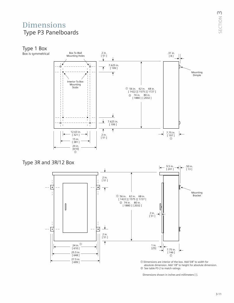
3-11
Dimensions Type P3 Panelboards
a"
a"
a"
a"
a"
a"
Type 1 BoxBox is symmetrical
Type 3R and 3R/12 Box
� Dimensions are interior of the box. Add 5/8” to width for absolute dimension. Add 1/8” to height for absolute dimension.
� See table P3-2 to match ratings.
Dimensions shown in inches and millimeters [ ].
SEC
TIO
N3
�
�
�
�
�
�
�
�

Dimensions Type P3 Panelboards
Standard A B C Box Size
47.97 42.00 40.75 56H 24W 7.75D
53.97 48.00 46.75 62H 24W 7.75D
59.97 54.00 52.75 68H 24W 7.75D
65.97 60.00 58.75 74H 24W 7.75D
71.97 66.00 64.75 80H 24W 7.75D
3-12

Kits and AccessoriesType P3 Panelboards
Table P3-21 – Standard Enclosures
Catalog Number
Box Type 1 Type 3R Type 3R/12Height Standard Trim(in.) Box Surface Flush
56 24WD56 P3S56 P3F56 24NRD56 24WPD5662 24WD62 P3S62 P3F62 24NRD62 24WPD6268 24WD68 P3S68 P3F68 24NRD68 24WPD6874 24WD74 P3S74 P3F74 24NRD74 24WPD7480 24WD80 P3S80 P3F80 24NRD80 24WPD80
Table P3-22 – Breaker Kits and Accessories
Options For Type 1 TrimsItems must be ordered as manual line item on factoryHinged trim – Add “H” suffixDoor-in-door – Add “D” suffixMetal card holder – Add “M” suffix
1 Although QR is rated 250A. it is limited to 225A in panelboard.2 Factory installed and Field installable Service Entrance Barrier kits are now available
as required by UL67 (In COMPAS, you must select Service Entrance Required.)
2SE
CTI
ON
3-13
Kit No. Description Contents
BBKB32 (P2/P3) BL/BQD 6-pole 3” branch breaker kit Kit contains top barrier, (3) A/C connectors, (3) B connectors, hardwareBBKNB32 (P2/P3) NGB 6-pole 3” branch mounting kit Kit contains top barrier, (3) A/C connectors, (1) B connector, hardwareBBKEB32 (P3) NEB/HEB 6-pole 3” branch mounting kit Kit contains top barrier, (3) A/C connectors, (1) B connector, hardwareBBKED32 (P2/P3) ED 6-pole 3” branch breaker kit Kit contains breaker support, inter-phase barriers, (3)A/C connectors, (1)B connector, hardware
BBKQ2 (P3)QJ/QR branch breaker kit for 2 and
Kit contains all connectors and cover plates necessary to mount 2 and 3 pole breakers 3-pole single mount
BBKQR11 P2 branch BKR strap kit for single QRKit contains all connectors and cover plates necessary to mount both 2 and 3-pole breakers1-phase/3-phase
BBKQR21 P3 branch BKR strap kit for single QRKit contains all connectors and cover plates necessary to mount both 2 and 3-pole breakers
1-phase/3-phaseDFFP3 Deadfront filler 3” 3” empty space filler and hardwareDFFP6 Deadfront filler 6” 6” empty space filler and hardwareP3BK1 P3 bonding kit Bonding strap and hardwareEBF1 NEB/HEB filler plate 1” filler plateBBKQRP1FK P2 filler for QR. Horizontal or vertical Kit contains all cover plates necessary to change from QJ to QR both 2 and 3-pole breaker
mount. 1-phase/3-phase. BBKQRP2FK P3 filler for QR. Dual mount horizontal. Kit contains all cover plates necessary to change from QJ to QR both 2 and 3-pole breakers.
1-phase/3-phase. For 1-phase panel, both breakers mush change from QJ to QR, cannot have one of each installed.
SEBP3V12 Service entrance barrier kit CFD, FD Kit contains barrier, mounting brackets, and hardware(P3 only)
SEBKP1P2P3V12 JD, LD Service Entrance Barrier Kit Kit contains barrier, mounting brackets, and hardware (RP1, P1, P2, P3)

Notes

P4 PanelboardsDescription PageGeneral Information 4-2
Selection and Application 4-2Applications 4-3 – 4-6
Main Breaker Selection 4-3Main Switch Connectors 4-3Enclosure Selection 4-3Main Breaker Unit Space Dimensions 4-3Main Lugs Only Unit Space Dimensions 4-4Branch Switch Unit Space 4-4Branch Circuit Breakers 4-5 – 4-6Branch Breaker Unit Space 4-7
Branch Breaker Side Gutter 4-7Typical Catalog Numbers 4-8
Main Lugs Only 4-8Main Circuit Breakers Only 4-8
Modifications and Additions 4-9Connector Modifications 4-10
Compression Lugs 4-10Alternate Lugs 4-10
Dimensions 4-11Kits and Accessories 4-12 – 4-13
SEC
TIO
N4

4-2
Type P4 Panelboards
The P4 panel is a medium sized footprint distribution panel to fit a large number of applications that require more or largerbranch devices and higher amp ratings than the lighting panelclass offers. Even with the increased capacity, this panel is aspace saver with its 32" width and 10" depth. The P4 panel offers a wide array of factory-assembled options and has the ability tomix breaker frames in unit space up to 800 amps and fusibleswitches up to 200 amps. Bussing options for the P4 vary fromthe standard temperature rated aluminum to temperature ratedcopper and 750A/Si aluminum and 1000A/Si copper designs.All aluminum bussing in the P4 panel is tin-plated as a standard.Silver-plated is offered as the default for copper bus and tin as anoption. Integrated time clocks, bus mounted contactors as mainsor submains, split bus and subfeed lugs (up to 600 amp) are justa few of the options of this flexible panel.
The 3 panel configurations defined by the unit space allowed for a given amperage, main device and box height. The P4 panelstarts with a 60" high box. All of the branch devices are unitspace mounted. Breakers and switches can be mixed andmatched to meet customer requirements.
Main Lug / Main Breaker / Main Switch
Enclosure – Standard Type 1 enclosure is 32" wide x 10" deep. X Box Height is determined by main device and unit space. Seecharts for box height.
Voltage – 600 Vac Max.250 Vdc Max
Amperage – 400-800 amp main breaker or 400-1200 ampMain Lug Only
Short Circuit Rating – 200 KAIC Max. symmetrical or equal tothe lowest rated device installed unless a series rating is indicated.Panels with subfeed or feed-thru lugs without a main device, circuit breaker or fusible unit, are limited to a three-cycle rating.The three-cycle rating for the P4 panel is limited to 42 KAIC. Notethat the main device may be mounted remote from the panel.
Bussing – The P4 panel has more options to meet marketrequirements. The standard bussing is temperature rated aluminum. The rating is per the requirements of UL 67 – the standard for panelboards. All aluminum bussing is tin-plated.Optional bussing for the P4 panel is: 750 A/Si aluminum, temperature rated copper, and 1000 A/Si copper. The copper bus option for this panel is silver-plated.
Weight – ApproximateTotal panelboard weight when filled with a normal quantity ofbreakers and accessories is about 8 lbs. (1 kg) per inch (54g permm) of box height.
Table P4-2 – Gauge Steel of Boxes Fronts, Surface and Flush
Selection and Application1) To specify a particular panelboard, first determine voltage,
system, amperage and type of main, amperage and type of branch devices, and modifications, if any. (Step 1)
2) List branch devices and modifications requiring space additions. List unit space requirements of each.
Note: Some units are twin mounted meaning two breakers occupy the same unit space.
Select appropriate enclosure height from selection chart on page 4-3, based on unit space requirements. (Step 2)
3) Select panelboard catalog number from appropriate table based upon voltage, system, amperage and unit space requirements. (Step 3)
Ampere Rating Connectors Suitable for Copper or Aluminum
400 (1) - #3/0 AWG-600 Kcmil(2) - #3/0 AWG-250 Kcmil
600 (2) - #3/0 AWG-600 Kcmil800 (3) - #3/0 AWG-600 Kcmil
1000 (4) - #3/0 AWG-600 Kcmil1200 (4) - #3/0 AWG-600 Kcmil
1 Alternate lugs for 750 kcmil cable are available, but result in significant loss of branch unit mounting space. Consult Siemens.
Step #1
Amperage 400Voltage 208Y/120System 3 Phase, 4 wireMain Main BreakerBranches 5-125/3, 2-225/3,
1-250/3Modifications NoneFeed TopMounting Surface
Step #2
5-125/3 ED4 3.75” = 11.25” Twin Mounted
2-225/3 QJ2/QR2 5” = 5” Twin Mounted
1-250/3 FXD6 5” = 5”21.25
Enclosure is B275 from SelectionChart on Page 4-3.(32” wide, 75” high, 10” deep)
Step #3
1-P4C75JX400ATS 3-ED4 1-Pole Provision 5-125/3 2-225/3 QJ2/QR21-250/3 FXD612” Space
Dimensions in inches (mm) Gauge SteelWidth Height Box Fronts
#161 #14 (1 piece trim)#14 (4 piece trim)
#12 #12 (1 piece trim, door in door)#10 #10 (1 piece door trim in)#16 #16 (4 piece trim)
1 Box has 16 gauge side panels, 14 gauge backplates and 12 gauge back support.
Table P4-1 – Main Lugs 1
32” 60 - 75 - 90 (813) (1524, 1905,
2286)

4-3
ApplicationType P4 Panelboards
Table P4-4 – Enclosure Selection 1
Enclosure Dimension Available Circuit Space in Inches (mm) in Inches (mm) Dimension “C”
Main Lug Main Breaker H H W D 400-800A 400-800A60 (1524) 32 (813) 10 (254) 30 (762) 21.25 (540)75 (1905) 32 (813) 10 (254) 45 (1143) 36.25 (921) 90 9090 (2286) 32 (813) 10 (254) 60 (1524) 51.25 (1302)
1 Standard trim is four piece without door. Surface or flush one piece trim is available for 32 in. (813 mm) wide circuit breaker panels.
Table P4-5 – Main Breaker Lug Location Reference (Fig. P4-1)
Ampere Breaker Dimensions in Inches (mm)Rating Type A B400 JXD6, JD6, HJXD6, HJD6 10.425 (265)400 HHJXD6, HHJD6400 NJ, HJ, LJ 12.500 (318)400 SJD6, SHJD6 10.425 (265)400 CJD6, SCJD6 8.250 (210)
600 LXD6, LD6, HLXD6, HLD6, HHLXD6, HHLD6
10.425 (265) 13.125 (333)
600 NL, HL, LL 11.250 (286)600 SLD6, SHLD6 10.425 (265)600 CLD6, SCLD6 8.250 (210)800 NM, HM, LM, 10.425 (265)
SEC
TIO
N4
Table P4-3 – Main Breaker Selection
Breaker type Maximum IC (KA) Symmetrical Amperes
Main BreakerAmpere Trip Frame Breaker Unit Space inrating type type family 240V 480V 600V inches (mm) Continuous Current Rating
JXD6, JD6 Sentron 65 35 22 8.75 (222) 200, 225, 250, 300, 350, 400Thermal HJXD6, HJD6 Sentron 100 65 35 8.75 (222) 200, 225, 250, 300, 350, 400Magnetic HHJXD6, HHJD6 Sentron 200 100 50 8.75 (222) 200, 225, 250, 300, 350, 400
CJD6 Sentron 200 150 100 8.75 (222) 200, 225, 250, 300, 350, 400
400A NJ VL 65 35 25 6.25 (159) 250, 400SJD6 Sentron 65 35 25 8.75 (222) 200, 300, 400
Electronic HJ VL 100 65 25 6.25 (159) 250, 400(solid state) SHJD6 Sentron 100 65 35 8.75 (222) 200, 300, 400
LJ VL 200 100 25 6.25 (159) 250, 400SCJD6 Sentron 200 150 100 8.75 (222) 200, 300, 400LXD6 Sentron 65 35 25 8.75 (222) 450, 500, 600
ThermalLD6 Sentron 65 35 25 8.75 (222) 250, 300, 350, 400, 450, 500, 600HLXD6, HLD6 Sentron 100 65 35 8.75 (222) 250, 300, 350, 400, 450, 500, 600
Magnetic HHLXD6, HHLD6 Sentron 200 100 50 8.75 (222) 250, 300, 350, 400, 450, 500, 600
600A CLD6 Sentron 200 150 100 8.75 (222) 250, 300, 350, 400, 450, 500, 600NL VL 65 35 18 6.25 (159) 400, 600SLD6 Sentron 65 35 25 8.75 (222) 300, 400, 500, 600
Electronic HL VL 100 65 18 6.25 (159) 400, 600(solid state) SHLD6 Sentron 100 65 35 8.75 (222) 300, 400, 500, 600
LL VL 200 100 18 6.25 (159) 400, 600SCLD6 Sentron 200 150 100 8.75 (222) 300, 400, 500, 600
Thermal NM VL 65 35 25 8.75 (222) 600, 700, 800
Magnetic HM VL 100 65 35 8.75 (222) 600, 700, 800
800ALM VL 200 100 50 8.75 (222) 600, 700, 800
Electronic NM VL 65 35 25 8.75 (222) 600, 800
(solid state) HM VL 100 65 35 8.75 (222) 600, 800LM VL 200 100 50 8.75 (222) 600, 800
Fig. P4-1

4-4
Table P4-8 – Branch Switch Unit Space
Unit Spacein inches (mm)
Ampere Number Twin Single AC Cables Per Connectors Suitable ForRating of Poles Mounted Mounted Voltage Connector Copper or Aluminum
30-30 2,3 2.50 (64) — 240 1 #14 - #8 AWG (Cu Only)30-30 2,3 5.00 (127) — 240 1 #14 - #4 AWG30-60 2,3 5.00 (127) — 240 1 #14 - #4 AWG60-60 2,3 5.00 (127) — 240 1 #14 - #4 AWG60-100 2,3 7.50 (191) — 240 1 #10 - #1/0 AWG
100-100 2,3 7.50 (191) — 240 1 #10 - #1/0 AWG200-200 3 10.00 (254) — 240 1 #6 AWG - 350 Kcmil200 2 — 7.50 (191) 240 1 #6 AWG - 350 Kcmil200 3 — 10.00 (254) 240 2 #6 AWG - 350 Kcmil
30-30 2,3 7.5 (191) — 600 1 #14 - #8 AWG30-60 2,3 7.5 (191) — 600 1 #14 - #4 AWG60-60 2,3 7.5 (191) — 600 1 #14 - #4 AWG60-100 2,3 7.5 (191) — 600 1 #10-#1/0 AWG
100-100 2,3 7.5 (191) — 600 1 #10-#1/0 AWG 200-200 3 10.00 (254) — 600 1 #6 AWG - 250 Kcmil100 2,3 — 7.50 (191) 600 1 #10-#1/0 AWG 200 2,3 — 10.00 (254) 600 1 #6 AWG - 250 Kcmil
Table P4-6 – Main Lugs Location Reference (Fig. P4-2)
Dimensions in inches (mm)Main Lug Neutral400A 600A 800A 1000A 1200A 400-600A 800-1200A
Lugs A B C D E F G
Standard 16.500 16.750 15.969 15.969 15.969 13.125 13.125 (419) (425) (406) (406) (406) (333) (333)
Oversize 16.500 21.750 25.969 25.969 25.969 18.125 23.125 (419) (552) (660) (660) (660) (460) (587)
Crimp 19.187 18.250 18.687 18.250 18.250 15.937 15.937(487) (464) (475) (464) (464) (405) (405)
Standard 16.750 15.969 — — — 13.125 13.125 w/Subfeed (425) (406) (333) (333)Standard 16.500 16.750 — — — 13.125 13.125 w/Feed-thru (419) (425 ) (333) (333)
Fig. P4-2
ApplicationType P4 Panelboards
Table P4-7 – Available Unit Space – MLO
Dimensions in inches (mm)Ampere Rating
Lug Type Box Height 400 600 800 1000 1200
Standard60 30 30 30 30 30
Mechanical 75 45 45 45 45 4590 60 60 60 60 60
Oversized60 30 25 20 20 20
Mechanical 75 45 40 35 35 3590 60 55 50 50 50
60 25 25 25 25 24Crimp Type 75 40 40 40 40 40
90 55 55 55 55 55
Std Mechanical60 30 30 — — —
W/ Sub-feed 75 45 45 — — —90 60 60 — — —
Std. Mechancial60 20 20 12.5 12.5 12.5
W/ Feed-thru 75 35 35 27.5 27.5 27.590 50 50 42.5 42.5 42.5

ApplicationType P4 Panelboards
Table P4-9 – Branch Circuit Breakers
1 CSA listed only at 600V AC.2 15-30A trip (shown) 65 KA, 35-100A 25 KA.
Maximum Bolt-on Maximum IC (KA) Symmetrical AmperesAmpere Breaker Number Trip Amp Voltage - ACRating Type of Poles Rating 120 120/240 240 277 480/ 277 480 600/347 600
BLF 1 15-30 10 — — — — — — —2 15-60 — 10 — — — — — —
BLHF 1 15-30 22 — — — — — — —2 15-60 — 22 — — — — — —
BLE 1 15-30 10 — — — — — — —2 15-60 — 10 — — — — — —
BLEH 1 15-30 22 — — — — — — —2 15-60 — 22 — — — — — —
BAF, BAFC 1 15-20 10 — — — — — — —BAFH, BAFHC 1 15-20 22 — — — — — — —BAF 2 15-20 — 10 — — — — — —BAFH 2 15-20 — 22 — — — — — —BGL 2 15-30 10 — — — — — — —
3 15-30 — 10 — — — — — —
100 BLR 2 15-100 — — 10 — — — — —BL 1 15-70 10 — — — — — — —
2 15-100 — 10 — — — — — —3 15-100 — — 10 — — — — —
BLH 1 15-70 — 22 — — — — — —2 15-100 — 22 — — — — — —3 15-100 — — 22 — — — — —
HBL 1 15-70 — 65 — — — — — —2 15-100 — 65 — — — — — —3 15-100 — — 65 — — — — —
BQD 1 15-100 — 65 — 14 — — — —2 15-100 — 65 — — 14 — — —3 15-100 — — 65 — 14 — — —
BQD61 1 15-70 65 — — — — — — —2/3 15-100 — — 65 — — — — 10
BL (HID) 1/2 15-30 — 10 — — — — — —BLF (GFCI) 1 15-60 — 10 — — — — — —
2 40-60 — 10 — — — — — —BLE (EQ GFI) 1/2 15-30 — 10 — — — — — —BLG (SWN) 2 15-30 10 — — — — — — —
3 15-30 — 10 — — — — — —BLHF (GCFI) 1/2 15-30 — 22 — — — — — —NGB 1 15-125 100 — — 25 — — — —
2/3 15-125 — 100 100 — 25 — 14 —HGB 1 15-125 100 — — 35 — — — —
2/3 15-125 — 100 100 — 35 — 14 —LGB 1 15-125 100 — — 65 — — — —
2/3 15-125 — 100 100 — 65 — 14 —NEB 1 15-125 100 85 85 35 — — — —
2/3 15-125 — 85 85 — 35 35 22 —HEB 1 15-125 200 100 100 65 — — — —
2/3 15-125 100 100 — 100 65 25 25 —
125 ED4 1 15-125 65 — — 22 — — — —2/3 15-125 — 65 65 — 18 18 —
ED6 2 15-125 — — — — 25 25 30 —3 15-125 — — 65 — 25 25 — 18
HED4 1 15-125 100 — — 652 — — — —2/3 15-125 — 100 100 — 42 42 — —
HHED6 2/3 15-125 100 — — — 65 65 18 18CED6 2/3 15-125 200 — — — 200 200 100 100�����������������������������
SEC
TIO
N4
4-5

4-6
Table P4-10 – Branch Circuit Breakers (VL)
Maximum IC (KA) Symmetrical AmperesMaximum Bolt-on Number Trip
Volts – ACAmpere Breaker of AmpRating Type Poles Rating 120 120/240 240 277 480/277 480 600/347 600
ND 3 60 - 150 — 65 65 — 35 35 18 18150 1 HD 3 60 - 150 — 100 100 — 65 65 20 20
LD 3 60 - 150 — 200 200 — 100 100 25 25NF 3 100 - 250 — 65 65 — 35 35 18 18
250 1 HF 3 100 - 250 — 100 100 — 65 65 20 20LF 3 100 - 250 — 200 200 — 100 100 25 25NJ 3 250 - 400 — 65 65 — 35 35 25 25
400 1 HJ 3 250 - 400 — 100 100 — 65 65 25 25LJ 3 250 - 400 — 200 200 — 100 100 25 25NL 3 400 - 600 — 65 65 — 35 35 18 18
600 1 HL 3 400 - 600 — 100 100 — 65 65 18 18LL 3 400 - 600 — 200 200 — 100 100 18 18NM 2/3 600 - 800 — 65 65 — 35 35 25 25
800 HM 2/3 600 - 800 — 100 100 — 65 65 35 35LM 2/3 600 - 800 — 200 200 — 100 100 50 50
1 Only offered with Electronic Trip Units.
ApplicationType P4 Panelboards
Table P4-9 – Branch Circuit Breakers (continued)
Maximum Bolt-on Number Trip Amp Maximum IC (KA) Symmetrical AmperesAmpere Breaker of Poles Rating Voltage – ACBreaker Type 120 120/240 240 277 480/277 480 600/347 480
225 QJ2 2/3 60-225 — — 10 — — — — —QJH2 2/3 60-225 — — 22 — — — — —QJ2H 2/3 60-225 — — 42 — — — — —QR2 2/3 100-225 — — 10 — — — — —QRH2 2/3 100-225 — — 25 — — — — —HQR2 2/3 100-225 — — 65 — — — — —HQR2H 2/3 100-225 — — 100 — — — — —FXD6, FD6 2/3 70-250 — — 65 — 35 35 18 18
250 HFXD6, HFD6 2/3 70-250 — — 100 — 65 65 25 25HHFXD6, HHFD6 2/3 70-250 — — 200 — 100 100 25 25CFD 2/3 70-250 — — 200 — 200 200 100 100JXD6, JD6, SJD6 2/3 200-400 — — 65 — 35 35 25 25HJXD6,HJD6, SHJD6 2/3 200-400 — — 100 — 65 65 35 35
400 HHJXD6, HHJD6 2/3 200-400 — — 200 — 100 100 50 50CJD6 2/3 200-400 — — 200 — 150 150 100 100LXD6 2/3 450-600 — — 65 — 35 35 25 25LD6 2/3 250-600 — — 65 — 35 35 25 25SLD6 2/3 300-600 — — 65 — 35 35 25 25
600 HLD6, HLXD6 2/3 250-600 — — 100 — 65 65 35 35SHLD6 2/3 300-600 — — 100 — 65 65 35 35HHLD6, HHLXD6 2/3 250-600 — — 200 — 100 100 50 50CLD6 2/3 450-600 — — 200 — 150 150 100 100SCLD6 2/3 300-600 — — 200 — 150 150 100 100
�����������������������������
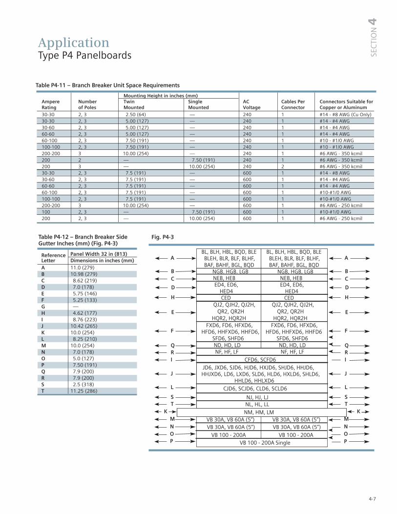
4-7
A
B
F
D
E
C
H
VB 100 - 200A Single
VB 30A, VB 60A (5”) VB 30A, VB 60A (5”) VB 30A, VB 60A (5”) VB 30A, VB 60A (5”)
VB 100 - 200A VB 100 - 200A
A
B
F
D
E
C
H
P
QRI
J
L
ST
MN OP
K
QRI
J
L
ST
MN O
K
BL, BLH, HBL, BQD, BLE BL, BLH, HBL, BQD, BLE BLEH, BLR, BLF, BLHF, BLEH, BLR, BLF, BLHF, BAF, BAHF, BGL, BQD BAF, BAHF, BGL, BQD NGB. HGB. LGB NGB, HGB, LGB NEB, HEB NEB, HEB ED4, ED6, ED4, ED6, HED4 HED4 CED CED QJ2, QJH2, QJ2H, QJ2, QJH2, QJ2H, QR2, QR2H QR2, QR2H HQR2, HQR2H HQR2, HQR2H FXD6, FD6, HFXD6, FXD6, FD6, HFXD6, HFD6, HHFXD6, HHFD6, HFD6, HHFXD6, HHFD6 SFD6, SHFD6 SFD6, SHFD6 ND, HD, LD ND, HD, LD NF, HF, LF NF, HF, LF CFD6, SCFD6 JD6, JXD6, SJD6, HJD6, HXJD6, SHJD6, HHJD6,HHJXD6, LD6, LXD6, SLD6, HLD6, HXLD6, SHLD6, HHLD6, HHLXD6 CJD6, SCJD6, CLD6, SCLD6
NJ, HJ, LJ NL, HL, LL NM, HM, LM
SEC
TIO
N4
Table P4-12 – Branch Breaker Side Gutter Inches (mm) (Fig. P4-3)
Reference Panel Width 32 in (813)Letter Dimensions in inches (mm)A 11.0 (279)B 10.98 (279)C 8.62 (219)D 7.0 (178)E 5.75 (146)F 5.25 (133)G —H 4.62 (177)I 8.76 (223)J 10.42 (265)K 10.0 (254)L 8.25 (210)M 10.0 (254)N 7.0 (178)O 5.0 (127)P 7.50 (191)Q 7.9 (200)R 7.9 (200)S 2.5 (318)T 11.25 (286)
ApplicationType P4 Panelboards
Table P4-11 – Branch Breaker Unit Space Requirements
Mounting Height in inches (mm) Ampere Number Twin Single AC Cables Per Connectors Suitable for Rating of Poles Mounted Mounted Voltage Connector Copper or Aluminum
30-30 2, 3 2.50 (64) — 240 1 #14 - #8 AWG (Cu Only) 30-30 2, 3 5.00 (127) — 240 1 #14 - #4 AWG 30-60 2, 3 5.00 (127) — 240 1 #14 - #4 AWG 60-60 2, 3 5.00 (127) — 240 1 #14 - #4 AWG 60-100 2, 3 7.50 (191) — 240 1 #10 - #1/0 AWG 100-100 2, 3 7.50 (191) — 240 1 #10 - #1/0 AWG 200-200 3 10.00 (254) — 240 1 #6 AWG - 350 kcmil 200 2 — 7.50 (191) 240 1 #6 AWG - 350 kcmil 200 3 — 10.00 (254) 240 2 #6 AWG - 350 kcmil 30-30 2, 3 7.5 (191) — 600 1 #14 - #8 AWG 30-60 2, 3 7.5 (191) — 600 1 #14 - #4 AWG 60-60 2, 3 7.5 (191) — 600 1 #14 - #4 AWG 60-100 2, 3 7.5 (191) — 600 1 #10-#1/0 AWG 100-100 2, 3 7.5 (191) — 600 1 #10-#1/0 AWG 200-200 3 10.00 (254) — 600 1 #6 AWG - 250 kcmil 100 2, 3 — 7.50 (191) 600 1 #10-#1/0 AWG 200 2, 3 — 10.00 (254) 600 1 #6 AWG - 250 kcmil
Fig. P4-3

4-8
ApplicationType P4 Panelboards
Table P4-13 – Main Lugs Only – shown with aluminum bus, top fed, and surface trims
Max. 208Y/120V 240/120V 120/240V or 240V 480Y/277V 480V 1Panel Unit 250 Vdc MaxAmp Space 3 Phase, 4 Wire 3 Phase, 4 Wire 1 Phase, 3 Wire 3 Phase, 3 Wire 3 Phase, 4 Wire 3 Phase, 3 Wire Rating (inches) Catalog Number Catalog Number Catalog Number Catalog Number Catalog Number Catalog Number
30 P4C60ML400ATS P4B60ML400ATS P4A60ML400ATS P4D60ML400ATS P4E60ML400ATS P4F60ML400ATS400 45 P4C75ML400ATS P4B75ML400ATS P4A75ML400ATS P4D75ML400ATS P4E75ML400ATS P4F75ML400ATS
60 P4C90ML400ATS P4B90ML400ATS P4A90ML400ATS P4D90ML400ATS P4E90ML400ATS P4F90ML400ATS30 P4C60ML600ATS P4B60ML600ATS P4A60ML600ATS P4D60ML600ATS P4E60ML600ATS P4F60ML600ATS
600 45 P4C75ML600ATS P4B75ML600ATS P4A75ML600ATS P4D75ML600ATS P4E75ML600ATS P4F75ML600ATS60 P4C90ML600ATS P4B90ML600ATS P4A90ML600ATS P4D90ML600ATS P4E90ML600ATS P4F90ML600ATS30 P4C60ML800ATS P4B60ML800ATS P4A60ML800ATS P4D60ML800ATS P4E60ML800ATS P4F60ML800ATS
800 45 P4C75ML800ATS P4B75ML800ATS P4A75ML800ATS P4D75ML800ATS P4E75ML800ATS P4F75ML800ATS60 P4C90ML800ATS P4B90ML800ATS P4A90ML800ATS P4D90ML800ATS P4E90ML800ATS P4F90ML800ATS30 P4C60ML101ATS P4B60ML101ATS P4A60ML101ATS P4D60ML101ATS P4E60ML101ATS P4F60ML101ATS
1000 45 P4C75ML101ATS P4B75ML101ATS P4A75ML101ATS P4D75ML101ATS P4E75ML101ATS P4F75ML101ATS60 P4C90ML101ATS P4B90ML101ATS P4A90ML101ATS P4D90ML101ATS P4E90ML101ATS P4F90ML101ATS30 P4C60ML120ATS P4B60ML120ATS P4A60ML120ATS P4D60ML120ATS P4E60ML120ATS P4F60ML120ATS
1200 45 P4C75ML120ATS P4B75ML120ATS P4A75ML120ATS P4D75ML120ATS P4E75ML120ATS P4F75ML120ATS60 P4C90ML120ATS P4B90ML120ATS P4A90ML120ATS P4D90ML120ATS P4E90ML120ATS P4F90ML120ATS
Table P4-14 – Main Circuit Breakers Only – shown with standard mains, aluminum bus, top fed, and surface trims
Max. 208Y/120V 240/120V 120/240V or 240V 480Y/277V 480V 1
Panel Unit 250 Vdc MaxAmp Space 3 Phase, 4 Wire 3 Phase, 4 Wire 1 Phase, 3 Wire 3 Phase, 3 Wire 3 Phase, 4 Wire 3 Phase, 3 Wire Rating (inches) Catalog Number Catalog Number Catalog Number Catalog Number Catalog Number Catalog Number
21.25 P4C60JX400ATS P4B60JX400ATS P4A60JX400ATS P4D60JX400ATS P4E60JX400ATS P4F60JX400ATS400 36.25 P4C75JX400ATS P4B75JX400ATS P4A75JX400ATS P4D75JX400ATS P4E75JX400ATS P4F75JX400ATS
51.25 P4C90JX400ATS P4B90JX400ATS P4A90JX400ATS P4D90JX400ATS P4E90JX400ATS P4F90JX400ATS21.25 P4C60LX600ATS P4B60LX600ATS P4A60LX600ATS P4D60LX600ATS P4E60LX600ATS P4F60LX600ATS
600 36.25 P4C75LX600ATS P4B75LX600ATS P4A75LX600ATS P4D75LX600ATS P4E75LX600ATS P4F75LX600ATS51.25 P4C90LX600ATS P4B90LX600ATS P4A90LX600ATS P4D90LX600ATS P4E90LX600ATS P4F90LX600ATS21.25 P4C60M1800ATS P4B60M1800ATS P4A60M1800ATS P4D60M1800ATS P4E60M1800ATS P4F60M1800ATS
800 36.25 P4C75M1800ATS P4B75M1800ATS P4A75M1800ATS P4D75M1800ATS P4E75M1800ATS P4F75M1800ATS51.25 P4C90M1800ATS P4B90M1800ATS P4A90M1800ATS P4D90M1800ATS P4E90M1800ATS P4F90M1800ATS
1 For 600V, change “F” in position 3 to “G.”

4-9
Modifications and AdditionsP4 Panelboards
Devices Mounted on Gutter CoverIncludes Device, Mounting – Wired orUnwired
Increased Capacity Neutral
Subfeed or Feed-Thru Lugs (One Set Per Panel)Subfeed Double Lugs (Main Lug Panels)
Feed-Thru Lugs
Grounding of Panelboards Ground Bars (except for brazed-to-box) are shipped with the panel interior factory mounted.• Non-Insulated Equipment Ground
Bar – Standard• Copper Non-Insulated Ground Bar• Al Insulated Equipment Ground Bar• Cu Insulated Equipment Ground Bar• Ground Bar Brazed to Box
Fuse Clip Provisions(Add to 250 Volts or 600 Volts Unit Prices Per Switch)
Spanner Wrenches(for Vacu-Break Switches)
Ground Fault on Main Breaker
Time Clocks 3
Sangamo, Tork or Paragon time clock can be supplied, mounted in panelboardcabinet. For required increase in enclosuredimension, consult local sales office.
Circuit Breaker AccessoriesHandle Blocking DeviceBlocks handle in either the “ON” or “OFF” position.
Padlocking Device – Padlocks in “OFF” position.
Main BusStandard main bus and ground bus aretin-plated aluminum. For copper mainbus, neutral bus and ground bus, addfrom the table for each panel.
Lugs – For Main Lug Only PanelsStandard main lugs and neutral lugs are tin-plated aluminum, UL listed for use with aluminum/copper cables.Copper only lugs are an option.
Shunt Trip on Main and Branches4
100% Rated Main Circuit Breakers
DescriptionConventional Ground Fault 1
Includes:Ground Fault Relay, Ground Sensor, CPT and Shunt Trip
Test and Monitor Panel 2
Ground Fault add to Sensitrip III breaker price
Ampere Rating Unit SpacePhase Neutral ( inches)
400 600 0400 800 0600 1200 0800 1200 0
Ampere Rating Unit Space (inches)
400 10600 10800 17.5
1200 17.5
Amp Class Class ClassRating J R T
30 — • •60 — • •
100 — • •200 — • •
Unit Spaces
Amp (Additional inches)Rating MLO
400 0600 0800 N/A
1200 N/A
1 Available in 90” high enclosure only. Unit space is 42 1/2” with Test and Monitor Panel; 45” without Test and Monitor Panel.
2 Not available on Sensitrip III.3 For required unit space, consult local sales office.
4 Shunt Trip on 100A frame breakers increases mounting height to 6.25” for twin mounting.
5 The 600A, 100% rated breaker requires the use of an 800A frame breaker.
DescriptionTime clock (1-or2-Pole, Single or DoubleThrow Contacts; 3-Pole Single Throw)277V Maximum with Plain DialOptional:
Astronomical DialAn Omitting DeviceReserve Power or Carryover
Space and Mounting Provisions Only
Description
BL, BQD, NGB, HGB, LGB (branch only)QJ2, QJH2, QJ2H, QR2, QRH2, HQR2,HQR2H, NEB, HEB, ED4, ED6, HED4,HHED6, CED6
Description
One piece front with door Hinged Gutter Covers 4 pc front
Toggle Switch — SPST or 3-way15A, 277V maximum
Pilot Light — General PurposeNeon or IncandescentPushbutton
Ampere Rating
400 - 1200
SEC
TIO
N4
Ampere BreakerRating Type
JXD6H, HJXD6H400A SCJD6H, SHJD6H
NJY, HJY, LJY
600ALXD6H, HLXD6HNMY 5, HMY 5, LMY 5
All others to 800A

4-10
Connector ModificationsP4 Panelboards
Amp BreakerRating Type Compression Connectors Available Unit Space Reduction
400 N/A (1)#3/0 AWG - 750 Kcmil or Deduct 0” of Unit Space (2)#3/0 AWG 250 Kcmil Cu or Al
600 N/A (2)#3/0 AWG - 750 Kcmil Deduct 5” of Unit Space800 N/A (3)#3/0 AWG - 750 Kcmil Cu or Al Deduct 10” of Unit Space
1200 N/A (4)#3/0 AWG - 600 Kcmil Cu or Al Deduct 10” of Unit Space(4)#3/0 AWG - 750 Kcmil Cu or Al
Table P4-15 – Compression Lugs
Lug Modifications
StyleAmp Rating
Breaker Type
Compression Connectors
Box HeightAddition
MLO
250 N/A (1)#6 AWG - 350 kcmil —
400 N/A (1) 250 - 500 kcmil or(2)# 1/0 AWG - 250 kcmil
——
600 N/A (2)#3/0 AWG - 500 kcmil —800 N/A (2) 400-750 kcmil Cu only —
Main Breaker
250 FXD6, HFD6, CFD6 (1)#6 AWG - 350 kcmil Cu or Al CFD6 requires anadditional 6.0" box height
400 JD6, JXD6, HJD6, CJD6, SJD6, SHJD6, SCJD6 (2)#1/0 AWG - 500 kcmil Cu or Al —
600LD6, LXD6, HLD6, CJD6,SLD6, SHLD6, SCLD6
(2)#2/0 AWG - 500 kcmil Cu or Al —
/ /
Table P4-16 – Alternate Lugs

4-11
DimensionsType P4 Panelboards
Type 1 BoxBox is symmetrical
Type 3R and 3R/12 Box
� Dimensions are interior of the box. Add 5/8” to width for absolute dimension. Add 1/8” to height for absolute dimension.
Dimensions shown in inches and millimeters [ ].
SEC
TIO
N4
�
�
�
�
30.0 in. [ 254 ]
�
�
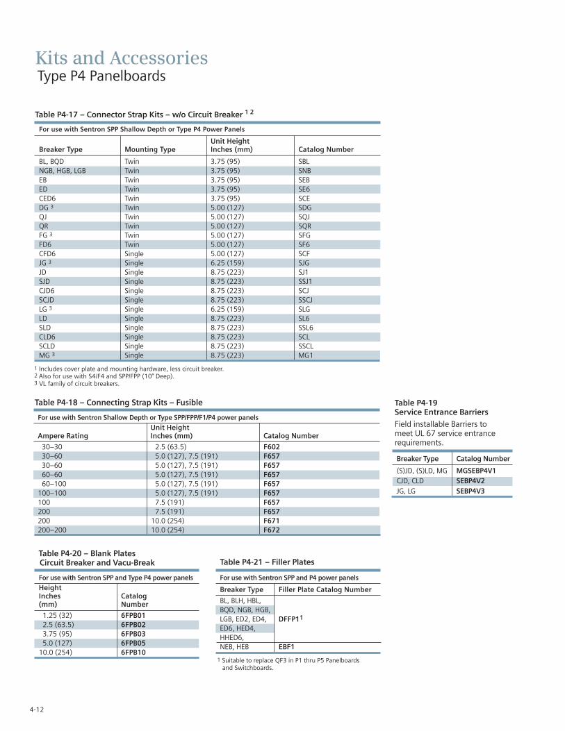
4-12
Kits and AccessoriesType P4 Panelboards
Table P4-17 – Connector Strap Kits – w/o Circuit Breaker 1 2
Table P4-20 – Blank Plates Circuit Breaker and Vacu-Break
For use with Sentron SPP and Type P4 power panels
HeightInches Catalog(mm) Number
1.25 (32) 6FPB012.5 (63.5) 6FPB023.75 (95) 6FPB035.0 (127) 6FPB05
10.0 (254) 6FPB10
Table P4-18 – Connecting Strap Kits – Fusible
For use with Sentron Shallow Depth or Type SPP/FPP/F1/P4 power panels
Unit HeightAmpere Rating Inches (mm) Catalog Number
30–30 2.5 (63.5) F60230–60 5.0 (127), 7.5 (191) F65730–60 5.0 (127), 7.5 (191) F65760–60 5.0 (127), 7.5 (191) F65760–100 5.0 (127), 7.5 (191) F657
100–100 5.0 (127), 7.5 (191) F657100 7.5 (191) F657200 7.5 (191) F657200 10.0 (254) F671200–200 10.0 (254) F672
Table P4-21 – Filler Plates
1 Suitable to replace QF3 in P1 thru P5 Panelboards and Switchboards.
For use with Sentron SPP and P4 power panels
Breaker Type Filler Plate Catalog Number
BL, BLH, HBL,BQD, NGB, HGB,LGB, ED2, ED4, DFFP11
ED6, HED4, HHED6,NEB, HEB EBF1
1 Includes cover plate and mounting hardware, less circuit breaker.2 Also for use with S4/F4 and SPP/FPP (10” Deep).3 VL family of circuit breakers.
For use with Sentron SPP Shallow Depth or Type P4 Power Panels
Unit HeightBreaker Type Mounting Type Inches (mm) Catalog Number
BL, BQD Twin 3.75 (95) SBLNGB, HGB, LGB Twin 3.75 (95) SNBEB Twin 3.75 (95) SEBED Twin 3.75 (95) SE6CED6 Twin 3.75 (95) SCEDG 3 Twin 5.00 (127) SDGQJ Twin 5.00 (127) SQJQR Twin 5.00 (127) SQRFG 3 Twin 5.00 (127) SFGFD6 Twin 5.00 (127) SF6CFD6 Single 5.00 (127) SCFJG 3 Single 6.25 (159) SJGJD Single 8.75 (223) SJ1SJD Single 8.75 (223) SSJ1CJD6 Single 8.75 (223) SCJSCJD Single 8.75 (223) SSCJLG 3 Single 6.25 (159) SLGLD Single 8.75 (223) SL6SLD Single 8.75 (223) SSL6CLD6 Single 8.75 (223) SCLSCLD Single 8.75 (223) SSCLMG 3 Single 8.75 (223) MG1
Table P4-19Service Entrance Barriers
Field installable Barriers to meet UL 67 service entrance requirements.
Breaker Type Catalog Number
(S)JD, (S)LD, MG MGSEBP4V1CJD, CLD SEBP4V2JG, LG SEBP4V3

4-13
SEC
TIO
N4
Kits and AccessoriesType P4 Panelboards
Description Catalog number
P4 Type 1 32” W x 10” D x 60” H PB60P4 Type 1 32” W x 10” D x 75” H PB75P4 Type 1 32” W x 10” D x 90” H PB90P4 Type 3R/12 60” H WP260P4 Type 3R/12 75” H WP275P4 Type 3R/12 90” H WP290
Table P4-22 – Enclosures
Table P4-23 – Trims
Description Catalog number
Flush kit for P4 60” High F60Flush kit for P4 75” High F75Flush kit for P4 90” High F90
Table P4-24 – Flush mounting kits
Description Catalog number
P4 Std (4 piece trim) vented 60” P460VP4 Std (4 piece trim) vented 75” P475VP4 Std (4 piece trim) vented 90” P490VP4 VBS Std (4 piece trim) vented 60” P460VVP4 VBS Std (4 piece trim) vented 75” P475VVP4 VBS Std (4 piece trim) vented 90” P490V VP4 Std (4 piece trim) unvented 60” P460NVP4 Std (4 piece trim) unvented 75” P475NVP4 Std (4 piece trim) unvented 90” P490NVP4 VBS Std (4 piece trim) unvented 60” P460NVV P4 VBS Std (4 piece trim) unvented 75” P475NVVP4 VBS Std (4 piece trim) unvented 90” P490NVVP4 Std (4 piece trim) vented 60” with hinged gutter covers P460VHGP4 Std (4 piece trim) vented 75” with hinged gutter covers P475VHGP4 Std (4 piece trim) vented 90” with hinged gutter covers P490VHGP4 VBS Std (4 piece trim) vented 60” with hinged gutter covers P460VVHGP4 VBS Std (4 piece trim) vented 75” with hinged gutter covers P475VVHGP4 VBS Std (4 piece trim) vented 90” with hinged gutter covers P490VVHGP4 Std (4 piece trim) unvented 60” with hinged gutter covers P460NVHGP4 Std (4 piece trim) unvented 75” with hinged gutter covers P475NVHGP4 Std (4 piece trim) unvented 90” with hinged gutter covers P490NVHGP4 VBS Std (4 piece trim) unvented 60” with hinged gutter covers P460NVVHGP4 VBS Std (4 piece trim) unvented 75” with hinged gutter covers P475NVVHGP4 VBS Std (4 piece trim) unvented 90” with hinged gutter covers P490NVVHG P4 Std (1 PC Door) vented 60” P460VD P4 Std (1 PC Door) vented 75” P475VD P4 Std (1 PC Door) vented 90” P490VD P4 Std (1 PC Door) unvented 60” P460NVD P4 Std (1 PC Door) unvented 75” P475NVD P4 Std (1 PC Door) unvented 90” P490NVD P4 Std (1 PC Door-in-door) vented 60” P460VDD P4 Std (1 PC Door-in-door) vented 75” P475VDD P4 Std (1 PC Door-in-door) vented 90” P490VDD P4 Std (1 PC Door-in-door) unvented 60” P460NVDD P4 Std (1 PC Door-in-door) unvented 75” P475NVDD P4 Std (1 PC Door-in-door) unvented 90” P490NVDD

Notes

P5 PanelboardsDescription PageGeneral Information 5-2
Selection and Application 5-2Application 5-3 – 5-8
Main Breaker Selection 5-3Enclosure Selection 5-4Main Breaker and Main Switch 5-3 – 5-4Main Switch Connectors 5-4Main Lugs Only Unit Space 5-5Branch Switch Unit Space 5-5Branch Circuit Breakers 5-6Branch Breaker Unit Space 5-7Branch Breaker Side Gutters 5-8
Typical Catalog Numbers 5-9Main Lugs Only 5-9Main Circuit Breakers Only 5-9Main Fusible Switch 5-9
Modifications and Additions 5-10 – 5-12Motor Starters 5-11 – 5-12
Connector Modifications 5-12Compression Lugs 5-12Alternate Lugs 5-12
Dimensions 5-13Kits and Accessories 5-14 – 5-15
SEC
TIO
N5

5-2
Type P5 Panelboards
The P5 panel is the largest distribution panel in the Siemenspanel family. Even so, the P5 panel is still a space saver with it’s 38” width and 12.75” depth. With even higher main ratings to fit the application that require more or larger branch devices.This panel offers a wide array of factory-assembled options andenables users to mix breaker frames in unit space up to 1200amps and fusible switches up to 1200 amps. Bussing options forthe P5 vary from the standard temperature rated aluminum totemperature rated copper and 750 A/Si aluminum and 1000A/Sicopper designs. All aluminum bussing in the P5 panel is tin-plated as a standard. All copper bus is silver plated. Integratedtime clocks, bus mounted contactors as mains or submains, splitbus and subfeed lugs (up to 600 amps) are just a few of theoptions of this flexible panel.
P5 panel configurations are defined by the unit space allowed for a given amperage, main device and box height. The P5 panelstarts with a 60” high box. All branch devices are unit spacemounted. Breakers and switches can be mixed and matched tomeet customer requirements.
Main Lug / Main Breaker / Main Switch
Enclosure – Standard Type 1 enclosure is 38" wide x 12.75"deep. X Box Height is determined by main device and unitspace. See charts for box height.
Voltage – 600 Vac Max.250 Vdc Max.
Amperage – 400-1200 amp Main breaker, 400-1200 amp MLO200-1200 amp Main switch.
Short Circuit Rating – 200 KAIC Max. symmetrical or equal tothe lowest rated device installed unless a series rating is indicated.Panels with subfeed or feed-thru lugs without a main device, circuit breaker or fusible unit, are limited to a three-cycle rating.
The three-cycle rating for the P5 panel is limited to 42 KAIC. Notethat the main device may be mounted remote from the panel.
Bussing – The P5 panel has more options to meet market requirements. The standard bussing is temperature rated aluminum. The rating is per the requirements of UL 67 – thestandard for panelboards. All aluminum bussing is tin-plated.Optional bussing for the P5 panel is: 750 A/Si aluminum, temperature rated copper, and 1000 A/Si copper. The copper bus option for this panel is tin-plated.
Weight – ApproximateTotal panelboard weight when filled with a normal quantity ofbreakers and accessories is about 10 lbs. (1 kg) per inch (54g per mm) of box height.
Ampere Connectors Suitable forRating Copper or Aluminum
400 (1) 250 - 500 Kcmil600 (2) #3/0 - 500 Kcmil800 (3) #3/0 AWG-500 Kcmil
1000 (4) #3/0 AWG-500 Kcmil1200 (4) #3/0 AWB-500 Kcmil
1 Alternate lugs for 750 Kcmil cable are available, but result in significant loss of branch unit mounting space. Consult Siemens.
Table P5-1 – Main Lugs 1
Dimensions in inches (mm) Gauge SteelWidth Height Box Fronts
60 - 75 - 90 #161 #14 (1 piece trim)(1524, 1905, 2286) #14 (4 piece trim)60 - 75 - 90 #14 #12 (1 piece trim)
38” (1524, 1905, 2286) & door in door(965) #10 (1 piece &
door in door)60 - 75 - 90 #14 #16 (4 piece, top (1524, 1905, 2286) and bottom over)
#10 (4 piece, side/gutter cover)
Table P5-2 – Gauge Steel of Boxes Fronts, Surface and Flush
Selection and Application 1) To specify a particular panelboard, first determine voltage,
system, amperage and type of main, amperage and type of branch devices, and modifications, if any. (Step 1)
2) List branch devices and modifications requiring space additions. List unit space requirements of each.
Note: Some units are twin mounted meaning two breakers occupy the same unit space.
Select appropriate enclosure height from selection chart on page 5-3 based on unit space requirements. (Step 2)
3) Select panelboard catalog number from appropriate table based upon voltage, system, amperage and unit space requirements. (Step 3)
Step #3
1-P5C75NI120ATS 5-125/3 xGB3-xGB 1 Pole Provision2-225/3 QJ2/QR21-250/3 FXD61-FXD6 Prov. 13.25” Space
Step #2
5-125/3 xGB 3.75” = 11.25” Twin Mounted
2-225/3 QJ2/QR2 5” = 5” Twin Mounted
1-250/3 FXD6 5” = 5”21.25
Enclosure is B875 from SelectionChart on Page 5-3.(32” wide, 75” high, 10” deep)
1 16 gauge side panels, 12 gauge back support, 14 gauge back panels.
Step #1
Amperage 1200Voltage 208Y/120System 3 Phase, 4 wireMain Main BreakerBranches 5-125/3, 2-225/3,
1-250/3Modifications NoneFeed TopMounting Surface

ApplicationType P5 Panelboards SE
CTI
ON
5
Table P5-3 – Alternate Main Breaker Selection 1
5-3
BreakerFrameRating
TripType
BreakerFamily
FrameType
AlternateMain BreakerCode 3
TripAmperage
Unit SpaceRequirementsin Inches
Maximum Interruption Rating (KAIC) Volts AC
240 480 600
400
ThermalMagnetic
Sentron
JXD6 JX 200, 225, 250, 300, 350, 400 8.75 65,000 35,000 25,000JD6 J6 200, 225, 250, 300, 350, 400 8.75 65,000 35,000 25,000HJXD6 H5 200, 225, 250, 300, 350, 400 8.75 100,000 65,000 35,000HJD6 H6 200, 225, 250, 300, 350, 400 8.75 100,000 65,000 35,000HHJXD6 H9 200, 225, 250, 300, 350, 400 8.75 200,000 100,000 50,000HHJD6 6H 200, 225, 250, 300, 350, 400 8.75 200,000 100,000 50,000CJD6 CJ 200, 225, 250, 300, 350, 400 8.75 200,000 150,000 100,000
Electronic(Solid state)
VLNJ J1 250, 400 6.25 65,000 35,000 25,000HJ J7 250, 400 6.25 100,000 65,000 25,000LJ J3 250, 400 6.25 200,000 100,000 25,000
SentronSJD6 SJ 200, 300, 400 8.75 65,000 35,000 25,000SHJD6 SX 200, 300, 400 8.75 100,000 65,000 35,000SCJD6 SC 200, 300, 400 8.75 200,000 150,000 100,000
600
ThermalMagnetic
Sentron
LXD6 LX 450, 500, 600 8.75 65,000 35,000 25,000LD6 L6 250, 300, 350, 400, 450, 500, 600 8.75 65,000 35,000 25,000HLXD6 HO 250, 300, 350, 400, 450, 500, 600 8.75 100,000 65,000 35,000HLD6 HL 250, 300, 350, 400, 450, 500, 600 8.75 100,000 65,000 35,000HHLXD6 XH 250, 300, 350, 400, 450, 500, 600 8.75 200,000 100,000 50,000HHLD6 HH 250, 300, 350, 400, 450, 500, 600 8.75 200,000 100,000 50,000CLD6 CL 250, 300, 350, 400, 450, 500, 600 8.75 200,000 150,000 100,000
Electronic(Solid state)
VLNL L7 400, 600 6.25 65,000 35,000 25,000HL L2 400, 600 6.25 100,000 65,000 25,000LL SL 400, 600 6.25 200,000 100,000 25,000
SentronSLD6 L6 300, 400, 500, 600 8.75 65,000 35,000 25,000SHLD6 S2 300, 400, 500, 600 8.75 100,000 65,000 35,000SCLD6 SI 300, 400, 500, 600 8.75 200,000 150,000 100,000
800
ThermalMagnetic
VLNM M1 600, 700, 800 8.75 65,000 35,000 25,000HM M2 600, 700, 800 8.75 100,000 65,000 35,000LM M3 600, 700, 800 8.75 200,000 100,000 50,000
Sentron
LMXD6 LM 500, 600, 700, 800 8.75 65,000 50,000 25,000LMD6 L1 500, 600, 700, 800 8.75 65,000 50,000 25,000HLMXD6 HK 500, 600, 700, 800 8.75 100,000 65,000 50,000HLMD6 HJ 500, 600, 700, 800 8.75 100,000 65,000 50,000MXD6 MX 500, 600, 700, 800 10.00 65,000 50,000 25,000MD6 MD 500, 600, 700, 800 10.00 65,000 50,000 25,000HMXD6 HR 500, 600, 700, 800 10.00 100,000 65,000 50,000HMD6 HM 500, 600, 700, 800 10.00 100,000 65,000 50,000CMD6 CM 500, 600, 700, 800 10.00 200,000 100,000 65,000
Electronic(Solid state)
VLNM M1 600, 800 8.75 65,000 35,000 25,000HM M2 600, 800 8.75 100,000 65,000 35,000LM M3 600, 800 8.75 200,000 100,000 50,000
SentronSMD6 SM 600, 700, 800 10.00 65,000 50,000 25,000SHMD6 S5 600, 700, 800 10.00 100,000 65,000 50,000SCMD6 SO 600, 700, 800 10.00 200,000 100,000 65,000
1200
ThermalMagnetic
VLNN N1 800, 900, 1000, 1200 10.00 65,000 35,000 25,000HN N2 800, 900, 1000, 1200 10.00 100,000 65,000 35,000LN N3 800, 900, 1000, 1200 10.00 200,000 100,000 65,000
Sentron
NXD6 NX 900, 1000, 1200 10.00 65,000 50,000 25,000ND6 ND 900, 1000, 1200 10.00 65,000 50,000 25,000HNXD6 HT 900, 1000, 1200 10.00 100,000 65,000 50,000HND6 HN 900, 1000, 1200 10.00 100,000 65,000 50,000CND6 Cn 900, 1000, 1200 10.00 200,000 100,000 65,000
Electronic(Solid state)
VLNN N1 800, 1000, 1200 10.00 65,000 35,000 25,000HN N2 800, 1000, 1200 10.00 100,000 65,000 35,000LN N3 800, 1000, 1200 10.00 200,000 100,000 65,000
SentronSND6 SN 800, 1000, 1200 10.00 65,000 50,000 25,000SHND6 AD 800, 1000, 1200 10.00 100,000 65,000 50,000SCND6 SR 800, 1000, 1200 10.00 200,000 100,000 65,000
1 For ground fault, see SpeedFax page 5-10.2 Replace “MS” in catalog number with code letter.
2

5-4
ApplicationType P5 Panelboards
Fig. P5-1
Table P5-5 – Main Breaker Lug Location Reference (Fig. P5-1)
Table P5–7 Main Switch ConnectorsTable P5-6 – Main Switch
MaximumAmpere Rating A B
400A/600A VB 9.30 (236)800A/1200A HCP 10.30 (262) 13.125 (333)200A VB 13.425 (265)
AmpereRating Connectors Suitable for Copper or Aluminum
400 (1) #3/0 – 500KCMIL(2) #3/0 – 250KCMIL
600 (2) #3/0 – 500KCMIL800 (3) #3/0 – 500KCMIL
1200 (4) #3/0 – 500KCMIL
Table P5-4 – Enclosure Selection 1
1 Standard trim is four piece without door. Surface or flush one piece trim is available for 32 in. (813 mm) wide circuit breaker panels.
Ampere Breaker Dimensions in inches (mm)Rating Type A B
400 JXD6, JD6, HJXD6, HJD6, HHJXD6, HHJD6 13.425 (265)400 NJ, HJ, LJ 15.500 (318)400 SJD6, SHJD6 13.425 (265)400 CJD6, SCJD6 11.250 (210)600 LXD6, LD6, HLXD6, HLD6, HHLXD6, HHLD6 13.425 (265) 13.125 (333)600 NL, HL, LL 14.250 (286)600 SLD6, SHLD6 13.425 (265)600 CLD6, SCLD6 11.250 (210)800 NM, HM, LM 13.425 (265)800 MXD6, MD6, HMXD6, HMD6, 13.00 (330)
CMD6, SMD6, SHMD6, SCMD6 10.42 (265)1200 NN, HN, LN 13.425 (265)1200 NXD6, ND6, HNXD6, HMD6, 13.00 (330)
CND6, SND6, SHMD6, SCND6 13.00 (330)
Enclosure Dimension Available Unit Space in inches (mm) in Inches (mm) Dimension “C” in Fig. P5-1
H W D Main Lug only Main Breaker Main SwitchType 1 Type 3R/12 800 / 1200A 800 / 1200A 800 / 1200A
60 (1524) 38 (965) 12.75 (324) 14.25 (362) 30 (762) 20 (508) 13.75 (349)75 (1905) 38 (965) 12.75 (324) 14.25 (362) 45 (1143) 35 (889) 28.75 (730)90 (2286) 38 (965) 12.75 (324) 14.25 (362) 60 (1524) 50 (1270) 43.75 (1111)
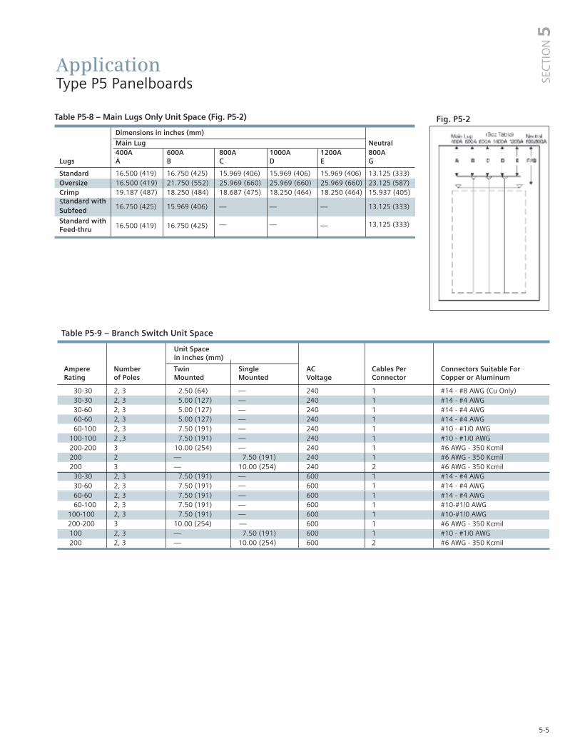
5-5
Table P5-9 – Branch Switch Unit Space
Unit Space in Inches (mm)
Ampere Number Twin Single AC Cables Per Connectors Suitable ForRating of Poles Mounted Mounted Voltage Connector Copper or Aluminum
30-30 2, 3 2.50 (64) — 240 1 #14 - #8 AWG (Cu Only)30-30 2, 3 5.00 (127) — 240 1 #14 - #4 AWG30-60 2, 3 5.00 (127) — 240 1 #14 - #4 AWG60-60 2, 3 5.00 (127) — 240 1 #14 - #4 AWG60-100 2, 3 7.50 (191) — 240 1 #10 - #1/0 AWG
100-100 2 ,3 7.50 (191) — 240 1 #10 - #1/0 AWG200-200 3 10.00 (254) — 240 1 #6 AWG - 350 Kcmil200 2 — 7.50 (191) 240 1 #6 AWG - 350 Kcmil200 3 — 10.00 (254) 240 2 #6 AWG - 350 Kcmil
30-30 2, 3 7.50 (191) — 600 1 #14 - #4 AWG30-60 2, 3 7.50 (191) — 600 1 #14 - #4 AWG60-60 2, 3 7.50 (191) — 600 1 #14 - #4 AWG60-100 2, 3 7.50 (191) — 600 1 #10-#1/0 AWG
100-100 2, 3 7.50 (191) — 600 1 #10-#1/0 AWG 200-200 3 10.00 (254) — 600 1 #6 AWG - 350 Kcmil100 2, 3 — 7.50 (191) 600 1 #10 - #1/0 AWG 200 2, 3 — 10.00 (254) 600 2 #6 AWG - 350 Kcmil
Table P5-8 – Main Lugs Only Unit Space (Fig. P5-2)
Dimensions in inches (mm)
Main Lug Neutral400A 600A 800A 1000A 1200A 800A
Lugs A B C D E G
Standard 16.500 (419) 16.750 (425) 15.969 (406) 15.969 (406) 15.969 (406) 13.125 (333)Oversize 16.500 (419) 21.750 (552) 25.969 (660) 25.969 (660) 25.969 (660) 23.125 (587)Crimp 19.187 (487) 18.250 (484) 18.687 (475) 18.250 (464) 18.250 (464) 15.937 (405)Standard with
16.750 (425) 15.969 (406) — — — 13.125 (333)Subfeed
Standard with16.500 (419) 16.750 (425) — — — 13.125 (333)
Feed-thru
ApplicationType P5 Panelboards
Fig. P5-2
SEC
TIO
N5

5-6
ApplicationType P5 Panelboards
BreakerFrameRating
TripType
BreakerFamily
FrameType Poles
TripAmperage
Unit Space Requirementsin Inches
Maximum Interruption Rating (KAIC) Volts AC
120 240480Y/277 480
600Y/347 600Single Twin
100 ThermalMagnetic
GeneralAppli-cation
BL 1, 2, 3 15-60, 70, 80, 90, 100, 110, 125 — 3.752 3 10,000 10,000 — — — —BLR 2 15, 20, 30, 40, 50, 60, 70, 80, 90,
100— 3.752 3 10,000 10,000 — — — —
BLH 1, 2, 3 15-60, 70, 80, 90, 100, 110, 125 — 3.752 3 22,000 22,000 — — — —HBL 1, 2, 3 15-60, 70, 80, 90, 100, 110, 125 — 3.752 3 65,000 65,000 — — — —BQD 1, 2, 3 15-50, 60, 70, 80, 90, 100 — 3.752 3 65,000 65,000 14,000 — — —BQD6 1, 2, 3 15-50, 60, 70 — 3.752 3 65,000 65,000 — — 10,000 —
SpecialApplication
BL-HID 1, 2 15, 20, 30 — 3.752 3 10,000 10,000 — — — —BL-BG 2, 3 15, 20, 30 — 3.752 3 10,000 10,000 — — — —
GroundFaultCircuitInterrupter
BLE-GFCI 1, 2 15, 20, 30, 40, 50, 60 — 3.752 10,000 10,000 — — — —BLEH-GFCI 1, 2 15, 20, 30, 40, 50, 60 — 3.752 10,000 10,000 — — — —BLF-GFCI 1, 2 15, 20, 30, 40, 50, 60 — 3.752 10,000 10,000 — — — —BLHF-GFCI 1, 2 15, 20, 30, 40, 50, 60 — 3.752 10,000 10,000 — — — —
ArcFaultCircuitInterrupter
BAF-AFCI 1, 2 15, 20 — 3.752 10,000 10,000 — — — —BAFH-AFCI 1, 2 15, 20 — 3.752 10,000 10,000 — — — —BAFC-AFCI 1, 2 15, 20 — 3.752 10,000 10,000 — — — —BAFCH-AFCI 1, 2 15, 20 — 3.752 10,000 10,000 — — — —
125 ThermalMagnetic
GeneralAppli-cation
NGB 1, 2, 3 15-60, 70, 80, 90, 100, 110, 125 — 3.752 3 — 100,000 25,000 — 14,000 —HGB 1, 2, 3 15-60, 70, 80, 90, 100, 110, 125 — 3.752 3 — 100,000 35,000 — 14,000 —LGB 1, 2, 3 15-60, 70, 80, 90, 100, 110, 125 — 3.752 3 — 100,000 65,000 — 14,000 —NEB 1, 2, 3 15-60, 70, 80, 90, 100, 110, 125 — 3.752 3 — 85,000 — 35,000 — 22,000HEB 1, 2, 3 15-60, 70, 80, 90, 100, 110, 125 — 3.752 3 — 100,000 — 65,000 — 25,000ED4 1, 2, 3 15-50, 60, 70, 80, 90, 100, 110, 125 — 3.752 3 — 65,000 — 18,000 — —HED44 5 1, 2, 3 15-50, 60, 70, 80, 90, 100, 110, 125 — 3.752 3 — 100,000 — 42,000 — —CED6 2, 3 15-50, 60, 70, 80, 90, 100, 110, 125 — 3.752 3 — 200,000 — 200,000 — 100,000
150 Electronic(Solid state)
VL ND 3 60, 100, 150 — 5.00 — 65,000 — 35,000 — 18,000HD 3 60, 100, 150 — 5.00 — 100,000 — 65,000 — 20,000LD 3 60, 100, 150 — 5.00 — 200,000 — 100,000 — 25,000
225 ThermalMagnetic
GeneralAppli-cation
QJ2 2, 3 60-110, 125, 150, 175, 200, 225
— 5.00 — 10,000 — — — —
QJH2 2, 3 60-110, 125, 150, 175, 200, 225
— 5.00 — 22,000 — — — —
QJ2H 2, 3 60-110, 125, 150, 175, 200, 225
— 5.00 — 42,000 — — — —
QR2 2, 3 100, 110, 125, 150, 175, 200, 225 — 5.00 — 10,000 — — — —QRH2 2, 3 100, 110, 125, 150, 175, 200, 225 — 5.00 — 25,000 — — — —HQR2 2, 3 100, 110, 125, 150, 175, 200, 225 — 5.00 — 65,000 — — — —HQR2H 2, 3 100, 110, 125, 150, 175, 200, 225 — 5.00 — 100,000 — — — —
250 ThermalMagnetic
Sentron FXD6, FD6 2, 3 70-110, 125, 150, 175, 200, 225, 250
5.00 5.00 — 65,000 — 35,000 — 22,000
HFXD6, HFD6
2, 3 70-110, 125, 150, 175, 200, 225, 250
5.00 5.00 — 100,000 — 65,000 — 25,000
HHFXD6, HHFD6
2, 3 70-110, 125, 150, 175, 200, 225, 250
5.00 5.00 — 200,000 — 100,000 — 25,000
CFD6 3 70-110, 125, 150, 175, 200, 225, 250
— 5.00 — 200,000 — 200,000 — 100,000
Electronic(Solid state)
VL NF 3 100, 150, 250 — 5.00 — 65,000 — 35,000 — 18,000HF 3 100, 150, 250 — 5.00 — 100,000 — 65,000 — 20,000LF 3 100, 150, 250 — 5.00 — 200,000 — 100,000 — 25,000
1 Includes housing frame plate with blank cover plate. Provision price includes all necessary mounting hardware, less circuit breaker, and includes housing frame cover plate with breaker handle opening.2 1 to 6 poles may be mounted in 3.75" of unit space.
3 Accessories such as shunt trips on three pole breakers require 6.25" of unit space.4 HED4 1-pole 15–30A = 65,000 IR 35–100A = 25,000 IR5 HED4 3-Pole = 42,000 IR.
Table P5-10 – Branch Circuit Breakers

5-7
ApplicationType P5 Panelboards
Table P5-11 – Branch Breaker Circuit Breakers (VL)
Maximum Trip Maximum IC (KA) Symmetrical AmperesAmpere Breaker Number Amp Voltage – ACRating Type of Poles Rating 120 120/250 240 277 480/277 480 600/347 600
ND 3 60-150 — 65 65 — 35 35 18 18150 1 HD 3 60-150 — 100 100 — 65 65 20 20
LD 3 60-150 — 200 200 — 100 100 25 25 NF 3 100-250 — 65 65 — 35 35 18 18
250 1 HF 3 100-250 — 100 100 — 65 65 20 20 LF 3 100-250 — 200 200 — 100 100 25 25NJ 3 250-400 — 65 65 — 35 35 25 25
400 1 HJ 3 250-400 — 100 100 — 65 65 25 25LJ 3 250-400 — 200 200 — 100 100 25 25NL 3 400-600 — 65 65 — 35 35 18 18
600 1 HL 3 400-600 — 100 100 — 65 65 18 18LL 3 400-600 — 200 200 — 100 100 18 18NM 2/3 600-800 — 65 65 — 35 35 25 25
800 HM 2/3 600-800 — 100 100 — 65 65 35 35LM 2/3 600-800 — 200 200 — 100 100 50 50NN 2/3 800-1200 — 65 65 — 35 35 25 25
1200 HN 2/3 800-1200 — 100 100 — 65 65 35 35LN 2/3 800-1200 — 200 200 — 100 100 50 50
SEC
TIO
N5
1 Only available with Electronic Trip Units.
Table P5-10 – Branch Circuit Breakers (continued)
BreakerFrameRating
TripType
BreakerFamily
FrameType Poles
TripAmperage
Unit Space Requirementsin Inches
Maximum Interruption Rating (KAIC) Volts AC
120 240480Y/277 480
600Y/347 600Single Twin
400 ThermalMagnetic
Sentron JXD6, JD6 2, 3 200, 225, 250, 300, 350,400
8.75 8.75 — 65,000 — 35,000 — 25,000
HJXD6, HJD6
2, 3 200, 225, 250, 300, 350, 400
8.75 8.75 — 100,000 — 65,000 — 35,000
HHJXD6, HHJD6
2, 3 200, 225, 250, 300, 350, 400
8.75 8.75 — 200,000 — 100,000 — 50,000
CJD6 3 200, 225, 250, 300, 350, 400
8.75 — — 200,000 — 150,000 — 100,000
Electronic(Solid state)
VL NJ 3 250, 400 6.25 6.25 — 65,000 — 35,000 — 25,000
HJ 3 250, 400 6.25 6.25 — 100,000 — 65,000 — 25,000
LJ 3 250, 400 6.25 6.25 — 200,000 — 100,000 — 25,000
Sentron SJD6 3 200, 300, 400 8.75 — — 65,000 — 35,000 — 25,000
SHJD6 3 200, 300, 400 8.75 — — 100,000 — 65,000 — 35,000
SCJD6 3 200, 300, 400 8.75 — — 200,000 — 150,000 — 100,000

5-8
ApplicationType P5 Panelboards
Fig. P5-3Table P5-13 – Branch Breaker Side Gutter
ED4, ED6 ED4, ED6 HED4 HED4 CED6 CED6 QJ2, QJH2, QJ2H, QJ2, QJH2, QJ2H, QR2, QRH2, QR2, QRH2, HQR2, HQR2H HQR2, HQR2H FD6, FXD6, FD6, FXD6 HFD6, HHFD6 HFD6, HHFD6 ND, HD, LD ND, HD, LD NF, HF, LF NF, HF, LF CFD JD6, JXD6, JD6, JXD6, HJD6, HHJD6 HJD6, HHJD6 NJ, HJ, LJ NJ, HJ, LJ SJD6, SHJD6, LD6, LXD6, HLD6, HHLD6, SLD6, SHLD6 CJD6, SCJD6, CLD6, SCLD6 NJ, HJ, LJ
NL, HL, LL
NM, HM, LM NN, HN, LN
A
D
VB 30 A VB 30 A VB 30 - 60A VB 30 - 60 A VB 60 -100A VB 60 - 100A
E
F
G
A
D
E
BL, BLH, HBL, BQD BL, BLH, HBL, BDQ
NGB, HGB, LGB NGB, HGB, LGB NEB, HEB NEB, HEB
B B
C C
F
G
H H
I I J J
K K
L L
M M
N N
O O P P
VB 200A VB 200A VB 100A Single VB 200A Single
STUVWX
STUVWX
VB 5 Single
Q Q
R R
Y Y
Z Z
VB 400 – 600A Single
HCP 400 – 1200A Single
Reference Panel Width – 32 (813)Letter Dimensions in inches (mm)
A 14.0 (356)B 13.98 (355)C 11.62 (295)D 10.0 (254)E 7.61 (193)F 8.75 (222)G 8.25 (210)H 10.90 (276)I 10.90 (276)J 11.76 (299)K 7.92 (201)L 8.0 (203)M 13.42 (341)N 12.0 (305)O 15.50 (393)P 14.25 (362)Q 13.42 (341)R 13.42 (341)S 10.0 (254)T 8.0 (203)U 10.50 (267)V 10.50 (267)W 9.30 (236)X 10.30 (262)Y 9.30 (236)Z 10.30 (262)
1 Mounting height shown will accomodate from (1) to (6) poles.2 Accessories such as shunt trips on three pole breakers requires 6.25" of unit space.
Table P5-12 – Branch Breakers Unit Space Requirements
Mounting HeightAmp Breaker in Inches (mm) Rating Type Twin Single
1001 BL,BLH,HBL,BQD,BLE, BLEH, BLR, BLF, BLHF, BAF, BAFC, BAFH, BAFCH, BGL 3.75 (95) 1
BL, BLH, HBL, BQD -With accessories 6.25 (159) —
125xGB, NEB, HEB, ED4, ED6, HED4, HHED6, CED6 3.75 (95)1
xGB, ED41 2, ED61 2, HED41 2, HHED61 2, CED61 2 (With accessories) 6.25 (159) —150 ND, HD, LD 5.00 (127) —225 QJ2, QJH2, QJ2H, QR2, QRH2, HQR2, HQR2H 5.00 (127) —
NF, HF, LF 5.00 (127) — 250 FD6, FXD6, HFD6, HFXD6, HHFD6, HHFXD6 5.00 (127) —
CFD6 — 5.00 (127)
400NJ, HJ, LJ — 6.25 (159)JD6, JXD6, HJD6, HJXD6, HHJD6, HHJXD6, CJD6 8.75 (222)
600NL, HL, LL — 6.25 (159)LD6, LXD6, HLD, HLXD6, HHLD6, HHLXD6, CLD6 8.75 (222)
800NM, HM, LM — 8.75 (222)MXD6, MD6, HMXD6, HMD6, CMD6 10.00 (254)
1200NN, HN, LN
— 10.00 (254)NXD6, ND6, HNXD6, HND6, CND6

5-9
Typical Catalog NumbersType P5 Panelboards
Table P5-14 – Main Lugs Only – shown with aluminum bus, top fed, and surface trims
Max. 208Y/120V 240/120V 120/240V or 240 480Y/277V 480V 1
Panel Unit 250 Vdc MaxAmp Space 3 Phase, 4 Wire 3 Phase, 4 Wire 1 Phase, 3 Wire 3 Phase, 3 Wire 3 Phase, 4 Wire 1 Phase, 3 Wire Rating (inches) Catalog Number Catalog Number Catalog Number Catalog Number Catalog Number Catalog Number
30 P5C60ML800ATS P5B60ML800ATS P5A60ML800ATS P5D60ML800ATS P5E60ML800ATS P5F60ML800ATS800 45 P5C75ML800ATS P5B75ML800ATS P5A75ML800ATS P5D75ML800ATS P5E75ML800ATS P5F75ML800ATS
60 P5C90ML800ATS P5B90ML800ATS P5A90ML800ATS P5D90ML800ATS P5E90ML800ATS P5F90ML800ATS30 P5C60ML101ATS P5B60ML101ATS P5A60ML101ATS P5D60ML101ATS P5E60ML101ATS P5F60ML101ATS
1000 45 P5C75ML101ATS P5B75ML101ATS P5A75ML101ATS P5D75ML101ATS P5E75ML101ATS P5F75ML101ATS60 P5C90ML101ATS P5B90ML101ATS P5A90ML101ATS P5D90ML101ATS P5E90ML101ATS P5F90ML101ATS30 P5C60ML120ATS P5B60ML120ATS P5A60ML120ATS P5D60ML120ATS P5E60ML120ATS P5F60ML120ATS
1200 45 P5C75ML120ATS P5B75ML120ATS P5A75ML120ATS P5D75ML120ATS P5E75ML120ATS P5F75ML120ATS60 P5C90ML120ATS P5B90ML120ATS P5A90ML120ATS P5D90ML120ATS P5E90ML120ATS P5F90ML120ATS
Table P5-16 – Main Fusible Switch (fuses not included)
Max. 208Y/120V 240/120V 120/240V 240V 480Y/277V 480V 1Panel UnitAmp Space 3 Phase, 4 Wire 3 Phase, 4 Wire 1 Phase, 3 Wire 3 Phase, 3 Wire 3 Phase, 4 Wire 3 Phase, 3 Wire Rating (inches) Catalog Number Catalog Number Catalog Number Catalog Number Catalog Number Catalog Number
20 P5C75MS400ATS P5B75MS400ATS P5A75MS400ATS P5D75MS400ATS P5E75MS400ATS P5F75MS400ATS400 40 P5C90MS400ATS P5B90MS400ATS P5A90MS400ATS P5D90MS400ATS P5E90MS400ATS P5F90MS400ATS
25 P5C75MS600ATS P5B75MS600ATS P5A75MS600ATS P5D75MS600ATS P5E75MS600ATS P5F75MS600ATS600 40 P5C90MS600ATS P5B90MS600ATS P5A90MS600ATS P5D90MS600ATS P5E90MS600ATS P5F90MS600ATS
28.75 P5C75MS800ATS P5B75MS800ATS P5A75MS800ATS P5D75MS800ATS P5E75MS800ATS P5F75MS800ATS8003
43.75 P5C90MS800ATS P5B90MS800ATS P5A90MS800ATS P5D90MS800ATS P5E90MS800ATS P5F90MS800ATS28.75 P5C75MS120ATS P5B75MS120ATS P5A75MS120ATS P5D75MS120ATS P5E75MS120ATS P5F75MS120ATS
1200343.75 P5C90MS120ATS P5B90MS120ATS P5A90MS120ATS P5D90MS120ATS P5E90MS120ATS P5F90MS120ATS
Table P5-15 – Main Circuit Breakers – shown with aluminum bus, top fed, and surface trims
Max. 208Y/120V 240/120V 120/240V or 240 480Y/277V 480V 1Panel Unit 250 Vdc MaxAmp Space 3 Phase, 4 Wire 3 Phase, 4 Wire 1 Phase, 3 Wire 3 Phase, 3 Wire 3 Phase, 4 Wire 1 Phase, 3 Wire Rating (inches) Catalog Number Catalog Number Catalog Number Catalog Number Catalog Number Catalog Number
21.25 P5C60M1800ATS P5B60M1800ATS P5A60M1800ATS P5D60M1800ATS P5E60M1800ATS P5F60M1800ATS800 2 36.25 P5C75M1800ATS P5B75M1800ATS P5A75M1800ATS P5D75M1800ATS P5E75M1800ATS P5F75M1800ATS
51.25 P5C90M1800ATS P5B90M1800ATS P5A90M1800ATS P5D90M1800ATS P5E90M1800ATS P5F90M1800ATS20 P5C60N1120ATS P5B60N1120ATS P5A60N1120ATS P5D60N1120ATS P5E60N1120ATS P5F60N1120ATS
1200 35 P5C75N1120ATS P5B75N1120ATS P5A75N1120ATS P5D75N1120ATS P5E75N1120ATS P5F75N1120ATS50 P5C90N1120ATS P5B90N1120ATS P5A90N1120ATS P5D90N1120ATS P5E90N1120ATS P5F90N1120ATS
1 For 600V, change “F” in position 3 to “G.” 2 Alternate main breaker requires an additional 1.25” unit space.3 800 and 1200 ampere switches have "L" class fuse provisions (Type HCD).
SEC
TIO
N5
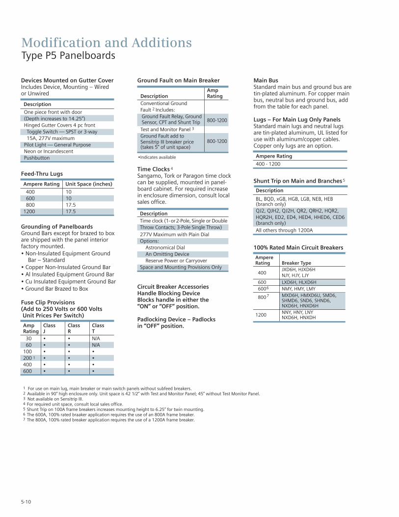
5-10
Devices Mounted on Gutter CoverIncludes Device, Mounting – Wired or Unwired
Feed-Thru Lugs
Grounding of Panelboards Ground Bars except for brazed to box are shipped with the panel interior factory mounted.• Non-Insulated Equipment Ground
Bar – Standard• Copper Non-Insulated Ground Bar• Al Insulated Equipment Ground Bar• Cu Insulated Equipment Ground Bar• Ground Bar Brazed to Box
Fuse Clip Provisions(Add to 250 Volts or 600 Volts Unit Prices Per Switch)
Ground Fault on Main Breaker
Time Clocks 4
Sangamo, Tork or Paragon time clock can be supplied, mounted in panel-board cabinet. For required increasein enclosure dimension, consult localsales office.
Circuit Breaker AccessoriesHandle Blocking DeviceBlocks handle in either the “ON” or “OFF” position.
Padlocking Device – Padlocks in “OFF” position.
Main BusStandard main bus and ground bus aretin-plated aluminum. For copper mainbus, neutral bus and ground bus, addfrom the table for each panel.
Lugs – For Main Lug Only PanelsStandard main lugs and neutral lugs are tin-plated aluminum, UL listed for use with aluminum/copper cables.Copper only lugs are an option.
Shunt Trip on Main and Branches5
100% Rated Main Circuit Breakers
Ampere Rating
400 - 1200
Description
BL, BQD, xGB, HGB, LGB, NEB, HEB(branch only)QJ2, QJH2, QJ2H, QR2, QRH2, HQR2,HQR2H, ED2, ED4, HED4, HHED6, CED6(branch only)All others through 1200A
Modification and AdditionsType P5 Panelboards
AmpDescription RatingConventional Ground Fault 2 Includes:Ground Fault Relay, Ground
800-1200Sensor, CPT and Shunt TripTest and Monitor Panel 3
Ground Fault add toSensitrip III breaker price 800-1200(takes 5” of unit space)
Ampere Rating Unit Space (inches)
400 10600 10800 17.5
1200 17.5
Amp Class Class ClassRating J R T
30 • • N/A60 • • N/A
100 • • •200 1 • • •400 • • •600 • • •
1 For use on main lug, main breaker or main switch panels without subfeed breakers.2 Available in 90” high enclosure only. Unit space is 42 1/2” with Test and Monitor Panel; 45” without Test Monitor Panel.3 Not available on Sensitrip III.4 For required unit space, consult local sales office.5 Shunt Trip on 100A frame breakers increases mounting height to 6.25” for twin mounting.6 The 600A, 100% rated braaker application requires the use of an 800A frame breaker.7 The 800A, 100% rated breaker application requires the use of a 1200A frame breaker.
DescriptionTime clock (1-or2-Pole, Single or DoubleThrow Contacts; 3-Pole Single Throw)277V Maximum with Plain DialOptions:
Astronomical DialAn Omitting DeviceReserve Power or Carryover
Space and Mounting Provisions Only
Description
One piece front with door (Depth increases to 14.25”)Hinged Gutter Covers 4 pc front
Toggle Switch — SPST or 3-way15A, 277V maximum
Pilot Light — General PurposeNeon or IncandescentPushbutton •Indicates available
AmpereRating Breaker Type
400JXD6H, HJXD6HNJY, HJY, LJY
600 LXD6H, HLXD6H6006 NMY, HMY, LMY
8007 MXD6H, HMXD6U, SMD6,SHMD6, SND6, SHND6,NXD6H, HNXD6H
1200 NNY, HNY, LNYNXD6H, HNXDH

5-11
Modification and AdditionsType P5 Panelboards
Motor StartersETI instantaneous-trip circuit breakers are recommended for use in combinationmotor starters to provide selective shortcircuit protection for the motor branch circuit. The adjustable instantaneous-tripfeature provides a trip setting slightlyabove the peak motor inrush current.With this setting, there is no delay opening the circuit when the fault occurs.Since these circuit breakers have no timedelay trip element, they must be used inconjunction with, and immediately aheadof, the motor-running over-current protective device.
Check the voltage and interrupting ratingof the circuit breaker to ensure they areadequate for the electrical system. UL recognized ETI breakers must be used.
Full voltage, non-reversing NEMA Size 1 through Size 4 motor starters are available as additions to P5 panelboards.P5 panelboards can accommodate motor
disconnect devices in either one of two circumstances: 1. by using a branch thermal magnetic (ETI) circuit breaker tofeed a remote starter that controls amotor which is in sight of and withinfifty feet of the panelboard. 2. by using a branch instantaneous trip only (ETI)circuit breaker in conjunction with amotor starter mounted in the sameenclosure which is in sight of and withinfifty feet of the controlled motor.
Whether a remote starter is used, or the breaker and starter are mounted in the same enclosure, a padlockingdevice must be specified so a padlockcan be installed in the “OFF” position. P2 panelboards incorporate motor disconnect devices much in the sameway as P5 panelboards, except a fusibleVacu-Break switch unit is utilized ratherthan an ETI circuit breaker. In addition,padlocking devices are standard on allVacu-Break switches eliminating theneed to order them as an accessory.
Standard Motor Starters EquippedWith:• 3rd overload relay• Mechanical interlock between circuit
breaker (or switch) and motor starterdoor
• Reset button• Class 1, Type A wiring
Optional Motor Control Accessories• Pushbuttons: Start/Stop or Open/Close,
Reverse/Forward/Stop or High/Low/Stop• Selector Switch: Hand/Off/Auto or
On/Off• Pilot Light: Red or Amber• Auxiliary interlock (normally open or
normally closed-unwired)• Control transformer, 60Hz, fused LV,
Sizes 1 thru 4• Class 1, Type B wiring
Maximum 3Ø Ratings Mounting Height in Inches (mm)Amp Breaker Min. Section Rating Type 220 (208)V 240V 480V1 2 Twin Single Width Inches (mm)
3 — — 1 5 (127) — 32 (813)5 0.5 0.5 2 5 (127) — 32 (813)
10 ED 1 2 2 3 5 (127) — 32 (813)25 5 5 10 5 (127) — 32 (813)50 15 15 30 5 (127) — 32 (813)
100 30 30 60 5 (127) — 32 (813)150 FD6 2 40 40 75 5 (127) — 32 (813)225 FD6, 50 50 100 5 (127) — 32 (813)
CFD6
Table P5-17 – ETI circuit Breakers (Instantaneous Trip Only)For Branch-Circuit Use with AC Full Voltage Motor Starters
1 100,000 kA at 480V with E-frame and CFD6 frame breakers.2 65,000 kA at 480V with F-frame breakers.3 Increase to 7.50 inches when pilot light or control transformer is required.
Table P5-18 – Full VoltageNon-Reversing Starters Class A20
NEMA Unit SpaceStarter Size Mtg. Ht. In. (mm)Left Right0 — 5 (127) 3
0 0 5 (127) 3
1 — 5 (127) 3
1 0 5 (127) 3
1 1 5 (127) 3
2 — 10 (254)2 0 10 (254)2 1 10 (254)2 2 10 (254)3 — 15 (381)3 0 15 (381)3 1 15 (381)3 2 15 (381)3 3 15 (381)4 — 15 (381)
Table P5-19 – Maximum 3 PhaseHorsepower Rating
NEMA Starter Voltage AC Size 220 (208)V 240V 480V
0 3 3 51 7.5 7.5 102 10 15 253 25 30 504 40 50 100
SEC
TIO
N5

5-12
Connector Modifications
Style Amp Rating Breaker Type Compression Connectors Available Unit Space Reduction
800 N/A (3)#3/0 AWG - 750 Kcmil Cu or Al Deduct 5.0” Unit Space MLO 1000 N/A (4)#3/0 AWG - 750 Kcmil Cu or Al Deduct 7.5” Unit Space
1200 N/A (4)#3/0 AWG - 750 Kcmil CU or Al Deduct 7.5” Unit Space
Table P5-22 – Alternate Lugs
Style Amp Rating Breaker Type Compression Connectors Available Unit Space Reduction
800 N/A All compression lugs Deduct 10.0” Unit Space MLO 1000 N/A All compression lugs Deduct 10.0” Unit Space
1200 N/A All compression lugs Deduct 10.0” Unit Space 800 MD6, HMD6, CMD6,
SMD6, SHMD6, (3)#2/0 AWG - 500 Kcmil CU or Al 0Main Breaker SCMD6
1200 ND6, HND6, CND6, SND6, SHND6. (4)#250 - 500 Kcmil Cu or Al 0SCND6
Table P5-21 – Compression Lugs
Compression Lugs
Modification and AdditionsType P5 Panelboards
Horsepower Ratings Mounting Height in Inches (mm)240V AC 480V AC 240V AC 480V AC Min. Section
Amp With With Dual- With NEC With Dual- WidthRating NEC Fuse Element Fuse Fuse Element Fuse Twin Single Twin Single Inches (mm)
30-30 3 7.5 — — 2.50 2
— — — 32 (813)(64)
30-30 3 7.5 5 105.00
—7.50
— 32 (813)(127) (191)
30-60 3-7.5 7.5-15 5-15 255.00
—7.50
— 32 (813)(127) (191)
60-60 7.5 15 15 255.00
—7.50
— 32 (813)(127) (191)
60-100 7.5-15 15-30 15-25 25-507.50
—7.50
— 32 (813)(191) (191)
100-100 15 30 25 507.50
—7.50
— 32 (813)(191) (191)
100 — — 25 50 — — —7.50
32 (813)(191)
200 25 50 50 100 —10.00
—10.00
32 (813)(254) (254)
200-200 — 50 — 10010.00
—10.00
— 32 (813)(254) (254)
400 50 100 100 — —15.00
—15.00
38 (965)(381) (381)
600 75 100 — — —15.00
—15.00
38 (965)(381) (381)
Table P5-20 – Vacu-Break Fusible SwitchesFor Branch Circuit Use with AC Combination Full Voltage Starters 1
1 100,000 kA at 480V with Class J or Class RK5 fuses.2 The 2.50 inch (64mm) high unit is suitable for NEC Class H and K5 fuses only. Class R rejection type fuse holders are not available.

5-13
DimensionsType P5 Panelboards
Type 1 BoxBox is symmetrical
Type 3R and 3R/12 Box
Dimensions are interior of the box. Add 5/8” to width for absolute dimension. Add 1/8” to height for absolute dimension.
Dimensions shown in inches and millimeters [ ].
�
SEC
TIO
N5
�
�
�
�
�
�
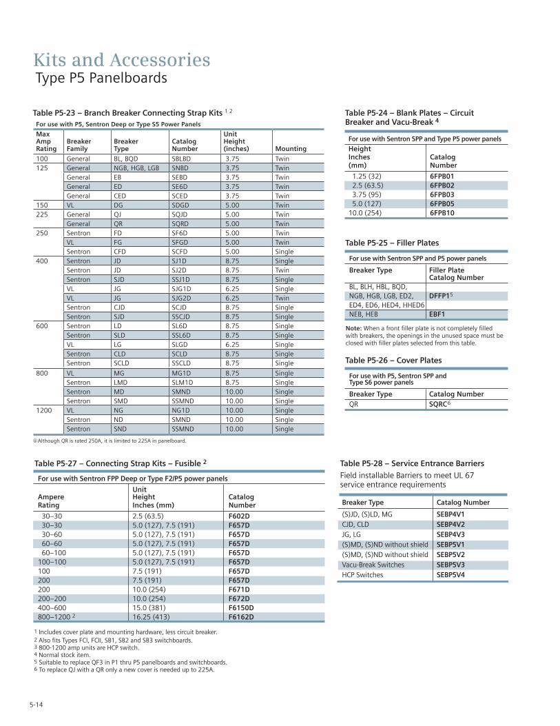
5-14
Kits and AccessoriesType P5 Panelboards
Table P5-23 – Branch Breaker Connecting Strap Kits 1 2 Table P5-24 – Blank Plates – Circuit Breaker and Vacu-Break 4
For use with Sentron SPP and Type P5 power panels
HeightInches Catalog(mm) Number
1.25 (32) 6FPB012.5 (63.5) 6FPB023.75 (95) 6FPB035.0 (127) 6FPB05
10.0 (254) 6FPB10
Table P5-27 – Connecting Strap Kits – Fusible 2 Table P5-28 – Service Entrance Barriers
Field installable Barriers to meet UL 67 service entrance requirements
For use with Sentron FPP Deep or Type F2/P5 power panels
UnitAmpere Height CatalogRating Inches (mm) Number
30–30 2.5 (63.5) F602D30–30 5.0 (127), 7.5 (191) F657D30–60 5.0 (127), 7.5 (191) F657D60–60 5.0 (127), 7.5 (191) F657D60–100 5.0 (127), 7.5 (191) F657D
100–100 5.0 (127), 7.5 (191) F657D100 7.5 (191) F657D200 7.5 (191) F657D200 10.0 (254) F671D200–200 10.0 (254) F672D400–600 15.0 (381) F6150D800–1200 2 16.25 (413) F6162D
Table P5-25 – Filler Plates
For use with Sentron SPP and P5 power panels
Breaker Type Filler Plate Catalog Number
BL, BLH, HBL, BQD, NGB, HGB, LGB, ED2, DFFP15
ED4, ED6, HED4, HHED6NEB, HEB EBF1
Note: When a front filler plate is not completely filledwith breakers, the openings in the unused space must beclosed with filler plates selected from this table.
1 Includes cover plate and mounting hardware, less circuit breaker.2 Also fits Types FCI, FCII, SB1, SB2 and SB3 switchboards.3 800-1200 amp units are HCP switch.4 Normal stock item.5 Suitable to replace QF3 in P1 thru P5 panelboards and switchboards. 6 To replace QJ with a QR only a new cover is needed up to 225A.
Table P5-26 – Cover Plates
For use with P5, Sentron SPP and Type S6 power panels
Breaker Type Catalog NumberQR SQRC6
For use with P5, Sentron Deep or Type S5 Power Panels
MaxAmpRating
BreakerFamily
BreakerType
CatalogNumber
UnitHeight(inches) Mounting
100 General BL, BQD SBLBD 3.75 Twin125 General NGB, HGB, LGB SNBD 3.75 Twin
General EB SEBD 3.75 TwinGeneral ED SE6D 3.75 TwinGeneral CED SCED 3.75 Twin
150 VL DG SDGD 5.00 Twin225 General QJ SQJD 5.00 Twin
General QR SQRD 5.00 Twin250 Sentron FD SF6D 5.00 Twin
VL FG SFGD 5.00 TwinSentron CFD SCFD 5.00 Single
400 Sentron JD SJ1D 8.75 SingleSentron JD SJ2D 8.75 TwinSentron SJD SSJ1D 8.75 SingleVL JG SJG1D 6.25 SingleVL JG SJG2D 6.25 TwinSentron CJD SCJD 8.75 SingleSentron SJD SSCJD 8.75 Single
600 Sentron LD SL6D 8.75 SingleSentron SLD SSL6D 8.75 SingleVL LG SLGD 6.25 SingleSentron CLD SCLD 8.75 SingleSentron SCLD SSCLD 8.75 Single
g800 VL MG MG1D 8.75 Single
Sentron LMD SLM1D 8.75 SingleSentron MD SMND 10.00 SingleSentron SMD SSMND 10.00 Single
1200 VL NG NG1D 10.00 SingleSentron ND SMND 10.00 SingleSentron SND SSMND 10.00 Single
f Although QR is rated 250A, it is limited to 225A in panelboard.
Breaker Type Catalog Number
(S)JD, (S)LD, MG SEBP4V1CJD, CLD SEBP4V2JG, LG SEBP4V3(S)MD, (S)ND without shield SEBP5V1(S)MD, (S)ND without shield SEBP5V2Vacu-Break Switches SEBP5V3HCP Switches SEBP5V4

5-15
SEC
TIO
N5
Kits and AccessoriesType P5 Panelboards
Description Catalog number
P5 Type 1 38” W x 12.75” D x 60” H PB860P5 Type 1 38”” W x 12.75” D x 75” H PB875P5 Type 1 38”” W x 12.75” D x 90” H PB890P5 Type 1 38” W x 14.75” D x 60” H PBD860 1
P5 Type 1 38”” W x 14.75” D x 75” H PBD875 1
P5 Type 1 38”” W x 14.75” D x 90” H PBD890 1
P5 Type 3R/12 60” H WP860P5 Type 3R/12 75” H WP875P5 Type 3R/12 90” H WP890
1 Required with door over breaker handles.
Table P5-29 – Enclosures
Description Catalog number
P5 Std (4 piece trim) vented 60” P560VP5 Std (4 piece trim) vented 75” P575VP5 Std (4 piece trim) vented 90” P590VP5 Std (4 piece trim) unvented 60” P560NV 1
P5 Std (4 piece trim) unvented 75” P575NV 1
P5 Std (4 piece trim) unvented 90” P575NV 1
P5 Std (4 piece trim) vented 60” with hinged gutter covers P560VHGP5 Std (4 piece trim) vented 75” with hinged gutter covers P575VHGP5 Std (4 piece trim) vented 90” with hinged gutter covers P590VHGP5 Std (4 piece trim) unvented 60” with hinged gutter covers P560NVHGP5 Std (4 piece trim) unvented 75” with hinged gutter covers P575NVHGP5 Std (4 piece trim) unvented 90” with hinged gutter covers P590NVHGP5 Std (1 PC Door) vented 60” P560VD 2
P5 Std (1 PC Door) vented 75” P575VD 2
P5 Std (1 PC Door) vented 90” P590VD 2
P5 Std (1 PC Door) unvented 60” P560NVD 2
P5 Std (1 PC Door) unvented 75” P575NVD 2
P5 Std (1 PC Door) unvented 90” P590NVD 2
P5 Std (1 PC Door-in-door) vented 60” P560VDD 2
P5 Std (1 PC Door-in-door) vented 75” P575VDD 2
P5 Std (1 PC Door-in-door) vented 90” P590VDD 2
P5 Std (1 PC Door-in-door) unvented 60” P560VDD 2
P5 Std (1 PC Door-in-door) unvented 75” P575VDD 2
P5 Std (1 PC Door-in-door) unvented 90” P590VDD 2
1 Unvented trims require amps per square inch bussing.2 Requires 14.5” deep box.
Table P5-30 – Trims
Description Catalog number
Flush kit to P5 60” High F860Flush kit to P5 75” High F875Flush kit to P5 90” High F890
Table P5-31 – Flush mounting kits

Notes

C1/C2 PanelboardsDescription PageGeneral Specifications 6-2
Box Sizing 6-2Gauge Steel Boxes 6-2Fronts 6-2Main Breaker Connectors 6-2Main Lug Connectors 6-2
Selection 6-3 – 6-5Main Lugs Only C1 and C2 6-3Main Circuit Breaker C1 and C2 6-3Alternate Main Breaker Selection C1 6-3Branch Breaker Selection C1 6-4
Subfeed Breakers C1 6-4Alternate Main Breaker Selection C2 6-5Branch Circuit Breaker C2 6-5Subfeed Breakers C2 6-5
Modification and Additions 6-6Box Modifications 6-6Interior Modifications 6-6Column Extension 6-6Pull Boxes 6-6
SEC
TIO
N6

6-2
Type C1240 Volts AC Maximum250 Ampere Mains250 Ampere Maximum BranchUL Short Circuit Rating – 200,000 IR MaximumBranch Breaker Symmetrical Interrupting RatingBased on Underwriters’ Test Procedure
Type C2480Y/277 Volts AC Maximum250 Ampere Mains250 Ampere Maximum Branch UL Short Circuit Rating – 100,000 IR MaximumMeets NEC wire bending requirement, section 312-6
PanelboardsListed by Underwriter’s Laboratories, Inc., under “Panelboards”File #E2269Meets Federal Specification W-C375B/Gen.
ServiceDescription: 240 Volts Maximum. 1-Phase, 3-wire or 3-Phase, 4-Wire.
Panelboards Fronts and DoorsStandard panelboards are furnished with trim with a flush doorlock. All are factory assembled for ease of installation. Fronts arefabricated from code gauge steel and finished ANSI-61.
Main Breakers C1BL, BLH and HBL frame breakers are mounted horizontally. Allother frames are mounted vertically.
Main Breakers C2BQD frame breakers are mounted horizontally. All other framesare mounted vertically.
Weight — ApproximateTotal panelboard weight when filled with a normal quantity ofbreakers and accessories is about 3 lbs. (1 kg) per inch (54g permm) of box height.
Table C1/C2-1 – Box SizingCertain Modifications such as subfeed breakers and feed-thrulugs require additional unit space. Use this table to determineproper enclosure size.
General SpecificationsC1 and C2 Panelboards
Main Lug with Feed-Thru Lugs
Main Breaker with Feed-Thru Lugs
Main Breaker with Subfeed Breaker
Main Lug withSubfeed Breaker
Main Breaker
Panel Height Dimensions in inches (mm)Config- No. of Inches Width Depthuration Circuits (mm) C1 C2 C1 C2
18 48 (1219)Main Lug 30 73 (1854)
42 85 (2159)18 73 (1854)30 86 (2184)42 85 (2159)18 73 (1854)30 85 (2159) 7.62 8.50 5.75 5.7518 48 (1219) (194) (216) (146) (146)30 73 (1854)42 85 (2159)18 73 (1854)30 85 (2159)42 85 (2159)18 73 (1854)30 85 (2159)
Table C1/C2-2 – Gauge Steel Boxes
Type Width Height Gauge SteelC1 7 ⁵⁄₈ ”1 48, 73, 85 #14C2 8 ¹⁄₂” 1 48, 73, 85 #14
Table C1/C2-3 – Fronts
Type Width Height Gauge SteelC1 7 ⁵⁄₈ ”1 48, 73, 85 #14C2 8 ¹⁄₂” 1 48, 73, 85 #14
Table C1/C2-4 – Main Breaker Connectors
Ampere Rating Connector Suitable for Cu or Al
100 (1) #14-1/0 AWG125 (1) #4-1/0 AWG225 (1) #6 AWG-300 kcmil250 (1) #4 AWG-350 kcmil Al
(1) #6 AWG-350 kcmil Cu
Table C1/C2-5 – Main Lug Connectors
Ampere Rating Connector Suitable for Cu or Al
125 (1) #6 AWG-350 kcmil250 (1) #6 AWG-350 kcmil
1 Feed thru lugs and subfeed breakers not available for this height.

6-3
SelectionC1 and C2 Panelboards
Max.Panel Max. Box 208Y/120V 120/240VAmp 1-Pole Height 3, Phase 4 Wire 1 Phase, 3 WireRating Circuits Inches Catalog Number Catalog Number
18 48 C1C18ML125CTS C1A18ML125CTS125 30 73 C1C30ML125CTS C1A30ML125CTS
42 85 C1C42ML125CTS C1A42ML125CTS18 48 C1C18ML250CTS C1A18ML250CTS
250 30 73 C1C30ML250CTS C1A30ML250CTS42 85 C1C42ML250CTS C1A42ML250CTS
Table C1/C2-6 – Main Lugs Only C1
18 48 C1C18BL100CTS C1A18BL100CTS100 30 73 C1C30BL100CTS C1A30BL100CTS
42 85 C1C42BL100CTS C1A42BL100CTS18 48 C1C18E4125CTS C1A18E4125CTS
125 30 73 C1C30E4125CTS C1A30E4125CTS42 85 C1C42E4125CTS C1A42E4125CTS18 48 C1C18QR225CTS C1A18QR225CTS
225 30 73 C1C30QR225CTS C1C30QR225CTS/ 42 85 C1C42QR225CTS C1A42QR225CTS/18 48 C1C18FX250CTS C1A18FX250CTS
250 30 73 C1C30FX250CTS C1A30FX250CTS42 85 C1C42FX250CTS C1A42FX250CTS
Table C1/C2-8 – Main Circuit Breaker C1 1 2
Max.Panel Max. Box 480Y/277VAmp 1-Pole Height 3 Phase, 4 WireRating Circuits Inches Catalog Number
18 48 C2E18ML125CTS125 30 73 C2E30ML125CTS
42 85 C2E42ML125CTS18 48 C2E18ML250CTS
250 30 73 C2E30ML250CTS42 85 C2E42ML250CTS
Table C1/C2-7 – Main Lugs Only C2
18 48 C2E18BD100CTS100 30 73 C2E30BD100CTS
42 85 C2E42BD100CTS18 48 C2E18E4125CTS
125 30 73 C2E30E4125CTS42 85 C2E42E4125CTS18 48 C2E18FX225CTS
225 30 73 C2E30FX225CTS42 85 C2E42FX225CTS18 48 C2E18FX250CTS
250 30 73 C2E30FX250CTS42 85 C2E42FX250CTS
Table C1/C2-9 – Main Circuit Breaker C2 1 2
Amp Breaker Maximum Interrupting Catalog Rating Type Rating (KA) Number Available Trip Values
BL 10 BL100 BLH 22 LH 50, 60, 70, 80, 90, 100
HBL 65 HLED4 65 E4
125HED4 100 H4
50, 60, 70, 80, 90, 100, 110, 125
QJ2 10 QJQJH2 22 QH 60, 70, 80, 90, 100, 110, 125, 150, 175, 200, 225
225 QJ2H 42 Q2QR2 10 QR 100, 110, 125, 150, 175, 200, 225FXD6 65 FX
70, 80, 90, 100, 110, 125, 150, 175, 200, 225HFD6 2 100 HF
250FXD6 65 FX
250HFD6 2 100 HF
1 BL, BLH, HBL and BQD are horizontally mounted. All others vertically mounted.2 Interchangeable trip breakers such as FD6 and HFD6 cannot be back fed. Must be top feed only.
Table C1/C2-10– Alternate Main Breaker Selection C1 1 2
SEC
TIO
N6

6-4
SelectionC1 and C2 Panelboards
Available Maximum Interrupting
Breaker Ampere Rating (kA)
Type Rating 120V 120/240V 240V
15, 20, 30, 40, 50, 60 — 10 —BL (120V) 70 — 10 —
70, 80, 90, 100 — 10 —BL (HID) 15, 20, 30 — — —
BLF (GFCI)15, 20, 30 10 — —40, 50, 60 10 — —
BLE (EQGFI) 15, 20, 30 10 — —BGL (SWN) 15, 20, 30 10 — —
BLR (240V)15, 20, 30, 40, 50, 60 — — 1070, 80, 90, 100 — — 1015, 20, 30, 40, 50, 60 — 22 —
BLH (120V) 70 — 22 —70, 80, 90, 100 — 22 —
BLHF (GFCI)15, 20, 30 — 22 —40, 50, 60 — 22 —
HBL15, 20, 30, 40, 50 — 65 6560, 70, 80, 90, 100 — 65 65
ED415, 20, 30, 40, 50, 60, 70, 80, 90, 100 — — 65110, 125 — — 65
HED415, 20, 30, 40, 50, 60, 70, 80, 90, 100 — — 65110, 125 — — 100
QJ2 60, 70, 80, 90, 100, 110, 125, 150, 175, 200, 225 — — 10QJH2 60, 70, 80, 90, 100, 110, 125, 150, 175, 200, 225 — — 22QJ2H 60, 70, 80, 90, 100, 110, 125, 150, 175, 200, 225 — — 42QR2 100, 110, 125, 150, 175, 200, 225 — — 10FXD6 70, 80, 90, 100, 110, 125, 150, 175, 200, 225, 250 — — 65HFD62 70, 80, 90, 100, 110, 125, 150, 175, 200, 225, 250 — — 100
Table C1/C2-12 – Subfeed Breakers - Limit One Per Panel – C11 (Not available for 42 circuit panels)
Table C1/C2-11 – Branch Breaker Selection C1
1 BL, BLH, HBL, and BQD are horizontally mounted. All others are vertically mounted.2 Interchangeable trip breakers such as FD6 and HFD6 cannot be back fed. Must be top feed only.

6-5
SelectionC1 and C2 Panelboards
Maximum Interrupting Rating (kA)
Breaker Type Available Ampere Rating 277V 480/277V 480V
15, 20, 30, 40, 50, 60 14 14 —BQD
70, 80, 90, 100 14 14 —
Table C1/C2-14 – Branch Circuit Breakers C2
ED415, 20, 30, 40, 50, 60, 70, 80, 90, 100 — 18 18110, 125 — 18 18
ED6 15, 20, 30, 40, 50, 60, 70, 80, 90, 100 — — 25110, 125 — — 25
HED4 15, 20, 30, 40, 50, 60, 70, 80, 90, 100 — — 42110, 125 — — 42
FXD6 70, 80, 90, 100, 110, 125, 150, 175, 200, 225, 250 — — 35HFD6 70, 80, 90, 100, 110, 125, 150, 175, 200, 225, 250 — — 65
Table C1/C2-15 – Subfeed Breakers - Limit One Per Panel 1 2 C2 (Not available for 42 circuit panels)
1 No increase in box height. Space is already built into C1 panel.2 BL, BLH, HBL and BQD are horizontally mounted. All others vertically mounted.
1 No increase in box height. Space is already built into C1 panel.2 BL, BLH, HBL and BQD are horizontally mounted. All others vertically mounted.
3 Interchangeable trip breakers such as FD6 and HFD6 cannot be back fed. Must be top feed only.
Ampere Breaker CatalogRating Type IR Number Available Trip Values
BQD 14 BD 50, 60, 70, 80, 90, 100ED4 18 E4 50, 60, 70, 80, 90, 100
100 ED6 25 E6 50, 60, 70, 80, 90, 100HED4 42 H4 50, 60, 70, 80, 90, 100HHED6 65 H6 50, 60, 70, 80, 90, 100ED4 18 E4 110, 125
125ED6 25 E6 110, 125HED4 42 H4 110, 125HHED6 65 H6 110, 125
225FXD6 35 FX 70, 80, 90, 100, 110, 125, 150, 175, 200, 225HFD6 65 HF 70, 80, 90, 100, 110, 125, 150, 175, 200, 225
250FXD6 35 FX 250 HFD6 65 HF 250
Table C1/C2-13 – Alternate Main Breaker Selection 1 2 3 C2
SEC
TIO
N6
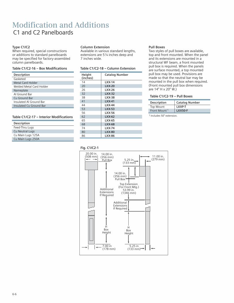
6-6
DescriptionFeed-Thru Lugs Cu Neutral LugsCu Main Lugs 125ACu Main Lugs 250A
Table C1/C2-17 – Interior Modifications
Type C1/C2When required, special constructions or additions to standard panelboardsmay be specified for factory-assembledcolumn panelboards.
Column ExtensionAvailable in various standard lengths,extensions are 5 ¹⁄₄ inches deep and 7 inches wide.
Pull BoxesTwo styles of pull boxes are available, top and front mounted. When the paneland its extensions are mounted in astructural WF beam, a front mountedpull box is required. When the panels are surface mounted, a top mounted pull box may be used. Provisions aremade so that the neutral bar may bemounted in the pull box when required.(Front mounted pull box dimensions are 14” H x 20” W.)
Description Catalog NumberTop Mount LXXP-TFront Mount 1 LXX50-F
Table C1/C2-19 – Pull Boxes
DescriptionGasketedMetal Card HolderWelded Metal Card HolderNameplateAl Ground BarCu Ground BarInsulated Al Ground BarInsulated Cu Ground Bar
Table C1/C2-16 – Box Modifications
Height Catalog Number(inches) 14 LXX-1420 LXX-2026 LXX-2632 LXX-3238 LXX-3841 LXX-4144 LXX-4453 LXX-5356 LXX-5662 LXX-6265 LXX-6568 LXX-6874 LXX-7480 LXX-8086 LXX-86
Table C1/C2-18 – Column Extension
1 Includes 50” extension.
Modification and AdditionsC1 and C2 Panelboards
Fig. C1/C2-1

MiscellaneousDescription PageTelephone Cabinets 7-2Conduit Enclosing Shield (Panel Skirts) 7-2Breaker Mechanical Lugs 7-2Compression Lugs 7-2Optional Mechanical Lugs 7-3Aluminum Body Lugs for Copper or
Aluminum Wire 7-3Miscellaneous Replacement Parts 7-4
Strap Kits 7-4Connecting Strap Kits 7-4Blank Plates – Vacu-Break 7-4Molded Case Switches 7-4
SEC
TIO
N7

7-2
Miscellaneous
Conduit Enclosing Shield (Panel Skirts)
Sheet metal to cover conduits above or below a standard panelboard box.
Panel Skirts Standard Length
3 Sides Open Back 4 Sides Screw Front
8, 9, 10, 11, 12, 14, 17, 18, 23, 24, 25, 26, 27, 28, 29, 30, 31, 32, 33, 34, 35, 36, 37, 38, 39, 40, 41, 42, 43, 44
Table Misc. 3 – Breaker Mechanical Lugs
For Use Amp Cables With Type(s) Rating Per Lug Lug Wire Range
Load Side15-20 1 #14-#10 AWG Cu
1 #12-#10 AWG Al25-35 1 #8-#6 AWG Cu
1 #8-#6 AWG Al40-50 1 #8-#6 AWG Cu
1 #8-#4 AWG Al55-70 1 #8-#4 AWG Cu
1 #8-#2 AWG Al80-100 1 #4-#1/0 AWG Cu
1 #2-#1/0 AWG Al110-125 1 #2-#1/0 AWG Cu
1 #1/0-#2/0 AWG Al
BQD15-40 1 #14-#6 AWG Cu
BQD6#12-#6 AWG Al
45-100 1 #8-1 AWG Cu#6-#1/0 AWG Al
Telephone CabinetsConform to requirements of Underwriter’sLaboratories, Inc., for all cabinets and boxesbearing their label. Surface enclosures,box and front constructed of code gaugesteel. Entire cabinet finished with lightgray, ANSI-61. Flush enclosures, box con-structed of code-gauge galvanized steel,front only finished with light gray, ANSI-61.
BoxesStandard construction has blank ends,without knockouts.
FrontConcealed hinges standard on fronts.Double doors supplied when door widthexceeds 24 in. (610 mm). 3-point catch
and vault handle supplied with doubledoors; two spring catches supplied ondoors more than 48 in. (1219 mm) high.
Backboard0.75 in. (19mm) plywood backboard supplied when specified.
Depth
Depth
Surface Mounting0.75 in. (19 mm)
0.75 in. (19 mm)
Flush Mounting
Trim Overlap
Table Misc.– 1
Box Width – In. (mm) Door
0 (0)–20 (508) Single21 (533)–24 (610) Single25 (635)–36 (914) Single25 (635)–36 (914) Double37 (940)–38 (965) Double
49 (1245)–60 (1524) Double
All available with 0.75 in. (19 mm) backboard.Depth 12 in. (305 mm) or less. Height 72 in. (1829mm) or less. Specify Mounting – Surface or Flush.Box width minus 5 in. (127 mm) equals door width.
BQ, BQH,BQHF, BQE
BQF,BL, BLHHBL, HBQ
SwitchingNeutrals
BGBLG
Table Misc. 2 – Compression Lugs
For Circuit Ampere Lugs Lug WireBreaker Types Rating Poles Per Kit SizeLugs (contains indicated number of lugs and necessary hardware per kit)
ED2, ED4, ED6, 15-125 1,2,3 1 #2/0HED4, HHED6, CED4 QJ2, QJH2, QJ2H, QR2, 125-225 2, 3 1 350 kcmilQR2H, HQR2, HQR2HF(X)D6-A, HF(X)D6, 125-250 2, 3 1 350 KcmilHHF(X)D6, CFD6JXD2-A, J(X)D6-A, HJ(X)D6-A, HHJXD6-A,CJD6, SJD6-A, 200-600 2, 3 1 500 Kcmil SHJD6-A, SCJD6, L(X)D6-A,HL(X)D6-A, CLD6, SLD6-A,SHLD6-A, SCLD6Kits (contains lug and hardware for complete line of load end of 2 or 3 pole breaker)
M(X)D6, HM(X)D6, CMD6, 500-800 2 6 500 KcmilSMD6, SHMD6, SCMD6 3 9 500 KcmilN(X)D6, HN(X)D6, CND6, 900-1200 2 8 500 KcmilSND6, SHND6, SCND6 3 12 500 Kcmil

7-3
Miscellaneous
For Use Circuit Breaker Cables Lug Quantity perWith Type Ampere Rating Per Lug Material Lug Wire Range Catalog Number
QJ2, QJH2,QJ2H, QR2,60-225 1 Cu #6 AWG-250 Kcmil (Cu) 1QRH2, HQR2, HQR2H
ED, HED, 2&3 pole 2-3 pole 30-125 1 Cu #10-#1/0 (Cu)HFD6, HHFD6 70-250 1 Cu #6 AWG-350 Kcmil (Cu) 1CFD6, F(X)D6-A J(X)D2(A), J(X)D6(A), 1 3/0-600 Kcmil (Cu) 1HJD6(A), HHJD6, 1,2 Cu 3/0-500 Kcmil (Cu) 1SHJD6(A), L(X)D6(A),HHLD6, SCD6, 250-600 1 Al 500-750 Kcmil (Al) 1HLD6(A), SHLD6(A),CJD6, CLD6, SCJD6, 1 500-600 Kcmil (Cu) 1SCLD6SMD6, M(X)D6, 500-600 1-2 Cu #1 AWG-500 Kcmil (Cu) 1HM(X)D6, HMD6, 1-3 Cu #1 AWG-350 Kcmil (Cu) 1CMD6, SCMD6, SND6, 700-800 1-2 Al 500-750 Kcmil (Cu) 2N(X)D6, HN(X)D6, 1-2 Al 500-750 Kcmil (Al) 3SHND6, CND6, SCND6 800-1200 1-3 Al 500-750 Kcmil(Cu) 2
500-750 kcmil (Al) 3
Table Misc. 5 – Optional Mechanical Lugs
Circuit For Use Breaker Cables With Type Amp Rating Per Lug Lug Wire Range
QJ2, QJH2, QJ2H 60-225 1 #6 AWG-300 kcmil (Cu) QR2, QRH2, HQR2, HQR2H #4 AWG-300 Kcmil (Al)All 2&3 pole 15-25 1 #14-#10 AWG (Cu)ED2, ED4, ED6, #12-#10 AWG (Al)ED6ETI 30-100 1 #10-#1/0AWG (Cu or Al)HED4, 110-125 1 #3-3/0 (Cu)HHED6 1 #1-2/0 (Al)CED6, All 1 Pole, 30-60 1 #10-4 (Cu or Al)ED, HED 70-100 1 #4-#1/0 (Cu or Al)FXD6-A, FD6-A, HFD6, 70-250 1 #6 AWG-350 Kcmil (Cu)CFD6, HHFD6 #4 AWG-350 Kcmil (Al)SJD6(A), SHJD6(A), 65-200 1-2 #4 AWG-310 Kcmil (Cu or Al)SCJD6JXD2(A), JXD6(A), JD6(A), SJD6(A), HJD6(A), HHJXD6(A), 200-400 1-2 3/0-500 Kcmil (Cu)HHJD6, SHJD6(A), 4/0-500 Kcmil (Al)CJD6, SCJD6LXD6(A), LD6(A),SLD6(A), HLD6(A),HHLXD6, HHLD6, 250-600 1-2 3/0-500 Kcmil (Cu)SHLD6(A), CLD6, SCLD6 4/0-500 Kcmil (Al)LMD6, 1 LMXD6,1
HLMD6,1 HLMXD6, 1 500-600 1-2 250-500 Kcmil (Cu or Al)MD6, MXD6, SMD6, HMD6, HMXD6, SHMD6, 700-800 1-3 1/0-500 Kcmil (Cu or Al)CMD6, SCMD6 500-750 Kcmil (Cu or Al)ND6, NXD6, SND6,HND6, HNXD6, SHND6, 800-1200 1-4 250-500 Kcmil (Cu or Al)CND6, SCND6
Table Misc. 4 – Aluminum Body Lugs for Copper or Aluminum Wire
1 Use TA2K500 or TA3K500 only.
SEC
TIO
N7

7-4
Miscellaneous
Connecting Strap Kits - Obsolete Circuit BreakersFor use with Series 5 or 6 CDP circuit breaker panelboards
FC20, FCI and FCII switchboards – includes copper straps, coverplates and necessary hardware.
Table Misc. 7
Breaker Strap Kit HeightFrame 1 Catalog Number (in.)
KM, HN 6KM1 10CN 6CN1 10KMB, HNB 6KMB1 10SKM 6SKM1 10KP, HK 6KP1 10KPB, HKB 6KPB1 10SKP, SHK 6SKP1 10
Table Misc. 9 – Connecting Strap Kits — Vacu-BreakFor use with VB-23 and VB-32 Type Panelboards.
For Use WithPanel Catalog Ampere Unit HeightType Number Rating (in.)
VB-23 V2AX25 30-30 2 1/2V2BX50 30-30 and 60-60 5V7AX25 30-30 2 1/2V7BX50 30-30 and 60-60 5
VB-32 V7EX75 100-100 7 1/2100 7 1/2200 7 1/2 (2-Pole)
V7FX100 200 10 (3-Pole)
Table Misc. 8 – Blank Plates – Vacu-Break For use with VB-23, VB-30, VB-32 and Uni-Power Switchboards
12 in. Units - 23 in. 17 in. Units - 30 in. andUnit Wide Enclosure Only 32 in. Wide EnclosuresHeight Catalog CatalogInches Number Number
2 1/2 VB2F025 VB7F0255 VB2F050 VB7F0507 1/2 VB2F075 VB7F075
10 VB2F100 VB7F100
Table Misc. 10 – Molded Case Switches (Non-Automatic Circuit Interrupters)
Ampere Breaker Rating Frame
100 ED2, ED4, ED6225 QJ2, QR2250 FXD6400 JXD2, JXD6600 LXD6800 MD6
1200 ND6
Table Misc. 6 – Miscellaneous Replacement Accessories
1 All 1” QP, BL, BQD and ED Frame Provisions.2 PDF can be downloaded for free and printed at this location:
http://www.nema.org/standards/pages/Panelboards.aspx
Catalog For Number Description Panel TypeEGK Al Ground Assembly 44 Connections P1, P2, P3 BK1 Bonding Kit for P1 250A Max. as notedBK3 Bonding Kit for S3 PanelBK4 Bonding Kit for SE & P5 400 as notedIMK Interior Adjusting Kit P1, P2, P311-1824-01 Directory Card Holder P1, P2, P312-1110-01 Directory Card P1, P2, P3 ANSI/NEMA General Instructions for Proper AllPB 1.1-20132 Installation, Operation, and Maintenance
of Panelboards Rated 600 Volts or Less (O&M Manual)
NBK3 Number Strips 1-42 P1, P2, P3NBK4 Number Strips 43-84 P1, P2, P3NBK5 Number Strips 85-126 P1, P2, P3NBK6 Number Strips 127-168 P1, P2, P3ECGK Cu Ground Bus 44 Connections P1, P2, P3IGK Insulated Al Ground Bus P1, P2, P3ICGK Insulated Cu Ground Bus P1, P2, P3EWK2 End Wall Kit with Knockouts P1
(24" W x 7.75" DP)DFFP1 Filler Plate (Suitable for replacing P1, P2, P3,
QF3 in P1 thru P5 Panelboards P4, P5and Switchboards)


Subject to changes and errors. The information given in this document only contains general descriptions and/or performance features which may not always specifically reflect those described, or which may undergo modification in the course of further development of the products. The requested performance features are binding only when they are expressly agreed upon in the concluded contract.
Published by Siemens Industry, Inc. 2016.
Siemens Industry, Inc. 5400 Triangle Parkway Norcross, GA 30092
For more information, please contact our Customer Support Center. Phone: 1-800-241-4453 E-mail: [email protected]
usa.siemens.com/panelboards
Order No.PBCS-20301-1116
Printed in U.S.A. © 2016 Siemens Industry, Inc.