Next Gen P1 Panelboards - Franklin Empire
34
siemens.ca/panelboards Quick reference guide for selection and application Next Gen P1 Panelboards
-
Upload
khangminh22 -
Category
Documents
-
view
3 -
download
0
Transcript of Next Gen P1 Panelboards - Franklin Empire

siemens.ca/panelboards
Quick reference guide for selection and application
Next Gen P1 Panelboards

P1 Panelboards • Quick reference for selection and application ii
Introducing the Siemens Next Gen P1 Panelboard
Siemens is proud to introduce new,
innovative additions to the P1 series
of panelboards. The new “Next
Gen P1” Panelboard increases the
flexibility and customization options
available in Siemens already robust
panelboard line of products.
Siemens New “Next Gen P1” Panelboard
Siemens new Next Gen P1 panelboard adds additional strength and flexibility, through the introduction of Non-Feed-Thru options, to the already rugged, best-in-class line of panelboards. By now offering both Feed-Thru (FT) and Non-Feed-Thru (NFT) configuration options, Siemens offers even greater flexibility and potential for customers to configure solutions that are optimized to meet the many unique application and budgetary requirements that today’s projects demand.
For applications where additional space for feed-thru lugs, a subfeed breaker, or an SPD device isn’t required, the new NFT P1 option is an ideal solution. The NFT Next Gen P1 features an enclosure that is 6’’ (152 mm) shorter than a comparably configured P1 with a FT design. Additionally, the NFT design can accommodate 12 circuits more than the FT design panelboard in the same sized enclosure.
Extended Circuitries
In addition to the new NFT options, Siemens P1 line of panelboard products now offer extended circuit options. New, higher 54 and 66 circuit options allow for the elimination
of a second enclosure in many applications that would have previously required it.
The extended circuit options also facilitate the configuration of P1 panelboard solutions for many applications that have traditionally required the use of a P2 or P3 panelboard.
Adaptability
The new NFT design, coupled with the extended circuitries offer additional options for adding circuits to existing Siemens P1 with the Feed-Thru design. Where a 42 circuit FT P1 panelboard needs additional circuits but is not utilizing the provided subfeed space, the interior can be replaced by a new 54 circuit NFT design interior. This saves the customer the cost of a new enclosure and cover while still providing the option for extended circuitries.
This selection and application guide is designed to provide full insight into these and many other new features, enhancements and options that will allow you to take full advantage of the flexibility and customization options Siemens offers to configure the P1 panelboard that best meets your specific needs.

iii P1 Panelboards • Quick reference for selection and application
Next Gen P1 Panelboard 250 & 400AAll FT and NFT are invertable in field – Top-feed or Bottom-feed
• Invertability
• Flexibility
20’’ (508 mm) Wide
Unit Space
18 30 42 54 66
250A MLO / MB
250A MLO / MB
FT
NFT
20’’ (508 mm) Wide
Subfeed FT Lugs
Subfeed Breakers SPD Devices
Unit Space
18 30 42 54 66
Box Sizes 32’’
(813 mm) 38’’
(965 mm) 44’’
(1118 mm) 50’’
(1270 mm) 56’’
(1422 mm)
400A MLO / MB
400A MLO / MB
20’’ (508 mm) Wide
Unit Space
30 42 54
Box Sizes 62’’
(1575 mm) 68’’
(1727 mm)74’’
(1880 mm)
Unit Space
30 42 54 66
20’’ (508 mm) Wide
ML (or) MB
Box Sizes 26’’
(660 mm) 38’’
(965 mm) 44’’
(1118 mm) 50’’
(1270 mm)
Box Sizes 56’’
(1422 mm)62’’
(1575 mm) 68’’
(1727 mm)74’’
(1880 mm)
ML (or) MB
P1 Panelboards • Quick reference for selection and application iv
Next Gen P1 Panelboard 250A
250A 18 circuit NFT
New for Next Gen
B26 Enclosure
6’’ (152 mm) shorter than FT
250A 30 circuit NFT
6’’ (152 mm) shorter than FT
B32 Enclosure
New for Next Gen
250A 42 circuit NFT
B38 Enclosure
6’’ (152 mm) shorter than FT
New for Next Gen
250A 18 circuit FT
B32 Enclosure
Original & Next Gen
250A 30 circuit FT
B38 Enclosure
Original & Next Gen
250A 42 circuit FT
250A 54 circuit NFT
250A 54 circuit FT
250A 66 circuit NFT
250A 66 circuit FT
Original & Next Gen New for Next Gen New for Next Gen New for Next Gen New for Next Gen
B44 Enclosure B44 Enclosure
6’’ (152 mm)shorter than FT
B56 Enclosure
6’’ (152 mm) shorter than FT
B50 Enclosure B50 Enclosure
Why move to NFT (Non Feed-Thru)? A) Smaller Box Size - If customer does not need Subfeed space or does not want to pay for it.
• 6’’ (152 mm) shorter enclosure than FT • No Subfeed Space - pay for what is needed only.
B) More Circuits needed - If customer does not need Subfeed space and does want more circuits.
• 12 more circuits than FT in same box size
New Options to Consider!
1) If a customer has an existing 42 circuit FT installed and needs additional circuits, the interior can be replaced by a 54 circuit NFT. Re-use the same enclosure and front.
2) If a customer needs more than 42 circuits, you can use a 54 or 66 circuit device and eliminate the second cabinet.
v P1 Panelboards • Quick reference for selection and application
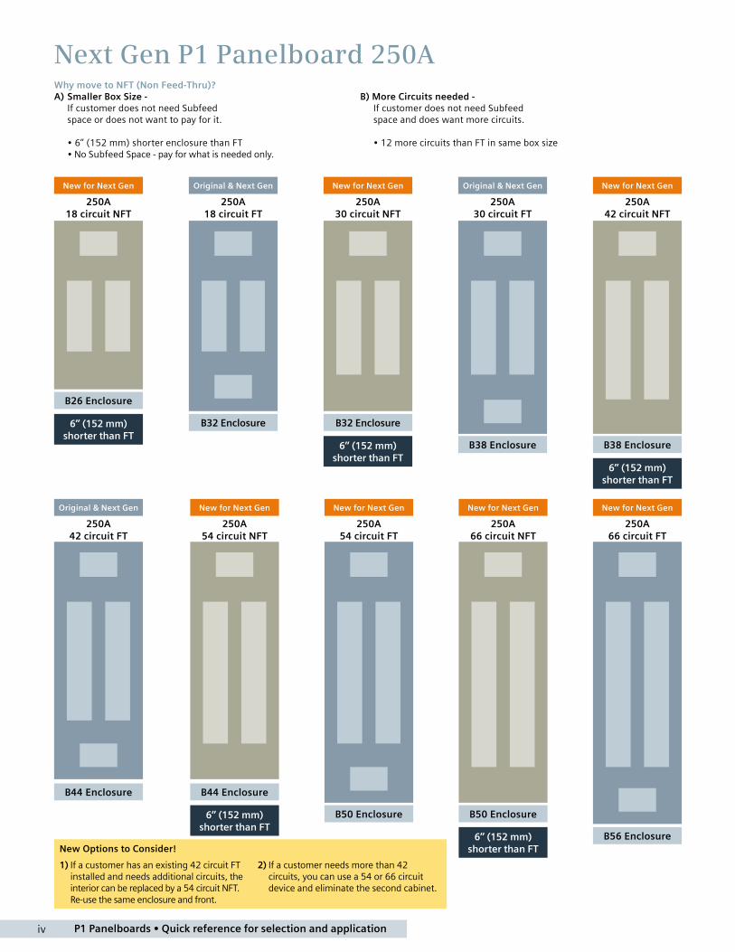
Next Gen P1 Panelboard 400AWhy move to NFT (Non Feed-thru)? A) Smaller Box Size - If Customer does not need Subfeed space or does not want to pay for it.
• 6’’ (152 mm) shorter Enclosure than FT • No Subfeed Space - pay for what is needed only.
B) More Circuits needed - If Customer does not need Subfeed space and does want more circuits.
• 12 more circuits than FT in same box size
New Options to Consider!
1) If a customer has an existing 42 circuit FT installed and needs additional circuits, the interior can be replaced by a 54 circuit NFT. Re-use the same enclosure and front.
2) If a customer needs more than 42 circuits, you can use a 54 or 66 circuit device and eliminate the second cabinet.
400A 18 circuit NFT
400A 66 circuit FT
Not Available
400A 30 circuit NFT
400A 30 circuit FT
400A 42 circuit NFT
400A 42 circuit FT
400A 54 circuit NFT
400A 54 circuit FT
400A 66 circuit NFT
B56 Enclosure
6’’ (152 mm) shorter than FT
B68 Enclosure
B68 Enclosure
6’’ (152 mm) shorter than FT
B62 Enclosure B62 Enclosure
6’’ (152 mm) shorter than FT
B74 Enclosure B74 Enclosure
New for Next Gen Original & Next Gen New for Next Gen Original & Next Gen
New for Next Gen New for Next Gen New for Next Gen
No Longer Available

P1 Panelboards • Quick reference for selection and application vi
1. Non-Feed-thru (NFT) variations of the Next Gen P1 panels are available for Factory assembled only:
• Feed-Thru (FT) versions are versions with a Subfeed space that can be occupied by Feed-thru lugs, Subfeed Breaker or an SPD device. All Original P1 interiors were FT versions.
• Non-Feed-thru (NFT) versions do not have the Subfeed space and therefore can fit into an enclosure 6“ (152 mm) smaller than the FT version.
• Both FT and NFT variations are fully invertible in the field and can be used for either Top-feed or Bottom-feed applications.
2. Extended Circuits are now available: Only 18, 30 and 42 circuits were available in Original P1 54 and 66 “extended circuit” panels are added for Next Gen P1
a) Next Gen P1 - 250A will have FT and NFT variations for all circuits: 18, 30, 42, 54 and 66 (NGB panels only available as FT)
b) Next Gen P1 - 400A will have FT and NFT variations for 30, 42, 54 circuits only. (NGB panels only available as FT) • The 66 circuit variation of 400A is only available in NFT due to enclosure size limit of 74“ high. • Also Next Gen P1 - 400A is not available in 18 circuit variations.
Benefits: Many P2 and P3 applications can now move to the Next Gen P1 platform!
3. New Neutral Configurations are now available in Next Gen P1:
• The new Neutral system has been developed to accommodate the extended circuit variations without increasing costs.
• The New Neutral configuration is still a split neutral arrangement with connections down either side of the interior, but it is not full length as before. Neutral connections are still near the breakers, but not adjacent to each breaker connection. Many configurations have extra connections and some larger configurations will allow adding more connections if needed.
4. Into stock program changes for Next Gen P1:
• Into stock program will only get 54 circuit added for both P1-250A and P1-400A.
• All into stock interiors will be the FT variation, the same as Original P1. (400A - 18 circuit is no longer available)
• All old Accessories/Kits will remain available for future needs in Original P1 installations.
• New Accessories/Kits are available - most are same as old kits with “A” added to end of part number.
5. Accessories and Kits for Next Gen P1 are replacing most of the Original P1 Kits: (most simply add an “A” to end of old kit number)
a) All Main/Subfeed Breaker mounting kits are new for the Next Gen P1.
b) All Main Lug Kits are new for Next Gen P1.
c) All Neutral Lug Kits are new for Next Gen P1.
Next Gen P1 Panelboard FAQ’sNew Features and Options for “Next Gen P1” offering compared to the “Original P1” panels
6. BL/BQD and NGB Main Breaker usage is ONLY available as a Back-Fed variation.
• The Next Gen P1 interior does not have “strap kits” for the BL/ BQD and NGB breakers to be used in the “Main” or “Subfeed” positions. If needed to be used as a Main - we now have a “Main Label Kit” that allows the placement of the breaker in unit space to be used as the Main when labeled properly. This does reduce unit space by “2 circuits” in a single phase panel and by “3 circuits” in a 3-phase panel. In other words, the first 2 circuits (single phase panel) or 3 circuits (3-phase panel) on the top left of the interior will be used for the main breaker by default.
• Back-fed variations can not be used for service entrance application.
7. New B-Phase bus configuration eliminates “Hump-bus” design
• The new flat bus with “B-Phase” connector has many benefits. Allows for replacement connectors in the field in case of a“stripped” connection.
• Accessory kits for both CU and AL variations of the B-Phase connectors and A/C connectors will be available for repair purposes only.
8. NGB Breaker series introduction:
• This addition to the Breaker line will now allow many configurations to use the Next Gen P1 series. See rating below:
NGB – 14,000 A IR Max. @ 600Y/347V AC / 100,000 A IR @ 240V AC
9. Misc. additional features:
a) New 750 kcmil AL Main Lug will be available as an option for 400A. (CU cable limited to 600 kcmil)
b) New 2/0 neutral kits are available. (Standard with NGB interiors)
c) New filler DFFP1 is introduced replacing QF3-UL (fits tighter in deadfront)
10. Misc. additional changes/notes:
a) All DC voltage offerings are removed from scope of Next Gen P1 interiors.
Customers will be moved to a P2 configuration for these DC Voltage applications.
b) The Next Gen P1 with NGB is limited to:
• 100A per connection (200A per pair) for 18 circuit 250A construction.
• 125A per connection (250A per pair) for 30, 42, 54 and 66 circuit 250A and 400A construction.
11. In the Next Gen P1, the branch breaker screws will be supplied as a kit with the interior
1 P1 Panelboards • Quick reference for selection and application
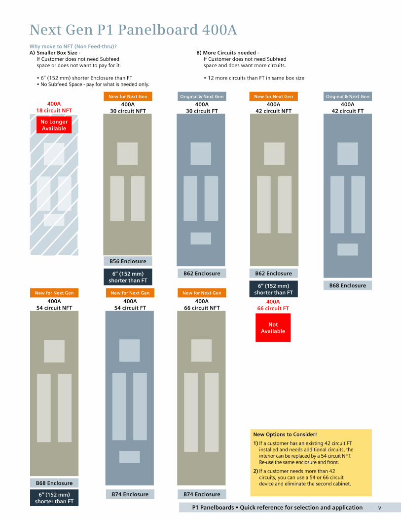
IndexNext Gen P1 panelboards quick reference guide for selection and application
Description Page
Introduction ii
Next Gen P1 Panelboard Overview iii
Next Gen P1 Panelboard FAQs vi
Next Gen P1 Factory Assembled Panelboards
General Information 2
Selection and Application 2
General Specifications 3
Catalogue Numbering System – (Factory Assembled) 4
Application 5
Main Breaker Panel Size Selector – Next Gen P1 5
Main Breaker Selection 5
Main Lug Panel Size Selector – Next Gen P1 6
Branch Circuit Breakers 6
Subfeed Breakers 7
Breaker Mounting Kit 7
Lug Kits (Main or Feed-Thru) 7
Copper Neutral Lug Kits – 250A 7
2/0 Neutral Lug Kits – 250A and 400A 7
200% Neutral Lug Kits – 250A 7
200% Neutral Lug Kits – 400A 7
Main Breaker Gutter Dimensions 8
Main Lug End Gutter Dimensions 8
Side Gutter Wiring Space 8
Typical Catalogue Numbers 9
Main Lugs Only 9
Main Circuit Breaker 9
Standard Enclosures 9
Standard Modifications 10
Miscellaneous Modifications 11
Compression Lugs 11
Enclosure Modifications 11
Remote Switch Modifications 11
Dimensions 12
Next Gen P1 Into Stock Panelboards
New Next Gen P1 into stock 14
Catalogue Numbering System (Into Stock) 15
Distributor Stock 16
Type P1 into stock (Next Gen P1 Introduced June 2015) 16
Lug Kits – Main or Feed Thru 17
Breaker Mounting Kits 17
Copper Neutral Lug Kits – 250A 17
2/0 Neutral Lug Kits – 250A and 400A 17
200% Neutral Lug Kits – 250A 17
200% Neutral Lug Kits – 400A 17
Miscellaneous Parts and Accessories 17
Main Breaker Mounting Kits with Breakers 18
AFCI and GFCI breakers 18
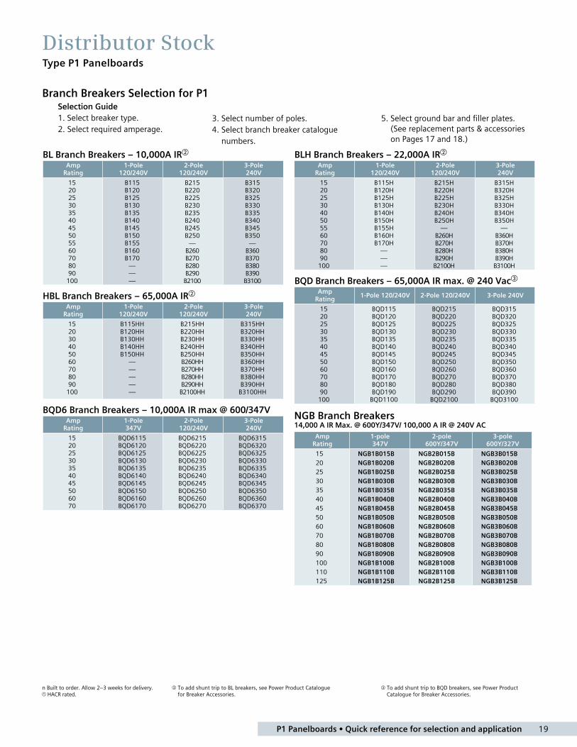
Branch Breakers Selection for P1 19
BL Branch Breakers – 10,000A IR 19
HBL Branch Breakers – 65,000A IR 19
GFCI Personnel Protection (5MA) 19
BLH Branch Breakers – 22,000A IR 19
BQD Branch Breakers – 14,000A IR 19
NGB Family Branch Breakers 19
TPS Surge Protection Devices 20
P1 Panelboards • Quick reference for selection and application 2
Type P1 Panelboards
Selection and Application3 Easy Steps for Selecting a Siemens Next Gen P1 Panelboard (Note: Factory assembled panels are configurable in IQS)
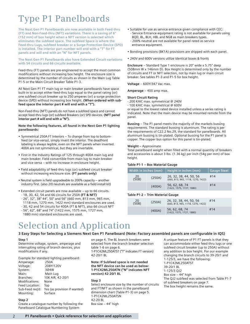
The Next Gen P1 Panelboards are now available in both Feed-thru (FT) and Non-Feed-thru (NFT) variations. There is a saving of 6’’ (152 mm) of box height when a NFT version is selected which eliminates the subfeed space. The subfeed Space is where the Feed-thru Lugs, subfeed breaker or a Surge Protection Device (SPD) is installed. The interior part number will end with a “T” for FT panels and will end with an “N” for NFT panels.
The Next Gen P1 Panelboards also have Extended Circuit variations with 54 circuits and 66 circuits available.
Feed-thru (FT) panels are pre-engineered to accept the most common modifications without increasing box height. The enclosure size is determined by the number of circuits as shown in the Main Lug Table P1-5 or the Main Circuit Breaker Table P1-3.
All Next Gen P1 FT main lug or main breaker panelboards have space built-in to accept either feed-thru lugs equal to the panel rating (or) one subfeed circuit breaker up to 250 amperes (or) a surge protection device (SPD) without increasing box height. (When ordered with sub-feed space the interior part # will end with a “T”).
Non-Feed-thru (NFT) panels do not have a subfeed space and cannot accept feed-thru lugs (or) subfeed Breakers (or) SPD devices. (NFT panel interior part # will end with a “N”).
Note the following features, all found in the Next Gen P1 lighting panelboards:
• Symmetrical 250A FT Interiors – To change from top to bottom- feed (or vice-versa), simply invert the interior. The deadfront labeling is always legible, even on the NFT panels when inverted. 400A are not symmetrical, but they are invertable.
• First in the Industry Ratings of 125 through 400A main lug and main breaker. Field convertible from main lug to main breaker and vice versa – with no increase in enclosure height.
• Field adaptability of feed-thru lugs (or) subfeed circuit breaker without increasing enclosure size. (FT panels only)
• Neutral system is field upgradeable to 200% capacity – another industry first. (also 2/0 neutrals are available as a field install kit)
• Extended circuit panels are now available – up to 66 circuits. - 18, 30, 42, 54 and 66 circuits for 250A (FT & NFT) - 26’’, 32’’, 38’’ 44’’, 50’’ and 56’’ (660 mm, 813 mm, 965 mm, 1118 mm, 1270 mm, 1422 mm) standard enclosures are used. - 30, 42 and 54 circuits for 400A (FT & NFT), also 66 circuit NFT - 56’’, 62’’, 68’’ and 74’’ (1422 mm, 1575 mm, 1727 mm, 1880 mm) standard enclosures are used.
Step 1 Determine voltage, system, amperage and interrupting rating of branch devices, plus modifications if any.
Example for standard lighting panelboard: Amperage: 250A Voltage: 208Y/120V System: 3Ø4W Main: Main Lug Branches: 10K AIR, 42-20/1 Modifications: None Feed Location: Top Sub-Feed req’d: Yes (as provision if wanted) Mounting: Surface
Step 2 Create a catalogue number by following the Panelboard Catalogue Numbering System
• Suitable for use as service entrance given compliance with CEC: - Service Entrance equipment rating is not available for panels using BQD, BL, BLH, HBL and NGB as main breakers types. - 200% neutral are not available for panel rated as service entrance equipment.
• Bonding provisions (BK1A) provisions are shipped with each panel.
• 240V and 600V versions utilize identical boxes & fronts
Enclosure – Standard Type 1 enclosure is 20’’ wide x 5.75’’ deep (508mm W x 146mm D). Box Height is determined only by the number of circuits and FT or NFT selection, not by main lug or main circuit breaker. See tables P1-3 and P1-5 for box height.
Voltage – 600Y/347 Vac max.
Amperage – 400 amp max.
Short Circuit Rating - 200 KAIC max. symmetrical @ 240V - 100 KAIC max. symmetrical @ 600V or equal to the lowest rated device installed unless a series rating is indicated. Note that the main device may be mounted remote from the panel.
Bussing – The P1 panel meets the majority of the markets bussing requirements. The standard bussing is aluminum. The rating is per the requirements of C22.2 No.29, the standard for panelboards. All aluminum bussing is tin-plated. Optional bussing for the P1 panel is copper. The copper bus option for this panel is tin-plated.
Weight – Approximate Total panelboard weight when filled with a normal quantity of breakers and accessories is about 3 lbs. (1.36 kg) per inch (54g per mm) of box height.
Table P1-1 – Box Material Gauge
Width in inches (mm) Height in inches (mm) Gauge Steel
20 (508) (250A) 26, 32, 38, 44, 50, 56
(660, 813, 965, 1118, 1270, 1422)#14
(400A) 56, 62, 68, 74 (1422, 1575, 1727, 1880)
#14
Table P1-2 – Trim Material Gauge
20 (508) (250A) 26, 32, 38, 44, 50, 56
(660, 813, 965, 1118, 1270, 1422)#14
(400A) 56, 62, 68, 74 (1422, 1575, 1727, 1880)
#14
on page 4. The BL branch breakers were selected from the branch breaker selection table 1-6 on page 6. 1-P1C42ML250ATST (“T” indicates FT version) 42-20/1 BL
Note: If Subfeed space is not needed the NFT device can be used as below: 1-P1C42ML250ATN (“N” indicates NFT version) 42-20/1 BL
Step 3 Select enclosure size by the number of circuits and FT/NFT as shown in the panelboard dimension chart (Table P1-3) on page 5. 1-P1C42ML250ATSN 42-20 BL Box size – 44” high
A unique feature of P1 FT panels is that they can accommodate either feed-thru lugs or one subfeed circuit breaker (up to 250A) without any addition to box height. For our example changing the branch circuits to 39-20/1 and 1-125/3, we have the following: 1-P1C42ML250ATST 39-20/1 BL 1-125/3 QJ2 Box size – 44” high The QJ2 subfeed was selected from Table P1-7 of subfeed breakers on page 7. The box height remains the same.
3 P1 Panelboards • Quick reference for selection and application
General Specifications
Service Entrance Equipment When a panelboard is used as service entrance equipment, it must be located as close as practicable to the point of entrance of building supply conductors. Panelboards must be identified as “Service Entrance” at the time of order entry in order to be supplied with the appropriate CSA certification and labelling. Panels include a connector for bonding and grounding neutral conductor. Please consult CSA, CEC and local inspection authorities for specification and installation guidelines.
Service Entrance equipment rating is not available for panels using BQD, BL, BLH, HBL and NGB as main breakers types.
200% neutral is not available when service entrance equipment rating is required. Panelboards with service entrance rating are available as Factory Assembled only.
Integrated Equipment Short Circuit Rating The term “Integrated Equipment Short Circuit Rating” refers to the application of series connected circuit breakers in a combination that allows some breakers to have lower individual interrupting ratings than the available fault current. This is permitted as long as the series combination has been tested and certified by CSA. “Series Rated” must be identified at the time of order entry.
For more information consult the series combinations catalogue.
Standards CSA: C22.2 No.29. Certified under files #1267408 UL: 67, 50 and 50E. Listed by Underwriter’s Laboratories, Inc., under “Panelboards” File #E2269, and #E4016.
Wire Connectors Standard wire connectors in Siemens panels are suitable for copper or aluminum cables rated 60/75 degree Celcius. Copper main lugs are a price-added option for most panel types and some Circuit Breakers (check with Siemens sales for availability). It should be noted that most copper lugs will only accept copper cables. Some applications, 100% rated devices in particular, require that the cable and connectors be rated 90 degree Celcius but are sized to the 75 degree Celcius tables.
Standard ground connectors are also suitable for copper or aluminum wire. Ground connector assemblies (EGK, IGK) have (6) 1/0 max. and (15) #6 max. connections. The 1/0 holes are capable of connecting up (3) #10 max. wires. The #6 holes can accept up to (2) #12 max. wires. Copper ground assemblies (ECGK, ICGK) are rated for copper wire only and have the same wiring capacity as the AL/CU connectors.
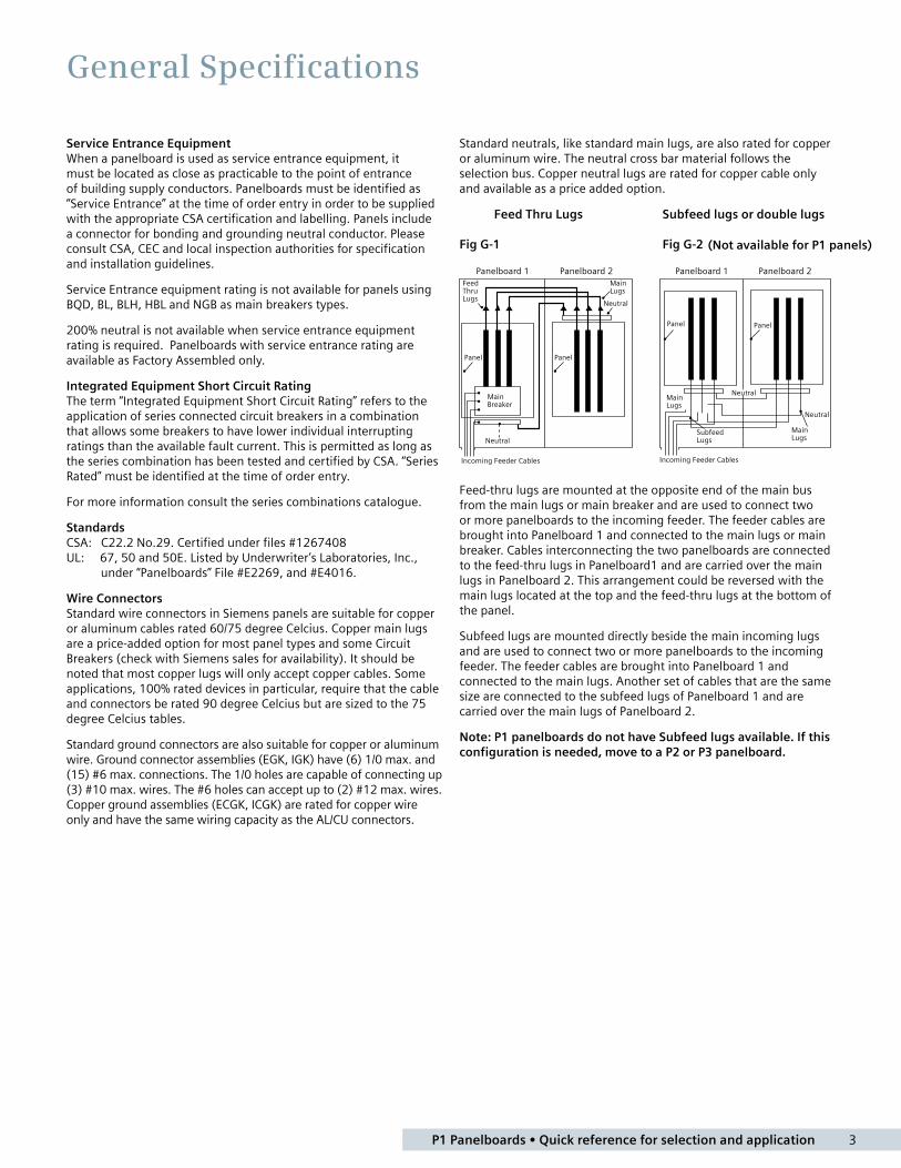
Standard neutrals, like standard main lugs, are also rated for copper or aluminum wire. The neutral cross bar material follows the selection bus. Copper neutral lugs are rated for copper cable only and available as a price added option.
Feed Thru Lugs Subfeed lugs or double lugs Fig G-1 Fig G-2
Panelboard 1 Panelboard 2
Main Breaker
Neutral
Feed Thru Lugs
Main Lugs
Neutral
PanelPanel
Incoming Feeder Cables
Panelboard 1 Panelboard 2
Neutral
Neutral
Subfeed Lugs
Main Lugs
Main Lugs
PanelPanel
Incoming Feeder Cables
Feed-thru lugs are mounted at the opposite end of the main bus from the main lugs or main breaker and are used to connect two or more panelboards to the incoming feeder. The feeder cables are brought into Panelboard 1 and connected to the main lugs or main breaker. Cables interconnecting the two panelboards are connected to the feed-thru lugs in Panelboard1 and are carried over the main lugs in Panelboard 2. This arrangement could be reversed with the main lugs located at the top and the feed-thru lugs at the bottom of the panel.
Subfeed lugs are mounted directly beside the main incoming lugs and are used to connect two or more panelboards to the incoming feeder. The feeder cables are brought into Panelboard 1 and connected to the main lugs. Another set of cables that are the same size are connected to the subfeed lugs of Panelboard 1 and are carried over the main lugs of Panelboard 2.
Note: P1 panelboards do not have Subfeed lugs available. If this configuration is needed, move to a P2 or P3 panelboard.
(Not available for P1 panels)
P1 Panelboards • Quick reference for selection and application 4
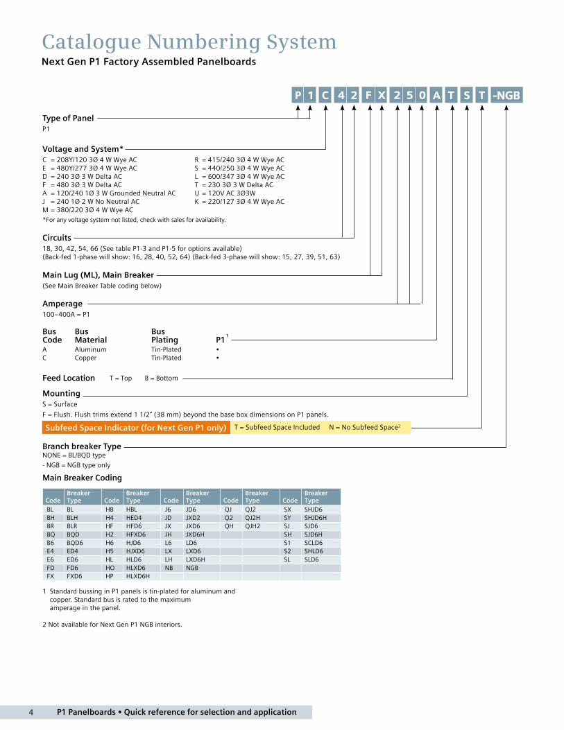
Catalogue Numbering SystemNext Gen P1 Factory Assembled Panelboards
Type of PanelP1
Voltage and System*C = 208Y/120 3Ø 4 W Wye AC R = 415/240 3Ø 4 W Wye AC E = 480Y/277 3Ø 4 W Wye AC S = 440/250 3Ø 4 W Wye AC D = 240 3Ø 3 W Delta AC L = 600/347 3Ø 4 W Wye AC F = 480 3Ø 3 W Delta AC T = 230 3Ø 3 W Delta AC A = 120/240 1Ø 3 W Grounded Neutral AC U = 120V AC 3Ø3W J = 240 1Ø 2 W No Neutral AC K = 220/127 3Ø 4 W Wye AC M = 380/220 3Ø 4 W Wye AC*For any voltage system not listed, check with sales for availability.
Circuits18, 30, 42, 54, 66 (See table P1-3 and P1-5 for options available) (Back-fed 1-phase will show: 16, 28, 40, 52, 64) (Back-fed 3-phase will show: 15, 27, 39, 51, 63)
Main Lug (ML), Main Breaker(See Main Breaker Table coding below)
Amperage 100–400A = P1
Bus Bus BusCode Material Plating P1
1
A Aluminum Tin-Plated •C Copper Tin-Plated •
Feed Location T = Top B = Bottom
MountingS = Surface
F = Flush. Flush trims extend 1 1/2” (38 mm) beyond the base box dimensions on P1 panels.
Branch breaker Type NONE = BL/BQD type
- NGB = NGB type only
Main Breaker Coding
CodeBreaker Type Code
Breaker Type Code
Breaker Type Code
Breaker Type Code
Breaker Type
BL BL HB HBL J6 JD6 QJ QJ2 SX SHJD6BH BLH H4 HED4 JD JXD2 Q2 QJ2H SY SHJD6HBR BLR HF HFD6 JX JXD6 QH QJH2 SJ SJD6BQ BQD H2 HFXD6 JH JXD6H SH SJD6HB6 BQD6 H6 HJD6 L6 LD6 S1 SCLD6E4 ED4 H5 HJXD6 LX LXD6 S2 SHLD6E6 ED6 HL HLD6 LH LXD6H SL SLD6FD FD6 HO HLXD6 NB NGBFX FXD6 HP HLXD6H
1 Standard bussing in P1 panels is tin-plated for aluminum and copper. Standard bus is rated to the maximum amperage in the panel.
2 Not available for Next Gen P1 NGB interiors.
Subfeed Space Indicator (for Next Gen P1 only) T = Subfeed Space Included N = No Subfeed Space2
-NGB
-NGB

5 P1 Panelboards • Quick reference for selection and application
ApplicationType P1 Panelboards
Table P1-3 – Main Breaker Panel Size Selector – Next Gen P1
Max Ampere rating
Main Breaker Types
Connections suitable for Al or Cu
Max # Poles FT 1
Max # Poles NFT
Dimensions in inches (mm)
Unit Space Box Height B
Weight in Lbs. (kg)FT
ANFT
A
70 BQD62 BL: 40-50A: #8-#4 AWG Al or #8-#6 AWG Cu 55-70A: #8-#2 AWG Al or #8-#4 AWG Cu 80-100A: #2-#1/0 AWG Al or #4-#1/0 AWG Cu
BQD: 45-100A: #6-1/0 AWG Al #8-#1 AWG Cu
– 18 – 9 26 (661) 90 (41)
100BL 2, BLH 2, HBL 2, BQD 2
– 18 – 9 26 (661) 90 (41)
18 30 9 15 32 (813) 105 (48)
30 42 15 21 38 (965) 120 (55)
42 54 21 27 44 (1118) 135 (61)
54 66 27 33 50 (1270) 150 (67)
66 – 33 – 56 (1423) 165 (73)
125NGB 2 ED2, ED4 ED6, HED4
NGB: 35-125A: #4-2/0 AWG Al or #6-1/0 AWG Cu
ED: 30-100A: #10-1/0 AWG Al/Cu 110-125A: #1-2/0 AWG Al or #3-3/0 AWG Cu
– 18 – 9 26 (661) 95 (43)
18 30 9 15 32 (813) 110 (50)
30 42 15 21 38 (965) 125 (57)
42 54 21 27 44 (1118) 140 (64)
54 66 27 33 50 (1270) 155 (71)
66 – 33 – 56 (1423) 170 (78)
225QJ2, QJH2, QJ2-H
#4 AWG-300 Kcmil (Al) or#6 AWG-300 Kcmil (Cu)
– 18 – 9 26 (661) 95 (43)
18 30 9 15 32 (813) 110 (50)
30 42 15 21 38 (965) 125 (57)
250FXD6, FD6, HFD6, HFXD6
#4 AWG-350 Kcmil (Al) or #6 AWG-350 Kcmil (Cu)
42 54 21 27 44 (1118) 140 (64)
54 66 27 33 50 (1270) 155 (71)
66 – 33 – 56 (1423) 170 (78)
400JD6, JXD6, HJD6, HJXD6
4/0-500 Kcmil (Al) or3/0-500 Kcmil (Cu)
– 30 – 15 56 (1423) 172 (78)
30 42 15 21 62 (1575) 190 (86)
42 54 21 27 68 (1728) 208 (95)
54 66 27 33 74 (1880) 226 (104)
Note: Main breakers use breaker connectors. For sizes, see breaker connector chart on page 400A MLO panels have wire bend space for 600kcmil CU and AL wire when using the standard lug. With the optional 750kcmil AL/CU connector – wire bend space is available for up to 750kcmil AL, but is still limited to 600kcmil CU wire.1 400A 66 circuit only available with non-feed thru versions.2 BL, BLH, HBL, BQD, BQD6, and NGB main breakers are back fed mounted in unit space and count in max. # of poles.
Table P1-4 – Main Breaker Selection Ampere rating
Breaker Types
Max. Ir (kA) at Main Breaker Code Additional Trip Values240V AC 600Y/347V AC
70 BQD6 65 10 B6 15, 20, 25, 30, 35, 40, 45, 50, 60, 70
100
BL (STD) 4 10 – BL 15, 20, 25, 30, 35, 40, 45, 50, 60, 70, 80, 90, 100
BLH 4 22 – BH 15, 20, 25, 30, 35, 40, 45, 50, 60, 70, 80, 90, 100
HBL 4 65 – HB 15, 20, 25, 30, 35, 40, 45, 50, 60, 70, 80, 90, 100
BQD 4 65 – BQ 15, 20, 25, 30, 35, 40, 45, 50, 60, 70, 80, 90, 100
125
NGB 4 100 14 NB 3 15, 20, 25, 30, 35, 40, 50, 60, 70, 80, 90, 100, 125
ED4 65 – E4 15, 20, 25, 30, 35, 40, 50, 60, 70, 80, 90, 100, 125
HED4 42 – H4 15, 20, 25, 30, 35, 40, 50, 60, 70, 80, 90, 100, 125
ED6 (STD) 65 18 E6 15, 20, 25, 30, 35, 40, 45, 50, 60, 70, 80, 90, 100, 110, 125
225
QJ2 (STD) 10 – QJ 60, 70, 80, 90, 100, 110, 125, 150, 175, 200, 225
QJH2 22 – QH 60, 70, 80, 90, 100, 110, 125, 150, 175, 200, 225
QJ2-H 42 – Q2 60, 70, 80, 90, 100, 110, 125, 150, 175, 200, 225
250
FXD6 (STD) 65 22 FX 70, 80, 90, 100, 110, 125, 150, 175, 200, 225, 250
FD6 65 22 FD 70, 80, 90, 100, 110, 125, 150, 175, 200, 225, 250
HFD6 100 25 HF 70, 80, 90, 100, 150, 175, 200, 225, 250
HFXD6 100 – H2 70, 80, 90, 100, 110, 125, 150, 175, 200, 225, 250
400
JXD2 65 – JD 300, 400
JXD6 (STD) 65 25 JX 200, 225, 250, 300, 350, 400
JD6 65 25 J6 200, 225, 250, 300, 350, 400
HJD6 100 35 H6 200, 225, 250, 300, 350, 400
HJXD6 100 35 H5 200, 225, 250, 300, 350, 400
3 NGB interiors are not available as non-feed-thru without subfeed space.4 Service Entrance equipment rating are not available for panels using BQD, BL, BLH, HBL and NGB as main breaker types.
P1 Panelboards • Quick reference for selection and application 6
ApplicationType P1 Panelboards
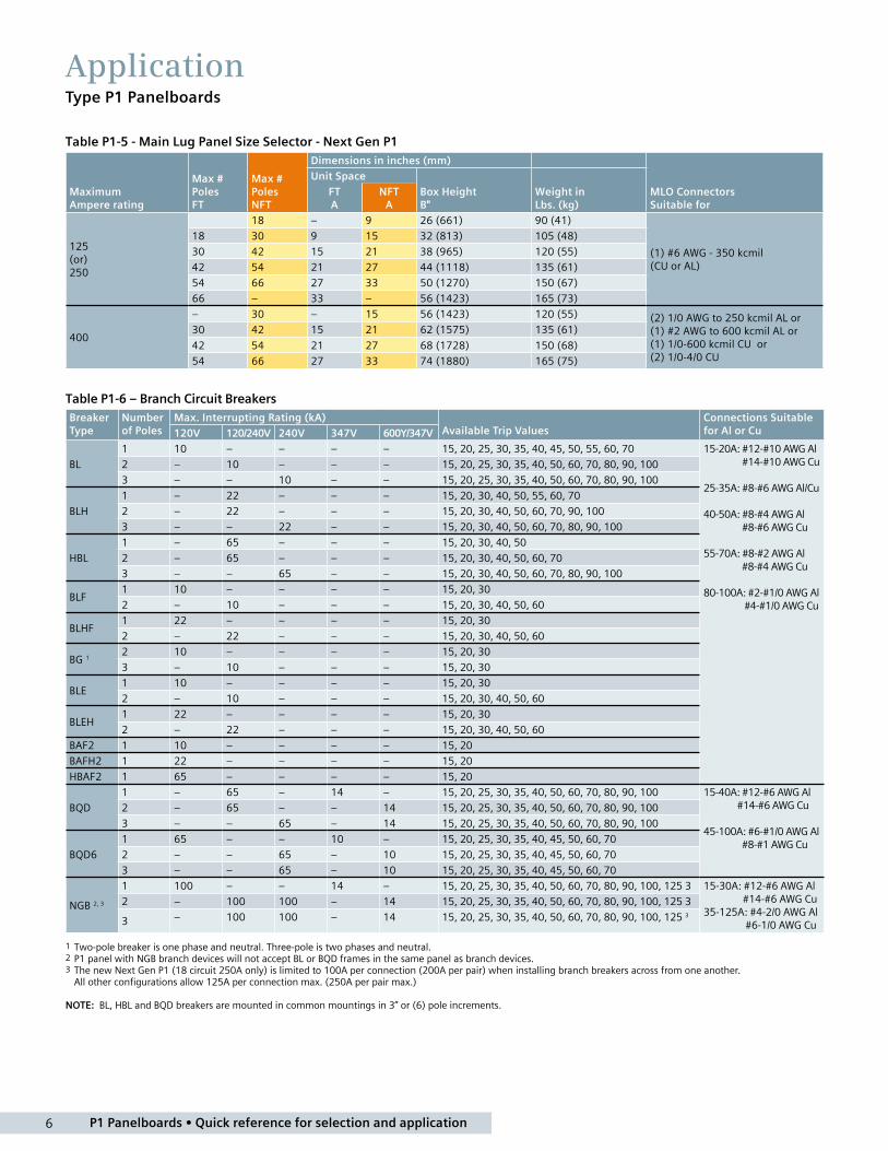
Table P1-5 - Main Lug Panel Size Selector - Next Gen P1
Maximum Ampere rating
Max # Poles FT
Max # Poles NFT
Dimensions in inches (mm)
MLO Connectors Suitable for
Unit Space
Box Height B"
Weight in Lbs. (kg)
FT A
NFT A
125 (or) 250
18 – 9 26 (661) 90 (41)
(1) #6 AWG - 350 kcmil (CU or AL)
18 30 9 15 32 (813) 105 (48)
30 42 15 21 38 (965) 120 (55)
42 54 21 27 44 (1118) 135 (61)
54 66 27 33 50 (1270) 150 (67)
66 – 33 – 56 (1423) 165 (73)
400
– 30 – 15 56 (1423) 120 (55) (2) 1/0 AWG to 250 kcmil AL or(1) #2 AWG to 600 kcmil AL or(1) 1/0-600 kcmil CU or (2) 1/0-4/0 CU
30 42 15 21 62 (1575) 135 (61)
42 54 21 27 68 (1728) 150 (68)
54 66 27 33 74 (1880) 165 (75)
Table P1-6 – Branch Circuit Breakers Breaker Type
Number of Poles
Max. Interrupting Rating (kA) Available Trip Values
Connections Suitable for Al or Cu120V 120/240V 240V 347V 600Y/347V
BL
1 10 – – – – 15, 20, 25, 30, 35, 40, 45, 50, 55, 60, 70 15-20A: #12-#10 AWG Al #14-#10 AWG Cu 25-35A: #8-#6 AWG Al/Cu 40-50A: #8-#4 AWG Al #8-#6 AWG Cu 55-70A: #8-#2 AWG Al #8-#4 AWG Cu 80-100A: #2-#1/0 AWG Al #4-#1/0 AWG Cu
2 – 10 – – – 15, 20, 25, 30, 35, 40, 50, 60, 70, 80, 90, 100
3 – – 10 – – 15, 20, 25, 30, 35, 40, 50, 60, 70, 80, 90, 100
BLH
1 – 22 – – – 15, 20, 30, 40, 50, 55, 60, 70
2 – 22 – – – 15, 20, 30, 40, 50, 60, 70, 90, 100
3 – – 22 – – 15, 20, 30, 40, 50, 60, 70, 80, 90, 100
HBL
1 – 65 – – – 15, 20, 30, 40, 50
2 – 65 – – – 15, 20, 30, 40, 50, 60, 70
3 – – 65 – – 15, 20, 30, 40, 50, 60, 70, 80, 90, 100
BLF1 10 – – – – 15, 20, 30
2 – 10 – – – 15, 20, 30, 40, 50, 60
BLHF1 22 – – – – 15, 20, 30
2 – 22 – – – 15, 20, 30, 40, 50, 60
BG 12 10 – – – – 15, 20, 30
3 – 10 – – – 15, 20, 30
BLE1 10 – – – – 15, 20, 30
2 – 10 – – – 15, 20, 30, 40, 50, 60
BLEH1 22 – – – – 15, 20, 30
2 – 22 – – – 15, 20, 30, 40, 50, 60
BAF2 1 10 – – – – 15, 20
BAFH2 1 22 – – – – 15, 20
HBAF2 1 65 – – – – 15, 20
BQD
1 – 65 – 14 – 15, 20, 25, 30, 35, 40, 50, 60, 70, 80, 90, 100 15-40A: #12-#6 AWG Al #14-#6 AWG Cu 45-100A: #6-#1/0 AWG Al #8-#1 AWG Cu
2 – 65 – – 14 15, 20, 25, 30, 35, 40, 50, 60, 70, 80, 90, 100
3 – – 65 – 14 15, 20, 25, 30, 35, 40, 50, 60, 70, 80, 90, 100
BQD6
1 65 – – 10 – 15, 20, 25, 30, 35, 40, 45, 50, 60, 70
2 – – 65 – 10 15, 20, 25, 30, 35, 40, 45, 50, 60, 70
3 – – 65 – 10 15, 20, 25, 30, 35, 40, 45, 50, 60, 70
NGB 2, 3
1 100 – – 14 – 15, 20, 25, 30, 35, 40, 50, 60, 70, 80, 90, 100, 125 3 15-30A: #12-#6 AWG Al #14-#6 AWG Cu35-125A: #4-2/0 AWG Al #6-1/0 AWG Cu
2 – 100 100 – 14 15, 20, 25, 30, 35, 40, 50, 60, 70, 80, 90, 100, 125 3
3 – 100 100 – 14 15, 20, 25, 30, 35, 40, 50, 60, 70, 80, 90, 100, 125 3
1 Two-pole breaker is one phase and neutral. Three-pole is two phases and neutral.2 P1 panel with NGB branch devices will not accept BL or BQD frames in the same panel as branch devices.3 The new Next Gen P1 (18 circuit 250A only) is limited to 100A per connection (200A per pair) when installing branch breakers across from one another. All other configurations allow 125A per connection max. (250A per pair max.)
NOTE: BL, HBL and BQD breakers are mounted in common mountings in 3” or (6) pole increments.

7 P1 Panelboards • Quick reference for selection and application
ApplicationType P1 Panelboards
Table P1-7 – Subfeed BreakersBreaker Type
Number of Poles
Max. Interrupting Rating (kA) Available Trip Values240V 600Y/347V
QJ2 2, 3 10 – 60, 70, 80, 90, 100, 110, 125, 150, 175, 200, 225
QJH2 2, 3 22 – 60, 70, 80, 90, 100, 110, 125, 150, 175, 200, 225
QJ2H 2, 3 42 – 60, 70, 80, 90, 100, 110, 125, 150, 175, 200, 225
HQJ2 2, 3 100 – 60, 70, 80, 90, 100, 110, 125, 150, 175, 200, 225
ED4 2, 3 65 – 15, 20, 25, 30, 35, 40, 45, 50, 55, 60, 70, 80, 90, 100, 110, 125
ED6 2, 3 65 25 15, 20, 25, 30, 35, 40, 45, 50, 55, 60, 70, 80, 90, 100, 110, 125
HED4 2, 3 100 22 15, 20, 25, 30, 35, 40, 45, 50, 55, 60, 70, 80, 90, 100, 110, 125
FXD6 2, 3 65 25 70, 80, 90, 100, 110, 125, 150, 175, 200, 225, 250
FD6 2, 3 65 25 70, 80, 90, 100, 110, 125, 150, 175, 200, 225, 250
HFD6 2, 3 100 65 70, 80, 90, 100, 110, 125, 150, 175, 200, 225, 250
HFXD6 2, 3 100 65 70, 80, 90, 100, 110, 125, 150, 175, 200, 225, 250
Table P1-8 – Breaker Mounting KitMain or Subfeed Strap Kit w/o BreakerMax Amp Rating
Breaker Frames Service
Original P1 Catalogue Number
Next Gen P1 Catalogue Number
100A BQD, BQD6 3 Phase MBKBC3 Use Back-fedMain LabelKit # MBKBFA 2
(includes Neutral Lug, “MAIN” labeland instructions)
100ABL, BLH, HBL 1 Phase MBKBL1
3 Phase MBKBL3
125ANGB 1 Phase –
3 Phase –
125ED4, ED6, HED4 1 Phase MBKED1 MBKED1A
3 Phase MBKED3 MBKED3A
225QJ2, QJH2, QJ2-H 1 Phase MBKQJ1 MBKQJ1A
3 Phase MBKQJ3 MBKQJ3A
250FXD6, FD6, HFD6, HFXD6 1 Phase MBKFD1 MBKFD1A
3 Phase MBKFD3 MBKFD3A
400 1JXD6, JD6 1 Phase MBKJD1 MBKJD1A
HJD6, HJXD6 3 Phase MBKJD3 MBKJD3A
1 400 amp kit is for main ONLY, not allowed for subfeed breaker. 2 Back-fed main occupies branch space.
Table P1-9 – Lug Kits (Main or Feed-Thru)
Max Amp Rating Matl.
Wire Range (includes Neutral) Service
Original Catalogue Number
Next Gen P1 Catalogue Number
250
AL(1) #6 AWG- 350 kcmil (CU or AL)
1 Phase MLKA1 MLKA1A
3 Phase MLKA3 MLKA3A
CU(1) #6 AWG- 350 kcmil (CU or AL)
1 Phase MLKC1 MLKC1A
3 Phase MLKC3 MLKC3A
400
AL(2) 1/0 - 250 kcmil or (1) #2 AWG-600 kcmil
1 Phase 4MLKA1 4MLKA1A
3 Phase 4MLKA3 4MLKA3A
CU(1) 1/0-600 kcmil CU or (2) 1/0-4/0 CU
1 Phase 4MLKC1 4MLKC1A
3 Phase 4MLKC3 4MLKC3A
400 ALAL 1/0-750 kcmil (max. 600 kcmil CU wire)
1 Phase – 4MLKA1B
3 Phase – 4MLKA3B
Table P1-10 – Copper Neutral Lug Kits – 250A
No. of Circuits Description
Original P1 Catalogue Number
Next Gen P1 Catalogue Number
18
2 or 4 Branch Neutral Strips, 1 Main Neutral Lug, Hardware
CNLK18 Use 30 ckt kit
30 CNLK30 CNLK30A
42 CNLK42 CNLK42A
54, 66 – CNLK54A
Table P1-10A – 2/0 Neutral Lug Kits – 250A and 400A
No. of Circuits Description
Original P1 Catalogue Number
Next Gen P1 Catalogue Number
18
2 or 4 Branch Neutral Strips, Hardware
– Use 30 ckt kit
30 – LNLK30A
42 – LNLK42A
54, 66 – LNLK54A
Table P1-11 – 200% Neutral Lug Kits – 250A
No. of Circuits Description
Original P1 Catalogue Number
Next Gen P1 Catalogue Number
18
2 or 4 Branch Neutral Strips, 2 Main Neutral Lugs, Hardware
2NLK18 Use 30 ckt kit
30 2NLK30 2NLK30A
42 2NLK42 2NLK42A
54, 66 – 2NLK54A
Table P1-12 – 200% Neutral Lug Kits – 400A
No. of Circuits Description
Original P1 Catalogue Number
Next Gen P1 Catalogue Number
18
2 or 4 Branch Neutral Strips, 1 Main600 kcmil Neutral Lug, Hardware
42NLK18 N/A
30 42NLK30 42NLK30A
42 42NLK42 42NLK42A
54, 66 – 42NLK54A

P1 Panelboards • Quick reference for selection and application 8
ApplicationType P1 Panelboards
Table P1-13 – Main Breaker Gutter Dimensions Inches (mm)Main Breaker
Side Gutter Neutral Location
20” wide box 24” wide box 20’’ or 24’’ wide box
BL, BLH, HBL 2 8.500 (216) 8.375 (213) 10.500 (267)
BQD, BQD6 2 5.500 (140) 7.500 (191) 10.500 (267)
NGB 2 8.000 (203) 7.000 (191) 10.500 (267)
ED2, ED4, ED6, HED4 6.125 (156) 8.125 (206) 10.500 (267)
QJ2, QJH2, QJ2-H 6.500 (165) 8.500 (216) 10.500 (267)
FD6, FXD6, HFD6, HFXD6 5.250 (133) 7.250 (184) 10.500 (267)
JD6, JXD6 1 15.000 (381) 15.000 (381) 26.500 (674)1JD Frame mounted vertically. Given dimensions are in respect to the End Gutter.
2 These breakers are back-fed main breakers. Service Entrance equipment rating is not available for panels using back-fed main breakers.
Table P1-14 – Main Lug End Gutter Dimensions Inches (mm)Amp Rating
End Gutter Neutral Location
20” wide box 24” wide box 20” wide box 24” wide box
125 9.500 (242) 9.500 (242) 10.500 (267) 10.500 (267)
250 9.500 (242) 9.500 (242) 10.500 (267) 10.500 (267)
400 25.500 (648) 25.500 (648) 26.750 (680) 26.750 (680)
NOTE: Feed-thru lug and neutral wire bending space is 15.000” and 16.250” respectively on 400A panel.
Table P1-15 – Side Gutter Wiring Space Inches (mm) (Fig P1-1) Fig P1-1
Reference Letter
Panel Width 20”
Panel Width 24” Optional
A 6.375 (167) 8.375 (213)
B 5.500 (140) 7.500 (191)
C 5.000 (127) 7.000 (178)
D 6.125 (156) 8.125 (206)
E 6.500 (165) 8.500 (216)
F 5.250 (133) 7.250 (184)
Note: Subfeed mounting limit 1 per panel.
Feed-Thru (FT) Non-Feed-Thru (NFT)
Miscellaneous Parts and AccessoriesCatalogue # Description
BK1 Bonding Kit for 250A max. Original P1 panels only
BK1A Bonding Kit for 250A max. Next Gen P1 panels only
IMK1 Interior Adjusting Kit
11-1824-01 Directory Card Holder
12-1110-01 Directory Card
11-1056-01B Instruction Book
NBK03Number Strips 1–42. Stick-on type; Use w/ P1 series Panels
NBK04Number Strips 43–84. Stick-on type; Use w/ P1 series Panels
NBK05Number Strips 85–126. Stick-on type; Use w/ P1 series Panels
NBK06Number Strips 127–168. Stick-on type; Use w/ P1 series Panels
EGK AL Ground Bus 44 Connections
ECGK CU Ground Bus 44 Connections
IGK Insulated AL Ground Bus
ICGK Insulated CU Ground Bus
P1SCRWS Package of 42 breaker mounting screws for P1
DFFP11" Branch circuit filler plate (suitable for replacing QF3-UL in panelboards (Package of 100 filler plates)
P1CONBPHCU Connector kit – 6 pcs. B-phase Copper
P1CONBPHAL Connector kit – 6 pcs. B-phase Aluminum
P1CONACPHCU Connector kit – 6 pcs. A or C-phase Copper
P1CONACPHAL Connector kit – 6 pcs. A or C-phase Aluminum
MCHK-1 1 Metallic directory card holder
FPLK2 2 Spare Fas-latch trim locks with 2 keys
SDKN Dripshield kit (20" W x 5.75" D)
TPS9IKITP1 Original P1 mounting bracket for SPD TPS3 09
TPS9IKITP1A Next Gen P1 mounting bracket for SPD TPS3 09
MBKBFA Back-Fed Main Breaker kit
1 Replacement parts only.
BQD, BQD6 BQD, BQD6
FXD6, FD6, HFD6, HFXD6
Panel Width20 in. (508 mm)
Example of Back-fed NGB Main breaker installed

9 P1 Panelboards • Quick reference for selection and application
Typical Catalogue Numbers Type P1 Factory Assembled Panelboards
2 No subfeed space only for 400A 66 circuit.3 BL/BQD/NGB Type Mains are only available as Back-Fed. No kits are available for use in Main or subfeed space. These breakers take up branch circuit space.4 NGB interiors are not available as Non-Feed-Thru, without subfeed space.
1 For all products without subfeed space - change “T” at end to “N” and reduce box size by 6’’ (152 mm).
Table P1-16 – Main Lugs Only
Main Lug OnlyOriginal P1 – Subfeed Space
Next Gen P1 – Subfeed Space 1, 3
Original P1 – Subfeed Space
Next GenP1 – Subfeed Space 1, 3
Original P1 – Subfeed Space
Next Gen P1 – Subfeed Space 1, 3, 4
Max Panel Amp Rating
Max 1-Pole Circuits
Box Height (in.)
208Y/120V 3-Phase 4-Wire Catalogue #
208Y/120V 3-Phase 4-Wire Catalogue #
120/240V 1-Phase 3-Wire Catalogue #
120/240V 1-Phase 3-Wire Catalogue #
600Y/347V 3-Phase 4-Wire Catalogue #
600Y/347V 3-Phase 4-Wire Catalogue #
125
18 32 P1C18ML125ATS P1C18ML125ATST P1A18ML125ATS P1A18ML125ATST P1L18ML125ATS P1L18ML125ATST30 38 P1C30ML125ATS P1C30ML125ATST P1A30ML125ATS P1A30ML125ATST P1L30ML125ATS P1L30ML125ATST42 44 P1C42ML125ATS P1C42ML125ATST P1A42ML125ATS P1A42ML125ATST P1L42ML125ATS P1L42ML125ATST54 50 – P1C54ML125ATST – P1A54ML125ATST – P1L54ML125ATST66 56 – P1C66ML125ATST – P1A66ML125ATST – P1L66ML125ATST
250
18 32 P1C18ML250ATS P1C18ML250ATST P1A18ML250ATS P1A18ML250ATST P1L18ML250ATS P1L18ML250ATST30 38 P1C30ML250ATS P1C30ML250ATST P1A30ML250ATS P1A30ML250ATST P1L30ML250ATS P1L30ML250ATST42 44 P1C42ML250ATS P1C42ML250ATST P1A42ML250ATS P1A42ML250ATST P1L42ML250ATS P1L42ML250ATST54 50 – P1C54ML250ATST – P1A54ML250ATST – P1L54ML250ATST66 56 – P1C66ML250ATST – P1A66ML250ATST – P1L66ML250ATST
400
18 56 P1C18ML400ATS – P1A18ML400ATS – P1L18ML400ATS –30 62 P1C30ML400ATS P1C30ML400ATST P1A30ML400ATS P1A30ML400ATST P1L30ML400ATS P1L30ML400ATST42 68 P1C42ML400ATS P1C42ML400ATST P1A42ML400ATS P1A42ML400ATST P1L42ML400ATS P1L42ML400ATST54 74 – P1C54ML400ATST – P1A54ML400ATST – P1L54ML400ATST66 2 74 2 – P1C66ML400ATSN 2 – P1A66ML400ATSN 2 – P1L66ML400ATSN 2
Table P1-17 – Main Circuit Breaker
100
18 32 P1C18BL100ATS P1C18BL100ATST P1A18BL100ATS P1A18BL100ATST P1L18B6100ATS P1L18B6100ATST30 38 P1C30BL100ATS P1C30BL100ATST P1A30BL100ATS P1A30BL100ATST P1L30B6100ATS P1L30B6100ATST42 44 P1C42BL100ATS P1C42BL100ATST P1A42BL100ATS P1A42BL100ATST P1L42B6100ATS P1L42B6100ATST54 50 – P1C54BL100ATST – P1A54BL100ATST – P1L54B6100ATST66 56 – P1C66BL100ATST – P1A66BL100ATST – P1L66B6100ATST
125 2
18 32 P1C18NB125ATS P1C18NB125ATST – – P1L18NB125ATS P1L18NB125ATST30 38 P1C30NB125ATS P1C30NB125ATST – – P1L30NB125ATS P1L30NB125ATST42 44 P1C42NB125ATS P1C42NB125ATST – – P1L42NB125ATS P1L42NB125ATST54 50 – P1C54NB125ATST – – – P1L54NB125ATST66 56 – P1C66NB125ATST – – – P1L66NB125ATST
225
18 32 P1C18QJ225ATS P1C18QJ225ATST P1A18QJ225ATS P1A18QJ225ATST P1L18FX250ATS P1L18FX225ATST30 38 P1C30QJ225ATS P1C30QJ225ATST P1A30QJ225ATS P1A30QJ225ATST P1L30FX250ATS P1L30FX225ATST42 44 P1C42QJ225ATS P1C42QJ225ATST P1A42QJ225ATS P1A42QJ225ATST P1L42FX250ATS P1L42FX225ATST54 50 – P1C54QJ225ATST – P1A54QJ225ATST – P1L54FX225ATST66 56 – P1C66QJ225ATST – P1A66QJ225ATST – P1L66FX225ATST
250
18 32 P1C18FX250ATS P1C18FX250ATST P1A18FX250ATS P1A18FX250ATST P1L18FX250ATS P1L18FX250ATST30 38 P1C30FX250ATS P1C30FX250ATST P1A30FX250ATS P1A30FX250ATST P1L30FX250ATS P1L30FX250ATST42 44 P1C42FX250ATS P1C42FX250ATST P1A42FX250ATS P1A42FX250ATST P1L42FX250ATS P1L42FX250ATST54 50 – P1C54FX250ATST – P1A54FX250ATST – P1L54FX250ATST66 56 – P1C66FX250ATST – P1A66FX250ATST – P1L66FX250ATST
400
18 56 P1C18JX400ATS – P1A18JX400ATS – P1L18JX400ATS –30 62 P1C30JX400ATS P1C30JX400ATST P1A30JX400ATS P1A30JX400ATST P1L30JX400ATS P1L30JX400ATST42 68 P1C42JX400ATS P1C42JX400ATST P1A42JX400ATS P1A42JX400ATST P1L42JX400ATS P1L42JX400ATST54 74 – P1C54JX400ATST – P1A54JX400ATST – P1L54JX400ATST66 2 74 2 – P1C66JX400ATSN 2 – P1A66JX400ATSN 2 – P1L66JX400ATSN 2
Table P1-18 – Standard Enclosures
Box Height (in.)
Catalogue NumberType 1 Standard Trim
Type 3R/12Box Surface Flush26 (660) B26 S26B F26B WP2632 (813) B32 S32B F32B WP3238 (965) B38 S38B F38B WP3844 (1118) B44 S44B F44B WP4450 (1270) B50 S50B F50B WP5056 (1422) B56 S56B F56B WP5662 (1575) B62 S62B F62B WP6268 (1727) B68 S68B F68B WP6874 (1880) B74 S74B F74B WP74
Shown with Standard Mains, Top Fed and Surface Trim Catalogue number is for aluminum main bus. For optional copper main bus change “A” in position 11 to “C”.
Panels are top feed, surface mounted. For bottom feed, change“T” in position 12 to “B”. For flush mounting, change “S” in position 13 to “F”.
Replace fifth and sixth position in panelboard catalogue number, with alternate main breaker code.
Note: Original P1 was produced until 2015 and in June the Next Gen P1 was introduced. All interior numbers that end with “T” or “N” are the new Next Gen interiors. T” at end of catalogue number indicates there is a Subfeed area available. “N” at end of catalogue number indicates there is no Subfeed area available.

P1 Panelboards • Quick reference for selection and application 10
Standard ModificationsType P1 Factory Assembled Panelboards
Panel OptionsEnclosures• 24” wide boxes• Hinged trims• Door-in-door trims• Screw to the box trims • Piano hinge trims• Painted boxes• Custom colours• Type 3R/12 enclosures• Type 4X enclosures (SS304 or SS316, surface mounted only)• Panel skirts• Relay Cabinet• Gaskets between trim and box
Panel Modifications• Main Bus All aluminum bussing is tin-plated. Optional bussing for the P1 panel is tin-plated copper. • Compression lug for MLO1
• Contactor Mains - Mount in 24” enclosure ahead of panel. - Asco 920 through 225 amps 3
- Asco 911 through 150 amps 3
- Siemens LEN through 30 amps 3
• Branch and main breaker accessories - Handle blocking devices - Handle padlocking devices • Feed-thru lugs 1 Cannot be used in conjunction with SPD or subfeed breakers.
Feed-thru Lugs Amp Rating Type
Connector CU/AL Range
250
AL/CU Mechanical
(1) #6 AWG-350 kcmil
CU Mechanical
(1) #6 AWG-350 kcmil
AL/CU Compression
(1) #6 AWG-350 kcmil
400
AL/CU Mechanical
(2) #1/0 -250 kcmil or(1) #2 AWG-600 kcmil
CU (1) 1/0-600 kcmil CU or (2) 1/0-4/0 CU
AL/CU Compression
(1) 400-600 kcmil AL (1) 400-500 kcmil CU
NOTE: Standard compression lugs used are range taking lugs and may require a particular crimping tool to accommodate the range. Consult factory for information.
• 200% neutral 1,4
• Copper lugs, mechanical line and branch neutral 1
• Bus mounted SPD 1
• Option for Service Entrance• Grounding of Panelboards Ground Bars are shipped with the panel interior. - Non-Insulated Equipment Ground Bar – Standard - Copper Non-Insulated Ground Bar - AL Insulated Equipment Ground Bar - CU Insulated Equipment Ground Bar• Shunt Trip on Main or Branch BL 2, BLH 2, HBL 2, BQD 2, BQD6 2, NGB 2 as branch use 1” unit space for shunt trip.
QJ2, QJ2-H, QJH2, ED2, ED4, ED6, HED4, FD6, FXD6, HFD6
HFXD6, JXD6, JD6, HJD6, HJXD6, HQJ2H
1 Do not increase panel or enclosure size.2 Accessories on 1” pole breakers (BL, BQD, NGB) will take 1” unit space.3 External to the panel, supplied in a separate enclosure. 4 Not available with service entrance equipment.
Surge Protection Devices TPS3 02• Bus connected• Internally mounted (30A breaker required to feed SPD)• Externally mounted in a 15” high aux, enclosure (30A breaker
required to feed SPD)TPS3 09• Internally mounted (20A breaker required to feed SPD)• Externally mounted (20A breaker required to feed SPD)TPS3 12• Externally mounted (40A breaker required to feed SPD)

11 P1 Panelboards • Quick reference for selection and application
Miscellaneous ModificationsType P1 Factory Assembled Panelboards
Enclosure Modifications
Compression Lugs
Remote Switch Modifications
Table P1-19 – Lugs
StyleAmp Rating
Breaker Type
Compression Connectors
Box Height Addition
MLO
125N/A (1) #6 AWG - 350 kcmil None
250
400 N/A(1) 400 - 600 kcmil AL (1) 400 - 500 kcmil CU
None
Main Breaker
125 ED4, ED6, HED4 (1) #14 AWG - 2/0 Box must go to 24” wide
225 QJ2, QJH2, QJ2H(1) #6 AWG - 350 kcmil CU or AL
Box must go to 24” wide
250 FD6, FXD6, HFD6, HFXD6(1) #6 AWG - 350 kcmil CU or AL
Box must go to 24” wide
Note: Standard compression lugs used for P1 panels are range taking lugs and require a particular crimping tool (tool is Hubbell/Anderson Versa Crimp VC6 - for 250A) to accommodate the range. Consult factory for information. 200% neutral not available with compression lugs. BL, BQD, NGB breakers cannot accommodate compression lugs. For 400A tool use Hubbell/Anderson Versa Crimp VC6FT/VC7FT - see instruction sheet for details.
Table P1-21 – Remote Control Switch Modification
Description
Auxiliary Contacts (mounted, not wired)
2-Wire Control
Table P1-22 – Applications for a Remote Switch
Switch Type Modification
920 Mounts in 24’’ H relay cabinet as a main only
LEN 30A mounts in 24’’ H relay cabinet as a main only
NEMA-4X (SS304 is standard, SS316 optional)Water Tight, Dust Tight and Corrosion Resistant Table P1-20
Catalogue Number
Enclosure – Stainless Steel Size (inches) (304SS is standard)
H W D
B4X26 26 20 5.75
B4X32 32 20 5.75
B4X38 38 20 5.75
B4X44 44 20 5.75
B4X50 50 20 5.75
B4X56 56 20 5.75
B4X62 62 20 5.75
B4X68 68 20 5.75
B4X74 74 20 5.75
P1 Panelboards • Quick reference for selection and application 12
20 in.[ 508 ]
5.75 in.[ 146 ]
³⁄₄ in.[19 ]
³⁄₄ in.[19 ]
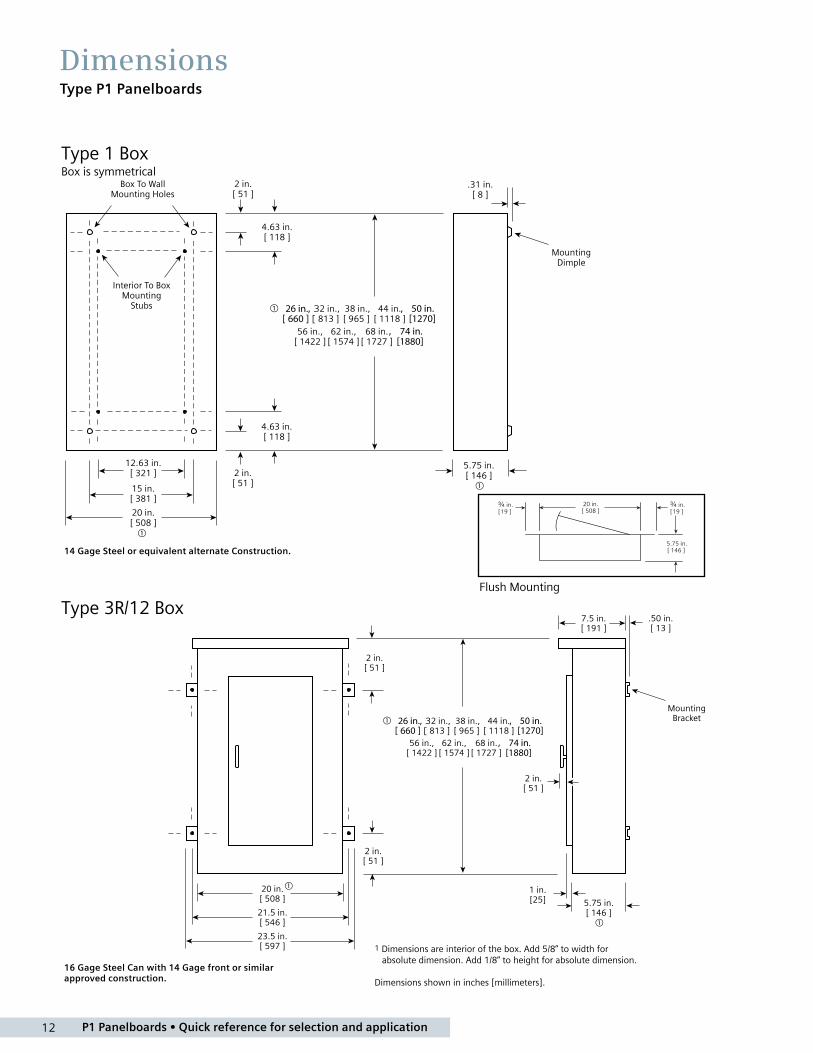
DimensionsType P1 Panelboards
Type 1 BoxBox is symmetrical
1 Dimensions are interior of the box. Add 5/8" to width for absolute dimension. Add 1/8" to height for absolute dimension.
Dimensions shown in inches and millimeters [ ].
50 in.26 in.,[1270][ 660 ]
74 in.[1880]
,
,
Type 1 BoxBox is symmetrical
Type 3R and 3R/12 Box
50 in.26 in.,[1270][ 660 ]
74 in.[1880]
,
,
1 Dimensions are interior of the box. Add 5/8” to width for absolute dimension. Add 1/8” to height for absolute dimension.
Dimensions shown in inches [millimeters].
Type 3R/12 BoxFlush Mounting
14 Gage Steel or equivalent alternate Construction.
16 Gage Steel Can with 14 Gage front or similar approved construction.
13 P1 Panelboards • Quick reference for selection and application
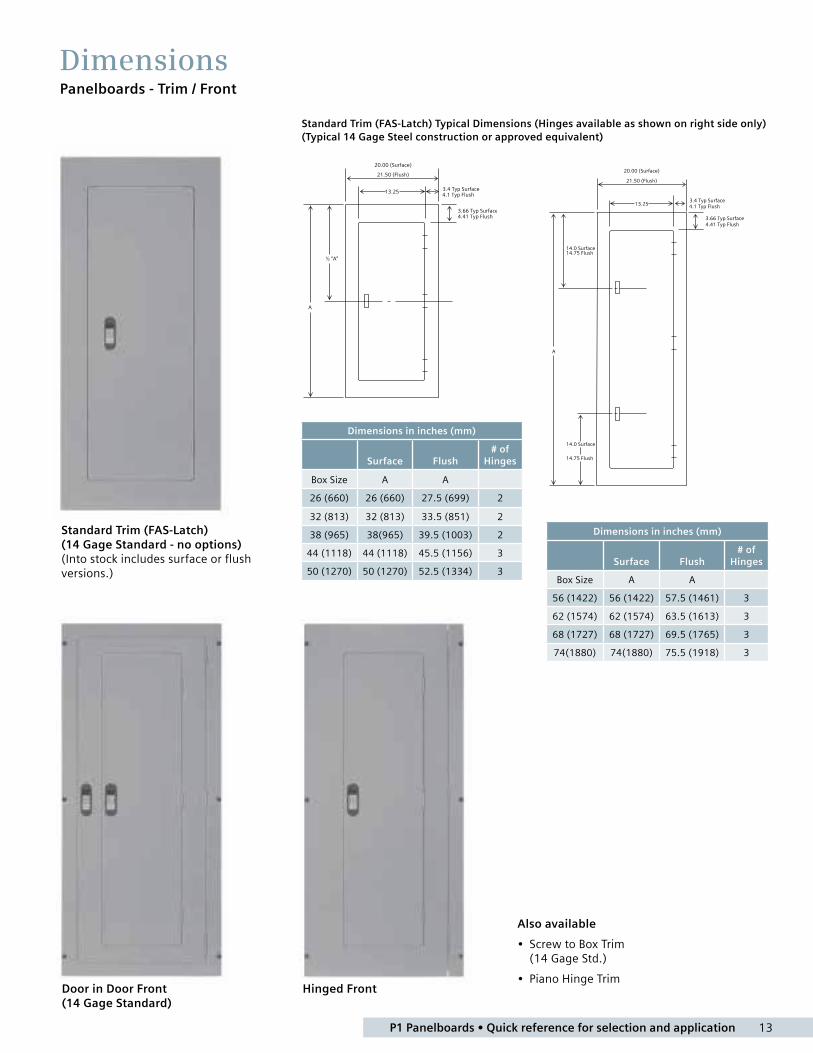
Also available
• Screw to Box Trim (14 Gage Std.)
• Piano Hinge Trim
Standard Trim (FAS-Latch) (14 Gage Standard - no options) (Into stock includes surface or flush versions.)
DimensionsPanelboards - Trim / Front
Door in Door Front (14 Gage Standard)
Hinged Front
Dimensions in inches (mm)
Surface Flush# of
Hinges
Box Size A A
26 (660) 26 (660) 27.5 (699) 2
32 (813) 32 (813) 33.5 (851) 2
38 (965) 38(965) 39.5 (1003) 2
44 (1118) 44 (1118) 45.5 (1156) 3
50 (1270) 50 (1270) 52.5 (1334) 3
Dimensions in inches (mm)
Surface Flush# of
Hinges
Box Size A A
56 (1422) 56 (1422) 57.5 (1461) 3
62 (1574) 62 (1574) 63.5 (1613) 3
68 (1727) 68 (1727) 69.5 (1765) 3
74(1880) 74(1880) 75.5 (1918) 3
Standard Trim (FAS-Latch) Typical Dimensions (Hinges available as shown on right side only)(Typical 14 Gage Steel construction or approved equivalent)

P1 Panelboards • Quick reference for selection and application 14
Next Gen P1 Into stock Panelboards
Flexibility and ease of assembly:Customer oriented design creates installation convenience. For all of its one-of-a-kind features, the P1 panelboard is also designed to be extremely user friendly. For instance, field convertible main breaker and main lug kits - (through 400 amps), will allow you to switch from main lug to main breaker, and vice versa with no change in box size or additional cabling. Plus, lay-in construction (for 250 A CU) and/or removable lugs make wiring the main and neutral lugs easier and faster. To further speed
1) Completely symmetrical boxes may be mounted with either end up. There are four pre-punched equipment ground connector locations for contractor friendly installation.
2) Box comes pre-punched for optional, field installable door-in-door or hinged style trims. The panel box will accept both standard ground connector (EGK and ECGK) assemblies and insulated ground connector kits (IGK and ICGK).
3) Interior is completely symmetrical allowing it to be changed from top to bottom feed by simply rotating the interior.
4) Choose either a Main Breaker kit or Main Lug kit with which to terminate your incoming cables. Main lug kits are contractor friendly lugs through 350 kcmil (250 amp panel) or (1) 600 kcmil or (2) 250 kcmil connectors for 400 amp panels. Main Breaker kits (250 amps and below) are horizontally mounted allowing field convertible top or bottom feeds to be performed easily. Main Lug kits and Main Breaker kits are interchangeable and can be changed/added in the field without making changes to the enclosure or interior.
To better serve the needs of customers, into stock program offers product flexibility, quicker job turn-around, and affordable pricing. All Siemens into stock panelboards are fully backed for high quality, trouble-free operations.
wiring, as well as reduce clutter, the P1 panel also features a split neutral design and branch neutral connections. Additionally, field addable sub-fed breakers (up to 250 amps) or feed through lug kits can be field installed without utilizing any of your feeder breaker positions or increasing your box height. Furthermore, the unique design allows the panel to be inverted in the field and keep its labeling legible.
5) Branch neutral connections are near the breaker connections to speed wiring and reduce clutter. The standard P1 neutral is rated for 100% of the panel’s ampacity and will accept copper or aluminum wire. Optional 200% and 2/0 neutrals are also available.
6) The panel includes space to add (1) subfeed breaker (max 250 amps), feed-thru lugs or TPS3 (SPD) kit.
7) Siemens standard trim has hidden hinges and mounting hardware for added safety. The rounded door corners not only enhance the panel’s appearance but also help to eliminate injuries caused from sharp corners.
8) Semi-flush lock comes standard. Easily identified locked position denoted by keyway being horizontal when door has been locked.
1
2
34
7
8
5
6
15 P1 Panelboards • Quick reference for selection and application
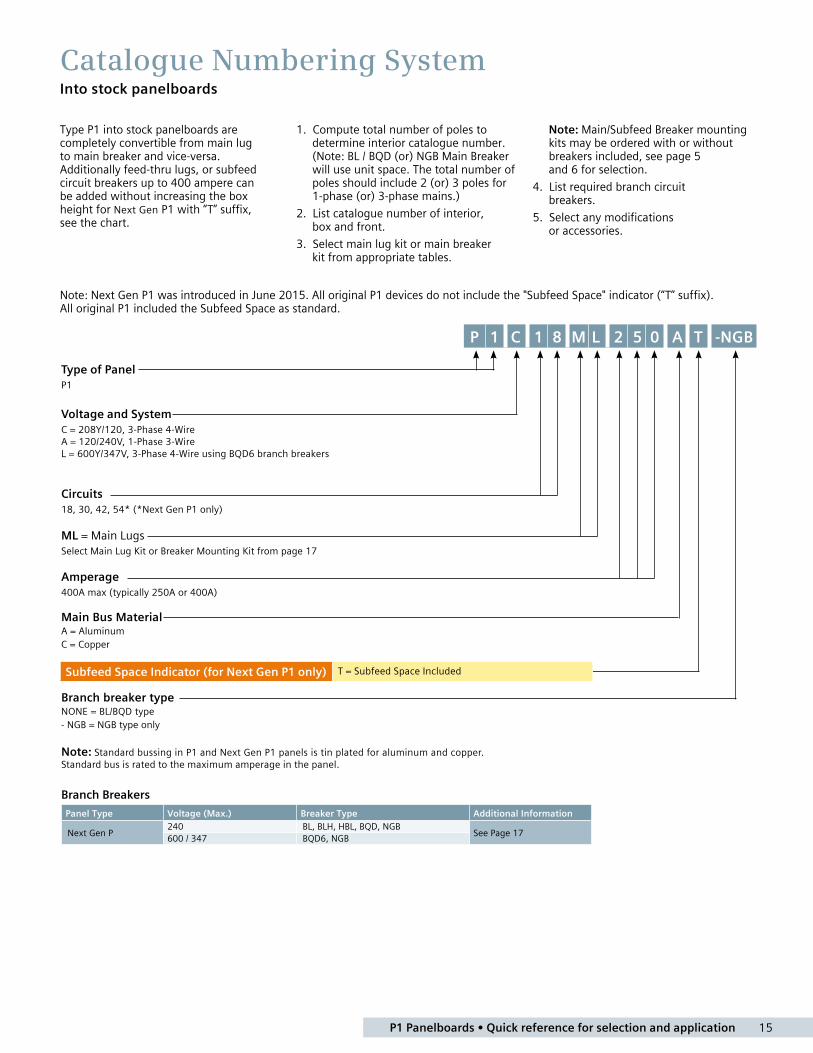
Catalogue Numbering SystemInto stock panelboards
Note: Next Gen P1 was introduced in June 2015. All original P1 devices do not include the "Subfeed Space" indicator (“T” suffix). All original P1 included the Subfeed Space as standard.
Type of PanelP1
Voltage and SystemC = 208Y/120, 3-Phase 4-Wire A = 120/240V, 1-Phase 3-Wire L = 600Y/347V, 3-Phase 4-Wire using BQD6 branch breakers
Circuits18, 30, 42, 54* (*Next Gen P1 only)
ML = Main LugsSelect Main Lug Kit or Breaker Mounting Kit from page 17
Amperage 400A max (typically 250A or 400A)
Main Bus MaterialA = Aluminum C = Copper
Branch breaker type NONE = BL/BQD type - NGB = NGB type only
Note: Standard bussing in P1 and Next Gen P1 panels is tin plated for aluminum and copper.Standard bus is rated to the maximum amperage in the panel.
Branch Breakers
Panel Type Voltage (Max.) Breaker Type Additional Information
Next Gen P240 BL, BLH, HBL, BQD, NGB
See Page 17600 / 347 BQD6, NGB
Type P1 into stock panelboards are completely convertible from main lug to main breaker and vice-versa. Additionally feed-thru lugs, or subfeed circuit breakers up to 400 ampere can be added without increasing the box height for Next Gen P1 with “T” suffix, see the chart.
1. Compute total number of poles to determine interior catalogue number. (Note: BL / BQD (or) NGB Main Breaker will use unit space. The total number of poles should include 2 (or) 3 poles for 1-phase (or) 3-phase mains.)
2. List catalogue number of interior, box and front.
3. Select main lug kit or main breaker kit from appropriate tables.
Note: Main/Subfeed Breaker mounting kits may be ordered with or without breakers included, see page 5 and 6 for selection.
4. List required branch circuit breakers.
5. Select any modifications or accessories.
P 1 C -NGB1 8 M L 2 5 0 A T
Subfeed Space Indicator (for Next Gen P1 only) T = Subfeed Space Included

P1 Panelboards • Quick reference for selection and application 16
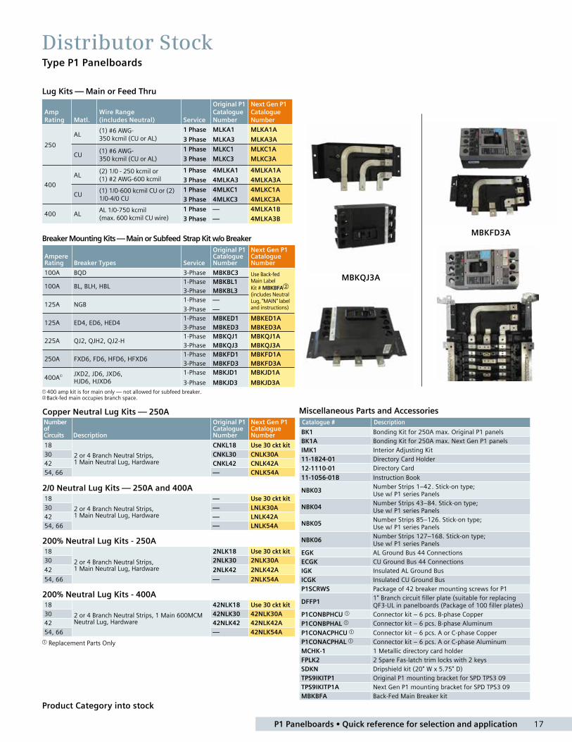
Distributor StockType P1 Panelboards
Product Category into stock
Type P1 Into Stock Panelboards (Next Gen P1 introduced in June 2015)
400A Max. — 20" Wide x 5.75" Deep
1. Choose the appropriate Interior from the table below.
2. Choose the Main Device: Main Lugs from page 16, Main Breaker Kit from pages 16 - 17.
Front included in type 3R/12 Box.
3. Choose Branch Breakers. BL, BQD and NGB breakers from page 19.
4. Choose Feed-Thru Lugs or Subfeed Breaker Kit from pages 16 - 17.
AmpsMax. # of Poles
Original Main Lugs InteriorCatalogue Number
Next Gen P1 Main Lug InteriorCatalogue Number
Original Main Convertible InteriorCatalogue Number
Next Gen P1 Main Convertible Interior Catalogue Number
Box Size
Type 1 Encl.
Type 3R/12
Encl.
Type 1 Front Surface
Type1 Front Flush
1-Phase, 3-Wire 120/240V
250
18 P1A18ML250A P1A18MC250AT P1A18MC250A P1A18MC250AT 32 B32 WP32 S32B F32B30 P1A30ML250A P1A30ML250AT P1A30MC250A P1A30MC250AT 38 B38 WP38 S38B F38B42 P1A42ML250A P1A42ML250AT P1A42MC250A P1A42MC250AT 44 B44 WP44 S44B F44B54 — P1A54ML250AT — P1A54MC250AT 50 B50 WP50 S50B F50B
400
18 P1A18ML400A — P1A18MC400A — — — — — —30 P1A30ML400A P1A30ML400AT P1A30MC400A P1A30MC400AT 62 B62 WP62 S62B F62B42 P1A42ML400A P1A42ML400AT P1A42MC400A P1A42MC400AT 68 B68 WP68 S68B F68B
54 — P1A54ML400AT — P1A54MC400AT 74 B74 WP74 S74B F74B
250
18 P1A18ML250C P1A18ML250CT P1A18MC250C P1A18MC250CT 32 B32 WP32 S32B F32B
30 P1A30ML250C P1A30ML250CT P1A30MC250C P1A30MC250CT 38 B38 WP38 S38B F38B
42 P1A42ML250C P1A42ML250CT P1A42MC250C P1A42MC250CT 44 B44 WP44 S44B F44B
54 — P1A54ML250CT — P1A54MC250CT 50 B50 WP50 S50B F50B
400
18 P1A18ML400C — P1A18MC400C — — — — — —30 P1A30ML400C P1A30ML400CT P1A30MC400C P1A30MC400CT 62 B62 WP62 S62B F62B42 P1A42ML400C P1A42ML400CT P1A42MC400C P1A42MC400CT 68 B68 WP68 S68B F68B54 — P1A54ML400CT — P1A54MC400CT 74 B74 WP74 S74B F74B
3-Phase, 4-Wire 208Y/120V
250
18 P1C18ML250A P1C18ML250AT P1C18MC250A P1C18MC250AT 32 B32 WP32 S32B F32B30 P1C30ML250A P1C30ML250AT P1C30MC250A P1C30MC250AT 38 B38 WP38 S38B F38B42 P1C42ML250A P1C42ML250AT P1C42MC250A P1C42MC250AT 44 B44 WP44 S44B F44B54 — P1C54ML250AT — P1C54MC250AT 50 B50 WP50 S50B F50B
400
18 P1C18ML400A — P1C18MC400A — — — — — —30 P1C30ML400A P1C30ML400AT P1C30MC400A P1C30MC400AT 62 B62 WP62 S62B F62B42 P1C42ML400A P1C42ML400AT P1C42MC400A P1C42MC400AT 68 B68 WP68 S68B F68B54 — P1C54ML400AT — P1C54MC400AT 74 B74 WP74 S74B F74B
250
18 P1C18ML250C P1C18ML250CT P1C18MC250C P1C18MC250CT 32 B32 WP32 S32B F32B30 P1C30ML250C P1C30ML250CT P1C30MC250C P1C30MC250CT 38 B38 WP38 S38B F38B42 P1C42ML250C P1C42ML250CT P1C42MC250C P1C42MC250CT 44 B44 WP44 S44B F44B54 — P1C54ML250CT — P1C54MC250CT 50 B50 WP50 S50B F50B
400
18 P1C18ML400C — P1C18MC400C — — — — — —30 P1C30ML400C P1C30ML400CT P1C30MC400C P1C30MC400CT 62 B62 WP62 S62B F62B42 P1C42ML400C P1C42ML400CT P1C42MC400C P1C42MC400CT 68 B68 WP68 S68B F68B54 — P1C54ML400CT — P1C54MC400CT 74 B74 WP74 S74B F74B
3-Phase, 4-Wire 600Y/347V
250
18 P1L18ML250A P1L18ML250AT P1L18MC250A P1L18MC250AT 32 B32 WP32 S32B F32B30 P1L30ML250A P1L30ML250AT P1L30MC250A P1L30MC250AT 38 B38 WP38 S38B F38B42 P1L42ML250A P1L42ML250AT P1L42MC250A P1L42MC250AT 44 B44 WP44 S44B F44B54 — P1L54ML250AT — P1L54MC250AT 50 B50 WP50 S50B F50B
400
18 P1L18ML400A — P1L18MC400A — — — — — —30 P1L30ML400A P1L30ML400AT P1L30MC400A P1L30MC400AT 62 B62 WP62 S62B F62B42 P1L42ML400A P1L42ML400AT P1L42MC400A P1L42MC400AT 68 B68 WP68 S68B F68B54 — P1L54ML400AT — P1L54MC400AT 74 B74 WP74 S74B F74B
250
18 P1L18ML250C P1L18ML250CT P1L18MC250C P1L18MC250CT 32 B32 WP32 S32B F32B30 P1L30ML250C P1L30ML250CT P1L30MC250C P1L30MC250CT 38 B38 WP38 S38B F38B42 P1L42ML250C P1L42ML250CT P1L42MC250C P1L42MC250CT 44 B44 WP44 S44B F44B54 — P1L54ML250CT — P1L54MC250CT 50 B50 WP50 S50B F50B
400
18 P1L18ML400C — P1L18MC400C — — — — — —30 P1L30ML400C P1L30ML400CT P1L30MC400C P1L30MC400CT 62 B62 WP62 S62B F62B42 P1L42ML400C P1L42ML400CT P1L42MC400C P1L42MC400CT 68 B68 WP68 S68B F68B54 — P1L54ML400CT — P1L54MC400CT 74 B74 WP74 S74B F74B
Interiors for NGB Breakers — 3-Phase, 4-Wire 600Y/347V
250
18 — P1L18ML250AT-NGB — P1L18MC250AT-NGB 32 B32 WP32 S32B F32B30 — P1L30ML250AT-NGB — P1L30MC250AT-NGB 38 B38 WP38 S38B F38B42 — P1L42ML250AT-NGB — P1L42MC250AT-NGB 44 B44 WP44 S44B F44B54 — P1L54ML250AT-NGB — P1L54MC250AT-NGB 50 B50 WP50 S50B F50B
400
18 — — — — — — — — —30 — P1L30ML400AT-NGB — P1L30MC400AT-NGB 62 B62 WP62 S62B F62B42 — P1L42ML400AT-NGB — P1L42MC400AT-NGB 68 B68 WP68 S68B F68B54 — P1L54ML400AT-NGB — P1L54MC400AT-NGB 74 B74 WP74 S74B F74B
250
18 — P1718ML250CT-NGB — P1L18MC250CT-NGB 32 B32 WP32 S32B F32B30 — P1730ML250CT-NGB — P1L30MC250CT-NGB 38 B38 WP38 S38B F38B42 — P1742ML250CT-NGB — P1L42MC250CT-NGB 44 B44 WP44 S44B F44B54 P1L54ML250CT-NGB P1L54MC250CT-NGB 50 B50 WP50 S50B F50B
400
18 — — — — — — — — —30 — P1L30ML400CT-NGB — P1L30MC400CT-NGB 62 B62 WP62 S62B F62B42 — P1L42ML400CT-NGB — P1L42MC400CT-NGB 68 B68 WP68 S68B F68B54 — P1L54ML400CT-NGB — P1L54MC400CT-NGB 74 B74 WP74 S74B F74B
42 circuit with Back-fed Main
54 circuit 400A
17 P1 Panelboards • Quick reference for selection and application
Distributor StockType P1 Panelboards
Product Category into stock
Miscellaneous Parts and AccessoriesCatalogue # Description
BK1 Bonding Kit for 250A max. Original P1 panelsBK1A Bonding Kit for 250A max. Next Gen P1 panelsIMK1 Interior Adjusting Kit11-1824-01 Directory Card Holder12-1110-01 Directory Card
11-1056-01B Instruction Book
NBK03Number Strips 1–42. Stick-on type; Use w/ P1 series Panels
NBK04Number Strips 43–84. Stick-on type; Use w/ P1 series Panels
NBK05Number Strips 85–126. Stick-on type; Use w/ P1 series Panels
NBK06Number Strips 127–168. Stick-on type; Use w/ P1 series Panels
EGK AL Ground Bus 44 ConnectionsECGK CU Ground Bus 44 ConnectionsIGK Insulated AL Ground BusICGK Insulated CU Ground BusP1SCRWS Package of 42 breaker mounting screws for P1
DFFP11" Branch circuit filler plate (suitable for replacing QF3-UL in panelboards (Package of 100 filler plates)
P1CONBPHCU Connector kit – 6 pcs. B-phase CopperP1CONBPHAL Connector kit – 6 pcs. B-phase Aluminum
P1CONACPHCU Connector kit – 6 pcs. A or C-phase CopperP1CONACPHAL Connector kit – 6 pcs. A or C-phase AluminumMCHK-1 1 Metallic directory card holderFPLK2 2 Spare Fas-latch trim locks with 2 keysSDKN Dripshield kit (20" W x 5.75" D)TPS9IKITP1 Original P1 mounting bracket for SPD TPS3 09TPS9IKITP1A Next Gen P1 mounting bracket for SPD TPS3 09MBKBFA Back-Fed Main Breaker kit
Lug Kits — Main or Feed Thru
Breaker Mounting Kits — Main or Subfeed Strap Kit w/o Breaker
AmpereRating Breaker Types Service
Original P1 Catalogue Number
Next Gen P1 Catalogue Number
100A BQD 3-Phase MBKBC3 Use Back-fed Main Label Kit # MBKBFAb (includes Neutral Lug, "MAIN" label and instructions)
100A BL, BLH, HBL1-Phase MBKBL13-Phase MBKBL3
125A NGB1-Phase —
3-Phase —
125A ED4, ED6, HED4 1-Phase MBKED1 MBKED1A3-Phase MBKED3 MBKED3A
225A QJ2, QJH2, QJ2-H1-Phase MBKQJ1 MBKQJ1A3-Phase MBKQJ3 MBKQJ3A
250A FXD6, FD6, HFD6, HFXD61-Phase MBKFD1 MBKFD1A3-Phase MBKFD3 MBKFD3A
400A JXD2, JD6, JXD6,HJD6, HJXD6
1-Phase MBKJD1 MBKJD1A
3-Phase MBKJD3 MBKJD3A 400 amp kit is for main only — not allowed for subfeed breaker.b Back-fed main occupies branch space.
Copper Neutral Lug Kits — 250ANumberof Circuits Description
Original P1 Catalogue Number
Next Gen P1 Catalogue Number
18
2 or 4 Branch Neutral Strips, 1 Main Neutral Lug, Hardware
CNKL18 Use 30 ckt kit30 CNKL30 CNLK30A42 CNKL42 CNLK42A54, 66 — CNLK54A
2/0 Neutral Lug Kits — 250A and 400A18
2 or 4 Branch Neutral Strips, 1 Main Neutral Lug, Hardware
— Use 30 ckt kit30 — LNLK30A42 — LNLK42A54, 66 — LNLK54A
200% Neutral Lug Kits - 250A18
2 or 4 Branch Neutral Strips, 1 Main Neutral Lug, Hardware
2NLK18 Use 30 ckt kit30 2NLK30 2NLK30A
42 2NLK42 2NLK42A
54, 66 — 2NLK54A
200% Neutral Lug Kits - 400A18
2 or 4 Branch Neutral Strips, 1 Main 600MCM Neutral Lug, Hardware
42NLK18 Use 30 ckt kit30 42NLK30 42NLK30A42 42NLK42 42NLK42A54, 66 — 42NLK54A
Replacement Parts Only
MBKQJ3A
MBKFD3A
Amp Rating Matl.
Wire Range (includes Neutral) Service
Original P1 Catalogue Number
Next Gen P1 Catalogue Number
250
AL(1) #6 AWG- 350 kcmil (CU or AL)
1 Phase MLKA1 MLKA1A
3 Phase MLKA3 MLKA3A
CU(1) #6 AWG- 350 kcmil (CU or AL)
1 Phase MLKC1 MLKC1A
3 Phase MLKC3 MLKC3A
400
AL(2) 1/0 - 250 kcmil or (1) #2 AWG-600 kcmil
1 Phase 4MLKA1 4MLKA1A
3 Phase 4MLKA3 4MLKA3A
CU(1) 1/0-600 kcmil CU or (2) 1/0-4/0 CU
1 Phase 4MLKC1 4MLKC1A
3 Phase 4MLKC3 4MLKC3A
400 ALAL 1/0-750 kcmil (max. 600 kcmil CU wire)
1 Phase — 4MLKA1B
3 Phase — 4MLKA3B

P1 Panelboards • Quick reference for selection and application 18
Distributor StockMain Breaker Mounting Kits with Breakers for P1 Panels (250A and lower can be used as subfeed kits also)
Product Category Into Stock
Selection Guide1. Select breaker type.2. Select required amperage.3. Select number of poles.4. Select branch breaker
catalogue numbers.5. Select ground bar and filler
plates. (See replacement parts & accessories on Page 15.)
Branch Breakers Selection for P1
* Built to order.
Switching NeutralsBreaker Type
Ampere Rating
Catalogue Number
Maximum Interrupting Rating (kA)
120V AC 120/240V AC 240V AC
BG 2-Wire Common Trip
1520 30
BG215* BG220* BG230*
1010 10
— — —
— — —
BG 3-Wire Common Trip
1520 30
BG315* BG320* BG330*
— — —
10 10 10
— — —
AFCI – Branch Feeder Type Arc Fault Circuit Interrupter
Breaker Type
Ampere Rating
Catalogue Number
Interrupting Ratings (kA) RMS Symmetrical Amperes
Volts AC
120 120/240 240
BAF2 1-pole
15 BA115AF 10 — —
20 BA120AF 10 — —
BAF2H 1-pole
15 BA115AFH 22 — —
20 BA120AFH 22 — —
HBAF2 1-pole
15 BA115AFHH 65 — —
20 BA120AFHH 65 — —
Original P1 Catalogue Number
Next Gen P1 Catalogue Number Description
Ratings
240V 600V
MBKQJ12225 MBKQJ12225A Kit w/2-pole QJ2 125A breaker 10KA —
MBKQJ33150 MBKQJ33150A Kit w/3-pole QJ2 150A breaker 10KA —
MBKQJ33200 MBKQJ33200A Kit w/3-pole QJ2 175A breaker 10KA —
MBKQJ33225 MBKQJ33225A Kit w/3-pole QJ2 200A breaker 10KA —
MBKED33100 MBKED33100A Kit w/3-pole ED6 100A breaker 65KA 18KA
MBKED33125 MBKED33125A Kit w/3-pole ED6 125A breaker 65KA 18KA
MBKFD33200 MBKFD33200A Kit w/3-pole FXD6 200A breaker 65KA 22KA
MBKFD33225 MBKFD33225A Kit w/3-pole FXD6 225A breaker 65KA 22KA
MBKFD33250 MBKFD33250A Kit w/3-pole FXD6 250A breaker 65KA 22KA
MBKHF33250 MBKHF33250A Kit w/3-pole HFD6 250A breaker 100KA 25KA
MBKJD33400 MBKJD33400A Kit w/3-pole JD6 400A breaker 65KA 25KA
NOTE: “Next Gen P1” kits above only work for interior numbers ending in "T" or "N". Use "Original P1" kits for all others.
Dual Function AFCI/GFCI Circuit Breaker
Breaker Type
Ampere Rating
Catalogue Number
Interrupting Ratings (kA) RMS Symmetrical Amperes
Volts AC
120 120/240 240
BFGA2 1-pole
15 BA115DF 10 — —
20 BA120DF 10 — —
BFGAH2 1-pole
15 BA115DFH 22 — —
20 BA120DFH 22 — —
HBFGA2 1-pole
15 BA115DFHH 65 — —
20 BA120DFHH 65 — —
GFCI Personnel Protection (5MA)
Breaker Type
Ampere Rating
Catalogue Number
Interrupting Ratings (kA) RMS Symmetrical Amperes
Volts AC
120 120/240 240
BLF 1-Pole
1520 25 30
BF115 BF120 BF125 BF130
1010 10 10
— — — —
— — — —
BLF 2-Pole
1520 30 40 50 60
BF215 BF220 BF230 BF240 BF250 BF260
— — — — — —
10 10 10 10 10 10
— — — — — —
BLHF 1-Pole
1520 30
BF115H BF120H BF130H
22 22 22
— — —
— — —
BLHF 2-Pole
15 20 30 40 50 60
BF215H BF220H BF230H BF240H BF250H BF260H
— — — — — —
22 22 22 22 22 22
— — — — — —
HBFGA2 1-pole
15 BA115DFHH 65 — —
20 BA120DFHH 65 — —
300A Main installed.
These Next Gen P1 kits can now be used as top or bottom feed.
AFCI-Combination Type Arc Fault Circuit Interrupter
Breaker Type
Ampere Rating
Catalogue Number
Interrupting Ratings (kA) RMS Symmetrical Amperes
Volts AC
120 120/240 240
BAF2 1-pole
15 B115AFC 10 — —
20 B120AFC 10 — —
BAFH2 1-pole
15 B115AFCH 22 — —
20 B120AFCH 22 — —
HBAF2 1-pole
15 BA115AFCHH 65 — —
20 BA120AFCHH 65 — —
BAF 15 B215AFC 10 — —
2-pole 20 B220AFC 10 — —
BAFH 15 B215AFCH 22 — —
2-pole 20 B220AFCH 22 — —
19 P1 Panelboards • Quick reference for selection and application
Distributor StockType P1 Panelboards
Selection Guide 1. Select breaker type. 2. Select required amperage.
Branch Breakers Selection for P1
n Built to order. Allow 2–3 weeks for delivery. HACR rated.
b To add shunt trip to BL breakers, see Power Product Catalogue for Breaker Accessories.
To add shunt trip to BQD breakers, see Power Product Catalogue for Breaker Accessories.
3. Select number of poles. 4. Select branch breaker catalogue
numbers.
5. Select ground bar and filler plates. (See replacement parts & accessories on Pages 17 and 18.)
BL Branch Breakers – 10,000A IRb
Amp Rating
1-Pole 120/240V
2-Pole 120/240V
3-Pole 240V
15 20 25 30 35 40 45 50 55 60 70 80 90
100
B115 B120 B125 B130 B135 B140 B145 B150 B155 B160 B170
— — —
B215 B220 B225 B230 B235 B240 B245 B250
— B260 B270 B280 B290
B2100
B315 B320 B325 B330 B335 B340 B345 B350
— B360 B370 B380 B390
B3100
HBL Branch Breakers – 65,000A IRb
Amp Rating
1-Pole 120/240V
2-Pole 120/240V
3-Pole 240V
15 20 30 40 50 60 70 80 90
100
B115HH B120HH B130HH B140HH B150HH
— — — — —
B215HH B220HH B230HH B240HH B250HH B260HH B270HH B280HH B290HH
B2100HH
B315HH B320HH B330HH B340HH B350HH B360HH B370HH B380HH B390HH
B3100HH
BQD6 Branch Breakers – 10,000A IR max @ 600/347VAmp
Rating1-Pole 347V
2-Pole 120/240V
3-Pole 240V
15 20 25 30 35 40 45 50 60 70
BQD6115BQD6120BQD6125BQD6130BQD6135BQD6140BQD6145BQD6150BQD6160BQD6170
BQD6215BQD6220BQD6225BQD6230BQD6235BQD6240BQD6245BQD6250BQD6260BQD6270
BQD6315BQD6320BQD6325BQD6330BQD6335BQD6340BQD6345BQD6350BQD6360BQD6370
BLH Branch Breakers – 22,000A IRb
Amp Rating
1-Pole 120/240V
2-Pole 120/240V
3-Pole 240V
15 20 25 30 40 50 55 60 70 80 90
100
B115H B120H B125H B130H B140H B150H B155H B160H B170H
— — —
B215H B220H B225H B230H B240H B250H
— B260H B270H B280H B290H
B2100H
B315H B320H B325H B330H B340H B350H
— B360H B370H B380H B390H
B3100H
BQD Branch Breakers – 65,000A IR max. @ 240 Vac
Amp Rating
1-Pole 120/240V 2-Pole 120/240V 3-Pole 240V
15 20 25 30 35 40 45 50 60 70 80 90
100
BQD115 BQD120 BQD125 BQD130 BQD135 BQD140 BQD145 BQD150 BQD160 BQD170 BQD180 BQD190
BQD1100
BQD215 BQD220 BQD225 BQD230 BQD235 BQD240 BQD245 BQD250 BQD260 BQD270 BQD280 BQD290
BQD2100
BQD315 BQD320 BQD325 BQD330 BQD335 BQD340 BQD345 BQD350 BQD360 BQD370 BQD380 BQD390
BQD3100
NGB Branch Breakers14,000 A IR Max. @ 600Y/347V/ 100,000 A IR @ 240V AC
Amp Rating
1-pole 347V
2-pole 600Y/347V
3-pole 600Y/327V
15 NGB1B015B NGB2B015B NGB3B015B20 NGB1B020B NGB2B020B NGB3B020B25 NGB1B025B NGB2B025B NGB3B025B30 NGB1B030B NGB2B030B NGB3B030B35 NGB1B035B NGB2B035B NGB3B035B40 NGB1B040B NGB2B040B NGB3B040B45 NGB1B045B NGB2B045B NGB3B045B50 NGB1B050B NGB2B050B NGB3B050B60 NGB1B060B NGB2B060B NGB3B060B70 NGB1B070B NGB2B070B NGB3B070B80 NGB1B080B NGB2B080B NGB3B080B90 NGB1B090B NGB2B090B NGB3B090B100 NGB1B100B NGB2B100B NGB3B100B110 NGB1B110B NGB2B110B NGB3B110B125 NGB1B125B NGB2B125B NGB3B125B
UL 1449 3rd Edition SPD
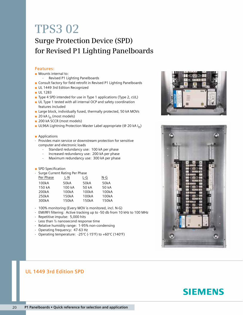
TPS3 02Surge Protection Device (SPD) for Revised P1 Lighting Panelboards
Features:■■ Mounts■internal■to:
■- Revised■P1■Lighting■Panelboards■■ Consult■factory■for■field■retrofit■in■Revised■P1■Lighting■Panelboards■■ UL■1449■3rd■Edition■Recognized■■ UL■1283■■ Type■4■SPD■intended■for■use■in■Type■1■applications■(Type■2,■cUL)■■ UL■Type■1■tested■with■all■internal■OCP■and■safety■coordination■■features■included
■■ Large■block,■individually■fused,■thermally■protected,■50■kA■MOVs■■ 20■kA■In■(most■models)■■ 200■kA■SCCR■(most■models)■■ UL96A■Lightning■Protection■Master■Label■appropriate■(@■20■kA■In)■
■■ Applications■- Provides■main■service■or■downstream■protection■for■sensitive■■
computer■and■electronic■loads■- Standard■redundancy■use:■■100■kA■per■phase■- Increased■redundancy■use:■■200■kA■per■phase■- Maximum■redundancy■use:■■300■kA■per■phase
■■ SPD■Specification■- Surge■Current■Rating■Per■Phase
Per■Phase■ ■L-N■ ■■■■■L-G■■ ■■■■■■■■■■N-G■■■■■
■- 100%■monitoring■(Every■MOV■is■monitored,■incl.■N-G)■- EMI/RFI■filtering:■■Active■tracking■up■to■-50■db■from■10■kHz■to■100■MHz■- Repetitive■impulse:■■5,000■hits■- Less■than■½■nanosecond■response■time■- Relative■humidity■range:■■1-95%■non-condensing■- Operating■frequency:■■47-63■Hz■■- Operating■temperature:■■-25°C■(-15°F)■to■+60°C■(140°F)■
100kA150■kA200kA250kA300kA
50kA100■kA100kA150kA150kA
50kA50■kA100kA100kA150kA
50kA50■kA100kA100kA150kA
P1 Panelboards • Quick reference for selection and application 20

21 P1 Panelboards • Quick reference for selection and application
■■ SPD■Features■- UL■1449■3rd■Edition■effective■■
September■2009■- Designed,■manufactured■&■tested■
consistent■with:■- ANSI/IEEE■C62.41.1-2002,■
C62.41.2-2002,■and■C62.45-2002
■- 1992/2000■NEMA■LS-1■- NEC■Article■285■- IEC■61643,■CE
■- Large■block,■individually■fused,■■thermally■protected,■50■kA■MOVs
■■ SPD■Features■- Direct■bus■connected■- Can■be■wired■to■a■circuit■breaker■(consult■
factory■at■time■of■order■or■see■installation■manual■for■retrofit)
■- 10■year■warranty■
■■ Standard■Monitoring■- LED■indicators■- Audible■alarm■with■silence■switch■and■test■
button■- Dry■contacts
■■ Available■Options■- Surge■counter■- Terminal■lug■for■circuit■breaker■connection
■■ Key■Bid■Specifications■- UL■1449■3rd■Edition■Recognized■- UL■1283■- Audible■alarm■with■silence■switch■■
and■test■button■- Dry■contacts■- EMI/RFI■filtering■- Protection■modes■on■L-N,■L-G,■L-L,■N-G■- In■Rating■-■20■kA■- Short■Circuit■Current■Rating■-■200■kA■- Surge■Current■Rating
Per■Phase■■=■■■L-N■■■+■■■L-G100■kA■■■■■■■■■■■■50■kA■■■■50■kA
UL■1449■3rd■Edition■-■2009■Test■Data■SummaryVoltage■Protection■Rating■■(VPR■-■6kV,■3kA)
Voltage■Code Service■Voltage L-N L-G N-G L-L Type In SCCR MCOVA 120/240V,■1Ø,■3W■(Fig■1) 700 700 700 1200 Type■4 20■kA 100■kA 150B 120/240V,■3Ø,■4W■(Fig■3) 700■■/■1200 700■/■1200 700 1800■/■1800 Type■4 20■kA 200■kA 150■/■320C 120/208V,■3Ø,■4W■(Fig■2) 700 700 700 1200 Type■4 20■kA 200■kA 150D 240V,■3Ø,■3W■(Fig■4) 1200 1200 Type■4 10■kA 200■kA 320E 277/480V,■3Ø,■4W■(Fig■2) 1200 1200 1200 2000 Type■4 20■kA 200■kA 320F 480V,■3Ø,■3W■(Fig■4) 1800 1800 Type■4 10■kA 200■kA 550G 600V,■3Ø,■3W■(Fig■4) 2500 2500 Type■4 10■kA 200■kA 690K 380/220V,■3Ø,■4W■(Fig■2) 1200 1200 1200 2000 Type■4 20■kA 200■kA 320L 600/347V,■3Ø,■4W■(Fig■2) 1500 1500 1500 2500 Type■4 10■kA 200■kA 420S 400/230V,■3Ø,■4W■(Fig■2) 1200 1200 1200 2000 Type■4 20■kA 200■kA 320
Split2■Hots,■1■Neu,■1■Grnd
Hot (BLK)
Hot (BLK)
Neutral (WHT)V
V
}}
Ground (GRN)
Figure■1Wye3■Hots,■1■Neu,■1■Grnd
}
Phase A (BLK)Phase B (BLK)
Neutral (WHT)
Phase C (BLK)
Ground (GRN)
A
C
N
V
B
Figure■2
Hi-Leg■Delta■(B■High)3■Hots,■(B■High),■■1■Neu,■1■Grnd
Phase A (BLK)Phase B (ORNG)
Neutral (WHT)
Phase C (BLK)
Ground (GRN)
}V
Figure■3
Delta■&■HRG■Wye3■Hots,■1■Grnd
Phase A (BLK)
Phase C (BLK)
Phase B (BLK)
Ground (GRN)
}V
Figure■4
� Available■100■kA■&■150■kA■only
Notes:
2.16.15.lh
Ordering■Information
Catalog■#■■ TPS3■o ■02■ oo ooVoltage■Code Surge■Current■(kA) Options
C = 120/208V,■3Ø,■4W■(Fig■2)■ 10 = 100■kA■per■phase W = Terminal■lugD = 240V,■3Ø,■3W■(Fig■4)■ 15 = 150■kA■per■phase X = Surge■counterE = 277/480V,■3Ø,■4W■(Fig■2) 20 = 200■kA■per■phaseF = 480V,■3Ø,■3W■(Fig■4) 25 = 250■kA■per■phaseG = 600V,■3Ø,■3W■(Fig■4)� 30 = 300■kA■per■phaseK = 380/220V,■3Ø,■4W■(Fig■2)L = 600/347V,■3Ø,■4W■(Fig■2)S = 400/230V,■3Ø,■4W■(Fig■2)
■- Example:■■TPS3C0120X0■=■SPD■for■a■208/120V■panelboard■with■a■surge■current■capacity■of■200■kA■per■phase■and■a■surge■counter■option
■- When■an■option■is■not■selected,■include■a■zero■(0)■in■the■fieldAvailable■Accessories:■Ordered■Separately■- RMSIE■-■Remote■monitor
Siemens Canada Limited1577 North Service Road EastOakville, ON L6H 0H6
SPD Hotline: 888.333.3545 [email protected]
©2013 Siemens Canada Limited, Inc.All Rights Reserved. Siemens is a registeredtrademark of Siemens AG. Product namesmentioned may be trademarks or registeredtrademarks of their respective companies.Specifications are subject to change withoutnotice.
www.siemens.ca/surge www.siemens.ca
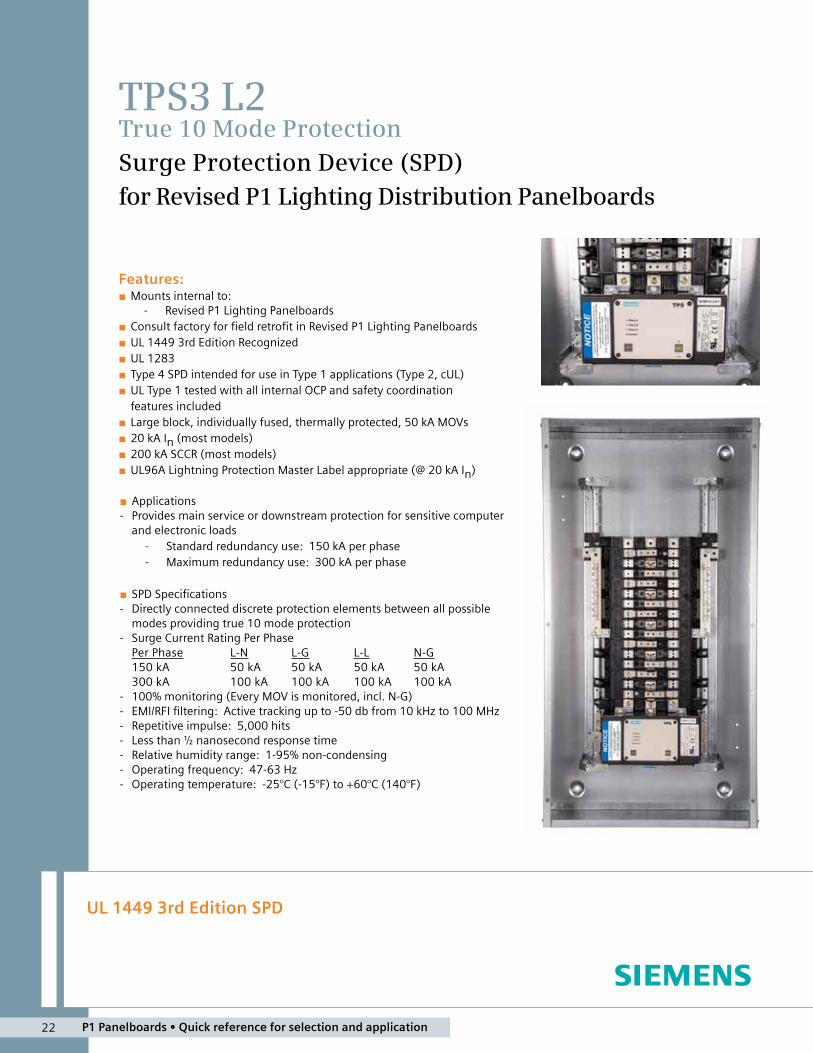
UL 1449 3rd Edition SPD
TPS3 L2True 10 Mode ProtectionSurge Protection Device (SPD) for Revised P1 Lighting Distribution Panelboards
■■ Applications■- Provides■main■service■or■downstream■protection■for■sensitive■computer■
and■electronic■loads■- Standard■redundancy■use:■■150■kA■per■phase■- Maximum■redundancy■use:■■300■kA■per■phase
■■ SPD■Specifications■- Directly■connected■discrete■protection■elements■between■all■possible■
modes■providing■true■10■mode■protection■- Surge■Current■Rating■Per■Phase
Per■Phase■ L-N■ L-G■ L-L■ N-G150■kA■ 50■kA■ 50■kA■ 50■kA■ 50■kA■300■kA■ 100■kA■ 100■kA■ 100■kA■ 100■kA
■- 100%■monitoring■(Every■MOV■is■monitored,■incl.■N-G)■- EMI/RFI■filtering:■■Active■tracking■up■to■-50■db■from■10■kHz■to■100■MHz■- Repetitive■impulse:■■5,000■hits■- Less■than■½■nanosecond■response■time■- Relative■humidity■range:■■1-95%■non-condensing■- Operating■frequency:■■47-63■Hz■- Operating■temperature:■■-25°C■(-15°F)■to■+60°C■(140°F)
Features:■■ Mounts■internal■to:
■- Revised■P1■Lighting■Panelboards■■ Consult■factory■for■field■retrofit■in■Revised■P1■Lighting■Panelboards■■ UL■1449■3rd■Edition■Recognized■■ UL■1283■■ Type■4■SPD■intended■for■use■in■Type■1■applications■(Type■2,■cUL)■■ UL■Type■1■tested■with■all■internal■OCP■and■safety■coordination■■features■included
■■ Large■block,■individually■fused,■thermally■protected,■50■kA■MOVs■■ 20■kA■In■(most■models)■■ 200■kA■SCCR■(most■models)■■ UL96A■Lightning■Protection■Master■Label■appropriate■(@■20■kA■In)
P1 Panelboards • Quick reference for selection and application 22
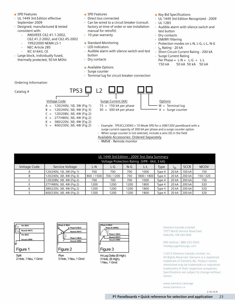
23 P1 Panelboards • Quick reference for selection and application
Voltage■Code Surge■Current■(kA) Options
A = 120/240V,■1Ø,■3W■(Fig■1)■ 15 = 150■kA■per■phase W = Terminal■lugB = 120/240V,■3Ø,■4W■(Fig■3)■ 30 = 300■kA■per■phase X = Surge■counterC = 120/208V,■3Ø,■4W■(Fig■2)■E = 277/480V,■3Ø,■4W■(Fig■2)■K = 380/220V,■3Ø,■4W■(Fig■2)S = 400/230V,■3Ø,■4W■(Fig■2)
Ordering■Information
Catalog■#■ TPS3 o L2 oo oo
■- Example:■■TPS3CL230X0■=■10■Mode■SPD■for■a■208/120V■panelboard■with■a■surge■current■capacity■of■300■kA■per■phase■and■a■surge■counter■option
■- When■surge■counter■is■not■selected,■include■a■zero■(0)■in■the■fieldAvailable■Accessories:■Ordered■Separately■- RMSIE■-■Remote■monitor
■■ SPD■Features■- UL■1449■3rd■Edition■effective■■
September■2009■- Designed,■manufactured■&■tested■
consistent■with:■- ANSI/IEEE■C62.41.1-2002,■
C62.41.2-2002,■and■C62.45-2002■- 1992/2000■NEMA■LS-1■- NEC■Article■285■- IEC■61643,■CE
■- Large■block,■individually■fused,■■thermally■protected,■50■kA■MOVs
■■ Key■Bid■Specifications■- UL■1449■3rd■Edition■Recognized■-■2009■■- UL■1283■- Audible■alarm■with■silence■switch■and■
test■button■- Dry■contacts■- EMI/RFI■filtering■- Protection■modes■on■L-N,■L-G,■L-L,■N-G■- In■Rating■-■20■kA■- Short■Circuit■Current■Rating■-■200■kA■- Surge■Current■Rating
Per■Phase■=■■L-N■+■■■L-G■■+■■■L-L150■kA■■■■■■■■50■kA■■50■kA■■■■50■kA
UL■1449■3rd■Edition■-■2009■Test■Data■SummaryVoltage■Protection■Rating■■(VPR■-■6kV,■3■kA)
Voltage■Code Service■Voltage L-N L-G N-G L-L Type■ In SCCR MCOVA 120/240V,■1Ø,■3W■(Fig■1) 700 700 700 1000 Type■4 20■kA 100■kA 150B 120/240V,■3Ø,■4W■(Fig■3) 800■■/■1500 700■/■1200 700 1800■/■1800 Type■4 20■kA 200■kA 150■/■320C 120/208V,■3Ø,■4W■(Fig■2) 700 700 700 1000 Type■4 20■kA 200■kA 150E 277/480V,■3Ø,■4W■(Fig■2) 1200 1200 1200 1800 Type■4 20■kA 200■kA 320K 380/220V,■3Ø,■4W■(Fig■2) 1200 1200 1200 1800 Type■4 20■kA 200■kA 320S 400/230V,■3Ø,■4W■(Fig■2) 1200 1200 1200 1800 Type■4 20■kA 200■kA 320
■■ SPD■Features■- Direct■bus■connected■- Can■be■wired■to■a■circuit■breaker■(consult■
factory■at■time■of■order■or■see■installation■manual■for■retrofit)
■- 10■year■warranty■
■■ Standard■Monitoring■- LED■indicators■- Audible■alarm■with■silence■switch■and■test■
button■- Dry■contacts
■■ Available■Options■- Surge■counter■- Terminal■lug■for■circuit■breaker■connection
Split2 Hots, 1 Neu, 1 Grnd
Hot (BLK)
Hot (BLK)
Neutral (WHT)V
V
}}
Ground (GRN)
Figure 1Wye3 Hots, 1 Neu, 1 Grnd
}
Phase A (BLK)Phase B (BLK)
Neutral (WHT)
Phase C (BLK)
Ground (GRN)
A
C
N
V
B
Figure 2Hi-Leg Delta (B High)3 Hots, (B High), 1 Neu, 1 Grnd
Phase A (BLK)Phase B (ORNG)
Neutral (WHT)
Phase C (BLK)
Ground (GRN)
}V
Figure 3
2.16.15.lh
Siemens Canada Limited1577 North Service Road EastOakville, ON L6H 0H6
SPD Hotline: 888.333.3545 [email protected]
©2013 Siemens Canada Limited, Inc.All Rights Reserved. Siemens is a registeredtrademark of Siemens AG. Product namesmentioned may be trademarks or registeredtrademarks of their respective companies.Specifications are subject to change withoutnotice.
www.siemens.ca/surge www.siemens.ca
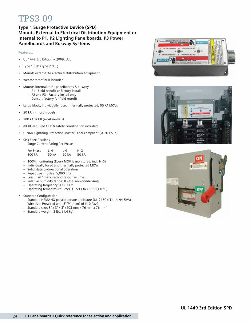
P1 Panelboards • Quick reference for selection and application 24
UL 1449 3rd Edition SPD
TPS3 09Type 1 Surge Protective Device (SPD) Mounts External to Electrical Distribution Equipment or Internal to P1, P2 Lighting Panelboards, P3 Power Panelboards and Busway Systems
Features:
• UL 1449 3rd Edition – 2009, cUL
• Type 1 SPD (Type 2 cUL)
• Mounts external to electrical distribution equipment
• Weatherproof hub included
• Mounts internal to P1 panelboards & busway – P1 - Field retrofit or factory install – P2 and P3 - Factory install only Consult factory for field retrofit
• Large block, individually fused, thermally protected, 50 kA MOVs
• 20 kA In(most models)
• 200 kA SCCR (most models)
• All UL-required OCP & safety coordination included
• UL96A Lightning Protection Master Label compliant (@ 20 kA In)
• SPD Specifications – Surge Current Rating Per Phase
Per Phase L-N L-G N-G 100 kA 50 kA 50 kA 50 kA
– 100% monitoring (Every MOV is monitored, incl. N-G) – Individually fused and thermally protected MOVs – Solid state bi-directional operation – Repetitive impulse: 5,000 hits – Less than 1 nanosecond response time – Relative humidity range: 0 -95% non-condensing – Operating frequency: 47-63 Hz – Operating temperature: -25°C (-15°F) to +60°C (140°F)
• Standard Configuration – Standard NEMA 4X polycarbonate enclosure (UL 746C (f1), UL 94-5VA) – Wire size: Prewired with 3’ (91.4cm) of #10 AWG – Standard size: 8” x 3” x 3” (203 mm x 76 mm x 76 mm) – Standard weight: 3 lbs. (1.4 kg)
UL 1449 3rd Edition SPD
TPS3 09Type 1 Surge Protective Device (SPD)
Mounts External to Electrical Distribution Equipment or
Internal to P1, P2 Lighting Panelboards, P3 Power
Panelboards and Busway Systems
Features:
� UL 1449 3rd Edition – 2009, cUL
� Type 1 SPD (Type 2 cUL)
� Mounts external to electrical distribution equipment - Weatherproof hub included
� Mounts internal to P1 panelboards & busway - P1 - Field retrofit or factory install - P2 and P3 - Factory install only
Consult factory for field retrofit
� Large block, individually fused, thermally protected, 50 kA MOVs
� 20 kA In(most models)
� 200 kA SCCR (most models)
� All UL-required OCP & safety coordination included
� UL96A Lightning Protection Master Label compliant (@ 20 kA In)
� SPD Specifications - Surge Current Rating Per Phase
Per Phase L-N L-G N-G100 kA 50 kA 50 kA 50 kA
- 100% monitoring (Every MOV is monitored, incl. N-G) - Individually fused and thermally protected MOVs - Solid state bi-directional operation - Repetitive impulse: 5,000 hits - Less than 1 nanosecond response time - Relative humidity range: 0 -95% non-condensing - Operating frequency: 47-63 Hz - Operating temperature: -25°C (-15°F) to +60°C (140°F)
� Standard Configuration - Standard NEMA 4X polycarbonate enclosure (UL 746C (f1),
UL 94-5VA) - Wire size: Prewired with 3’ (91.4cm) of #10 AWG - Standard size: 8” x 3” x 3” (203 mm x 76 mm x 76 mm) - Standard weight: 3 lbs. (1.4 kg)
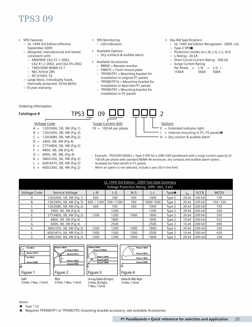
25 P1 Panelboards • Quick reference for selection and application
• SPD Features – UL 1449 3rd Edition effective September 2009 – Designed, manufactured and tested consistent with: – ANSI/IEEE C62.41.1-2002, C62.41.2-2002, and C62.45-2002 – 1992/2000 NEMA LS-1 – NEC Article 285 – IEC 61643, CE – Large block, individually fused, thermally protected, 50 kA MOVs – 10 year warranty
• SPD Monitoring – LED indicators
• Available Options – Dry contacts & audible alarm
• Available Accessories – RMSIE = Remote monitor – FMKITC = Flush mount plate – TPS9IKITP1 = Mounting bracket for installation in original P1 panels – TPS9IKITP1A = Mounting bracket for installation in Next Gen P1 panels – TPS9IKITP2 = Mounting bracket for installation in P2 panels
• Key Bid Specifications – UL 1449 3rd Edition Recognized - 2009, cUL – Type 2 SPD1 – Protection modes on L-N, L-G, L-L, N-G – In Rating - 20 kA – Short Circuit Current Rating - 200 kA – Surge Current Rating Per Phase = L-N + L-G + 150kA 50kA 50kA
TPS3 09
Ordering Information
Catalog # TPS3 � 09 �� ��� 2
Voltage Code Surge Current (kA) Options
A = 120/240V, 1Ø, 3W (Fig 1) 10 = 100 kA per phase E = Extended indicator light
B = 120/240V, 3Ø, 4W (Fig 3) I = Internal mounting in P1, P2 panels�
C = 120/208V, 3Ø, 4W (Fig 2) D = Dry contact & audible alarm
D = 240V, 3Ø, 3W (Fig 4)
E = 277/480V, 3Ø, 4W (Fig 2)
F = 480V, 3Ø, 3W (Fig 4)
G = 600V, 3Ø, 3W, (Fig 4)
K = 380/220V, 3Ø, 4W (Fig 2)
L = 600/347V, 3Ø, 4W (Fig 2)
S = 400/230V, 3Ø, 4W (Fig 2)
- Example: TPS3C0910D002 = Type 2 SPD for a 208/120V panelboard with a surge current capacity of
100 kA per phase with standard NEMA 4X enclosure, dry contacts and audible alarm option.
- Available for field retrofit in P1 panels
- When an option is not selected, include a zero (0) in the field
UL 1449 3rd Edition - 2009 Test Data Summary
Voltage Protection Rating (VPR - 6kV, 3 kA)
Voltage Code Service Voltage L-N L-G N-G L-L Type� In SCCR MCOV
A 120/240V, 1Ø, 3W (Fig 1) 600 700 500 1000 Type 2 20 kA 100 kA 150
B 120/240V, 3Ø, 4W (Fig 3) 600 / 1200 700 / 1200 500 1000/ 1000 Type 2 20 kA 200 kA 150 / 320
C 120/208V, 3Ø, 4W (Fig 2) 600 700 500 1000 Type 2 20 kA 200 kA 150
D 240V, 3Ø, 3W (Fig 4) 1200 1200 Type 2 20 kA 200 kA 320
E 277/480V, 3Ø, 4W (Fig 2) 1200 1200 1000 1800 Type 2 20 kA 200 kA 320
F 480V, 3Ø, 3W (Fig 4) 1800 1800 Type 2 10 kA 200 kA 552
G 600V, 3Ø, 3W (Fig 4) 2500 2500 Type 2 10 kA 200 kA 690
K 380/220V, 3Ø, 4W (Fig 2) 1200 1200 1000 1800 Type 2 20 kA 200 kA 320
L 600/347V, 3Ø, 4W (Fig 2) 1500 1500 1500 2500 Type 2 10 kA 200 kA 420
S 400/230V, 3Ø, 4W (Fig 2) 1200 1200 1000 1800 Type 2 20 kA 200 kA 320
� SPD Features - UL 1449 3rd Edition effective September
2009 - Designed, manufactured and tested
consistent with: - ANSI/IEEE C62.41.1-2002,
c62.41.2-2002, C62.45-2002, - 1992/2000 NEMA LS-1 - NEC Article 285 - IEC 61643, CE
- Large block, individually fused, thermally protected, 50 kA MOVs
- 10 year warranty
� SPD Monitoring - LED indicators
� Available Options - Dry contacts & audible alarm
� Available Accessories - RMSIE = Remote monitor - FMKITC = Flush mount plate - TPS9IKITP1 = Mounting bracket for
installation in P1 panels - TPS9IKITP2 = Mounting bracket for
installation in P2 panels
� Key Bid Specifications - UL 1449 3rd Edition – 2009, cUL
- Type 2 SPD�
- Protection modes on L-N, L-G, L-L, N-G - In Rating – 20 kA - Short Circuit Current Rating – 200 kA - Surge Current Rating
Per Phase = L-N + L-G100 kA 50 kA 50 kA
Siemens Canada Limited
1577 North Service Road East
Oakville, ON L6H 0H6
SPD Hotline: 888.333.3545
©2010 Siemens Canada Limited, Inc.
All Rights Reserved. Siemens is a registered
trademark of Siemens AG. Product names
mentioned may be trademarks or registered
trademarks of their respective companies.
Specifications are subject to change without
notice.
www.purgethesurge.ca
www.siemens.ca4.11.13.lh
��Type 1 UL
��Requires TPS9IKITP1 or TPS9IKITP2 mounting bracket accessory, see available Accessories
Notes:
Split2 Hots, 1 Neu, 1 Grnd
Hot (BLK)
Hot (BLK)
Neutral (WHT)V
V
}}
Ground (GRN)
Figure 1
Wye3 Hots, 1 Neu, 1 Grnd
}
Phase A (BLK)
Phase B (BLK)
Neutral (WHT)
Phase C (BLK)
Ground (GRN)
A
C
N
V
B
Figure 2
Hi-Leg Delta (B High)3 Hots, (B High), 1 Neu, 1 Grnd
Phase A (BLK)
Phase B (ORNG)
Neutral (WHT)
Phase C (BLK)
Ground (GRN)
}V
Figure 3
Delta & HRG Wye3 Hots, 1 Grnd
Phase A (BLK)
Phase C (BLK)
Phase B (BLK)
Ground (GRN)
}V
Figure 4
Catalogue #
Ordering Information
Catalog # TPS3 � 09 �� ��� 2
Voltage Code Surge Current (kA) Options
A = 120/240V, 1Ø, 3W (Fig 1) 10 = 100 kA per phase E = Extended indicator light
B = 120/240V, 3Ø, 4W (Fig 3) I = Internal mounting in P1, P2 panels�
C = 120/208V, 3Ø, 4W (Fig 2) D = Dry contact & audible alarm
D = 240V, 3Ø, 3W (Fig 4)
E = 277/480V, 3Ø, 4W (Fig 2)
F = 480V, 3Ø, 3W (Fig 4)
G = 600V, 3Ø, 3W, (Fig 4)
K = 380/220V, 3Ø, 4W (Fig 2)
L = 600/347V, 3Ø, 4W (Fig 2)
S = 400/230V, 3Ø, 4W (Fig 2)
- Example: TPS3C0910D002 = Type 2 SPD for a 208/120V panelboard with a surge current capacity of
100 kA per phase with standard NEMA 4X enclosure, dry contacts and audible alarm option.
- Available for field retrofit in P1 panels
- When an option is not selected, include a zero (0) in the field
UL 1449 3rd Edition - 2009 Test Data Summary
Voltage Protection Rating (VPR - 6kV, 3 kA)
Voltage Code Service Voltage L-N L-G N-G L-L Type� In SCCR MCOV
A 120/240V, 1Ø, 3W (Fig 1) 600 700 500 1000 Type 2 20 kA 100 kA 150
B 120/240V, 3Ø, 4W (Fig 3) 600 / 1200 700 / 1200 500 1000/ 1000 Type 2 20 kA 200 kA 150 / 320
C 120/208V, 3Ø, 4W (Fig 2) 600 700 500 1000 Type 2 20 kA 200 kA 150
D 240V, 3Ø, 3W (Fig 4) 1200 1200 Type 2 20 kA 200 kA 320
E 277/480V, 3Ø, 4W (Fig 2) 1200 1200 1000 1800 Type 2 20 kA 200 kA 320
F 480V, 3Ø, 3W (Fig 4) 1800 1800 Type 2 10 kA 200 kA 552
G 600V, 3Ø, 3W (Fig 4) 2500 2500 Type 2 10 kA 200 kA 690
K 380/220V, 3Ø, 4W (Fig 2) 1200 1200 1000 1800 Type 2 20 kA 200 kA 320
L 600/347V, 3Ø, 4W (Fig 2) 1500 1500 1500 2500 Type 2 10 kA 200 kA 420
S 400/230V, 3Ø, 4W (Fig 2) 1200 1200 1000 1800 Type 2 20 kA 200 kA 320
� SPD Features - UL 1449 3rd Edition effective September
2009 - Designed, manufactured and tested
consistent with: - ANSI/IEEE C62.41.1-2002,
c62.41.2-2002, C62.45-2002, - 1992/2000 NEMA LS-1 - NEC Article 285 - IEC 61643, CE
- Large block, individually fused, thermally protected, 50 kA MOVs
- 10 year warranty
� SPD Monitoring - LED indicators
� Available Options - Dry contacts & audible alarm
� Available Accessories - RMSIE = Remote monitor - FMKITC = Flush mount plate - TPS9IKITP1 = Mounting bracket for
installation in P1 panels - TPS9IKITP2 = Mounting bracket for
installation in P2 panels
� Key Bid Specifications - UL 1449 3rd Edition – 2009, cUL
- Type 2 SPD�
- Protection modes on L-N, L-G, L-L, N-G - In Rating – 20 kA - Short Circuit Current Rating – 200 kA - Surge Current Rating
Per Phase = L-N + L-G100 kA 50 kA 50 kA
Siemens Canada Limited
1577 North Service Road East
Oakville, ON L6H 0H6
SPD Hotline: 888.333.3545
©2010 Siemens Canada Limited, Inc.
All Rights Reserved. Siemens is a registered
trademark of Siemens AG. Product names
mentioned may be trademarks or registered
trademarks of their respective companies.
Specifications are subject to change without
notice.
www.purgethesurge.ca
www.siemens.ca4.11.13.lh
��Type 1 UL
��Requires TPS9IKITP1 or TPS9IKITP2 mounting bracket accessory, see available Accessories
Notes:
Split2 Hots, 1 Neu, 1 Grnd
Hot (BLK)
Hot (BLK)
Neutral (WHT)V
V
}}
Ground (GRN)
Figure 1
Wye3 Hots, 1 Neu, 1 Grnd
}
Phase A (BLK)
Phase B (BLK)
Neutral (WHT)
Phase C (BLK)
Ground (GRN)
A
C
N
V
B
Figure 2
Hi-Leg Delta (B High)3 Hots, (B High), 1 Neu, 1 Grnd
Phase A (BLK)
Phase B (ORNG)
Neutral (WHT)
Phase C (BLK)
Ground (GRN)
}V
Figure 3
Delta & HRG Wye3 Hots, 1 Grnd
Phase A (BLK)
Phase C (BLK)
Phase B (BLK)
Ground (GRN)
}V
Figure 4

P1 Panelboards • Quick reference for selection and application 26
Notes:

27 P1 Panelboards • Quick reference for selection and application
Notes:
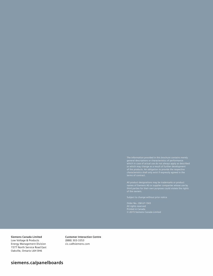
siemens.ca/panelboards
Customer Interaction Centre(888) [email protected]
Siemens Canada Limited Low Voltage & ProductsEnergy Management Division1577 North Service Road EastOakville, Ontario L6H 0H6
The information provided in this brochure contains merely general descriptions or characteristics of performance which in case of actual use do not always apply as described or which may change as a result of further development of the products. An obligation to provide the respective characteristics shall only exist if expressly agreed in the terms of contract.
All product designations may be trademarks or product names of Siemens AG or supplier companies whose use by third parties for their own purposes could violate the rights of the owners.
Subject to change without prior notice
Order No.: EM-LP-1343All rights reservedPrinted in Canada © 2015 Siemens Canada Limited