
Segmentation-Driven 2D-3D Registration for Abdominal Catheter Interventions
9
Segmentation-Driven 2D-3D Registration for Abdominal Catheter Interventions Martin Groher 1 , Frederik Bender 1 , Ralf-Thorsten Hoffmann 2 , and Nassir Navab 1 1 Computer Aided Medical Procedures (CAMP), TUM, Munich, Germany {groher,benderf,navab}@cs.tum.edu 2 Department of Clinical Radiology, University-Hospitals Munich-Grosshadern, Germany [email protected] Abstract. 2D-3D registration of abdominal angiographic data is a difficult prob- lem due to hard time constraints during the intervention, different vessel contrast in volume and image, and motion blur caused by breathing. We propose a novel method for aligning 2D Digitally Subtracted Angiograms (DSA) to Computed Tomography Angiography (CTA) volumes, which requires no user interaction in- trainterventionally. In an iterative process, we link 2D segmentation and 2D-3D registration using a probability map, which creates a common feature space where outliers in 2D and 3D are discarded consequently. Unlike other approaches, we keep user interaction low while high capture range and robustness against vessel variability and deformation are maintained. Tests on five patient data sets and a comparison to two recently proposed methods show the good performance of our method. 1 Introduction Catheter-guided interventions are carried out on an every-day basis in almost every hospital throughout the world. Common practice in these interventions is to acquire 2D fluoroscopic sequences of the patient in which catheter, contrasted vessels, and patient anatomy can be visualized for navigation. Also, in order to provide a high resolution visualization of the vasculature only, DSAs are taken. A 3D scan (CTA) of the patient is usually acquired preoperatively in order to evaluate possible risks and plan the treat- ment. In abdominal catheterizations (e.g. Transarterial Chemoembolization (TACE), or Transjugular Portosystemic Shunt (TIPS)) mono-plane X-ray imaging devices are used more often in contrast to neuroradiology interventions where biplane systems are com- monly utilized. Only guided by 2D projections of one view, it is often very difficult for the physician to find a path through the patient’s vessel system to the region of in- terest. This is mainly due to overlay of vessel structures and, in the case of abdominal procedures, the breathing deformation of vessel systems. In order to provide a catheter guidance in 3D, or the transfer of planned information to intraoperative 2D projections, a 2D-3D registration is needed to align 3D preoperative to 2D intraoperative data set. Problems and challenges for this data fusion are as follows. First, due to hard time constraints during the intervention, a 2D-3D registration algorithm should be fast and as automatic as possible during the treatment. Second, vessel features, which are the only features that can be used for DSA-to-CTA registration, are rather distinct in the two N. Ayache, S. Ourselin, A. Maeder (Eds.): MICCAI 2007, Part II, LNCS 4792, pp. 527–535, 2007. c Springer-Verlag Berlin Heidelberg 2007
Transcript of Segmentation-Driven 2D-3D Registration for Abdominal Catheter Interventions
Segmentation-Driven 2D-3D Registration forAbdominal Catheter Interventions
Martin Groher1, Frederik Bender1, Ralf-Thorsten Hoffmann2, and Nassir Navab1
1 Computer Aided Medical Procedures (CAMP), TUM, Munich, Germany{groher,benderf,navab}@cs.tum.edu
2 Department of Clinical Radiology, University-Hospitals Munich-Grosshadern, [email protected]
Abstract. 2D-3D registration of abdominal angiographic data is a difficult prob-lem due to hard time constraints during the intervention, different vessel contrastin volume and image, and motion blur caused by breathing. We propose a novelmethod for aligning 2D Digitally Subtracted Angiograms (DSA) to ComputedTomography Angiography (CTA) volumes, which requires no user interaction in-trainterventionally. In an iterative process, we link 2D segmentation and 2D-3Dregistration using a probability map, which creates a common feature space whereoutliers in 2D and 3D are discarded consequently. Unlike other approaches, wekeep user interaction low while high capture range and robustness against vesselvariability and deformation are maintained. Tests on five patient data sets and acomparison to two recently proposed methods show the good performance of ourmethod.
1 Introduction
Catheter-guided interventions are carried out on an every-day basis in almost everyhospital throughout the world. Common practice in these interventions is to acquire 2Dfluoroscopic sequences of the patient in which catheter, contrasted vessels, and patientanatomy can be visualized for navigation. Also, in order to provide a high resolutionvisualization of the vasculature only, DSAs are taken. A 3D scan (CTA) of the patientis usually acquired preoperatively in order to evaluate possible risks and plan the treat-ment. In abdominal catheterizations (e.g. Transarterial Chemoembolization (TACE), orTransjugular Portosystemic Shunt (TIPS)) mono-plane X-ray imaging devices are usedmore often in contrast to neuroradiology interventions where biplane systems are com-monly utilized. Only guided by 2D projections of one view, it is often very difficultfor the physician to find a path through the patient’s vessel system to the region of in-terest. This is mainly due to overlay of vessel structures and, in the case of abdominalprocedures, the breathing deformation of vessel systems. In order to provide a catheterguidance in 3D, or the transfer of planned information to intraoperative 2D projections,a 2D-3D registration is needed to align 3D preoperative to 2D intraoperative data set.
Problems and challenges for this data fusion are as follows. First, due to hard timeconstraints during the intervention, a 2D-3D registration algorithm should be fast and asautomatic as possible during the treatment. Second, vessel features, which are the onlyfeatures that can be used for DSA-to-CTA registration, are rather distinct in the two
N. Ayache, S. Ourselin, A. Maeder (Eds.): MICCAI 2007, Part II, LNCS 4792, pp. 527–535, 2007.c© Springer-Verlag Berlin Heidelberg 2007
528 M. Groher et al.
data sets because contrast is injected globally in the preoperative, and locally (throughthe catheter) in the intraoperative case. A naive registration would not be able to dealwith these outliers emerging in 2D as well as in 3D and could drive the registrationto “false positives”. Third, an automatic extraction of vessel features in the 2D DSAwould also segment other tubular structures (needles, catheters), which would disturba feature-based registration. Fourth, due to patient breathing, structures are deformedin the 2D data set, when compared to the 3D data set. 2D-3D rigid registration in de-formable regions can be addressed by a fully intensity-based procedure with gating,as proposed e.g. by Turgeon et al. [1] for heart. However, it is difficult to use such animage-based method without gating information. In fact, the more appropriate approachto follow would be (partly) feature-based to be able to be robust against deformations.Recently, two methods for 2D-3D registration in the particular case of abdominal an-giographic alignment were proposed by Jomier et al. [2] and Groher et al. [3]. The firstis a model-to-image technique, which only requires a preoperative segmentation stepfor aligning DSA images of two views. The second is feature-based aligning extracted2D and 3D vessel graphs in a one-view scenario. The former is fully automatic duringthe intervention but suffers from a small capture range while the latter has high capturerange but requires manual interaction intraoperatively. As will be shown in section 3both methods have difficulties to deal with outliers in 3D.
Contribution: We propose a method for 2D-3D registration of preoperative CTA tointraoperative DSA images for abdominal interventions. It automatically aligns a pre-operatively segmented 3D vasculature to a 2D DSA image by iteratively segmentingthe image and aligning the extracted 2D and 3D vasculatures. A combination of regis-tration and 2D segmentation via a probability map allows us to adjust the feature spacessuch that non-corresponding features in 2D as well as 3D vasculature are removed con-sequently. With this approach we combine robustness and high capture range with afully automatic registration technique. Moreover, one-to-one correspondence of vascu-lar features is assured, which makes it possible to visualize roadmaps in 3D. We mo-tivate our method through an maximum likelihood (ML) formulation solving for bothregistration and segmentation. Unlike traditional ML-based algorithms for combinedsegmentation/registration, we only care about the resulting registration and also leavethe algorithm as generic as possible in order to use alternative registration and segmen-tation steps.
Related Work: A combination of segmentation and 2D-3D registration was proposedby Hamadeh et al. [4] and Bansal et al. [5] for the rigid alignment of medical im-ages. The former only segmented once for aiding the registration, the latter used aminimax-approach in order to optimize one energy functional that encapsulates thejoint conditional entropy of DRR and X-ray given a segmentation. A recent methodproposed by Brox et al. [6] combines pose estimation with a level set formulation tolet a registration aid the segmentation. In all these methods, the segmentation is inte-grated into the algorithm and cannot be replaced. Since vessel segmentation is a specificproblem where general approaches cannot be applied without modification we tried toleave the combination as generic as possible and discarded these methods. Combinedsegmentation and registration has also been successfully applied to brain MR images

Segmentation-Driven 2D-3D Registration for Abdominal Catheter Interventions 529
(see Pohl et al. [7] and references therein) where an Expectation Maximization (EM)formulation was favored. In contrast to our proposed algorithm, this work also solvesfor MR specific nuisance parameters and serves a diagnostic application not subject tohard time constraints.
2 Method
We now describe our segmentation-driven 2D-3D registration algorithm. We first justifyour approach via an ML formulation integrating a segmentation into the registrationprocess and derive a generic algorithm. In section 2.2 we apply our algorithm to 2D-3DDSA-to-CTA registration for abdominal interventions.
2.1 MLE with Labelmaps
We want to maximize the probability such that certain registration parameters Θ fit bestthe 2D image data I and the 3D model M :
Θ̂ = argmaxΘ
P(Θ|I ,M ) (1)
Maximizing the likelihood of (1), i.e. argmaxΘ P(I ,M |Θ), is very difficult if there isno correspondence information between image pixels and model points. Thus, we let a2D segmentation aid the estimation. We introduce a random variable L representing alabelmap over the image I . Marginalizing over L we get
Θ̂ = argmaxΘ ∑
LP(Θ,L|I ,M ) (2)
= argmaxΘ ∑
LP(L|I ,M )P(Θ|L,I ,M ) (3)
using the product rule. From this formulation we can deduce an iterative scheme. Ifwe had values for variable L given, we could solve the ML of eq. (3). Since L has tobe estimated also, we iterate between expectation estimation (E-step) of the unknownrandom variable L and optimization of a cost function (M-step) given this expectation:
L(t) ← E(L|Θ(t−1),I ,M ) = ∑L
LP(L|Θ(t−1),I ,M ) (4)
Θ(t) ← argmaxΘ
P(Θ|L(t),I ,M ) ML∝ argmaxΘ
P(L(t),I ,M |Θ) (5)
The M-step (eq. (5)) is rather easy to accomplish since we already have a model in 3D(M ) and can determine the MLE using L(t) in a model-to-model registration. For the E-step (eq. (4)), however, we must determine the expectation value of the labelmap giventhe last registration and the data. Since this is not straight-forward, we will discuss it inmore detail. Assuming spatial independence of pixels in image I (which is common inthis context, see [7,5]), we can determine the expectation for each pixel x separately. Ifwe restrict our segmentation on one object only, we can deduce an indicator variable �xfor each pixel x, where
530 M. Groher et al.
�x ={
1, if x is inside the object0, otherwise
(6)
Thus, the expectation for the label �x of a pixel x becomes
E(�x|Θ(t−1),I ,M ) = P(�x = 1|Θ(t−1),I ,M ) (7)
= αP(Θ(t−1)|�x = 1,I ,M )P(�x = 1|I ) (8)
using Bayes’ rule, where α = P(Θ(t−1)|I ,M ), and M is dropped in the last term of (8)since the segmentation of I is independent of the model. With eq. (8) we can assign theexpectation of the segmentation to each pixel and thus get a probability map IL(t) forL(t). We can interpret this map as the probability for each pixel to be registered (hasa correspondence) to the model, given that it is part of the segmented object combinedwith the a-priori probability to be part of the segmented object.
Note that we see the expectation as a probability where we joined the registrationparameters from the last iteration and the a-priori knowledge of a pixel belonging to anobject. We still keep the freedom to choose any kind of binarization technique, whichwe apply to the probability map. We can give a generic algorithm for the segmentation-driven 2D-3D registration, which we will henceforth refer to as EBM algorithm:
Algorithm EBM: Given an image I , a model M , and initial estimates for the parame-ters Θ(0), and labelmap L(0)
Initialize values: Θ(t−1) ← Θ(0); L(t−1) ← L(0)
Repeat until convergenceE-step: For each pixel x: if �x = 1 determine the probability for the
new label using eq. (8), else set probability to zeroB-step: Binarize IL(t) to get L(t).M-step: Register M to L(t) starting from Θ(t−1) to get Θ(t)
Note that our method does not follow the strict formulation of the EM algorithm [8],
Θ(t) = argmaxΘ ∑
LP(L|Θ(t−1),I ,M )P(L,I ,M |Θ). (9)
In our algorithm, we directly calculate the expectation of the hidden variable L , whereasEM calculates the expectation of the probability of the complete data (L,I ,M ) giventhe incomplete data (I ,M ) and an estimate of Θ. Unlike EM, convergence is not provenfor our approach. In our experiments, however, the algorithm always converged givensuitable termination criteria.
2.2 Segmentation-Driven 2D-3D Registration on Angiographic Data
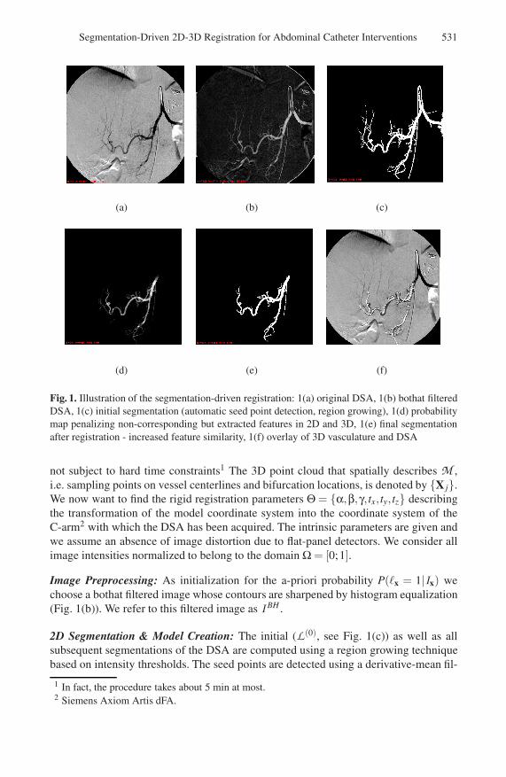
We now describe the single steps of EBM in the particular case of 2D-3D registrationof 3D CTA and 2D DSA data sets as illustrated in Fig. 1. The object to be segmentedin order to aid the 2D-3D registration is, naturally, the vessels of the DSA. Given aDSA image I (Fig. 1(a)) and the vasculature model M (laid over the DSA in Fig. 1(f))of a CTA volume. The vessel model M is generated by a region growing step and acenterline extraction. Seed points and thresholds are determined manually. Note thatthe CTA data set is acquired preoperatively and thus, the extraction of vasculature is
Segmentation-Driven 2D-3D Registration for Abdominal Catheter Interventions 531
(a) (b) (c)
(d) (e) (f)
Fig. 1. Illustration of the segmentation-driven registration: 1(a) original DSA, 1(b) bothat filteredDSA, 1(c) initial segmentation (automatic seed point detection, region growing), 1(d) probabilitymap penalizing non-corresponding but extracted features in 2D and 3D, 1(e) final segmentationafter registration - increased feature similarity, 1(f) overlay of 3D vasculature and DSA
not subject to hard time constraints1 The 3D point cloud that spatially describes M ,i.e. sampling points on vessel centerlines and bifurcation locations, is denoted by {X j}.We now want to find the rigid registration parameters Θ = {α,β,γ, tx, ty,tz} describingthe transformation of the model coordinate system into the coordinate system of theC-arm2 with which the DSA has been acquired. The intrinsic parameters are given andwe assume an absence of image distortion due to flat-panel detectors. We consider allimage intensities normalized to belong to the domain Ω = [0;1].
Image Preprocessing: As initialization for the a-priori probability P(�x = 1|Ix) wechoose a bothat filtered image whose contours are sharpened by histogram equalization(Fig. 1(b)). We refer to this filtered image as I BH .
2D Segmentation & Model Creation: The initial (L(0), see Fig. 1(c)) as well as allsubsequent segmentations of the DSA are computed using a region growing techniquebased on intensity thresholds. The seed points are detected using a derivative-mean fil-
1 In fact, the procedure takes about 5 min at most.2 Siemens Axiom Artis dFA.

532 M. Groher et al.
ter defined by Can et al. [9] for vessel tracing. It detects pixels that are likely to lieon a vessel centerline by filter inspection in 12 directions and criteria evaluation. Thismethod is very fast and yields decent candidate seeds. In order to start with a segmen-tation, we choose the intensity values for the region growing to be inside the intervalµseeds ±2σseeds, which are mean and standard deviation of the intensity values of all de-tected seed points. We start the region growing from all detected seed points. Outliersare removed by choosing the largest connected region as the actual segmentation. Fromthe segmentation we create a model of a 2D vessel centerline to be able to register itwith the 3D model M and deduce a diameter, which is used as σ in the E-step. This isdone with the same technique as in 3D.
Initial Registration: Θ(0) is determined by combining information from the C-arm withan exhaustive feature search following the approach proposed by Groher et al. [3].
Iteration: We define the pixel error of a pixel x as
ε(x) = d(x,C(x,{PΘXj}))2 (10)
where d(., .) determines the Euclidean distance of two vectors, C(y,{z j}) determinesthe closest point of a point set {z j} to a point y, {X j} are all points on the 3D centerline,and PΘ = K[RΘ|tΘ] is the projection matrix with the current pose parameters Θ.
E-step: This step computes the probability map as defined in eq. (8). The probability
that a vessel pixel is registered to the 3D model, P(Θ(t−1)|�x = 1,I ,M ), is defined viathe pixel error (eq. (10)). If we allow a deviation proportional to the maximal width ofa vessel in the 2D image, σ, and assume the error distribution to be Gaussian, we get
P(Θ(t−1)|�x = 1,I ,M ) =1
σ√
2πe−ε(x)/σ2
(11)
The a-priori probability for a pixel x to lie inside a vessel is defined by the image I BH
as described above, i.e. P(�x = 1|I ) = I BH(x). Putting both terms together, we definethe probability map as
E(�x|Θ(t−1),I ,M ) ∝ e−ε(x)/σ2 · I BH(x), (12)
where we dropped α from eq. (8) since it just represents an isotropic scaling in pixelintensities of IL(t) .
B-step: After building up the map (Fig. 1(d)), we perform a new region growing(Fig. 1(e)) and centerline extraction as described above to get a new 2D centerline.
M-step: The 2D-3D registration is computed by minimizing the pixel error ε, which isevaluated only on the 2D centerline points. If a projected centerline point PΘXj alreadyhas a closest point, the one with the smaller error is chosen. Thus, we assure one-to-onecorrespondence of centerline features. The iteration of the registration is governed by aDownhill Simplex optimizer minimizing the non-linear cost function ∑x ε(x), where xhas a corresponding (closest) point in the 3D model M .
We stop the algorithm if the absolute difference of the two labelmaps of current andlast E-step, |L(t−1) − L(t)|, is very small. We choose a threshold of 5% of the pixelsin an image (size 10242), at which the difference of the labelmaps becomes visuallyinsignificant.
Segmentation-Driven 2D-3D Registration for Abdominal Catheter Interventions 533
3 Results
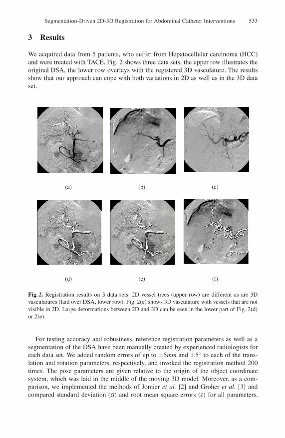
We acquired data from 5 patients, who suffer from Hepatocellular carcinoma (HCC)and were treated with TACE. Fig. 2 shows three data sets, the upper row illustrates theoriginal DSA, the lower row overlays with the registered 3D vasculature. The resultsshow that our approach can cope with both variations in 2D as well as in the 3D dataset.
(a) (b)
( )(c)
(d) (e) (f)
Fig. 2. Registration results on 3 data sets. 2D vessel trees (upper row) are different as are 3Dvasculatures (laid over DSA, lower row). Fig. 2(e) shows 3D vasculature with vessels that are notvisible in 2D. Large deformations between 2D and 3D can be seen in the lower part of Fig. 2(d)or 2(e).
For testing accuracy and robustness, reference registration parameters as well as asegmentation of the DSA have been manually created by experienced radiologists foreach data set. We added random errors of up to ±5mm and ±5◦ to each of the trans-lation and rotation parameters, respectively, and invoked the registration method 200times. The pose parameters are given relative to the origin of the object coordinatesystem, which was laid in the middle of the moving 3D model. Moreover, as a com-parison, we implemented the methods of Jomier et al. [2] and Groher et al. [3] andcompared standard deviation (σ) and root mean square errors (ε) for all parameters.
534 M. Groher et al.
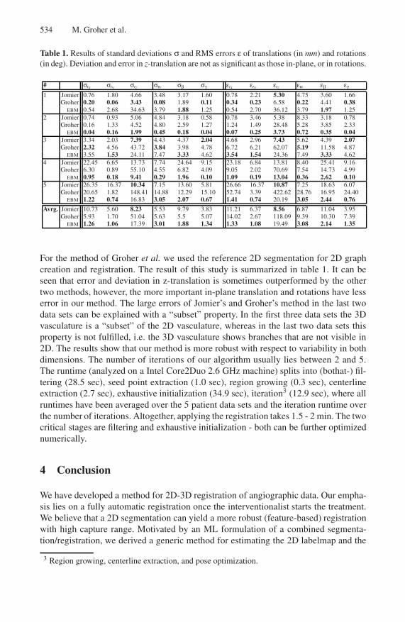
Table 1. Results of standard deviations σ and RMS errors ε of translations (in mm) and rotations(in deg). Deviation and error in z-translation are not as significant as those in-plane, or in rotations.
# σtx σty σtz σα σβ σγ εtx εty εtz εα εβ εγ
1 Jomier 0.76 1.80 4.66 3.48 3.17 1.60 0.78 2.21 5.30 4.75 3.60 1.66Groher 0.20 0.06 3.43 0.08 1.89 0.11 0.34 0.23 6.58 0.22 4.41 0.38
EBM 0.54 2.68 34.63 3.79 1.88 1.25 0.54 2.70 36.12 3.79 1.97 1.252 Jomier 0.74 0.93 5.06 4.84 3.18 0.58 0.78 3.46 5.38 8.33 3.18 0.78
Groher 0.16 1.33 4.52 4.80 2.59 1.27 1.24 1.49 28.48 5.28 3.85 2.33EBM 0.04 0.16 1.99 0.45 0.18 0.04 0.07 0.25 3.73 0.72 0.35 0.04
3 Jomier 3.34 2.03 7.39 4.43 4.37 2.04 4.68 2.96 7.43 5.62 4.39 2.07Groher 2.32 4.56 43.72 3.84 3.98 4.78 6.72 6.21 62.07 5.19 11.58 4.87
EBM 3.55 1.53 24.11 7.47 3.33 4.62 3.54 1.54 24.36 7.49 3.33 4.624 Jomier 22.45 6.65 13.73 7.74 24.64 9.15 23.18 6.84 13.81 8.40 25.41 9.16
Groher 6.30 0.89 55.10 4.55 6.82 4.09 9.05 2.02 70.69 7.54 14.73 4.99EBM 0.95 0.18 9.41 0.29 1.96 0.10 1.09 0.19 13.04 0.36 2.62 0.10
5 Jomier 26.35 16.37 10.34 7.15 13.60 5.81 26.66 16.37 10.87 7.25 18.63 6.07Groher 20.65 1.82 148.41 14.88 12.29 15.10 52.74 3.39 422.62 28.76 16.95 24.40
EBM 1.22 0.74 16.83 3.05 2.07 0.67 1.41 0.74 20.19 3.05 2.44 0.76
Avrg. Jomier 10.73 5.60 8.23 5.53 9.79 3.83 11.21 6.37 8.56 6.87 11.04 3.95Groher 5.93 1.70 51.04 5.63 5.5 5.07 14.02 2.67 118.09 9.39 10.30 7.39
EBM 1.26 1.06 17.39 3.01 1.88 1.34 1.33 1.08 19.49 3.08 2.14 1.35
For the method of Groher et al. we used the reference 2D segmentation for 2D graphcreation and registration. The result of this study is summarized in table 1. It can beseen that error and deviation in z-translation is sometimes outperformed by the othertwo methods, however, the more important in-plane translation and rotations have lesserror in our method. The large errors of Jomier’s and Groher’s method in the last twodata sets can be explained with a “subset” property. In the first three data sets the 3Dvasculature is a “subset” of the 2D vasculature, whereas in the last two data sets thisproperty is not fulfilled, i.e. the 3D vasculature shows branches that are not visible in2D. The results show that our method is more robust with respect to variability in bothdimensions. The number of iterations of our algorithm usually lies between 2 and 5.The runtime (analyzed on a Intel Core2Duo 2.6 GHz machine) splits into (bothat-) fil-tering (28.5 sec), seed point extraction (1.0 sec), region growing (0.3 sec), centerlineextraction (2.7 sec), exhaustive initialization (34.9 sec), iteration3 (12.9 sec), where allruntimes have been averaged over the 5 patient data sets and the iteration runtime overthe number of iterations. Altogether, applying the registration takes 1.5 - 2 min. The twocritical stages are filtering and exhaustive initialization - both can be further optimizednumerically.
4 Conclusion
We have developed a method for 2D-3D registration of angiographic data. Our empha-sis lies on a fully automatic registration once the interventionalist starts the treatment.We believe that a 2D segmentation can yield a more robust (feature-based) registrationwith high capture range. Motivated by an ML formulation of a combined segmenta-tion/registration, we derived a generic method for estimating the 2D labelmap and the
3 Region growing, centerline extraction, and pose optimization.
Segmentation-Driven 2D-3D Registration for Abdominal Catheter Interventions 535
registration parameters iteratively linked by a common probability map. In this prob-abilistic framework, we keep the freedom to choose any segmentation or registrationtechnique. Unlike other approaches, we keep user interaction low while high capturerange and robustness against vessel variability and deformation are maintained. Withthe segmentation-driven registration, we create a common feature space and thus one-to-one correspondence of vessel features. Hence, we can visualize catheter locationsand roadmaps in 3D and 2D simultaneously (see supplementary material). Applicationto different medical procedures and tests of alternative 2D segmentation and/or registra-tion steps will follow the work in the future. With these future tests, we will also assessthe impact of all processing steps, which are performed in the iteration.
Acknowledgements. This research was funded by an academic grant from Siemens Med-ical Solutions Angiography/X-Ray division, Forchheim, Germany. The authors wouldlike to thank in particular K. Klingenbeck-Regn and M. Pfister for their continuoussupport.
References
1. Turgeon, G.A., Lehmann, G., Guiraudon, G., Drangova, M., Holdsworth, D., Peters, T.: 2D-3D registration of coronary angiograms for cardiac procedure planning and guidance. MedicalPhysics 32, 3737–3749 (2005)
2. Jomier, J., Bullitt, E., van Horn, M., Pathak, C., Aylward, S.: 3D/2D model-to-image regis-tration applied to tips surgery. In: Larsen, R., Nielsen, M., Sporring, J. (eds.) MICCAI 2006.LNCS, vol. 4190, pp. 662–670. Springer, Heidelberg (2006)
3. Groher, M., Padoy, N., Jakobs, T., Navab, N.: New CTA protocol and 2D-3D registrationmethod for liver catheterization. In: Larsen, R., Nielsen, M., Sporring, J. (eds.) MICCAI 2006.LNCS, vol. 4190, pp. 873–882. Springer, Heidelberg (2006)
4. Hamadeh, A., Lavalle, S., Cinquin, P.: Automated 3-dimensional computed tomographic andfluoroscopic image registration. Computer Aided Surgery 3, 11–19 (1998)
5. Bansal, R., Staib, L.H., Chen, Z., Rangarajan, A., Knisely, J., Nath, R., Duncan, J.S.: Entropy-based, multiple-portal-to-3DCT registration for prostate radiotherapy using iteratively esti-mated segmentation. In: Taylor, C., Colchester, A. (eds.) MICCAI 1999. LNCS, vol. 1679,pp. 567–578. Springer, Heidelberg (1999)
6. Brox, T., Rosenhahn, B., Weickert, J.: Three-dimensional shape knowledge for joint imagesegmentation and pose estimation. In: Kropatsch, W.G., Sablatnig, R., Hanbury, A. (eds.) Pat-tern Recognition. LNCS, vol. 3663, pp. 109–116. Springer, Heidelberg (2005)
7. Pohl, K.M., Fisher, J., Grimson, Kikinis, Ron, Wells, W.M.: A bayesian model for joint seg-mentation and registration. NeuroImage 31, 228–239 (2006)
8. Dempster, A.P., Laird, N.M., Rubin, D.B.: Maximum likelihood from incomplete data via theEM algorithm. J. of the Royal Statistical Soc. Series B 39, 1–38 (1977)
9. Can, A., Shen, H., Turner, J., Tanenbaum, H., Raysam, B.: Rapid automated tracing and fea-ture extraction from retinal fundus images using direct exploratory algorithms. IEEE Transac-tions on Information Technology in Biomedicine 3, 125–138 (1999)