Section Dividers - City of Port Arthur
319
SPECIFICATIONS AND CONTRACT DOCUMENTS JADE AVE. SANITARY SEWER REHABILITATION PROJECT STATE HWY 365 TO 63RD STREET OF TWELVE INCH (12”) CONCRETE SEWER LINE BY PIPEBURSTING TO A SIXTEEN INCH (16”) (IPS) SDR 17 HDPE PIPE CITY OF PORT ARTHUR JEFFERSON COUNTY, TEXAS Action Civil Engineers, PLLC 8460 Central Mall Drive, Suite J Port Arthur, Texas 77642 Phone: (409) 983-6263 Fax: (409) 983-6265 Email: [email protected] Firm Reg.: F-16376
-
Upload
khangminh22 -
Category
Documents
-
view
1 -
download
0
Transcript of Section Dividers - City of Port Arthur
SPECIFICATIONS AND CONTRACT DOCUMENTS
JADE AVE. SANITARY SEWER REHABILITATION PROJECT STATE HWY 365 TO 63RD STREET OF TWELVE INCH (12”) CONCRETE
SEWER LINE BY PIPEBURSTING TO A SIXTEEN INCH (16”) (IPS) SDR 17 HDPE PIPE
CITY OF PORT ARTHUR JEFFERSON COUNTY, TEXAS
Action Civil Engineers, PLLC 8460 Central Mall Drive, Suite J Port Arthur, Texas 77642 Phone: (409) 983-6263 Fax: (409) 983-6265 Email: [email protected] Firm Reg.: F-16376
MANDATORY PRE-BID CONFERENCE A Mandatory Pre-Bid Conference between Representatives of the City of Port Arthur, Texas and
prospective bidders for Jade Avenue Sanitary Rehabilitation State Hwy to 63rd Street of Twelve
Inch (12”) Concrete Sewer Line by Pipebursting to a Sixteen Inch (16”) (IPS) SDR 17 HDPE
Pipe will be held on Thursday, July 12, 2018 at 2:00 p.m. at the City Hall Council Chambers
located at 444 4th Street, Port Arthur, Texas.
The purpose of the Mandatory Pre-Bid Conference is to make certain that the scope of work is fully
understood, to answer any questions, to clarify the intent of the Contract Documents, and to resolve
any problems that may affect the project construction. No addendum will be issued at this meeting,
but subsequent thereto, the Purchasing Manager, if necessary, will issue an addendum(s) to clarify
the intent of the Contract Documents.
Bids received from firms or individuals not listed on the roll of attendees of the Mandatory Pre-Bid
Conference will be rejected and returned unopened to the bidder.
DERRICK FORD FREEMAN, MAYOR HARVEY ROBINSON THOMAS J. KINLAW III, MAYOR PRO TEM INTERIM CITY MANAGER COUNCIL MEMBERS: SHERRI BELLARD, TRMC RAYMOND SCOTT, JR. CITY SECRETARY CAL J. JONES HAROLD DOUCET, SR. VAL TIZENO CHARLOTTE MOSES CITY ATTORNEY KAPRINA FRANK JULY 3, 2018
INVITATION TO BID JADE AVE. SANITARY SEWER REHABILATATION FROM STATE HWY 365 TO 63RD
STREET OF TWELVE INCH (12”) CONCRETE SEWER LINE BY PIPEBURSTING TO A SIXTEEN INCH (16”) (IPS) SDR 17 HDPE PIPE
. DEADLINE: Sealed Bid submittals must be received and time stamped by 3:00 p.m., Central Standard Time, Wednesday, July 18, 2018. (The clock located in the City Secretary’s office will be the official time.) All bids received will be read aloud at 3:15 p.m. on Wednesday, July 18, 2018 in the City Council Chambers, City Hall, 5th Floor, Port Arthur, TX. You are invited to attend. MARK ENVELOPE: P18-084 DELIVERY ADDRESS: Please submit one (1) original and one (1) copy of your bid to: CITY OF PORT ARTHUR CITY OF PORT ARTHUR CITY SECRETARY or CITY SECRETARY P.O. BOX 1089 444 4TH STREET, 4th Floor PORT ARTHUR, TEXAS 77641 PORT ARTHUR, TEXAS 77640 POINTS OF CONTACT: Questions concerning the Invitation to Bid or Scope of Work should be directed in writing to: City of Port Arthur, TX Clifton Williams, Purchasing Manager P.O. Box 1089 Port Arthur, TX 77641 [email protected]
Purchasing Division/Finance Department | Purchasing Manager, Clifton Williams, CPPB P.O. Box 1089|444 4th Street| Port Arthur, Texas 77641| 409.983.8160 |Fax 409.983.8291
The enclosed INVITATION TO BID (ITB) and accompanying GENERAL INSTRUCTIONS, CONDITIONS SPECIFICATIONS, are for your convenience in submitting bids for the enclosed referenced services for the City of Port Arthur.
Bids must be signed by a person having authority to bind the firm in a contract. Bids shall be placed in a sealed envelope, with the Vendor’s name and address in the upper left-hand corner of the envelope.
ALL BIDS MUST BE RECEIVED IN THE CITY SECRETARY’S OFFICE BEFORE OPENING DATE AND TIME. It is the sole responsibility of the firm to ensure that the sealed ITB submittal arrives at the above location by specified deadline regardless of delivery method chosen by the firm. Faxed or electronically transmitted ITB submittals will not be accepted.
Clifton Williams, CPPB Purchasing Manager
Clifton Williams
INVITATION TO BID JADE AVE. SANITARY SEWER REHABILATATION FROM STATE HWY 365 TO 63RD
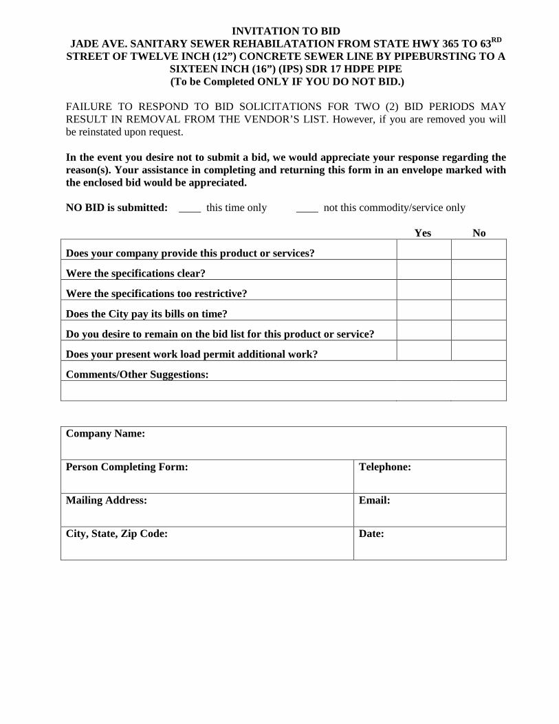
STREET OF TWELVE INCH (12”) CONCRETE SEWER LINE BY PIPEBURSTING TO A SIXTEEN INCH (16”) (IPS) SDR 17 HDPE PIPE (To be Completed ONLY IF YOU DO NOT BID.)
FAILURE TO RESPOND TO BID SOLICITATIONS FOR TWO (2) BID PERIODS MAY RESULT IN REMOVAL FROM THE VENDOR’S LIST. However, if you are removed you will be reinstated upon request. In the event you desire not to submit a bid, we would appreciate your response regarding the reason(s). Your assistance in completing and returning this form in an envelope marked with the enclosed bid would be appreciated. NO BID is submitted: ____ this time only ____ not this commodity/service only Yes No
Does your company provide this product or services?
Were the specifications clear?
Were the specifications too restrictive?
Does the City pay its bills on time?
Do you desire to remain on the bid list for this product or service?
Does your present work load permit additional work?
Comments/Other Suggestions:
Company Name:
Person Completing Form: Telephone:
Mailing Address: Email:
City, State, Zip Code: Date:
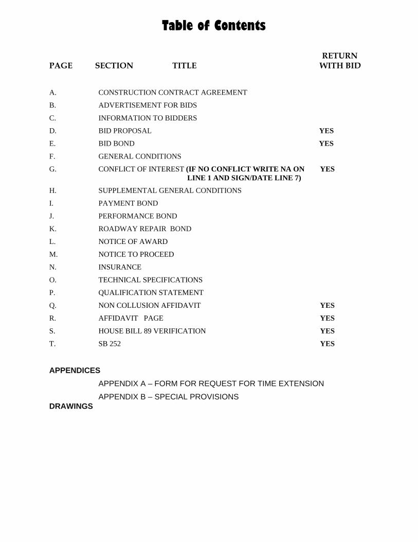
Table of Contents
RETURN PAGE SECTION TITLE WITH BID
A. CONSTRUCTION CONTRACT AGREEMENT
B. ADVERTISEMENT FOR BIDS
C. INFORMATION TO BIDDERS
D. BID PROPOSAL YES
E. BID BOND YES
F. GENERAL CONDITIONS
G. CONFLICT OF INTEREST (IF NO CONFLICT WRITE NA ON YES LINE 1 AND SIGN/DATE LINE 7)
H. SUPPLEMENTAL GENERAL CONDITIONS
I. PAYMENT BOND
J. PERFORMANCE BOND
K. ROADWAY REPAIR BOND
L. NOTICE OF AWARD
M. NOTICE TO PROCEED
N. INSURANCE
O. TECHNICAL SPECIFICATIONS
P. QUALIFICATION STATEMENT
Q. NON COLLUSION AFFIDAVIT YES
R. AFFIDAVIT PAGE YES
S. HOUSE BILL 89 VERIFICATION YES
T. SB 252 YES
APPENDICES APPENDIX A – FORM FOR REQUEST FOR TIME EXTENSION APPENDIX B – SPECIAL PROVISIONS
DRAWINGS
SECTION A
CONSTRUCTION CONTRACT AGREEMENT
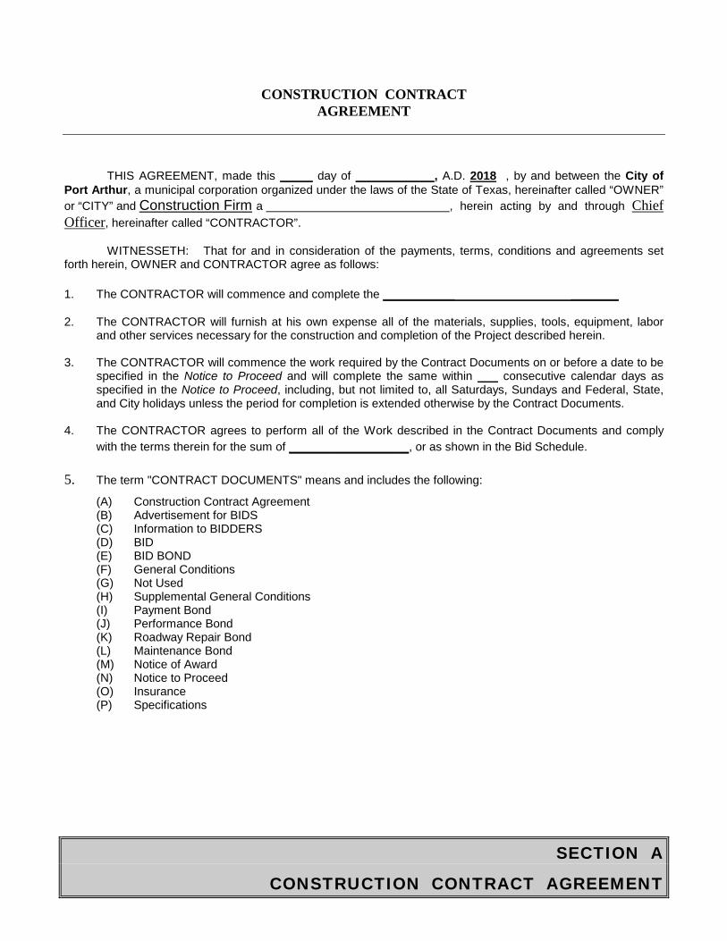
CONSTRUCTION CONTRACT AGREEMENT
THIS AGREEMENT, made this _____ day of ____________, A.D. 2018 , by and between the City of Port Arthur, a municipal corporation organized under the laws of the State of Texas, hereinafter called “OWNER” or “CITY” and Construction Firm a , herein acting by and through Chief Officer, hereinafter called “CONTRACTOR”.
WITNESSETH: That for and in consideration of the payments, terms, conditions and agreements set forth herein, OWNER and CONTRACTOR agree as follows:
1. The CONTRACTOR will commence and complete the _________ ______
2. The CONTRACTOR will furnish at his own expense all of the materials, supplies, tools, equipment, laborand other services necessary for the construction and completion of the Project described herein.
3. The CONTRACTOR will commence the work required by the Contract Documents on or before a date to bespecified in the Notice to Proceed and will complete the same within consecutive calendar days asspecified in the Notice to Proceed, including, but not limited to, all Saturdays, Sundays and Federal, State,and City holidays unless the period for completion is extended otherwise by the Contract Documents.
4. The CONTRACTOR agrees to perform all of the Work described in the Contract Documents and complywith the terms therein for the sum of _______________, or as shown in the Bid Schedule.
5. The term "CONTRACT DOCUMENTS" means and includes the following:
(A) Construction Contract Agreement(B) Advertisement for BIDS(C) Information to BIDDERS(D) BID(E) BID BOND(F) General Conditions(G) Not Used(H) Supplemental General Conditions(I) Payment Bond(J) Performance Bond(K) Roadway Repair Bond(L) Maintenance Bond(M) Notice of Award(N) Notice to Proceed(O) Insurance(P) Specifications
SECTION A
CONSTRUCTION CONTRACT AGREEMENT
Addenda: No. , dated , 20 . No. , dated , 20 . 6. The OWNER will pay to the CONTRACTOR in the manner and at such times as set forth in the General
Conditions such amounts as required by the Contract Documents. 7. This Agreement shall be binding upon all parties hereto and their respective heirs, executors, administrators,
successors and assigns. IN WITNESS WHEREOF, the Parties hereto have executed, or caused to be executed by their duly authorized officials, this Agreement in two (2) copies, each of which shall be deemed an original on the date first above written. OWNER:
City of Port Arthur
BY:
CONTRACTOR: NAME:
TITLE:
Contruction Firm
BY:
NAME:
ADDRESS:
[CORPORATE SEAL] ATTEST:
NAME:
SECTION B
ADVERTISEMENT FOR BIDS
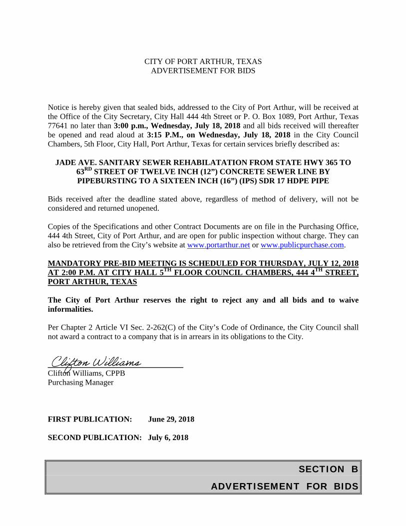
CITY OF PORT ARTHUR, TEXAS
ADVERTISEMENT FOR BIDS
Notice is hereby given that sealed bids, addressed to the City of Port Arthur, will be received at the Office of the City Secretary, City Hall 444 4th Street or P. O. Box 1089, Port Arthur, Texas 77641 no later than 3:00 p.m., Wednesday, July 18, 2018 and all bids received will thereafter be opened and read aloud at 3:15 P.M., on Wednesday, July 18, 2018 in the City Council Chambers, 5th Floor, City Hall, Port Arthur, Texas for certain services briefly described as:
JADE AVE. SANITARY SEWER REHABILATATION FROM STATE HWY 365 TO
63RD STREET OF TWELVE INCH (12”) CONCRETE SEWER LINE BY PIPEBURSTING TO A SIXTEEN INCH (16”) (IPS) SDR 17 HDPE PIPE
Bids received after the deadline stated above, regardless of method of delivery, will not be considered and returned unopened. Copies of the Specifications and other Contract Documents are on file in the Purchasing Office, 444 4th Street, City of Port Arthur, and are open for public inspection without charge. They can also be retrieved from the City’s website at www.portarthur.net or www.publicpurchase.com.
MANDATORY PRE-BID MEETING IS SCHEDULED FOR THURSDAY, JULY 12, 2018 AT 2:00 P.M. AT CITY HALL 5TH FLOOR COUNCIL CHAMBERS, 444 4TH STREET, PORT ARTHUR, TEXAS The City of Port Arthur reserves the right to reject any and all bids and to waive informalities. Per Chapter 2 Article VI Sec. 2-262(C) of the City’s Code of Ordinance, the City Council shall not award a contract to a company that is in arrears in its obligations to the City.
__________________________________ Clifton Williams, CPPB Purchasing Manager
FIRST PUBLICATION: June 29, 2018 SECOND PUBLICATION: July 6, 2018
Clifton Williams
SECTION C
INFORMATION TO BIDDERS
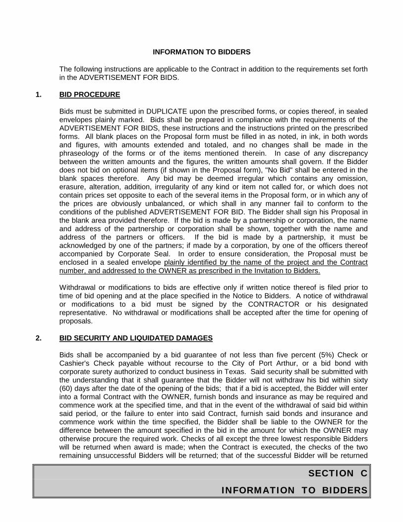
INFORMATION TO BIDDERS
The following instructions are applicable to the Contract in addition to the requirements set forth in the ADVERTISEMENT FOR BIDS.
1. BID PROCEDURE
Bids must be submitted in DUPLICATE upon the prescribed forms, or copies thereof, in sealed envelopes plainly marked. Bids shall be prepared in compliance with the requirements of the ADVERTISEMENT FOR BIDS, these instructions and the instructions printed on the prescribed forms. All blank places on the Proposal form must be filled in as noted, in ink, in both words and figures, with amounts extended and totaled, and no changes shall be made in the phraseology of the forms or of the items mentioned therein. In case of any discrepancy between the written amounts and the figures, the written amounts shall govern. If the Bidder does not bid on optional items (if shown in the Proposal form), "No Bid" shall be entered in the blank spaces therefore. Any bid may be deemed irregular which contains any omission, erasure, alteration, addition, irregularity of any kind or item not called for, or which does not contain prices set opposite to each of the several items in the Proposal form, or in which any of the prices are obviously unbalanced, or which shall in any manner fail to conform to the conditions of the published ADVERTISEMENT FOR BID. The Bidder shall sign his Proposal in the blank area provided therefore. If the bid is made by a partnership or corporation, the name and address of the partnership or corporation shall be shown, together with the name and address of the partners or officers. If the bid is made by a partnership, it must be acknowledged by one of the partners; if made by a corporation, by one of the officers thereof accompanied by Corporate Seal. In order to ensure consideration, the Proposal must be enclosed in a sealed envelope plainly identified by the name of the project and the Contract number, and addressed to the OWNER as prescribed in the Invitation to Bidders.
Withdrawal or modifications to bids are effective only if written notice thereof is filed prior to time of bid opening and at the place specified in the Notice to Bidders. A notice of withdrawal or modifications to a bid must be signed by the CONTRACTOR or his designated representative. No withdrawal or modifications shall be accepted after the time for opening of proposals.
2. BID SECURITY AND LIQUIDATED DAMAGES
Bids shall be accompanied by a bid guarantee of not less than five percent (5%) Check or Cashier's Check payable without recourse to the City of Port Arthur, or a bid bond with corporate surety authorized to conduct business in Texas. Said security shall be submitted with the understanding that it shall guarantee that the Bidder will not withdraw his bid within sixty (60) days after the date of the opening of the bids; that if a bid is accepted, the Bidder will enter into a formal Contract with the OWNER, furnish bonds and insurance as may be required and commence work at the specified time, and that in the event of the withdrawal of said bid within said period, or the failure to enter into said Contract, furnish said bonds and insurance and commence work within the time specified, the Bidder shall be liable to the OWNER for the difference between the amount specified in the bid in the amount for which the OWNER may otherwise procure the required work. Checks of all except the three lowest responsible Bidders will be returned when award is made; when the Contract is executed, the checks of the two remaining unsuccessful Bidders will be returned; that of the successful Bidder will be returned
SECTION C
INFORMATION TO BIDDERS
when formal Contract, bonds and insurance are approved, and work has commenced within the time specified.
The Bidder to whom the award is made shall execute and return the formal Contract with the OWNER and furnish Performance and Payment Bonds and required insurance Documents within ten (14) calendar days after the prescribed forms are presented to him for signature. Said period will be extended only upon written presentation to the OWNER, within said period, of reasons which, in the sole discretion of the OWNER, justify an extension. If said Contract, bonds and insurance Documents are not received by the OWNER within said period or if work has not been commenced within the time specified, the OWNER may proceed to have the work required by the Plans and Specifications performed by any means at its command, and the Bidder shall be liable to the CITY OF PORT ARTHUR for any excess cost to the OWNER over his bid amount. Further, the bid guarantee shall be forfeited to the CITY OF PORT ARTHUR as liquidated damages and Bidder shall be liable to the CITY OF PORT ARTHUR for an additional amount of five percent (5%) of the bid amount as liquidated damages without limitation.
The OWNER, within Fourteen (14) calendar days of receipt of acceptable Performance and Payment Bonds, Insurance Documents and Contract signed by Bidder to whom Contract was awarded, shall sign and return executed duplicate of the Contract to said party. Should OWNER not execute the Contract within such period, the Bidder may, by written Notice to OWNER, withdraw his signed Agreement.
3. BONDS
If the Contract exceeds Fifty Thousand Dollars ($50,000.00), a Payment Bond shall be furnished, and if the contract exceeds One Hundred Thousand Dollars ($100,000) a performance bond also, shall be furnished on prescribed forms in the amount of one hundred percent (100%) corporate surety duly authorized to do business in the State of Texas. Attorneys-in-fact who sign Bonds must file with each Bond a certified and effective date copy of their Power of Attorney.
4. NOTICE TO PROCEED
Notice to Proceed shall be issued within fourteen (14) calendar days of the execution of the Contract by OWNER. Should there by any reasons why Notice to Proceed cannot be issued within such period, the time may be extended by mutual agreement between OWNER and CONTRACTOR. If Notice to Proceed has not been issued within the fourteen (14) calendar day period or a period mutually agreed upon, CONTRACTOR may terminate the Contract without liability on the part of either party.
5. INSURANCE
All insurance must be written by an insurer licensed to conduct business in the State of Texas, unless otherwise permitted by OWNER. The CONTRACTOR shall, at his own expense, purchase, maintain and keep in force insurance that will protect against injury and/or damages which may arise out of or result from operations under this Contract, whether the operations be himself or by any Subcontractor or by anyone directly or indirectly employed by any of them, or by anyone for whose acts any of them may be liable of the following types and limits (No
SECTION C
INFORMATION TO BIDDERS
insurance policy or certificate of insurance required below shall contain any aggregate policy year limit unless a specific dollar amount[or specific formula for determining a specific dollar amount] aggregate policy year limit is expressly provided in the specification below which covers the particular insurance policy or certificate of insurance).
1. Standard Worker’s Compensation Insurance (with waiver of
subrogation in favor of the City of Port Arthur, (City of Port Arthur and Contractor and all persons providing services shall comply with the workers compensation insurance requirements of Section 406.096 of the Texas Labor Code and 28 TAC Section 110.110, a copy of which is attached hereto and is hereby incorporated by reference).
2. Commercial General Liability occurrence type insurance. No. “XCU” RESTRICTIONS SHALL BE APPLICABLE. Products/completed operations coverage must be included, and City of Port.
a. Bodily Injury $500,000 single limit per occurrence or $500,000 each person/$500,000 per occurrence for contracts of $100,000 or less; or, b. Bodily Injury $1,000,000 single limit per
occurrence of $1,000,000 each person/$1,000,000 per occurrence for contracts in excess of $100,000; and, c. Property Damage $100,000 per occurrence regardless of Contract amount; and, d. Minimum aggregate policy year limit of $1,000,000 for contracts of $100,000 or less; or, e. Minimum aggregate policy year limit of $2,000,000 for contracts in excess of $100,000.
3. Comprehensive Automobile Liability (Including owned, non- owned and hired vehicles coverage). a. Minimum combined single limit of $500,000 per occurrence for bodily injury and property damage. b. If individual limits are provided, minimum limits are $300,000 per person, $500,000 per occurrence for bodily injury and $100,000 per occurrence for property damage.
SECTION C
INFORMATION TO BIDDERS
4. Contractual Liability Insurance covering the indemnity provision of this Contract in the same amount and coverage
as provided for Commercial General Liability Policy, specifically referring to this Contract by date, job number and location;
5. All-Risk Builder's Risk of the non-reporting type
(not required for paving projects, water and sewer line projects or projects involving lump sum payments).
CONTRACTOR shall cause CONTRACTOR'S insurance company or insurance agent to fill in all information required(including names of insurance agency, CONTRACTOR and insurance companies, and policy numbers, effective dates and expiration dates) and to date and sign and do all other things necessary to complete and make into a valid certificate of insurance the CERTIFICATE OF INSURANCE form attached to and made a part of the Information To Bidders, and pertaining to the above listed Items 1, 2, 3 and 4; and before commencing any of the work and within the time otherwise specified. CONTRACTOR shall file said completed form with the OWNER. None of the provisions in said Form shall be altered or modified in any respect except as herein expressly authorized. Said CERTIFICATE OF INSURANCE Form contains a provision that coverages afforded under the policies will not be altered, modified or cancelled unless at least fifteen (15) days prior written notice has been given to the OWNER. CONTRACTOR shall also file with the OWNER valid CERTIFICATE(s) OF INSURANCE on like form from or for all Subcontractors and showing the Subcontractor(s) as the Insured. Said completed CERTIFICATE OF INSURANCE Form(s) shall in any event be filed with OWNER not more than ten (10) days after execution of this Contract.
The original Builder's Risk policy (if required) shall provide for fifteen (15) days written notice of alteration, modification or cancellation and shall be furnished to OWNER. Provided, however, until the Original Policy is issued and furnished to the OWNER a Certified Insurance Binder with the identical notice will be acceptable in place of the original policy, which original policy must be received by the OWNER not later than thirty (30) days after issuance of the Notice to Proceed for the project. Notwithstanding any other provision in the Contract Documents, it is further mutually understood and agreed that no payment will be due and owing or made to the CONTRACTOR for any work performed under the Contract until all of the required insurance documentation, including the original policy specified above, are received by the OWNER.
6. JOB EXAMINATION
Bidder should carefully examine and be familiar with the Plans, Specifications and other Documents and other conditions and matters which can in any way affect the work or the cost thereof. By submitting a bid, the CONTRACTOR acknowledges that he or his qualified representative has visited the job site and investigated and satisfied himself as to (a) the conditions affecting the work including but not limited of the physical conditions of the site which may bear upon site access, handling and storage of tools and materials, access to water, electric or other utilities or otherwise affect performance of required activities; (b) the character and quantity of all surface and subsurface materials or obstacles to be encountered in so far as this information is reasonably ascertainable from inspection of the site, including exploratory work done by the OWNER or a designated consultant. Failure to do all of he above will not relieve a successful Bidder of the obligation to furnish all material and labor necessary to carry
SECTION C
INFORMATION TO BIDDERS
out the provisions of the Contract Documents and to complete the contemplated work for the considerations set forth in the bid. Any information shown in the specifications or on the Plans in regard to subsurface data, test borings and similar conditions is to be considered approximate and does not relive the Bidder of the responsibility for its verification. OWNER is not responsible for any failure by the CONTRACTOR to acquaint himself with available information for estimating properly the difficulty or cost of successfully performing the work. The OWNER is not responsible for any conclusions or interpretations made by the CONTRACTOR on the basis of the information made available by the OWNER. In conformity with applicable statutes, the OWNER has adopted a labor classification and a minimum wage scale, which is included preceding the Specifications.
7. SALES TAX
This Contract is issued by an organization which qualifies for exemption pursuant to the provisions of Section 151.209 of the Texas Limited Sales, Excise and Use Tax Act as codified in Chapter 151 of the Texas Tax Code.
The CONTRACTOR'S attention is directed to the State of Texas Comptroller of Public Accounts Limited Sales, Excise and Use Tax rules and regulations Rulings regarding Repairmen and Contractors - Reference: Section 151.056 Texas Tax Code which, upon compliance with certain conditions, provides for exemption from this tax of non-consumable materials and equipment permanently incorporated into work done for an exempt organization, and to House Bill 11 amendments to Section 151.311 of the Tax Code(Vernon Supp. 1992) as they relate to separated contracts/bids in order for non-consumable materials and equipment to qualify for resale to the Pleasure Island Commission and be exempt from sales tax.
Any Bidder may elect to exclude this sales tax from his bid. The bid and contract, however, must separately identify the charges for (1) non-consumable materials and equipment that are permanently incorporated into the project and (2) charges for skill, labor and consumable materials, tools and equipment which are not permanently incorporated into the project. This statement shall be included in and made part of the Contract. CONTRACTORS are required to have a sales tax permit issued by the Comptroller of the State of Texas in order to qualify under the exemption provisions and the separated Contract procedure.
The City of Port Arthur will issue a specific exemption certificate for a separated Contract to the CONTRACTOR in order that he does not have to pay taxes on qualifying materials and equipment purchased for and permanently incorporated into the City of Port Arthur project. The CONTRACTOR performing this Contract must issue to his suppliers an exemption certificate in lieu of the tax, said exemption certificate complying with all applicable State Comptroller's rulings, along with a copy of the certificate issued to him by the City of Port Arthur.
The OWNER will make no further allowance for and will make no price adjustment above or below the originally bid unit prices on account of this tax. It shall be the CONTRACTOR'S sole responsibility, if CONTRACTOR has elected to exclude the sales tax from the bid, to comply with the aforementioned Rulings and with any other applicable rules, regulations or laws pertaining to the Texas Limited Sales, Excise and Use Tax which may now or at any time during the performance of this Contract be in effect, and the OWNER shall have no responsibility for any sales or use tax which the CONTRACTOR may be required to pay as a result of CONTRACTOR'S failure or the OWNER'S failure to comply with said rules, regulations or laws,
SECTION C
INFORMATION TO BIDDERS
or as the result of the performance of the Contract or any part hereof by the CONTRACTOR.
Bidders are cautioned that materials which are not permanently incorporated into the work (Example: Fuel, lubricants, tools, forming materials, etc.) are not eligible for exemption and are not to be included in the statement as "Non-Consumable Materials and Equipment".
8. FINANCIAL STATEMENT AND EXPERIENCE RECORD
The Bidder will, upon request by the OWNER, furnish such information and data as OWNER may request to determine ability of the Bidder to perform the work, including, without limitation, a list of all jobs completed in the last 24 months giving name of OWNER, amount of Contract, description of the job, and name of OWNER'S representative who is familiar with the work performed by the CONTRACTOR.
9. INTERPRETATION OF PLANS AND SPECIFICATIONS
Bidders desiring further information, or further interpretation of the Plans and Specifications must make request for such information in writing to the Architect/Engineer, not later than 96 hours before the bid opening. Answers to all such requests will be given in writing to all qualified Bidders, in Addendum form, and all addenda will be bound and made a part of the Contract Documents. No other explanation or interpretation will be considered official or binding. Should a Bidder find discrepancies in, or omissions from, the Plans, Specifications or other Contract Documents, or should a Bidder be in doubt as to their meaning, the Bidder should, no later than 96 hours prior to the bid opening, notify the Architect/Engineer in order that a written Addendum if necessary, may be sent to all Bidders prior to submission of the bids. Failure to request such clarification is a waiver to any claim by the Bidder for expense made necessary by reason of later interpretation of the Contract Documents by the OWNER.
10. AWARD OF CONTRACT
Unless it elects to reject all bids, the OWNER will award the Contract as promptly as possible consistent with the time required for a thorough analysis of bids submitted. Award will be made on the basis of the greatest advantage to the OWNER, considering all elements of the bid. The right is reserved to reject any or all Proposals and to waive technical defects, as the interest of the OWNER may require.
A Bidder may withdraw his Proposal before the expiration of the time during which a Proposal may be submitted, without prejudice to himself, by submitting a written request for its withdrawal to the officer who holds it.
11. TIME OF COMPLETION
Attention is directed to the requirement that each Bidder specify in his Proposal the time in which he will agree to complete the work. The time required for completion of the work will be a consideration in the determination of the successful Bidder. Unless otherwise specified, Bidder must state time in consecutive calendar days, including, but not limited to, all Saturdays, Sundays, and Federal, State and Pleasure Island Commission holidays.

SECTION C
INFORMATION TO BIDDERS
12. SUBSTITUTIONS
Where materials or equipment are specified by a trade or brand name, it is not the intention of the OWNER to discriminate against an equal product of another manufacturer, but rather to set a definite standard of quality or performance, and to establish an equal basis for the evaluation of bids.
13. LAWS
All applicable laws, ordinances and the rules and regulations of all authorities having jurisdiction over construction of the project shall apply to the Contract throughout.
14. EQUAL OPPORTUNITY
Bidder agrees to abide by the requirement under Executive Order No. 11246, as amended, including specifically the provisions of the equal opportunity clause set forth in the General Conditions.
15. MATERIAL SUPPLIERS AND SUBCONTRACTORS
Low bidder shall supply the names and addresses of major material suppliers and Subcontractors when requested to do so by OWNER.
16. RETAINAGE
Five percent (5%) of the amount of each periodic progress payment shall be retained, by OWNER, until final completion and acceptance of all work under the CONTRACT.
17. UNIT PRICES
If the Contract may be let on a unit price basis, the Specifications furnished to bidders shall contain approximate quantities estimated upon the best available information, but the compensation to be paid to the CONTRACTOR shall be based upon the actual quantities constructed or supplied.
18. PRE-BID CONFERENCE
Prospective bidders shall be required to attend the Pre-Bid Conference. Bids received from firms or individuals not listed on the roll of attendees of the Pre-Bid Conference will be rejected and returned unopened to the bidder.
19. SCOPE OF WORK
GENERAL CONSIDERATIONS
The Contractor will perform the following Jade Ave. Sanatiry Sewer Rehibilation FROM State HWY 365 to 63rd Street of Twelve Inch (12”) Concrete Sewer Line by Pipebusting to a Sixteen Inch (16”) (IPS) SDR 17 HDPE Pipe.
SECTION C
INFORMATION TO BIDDERS
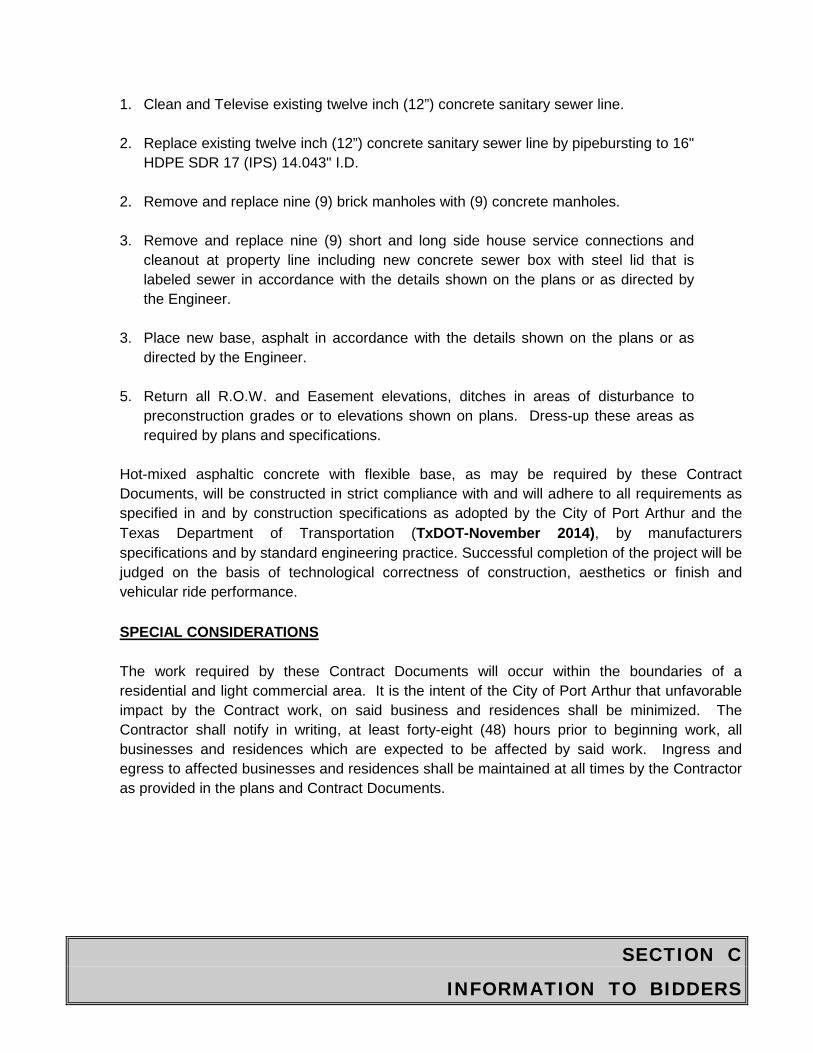
1. Clean and Televise existing twelve inch (12”) concrete sanitary sewer line.
2. Replace existing twelve inch (12”) concrete sanitary sewer line by pipebursting to 16" HDPE SDR 17 (IPS) 14.043" I.D.
2. Remove and replace nine (9) brick manholes with (9) concrete manholes.
3. Remove and replace nine (9) short and long side house service connections and
cleanout at property line including new concrete sewer box with steel lid that is labeled sewer in accordance with the details shown on the plans or as directed by the Engineer.
3. Place new base, asphalt in accordance with the details shown on the plans or as
directed by the Engineer. 5. Return all R.O.W. and Easement elevations, ditches in areas of disturbance to
preconstruction grades or to elevations shown on plans. Dress-up these areas as required by plans and specifications.
Hot-mixed asphaltic concrete with flexible base, as may be required by these Contract Documents, will be constructed in strict compliance with and will adhere to all requirements as specified in and by construction specifications as adopted by the City of Port Arthur and the Texas Department of Transportation (TxDOT-November 2014), by manufacturers specifications and by standard engineering practice. Successful completion of the project will be judged on the basis of technological correctness of construction, aesthetics or finish and vehicular ride performance.
SPECIAL CONSIDERATIONS
The work required by these Contract Documents will occur within the boundaries of a residential and light commercial area. It is the intent of the City of Port Arthur that unfavorable impact by the Contract work, on said business and residences shall be minimized. The Contractor shall notify in writing, at least forty-eight (48) hours prior to beginning work, all businesses and residences which are expected to be affected by said work. Ingress and egress to affected businesses and residences shall be maintained at all times by the Contractor as provided in the plans and Contract Documents.
SECTION C
INFORMATION TO BIDDERS
The Contractor shall work closely with the various utility owners and assure prompt access to their equipment for service or adjustment. The Contractor shall be e solely responsible for coordination the work with any utility owner which may be affected by the work. Additionally, forces of the City of Port Arthur, in order to secure the safety, welfare and convenience of the citizens of Port Arthur, must provide services on both emergency and normal, continuing basis. Provisions of these services may require City forces to work within or around the construction area prescribed by this project. While it is anticipated that the construction schedule impact induced by the work of City and utility crews will be minimal, the Contractor, by affixing proper signature to these Contract Documents, agrees to indemnify and hold harmless the City of Port Arthur from any and all claims of damage or delay, incurred or alleged to have incurred, in connection with the work of said crews.

SECTION D
BID

DOLLARS CENTS DOLLARS CENTS DOLLARS
1 MOBILIZATION AND DEMOBILIZATION L.S. 1
2CLEAN & TELEVISE 12" GRAVITY SANITARY SEWER FOR PIPE BURSTING & SERVICE LOCATION, COMPLETE IN PLACE
L.F. 3,600
3
12" SEWER RECONSTRUCTION BY PIPEBURSTING EXISTING 12" SEWER, INSTALL(16”) (IPS) SDR 17 HDPE PIPE,ALL DEPTHS, COMPLETE IN PLACE
L.F. 3,600
4 EXTRA DEPTH ON CONCRETE SANITARY SEWER MANHOLE
V.F. 25
5 REMOVE AND DISPOSE OF EXISTINGMANHOLE, COMPLETE IN PLACE
EA. 9
6
STANDARD 4' DIA. CONCRETE MANHOLES, WITH WATER TIGHT RING AND COVER, BUILT ABOUT NEW LINE OR ON EXISTING LINES INCLUDING EXCAVATION, DEWATERING, TRENCH SAFETY SYSTEM, CEMENT STABILIZED SAND BACKFILL, COMPLETE IN PLACE
EA. 9
TOTAL PRICE BID WRITTEN IN FIGURESNO. ITEM UNIT
Bid Proposal
QUANTITYUNIT PRICE BID WRITTEN IN WORDS
UNIT PRICE WRITTEN IN FIGURES
JADE AVE. SANATIRY SEWER REHABILITATION PROJECTSTATE HWY 365 TO 63RD STREET OF TWELVE INCH (12”)
CONCRETE SEWER LINE BY PIPEBURSTING TO A SIXTEEN INCH (16”) (IPS) SDR 17 HDPE PIPEACE Job No. 117-26
Bid Proposal
DOLLARS CENTS DOLLARS CENTS DOLLARS
TOTAL PRICE BID WRITTEN IN FIGURESNO. ITEM UNIT
Bid Proposal
QUANTITYUNIT PRICE BID WRITTEN IN WORDS
UNIT PRICE WRITTEN IN FIGURES
JADE AVE. SANATIRY SEWER REHABILITATION PROJECTSTATE HWY 365 TO 63RD STREET OF TWELVE INCH (12”)
CONCRETE SEWER LINE BY PIPEBURSTING TO A SIXTEEN INCH (16”) (IPS) SDR 17 HDPE PIPEACE Job No. 117-26
7 4" PVC SERVICE LINE COMPLETE IN PLACE, INCLUDING BORE/PIPE BURST AS NEEDED
L.F. 500
8CLEANOUT LOCATED AT PROPERTY LINEINCLUDING ALL FITTINGS & CLEAN OUT BOX, COMPLETE IN PLACE
EA. 9
9CONNECT NEW 4" SERVICE LINE TO EXISTING 4" SERVICE LINE AT PROPERTY LINE INCLUDING ALL FITTINGS COMPLETE IN PLACE
EA. 9
10CONNECT NEW 4" SERVICE LINE TO NEW SEWER MAIN INCLUDING SAW-CUT AS REQUIRED, ALL FITTINGS COMPLETE IN PLACE
EA. 9
11"610" LIMESTONE ROCK FOR DRIVEWAY MAINTENANCE (LOOSE DUMP AND SPREAD)
TON 100
Bid Proposal
DOLLARS CENTS DOLLARS CENTS DOLLARS
TOTAL PRICE BID WRITTEN IN FIGURESNO. ITEM UNIT
Bid Proposal
QUANTITYUNIT PRICE BID WRITTEN IN WORDS
UNIT PRICE WRITTEN IN FIGURES
JADE AVE. SANATIRY SEWER REHABILITATION PROJECTSTATE HWY 365 TO 63RD STREET OF TWELVE INCH (12”)
CONCRETE SEWER LINE BY PIPEBURSTING TO A SIXTEEN INCH (16”) (IPS) SDR 17 HDPE PIPEACE Job No. 117-26
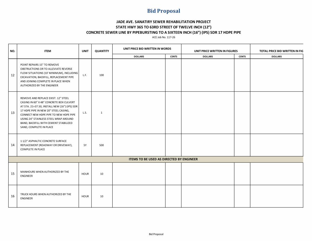
12
POINT REPAIRS 15" TO REMOVE OBSTRUCTIONS OR TO ALLEVIATE REVERSE FLOW SITUATIONS (10' MINIMUM), INCLUDING EXCAVATION, BACKFILL, REPLACEMENT PIPE AND JOINING COMPLETE IN PLACE WHEN AUTHORIZED BY THE ENGINEER
L.F. 100
13
REMOVE AND REPLACE EXIST. 12" STEEL CASING IN 60" X 48" CONCRETE BOX CULVERT AT STA. 21+37.50, INSTALL NEW (16”) (IPS) SDR 17 HDPE PIPE IN NEW 20" STEEL CASING, CONNECT NEW HDPE PIPE TO NEW HDPE PIPE USING 24" STAINLESS STEEL WRAP AROUND BAND, BACKFILL WITH CEMENT STABILIZED SAND, COMPLETE IN PLACE
L.S. 1
141 1/2" ASPHALTIC CONCRETE SURFACEREPLACEMENT (ROADWAY OR DRIVEWAY), COMPLETE IN PLACE
SY 500
15 MANHOURS WHEN AUTHORIZED BY THE ENGINEER
HOUR 10
16 TRUCK HOURS WHEN AUTHORIZED BY THE ENGINEER
HOUR 10
ITEMS TO BE USED AS DIRECTED BY ENGINEER
Bid Proposal
DOLLARS CENTS DOLLARS CENTS DOLLARS
TOTAL PRICE BID WRITTEN IN FIGURESNO. ITEM UNIT
Bid Proposal
QUANTITYUNIT PRICE BID WRITTEN IN WORDS
UNIT PRICE WRITTEN IN FIGURES
JADE AVE. SANATIRY SEWER REHABILITATION PROJECTSTATE HWY 365 TO 63RD STREET OF TWELVE INCH (12”)
CONCRETE SEWER LINE BY PIPEBURSTING TO A SIXTEEN INCH (16”) (IPS) SDR 17 HDPE PIPEACE Job No. 117-26
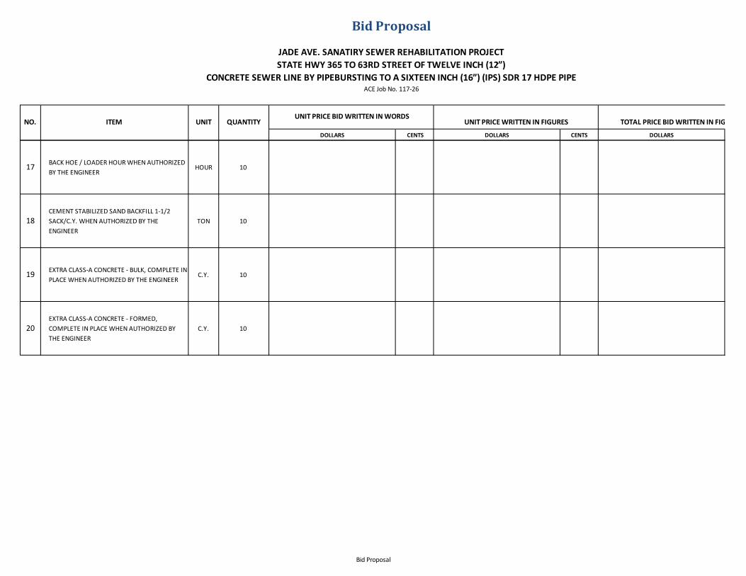
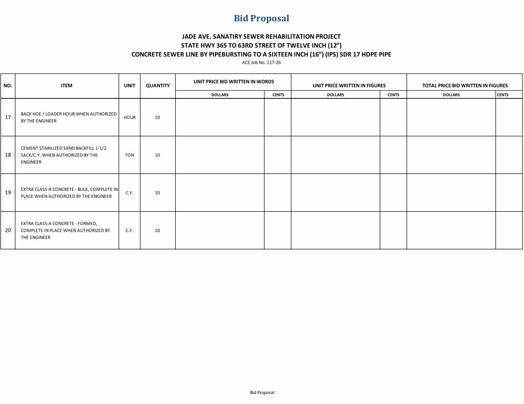
17 BACK HOE / LOADER HOUR WHEN AUTHORIZED BY THE ENGINEER
HOUR 10
18CEMENT STABILIZED SAND BACKFILL 1-1/2 SACK/C.Y. WHEN AUTHORIZED BY THE ENGINEER
TON 10
19 EXTRA CLASS-A CONCRETE - BULK, COMPLETE IN PLACE WHEN AUTHORIZED BY THE ENGINEER
C.Y. 10
20EXTRA CLASS-A CONCRETE - FORMED, COMPLETE IN PLACE WHEN AUTHORIZED BY THE ENGINEER
C.Y. 10
Bid Proposal
DOLLARS CENTS DOLLARS CENTS DOLLARS
TOTAL PRICE BID WRITTEN IN FIGURESNO. ITEM UNIT
Bid Proposal
QUANTITYUNIT PRICE BID WRITTEN IN WORDS
UNIT PRICE WRITTEN IN FIGURES
JADE AVE. SANATIRY SEWER REHABILITATION PROJECTSTATE HWY 365 TO 63RD STREET OF TWELVE INCH (12”)
CONCRETE SEWER LINE BY PIPEBURSTING TO A SIXTEEN INCH (16”) (IPS) SDR 17 HDPE PIPEACE Job No. 117-26
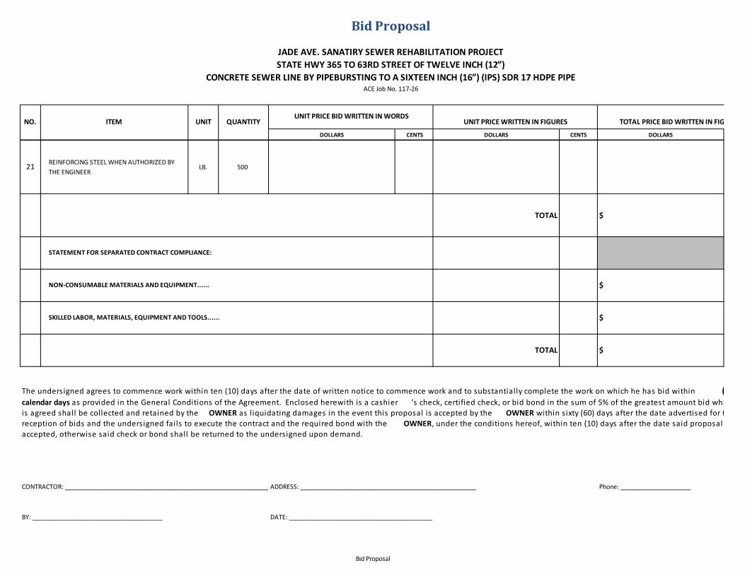
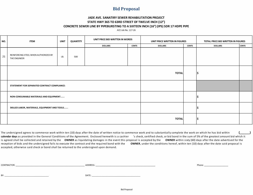
21 REINFORCING STEEL WHEN AUTHORIZED BY THE ENGINEER
LB. 500
TOTAL $
$
$
TOTAL $
DATE: __________________________________________________BY: _____________________________________
STATEMENT FOR SEPARATED CONTRACT COMPLIANCE:
NON-CONSUMABLE MATERIALS AND EQUIPMENT......
SKILLED LABOR, MATERIALS, EQUIPMENT AND TOOLS......
The undersigned agrees to commence work within ten (10) days after the date of written notice to commence work and to substantially complete the work on which he has bid within (______) calendar days as provided in the General Conditions of the Agreement. Enclosed herewith is a cashier ’s check, certified check, or bid bond in the sum of 5% of the greatest amount bid which it is agreed shall be collected and retained by the OWNER as liquidating damages in the event this proposal is accepted by the OWNER within sixty (60) days after the date advertised for the reception of bids and the undersigned fails to execute the contract and the required bond with the OWNER, under the conditions hereof, within ten (10) days after the date said proposal is accepted, otherwise said check or bond shall be returned to the undersigned upon demand.
CONTRACTOR: _______________________________________________________________ADDRESS: __________________________________________________ Phone: ____________________
Bid Proposal

DOLLARS CENTS DOLLARS CENTS DOLLARS CENTS
1 MOBILIZATION AND DEMOBILIZATION L.S. 1
2CLEAN & TELEVISE 12" GRAVITY SANITARY SEWER FOR PIPE BURSTING & SERVICE LOCATION, COMPLETE IN PLACE
L.F. 3,600
3
12" SEWER RECONSTRUCTION BY PIPEBURSTING EXISTING 12" SEWER, INSTALL(16”) (IPS) SDR 17 HDPE PIPE,ALL DEPTHS, COMPLETE IN PLACE
L.F. 3,600
4 EXTRA DEPTH ON CONCRETE SANITARY SEWER MANHOLE
V.F. 25
5 REMOVE AND DISPOSE OF EXISTINGMANHOLE, COMPLETE IN PLACE
EA. 9
6
STANDARD 4' DIA. CONCRETE MANHOLES, WITH WATER TIGHT RING AND COVER, BUILT ABOUT NEW LINE OR ON EXISTING LINES INCLUDING EXCAVATION, DEWATERING, TRENCH SAFETY SYSTEM, CEMENT STABILIZED SAND BACKFILL, COMPLETE IN PLACE
EA. 9
TOTAL PRICE BID WRITTEN IN FIGURESNO. ITEM UNIT
Bid Proposal
QUANTITYUNIT PRICE BID WRITTEN IN WORDS
UNIT PRICE WRITTEN IN FIGURES
JADE AVE. SANATIRY SEWER REHABILITATION PROJECTSTATE HWY 365 TO 63RD STREET OF TWELVE INCH (12”)
CONCRETE SEWER LINE BY PIPEBURSTING TO A SIXTEEN INCH (16”) (IPS) SDR 17 HDPE PIPEACE Job No. 117-26
Bid Proposal

DOLLARS CENTS DOLLARS CENTS DOLLARS CENTS
TOTAL PRICE BID WRITTEN IN FIGURESNO. ITEM UNIT
Bid Proposal
QUANTITYUNIT PRICE BID WRITTEN IN WORDS
UNIT PRICE WRITTEN IN FIGURES
JADE AVE. SANATIRY SEWER REHABILITATION PROJECTSTATE HWY 365 TO 63RD STREET OF TWELVE INCH (12”)
CONCRETE SEWER LINE BY PIPEBURSTING TO A SIXTEEN INCH (16”) (IPS) SDR 17 HDPE PIPEACE Job No. 117-26
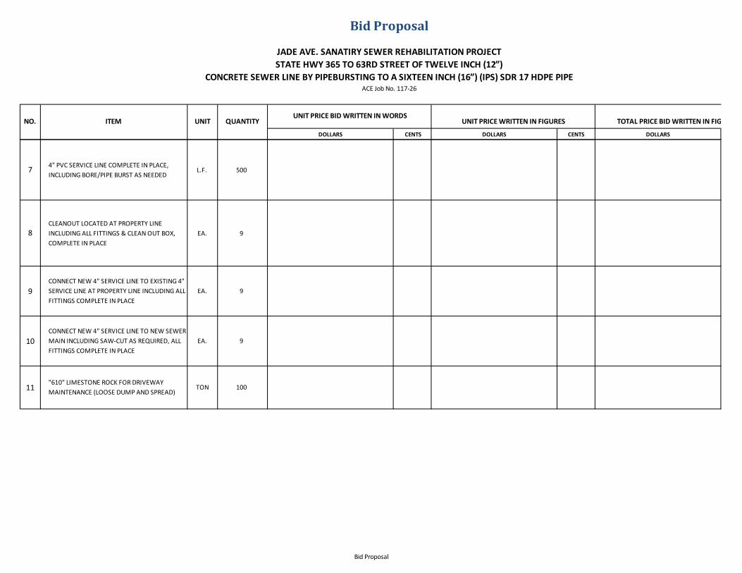
7 4" PVC SERVICE LINE COMPLETE IN PLACE, INCLUDING BORE/PIPE BURST AS NEEDED
L.F. 500
8CLEANOUT LOCATED AT PROPERTY LINEINCLUDING ALL FITTINGS & CLEAN OUT BOX, COMPLETE IN PLACE
EA. 9
9CONNECT NEW 4" SERVICE LINE TO EXISTING 4" SERVICE LINE AT PROPERTY LINE INCLUDING ALL FITTINGS COMPLETE IN PLACE
EA. 9
10CONNECT NEW 4" SERVICE LINE TO NEW SEWER MAIN INCLUDING SAW-CUT AS REQUIRED, ALL FITTINGS COMPLETE IN PLACE
EA. 9
11"610" LIMESTONE ROCK FOR DRIVEWAY MAINTENANCE (LOOSE DUMP AND SPREAD)
TON 100
Bid Proposal
DOLLARS CENTS DOLLARS CENTS DOLLARS CENTS
TOTAL PRICE BID WRITTEN IN FIGURESNO. ITEM UNIT
Bid Proposal
QUANTITYUNIT PRICE BID WRITTEN IN WORDS
UNIT PRICE WRITTEN IN FIGURES
JADE AVE. SANATIRY SEWER REHABILITATION PROJECTSTATE HWY 365 TO 63RD STREET OF TWELVE INCH (12”)
CONCRETE SEWER LINE BY PIPEBURSTING TO A SIXTEEN INCH (16”) (IPS) SDR 17 HDPE PIPEACE Job No. 117-26
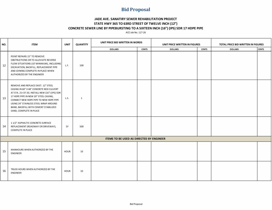
12
POINT REPAIRS 15" TO REMOVE OBSTRUCTIONS OR TO ALLEVIATE REVERSE FLOW SITUATIONS (10' MINIMUM), INCLUDING EXCAVATION, BACKFILL, REPLACEMENT PIPE AND JOINING COMPLETE IN PLACE WHEN AUTHORIZED BY THE ENGINEER
L.F. 100
13
REMOVE AND REPLACE EXIST. 12" STEEL CASING IN 60" X 48" CONCRETE BOX CULVERT AT STA. 21+37.50, INSTALL NEW (16”) (IPS) SDR 17 HDPE PIPE IN NEW 20" STEEL CASING, CONNECT NEW HDPE PIPE TO NEW HDPE PIPE USING 24" STAINLESS STEEL WRAP AROUND BAND, BACKFILL WITH CEMENT STABILIZED SAND, COMPLETE IN PLACE
L.S. 1
141 1/2" ASPHALTIC CONCRETE SURFACEREPLACEMENT (ROADWAY OR DRIVEWAY), COMPLETE IN PLACE
SY 500
15 MANHOURS WHEN AUTHORIZED BY THE ENGINEER
HOUR 10
16 TRUCK HOURS WHEN AUTHORIZED BY THE ENGINEER
HOUR 10
ITEMS TO BE USED AS DIRECTED BY ENGINEER
Bid Proposal
DOLLARS CENTS DOLLARS CENTS DOLLARS CENTS
TOTAL PRICE BID WRITTEN IN FIGURESNO. ITEM UNIT
Bid Proposal
QUANTITYUNIT PRICE BID WRITTEN IN WORDS
UNIT PRICE WRITTEN IN FIGURES
JADE AVE. SANATIRY SEWER REHABILITATION PROJECTSTATE HWY 365 TO 63RD STREET OF TWELVE INCH (12”)
CONCRETE SEWER LINE BY PIPEBURSTING TO A SIXTEEN INCH (16”) (IPS) SDR 17 HDPE PIPEACE Job No. 117-26
17 BACK HOE / LOADER HOUR WHEN AUTHORIZED BY THE ENGINEER
HOUR 10
18CEMENT STABILIZED SAND BACKFILL 1-1/2 SACK/C.Y. WHEN AUTHORIZED BY THE ENGINEER
TON 10
19 EXTRA CLASS-A CONCRETE - BULK, COMPLETE IN PLACE WHEN AUTHORIZED BY THE ENGINEER
C.Y. 10
20EXTRA CLASS-A CONCRETE - FORMED, COMPLETE IN PLACE WHEN AUTHORIZED BY THE ENGINEER
C.Y. 10
Bid Proposal
DOLLARS CENTS DOLLARS CENTS DOLLARS CENTS
TOTAL PRICE BID WRITTEN IN FIGURESNO. ITEM UNIT
Bid Proposal
QUANTITYUNIT PRICE BID WRITTEN IN WORDS
UNIT PRICE WRITTEN IN FIGURES
JADE AVE. SANATIRY SEWER REHABILITATION PROJECTSTATE HWY 365 TO 63RD STREET OF TWELVE INCH (12”)
CONCRETE SEWER LINE BY PIPEBURSTING TO A SIXTEEN INCH (16”) (IPS) SDR 17 HDPE PIPEACE Job No. 117-26
21 REINFORCING STEEL WHEN AUTHORIZED BY THE ENGINEER
LB. 500
TOTAL $
$
$
TOTAL $
DATE: __________________________________________________BY: _____________________________________
STATEMENT FOR SEPARATED CONTRACT COMPLIANCE:
NON-CONSUMABLE MATERIALS AND EQUIPMENT......
SKILLED LABOR, MATERIALS, EQUIPMENT AND TOOLS......
The undersigned agrees to commence work within ten (10) days after the date of written notice to commence work and to substantially complete the work on which he has bid within (______) calendar days as provided in the General Conditions of the Agreement. Enclosed herewith is a cashier ’s check, certified check, or bid bond in the sum of 5% of the greatest amount bid which it is agreed shall be collected and retained by the OWNER as liquidating damages in the event this proposal is accepted by the OWNER within sixty (60) days after the date advertised for the reception of bids and the undersigned fails to execute the contract and the required bond with the OWNER, under the conditions hereof, within ten (10) days after the date said proposal is accepted, otherwise said check or bond shall be returned to the undersigned upon demand.
CONTRACTOR: _______________________________________________________________ADDRESS: __________________________________________________ Phone: ____________________
Bid Proposal
SECTION E
BID BOND
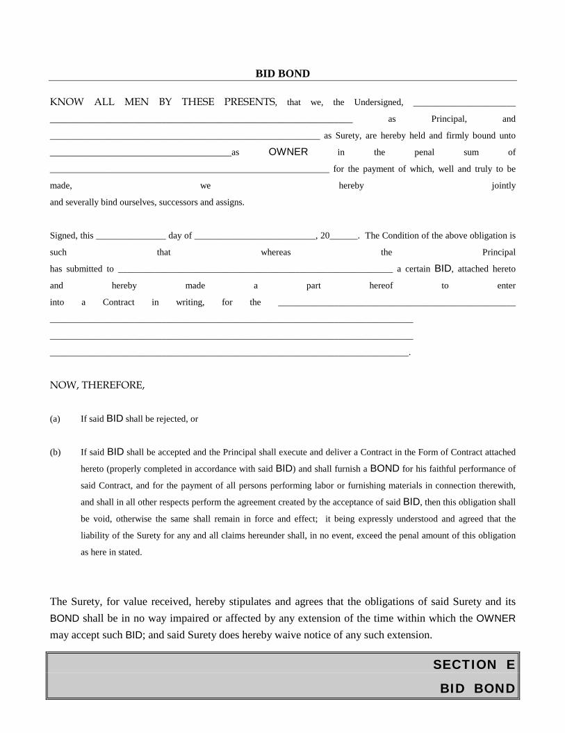
BID BOND
KNOW ALL MEN BY THESE PRESENTS, that we, the Undersigned, ______________________
_________________________________________________________________ as Principal, and
__________________________________________________________ as Surety, are hereby held and firmly bound unto
_______________________________________as OWNER in the penal sum of
____________________________________________________________ for the payment of which, well and truly to be
made, we hereby jointly
and severally bind ourselves, successors and assigns.
Signed, this _______________ day of __________________________, 20______. The Condition of the above obligation is
such that whereas the Principal
has submitted to ___________________________________________________________ a certain BID, attached hereto
and hereby made a part hereof to enter
into a Contract in writing, for the ___________________________________________________
______________________________________________________________________________
______________________________________________________________________________
_____________________________________________________________________________.
NOW, THEREFORE, (a) If said BID shall be rejected, or
(b) If said BID shall be accepted and the Principal shall execute and deliver a Contract in the Form of Contract attached
hereto (properly completed in accordance with said BID) and shall furnish a BOND for his faithful performance of
said Contract, and for the payment of all persons performing labor or furnishing materials in connection therewith,
and shall in all other respects perform the agreement created by the acceptance of said BID, then this obligation shall
be void, otherwise the same shall remain in force and effect; it being expressly understood and agreed that the
liability of the Surety for any and all claims hereunder shall, in no event, exceed the penal amount of this obligation
as here in stated.
The Surety, for value received, hereby stipulates and agrees that the obligations of said Surety and its BOND shall be in no way impaired or affected by any extension of the time within which the OWNER may accept such BID; and said Surety does hereby waive notice of any such extension.
SECTION E
BID BOND
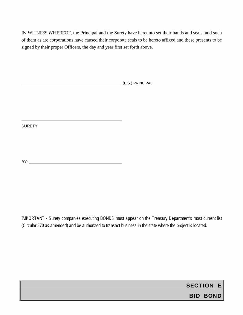
IN WITNESS WHEREOF, the Principal and the Surety have hereunto set their hands and seals, and such of them as are corporations have caused their corporate seals to be hereto affixed and these presents to be signed by their proper Officers, the day and year first set forth above.
(L.S.) PRINCIPAL
SURETY
BY:
IMPORTANT - Surety companies executing BONDS must appear on the Treasury Department's most current list (Circular 570 as amended) and be authorized to transact business in the state where the project is located.
SECTION F
GENERAL CONDITIONS
NUMERICAL INDEX TO
GENERAL CONDITIONS
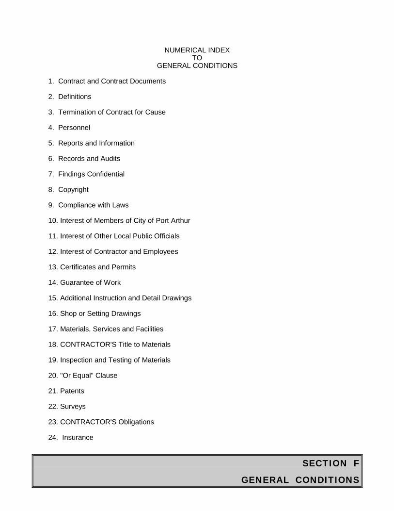
1. Contract and Contract Documents 2. Definitions 3. Termination of Contract for Cause 4. Personnel 5. Reports and Information 6. Records and Audits 7. Findings Confidential 8. Copyright 9. Compliance with Laws 10. Interest of Members of City of Port Arthur 11. Interest of Other Local Public Officials 12. Interest of Contractor and Employees 13. Certificates and Permits 14. Guarantee of Work 15. Additional Instruction and Detail Drawings 16. Shop or Setting Drawings 17. Materials, Services and Facilities 18. CONTRACTOR'S Title to Materials 19. Inspection and Testing of Materials 20. "Or Equal" Clause 21. Patents 22. Surveys 23. CONTRACTOR'S Obligations 24. Insurance
SECTION F
GENERAL CONDITIONS
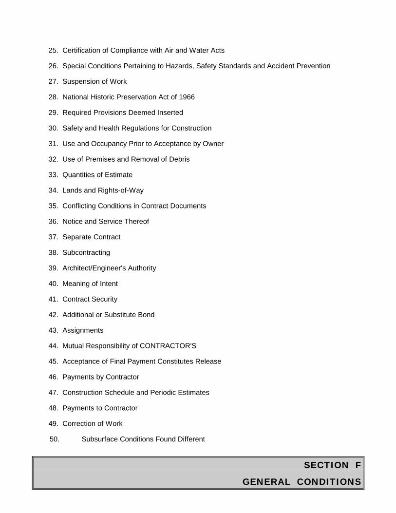
25. Certification of Compliance with Air and Water Acts 26. Special Conditions Pertaining to Hazards, Safety Standards and Accident Prevention 27. Suspension of Work 28. National Historic Preservation Act of 1966 29. Required Provisions Deemed Inserted 30. Safety and Health Regulations for Construction 31. Use and Occupancy Prior to Acceptance by Owner 32. Use of Premises and Removal of Debris 33. Quantities of Estimate 34. Lands and Rights-of-Way 35. Conflicting Conditions in Contract Documents 36. Notice and Service Thereof 37. Separate Contract 38. Subcontracting 39. Architect/Engineer's Authority 40. Meaning of Intent 41. Contract Security 42. Additional or Substitute Bond 43. Assignments 44. Mutual Responsibility of CONTRACTOR'S 45. Acceptance of Final Payment Constitutes Release 46. Payments by Contractor 47. Construction Schedule and Periodic Estimates 48. Payments to Contractor 49. Correction of Work 50. Subsurface Conditions Found Different
SECTION F
GENERAL CONDITIONS
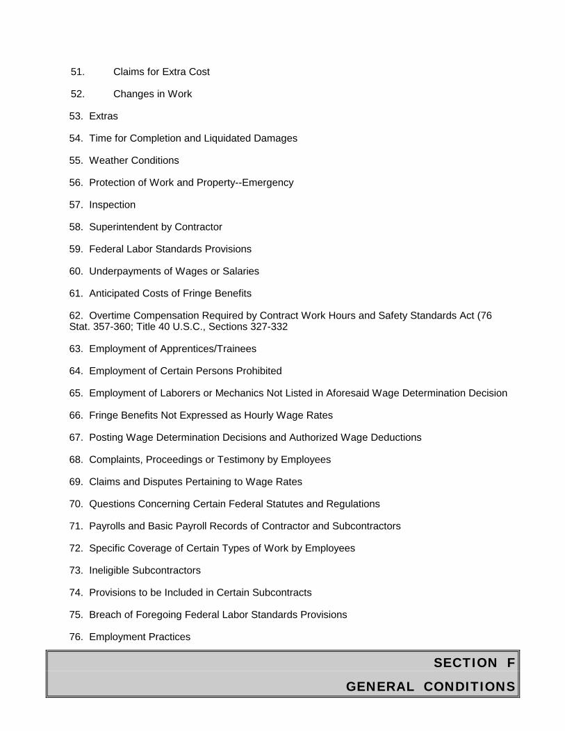
51. Claims for Extra Cost 52. Changes in Work 53. Extras 54. Time for Completion and Liquidated Damages 55. Weather Conditions 56. Protection of Work and Property--Emergency 57. Inspection 58. Superintendent by Contractor 59. Federal Labor Standards Provisions 60. Underpayments of Wages or Salaries 61. Anticipated Costs of Fringe Benefits 62. Overtime Compensation Required by Contract Work Hours and Safety Standards Act (76 Stat. 357-360; Title 40 U.S.C., Sections 327-332 63. Employment of Apprentices/Trainees 64. Employment of Certain Persons Prohibited 65. Employment of Laborers or Mechanics Not Listed in Aforesaid Wage Determination Decision 66. Fringe Benefits Not Expressed as Hourly Wage Rates 67. Posting Wage Determination Decisions and Authorized Wage Deductions 68. Complaints, Proceedings or Testimony by Employees 69. Claims and Disputes Pertaining to Wage Rates 70. Questions Concerning Certain Federal Statutes and Regulations 71. Payrolls and Basic Payroll Records of Contractor and Subcontractors 72. Specific Coverage of Certain Types of Work by Employees 73. Ineligible Subcontractors 74. Provisions to be Included in Certain Subcontracts 75. Breach of Foregoing Federal Labor Standards Provisions 76. Employment Practices

SECTION F
GENERAL CONDITIONS
77. Contract Termination; Debarment 78. Kickbacks from Public Works Employees 79. Labor-Title 29 CFR Part 3 80. Weekly Statement with Respect to Payment of Wages 81. Submission of Weekly Statements and the Preservation and Inspection of Weekly Payroll Records 82. Payroll Deductions Permissible without Application to or Approval of the Secretary of Labor 83. Payroll Deductions Permissible with the Approval of the Secretary of Labor 84. Applications for the Approval of the Secretary of Labor 85. Section 3.8 Action by the Secretary of Labor upon Applications 86. Prohibited Payroll Deductions 87. Methods of Payment of Wages 88. Regulations Part of Contract 89. Equal Opportunity Provisions (E.O. 11246) 90. Section 3 Compliance in the Provision of Training, Employment and Business Opportunities 91. Civil Rights Act of 1964 92. Section 109 of the Housing and Community Development Act of 1974 93. Indemnification 94. Delays 95. Maintenance of Work 96. Antitrust 97. Federal Labor Standards Provisions 98. Delay, Disruption and/or Other Claims
SECTION F
GENERAL CONDITIONS
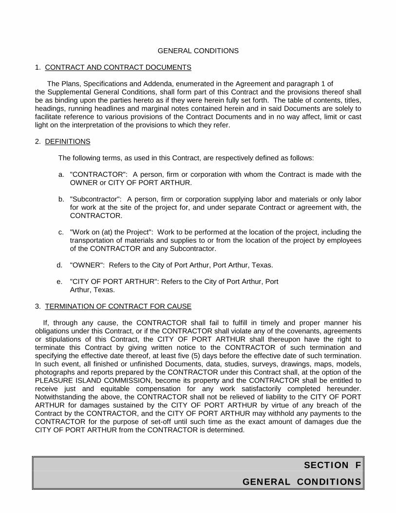
GENERAL CONDITIONS 1. CONTRACT AND CONTRACT DOCUMENTS The Plans, Specifications and Addenda, enumerated in the Agreement and paragraph 1 of the Supplemental General Conditions, shall form part of this Contract and the provisions thereof shall be as binding upon the parties hereto as if they were herein fully set forth. The table of contents, titles, headings, running headlines and marginal notes contained herein and in said Documents are solely to facilitate reference to various provisions of the Contract Documents and in no way affect, limit or cast light on the interpretation of the provisions to which they refer. 2. DEFINITIONS The following terms, as used in this Contract, are respectively defined as follows:
a. "CONTRACTOR": A person, firm or corporation with whom the Contract is made with the OWNER or CITY OF PORT ARTHUR.
b. "Subcontractor": A person, firm or corporation supplying labor and materials or only labor
for work at the site of the project for, and under separate Contract or agreement with, the CONTRACTOR.
c. "Work on (at) the Project": Work to be performed at the location of the project, including the
transportation of materials and supplies to or from the location of the project by employees of the CONTRACTOR and any Subcontractor.
d. "OWNER": Refers to the City of Port Arthur, Port Arthur, Texas. e. "CITY OF PORT ARTHUR": Refers to the City of Port Arthur, Port Arthur, Texas. 3. TERMINATION OF CONTRACT FOR CAUSE If, through any cause, the CONTRACTOR shall fail to fulfill in timely and proper manner his obligations under this Contract, or if the CONTRACTOR shall violate any of the covenants, agreements or stipulations of this Contract, the CITY OF PORT ARTHUR shall thereupon have the right to terminate this Contract by giving written notice to the CONTRACTOR of such termination and specifying the effective date thereof, at least five (5) days before the effective date of such termination. In such event, all finished or unfinished Documents, data, studies, surveys, drawings, maps, models, photographs and reports prepared by the CONTRACTOR under this Contract shall, at the option of the PLEASURE ISLAND COMMISSION, become its property and the CONTRACTOR shall be entitled to receive just and equitable compensation for any work satisfactorily completed hereunder. Notwithstanding the above, the CONTRACTOR shall not be relieved of liability to the CITY OF PORT ARTHUR for damages sustained by the CITY OF PORT ARTHUR by virtue of any breach of the Contract by the CONTRACTOR, and the CITY OF PORT ARTHUR may withhold any payments to the CONTRACTOR for the purpose of set-off until such time as the exact amount of damages due the CITY OF PORT ARTHUR from the CONTRACTOR is determined.
SECTION F
GENERAL CONDITIONS
4. PERSONNEL
a. The CONTRACTOR represents that he has, or will secure at his own expense, all personnel required in performing the work under this Contract. Such personnel shall not be employees
of or have any contractual relationship with the CITY OF PORT ARTHUR. b. All of the work required hereunder will be performed by the CONTRACTOR or under his
supervision and all personnel engaged in the work shall be fully qualified and shall be authorized or permitted under state and local law to perform such services.
c. None of the work covered by this Contract shall be subcontracted without the prior written
approval of the CITY OF PORT ARTHUR. Any work or services subcontracted hereunder shall be specified by written Contract or agreement and shall be subject to each provision of this Contract.
5. REPORTS AND INFORMATION The CONTRACTOR, at such times and in such forms as the CITY OF PORT ARTHUR may require, shall furnish the CITY OF PORT ARTHUR such periodic reports as it may request pertaining to the work or services undertaken pursuant to this Contract, the costs and obligations incurred or to be incurred in connection therewith, and any other matters covered by this Contract. 6. RECORDS AND AUDITS The CONTRACTOR shall maintain accounts and records, including personnel, property and financial records, adequate to identify and account for all costs pertaining to the Contract and such other records as may be deemed necessary by the CITY OF PORT ARTHUR to assure proper accounting for all project funds, both federal and non-federal shares. These records will be made available for audit purposes to the CITY OF PORT ARTHUR or any authorized representative, and will be retained for three (3) years after the expiration of this Contract unless permission to destroy them is granted by the CITY OF PORT ARTHUR. 7. FINDINGS CONFIDENTIAL All of the reports, information, data, etc., prepared or assembled by the CONTRACTOR under this Contract are confidential and CONTRACTOR agrees that they shall not be made available to any individual or organization without the prior written approval of the CITY OF PORT ARTHUR. 8. COPYRIGHT No report, maps or other Documents produced in whole or in part under this Contract shall be the subject of an application for copyright by or on behalf of the CONTRACTOR. 9. COMPLIANCE WITH LAWS The CONTRACTOR shall comply with all applicable laws, ordinances, rules, orders, regulations and codes of the federal, state and local governments relating to performance of the work herein, the
SECTION F
GENERAL CONDITIONS
protection of adjacent property and the maintenance of passageways, guard fences or other protective facilities. 10. INTEREST OF MEMBERS OF CITY OF PORT ARTHUR No member of the governing body of the CITY OF PORT ARTHUR, and no other officer, employee or agent of the CITY OF PORT ARTHUR who exercises any functions or responsibilities in connection with the planning and carrying out of the program, shall have any personal financial interest, direct or indirect, in this Contract; and, the CONTRACTOR shall take appropriate steps to assure compliance. 11. INTEREST OF OTHER LOCAL PUBLIC OFFICIALS No member of the governing body of the locality and no other public official of such locality, who exercises any functions or responsibilities in connection with the planning and carrying out of the program, shall have any personal financial interest, direct or indirect, in this Contract; and, the CONTRACTOR shall take appropriate steps to assure compliance. 12. INTEREST OF CONTRACTOR AND EMPLOYEES The CONTRACTOR covenants that he presently has no interest and shall not acquire any interest, direct or indirect, in the study area or any parcels therein or any other interest which would conflict in any manner or degree with the performance of his services hereunder. The CONTRACTOR further covenants that in the performance of this Contract, no person having any such interest shall be employed. 13. CERTIFICATES AND PERMITS Except for required permits issued by OWNER, which shall be issued at no cost to CONTRACTOR. CONTRACTOR shall secure at his own expense from other public authorities all necessary certificates, licenses, approvals and permits required in connection with the work of this Contract or any part thereof, and shall give all notices required by law, ordinance or regulation. CONTRACTOR shall pay all fees and charges incident to the due and lawful prosecution of the work of this Contract, and any extra work performed by him. 14. GUARANTEE OF WORK a. Neither the final certificate of payment nor any provision in the Contract Documents nor partial or entire occupancy of the premises by the OWNER shall constitute an acceptance of work not done in accordance with the Contract Documents or relieve the CONTRACTOR of liability in respect to any warranties or responsibility for faulty materials or workmanship. The CONTRACTOR guarantees and warrants that all materials and equipment which are to become part of the work shall be new unless otherwise specified and that all work will be of good quality and free from faults or defects and in accordance with the Contract Documents and of any inspections, tests or approvals required by the Contract Documents, law, ordinance, rules, regulations or orders of any public authority having jurisdiction. The OWNER will give notice of observed defects with reasonable promptness. b. Neither observations by Architect or Engineer nor inspections, tests or approvals by persons other than CONTRACTOR shall relieve CONTRACTOR from his obligations to perform the work in accordance with the requirements of the Contract.
SECTION F
GENERAL CONDITIONS
c. The provisions of this paragraph shall be cumulative of and not in limitation of the responsibility of CONTRACTOR for defects in the work or materials or damages resulting therefrom as otherwise provided by the law of the State of Texas or this Contract, including, without limitation, the implied warranty of fitness of the work and the implied obligation to perform the work in a good and workmanlike manner. 15. ADDITIONAL INSTRUCTIONS AND DETAIL DRAWINGS The CONTRACTOR will be furnished additional instructions and detail drawings as necessary to carry out the work included in the Contract. The additional drawings and instructions thus supplied to the CONTRACTOR will coordinate with the Contract Documents and will be so prepared that they can be reasonably interpreted as part thereof. The CONTRACTOR shall carry out the work in accordance with the additional detail drawings and instructions. The CONTRACTOR and the Architect/Engineer will prepare jointly (a) a schedule, fixing the dates at which special detail drawings will be required, such drawings, if any, to be furnished by the Architect/Engineer in accordance with said schedule, and (b) a schedule fixing the respective dates for the submission of shop drawings, the beginning of manufacture, testing and installation of materials, supplies and equipment, and the completion of the various parts of the work; each such schedule to be subject to change from time to time in accordance with the progress of the work.
16. SHOP OR SETTING DRAWINGS The CONTRACTOR shall submit promptly to the Architect/Engineer two copies of each shop or setting drawing prepared in accordance with the schedule predetermined as aforesaid. After examination of such drawings by the Architect/Engineer and the return thereof, the CONTRACTOR shall make such corrections to the drawings as have been indicated and shall furnish the Architect/Engineer with two corrected copies. If requested by the Architect/Engineer, the CONTRACTOR must furnish additional copies. Regardless of corrections made in or approval given to such drawings by the Architect/Engineer, the CONTRACTOR will nevertheless be responsible for the accuracy of such drawings and for their conformity to the Plans and Specifications, unless he notifies the Architect/Engineer in writing of any deviations at the time he furnishes such drawings. 17. MATERIALS, SERVICES AND FACILITIES a. It is understood that, except as otherwise specifically stated in the Contract Documents, the CONTRACTOR shall provide and pay for all materials, labor, tools, equipment, water, light, power, transportation, superintendents, temporary construction of every nature and all other services and facilities of every nature whatsoever necessary to execute, complete and deliver the work within the specified time. b. Any work necessary to be performed after regular working hours, on Sundays or Legal Holidays, shall be performed without additional expense to the OWNER. 18. CONTRACTOR'S TITLE TO MATERIALS No materials or supplies for the work shall be purchased by the CONTRACTOR or by any Subcontractor subject to any chattel mortgage or under a conditional sale Contract or other agreement by which an interest is retained by the seller. The CONTRACTOR warrants that he has good title to all materials and supplies used by him in the work, free from all liens, claims or encumbrances.
SECTION F
GENERAL CONDITIONS
19. INSPECTION AND TESTING OF MATERIALS All materials, equipment, etc., used in the construction of the project shall be subject to adequate inspection and testing in accordance with accepted standards and frequency, or as required by the contract documents. The CONTRACTOR shall make all arrangements for such tests and inspections with a local independent testing laboratory acceptable to the OWNER, and the CONTRACTOR shall bear all related costs of tests and inspections. If such procedures for testing and inspection reveal failure to comply with accepted standards or with requirements established by the contract documents, all re-testing and re-inspection costs made necessary by such failure, including those of related procedures, shall also be at CONTRACTOR’S expense. If the ENGINEER and/or OWNER determines that portions of the project requires additional testing or inspection not included in CONTRACTOR’S original bid, the ENGINEER shall, upon written authorization from the OWNER, instruct the CONTRACTOR to make arrangements for additional testing and inspection. The costs for such additional testing and inspection shall be at OWNER’S expense.
The CONTRACTOR’S independent testing laboratory shall give timely notice to the CONTRACTOR and the ENGINEER of when and where tests and inspections are to be made so that the CONTRACTOR and the ENGINEER may be present for such procedures. If the ENGINEER is to observe tests and inspections, the ENGINEER will do so promptly and, where practical, at the normal pace of testing. Tests and inspections shall be made promptly to avoid unreasonable delays on the project. Required certificates and/or reports of all test and inspections shall, unless otherwise required by the contract documents, be promptly delivered by the independent testing laboratory to the CONTRACTOR, the ENGINEER, and the OWNER. 20. "OR EQUAL" CLAUSE Whenever a material, article or piece of equipment is identified on the Plans or in the Specifications by reference to manufacturers' or vendors' names, trade names, catalogue numbers, etc., it is intended merely to establish a standard; and, any material, article or equipment of other manufacturers and vendors which will perform adequately the duties imposed by the general design will be considered equally acceptable provided the material, article or equipment so proposed is, in the opinion of the Architect/Engineer, of equal substance and function. It shall not be purchased or installed by the CONTRACTOR without the Architect/Engineer's written approval. 21. PATENTS a. The CONTRACTOR shall hold and save the OWNER and its officers, agents, servants and employees harmless from liability of any nature or kind, including cost and expenses for, or on account of, any patented or unpatented invention, process, article or appliance manufactured or used in the performance of the Contract, including its use by the OWNER, unless otherwise specifically stipulated in the Contract Documents. b. License or Royalty Fees: License and or royalty fees for the use of a process which is authorized by the OWNER of the project must be reasonable and paid to the holder of the patent, or his authorized licensee, direct by the OWNER and not by or through the CONTRACTOR.
SECTION F
GENERAL CONDITIONS
c. If the CONTRACTOR uses any design, device or materials covered by letters patent or copyright, he shall provide for such use by suitable agreement with the OWNER of such patented or copyrighted design, device or material. It is mutually agreed and understood that, without exception, the Contract prices shall include all royalties or costs arising from the use of such design, device or materials in any way involved in the work. The CONTRACTOR and/or his Sureties shall indemnify and save harmless the OWNER of the project from any and all claims for infringement by reason of the use of such patented or copyrighted design, device or materials or any trademark or copyright in connection with work agreed to be performed under this Contract, and shall indemnify the OWNER for any cost, expense or damage which it may be obliged to pay by reason of such infringement at any time during the prosecution of the work or after completion of the work. 22. SURVEYS Unless otherwise expressly provided for in the Specifications, the OWNER will furnish to the CONTRACTOR all surveys necessary for the execution of the work. 23. CONTRACTOR'S OBLIGATIONS The CONTRACTOR shall and will, in good workmanlike manner, do and perform all work and furnish all supplies and materials, machinery, equipment, facilities and means, except as herein otherwise expressly specified, necessary or proper to perform and complete all the work required by this Contract, within the time herein specified, in accordance with the provisions of this Contract and said Specifications and in accordance with the Plans and drawings covered by this Contract and any and all supplemental Plans and drawings, and in accordance with the directions of the Architect/Engineer as given from time to time during the progress of the work. He shall furnish, erect, maintain and remove such construction plant and such temporary works as may be required. The CONTRACTOR shall observe, comply with and be subject to all terms, conditions, requirements and limitations of the Contract and Specifications, and shall do, carry on and complete the entire work to the satisfaction of the Architect/Engineer and the OWNER. 24. INSURANCE The CONTRACTOR shall not commence work under this Contract until he has obtained all the insurance required herein and such insurance has been approved by the OWNER, nor shall the CONTRACTOR allow any Subcontractor to commence work on this Subcontract until the insurance required of the Subcontractor has been so obtained and approved (See information to Bidders, paragraph 5.). 25. CERTIFICATION OF COMPLIANCE WITH AIR AND WATER ACTS (Applicable to federally assisted construction contracts and related subcontracts exceeding $100,000.00.) During the performance of this Contract, the CONTRACTOR and all Subcontractors shall comply with the requirements of the Clean Air Act, as amended, 42 U.S.C. 1857, et seq., the Federal Water Pollution Control Act, as amended, 33 U.S.C. 1251, et seq., and the regulations of the Environmental Protection Agency with respect thereto, at 40 CFR Part 15, as amended.
SECTION F
GENERAL CONDITIONS
In addition to the foregoing requirements, all nonexempt CONTRACTOR'S and Subcontractors shall furnish to the OWNER the following: a. A stipulation by the CONTRACTOR or Subcontractor that any facility to be utilized in the performance of any nonexempt Contract or Subcontract is not listed on the List of Violating Facilities issued by the Environmental Protection Agency(EPA) pursuant to 40 CFR 15.20. b. Agreement by the CONTRACTOR to comply with all the requirements of Section 114 of the Clean Air Act, as amended (42 U.S.C. 1857c-8) and Section 308 of the Federal Water Pollution Act, as amended (33 U.S.C. 1318) relating to inspection, monitoring, entry, reports and information, as well as all other requirements specified in said Section 114 and Section 308 and all regulations and guidelines issued thereunder. c. A stipulation that, as a condition for the award of the Contract, prompt notice will be given of any notification received from the Director, Office of Federal Activities, EPA, indicating that a facility utilized, or to be utilized for the Contract, is under consideration to be listed on the EPA List of Violating Facilities. d. Agreement by the CONTRACTOR that he will include, or cause to be included, the criteria and requirements in paragraphs (a) through (d) of this section in every nonexempt Subcontract and requiring that the CONTRACTOR will take such action as the government may direct as a means of enforcing such provisions. 26. SPECIAL CONDITIONS PERTAINING TO HAZARDS, SAFETY STANDARDS AND ACCIDENT PREVENTION a. Lead-Based Paint Hazards: (Applicable to Contracts for construction or rehabilitation of residential structures.) The construction or rehabilitation of residential structures is subject to the HUD Lead-Based Paint regulations, 24 CFR Part 35. The CONTRACTOR and Subcontractors shall comply with the provisions for the elimination of lead-base paint hazards under subpart B of said regulations. The OWNER will be responsible for the inspections and certifications required under Section 35.14(f) thereof. b. Use of Explosives: When the use of explosives is necessary for the prosecution of the work, the CONTRACTOR shall observe all local, state and federal laws in purchasing and handling explosives. The CONTRACTOR shall take all necessary precautions to protect completed work, neighboring property, water lines or other underground structures. Where there is danger to structures or property from blasting, the charges shall be reduced and the material shall be covered with suitable timber, steel or rope mats. The CONTRACTOR shall notify all OWNER'S of public utility property of the intention to use explosives at least eight (8) hours before blasting is done, close to such property. Any supervision or direction of use of explosives by the Engineer does not in any way reduce the responsibility of the CONTRACTOR or his Surety for damages that may be caused by such use.

SECTION F
GENERAL CONDITIONS
c. Danger Signals and Safety Devices: The CONTRACTOR shall make all necessary precautions to guard against damages to property and injury to persons. He shall put up and maintain in good condition sufficient red or warning lights at night, suitable barricades and other devices necessary to protect the public. In case the CONTRACTOR fails or neglects to take such precautions, the OWNER may have such lights and barricades installed and charge the cost of this work to the CONTRACTOR. Such action by the OWNER does not relieve the CONTRACTOR of any liability incurred under these Specifications or Contract. 27. SUSPENSION OF WORK Should the OWNER be prevented or enjoined from proceeding with work or from authorizing its prosecution either before or after its prosecution, by reason of any litigation, the CONTRACTOR shall not be entitled to make or assert claim for damage by reason of said delay, but time for completion of the work will be extended to such reasonable time as the OWNER may determine will compensate for time lost by such delay with such determination to be set forth in writing. 28. NATIONAL HISTORIC PRESERVATION ACT OF 1966 The CONTRACTOR agrees to contribute to the preservation and enhancement of structures and objects of historical, architectural or archaeological significance when such items are found and/or unearthed during the course of project construction and to consult with the State Historic Preservation Officer for recovery of the items. (Reference: National Historic Preservation Act of 1966(80 Stat. 915, 16 U.S.C. 470) and Executive Order No. 11593 of May 31, 1971). 29. REQUIRED PROVISIONS DEEMED INSERTED Each and every provision of law and clause required by law to be inserted in this Contract shall be deemed to be inserted herein and the Contract shall be read and enforced as though it were included herein, and if through mistake or otherwise any such provision is not inserted or is not correctly inserted, then upon the application of either party, the Contract shall forthwith be physically amended to make such insertion or correction. 30. SAFETY AND HEALTH REGULATIONS FOR CONSTRUCTION In order to protect the lives and health of his employees under the Contract, the CONTRACTOR shall comply with all pertinent provisions of the Contract Work Hours and Safety Standards Act, as amended, commonly known as the Construction Safety Act as pertains to health and safety standards; and shall maintain an accurate record of all cases of death, occupational disease and injury requiring medical attention or causing loss of time from work, arising out of and in the course of employment on work under the Contract. The CONTRACTOR along shall be responsible for the safety, efficiency and adequacy of his plant, appliances and methods, and for any damage which may result from their failure or their improper construction, maintenance or operation.
SECTION F
GENERAL CONDITIONS
31. USE AND OCCUPANCY PRIOR TO ACCEPTANCE BY OWNER The CONTRACTOR agrees to the use and occupancy of a portion or unit of the project before formal acceptance by the OWNER, provided the OWNER: a. Secures written consent of the CONTRACTOR except in the event, in the opinion of the Architect/Engineer, the CONTRACTOR is chargeable with unwarranted delay in completing the contract requirements; b. Secures consent of the Surety; c. Secures endorsement from the insurance carrier(s) permitting occupancy of the building or use of the project during the remaining period of construction; or, d. When the project consists of more than one building and one of the buildings is occupied, secures permanent fire and extended coverage insurance, including a permit from the insurance carrier to complete construction. 32. USE OF PREMISES AND REMOVAL OF DEBRIS The CONTRACTOR expressly undertakes at his own expense: a. To take every precaution against injuries to persons or damage to property; b. To store his apparatus, materials, supplies and equipment in such orderly fashion at the site of the work as will not unduly interfere with the progress of his work or the work of any other CONTRACTOR'S; c. To place upon the work or any part thereof only such loads as are consistent with the safety of that portion of the work; d. To clean up frequently all refuse, rubbish, scrap materials and debris caused by his operations, to the end that at all times the site of the work shall present a neat, orderly and workmanlike appearance; e. Before final payment to removal all surplus material, false work, temporary structures, including foundations thereof, plant of any description and debris of every nature resulting from his operations, and to put the site in a neat, orderly condition; f. To effect all cutting, fitting or patching of his work required to make the same to conform to the Plans and Specifications and, except with the consent of the Architect/Engineer, not to cut or otherwise alter the work of any other CONTRACTOR. 33. QUANTITIES OF ESTIMATE Wherever the estimated quantities of work to be done and materials to be furnished under this Contract are shown in any of the documents including the proposal, they are given for use in comparing bids and the right is especially reserved, except as herein otherwise specifically limited, to increase or diminish them as may be deemed reasonably necessary or desirable by the OWNER to complete the work contemplated by the Contract, and such increase or diminution shall in no way
SECTION F
GENERAL CONDITIONS
vitiate this Contract, nor shall any such increase or diminution give cause for claims or liability for damages. 34. LAND AND RIGHTS-OF-WAY Prior to the start of construction, the OWNER shall obtain all lands and rights-of-way necessary for the carrying out and completion of work to be performed under this CONTRACT. 35. CONFLICTING CONDITIONS IN CONTRACT DOCUMENTS The Contract Documents are complementary and what is called for by one shall be as binding as if called for by all. In case of a conflict between any of the Contract Documents, priority of interpretation shall be in the following order: Signed Agreement (including General Conditions), Performance Bond, Payment Bond, Special Bonds (if any), Proposal, Special Conditions (including Information to Bidders), Advertisements for Bids, Detailed Drawings, Technical Specifications, General Drawings (Plans) and Supplemental General Conditions. 36. NOTICE AND SERVICE THEREOF Any notice to any CONTRACTOR from the OWNER relative to any part of this Contract shall be in writing and considered delivered and the service thereof completed when said notice is posted, by certified or registered mail, to the said CONTRACTOR at his last given address or delivered in person to the said CONTRACTOR or his authorized representative on the work. 37. SEPARATE CONTRACT The CONTRACTOR shall coordinate his operations with those of other CONTRACTOR'S. Cooperation will be required in the arrangement for the storage of materials and in the detailed execution of the work. The CONTRACTOR, including his Subcontractors, shall keep informed of the progress and the detail work of other CONTRACTOR'S and shall notify the Architect/Engineer immediately of lack of progress or effective workmanship on the part of other CONTRACTOR'S. Failure of a CONTRACTOR to keep informed of the work progressing on the site and failure to give notice of lack of progress or defective workmanship by others shall be construed as acceptance by him of the status of the work as being satisfactory for proper coordination with his own work. 38. SUBCONTRACTING a. The CONTRACTOR may utilize the services of specialty Subcontractors on those parts of Work which, under normal contracting practices, are performed by specialty Subcontractors. b. The CONTRACTOR shall not award any work to any Subcontractor without prior written approval of the OWNER, which approval will not be given until the CONTRACTOR submits to the OWNER a written statement concerning the proposed award to the Subcontractor, which statement shall contain such information as the OWNER may require. c. The CONTRACTOR shall be as fully responsible to the OWNER for the acts or omissions of his Subcontractors, and of persons either directly or indirectly employed by them, as he is for the acts and omissions of persons directly employed by him.
SECTION F
GENERAL CONDITIONS
d. The CONTRACTOR shall cause appropriate provisions to be inserted in all Subcontracts relative to the work to bind Subcontractors to the CONTRACTOR by the terms of the General Conditions and other Contract Documents insofar as applicable to the work of Subcontractors and to give the CONTRACTOR the same power as regards terminating any Subcontract that the OWNER may exercise over the CONTRACTOR under any provision of the Contract Documents. e. Nothing contained in this Contract shall create any contractual relation between any Subcontractor and the OWNER.
f. The CONTRACTOR shall not sublet the contract work to subcontractors more than 50% of the awarded project contract amount.
39. ARCHITECT/ENGINEERS AUTHORITY The Architect/Engineer shall give all orders and directions contemplated under this Contract and Specifications, relative to the execution of the work. The Architect/Engineer shall determine the amount, quality, acceptability and fitness of the several kinds of work and materials which are to be paid for under this Contract and shall decide all questions which may arise in relation to said work and the construction thereof. The Architect/Engineers estimates and decisions shall be final and conclusive, except as herein otherwise expressly provided. In case any question shall arise between the parties hereto relative to said Contract or Specifications, the determination or decision of the Architect/Engineer shall be a condition precedent to the right of the CONTRACTOR to receive any money or payment for work under this Contract affected in any manner or to any extent by such question. 40. MEANING OF INTENT The Architect/Engineer shall decide the meaning and intent of any portion of the Specifications and of any Plans or drawings where the same may be found obscure or be in dispute. Any differences or conflicts in regard to their work which may arise between the CONTRACTOR, under this Contract and other CONTRACTOR'S, performing work for the OWNER, shall be adjusted and determined by the Architect/Engineer. 41. CONTRACT SECURITY If the Contract amount exceeds Twenty-five Thousand Dollars ($25,000), a Payment Bond shall be furnished, and if the contract exceeds One Hundred Thousand Dollars($100,000.00)a Performance Bond also shall be furnished, on prescribed forms in the amount of one hundred percent(100%)than that prescribed by state, territorial or local law, as security for the payment of all persons performing labor on the project under this Contract and furnishing materials in connection with this Contract and as security for the faithful performance of this Contract. 42. ADDITIONAL OR SUBSTITUTE BOND If at any time the OWNER, for justifiable cause, shall be or become dissatisfied with any Surety or Sureties for the Performance and/or Payment Bonds, the CONTRACTOR shall, within five (5) days after notice from the OWNER to do so, substitute an acceptable bond (or bonds) in such form and sum and signed by such other Surety or Sureties as may be satisfactory to the OWNER. The premiums on such bond shall be paid by the CONTRACTOR. No further payments shall be deemed due nor shall
SECTION F
GENERAL CONDITIONS
be made until the new Surety and Sureties shall have furnished such an acceptable bond to the OWNER. 43. ASSIGNMENTS The CONTRACTOR shall not assign the whole or any part of this Contract or any monies due or to become due hereunder without written consent of the OWNER. In case the CONTRACTOR assigns all or any part of any monies due or to become due under this Contract, the instrument of assignment shall contain a clause substantially to the effect that it is agreed that the right of the assignee in and to any monies due or to become due to the CONTRACTOR shall be subject to prior claims of all persons, firms and corporations of services rendered or materials supplied for the performance of the work called for in this Contract. 44. MUTUAL RESPONSIBILITY OF CONTRACTOR'S If, through acts of neglect on the part of the CONTRACTOR, any other CONTRACTOR or any Subcontractor shall suffer loss or damage on the work, the CONTRACTOR agrees to settle with such other CONTRACTOR or Subcontractor by agreement or arbitration if such other CONTRACTOR Subcontractor will so settle. If such other CONTRACTOR or Subcontractor shall assert any claim against the OWNER on account of any damage alleged to have been sustained, the OWNER shall notify the CONTRACTOR, who shall indemnify and safe harmless the OWNER against any such claim. 45. ACCEPTANCE OF FINAL PAYMENT CONSTITUTES RELEASE The Acceptance by the CONTRACTOR of final payment shall be and shall operate as a release to the OWNER of all claims and all liability to the CONTRACTOR for all things done or furnished in connection with this work and for every act and neglect of the OWNER and others relating to or arising out of this work. No payment, however, final or otherwise, shall operate to release the CONTRACTOR or his Sureties from any obligations under this Contract or the Performance and Payment Bonds. 46. PAYMENTS BY CONTRACTOR The CONTRACTOR shall pay (a) for all transportation and utility services no later than the 20th day of the calendar month following that in which services are rendered, (b) for all materials, tools and other expendable equipment to the extent of ninety percent (90%) cost thereof, no later than the 20th day of the calendar month following that in which such materials, tools and equipment are delivered at the site of the project, and the balance of the cost thereof, no later than the 30th day following the completion of that part of the work in or on which such materials, tools and equipment are incorporated or used, and (c) to each of his Subcontractors, no later than the 5th day following each payment to the CONTRACTOR, the respective amounts allowed the CONTRACTOR on account of the work performed by his Subcontractors to the extent of each Subcontractors interest therein. 47. CONSTRUCTION SCHEDULE AND PERIODIC ESTIMATES Immediately after execution and delivery of the Contract, the CONTRACTOR shall deliver to the OWNER an estimated construction progress schedule in form satisfactory to the OWNER, showing the proposed dates of commencement and completion of each of the various subdivisions of work required under the Contract Documents and the anticipated amount of each monthly payment that will become due the CONTRACTOR in accordance with the progress schedule. The CONTRACTOR shall also
SECTION F
GENERAL CONDITIONS
furnish on forms to be supplied by the OWNER (a) a detailed estimate giving a complete breakdown of the Contract price and (b) periodic itemized estimates of work done for the purpose of making partial payments thereon. The costs employed in making up any of these schedules will be used only for determining the basis of partial payments and will not be considered as fixing a basis for additions to or deductions from the Contract price. 48. PAYMENTS TO CONTRACTOR
a. Not later than the thirty (30) calendar days from the date of submission to the City of Port Arthur, the OWNER shall make a progress payment to the CONTRACTOR on the basis of a duly certified and approved estimate of the work performed during the preceding calendar month under this Contract, but to insure the proper performance of the Contract, the OWNER shall retain ten percent (10%) (five percent [5%] if the total contract price exceeds $25,000)of the amount of each estimate until final completion and acceptance of all work covered by this Contract; Provided, that the CONTRACTOR shall submit his estimate no later than the fifth (5th) day of the month. Provided further, that on completion and acceptance of each separate building, public work or other division of the Contract on which the price is stated separately in the Contract, payment may be made in full, including retained percentages thereon, less authorized deductions. The CONTRACTOR is advised that the payment schedule noted is subject to fluctuation due to the Pleasure Island Commission Council's regular schedule of meeting on every other Tuesday. The CONTRACTOR may alter his estimate period such as to give the Engineer (ten)10 working days prior to the next scheduled Pleasure Island Commission Council meeting to prepare an estimate of the work completed and submit said estimate for the OWNER'S action.
b. In preparing estimates, No materials on hand will be paid. The material delivered on the site and preparatory work done may be taken into consideration by the Engineer. c. All material and work covered by partial payments made shall thereupon become the sole property of the OWNER, but this provision shall not be construed as relieving the CONTRACTOR from the sole responsibility for the care and protection of materials and work upon which payments have been made or the restoration of any damaged work or as a waiver of the right of the OWNER to require the fulfillment of all of the terms of the Contract. d. OWNER'S Right to Withhold Certain Amounts and Make Application Thereof: The CONTRACTOR agrees that he will indemnify and save the OWNER harmless from all claims growing out of the lawful demands of Subcontractors, laborers, workmen, mechanics, materialmen and furnishers of machinery and parts thereof, equipment, power tools and all supplies, including commissary, incurred in the furtherance of the performance of this Contract. The CONTRACTOR shall, at the OWNER'S request, furnish satisfactory evidence that all obligations of the nature hereinabove designated have been paid, discharged or waived. If the CONTRACTOR fails to do so, then the OWNER may, after having served written notice on the said CONTRACTOR, either pay unpaid bills, of which the OWNER has written notice, direct, or withhold from the CONTRACTOR'S unpaid compensation a sum of money deemed reasonably sufficient to pay any and all such lawful claims until satisfactory evidence is furnished that all liabilities have been fully discharged whereupon payment to the CONTRACTOR shall be resumed, in accordance with the terms
SECTION F
GENERAL CONDITIONS
of this Contract, but in no event shall the provisions of this sentence be construed to impose any obligations upon the OWNER to either the CONTRACTOR or his Surety. In paying any unpaid bills of the CONTRACTOR, the OWNER shall be deemed the agent of the CONTRACTOR, and any payment so made by the OWNER shall be considered as a payment made under Contract by the OWNER to the CONTRACTOR and the OWNER shall not be liable to the CONTRACTOR for any such payments made in good faith. This provision shall not be construed to give rise to any third party beneficiary rights in claimants.
49. CORRECTION OF WORK All work, all materials, whether incorporated in the work or not, all processes of manufacture and all methods of construction shall be at all times and places subject to the inspection of the Architect/Engineer who shall be the final judge of the quality and suitability of the work, materials, processes of manufacture and methods of construction for the purposes for which they are used. Should they fail to meet his approval, they shall be forthwith reconstructed, made good, replaced and/or corrected, as the case may be, by the CONTRACTOR at his own expense. Rejected material shall immediately be removed from the site. If, in the opinion of the Architect/Engineer, it is undesirable to replace any defective or damaged materials or to reconstruct or correct any portion of the work injured or not performed in accordance with the Contract Documents, the compensation to be paid to the CONTRACTOR hereunder shall be reduced by such amount as in the judgement of the Architect/Engineer shall be equitable. 50. SUBSURFACE CONDITIONS FOUND DIFFERENT Should the CONTRACTOR encounter subsurface and/or latent conditions at the site materially differing from those shown on the Plans or indicated in the Specifications, he shall immediately give notice to the Architect/Engineer of such conditions before they are disturbed. The Architect/Engineer will thereupon promptly investigate the conditions and, if he finds that they materially differ from those shown on the Plans or indicated in the Specifications, he will at once make such changes in the Plans and/or Specifications as he may find necessary, any increase or decrease of cost resulting from such changes to be adjusted in the manner provided in paragraph 52 of the General Conditions. 51. CLAIMS FOR EXTRA COST No claim for extra work or cost shall be allowed unless the same was done pursuant to a written order of the Architect/Engineer approved by the OWNER, as aforesaid, and the claim presented with the first estimate after the changed or extra work is done. When work is performed under the terms of subparagraph 52(c) of the General Conditions, the CONTRACTOR shall furnish satisfactory bills, payrolls and vouchers covering all items of cost and when requested by the OWNER, give the OWNER access to accounts relating thereto. 52. CHANGES IN WORK No changes in the work covered by the approved Contract Documents shall be made without having prior written approval of the OWNER. Charges or credit for the work covered by the approved change shall be determined by one or more, or a combination of the following methods: a. Unit bid prices previously approved.
SECTION F
GENERAL CONDITIONS
b. An agreed lump sum. c. The actual cost of: (1) Labor, including foreman; (2) Materials entering permanently into the work; (3) The ownership or rental cost of construction plant and equipment during the time of use on the extra work; (4) Power and consumable supplies for the operation of power equipment; (5) Insurance; (6) Social Security and old age unemployment contributions. To the cost under (c) there shall be added a fixed fee to be agreed upon but not to exceed fifteen percent (15%) of the work. The fee shall be compensation to cover the cost of supervision, overhead, bond, profit and any other general expenses. 53. EXTRAS Without invalidating the Contract, the OWNER may order extra work or make changes by altering, adding to or deducting from the work, the Contract sum being adjusted accordingly, and the consent of the Surety being first obtained where necessary or desirable. All the work of the kind bid upon shall be paid for at the price stipulated in the proposal, and no claims for any extra work or materials shall be allowed unless the work is ordered in writing by the OWNER or its Architect/Engineer, acting officially for the OWNER, and the price is stated in such order. 54. TIME FOR COMPLETION AND LIQUIDATED DAMAGES It is hereby understood and mutually agreed, by and between the CONTRACTOR and the OWNER, that the date of beginning and the time for completion as specified in the Contract of the work to be done hereunder are ESSENTIAL CONDITIONS of this Contract; and it is further mutually understood and agreed that the work embraced in this Contract shall be commenced on a date to be specified in the "Notice to Proceed". The CONTRACTOR agrees that said work shall be prosecuted regularly, diligently and without interruption at such rate of progress as will insure full completion thereof within the time specified. It is expressly understood and agreed, by and between the CONTRACTOR and the OWNER, that the time for the completion of the work described herein is a reasonable time for the completion of same, taking into consideration the average climatic range and usual industrial conditions prevailing in this locality. If the said CONTRACTOR shall neglect, fail or refuse to complete the work within the time herein specified, or any proper extension thereof granted by the OWNER, then the CONTRACTOR does hereby agree, as a part consideration for the awarding of this Contract, to pay to the OWNER the amount specified in the Contract, not as a penalty, but as liquidated damages for such breach of Contract as hereinafter set forth, for each and every consecutive calendar day, including, but not limited to, all Saturdays, Sundays, and Federal, State, and Pleasure Island Commission holidays and that the CONTRACTOR shall be in default after the time stipulated in the Contract for completing the work. The said amount is fixed and agreed upon by and between the CONTRACTOR and the OWNER because of the impracticability and extreme difficulty of fixing and ascertaining the actual damages the
SECTION F
GENERAL CONDITIONS
OWNER would in such event sustain, and said amount is agreed to be the amount of damages which the OWNER would sustain and said amount shall be retained from time to time by the OWNER from current periodical estimates. It is further agreed that time is of the essence of each and every portion of this Contract and of the Specifications wherein a definite and certain length of time is fixed for the performance of any act whatsoever; and where under the Contract an additional time is allowed for the completion of any work, the new time limit fixed by such extension shall be of the essence of this Contract. Provided, that the CONTRACTOR shall not be charged with any part of liquidated damages or any excess cost when the OWNER determines that any part of liquidated damages was not the fault of the CONTRACTOR and the OWNER determines that the request for extension by the CONTRACTOR is justified and due to: a. Any preference, priority or allocation order duly issued by the government; b. The following unforeseeable causes, namely: acts of the public enemy, acts of the OWNER, acts of another CONTRACTOR in the performance of a Contract with the OWNER, fires, floods, epidemics, quarantine restrictions, strikes, freight embargoes, earthquakes, hurricanes and tornadoes; and rainy days claimed by the CONTRACTOR; however, rainy days shall be considered only if the CONTRACTOR notifies the Engineer or OWNER on the day the CONTRACTOR claims he cannot work because of rainy weather that day. Failure to so report will eliminate any claim for time extension because of rainy weather on that day. c. Rainy weather when 60 percent of his work force cannot work for seven (7) hours or more that day because of rainy weather and providing that he has complied with the condition under 54(b). d. Any delays of Subcontractors or suppliers occasioned by any of the causes specified in subsections (a) and (b) of this article. It is also agreed that for each five(5) regular days of work lost due to any of the foregoing reasons, seven(7) calendar days will be added to the contract time(or 1.4 calendar days added for each one(1) regular day of work lost) Fractional calendar days will be rounded to the nearest whole number of days. Provided, further, that the CONTRACTOR shall, within ten (10) days from the beginning of such delay, unless the OWNER shall grant a further period of time prior to the date of final settlement of the Contract, notify the OWNER, in writing, of the causes of delay, who shall ascertain the facts and extent of the delay and notify the CONTRACTOR within reasonable time of its decision in the matter. Provided, that this provision for liquidated damages shall be cumulative of and not in limitation of any other remedy available to OWNER, including, without limitation, the right to terminate as provided in paragraph 3 and to recover additional damages for any excess cost in otherwise completing the work. 55. WEATHER CONDITIONS In the event of temporary suspension of work, or during inclement weather, or whenever the Architect/Engineer shall direct, the CONTRACTOR will, and will cause his Subcontractors to, protect carefully his, and their, work and materials against damage or injury from the weather. If,
SECTION F
GENERAL CONDITIONS
in the opinion of the Architect/Engineer, any work or materials shall have been damaged or injured by reason of failure on the part of the CONTRACTOR or any of his Subcontractors so to protect his work, such materials shall be removed and replaced at the expense of the CONTRACTOR. 56. PROTECTION OF WORK AND PROPERTY--EMERGENCY The CONTRACTOR shall at all times safely guard the OWNER'S property from injury or loss in connection with this Contract. He shall at all times safely guard and protect his own work, and that of adjacent property, from damage. The CONTRACTOR shall replace or make good any such damage, loss or injury unless such be caused directly by errors contained in the Contract or by the OWNER, or his duly authorized representatives. In case of an emergency which threatens loss or injury of property and/or safety of life, the CONTRACTOR will be allowed to act, without previous instructions from the Architect/Engineer, in a diligent manner. He shall notify the Architect/Engineer immediately thereafter. Any claim for compensation by the CONTRACTOR due to such extra work shall be promptly submitted to the Architect/Engineer for approval. Where the CONTRACTOR has not taken action but has notified the Architect/Engineer of an emergency threatening injury to persons or damage to the work or any adjoining property, he shall act as instructed or authorized by the Architect/Engineer. The amount of reimbursement claimed by the CONTRACTOR on account of any emergency action shall be determined in the manner provided in paragraph 52 of the General Conditions. 57. INSPECTION The authorized representatives and agents of the shall be permitted to inspect all work, materials, payrolls, records of personnel, invoices of materials and other relevant data and records. 58. SUPERINTENDENCE BY CONTRACTOR At the site of the work, the CONTRACTOR shall employ a construction superintendent or foreman who shall have full authority to act for the CONTRACTOR. It is understood that such representative shall be acceptable to the Architect/Engineer and shall be one who can be continued in the capacity for the particular job involved unless he ceases to be on the CONTRACTOR'S payroll. 59. FEDERAL LABOR STANDARDS PROVISIONS All laborers and mechanics employed upon the work covered by this Contract shall be paid unconditionally and not less often than once each week and without subsequent deduction or rebate on any account (except such payroll deductions as are made mandatory by law and such other payroll deductions as are permitted by the applicable regulations issued by the Secretary of Labor, United States Department of Labor, pursuant to the Anti-Kickback Act hereinafter identified) the full amount due at time of payment computed at wage rates not less than those contained in the wage determination decision of said Secretary of Labor (a copy of which is attached hereto and incorporated herein by reference), regardless of any contractual relationship which may be alleged to exist between the CONTRACTOR or any Subcontractor and such laborers and mechanics. All laborers and mechanics employed upon such work shall be paid in cash, except that payment may be
SECTION F
GENERAL CONDITIONS
by check if the employer provides or secures satisfactory facilities approved by the OWNER for the cashing of the same without cost or expense to the employee. For the purpose of this clause, contributions made or costs reasonably anticipated under Section 1(b) (2) of the Davis Bacon Act on behalf of laborers or mechanics are considered wages paid to such laborers or mechanics, subject to the provisions of Section 5.5 (a) (1) (iv) of Title 29, Code of Federal Regulations. Also, for the purpose of this clause, regular contributions made or costs incurred for more than a weekly period under Plans, funds or programs, but covering the particular weekly period, are deemed to be constructively made or incurred during such weekly period. 60. UNDERPAYMENTS OF WAGES OR SALARIES In case of underpayment of wages by the CONTRACTOR or by any Subcontractor to laborers or mechanics employed by the CONTRACTOR or Subcontractor upon the work covered by the Contract, the OWNER, in addition to such other rights as may be afforded it under this Contract, shall withhold from the CONTRACTOR, out of any payments due the CONTRACTOR, so much thereof as the OWNER may consider necessary to pay such laborers or mechanics the full amount of wages required by this Contract. The amount so withheld may be disbursed by the OWNER for and on account of the CONTRACTOR or the Subcontractor (as may be appropriate), to the respective laborers or mechanics to whom the same is due or on their behalf to Plans, funds or programs for any type of fringe benefit prescribed in the applicable wage determination. 61. ANTICIPATED COSTS OF FRINGE BENEFITS If the CONTRACTOR does not make payments to a trustee or other third person, he may consider, as part of the wages of any laborer or mechanic, the amount of any costs reasonable anticipated in providing fringe benefits under a Plan or program of a type expressly listed in the wage determination decision of the Secretary of Labor which is a part of this Contract: Provided, however, the Secretary of Labor has found, upon the written request of the CONTRACTOR, that the applicable standards of the Davis-Bacon Act have been met. The Secretary of Labor may require the CONTRACTOR to set aside in a separate account asset for the meeting of obligations under the plan or program. A copy of any findings made by the Secretary of Labor in respect to fringe benefits being provided by the CONTRACTOR must be submitted to the OWNER with the first payroll filed by the CONTRACTOR subsequent to receipt of the findings. 62. OVERTIME COMPENSATION REQUIRED BY CONTRACT WORK HOURS AND SAFETY STANDARDS ACT (76 Stat. 357-360: TITLE 40 U.S.C., SECTIONS 327-332 a. Overtime Requirements: No CONTRACTOR or Subcontractor contracting for any part of the Contract work which may require or involve the employment of laborers or mechanics, including watchmen and guards, shall require or permit any laborer or mechanic in any work week in which he is employed on such work to work in excess of forty (40) hours in such work week unless such laborer or mechanic receives compensation at a rate not less than one and one-half times his basic rate of pay for all hours worked in excess of forty (40) hours in such work week. b. Violation - Liability for Unpaid Wages Liquidated Damages: In the event of any violation of the clause set forth in paragraph (a), the CONTRACTOR and any Subcontractor responsible therefore shall be liable to any affected employee for his unpaid wages. In addition, such CONTRACTOR and Subcontractor shall be liable to the United States for liquidated damages. Such liquidated damages shall be computed with respect to each individual laborer or mechanic employed in violations of the
SECTION F
GENERAL CONDITIONS
clause set forth in paragraph (a), in the sum of Ten Dollars ($10.00) for each calendar day on which such employee was required or permitted to work in excess of forty (40) hours without payment of the overtime wages required by the clause set forth in paragraph (a). c. Withholding for Liquidated Damages: The OWNER shall withhold or cause to be withheld from any monies payable on account of work performed by the CONTRACTOR or Subcontractor such sums as may administratively be determined to be necessary to satisfy any liabilities of such CONTRACTOR or Subcontractor for liquidated damages as provided in the clause set forth in paragraph (b). d. Subcontracts: The CONTRACTOR shall insert in any Subcontracts the clauses set forth in paragraphs (a), (b) and (c) of this section and also a clause requiring the Subcontractors to include these clauses in any lower tier Subcontracts which they may enter into, together with a clause requiring this insertion in any further Subcontracts that may in turn be made. 63. EMPLOYMENT OF APPRENTICES/TRAINEES a. Apprentices: Apprentices will be permitted to work at less than the predetermined rate for the work they performed when they are employed and individually registered in a bona fide apprenticeship program registered with the U.S. Department of Labor, Manpower Administration, Bureau of Apprenticeship and Training, or with a state apprenticeship agency recognized by the Bureau, or if a person is employed in his first ninety (90) days of probationary employment as an apprentice in such an apprenticeship program, who is not individually registered in the program, but who has been certified by the Bureau of Apprenticeship and Training or a state apprenticeship agency(where appropriate) to be eligible for probationary employment as an apprentice. The allowable ratio of apprentices to journeymen in any craft classification shall not be greater than the ratio permitted to the CONTRACTOR as to his entire work force under the registered program. Any employee listed on a payroll at an apprentice wage rate, who is not a trainee as defined in subdivision (b) of this subparagraph or is not registered or otherwise employed as stated above, shall be paid the wage rate determined by the Secretary of Labor for the classification of work he actually performed. The CONTRACTOR or Subcontractor will be required to furnish to the contracting officer or a representative of the Wage-Hour Division of the U.S. Department of Labor written evidence of the registration of his program and apprentices as well as the appropriate ratios and wage rates (expressed in percentages of the journeyman hourly rates) for the area of construction prior to using any apprentices on the Contract work. The wage rate paid apprentices shall be not less than the appropriate percentage of the journeyman's rate contained in the applicable wage determination. b. Trainees: Except as provided in 29 CFR 5.15, trainees will not be permitted to work at less than the predetermined rate for the work performed unless they are employed pursuant to and individually registered in a program which has received prior approval, evidenced by formal certification, by the U.S. Department of Labor, Manpower Administration, Bureau of Apprentice and Training. The ratio of trainees to journeymen shall not be greater than permitted under the plan approved by the Bureau of Apprenticeship and Training. Every trainee must be paid at not less than the rate specified in the approved program for his level of progress. Any employee listed on the payroll at a trainee rate, who is not registered and participating in a training plan approved by the Bureau of Apprenticeship and Training, shall be paid not less than the wage rate determined by the Secretary of Labor for the classification of work he actually performed. The CONTRACTOR or Subcontractor will be required to furnish the contracting officer or a representative of the Wage-Hour Division of the U.S. Department of Labor written evidence of the certification of his program, the registration of the trainees and the ratios and wage rates prescribed in that program. In the event the Bureau of Apprenticeship and Training withdraws approval of a training program, the CONTRACTOR will no longer be permitted to utilize
SECTION F
GENERAL CONDITIONS
trainees at less than the applicable predetermined rate for the work performed until an acceptable program is provided. c. Equal Employment Opportunity: The utilization of apprentices, trainees and journeymen under this part shall be in conformity with the equal employment opportunity requirements of Executive Order No. 11246, as amended, and 29 CFR Part 30. 64. EMPLOYMENT OF CERTAIN PERSONS PROHIBITED No person under the age of sixteen (16) years and no person who, at the time, is serving sentence in a penal or correctional institution shall be employed on the work covered by this Contract. 65. EMPLOYMENT OF LABORERS OR MECHANICS NOT LISTED IN AFORESAID WAGE DETERMINATION DECISION Unlisted classifications needed for work not included within the scope of the classifications listed in the wage determination in this Contract may be added after award only as provided in the labor standards contract clauses (29 CFR, 5.5 (a) (1) (ii). 66. FRINGE BENEFITS NOT EXPRESSED AS HOURLY WAGE RATES The OWNER shall require, whenever the minimum wage rate prescribed in the Contract for a class of laborers or mechanics includes a fringe benefit which is not expressed as an hourly wage rate and the CONTRACTOR is obligated to pay cash equivalent of such a fringe benefit, an hourly cash equivalent thereof to be established. In the event the interested parties cannot agree upon a cash equivalent of the fringe benefit, the question, accompanied by the recommendation of the OWNER, shall be referred, through the Secretary of Housing and Urban Development, to the Secretary of Labor for determination. 67. POSTING WAGE DETERMINATION DECISIONS AND AUTHORIZED WAGE DEDUCTIONS The applicable wage poster and the applicable wage determination decisions, with respect to the various classification of laborers and mechanics employed and to be employed upon the work covered by this Contract, and a statement showing all deductions, if any, in accordance with the provisions of this Contract, to be made from wages actually earned by persons so employed or to be employed in such classifications, shall be posted at appropriate conspicuous points at the site of the work. 68. COMPLAINTS, PROCEEDINGS OR TESTIMONY BY EMPLOYEES No laborer or mechanic to whom the wage, salary or other labor standards provisions of this Contract are applicable shall be discharged or in any other manner discriminated against by the CONTRACTOR or any Subcontractor because such employee has filed any complaint or instituted or caused to be instituted any proceeding or has testified or is about to testify in any proceeding under or relating to the labor standards applicable under this Contract to his employer. 69. CLAIMS AND DISPUTES PERTAINING TO WAGE RATES Claims and disputes pertaining to wage rates or to classifications of laborers and mechanics employed upon the work covered by this Contract shall be promptly reported by the CONTRACTOR in
SECTION F
GENERAL CONDITIONS
writing to the OWNER for referral by the latter through the Secretary of Housing and Urban Development to the Secretary of Labor, United States Department of Labor, whose decision shall be final with respect thereto. 70. QUESTIONS CONCERNING CERTAIN FEDERAL STATUTES AND REGULATIONS All questions arising under this Contract which relate to the application or interpretation of (a) the aforesaid Anti-Kickback Act, (b) the Contract Work Hours and Safety Standards Act, (c) the aforesaid Davis-Bacon Act, (d) the regulations issued by the Secretary of Labor, United States Department of Labor, pursuant to said Acts, or (e) the labor standards provisions of any other pertinent federal statute, shall be referred, through the OWNER and the Secretary of Housing and Urban Development, to the Secretary of Labor, United States Department of Labor, for said Secretary's appropriate ruling or interpretation which shall be authoritative and may be relied upon for the purposes of this Contract. 71. PAYROLLS AND BASIC PAYROLL RECORDS OF CONTRACTOR AND SUBCONTRACTOR The CONTRACTOR and each Subcontractor shall prepare his payrolls on forms satisfactory to and in accordance with instructions to be furnished by the OWNER. The CONTRACTOR shall submit weekly to the OWNER one certified copy of all payrolls of the CONTRACTOR and of the Subcontractors, it being understood that the CONTRACTOR shall be responsible for the submission of copies of payrolls of all Subcontractors. Each such payroll shall contain the "Weekly Statement of Compliance" set forth in Section 3.3 of Title 29, Code of Federal Regulations. The payrolls and basic payroll records of the CONTRACTOR and each Subcontractor covering all laborers and mechanics employed upon the work covered by this Contract shall be maintained during the course of the work and preserved for a period of three (3) years thereafter. Such payrolls and basic payroll records shall contain the name and address of each employee, his correct classification, rate of pay (including rates of contributions or costs anticipated of the types described in Section 1 (b) (2) of the Davis-Bacon Act), daily and weekly number of hours worked, deductions made and actual wages paid. In addition, whenever the Secretary of Labor has found, under Section 5.5(a) (1) (iv) of Title 29, Code of Federal Regulations, that the wages of any laborer or mechanic include the amount of any costs reasonably anticipated in providing benefits under a plan or program described in Section 1(b) (2) (B) of the Davis-Bacon Act, the CONTRACTOR of Subcontractor shall maintain records which show that the commitment to provide such benefits is enforceable, that the plan or program is financially responsible and that the plan or program has been communicated in writing to the laborers or mechanics affected, and will maintain records which show the costs anticipated or the actual cost incurred in providing such benefits. The CONTRACTOR and each Sub-contractor shall make his employment records, with respect to persons employed by him upon the work covered by this Contract, available for inspection by authorized representatives of the Secretary of Housing and Urban Development, the OWNER and the United States Department of Labor. Such representatives shall be permitted to interview employees of the CONTRACTOR or of any Subcontractors during working hours on the job. 72. SPECIFIC COVERAGE OF CERTAIN TYPES OF WORK BY EMPLOYEES The transporting of materials and supplies to or from the site of the project or program to which the Contract pertains by the employees of the CONTRACTOR or of any Subcontractor and the manufacturing or furnishing of materials, articles, supplies or equipment on the site of the project or program to which this Contract pertains by persons employed by the CONTRACTOR or by any Subcontractor, shall, for the purposes of this Contract, and without limiting the generality of the
SECTION F
GENERAL CONDITIONS
foregoing provisions of this Contract, shall be deemed to be work to which these Federal Labor Standards Provisions are applicable. 73. INELIGIBLE SUBCONTRACTORS The CONTRACTOR shall not subcontract any part of the work covered by this Contract or permit subcontracted work to be further subcontracted without the OWNER'S prior written approval of the Subcontractor. The OWNER will not approve any Subcontractor for work covered by this Contract who is at the time ineligible under the provisions of any applicable regulations issued by the Secretary of Labor, United States Department of Labor, or the Secretary of Housing and Urban Development to receive an award of such Subcontract. 74. PROVISIONS TO BE INCLUDED IN CERTAIN SUBCONTRACTS The CONTRACTOR shall include or cause to be included in each subcontract covering any of the work covered by this Contract, provisions which are consistent with these Federal Labor Standards Provisions and also a clause requiring the Subcontractors to include such provisions in any lower tier Subcontracts which they may enter into, together with a clause requiring such insertion in any further Subcontracts that may in turn be made. 75. BREACH OF FOREGOING FEDERAL LABOR STANDARDS PROVISIONS In addition to the causes for termination of this Contract as herein elsewhere set forth, the OWNER reserves the right to terminate this Contract if the CONTRACTOR or any Subcontractor, whose Subcontract covers any of the work covered by this Contract, shall breach any of these Federal Labor Standards Provisions. A breach of these Federal Labor Standards Provisions may also be grounds for debarment as provided by the applicable regulations issued by the Secretary of Labor, United States Department of Labor. 76. EMPLOYMENT PRACTICES The CONTRACTOR (1) shall, to the greatest extent practicable, follow hiring and employment practices for work on the project which will provide new job opportunities for the unemployed and underemployed, and (2) shall insert or cause to be inserted the same provision in each construction Subcontract. 77. CONTRACT TERMINATION; DEBARMENT A breach of Section 45 and the Federal Labor Standards Provisions may be grounds for termination of the Contract and for debarment as provided in 29 CFR 5.6. 78. KICKBACKS FROM PUBLIC WORKS EMPLOYEES a. Whoever, by force, intimidation or threat of procuring dismissal from employment or by any other manner whatsoever, induces any person employed in the construction, prosecution, completion or repair of any public buildings, public works or buildings or works financed in whole or in part by loans or grants from the United States to give up any part of the compensation to which he is entitled under this Contract of employment, shall be fined not more than $5,000 or imprisoned not more than five (5) years, or both.
SECTION F
GENERAL CONDITIONS
b. The Secretary of Labor shall make reasonable regulations for CONTRACTOR'S and Subcontractors engaged in the construction, prosecution, completion or repair of public buildings, public works or buildings or works financed in whole or in part by loans or grants from the United States, including a provision that each Contractor and Subcontractor shall furnish weekly a statement with respect to the wages paid each employee during the preceding week. Section 1001 of Title 18 (United States Code) shall apply to such statements.
c. Pursuant to the aforesaid Anti-Kickback Act, the Secretary of Labor, United States Department of Labor, has promulgated the regulations hereinafter set forth, which regulations are found in Title 29, Subtitle A, Code of Federal Regulations, Part 3. The term "this part", as used in the regulations hereinafter set forth, refers to Part 3 last above mentioned. Said regulations follow in Section 79. 79. LABOR-TITLE 29 CFR PART 3 This part prescribes "Anti-Kickback" regulations under Section 2 of the Act of June 13, 1934, as amended (40 U.S.C. 276c), popularly known as the Copeland Act. This part applies to any Contract which is subject to federal wage standards and which is for the construction, prosecution, completion or repair of public buildings, public works or buildings or works financed in whole or in part by loans or grants from the United States. This part is intended to aid in the enforcement of the minimum wage provisions of the Davis-Bacon Act and the various statutes dealing with federally-assisted construction that contain similar minimum wage provisions, including those provisions which are not subject to Reorganization Plan No. 14 (e.g. the College Housing Act of 1950, the Federal Water Pollution Control Act and the Housing Act of 1959), and in the enforcement of the overtime provisions of the Contract Work Hours Standards Act whenever they are applicable to construction work. This part details the obligation of CONTRACTOR'S and Subcontractors relative to the weekly submission of statements regarding the wages paid on work covered thereby, sets forth the circumstances and procedures governing the making of payroll deductions from the wages of those employed on such work and delineates the methods of payment permissible on such work. Section 3.2 definitions as used in this part: a. The terms "building" or "work" generally include construction activity as distinguished from manufacturing, furnishing or materials or servicing and maintenance work. The terms include without limitation, buildings, structures and improvements of all types, such as bridges, dams, plants, highways, parkways, streets, subways, tunnels, sewers, mains, powerlines, pumping stations, railways, airports, terminals, docks, piers, wharves, ways, lighthouses, buoys, jetties, breakwaters, levees and canals; dredging, shoring, scaffolding, drilling, blasting, excavating, clearing and landscaping. Unless conducted in connection with and at the site of such a building or work as is described in the foregoing sentence, the manufacture or furnishing of materials, articles, supplies or equipment (whether or not a federal or state agency acquires title to such materials, articles, supplies or equipment during the course of the manufacture or furnishing or owns the materials from which they are manufactured or furnished) is not a "building" or "work" within the meaning of the regulations in this part. b. The terms "construction", "prosecution", "completion" or "repair" mean all types of work done on a particular building or work at the site thereof, including, without limitation, altering, remodeling, painting and decorating, the transporting of materials and supplies to or from the building or work by the employees of the construction contractor or construction subcontractor, and the manufacturing or furnishing of materials, articles, supplies or equipment on the site of the building or work by persons employed at the site by the CONTRACTOR or Subcontractor.
SECTION F
GENERAL CONDITIONS
c. The terms "public building" or "public work" include building or work for whose construction, prosecution, completion or repair, as defined above, a federal agency is a contracting party, regardless of whether title thereof is in a federal agency. d. The term "building or work financed in whole or in part by loans or grants from the United States" includes building or work for whose construction, prosecution completion or repair, as defined as above, payment or part payment is made directly or indirectly from funds provided by loans or grants by a federal agency. The term does not include building or work for which federal assistance is limited solely to loan guarantees or insurance. e. Every person paid by a CONTRACTOR or Subcontractor in any manner for his labor in the construction, prosecution, completion or repair of any public buildings, or public works or buildings or works financed in whole or in part by loans or grants from the United States is "employed" and receiving "wages", regardless of any contractual relationship alleged to exist between him and the real employer. f. The term "any affiliated person" includes a spouse, child, parent or other close relative of the CONTRACTOR or Subcontractor; a partner or officer of the CONTRACTOR or Subcontractor; a corporation closely connected with the CONTRACTOR or Subcontractor as parent, subsidiary or otherwise, and an officer or agent of such corporation. g. The term "federal agency" means the United States, the District of Columbia, and all executive departments, independent establishments, administrative agencies and instrumentalities of the United States and of the District of Columbia, including corporations, all or substantially all of the stock which is beneficially owned by the United States, by the District of Columbia or any of the foregoing departments, establishments, agencies and instrumentalities. 80. WEEKLY STATEMENT WITH RESPECT TO PAYMENT OF WAGES a. As used in this section, the term "employee" shall not apply to persons in classifications higher than that of laborer or mechanic and those who are the immediate supervisors of such employees. b. Each CONTRACTOR or Subcontractor engaged in the construction, prosecution, completion or repair of any public buildings, or public works, or buildings or works financed in whole or in part by loans or grants from the United States, shall furnish each week a statement with respect to the wages paid each of its employees engaged on work covered by 29 CFR Parts 3 and 5 during the preceding weekly payroll period. This statement shall be executed by the CONTRACTOR or Subcontractor or by an authorized officer or employee of the CONTRACTOR or Subcontractor who supervises the payment of wages and shall be on form WH 348, "Statement of Compliance", or on identical form on the back of WH 347, "Payroll (for CONTRACTOR'S Optional Use)" or on any form with identical wording. Sample copies of WH 347 and WH 348 may be obtained from the government contracting or sponsoring agency and copies of these forms may be purchased at the Government Printing Office. c. The requirements of this section shall not apply to any Contract for Two Thousand Dollars ($2,000) or less. d. Upon a written finding by the head of a federal agency, the Secretary of Labor may provide reasonable limitations, variations, tolerances and exemptions from the requirements of this section subject to such conditions as the Secretary of Labor may specify.
SECTION F
GENERAL CONDITIONS
81. SUBMISSION OF WEEKLY STATEMENTS AND THE PRESERVATION AND INSPECTION OF WEEKLY PAYROLL RECORDS a. Each weekly statement required under § 3.3 shall be delivered by the CONTRACTOR or Subcontractor, within seven (7) days after the regular payment date of the payroll period, to a representative of OWNER in charge at the site of the building or work or, if there is no representative of OWNER at the site of the building or work, the statement shall be mailed by the CONTRACTOR or Subcontractor, within such time, to the OWNER. After such examination and check as may be made, such statement, or a copy thereof, shall be kept available and shall be transmitted together with a report of any violation, in accordance with applicable procedures prescribed by the United States Department of Labor. b. Each CONTRACTOR of Subcontractor shall preserve his weekly payroll records for a period of three (3) years from date of completion of the Contract. The payroll records shall set out accurately and completely the name and address of each laborer and mechanic, his correct classification, rate of pay, daily and weekly number of hours worked, deductions made and actual wages paid. Such payroll records shall be made available at all times for inspection by the contracting officer or his authorized representative and by authorized representatives of the Department of Labor.
82. PAYROLL DEDUCTIONS PERMISSIBLE WITHOUT APPLICATION TO OR APPROVAL OF THE SECRETARY OF LABOR Deductions made under the circumstances or in the situations described in the paragraphs of this section may be made without application to and approval of the Secretary of Labor. a. Any deduction made in compliance with the requirements of federal, state or local law, such as federal or state withholding income taxes and federal social security taxes.
b. Any deduction of sums previously paid to the employee as a bona fide prepayment of wages when such prepayment is made without discount or interest. A "bona fide prepayment of wages" is considered to have been made only when cash or its equivalent has been advanced to the person employed in such manner as to give him complete freedom of disposition of the advanced funds.
c. Any deduction of amounts required by court process to be paid to another, unless the deduction is in favor of the CONTRACTOR, Subcontractor or any affiliated person, or when collusion or collaboration exists. d. Any deduction constituting a contribution on behalf of the person employed to funds established by the employer or representatives of employees, or both, for the purpose of providing either from principal or income, or both, medical or hospital care, pensions or annuities on retirement, death benefits, compensation for injuries, illness, accidents, sickness or disability, or for insurance to provide any of the foregoing, or unemployment benefits, vacation pay, savings accounts or similar payments for the benefit of employees, their families and dependents: Provided, however, that the following standards are met: (1) the deduction is not otherwise prohibited by law; (2) it is either (i) voluntarily consented to by the employee in writing and in advance of the period in which the work is to be done and such consent is not a condition either for the obtaining of or for the continuation of employment, or (ii) provided for in a bona fide collective bargaining agreement between the CONTRACTOR or Subcontractor and representatives of its employees; (3) no profit or other benefit is otherwise obtained
SECTION F
GENERAL CONDITIONS
directly or indirectly, by the CONTRACTOR or Subcontractor or any affiliated person in the form of commission, dividend or otherwise; and (4) the deductions shall serve the convenience and interest of the employee. e. Any deduction contributing toward the purchase of United States Defense Stamps and Bonds when voluntarily authorized by the employee. f. Any deduction requested by the employee to enable him to repay loans to, or to purchase shares in credit unions organized and operated in accordance with federal and state credit union statutes. g. Any deduction voluntarily authorized by the employee for the making of contributions to governmental or quasi-governmental agencies such as the American Red Cross. h. Any deductions voluntarily authorized by the employee for the making of contributions to Community Chests, United Givers Funds and similar charitable organizations. i. Any deductions to pay regular union initiation fees and membership dues, not including fines or special assessments: Provided, however, that a collective bargaining agreement between the CONTRACTOR or Subcontractor and representatives of its employees provides for such deductions and the deductions are not otherwise prohibited by law. j. Any deduction not more than for the "reasonable cost" of board, lodging or other facilities meeting the requirements of Section 3(m) of the Fair Labor Standards Act of 1938, as amended, and Part 531 of this title. When such a deduction is made, the additional records required under § 516.27(a) of this title shall be kept.
83. PAYROLL DEDUCTIONS PERMISSIBLE WITH THE APPROVAL OF THE SECRETARY OF LABOR
Any CONTRACTOR or Subcontractor may apply to the Secretary of Labor for permission to make any deduction not permitted under §3.5. The Secretary may grant permission whenever he finds that: a. The CONTRACTOR, Subcontractor or any affiliated person does not make a profit or benefit directly or indirectly from the deduction either in the form of a commission, dividend or otherwise; b. The deduction is not otherwise prohibited by law; c. The deduction is either (1) voluntarily consented to by the employee in writing and in advance of the period in which the work is to be done and such consent is not a condition either for the obtaining of employment or its continuance, or (2) provided for in a bona fide collective bargaining agreement between the CONTRACTOR or Subcontractor and representatives of its employees; and d. The deduction serves the convenience and interest of the employee. 84. APPLICATIONS FOR THE APPROVAL OF THE SECRETARY OF LABOR Any application for the making of payroll deductions under §3.6 shall comply with the requirements prescribed in the following paragraphs of this section:
SECTION F
GENERAL CONDITIONS
a. The application shall be in writing and shall be addressed to the Secretary of Labor. b. The application shall identify the Contract or Contracts under which the work in question is to be performed. Permission will be given for deductions only on specific, identified Contracts, except upon a showing of exceptional circumstances. c. The application shall state affirmatively that there is compliance with the standards set forth in the provisions of §3.6. The affirmation shall be accompanied by a full statement of the facts indicating such compliance. d. The application shall include a description of the proposed deduction, the purpose to be served thereby and the classes of laborers or mechanics from whose wages the proposed deduction would be made. e. The application shall state the name and business of any third person to whom any funds obtained from the proposed deductions are to be transmitted and the affiliation of such person, if any, with the applicant.
85. SECTION 3.8 ACTION BY THE SECRETARY OF LABOR UPON APPLICATIONS The Secretary of Labor shall decide whether or not the requested deduction is permissible under provisions of §3.6 and shall notify the applicant in writing of his decision. 86. PROHIBITED PAYROLL DEDUCTIONS Deductions not elsewhere provided for by this part and which are not found to be permissible under §3.6 are prohibited. 87. METHODS OF PAYMENT OF WAGES The payment of wages shall be by cash, negotiable instruments payable on demand or the additional forms of compensation for which deductions are permissible under this part. No other methods of payment shall be recognized on work subject to the Copeland Act. 88. REGULATIONS PART OF CONTRACT All Contracts made with respect to the construction, prosecution, completion or repair of any public building or public work or building or work financed in whole or in part by loans or grants from the United States covered by the regulations in this part shall expressly bind the CONTRACTOR or Subcontractor to comply with such of the regulations in this part as may be applicable. In this regard, see §5.5(a) of this subtitle. 89. EQUAL OPPORTUNITY PROVISIONS (E.O. 11246) A. Activities and Contracts Subject to Executive Order 11246, as Amended (applicable to federally-assisted construction contracts and related subcontracts under Ten Thousand Dollars ($10,000)): During the performance of this Contract, the CONTRACTOR agrees as follows:
SECTION F
GENERAL CONDITIONS
(1) The CONTRACTOR shall not discriminate against any employee or applicant for employment because of race, color, religion, sex or national origin. The CONTRACTOR shall take affirmative action to ensure that applicants for employment are employed and that employees are treated during employment without regard to their race, color, religion, sex or national origin. Such action shall include, but not be limited to, the following: employment, upgrading, demotion or transfer; recruitment or recruitment advertising; layoff or termination; rates of pay or other forms of compensation; and selection for training, including apprenticeship. (2) The CONTRACTOR shall post in conspicuous places, available to employees and applicants for employment, notices to be provided Contracting Officer setting forth the provisions of this nondiscrimination clause. The CONTRACTOR shall state that all qualified applicants will receive consideration for employment without regard to race, color, religion, sex or national origin. (3) CONTRACTOR'S shall incorporate foregoing requirements in all Subcontracts. B. Contracts Subject to Executive Order 11246, as Amended (applicable to federally-assisted construction contracts and related subcontracts exceeding Ten Thousand Dollars ($10,000)): During the performance of this Contract, the CONTRACTOR agrees as follows:
(1) The CONTRACTOR will not discriminate against any employee or applicant for Employment because of race, color, religion, sex or national origin. The CONTRACTOR will take affirmative action to ensure that applicants are employed and that employees are treated during employment without regard to their race, color, religion, sex or national origin. Such action shall include, but not be limited to, the following: employment, upgrading, demotion or transfer, recruitment or recruitment advertising; layoff or termination; rates of pay or other forms of compensation; and selection for training, including apprenticeship. The CONTRACTOR agrees to post in conspicuous places, available to employees and applicants for employment, notices to be provided setting forth the provisions of this nondiscrimination clause.
(2) The CONTRACTOR will, in all solicitations or advertisements for employees placed by or on
behalf of CONTRACTOR, state that all qualified applicants will receive consideration for employment without regard to race, color, religion, sex or national origin.
(3) The CONTRACTOR will send to each labor union or representative of workers, with which he has a collective bargaining agreement or other contract or understanding, a notice to be provided by the Contract Compliance Officer advising the said labor union or workers' representatives of the CONTRACTOR'S commitment under this section and shall post copies of the notice in conspicuous places available to employees and applicants for employment. (4) The CONTRACTOR will comply with all provisions of Executive Order 11246 of September 24, 1965, and of the rules, regulations and relevant orders of the Secretary of Labor. (5) The CONTRACTOR will furnish all information and reports required by Executive Order 11246 of September 24, 1965, and by the rules, regulations and orders of the Secretary of Labor, or pursuant thereto, and will permit access to his books, records and accounts by the Department and the Secretary of Labor for purposes of investigation to ascertain compliance with such rules, regulations and orders.
SECTION F
GENERAL CONDITIONS
(6) In the event of the CONTRACTOR'S noncompliance with the non- discrimination clauses of this Contract or with any of the said rules, regulations or orders, this Contract may be cancelled, terminated or suspended in whole or in part, and the CONTRACTOR may be declared ineligible for further government CONTRACTOR'S or federally assisted construction Contract in accordance with procedures authorized in Executive Order 11246 of September 24, 1965, or by rule, regulation or order of the Secretary of Labor, or as otherwise provided by law.
(1) The CONTRACTOR will include the portion of the sentence immediately preceding paragraph (1) and the provisions of paragraph (1) through (7) in every Subcontract or purchase order unless exempted by rules, regulations or orders of the Secretary of Labor issued pursuant to Section 204 of Executive Order 11246 of September 24, 1965, so that such provisions will be binding upon each Subcontractor or vendor. The CONTRACTOR will take such action with respect to any 204 of Executive Order 11246 of September 24, 1965, so that such provisions will be binding upon each Subcontractor or vendor. The CONTRACTOR will take such action with respect to any Subcontract or purchase order as the Department may direct as a means of enforcing such provisions, including sanctions of noncompliance: Provided, however, that in the event a CONTRACTOR becomes involved in, or is threatened with, litigation with a Subcontract or vendor as a result of such direction by the Department, the CONTRACTOR may request the United States to enter into such litigation to protect the interest of the United States.
C. Notice of Requirement for Affirmative Action to Ensure Equal Employment Opportunity (Executive Order 11246) (applicable to contracts/subcontracts exceeding Ten Thousand Dollars ($10,000)): (1) The Offeror's or Bidder's attention is called to the "Equal Opportunity Clause" and the "Standard Federal Equal Employment Opportunity Construction Contract Specifications" set forth herein. (2) The goals and timetables for minority and female participation, expressed in percentage terms for the CONTRACTOR'S aggregate work force in each trade on all construction work in the covered area, are as follows: Goals for Minority Timetable Goals for Female Participation for Participation in Each Trade - 8% Each Trade - 8% These goals are applicable to all the CONTRACTOR'S construction work (whether or not it is federal or federally assisted) performed in the covered area. The CONTRACTOR'S compliance with the Executive Order and the regulations in 41 CFR Part 60-4 shall be based on its implementation of the Equal Opportunity Clause, specific affirmative action obligations required by the Specifications set forth in 41 CFR 60-4.3(a), and its efforts to meet the goals established for the geographical area where the Contract resulting from this solicitation is to be performed. The hours of minority and female employment and training must be substantially uniform throughout the length of the Contract, and in each trade, and the CONTRACTOR shall make a good faith effort to employ minorities and women evenly on each of its projects. The transfer of minority or female employees or trainees from CONTRACTOR to CONTRACTOR or from project to project for the sole purpose of meeting the CONTRACTOR'S goals shall be a violation of the Contract, the Executive Order and the regulations in 41 CFR Part 60-4. Compliance with the goals will be measured against the total work hours performed.
SECTION F
GENERAL CONDITIONS
(3) The CONTRACTOR shall provide written notification to the Director of the Office of
Federal Contract Compliance Programs within ten (10) working days of award of any construction subcontract in excess of $10,000 at any tier for Construction work under the Contract resulting from this solicitation. The notification shall list the name, address and telephone number of the Subcontractor; employer identification number; estimated dollar amount of the Subcontract; estimated starting and completion dates of the Subcontract; and the geographical area in which the Contract is to be performed. (4) As used in this Notice, and in the Contract resulting from this solicitation, the "covered area" is City of Port Arthur, Jefferson County, Texas. D. Standard Federal Equal Employment Opportunity Construction Contract Specifications (Executive Order 11246): (1) As used in these Specifications: (a) "Covered area" means the geographical area described in the solicitation from which this contract resulted; (b) "Director" means Director, Office of Federal Contract Compliance Programs, United States Department of Labor, or any person to whom the Director delegates authority; (c) "Employer identification number" means the Federal Social Security number used on the Employer's Quarterly Federal Tax Return, U.S. Treasury Department Form 941. (d) "Minority" includes: (i) Black (all persons having origins in any of the Black African racial groups not of Hispanic origin); (ii) Hispanic (all persons of Mexican, Puerto Rican, Cuban, Central or South American or other Spanish Culture or origin, regardless of race); (iii) Asian and Pacific Islander (all persons having origins in any of the original peoples of the Far East, Southeast Asia the Indian Subcontinent or the Pacific Islands); and (iv) American Indian or Alaskan Native (all persons having origins in any of the original peoples of North American maintaining identifiable tribal affiliations through membership and participation or community identification). (2) Whenever the CONTRACTOR, or any subcontractor at any tier, Subcontracts a portion of the work involving any construction trade, it shall physically included in each Subcontract in excess of $10,000 the provisions of these Specifications and the Notice which contains the applicable goals for minority and female participation and which is set forth in the solicitations from which this Contract resulted.
(2) If the CONTRACTOR is participating (pursuant to 41 CFR 60-4.5) in a Hometown Plan approved by the U.S. Department of Labor in the covered area either individually or through an association, its affirmative action obligations on all work in the Plan area (including goals and timetables) shall be in accordance with that Plan for those trades which have unions participating in the
SECTION F
GENERAL CONDITIONS
Plan. CONTRACTOR'S must be able to demonstrate their participation in and compliance with the provisions of any such Hometown Plan. Each CONTRACTOR or Subcontractor participating in an approved Plan is individually required to comply with its obligations under the EEO clause and to make a good faith effort to achieve each goal under the Plan in each trade in which it has employees. The overall good faith performance by other CONTRACTOR'S or Subcontractors toward a goal in an approved Plan does not excuse any covered CONTRACTOR'S or Subcontractors failure to take good faith efforts to achieve the Plan goals and timetables. (4) The CONTRACTOR shall implement the specific affirmative action standards provided in paragraphs 7a through 7p of these Specifications. The goals set forth in the solicitation from which the Contract resulted are expressed as percentages of the total hours of employment and training of minority and female utilization the CONTRACTOR should reasonably be able to achieve in each Construction trade in which it has employees in the covered area. Covered construction CONTRACTOR'S performing construction work in geographical areas where they do not have a federal or federally assisted construction Contract shall apply the minority and female goals established for the geographical area where the work is being performed. Goals are published periodically in the Federal Register in notice form, and such notices may be obtained from any Office of Federal Contract Compliance Programs office or from Federal Procurement Contracting Officers. The CONTRACTOR is expected to make substantially uniform progress toward its goals in each craft during the period specified. (5) Neither the provisions of any collective bargaining agreement nor the failure by a union with whom the CONTRACTOR has a collective bargaining agreement to refer either minorities or women shall excuse the CONTRACTOR'S obligations under these Specifications, Executive Order 11246, or the regulations promulgated pursuant thereto. (6) In order for the non-working training hours of apprentices and trainees to be counted in meeting the goals, such apprentices and trainees must be employed by the CONTRACTOR during the training period, and the CONTRACTOR must have made a commitment to employ the apprentices and trainees at the completion of their training, subject to the availability of employment opportunities. Trainees must be trained pursuant to training programs approved by the U.S. Department of Labor. (7) The CONTRACTOR shall take specific affirmative actions to ensure equal opportunity. The evaluation of the CONTRACTOR'S compliance with these Specifications shall be based upon its effort to achieve maximum results from its actions. The CONTRACTOR shall document these efforts fully and shall implement affirmative ACTION steps at least as extensive as the following:
(a) Ensure and maintain a working environment free of harassment, intimidation and coercion at all sites and in all facilities at which the CONTRACTOR'S employees are assigned to work. The CONTRACTOR, where possible, will assign two or more women to each construction project. The CONTRACTOR shall specifically ensure that all foremen, superintendents and other on-site supervisory personnel are aware of and carry out the CONTRACTOR'S obligation to maintain such a working environment, with specific attention to minority or female individuals working at such sites or in such facilities.
b) Establish and maintain a current list of minority and female recruitment sources, provide
written notification to minority and female recruitment sources and to community organizations when the CONTRACTOR or its unions have employment opportunities available and maintain a record of the organizations responses.

SECTION F
GENERAL CONDITIONS
c) Maintain a current file of the names, addresses and telephone numbers of each minority and female off-the-street applicant and minority or female referral from a union, a recruitment source or community organization and of what action was taken with respect to each such individual. If such individual was sent to the union hiring hall for referral and was not referred back to the CONTRACTOR by the union or, if referred, not employed by the CONTRACTOR, this shall be documented in the file with the reason therefore, along with whatever additional actions the CONTRACTOR may have taken.
d) Provide immediate written notifications to the Director when the union or unions with which the CONTRACTOR has a collective bargaining agreement has not referred to the CONTRACTOR a minority person or woman sent by the CONTRACTOR, or when the CONTRACTOR has other information that the union referral process has impeded the CONTRACTOR'S efforts to meet its obligations.
(e) Develop on-the-job training opportunities and/or participate in training programs for the area which expressly include minorities and women, including upgrading programs and apprenticeship and trainee programs relevant to the CONTRACTOR'S employment needs, especially those programs funded or approved by the Department of Labor. The CONTRACTOR shall provide notice of these programs to the sources compiled under 7b above. (f) Disseminate the CONTRACTOR'S EEO policy by providing notice of the policy to unions and training programs and requesting their cooperation in assisting the CONTRACTOR in meeting its EEO obligations; by including it in any policy manual and collective bargaining agreement; by publicizing it in the company newspaper, annual report, etc.; by specific review of the policy with all management personnel and with all minority and female employees at least once a year; and by posting the company EEO policy on bulletin boards accessible to all employees at each location where construction work is performed.
(g) Review, at least annually, the company's EEO policy and affirmative action obligations under these Specifications with all employees having any responsibility for hiring, assignment, layoff, termination or other employment decisions including specific review of these items with on-site supervisory personnel such as Superintendents, General Foremen, etc., prior to the initiation of construction work at any job site. A written record shall be made and maintained identifying the time and place of these meetings, persons attending, subject matter discussed and disposition of the subject matter.
(h) Disseminate the CONTRACTOR'S EEO policy externally by including it in any advertising in the news media, specifically including minority and female news media, and providing written notification to and discussing the CONTRACTOR'S EEO policy with other CONTRACTOR'S and Subcontractors with whom the CONTRACTOR does or anticipates doing business.
(i) Direct its recruitment efforts, both oral and written, to minority, female and community organizations, to schools with minority and female students and to minority and female recruitment and training organizations serving the CONTRACTOR'S recruitment area and employment needs. Not later than one month prior to the date for the acceptance of applications for apprenticeship or other training by any recruitment source, the CONTRACTOR shall send written notification to organizations such as the above, describing the openings, screening procedures and tests to be used in the selection process.
SECTION F
GENERAL CONDITIONS
(j) Encourage present minority and female employees to recruit other minority persons and women and, where reasonable, provide after school, summer and vacation employment to minority and female youth both on the site and in other areas of a CONTRACTOR'S work force. (k) Validate all tests and other selection requirements where there is an obligation to do so under 41 CFR Part 60-3. (l) Conduct, at least annually, an inventory and evaluation at least of all minority and female personnel for promotional opportunities and encourage these employees to seek or to prepare for, through appropriate training, etc., such opportunities. (m) Ensure that seniority practices, job classifications, work assignments and other personnel practices, do not have a discriminatory effect by continually monitoring all personnel and employment related activities to ensure that the EEO policy and the CONTRACTOR'S obligations under the Specifications are being carried out. (n) Ensure that all facilities and company activities are non-segregated except that separate or single-user toilet and necessary changing facilities shall be provided to assure privacy between the sexes. (o) Document and maintain a record of all solicitations of offers for Subcontracts from minority and female construction CONTRACTOR'S and suppliers, including circulation of solicitations to minority and female CONTRACTOR associations and other business associations. (p) Conduct a review, at least annually, of all supervisors’ adherence to and performance under the CONTRACTOR'S EE0 policies and affirmative action obligations.
(8) CONTRACTOR'S are encouraged to participate in voluntary associations which assist in fulfilling one or more of their affirmative action obligations (7a though 7p). The efforts of a CONTRACTOR association, joint CONTRACTOR-union, CONTRACTOR-community or other similar group of which the CONTRACTOR is a member and participant, may be asserted as fulfilling any one or more of its obligations under 7a through 7p of these Specifications provided that the CONTRACTOR actively participates in the group, makes every effort to assure that the group has a positive impact on the employment of minorities and women in the industry, ensures that the concrete benefits of the program are reflected in the CONTRACTOR'S minority and female work force participation, makes a good faith effort to meet its individual goals and timetables and can provide access to documentation which demonstrates the effectiveness of actions taken on behalf of the CONTRACTOR. The obligation shall not be a defense for the CONTRACTOR'S non-compliance.
(9) A single goal for minorities and a separate single goal for women have been established. The CONTRACTOR, however, is required to provide equal employment opportunity and to take affirmative action for all minority groups, both male and female, and all women, both minority and non-minority. Consequently, the CONTRACTOR may be in violation of the Executive Order if a particular group is employed in a substantially disparate manner (for example, even though the CONTRACTOR has achieved its goals for women generally, the CONTRACTOR may be in violation of the Executive Order if a specific minority group of women is under utilized).
SECTION F
GENERAL CONDITIONS
(10) The CONTRACTOR shall not use the goals and timetables or affirmative action standards to discriminate against any person because of race, color, religion, sex or national origin. (11) The CONTRACTOR shall not enter into any Subcontract with any person or firm debarred from government Contracts pursuant to Executive Order 11246. (12) The CONTRACTOR shall carry out such sanctions and penalties for violation of these Specifications and of the Equal Opportunity Clause, including suspension, termination and cancellation of existing Subcontracts as may be imposed or ordered pursuant to Executive Order 11246, as amended, and its implementing regulations, by the Office of Federal Contract Compliance Programs. Any CONTRACTOR who fails to carry out such sanctions and penalties shall be in violation of these Specifications and Executive Order 11246, as amended. (13) The CONTRACTOR, in fulfilling its obligations under these Specifications, shall implement specific affirmative action steps, at least as extensive as those standards prescribed in paragraph 7 of these Specifications, so as to achieve maximum results from its efforts to ensure equal employment opportunity. If the CONTRACTOR fails to comply with the requirements of the Executive Order, the implementing regulations or these Specifications, the Director shall proceed in accordance with 41 CFR 60-4.8.
(14) The CONTRACTOR shall designate a responsible official to monitor all employment related activity to ensure that the company EEO policy is being carried out, to submit reports relating to the provisions hereof as may be required by the government and to keep records.
Records shall at least include for each employee the name, address, telephone number, construction trade, union affiliation, if any, employee identification number when assigned,
social security number, race, sex, status (e.g., mechanic, apprentice trainee, helper or laborer), dates of changes in status, hours worked per week in the indicated trade, rate of pay and locations at which the work was performed. Records shall be maintained in an easily understandable and retrievable form; however, to the degree that existing records satisfy this requirement, CONTRACTOR'S shall not be required to maintain separate records. (15) Nothing herein provided shall be construed as a limitation upon which the application of other laws which establish different standards of compliance or upon the application of requirements for the hiring of local or other area residents (e.g., those under the Public Works Employment Act of 1977 and the Community Development Block Grant Program). 90. SECTION 3 COMPLIANCE IN THE PROVISION OF TRAINING EMPLOYMENTAND BUSINESS OPPORTUNITIES During the performance of this Contract, the CONTRACTOR agrees as follows:
a. The CONTRACTOR agrees to comply with the requirements of Section 3 of the Housing and Urban Development Act of 1968 (12 U.S.C. 1701(u)), as amended, the HUD regulations issued pursuant thereto at 24 CFR Part 135 and any applicable rules and orders of HUD issued thereunder.
b. The "Section 3 clause" set forth in 24 CFR 135.20(b) shall form part of this Contract as set forth in paragraph 1 of the General Conditions, "Contract and Contract Documents".
SECTION F
GENERAL CONDITIONS
c. CONTRACTOR'S shall incorporate the Section 3 clause shown below and the foregoing requirements in all Subcontracts. d. Section 3 clause as set forth in 24 CFR 135.20(b): (1) The work to be performed under this Contract is on a project assisted under a program providing direct federal financial assistance from the Department of Housing and Urban Development and is subject to the requirements of Section 3 of the Housing and Urban Development Act of 1968, as amended, 12 U.S.C. 1701u. Section 3 requires that to the greatest extent feasible, opportunities for training and employment be given lower income residents of the project area and Contracts for work in connection with the project be awarded to business concerns which are located in, or owned in substantial part by persons residing in, the area of the project. (2) The parties to this Contract will comply with the provisions of said Section 3 and the regulations issued pursuant thereto by the Secretary of Housing and Urban Development set forth in 24 CFR 135 and all applicable rules and orders of the Department issued thereunder prior to the execution of this Contract. The parties to this Contract certify and agree that they are under no contractual or other disability which would prevent them from complying with these requirements.
(3) The CONTRACTOR will send to each labor organization or representative of workers with which he has a collective bargaining agreement or other Contract or understanding, if any, a notice advising the said labor organization or workers representative of his commitments under this Section 3 clause and shall post copies of the notice in conspicuous places available to employees and applicants for employment or training. (4) The CONTRACTOR will include this Section 3 clause in every Subcontract for work in connection
with the project and will, at the direction of the applicant for, or recipient of federal financial assistance, take appropriate action pursuant to the Subcontract upon a finding that the Subcontractor is in violation of regulations issued by the Secretary of Housing and Urban Development, 24 CFR 135. The CONTRACTOR will not Subcontract with any Subcontractor where it has notice or knowledge that the latter has been found in violation of regulations under 24 CFR 135 and will not let any Subcontract unless the Subcontractor has first provided it with a preliminary statement of ability to comply with the requirements of these regulations. (5) Compliance with the provisions of Section 3, the regulations set forth in 24 CFR 135 and all applicable rules and orders of the Department issued thereunder prior to the execution of the Contract shall be a condition of the federal financial assistance provided to the project, binding upon the applicant or recipient for such assistance, its successors and assigns. Failure to fulfill these requirements shall be subject the applicant or recipient, or its CONTRACTOR'S and Subcontractors, its successors and assigns to those sanctions specified by the grant or loan agreement or Contract through which federal assistance is provided and to such sanctions as are specified by 24 CFR 135. 91. CIVIL RIGHTS ACT OF 1964 Under Chapter 106 of the Civil Practice & Remedies Code of the Revised Civil Statues of Texas, no person shall, on the ground of race, color, national origin, sex, age or handicap, be excluded from participation in, be denied the benefits of or be subjected to discrimination under any program or activity of the Pleasure Island Commission.
SECTION F
GENERAL CONDITIONS
92. SECTION 109 OF THE HOUSING AND COMMUNITY DEVELOPMENT ACT OF 1974 No person in the United States shall on the ground of race, color, national origin or sex be excluded from participation in, be denied the benefits of or be subjected to discrimination under any program or activity funded in whole or in part with funds made available under this title. 93. INDEMNIFICATION The CONTRACTOR shall defend, indemnify, and hold harmless the OWNER and the Engineer and their respective officers, agents, and employees, from and against all damages, claims, losses, demands, suits, judgements, and costs, including reasonable attorney's fees and expenses arising out of or resulting from the performance of the work, provided that any such damages, claim, loss, demand, suit, judgement, cost or expense: a. Is attributable to bodily injury, sickness, disease, or death or to injury to or destruction of tangible property (other than the work itself) including the loss of use resulting therefrom; and, b. Is caused in whole or in part by any negligent act or omission of the CONTRACTOR, or Subcontractor, anyone directly or indirectly employed by any one of them or anyone for whose acts any of them may be liable, regardless of whether or not it is caused in part by a party indemnified hereunder. The obligation of the CONTRACTOR under this Paragraph shall not extend to the liability of the Engineer, his agents or employees arising out of the preparation or approval of maps, drawings, reports, surveys, Change Orders, designs or Specifications, or the giving of or the failure to give directions or instructions by the Engineer, his agents or employees, provided such giving or failure to give is the primary cause of the injury or damage. 94. DELAYS The CONTRACTOR shall receive no compensation for delays or hindrances to the work, except when direct and unavoidable extra cost to the CONTRACTOR is caused by the failure of the CITY OF PORT ARTHUR to provide information or material, if any, which is to be furnished by the CITY OF PORT ARTHUR. When such extra compensation is claimed, a written statement thereof shall be presented by the CONTRACTOR to the Engineer and, if by him found correct, shall be approved and referred by him to the Council for final approval or disapproval; and the action thereon by the Council shall be final and binding. If delay is caused by specific orders given by the Engineers to stop work, of by the performance of extra work, or by the failure of the CITY OF PORT ARTHUR to provide material or necessary instructions for carrying on the work, then such delay will entitle the CONTRACTOR to an equivalent extension of time, his application for which shall, however, be subject to the approval of the City of Port Arthur Council; and no such extension of time shall release the CONTRACTOR or the Surety on his performance bond from all his obligations hereunder which shall remain in full force until the discharge of the Contract. 95. MAINTENANCE OF WORK If, after approval of final payment and prior to expiration of one (1) year after date of Substantial Completion or such longer period as may be prescribed by law or by any applicable special guarantee
SECTION F
GENERAL CONDITIONS
required by the Contract Documents, any work is found to be defective, CONTRACTOR shall promptly, without cost to OWNER and in accordance with the OWNER'S written instructions, correct such defective work. If CONTRACTOR does not promptly comply with such instructions, OWNER may have such defective work corrected and all direct and indirect costs of such removal and replacement, including compensation for additional professional services, shall be paid by CONTRACTOR. The provisions of this paragraph shall not limit the obligation of CONTRACTOR under paragraph 14 (Guarantee of Work) in any respect whatsoever, including the time period of such Guarantee of Work provision in paragraph 14 as will arise under the laws of the State of Texas and such Paragraph 14 and without regard to the provisions of this paragraph (Maintenance of Work), nor shall this paragraph (Maintenance of Work) be construed to establish any period of limitations for any cause of action against CONTRACTOR under the obligations of Paragraph 14. 96. ANTITRUST CONTRACTOR hereby assigns to OWNER any and all claims for overcharges associated with this Contract which arise under the anti- trust laws of the United States, 15 U.S.C.A. Sec. 1, et seq. (1973). 97. FEDERAL LABOR STANDARDS PROVISIONS Federal Labor Standards Provisions U.S. Department of Housing and Urban Development Applicability
The Project or Program to which the construction work covered by his contract pertains is being assisted by the United States of America and the following Federal Labor Standards Provisions are included in this Contract pursuant to the provisions applicable to such Federal assistance. A. 1. (i) Minimum Wages. All laborers and mechanics
employed or working upon the site of the work (or under the United States Housing Act of 1937 or under the Housing Act of 1949 in the construction or development of the project), will be paid unconditionally and not less often than once a week, and without subsequent deduction or rebate on any account (except such payroll deductions as are permitted by regulations issued by the Secretary of Labor under the Copeland Act. (29 CFR Part 3), the full amount of wages and bona fide fringe benefits (or cash equivalents thereof @ due at time of payment computed at rates not less than those contained in the wage determination of the Secretary of Labor which is attached hereto and made a part thereof, regardless of any contractual relationship which may be alleged to exist between the contractor and such laborers and mechanics. Contributions made or costs reasonably anticipated for bona fide fringe benefits under Section 1(b)(2) of the Davis-Bacon Act on behalf of laborers or mechanics are considered wages paid to such laborers or mechanics, subject to the provisions of 29 CFR-5.5(a)(1)(iv); also, regular contributions made or costs incurred for more than
a weekly period (but not less often than quarterly) under plans, funds, or programs, which cover the particular weekly period, are deemed to be constructively made or incurred during such weekly period.
Such laborers and mechanics shall be paid the appropriate wage rate and fringe benefits on the wage determination for the classification of work actually performed without regard to skill, except as provided in 29 CFR Part 5.5(a)(4). Laborers or mechanics performing work in more than one classification may be compensated at the rate specified for each classification for the time actually worked therein: Provided, that the employer’s payroll records accurately set forth the time spent in each classification in which work is performed. The wage determination (including any additional classification and wage rates conformed under 29 CFR Part 5.5(a)(1)(ii) and the Davis-Bacon poster (WH-1321) shall be posted at all times by the contractor and its sub-contractors at the site of the work in a prominent and accessible, place where it can be easily seen by the workers. (II) (a) Any class of laborers or mechanics which is not listed in the wage determination and which is to be employed under the contract shall be classified in conformance with the wage determination. HUD shall approve an additional classification and wage rate and fringe benefits therefore only when the following criteria have been met:
SECTION F
GENERAL CONDITIONS
(1) The work to be performed by the classification requested is
not performed by a classification in the wage determination; and
(2) The classification is utilized in the area by the construction industry; and (3) The proposed wage rate, including any bona fide fringe benefits, bears a reasonable relationship to the wage rates contained in the wage determination. (b) If the contractor and the laborers and mechanics to be employed in the classification (if known), or their representatives, and HUD or its designee agree on the classification and wage rate (including the amount designated for fringe benefits where appropriate), a report of the action taken shall be sent by HUD or its designee to the Administrator of the Wage and Hour Division, Employment Standards Administration, U.S. Department of Labor, Washington, D.C. 20210. The Administrator, or an authorized representative, will approve, modify, or disapprove every additional classification action within 30 days of receipt and so advise HUD or its designee or will notify HUD or its designee within the 30-day period that additional time is necessary. (Approved by the Office of Management and Budget under OMB control number 1215-0140.) (c) In the event the contractor, the laborers or mechanics to be employed in the classification or their representatives, and HUD or its designee do not agree on the proposed classification and wage rate (including the amount designated for fringe benefits, where appropriate), HUD or its designee shall refer the questions, including the views of all interested parties and the recommendation of HUD or its designee, to the Administrator for determination. The Administrator, or an authorized representative, will issue a determination within 30 days of receipt and so advise HUD or its designee or will notify HUD or its designee within the 30-day period that additional time is necessary. (Approved by the Office of Management and Budget under OMB Control Number 1215-0140.)
(d) The Wage rate (including fringe benefits where appropriate) determined pursuant to subparagraphs (1)(b) or (c) of this paragraph, shall be paid to all workers performing work in the classification under this contract from the first day on which work is performed in the classification. (III) Whenever the minimum wage rate prescribed In the contract for a class of laborers or mechanics includes a fringe benefit which is not expressed as an hourly rate, the contractor shall either pay the benefit as stated in the wage determination or shall pay another bona fide fringe benefit or an
hourly cash equivalent thereof. (iv) If the contractor does not make payments to a trustee or other third person, the contractor may consider as part of the wages of any laborer or mechanic the amount of any costs reasonably anticipated in providing bona fide fringe benefits under a plan or program, Provided, That the Secretary of Labor has found, upon the written request of the contractor, that the applicable standards of the Davis Bacon Act have been met. The Secretary of Labor may require the contractor to set aside in a separate account assets for the meeting of obligations under the plan or program. (Approved by the Office of Management and Budget under OMB Control Number 1215-0140.)
2. Withholding. HUD or its designee shall upon its own action or upon written request of an authorized representative of the Department of Labor withhold or cause to be withheld from the contractor under this contract or any other Federal contract with the same prime contractor, or any other Federally-assisted contract subject to Davis-Bacon prevailing wage requirements, which is held by the same prime contractor so much of the accrued payments or advances as may be considered necessary to pay laborers and mechanics, including apprentices, trainees and helpers, employed by the contractor or any subcontractor the full amount of wages required by the contractor in the event of failure to pay any laborer or mechanic, including any apprentice, trainee or helper, employed or working on the site of the work (or under the United States Housing Act of 1937 or under the Housing Act of 1949 in the construction or development of the project), all or part of the wages required by the contract, HUD or its designee may, after written notice to the contractor, sponsor, applicant, or owner, take such action as may be necessary to cause the suspension of any further payment, advance, or guarantee of funds until such violations have ceased. HUD or its designee may, after written notice to the contractor, disburse such amounts withheld for and on account of the contractor or subcontractor to the respective employees to whom they are due. The Comptroller General shall make such disbursements in the case of direct Davis-Bacon Act contracts.
3. (i) Payrolls and basic records. Payrolls and basic records relating thereto shall be maintained by the contractor during the course of the work preserved for a period of three years thereafter for all laborers and mechanics working at the site of the work (or under the United States Housing Act of 1937, or under the Housing Act. Of 1949, in the construction or development of the project). Such records shall contain the name, address, and social security number of each such worker, his or her correct classification, hourly rates of wages paid (including rates of contribution or costs anticipated for bona fide
SECTION F
GENERAL CONDITIONS
fringe benefits or cash equivalents thereof of the types described in Section (b)(2)(B) of the Davis-bacon Act), daily and weekly number of hours worked, deductions made and actual wages paid. Whenever the Secretary of Labor has found under 29 CFR 5.5 (a)(1)(iv) that the wages of any laborer or mechanic include the amount of any costs reasonably anticipated in providing benefits under a plan or program described in Section 1(b)(2)(B) of the Davis-Bacon Act, the contractor shall maintain records which show that the commitment to provide such benefits is enforceable, that the plan or program is financially responsible, and that the plan or program has been communicated in writing to the laborers or mechanics affected, and records which show the costs anticipated or the actual cost incurred in providing such benefits. Contractors employing apprentices or trainees under approved programs shall maintain written evidence of the registration of apprenticeship programs and certification of trainee programs, the registration of the apprentices and trainees, and the ratios and wage rates described in the applicable programs. (Approved by the Office of Management and Budget under OMB Control Numbers 1215-0140 and 121500017.) (ii) (a) The contractor shall submit weekly for each week in which any contract work is performed a copy of all payrolls to HUD or its designee if the agency is a party to the contract, but if the agency is not such a party, the contractor will submit the payrolls to the applicant sponsor, or owner, as the case may be, for transmission to HUD or its designee. The payrolls submitted shall set out accurately and completely all of the information required to be maintained under 29 CFR Part 5.5(a)(3)(I). This information may be submitted in any form desired. Optional Form WH-347 is available for this purpose and may be purchased from the Superintendent of Documents (Federal Stock Number 029-005-00014-1), U.S. Government Printing Office, Washington, DC. 20402. The prime contractor is responsible for the submission of copies of payrolls by all subcontractors. (Approved by the Office of Management and Budget under OMB Control Number 1215-0149.) (b) Each payroll submitted shall be accompanied by a “Statement of Compliance,” signed by the contractor or subcontractor or his or her agent who pays or supervises the payment of the persons employed under the contract and shall certify the following: (1) That the payroll for the payroll period contains the information required to be maintained under 29 CFR Part 5.5(a)(3)(i) and that such information is correct and complete; (2) That each laborer or mechanic (including each helper, apprentice, and trainee) employed on the contract during the payroll period has been paid the full weekly wages earned, without rebate, either directly or indirectly, and that no
deductions have been made either directly or indirectly from the full wages earned, other than permissible deductions as set forth in 29 CFR Part 3; (3) That each laborer or mechanic has been paid not less than the applicable wage rates and fringe benefits or cash equivalents for the classification of work performed, as specified in the applicable wage determination incorporated into the contract.
(4) The weekly submission of a properly executed certification set forth on the reverse side of Optional Form WH-347 shall satisfy the requirement for submission of the “Statement of Compliance” required by paragraph A.3(ii)(b) of this section.
(d) The falsification of any of the above certifications may subject the contractor or subcontractor to civil or criminal prosecution under Section 1001 of Title 18 and Section 231 of Title 31 of the United States Code. (iii) The contractor or subcontractor shall make the records required under paragraph A.3.(I) of this section available for inspection, copying, or transcription by authorized representatives of HUD or its designee or the Department of Labor, and shall permit such representatives to interview employees during working hours on the job. If the contractor or subcontractor fails to submit the required records or to make them available, HUD or its designee may, after written notice to the contractor, sponsor, applicant or owner, take such action as may be necessary to cause the suspension of any further payment advance, or guarantee of funds. Furthermore failure to submit the required records upon request or to make such records available maybe grounds for debarment action pursuant to 29 CFR Part 5.12. (Apprentices and Trainees) (5) Apprentices. Apprentices will be permitted to work at less than the predetermined rate for the work they performed when they are employed pursuant to and individually registered in a bona fide apprenticeship program registered with the U.S. Department of Labor, Employment and Training Administration, Bureau of Apprenticeship and Training, or with a State apprenticeship Agency recognized by the Bureau, or if a person is employed in his or her first 90 days of probationary employment as an apprentice in such an apprenticeship program, who is not individually registered in the program, but who has been certified by the Bureau of Apprenticeship and Training or a State Apprenticeship Agency (where appropriate) to be eligible for probationary employment as an apprentice. The allowable ratio of apprentices to journeymen on the job site in any craft classification shall not be greater than the ratio permitted to the contractor as to the entire work force under the registered
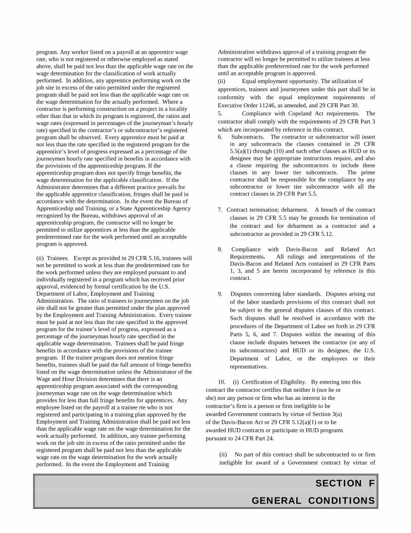
SECTION F
GENERAL CONDITIONS
program. Any worker listed on a payroll at an apprentice wage rate, who is not registered or otherwise employed as stated above, shall be paid not less than the applicable wage rate on the wage determination for the classification of work actually performed. In addition, any apprentice performing work on the job site in excess of the ratio permitted under the registered program shall be paid not less than the applicable wage rate on the wage determination for the actually performed. Where a contractor is performing construction on a project in a locality other than that in which its program is registered, the ratios and wage rates (expressed in percentages of the journeyman’s hourly rate) specified in the contractor’s or subcontractor’s registered program shall be observed. Every apprentice must be paid at not less than the rate specified in the registered program for the apprentice’s level of progress expressed as a percentage of the journeymen hourly rate specified in benefits in accordance with the provisions of the apprenticeship program. If the apprenticeship program does not specify fringe benefits, the wage determination for the applicable classification. If the Administrator determines that a different practice prevails for the applicable apprentice classification, fringes shall be paid in accordance with the determination. In the event the Bureau of Apprenticeship and Training, or a State Apprenticeship Agency recognized by the Bureau, withdraws approval of an apprenticeship program, the contractor will no longer be permitted to utilize apprentices at less than the applicable predetermined rate for the work performed until an acceptable program is approved. (ii) Trainees. Except as provided in 29 CFR 5.16, trainees will not be permitted to work at less than the predetermined rate for the work performed unless they are employed pursuant to and individually registered in a program which has received prior approval, evidenced by formal certification by the U.S. Department of Labor, Employment and Training Administration. The ratio of trainees to journeymen on the job site shall not be greater than permitted under the plan approved by the Employment and Training Administration. Every trainee must be paid at not less than the rate specified in the approved program for the trainee’s level of progress, expressed as a percentage of the journeyman hourly rate specified in the applicable wage determination. Trainees shall be paid fringe benefits in accordance with the provisions of the trainee program. If the trainee program does not mention fringe benefits, trainees shall be paid the full amount of fringe benefits listed on the wage determination unless the Administrator of the Wage and Hour Division determines that there is an apprenticeship program associated with the corresponding journeyman wage rate on the wage determination which provides for less than full fringe benefits for apprentices. Any employee listed on the payroll at a trainee rte who is not registered and participating in a training plan approved by the Employment and Training Administration shall be paid not less than the applicable wage rate on the wage determination for the work actually performed. In addition, any trainee performing work on the job site in excess of the ratio permitted under the registered program shall be paid not less than the applicable wage rate on the wage determination for the work actually performed. In the event the Employment and Training
Administration withdraws approval of a training program the contractor will no longer be permitted to utilize trainees at less than the applicable predetermined rate for the work performed until an acceptable program is approved. (ii) Equal employment opportunity. The utilization of apprentices, trainees and journeymen under this part shall be in conformity with the equal employment requirements of Executive Order 11246, as amended, and 29 CFR Part 30. 5. Compliance with Copeland Act requirements. The contractor shall comply with the requirements of 29 CFR Part 3 which are incorporated by reference in this contract. 6. Subcontracts. The contractor or subcontractor will insert
in any subcontracts the clauses contained in 29 CFR 5.5(a)(1) through (10) and such other clauses as HUD or its designee may be appropriate instructions require, and also a clause requiring the subcontractors to include these clauses in any lower tier subcontracts. The prime contractor shall be responsible for the compliance by any subcontractor or lower tier subcontractor with all the contract clauses in 29 CFR Part 5.5.
7. Contract termination; debarment. A breach of the contract
clauses in 29 CFR 5.5 may be grounds for termination of the contract and for debarment as a contractor and a subcontractor as provided in 29 CFR 5.12.
8. Compliance with Davis-Bacon and Related Act
Requirements. All rulings and interpretations of the Davis-Bacon and Related Acts contained in 29 CFR Parts 1, 3, and 5 are herein incorporated by reference in this contract.
9. Disputes concerning labor standards. Disputes arising out
of the labor standards provisions of this contract shall not be subject to the general disputes clauses of this contract. Such disputes shall be resolved in accordance with the procedures of the Department of Labor set forth in 29 CFR Parts 5, 6, and 7. Disputes within the meaning of this clause include disputes between the contractor (or any of its subcontractors) and HUD or its designee, the U.S. Department of Labor, or the employees or their representatives.
10. (i) Certification of Eligibility. By entering into this
contract the contractor certifies that neither it (nor he or she) nor any person or firm who has an interest in the contractor’s firm is a person or firm ineligible to be awarded Government contracts by virtue of Section 3(a) of the Davis-Bacon Act or 29 CFR 5.12(a)(1) or to be awarded HUD contracts or participate in HUD programs pursuant to 24 CFR Part 24.
(ii) No part of this contract shall be subcontracted to or firm ineligible for award of a Government contract by virtue of
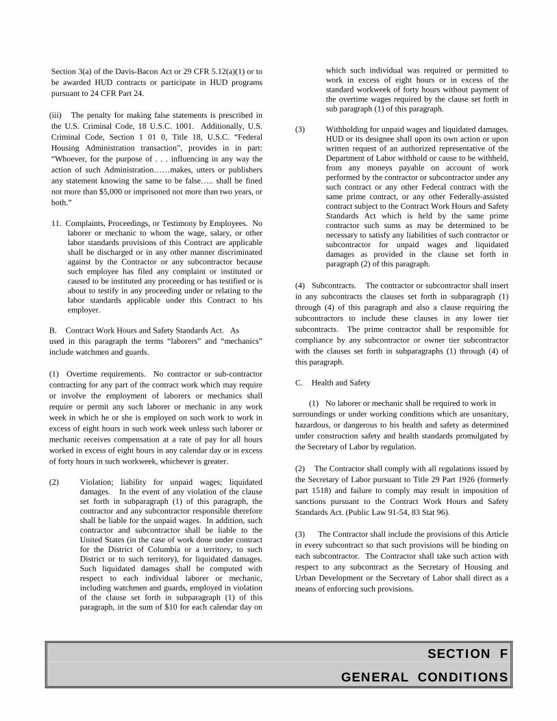
SECTION F
GENERAL CONDITIONS
Section 3(a) of the Davis-Bacon Act or 29 CFR 5.12(a)(1) or to be awarded HUD contracts or participate in HUD programs pursuant to 24 CFR Part 24.
(iii) The penalty for making false statements is prescribed in the U.S. Criminal Code, 18 U.S.C. 1001. Additionally, U.S. Criminal Code, Section 1 01 0, Title 18, U.S.C. “Federal Housing Administration transaction”, provides in in part: “Whoever, for the purpose of . . . influencing in any way the action of such Administration……makes, utters or publishers any statement knowing the same to be false….. shall be fined not more than $5,000 or imprisoned not more than two years, or both.” 11. Complaints, Proceedings, or Testimony by Employees. No
laborer or mechanic to whom the wage, salary, or other labor standards provisions of this Contract are applicable shall be discharged or in any other manner discriminated against by the Contractor or any subcontractor because such employee has filed any complaint or instituted or caused to be instituted any proceeding or has testified or is about to testify in any proceeding under or relating to the labor standards applicable under this Contract to his employer.
B. Contract Work Hours and Safety Standards Act. As used in this paragraph the terms “laborers” and “mechanics” include watchmen and guards. (1) Overtime requirements. No contractor or sub-contractor contracting for any part of the contract work which may require or involve the employment of laborers or mechanics shall require or permit any such laborer or mechanic in any work week in which he or she is employed on such work to work in excess of eight hours in such work week unless such laborer or mechanic receives compensation at a rate of pay for all hours worked in excess of eight hours in any calendar day or in excess of forty hours in such workweek, whichever is greater. (2) Violation; liability for unpaid wages; liquidated
damages. In the event of any violation of the clause set forth in subparagraph (1) of this paragraph, the contractor and any subcontractor responsible therefore shall be liable for the unpaid wages. In addition, such contractor and subcontractor shall be liable to the United States (in the case of work done under contract for the District of Columbia or a territory, to such District or to such territory), for liquidated damages. Such liquidated damages shall be computed with respect to each individual laborer or mechanic, including watchmen and guards, employed in violation of the clause set forth in subparagraph (1) of this paragraph, in the sum of $10 for each calendar day on
which such individual was required or permitted to work in excess of eight hours or in excess of the standard workweek of forty hours without payment of the overtime wages required by the clause set forth in sub paragraph (1) of this paragraph.
(3) Withholding for unpaid wages and liquidated damages.
HUD or its designee shall upon its own action or upon written request of an authorized representative of the Department of Labor withhold or cause to be withheld, from any moneys payable on account of work performed by the contractor or subcontractor under any such contract or any other Federal contract with the same prime contract, or any other Federally-assisted contract subject to the Contract Work Hours and Safety Standards Act which is held by the same prime contractor such sums as may be determined to be necessary to satisfy any liabilities of such contractor or subcontractor for unpaid wages and liquidated damages as provided in the clause set forth in paragraph (2) of this paragraph.
(4) Subcontracts. The contractor or subcontractor shall insert in any subcontracts the clauses set forth in subparagraph (1) through (4) of this paragraph and also a clause requiring the subcontractors to include these clauses in any lower tier subcontracts. The prime contractor shall be responsible for compliance by any subcontractor or owner tier subcontractor with the clauses set forth in subparagraphs (1) through (4) of this paragraph. C. Health and Safety
(1) No laborer or mechanic shall be required to work in surroundings or under working conditions which are unsanitary, hazardous, or dangerous to his health and safety as determined under construction safety and health standards promulgated by the Secretary of Labor by regulation. (2) The Contractor shall comply with all regulations issued by the Secretary of Labor pursuant to Title 29 Part 1926 (formerly part 1518) and failure to comply may result in imposition of sanctions pursuant to the Contract Work Hours and Safety Standards Act. (Public Law 91-54, 83 Stat 96). (3) The Contractor shall include the provisions of this Article in every subcontract so that such provisions will be binding on each subcontractor. The Contractor shall take such action with respect to any subcontract as the Secretary of Housing and Urban Development or the Secretary of Labor shall direct as a means of enforcing such provisions.
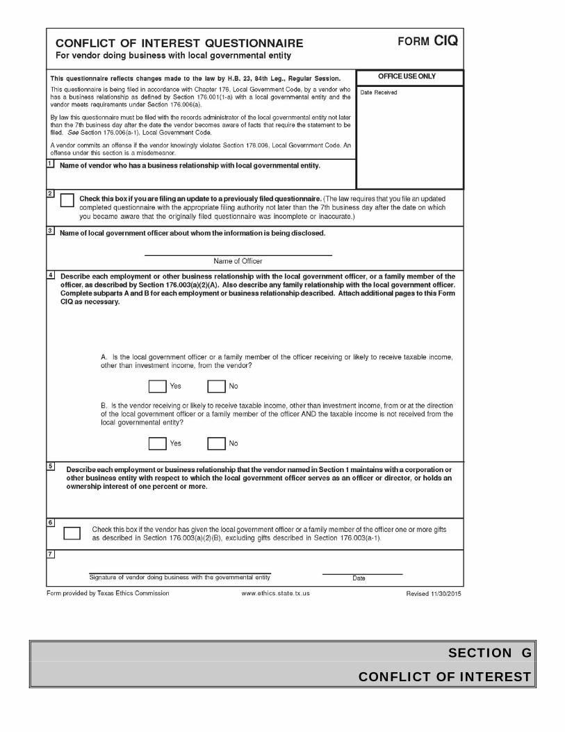
SECTION G
CONFLICT OF INTEREST
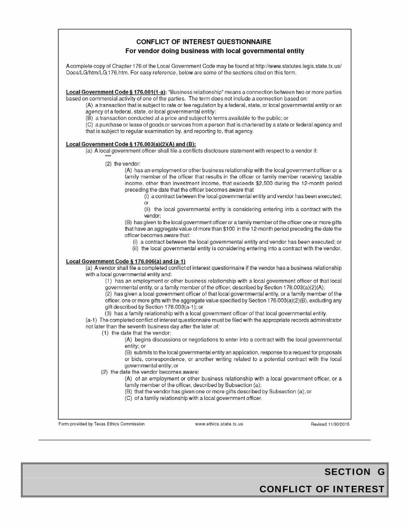
SECTION G
CONFLICT OF INTEREST

SECTION H
SUPPLEMENTAL GENERAL CONDITIONS
SUPPLEMENTAL CONDITIONS OF THE AGREEMENT - PART A
A. Jade Ave. Sanatiry Sewer Rehibilation FROM State HWY 365 to 63rd Street of Twelve Inch (12”) Concrete Sewer Line by Pipebusting to a Sixteen Inch (16”) (IPS) SDR 17 HDPE Pipe.,
B. DESCRIPTION OF WORK.
Contractor shall furnish all materials, appliances, tools, equipment, transportation, services, and all labor and superintendence necessary for the construction of work as described in these TECHNICAL SPECIFICATIONS, and as shown on the PLANS. Work, in general, consists of construction of a Sanatiry Sewer Rehibilation FROM State HWY 365 to 63rd Street of Twelve Inch (12”) Concrete Sewer Line by Pipebusting to a Sixteen Inch (16”) (IPS) SDR 17 HDPE Pipe.. The completed installation shall not lack any part which can be reasonably implied as necessary to its proper functioning or any subsidiary item which is customarily furnished, and the Contractor shall deliver the installation to the OWNER in operating condition.
C. PLANS.
City of Port Arthur Jade Ave. Sanatiry Sewer Rehibilation FROM State HWY 365 to 63rd Street of Twelve Inch (12”) Concrete Sewer Line by Pipebusting to a Sixteen Inch (IPS) (16”) SDR 17 HDPE Pipe.
D. BASIS OF PAYMENT. All work outlined in Paragraph B. above, and shown on PLANS listed in Paragraph C. above, is included in items of BID for which unit prices are shown, and these prices shall be basis of payment.
E. OTHER CONTRACTS. Other construction may be underway concurrently in this area. Contractor shall afford utility companies and other Contractors reasonable opportunity for introduction and storage of their material and execution of their work. All work under this Contract must be properly connected and coordinated with that constructed by others.
F. SEQUENCE OF WORK. City reserves the right to schedule sequence of construction.
G. SPECIAL PROVISIONS. Basic TECHNICAL SPECIFICATIONS Items which follow describe general requirements. When necessary, Special Provisions are inserted to describe additional requirements applicable to this Contract. Special Provisions are to be used in conjunction with basic TECHNICAL SPECIFICATION Items. In event of conflict between requirements of the Special Provisions and the basic TECHNICAL SPECIFICATION Item, the requirements as set forth in the Special Provisions shall govern.
SECTION H
SUPPLEMENTAL GENERAL CONDITIONS
H. SUPPLEMENTAL PAY ITEMS. Approximate Quantity and a minimum Unit Price have been established for Supplemental Items shown in SECTION D - BID. The Contractor may not bid a unit price less than the minimum value; however, he may increase the minimum unit price. If no entry is made in the spaces provided, the minimum unit prices shown shall apply. These items are included to facilitate payment for charges and alterations that may be required to complete work. The actual work as provided by the GENERAL and SPECIAL CONDITIONS OF THE AGREEMENT and TECHNICAL SPECIFICATIONS and shown on PLANS is described in PROPOSAL items other than Supplemental Pay Items. When work covered by Supplemental Items is requested by the Contractor and approved by the Engineer, payment will be based on the quantity actually constructed and Unit Prices bid in BID.
I. AS-BUILT DIMENSIONS. Contractor to make daily measurements of facilities constructed
and keep accurate records of location (horizontal and vertical) of all facilities. On completion of job, Contractor to furnish Owner with one (1) set of direct prints marked with red pencil to show as-built dimensions and location of all work constructed.
J. SURVEY MONUMENTS. Contractor is to protect existing survey monuments consisting of
right-of-way markers and horizontal and vertical control monuments in the vicinity of the project. All monuments destroyed during construction shall be replaced by the Owner and the Contractor shall pay all costs involved in restaking.
1. The selection of a CONTRACTOR for this project shall be determined by the low responsive, responsible bid for the proposal. The price bid should include the cost of all items outlined in the summary of work to accomplish the respective task.
AWARD OF A CONTRACT WILL BE MADE TO ONE SUCCESSFUL CONTRACTOR BASED ON TWO (2) CONSIDERATIONS, THE DOLLAR AMOUNT INDICATED AS THE TOTAL PRICE BID FOR PROPOSALS, AND THE NUMBER OF CALENDAR DAYS BID. Please indicate the number of calendar days in the space provided on the BID PROPOSAL FORM. Bidders are advised that when an Addendum is issued each Addendum must be recognized by signature and a copy of all signed Addendums must be submitted with Bid. It is the intent of these specifications to pay the CONTRACTOR for those items in the proposal, which he performs on. The CONTRACTOR will not be due profit or any other compensation for those items in the proposal, which are not used, not used completely, used in quantities exceeding the approximate quantities or for items deleted from this contract. The CITY Reserves the Right to

SECTION H
SUPPLEMENTAL GENERAL CONDITIONS
Add any alternate bid item at their discretion from the Alternate Bid Proposals into the Award to utilize the available funds.
2. Where there is conflict of measurement designation between the Specification and the Proposal, the unit of measurement indicated on the Proposal shall prevail.
3. When conflicts exist between the Special Provisions and General Specifications, the Special Provisions shall control.
4. Safety Standards and Accident Prevention
With respect to all work performed under this contract, the CONTRACTOR shall: a) Comply with safety standard provisions of applicable laws, building and construction codes and the "Manual of Accident Prevention in Construction", published by the Associated General CONTRACTORS of America, the requirements of the Occupational Safety and Health Act of 1970 (Public Law 91-596), and the requirements of Title 29 of Code Federal Regulations, Section 1518 as published in the "Federal Register", Volume 36, No. 75, Saturday, April 17, 1971.
b) Exercise every precaution at all times for the prevention of accidents and the protection of person (including employees and property).
7. Regardless of culpability, the CONTRACTOR shall not be allowed to take advantage of any errors or omissions in these plans and specifications or his work orders. The CONTRACTOR is required to notify the ENGINEER of all errors or omissions as soon as he becomes aware of them. Suitable instructions will be given to the CONTRACTOR by the ENGINEER when such errors or omissions are discovered. No compensation for any delay or down time, including time to receive the ENGINEER'S instructions or approval, shall be allowed. Further, any errors and/or omissions contained in the plans and/or specifications do not absolve the CONTRACTOR from ultimate and final responsibility for the successful completion of this project to the satisfaction of the ENGINEER. The degree of detail reflected in the plans or lack of same does not absolve the CONTRACTOR from the necessity of conducting an extensive investigation of the project area prior to submission of his/her bid. The CONTRACTOR will not be due any additional compensation for difficulties arising out of his/her failure to inspect, analyze the actual job site prior to submission of his/her bid.

SECTION H
SUPPLEMENTAL GENERAL CONDITIONS
8. The CONTRACTOR is expected to be completely familiar with the provisions contained in these specifications. The CONTRACTOR will not be allowed any additional payment or extension of time due to difficulties caused by his/her failure to acquaint himself/herself with this document.
9. Any and all work which, in the opinion of the ENGINEER, is necessary to complete the project and which is neither specifically listed and/or identified in the bid proposal items not elsewhere in these specifications, shall be considered incidental to the work and the CONTRACTOR will not be due any additional payment for completion of said required work.
10. Liquidation damages for delay beyond specified time for completion are $500.00 per day.
11. Warranty
The CONTRACTOR and/or his Surety will be required by the OWNER to repair, replace, restore, and/or to make to comply strictly in all things with the contract, and the plans and specifications, and any and all of said work and/or materials which within a period of one year from and after the date of the passing, approval, and/or acceptance of any such work or materials are found to be defective, or to fail in any way to comply with this contract or with the plans and specifications.
12. Permits, Licenses and Laws
The CONTRACTOR shall obtain at his own expenses, all necessary permits and licenses from the proper authorities and shall give all notice required by law or ordinance and shall pay all fees and charges incidental to the due and lawful prosecution for the work and shall comply with all laws, ordinances and regulations relating thereto. 13. Although trade names for materials may have been used in the Proposals and Plans for this project, it is intended that materials of equal quality will be acceptable on approval of the ENGINEER and the OWNER. Approval shall be obtained prior to receiving bids.
14. This contract is issued by an organization which qualifies for exemption pursuant to the provisions of Section 151.309 of the Texas Limited Sales, Excise and Use Tax Act as codified in Chapter 151 of the Texas Tax Code.
15. House Bill 1859 provides that retainage can be withheld from payment due the CONTRACTOR, from monthly progress payments for completed work. A 10% retainage will be retained until final payment is made
SECTION H
SUPPLEMENTAL GENERAL CONDITIONS
16. Bidders are advised that OWNER reserves the right to reduce any proposal by any amount, in accordance with General Conditions of the Agreement.
17. If a bidder desires to make qualifications in his bid, it shall be done in writing, attached to and submitted with his sealed bid.
18. The CONTRACTOR is responsible for any damage resulting from negligence. The CONTRACTOR will take the necessary steps to prevent these occurrences and damage to OWNERS property or adjacent properties.
19. Utilities
It shall be the CONTRACTOR'S responsibility to contact public and private utility companies in advance of construction, allowing each their respective lead time to locate and to make adjustment as necessary, of water, electric, telephone and gas mains or service lines. The CONTRACTOR shall also notify various utility companies of proposed work and work schedule. The CONTRACTOR will verify the existing utility or pipelines horizontal and vertical locations prior to initiation of construction. No extra payment will be allowed for any extra excavation incurred or downtime, which results from the required location of existing utilities. CONTRACTOR shall keep a notebook of all location requests. Each notation will contain the following information: Date, Time, Brief Location Summary, Request ID Number, and Call Back Repair Number. Any damage to utilities as a result of the CONTRACTOR'S negligence will be repaired to the satisfaction of the OWNER of the damaged utility with no compensation due the CONTRACTOR. 20. All surplus excavated materials shall become the property of the CONTRACTOR, to be disposed of as the CONTRACTOR wishes and as directed by the ENGINEER. Suitable material may be retained to facilitate site drainage as directed by the ENGINEER.
21. CONTRACTOR shall furnish temporary sanitary facilities at the site, as provided herein, for the needs of all construction workers and others performing work or furnishing services of the project. Sanitary facilities shall be of reasonable capacity, properly maintained throughout the construction period, and obscured from public view to the greatest practical extent. If toilets of the chemically treated type are used, at least one toilet will be furnished for each 20 workers, and serviced at least once a week. CONTRACTOR shall enforce the use of such sanitary facilities by all personnel at the site.
SECTION H
SUPPLEMENTAL GENERAL CONDITIONS
22. Cement stabilized sand for this Project shall contain 1½ sacks of cement per cubic yard of sand.
23. The cleanup for each respective task shall be included in the unit price bid for each item and shall be full compensation for all labor, materials, equipment, etc., required to complete work as directed by the ENGINEER. This item includes the removal of all surplus materials and debris, final grading as required including the import of material required to raise grade to proper elevation following backfill settlement or excessive soil removal. Any ditches disturbed by the construction shall be restored to their original grade.
28. Ditches along roadways shall be restored to original shape and grade. No additional compensation will be made for restoring ditches disturbed during water line installation.
29. The CONTRACTOR shall maintain streets and roadways as directed by the ENGINEER. This maintenance shall be limited to that amount required to enable suitable traffic movement. Road shell or other suitable material shall be used to provide suitable surface for traffic on streets, driveways, and shoulders. This task is considered incidental to the work and the CONTRACTOR will not be due any additional payment for this required work. During the course of construction, the CONTRACTOR will be required to maintain sanitary sewer service and to maintain the integrity of existing water services providing water to customers. Coordination with the Director of Public Works or his designated representative during service interruption is required. Interruption of existing service due to CONTRACTORS work or negligence will be repaired at the CONTRACTORS expense.
30. Concrete for this project, when directed, Shall be Class A, 3000 p.s.i (28 days), concrete using 1½” maximum size aggregate.
31. CONTRACTOR shall provide ENGINEER with written confirmation that CONTRACTOR has supplied all SUB-CONTRACTORS with a COMPLETE copy of all plans and specifications that apply to their respective tasks.
SECTION H
SUPPLEMENTAL GENERAL CONDITIONS
SUPPLEMENTAL GENERAL CONDITIONS - PART B
A. TECHNICAL SPECIFICATIONS
1. TECHNICAL SPECIFICATIONS are of the abbreviated, simplified, or streamlined type andinclude incomplete sentences. The omission of words or phrases such as "Contractorshall", "in conformity therewith", "shall be", "as noted on PLANS", "according to PLANS","a", "an", "the", and "all", are intentional. Omitted words or phrases shall be supplied byinference in same matter as they are when a "note" occurs on PLANS.
2. The TECHNICAL SPECIFICATIONS are interpreted to require that Contractor shall provideall items, articles, materials, operation or methods listed, mentioned, or scheduled either onPLANS or specified herein, or both, including all labor, materials, equipment, andincidentals necessary or required for their completion.
3. Whenever the words "approved", "satisfactory", "designated", "submitted", "observed", orsimilar words or phrases are used, it shall be assumed that the word "Engineer" follows theverb as the object of the clause, such as "approved by Engineer".
4. All references to standard TECHNICAL SPECIFICATIONS or manufacturer's installationdirections shall mean the latest edition thereof.
5. Referenced to technical society, organization, or body is made in TECHNICALSPECIFICATIONS in accordance with following abbreviations:
AASHTO American Association of State Highway and Transportation Officials ACI American Concrete Institute ASTM American Society for Testing and Materials AWWA American Waterworks Association FS Federal Specifications PCA Portland Cement Association IEEE Institute of Electrical and Electronic Engineers NEC National Electric Code UL Underwriters' Laboratories
SECTION H
SUPPLEMENTAL GENERAL CONDITIONS
AISI American Iron and Steel Institute API American Petroleum Institute IPCEA Insulated Power Cable Engineers Association NEMA National Electrical Manufacturers Association AWS American Welding Society PCI Prestressed Concrete Institute AISC American Institute of Steel Construction ANSI American National Standards Institute (Formerly ASA)
6. Some TECHNICAL SPECIFICATIONS items cover construction requirements andmaterials in comprehensive manner, and only pertinent portions of these items apply.
B. LANDS FOR WORK. Owner provides, as indicated on PLANS, land upon which work is to be done, rights-of-way for access to same, and such other lands which are designated for use by Contractor. Contractor provides, at his expense and without liability of Owner, any additional land and access thereto that may be required for his construction operations, temporary construction facilities, or for storage of materials.
C. LINES AND GRADES. From benchmarks and horizontal control references established by on the plans, stake out work, establish elevations, and assume responsibility for correctness of installation as to location and grade.
1. One Structure at Site. Benchmark and reference hubs at two corners of structure.
2. Two or More Structures. Benchmark and base line at site.
3. Sewer Lines. Benchmarks at intervals not exceeding 2,000 feet and reference hubs atmanholes and on line at intervals not exceeding 200 feet.
4. Waterlines. Reference hubs at turns in line, valves, and fire hydrants, and benchmarks atintervals not exceeding 2,000 feet.
5. Pavements and Ditches. Reference hubs on centerline or one right-of-way line at the P.C.,P.I., and P.T. of curves and on tangents at intervals not exceeding 200 feet. Benchmarks atintervals not exceeding 2,000 feet.
D. UTILITY SERVICES FOR CONSTRUCTION. Contractor will provide all utilities necessary for construction at no additional cost to Owner unless otherwise specified in preceding Special Provision.
SECTION H
SUPPLEMENTAL GENERAL CONDITIONS
E. MATERIALS TESTING. All materials, equipment, etc., per scope of work, used in the
construction of the project shall be subject to adequate inspection and testing in accordance with accepted standards and frequency, or as required by the contract documents. The CONTRACTOR shall make all arrangements for such tests and inspections with a local independent testing laboratory acceptable to the OWNER, and the CONTRACTOR shall bear all related costs of tests and inspections. If such procedures for testing and inspection reveal failure to comply with accepted standards or with requirements established by the contract documents, all re-testing and re-inspection costs made necessary by such failure, including those of related procedures, shall also be at CONTRACTOR’S expense. If the ENGINEER and/or OWNER determines that portions of the project requires additional testing or inspection not included in CONTRACTOR’S original bid, the ENGINEER shall, upon written authorization from the OWNER, instruct the CONTRACTOR to make arrangements for additional testing and inspection. The costs for such additional testing and inspection shall be at OWNER’S expense. The CONTRACTOR’S independent testing laboratory shall give timely notice to the CONTRACTOR and the ENGINEER of when and where tests and inspections are to be made so that the CONTRACTOR and the ENGINEER may be present for such procedures. If the ENGINEER is to observe tests and inspections, the ENGINEER will do so promptly and, where practical, at the normal pace of testing. Tests and inspections shall be made promptly to avoid unreasonable delays on the project. Required certificates and/or reports of all test and inspections shall, unless otherwise required by the contract documents, be promptly delivered by the independent testing laboratory to the CONTRACTOR, the ENGINEER, and the OWNER.
F. VARIATIONS DUE TO EQUIPMENT. Foundations, structural supports, electrical work,
and piping shown on PLANS for items of equipment may be changed if necessary to accommodate equipment furnished. Every effort has been made to design foundations, structural supports, electrical work, and piping to that no changes will be necessary; however, exact dimensions and size of subject foundations and structural supports and exact electrical and piping installations cannot be finally determined until various items of equipment are purchased and manufacturer's certified shop drawings are secured. Make changes, after prior consultation with Engineer, at no cost to Owner.
SECTION H
SUPPLEMENTAL GENERAL CONDITIONS
If substitute items of equipment are authorized which vary materially from those shown on PLANS, prepare equipment data and detailed drawings covering necessary modifications and submit to Engineer for approval. Make drawings same size as Contract PLANS and of comparable quality. Make payment of charges resulting from modifications, including engineering charges for checking modifications.
G. ALTERNATE DESIGNS. If alternate design features are proposed for convenience of Contractor, submit design calculations and detail drawings covering proposed changes and related modifications of Contract PLANS to Engineer for review. Make drawings same size as Contract PLANS and of comparable quality. Make payment of charges resulting from modifications, including engineering charges for checking such designs.
H. SHOP DRAWINGS. Furnish engineer six (6) copies of shop and erection drawings, schedules, and data sheets covering items of construction and equipment listed below:
1. Structural and miscellaneous steel and steel tanks.
2. Architectural products.
3. Reinforcing steel
4. Prestressed reinforced concrete members.
5. Reinforced concrete pressure pipe.
6. Mechanical equipment, including valves and sluice gates.
7. Electrical equipment, including instruments.
8. Special items, as directed.
Contractor will check and approve shop drawings for compliance with requirements of Contract and will so certify by stamp on each drawing prior to submittal to Engineer. Any drawings submitted without Contractor's stamp of approval will not be considered and will be returned to him for proper submission.
Engineer will pass promptly upon drawings submitted, noting necessary corrections or revisions. If Engineer rejects drawings, resubmit corrected drawings until drawings are acceptable to Engineer as being in conformance with design concept of project and for compliance with information given in the Contract Documents. Such procedure shall not be considered cause for delay. Acceptance of drawings by Engineer does not relieve Contractor of any requirements of terms of Contract.
SECTION H
SUPPLEMENTAL GENERAL CONDITIONS
I. OPERATION AND MAINTENANCE MANUALS. Operation and maintenance manuals are to be provided where required by Specification Item.
1. Contractor to be responsible for obtaining installation, operation, and maintenance manuals
from manufacturers and suppliers for equipment furnished under the contract. Submit three (3) copies of each complete manual to the Engineer within ninety (90) days after approval of shop drawings, product data, and samples, and not later than the date of shipment of each item of equipment to the project site or storage location.
2. Operations and maintenance manuals specified hereinafter are in addition to any operation,
maintenance, or installation instructions required by the Contractor to install, test, and start up equipment.
3. Each manual to be bound in a folder and labeled to identify the contents and project to
which it applies. 4. The manual is to contain the following: (a) An 8½-inch x 11-inch typewritten sheet listing the manufacturer's identification,
including order number, model, and serial number and location of parts and service centers.
(b) A separate 8½-inch x 11-inch typewritten list of recommended stock of parts, including part number and quantity.
(c) Complete replacement parts list.
(d) Performance data and rating tables.
(e) Specific instructions for installation, operation, adjustment, and maintenance. J. COST BREAKDOWN. Within fifteen (15) days after execution of Contract, submit, in
acceptable form, schedule showing subdivision of Contract into various items of permanent construction, stating quantities and prices, as basis for computing value to Owner of permanent usable parts of facility to be paid for on monthly estimates. No payment will be made to Contractor until such schedule has been submitted and approved.
K. PROGRESS SCHEDULE. Within fifteen (15) days after execution of Contract, submit in
acceptable form, anticipated progress schedule covering work to be performed.
SECTION H
SUPPLEMENTAL GENERAL CONDITIONS
L. GUARANTEES. Guarantee work, including equipment installed, to be free from defects due to faulty workmanship or materials for period of one year from date of issue of Certificate of Acceptance. Upon notice from Owner, repair defects in all construction which develop during specified period at no cost to Owner. Neither final acceptance nor final payment nor any provision in Contract Documents relieves Contractor of above guarantee. Notice of observed defects will be given with reasonable promptness. Failure to repair or replace defect upon notice entitles Owner to repair or replace same and recover reasonable cost thereof from Contractor and/or his Surety.
M. SITE MAINTENANCE AND CLEAN-UP. Maintain sites of work during construction to keep them reasonably neat and free of trash, rubbish, and other debris. In clean-up operations, remove from sites of work and from public and private property, temporary structures, rubbish, and waste materials. Dispose of excavated materials beyond that needed to bring site to elevations shown. During final clean-up, any road constructed by Contractor for access to construction site to be leveled and ruts filled so that natural surface drainage is not hindered.
N. MATERIALS AND EQUIPMENT. Incorporate into work only new materials and equipment of domestic manufacture unless otherwise designated. Store these materials and equipment in manner to protect them from damages. Manner of protection subject to specific approval of Engineer. Pipe, fittings, equipment, and other serviceable materials found on site of work, or dismantled by reason of construction, remain property of Owner. Remove and deliver materials to Owner at designated points. Pay, at prevailing market price, for usable materials that are damaged through negligence.
O. SUBSURFACE EXPLORATION. It is not represented that PLANS show all existing storm sewer, sanitary sewer, water, gas, telephone, and electrical facilities, and other underground structures. Determine location of these installations in way of construction by referring to available records, consulting appropriate municipal departments and utility owners, and by making necessary exploration and excavations.
P. DEVIATIONS OCCASIONED BY UTILITY STRUCTURES. Whenever existing utilities, not indicated on PLANS, present obstructions to grade and alignment of pipe, immediately notify Engineer, who without delay, will determine whenever existing improvements are to be relocated, or grade and alignment of pipe changed. Where necessary to move services, poles, guy wires, pipelines, or other obstructions, make arrangements with owners of utilities. Owner will not be liable for damages on account of delays due to changes made by owners of privately owned utilities which hinder progress of work.
SECTION H
SUPPLEMENTAL GENERAL CONDITIONS
Q. PROTECTION AND REPLACEMENT OF PROPERTY. In addition to requirements of
Paragraph 56 of GENERAL CONDITIONS OF AGREEMENT, the following applies: "Where necessary to take down fences, signs, or other obstructions, replace in their original
condition and restore damaged property or make satisfactory restitution, at no cost to Owner.” R. INTERRUPTION OF UTILITY SERVICES. Operate no valve or other control on existing
systems. Exercise care in performing work so as not to interrupt service. Locate and uncover existing utilities ahead of heavy excavation equipment. At house connections, either lift trenching machine over lines or cut and reconnect with minimum interruption of service, as approved.
S. PROTECTIVE MEASURES. Where construction creates hazard to traffic or public safety,
furnish and maintain suitable barricades, warning signs, and lights. Remove same when no longer necessary.
T. USE OF STREETS. 1. Remove, as soon as practicable, accumulated rubbish and open each block for public use.
Use of any portion of street shall not constitute acceptance of any portion of work. Backfill and shape trenches across street intersections or driveways for safe traffic at night or, where permitted, span open trenches with wooden mats or bridges to permit traffic flow. When driveways are cut, immediate placement of mats for ingress or egress of vehicles may be directed if undue hardship to property owner would otherwise result.
2. Except where approved otherwise, do not hinder or inconvenience travel on streets or
intersecting alleys for more than two blocks at any one time. Whenever street is closed, place properly worded sign announcing fact to public, with proper barricades at nearest street corners, on both sides of obstruction. Leave no street or driveway blocked at night.
3. When street is closed, notify Fire Department and Police Department. 4. Do not block ditches, inlets, fire hydrants, etc., and, where necessary, provide temporary
drainage.
SECTION I
PAYMENT BOND
PAYMENT BOND STATE OF TEXAS KNOW ALL MEN BY THESE PRESENTS: COUNTY OF JEFFERSON THAT we _____________________________________________, of the City of __________________, County of _______________________, and State of ___________________, as Principal, and _______________________________, as Surety, authorized under the laws of the State of Texas to act as Surety on bonds for principals are held and firmly bound unto the Pleasure Island Commission, Port Arthur, Texas, and to all Subcontractors, workmen, laborers, mechanics and furnishers of material, and any other claimant, as their interest may appear, all of whom shall have the right to sue upon their bond, in the penal sum of ______________________________________________________________________________ ______________________________________________________________________________ Dollars ($_________________), lawful currency of the United States of America, for the payment of which, well and truly to be made, we do hereby bind ourselves, our heirs, executors, administrators and successors, jointly and severally and firmly by these presents: The condition of this Bond is such that, whereas, the above bounden Principal as prime contractor has on the ________ day of __________________, 2017, entered into a formal contract with the City of Port Arthur for which is hereby referred to and made part hereof as if fully written herein. NOW, THEREFORE, if the above bounden Principal shall protect all claimants supplying labor and material as provided for in Section 1 of Chapter 93 of the Acts of the 56th Regular Session of the Legislature of Texas (compiled as Article 5160 of Vernon's Texas Civil Statutes, as amended) and shall pay and perform any and every obligation that of such principal is required or provided for in such law, this bond being solely for the protection of all such claimants and being for the use of each such claimant, then this obligation shall be null and void, otherwise it shall remain in full force and effect. It is stipulated and agreed that no change, extension of time, addition to or modification of the Contract or work performed thereunder, shall in anywise affect the obligation of this bond, and surety expressly waives notice of any such change, extension of time, addition or modification.
SECTION I
PAYMENT BOND
IN WITNESS WHEREOF, the said Principal has caused these presents to be executed, and the said surety has caused these presents to be executed, each by its duly authorized agent and officer, and its corporate seal to be affixed at ____________________________________ on this the _________ day of ___________________________, A.D., 2017.
CONTRACTOR
ATTEST: BY:
TITLE:
SURETY
ATTEST: BY:
TITLE:
NOTE: Date of Bond must not be prior to date of Contract. If CONTRACTOR is Partnership, all partners shall execute Bond. Surety companies executing bonds must appear on Treasury Department’s most current list (Circular 570 as amended) and be authorized to transact business in Texas.
SECTION J
PERFORMANCE BOND
PERFORMANCE BOND KNOW ALL MEN BY THESE PRESENTS: THAT
(Name of Contractor)
(Address of Contractor)
a , hereinafter called Principal, and
(Name of Surety)
(Address of Surety)
hereinafter called Surety, are held and firmly bound unto
(Name of Owner)
(Address of Owner)
hereinafter called OWNER, in the penal sum of
Dollars, $( )
in lawful money of the United States, for the payment of which sum well and truly to be made, we bind ourselves, successors, and assigns, jointly and severally, firmly by these presents. THE CONDITION OF THIS OBLIGATION is such that whereas, the Principal entered into a certain Contract with the OWNER, dated the _________ day of __________________________, 2017, a copy of which is hereto attached and made a part hereof for the construction of:
. NOW, THEREFORE, if the Principal shall well, truly and faithfully perform its duties, all the undertakings, covenants, terms, conditions, and agreements of said contract during the original term thereof, and any extensions thereof which may be granted by the OWNER, with or without notice to the Surety and during the one year guaranty period, and if he shall satisfy all claims and demands incurred under such contract, and shall fully indemnify and save harmless the OWNER from all costs and damages which it may suffer by reason of failure to do so, and shall reimburse and repay the OWNER all outlay and expense which the OWNER may incur in making good any default, then this obligation shall
SECTION J
PERFORMANCE BOND
be void; otherwise to remain in full force and effect. Provided, that this bond is executed pursuant to Article 5160 of the Revised Civil Statutes of Texas as amended and all liabilities on this bond shall be determined in accordance therewith. PROVIDED, FURTHER, that the said surety, for value received hereby stipulates and agrees that no change, extension of time, alteration or addition to the terms of the contract or to WORK to be performed thereunder or the SPECIFICATIONS accompanying the same shall in any wise affect its obligation on this BOND, and it does hereby waive notice of any such change, extension of time, alteration or addition to the terms of the contract or to the WORK or the SPECIFICATIONS. PROVIDED, FURTHER, that no final settlement between the OWNER and the CONTRACTOR shall abridge the right of any beneficiary hereunder, whose claim may be unsatisfied. IN WITNESS WHEREOF, this instrument is executed in _______ counterparts, each one of which shall be deemed an original, this the _________ day of ______________________, 2017. ATTEST: Principal BY: (s) (Principal) Secretary [SEAL] (Witness as to Principal) (Address) Address Surety ATTEST: BY: Witness as to Surety Attorney-in-Fact Address Address NOTE: DATE OF BOND must not be prior to date of Contract. IF CONTRACTOR is Partnership, all partners
should execute BOND.
SECTION J
PERFORMANCE BOND
IMPORTANT: Surety companies executing BONDS must appear on the Treasury Department's most current list (Circular 570 as amended) and be authorized to transact business in the state where the PROJECT is located.
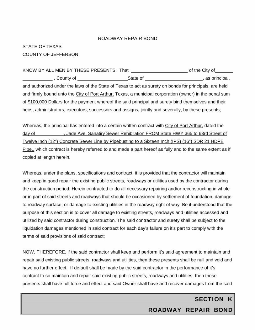
SECTION K
ROADWAY REPAIR BOND
ROADWAY REPAIR BOND
STATE OF TEXAS
COUNTY OF JEFFERSON
KNOW BY ALL MEN BY THESE PRESENTS: That of the City of
, County of State of , as principal,
and authorized under the laws of the State of Texas to act as surety on bonds for principals, are held
and firmly bound unto the City of Port Arthur, Texas, a municipal corporation (owner) in the penal sum
of $100,000 Dollars for the payment whereof the said principal and surety bind themselves and their
heirs, administrators, executors, successors and assigns, jointly and severally, by these presents;
Whereas, the principal has entered into a certain written contract with City of Port Arthur, dated the
day of , Jade Ave. Sanatiry Sewer Rehibilation FROM State HWY 365 to 63rd Street of
Twelve Inch (12”) Concrete Sewer Line by Pipebusting to a Sixteen Inch (IPS) (16”) SDR 21 HDPE
Pipe., which contract is hereby referred to and made a part hereof as fully and to the same extent as if
copied at length herein.
Whereas, under the plans, specifications and contract, it is provided that the contractor will maintain
and keep in good repair the existing public streets, roadways or utilities used by the contractor during
the construction period. Herein contracted to do all necessary repairing and/or reconstructing in whole
or in part of said streets and roadways that should be occasioned by settlement of foundation, damage
to roadway surface, or damage to existing utilities in the roadway right of way. Be it understood that the
purpose of this section is to cover all damage to existing streets, roadways and utilities accessed and
utilized by said contractor during construction. The said contractor and surety shall be subject to the
liquidation damages mentioned in said contract for each day’s failure on it’s part to comply with the
terms of said provisions of said contract;
NOW, THEREFORE, if the said contractor shall keep and perform it’s said agreement to maintain and
repair said existing public streets, roadways and utilities, then these presents shall be null and void and
have no further effect. If default shall be made by the said contractor in the performance of it’s
contract to so maintain and repair said existing public streets, roadways and utilities, then these
presents shall have full force and effect and said Owner shall have and recover damages from the said
SECTION K
ROADWAY REPAIR BOND
contract and it’s principal and surety. It is further agreed that this obligation shall be continuing one
against the principal and surety herein, and that successive recoveries may be hereon for successive
breaches until the full amount shall have been exhausted.
PROVIDED, the aggregate liability of surety hereunder is limited to the penal sum of this bond.
IT WITNESS WHEREOF, the said principal and surety have signed and sealed this instrument this day of , 20 . Principal Surety By: By: Title Title Address Address The name and address of the resident agent of surety is: NOTE: Date of Roadway Repair Bond must not be prior to date of contract.
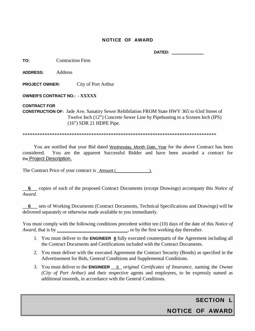
SECTION L
NOTICE OF AWARD
NOTICE OF AWARD
DATED: _____________
TO: Contruction Firm
ADDRESS: Address
PROJECT OWNER: City of Port Arthur
OWNER'S CONTRACT NO.: - XXXXX
CONTRACT FOR CONSTRUCTION OF: Jade Ave. Sanatiry Sewer Rehibilation FROM State HWY 365 to 63rd Street of
Twelve Inch (12”) Concrete Sewer Line by Pipebusting to a Sixteen Inch (IPS) (16”) SDR 21 HDPE Pipe.
*******************************************************************************
You are notified that your Bid dated Wednesday, Month Date, Year for the above Contract has been considered. You are the apparent Successful Bidder and have been awarded a contract for the Project Description.
The Contract Price of your contract is Amount (_______________).
6 copies of each of the proposed Contract Documents (except Drawings) accompany this Notice of Award.
6 sets of Working Documents (Contract Documents, Technical Specifications and Drawings) will be delivered separately or otherwise made available to you immediately.
You must comply with the following conditions precedent within ten (10) days of the date of this Notice of Award, that is by , or by the first working day thereafter.
1. You must deliver to the ENGINEER 6 fully executed counterparts of the Agreement including allthe Contract Documents and Certifications included with the Contract Documents.
2. You must deliver with the executed Agreement the Contract Security (Bonds) as specified in theAdvertisement for Bids, General Conditions and Supplemental Conditions.
3. You must deliver to the ENGINEER 6 original Certificates of Insurance, naming the Owner(City of Port Arthur) and their respective agents and employees, to be expressly named asadditional insureds, in accordance with the General Conditions.
SECTION L
NOTICE OF AWARD
NOTICE OF AWARD Contruction Firm
_____________Page 2 Failure to comply with these conditions within the time specified will entitle OWNER to consider your bid in default, to annul this Notice of Award, and to declare your Bid Security forfeited. Within ten (10) days after you comply with the above conditions, OWNER will return to you two (2) fully signed counterparts of the Agreement with the Contract Documents attached. OWNER: City of Port Arthur, TEXAS BY: TITLE: ACCEPTANCE OF AWARD: CONTRACTOR: BY: TITLE: DATE:
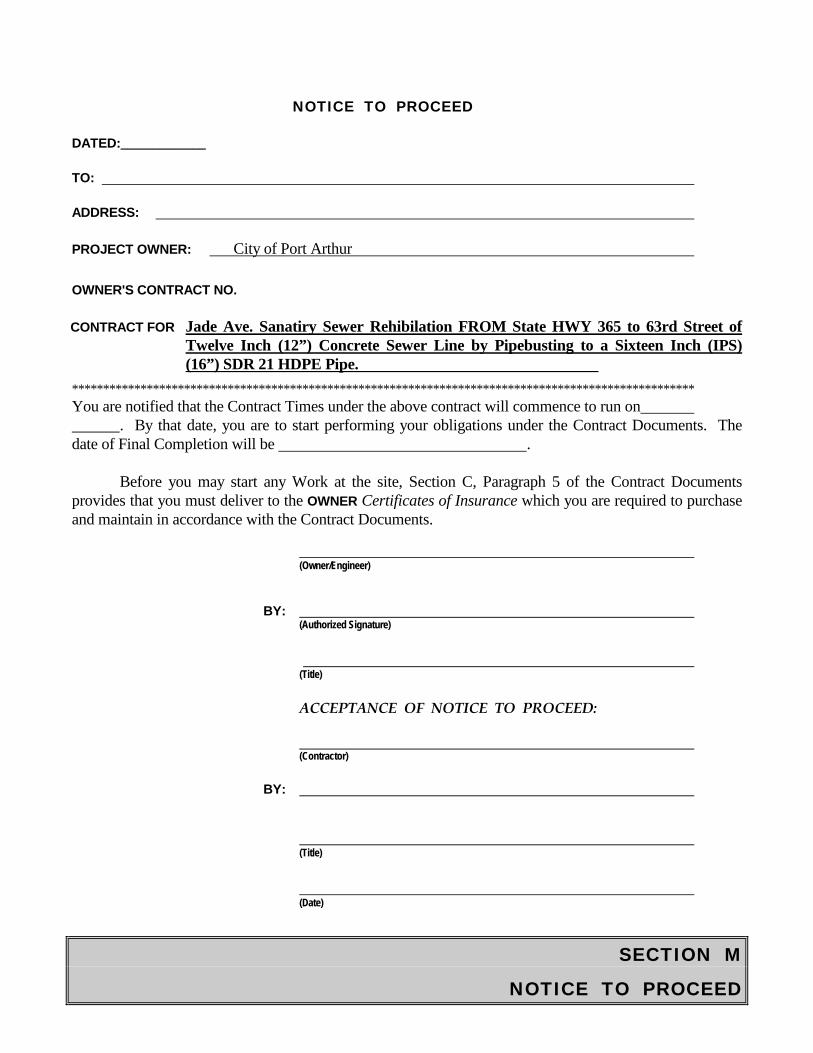
SECTION M
NOTICE TO PROCEED
NOTICE TO PROCEED
DATED:_____________
TO:
ADDRESS:
PROJECT OWNER: City of Port Arthur
OWNER'S CONTRACT NO.
CONTRACT FOR Jade Ave. Sanatiry Sewer Rehibilation FROM State HWY 365 to 63rd Street of Twelve Inch (12”) Concrete Sewer Line by Pipebusting to a Sixteen Inch (IPS) (16”) SDR 21 HDPE Pipe.
**************************************************************************************************** You are notified that the Contract Times under the above contract will commence to run on
. By that date, you are to start performing your obligations under the Contract Documents. The date of Final Completion will be .
Before you may start any Work at the site, Section C, Paragraph 5 of the Contract Documents provides that you must deliver to the OWNER Certificates of Insurance which you are required to purchase and maintain in accordance with the Contract Documents.
(Owner/Engineer)
BY: (Authorized Signature)
(Title)
ACCEPTANCE OF NOTICE TO PROCEED:
(Contractor)
BY:
(Title)
(Date)
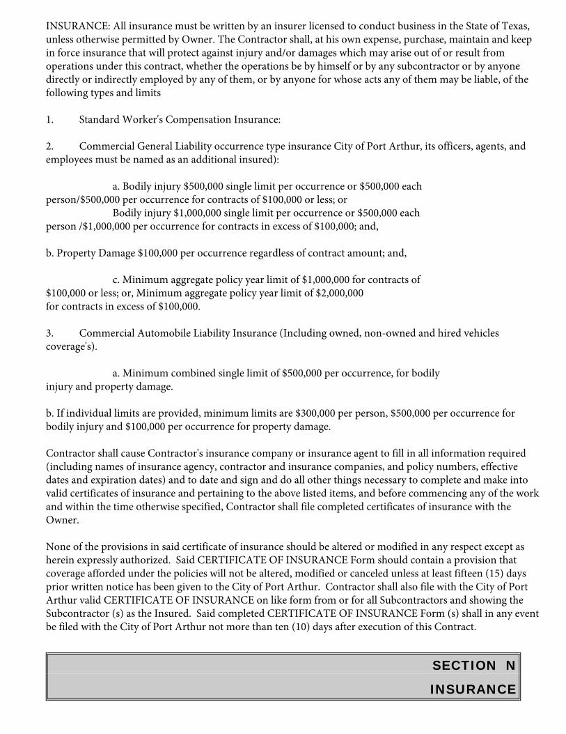
SECTION N
INSURANCE
INSURANCE: All insurance must be written by an insurer licensed to conduct business in the State of Texas, unless otherwise permitted by Owner. The Contractor shall, at his own expense, purchase, maintain and keep in force insurance that will protect against injury and/or damages which may arise out of or result from operations under this contract, whether the operations be by himself or by any subcontractor or by anyone directly or indirectly employed by any of them, or by anyone for whose acts any of them may be liable, of the following types and limits
1. Standard Worker's Compensation Insurance:
2. Commercial General Liability occurrence type insurance City of Port Arthur, its officers, agents, and employees must be named as an additional insured):
a. Bodily injury $500,000 single limit per occurrence or $500,000 each person/$500,000 per occurrence for contracts of $100,000 or less; or Bodily injury $1,000,000 single limit per occurrence or $500,000 each person /$1,000,000 per occurrence for contracts in excess of $100,000; and,
b. Property Damage $100,000 per occurrence regardless of contract amount; and,
c. Minimum aggregate policy year limit of $1,000,000 for contracts of $100,000 or less; or, Minimum aggregate policy year limit of $2,000,000 for contracts in excess of $100,000.
3. Commercial Automobile Liability Insurance (Including owned, non-owned and hired vehicles coverage's).
a. Minimum combined single limit of $500,000 per occurrence, for bodily injury and property damage.
b. If individual limits are provided, minimum limits are $300,000 per person, $500,000 per occurrence for bodily injury and $100,000 per occurrence for property damage.
Contractor shall cause Contractor's insurance company or insurance agent to fill in all information required (including names of insurance agency, contractor and insurance companies, and policy numbers, effective dates and expiration dates) and to date and sign and do all other things necessary to complete and make into valid certificates of insurance and pertaining to the above listed items, and before commencing any of the work and within the time otherwise specified, Contractor shall file completed certificates of insurance with the Owner.
None of the provisions in said certificate of insurance should be altered or modified in any respect except as herein expressly authorized. Said CERTIFICATE OF INSURANCE Form should contain a provision that coverage afforded under the policies will not be altered, modified or canceled unless at least fifteen (15) days prior written notice has been given to the City of Port Arthur. Contractor shall also file with the City of Port Arthur valid CERTIFICATE OF INSURANCE on like form from or for all Subcontractors and showing the Subcontractor (s) as the Insured. Said completed CERTIFICATE OF INSURANCE Form (s) shall in any event be filed with the City of Port Arthur not more than ten (10) days after execution of this Contract.
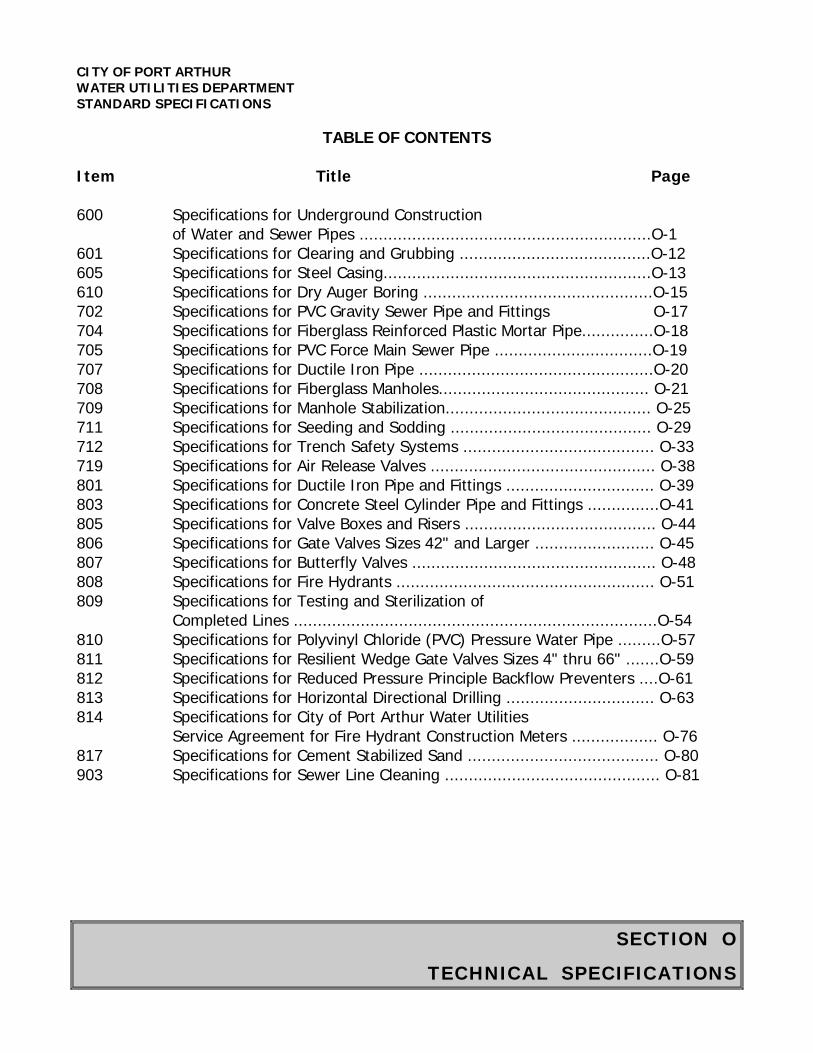
SECTION O
TECHNICAL SPECIFICATIONS
CITY OF PORT ARTHUR WATER UTILITIES DEPARTMENT STANDARD SPECIFICATIONS
TABLE OF CONTENTS
Item Title Page
600 Specifications for Underground Construction of Water and Sewer Pipes .............................................................O-1
601 Specifications for Clearing and Grubbing ........................................O-12 605 Specifications for Steel Casing........................................................O-13 610 Specifications for Dry Auger Boring ................................................O-15 702 Specifications for PVC Gravity Sewer Pipe and Fittings O-17 704 Specifications for Fiberglass Reinforced Plastic Mortar Pipe...............O-18 705 Specifications for PVC Force Main Sewer Pipe .................................O-19 707 Specifications for Ductile Iron Pipe .................................................O-20 708 Specifications for Fiberglass Manholes............................................ O-21 709 Specifications for Manhole Stabilization........................................... O-25 711 Specifications for Seeding and Sodding .......................................... O-29 712 Specifications for Trench Safety Systems ........................................ O-33 719 Specifications for Air Release Valves ............................................... O-38 801 Specifications for Ductile Iron Pipe and Fittings ............................... O-39 803 Specifications for Concrete Steel Cylinder Pipe and Fittings ...............O-41 805 Specifications for Valve Boxes and Risers ........................................ O-44 806 Specifications for Gate Valves Sizes 42" and Larger ......................... O-45 807 Specifications for Butterfly Valves ................................................... O-48 808 Specifications for Fire Hydrants ...................................................... O-51 809 Specifications for Testing and Sterilization of
Completed Lines ............................................................................O-54 810 Specifications for Polyvinyl Chloride (PVC) Pressure Water Pipe .........O-57 811 Specifications for Resilient Wedge Gate Valves Sizes 4" thru 66" .......O-59 812 Specifications for Reduced Pressure Principle Backflow Preventers ....O-61 813 Specifications for Horizontal Directional Drilling ............................... O-63 814 Specifications for City of Port Arthur Water Utilities
Service Agreement for Fire Hydrant Construction Meters .................. O-76 817 Specifications for Cement Stabilized Sand ........................................ O-80 903 Specifications for Sewer Line Cleaning ............................................. O-81
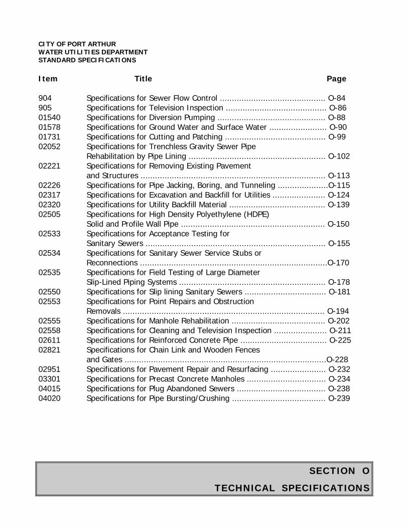
SECTION O
TECHNICAL SPECIFICATIONS
CITY OF PORT ARTHUR WATER UTILITIES DEPARTMENT STANDARD SPECIFICATIONS Item Title Page 904 Specifications for Sewer Flow Control ............................................ O-84 905 Specifications for Television Inspection .......................................... O-86 01540 Specifications for Diversion Pumping ............................................. O-88 01578 Specifications for Ground Water and Surface Water ........................ O-90 01731 Specifications for Cutting and Patching .......................................... O-99 02052 Specifications for Trenchless Gravity Sewer Pipe
Rehabilitation by Pipe Lining ......................................................... O-102 02221 Specifications for Removing Existing Pavement
and Structures ............................................................................. O-113 02226 Specifications for Pipe Jacking, Boring, and Tunneling .....................O-115 02317 Specifications for Excavation and Backfill for Utilities ...................... O-124 02320 Specifications for Utility Backfill Material ........................................ O-139 02505 Specifications for High Density Polyethylene (HDPE)
Solid and Profile Wall Pipe ............................................................ O-150 02533 Specifications for Acceptance Testing for
Sanitary Sewers ........................................................................... O-155 02534 Specifications for Sanitary Sewer Service Stubs or
Reconnections ..............................................................................O-170 02535 Specifications for Field Testing of Large Diameter
Slip-Lined Piping Systems ............................................................. O-178 02550 Specifications for Slip lining Sanitary Sewers .................................. O-181 02553 Specifications for Point Repairs and Obstruction
Removals .................................................................................... O-194 02555 Specifications for Manhole Rehabilitation ....................................... O-202 02558 Specifications for Cleaning and Television Inspection ...................... O-211 02611 Specifications for Reinforced Concrete Pipe .................................... O-225 02821 Specifications for Chain Link and Wooden Fences
and Gates ....................................................................................O-228 02951 Specifications for Pavement Repair and Resurfacing ....................... O-232 03301 Specifications for Precast Concrete Manholes ................................. O-234 04015 Specifications for Plug Abandoned Sewers ..................................... O-238 04020 Specifications for Pipe Bursting/Crushing ....................................... O-239
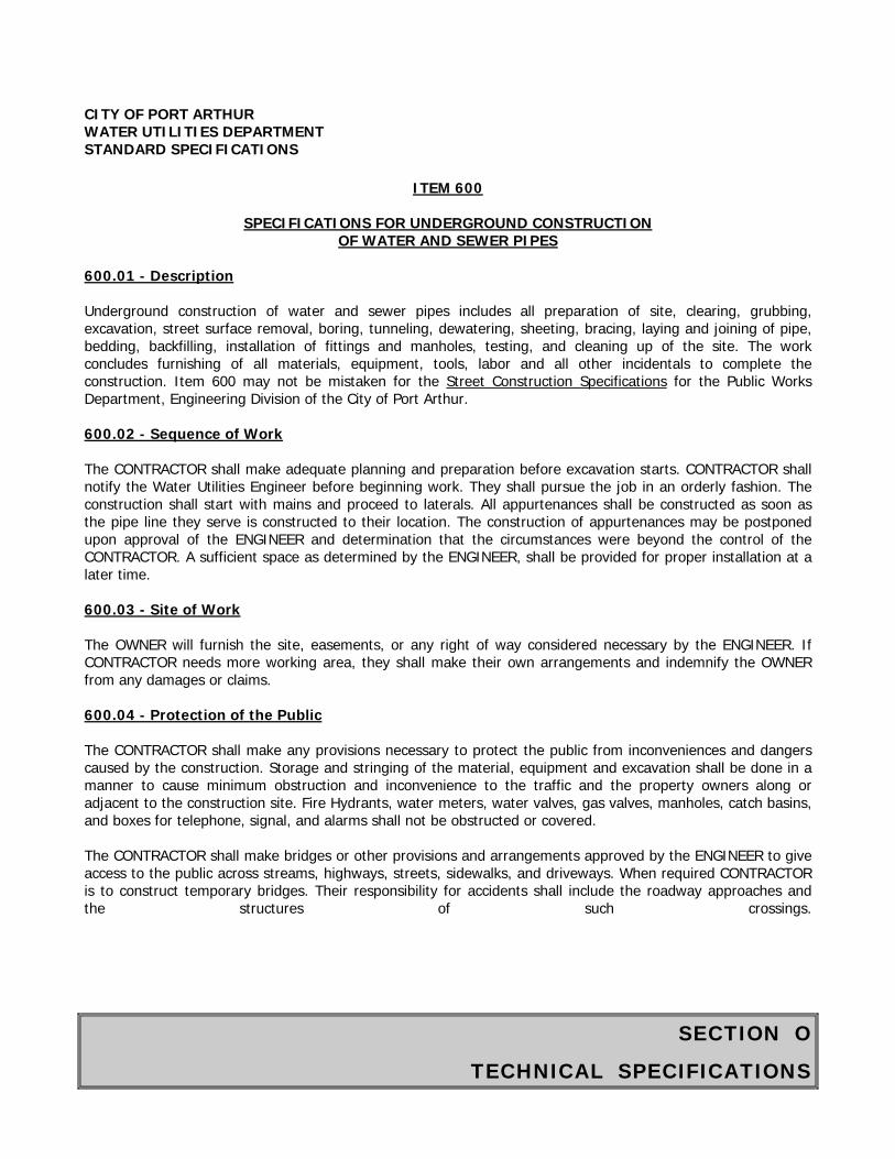
SECTION O
TECHNICAL SPECIFICATIONS
CITY OF PORT ARTHUR WATER UTILITIES DEPARTMENT STANDARD SPECIFICATIONS
ITEM 600
SPECIFICATIONS FOR UNDERGROUND CONSTRUCTION OF WATER AND SEWER PIPES
600.01 - Description
Underground construction of water and sewer pipes includes all preparation of site, clearing, grubbing, excavation, street surface removal, boring, tunneling, dewatering, sheeting, bracing, laying and joining of pipe, bedding, backfilling, installation of fittings and manholes, testing, and cleaning up of the site. The work concludes furnishing of all materials, equipment, tools, labor and all other incidentals to complete the construction. Item 600 may not be mistaken for the Street Construction Specifications for the Public Works Department, Engineering Division of the City of Port Arthur.
600.02 - Sequence of Work
The CONTRACTOR shall make adequate planning and preparation before excavation starts. CONTRACTOR shall notify the Water Utilities Engineer before beginning work. They shall pursue the job in an orderly fashion. The construction shall start with mains and proceed to laterals. All appurtenances shall be constructed as soon as the pipe line they serve is constructed to their location. The construction of appurtenances may be postponed upon approval of the ENGINEER and determination that the circumstances were beyond the control of the CONTRACTOR. A sufficient space as determined by the ENGINEER, shall be provided for proper installation at a later time.
600.03 - Site of Work
The OWNER will furnish the site, easements, or any right of way considered necessary by the ENGINEER. If CONTRACTOR needs more working area, they shall make their own arrangements and indemnify the OWNER from any damages or claims.
600.04 - Protection of the Public
The CONTRACTOR shall make any provisions necessary to protect the public from inconveniences and dangers caused by the construction. Storage and stringing of the material, equipment and excavation shall be done in a manner to cause minimum obstruction and inconvenience to the traffic and the property owners along or adjacent to the construction site. Fire Hydrants, water meters, water valves, gas valves, manholes, catch basins, and boxes for telephone, signal, and alarms shall not be obstructed or covered.
The CONTRACTOR shall make bridges or other provisions and arrangements approved by the ENGINEER to give access to the public across streams, highways, streets, sidewalks, and driveways. When required CONTRACTOR is to construct temporary bridges. Their responsibility for accidents shall include the roadway approaches and the structures of such crossings.
SECTION O
TECHNICAL SPECIFICATIONS
CITY OF PORT ARTHUR WATER UTILITIES DEPARTMENT STANDARD SPECIFICATIONS
The OWNER reserves the right to remedy any neglect by the contractor about the public conveniences and safety which may come to its attention. After twenty-four hours of notice in writing to the CONTRACTOR, except in cases of emergency, when they shall have the right to remedy any neglect without notice, and, in either case, the cost of such work done by the OWNER shall be deducted from monies due or because of the CONTRACTOR. 600.05 - Handling of Traffic The CONTRACTOR shall make provisions necessary to handle, direct, and divert the traffic. Notify the Public Works Department, Transportation Division of the City of Port Arthur of any change in traffic flow at least forty-eight (48) hours in advance. If diversion of traffic requires construction of a temporary roadway, the CONTRACTOR shall make all arrangements at their own cost and to the approval of the ENGINEER and the Public Works Department, Transportation Division. If a street needs closing, the department shall be informed forty-eight (48) hours before closing, and also after opening street to traffic. Adequate signs to divert the traffic shall be used as directed by the Public Works Department, Transportation Division. The CONTRACTOR shall make every attempt to save traffic signs and also traffic boxes, cables and lights. If any of these appurtenances need to be removed or moved accidentally, the Public Works Department, Transportation Division shall be informed immediately. 600.06 - Barricades, Lights, and Guard(s)
Where the work is in or adjacent to any street, alley, or public place, the CONTRACTOR, at their own cost and expense, furnish and build such barricades, fences, lights and danger signals; shall provide such guard (s) and shall take such other precautionary measures for the protection of persons or property and of the work necessary. Barricades shall be recently painted in a color that will be visible at night. From sunset to sunrise the CONTRACTOR shall furnish and maintain adequate lights at each barricade. Enough barricades shall be built to keep vehicles from being driven on or into any work under construction. The CONTRACTOR shall furnish guard (s) in sufficient numbers to protect the work. The CONTRACTOR shall be responsible for all damage to the work because of failure of barricades, signs, lights and guard (s) to protect it, and whenever evidence found of such damage, the ENGINEER may order the damage portion immediately removed and replaced by the CONTRACTOR at the CONTRACTOR'S cost and expense. The CONTRACTOR'S responsibility for the maintenance of barricades, signs and lights, and for providing guard (s), shall not cease until the project is accepted by the OWNER. Barricades, signs, and handling of traffic shall be in agreement with the Manual on Uniform Traffic Control Devices as adopted by the Texas Highway Department, and as directed by the Public Works Department, Transportation Division of the City of Port Arthur, all in agreement
SECTION O
TECHNICAL SPECIFICATIONS
CITY OF PORT ARTHUR WATER UTILITIES DEPARTMENT STANDARD SPECIFICATIONS with these specifications. A copy of the manual is available for review without charge at the Traffic and Transportation in City Hall. 600.07 - Protection of Utilities The locations of utilities are not shown on the plans. The CONTRACTOR shall inspect the route of the construction during the bidding period to check the location of such utilities, and possibility of any conflict. Whenever existing utilities present obstructions to grade and alignment of pipes or appurtenances, the CONTRACTOR will notify the ENGINEER, who without delay, will determine whenever existing improvements are to be relocated or grade and alignment of pipe to be changed. When necessary to move services, poles, guy wires, pipe lines, or other obstructions, the CONTRACTOR will make necessary arrangements with owner-operator of utilities. The OWNER will not be liable for damages because of changes made by the owner operator of the utility which hinders progress of work, nor will the OWNER be liable for cost incurred in relocating utilities service poles, services and appurtenances. The CONTRACTOR shall make any provision necessary to protect all utilities, services, and appurtenances. They shall locate and inform the owner-operator of a utility at least forty-eight (48) hours before progressing to such utility. It is the responsibility of the CONTRACTOR to provide and install all beam span supporting, bracing, shoring, and sheeting necessary to support all utilities crossed at their own expense. 600.08 - Protection of Private Property The CONTRACTOR shall not enter upon private property for any purpose without having previously obtained permission from the OWNER. The CONTRACTOR shall be responsible for the preservation of, and shall use every precaution to prevent damage to all trees, shrubbery, plants, lawns, fences, culverts, bridges, pavement, driveways, sidewalks, buildings, and service lines in or adjacent to private property. If a private property owner has a complaint, the CONTRACTOR shall take immediate action to satisfy the property owner. 600.09 - Preparation of the Site and the Route The CONTRACTOR shall make all preparation necessary before excavation starts. The construction site and or the route which the pipe will be laid in shall be cleared and grubbed before pipe laying. All trees, stumps, brush, roots, logs, rubbish and other objectionable material shall be removed and disposed of in a manner approved by the ENGINEER. Burning and or hauling of the material shall be executed in compliance with ordinances of the City of Port Arthur, County of Jefferson, or any other governmental body. If work is proceeding through a utility easement, care shall be taken to clear all the proposed easement as specified above. CONTRACTOR shall prepare the site furthermore by establishing drainage along the route if necessary, filling up holes, and generally leveling the site and or the route. The purpose is to keep the surface water away from the trench for pipe. It will also benefit the CONTRACTOR since soil conditions will improve and therefore the progress of the pipe laying 600.10 - Protection of Street and Drainage The CONTRACTOR shall make all attempts to keep streets and drainage open. Streets should be kept as clean as possible and mud scraped often as required and dust watered down if asked by the City. Drainage ditches shall
SECTION O
TECHNICAL SPECIFICATIONS
CITY OF PORT ARTHUR WATER UTILITIES DEPARTMENT STANDARD SPECIFICATIONS be kept open and if filled by the CONTRACTOR, they shall be reopened before the crew leaves the site at the end of a working day. If in the opinion of the ENGINEER the street needs to be closed, the CONTRACTOR shall inform the Public Works Department, Transportation Division and the residents being affected at least forty-eight (48) hours in advance. Attempts should be made to give temporary access to the residents of the blocking being affected. CONTRACTOR should attempt to minimize the duration of street closing by proper planning of the work and arranging for all the required material, equipment, and personnel. However, since the safety of the public is more important than the inconveniences imposed on, the CONTRACTOR should keep a closed street unpassable to through traffic and not open it until it is safe for through traffic. If sections of the original pavement or surface are removed by the CONTRACTOR, the trench shall be filled according to the provisions of "ITEM 600.19 and 20". Fill the top layer of the street with limestone temporarily until the street is ready for surface replacement in agreement with "ITEM 600.20 and 21", until the street is ready for final replacement of the surface, CONTRACTOR should keep the street passable for the local residents. The Street Division of the City of Port Arthur makes the final inspection of pavements, streets, shoulders, drainage ditches, and structures related to their department. CONTRACTOR shall correct any problem pointed out by this department. 600.11 - Temporary Sewer and Drainage Connections If existing sewers have to be taken up or removed, the CONTRACTOR at his cost and expense, provide and maintain temporary outlets and connections for all private or public drains and sewers. The CONTRACTOR shall also take care of all sewage and drainage which will be received from these drains and sewers; and for that purpose they shall provide and maintain, at their own expense, adequate pumping facilities and temporary outlets or diversions. The CONTRACTOR, at their own expense, shall construct such trough, pipe or other structures necessary, and at all times prepare to dispose of drainage and sewage received from these temporary connections until the permanent connections built and maintained under the contract, except where specified or ordered to be abandoned by the ENGINEER. All water or sewage shall be disposed of satisfactorily so that no nuisance is created and so that the work under construction will be adequately protected. Under no circumstances shall sewage be diverted to a drainage ditch, street, or natural ground. 600.12 - Control of Grade and Alignment
It is the responsibility of the CONTRACTOR to provide centerline stakes and cuts at each stake and to protect such stakes and control the alignment and grade. The CONTRACTOR may use any device such as level, transit or laser beam instrument to control the pipe laying. If the pipe alignment and grade is incorrect, it shall be taken out. 600.13 - Trench Excavation The ground shall be excavated by the open trench method to the required depth, width, line and grade as given by the ENGINEER. The trench walls shall be vertical to a point not less than 12 inches above the top of the pipe. For all pipes the sides of the trench below the top of the pipe shall be less than 6 inches nor more than 8 inches from the side of the pipe for sizes 12 inches and less, and the pipe outside diameter plus 24 inches maximum trench width for pipe sizes 15 inches and larger. If the trench is excavated below the proper grade, it shall be refilled to grade with selected backfill material and thoroughly rammed without extra compensation, unless the extra excavation was ordered by the ENGINEER. In case of a cave-in and if the trench width is larger than the
SECTION O
TECHNICAL SPECIFICATIONS
CITY OF PORT ARTHUR WATER UTILITIES DEPARTMENT STANDARD SPECIFICATIONS
maximum allowed, selected backfill material shall be placed on sides of the pipe up to the undisturbed wall and compacted.
In sewer construction, use 3" of washed sand for final grading/bedding. In sewer and water construction, bell holes must be excavated before pipe placement.
600.14 - Locating Intersecting Pipes
The CONTRACTOR shall make attempts to locate intersecting lines ahead of pipe laying. They shall locate and excavate in advance service lines, sewers, and water lines which will be tied into the system under construction. Any pipe line or gas line, underground power lines, fiber optic and telephone cables shall be located with proper notification.
600.15 - Sheeting and Bracing
The CONTRACTOR shall provide sheeting and bracing necessary for the protection of the work and employees. In the event the soil conditions are such that the CONTRACTOR should desire to leave such sheeting in place, they shall secure the permission of the ENGINEER to do so. Any cost of such sheeting and bracing shall be included in the unit price of laying pipe.
600.16 - De-watering
Under no circumstances shall the surface water be allowed to flow in the trench. When ground water exists in the trench, the CONTRACTOR shall make attempts to drain it away from pipe laying area or pump it out of the trench. If quicksand or water sand conditions appear in the trench bottom, the CONTRACTOR shall undercut the trench and replace it with granular material at no extra cost to the OWNER, and with the ENGINEER'S approval. City reserves the right to require the CONTRACTOR to use adequate dewatering and sheeting and bracing if the CONTRACTOR was not installing the pipe properly in unstable soil.
600.17 - Pipe Handling
The CONTRACTOR shall unload, store, and replace pipe according to the specifications of the pipe manufacturer. Care shall be taken not to damage the pipe by impaction or point loading. If using PVC or Truss pipe the pipe shall be kept in the shipping bundle until the day that it will be installed.
600.18 - Pipe Placement
The pipe shall be laid straight to the exact alignment and grade as given by the ENGINEER. No variation from the given alignment and grade will be permitted except to avoid existing underground mains, and then only upon the written permission of the ENGINEER. It is important to locate such mains in advance for possible conflict. All pipe shall be laid with the spigot end or tongue end downstream entering the bell or groove to full depth. Care shall be taken in placing pipe to prevent any bedding material being dragged into or left in the annular space for sealing of the joints. The pipe shall be examined for defects, cut to correct lengths, and the interior surface and the bell and spigot thoroughly cleaned of all foreign material. The ENGINEER reserves the right to reject any joint of pipe which has not completely complied with the provisions of these specifications. Any unsatisfactory joint shall be replaced without cost to the OWNER.
SECTION O
TECHNICAL SPECIFICATIONS
CITY OF PORT ARTHUR WATER UTILITIES DEPARTMENT STANDARD SPECIFICATIONS 600.19 - Jointing and Backfilling Jointing and backfilling depends on the pipe material. Under each item for a given material, jointing and backfilling provisions are specified. As soon as jointing is completed, backfilling shall start. The trench shall be absolutely backfilled before the working day ends. Backfill material above the required 6 or 12 inch select backfill depends on the location of the line in relation to type of street or pavement.
(a) Portland Cement Concrete Pavement and Flexible Base Asphalt Surfaces with curb and gutter, the trench shall be filled to the bottom of the pavement with a dry mixture of clean sand and one and one half (1½) sacks of cement to the cu. yd., thoroughly tamped. This requirement shall apply to both trenches running along, parallel and under the pavement and in trenches crossing the pavement.
(b) Flexible Base Asphalt Surfaces without Curb and Gutter in trench crossing flexible base surfaces with bituminous topping of any type or condition, the trench shall be filled to the bottom of the pavement surface with a dry mixture of clean sand and one and one-half (1½) sacks of cement to the cu.yd. thoroughly tamped. This requirement shall apply in trenches crossing this type of pavement surface; however, in trench running under and parallel to this type of surface the requirement shall be the same as that specified for dirt streets in (c) below.
(c) Dirt Streets - The trench shall be backfilled with selected excavation of loose fine earth by either of two methods of backfill procedure, water tamping or power tamping. In using water tamping, the balance of the trench above the 6" height above the top of pipe shall be filled with the loose fine material in even layers not exceeding eighteen (18") inches in thickness of loose material and immediately flooded to complete saturation and left undisturbed for three (3) days.
The trench shall then be refilled and flooded again using poles to insure penetration of water to the full depth of the trench. This flooding shall continue until there is no further settlement. The top ten (10") inches of the trench shall be backfilled as per standard detail. Power tamping will be permitted only where the trench and backfill material are dry enough to permit satisfactory compaction. Backfill shall be placed in the trench in layers not exceeding twelve (12") inches in thickness.
On completion of the tamping, all excavated material shall be substantially replaced in the trench deducting the space occupied by the pipe and bedding. Compaction in all levels from six (6") inches above the top of the pipe to grade shall be not less than 90% of the Maximum density value as determined by the "Standard Laboratory Method for Compaction and Density of Soil", "AASHO Designation T-99". The top six (6") inches of the trench shall be backfilled with gravel or insitu materials with no fines as per standard detail. The above procedure for dirt streets shall apply in trenches running in, parallel to and running across the normally maintained portion of the road or street right-of-way.
Whenever the trench is not in a street but in an easement or plant area which is not traveled, the backfill procedure shall be the same as for a dirt street, except for the top six (6") inches, refer to standard detail.
Whenever the trench is within a street right-of-way in which there is concrete or flexible base asphalt pavement but the trench is not in the paved portion of the right-of-way, the procedure shall be the same as for the dirt street, except that the shell in the top six (6") inches of the trench shall be placed only in driveway crossings, roadway shoulders and other areas where there will be light traffic. Where shell is omitted the ground shall be restored to its original condition by the replacement of grass or any other improvement which existed before the construction.
In general, pipe shall be placed in a trench free of clods of dirt and bedded with a bedding material or natural ground free of any large clods to damage the pipe or its position. The material around the pipe up to the spring line shall be packed to 90% density.
SECTION O
TECHNICAL SPECIFICATIONS
CITY OF PORT ARTHUR WATER UTILITIES DEPARTMENT STANDARD SPECIFICATIONS 600.20 - Removal and Replacement of Street Surfaces
The provisions of this item are same as those of Item 121.15 of the Street Construction Specifications for the Public Works Department, Engineering Division of the City of Port Arthur. This work shall comprise the cutting and replacement of pavement where such is necessary for the installation of pipe lines or appurtenances under the contract. The work shall include the furnishing of all labor, materials, tools and equipment and doing all work of whatever nature including the hauling and disposal of surplus materials necessary for the removal and later replacement of pavement in agreement with the plans and specifications. Whenever pipe line construction occurs in any street, regardless of type of pavement, the contractor will make every effort to provide ingress and egress to residents living along said streets. No separate items for pavement for removal and replacement of concrete, asphaltic, shell or gravel, streets shall be listed. The cost of this work shall be included in the unit cost per foot of pipe line.
(a) Concrete Pavement: Concrete pavement shall include streets with a concrete slab, concrete base with topping, and asphaltic pavements with curb and gutter. The CONTRACTOR shall not use equipment to cut trenches in existing pavements which will strike a heavier blow than is usual with a hand pavement breaker operated from an air compressor. The edges of the cut shall be trimmed to leave a vertical face of sound, unfractured, pavement. The pavement shall be removed to a distance not less than twelve (12") inches back from a firm bank of the trench excavation. All concrete for pavement replacement shall meet the requirements for concrete pavements as set out by the OWNER. Replacement of pavement shall be made as per Public Works Department, Engineering Division standard details as shown in the plans. All replacement pavement shall be finished in a neat and workmanlike manner and protected and cured as its nature may require.
(b) Streets other than Concrete pavement: Street pavements other than concrete and asphaltic pavements with curb and gutter may be removed with the excavation to the extent of the excavation. After backfilling the trench as specified elsewhere herein, the CONTRACTOR shall replace the pavement to its original condition.
(c) Street surfacing: P. C. Concrete or asphaltic pavement, shall be replaced within 72 hours after completion of trench backfilling or be patched with three inches (3") of temporary asphalt and maintained until permanent replacement is made. 600.21 - Crossings of Driveways, Sidewalks, and Parking Areas
In backfilling the trenches which cross under driveways of any type (concrete, bituminous, shell and dirt), and under concrete sidewalks, the procedure shall be the same as that specified in Item 600.19 Paragraph (a) for concrete pavement which specifies a dry mixture of clean sand and one and one-half (1½) sack of cement to cubic yard thoroughly tamped. Such backfill shall also conform to provisions of the Public Works Department, Engineering Division Street Construction Specifications of the City of Port Arthur. The CONTRACTOR shall restore driveways and their culverts to their original condition as soon as possible. They shall inform citizens which will be affected by this work before start of work.

SECTION O
TECHNICAL SPECIFICATIONS
CITY OF PORT ARTHUR WATER UTILITIES DEPARTMENT STANDARD SPECIFICATIONS 600.22 - Highway Crossings
Crossings of highways shall be done according to the requirements set forth by the Texas Highway Department as explained in the permit. The ENGINEER shall provide the City of Port Arthur Water Utilities Department with plan and profile drawings of the proposed construction. The City of Port Arthur Water Utilities Department will acquire the permit. It is the responsibility of the CONTRACTOR to familiarize himself with the requirements. The CONTRACTOR shall notify the maintenance superintendent of the Texas Highway Department at least 48 hours before any work starts. Adequate signs, flares, barricades and flagmen shall be used according to the State Highway Standards. Highway shall be restored to its original condition. 600.23 - Railroad Crossings
Crossings of the railroads shall be done according to the requirements set by the Railroad Company as explained in the permit. The CONTRACTOR and/or ENGINEER will acquire the permit. The completed permit shall be submitted to the City of Port Arthur Water Utilities Department prior to construction. It is the responsibility of the CONTRACTOR to familiarize himself with the requirements. The CONTRACTOR shall notify railroad roadmaster before crossing railroad at least 48 hours before any work starts. CONTRACTOR shall pay all costs connected with the furnishing by the railroad of foreman and/or crews for the supervision of work done by the railroad. 600.24 - Drainage Ditch Crossings Crossings of drainage ditches and canals shall be done according to the requirements set by the authority in charge of the ditch as explained in the permit. The CONTRACTOR and/or ENGINEER will acquire the permit. The completed permit shall be submitted to the City of Port Arthur Water Utilities Department prior to construction. It is the responsibility of the CONTRACTOR to familiarize himself with the requirements. The CONTRACTOR shall notify the authority in charge before crossing ditch or canal at least 48 hours before any work starts. Adequate protection shall be taken to establish drainage back before the working day ends. The CONTRACTOR shall be responsible for any damages caused by the stoppage of drainage. CONTRACTOR shall restore the ditch or canal to its original shape and density as soon as possible. 600.25 - Pipe Line Crossings
It is the responsibility of the CONTRACTOR to locate all pipe lines to be crossed, contact the owner of the pipe line, and make arrangements for crossing such lines. It is best to locate such lines a few hundred feet ahead of pipe laying operation, in order to make revisions in grade or alignment, if they are necessary and approved by the ENGINEER 600.26 - Excess Excavation
Excess excavation shall be hauled and placed on properties designated by the OWNER. If OWNER does not have any use for the excess dirt, the CONTRACTOR at his cost is to make arrangements to dispose of the excess excavation in a manner approved by the ENGINEER.
SECTION O
TECHNICAL SPECIFICATIONS
CITY OF PORT ARTHUR WATER UTILITIES DEPARTMENT STANDARD SPECIFICATIONS Those portions of excavated fine quality soil may be used in the trench above the 6 or 12 inch select backfill. Such portions may also be used on the construction site if they are spread properly as directed by the ENGINEER. 600.27 - Plugging Ends Before leaving the work for the night, or at any time, the end of the pipe line shall be securely closed with a water tight plug at the entire cost and expense of the CONTRACTOR. 600.28 - Tunneling, Boring, and Casing Requirements for tunneling, boring, and casing depends on the permit issuing agency involved. However, the Water Utilities Department of the City of Port Arthur should concur with the requirement set. In general casings shall have a uniform invert to be accepted for maintenance by the City of Port Arthur. Furthermore, size of the casing shall be at least 6 inches larger than the outside diameter of the bell of the pipe. Whenever a water line or sewer line is too shallow and pipe material is not adequate to withstand the traffic load at street crossings, casing or a rigid pipe such as ductile iron shall be used. An asphalt coated corrugated metal pipe may be used as a casing pipe under streets. 600.29 - Protective Coating
All bolts shall receive a protective coating of an asphaltic compound or shall be wrapped with a sand and cement (2 sack cement per 1 cubic yard of sand mixture). 600.30 - Spacing of Sanitary Sewers and Water Lines A. Water Lines Water lines shall be laid as per Texas Commission on Environmental Quality Control (TCEQ) regulations that will be determined on a case by case basis because of physical conditions, precautions shall be taken in securing absolute and permanent tightness of water pipe joints. No water pipe joint shall exist within nine feet (9') of the crossover point. B. Sanitary Sewer Lines Sanitary sewer lines shall be laid as per Texas Commission on Environmental Quality Control (TCEQ) regulations that will be determined on a case by case basis. Where this requirement cannot meet physical conditions, precautions shall be taken in securing absolute and permanent tightness of the sewer line joints. 600.31 - Testing and Acceptance All water lines shall be flushed, sterilized and pressure tested according to the provisions of Section 809 before acceptance for maintenance by the Water Utilities Department of the City of Port Arthur. 600.32 - Clean up
SECTION O
TECHNICAL SPECIFICATIONS
CITY OF PORT ARTHUR WATER UTILITIES DEPARTMENT STANDARD SPECIFICATIONS The CONTRACTOR shall remove from site of work, and from public and private property, all temporary structures, rubbish, waste material including all excess excavated materials, and all trees removed. The completed clean up shall not be greater than 1,000 feet behind pipe laying operation, however, this distance shall be reduced in residential areas. Not more than one block can be disrupted for construction. Clean up and testing may be done at the same time but clean up shall not be delayed on the account of testing. Pipe laying operation will be suspended temporarily if completed cleanup is farther behind than 1,000 feet. 600.33 - Agency Requirements to be Met All water and sewer lines installed in City of Port Arthur shall meet the requirements of the Texas Commission on Environmental Quality Control (TCEQ). 600.34 - Measurement Pipe will be measured by the linear foot of pipe complete in place. Such measurements will be made between the ends of the pipe barrel along the center axis as installed. Also consisting of all materials, labor, excavation, backfilling, testing, inspection, and other incidentals necessary to the complete installation.
End Of Section
SECTION O
TECHNICAL SPECIFICATIONS
CITY OF PORT ARTHUR WATER UTILITIES DEPARTMENT STANDARD SPECIFICATIONS
ITEM 601
SPECIFICATIONS FOR CLEARING AND GRUBBING Description Clearing and grubbing shall consist of the removal and disposal of trees, stumps, brush, roots, vegetation, logs, rubbish and other objectionable matter. Construction Methods The entire street or drainage right-of-way and other specified areas shall be cleaned except such trees and brush as may be designated by the Engineer for preservation. Trees and brush designated to be left in place shall be carefully trimmed as directed and shall be protected from scarring, barking or other injuries during construction operations. When directed by the Engineer, this item shall receive priority and shall be completed throughout the project. Areas required for water and sanitary sewer construction shall be cleared and grubbed and roots and stumps must be removed to a depth of at least two (2) feet below the existing ground surface. All holes remaining after clearing and grubbing shall be backfilled and tamped as directed by the Engineer. All cleared and grubbed material shall become the property of the Contractor and shall be disposed of at the Contractor’s expense. Measurement and Payment When specifically included as a Bid Item, Clearing and Grubbing performed as specified herein, will be measured by the acre of surface area as measured on the ground within the limits designated on the plans. All work performed satisfactorily as specified and measured as herein provided shall be paid for at the unit price bid for “Clearing and Grubbing” which price shall be full compensation for furnishing all labor, materials, equipment, tools, supplies and incidentals necessary to perform the work as specified. When not included as a Bid Item, Clearing and Grubbing will not be paid for directly but will be considered subsidiary to pay items.
End of Section
SECTION O
TECHNICAL SPECIFICATIONS
CITY OF PORT ARTHUR WATER UTILITIES DEPARTMENT STANDARD SPECIFICATIONS
ITEM 605
STEEL CASING 605.01 - GENERAL
This specification shall govern for underground construction using casing pipes in the excavation. The work shall be accomplished in accordance with these specifications and the requirements of Technical Specification Item 600, as they apply. 605.02 - MATERIALS The carrier or casing pipe shall be of the type and strength as specified in these specifications, as follows: A. Steel Casing Pipe Steel casing used for underground construction shall be new and unused steel pipe of the size and thickness as shown on the plans and specifications. The exterior of the casing pipe shall have a minimum of 20 mil. DFT of cold tar epoxy (three coats) applied after surface preparation meeting SSPC - SP10-85 to a near-white condition, using an abrasive blast material. During installation operations, care shall be taken to protect the epoxy coating and to repair any damaged areas. The Contractor shall mechanical brush and repaint all welded joints or damaged areas. During the installation operation using a quick cure coal tar epoxy paint and allow the newly painted areas to dry to touch prior to placing the casing pipe into the excavation. The proposed carrier pipe with bell/spigot joints shall have spacers to center the pipe consisting of RACI casing spacers as manufactured by Public Works Marketing, Inc. or prior approved equal. Both ends of the casing shall be sealed water tight after inserting the carrier pipe, with rubber end seals. B. Exposed Steel Casing Pipe Steel casing used for creek crossing construction shall be new and unused steel pipe of the size and thickness shown on the plans and in the specifications. The exterior of the casing pipe surface preparation shall be SSPC-SP10 near-white blast cleaned and primed with Tnemec Series 66 Hi-Build Epoxoline consisting of a minimum dry film thickness of 4.0 mils, or an approved equal. Finish coat shall be Tnemec Series 69 Hi-Build Epoxline II consisting of a minimum dry film thickness of 8.0 mils, or approved equal. The color of the finish coat shall by “Tank White”. The proposed carrier pipe with bell/spigot joints shall have spacers to center the pipe consisting of RACI casing spacers as manufactured by Public Works Marketing, Inc. or prior approved equal. Both ends of the casing shall be sealed water tight after inserting the carrier pipe, with rubber end seals. 605.03 - MEASUREMENT
The casing will be measured by the linear foot of casing in placing. Such measurements will be made between the ends of the casing along the center axis as installed.
End of Section
SECTION O
TECHNICAL SPECIFICATIONS
CITY OF PORT ARTHUR WATER UTILITIES DEPARTMENT STANDARD SPECIFICATIONS
ITEM 610
SPECIFICATIONS FOR DRY AUGER BORING 610.01 - Description
This item shall govern for the furnishing and installation of pipe by the methods of jacking, boring or tunneling as shown on the plans and in conformity with this specification. 610.02 - Materials Casings shall be steel pipe, coated on the inside and outside with coal tar epoxy (20 mil minimum thickness). Minimum wall thickness shall be 0.375" for 24" pipe. The diameter (if not specified in plans and specifications) shall be sufficient to allow installation of the carrier pipe (including joints). Any joints in casing shall be welded and coated with manufacturer approved field wrap. 610.03 - Construction The owner will provide all boring and receiving pits necessary for the boring operations. All trench excavation protection shall be constructed in accordance with the provisions of, Part 1926, Subpart P-Excavations, Trenching, and Shoring of the Occupational Safety and Health Administration's Standards and Interpretations.
Where pipe is required to be installed under railroad embankments or under highways, streets, or other facilities by jacking or boring methods, construction shall be made in such a manner that will not interfere with the operation of the railroad, street, highway, or other facility, and shall not weaken or damage any embankment or structure. During construction operations, barricades and lights to safeguard traffic and pedestrians shall be furnished and maintained by the owner until such time as the backfill has been completed and then shall be removed from the site. Heavy duty jacks suitable for forcing the pipe through the embankment shall be provided. In operating jacks, even pressure shall be applied to all jacks used. A suitable jacking head, usually of timber, and suitable bracing between jacks and jacking head shall be provided so that pressure will be applied to the pipe uniformly around the ring of the pipe. A suitable jacking frame or back stop shall be provided. The pipe to be jacked shall be set on guides, properly braced together, to support the section of the pipe and to direct it in the proper line and grade. The whole jacking assembly shall be placed so as to line up with the direction and grade of the pipe. In general, embankment material shall be excavated just ahead of the pipe and material removed through the pipe, and the pipe forced through the embankment with jacks, into the space thus provided. The Contractor shall furnish for the Engineer's approval, a plan showing his proposed method of handling, including the design for the jacking head, jacking support or back stop, arrangement and position of jacks, pipe guides, etc., complete in assembled position. The approval of this plan by the Engineer will not relieve the Contractor from his responsibility to obtain the specified results. The excavation for the underside of the pipe, for at least one third of the circumference of the pipe, shall conform to the contour and grade of the pipe. A clearance of not more than 2 inches may be provided for the upper half of the pipe
This clearance is to be tapered off to zero at the point where the excavation conforms to the contour of the pipe.
SECTION O
TECHNICAL SPECIFICATIONS
CITY OF PORT ARTHUR WATER UTILITIES DEPARTMENT STANDARD SPECIFICATIONS
The distance that the excavation shall extend beyond the end of the pipe depends on the character of the material, but it shall not exceed 2 feet in any case. The distance shall be decreased on instructions from the Engineer, if the character of the material, being excavated makes it desirable to keep the advance excavation closer to the end of the pipe.
The pipe, preferably, shall be jacked from the low or downstream end. Vertical variation in the final position of the pipe from the grade established by the Engineer will be permitted only to the extent of l inch in 50 feet, provided that such variation shall be regular and only in one direction and that the final grade of flow line shall be in the direction indicated on the plans. Lateral variation in the final position of the pipe from the line established by the Engineer will be permitted only to the extent of 1 inch in 10 feet, provided that such variation shall be regular and only in one direction.
If the Contractor desires, he may use a cutting edge of steel plate around the head end of the pipe extending a short distance beyond the end of the pipe with inside angles or lugs to keep the cutting edge from slipping back onto pipe.
When jacking of pipe is once begun, the operation shall be carried on without interruption, insofar as practicable, to prevent the pipe from becoming firmly set in the embankment. Any pipe damaged in jacking operations shall be removed and replaced by the Contractor at his entire expense.
The pits or trenches excavated to facilitate jacking operations shall be backfilled, immediately after the jacking of the pipe has been completed and the carrier pipe installed.
610.04 - Measurement
Boring and casing pipe will be measured by the linear foot of pipe complete in place. Such measurement will be made between the ends of the pipe along the flow line as installed.
610.05 - Payment
The work performed and materials furnished as prescribed by this section, measured as provided under "Measurement" will be paid for at the unit price bid per linear foot for "Boring and Casing Pipe", of the type, size, and class specified on the plans, which price shall be full compensation for furnishing all materials, pipe liner materials required for tunnel operations, for all preparation, hauling and installing of same, and for all labor, tools, equipment, and incidentals necessary to complete the work.
End of Section
SECTION O
TECHNICAL SPECIFICATIONS
CITY OF PORT ARTHUR WATER UTILITIES DEPARTMENT STANDARD SPECIFICATIONS
ITEM 702
SPECIFICATIONS FOR PVC GRAVITY SEWER PIPE AND FITTINGS
702.01 - Special Requirement The work includes all PVC (Poly Vinyl Chloride) Gravity Sewer pipe installed at locations and grades shown on plans and consisting of all excavation, backfilling, testing, and the furnishing of all materials, equipment, tools, labor, and incidentals for complete construction of the sewer line.
702.02 – Pipe and Fittings All PVC (Poly Vinyl Chloride) sewer pipe and fittings installed under these specifications and intended as a gravity sewer line shall be manufactured to the dimensions and minimum design criteria as set forth in “Type PSM (Poly Vinyl Chloride) (PVC) Sewer Pipe and Fittings”, ASTM Designation D-3034, except as herein stated. Pipe shall have a minimum SDR of 26. Joints used in installing PVC sewer pipe shall be of the bell and spigot confined rubber gasket type with joining in agreement with the manufacturer’s recommendations. Pipe shall be installed in compliance with Item 600 of these specifications, manufacturer’s specifications, and ASTM Standard D-2321-72 for “Underground Installation of Flexible Thermoplastic Sewer Pipe” or latest revision thereof. Pipe shall be kept in the bundle as shipped from the plant until the day it is installed. A deflection test may be required if deflection is apparent. 702.03 – Inspection and Testing Upon request, the CONTRACTOR shall furnish the OWNER with a certified copy of test results showing that pipe supplier’s material meets the requirements of this specification and those set forth in ASTM D-3034. The finished gravity sewer line shall pass the test in agreement with the procedure outlined in Item 02533. If any section of line fails to pass the above test, the CONTRACTOR, at his own expense, shall locate and repair all defects and retest until the line passes the prescribed test. 702.04 – Method of Payment Payment shall be by linear foot of pipe, complete in place, measured in agreement with Item 600.34 and consisting of all materials, labor, excavation, backfilling, testing, inspection, and other incidentals necessary to complete construction.
End of Section
SECTION O
TECHNICAL SPECIFICATIONS
CITY OF PORT ARTHUR WATER UTILITIES DEPARTMENT STANDARD SPECIFICATIONS
ITEM 704
SPECIFICATIONS FOR FIBERGLASS REINFORCED PLASTIC MORTAR PIPE 704.01 – General This specification covers machine-made fiberglass reinforced plastic mortar pipe intended for us as a gravity line for domestic wastes to be furnished in nominal 10, 20, or 40 foot lengths. 704.02 – Pipe The fiberglass reinforced plastic mortar sewer pipe, fabricated in a composite laminate consisting of a catalyzed isopthalic polyester resin, glass fibers, and siliceous sand, shall be as manufactured by Johns-Manville, Owens/Corning, or United Technology Center or Equivalent. Pipe shall be designed to withstand trench loads developed with 25 feet of depth. All materials used in manufacture of pipe shall conform to the applicable ASTM Standards. The fiber-glass reinforced plastic mortar sewer pipe shall meet the most current requirements of ASTM Committee D-20.23.11 proposed Standard Specification for R.P.M.P. 704.03 – Installation Fiberglass reinforced plastic mortar sewer pipe shall be installed in agreement with ASTM D-2321, Class I embedment, 70% haunching unless otherwise altered in writing from the pipe manufacturer requiring custom bedding. 704.04 – Joints The joint shall be a bell and spigot with a rubber-ring gasket which compresses to form a watertight seal when the joint is assembled. The rubber-ring gasket shall be contained in a groove in the bell end of the pipe. The gasket shall conform to ASTM Specification D-1869 except that the nominal hardness durometer will be from A35 to A65. 704.05 – Fittings Fittings shall be factory fabricated tees, ells, and wyes and shall be of the same composite laminate as the pipe. The joining method of the fittings to pipe sections shall be bell and spigot. 704.06 - Method of Payment Payment shall be by linear feet of the line complete in place in agreement with the plans and specifications.
End of Section
SECTION O
TECHNICAL SPECIFICATIONS
CITY OF PORT ARTHUR WATER UTILITIES DEPARTMENT STANDARD SPECIFICATIONS
ITEM 705
SPECIFICATIONS FOR PVC FORCE MAIN SEWER PIPE
705.01 - General
This specification covers PVC (Poly Vinyl Chloride) pipe used as a force main for domestic wastes.
705.02 – Pipe
PVC force main pipe Class 12454-B shall be designed for use at a minimum hydrostatic working pressure of 160 psi with a minimum standard dimension ratio SDR 26 or Class 150 PVC.
705.03 – Installation
PVC Force main sewer pipe shall be installed in agreement with ASTM D-2774-69T.
705.04 – Joints
Joints shall be of the bell and spigot type with confined rubber gasket.
705.05 - Inspections and Testing
The completed force main line shall pass a hydrostatic test equal to a minimum of 25 pounds per square inch or 1.5 times the manufacturers recommended operating pressure of the pipe for a 2 hour duration.
705.06 - Method of Payment
Payment shall be by linear feet of the line complete in place in agreement with the plans and specifications.
End of Section
SECTION O
TECHNICAL SPECIFICATIONS
CITY OF PORT ARTHUR WATER UTILITIES DEPARTMENT STANDARD SPECIFICATIONS
ITEM 707
SPECIFICATIONS FOR DUCTILE IRON PIPE 707.01 – General This specification covers ductile iron pipe intended for a gravity pipe line to convey domestic wastes. 707.02 - Pipe and Fittings Pipe shall conform to AWWA Class 150 and have a Protecto 401 or equal inside coating of 20mils. All fittings for cast iron pressure pipe shall be ductile iron designed and manufactured in conformance with AWWA Standard Specifications C110/A21.10-98, or latest revision thereof. Fittings shall be mechanical joint fittings and shall be furnished complete with glands, gaskets and bolts. All bolts, glands, and gaskets shall be in accordance with AWWA Standard Specification C111/A21.11-95, or latest revision thereof. All fittings shall be furnished with standard outside coatings consisting of coal tar or asphalt base bituminous materials. Fittings shall be wrapped in Protecto 401 or equal and sealed in conformity with AWWA Standard Specification C104/A21.4-95, or the latest revision thereof. 707.03 – Installation Pipe not installed through a bore shall be installed with bedding equal to that of adjacent pipe material. 707.04 – Joints Joints shall be of the bell and spigot type with confined rubber gasket unless otherwise shown on drawings. 707.05 - Method of Payment Payment for ductile iron pipe shall be included in the lump sum payment for the item of construction in which the pipe occurs.
End of Section
SECTION O
TECHNICAL SPECIFICATIONS
CITY OF PORT ARTHUR WATER UTILITIES DEPARTMENT STANDARD SPECIFICATIONS
ITEM 708
MANHOLES
1.00 GENERAL 1.01 SCOPE The work included in this section of the Specifications shall consist of providing fiberglass manholes, cast-iron rims, covers, and stainless steel rain stoppers where indicated on the Plans. 1.02 QUALITY ASSURANCE A. Comply with the latest edition of the following standards:
1. ASTM C270, Type M Mortar. 2. ASTM D3753, Glass Fiber-Reinforced Polyester Manholes.
1.03 SUBMITTALS Submit the following information in accordance with the requirements of Section 01300: Contractor’s Submittal. A. Record Data
Submit record data of detailed drawings showing dimensions, materials, and thicknesses of materials, manufacturer’s installation instructions, accessories, fittings, hardware, anchorages, schedule of components, and other pertinent data.
B. Certificate of Adequacy of Design. 2.00 PRODUCTS 2.01 MORTAR Comply with Mortar for Unit Masonry, ASTM C270, for Type M mortar. The cement material used in the preparation of the mortar shall be Portland cement, Type I, normal, or Type II, moderate sulfate resistant. 2.02 CAST IRON FRAMES AND COVERS Frames and slotted covers shall be furnished and installed in accordance with the details on the Plans and shall be East Jordan Iron Works V-1418-2 with City of Port Arthur logo or approved equivalent, unless otherwise shown on the drawings. CITY OF PORT ARTHUR WATER UTILITIES DEPARTMENT STANDARD SPECIFICATIONS 2.03 FIBERGLASS MANHOLES
SECTION O
TECHNICAL SPECIFICATIONS
CITY OF PORT ARTHUR WATER UTILITIES DEPARTMENT STANDARD SPECIFICATIONS A. Fiberglass manholes shall conform to all ASTM standards governing plastic laminations and the latest Glass Fiber-Reinforced Polyester Manholes, ASTM Designation D3753, with supplementary details or additions as set forth in these specifications. B. The barrel and cone shall each be produced in a continuous manufacturing process which ensures continuous reinforcement and uniform strength and composition. The cone section, if produced separately, shall be affixed to the barrel section at the factory with a reinforced glass-resin joint resulting in a one-piece unit. Field-made joints shall not be acceptable. C. The manhole shall be a circular cylinder with a minimum internal diameter of four feet. The cone of the manhole shall have a bearing surface wide enough to facilitate the placement of concrete adjustment rings. The ring and cover shall not be placed directly on the manhole. D. Provide and install concrete grade rings to bring the cast iron frames to grade. Grade rings shall be 2 inches by 8 inches with an inside diameter of 24 inches. E. Where PVC piping is connected to manholes, provide and install PVC sleeves with rubber gaskets and an abrasive silica outer coating. Sleeve shall be as manufactured by GPK products, Inc., of Fargo, North Dakota, or approved equivalent. Sleeve shall be firmly grouted into manhole opening in accordance with manufacturer’s instructions. F. Any manhole shall be rejected for failure to conform with any of the requirements of these specifications. Any manhole found to be defective or damaged resulting from improper handling or installation shall be removed and replaced at no additional expense to the OWNER. Patching shall not be acceptable. 2.04 MANHOLE INSERT A. Manhole inserts shall be furnished and installed at each manhole and shall be a stainless steel Preco Sewer Guard ME C-4 watertight manhole insert or equivalent. B. The manhole insert shall be stainless steel and each of its components, the valve bodies, the valve plugs, the valve springs, and the gasket shall be manufactured of plastic, stainless steel, or other corrosion proof material. C. Each insert shall contain a gasket manufactured of Grade RE-41 black closed cell neoprene and meet the requirements of ASTM D-1056-73T. The gasket shall have a pressure sensitive adhesive on one side and be placed on the underside of the insert rim by the manufacturer. D. Each insert shall have a gas relief valve and a vacuum relief valve each designed to release at a pressure differential equivalent to approximately ½ psi and approximately 2.25 psi, respectively. The valve body shall be manufactured of specially formulated plastic polymers and the valve plug shall be neoprene confined within a stainless steel spring. E. The manhole insert shall be manufactured and finished to fit upon the manhole frame rim upon which the manhole cover rests.
SECTION O
TECHNICAL SPECIFICATIONS
CITY OF PORT ARTHUR WATER UTILITIES DEPARTMENT STANDARD SPECIFICATIONS F. The manhole frame shall be cleaned of all dirt/debris before placing the insert upon the rim. G. The insert lip with gasket shall be placed in contact with 360 degrees of manhole frame rim to retard water seepage between the insert and the manhole frame. H. After the manhole insert has been installed on the manhole frame rim, note that the insert does not come in contact with the cover upon its removal or replacement (flipping). I. After installation of the watertight manhole insert, the seal shall be water tested and shall not allow more than 1-gallon of inflow during a period of 24 hours. 3.00 EXECUTION 3.01 INSTALLATION A. Manhole Base:
1. Inverts shall be built of concrete or half-sections of pipe (unless otherwise shown on the Plans) and shall be true and troweled to a smooth, hard finish. The invert depth shall be equal to one-half of the diameter of the largest pipe connected to the manhole, and shall be sloped at 1:1 between the inlet and outlet pipe flowlines. The top of the poured manhole invert outside of the flow channel shall be steeply-sloped to prevent solids deposition. 2. Concrete and reinforcing steel for the manhole base shall be placed in accordance with the details on the Plans and the applicable provisions of these Specifications. 3. Fiberglass manholes shall be installed in accordance with the manufacturer’s recommendation and with supplementary details, addition or exception as directed by the OWNER and/or shown on the Plans. A minimum of 8 holes 5/8-inch in diameter shall be drilled around the periphery of the manholes, 2 inches from the bottom for use in securing the manhole to the concrete base. 4. All concrete used in the construction of fiberglass manhole bases shall have a minimum concrete alkalinity of 70 percent calcium carbonate equivalency in the final concrete product. Alkalinity shall be tested in accordance with methodology set forth in Concrete Pipe Handbook, published by the American Concrete Pipe Association, or equivalent industrial standards, with test results provided to the ENGINEER for record data.
B. Provide an adequate connection where the pipe connects to the manhole such that infiltration and exfiltration are prevented from occurring at the connection. When required, manhole adaptors shall be used. If the manhole base is concrete and cast-in-place around the pipe, an adapter gasket shall then be installed such that the gasket will serve as a watertight seal (water stop) between the pipe and concrete. If the manhole base has a pipe fabricated integrally with the manhole, then a manufacturer’s recommended adaptor shall then be used to connect the pipe to the manhole pipe. If a “boot type” flexible connection is used, a minimum of two stainless steel straps shall then be used to secure the flexible connector to the pipe. C. Frames and covers shall be furnished and installed as required and indicated on the Plans. D. Use no more than 4 grade rings per manhole. Ring hold down bolts shall pass through rings into the top of the cone.
SECTION O
TECHNICAL SPECIFICATIONS
CITY OF PORT ARTHUR WATER UTILITIES DEPARTMENT STANDARD SPECIFICATIONS E. Where piping is connected to a manhole, CONTRACTOR shall provide a resilient connector in accordance with ASTM C-923 and the specifications and drawings. Where resilient connectors cannot be made at manhole connections, CONTRACTOR shall ensure that the pipe on each side of the manhole does not extend further than six (6) feet from the outside of the manhole wall or base, and the concrete cradle extends to within one (1) foot of the end of the pipe. F. Where main sewer (lowest line) passes straight through manhole or degree of deflection of main sewer is less than 5 degrees, and no other line or stub-out is shown entering manhole below centerline of main sewer, lay sewer continuous through manhole. After manhole wall sections have been completed above top of sewer, break out and remove top half of barrel of sewer pipe that was previously laid through manhole. Use barrel of sewer pipe that was previously laid through manhole. Use concrete with 1-inch mortar topping and shape floor. Where main sewer (lowest line) alignment deflects greater than 5 degrees at manhole or where another sewer or stub-out enters at or below centerline of main sewer, terminate main sewer pipe laying in such a manner that ends of pipe are 2 inches inside of manhole wall.
End of Section
SECTION O
TECHNICAL SPECIFICATIONS
CITY OF PORT ARTHUR WATER UTILITIES DEPARTMENT STANDARD SPECIFICATIONS
ITEM 709
MANHOLE STABILIZATION PART 1-GENERAL 1.01 SCOPE A. Stabilization, void filing and sealing of deteriorated, leaking or structurally unsound manholes. 1.02 MEASUREMENT AND PAYMENT A. Unit Prices 1. Rehabilitated Manholes:
a. Measurement and manhole stabilization, void fill and sealing (including bench stabilization) is on a vertical foot basis to the nearest tenth of a foot, measured from the bottom of the frame to the top of the bench.
b. Payment for stabilization, void filling and sealing of manholes or junction boxes other than four foot diameter circular manholes will be on an equivalent rehabilitated shall be converted to an equivalent vertical feet of a four foot diameter manhole by dividing the square feet by 12.57. B. Stipulated Price (Lump Sum): If the Contract is a Stipulated Price Contract, payment for work in the Section is included in the total Stipulated Price. 1.03 PERFORMANCE REQUIREMENTS A. Perform work needed to structurally stabilize manholes, prevent entrance of inflow or groundwater, prevent entrance of soil or debris, and prevent further movement and/or subsidence due to supporting soils. B. Manufacturer’s Product Support: When requested by the Engineer, provide a representative employed by the manufacturer having technical training in closed cell, hydro-sensitive structural polyurethane available for consultation on site upon 48 hours notice. 1.04 SUBMITTALS 1. Submittals: Comply with Section 01300- Submittal Procedures. 2. Product Data: Submit manufacturer’s product data, MSDS sheets, and application methods including the URETEK method and the URETEK Deep Injection Method. 3. Technician Qualifications: Contractor shall submit technician qualifications to the Engineer. Technicians must have a minimum of 5 years experience in performing manhole stabilization, void fill, and sealing utilizing closed cell, hydro-insensitive, structural polyurethane and in the application of the URETEK method and patented URETEK Deep Injection method. 1.05 PROJECT CONDITIONS
SECTION O
TECHNICAL SPECIFICATIONS
CITY OF PORT ARTHUR WATER UTILITIES DEPARTMENT STANDARD SPECIFICATIONS A. Manholes Containing Mechanical or Electrical Equipment:
1. Drawings may not show locations of flow monitoring equipment. If a manhole contains any mechanical hardware or electrical flow monitoring equipment, immediately notify the Engineer. 2. Reschedule work in such manholes until equipment has been removed by the further instructions are given. 3. Do not subject manholes with mechanical hardware or electrical equipment to diversion or bypass pumping. 4. Damage to installed equipment, due to Contractor’s failure to adhere to this instruction, will be repaired by the City and cost of repairs charged to the Contractor.
B. Field Location of Manholes
1. Contractor is responsible for locating and uncovering all manholes. If Contractor is unable to locate manholes, Contractor shall notify the Engineer in writing. 2. Manholes may be located within project limits which are not part of the system being rehabilitated. Properly identify manholes before starting work.
PART 2-PRODUCTS 2.01 STABILIZATION, VOID FILL, AND SEALING MATERIAL A. The material for stabilizing, void filling and sealing manholes shall be URETEK 486 STAR, a closed cell, hydro-insensitive, high density polyurethane system. B. The material shall have a minimum free rise density of 3.0 lbs./cubic ft. with a minimum compressive strength of 38.0 psi C. The material shall have a maximum free rise density of 3.2 lbs./cubic ft. with a minimum compressive strength of 42.0 psi. D. The polyurethane material shall be hydro-insensitive in the material’s component reaction such that the injected product is not significantly compromised by soil moisture or free water in the soil surrounding and/or supporting to the manhole. PART 3-EXECUTION 3.01 PROTECTION A. Provide barricades, warning lights and signs for manhole or cleanout removal excavations. Comply with City Port Arthur Special Provisions Section. B. Do not allow soil, sand debris, or runoff to enter sewer system. 3.02 DIVERSION PUMPING A. Install and operate diversion pumping equipment to maintain sewage flow and to prevent backup or overflow as specified in Section 01540-Diversion Pumping.

SECTION O
TECHNICAL SPECIFICATIONS
CITY OF PORT ARTHUR WATER UTILITIES DEPARTMENT STANDARD SPECIFICATIONS B. In the event of accidental spill or overflow, immediately stop the overflow and take action to clean up and disinfect spillage. Promptly notify the Engineer so that required reporting can be made to the Texas Commission on Environmental Quality and U.S. Environmental Protection Agency. 3.03 MANHOLE WALL STABILIZATION, VOID FILL, AND SEALING A. Multiple injection holes (5/8" diameter) shall be drilled thru the wall of the manhole at locations and at spacing as determined by field conditions. Or, Injection tubes (½”) are inserted thru augured holes, or are driven, or are jetted at multiple locations from grade and at depths as determined by field conditions. B. URETEK 486 polymer is injected in multiple shots thru the injection holes, allowed to expand, void fill, stabilize and seal the back side of the repair area. Or, URETEK 486 polymer is injected in multiple shots thru the injection tubes, allowed to expand, void fill, stabilize, and seal the back side of the repair area. (As per all or part of URETEK’s patented “Deep Injection” process) C. If annular space stabilization and seal, following pipe bursting and/or slip lining is required, injection tubes are placed into the annular space a minimum of three feet. The material is injected and allowed to outcrop and seal the entire annular area. D. Outcropped material is removed with hand tools and disposed of by the technician. E. The new seal is inspected visually for completeness and repair documentation form is completed by the technician. 3.04 MANHOLE BENCH STABILIZATION A. Multiple injection holes (5/8" dia) shall be drilled thru the bench of the manhole and injection tubes placed at multiple depths and at locations/spacing as determined by field conditions. B. Per the patented URETEK Deep Injection method, URETEK 486 polymer is injected thur tubes at multiple depths, allowed to expand, void fill, stabilize and seal the underside side of the bench thus densifying and strengthening the manhole supporting soils. 3.05 FIELD QUALITY CONTROL A. Inform the Engineer immediately if materials being used are not producing required results or need modification. The Engineer has the right to stop the use of any material at any time. 3.06 INSPECTION A. After manhole stabilization, void fill and sealing, visually inspect manholes in the presence of the Engineer. Check for cleanliness and for elimination of active leaks.
End of Section
SECTION O
TECHNICAL SPECIFICATIONS
CITY OF PORT ARTHUR WATER UTILITIES DEPARTMENT STANDARD SPECIFICATIONS
ITEM 711
SEEDING AND SODDING SEEDING 1. Description. This item shall govern for preparing ground, providing for sowing of seeds mulching with straw, hay, or cellulose fiber and other management practices along and across such areas as are designated on the plans and in accordance with these specifications. 2. Materials. All seed must meet the requirements of the Texas Seed Law including the labeling requirements for showing pure live seed (PLS = purity x germination), name and type of seed. Seed furnished shall be of the previous season’s crop and the date of analysis shown on each bag shall be within nine months of the time of use on the project. Each variety of seed shall be furnished and delivered in separate bags or containers. A sample of each variety of seed shall be furnished for analysis and testing when directed by the Engineer. The amount of seed planted per acre shall be of the type specified below. Common Name Scientific Name
Bermuda and giant Bermuda grass (Hulled or Unhulled) Cynodon dactylon
Annual Rye Lolium multiflorum German Foxtail Millet Setaria italic 3. Planting Season. Planting dates, seed mixtures and application rates shall conform to the following table:
Application Rate Planting Date Type(s) (Lbs. per Acre PLS) April 1 - September 30 Bermuda and Giant 20
Bermuda grass (Hulled) Millet 40
October 1 - March 31 Hulled Bermuda 20 Unhulled Bermuda 20
Annual Rye grass 40 4. Fertilizer. All fertilizers used shall be delivered in bags or containers clearly labeled showing the analysis. The fertilizer is subject to testing in accordance with the Texas Fertilizer Law. A pelleted or granulated fertilizer shall be used with an analysis of 13-13-13- or having the analysis shown on the plans. The figures in the analysis represent the percent of nitrogen, phosphoric acid, and potash nutrients respectively as determined by the methods of the Association of Official Agricultural Chemists. In the event it is necessary to substitute a fertilizer of a different analysis, it shall be pelleted or granulated fertilizer with a lower concentration, but the total amount of nutrients furnished and applied per acre shall equal or exceed that specified for each nutrient.
SECTION O
TECHNICAL SPECIFICATIONS
CITY OF PORT ARTHUR WATER UTILITIES DEPARTMENT STANDARD SPECIFICATIONS Pelleted or granulated fertilizer shall be applied uniformly over the area specified to be fertilized and in the manner directed for the particular item of work. The fertilizer shall be dry and in good physical condition. Fertilizer that is powdered or caked will be rejected. Distribution of fertilizer for the particular item of work shall meet the approval of the Engineer. Unless otherwise indicated in the plans or specifications, fertilizer shall be applied uniformly at the average rate of 600 pounds per acre for all types of “Seeding.” 5. Sprinkle Irrigation. Sprinkle Irrigation shall consist of the authorized application of water on those portions of the right-of-way as shown on plans or as directed by the Water Utilities Engineer, and as herein specified. Water shall be furnished by the Contractor and shall be clean and free of industrial wastes and other substances harmful to the growth of grass. This work will be done only at such time as approved by the Water Utilities Engineer and in sufficient frequency to allow optimum germination. The Contractor shall furnish and operate approved sprinklers which will insure the distribution of water in a uniform and controllable rate of application. 6. Straw Mulch. Straw mulch shall be oat, wheat or rice straw. Hay mulch shall be prairie grass, Bermuda grass or other hay as approved by the engineer. The mulch shall be free of Johnson grass or other noxious weeds and foreign materials. It shall be kept in a dry condition and shall not be molded or rotted. 7. Cellulose Fiber Mulch. Cellulose fiber mulch shall be a natural cellulose fiber mulch produced from grinding clean, whole wood chips, or fiber produced from ground newsprint with a labeled ash content not to exceed 7 percent. The mulch shall be designed for use in conventional mechanical planting, hydraulic planting of seed or hydraulic mulching of grass see, either alone or with fertilizers and other additives. The mulch shall be such, that when applied, the material shall form a strong, moisture-retaining mat without the need of an asphalt binder. Application rate for mulch in HYDRO MULCH SEEDING shall be 2000 lbs./acre. 8. Soil Stabilizer/Tacking Agent. Soil stabilizer for hydro-mulch seeding shall be of a commercially available type approved by the Engineer and shall be applied at a rate of 40 lbs./acre unless otherwise specified. 9. Construction Methods. After the designated areas have been completed to the lines, grades and cross sections shown on the plans, and as provided for in other items of this contract, seeding shall be performed in accordance with the requirements hereinafter described. All areas to be seeded shall be cultivated to a depth of at least four inches (4"), unless otherwise directed by the Engineer. The seedbed shall be cultivated sufficiently to reduce the soil to a state of good tilth when the soil particles on the surface are small enough and lie closely enough together to prevent the seed from being covered too deep for optimum germination. Cultivation of the seedbed will not be required in loose sand where depth of sand is four inches (4") or more. The cross-section previously established shall be maintained throughout the process of cultivation and any necessary reshaping shall be done prior to any planting of seed. The following are four methods of seeding which may be specified in the plans: 10. Straw or Hay Mulch Seeding. The seed or seed mixture in the quantity specified shall be uniformly distributed over the areas shown on plans or where directed by the Engineer. If the sowing of seed is by hand, rather than by mechanical methods, the seed shall be sown in two directions at right angles to each other. If mechanical equipment is used, all varieties of seed as well as fertilizer may be distributed at the same time, provided that each component is uniformly applied at the specified rate. When seed and fertilizer are to be distributed as a water slurry, the mixture shall be applied to the
SECTION O
TECHNICAL SPECIFICATIONS
CITY OF PORT ARTHUR WATER UTILITIES DEPARTMENT STANDARD SPECIFICATIONS
area to be seeded within 30 minutes after all components are placed in the equipment. Upon completion of planting of seed, straw or hay mulch shall be spread uniformly over the seeded area at the rate of approximately 1½ to 21 tons of hay or 2 to 2½ tons of straw per acre. A mulching machine approved by the Engineer shall be equipped to inject a tacking agent into the straw or hay uniformly as it leaves the equipment at a rate of 0.05 to 0.10 gallon of tacking agent per square yard of mulched area. If the straw or hay and tacking agent are placed by hand, then the rate of application for the tacking agent shall be approximately 0.15 gallon per square yard.
11. Cellulose Fiber Mulch Seeding. The seed or seed mixture, in the quantity specified, andfertilizer, shall be uniformly distributed over the areas shown on the plans or where directed. If the sowing of seed is by hand, rather than by mechanical methods, the seed shall be sown in two directions at right angles to each other. If mechanical equipment is used, all varieties of seed as well as fertilizer may be distributed at the same time, provided that each component is uniformly applied at the specified rate. When seed and fertilizer are to be distributed as a water slurry, the mixture shall be applied to the area to be seeded within 30 minutes after all components are placed in the equipment. After planting, the planted area shall be rolled with a corrugated roller of the “Cultipacker” type. All rolling of the slope areas shall be on the contour. Upon completion of planting and cultipacking of the seed, cellulose fiber mulch shall be spread uniformly over the area at the rate of 2000 lbs. per acre given in dry weight of mulch per acre. A mulching machine, approved by the Engineer, shall be equipped to eject the thoroughly wet mulch material at a uniform rate to provide the mulch coverage specified.
12. Hydro Mulch Seeding. The seed or seed mixture, in the quantity specified, shall be mixed in an approvedmixer/distributor with fertilizer and cellulose fiber mulch at the specified rates. Mixing and distributing shall be in such a manner so that thoroughly wet mulch material will be distributed at a uniform rate to provide the coverages specified. Soil stabilizer/tacking agent shall be added to the mixture at the specified rates.
13. Broadcast Seeding. The seed or seed mixture in the quantity specified shall be uniformlydistributed over the areas shown on plans or where directed by the Engineer. If the sowing of seed is by hand, rather than by mechanical methods, the seed shall be sown in two directions at right angles to each other. If mechanical equipment is used, all varieties of seed as well as fertilizer may be distributed at the same time, provided that each component is uniformly
applied at the specified rate. When seed and fertilizer are to be distributed as a water slurry, the mixture shall be applied to the area to be seeded within 30 minutes after all components are placed in the equipment. After planting, the planted area shall be rolled with a corrugated roller of the “Cultipacker” type. All rolling of the slope areas shall be on the contour.
14. Required Coverage. Germination and establishment of a good stand of Bermuda grass will be required inorder to qualify any Seeding as “Acceptable Work.” Substantial bare spots and ruts designed by the Engineer will be reseeded and fertilized as required to achieve germination. Isolated bare spots measuring 2 feet in diameter or less will be considered as acceptable work. These requirements will be adhered to assuming normal weather conditions. In the event of abnormal flooding conditions, these requirements will be applied to areas above measured highwater marks.
SODDING
The Contractor shall be responsible for restoration of all disturbed areas. Sod shall consist of St. Augustine grass. Prior to planting the St. Augustine grass, the Contractor shall prepare the disturbed area by removing all building materials such as concrete rubble, wood, bricks, etc. The planting area shall have straight edges, then be rough

SECTION O
TECHNICAL SPECIFICATIONS
CITY OF PORT ARTHUR WATER UTILITIES DEPARTMENT STANDARD SPECIFICATIONS graded, and covered with top soil or sand. The contractor shall then apply starter fertilizer that is high in phosphate and mix it with the top soil prior to planting the sod. The Contractor shall completely (100% coverage) sod all disturbed areas. Once the sod is in place, the Contractor shall water within 30 minutes of installation and then water daily for approximately two (2) weeks.
End of Section
SECTION O
TECHNICAL SPECIFICATIONS
CITY OF PORT ARTHUR WATER UTILITIES DEPARTMENT STANDARD SPECIFICATIONS
ITEM 712
TRENCH SAFETY SYSTEMS 712.01- General 1. Description: The Contractor shall comply with the minimum requirements of this specification. Maintenance and inspection of any shoring and related equipment shall be the responsibility of the Contractor. Owner and/or Engineer reserve the right to require the Contractor to remove, repair and/or replace any portions of the shoring system deemed unsafe but the final responsibility for worker’s safety remains with the Contractor. The Contractor shall determine the safety system needed for the project within the minimum requirements of this specification. The Contractor shall submit to the Owner’s Engineer a certified submittal from a Registered professional Engineer from the State of Texas that the Contractor’s Trench Safety System meets the minimum requirements of this specification, and shall make adjustments as required by the Owner and/or Engineer to meet minimum requirements at Contractor’s expense. Approval of a trench safety system by the Owner and/or Engineer shall not relieve the Contractor of his responsibility to provide a safe working place for his employees. The Contractor agrees to hold harmless and defend the Owner and/or Engineer against any claim resulting from failure of the trench system or lack of one. 2. Regulatory Requirements:
A. Conform to applicable Occupational Safety and Health Administration (OSHA) Standards as contained in 29 CFR, Part 1926, Subpart P - Excavations (as may be amended) including OSHA “Proposed Rules: Excavations. Federal Register, Vol. 52, No. 72 Wednesday, April 15, 1987, pages 12325-12339.” The sections that are made part of these specifications by reference include Sections 1926.652 and 1926.653. B. The Contractor’s Trench Safety System shall be designed by “a registered professional engineer” or “a qualified person or a qualified engineer,” such a person shall be a Professional Engineer registered in the State of Texas.
C. The Contractor’s “Engineer” shall develop a specific trench safety system design for the project in general compliance to the requirements set forth by House Bills 662 and 665 of the 70th Legislature, and in accordance with Part 1926.652(c)(4) of OSHA “Proposed Rules.”
3. Definitions:
A. Angle of Repose: The greatest angle above the horizontal plane at which a material will lie without sliding. B. Bank: A mass of soil rising above a digging level.
C. Braces: The horizontal members of the shoring system whose ends bear against the uprights or stringers.
D. Excavation: Any man-made cavity or depression in the earth’s surface, including its sides, walls, or faces, formed by earth removal and producing unsupported earth conditions by reasons of the excavation. If installed forms or similar structures reduce the depth-to-width relationship, an excavation may become a trench.
SECTION O
TECHNICAL SPECIFICATIONS
CITY OF PORT ARTHUR WATER UTILITIES DEPARTMENT STANDARD SPECIFICATIONS E. Hard Compact Soil: All earth materials not classified as running or unstable. F. Kickouts: Accidental release or failure of a shore or brace. G. Sheet Pile: A pile, or sheeting, that form one of a continuous interlocking line, or a row of timber, concrete, or steel piles, driven in close contact to provide a tight wall to resist the lateral pressure of water, adjacent earth, or other materials. H. Sides, Walls, Faces: The vertical or inclined earth surfaces formed as a result of excavation work. I. Slope: The angle with the horizontal at which a particular earth material will stand indefinitely without movement. J. Stringers Wales The horizontal members of a shoring system whose sides bear against the uprights or earth. K. Trench: A narrow excavation made below the surface of the ground. In general, the depth is greater than the width, but the width of a trench is not greater than 15 feet. L. Trench Jack: Screw or hydraulic type jacks used as cross bracing in a trench shoring system. M. Trench Shield: A shoring system composed of steel plates and bracing, welded or bolted together, which support the walls or a trench from the ground level to the trench bottom and which can be moved along as work progresses. N. Unstable Soil: Earth material, other than running, that because of its nature or the influence of related conditions, cannot be depended upon to remain in place without extra support such as would be furnished by a system of shoring. O. Uprights: The vertical members of a shoring system. 712.02 - CONSTRUCTION MATERIALS AND MAINTENANCE 1. Materials used for sheeting, sheet piling, cribbing, bracing, shoring, and underpinning shall be in good, serviceable condition, and timbers shall be sound, free from large or loose knots, and of proper dimensions as called for in the latest revision of OSHA Construction Standards, Subpart P, “Table P-2 - Trench Shoring - Minimum Requirements,” of which is made a part of these specifications. All materials which are found to be defective in any way shall be immediately removed from the job site. It shall be the responsibility of the Contractor to regularly check all trench safety equipment for soundness and adequacy. 2. Steel trench shields shall be constructed of steel plate sides, welded to a steel framework. All shields shall be construction in order to provide protection equivalent to or greater than
SECTION O
TECHNICAL SPECIFICATIONS
CITY OF PORT ARTHUR WATER UTILITIES DEPARTMENT STANDARD SPECIFICATIONS sheeting or shoring required for the trench. The Contractor shall provide written certification from the manufacturer’s engineer to the Owner’s Engineer of adequacy before using any trench shield. Adjustable jacks may be used in order adjust the shield to varying trench widths. An access ladder shall be provided at the midpoint. Pipe or flat steel runners or wheels shall be installed under the side walls for ease of movement of the shield during trenching operations. Substantial lifting eyes and/or rings shall be welded at proper points for moving of the shield. For adaptability to deep and shallow trenches, the shield may be made with top and bottom sections. When the sides of the trench extend above the top of the shield, a reinforced roof with hatches shall be provided. Forced ventilation shall be provided for fully-enclosed shields. 3. All maintenance of the trench safety equipment shall be the sole responsibility of the Contractor. 712.03 - IMPLEMENTATION Within fifteen (15) days after the Contract is awarded and prior to beginning any construction, the Contractor shall submit a written plan for a Trench Safety System specifically for construction of trench excavation, together with the general safety program required by OSHA standards governing the presence and activities of individuals in and around trench excavations. Failure to submit a Trench Safety System submittals required may result in forfeiture of the bid bond. The Trench Safety System submittal shall be all inclusive of specific requirements required by OSHA and Owner’s Engineer. The Contractor shall provide a trench safety system for all trench excavations which exceed a depth of five feet (5'). The Trench Safety System shall conform to the Occupational Safety and Health Administration (OSHA) standards, latest revision, the same of which is made a part of these specifications, along with the following additions and revisions. The types of trench safety systems currently allowed include shoring, bracing, solid shoring, sloping of the ground, and trench shields. The Contractor may submit an alternative method of trench safety, but may not implement until a sealed submittal by a Registered Professional Engineer from the State of Texas is approved by the Owner’s Engineer. Should the Contractor decide to slope the sides of the trench, he shall have the angle of repose of the soil determined by an approved independent soil testing lab. At a minimum, the Contractor’s design for sloping of the trench sides shall conform to the last revision of OSHA Construction Standards, Subpart P, “Table P-1 - Approximate Angle of Repose for Sloping of Sides of Excavations,” which is made a part of these specifications. Soil core samples taken to a depth of at least the depth of the trench plus four feet shall be taken a minimum of every 700 feet. A minimum of two copies of the results of the lab tests shall be provided to the Engineer. The cost of the tests shall be included in the unit price bid for the trench safety system. 1. Each Contractor shall be responsible and liable for his own Trench Safety System, including self inspections, whether or not a project representative is present on the job site. The Contractor shall install additional safety equipment if requested to do so by the engineer. The Engineer’s decision shall be final. The cost of additional trench safety equipment required shall be the responsibility of the contractor. 2. Before beginning any excavation, the Contractor shall make an inspection of the job site. He shall pay special attention to the type of soil or soils in which he will be working, any adjacent roads, highways, railroads, and any previous excavations. All underground installations shall be located, including utility lines, pipelines, etc., before any excavation begins. The Contractor shall provide a trench safety system in every trench. The trench safety system shall be installed in a true horizontal position, be spaced vertically and shall be secured to prevent sliding, falling, or kickouts. The trench safety system shall be effective to the bottom of the excavation. All
SECTION O
TECHNICAL SPECIFICATIONS
CITY OF PORT ARTHUR WATER UTILITIES DEPARTMENT STANDARD SPECIFICATIONS trenches shall be provided with an adequate means of exit at all times with spacings of 25 feet or less. These means of exit shall be anchored in place in order to aid in the event a quick exit is necessary. During trench excavation, the excavated material shall be placed a minimum of two feet (2') away from the edge of the trench. 3. The Contractor shall make an inspection of all trench excavations. He shall check for any evidence of cave-ins, slides, etc. If any change in soil conditions or failure of the trench is found, the Contractor shall remedy such. All water shall be diverted by suitable means to prevent the entrance of same into any excavation. No water shall be allowed to accumulate in any excavation and shall be removed as soon as possible. 712.04 - INDEMNIFICATION 1. The Contractor shall indemnify and hold harmless the Owner, and the Owner’s employees, agent and Engineer, from any and all damages, cost (including without limitation, legal fees, court costs, and investigation costs), judgments, or claims by anyone for injury or death of persons resulting from the collapse or failure of trenches constructed under this contract. These specifications for the trench safety system in no way relieve the Contractor of his responsibilities and liability to ensure the safety of the workers or any other party from the hazards of the construction operations. 2. The Trench safety system plan by the Contractor’s Engineer should cover the situations that may be encountered during construction. It should be recognized that information contained in the required Geotechnical report is based on the data obtained from the soil borings and conditions along the line route may differ from those found at the soil boring locations. It is the Contractor’s responsibility to detect varying conditions which may be hazardous and take appropriate action. 3. The Contractor is responsible for determining the appropriate trench safety systems necessary for specific locations based on actual subsurface conditions encountered during construction. The Owner and Owner’s Engineer shall be held harmless from any claim or liability for injury or loss that results from failure on the part of the Contractor to implement the Trench Safety System plan properly or to make necessary changes to the trench safety systems necessitated by conditions encountered during construction. 712.05 - MEASUREMENT AND PAYMENT The specified trench safety system will be measured by the linear foot along the centerline of the pipe, including manholes/inlets, in accordance with the specifications. Payment for the trench safety system, measured by prescribed above, will be made at the unit price bid per linear foot. Payment shall be full compensation, in accordance with the pay item set in the bid for the trench safety system, including but not limited to all benching, sloping, hauling, shoring, sheeting, excess excavations, dewatering, sheet piling, bracing, trench shields, and all other incidentals necessary to provide the trench safety system as specified in the approved Trench Safety System plan.
End of Section
SECTION O
TECHNICAL SPECIFICATIONS
CITY OF PORT ARTHUR WATER UTILITIES DEPARTMENT STANDARD SPECIFICATIONS
ITEM 719
SPECIFICATIONS FOR AIR RELEASE VALVES 719.01 - General The Contractor shall furnish all equipment and materials and perform all operations necessary for furnishing and installing sewage air and vacuum or combination air valves and manual air valves complete with all fittings and manholes as shown on the plans and herein specified for a complete automatic system. 719.02 - Design The valve shall have a conical shaped body with a clam lock-flush nozzle as the air opening. Valve body shall be stainless steel 316 and all internal parts shall be corrosion resistant plastic or stainless steel. The valve shall have a working pressure range of 3 to 230 psi. Inlet size shall be determined by the valve manufacturer. 719.03 – Installation The sewage air valve shall be located on the top of the pipe at locations as indicated on the plans. The sewage air valve shall be connected to the pipe using a tapped pipe saddle. A 2-inch gate valve shall be installed between the pipe saddle and the air/vacuum valve. 719.04 – Manufacturer The sewage air valve shall be ARI Model D-020, or approved equal.
End of Section
SECTION O
TECHNICAL SPECIFICATIONS
CITY OF PORT ARTHUR WATER UTILITIES DEPARTMENT STANDARD SPECIFICATIONS
ITEM 801
SPECIFICATIONS FOR DUCTILE IRON PIPE & FITTINGS
801.01 – General
These Specifications cover the furnishing and the installing of ductile iron pipe and ductile iron fittings, including taps, connections, and appurtenances as required for a functional system as indicated herein.
(a) All ductile iron pipe furnished under the Specifications shall be manufactured by either of the following processes:
1. Nominal sizes 4-inch through 24-inch centrifugally cast in Metal Molds and Sand Lined Molds inconformity with AWWA Standard Specifications C151/A21.51-96 except as may be herein modified.
(b) All ductile iron pipe furnished under the specifications shall be in agreement with AWWA Standard Specifications C150/A21.50-96 and C151/A21.51-96.
(c) All pipe shall be AWWA Class 150 standard weight and wall thickness for installation in flat-bottom trenches with tamped backfill of four (4) foot cover. Joints shall be flange, mechanical joint, or of the push-on type as specified and furnished in nominal 16 or 18 foot lengths. Rubber gasket joints shall conform with American Standards' Association Specification C111/A21.11-95.
(d) All pipe shall be furnished with standard outside coatings consisting of coal tar. Inside surface of nominal pipe sizes 4-inch through 48-inch shall be Cement Mortar lined to standard thickness and sealed in conformity with AWWA Standard Specifications C104/A21.4-95.
(e) All pipe shall be acceptable, without penalty, to the Texas Fire Insurance Commission for use in Water Works Distribution Systems. The plans show size, approximate location and arrangement for all piping and responsibility for exact "make-up" rests with the CONTRACTOR.
801.02 – Fittings
(a) All fittings shall be short body ductile iron designed and manufactured in conformance with "AWWA Standard Specifications" C110/A21.10-98 revision thereto.
(b) Fittings shall be furnished with the type of joint and end combinations as well as pressure class specified. Mechanical joint fittings shall be furnished complete with glands, gaskets and bolts. All bolts shall be coated according to provisions of Item 600, Section 600.29.
Push-on fittings shall be furnished complete with joint gaskets and lubricant. Flange joint fittings shall be furnished complete with gasket and bolts. All mechanical joint pipe and fittings shall be supplied with ductile iron T-Head bolts with hexagonal nuts and shall comply with ASTM A536 ANSI-AWWA standard specification C-111/A21.11-95.
(c) All fittings shall be furnished with standard outside coatings consisting of coal tar. Fittings shall be cement mortar lined and sealed in conformity with AWWA Specification C104/A21.4-95.
SECTION O
TECHNICAL SPECIFICATIONS
CITY OF PORT ARTHUR WATER UTILITIES DEPARTMENT STANDARD SPECIFICATIONS 801.03 - Hammer Test All pipe shall be inspected for defects and rung with a light hammer to detect possible cracks while suspended and before lowering. Any defective, damaged or unsound pipe shall be rejected. 801.04 - Laying Ductile Iron Pipe The laying of the pipe and the making of the joints shall be in agreement with AWWA Standard Specification C600-99 or the latest revisions thereof. Pipe shall be "poly" wrapped in agreement with AWWA Specification C105/A21.5-99. 801.05 - Concrete Blocking Concrete having a compressive strength of not less than 1,500 psi shall be used as a cradle or blocking where shown on the Plans or where directed by the ENGINEER. Bends, crosses with one opening plugged, and all tees shall be blocked with reinforced concrete as a thrust blocking. Blocking shall be placed between solid ground and the fitting to be anchored to the size and shape as shown on the Plans or as directed by the ENGINEER. 801.06 - Cutting Pipe Plans show size, approximate location and arrangement for piping. Responsibility for furnishing and installing exact lengths of various sized pipes for exact "make-up" rests with the CONTRACTOR. Pipe cutting for insertion of valves, fittings, or closure pieces shall be done in a neat and workmanlike manner with no damage to pipe. 801.07 - Method of Measurement All pipe shall be measured by the linear foot along the centerline of pipe completed in place. The length of reducer shall be included with pipe of same size as the larger end of the reducer. It shall be noted that deductions will be made from the pipe measurement for all specials, fittings, valves, and any other appurtenances which appear in the Proposal as a bid item.
End of Section
SECTION O
TECHNICAL SPECIFICATIONS
CITY OF PORT ARTHUR WATER UTILITIES DEPARTMENT STANDARD SPECIFICATIONS
ITEM 803 SPECIFICATIONS FOR CONCRETE STEEL CYLINDER PIPE AND FITTINGS
803.01 – General All concrete steel cylinder pipe shall be manufactured in agreement with “AWWA Standards” C301-84 or latest revision for prestressed pipe and C303-87 or latest revision for pretension pipe. All pipe shall be designated to meet 150 psi working pressure. Manufacturer shall furnish a sworn statement of compliance in agreement with Paragraph 1-10 of AWWA C301-84 and Paragraph 1-11 of AWWA C303-87 to the Engineer. In addition, the manufacturer shall submit design calculations and tabulated layout schedules. Concrete steel cylinder pipe is used mainly as a transmission line. It may not be tapped often after installation. Pipe shall be acceptable, without penalty, to the the “Texas Fire Insurance Commission” for use in Water Works Distribution Systems. 803.02 – Joints Joints shall be of steel bell and spigot rings. Rings shall be smooth to prevent cutting of the rubber gasket. Joints shall be sealed watertight, with ASTM approved and tested rubber gaskets. Gaskets shall be stored in a dry place away from the sun before use. They shall be cleaned and lubricated by an approved lubricant recommended by the pipe manufacturer. If moisture in the trench is too high, an underwater lubricant shall be used to prevent washing of lubricant. If required by the engineer, the contractor shall submit test reports showing results of gasket tests. After making up a joint, check gasket with a gage to guarantee a tight joint. A burlap wrapper, supplied by a manufacturer, shall be placed around the joint and fastened with required tools. The joint shall be filled with a cement mortar of one part cement to 2 ½ parts sand and enough water mix consistent mortar free of clods. Mortar shall be poured evenly to fill the joint. Joint shall also be filled with a thick and rich mortar from inside. Joint recess shall be coated with mortar before the joint is made. Afterward, the excess shall be wiped and any gap shall be filled up. In small diameter pipe a swab may be used afterward to wipe joints clean from the inside. In critical sections and with approval of the engineer joints may be welded together before pouring mortar. Such cases may arise in pipe laying around a bend, under a road or canal, or in tunnel construction. 803.03 - Specials and Fittings Long radius curves may be accomplished by joint deflections and use of maximum 5 degree bevel pipe. Specials and bends shall be furnished specially fabricated for closures, curves, bends, and other connections to main valves or other pipe. Specials and bends shall be fabricated from steel plate or sheets, lined and coated with
SECTION O
TECHNICAL SPECIFICATIONS
CITY OF PORT ARTHUR WATER UTILITIES DEPARTMENT STANDARD SPECIFICATIONS cement mortar or steel sheets surrounded by one of or more reinforcing steel cages all encased in concrete. The specials and bends shall be of equal strength to the adjoining pipeline. All line valves are to be flange and special flange adapters conforming to ASA B-16.1 drilling shall be provided. 803.04 - Pipe Laying Pipe shall be laid in agreement with provision of the AWWA standards, as shown in AWWA Manual M9 “Installation of Concrete Pipe”, and the engineers approval. Pipe shall be encased as per Manufacturer’s recommendation. The trench shall be backfilled right after making a joint. 803.05 – Tapping Concrete steel cylinder pipe shall not be tapped in the field or while under pressure. If a special case arises, it shall be tapped under supervision of the Water Utilities Department representative, and a factory representative. Tapping procedures of the manufacturer shall be followed. Tapped outlets shall be manufactured in plant at points shown on the plans. Three inch taps shall be made for air release valves. Flange outlets of 6 inch, 8 inch, and 12 inch shall be manufactured into the side of the pipe at locations shown on the plans. Quarter of an inch taps shall be built at beginning or end sections of a line for chlorination and testing of line or at either side of valves, if required by the engineer. Manholes or handholes may be required on one side of the line valves depending on construction procedures. All joints shall be wiped from inside. 803.06 - Connection of Metallic Pipe All lateral connections to cast or ductile iron shall be electrically isolated from the main line by use of insulating type joints or nonmetallic pipe. The flanges shall be coated with cement mortar or an asphaltic compound. No metal section shall be left unprotected. 803.07 - Method of Measurement All pipe shall be measured by the linear foot along the centerline of the pipe complete in place. Deductions will be made from pipe measurement for all specials, fittings, valves, and any other appurtenances which appear in the proposal as a bid item.
End of Section
SECTION O
TECHNICAL SPECIFICATIONS
CITY OF PORT ARTHUR WATER UTILITIES DEPARTMENT STANDARD SPECIFICATIONS
ITEM 805
SPECIFICATIONS
FOR VALVE BOXES AND RISERS
VALVE BOX
Valve box complete with water lid 24" Min. - 36" Max. Extension 5¼" Shaft Tyler Pipe #562-S
Valve box complete with water lid 16" Length 5¼" Shaft Tyler Pipe #562-S
Valve box complete with water lid 10" Length 5¼" Shaft Tyler Pipe #461-S
RISERS
6" C-900 pipe for Shaft between Valve box and Valve equipment
End of Section
SECTION O
TECHNICAL SPECIFICATIONS
CITY OF PORT ARTHUR WATER UTILITIES DEPARTMENT STANDARD SPECIFICATIONS
ITEM 806
SPECIFICATIONS FOR GATE VALVES SIZES 42" AND LARGER 806.01 - General Description Gate valves shall conform strictly to requirements of American Water Works Association Standard Specifications for Double-Disc Parallel Seat Gate Valves for Ordinary Water Works Service, C500-93, including changes and additions specifically stated in these specifications. Gate valves shall be of the double-disc, parallel seat design with a two piece beveled wedging system with wedges to apply the pressure in the center of the discs. The wedging device shall consist of an upper and lower wedge so designed to allow the discs to reach the seating position before wedging forces are applied and to release the wedging forces before discs are moved away from seating position. The upper wedge shall be fitted with a heavy bronze or corrosion-resisting stem nut, threaded to accept the valve stem. The wedge's bearing shall be not less than one-third the diameter of the gate or disc and shall be solid, with no links, hooks, nor auxiliary parts to hold parts in place. 806.02 - Test and Operating Procedures All gate valve parts shall be designed to withstand safely and without permanent deformation both the stresses resulting from an internal test pressure of 350 psi and the combined stresses resulting from the full internal pressure of 150 psi coincident with moving of the valve gates across their seats in either direction under fully unbalanced service pressure from their fully-closed position to the point of opening. Further, the valve body and internal parts of all valves shall be so constructed to develop full strength of the valve to the point of failure, in moving the valve gates in either direction across their seats from point of opening to their full-closed position under full service pressure without rupture or permanent deformation of any other part. The gate valves shall be subject to a 350 psi hydrostatic seat and shell test which shall be applied between the gates. All joints and castings shall be completely water-tight. No casting shall show any suggestion of permanent distortion. Gates shall be considered water-tight if the seat leakage during hydrostatic seat test is less than one fluid ounce per inch of port diameter per hour per port. 806.03 - Valve Construction
(a) Valves shall open left with fixed non-rising stem. (b) Operating nut is to be 2 inches square. (c) Stem shall be made of bronze with tensile strength of not less than 60,000 psi, a yield strength greater than 30,000 psi, and an elongation of not less than 15 percent. (d) All valves to be manufactured with mechanical joints unless otherwise specified.
SECTION O
TECHNICAL SPECIFICATIONS
CITY OF PORT ARTHUR WATER UTILITIES DEPARTMENT STANDARD SPECIFICATIONS (e) Valve stems, stem collars and stem nuts for valves 42 inches and larger shall have stems, stem collars and stem nuts cast or forged from manganese bronze or corrosion resisting material which has a tensile strength of at least 80,000 psi, a yield strength of at least 40,000 psi and an elongation of not less than 15 percent. (f) Bronze alloy used for pinned or rolled-in gate faces shall be sufficiently malleable to conform to the dovetail grooves of the disc and shall have a minimum compressive strength, without deformation, or 4,000 psi. (g) Bronze alloy used for seat rings and other miscellaneous parts shall have a tensile strength of at least 30,000 psi, a yield strength of at least 14,000 psi, and an elongation of not less than 15 percent. (h) Manufacturer shall supply certified reports stating materials used in the gate valves conform to this Specification and latest AWWA C-500 Specification. (i) Packing may be conventional stuffing box or "O" ring stuffing box. (j) Valves 42 inches in size and larger shall have extended type gears and gear or grease case or cover. Gears are to be either bevel or spur type gears, steel cut teeth embedded in grease. (k) Valves forty two inches and larger which are installed horizontally "on the edge", shall be equipped with bronze rollers, bronze tracks and bronze scrappers, or may be designed so that edges of the disc shall act as rollers when moving the gate assembly to and from the parts of the valves on opening and closing. (l) Body of valves shall have interior ribbing to provide strength of valve housing. (m) Valves 42 inches in size and larger shall be furnished with by-passes according to AWWA C-500 Standard Specifications. By-passes and by-pass valves shall be flange connections and shall be of the same size as for valves covered by this Specification. By-pass and by-pass valve shall be as listed in Table 8 AWWA C500-93. (n) Tapping valves shall meet the same specifications as ordinary gate valves of the same size. (o) Valves furnished under these Specifications shall be M & H or approved equal. (p) All necessary bolts, glands, and gaskets for complete installation of each valve shall be supplied with each valve and shall conform to AWWA Standard Specification C111/A21.11-95. They shall be shipped and stored in such a manner to prevent rusting or damage before installation. 806.04 - Basis of Payment Payment for valves in place shall be for size listed in the bid item of the proposal and shall include valve, concrete support, cast iron adjustable valve box and cover and reinforced concrete slab around the valve box including all materials, labor, tools, equipment and supervision necessary to install, sterilize, test and make the valve ready for operation.
End of Section

SECTION O
TECHNICAL SPECIFICATIONS
CITY OF PORT ARTHUR WATER UTILITIES DEPARTMENT STANDARD SPECIFICATIONS
ITEM 807
SPECIFICATIONS FOR BUTTERFLY VALVES
807.01 - General Butterfly valves shall conform to requirements of American Water Works Association Standard C504-87 or the latest revision thereof. Valves shall be tight closing with rubber seats which are recess mounted and clamped into the valve body. Valve disc shall rotate 90 degrees from full open to tight shut position. Valves shall be suitable for installation with shaft in any position. Valves shall be short body type designed for closing against flow velocity of 16 feet per second at normal working pressure of 150 psi with downstream pressure of zero (0) psi. (Class 150 B) 807.02 - Construction Details
(a) Body Valve body shall be cast iron conforming to ASTM A126, Class B or ASTM A48, Class 40. Ductile iron conforming to ASTM A536, Grade 65-45-12. There shall be two hubs for shaft bearings cast integral with the valve body. Valve shall have flange ends faced and drilled in agreement with ASA B16.2 standards. Drilled and tapped holes at shaft hubs will be acceptable. Drilled and tapped holes in flanges are acceptable when required.
(b) Main Shaft Valve shaft shall be of the one piece type. Shafts shall be of 18-8 stainless steel Type 304 secured to the disc by tangentially fitted stainless steel pins (Type 416), and shall be offset from center line to provide eccentric seating action.
(c) Valve Disc The valve disc or vane shall be solid bronze or cast iron (ASTM A48, Class 40) with attached bronze or stainless steel disc ring. Disc ring shall be offset to clear main shaft at the circumferential seating surface and shall engage the rubber seat to make a double tight shutoff in closed position. Mechanical stops shall be provided to prevent over travel of the disc in both the full open and full closed position. The disc assembly shall be geometrically arranged with the main shaft so that closure is affected with an eccentric motion to prevent drag across the rubber seat.
(d) Valve Seats The valve seat shall be of natural or synthetic rubber, and shall conform to the requirements of AWWA Standard C504-87 or the latest revision thereof. The valve seat shall be a continual ring offset to clear the main shaft and shall seat against the outside diameter of the disc ring.
The seat shall be mounted and clamped in a recess in the body with provision for increasing clamping pressure to force the ring inwardly against the disc ring so as to adjust seat pressures for tight shut-off. This seat shall be replaceable without disassembly of the main shaft and disc from the valve.
(e) Bearings
SECTION O
TECHNICAL SPECIFICATIONS
CITY OF PORT ARTHUR WATER UTILITIES DEPARTMENT STANDARD SPECIFICATIONS
Valves shall be fitted with sleeve-type self-lubricating bearings contained in the hubs of the valve body. Valves shall have an adjustable thrust bearing to hold the disc in the center of the valve seat. A bearing beyond the stuffing box shall be contained in the operator housing.
(f) Stuffing Box Stuffing box packing shall be flax. Stuffing boxes shall be such that the packing can be replaced or adjusted without disturbing any part of the valve or operator except the follower gland.
(g) Manual Operators Manual operators shall be properly sized gear type for 30" and larger. The traveling nut and lever type operators may be used on 24" and smaller valves. The operator shall be equipped with a 2" square nut operating counterclockwise to open valve. All gears or traveling nut and lever accessories shall be totally enclosed and suitable for buried service. Operators shall conform to the requirements of AWWA Standard C504-87 or the latest revision and shall be equipped with adjustable limit stop devices. Operator enclosures shall be properly lubricated at the factory.
807.03 - Amendment
The herein above specifications are modified to the extent that the following valves will be acceptable under this contract.
Clow Style 1450 and Style 4500 as manufactured by McWane, Inc., Birmingham, Alabama; BIF Series 650 as manufactured by BIF; Providence, Rhode Island; Dresser “450" Series as manufactured by Dresser Manufacturing Division, Bradford, Pennsylvania; American Darling as manufactured by American Darling Valve and Manufacturing, Birmingham, Alabama; Pratt Valves as manufactured by Henry Pratt Company, Aurora, Illinois.
End of Section
SECTION O
TECHNICAL SPECIFICATIONS
CITY OF PORT ARTHUR WATER UTILITIES DEPARTMENT STANDARD SPECIFICATIONS
ITEM 808
SPECIFICATIONS FOR FIRE HYDRANTS
808.01 - Special Requirement Fire hydrants furnished as part of water system extension or improvements shall be same type and brand as fire hydrants purchased by the City's Water Utilities Department under annual contract. Terms of the annual contract require the Supply Company to furnish fire hydrants to contractors at a cost no greater than the City's contract price. The annual contract will be renewed each January. Contact the Water Utilities Office at (409) 983-8230 for the type of hydrant being used. 808.02 – Specification Fire hydrants shall conform to requirements and test of AWWA Standard for Dry Barrel Fire Hydrant –C502-94 or latest revision thereof, as they pertain to the design, component materials, construction and manufacture, except as modified or supplemented below:
Operating nuts on hydrants must be bronze, non-rising, pentagonal in shape, open counterclockwise, and measure 1-1/2” from point to flat.
Hold-down nut on hydrants must incorporate an integral resilient weather seal and be e-coated epoxy. The lubrication chamber must be provided sealed top and bottom with “O” rings and filled with lubricant
which shall be food grade grease. The design shall be such that the thrust collar and the threaded operating parts are automatically lubricated each time the hydrant is cycled. There must be not less than two (2) “O” rings separating the lubrications reservoir from the waterway and that portion of the stem contracting these “O” rings shall be sleeved with bronze. An anti-friction device must be in place above the thrust collar to further minimize operating torque.
The bonnet on each hydrant must be attached to the upper barrel by not less than six (6) bolts and nuts, with an inserted flat rubber gasket as a pressure seal. The bonnet must incorporate a flat surface in the bottom to provide for an integral stop nut attached to the hydrant rod to limit the open travel.
Hydrants must be “three-way”, having two (2) 2-1/2” hose nozzles and one (1) pumper nozzle, measuring 4-1/2” I.D. with 4-491 City of Port Arthur threads.
o Nozzles must attach clockwise into hydrant barrel utilizing a breach-lock design with clockwise rotation into hydrant barrel utilizing “O” ring pressure seals.
o A suitable nozzle lock must be in place to prevent inadvertent nozzle removal. Lock shall use a ductile iron threaded retainer ring that threads onto the nozzle and mates against the nozzle outlet and is “O” ring sealed.
o “Traffic model” having upper and lower barrels joined approximately 3-1/2-inches above the ground line by a separated and breakable “swivel” flange providing 360-degree rotation of upper barrel for proper nozzle facing. This flange must employ no less than eight (8) bolts.
o Stem must be two-piece, 1” x 1” square (excluding threaded or machined areas) and must be connected by a breakable stem coupling that is e-coated epoxy near the ground line flange. Screws, pins, bolts, or fasteners used in conjunction with the stem coupling must be stainless steel.
SECTION O
TECHNICAL SPECIFICATIONS
CITY OF PORT ARTHUR WATER UTILITIES DEPARTMENT STANDARD SPECIFICATIONS
Hydrant barrel casting must be ductile iron and e-coat epoxy primed, and painted silver with polyurethane
top coat. The inside diameter of the hydrant barrel shall be six and one-eighth inches (6-1/8”). Main valves must be compression type closing with the pressure and must not be less than five and one-
quarter inch (5-1/4”) diameter. Composition of the main valve must be molded rubber of EPDM having a durometer hardness of 95 +/- 5 and must not be less than 1-inch thick. Valve assembly shall consist of three parts: valve top, hydrant valve rubber, valve bottom. Valve top and bottom shall be C550 FBE epoxy and interlock to prevent unthreading of the assembly. The valve assembly shall be locked to the lower rod using a stainless steel clevis pin.
Hydrants must be equipped with a spring to give positive shut off to the drain lever with a maximum of three complete turns of the operating nut. Hydrant must have throttling capability without causing damage to the drain mechanism. Hydrant shall employ a stop nut to restrict travel of the stem. Upper and lower plates to be epoxy coated per AWWA C-550. All assembly bolts shall be of the same dimension for ease in repair.
Seat ring and drain must be bronze meeting ASTM B-62 and work in conjunction to form an all-bronze drain way. Two (2) internal drains and four (4) external drain openings are required. Seat ring seals must be “O” rings. The 6-inch shoe connection must be specified (flanged, A/C, M.J., etc.) and must be of ductile iron and AWWA C550 fusion bonded epoxy.
Each fire hydrant shall have a working pressure rating of 250 PSIG and tested at not less than 500 PSIG. Upon request, supplier must furnish flow data, indicating friction loss in pounds per square inch (PSI) at
the flow of 1,000 gallons per minute (GPM) from the pumper nozzle, such friction loss must not exceed 3 PSI.
Hydrants shall have a manufacturer’s published warranty against defects in material or workmanship for a period of ten (10) years from date of manufacture.
The manufacturing facility for the hydrant must have current ISO 9001 certification. The barrel joint shall be designed so that the hydrant shut-off valve will remain closed and reasonably
tight against leakage if an impact accident resulting in damage or breaking of the hydrant above or near ground level. The joint shall be provided with a breakable bolt flange or breakable coupling.
All necessary bolts, glands, and gaskets for complete installation of each hydrant shall be supplied with each hydrant and shall conform to AWWA Standard Specification C111.72. They shall be shipped and stored in such a manner to prevent rusting or other damage before installation. All bolts installed below ground shall be 304 stainless steel.
Hydrants shall be American Flow 5-1/4” B-84-B or pre-approved equal. 808.03 – Installation Fire hydrants shall be connected to the main by means of a swivel (anchor) tee, mechanical joint gate valve with valve box, and a variable length Fire Hydrant Gradelok anchoring device. Where Gradelok cannot be used concrete having a compressive strength of not less than 1,500 psi shall be used, as a cradle or blocking as shown on the plans, or where directed by the ENGINEER. Blocking shall be placed between solid undisturbed ground and the fire hydrant elbow (inlet shoe). Bury depth is variable, depending on depth of main. Runout pipe to be horizontal. Ground line flange to be set 3" above ground.
SECTION O
TECHNICAL SPECIFICATIONS
CITY OF PORT ARTHUR WATER UTILITIES DEPARTMENT STANDARD SPECIFICATIONS 808.04 - Salvage Fire Hydrants which have been abandoned and/or replaced shall remain the property of the City. Please contact the City of Port Arthur’s Purchasing Division at (409) 983-8160 for a current list of salvage vendor’s to deliver the salvaged items to. Hauling of salvaged items will not be paid for directly, but will be paid for under various bill items.
End of Section
SECTION O
TECHNICAL SPECIFICATIONS
CITY OF PORT ARTHUR WATER UTILITIES DEPARTMENT STANDARD SPECIFICATIONS
ITEM 809
SPECIFICATIONS FOR TESTING AND STERILIZATION OF COMPLETED LINE 809.01 - Procedure Flushing, checking, chlorinating, sampling and testing of the completed line shall be done in the following sequence: 1. Flush line properly through valve or other opening at dead end. Area of opening should be no less than 1/4 area of pipe being flushed and not less than 2". 2. Chlorinate line. Pressure drop and flow should be away from point of chlorination and should be toward dead end (open) of line, not toward City connection. Chlorination shall be in agreement with AWWA Specification C651-99. 3. Make specified pressure test using City water through a direct connection to pump suction, using water hoses approved for “drinking” water to the standards set by the City of Port Arthur and AWWA. 4. Make bacteriological test before and after pressure test. 5. Installation, disinfection, and testing shall meet the requirements of the "Rules and Regulations for Public Water Systems" adopted by the Texas State Department of Health, September 9, 1973. If a line failure occurs where a joint or portion of a joint of pipe is replaced, that section of line should be isolated by closing adjacent line valves and the open line kept free of foreign matter. Make repairs and use HTH liberally, then flushed out at the nearest hydrant. In extreme cases of failure, the CONTRACTOR may be required to repeat the entire chlorination procedure. City personnel only may open and close existing valves. 809.02 - Pressure Testing After pipe is laid and backfilled as specified, all newly laid pipe shall be subject to a hydrostatic pressure equal to 120% of the class of pipe unless otherwise noted on specification of pipe material, but shall not be less than 180 pounds per square inch. Water for testing shall be furnished by the City at the nearest convenient connection approved by the Water Utilities Engineer of the Water Utilities Department. The duration of each pressure test shall be two (2) hours. 809.03 - Pressure Test Procedure The CONTRACTOR, after back-filling or partial back-filling all newly laid pipe, shall slowly fill the lines with water expelling all air. The CONTRACTOR shall use all available outlets to accomplish this, such as hydrants, air relief valves and taps when specified. Should additional taps be needed to vent air from high points in the line, the same shall be installed by and at the expense of the CONTRACTOR. The CONTRACTOR shall install certified gauges on the line tested at spacing not to exceed 2000 feet and at the end of the test section.
SECTION O
TECHNICAL SPECIFICATIONS
CITY OF PORT ARTHUR WATER UTILITIES DEPARTMENT STANDARD SPECIFICATIONS The water under pressure (10 to 50 psi), shall be allowed to stand for not less than 24 hours to allow for absorption before applying a pressure test. During this period, the bulkheads, valves, and connections shall be examined for leaks. A test pressure of not less than 180 psi shall be applied to valve or bulkhead sections by a dedicated hydrostatic test pump, 300 psi liquid filled guage, and water meter. The CONTRACTOR shall furnish, install and operate at their own expense the necessary connections, pumps, meters and gauges in filling the line and making the test. The water necessary to maintain the test pressure shall be measured through a meter or other means satisfactory to the ENGINEER. If using “other means”, an authorization letter by the City of Port Arthur Water Utilities Engineer is required to be onsite during the test. 809.04 - Permissible Leakage No pipe installation will be accepted until or unless the leakage in the foregoing test is less than the following values (based on nominal diameters, a 24-hour day, and 150 psi pressure):
(a) Ductile Iron Pipe: 24 gallons /(inch diameter--mile--day) for 18 foot length joints of pipe,evaluated on a basis of 150 psi. (b) Reinforced Concrete Pressure Water Pipe, Steel Cylinder Type, Pre-stressed or Pretension: 35 gallons/(inch diameter--mile--day). (c) Polyvinyl Chloride (PVC) C-900 Pipe: 24 gallons/(inch-- diameter--day). (d) For other pressures the ratio of the square roots of pressures shall be used in determining allowable leakages. (e) The leakage shall be considered the amount of water entering the pipe line during the test, less the measured leakage through valves or bulkheads.
809.05 – Sterilization When repairs made to existing mains or when new main extensions are provided, they must be disinfected by the CONTRACTOR using such amount of chlorine or chlorine compounds to fill the repaired or new mains and appurtenances with water containing 50 ppm chlorine. After the water containing this amount of chlorine which is greater than that normally present in drinking water has been in contact with the pipe and appurtenances at least 24 hours, the water shall be replaced with water to be transported normally and samples of water from the new or repaired main submitted to laboratories for bacteriological examination to be sure that the disinfection procedure was effective.
End of Section
SECTION O
TECHNICAL SPECIFICATIONS
ITEM 810
SPECIFICATIONS FOR POLYVINYL CHLORIDE (PVC) PRESSURE WATER PIPE
810.01 – General
(a) Pipe sizes 4 inches through 12 inches shall conform to American Water Works Association Standard C900-97 or the latest revision thereof, for pipe of class 150 with cast iron outside diameter.
(b) Pipe sizes 14 inches through 24 inches shall conform to American Water Works Association Standard C905-97 or the latest revision thereof, for pipe of class 165 with cast iron outside diameter.
(c) Unless contrary to these specifications, the CONTRACTOR shall handle, haul, and store pipe and other materials in agreement with the manufacturers recommendations.
(d) All pipe must be acceptable, without penalty, to the Texas Fire Insurance Department for use in Water Works Distribution Systems.
(e) Gasket shall be glued or held in place with a retainer ring.
810.02 - Manufacturer's Certificate
The manufacturer shall supply the City of Port Arthur an affidavit that the materials supplied for this contract comply with all applicable requirements of AWWA C900-97 or C905-97 standards.
810.03 – Fittings
(a) All fittings for polyvinyl chloride pressure water pipe shall be gray iron or ductile iron design and manufactured in conformance with AWWA Standard Specifications C110/a21.10-98 revisions thereto.
(b) Fittings shall be furnished with type of joint and end combinations and pressure class specified. Mechanical joint fittings shall be furnished complete with glands, gaskets and bolts. Flange joint fittings shall be in agreement with AWWA Standard Specification C111/A21.11-95.
(c) All fittings shall be furnished with standard outside coatings consisting of coal tar or asphalt base bituminous materials. Fittings shall be cement mortar lined to standard thickness and sealed in conformity with AWWA Standard Specification C104/A21.4-95.
810.04 – Trench
(a)Minimum width of trench shall be outside diameter of pipe plus twelve (12") inches. Maximum width of trench shall be outside diameter of pipe plus twenty-four (24") inches. Depth of cover shall be three (3') feet over the top of the pipe, unless otherwise authorized by the Water Utilities Engineer. In places where lines cross roadway ditches or drainage ditches in open excavation, the cover shall meet the requirements of the crossing’s Owner from top of pipe to flow of ditch.
(b) Preparation of trench bottom. The trench bottom should be constructed to provide a firm, stable, and uniform support for the full length of the pipe. Bell holes should be provided at each joint to permit proper assembly and pipe support. Any part of the trench bottom below grade should be backfilled to grade and should be compacted as required to provide firm pipe support.
SECTION O
TECHNICAL SPECIFICATIONS
CITY OF PORT ARTHUR WATER UTILITIES DEPARTMENT STANDARD SPECIFICATIONS 810.05 - Laying of PVC Pipe (a) Laying of pipe. To prevent damage, proper implements, tools, and equipment shall be used for placement of pipe in the trench. Under no circumstances drop pipe or accessories into the trench. All foreign matter or dirt shall be removed from the pipe interior. Pipe joints should be assembled with care. When pipe laying is not in progress, open ends of installed pipe shall be closed to prevent entrance of trench water, dirt, foreign matter, or small animals into the line. (b) Pipe embedment. PVC pipe shall be installed with proper bedding providing uniform longitudinal support under the pipe. Backfill material shall be worked under the sides of the pipe to provide satisfactory haunching. Initial backfill material shall be placed to a minimum depth of 12 inches over the top of the pipe. All pipe embedment material shall be selected and placed carefully, avoiding stones (over 1/2 inch in size) and debris. (c) Final backfill. After placement and compaction of pipe embedment materials, the balance of backfill materials may be machine placed. The material should contain no large stones or rocks, or debris. Proper compaction procedures should be exercised to provide required densities. 810.06 - Concrete Blocking Concrete having a compressive strength of not less than 1500 pounds per square inch shall be used as a cradle or blocking as per manufacturer’s recommendations. Bends, crosses with one opening plugged, and all tees shall be placed between solid ground and fitting to be anchored to the size and shape as per manufacturer’s recommendations. Gate valves shall be anchored as per manufacturer’s recommendations. 810.07 - Service Connections Make service connections in accordance with AWWA Manual M23 “PVC Pipe - Design and Installation” and the instructions from the Manufacturer. Use a service clamp or saddle to connect 2" and smaller services to PVC pipe sizes 4" - 12". Use a ductile iron Tapped tee to connect 3" service connections. 810.08 - Method of Measurement All pipe shall be measured by the linear foot along centerline of the pipe complete in place. The length of reducer shall be included with pipe of the same size as the larger end of the reducer. It shall be noted here that deductions will be made from pipe measurements for all specials, fittings, valves and other appurtenances which appear in the Proposal as a bid item.
End of Section
SECTION O
TECHNICAL SPECIFICATIONS
CITY OF PORT ARTHUR WATER UTILITIES DEPARTMENT STANDARD SPECIFICATIONS
ITEM 811
SPECIFICATIONS FOR RESILIENT WEDGE GATE VALVES 4” THRU 66” 811.01 – General Description Gate valves shall conform strictly to American Water Works Association Standard Specifications requirements for Resilient Wedge Gate Valves for Ordinary Water Works Service C515-01, including changes and additions specifically stated in these specifications. Valves shall have an unobstructed waterway equal to or greater than the full nominal diameter of the valve. 811.02 – Testing and Operating Procedures All gate valve parts shall be designed to withstand safely and without permanent deformation both stresses resulting from an internal test pressure of 500 psi and combined stresses resulting from full internal pressure of 250 psi for valves sized up to and including 66 inches. Further, the valve body and the internal parts of all valves shall be so constructed to develop full strength of the valve to the point of failure, in moving the valve gates in either direction across their seats from the point of opening to their full-closed position under full service pressure without rupture or permanent deformation of any other part. The gate valve shall be subjected to a 500 psi hydrostatic seat and shell test which shall be applied between the gates. All joints and castings shall be completely water-tight. No casting shall show any suggestion of permanent distortion. The resilient wedge mechanism shall provide zero leakage at the rated water working pressure when installed with the line flow in either direction 811.03 – Valve Construction (a) Valves shall open left with fixed non-rising stem. (b) Operating nut is to be 2 inch square.
(b) For Valve Sizes from 4" thru 24", the Stem shall be made of bronze (ASTM B-763, Alloy 867) with tensile strength of not less than 80,000 psi, a yield strength greater than 32,000 psi, and an elongation of not less than 15 percent. The stem shall not be designed to break above the stuffing box from excess torque. For Valve Sizes from 30" to 66", the Stem shall be made of bronze (ASTM B-862) with tensile strength of not less than 90,000 psi, a yield strength greater than 40,000 psi, and an elongation of not less than 18 percent.
(d) All valves are manufactured with mechanical joints. (e) The body and bonnet shall be cast from a high-grade ductile iron which conforms to all requirements of ASTM 536-6545-12, or latest revision thereof.
SECTION O
TECHNICAL SPECIFICATIONS
CITY OF PORT ARTHUR WATER UTILITIES DEPARTMENT STANDARD SPECIFICATIONS (f) All ferrous surfaces inside and outside shall have a fusion-bonded epoxy coating in accordance with AWWA C-550 or latest revision thereof. (g) The wedge shall be ductile iron fully encapsulated with EPDM rubber, symmetrical in design and shall seat equally well with flow in either direction. The wedge to stem design shall employ the use of an independent stem nut. An integral stem nut design is not allowed. The independent stem nut shall be inserted into the stem nut slot of the wedge in one direction only and shall be enclosed by three (3) surrounding sides. (h) Packing shall be double "O" ring construction, with two above and one below the thrust collar except for 24" valves and larger where one above and one below the thrust collar are required. “O” rings set in a cartridge shall not be allowed. Valve stem should have one stainless steel friction washer above and one below the stem collar to provide lower torques. (i) The manufacturer shall supply certified reports stating the materials used in the gate valve conform to this specification and the latest AWWA C515-01 specification. 811.04 – Basis of Payment Payment for valves in place shall be for size listed in bid item of the proposal and shall include the valve, concrete support, cast iron adjustable valve box and cover, reinforced concrete slab around valve box including all materials, labor, tools, equipment, and supervision necessary to install, sterilize, test, and make the valve ready for operation.
End of Section

SECTION O
TECHNICAL SPECIFICATIONS
CITY OF PORT ARTHUR WATER UTILITIES DEPARTMENT STANDARD SPECIFICATIONS
ITEM 812
SPECIFICATIONS FOR REDUCED PRESSURE PRINCIPLE BACKFLOW PREVENTERS 812.01 - General Description Reduced pressure principle backflow preventers shall be in accordance with AWWA C506 latest revision, ASTM Standards, Texas Water Commission Regulations, and shall be approved by Underwriters Laboratories for fire system installations. Reduced pressure principle backflow preventers shall be comprised of two (2) Isolation Gate Valves, two (2) check valves and one (1) pressure relief valve. The check valves and pressure relief valve may be constructed as a one-piece unit. Reduced pressure principle backflow preventers shall be required on all new sprinkler systems, where system can be pressurized, and when an existing sprinkler system is remodeled, such that the sprinkler system riser is modified, or the existing riser does not contain a testable double check valve. Reduced pressure principle backflow preventers shall also be required for all industrial systems where the possibility of contamination is existent. 812.02 - Construction Details (a) Reduced pressure principle backflow preventers shall include an integral sensing system that will automatically open a relief valve whenever the differential pressure between the inlet supply and the reduced pressure zone drops to 2 psi. The relief valve shall remain open until a positive pressure differential of 2 psi is re-established. If pressure upstream of the first check valve drops to atmospheric or below, the relief valve shall remain fully open providing an internal air gap between the first check valve and the water level in the reduced pressure zone. The unit shall also be constructed such that any minor leakage of the second check valve will result in visible flow from the relief valve, even if the first check valve is totally disabled. (b) Reduced pressure principle backflow preventers shall have all bronze bodies for sizes three (3) inches and smaller and cast iron bodies for sizes four (4) inches and larger. Cast iron bodies shall be coated with a two (2) part thermosetting epoxy coating in accordance with AWWA C550. The reduced pressure backflow preventer shall consist of two (2) independently operated, spring loaded, wye pattern, poppet type check valves designed for installation in a normal horizontal flow attitude. An independent spring loaded relief valve shall be located between the two (2) check valves. Check valve and relief valve springs shall be stainless steel, and all other internal working parts shall be bronze and stainless steel. Check valve and relief valve seats shall be stainless steel or bronze and shall be field replaceable without removing the device from the service line. (c) Backflow preventers shall be designed for a working pressure of 150 psi and a temperature range of 32 degrees F to 140 degrees F. The backflow preventer shall be manufactured as a complete unit including test cocks, and upstream and downstream isolation gate valves. The test cocks shall be arranged such that the unit can be tested without removing the unit from the line. (d) Reduced pressure principle backflow preventers shall be manufactured by Hersey Products, Inc. Golden Anderson Valve or an equal approved by the City of Port Arthur Water Utilities Department.
SECTION O
TECHNICAL SPECIFICATIONS
CITY OF PORT ARTHUR WATER UTILITIES DEPARTMENT STANDARD SPECIFICATIONS 812.03 - Installation Backflow preventers shall be installed at the locations shown on the Drawings. Backflow preventers shall be installed in accordance with the manufacturer’s written installation instructions and as shown on the Standard Details. Backflow preventers shall be installed in an accessible location for maintenance and testing purposes, which may be inside or outside of enclosed building. Where placed inside of building, the reduced pressure backflow preventers shall be installed with the provisions for a suitable drain arrangement to drain off discharges from the relief valve, so that discharges are not objectionable. Backflow preventers shall be installed such that they are easily accessible for testing, maintenance and repair. Piping and fitting for the unit, three (3) inches and larger in size, shall have flange joints and shall be properly supported with concrete foundations and adjustable pipe support stands. Support stands shall be approved by the City of Port Arthur, Water Utilities Department. Following installation of the backflow preventer, piping, fittings, and valves, the entire above ground assembly shall be primed and coated. Prior to applying primer and finish coatings all surfaces shall be clean, dry, and free of rust, oil, and grease. The above ground installation shall be primed with one (1) coat, 1.5 mils DFT per coat, of a rust inhibitive synthetic resin primer or an equal approved by the Engineer. The installation shall be finish coated with two (2) coats, 1.4 mils DFT each coat, of a straight long oil alkyd resin enamel. The finish coating shall be Koppers Rustarmor 500 or an equal approved by the Engineer. Additional coating after installation will not be required if backflow preventers are located inside of enclosed building. 812.04 - Basis of Payment Payment for backflow preventers in place shall be for size listed in the bid item of the proposal and shall include all valves necessary to assemble backflow preventer units, concrete supports, concrete vault and hatch (if specified), including all materials, labor, tools, equipment, and supervision necessary to install, sterilize, test, and make the backflow preventer ready for operation.
End of Section
SECTION O
TECHNICAL SPECIFICATIONS
CITY OF PORT ARTHUR WATER UTILITIES DEPARTMENT STANDARD SPECIFICATIONS
ITEM 813
HORIZONTAL DIRECTIONAL DRILLING PART 1 GENERAL WORK INCLUDED A. Furnish all labor, materials and equipment required to install (Pipe Size) potable water main, reclaimed main and force main pipe using directional drilling method of installation, all in accordance with the requirements of the Contract Documents. The pipe size, type and length shall be as specified herein and as shown on the Drawings. Work shall include and not be limited to proper installation, testing, restoration of underground utilities and environmental protection and restoration. B. The directional drill shall be accomplished by first drilling a pilot hole as shown on the approved pilot bore plan, and then enlarging the pilot hole no larger than 1.5 times the outer diameter of the Certa-Lok C900 / RJ coupling to accommodate the pull back of the pipe through the enlarged hole. C. Soil borings as required for certain subsurface soil conditions shall be provided by the Directional Drilling Contractor within the scope of this project. D. See CONDITIONS OF THE CONTRACT and GENERAL REQUIREMENTS, which contain information and requirements that apply to the Work specified herein and are mandatory for this project. Wherever possible, the PBCWUD Minimum Engineering & Construction Standards (latest edition) shall apply. REFERENCE SPECIFICATIONS, CODES AND STANDARDS CERTAINTEED - CERTA-LOK C900 / RESTRAINED JOINT PIPE 1.01 SCOPE This specification covers thrust-restrained Poly-Vinyl Chloride (PVC) pipe, in nominal sizes 4” –12” with cast iron pipe outside diameters. Pipe is included for use as a pressure-rated water delivery system, reclaimed water system, as well as in sewer force main and fire protection piping applications or as a casing for small diameter pipe. 1.02 REFERENCE DOCUMENTS American Society for Testing Materials (ASTM) ASTM D1784: Standard for Rigid PVC Compounds and Chlorinated PVC Compounds ASTM D2837: Standard Test Method for Obtaining Hydrostatic Design Basis for Thermoplastic Pipe Materials ASTM D3139: Standard Specification for Joints for Plastic Pipes Using Flexible Elastomeric Seals ASTM F477: Standard Specification for Elastomeric Seals (Gaskets) for Joining Plastic Pipe American Water Works Association (AWWA) AWWA C900: Standard for PVC Pressure Pipe Fabricated Fittings, 4” Through 12”, for Water Distribution National Sanitation Foundation (NSF) NSF14: Plastic Pipe System Components and Related Materials NSF61 Drinking Water System Components – Health Effects Underwriters Laboratories (UL) Quick burst test
SECTION O
TECHNICAL SPECIFICATIONS
CITY OF PORT ARTHUR WATER UTILITIES DEPARTMENT STANDARD SPECIFICATIONS Million cycle test 1000 hour sustained pressure test Deflection leakage test Factory Mutual Research (FM) Underground fire protection approval 1.03 REQUIREMENTS 3.1 GENERAL: Products delivered under this specification shall be manufactured only from new water distribution pipe and couplings, conforming to AWWA C900. The restrained joint pipe shall also meet all AWWA C900 short-term pressure test requirements. Pipe, couplings, and all locking splines components used thereon shall be completely non-metallic to eliminate corrosion problems. 3.2 MATERIALS: Pipe and couplings shall be made from unplasticized PVC compounds having a minimum cell classification of 12454-B, as defined in ASTM D1784. The compound shall qualify for a Hydrostatic Design Basis (HDB) of 4000 psi for water at 73.4 Degrees F, in accordance with the requirements of ASTM D2837. 3.3 APPROVALS: Restrained joint pipe products shall be tested and approved by an independent third-party laboratory for continuous use at rated pressure. Copies of Agency approval reports or product listing shall be provided to the ENGINEER. Products intended for contact with potable water shall be evaluated, tested, and certified for conformance with NSF Standard 61 by an acceptable certifying organization. 3.4 DIMENSIONS: Nominal outside diameters and wall thicknesses of thrust-restrained pipe shall conform to the requirements of AWWA C900. Thrust-restrained pipe shall be furnished in sizes 4”, 6”, 8”, 10”, and 12”, Class 150 and Class 200. Pipe shall be furnished in standard lengths of 20 feet. Dimensions of the pipe thrust restraint grooves shall be in accordance with manufacturer’s specifications. 3.5 JOINTS: The pipe shall be joined using non-metallic couplings, which have been designed as an integral system for maximum reliability and interchangeability. High-strength flexible thermoplastic splines shall be inserted into mated, precision-machined grooves in the pipe and coupling to provide joint restraint with evenly distributed loading. Couplings shall be designed for use at the rated pressure of the pipe with which they are utilized, and shall incorporate twin elastomeric sealing gaskets meeting the requirements of ASTM F477. Joints shall be designed to meet the leakage test requirements of ASTM D3139 or the Owner’s requirements whichever is more stringent. 3.6 QUALITY CONTROL: Every pipe and machined coupling shall pass AWWA C900 hydrostatic proof test requirements (4X rated pressure for 5 seconds).
SECTION O
TECHNICAL SPECIFICATIONS
CITY OF PORT ARTHUR WATER UTILITIES DEPARTMENT STANDARD SPECIFICATIONS 3.7 MARKING: Pipe shall be legibly and permanently marked in ink with the following information. · Manufacturer and Trade Name · Nominal Size & DR Rating/Pressure Class · Hydrostatic Proof Test Pressure · NSF-61 · Manufacturing Date Code · AWWA C-900 Pipe and couplings shall bear the mark of the certifying agency(s), which have tested and approved the product for use in fire protection applications. 3.8 WORKMANSHIP: As defined in AWWA C900, pipe and couplings shall be homogeneous throughout and free from voids, cracks, inclusions, and other defects, and shall be as uniform as commercially practicable in color, density, and other physical characteristics. 1. SUGGESTED SOURCE OF SUPPLY Restrained Joint PVC Pipe shall be the CertainTeed’s Certa-Lok C900/RJ System, or approved equal. SUBMITTALS 1. Data supporting the directional drilling contractor’s qualifications and experience. 2. Work plan: Prior to beginning work, the CONTRACTOR must submit to the ENGINEER and the WATER UTILITIES DEPARTMENT a work plan detailing the procedure and schedule to be used to execute the project. The work plan should include a description of all equipment to be used, down-hole tools, a list of personnel and their qualification and experience (including backup personnel in the event that an individual is unavailable), list of subcontractors, a schedule of work activity, a safety plan (including MSDS of any potentially hazardous substances to be used), an environmental protection plan and contingency plans for possible problems. Work plan should be comprehensive, realistic and based on actual working conditions for this particular project. Plan should document the thoughtful planning required to successfully complete the project. 3. Bore plan: Prior to beginning work, the CONTRACTOR must submit to the ENGINEER and the WATER UTILITIES DEPARTMENT a signed and sealed, scaled drawing of the pilot bore plan for review and approval. (Max. Vertical scale 1” = 2’ and Max. Horizontal scale 1” = 20’). The plan shall show finished grade, deflection and radiuses of the pilot bore, all existing utilities with minimum vertical and horizontal clearances. The plan shall also address the location of the drill rig setups and for multiple bores, the lengths of each bore based on soil condition, equipment used, topography, etc. The proposed vertical and horizontal clearances between the bored C-900 PVC pipe and any existing/proposed conflicting pipes, conduits or obstructions shall exceed the guidance system accuracy tolerance by a minimum of 100%. 4. Material: Specifications on material to be used shall be submitted to ENGINEER. Material shall include the pipe, fittings and any other item, that is to be an installed component of the project. 5. Equipment: Submit specifications on directional drilling equipment to be used to ensure that the equipment will be adequate to complete the project. Equipment list shall include but not be limited to: drilling rig, mud system,
SECTION O
TECHNICAL SPECIFICATIONS
CITY OF PORT ARTHUR WATER UTILITIES DEPARTMENT STANDARD SPECIFICATIONS mud motors (if applicable), down hole tools, guidance system, and rig safety systems. Calibration records for guidance equipment shall be included. Specifications for any drilling fluid additives that CONTRACTOR intends to use or might use shall also be submitted. QUALITY ASSURANCE A. All directional drilling operations shall be performed by a qualified directional drilling CONTRACTOR with at least (3) years experience involving work of a similar nature to the work required of this project. The CONTRACTOR must have installed a minimum of 10,000 linear feet of pipe (4-inch diameter or greater) using directional drilling operations. A list of project references is required prior to job commencement. B. All work shall be scheduled through the ENGINEER and the Water Utilities Engineer. Notify ENGINEER and OWNER a minimum of three (3) days in advance of the start of work. C. All work shall be performed in the presence of the OWNER and ENGINEER. D. All applicable permits and applications must be in place prior to start of work. PART 2 PRODUCTS POLYVINYL CHLORIDE (PVC) PIPE A. The pipe material to be used shall meet AWWA C900 standards for Polyvinyl Chloride pressure pipe and fittings with a standard dimension ratio SDR17. PVC pipe that is intended for use as a casing for a finished product pipe may have the standard dimension ratio of 17. The pipe shall be designated as Certa-Lok C900/RJ as manufactured by CertainTeed Corporation. All other pipe shall have the written approval of the ENGINEER and the WATER UTILITIES DEPARTMENT and meet all submittal review as an optional approved product. B. The pipe shall be joined using a separate PVC coupling, built in sealing gaskets and restraining grooves. The restraining splines shall be square and made from Nylon 101. C. Exposed splines shall be cut ¾” from coupling to reduce soil drag. D. Couplings shall be beveled on leading edges to minimize soil friction. E. Using Certa-Lok C900/RJ pipe, the CONTRACTOR shall adhere to the pipe manufacturer’s most current data regarding tensile load limitations for trenchless application. Generally, the maximum pull-in force shall not exceed the following values.
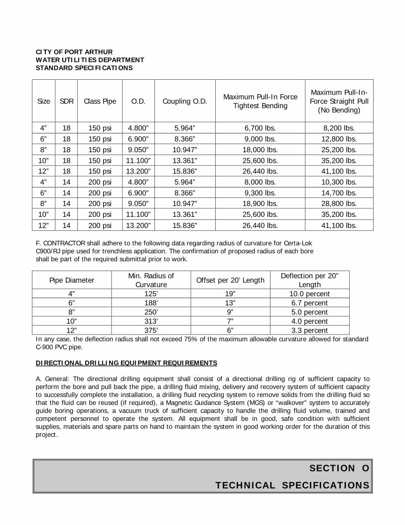
SECTION O
TECHNICAL SPECIFICATIONS
CITY OF PORT ARTHUR WATER UTILITIES DEPARTMENT STANDARD SPECIFICATIONS
Size SDR Class Pipe O.D. Coupling O.D. Maximum Pull-In Force Tightest Bending
Maximum Pull-In-Force Straight Pull
(No Bending)
4” 18 150 psi 4.800” 5.964” 6,700 lbs. 8,200 lbs. 6” 18 150 psi 6.900” 8.366” 9,000 lbs. 12,800 lbs. 8” 18 150 psi 9.050” 10.947” 18,000 lbs. 25,200 lbs. 10” 18 150 psi 11.100” 13.361” 25,600 lbs. 35,200 lbs. 12” 18 150 psi 13.200” 15.836” 26,440 lbs. 41,100 lbs. 4” 14 200 psi 4.800” 5.964” 8,000 lbs. 10,300 lbs. 6” 14 200 psi 6.900” 8.366” 9,300 lbs. 14,700 lbs. 8” 14 200 psi 9.050” 10.947” 18,900 lbs. 28,800 lbs. 10” 14 200 psi 11.100” 13.361” 25,600 lbs. 35,200 lbs. 12” 14 200 psi 13.200” 15.836” 26,440 lbs. 41,100 lbs.
F. CONTRACTOR shall adhere to the following data regarding radius of curvature for Certa-Lok C900/RJ pipe used for trenchless application. The confirmation of proposed radius of each bore shall be part of the required submittal prior to work.
Pipe Diameter Min. Radius of Curvature Offset per 20’ Length Deflection per 20”
Length 4” 125’ 19” 10.0 percent 6” 188’ 13” 6.7 percent 8” 250’ 9” 5.0 percent 10” 313’ 7” 4.0 percent 12” 375’ 6” 3.3 percent
In any case, the deflection radius shall not exceed 75% of the maximum allowable curvature allowed for standard C-900 PVC pipe. DIRECTIONAL DRILLING EQUIPMENT REQUIREMENTS A. General: The directional drilling equipment shall consist of a directional drilling rig of sufficient capacity to perform the bore and pull back the pipe, a drilling fluid mixing, delivery and recovery system of sufficient capacity to successfully complete the installation, a drilling fluid recycling system to remove solids from the drilling fluid so that the fluid can be reused (if required), a Magnetic Guidance System (MGS) or “walkover” system to accurately guide boring operations, a vacuum truck of sufficient capacity to handle the drilling fluid volume, trained and competent personnel to operate the system. All equipment shall be in good, safe condition with sufficient supplies, materials and spare parts on hand to maintain the system in good working order for the duration of this project.
SECTION O
TECHNICAL SPECIFICATIONS
CITY OF PORT ARTHUR WATER UTILITIES DEPARTMENT STANDARD SPECIFICATIONS B. Drilling Rig: The directional drilling machine shall consist of a hydraulically powered system to rotate and push hollow drilling pipe into the ground at a variable angle while delivering a pressurized fluid mixture to a guidable drill (bore) head. The machine shall be anchored to the ground to withstand the pulling, pushing and rotating pressure required to complete the installation. The hydraulic power system shall be self-contained with sufficient pressure and volume to power drilling operations. Hydraulic system shall be free of leaks. Rig shall have a system to monitor and record maximum pull-back pressure during pull-back operations. There shall be a system to detect electrical current from the drill string and an audible alarm that automatically sounds when an electrical current is detected. C. Drill Head: The drill head shall be steerable by changing its rotation and shall provide necessary cutting surfaces and drilling fluid jets. D. Mud Motors (if required): Mud motors shall be of adequate power to turn the required drilling tools. E. Drill Pipe: Shall be constructed of high quality 4130 seamless tubing, grade D or better, with threaded box and pins. Tools joints should be hardened to 32-36 RC. GUIDANCE SYSTEM A. General: An electronic “walkover” tracking system or a Magnetic Guidance System (MGS) probe or proven (non-experimental) gyroscopic probe and interface shall be used to provide a continuous and accurate determination of the location of the drill head during the drilling operation. The guidance system shall be capable of tracking at all depths up to fifty feet and in any soil condition, including hard rock. It shall enable the driller to guide the drill head by providing immediate information on the tool face, azimuth (horizontal direction), and inclination (vertical direction). The guidance system shall be accurate and calibrated to manufacturer’s specifications of the vertical depth of the borehole at sensing position at depths up to fifty feet and accurate to 2-feet horizontally. B. Components: The CONTRACTOR shall supply all components and materials to install, operate, and maintain the guidance system. C. The Magnetic Guidance System (MGS) shall be set up and operated by personnel trained and experienced with the system. The CONTRACTOR shall be aware of any geo-magnetic anomalies and shall consider such influences in the operation of the guidance system. DRILLING FLUID (MUD) SYSTEM
A. Mixing System: A self-contained, closed, drilling fluid mixing system shall be of sufficient size to mix and deliver drilling fluid composed of bentonite clay, potable water, and appropriate additives. The mixing system shall be able to molecularly shear individual bentonite particles from the dry powder to avoid clumping and ensure thorough mixing. The drilling fluid reservoir tank shall be minimum of 1,000 gallons. Mixing system shall continually agitate the drilling fluid during drilling operations. Drilling Fluids: Drilling fluid shall be composed of potable water and bentonite clay. Water shall be from a authorized source with a pH of 8.5 – 10. Water of a lower pH or with excessive calcium shall be treated with the appropriate amount of sodium carbonate or equal. No additional material may be used in drilling
SECTION O
TECHNICAL SPECIFICATIONS
CITY OF PORT ARTHUR WATER UTILITIES DEPARTMENT STANDARD SPECIFICATIONS
fluid without prior approval from ENGINEER. The bentonite mixture used shall have the minimum viscosity’s as measured by a March funnel:
Rocky Clay - 60 seconds Hard Clay - 40 seconds Soft Clay - 45 seconds Sandy Clay - 90 seconds Stable Sand - 80 seconds Loose Sand - 110 seconds Wet Sand - 110 seconds
These viscosities may be varied to best fit the soil conditions encountered, or as determined by the operator.
B. Delivery System: The drilling fluid pumping system shall have a minimum capacity of 35-500 GPM and be capable of delivering the drilling fluid at a constant minimum pressure of 1200 psi. The delivery system shall have filters in-line to prevent solids from being pumped into drill pipe. Used drilling fluid and drilling fluid spilled during operations shall be contained and conveyed to the drilling fluid recycling system or shall be removed by vacuum trucks or other methods acceptable to ENGINEER and the WATER UTILITIES DEPARTMENT. A berm, minimum of 12-inches high, shall be maintained around drill rigs drilling fluid mixing system, entry and exit pits and drilling fluid recycling system to prevent spills into the surrounding environment. Pumping equipment and/ or vacuum truck(s) of sufficient size shall be in place to convey drilling fluid from containment areas to storage and recycling facilities or disposal.
OTHER EQUIPMENT
A. Pipe Rollers: Pipe rollers shall be used for pipe assembly during final product pull back.
B. Restrictions: Other devices or utility placement systems for providing horizontal thrust other than those previously defined in the preceding sections shall not be used unless approved by the ENGINEER/OWNER/WATER UTILITIES DEPARTMENT prior to commencement of the work. Consideration for approval will be made on an individual basis for each specified location. The proposed device or system will be evaluated (by ENGINEER/OWNER/WATER UTILITIES DEPARTMENT) without undue delay and shall maintain line and grade within the tolerances prescribed by the particular conditions of the project.
PERSONNEL REQUIREMENTS
A. All personnel shall be fully trained in their respective duties as part of the directional drilling crew and in safety. Each person must have at least two years directional drilling experience.
B. A competent and experienced supervisor representing the CONTRACTOR and Drilling Subcontractor shall be present at all times during the actual drilling operations. A responsible representative who is thoroughly familiar with the equipment and type of work to be performed must be in direct charge and control of the operation at all times. In all cases, the supervisor must be continually present at the job site during the actual Directional Bore operation. The CONTRACTOR and Subcontractor shall have a sufficient number of competent workers on the job at all times to insure the Directional Bore is made in a timely and satisfactory manner.
SECTION O
TECHNICAL SPECIFICATIONS
CITY OF PORT ARTHUR WATER UTILITIES DEPARTMENT STANDARD SPECIFICATIONS
C. Personnel who are unqualified, incompetent or otherwise not suitable for the performance of this project shall be removed from the job site and replaced with suitable personnel.
D. A professional land surveyor registered in the State of Texas may be required to prepare and certify as-builts as per specifications
PART 3 EXECUTION
GENERAL REQUIREMENTS
A. The ENGINEER and the WATER UTILITIES DEPARTMENT must be notified a minimum of 3 days in advance of starting work. All necessary permits and approvals must be in place prior to commencement of work. The Directional Bore shall not begin until the ENGINEER is present at the job site and agrees that proper preparations for the operation have been made. The ENGINEER’S approval for beginning the installation shall in no way relieve the CONTRACTOR of the ultimate responsibility for the satisfactory completion of the work as authorized under the Contract. It shall be the responsibility of the ENGINEER to provide inspection personnel at such time as appropriate without causing undue hardship by reason of delay to the CONTRACTOR. A copy of the WATER UTILITIES DEPARTMENT approved construction drawings must be on the job site during construction.
B. All work under this specification affecting the Texas Department of Transportation (TXDOT) property, right-of-way or facilities shall be carried out to the full satisfaction of the TXDOT authorized representative. The CONTRACTOR shall fully inform himself of all requirements of TXDOT as it pertains to the specific project and shall conduct all his work accordingly.
C. All equipment used by the CONTRACTOR on Owner’s property and right-of-ways may be inspected by the OWNER or the Owner’s Representatives and shall not be used if considered unsatisfactory by OWNER or Owner’s Representatives.
D. The CONTRACTOR shall be fully responsible for all damages arising from his failure to comply with all applicable regulations and the requirements of these Specifications.
DIRECTIONAL DRILLING OPERATION
A. The CONTRACTOR shall provide all material, equipment, and facilities required for directional drilling. Proper alignment and elevation of the borehole shall be consistently maintained throughout the directional drilling operation. The method used to complete the directional drill shall conform to the requirements of all applicable permits. The ENGINEER will supply copies of all permits to the CONTRACTOR.
B. The entire drill path shall be accurately surveyed by the CONTRACTOR with entry and exit stakes placed in the appropriate locations within the areas indicated on drawings. If CONTRACTOR is using a magnetic guidance system, drill path shall be surveyed for any surface geo-magnetic variations or anomalies.
C. CONTRACTOR shall place silt fence between all drilling operations and any drainage, well-fields, wetland, waterway or other area designated for such protection if required by documents, state, federal and local regulations. Additional environmental protection necessary to contain any hydraulic or drilling fluid spills shall be put in place, including berms, liners, turbidity curtains and other measures. CONTRACTOR shall adhere to all
SECTION O
TECHNICAL SPECIFICATIONS
CITY OF PORT ARTHUR WATER UTILITIES DEPARTMENT STANDARD SPECIFICATIONS applicable environmental regulations. Fuel may not be stored in bulk containers within 200 feet of any water body or wetland. D. Readings shall be recorded after advancement of each successive drill pipe (no more than 10’) and recorded readings and plan and profile information shall be made available to the ENGINEER, or his representative, and the WATER UTILITIES DEPARTMENT at all times. At no time shall the deflection radius of the drill pipe exceed the deflection limits of the carrier pipe as specified herein. E. A complete list of all drilling fluid additives and mixtures to be used in the directional operation will be submitted to the ENGINEER, along with their respective Material Safety Data Sheets. All drilling fluids and loose cuttings shall be contained in pits or holding tanks for recycling or disposal, no fluids shall be allowed to enter any unapproved areas or natural waterways. Upon completion of the directional drill project, the drilling mud and cuttings shall be disposed of by the CONTRACTOR at an approved dumpsite. F. The pilot hole shall be drilled on bore path with no deviations greater than 5% of depth over the length of the bore unless previously agreed to by the ENGINEER/OWNER/UTILITY. In the event that pilot does deviate from the bore path more than 5% of depth over the length of the bore, CONTRACTOR will notify ENGINEER/OWNER/WATER UTILITIES DEPARTMENT may require CONTRACTOR to pull-back and re-drill from the location along bore path before the deviation. In the event of a drilling fluid fracture, inadvertent returns, or returns loss during pilot hole drilling operations, CONTRACTOR shall cease drilling, wait at least 30 minutes, inject a quantity of drilling fluid with a viscosity exceeding 120 seconds as measured by a March funnel and wait another 30 minutes. If mud fracture or returns loss continues, CONTRACTOR will discuss additional options with the ENGINEER/OWNER/WATER UTILITIES DEPARTMENT and work will then proceed as agreed. G. Upon completion of pilot hole phase of the operation, a complete set of “as-built” records shall be submitted in duplicate to the ENGINEER, WATER UTILITIES DEPARTMENT and OWNER. These records shall include copies of the pilot bore path, plan and profile record drawing, as well as directional survey reports as recorded during the drilling operation. H. Upon approval of the pilot hole location by the ENGINEER/OWNER/WATER UTILITIES DEPARTMENT, the hole opening or enlarging phase of the installation shall begin. The bore hole diameter shall be increased to accommodate the pullback operation of the required size of carrier pipe. The type of hole opener or back reamer to be utilized in this phase shall be determined by the types of subsurface soil conditions that have been encountered during the pilot hole drilling operation. The CONTRACTOR shall select the proper reamer type with the final hole opening being a maximum of 1.5 times the largest outside diameter pipe system component to be installed in the bore hole. I. The open bore hole shall be stabilized by means of bentonite drilling slurry pumped through the inside diameter of the drill rod and through openings in the reamer. The drilling slurry must be in a homogenous / flowable state serving as an agent to carry the loose cuttings to the surface through the annulus of the borehole. The volume of bentonite mud required for each pullback shall be calculated based on soil conditions, largest diameter of the pipe system component, capacity of the bentonite mud pump, and the speed of pullback as recommended by the bentontie drilling fluid manufacturer. The bentonite slurry is to be contained at the exit or entry side of the directional bore in pits or holding tanks. The slurry may be recycled at this time for reuse in the hole opening operation, or shall be hauled by the CONTRACTOR to an approved dumpsite for proper disposal.
SECTION O
TECHNICAL SPECIFICATIONS
CITY OF PORT ARTHUR WATER UTILITIES DEPARTMENT STANDARD SPECIFICATIONS J. The pipe section shall be joined together according to manufacturer’s specifications. The gaskets and the ends of pipe must be inspected and cleaned with a wet cloth prior to each joint assembly so they are free of any dirt or sand. The pipe must be free of any chips, scratches, or scrapes. A pulling eye will be attached to the Certa-Lok C900/RJ pulling head on the lead stick of pipe which in turn will be attached to a swivel on the end of the drill pipe. Tracer wire (#8) solid coated copper wire shall be attached to the pulling eye and the crown of PVC pipe with duct tape @ 24” O.C. and a minimum of two full wraps around the pipe. This will allow for a straight, smooth pull of the product pipe as it enters and passes through the borehole toward the drill rig and original entrance hole of the directional bore. The product pipe shall be elevated to the approximate angle of entry and supported by means of a side boom with roller arm, or similar equipment, to allow for the “free stress” situation as the pipe is pulled into the exit hole toward the drill rig. The product pullback phase of the directional operation shall be carried out in a continuous manner until the pipe reaches the original entry side of the bore. PIPE HANDLING A. Care shall be taken during transportation of the pipe such that it will not be cut, kinked or otherwise damaged. B. Ropes, fabrics or rubber protected slings and straps shall be used when handling pipes. Chains, cables or hooks inserted into the pipe ends shall not be used. Two slings spread apart shall be used for lifting each length of pipe. Pipe or fittings shall not be dropped into rocky or unprepared ground. C. Pipes shall be stored on level ground, preferably turf or sand, free of sharp objects that could damage the pipe. Stacking of the Certa-Lok C900 / RJ pipe shall be limited to a height that will not cause excessive deformation of the bottom layers of pipes under anticipated temperature conditions. Where necessary due to ground conditions the pipe shall be stored on wooden sleepers, spaced suitably and of such width as not to allow deformation of the pipe at the point of contact with the sleeper or between supports. D. The handling of the assembled pipeline shall be in such a manner that the pipe is not damaged by dragging it over sharp and cutting objects. Slings for handling the pipeline shall not be positioned at pipe joints. Sections of the pipes with cuts and gouges or excessive deformation shall be removed and replaced. TESTING PIPE A. Cleaning and flushing are to be done by the CONTRACTOR in order to obtain a clear and debris free product. Only potable water shall be used for flushing and pressure testing. B. Directional drilling pipe shall be tested by CONTRACTOR after pullback. The average pressure shall be maintained at 150 psi for two hours. The test pump and water supply shall be arranged to allow accurate measurements of the water required to maintain the test pressure. Any material showing seepage or the slightest leakage shall be replaced as directed by the OWNER at no additional expense to the OWNER. C. The pipe manufacturer’s (or ENGINEER’S/OWNER’S/WATER UTILITIES DEPARTMENT, whichever is more stringent) recommendations on pipe stretch allowances, bending radius, tensile strength, allowable test leakage allowance, and magnitude and duration of test pressure shall be observed.
SECTION O
TECHNICAL SPECIFICATIONS
CITY OF PORT ARTHUR WATER UTILITIES DEPARTMENT STANDARD SPECIFICATIONS D. Pipeline shall be tested end to end. E. All new service lines connected to the new main and installed with new pipe shall be pressure tested along with the newly installed main. F. Pressure testing shall not be required for the drilled pipe if the pipe is intended to be used as a casing for a finished product pipe. SITE RESTORATION A. Following drilling operations, CONTRACTOR will de-mobilize equipment and restore the work site to the original conditions or better. All excavations will be backfilled and compacted according to the specifications. B. Surface restoration shall be completed in accordance with the requirements of the contract, approvals or permits to a condition as good or better than existing prior to construction. RECORD KEEPING AND AS-BUILTS A. CONTRACTOR shall maintain a daily project log of drilling operations and a guidance system log with a copy given to the ENGINEER/OWNER/WATER UTILITIES DEPARTMENT at completion of project. The guidance system data shall be recorded per page 10 paragraph G during the actual crossing operation. The CONTRACTOR shall furnish to the ENGINEER/OWNER/WATER UTILITIES DEPARTMENT, “as-built” plan and profile drawings based on these recordings showing the actual location horizontally and vertically of the installation, and all utility facilities found during the installation. The guidance data shall be certified accurate by the CONTRACTOR to the capability of the guidance System. B. “As-built” drawings shall be completed and certified by a Texas Registered Professional Surveyor and mapped at CONTRACTORS expense in a form as required by the WATER UTILITIES DEPARTMENT, including signed and sealed plans, mylars, and electronic data files if available.
End of Section
SECTION O
TECHNICAL SPECIFICATIONS
CITY OF PORT ARTHUR WATER UTILITIES DEPARTMENT STANDARD SPECIFICATIONS
ITEM 814
SERVICE AGREEMENT FOR FIRE HYDRANT CONSTRUCTION METER I. Purpose. The Texas Commission on Environmental Quality (TCEQ) requires cities to take all necessary measures to insure its water supply remains protected. The City of Port Arthur Water Utilities Department is responsible for protecting the drinking water supply from contamination or pollution. In order to protect the health of the public, the City Council enacted the Cross Connection Control and Prevention Ordinance 01- 032 on March 27, 2001. These restrictions are enforced by the Water Utilities Department to insure public health and welfare. The purpose of this Service Agreement with ____________________________(herein “Contractor”) is to provide and insure this protection. The Contractor must sign this agreement before the City of Port Arthur Water Utilities Department will allow the use of water service through fire hydrant connections. In addition, when service to an existing connection has been suspended or terminated, the Water Utilities Department will not reestablish service unless it has received a signed copy of this Agreement. II. Service Agreement. The following are the terms of the Service Agreement between the City of Port Arthur Water Utilities Department and the Contractor. A. Effective immediately, fire hydrant construction meters will be issued to the Contractor on a job by job basis. When that particular project is finished, the fire hydrant assembly will be returned to the City of Port Arthur Water Utilities Department. The assembly will not be relocated to another project or site without first notifying Brian Smith, Project Manager at (409) 983-8550. B. The fire hydrant meter and backflow prevention assemblies are required to be in a protective cage (device) and will be supplied by the Water Utilities Department. Initial testing of the backflow prevention assembly will be performed by the City. Periodic testing will be required and the frequency will be determined by the Water Quality Control Manager. This testing is to be done by a certified backflow tester at the contractor’s expense only if the meter is kept over one year from date of this Agreement. Original Reports are to be sent to:
Brian Smith, Water Quality Control Manager, Water Utilities Department, 111 H.O. Mills Blvd., Port Arthur, TX, 77640 Fax copy to: Donald Stanton, 409-983-8550
C. An initial refundable service fee and a security deposit of $3,000.00 (payable to the City of Port Arthur), will be required to accompany this Service Agreement and Application Form when the meter assembly is picked up. D. Damage protection of the device will be the responsibility of the contractor. Contractors will use a fire hydrant wrench only when turning on or off the hydrant. The cost to replace or repair any damaged parts will be taken out of the deposit. E. Daily protective storage of the device will be performed by the Contractor. If the device is stolen or removed from the designated job site, the deposit will not be refunded. F. Placement of this device will be located in such a place as to protect the public, pedestrians,

SECTION O
TECHNICAL SPECIFICATIONS
CITY OF PORT ARTHUR WATER UTILITIES DEPARTMENT STANDARD SPECIFICATIONS vehicles, and construction workers on the site. The city assumes no responsibility for injuries or damages to personnel or equipment.
G. Any unauthorized tampering with City water utility valves or appurtenances, or any theft of water, will be dealt with according to the penalties set forth in the City Ordinance. H. Meters will be read by the Contractor and the reading (and meter location) must be called in each 3rd
Monday of the month to: Customer Service (409) 983-8230. The City expects the contractors to give their full cooperation. III. Enforcement. If the Contractor fails to comply with the terms of this Service Agreement, the Water Utilities Department shall, as its option, terminate service and enforce any and all penalties set forth in City Ordinance 01-032. Any expenses associated with the enforcement of this Agreement shall be billed to the Contractor. I. In connection with this Agreement, the official name and address for notification shall be: A. Contractor: Contractor Name Owner/Manager (Print) Owner/Manager (Signature) Date Mailing Address City State Zip Code Phone/Cell Fax B. City of Port Arthur, Water Utilities Department _______________________________________ Payment Information: (Fees must accompany this Agreement) Refundable Service/Deposit Fee $3,000.00 Receipt #________________ For Office Use: Contractor’s Account Number: _________________________________ Cage No. ______ Meter No.______________________ Backflow Preventer No. ______________________ Location of Fire Hydrant Meter: ________________________________________________ ACCOUNT APPLICATION FOR TEMPORARY FIRE HYDRANT CONSTRUCTION METER DATE OF APPLICATION: ________________________
ACCOUNT APPLICATION FOR TEMPORARY FIRE HYDRANT CONSTRUCTION METER DATE OF APPLICATION ___________________________________ BILLING INFORMATION: Company Name:_______________________________________________________________
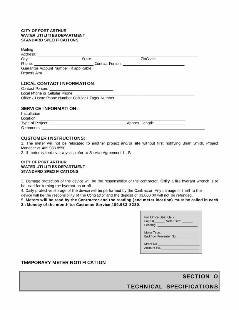
SECTION O
TECHNICAL SPECIFICATIONS
CITY OF PORT ARTHUR WATER UTILITIES DEPARTMENT STANDARD SPECIFICATIONS Mailing Address: ____________________________________________________________________________ City: ________________________ State_______________________ ZipCode:______________ Phone: ____________________________ Contact Person: _____________________________ Guarantor Account Number (if applicable) _______________________ Deposit Amt.__________________ LOCAL CONTACT INFORMATION: Contact Person: ______________________________ Local Phone or Cellular Phone: _____________________________ ___________________________ Office / Home Phone Number Cellular / Pager Number SERVICE INFORMATION: Installation Location: _____________________________________________________________________ Type of Project: ____________________________________ Approx. Length: ______________ Comments: _____________________________________________________________________________ CUSTOMER INSTRUCTIONS: 1. The meter will not be relocated to another project and/or site without first notifying Brian Smith, Project Manager at 409.983.8550. 2. If meter is kept over a year, refer to Service Agreement II. B. CITY OF PORT ARTHUR WATER UTILITIES DEPARTMENT STANDARD SPECIFICATIONS 3. Damage protection of the device will be the responsibility of the contractor. Only a fire hydrant wrench is to be used for turning the hydrant on or off. 4. Daily protective storage of the device will be performed by the Contractor. Any damage or theft to the device will be the responsibility of the Contractor and the deposit of $3,000.00 will not be refunded. 5. Meters will be read by the Contractor and the reading (and meter location) must be called in each 3rd Monday of the month to: Customer Service 409.983-8230.
For Office Use: Clerk: ___________ Cage #______ Meter Size: ______ Reading: _______________________ Meter Type: _____________________ Backflow Preventer No.____________ Meter No.________________________ Account No.______________________
TEMPORARY METER NOTIFICATION

SECTION O
TECHNICAL SPECIFICATIONS
CITY OF PORT ARTHUR WATER UTILITIES DEPARTMENT STANDARD SPECIFICATIONS
DATE: _____________________
TO WHOM IT MAY CONCERN:
The City of Port Arthur Water Utilities Department will be providing a temporary meter to ___________________________________________________________________ at the installation location of ______________________________________________________. As stated in the Service Agreement II.A., the Fire Hydrant construction meters will be issued to the Contractor on a job-by-job basis, and must be returned to the City of Port Arthur immediately upon completion of that particular project location.
It will be the Contractors responsibility to report meter readings to Customer Service at (409) 983-8230. These readings must be called in each 3rd Monday of the month as stated in the Service Agreement II.H. It will be the Contractors responsibility to report meter locations to Brian Smith, Project Manager at (409) 983-8550. Your cooperation in this procedure will be appreciated.
____________________________________________________________________________ Local Contact Person Local Contact Number
WATER UTILITIES DEPARTMENT ADMINISTRATION
End of Section
SECTION O
TECHNICAL SPECIFICATIONS
CITY OF PORT ARTHUR WATER UTILITIES DEPARTMENT STANDARD SPECIFICATIONS
ITEM 817
SPECIFICATIONS FOR CEMENT STABILIZED SAND
The following specifications are intended to describe sand cement 1 1/2 sack, and sand cement 2 sack. 1. Soil shall consist of sandy loam material free from vegetation or other objectionable materials. 2. Cement shall be Type 1 of a standard brand of Portland Cement and shall conform to the requirements of ASTM Designation: C150 and Texas Department of Transportation standards. 3. Mixing of materials shall be uniform. 4. Materials are subject to an independent testing laboratory batch design test.
End of Section
SECTION O
TECHNICAL SPECIFICATIONS
CITY OF PORT ARTHUR WATER UTILITIES DEPARTMENT STANDARD SPECIFICATIONS
ITEM 903
SPECIFICATIONS FOR SEWER LINE CLEANING
903.01 - Intent The intent of sewer line cleaning is to remove foreign materials from the lines and restore the sewer to a minimum of 95% of the original carrying capacity or as required for proper seating of internal pipe joint sealing packers. Since the success of the other phases of work depends a great deal on the cleanliness of the lines, the importance of this phase of the operation is emphasized. It is recognized that there are some conditions such as broken pipe and major blockages that prevent cleaning from being accomplished or where additional damage would result if cleaning were attempted or continued. Should such conditions be encountered the Contractor will not be required to clean those specific manhole sections. If in the course of normal cleaning operations, damge does result from pre-existing and unforeseen conditions such as broken pipe, the Contractor will not be held responsible. 903.02 - Cleaning Equipment (a) Hydraulically Propelled Equipment: The equipment used shall be of a movable dam type and be constructed in such a way that a portion of the dam may be collapsed at any time during the cleaning operation to protect against flooding of the sewer. The movable dam shall be equal in diameter to the pipe being cleaned and shall provide a flexible scraper around the outer periphery to insure removal of grease. If sewer cleaning balls or other equipment which cannot be collapsed is used, special precautions to prevent flooding of the sewers and public or private property shall be taken. (b) High-Velocity Jet (Hydro cleaning) Equipment: All high velocity sewer cleaning equipment shall be constructed for ease and safety of operation. The nozzles shall be capable of producing a scouring action from 15 to 45 degrees in all size lines designated to be cleaned. Equipment shall also include a high velocity gun for washing and scouring manhole walls and floor. The gun shall be capable of producing flows from a fine spray to a solid stream. The equipment shall carry its own water tank, auxiliary engines, pumps, and hydraulically driven hose reel. (c) Mechanically Powered Equipment: Bucket machines shall be in pairs with sufficient power to perform the work in an efficient manner. Machines shall be belt operated to have an overload device. Machines with direct drive that could cause damage to the pipe will not be allowed. A power rodding machine shall be either a sectional or continuous rod type capable of holding a minimum of 750 feet of rod. The rod shall be specifically heat-treated steel. To ensure safe operation, the machine shall be fully enclosed and have an automatic safety clutch or relief valve. 903.03 - Cleaning Precautions During sewer cleaning operations. Satisfactory precautions shall be taken in the use of cleaning equipment. When hydraulically propelled cleaning tools (which depend upon water pressure to provide their cleaning force) or tools which retard the flow in the sewer line are used, precautions shall be taken to insure that the water pressure created does not damage or cause flooding of public or private property being served by the sewer. When possible, the flow of sewage in the sewer shall be utilized to provide the necessary pressure for
SECTION O
TECHNICAL SPECIFICATIONS
CITY OF PORT ARTHUR WATER UTILITIES DEPARTMENT STANDARD SPECIFICATIONS hydraulic cleaning devices. When additional water from fire hydrants is necessary to avoid delay in normal work procedures, the water shall be conserved and not used unnecessarily. No fire hydrant shall be obstructed in case of a fire in the area served by the hydrant. 903.04 - Sewer Cleaning The designated sewer manhole sections shall be cleaned using hydraulically propelled, high velocity jet, or mechanically powered equipment. Selection of the equipment used shall be based on the conditions of lines at the time the work commences. The equipment and methods selected shall be satisfactory to the Owner’s Representative. The equipment shall be capable of removing dirt, grease, rocks, sand, and other materials and obstructions from the sewer lines and manholes. If cleaning of an entire section cannot be successfully performed from one manhole, the equipment shall be set up on the other manhole and cleaning again attempted. If, again, successful cleaning cannot be performed or the equipment fails to traverse the entire manhole section, it will be assumed that a major blockage exists and the cleaning effort shall be abandoned. 903.05 - Root Removal Roots shall be removed in the designated sections where root intrusion is a problem. Special attention should be used during the cleaning operation to assure almost complete removal of roots from the joints. Any roots which could prevent the seating of the packer or could prevent the proper application of chemical sealants shall be removed. Procedures may include the use of mechanical equipment such as rodding machines, bucket machines and winches using root cutters and porcupines, and equipment such as high-velocity jet cleaners. Chemical root treatment may be used at the option of the Contractor. 903.06 - Chemical Root Treatment To aid in the removal of roots and at the option of the Contractor, manhole sections that have root intrusion may be treated with an approved herbicide. The application of the herbicide to the roots shall be done in accordance with the manufacturer’s recommendations and specifications in such a manner to preclude damage to surrounding vegetation. Any damaged vegetation so designated by the Engineer shall be replaced by the Contractor at no additional cost to the Owner. All safety precautions as recommended by the manufacturer shall be adhered to concerning handling and application of the herbicide. 903.07 - Material Removal All sludge, dirt, sand, rocks, grease, and other solid or semisolid material resulting from the cleaning operation shall be removed at the downstream manhole of the section being cleaned. Passing material from manhole section, which could cause line stoppages, accumulations of sand in wet wells, or damage pumping equipment, shall not be permitted. 903.08 - Disposal of Materials All solids or semisolids resulting from the cleaning operations shall be removed from the site and disposed of at a site designated by the Owner. All materials shall be removed from the site no less often than at the end of each

SECTION O
TECHNICAL SPECIFICATIONS
CITY OF PORT ARTHUR WATER UTILITIES DEPARTMENT STANDARD SPECIFICATIONS workday. Under NO circumstances will the Contractor be allowed to accumulate debris, etc., on the site of work or beyond the stated time, except in totally enclosed containers and as approved by the Owner. 903.09 - Final Acceptance Acceptance of sewer line cleaning shall be made upon the successful completion of the television inspection and shall be to the satisfaction of the Owner’s Representative. If TV inspection shows the cleaning to be unsatisfactory, the Contractor shall be required to reclean and reinspect the sewer line until the cleaning is shown to be satisfactory. In areas where television inspection is not performed, the Owner’s Representative may require the Contractor to pull a double squeegee (with each squeegee the same diameter as the sewer) through each manhole section as evidence of adequate cleaning. If internal sealing is to follow the television inspection, particular attention should be given to the adequacy of the cleaning to insure that proper seating of the sealing packer can be achieved. 903.10 - Measurement & Payment Sewer line cleaning shall be paid for at the unit price bid per linear foot of each size pipe. Measurement of the actual number of feet cleaned shall be made from the center of the manholes.
End of Section
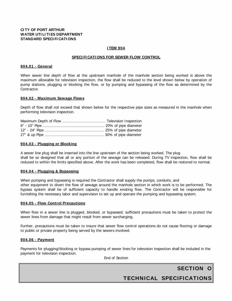
SECTION O
TECHNICAL SPECIFICATIONS
CITY OF PORT ARTHUR WATER UTILITIES DEPARTMENT STANDARD SPECIFICATIONS
ITEM 904
SPECIFICATIONS FOR SEWER FLOW CONTROL 904.01 - General When sewer line depth of flow at the upstream manhole of the manhole section being worked is above the maximum allowable for television inspection, the flow shall be reduced to the level shown below by operation of pump stations, plugging or blocking the flow, or by pumping and bypassing of the flow as determined by the Contractor. 904.02 - Maximum Sewage Flows Depth of flow shall not exceed that shown below for the respective pipe sizes as measured in the manhole when performing television inspection. Maximum Depth of Flow ...................................... Television Inspection 6" - 10" Pipe ...................................................... 20% of pipe diameter 12" - 24" Pipe .................................................... 25% of pipe diameter 27" & up Pipe .................................................... 30% of pipe diameter 904.03 - Plugging or Blocking A sewer line plug shall be inserted into the line upstream of the section being worked. The plug shall be so designed that all or any portion of the sewage can be released. During TV inspection, flow shall be reduced to within the limits specified above. After the work has been completed, flow shall be restored to normal. 904.04 - Plugging & Bypassing When pumping and bypassing is required the Contractor shall supply the pumps, conduits, and other equipment to divert the flow of sewage around the manhole section in which work is to be performed. The bypass system shall be of sufficient capacity to handle existing flow. The Contractor will be responsible for furnishing the necessary labor and supervision to set up and operate the pumping and bypassing system. 904.05 - Flow Control Precautions When flow in a sewer line is plugged, blocked, or bypassed; sufficient precautions must be taken to protect the sewer lines from damage that might result from sewer surcharging. Further, precautions must be taken to insure that sewer flow control operations do not cause flooring or damage to public or private property being served by the sewers involved. 904.06 - Payment Payments for plugging/blocking or bypass pumping of sewer lines for television inspection shall be included in the payment for television inspection.
End of Section
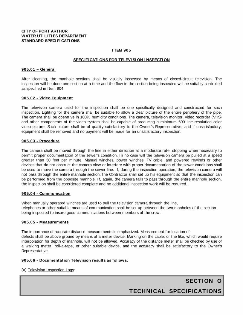
SECTION O
TECHNICAL SPECIFICATIONS
CITY OF PORT ARTHUR WATER UTILITIES DEPARTMENT STANDARD SPECIFICATIONS
ITEM 905
SPECIFICATIONS FOR TELEVISION INSPECTION 905.01 – General After cleaning, the manhole sections shall be visually inspected by means of closed-circuit television. The inspection will be done one section at a time and the flow in the section being inspected will be suitably controlled as specified in Item 904. 905.02 - Video Equipment The television camera used for the inspection shall be one specifically designed and constructed for such inspection. Lighting for the camera shall be suitable to allow a clear picture of the entire periphery of the pipe. The camera shall be operative in 100% humidity conditions. The camera, television monitor, video recorder (VHS) and other components of the video system shall be capable of producing a minimum 500 line resolution color video picture. Such picture shall be of quality satisfactory to the Owner’s Representative; and if unsatisfactory, equipment shall be removed and no payment will be made for an unsatisfactory inspection. 905.03 - Procedure The camera shall be moved through the line in either direction at a moderate rate, stopping when necessary to permit proper documentation of the sewer’s condition. In no case will the television camera be pulled at a speed greater than 30 feet per minute. Manual winches, power winches, TV cable, and powered rewinds or other devices that do not obstruct the camera view or interfere with proper documentation of the sewer conditions shall be used to move the camera through the sewer line. If, during the inspection operation, the television camera will not pass through the entire manhole section, the Contractor shall set up his equipment so that the inspection can be performed from the opposite manhole. If, again, the camera fails to pass through the entire manhole section, the inspection shall be considered complete and no additional inspection work will be required. 905.04 - Communication When manually operated winches are used to pull the television camera through the line, telephones or other suitable means of communication shall be set up between the two manholes of the section being inspected to insure good communications between members of the crew. 905.05 - Measurements The importance of accurate distance measurements is emphasized. Measurement for location of defects shall be above ground by means of a meter device. Marking on the cable, or the like, which would require interpolation for depth of manhole, will not be allowed. Accuracy of the distance meter shall be checked by use of a walking meter, roll-a-tape, or other suitable device, and the accuracy shall be satisfactory to the Owner’s Representative. 905.06 - Documentation Television results as follows: (a) Television Inspection Logs:
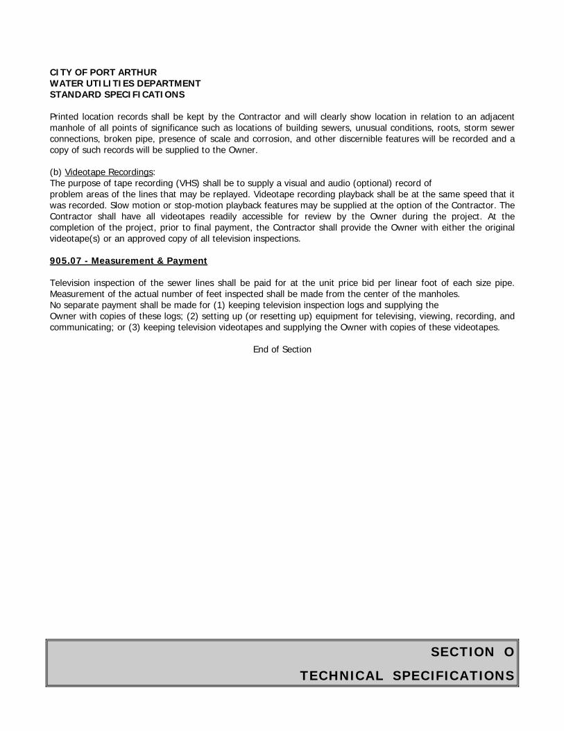
SECTION O
TECHNICAL SPECIFICATIONS
CITY OF PORT ARTHUR WATER UTILITIES DEPARTMENT STANDARD SPECIFICATIONS
Printed location records shall be kept by the Contractor and will clearly show location in relation to an adjacent manhole of all points of significance such as locations of building sewers, unusual conditions, roots, storm sewer connections, broken pipe, presence of scale and corrosion, and other discernible features will be recorded and a copy of such records will be supplied to the Owner.
(b) Videotape Recordings: The purpose of tape recording (VHS) shall be to supply a visual and audio (optional) record of problem areas of the lines that may be replayed. Videotape recording playback shall be at the same speed that it was recorded. Slow motion or stop-motion playback features may be supplied at the option of the Contractor. The Contractor shall have all videotapes readily accessible for review by the Owner during the project. At the completion of the project, prior to final payment, the Contractor shall provide the Owner with either the original videotape(s) or an approved copy of all television inspections.
905.07 - Measurement & Payment
Television inspection of the sewer lines shall be paid for at the unit price bid per linear foot of each size pipe. Measurement of the actual number of feet inspected shall be made from the center of the manholes. No separate payment shall be made for (1) keeping television inspection logs and supplying the Owner with copies of these logs; (2) setting up (or resetting up) equipment for televising, viewing, recording, and communicating; or (3) keeping television videotapes and supplying the Owner with copies of these videotapes.
End of Section
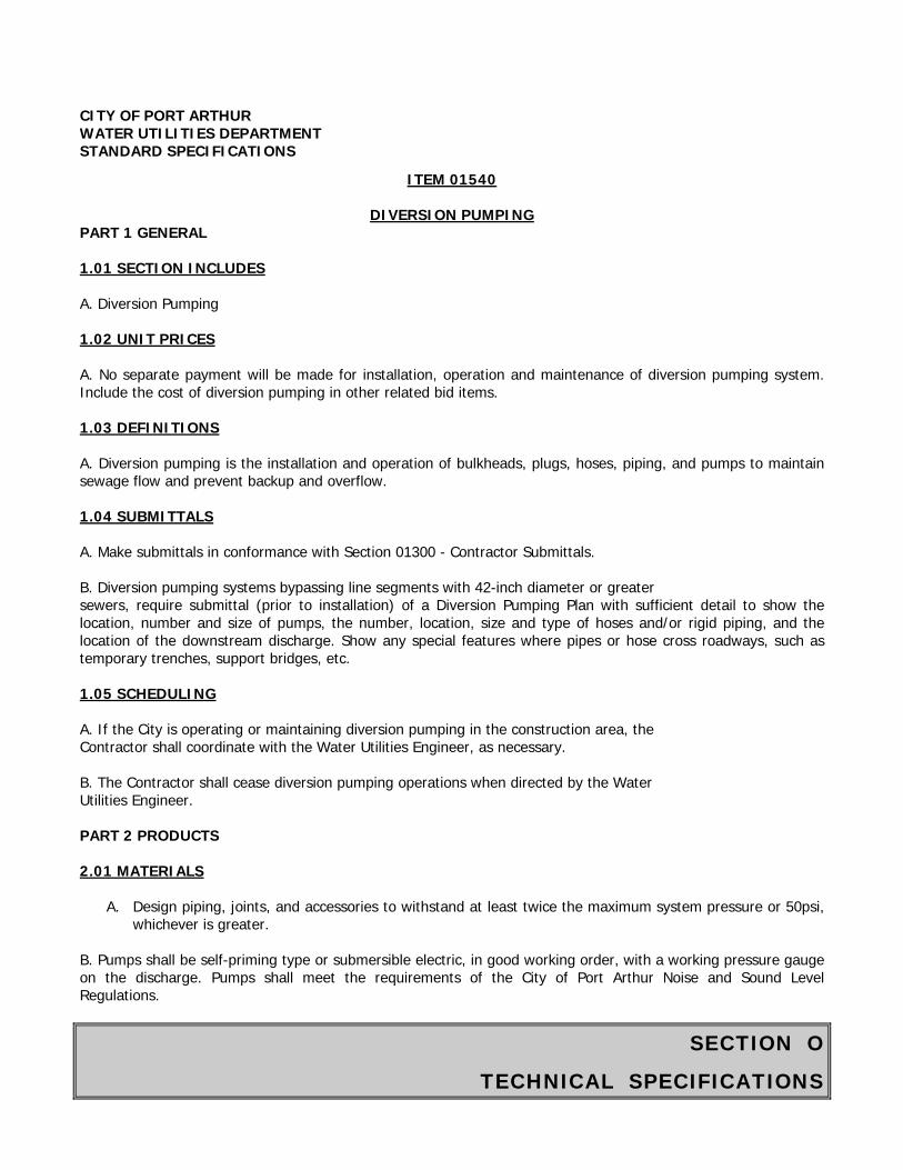
SECTION O
TECHNICAL SPECIFICATIONS
CITY OF PORT ARTHUR WATER UTILITIES DEPARTMENT STANDARD SPECIFICATIONS
ITEM 01540
DIVERSION PUMPING PART 1 GENERAL 1.01 SECTION INCLUDES A. Diversion Pumping 1.02 UNIT PRICES A. No separate payment will be made for installation, operation and maintenance of diversion pumping system. Include the cost of diversion pumping in other related bid items. 1.03 DEFINITIONS A. Diversion pumping is the installation and operation of bulkheads, plugs, hoses, piping, and pumps to maintain sewage flow and prevent backup and overflow. 1.04 SUBMITTALS A. Make submittals in conformance with Section 01300 - Contractor Submittals. B. Diversion pumping systems bypassing line segments with 42-inch diameter or greater sewers, require submittal (prior to installation) of a Diversion Pumping Plan with sufficient detail to show the location, number and size of pumps, the number, location, size and type of hoses and/or rigid piping, and the location of the downstream discharge. Show any special features where pipes or hose cross roadways, such as temporary trenches, support bridges, etc. 1.05 SCHEDULING A. If the City is operating or maintaining diversion pumping in the construction area, the Contractor shall coordinate with the Water Utilities Engineer, as necessary. B. The Contractor shall cease diversion pumping operations when directed by the Water Utilities Engineer. PART 2 PRODUCTS 2.01 MATERIALS
A. Design piping, joints, and accessories to withstand at least twice the maximum system pressure or 50psi, whichever is greater.
B. Pumps shall be self-priming type or submersible electric, in good working order, with a working pressure gauge on the discharge. Pumps shall meet the requirements of the City of Port Arthur Noise and Sound Level Regulations.

SECTION O
TECHNICAL SPECIFICATIONS
CITY OF PORT ARTHUR WATER UTILITIES DEPARTMENT STANDARD SPECIFICATIONS PART 3 EXECUTION 3.01 FIELD QUALITY CONTROL A. During diversion pumping, do not allow sewage to be leaked, dumped, or spilled in or onto any area outside of the existing sanitary sewer system. B. In the event of accidental spill or overflow, immediately stop the discharge and take action to clean up and disinfect the spill. Promptly notify the Water Utilities Engineer so that required reporting can be made to the Texas Commission on Environmental Quality (TCEQ) and the Environmental Protection Agency (EPA) by the Water Utilities Engineer. 3.02 CLEANING A. When diversion pumping operations are complete, piping shall be drained into the sanitary sewer prior to disassembly.
End of Section
SECTION O
TECHNICAL SPECIFICATIONS
CITY OF PORT ARTHUR WATER UTILITIES DEPARTMENT STANDARD SPECIFICATIONS
ITEM 01578
CONTROL OF GROUND WATER AND SURFACE WATER PART I GENERAL 1.01 SECTION INCLUDES A. Dewatering, depressurizing, draining, and maintaining trenches, shaft excavations, structural excavations, and foundation beds in a stable condition, and controlling ground water conditions for tunnel excavations. B. Protecting work against surface runoff and rising flood waters. C. Disposing of removed water. 1.02 METHOD OF PAYMENT A. No separate payment will be made for control of ground water and surface water. Include the cost to control ground water and surface water in unit price for work requiring such controls. 1.03 REFERENCES A. ASTM D 698 - Test Methods for Moisture-Density Relations of Soils and Soil-Aggregate Mixtures, Using 5.5-lb (2.49 kg) Rammer and 12-inch (304.8 mm) Drop. B. Federal Regulations, 29 CFR Part 1926, Standards-Excavation, Occupational Safety and Health Administration (OSHA). C. Federal Register 40 CFR (Vol. 55, No. 222) Part 122, EPA Administered Permit Programs (NPDES), Para. 122.26(b)(14) Storm Water Discharge. 1.04 DEFINITIONS A. Ground water control includes both dewatering and depressurization of water-bearing soil layers.
1.Dewatering includes lowering the water table and intercepting seepage which would otherwise emerge from slopes or bottoms of excavations, or into tunnels and shafts, and disposing of removed water. The intent of dewatering is to increase stability of tunnel excavations and excavated slopes; prevent dislocation of material from slopes or bottoms of excavations; reduce lateral loads on sheeting and bracing; improve
CITY OF PORT ARTHUR WATER UTILITIES DEPARTMENT STANDARD SPECIFICATIONS
excavating and hauling characteristics of excavated material; prevent failure or heaving of the bottom of excavations; and to provide suitable conditions for placement of backfill materials and construction of structures and other installations.
SECTION O
TECHNICAL SPECIFICATIONS
CITY OF PORT ARTHUR WATER UTILITIES DEPARTMENT STANDARD SPECIFICATIONS
2. Depressurization includes reduction in piezometric pressure within strata not controlled by dewatering alone, as required to prevent failure or heaving of excavation bottom or instability of tunnel excavations.
B. Excavation drainage includes keeping excavations free of surface and seepage water. C. Surface drainage includes use of temporary drainage ditches and dikes and installation of temporary culverts and sump pumps with discharge lines as required to protect the work from any source of surface water. D. Equipment and instrumentation for monitoring and control of ground water control system includes piezometers and monitoring wells, and devices, such as flow meters, for observing and recording flow rates. 1.05 PERFORMANCE REQUIREMENTS A. Conduct subsurface investigations to identify groundwater conditions and to provide parameters for design, installation, and operation of groundwater control systems. B. Design a ground water control system, compatible with requirements of Federal Regulations 29 CFR Part 1926 and Item 712 - Trench Safety Systems, to produce the following results:
1. Effectively reduce the hydrostatic pressure affecting: (a) Excavations. (b) Tunnel excavation, face stability or seepage into tunnels.
2. Develop a substantially dry and stable subgrade for subsequent construction operations. 3. Preclude damage to adjacent properties, buildings, structures, utilities, installed facilities, and other work. 4. Prevent the loss of fines, seepage, boils, quick condition, or softening of the foundation trata. 5. Maintain stability of sides and bottom of excavations.
C. Provide ground water control systems may include single-stage or multiple-stage well point systems, ejector and ejector-type systems, deep wells, or combinations of these equipment types. D. Provide drainage of seepage water and surface water, as well as water from any other source entering the excavation. Excavation drainage may include placement of drainage materials, such as crushed stone and filter fabric, together with sump pumping. E. Provide ditches, berms, pumps and other methods necessary to divert and drain surface water from excavation and other work areas. F. Locate ground water control and drainage systems so as not to interfere with utilities, construction operations, adjacent properties, or adjacent water wells. G. Assume sole responsibility for ground water control systems and for any loss or damage resulting from partial or complete failure of protective measures and any settlement or resultant damage caused by the ground water control operations. Modify ground water control systems or operations if they cause or threaten to cause damage to new construction, existing site improvements, adjacent property, or adjacent water
SECTION O
TECHNICAL SPECIFICATIONS
CITY OF PORT ARTHUR WATER UTILITIES DEPARTMENT STANDARD SPECIFICATIONS wells, or affect potentially contaminated areas. Repair damage caused by ground water control systems or resulting from failure of the system to protect property as required. H. Provide an adequate number of piezometers installed at the proper locations and depths as required to provide meaningful observations of the conditions affecting the excavation, adjacent structures, and water wells. I. Provide environmental monitoring wells installed at the proper locations and depths as required to provide adequate observations of hydrostatic conditions and possible contaminant transport from contamination sources into the work area or into the ground water control system. J. Decommission piezometers and monitoring wells installed during design phase studies and left for Contractors monitoring and use. 1.06 SUBMITTALS A. Submittals shall conform to requirements of Section 01300 - Contractor Submittals. B. Submit a Ground Water and Surface Water Control Plan for review by the Water Utilities Engineer prior to start of any field work. The Plan shall be signed by a Professional Engineer registered in the State of Texas. Submit a plan to include the following:
1. Results of subsurface investigation and description of the extent and characteristics of water bearing layers subject to ground water control. 2. Names of equipment suppliers and installation subcontractors. 3. A description of proposed ground water control systems indicating arrangement, location, depth and capacities of system components, installation details and criteria, and operation and maintenance procedures.
4. A description of proposed monitoring and control system indicating depths and locations of piezometers and monitoring wells, monitoring installation details and criteria, type of equipment and instrumentation with pertinent data and characteristics.
5. A description of proposed filters including types, sizes, capacities and manufacturer’s application recommendations. 6. Design calculations demonstrating adequacy of proposed systems for intended applications. Define potential area of influence of ground water control operation near contaminated areas. 7. Operating requirements, including piezometric control elevations for dewatering and depressurization. 8. Excavation drainage methods including typical drainage layers, sump pump application and other necessary means. 9. Surface water control and drainage installations. 10. Proposed methods and locations for disposing of removed water.
C. Submit the following records upon completed initial installation:
1. Installation and development reports for well points, eductors, and deep wells. 2. Installation reports and baseline readings for piezometers and monitoring wells. 3. Baseline analytical test data of water from monitoring wells. 4. Initial flow rates.
SECTION O
TECHNICAL SPECIFICATIONS
CITY OF PORT ARTHUR WATER UTILITIES DEPARTMENT STANDARD SPECIFICATIONS
D. Submit the following records on a weekly basis during operations: 1. Records of flow rates and piezometric elevations obtained during monitoring of dewatering anddepressurization. Refer to Paragraph 3.02, Requirements for eductor, well points, or deep wells. 2. Maintenance records for ground water control installations, piezometers, and monitoring wells.
E. Submit the following records at the end of work. Decommissioning (abandonment) reports for monitoring wells and piezometers installed by others during the design phase and left for Contractor’s monitoring and use.
1.07 ENVIRONMENTAL REQUIREMENTS
A. Comply with requirements of agencies having jurisdiction.
B. Comply with Texas Natural Commission on Environmental Quality regulations and Texas Water Well Drillers Association for development, drilling, and abandonment of wells used in dewatering system.
C. Obtain permit from EPA under the National Pollutant Discharge Elimination System (NPDES), for storm water discharge from construction sites.
D. Obtain all necessary permits from agencies with control over the use of groundwater and matters affecting well installation, water discharge, and use of existing storm drains and natural water sources. Because the review and permitting process may be lengthy, take early action to pursue and submit for the required approvals.
E. Monitor ground water discharge for contamination while performing pumping in the vicinity of potentially contaminated sites.
PART 2 PRODUCTS
2.01 EQUIPMENT AND MATERIALS
A. Equipment and materials are at the option of Contractor as necessary to achieve desired results for dewatering. Selected equipment and materials are subject to review of the Water Utilities Engineer through submittals required in Paragraph 1.06, Submittals.
B. Eductors, well points, or deep wells, where used must be furnished, installed and operated by an experienced contractor regularly engaged in ground water control system design, installation, and operation.
C. All equipment must be in good repair and operating order.
D. Sufficient standby equipment and materials shall be kept available to ensure continuous operation, where required.
PART 3 EXECUTION
3.01 GROUND WATER CONTROL
SECTION O
TECHNICAL SPECIFICATIONS
CITY OF PORT ARTHUR WATER UTILITIES DEPARTMENT STANDARD SPECIFICATIONS
A. Perform a subsurface investigation by borings as necessary to identify water bearing layers, piezometric pressures, and soil parameters for design and installation of ground water control systems. Perform pump tests, if necessary to determine the draw down characteristics of the water bearing layers. The results shall be presented in the Ground Water and Surface Water Control Plan (See Paragraph 1.06, B).
B. Provide labor, material, equipment, techniques and methods to lower, control and handle ground water in a manner compatible with construction methods and site conditions. Monitor effectiveness of the installed system and its effect on adjacent property.
C. Install, operate, and maintain ground water control systems in accordance with the Ground Water and Surface Water Control Plan. Notify the Water Utilities Engineer in writing of any changes made to accommodate field conditions and changes to the Work. Provide revised drawings and calculations with such notification.
D. Provide for continuous system operation, including nights, weekends, and holidays. Arrange for appropriate backup if electrical power is primary energy source for dewatering system.
E. Monitor operations to verify that the system lowers ground water piezometric levels at a rate required to maintain a dry excavation resulting in a stable subgrade for prosecution of subsequent operations.
F. Where hydrostatic pressures in confined water bearing layers exist below excavation, depressurize those zones to eliminate risk of uplift or other instability of excavation or installed works. Allowable piezometric elevations shall be designed in the Ground Water and Surface Water Control Plan.
G. Remove ground water control installations.
1. Remove pumping system components and piping when ground water control is no longer required2. Remove piezometers, including piezometers installed during the design phase investigations and leftfor Contractor’s use, upon completion of testing, in accordance with Section 02533 - Acceptance Testing of Sanitary Sewers. 3. Remove monitoring wells when directed by the Water Utilities Engineer.4. Grout abandoned well and piezometer holes. Fill piping that is not removed with cement-bentonitegrout or cement-sand grout.
H. During backfilling, dewatering may be reduced to maintain water level a minimum of 5 feet below prevailing level of backfill. However, do not allow that water level to result in uplift pressures in excess of 80 percent of downward pressure produced by weight of structure or backfill in place. Do not allow water levels to rise into cement stabilized sand until at least 48 hours after placement.
I. Provide a uniform diameter for each pipe drain run constructed for dewatering. Remove pipe drain when it has served its purpose. If removal of pipe is impractical, provide grout connections at 50-foot intervals and fill pipe with cement-bentonite grout or cement-sand grout when pipe is removed from service.
J. Extent of construction ground water control for structures with a permanent perforated underground drainage system may be reduced, such as for units designed to withstand hydrostatic uplift pressure. Provide a means of draining the affected portion of underground system, including standby equipment. Maintain drainage system during operations and remove it when no longer required.
SECTION O
TECHNICAL SPECIFICATIONS
CITY OF PORT ARTHUR WATER UTILITIES DEPARTMENT STANDARD SPECIFICATIONS K. Remove system upon completion of construction or when dewatering and control of surface or ground water is no longer required. L. Compact backfill to not less than 95 percent of the maximum dry density in accordance with ASTM D 698. 3.02 REQUIREMENTS FOR EDUCTOR, WELL POINTS, OR DEEP WELLS A. For aboveground piping in ground water control system, include a 12-inch minimum length of clear, transparent piping between every eductor well or well point and discharge header so that discharge from each installation can be visually monitored. B. Installation sufficient piezometers or monitoring wells to show that all trench or shaft excavations in water bearing materials are predrained prior to excavation. Provide separate piezometers for monitoring of dewatering and for monitoring of depressurization. Install piezometers and monitoring wells for tunneling as appropriate for Contractor’s selected method of work. C. Install piezometers or monitoring wells not less than one week in advance of beginning the associated excavation. D. Dewatering may be omitted for portions of underdrains or other excavations, but only where auger borings and piezometers or monitoring wells show that soil is predrained by an existing system such that the criteria of the ground water control plan are satisfied. E. Replace installations that produce noticeable amounts of sediments after development. F. Provide additional ground water control installations, or change the methods, in the event that the installations according to the ground water control plan does not provide satisfactory results based on the performance criteria defined by the plan and by the specification. Submit a revised plan according to Paragraph 1.06B. 3.03 EXCAVATION DRAINAGE A. Contractor may use excavation drainage methods if necessary to achieve well drained conditions. The excavation drainage may consist of a layer of crushed stone and filter fabric, and sump pumping in combination with sufficient wells for ground water control to maintain stable excavation and backfill conditions. 3.04 MAINTENANCE AND OBSERVATION
A. Conduct daily maintenance and observation of piezometers or monitoring wells while the ground water control installations or excavation drainage are operating in an area or seepage into tunnel is occurring. Keep system in good condition.
B. Replace damaged and destroyed piezometers or monitoring wells with new piezometers or wells as necessary to meet observation schedule. C. Cut off piezometers or monitoring wells in excavation areas where piping is exposed, only
SECTION O
TECHNICAL SPECIFICATIONS
CITY OF PORT ARTHUR WATER UTILITIES DEPARTMENT STANDARD SPECIFICATIONS as necessary to perform observation as excavation proceeds. Continue to maintain and make observations, as specified. D. Remove and grout piezometers inside or outside the excavation area when ground water control operations are complete. Remove and grout monitoring wells when directed by the Water Utilities Engineer. 3.05 MONITORING AND RECORDING A. Monitor and record average flow rate of operation for each deep well, or for each wellpoint or eductor header used in dewatering system. Also monitor and record water level and ground water recovery. These records shall be obtained daily until steady conditions are achieved, and twice weekly thereafter. B. Observe and record elevation of water level daily as long as ground water control system is in operation, and weekly thereafter until the Work is completed or piezometers or wells are removed, except when the Water Utilities Engineer determines that more frequent monitoring and recording are required. Comply with the Water Utilities Engineer’s direction for increased monitoring and recording and take measures as necessary to ensure effective dewatering for intended purpose 3.06 SURFACE WATER CONTROL A. Intercept surface water and divert it away from excavations through use of dikes, ditches, curb walls, pipes, sumps or other approved means. The requirement includes temporary works required to protect adjoining properties from surface drainage caused by construction operations. B. Divert surface water and seepage water into sumps and pump it into drainage channels or storm drains, when approved by agencies having jurisdiction. Provide settling basins when required by such agencies.
End of Section
SECTION O
TECHNICAL SPECIFICATIONS
CITY OF PORT ARTHUR WATER UTILITIES DEPARTMENT STANDARD SPECIFICATIONS
ITEM 01731
SPECIFICATION FOR CUTTING AND PATCHING PART 1 GENERAL 1.01 SECTION INCLUDES A. Cutting, patching and fitting of the Work or Work under construction and to existing facilities and to accommodate the coordination installation or connection of Work with existing facilities, or to uncover work for access, inspection or testing and related submittals 1.02 CUTTING AND PATCHING A. Perform activities to avoid interference with facility operations and the Work of others in accordance with Section 1100 - General Conditions. B. Execute cutting and patching, including excavation, backfill and fitting to:
1. Remove and replace defective Work or Work not conforming to the Drawings and Specifications. 2. Take samples of installed Work as required for testing. 3. Remove construction required to provide for specified alteration or addition to existing work. 4. Uncover Work to provide for inspection or reinspection of covered Work by the Water Utilities Engineer or regulatory agencies having jurisdiction. 5. Connect any Work that was not accomplished in the proper sequence to completed Work. 6. Remove or relocate existing utilities and pipes which obstruct Work to which connections must be made. 7. Make connections or alterations to existing or new facilities. 8. Provide openings, channels, chases and flues, if any, and do cutting, patching and finishing.
C. Restore existing work to a state equal to or better than that prior to cutting and patching. Restore new Work to standards of these Specifications. D. Support, anchor, attach, match, trim and seal materials to the Work of others. Unless otherwise specified, furnish and install sleeves, inserts, hangers, required for the execution of the Work. E. Provide shoring, bracing and support as required to maintain structural integrity and protect adjacent Work from damage during cutting and patching. Before cutting beams or other structural member, anchors, lintels or other supports, request written instruction from the Water Utilities Engineer. Follow such instructions, as applicable. 1.03 SUBMITTALS A. Submit written notice to the Water Utilities Engineer requesting consent to proceed prior to cutting which may affect structural integrity or design function, City operations, or work of another contractor.
SECTION O
TECHNICAL SPECIFICATIONS
CITY OF PORT ARTHUR WATER UTILITIES DEPARTMENT STANDARD SPECIFICATIONS B. Include the following in submittal:
1. Identification of project 2. Description of affected Work. 3. Necessity for cutting 4. Effect on other work and on structural integrity. 5. Include description of proposed Work:
a. Scope of cutting and patching. b. Contractor, subcontractor or trade to execute Work. c. Products proposed to be used. d. Extent of refinishing. e. Schedule of operations.
6. Alternatives to cutting and patching, if any. C. Should conditions of Work or schedule indicate change of materials or methods, submit a written recommendation to the Water Utilities Engineer including:
1. Conditions indicating change. 2. Recommendations for alternative materials or methods. 3. Submittals as required for substitutions.
D. Submit written notice to the Water Utilities Engineer designating time Work will be uncovered for observation. Do not begin cutting or patching operations until authorized by the Water Utilities Engineer. 1.04 CONNECTIONS TO EXISTING FACILITIES A. Perform construction necessary to complete connections and tie-ins to existing facilities. Keep all existing facilities in continuous operation unless otherwise specifically permitted in these Specifications or approved by the Water Utilities Engineer. B. Coordinate with the Water Utilities Engineer, interruption of service requiring connection into existing facilities. Bypassing of wastewater or sludge to waterways is not permitted. Provide temporary pumping facilities to handle wastewater, if necessary. Use temporary bulkheads (e.g., inflatable plugs) to minimize disruption. Provide temporary power supply and piping to facilitate construction where necessary. C. Submit a detailed schedule of proposed connections, including shut-downs and tie-ins. Include in the submittal the proposed time and date as well as the anticipated duration of the Work. Submit the detailed schedule coordinated with the construction schedule.
1. Provide specific time and date information to the Water Utilities Engineer 48 hours in advance of proposed Work.
D. Procedures and Operations:
1. The Contractor shall operate existing pumps, valves and gates required for sequencing procedures under the supervision of the Water Utilities Engineer. Do not operate any valve, gate or other item of equipment without the knowledge of the Water Utilities Engineer. 2. Insofar as possible, equipment shall be tested and in operating condition before final tie-ins are made
to connect equipment to the existing facility. 3. Carefully coordinate Work and schedules. Provide written notice to the Water
SECTION O
TECHNICAL SPECIFICATIONS
CITY OF PORT ARTHUR WATER UTILITIES DEPARTMENT STANDARD SPECIFICATIONS
Utilities Engineer at least 48 hours before shutdowns or bypasses are required.
PART 2 PRODUCTS - Not Used PART 3 EXECUTION - Not Used
End of Section
SECTION O
TECHNICAL SPECIFICATIONS
CITY OF PORT ARTHUR WATER UTILITIES DEPARTMENT STANDARD SPECIFICATIONS
ITEM 02052 SPECIFICATION FOR TRENCHLESS GRAVITY SEWER
PIPE REHABILITATION BY PIPE LINING
PART I GENERAL
1.01 DESCRIPTION
The work performed under this section shall include all labor material, tools, equipment and incidentals necessary to provide for the complete rehabilitation of deteriorated gravity sewer lines, junction boxes and manholes using cured in place pipe (CIPP) methods. This method utilizes the installation of a continuous liner which is initially smaller in size than the inside diameter of the host pipe, then heated, pressurized and cooled so that it conforms to the shape of the existing pipe. Additional systems or processes used shall be submitted to the ENGINEER for approval.
1.02 SUBMITTALS
A. The CONTRACTOR and MANUFACTURER shall review the TV Inspection Video (Base Bid) and visit the site prior to preparation of submittals.
B. The CONTRACTOR shall furnish for the ENGINEER’s approval a plan showing the proposed method of lining, including shop drawings, catalogue data and MANUFACTURER’s technical data of the proposed liner and installation equipment and techniques.
C. The CONTRACTOR shall submit to the ENGINEER, MANUFACTURER’s certifications that the proposed materials, methods, details and systems proposed will comply with the MANUFACTURER’s specifications.
D. The CONTRACTOR shall submit to the ENGINEER for review, MANUFACTURER’s detailed design calculations for both the internal and external-loading parameters specified in Section 1.04. The design shall follow the requirements specified in Section 1.04 and shall clearly identify the physical properties used for design. The bid design shall provide for Type II or Type III conditions in accordance with ASTM 5813. Submittal design shall provide for actual conditions based on the TV Video Inspection.
E. The CONTRACTOR shall submit to the ENGINEER, copies of certification of workmen’s training for installing the proposed liner.
F. Review of the plan and other submittals by the ENGINEER will not relieve the CONTRACTOR from his responsibility to obtain the specified results.
1.03 QUALITY ASSURANCE
A. Referenced Standards:
1. ASTM F1216: Practice for Rehabilitation of Existing Pipelines and Conduits by the Inversion and Curingof a Resin-Impregnated Tube. 2. ASTM F1743: Practice for Rehabilitation of Existing Pipelines and conduits by Pulledin-Place Thermosetting Resin Pipe (CIPP).
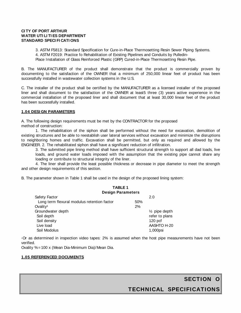
SECTION O
TECHNICAL SPECIFICATIONS
CITY OF PORT ARTHUR WATER UTILITIES DEPARTMENT STANDARD SPECIFICATIONS
3. ASTM F5813: Standard Specification for Cure-in-Place Thermosetting Resin Sewer Piping Systems. 4. ASTM F2019: Practice fo Rehabilitation of Existing Pipelines and Conduits by Pulledin- Place Installation of Glass Reinforced Plastic (GRP) Cured-in-Place Thermosetting Resin Pipe.
B. The MANUFACTURER of the product shall demonstrate that the product is commercially proven by documenting to the satisfaction of the OWNER that a minimum of 250,000 linear feet of product has been successfully installed in wastewater collection systems in the U.S. C. The installer of the product shall be certified by the MANUFACTURER as a licensed installer of the proposed liner and shall document to the satisfaction of the OWNER at least5 three (3) years active experience in the commercial installation of the proposed liner and shall document that at least 30,000 linear feet of the product has been successfully installed. 1.04 DESIGN PARAMETERS A. The following design requirements must be met by the CONTRACTOR for the proposed method of construction:
1. The rehabilitation of the siphon shall be performed without the need for excavation, demolition of existing structures and be able to reestablish user lateral services without excavation and minimize the disruptions to neighboring homes and traffic. Excavation shall be permitted, but only as required and allowed by the ENGINEER. 2. The rehabilitated siphon shall have a significant reduction of infiltration.
3. The submitted pipe lining method shall have sufficient structural strength to support all dad loads, live loads, and ground water loads imposed with the assumption that the existing pipe cannot share any loading or contribute to structural integrity of the liner. 4. The liner shall provide the least possible thickness or decrease in pipe diameter to meet the strength
and other design requirements of this section. B. The parameter shown in Table 1 shall be used in the design of the proposed lining system:
TABLE 1
Design Parameters Safety Factor 2.0
Long term flexural modulus retention factor 50% Ovality¹ 2% Groundwater depth ½ pipe depth
Soil depth refer to plans Soil density 120 pcf Live load AASHTO H-20 Soil Modolus 1,000psi
¹Or as determined in inspection video tapes: 2% is assumed when the host pipe measurements have not been verified. Ovality %=100 x (Mean Dia-Minimum Dia)/Mean Dia. 1.05 REFERENCED DOCUMENTS
SECTION O
TECHNICAL SPECIFICATIONS
CITY OF PORT ARTHUR WATER UTILITIES DEPARTMENT STANDARD SPECIFICATIONS The following specifications and documents are made a part of this Section by reference and shall be the latest edition and revision thereof: A. For cured in place pipe liner:
ASTM Standard: F 1216 ASTM Standard: D 5813 ASTM Standard: D 790
Test Report: “Long Term Structural Behavior of Pipeline Rehabilitation Systems,” by Trenchless Technology Center at Louisiana Tech University. 1.06 WARRANTY Provide a MANUFACTURER warranty for five (5) years against failure of the CIPP liner. A. The MANUFACTURER shall repair or replace the liner failures resulting from faulty materials, improper surface preparation, or installation procedures. B. All costs required to complete the repairs shall be warranted. PART 2 - MATERIALS 2.01 CURED IN PLACE PIPE (CIPP) A. Tube
1. The sewn Tube shall consist of one or more layers of absorbent non-woven felt fabric and beet the requirements of ASTM F 1216, Section 5.1 or ASTM F1743, Section 5.2.1. The tube shall be constructed to withstand installation pressures, have sufficient strength to bridge missing pipe, and stretch to fit irregular pipe sections. 2. The wet out Tube shall have a relatively uniform thickness that when compressed at installation pressures will equal or exceed the calculated minimum design thickness. 3. The Tube shall be manufactured to a size that when installed will tightly fit the internal circumference and length of the original pipe. Allowance should be made for circumferential stretching during inversion. Overlapped layers of felt in longitudinal seams that cause lumps in the final product shall not be utilized. 4. The outside layer of the Tube shall be coated with an impermeable, flexible membrane that will contain the resin and all the resin impregnation (wet out) procedure to be monitored. 5. The Tube shall be homogeneous across the entire wall thickness containing no intermediate or encapsulated elastomeric layers. No material shall be included in the Tube that may cause delamination in the cured CIPP. No dry or unsaturated layers shall be evident.
6. The wall color of the interior pipe surface of CIPP after installation shall be relatively light reflective color so that a clear detailed examination with closed circuit television inspection equipment may be made. 7. Seams in the Tube shall be stronger than the non-seamed felt material. 8. The Tube shall be marked for distance at regular intervals along its entire length, not to exceed 5 ft. Such markings shall include the MANUFACTURER’s name or identifying symbol. The tubes must be manufactured in the USA
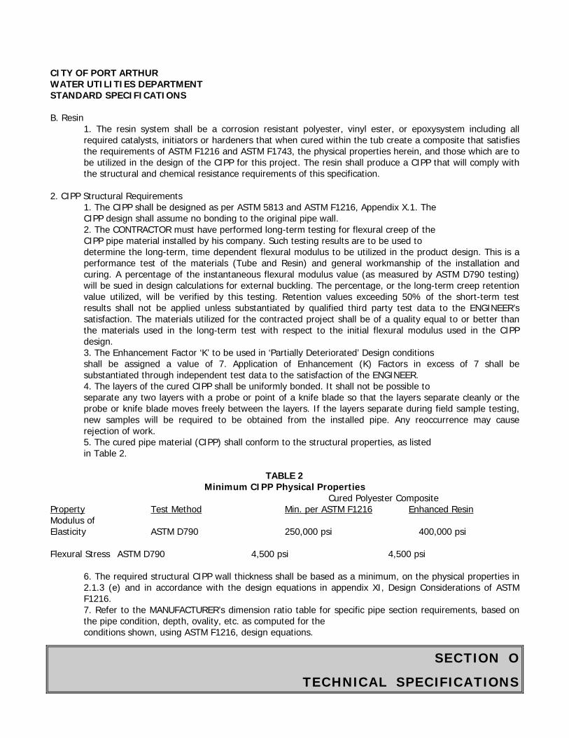
SECTION O
TECHNICAL SPECIFICATIONS
CITY OF PORT ARTHUR WATER UTILITIES DEPARTMENT STANDARD SPECIFICATIONS B. Resin
1. The resin system shall be a corrosion resistant polyester, vinyl ester, or epoxysystem including all required catalysts, initiators or hardeners that when cured within the tub create a composite that satisfies the requirements of ASTM F1216 and ASTM F1743, the physical properties herein, and those which are to be utilized in the design of the CIPP for this project. The resin shall produce a CIPP that will comply with the structural and chemical resistance requirements of this specification.
2. CIPP Structural Requirements
1. The CIPP shall be designed as per ASTM 5813 and ASTM F1216, Appendix X.1. The CIPP design shall assume no bonding to the original pipe wall. 2. The CONTRACTOR must have performed long-term testing for flexural creep of the
CIPP pipe material installed by his company. Such testing results are to be used to determine the long-term, time dependent flexural modulus to be utilized in the product design. This is a performance test of the materials (Tube and Resin) and general workmanship of the installation and curing. A percentage of the instantaneous flexural modulus value (as measured by ASTM D790 testing) will be sued in design calculations for external buckling. The percentage, or the long-term creep retention value utilized, will be verified by this testing. Retention values exceeding 50% of the short-term test results shall not be applied unless substantiated by qualified third party test data to the ENGINEER’s satisfaction. The materials utilized for the contracted project shall be of a quality equal to or better than the materials used in the long-term test with respect to the initial flexural modulus used in the CIPP design. 3. The Enhancement Factor ‘K’ to be used in ‘Partially Deteriorated’ Design conditions shall be assigned a value of 7. Application of Enhancement (K) Factors in excess of 7 shall be substantiated through independent test data to the satisfaction of the ENGINEER. 4. The layers of the cured CIPP shall be uniformly bonded. It shall not be possible to separate any two layers with a probe or point of a knife blade so that the layers separate cleanly or the probe or knife blade moves freely between the layers. If the layers separate during field sample testing, new samples will be required to be obtained from the installed pipe. Any reoccurrence may cause rejection of work. 5. The cured pipe material (CIPP) shall conform to the structural properties, as listed in Table 2.
TABLE 2
Minimum CIPP Physical Properties Cured Polyester Composite
Property Test Method Min. per ASTM F1216 Enhanced Resin Modulus of Elasticity ASTM D790 250,000 psi 400,000 psi Flexural Stress ASTM D790 4,500 psi 4,500 psi
6. The required structural CIPP wall thickness shall be based as a minimum, on the physical properties in 2.1.3 (e) and in accordance with the design equations in appendix XI, Design Considerations of ASTM F1216. 7. Refer to the MANUFACTURER’s dimension ratio table for specific pipe section requirements, based on the pipe condition, depth, ovality, etc. as computed for the conditions shown, using ASTM F1216, design equations.
SECTION O
TECHNICAL SPECIFICATIONS
CITY OF PORT ARTHUR WATER UTILITIES DEPARTMENT STANDARD SPECIFICATIONS
8. Any layers of the tube that are not saturated with resin prior to insertion into the existing pipe shall not be included in the structural CIPP wall thickness computation.
D. CIPP Testing Requirements
1. Test Requirements - Cured-in-Place liner materials shall be tested by one MANUFACTURER in accordance with ASTM 1216 and 5813. Should the standards conflict, the more restrictive shall apply. 2. Chemical Resistance - The CIPP shall meet the chemical resistance requirements of ASTM F1216,
Appendix X2. CIPP samples for testing shall be of tube and resin system similar to that proposed for actual construction. It is required that CIPP samples with and without plastic coating meet these chemical-testing requirements.
3. Hydraulic Capacity - Overall, the hydraulic cross-section shall be maintained as large as possible. The CIPP shall have a minimum of the full flow capacity of the original pipe before rehabilitation. Calculated capacities may be derived using a commonly accepted roughness coefficient for the existing pipe material taking into consideration its age and condition. 4. CIPP Field Samples - When requested by the ENGINEER, the CONTRACTOR shall submit test results from field installations in the USA of the same resin system and tube materials as proposed from the actual installation. These test results must verify that the CIPP physical properties specified in Section 2.1.3(e) have been achieved in previous field applications.
2.02 CURED IN PLACE MANHOLE AND JUNCTION BOX A. Fabric/Resin
1. Sewn liner sock shall meet the requirements and standards identified in Section 2.01 pertaining to CIPP. 2. The liner sock shall be sized based on field measurements of the structures taken by CONTRACTOR.
B. CIPP Structural Requirements 1. The CIPP shall be designed as per ASTM 5813 and ASTM F1216, Appendix X.1. The CIPP design shall assume no bonding to the original pipe wall. 2. The CONTRACTOR must have performed long-term testing for flexural creep of the CIPP pipe material installed by his Company. Such testing results are to be sued to determine the long-term, time dependent flexural modulus to be utilized in the product design. This is a performance test of the materials (Tube and Resin) and general workmanship of the installation and curing. A percentage of the instantaneous flexural modulus value (as measured by ASTM D790 testing) will be used in design calculations for external buckling. The percentage, or the long-term creep retention value utilized, will be verified by this testing. Retention values exceeding 50% of the short-term test results shall not be applied unless substantiated by qualified third party test data to the ENGINEER’s satisfaction. The materials utilized for the contracted project shall be of a quality equal to or better than the materials used in the long-term test with respect to the initial flexural modulus used in the CIPP design. 3. The enhancement factor ‘K’ to be used in ‘Partially Deteriorated’ Design conditions shall be assigned a value of 7. Application of Enhancement (K) Factors in excess of 7 shall be substantiated through independent test data to the satisfaction of the ENGINEER. 4. The layers of the cured CIPP shall be uniformly bonded. It shall not be possible to separate any two layers with a probe or point of a knife blade so that the layers separate cleanly or the probe or knife blade moves freely between the layers. If the layers separate during field sample testing,
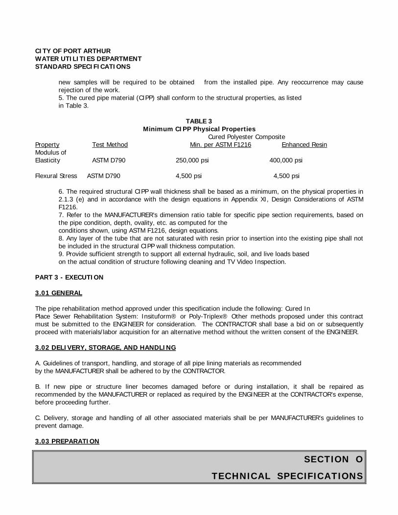
SECTION O
TECHNICAL SPECIFICATIONS
CITY OF PORT ARTHUR WATER UTILITIES DEPARTMENT STANDARD SPECIFICATIONS
new samples will be required to be obtained from the installed pipe. Any reoccurrence may cause rejection of the work. 5. The cured pipe material (CIPP) shall conform to the structural properties, as listed in Table 3.
TABLE 3
Minimum CIPP Physical Properties Cured Polyester Composite
Property Test Method Min. per ASTM F1216 Enhanced Resin Modulus of Elasticity ASTM D790 250,000 psi 400,000 psi Flexural Stress ASTM D790 4,500 psi 4,500 psi
6. The required structural CIPP wall thickness shall be based as a minimum, on the physical properties in 2.1.3 (e) and in accordance with the design equations in Appendix XI, Design Considerations of ASTM F1216. 7. Refer to the MANUFACTURER’s dimension ratio table for specific pipe section requirements, based on the pipe condition, depth, ovality, etc. as computed for the conditions shown, using ASTM F1216, design equations. 8. Any layer of the tube that are not saturated with resin prior to insertion into the existing pipe shall not be included in the structural CIPP wall thickness computation. 9. Provide sufficient strength to support all external hydraulic, soil, and live loads based on the actual condition of structure following cleaning and TV Video Inspection.
PART 3 - EXECUTION 3.01 GENERAL The pipe rehabilitation method approved under this specification include the following: Cured In Place Sewer Rehabilitation System: Insituform® or Poly-Triplex® Other methods proposed under this contract must be submitted to the ENGINEER for consideration. The CONTRACTOR shall base a bid on or subsequently proceed with materials/labor acquisition for an alternative method without the written consent of the ENGINEER. 3.02 DELIVERY, STORAGE, AND HANDLING A. Guidelines of transport, handling, and storage of all pipe lining materials as recommended by the MANUFACTURER shall be adhered to by the CONTRACTOR. B. If new pipe or structure liner becomes damaged before or during installation, it shall be repaired as recommended by the MANUFACTURER or replaced as required by the ENGINEER at the CONTRACTOR’s expense, before proceeding further. C. Delivery, storage and handling of all other associated materials shall be per MANUFACTURER’s guidelines to prevent damage. 3.03 PREPARATION
SECTION O
TECHNICAL SPECIFICATIONS
CITY OF PORT ARTHUR WATER UTILITIES DEPARTMENT STANDARD SPECIFICATIONS A. Bypassing Sewage:
1. The CONTRACTOR shall bypass the sewage around the section or sections of sewer to be rehabilitated and videotaped. The bypass shall be made by plugging the existing upstream manhole and pumping the sewage into a downstream manhole or adjacent system or by another method if approved by the ENGINEER. The pump and bypass lines shall be of adequate capacity and size to handle the flow without sewage backup occurring to facilities connected to the sewer. The CONTRACTOR shall have a standby pump available equal in capacity to the largest in service pump. All bypass pumping shall be subsidiary of the CIPP lining; no separate payment shall be made for pumping. Provisions shall be made at driveways and street crossings to permit safe vehicular travel without interrupting flow in the bypass system. Under no circumstances will the CONTRACTOR be permitted to discharge sewage into trenches. 2. The CONTRACTOR shall be responsible for continuity of sanitary sewer service to each facility connected to the section of sewer during the execution of the work. If sewage backup occurs and enters a building, the CONTRACTOR shall be responsible for clean-up, repair, property damage cost and claims.
B. Inspection of Siphon: Inspection of the siphon (Base Bid) shall be performed by experienced personnel trained in locating breaks, obstacles and service connections using close circuit television (CCTV) inspection techniques. The siphon interior shall be carefully inspected to determine the location of any conditions that may prevent proper installation of the liner. These shall be noted and corrected. A video (DVD) and suitable written log for each line section shall be furnished to the OWNER and MANUFACTURER. The CIPP MANUFACTURER shall review the video provided and furnish written certification of the actual applicability of the proposed process to the actual condition of the siphon and acknowledgment of the warranty required herein. C. Line Obstructions: If pre-installation (CCTV) inspection reveals an obstruction in the existing sewer (heavy solids, dropped joints, protruding service taps or collapsed pipe) which will prevent completion of the pipe lining process, and cannot be removed by conventional sewer equipment, then an obstruction removal should be considered to be made by the CONTRACTOR, with the approval of the ENGINEER. CITY OF PORT ARTHUR WATER UTILITIES DEPARTMENT STANDARD SPECIFICATIONS 3.04 LINER INSTALLATION A. A cable shall be strung through the existing pipe to be rehabilitated and attached to the liner through an existing manhole or access point. The liner shall be pulled through the existing manhole and through the existing pipe by this cable. Care shall be taken not to damage the pipe liner during the installation. Appropriate sleeves and rollers shall be sued to protect the liner. B. When the pre-formed pipe liner is in place, it shall be prepared for forming to the interior of the host pipe using MANUFACTURER’s approved equipment and methods. Temperature and pressure measuring instruments shall be attached to the pre-formed pipe liner at both ends. C. Areas of active infiltration visible to field personnel or present in the Television Video Inspection shall be repaired to MANUFACTURER’s standards prior to installation.
SECTION O
TECHNICAL SPECIFICATIONS
CITY OF PORT ARTHUR WATER UTILITIES DEPARTMENT STANDARD SPECIFICATIONS D. Liner Forming
1. Through the use of heat (ex: steam) and pressure (ex: air or water pressure), the pipe liner shall be formed to the existing pipe wall. The CONTRACTOR shall explicitly follow MANUFACTURER’s procedures for completing this process.
E. Cool-Down
1. The CONTRACTOR shall cool the reformed pipe in accordance with the approved MANUFACTURER recommendation. 2. Gradual transition shall be made from the heating to cooling process. Cooling shall be done without pressure interruption and with water or air as recommended by the MANUFACTURER. As cooling progresses, the pressure shall be gradually increased to maximum recommended by the MANUFACTURER. The final pressure level shall be maintained for a period of another 15 to 30 minutes or longer if determined by the ENGINEER. 3. Temperatures and pressures shall be monitored and recorded throughout the installation process to ensure that each phase of the process is achieved at the approved MANUFACTURER’s recommended temperature and pressure levels.
F. Finish
1. The finished lining shall be continuous over the entire length of an Insertion run and be as free as commercially practicable from visual defects such as foreign inclusions, pinholes, and delamination. The lining shall be impervious and free of any leakage from the pipe to the surrounding ground or from the ground to inside the lined pipe. 2. Any defects, which will or could affect the integrity or strength of the linings, shall be repaired at the CONTRACTOR’s expense, in a manner approved by the OWNER and ENGINEER. 3. The pipe liner shall be neatly trimmed at both upstream and downstream manholes to prevent snagging of debris. 4. The beginning and end of the new pipe liner shall be sealed to the rehabilitated pipeline. The sealing material shall provide a watertight seal.
G. Field Testing:
1. Low Pressure air Test of Rehabilitated Pipe: After a manhole-to-manhole (lined structure to lined structure) section has been lined and prior to any service lines being connected, the pipe shall be plugged at each manhole with pneumatic plugs. The design of the plugs shall be such taht they will hold against the test pressure without requiring external blocking or bracing. One of the plugs shall have three air hose connections; one for the inflation of the plug, one for reading the air pressure in the sealed line, and one for introducing air into the sealed line. All testing shall be in accordance with Item 02533 - Acceptance Testing for Sanitary Sewers.
H. Pre and Post-Construction Television Inspection
1. Upon completion, and before acceptance of the work, the CONTRACTOR will re-inspect the rehabilitated pipeline by the use of CCTV cameras and shall submit two (2) copies of the pre-installation and post-installation video tapes on DVD of the rehabilitated pipeline to the ENGINEER for approval/acceptance of the work.
End of Section

SECTION O
TECHNICAL SPECIFICATIONS
CITY OF PORT ARTHUR WATER UTILITIES DEPARTMENT STANDARD SPECIFICATIONS
ITEM 02221
REMOVING EXISTING PAVEMENTS AND STRUCTURES Part I General 1.01 SECTION INCLUDES A. Removing concrete paving, asphaltic concrete pavement, and base courses. B. Removing concrete curbs, concrete curbs and gutters, sidewalks and driveways. C. Removing pipe culverts and sewers. D. Removing existing inlets and manholes. E. Removing miscellaneous structures of concrete or masonry. 1.02 MEASUREMENT AND PAYMENT A. Unit Prices.
1. No separate payment will be made for removing existing pavement or structures under this Section. Include cost in unit price for different bid items.
1.03 REGULATORY REQUIREMENTS A. Conform to applicable codes for disposal of debris. B. Coordinate removal work with utility companies. PART 2 PRODUCTS - Not Used PART 3 EXECUTION 3.01 PREPARATION A. Obtain advance approval from Water Utilities Engineer for dimensions and limits of removal work. B. Identify known utilities below grade. Stake and flag locations. 3.02 PROTECTION A. Protect the following from damage or displacement.
1. Adjacent public and private property. 2. Trees, plants, and other landscape features designated to remain. 3. Utilities designated to remain. 4. Pavement and utility structures designated to remain. 5. Bench marks, monuments, and existing structures designated to remain.
3.03 REMOVALS A. Remove pavements and structures by methods that will not damage underground utilities. Do not use a drop hammer near existing underground utilities.
SECTION O
TECHNICAL SPECIFICATIONS
CITY OF PORT ARTHUR WATER UTILITIES DEPARTMENT STANDARD SPECIFICATIONS B. Minimize amount of earth loaded during removal operations. C. Where existing pavement is to remain, make straight saw cuts in existing pavement to provide clean breaks prior to removal. Do not break concrete pavement or base with drop hammer unless concrete or base has been saw cut to a minimum depth of 2 inches. D. Where street and driveway saw cut locations coincide or fall within 3 feet of existing construction or expansion joints, break out to existing joint. E. Remove sidewalks and curbs to nearest existing dummy, expansion, or construction joint. F. Where existing end of pipe culvert or end of sewer is to remain, install an 8-inch-thick masonry plug in pipe end prior to backfill. 3.04 BACKFILL A. Backfill of removal areas shall be in accordance with requirements of Item 2317 - Specifications for Excavation and Backfill For Utilities. 3.05 DISPOSAL A. Manhole frames and covers, will remain City property, and shall be delivered to 111 Henry O. Mills Blvd., Port Arthur,Texas, 77640. B. Methods of the removal of site debris resulting from work under this section shall be approved by the Water Utilities Manager and/or the City Engineer.
End of Section
SECTION O
TECHNICAL SPECIFICATIONS
CITY OF PORT ARTHUR WATER UTILITIES DEPARTMENT STANDARD SPECIFICATIONS
ITEM 02226
PIPE JACKING, BORING, AND TUNNELING 1.00 GENERAL 1.01 WORK INCLUDED A. All labor, materials and equipment required to furnish and install pipelines under highways, railroads, or streets by jacking, boring, or tunneling. B. The CONTRACTOR shall conform to the requirements of the Texas Department of Transportation, railroad company, county, or city construction specifications. All work necessary to meet these requirements shall be considered incidental to the installation of the pipeline in the rights-of-way. C. Pipeline crossings of railroad tracks will be encased using welded steel casing pipe as specified herein and also in accordance with all railroad specifications while in the right-of-way. No tunnel liner plates shall be used within railroad right-of-way. 1.02 SUBMITTALS A. Record Data: Submit for record purposes only detailed drawings, data, and design calculations for encasement pipe, tunnel liner plate, fasteners, coatings and miscellaneous fittings in conformance with the Contract Documents. B. Certificate: Submit certificates of compliance with referenced standards for all products specified in Part 2. C. Calculations by a licensed professional engineer in the State of Texas must be submitted verifying the suitability of the material to sustain installation and service loads. 1.03 DEFINITIONS A. Carrier pipe shall mean the pipeline placed inside the encasement pipe. The carrier pipe conveys potable or nonpotable water and shall have the same inside diameter and be installed on the same grade and at the same alignment as shown on the plans. B. Encasement (casing) pipe shall mean any pipe, tunnel liner plates, tunnel pipes, similar material, etc., used to protect the excavation through the embankment from collapsing and used to contain the carrier pipe. The encasement pipe is placed in the excavation and the carrier pipe is placed inside the encasement pipe. 2.00 PRODUCTS 2.01 TUNNEL LINER PLATES A. Material
1. Plates. The plates shall be fabricated from steel sheets conforming to the requirements of Steel, Carbon (0.15 minimum, percent) Hot-Rolled Sheet and Strap, Commercial Quality, ASTM Designation
SECTION O
TECHNICAL SPECIFICATIONS
CITY OF PORT ARTHUR WATER UTILITIES DEPARTMENT STANDARD SPECIFICATIONS
A569. In addition, the flat plates shall have the following minimum mechanical properties before cold forming.
Tensile strength = 42,000 psi Yield strength = 28,000 psi Elongation, 2 inch (51 mm) = 30 percent
2. Bolts and Nuts. Bolts used with lapped seam type (2 flange) liner plates shall be not less than 5/8-inch (15 mm) diameter. Bolts shall conform to Quenched and Tempered Steel Bolts and Studs, ASTM Designation A449 for plate thickness equal or greater than 0.209 inch (5 mm) and to Carbon Steel Externally Threaded Standard Fasteners, ASTM Designation A307 for plate thickness less than 0.209 inch (5 mm). The nuts shall conform to ASTM Designation A307.
B. Fabrication. The plates shall be new and unused prior to fabrication. All plates shall be punched for bolting on both longitudinal and circumferential seams or joints and shall be so fabricated as to permit complete erection from the inside of the tunnel. All plates shall be uniform in fabrication and those intended for one size tunnel shall be interchangeable. C. Grout Holes. One half of the total number of the top plates shall be equipped with 2-inch (50-mm) diameter grout holes to facilitate grouting above and around the tunnel liner conduit. All grout holes shall be equipped with screw type galvanized plugs for final watertight closure of the grout holes. D. Galvanizing. After the plates are formed to shape and after all holes are punched, the plates shall be galvanized on all surfaces by the hot-dip process. A coating of prime western spelter, or equal, shall be applied at the rate of not less than 3 ounces per square foot of finished plate or 1-1/2 ounce each side. Spelter coating shall be of a first-class commercial quality free from injurious defects such as blisters, flux and uncoated spots. All nuts and bolts shall be galvanized or sherardized. E. Bituminous Coating. The plates shall be given a bituminous coating (inside and outside) meeting in all respects the American Railway Engineering Association specifications for bituminous protected corrugated metal pipe. F. Rejection. Structures on which the spelter coating has been bruised or broken either in the shop or in shipping, or which shows defective workmanship, shall be rejected. The requirement applies not only to the individual plates but to the shipment on any contract as a whole. Among others, the following defects are specified as constituting poor workmanship, and the presence of any or all of them in any individual culvert plate or in general in any shipment shall constitute sufficient cause for rejection:
1. Uneven laps, 2. Elliptical shaping, 3. Variation from a straight centerline, 4. Ragged edges, 5. Unevenly lined or spaced bolt holes, 6. Illegible brands, 7. Bruised, scaled or broken spelter coating, or 8. Dents or bends in the metal itself.
G. Section Properties. Section properties shall conform to those specified in Section 16, Steel Tunnel Liner Plates, of the AASHTO Standard Specifications for Highway Bridges.
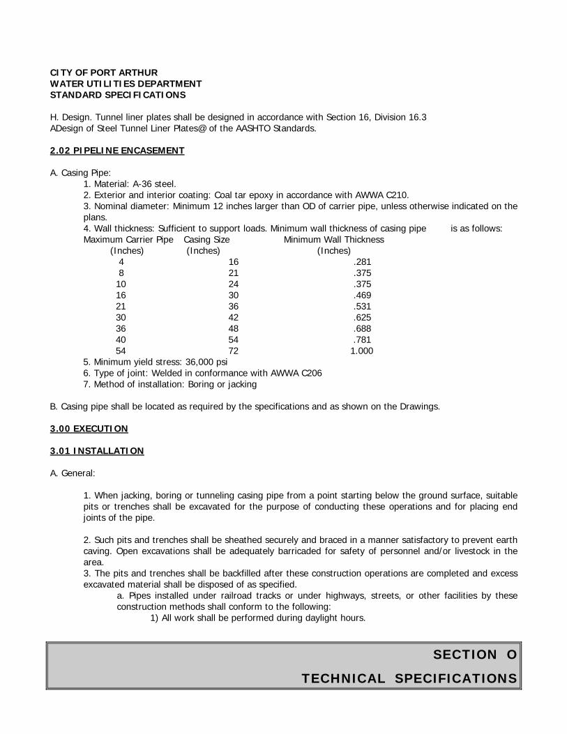
SECTION O
TECHNICAL SPECIFICATIONS
CITY OF PORT ARTHUR WATER UTILITIES DEPARTMENT STANDARD SPECIFICATIONS
H. Design. Tunnel liner plates shall be designed in accordance with Section 16, Division 16.3 ADesign of Steel Tunnel Liner Plates@ of the AASHTO Standards.
2.02 PIPELINE ENCASEMENT
A. Casing Pipe: 1. Material: A-36 steel.2. Exterior and interior coating: Coal tar epoxy in accordance with AWWA C210.3. Nominal diameter: Minimum 12 inches larger than OD of carrier pipe, unless otherwise indicated on theplans. 4. Wall thickness: Sufficient to support loads. Minimum wall thickness of casing pipe is as follows: Maximum Carrier Pipe Casing Size Minimum Wall Thickness
(Inches) (Inches) (Inches) 4 16 .281 8 21 .375
10 24 .375 16 30 .469 21 36 .531 30 42 .625 36 48 .688 40 54 .781 54 72 1.000
5. Minimum yield stress: 36,000 psi6. Type of joint: Welded in conformance with AWWA C2067. Method of installation: Boring or jacking
B. Casing pipe shall be located as required by the specifications and as shown on the Drawings.
3.00 EXECUTION
3.01 INSTALLATION
A. General:
1. When jacking, boring or tunneling casing pipe from a point starting below the ground surface, suitablepits or trenches shall be excavated for the purpose of conducting these operations and for placing end joints of the pipe.
2. Such pits and trenches shall be sheathed securely and braced in a manner satisfactory to prevent earthcaving. Open excavations shall be adequately barricaded for safety of personnel and/or livestock in the area. 3. The pits and trenches shall be backfilled after these construction operations are completed and excessexcavated material shall be disposed of as specified.
a. Pipes installed under railroad tracks or under highways, streets, or other facilities by theseconstruction methods shall conform to the following:
1) All work shall be performed during daylight hours.
SECTION O
TECHNICAL SPECIFICATIONS
CITY OF PORT ARTHUR WATER UTILITIES DEPARTMENT STANDARD SPECIFICATIONS
2) Construction shall be done in such a manner that will not interfere with the operation of the transportation facilities. 3) During construction operations, barricades and lights to safeguard traffic and pedestrians shall be furnished and maintained until backfilling has been completed. 4) Construction shall not weaken or damage any embankment or structure. 5) The railroad shall be notified and requested to furnish a flagman whenever tunneling is being performed closer than 40 feet from the center line of the railroad track. The CONTRACTOR shall reimburse the railroad for the flagman’s services. 6) Temporary bulkheads shall be in the tunnel liner plate before and during the passage of trains and when work ceases for the day. 7) Construction must comply with all requirements and specifications of any railroad company, State highway Department, city or county incidental to the pipeline installation within respective right-of-ways. 8) All backfilling of open excavations within these right-of-ways shall be compacted to 95 percent of the maximum dry density, Standard Proctor, as defined by ASTM D698.
4. The pipe shall be installed starting from the lower end. 5. Lateral and vertical variation in the field position of the pipe from the line and grade shall be permitted to the extent of 1 inch in 100 feet, provided that such variation shall be regular and only in one direction and that the final grade of flow line shall be in the direction indicated on the plans.
6. Any pipe damaged as a result of the construction operations shall be removed and replaced by the CONTRACTOR at no additional cost. Variations in plan, profile and manhole locations suggested by Contractor shall be submitted in writing to the Water Utilities Engineer and must be approved prior to construction.
7. Dewatering: a. All water used or encountered during construction by boring, jacking or tunneling by the
CONTRACTOR is the responsibility of the CONTRACTOR and measures shall be provided by the CONTRACTOR in such a manner that the water will not damage public or private property or create a nuisance or health menace. b. The CONTRACTOR shall provide and operate pumps, pipes and equipment to keep all excavations and accesses free from water until the pipeline is installed and backfilling has been completed. c. The CONTRACTOR shall provide all power and facilities necessary to operate the pumps and equipment. d. Water, if odorless and stable, may be discharged into an existing storm drain, channel, or street gutter in a manner approved by the OWNER. e. When required, a means of desilting the water before discharging shall be provided.
8. Shoring in areas of railroad crossings shall be done in accordance with this Project Manual and in accordance with American Railway Engineering Association (AREA) Manual Volume 1, Chapter 8, Part 20, and the Burlington Northern Santa Fe Railway Company. The more conservative approach shall govern. 9. The design of the trench safety system for all pipe jacking, boring and tunneling operations is the CONTRACTOR=s sole responsibility. The CONTRACTOR shall engage a Professional Engineer registered in the State of Texas to prepare the trench safety system design. Prior to beginning any construction activities in the vicinity of a railroad crossing, trench safety system designs prepared for railroad crossings shall be submitted to the OWNER for forwarding to the railroad for the railroad owner=s review and approval. Same applies for highway crossings.
B. Jacking:
SECTION O
TECHNICAL SPECIFICATIONS
CITY OF PORT ARTHUR WATER UTILITIES DEPARTMENT STANDARD SPECIFICATIONS
1. Heavy-duty jacks suitable for forcing the casing pipe through the embankment shall be provided. 2. Even pressure shall be applied to all jacks used. 3. A suitable jacking head and suitable bracing between jacks and jacking head shall be provided so that pressure will be applied to the pipe uniformly around the ring of the pipe. 4. Pipe guides shall be properly braced together and positioned to support the pipe section being jacked and to direct the pipe in the proper line and grade. 5. Excavation for the undersides of the pipe shall conform to the contour and grade of the pipe for at least one third of the pipe circumference. 6. A clearance of not more than 2 inches may be provided for the upper half of the pipe and shall be tapered to zero at the point where the elevation conforms to the contour of the pipe as shown on the Drawings. 7. Excavation shall not exceed 2 feet beyond the end of the pipe. 8. The CONTRACTOR may use a steel plate cutting edge extending a short distance beyond the head end of the pipe with inside angles and lugs. 9. Once jacking has begun, the operation shall be carried on without interruption, insofar as practicable, to prevent the pipe from being firmly set in the embankment. 10. All voids created by over cutting shall be filled by pressure grouting the entire length of the casing pipe and per grout specifications.
C. Boring:
1. Holes are to be bored mechanically and shall be accomplished using a pilot hole. 2. A 2-inch pilot hole shall be bored the entire length of the crossing and shall be checked for line and grade on both sides of the embankment. 3. The pilot hole shall serve as the centerline of the larger diameter hole to be bored. 4. Use of water or other fluids in connection with boring operations shall be permitted only to lubricate cuttings. 5. Jetting shall not be permitted. 6. Gel-forming colloidal drilling fluid consisting of at least 10 percent high grade carefully processed bentonite may be used in unconsolidated soil formations to:
a. Consolidate cuttings. b. Seal the bore hole walls. c. Provide lubrication for subsequent removal of cuttings. d. Provide immediate lubrication for installing the pipe.
7. All voids created because of any over cutting shall be filled by pressure grouting the entire length of the pipe boring installation, per grout specifications.
D. Tunneling: 1. Tunneling shall be used where soil characteristics or size of the proposed pipe would require such a method of construction or where tunneling is called for on the Drawings. 2. Work pits shall be located where shown on the Drawings. Where no such locations are given, the CONTRACTOR shall have the operation of determining such locations subject to approval by the OWNER. 3. In general, access shafts or portals will not be permitted within rights-of-way. 4. All materials encountered in the tunnel within the width and height shall be excavated as necessary to install tunnel supports, place pipe, make joints, and properly place backfill to fill all void space around the pipe to complete the pipe installation in tunneling. 5. Clearances shown on the tunnel details on the Drawings are minimum and no encroachment within the dimensions shown will be permitted.
SECTION O
TECHNICAL SPECIFICATIONS
CITY OF PORT ARTHUR WATER UTILITIES DEPARTMENT STANDARD SPECIFICATIONS
6. The Spring line clearances shown shall be increased by 3 inches for any tunnel to be constructed on a curve with a centerline radius of less than 300 feet. 7. All drilling shall be performed in such a manner as to avoid undue shattering or loosening of material.
8. The CONTRACTOR shall remove all material which is likely to fall or appears dangerous to workmen or the work. That such removal may enlarge the excavation beyond the required limits shall not relieve the CONTRACTOR from the necessity of performing such work, and the CONTRACTOR will not be entitled to any additional compensation by reason of such tunnel enlargement. 9. Excavation for tunnel shall be held to the minimum diameter required for installation for the liner plate and not more than 18 inches from the end of the tunnel liner plate. 10. Blasting shall not be allowed. 11. All 1-inch plates for the full length of a specified tunnel shall be of one type only and shall be assembled in accordance with the manufacturer’s.
E. Grouting: 1. To fill all voids created because of over cutting, the outside diameter of the tunnel liner plate shall be pressure grouted after installation is completed, per grout specifications and instructions.
F. Carrier Pipe Installation: 1. Install carrier pipe to grade and securely block in place to prevent movement as shown on the Plans. 2. After the carrier pipe has been installed as detailed on the Drawing, the ends of the tunnel/casing shall be installed. The void space between the carrier pipe and casing shall not be filled. 3. All voids created between the outside of the casing pipe and undisturbed soil shall be pressure grouted after installation of the casing pipe, per grout specifications.
G. Tolerances: 1. Conduits shall be placed to line and grade and the CONTRACTOR shall correct any deviation. 2. Unless otherwise noted on the Drawings, the CONTRACTOR will be permitted a tolerance from exact grade alignment of 1 inch per 100 linear feet, or portion thereof, for vertical and horizontal. The variation shall be regular and only in one direction and the final grade of flow line shall be in the direction indicated on the drawings. 3. The CONTRACTOR shall inform the OWNER of any horizontal or vertical variations for their approval. The OWNER will approve or reject the pipe position and the CONTRACTOR shall make appropriate modifications to the pipe alignment and grades, if necessary, at the CONTRACTOR’s sole expense. 4. As-built record data of crossings shall be completed by a surveyor licensed in the State of Texas. An electronic data format approved by the Water Utilities Engineer shall be submitted to the City.
End of Section
SECTION O
TECHNICAL SPECIFICATIONS
CITY OF PORT ARTHUR WATER UTILITIES DEPARTMENT STANDARD SPECIFICATIONS
ITEM 02317
SPECIFICATIONS FOR EXCAVATION AND BACKFILL FOR UTILITIES
PART 1 GENERAL
1.01 SECTION INCLUDES
Excavation, trenching, foundation, embedment, and backfill for installation of utilities, including manholes and other pipeline structures.
1.02 MEASUREMENT AND PAYMENT
Unit Prices. No additional payment will be made for trench excavation, embedment and backfill under this Section. Include cost in the unit price for installed underground piping, sewer, conduit, or duct work. No separate or additional payment will be made for surface water control, ground water control, or for excavation drainage. Include in the unit price for the installed piping, sewer, conduit, or bed work.
1.03 DEFINITIONS
Pipe Foundation: Suitable and stable native soils that are exposed at the trench subgrade after excavation to depth of bottom of the bedding as shown on the Drawings, or foundation backfill material placed and compacted in over-excavations.
Pipe Bedding: The portion of trench backfill that extends vertically from top of foundation up to a levelline at bottom of pipe, and horizontally from one trench sidewall to opposite sidewall.
Haunching: The material placed on either side of pipe from top of bedding up to springline of pipe andhorizontally from one trench sidewall to opposite sidewall.
Initial Backfill: The portion of trench backfill that extends vertically from springline of pipe (top ofhaunching) up to a level line 12 inches above top of pipe, and horizontally from one trench sidewall to opposite sidewall.
Pipe Embedment: The portion of trench backfill that consists of bedding, haunching and initialbackfill. Trench Zone: The portion of trench backfill that extends vertically from top of pipe embedment up to
pavement subgrade or up to final grade when not beneath pavement.
Unsuitable Material: Unsuitable soil materials are the following:
Materials that are classified as ML, CL-ML, MH, PT, OH, and OL according to ASTM D 248. Materials that cannot be compacted to required density due to either gradation, plasticity,or moisture
content. Materials that contain large clods, aggregates, stones greater than 4 inches in any dimension, debris,
vegetation, waste or any other deleterious materials. Materials that are contaminated with hydrocarbons or other chemical contaminants.
Suitable Material: Suitable soil materials are those meeting specification requirements.
SECTION O
TECHNICAL SPECIFICATIONS
CITY OF PORT ARTHUR WATER UTILITIES DEPARTMENT STANDARD SPECIFICATIONS Unsuitable soils meeting specification requirements for suitable soils after treatment with lime or cement are considered suitable, unless otherwise indicated. Backfill: Suitable material meeting specified quality requirements, placed and compacted under controlled conditions. Ground Water Control Systems: Installations external to trench, such as well points, eductors, or deep wells. Ground water control includes dewatering to lower ground water, intercepting seepage which would otherwise emerge from side or bottom of trench excavation, and depressurization to prevent failure or heaving of excavation bottom. Refer to Section 01578 - Control of Ground Water and Surface Water. Surface Water Control: Diversion and drainage of surface water runoff and rain water away from trench excavation. Rain water and surface water accidentally entering trench shall be controlled and removed as a part of excavation drainage. Excavation Drainage: Removal of surface and seepage water in trench by sump pumping and using a drainage layer, as defined in ASTM D 2321, placed on the foundation beneath pipe bedding or thickened bedding layer of Class I material. Trench Conditions are defined with regard to the stability of trench bottom and trench walls of pipe embedment zone. Maintain trench conditions that provide for effective placement and compaction of embedment material directly on or against undisturbed soils or foundation backfill, except where structural trench support is necessary.
Dry Stable Trench: Stable and substantially dry trench conditions exist in pipe embedmentzone as a result of typically dry soils or achieved by ground water control (dewatering or depressurization) for trenches extending below ground water level.
Stable Trench with Seepage: Stable trench in which ground water seepage is controlled by excavation drainage.
Stable Trench with Seepage in Clayey Soils: Excavation drainage is provided in lieu of or to supplement ground water control systems to control seepage and provide stable trench subgrade in predominately clayey soils prior to bedding placement.
Stable Wet Trench Sandy Soils: Excavation drainage is provided in the embedment zone in combination with ground water control in predominately sandy or silty soils.
Unstable Trench: Unstable trench conditions exist in the pipe embedment zone if groundwater inflow or high water content causes soil disturbances, such as sloughing, sliding,boiling, heaving or loss of density.
Subtrench: Subtrench is a special case of benched excavation. Subtrench excavation below trench shields or shoring installations may be used to allow placement and compaction of foundation or embedment materials directly against undisturbed soils. Depth of a subtrench depends upon trench stability and safety as determined by the Contractor. Trench Dam: A placement of low permeability material in pipe embedment zone or foundation to prohibit ground water flow along the trench.
SECTION O
TECHNICAL SPECIFICATIONS
CITY OF PORT ARTHUR WATER UTILITIES DEPARTMENT STANDARD SPECIFICATIONS Over-Excavation and Backfill: Excavation of subgrade soils with unsatisfactory bearing capacity or composed of otherwise unsuitable materials below top of foundation as shown on Drawings, and backfilled with foundation backfill material. Foundation Backfill Materials: Natural soil or manufactured aggregate of controlled gradation, and geotextile filter fabrics as required, to control drainage and material separation. Foundation backfill material is placed and compacted as backfill to provide stable support for bedding. Foundation backfill materials may include concrete seal slabs. Trench Safety Systems include both protective systems and shoring systems as defined in Item 712- Trench Safety Systems. Trench Shield (Trench Box): A portable worker safety structure moved along the trench as work proceeds, used as a protective system and designed to withstand forces imposed on it by cave-in, thereby protecting persons within the trench. Trench shields may be stacked if so designed or placed in a series depending on depth and length of excavation to be protected. Shoring System: A structure that supports sides of an excavation to maintain stable soil conditions and prevent cave-ins, or to prevent movement of the ground affecting adjacent installations or improvements. Special Shoring: A shoring system meeting special shoring as specified in Paragraph 1.08, Special Shoring Design Requirements, for locations identified on the Drawings. 1.04 REFERENCES ASTM C 12 - Standard Practice for Installing Vitrified Clay Pipe Lines. ASTM D 558 - Test Methods for Moisture-Density Relations of Soil Cement Mixtures. ASTM D 698 - Test Methods for Moisture-Density Relations of Soils and Soil-Aggregate Mixtures U 5.5-lb (2.49-kg) Rammer and 12-in., (304.8-mm) Drop. ASTM D 156 - Test Method for Density in Place by the Sand-Cone Method. ASTM D 2321 - Standard Practice for Underground Installation of Thermoplastic Pipe for Sewers and Other Gravity Flow Applications. ASTM D 2478 - Classification of Soils for Engineering Purposes. ASTM D 2922 - Test Method for Density of Soil and Soil-Aggregate in Place by Nuclear Methods (Shallow Depth). ASTM D 3017 - Test Method for Water Content of Soil and Rock in Place by Nuclear Methods (Shallow Depth). ASTM D 4318 - Test Method for Liquid Limit, Plastic Limit, and Plasticity Index of Soils. TxDOT Tex-101-E - Preparation of Soil and Flexible Base Materials for Testing. TxDOT Tex-110-E - Determination of Particle Size Analysis of Soils. Federal Regulations, 29 CFR Part 1926, Standard-Excavation, Occupational Safety and Health Administration (OSHA). 1.05 SCHEDULING Schedule work so that pipe embedment can be completed on the same day that acceptable foundation been achieved for each section of pipe installation, manhole, or other structures.
SECTION O
TECHNICAL SPECIFICATIONS
CITY OF PORT ARTHUR WATER UTILITIES DEPARTMENT STANDARD SPECIFICATIONS 1.06 SUBMITTALS Conform to Section 01300 - Contractor Submittals. Submit a written description for information only of the planned typical method of excavation, backfill placement and compaction, including:
Sequence of work and coordination of activities. Selected trench widths. Procedures for foundation and embedment placement, and compaction. Procedure for use of trench boxes and other pre-manufactured systems while assuring specified
compaction against undisturbed soil. Procedure for installation of Special Shoring at locations identified on the Drawings.
Submit a ground and surface water control plan in accordance with requirements in this Item and Item 01578 - Control of Ground Water and Surface Water. Submit backfill material sources and product quality information in accordance with requirements of Item 02320 - Utility Backfill Materials. Submit a trench excavation safety program in accordance with requirements of Item 712 – Trench Safety System. Include designs for special shoring meeting the requirements defined in Paragraph 1.08, Special Shoring Design Requirements. Submit record of location of utilities as installed, referenced to survey control points. Include locations of utilities encountered or rerouted. Give stations, horizontal dimensions, elevations, inverts, and gradients. 1.07 TESTS Testing and analysis of backfill materials for soil classification and compaction during construction will be performed by an independent laboratory provided by the City. Perform backfill material source qualification testing in accordance with requirements of Item 02320 - Utility Backfill Materials. 1.08 SPECIAL SHORING DESIGN REQUIREMENTS Have special designed or selected by the Contractor’s Professional Engineer to provide support for the sides of the excavations, including soils and hydrostatic ground water pressures as applicable, and to prevent ground movements affecting adjacent installations or improvements such as structures, pavements and utilities. Special shoring may be a premanufactured system selected by the Contractor’s Professional Engineer to meet the project site requirements based on the manufacturer’s standard design. PART 2 PRODUCTS 2.01 EQUIPMENT Perform excavation with hydraulic excavator or other equipment suitable for achieving the requirements of this Section. Use only hand-operated tamping equipment until a minimum cove of 12 inches is obtained over pipe, conduits, and ducts. Do not use heavy compacting equipment until adequate cover is attained to prevent damage
SECTION O
TECHNICAL SPECIFICATIONS
CITY OF PORT ARTHUR WATER UTILITIES DEPARTMENT STANDARD SPECIFICATIONS to pipes, conduits, or ducts. Use trench shields or other protective systems or shoring systems which are designed and operated to achieve placement and compaction of backfill directly against undisturbed native soil. Use special shoring systems where required which may consist of braced sheeting, braced soldier piles and lagging, slide rail systems, meeting requirements as specified in Paragraph 1.09, Shoring Design Requirements. 2.02 MATERIAL CLASSIFICATIONS Embedment and Trench Zone Backfill Materials: Conform to classifications and product descriptions of Item 02320 - Utility Backfill Materials. Concrete Backfill: Conform to requirements for Class B concrete. Concrete for Trench Dams: Concrete backfill or 3 sack premixed (bag) concrete. Timber Shoring Left in Place: Untreated oak. PART 3 EXECUTION 3.01 STANDARD PRACTICE Install flexible pipe, including “semi-rigid” pipe, to conform to standard practice described in ASTMD 2321, and as described in this Section. Where an apparent conflict occurs between the standard practice and the requirements of this Section, this Section governs. Install rigid pipe to conform with standard practice described in ASTM C 12, and as described in this Section. Where an apparent conflict occurs between the standard practice and the requirements of this Section, this Section governs. 3.02 PREPARATION Establish traffic control to conform with requirements of the Special Provisions Section. Maintain barricades and warning lights for streets and intersections affected by the Work, and is considered hazardous to traffic movements. Perform work to conform with applicable safety standards and regulations. Employ a trench safety system as specified in Item 712 - Trench Safety Systems. Immediately notify the agency or company owning any existing utility line which is damaged, broken, or disturbed. Obtain approval from the Water Utilities Engineer and agency for any repairs or relocations, either temporary or permanent. Remove existing pavements and structures, including sidewalks and driveways, to conform with requirements of Item 02221 - Removing Existing Pavements and Structures, as applicable. Install and operate necessary dewatering and surface water control measures to conform with Item 01578 - Control of Ground Water and Surface Water. Maintain permanent benchmarks, monumentation, and other reference points. Unless otherwise directed in writing, replace those which are damaged or destroyed. 3.03 PROTECTION Protect trees, shrubs, lawns, existing structures, and other permanent objects outside of rading limits and within the grading limits as designated on the Drawings. Protect and support above-grade and below-grade utilities which are to remain. Restore damaged permanent facilities to pre-construction conditions unless replacement or abandonment of facilities are indicated on the Drawings. Take measures to minimize erosion of trenches. Do not allow water to pond in

SECTION O
TECHNICAL SPECIFICATIONS
CITY OF PORT ARTHUR WATER UTILITIES DEPARTMENT STANDARD SPECIFICATIONS trenches. Where slides, washouts, settlements, or areas with loss of density or pavement failures or potholes occur, repair, recompact, and pave those areas at no additional cost to City. 3.04 EXCAVATION Except as otherwise specified or shown on the Drawings, install underground utilities in open cut trenches with vertical sides. Perform excavation work so that pipe, conduit, and ducts can be installed to depths and alignments shown on the Drawings. Avoid disturbing surrounding ground and existing facilities and improvements. Determine trench excavation widths using the following schedule as related to pipe outside diameter (O.D.). Maximum trench width shall be the minimum trench width plus 24 inches.
Nominal Minimum Trench Pipe Size, Inches Width, Inches Less than 18 O.D. + 18
18 to 30 O.D. + 24 Greater than 30 O.D. + 36
Use sufficient trench width or benches above the embedment zone for installation of well point headers or manifolds and pumps where depth of trench makes it uneconomical or impractical to pump from the surface elevation. Provide sufficient space between shoring cross braces to permit equipment operations and handling of forms, pipe, embedment and backfill, and other materials. Upon discovery of unknown utilities, badly deteriorated utilities not designated for removal, or concealed conditions, discontinue work at that location. Notify the Water Utilities Engineer and obtain instructions before proceeding. Shoring of Trench Walls. Install Special Shoring in advance of trench excavation or simultaneously with the trench excavation, so that the soils within the full height of the trench excavation walls will remain laterally supported at all times. For all types of shoring, support trench walls in the pipe embedment zone throughout the installation. Provide trench wall supports sufficiently tight to prevent washing the trench wall soil out from behind the trench wall support. Unless otherwise directed by the Water Utilities Engineer, leave sheeting driven into or below the pipe embedment zone in place to preclude loss of support of foundation and embedment materials. Leave rangers, walers, and braces in place as long as required to support sheeting, which has been cut off, and the trench wall in the vicinity of the pipe zone. Employ special methods for maintaining the integrity of embedment or foundation material. Before moving supports, place and compact embedment to sufficient depths to provide protection of pipe and stability of trench walls. As supports are moved, finish placing and compacting embedment. If sheeting or other shoring is used below top of the pipe embedment zone, do not disturb pipe foundation and embedment materials by subsequent removal. Maximum thickness of removable sheeting extending into the embedment zone shall be the equivalent of a 1-inch thick steel plate. Fill voids left on removal of supports with compacted backfill material. Use of Trench Shields. When a trench shield (trench box) is used as a worker safety device, the following requirements apply:
Make trench excavations of sufficient width to allow shield to be lifted or pulled freely, without damage to the trench sidewalls.
Move trench shields so that pipe, and backfill materials, after placement and compaction, are not damaged nor disturbed, nor the degree of compaction reduced.
When required, place spread, and compact pipe foundation and bedding materials beneath the shield. For backfill above bedding, lift the shield as each layer of backfill is placed and spread. Place and compact backfill materials against undisturbed trench walls and foundation.
Maintain trench shield in position to allow sampling and testing to be performed in a safe manner.
SECTION O
TECHNICAL SPECIFICATIONS
CITY OF PORT ARTHUR WATER UTILITIES DEPARTMENT STANDARD SPECIFICATIONS 3.05 HANDLING EXCAVATED MATERIALS Use only excavated materials which are suitable as defined in this Section and conforming with Item 02320 - Utility Backfill Materials. Place material suitable for backfilling in stockpiles at a distance from the trench to prevent slides or cave-ins. When required, provide additional backfill material conforming with requirements of Item 02320 - Utility Backfill Materials Do not place stockpiles of excess excavated materials on streets and adjacent properties. Protect excess stockpiles for use on site. 3.06 GROUND WATER CONTROL Implement ground water control according to Item 01578 - Control of Ground Water and Surface Water. Provide a stable trench to allow installation in accordance with the Specifications. 3.07 TRENCH FOUNDATION Excavate bottom of trench to uniform grade to achieve stable trench conditions and satisfactory compaction of foundation or bedding materials. Place trench dams in Class I foundations in line segments longer than 100 feet between manholes, and not less than one in every 500 feet of pipe placed. Install additional dams as needed to achieve workable construction conditions. Do not place trench dams closer than 5 feet from manholes. 3.08 PIPE EMBEDMENT, PLACEMENT AND COMPACTION Immediately prior to placement of embedment materials, the bottoms and sidewalls of trenches shall be free of loose, sloughing, caving, or otherwise unsuitable soil. Place embedment including bedding, haunching, and initial backfill as shown on Drawings. For pipe installation, manually spread embedment materials around the pipe to provide uniform bearing and side support when compacted. Do not allow materials to free-fall from heights greater than 24 inches above the top of the pipe. Perform placement and compaction directly against the undisturbed soils in the trench sidewalls, or against sheeting which is to remain in place. Do not place trench shields or shoring within height of the embedment zone unless means to maintain the density of compacted embedment material are used. If moveable supports are used in embedment zone, lift the supports incrementally to allow placement and compaction of the material against undisturbed soil. Place geotextile to prevent particle migration from the in-situ soil into open-graded (Class I) embedment materials or drainage layers. Do not damage coatings or wrappings of pipes during backfilling and compacting operations. When embedding coated or wrapped pipes, do not use crushed stone or other sharp, angular aggregates. Place haunching material manually around the pipe and compact it to provide uniform bearing and side support. If necessary, hold small diameter or lightweight pipe in place during compaction of haunch areas and placement beside the pipe with sand bags or other suitable means. Place electrical conduit, if used, directly on foundation without bedding. Shovel in-place and compact embedment material using pneumatic tampers in restricted areas, and vibratory-plate compactors or engine-powered jumping jacks in unrestricted areas. Compact each lift before proceeding with placement of next lift. Water tamping is not allowed. For water lines construction embedment, use bank run sand, concrete sand, gem sand, pea gravel, or crushed limestone as specified in Item 02320 - Utility Backfill Material. For water lines adhere to the following subparagraph numbers 1 and 2; for utility installation other than water, adhere to numbers 3 and 4 below. Class I, II, III Embedment Materials:
Maximum 6 inches compacted lift thickness.
SECTION O
TECHNICAL SPECIFICATIONS
CITY OF PORT ARTHUR WATER UTILITIES DEPARTMENT STANDARD SPECIFICATIONS
Compact to achieve a minimum of 95 percent of maximum dry density as determined according to ASTM
D 698. Moisture content to be within -3 percent to +5 percent of optimum as determined according to ASTM D
698, unless otherwise approved by Water Utilities Engineer. Cement Stabilized Sand:
Maximum 6 inches compacted thickness. Compact to achieve a minimum of 95 percent of maximum dry density as determined according to ASTM
D 698. Moisture content to be on dry side of optimum as determined according to ASTM D 698 but sufficient for
effective hydration. Class I embedment materials.
Maximum 6 inches compacted lift thickness. Systematic compaction by at least two passes of vibrating equipment. Increase compaction effort as necessary to effectively embed the pipe to meet the deflection test criteria. Moisture content as determined by Contractor for effective compaction without softening the soil of
trench bottom, foundation or trench walls. Class II embedment and cement stabilized sand.
Maximum 6 inches compacted thickness. Compaction by methods determined by Contractor to achieve a minimum of 95 percent the maximum dry
density as determined according to ASTM D 698 for Class II material and according to ASTM D 558 for cement stabilized materials.
Moisture content of Class II materials within 3 percent of optimum as determined according to ASTM D 698. Moisture content of cement stabilized sands on the dry side of optimum as determined according to ASTM D 558 but sufficient for effective hydration.
Place trench dams in Class I embedment in line segments longer than 100 feet between manholes, and not less than one in every 500 feet of pipe placed. Install additional dams as needed to achieve workable construction conditions. Do not place trench dams closer than 5 feet from manholes.
3.09 TRENCH ZONE BACKFILL PLACEMENT AND COMPACTION Place backfill for pipe or conduits and restore surface as soon as practicable. Leave only the minimum length of trench open as necessary for construction. Where damage to completed pipe installation work is likely to result from withdrawal of sheeting, leave the sheeting in place. Cut off sheeting 1.5 feet or more above the crown of the pipe. Remove trench supports within 5 feet from the ground surface. For sewer pipes, use backfill materials described here as determined by trench limits. As trench zone backfill in paved areas for streets and to one foot back of curbs and pavements, use cement stabilized sand for pipe for nominal sizes less than 36 inches. Uniformly backfill trenches partially within limits one foot from streets and curbs according to the paved area criteria. Use select backfill within one foot below pavement subgrade for rigid pavement. For asphalt concrete, use flexible base material within one foot below pavement subgrade. For water lines, backfill in trench zone, including auger pits, with bank run sand, select fill, or random backfill material as specified in Item 02320 - Utility Backfill materials. When shown in Drawings, a random backfill of suitable material may be used in trench zone for trench excavations outside pavements. Place trench zone backfill in lifts and compact by methods selected by the Contractor. Fully compact each lift before placement of the next lift. Bank run sand.
SECTION O
TECHNICAL SPECIFICATIONS
CITY OF PORT ARTHUR WATER UTILITIES DEPARTMENT STANDARD SPECIFICATIONS
Maximum 9 inches compacted lift thickness. Compaction by vibratory equipment to a minimum of 95 percent of the maximum dry density determined
according to ASTM D 698. Moisture content within 3 percent of optimum determined according to ASTM D 698.
Cement-stabilized sand.
Maximum lift thickness determined by Contractor to achieve uniform placement and required compaction, but not exceeding 24 inches.
Compaction by Vibratory equipment to a minimum of 95 percent of the maximum dry density determined according to ASTM D 558.
Moisture content on the dry side of optimum determined according to ASTM D 558 but sufficient for cement hydration.
Select fill. Maximum 6 inches compacted thickness. Compaction by equipment providing tamping or kneading impact to a minimum of 95 percent of the
maximum dry density determined according to ASTM D 698. Moisture content within 2 percent of optimum determined according to ASTM D 698.
For trench excavations outside pavements, a random backfill of suitable material may be used in the trench zone. Flat clays (CH) may be used as trench zone backfill outside paved areas at the Contractor’s option. If the
required density is not achieved, the Contractor, at his option and at no additional cost to the City, may use lime stabilization to achieve compaction requirements or use a different suitable material.
Maximum 9 inch compacted lift thickness for clayey soils and maximum 12-inch lift thickness for granular soils.
Compact to a minimum of 90 percent of the maximum dry density determined according to ASTM D 698. Moisture content as necessary to achieve density. For electrical conduits, remove form work used for
construction of conduits before placing trench zone backfill. 3.10 MANHOLES, JUNCTION BOXES, AND OTHER PIPELINE STRUCTURES Meet the requirements of adjoining utility installations for backfill of pipeline structures, as shown on the Drawings. 3.11 FIELD QUALITY CONTROL Test for material source qualifications as defined in Item 02320 - Utility Backfill Materials. Provide excavation and trench safety systems at locations and to depths required for testing and retesting during construction at no additional cost to City. Tests will be performed on a minimum of three different samples of each material type for plasticity characteristics, in accordance with ASTM D 4318, and for gradation characteristics, in accordance with Tex-101-E and Tex-110-E. Additional classification tests will be performed whenever there is a noticeable change in material gradation or plasticity.
SECTION O
TECHNICAL SPECIFICATIONS
CITY OF PORT ARTHUR WATER UTILITIES DEPARTMENT STANDARD SPECIFICATIONS At least three tests for moisture-density relationships will be performed initially for backfill materials in accordance with ASTM D 698, and for cement-stabilized sand in accordance with ASTM 558. Additional moisture-density relationship tests will be performed whenever there is a noticeable change in material gradation or plasticity. In-place density tests of compacted pipe foundation, embedment and trench zone backfill soil materials will be performed according to ASTM D 1556, or ASTM D 2922 and ASTM D 3017, and at the following frequencies and conditions.
A minimum of one test for every 20 cubic yards of compacted embedment and for every 50 cubic yards of compacted trench zone backfill material. A minimum of three density tests for each full shift to Work. Density tests will be distributed among the placement areas. Placement areas are: foundation, bedding, haunching, initial backfill and trench zone. The number of tests will be increased if inspection determines that soil type or moisture content are not uniform or if compacting effort is variable and not considered sufficient to attain uniform density, as specified. Density tests may be performed at various depths below the fill surface by pit excavation. Material in previously placed lifts may therefore be subject to acceptance/rejection. Two verification tests will be performed adjacent to in-place tests showing density less than the acceptance criteria. Placement will be rejected unless both verification tests show acceptable results.
Recompacted placement will be retested at the same frequency as the first test series, including verification tests. Recondition, recompacted, and retest at Contractor’s expense if tests indicate Work does not meet specified compaction requirements. For hardened soil cement with nonconforming density, core and test for compressive strength at Contractor’s expense. Acceptability of crushed rock compaction will be determined by inspection. 3.12 DISPOSAL OF EXCESS MATERIAL Disposal of excess materials shall be at the Contractor’s cost and in areas approved by the owner.
End of Section
SECTION O
TECHNICAL SPECIFICATIONS
CITY OF PORT ARTHUR WATER UTILITIES DEPARTMENT STANDARD SPECIFICATIONS
ITEM 02320
SPECIFICATIONS FOR UTILITY BACKFILL MATERIAL PART 1 GENERAL SECTION INCLUDES
Material Classifications. Utility Backfill Materials:
Concrete sand Gem sand Pea gravel Crushed stone Crushed concrete Back run sand Select backfill Random backfill Material Handling and Quality Control Requirements.
1.02 MEASUREMENT AND PAYMENT Unit Prices. No payment will be made for backfill material under this Section. Include payment in unit price for applicable utility installation. Payment for backfill material, when included as a separate pay item, is on a cubic yard basis for material placed and compacted within theoretical trench width limits and thickness of material according to Drawings. 1.03 DEFINITIONS Unsuitable Material: Unsuitable soil materials are the following:
Materials that are classified as ML, CL-ML, MH, PT, OH, and OL according to ASTM D 2487. Materials that cannot be compacted to the required density due to either gradation, plasticity, or moisture
content. Materials that contain large clods, aggregates, and stones greater than 4 inches in any dimension; debris,
vegetation, and waste; or any other deleterious materials. Materials that are contaminated with hydrocarbons or other chemical contaminants. Materials that do not satisfy the installed utilities manufacturers recommendations.
Suitable Material: Suitable soil materials are the following:
Those meeting specification requirements and manufacturers recommendations. Unsuitable soils meeting specification requirements for suitable soils after treatment with lime or cement.
Foundation Backfill Materials: Natural soil or manufactured aggregate meeting Class I requirements and geotextile filter fabrics as required, to control drainage and material separation. Foundation backfill material is placed and
SECTION O
TECHNICAL SPECIFICATIONS
CITY OF PORT ARTHUR WATER UTILITIES DEPARTMENT STANDARD SPECIFICATIONS compacted as backfill where needed to provide stable support for the structure foundation base. Foundation backfill materials may include concrete fill and seal slabs. Foundation Base: Crushed stone aggregate with filter fabric as required, cement stabilized sand, or concrete seal slab., The foundation base provides a smooth, level working surface for the construction of the concrete foundation. Backfill Material: Classified soil material meeting specified quality requirements for the designated application as embedment or trench zone backfill. Embedment Material: Soil material placed under controlled conditions within the embedment zone extending vertically upward from top of foundation to an elevation 12 inches above top of pipe, and including pipe bedding, haunching, and initial backfill. Trench Zone Backfill: Classified soil material meeting specified quality requirements and placed under controlled conditions in the trench zone from the top of embedment zone to base course in paved areas or to the surface grading material in unpaved areas. Foundation: Either suitable soil of the trench bottom, or material placed as backfill of overexcavation for removal and replacement of unsuitable or otherwise unstable soils. Source: A source selected by the Contractor supply of embedment or trench zone backfill material. A selected source may be the project excavation, off-site borrow pits, commercial borrow pits, or sand and aggregate production or manufacturing plants. Refer to Item 02317 - Excavation and Backfill for Utilities for other definitions regarding utility installation by trench construction. 1.04 REFERENCES ASTM C 33 - Specification for Concrete Aggregate. ASTM C 40 - Test Method for Organic Impurities in Fine Aggregates for Concrete. ASTM C 123 - Test Method for Lightweight Pieces in Aggregate. ASTM C 131 - Test Method for Resistance to Degradation of Small-Size Coarse Aggregate by Abrasion and Impact in the Los Angeles Machine. ASTM C 136 - Test Method for Sieve Analysis of Fine and Coarse Aggregates. ASTM C 142 - Test Method for Clay Lumps and Friable Particles in Aggregates. ASTM D 1140 - Test Method for Amount of Materials in Soils Finer Than No. 200 Sieve. ASTM D 2487 - Classification of Soils for Engineering Purposes (Unified Soil Classification System). ASTM D 2488 - Standard Practice for Description and Identification of Soils (Visual-Manual Procedure). ASTM D 4318 - Test Method for Liquid Limit, Plastic Limit, and Plasticity Index of Soils. ASTM D 4643 - Method for Determination of Water (Moisture) Content of Soil by the Microwave Oven Method. TxDOT Tex-101-E - Preparation of Soil and Flexible Base Materials for Testing. TxDOT Tex-104-E - Test Method for Determination of Liquid Limit of Soils (Part 1). TxDOT Tex-106-E - Test Method - Methods of Calculating Plasticity Index of Soils. TxDOT Tex-110-E - Determination of Particle Size Analysis of Soils. 1.05 SUBMITTALS Conform to requirements of Section 01300 - Contractor Submittals.
SECTION O
TECHNICAL SPECIFICATIONS
CITY OF PORT ARTHUR WATER UTILITIES DEPARTMENT STANDARD SPECIFICATIONS Submit a description of source, material classification and product description, production method, and application of backfill materials. Submit test results for samples of off-site backfill materials to comply with Paragraph 2.03, Materials testing. Before stockpiling materials, submit a copy of temporary easement or approval from landowner for stockpiling backfill material on private property. For each delivery of material, provide a delivery ticket which includes source location. 1.06 TESTS Perform tests of sources for backfill material in accordance with Paragraph 2.03B. Verification tests of backfill materials may be performed by the City and in accordance with Paragraph 3.02. Random fill obtained from the project excavation as source is exempt from pre-qualification requirements by Contractor but must be inspected by City testing lab at Contractors expense for unacceptable materials based on ASTM D 2488. PART 2 PRODUCTS 2.01 MATERIAL CLASSIFICATIONS Materials for backfill shall be classified for the purpose of quality control in accordance with the Unified Soil Classification Symbols as defined in ASTM D 2487. Material use and application is defined in utility installation specifications and Drawings either by class, as described in Paragraph 2.01B, or by product descriptions, as given in Paragraph 2.02. Class Designations Based on Laboratory Testing: Class I: Well-graded gravels and sands, gravel-sand mixtures, crushed well-graded rock, little or no fines (FW, SW):
Plasticity index: non-plastic. Gradation: D60/D10 - greater than 4 percent; amount passing No. 200 sieve - less than or equal to 5 percent.
Class II: Poorly graded gravels and sands, silty gravels and sands, little to moderate fines:
Plasticity index: non-plastic to 4. Gradations: Gradation (GP, SP): amount passing No. 200 sieve-less than 5 percent. Gradation (GM, SM): amount passing No. 200 sieve - between 12 percent and 50 percent. Borderline gradations with dual classifications (e.g., SP-SM): amount passing No. 200 sieve - between 5 percent and 12 percent.
Class III: Clayey gravels and sands, poorly graded mixtures of gravel, sand, silt, and clay (GC, SC, and dual classifications, E.G., SP-SC):
Plasticity index: greater than7> Gradation: amount passing No. 200 sieve - between 12 percent and 50 percent.
Class IVA: Lean clays (CL) Plasticity Indexes:
Plasticity index: greater than 7, and above A line. Borderline plasticity with dual classifications (CL-ML): PI between 4 and 7.
Liquid limit: less than 50. Gradation: amount passing No. 200 sieve - greater than 50 percent. Inorganic.
SECTION O
TECHNICAL SPECIFICATIONS
CITY OF PORT ARTHUR WATER UTILITIES DEPARTMENT STANDARD SPECIFICATIONS
Class IVB: Fat clays (CH) Plasticity index: above A line. Liquid limit: 50 or greater. Gradation: amount passing No. 200 sieve - greater than 50 percent. Inorganic.
Use soils with dual class designation according to STM D 2487, and which are not defined above, according to the more restrictive class.
2.02 PRODUCT DESCRIPTIONS
Soils classified as silt (ML), elastic silt (MH), organic clay and organic silt (OL, OH), and organic matter (PT) are not acceptable as backfill materials. These soils may be used for site grading and restoration in unimproved areas as approved by the Water Utilities Engineer. Soils in Class IVB, fat clay (CH) may be used as backfill materials where allowed by the applicable backfill installation specification. Refer to Section 02317 - Excavation and Backfill for Utilities. Provide backfill material that is free of stones greater than 6 inches, free of roots, waste, debris, trash, organic material, no-soil matter, hydrocarbon or other contamination, conforming to the following limits for deleterious materials:
Clay lumps: Less than 0.5 percent for Class I, and less than 2.0 percent for Class II, when tested in accordance with ASTM C 142. Lightweight pieces: Less than 5 percent when tested in accordance with ASTM C 123. Organic impurities: No color darker than standard color when tested in accordance with ASTM C 40. Manufactured materials, such as crushed concrete, may be substituted for natural soil or rock products where indicated in the product specification, and approved by the Water Utilities Engineer, provided that the physical property criteria are determined to be satisfactory by testing. Bank Run Sand: Durable bank run sand classified as SP, SW, or SM by the Unified Soil Classification System (ASTM D 2487) meeting the following requirements: Less than 15 percent passing the number 200 sieve when tested in accordance with ASTM D 1140. The amount of clay lumps or balls not exceeding 2 percent. Materials passing the number 40 sieve shall meet the following requirements when tested in accordance with ASTM D 4318: Liquid limit: not exceeding 25 percent. Plasticity index: not exceeding 7. Concrete Sand: Natural sand, manufactured sand, or a combination of natural and manufactured sand conforming to the requirements of ASTM C 33 and graded within the following limits when tested in accordance with ASTM C 136:

SECTION O
TECHNICAL SPECIFICATIONS
CITY OF PORT ARTHUR WATER UTILITIES DEPARTMENT STANDARD SPECIFICATIONS
Sieve Percent Passing 3/8” 100 No. 4 95 to 100 No. 8 80 to 100 No. 16 50 to 85 No. 30 25 to 60 No. 50 10 to30 No. 100 2 to 10
Gem Sand: Sand conforming to the requirements of ASTM C 33 for course aggregates specified for number 8 size and graded within the following limits when tested in accordance with ASTM C 136:
Sieve Percent Passing 3/8” 95 to 100 No. 4 60 to 80 No. 8 15 to 40
Pea Gravel: Durable particles composed of small, smooth, rounded stones or pebbles and graded within the following limits when tested in accordance with ASTM C 136:
Sieve Percent Passing ½” 100 3/8” 85 to 100 No. 4 10 to 30 No. 8 0 to 10 No. 16 0 to 5
Crushed Aggregates: Crushed aggregates consist of durable particles obtained from an approved source and meeting the following requirements: Materials of one product delivered for the same construction activity from a single source. Non-plastic fines. Los Angeles abrasion test wear not exceeding 45 percent when tested in accordance with ASTM C 131. Crushed aggregate shall have a minimum of 90 percent of the particles retained on the No. 4 sieve with 2 or more crushed faces as determined by Test Method Tex- 460-A, Part I. Crushed stone: Produced from oversized plant processed stone or gravel sized by crushing to predominantly angular particles from a naturally for embedment where crushed stone is shown on the applicable utility embedment drawing details. Crushed Concrete: Crushed concrete is an acceptable substitute for crushed stone as utility backfill. Gradation and quality control test requirements are the same as crushed stone. Provide crushed concrete produced from normal weight concrete of uniform quality; containing particles of aggregate and cement material, free from other substances such as asphalt, reinforcing steel fragments, soil, waste gypsum (calcium sulfate), or debris. Gradations, as determined in accordance with Tex-110-E.
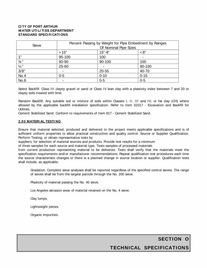
SECTION O
TECHNICAL SPECIFICATIONS
CITY OF PORT ARTHUR WATER UTILITIES DEPARTMENT STANDARD SPECIFICATIONS
Sieve Percent Passing by Weight for Pipe Embedment by Ranges Of Nominal Pipe Sizes
>15” 15”-8” <8” 1” 95-100 100 - ¾” 60-90 90-100 100 ½” 25-60 - 90-100 3/8” - 20-55 40-70 No.4 0-5 0-10 0-15 No.8 - 0-5 0-5 Select Backfill: Class III clayey gravel or sand or Class IV lean clay with a plasticity index between 7 and 20 or clayey soils treated with lime. Random Backfill: Any suitable soil or mixture of soils within Classes I, II, III and IV; or fat clay (CH) where allowed by the applicable backfill installation specification. Refer to Item 02317 - Excavation and Backfill for Utilities. Cement Stabilized Sand: Conform to requirements of Item 817 - Cement Stabilized Sand. 2.03 MATERIAL TESTING Ensure that material selected, produced and delivered to the project meets applicable specifications and is of sufficient uniform properties to allow practical construction and quality control. Source or Supplier Qualification. Perform Testing, or obtain representative tests by suppliers, for selection of material sources and products. Provide test results for a minimum of three samples for each source and material type. Tests samples of processed materials from current production representing material to be delivered. Tests shall verify that the materials meet the specification requirements and/or manufacturer recommendations. Repeat qualification test procedures each time the source characteristic changes or there is a planned change in source location or supplier. Qualification tests shall include, as applicable:
Gradation. Complete sieve analyses shall be reported regardless of the specified control sieves. The range of sieves shall be from the largest particle through the No. 200 sieve. Plasticity of material passing the No. 40 sieve. Los Angeles abrasion wear of material retained on the No. 4 sieve.
Clay lumps. Lightweight pieces. Organic impurities.
SECTION O
TECHNICAL SPECIFICATIONS
CITY OF PORT ARTHUR WATER UTILITIES DEPARTMENT STANDARD SPECIFICATIONS Production Testing. Provide reports to the Water Utilities Engineer from an independent testing laboratory that backfill materials to be placed in the Work meet applicable specification requirements. Assist the Water Utilities Engineer in obtaining material samples for verification testing at the source or at the production plant. PART 3 EXECUTION 3.01 SOURCES Use of material encountered in the trench excavations is acceptable, provided applicable specification requirements are satisfied. If excavation material is not acceptable, provide materials from other approved source. Identify off-site sources for backfill materials at least 14 days ahead of intended use so that the Water Utilities Engineer may obtain samples for verification testing. Obtain approval for each material source by the Water Utilities Engineer before delivery is started. If sources previously approved do not produce uniform and satisfactory products, furnish materials from other approved sources. Materials may be subjected to inspection or additional verification testing after delivery. Materials which do not meet the requirements of the specifications will be rejected. Do not use material which, after approval, has become unsuitable for use due to segregation, mixing with other materials, or by contamination. Once change to a different material will be credited by the City through a change order. Bank run sand, select backfill, and random backfill, if available in the project excavation, may be obtained by selective excavation and acceptance testing. Obtain additional quantities of these materials and other materials required to complete the work from off-site sources. The City does not represent or guarantee that any soil found in the excavation work will be suitable and acceptable as backfill material. 3.02 MATERIAL HANDLING When backfill material is obtained from either a commercial or non-commercial borrow pit, open the pit to expose the vertical faces of the various strata for identification and selection of approved material to be used. Excavate the selected material by vertical cuts extending through the exposed strata to achieve uniformity in the product. Establish temporary stockpile locations for practical material handling and control, and verification testing by the Water Utilities Engineer in advance of final placement. Obtain approval from landowner for storage of backfill material on adjacent private property. When stockpiling backfill material near the project site, use appropriate covers to eliminate blowing of materials into adjacent areas and prevent runoff containing sediments from entering the drainage system. Place stockpiles in layers to avoid segregation of processed materials. Load material by making successive vertical cuts through entire depth of stockpile. 3.03 FIELD QUALITY CONTROL Quality Control The Water Utilities Engineer may sample and test backfill at:
Sources including borrow pits, production plants and Contractor’s designated off-site stockpiles. On-site stockpiles.
SECTION O
TECHNICAL SPECIFICATIONS
CITY OF PORT ARTHUR WATER UTILITIES DEPARTMENT STANDARD SPECIFICATIONS
Materials placed in the Work. The Water Utilities Engineer may resample material at any stage of work or location if changes in characteristics are apparent.
Production Verification Testing: The City’s testing laboratory will provide verification testing on backfill materials, as directed by the Water Utilities Engineer. Samples may be taken at the source or at the production plant, as applicable.
End of Section
SECTION O
TECHNICAL SPECIFICATIONS
CITY OF PORT ARTHUR WATER UTILITIES DEPARTMENT STANDARD SPECIFICATIONS
ITEM 02505
SPECIFICATIONS FOR HIGH DENSITY POLYETHYLENE (HDPE)
SOLID AND PROFILE WALL PIPE PART 1 GENERAL 1.01 SECTION INCLUDES A. High Density Polyethylene (HDPE) pipe for gravity sewers and drains, including fittings. B. HDPE pipe for sanitary sewer force mains, including fittings. 1.02 MEASUREMENT AND PAYMENT A. Unit Prices
1. No separate payment will be made for HDPE pipe under this Section. Include cost in unit prices for work as specified in the bid items or in the following sections.
a. Item 02550 – Slip lining Sanitary Sewers 1.03 REFERENCES A. ASTM D 618 - Practice for Conditioning Plastics and Electrical Insulating Materials for testing. B. ASTM D 1248 - Specification for Polyethylene Plastics Molding and Extrusion Materials. C. ASTM D 2657 - Standard Practice for Heat - Joining Polyolethylene Pipe and Fittings. D. ASTM D 3212 - Specification for Joints for Drain and Sewer Plastic Pipes Using Flexible Elastomeric Seals. E. ASTM D 3350 - Specification for Polyethylene Plastic Pipe and Fittings Materials. F. ASTM F 477 - Specification for Elastomeric Seals (Gaskets) for Joining Plastic Pipe. G. ASTM F 714 - Specifications for Polyethylene Plastic (PE) Pipe (SDR-PR) Based on Outside Diameter. H. ASTM F 894 - Specification for Polyethylene Plastic (PE) Large-diameter Profile Wall Sewer and Drain Pipe. 1.04 SUBMITTALS A. Conform to requirements of Section 01300 - Contractor Submittals. B. Submit shop drawings showing design of pipe and fittings indicating alignment and grade, laying dimensions, fabrication, fittings, flanges, and special details. 1.05 QUALITY CONTROL
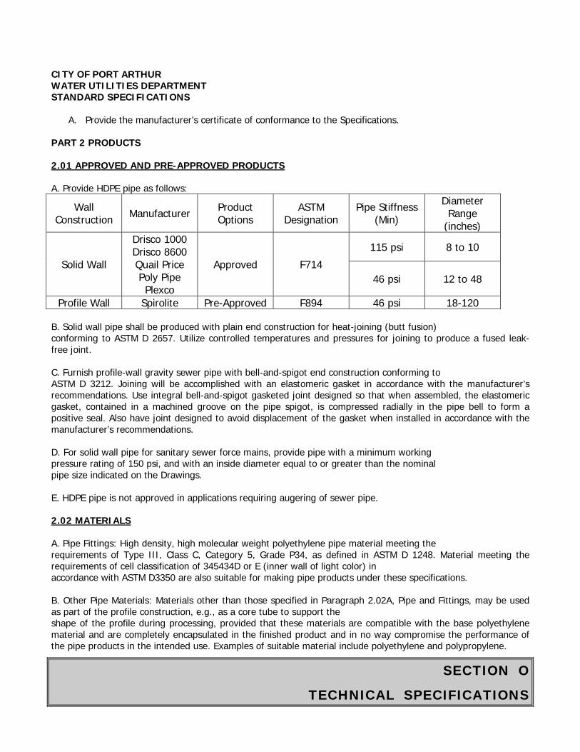
SECTION O
TECHNICAL SPECIFICATIONS
CITY OF PORT ARTHUR WATER UTILITIES DEPARTMENT STANDARD SPECIFICATIONS
A. Provide the manufacturer’s certificate of conformance to the Specifications.
PART 2 PRODUCTS 2.01 APPROVED AND PRE-APPROVED PRODUCTS A. Provide HDPE pipe as follows:
Wall Construction Manufacturer Product
Options ASTM
Designation Pipe Stiffness
(Min) Diameter Range
(inches)
Solid Wall
Drisco 1000 Drisco 8600 Quail Price Poly Pipe Plexco
Approved F714 115 psi 8 to 10
46 psi 12 to 48
Profile Wall Spirolite Pre-Approved F894 46 psi 18-120 B. Solid wall pipe shall be produced with plain end construction for heat-joining (butt fusion) conforming to ASTM D 2657. Utilize controlled temperatures and pressures for joining to produce a fused leak-free joint. C. Furnish profile-wall gravity sewer pipe with bell-and-spigot end construction conforming to ASTM D 3212. Joining will be accomplished with an elastomeric gasket in accordance with the manufacturer’s recommendations. Use integral bell-and-spigot gasketed joint designed so that when assembled, the elastomeric gasket, contained in a machined groove on the pipe spigot, is compressed radially in the pipe bell to form a positive seal. Also have joint designed to avoid displacement of the gasket when installed in accordance with the manufacturer’s recommendations. D. For solid wall pipe for sanitary sewer force mains, provide pipe with a minimum working pressure rating of 150 psi, and with an inside diameter equal to or greater than the nominal pipe size indicated on the Drawings. E. HDPE pipe is not approved in applications requiring augering of sewer pipe. 2.02 MATERIALS A. Pipe Fittings: High density, high molecular weight polyethylene pipe material meeting the requirements of Type III, Class C, Category 5, Grade P34, as defined in ASTM D 1248. Material meeting the requirements of cell classification of 345434D or E (inner wall of light color) in accordance with ASTM D3350 are also suitable for making pipe products under these specifications. B. Other Pipe Materials: Materials other than those specified in Paragraph 2.02A, Pipe and Fittings, may be used as part of the profile construction, e.g., as a core tube to support the shape of the profile during processing, provided that these materials are compatible with the base polyethylene material and are completely encapsulated in the finished product and in no way compromise the performance of the pipe products in the intended use. Examples of suitable material include polyethylene and polypropylene.
SECTION O
TECHNICAL SPECIFICATIONS
CITY OF PORT ARTHUR WATER UTILITIES DEPARTMENT STANDARD SPECIFICATIONS C. Gaskets.
1. Use gaskets meeting requirement of ASTM F 477. Use gasket molded into a circular form or extruded to the proper section and then spliced into circular form. When no contaminant is identified, use gaskets of a properly cured, high-grade elastomeric compound. The basic polymer shall be natural rubber, synthetic elastomer, or a blend of both. 2. Pipes to be installed in potentially contaminated areas, especially where free product is found near the elevation of the proposed sewer, shall have the following gasket materials for the noted contaminants:
Contaminant Gasket Material Required Petroleum (diesel, gasoline) Nitrile Rubber Other Contaminants As recommended by the pipe manufacturer D. Lubricant. Use a lubricant for assembly of gasketed joints which has no detrimental effect on the gasket or on the pipe, in accordance with manufacturer’s recommendations. 2.03 WORKMANSHIP A. Furnish pipe and fittings that are homogeneous throughout and free from visible cracks, holes, foreign inclusions, or other injurious defects. Provide pipe as uniform as commercially practical in color, opacity, density, and other physical properties. 2.04 INSPECTIONS A. The Water Utilities Engineer reserves the right to inspect pipes or witness pipe manufacturing. Such inspection shall in no way relieve the manufacturer of the responsibilities to provide product that comply with the applicable standards and these Specifications. B. Manufacturer’s Notification: Should the Water Utilities Engineer wish to witness the manufacture of specific pipes, the manufacturer shall provide the Water Utilities Engineer with adequate advance notice of when and where the production of those specific pipes will take place. C. Failure to Inspect. Approval of the products or tests is not implied by the Water Utilities Engineer’s decision not to inspect the manufacturing, testing, or finished pipes. 2.05 TESTING METHODS A. Conditioning. Conditioning of samples prior to and during tests are subject to approval by Water Utilities Engineer. When referee tests are required, condition the specimens in accordance with Procedure A in ASTM D 618 at 73.4 degrees F plus or minus 3.6 degrees F and 50 percent relative humidity plus or minus 5 percent relative humidity for not less than 40 hours prior to test. Conduct tests under the same conditions of temperature and humidity unless otherwise specified. B. Flattening. Flattening three specimens of pipe, prepared in accordance with Paragraph 2.05A, in a suitable press until the internal diameter has been reduced to 40 percent of the original inside diameter of the pipe. The
SECTION O
TECHNICAL SPECIFICATIONS
CITY OF PORT ARTHUR WATER UTILITIES DEPARTMENT STANDARD SPECIFICATIONS rate of loading shall be uniform and at 2-inches per minute. The test specimens, when examined under normal light and with the unaided eye, shall show no evidence of splitting, cracking, breaking, or separation of the pipe walls or bracing profiles. C. Joint Tightness. Test for joint tightness in accordance with ASTM D 3212, except replace the shear load transfer bars and supports with 6-inch-wide support blocks that can be either flat or contoured to conform to the pipe’s outer contour. D. Purpose of Tests. The flattening and the joint tightness tests are not intended to be routine quality control test, but rather to qualify pipe to specified level of performance. 2.06 MARKING A. Mark each standard and random length of pipe in compliance with these Specifications with the following information:
A. Pipe size B. Pipe class C. Production code D. Material designation
PART 3 EXECUTION 3.01 INSTALLATION A. Conform to requirements of the following Items:
1. Item 600 - Specifications for Underground Construction of Water and Sewer Pipes 2. Item 02550 – Slip lining Sanitary Sewers 3. Item 04020 - Pipe Bursting/Crushing Sanitary Sewers
B. Install pipe in accordance with the manufacturer’s recommended installation procedures.
End of Section
SECTION O
TECHNICAL SPECIFICATIONS
CITY OF PORT ARTHUR WATER UTILITIES DEPARTMENT STANDARD SPECIFICATIONS
ITEM 02533
ACCEPTANCE TESTING FOR SANITARY SEWERS PART 1 GENERAL 1.01 SECTION INCLUDES A. Acceptance testing of sanitary sewers including:
1. Visual inspection of sewer pipes 2. Mandrel testing for flexible sewer pipes. 3. Leakage testing of sewer pipes. 4. Leakage testing of manholes. 5. Smoke testing of point repairs.
B. All tests listed in this Section are not necessarily required on this Project. Required tests are named in other Sections which refer to this Section for testing criteria and procedures. 1.02 MEASUREMENT AND PAYMENT A. Unit Prices.
No payment will be made for acceptance testing under this Section. Include payment in unit price for work requiring acceptance testing.
B. Stipulated Price (Lump Sum). If the Contract is a Stipulated Price Contract, payment for work in this Section is included in the total Stipulated Price. 1.03 REFERENCES A. ASTM C 828 - Standard Test Method for Low Pressure Air Test of Vitrified Clay Pipe Lines. B. ASTM C 924 - Standard Practice for Testing Concrete Pipe Sewer Lines by Low-Pressure Air Test Method. C. ASTM D 3034 - Standard Specification for Type PSM Polyethylene (Vinyl Chloride) (PVC) Sewer Pipe and Fittings. D. ASTM F 794 - Specification for Polyvinyl Chloride Large-Diameter Ribbed Gravity Sewer Pipe and Fittings Based on Controlled Inside Diameter. E. ASTM F 1417 - Standard Test Method for Installation Acceptance of Plastic Gravity Sewer Lines Using Low Pressure Air. F. 30 TAC 317.2 - Design Criteria for Sewage Systems.
G. Uni-Bell UNI-B-3 Polyvinyl Chloride (PVC) Pressure Pipe (Complying with AWWA C 900). 1.04 PERFORMANCE REQUIREMENTS
SECTION O
TECHNICAL SPECIFICATIONS
CITY OF PORT ARTHUR WATER UTILITIES DEPARTMENT STANDARD SPECIFICATIONS A. Gravity flow sanitary sewers are required to have a straight alignment and uniform grade between manholes. B. Flexible pipe, including “semi-rigid” pipe, is required to show no more than 5 percent deflection. Test pipe no sooner than 30 days after backfilling of a line segment but prior to final acceptance using a standard mandrel to verify that installed pipe is within specified deflection tolerances. C. Maximum allowable leakage for Infiltration or Exfiltration
1. The total exfiltration, as determined by a hydrostatic head test, shall not exceed 50 gallons per inch diameter per mile of pipe per 24 hours at a minimum test head of 2 feet above the crown of the pipe at the upstream manhole or 2 feet above the groundwater elevation, whichever is greater. 2. When pipes are installed more than 2 feet below the groundwater level, an infiltration test shall be used in lieu of the exfiltration test. The total infiltration shall not exceed 50 gallons per inch diameter per mile of pipe per 24 hours. Groundwater elevation must be at least 2 feet above the crown of the pipe at the upstream manhole. 3. Refer to Table 02533-1, Water Test Allowable Leakage, at the end of the Section, for measuring leakage in sewers. Perform leakage testing to verify that leakage criteria are met.
D. Perform air testing in accordance with requirements of this Section and the Texas Commission on Environmental Quality (TCEQ) requirements. Refer to Table 02533-2, Time Allowed for Pressure Loss from 3.5 psig to 2.5 psig, Table 02533-3, Minimum Testing Times for Low Pressure Air Test, and Table 02533-4, Vacuum Test Time Table, at the end of this Section. 1.05 SUBMITTALS A. Conform to requirements of Section 1300 - Contractor Submittals. B. Test Plan: Before testing begins and in adequate time to obtain approval through the submittal process, prepare and submit a test plan for approval by Water Utilities Engineer. Include testing procedures, methods, equipment, and tentative schedule. Obtain advance written approval for deviations from the Drawings and Specifications. C. Test Reports: Submit test reports for each test on each segment of sanitary sewer. 1.06 GRAVITY SANITARY SEWER QUALITY ASSURANCE A. Repair, correct, and retest manholes or sections of pipe which fail to meet specified requirements when tested. B. Provide testing reports and post-installation video tape of television inspection as directed by Water Utilities Engineer. C. Upon completion of tape reviews by Water Utilities Engineer, Contractor will be notified regarding final acceptance of the sewer segment. 1.07 SEQUENCING AND SCHEDULING
SECTION O
TECHNICAL SPECIFICATIONS
CITY OF PORT ARTHUR WATER UTILITIES DEPARTMENT STANDARD SPECIFICATIONS A. Perform testing as work progresses. Schedule testing so that no more than 1000 linear feet of installed sewer remains untested at any one time. B. Coordinate testing schedules with Water Utilities Engineer. Perform testing under observation of Water Utilities Engineer. PART 2 PRODUCTS 2.01 DEFLECTION MANDREL A. Mandrel Sizing. The rigid mandrel shall have an outside diameter (O.D.) equal to 95 percent of the inside diameter (I.D.) of the pipe. The inside diameter of the pipe, for the purpose of determining the outside diameter of the mandrel, shall be the average outside diameter minus two minimum wall thicknesses for O.D. controlled pipe and the average inside diameter for I.D. controlled pipe, dimensions shall be per appropriate standard. Statistical or other "tolerance packages" shall not be considered in mandrel sizing. B. Mandrel Design. The rigid mandrel shall be constructed of a metal or a rigid plastic material that can withstand 200 psi without being deformed. The mandrel shall have nine or more "runners" or "legs" as long as the total number of legs is an odd number. The barrel section of the mandrel shall have a length of at least 75 percent of the inside diameter of the pipe. The rigid mandrel shall not have adjustable or collapsible legs which would allow a reduction in mandrel diameter during testing. A proving ring shall be provided and used for modifying each size mandrel. C. Proving Ring. Furnish a "proving ring" with each mandrel. Fabricate the ring of 1/2-inch-thick, 3-inch-wide bar steel to a diameter 0.02 inches larger than approved mandrel diameter. D. Mandrel Dimensions (5 percent allowance). Average inside diameter and minimum mandrel diameters are specified in Table 02533-5, Pipe vs. Mandrel Diameter, at the end of this Section. Mandrels for higher strength, thicker wall pipe or other pipe not listed in the table may be used when approved by the Water Utilities Engineer. 2.02 EXFILTRATION TEST A. Water Meter: Obtain a transient water meter from the City for use when water for testing will be taken from the City system. Conform to City requirements for water meter use. B. Test Equipment:
1. Pipe plugs. 2. Pipe risers where the manhole cone is less than 2 feet above highest point in pipe or service lead.
2.03 INFILTRATION TEST A. Test Equipment:
1. Calibrated 90 degree V-notch weir. 2. Pipe plugs.
2.04 LOW PRESSURE AIR TEST
SECTION O
TECHNICAL SPECIFICATIONS
CITY OF PORT ARTHUR WATER UTILITIES DEPARTMENT STANDARD SPECIFICATIONS A. Minimum Requirement for Equipment:
1. Control panel. 2. Low-pressure air supply connected to control panel. 3. Pneumatic plugs: Acceptable size for diameter of pipe to be tested; capable of withstanding internal test pressure without leaking or requiring external bracing. 4. Air hoses from control panel to:
a. Air supply. b. Pneumatic plugs. c. Sealed line for pressuring. d. Sealed line for monitoring internal pressure.
B. Testing Pneumatic Plugs: Place a pneumatic plug in each end of a length of pipe on the ground. Pressurize plugs to 25 psig; then pressurize sealed pipe to 5 psig. Plugs are acceptable if they remain in place against the test pressure without external aids. 2.05 GROUND WATER DETERMINATION A. Equipment: Pipe probe or small diameter casing for ground water elevation determination. 2.06 SMOKE TESTING A. Equipment:
1. Pneumatic plugs. 2. Smoke generator as supplied by Superior Signal Company, or an approved equal. 3. Blowers producing 2500 scfm minimum.
PART 3 EXECUTION 3.01 PREPARATION A. Provide labor, equipment, tools, test plugs, risers, air compressor, air hose, pressure meters, pipe probe, calibrated weirs, or any other device necessary for proper testing and inspection. B. The selection of test methods and pressures for gravity sanitary sewers shall be determined based on ground water elevation. Determine ground water elevation using equipment and procedures conforming to Item 01578 - Control of Ground Water and Surface Water. 3.02 VISUAL INSPECTION OF GRAVITY SANITARY SEWERS A. Check pipe alignment visually by flashing a light between structures. Verify if alignment is true and no pipes are misplaced. In case of misalignment or damaged pipe, remove and re-lay or replace pipe segment. 3.03 MANDREL TESTING FOR GRAVITY SANITARY SEWERS A. Perform deflection testing on flexible and semi-rigid pipe to confirm pipe has no more than 5 percent deflection. Mandrel testing shall conform to ASTM D 3034. Perform testing no sooner than 30 days after backfilling of line segment, but prior to final acceptance testing of the line segment.
SECTION O
TECHNICAL SPECIFICATIONS
CITY OF PORT ARTHUR WATER UTILITIES DEPARTMENT STANDARD SPECIFICATIONS B. Pull the approved mandrel by hand through sewer sections. Replace any section of sewer not passing the mandrel. Mandrel testing is not required for stubs. C. Retest repaired or replaced sewer sections. 3.04 LEAKAGE TESTING FOR GRAVITY SANITARY SEWERS A. Test Options:
1. Test gravity sanitary sewer pipes for leakage by either exfiltration or infiltration methods, as appropriate, or with low pressure air testing. 2. Test new or rehabilitated sanitary sewer manholes with water or low pressure air. Manholes tested with low pressure air shall undergo a physical inspection prior to testing. 3. Leakage testing shall be performed after backfilling of a line segment, and prior to tie-in of service connections. 4. If no installed piezometer is within 500 feet of the sewer segment, Contractor shall provide a temporary piezometer for this purpose.
B. Compensating for Ground Water Pressure:
1. Where ground water exists, install a pipe nipple at the same time sewer line is placed. Use a 1/2-inch capped pipe nipple approximately 10 inches long. Make the installation through manhole wall on top of the sewer line where line enters manhole. 2. Immediately before performing line acceptance test, remove cap, clear pipe nipple with air pressure, and connect a clear plastic tube to nipple. Support tube vertically and allow water to rise in the tube. After water stops rising, measure height in feet of water over invert of the pipe. Divide this height by 2.3 feet/psi to determine the ground water pressure to be used in line testing.
C. Exfiltration test:
1. Determine ground water elevation. 2. Plug sewer in downstream manhole. 3. Plug incoming pipes in upstream manhole. 4. Install riser pipe in outgoing pipe of upstream manhole if highest point in service lead (house service) is less than 2 feet below bottom of manhole cone. 5. Fill sewer pipe and manhole or pipe riser, if used, with water to a point 2-1/2 feet above highest point in sewer pipe, house lead, or ground water table, whichever is highest. 6. Allow water to stabilize for one to two hours. Take water level reading to determine drop of water surface, in inches, over a one-hour period, and calculate water loss (1 inch of water in 4 feet diameter manhole equals 8.22 gallons) or measure the quantity of water required to keep water at same level. Loss shall not exceed that calculated from allowable leakage according to Table 02533-1 at the end of this Section.
D. Infiltration test: Ground water elevation must be not less than 2.0 feet above highest point of sewer pipe or service lead (house service).
1. Determine ground water elevation. 2. Plug incoming pipes in upstream manhole. 3. Insert calibrated 90 degree V-notch weir in pipe on downstream manhole. 4. Allow water to rise and flow over weir until it stabilizes.
SECTION O
TECHNICAL SPECIFICATIONS
CITY OF PORT ARTHUR WATER UTILITIES DEPARTMENT STANDARD SPECIFICATIONS
5. Take five readings of accumulated volume over a period of 2 hours and use average for infiltration. The average must not exceed that calculated for 2 hours from allowable leakage according to the Table 02533-1 at the end of this Section.
E. Low Air Pressure Test: When using this test conform to ASTM C 828, ASTM C 924, or ASTM F 1417, as applicable, with holding time not less than that listed in Table 02533-2.
1. Air testing for sections of pipe shall be limited to lines less than 36-inch average inside diameter. 2. Lines 36-inch average inside diameter and larger shall be tested at each joint. The minimum time allowable for the pressure to drop from 3.5 pounds per square inch gauge to 2.5 pounds per square inch during a joint test shall be 10 seconds, regardless of pipe size. 3. For pipe sections less than 36-inch average inside diameter:
a. Determine ground water level. b. Plug both ends of pipe. For concrete pipe, flood pipe and allow 2 hours to saturate concrete. Then drain and plug concrete pipe. c. After a manhole-to-manhole section of sanitary sewer main has been sliplined. and prior to any service lines being connected to new liner, plug liner at each manhole with pneumatic plugs. d. Pressurize pipe to 4.0 psig. Increase pressure 1.0 psi for each 2.3 feet of ground water over highest point in system. Allow pressure to stabilize for 2 to 4 minutes. Adjust pressure to start at 3.5 psig (plus adjustment for ground water table). See Table 02533-2 at the end of this Section. e. To determine air loss, measure the time interval for pressure to drop to 2.5 psig. The time must exceed that listed in the Table 02533-2 at the end of this Section for pipe diameter and length. For sliplining, use diameter of carrier pipe.
F. Retest: Any section of pipe which fails to meet requirements shall be repaired and retested.
3.05 TEST CRITERIA TABLES A. Exfiltration and Infiltration Water Tests: Refer to Table 02533-1, Water Test Allowable Leakage, at the end of this Section. B. Low Pressure Air Test:
1. Times in Table 02533-2, Time Allowed for Pressure Loss from 3.5 psig to 2.5 psig, at the end of this Section, are based on the equation from Texas Natural Resources and Conservation Commission (TNRCC) Design Criteria 317.2(a)(4)(B).
T = 0.0850(D)(K)/(Q)
where: T = time for pressure to drop 1.0 pounds per square inch gauge in seconds K = 0.000419 DL, but not less than 1.0 D = average inside diameter in inches L = length of line of same pipe size in feet Q = rate of loss, 0.0015 ft3/min./sq. ft. internal surface
3. Since a K value of less than 1.0 shall not be used, there are minimum testing times for each pipe diameter as given in Table 02533-3, Minimum Testing Times for Low Pressure Air Test.
SECTION O
TECHNICAL SPECIFICATIONS
CITY OF PORT ARTHUR WATER UTILITIES DEPARTMENT STANDARD SPECIFICATIONS
Notes: 1. When two sizes of pipe are involved, the time shall be computed by the ratio of lengths involved. 2. Lines with a 27-inch average inside diameter and larger may be air tested at each joint. 3. Lines with an average inside diameter greater than 36 inches must be air tested for leakage at each joint. 4. If the joint test is used, a visual inspection of the joint shall be performed immediately after testing. 5. For joint test, the pipe is to be pressurized to 3.5 psi greater than the pressure exerted by groundwater above the pipe. Once the pressure has stabilized, the minimum times allowable for the pressure to drop from 3.5 pounds per square inch gauge to 2.5 pounds per square inch gauge shall be 10 seconds.
3.06 LEAKAGE TESTING FOR MANHOLES A. After completion of manhole construction, wall sealing, or rehabilitation, but prior to backfilling, test manholes for water tightness using hydrostatic or vacuum testing procedures. B. Plug influent and effluent lines, including service lines, with suitably-sized pneumatic or mechanical plugs. Ensure plugs are properly rated for pressures required for test; follow manufacturer's safety and installation recommendations. Place plugs a minimum of 6 inches outside of manhole walls. Brace inverts to prevent lines from being dislodged if lines entering manhole have not been backfilled. C. Vacuum testing:
1. Install vacuum tester head assembly at top access point of manhole and adjust for proper seal on straight top section of manhole structure. Following manufacturer's instructions and safety precautions, inflate sealing element to the recommended maximum inflation pressure; do not over-inflate. 2. Evacuate manhole with vacuum pump to 10 inches mercury (Hg), disconnect pump, and monitor vacuum for the time period specified in Table 02533-4, Vacuum Test Time Table. 3. If the drop in vacuum exceeds 1 inch Hg over the specified time period tabulated above, locate leaks, complete repairs necessary to seal manhole and repeat test procedure until satisfactory results are obtained.
D. Hydrostatic exfiltration testing shall be performed as follows:
1. Seal wastewater lines coming into the manhole with an internal pipe plug. Then fill the manhole with water and maintain it full for at least one hour.
2. The maximum leakage for hydrostatic testing shall be 0.025 gallons per foot diameter per foot of manhole depth per hour.
3. If water loss exceeds amount tabulated above, locate leaks, complete repairs necessary to seal manhole and repeat test procedure until satisfactory results are obtained.
3.07 SMOKE TEST PROCEDURE FOR POINT REPAIRS A. Application: Perform smoke test to:
1. Locate points of line failure for point repair.
SECTION O
TECHNICAL SPECIFICATIONS
CITY OF PORT ARTHUR WATER UTILITIES DEPARTMENT STANDARD SPECIFICATIONS
2. Determine if point repairs are properly made. 3. Determine if service connections have been reconnected to the rehabilitated sewer. 4. Check integrity of connections to newly replaced service taps to liners and to existing private service connections.
B. Limitations: Do not backfill service taps until completion of this test. Test only those taps in a single manhole section at any one time. Keep the number of open excavations to a minimum. C. Preparation: Prior to smoke testing, give written notices to area residents no fewer than 2 days, nor more than 7 days, prior to proposed testing. Also give notice to City of Port Arthur Police and Fire Departments 24 hours prior to actual smoke testing. D. Isolate Section: Isolate the manhole section to be tested from adjacent manhole sections to keep smoke localized. Temporarily seal the annular space at manhole for slip lined sections. E. Smoke Introduction:
1. Operate equipment according to manufacturer's recommendation and as approved by Water Utilities Engineer. 2. Conduct test by forcing smoke from smoke generators through sanitary sewer main and service connections. Operate smoke generators for a minimum of 5 minutes. 3. Introduce smoke into upstream and downstream manhole as appropriate. Monitor the
tap/connection for smoke leaks. Note sources of leaks. F. Repair and Retest: Repair and replace any taps or connections noted as leaking and then retest. Taps and connections may be left exposed in only one manhole section at a time. If repair or replacement, testing or retesting, and backfilling of the excavation is not completed within one work day, properly barricade and cover each excavation as approved by Water Utilities Engineer. G. Service Connections: On houses where smoke does not issue from plumbing vent stacks to confirm reconnection of sewer service to the newly installed liner pipe, perform a dye test to confirm reconnection. Introduce dye into the service line through a plumbing fixture inside the structure or a sewer cleanout immediately outside the structure and flush with water. Observe flow at service reconnection or downstream manhole. Detection of dye confirms a reconnection.
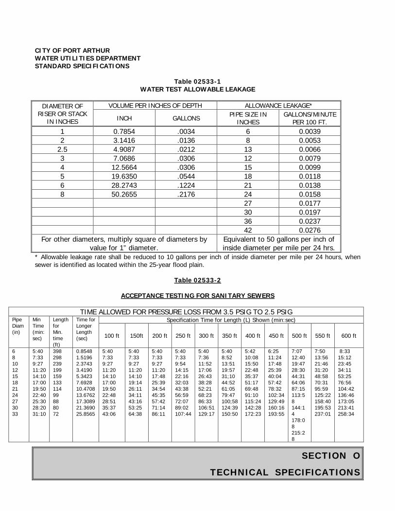
SECTION O
TECHNICAL SPECIFICATIONS
CITY OF PORT ARTHUR WATER UTILITIES DEPARTMENT STANDARD SPECIFICATIONS
Table 02533-1 WATER TEST ALLOWABLE LEAKAGE
DIAMETER OF
RISER OR STACK IN INCHES
VOLUME PER INCHES OF DEPTH ALLOWANCE LEAKAGE*
INCH GALLONS PIPE SIZE IN INCHES
GALLONS/MINUTE PER 100 FT.
1 0.7854 .0034 6 0.0039 2 3.1416 .0136 8 0.0053
2.5 4.9087 .0212 13 0.0066 3 7.0686 .0306 12 0.0079 4 12.5664 .0306 15 0.0099 5 19.6350 .0544 18 0.0118 6 28.2743 .1224 21 0.0138 8 50.2655 .2176 24 0.0158 27 0.0177 30 0.0197 36 0.0237 42 0.0276
For other diameters, multiply square of diameters by value for 1” diameter.
Equivalent to 50 gallons per inch of inside diameter per mile per 24 hrs.
* Allowable leakage rate shall be reduced to 10 gallons per inch of inside diameter per mile per 24 hours, when sewer is identified as located within the 25-year flood plain.
Table 02533-2
ACCEPTANCE TESTING FOR SANITARY SEWERS
TIME ALLOWED FOR PRESSURE LOSS FROM 3.5 PSIG TO 2.5 PSIG Pipe Diam (in)
Min Time (min:sec)
Length for Min. time (ft)
Time for Longer Length (sec)
Specification Time for Length (L) Shown (min:sec)
100 ft 150ft 200 ft 250 ft 300 ft 350 ft 400 ft 450 ft 500 ft 550 ft 600 ft
6 8 10 12 15 18 21 24 27 30 33
5:40 7:33 9:27 11:20 14:10 17:00 19:50 22:40 25:30 28:20 31:10
398 298 239 199 159 133 114 99 88 80 72
0.8548 1.5196 2.3743 3.4190 5.3423 7.6928 10.4708 13.6762 17.3089 21.3690 25.8565
5:40 7:33 9:27 11:20 14:10 17:00 19:50 22:48 28:51 35:37 43:06
5:40 7:33 9:27 11:20 14:10 19:14 26:11 34:11 43:16 53:25 64:38
5:40 7:33 9:27 11:20 17:48 25:39 34:54 45:35 57:42 71:14 86:11
5:40 7:33 9:54 14:15 22:16 32:03 43:38 56:59 72:07 89:02 107:44
5:40 7:36 11:52 17:06 26:43 38:28 52:21 68:23 86:33 106:51 129:17
5:40 8:52 13:51 19:57 31;10 44:52 61:05 79:47 100;58 124:39 150:50
5:42 10:08 15:50 22:48 35:37 51:17 69:48 91:10 115:24 142:28 172:23
6:25 11:24 17:48 25:39 40:04 57:42 78:32 102:34 129:49 160:16 193:55
7:07 12:40 19:47 28:30 44:31 64:06 87:15 113:58 144:14 178:08 215:28
7:50 13:56 21:46 31:20 48:58 70:31 95:59 125:22 158:40 195:53 237:01
8:33 15:12 23:45 34:11 53:25 76:56 104:42 136:46 173:05 213:41 258:34

SECTION O
TECHNICAL SPECIFICATIONS
CITY OF PORT ARTHUR WATER UTILITIES DEPARTMENT STANDARD SPECIFICATIONS
Table 02533-3
MINIMUM TESTING TIMES FOR LOW PRESSURE AIR TEST
PIPE DIAMETER (INCHES)
MINIMUM TIME (SECONDS)
LENGTH FOR MINIMUM TIME
(FEET)
TIME FOR LONGER LENGTH
(SECONDS)
6810 12 15 18 21 24 27 30 33
340 454 567 680 850 1020 1190 1360 1530 1700 1870
398 298 239 199 159 133 114 100 88 80 72
0.855 (L) 1.520 (L) 2.374 (L) 3.419 (L) 5.342 (L) 7.693 (L) 10.471 (L) 13.676 (L) 17.309 (L) 21.369 (L) 25.856 (L)
CITY OF PORT ARTHUR WATER UTILITIES DEPARTMENT STANDARD SPECIFICATIONS
Table 02533-4
VACUUM TEST TIME TABLE
DEPTH IN FEET TIME IN SECONDS BY PIPE DIAMETER 48” 60” 72”
4 10 13 16 8 20 26 32
12 30 39 48 16 40 52 64 20 50 65 80 24 60 78 96 * 5.0 6.5 8.0
*Add T times for each additional 2-foot depth.(The values listed above bave been extrapolated from ASTM C 924-85)
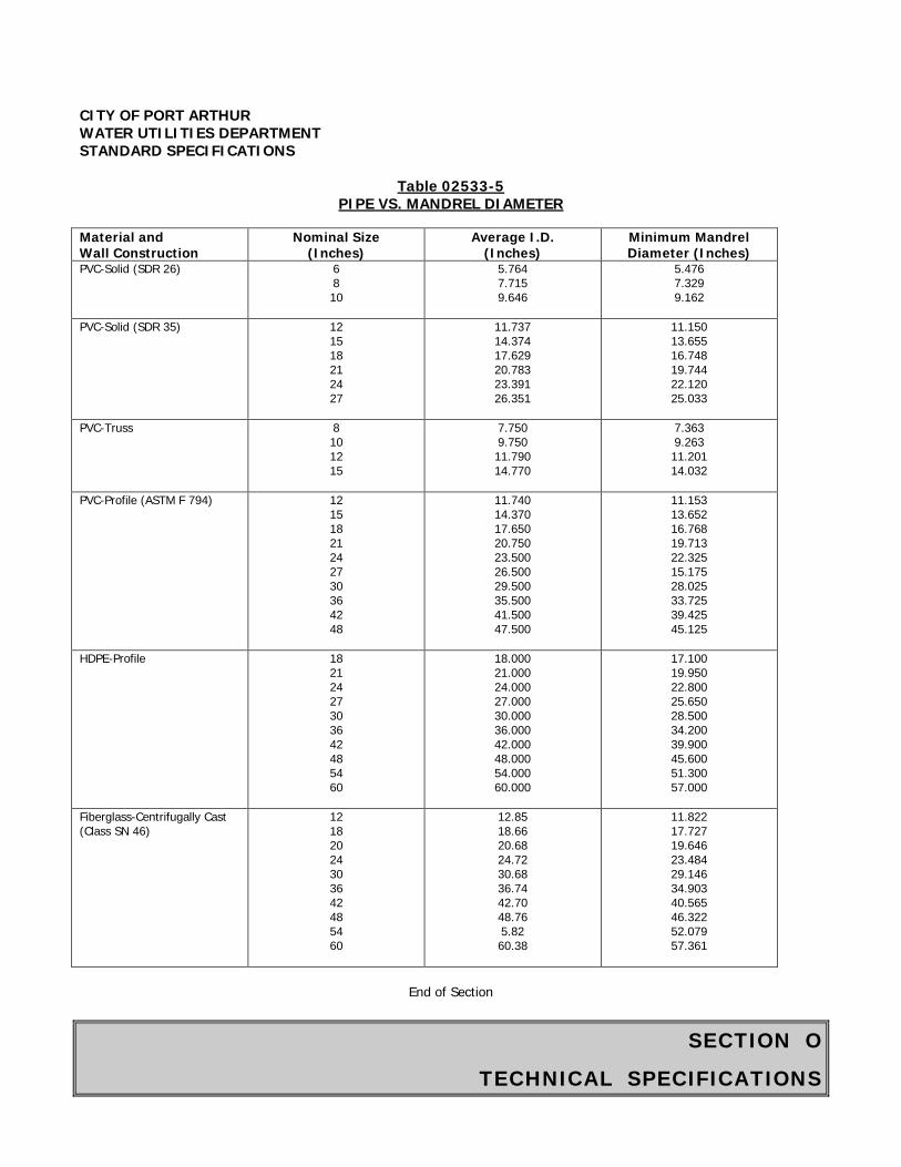
SECTION O
TECHNICAL SPECIFICATIONS
CITY OF PORT ARTHUR WATER UTILITIES DEPARTMENT STANDARD SPECIFICATIONS
Table 02533-5
PIPE VS. MANDREL DIAMETER Material and Wall Construction
Nominal Size (Inches)
Average I.D. (Inches)
Minimum Mandrel Diameter (Inches)
PVC-Solid (SDR 26) 6 8 10
5.764 7.715 9.646
5.476 7.329 9.162
PVC-Solid (SDR 35) 12 15 18 21 24 27
11.737 14.374 17.629 20.783 23.391 26.351
11.150 13.655 16.748 19.744 22.120 25.033
PVC-Truss 8 10 12 15
7.750 9.750 11.790 14.770
7.363 9.263 11.201 14.032
PVC-Profile (ASTM F 794) 12 15 18 21 24 27 30 36 42 48
11.740 14.370 17.650 20.750 23.500 26.500 29.500 35.500 41.500 47.500
11.153 13.652 16.768 19.713 22.325 15.175 28.025 33.725 39.425 45.125
HDPE-Profile 18 21 24 27 30 36 42 48 54 60
18.000 21.000 24.000 27.000 30.000 36.000 42.000 48.000 54.000 60.000
17.100 19.950 22.800 25.650 28.500 34.200 39.900 45.600 51.300 57.000
Fiberglass-Centrifugally Cast (Class SN 46)
12 18 20 24 30 36 42 48 54 60
12.85 18.66 20.68 24.72 30.68 36.74 42.70 48.76 5.82 60.38
11.822 17.727 19.646 23.484 29.146 34.903 40.565 46.322 52.079 57.361
End of Section
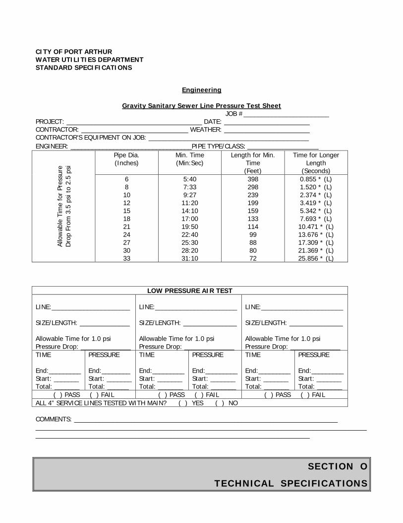
SECTION O
TECHNICAL SPECIFICATIONS
CITY OF PORT ARTHUR WATER UTILITIES DEPARTMENT STANDARD SPECIFICATIONS
Engineering
Gravity Sanitary Sewer Line Pressure Test Sheet
JOB #________________________ PROJECT: ______________________________________ DATE: ________________________ CONTRACTOR: ______________________________ WEATHER: ________________________ CONTRACTOR’S EQUIPMENT ON JOB: _____________________________________________ ENGINEER: __________________________________PIPE TYPE/CLASS: __________________
Allo
wab
le T
ime
for P
ress
ure
Drop
Fro
m 3
.5 p
si to
2.5
psi
Pipe Dia. (Inches)
Min. Time (Min:Sec)
Length for Min. Time (Feet)
Time for Longer Length
(Seconds) 6 8 10 12 15 18 21 24 27 30 33
5:40 7:33 9:27 11:20 14:10 17:00 19:50 22:40 25:30 28:20 31:10
398 298 239 199 159 133 114 99 88 80 72
0.855 * (L) 1.520 * (L) 2.374 * (L) 3.419 * (L) 5.342 * (L) 7.693 * (L) 10.471 * (L) 13.676 * (L) 17.309 * (L) 21.369 * (L) 25.856 * (L)
LOW PRESSURE AIR TEST LINE:______________________ SIZE/LENGTH: ______________ Allowable Time for 1.0 psi Pressure Drop: ______________
LINE:_______________________ SIZE/LENGTH: _______________ Allowable Time for 1.0 psi Pressure Drop: ______________
LINE:_______________________ SIZE/LENGTH: _______________ Allowable Time for 1.0 psi Pressure Drop: ______________
TIME End:_________ Start: _______ Total: _______
PRESSURE End:________ Start: _______ Total: ______
TIME End:_________ Start: _______ Total: _______
PRESSURE End:_________ Start: _______ Total: _______
TIME End:_________ Start: _______ Total: _______
PRESSURE End:_________ Start: _______ Total: _______
( ) PASS ( ) FAIL ( ) PASS ( ) FAIL ( ) PASS ( ) FAIL ALL 4” SERVICE LINES TESTED WITH MAIN? ( ) YES ( ) NO COMMENTS: __________________________________________________________________________ __________________________________________________________________________________________________________________________________________________________________________
SECTION O
TECHNICAL SPECIFICATIONS
CITY OF PORT ARTHUR WATER UTILITIES DEPARTMENT STANDARD SPECIFICATIONS CITY REPRESENTATIVE: __________________________ SIGNATURE: ___________________________
SECTION O
TECHNICAL SPECIFICATIONS
CITY OF PORT ARTHUR WATER UTILITIES DEPARTMENT STANDARD SPECIFICATIONS
ITEM 02534
SPECIFICATIONS FOR SANITARY SEWER SERVICE STUBS OR RECONNECTIONS PART 1 GENERAL 1.01 SECTION INCLUDES A. Installation of service stubs in sanitary sewers serving areas where sanitary sewer service did not previously exist.
B. Reconnection of existing service connections along parallel, replacement, or rehabilitated lines. 1.02 MEASUREMENT AND PAYMENT A. Unit Prices.
1. Payment for sanitary sewer service stubs or service reconnections from the sanitary sewer main centerline to the property line or the edge of the right of way is on a unit price basis for each stub or reconnection based on it being a long side service or a short side service. Payment will be made for each service stub or reconnection installed complete in place, including service connections, couplings, adapters, disconnecting existing services, reconnecting new service, fittings, excavation, and backfill.
2. Pay estimates for progress payments will be made as measured above according to the following schedule:
a. An estimate for 95 percent payment will be authorized when the reconnection is completely installed and backfilled. b. An estimate for 100 percent payment will be authorized when the reconnection has been tested as specified in Item 02533- Acceptance Testing for Sanitary Sewers.
3. One or more connections discharging into a common point are considered one service connection. The Contractor shall not add service reconnections without approval of the Water Utilities Engineer. The Water Utilities Engineer may require connections to be relocated to avoid having more than two service connections per reconnection.
4. Protruding service connections which must be removed to allow liner insertion are paid as a service reconnection when connected.
5. No separate payment will be made for abandonment of service connection unless excavation is required. No separate payment will be made for excavation of sanitary sewer services within the new or replacement sewer trench.
6. No separate payment will be made for removal of existing sanitary sewer service stubs. Include payment in unit price for Item 02534 - Sanitary Sewer Service Stubs or
Reconnections.
7. No separate payment will be made for an abandoned service connection if the service to be abandoned is within 4 feet of an active connection.
SECTION O
TECHNICAL SPECIFICATIONS
CITY OF PORT ARTHUR WATER UTILITIES DEPARTMENT STANDARD SPECIFICATIONS
8. If a faulty remote cut is later corrected using the procedures specified for reconnection by excavation, only one reconnection will be allowed for payment.
B. Stipulated Price (Lump Sum). If the Contract is a Stipulated Price Contract, payment for work in this section is included in the total Stipulated Price. 1.03 REFERENCES A. ASTM D 1784 - Specifications for Rigid Poly (Vinyl Chloride) (PVC) Compounds and Chlorinated Poly (Vinyl Chloride) (CPVC) Compounds B. ASTM D 3034 - Specification for Type PSM Poly (Vinyl Chloride) (PVC) Sewer Pipe and Fittings. C. ASTM D 3212 - Specification for Joints for Drain and Sewer Plastic Pipes Using Flexible Elastromeric Seals. 1.04 PERFORMANCE REQUIREMENTS A. Accurately locate in the field all proposed service stubs along the new sanitary sewer main. B. Accurately locate in the field existing service connections and proposed service stubs along the alignment of the new parallel or replacement sewer main. 1.05 SUBMITTALS A. Conform to requirements of Section 1300 - Contractor Submittals. B. Submit product data for each pipe product, fitting, coupling and adapter. C. Show reconnected services on record drawings. Give the exact distance from each service connection to the nearest downstream manhole. PART 2 PRODUCTS 2.01 PVC SERVICE CONNECTION A. As stub outs, use PVC sewer pipe of 4-inch through 10-inch diameter, conforming to ASTM D 1784 and ASTM D 3034, with a cell classification of 12454-B. The SDR (ratio of diameter to wall thickness) shall be 35 for pipe 8 inches in diameter or larger. PVC schedule 40 shall be used for 4 and 6-inch service line connections. B. PVC pipe shall be gasket jointed with gasket conforming to ASTM D 3212. C. For reconnection of existing services, select service connection pipe diameter to match existing service diameter. Reconnections to rehabilitated sanitary sewer mains shall be limited to the following maximum service connection diameter:
SECTION O
TECHNICAL SPECIFICATIONS
CITY OF PORT ARTHUR WATER UTILITIES DEPARTMENT STANDARD SPECIFICATIONS
Sewer Diameter Maximum Service Connection Diameter 8” or less 4”
10” or greater 6” D. Subject to the above limits, provide a 6-inch service connection when more than one service discharges into a single pipe. E. Connect service pipes to parallel or replacement sewer mains with prefabricated, full-bodied tee or wye fittings conforming to specifications for sewer main pipe material as specified in other Sections for sewers up to 18 inches in diameter. F. Where sewers are installed using pipe augering or tunneling, or where the sewer is greater than 18 inches in diameter, use Fowler “Inserta-Tee” to connect the service to sewer main. 2.02 PIPE SADDLES A. Use pipe saddles only on rehabilitated sanitary sewer mains. Comply with Paragraph 2.01E for new parallel and replacement sanitary sewer mains. B. Supply one-piece prefabricated saddle, either polyethylene or PVC, with neoprene gasket to accomplish a complete seal. Use a saddle fabricated to fit the outside diameter of the connecting pipe. The protruding lip of the saddle must be at least 5/8-inch long with grooves or ridges to retain the stainless steel band clamps. C. Use ½-inch stainless steel band clamps for securing saddles to liner pipe. 2.03 COUPLINGS AND ADAPTERS A. For connections between new PVC pipe stubouts and existing service, 4-, 6-, 8-inch diameter, use a flexible adapter coupling consisting of a neoprene gasket and stainless steel shear rings with ½ inch stainless steel band clamps:
1. Fernco Pipe Connectors, Inc. Series 1055 with shear ring SR-8 2. Band Seal by Mission Rubber Co., Inc. 3. Approved equal.
B. For connections between new PVC pipe stubout and new service, use rubber-gasketed adapter coupling:
1. GPK Products, Inc. 2. IPS & Sewer Adapter 3. Approved equal
2.04 STACKS A. Provide stacks for service connections wherever the crown of the sewer is 8 feet or more below finished grade. B. Construct stacks of the same material as the sanitary sewer and as shown on the Drawings.
SECTION O
TECHNICAL SPECIFICATIONS
CITY OF PORT ARTHUR WATER UTILITIES DEPARTMENT STANDARD SPECIFICATIONS C. Provide stacks of the same nominal diameter at the sanitary service line. 2.05 PLUGS AND CAPS A. Seal the upstream end of unconnected sewer service stubs with rubber gasketed plugs or caps of the same pipe type and size. Provide plugs or caps by GPK Products, Inc., or approved equal. 2.06 INSERTA TEE A. The inserta tee is comprised of three parts; PVC hub, stainless steel band and rubber boot as manufactured by Fowler Manufacturing Co., Inc. B. PVC hub and rubber boot shall be engineered to accept the wall thickness and internal radius of the pipe. The PVC hub and rubber boot shall not protrude more than ½" into the sewer pipe. C. The PVC hub shall be in accordance with ASTM D-3034. D. The rubber boot shall be in accordance with ASTM C-443. E. The inserta tee shall be sized to accept 4" or 6" service lines, as required. PART 3 EXECUTION 3.01 A. Provide a minimum of 72 hours notice to customers whose sanitary sewer service will potentially be interrupted. B. Accurately field locate service connections, whether in service or not, along the rehabilitated sanitary sewer main. For parallel and replacement sewers, service connections may be located as pipe laying progresses from downstream to upstream. C. Properly disconnect existing connections from the sewer and reconnect to the rehabilitated liner, as described in this Section. D. Reconnect service connections, including those that go to unoccupied or abandoned buildings or to vacant lots, unless directed differently by the Water Utilities Engineer. Install a stack and cap the reconnection where the service is to a vacant lot or location where a structure has been demolished, unless directed otherwise by the Water Utilities Engineer. E. Complete reconnection of service lines within 24 hours after cured-in-place liner installation or after disconnection for sliplining, parallel, or replacement sanitary sewer mains. F. Reconnect services on cured-in-place liner at 10 feet depth or less by the excavation method. The Water Utilities Engineer reserves the right to require service connections by excavation when a remote cut service connection damages the lines.
SECTION O
TECHNICAL SPECIFICATIONS
CITY OF PORT ARTHUR WATER UTILITIES DEPARTMENT STANDARD SPECIFICATIONS G. Reconnection by the excavation method shall include the stack and fittings and required pipe length to reconnect service line. H. All services which are connected to the rehabilitated sanitary sewer shall be properly shown on the “As Built” drawings with exact distances for the nearest downstream manhole. 3.02 PROTECTION A. Provide barricades, warning light, and signs for excavations created for service connections as per the Special Provisions Section. B. Do not allow sand, debris, or runoff to enter sewer system. 3.03 PREPARATION A. Determine the existing sewer locations and number of existing service connections from closed-circuit television (CCTV) inspection tapes or from field survey. Accurately field locate existing service connections, whether in service or not. Use existing service locations to connect or reconnect service lines or liner. B. For rehabilitated sanitary sewer mains, allow liner to normalize to ambient temperature and recover from imposed stretch. For cured-in-place liners, verify that liner is completely cured. C. For new parallel and replacement sanitary sewer mains, complete testing and acceptance of downstream sewers as applicable. Provide for compliance with requirements of Paragraph 3.01E. 3.04 EXCAVATION AND BACKFILL A. Excavate in accordance with Item 02317 - Excavation and Backfill for Utilities. B. Perform work in accordance with OSHA standards. Employ a Trench Safety System as specified in Item 712 - Trench Safety System for excavations requiring trench safety. C. Install and operate necessary ground water and surface water control measures in accordance with requirements of Item 01578 - Control of Ground Water and Surface Water. D. Determine locations where limited access, buildings or structure preclude use of mechanical excavation equipment. Obtain approval from Water Utilities Engineer for hand excavation. E. When the excavation shows that a service line is not connected, abandon the service reconnection and backfill the excavation. 3.05 RECONNECTION BY EXCAVATION METHOD A. SADDLE METHOD
1. Remove a portion of the existing sanitary sewer main or carrier pipe to expose the liner pipe. Provide sufficient working space for installing a pre-fabricated pipe saddle.
3. Carefully cut a hole in the liner pipe to accept the protrusion on the underside of the

SECTION O
TECHNICAL SPECIFICATIONS
CITY OF PORT ARTHUR WATER UTILITIES DEPARTMENT STANDARD SPECIFICATIONS
saddle. Length of protrusion shall be equal to the wall thickness of the line pipe. 3. Install the saddle with gasket using stainless steel bands on each side of the saddle. Tighten the bands to produce a watertight seal between the saddle and the liner pipe.
B. INSERTA TEE METHOD
1. Remove a portion of the existing sanitary sewer main or carrier pipe to expose the liner pipe. Provide sufficient space to install an inserta tee. 2. Precisely cut a circular hole, per the manufactures recommendations, in the liner pipe that will form a
tight fit between the liner pipe PVC stub and rubber boot. 3. Install the rubber boot into the cored hole, making sure the boot is properly oriented to the mainline. Lubricate the rubber boot with a special solution provided by the inserta tee manufacturer. Make sure the upper and lower ribs of the rubber boot are correctly seated against the inside and outside diameter of the liner pipe. 4. Insert the PVC hub into the rubber boot, per manufacturers recommended instructions. Place stainless steel band around the top of the rubber boot and tighten to form a water tight seal.
C. SERVICE CONNECTIONS TO SADDLES AND/OR INSERTA TEE
1. Remove and replace cracked, offset or leaking service line up to 8 feet (measured horizontally) from the center line of the new line. 2. Make connections between liner and existing service line using PVC sewer pipe and approved couplings/fittings using stainless steel bands to construct new stacks and/or service lines. 3. Test all service connections by smoke testing the sewer main and connections before backfilling. 4. Encase the entire service connection in cement stabilized sand or crushed stone. Place a minimum of 6 inches below and 12 inches above and on each side of the service line and pipe connection.
3.06 RECONNECTION BY REMOTE METHOD A. Make service reconnections using remote-operated cutting tools on cured-in-place liners at depth greater than 10 feet. B. Employ method and equipment that restore the service connection capacity to not less than 90 percent of original capacity. C. Immediately open any missed connections and repair any holes drilled in error using a method approved by the Water Utilities Engineer. D. If a faulty remote cut is later corrected using the procedures specified for reconnection by excavation, only one reconnection will be allowed for payment. 3.07 RECONNECTION ON PARALLEL OR REPLACEMENT SEGMENTS A. Install a full-bodied tee or wye fitting on the new sanitary sewer main for each service connection. B. Remove and replace cracked, offset or leaking service line for up to 5 feet, measured horizontally, from the centerline of the sanitary sewer main.
SECTION O
TECHNICAL SPECIFICATIONS
CITY OF PORT ARTHUR WATER UTILITIES DEPARTMENT STANDARD SPECIFICATIONS C. Make up the connection between the main and the existing service line using PVC sewer pipe and approved couplings, as shown on the Drawings. D. Test service connections before backfilling. E. Embed the service connection and service line as specified for the sanitary sewer main as shown on the Drawings. Place and compact trench zone backfill in compliance with Item 02317 - Excavation and Backfill for Utilities. 3.08 INSTALLATION OF NEW SERVICE STUBS A. Install service connections on sanitary sewer main for each service connection. Provide the length to the report line or the right of way. Install plug or cap on the upstream end of the service stub as needed. B. Test service connections before backfilling. C. Embed the service connection and service line as specified for sanitary sewer main, and as shown on the Drawings. Place and compact trench zone backfill in compliance with Item 02317- Excavation and Backfill for Utilities. Install a minimum 2-foot length of magnetic locating tape along the axis of the service stub and 9 inches to 12 inches above the crown of the pipe, at the end of the stub. 3.09 TESTING A. Test service reconnections and service stubs. Follow applicable procedures given in Item 02533 - Acceptance Testing for Sanitary Sewers to perform smoke testing to confirm reconnection. 3.10 CLEANUP A. Backfill the excavation as specified in Item 02317 - Excavation and Backfill for Utilities. B. Replace pavement on sidewalks removed or damaged by excavation in accordance with Item 02951 - Pavement Repair and Resurfacing. In unpaved areas, bring surface to grade and slope surrounding the excavation. Replace a minimum of 4 inches of topsoil and seed according to requirements of Item 711 - Seeding and Sodding.
End of Section

SECTION O
TECHNICAL SPECIFICATIONS
CITY OF PORT ARTHUR WATER UTILITIES DEPARTMENT STANDARD SPECIFICATIONS
ITEM 02535
SPECIFICATIONS FOR FIELD TESTING OF LARGE DIAMETER SLIP-LINED PIPING SYSTEMS
PART 1 GENERAL 1.01 SCOPE A. Provide all necessary labor, materials and equipment, including test pumps and gauges, as well as temporary valves and piping to perform the testing operations of piping systems as specified herein. B. This specification describes in place testing requirements for slip-lined piping in excess of 36-inch diameter. C. All slip-lined pipes will be tested. D. CONTRACTOR’s Responsibility:
1. Take such precautions as required to prevent damage to lines and appurtenances being tested. 2. Repair any damage resulting from tests. 3. Repair and retest all items which do not pass the tests as specified here in. 4. Conduct all tests in the presence of the Water Utilities Engineer and to his satisfaction and all State and local authorities having jurisdiction. 5. All necessary pumps, water, pipe connections, meters, gauges, and any necessary apparatus to perform and conduct the tests shall be furnished by the CONTRACTOR. CONTRACTOR shall furnish all necessary equipment and make all tests at CONTRACTOR’s expense without separate measurement and payment, but said expense shall be subsidiary to installation of pipe.
E. Water used for testing purposes shall be potable water only and provided by the Contractor. 1.02 REFERENCES STANDARDS Based on pipe material, the AWWA testing standards must be followed. 1.03 SUBMITTALS A. Submit record data describing proposed testing methods, procedures, and apparatus for the Water Utilities Engineer’s record, prior to testing. B. Conform to any other applicable requirements of Section 01300 Contractor Submittals. C. Submit a certified test report for each test to the Water Utilities Engineer certifying the test pressures, duration of the test, leakage and pertinent observations and comments 1.04 GENERAL SEQUENCE OF WORK
SECTION O
TECHNICAL SPECIFICATIONS
CITY OF PORT ARTHUR WATER UTILITIES DEPARTMENT STANDARD SPECIFICATIONS 1. Obtain the OWNER’s approval of proposed testing methods, procedures, and apparatus, before performing any test. 2. Upon receipt of the OWNER’s approval, submit a schedule of testing dates and times at least 24 hours in advance of testing. 3. Perform tests as specified herein. PART 2 - PRODUCTS Not Applicable. PART 3 - EXECUTION 3.01 TESTING OF DRAINS, SEWERS, AND OTHER GRAVITY LINES A. General:
1. For all pipe, the method of testing shall be an hydrostatic exfiltration test. For any flexible, non-metallic or non-concrete pipe, such as plastic (PVC, PE, etc.) or fiber reinforced plastic pipe or similar flexible pipe materials, a deflection test shall also be performed. 2. CONTRACTOR may make first test 24 hours after first section of line is installed and the annular space has been grouted. A section of pipe will normally be a run between two manholes, or between a structure and the first manhole. 3. Do not install additional piping of the type being tested until test of first section is complete.
B. Hydrostatic Exfiltration Test Procedure: 1. Seal ends of section being tested with watertight plugs. 2. Fill section with water prior to start of test. 3. Vent line during filling so that no air is trapped in line. 4. Leave outlets of stacks, inlets, and service lines exposed and unplugged until after exfiltration test has been made. 5. Outlets terminating below level of test water surface to be temporarily extended upward by installing lengths of pipe. 6. Measure leakage or exfiltration during test period by adding measured quantities of water to maintain water level in test structure. 7. Quantity of water added to maintain water level is amount of leakage or exfiltration. 8. Test for at least two hours with minimum head of four feet measured above top crown, inside pipe at upper end of section being tested. Allow for increase in height due to ground water level, if any. 9. Storm sewer leads to be tested with water level at gutter grade. 10. After completion of satisfactory test, remove lengths of pipe added for test. 11. Allowable Leakage: Allowable leakage for exfiltration test in any individual section or entire sewer line under construction shall not exceed 10 gallons per inch of inside diameter per mile of pipe per 24 hours.
3.02 MANHOLE TESTING A. Manholes shall be tested separately and independently of the wastewater lines. All wastewater lines coming into the manhole shall be sealed with an internal pipe plug before testing. All manholes shall be hydrostatically tested with a maximum loss allowance of 0.025 gallons per foot diameter per foot of head per hour. The testing period shall not be less than one hour.
SECTION O
TECHNICAL SPECIFICATIONS
CITY OF PORT ARTHUR WATER UTILITIES DEPARTMENT STANDARD SPECIFICATIONS B. Vacuum testing of manholes may be allowed per OWNER’s requirements.
End of Section
SECTION O
TECHNICAL SPECIFICATIONS
CITY OF PORT ARTHUR WATER UTILITIES DEPARTMENT STANDARD SPECIFICATIONS
ITEM 02550
SPECIFICATIONS FOR SLIPLINING SANITARY SEWERS PART 1 GENERAL 1.01 SECTION INCLUDES A. Sliplining existing sanitary sewers. 1.02 UNIT PRICES A. Measurement for sliplining is on a linear foot basis for installed liner pipe, measured from center line of upstream manhole to center line of downstream manhole. Depth range for payment is based on greatest depth measured at manholes from natural ground level to flow line of sanitary sewer for each pipeline segment. B. Insertion pits, access pits, clamp installation, embedment (bedding, haunching and initial backfill), field quality control (testing), sealing liner at manholes, grouting annular space, building up, shaping and reworking manhole inverts and benches, and pre-installation and post-installation cleaning and television inspection of completed work are included in sliplining unit price and not paid for separately. C. Excavations initially begun as obstruction removals or point repairs which the Contractor later decides to use as insertion pits are considered as insertion pits and not paid for separately. D. Trench safety systems, well pointing and other applicable bid items associated with insertion pits will be paid for at their respective contract unit prices. E. Payment will be issued for the footage installed. 1.03 REFERENCES A. ASTM D 1784 - Specification for Rigid Ploy (Vinyl Chloride) (PVC) Compounds. B. ASTM D 1248 - Polyethylene Plastics Molding and Extrusion Materials. C. ASTM D 2122 - Determining Dimensions of Thermoplastic Pipe and Fittings. D. ASTM D 2412 - Determination of External Loading Characteristics of Plastic Pipe by Parallel- Plate Loading. E. ASTM D 2837 - Test Method for Obtaining Hydrostatic Design Basis for Thermoplastic Pipe Materials. F. ASTM D 2992 - Obtaining Hydrostatic or Pressure Design Basis for “Fiberglass” (Glass-Fiber- Reinforced Thermosetting-Resin) Pipe and Fittings.
SECTION O
TECHNICAL SPECIFICATIONS
CITY OF PORT ARTHUR WATER UTILITIES DEPARTMENT STANDARD SPECIFICATIONS G. ASTM D 3262 - “Fiberglass” (Glass-Fiber-Reinforced Thermosetting-Resin) Sewer Pipe. H. ASTM D 3350 - Polyethylene Plastics Pipe and Fittings Materials. I. ASTM D 3681 - Chemical Resistance of “Fiberglass” (Glass-Fiber-Reinforced- Thermosetting- Resin) Pipe in a Deflected Condition. J. ASTM D 4161 - “Fiberglass” (Glass-Fiber-Reinforced Thermosetting-Resin) Pipe Joints Using Flexible Elastomeric Seals. K. ASTM F 585 - Practice for Insertion of Flexible Polyethylene Pipe Into Existing Sewers. L. ASTM F 714 - Polyethylene (PE) Plastic Pipe (SDR-PR) Based on Outside Diameter. M. ASTM F 794 - Specification for Poly (Vinyl Chloride ) (PVC) Profile Gravity Sewer Pipe and Fittings Based on Controlled Inside Diameter. N. ASTM F 894 - Specification for Polyethylene (PE) Large Diameter Profile Wall Sewer and Drain Pipe. O. AWWA C 151 - Ductile Iron Pipe, Centrifugally Cast in Metal Molds or Sand-Lined Molds, for Water or Other Liquids. 1.04 DEFINITIONS A. Sliplining: Reconstruction of sanitary sewers by insertion of liner pipe into existing sewers. 1.05 SYSTEM DESCRIPTION A. Sliplining is accomplished by pulling or pushing liner pipe into existing sewers by use of mechanical or hydraulic equipment. Once in place, liner pipe is allowed time to normalize and is then cut to fit between manholes. Annular spaces between liners and existing sewers are sealed at each manhole. Manhole inverts and benches are reworked and reshaped. Existing sewers remain in operation during sliplining process, with sewage flow diverted around operations in progress. 1.06 QUALITY ASSURANCE A. Liner Acceptance: Provide liner material manufactured, without defects, to standards and dimensions specified. Causes for rejection include physical defects or liner pipe, such as concentrated ridges, chain marks, discoloration, excessive spot roughness, pitting, visible cracks, foreign inclusions and varying wall thickness. 1.07 DELIVERY, STORAGE, AND HANDLING A. Prevent injury to or abrasion of pipe during loading, transportation and unloading. Do not drop pipe from vehicles nor allow pipe to roll down skids or slopes without proper restraining ropes. Use suitable pads, strips, skids or blocks for each pipe during transportation and while awaiting installation.
B. Do not use, and remove from construction site, pipe with physical damage such as cuts,
SECTION O
TECHNICAL SPECIFICATIONS
CITY OF PORT ARTHUR WATER UTILITIES DEPARTMENT STANDARD SPECIFICATIONS gashes, nicks or abrasions, whether from manufacturing, shipping, storage or handling, and which is deeper than 10 percent thickness. C. Use wide belly band slings for lifting and moving pipe. Do not use bare chains in contact with pipe. 1.08 PERFORMANCE REQUIREMENTS A. Maintain sewage flow by diversion pumping or other method approved by the Water Utilities Engineer. B. Clear existing sewers of debris, obstructions and other foreign material and make point repairs to existing sewers as specified in Item 02553, Point Repairs and Obstruction Removals. C. Install sliplining according to this Section. D. Grout annular space(s) as per Manufacturer’s specifications. E. Shape, refurbish or construct manhole inverts as specified in Item 02555, Manhole Rehabilitation. F. Test lines as specified in Item 02533, Acceptance Testing of Sanitary Sewers. G. Videotape-record completed lines as specified in Item 02558, Cleaning and Television Inspection of Sanitary Sewers. 1.09 SUBMITTALS A. Comply with Section 1300, Contractor Submittals. B. Submit manufacturer’s product data with complete information on pipeline materials, including physical properties and dimensions pertinent to this job. C. Submit independent testing laboratory test reports certifying that polyethylene pipe meets ASTM D 1248 and ASTM D 3350, that fiberglass reinforced plastic (FRP) pipe meets ASTM D 3681, or that PVC pipe meets ASTM F 794 and ASTM D 1784, as applicable. D. Submit grouting plan showing where grout is to be injected, materials and chemicals to be used in grout, anchoring methods, and planned grouting pressure. E. Submit videotapes as specified in Item 02558, Cleaning and Television Inspection of Sanitary Sewers. PART 2 PRODUCTS 2.01 MANUFACTURERS A. Liner pipe systems shall be polyethylene, fiberglass reinforced plastic (FRP) PVC profile wall or polyethylene profile wall pipe, as approved by the City.
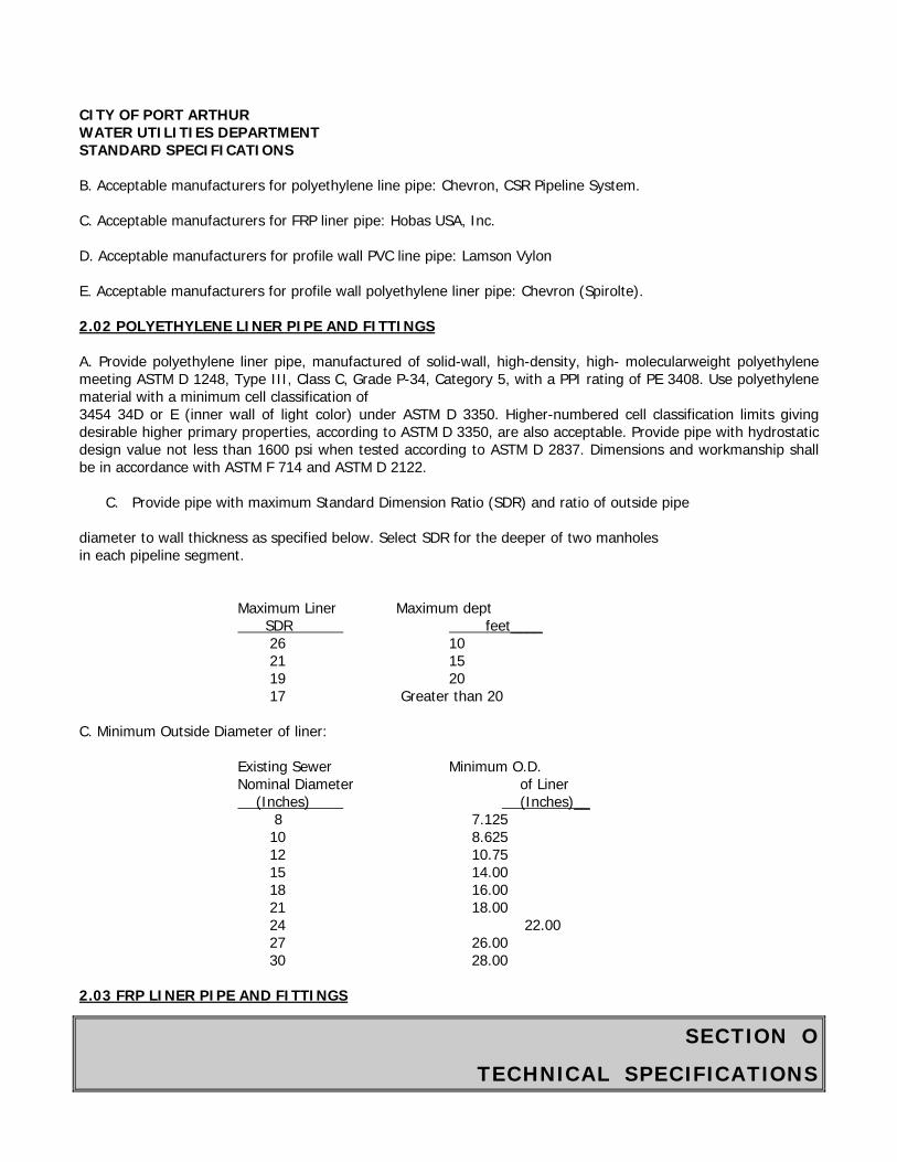
SECTION O
TECHNICAL SPECIFICATIONS
CITY OF PORT ARTHUR WATER UTILITIES DEPARTMENT STANDARD SPECIFICATIONS B. Acceptable manufacturers for polyethylene line pipe: Chevron, CSR Pipeline System. C. Acceptable manufacturers for FRP liner pipe: Hobas USA, Inc. D. Acceptable manufacturers for profile wall PVC line pipe: Lamson Vylon E. Acceptable manufacturers for profile wall polyethylene liner pipe: Chevron (Spirolte). 2.02 POLYETHYLENE LINER PIPE AND FITTINGS A. Provide polyethylene liner pipe, manufactured of solid-wall, high-density, high- molecularweight polyethylene meeting ASTM D 1248, Type III, Class C, Grade P-34, Category 5, with a PPI rating of PE 3408. Use polyethylene material with a minimum cell classification of 3454 34D or E (inner wall of light color) under ASTM D 3350. Higher-numbered cell classification limits giving desirable higher primary properties, according to ASTM D 3350, are also acceptable. Provide pipe with hydrostatic design value not less than 1600 psi when tested according to ASTM D 2837. Dimensions and workmanship shall be in accordance with ASTM F 714 and ASTM D 2122.
C. Provide pipe with maximum Standard Dimension Ratio (SDR) and ratio of outside pipe diameter to wall thickness as specified below. Select SDR for the deeper of two manholes in each pipeline segment.
Maximum Liner Maximum dept SDR feet____ 26 10 21 15 19 20 17 Greater than 20
C. Minimum Outside Diameter of liner:
Existing Sewer Minimum O.D. Nominal Diameter of Liner (Inches) (Inches)__ 8 7.125 10 8.625 12 10.75 15 14.00 18 16.00 21 18.00 24 22.00 27 26.00 30 28.00
2.03 FRP LINER PIPE AND FITTINGS

SECTION O
TECHNICAL SPECIFICATIONS
CITY OF PORT ARTHUR WATER UTILITIES DEPARTMENT STANDARD SPECIFICATIONS
A. Pipe, joints and fittings: ASTM D 3262, Type 1, Liner 2, Grade 3.
B. FRP Liner Pipe: Reinforced plastic mortar pipe manufactured by centrifugal casting process resulting in dense, nonporous, corrosion-resistant, consistent, composite structure. Minimum stiffness: 46 psi, measured accordance to ASTM D 2412. Use with a stiffness of 72 psi where specified or shown on the Drawings.
C. Resin Systems: Thermosetting polyester epoxy resin, with or without filler, meeting ASTM D 3262.
D. Reinforcing Glass Fibers: Commercial grad E.-type glass filaments, with binder and sizing compatible with impregnating resins.
E. Filler: Sand with at least 98 percent silica content, and maximum moisture content of 0.2 percent.
F. Joints: Low-profile FRP jacking bell-and spigot joints, with elastomeric sealing gaskets for watertight joints meeting ASTM D 4161.
G. Dimensions and Tolerances: 1. Pipe outside diameters and tolerances: Comply with ASTM D 3262, Cast Iron Pipe Equivalent Outside
Diameters, and table below. 2. When possible supply pipe in nominal lengths of 20 feet. Where radius curves in existing pipe orlimitations in entry pit dimensions restrict pipe length, shorter lengths may be used. 3. FRP pip minimum outside diameters and minimum wall thicknesses:
Minimum Minimum Wall Minimum Wall Existing Sewer Liner Thickness Thickness Nominal Diameter O.D. 46 psi Stiffness 72 psi Stiffness
(Inches) (Inches) (Inches) (Inches) 21 19.50 0.42 0.48 24 21.60 0.46 0.53 30 25.80 0.54 0.63 36 32.00 0.66 0.77 42 38.30 0.78 0.91 48 44.50 0.90 1.05 54 50.80 1.02 1.19 60 57.10 1.14 1.33 66 62.90 1.26 1.47 72 69.20 1.38 1.61 78 75.40 1.50 1.75
4. Fabricate pipe ends square to pipe axis plus or minus 0.25 inches, or plus or minus .05 percent ofnominal diameter, whichever is greater.
H. Fittings: 1. Flanges, elbows, reducers, tees, wyes another fittings: Capable of withstanding operating conditions.2. Fabrication: Contact-molded or manufactured from mitered sections of pipe joined by glass-fiber-reinforced overlays.
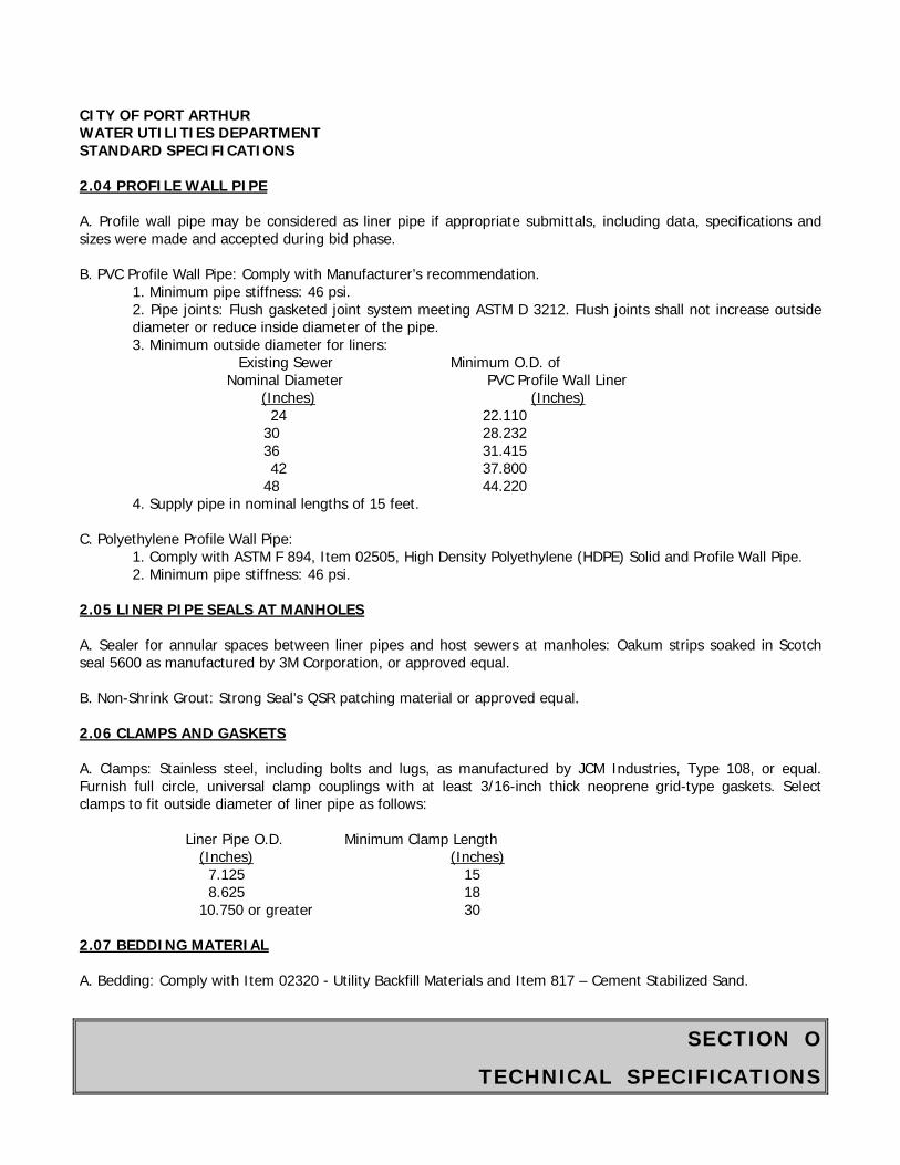
SECTION O
TECHNICAL SPECIFICATIONS
CITY OF PORT ARTHUR WATER UTILITIES DEPARTMENT STANDARD SPECIFICATIONS 2.04 PROFILE WALL PIPE A. Profile wall pipe may be considered as liner pipe if appropriate submittals, including data, specifications and sizes were made and accepted during bid phase. B. PVC Profile Wall Pipe: Comply with Manufacturer’s recommendation.
1. Minimum pipe stiffness: 46 psi. 2. Pipe joints: Flush gasketed joint system meeting ASTM D 3212. Flush joints shall not increase outside diameter or reduce inside diameter of the pipe. 3. Minimum outside diameter for liners:
Existing Sewer Minimum O.D. of Nominal Diameter PVC Profile Wall Liner
(Inches) (Inches) 24 22.110 30 28.232 36 31.415 42 37.800 48 44.220
4. Supply pipe in nominal lengths of 15 feet. C. Polyethylene Profile Wall Pipe:
1. Comply with ASTM F 894, Item 02505, High Density Polyethylene (HDPE) Solid and Profile Wall Pipe. 2. Minimum pipe stiffness: 46 psi.
2.05 LINER PIPE SEALS AT MANHOLES A. Sealer for annular spaces between liner pipes and host sewers at manholes: Oakum strips soaked in Scotch seal 5600 as manufactured by 3M Corporation, or approved equal. B. Non-Shrink Grout: Strong Seal’s QSR patching material or approved equal. 2.06 CLAMPS AND GASKETS A. Clamps: Stainless steel, including bolts and lugs, as manufactured by JCM Industries, Type 108, or equal. Furnish full circle, universal clamp couplings with at least 3/16-inch thick neoprene grid-type gaskets. Select clamps to fit outside diameter of liner pipe as follows:
Liner Pipe O.D. Minimum Clamp Length (Inches) (Inches) 7.125 15 8.625 18 10.750 or greater 30
2.07 BEDDING MATERIAL A. Bedding: Comply with Item 02320 - Utility Backfill Materials and Item 817 – Cement Stabilized Sand.
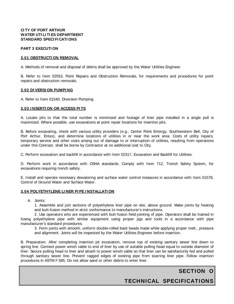
SECTION O
TECHNICAL SPECIFICATIONS
CITY OF PORT ARTHUR WATER UTILITIES DEPARTMENT STANDARD SPECIFICATIONS PART 3 EXECUTION 3.01 OBSTRUCTION REMOVAL A. Methods of removal and disposal of debris shall be approved by the Water Utilities Engineer. B. Refer to Item 02553, Point Repairs and Obstruction Removals, for requirements and procedures for point repairs and obstruction removals. 3.02 DIVERSION PUMPING A. Refer to Item 01540, Diversion Pumping. 3.03 INSERTION OR ACCESS PITS A. Locate pits to that the total number is minimized and footage of liner pipe installed in a single pull is maximized. Where possible, use excavations at point repair locations for insertion pits. B. Before excavating, check with various utility providers (e.g., Center Point Entergy, Southwestern Bell, City of Port Arthur, Entex), and determine locations of utilities in or near the work area. Costs of utility repairs, temporary service and other costs arising out of damage to or interruption of utilities, resulting from operations under this Contract, shall be borne by Contractor at no additional cost to City. C. Perform excavation and backfill in accordance with Item 02317, Excavation and Backfill for Utilities. D. Perform work in accordance with OSHA standards. Comply with Item 712, Trench Safety System, for excavations requiring trench safety. E. Install and operate necessary dewatering and surface water control measures in accordance with Item 01578, Control of Ground Water and Surface Water. 3.04 POLYETHYLENE LINER PIPE INSTALLATION
A. Joints: 1. Assemble and join sections of polyethylene liner pipe on site, above ground. Make joints by heating and butt-fusion method in strict conformance to manufacturer’s instructions. 2. Use operators who are experienced with butt-fusion field-jointing of pipe. Operators shall be trained in
fusing polyethylene pipe with similar equipment using proper jigs and tools in a accordance with pipe manufacturer’s standard procedures.
3. Form joints with smooth, uniform double-rolled back beads made while applying proper melt., pressure and alignment. Joints will be inspected by the Water Utilities Engineer before insertion.
B. Preparation: After completing insertion pit excavation, remove top of existing sanitary sewer line down to spring line. Connect power winch cable to end of liner by use of suitable pulling head equal to outside diameter of liner. Secure pulling head to liner and attach to power winch cable so that liner can be satisfactorily fed and pulled through sanitary sewer line. Prevent ragged edges of existing pipe from scarring liner pipe. Follow insertion procedures in ASTM F 585. Do not allow sand or other debris to enter liner.
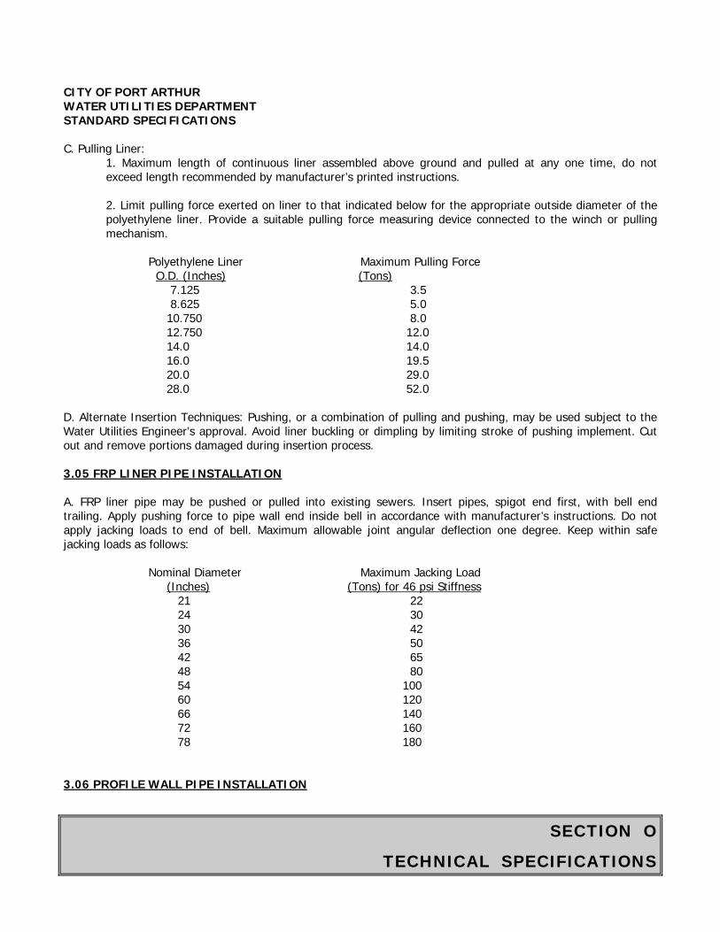
SECTION O
TECHNICAL SPECIFICATIONS
CITY OF PORT ARTHUR WATER UTILITIES DEPARTMENT STANDARD SPECIFICATIONS C. Pulling Liner:
1. Maximum length of continuous liner assembled above ground and pulled at any one time, do not exceed length recommended by manufacturer’s printed instructions. 2. Limit pulling force exerted on liner to that indicated below for the appropriate outside diameter of the polyethylene liner. Provide a suitable pulling force measuring device connected to the winch or pulling mechanism.
Polyethylene Liner Maximum Pulling Force O.D. (Inches) (Tons) 7.125 3.5 8.625 5.0 10.750 8.0 12.750 12.0 14.0 14.0 16.0 19.5 20.0 29.0 28.0 52.0
D. Alternate Insertion Techniques: Pushing, or a combination of pulling and pushing, may be used subject to the Water Utilities Engineer’s approval. Avoid liner buckling or dimpling by limiting stroke of pushing implement. Cut out and remove portions damaged during insertion process. 3.05 FRP LINER PIPE INSTALLATION A. FRP liner pipe may be pushed or pulled into existing sewers. Insert pipes, spigot end first, with bell end trailing. Apply pushing force to pipe wall end inside bell in accordance with manufacturer’s instructions. Do not apply jacking loads to end of bell. Maximum allowable joint angular deflection one degree. Keep within safe jacking loads as follows:
Nominal Diameter Maximum Jacking Load (Inches) (Tons) for 46 psi Stiffness 21 22 24 30 30 42 36 50 42 65 48 80 54 100 60 120 66 140 72 160 78 180
3.06 PROFILE WALL PIPE INSTALLATION
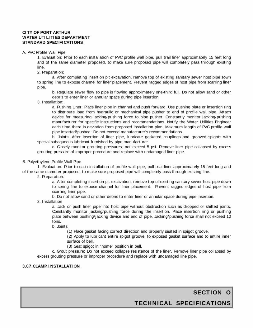
SECTION O
TECHNICAL SPECIFICATIONS
CITY OF PORT ARTHUR WATER UTILITIES DEPARTMENT STANDARD SPECIFICATIONS A. PVC Profile Wall Pipe
1. Evaluation: Prior to each installation of PVC profile wall pipe, pull trail liner approximately 15 feet long and of the same diameter proposed, to make sure proposed pipe will completely pass through existing line. 2. Preparation:
a. After completing insertion pit excavation, remove top of existing sanitary sewer host pipe sown to spring line to expose channel for liner placement. Prevent ragged edges of host pipe from scarring liner pipe.
b. Regulate sewer flow so pipe is flowing approximately one-third full. Do not allow sand or other debris to enter liner or annular space during pipe insertion.
3. Installation: a. Pushing Liner: Place liner pipe in channel and push forward. Use pushing plate or insertion ring to distribute load from hydraulic or mechanical pipe pusher to end of profile wall pipe. Attach device for measuring jacking/pushing force to pipe pusher. Constantly monitor jacking/pushing manufacturer for specific instructions and recommendations. Notify the Water Utilities Engineer each time there is deviation from proposed installation plan. Maximum length of PVC profile wall pipe inserted/pushed: Do not exceed manufacturer’s recommendations. b. Joints: After insertion of liner pipe, lubricate gasketed couplings and grooved spigots with
special subaqueous lubricant furnished by pipe manufacturer. c. Closely monitor grouting pressures; not exceed 5 psi. Remove liner pipe collapsed by excess
grouting pressure of improper procedure and replace with undamaged liner pipe. B. Polyethylene Profile Wall Pipe
1. Evaluation: Prior to each installation of profile wall pipe, pull trial liner approximately 15 feet long and of the same diameter proposed, to make sure proposed pipe will completely pass through existing line.
2. Preparation: a. After completing insertion pit excavation, remove top of existing sanitary sewer host pipe down to spring line to expose channel for liner placement. Prevent ragged edges of host pipe from scarring liner pipe. b. Do not allow sand or other debris to enter liner or annular space during pipe insertion.
3. Installation a. Jack or push liner pipe into host pipe without obstruction such as dropped or shifted joints. Constantly monitor jacking/pushing force during the insertion. Place insertion ring or pushing plate between pushing/jacking device and end of pipe. Jacking/pushing force shall not exceed 10 tons. b. Joints:
(1) Place gasket facing correct direction and properly seated in spigot groove. (2) Apply to lubricant entire spigot groove, to exposed gasket surface and to entire inner surface of bell. (3) Seat spigot in “home” position in bell.
c. Grout pressure: Do not exceed collapse resistance of the liner. Remove liner pipe collapsed by excess grouting pressure or improper procedure and replace with undamaged line pipe.
3.07 CLAMP INSTALLATION
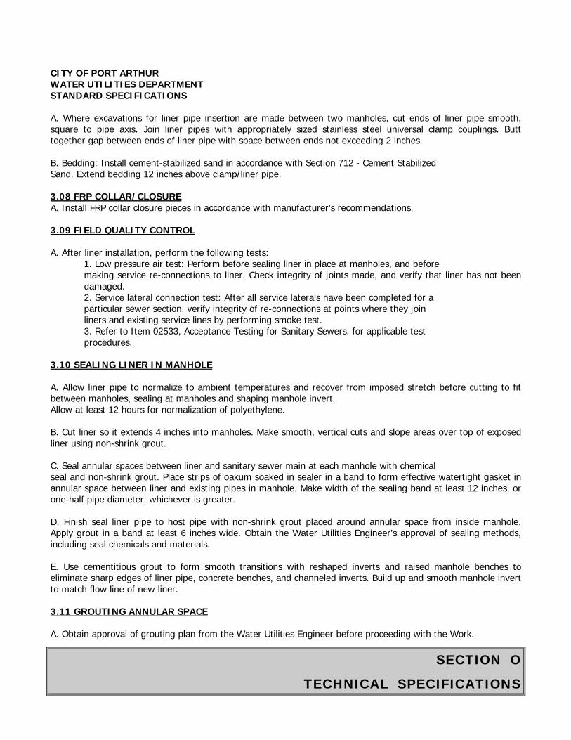
SECTION O
TECHNICAL SPECIFICATIONS
CITY OF PORT ARTHUR WATER UTILITIES DEPARTMENT STANDARD SPECIFICATIONS A. Where excavations for liner pipe insertion are made between two manholes, cut ends of liner pipe smooth, square to pipe axis. Join liner pipes with appropriately sized stainless steel universal clamp couplings. Butt together gap between ends of liner pipe with space between ends not exceeding 2 inches. B. Bedding: Install cement-stabilized sand in accordance with Section 712 - Cement Stabilized Sand. Extend bedding 12 inches above clamp/liner pipe. 3.08 FRP COLLAR/CLOSURE A. Install FRP collar closure pieces in accordance with manufacturer’s recommendations. 3.09 FIELD QUALITY CONTROL A. After liner installation, perform the following tests:
1. Low pressure air test: Perform before sealing liner in place at manholes, and before making service re-connections to liner. Check integrity of joints made, and verify that liner has not been damaged. 2. Service lateral connection test: After all service laterals have been completed for a particular sewer section, verify integrity of re-connections at points where they join liners and existing service lines by performing smoke test. 3. Refer to Item 02533, Acceptance Testing for Sanitary Sewers, for applicable test procedures.
3.10 SEALING LINER IN MANHOLE A. Allow liner pipe to normalize to ambient temperatures and recover from imposed stretch before cutting to fit between manholes, sealing at manholes and shaping manhole invert. Allow at least 12 hours for normalization of polyethylene. B. Cut liner so it extends 4 inches into manholes. Make smooth, vertical cuts and slope areas over top of exposed liner using non-shrink grout. C. Seal annular spaces between liner and sanitary sewer main at each manhole with chemical seal and non-shrink grout. Place strips of oakum soaked in sealer in a band to form effective watertight gasket in annular space between liner and existing pipes in manhole. Make width of the sealing band at least 12 inches, or one-half pipe diameter, whichever is greater. D. Finish seal liner pipe to host pipe with non-shrink grout placed around annular space from inside manhole. Apply grout in a band at least 6 inches wide. Obtain the Water Utilities Engineer’s approval of sealing methods, including seal chemicals and materials. E. Use cementitious grout to form smooth transitions with reshaped inverts and raised manhole benches to eliminate sharp edges of liner pipe, concrete benches, and channeled inverts. Build up and smooth manhole invert to match flow line of new liner. 3.11 GROUTING ANNULAR SPACE A. Obtain approval of grouting plan from the Water Utilities Engineer before proceeding with the Work.

SECTION O
TECHNICAL SPECIFICATIONS
CITY OF PORT ARTHUR WATER UTILITIES DEPARTMENT STANDARD SPECIFICATIONS B. Grout annular space between the outside of liner and inside of existing pipe for sewer pipe 18 inches in diameter and larger, in accordance with Manufacturer’s specifications. 3.12 POST-INSTALLATION VIDEOTAPE RECORDING A. Provide the Water Utilities Engineer with videotape showing completed work including condition of restored connections. Comply with Item 02533 - Acceptance Testing for Sanitary Sewers and Item 02558 - Cleaning and Television Inspection of Sanitary Sewers. 3.13 FINAL CLEANUP A. Upon completion of installation and testing, clean and restore project area affected by work of this Section. Restore site to a condition equal to or better than pre-construction.
End of Section
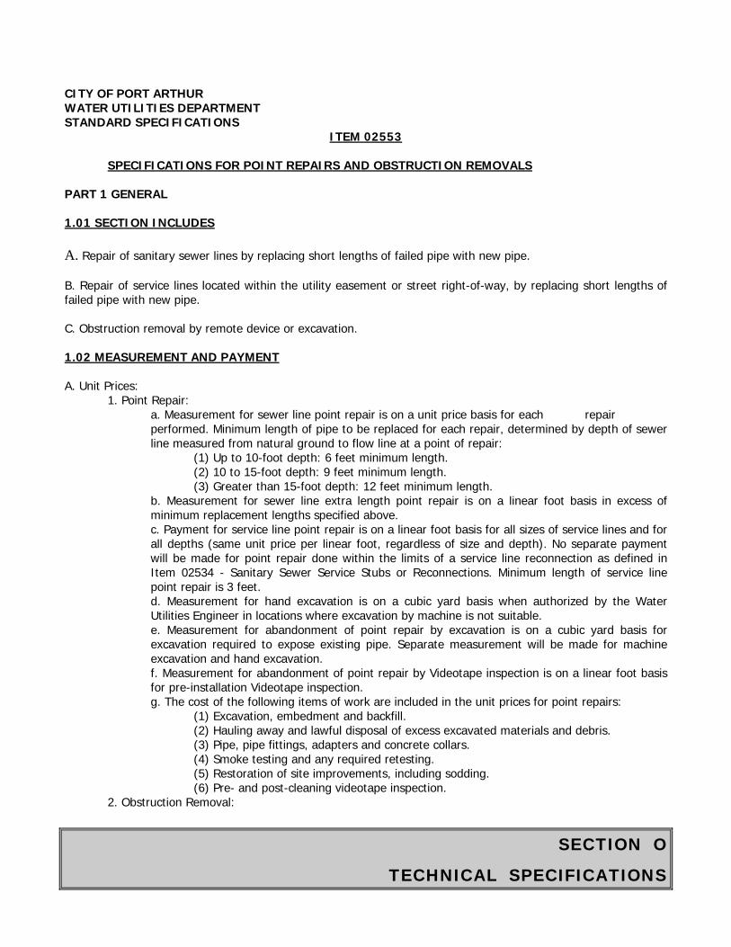
SECTION O
TECHNICAL SPECIFICATIONS
CITY OF PORT ARTHUR WATER UTILITIES DEPARTMENT STANDARD SPECIFICATIONS
ITEM 02553
SPECIFICATIONS FOR POINT REPAIRS AND OBSTRUCTION REMOVALS PART 1 GENERAL 1.01 SECTION INCLUDES A. Repair of sanitary sewer lines by replacing short lengths of failed pipe with new pipe. B. Repair of service lines located within the utility easement or street right-of-way, by replacing short lengths of failed pipe with new pipe. C. Obstruction removal by remote device or excavation. 1.02 MEASUREMENT AND PAYMENT A. Unit Prices:
1. Point Repair: a. Measurement for sewer line point repair is on a unit price basis for each repair performed. Minimum length of pipe to be replaced for each repair, determined by depth of sewer line measured from natural ground to flow line at a point of repair:
(1) Up to 10-foot depth: 6 feet minimum length. (2) 10 to 15-foot depth: 9 feet minimum length. (3) Greater than 15-foot depth: 12 feet minimum length.
b. Measurement for sewer line extra length point repair is on a linear foot basis in excess of minimum replacement lengths specified above. c. Payment for service line point repair is on a linear foot basis for all sizes of service lines and for all depths (same unit price per linear foot, regardless of size and depth). No separate payment will be made for point repair done within the limits of a service line reconnection as defined in Item 02534 - Sanitary Sewer Service Stubs or Reconnections. Minimum length of service line point repair is 3 feet. d. Measurement for hand excavation is on a cubic yard basis when authorized by the Water Utilities Engineer in locations where excavation by machine is not suitable. e. Measurement for abandonment of point repair by excavation is on a cubic yard basis for excavation required to expose existing pipe. Separate measurement will be made for machine excavation and hand excavation. f. Measurement for abandonment of point repair by Videotape inspection is on a linear foot basis for pre-installation Videotape inspection. g. The cost of the following items of work are included in the unit prices for point repairs:
(1) Excavation, embedment and backfill. (2) Hauling away and lawful disposal of excess excavated materials and debris. (3) Pipe, pipe fittings, adapters and concrete collars. (4) Smoke testing and any required retesting. (5) Restoration of site improvements, including sodding. (6) Pre- and post-cleaning videotape inspection.
2. Obstruction Removal:
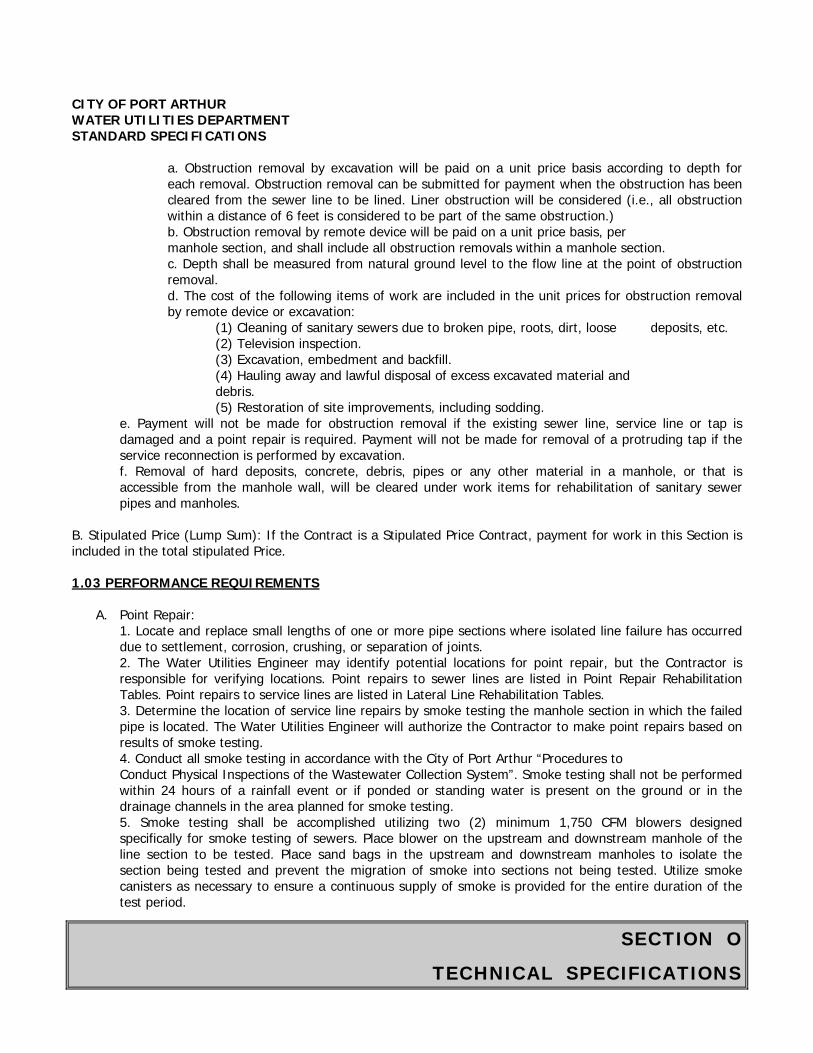
SECTION O
TECHNICAL SPECIFICATIONS
CITY OF PORT ARTHUR WATER UTILITIES DEPARTMENT STANDARD SPECIFICATIONS
a. Obstruction removal by excavation will be paid on a unit price basis according to depth for each removal. Obstruction removal can be submitted for payment when the obstruction has been cleared from the sewer line to be lined. Liner obstruction will be considered (i.e., all obstruction within a distance of 6 feet is considered to be part of the same obstruction.) b. Obstruction removal by remote device will be paid on a unit price basis, per manhole section, and shall include all obstruction removals within a manhole section. c. Depth shall be measured from natural ground level to the flow line at the point of obstruction removal. d. The cost of the following items of work are included in the unit prices for obstruction removal by remote device or excavation:
(1) Cleaning of sanitary sewers due to broken pipe, roots, dirt, loose deposits, etc. (2) Television inspection. (3) Excavation, embedment and backfill. (4) Hauling away and lawful disposal of excess excavated material and debris. (5) Restoration of site improvements, including sodding.
e. Payment will not be made for obstruction removal if the existing sewer line, service line or tap is damaged and a point repair is required. Payment will not be made for removal of a protruding tap if the service reconnection is performed by excavation. f. Removal of hard deposits, concrete, debris, pipes or any other material in a manhole, or that is accessible from the manhole wall, will be cleared under work items for rehabilitation of sanitary sewer pipes and manholes.
B. Stipulated Price (Lump Sum): If the Contract is a Stipulated Price Contract, payment for work in this Section is included in the total stipulated Price. 1.03 PERFORMANCE REQUIREMENTS
A. Point Repair: 1. Locate and replace small lengths of one or more pipe sections where isolated line failure has occurred due to settlement, corrosion, crushing, or separation of joints. 2. The Water Utilities Engineer may identify potential locations for point repair, but the Contractor is responsible for verifying locations. Point repairs to sewer lines are listed in Point Repair Rehabilitation Tables. Point repairs to service lines are listed in Lateral Line Rehabilitation Tables. 3. Determine the location of service line repairs by smoke testing the manhole section in which the failed pipe is located. The Water Utilities Engineer will authorize the Contractor to make point repairs based on results of smoke testing. 4. Conduct all smoke testing in accordance with the City of Port Arthur “Procedures to Conduct Physical Inspections of the Wastewater Collection System”. Smoke testing shall not be performed within 24 hours of a rainfall event or if ponded or standing water is present on the ground or in the drainage channels in the area planned for smoke testing. 5. Smoke testing shall be accomplished utilizing two (2) minimum 1,750 CFM blowers designed specifically for smoke testing of sewers. Place blower on the upstream and downstream manhole of the line section to be tested. Place sand bags in the upstream and downstream manholes to isolate the section being tested and prevent the migration of smoke into sections not being tested. Utilize smoke canisters as necessary to ensure a continuous supply of smoke is provided for the entire duration of the test period.
SECTION O
TECHNICAL SPECIFICATIONS
CITY OF PORT ARTHUR WATER UTILITIES DEPARTMENT STANDARD SPECIFICATIONS
6. Determine the location of point repairs by smoke testing or videotape inspection of the manhole section in which the failed pipe is located. The Water Utilities Engineer will authorize the Contractor to make point repairs. 7. The Water Utilities engineer will authorize each point repair after failure points are located. Do not make point repairs without prior authorization of the City Engineer. Perform point repairs only on those portions of service lines which are located in an easement or right-of-way; perform no repairs to service lines on private property. 8. Replace carrier pipe for point repairs unless otherwise directed by the Water Utilities Engineer.
B. Obstruction Removal: Remove obstructions by one of the following methods:
1. Obstruction removal by remote device: a. Protruding taps: Service lines that protrude more than one inch into the sewer. b. Other obstructions: Hanging gaskets, fixed debris, stabilized sand, hardened mineral deposits, roots, rust scale, tuberculation, etc.
2. Obstruction removal by excavation: Obstructions encountered during liner insertion that are removed by digging and exposing the pipe.
1.04 DEFINITIONS A. Point Repair: Repair of broken or collapsed gravity sanitary sewer lines on public property, including mains, collectors and service lines, by replacing, at the point of failure, the length of failed pipe with new pipe. B. Obstruction Removal: Clearing sewer mains of obstructions to allow for rehabilitation. C. Sewer Lines: Gravity flow pipe lines in the easement or right-of-way which collect sanitary sewer discharges from commercial or residential service lines and discharge into another sewer line (main or collector), or into a lift station or treatment plant. D. Service Lines: Those gravity flow sewer lines from commercial or residential property that discharge into a sewer line. 1.05 SUBMITTALS A. Submittals: Comply with Section 1300 - Contractor Submittals. B. Submit product data for each pipe product, fitting and jointing material. 1.06 SEQUENCING A. Before rehabilitating a sewer line section between adjacent manholes, complete point repair and obstruction removal on that section. B. Clean line and perform post-installation videotape inspection for each point repair on sewer lines not scheduled for rehabilitation. C. Post-installation videotape inspection of service line point repairs is not required.
SECTION O
TECHNICAL SPECIFICATIONS
CITY OF PORT ARTHUR WATER UTILITIES DEPARTMENT STANDARD SPECIFICATIONS PART 2 PRODUCTS 2.01 PVC PIPE A. PVC Sewer Pipe and Joints: 4-inch through 24-inch pipe complying with Item 702 – PVC Gravity Sewer Pipe and Fittings. If point repair is located at a service connection, use a fullbodied fitting for the service connection. No field fabrication of fittings allowed. 2.02 DUCTILE IRON PIPE A. Ductile Iron Pipe: 4-inch through 48-inch, complying with Item 707 - Ductile Iron Pipe and Fittings. B. Fittings: Push-on end-joint fittings with bell-and-spigot ends, with bells modified for push-on joints, complying with Item 707 - Ductile Iron Pipe and Fittings. C. Interior Coating: Comply with Item 707 - Ductile Iron Pipe Fittings. D. Exterior Coating: 8-mil polyethylene tubular material as per Manufacturer’s specifications. 2.03 REINFORCED CONCRETE PIPE A. Reinforced Concrete Pipe and Joints: Comply with Section 02611 - Reinforced Concrete Pipe. Reinforced concrete pipe may be used for sewers 21 inches in diameter and larger. 2.04 FRP PIPE A. FRP Pipe: Comply with Manufacturer’s specifications. 2.05 JOINTING MATERIALS A. Use flexible adapters secured with ½-inch stainless steel bands, as manufactured by Fernco, or approved equal. B. Form a concrete collar around each joint using concrete complying Manufacturer’s specifications. PART 3 EXECUTION 3.01 PROTECTION A. Provide barricades, warning lights and signs for excavations created by point repairs as per Special Provisions - Detours, Barricades, Warning Signs, Sequence of Work, etc. B. Do not allow soil, sand, debris or runoff to enter sewer system. 3.02 DIVERSION PUMPING
SECTION O
TECHNICAL SPECIFICATIONS
CITY OF PORT ARTHUR WATER UTILITIES DEPARTMENT STANDARD SPECIFICATIONS A. Install and operate diversion pumping equipment as required to maintain sewage flow and to prevent backup or overflow. Comply with Item 01540 - Diversion Pumping. 3.03 EXCAVATION A. Excavation and backfill trenches in accordance with Item 02317 - Excavation and Backfill for Utilities. B. Perform work in accordance with ASHA standards Employ a trench safety system as required in Item 712 - Trench Safety Systems. C. Install and operate necessary dewatering and surface water control measures as required in Item 01578 - Control of Ground Water and Surface Water. D. Remove and lawfully dispose of excess excavated material and debris from the work site daily. 3.04 TYPICAL SEQUENCE OF POINT REPAIR A. Perform pre-installation videotape inspection to verify location of sewer line point repairs. Perform service testing between manholes to verify location of service line point repairs. B. After the location of a point repair, excavate the required length for the point repair. C. Prior to replacing pipe, determine condition of the existing line on both sides of the point repair by lamping the line at least 10 feet in each direction. Determine whether additional lengths of line (beyond “minimum length” criteria) need replacement. Report need for additional replacement to the Water Utilities Engineer and obtain authorization before proceeding. D. Remove the damaged pipe and replace with new pipe, shaping the bottom of the trench and placing the required pipe bedding so that the grade of the replaced pipe matches the grade of the existing line. Establish proper grade for the pipe being replaced using methods acceptable to the Water Utilities Engineer. E. Connect the new pipe to existing pipe using flexible adapters. If joints cannot be made watertight using flexible adapters, place waterstop gaskets on each joint and encase in a reinforced concrete collar. Place concrete as per Manufacturer’s specifications. Reconnect affected service connections or stacks using full-bodied fittings. No field fabrication of fittings allowed. F. After completion of point repair, but prior to backfill, perform a smoke test to demonstrate the integrity of the repair, in the presence of the Water Utilities Engineer. Test as specified in Item 02533 - Acceptance Testing for Sanitary Sewers. Repair and retest sections that fail until repair passes test. G. Encase exposed pipe in cement stabilized sand complying with Item 817 - Cement Stabilized Sand. H. Backfill the excavation as specified in Item 02317 - Excavation and Backfill for Utilities. I. Site to be restored to a condition equal to or better than pre-construction.

SECTION O
TECHNICAL SPECIFICATIONS
CITY OF PORT ARTHUR WATER UTILITIES DEPARTMENT STANDARD SPECIFICATIONS
J. Perform a post-installation videotape inspection as specified in Item 02558 - Cleaning and Television Inspection. Point repairs that show offset joints, non-uniform grade, incorrect alignment, excessive deflection or similar conditions are considered defective work. Replace pipe and bedding as required to correct defective work.
3.05 ABANDONMENT OF POINT REPAIR
A. If pipe is exposed by excavation and found to be in good condition, not requiring a point repair, that point repair shall be abandoned. Notify Water Utilities Engineer.
B. If pre-installation videotape inspection reveals that no point repair is required in a manhole section, point repair shall be abandoned. Notify Water Utilities Engineer.
C. Backfill the excavation, replace pavement or sidewalk, and repair and seed or sod unpaved areas, to a condition equal to or better than pre-construction.
3.06 OBSTRUCTION REMOVAL
A. Remote Device: Remove obstructions identified on videotape of a sanitary sewer line segment which could cause a non-uniform liner pipe installation or obstruction of the liner during installation. Obtain authorization from the Water Utilities Engineer for obstruction removal with a remote device before proceeding.
1. Use a power-driven cutting device (robotic cutter) to remove protruding taps. Cut protruding taps sothat protrusions are no greater than 3/4 inch. If a protruding tap cannot be removed by the cutting device, then a point repair may be performed. Obtain authorization from the Water Utilities Engineer before proceeding. 2. To remove other obstructions, use a remote device. Pull or drive the device from manhole to manholeup to a continuous length of 500 feet using a solid steel mandrel, porcupine, root saw, bucket, robotic cutter or similar device to remove the obstruction. Select a device that is adequately sized to remove the obstruction.
B. Excavation: Use excavation as the method of obstruction removal when installation of the liner in the sanitary sewer is in progress. If during the liner insertion operation, a collapsed sewer, off-set joint or other obstruction is encountered which prevents or blocks the passage or insertion of the liner, notify the Water Utilities Engineer for authorization to excavate. Uncover and remove the obstruction as follows:
1. Excavate at the point where there is an obstruction. Use a trench safety system as required.2. Break out the existing sanitary sewer pipe (carrier pipe) as directed by the Water Utilities Engineer.Remove only that amount of material which is causing the obstruction. Remove the minimum amount of carrier pipe. 3. Under such conditions, replacement of the carrier pipe is not required. Do not disturb the existingsewer bedding during excavation. However, if embedment is disturbed during the obstruction removal procedure, place cement-stabilized sand or crushed stone beneath the liner. 4. When the liner is completely in place, encase it with crushed stone or cement stabilized sand.
End of Section
SECTION O
TECHNICAL SPECIFICATIONS
CITY OF PORT ARTHUR WATER UTILITIES DEPARTMENT STANDARD SPECIFICATIONS
ITEM 02555
MANHOLE REHABILITATION PART 1 GENERAL 1.01 SECTION INCLUDES A. Repair, rehabilitation or replacement of deteriorated, leaking or structurally unsound manholes. 1.02 MEASUREMENT AND PAYMENT A. Unit Prices:
1. Rehabilitated Manholes: a. Measurement for manhole wall lining (including bench repair) is on a vertical foot basis to the nearest tenth of a foot, measured from the bottom of the frame to the top of the bench. If the bench is not required, measurement will be from the bottom of the frame to the top of the effluent pipe. The price shall include manhole adjustment, a new manhole ring, frame and cover, new stainless steel insert, and surface restoration. b. Backfill, including cement-stabilized sand, is included in the unit prices for rehabilitated manholes; no separate payment will be made.
2. New/Replacement Manholes: a. Measurement for abandoned manholes is on a unit price basis per manhole abandoned. b. Measurement for new manholes is on a unit price basis, per manhole. Price includes excavation, removal of existing manhole/cleanout/end of line, new frame and cover, sealant and backfill materials. Price also includes up to 6 feet of sewer pipe, in each and every direction, measured from the outside wall of the manhole. c. Backfill, including cement-stabilized sand, is included in the unit price for new/replacement manholes; no separate payment will be made.
1.03 REFERENCES A. ASTM C 1140 - Standard Practice for Preparing and Testing Specimens from Shortcrete Test Panels. B. ASTM D 698 - Test Method for Laboratory Compaction Characteristics of Soil Using Standard Effort (12,400 ft-lbf/ft). 1.04 PERFORMANCE REQUIREMENTS A. Performance work needed to make manholes structurally sound, improve flow, prevent entrance of inflow or groundwater, prevent entrance of soil or debris, and provide protection against hydrogen sulfide gas attack. B. Manufacturer’s Product Support: When requested by the Water Utilities Engineer, provide a representative employed by the manufacturer having technical training in admixture and manhole wall liner available for consultation on site upon 48 hours notice.
SECTION O
TECHNICAL SPECIFICATIONS
CITY OF PORT ARTHUR WATER UTILITIES DEPARTMENT STANDARD SPECIFICATIONS 1.05 SUBMITTALS A. Submittals: Comply with Section 01300 - Contractor Submittals. B. Product Data: Submit product data, including surface preparation instructions and application instructions, from pre-approved manufacturer of wall repair materials, hydraulic cements, quick-set mortars, specialized sealants, grouts, manhole inserts, manhole frame covers and frame-to-manhole seals. C. Installer Qualifications: Installers of liners and wall repair systems shall submit qualifications to the Water Utilities Engineer. List installer’s personnel who have satisfactorily completed manufacturer’s training in product application within the previous 2 years. Include date of certification for each person. 1.06 PROJECT CONDITIONS A. Manholes Containing Mechanical or Electrical Equipment:
1. Drawings may not show locations of flow monitoring equipment. If a manhole contains any mechanical hardware or electrical flow monitoring equipment, immediately notify the Water Utilities Engineer. 2. Reschedule work in such manholes until equipment has been removed by the City and further instructions are given. 3. Do not subject manholes with mechanical hardware or electrical equipment to diversion or bypass pumping. 4. Damage to installed equipment, due to Contractor’s failure to adhere to this instruction, will be repaired by the City and cost of repairs charged to the Contractor.
B. Field Location of Manholes, Cleanouts and End of Lines:
1. Contractor is responsible for locating and uncovering all manholes, cleanouts and ends of lines. If Contractor is unable to locate manholes, cleanouts or ends of lines, Contractor shall notify Water Utilities Engineer in writing. 2. Manholes may be located within project limits which are not part of the system being rehabilitated. Properly identify manholes before starting work.
1.07 SALVAGE
A. Manhole covers and frames from abandoned and replaced manholes remain the property of the City. Unless indicated to be re-used in the work, deliver salvaged items to 1101 Henry O. Mills Blvd, Port Arthur, Texas.
PART 2 PRODUCTS 2.01 WALL CLEANING MATERIAL A. High Pressure Water: 3500 psi minimum force. B. Cleaners: Detergents or muriatic acid capable of removing dirt, grease, oil and other matter which would interfere with bond of sealing material to wall; refer to sealing manufacturer’s recommendations.
SECTION O
TECHNICAL SPECIFICATIONS
CITY OF PORT ARTHUR WATER UTILITIES DEPARTMENT STANDARD SPECIFICATIONS 2.02 WALL REPAIR MATERIALS A. Hydraulic Cements: Use a blend of cement powders or hydraulic cement to stop active leaks in the manhole structure. B. Quick-set Mortar: Use a quick-set mortar to repair wide cracks, holes or disintegrated mortar. 2.03 MANHOLE WALL LINERS, BENCH FORMING AND REPAIR MATERIAL A. Use products approved by City of Port Arthur Water Utilities Engineer. 2.04 MANHOLE COVERS, FRAME INSERTS AND FRAME-TO-MANHOLE SEALS A. New Covers/Frames: Comply with Item 708 - Manholes. B. Existing manhole shall be water tight and include a stainless steel rain stopper. C. Provide manhole inserts including new dishes, gaskets and relief valves. Select appropriate watertight inserts to fit walls and frames of manholes.
1. Stainless steel (18 gauge minimum) inserts; Southwestern Packing and Seals “Rain Stopper,” or approved equal. 2. Inserts shall have a handle of plastic-coated stainless steel installed on the body of the insert dish. The handle shall be attached with a #6 high-grade stainless steel rivet. Each dish shall have a factory-installed 5-foot-long, 3/16" braided stainless steel retaining cable to connect the dish to the manhole frame.
D. Frame-to-Manhole Seals: As manufactured by Cretex, or approved equal. E. Sealing materials between adjustments rings and manhole frame shall be Adeka Ultraseal P201 or approved equal. PART 3 EXECUTION 3.01 PROTECTION A. Provide barricades, warning lights and signs for manhole or cleanout removal excavations. Comply with City of Port Arthur Special Provisions Section. B. Do not allow soil, sand debris or runoff to enter sewer system. 3.02 EXCAVATION A. Excavation in accordance with Item 02317 - Specifications for Underground Construction of Water and Sewer Pipes.
SECTION O
TECHNICAL SPECIFICATIONS
CITY OF PORT ARTHUR WATER UTILITIES DEPARTMENT STANDARD SPECIFICATIONS B. Perform work in accordance with OSHA standards. Employ a trench safety system as required in Item 712 - Trench Safety System. C. Install and operate necessary dewatering and surface water control measures as required in Item 01578 - Control Ground Water and Surface Water. 3.03 DIVERSION PUMPING A. Install and operate diversion pumping equipment to maintain sewage flow and to prevent backup or overflow as specified in Item 01540 - Diversion Pumping. B. In the event of accidental spill or overflow, immediately stop the overflow and take action to clean up and disinfect spillage. Promptly notify the Water Utilities Engineer so that required reporting can be made to the Texas Commission on Environmental Quality and U.S. Environmental Protection Agency. 3.04 CLEANOUT/END OF LINE REMOVAL AND REPLACEMENT A. Remove and replace clean-outs as per City of Port Arthur Standard Details. 3.05 ABANDONMENT OF CLEANOUTS AND MANHOLES
A. Abandon manholes that are designated on Drawings or directed by the Water Utilities Engineer to be abandoned. B. Dismantle manholes to be abandoned, including frames, to 2 feet below ground level. C. If a manhole is to be abandoned on a rehabilitated line, install a carrier pipe through the manhole structure and fill the manhole with cement-stabilized sand, compacted to a level 2 feet above the top of carrier pipe. D. If a manhole is to be abandoned on an abandoned line, plug all lines in the manhole and backfill in accordance with Item 02317 - Specifications for Underground Construction of Water and Sewer pipes. E. If a manhole is to be abandoned in a paved street, backfill manhole as described above, but with cement-stabilized sand to underside of pavement repair in lieu of select backfill material. Patch paving in lieu of select backfill material. Patch paving in accordance with City of Port Arthur Standard Details. F. If an abandoned manhole is not located in a paved street, fill remainder of manhole with select backfill material to 2 feet below ground level. Restore surface to match adjacent area. 3.06 MANHOLE WALL CLEANING A. Clean bench/invert floor and interior walls of manholes by removing deleterious materials, including dirt, grease and other debris. Use high pressure water at a minimum force of 3500 psi. If required, use detergent or muriatic acid to remove grease, oil and other matter which would interfere with bond between existing manhole wall and approved repair materials.
SECTION O
TECHNICAL SPECIFICATIONS
CITY OF PORT ARTHUR WATER UTILITIES DEPARTMENT STANDARD SPECIFICATIONS B. Prepare interior surfaces as recommended by the wall liner material manufacturer. Remove brick steps and cast iron steps prior to wall lining. 3.07 MANHOLE WALL SEALING A. Seal active leaks in manhole structures with a blend of cement powder or hydraulic cement. B. Remove loose or defective wall material. Wipe or brush surfaces clean prior to application of hydraulic cements. C. Stopping Leaks: Drill weep holes at bottom of manhole walls to relieve hydrostatic pressure. Plug pressure-relief holes after leaks are stopped using hydraulic cement materials. Lead wool may also be used to plug large leaks. D. Repair wide cracks, holes and disintegrated mortar with quick-set mortars following manufacturer’s instructions and recommendations. E. Reshape manhole inverts before wall-sealing work. Apply concrete to cleaned manhole benches. F. After active leaks have been stopped, clean and prepare walls for application of selected liner material. G. Properly apply sealing compound to provide the minimum required uniform coating to the wall surface. H. Prevent foreign material from entering adjoining pipes. Remove droppings of foreign and wall sealant materials before they harden on the bottom of the manhole. I. Strictly follow product manufacturers’ published instructions and recommendations for surface preparation, application and proportioning. 3.08 MANHOLE REMOVAL AND REPLACEMENT A. When indicated on the Drawings or instructed by the Water Utilities Engineer, excavate and properly remove and dispose of the existing manhole, including base. Employ a trench safety system and keep the excavation dry from sewage flow and surface or ground water. B. Replace manhole with a new manhole as specified in Item 708- Manholes and per City of Port Arthur Standard Details. C. Construct or reconstruct drop connections whenever the flowline elevation of an influent line is more than 24 inches above the bench elevation. D. Sewer pipe up to 6 feet outside new manholes may be replaced with new sewer pipe in conjunction with manhole removal and replacement. E. Properly backfill replacement manholes as required by Manufacturer. F. Furnish replacement manholes with new 32-inch frames and covers as per City of Port Arthur Standard Details.
SECTION O
TECHNICAL SPECIFICATIONS
CITY OF PORT ARTHUR WATER UTILITIES DEPARTMENT STANDARD SPECIFICATIONS 3.09 MANHOLE BENCHES/INVERTS A. Remove obstructions and loose materials from benches prior to shaping inverts. Form smooth, U-shaped inverts having minimum depths of one-half the pipe diameter and channel it CITY OF PORT ARTHUR WATER UTILITIES DEPARTMENT STANDARD SPECIFICATIONS across the floor of the manhole using an approved manhole rehabilitation material. Control flow to allow sufficient setting time for material used. B. Make finished benches and inverts smooth and without defects which would allow accumulation of debris. 3.10 MANHOLE COVERS AND FRAMES
A. Adjust manhole frames and covers found above or below grade and reset loose frames. Combine precast concrete adjustment rings so that the elevation of the installed frame and cover extends 6 inches above the natural ground in unpaved areas. In paved areas, set flush and smooth with pavement grades. An approved sealant shall be applied between the top and adjustment ring and the manhole frame. No less than two beads shall be applied ½-inch wide and 3/4-inch high. An approved manhole cementitious lining material shall be applied between the rings and no less than 1-inch of lining material shall be applied to the inside and outside face of the adjustment rings.
B. Install new watertight manhole covers and frames at locations shown on the Drawings or where instructed by the Water Utilities Engineer. Use new frames and covers. 3.11 MANHOLE INSERTS A. Install stainless steel manhole inserts in all replaced and rehabilitated manholes. B. Exercise care in selecting the proper insert dish to fit properly with the manhole frame and cover. The insert flange should have an outside diameter 3/16 inch less than the inside diameter of the manhole frame. Once proper fit is established, clean manhole frame surface of all dirt, grit and debris with a wire brush. Fully seal insert on the manhole frame, providing a watertight seal. C. Securely attach retaining tether to the manhole frame following manufacturer’s instructions with a tamper-proof anchoring device. D. Replace damaged, tight-fitting or missing inserts identified prior to final inspection at no cost to the City. E. For new sanitary sewer manholes subject to loading or differential movement at manhole frames, and for rehabilitated manholes, install manhole chimney seals to prevent inflow between manhole frames and masonry chimneys. 3.12 FRAME-TO-MANHOLE SEALS
SECTION O
TECHNICAL SPECIFICATIONS
CITY OF PORT ARTHUR WATER UTILITIES DEPARTMENT STANDARD SPECIFICATIONS
A. Surfaces on which the sleeve or extension is to be compressed shall be circular, clean, reasonably smooth and free of loose material and excessive voids. If a surface is rough or irregular and would not provide an effective seal, smooth it with an approved microsilicaenhanced grout. Repair flaws in manhole frames, such as cracks, pits or protrusions, by filling with concrete or grinding smooth. This type of surface work will need to be done on manholes that have not been lined; manholes that have been lined should not need any surface work in order to install seal.
B. Install seals following manufacturer’s installation instructions. Arrange for manufacturer’s representative to train Installer’s personnel in proper methods of installing seals and assist the Installer and Contractor with any problems they might encounter installing the seals.
C. If internal surfaces of the chimney or corbel section of the manhole exceed a slope of 1 in 3, do not use a frame-to-manhole seal.
D. Install frame-to-manhole seals so as to prevent water migration between manhole frames and manhole structures.
3.13 FIELD QUALITY CONTROL
A. Inform the Water Utilities Engineer immediately if materials being used are not producing required results or need modification. The Water Utilities Engineer has the right to stop the use of any material at any time.
3.14 INSPECTION
A. After manhole wall sealing or manhole rehabilitation is complete, visually inspect manholes in the presence of the Water Utilities Engineer. Check for cleanliness and for elimination of active leaks.
B. At completion of manhole rehabilitation, assist the Water Utilities Engineer in verifying installation of minimum coating thickness of concrete liner. Test several points on manhole walls. Repair verification points prior to final acceptance for payment.
3.15 TESTING
A. Perform leakage testing for manholes, refer to Item 02533 - Acceptance Testing for Sanitary Sewers.
3.16 BACKFILL
A. Backfill and compact soil in area of excavation surrounding manholes in accordance with Item 02317 - Specifications for Underground Construction of Water and Sewer Pipes.
B. In unpaved areas, grade surface at a uniform slope of 1 to 5 from the manhole frame to natural grade. Provide at least 4 inches of topsoil.
End of Section
SECTION O
TECHNICAL SPECIFICATIONS
CITY OF PORT ARTHUR WATER UTILITIES DEPARTMENT STANDARD SPECIFICATIONS
ITEM 02558
SPECIFICATIONS FOR CLEANING AND TELEVISION INSPECTION PART 1 GENERAL 1.01 SECTION INCLUDES A. Cleaning sewer lines remove solids, roots, soil, sand, pieces of broken pipe, bricks, grease, grit from sewer lines and manholes and other debris, thus improving flow and facilitating television inspection for sewer evaluation. Cleaning includes initial manhole wall washing by high-pressure water jet. B. Television inspecting the line to obtain quality DVDs and Television Inspection Reports upon which the Water Utilities Engineer can make decisions regarding needed sewer rehabilitation and repair. 1.02 MEASUREMENT AND PAYMENT A. Unit Prices:
1. Survey Normal Cleaning Equipment: Cleaning sanitary sewer mains with normal cleaning equipment will not be paid as a separate item and its cost should be included with other bid items. Cleaning using normal cleaning equipment includes:
a. Charges for transient water meter setup and water usage. b. Collection, removal, transportation and legal disposal of liquid wastes, soil, sand and other debris. c. Locating, exposing and opening manholes on sewers to be cleaned. d. Initial manhole wall washing with high-pressure water. Payment for additional cleaning and scrubbing of manhole walls which may be required for manhole rehabilitation is included in the unit price for manhole wall sealing as specified in Item 02555 - Manhole rehabilitation. e. Reconstruction of manholes dismantled for cleaning equipment access, and repair of damage caused by dismantling or cleaning equipment.
2. Cleaning Using Mechanical Cleaning Equipment: Cleaning sanitary sewer mains with mechanical cleaning equipment will not be paid as a separate item and its cost should be included with other bid items. Mechanical cleaning is limited to locations approved by the Water Utilities Engineer on a case-by-case basis after normal cleaning methods have failed to produce satisfactory results, as determined by viewing videotapes.
a. Mechanical cleaning prior to normal cleaning does not relieve the Contractor of the responsibility for fully cleaning the pipe with normal cleaning equipment. b. Reconstruction of manholes dismantled for cleaning equipment access, and repair of damage caused by dismantling or cleaning equipment.
3. Survey Television Inspection: Measurement of survey television inspection for pipe segments selected by the Water Utilities Engineer will not be paid as a separate item and its cost should be included with other bid items. The following will not be acceptable:
a. Poor or unacceptable-quality tapes. Hazy, unclear pictures will not qualify for payment. b. Re-taping any segment without prior approval of the Water Utilities Engineer. c. Portions of sanitary sewer not videotaped.
4. Survey Television Inspection by Floating Camera: Measurement of survey television
SECTION O
TECHNICAL SPECIFICATIONS
CITY OF PORT ARTHUR WATER UTILITIES DEPARTMENT STANDARD SPECIFICATIONS
inspection by floating camera for pipe segments selected by the Water Utilities Engineer will not be paid as a separate item and its cost should be included with other bid items. Such inspections may be required in 36-inch through 84-inch diameter sewer pipes, without any cleaning, for purely investigative studies. 5. Pre-Installation Cleaning: No separate payment will be made for pre-installation cleaning using normal cleaning equipment. Include cost for pre-installation cleaning using normal cleaning equipment. Include cost for pre-installation cleaning in cost of line work for which the rehabilitation effort is performed. 6. Pre-Installation Television Inspection: No separate payment will be made for preinstallation television inspection. Include cost for pre-installation television inspection in the cost of line work for which the rehabilitation effort is performed. 7. Post-Installation Television Inspection: No separate payment will be made for postinstallation television inspection. Include cost for post-installation television inspection in the cost of line work for which the rehabilitation is performed.
1.03 DEFINITIONS A. Normal Cleaning Equipment: Cleaning devices such as rods, metal pigs, porcupines, root saws, snakes, scooters, sewer balls, kites, and other approved equipment in conjunction with hand-winching devices and gas or electric rod-propelled devices. Variable-pressure water nozzles (3000 psi) are considered normal cleaning equipment. B. Mechanical Cleaning Equipment: Buckets, scrapers, scooters, porcupines, kites, heavy-duty brushes, metal pigs and other debris-removing equipment and accessories used in conjunction with approved power winching machines. High-to very-high-pressure water nozzles (10,000 psi) are considered mechanical cleaning equipment. C. Survey Cleaning and Television Inspection: Video inspection of existing sanitary sewers to evaluate lines and determine whether conditions exist which would require line rehabilitation. D. Pre-Installation Television Inspection: Video inspection by Contractor of sewer lines designated for rehabilitation to confirm cleaning, location of service connections and constructability of line rehabilitation according to Drawings and Specifications. E. Post-Installation Television Inspection: Video inspection to determine whether rehabilitation or a sanitary sewer has been completed according to Drawings and Specifications. F. Television Inspection Report: A form that is filled out by each television operator for any television inspection effort that is submitted to the City, on a form provided by the City. 1.04 PERFORMANCE REQUIREMENTS A. Clean designated sanitary sewers and manholes using mechanical, hydraulically-propelled or high-velocity sewer cleaning equipment. Select cleaning processes which will remove grease, soil, sand, silt, solids, rags and debris from each sewer segment and associated manholes. B. The Water Utilities Engineer may determine that no additional line rehabilitation work is required if the cleaning operation shows the sewer line to be free of damage or deterioration. The Water Utilities Engineer may delete from the project any or all sanitary sewer lines which do not show a need for rehabilitation.
SECTION O
TECHNICAL SPECIFICATIONS
CITY OF PORT ARTHUR WATER UTILITIES DEPARTMENT STANDARD SPECIFICATIONS 1.05 SUBMITTALS A. Comply with Section 01300 - Contractor Submittals. B. Submit equipment manufacturer’s operational manuals and guidelines to the Water Utilities Engineer for review. Strictly follow such instructions unless otherwise directed by the Water Utilities Engineer. C. Submit a list of lawful disposal sites proposed for dumping debris from cleaning operations. D. Submit and maintain Liquid Waste Manifests conforming to City of Port Arthur Health and Human Services requirements. Send the owner’s and regulator’s copies of the completed manifests to the Water Utilities Engineer within 24 hours after disposal of waste materials. E. Submit digital videotapes (DVD) and Television Inspection Reports to the Water Utilities Engineer for review.
1. Provide DVDs of quality sufficient for the Water Utilities Engineer to evaluate the condition of the sanitary sewer, locate the sewer service connections and verify cleaning. If quality is not sufficient, re-tape the sanitary sewer segment and provide a new dvd and report at no additional cost to the City. Camera distortion, inadequate lighting, dirty lens and blurred or hazy pictures will be causes for rejection of tape and associated line segment. 2. DVDs submitted become the property of the City and will be retained by the Water Utilities Engineer.
2. Contractor shall maintain the master originals of all DVDs and Television Inspection Reports submitted, until final acceptance of the Contract.
1.06 QUALITY ASSURANCE A. Qualifications: Use experienced personnel to operate cleaning equipment and devices.
B. Acceptance of sewer cleaning work is subject to successful completion of the television inspection. If videotape inspection shows solids, sand, grease, grit or other debris remaining in the line, the cleaning is considered unsatisfactory. Repeat cleaning, inspection and videotaping of the sewer line until cleaning is acceptable by the Water Utilities Engineer.
C. For reporting overflow or spillage of wastewater immediately contact the Water Utilities Engineer. PART 2 PRODUCTS 2.01 CLEANING EQUIPMENT A. Select cleaning equipment and methods based on the condition of the sanitary sewer mains at the time work begins. More than one method or type of equipment may be required on a single project or at a single location.
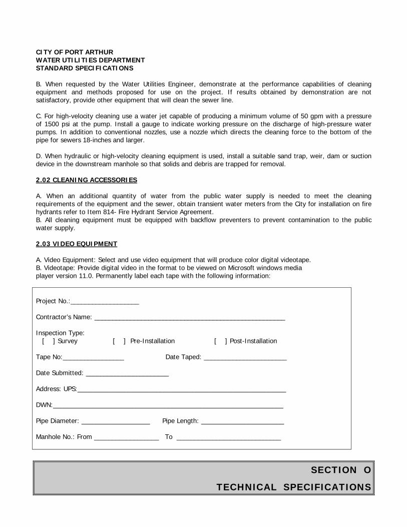
SECTION O
TECHNICAL SPECIFICATIONS
CITY OF PORT ARTHUR WATER UTILITIES DEPARTMENT STANDARD SPECIFICATIONS B. When requested by the Water Utilities Engineer, demonstrate at the performance capabilities of cleaning equipment and methods proposed for use on the project. If results obtained by demonstration are not satisfactory, provide other equipment that will clean the sewer line. C. For high-velocity cleaning use a water jet capable of producing a minimum volume of 50 gpm with a pressure of 1500 psi at the pump. Install a gauge to indicate working pressure on the discharge of high-pressure water pumps. In addition to conventional nozzles, use a nozzle which directs the cleaning force to the bottom of the pipe for sewers 18-inches and larger. D. When hydraulic or high-velocity cleaning equipment is used, install a suitable sand trap, weir, dam or suction device in the downstream manhole so that solids and debris are trapped for removal. 2.02 CLEANING ACCESSORIES A. When an additional quantity of water from the public water supply is needed to meet the cleaning requirements of the equipment and the sewer, obtain transient water meters from the City for installation on fire hydrants refer to Item 814- Fire Hydrant Service Agreement. B. All cleaning equipment must be equipped with backflow preventers to prevent contamination to the public water supply. 2.03 VIDEO EQUIPMENT A. Video Equipment: Select and use video equipment that will produce color digital videotape. B. Videotape: Provide digital video in the format to be viewed on Microsoft windows media player version 11.0. Permanently label each tape with the following information: Project No.:___________________ Contractor’s Name: _____________________________________________________ Inspection Type: [ ] Survey [ ] Pre-Installation [ ] Post-Installation Tape No:_________________ Date Taped: _______________________ Date Submitted: _______________________ Address: UPS:__________________________________________________________ DWN:________________________________________________________________ Pipe Diameter: ___________________ Pipe Length: _______________________ Manhole No.: From __________________ To _____________________________
SECTION O
TECHNICAL SPECIFICATIONS
CITY OF PORT ARTHUR WATER UTILITIES DEPARTMENT STANDARD SPECIFICATIONS C. Pipe Inspection Camera: Produce a videotape using a pan-and-tilt radial-viewing pipe inspection camera that pans ± 275 degrees and rotates 360 degrees. Use a camera with an accurate footage counter which displays on the monitor the exact distance of the camera from the centerline of the starting manhole. Use a camera with camera height adjustment so that the camera lens is always centered at one-half the inside diameter, or higher, in the pipe being taped. Provide a lighting system that allows the features and condition of the pipe to be clearly seen. A reflector in front of the camera may be required to enhance lighting in dark or large diameter pipe.
1. Two labels are required, one on the spine and the other on the face of the video tape. 2. Tapes shall show only one basin. Only line segments from the same basin shall be included on a single video. 3. Up to 5 (maximum) line segments may be included on the same videotape if they are in the same basin.
PART 3 EXECUTION 3.01 EXAMINATION A. Do not begin cleaning until both upstream and downstream manholes have been checked for flow monitors and other mechanical devices. Refer to Item 02555 – Manhole Rehabilitation. 3.02 PREPARATION
A. Cleaning: 1. Take precautions to protect sanitary sewer mains and manholes from damage that might be inflicted by the improper selection of cleaning processes or improper use of equipment. When using hydraulically-propelled devices take precautions to ensure that the water pressure created does not cause damage to or flooding of public or private property. Do not surcharge any sanitary sewer to an elevation that could cause overflow of sewage into area waterways, homes or buildings, or onto the surface. 2. Do not use or obstruct fire hydrants when there is a fire in the area. Remove water meters, fittings and piping from fire hydrants at the end of each working day. 3. Exercise care to prevent contamination of the potable water system. Use an appropriately sized backflow preventer as required by the City of Port Arthur Water Department when drawing water from a public hydrant. 4. Where possible, use the flow of wastewater present in the sanitary sewer main to provide fluid for hydraulic cleaning devices.
B. Document results of videotape inspections using the Television Inspection Report form following this section. 3.03 CLEANING A. Conserve Water. Do not waste water from the public water supply through poor connections, hydrants left open, or any other cause. B. Collapsible Dams: Use collapsible dams for hydraulically-propelled devices which require a head of water to operate. Dam shall be easily collapsible to prevent damage to the sewer, public property and private property.
SECTION O
TECHNICAL SPECIFICATIONS
CITY OF PORT ARTHUR WATER UTILITIES DEPARTMENT STANDARD SPECIFICATIONS C. High Velocity Cleaning: Operate high-velocity cleaning equipment so that the pressurized nozzle moves continuously. Turn off or reduce the flow to the nozzle to prevent damage to the line any time the nozzle becomes stationary. D. Mechanical Cleaning: In addition to normal cleaning equipment, perform mechanical cleaning when required and approved using equipment and accessories as defined in this Section. E. Debris Disposal: Remove sludge, soil, sand, rocks, grease, roots and other solid or semisolid material resulting from the cleaning operation at the downstream manhole of the section being cleaned. Passing debris from any sewer section to any other sewer section is not allowed. Load debris from the manholes into an enclosed container permitted by the City of Port Arthur Health Department for liquid waste hauling. Remove solids and semisolids resulting from cleaning operation from the site and dispose them lawfully at the end of each work day. Do not accumulate debris, liquid waste, or sludge on the site except in totally enclosed containers approved by the Water Utilities Engineer. F. Disposal Sites: Dispose of waste at a lawfully-permitted disposal site using a transporter having a valid City Liquid Waste Transporter Permit. 3.04 TELEVISION INSPECTION A. Immediately after cleaning, videotape the sanitary sewer line to document the condition of the line and to locate existing service connections. Notify the Water Utilities Engineer 24 hours in advance of any television inspection so that the Water Utilities Engineer may observe inspection operations. B. Perform television inspection of sanitary sewers as follows:
1. Perform a survey television inspection on sanitary sewers within the boundary of the project, as directed by the Water Utilities Engineer. After reviewing survey videotapes, the Water Utilities Engineer will determine which sanitary sewers will be rehabilitated or need additional work. 2. Perform pre-installation television inspection immediately after line cleaning and before line rehabilitation work. Pre-installation videotape is not required for sewer lines designated to be removed and replaced. Verify that the line is clean and ready to accept rehabilitation. Prepare Television Inspection Report forms. Maintain copies of tapes and reports for reference by the Water Utilities Engineer for the duration of the project. 3. Videos shall pan beginning and ending manholes to show that all debris has been removed. Camera operator shall slowly pan each service connection, clamped joint and pipe material transition from one material to another. Complete and submit a Television Inspection Report for every sewer segment videotape submitted to the Water Utilities Engineer. 4. Perform post-installation television inspection to confirm completion of rehabilitation work, including removal and replacement. Verify that rehabilitation work conforms to the requirements of the Drawings and Specifications. Provide a color videotape showing the completed work, including the condition of restored service connections. Prepare and submit Television Inspection Report forms providing location of service connections
SECTION O
TECHNICAL SPECIFICATIONS
CITY OF PORT ARTHUR WATER UTILITIES DEPARTMENT STANDARD SPECIFICATIONS
along with location of any discrepancies. Post-installation videotape of completed manholes may be substituted for photographic documentation, as described in Item 02555 - Manhole Rehabilitation. Manhole work, including benches, inverts and pipe penetrations into manhole, should be complete prior to post-installation videotape work.
C. Survey television inspection tapes shall be continuous for pipe segments between manholes. Do not leave gaps in the videotaping of a segment between manholes and do not show a single segment on more than one videotape, unless specifically allowed by the Water Utilities Engineer.
3.05 FLOW CONTROL
A. Perform survey television inspection on one manhole section at a time. Adequately control the flow in the section being taped. Do not exceed the depth of wastewater flow shown below:
Pipe Diameter Depth of Flow (Inches) (Percentage of Pipe Diameter)
6-10 10 12-24 15
Over 24 20
1. If during survey television inspection of a manhole section, the wastewater flow depth exceeds themaximum allowable, reduce the flow depth to an acceptable level by performing the survey television inspection during minimum flow hours, by diversion pumping, or by pulling a camera with swab, high-velocity jet nozzle or other acceptable de-watering device. Videotape made while floating the camera is not acceptable unless approved by the Water Utilities Engineer.
B. Minimize flow in the line while performing pre-installation television inspection. Divert the normal flow as specified in Item 01540 - Diversion Pumping, and clean the line to be inspected.
C. No flow is allowed in the line while performing post-installation videotape inspection.
3.06 PASSAGE OF VIDEO CAMERA
A. Do not pull or propel the video camera through the line at a speed greater than 30 feet per minute.
B. If during survey television inspection of a manhole section, the camera is unable to pass an obstruction even through flow is unobstructed, televise the manhole section from the other direction (reverse setup) in order to obtain a complete video of the line. Whenever such a condition arises, notify the Water Utilities Engineer to determine whether an obstruction removal or point repair is necessary. If a point repair is authorized, repair the pipe at the designated location and then re-televise the manhole section to verify completion of the point repair, unless waived by the Water Utilities Engineer.
1. When the camera is being pulled from the other direction in order to survey on either side of anobstruction, and a second obstruction or repair location is encountered away from the first obstruction, notify the Water Utilities Engineer and request a review of the videotape. The Water Utilities Engineer may direct the Contractor to make one or both point repairs. No downtime shall be allowed.
SECTION O
TECHNICAL SPECIFICATIONS
CITY OF PORT ARTHUR WATER UTILITIES DEPARTMENT STANDARD SPECIFICATIONS
2. If two point repairs are allowed and completed, re-tape the manhole section. Generally, up to 20 feetof the sewer pipe from the finished end of the first point repair to the starting end of the second point repair may be lamped or physically inspected to verify the condition of the sewer without further television inspection. 3. The City makes no guarantee that the sanitary sewer designated for survey television after cleaning isclear for the passage of the camera set-up. Select the appropriate equipment, tools and methods for securing sage passage of the camera.
C. During pre-installation television inspection, camera passage should show the line is ready for rehabilitation. Report to the Water Utilities Engineer any variations between previous reported (existing data) conditions and actual conditions encountered.
D. For post-installation television inspection, exercise the full capabilities of the camera equipment to document the completion of the rehabilitation work and the conformance of the work to the Drawings and Specifications. Provide a full 360-degree view of pipe, joints and service connections.
3.07 TELEVISION INSPECTION REPORT
A. For each television inspection video provide a completed Television Inspection Report, as attached at the end of this Section. The Report is a written narrative log of pipe defects, sags and service connection locations and conditions, indexed to the footage counter. Fill out the Television Inspection Report as follows.
B. HEADER SECTION 1. ADDRESS UPS/DWN: The upstream and downstream address of the line segment;an alpha-numeric field with 6 spaces available for the street number and 21 spaces available for the street name (e.g., UPS: 2150 Sunnyland DWN: 2110 Sunnyland). 2. W.W. File NO.: The Wastewater File number; found on the Contract Documents; analpha-numeric field with 10 spaces available (e.g., 4250-49). 3. WORK ORDER NO.: Since this number will be provided by the City, this field shall be left blank. This isa numeric field with 10 spaces available. 4. TAPING DATE: The date that the videotape was produced (same as the date shownon the display screen), a numeric field with 8 spaces available (e.g., 2/21/95). 5. BASIN: The basin that the line segment is located in; an alpha-numeric field with 10spaces available (e.g., IA010). 6. VIDEO CONTRACTOR: The Video Contractor’s name; an alpha-numeric field with 5spaces available (e.g., KIN (Kinsel), IGS (Insituform or Chief). 7. WEATHER: The existing weather conditions at the time that the videotape was made; an alpha-numeric field with 10 spaces available (e.g., Cloudy). 8. VTR FORMAT: An alpha-numeric field with 4 spaces available (e.g., VHS).9. TAPE NUMBER: Each videotape produced must have tape number for identification,affixed to the cassette label. This number must not be duplicated in the same project. This is an alpha-numeric field with 6 spaces available (e.g., IA0101). 10. VTR INDEX: The numberic location of the line segment on the tape;; an alphanumeric field with 6spaces available for each number (e.g., 1336 to 2185). 11. SUMMARY:
a. Use for additional information about the line segment as follows:
SECTION O
TECHNICAL SPECIFICATIONS
CITY OF PORT ARTHUR WATER UTILITIES DEPARTMENT STANDARD SPECIFICATIONS
1) Type of video tape (e.g., Post, Survey, Pre-Rehabilitation) 2) General Contractor (e.g., Allco, Brystar, Texas Sterline) 3) Rehabilitation Method (e.g., FF, CPP, PG, SL, RR) 4) Rehabilitation System Manufacturer or Trade Name when applicable (e.g., Insituform, Inliner II, PIM System, McConnell Pipe Crushing, U Liner). 5) Pipe Trade Name for PVC, PEP or FRP pipe (e.g., Hobas Drisco 1000,
Lamson Vylon, Quail). b. Note information according to the following examples:
1) Post/Cullum/FF/U Liner/Quail (a typical listing for a Fold and Form line segment). 2) Post/Insituform/CPP/Insituform (a typical listing for a Cured-in- Place line segment). 3) Post/McLat/PB/McConnell Pipe Crushing/Drisco 1000 (a typical listing for a Pipeburst). 4) Post/Kinsel/SL/Hobas (a typical listing for a Sliplined line segment). 5) Post/Texas Sterling/RR/Lamson Vylon (a typical listing for a Remove and Replaced line segment).
12. LOCATION: The physical location of the line segment (for the line segment, not the manholes). If the line segment covers more than one location, then state the location at the majority of line segment. Location codes are listed on the attached Television Inspection Codes list. This is an alpha-numeric field with 2 spaces available (e.g., C). 13. SURFACE COVER: The type of surface that covers the majority of the line segment. Codes for surface cover are listed on the attached Television Inspection Codes list. This is an alpha field with only 1 space available (e.g., F). 14. PIPE SIZE: The inside diameter of the liner or pipe in inches, based on new pipe size, material and SDR; a numeric field with 6 spaces available, including 2 spaces for decimal (e.g., 6.58 IN). 15. PIPE TYPE: The pipe or liner type installed; an alpha field with 3 spaces available (e.g., PEP, CPP, PVC). 16. LENGTH: The length of the line segment, in feet. The length shown on the Television Inspection Report must be the same as the length shown on the videotape. Also, the length on the top portion of the Television Inspection Report shall match that shown on the bottom portion of the Television Inspection Report. This is a numeric field with 4 spaces available, with no decimals (e.g., 305 FT). 17. UPS DEPTH: The depth, measured from the top of the manhole frame of the upstream manhole to the invert of the upstream manhole, in feet and tenths of a foot; a numeric field with 3 spaces available, including one space for a decimal (e.g., 6.9 FT). 18. DWN DEPTH: The depth, measured from the top of the manhole frame of the downstream manhole to the invert of the downstream manhole, in feet and tenths of a foot; a numeric field with 3 spaces available, including one space for a decimal (e.g., 7.4 FT). 19. JOINT LENGTH: The pipe joint length, in inches. Show “0" joint length for CPP, FF and PEP line segments (since they have no joints). This is a alpha field with 2 spaces available (e.g., 40 IN). 20. FLOW DEPTH: The pipe or liner flow depth shall be placed in this field. The unit of measure is inches. This is a numeric field with 3 spaces available, which includes one decimal place (e.g., 2.5 IN).
SECTION O
TECHNICAL SPECIFICATIONS
CITY OF PORT ARTHUR WATER UTILITIES DEPARTMENT STANDARD SPECIFICATIONS
21. MASTER TAPE NO.: Contractor’s master tape number (if one exists). 22. REVERSE SET UP: When a reverse set up is done on a line segment, check “yes”; if not check “no”. 23. SKETCH: If a sketch of the line segment is included check “yes”; if not check “no”. 24. PRIOR HISTORY: If any prior information exists on this line segment check “yes”; if not check “no”. 25. EVALUATION DVD: If the Television Inspection Report is for a line segment evaluation or survey purpose, check “yes”; if not check “no”. 26. PRE-REHAB DVD: If the Television Inspection Report is for pre-installation video inspection to show that the line is ready for rehabilitation, check “yes”; if not check “no”. 27. POST-REHAB DVD: If the Television Inspection Report is for post-rehab video inspection to document completion of the rehabilitation work, check “yes”; if not check “no”. 28. LINE DETERIORATION: Indicate here the existence and extent of pipe deterioration. If no deterioration, check “N”; if deterioration is light, check “L”’ if medium, check “M”; if heavy, check “H”. 29. DIRECTION OF FLOW: Indicate that direction of flow in the line segment. Typically, the larger number is the upstream manhole and the smaller number is the downstream manhole. Do not reverse the manhole designation; if a reverse set up is shown, check the “Reverse Setup” box.
C. CODE INPUT SECTION
1. TELEVISION INSPECTION CODES: Codes to be used in reports are specified and defined on the Television Inspection Codes sheet (attached following this Section and Sample Report form). 2. FOOTAGE READING U/D: Show the up/down designation under the section titled “footage Reading” in the boxes marked “U” and “D”. This will make it clear what direction footage is measured from. 3. CLOCK POSITION: Show the clock position with 12 o’clock straight up, of each defect (e.g., 12:00, 3:00). Also, show the clock position of each service connection and state the condition of the connection. Include the distance the connection is protruding into the pipe, when appropriate, and the type of connection, such as “plumber service”. 4. CRACKS: List cracks in the pipe Television Inspection Codes. Report the size (length and width) of all cracks. 5. JOINTS: List misaligned and broken joints using Television Inspection Codes. 6. LATERALS: List all laterals using Television Inspection Codes. 7. ROOTS: List any root intrusions into the pipe using Television Inspection Codes. 8. DEBRIS: List any debris in the pipe using Television Inspection Codes. 9. INFLOW/INFILTRATION: Report any inflow and infiltration using Television Inspection Codes. 10. ALIGNMENT: Report the existence of any sags in the field using Television Inspection Codes. Report the beginning of sags for one-quarter pipe, one-half pipe and underwater, as well as where the camera pulls out of the sag. 11. STRUCTURAL: Report structural condition of the pipe using Television Inspection Codes. 12. PICTURE NO.: Leave this field blank 13. COMMENTS: Place comments in this field. Comments must be accompanied by a
SECTION O
TECHNICAL SPECIFICATIONS
CITY OF PORT ARTHUR WATER UTILITIES DEPARTMENT STANDARD SPECIFICATIONS
corresponding footage reading. Items to report in this field: collapses in pipe, stabilized material, mineral deposits, changes in pipe material, reverse setup, dropstack, large voids, multiple cracks, when unable to continue video, etc.
14. CLAMP/SPLICE LOCATION: The clamp/splice location shall be shown in the Comments field. Clamp/splice location must be accompanied by a footage reading.
15. START SURVEY AT M.H. XYZ: Note the depth of the line segment in the Comments field. (E.g., “Start Survey at M.H. 021 - Line Depth 10.2 FT”). Measure depth from the top of the manhole frame to the invert of the pipe being televised in feet and tenths of a foot. (This depth may be different from the manhole depth).
16. END OF SURVEY AT M.H. XYZ: Note the depth of the line segment in the Comments field. (E.g., “End Survey at M.H. 022 - Line Depth 10.8 FT). Measure depth from the top of the manhole frame to the invert of the pipe being videotaped in the feet and tenths of a foot. (This depth may be different from the manhole depth).
3.08 FIELD QUALITY CONTROL A. Do not under any circumstances, allow sewage or solids removed in the cleaning process to be released onto streets or into ditches, catch basins, cleanouts, storm drains, or sanitary or storm sewer manholes. B. Acceptance of sewer cleaning work is subject to successful completion of the television inspection. If the televisions inspection shows solids, soil, sand, grease, grit, or other debris remaining in the line, cleaning will be considered unsatisfactory. Repeat cleaning, inspection, and videotaping of the sewer line until cleaning is judged satisfactory by the Water Utilities Engineer. 3.09 MANHOLE REPAIR A. Repair manholes dismantled or damaged during the cleaning process, and replace manhole frames and covers damaged during the cleaning process.
End of Section
SECTION O
TECHNICAL SPECIFICATIONS
CITY OF PORT ARTHUR WATER UTILITIES DEPARTMENT STANDARD SPECIFICATIONS
ITEM 02611
SPECIFICATIONS FOR REINFORCED CONCRETE PIPE PART 1 GENERAL 1.01 SECTION INCLUDES A. Reinforced concrete pipe for sanitary sewers and storm sewers. 1.02 MEASUREMENT AND PAYMENT A. Unit Prices 1. Payment will be made for reinforced concrete pipe based on the linear foot of pipe installed from center of manhole to center of next manhole. 1.03 REFERENCES A. ASTM C 76 - Reinforced Concrete Culvert, Storm Drain, and Sewer Pipe. B. ASTM C 443 - Joints for Circular Concrete Sewer and Culvert Pipe. C. ASTM C 497 - Method of Testing Concrete Pipe, Sections, or Tile. D. ASTM C 506 - Reinforced Concrete Arch Culvert, Storm Drain and Sewer Pipe. E. ASTM C 507 - Reinforced Concrete Elliptical Culvert, Storm Drain and Sewer Pipe. F. ASTM C 655 - Reinforced Concrete D-load Culvert, Storm Drain, and Sewer Pipe. G. ASTM C 822 - Standard Definitions and Terms Relating to Concrete Pipe and Related Products. H. ASTM C 877 - Standard Specification for External Sealing Bands for Non circular Concrete Sewer, Storm Drain, and Culvert Pipe. 1.04 SUBMITTALS A. Submittals shall conform to requirements of Section 01300 - Contractor Submittals. B. Submit complete product data for pipe, fittings and gaskets for approval. Indicate conformance to appropriate reference standards. C. Submit certificates by a testing laboratory, hired and paid by the manufacturer, that concrete pipes meet applicable standards when tested in accordance with ASTM C 497. PART 2 PRODUCTS
SECTION O
TECHNICAL SPECIFICATIONS
CITY OF PORT ARTHUR WATER UTILITIES DEPARTMENT STANDARD SPECIFICATIONS 2.01 REINFORCED CONCRETE PIPE A. Circular reinforced concrete pipe shall conform to requirements of ASTM C 76, for Class III wall thickness. Joints shall be rubber gasketed conforming to ASTM C 443. B. Reinforced concrete arch pipe shall conform to the requirements of ASTM C 506 for Class A-III. Joints shall conform to ASTM C 877. C. Reinforced concrete elliptical pipe, either vertical or horizontal, shall conform to the requirements of ASTM C 507 for Class VE-III for vertical or Class HE-III for horizontal. Joints shall be rubber gaskets conforming to ASTM C 877. D. Reinforced concrete D-load pipe shall conform to the requirements of ASTM C 655. 2.02 GASKETS A. When no contaminant is identified, furnish rubber gasket conforming to ASTM C 443 for circular reinforced concrete pipe and rubber gasket conforming to ASTM C 877 for reinforced concrete elliptical pipe. B. Pipes to be installed in potentially contaminated areas, especially where free product is found near the elevation of the proposed sewer, shall have the following gasket materials for the noted contaminants:
CONTAMINANT GASKET MATERIAL REQUIRED Petroleum (diesel, gasoline) Nitrile Rubber Other Contaminants As recommended by the pipe manufacturer 2.03 LINERS FOR SANITARY SEWER PIPE A. Reinforced concrete pipe for sanitary sewers shall be PVC lined and conform to manufacturer’s recommendations. B. Reinforced concrete pipes to be installed in potentially contaminated areas shall have liners that are recommended by the manufacturer as resistant to contaminants identified in the Phase II Environmental Site Assessment Report. 2.04 SOURCE QUALITY CONTROL A. Representatives of Water Utilities Engineer will inspect manufacturer’s plant and casting operations as deemed necessary. PART 3 EXECUTION 3.01 INSTALLATION A. Conform to requirements of the following Items, as applicable:
A. Item 600 - Specifications for Underground Construction of Water and Sewer Pipes. B. Item 02226 - Pipe Jacking, Boring and Tunneling.

SECTION O
TECHNICAL SPECIFICATIONS
CITY OF PORT ARTHUR WATER UTILITIES DEPARTMENT STANDARD SPECIFICATIONS
B. Install reinforced concrete pipe by sliplining, open cut and jacking in accordance with manufacturer’s recommendations.
End of Section
SECTION O
TECHNICAL SPECIFICATIONS
CITY OF PORT ARTHUR WATER UTILITIES DEPARTMENT STANDARD SPECIFICATIONS
ITEM 02821
SPECIFICATIONS FOR CHAIN LINK AND WOODEN FENCES AND GATES I - CHAIN LINK FENCES AND GATES PART I - GENERAL 1.01 SECTION INCLUDES A. Fence framework, fabric, and accessories. B. Excavation for post bases, concrete foundation for posts and center drop for gates.
1. Manual gates and related hardware. 1.02 MEASUREMENT AND PAYMENT A. No separate payment for fencing and gates shall be made. Fencing cost shall be included in other bid items. 1.03 REFERENCES A. ANSI/ASTM A 123 - Zinc (Hot Dip Galvanized) Coatings on Iron and Steel Products. B. ANSI/ASTM F 567 - Installation of Chain-Link Fence. C. ASTM A 116 - Zinc-Coated (Galvanized) Steel Woven Wire Fence Fabric. D. ASTM A 120 - Pipe, Steel, Black and Hot-Dipped Zinc Coated (Galvanized) Welded and Seamless, for Ordinary Uses. E. ASTM A 153 - Zinc Coating (Hot-Dip) on Iron and Steel Hardware. F. ASTM A 392 - Zinc-Coated Steel Chain Link Fence Fabric. G. ASTM A 428 - Weight of Coating on Aluminum-Coated Iron or Steel Articles. H. ASTM C 94 - Ready-mixed Concrete. I. ASTM F 573 - Residential Zinc-Coated Steel Chain Link Fence Fabric. J. ASTM F 668 - Poly (Vinyl Chloride) (PVC) Coated Steel Chain Link Fence Fabric. K. Chain Link Fence Manufacturers Institute (CLFMI) - Product Manual. L. FS RR-F-191 - Fencing, Wire and Post Metal (and Gates, Chain Link Fence Fabric, and Accessories.
SECTION O
TECHNICAL SPECIFICATIONS
CITY OF PORT ARTHUR WATER UTILITIES DEPARTMENT STANDARD SPECIFICATIONS 1.04 SYSTEM DESCRIPTION A. Fence height shall match height of existing before it was damaged. B. Extension arms for barbed wire shall match existing arms before it was damaged. C. Line post spacing shall not exceed 10 feet, or should match with existing posts before they were removed. 1.05 SUBMITTALS A. Submit under provisions of Section 01300 - Contractor Submittals. B. Product Data: Provide data on fabric, posts, accessories, fittings, and hardware that indicates that items match or exceed the quality of existing items. 1.06 QUALIFICATIONS A. Manufacturer: Company specializing in manufacturing the products specified in this Section with minimum three years experience. PART 2 PRODUCTS 2.01 GALVANIZED FENCING A. Fence fabric shall be No. 9 steel wire, hot galvanized after weaving, to match or exceed existing fence fabric. B. Framework shall be hot-dipped galvanized with a minimum coating of 2 ounces/sf, or one ounce/sf plus 30 micrograms/square-inch chromate conversion coating. C. Line posts shall conform to ASTM A 570 Grade 45 steel or ASTM A 569, cold rolled steel. D. End corner, angle, and pull posts shall conform to ASTM A 570 Grade 45 steel ro ASTM A 569 for steel pipe. E. Top rails shall be 1.65 x 1.25-inch formed C-section; or 1.6-inch round ASTM A 569, 1.35 lbs/ft; or 1-5/8-inch outside diameter steel pipe, 2.27 lbs/ft. Top rails shall pass through openings provided for that purpose in post tops. F. Fabric ties shall be hog rings, galvanized steel wire not less than 9-ga with a zinc coating of not less than 1.2 ounces/sf. G. Bolts and nuts shall be in conformance with ASTM A 307 and shall be galvanized in accordance with AASHTO M 232. H. Install horizontal braces fabricated of 1-5/8-inch, 2.27-lb copper bearing steel pipe at all corner, gate and end posts.
SECTION O
TECHNICAL SPECIFICATIONS
CITY OF PORT ARTHUR WATER UTILITIES DEPARTMENT STANDARD SPECIFICATIONS
I. The replaced damaged gates shall match existing gates. Swing gates shall be hinged to swing 90 degrees from closed to open or hinged to swing 180 degrees from close to open. All gate leaves shall have intermediate members and diagonal stress rods as required for rigid construction and shall be free from sag or twist. All gates shall be fitted with vertical extension arms or shall have frame end number extended to carry barbed wire. Gate posts for gates shall be 4-inch, 9.1 lb pipe. Gate frames shall be made of 2-inch outside diameter, castings. Fabric shall be the same as for the fence. Gates shall have malleable iron ball and socket hinges, catches, stops and padlocks with 3 keys each. Posts for single gates shall be the same as end posts.
PART 3 EXECUTION
A. Install chain link fence in accordance with the directions of the manufacturer and these Specifications.
B. Install fence posts at not more than 10-foot centers and at least 36 inches into the ground in a Class B concrete base. Allow concrete to cure for at least 7 days before erecting remainder of fence. Fasten fabric to line posts with wire ties spaced about 14 inches apart and to top rail spaced about 24 inches apart.
C. Use standard chain link fence stretching equipment to stretch the fabric before tying to the rails and posts. Repeat the stretching and tying operations about every 100 feet.
D. Erect gates so they swing or slide in the appropriate direction. Provide gate stops as required. Secure hardware, adjust, and leave in perfect working order. Adjust hinges and diagonal bracing so that gates will hang level.
E. At small natural or drainage ditches where it is not practical for the fence to conform to the
contour of the ground, span the opening below the fence with wire fastened to stakes of required length. The finished fence shall be plumb, taut, true to line and ground contour. When directed, stake down the chain link fence at several points between posts.
F. Where the new fence joins an existing fence, set a corner post and brace post at the junction and brace as directed. If the connection is made at other than the corner of the new fence the last span of the old fence shall contain a brace.
II- WOODEN FENCES AND GATES:
All wooden fences and gates damaged during construction shall be replaced with the same existing material at no additional cost to the City.
End of Section
SECTION O
TECHNICAL SPECIFICATIONS
CITY OF PORT ARTHUR WATER UTILITIES DEPARTMENT STANDARD SPECIFICATIONS
ITEM 02951
SPECIFICATIONS FOR PAVEMENT REPAIR AND RESURFACING PART 1 - GENERAL 1.01 SECTION INCLUDES A. Repairing and resurfacing streets, highways, driveways, sidewalks, and other pavements that have been cut, broken or otherwise damaged during construction. 1.02 MEASUREMENT AND PAYMENT A. Unit Prices
1. No separate payment will be made for pavement repair and resurfacing under this Section. Include payment in unit price for work in appropriate sections.
PART 2 - PRODUCTS 2.01 MATERIALS A. Subgrade:
1. Provide backfill material as required by City of Port Arthur and Texas Department of Transportation Standards. 2. Provide material for stabilization as required by City of Port Arthur and Texas Department of Transportation Standards.
B. Base: Provide base material as required by City of Port Arthur and Texas Department of Transportation Standards. C. Pavement: Provide paving materials as required by City of Port Arthur and Texas Department of Transportation Standards for Asphaltic Concrete Pavement, Concrete Paving, Concrete Driveways, Curb, Curb and Gutter, and Headers, and Concrete Sidewalks. PART 3 - EXECUTION 3.01 PREPARATION A. Conform to requirements of Item 02221 - Removing Existing Pavements and Structures, for removals. B. Saw cut pavement 18 inches wider than width of trench needed to install utilities unless otherwise indicated on Drawings.
B. Protect edges of existing pavement to remain from damage during removals, utility placement, backfill, and paving operations. For concrete pavement leave and protect minimum of 18 inches of undisturbed subgrade on each side of trench to support replacement slab.
SECTION O
TECHNICAL SPECIFICATIONS
CITY OF PORT ARTHUR WATER UTILITIES DEPARTMENT STANDARD SPECIFICATIONS 3.02 INSTALLATION A. Parking Areas, Service Drives, Driveways and Sidewalks: Replace with material equal to or better than existing or as indicated on Drawings. Conform to applicable requirements of sections referenced in Paragraph 2.01 Materials. B. Street Pavements and Curbs, Curbs and Gutters: Replace subgrade, base and surface course with like materials or as indicated on Drawings. Curbs and curbs and gutters shall match existing. Conform to requirements of sections referenced in Paragraph 2.01, Materials. C. For concrete pavement, install size and length of reinforcing steel and pavement thickness or as indicated on Drawings. D. Where existing pavement consists of concrete pavement with asphaltic surfacing, resurface with minimum 2-inch depth asphaltic pavement. E. Repair State highway crossing in accordance with TxDOT permit and within 1 week after utility work is installed. 3.03 WASTE MATERIAL DISPOSAL A. Dispose of waste material to sites approved by the Water Utilities Engineer. 3.04 PROTECTION A. Maintain pavement in good condition until completion of the Work. B. Replace damaged pavement.
End of Section
SECTION O
TECHNICAL SPECIFICATIONS
CITY OF PORT ARTHUR WATER UTILITIES DEPARTMENT STANDARD SPECIFICATIONS
ITEM 03301
SPECIFICATIONS FOR PRECAST CONCRETE MANHOLES
PART 1 - GENERAL
1.01 SCOPE
The work included in this section of the Specifications shall consist of providing precast and/or castin-place manholes, rims, and covers where indicated on the Plans.
1.02 QUALITY ASSURANCE
A. ACCEPTABLE MANUFACTURERS 1. Hanson
B. Comply with the latest edition of the following referenced standards: 1. ASTM C270, Type M Mortar.2. ASTM C478, Reinforced Concrete Manhole Sections.3. ASTM C443, Joints for Circular Concrete Sewer and Culvert Pipe Using Rubber Gaskets.
1.03 SUBMITTALS
Submit the following information in accordance with the requirements of Section 01300: Contractor Submittals.
A. Record Data Submit record data of detailed drawings showing dimensions, materials thickness of materials, manufacturer’s installation instructions, accessories, fittings, hardware, anchorages, schedule of components, and other pertinent data.
B. Certificate of Adequacy of Design.
PART 2 - PRODUCTS
2.01 MORTAR
Comply with Mortar for Unit Masonry, ASTM C 270, for Type M mortar. The cement material used in the preparation of the mortar shall be Portland cement, Type I, normal, or Type II, moderate sulfate resistant.
2.02 CAST IRON FRAMES AND COVERS
Frames and slotted covers shall be furnished and installed in accordance with the details on the Plans and shall be East Jordan Iron Works V-1418-2 with City of Port Arthur logo or approved equivalent, unless otherwise shown on the drawings.
2.03 PRECAST REINFORCED CONCRETE MANHOLE SECTIONS
SECTION O
TECHNICAL SPECIFICATIONS
CITY OF PORT ARTHUR WATER UTILITIES DEPARTMENT STANDARD SPECIFICATIONS
A. Conform to Precast Reinforced Concrete Manhole Sections, ASTM C478. Cement shall be Type I or Type II. Aggregate for concrete work per C33, coarse aggregate shall be crushed limestone, with a resulting minimum concrete alkalinity of 70 percent calcium carbonate equivalency in the final concrete product. Admixtures, if used, shall conform to ASTM C494, no calcium chloride shall be used.
B. Provide and install concrete grade rings to bring the cast iron frames to grade. Grade rings shall be 2 inches by 8 inches with an inside diameter of 24 inches. Grade rings shall be grouted in place with 2-#3 bars in accordance with the City of Port Arthur Standard Specifications.
C. The concrete manhole riser sections, with the exception of the grade rings, shall be formed with male and female ends and installed with bell ends turned down.
D. The joints and gaskets in the riser sections shall comply with the requirements of ASTM C443, Joints for Circular Concrete Sewer and Culvert Pipe, using rubber gaskets, as modified to incorporate an O-ring type gasket.
E. Manhole riser sections shall be of sufficient diameter to allow personnel to work inside them and to allow proper joining of all pipes to the manhole wall while maintaining the structural integrity of the riser sections. All manholes shall have a minimum diameter of four feet unless a larger diameter is noted in the Plans or required by the piping configuration shown. Provide larger diameter manholes where necessary to maintain at least a 12-inch clearance between any holes cut in the riser section.
F. Provide eccentric cone immediately below the grade rings sections for each manhole. For manholes larger than 48-inches, precast concrete covers with integrally-cast frames and covers may be used when approved by ENGINEER.
G. Where PVC piping is connected to manholes, provide and install PVC sleeves with rubber gaskets and an abrasive silica out coating. Sleeve shall be as manufactured by GPK products, Inc., of Fargo, North Dakota, or approved equivalent. Sleeve shall be firmly grouted into manhole opening in accordance with manufacturer’s instructions.
2.04 MANHOLE INSERT
A. Manhole inserts shall be furnished and installed at each manhole and shall be a stainless steel Preco Sewer Guard ME C-4 watertight manhole insert or equivalent.
B. The manhole insert shall be stainless steel and each of its components, the valve bodies, the valve plugs, the valve springs, and the gasket shall be manufactured of plastic, stainless steel, or other corrosion proof material.
C. Each insert shall contain a gasket manufactured of Grade RE-41 black closed cell neoprene and meet the requirements of ASTM D-1056-73T. The gasket shall have a pressure sensitive adhesive on one side and be placed on the underside of the insert rim by the manufacturer.
D. Each insert shall have a gas relief valve and a vacuum relief valve each designed to release at a pressure differential equivalent to approximately ½ psi and approximately 2.25 psi, respectively. The valve body shall be manufactured of specially formulated plastic polymers and the valve plug shall be neoprene confined within a stainless steel spring.
SECTION O
TECHNICAL SPECIFICATIONS
CITY OF PORT ARTHUR WATER UTILITIES DEPARTMENT STANDARD SPECIFICATIONS E. The manhole insert shall be manufactured and finished to fit upon the manhole frame rim upon which the manhole cover rests. F. The manhole frame shall be cleaned of all dirt/debris before placing the insert upon the rim. G. The insert lip with gasket shall be placed in contact with 360 degrees of manhole frame rim to retard water seepage between the insert and the manhole frame. H. After the manhole insert has been installed on the manhole frame rim, note that the insert does not come in contact with the cover upon its removal or replacement (flipping). I. After installation of the watertight manhole insert, the seal shall be water tested and shall not allow more than 1-gallon of inflow during a period of 24 hours. 3.00 EXECUTION 3.01 INSTALLATION A. Manhole Base:
1. Inverts: Inverts shall be built of concrete or half-sections of pipe (unless otherwise shown on the Plans) and shall be true and troweled to a smooth, hard finish. The invert depth shall be equal to one-half of the diameter of the largest pipe connected to the manhole, and shall be sloped at 1:1 between the inlet and outlet pipe flowlines. The top of the poured manhole invert outside of the flow channel shall be steeply-sloped to prevent solids deposition. 2. Hanson pre-cast manhole base shall be utilized and placed in accordance with the details on the Plans and the applicable provisions of these Specifications. 3. All concrete used in the construction of manholes including precast and cast-in-place bases, sections, lids, etc., shall have a minimum concrete alkalinity of 70 percent calcium carbonate equivalency in the final concrete product. Alkalinity shall be tested in accordance with methodology set forth in Concrete Pipe Handbook, published by the American Concrete Pipe Association, or equivalent industrial standards, with test results provided to the ENGINEER for record data.
B. Provide an adequate connection where the pipe connects to the manhole such that infiltration and exfiltration is prevented from occurring at the connection. When required, manhole adaptors shall be used. If the manhole base is concrete and cast-in-place around the pipe, then an adapter gasket shall be installed such that the gasket will serve as a watertight seal (water stop) between the pipe and concrete. If the manhole base has a pipe fabricated integrally with the manhole, then a manufacturer’s recommended adaptor shall be used to connect the pipe to the manhole pipe. If a “boot type” flexible connection is used, then a minimum of two stainless steel straps shall be used to secure the flexible connector to the pipe. C. Frames and covers shall be furnished and installed as required and indicated on the Plans. D. Use no more than 4 grade rings per manhole. Ring hold down bolts shall pass through the rings into the top of the cone. E. Where piping is connected to a manhole, CONTRACTOR shall provide a resilient connector in accordance with ASTM C-923 and the specifications and drawings. Where resilient connectors cannot be made at manhole

SECTION O
TECHNICAL SPECIFICATIONS
CITY OF PORT ARTHUR WATER UTILITIES DEPARTMENT STANDARD SPECIFICATIONS connections, CONTRACTOR shall ensure that the pipe on each side of the manhole does not extend further than five (5) feet from the outside of the manhole wall or base, and the concrete cradle extends to within one (1) foot of the end of the pipe. F. Where main sewer (lowest line) passes straight through manhole or degree of deflection of main sewer is less than 5 degrees, and no other line or stub-out is shown entering manhole below centerline of main sewer, lay sewer continuous through manhole. After manhole wall sections have been completed above top of sewer, break out and remove top half of barrel of sewer pipe that was previously laid through manhole. Use barrel of sewer pipe that was previously laid through manhole. Use concrete with 1-inch mortar topping and shape floor. Where main sewer (lowest line) alignment deflects greater than 5 degrees at manhole or where another sewer or stub-out enters at or below centerline of main sewer, terminate main sewer pipe laying in such a manner that ends of pipe are 2 inches inside of manhole wall.
End of Section
SECTION O
TECHNICAL SPECIFICATIONS
CITY OF PORT ARTHUR WATER UTILITIES DEPARTMENT STANDARD SPECIFICATIONS
ITEM 4015
PLUG ABANDONED SEWERS 4015.01 - INTENT It is the intent of this specification to provide for the plugging of abandoned sewer lines, or the repair of existing plugs, at points indicated on the plans or designated by the Owner’s Representative. 4015.02 - GENERAL Each designated abandoned sewer line shall be plugged at its entrance into a manhole or junction box, or at such other point as may be designated. The Contractor may use a prefabricated plug of approximately the diameter of the pipe; Class B Concrete as specified by the Texas State Department of Highways and Public Transportation; or any other method acceptable to the Owner’s Representative. The Contractor shall seal around the plug with a approved adhesive so as to make the entire plug permanently watertight. Where designated, the Contractor shall remove and replace existing plugs, or shall repair or seal them to make them watertight. 4015.03 - MATERIALS All material used for plugs or adhesives shall be impermeable and shall be resistant to chemicals, temperature cycles, and wet-dry cycles. These materials shall not be brittle or biodegradable. 4015.04 - PAYMENT No separate payment will be made for plugging abandoned sewers in the course of new sewer construction. This work shall be included in the applicable sewer and manhole costs.
End of Section
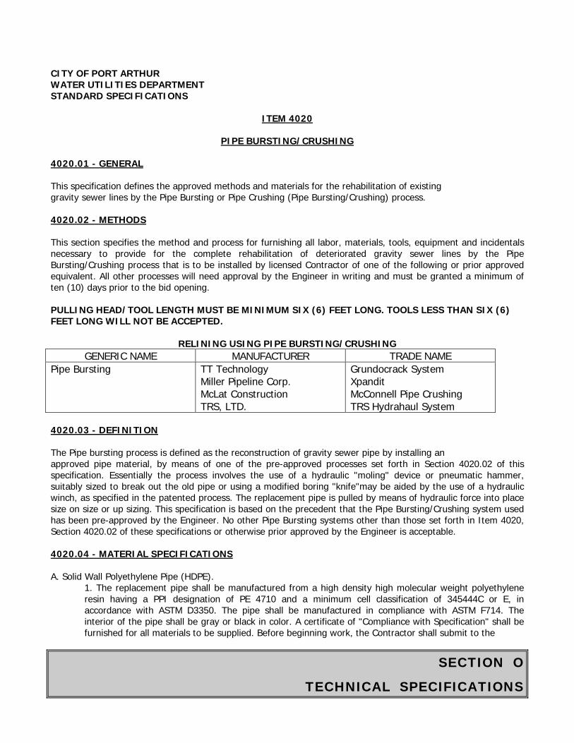
SECTION O
TECHNICAL SPECIFICATIONS
CITY OF PORT ARTHUR WATER UTILITIES DEPARTMENT STANDARD SPECIFICATIONS
ITEM 4020
PIPE BURSTING/CRUSHING 4020.01 - GENERAL This specification defines the approved methods and materials for the rehabilitation of existing gravity sewer lines by the Pipe Bursting or Pipe Crushing (Pipe Bursting/Crushing) process. 4020.02 - METHODS This section specifies the method and process for furnishing all labor, materials, tools, equipment and incidentals necessary to provide for the complete rehabilitation of deteriorated gravity sewer lines by the Pipe Bursting/Crushing process that is to be installed by licensed Contractor of one of the following or prior approved equivalent. All other processes will need approval by the Engineer in writing and must be granted a minimum of ten (10) days prior to the bid opening. PULLING HEAD/TOOL LENGTH MUST BE MINIMUM SIX (6) FEET LONG. TOOLS LESS THAN SIX (6) FEET LONG WILL NOT BE ACCEPTED.
RELINING USING PIPE BURSTING/CRUSHING GENERIC NAME MANUFACTURER TRADE NAME
Pipe Bursting TT Technology Miller Pipeline Corp. McLat Construction TRS, LTD.
Grundocrack System Xpandit McConnell Pipe Crushing TRS Hydrahaul System
4020.03 - DEFINITION The Pipe bursting process is defined as the reconstruction of gravity sewer pipe by installing an approved pipe material, by means of one of the pre-approved processes set forth in Section 4020.02 of this specification. Essentially the process involves the use of a hydraulic "moling" device or pneumatic hammer, suitably sized to break out the old pipe or using a modified boring "knife"may be aided by the use of a hydraulic winch, as specified in the patented process. The replacement pipe is pulled by means of hydraulic force into place size on size or up sizing. This specification is based on the precedent that the Pipe Bursting/Crushing system used has been pre-approved by the Engineer. No other Pipe Bursting systems other than those set forth in Item 4020, Section 4020.02 of these specifications or otherwise prior approved by the Engineer is acceptable. 4020.04 - MATERIAL SPECIFICATIONS A. Solid Wall Polyethylene Pipe (HDPE).
1. The replacement pipe shall be manufactured from a high density high molecular weight polyethylene resin having a PPI designation of PE 4710 and a minimum cell classification of 345444C or E, in accordance with ASTM D3350. The pipe shall be manufactured in compliance with ASTM F714. The interior of the pipe shall be gray or black in color. A certificate of "Compliance with Specification" shall be furnished for all materials to be supplied. Before beginning work, the Contractor shall submit to the
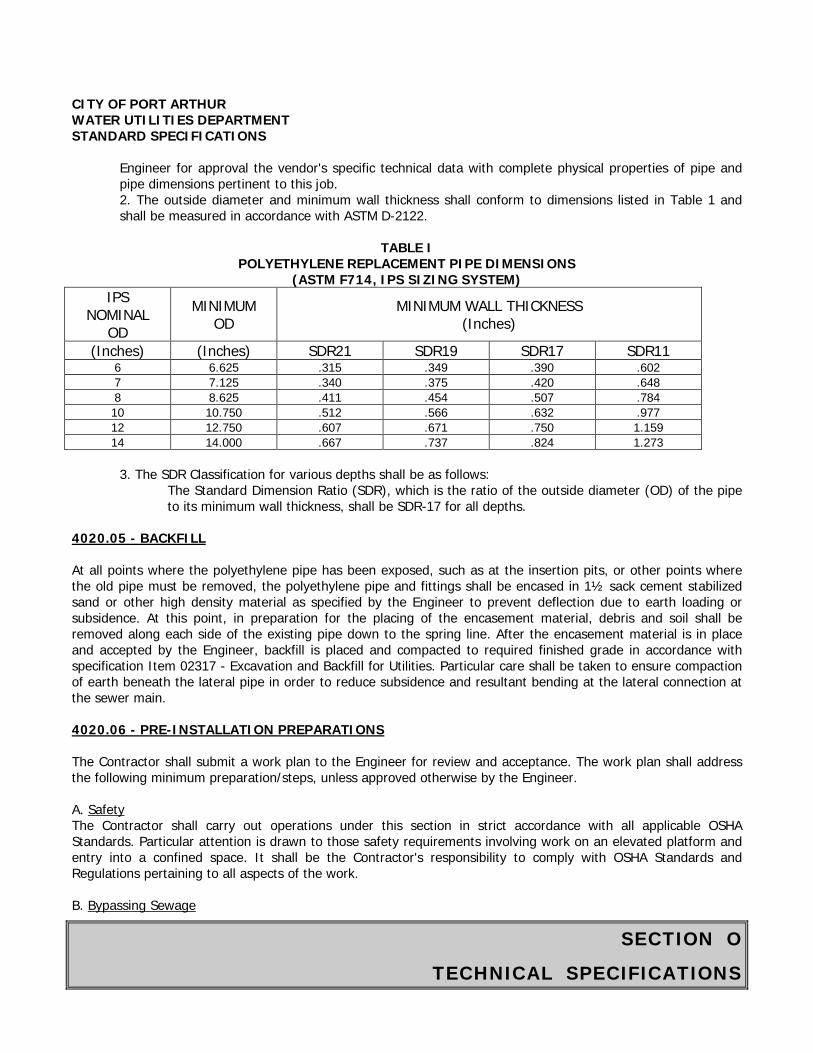
SECTION O
TECHNICAL SPECIFICATIONS
CITY OF PORT ARTHUR WATER UTILITIES DEPARTMENT STANDARD SPECIFICATIONS
Engineer for approval the vendor's specific technical data with complete physical properties of pipe and pipe dimensions pertinent to this job. 2. The outside diameter and minimum wall thickness shall conform to dimensions listed in Table 1 and shall be measured in accordance with ASTM D-2122.
TABLE I
POLYETHYLENE REPLACEMENT PIPE DIMENSIONS (ASTM F714, IPS SIZING SYSTEM)
IPS NOMINAL
OD MINIMUM
OD MINIMUM WALL THICKNESS
(Inches)
(Inches) (Inches) SDR21 SDR19 SDR17 SDR11 6 6.625 .315 .349 .390 .602 7 7.125 .340 .375 .420 .648 8 8.625 .411 .454 .507 .784 10 10.750 .512 .566 .632 .977 12 12.750 .607 .671 .750 1.159 14 14.000 .667 .737 .824 1.273
3. The SDR Classification for various depths shall be as follows:
The Standard Dimension Ratio (SDR), which is the ratio of the outside diameter (OD) of the pipe to its minimum wall thickness, shall be SDR-17 for all depths.
4020.05 - BACKFILL At all points where the polyethylene pipe has been exposed, such as at the insertion pits, or other points where the old pipe must be removed, the polyethylene pipe and fittings shall be encased in 1½ sack cement stabilized sand or other high density material as specified by the Engineer to prevent deflection due to earth loading or subsidence. At this point, in preparation for the placing of the encasement material, debris and soil shall be removed along each side of the existing pipe down to the spring line. After the encasement material is in place and accepted by the Engineer, backfill is placed and compacted to required finished grade in accordance with specification Item 02317 - Excavation and Backfill for Utilities. Particular care shall be taken to ensure compaction of earth beneath the lateral pipe in order to reduce subsidence and resultant bending at the lateral connection at the sewer main. 4020.06 - PRE-INSTALLATION PREPARATIONS The Contractor shall submit a work plan to the Engineer for review and acceptance. The work plan shall address the following minimum preparation/steps, unless approved otherwise by the Engineer. A. Safety The Contractor shall carry out operations under this section in strict accordance with all applicable OSHA Standards. Particular attention is drawn to those safety requirements involving work on an elevated platform and entry into a confined space. It shall be the Contractor's responsibility to comply with OSHA Standards and Regulations pertaining to all aspects of the work. B. Bypassing Sewage
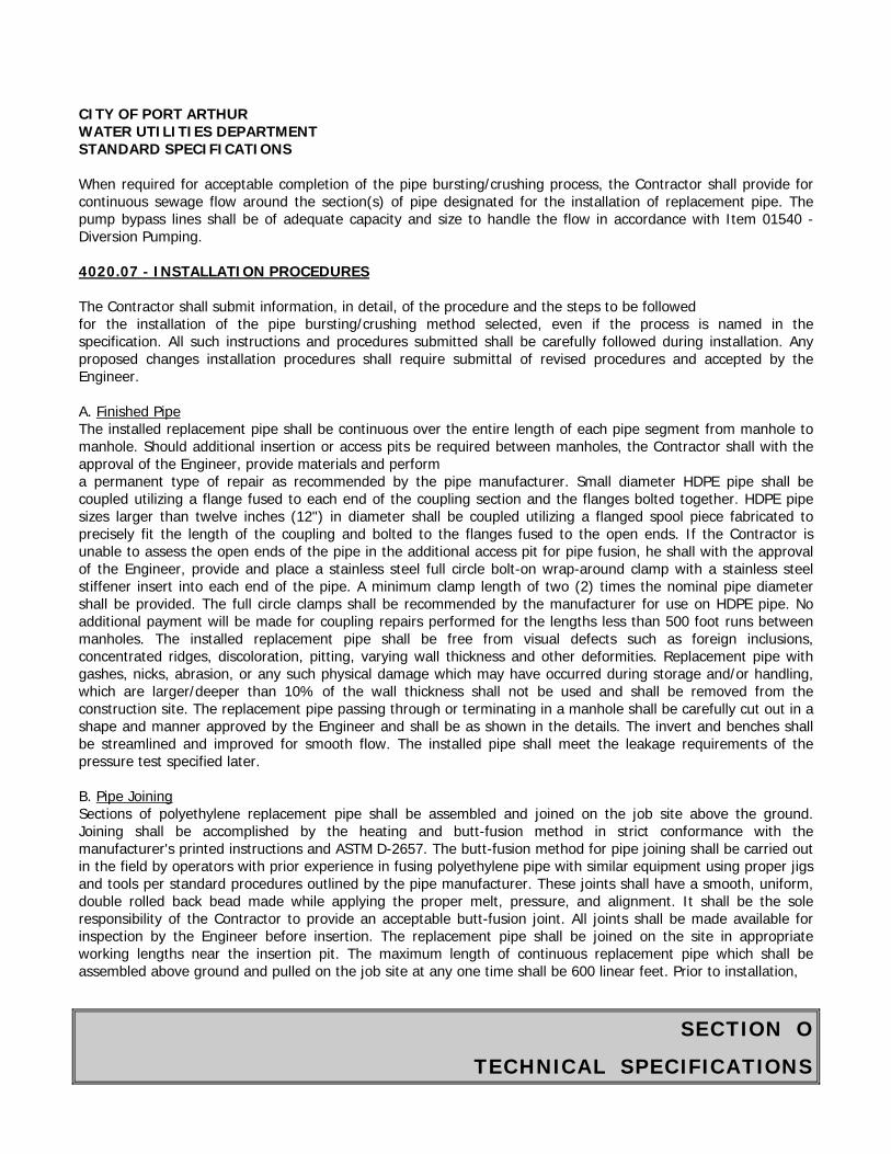
SECTION O
TECHNICAL SPECIFICATIONS
CITY OF PORT ARTHUR WATER UTILITIES DEPARTMENT STANDARD SPECIFICATIONS
When required for acceptable completion of the pipe bursting/crushing process, the Contractor shall provide for continuous sewage flow around the section(s) of pipe designated for the installation of replacement pipe. The pump bypass lines shall be of adequate capacity and size to handle the flow in accordance with Item 01540 - Diversion Pumping.
4020.07 - INSTALLATION PROCEDURES
The Contractor shall submit information, in detail, of the procedure and the steps to be followed for the installation of the pipe bursting/crushing method selected, even if the process is named in the specification. All such instructions and procedures submitted shall be carefully followed during installation. Any proposed changes installation procedures shall require submittal of revised procedures and accepted by the Engineer.
A. Finished Pipe The installed replacement pipe shall be continuous over the entire length of each pipe segment from manhole to manhole. Should additional insertion or access pits be required between manholes, the Contractor shall with the approval of the Engineer, provide materials and perform a permanent type of repair as recommended by the pipe manufacturer. Small diameter HDPE pipe shall be coupled utilizing a flange fused to each end of the coupling section and the flanges bolted together. HDPE pipe sizes larger than twelve inches (12") in diameter shall be coupled utilizing a flanged spool piece fabricated to precisely fit the length of the coupling and bolted to the flanges fused to the open ends. If the Contractor is unable to assess the open ends of the pipe in the additional access pit for pipe fusion, he shall with the approval of the Engineer, provide and place a stainless steel full circle bolt-on wrap-around clamp with a stainless steel stiffener insert into each end of the pipe. A minimum clamp length of two (2) times the nominal pipe diameter shall be provided. The full circle clamps shall be recommended by the manufacturer for use on HDPE pipe. No additional payment will be made for coupling repairs performed for the lengths less than 500 foot runs between manholes. The installed replacement pipe shall be free from visual defects such as foreign inclusions, concentrated ridges, discoloration, pitting, varying wall thickness and other deformities. Replacement pipe with gashes, nicks, abrasion, or any such physical damage which may have occurred during storage and/or handling, which are larger/deeper than 10% of the wall thickness shall not be used and shall be removed from the construction site. The replacement pipe passing through or terminating in a manhole shall be carefully cut out in a shape and manner approved by the Engineer and shall be as shown in the details. The invert and benches shall be streamlined and improved for smooth flow. The installed pipe shall meet the leakage requirements of the pressure test specified later.
B. Pipe Joining Sections of polyethylene replacement pipe shall be assembled and joined on the job site above the ground. Joining shall be accomplished by the heating and butt-fusion method in strict conformance with the manufacturer's printed instructions and ASTM D-2657. The butt-fusion method for pipe joining shall be carried out in the field by operators with prior experience in fusing polyethylene pipe with similar equipment using proper jigs and tools per standard procedures outlined by the pipe manufacturer. These joints shall have a smooth, uniform, double rolled back bead made while applying the proper melt, pressure, and alignment. It shall be the sole responsibility of the Contractor to provide an acceptable butt-fusion joint. All joints shall be made available for inspection by the Engineer before insertion. The replacement pipe shall be joined on the site in appropriate working lengths near the insertion pit. The maximum length of continuous replacement pipe which shall be assembled above ground and pulled on the job site at any one time shall be 600 linear feet. Prior to installation,
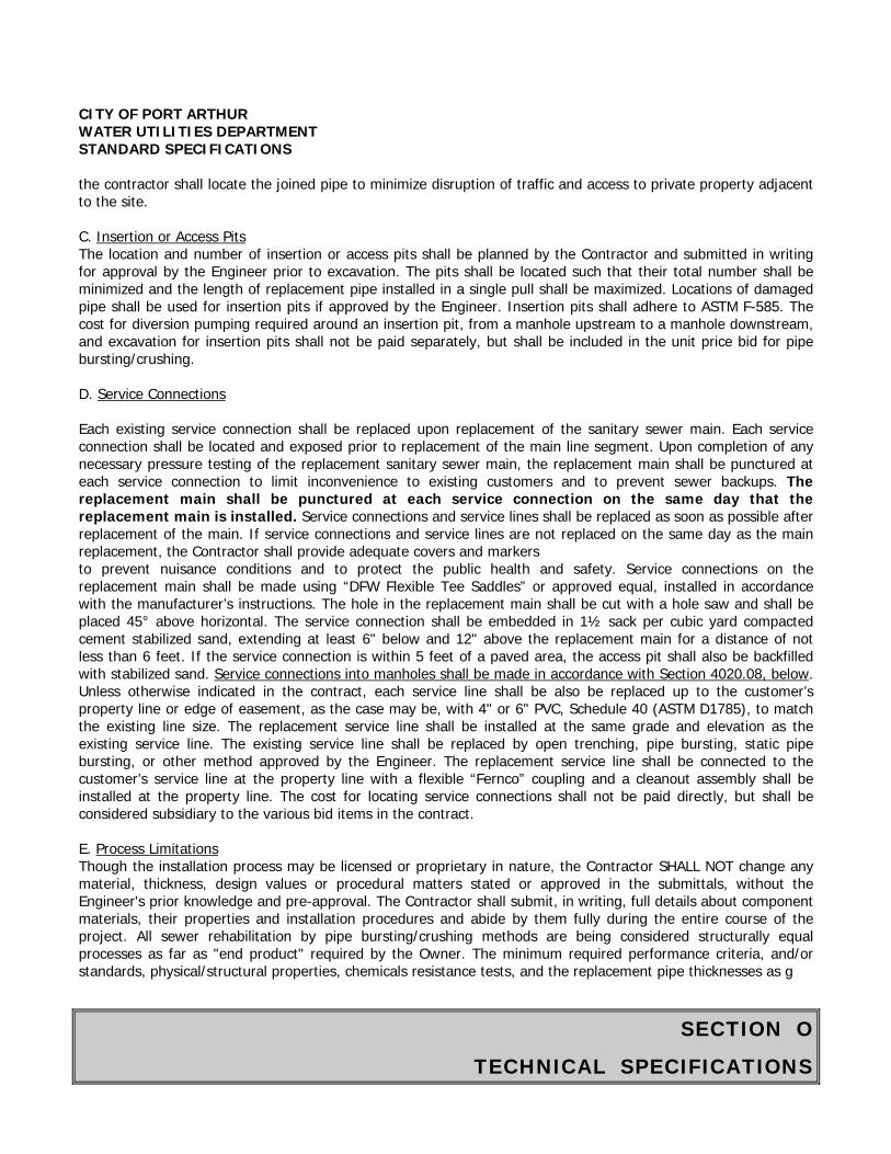
SECTION O
TECHNICAL SPECIFICATIONS
CITY OF PORT ARTHUR WATER UTILITIES DEPARTMENT STANDARD SPECIFICATIONS
the contractor shall locate the joined pipe to minimize disruption of traffic and access to private property adjacent to the site.
C. Insertion or Access Pits The location and number of insertion or access pits shall be planned by the Contractor and submitted in writing for approval by the Engineer prior to excavation. The pits shall be located such that their total number shall be minimized and the length of replacement pipe installed in a single pull shall be maximized. Locations of damaged pipe shall be used for insertion pits if approved by the Engineer. Insertion pits shall adhere to ASTM F-585. The cost for diversion pumping required around an insertion pit, from a manhole upstream to a manhole downstream, and excavation for insertion pits shall not be paid separately, but shall be included in the unit price bid for pipe bursting/crushing.
D. Service Connections
Each existing service connection shall be replaced upon replacement of the sanitary sewer main. Each service connection shall be located and exposed prior to replacement of the main line segment. Upon completion of any necessary pressure testing of the replacement sanitary sewer main, the replacement main shall be punctured at each service connection to limit inconvenience to existing customers and to prevent sewer backups. The replacement main shall be punctured at each service connection on the same day that the replacement main is installed. Service connections and service lines shall be replaced as soon as possible after replacement of the main. If service connections and service lines are not replaced on the same day as the main replacement, the Contractor shall provide adequate covers and markers to prevent nuisance conditions and to protect the public health and safety. Service connections on the replacement main shall be made using “DFW Flexible Tee Saddles” or approved equal, installed in accordance with the manufacturer’s instructions. The hole in the replacement main shall be cut with a hole saw and shall be placed 45° above horizontal. The service connection shall be embedded in 1½ sack per cubic yard compacted cement stabilized sand, extending at least 6" below and 12" above the replacement main for a distance of not less than 6 feet. If the service connection is within 5 feet of a paved area, the access pit shall also be backfilled with stabilized sand. Service connections into manholes shall be made in accordance with Section 4020.08, below. Unless otherwise indicated in the contract, each service line shall be also be replaced up to the customer’s property line or edge of easement, as the case may be, with 4" or 6" PVC, Schedule 40 (ASTM D1785), to match the existing line size. The replacement service line shall be installed at the same grade and elevation as the existing service line. The existing service line shall be replaced by open trenching, pipe bursting, static pipe bursting, or other method approved by the Engineer. The replacement service line shall be connected to the customer’s service line at the property line with a flexible “Fernco” coupling and a cleanout assembly shall be installed at the property line. The cost for locating service connections shall not be paid directly, but shall be considered subsidiary to the various bid items in the contract.
E. Process Limitations Though the installation process may be licensed or proprietary in nature, the Contractor SHALL NOT change any material, thickness, design values or procedural matters stated or approved in the submittals, without the Engineer's prior knowledge and pre-approval. The Contractor shall submit, in writing, full details about component materials, their properties and installation procedures and abide by them fully during the entire course of the project. All sewer rehabilitation by pipe bursting/crushing methods are being considered structurally equal processes as far as "end product" required by the Owner. The minimum required performance criteria, and/or standards, physical/structural properties, chemicals resistance tests, and the replacement pipe thicknesses as g

SECTION O
TECHNICAL SPECIFICATIONS
CITY OF PORT ARTHUR WATER UTILITIES DEPARTMENT STANDARD SPECIFICATIONS iven in this specification shall be strictly complied with. It shall be the responsibility of the Contractor to comply with the specifications in full without any request for any change after the award of the contract. The City reserves the right to accept, reject, or modify any later requests for change at no additional cost to the City or even to the extent of asking credit for the City. 4020.08 - SEALING AND BENCHES IN MANHOLE The replacement pipe shall be installed with a tight fitting seal at existing or new manholes to prevent inflow at the manhole as per details in the plans. For entry into fiberglass manholes above the invert, a molded entry saddle with flexible boot connector and stainless steel clamp shall be used. The replacement pipe shall extend at least 6 inches into the manhole. For entry into concrete or brick manholes above the invert, the contractor shall provide a half-inch diameter activated oakum band soaked in non-shrink grout or equal, applied circumferentially on the replacement pipe passing through the manhole wall, and encased with a non-shrink grout. The replacement pipe shall extend at least 6 inches into the manhole. For all entries into manholes above the invert, the hole cut in the manhole riser shall be circular and no more than 1" larger than the outside diameter of the pipe. For entry into new or existing manholes at or near the flow line, the pipe shall extend at least 6 inches into the manhole. When the pipe continues through the manhole, top half of the pipe crossing through the manhole shall be neatly cut off and not broken or sheared off, at least six inches away from the manhole walls. Twelve inches of 4½ sack concrete shall be placed around the pipe on the outside of the manhole. The channel in the manhole shall be a smooth continuation of the pipe(s) and shall be merged with other lines or channels, if any. Channel cross-section shall be U-shaped with a minimum height of half pipe diameter to three-fourths of the pipe diameter for fifteen inches and larger. The side of the channels shall be built-up with grout to form an invert, as specified, to provide benches at 1H : 1V pitch towards the channel. The invert shall extend above all pipes entering the manhole near the flow line. When pipe bursting through an existing manhole, the contractor shall remove a sufficient portion of the manhole base and invert to avoid a “hump” in the newly installed line. Payment for above work shall be incidental to sewer rehabilitation by the pipe bursting/crushing method. The replacement pipe in the manhole shall be sealed as specified in the plans and details before proceeding on to the next manhole section and all manholes shall be individually inspected for replacement pipe cut-offs, benches and sealing works. 4020.09 - TESTING OF THE REPLACEMENT PIPE A low pressure air test will be required for each pipe section, as specified in Item 02533 - Acceptance Testing for Sanitary Sewers. The Owner reserves the right to require deflection testing and television inspection, in accordance with Item 02533 - Acceptance Testing for Sanitary Sewers. All costs for testing the replacement pipe will be incidental to the installation. 4020.10 - PAYMENT The unit price bid for rehabilitating the sewer main in the manner described shall be full compensation for all materials, labor, equipment, and incidentals required to install the replacement pipe within the sewer main, reworking the manholes inverts and benches, etc. Payment shall be for actual linear footage for replacement pipe installed in the field and shall be
SECTION O
TECHNICAL SPECIFICATIONS
CITY OF PORT ARTHUR WATER UTILITIES DEPARTMENT STANDARD SPECIFICATIONS measured between the center lines of the manholes. All costs for testing the replacement pipe shall be considered incidental to the cost of rehabilitating the sewer. The Contractor shall be responsible for making adequate and suitable arrangements for any bypass pumping that may become necessary to prevent any backflow into houses or buildings, or onto the streets between the time the replacement pipes are installed and the service reconnections have been made, tested, and approved by the City. Bypass pumping shall be considered incidental to the cost of rehabilitating the sewer. All other payments shall be made as per bid items. No payment shall be made for work considered incidental or complimentary to a pay item already in bid item. The Contractor shall clarify, for his own benefit, all work required for any item, incidental or otherwise, prior to bidding.
End of Section

SECTION P
QUALIFICATION STATEMENT
QUALIFICATION STATEMENT SUBMITTED TO: CITY OF PORT ARTHUR BY [Corporation, Co-Partnership, An Individual] PRINCIPAL OFFICE The signatory of this questionnaire guarantees the truth and accuracy of all statements and of all answers to interrogatories hereinafter made. 1. How many years has your organization been in business as a general contractor under your
present business name: 2. How many years' experience in this type of construction work has your organization had? (a) As a general contractor (b) As a sub-contractor 3. What projects has your organization completed? Contract Class of When Name and Address Amount Work Completed of Owner
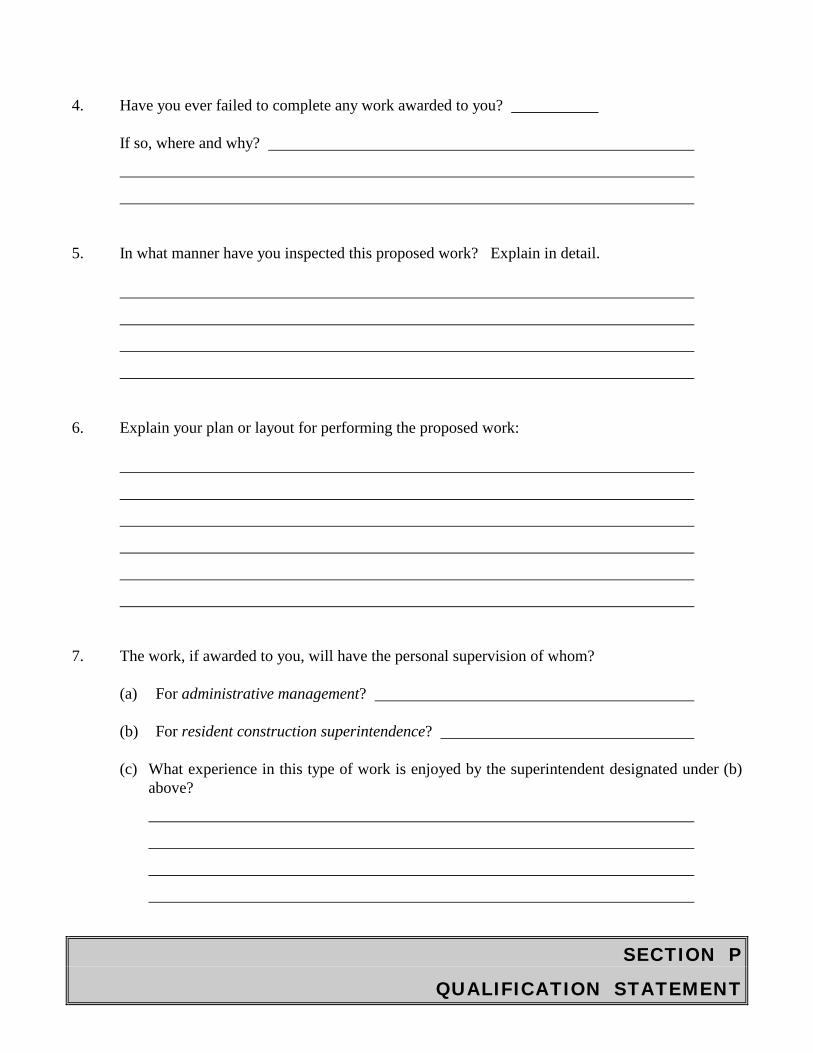
SECTION P
QUALIFICATION STATEMENT
4. Have you ever failed to complete any work awarded to you? If so, where and why?
5. In what manner have you inspected this proposed work? Explain in detail.
6. Explain your plan or layout for performing the proposed work:
7. The work, if awarded to you, will have the personal supervision of whom? (a) For administrative management? (b) For resident construction superintendence? (c) What experience in this type of work is enjoyed by the superintendent designated under (b)
above?
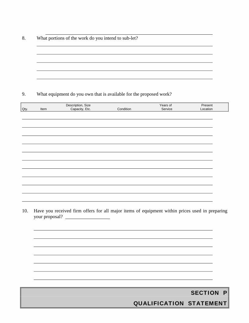
SECTION P
QUALIFICATION STATEMENT
8. What portions of the work do you intend to sub-let?
9. What equipment do you own that is available for the proposed work? Description, Size Years of Present Qty. Item Capacity, Etc. Condition Service Location
10. Have you received firm offers for all major items of equipment within prices used in preparing
your proposal?
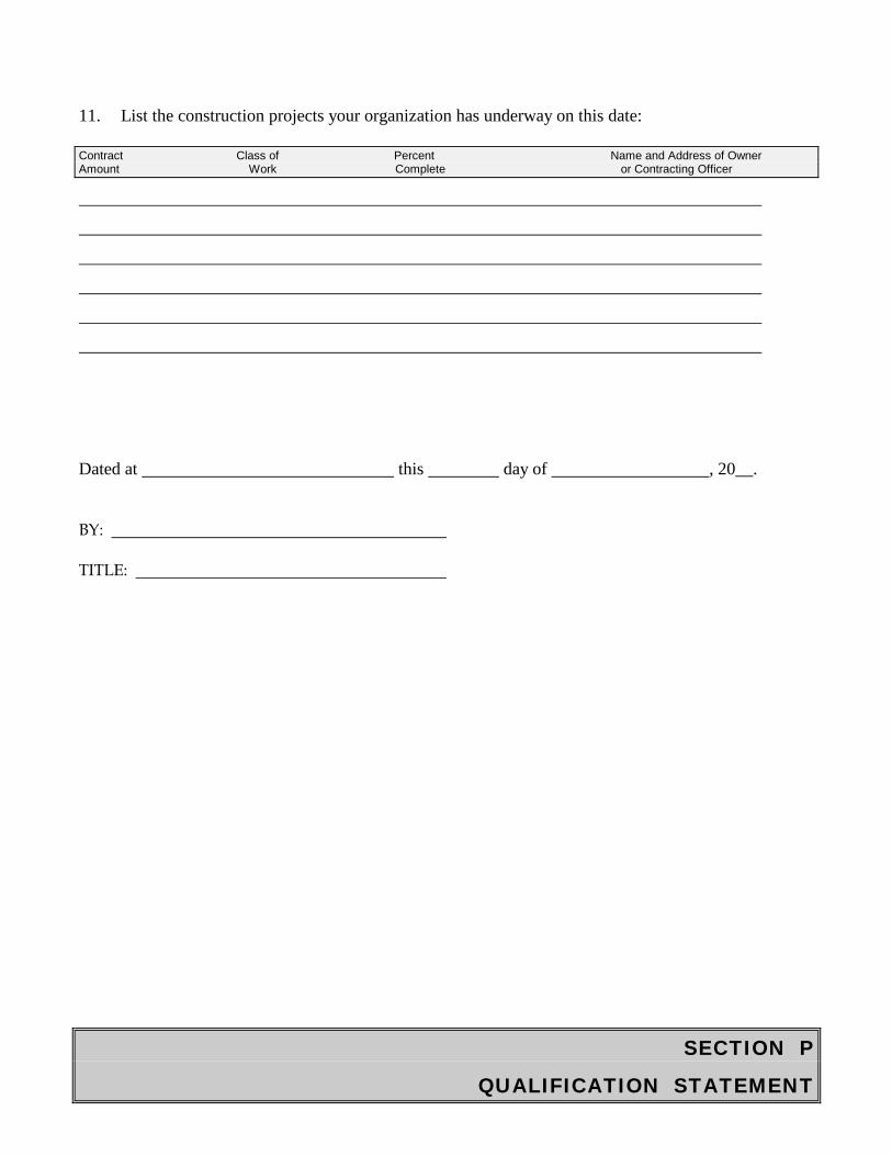
SECTION P
QUALIFICATION STATEMENT
11. List the construction projects your organization has underway on this date:
Contract Class of Percent Name and Address of Owner Amount Work Complete or Contracting Officer
Dated at this day of , 20__.
BY:
TITLE:
SECTION Q
NON COLLUSION AFFIDAVIT
NON-COLLUSION AFFIDAVIT
CITY OF PORT ARTHUR § §
STATE OF TEXAS §
By the signature below, the signatory for the bidder certifies that neither he nor the firm, corporation,
partnership or institution represented by the signatory or anyone acting for the firm bidding this project
has violated the antitrust laws of this State, codified at Section 15.01, et seq., Texas Business and
Commerce Code, or the Federal antitrust laws, nor communicated directly or indirectly the bid made
to any competitor or any other person engaged in the same line of business, nor has the signatory or
anyone acting for the firm, corporation or institution submitting a bid committed any other act of
collusion related to the development and submission of this bid proposal.
Signature:
Printed Name:
Title:
Company:
Date:
SUBSCRIBED and sworn to before me the undersigned authority by the of, on behalf of said bidder.
________________________________ Notary Public in and for the State of Texas
My commission expires: ____________
SECTION R
AFFIDAVIT
AFFIDAVIT
All pages in Offeror’s Responses containing statements, letters, etc., shall be signed by a duly authorized officer of the company whose signature is binding.
The undersigned offers and agrees to one of the following:
______ I hereby certify that I do not have outstanding debts with the City of Port Arthur. I further agree to pay succeeding debts as they become due.
______ I hereby certify that I do have outstanding debts with the City of Port Arthur and agree to pay said debts prior to execution of this agreement. I further agree to pay succeeding debts as they become due.
______ I hereby certify that I do have outstanding debts with the City of Port Arthur and agree to enter into an agreement for the payment of said debts. I further agree to pay succeeding debts as they become due.
Firm Name Date
Authorized Signature Title
Name (please print) Telephone
STATE: ____________
COUNTY: ____________
SUBSCRIBED AND SWORN to before me by the above named ________________________
on this the _____________________ day of _____________, 20_____.
___________________________ Notary Public
RETURN THIS AFFIDAVIT AS PART OF THE BID PROPOSAL
SECTION S
HOUSE BILL 89 VERIFICATION
House Bill 89 Verification
I, ______________________________________ (Person name), the undersigned representative
(hereafter referred to as “Representative”) of
______________________________________________________________________
_______________________________ (company or business name, hereafter referred to as
“Business Entity”), being an adult over the age of eighteen (18) years of age, after being duly sworn
by the undersigned notary, do hereby depose and affirm the following:
1. That Representative is authorized to execute this verification on behalf of Business Entity;
2. That Business Entity does not boycott Israel and will not boycott Israel during the term of any
contract that will be entered into between Business Entity and the City of Port Arthur; and
3. That Representative understands that the term “boycott Israel” is defined by Texas
Government Code Section 2270.001 to mean refusing to deal with, terminating business activities
with, or otherwise taking any action that is intended to penalize, inflict economic harm on, or limit
commercial relations specifically with Israel, or with a person or entity doing business in Israel or in an
Israeli-controlled territory, but does not include an action made for ordinary business purposes.
_____________________________________ SIGNATURE OF REPRESENTATIVE
SUBSCRIBED AND SWORN TO BEFORE ME, the undersigned authority, on this _____ day of ____________________, 20___.
_____________________________________ Notary Public
SECTION T
SB 252
SB 252 CHAPTER 2252 CERTIFICATION
I, ______________________________________________, the undersigned an representative
of_________________________________________________________________________________ (Company or Business Name)
being an adult over the age of eighteen (18) years of age, pursuant to Texas Government Code, Chapter 2252,
Section 2252.152 and Section 2252.153, certify that the company named above is not listed on the website of the
Comptroller of the State of Texas concerning the listing of companies that are identified under Section 806.051,
Section 807.051 or Section 2253.153. I further certify that should the above-named company enter into a
contract that is on said listing of companies on the website of the Comptroller of the State of Texas which do
business with Iran, Sudan or any Foreign Terrorist Organization, I will immediately notify the City of Port
Arthur Purchasing Department.
___________________________________ Name of Company Representative (Print)
___________________________________ Signature of Company Representative
___________________________________ Date
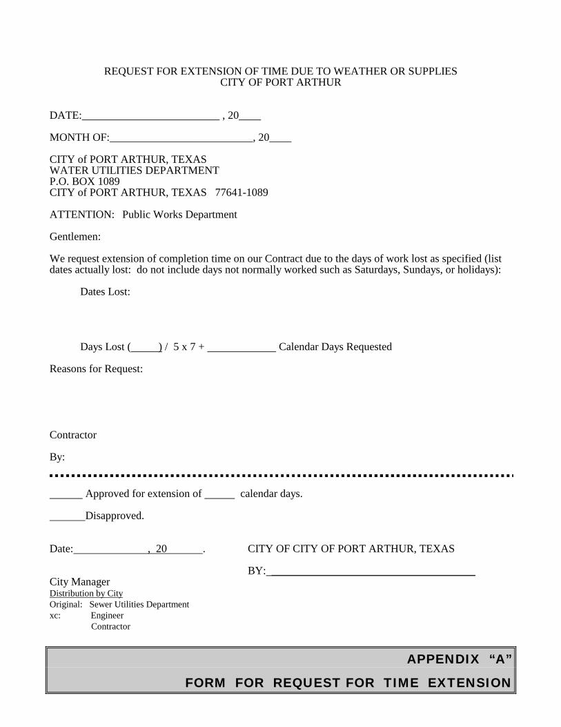
APPENDIX “A”
FORM FOR REQUEST FOR TIME EXTENSION
REQUEST FOR EXTENSION OF TIME DUE TO WEATHER OR SUPPLIES CITY OF PORT ARTHUR
DATE:_________________________ , 20____
MONTH OF:__________________________, 20____
CITY of PORT ARTHUR, TEXAS WATER UTILITIES DEPARTMENT P.O. BOX 1089 CITY of PORT ARTHUR, TEXAS 77641-1089
ATTENTION: Public Works Department
Gentlemen:
We request extension of completion time on our Contract due to the days of work lost as specified (list dates actually lost: do not include days not normally worked such as Saturdays, Sundays, or holidays):
Dates Lost:
Days Lost ( ) / 5 x 7 + Calendar Days Requested
Reasons for Request:
Contractor
By:
Approved for extension of calendar days.
Disapproved.
Date: , 20 . CITY OF CITY OF PORT ARTHUR, TEXAS
BY: _____________________________________ City ManagerDistribution by City Original: Sewer Utilities Department xc: Engineer
Contractor
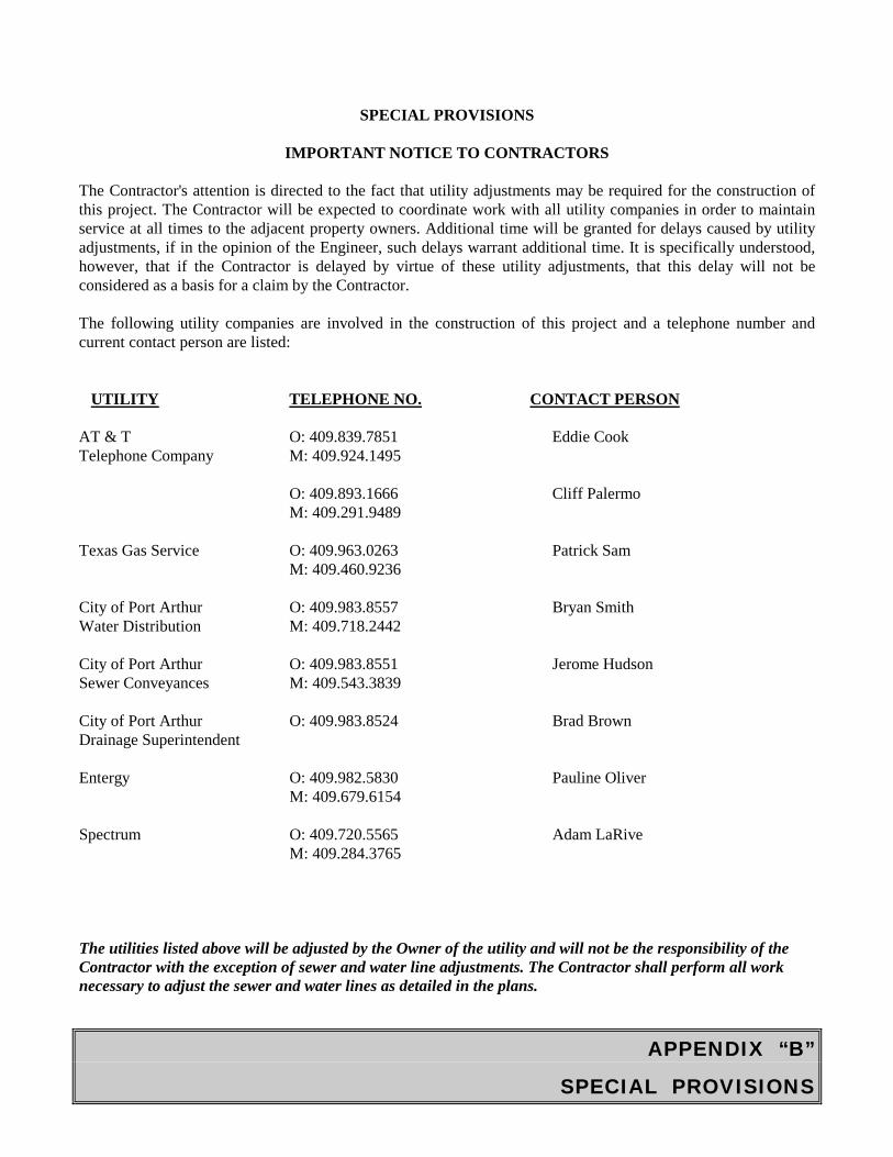
APPENDIX “B”
SPECIAL PROVISIONS
SPECIAL PROVISIONS
IMPORTANT NOTICE TO CONTRACTORS
The Contractor's attention is directed to the fact that utility adjustments may be required for the construction of this project. The Contractor will be expected to coordinate work with all utility companies in order to maintain service at all times to the adjacent property owners. Additional time will be granted for delays caused by utility adjustments, if in the opinion of the Engineer, such delays warrant additional time. It is specifically understood, however, that if the Contractor is delayed by virtue of these utility adjustments, that this delay will not be considered as a basis for a claim by the Contractor.
The following utility companies are involved in the construction of this project and a telephone number and current contact person are listed:
UTILITY TELEPHONE NO. CONTACT PERSON
AT & T O: 409.839.7851 Eddie Cook Telephone Company M: 409.924.1495
O: 409.893.1666 Cliff Palermo M: 409.291.9489
Texas Gas Service O: 409.963.0263 Patrick Sam M: 409.460.9236
City of Port Arthur O: 409.983.8557 Bryan Smith Water Distribution M: 409.718.2442
City of Port Arthur O: 409.983.8551 Jerome Hudson Sewer Conveyances M: 409.543.3839
City of Port Arthur O: 409.983.8524 Brad Brown Drainage Superintendent
Entergy O: 409.982.5830 Pauline Oliver M: 409.679.6154
Spectrum O: 409.720.5565 Adam LaRive M: 409.284.3765
The utilities listed above will be adjusted by the Owner of the utility and will not be the responsibility of the Contractor with the exception of sewer and water line adjustments. The Contractor shall perform all work necessary to adjust the sewer and water lines as detailed in the plans.
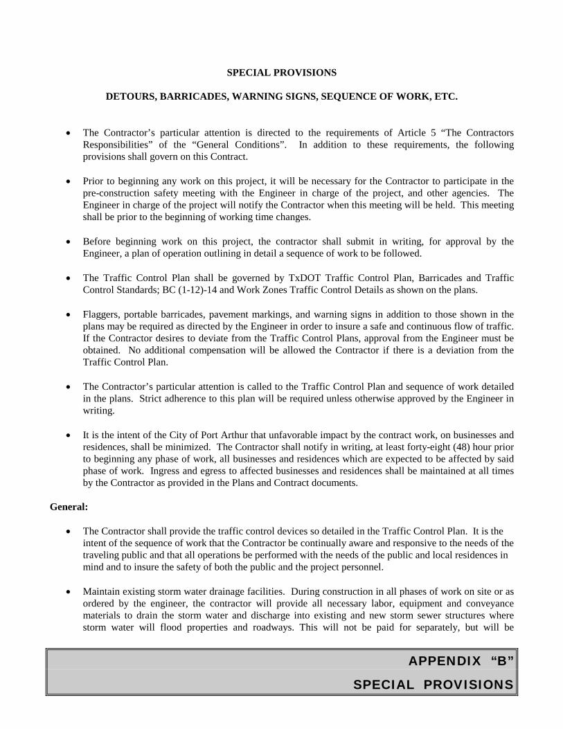
APPENDIX “B”
SPECIAL PROVISIONS
SPECIAL PROVISIONS
DETOURS, BARRICADES, WARNING SIGNS, SEQUENCE OF WORK, ETC.
• The Contractor’s particular attention is directed to the requirements of Article 5 “The ContractorsResponsibilities” of the “General Conditions”. In addition to these requirements, the followingprovisions shall govern on this Contract.
• Prior to beginning any work on this project, it will be necessary for the Contractor to participate in thepre-construction safety meeting with the Engineer in charge of the project, and other agencies. TheEngineer in charge of the project will notify the Contractor when this meeting will be held. This meetingshall be prior to the beginning of working time changes.
• Before beginning work on this project, the contractor shall submit in writing, for approval by theEngineer, a plan of operation outlining in detail a sequence of work to be followed.
• The Traffic Control Plan shall be governed by TxDOT Traffic Control Plan, Barricades and TrafficControl Standards; BC (1-12)-14 and Work Zones Traffic Control Details as shown on the plans.
• Flaggers, portable barricades, pavement markings, and warning signs in addition to those shown in theplans may be required as directed by the Engineer in order to insure a safe and continuous flow of traffic.If the Contractor desires to deviate from the Traffic Control Plans, approval from the Engineer must beobtained. No additional compensation will be allowed the Contractor if there is a deviation from theTraffic Control Plan.
• The Contractor’s particular attention is called to the Traffic Control Plan and sequence of work detailedin the plans. Strict adherence to this plan will be required unless otherwise approved by the Engineer inwriting.
• It is the intent of the City of Port Arthur that unfavorable impact by the contract work, on businesses andresidences, shall be minimized. The Contractor shall notify in writing, at least forty-eight (48) hour priorto beginning any phase of work, all businesses and residences which are expected to be affected by saidphase of work. Ingress and egress to affected businesses and residences shall be maintained at all timesby the Contractor as provided in the Plans and Contract documents.
General:
• The Contractor shall provide the traffic control devices so detailed in the Traffic Control Plan. It is theintent of the sequence of work that the Contractor be continually aware and responsive to the needs of thetraveling public and that all operations be performed with the needs of the public and local residences inmind and to insure the safety of both the public and the project personnel.
• Maintain existing storm water drainage facilities. During construction in all phases of work on site or asordered by the engineer, the contractor will provide all necessary labor, equipment and conveyancematerials to drain the storm water and discharge into existing and new storm sewer structures wherestorm water will flood properties and roadways. This will not be paid for separately, but will be

APPENDIX “B”
SPECIAL PROVISIONS
considered subsidiary to various bid items.
• Insure that safe access is provided to bus stops, bus shelters and to and from bus loading and unloading atall times.
• Provide temporary driveway access crossing construction area at the end of each day.
END OF SECTION