SECTION 9P TABLE OF CONTENTS - matiz-club.com
34
DAEWOO M-150 BL2 SECTION 9P DOORS CAUTION: Disconnect the negative battery cable before removing or installing any electrical unit or when a tool or equipment could easily come in contact with exposed electrical terminals. Disconnecting this cable will help prevent personal injury and damage to the vehicle. The ignition must also be in B unless otherwise noted. TABLE OF CONTENTS Description and Operation 9P-2 . . . . . . . . . . . . . . . . . . Door Lock Striker 9P-2 . . . . . . . . . . . . . . . . . . . . . . . . . . Childproof Rear Door Lock 9P-2 . . . . . . . . . . . . . . . . . . Power Door Locks 9P-2 . . . . . . . . . . . . . . . . . . . . . . . . . Power Windows 9P-2 . . . . . . . . . . . . . . . . . . . . . . . . . . . Tailgate Strut 9P-2 . . . . . . . . . . . . . . . . . . . . . . . . . . . . . Component Locator 9P-3 . . . . . . . . . . . . . . . . . . . . . . . . Front Door 9P-3 . . . . . . . . . . . . . . . . . . . . . . . . . . . . . . . Rear Door 9P-5 . . . . . . . . . . . . . . . . . . . . . . . . . . . . . . . . Repair Instructions 9P-7 . . . . . . . . . . . . . . . . . . . . . . . . . On-Vehicle Service 9P-7 . . . . . . . . . . . . . . . . . . . . . . . . . . Front Door Glass Run 9P-7 . . . . . . . . . . . . . . . . . . . . . . Rear Door Glass Run 9P-8 . . . . . . . . . . . . . . . . . . . . . . Door Lock Striker 9P-9 . . . . . . . . . . . . . . . . . . . . . . . . . . Tailgate Lock Striker 9P-9 . . . . . . . . . . . . . . . . . . . . . . . Door Lock Striker Adjustment 9P-10 . . . . . . . . . . . . . . Tailgate Lock Striker Adjustment 9P-11 . . . . . . . . . . . . Front Door Lock 9P-13 . . . . . . . . . . . . . . . . . . . . . . . . . . Childproof Rear Door Lock 9P-14 . . . . . . . . . . . . . . . . . Central Door Lock Actuator 9P-16 . . . . . . . . . . . . . . . . Tailgate Lock 9P-16 . . . . . . . . . . . . . . . . . . . . . . . . . . . . Inside Door Handle 9P-17 . . . . . . . . . . . . . . . . . . . . . . . Outside Front Door Handle 9P-17 . . . . . . . . . . . . . . . . Outside Rear Door Handle 9P-18 . . . . . . . . . . . . . . . . . Door Lock Cylinder 9P-18 . . . . . . . . . . . . . . . . . . . . . . . Manual Window Regulator 9P-19 . . . . . . . . . . . . . . . . . Power Front Window Regulator 9P-19 . . . . . . . . . . . . Front Door Assembly 9P-20 . . . . . . . . . . . . . . . . . . . . . Rear Door Assembly 9P-21 . . . . . . . . . . . . . . . . . . . . . . Tailgate 9P-22 . . . . . . . . . . . . . . . . . . . . . . . . . . . . . . . . . Tailgate Lock Cylinder 9P-23 . . . . . . . . . . . . . . . . . . . . . Door Hinge 9P-23 . . . . . . . . . . . . . . . . . . . . . . . . . . . . . . Door Hold Open Link 9P-24 . . . . . . . . . . . . . . . . . . . . . Inside Channel Weatherstrip (Standard) 9P-24 . . . . . Inside Channel Weatherstrip (Deluxe) 9P-25 . . . . . . . Door Outside Channel Weatherstrip 9P-25 . . . . . . . . . Door Weatherstrip 9P-26 . . . . . . . . . . . . . . . . . . . . . . . . Door Seal Trim 9P-27 . . . . . . . . . . . . . . . . . . . . . . . . . . . Door Opening Weatherstrip 9P-27 . . . . . . . . . . . . . . . . Manual Window Regulator Handle 9P-28 . . . . . . . . . . Tailgate Strut 9P-28 . . . . . . . . . . . . . . . . . . . . . . . . . . . . Schematic and Routing Diagrams 9P-30 . . . . . . . . . . Power Door Locks 9P-30 . . . . . . . . . . . . . . . . . . . . . . . . Power Windows (Front Only) 9P-34 . . . . . . . . . . . . . . .
-
Upload
khangminh22 -
Category
Documents
-
view
0 -
download
0
Transcript of SECTION 9P TABLE OF CONTENTS - matiz-club.com

DAEWOO M-150 BL2
SECTION 9P
DOORSCAUTION: Disconnect the negative battery cable before removing or installing any electrical unit or when atool or equipment could easily come in contact with exposed electrical terminals. Disconnecting this cablewill help prevent personal injury and damage to the vehicle. The ignition must also be in B unless otherwisenoted.
TABLE OF CONTENTSDescription and Operation 9P-2. . . . . . . . . . . . . . . . . .
Door Lock Striker 9P-2. . . . . . . . . . . . . . . . . . . . . . . . . .
Childproof Rear Door Lock 9P-2. . . . . . . . . . . . . . . . . .
Power Door Locks 9P-2. . . . . . . . . . . . . . . . . . . . . . . . .
Power Windows 9P-2. . . . . . . . . . . . . . . . . . . . . . . . . . .
Tailgate Strut 9P-2. . . . . . . . . . . . . . . . . . . . . . . . . . . . .
Component Locator 9P-3. . . . . . . . . . . . . . . . . . . . . . . .
Front Door 9P-3. . . . . . . . . . . . . . . . . . . . . . . . . . . . . . .
Rear Door 9P-5. . . . . . . . . . . . . . . . . . . . . . . . . . . . . . . .
Repair Instructions 9P-7. . . . . . . . . . . . . . . . . . . . . . . . .
On-Vehicle Service 9P-7. . . . . . . . . . . . . . . . . . . . . . . . . .
Front Door Glass Run 9P-7. . . . . . . . . . . . . . . . . . . . . .
Rear Door Glass Run 9P-8. . . . . . . . . . . . . . . . . . . . . .
Door Lock Striker 9P-9. . . . . . . . . . . . . . . . . . . . . . . . . .
Tailgate Lock Striker 9P-9. . . . . . . . . . . . . . . . . . . . . . .
Door Lock Striker Adjustment 9P-10. . . . . . . . . . . . . .
Tailgate Lock Striker Adjustment 9P-11. . . . . . . . . . . .
Front Door Lock 9P-13. . . . . . . . . . . . . . . . . . . . . . . . . .
Childproof Rear Door Lock 9P-14. . . . . . . . . . . . . . . . .
Central Door Lock Actuator 9P-16. . . . . . . . . . . . . . . .
Tailgate Lock 9P-16. . . . . . . . . . . . . . . . . . . . . . . . . . . .
Inside Door Handle 9P-17. . . . . . . . . . . . . . . . . . . . . . .
Outside Front Door Handle 9P-17. . . . . . . . . . . . . . . .
Outside Rear Door Handle 9P-18. . . . . . . . . . . . . . . . .
Door Lock Cylinder 9P-18. . . . . . . . . . . . . . . . . . . . . . .
Manual Window Regulator 9P-19. . . . . . . . . . . . . . . . .
Power Front Window Regulator 9P-19. . . . . . . . . . . .
Front Door Assembly 9P-20. . . . . . . . . . . . . . . . . . . . .
Rear Door Assembly 9P-21. . . . . . . . . . . . . . . . . . . . . .
Tailgate 9P-22. . . . . . . . . . . . . . . . . . . . . . . . . . . . . . . . .
Tailgate Lock Cylinder 9P-23. . . . . . . . . . . . . . . . . . . . .
Door Hinge 9P-23. . . . . . . . . . . . . . . . . . . . . . . . . . . . . .
Door Hold Open Link 9P-24. . . . . . . . . . . . . . . . . . . . .
Inside Channel Weatherstrip (Standard) 9P-24. . . . .
Inside Channel Weatherstrip (Deluxe) 9P-25. . . . . . .
Door Outside Channel Weatherstrip 9P-25. . . . . . . . .
Door Weatherstrip 9P-26. . . . . . . . . . . . . . . . . . . . . . . .
Door Seal Trim 9P-27. . . . . . . . . . . . . . . . . . . . . . . . . . .
Door Opening Weatherstrip 9P-27. . . . . . . . . . . . . . . .
Manual Window Regulator Handle 9P-28. . . . . . . . . .
Tailgate Strut 9P-28. . . . . . . . . . . . . . . . . . . . . . . . . . . .
Schematic and Routing Diagrams 9P-30. . . . . . . . . .
Power Door Locks 9P-30. . . . . . . . . . . . . . . . . . . . . . . .
Power Windows (Front Only) 9P-34. . . . . . . . . . . . . . .

9P – 2 DOORS
DAEWOO M-150 BL2
DESCRIPTION AND OPERATIONDOOR LOCK STRIKERThe front and the rear door lock strikers each consist ofa striker with two screws threaded into a floating cageplate in the B-pillars and C-pillars. The door is secured inthe closed position when the door lock fork snaps overand engages the striker.
CHILDPROOF REAR DOOR LOCKThe childproof rear door locks help prevent passengers,especially children, from opening the rear doors of thevehicle from the inside.
In order to activate these locks, move the levers of bothrear doors to the lock position. Then, close both doors.Rear passengers will be unable to open the doors fromthe inside of the vehicle.
In order to deactivate the childproof rear door lock, un-lock the door from the inside of the vehicle and open thedoor from the outside. Move the lever to the unlock posi-tion. The rear door will now work normally.
POWER DOOR LOCKSThe power door locks use a solenoid that is contained ineach door lock assembly. The door locks are activated
by the actuator on the inside door handle or by the lockcylinder on the driver door only. When the driver door islocked or unlocked by the actuator or lock cylinder, alldoors are locked or unlocked accordingly.
POWER WINDOWSThe power windows are controlled by electrical switcheson the front door tirm and operated by a motor at eachwindow regulator. The windows are lowered by pressingthe switch and raised by pulling up on the switch. Thewindow will stop movement when the switch is releasedor when the window is completely open or closed.
TAILGATE STRUTThis vehicle is equipped with the gas struts. The strutssupport the tailgate suitably when opening the tailgate.
The strut contained the high pressure compressed gas.Therefore, be careful not to take apart, puncture, applyheat or fire bacause the strut may explode.

DOORS 9P – 3
DAEWOO M-150 BL2
COMPONENT LOCATOR
FRONT DOOR
D19C403A

9P – 4 DOORS
DAEWOO M-150 BL2
1. Seal Trim2. Lock Button3. Trim Panel4. Pocket Handle (Deluxe Type)5. Pocket Handle Bracket (Deluxe Type)6. Inside handle7. Manual Regulator Handle8. Pocket Handle (Standard Type)9. Door Speaker Cover
10. Map Pocket11. Contact Switch12. Striker13. Opening Weatherstrip14. Door Weatherstrip15. Glass Run16. Front Door17. Inside Channel Weatherstrip18. Inside Handle Rod19. Door Lock
20. Door Lock Cylinder Rod21. Lock Rod22. Actuator Rod23. Actuator24. Window Regulator25. Outside Channel Weatherstrip26. Outside Handle Rod27. Outside Handle28. Division Bar29. Quarter Glass30. Quarter Glass Run31. Door Hinge32. Door Hold Open Link33. Power Window Switch Cover34. Mirror Switch35. Power Window Switch Assembly36. Mirror switch Blank37. Door Side Molding

DOORS 9P – 5
DAEWOO M-150 BL2
REAR DOOR
D19C404A

9P – 6 DOORS
DAEWOO M-150 BL2
1. Seal Trim2. Lock Button3. Trim Panel4. Pocket Handle (Deluxe Type)5. Pocket Handle Bracket (Deluxe Type)6. Inside handle7. Manual Regulator Handle8. Pocket Handle (Standard Type)9. Striker
10. Opening Weatherstrip11. Door Weatherstrip12. Glass Run13. Interior Garnish Molding14. Rear Door15. Inside Channel Weatherstrip
16. Upper Guide Rail17. Exterior Garnish Molding18. Lower Guide Rail19. Lock Rod20. Door Lock21. Inside Handle Rod22. Actuator Rod23. Actuator24. Outside Handle Rod25. Outside Handle26. Window Regulator27. Outside Channel Weatherstrip28. Door Hinge29. Door Hold Open Link30. Door Side Molding

DOORS 9P – 7
DAEWOO M-150 BL2
REPAIR INSTRUCTIONS
ON–VEHICLE SERVICE
D109E521
FRONT DOOR GLASS RUNRemoval Procedure1. Remove the front door seal trim from the front door.
Refer to “Door Seal Trim” in this section.
2. Remove the outside rearview mirror from the frontdoor. Refer to Section 9L, Glass and Mirrors.
3. Remove the guide rail from the door.
� Remove the screws (1).
� Remove the inside bolts (2).
� Remove the outside bolts (3).
� Remove the division bar (4).
D109E522
4. Remove the glass run.
a. Glass run.
D109E526
Installation Procedure1. Install the glass run.
2. Install the division bar with the bolts and the screws.
3. Install the outside rearview mirror. Refer to Section9L, Glass and Mirrors.
4. Install the front door seal trim. Refer to “Door SealTrim” in this section.

9P – 8 DOORS
DAEWOO M-150 BL2
D109C566
REAR DOOR GLASS RUNRemoval Procedure1. Remove the inside channel weatherstrip from the
rear door. Refer to Section 9G, Interior Trim.2. Remove the outside channel weatherstrip from the
rear doors. Refer to Section 9G, Interior Trim.3. Remove the rear door trim panel. Refer to Section
9G, Interior Trim.4. Remove the rear door seal trim.
a. Door seal trim.b. Door pocket handle bracket.
Important: In case of the deluxe type, remove the sealtrim after removing the door pocket handle bracket.
D109C567
5. Remove the guide piece.
� Remove the screw (1).
� Remove the guide piece (2).
D109C568
6. Remove the upper guide rail and the glass run.
� Remove the bolts (1).
� Lift up and remove the upper guide rail and theglass run simultaneously (2).
D109C569
Installation Procedure1. Install the upper guide rail and the rear door glass
run.
2. Install the guide piece with the screw.
3. Install the rear door seal trim.
4. Install the rear door trim panel. Refer to Section 9G,Interior Trim.
5. Install the outside channel weatherstrip to the reardoor. Refer to Section 9G, Interior Trim.
6. Install the inside channel weatherstrip to the reardoor. Refer to Section 9G, Interior Trim.

DOORS 9P – 9
DAEWOO M-150 BL2
D109C570
DOOR LOCK STRIKERRemoval Procedure1. Remove the door lock striker.
� Remove the screws (1).
� Remove the door lock striker (2).
D109C571
Installation Procedure
Notice: Dissimilar metals in direct contact with eachother may corrode rapidly. Make sure to use the correctfasteners to prevent premature corrosion.
1. Install the door lock striker with the screws.
D109C572
TAILGATE LOCK STRIKERRemoval Procedure1. Open the tailgate and suitably support it.
2. Remove the tailgate lock striker.
� Remove the screws (1).
� Disconnect the cable (2).
� Remove the striker (3).
D109C573
Installation Procedure
Notice: Dissimilar metal in direct contact with each oth-er may corrode rapidly. Make sure to use the correct fas-teners to prevent premature corrosion.
1. Connect the cable.
2. Install the tailgate lock striker with the screws.

9P – 10 DOORS
DAEWOO M-150 BL2
D109C574
DOOR LOCK STRIKER ADJUSTMENTNotice: The door lock striker is an important attachingpart that can affect the performance of vital componentsand systems and can cause major repair expenses. Ifreplacement becomes necessary, the door lock strikermust be replaced by one with the same part number orwith an equivalent part if replacement becomes neces-sary. Do not use a replacement part of lesser quality orof a substitute design. The specified torque values mustbe used during reassembly in order to ensure the properretention of the part.
The door lock striker consists of a striker with twoscrews that are threaded into a tapped, floating cageplate located in the appropriate body pillar. This floatingcage plate allows the striker to be easily adjusted in orout and up or down. The door is secured in the closedposition when the door lock fork snaps over and en-gages the striker.
D19C575A
Fore/Aft Adjustment1. The door must be properly aligned.
2. Close the door until the lock fork contacts the striker.
3. Stand next to the door opening and move the doorslowly in and out, just touching the striker each time.
D109C576
4. The alignment of the lock fork and the striker can beeasily seen. The lock fork should be perpendicular toand fall near the middle of the striker. The lock forkshould fall near the middle of the striker between theB-pillar and the end of the striker.

DOORS 9P – 11
DAEWOO M-150 BL2
D109C577
5. If a fore or aft adjustment is required, use the followingsteps:
� Remove the striker screws (1).
� Remove the spacer in order to move the striker to-ward the rear of the vehicle (2).
� Add a 2 mm (0.08 inch) spacer in order to movethe striker toward the front of the vehicle.
� Install the striker screws.
6. Perform the up/down or the in/out adjustment. Referto ‘‘Up/Down or In/Out Adjustment’’ in this section.
D109C574
Up/Down or In/Out AdjustmentAn adjustment of the striker in the up and down or in andout directions may be necessary for a number of reasons:vehicle frame damage as the result of a collision, installa-tion of new door weatherstripping, customer complaintsof excessive windnoise, or difficulty in opening or closingthe door. In order to adjust the door striker in an up anddown or in and out direction, perform the following proce-dure:
1. The door must be properly aligned.
2. Loosen the striker screws.
3. The floating cage plate can be moved slightly usingthe ends of the striker screws. Move the floating cageplate to the desired position.
Notice: It is important to use a flat-end rotary file in or-der not to damage the tapped floating cage plate. Thestriker screws and the tapped floating cage plate are im-portant attaching parts that could affect the performanceof vital components and systems.
4. If proper adjustment requires that the floating cage platebe moved more than is possible, use an electric handdrill and a 3/8- inch rotary file with a flat head in order toenlarge the body opening in the direction required.
5. Tighten the striker screws to the correct position.
D109C578
TAILGATE LOCK STRIKERADJUSTMENTNotice: The tailgate lock striker is an important attachingpart that can affect the performance of vital componentsand systems and can cause major repair expenses. If re-placement becomes necessary, the tailgate lock strikermust be replaced by one with the same part number orwith an equivalent part if replacement becomes neces-sary. Do not use a replacement part of lesser quality or ofa substitute design. The specified torque values must beused during reassembly in order to ensure the properretention of the part.

9P – 12 DOORS
DAEWOO M-150 BL2
The tailgate lock striker consists of a striker with twoscrews that are threaded into a tapped, floating cageplate located in the appropriate body pillar. This floatingcage plate allows the striker to be easily adjusted in orout and up or down. The tailgate is secured in the closedposition when the tailgate lock fork snaps over and en-gages the striker.
D109C578
Fore/Aft or In/Out AdjustmentAn adjustment of the striker in the fore and aft or in andout directions may be necessary for a number of reasons:vehicle frame damage as the result of a collision, installa-tion of new tailgate weatherstripping, customer com-plaints of excessive windnoise, or difficulty in opening orclosing the tailgate. In order to adjust the tailgate striker inan fore and aft or in and out direction, perform the follow-ing procedure:
1. The tailgate must be properly aligned.
2. Loosen the striker screws.
3. The floating cage plate can be moved slightly usingthe ends of the striker screws. Move the floating cageplate to the desired position.
Notice: It is important to use a flat-end rotary file in or-der not to damage the tapped floating cage plate. Thestriker screws and the tapped floating cage plate are im-portant attaching parts that could affect the performanceof vital components and systems.
D109C579
4. If proper adjustment requires that the floating cage platebe moved more than is possible, use an electric handdrill and a 3/8- inch rotary file with a flat head in order toenlarge the body opening in the direction required.
5. Tighten the striker screws to the correct position.
6. Perform the up/down adjustment. Refer to “Up andDown Adjustment” in this section.

DOORS 9P – 13
DAEWOO M-150 BL2
D19C580A
Up and Down Adjustment1. The tailgate must be properly aligned.
2. Close the tailgate until the lock fork contacts the strik-er.
3. Stand next to the tailgate opening and move the tail-gate slowly up and down, just touching the strikereach time.
D109C581
4. The alignment of the lock fork and the striker can beeasily seen. The lock fork should be perpendicular toand fall near the middle of the striker. The lock forkshould fall near the middle of the striker between therear body pillar and the end of the striker.
D109C582
5. If a up and down adjustment is required, use the fol-lowing steps:
� Remove the striker screws (1).
� Remove the spacer in order to move the striker to-ward the down of the vehicle (2).
� Add a 2 mm (0.08 inch) spacer in order to movethe striker toward the up of the vehicle.
� Install the striker screws.
D19C583A
FRONT DOOR LOCKRemoval Procedure1. Disconnect the negative battery cable if equipped
with the central door lock system.
2. Remove the seal trim. Refer to “Door Seal Trim” inthis section.
3. Disconnect the outside door handle rod from the doorlock.
a. Outside door handle rod.
b. Key rod.

9P – 14 DOORS
DAEWOO M-150 BL2
D109C584
4. Remove the front door lock.
� Remove the screws (1).
� Remove the front door lock (2).
Important: Disconnect the actuator connector, ifequipped with the central door lock system.
D109C585
Installation ProcedureNotice: Dissimilar metals in direct contact with eachother may corrode rapidly. Make sure to use the correctfasteners to prevent premature corrosion.
1. Install the front door lock with screws.
Important: Connect the actuator connector if equippedwith the central door lock system.
2. Connect the outside door handle rod and the key rodto the door lock.
3. Install the seal trim. Refer to “Door Seal Trim” in thissection.
4. Connect the negative battery cable, if equipped withthe central door lock system.
D109C566
CHILDPROOF REAR DOOR LOCKRemoval Procedure1. Disconnect the negative battery cable if equipped
with the central door lock system.2. Remove the door trim panel. Refer to Section 9G, In-
terior Trim.3. Remove the door seal trim. Refer to “Door Seal Trim”
in this section.a. Door seal trim.b. Door pocket handle bracket.
Important: In case of the deluxe type, remove the sealtrim after removing the door pocket handle bracket.
D109C567
4. Remove the guide piece.
� Remove the screw (1).
� Remove the guide piece (2).

DOORS 9P – 15
DAEWOO M-150 BL2
D109C583
5. Disconnect the outside door handle rod from the doorlock.
a. Outside door handle rod.
D109C586
6. Disconnect the door lock from the vehicle.
� Remove the screws (1).
� Remove the door lock (2).
Important: Disconnect the actuator connector ifequipped with the central door lock system.
D109C587
Installation Procedure
Notice: Dissimilar metals in direct contact with eachother may corrode rapidly. Make sure to use the correctfasteners to prevent premature corrosion.
1. Install the rear door lock with the screws.
Important: Connect the actuator connector if equippedwith the central door lock system.
2. Connect the outside door handle rod to the door lock.
3. Install the guide rail with the screw.
4. Install the seal trim. Refer to “Door Seal Trim” in thissection.
5. Install the door trim panel. Refer to Section 9G, Interi-or Trim.
6. Connect the negative battery cable if equipped withthe central door lock system.

9P – 16 DOORS
DAEWOO M-150 BL2
D109C588
CENTRAL DOOR LOCK ACTUATORRemoval Procedure1. Disconnect the negative battery cable.
2. Remove the door seal trim. Refer to “Door Seal Trim”in this section.
3. Remove the door lock assembly. Refer to “Door Lock”in this section.
4. Remove the actuator from the door lock assembly.
� Remove the screws (1).
� Remove the actuator (2).
D109C589
Installation Procedure1. Install the door lock actuator to the door lock assem-
bly with the screws.
2. Install the door lock assembly to the vehicle. Refer to“Door Lock” in this section.
3. Install the door seal trim. Refer to “Door Seal Trim” inthis section.
4. Connect the negative battery cable.
D109C590
TAILGATE LOCKRemoval Procedure1. Remove the tailgate trim panel. Refer to Section 9G,
Interior Trim.
2. Remove the lock rod from the tailgate lock cylinder.
a. Lock rod.
D109C591
3. Remove the tailgate lock.
� Remove the screws (1).
� Remove the tailgate lock (2).

DOORS 9P – 17
DAEWOO M-150 BL2
D109C592
Installation Procedure1. Install the tailgate lock with the screws.
2. Install the lock rod to the tailgate lock cylinder.
3. Install the tailgate trim panel. Refer to Section 9G, In-terior Trim.
D109C593
INSIDE DOOR HANDLERemoval Procedure1. Removal the inside door handle.
� Remove the screw (1).
� Remove the inside door handle (2).
D109C594
Installation Procedure1. Install the inside door handle with the screw.
D109C595
OUTSIDE FRONT DOOR HANDLERemoval Procedure1. Disconnect the negative battery cable.
2. Remove the front door lock rods.
3. Remove the outside front door handle.
� Remove the bolts (1).
� Remove the outside front door handle (2).

9P – 18 DOORS
DAEWOO M-150 BL2
D109C596
Installation Procedure1. Install the outside front door lock handle with the
bolts.
2. Install the front door lock rods.
3. Connect the negative battery cable.
D109C597
OUTSIDE REAR DOOR HANDLERemoval Procedure1. Disconnect the negative battery cable.
2. Remove the rear door lock. Refer to “Childproof RearDoor Lock” in this section.
3. Remove the outside rear door handle.
� Remove the bolts (1).
� Remove the outside rear door handle (2).
D109C598
Installation Procedure1. Install the outside rear door handle with the bolts.
2. Install the rear door lock. Refer to “Childproof Reardoor Lock” in this section.
3. Connect the negative battery cable.
D109C599
DOOR LOCK CYLINDERRemoval Procedure1. Disconnect the negative battery cable.
2. Remove the outside door handle. Refer to “OutsideFront Door Handle” in this section.
3. Remove the door lock cylinder from the outside doorhandle.
� Remove the clip (1).
� Remove the door lock cylinder (2).

DOORS 9P – 19
DAEWOO M-150 BL2
D109C600
Installation Procedure1. Install the door lock cylinder with the clip.
2. Install the outside door handle. Refer to “OutsideFront Door Handle” in this section.
3. Connect the negative battery cable.
D109C601
MANUAL WINDOW REGULATORRemoval Procedure1. Remove the glass. Refer to Section 9L, Glass and
Mirrors.
2. Remove the window regulator.
� Remove the screws (1).
� Remove the regulator (2).
D109C602
Installation Procedure1. Install the regulator with the screws.
2. Install the glass. Refer to Section 9L, Glass and Mir-rors.
D109C603
POWER FRONT WINDOWREGULATORRemoval Procedure1. Disconnect the negative battery cable.
2. Remove the glass. Refer to Section 9L, Glass andMirrors.
3. Remove the window regulator assembly.
� Disconnect the window motor electrical connector(1).
� Remove the screws (2).
� Remove the window regulator assembly (3).

9P – 20 DOORS
DAEWOO M-150 BL2
D109C604
4. Remove the window motor from the window regula-tor.
� Remove the screws (1).
� Remove the window regulator (2).
Caution: Be careful what you are doing when sepa-rating the window motor and the window regulator.You may be hurt.
D109C605
Installation Procedure1. Install the window motor to the window regulator with
the screws.
2. Install the window regulator assembly with the screws.
3. Connect the window motor electrical connector.
4. Install the glass. Refer to Section 9L, Glass and Mir-rors.
5. Connect the negative battery cable.
D109C606
FRONT DOOR ASSEMBLYRemoval Procedure1. Disconnect the negative battery cable.
2. Disconnect the electrical connector under the instru-ment panel.
Important: In case of the front passenger door, removethe glove box in advance.
D109C607
3. Remove the fender. Refer to Section 9R, Body FrontEnd.
4. Remove the front door assembly.
� Remove the door hinge bolts (1).
� Remove the door hold open bolt (2).
� Disconnect the body–to–door rubber grommet (3).
� Remove the front door assembly (4).

DOORS 9P – 21
DAEWOO M-150 BL2
D19C608A
Installation Procedure
Notice: Dissimilar metals in direct contact with eachother may corrode rapidly. Make sure to use the correctfastener to prevent premature corrosion.
1. Connect the body–to–door rubber grommet.
2. With the aid of another technician, lightly secure thefront door with the bolts.
3. Adjust the door for proper fit.
4. Tighten the hinge–to–body bolts.
5. Install the door hold open link with the bolt.
6. Install the fender. Refer to Section 9R, Body FrontEnd.
7. Connect the electrical connector.
8. Connect the negative battery cable.
9. Perform the waterleak test. Refer to Section 9I, Wa-terleak.
10. Check for windnoise. Refer to Section 9J, Wind-noise.
D109C609
REAR DOOR ASSEMBLYRemoval Procedure1. Disconnect the negative battery cable.
2. Pry off the lower B–pillar trim panel. Refer to Section9G, Interior Trim.
3. Disconnect the rear door electrical connector.
a. Rear door electrical connector.
D109C610
4. Remove the rear door assembly.
� Remove the door hinge bolts (1).
� Remove the door hold open link bolt (2).
� Disconnect the body–to–door rubber grommet (3).
� Remove the rear door assembly (4).

9P – 22 DOORS
DAEWOO M-150 BL2
D19C611A
Installation ProcedureNotice: Dissimilar metals in direct contact with eachother may corrode rapidly. Make sure to use the correctfastener to prevent premature corrosion.1.Connect the body–to–door rubber grommet.2. With the aid of another technician, lightly secure the
rear door with the bolts.3. Adjust the door for proper fit.4. Install the door hold open link with the bolt.5. Connect the rear door electrical connector.6. Connect the negative battery cable.7. Perform the waterleak test. Refer to Section 9I, Wa-
terleaks.8. Check for windnoise. Refer to Section 9J, Windnoise.
D109C612
TAILGATERemoval Procedure1. Disconnect the negative battery cable.
2. Remove the luggage compartment wheelhouse trimpanel. Refer to Section 9G, Interior Trim.
3. Disconnect the tailgate electrical connector.
a. Tailgate electrical connector.
D109C636
4. Remove the tailgate strut. Refer to “Tailgate Strut” inthis section.
5. Remove the tailgate.
� Remove the hinge bolts.
� Disconnect the body–to–tailgate rubber grommet.
� Remove the tailgate.
D19C613A
DOORS 9P – 23
DAEWOO M-150 BL2
D19C614A
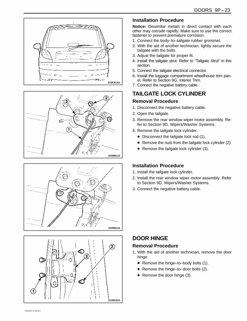
Installation ProcedureNotice: Dissimilar metals in direct contact with eachother may corrode rapidly. Make sure to use the correctfastener to prevent premature corrosion.1. Connect the body–to–tailgate rubber grommet.2. With the aid of another technician, lightly secure the
tailgate with the bolts.3. Adjust the tailgate for proper fit.4. Install the tailgate strut. Refer to “Tailgate Strut” in this
section.5. Connect the tailgate electrical connector.6. Install the luggage compartment wheelhouse trim pan-
el. Refer to Section 9G, Interior Trim.7. Connect the negative battery cable.
D209B113
TAILGATE LOCK CYLINDERRemoval Procedure1. Disconnect the negative battery cable.
2. Open the tailgate.
3. Remove the rear window wiper motor assembly. Re-fer to Section 9D, Wipers/Washer Systems.
4. Remove the tailgate lock cylinder.
� Disconnect the tailgate lock rod (1).
� Remove the nuts from the tailgate lock cylinder (2).
� Remove the tailgate lock cylinder (3).
D209B114
Installation Procedure1. Install the tailgate lock cylinder.
2. Install the rear window wiper motor assembly. Referto Section 9D, Wipers/Washer Systems.
3. Connect the negative battery cable.
D109C615
DOOR HINGERemoval Procedure1. With the aid of another technician, remove the door
hinge.
� Remove the hinge–to–body bolts (1).
� Remove the hinge–to–door bolts (2).
� Remove the door hinge (3).

9P – 24 DOORS
DAEWOO M-150 BL2
D109C616
Installation Procedure
Notice: Dissimilar metals in direct contact with eachother may corrode rapidly. Make sure to use the correctfastener to prevent premature corrosion.
1. With the aid of another technician, install the hinge tothe door and the body with the bolts.
D109C617
DOOR HOLD OPEN LINKRemoval Procedure1. Remove the door seal trim. Refer to “Door Seal Trim”
in this section.
2. Remove the door hold open link.
� Remove the hinge–to–body bolt (1).
� Remove the hinge–to–door bolts (2).
� Remove the door hold open link (3).
D109C618
Installation Procedure
Notice: Dissimilar metals in direct contact with eachother may corrode rapidly. Make sure to use the correctfastener to prevent premature corrosion.
1. Install the door hold open link to the door and thebody with the bolts.
2. Remove the door seal trim. Refer to “Door Seal Trim”in this section.
D109C619
INSIDE CHANNEL WEATHERSTRIP(STANDARD)Removal Procedure1. Remove the channel weatherstrip.
a. Weatherstrip.

DOORS 9P – 25
DAEWOO M-150 BL2
D109C620
Installation Procedure1. Install the channel weatherstrip.
D109C621
INSIDE CHANNEL WEATHERSTRIP(DELUXE)Removal Procedure1. Remove the door trim. Refer to Section 9G, Interior
Trim.
2. Remove the channel weatherstrip from the door trim.
� Straighten the retaining tabs (1).
� Remove the channel weatherstrip (2).
D109C622
Installation Procedure1. Install the channel weatherstrip onto the door trim
panel.
2. Bend the retaining tabs to secure the channel weath-erstrip to the door trim panel.
3. Install the door trim panel. Refer to Section 9G, Interi-or Trim.
D109C623
DOOR OUTSIDE CHANNELWEATHERSTRIPRemoval Procedure1. Remove the channel weatherstrip.
� Remove the screw (1).
� Lift off the outside channel weatherstrip (2).

9P – 26 DOORS
DAEWOO M-150 BL2
D109C624
Installation Procedure1. Press the outside channel weatherstrip onto the door.
2. Install the weatherstrip screw.
D109C625
DOOR WEATHERSTRIPRemoval Procedure1. Remove the door hold open link bolt.
D109C626
2. Remove the door weatherstrip.
� Remove the clip (1).
� Remove the weatherstrip pins (2).
D109C627
Installation Procedure1. Install the door weatherstrip with the clip and the pins.
2. Install the door hold open link bolt.

DOORS 9P – 27
DAEWOO M-150 BL2
D109C566
DOOR SEAL TRIMRemoval Procedure1. Remove the door trim panel. Refer to Section 9G, In-
terior Trim.
2. Remove the door seal trim.
a. Door seal trim.
b. Door pocket handle bracket.
Important: In case of the deluxe trim, remove the doorpocket handle bracket in advance.
D109C628
Installation Procedure1. Install the door seal trim.
2. Install the door pocket handle bracket for the deluxetrim.
3. Install the door trim panel. Refer to Section 9G, Interi-or Trim.
D109C629
DOOR OPENING WEATHERSTRIPRemoval Procedure1. Mark the door opening weatherstrip edge by a soluble
pen.
D109C630
2. Remove the door opening weatherstrip.
� Take off the rocker trim panel partially (1).
� Take off the lower B–pillar trim panel partially (2).
� Remove the door opening weatherstrip (3).

9P – 28 DOORS
DAEWOO M-150 BL2
D109C631
Installation Procedure1. Install the door opening weatherstrip to match the
marking.
2. Install the rocker panel trim and the lower B–pillarpanel trim.
D109E543
MANUAL WINDOW REGULATORHANDLERemoval Procedure1. Remove the window regulator handle.
� Using a cloth, pull out the clip (1).
� Remove the window regulator handle (2).
D109C632
Installation Procedure1. Install the window regulator handle with the clip.
D19C634A
TAILGATE STRUTRemoval Procedure1. Open the tailgate and suitably support it.
2. Remove the tailgate strut assembly.
� Remove the end fitting nut from the ball studs (rearbody) (1).
� Removethe end fitting nut from the ball studs (tail-gate) (2).

DOORS 9P – 29
DAEWOO M-150 BL2
D19C635A
Installation Procedure1. Install the tailgate strut with the ball studs.

9P – 30 DOORS
DAEWOO M-150 BL2
SCHEMATIC AND ROUTING DIAGRAMS
POWER DOOR LOCKS(LEFT–HAND DRIVE)
D19C201B

DOORS 9P – 31
DAEWOO M-150 BL2
POWER DOOR LOCKS(RIGHT–HAND DRIVE)
D19C201S

9P – 32 DOORS
DAEWOO M-150 BL2
POWER DOOR LOCKS(W/ ANTI–THEFT CONTROL : LHD)
D19C201S

DOORS 9P – 33
DAEWOO M-150 BL2
POWER DOOR LOCKS(W/ ANTI–THEFT CONTROL : RHD)
D19C202S

9P – 34 DOORS
DAEWOO M-150 BL2
POWER WINDOWS (FRONT ONLY)
D19C202B