Section 407 Issue No. 1 March, 1959 HOW TO MAKE ...
58
~ural Electrification Administration Telephone'Engineering & Construction Manual Section 407 Issue No. 1 March, 1959 HOW TO MAKE INSERTION LOSS MEASUREMENTS CONTENTS 1. GENERAL 2. DEFINITIONOF INSERTION LOSS 3. DEFINI'l'ION OF DBM 4. A. C. VOLTMETERS 5, OSCILLATOR CHARACTERISTICS 6. D,C. 11 HOUSEKEF..:PING 11 7. WHAT FACILITY INSERTION LOSS INCLUDES 8. WHEN SHOULD REPEAT COILS BE USEDIN INSERTION LOSS MEASUREMENTS? 9. EFFECTOF PRESENCE OF INDUCED VOLTAGES (NOISE & CROSSTALK) ON INSERTION LOSS MEASUREMENTS 10. SELECTION AND CALIBRATION OF OSCILLATOR AND TRANSMISSION MEASURING SET EQUIPMENT 11. INSERTION LOSS TEST SETUPS LIST OF TABLES Page No. TABLE I. TABLE II, TABLE III. TABLE IV. TABLE V. Relationship of DBM vs. RMS Voltage Across 600 Ohms "Wet" to "Dry" Attenuation Correction Factors Temperature Correction Factors Reflection Losses in db for Various Facilities from 1 to 400 KC/S Correction Factors to be Applied to the Voltmeter Readings in the Presence of Noise 48-53 54 54 54-57 58 LIST OF FIGURES Figure 1. Figure 2. Figure 3, Figure 4. Figure 5. Figure 6. Figure 7, Figure 8. Figure 9. Figure 10. Figure 11. Figure 12. Figure 13. Figure 14. Measurement of Oscillator Internal Resistance Example 3 Oscillator Internal Resistance 631 to 698 OhmRange Oscillator Internal Resistance 570 to 630 Ohm Range Example 4 Example 5 Example 6 Between 509 to 569 or Any Value Outside the Calibration of Oscillator Output Level for Oscillator Internal Resistance Between 8 9 10-11 11 12 13 14 25 26 27 Calibration of Oscillator Output Level for Oscillator Internal Resistance Between 509 to 569 or 631 to 698 Ohms Calibration of Oscillator Output Level for Oscillator Internal Resistance Less than 570 or Greater than 630 Example 10 Ohms 28 29 30 30 Example 11 Example 12 Example 13
-
Upload
khangminh22 -
Category
Documents
-
view
0 -
download
0
Transcript of Section 407 Issue No. 1 March, 1959 HOW TO MAKE ...

~ural Electrification Administration Telephone'Engineering & Construction Manual
Section 407 Issue No. 1 March, 1959
HOW TO MAKE INSERTION LOSS MEASUREMENTS
CONTENTS
1. GENERAL 2. DEFINITION OF INSERTION LOSS 3. DEFINI'l'ION OF DBM 4. A. C. VOLTMETERS 5, OSCILLATOR CHARACTERISTICS 6. D,C. 11HOUSEKEF..:PING11
7. WHAT FACILITY INSERTION LOSS INCLUDES 8. WHEN SHOULD REPEAT COILS BE USED IN INSERTION LOSS MEASUREMENTS? 9. EFFECT OF PRESENCE OF INDUCED VOLTAGES (NOISE & CROSSTALK) ON
INSERTION LOSS MEASUREMENTS 10. SELECTION AND CALIBRATION OF OSCILLATOR AND TRANSMISSION MEASURING
SET EQUIPMENT 11. INSERTION LOSS TEST SETUPS
LIST OF TABLES Page No.
TABLE I. TABLE II, TABLE III. TABLE IV.
TABLE V.
Relationship of DBM vs. RMS Voltage Across 600 Ohms "Wet" to "Dry" Attenuation Correction Factors Temperature Correction Factors Reflection Losses in db for Various Facilities from 1 to 400 KC/S Correction Factors to be Applied to the Voltmeter Readings in the Presence of Noise
48-53 54 54
54-57
58
LIST OF FIGURES
Figure 1. Figure 2. Figure 3,
Figure 4.
Figure 5. Figure 6. Figure 7, Figure 8.
Figure 9.
Figure 10.
Figure 11. Figure 12. Figure 13. Figure 14.
Measurement of Oscillator Internal Resistance Example 3 Oscillator Internal Resistance 631 to 698 Ohm Range Oscillator Internal Resistance 570 to 630 Ohm Range Example 4 Example 5 Example 6
Between 509 to 569 or
Any Value Outside the
Calibration of Oscillator Output Level for Oscillator Internal Resistance Between
8 9
10-11
11
12 13 14 25
26
27
Calibration of Oscillator Output Level for Oscillator Internal Resistance Between 509 to 569 or 631 to 698 Ohms Calibration of Oscillator Output Level for Oscillator Internal Resistance Less than 570 or Greater than 630 Example 10
Ohms 28 29 30 30
Example 11 Example 12 Example 13

Figure 15. Figure 16. Figure 17. Figure 18. Figure 19. Figure 20.
REA-TE & CM-407
Example 14 Fundamental Procedure for Insertion Loss Measurements Example 18 Example 19 Example 20 Example 21
LIST OF EXAMPLES
Example 1. Example 2. Example 3.
Example 4.
Example 5.
Example 6.
Example 7. Example 8. Example 9.
Example 10.
Example 11.
Example 12.
Example 13.
Conversion of Volts Across 600 Ohms to dbm. Conversion of dbm to Volts Across 600 Ohms. Measurement of the Internal Resistance of an Qscillator at 300 KC/S. Measurement of Oscillator Internal Resistance Between 631 and 693 Ohms. Measurement of Oscillator Internal Resistance Outside the 570 to 690 Ohm Range. Power Output Capability of Oscillator Having Internal Resistance Greater than 698 Ohms. Correction of Attenuation Data for Dryness. Correction of Attenuation Data for Dryness & Temperature. Output Level Calibration of 595 Ohm Oscillator Prior to Measuring a 600 Ohm T pad. Output Level Calibration of 595 Ohm Oscillator Prior to Measuring a Length of .o80"-30% C-S Facility. Output Level Calibration of 691 Ohm Oscillator Prior to Measuring a Length of H-88 Loaded Facility. Output Level Calibration of 751 Ohm Oscillator Prior to Measuring·an Unbalanced Network. Calibration of Oscillator in Above Example for Output Level of -10 dbm.
Page No.
31 35 41 43 47 47
4 4 9
12-13
13
14
18 18-19
28
28
29
30
30
Example 14. Output Level Calibration of 750 Ohm Oscillator Prior to 31 Measuring Insertion Loss of 20 Miles of .080"-30% Facility.
Example 15. Insertion Loss Measurement of 300 Ohm Resistive Shunt 36 at 1 KC/S.
Example 16. Insertion Loss Measurement of Voice Pass Filter. 37 Example 17. Insertion Loss Measurement at 1 KC/Sofa Central 38
Office Connector Circuit. Example 18. Insertion Loss Measurement of 6 Mi, 22 gauge High
Capacitance Cable H-88 Loaded at 1 KC/S. Example 19. Insertion Loss Measurement at 1 KC/Sofa Voice Repeatered
Trunk Operating Over the Facilities of Example 18. Example 20, Insertion Loss Measurement for Determination of
Suitability of a.Line for the Application of Carrier Equipment.
Example 21. Lineup of Carrier Channel for Net Loss of 3 db at 1 KC/S.
- 2 -
40
42
44-46
46

RR .-TE & CM-407
1. GENERAL
1.01 This section is intended to provide F.&A borrowers, consulting engiLeers, contractors and other inverested parties with technical information for use in mE,king insertion loss measurements. It discusses in particular the method underlying the measurements, selection of test equipment, calibration of test equipment and gives representative examples encompassing typical REA facilities. It also defines terms used in conjunction with these measurements.
1.02 This section does not contain information on when measurements should be made or what corrective procedures are to be employed if the measurement results indicate malfunctioning equipment or faulty facilities. These are covered in other sections of this manual and in appropriate REA recommended equipment,construction and service contracts. It does, however, provide means of· checking whether the measured insertion loss of facilities is reasonably close to normal.
2. DEFINITION OF INSERTION LOSS
2.01 Insertion loss is the loss (in decibels) which results when a network is introduced between a supply and a load. For the measurements considered in this section the supply will alway8 be an oscillator and the load a resistor shunting an a.c. vacuum tube voltmeter (a.c.-vtvm.
3, DEFINITION OF DBM
3.01 Zero dbm (0 dbm) is a reference level and denotes a power level of one milliwatt into a 600 ohm resistor. DBM is always measured across a 600 ohm resistive load. All power levels above zero dbm are plus and all below minus. The relation between r.m.s. volts across 600 ohms and dbm levels is shown Table I for levels ranging from +30 to -90 dbm. (24.5 to 0.0000245 volts).
3,02 All measurements in this section will be limited to insertion loss between a 600 ohm resistive source (oscillator) and a 600 ohm load (resistor shunted by an a.c.-vtVlll), The a.c.vtvm dial may be calibrated in volts; or in volts and dbm; o~ in dbm.
- 3 -

REA-TE & CM-407
3,03 Examples Showing the Relationship of dbm Versus r.m.s. Voltage Across 600 Ohms.
Example L Conversion of Volts Across 00 Ohms to DBM
12.4, 0.775 and 0.00162 volts r.m.s. are read across a 600 ohm resistor at various stages of a test; what power levels in dbm are indicated by the voltage readings. From Table I:
Volts across 600 ohms Page No. Power Level in dbm
12.4 48 +24.1 0.775 49 0 ANS. 0.00162 52 -53,6
Example 2. Conversion of DBM to Volts Across 600 Ohms
An a.c.-vtvm calibrated in dbm reads the following for three different measurements: +14.2, -11.7, -36.4. How many volts across 600 ohms does this correspond to? From Table I:
Power Level in dbm Page No. Volts Across 600 ohms
14.2 -11.7 -36.4
48 50 51
3.97 0.201 ANS. 0.0117
Note: Care should be taken in selecting resistors for carrier frequency measurements. Every resistor has a frequency characteristic where, not only does the value of the resistance change as the frequency is raised, but it acquires a reactive component at some frequencies leading to error; this is particularly true of wire-wound resistors. Even some so-called "precision" resistors exhibit such characteristics in the carrier range. If the composition or frequency characteristic of such a resistor is not known, a carbon resistor whose d.c. resistance is closely known is to be preferred.
AC VOLTMETERS
4.01 Non-Vacuum tube or non-transistorized types (v.o.m.)
4,011 It is possible to use a "v .. o.m." type meter (non-vacuum tube or non-transistorized a.c. voltmeter) for measuring dbm levels if three conditions are met:
1. The frequency range of the instrument is not exceeded.
2. The sensitivity (ohm per volt) of the instrument is high enough.
- 4 -

REA-TE & CM-407
3. The accuracy tolerance is adequate within the assigned range of the first two conditions.
4.012 Such instruments usually have a narrow frequency range, low sensitivity and their accuracy is poor for the requirements in this section, particularly above 20 kc/s. It is not recommended that v.o.m. 's be employed for such measurement unless they are calibrated at all frequencies where their use is proposed, against a known good a.c.-vtvm.
4.013 V0M type meters with accuracies of a few percent within their assigned range are available. They may be used therefore only if the frequency is low enough, the level to be measured high enough, and the sensitivity high. They are not recommended for most of the insertion loss work covered in this section.
4.02 Vacuum Tube or Transistorized Types (a,c.-vtvm)
4.021 The voltmeters of this type are characterized by very high input resistance, wide frequency range, and extreme sensitivity. "Loading", therefore, of the 600 ohm resistor is entirely negligible within the assigned frequency range. Similarly the power level required at the input to deflect the meter is in the micro-microwatt range, since the instrument provides electronic amplification. These ac-vtvm's may be a.c. or battery powered, An accuracy of 3~ is considered adequate for the type of measurements d:l.scussed in this section and it is readily available.
4.022 There are also vtvm's which measure a.c., d.c. volts and d,c. resistance. They have very limited use in insertion loss measurements due to their low sensitivity in the a.c. range. Their most sensitive a.c. range rarely goes below 1.0 volt full scale. Their main field of application is in the measurement of d.c. voltage and resistance and are generally too insensitive for insertion loss measurements.
4.023 While this section is not intended to be a specification, the characteristics that an a.c.-vtvm should have for measuring physical and electronic telephone plant (with the exception of VHF and UHF radio frequency measurements) are approximately as follows:
- 5 -

REA-TE & CM-407
Instrument measuring a.c. voltage only.
Minimum frequency range Minimum full-scale deflection Minimum input resistance Maximum shunt input capacitance Minimum full scale accuracy
20 cps to 500 kc/s 0.001 to 100 volts 10 megohms 25 micro-microfarad Not over 3% error
4.024 Some of these types of instruments which appear suitable are the Hewlett-Packard Models 400D a.c.-vtvm and the battery operated transistorized Fischer Research Laboratory a.c. millivoltmeter.
5. OSCILLATOR CHARACTERISTICS
5.01 The oscillator should have an output waveform that is substantially that of a sine wave and fts output frequency should track the frequency indicating dial within a few percent. Measurement procedures for determining these are more complex than those which would normally be expected in small telephone company operations and therefore will not be discussed here. The best way a purchaser of an oscillator has of assuring itself of good waveform and frequency -tracking is in purchasing the products of reliable suppliers only; In the event that a borrower or an engineer owns an oscillator about which there may be some doubt it probably will be found that one of the bigger telephone companies will lend assistance in determining these characte~istics since they usually have the instrumentation and personnel capable of making such measurements. As a general principle if such an opportunity affords itself it should be taken advantage of regardless of whether the oscillator is suspect or not.- It is good practice to calib~ate instruments every year or so and this is true for other instruments beside oscillators.
5,02 Frequency Range
The frequency range of the oscillator is usually determined by the ope:rating frequencies of the equipment in plant, especially wire line carrier. For the types of carrier used by small telephone companies today a range of 20 cps to 500 kc/sis desirable.
6

REA-TE & CM-407
5.03 Balance of Output Terminals
It will be assumed herein that the output terminals of the oscillator are unbalanced to ground, that is, one of the input terminals should be grounded for proper operation. Although some types of oscillators have a pair of "balanced" terminals available care should be taken that the manufacturers' instructions regarding limitations of balance are followed as some oscillators present a "balanced" output only at maximum levels.
5.04 Internal Impedance and Output Voltage
The internal impedance should be 600 ohms and substantially resistive. Maximum open circuit output voltage should be not less than about 15 volts.
5,05 While the following is not intended to be a specification, the characteristics that an a.c.-vtvm should have for measuring physical and electronic telephone plant (with the exception of VHF and UHF radio frequency measurements) are approximately as follows:
Calibration Accuracy:
Frequency Distortion:
Frequency Response:
trequency Range:
Open Circuit Voltage: Internal Impedance
+ 2~ under normal ambient temperature conditions. Less than 0,5% over entire frequency range and independent of load impedance. + 1 db over entire frequency range with 1000 cps taken as reference. 20 cps to 500 kc/sin 4 or more ranges. 15 volts min. 600 ohms, resistive over the frequency range.
5.051 An example of such an instrument which appears suitable for the measurements herein is the Hewlett-Packard Co. Model 200CD oscillator.
5.06 Measurement of Oscillator Internal Resistance. Measurements should be made to establish the internal resistance of any oscillator to be used for insertion loss measurements described herein. Paragraph 5.061 which follows describes a meiJ).9d for determining the oscillator internal resistance and gives step by step instructions,* For the measurements in this section an oscillator with an internal resistance between 570 and 630 ohms will yield sufficiently accurate results. Later sections describe treatment necessary on oscillators falling outside this range.
*Example 3, paragraph 5,062 provides an illustration of the above method.
- '7 -

5.061
REA-TE & CM-407
Measurement of Oscillator Internal Resistance.
This method for determining the oscillator internal resistance may be employed if a carbon resistor between 500 and 700 ohms whose value is accurately known by Wheatstone bridge measurements is available:
1 -t~~ l I R I I g I \ I ; V I I g I 1~1 '------J Oscillator
,----7 I I I I I I I I g I I
r-----, I I I Rl I
I
I I I
Vg / I I L __ ---1 r----.-- a.c.-vtvm
- C -- A -
Per Figure A. 1. 2.
Per Figure B. 3.
Per Figure C. 4.
5. 6.
- B -
FIGURE 1
Set oscillator to frequency of interest. Set oscillator output to maximum value,· with output terminals unconnected.
Connect a.c.-vtvm across output of oscillator, and read the open circuit voltage, vg.
Without changing the oscillator output level,place a resistor (R1) whose value is known accurately (1%) across the terminals of the oscillator. Place the a.c.-vtvm across the resistor. Read Vi in volts. (Vi should be preferably between one quarter and three quarters of Vg). If it is not, repeat step 4 with another resistor which will yield such reading of V1, Oscillator internal resistance is:
In Ohms
8. Repeat the above procedure for each frequency of interest.
- e -

REA-TE & CM-407
5.062
Example 3 Measure the intP.rnal resistance of an oscillator, at 330 kc/s. A carbon resistor marked as 680 ohms is on hand and measures 667 ohms on a d.c. Wheatstone bridge.
I vg : i~R~ ----! I I L ______ j
[-~~its _____ =-=:r--
L-----...J
Oscil.l.ator Oscillator
- A -
Per Figure A. 1. 2.
Per Figure B. 3.
Per Figure C. 4.
5.
a.c.-vtvm - B -
FIGURE 2
Set oscillator at 300 kc/s. Turn output control to maximum.
The a.c.-vtvm across the oscillator terminals reads 12,3 volts.
The a.c;-vtvm across the 667 ohm resistor across the oscillator reads 6.50 volts.
R = 667 ( 12.3 1) g 6.5 = 667 (1.892 1) = 667 X 0.892 = 595 Ohms ANS.
Note: The value of 6.5 volts is within the one quarter to three quarters the oscillator open circuit voltage.
- 9 -
a. c. -vt vm
- C -
REA-TE &.CM-407
5.07 T"reatment of Oscillators Having Internal Resistance Outside the 570 to 630 Ohms Range.
5.071 As mentioned before, a value for oscillator internal resistance between 570 to 630 o):uns is considered sufficiently accurate for all the insertion loss measurements outlined in later sections of this manual.
If the internal resistance falls outside this range, the oscillator may be treated with external resistors to, in effect, establish a new set of output terminals which will fall in the desired impedance range. ( 570-630 ohms).
5.072 It is to be noted that these procedures to be outlined are a nuisance at best, and it is not recommended that an oscillator possessing such characteristics be purchased by an REA borrower or consulting engineer for insertion loss measurements. The treatment of such oscillators is.outlined here 'to remedy situations where such an oscillator has been acquired in the past.
5 .073 os·cillator Internal Resistance Between 509 to 569 or 631 to 698 Ohms.
Original
If the method outlined in par. 5. 061 or Example 3 indicates the oscillator internal resistance to be outside the limits of 57-0 to 630 ohms, a 5 db 600 ohm pad can be connected to the output terminals of the oscillator to bring it within the 570 to 630 ohm range. This treatment is illustrated below in Figure 3,
90 Ohms
---1------__...---o '----- ----- _____ ...J
~ New "oscillator output terminals"
I i Oscillator output
I ter.illo.
5 db, 600 Ohm pad All resistors:!:. 5~
FIGURE 3-A L _____________ · ___ .... ________ · ______________ _ - 10 -
REA-TE & CM-407
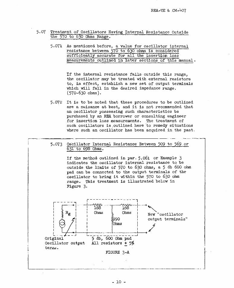
5.074 The effect of the 600 ohm 5 db pad is also to reduce the available oscillator power to a 600 ohm lev·el to as much as 5,2 db. It becomes, therefore, important after treating the osciilator to check its new output power to determine whether a level of O dbm can be obtained. This is accomplished by connecting a 600 ohm resistor across the new "output terminals" and ~hown in Figure 3B,
! t·~··--168 ..n.
I I I I
-----<>-4------- -- - ---1
Oscillator
FIGURE 3-B
5.075 Oscillator Internal Resistance Any Value Outside 570-630 ohm Range.
This method has no theoretical limitations as to the value of oscillator internal resistance which can be corrected. Again, however, it should be borne in mind that if the oscillator internal impedance is considerably higher than 600 ohms little power will be delivered from the new output terminals to an external 600 ohms load. Therefore a 600 ohm resistor should be connected across the new oscillator output terminals to indicate if the oscillator is capable of providing a reference level of at least zero dbm. The procedure is outlined below in Figure 4.
r------ A
i Lg;--____ ::i~~:!:_2%~w
1 , a.c.- V1 Oscillator I I
L-----~l :~vm - l ______ ~/~;:!als Oscillator"Sf" - A -
FIGURE 4-A 600 Ohms ,------7
1 ----~~-r~ I V1 600 , vm Ohms I
T
a.c.- J J2 vtvm _ _r_ I L _____ _._
Oscillator~ - B - FIGURE 4-B
- 11 -

5.07
REA-TE & CM-407
Per Figure A 1. Turn oscillator output level control to give 1.55 volts on a.c.-vtvm.
Per Figure B 2. When external 600 ohm load (R1 ) is connected across the new oscillator Output tel'l)l.inals, A and B, fncrease. oscillator output level control to maintain the original 1.55 volts (Vi) across the oscillator output terminals.
3. Read the voltage V2 across the 600 ohm load resistor RL, directly in dbm on the a.c.-vtvm.
5,0751 Figure 4 shows the a.c.-vtvm set to 1.55 volts. It is to be emphasized that the setting of the a.c.-vtvm is to be maintained constant at 1.55 volts by varying the oscillator output level control under all measurement and calibration conditions or this method of correcting for internal resistance outside ~he desired range is not valid. In addition, if the 1.55 volts can be maintained when a 600 ohm load resistor is placed across the new output terminals, the oscillator is capable of delivering zero dbm into a 600 ohm load.
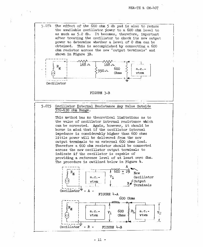
Example • Measurement of Oscillator Internal Resistance (Between 631 and 693·ohms)
It is desired to measure the internal resistance of a certain oscillator at 1 kc/s to find out if any treatment external to its terminals is necessary. A carbon resistor marked as 560 ohms is found to be 558 ohms with a d.c. Wheatstone Bridge.
f-}::~ . -~ --1 • I 11,2 1 ® 1 Volts I . I I
,- -- -I I
1558, 1ohm I
~ I v~its I l i
I ~----<>' L _______ --l 1
· 1 a.c. L _____ , ;:r vtvm
I
I I I I I I
I '- - - - - ..J
a.c. vtvm
Oscillator - B - - C -
FIGURE 5
- 12 -
REA-TE & CM-407
Per Figure A: Set oscillator to 1 kc/sand turn output control to maximum.
Per Figure B: Reading on a.c.-vtvm open circuit= ll.2 volts.
Per Figure C: Reading on a.c.-vtvm across 558 ohms= 5.0 volts.
5,077 Example 5,
Rg = 558 (1~:~ - 0 = 558 X 1.24 = 692 volts
The internal resistance of this oscillator is outside the accepted 570 to 630 ohm range. It may therefore be treated by either of the methods shown in Figures 3 and 4. ANS.
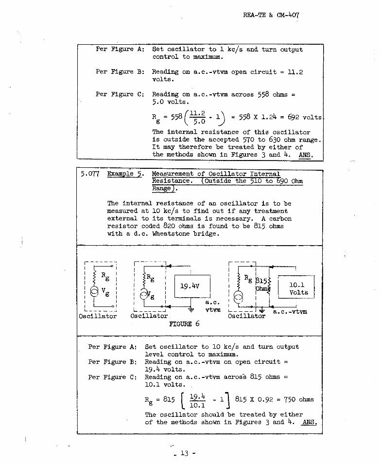
Measurement of Oscillator Internal Resistance. (Outside the 510 to 690 Ohm Range),
The internal resistance of an oscillator is to be measured at 10 kc/s to find out if any treatment external to its terminals is necessary. A carbon resistor coded 820 ohms is found to be 815, ohms with a d.c. Wheatstone bridge.
,-------7 I I I I I I I g I
19.4v
a.c.
,---1 I I I I I I I I I
10.1 Volts
L _______ ...J ,;:-
Oscillator vtV1I1 "-----'
Oscillator a. c. -vtvm
FIGURE 6
Per Figure A: Set oscillator to 10 kc/sand turn output level control to maximum.
Per Figure B: Reading on a,c.-vtvm on open circuit= 19.4 volts.
Per Figure C: Reading on a.c.-vtvm across 815 ohms= 10.1 volts.
Rg = 815 f l9, 4 - 11 815 X 0.92 = 750 ohms l 10.1 The oscillator should be treated by either , of the methods shown in Figures 3 and 4. ANS.
_ 13 -

REA-TE & CM-407
Example Power Output Capability of·oscillator Having Internal Resistance Greater than 698 Ohms.
To determine if the oscillator of Example 5 is capable of delivering O dbm or greater into an external 600 ohm load, R2, after treatment external to its output terminals has been applied according to Figure 7.
FIGURE 7 Solution. It is not necessary to find this out by (tirect
measurement although it may be verified in this manner . .An easier method allows to calculate this from Ohms' law since Rg and'Vg are now known.
1. Current in RL = Vg = 19.4 = 9.95 ma .. -------Rg +Rs+ RL 75o+600+600
2. Voltage drop in RL = lL X RL = 0.00995 X 600 = 5.96 volts
3. From Table I this is about +17. 7 dbm.
4. The oscillator is therefore capable of delivering in excess of zero dbm into a 600 ohm load; it may therefore be considered suitable.
5.079 Output Power Levels Other Than Zero DBM for Oscillators Treated per Figure 4.
If other dbm levels at the treated oscillator output terminals are desired their appropriate voltage readings can be found from Table I. Note that 1.55 volts in the same table corresponds to +6 dbm. This is also in accordance with the half-voltage method which states that the oscillator output level control on -open circuit should give .a voltage reading that is 6 db higher than that desired into a 600 ohm load (note also that the a.c.-vtvm l in Figure 7 is not across the load above). Although using dbm
- 14 -

REA-TE & CM-407
(600 ohm) tables in this manner may be questioned, the fact that we are only considering differences in level, (db's rather than dbm's) justifies it. The above procedures are slightly modified where repeating coils are required, as discussed below.
6. D.C. "HOUSEKEEPING"
6.01 Where measurements of facility (outside plant) insertion.loss are to be made, the importance of the facilities being in a good state of d,c. housekeeping cannot b~ overemphasized. These facilities should be free from opens, shorts, crosses, grounds, leaks, or split pairs. Procedures toward that end are outlined in appropriate TOM and TE & CM Sections.
7. WHAT FACILITY INSERTION LOSS INCLUDES
7.01 In general, facil~ty insertion loss is not the same attenuation. Attenuation may be thought of as a special case of insertion loss where the characteristic impedance of the facility is. the same as the impedance of either the oscillator or the load. For the measurements outlined herein,. this value of 600 ohms resistive is closely approximated at carrier frequencies in open wire lines average-spaced between 8 and 12 inches.
7.02 Facility insertion loss includes:
1. Attenuation.
2. Reflection at the sending and receiving ends.
3, Interaction between the sending and receiving ends as modified by the intervening network or facility.
4. Absorption Peaks where the facility is open wire.
7 .03 The at.tenuation for• most non-loaded facilities used by REA borrowers is contained in REA-TE & CM-406, Attenuation Data and that of loaded facilities is found in REA-TE & CM-431, Voice Frequency Loading for Trunk Cables. The data is given at a specific temperature as indicated in each table, and, for open wire under "wet" conditions. Usually facility insertion loss is measured at some temperature other than specified in the attenuation tables and for dry weather. Therefore in order to be able to estimate a reasonable value for attenuation under measurement conditions, some correction factors will have to be applied to the published data.
7.04 Table II herein gives factors which may be used to correct data on "wet" attenuation to "dry." Although the values
- 15 -

REA-TE & CM-407
applying to open wire in Table II (and Table IV, below) assume 8 inch spaced facilities, they may be applied to 12 inch spaced facilities with small error.
7.05 Table III herein gives factors which may be used to .correct approximately for temperatures which a.re different from those stated in the attenuation tables. From this table, a "temperature correction factor" may be obtained using the following formula.
= 1 [ lOOD
Temperature correction factor. from REA-TE & CM-406.
l Temperature recorded during measurements in degrees Farenheit.
D = Approximate number of degrees Farenheit change in temperature for 1i change in attenuation. From Table III.
To obtain the estimated attenuation of the facility being measured, multiply the attenuation shown in the table in REA-TE & CM-406 by FT and the length of the facility in miles.
7.06 Reflection Losses are the result of impedance mismatches created by the joining of dissimilar facilities. In effect they place impedance irregularities in an otherwise smooth line so that current traveling do'Wl;l in the line is reflected back towards the sending end and therefore constitutes a loss in the useful amount ~f energy that can be delivered to a load. It is of course different for different frequencies since the impedance of these facilities is a function of frequency. These losses, in the case of such diverse facilities as cable and open wire tend to increase as the frequency is increased.
It is possible, however, in some instances for the magnitude and phase of these impedances to combine in such a manner as to produce a reflection gain. Reflection losses up to 400 kc/s are included herein as Table IV, and given for several frequency ranges, where the reflection losses between
.some facilities change signific~ntly. For more accurate results (not warranted in the usual case of checking the
- 16 -

REA-TE & CM-40'7
results of measurements) interpolation may be employed. For example, if the reflection loss between 22 gauge cable and 600 ohms is desired at 65 kc/s the average of the reflection losses shown in Table IV, at 30 and 100 kc/s may be taken as (1.9 + 2,5)/2 = 2.2 db.
7.07 Interaction Losses. Interaction losses are a further extension of reflection losses. They represent the sum total -Of all possible reflections traveling back and forth in the line as a result of impedance mismatches between the generator, facilities and load as modified by the attenuation of the line. The relation which describes interaction losses is a highly complicated one and unlike the reflection loss is not readily adaptable to calculation. Based on a lim.ited number of calculations on some facilities used by REA borrowers, the interaction loss can apparently cause the measured insertion loss to be different from the sum of attenuation plus reflections by as much as one db for each facility in the line. This is true where the line insertion loss is less than 10 db. For line losses greater than about 10 db, interaction may safely be ignored in insertion loss measurements.
7.o8 Absorption Peaks will occur in all transposed open wire pairs at some frequencies and when they do will always cause a transmission loss. Though the physical phenomenon of the absorption peaks is not very well understood it, manifests itself as follows in an open wire line: Undesired coupling from one pair to other pairs (not necessarily the adjacent pair) results in energy loss at some particular high frequencies making the line attenuation in excess of its normal loss and in a very uneven manner so that the attenuation-frequency characteristics resemble a set of peaks and valleys. The severity of these absorption peaks and also their shape depends to a great extent to the transposition pattern used and the geometry of the open wire line. Absorption peaks can be severe and where insertion loss at carrier frequencies shows a loss not accounted for.by attenuation, reflection and interaction, absorption peaks may b_e suspected. Appropriate sections of REA.;.TE & CM give the approximate frequency ranges where absorption peaks may occur for a particular transposition system. Example 20 illustrates in detail an insertion loss measurement.
7.09 Therefore, provided that absorption peaks in open wire lines are not present the insertion loss formula can be approximatP.d:
- 17 -
REA-TE & CM-40'7
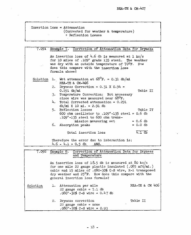
Insertion Loss= Attenuation (Corrected for weather & temperature) + Reflection Losses
7,091 Example 7, Correction of ttenuation Data for Dryness
An insertion loss of 4.6 db is measured at 1 kc/s for 10 miles of .109 11 grade 135 steel. The weather was dry with an outside temperature of 70°F. Hnw does this compare with the insertion loss formula above?
Solution 1.
2.
3.
4.
5.
Wet attenuation at 68°F. = 0,31 db/mi REA-TE & CM-406 Dryness Correction= 0.31 X 0.94 = 0,291 db/mi Temperature Correction: Not necessary since wire was measured near 68°F. Total Corrected attenuation= 0.291 db/mi X 10 mi. = 2,91 db Reflection losses
Table II
Table IV 0.6 db 600 ohm oscillator to ,109"-135 steel=
6.
.109"-135 steel to 600 ohm trans-mission measuring set
Absorptiqn peaks
Total insertion loss
Therefore the error due to interaction is: 4.6 - 4.1 = 0,5 db ANS.
= 0.6 db = 0.0 db
4.1 db
7. 2 Example • Correction of Attenuation Data for Dryness and Temperature
Solution
An insertion loss of 18.5 db is measured at 80 kc/s for one mile 22 gauge plastic insulated (.o85 mfd/mi.) cable and 15 miles of .oB0-30'/o C-S wire, R-1 transposed dry weather and 25°F. How does this compare with the general insertion loss formula?
1. Attenuation per mile 22 gauge cable = 7 .1 db . o80" - 30<,(, C-S wire = 0. 4 7 db
2. Dryness correction 22 gauge cable= none .o80"-30 C-S wire= 0.93
- 18 -
REA-TE & CM 406
Table II

REA-TE & CM-4o7
3. Temperature-Correction 22 gauge cable
Table rn
F = 1 - TA - TR = 1 - 55-25 = 0.97 T lOOA lOOXlO
.o80"-3~ C-S
F = 1 - 68-25 = 0.914 T 100X5
4. Corrected Attenuation
5.
6.
22 gauge cable = 7.1 db/mi X 0,97 X 1 mi. = 6.88 db .o80"-30% C-S wire= 0.47 db/mi X ,93 X 0.914 X 15 mi.
= 5,99 db
Reflection Losses Table IV 600 ohm oscillator to 22 gauge cable = 2.5 db .oB0"-30% C-S and .109"-135 steel .o80"-3~ C-S wire and 600 ohm
= 2,7 db
transmission measuring set = 0 db
Total insertion loss 18. 1 db
The difference of o.4 db from that of the measured insertion loss may be assumed to be interaction. ANS.
8. WHEN SHOULD REPEAT COILS BE USED IN INSERTION LOSS MEASUREMENTS?
8.01 Repeat coils are usually employed for the following purposes:
1. To measure a balanced circuit with unbalanced test equipment without disturbing the a.c. characteristics of the balanced circuit.
2. To isolate direct currents in one or both circuits between which the repeat coil connects without disturbing the a.c. flow.
3. To match impedances between circuits.
8.02. Balanced to Unbalanced
8.021 Repeat coils are required for making insertion loss measurements on:
1. Any outside plant facilities with the exception of coaxial cable.
- 19 -

REA-TE & CM-407
2. Any central office equipment which connects to outside plant conductors in normal operation and is not already equipped with repeat coils at the terminals at which measurements are made. This may include line circuits, long line adapters, revertive call switches, trunk and connector circuits.
3. The "carrier line," "C.O. line," or "subscriber line" terminals of carrier equipment.
4. Carrier line filters not alrea~y equipped with repeat coils.
5. Any attenuation pad.
8.03 Isolation of Direct Currents
8.031 Where it becomes necessary to measure a circuit which requires a superimposed d.c. a repeat coil should be used to permit d.c. in the measured circuit and isolate d.c. from the oscillator or voltmeter equipment. This is mainly to protect the oscillator equipment, as some of the better ones have 600 ohm pads through which the output level is set and which may easily be damaged on application of d,c, Most a.c. voltmeters do have d.c, blocking however at their input terminals.
8.04 Impedance Matching
8.041 For the purpose of the measurements described herein only one to one ratio repeat coils are considered; where as other ratios can be used for the purpose of matching impedances, such procedures are beyond the scone of this section.
8.05 The insertion loss of the repeat coil should not exceed 0,5 db (connected one to one ratio) within its rated frequency range with or without superimposed d.c. flowing through it. An example of such a coil in the frequency range of 20-10,000 cps is the W. E. Co. 120H Repeating Coil. In the 1 to 400 kc/s frequency range a Lynch Carrier Systems, Inc., 2624 Repeat Coil is suitable if the latter is not used to isolate d.c.
9. EFFECT OF PRESENCE OF INDUCED VOLTAGES (NOISE AND CROSSTALK) ON INSERTION LOSS MEASUREMENTS.
9.01 The a,c.-vtvm's so far described herein are flat. That is, they will give equal weight to voltages of frequencies over practically the entire range of telephone wire line transmission among REA borrowers. High frequency interference may also
- 20 -

REA-TE & CM-407
be present. Any voltage in this range which is induced into the facility being measured may cause the a.c.-vtvm to read more than the power received from the oscillator. Thus a false "receive power" reading and will result as far as the measurement of insertion loss is concerned.
9.02 As a practical matter, open wire will most often have a level of metallic 60 cycle voltage which will interfere with insertion loss measurements if not discriminated against by the transmission m measuring set (defined below). This is less true for circuits entirely in cable.
9.03 Correction to Be Applied To Voltmeters When Noi&e is Present on The Facility.
If the a.c.-vtvm reading of noise is of a level comparable to the combined noise and received signal, a correction may be applied to this combined signal and noise to obtain the received signal power level alone. Step-by-step procedure is as follows:
1. Oscillator-on at sending end. Read the combined signal and noise at receiving end.
2. Oscillator-off at sending end. Read the noise only at the receiving end.
3. If the reading in (1) is at least 15 db greater than that in (2) the noise reading can be safely ignored and the true power then at the receiving end is the reading obtained in (1).
4. If the reading in {1) is less than one db greater than the reading in (2) then the reading in (1) cannot reliably be taken with an a.c,-vtvm of the type so far described. A selective type a.c.-vtvm (described below) should be used.
5. If the difference in the readings in (1) and (2) is between one and fourteen db, reference to Table V will provide correction factors to be subtracted from the reading in (1) to obtain the true received signal level.
9.04 Selective Type Voltmeters. Voice Frequency Measurements
9.041 One way of reducing the magnitude of sixty cycle induced components in a meter reading is to place a weighting network in front of the a.c.-vtvm, which will reject sixty cycles but permit sudio frequencies to reach the amplifier and therefore deflect the indicating meter in the instrument.
9.042 Devices originally designed for noise measurements are suitable as selective voltmeters. The W. E.. Co. 2B or the Daven Co. 34B Noise Measuring Sets are examples of in_struments which when properly connected and calibrated are suitable for insertion loss work at levels as low as
- 21 -
REA-TE & CM-407
-60 dbm (balanced or unbalanced) from about 180 to 3000 cycles, with modifications extending their operation to 15 kc/s. These instruments are insensitive to 60 cyclee as well as carrier frequencies over the frequency range of 15 kc/s.
9.043 If there are interfering signals in the range of the instrument the step-by-step instructions of par. 9.03 should be followed. If the condition of step (4) in par. 9.03 obtains a value of less than one db for the combined value.of measured and interfering signal than the reading of the interfering signal alone, the output level of the oscillator may be raised so as to affect a better signal to noise ratio and so·that the correction factors of Table V can be applied.
9.044 For best results, however, a passive vacuum tube or transistorized variable tune~ frequency network should be connected ahead of either of the a.c.-vtvm's described above. Examples of such passive networks are the W. E. Co. l0A Noise Analyzer Attachment Filter, and may be advantageously used for these type of measurements. The first is of the continuously variable type whenever the latter comes in step frequencies.
9.05 Selective Type Voltmeters. Carrier Frequency Measurements.
9.051 Interference from wire line carrier, powerful radio stations, and other sources of voltages of high enough level to interfere with carrier frequency measurements may occur at any frequency in either open wire or cable. Highly selective carrier frequency voltmeters are availabi~• and can be used advantageously for the elimination of the undesired signals and measurement of the desired levels. A matching transformer is usually required at the input of these selective voltmeters and in all cases a 600 ohm carbon resistor for measurement of signal levels in dbm. Two such voltmeters which are suitable for carrier frequency insertion loss work are the Sierra Electronics Corp. Models lo8A and 121 and Rycom Model 2174 Carrier Frequency Voltmeters.
9,052 It is possible however that an interfering frequency might be present at the desired frequency under measurement. In this case the expedient of shifting the oscillator ... frequency somewhat_will put the interfering frequency into the rejection band of the voltmeter tuned circuit and
- 22 -

REA-TE & CM-4o7
measurement will be possible. Also it might be possible to raise the oscillator output level well above that of the interfering signal, so that application of the correction factors of par. 9.03 can be used. The maximum
-recommended level, however, in the latter case at the input terminals of any electronic equipment under measurement should not be exceeded. Excessive distortion or outright failure of the equipment itself might otherwise result. These types of voltmeters require calibration before used for measure~ents.
10. SELECTION AND CALIBRATION OF OSCILLATOR AND TRANSMISSION MEASURING SET EQUIPMENT.
10.01 For the purposes of this section "Oscillator Equipment" is defined as one of the following:
1. An oscillator meeting the requirements of par. 5.05 with no external modifications and used for measuring equipment with one terminal grounded as per Fig. 8A or for balanced measurements. In the latter case the oscillator must be used with a repeat coil as per Fig. 8B.
2. An oscillator having an internal resistance between 509 to 569 or between 631 to 698 ohms and treated with an external pad for measuring equipment with one terminal grounded as per Fig. 9A or for balanced measurements. In the latter case the oscillator must be used with a repeat coil as per Fig. 9B.
3. An oscillator having an internal resistance less than 570 or more than 530 ohms and externally treated with a 600 ohm resistor and a.c.-vtvm for measuring equipment with one terminal grounded as per Fig. lOA or for balanced measurements. In the latter case the oscillator must be used with a reveat coil as per Fig. lOB.
10.02 A "Transmission Measuring Set" usually abbreviated as TMS is arbitrarily defined as either:
1. An a.c.-vtvm and 600 ohm resistor(+ 2%) for measurements on unbalanced equipment as per Figs-:- 8A, 9A or lOA or an a.c.-vtvm and a 600 ohm resistor with a repeat coil for balanced measurements as per Figs. 8B, 9B and lOB.
2. A frequency_selective voltmeter as described in par. 9.
10.03 Thus the considerations for choosing oscillator equipment and a transmission measuring set may be summarized in Table A.
- 23 -

• REA-TE & CM ... 4'07
TABLE A
Eq_uipment or Figure applicable Facilities to Range of oscillator for calibration of be measured internal resistance test eq_uipment
Unbalanced Between 570 and 630 Ohms 8A balanced 8B
Unbalanced 509 to 569 or 631 to 598 9A balanced ohms 9B
Unbalanced Less than 570 or more than lOA balanced 630 Ohms lOB
10.04 Calibration of Measuring Eq_uipment
Any of the test setups ih Figures 8, 9 or 10 may be used to ca1ibrate the output level of the oscillator eq_uipment prior to making measurements. The general step by step instructions for the above Figures are shown in paragraphs 10.041, 10.042 and 10.043. Illustrative examples then follow in paragraphs 10.044 to 10.048.

10.041
REA-'.I'E & CM-407
Calibration of Oscillator Output Level for Oscillator Internal Resistance Between 570 to 630 Ohms
Oscillator equipment Transmission Measuring Set·Equipment r----------,
~ Rg •
'[:_ ~----------Ji
I I I I f
I I I I I I
Oscillator
. I i
I t, 600
I Ohms
i -
7
a.c. vtvm
I
Set to desired
V level in ,- dbm
A. UNBALANCED MEASUREMENTS (~O REPEAT COILS)
Oscillator Equipment Transmission Measuring Set Equipment r-- - -, r-----1 r---.---7 r~:=]~ I
tRg I ~t•:
I 2a . , 4
I I I -< ,.,.. I I I I i . 3 I
C r ;1
I I I 1,J: I 600 I , a.c.
I 1 I I :t: Ohms : vtvm Vgl I 611:--81 I 6 ..)
I ',.. I I i ,,..
I s.) t I I I 5 (._ .71 I .7,
L ____ _j~ L------ ..J L __ -- - - _,
Oscillator Repeat Coils ?
Procedure:
B. FOR BALANCED MEASUREMENTS (REPEAT COILS USED) ··---- · ... ·------·.
1. Set oscillator to desired frequency.
2. Va.x:y oscillator output level control for a.c.-vtvm (Selective or nan..,..selective) to register desired reference level in dbm or volts across the 600 ohm resistor. (0.775 volts across this 600 ohm resistor if O dbm reference level is desired.)
3. Do not change the oscillator output level control.
4. The oscillator equipment is now calibrated to measure insertion loss in db between a 600 ohm source and load.
5. Repeat steps 1 to 3 above for each frequency under measurement.
FIGURE 8
Note: Terminal Numbers of repeating coils shown are W. E. Co. 120H.

REA-TE & CM-407
10.042 Calibr~tion of Oscillator Output Level for Oscillator Internal Resistance Between 509 to 569 or 631 to 698 Ohms
Oscillator EQuipment ! Transmission Measuring Set
,------, I I i----Nv\/' . ... -J\/v\l'----r-0 . --: R / 168 168 . I g I Ohms Ohms I I I . I ·· V I 990 1600 I g I 1 I Ohms . Ohms
~-------Jl- 5-·db--600 Ohm.pad+-- ·-----···-- ' Oscillator -=-
a.c. -j ..____vtvm __ _
A. UNBALANCED MEASUREMENTS (NO REPEAT COILS)
Oscillator EQuipment ! Transmission Measuring Set [. _______ _
I ,-------, I ~--<>·+-..../\IVV'
I 1 R 1 168 I g I I I Ohms I I I I
·- V I I ' g I I ----+i L------....J-5 Oscillator '
,------ -,, ,------, -./I/Vv'~3 ' • I 11 • ) rr-1 2. •--4 I I 2. 4
168' l l. ' 7( ~ I I : J. j 3 : Ohms r· 111 t·~ -7 I
990 : ~ .. I : L _j :600 Ohms I 6 '"'1 S-B i 1, 1 6 ) ~ e 10
I ) I I ..) I I 5 -c-1115_) 71
t.-:=-<>· ____ o_llL.~-------' ~ Repeat coils ~
a.c. vtvm
db, 600 Ohm pad
~ B. BALANCED MEASUREMENTS ( REPEAT COILS USED)
Proced-ure-: --
1. Set oscillator to desired freQUency.
' ' I 2·, Vary oscillator output level control for a.c.-vtvm (Selective or non-selective).to register desired reference level in dbm or in volts across the 600 ohms resistor. (0.775 volts across this 600 ohm resistor if O dbm reference level is. desired).
3. Do not change the oscillator output level control.
4. The oscillator eQuipment is now calibrated to measure insertion loss in db between a 600 ohm source and load.
5, Repeat steps 1 to 3 above for each freQUency under measurement.
Note: Terminal Numbers of repeating coils shown are W. E. Co. 120H.
FIGURE 9
- 26 -

10.043
REA-TE & CM-407
Calibration of Oscillator Output Level for Oscillator Internal Resistance Less Than 570 or Greater Than 630 Ohms
Oscillator Equipment
A.
Oscillator Equipment
,/\/VV'-~ -
600 Ohms\ + 2% . - I
I
Transmission Measuring Set
600 Ohms ~ 2%
- --· ---] _____ _
a.c. vtvm2
UNBALANCED MEASUREMENTS (NO REPEAT COILS)
Transmission Measuring Set
Procedure: Per Fig. A 1. Set oscillator to desired frequency for A or B.
2. Vary oscillator output level control for 1.55 volts on a.c.-vtvm1,
3. Maintain this level at 1,55V on vtvm1 during measurements by varying oscillator output level control.
4. Oscillator equipment is now calibrated for O dbm.
Per Fig. B 5. Vary oscillator output control to obtain 0.775 volts on a.c.-vt~ but record voltage on a.c.-vtvm1,
6. Maintain this same level on a.c.-vtvm1 for all measurements that follow by varying the oscillator output level control.
7. The oscillator equipment is now calibrated for a level of O dbm.
Note: Terminal Numbers of repeating coils shown are W. E. Co. 120H.
FIGURE 10
- 27 -

l0.044 Example 9
Solution:
10.045 Example 10
REA-TE & CM-407
Calibrate an oscillator having 595 ohms internal resistance for an output level of O dbm prior to making an insertion loss measurement on a 600 ohm "T" pad at 200 kc/s.
Since the internal resistance of the oscillator is 595 ohms Figure 8A is applicable. Steps l to 3 of Example 10 below/completely describe this calibration; ANS,
Calibrate an oscillator having an internal resistance of 595 ohms for an output level of O dbm prior to making an insertion loss measurement on a length of .o80"-30% C-S facility at 200 kc/s. What is the insertion loss of the repeat coils used for this measurement?
J a.c.-vtvm
Oscillator FIGURE 11-A
,------r I I I
I I I
595 Ohms
l. 2.
3, 4.
Set oscillator frequency to 200 kc/s. Vary oscillator output level control for 0.775 volts on a,c.-vtvm. Do not change oscillator output level, Insert repeating coils as shown in Figure llB below.
Repeat Coils
I .,_;_I_-.-<>-_, ~ - _:-·=-:-= . .J
~--1 r, :--~;, Oscillator FIGURE 11-B
5. Read the new reading on the a.c.-vtvm. Say it is 0.704v which from Table I yields -0.8 dbm.
6. This means then that each repeat coil has a loss of 0.4 db which is within limits. ANS.
7, Raise the oscillator output ievel control for 0 dbm on the a.c.-vtvm. The oscillator equipment is now calibrated for proceeding with the insertion loss measurements. ANS.
--------- ___.
- 28 -

REA-TE & CM-407
10.046 Example 11 Calibrate an oscillator having an internal resistance
of 691 ohms for an output level of 0 dbm prior to measuring at 1 kc/s a length of H-88 loaded facility. What is the insertion lnss of th~ repeat coil used for the measurements?
Solution r -- - - - -: I c· ---~ : i I < 691 I 168 · 168 1 ~ Ohms : c:Jhms~ Ohms 600
;~ I 990 Ohms I 0.775v a.c.-vtvm
::j l Ohms I I L--- ... -~ --·---•·-··-----··-·----1-+---·--J
Os-cili~to~ J~ FIGlJRE 12-A
-------1.1"
Oscillator
1. Set oscillator frequency to 1 kc/s.
2. Vary oscillator output level control for 0.775 Von a.c.-vtvm.
3.
4. Do not change oscillator output level.
FIGURE 12-B
a.c.-vtvm
0.711v
5. Read the new reading on the a.c.-vtvm; say it is 0.711v. From Table I this is -0.7 dbm.
6. Since this is 0.7 db below zero we can assume each coil has a loss of 0.35 db and they are suited for the intended measurement. ANS.
7, Rai$e the oscillator output level control to indicate 0 dbm on the a.c.-vtvm. The oscillator equipment is now calibrated for the intended measurement. ANS.
- 29 -
REA-TE & CM-407
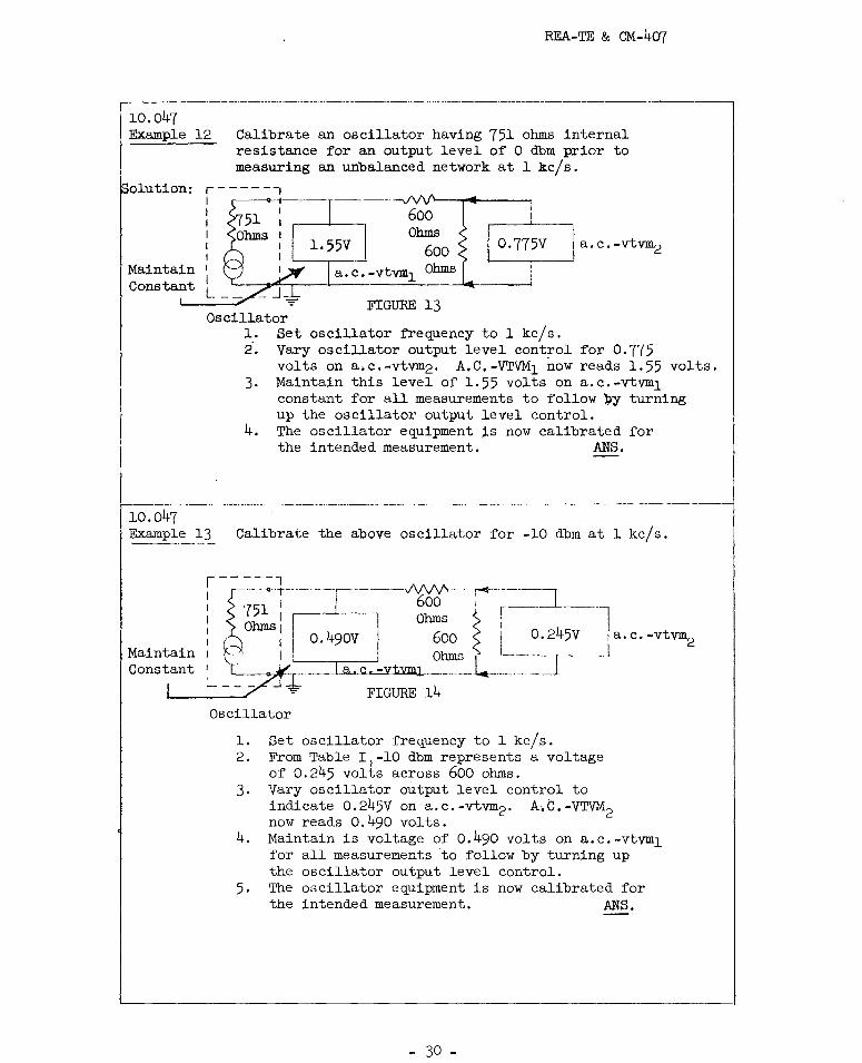
l0.047 Example l2 Calibrate an oscillator having 75l ohms internal
resistance for an output level of O dbm prior to measuring an unbalanced network at l kc/s.
olution: r------,
Maintain Constant
I o I I I I I
600 I I Ohms
l.55y 600
a.c.-vtvml Ohms
FIGURE l3 Oscillator
l. Set oscillator frequency to l kc/s. i. Vary oscillator output level control for 0.775
volts on a.c.-vtvm2. A,C.-VTVMl now reads l.55 volts. 3, Maintain this level of 1.55 volts on a.c.-vtvm1
constant for all measurements to follow py turning up the oscillator output level control.
4. The oscillator equipment ~snow calibrated for the intended measurement. ANS.
10.047 Example l3 Calibrate the above oscillator for -lO dbm at l kc/s.
Maintain Constant
r-----,
! D~: i-0-~f = 1-1~ f i--~45v
: \r_ 7--- ~tvmi J. _________ I -- - - .- -1 + FIGURE l4
Oscillator
l. Set oscillator frequency to 1 kc/s. 2. From Table 1
1-lO dbm represents a voltage
of 0.245 volts across 600 ohms.
I 1a,c.-vtvm
2 I
3, Vary oscillator output level control to indicate 0.245V on a.c.-vtvm 2 . A.C.-VTVM2 now reads 0.490 volts.
4. Maintain is voltage of o.490 volts on a.c.-vtvm1 for all measurements to follow by turning up the oscillator output level control.
5. The oscillator equipment is now calibrated for the intended measurement. ANS.
- 30 -
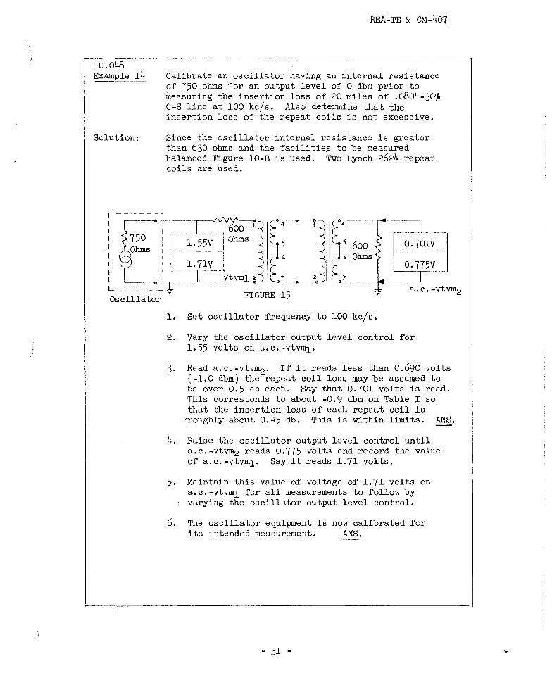
10.048 Example 14
Solution:
REA-TE & CM-407
Calibrate an oscillator having an internal resistance of 750 .ohms for an output level of O dbm prior to measuring the insertion loss of 20 miles of .o80"-30% C-S line at 100 kc/s. Also determine that the insertion loss of the repeat coils is not excessive.
Since the oscillator internal resistance is greater than 630 ohms and the facilitie~ to be measured balanced Figure 10-B is used; Two Lynch 2624 repeat coils are used,
FIGURE 15
1. Set oscillator frequency to 100 kc/s.
2. Vary the oscillator output level control for 1. 55 vol ts on a. c. -vtvm1.
3. Read a.c.-vt~. If it reads less than 0.~90 volts (-1.0 dbm) the repeat coil loss may be assumed to be over 0.5 db each. Say that 0,701 volts is read. This corresponds to about -0,9 dbm on Table I so that the insertion loss of each repeat coil is
'roughly about 0.45 db. This is within limits. ANS.
4. Raise the oscillator output level control until a.c.-vtvm2 reads 0.775 volts and record the value of a.c.-vtvm1, Say it reads 1.71 volts.
5. Maintain this value of voltage of 1.71 volts on a.c.-vtvm1 for all measurements to follow by varying the oscillator output level control.
6. The oscillator equipment is now calibrated for its intended measurement. ANS.
- 31 -

REA-TE & CM-407
10.05 Calibration for a Frequency Run Where Terminals of Network to be Measured are Accessible or Remote From Each Other.
10.051 "Frequency run" indicates a series of insertion loss measurements in the frequency range of interest using the same "oscillator equipment" and output level.
10.052 Where the input and output terminals of the facility or network to be measured are accessible at one location, one transmission measuring set will suffice by both calibration and measurement, and depending on the oscillator resistance one of the procedures in Figures 8, 9 and 10 will be appropriate for calibration.
10.053 Where the input and output terminals of the facility or network to be measured are remotely located from each other, two transmission measuring sets will be required forafrequency run; one at each terminal. This again will be performed as per one of the procedures in Figures 8, 9 or 10.
11. INSERTION LOSS TEST SETUPS
11.01 We may now summarize, before proceeding with the procedure for actual insertion loss measurements, the factors so far involved in the choice of test equipment and the procedures used for calibration.
1. Desirable characteristics were given for oscillators and a.c.-vtvm measuring equipment which would meet the features shown paragraphs 5.05 and 4.023,
2. Due emphasis was placed on the oscillator equipment having an internal resistance of·570 to 630 ohms over the desired frequency range. This is a most desirable feature and greatly simplifies calibration and measurement. Measurement of oscillator internal resistance was shown in Figure 1 and Example 3,
3, Procedures were given for externally treating oscillators having internal resistances outside the desirable 570 to 630 ohms range in Figures 3 and 4 and also illustrative Examples 4 to 6.
4. Calibration procedures were then given in detail for all measuring equipment and accessories prior to making the actual insertion loss measurements in Figures 8 to 10 and also illustrative Examples 9 to 14.
- 32 -

REA-TE & CM-407
11.02 General Procedure
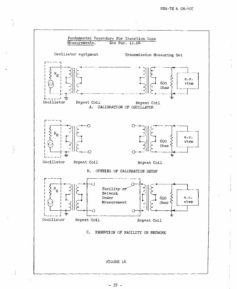
11.021 All insertion loss measurements follow the same fundamental procedure once the measuring equipment has been calibrated. That is the network or facility is inserted between the oscillator and a.c.-vtvm equipment properly terminated, and the value of the resulting signal is recorded. The difference between the calibration and measured levels is the desired insertion loss. The receiving equipment may also be, and it usually is, calibrated in dbm in addition to volts. In this case the ca:ibration level is in dbm, a direct reading in db for the insertion loss is obtained. This procedure is shown in Figure 16. Though the sending level can be quite arbitrary care is taken not to overload any electronic equipment also measured; the manufacturers recommendations will therefore be followed. For most measurements a level of 0 dbm seems to be suitable.
11.022 The range of facilities and equipment to be measured for insertion loss is varied. They may be four or two terminal devices unbalanced or balanced, active or passive. Non-loaded and loaded cable facilities, aerial or buried wire, or combinations thereof, trunk equipment filters of any description, repeat coils, attenuation pads and even. a simple series or shunt resistor. Abnormal line loss conditions such as those caused by absorption peaks can also be investigated. Calibration procedures for any of the above cases are fully covered in Figures 8, 9 or 10.
11.023 Insertion loss measurements therefore constitute a powerful tool through which the proper operation of an existing system or any of its components or the suitability of a contemplated application can readily be verified. In addition it provides a means for proper maintenance, once such e4uipments ~ave been installed and are operating.
11.03 Initial and Periodic Check of Measuring Equipment.
1. Be assured voltmeter or voltmeters are sensitive and accurate enough for the frequencies to be measured and frequency selective if applicable.
2. Be assured of the proper oscillator waveform, fre4uency calibration and range and output voltage.
3, Measure the internal oscillator resistance over its full frequency range.
- 33 -
ll.04
REA-TE & CM-407
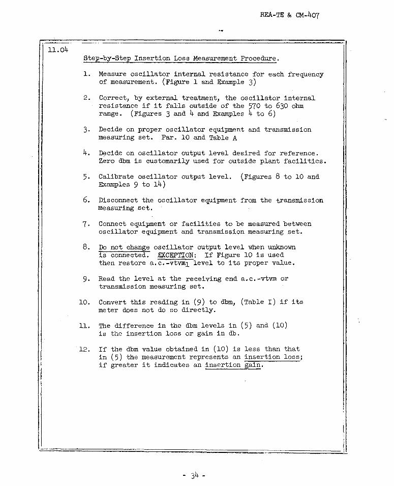
Step-by-Step Insertion Loss Measurement Procedure.
1. Measure oscillator internal resistance for each frequency •Of measurement. (Figure 1 and Example 3)
2. Correct, by external treatment, the oscillator internal resistance if it falls outside of the 570 to 630 ohm range. (Figures 3 and 4 and Examples 4 to 6)
3. Decide on proper oscillator equipment and transmission measuring set. . Par. 10 and Table A
4. Decide on oscillator output level desired for reference. Zero dbm is customarily used for outside plant facilities.
5, Calibrate oscillator output level. (Figures 8 to 10 and Examples 9 to 14)
6. Disconnect the oscillator equipment from the transmission measuring set.
7. Connect equipment or facilities to be measured between oscillator equipment and transmission measuring set.
8. Do not change oscillator output level when unknown is connected. EXCEPTION: If Figure 10 is used then restore a.c.-vtvm1 level to its proper value.
9. Read the level at the receiving end a.c.-vtvm or transmission measuring set.
10. Convert this reading in (9) to dbm, (Table I) if its meter does not do so directly.
11. The difference in the dbm levels in (5) and (10) is the insertion loss or gain in db.
12. If the dbm value obtained in (10) is less than that in (5) the measurement represents an insertion loss; if greater it indicates an insertion gain.
REA-TE & CM-407
Fundamental Procedure For Insertion Loss Measurements. See Par. 11.04
Oscillator e~uipment Transmission Measuring Set
Oscillator
Repeat Coil Repeat Coil A. CALIBRATION OF OSCILLATOR
Repeat Coil Repeat Coil
B, OPENING OF CALIBRATION SETUP
Repeat Coil
Facili-tyNetwork Under Measurement
600 Ohms
Repeat Coil
C. INSERTION OF FACILITY OR NETWORK
FIGURE 16
- 35 -
T
a.c. vtvm
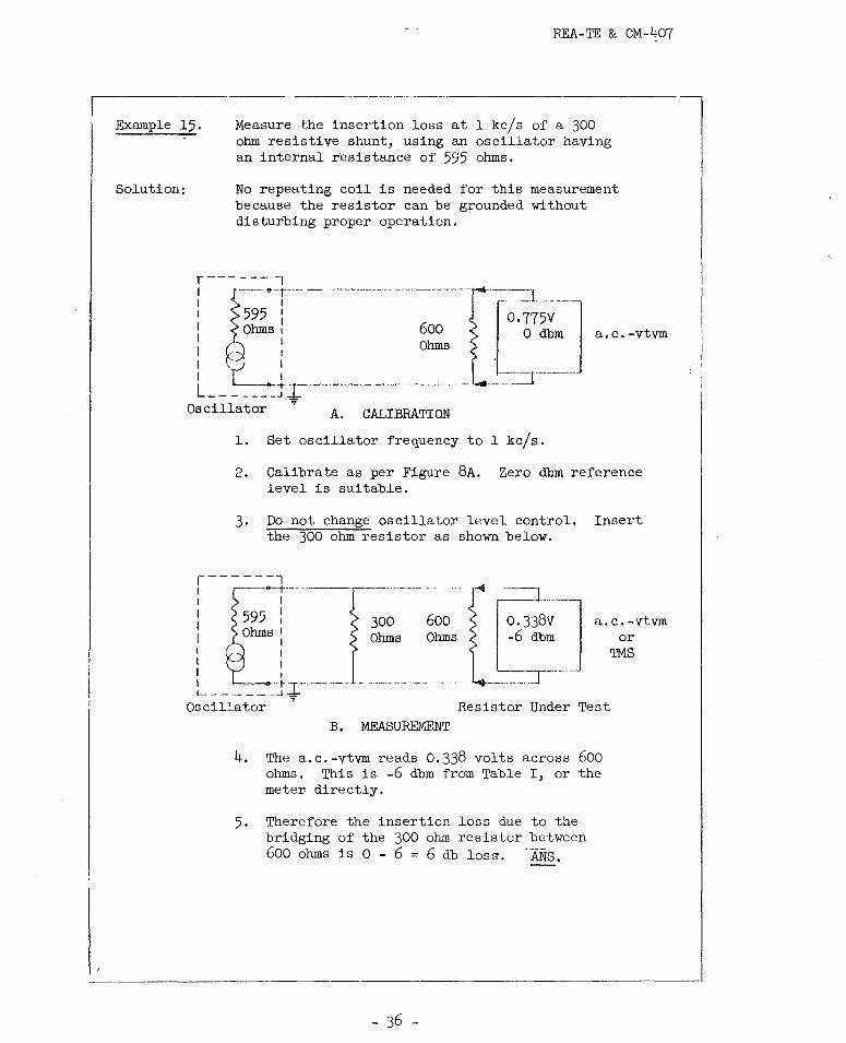
Example 15, Measure the insertion loss at l kc/sofa 300 ohm resistive shunt, using an oscillator having an internal resistance of 595 ohms.
Solution: No repeating coil is needed for this measurement because the resistor can be grounded without disturbing proper operation.
r------7 I -- "_i ____ - ····-----··-··-··--·-···--·---···· I I I 595 : 0.775v I Ohms I I I
600 ·-L---=-.] ____ ~_
0 dbm a.c.-vtvm I Ohms I I I L _______ TJ_ --------·--·--•-···- ◄
=r-.,.
Oscillator A. CALIBRATION
1. Set oscillator frequency to l kc/s.
2. Calibrate as per Figure 8A. Zero dbm reference level is suitable.
3. Do not change oscillator level control. Insert the 300 ohm resistor as shown below.
1-------7 I -<>-·t··-- · ---~-I I
: 595 i I Ohms: I I I I
I ~---'
300 600 Ohms Ohms
O. 338v·-1 a. c. -vtvm -6 dbm or
'IMS
~-----_JJ.-·--··-··· Oscillator .,. Resistor Under Test
B. MEASUREMENT
4. The a.c.-vtvm reads 0.338 volts across 600 ohms. This is -6 dbm from Table I, or the meter directly.
5. Therefore the insertion loss due to the bridging of the 300 ohm resistor between 600 ohms is O - 6 = 6 db loss. ·ANs.

REA-TE & CM-407
----- ··--·------Example 16. A subscriber carrier voice pass filter is suspected
of having a shorted turn. The normal 600 ohm insertion loss according to ·the manufacturers literature is 0.3 db at 1 kc/sand 40 db at 50 kc/s. The available oscillator has an internal resistance of 580 ohms for this frequency range. How should the insertion loss of the filter be checked?
Solution: Figure 9B is used due to the oscillator internal resistance and the normally balanced operation of the filter.
0.775V i or O db
a.c.-vtvm
A. CALIBRATION
1. Set oscillator frequency to 1 kc/s. Calibrate as per Figure 9B. Zero dbm level is suitable.
2. Do not change oscillator level control. 3. Insert voice pass filter to be measured as shown
below.
EIS .) : '>-
- 'I -<:i_;,-I
Carrier Line Side
Voice Side I I':: (I\·
⇒ !:Cl Filter , 1
,,..
Under · •>-
i 600 1-Io. 749v
or -0.3 Ohms : dbm
I '--. . I
--~"--T·' ••-•----·-----·--·-<>--...II.'~ Test ~' '--...,___ __ _ =r- _j a.c.--- -·-----·-;-Oscillator
W. E. C0. 120H or Lynch 2624
1---------~· W. E. Co. . vtvm
B. MEASUREMENTS
120H or Lynch 2624
4. Reading of a.c.-vtvm is 0.749v or -0.3 dbm. 5, Therefore the 1 kc/s insertion loss of the filter
is 0.3 db and seems to be normal. ANS. 6. For 50 kc/s measurement repeat above procedure.
(Change the repeat coils to Lynch 2624) 7. Say the a.c.-vtvm 0.243 volts which is -10.1 dbm. 8. Therefore the 50 kc/s insertion loss of the filter
is 0-10.1 = 10.1 db which is much lower than the manufacturers stated figure of 40 db. Therefore the voice pass filter is assumed to be defective.
ANS.
- 37 -
or ™8

Example 17.
Solution:
Oscillator
REA-TE & CM-407
Measure the insertion loss at l kc/sofa central office connector circuit. The available oscillator has an internal resistance of 590 ohms at this frequency.
Value of oscillator resistance and normally balanced operation of connector dictates the use of Figure 8B Only one-a.c.-vtvm is absolutely necessary since both terminals are accessible in the same C.O.
2 1, ::-•
ir~\'-r~ 600 i ' ! I I hins
_____ : .... --___ .:_! i (_;_~----··-. W. E. Co. 120H ~ 120H
Io. 7°75V I 'or 0 I ~m J
a.c.-vtvm
A. CALIBRATION
1. Set oscillator frequency to 1 kc/s. Calibrate 0 dbm reference level as per steps of Figure 8B
2. Do not change oscillator output level controls. 3. Insert connector to be measured as shown below. This
is accomplished as follows: Connect a telephone set to each of two spare lines in the connector group to be tested at the equipment side of the MDF. Busy-out the rest of the connectors except the one under measurement. Dial a call in the normal manner so that a connection between these two phones is no~ established through the desired connector.
.--~'T . ., I R
' ---
T c---+--1 -
Ro--...--------' ____ ___J
~ 4. After the connection has been established and without
disconnecting the telephone sets connect the oscillator and measuring equipment of A. Now, disconnect the telephone sets.
,-ii~l ~ 1s:f T Co::~tor Under in,~:=, ,. P-7~lV •
· ~ I ,i, l,J, f Test I ;~ ' ~' ordb~·~j '· I < -< , _.,.. \ 1 S -'., 5 ·
~--,-..,..:....-· '---5--+..., R R .,_~...., - ---r-~ • ______ J -=-· _________________ . ---• -or a. c. -vtvm Oscillator' W. E. Co. 120H W. E. Co. 120H
C. MEASUREMENT
5. Read the vtvm or TMS. It reads 0.701 volts which is -0.9 dbm.
6. Therefore the insertion loss through the connector at 1 kc/sis 0.9 db. ANS.

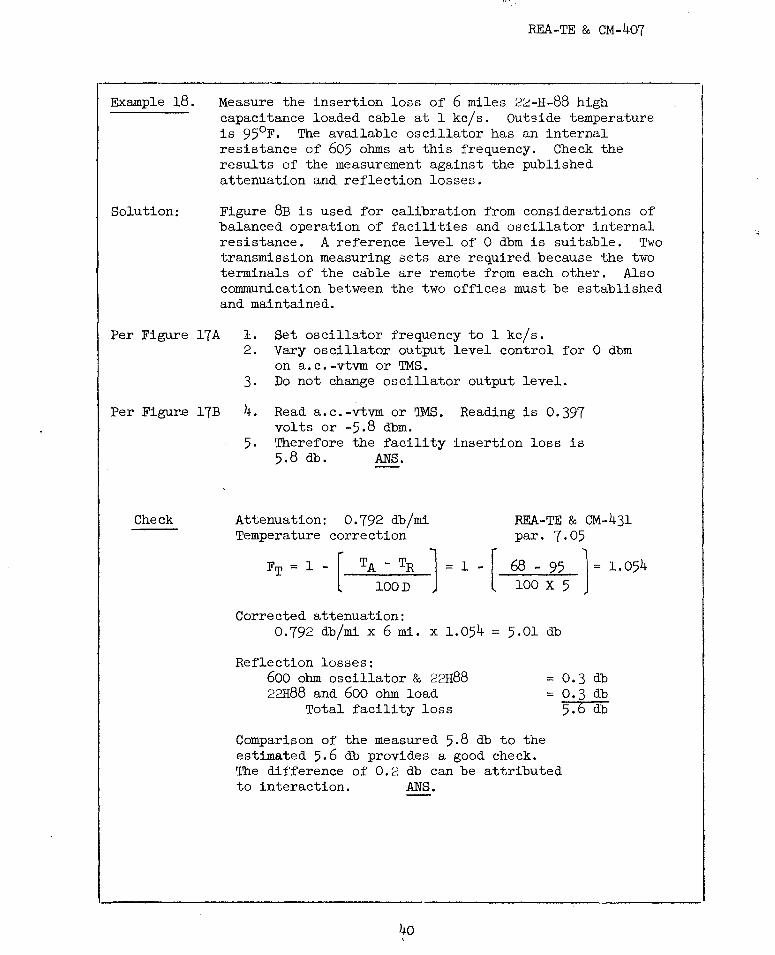
Example 18.
Solution:
REA-TE & CM-407
Measure the insertion loss of 6 miles 22-H-88 high capacitance loaded cable at 1 kc/s. Outside temperature is 95°F. The available oscillator has an internal resistance of 605 ohms at this frequency. Check the results of the measurement against the published attenuation and reflection losses.
Figure 8B is used for calibration from considerations of balanced operation of facilities and oscillator internal resistance. A reference level of O dbm is suitable. Two transmission measuring sets are required because the two terminals of the cable are remote from each other. Also communication between the two offices must be established and maintained.
Per Figure 17A 1. Set oscillator frequency to 1 kc/s.
Per Figure 17B
Check
2. Vary oscillator output level control for O dbm on a.c.-vtvm or 'IMS.
3. Do not change oscillator output level.
4. Read a.c.-vtvm or 'IMS. Reading is 0.397 volts or -5.8 dbm.
5, Therefore the facility insertion loss is 5.8 db. ANS.
Attenuation: 0. 792 db/mi Temperature correction
FT= 1 - [-T_A_-_T_R_l = 1 - [ 1001) 'J
Corrected attenuation: 0,792 db/mi X 6 mi. X 1.054 =
Reflection losses: 600 ohm oscillator & 22H88 22H88 and 600 ohm load
Total facility loss
REA-TE & CM-431 par. 7.05
68 - 95 1 = 1. 054 100 X 5
5.0l db
= 0.3 db = 0.3 db
5.6 db
Comparison of the measured 5.8 db to the estimated 5.6 db provides a good check. The difference of 0.2 db can be attributed to interaction. ANS.
40 '

~
Oscillator r-----7 W.E.Co. 120H Switch W.E.Co. 120H
Ohmsl
,lr ____ l_ r-
~
605 :
I I
i I
z-=:)I ~ ~ DPDr
i : r • 1 J -:7 I ~i i ~'~\t-r ~ -: :- ;---- r-- ~; ~·' ; -t--J . . 6 MI 22-H-88 ------ ~: I '<, -a;, . UlJ Cable 'r· - __ 1 I .
W.E.Co. 120H i ~ d,
3 G7 1 600 , ~e Ohms a.c.- ' (" 7 ,vtvm .
I e --- I I
'-------_j
P (---e---1
o.775v / i I' .. or O dbm ~~ . , I 3 ,3· !~8
--· 5 11~ · Ii_ 7
Office A
W.E. Co. 120H
Line side of MDF. Protector toothpicked.
A.
Line side of MDF. Protector toothpicked.
CALIBRATION Office B
r------ 7 ~----D_PDr Switch 1 I z° - '; 4 • , -I 6 -! >- ; ~ - -, I 2 ;i11, 4 1 05 1 1 3 r - - - - -t- -- -- 'tJ I T, -,! ,>-
1 I I .,_., ' I I ==========::========::::======== i I 1' 3
or 'IMS
0.397V -5.8 dbm G ,,-<! 1 I I I G I IB hms
I , I '>-8 ,__ - - - - --~ IR I RI °'' -~ 0 : I 5 ' (.__J7: , __ , : 5 -<1 I\ . ::::;p .J
Os~ill~t;: + W.E.Co. l~OH• _. a.c.-vtvm or 'IMS
W.E.CQ_. 1~ B. MEASUREMENT
a.c.-vtvml or 'IMS , ! I
2)fl 4 ,;-·--,,
; 600 1r
,..it e o~~ ----+---.:;.. 5_;j Ii: i I
FIGURE 17 FOR EXAMPLE 18
;:u
~ I
~ go
£ I + -8
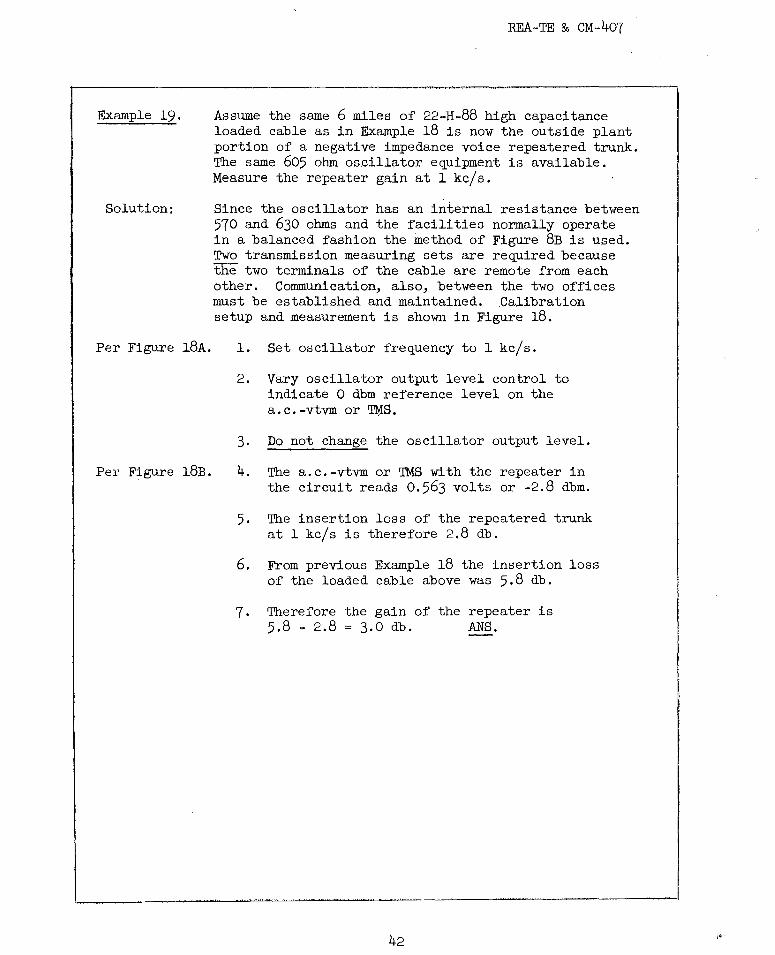
Example 19,
Solution:
Per Figure 18A.
Per Figure 18B.
REA-TE & CM-407
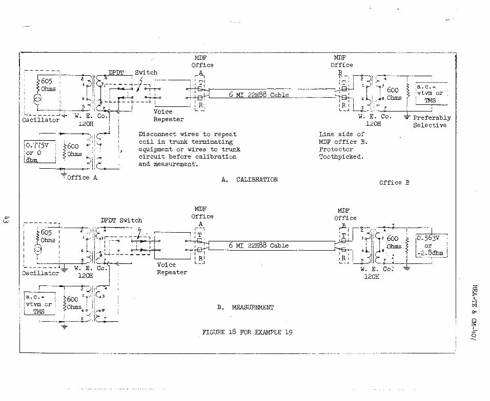
Assume the same 6 miles of 22-H-88 high capacitance loaded cable as in Example 18 is now the outside plant portion of a negative impedance voice repeatered trunk. The same 605 ohm oscillator equipment is available. Measure the repeater gain at 1 kc/s.
Since the oscillator has an internal resistance between 570 and 630 ohms and the facilities normally operate in a balanced fashion the method of Figure 8B is used. Two transmission measuring sets are required because the two terminals of the cable are remote from each other. Communication, also, between the two offices must be established and maintained. .Calibration setup and measurement is shown in Figure 18.
1. Set oscillator frequency to 1 kc/s.
2. Vary oscillator output level control to indicate 0 dbm reference level on the a.c.-vtvm or 'Th,18.
3. Do not change the oscillator output level.
4. The a.c.-vtvm or TMS with the repeater in the circuit reads 0.563 volts or -2.8 dbm.
5. The insertion loss of the repeatered trunk at 1 kc/sis therefore 2.8 db.
6. From previous Example 18 the insertion loss of the loaded cable above was 5.8 db.
7. Therefore the gain of the repeater is 5.8 - 2.8 = 3,0 db. ANS.
42
-.0-w
----- --i
;~•
{o~ @ :.
I I I L----+-r
1 _______ ....J.J..
Oscillator ·
MDF OMDff~ Office
ice B . . 9
_ ______,
DPDI' Switch -----, A. r -,, ~I • 4 I 1
• r I J,WT' l < <, r r r--;-,p1· 4
I j --- ~' T 1 I I 1 r'I ''-97 ,a. c. -~ ',Ii 3
---~- - 1 I ' 1 ' 1 600 :vtvm or r-': i : r◄ , °ft 1
6 MI 22H88 Cable ~ .; l1
•_ .Ja Ohms ; '.IMS I ,, I ' H o-+-+-<> I I I • ~- ·---,
61,...._,; l..j- --t----.1: 'I RI 1R '· ! s '1' - 7 ' I l I - ' I L _J "--<>--. ' " J__
L:'ii( ~C < I Voice L ..:J w. E. Co. -,. Preferably W. E • Co• ! 1 Repeater l20H Selective l20H ! 1
I ... . ) c-" ~0-. 7-7-5V- } 600 r 1 ,
Disconnect wires to repeat coil in trunk terminating e~uipment or wires to trunk circuit before calibration
Line side of MDF office B. Protector Toothpicked. or o {ohms 1_, ~
dbm · .! t_. and measurement·. -L -==office A A. CALIBRATION Office B
MDF
I- - - - - - -T DPDI' Switch Office MDF
r·----'-1 ~605 1 --2--.,j'( : 7 1 -~- Office : Ohms : 1 ;~ i s; r -- - - -j -f- _: 7 I : T ; ,Ji i ~- ---':--f-· -...,----
.-- I I , I f--<> 0 I p,0 J O ~ : T I 2. f I t ~ I i , '- ' "Lj j, [l_ •- ,,--l--,-,-4-. ~ 6 MI 22H88 Cable ~ 1
1
13
600 jO. 563v ~ I ~- : s-<;1~8 7 i -r---L___J,'R, 1 h-g..;, 6 ~ ;ohms ~· or i L JI . - . . ~ •
Os
-c-il_l_t __ ~ W. E. Co. 1
Voice 1.._J :R; I -< - : -2.8dbm a or l , R .._ ~ , s , 7 • 20H · i epeater · ___,,__, _.,___.__-!----I . W. E. Co:
2 _;;,
1
r-i l20H
~~- I ~600 iy. !:~3 or 1 ~Ohms ! j ! !
'.IMS . 60-.,J~e
'{ ~:Ill: B. MEASUREMENT
,,, FIGURE l8 FOR EXAMPLE l9
-----------------------------------·--
~ I
~ go
~ I -.0--
-8
Example 20.
Solution:
REA-TE & CM-407
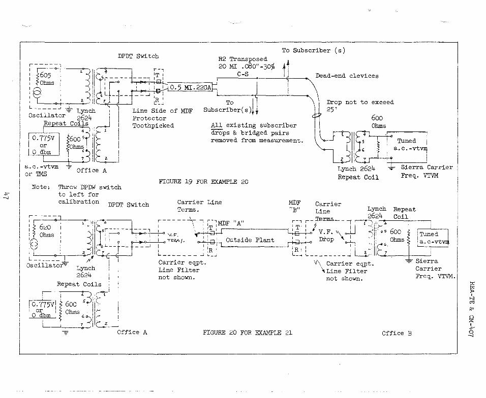
It is desired to measure the suitability of a s.ubscriber line for the application of carrier equipment from the absorption peak viewpoint in the frequency range of 50 to 180 kc/s. The line consists of facilities as shown in Figure 19. Temperature is 65°F. and the weather dry. Determine such suitability for carrier operation.
Before locating the carrier frequency voltmeter at the open wire dead-end the equipment at the left of the main frame in Figure 17 must be checked from 50 to 180 kc/s to assure that the repeating coils are satisfactory. The method in Example 14 may be used. Also check the repeat coil which will eventually be connected to the right of the dead-end clevices in Figure 19 in the same manner.
It will be necessary to have telephone contact between the man at the central office and the man at the open wire dead-end. This may be done with two handsets and a battery. If another pair is available between the two points it should be preferred for _communication because it provides for continuous cont,ac.t. If not the same pair that is being measured must be used. Contact will initially be established before connecting the equipment. Then communication must be reestablished of pre-arranged intervals. Only in this way can the man at the dead-end be sure of what signal is being
sent from the C.O. To maintain talking contact continuously on the same pair being measured, it is necessary to equip both ends with a voice pass or other suitable filter. The two telephone sets, with battery in series at one end, can then be left on the voice side of the filters even while the oscillator equipment is on the line. Since all known carrier frequency voltmeters require only 117 volt a.c. power it must be provided at the foot of the dead-~nd pole. A portable generator may not be satisfactory because of radiated interference and somewhat poor regulation for the purpose. An alternative is to obtain the power at the nearest establishment.
When carrier equipment is being tested for insertion loss it should be borne in mind that the circuit should be in the off-hook condition in both directions of transmission, otherwise systems with inband type signaling may produce measurement error. The measuring set-up is shown in Figure 19.
44

REA-TE & CM-407
1. Use oscillator equipmen~ similar to that in Figure BB, since the oscillator has internal resistance between 570 and 630 obms and normally balanced facilities are to be measured. Two transmission measuring sets are required. The one at the C.O. neea not be tuned but that beyond the open wire dead-end most probably will have to be. Carrier frequency voltmeters have means of self calibration and this should be done by the man of the open wire dead-end in accordance with manufacturers instructions. The tuned voltmeter usually will then read the receive levels in directly in dbm.
2. Use zero dbm at 50 kc/s as oscillator equipment output level.
3. Calibration is shown in Figure 8B.
4. Throw double-pole double-throw switch to the right as per Figure 19,
5, Do not touch oscillator controls.
6. Say the carrier frequency voltmeter reads -16.9 dbm. Therefore the insertion loss at 50 kc/sis O - 16.9 = 16.9 db loss.
7, Repeat the above steps for other frequencies of interest. The results are shown tabulated below:
Frequency Measured Insertion Calculated Attenua- Difference in kc/s Loss in db tion plus reflec- in db
tion lossesl 50 16.9 15,4 1.5 60 17.8 16.8 1.0 70 18.3 17.1 1.2 Bo 19.0 17.2 1.8 90 19.2 17.4 1.8
100 20.9 17,7 3,23 110 21.8 18.0 3,83 120 23.7 18.1 5.6 3 130 28.0 18.6 9 43 140 34.12 19.0
. 3 15.13
1502 39.72 19.1 20.6 1602 48.62 19.2 29.43 1702 59.12 19.3 29.83 1802 51.1 19.4 31.73
1. Calculated per Method of Example 8.
2. In the frequency range of 150 to 180 kc/s, insertion loss is over 35 db which is about the maximum line loss recommended by some carrier manufacturers.

REA-TE & CM-407
3, In the frequency range 100 to 180 kc/s the large difference between insertion loss and the sum of attenuation and reflection losses is greater than would be expected from interaction. It is therefore concluded that these are absorption peaks inherent in the transposition system employed in this line. ANS.
Example 21. A trunk carrier channel is to be lined up for a 3 db net loss at 1 kc/s. The manufacturer's recommendation for this particular type states that levels above -4 dbm will cause compression (distortion) and that a level 3 db below this should be used for adjustment of net loss. An oscillator having an internal resistance of 620 ohms at 1 kc/sis available. What is the measurement procedure?
1. Refer to Figure 20. The oscillator resistance is between 570 and 630 ohms and the voice terminals of the carrier equipment normally connect to balanced circuits so the oscillator equipment and the transmission 'measuring set per Figure 8B should be used. They should·be connected per Figure 17A for calibration at office A. At office "B" another transmission measuring set is required.
2. To prevent distortion, set oscillator output at 0.346 volts (-7 dbm) when the double-pole, double-throw switch is thrown as in Figure 17A,
3. By throwing the double-pole double-throw switch to right proceed with measurements per Figure 20. Adjust proper carrier equipment control at far-end per carrier manufacturer's recommendations until transmission measuring set in office "B" reads 0.245 volts, (:..10 dbm).
4. Do not touch oscillator output level control.
5, 7 - 10 = 3 db loss. The carrier equipment is now set for 3 db net loss in the A to B direction. To do the same in the B to A direction, the test equipment should be interchanged and the procedure repeated.
46
.::;
DPDI' Switch To Subscriber (s)
R2 Transposed ,
l.~ 20 MI .o80"-30% tJ
~ ~ ; \Dead-end clevices
J ,'
L _____ .J -:;- Lynch
~-.rBT - -7 1 I ~ \ ~- ~ To i \ ! Drop not to exceed
Line Side of MDF Subscriber( s )1,} , 25' Oscillator 2624 ,
Repeat Coi}s .,--.-J ' 4- ) '>- 1
Protector Tooth picked All existing subscriber
drops & bridged pairs removed from measurement. 0.775v 600 5? I;,-
Q~ lohm~ ~ Lr, O dbm , ! 7 .. : L----r---•-
a.c.-vtvm Ol' 'IMS
"" Office A
Note. Throw DPDW switch to left for calibration DPDT Switch
r-----1 1 '}iii'' -,i·- -,
1
• ·ohms ,
3~)C:.sr---__ J __ --¥ ' ,I l ' ,-, ._,__:, I 1' I I\ : I
• I ,_. 1
I
, ! 2-<il; __ &L~-f--t-~"__j L - - 0 I O __,, IC 7 C < ' -- __ , * 8 I
Oscillator" ;11 i 1 Lynch ! 2624 ,
620
Repeat Coils
j o. 115v1 !' 6oo :~+-.-• , or ! II 1 0 dbm I Ohms ; ,I,... r i ~~lll2
Office A
FIGURE 19 FOR EXAMPLE 20
Carrier Line Terms.
MDF "Bn
r-----~- 7 r-, I \ ,------------ I T' I :..0--+-'-1-·h-+ I t-<> Y.F. I I i O T'E'1J\.\f. 0 : : □:
1 Outside Plant ~
I 'R I .._ _________ __, l R
~------- ..l ~-J I__
Carrier eqpt. Line Filter not shown.
FIGURE 20 FOR EXAMPLE 21
600 Ohms
I
~ Tuned I a.c.-vtVI!f
~II~ I ±: I Lynch 2624 ~ Sierra Carrier Repeat Coil Freq_. VTVM
Carrier Lynch Repeat Line 2624 Coil
r---1.erms._ -JJ-r t ii:rr: 600 t' I TuJed j 1 1 V.F. ~\ I,
.-o . I -- 1, 1 Ohms I a. c-vt I ]):rQp <>--1---, -1• __,.~ c___, j---0 I' I(' ± ' I ' I 2 •. C 7 I : _________ ..J Ll • ~ Sierra
V\ Carrier eqpt. Carrier \Line Filter Freq_. VTVM .
not shown.
Office B
::rj
~ I
t,5 go
0 :s: I + ~
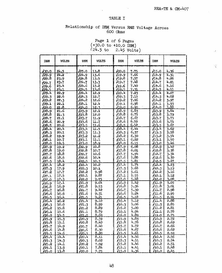
REA-TE & CM-407
TABLE I
Relationship of DBM Versus RMS Voltage Across 600 Ohms
Page 1 of 6 Pages (+30.0 to +10.0 DBM) (24.5 to 2.45 Volts)
DBM VOLTS DBM VOLTS DBM VOLTS DBM VOLTS
4. 6 4.31 . 4.26
.7 4.21
.6 4.16 . 4.11 7.23 • 4 4.07
l.19.3 7.15 .3 4,02 l.19.2 7.06 .2 3.97
6.98 .1 3.93 6. .o .88 6.83 .9 3,84 6.75 .8 3.79 6.67 .7 3,75 6.59 6. 2 6.44
.3 6.37 ,2 6.30 .1 6.22 .o 6.1 .9 6.o8 . 10.7 .8 6.01
.7 10.6 .7 5.94
.6 10.4 5.88 . 10 • .81 • 4 5.7 3.23 .3 5,68 3.19 .2 5.61 .2 3.16
5.55 .1 3.12 .48 • o .oa .
5.42 .9 3.05 .8 .8 5.36 .8 3.01 .7 ·.7 5.30 ,7 2.98 .6 .6 5.24 .6 2.95 . . .18 . 2, 1 .4 .4 5.12 .4 2.88 .3 .3 5.06 .3 2.85 ,.2 /.16.2 5.00 .2 2.81
/.16.1 4.94 ,1 2.78 16.0 4.8 .o 2
/15.9 4.83 .9 2.72 t.15,8 4.78 .8 2.69 t.15,7 4.72 .7 2,66
4.67 .6 2.62 4.61 2. 4.56 .4 2.56 4.51 ,3 2.54 4.46 .2 2.51 4.41 ,1 2.48 4. 6 .o 2.4
48

DBM
~
~
REA-TE & CM-407
TABLE I
Relationship of DBM Versus RMS Voltage Across 600 Ohms
VOLTS DBM
Page 2 of 6 Pages (+10.0 to -10,0 DBM) ( 2.45 to 0.245 Volts)
VOLTS DBM VOLTS
0 - 0.1 0.7 - 0.2 0.757 - 0.3 0.748 - o.4 0.740 - 0 - o.6 0.723 - 0.7 0.715 - o.8 0.706 - 0.9 0.698 - .o o.6 - 1.1 o. - 1.2 0.675 - 1.3 0.667 - 1.4 0.659
o. o. 0.637 0.630
- 3.7 0.506 - 3.8 0.500 - 3•9 o.494 - 4.o o.48 - 4.1 o.483 - 4.2 o.478 - 4.3 o.472 - 4.4 o.467 - 4. o.461 - 4.6 o.456
0.802 - 4.7 o.451 0.792 - 4.8 o.446 0.784 - 4.9 o.441
- .o o 4 6
49
DBM VOLTS
- 5.0 - 5.1 - 5.2 - 5.3 - 5.4
o. o.402 0.397 0.393 0.388 o. 0.379 0.375 0.371 0.367 0.3 2
- 6.7 0.358 - 6.8 0.354 - 6.9 0.350 - 7.0 0.346 - 7.1 0.3 2 - 7.2 0.338 - 7.3 0.334 - 7.4 0.330
o. 27 0.323 0.319 0.316 0.312 o.3o8 0.305 0.301 0.298 0.295 0.291 o.
- 8.7 0.285 - 8.8 0.281 - 8.9 0.278 - 9.0 0.275 - 9.1 0.272 - 9.2 0.269 - 9.3 0.266 - 9.4 0.262 - 9.5 0.259 - 9. - 9.7 - 9.8 - 9.9 -10.0

DBM
-10.0 -10.1 -10.2 -10.3--10,4 -10.c; -10.6 -10.7 -10.8 -10.9 -11.0 -11.l -11.2 -11.3 -ll.4 -11,'i -ll.6 -11.7 -11,8 -11.9 -12,0 -12,l -12.2 -12.3 -12.4 -12,'5 -12.6 -12,7 -12.8 -12.9 -l"l,0 -13.1 -13,2 .13.3 -13,4 .1 q. c; -13,b -13,7 -13.8 -13.9 -14.o -14,l -14,2 -14.3 -14,4 -14.s -14,6 -14.7 -14.8 -14.9 -15,0
REA-TE & CM-407
TABLE I
Relationship of DBM Versus RMS Voltage Across 600 Ohms
Page 3 of 6 Pages (-10.0 to -30,0 DBM)
(0.245 to 0.0245 Volts)
VOLTS DBM VOLTS DBM VOLTS DBM
0.24'5 -1'5,0 o.,~ -20.0 0.(177'5 -25.0 o.2li-2 -15.1 0.136 -20.l 0.0766 -25.1 0.239 -15.2 0.135 -20,2 0.0757 -25,2 0.237 -15,3 0.133 -20,3 0.0748 -25,3 0.234 -15.4 0.132· -20.4 o.074o -25,4 0.2-:i, .l_c;. c; 0,1':lO -20.5 0.0731 -25,5 0.229 -15.6 0.129 -20,6 0.0723 -25,6 0.226 -15.7 0.127 -20.7 0.0715 -25,7 0.223 -15.8 0.126 -20.8 o.07o6 -25.8 0.221 -15.9 0.124 -20.9 o.o698 -25.9 o.218 -16.0 0.12-:i -21,0 o.o690 -26.0 0.216 -16.1 0.121 -21.l 0.0003 -26,l 0.213 -16.2 0.120 -21.2 o.o675 -26.2 0.211 -16.3 0~119 -21.3 o.o667 -26.3 0.209 -16,4 0.117 -21.4 o.o659 -26.4 o.2o6 -16,'5 0.116 -21,5 o.o652 -26_.5 0.204 -16.6 0.115 •21.,b u.0644 -26,b 0.201 -16.7 0.113 -21.7 o.o637 -26.7 0.199 -16.8 0.112 -21.8 o.o630 -26.8 0.197 -16.9 0.111 -21.9 0.0622 -26.9 o.1c:ic; -17,0 o.-1no -22.0 o.o615 -27,0 0.192 -17,l -o.1o8 -22,l u.oovo .27.1
· 0.190 -17.2 0.107 -22.2 O.o6ol .27.2 o.188 -17,3 0.106 -22.3 0.0594 .27.3 0.186 -17.4 0.104 -22.4 0.0588 -27,4 0.184 -17,c; 0,10':l -22.5 0.0581 .27.5 0.1<32 -17.6 0.102 -22.6 0.05·(1.J. -27,6 0.179 -17,7 0.101 -22,7 0.0568 -27,7 O,lTI -17.8 0.0998 -22,8 0.0561 .27.8 0.175 -17~9 0.0987 -22,9 0.0555 .27.9 0.17"! -18.0 O,Wl'i .23.0 0.0548 -28.o 0.171 -18.1 0.0964 -23.1 0.051.J.2 -25,l 0.169 -18.2 0.0953 -23,2 0.0536 -28.2 0.168 -18.3 0.0942 -23,3 0.0530 -28.3 0.166 -18.4 0.0931 -23,4 0.0524 -28.4 0.164 -18.s 0.0021 -23,5 0.0518 -28.5 0.162 -18.6 0.0910 -~j,b U,05J.2 -~O,b o.16o -18.7 o.o899 -23,7 o.05o6 -28.7 0.158 -18.8 o.o889 -23,8 0.0500 -28.8 0.156 -18.9 o.o879 -23,9 0.0494 -28.9 0.155 -19,0 o.o86ci -24.o 0.0489 -29,0 0,153 -19.1 0.0059 -24,l U,V'lO.:) -~.J. 0.151 -19,2 o.o849 -24.2 0.0478 -29,2 0.149 -19,3 o.o84o -24,3 0.0472 .29.3 0.148 -19.4 o.o830 -24.4 0.0467 -29,4 0.146 -lCl,S o.o820 -24.5 0.0461 .29.5 0.144 -19.6 o.o811 -24,6 o. -~.6 0.143 -19,7 o.oa02 -24.7 0.0451 -29,7 0,141 -19.8 0.0792 -24.8 0.0446 .29.8 0.139 -19.9 0.0784 -24,9 0.0441 -29,9 O.l~ -20.0 0,077'i -25,0 0.0436 -30,0
so
VOLTS
0.0436 0.0431 0.0426 0.0421 0.0416 0.0411 O,OLIU7 o.o4o2 0.0397 0.0393 0.0388 0,03tl4 0.0379 0.0375 0.0371 0.0367 0.0302 0.0358 0.0354 0.0350 0.0346 0,0342 0.0338 0.0334 0.0330 0.0327 0.0323 0.0319 0.0316 0.0312 o.03o8 0.0305 (),0301 0.0298 0.0295 0.0291 o.o~oo 0.0285 0.0281 0.0278 0.0275 0,U.:!(~
0.0269 0.0266 0.0262 0.0259 0.0256 0.0254 0.0251 0.0248 0.0245
··-

DBM
_qo,o . -30,l -30,2 -30.3 -30,4
....:.3Q-!2 -30.6 -30.7 -30.8 .30.9 _q1.o -31.1 -31.2 -31.3 -31,4 -,1.5 -31,6 -31.7 -31.8 -31.9 -32,0 -32,1 -32.2 .32.3 -32,4 -32,5 -32,6 -32·« -32, -32,9 -33,0 -33.1 .33.2 -33,3 -33,4 -33,5 -33,6 -33,7 .33.8 -33,9 -34,o -34,l -34,2 -34,3 -34,4 -34,5 -34,6 -34,7 -34,8 -34,9 .35.0
REA-TE & CM-407 '!.'ABLE I
Relationship of DBM Versus RMS Voltage Across 600 Ohms
VOLTS
0,024'> 0.0242 0.0239 0.0237 0.0234 o.02q1 0.0229 0.0226 0.0223 0.0221 0.0218 0.0216 0.0213 0.0211 0.0209 o.02o6 0.0204 0.0201 0.0199 0.0197 0.0195 0.0192 o.01~ 0.01 0,0186 0.0184 0.0182 0.0179 0.0177 0.0175 0.0173 0.0171 I0.0169 0.0168 o.oi66 0.0164 0.0162. o.016o 0.0158 0.0156 0.0155 0.0153 0.0151 0.0149 0.0148 0.0146 10,0144 0.0143 0.0141 p.0139 J,01~
Page 4 of 6 Pages (-30.0 to -50.0 DBM)
(0.0245 to 0.00245 Volts)
DBM VOLTS DBM VOLTS
-~c;.n I\ n,~ -40.0 O,OC/77'i--35,1 0.0136 -40.1 0.00766 -35,2 0.0135 -40.2 0.00757 -35,3 0.0133 -40.3 0.00748 -35,4 0.0132 -40.4 0.00740 -~c; c; n n, ~/'\ -40.'i o.oon1 -35,o 0.0129 -40.6 0.00723 -35,7 0.0127 -40.7 0.00715 -35,8 0.0126 -40.8 o.007o6 -35,9 0.0124 -40.9 o.oo698 _q6.o o.012q -41.0 O,oo6QO -36,1 0.0121 -41.1 0,006t:S3 -36.2 0.0120 -41.2 o.oo675 -36.3 0.0119 -41.3 0.00667 -36,4 0.0117 -41.4 0.00659 _q6,5 a..0116 -41.5 0.00651 -36,6 0.0115 - 1.6 0.00644 -36.7 0,0113 -41.7 o.oo637 -36,8 0.0112 -41.8 o.oo630 -36.9 0.0111 -41.9 0.00622 -,7.0 0.0100 -42.0 o.oo615 -37,1 0.0100 -42.1 Q,O()b()tj
-37,2 0.0107 -42.2 o.oo6o1 -37,3 0.0106 -42.3 0.00594 -37,4 0.0104 -42.4 0.00588 -,7 ,5 0.010, -42.5 0.00581 -37,6 0.0102 -42.6 0.00574 -37,7 0.0101 -42.7 0.00568 -37,8 0.00998 -42.8 0.00561 -37,9 0.00987 -42.9 0.00555 -,8.o O,OOQ7'i -43,0 0.00548 -38.1 0.00964 -43,1 0.005~2 -38.2 0.00953 -43,2 0.00536 -38.3 0.00942 -1~3.3 0.00530 -38,4 0.00931 -43.4 0,00524 -,8.5 0~00021 -4~.5 0.00518 -38,6 0.00910 -43,6 0.00512 -38,7 o.oo899 -43,7 0.00506 -38,8 o.oo889 -43,8 0.00500 -38,9 o.oo879 -43.9 0.00494 -~Q,O o.oo869 -44.o 0.00489 -39,1 0.00059 -44.1 0,00483 -39,2 o,oo849 -44,2 0.00478 -39,3 o.oo840 -44.3 0.00473 -39,4 o.oo830 -44.4 0.00467 -39,5 o.oo820 -44,5 0,00461 -39,6 0.00011 -44,6 0.00456 -39,7 o.oo802 -44.7 0.00451 -39,8 0.00792 -44.8 0.00446 -39,9 0.00784 -44.9 0.00441 -40.o 0.00775 -45,0 0.00436
51
DBM VOLTS
-45.0 0.00436 -45.1 0.90431 -45.2 0.00426 -45,3 0.00421 -45.4 0.00416 -4'i.'i o.oo41i -45,6 0.00407 -45,7 0.00402 -45.8 0.00397 .45.9 0.00393 -46.o 0.00388 -46.1 0.00384 -46.2 0.00380 -46.3 0.00375 -46.4 0.00371 -46.5 0.00367 -46.6 0.00362 -46-7 0.00358 -46.8 0.00354 -46.9 0.00350 -47 .o 0.00346 -47 .1 0.0031{2 -47.2 0.00338 -47,3 ·0.00334 -47,4 0.00330 -47.5 0.00327 -47.6 0.00323 -47-i 0.00319 -47. 0.00316 -47,9 0.00312 -48.o o.003o8 -48,1 0.00305 -48,2 0.00301 -48.3 0.00298 -48.4 0.00295 -48.5 0.00291 -48.6 0.00200 -48.7 0.00285 -48.8 0.00281 -48.9 0.00278 -49.0 0.00275 -49,1 -0.00272 -49,2 0.00269 -49.3 0.00266 -49,4 0.00262 -49.5 0.00259 -49,6 0,00256 -49.7 0.00254 -49.8 0.00251 -49,9 0.00248 -50.0 0.00245
-

DBM
-,o.o -50,1 -50,2 -50,3 -50,4 -50., -50,6 -50,7 -50,8 -50,9 -,1.0 -51,1 -5l,2 -51.3 -51.4 -51.5 -51,6 -51.7 -51,8 -5lo9 -,2.0 -52,1 -52,2 -52,3 -52,4 -52,5 -52,6 -52,7 -52,-8 -52,9 -51,0 -53,1 -53,2 -53,3 -53,4 -5':l.,5 -53,6 -53,7 -53,8 -53,9 -54.o -54,1 -54,2 -54,3 -54,4 -54,5 -54,6 -54,7 -54,8 -54,9 -55,0
REA-TE & CM-407
TABLE I
Relationship of DBM Versus RMS Voltage Across 600 Ohms
VOLTS
0.0024, 0,00242 0.00239 0.00237 0.00234 0.002-:i.1 0.00229 0.00226 0.00223 0.00221 0.00218 0.00216 0.00213 0.00211 0.00209 0.00206 0.00204 0.00201 0.00199 0.00197 o.001qs 0.00192 0.00190 0.00188 0.00186 0.00184 0.00182 0.00179 0.00177 0.00175 0.00171 0.00171 0.00169 0.00168 0.00166 0.00164 0.00162 o.0016o 0.00158 0.00156 0.00155 0.00153 0.00151 0.00149 0.00148 0.00146 0,00144 0.00143 0.00141 0.00139 0.00138
Page 5 of-6 Pages (-50,0 to -70,0 DBM)
(0.00245 to 0.060245 Volts)
DBM VOLTS DBM VOLTS
_,,.o 0.001-:i.8 -60.0 0,000775 -55,1 0.00136 -60,1 0.000766 -55,2 0.00135 -60,2 0,00Cf757 -55,3 0.00133 -6o.3 0.000748 -55,4 0.00132 -60.4 0.000740 -55,5 O,OOBO -60.5 O,OOOTll -55,6 0.00129 -oo.6 0.000723 -55,7 0.00127 -60.7 o·.000715 -55,8 0.00126 -60.8' 0.000706 -55,9 0.00124 · -60.9: 0,000698 -56,o 0.00123 -61.0 0.000690 -56,1 0.00121 -61.1 0,000b03 -56,2 0.00120 -61.2 0.000675 -56,3 0.00119 -61.3 0.000667 -56,4 0.00117 -61.4 0.000659 -56,5 0.00116 -61.5 0.000652 -56,6 0.00115 .:01.6 0.000644 -56.7 0.00113 -61.7 0.000637 -56.8 0.00112 -61.8 0.000630 -56.9 0.00111 -61.9 0.000622 -57,0 0.00109 -62.0 0.000615 -57 .1 0.00100 -62.1 O,OOObOO -57,2 0.00107 -62.2 0.000601 -57,3 0.00106 -62,3 0.000594 -57,4 0.00104 -62.4 0.000588 -57,5 0.00103 -62.5 0.000581 -57,b 0.00102 -62.6 0.000574 -57,7 o·.00101 -62.7 0.000568 -57,8 0.000998 -62.8 0.000561 -57,9 0.000987 -62.9 0.000555 -58,o 0.000975 -63.0 0.000548 -58,1 0.000964 -t>3,l 0,000542 -58,2 0.000953 -63,2 0.000536 -58,3 0.000942 -63,3 0.000530 -58,4 0.000931 -63.4 0.000524 -58.5 0.000921 -6,.c; 0.000518 -58,6 0.000910 -63.6 ': -0.000512 -58.7. o.ooo899 -63.7 o.0005o6 -58,8 o.ooo889 -63.8 0.000500 -58.9 o,ooo879 -63.9 0.000494 -5Q,O o.ooo869 -64.o 0.000489 -59,1 0.000059 -6!+.1 0,000483 -59,2 o.ooo849 -64,2 0.000478 -59,3 o.ooo84o -64.3 0.000472 -59,4 o.ooo830 -64.4 0.000467 -59,5 o,ooo820 -64.5 0.000461 -59,6 0 , OQOOll -64.6 0,000456 -59,7 o.ooo802 -64.7 0.000451 -59,8 0.000792 -64.8 0.000446 -59,9 0.000784 -64.9 0.000441 -60.0 0.000775 -65,0 0:000436
52
DBM VOLTS
-65.0 0.0004-:i.6 -65,1 0.000431 -65,2 0.000426 -65,3 0,000421 -65.4 0.000416 -65,'5 0.000411 -65.6 0.000407 -65,7 0.000402 -65.8 0.000397 -65.9 0.000393 -66.o o.ooo-:i.88 -bb,l . 0,00038lf -66.2 0.000379 -66.3 0.000375 -66.4 0.000371 -66., o.ooo-:i.67 -bb.6 0.000362 -66.7 0.000358 -66.8 0.000354 -66.9 0.000350 -61.0 0.000146 -67,1 0.000342 -67.2 0.000338 -67,3 0.000334 -6_7.4 . 0.000330 -67,5 0.000327 -67,6 0.000323 -67,7 0.000319 -67.8 0.000316 -67,9 0.000312 -68.o o.0003o8 -00,1. 0.000305 -68;2 0.000301 -68.3 0.000298 -68.4 0.000295 -68.5 0.000291 -b0,6 o.0002~ -68.7 0.000285 -68.8 0.000281 -28.9 0.000278 -69.0 0.000275 -69.1 0.000272 -~-2 0.000269 - 9.3 0.000266 -69.4 0.000262 -69.5 0.000259 -69,b 0.000256 -69,7 0.000254 -69.8 0.000251 -69.9 0.000248' -70,0 0.000245

DBM
-70,0 -70,1 -70,2 -10.3 -70,4 -70,5 -10.6 -70,7 -70,8 -10.9 -71.0 -71.l -71.2 -71.3 -71,4 -71.5 -71.6 -71.7 -71.8 -71.9 -72,0 -72,l -72,2 -72,3 -72,4 -72,5 -72,6 -72,7 -72,8 -72,9 -n.o -73,l -73,2 -73~3 -73,4 -7i,5 -73,6 -73,7 -73,8 -73,9 -74.o -74,l -74,2 -74,3 -74,4 -74,c; -74,6 -74,7 -74,8 -74,9 -75,0
REA-TE & CM-407
TABLE I
Relationship of DBM Versus RMS Voltage Across 600 Ohms
VOLTS
0.000245 0.000242 0.000239 0.000237 0.000234 0,0002"il 0.000229 0.000226 0.000223 0.000221 0.000218 0.000216 0.000213 0.000211 0.000209 0.000206 0.000204 ·0.000201 0.000199 0.000197 o.0001qs 0.000192 0.000190 0.000188 0.000186 0.000184 0.000182 0.000179 0.000177 0.000175 0 • 0001 7'l 0.000171 0.000169 0.000168 0.000166 0.000164 0.000162 0.000160 0.000158 0.000156 0.000155 0.000153 0.000151 0.000149 0.000148 0.000146 0.000144 0.000143 0.000141 0.000139 0,000li8
Page 6 of 6 Pages (-70,0 to -90,0 DBM)
(0.000245 LJ 0.0000245 Vclts)
DBM VOLTS DBM VOLTS DBM
-75.0 0,000l"i8 -80,0 0.0000775 -85.0 -75,l 0.000139 -80,l 0.0000766 -85,l -75,2 0.000135 -80,2 0.0000757 -85,2 -75,3 0.000133 -80.3 0.0000748 -85,3 -75,4 0.000132 -80.4 0.0000740 -85,4 _75,c; O,OOOl"iO -80.5 o.oooorn -85.5 -75,6 0.000129 -80.6 0.0000723 -85.6 -75,7 0.000127 -80.7 0.0000715 -85.7 -75,8 0.000126 -80.8 0.0000706 -85.8 -75,9 0.000124 -80.9 0.0000698 -85,9 -16.0 0,00012"i -81.0 0.0000690 -86.o -76,l 0.000121 -81.i 0.000061.33 -86,l -76,2 0.000120 -81.2 0.0000675 -86.2 -16.3 0.000119 -81.3 0.0000667 -86.3 -76,4 0.000117 -81.4 o.oooo659 -86.4 -76,5 0.000116 . -81.5 0.0000652 -86.5 -16.6 0.000115 -81.6 o. oooo641i" -bb.6 -76,7 0.000113 -81.7 0.0000437 -86.7 -76,8 0.000112 -81.8 0.0000630 -86.8 -16.9 0.000111 -81.9 0.0000622 -86.9 -77,0 0.000109 -82.0 0.0000615 -87.0 -77,1 o.0001o3 -82,l 0,0000600 -137 ,l -77,2 0.000107 -82.2 0.0000601 -87,2 -77,3 0.000106 -82.3 0.0000594 -87 .3 -77,4 0.000104 -82.4 0.0000588 -87,4 - 7 7,5 0.00010-:i -82,5 0.0000581 -87.5 -77,6 0.000102 -82.6 0.0000574 -87,6 -77,7 0.000101 -82.7 0.0000568 -87,7 -77,8 0.0000998 -82.8 0.0000561 -87.8 -77,9 0.0000987 -82.9 0.0000555 -87.9 -78,o 0.0000975 -83.0 0.0000548 -88.o -78,1 0.0000964 -83,1 0.0000542 -88,1 -78,2 0.0000953 -83,2 0.0000536 -88.2 -78,3 0.0000942 -83.3 0.0000530 -88.3 -78,4 0.0000931 -83,4 0.0000524 -88.4 -78.5 0.0000921 -83.5 0.0000518 -88.5 -78,6 0.0000910 -83.6 0.0000512 -88.6 -78,7 o.oooo399 -83,7 0.0000506 -88,7 -78,8 o.oooo889 -83,8 0.0000500 -88.8 -78,9 o.oooo379 -83,9 0.0000~94 -88.9 -79,0 o.oooo369 -84.o 0.0000489 -89,0 -79,1 o.oooo359 I -84.1 0.0000lj{j3 -89.1 -79,2 o.oooo349 -84.2 0.0000478 -89.2 -79,3 o.oooo34o -84.3 0,0000472 j89.3 -79,4 o.oooo330 -84.4 0.0000467 89.4 -79,5 o.oooo320 -84.5 0.0000461 -89.5 -79,6 o.000Q311 -84.-6 0.0000456 -89.6 -79,7 :i.oooo302 ;84.7 0.0000451 -89,7 -79,8 :),0000792 -84.8 0.0000446 -89.8 -79,9 0.0000784 -84.9 0.0000441 -89.9 -80.0 0, OC•C')I75 -85,0 0.0000436 -90,0
53
l ! VOLTS
0.0000436 0.0000431 0,0000426 0.0000421 0.0000416 0.0000411 0.0000407 0.0000402 0.0000397 0.0000393 0.0000388 0.0000384 0.0000379 0.0000375 0.0000371 0.0000367 0.0000362 0.0000358 0.0000354 0.0000350 0.0000346 0.0000342 0.0000338 0.0000334 0.0000330 0.0000327 0.0000323 0.0000319 0.0000316 0.0000312 o.00003o3 0.0000305 0.0000301 0.0000298 0.0000295 0.0000291 0.00002w 0.0000285 0.0000281 0.0000278 0.0000275 0.0000272 0.0000269 0.0000266 0.0000262 0.0000259 0.0000256 0.0000254 0.0000251 0.0000248 0.0000245
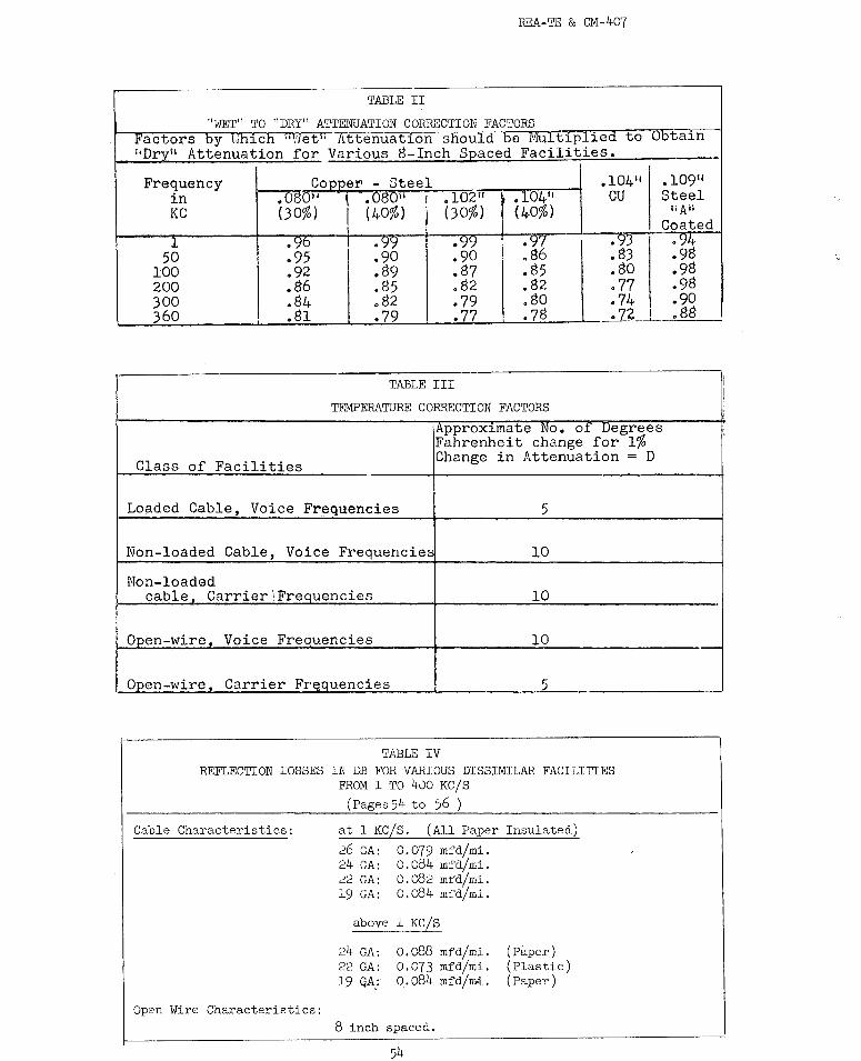
REA-TE & CM-407
TABLE II
"WET" TO "DRY" ATTENUATION CORRECTION FACTORS Factors by ~,hfcfi ·•Hett: Attenuation should be I'.l!ultiplied to Obtain •
1Drv11 Attenuation for Various 8-Inch Seaced Facilities.
Frequency Copper - Steel .104 11 .109 11
in ----:OS01, I .080 11 I .102li .104 11 cu Steel
KC (30%) I (40%) ( 3 0%) ( 40%) itAii
Coated l. • ':)b . ':)':) • ':)'j . ':)'( • 93 .94
50 .95 .90 .90 .86 • 83 .98 100 • 92 .89 .87 .85 .so .98 200 .86 .85 .82 • 82 .77 .98 300 .84 • 82 .79 .so .74 .90 360 .81 .79 .77 .78 . n_, .88
TABLE III
TEMPERATURE CORRECTION FACTORS
Approximate "No. oT Degrees Fahrenheit change for 1%
Class of Facilities Change in Attenuation= D
Loaded Cable, Voice Fr~quencies 5
Non-loaded Cable, Voice Frequencies 10
Non-loaded cable. Carrier\Frequencies 10
Open-wire. Voice Frequencies 10
Open-wire. Carrier FrP-auencies 5
TP.BLE IV REFLECTION LOSSES IN DB FOR VARIOUS DISSIMILAR FACILITIES
FROM 1 TO 400 KC/S
Cable Characteristics:
Open Wire Characteristics:
(Pages 54 to 56 )
at 1 KC/S. (All Paper Insulated)
26 GA: 0.079 mfd/mi. 24 GA: 0.084 mfd/mi. 22 GA: O.o82 mfd/mi. 19 GA: o.o84 mfd/mi.
above 1 KC/S
24 GA: 22 GA: 19 GA,:
o.o88 mfd/mi. 0.073 mfd/mi. 0. o84 mfd/m.i .
8 inch spaced,
54
(Paper) (Plastic) (Paper)
·-
' l l

V1 V1
I
I --
TABLE IV
REFLECTION LOSSES IN DB AT 1 KC/S
CABLE
FACILITY 26 GA.. 24 w.. 22 GA. l9 GA.
H88 B88 H44 N.L. H88 BBB H44 N.L. BBB BBB H44 M.L. H8B BBB
26 H.L -.2 -.l -.l. +.l -.3 -.2 -.l +.3 -.4 -.4 -.2 +.9 -.5 -.5 26"H8B X 0 0 +.l 0 0 +.l +.5 0 -.l. +.2 +l..2 0 -.l 26 B88 X 0 +.2 +.]. 0 ,.3 +.8 +.2 0 +.5 +l..8 +.2 0 26 H44 X 0 -.1 0 0 +.4 -.2 -.2 +.l +l..O +.2 -.2 .24 N.L. X -.1 +.l -.1 +.l -.3 -.1 -.2 +.5 -.5 -.2
24 H88 X +.l 0 +.2 0 0 +.2 +1.0 0 0 24 B88 X +.2 +.6 +.2 0 +.4 +.6 +.2 0 24 H44 X +.l -.1 +.l 0 +.6 -.l 0 22 N.L. X 0 +.4 -.l +.l -.2 +.4 22 H88 X +.l +.l +.7 0 +.l
22 B88 X +.3 +l.3 +.l 0 22 H44 X +.3 0 +.3 l.9 M.L. X +.5 +l.2 19 H88 X +.1 1.9 BBB X
19 H44
109 Steel (BS or 1.35)
109 Steel {190)
104 c.w. XJ1,
104 c.w. 40%
060 c.w. 30% 080 c.w. 40'.l'.
Note: Negative sign indicates reflection gain.
..
OPEN 'WIRE
l.09 STEEL COPPERWELD
H44 .tl5- 30% 40% y:yf, 40% l.35 l.90 l.04 l.04 080 080
-.3 0 +.l. -.l -.l 0 -.l +.3 0 0 +.2 +.a 0 +.l +.6 0 -.l. +.3 +.5 0 +.2
0 +.l +.l 0 +.l 0 0 -.4 +.2 +.4 -.2 -.2 +.2 -.l
+.2 0 0 +.l +.l 0 0 +.6 -.1 -.l +~2 +.4 0 +.l
0 +.2 +.3 0 0 0 0 -.3 +.8 +.9 0 0 +.5 +.2 +.2 0 0 0 0 -.2 -.l
+.5 -.2 -.2 +.1 +.3 -.2 0 0 +.J +.~ 0 0 +.l 0 0 +l..5+1.13 + • .s +.4 +l.l. +.7
+.l 0 0 -.1 0 -.3 -.1 +.4 -.2 -.2 +.l +.2 -.3 0
X +.4 +.5 0 . -.1 0 0
X 0 +.2 +.3 +.l +.2
X +.) +.4 +.1 +.2
X 0 +.2 0
X +.2 +.]
X 0
X
104 COPPER
-.2 +.4 +.7 +.l -.3
+.3 +.6
0 -.3 +.2
+.5 0 0
+el. +.5
0
+.4
+.6
0
0
+.2
+.l.
----~
600 _n_
-.4 ·4 .9 • 1
--6
.4 ·9 0
--6 .3
·--• 7 0
--4 .3 • 7
0
•b
--• 7
·--·-
0
~-----i
...
·!.
0
~ I
~ go
0 :s:
+"" 0 --:J

V1
"'
TABLE IV. REFLECTION LOSSES IN DB. ·---------------
2-5 KC S. (Use Also For 1 to 3.5 KC S) I Cable Open \lire ~
: 24 22__ 19 .1o;;;;_l· 1o_;;;;i-. t-oi;,; 1. tg,;,, . ooo" :-680" l0 hms I Facility ' GA GA GA steel . cu . [c-~o llc-!J°l c~~) c~~o) ~~~!s
24 GA j· -- ) o j 0.2 j Ll j -0.3 I -0.2 i o i 0.1 I 0.3 !-o.4
22 GA O i
0 j
0 I LO l-0.2
' i o : 0.1 l 0.2 o.4 i-o.4
I 19 GA 0.2 I
I 2-3 l o.4 j 0.7 I I I 0.9 ; 1.0 i 1.2 i 0.3
-109" i Ll . Lo i 2.3: -- 1 o.4l: o.4 0.3 : 0.3 I 0.2 o.4 Steel , : · 1 1 I ! I , .. ···---·+------r-- .. ···+• .... +-··i··- -- I .1o4" Lo.3 '-0.2 ! o.41 o_ .4. i o o , o : o ! o cu I ; i ......L. -- : : , . ...j.... ...i. ... -
.lo4" (4o) 0.2 i o I 0.7 1 o.4[ o ! -- o i o 1
: o C-S ' I :
.102" (30) o 0.1 i 0.9; 0.3 i o : o -- 1· o I o ~S - i I I
.o8o" (4o), 0.1 -~--2-T~.o l -~_3;---~ -,-1 o o I C-S I i ' I
0
0
0 -0.1
~-~~- ~~~~~--3 lO--~ -1-~1.:..2+ 0.2 i O I O I O I O -- -0.1
6oo '-0.4 1 o.4 0.3, o.4 J o o : o -0.1 -0.1 i Ohms ' ' I_ -'-· ----
7-5 KC/S. (Use Also For 6.0 to 8.:; KCflll
Cabl.e Open \lire 600
Facility~ GA GA -------,- .,.
l.9 .l.09" .104" \.+64'' .:j.02 .i)6b"W07T ohm GA Steel CU C(40) (30) (40) (30) resis
-7---==-t---+-___µ,c::-~S--4~C-S C-S C.:.S 24 GA I -- I 0 0.3 I L; 0.2 0.3 o.4 0.5 o.6 0.2
22 GA 0 -- I 0.2 I 2.i~to.8 0.9 0.9 o.6 I --i 3.2 i L7 L8 L8 19 GA 0.3 0.2 i 2.0 2.l. L5 I I I
.109" L5 2.i I C!+;:,.;:,.1 3.21, -- ' 0.21 0.2 I 0.2 J 0.1 I 0.1 I 0.2
.io4" I . -~--l~· 2 ! *.6 L71 0.2
.104" · -,· ·-+--li½-2LQ:-§. I o.3, o. 1 L8, 9_2
.l.02" -+--+---+---+-_.) J39l..£-s ! 0· 4 i o.8 ! L8 0.2
. o80;' - I ... ·--- · ---t' 1--J.---1 (40) C-S ; o.5 I o.9 j 2.0 0.1
.o80" , (30) C-S 0.6 i 0.9 l 2.11 O.l.
600 ohms, I . resistive : 0 . .2:
~---...L----• o.6 · L5, 0.2
ZERO
5 KC S (Use Also For 3.5 to 6 KC S_l
Cable Open \lire 600
24 22 . -19 .. 1 .• ·109-;:-lo4ff lro'i -:-t~BJ · 8'i · 38'i ~~
GA GA GA Steel! CU C-S C-S C-S C-S ti ve
0 I 0.3' 0.8 ,-0.l. O.l. 0.2 0.3 0.5 -0.l. t-- -· ··i· t---+;--1--............. ... -
o -- ~o.! I 0.1 , 0.3 o.4 0.5 o.6 I 0.1
0.3 0.2 I -- f 2.9t:i L3 L4 L6 \ L7 Ll
' i o.8 0.9 2.9 -- I 0.3 [ 0.3 0:3 0.2 · 0.2 0.3
I ' -0.1 I 0.11 Ll I 0.3 / -- ; o o o o o
-+-----' 0.1 0.3 L3 0.3 I O I I O I O I O I 0
0.2 o.4 L4 0.3 I o I o I I o I o I o
0.3 I 0.5 1.61, 0.2 I o I o 1· o I -- I o I o
0.5 o.6 L7; ~l_~-t-o-t o I o I 0.1
-0.l. O.l. , LL 0.3 I O O O O O.l. ,
10 KC/S (Use Also For 8.5 to l.5 KC/S)
Cabl.e Open \lire 1600 I 24 22 19 .109" .104 • .l.04" : .l.02" .o80" osci"i ohms I
c~~o) .'..cij~~ LcI~l · (~o)! resis
GA GA ~-c;~ ~!_E:.~3: cu C- -fiv~ ·-
-- 0 0.2 L9 0.6 0.7 0.7 0.8 0.9_ 0.6
0 -- 0.2 2.2 LO LO! Ll Ll Ll. 0.9
0.2 0.2 -- 3.4 2.l. 2.l. I 2.1 2.l. 2.l. 2.1
L9 2.2 3.4 -- ! O.l. 0.2: 0.2 i O.l. 0.1 O.l.
0.6 i LO; 2.if O.l. I
, 0.7 LO: 2.il 0.2
0.7 [ Ll i I 0.2 2.i: ZERO
I I ' o.8 I Ll; 2.1l 0.1
I O.CJ I Ll' 2.1: 0.1
i o.6 1• 0.9 i 2.11 O.l.
I i
Note: Negative sign indicates reflection gain.
~ I I
~ R"
~ .,,.
I ~
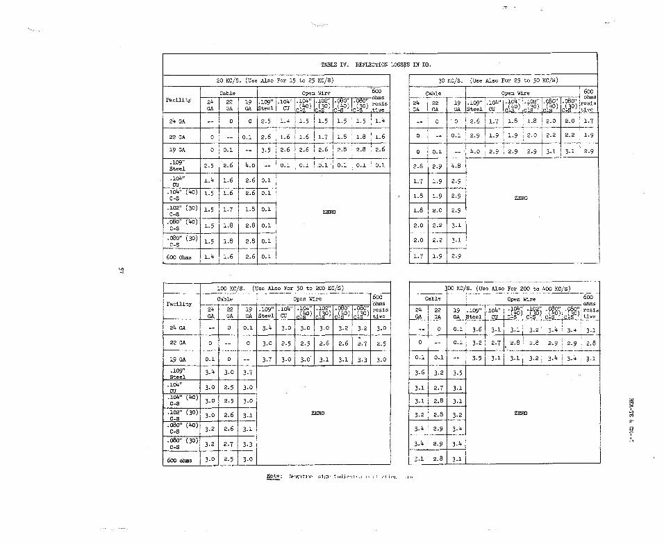
V, .-,
Facility
24 GA
22 GA
19 GA
;].09" Steel ---.lo4" cu
.J.o4" (40) C-S
.102" (30) C-S
--:-OS6"(40j c-s
.o80" (30) µ:s I 600 Ohms
FaciJ.ity
24 GA
22 GA
19 GA
.109" Steel
.104" cu
.lo4" (40) C-S
.102" (30) C-S
.o80" (40) c-s
.o8o" (30) c-s
6oo ohms
-~
TABLE IV. REFLECTION LOSS:i;:8 IN DB.
20 KC/S. (Use Also For 15 to 25 KC/S) 30 KC/S. (Use Also For 25 to 50 KC/S)
Cable Open Wire 1600 ~-109" 104" .J.04" 1.102" .o80" I ·o80" [ohms 24 22 19
GA GA GA Steel • cu ~;\°) i~-~~o) c~~) ilJO) ~~!!s
2.5 1.4 I I I -- 0 0 1.5 I 1.5 1.5 , 1.5 J 1.4
Cable Open Wire 600
Tif ohms
24 19 1-109" .104" .104" .102" .o80" .o80" •resis GA GA St 0el, _Q!f __ Jr-4c~~) ~ 0
]_:_tJ..v~
0 0 2.6 1.7 l.8 I 1.8 j 2.0 2.0 1.7 --
0 2.6 1.6 I : . i -- O.l 1.6 1 1.1 I 1.8 : 1..8 , 1.6 0 I
I 1.9 1.9 ; 2.0 2.2 2.2 1.9 0.1 I 2.9
0 O.l -- 3.5 f 2.6 I 2.6 1 2.6 ! 2.8 : 2.8 ' 2.6 ' ' I
-0 0.1
1 4.o i 2.9
1 2.9 : 2.9 3.1 I 3.1 2.9
---
2.5 2.6 4.o -- I O.l I
I ' , O.l . O.l ·1 O.l O.l ' O.l 2.6 2.9 4.8 --···--
1.4 1.6 2.6 O.l l.7 1.9 2.9
1.5 1.6 2.6 O.l l.8 1.9 2.9 ZERO
1.5 1.7 J..8 O.l ZERO l.8 2.0 2.9 -
1.5 1.8 2.8 O.l 2.0 I 2.2 3.1
1.5 1.8 2.8 O.l 2.0 I 2.2 3.1
1.4 1.6 2.6 O.l L7 l.9 2.9
---------- -· -
100 KC/S. {Use Also For 50 to 200 KC/S)
Cable Open Wire 600 ohms
24 22 19 109" 104" .104" .102" . Ot:SO" . Ot:SO" resis GA GA GA Steel • CU lr.~l\O) r.£~0) 1r.£l\O) r.~~O) tive
-- 0 O.l 3.4 3.0 3.0 3.0 3.2 3.2 3.0
I 100 KC/S. (Use Also For 200 to 400 KC/S)
Open Wire I 600 t----.------i----;---,-----.--,-:,;-::r--::-:=::--:,;;-:-;;--:=::1 ohms
24 22 19 .109" 1.104" I ·flli\)1· ·t~§'y -~) ·\18) resis GA G4 GA teel , CU I C-S . C-S , C-S C-~ I tive
' 61 I I ' 4 4 ; 0.1 ! 3. , 3.1 I 3.1 I 3.2 3. 3. i 3.1
Cable
0 . 0 -- 0 3.0 2.5 2.5 2.6 2.6 2.7 2.5
··---····-r---- -0 0.1 I 3.2 ! 2. 7 II 2.81 2.8 2.9 2.9 : 2.8
• ' I
O.l 0 -- 3.7 3.0 3-0 3.1 3.1 3.3 3.0 0.1 0.1 3.5 i 3.1 I 3-1 I 3.2: 3.4 3.4 i J.l
3.4 3.0 3.7 3.6 i 3.2 I 3.5 -!
3.0 2.5 3.0 3.1 [ 2.7 3.1 I
3.0 2.5 3.0 3.1 ; 2.8 3.1 ill >
3.0 2.6 3.1 ZERO 3.2 i 2.8 3.2 ZERO 8 l>l
"' 3.2 2.6 3.1 i 3.4 ! 2.9 3.4 (')
----·----· f . 3.2 2.7 3.3 I 3.4 r 2.9 3.4
,--,
··- ·---1 I 3.0 2.5 3.0 :,.1 ' 2.8 3.1 j
~: Nt•g-Ltlv• ;;1,-;i: 111<.il1""-:l1•;; 1·• :·1 ,•1 i•,11

REA-TE & CM-407
TABLE V
CORRECTION FACTORS TO BE APPLIED TO THE VOL'IMETER READINGS IN THE PRESENCE OF NOISE.
D F D F
!
0.5 I 8.8 7.0 0.7 1.0 6.5 7.5 o.6 1.5 ; 4.7 8.o 0.5 2.0 ' 3.4 8.5 o.4
i 2.5 I 2.7 9.0 0.3 3.0 ! 2.2 9.5 0.3 ' 3.5 I 1.9 10.0 0.3 4.o 1.7 10.5 0.25 4.5 l 1.4 11 0.20 5.0 I 1.3 12 0.20 5.5 i 1.1 13 0.20 6.o I 0.9 14 0.10 6.5 l o.8 15 0.10 ;
PROCEDURE: Measurements performed according to paragraph 9.03 in text.
1. D represents the difference of levels in db of steps 1 and 2, paragraph 9.03.
2. Fis the value corresponding to above difference that must be subtracted from reading of step 1, par. 9.03 to obtain true signal level.
NOTE: Correction applies to average reading a.c.-vtvm such as H.P. 400D or H types or eq_ui valent.
,, I'