Sea Ice Forces on Structures
17
OCEANS IV Vol. II
Transcript of Sea Ice Forces on Structures

OCEANS IV Vol. II
ICEBREAKER EXPERIENCE AS A GUIDE TO SEA ICE FORCES ON STRUCTURES
1 2 Ben C. Gerwick Jr. , F.ASCE & Lawrence B. Karp , M.ASCE
ABSTRACT
The design and verification of fixed platforms for Arctic and sub-Arctic ocean service requires a determination of the probable sea ice forces acting on structures of various configurations and sizes. Considerable research, including field measurements and model testing, has been carried out over past years. By necessity, almost all of this has been performed in micro-scale, and adaptation of that data to the scale of actual structures requires use of relatively large correction factors.
Until there has been a significant history of fixed structures in sea ice, a promising source of data appears to be use of icebreaker vessel experience.
Because icebreaker vessels traverse a varied sequence of sheet and ridge forms, they integrate the forces that may be imposed on a fixed structure over a period of time. In order to translate such data from a moving ship to a fixed structure, it is necessary to evaluate characteristic ice failure mechanisms of each. An energy approach based on a three dimensional failure criterion offers a practicable means for correlation and resolution of icebreaker data into the several components involved, and hence determination of total forces acting on fixed structures.
INTRODUCTION
Structures have been proposed for service in Arctic waters, covered by substantial thicknesses of ice most of the year. In order to explore for and develop the resources of this area in an orderly and economical manner, structures must be designed which will resist the forces of ice moving about them.
The rational design against ice hazards requires determination ,of the mechanical properties and the strength of ice under conditions which best represent those in nature.
In order to provide a meaningful pattern and calibration to·both mathematical and physical models of ice forces
1 Professor of Civil Engineering, University of California, Berkeley
2Teaching Associate, College of Engineering,
University of California, Berkeley
622

SEA ICE FORCES ON STRUCTURES 623
on structures which have been developed in recent years~ one promising approach is to expand and utilize the experience, quatitative data, and energy concepts developed for and by the design and operation of icebreaker ships.
SCALE EFFECT
The majority of recent papers and current studies )n the forces exerted by sea ice on structures are based on appli2ation of classical mechanics to the dynamic ice problem, using properties of sea ice obtained from tests on relatively small samples. Calibration to actual structures is extremely scarce and has largely taken the form of introducing a reduced or "effective" ice strength into mathematical models based on homogeneous properties, as a very approximate means of correcting for the scale effects. Such determinations are subject to inherent inadequacies due to the anisotropy and heterogeneity of sea ice, the varied morphology of its formations, and the dynamics of sea ice movement. Elastic and plastic properties of sea ice develop in various ways depending on age, location, presence of snow cover, direction and duration of load application, mobility, state of stress, mass, temperature, form, texture and chemical composition. Its physical and mechanical characteristics also vary correspondingly; crystals are oriented in different patterns and there is a change in relationship between the crystal and liquid (brine} phases within the ice thickness. The result is a diverse material that has a complex array of properties and exhibits viscoelastic behavior.
Many ice force measurements which have been made rely upon scaled-down models in laboratory tests. This approach has limitations. Many scaling problems are due to the fact that it is impossible to simultaneously simulate inertia, viscous, and gravity forces. Direct comparison to the results obtained from model tests of offshore structures is largely confined to data from structures in Cook Inlet plus a few observations of lighthouse structures in the Baltic. Although this data is invariably incomplete, calibration of these and other in-situ evaluations suggests that small sample test solutions considerably overestimate ice pressures.
Blenkarn ("1} reports the Cook Inlet structures, instrumented at different times with load cells and strain gauges, were subjected to steady crushing of a uniform ice sheet on 36 inch diameter vertical legs to a maximum effective pressure of "160 psi. Blenkarn concluded sustained pressure on the structures was less than "125 psi and a pressure ridge loading intensity was about "150 psi, versus the 300 psi design load. Smaller scale in-situ "Nutcracker" tests (2), using indenters of 4.5 and "18 inch diameters, resulted in considerably higher ice pressures of 587 and 420 psi respectively. Peyton (3) showed general dependence of strength of sea ice on rate of loading by determining test values ranging from "175 (high rate} to 350 psi on small samples but recommended (4} a design ice pressure of 475 psi for Arctic ice. Neill (5} reported on tests in Alberta
624 CIVIL ENGINEERING IN THE OCEANS
rivers. The maximum effective pressures on Pembina River vertical piles was 260 psi, and about 180 psi on an Athabasca River inclined pier. Bergdahl (6) observed damaged lighthouses in northern sweden and southern Finland. Pressures at failure, at very low temperatures where ice strengths would be expected to be higher, were estimated at 350 to 465 psi.
Scaling laws developed for icebreaking ships are also relevant to the modeling of structures; however_, because of the lower speeds involved, the plastic behavior of the real and model ice sheets must be considered. Of critical importance in modeling the action of ice against offshore structures is the knowledge of probable ice failure modes. This is important because it is currently impossible to scale all mechanical properties of the ice formations properly. The Cook Inlet structures, for example, cause failure of sea ice predominantly by local crushing with some occasional tensile cracking, so the proper scaling of crushing strength would be very important in modeling that phenomena. Many proposed Arctic offshore structures will fail the ice primarily by bending. This type of failure is similar to that caused by icebreaking ships and would call for accurate scaling of the flexural ice strength property. In both instances, proper scaling of the elastic modulus of the ice sheet is also important and thus the ratio of strength to elastic properties must be scaled correctly.
Bercha (7) suggests the scale effect problem may be divided into types,
1. stress concentration effects 2. geometric and material discontinuity effects.
Stress effects, such as relatively simple ice-structure interactions, involve the mathematical techniques of solid mechanics and finite element modeling. Discontinu~ty effects are also analytically tractable through a combination of experimental programs and application of methods of probabilistic mechanics.
$cale effect has generally been approached by semiempirical methods attempting to relate certain critical ratios with loading and ice conditions. Korzhavin's (8) approach involved the definition of an indentation coefficient (ratio of effective ice pressure to basic strength) as a function of kinematic and geometric variables. Research (9) corroborated a relationship between this indentation coefficient and an aspect ratio parameter b/h, where b is the structure width and h, the ice thickness. This empirically derived ratio, due to lack of data, has only been successful within lower ranges of b/h val~es. As large ratios would exist for structures currently being contemplated-for Arctic service, extrapolative values would be unreliable.
Another aspect of the scale effect, ice morphology, arises due to the unique historical and current physical properties of specific types of formations. First-year pr.essure ridges, which are partially consolidated, have
SEA ICE FORCES ON STRUCTURES 625
different macro-properties than their older counterpar~s. The multi-year ridge, with its low salinity and random crystal orientation in the refrozen zones, represents the most formidable ice formation. Croasdale (4) estimates, for a 50 foot thick, 100 foot wide ridge, a force on a 450 sloped cone of 26,000 kips to clear the ridge. For a comparable vertical structure, a crushing force . of 65,000 kips has been estimated for the same ridge.
ICEBREAKER RESISTANCE
The first polar icebreaker, USSR Ermak, was built in England in 1899. By World War II icebreakers were in common use and eventually the Stalin class was developed in Russia, the Wind class in the United States, and the Canadian Labrador, John A. MacDonald and Louis St. Laurent, the Japanese Fuji, and the Russian Moskva class. The Russian Lenin, with 44,000 HP, was the world's first nuclear powered surface ship. In 1969 the bow of the tanker Manhattan was fitted with a 2.5 inch thick hull plate and increased power to transit the Northwest passage in the Canadian Arctic. In 1977 the Soviet atomic icebreaker Arktika navigated through thick pack ice to reach the North Pole.
Instrumented full scale tests on some ships have been made to determine actual ice loads experienced. Foil rosette strain gauges were used on the SS Manhattan, and the release of data pertaining to ice impact forces, hull bending loads, and steel temperature appears (10) imminent. Electric resistance-type strain gauges have been used on Russian icebreakers, on the USCG Mackinaw, the Great Lakes bulkcarrier Leon Frazer, and the CCGS Louis St. Laurent.
Many full scale tests relied upon reports from captains based on general observation and comparisons have been made for power vs ice thickness. The 90 foot beam Lenin, at 38,000 SHP, was reported to have cut through 7.8 feet of ice at 2.0 knots; the Labrador, at 10,000 SHP cut 3.0 feet of ice, and the John A. MacDonald, 15,000 SHP, was informally observed to navigate 4.5 feet of ice. The Alexbow upward breaking plough was pushed (11) through 1.2 feet of ice by a 1400 SHP tug at 5 knots. The output power was not measured but the ballard pull for this small vessel corresponded to only about 31 lbs. per SHP on the basis of rated power having been developed.
For ship design estimates, there is general acceptance of approximate relationships, such as resistance varies as beam linearly, resistance varies as ice thickness squared, and power is proportional to resistance. Public media reports that icebreaking performance of the 43,000 HP, 155 foot beam, Manhattan (Figure 1) made 12 knots through 15 foot ice packs and successfully smashed ridges up to 60 feet thick. Bustard (12) estimated a ridge breaking energy capability, because of its size, of 183,750 foot-tons for the Manhattan (powered at only 0.3 HP per ton of displacement) at 4 knots in 6 feet of uniform ice.

626 CIVIL ENGINEERING IN THE OCEANS
Figure I
:.lore recently, the 78 ,000 SHP USC G Polar Star (Fig. 2), capable of ramming through ice up to 21 feet thici( and desianed to continuously break ice 6 feet thick at 3 knots, was instrumented with an impulse radar device to give a continuous record of ice thickness. The CCGS Norman ~.1cleod
Rodgers' hull was instrumented to determine total ice impact loads. Two new Class 3 icebreakers, the CCGS Franklin and the CCGS Pierre Radisson, were very recently commissioned. Arctec, Inc. is currently analyzing data from an instrumentation program on the CCGS Pierre Radisson.
Figure 2

SEA ICE FORCES ON STRUCTURES 627
The problem of designing offshore structures is somewhat different from icebreaker ship design, which involves the motion of a ship at moderate to high speeds through ice fields; whereas structural design is based on the destruction of slowly moving ice set into motion by winds and currents. Consideration of any analogies between ships and structures begins with the basic modes of ice/structure interaction,
I. static: pressure from expanding or contracting ice; this type of loading is only of major significance in lakes or sheltered coastal environment.
2. impact: moving ice formations, directed by wind and/or water currents.
3. friction: pressure of unconsolidated ice accumulations in the form of jams or pack ice.
4. adhesion: forces exerted by movement of ice adhering to a structure due to variation in water level or superimposed pressure.
Of the above, icebreaker experience may be utilized to evaluate forces and failure mechanisms evolving from impact, and frictional forces resulting from contact with ice during the continuous icebreaking mode.
The first major work presenting a theoretical model for ice loads en ships was by Popov et al (13). This model represents a collecti~e effort between 1957 and 1963 of Soviet endeavor to develop energy solutions to the ice impact problem. The basis of the model is a collision of two bodies, each of which includes the mass of its body plus an added mass to account for acceleration of the fluid in which the bodies are floating.
Probably the most significant description of the continuous icebreaking mechanism is the rational theoretical analysis developed by Kashteljan et al (14) in 1968. Limited full scale and model test data with the USSR Ermak are utilized to define semi-empirically the various basic components of ice resistance: breaking, gravity, and inertia. Hull and icebreaking efficiency coefficients were used in the equations to provide general applicability.
In 1970 Lewis & Edwards (15) presented a number of predictor equations derived by regression analysis based on results from model and full scale tests. They essentially revised Kashteljan's semi-empirical model by factoring the three resitive groups,
I. forces necessary to break ice 2. forces resulting from ice buoyancy 3. forces resulting fro~ imparting a velocity to the
broken ice pieces, with nondimensional coefficients determined experimentally. These coefficients were supposed to account for friction effects, the shape of the icebreaker, and other factors. Full scale trials of the USCGC Staten Island in continuous mode icebreaking were used to confirm the model tests.
Resistance curves were established theoretically in 1973 by Milano (16) on the basis of an energy approach. The total energy required for breaking an ice cover in the

628 CIVIL ENGINEERING IN THE OCEANS
continuous mode consists of energy components lost due to, 1. removing broken ice pieces 2. ship impact w~th unbroken ice sheet 3. ship climbing onto the unbroken ice sheet 4. ship falling after ice failure 5. submersion, rotation and moving away of ice pieces.
These equations and curves utilized regression techniques based on statistical data gathered by researchers. Sets of data (both model and full scale) have been analyzed by Vance (17), and the most reliable and accessible information appears to be that of the USCGC ~ackinaw. In 1975 Milano (18) studied the capability of this analytical model for predicting ship resistance in solid ice. Plots of total resistance vs ship speed as a function of ice thickness (Figure 3) showed high average relative resistance until speeds of about 5.4 knots were attained. The transition zone, for four feet of ice, was at 3 knots. Plots of energy lost due to ship impact with unbroken ice sheet two feet thick were asymptotic at about 2 knots. Sch1t1arz (19) verified this theory recently at the Hamburg Model Basin. Accordingly, significant basic conclusions can be made relating icebreaker operation to fixed structures.
({)
c 0 I-
30
~ 25 c ro +' ({)
•r-1 ({) Q)
0::
20
0 2
Ice 4 feet thick
4 6 8 10 12
Ship Speed - Knots
Figure 3

SEA ICE FORCES ON STRUCTURES 629
Loss of energy by the ship due to impact is completely absorbed in local bending and crushing of the ice sheet, with crushing a direct function of ice thickness and the ultimate crushing strength of the ice. Effective strength is reduced by non-homogeneities; weaker rupture planes are due to impurities, In treating moving ship/ice impact, the ship is propelled at a constant velocity and strikes the ice field in a symmetrical wedging manner. The speed of the vessel is fast enough that the time interval of impact is small, the impact force is dominant, and secondary forces such as friction are ignored. For fixed structure/ice impact, the ice moves at a constant velocity and also strikes the structure in a symmetrical wedging manner, but the speed of the ice is slow enough that the time interval of impact is large, so the impact and secondary forces such as friction must be considered.
For ship resistance in broken ice, Kashteljan {14) showed that the effect of upturning or moving the ice pieces is small and can be ignored, and that friction is low since there is almost complete lubrication; therefore motion is resisted primarily by inertia forces and open-water. Lewis and Edwards {15) concluded that ship resistance, while breaking ice in the continuous mode, is primarily due to forces attributable to the buoyancy {tipping and submerging) of the broken ice and friction caused when the broken ice is forced against the hull under the influence of buoyancy. The next most important resistive forces are due to the inertial effect which increases proportionally to the square of the velocity. Forces breaking ice are given lesser value. Enkvist (20) also states that pure breaking resistance is only a small portion of the total resistance of an icebreaking ship. Although there is great variation in total force that occurs due to differing contributions from the ice failure/dispersal mechanisms involved, at high ship velocities these theories hold; but for fixed engineering structures subjected to moving ice fields, pure breaking and frictional resistance are the dominant parameters.
It follows then that an efficient (12) icebreaker, such as the USCGC Polar Star, powered at 5 HP per ton of displacement could be said to expend an equivalent 1.0 unit of energy to overcome high speed resistive forces, but fixed structures, such as a cone, breaking upward or downward, could expend 1.5 to 2.0 units and a less efficient shape such as a cylinder or rectangle could expend 3.0 to 4,0 equivalent units to overcome low speed forces. The interaction between relevant energy components due to the slower speed of the ice field, and the geometry of the structure causing different combinations of failure mechanisms, are the responsible parametric bounds.

630 CIVIL ENGINEERING IN THE OCEANS
FAILURE ~ECHANISMS
Following the pattern which has been set earlier in developino enerqy concepts for icebreaker vessels, ice forces upon structures may be categorized into five components of energy requirements:
1. fracture initiation 2. fracture propaqation 3. se"'aration of ~Jroken IJut interlocked masses ((luasi
cohesion) 4. displacement, raising, and submerging broken ice 5. movement of ice past the structure.
As a ship moves throu gh compact ice, observations have shown a characteristic breal~ing pattern. First, local crushing is observed. As loading of the ice progresses, a series of radial cracks appears followed by one or more rows of circumferential cracks just prior to ice failure. Two principal wedges of 67.5° form on both sides of the center-! i n e c r a c k ( F i g u r e 4 ) . c o mp r i s in g a 2 7 0 o fa i 1 u r e d om a i n • A s these wedges fail, cusps and points are formed which become load points as the ship advances. l<ashteljan observed (14) that the number of rows of circumferential cracks which ~ppear depends primarily on ice thickness and ship speed. For lower speeds and thicker ice (the condition relative to offshore structures subjected to slowly moving ice) breaking gives rise to only one circumferential crack, producing greater forces because loading of abundantly cracked ice produces little additional resistance. Full scale tests (15) of the USCGC Northwind in the Chukchi Sea verified Kashteljan's observations.
Figure 4

SEA ICE FORCES ON STRUCTURES
By applying the general equations of energy conservation to icebreaking,
(EO- E1) + E2 = E3 + E4 + E5 where
EO Kinetic energy of vessel at first contact with ice E1 Kinetic energy of vessel when ice collapses E2 Energy derived from propeller thrust E3 Enerqy dissipated by impact E4 Potential ener g y acquired by ship E5 Enerny lost by friction,
it can be seen that the energy components applicable to fixed structures are E3 and E5; that is the energy lost by impact and friction.
631
To determine failure mechanisms, the concepts of critical stress and strain are usually used. ~ost common is the hypothesis that failure occurs when a critical value of unit stress is equalled or exceeded. For strain, failure is at a critical deflection or elongation of the material. These familiar stress and strain criteria assume that the failure load is applied instantaneously, and therefore do not account for creep and the viscous nature of ice. Practical application to viscoelastic materials has been attempted using a time-dependent modulus of elasticity to adjust for the macroscopic point of view, but only recently has research been devoted to studying fracture and failure of materials from the more appropriate microscopic viewpoint.
Korzhavin (B) noted failure deflections decreased with increasing loads, other things being equal. From a physical standpoint, only a work-based criteria could be accountable; therefore, for ice, a three dimensional failure criterion based on the maximum strain enerqy theory appears promising. Briefly, this suggests that failure occurs when the maximum work done by internal stresses on a unit volume of material equals or exceeds a critical value. For plastic materials, a refinement of this theory, known as the Von Mises yield criterion, has proved (2) to be satisfactory.
A study of the mechanics of cracking, based on these energy considerations, assumes that there are always preexisting cracks in all materials that fracture in a brittle fashion. These flaws, which in ice may be very small microcracks such as air or brine pockets, are the starting cracks in the energy balance.
If a gradually increasing force is applied to the sheet of ice, the external boundaries move (the cantilever bends) but at first the crack does not grow to split the sheet. The amount of movement depends on the stiffness of the cracked sheet. Relatively large cracks give a compliant piece of material, so large deflections are obtained at modest loads; however, small cracks give stiff sheets with large force/displacement ratios. Since the load deflection behavior depends on the presence of the crack, only when there are no cracks can the force/displacement slope be converted to an elastic modulus.
The external work done in an increment of movement be-

632 CIVIL ENGINEERING IN THE OCEANS
comes elastic strain energy in the sheet, and is available to feed the crack when it decides to propagate. During propagation the strain energy changes (when the crack grows, the stiffness of the sheet changes, and its capability to store energy changes) and work has to be done to feed the crack. The specific work (force-distance) of crack spreading per unit area of crack growth is the fracture touqhness of the material.
The strength of brittle materials in general is related to this fundamental theory, and the advantages of the strain energy criterion is that it is time-independent, capable of taking into account the loading history regardless of its complexity, and its effect on the strain history. It follows that the fracture toughness of ice and the size of flaws that propagate to failure are the parameters of concern to determine favorable failure mechanisms.
FRICTION FORCES
Frictional resistance results not only from the interaction between a vessel hull or a structure's surface and ice but also from the friction between ice and ice. Interfacial friction effects are highly directionally dependent; therefore the structure's shape is crucial to minimize friction forces. Complex friction processes also develop in the layer directly adjoining the side of a ship. The structure of this layer depends on the direction of impact. When there is a central impact, friction between the side and the broken layer can be considered "dry". \'/hen there is a glancing impact, the boundary layer is in a melted state, primarily because the work of the driving forces overcoming the friction is converted to heat. This is known as selflubrication of ice.
Coefficients of friction depend on surface roughness and temperature. Enkvist (20) quotes measurements for kinetic friction coefficients ranging from 0.025 to 0.25 for drag experienced by icebreakers. Zubov (21) gives coefficients of static friction for dry cold ice on steel ranging from 0.30 to 0.50 and wet cold ice on steel ranging from 0.15 to 0.25; and for ice in motion against steel: dry, 0.30 to 0.50, and wet, 0.10 to 0.20. No values are available for concrete.
Adhesion, or the bond between ice and structure surface, can materially increase the apparent frictional resistance by forcing the failure to take place in the ice. When ice adheres to the structure's surface above the water line (a phenomenon known as "collaring") it changes the mode of failure of the ice. This notorious event is associated with up-breaking cone shaped structures. This adfreeze bond (4) develops if the ice remains stationary for extended periods of time, and the bond results in large forces being transmitted to the structure when ice movement begins again.
Enkvist (20) has determined that mechanical friction causes 50 to 70% of the total icebreaking resistance and is part ~f each mechanism. The breaking, submersion and
SEA ICE FORCES ON STRUCTURES 633
velocity components of resistance all cause normal forc~s resulting in friction. Applicable to offshore structures, Milano (18) plotted total resistance vs ship speed as a function of the dynamic coefficient of friction for USCG Mackinaw in 2 feet of ice and, because of inertia effects, the effect of friction is most severe at lower ship speeds.
The USSR Moskva was model tested (17) by Wartsila with various hull surfaces so that the coefficient of friction varied from 0.0 3 to 0.35. The results of the model tests were then regressed on coefficient equations to determine coefficients to be utilized with other full scale parameters, to determine the resistance of the full scale prototype.
The ore carrier Leon Fraser was retro-fitted with an air coa ting system to provide a lubricating film of water and a ir between the ship's hull and the tightly compacted broken ice pieces found in mush fields and clogged ice channels. The reduction in ship resistance is accomplished by the rapid discharge of low pressure air through small holes in a series of manifolds located externally on the hull. The rapid rise of large quantities of air causes an up~elling of water to accompany the air, and this air-water mixture provides the desired lubricating film.
STRUCTURE CONFIGURATION
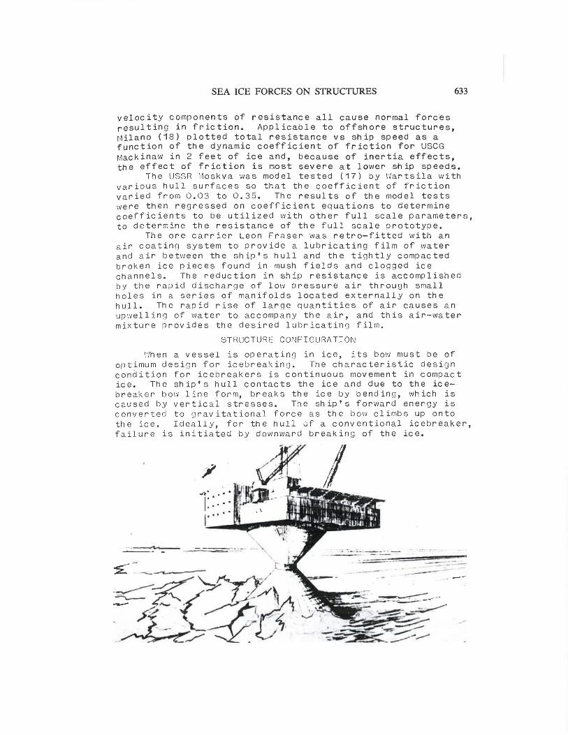
Uhen a vessel is operating in ice, its bow must be of optimum desi g n for icebre a king. The characteristic design condition for icebreakers is continuous movement in compact ice. The ship's hull contacts the ice and due to the icebreak e r bow line form, breaks the ice by bending, •Nhich is caused by vertical stresses. The ship's forward energy is converted to g ravitational force a s the bow climbs up onto the ice. Ideall y , for the hull 0f a conventional icebreaker, failure is initiated by downward breaking of the ice.
-----·-- - .. .,_. ___ __ _ - - - · - - -
. -:---==-~----
634 CIVIL ENGINEERING IN THE OCEANS
Offshore structures have been proposed (22) for Arctic service that employ a conical shape (Figure 5) to cause upvJard icebreaking. Icebreaker vessel experience with this mode of breaking is very scarce, primarily because such a bow form decreases the ship's efficiency at open water service speeds and presents the dan~er on board of climbing ice. However, tests (12) on the "Alexbo>·J" upbreal<ing icebreaker or plough form were made in 1967, and several advantages ~ere found that apply to offshore structures.
For the thicker ice covers that could be expected in regions where offshore structures would be in service, it is evident that while the underside is exposed to water at temperatures only sliqhtly below freezing, the upper surface may be very cold, dependinq on weather conditions. The thermal gradient between upper and lower surfaces will result in the ice being harder toward the upper surface. Althouqh analytical treatment of failure mode combinations and sequencing is extremely complex, simple beam tests show that flexural strength for saline ice in downward breaking is about half that of upward breakin~. Since bending fracture takes place through tension failure, it follows that the touohness of the colder upper surface is much less inducive to tensile failure than the warmer under surface.
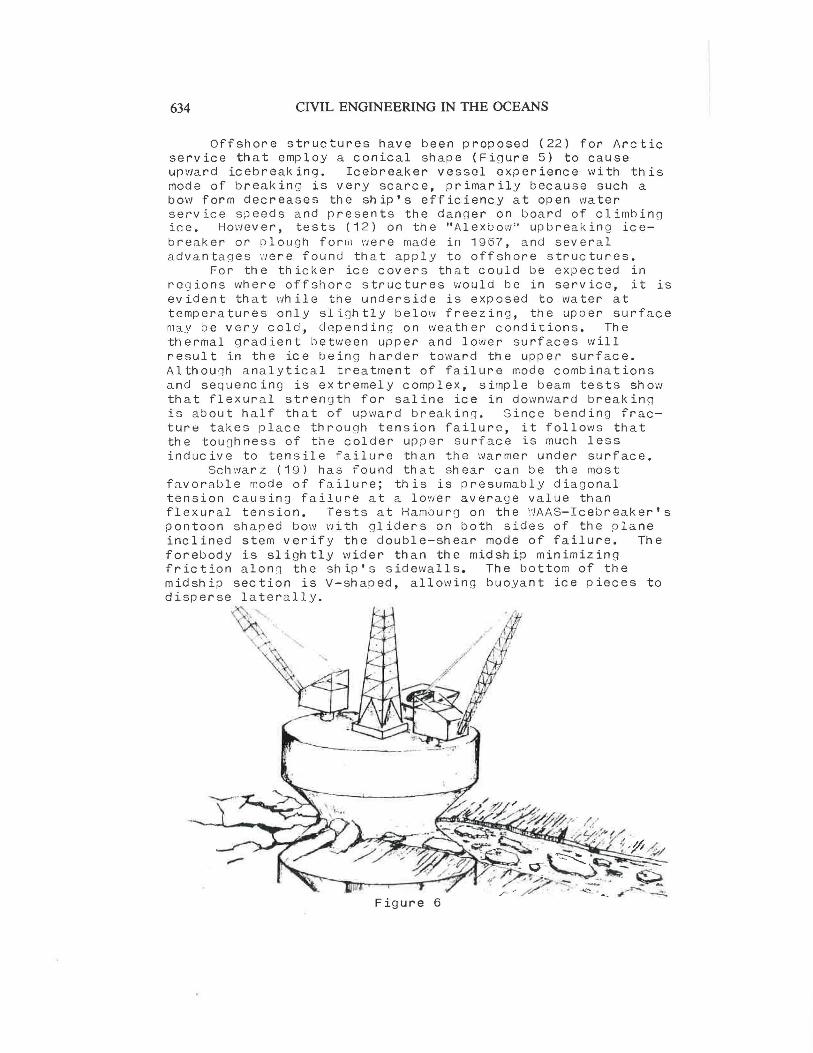
Schwarz (19) has found that shear can be the most favorable mode of failure; this is presumably diagonal tension causing failure at a lower average value than flexural tension. Tests at Hambura on the ~AAS-Icebreaker's pontoon shaped bow with gliders on both sides of the plane inclined stem verify the double-shear mode of failure. The forebody is slightly wider than the midship minimizing friction alonq the ship's sidewalls. The bottom of the midship section is V-shaped, allowing buoyant ice pieces to disperse laterally.
Figure 6

SEA ICE FORCES ON STRUCTURES
Another concept (23) is an hour-glass confiauration (Figure 6) at the waterline. For a moored floating structure, ballast control of draft allows either up or down breaking of the ice.
635
High friction between hull and snow-covered ice has often been attributed to be the main force stopping a vessel, at times exceeding the force actually needed to break the ice. Snow-cover also softens the blow by effectively reducing the coefficient of restitution, in effect absorbin~ the impact of an advancing icebreaker to the point where little of the potential im~act is transmitted to the solid ice. To overcome this deficiency, lake icebreakers have been fitted with bow pro~ellers (24) primarily to mix the ice with water and to lubricate the ship's hull sides to reduce the friction coefficient. l'lartsila developed, for the Baltic roll-on/roll-off icebreal~int] ferry Finncarrier, a hull equipped with an anti-friction bubbler system. As applied to offshore structures, tests (12) on the "AlexbO\'J" indic a te that the self-lubrication from contact belo~ the ice is definitely favorable.
A siqnificant portion of total ener~y is spent in displacing the broken ice. Ideally this will be moved sideways, with only the minimum amount of raisino or submerging, since this requires energy. The broken ice must be moved clear of the hull or structure to minimize friction.
Important form-dependent advances have been achieved by model testing of various icebreaker bow and hull configurations. The Canadian "R" class icebreaker hLLvin:.:J the same 15,000 SHP and tested at the same 3 knots in 3 feet of ice as the CCGI i'Jorman f,1cleod Rodaers, showed that a 12~~ improvement is obtained by a Manhattan-type bow.
Thus the confiouration of both structures and icebreakers can have a major effect in initiatinn and propaqating fractures and in facilitatin~ lubricLLtion and clearance of the broken ice.
CONCLUSIONS
Data taken from ship operations can be used to calibrate probable ice forces that may act on structures of various shapes. Components of forces on vessels can be correlated to those acting on structures by using ener~y concepts.
Ice mechanics can be used to identify the several mechanisms by which ice formations may fail, by evaluating the energy required for each mode in relation to the physical ice properties. Extrapolation from small scale field tests and instrumented model tests to full scale structures can be aided by comparison with icebreaker data. The resistance of anisotropic sea ice can then be statistically integrated over a meaningful space/time frame.
Icebreaker experience can al~o be valuable in selecting appropriate configurations for offshore structures. The various componer,ts of sea ice forces, translated from ship data, can be extrapolated and recombined to determine forces that may act on a fixed structure.

636 CIVIL ENGINEERING IN THE OCEANS
REFERENCES
1. Blenkarn, K.A.; "Measurement and Analysis of Ice Forces on Cool< Inlet Structures", Offshore Technology Conference, Houston, TX, April 22-24, 1970.
2. Morgenstern, N.R. & Nuttall, J,B,; "The Interpretation of Ice Strength from In-Situ Indentation Tests", APOA Project 16, Vol 1 of 2, March 1971.
3. Peyton, H.R.; "Sea Ice Forces", Proceedings: Ice Pressures Against Structures, Quebec 1966, National Research Council of Canada,Technical Memorandum #92, Mar 1968,
4 • C r o as d a 1 e , K . R . ; " Ice For c e s on iv1 a r in e s t r u c t u r e s" , International Association of Hydraulic Research (IAHR) Third International Symposium on Ice Problems, Hanover, NH, Aug 18-21, 1975.
5. Neill, Charles R.; "Dynamic Ice Forces on Piers & Piles. An Assessment of Design Guidelines in the Light of Recent Research", Canadian Journal of Civil Engineering, Vol. 3, 1976.
6. Bergdahl, Lars; "Two Lighthouses Damaged by Ice", International Association of Hydraulic Research (IAHR) Proceedings of 2nd Ice Symposium, Leningrad, Sept 26-29, 1972.
7. Bercha, F.G.; "Scale Effect in Ice Mechanics", c'Jorkshop on the Mechanical Properties of Ice, Jan 24-25, 1977, Calgary, Alberta, National Research Council of Canada, Associate Committee on Geotechnical Research, Snow & Ice Subcommittee, Technical 1·1emorandum #-121, October 1977.
8. l<orzhavin, K.N.; "Action of Ice on Engineering Structures", Novosibirsk 1962, Draft Translation (from Russian) 260, CRREL, Sept 1971.
9. Michel, Bernard; Ice Mechanics, Les Presses de L'Universite Laval, Quebec, 1978.
10. ARCTEC, Inc. (Voelker, DeBord, Dane); Executive Summary SS Manhattan Arctic Marine Project, Maritime Administration, US Dept of Commerce, Report #375C-1, Mar 12, 1979.
11. Bustard, E.E.; "The Importance of Size in an Arctic Ship", SNAME Ice Tech Symposium, Montreal, April 9-11, 1975.
12. Gilmore, German & Milne; Alexbow, Report on Development and Trials up to March 1967, Montreal, 1967.
13. Popov, Yu.N., Faddeyev, o.v., Kheysin, D.Ye., Yakovlev, A.A.; Strength of Ships Sailing in Ice, Leningrad, 1967, (translated from Russian), Foreign Science & Technology Center, US Army Material Command, Dept of the Army, Feb 5, 1969.

SEA ICE FORCES ON STRUCTURES
14. Kashteljan, V.I., Poznjak, I.I. & Ryvlin, A.Ja.; "Ice Resistance to Motion of a Ship", (translated from Russian) Chapter 3, Sudostroyeniye, Leningrad, 1968.
637
15. Lewis, Jack \'1. & Edwards, Roderick Y. Jr.; "Methods for Predicting Icebreaking and Ice Resistance Characteristics of Icebreakers", SNAME Annual Meeting, New York, ~ov 12-13, 1970.
1 6 • :'.1i 1 a n o , V • R • ; " s h i p R e s i s t an c e to C o n t in u o u s M o t i on i n Ice", S~~Af'!lE f;Jeeting, New York, Nov 15-17, 1973.
17. Vance, G.P.; "A Scaling System for Vessels :.1odeled in Ice", SNAflE Ice Tech Symposium, rlontreal, Apr 9-11, 1975.
18, !1ilano, V.R.; "Variation of Ship/Ice Parameters on Ship Resistance to Continuous ;',lotion in Ice", SI~A M E Ice Tech Symposium, ~:1ontreal, Apr 9-11, 1975.
19. Schwarz, Joachim; "l~ew Developments in !i1odeling Ice Problems", 4th International Conference on Port and Ocean Engineering Under Arctic Conditions (POAC), Newfoundland, Canada, Sept 26-30, 1977.
20. Enkvist, E.; "On the Ice Resistance Encountered by Ships Operating in the Continuous ~:lode of Icebreaking", Swedish Academy of Engineering Sciences in Finland Report #24, ~artsila, Helsinki, Nov 1972.
21. Zubov, N.N.; Arctic Ice, (translated from Russian), u.s. Navy Elec t ron i cs Laboratory, May 1943.
22. Gerwick, Ben c. Jr. !', Lloyd, Ronald R.; "Design and Construction Procedures for Proposed Arctic Offshore Structures", Offshore Technology Conference, Houston, TX, Apr 22-24, 1970.
23. Gerwick, Ben c. Jr. c\ Jahns, Hans 0.; "Conceptual Design of Floating Drilling, Production and Storage Caisson for Arctic \·Jaters", 5th International Conference on Port and Ocean Engineering Under Arctic Conditions (POAC), Trondheim, Norway, Aug 13-16, 1979.
24. Edwards, Lewis, ~·Jheaton & Coburn; "Full-Scale and Model Tests of a Great Lakes Icebreaker", SNAME Annual Meeting, New York, Nov 16-17, 1972.