
Science for Tenth Class - Web Education
369
-
Upload
khangminh22 -
Category
Documents
-
view
0 -
download
0
Transcript of Science for Tenth Class - Web Education

This book has been revised according to the CCE pattern of school education based onNCERT syllabus prescribed by the Central Board of Secondary Education (CBSE) for Class X
Science for Tenth Class(Part – 1)
PHYSICSAs per NCERT/CBSE Syllabus
(Based on CCE Pattern of School Education)
LAKHMIR SINGHAnd
MANJIT KAUR
This Book Belongs to :
Name ..............................................................................
Roll No............................................................................
Class ................................. Section ..............................
School .............................................................................
Containing
answers to NCERT
book questions
and value-based
questions

Branches :
Ahmedabad : Ph: 27541965, 27542369, [email protected] : Ph: 22268048, 22354008, [email protected] : Ph: 4274723, 4209587, [email protected] : Ph: 2725443, 2725446, [email protected] : Ph: 28410027, 28410058, [email protected] : Ph: 2323620, 4217136, [email protected] (Marketing Office)Cuttack : Ph: 2332580; 2332581, [email protected] : Ph: 2711101, 2710861, [email protected] : Ph: 2738811, 2735640, [email protected] : Ph: 27550194, 27550195, [email protected] : Ph: 2219175, 2219176, [email protected] : Ph: 2401630, 5000630, [email protected] : Ph: 2378740, 2378207-08, [email protected] : Ph: 22367459, 22373914, [email protected] : Ph: 4026791, 4065646, [email protected] : Ph: 22690881, 22610885, [email protected] : Ph: 6451311, 2720523, 2777666, [email protected] : Ph: 2300489, 2302100, [email protected] : Ph: 64017298, [email protected] : Ph: 2443142, [email protected] (Marketing Office)Ranchi : Ph: 2361178, [email protected] Siliguri : Ph: 2520750, [email protected] (Marketing Office) Visakhapatnam : Ph: 2782609, [email protected] (Marketing Office)
© 1980, Lakhmir Singh & Manjit Kaur
All rights reserved. No part of this publication may be reproduced or copied in any material form (including photocopying or storing it in any medium in form of graphics, electronic or mechanical means and whether or not transient or incidental to some other use of this publication) without written permission of the publisher. Any breach of this will entail legal action and prosecution without further notice.Jurisdiction : All disputes with respect to this publication shall be subject to the jurisdiction of the Courts, Tribunals and Forums of New Delhi, India only.
First Published in 1980Revised Edition 2014, 2016Reprints 1981, 82, 83, 84, 85, 86, 87, 88, 89, 90 (Twice), 91 (Twice), 92 (Twice), 93, 94, 95, 96, 97, 98, 99, 2000, 2001, 2002, 2003, 2004, 2005, 2006, 2007, 2008, 2009, 2010, 2011, 2012, 2013, 2015, 2016 (Thrice)
ISBN : 978-93-525-3028-1 Code : 1016H 282
S. CHAND SCHOOL BOOKS(An imprint of S. Chand Publishing)A Division of S. Chand And Company Pvt. Ltd.(An ISO 9001 : 2008 Company)7361, Ram Nagar, Qutab Road, New Delhi-110055Phone: 23672080-81-82, 9899107446, 9911310888; Fax: 91-11-23677446www.schandpublishing.com; e-mail : [email protected]
Physics X: Lakhmir Singh
In our endeavour to protect you against counterfeit/fake books, we have pasted a holographic film over the cover of this book. The hologram displays the unique 3D multi-level, multi-colour effects of our logo from different angles when tilted or properly illuminated under a single source of light, such as 2D/3D depth effect, kinetic effect, gradient effect, trailing effect, emboss effect, glitter effect, randomly sparkling tiny dots, etc.
A fake hologram does not display all these effects.
S. CHAND’S Seal of Trust

LAKHMIR SINGH did his M.Sc. from DelhiUniversity in 1969. Since then he has beenteaching in Dyal Singh College of DelhiUniversity, Delhi. He started writing books in1980. Lakhmir Singh believes that book writingis just like classroom teaching. Though a bookcan never replace a teacher but it should makethe student feel the presence of a teacher.Keeping this in view, he writes books in such astyle that students never get bored reading hisbooks. Lakhmir Singh has written more than 15books so far on all the science subjects: Physics,Chemistry and Biology. He believes in writingquality books. He does not believe in quantity.
MANJIT KAUR did her B.Sc., B.Ed. from DelhiUniversity in 1970. Since then she has beenteaching in a reputed school of Directorate ofEducation, Delhi. Manjit Kaur is such a popularscience teacher that all the students want to jointhose classes which she teaches in the school.She has a vast experience of teaching scienceto school children, and she knows the problemsfaced by the children in the study of science.Manjit Kaur has put all her teaching experienceinto the writing of science books. She has co-authored more than 15 books alongwith herhusband, Lakhmir Singh.
It is the team-work of Lakhmir Singh and ManjitKaur which has given some of the most popularbooks in the history of science education in India.Lakhmir Singh and Manjit Kaur both writeexclusively for the most reputed, respected andlargest publishing house of India : S.Chand andCompany Pvt. Ltd.
ABOUT THE AUTHORS
AN OPEN LETTERDear Friend,
We would like to talk to you for a few minutes, just togive you an idea of some of the special features of thisbook. Before we go further, let us tell you that this bookhas been revised according to the NCERT syllabusprescribed by the Central Board of Secondary Education(CBSE) based on new “Continuous and ComprehensiveEvaluation” (CCE) pattern of school education. Just like ourearlier books, we have written this book in such a simplestyle that even the weak students will be able to understandphysics very easily. Believe us, while writing this book, wehave considered ourselves to be the students of Class Xand tried to make things as simple as possible.
The most important feature of this revised edition of the bookis that we have included a large variety of different types ofquestions as required by CCE for assessing the learning abilitiesof the students. This book contains :
(i) Very short answer type questions (including true-falsetype questions and fill in the blanks type questions),
(ii) Short answer type questions,
(iii) Long answer type questions (or Essay type questions),
(iv) Multiple choice questions (MCQs) based on theory,
(v) Questions based on high order thinking skills (HOTS),
(vi) Multiple choice questions (MCQs) based on practicalskills in science,
(vii) NCERT book questions and exercises (with answers),and
(viii) Value based questions (with answers).
Please note that answers have also been given for the varioustypes of questions, wherever required. All these features willmake this book even more useful to the students as well as theteachers. “A picture can say a thousand words”. Keeping thisin mind, a large number of coloured pictures and sketches ofvarious scientific processes, procedures, appliances,manufacturing plants and everyday situations involvingprinciples of physics have been given in this revised edition ofthe book. This will help the students to understand the variousconcepts of physics clearly. It will also tell them how physicsis applied in the real situations in homes, transport and industry.

We are sure you will agree with us that the facts andformulae of physics are just the same in all the books,the difference lies in the method of presenting thesefacts to the students. In this book, the various topics ofphysics have been explained in such a simple way thatwhile reading this book, a student will feel as if ateacher is sitting by his side and explaining the variousthings to him. We are sure that after reading this book,the students will develop a special interest in physicsand they would like to study physics in higher classes aswell.
We think that the real judges of a book are the teachersconcerned and the students for whom it is meant. So,we request our teacher friends as well as the students topoint out our mistakes, if any, and send their commentsand suggestions for the further improvement of this book.
Wishing you a great success,
Yours sincerely,
396, Nilgiri Apartments,Alaknanda, New Delhi-110019E-mail : [email protected]
Other Books by Lakhmir Singh and Manjit Kaur
1. Awareness Science for Sixth Class
2. Awareness Science for Seventh Class
3. Awareness Science for Eighth Class
4. Science for Ninth Class (Part 1) PHYSICS
5. Science for Ninth Class (Part 2) CHEMISTRY
6. Science for Tenth Class (Part 2) CHEMISTRY
7. Science for Tenth Class (Part 3) BIOLOGY
8. Rapid Revision in Science
(A Question-Answer Book for Class X)
9. Science for Ninth Class (J & K Edition)
10. Science for Tenth Class (J & K Edition)
11. Science for Ninth Class (Hindi Edition) :
PHYSICS and CHEMISTRY
12. Science for Tenth Class (Hindi Edition) :
PHYSICS, CHEMISTRY and BIOLOGY
13. Saral Vigyan (A Question-Answer Science
Book in Hindi for Class X)
DISCLAIMERWhile the authors of this book have made every effort to avoid any mistake or omission and have used their skill, expertise andknowledge to the best of their capacity to provide accurate and updated information, the authors and the publisher do not give anyrepresentation or warranty with respect to the accuracy or completeness of the contents of this publication and are selling thispublication on the condition and understanding that they shall not be made liable in any manner whatsoever. The publisher and theauthors expressly disclaim all and any liability/responsibility to any person, whether a purchaser or reader of this publication or not, inrespect of anything and everything forming part of the contents of this publication. The publisher and authors shall not be responsiblefor any errors, omissions or damages arising out of the use of the information contained in this publication. Further, the appearance ofthe personal name, location, place and incidence, if any; in the illustrations used herein is purely coincidental and work of imagination.Thus the same should in no manner be termed as defamatory to any individual.

CONTENTSFFFFFIIIIIRRRRRSSSSST TET TET TET TET TERRRRRMMMMM
1. ELECTRICITY 1 – 67Types of Electric Charges ; SI Unit of Electric Charge : Coulomb ; Conductors andInsulators ; Electric Potential and Potential Difference ; Measurement of PotentialDifference : Voltmeter ; Electric Current ; Measurement of Electric Current :Ammeter ; How to Get a Continuous Flow of Electric Current ; Direction of ElectricCurrent ; How the Current Flows in a Wire ; Electric Circuits ; Symbols for ElectricalComponents (or Circuit Symbols) ; Circuit Diagrams ; Relationship Between Currentand Potential Difference : Ohm’s Law ; Resistance of a Conductor ; Graph BetweenPotential Difference and Current (V–I Graph) ; Experiment to Verify Ohm’s Law ;Good Conductors, Resistors and Insulators ; Factors Affecting the Resistance of aConductor ; Resistivity ; Combination of Resistances (or Resistors) in Series andParallel ; Domestic Electric Circuits : Series or Parallel ; Electric Power ; VariousFormulae for Calculating Electric Power ; Power–Voltage Rating of ElectricalAppliances ; Commercial Unit of Electrical Energy : kilowatt-hour (kWh) ; RelationBetween kilowatt-hour and Joule ; How to Calculate the Cost of Electrical EnergyConsumed ; Heating Effect of Electric Current ; Applications of the Heating Effectof Electric Current.
2. MAGNETIC EFFECT OF ELECTRIC CURRENT 68 – 116Magnetic Field and Magnetic Field Lines ; To Plot the Magnetic Field Pattern Dueto a Bar Magnet ; Properties of the Magnetic Field Lines ; Magnetic Field of Earth;Magnetic Effect of Current ; Experiment to Demonstrate the Magnetic Effect ofCurrent ; Magnetic Field Pattern Due to a Straight Current-Carrying Conductor ;Direction of Magnetic Field Produced by a Straight Current-Carrying Conductor :Right-Hand Thumb Rule and Maxwell’s Corkscrew Rule ; Magnetic Field PatternDue to a Circular Loop (or Circular Wire) Carrying-Current ; Clock-Face Rule ;Magnetic Field Due to a Current-Carrying Solenoid ; Electromagnet ; Magnetismin Human Beings ; Force on Current-Carrying Conductor Placed in a MagneticField ; Fleming’s Left-Hand Rule for the Direction of Force ; Electric Motor ;Electromagnetic Induction : Electricity from Magnetism ; Fleming’s Right-HandRule for the Direction of Induced Current ; Direct Current and Alternating Current ;Electric Generator ; Domestic Electric Circuits ; Earthing of Electrical Appliances ;Short-Circuiting and Overloading ; Electric Fuse and Miniature Circuit Breakers(MCBs); Hazards of Electricity ; Precautions in the Use of Electricity.
3. SOURCES OF ENERGY 117 – 161Non-Renewable Sources of Energy and Renewable Sources of Energy ; Fuels ;Calorific Value of Fuels ; Characteristics of an Ideal Fuel (or Good Fuel) ;Conventional Sources of Energy ; Fossil Fuels ; How Fossil Fuels Were Formed;Sun is the Ultimate Source of Fossil Fuels ; Coal, Petroleum and Natural Gas ;Thermal Power Plant ; Pollution Caused by Fossil Fuels ; Controlling Pollution

Caused by Fossil Fuels ; Effects of Industrialisation ; Alternative Sources of Energy(Non-Conventional Sources of Energy) ; Hydroelectric Energy : Hydroelectric PowerPlant ; Wind Energy : Wind Generator ; Solar Energy; Solar Energy Devices : SolarCooker, Solar Water Heater and Solar Cells ; Biomass Energy : Biogas Plant ;Energy From the Sea : Tidal Energy, Sea-Waves Energy and Ocean ThermalEnergy ; Geothermal Energy ; Nuclear Energy ; Nuclear Fission ; Nuclear PowerPlant ; Nuclear Bomb (or Atom Bomb) ; Einstein’s Mass-Energy Relation ; EnergyUnits for Expressing Nuclear Energy ; Nuclear Fusion ; Hydrogen Bomb ; TheSource of Sun’s Energy ; Advantages and Disadvantages of Nuclear Energy ;Environmental Consequences of the Increasing Demand for Energy ; How LongWill Energy Resources of Earth Last
SSSSSEEEEECOCOCOCOCONNNNND TED TED TED TED TERRRRRMMMMM4. REFLECTION OF LIGHT 162 – 210
Luminous Objects and Non-Luminous Objects ; Nature of Light ; Reflection ofLight ; Reflection of Light From Plane Surfaces : Plane Mirror ; Laws of Reflectionof Light ; Regular Reflection and Diffuse Reflection of Light ; Objects and Images ;Real Images and Virtual Images ; Formation of Image in a Plane Mirror ; LateralInversion ; Uses of Plane Mirrors ; Reflection of Light From Curved Surfaces :Spherical Mirrors (Concave Mirror and Convex Mirror) ; Centre of Curvature,Radius of Curvature, Pole and Principal Axis of a Spherical Mirror ; PrincipalFocus and Focal Length of a Concave Mirror and Convex Mirror; Relation BetweenRadius of Curvature and Focal Length of a Spherical Mirror ; Rules for ObtainingImages Formed by Concave Mirrors ; Formation of Different Types of Images bya Concave Mirror ; Uses of Concave Mirrors ; Sign Convention for SphericalMirrors ; Mirror Formula ; Linear Magnification Produced by Spherical Mirrors ;Numerical Problems Based on Concave Mirrors ; Rules for Obtaining ImagesFormed by Convex Mirrors ; Formation of Image by a Convex Mirror ; Uses ofConvex Mirrors ; Numerical Problems Based on Convex Mirrors
5. REFRACTION OF LIGHT 211 – 263Refraction of Light : Bending of Light ; Cause of Refraction of Light : Change inSpeed of Light in Two Media ; Why a Change in Speed of Light Causes Refractionof Light ; Optically Rarer Medium and Optically Denser Medium ; Refraction ofLight Through a Parallel-Sided Glass Slab ; Effects of Refraction of Light ; Laws ofRefraction of Light and Refractive Index ; Relation Between Refractive Index andSpeed of Light ; Refraction of Light by Spherical Lenses (Convex Lens and ConcaveLens) ; Optical Centre and Principal Axis of a Lens ; Principal Focus and FocalLength of a Convex Lens and a Concave Lens ; Rules for Obtaining Images Formedby Convex Lenses ; Formation of Different Types of Images by a Convex Lens ;Uses of Convex Lenses ; Sign Convention for Spherical Lenses ; Lens Formula ;Magnification Produced by Lenses ; Numerical Problems Based on ConvexLenses ; Rules for Obtaining Images Formed by Concave Lenses ; Formation ofImage by a Concave Lens ; Uses of Concave Lenses ; Numerical Problems Basedon Concave Lenses ; Power of a Lens ; Power of a Combination of Lenses

6. THE HUMAN EYE AND THE COLOURFUL WORLD 264 – 298The Human Eye ; Construction and Working of Eye ; The Function of Iris andPupil ; Light Sensitive Cells in the Retina of Eye : Rods and Cones ;Accommodation ; Range of Vision of a Normal Human Eye ; Defects of Visionand Their Correction by Using Lenses ; Myopia (Short-Sightedness or Near-Sightedness) ; Hypermetropia (Long-Sightedness or Far-Sightedness); Presbyopiaand Cataract ; Why Do We Have Two Eyes for Vision and Not Just One ; The Giftof Vision : Eye Donation ; Glass Prism ; Refraction of Light Through a Glass Prism ;Dispersion of Light ; Recombination of Spectrum Colours to Give White Light ;The Rainbow ; Atmospheric Refraction ; Effects of Atmospheric Refraction :Twinkling of Stars , The Stars Seem Higher Than They Actually Are and AdvanceSunrise and Delayed Sunset ; Scattering of Light : Tyndall Effect ; The Colour ofScattered Light Depends on the Size of the Scattering Particles ; Effects of Scatteringof Sunlight in the Atmosphere ; Why the Sky is Blue ; Why the Sun Appears Redat Sunrise and Sunset ; Experiment to Study the Scattering of Light
• Multiple Choice Questions (MCQs) Based on Practical Skills in Science (Physics) 299 – 320
• NCERT Book Questions and Exercises (with answers) 321 – 350
• Value Based Questions (with answers) 351 – 360
CHEMISTRY & BIOLOGY BY SAME AUTHORSScience for Tenth Class, Part 2 : CHEMISTRY
1. Chemical Reactions and Equations2. Acids, Bases and Salts3. Metals and Non-Metals4. Carbon and its Compounds5. Periodic Classification of Elements
• Multiple Choice Questions (MCQs) Based on Practical Skills in Science(Chemistry)
• NCERT Book Questions and Exercises (with answers)• Value Based Questions (with answers)
Science for Tenth Class, Part 3 : BIOLOGY1. Life Processes2. Control and Coordination3. How do Organisms Reproduce4. Heredity and Evolution5. Our Environment6. Management of Natural Resources• Multiple Choice Questions (MCQs) Based on Practical Skills in Science
(Biology)• NCERT Book Questions and Exercises (with answers)• Value Based Questions (with answers)

LATEST CBSE SYLLABUS, CLASS 10 SCIENCE(PHYSICS PART)
FIRST TERM(April to September)
Electricity : Electric current ; Potential difference and electric current ; Ohm’s law ; Resistance ;Resistivity ; Factors on which the resistance of a conductor depends ; Series combination of resistors,parallel combination of resistors, and its applications in daily life ; Heating effect of electric current and itsapplications in daily life ; Electric power ; Inter-relation between P, V, I and R
Magnetic effect of current : Magnetic field, field lines, field due to a current-carrying conductor, fielddue to a current-carrying coil or solenoid ; Force on current-carrying conductor, Fleming’s left-hand rule ;Electromagnetic induction, Induced potential difference, Induced current, Fleming’s right-hand rule ; Directcurrent ; Alternating current ; Frequency of AC ; Advantage of AC over DC ; Domestic electric circuits
Sources of energy : Different forms of energy ; Conventional and non-conventional sources of energy ;Fossil fuels, solar energy, biogas, wind, water and tidal energy ; Nuclear energy ; Renewable versus non-renewable sources of energy
SECOND TERM(October to March)
Light : Reflection of light at curved surfaces ; Images formed by spherical mirrors, centre of curvature,principal axis, principal focus, focal length ; Mirror formula (Derivation not required) ; Magnification ;Refraction : Laws of refraction, refractive index ; Refraction of light by spherical lenses ; Image formed byspherical lenses ; Lens formula (Derivation not required) ; Magnification ; Power of a lens ; Functioning oflens in a human eye ; Defects of vision and their correction ; Applications of spherical mirrors and lenses ;Refraction of light through a prism ; Dispersion of light, scattering of light, applications in daily life

Electricity is an important source of energy in the modern times.Electricity is used in our homes, in industry and in transport.For example, electricity is used in our homes for lighting,
operating fans and heating purposes (see Figure 1). In industry,electricity is used to run various types of machines, and in transportsector electricity is being used to pull electric trains. In this chapter,we will discuss electric potential, electric current, electric power andthe heating effect of electric current. In order to understand electricity,we should first know something about the electric charges. Theseare discussed below.
If we bring a plastic comb near some very tiny pieces of paper, itwill not have any effect on them. If, however, the comb is first rubbedwith dry hair and then brought near the tiny pieces of paper, wefind that the comb now attracts the pieces of paper towards itself.These observations are explained by saying that initially the comb iselectrically neutral so it has no effect on the tiny pieces of paper.When the comb is rubbed with dry hair, then it gets electric charge.This electrically charged comb exerts an electric force on the tinypieces of paper and attracts them. Similarly, a glass rod rubbed withsilk cloth ; and an ebonite rod rubbed with woollen cloth also acquirethe ability to attract small pieces of paper and are said to have electric charge.
Types of Electric ChargesIt has been found by experiments that there are two types of electric charges : positive charges and
negative charges. By convention, the charge acquired by a glass rod (rubbed with a silk cloth) is calledpositive charge and the charge acquired by an ebonite rod (rubbed with a woollen cloth) is called negativecharge. An important property of electric charges is that :
Electricity
CHAPTERCHAPTERCHAPTERCHAPTERCHAPTER
1
Figure 1. Can you imagine life withoutelectricity ? What would this city look like atnight if there was no electricity ?

SCIENCE FOR TENTH CLASS : PHYSICS2
(i) Opposite charges (or Unlike charges) attract each other. For example, a positive charge attracts anegative charge.
(ii) Similar charges (or Like charges) repel each other. For example, a positive charge repels a positivecharge; and a negative charge repels a negative charge.
The SI unit of electric charge is coulomb which is denoted by the letter C. We can define this unit ofcharge as follows : One coulomb is that quantity of electric charge which exerts a force of 9 × 10⁹ newtonson an equal charge placed at a distance of 1 metre from it. We now know that all the matter containspositively charged particles called protons and negatively charged particles called electrons. A proton possessesa positive charge of 1.6 × 10⁻¹⁹ C whereas an electron possesses a negative charge of1.6 × 10–19 C. It is obvious that the unit of electric charge called ‘coulomb’ is much bigger than the charge ofa proton or an electron. This point will become more clear from the following example.
Sample Problem. Calculate the number of electrons constituting one coulomb of charge.
(NCERT Book Question)
Solution. We know that the charge of an electron is 1.6 × 10⁻¹⁹ coulomb (or 1.6 × 10⁻¹⁹ C).Now, If charge is 1.6 × 10⁻¹⁹ C, No. of electrons = 1
So, If charge is 1 C, then No. of electrons = 19
1× 1
1.6 ×101910
=1.6
1810= ×10
1.6= 6.25 × 10¹⁸
Thus, 6.25 × 10¹⁸ electrons taken together constitute 1 coulomb of charge.
The above example tells us that the SI unit of electric charge ‘coulomb’ (C) is equivalent to the chargecontained in 6.25 × 10¹⁸ electrons. Thus, coulomb is a very big unit of electric charge.
Conductors and InsulatorsIn some substances, the electric charges can flow easily while in others they cannot. So, all the substances
can be divided mainly into two electrical categories : conductors and insulators.
Those substances through which electric charges can flow, are called conductors. But the flow of electriccharges is called electricity, so we can also say that : Those substances through which electricity can floware called conductors. All the metals like silver, copper and aluminium, etc., are conductors (see Figure 2).The metal alloys such as nichrome, manganin and constantan (which are used for making heating elementsof electrical appliances) are also conductors but their electrical conductivity is much less than that of puremetals. Carbon, in the form of graphite, is also a conductor. The human body is a fairly good conductor.
(a) An electric cable containing (b) A three-pin plug three insulated copper wires
Figure 2. Conductors and insulators.
Copper wires(Conductor)
Plastic cover(Insulator)
Plasticcase
(Insulator)
Metal pins(Conductor)

ELECTRICITY 3
Figure 3. The electricity which we use in our homesis current electricity.
Those substances through which electric charges cannot flow, are called insulators. In other words :Those substances through which electricity cannot flow are called insulators. Glass, ebonite, rubber,most plastics, paper, dry wood, cotton, mica, bakelite, porcelain, and dry air, are all insulators because theydo not allow electric charges (or electricity) to flow through them (see Figure 2). In the case of chargedinsulators like glass, ebonite, etc., the electric charges remain bound to them, and do not move away.
We have just seen that some of the substances are conductors whereas others are insulators. We willnow explain the reason for this difference in their behaviour.
All the conductors (like metals) have some electrons which are loosely held by the nuclei of their atoms.These electrons are called “free electrons” and can move from one atom to another atom throughout theconductor. The presence of “free electrons” in a substance makes it a conductor (of electricity).
The electrons present in insulators are strongly held by the nuclei of their atoms. Since there are “nofree electrons” in an insulator which can move from one atom to another, an insulator does not allowelectric charges (or electricity) to flow through it.
Electricity can be classified into two parts :
1. Static electricity, and
2. Current electricity.
In static electricity, the electric charges remain at rest (orstationary), they do not move. The charge acquired by a glassrod rubbed with a silk cloth and the charge acquired by anebonite rod rubbed with a woollen cloth are the examples ofstatic electricity. The lightning which we see in the sky duringthe rainy season also involves static electricity. In currentelectricity, the electric charges are in motion (and produce anelectric current). The electricity which we use in our homesis the current electricity (see Figure 3). In this chapter, wewill discuss only current electricity in detail. So, when wetalk of electricity in these discussions, it will actually meancurrent electricity.
Electric Potential
When a small positive test charge is placed in the electric field due to another charge, it experiences aforce. So, work has to be done on the positive test charge to move it against this force of repulsion. Theelectric potential (or potential) at a point in an electric field is defined as the work done in moving aunit positive charge from infinity to that point. Potential is denoted by the symbol V and its unit is volt.A potential of 1 volt at a point means that 1 joule of work is done in moving 1 unit positive charge frominfinity to that point. Since the unit of charge is coulomb, so we can also say that : A potential of 1 volt ata point means that 1 joule of work is done in moving 1 coulomb of positive charge from infinity to thatpoint. A more common term used in electricity is, however, potential difference which we will discussnow.
Potential Difference
The difference in electric potential between two points is known as potential difference. The potentialdifference between two points in an electric circuit is defined as the amount of work done in moving aunit charge from one point to the other point. That is :
Work donePotential difference =
Quantity of charge moved

SCIENCE FOR TENTH CLASS : PHYSICS4
If W joules of work has to be done to move Q coulombs of charge from one point to the other point,then the potential difference V between the two points is given by the formula :
Potential difference, V = WQ
where W = work done
and Q = quantity of charge moved
The SI unit of potential difference is volt which is denoted by the letter V. The potential difference isalso sometimes written in symbols as p.d.
The potential difference between two points is said to be 1 volt if 1 joule of work is done in moving1 coulomb of electric charge from one point to the other.
Thus, 1 volt = 1 joule
1 coulomb
or 1 V = 1 J1 C
or 1 V = 1 J C–1
The potential difference is measured bymeans of an instrument called voltmeter (seeFigure 4). The voltmeter is always connectedin parallel across the two points where thepotential difference is to be measured. Forexample, in Figure 5 we have a conductor ABsuch as a resistance wire (which is the partof a circuit), and we want to measure thepotential difference across its ends. So, oneend of the voltmeter V is connected to thepoint A and the other end to the point B. Wecan read the value of the potential differencein volts on the dial of the voltmeter. A voltmeter has a high resistance so that it takes a negligible currentfrom the circuit. The term “volt” gives rise to the word “voltage”. Voltage is the other name for potentialdifference. We will now solve some problems based on potential difference.
Sample Problem 1. How much work is done in moving a charge of 2 coulombs from a point at 118volts to a point at 128 volts ?
Solution. We know that :
Work donePotential difference =
Charge moved
or V =WQ
Here, Potential difference, V = 128 – 118= 10 volts
Work done, W = ? (To be calculated)And, Charge moved, Q = 2 coulombsPutting these values in the above formula, we get :
10 =2
W
+ –
Voltmeter
V
A B
Conductor
Figure 4. This is a voltmeter. Figure 5. A voltmeter connectedin parallel with conductor AB tomeasure the potential differenceacross its ends.
+
–

ELECTRICITY 5
or W = 10 × 2Thus, Work done, W = 20 joules
Sample Problem 2. How much energy is given to each coulomb of charge passing through a 6 V battery ?(NCERT Book Question)
Solution. The term ‘each coulomb’ means ‘every 1 coulomb’, so the charge here is 1 coulomb. Thepotential difference is 6 volts. We have to find out the energy. This energy will be equal to the work done.Now,
Work donePotential difference =
Charge moved
or V = QW
6 = 1W
So, Work done, W = 6 × 1 joules= 6 J
Since the work done on each coulomb of charge is 6 joules, therefore, the energy given to each coulombof charge is also 6 joules.
Before we go further and discuss electric current, please answer the following questions :
Very Short Answer Type Questions1. By what other name is the unit joule/coulomb called ?2. Which of the following statements correctly defines a volt ?
(a) a volt is a joule per ampere.(b) a volt is a joule per coulomb.
3. (a) What do the letters p.d. stand for ?(b) Which device is used to measure p.d. ?
4. What is meant by saying that the electric potential at a point is 1 volt ?5. How much work is done when one coulomb charge moves against a potential difference of 1 volt ?6. What is the SI unit of potential difference ?7. How much work is done in moving a charge of 2 C across two points having a potential difference of 12 V ?8. What is the unit of electric charge ?9. Define one coulomb charge.
10. Fill in the following blanks with suitable words :(a) Potential difference is measured in ..............by using a ..................placed in...............across a component.(b) Copper is a good................Plastic is an...................
Short Answer Type Questions
11. What is meant by conductors and insulators ? Give two examples of conductors and two of insulators.12. Which of the following are conductors and which are insulators ?
Sulphur, Silver, Copper, Cotton, Aluminium, Air, Nichrome, Graphite, Paper, Porcelain, Mercury, Mica,Bakelite, Polythene, Manganin.
13. What do you understand by the term “electric potential” ? (or potential) at a point ? What is the unit ofelectric potential ?
14. (a) State the relation between potential difference, work done and charge moved.(b) Calculate the work done in moving a charge of 4 coulombs from a point at 220 volts to another point at
230 volts.15. (a) Name a device that helps to measure the potential difference across a conductor.
(b) How much energy is transferred by a 12 V power supply to each coulomb of charge which it movesaround a circuit ?

SCIENCE FOR TENTH CLASS : PHYSICS6
Long Answer Type Question16. (a) What do you understand by the term “potential difference” ?
(b) What is meant by saying that the potential difference between two points is 1 volt ?(c) What is the potential difference between the terminals of a battery if 250 joules of work is required to
transfer 20 coulombs of charge from one terminal of battery to the other ?(d) What is a voltmeter ? How is a voltmeter connected in the circuit to measure the potential difference
between two points. Explain with the help of a diagram.(e) State whether a voltmeter has a high resistance or a low resistance. Give reason for your answer.
Multiple Choice Questions (MCQs)
17. The work done in moving a unit charge across two points in an electric circuit is a measure of :(a) current (b) potential difference (c) resistance (d) power
18. The device used for measuring potential difference is known as :(a) potentiometer (b) ammeter (c) galvanometer (d) voltmeter
19. Which of the following units could be used to measure electric charge ?(a) ampere (b) joule (c) volt (d) coulomb
20. The unit for measuring potential difference is :(a) watt (b) ohm (c) volt (d) kWh
21. One coulomb charge is equivalent to the charge contained in :(a) 2.6 × 10¹⁹ electrons (b) 6.2 × 10¹⁹ electrons(c) 2.65 × 10¹⁸ electrons (d) 6.25 × 10¹⁸ electrons
Questions Based on High Order Thinking Skills (HOTS)22. Three 2 V cells are connected in series and used as a battery in a circuit.
(a) What is the p.d. at the terminals of the battery ?(b) How many joules of electrical energy does 1 C gain on passing through (i) one cell (ii) all three cells ?
23. The atoms of copper contain electrons and the atoms of rubber also contain electrons. Then why does copperconduct electricity but rubber does not conduct electricity ?
ANSWERS
1. Volt 2. (b) 5. 1 J 7. 24 J 10. (a) volts ; voltmeter ; parallel (b) conductor ; insulator14. (b) 40 J 15. (b) 12 J 16. (c) 12.5 V 17. (b) 18. (d) 19. (d) 20. (c) 21. (d)22. (a) 6 V (b) (i) 2 J (ii) 6 J
ELECTRIC CURRENTWhen two charged bodies at different electric potentials are connected by a metal wire, then electric
charges will flow from the body at higher potential to the one at lower potential (till they both acquire thesame potential). This flow of charges in the metal wire constitutes an electric current. It is the potentialdifference between the ends of the wire which makes the electric charges (or current) to flow in thewire. We now know that the electric charges whose flow in a metal wire constitutes electric current are thenegative charges called electrons. Keeping this in mind, we can now define electric current as follows.
The electric current is a flow of electric charges (called electrons) in a conductor such as a metalwire. The magnitude of electric current in a conductor is the amount of electric charge passing through a given pointof the conductor in one second. If a charge of Q coulombs flows through a conductor in time t seconds, thenthe magnitude I of the electric current flowing through it is given by :
QCurrent, I = —
tThe SI unit of electric current is ampere which is denoted by the letter A. We can use the above
formula to obtain the definition of the unit of current called ‘ampere’. If we put charge Q = 1 coulomb and

ELECTRICITY 7
time t = 1 second in the above formula, then current I becomes 1 ampere. This gives us the followingdefinition of ampere : When 1 coulomb of charge flows through any cross-section of a conductor in1 second, the electric current flowing through it is said to be 1 ampere. That is,
1 coulomb1 ampere = ————–
1 second
or 1 C
1 A1 s
Sometimes, however, a smaller unit of current called “milliampere” is also used, which is denoted bymA.
11 milliampere = ——– ampere
1000 1
or 1 mA = ——– A1000
or 1 mA = 10–3 A
Thus, the small quantities of current are expressed in the unit of milliampere, mA (1 mA = 10–3 A).The very small quantities of current are expressed in a still smaller unit of current called microampere, A(1 A = 10–6 A).
Current is measured by an instrument calledammeter (see Figure 6). The ammeter is alwaysconnected in series with the circuit in which the currentis to be measured. For example, if we want to findout the current flowing through a conductor BC (suchas a resistance wire), then we should connect theammeter A in series with the conductor BC as shownin Figure 7. Since the entire current passes throughthe ammeter, therefore, an ammeter should have verylow resistance so that it may not change the value ofthe current flowing in the circuit. Let us solve oneproblem now.
Sample Problem. An electric bulb draws a current of 0.25 A for 20 minutes. Calculate the amount ofelectric charge that flows through the circuit.
Solution. Here, Current, I = 0.25 ACharge, Q = ? (To be calculated)
And Time, t = 20 minutes= 20 × 60 seconds= 1200 s
We know that, I = Qt
So, 0.25 = 1200
Q
Q = 0.25 × 1200 CQ = 300 C
Thus, the amount of electric charge that flows through the circuit is 300 coulombs.
Figure 6. This is anammeter.
+ –
Ammeter
AB C
Conductor
Figure 7. An ammeter connectedin series with a conductor BC tomeasure the current passingthrough it.
–

SCIENCE FOR TENTH CLASS : PHYSICS8
Bulblights up
Electriccurrent
Copperconnectingwire
Negativeterminal
Positiveterminal
Cell
+ –1.5 V
Figure 8. The potential difference betweenthe two terminals of this cell causes elec-tric current to flow through copper wiresand the bulb.
Electrons
Metal wiree–
e–
e–
e–
e– e–
e–
e–
e–
e–
e–
Figure 9. When no cell or battery is connected across ametal wire, the electrons in it flow at random in all direc-tions (Please note that this is a highly magnified diagramof a metal wire).
Figure 10. When a cell or battery is connected acrossa metal wire, the electrons in it flow towards positiveterminal.
How to Get a Continuous Flow of Electric Current
We have just studied that it is due to the potential differencebetween two points that an electric current flows between them.The simplest way to maintain a potential difference between thetwo ends of a conductor so as to get a continuous flow of currentis to connect the conductor between the terminals of a cell or abattery. Due to the chemical reactions going on inside the cell orbattery, a potential difference is maintained between its terminals.And this potential difference drives the current in a circuit in whichthe cell or battery is connected. For example, a single dry cell has apotential difference of 1.5 volts between its two terminals(+ terminal and – terminal). So, when a dry cell is connected to atorch bulb through copper connecting wires, then its potentialdifference causes the electric current to flow through the copperwires and the bulb, due to which the bulb lights up (see Figure 8).In order to maintain current in the external circuit, the cell has toexpend the chemical energy which is stored in it. Please note thatthe torch bulb used in the circuit shown in Figure 8 is actually akind of ‘conductor’. We can also call it a resistor. It is clear from the above discussion that a commonsource of ‘potential difference’ or ‘voltage’ is a cell or a battery. It can make the current flow in a circuit.
Direction of Electric Current
When electricity was invented a long time back, it was known that there are two types of charges :positive charges and negative charges, but the electron had not been discovered at that time. So, electriccurrent was considered to be a flow of positive charges and the direction of flow of the positive chargeswas taken to be the direction of electric current. Thus, the conventional direction of electric current isfrom positive terminal of a cell (or battery) to the negative terminal, through the outer circuit. So, in ourcircuit diagrams, we put the arrows on the connecting wires pointing from the positive terminal of the celltowards the negative terminal of the cell, to show the direction of conventional current (see Figure 8). Theactual flow of electrons (which constitute the current) is,however, from negative terminal to positive terminal of a cell,which is opposite to the direction of conventional current.
How the Current Flows in a WireWe know that electric current is a flow of electrons
in a metal wire (or conductor) when a cell or battery isapplied across its ends. A metal wire has plenty of freeelectrons in it.
(i) When the metal wire has not been connected to asource of electricity like a cell or a battery, then the electronspresent in it move at random in all the directions betweenthe atoms of the metal wire as shown in Figure 9.
(ii) When a source of electricity like a cell or a batteryis connected between the ends of the metal wire, then anelectric force acts on the electrons present in the wire. Sincethe electrons are negatively charged, they start moving fromnegative end to the positive end of the wire (see Figure 10).This flow of electrons constitutes the electric current in thewire.

ELECTRICITY 9
Switch(closed) Bulb
lights up
Copperwire
Cell
Switch(open)
Cell
Bulb stopsglowing
–
+
–
+
(d ) A wire joint (e ) Wires crossingwithout contact
(f ) Fixed resistance(or Resistor)
(g) Variable resistance(or Rheostat)
+ –
( )a Cell
+ –
(b) Battery (c) Connecting wire
(h) Ammeter
A V
(i ) Voltmeter
G
(j ) Galvanometer
or
(k ) An open switch(An open plug key)
(l ) A closed switch(A closed plug key) (m) Electric bulb
or
or+ – + –
or
of two cells
(Electric lamp)
Electric CircuitsA cell (or battery) can make electrons move and electric current flow. But there must be a conducting
path (like wires, bulb, etc.) between the two terminals of the cell through which electrons can move causingthe electric current to flow. A continuous conducting path consisting of wires and other resistances (likeelectric bulb, etc.) and a switch, between the two terminals of a cell or a battery along which an electriccurrent flows, is called a circuit. A simple electric circuit is shown in Figure 11(a).
(a) When the switch is closed, the circuit (b) When the switch is open, the circuit getsis complete and a current flows in it. broken and no current flows in it.
Figure 11. The electric circuits showing actual components (like cell, bulb, switch, etc.).
In Figure 11(a) we have a cell having a positive terminal (+) and a negative terminal (–). The positiveterminal of the cell is connected to one end of the bulb holder with a copper wire (called connecting wire)through a switch. The negative terminal of the cell is connected to the other end of bulb holder. In Figure11(a) the switch is closed. So, the circuit in Figure 11(a) is complete and hence a current flows in this circuit.This current makes the bulb light up [see Figure 11(a)].
If we open the switch as shown in Figure 11(b), then a gap is created between the two ends of theconnecting wire. Due to this, one terminal of the cell gets disconnected from the bulb and current stopsflowing in the circuit. Thus, when the switch is open, the circuit breaks and no current flows through thebulb. The bulb stops glowing [see Figure 11(b)].Symbols for Electrical Components (or Circuit Symbols)
In electric circuits, we have to show various electrical components such a cell, a battery, connectingwires, wire joints, fixed resistance, variable resistance, ammeter, voltmeter, galvanometer, an open switch,a closed switch, and an electric bulb (or lamp), etc. Now, to draw the electric circuits by making the actualsketches of the various electrical components is a difficult job and takes a lot of time. So, the scientists havedevised some symbols for electrical components which are easy to draw. They are called electrical symbolsor circuit symbols. The common electrical symbols for electrical components which are used in drawingcircuit diagrams are given below :
Figure 12. Electrical symbols (or circuit symbols).

SCIENCE FOR TENTH CLASS : PHYSICS10
+ –
A
V
Ammeter inseries with thecircuit
Voltmeter connectedin parallel withthe resistor
R
Resistor
Connectingwires
Cell
+ –
+ –
( )Switch
Figure 14. An electric circuit consistingof a cell, a resistor, an ammeter, avoltmeter and a switch (or plug key).
The symbol for a single cell is shown in Figure 12(a). The symbol of a single cell consists of two parallelvertical lines, one thin and long and the other thick and short (having horizontal lines on the sides). Thelonger vertical line represents the positive terminal of the cell (so it is marked plus, +), whereas the shortervertical line represents the negative terminal of the cell (so it is marked minus, –). Battery is a combinationof two (or more) cells connected in series. In order to obtain a battery, the negative terminal of the firstcell is joined with the positive terminal of the second cell, and so on. The symbol for a battery is shown inFigure 12(b). The battery shown in Figure 12(b) consists of two cells joined together in series. We can alsodraw the symbol for a battery having more than two cells in a similar way.
The resistance which can be changed as desired is called variable resistance. Variable resistance has twosymbols shown in Figure 12(g). Variable resistance is also known as rheostat. Rheostat is a variableresistance which is usually operated by a sliding contact on a long coil (made of resistance wire). A rheostatis used to change the current in a circuit without changing the voltage source like the cell or battery. It cando so by changing the resistance of the circuit. The galvanometer is a current-detecting instrument (whichwe will come across in the next Chapter). The switch (or plug key) is a device for ‘making’ or ‘breaking’ anelectric circuit. When the switch is open, then the circuit ‘breaks’ and no current flows in it [see Figure12(k)]. But when the switch is closed, then the circuit is ‘made’ (or completed) and current flows in it [seeFigure 12(l)].Circuit Diagrams
Electrical circuits are represented by drawing circuit diagrams. A diagram which indicates how differentcomponents in a circuit have been connected by using the electrical symbols for the components, iscalled a circuit diagram. An electric circuit consisting of a cell, a bulb and a closed switch which wasdrawn in Figure 11(a) can be represented by drawing a circuit diagram shown in Figure 13(a). In the circuitdiagram shown in Figure 13(a), a bulb has been connected to the two terminals of a cell by copper wiresthrough a closed switch.
+ – + –
(a) This is the circuit diagram of the circuit shown (b) This is the circuit diagram of the circuit givenin Figure 11(a). in Figure 11(b).
Figure 13. Circuit diagrams drawn by using the electrical symbols of the various components.The electric circuit consisting of a cell, a bulb and an open switch
which was drawn in Figure 11(b) can be represented by drawing a circuitdiagram shown in Figure 13(b). In the circuit diagram shown in Figure13(b), a bulb has been connected to the two terminals of the cell bycopper wires through an open switch.
The circuit shown in Figure 13(a) is complete (due to closed switch).Since there is no gap, therefore, current flows in this circuit and thebulb lights up. In this case, the electrons can move through the externalcircuit. These moving electrons form an electric current. The circuit givenin Figure 13(b) is broken (due to a gap because of open switch), so nocurrent flows in this circuit and bulb goes off. The electrons cannot flowin this circuit due to the gap produced by the open switch.
Another simple electric circuit has been shown in Figure 14. In thiscircuit, a resistor R has been connected to the two terminals of a cell
ELECTRICITY 11
through a switch. An ammeter A has been put in series with the resistor R. This is to measure current in thecircuit. A voltmeter V has been connected across the ends of the resistor R, that is, voltmeter is connectedin parallel with the resistor. This voltmeter is to measure potential difference (or voltage) across the ends ofthe resistor R. Before we go further and discuss Ohm’s law, please answer the following questions :
Very Short Answer Type Questions1. By what name is the physical quantity coulomb/second called ?2. What is the flow of charge called ?3. What actually travels through the wires when you switch on a light ?4. Which particles constitute the electric current in a metallic conductor ?5. (a) In which direction does conventional current flow around a circuit ?
(b) In which direction do electrons flow ?6. Which of the following equation shows the correct relationship between electrical units ?
1 A = 1 C/s or 1 C = 1 A/s7. What is the unit of electric current ?8. (a) How many milliamperes are there in 1 ampere ?
(b) How many microamperes are there in 1 ampere ?9. Which of the two is connected in series : ammeter or voltmeter ?
10. Compare how an ammeter and a voltmeter are connected in a circuit.11. What do the following symbols mean in circuit diagrams ?
(i) (ii)
12. If 20 C of charge pass a point in a circuit in 1 s, what current is flowing ?13. A current of 4 A flows around a circuit for 10 s. How much charge flows past a point in the circuit in this
time ?14. What is the current in a circuit if the charge passing each point is 20 C in 40 s ?15. Fill in the following blanks with suitable words :
(a) A current is a flow of.................For this to happen there must be a ...........circuit.(b) Current is measured in..............using an..............placed in............in a circuit.
Short Answer Type Questions16. (a) Name a device which helps to maintain potential difference across a conductor (say, a bulb).
(b) If a potential difference of 10 V causes a current of 2 A to flow for 1 minute, how much energy istransferred ?
17. (a) What is an electric current ? What makes an electric current flow in a wire ?(b) Define the unit of electric current (or Define ampere).
18. What is an ammeter ? How is it connected in a circuit ? Draw a diagram to illustrate your answer.19. (a) Write down the formula which relates electric charge, time and electric current.
(b) A radio set draws a current of 0.36 A for 15 minutes. Calculate the amount of electric charge that flowsthrough the circuit.
20. Why should the resistance of :(a) an ammeter be very small ?(b) a voltmeter be very large ?
21. Draw circuit symbols for (a) fixed resistance (b) variable resistance (c) a cell (d) a battery of three cells(e) an open switch (f) a closed switch.
22. What is a circuit diagram ? Draw the labelled diagram of an electric circuit comprising of a cell, a resistor, anammeter, a voltmeter and a closed switch (or closed plug key). Which of the two has a large resistance : anammeter or a voltmeter ?
23. If the charge on an electron is 1.6 × 10⁻¹⁹ coulombs, how many electrons should pass through a conductor in1 second to constitute 1 ampere current ?
24. The p.d. across a lamp is 12 V. How many joules of electrical energy are changed into heat and light when :(a) a charge of 1 C passes through it ?

SCIENCE FOR TENTH CLASS : PHYSICS12
+ + +– – –
Ammeter
Lamps
Cells
(b) a charge of 5 C passes through it ?(c) a current of 2 A flows through it for 10 s ?
25. In 10 s, a charge of 25 C leaves a battery, and 200 J of energy are delivered to an outside circuit as a result.(a) What is the p.d. across the battery ?(b) What current flows from the battery ?
Long Answer Type Question26. (a) Define electric current. What is the SI unit of electric current.
(b) One coulomb of charge flows through any cross-section of a conductor in 1 second. What is the currentflowing through the conductor ?
(c) Which instrument is used to measure electric current ? How should it be connected in a circuit ?(d) What is the conventional direction of the flow of electric current ? How does it differ from the direction
of flow of electrons ?(e) A flash of lightning carries 10 C of charge which flows for 0.01 s. What is the current ? If the voltage is
10 MV, what is the energy ?
Multiple Choice Questions (MCQs)27. The other name of potential difference is :
(a) ampereage (b) wattage (c) voltage (d) potential energy28. Which statement/statements is/are correct ?
1. An ammeter is connected in series in a circuit and a voltmeter is connected in parallel.2. An ammeter has a high resistance.3. A voltmeter has a low resistance.(a) 1, 2, 3 (b) 1, 2 (c) 2, 3 (d) 1
29. Which unit could be used to measure current ?(a) Watt (b) Coulomb (c) Volt (d) Ampere
30. If the current through a floodlamp is 5 A, what charge passes in 10 seconds ?(a) 0.5 C (b) 2 C (c) 5 C (d) 50 C
31. If the amount of electric charge passing through a conductor in 10 minutes is 300 C, the current flowing is :(a) 30 A (b) 0.3 A (c) 0.5 A (d) 5 A
Questions Based on High Order Thinking Skills (HOTS)32. A student made an electric circuit shown here to measure the current
through two lamps.(a) Are the lamps in series or parallel ?(b) The student has made a mistake in this circuit.
What is the mistake ?(c) Draw a circuit diagram to show the correct way to connect the circuit.
Use the proper circuit symbols in your diagram.33. Draw a circuit diagram to show how 3 bulbs can be lit from a battery
so that 2 bulbs are controlled by the same switch while the third bulbhas its own switch.
34. An electric heater is connected to the 230 V mains supply. A current of8 A flows through the heater.(a) How much charge flows around the circuit each second ?(b) How much energy is transferred to the heater each second ?
35. How many electrons are flowing per second past a point in a circuit in which there is a current of 5 amp ?
ANSWERS
1. Ampere 2. Electric current 3. Electrons 4. Electrons 6. 1 A = 1 C/s 9. Ammeter 11. (i) Variableresistance (ii) Closed plug key 12. 20 A 13. 40 C 14. 0.5 A 15. (a) electrons ; closed (b) amperes ;ammeter ; series 16. (a) Cell or Battery (b) 1200 J 19. (b) 324 C 22. See Figure 14 on page 10;

ELECTRICITY 13
Voltmeter 23. 6.25 × 10¹⁸ electrons 24. (a) 12 J (b) 60 J (c) 240 J 25. (a) 8 V (b) 2.5 A 26. (b) 1ampere (e) 1000 A ; 100 MJ (or 100,000,000 J) Note. M = Mega which means 1 million or 1000,000 27. (c)28. (d) 29. (d) 30. (d) 31. (c) 32. (a) In series (b) Ammeter is connected in parallel with the lamps.It should be connected in series.
(c) + –
+ –A
33. + –
34. (a) 8 C (b) 1840 J 35. 31.25 × 10¹⁸
OHM’S LAWOhm’s law gives a relationship between current and potential difference. According to Ohm’s law : At
constant temperature, the current flowing through a conductor is directly proportional to the potentialdifference across its ends. If I is the current flowing through a conductor and V is the potential difference(or voltage) across its ends, then according to Ohm’s law :
I V (At constant temp.)
This can also be written as : V I
or V = R × I
where R is a constant called “resistance” of the conductor. The value of this constant depends on thenature, length, area of cross-section and temperature of the conductor. The above equation can also bewritten as :
VI = R ...(1)
where V = Potential difference
I = Current
and R = Resistance (which is a constant)
The above equation is a mathematical expression of Ohm’s law. Equation (1) can be written in words asfollows :
Potential difference –————————– = constant (called resistance)
Current We find that the ratio of potential difference applied between the ends of a conductor and the
current flowing through it is a constant quantity called resistance. V
We have just seen that : — = R I
or V = I × R
Vor — = IR
VSo, Current, I = — R
It is obvious from this relation that :(i) the current is directly proportional to potential difference, and
(ii) the current is inversely proportional to resistance.
Since the current is directly proportional to the potential difference applied across the ends of a conductor,it means that if the potential difference across the ends of a conductor is doubled, the current flowingthrough it also gets doubled, and if the potential difference is halved, the current also gets halved. On

SCIENCE FOR TENTH CLASS : PHYSICS14
the other hand, the current is inversely proportional to resistance. So, if the resistance is doubled, thecurrent gets halved, and if the resistance is halved, the current gets doubled. Thus, the strength of anelectric current in a given conductor depends on two factors :
(i) potential difference across the ends of the conductor, and
(ii) resistance of the conductor.We will now discuss the electrical resistance of a conductor in detail.
Resistance of a ConductorThe electric current is a flow of electrons through a conductor. When the electrons move from one part
of the conductor to the other part, they collide with other electrons and with the atoms and ions present inthe body of the conductor. Due to these collisions, there is some obstruction or opposition to the flow ofelectron current through the conductor. The property of a conductor due to which it opposes the flow ofcurrent through it is called resistance. The resistance of a conductor is numerically equal to the ratio ofpotential difference across its ends to the current flowing through it. That is :
Potential differenceResistance = ————————— Current
or R =VI
The resistance of a conductor depends on length, thickness, nature of material and temperature, ofthe conductor. A long wire (or conductor) has more resistance and a short wire has less resistance. Again,a thick wire has less resistance whereas a thin wire has more resistance. Rise in temperature of a wire (orconductor) increases its resistance.
The SI unit of resistance is ohm which is denoted by the symbol omega,. The unit of resistance ohm,can be defined by using Ohm’s law as described below.
According to Ohm’s law :
Potential difference————–———— = Resistance (A constant)
Current
That is,VI = R
So, Resistance, R =VI
Now, if the potential difference V is 1 volt and the current I is 1 ampere, then resistance R in the aboveequation becomes 1 ohm.
1 voltThat is, 1 ohm = ————
1 ampereThis gives us the following definition for ohm : 1 ohm is the resistance of a conductor such that when
a potential difference of 1 volt is applied to its ends, a current of 1 ampere flows through it. We can find
out the resistance of a conductor by using Ohm’s law equation .V RI This will become more clear from
the following examples.
Sample Problem 1. Potential difference between two points of a wire carrying 2 ampere current is 0.1volt. Calculate the resistance between these points.
Solution. From Ohm’s law we have :
Potential difference————–———— = Resistance
Current
or VI = R

ELECTRICITY 15
Here, Potential difference, V = 0.1 voltCurrent, I = 2 amperes
And, Resistance, R = ? (To be calculated)Putting these values in the above formula, we get :
0.1 —– = R
2 0.05 = R
or Resistance, R = 0.05 ohm (or 0.05 )
Sample Problem 2. A simple electric circuit has a 24 V battery and a resistor of 60 ohms. What will bethe current in the circuit ? The resistance of the connecting wires is negligible.
Solution. In this case :Potential difference, V = 24 volts
Resistance, R = 60 ohmsAnd, Current, I = ? (To be calculated)
Now, putting these values in the Ohm’s law equation :
VI = R
24 we get : —– = 60
I So, 60 I = 24
24And, I = —– ampere 60
I = 0.4 ampere (or 0.4 A)Thus, the current flowing in the circuit is 0.4 ampere.
Sample Problem 3. An electric iron draws a current of 3.4 A from the 220 V supply line. What currentwill this electric iron draw when connected to 110 V supply line ?
Solution. First of all we will calculate the resistance of electric iron. Now, in the first case, the electriciron draws a current of 3.4 A from 220 V supply line. So,
Potential difference, V = 220 VCurrent, I = 3.4 A
And, Resistance, R = ? (To be calculated)
Now, V RI
=
So, R2203.4
Resistance, R = 64.7 Thus, the resistance of electric iron is 64.7 ohms. This resistance will now be used to find out the current
drawn when the electric iron is connected to 110 V supply line. So,
V = RI
I
110= 64.7
Current, I = 11064.7
= 1.7 A
SCIENCE FOR TENTH CLASS : PHYSICS16
Figure 15. V – I graph fora metal conductor.
Thus, the electric iron will draw a current of 1.7 amperes from 110 volt supply line.
Graph Between V and I
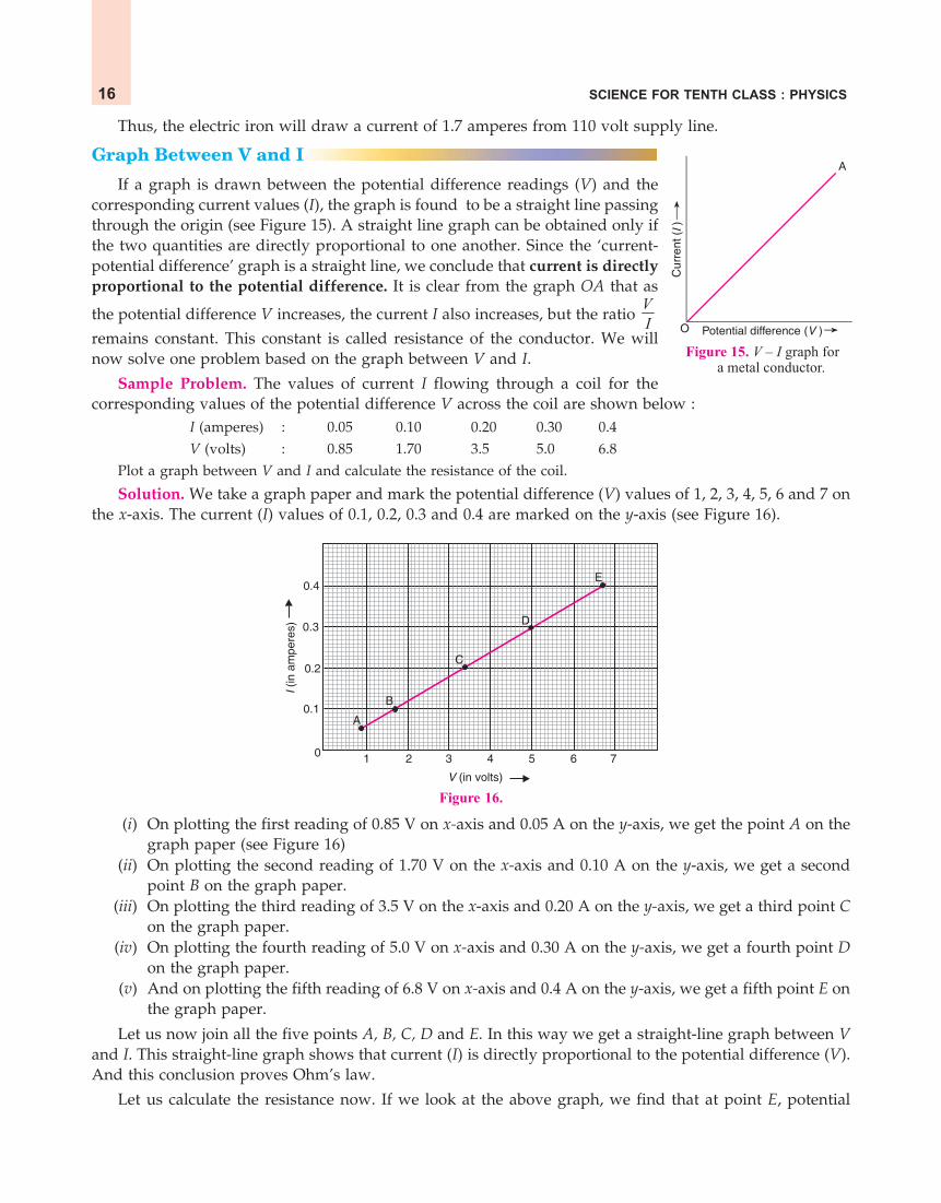
If a graph is drawn between the potential difference readings (V) and thecorresponding current values (I), the graph is found to be a straight line passingthrough the origin (see Figure 15). A straight line graph can be obtained only ifthe two quantities are directly proportional to one another. Since the ‘current-potential difference’ graph is a straight line, we conclude that current is directlyproportional to the potential difference. It is clear from the graph OA that as
the potential difference V increases, the current I also increases, but the ratio VI
remains constant. This constant is called resistance of the conductor. We willnow solve one problem based on the graph between V and I.
Sample Problem. The values of current I flowing through a coil for thecorresponding values of the potential difference V across the coil are shown below :
I (amperes) : 0.05 0.10 0.20 0.30 0.4V (volts) : 0.85 1.70 3.5 5.0 6.8
Plot a graph between V and I and calculate the resistance of the coil.
Solution. We take a graph paper and mark the potential difference (V) values of 1, 2, 3, 4, 5, 6 and 7 onthe x-axis. The current (I) values of 0.1, 0.2, 0.3 and 0.4 are marked on the y-axis (see Figure 16).
Figure 16.
(i) On plotting the first reading of 0.85 V on x-axis and 0.05 A on the y-axis, we get the point A on thegraph paper (see Figure 16)
(ii) On plotting the second reading of 1.70 V on the x-axis and 0.10 A on the y-axis, we get a secondpoint B on the graph paper.
(iii) On plotting the third reading of 3.5 V on the x-axis and 0.20 A on the y-axis, we get a third point Con the graph paper.
(iv) On plotting the fourth reading of 5.0 V on x-axis and 0.30 A on the y-axis, we get a fourth point Don the graph paper.
(v) And on plotting the fifth reading of 6.8 V on x-axis and 0.4 A on the y-axis, we get a fifth point E onthe graph paper.
Let us now join all the five points A, B, C, D and E. In this way we get a straight-line graph between Vand I. This straight-line graph shows that current (I) is directly proportional to the potential difference (V).And this conclusion proves Ohm’s law.
Let us calculate the resistance now. If we look at the above graph, we find that at point E, potential

ELECTRICITY 17
+ –
Ammeter
A
Voltmeter
V
R
Connectingwires
BBattery
+ –
+ –
SSwitch
C
RhRheostat
Sliding contactof rheostat
Conductor(A piece of
resistance wire)
Figure17. Circuit to verify Ohm’s law in the laboratory.
difference (V) is 6.8 volts whereas the current (I) is 0.4 amperes. Now, we know that :
Resistance,V
RI
=
So, R6.8=0.4
R = 17 ohmsThus, the resistance is of 17 ohms.
Experiment to Verify Ohm’s Law
If we can show that for a given conductor, say a piece of resistance wire (such as a nichrome wire), the
ratio potential difference
current is constant, then Ohm’s law will get verified. Alternatively, we can draw a graph
between the potential difference (V) and current (I), and if this graph is a straight line, even then Ohm’s
law gets verified. Let us see how this is done in the laboratory.
Suppose we have a piece of resistance wire R(which is the conductor here) (Figure 17), and wewant to verify Ohm’s law for it, that is, we want toshow that the conductor R obeys Ohm’s law. Forthis purpose we take a battery (B), a switch (S), arheostat (Rh), an ammeter (A), a voltmeter (V) andsome connecting wires. Using all these and theconductor R we make a circuit as shown in Figure17.
To start the experiment, the circuit is completedby pressing the switch S. On pressing the switch, acurrent starts flowing in the whole circuit includingthe conductor R. This current is shown by theammeter. The rheostat Rh is initially so adjusted that a small current passes through the circuit. The ammeterreading is now noted. This reading gives us the current I flowing through the conductor R. The voltmeterreading is also noted which will give the potential difference V across the ends of the conductor. This givesus the first set of V and I readings. The current in the circuit is now increased step by step, by changing theposition of the sliding contact C of the rheostat. The current values and the corresponding potential difference
values are noted in all the cases. The ratio potential difference
current or VI is calculated for all the readings. It is
found that the ratio VI has constant value for all the observations. Since the ratio of potential difference
and current, VI is constant, Ohm’s law gets verified because this shows that the current is directly
proportional to potential difference. The constant ratio VI gives us the resistance R of the conductor. So,
this Ohm’s law experiment can also be used to determine the resistance of a conductor. If a graph is drawnbetween potential difference readings and corresponding current readings, we will get a straight line graphshowing that current is directly proportional to potential difference. This also verifies Ohm’s law.
Good Conductors, Resistors and Insulators
On the basis of their electrical resistance, all the substances can be divided into three groups : Goodconductors, Resistors and Insulators. Those substances which have very low electrical resistance are calledgood conductors. A good conductor allows the electricity to flow through it easily. Silver metal is the best

SCIENCE FOR TENTH CLASS : PHYSICS18
Figure 18. The electric wires are Figure 19. The heating element Figure 20. Rubber is anmade of copper (good conductor). of electric iron is made of insulator. The electriciansTheir covering is made of plastic nichrome wire which is a resistor. wear rubber gloves to protect(insulator). themselves from electric shocks.
conductor of electricity. Copper and aluminium metals are also good conductors. Electric wires are made ofcopper or aluminium because they have very low electrical resistance (see Figure 18). Those substanceswhich have comparatively high electrical resistance, are called resistors. The alloys like nichrome, manganinand constantan (or eureka), all have quite high resistances, so they are called resistors. Resistors are used tomake those electrical devices where high resistance is required (see Figure 19). A resistor reduces the currentin a circuit. Those substances which have infinitely high electrical resistance are called insulators. Aninsulator does not allow electricity to flow through it. Rubber is an excellent insulator. Electricians wearrubber handgloves while working with electricity because rubber is an insulator and protects them fromelectric shocks (see Figure 20). Wood is also a good insulator. We are now in a position to answer thefollowing questions :
Very Short Answer Type Questions1. Name the law which relates the current in a conductor to the potential difference across its ends.2. Name the unit of electrical resistance and give its symbol.3. Name the physical quantity whose unit is “ohm”.4. What is the general name of the substances having infinitely high electrical resistance ?5. Keeping the resistance constant, the potential difference applied across the ends of a component is halved.
By how much does the current change ?6. State the factors on which the strength of electric current flowing in a given conductor depends.7. Which has less electrical resistance : a thin wire or a thick wire (of the same length and same material) ?8. Keeping the potential difference constant, the resistance of a circuit is halved. By how much does the current
change ?9. A potential difference of 20 volts is applied across the ends of a resistance of 5 ohms. What current will flow
in the resistance ?10. A resistance of 20 ohms has a current of 2 amperes flowing in it. What potential difference is there between
its ends ?11. A current of 5 amperes flows through a wire whose ends are at a potential difference of 3 volts. Calculate
the resistance of the wire.12. Fill in the following blank with a suitable word :
Ohm’s law states a relation between potential difference and ........................
Short Answer Type Questions13. Distinguish between good conductors, resistors and insulators. Name two good conductors, two resistors
and two insulators.14. Classify the following into good conductors, resistors and insulators :
Rubber, Mercury, Nichrome, Polythene, Aluminium, Wood, Manganin, Bakelite, Iron, Paper, Thermocol,Metal coin

ELECTRICITY 19
15. What is Ohm’s law ? Explain how it is used to define the unit of resistance.16. (a) What is meant by the “resistance of a conductor” ? Write the relation between resistance, potential
difference and current.(b) When a 12 V battery is connected across an unknown resistor, there is a current of 2.5 mA in the circuit.
Calculate the value of the resistance of the resistor.17. (a) Define the unit of resistance (or Define the unit “ohm”).
(b) What happens to the resistance as the conductor is made thinner ?(c) Keeping the potential difference constant, the resistance of a circuit is doubled. By how much does the
current change ?18. (a) Why do electricians wear rubber hand gloves while working with electricity ?
(b) What p.d. is needed to send a current of 6 A through an electrical appliance having a resistance of 40 19. An electric circuit consisting of a 0.5 m long nichrome wire XY, an ammeter, a voltmeter, four cells of 1.5 V
each and a plug key was set up.(i) Draw a diagram of this electric circuit to study the relation between the potential difference maintained
between the points ‘X’ and ‘Y’ and the electric current flowing through XY.(ii) Following graph was plotted between V and I values :
1.61.5
1.0
0.5
0 0.2 0.4 0.6
V(Volt)
I (Amp.)
What would be the values of VI ratios when the potential difference is 0.8 V, 1.2 V and 1.6 V respectively ?
What conclusion do you draw from these values ?(iii) What is the resistance of the wire ?
Long Answer Type Question20. (a) What is the ratio of potential difference and current known as ?
(b) The values of potential difference V applied across a resistor and the correponding values of current Iflowing in the resistor are given below :
Potential difference, V (in volts) : 2.5 5.0 10.0 15.0 20.0 25.0Current, I (in amperes) : 0.1 0.2 0.4 0.6 0.8 1.0Plot a graph between V and I, and calculate the resistance of the resistor.
(c) Name the law which is illustrated by the above V–I graph.(d) Write down the formula which states the relation between potential difference, current and resistance.(e) The potential difference between the terminals of an electric iron is 240 V and the current is 5.0 A. What
is the resistance of the electric iron ?
Multiple Choice Questions (MCQs)21. The p.d. across a 3 resistor is 6 V. The current flowing in the resistor will be :
(a) 1 A2
(b) 1 A (c) 2 A (d) 6 A
22. A car headlight bulb working on a 12 V car battery draws a current of 0.5 A. The resistance of the light bulbis :(a) 0.5 (b) 6 (c) 12 (d) 24
23. An electrical appliance has a resistance of 25 . When this electrical appliance is connected to a 230 Vsupply line, the current passing through it will be :(a) 0.92 A (b) 2.9 A (c) 9.2 A (d) 92 A
24. When a 4 resistor is connected across the terminals of a 12 V battery, the number of coulombs passingthrough the resistor per second is :(a) 0.3 (b) 3 (c) 4 (d) 12

SCIENCE FOR TENTH CLASS : PHYSICS20
25. Ohm’s law gives a relationship between :(a) current and resistance(b) resistance and potential difference(c) potential difference and electric charge(d) current and potential difference
26. The unit of electrical resistance is :(a) ampere (b) volt (c) coulomb (d) ohm
27. The substance having infinitely high electrical resistance is called :(a) conductor (b) resistor (c) superconductor (d) insulator
28. Keeping the potential difference constant, the resistance of a circuit is doubled. The current will become :(a) double (b) half (c) one-fourth (d) four times
29. Keeping the p.d. constant, the resistance of a circuit is halved. The current will become :(a) one-fourth (b) four times (c) half (d) double
Questions Based on High Order Thinking Skills (HOTS) 30. An electric room heater draws a current of 2.4 A from the 120 V supply line. What current will this room
heater draw when connected to 240 V supply line ?31. Name the electrical property of a material whose symbol is “omega”.32. The graph between V and I for a conductor is a straight line passing through the origin.
(a) Which law is illustrated by such a graph ?(b) What should remain constant in a statement of this law ?
33. A p.d. of 10 V is needed to make a current of 0.02 A flow through a wire. What p.d. is needed to make acurrent of 250 mA flow through the same wire ?
34. A current of 200 mA flows through a 4 k resistor. What is the p.d. across the resistor ?
ANSWERS1. Ohm’s law 3. Electrical resistance 4. Insulators 5. Current becomes half 7. Thick wire8. Current becomes double 9. 4 A 10. 40 V 11. 0.6 12. current 16. (b) 4800 17. (c) Current becomes half 18. (b) 240 V 19. (ii) 2.5, 2.5, 2.5 ; The ratio of potential difference appliedto the wire and current passing through it is a constant (iii) 2.5 20. (a) Resistance (b) 25 (c) Ohm’s law(e) 48 21. (c) 22. (d) 23. (c) 24. (b) 25. (d) 26. (d) 27. (d) 28. (b) 29. (d)30. 4.8 A 31. Resistance 32. (a) Ohm’s law (b) Temperature 33. 125 V 34. 800 V
FACTORS AFFECTING THE RESISTANCE OF A CONDUCTORThe electrical resistance of a conductor (or a wire) depends on the following factors :(i) length of the conductor,
(ii) area of cross-section of the conductor (or thickness of the conductor),(iii) nature of the material of the conductor, and(iv) temperature of the conductor.
We will now describe how the resistance depends on these factors.
1. Effect of Length of the Conductor
It has been found by experiments that on increasing the length of a wire, its resistance increases; andon decreasing the length of the wire, its resistance decreases. Actually, the resistance of a conductor isdirectly proportional to its length. That is,
Resistance, R l (where l is the length of conductor)
Since the resistance of a wire is directly proportional to its length, therefore, when the length of a wireis doubled, its resistance also gets doubled; and if the length of a wire is halved, then its resistance alsogets halved. When we double the length of a wire, then this can be considered to be equivalent to tworesistances joined in series, and their resultant resistance is the sum of the two resistances (which is double

ELECTRICITY 21
the original value). From this discussion we conclude that a long wire (or long conductor) has moreresistance, and a short wire has less resistance.2. Effect of Area of Cross-Section of the Conductor
It has been found by experiments that the resistance of a conductor is inversely proportional to itsarea of cross-section. That is,
Resistance, R 1A (where A is area of cross-section of conductor)
Since the resistance of a wire (or conductor) is inversely proportional to its area of cross-section, therefore,when the area of cross-section of a wire is doubled, its resistance gets halved; and if the area of cross-section of wire is halved, then its resistance will get doubled. We know that a thick wire has a greaterarea of cross-section whereas a thin wire has a smaller area of cross-section. This means that a thick wirehas less resistance, and a thin wire has more resistance. A thick wire (having large area of cross-section)can be considered equivalent to a large number of thin wires connected in parallel. And we know that if wehave two resistance wires connected in parallel, their resultant resistance is halved. So,doubling the area of cross-section of a wire will, therefore, halve the resistance. From theabove discussion it is clear that to make resistance wires (or resistors) :
(i) short length of a thick wire is used for getting low resistance, and(ii) long length of a thin wire is used for getting high resistance.
The thickness of a wire is usually represented by its diameter. It can be shown by calculations that theresistance of a wire is inversely proportional to the square of its diameter. Thus, when the diameter of a
wire is doubled (made 2 times), its resistance becomes one-fourth 14
, and if the diameter of the wire is
halved 1made2
, then its resistance becomes four times (4 times). Similarly, if the diameter of a wire is
tripled (made 3 times), then its resistance will become 213
or 19 th of its original value.
3. Effect of the Nature of Material of the Conductor
The electrical resistance of a conductor (say, a wire) depends on the nature of the material of which itis made. Some materials have low resistance whereas others have high resistance. For example, if we taketwo similar wires, having equal lengths and diameters, of copper metal and nichrome alloy, we will findthat the resistance of nichrome wire is about 60 times more than that of the copper wire. This shows thatthe resistance of a conductor depends on the nature of the material of the conductor.
4. Effect of TemperatureIt has been found that the resistance of all pure metals increases on raising the temperature; and
decreases on lowering the temperature. But the resistance of alloys like manganin, constantan and nichromeis almost unaffected by temperature.
RESISTIVITYIt has been found by experiments that :
(i) The resistance of a given conductor is directly proportional to its length. That is :
R l ... (1)
(ii) The resistance of a given conductor is inversely proportional to its area of cross-section. That is :
R A1
... (2)
By combining the relations (1) and (2), we get :
R lA
or l
RA
... (3)

SCIENCE FOR TENTH CLASS : PHYSICS22
where (rho) is a constant known as resistivity of the material of the conductor. Resistivity is also known asspecific resistance.
From equation (3), it is clear that for a given conductor having a specified length l and area of cross-section A, the resistance R is directly proportional to its resistivity So, if we change the material of aconductor to one whose resistivity is two times, then the resistance will also become two times. And if wechange the material of a conductor to one whose resistivity is three times, then the resistance will alsobecome three times.
If we rearrange equation (3), we can write it as :
Resistivity,R A
l ..... (4)
where R = resistance of the conductor
A = area of cross-section of the conductor
and l = length of the conductor
This formula for calculating the resistivity of the material of a conductor should be memorised becauseit will be used to solve numerical problems. By using this formula, we will now obtain the definition ofresistivity. Let us take a conductor having a unit area of cross-section of 1 m2 and a unit length of 1 m. So,putting A = 1 and l = 1 in equation (4), we get :
Resistivity, = R
Thus, the resistivity of a substance is numerically equal to the resistance of a rod of that substancewhich is 1 metre long and 1 square metre in cross-section. Since the length is 1 metre and the area ofcross-section is 1 square metre, so it becomes a 1 metre cube. So, we can also say that the resistivity of asubstance is equal to the resistance between the opposite faces of a 1 metre cube of the substance. We will now findout the unit of resistivity.
We have just seen that :
Resistivity, =R × A
lNow, to get the unit of resistivity we should put the units of resistance R, area of
cross-section A and length l in the above equation. We know that :
The unit of resistance R is ohm
The unit of area of cross-section A is (metre)2
And, The unit of length l is metre
So, putting these units in the above equation, we get :
Unit of resistivity, 2ohm × (metre)
=metre
= ohm–metre (or m)
Thus, the SI unit of resistivity is ohm-metre which is written in symbols as m.
Please note that the resistivity of a substance does not depend on its length or thickness. It dependson the nature of the substance and temperature. The resistivity of a substance is its characteristic property.So, we can use the resistivity values to compare the resistances of two or more substances. Another point tobe noted is that just as when we talk of resistance in the context of electricity, it actually means electricalresistance, in the same way, when we talk of resistivity, it actually means electrical resistivity. The resistivitiesof some of the common substances (or materials) are given on the next page.

ELECTRICITY 23
Resistivities of Some Common Substances (at 20°C)
CategorySubstance Resistivity(Material)
Conductors : Metals
1. Silver 1.60 × 10⁻⁸ m
2. Copper 1.69 × 10⁻⁸ m
3. Aluminium 2.63 × 10⁻⁸ m
4. Tungsten 5.20 × 10⁻⁸ m
5. Nickel 6.84 × 10⁻⁸ m
6. Iron 10.0 × 10⁻⁸ m
7. Chromium 12.9 × 10⁻⁸ m
8. Mercury 94.0 × 10⁻⁸ m
9. Manganese 184.0 × 10⁻⁸ m
Alloys
1. Manganin 44 × 10–8 m (Cu–Mn–Ni)
2. Constantan 49 × 10–8 m (Cu–Ni)
3. Nichrome 110 × 10–8 m (Ni–Cr–Mn–Fe)
Semiconductors : 1. Germanium 0.6 m2. Silicon 2300 m
Insulators : 1. Glass 1010 to 1014 m2. Paper (Dry) 1012 m3. Diamond 1012 to 1013 m
4. Hard rubber 1013 to 1016 m
5. Ebonite 1015 to 1017 m
From the above table we find that the resistivity of copper is 1.69 × 10⁻⁸ ohm-metre. Now, by sayingthat the resistivity of copper is 1.69 × 10⁻⁸ ohm-metre, we mean that if we take a rod of copper metal1 metre long and 1 square metre in area of cross-section, then its resistance will be 1.69 × 10⁻⁸ ohms.Please note that a good conductor of electricity should have a low resistivity and a poor conductor ofelectricity will have a high resistivity. From the above table we find that of all the metals, silver has thelowest resistivity (of 1.60 × 10⁻⁸ m), which means that silver offers the least resistance to the flow ofcurrent through it. Thus, silver metal is the best conductor of electricity. It is obvious that we shouldmake electric wires of silver metal. But silver is a very costly metal. We use copper and aluminium wiresfor the transmission of electricity because copper and aluminium have very low resistivities (due towhich they are very good conductors of electricity). From this discussion we conclude that silver, copperand aluminium are very good conductors of electricity.
The resistivities of alloys are much more higher than those of the pure metals (from which they aremade). For example, the resistivity of manganin (which is an alloy of copper, manganese and nickel) isabout 25 times more than that of copper; and the resistivity of constantan (which is an alloy of copper andnickel) is about 30 times more than that of copper metal. It is due to their high resistivities that manganinand constantan alloys are used to make resistance wires (or resistors) used in electronic appliances toreduce the current in an electrical circuit. Another alloy having a high resistivity is nichrome. This is an

SCIENCE FOR TENTH CLASS : PHYSICS24
alloy of nickel, chromium, manganese and iron having a resistivity of about 60 times more than that ofcopper.
The heating elements (or heating coils) of electrical heatingappliances such as electric iron and toaster, etc., are made of analloy rather than a pure metal because (i) the resistivity of analloy is much higher than that of pure metal, and (ii) an alloydoes not undergo oxidation (or burn) easily even at hightemperature, when it is red hot. For example, nichrome alloy isused for making the heating elements of electrical appliancessuch as electric iron, toaster, electric kettle, room heaters, waterheaters (geysers), and hair dryers, etc., because :
(i) nichrome has very high resistivity (due to which theheating element made of nichrome has a high resistance and produces a lot of heat on passingcurrent).
(ii) nichrome does not undergo oxidation (or burn) easily even at high temperature. Due to thisnichrome wire can be kept red-hot without burning or breaking in air.
The resistivity of conductors (like metals) is very low. The resistivity of most of the metals increaseswith temperature. On the other hand, the resistivity of insulators like ebonite, glass and diamond is veryhigh and does not change with temperature. The resistivity of semi-conductors like silicon and germaniumis in-between those of conductors and insulators, and decreases on increasing the temperature. Semi-conductors are proving to be of great practical importance because of their marked change in conductingproperties with temperature, impurity, concentration, etc. Semi-conductors are used for making solar cellsand transistors. We will now solve some problems based on resistivity.
Sample Problem 1. A copper wire of length 2 m and area of cross-section 1.7 × 10⁻⁶ m2 has a resistanceof 2 × 10⁻² ohms. Calculate the resistivity of copper.
Solution. The formula for resistivity is :
Resistivity, = R A
l
Here, Resistance, R = 2 × 10⁻² Area of cross-section, A = 1.7 × 10⁻⁶ m2
And, Length, l = 2 mSo, putting these values in the above formula, we get :
2 62 10 1.7 102
= 1.7 × 10⁻⁸ m
Thus, the resistivity of copper is 1.7 × 10⁻⁸ ohm-metre.
Sample Problem 2. A copper wire has a diameter of 0.5 mm and resistivity of 1.6 × 10⁻⁸ m.
(a) What will be the length of this wire to make its resistance 10 ?(b) How much does the resistance change if the diameter is doubled ? (NCERT Book Question)
Solution. (a) First of all we will calculate the area of cross-section of the copper wire. Here the diameter
of copper wire is 0.5 mm, so its radius (r) will be 0.52
mm or 0.25 mm. This radius of 0.25 mm will be equal
to 0.251000
m or 30.25 10 m. Thus, the radius r of this copper wire is 0.25 × 10⁻³ m. We will now find out the
area of cross-section of the copper wire by using this value of the radius. So,Area of cross-section of wire, A = r2
Figure 21. An electric iron.
Heatingelementmade of
nichrome
ELECTRICITY 25
3 222(0.25 10 )
7= 0.1964 × 10⁻⁶
m2
Resistivity, = 1.6 × 10⁻⁸ mResistance, R = 10
And, Length, l = ? (To be calculated)Now, putting these values in the formula :
= R Al
We get : 1.6 × 10–8 =
l
610 0.1964 10
So, l =
6
8
10 0.1964 101.6 10
l = 196416
l = 122.7 m
Thus, the length of copper wire required to make 10 resistance will be 122.7 metres.
(b) The resistance of a wire is inversely proportional to the square of its diameter. So, when the diameter
of the wire is doubled (that is, made 2 times), then its resistance will become
212
or 14
(one-fourth).
Sample Problem 3. A 6 resistance wire is doubled up by folding. Calculate the new resistance of thewire.
Solution. Suppose the length of 6 resistance wire is l, its area of cross-section is A and its resistivityis . Then :
R = l
A
or 6 = lA
... (1)
Now, when this wire is doubled up by folding, then its length will become half, that is, the length will
become 2l
. But on doubling the wire by folding, its area of cross-section will become double, that is, the
area of cross-section will become 2A. Suppose the new resistance of the doubled up wire (or folded wire) isR. So,
R = 2 2
lA
or R = 4
lA
... (2)
Now, dividing equation (2) by equation (1), we get :
6 4R l A
A l
or 16 4R
4R = 6
R = 64
R = 1.5

SCIENCE FOR TENTH CLASS : PHYSICS26
Thus, the new resistance of the doubled up wire is 1.5 .
Before we go further and study the combination of resistances (or resistors) in series and parallel, pleaseanswer the following questions :
Very Short Answer Type Questions1. What happens to the resistance as the conductor is made thicker ?2. If the length of a wire is doubled by taking more of wire, what happens to its resistance ?3. On what factors does the resistance of a conductor depend ?4. Name the material which is the best conductor of electricity.5. Which among iron and mercury is a better conductor of electricity ?6. Why are copper and aluminium wires usually used for electricity transmission ?7. Name the material which is used for making the heating element of an electric iron.8. What is nichrome ? State its one use.9. Give two reasons why nichrome alloy is used for making the heating elements of electrical appliances.
10. Why are the coils of electric irons and electric toasters made of an alloy rather than a pure metal ?11. Which has more resistance :
(a) a long piece of nichrome wire or a short one ?(b) a thick piece of nichrome wire or a thin piece ?
12. (a) How does the resistance of a pure metal change if its temperature decreases ?(b) How does the presence of impurities in a metal affect its resistance ?
13. Fill in the following blanks with suitable words :Resistance is measured in............ The resistance of a wire increases as the length.........; as thetemperature............. ; and as the cross-sectional area.............
Short Answer Type Questions14. (a) What do you understand by the “resistivity” of a substance ?
(b) A wire is 1.0 m long, 0.2 mm in diameter and has a resistance of 10 . Calculate the resistivity of itsmaterial ?
15. (a) Write down an expression for the resistance of a metallic wire in terms of the resistivity.(b) What will be the resistance of a metal wire of length 2 metres and area of cross-section
1.55 × 10⁻⁶ m2, if the resistivity of the metal be 2.8 × 10⁻⁸ m ?16. (a) Give two examples of substances which are good conductors of electricity. Why do you think they are
good conductors of electricity ?(b) Calculate the resistance of a copper wire 1.0 km long and 0.50 mm diameter if the resistivity of copper is
1.7 × 10⁻⁸ m.17. Will current flow more easily through a thick wire or a thin wire of the same material when connected to
the same source ? Give reason for your answer.18. How does the resistance of a conductor depend on :
(a) length of the conductor ?(b) area of cross-section of the conductor ?(c) temperature of the conductor ?
19. (a) Give one example to show how the resistance depends on the nature of material of the conductor.(b) Calculate the resistance of an aluminium cable of length 10 km and diameter 2.0 mm if the resistivity of
aluminium is 2.7 × 10⁻⁸ m.20. What would be the effect on the resistance of a metal wire of :
(a) increasing its length ?(b) increasing its diameter ?(c) increasing its temperature ?
21. How does the resistance of a wire vary with its :(a) area of cross-section ?(b) diameter ?

ELECTRICITY 27
22. How does the resistance of a wire change when :(i) its length is tripled ?
(ii) its diameter is tripled ?(iii) its material is changed to one whose resistivity is three times ?
23. Calculate the area of cross-section of a wire if its length is 1.0 m, its resistance is 23 and the resistivity ofthe material of the wire is 1.84 × 10⁻⁶ m.
Long Answer Type Question24. (a) Define resistivity. Write an expression for the resistivity of a substance. Give the meaning of each symbol
which occurs in it.(b) State the SI unit of resistivity.(c) Distinguish between resistance and resistivity.(d) Name two factors on which the resistivity of a substance depends and two factors on which it does not
depend.(e) The resistance of a metal wire of length 1 m is 26 at 20°C. If the diameter of the wire is 0.3 mm, what
will be the resistivity of the metal at that temperature ?
Multiple Choice Questions (MCQs)
25. The resistance of a wire of length 300 m and cross-section area 1.0 mm2 made of material of resistivity1.0 × 10–7 m is :(a) 2 (b) 3 (c) 20 (d) 30
26. When the diameter of a wire is doubled, its resistance becomes :(a) double (b) four times (c) one-half (d) one-fourth
27. If the resistance of a certain copper wire is 1 , then the resistance of a similar nichrome wire will be about :(a) 25 (b) 30 (c) 60 (d) 45
28. If the diameter of a resistance wire is halved, then its resistance becomes :(a) four times (b) half (c) one-fourth (d) two times
29. The resistivity of a certain material is 0.6 m. The material is most likely to be :(a) an insulator (b) a superconductor (c) a conductor (d) a semiconductor
30. When the area of cross-section of a conductor is doubled, its resistance becomes :(a) double (b) half (c) four times (d) one-fourth
31. The resistivity of copper metal depends on only one of the following factors. This factor is :(a) length (b) thickness (c) temperature (d) area of cross-section
32. If the area of cross-section of a resistance wire is halved, then its resistance becomes :(a) one-half (b) 2 times (c) one-fourth (d) 4 times
Questions Based on High Order Thinking Skills (HOTS)33. A piece of wire of resistance 20 is drawn out so that its length is increased to twice its original length.
Calculate the resistance of the wire in the new situation.34. The electrical resistivities of three materials P, Q and R are given below :
P 2.3 × 10³ mQ 2.63 × 10⁻⁸ mR 1.0 × 10¹⁵ m
Which material will you use for making (a) electric wires (b) handle for soldering iron, and (c) solar cells ?Give reasons for your choices.
35. The electrical resistivities of four materials A, B, C and D are given below :A 110 × 10–8 mB 1.0 × 10¹⁰ mC 10.0 × 10⁻⁸ mD 2.3 × 10³ m
Which material is : (a) good conductor (b) resistor (c) insulator, and (d) semiconductor ?36. The electrical resistivities of five substances A, B, C, D and E are given below :
A 5.20 × 10⁻⁸ m

SCIENCE FOR TENTH CLASS : PHYSICS28
B 110 × 10–8 mC 2.60 × 10⁻⁸ mD 10.0 × 10⁻⁸ mE 1.70 × 10⁻⁸ m
(a) Which substance is the best conductor of electricity ? Why ?(b) Which one is a better conductor : A or C ? Why ?(c) Which substance would you advise to be used for making heating elements of electric irons ? Why ?(d) Which two substances should be used for making electric wires ? Why ?
ANSWERS1. Resistance decreases 2. Resistance gets doubled 5. Iron 7. Nichrome 11. (a) Long piece of nichromewire (b) Thin piece of nichrome wire 12. (a) Resistance decreases (b) Resistance increases 13. Ohms ;increases ; increases ; decreases 14. (b) 31.4 × 10⁻⁸ m 15. (b) 0.036 16. (b) 86.5 17. Thick wire ;
Lesser electrical resistance 19. (b) 86 22. (i) Resistance becomes 3 times (ii) Resistance becomes 19 th.
(iii) Resistance becomes 3 times 23. 8.0 × 10⁻⁸ m2 24. (e) 1.84 × 10⁻⁸ m, 25. (d) 26. (d) 27. (c)28. (a) 29. (d) 30. (b) 31. (c) 32. (b) 33. 80 (Hint. In the new situation, length becomes 2l
and area of cross-section becomes 2A
) 34. (a) Q ; Very low resistivity (b) R ; Very high resistivity (c) P;
Semiconductor 35. (a) C (b) A (c) B (d) D 36. (a) E ; Least electrical resistivity (b) C ; Lesser electricalresistivity (c) B ; High electrical resistivity (d) C and E ; Low electrical resistivities
COMBINATION OF RESISTANCES (OR RESISTORS)Apart from potential difference, current in a circuit depends
on resistance of the circuit. So, in the electrical circuits of radio,television and other similar things, it is usually necessary tocombine two or more resistances to get the required current in thecircuit. We can combine the resistances lengthwise (called series)or we can put the resistances parallel to one another. Thus, theresistances can be combined in two ways : (i) in series, and (ii) inparallel. If we want to increase the total resistance, then theindividual resistances are connected in series, and if we want todecrease the resistance, then the individual resistances are connectedin parallel. We will study these two cases in detail, one by one.
When two (or more) resistances are connected end to endconsecutively, they are said to be connected in series. Figure 23shows two resistances R1 and R2 which are connected in series. On
Figure 23. Two resistances (R1 and R2) Figure 24. Two resistances (R1 and R2)connected in series. connected in parallel.
the other hand, when two (or more) resistances are connected between the same two points, they are saidto be connected in parallel (because they become parallel to one another). In Figure 24, the two resistancesR1 and R2 are connected in parallel arrangement between the same two points A and B. In the aboveexamples, we have shown only two resistances (or resistors) connected in series and parallel combinations.We can, however, connect any number of resistors in these two arrangements.
Figure 22. This picture shows some of theresistances (or resistors) . These can beconnected in series or parallel combinations.

ELECTRICITY 29
RESISTANCES (OR RESISTORS) IN SERIESThe combined resistance (or resultant resistance) of a number of resistances or resistors connected in
series is calculated by using the law of combination of resistances in series. According to the law ofcombination of resistances in series : The combined resistance of any number of resistances connected inseries is equal to the sum of the individual resistances. For example, if a number of resistances R1, R2, R3
...... etc., are connected in series, then their combined resistance R is given by : R = R1 + R2 + R3 +.........
Suppose that a resistance R1 of 2 ohms and another resistance R2 of 4 ohms are connected in series andwe want to find out their combined resistance R.
We know that : R = R1 + R2
So, R = 2 + 4
And, Combined resistance, R = 6 ohms
Thus, if we join two resistances of 2 ohms and 4 ohms in series, then their combined resistance (orresultant resistance) will be 6 ohms which is equal to the sum of the individual resistances. Before wederive the formula for the resultant resistance of a number of resistances connected in series, we shouldkeep in mind that :
(i) When a number of resistances connected in series are joined to the terminals of a battery, then eachresistance has a different potential difference across its ends (which depends on the value ofresistance). But the total potential difference across the ends of all the resistances in series is equalto the voltage of the battery. Thus, when a number of resistances are connected in series, then thesum of the potential differences across all the resistances is equal to the voltage of the batteryapplied.
(ii) When a number of resistances are connected in series, then the same current flows through eachresistance (which is equal to the current flowing in the whole circuit).
1. Resultant Resistance of Two Resistances Connected in Series
We will now derive a formula for calculating the combined resistance(equivalent resistance or resultant resistance) of two resistancesconnected in series.
Figure 25 shows two resistances R1 and R2 connected in series. Abattery of V volts has been applied to the ends of this series combination.Now, suppose the potential difference across the resistance R1 is V1
and the potential difference across the resistance R2 is V2. We haveapplied a battery of voltage V, so the total potential difference acrossthe two resistances should be equal to the voltage of the battery.
That is : V = V1 + V2 ... (1)
We have just seen that the total potential difference due to batteryis V. Now, suppose the total resistance of the combination be R, andthe current flowing through the whole circuit be I. So, applying Ohm’s law to the whole circuit, we get :
V — = R Ior V = I × R ... (2)
Since the same current I flows through both the resistances R1 and R2 connected in series, so by applyingOhm’s law to both the resistances separately, we will get :
V1 = I × R1 ... (3)and V2 = I × R2 ... (4)
Now, putting the values of V, V1 and V2 from equations (2), (3) and (4) in equation (1), we get :
V volts
II
A B C
I I
R1 R2
V1 V2
V
R
+ –
Figure 25.

SCIENCE FOR TENTH CLASS : PHYSICS30
I × R = I × R1 + I × R2
or I × R = I × (R1 + R2)
Cancelling I from both sides, we get :
Resultant resistance (combined resistance or equivalent resistance),R = R1 + R2
2. Resultant Resistance of Three Resistances Connected in Series
Figure 26 shows three resistances R1, R2 and R3 connected in series.A battery of V volts has been applied to the ends of this seriescombination of resistances. Now, suppose the potential differenceacross the resistance R1 is V1, the potential difference across theresistance R2 is V2 and that across resistance R3 is V3. We have applieda battery of voltage V, so the total potential difference across the threeresistances should be equal to the voltage of the battery applied. Thatis,
V = V1 + V2 + V3 ... (1)
We have just seen that the total potential difference due to batteryis V. Now, let the total resistance (or resultant resistance) of thecombination be R. The current flowing through the whole circuit is I.So, applying Ohm’s law to the whole circuit, we get :
V — = RI
or V = I × R ... (2)
Since the same current I flows through all the resistances R1, R2 and R3 in series, so by applying Ohm’slaw to each resistance separately, we will get :
V1 = I × R1 ... (3)V2 = I × R2 ... (4)
and V3 = I × R3 ... (5)Putting these values of V, V1, V2 and V3 in equation (1), we get :
I × R = I × R1 + I × R2 + I × R3or I × R = I × (R1 + R2 + R3)
Cancelling I from both sides, we get :R = R1 + R2 + R3
Thus, if three resistors R1, R2, and R3 are connected in series then their total resistance R is given by the formula :R = R1 + R2 + R3
Similarly, if there are four resistors R1, R2, R3 and R4 connected in series, then their resultant resistanceR is given by the formula : R = R1 + R2 + R3 + R4 and so on.
We will now solve some problems based on the combination of resistances in series.
Sample Problem 1. If four resistances, each of value 1 ohm, are connected in series, what will be theresultant resistance ?
Solution. Here we have four resistances, each of 1 ohm, connected in series. These are shown in theFigure below.
R1 R2 R3 R4
1 ohm 1 ohm 1 ohm 1 ohm
Now, if we have four resistances R1, R2, R3 and R4 connected in series, then their resultant resistance Ris given by : R = R1 + R2 + R3 + R4
II
A B C
II
R1 R2
V1
V
I
R3 D
R
V2 V3
V volts
+ –
Figure 26.

ELECTRICITY 31
Here R1 = 1 , R2 = 1 , R3 = 1 R4 = 1 So, Resultant resistance, R = 1 + 1 + 1 + 1
or R = 4 Thus, the resultant resistance is equal to 4 ohms.We will now solve some problems by applying Ohm’s law to the circuits having resistances in series.
Sample Problem 2. A resistance of 6 ohms is connected in series with another resistance of 4 ohms. Apotential difference of 20 volts is applied across the combination. Calculate the current through the circuitand potential difference across the 6 ohm resistance.
Solution. The first step in solving such problems based on currentelectricity is to draw a proper circuit diagram. For example, in this problemwe have two resistances of 6 ohms and 4 ohms which are connected in series.So, first of all we have to draw these two resistances on paper as shown inFigure alongside. Now, a potential difference of 20 volts has been appliedacross this combination of resistances. So, we draw a cell or a battery of 20volts and complete the circuit as shown in Figure alongside. Suppose thecurrent flowing in the circuit is I amperes.
We will now find out the value of current I flowing through the circuit. To do this we should know thetotal resistance R of the circuit. Here we have two resistances of 6 and 4 connected in series. So,
Total resistance, R = R1 + R2
R = 6 + 4
R = 10 ohms
Now, Total resistance, R = 10 ohms
Potential difference, V = 20 voltsand, Current in the circuit, I = ? (To be calculated)
So, applying Ohm’s law to the whole circuit, we get :
V — = R
I 20 So that, —– = 10I
And, 10 I = 20
20I = —– 10So, Current, I = 2 amperes (or 2 A)
Thus, the current flowing through the circuit is 2 amperes.
The second part of this problem is to find out the potential difference across the ends of the 6 ohmresistance. To do this we will have to apply Ohm’s law to this resistance only. We know that the currentflowing through the 6 ohm resistance will also be 2 amperes. Now,
Potential difference (across 6 resistance), V = ? (To be calculated)Current (through 6 resistance), I = 2 amperesAnd, Resistance, R = 6 ohms
So, applying Ohm’s law to the 6 resistance only, we get : VI = R
or2V
= 6
20 V
I
6 Ω 4 Ω
+ –

SCIENCE FOR TENTH CLASS : PHYSICS32
So, Potential difference, V = 12 volts
Thus, the potential difference across the 6 ohm resistance is 12 volts.
Here is an exercise for you. Find out the potential difference across the 4 ohm resistance yourself. Theanswer will be 8 volts. Remember that the same current of 2 amperes flows through the 4 ohm resistance.
Sample Problem 3. (a) Draw the diagram of a circuit consisting of a battery of three cells of 2 V each, a5 resistor, an 8 resistor and a 12 resistor, and a plug key, all connected in series.
(b) Redraw the above circuit putting an ammeter to measure the current through the resistors and avoltmeter to measure the potential difference across the 12 resistor. What would be the readings in theammeter and the voltmeter ? (NCERT Book Question)
Solution. (a) In this problem, we have a battery of 3 cells of 2 V each, sothe total potential difference (or voltage) of the battery will be 3 × 2 = 6 V.The circuit consisting of a battery of three cells of 2 V each (having a voltageof 6 V), resistors of 5 , 8 , 12 and a plug key, all connected in series isgiven in Figure alongside.
(b) The above circuit can be redrawn by including an ammeter in the maincircuit and a voltmeter across the 12 resistor, as shown in Figure alongside.Please note that the ammeter has been put in series with the circuit but thevoltmeter has been put in parallel with the 12 resistor. We will now calculatethe current reading in the ammeter and potential difference reading in thevoltmeter.
(i) Calculation of current flowing in the circuit. The three resistors of 5 , 8 and 12 are connected in series. So,
Total resistance, R = 5 + 8 + 12 = 25
Potential difference, V = 6 VAnd, Current, I = ? (To be calculated)
Now, V RI
So, 625
I 25 I = 6
625
I
I = 0.24 A
Now, since the current in the circuit is 0.24 amperes, therefore, the ammeter will show a reading of0.24 A.
(ii) Calculation of potential difference across 12 resistor. We have just calculated that a current of0.24 A flows in the circuit. The same current of 0.24 A also flows through the 12 resistor which is connectedin series. Now, for the 12 resistor :
Current, I = 0.24 A (Calculated above)Resistance, R = 12 (Given)
And, Potential difference, V = ? (To be calculated)
We know that, VR
I
6 V
5 Ω 8 Ω
+ –
12 Ω
( )
V+ –
A–
+
6 V
5 Ω 8 Ω
+ –
12 Ω
( )

ELECTRICITY 33
So, 120.24V
And V = 0.24 × 12V = 2.88 V
Thus, the potential difference across the 12 resistor is 2.88 volts. So, the voltmeter will show a reading of 2.88 V.
RESISTANCES (OR RESISTORS) IN PARALLELThe combined resistance (or resultant resistance) of a number of resistances or resistors connected in
parallel can be calculated by using the law of combination of resistances in parallel. According to the lawof combination of resistances in parallel : The reciprocal of the combined resistance of a number ofresistances connected in parallel is equal to the sum of the reciprocals of all the individual resistances.For example, if a number of resistances, R1, R2, R3 ...... etc., are connected in parallel, then their combinedresistance R is given by the formula :
1 2 3
1 1 1 1.......
R R R R
Suppose that a resistance R1 of 6 ohms and another resistance R2 of 12 ohms are connected in paralleland we want to find out their combined resistance R.
We know that : 1 2
1 1 1R R R
1 16 12
2 1
12
3
12
Now, 1 14R
So, Combined resistance, R = 4 ohmsThis means that if we join two resistances of 6 ohms and 12 ohms in parallel then their combined
resistance is only 4 ohms which is less than either of the two individual resistances (of 6 ohms and 12ohms). Thus, when a number of resistances are connected in parallel then their combined resistance isless than the smallest individual resistance. This is due to the fact that when we have two or moreresistances joined parallel to one another, then the same current gets additional paths to flow and theoverall resistance decreases. Before we derive a formula for the resultant resistance of a number of resistancesconnected in parallel, we should keep in mind that :
(i) When a number of resistances are connected in parallel, then the potential difference across eachresistance is the same which is equal to the voltage of the battery applied.
(ii) When a number of resistances connected in parallel are joined to the two terminals of a battery,then different amounts of current flow through each resistance (which depends on the value ofresistance). But the current flowing through all the individual parallel resistances, taken together, isequal to the current flowing in the circuit as a whole. Thus, when a number of resistances areconnected in parallel, then the sum of the currents flowing through all the resistances is equal tothe total current flowing in the circuit.

SCIENCE FOR TENTH CLASS : PHYSICS34
R1
R2
A B
I2
I1
I I
V
R
V volts
+ –
Figure 27.
1. Combined Resistance of Two Resistances Connected in Parallel
We will now derive a formula for calculating the combined resistance(resultant resistance or equivalent resistance) of two resistors connectedin parallel. In Figure 27, two resistances R1 and R2 are connected parallelto one another between the same two points A and B. A battery of V voltshas been applied across the ends of this combination. In this case thepotential difference across the ends of both the resistances will be thesame. And it will be equal to the voltage of the battery used. The currentflowing through the two resistances in parallel is, however, not the same.
Suppose the total current flowing in the circuit is I, then the currentpassing through resistance R1 will be I1 and the current passing throughthe resistance R2 will be I2 (see Figure 27). It is obvious that :
Total current, I = I1 + I2 ... (1)
Suppose the resultant resistance of this parallel combination is R. Thenby applying Ohm’s law to the whole circuit, we get :
VI = — ... (2)R
Since the potential difference V across both the resistances R1 and R2 in parallel is the same, so byapplying Ohm’s law to each resistance separately, we get :
VI1 = — ... (3)R1
Vand I2 = — ... (4)R2
Now, putting the values of I, I1 and I2 from equations (2), (3) and (4) in equation (1), we get :
1 2
V V VR R R
or 1 2
1 1 1V V
R R R
Cancelling V from both sides, we get :
1 2
1 1 1R R R
Thus, if two resistances R1 and R2 are connected in parallel, then their resultant resistance R is given bythe formula :
1 2
1 1 1R R R
2. Combined Resistance of Three Resistances Connected in ParallelIn Figure 28, three resistances R1, R2 and R3 are connected parallel to one another between the same two
points A and B. A battery of V volts has been applied across the ends of this combination. In this case thepotential difference across the ends of all the three resistances will be the same. And it will be equal to thevoltage of the battery used. The current flowing through the three resistances connected in parallel is,however, not the same. Suppose the total current flowing through the circuit is I, then the current passing

ELECTRICITY 35
through resistance R1 will be I1, the current passing through resistance R2
will be I2, and that through R3 will be I3 (see Figure 28). It is obvious that :
Total current, I = I1 + I2 + I3 ... (1)
Suppose the resultant resistance of this combination is R. Then, byapplying Ohm’s law to the whole circuit, we get :
VI = — ... (2)R
Since the potential difference V across all the three resistances R1, R2
and R3 in parallel is the same, so by applying Ohm’s law to each resistanceseparately, we get :
VI1 = — ... (3)R1
VI2 = — ... (4)R2
Vand I3 = — ... (5)R3
Putting these values of I, I1, I2 and I3 in equation (1), we get :
1 2 3
V V VVR R R R
or = + + 1 2 3
1 1 1 1V V
R R R R
Cancelling V from both sides, we get :
1 2 3
1 1 1 1R R R R
Thus, if three resistances R1, R2 and R3 are connected in parallel, then their resultant resistance R isgiven by the formula :
1 2 3
1 1 1 1R R R R
Similarly, when four resistances R1, R2, R3 and R4 are connected in parallel, then their resultant resistanceR is given by the formula :
1 2 3 4
1 1 1 1 1R R R R R and so on
Let us solve some problems now.
Sample Problem 1. Calculate the equivalent resistance when two resistances of 3 ohms and6 ohms are connected in parallel.
Solution. Here we have two resistances of 3 ohms and 6 ohms which are connected in parallel. Thisarrangement is shown in Figure given below. Now, we want to find out their equivalent resistance orresultant resistance. We know that when two resistances R1 and R2 are connected in parallel, then theirequivalent resistance R is given by :
1 2
1 1 1R R R
Here, R1 = 3 ohmsand, R2 = 6 ohms
So, 1 1 13 6R
R1
R3
A BI2
I1
I I
V
R
I3
R2
V volts
+ –
Figure 28.
3 ohms
6 ohms

SCIENCE FOR TENTH CLASS : PHYSICS36
or 1 2 16R
or 316R
or 112R
and R = 2 Thus, the equivalent resistance is 2 ohms.
So far we have studied the combination of resistances in series and parallel separately. Many times,however, the practical electrical circuits involve the combination of resistances in series as well as in parallelin the same circuit. We will now solve a problem in which the resistances are connected in series as wellas in parallel in the same circuit.
Sample Problem 2. In the circuit diagram given alongside, find :(i) total resistance of the circuit,
(ii) total current flowing in the circuit, and(iii) the potential difference across R1
Solution. In this problem the resistances are connected in series as well asin parallel combination. For example, the two resistances R2 and R3 are inparallel combination to each other but, taken together, they are in seriescombination with the resistance R1.
(i) Calculation of Total Resistance. We will now find out the total resistance of the circuit. For doingthis, let us first calculate the resultant resistance R of R2 and R3 which are connected in parallel.
Now, 2 3
1 1 1R R R
Here, R2 = 8
and, R3 = 12
So, 1 1 18 12R
or1 3 224R
1 524R
245
R
and R = 4.8 ohms
Thus, the two resistances of 8 ohms and 12 ohms connected in parallelare equal to a single resistance of 4.8 ohms. It is obvious that in the abovegiven diagram, we can replace the two resistances R2 and R3 by a singleresistance of 4.8 ohms. We can now draw another circuit diagram for thisproblem by showing a single resistance of 4.8 ohms in place of two parallelresistances. Such a circuit diagram is given alongside.
It is clear from this diagram that now we have two resistances of 7.2ohms and 4.8 ohms which are connected in series. So,
Total resistance = 7.2 + 4.8
= 12 ohms
7.2 Ω
8 Ω
12 Ω
6 V
R1
R2
R3
+ –
7.2 Ω 4.8 Ω
6 V
R1
This is the resultantresistance of R2 and R3
+ –

ELECTRICITY 37
Thus, the total resistance of the circuit is 12 ohms.
(ii) Calculation of Total Current. The battery shown in the given circuit is of 6 volts. So,
Total potential difference, V = 6 volts
Total current, I = ? (To be calculated)
and Total resistance, R = 12 ohms (Calculated above)So, applying Ohm’s law to the whole circuit, we get :
VR
I
or 612
I
or 12 I = 6
or 612
I
12
I
So, Total current, I = 0.5 ampere (or 0.5 A)
Thus, the total current flowing in the circuit is 0.5 ampere. It should be noted that the same currentflows through all the parts of a series circuit. So, the current flowing through the resistance R1 is also 0.5ampere.
(iii) Calculation of Potential Difference Across R1. We have now to find out the potential differenceacross the resistance R1 of 7.2 ohms.
Now,Potential difference across R1 = ? (To be calculated)Current through R1 = 0.5 ampere
And, Resistance of R1 = 7.2 ohms
Applying Ohm’s law to the resistance R1 only, we get :
V — = RI V or —– = 7.2
0.5 or V = 7.2 × 0.5or V = 3.6 volts
Thus, the potential difference across the ends of the resistance R1 is 3.6 volts.
Before we go further and discuss the advantages and disadvantages of series and parallel circuits,please answer the following questions and problems yourself :
Very Short Answer Type Questions
1. Give the law of combination of resistances in series.2. If five resistances, each of value 0.2 ohm, are connected in series, what will be the resultant resistance ?3. State the law of combination of resistances in parallel.4. If 3 resistances of 3 ohm each are connected in parallel, what will be their total resistance ?5. How should the two resistances of 2 ohms each be connencted so as to produce an equivalent resistance of
1 ohm ?6. Two resistances X and Y are connected turn by turn : (i) in parallel, and (ii) in series. In which case the
resultant resistance will be less than either of the individual resistances ?7. What possible values of resultant resistance one can get by combining two resistances, one of value 2 ohm
and the other 6 ohm ?

SCIENCE FOR TENTH CLASS : PHYSICS38
8. Show how you would connect two 4 ohm resistors to produce a combined resistance of (a) 2 ohms(b) 8 ohms.
9. Which of the following resistor arrangement, A or B, has the lower combined resistance ?
10 �
10 �
1000 �
(A) (B)10. A wire that has resistance R is cut into two equal pieces. The two parts are joined in parallel. What is the
resistance of the combination ?11. Calculate the combined resistance in each case :
500 � 1 k�
2 �
2 �
4 �
4 �
3 �
(a) (b) (c)12. Find the current in each resistor in the circuit shown below :
6 � 4 �
24 V
Short Answer Type Questions
13. Explain with diagrams what is meant by the “series combination” and “parallel combination” of resistances.In which case the resultant resistance is : (i) less, and (ii) more, than either of the individual resistances ?
14. A battery of 9 V is connected in series with resistors of 0.2 , 0.3 , 0.4 , 0.5 and 12 . How muchcurrent would flow through the 12 resistor ?
15. An electric bulb of resistance 20 and a resistance wire of 4 are connected in series with a 6 V battery.Draw the circuit diagram and calculate :(a) total resistance of the circuit.(b) current through the circuit.(c) potential difference across the electric bulb.(d) potential difference across the resistance wire.
16. Three resistors are connected as shown in the diagram.
5 �
1 amp.A B C
10 �
15 �
Through the resistor 5 ohm, a current of 1 ampere is flowing.(i) What is the current through the other two resistors ?
(ii) What is the p.d. across AB and across AC ?(iii) What is the total resistance ?
17. For the circuit shown in the diagram below :4 V
12 �
3 �
3 �
6 �
+ –

ELECTRICITY 39
What is the value of :(i) current through 6 resistor ?(ii) potential difference across 12 resistor ?
18. Two resistors, with resistances 5 and 10 respectively are to be connected to a battery of emf 6 V so as toobtain :(i) minimum current flowing (ii) maximum current flowing(a) How will you connect the resistances in each case ?(b) Calculate the strength of the total current in the circuit in the two cases.
19. The circuit diagram given below shows the combination of three resistors R1, R2 and R3 :
4 �
R1
R2
R3
3 �
6 �
12 V
+ –
Find : (i) total resistance of the circuit.(ii) total current flowing in the circuit.
(iii) the potential difference across R1.20. In the circuit diagram given below, the current flowing across 5 ohm resistor is 1 amp. Find the current
flowing through the other two resistors.
A B
10 �
4 �
5 �
+ –
21. A resistor has a resistance of 176 ohms. How many of these resistors should be connected in parallel so thattheir combination draws a current of 5 amperes from a 220 volt supply line ?
22. An electric heater which is connected to a 220 V supply line has two resistance coils A and B of 24 resistance each. These coils can be used separately (one at a time), in series or in parallel. Calculate thecurrent drawn when :(a) only one coil A is used.(b) coils A and B are used in series.(c) coils A and B are used in parallel.
23. In the circuit diagram given below five resistances of 10 , 40 , 30 , 20 and 60 are connected asshown to a 12 V battery.
10 �30 �
60 �
12V
+ –
20 �
40 �
( )
Calculate :(a) total resistance in the circuit.
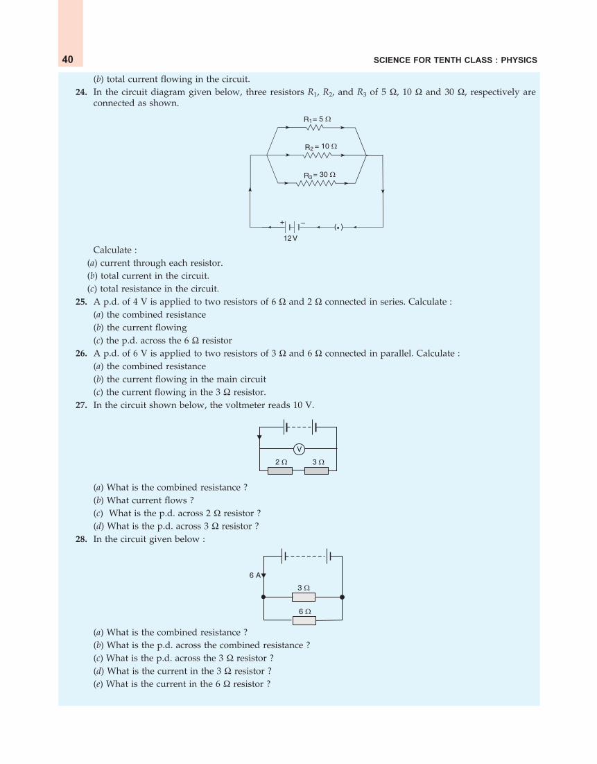
SCIENCE FOR TENTH CLASS : PHYSICS40
(b) total current flowing in the circuit.24. In the circuit diagram given below, three resistors R1, R2, and R3 of 5 , 10 and 30 , respectively are
connected as shown.
R1
R3
R2
= 5 �
= 10 �
= 30 �
12V
+ – ( )
Calculate :(a) current through each resistor.(b) total current in the circuit.(c) total resistance in the circuit.
25. A p.d. of 4 V is applied to two resistors of 6 and 2 connected in series. Calculate :(a) the combined resistance(b) the current flowing(c) the p.d. across the 6 resistor
26. A p.d. of 6 V is applied to two resistors of 3 and 6 connected in parallel. Calculate :(a) the combined resistance(b) the current flowing in the main circuit(c) the current flowing in the 3 resistor.
27. In the circuit shown below, the voltmeter reads 10 V.
2 � 3 �
V
(a) What is the combined resistance ?(b) What current flows ?(c) What is the p.d. across 2 resistor ?(d) What is the p.d. across 3 resistor ?
28. In the circuit given below :
6 �
3 �
6 A
(a) What is the combined resistance ?(b) What is the p.d. across the combined resistance ?(c) What is the p.d. across the 3 resistor ?(d) What is the current in the 3 resistor ?(e) What is the current in the 6 resistor ?

ELECTRICITY 41
29. A 5 V battery is connected to two 20 resistors which are joined together in series.(a) Draw a circuit diagram to represent this. Add an arrow to indicate the direction of conventional current
flow in the circuit.(b) What is the effective resistance of the two resistors ?(c) Calculate the current that flows from the battery.(d) What is the p.d. across each resistor ?
30. The figure given below shows an electric circuit in which current flows from a 6 V battery through tworesistors.
2 � 3 �6 V
(a) Are the resistors connected in series with each other or in parallel ?(b) For each resistor, state the p.d. across it.(c) The current flowing from the battery is shared between the two resistors. Which resistor will have bigger
share of the current ?(d) Calculate the effective resistance of the two resistors.(e) Calculate the current that flows from the battery.
31. A 4 coil and a 2 coil are connected in parallel. What is their combined resistance ? A total current of3 A passes through the coils. What current passes through the 2 coil ?
Long Answer Type Questions32. (a) With the help of a circuit diagram, deduce the equivalent resistance of two resistances connected in
series.(b) Two resistances are connected in series as shown in the diagram :
V volt
5 � R
10 V 6 V
+ –
(i) What is the current through the 5 ohm resistance ?(ii) What is the current through R ?
(iii) What is the value of R ?(iv) What is the value of V ?
33. (a) With the help of a diagram, derive the formula for the resultant resistance of three resistors connected inseries.
(b) For the circuit shown in the diagram given below :5 �
10 �
30 �
6 V
A+–

SCIENCE FOR TENTH CLASS : PHYSICS42
Calculate :(i) the value of current through each resistor.
(ii) the total current in the circuit.(iii) the total effective resistance of the circuit.
34. (a) With the help of a circuit diagram, obtain the relation for the equivalent resistance of two resistancesconnected in parallel.
(b) In the circuit diagram shown below, find : (i) Total resistance. (ii) Current shown by the ammeter A
A4 V
5 �
3 � 2 �
+ –
35. (a) Explain with the help of a labelled circuit diagram, how you will find the resistance of a combination ofthree resistors of resistances R1, R2 and R3 joined in parallel.
(b) In the diagram shown below, the cell and the ammeter both have negligible resistance. The resistors areidentical.
K
A+ –
With the switch K open, the ammeter reads 0.6 A. What will be the ammeter reading when the switch isclosed ?
Multiple Choice Questions (MCQs)
36. The figure given below shows three resistors :6 �
2 �
6 �
Their combined resistance is :
(a) 517 (b) 14 (c)
263 (d)
172
37. If two resistors of 25 and 15 are joined together in series and then placed in parallel with a 40 resistor, the effective resistance of the combination is :(a) 0.1 (b) 10 (c) 20 (d) 40
38. The diagram below shows part of a circuit :6 �
6 �6 �
If this arrangement of three resistors was to be replaced by a single resistor, its resistance should be :(a) 9 (b) 4 (c) 6 (d) 18

ELECTRICITY 43
39. In the circuit shown below :2 V 1 �
2 � 3 �
The potential difference across the 3 resistor is :
(a) 1 V9 (b)
1 V2
(c) 1 V (d) 2 V
40. A battery and three lamps are connected as shown :
X
Y
Z
Which of the following statements about the currents at X, Y and Z is correct ?(a) The current at Z is greater than that at Y.(b) The current at Y is greater than that at Z.(c) The current at X equals the current at Y.(d) The current at X equals the current at Z.
41. V1, V2 and V3 are the p.ds. across the 1 , 2 and 3 resistors in the following diagram, and the current is5 A.
2 �1 � 3 �Current5 A
V1 V2 V3
Which one of the columns (a) to (d) shows the correct values of V1 , V2 and V3 measured in volts ?V1 V2 V3
(a) 1.0 2.0 3.0(b) 5.0 10.0 15.0(c) 5.0 2.5 1.6(d) 4.0 3.0 2.0
42. A wire of resistance R1 is cut into five equal pieces. These five pieces of wire are then connected in parallel.
If the resultant resistance of this combination be R2, then the ratio 1
2
RR is :
(a) 125 (b)
15 (c) 5 (d) 25
Questions Based on High Order Thinking Skills (HOTS)43. Show with the help of diagrams, how you would connect three resistors each of resistance 6 , so that the
combination has resistance of (i) 9 (ii) 4 .44. Two resistances when connected in parallel give resultant value of 2 ohm; when connected in series the
value becomes 9 ohm. Calculate the value of each resistance.45. A resistor of 8 ohms is connected in parallel with another resistor X. The resultant resistance of the combination
is 4.8 ohms. What is the value of the resistor X ?46. You are given three resistances of 1, 2 and 3 ohms. Show by diagrams, how with the help of these resistances
you can get :

SCIENCE FOR TENTH CLASS : PHYSICS44
(i) 6 (ii)6
11 (iii) 1.5
47. How will you connect three resistors of 2 , 3 and 5 respectively so as to obtain a resultant resistance of2.5 ? Draw the diagram to show the arrangement.
48. How will you connect three resistors of resistances 2 , 3 and 6 to obtain a total resistance of : (a) 4 ,and (b) 1 ?
49. What is (a) highest, and (b) lowest, resistance which can be obtained by combining four resistors having thefollowing resistances ?
4 , 8 , 12 , 24 50. What is the resistance between A and B in the figure given below ?
10 � 20 �
10 � 20 �
10 �30 �
A
B
51. You are given one hundred 1 resistors. What is the smallest and largest resistance you can make in acircuit using these ?
52. You are supplied with a number of 100 resistors. How could you combine some of these resistors to makea 250 resistor ?
53. The resistors R1, R2, R3 and R4 in the figure given below are all equal in value.
A B C
R1 R2 R3 R4
12 V
What would you expect the voltmeters A, B and C to read assuming that the connecting wires in the circuithave negligible resistance ?
54. Four resistances of 16 ohms each are connected in parallel. Four such combinations are connected in series.What is the total resistance ?
55. If the lamps are both the same in the figure given below and if A1 reads 0.50 A, what do A2, A3, A4 and A5read ?
A1
A2 A4
A3 A5
ANSWERS
2. 1 ohm 4. 1 ohm 5. In parallel 6. In parallel 7. 8 ; 1.5 8. (a) In parallel (b) In series
9. B 10. 4R
11. (a) 1500 (b) 1 (c) 5 12. Current in 6 resistor = 4 A ; Current in 4
resistor = 6 A. 13. (i) Parallel combination (ii) Series combination 14. 0.67 A
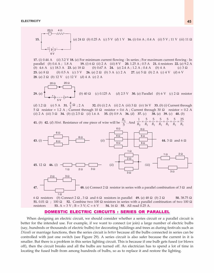
ELECTRICITY 45
15.
6 V
20 � 4 �
+ –
(a) 24 (b) 0.25 A (c) 5 V (d) 1 V 16. (i) 0.6 A ; 0.4 A (ii) 5 V ; 11 V (iii) 11
17. (i) 0.44 A (ii) 3.2 V 18. (a) For minimum current flowing : In series ; For maximum current flowing : Inparallel (b) 0.4 A ; 1.8 A 19. (i) 6 (ii) 2 A (iii) 8 V 20. 1.25 A ; 0.5 A 21. 4 resistors 22. (a) 9.2 A(b) 4.6 A (c) 18.3 A 23. (a) 18 (b) 0.67 A 24. (a) 2.4 A ; 1.2 A ; 0.4 A (b) 4 A (c) 3 25. (a) 8 (b) 0.5 A (c) 3 V 26. (a) 2 (b) 3 A (c) 2 A 27. (a) 5 (b) 2 A (c) 4 V (d) 6 V28. (a) 2 (b) 12 V (c) 12 V (d) 4 A (e) 2 A
29. (a)
20 � 20 �
5 V
+ –(b) 40 (c) 0.125 A (d) 2.5 V 30. (a) Parallel (b) 6 V (c) 2 resistor
(d) 1.2 (e) 5 A 31. 43 ; 2 A 32. (b) (i) 2 A (ii) 2 A (iii) 3 (iv) 16 V 33. (b) (i) Current through
5 resistor = 1.2 A ; Current through 10 resistor = 0.6 A ; Current through 30 resistor = 0.2 A(ii) 2 A (iii) 3 34. (b) (i) 2.5 (ii) 1.6 A 35. (b) 0.9 A 36. (d) 37. (c) 38. (a) 39. (c) 40. (b)
41. (b) 42. (d) Hint. Resistance of one piece of wire will be 1
5R
. And 2 1 1 1 1 1 1
1 5 5 5 5 5 25R R R R R R R
43. (i)
6 �
6 �
6 � (ii)
6 �
6 �
6 �
6 �
6 �
6 �
44. 3 and 6
45. 12 46. (i) 1 � 2 � 3 �
(ii)
1 �
2 �
3 �
(iii)
1 � 2 �
3 �
47.
2 � 3 �
5 �
48. (a) Connect 2 resistor in series with a parallel combination of 3 and
6 resistors (b) Connect 2 , 3 and 6 resistors in parallel 49. (a) 48 (b) 2 50. 38.75 51. 0.01 ; 100 52. Combine two 100 resistors in series with a parallel combination of two 100 resistors 53. A = 3 V ; B = 3 V; C = 6 V 54. 16 55. All read 0.25 A.
DOMESTIC ELECTRIC CIRCUITS : SERIES OR PARALLELWhen designing an electric circuit, we should consider whether a series circuit or a parallel circuit is
better for the intended use. For example, if we want to connect (or join) a large number of electric bulbs(say, hundreds or thousands of electric bulbs) for decorating buildings and trees as during festivals such asDiwali or marriage functions, then the series circuit is better because all the bulbs connected in series can becontrolled with just one switch (see Figure 29). A series circuit is also safer because the current in it issmaller. But there is a problem in this series lighting circuit. This is because if one bulb gets fused (or blowsoff), then the circuit breaks and all the bulbs are turned off. An electrician has to spend a lot of time inlocating the fused bulb from among hundreds of bulbs, so as to replace it and restore the lighting.

SCIENCE FOR TENTH CLASS : PHYSICS46
Figure 30. The electric bulbs in a house areconnected in parallel circuit with the 220volt a.c. power supply line. Please note thatall the bulbs have separate switches (Just likebulbs, all other appliances like fan, TV,fridge, electric iron, etc., are also connectedin parallel in a similar way).
Figure 29. The electric bulbs for decorationare usually connected in series circuit withthe 220 volt a.c. (alternating current) powersupply line (The circuit symbol foralternating current or a.c. supply is
). Please note that all the bulbshave just one switch.
220 V a.c.powersupply
Switch
Bulbs
220 V a.c.powersupply
Bulbs
Switches
The parallel electric circuit is better for connecting bulbs (and other electrical appliances) in a housebecause then we can have separate switches for each bulb (or electrical appliance) and hence operate itseparately (see Figure 30). In addition to having ease of operation, parallel domestic circuits (or householdcircuits) have many other advantages over the series circuits. We will first give the disadvantages of theseries electric circuits for domestic purposes and then the advantages of the parallel electric circuits.
Disadvantages of Series Circuits for Domestic Wiring
The arrangement of lights and various other electrical appliances in series circuit is not used in domesticwiring because of the following disadvantages :
1. In series circuit, if one electrical appliance stops working due to some defect, then all otherappliances also stop working (because the whole circuit is broken). For example, if a number of bulbs areconnected in series and just one bulb gets fused (or blows off), then all other bulbs will also stop glowing.
2. In series circuit, all the electrical appliances haveonly one switch due to which they cannot be turned onor off separately. For example, all the bulbs connected inseries have only one switch due to which all the bulbscan be switched on or switched off together and notseparately.
3. In series circuit, the appliances do not get the samevoltage (220 V) as that of the power supply line becausethe voltage is shared by all the appliances. The appliancesget less voltage and hence do not work properly. Forexample, all the bulbs connected in series do not get the same voltage of 220 volts of the power supply line.They get less voltage and hence glow less brightly.
4. In the series connection of electrical appliances, the overall resistance of the circuit increases toomuch due to which the current from the power supply is low. Moreover, the same current flows throughouta series circuit due to which all the appliances of different power ratings cannot draw sufficient current fortheir proper working.
Figure 31. Christmas tree bulbs are usually wired inseries.

ELECTRICITY 47
Advantages of Parallel Circuits in Domestic WiringThe arrangement of lights and various other electrical appliances in parallel circuits is used in domestic
wiring because of the following advantages :
1. In parallel circuits, if one electrical appliance stops working due to some defect, then all otherappliances keep working normally. For example, if a number of bulbs are connected in parallel circuitsand one bulb gets fused (or blows out), then all the remaining bulbs will keep glowing.
2. In parallel circuits, each electrical appliance has its own switch due to which it can be turned onor turned off independently, without affecting other appliances. For example, all the bulbs joined inparallel circuits in a house have separate switches due to which we can switch on or switch off any bulb asrequired, without affecting other bulbs in the house.
3. In parallel circuits, each electrical appliance gets the same voltage (220 V) as that of the powersupply line. Due to this, all the appliances will work properly. For example, all the bulbs connected inparallel circuits get the same voltage of 220 volts of the power supply line and hence glow very brightly.
4. In the parallel connection of electrical appliances, the overall resistance of the household circuit isreduced due to which the current from the power supply is high. Every appliance can, therefore, drawthe required amount of current. For example, in parallel circuits, even the high power rating applianceslike electric irons, water heaters and air-conditioners, etc., can draw the high current needed for their properfunctioning.
We are now in a position to answer the following questions :
Very Short Answer Type Questions
1. Are the lights in your house wired in series ?2. What happens to the other bulbs in a series circuit if one bulb blows off ?3. What happens to the other bulbs in a parallel circuit if one bulb blows off ?4. Which type of circuit, series or parallel, is preferred while connecting a large number of bulbs :
(a) for decorating a hotel building from outside ?(b) for lighting inside the rooms of the hotel ?
5. Draw a circuit diagram to show how two 4 V electric lamps can be lit brightly from two 2 V cells.
Short Answer Type Questions6. Why is a series arrangement not used for connecting domestic electrical appliances in a circuit ?7. Give three reasons why different electrical appliances in a domestic circuit are connected in parallel.8. Ten bulbs are connected in a series circuit to a power supply line. Ten identical bulbs are connected in a
parallel circuit to an identical power supply line.(a) Which circuit would have the highest voltage across each bulb ?(b) In which circuit would the bulbs be brighter ?(c) In which circuit, if one bulb blows out, all others will stop glowing ?(d) Which circuit would have less current in it ?
9. Consider the circuits given below :
(i) (ii) (iii)
(a) In which circuit are the lamps dimmest ?(b) In which circuit or circuits are the lamps of equal brightness to the lamps in circuit (i) ?(c) Which circuit gives out the maximum light ?

SCIENCE FOR TENTH CLASS : PHYSICS48
10. If you were going to connect two light bulbs to one battery, would you use a series or a parallel arrangement ?Why ? Which arrangement takes more current from the battery ?
Long Answer Type Question11. (a) Which is the better way to connect lights and other electrical appliances in domestic wiring : series circuits
or parallel circuits ? Why ?(b) Christmas tree lamps are usually wired in series. What happens if one lamp breaks ?(c) An electrician has wired a house in such a way that if a lamp gets fused in one room of the house, all the
lamps in other rooms of the house stop working. What is the defect in the wiring ?(d) Draw a circuit diagram showing two electric lamps connected in parallel together with a cell and a
switch that works both lamps. Mark an A on your diagram to show where an ammeter should beplaced to measure the current.
Multiple Choice Questions (MCQs)12. The lamps in a household circuit are connected in parallel because :
(a) this way they require less current(b) if one lamp fails the others remain lit(c) this way they require less power(d) if one lamp fails the others also fail
13. Using the circuit given below, state which of the following statement is correct ?
S1
+ –
A B
S2
(a) When S1 and S2 are closed, lamps A and B are lit.(b) With S1 open and S2 closed, A is lit and B is not lit.(c) With S2 open and S1 closed A and B are lit.(d) With S1 closed and S2 open, lamp A remains lit even if lamp B gets fused.
Questions Based on High Order Thinking Skills (HOTS)
14. (a) Draw a circuit diagram showing two lamps, one cell and a switch connected in series.(b) How can you change the brightness of the lamps ?
15. Consider the circuit given below where A, B and C are three identical light bulbs of constant resistance.
A B
C
(a) List the bulbs in order of increasing brightness.(b) If C burns out, what will be the brightness of A now compared with before ?(c) If B burns out instead, what will be the brightness of A and C compared with before ?
16. How do you think the brightness of two lamps arranged in parallel compares with the brightness of twolamps arranged in series (both arrangements having one cell) ?
17. If current flows through two lamps arranged :(a) in series,(b) in parallel,and the filament of one lamps breaks, what happens to the other lamp ? Explain your answer.
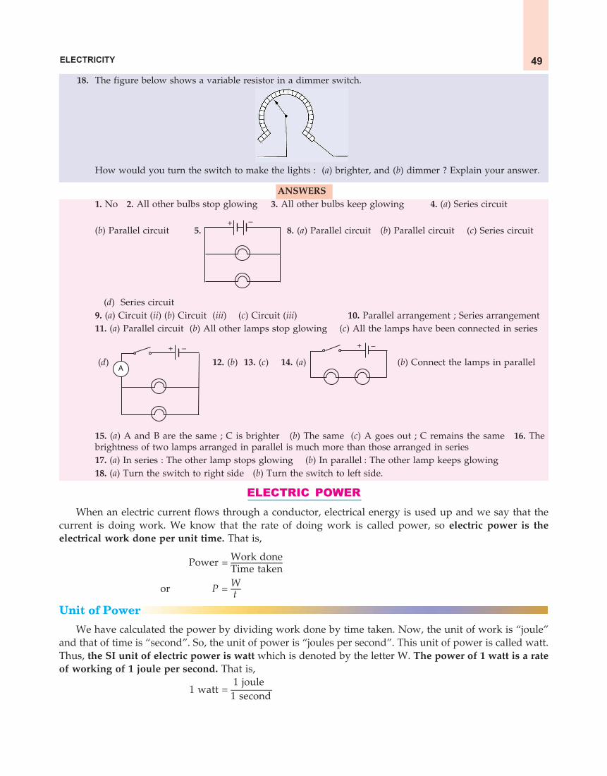
ELECTRICITY 49
18. The figure below shows a variable resistor in a dimmer switch.
How would you turn the switch to make the lights : (a) brighter, and (b) dimmer ? Explain your answer.
ANSWERS1. No 2. All other bulbs stop glowing 3. All other bulbs keep glowing 4. (a) Series circuit
(b) Parallel circuit 5. + –
8. (a) Parallel circuit (b) Parallel circuit (c) Series circuit
(d) Series circuit9. (a) Circuit (ii) (b) Circuit (iii) (c) Circuit (iii) 10. Parallel arrangement ; Series arrangement11. (a) Parallel circuit (b) All other lamps stop glowing (c) All the lamps have been connected in series
(d)
+ –
A 12. (b) 13. (c) 14. (a)
+ –
(b) Connect the lamps in parallel
15. (a) A and B are the same ; C is brighter (b) The same (c) A goes out ; C remains the same 16. Thebrightness of two lamps arranged in parallel is much more than those arranged in series17. (a) In series : The other lamp stops glowing (b) In parallel : The other lamp keeps glowing18. (a) Turn the switch to right side (b) Turn the switch to left side.
ELECTRIC POWERWhen an electric current flows through a conductor, electrical energy is used up and we say that the
current is doing work. We know that the rate of doing work is called power, so electric power is theelectrical work done per unit time. That is,
Work donePower = ————––Time takenWor P = — t
Unit of Power
We have calculated the power by dividing work done by time taken. Now, the unit of work is “joule”and that of time is “second”. So, the unit of power is “joules per second”. This unit of power is called watt.Thus, the SI unit of electric power is watt which is denoted by the letter W. The power of 1 watt is a rateof working of 1 joule per second. That is,
1 joule1 watt = ————
1 second

SCIENCE FOR TENTH CLASS : PHYSICS50
Figure 32. This electric bulbconsumes electric energy at therate of 60 joules per second, soits power is 60 watts.
Actually, watt is a small unit, therefore, a bigger unit of electric powercalled kilowatt is used for commercial purposes. It is obvious that :
1 kilowatt = 1000 wattsor 1 kW = 1000 W
It should be noted that the symbol for watt is W and that for kilowatt iskW. When work is done, an equal amount of energy is consumed. So, we canalso say that electric power is the rate at which electrical energy is consumed.In other words, electric power is the electrical energy consumed per second. We cannow write down another definition of watt based on electrical energy. Whenan electrical appliance consumes electrical energy at the rate of 1 joule persecond, its power is said to be 1 watt. We have just given two definitions ofelectric power, one by using the term ‘work’ and another by using the term‘energy’. We can combine these two definitions and say that : The rate atwhich electrical work is done or the rate at which electrical energy is consumed, is called electric power.
Formula for Calculating Electric PowerWe know that :
Work donePower = —————
Time takenWor P = — ... (1) t
We have already studied that the work done W by current I when it flows for time t under a potentialdifference V is given by :
W = V × I × t joulesPutting this value of W in equation (1), we get :
V × I × tP = ———— joules per second t
or P = V × I joules per secondor Power, P = V × I watts
where V = Potential difference (or Voltage) in voltsand I = Current in amperes
Thus, the power in watts is found by multiplying the potential difference in volts by the current inamperes. We can write down the above formula for electric power in words as follows :
Electric power = Potential difference × CurrentSince the potential difference is also known by the name of voltage, we can also say that :
Electric power = Voltage × CurrentIt is clear from the above discussion that in electric circuits, the power expended in heating a resistor
or turning a motor depends upon the potential difference between the terminals of the device and theelectric current passing through it.
We can also use the formula P = V × I for defining the unit of power called ‘watt’ in another way asdescribed below.
Power, P = V × I watts
Now, if an electrical device is operated at a potential difference of 1 volt and the device carries a currentof 1 ampere, then power becomes 1 watt. That is :
1 watt = 1 volt × 1 ampereor 1 W = 1 V × 1 Aor 1 W = 1 V A
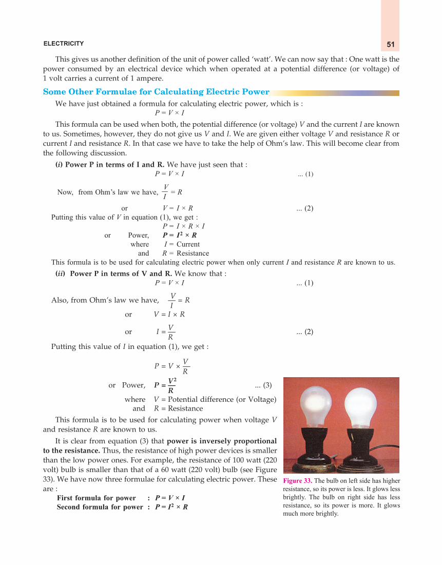
ELECTRICITY 51
This gives us another definition of the unit of power called ‘watt’. We can now say that : One watt is thepower consumed by an electrical device which when operated at a potential difference (or voltage) of1 volt carries a current of 1 ampere.
Some Other Formulae for Calculating Electric PowerWe have just obtained a formula for calculating electric power, which is :
P = V × IThis formula can be used when both, the potential difference (or voltage) V and the current I are known
to us. Sometimes, however, they do not give us V and I. We are given either voltage V and resistance R orcurrent I and resistance R. In that case we have to take the help of Ohm’s law. This will become clear fromthe following discussion.
(i) Power P in terms of I and R. We have just seen that :P = V × I ... (1)
Now, from Ohm’s law we have, VI = R
or V = I × R ... (2)Putting this value of V in equation (1), we get :
P = I × R × Ior Power, P = I2 × R
where I = Currentand R = Resistance
This formula is to be used for calculating electric power when only current I and resistance R are known to us.(ii) Power P in terms of V and R. We know that :
P = V × I ... (1)
V Also, from Ohm’s law we have, — = R
I or V = I × R
Vor I = — ... (2)R
Putting this value of I in equation (1), we get :
VP = V × — RV
2or Power, P = — ... (3)
Rwhere V = Potential difference (or Voltage)
and R = Resistance
This formula is to be used for calculating power when voltage Vand resistance R are known to us.
It is clear from equation (3) that power is inversely proportionalto the resistance. Thus, the resistance of high power devices is smallerthan the low power ones. For example, the resistance of 100 watt (220volt) bulb is smaller than that of a 60 watt (220 volt) bulb (see Figure33). We have now three formulae for calculating electric power. Theseare :
First formula for power : P = V × ISecond formula for power : P = I2 × R
Figure 33. The bulb on left side has higherresistance, so its power is less. It glows lessbrightly. The bulb on right side has lessresistance, so its power is more. It glowsmuch more brightly.

SCIENCE FOR TENTH CLASS : PHYSICS52
V2Third formula for power : P = —
RThese three formulae should be memorized because they will be used to solve numerical problems.
Before we solve the problems based on electric power, it is very important to know the meaning of ‘power-voltage’ rating of electrical appliances.
Power-Voltage Rating of Electrical Appliances
Every electrical appliance like an electric bulb, radio or fan has a label or engraved plate on it whichtells us the voltage (to be applied) and the electrical power consumed by it. For example, if we look at aparticular bulb in our home, it may have the figures 100 W – 220 V written on it. Now, 100 W means thatthis bulb has a power consumption of 100 watts and 220 V means that it is to be used on a voltage of 220volts. The power rating of an electrical appliance tells us the rate at which electrical energy is consumed bythe appliance. For example, a power rating of 100 watts on the bulb means that it will consume electricalenergy at the rate of 100 joules per second. If we know the power P and voltage V of an electrical appliance,then we can very easily find out the current I drawn by it. This can be done by using the formula :P = V × I. The usual power-voltage ratings of some of the common household electrical appliances and thecurrent drawn by them are given below.
Power-Voltage Ratings of Some Electrical Appliances and theCurrent Drawn by Them
Electrical appliance Usual power Usual voltage Current drawn
1. Tube light 40 W 220 V 0.18 A2. Electric bulb (or Lamp) 60 W 220 V 0.27 A3. Radio set 80 W 220 V 0.36 A4. Electric fan 100 W 220 V 0.45 A5. T.V. set 120 W 220 V 0.54 A6. Refrigerator 150 W 220 V 0.68 A7. Electric iron 750 W 220 V 3.4 A8. Electric heater 1000 W 220 V 4.5 A9. Immersion heater 1500 W 220 V 6.8 A
10. Washing machine 3000 W 220 V 13.6 A
(a) An electric bulb (b) The usual (c) An electric (d) An electric (e) The usualmay have power of power of a iron has a heater may have power of a washing15 W, 40 W, 60 W, TV set is power of 750 W power of 1000 W machine
100 W or more about 120 W or more or 2000 W, etc. is 3000 W (or 3 kW)
Figure 34. Different electrical appliances have different power ratings.

ELECTRICITY 53
Let us solve some problems now.
Sample Problem 1. What will be the current drawn by an electric bulb of 40 W when it is connected toa source of 220 V ?
Solution. In this case we have been given power P and voltage V, so the formula to be used for calculatingthe current will be :
P = V × IHere, Power, P = 40 watts
Voltage, V = 220 voltsAnd, Current, I = ? (To be calculated)
Now, putting these values in the above formula, we get :40 = 220 × I
40I = —— 220 2
= —– 11
Thus, Current, I = 0.18 ampereSample Problem 2. An electric bulb is rated 220 V and 100 W. When it is operated on 110 V, the power
consumed will be :(a) 100 W (b) 75 W (c) 50 W (d) 25 W (NCERT Book Question)Solution. In the first case :
Power, P = 100 WPotential difference, V = 220 V
And, Resistance, R =? (To be calculated)
Now, P =2V
R
So, 100 =2(220)
R
And R =220 220
100 = 484
This resistance of 484 of the bulb will remain unchanged.In the second case :
Power, P = ? (To be calculated)Potential difference, V = 110 V
And, Resistance, R = 484 (Calculated above)
Now, P =2V
R
P =2(110)
484 =
110 110484
= 25 W
Thus, the correct answer is : (d) 25 W.
Sample Problem 3. Which of the following does not represent electrical power in a circuit ?
(a) I2R (b) IR2 (c) VI (d)2V
R(NCERT Book Question)
Answer. (b) IR2

SCIENCE FOR TENTH CLASS : PHYSICS54
An Important Formula for Calculating Electrical EnergyWe will now derive a formula for calculating electrical energy in terms of power and time. We have
already studied that :
Work done by electric currentElectric power = ————————————–––
Time takenNow, according to the law of conservation of energy,
Work done by electric current = Electric energy consumed
So, we can now write down the above relation as :
Electrical energyPower = ———————
Timeor Electrical energy = Power × Timeor E = P × t
It is obvious that the electrical energy consumed by an electrical appliance is given by the product ofits power rating and the time for which it is used. From this we conclude that the electrical energy consumedby an electrical appliance depends on two factors : (i) power rating of the appliance, and (ii) time for which theappliance is used. We should memorize the above formula for calculating electrical energy because it will beused in solving numerical problems.
In the formula : Electrical energy = Power × Time, if we take the power in ‘watts’and time in ‘hours’ thenthe unit of electrical energy becomes ‘Watt-hour’ (Wh). One watt-hour is the amount of electrical energyconsumed when an electrical appliance of 1 watt power is used for 1 hour. We will now describe thecommercial unit (or trade unit) of electrical energy called kilowatt-hour.
COMMERCIAL UNIT OF ELECTRICAL ENERGY : KILOWATT-HOURThe SI unit of electrical energy is joule and we know that “1 joule is the amount of electrical energy consumed
when an appliance of 1 watt power is used for 1 second”. Actually, joule represents a very small quantity ofenergy and, therefore, it is inconvenient to use where a large quantity of energy is involved. So, forcommercial purposes we use a bigger unit of electrical energy which is called “kilowatt-hour”. One kilowatt-hour is the amount of electrical energy consumed when an electrical appliance having a power rating of1 kilowatt is used for 1 hour. Since a kilowatt means 1000 watts, so we can also say that one kilowatt-houris the amount of electrical energy consumed when an electrical appliance of 1000 watts is used for 1 hour. In otherwords, one kilowatt-hour is the energy dissipated by a current at the rate of 1000 watts for 1 hour. Fromthis discussion we conclude that the commercial unit of electrical energy is kilowatt-hour which is writtenin short form as kWh.
Relation between kilowatt-hour and joule1 kilowatt-hour is the amount of energy consumed at the rate of 1 kilowatt for 1 hour. That is,
1 kilowatt-hour = 1 kilowatt for 1 hour or 1 kilowatt-hour = 1000 watts for 1 hour ... (1)
1 joule But : 1 watt = ————
1 secondSo, equation (1) can be rewritten as :
joules1 kilowatt-hour = 1000 ———— for 1 hour
secondsAnd, 1 hour = 60 × 60 seconds
joulesSo, 1 kilowatt-hour = 1000 ———— × 60 × 60 seconds
secondsor 1 kilowatt-hour = 36,00,000 joules (or 3.6 × 10⁶ J)

ELECTRICITY 55
From this discussion we conclude that 1 kilowatt-hour is equal to 3.6 × 10⁶ joules of electrical energy.It should be noted that watt or kilowatt is the unit of electrical power but kilowatt-hour is the unit ofelectrical energy. Let us solve some problems now.
Sample Problem 1. A radio set of 60 watts runs for 50 hours. How much electrical energy is consumed ?
Solution. We know that :Electrical energy = Power × Timeor E = P × t ... (1)
We want to calculate the electrical energy in kilowatt-hours, so first we should convert the power of 60watts into kilowatts by dividing it by 1000. That is :
Power, P = 60 watts 60= ——– kilowatt1000
= 0.06 kilowattAnd, Time, t = 50 hours
Now, putting P = 0.06 kW and, t = 50 hours in equation (1), we get :Electrical energy, E = 0.06 × 50
= 3 kilowatt-hours (or 3 kWh)Thus, electrical energy consumed is 3 kilowatt-hours.
Note. In the above problem we have calculated the electrical energy consumed in the commercial unitof energy ‘kilowatt-hour’ (kWh). We can also convert this electrical energy into SI unit of energy calledjoule by using the relation between kilowatt-hour and joule. Now,
1 kWh = 3.6 × 10⁶ JSo, 3 kWh = 3.6 × 106 × 3 J
= 10.8 × 10⁶ J (or 10.8 × 10⁶ joules)
Sample Problem 2. A current of 4 A flows through a 12 V car headlight bulb for 10 minutes. How muchenergy transfer occurs during this time ?
Solution. Energy = Power × Timeor E = P × t ... (1)
First of all we should calculate power P by using the current of 4 A and voltage of 12 V.Now, P = V × ISo, P = 12 × 4or, Power, P = 48 watts
48= ——– kilowatts1000
Thus, Power, P = 0.048 kWAnd, Time, t = 10 minutes
10= —– hours 60 1= — hours 6
1Now, putting P = 0.048 kW and, t = — hours in equation (1), we get : 6
1E = 0.048 × — 6
= 0.008 kWh
Thus, the energy transferred is 0.008 kilowatt-hour.
Sample Problem 3. Calculate the energy transferred by a 5 A current flowing through a resistor of2 ohms for 30 minutes.
Solution. We will first calculate the power by using the given values of current and resistance. This can

SCIENCE FOR TENTH CLASS : PHYSICS56
Figure 35. This is a domestic electricity meter.The reading in this meter shows the numberof kilowatt-hours (or units) that have beenused. The reading from this electricity meteris used to prepare our monthly electricity bill.
be done by using the formula :P = I2 × R
Here, Current, I = 5 amperesAnd, Resistance, R = 2 ohmsSo, Power, P = (5)2 × 2
= 25 × 2= 50 watts
50= ——– kilowatts1000
Thus, Power, P = 0.05 kW ... (1)And, Time, t = 30 minutes
30= —– hours
601= – hours2
= 0.5 hours ... (2)Now, Energy, E = P × t
= 0.05 × 0.5Energy, E = 0.025 kWh
In the above given sample problems, we have calculated the electrical energy in the commercial unit of“kilowatt-hour”. Please calculate the energy in “joules” yourself.
How to Calculate the Cost of Electrical Energy Consumed
Kilowatt-hour is the “unit” of electrical energy for which we payto the Electricity Supply Department of our City. One unit ofelectricity costs anything from rupees 3 to rupees 5 (or even more).The rates vary from place to place and keep on changing from timeto time. Now, by saying that 1 unit of electricity costs say, 3 rupees,we mean that 1 kilowatt-hour of electrical energy costs 3 rupees.The electricity meter in our homes measures the electrical energyconsumed by us in kilowatt-hours (see Figure 35). Now, we usedifferent electrical appliances in our homes. We use electric bulbs,tube-lights, fans, electric iron, radio, T.V., and refrigerator, etc. Allthese household electrical appliances consume electrical energy atdifferent rates. Our electricity bill depends on the total electricalenergy consumed by our appliances over a given period of time,say a month. We will now describe how the cost of electricityconsumed is calculated. Since the electricity is sold in units ofkilowatt-hour, so first we should convert the power consumed inwatts into kilowatts by dividing the total watts by 1000. The kilowattsare then converted into kilowatt-hours by multiplying the kilowattsby the number of hours for which the appliance has been used. Thisgives us the total electrical energy consumed in kilowatt-hours. In other words, this gives us the totalnumber of “units” of electricity consumed. Knowing the cost of 1 unit of electricity, we can find out thetotal cost. This will become more clear from the following examples.
Sample Problem 1. A refrigerator having a power rating of 350 W operates for 10 hours a day. Calculatethe cost of electrical energy to operate it for a month of 30 days. The rate of electrical energy isRs. 3.40 per kWh.

ELECTRICITY 57
Solution. Electrical energy, E = P × tHere, Power, P = 350 W
=350
kW1000
= 0.35 kWAnd, Time, t = 10 × 30 hours
= 300 hNow, putting these values of P and t in the formula,
E = P × tWe get : E = 0.35 × 300 kWh
= 105 kWhThus, the electrical energy consumed by the refrigerator in a month of 30 days is 105 kilowatt-hours.Now, Cost of 1 kWh of electricity = Rs. 3.40So, Cost of 105 kWh of electricity = Rs. 3.40 × 105
= Rs. 357
Sample Problem 2. A bulb is rated at 200 V-100 W. What is its resistance ? Five such bulbs burn for 4hours. What is the electrical energy consumed ? Calculate the cost if the rate is ` 4.60 per unit.
Solution. (a) Calculation of Resistance. Here we know the voltage and power of the bulb. So, theresistance can be calculated by using the formula :
V 2P = —
RHere, Power, P = 100 watts
Voltage, V = 200 voltsAnd, Resistance, R = ? (To be calculated)
Now, putting these values in the above formula, we get :
(200)2100 = ——–
R100 R = 40000
40000And, R = ——— 100
= 400 ohms(b) Calculation of Electrical Energy Consumed. The electrical energy consumed in kilowatt-hours can
be calculated by using the formula :E = P × t
Here, Power, P = 100 watts 100= ——– kilowatt1000
= 0.1 kilowatt ... (1)And, Time, t = 4 hours ... (2)
So, Energy consumed by 1 bulb = 0.1 × 4= 0.4 kilowatt-hours
And,Energy consumed by 5 bulbs = 0.4 × 5= 2 kilowatt-hours (or 2 kWh)
Thus, the total electrical energy consumed is “2 kilowatt-hours” or “2 units”.(c) Calculation of Cost of Electrical Energy. We have been given that :
Cost of 1 unit of electricity = ` 4.60So, Cost of 2 units of electricity = ` 4.60 × 2
= ` 9.20

SCIENCE FOR TENTH CLASS : PHYSICS58
Sample Problem 3. An electric heater draws a current of 10 A from a 220 V supply. What is the cost ofusing the heater for 5 hours everyday for 30 days if the cost of 1 unit (1 kWh) is ` 5.20 ?
Solution. In this problem, first of all we have to calculate the power of the heater by using the givenvalues of current and voltage. This can be done by using the formula :
P = V × IHere, Voltage (or p.d.), V = 220 VAnd, Current, I = 10 ASo, Power, P = 220 × 10 W
= 2200 W2200= ——– kW1000
= 2.2 kW ... (1)Now, Electric energy consumed, E = P × tHere, Power, P = 2.2 kWAnd, Time, t = 5 hSo, Electric energy consumed in 1 day = 2.2 × 5
= 11 kWhAnd, Electric energy consumed in 30 days = 11 × 30
= 330 kWh (or 330 units) ... (2)Now, Cost of 1 unit of electricity = ` 5.20So, Cost of 330 units of electricity = ` 5.20 × 330
= ` 1716
Before we go further and discuss the heating effect of electric current, please answer the followingquestions :
Very Short Answer Type Questions1. State two factors on which the electrical energy consumed by an electrical appliance depends.2. Which one has a higher electrical resistance : a 100 watt bulb or a 60 watt bulb ?3. Name the commercial unit of electric energy.4. An electric bulb is rated at 220 V, 100 W. What is its resistance ?5. What is the SI unit of (i) electric energy, and (ii) electric power ?6. Name the quantity whose unit is (i) kilowatt, and (ii) kilowatt-hour.7. Which quantity has the unit of watt ?8. What is the meaning of the symbol kWh ? Which quantity does it represent ?9. If the potential difference between the end of a wire of fixed resistance is doubled, by how much does the
electric power increase ?10. An electric lamp is labelled 12 V, 36 W. This indicates that it should be used with a 12 V supply. What other
information does the label provide ?11. What current will be taken by a 920 W appliance if the supply voltage is 230 V ?
Short Answer Type Questions12. Define watt. Write down an equation linking watts, volts and amperes.13. Define watt-hour. How many joules are equal to 1 watt-hour ?14. How much energy is consumed when a current of 5 amperes flows through the filament (or element) of a
heater having resistance of 100 ohms for two hours ? Express it in joules.15. An electric bulb is connected to a 220 V power supply line. If the bulb draws a current of 0.5 A, calculate the
power of the bulb.16. In which of the following cases more electrical energy is consumed per hour ?
(i) A current of 1 ampere passed through a resistance of 300 ohms.(ii) A current of 2 amperes passed through a resistance of 100 ohms.
17. An electric kettle rated at 220 V, 2.2 kW, works for 3 hours. Find the energy consumed and the currentdrawn.

ELECTRICITY 59
18. In a house two 60 W electric bulbs are lighted for 4 hours, and three 100 W bulbs for 5 hours everyday.Calculate the electric energy consumed in 30 days.
19. A bulb is rated as 250 V; 0.4 A. Find its : (i) power, and (ii) resistance.20. For a heater rated at 4 kW and 220 V, calculate :
(a) the current,(b) the resistance of the heater,(c) the energy consumed in 2 hours, and(d) the cost if 1 kWh is priced at ` 4.60.
21. An electric motor takes 5 amperes current from a 220 volt supply line. Calculate the power of the motor andelectrical energy consumed by it in 2 hours.
22. Which uses more energy : a 250 W TV set in 1 hour or a 1200 W toaster in 10 minutes ?23. Calculate the power used in the 2 resistor in each of the following circuits :
(i) a 6 V battery in series with 1 and 2 resistors.(ii) a 4 V battery in parallel with 12 and 2 resistors.
24. Two lamps, one rated 40 W at 220 V and the other 60 W at 220 V, are connected in parallel to the electricsupply at 220 V.(a) Draw a circuit diagram to show the connections.(b) Calculate the current drawn from the electric supply.(c) Calculate the total energy consumed by the two lamps together when they operate for one hour.
25. An electric kettle connected to the 230 V mains supply draws a current of 10 A. Calculate :(a) the power of the kettle.(b) the energy transferred in 1 minute.
26. A 2 kW heater, a 200 W TV and three 100 W lamps are all switched on from 6 p.m. to 10 p.m. What is thetotal cost at Rs. 5.50 per kWh ?
27. What is the maximum power in kilowatts of the appliance that can be connected safely to a 13 A ; 230 Vmains socket ?
28. An electric fan runs from the 230 V mains. The current flowing through it is 0.4 A. At what rate is electricalenergy transferred by the fan ?
Long Answer Type Question29. (a) What is meant by “electric power” ? Write the formula for electric power in terms of potential difference
and current.(b) The diagram below shows a circuit containing a lamp L, a voltmeter and an ammeter. The voltmeter
reading is 3 V and the ammeter reading is 0.5 A.
A
V
L (i) What is the resistance of the lamp ? (ii) What is the power of the lamp ?(c) Define kilowatt-hour. How many joules are there in one kilowatt-hour ?(d) Calculate the cost of operating a heater of 500 W for 20 hours at the rate of ` 3.90 per unit.
Multiple Choice Questions (MCQs)30. When an electric lamp is connected to 12 V battery, it draws a current of 0.5 A. The power of the lamp is :
(a) 0.5 W (b) 6 W (c) 12 W (d) 24 W31. The unit for expressing electric power is :
(a) volt (b) joule (c) coulomb (d) watt32. Which of the following is likely to be the correct wattage for an electric iron used in our homes ?
(a) 60 W (b) 250 W (c) 850 W (d) 2000 W33. An electric heater is rated at 2 kW. Electrical energy costs ` 4 per kWh. What is the cost of using the heater
for 3 hours ?

SCIENCE FOR TENTH CLASS : PHYSICS60
(a) ` 12 (b) ` 24 (c) ` 36 (d) ` 4834. The SI unit of energy is :
(a) joule (b) coulomb (c) watt (d) ohm-metre35. The commercial unit of energy is :
(a) watt (b) watt-hour (c) kilowatt-hour (d) kilo-joule36. How much energy does a 100 W electric bulb transfer in 1 minute ?
(a) 100 J (b) 600 J (c) 3600 J (d) 6000 J37. An electric kettle for use on a 230 V supply is rated at 3000 W. For safe working, the cable connected to it
should be able to carry at least :(a) 2 A (b) 5 A (c) 10 A (d) 15 A
38. How many joules of electrical energy are transferred per second by a 6 V ; 0.5 A lamp ?(a) 30 J/s (b) 12 J/s (c) 0.83 J/s (d) 3 J/s
39. At a given time, a house is supplied with 100 A at 220 V. How many 75 W, 220 V light bulbs could beswitched on in the house at the same time (if they are all connected in parallel) ?(a) 93 (b) 193 (c) 293 (d) 393
40. If the potential difference between the ends of a fixed resistor is halved, the electric power will become :(a) double (b) half (c) four times (d) one-fourth
Questions Based on High Order Thinking Skills (HOTS)41. State whether an electric heater will consume more electrical energy or less electrical energy per second
when the length of its heating element is reduced. Give reasons for your answer.42. The table below shows the current in three different electrical appliances when connected to the 240 V
mains supply :Appliance CurrentKettle 8.5 ALamp 0.4 AToaster 4.8 A
(a) Which appliance has the greatest electrical resistance ? How does the data show this ?(b) The lamp is connected to the mains supply by using a thin, twin-cored cable consisting of live and neutral
wires. State two reasons why this cable should not be used for connecting the kettle to the mains supply.(c) Calculate the power rating of the kettle when it is operated from the 240 V mains supply.(d) A man takes the kettle abroad where the mains supply is 120 V. What is the current in the kettle when it
is operated from the 120 V supply ?43. A boy noted the readings on his home’s electricity meter on Sunday at 8 AM and again on Monday at 8 AM
(see Figures below).
(a) What was the meter reading on Sunday ?(b) What was the meter reading on Monday ?(c) How many units of electricity have been used ?(d) In how much time these units have been used ?(e) If the rate is Rs. 5 per unit, what is the cost of electricity used during this time ?
44. An electric bulb is rated as 10 W, 220 V. How many of these bulbs can be connected in parallel across thetwo wires of 220 V supply line if the maximum current which can be drawn is 5 A ?
45. Two exactly similar electric lamps are arranged (i) in parallel, and (ii) in series. If the parallel and seriescombination of lamps are connected to 220 V supply line one by one, what will be the ratio of electric powerconsumed by them ?

ELECTRICITY 61
Figure 36. An electric current produces heatingeffect. This filament has become red-hot due tothe heating effect of current.
ANSWERS2. 60 watt bulb 4. 484 9. Four times 10. The electric lamp consumes energy at the rate of 36 J/s11. 4 A 14. 18.0 × 10⁶ J 15. 110 W 16. 2 A ; 100 17. 6.6 kWh ; 10 A 18. 59.4 kWh19. (i) 100 W (ii) 625 20. (a) 18.18 A (b) 12.1 (c) 8 kWh (d) ` 36.80 21. 1.1 kW ; 2.2 kWh22. TV set uses 0.25 kWh energy whereas toaster uses 0.20 kWh energy. So, TV uses more energy.
23. (i) 8 W (ii) 8 W 24. (a) 220 V
40 W
60 W
(b) 0.45 A (c) 356.4 kJ 25. (a) 2300 W or 2.3 kW
(b) 1,38,000 J or 138 kJ 26. Rs. 55.00 27. 2.99 kW 28. 92 J/s 29. (b) (i) 6 (ii) 1.5 W(d) ` 39.00 30. (b) 31. (d) 32. (c) 33. (b) 34. (a) 35. (c) 36. (d) 37. (d) 38. (d) 39. (c) 40. (d)41. More electrical energy ; Power is inversely proportional to resistance 42. (a) Lamp ; Least currentflowing in it (b) Large current drawn by kettle ; Earth connection needed (c) 2040 W (d) 4.25 A43. (a) 42919 (b) 42935 (c) 16 units (d) 24 hours (e) Rs. 80 44. 110 bulbs 45. 4 : 1
Effects Produced by Electric Current
An electric current can produce three important effects. These are : (1) Heating effect, (2) Magneticeffect, and (3) Chemical effect. We will now discuss the heating effect of current. The magnetic effect ofcurrent will be discussed in the next Chapter whereas the chemical effect of current will be described inhigher classes.
HEATING EFFECT OF CURRENTWhen an electric current is passed through a high resistance
wire, like nichrome wire, the resistance wire becomes very hotand produces heat. This is called the heating effect of current.The heating effect of current is obtained by the transformation ofelectrical energy into heat energy. Just as mechanical energy usedto overcome friction is converted into heat, in the same way,electrical energy is converted into heat energy when an electriccurrent flows through a resistance wire. Thus, the role of ‘resistance’in electrical circuits is similar to the role of ‘friction’ in mechanics. Wewill now derive a formula for calculating the heat produced whenan electric current flows through a resistance wire.
Since a conductor, say a resistance wire, offers resistance tothe flow of current, so work must be done by the currentcontinuously to keep itself flowing. We will calculate the workdone by a current I when it flows through a resistance R for time t. Now, when an electric charge Q movesagainst a potential difference V, the amount of work done is given by :
W = Q × V ... (1)From the definition of current we know that :
QCurrent, I = — t
So, Q = I × t ... (2)And from Ohm’s law, we have :
V — = RI
or Potential difference, V = I × R ... (3)

SCIENCE FOR TENTH CLASS : PHYSICS62
Now, putting Q = I × t and V = I × R in equation (1), we get :W = I × t × I × R
So, Work done, W = I2 × R × t
Assuming that all the electrical work done or all the electrical energy consumed is converted into heatenergy, we can write ‘Heat produced’ in place of ‘Work done’ in the above equation. Thus,
Heat produced, H = I2 × R × t joules
This formula gives us the heat produced in joules when a current of I amperes flows in a wire ofresistance R ohms for time t seconds. This is known as Joule’s law of heating. According to Joule’s law ofheating given by the formula H = I2 × R × t, it is clear that the heat produced in a wire is directly proportionalto :
(i) square of current (I2)(ii) resistance of wire (R)
(iii) time (t), for which current is passed(a) Since the heat produced is directly proportional to the square of current :
H I2
so, if we double the current, then the heat produced will become four times. And if we halve the current, thenheat generated will become one-fourth.
(b) Since the heat produced in a wire is directly proportional to the resistance :H R
so, if we double the resistance, then heat produced will also get doubled. And if we halve the resistance, thenthe heat produced will also be halved. This means that a given current will produce more heat in a highresistance wire than in a low resistance wire.
We know that when two similar resistance wires are connected in series, then their combined resistancegets doubled but when they are connected in parallel then their combined resistance gets halved. So, agiven current will produce more heat per unit time if the two resistances are connected in series thanwhen they are connected in parallel.
(c) Since the heat produced in a wire is directly proportional to the time for which current flows :H t
so, if the current is passed through a wire for double the time, then the heat produced is doubled. And if thetime is halved, the heat produced is also halved.
We will now solve some problems based on the heating effect of current. Please note that the formula :H = I2 × R × t for calculating the heat produced can be used only if the current I, resistance R and time t areknown to us. In some cases, however, they give us the power P and time t only. In that case the heat energyis to be calculated by using the formula : E = P × t.
It should be noted that all the appliances which run on electricitydo not convert all the electric energy into heat energy. Only theelectrical heating appliances convert most of the electric energy intoheat energy. For example, when electric current is passed through anelectric appliance such as a fan, then most of the electric energy is usedup in running the fan (or turning the fan), only a very small amount ofelectric energy is converted into heat energy by a fan. Due to this, anelectric fan becomes slightly warm when run continuously for a longtime. On the other hand, when electric current is passed through anelectrical heating appliance such as an electric heater, electric kettle,hair dryer, immersion rod or a geyser, then most of the electrical energyis converted into heat. All the electrical heating appliances have a ‘heating element’ or ‘heating coil’ madeof high resistance wire (like nichrome wire) which helps in converting most of the electric energy into heatenergy. We will now solve some problems based on the heating effect of current.
Figure 37. An electric room heaterconverts almost all the electrical energyinto heat.
Cord (connectingcable) made of
insulatedcopper wires
Element(coil of nichrome wire)

ELECTRICITY 63
Sample Problem 1. A potential difference of 250 volts is applied across a resistance of 500 ohms in anelectric iron. Calculate (i) current, and (ii) heat energy produced in joules in 10 seconds.
Solution. (i) Calculation of Current. The current can be calculated by using Ohm’s law equation :V
— = RI
Here, Potential difference, V = 250 voltsCurrent, I = ? (To be calculated)
Resistance, R = 500 ohmsPutting these values in the above formula, we get :
250 —— = 500
I
250So, I = —— 500
1= –2
= 0.5 ampereThus, the current flowing in the electric iron is 0.5 A.
(ii) Calculation of Heat Energy. The heat energy in joules can be calculated by using the formula :H = I2 × R × t
Here, Current, I = 0.5 AResistance, R = 500
And, Time, t = 10 sPutting these values in the above formula, we get :
H = (0.5)2 × 500 × 10= 1250 joules
Sample Problem 2. Calculate the heat produced when 96,000 coulombs of charge is transferred in1 hour through a potential difference of 50 volts. (NCERT Book Question)
Solution. First of all we will calculate the current by using the values of charge and time. We knowthat :
Current, I =Qt
I = 96,00060 60 (Because 1 h = 60 × 60 s)
I = 26.67 A
We will now calculate the resistance by using Ohm’s law :
R =VI
R =50
26.67
R = 1.87 Heat produced, H = I2 × R × t
= (26.67)2 × 1.87 × 60 × 60= 4788400 J= 4788.4 kJ
Thus, the heat produced is 4788.4 kilojoules.

SCIENCE FOR TENTH CLASS : PHYSICS64
Sample Problem 3. Two conducting wires of the same material and of equal lengths and equal diametersare first connected in series and then in parallel in a circuit across the same potential difference. The ratioof heat produced in series and parallel combinations would be :
(a) 1 : 2 (b) 2 : 1 (c) 1 : 4 (d) 4 : 1 (NCERT Book Question)
Solution. Suppose the resistance of each one of the two wires is x.(i) When the two resistance wires, each having a resistance x, are connected in series, then :
Combined resistance, R1 = 2xAnd, if the potential difference in the circuit is V, then applying Ohm’s law :
Current, I1 = Vx2
Suppose the heat produced with the series combination of wires is H1. Then :
H1 = I R t21 1
or H1 =
V Vx t x t
x x
2 2
222 2
4
or H1 = V tx
2
2... (1)
(ii) When the two resistance wires, each of resistance x, are connected in parallel, then :
Combined resistance, R2 = x2
And if the potential difference in the circuit is V, then applying Ohm ’s law :
Current, I2 = Vx
2
Suppose the heat produced with the parallel combination of wires is H2. Then :
H2 = I R t 22 2
or H2 =
V V x txt
x x
2 2
2
2 42 2
or H2
V t
x
2 2... (2)
Dividing equation (1) by equation (2), we get :
V t xHH x V t
21
22 2 2
HH
1
2
14 or H1 : H2 = 1 : 4
Thus, the correct option is : (c) 1 : 4
Applications of the Heating Effect of Current
The important applications of the heating effect of electric current are given below :
1. The heating effect of current is utilised in the working of electrical heating appliances such aselectric iron, electric kettle, electric toaster, electric oven, room heaters, water heaters (geysers), etc. Allthese heating appliances contain coils of high resistance wire made of nichrome alloy. When these appliancesare connected to power supply by insulated copper wires then a large amount of heat is produced in theheating coils (because they have high resistance), but a negligible heat is produced in the connecting wiresof copper (because copper has very, very low resistance). For example, the heating element (or coil) of anelectric heater made of nichrome glows because it becomes red-hot due to the large amount of heat producedon passing current (because of its high resistance), but the cord or connecting cable of the electric heatermade of copper does not glow because negligible heat is produced in it by passing current (because of itsextremely low resistance). The temperature of the heating element (or heating coil) of an electrical heatingdevice when it becomes red-hot and glows is about 900°C.

ELECTRICITY 65
2. The heating effect of electric current is utilised in electric bulbs (electric lamps) for producinglight. When electric current passes through a very thin, high resistance tungsten filament of an electricbulb, the filament becomes white-hot and emits light. Please note that the same current flowing throughthe tungsten filament of an electric bulb produces enormous heat but almost negligible heat is produced inthe connecting wires of copper. This is because of the fact that the fine tungsten filament has very highresistance whereas copper connecting wires have very low resistance.
Tungsten metal is used for making thefilaments of electric bulbs because it has avery high melting point (of 3380°C). Due toits very high melting point, the tungstenfilament can be kept white-hot without meltingaway. The other properties of tungsten whichmake it suitable for making filaments ofelectric bulbs are its high flexibility and low rateof evaporation at high temperature. Please notethat when the tungsten filament of an electricbulb becomes white-hot and glows to emitlight, then its temperature is about 2500°C !
If air is present in an electric bulb, then theextremely hot tungsten filament would burnup quickly in the oxygen of air. So, the electricbulb is filled with a chemically unreactive gas like argon or nitrogen (or a mixture of both). The gaseslike argon and nitrogen do not react with the hot tungsten filament and hence prolong the life of thefilament of the electric bulb. It should be noted that most of the electric power consumed by the filament ofan electric bulb appears as heat (due to which the bulb becomes hot), only a small amount of electric poweris converted into light. So, filament-type electric bulbs are not power efficient. Onthe other hand, tube-lights are much more power efficient, because they have nofilaments.
3. The heating effect of electric current is utilised in electric fuse for protectinghousehold wiring and electrical appliances. A fuse is a short length of a thin tin-plated copper wire having low melting point. The thin fuse wire has a higherresistance than the rest of the electric wiring in a house. So, when the current in ahousehold electric circuit rises too much due to some reason, then the fuse wiregets heated too much, melts and breaks the circuit (due to which the current stopsflowing). This prevents the fire in house (due to over-heating of wiring) and alsoprevents damage to various electrical appliances in the house due to excessive currentflowing through them. Thus, an electric fuse is a very important application of the
Figure 38. This is an electric iron. Figure 39. An electric iron works on the heating effect ofcurrent. When current is passed, its heating element made ofnichrome wire becomes red-hot and produces heat.
Cord (connecting cable)made of insulated
copper wires
Element(coil of nichrome wire)
Figure 40. An electric bulb workson the heating effect of electriccurrent. When current is passed,its filament becomes white-hotand produces heat and light.
Figure 41. The glowing filamentof this electric bulb is producinglight and heat.
Figure 42. An electricfuse works on the heatingeffect of current. Thisdiagram shows a fusewhich is used to protectindividual electricalappliances.

SCIENCE FOR TENTH CLASS : PHYSICS66
heating effect of current. We will discuss the electric fuse in more detail in the topic on domestic electriccircuits in the next Chapter. We are now in a position to answer the following questions :
Very Short Answer Type Questions1. How does the heat H produced by a current passing through a fixed resistance wire depend on the magnitude
of current I ?2. If the current passing through a conductor is doubled, what will be the change in heat produced ?3. Name two effects produced by electric current.4. Which effect of current is utilised in an electric light bulb ?5. Which effect of current is utilised in the working of an electric fuse ?6. Name two devices which work on the heating effect of electric current.7. Name two gases which are filled in filament type electric light bulbs.8. Explain why, filament type electric bulbs are not power efficient.9. Why does the connecting cord of an electric heater not glow hot while the heating element does ?
Short Answer Type Questions10. (a) Write down the formula for the heat produced when a current I is passed through a resistor R for time t.
(b) An electric iron of resistance 20 ohms draws a current of 5 amperes. Calculate the heat produced in 30seconds.
11. State three factors on which the heat produced by an electric current depends. How does it depend on thesefactors ?
12. (a) State and explain Joule’s law of heating.(b) A resistance of 40 ohms and one of 60 ohms are arranged in series across 220 volt supply. Find the heat
in joules produced by this combination of resistances in half a minute.13. Why is an electric light bulb not filled with air ? Explain why argon or nitrogen is filled in an electric bulb.14. Explain why, tungsten is used for making the filaments of electric bulbs.15. Explain why, the current that makes the heater element very hot, only slightly warms the connecting wires
leading to the heater.16. When a current of 4.0 A passes through a certain resistor for 10 minutes, 2.88 × 10⁴ J of heat are produced.
Calculate :(a) the power of the resistor.(b) the voltage across the resistor.
17. A heating coil has a resistance of 200 . At what rate will heat be produced in it when a current of 2.5 Aflows through it ?
18. An electric heater of resistance 8 takes a current of 15 A from the mains supply line. Calculate the rate atwhich heat is developed in the heater.
19. A resistance of 25 is connected to a 12 V battery. Calculate the heat energy in joules generated per minute.20. 100 joules of heat is produced per second in a 4 ohm resistor. What is the potential difference across the
resistor ?
Long Answer Type Question21. (a) Derive the expression for the heat produced due to a current ‘I’ flowing for a time interval ‘t’ through a
resistor ‘R’ having a potential difference ‘V’ across its ends. With which name is this relation known ?(b) How much heat will an instrument of 12 W produce in one minute if it is connected to a battery of 12 V ?(c) The current passing through a room heater has been halved. What will happen to the heat produced by
it ?(d) What is meant by the heating effect of current ? Give two applications of the heating effect of current.(e) Name the material which is used for making the filaments of an electric bulb.
Multiple Choice Questions (MCQs)22. The heat produced by passing an electric current through a fixed resistor is proportional to the square of :
(a) magnitude of resistance of the resistor (b) temperature of the resistor(c) magnitude of current (d) time for which current is passed

ELECTRICITY 67
23. The current passing through an electric kettle has been doubled. The heat produced will become :(a) half (b) double (c) four times (d) one-fourth
24. An electric fuse works on the :(a) chemical effect of current (b) magnetic effect of current(c) lighting effect of current (d) heating effect of current
25. The elements of electrical heating devices are usually made of :(a) tungsten (b) bronze (c) nichrome (d) argon
26. The heat produced in a wire of resistance ‘x’ when a current ‘y’ flows through it in time ‘z’ is given by :(a) x2 × y × z (b) x × z × y2 (c) y × z2 × x (d) y × z × x
27. Which of the following characteristic is not suitable for a fuse wire ?(a) thin and short (b) thick and short(c) low melting point (d) higher resistance than rest of wiring
28. In a filament type light bulb, most of the electric power consumed appears as :(a) visible light (b) infra-red-rays (c) ultraviolet rays (d) fluorescent light
29. Which of the following is the most likely temperature of the filament of an electric light bulb when it isworking on the normal 220 V supply line ?(a) 500°C (b) 1500°C (c) 2500°C (d) 4500°C
30. If the current flowing through a fixed resistor is halved, the heat produced in it will become :(a) double (b) one-half (c) one-fourth (d) four times
Questions Based on High Order Thinking Skills (HOTS)31. The electrical resistivities of four materials P, Q, R and S are given below :
P 6.84 × 10⁻⁸ m
Q 1.70 × 10⁻⁸ m
R 1.0 × 10¹⁵ m
S 11.0 × 10⁻⁷ mWhich material will you use for making : (a) heating element of electric iron (b) connecting wires of electriciron (c) covering of connecting wires ? Give reason for your choice in each case.
32. (a) How does the wire in the filament of a light bulb behave differently to the other wires in the circuit whenthe current flows ?
(b) What property of the filament wire accounts for this difference ?33. Two exactly similar heating resistances are connected (i) in series, and (ii) in parallel, in two different circuits,
one by one. If the same current is passed through both the combinations, is more heat obtained per minutewhen they are connected in series or when they are connected in parallel ? Give reason for your answer.
34. An electric iron is connected to the mains power supply of 220 V. When the electric iron is adjusted at‘minimum heating’ it consumes a power of 360 W but at ‘maximum heating’ it takes a power of 840 W.Calculate the current and resistance in each case.
35. Which electric heating devices in your home do you think have resistors which control the flow of electricity ?
ANSWERS2. Heat produced becomes four times 10. (b) 15000 J 12. (b) 14520 J 16. (a) 48 W (b) 12 V 17. 1250 J/s18. 1800 J 19. 345.6 J 20. 20 V 21. (b) 720 J (c) Heat produced becomes one-fourth 22. (c) 23. (c)24. (d) 25. (c) 26. (b) 27. (b) 28. (b) 29. (c) 30. (c) 31. (a) S ; Because it has high resistivityof 11.0 × 10⁻⁷ m (It is actually nichrome) (b) Q ; Because it has very low resistivity of 1.70 × 10⁻⁸ m (It isactually copper) (c) R ; Because it has very, very high resistivity of 1.0 × 10¹⁵ m (It is actually rubber)32. (a) The filament wire becomes white hot whereas other wires in the circuit do not get heated much(b) High resistance of filament wire 33. In series 34. 1.64 A ; 134.15 ; 3.82 A , 57.60 35. Electriciron ; Electric oven ; Water heater (Geyser) ; Room heater (Convector)
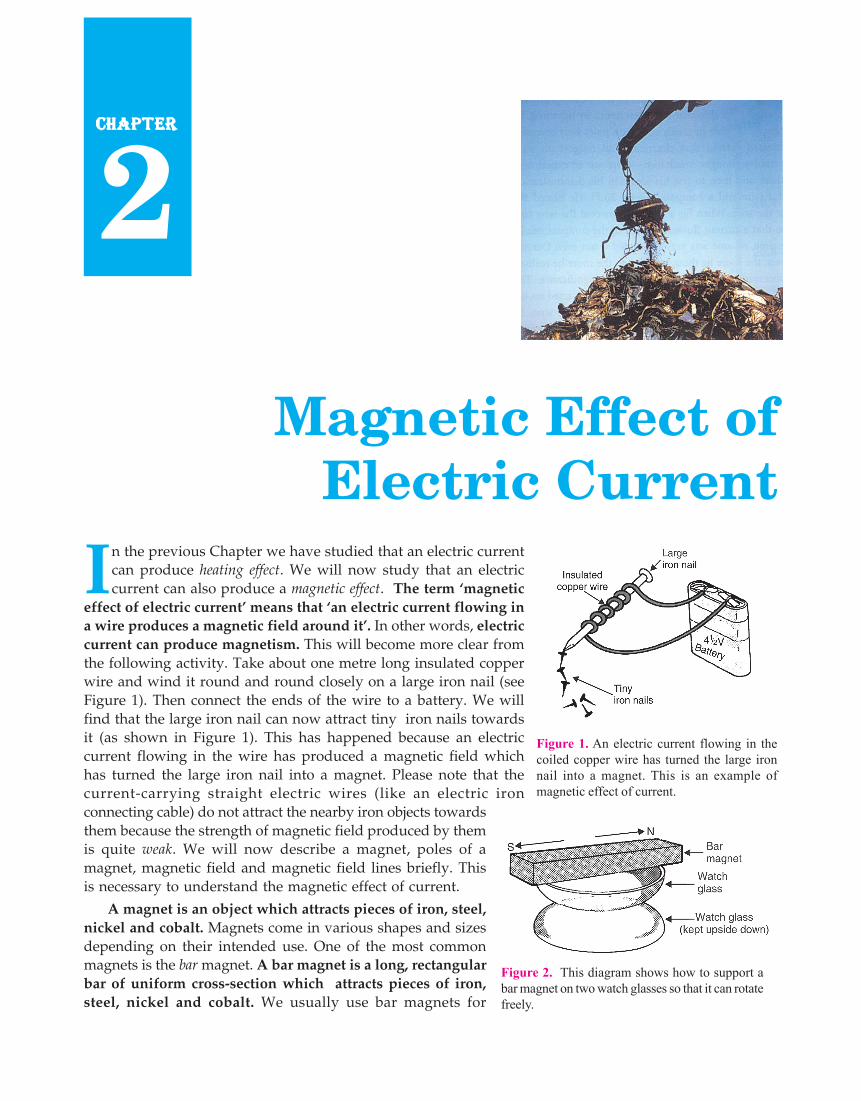
In the previous Chapter we have studied that an electric currentcan produce heating effect. We will now study that an electriccurrent can also produce a magnetic effect. The term ‘magnetic
effect of electric current’ means that ‘an electric current flowing ina wire produces a magnetic field around it’. In other words, electriccurrent can produce magnetism. This will become more clear fromthe following activity. Take about one metre long insulated copperwire and wind it round and round closely on a large iron nail (seeFigure 1). Then connect the ends of the wire to a battery. We willfind that the large iron nail can now attract tiny iron nails towardsit (as shown in Figure 1). This has happened because an electriccurrent flowing in the wire has produced a magnetic field whichhas turned the large iron nail into a magnet. Please note that thecurrent-carrying straight electric wires (like an electric ironconnecting cable) do not attract the nearby iron objects towardsthem because the strength of magnetic field produced by themis quite weak. We will now describe a magnet, poles of amagnet, magnetic field and magnetic field lines briefly. Thisis necessary to understand the magnetic effect of current.
A magnet is an object which attracts pieces of iron, steel,nickel and cobalt. Magnets come in various shapes and sizesdepending on their intended use. One of the most commonmagnets is the bar magnet. A bar magnet is a long, rectangularbar of uniform cross-section which attracts pieces of iron,steel, nickel and cobalt. We usually use bar magnets for
Magnetic Effect ofElectric Current
CHAPTERCHAPTERCHAPTERCHAPTERCHAPTER
2
Figure 1. An electric current flowing in thecoiled copper wire has turned the large ironnail into a magnet. This is an example ofmagnetic effect of current.
Figure 2. This diagram shows how to support abar magnet on two watch glasses so that it can rotatefreely.

MAGNETIC EFFECT OF ELECTRIC CURRENT 69
Figure 3. A magnetic strip inthe refrigerator door is used tokeep it closed properly.
performing practicals in a science laboratory. A magnet has two poles near its ends : north pole and southpole. The end of a freely suspended magnet (or a freely pivoted magnet) which points towards the northdirection is called the north pole of the magnet (see Figure 2). And the end of afreely suspended magnet (or freely pivoted magnet) which points towards thesouth direction is called the south pole of the magnet. It has been found byexperiments that like magnetic poles repel each other whereas unlike magneticpoles attract each other. This means that the north pole of a magnet repels thenorth pole of another magnet and the south pole of a magnet repels the southpole of another magnet; but the north pole of a magnet attracts the south pole ofanother magnet. These days magnets are used for a variety of purposes. Magnetsare used in radio, television, and stereo speakers, in refrigerator doors, on audioand video cassette tapes, on hard discs and floppies for computers, and inchildren’s toys. Magnets are also used in making electric generators and electricmotors. The Magnetic Resonance Imaging (MRI) technique which is used to scaninner human body parts in hospitals also uses magnets for its working.
Magnetic Field
Just as an electric charge creates an electric field, in the same way, a magnetcreates a magnetic field around it. The space surrounding a magnet in which magnetic force is exerted, iscalled a magnetic field. A compass needle placed near a magnet gets deflected due to the magnetic forceexerted by the magnet, and the iron filings also cling to the magnet due to magnetic force. The magneticfield pattern due to a bar magnet is shown in Figure 8. The magnetic field has both, magnitude as well asdirection.The direction of magnetic field at a point is the direction of the resultant force acting on ahypothetical north pole placed at that point. The north end of the needle of a compass indicates thedirection of magnetic field at a point where it is placed.
Magnetic Field LinesA magnetic field is described by drawing the magnetic field lines. When a small north magnetic pole is
placed in the magnetic field created by a magnet, it will experience a force. And if the north pole is free, itwill move under the influence of magnetic field. The path traced by a north magnetic pole free to moveunder the influence of a magnetic field is called a magnetic field line. In other words, the magnetic fieldlines are the lines drawn in a magnetic field along which a north magnetic pole would move. The magneticfield lines are also known as magnetic lines of force. The direction of a magnetic field line at any point givesthe direction of the magnetic force on a north pole placed at that point. Since the direction of magnetic fieldline is the direction of force on a north pole, so the magnetic field lines always begin from the N-pole ofa magnet and end on the S-pole of the magnet (see Figure 8). Inside the magnet, however, the direction ofmagnetic field lines is from the S-pole of the magnet to the N-pole of the magnet. Thus, the magnetic fieldlines are closed curves. The magnetic field lines due to a bar magnet are shown in Figure 8. When a smallcompass is moved along a magnetic field line, the compass needle always sets itself along the line tangentialto it. So, a line drawn from the south pole of the compass needle to its north pole indicates the direction ofthe magnetic field at that point. We will now describe how the magnetic field lines (or magnetic field)produced by a bar magnet can be plotted on paper.
1. To Plot the Magnetic Field Pattern Due to a Bar Magnet by Using Iron Filings
Place a card (thick, stiff paper) over a strong bar magnet (as shown in Figure 4). Sprinkle a thin layer ofiron filings over the card with the help of a sprinkler, and then tap the card gently. The iron filings arrangethemselves in a regular pattern as shown in Figure 5. This arrangement of iron filings gives us a roughpicture of the pattern of magnetic field produced by a bar magnet. This happens as follows : The barmagnet exerts a magnetic field all around it. The iron filings experience the force of magnetic field of the
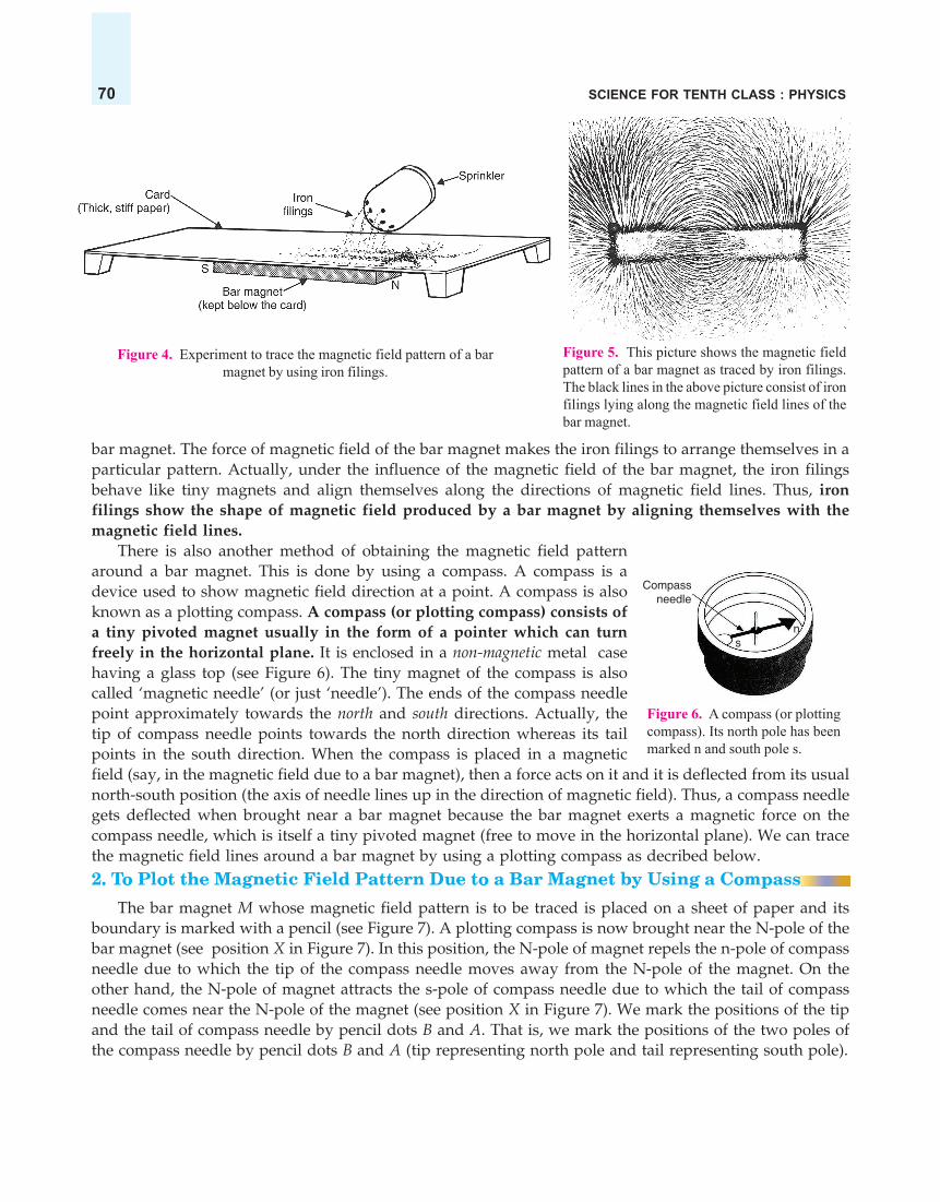
SCIENCE FOR TENTH CLASS : PHYSICS70
Figure 4. Experiment to trace the magnetic field pattern of a barmagnet by using iron filings.
Compassneedle
Figure 6. A compass (or plottingcompass). Its north pole has beenmarked n and south pole s.
s n
Figure 5. This picture shows the magnetic fieldpattern of a bar magnet as traced by iron filings.The black lines in the above picture consist of ironfilings lying along the magnetic field lines of thebar magnet.
bar magnet. The force of magnetic field of the bar magnet makes the iron filings to arrange themselves in aparticular pattern. Actually, under the influence of the magnetic field of the bar magnet, the iron filingsbehave like tiny magnets and align themselves along the directions of magnetic field lines. Thus, ironfilings show the shape of magnetic field produced by a bar magnet by aligning themselves with themagnetic field lines.
There is also another method of obtaining the magnetic field patternaround a bar magnet. This is done by using a compass. A compass is adevice used to show magnetic field direction at a point. A compass is alsoknown as a plotting compass. A compass (or plotting compass) consists ofa tiny pivoted magnet usually in the form of a pointer which can turnfreely in the horizontal plane. It is enclosed in a non-magnetic metal casehaving a glass top (see Figure 6). The tiny magnet of the compass is alsocalled ‘magnetic needle’ (or just ‘needle’). The ends of the compass needlepoint approximately towards the north and south directions. Actually, thetip of compass needle points towards the north direction whereas its tailpoints in the south direction. When the compass is placed in a magneticfield (say, in the magnetic field due to a bar magnet), then a force acts on it and it is deflected from its usualnorth-south position (the axis of needle lines up in the direction of magnetic field). Thus, a compass needlegets deflected when brought near a bar magnet because the bar magnet exerts a magnetic force on thecompass needle, which is itself a tiny pivoted magnet (free to move in the horizontal plane). We can tracethe magnetic field lines around a bar magnet by using a plotting compass as decribed below.2. To Plot the Magnetic Field Pattern Due to a Bar Magnet by Using a Compass
The bar magnet M whose magnetic field pattern is to be traced is placed on a sheet of paper and itsboundary is marked with a pencil (see Figure 7). A plotting compass is now brought near the N-pole of thebar magnet (see position X in Figure 7). In this position, the N-pole of magnet repels the n-pole of compassneedle due to which the tip of the compass needle moves away from the N-pole of the magnet. On theother hand, the N-pole of magnet attracts the s-pole of compass needle due to which the tail of compassneedle comes near the N-pole of the magnet (see position X in Figure 7). We mark the positions of the tipand the tail of compass needle by pencil dots B and A. That is, we mark the positions of the two poles ofthe compass needle by pencil dots B and A (tip representing north pole and tail representing south pole).

MAGNETIC EFFECT OF ELECTRIC CURRENT 71
A
B
C
D
EF
L
K
J
I
HG
X
Y
M
N S
A�
B�
C�
D�
E�
F� G�
H�
I�
J�
K�
L�Bar magnet
Plottingcompass
ns
Magnetic field line obtained byjoining various positions of northpole of plotting compass
Figure 7. To draw the magnetic field pattern (or magnetic field lines) due to a barmagnet by using a plotting compass.
We now move the compass to position Y so that the tail of compass needle (or south pole) points at dotB (previously occupied by n-pole of compass needle). We mark a dot C at the tip of the compass needle toshow the position of its north pole. In this manner we go on step by step till we reach the south pole of themagnet. By doing this we get the various dots A, B, C, D, E, F, G, H, I, J, K and L, all denoting the path inwhich the north pole of the compass needle moves. By joining the various dots, we get a smooth curverepresenting a magnetic field line, which begins on the north pole of the bar magnet and ends on its southpole (see Figure 7). We can draw a large number of lines of force in the same way by starting from differentpoints near the magnet. Every line is labelled with an arrow to indicate its direction. In this way we willget the complete pattern of the magnetic field around a bar magnet.
The magnetic field pattern around a bar magnet is shown in Figure 8. This has been traced by using aplotting compass. The magnetic field lines leave thenorth pole of a magnet and enter its south pole (asshown in Figure 8). In other words, each magnetic fieldline is directed from the north pole of a magnet to itssouth pole. Each field line indicates, at every point onit, the direction of magnetic force that would act on anorth pole if it were placed at that point. The strengthof magnetic field is indicated by the degree ofcloseness of the field lines. Where the field lines areclosest together, the magnetic field is the strongest. Forexample, the field lines are closest together at the twopoles of the bar magnet, so the magnetic field is thestrongest at the poles. Please note that no two magneticfield lines are found to cross each other. If two field linescrossed each other, it would mean that at the point ofintersection, the compass needle would point in twodirections at the same time, which is not possible. Itshould be noted that we have drawn the magnetic lines
N SBar magnet
Magnetic fieldlines
Figure 8. The magnetic field pattern (or magnetic fieldlines) produced by a bar magnet (These have been traced
by using a plotting compass).

SCIENCE FOR TENTH CLASS : PHYSICS72
Figure 9. The earth’s magnetism is due to an imaginary bar magnetburied at its centre. The S pole of earth’s magnet is towards its north;and the N pole of earth’s magnet is towards its south.
of force only in one plane around the magnet. Actually, the magnetic field and hence the magnetic linesof force exist in all the planes all round the magnet.
Properties (or Characteristics) of the Magnetic Field Lines
1. The magnetic field lines originate from the north pole of a magnet and end at its south pole.
2. The magnetic field lines come closer to one another near the poles of a magnet but they are widelyseparated at other places. A north magnetic pole experiences a stronger force when it approaches one ofthe poles of the magnet. This means that the magnetic field is stronger near the poles. From this we concludethat where magnetic field lines are closer together, it indicates a stronger magnetic field. On the otherhand, when magnetic field lines are widely separated, then it indicates a weak magnetic field.
3. The magnetic field lines do not intersect (or cross) one another. This is due to the fact that theresultant force on a north pole at any point can be only in one direction. But if the two magnetic field linesintersect one another, then the resultant force on a north pole placed at the point of intersection will bealong two directions, which is not possible.
Magnetic Field of Earth
A freely suspended magnet always points in the north-south direction even in the absence of any othermagnet. This suggests that the earth itself behaves as a magnet which causes a freely suspended magnet(or magnetic needle) to point always in aparticular direction : north and south. Theshape of the earth’s magnetic fieldresembles that of an imaginary bar magnetof length one-fifth of earth’s diameter buriedat its centre (see Figure 9).
The south pole of earth’s magnet is inthe geographical north because it attracts thenorth pole of the suspended magnet.Similarly, the north pole of earth’s magnetis in the geographical south because itattracts the south pole of the suspendedmagnet. Thus, there is a magnetic S-pole nearthe geographical north, and a magnetic N-pole near the geographical south. Thepositions of the earth’s magnetic poles arenot well defined on the globe, they arespread over an area. The axis of earth’smagnet and the geographical axis do notcoincide with each other. The axis of earth’smagnetic field is inclined at an angle ofabout 15° with the geographical axis. Due to this a freely suspended magnet (or magnetic needle) makesan angle of about 15° with the geographical axis and points only approximately in the north-south directionsat a place. In other words, a freely suspended magnet does not show exact geographical north and southbecause the magnetic axis and geographical axis of the earth do not coincide. It is now believed that theearth’s magnetism is due to the magnetic effect of current (which is flowing in the liquid core at thecentre of the earth). Thus, earth is a huge electromagnet. Before we go further and discuss the magneticeffect of current in detail, please answer the following questions :

MAGNETIC EFFECT OF ELECTRIC CURRENT 73
Very Short Answer Type Questions
1. State any two properties of magnetic field lines.2. What are the two ways in which you can trace the magnetic field pattern of a bar magnet ?3. You are given the magnetic field pattern of a magnet. How will you find out from it where the magnetic
field is the strongest ?4. State whether the following statement is true or false :
The axis of earth’s imaginary magnet and the geographical axis coincide with each other.5. Why does a compass needle get deflected when brought near a bar magnet ?6. Where do the manufacturers use a magnetic strip in the refrigerator ? Why is this magnetic strip used ?7. Fill in the following blanks with suitable words :
(a) Magnetic field lines leave the..........pole of a bar magnet and enter at its........pole.(b) The earth’s magnetic field is rather like that of a ......... magnet with its........pole in the northern hemisphere.
Short Answer Type Questions8. Draw a diagram to show the magnetic field lines around a bar magnet.9. What is a magnetic field ? How can the direction of magnetic field lines at a place be determined ?
10. Explain why, two magnetic field lines do not intersect each other.11. When an electric current is passed through any wire, a magnetic field is produced around it. Then why an
electric iron connecting cable does not attract nearby iron objects when electric current is switched on throughit ?
Long Answer Type Question12. (a) Define magnetic field lines. Describe an activity to draw a magnetic field line outside a bar magnet from
one pole to another pole.(b) Explain why, a freely suspended magnet always points in the north-south direction.
Multiple Choice Questions (MCQs)
13. A strong bar magnet is placed vertically above a horizontal wooden board. The magnetic lines of force willbe :(a) only in horizontal plane around the magnet(b) only in vertical plane around the magnet(c) in horizontal as well as in vertical planes around the magnet(d) in all the planes around the magnet
14. The magnetic field lines produced by a bar magnet :(a) originate from the south pole and end at its north pole(b) originate from the north pole and end at its east pole(c) originate from the north pole and end at its south pole(d) originate from the south pole and end at its west pole
15. Which of the following is not attracted by a magnet ?(a) steel (b) cobalt (c) brass (d) nickel
16. The magnetic field lines :(a) intersect at right angles to one another(b) intersect at an angle of 45° to each other(c) do not cross one another(d) cross at an angle of 60° to one another
17. The north pole of earth’s magnet is in the :(a) geographical south (b) geographical east(c) geographical west (d) geographical north
18. The axis of earth’s magnetic field is inclined with the geographical axis at an angle of about :(a) 5° (b) 15° (c) 25° (d) 35°

SCIENCE FOR TENTH CLASS : PHYSICS74
19. The shape of the earth’s magnetic field resembles that of an imaginary :(a) U-shaped magnet (b) Straight conductor carrying current(c) Current-carrying circular coil (d) Bar magnet
20. A magnet attracts :(a) plastics (b) any metal (c) aluminium (d) iron and steel
21. A plotting compass is placed near the south pole of a bar magnet. The pointer of plotting compass will :(a) point away from the south pole (b) point parallel to the south pole(c) point towards the south pole (d) point at right angles to the south pole
22. The metallic pointer of a plotting compass gets deflected only when it is placed near a bar magnet becausethe pointer has :(a) electromagnetism (b) permanent magnetism(c) induced magnetism (d) ferromagnetism
23. Which of the following statements is incorrect regarding magnetic field lines ?(a) The direction of magnetic field at a point is taken to be the direction in which the north pole of a magnetic
compass needle points.(b) Magnetic field lines are closed curves(c) If magnetic field lines are parallel and equidistant, they represent zero field strength(d) Relative strength of magnetic field is shown by the degree of closeness of the field lines
Questions Based on High Order Thinking Skills (HOTS)24. Copy the figure given below which shows a plotting compass and a magnet. Label the N pole of the magnet
and draw the field line on which the compass lies.
25. (a) The diagram shows a bar magnet surrounded by four plotting compasses. Copy the diagram and markin it the direction of the compass needle for each of the cases B, C and D.
B
A
DC
X Y
(b) Which is the north pole, X or Y ?26. The three diagrams in the following figure show the lines of force (field lines) between the poles of two
magnets. Identify the poles A, B, C, D, E and F.
B C D FEA
27. The figure given below shows the magnetic field between two magnets :
Magnet 1 Magnet 2
N

MAGNETIC EFFECT OF ELECTRIC CURRENT 75
(i) Copy the diagram and label the other poles of the magnets.(ii) Which is the weaker magnet ?
ANSWERS4. False 7. (a) north ; south (b) bar ; south 13. (d) 14. (c) 15. (c) 16. (c) 17. (a) 18. (b)19. (d) 20. (d) 21. (c) 22. (b) 23. (c)
24.
N S
25(a)
B
A
DC
X Y
(b) X
26. A = N ; B = N ; C = S, D = S ; E = N, F = S 27. (i) S—N ; N—S (ii) Magnet 2
MAGNETIC EFFECT OF CURRENT (OR ELECTROMAGNETISM)The magnetic effect of current was discovered by Oersted in 1820. Oersted found that a wire carrying a
current was able to deflect a compass needle. Now, the compass needle is a tiny magnet which can bedeflected only by a magnetic field. Since a current carrying wire was able to deflect a compass needle, itwas concluded that a current flowing in a wire always gives rise to a magnetic field around it. Theimportance of magnetic effect of current lies in the fact that it gives rise to mechanical forces. The electricmotor, electric generator, telephone and radio, all utilize the magnetic effect of current. The magnetic effectof current is also called electromagnetism which means electricity produces magnetism.Experiment to Demonstrate the Magnetic Effect of Current
We will now describe Oersted’s experiment to show that a current carrying wire produces a magneticfield around it. We take a thick insulated copper wire and fix it in such a way that the portion AB of thewire is in the north-south direction as shown in Figure 10(a). A plotting compass M is placed under thewire AB. The two ends of the wire are connected to a battery through a switch. When no current is flowingin the wire AB, the compass needle is parallel to the wire AB and points in the usual north-south direction[Figure 10(a)].
NorthA
BSouth
Cur
rent+
–
NorthA
BSouth
N
M
S
Switch
Plottingcompass
N
M
S Compassneedle getsdeflected
+
–
(a) (b)Figure 10. Experiment to show that an electric current produces a magnetic effect.
Let us pass the electric current through wire AB by pressing the switch. On passing the current we findthat compass needle is deflected from its north-south position as shown in Figure 10(b). And when thecurrent is switched off, the compass needle returns to its original position. We know that a freely pivotedcompass needle always sets itself in the north-south direction. It deflects from its usual north-south directiononly when it is acted upon by another magnetic field. So, the deflection of compass needle by the current-carrying wire in the above experiment shows that an electric current produces a magnetic field aroundit. It is this magnetic field which deflects the compass needle placed near the current-carrying wire.

SCIENCE FOR TENTH CLASS : PHYSICS76
If we reverse the direction of electric current flowing in the wire AB by reversing the battery connections,we will find that the compass needle is deflected in the opposite direction. This shows that when we reversethe direction of electric current flowing in the wire, then the direction of magnetic field produced by it isalso reversed.
A concealed current-carrying conductor can be located due to the magnetic effect of current by usinga plotting compass. For example, if a plotting compass is moved on a wall, its needle will show deflectionat the place where current-carrying wire is concealed.
Magnetic Field Patterns Produced by Current-Carrying Conductors HavingDifferent Shapes
The pattern of magnetic field (or shape of magnetic field lines) produced by a current-carrying conductordepends on its shape. Different magnetic field patterns are produced by current-carrying conductors havingdifferent shapes. We will now study the magnetic field patterns produced by :
(i) a straight conductor (or straight wire) carrying current,(ii) a circular loop (or circular wire) carrying current, and
(iii) a solenoid (long coil of wire) carrying current.
We will discuss all these cases, one by one. Let us start with the straight current-carrying conductor.
1. Magnetic Field Pattern due to Straight Current-Carrying Conductor (Straight Current-Carrying Wire)
The magnetic field lines around a straight conductor (straight wire)carrying current are concentric circles whose centres lie on the wire (Figure11). In Figure 11, we have a straight vertical wire (or conductor) AB whichpasses through a horizontal cardboard sheet C. The ends of the wire AB areconnected to a battery through a switch. When current is passed throughwire AB, it produces a magnetic field around it. This magnetic field hasmagnetic field lines around the wire AB which can be shown by sprinklingiron filings on the cardboard C. The iron filings get magnetised. And ontapping the cardboard sheet, the iron filings arrange themselves in circlesaround the wire showing that the magnetic field lines are circular in nature.A small plotting compass M placed on the cardboard indicates the directionof the magnetic field. When current in the wire flows in the upward direction(as shown in Figure 11), then the lines of magnetic field are in theanticlockwise direction. If the direction of current in the wire is reversed, thedirection of magnetic field lines also gets reversed.
It has been shown by experiments that the magnitude of magnetic field produced by a straight current-carrying wire at a given point is : (i) directly proportional to the current passing in the wire, and(ii) inversely proportional to the distance of that point from the wire. So, greater the current in the wire,stronger will be the magnetic field produced. And greater the distance of a point from the current-carryingwire, weaker will be the magnetic field produced at that point. In fact, as we move away from a current-carrying straight wire, the concentric circles around it representing magnetic field lines, become larger andlarger indicating the decreasing strength of the magnetic field.
Direction of Magnetic Field Produced by Straight Current-Carrying Conductor(Straight Current-Carrying Wire)
If the direction of current is known, then the direction of magnetic field produced by a straight wirecarrying current can be obtained by using Maxwell’s right-hand thumb rule. According to Maxwell’s right-hand thumb rule : Imagine that you are grasping (or holding) the current-carrying wire in your right
Current(Upwards)
Magneticfield lines(Anticlockwise)
–
+
B
C
A
M
(•)
Figure 11. Magnetic fieldpattern due to a straightcurrent-carrying wire.

MAGNETIC EFFECT OF ELECTRIC CURRENT 77
Direction ofmagneticfield
Directionof current
Straight wirecarrying current Right
hand
B
A
Figure 12. Right-handthumb rule to find the
direction of magnetic field.
Direction ofmagneticfield
Directionofcurrent
Figure 13. Maxwell’scorkscrew rule to find the
direction of magnetic field.
hand so that your thumb points in the direction of current, then the directionin which your fingers encircle the wire will give the direction of magnetic fieldlines around the wire. Figure 12 shows a straight current-carrying wire AB inwhich the current is flowing vertically upwards from A to B. To find out thedirection of magnetic field lines produced by this current, we imagine the wireAB to be held in our right hand as shown in Figure 12 so that our thumb points inthe direction of current towards B. Now, the direction in which our fingers arefolded gives the direction of magnetic field lines. In this case our fingers are foldedin the anticlockwise direction, so the direction of magnetic field(or magnetic field lines) is also in the anticlockwise direction (asshown by the circle drawn at the top of the wire).
Maxwell’s right-hand thumb rule is also known as Maxwell’scorkscrew rule (Corkscrew is a device for pulling corks frombottles, and consists of a spiral metal rod and a handle). Accordingto Maxwell’s corkscrew rule : Imagine driving a corkscrew in the direction of current,then the direction in which we turn its handle is the direction of magnetic field (ormagnetic field lines). The corkscrew rule is illustrated in Figure 13. In Figure 13,the direction of current is vertically downwards. Now, if we imagine drivingthe corkscrew downwards in the direction of current, then the handle ofcorkscrew is to be turned in the clockwise direction. So, the direction of magneticfield (or magnetic field lines) will also be in the clockwise direction. Thisexample is opposite to the one we considered in right-hand thumb rule givenabove. Thus, when electric current flows vertically upwards the direction ofmagnetic field produced is anticlockwise. On the other hand, when electriccurrent flows vertically downwards then the direction of magnetic field isclockwise.
2. Magnetic Field Pattern due to a Circular Loop (or Circular Wire) Carrying Current
We know that when current is passed through a straight wire, a magnetic field is produced around it.It has been found that the magnetic effect of current increases ifinstead of using a straight wire, the wire is converted into a circularloop (as shown in Figure 14). In Figure 14, a circular loop (or circularwire) is fixed to a thin cardboard sheet T. When a current is passedthrough the circular loop of wire, a magnetic field is producedaround it. The pattern of magnetic field due to a current-carryingcircular loop (or circular wire) is shown in Figure 14. The magneticfield lines are circular near the current-carrying loop. As we moveaway, the concentric circles representing magnetic field lines becomebigger and bigger. At the centre of the circular loop, the magneticfield lines are straight (see point M in Figure 14). By applying right-hand thumb rule, it can be seen that each segment of circular loopcarrying current produces magnetic field lines in the same directionwithin the loop. At the centre of the circular loop, all the magneticfield lines are in the same direction and aid each other, due to whichthe strength of magnetic field increases.
The magnitude of magnetic field produced by a current-carrying circular loop (or circularwire) at its centre is :
(i) directly proportional to the current passing through the circular loop (or circularwire), and
C
Circularcurrent
M
Magneticfield lines
ti
–
T
Circular loopof wirecarryingcurrent
+
Figure 14. Magnetic field lines due tocircular loop (or circular wire) carrying
current.

SCIENCE FOR TENTH CLASS : PHYSICS78
(ii) inversely proportional to the radius of circular loop (or circular wire).
In this discussion we have considered the magnetic field produced by a circular loop (or circular wire)which consists of only ‘one turn’ of the wire. The strength of magnetic field can be increased by taking acircular coil consisting of a number of turns of insulated copper wire closely wound together. Thus, if thereis a circular coil having n turns, the magnetic field produced by this current-carrying circular coil will ben times as large as that produced by a circular loop of a single turn of wire. This is because the current ineach circular turn of coil flows in the same direction and magnetic field produced by each turn of circularcoil then just adds up. We can now say that : The strength of magnetic field produced by a circular coilcarrying current is directly proportional to both, number of turns (n) and current (I); but inverselyproportional to its radius (r). Thus, the strength of magnetic field produced by a current-carrying circularcoil can be increased : (i) by increasing the number of turns of wire in the coil, (ii) by increasing the currentflowing through the coil, and (iii) by decreasing the radius of the coil.
Clock Face Rule
A current-carrying circular wire (or loop) behaves like a thin disc magnet whose one face is a northpole and the other face is a south pole. The polarity (north or south) of the two faces of a current-carryingcircular coil (or loop) can be determined by using the clock face rule given below.
According to Clock face rule, look at one face of a circular wire (or coil) through which a current ispassing :
(i) if the current around the face of circular wire (or coil) flows in the Clockwise direction, then that faceof the circular wire (or coil) will be South pole (S-pole).
(ii) if the current around the face of circular wire (or coil) flows in the Anticlockwise direction, then thatface of circular wire (or coil) will be a North pole (N-pole)
For example, in Figure 15(a), the current in a face of the circular wire is flowing in the Clockwisedirection, so this face of current-carrying circular wire will behave as a South magnetic pole (or S-pole). Onthe other hand, in Figure 15(b) the current in the face of the circular wire is flowing in the Anticlockwisedirection, so this face of current-carrying circular wire will behave as a North magnetic pole (or N-pole).
Currentclockwise
Southmagneticpole
Northmagneticpole
Currentanticlockwise
(a) The direction of current (b) The direction of current in thisin this face of circular wire face of circular wire is Anticlockwise,is Clockwise, so this face of so this face of circular wire carrying
circular wire carrying current current will act as a North magneticwill act as a South magnetic pole (or N-pole)
pole (S-pole)Figure 15.
Please note that if the direction of current in the front face of a circular wire is clockwise, then thedirection of current in the back face of this circular wire will be anticlockwise (and vice versa). Thismeans that the front face of this current-carrying circular wire will be a south pole but its back face will bea north pole. For example, the direction of current in the front face of current-carrying circular wire shownin Figure 14 is clockwise, so the front face of this current-carrying circular wire will be a south magneticpole (S-pole). If, however, we view the current-carrying circular wire given in Figure 14 from back side, wewill find that the direction of current flowing in the back face of this circular wire is anticlockwise. Due tothis, the back face of this current-carrying circular wire will be a North magnetic pole (N-pole). The Clock

MAGNETIC EFFECT OF ELECTRIC CURRENT 79
S N
BX
Solenoid
Magneticfield lines
–+
Figure 16. Magnetic field due to a currentcarrying solenoid is similar to that of a bar
magnet.
face rule is also used in determining the polarities of the two faces (or two ends) of a current-carryingsolenoid as well as an electromagnet.
3. Magnetic Field due to a Solenoid
The solenoid is a long coil containing a large number of closeturns of insulated copper wire. Figure 16 shows a solenoid SNwhose two ends are connected to a battery B through a switch X.When an electric current is passed through the solenoid, it producesa magnetic field around it. The magnetic field produced by a currentcarrying solenoid is shown in Figure 16. The magnetic fieldproduced by a current-carrying solenoid is similar to the magneticfield produced by a bar magnet. Please note that the lines ofmagnetic field pass through the solenoid and return to the otherend as shown in Figure 16. The magnetic field lines inside thesolenoid are in the form of parallel straight lines. This indicates thatthe strength of magnetic field is the same at all the points insidethe solenoid. If the strength of magnetic field is just the same in aregion, it is said to be uniform magnetic field. Thus, the magneticfield is uniform inside a current-carrying solenoid. The uniformmagnetic field inside the current-carrying solenoid has beenrepresented by drawing parallel straight field lines (see Figure 16). Even the earth’s magnetic field at agiven place is uniform which consists of parallel straight field lines (which run roughly from southgeographical pole to north geographical pole).
One end of the current-carrying solenoid acts like a north-pole (N-pole) and the other end a south pole(S-pole). So, if a current-carrying solenoid is suspended freely, it will come to rest pointing in the north andsouth directions (just like a freely suspended bar magnet). We can determine the north and south poles ofa current-carrying solenoid by using a bar magnet. This can be done as follows : We bring the north pole ofa bar magnet near both the ends of a current-carrying solenoid. The end of solenoid which will be repelledby the north pole of bar magnet will be its north pole, and the end of solenoid which will be attracted bythe north pole of bar magnet will be its south pole.
The current in each turn of a current-carrying solenoid flows in the same direction due to which themagnetic field produced by each turn of the solenoid adds up, giving a strong magnetic field inside thesolenoid. The strong magnetic field produced inside a current-carrying solenoid can be used to magnetisea piece of magnetic material like soft iron, when placed inside the solenoid. The magnet thus formed iscalled an electromagnet. So, a solenoid is used for making electromagnets.
The strength of magnetic field produced by a current carrying solenoid depends on :(i) The number of turns in the solenoid. Larger the number of turns in the solenoid,
greater will be the magnetism produced.(ii) The strength of current in the solenoid. Larger the current passed through solenoid,
stronger will be the magnetic field produced.(iii) The nature of “core material” used in making solenoid. The use of soft iron rod as
core in a solenoid produces the strongest magnetism.
ElectromagnetAn electric current can be used for making temporary magnets known as electromagnets. An
electromagnet works on the magnetic effect of current. Let us discuss it in detail. We have just studiedthat when current is passed through a long coil called solenoid, a magnetic field is produced. It has been

SCIENCE FOR TENTH CLASS : PHYSICS80
found that if a soft iron rod called core is placed inside a solenoid, thenthe strength of magnetic field becomes very large because the iron coregets magnetised by induction. This combination of a solenoid and a softiron core is called an electromagnet. Thus, An electromagnet is a magnetconsisting of a long coil of insulated copper wire wrapped around asoft iron core that is magnetised only when electric current is passedthrough the coil. A simple electromagnet is shown in Figure 17. To makean electromagnet all that we have to do is to take a rod NS of soft ironand wind a coil C of insulated copper wire round it. When the two endsof the copper coil are connected to a battery, an electromagnet is formed(see Figure 17).
It should be noted that the solenoid containing soft iron core in it acts as a magnet only as long as thecurrent is flowing in the solenoid. If we switch off the current in the solenoid, it no more behaves as amagnet. All the magnetism of the soft iron core disappears as soon as the current in the coil is switched off.A very important point to be noted is that it is the iron piece inside the coil which becomes a strongelectromagnet on passing the current. The core of an electromagnet must be of soft iron because soft ironloses all of its magnetism when current in the coil is switched off. On the other hand, if steel is used formaking the core of an electromagnet, the steel does not lose all its magnetism when the current is stoppedand it becomes a permanent magnet. This is why steel is not used for making electromagnets.Electromagnets can be made in different shapes and sizes depending on the purpose for which they are tobe used.
Factors Affecting the Strength of an Electromagnet. The strength of an electromagnet depends on :
(i) The number of turns in the coil. If we increase the number of turns in the coil, the strength ofelectromagnet increases.
(ii) The current flowing in the coil. If the current in the coil is increased, the strength of electromagnetincreases.
(iii) The length of air gap between its poles. If we reduce the lengthof air gap between the poles of an electromagnet, then its strengthincreases. For example, the air gap between the poles of a straight, bartype electromagnet is quite large, so a bar type electromagnet is not verystrong. On the other hand, the air gap between the poles of a U-shapedelectromagnet is small, so it is a very strong electromagnet (see Figure18).
It should be noted that in many respects an electromagnet is betterthan a permanent magnet because it can produce very strong magneticfields and its strength can be controlled by varying the number of turnsin its coil or by changing the current flowing through the coil.
We can determine the polarity of electromagnet shown in Figure 17by using the clock face rule. If we view the electromagnet from its leftend, we will see that the direction of current flowing in the coil isanticlockwise. So, the left end of this electromagnet will be North pole (N-pole). And if we view theelectromagnet given in Figure 17 from its right end, we will see that the direction of current in its coil isclockwise. So, the right side end of this electromagnet is a South pole (S-pole). Some uses of electromagnetsare shown in Figures 19 and 20.
+ –
N S
C
Soft ironcore
Coil of insulatedcopper wire
Figure 17. Electromagnet.
Figure 18. This is a U-shapedelectromagnet with iron nails stickingto its two poles.

MAGNETIC EFFECT OF ELECTRIC CURRENT 81
S N
Magneticfield lines
The uniform magnetic field inside acurrent-carrying solenoid.
Figure 19. In hospitals, doctors use an electromagnet Figure 20. This is a Maglev train (Magnetic leviation train) to remove particles of iron or steel from a which does not need wheels. It floats above its track by
patient’s eye. strong magnetic forces produced by computer-controlledelectromagnets.
Differences Between a Bar Magnet (or Permanent Magnet) and an Electromagnet
Bar magnet (or Permanent magnet) Electromagnet
1. The bar magnet is a permanent magnet. 1. An electromagnet is a temporary magnet. Its magnetismis only for the duration of current passing through it.So, the magnetism of an electromagnet can be switchedon or switched off as desired.
2. A permanent magnet produces a 2. An electromagnet can produce very strong magneticcomparatively weak force of attraction. force.
3. The strength of a permanent magnet 3. The strength of an electromagnet can be changedcannot be changed. by changing the number of turns in its coil or
by changing the current passing through it.
4. The (north-south) polarity of a permanent 4. The polarity of an electromagnet can be changed bymagnet is fixed and cannot be changed. changing the direction of current in its coil.
Permanent magnets are usually made of alloys such as : Carbon steel, Chromium steel, Cobalt steel,Tungsten steel, and Alnico (Alnico is an alloy of aluminium, nickel, cobalt and iron). Permanent magnets ofthese alloys are much more strong than those made of ordinary steel. Such strong permanent magnets areused in microphones, loudspeakers, electric clocks, ammeters, voltmeters, speedometers, and many otherdevices. Let us solve one problem now.
Sample Problem. The magnetic field in a given region is uniform. Draw a diagram to represent it.(NCERT Book Question)
Answer. A uniform magnetic field in a region is representedby drawing equidistant, parallel straight lines, all pointing in thesame direction. For example, the uniform magnetic field whichexists inside a current-carrying solenoid can be represented byparallel straight lines pointing from its S-pole to N-pole (as shownin Figure alongside).
We are now in a position to answer the following questions :
Very Short Answer Type Questions1. Which effect of current can be utilised in detecting a current-
carrying wire concealed in a wall ?2. What conclusion do you get from the observation that a current-carrying wire deflects a compass needle
placed near it ?

SCIENCE FOR TENTH CLASS : PHYSICS82
3. Name the scientist who discovered the magnetic effect of current.4. State qualitatively the effect of inserting an iron core into a current-carrying solenoid.5. Name the rule for finding the direction of magnetic field produced by a straight current-carrying conductor.6. State the form of magnetic field lines around a straight current-carrying conductor.7. What is the other name of Maxwell’s right-hand thumb rule ?8. State whether the following statement is true or false :
The magnetic field inside a long circular coil carrying current will be parallel straight lines.9. What is the shape of a current-carrying conductor whose magnetic field pattern resembles that of a bar
magnet ?10. State three ways in which the strength of an electromagnet can be increased.11. Fill in the following blanks with suitable words :
(a) The lines of..............round a straight current-carrying conductor are in the shape of.............(b) For a current-carrying solenoid, the magnetic field is like that of a...............(c) The magnetic effect of a coil can be increased by increasing the number of.............., increasing the .............,
or inserting an..............core.(d) If a coil is viewed from one end and the current flows in an anticlockwise direction, then this end is
a.........pole.(e) If a coil is viewed from one end, and the current flows in a clockwise direction, then this end is a ..... pole.
Short Answer Type Questions12. Describe how you will locate a current-carrying wire concealed in a wall.13. Describe some experiment to show that the magnetic field is associated with an electric current.14. (a) Draw a sketch to show the magnetic lines of force due to a current-carrying straight conductor.
(b) Name and state the rule to determine the direction of magnetic field around a straight current-carryingconductor.
15. State and explain Maxwell’s right-hand thumb rule.16. What is Maxwell’s corkscrew rule ? For what purpose is it used ?17. (a) Draw the magnetic lines of force due to a circular wire carrying current.
(b) What are the various ways in which the strength of magnetic field produced by a current-carrying circularcoil can be increased ?
18. State and explain the Clock face rule for determining the polarities of a circular wire carrying current.19. Name any two factors on which the strength of magnetic field produced by a current-carrying solenoid
depends. How does it depend on these factors ?20. (a) Draw a circuit diagram to show how a soft iron piece can be transformed into an electromagnet.
(b) Describe how an electromagnet could be used to separate copper from iron in a scrap yard.21. (a) How does an electromagnet differ from a permanent magnet ?
(b) Name two devices in which electromagnets are used and two devices where permanent magnets areused.
Long Answer Type Questions22. (a) What is a solenoid ? Draw a sketch to show the magnetic field pattern produced by a current-carrying
solenoid.(b) Name the type of magnet with which the magnetic field pattern of a current-carrying solenoid resembles.(c) What is the shape of field lines inside a current-carrying solenoid ? What does the pattern of field lines
inside a current-carrying solenoid indicate ?(d) List three ways in which the magnetic field strength of a current-carrying solenoid can be increased ?(e) What type of core should be put inside a current-carrying solenoid to make an electromagnet ?
23. (a) What is an electromagnet ? Describe the construction and working of an electromagnet with the help ofa labelled diagram.
(b) Explain why, an electromagnet is called a temporary magnet.(c) Explain why, the core of an electromagnet should be of soft iron and not of steel.

MAGNETIC EFFECT OF ELECTRIC CURRENT 83
(d) State the factors on which the strength of an electromagnet depends. How does it depend on these factors ?(e) Write some of the important uses of electromagnets.
Multiple Choice Questions (MCQs)24. The strength of the magnetic field between the poles of an electromagnet would be unchanged if :
(a) current in the electromagnet winding were doubled(b) direction of current in electromagnet winding were reversed(c) distance between the poles of electromagnet were doubled(d) material of the core of electromagnet were changed
25. The diagram given below represents magnetic field caused by a current-carrying conductor which is :
(a) a long straight wire (b) a circular coil(c) a solenoid (d) a short straight wire
26. The magnetic field inside a long straight solenoid carrying current :(a) is zero(b) decreases as we move towards its end.(c) increases as we move towards its end.(d) is the same at all points.
27. Which of the following correctly describes the magnetic field near a long straight wire ?(a) The field consists of straight lines perpendicular to the wire.(b) The field consists of straight lines parallel to the wire.(c) The field consists of radial lines originating from the wire.(d) The field consists of concentric circles centred on the wire.
28. The north-south polarities of an electromagnet can be found easily by using :(a) Fleming’s right-hand rule (b) Fleming’s left-hand rule(c) Clock face rule (d) Left-hand thumb rule
29. The direction of current in the coil at one end of an electromagnet is clockwise. This end of the electromagnetwill be :(a) north pole (b) east pole (c) south pole (d) west pole
30. If the direction of electric current in a solenoid when viewed from a particular end is anticlockwise, then thisend of solenoid will be :(a) west pole (b) south pole (c) north pole (d) east pole
31. The most suitable material for making the core of an electromagnet is :(a) soft iron (b) brass (c) aluminium (d) steel
32. The magnetic effect of current was discovered by :(a) Maxwell (b) Fleming (c) Oersted (d) Faraday
33. A soft iron bar is inserted inside a current-carrying solenoid. The magnetic field inside the solenoid :(a) will decrease (b) will increase(c) will become zero (d) will remain the same
34. The magnetic field lines in the middle of the current-carrying solenoid are :(a) circles (b) spirals(c) parallel to the axis of the tube (d) perpendicular to the axis of the tube
35. The front face of a circular wire carrying current behaves like a north pole. The direction of current in thisface of the circular wire is :(a) clockwise (b) downwards (c) anticlockwise (d) upwards

SCIENCE FOR TENTH CLASS : PHYSICS84
N
36. The back face of a circular loop of wire is found to be south magnetic pole. The direction of current in thisface of the circular loop of wire will be :(a) towards south (b) clockwise (c) anticlockwise (d) towards north
Questions Based on High Order Thinking Skills (HOTS)37. In the straight wire A, current is flowing in the vertically downward direction whereas in wire B the current
is flowing in the vertically upward direction. What is the direction of magnetic field :(a) in wire A ?(b) in wire B ?Name the rule which you have used to get the answer.
38. The figure shows a solenoid wound on a core of soft iron. Will the end A be a N pole or S pole when thecurrent flows in the direction shown ?
39. A current-carrying straight wire is held in exactly vertical position. If the current passes through this wire inthe vertically upward direction, what is the direction of magnetic field produced by it ? Name the rule usedto find out the direction of magnetic field.
40. For the coil in the diagram below, when the switch is pressed :(a) what is the polarity of end A ?(b) which way will the compass point then ?
41. A current flows downwards in a wire that passes vertically through a table top. Will the magnetic field linesaround it go clockwise or anticlockwise when viewed from above the table ?
42. The directions of current flowing in the coil of an electromagnet at its two ends X and Y are as shownbelow :
End X End Y
(a) What is the polarity of end X ?(b) What is the polarity of end Y ?(c) Name and state the rule which you have used to determine the polarities.
43. The magnetic field associated with a current-carrying straight conductor is in anticlockwise direction. If theconductor was held along the east-west direction, what will be the direction of current through it ? Nameand state the rule applied to determine the direction of current ?
44. A current-carrying conductor is held in exactly vertical direction. In order to produce a clockwise magneticfield around the conductor, the current should be passed in the conductor :(a) from top towards bottom (b) from left towards right(c) from bottom towards top (d) from right towards left
45. A thick wire is hanging from a wooden table. An anticlockwise magnetic field is to be produced around thewire by passing current through this wire by using a battery. Which terminal of the battery should beconnected to the :(a) top end of wire ?(b) bottom end of wire ?Give reason for your choice.
ANSWERS1. Magnetic effect 4. Magnetic field becomes very strong 8. True 9. Solenoid11. (a) magnetic field ; concentric circles (b) bar magnet (c) turns ; current ; iron (d) north (e) south21. (b) Electromagnets : Electric bell, Electric motors ; Permanent magnets : Refrigerator doors ; Toys
A
A
B

MAGNETIC EFFECT OF ELECTRIC CURRENT 85
Figure 21. This pictureshowing the insides of thebody was produced byusing Magnetic ResonanceImaging (MRI).
Figure 22. In this photograph we cansee a piece of aluminium foil that hasbeen fixed between the poles of a strongmagnet. When a current is passedthrough the foil, it is pushed upwards,away from the magnet. It happens due torepulsion between the two magneticfields : one from the magnet and onefrom current.
22. (b) Bar magnet 24. (b) 25. (b) 26. (d) 27. (d) 28. (c) 29. (c) 30. (c) 31. (a) 32. (c)33. (b) 34. (c) 35. (c) 36. (b) 37. (a) Clockwise (b) Anticlockwise 38. S-pole 39. Anti-clockwise ; Right-hand thumb rule 40. (a) S-pole (b) Away from the end B (Because end B is a N-pole) 41. Clockwise 42. (a) S-pole (b) N-pole (c) Clock-face rule 43. East to West 44. (a)45. (a) Negative terminal (b) Positive terminal ; The current should be passed into wire upwards
MAGNETISM IN HUMAN BEINGSExtremely weak electric currents are produced in the human body by the
movement of charged particles called ions. These are called ionic currents. Now,we have studied that whenever there is an electric current, a magnetic field isproduced. So, when the weak ionic currents flow along the nerve cells, they producemagnetic field in our body. For example, when we try to touch something withour hand, our nerves carry electric impulse to the appropriate muscles. And thiselectric impulse creates a temporary magnetism in the body. The magnetismproduced in the human body is very, very weak as compared to the earth’smagnetism. The two main organs of the human body where the magnetic fieldproduced is quite significant are the heart and the brain.
The magnetism produced inside the human body (by the flow of ionic currents)forms the basis of a technique called Magnetic Resonance Imaging (MRI) which isused to obtain images (or pictures) of the internal parts of our body (see Figure21). It is obvious that magnetism has an important use in medical diagnosis because,through MRI scans, it enables the doctors to see inside the body. For example, MRIcan detect cancerous tissue inside the body of a person. Please note that themagnetism in human body is actually electromagnetism (which is produced bythe flow of ionic currents inside the human body). Before we go further, and describethe force acting on a current-carrying conductor placed in a magnetic field, pleaseanswer the following questions :
Very Short Answer Type Questions1. What produces magnetism in the human body ?2. Name one medical technique which is based on magnetism produced in human body. For what purpose is
this technique used ?3. Name two human body organs where magnetism produced is significant.4. What is the full form of MRI ?5. Name the technique by which doctors can produce pictures showing
insides of the human body.6. Name one technique which can detect cancerous tissue inside the body
of a person.
FORCE ON CURRENT-CARRYING CONDUCTORPLACED IN A MAGNETIC FIELD
We have already described Oersted’s experiment which shows that acurrent-carrying wire exerts a force on a compass needle and deflects itfrom its usual north-south position. Since a compass needle is actually asmall freely pivoted magnet, we can also say that a current-carrying wireexerts a mechanical force on a magnet, and if the magnet is free to move,this force can produce a motion in the magnet. The reverse of this is alsotrue, that is, a magnet exerts a mechanical force on a current-carryingwire, and if the wire is free to move, this force can produce a motion inthe wire (see Figure 22). In fact, this result can be obtained by applying

SCIENCE FOR TENTH CLASS : PHYSICS86
Newton’s third law of motion according to which if a current-carrying wire exerts a force on a magnet,then the magnet will exert an equal and opposite force on the current carrying wire. In 1821, Faraday discoveredthat : When a current-carrying conductor is placed in a magnetic field, a mechanical force is exerted onthe conductor which can make the conductor move. This is known as the motor principle and forms thebasis of a large number of electrical devices like electric motor and moving coil galvanometer. We will nowdescribe an experiment to demonstrate the force exerted by a magnet on a current-carrying wire and toshow how the direction of force is related to the direction of current and the direction of magnetic field.
Experiment to Demonstrate the Force Acting on a Current-Carrying ConductorPlaced in a Magnetic Field : The Kicking Wire Experiment
A thick copper wire AB is suspended vertically from a support T by means of a flexible joint J (Figure23). The lower end B of this wire is free to move between the poles of a U-shaped magnet M. The lower endB of the wire just touches the surface of mercury kept in a shallow vessel V so that it can move when aforce acts on it. The positive terminal of a battery is connected to end A of the wire. The circuit is completedby dipping another wire from the negative terminal ofthe battery into the mercury pool as shown in Figure 23.We know that mercury is a liquid which is a goodconductor of electricity, so the circuit is completedthrough mercury contained in the vessel V.
On pressing the switch, a current flows in the wireAB in the vertically downward direction. The wire AB iskicked in the forward direction (towards south) and itslower end B reaches the position B, so that the wirecomes to the new position AB as shown by dotted linein Figure 23. When the lower end B of the hanging wirecomes forward to B, its contact with the mercury surfaceis broken due to which the circuit breaks and currentstops flowing in the wire AB. Since no current flows inthe wire, no force acts on the wire in this position and itfalls back to its original position. As soon as the wirefalls back, its lower end again touches the mercurysurface, current starts flowing in the wire and it is kickedagain. This action is repeated as long as the current is passed in wire AB. It should be noted that thecurrent-carrying wire is kicked forward because a force is exerted on it by the magnetic field of theU-shaped magnet. From this experiment we conclude that when a current-carrying conductor is placed ina magnetic field, a mechanical force is exerted on the conductor which makes it move.
In Figure 23, the current is flowing in the vertically downward direction and the direction of magneticfield is from left to right directed towards east, thus, the current carrying conductor is at right angles to themagnetic field. Now, we have just seen that the motion of the conductor is in the forward direction (towardssouth) which is at right angles to both, the direction of current and the direction of magnetic field. Since thedirection of motion of the wire represents the direction of force acting on it, we can say that : The directionof force acting on a current-carrying wire placed in a magnetic field is (i) perpendicular to the directionof current, and (ii) perpendicular to the direction of magnetic field. In other words, we can say that thecurrent, the magnetic field and the force, are at right angles to one another. It should be noted that themaximum force is exerted on a current-carrying conductor only when it is perpendicular to the directionof magnetic field. No force acts on a current-carrying conductor when it is parallel to the magnetic field.
If we reverse the direction of current in the wire AB so that it flows in the vertically upward directionfrom B to A, then the wire swings in the backward direction (towards north). This means that the direction
M
NMagnet
Mercury
B
V
SB�
+
–
T
J
SupportFlexiblejoint
AStraightcopper wirecarrying current
Battery
Figure 23. Experiment to demonstrate the force actingon a current-carrying wire (or conductor) AB, when
placed in a magnetic field.

MAGNETIC EFFECT OF ELECTRIC CURRENT 87
of force on the current-carrying wire has been reversed. From this we conclude that the direction of forceon a current-carrying conductor placed in a magnetic field can be reversed by reversing the direction ofcurrent flowing in the conductor. Keeping the direction of current unchanged, if we reverse the directionof magnetic field applied in Figure 23 by turning the magnet M so that its poles are reversed, even then thewire swings backwards showing that the direction of force acting on it has been reversed. Thus, the directionof force on a current-carrying conductor placed in a magnetic field can also be reversed by reversing thedirection of magnetic field.
If the direction of current in a conductor and the direction of magnetic field (in which it is placed), areknown, then the direction of force acting on the current-carrying conductor can be found out by usingFleming’s left-hand rule. This is described below.
Fleming’s Left-Hand Rule for the Direction of Force
When a current carrying wire is placed in a magnetic field, a force is exerted on the wire. Fleming gavea simple rule to determine the direction of force acting on a current carrying wire placed in a magneticfield. This rule is known as Fleming’s left-hand rule and it can be stated as follows. According to Fleming’sleft-hand rule : Hold the forefinger, the centre finger and the thumb of your left hand at right angles toone another [as shown in Figure 24(a)]. Adjust your hand in such a way that the forefinger points in thedirection of magnetic field and the centre finger points in the direction of current, then the direction inwhich thumb points, gives the direction of force acting on the conductor. Since the conductor (say, awire) moves along the direction in which the force acts on it, we can also say that the direction in which
Left hand
Magnetic field
Current
Forceor
Motion
Magnetic fieldB EastA
C
DSouth
Current
Forceor Motion
Verticallydownward
(a) (b)
Figure 24. Diagrams to illustrate Fleming’s left-hand rule.
the thumb points gives the direction of motion of the conductor. Thus, we can write Fleming’s left-handrule in another way as follows : Hold the forefinger, the centre finger and the thumb of your left hand at rightangles to one another. Adjust your hand in such a way that the forefinger points in the direction of magnetic field andthe centre finger points in the direction of current in the conductor, then the direction in which the thumb pointsgives the direction of motion of the conductor. To memorize Fleming’s left-hand rule we should remember thatthe forefinger represents the (magnetic) field (both, forefinger and field, start with the same letter f ), thecentre finger represents current (both, centre and current start with letter c), and the thumb represents forceor motion (both, thumb and motion contain the letter m). We will make the Fleming’s left hand rule moreclear by taking an example.
Suppose we have a vertical current-carrying wire or conductor placed in a magnetic field. Let the directionof magnetic field be from west to east as shown by arrow AB in Figure 24(b). Again suppose that thedirection of current in the wire is vertically downwards as shown by arrow AC. Now, we want to find outthe direction of force which will be exerted on this current-carrying wire. We will find out this direction byusing Fleming’s left-hand rule as follows : We stretch our left hand as shown in Figure 24(a) so that theforefinger, the centre finger and the thumb are perpendicular to one another. Since the direction of magnetic

SCIENCE FOR TENTH CLASS : PHYSICS88
field is from west to east, so we point our forefinger from west to east direction to represent the magneticfield [Figure 24(a)]. Now, the current is flowing vertically downwards, so we point our centre finger verticallydownwards to represent the direction of current. Now, let us look at the direction of our thumb. Thethumb points in the forward direction towards south. This gives us the direction of force acting on the wire(or direction of motion of wire). So, the force acting on the current carrying wire will be in the southdirection as shown by the arrow AD in Figure 24(b), and the wire will move in the south direction.
The devices which use current-carrying conductors and magnetic fields include electric motor, electricgenerator, microphone, loudspeakers, and current detecting and measuring instruments (such as ammeterand galvanometer, etc.)
Before we solve problems involving direction of current, direction of magnetic field and the directionof force by using Fleming’s left-hand rule, we should keep the following points in mind :
(i) By convention, the direction of flow of positive charges is taken to be the direction of flow of current.So, the direction in which the positively charged particles such as protons or alpha particles, etc., move willbe the direction of electric current.
(ii) The direction of electric current is, however, taken to be opposite to the direction of flow of negativecharges (such as electrons). So, if we are given the direction of flow of electrons, then the direction ofelectric current will be taken as opposite to the direction of flow of electrons.
(iii) The direction of deflection of a current-carrying conductor (or a stream of positively charged particlesor a stream of negatively charged particles like electrons) tells us the direction of force acting on it.
Let us solve some problems now.
Sample Problem 1. A stream of positively charged particles (alpha particles) moving towards west isdeflected towards north by a magnetic field. The direction of magnetic field is :
(a) towards south (b) towards east
(c) downward (d) upward (NCERT Book Question)
Solution. Here the positively charged alpha particles are moving towards west, so the direction ofcurrent is towards west. The deflection is towards north, so the force is towards north. So, we are given that :
(i) direction of current is towards west, and
(ii) direction of force is towards north.
Let us now hold the forefinger, centre finger and thumb of our left-hand at right angles to one another.Adjust the hand in such a way that our centre finger points towards west (in the direction of current) andthumb points towards north (in the direction of force). Now, if we look at our forefinger, it will be pointingupward. Since the direction of forefinger gives the direction of magnetic field, therefore, the magnetic fieldis in the upward direction. So, the correct answer is : (d) upward.
Sample Problem 2. Think you are sitting in a chamber with your back to one wall. An electron beammoving horizontally from back wall towards the front wall is deflected by a strong magnetic field to yourright side. What is the direction of magnetic field ? (NCERT Book Question)
Solution. Here the electron beam is moving from our back wall to the front wall, so the direction ofcurrent will be in the opposite direction, from front wall towards back wall or towards us. The direction ofdeflection (or force) is towards our right side. We now know two things :
(i) direction of current is from front towards us, and
(ii) direction of force is towards our right side.
Let us now hold the forefinger, centre finger and thumb of our left hand at right angles to one another.We now adjust the hand in such a way that our centre finger points towards us (in the direction of current)and thumb points towards right side (in the direction of force). Now, if we look at our forefinger, it will bepointing vertically downwards. Since the direction of forefinger gives the direction of magnetic field,therefore, the magnetic field is in the vertically downward direction.

MAGNETIC EFFECT OF ELECTRIC CURRENT 89
THE ELECTRIC MOTORA motor is a device which converts electrical energy into mechanical energy. Every motor has a shaft
or spindle which rotates continuously when current is passed into it. The rotation of its shaft is used to
(a) This is an (b) Washing machine (c) Mixer and grinder (d) Each wheel of thiselectric motor uses an electric motor has an electric electric car is turned by an
for its working motor in it electric motorFigure 25. Electric motor and some of its uses.
drive the various types of machines in homes and industry. Electric motor is used in electric fans, washingmachines, refrigerators, mixer and grinder, electric cars and many, many other appliances (see Figure 25).A common electric motor works on direct current. So, it is also called D.C. motor, which means a “DirectCurrent motor”. The electric motor which we are going to discuss now is actually a D.C. motor.
Principle of a Motor
An electric motor utilises the magnetic effect of current. A motor works on the principle that when arectangular coil is placed in a magnetic field and current is passed through it, a force acts on the coilwhich rotates it continuously. When the coil rotates, the shaft attached to it also rotates. In this way theelectrical energy supplied to the motor is converted into the mechanical energy of rotation.
Construction of a Motor
An electric motor consists of a rectangular coil ABCD of insulated copper wire, which is mountedbetween the curved poles of a horseshoe-type permanent magnet M in such a way that it can rotate freelybetween the poles N and S on a shaft (The shaft is a long cylindrical rotating rod at the centre of the coilwhich has not been shown in Figure 26 to keep the diagram simple). The sides AB and CD of the coil arekept perpendicular to the direction of magnetic field between the poles of the magnet. This is done so thatthe maximum magnetic force is exerted on the current-carrying sides AB and CD of the coil. A devicewhich reverses the direction of current through a circuit is called a commutator (or split ring). The twoends of the coil are soldered (or welded) permanently to the two half rings X and Y of a commutator. Acommutator is a copper ring split into two parts X and Y, these two parts are insulated from one anotherand mounted on the shaft of the motor. End A of the coil is welded to part X of the commutator and end Dof the coil is welded to part Y of the commutator. The commutator rings are mounted on the shaft of thecoil and they also rotate when the coil rotates. As we will see later on, the function of commutator rings isto reverse the direction of current flowing through the coil every time the coil just passes the verticalposition during a revolution. In other words, commutator rings reverse the direction of current flowingthrough the coil after every half rotation of the coil.
We cannot join the battery wires directly to the two commutator half rings to pass current into the coilbecause if we do so, then the connecting wires will get twisted when the coil rotates. So, to pass in electriccurrent to the coil, we use two carbon strips P and Q known as brushes. The carbon brushes P and Q arefixed to the base of the motor and they press lightly against the two half rings of the commutator. Thebattery to supply current to the coil is connected to the two carbon brushes P and Q through a switch.

SCIENCE FOR TENTH CLASS : PHYSICS90
Permanentmagnet
N
Rectangularcoil
Direction ofrotation of coil(Anticlockwise)
CB
S
Curre
nt
Cur
rent
Force
Magneticfield
Force
DA
CommutatorX Carbon
brush (fixed)
PQY
+ –
Battery
M
(rotates withcoil)
(•)
The function of carbon brushes is to make contact with the rotating rings of the commutator and throughthem to supply current to the coil. It should be noted that any one brush touches only one ring at a time,so that when the coil rotates, the two brushes will touch both the rings one by one.
Figure 26. An electric motor.
Working of a Motor
When an electric current is passed into the rectangular coil, this current produces a magnetic fieldaround the coil. The magnetic field of the horseshoe-type magnet then interacts with the magnetic field ofthe current-carrying coil and causes the coil to rotate (or spin) continuously. The working of a motor willbecome more clear from the following discussion.
Suppose that initially the coil ABCD is in the horizontal position as shown in Figure 26. On pressing theswitch, current from battery enters the coil through carbon brush P and commutator half ring X. The currentflows in the direction ABCD and leaves via ring Y and brush Q.
(i) In the side AB of the rectangular coil ABCD, the direction of current is from A to B (see Figure 26).And in the side CD of the coil, the direction of current is from C to D (which is opposite to the direction ofcurrent in side AB). The direction of magnetic field is from N pole of the magnet to its S pole. By applyingFleming’s left-hand rule to sides AB and CD of the coil we find that the force on side AB of the coil is in thedownward direction whereas the force on side CD of the coil is in the upward direction. Due to this theside AB of the coil is pushed down and side CD of the coil is pushed up. This makes the coil ABCD rotatein the anticlockwise direction (see Figure 26).
(ii) While rotating, when the coil reaches vertical position, then the brushes P and Q will touch the gapbetween the two commutator rings and current to the coil is cut off. Though the current to the coil is cut offwhen it is in the exact vertical position, the coil does not stop rotating because it has already gainedmomentum due to which it goes beyond the vertical position.
(iii) After half rotation, when the coil goes beyond vertical position, the side CD of the coil comes on theleft side whereas side AB of the coil comes to the right side, and the two commutator half rings automaticallychange contact from one brush to the other. So, after half rotation of the coil, the commutator half ring Ymakes contact with brush P whereas the commutator half ring X makes contact with brush Q (see Figure26). This reverses the direction of current in the coil. The reversal of direction of current reverses the directionof forces acting on the sides AB and CD of the coil. The side CD of the coil is now on the left side with a

MAGNETIC EFFECT OF ELECTRIC CURRENT 91
downward force on it whereas the side AB is now on the right side with an upward force on it. Due to thisthe side CD of the coil is pushed down and the side AB of coil is pushed up. This makes the coil rotateanticlockwise by another half rotation.
(iv) The reversing of current in the coil is repeated after every half rotation due to which the coil (andits shaft) continue to rotate as long as current from the battery is passed through it. The rotating shaft ofelectric motor can drive a large number of machines which are connected to it.
It should be noted that the current flowing in the other two sides, AD and BC of the rectangular coil isparallel to the direction of magnetic field, so no force acts on the sides AD and BC of the coil.
We have just described the construction and working of a simple electric motor. In commercial motors :(a) the coil is wound on a soft iron core. The soft iron core becomes magnetised and increases the
strength of magnetic field. This makes the motor more powerful. The assembly of soft iron coreand coil is called an armature.
(b) the coil contains a large number of turns of the insulated copper wire.(c) a powerful electromagnet is used in place of permanent magnet.
All these features together help in increasing the power of commercial electric motors.We are now in a position to answer the following questions :
Very Short Answer Type Questions
1. What happens when a current-carrying conductor is placed in a magnetic field ?2. When is the force experienced by a current-carrying conductor placed in a magnetic field largest ?3. In a statement of Fleming’s left-hand rule, what do the following represent ?
(a) direction of centre finger.(b) direction of forefinger.(c) direction of thumb.
4. Name one device which works on the magnetic effect of current.5. Name the device which converts electrical energy into mechanical energy.6. A motor converts one form of energy into another. Name the two forms.7. State whether the following statement is true or false :
An electric motor converts mechanical energy into electrical energy.8. For Fleming’s left-hand rule, write down the three things that are 90° to each other, and next to each one
write down the finger or thumb that represents it.9. Name the device which is used to reverse the direction of current in the coil of a motor.
10. What is the other name of the split ring used in an electric motor ?11. What is the function of a commutator in an electric motor ?12. Of what substance are the brushes of an electric motor made ?13. Of what substance is the core of the coil of an electric motor made ?14. In an electric motor, which of the following remains fixed and which rotates with the coil ?
Commutator ; Brush15. What is the role of the split ring in an electric motor ?16. Fill in the following blanks with suitable words :
(a) Fleming’s Rule for the motor effect uses the............... hand.(b) A motor contains a kind of switch called a ............ which reverses the current every half............ .
Short Answer Type Questions17. (a) A current-carrying conductor is placed perpendicularly in a magnetic field. Name the rule which can be
used to find the direction of force acting on the conductor.(b) State two ways to increase the force on a current-carrying conductor in a magnetic field.(c) Name one device whose working depends on the force exerted on a current-carrying coil placed in a
magnetic field.

SCIENCE FOR TENTH CLASS : PHYSICS92
18. State Fleming’s left-hand rule. Explain it with the help of labelled diagrams.19. What is the principle of an electric motor ? Name some of the devices in which electric motors are used.20. (a) In a d.c. motor, why must the current to the coil be reversed twice during each rotation ?
(b) What device reverses the current ?21. (a) State what would happen to the direction of rotation of a motor if :
(i) the current were reversed(ii) the magnetic field were reversed
(iii) both current and magnetic field were reversed simultaneously.(b) In what ways can a motor be made more powerful ?
Long Answer Type Question22. (a) What is an electric motor ? With the help of a labelled diagram, describe the working of a simple electric
motor.(b) What are the special features of commercial electric motors ?
Multiple Choice Questions (MCQs)23. In an electric motor, the direction of current in the coil changes once in each :
(a) two rotations (b) one rotation (c) half rotation (d) one-fourth rotation24. An electron beam enters a magnetic field at right angles to it as shown in the Figure.
Magneticfield
Electronbeam
The direction of force acting on the electron beam will be :(a) to the left (b) to the right (c) into the page (d) out of the page
25. The force experienced by a current-carrying conductor placed in a magnetic field is the largest when theangle between the conductor and the magnetic field is :(a) 45° (b) 60° (c) 90° (d) 180°
26. The force exerted on a current-carrying wire placed in a magnetic field is zero when the angle between thewire and the direction of magnetic field is :(a) 45° (b) 60° (c) 90° (d) 180°
27. A current flows in a wire running between the S and N poles of a magnet lying horizontally as shown inFigure below :
current
S
N
The force on the wire due to the magnet is directed :(a) from N to S (b) from S to N (c) vertically downwards (d) vertically upwards
28. An electric motor is a device which transforms :(a) mechanical energy to electrical energy(b) heat energy to electrical energy(c) electrical energy to heat energy only(d) electrical energy to mechanical energy
29. A magnetic field exerts no force on :(a) an electric charge moving perpendicular to its direction (b) an unmagnetised iron bar(c) a stationary electric charge (d) a magnet

MAGNETIC EFFECT OF ELECTRIC CURRENT 93
30. A horizontal wire carries a current as shown in Figure below between magnetic poles N and S :
S
Ncurrent
Is the direction of the force on the wire due to the magnet :(a) in the direction of the current (b) vertically downwards(c) opposite to the current direction (d) vertically upwards
Questions Based on High Order Thinking Skills (HOTS)31. In the simple electric motor of figure given below, the coil rotates anticlockwise as seen by the eye from the
position X when current flows in the coil.
N
S
Is the current flowing clockwise or anticlockwise around the coil when viewed from above ?32. Which way does the wire in the diagram below tend to move ?
Current
S
N
33. If the current in a wire is flowing in the vertically downward direction and a magnetic field is applied fromwest to east, what is the direction of force on the wire ?
34. Which way does the wire in the diagram below tend to move ?
Current S
N
35. What is the force on a current-carrying wire that is parallel to a magnetic field ? Give reason for your answer.36. A charged particle enters at right angles into a uniform magnetic field as shown :
Magneticfield
Chargedparticle
What should be the nature of charge on the particle if it begins to move in a direction pointing vertically outof the page due to its interaction with the magnetic field ?
ANSWERS
2. When the current-carrying conductor is at right angles to the magnetic field 6. Electrical energy toMechanical energy 7. False 14. Remains fixed : Brush ; Rotates with the coil : Commutator 16. (a) left(b) commutator; rotation; 17. (c) Electric motor 21. (a) (i) Direction of rotation would be reversed(ii) Direction of rotation would be reversed (iii) Direction of rotation would remain unchanged 23. (c)24. (c) 25. (c) 26. (d) 27. (c) 28. (d) 29. (c) 30. (d) 31. Clockwise 32. Upward (out ofthe page) 33. South 34. Downward (into the page) 35. Nil 36. Positive charge
X

SCIENCE FOR TENTH CLASS : PHYSICS94
ELECTROMAGNETIC INDUCTION : ELECTRICITYFROM MAGNETISM
We have already studied that an electric current can produce magnetism. The reverse of this is alsotrue. That is, magnetism (or magnets) can produce electric current. The production of electricity frommagnetism is called electromagnetic induction. For example, when a straight wire is moved up and downrapidly between the two poles of a horseshoe magnet, then an electric current is produced in the wire. Thisis an example of electromagnetic induction. Again, if a bar magnet is moved in and out of a coil of wire,even then an electric current is produced in the coil. This is also an example of electromagnetic induction.
The current produced by moving a straight wire in a magneticfield (or by moving a magnet in a coil) is called induced current.The phenomenon of electromagnetic induction was discovered bya British scientist Michael Faraday and an American scientist JosephHenry independently in 1831. The process of electromagneticinduction has led to the construction of generators for producingelectricity at power stations. Before we describe experiments todemonstrate the phenomenon of electromagnetic induction, weshould know something about the galvanometer which we will beusing now.
A galvanometer is an instrument which can detect thepresence of electric current in a circuit. It is connected in serieswith the circuit. When no current is flowing through agalvanometer, its pointer is at the zero mark (in the centre of semi-circular scale). When an electric current passes through thegalvanometer, then its pointer deflects (or moves) either to the left side of zero mark or to the right side ofthe zero mark, depending on the direction of current. We will describe the experiments now.
1. To Demonstrate Electromagnetic Induction by Using a Straight Wire and a Horseshoe–Type Magnet
In Figure 28(a), we have a straight wire AB held between the poles N and S of a horseshoe magnet(which is a U-shaped magnet). The two ends of wire are connected to a current-detecting instrument calledgalvanometer. When the wire AB is held standstill between the poles of the horseshoe magnet, then thereis no deflection in the galvanometer pointer. This shows that no current is produced in the wire when it isheld stationary in the magnetic field.
(a) As the wire AB is moved up through the (b) When the wire AB is moved down in themagnetic field, a current is produced in it magnetic field, even then current is produced
in it (but in the opposite direction)Figure 28. Experiment to demonstrate electromagnetic induction. A current is induced
in the wire when it is moved up or down between the poles of the magnet.
Figure 27. Singers rely on induced currentsin a microphone.
Motionof wire
Motionof wire
B B
SS
A
NN
A Metalwire
Currentflows
Current flows(in opposite direction)
Fixedmagnet
Galvanometer

MAGNETIC EFFECT OF ELECTRIC CURRENT 95
1. Let us move the wire AB upwards rapidly between the poles of the horseshoe magnet [see Figure28(a)]. When the wire is moved up, there is a deflection in the galvanometer pointer showing that a currentis produced in the wire AB momentarily which causes the deflection in galvanometer [see Figure 28(a)].The deflection lasts only while the wire is in motion. Thus, as the wire is moved up through the magnetic field,an electric current is produced in it.
2. We now move the wire AB downwards rapidly between the poles of the horseshoe magnet [see Figure28(b)]. When the wire is moved down, the galvanometer pointer again shows a deflection, but in the oppositedirection (to the left side) [see Figure 28(b)]. This means that when the wire is moved down in the magnetic field,even then an electric current is produced in it. But when the direction of movement of wire is reversed (fromup to down), then the direction of current produced in the wire is also reversed.
If we move the wire AB up and down continuously between the poles of the horse-shoe magnet, then acontinuous electric current will be produced in the wire. But the direction of this electric current will changerapidly as the direction of movement of the wire changes. This is because when the wire moves up, thenthe current in it will flow in one direction but when the wire moves down, then the current in it will flowin opposite direction. We will see the pointer of galvanometer move to and fro rapidly as the current in thewire changes direction of flow continuously. The electric current produced in the wire (which changesdirection continuously) is called alternating current or a.c.
The above experiment shows that when the direction of motion of wire in the magnetic field is reversed,then the direction of induced current is also reversed. Please note that the direction of induced current inthe wire can also be reversed by reversing the positions of the poles of the magnet which means that thedirection of induced current can also be reversed by reversing the direction of magnetic field. We willnow discuss why the movement of a wire in the magnetic field produces an electric current in the wire.
When a wire is moved in a magnetic field between the poles of a magnet, then the free electrons presentin the wire experience a force. This force makes the electrons move along the wire. And the movement ofthese electrons produces current in the wire. We are spending energy (from our body) in moving the wireup and down in the magnetic field. So, it is the energy spent by us in moving the wire in the magnetic fieldwhich is getting converted into electrical energy in the wire and producing an electric current in the wire.Thus, the movement of a wire in a magnetic field can produce electric current. So, we can generateelectricity by moving a wire continuously in the magnetic field between the poles of a magnet. This principleis used in producing electricity through generators. A generator uses the movement (or rotation) of arectangular coil of wire between the poles of a horseshoe magnet to produce an electric current (orelectricity). Thus, the phenomenon of electromagnetic induction is used in the production of electricity bya generator.
In the above experiment we have seen that when a wire is moved between the poles of a fixed magnet,then an electric current is produced in the wire. The reverse of this is also true. That is, if a wire (in theform of a coil) is kept fixed but a magnet is moved inside it, even then a current is produced in the coilof wire. This point will become more clear from the following experiment.
2. To Demonstrate Electromagnetic Induction by Using a Coil and a Bar Magnet
In Figure 29(a), we have a fixed coil of wire AB. The two ends of the coil are connected to a current-detecting instrument called galvanometer. Now, when a bar magnet is held standstill inside the hollow coilof wire, then there is no deflection in the galvanometer pointer showing that no electric current is producedin the coil of wire when the magnet is held stationary in it.
When a bar magnet is moved quickly into a fixed coil of wire AB, then a current is produced in the coil.This current causes a deflection in the galvanometer pointer [see Figure 29(a)]. Similarly, when the magnetis moved out quickly from inside the coil, even then a current is produced in the coil [see Figure 29(b)].This current also causes a deflection in the galvanometer pointer but in the opposite direction (showing

SCIENCE FOR TENTH CLASS : PHYSICS96
that when the direction of movement of magnet changes, then the direction of current produced in the coilalso changes). So, the current produced in this case is also alternating current or a.c.
Motion ofmagnet
Motion ofmagnet
A B
Magnet MagnetFixed coil
of wireFixed coil
of wire
PUSH PULL
GalvanometerCurrentflows
Current flows(in opposite direction)
A B
N N
(a) As a magnet is pushed into the (b) When the magnet is pulled out from thefixed coil, a current is produced fixed coil, even then a current is produced
in the coil in the coil (but in the opposite direction)Figure 29. Another way of demonstrating electromagnetic induction. A current is induced in the
coil when the magnet is moved in or out.
The production of electric current by moving a magnet inside a fixed coil of wire is also a case ofelectromagnetic induction. The concept of a fixed coil and a rotating magnet is used to produce electricityon large scale in big generators of power houses. Please note that the condition necessary for the productionof electric current by electromagnetic induction is that there must be a relative motion between the coilof wire and a magnet. Out of the coil of wire and a magnet, one can remain fixed but the other has to rotate(or move).
After performing a large number of experiments, Faraday and Henry made the following observationsabout electromagnetic induction :
1. A current is induced in a coil when it is moved (or rotated) relative to a fixed magnet.
2. A current is also induced in a fixed coil when a magnet is moved (or rotated) relative to the fixedcoil.
3. No current is induced in a coil when the coil and magnet both are stationary relative to one another.
4. When the direction of motion of coil (or magnet) is reversed, the direction of current induced in thecoil also gets reversed.
5. The magnitude of current induced in the coil can be increased :
(a) by winding the coil on a soft iron core,
(b) by increasing the number of turns in the coil,
(c) by increasing the strength of magnet, and
(d) by increasing the speed of rotation of coil (or magnet).
Fleming’s Right-Hand Rule for the Direction of Induced Current
The direction of induced current produced in a straight conductor (or wire) moving in a magnetic fieldis given by Fleming’s right-hand rule. According to Fleming’s right-hand rule : Hold the thumb, theforefinger and the centre finger of your right-hand at right angles to one another [as shown in Figure30(b)]. Adjust your hand in such a way that forefinger points in the direction of magnetic field, andthumb points in the direction of motion of conductor, then the direction in which centre finger points,gives the direction of induced current in the conductor.

MAGNETIC EFFECT OF ELECTRIC CURRENT 97
Suppose the direction of magnetic field is directed from east to west as shown by arrow AB in Figure30(a), and the direction of motion of conductor is vertically downwards, as shown by the arrow AC inFigure 30(a). Then to find out the direction of induced current in the conductor, we hold the thumb, theforefinger and centre finger of our right-hand mutually at right angles to one another. We adjust the righthand in such a way that the forefinger points from east to west (to represent the magnetic field), and the
(a) (b)Figure 30. Diagrams to illustrate Fleming’s right-hand rule for finding the
direction of induced current in a conductor.
thumb points vertically downwards (to represent the direction of motion), then we will find that our centrefinger points towards north [Figure 30(b)] and this gives the direction of induced current. Thus, the inducedcurrent in this case will be towards north as represented by arrow AD in Figure 30(a). Please note thatFleming’s right-hand rule is also called dynamo rule.
Direct Current and Alternating Current
Before we discuss the construction and working of an electric generator, it is necessary to know themeaning of direct current and alternating current. This is discussed below. If the current flows in onedirection only, it is called a direct current. Direct current is written in short form as D.C. (or d.c.) Thecurrent which we get from a cell or a battery is direct current because it always flows in the same direction.The positive (+) and negative (–) polarity of a direct current is fixed. Some of the sources of direct current(or d.c.) are dry cell, dry cell battery, car battery and d.c. generator. If the current reverses direction afterequal intervals of time, it is called alternating current. Alternating current is written in short form as A.C.(or a.c.). Most of the power stations in India generate alternating current. The alternating current produced
in India reverses its direction every 1100 second. Thus, the positive (+) and negative (–) polarity of an
alternating current is not fixed. Some of the sources which produce alternating current (or a.c.) are powerhouse generators, car alternators and bicycle dynamos. An important advantage of alternating current (overdirect current) is that alternating current can be transmitted over long distances without much loss of
Righthand
Inducedcurrent
Magnetic field
Motion
AB
D
C
WestMagnetic field
Inducedcurrent
Motion
North
Verticallydownward
(a) This is a very large power house (b) Lamps and kettles can work with (c) Radios and televisions work only withgenerator. It produces alternating a.c. or d.c. d.c. (They have a device in them whichcurrent (a.c.) converts a.c. supplied to them into d.c.).
Figure 31.

SCIENCE FOR TENTH CLASS : PHYSICS98
electrical energy. Both a.c. and d.c. can be used for lighting and heating purposes. But radios and televisions,etc., need a d.c. supply. The radios and televisions have a special device inside them which changes the a.c.supplied to them into d.c.
ELECTRIC GENERATORThe electric generator is a machine for producing electric current or electricity. The electric generator
converts mechanical energy into electrical energy. A small generator is called a dynamo. For example, thesmall generator used on bicycles for lighting purposes is called a bicycle dynamo.
Principle of Electric Generator
The electric generator is an application of electromagnetic induction. The electric generator works onthe principle that when a straight conductor is moved in a magnetic field, then current is induced in theconductor. In an electric generator, a rectangular coil (having straight sides) is made to rotate rapidly in themagnetic field between the poles of a horseshoe-type magnet. When the coil rotates, it cuts the magneticfield lines due to which a current is produced in the coil.
Electric generators are of two types :
1. Alternating Current generator (A.C. generator), and
2. Direct Current generator (or D.C. generator).
Please note that A.C. generator is also written as a.c. generator and D.C. generator is also written asd.c. generator. We will now discuss both the types of electric generators, one by one. Let us start with theA.C. generator.
A.C. GENERATOR“A.C. generator” means “Alternating Current generator”. That is, an A.C. generator produces alternating
current, which reverses its direction continuously. A.C. generator is also known as an alternator. We willnow describe the construction and working of an A.C. generator.
Construction of an A.C. Generator
A simple A.C. generator consists of a rectangular coil ABCD which can be rotated rapidly between thepoles N and S of a strong horseshoe-type permanent magnet M (see Figure 32). The coil is made of a largenumber of turns of insulated copper wire. The two ends A and D of the rectangular coil are connected totwo circular pieces of copper metal called slip rings R1 and R2. As the slip rings R1 and R2 rotate with thecoil, the two fixed pieces of carbon called carbon brushes, B1 and B2, keep contact with them. So, thecurrent produced in the rotating coil can be tapped out through slip rings into the carbon brushes. Theouter ends of carbon brushes are connected to a galvanometer to show the flow of current in the externalcircuit (which is produced by the generator).
Working of an A.C. generator
Suppose that the generator coil ABCD is initially in the horizontal position (as shown in Figure 32).Again suppose that the coil ABCD is being rotated in the anticlockwise direction between the poles N andS of a horseshoe-type magnet by rotating its shaft.
(i) As the coil rotates in the anticlockwise direction, the side AB of the coil moves down cutting themagnetic field lines near the N-pole of the magnet, and side CD moves up, cutting the magnetic field linesnear the S-pole of the magnet (see Figure 32). Due to this, induced current is produced in the sides AB andCD of the coil. On applying Fleming’s right-hand rule to the sides AB and CD of the coil, we find that thecurrents are in the directions B to A and D to C. Thus, the induced currents in the two sides of the coil arein the same direction, and we get an effective induced current in the direction BADC (see Figure 32). Thus,in the first half revolution (or rotation) of coil, the current in the external circuit flows from brush B1
to B2.

MAGNETIC EFFECT OF ELECTRIC CURRENT 99
Figure 32. A.C. generator.(ii) After half revolution, the sides AB and CD of the coil will interchange their positions. The side AB
will come on the right hand side and side CD will come on the left side. So, after half a revolution, side ABstarts moving up and side CD starts moving down. As a result of this, the direction of induced current ineach side of the coil is reversed after half a revolution giving rise to the net induced current in the directionCDAB (of the reversed coil). The current in the external circuit now flows from brush B2 to B1.
Since the direction of induced current in the coil is reversed after half revolution so the polarity (positiveand negative) of the two ends of the coil also changes after half revolution. The end of coil which waspositive in the first half of revolution becomes negative in the second half. And the end which was negativein the first half revolution becomes positive in the second half of revolution. Thus, in 1 revolution of thecoil, the current reverses its direction 2 times. In this way alternating current is produced in this generator.
The alternating current (A.C.) produced in India has a frequency of 50 Hz. That is, the coil is rotatedat the rate of 50 revolutions per second. Since in 1 revolution of coil, the current reverses its direction2 times, so in 50 revolutions of coil, the current reverses its direction 2 × 50 = 100 times. Thus, the A.C.supply in India reverses its direction 100 times in 1 second. Another way of saying this is that the alternating
current produced in India reverses its direction every 1
100 second. That is, each terminal of the coil is positive
(+) for 1
100 of a second and negative (–) for the next 1
100 of a second. This process is repeated again and
again with the result that there is actually no positive and negative in an A.C. generator.
A.C. generators are used in power stations to generate electricity which is supplied to our homes.These days most of the cars are fitted with small A.C. generators commonly known as alternators. Thebicycle dynamos are very small A.C. generators.
We have just described a simple A.C. generator. In practical generators, the voltage (and the current)produced can be increased :
(a) by using a powerful electromagnet to make the magnetic field stronger in place of a permanentmagnet.
(b) by winding the coil round a soft iron core to increase the strength of magnetic field.
(c) by using a coil with more turns.
Permanentmagnet
M
N
Curre
nt
Rectangularcoil
B C
Rotation of coilanticlockwise
Cur
rentMotion
Field
S
Field
Motion
DA
R1
R2
B1
B2
Shaft
Carbonbrushes (fixed)
Galvanometer
G
Slip rings(rotate with
coil)

SCIENCE FOR TENTH CLASS : PHYSICS100
(d) by rotating the coil faster.
(e) by using a coil with a larger area.In power stations, huge A.C. generators (or alternators) are used to generate current for
the A.C. mains which is supplied to homes, transport and industry. The power house A.C.generators have a fixed set of coils arranged around a rotating electromagnet (see Figure33). Thus, in large power house generators, the coils are stationary and the electromagnet rotates.The big coils of a power house generator are kept stationary because they are very heavyand hence difficult to rotate. The electromagnet can, however, be rotated more easily. The shaft ofelectromagnet of a generator is connected to a turbine. When the turbine is turned by fast flowing water (orpressure of steam), then the electromagnet turns inside the coils and generator produces electricity.
Figure 33. This power house generator produces electricity Figure 34. The bicycle dynamo in this picture by rotating an electromagnet inside fixed coils of wire. also uses a rotating magnet inside a fixed coil of wire.
At Hydroelectric Power House, the generator is driven by the power of fast flowing water releasedfrom a dam across a river. In Thermal Power House, the generator is driven by the power of high pressuresteam. The heat energy for making steam from water comes from burning coal, natural gas or oil. AtNuclear Power House, the heat energy for making steam comes from nuclear reactions taking place insidethe nuclear reactor. The high pressure steam turns a turbine. The turbine turns the generator. And thegenerator converts mechanical energy (or kinetic energy) into electrical energy (or electricity). This electricityis then supplied to our homes.
D.C. GENERATORWe have just studied an A.C. generator which produces alternating current. In order to obtain direct
current (which flows in one direction only), a D.C. generator is used. Actually, if we replace the slip ringsof an A.C. generator by a commutator, then it will become a D.C. generator. Thus, in a D.C. generator, asplit ring type commutator is used (like the one used in an electric motor). When the two half rings ofcommutator are connected to the two ends of the generator coil, then one carbon brush is at all times incontact with the coil arm moving down in the magnetic field while the other carbon brush always remainsin contact with the coil arm moving up in the magnetic field. Due to this, the current in outer circuit alwaysflows in one direction. So, it is direct current. A diagram of D.C. generator is given in Figure 35.
We can see from Figure 35 that the only difference between a D.C. generator and an A.C. generator is in theway the two ends of the generator coil are linked to the outer circuit. In a D.C. generator we connect the two endsof the coil to a commutator consisting of two half rings of copper. On the other hand, in an A.C. generator,we connect the two ends of the coil to two full rings of copper called slip rings. There is no commutator inan A.C. generator

MAGNETIC EFFECT OF ELECTRIC CURRENT 101
Figure 35. D.C. generator.
Electromagnetic Induction Using Two Coils
So far we have learnt that electromagnetic induction can be brought about by moving a straight wirebetween the poles of a U-shaped magnet or by moving a bar magnet in a circular coil of wire. We will nowstudy that electromagnetic induction can also be produced by using two coils. This is because if current ischanged in one coil, then current is induced in the other coil kept near it. No relative motion of the coilsis needed in this case. This will become more clear from the following discussion.
Two circular coils A and B are placed side by side, close to each other (see Figure 36). Coil A is connectedto a battery and a switch S whereas coil B is connected to a galvanometer G.
(i) Let us pass current in coil A by pressing the switch. Assoon as we pass current in coil A, the pointer of galvanometerattached to coil B shows a deflection, but quickly returns tozero position. This means that on switching on the current incoil A, an electric current is induced in coil B momentarily. Ifthe current is now kept ‘on’ in coil A, nothing happens in thegalvanometer of coil B.
(ii) Let us now switch off the current in coil A. As soon aswe switch off the current in coil A, the pointer of galvanometerattached to coil B again shows a momentary deflection, but onthe opposite side. This means that on switching off current in coil A, an electric current is induced in coil Bbut in a direction opposite to that when the current was switched on.
(iii) If we keep on switching the current ‘on and off’ in coil A rapidly, then the galvanometer pointerwill keep moving on both the sides of zero mark continuously, showing that a continuous current is inducedin coil B. Since the current induced in coil B changes direction continuously, so it is an alternating current(or a.c.).
From this discussion we conclude that whenever the current in coil A is changing (starting or stopping)then an electric current is induced in the nearby coil B. Coil A which causes induction is called primary coilwhereas coil B in which current is induced is known as secondary coil. A current is induced here even
Permanentmagnet
M
N
Curre
nt
Rectangularcoil
B C
Rotation of coilanticlockwise
Curre
ntMotion
Field
S
Field
Motion
DA R1
R2
CommutatorB1
B2
Shaft Carbonbrush
–
Galvanometer+
G
–+
Coil A Coil B
Figure 36. When the current in coil A ischanged then a current is induced in coil B.
S G

SCIENCE FOR TENTH CLASS : PHYSICS102
though the coils are not moving relative to each other. We will now explain why a change in current in coilA induces current in coil B.
(i) When we switch on current in coil A, it becomes an electromagnet and produces a magnetic fieldaround coil B. The effect is just the same as pushing a magnet into coil B. So, an induced current flows incoil B for a moment. When the current in coil A becomes steady, its magnetic field also becomes steady andthe current in coil B stops.
(ii) When we switch off the current in coil A, its magnetic field in coil B stops quickly. This effect is justthe same as pulling a magnet quickly out of coil B. So, an induced current flows in coil B in the oppositedirection.
Thus, the current is induced in coil B by the changing magnetic field in it when the current in coil A is‘switched on’ or ‘switched off’.
If the coil A is connected to alternating current (which keeps on changing), then a constant current willbe induced in coil B whose magnitude will depend on the relative number of turns of wire in coil A andcoil B. This fact is used in making transformers for stepping up (increasing) or stepping down (decreasing)the voltage of alternating current. These transformers are used at power stations and in a variety of electronicappliances such as radio sets and T.V. sets, etc. Let us solve some problems now.
Sample Problem 1. A coil of insulated copper wire is connected to a galvanometer. What will happenif a bar magnet is :
(i) pushed into the coil ?
(ii) held stationary inside the coil ?
(iii) withdrawn from inside the coil ? (NCERT Book Question)
Solution. (i) As a bar magnet is pushed into the coil, a momentary deflection is observed in thegalvanometer indicating the production of a momentary current in the coil.
(ii) When the bar magnet is held stationary inside the coil, there is no deflection in galvanometerindicating that no current is produced in the coil.
(iii) When the bar magnet is withdrawn (or pulled out) from the coil, the deflection of galvanometer isin opposite direction showing the production of an opposite current.
Sample Problem 2. Explain why, the direction of induced current in the coil of an A.C. generatorchanges after every half revolution of the coil.
Solution. After every half revolution, each side of the generator coil starts moving in the oppositedirection in the magnetic field. The side of the coil which was initially moving downwards in the magneticfield, after half revolution, it starts moving in opposite direction – upwards. Similarly, the side of coilwhich was initially moving upwards, after half revolution, it starts moving downwards. Due to the changein the direction of motion of the two sides of the coil in the magnetic field after every half revolution, the direction ofcurrent produced in them also changes after every half revolution.
Before we go further and describe the household electric circuits or domestic wiring, please answer thefollowing questions :
Very Short Answer Type Questions1. Name the device which converts mechanical energy into electric energy.2. Out of an A.C. generator and a D.C. generator :
(a) which one uses a commutator (split rings) ?(b) which one uses slip rings ?
3. Name the phenomenon which is made use of in an electric generator.4. Name the rule which gives the direction of induced current.5. What condition is necessary for the production of current by electromagnetic induction ?
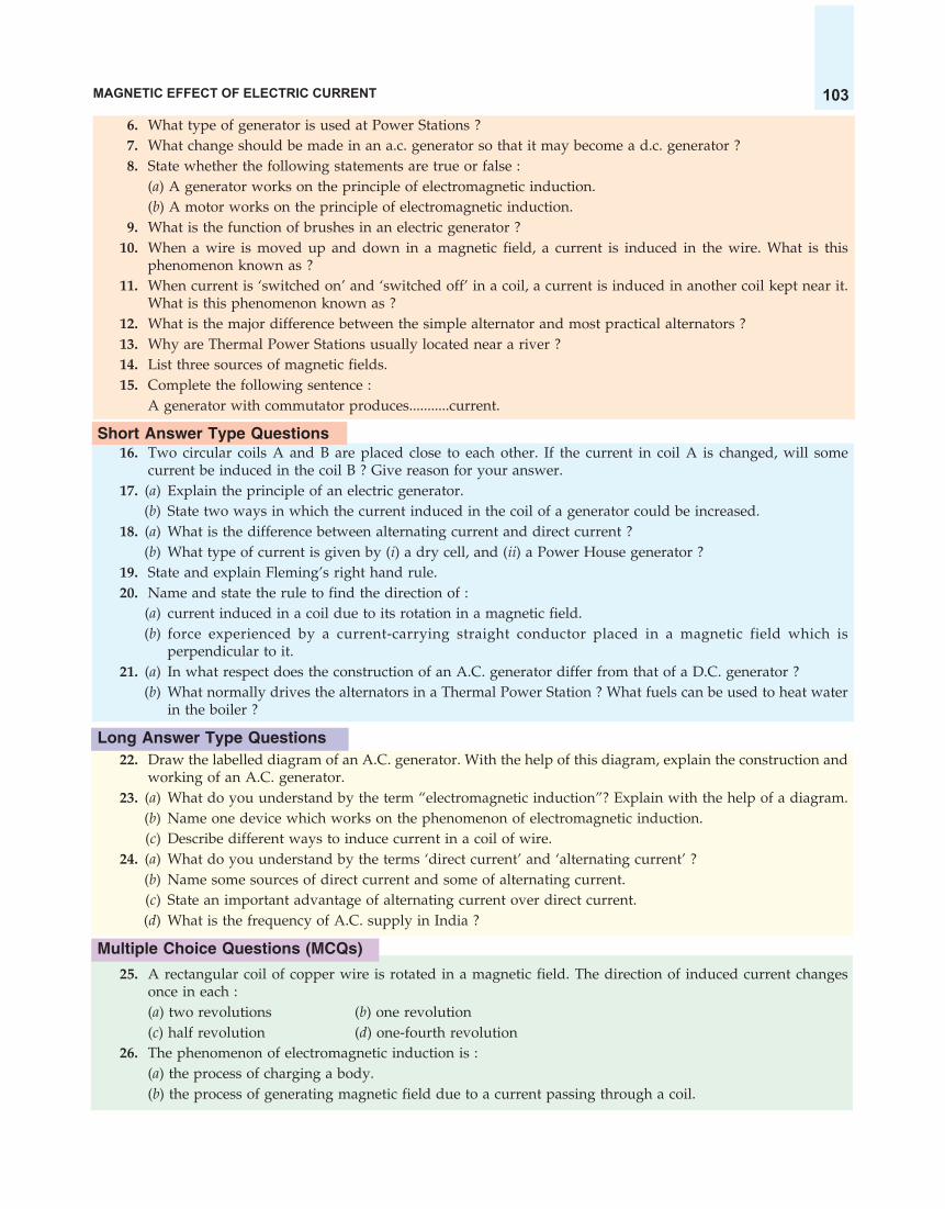
MAGNETIC EFFECT OF ELECTRIC CURRENT 103
6. What type of generator is used at Power Stations ?7. What change should be made in an a.c. generator so that it may become a d.c. generator ?8. State whether the following statements are true or false :
(a) A generator works on the principle of electromagnetic induction.(b) A motor works on the principle of electromagnetic induction.
9. What is the function of brushes in an electric generator ?10. When a wire is moved up and down in a magnetic field, a current is induced in the wire. What is this
phenomenon known as ?11. When current is ‘switched on’ and ‘switched off’ in a coil, a current is induced in another coil kept near it.
What is this phenomenon known as ?12. What is the major difference between the simple alternator and most practical alternators ?13. Why are Thermal Power Stations usually located near a river ?14. List three sources of magnetic fields.15. Complete the following sentence :
A generator with commutator produces...........current.
Short Answer Type Questions16. Two circular coils A and B are placed close to each other. If the current in coil A is changed, will some
current be induced in the coil B ? Give reason for your answer.17. (a) Explain the principle of an electric generator.
(b) State two ways in which the current induced in the coil of a generator could be increased.18. (a) What is the difference between alternating current and direct current ?
(b) What type of current is given by (i) a dry cell, and (ii) a Power House generator ?19. State and explain Fleming’s right hand rule.20. Name and state the rule to find the direction of :
(a) current induced in a coil due to its rotation in a magnetic field.(b) force experienced by a current-carrying straight conductor placed in a magnetic field which is
perpendicular to it.21. (a) In what respect does the construction of an A.C. generator differ from that of a D.C. generator ?
(b) What normally drives the alternators in a Thermal Power Station ? What fuels can be used to heat waterin the boiler ?
Long Answer Type Questions22. Draw the labelled diagram of an A.C. generator. With the help of this diagram, explain the construction and
working of an A.C. generator.23. (a) What do you understand by the term “electromagnetic induction”? Explain with the help of a diagram.
(b) Name one device which works on the phenomenon of electromagnetic induction.(c) Describe different ways to induce current in a coil of wire.
24. (a) What do you understand by the terms ‘direct current’ and ‘alternating current’ ?(b) Name some sources of direct current and some of alternating current.(c) State an important advantage of alternating current over direct current.(d) What is the frequency of A.C. supply in India ?
Multiple Choice Questions (MCQs)
25. A rectangular coil of copper wire is rotated in a magnetic field. The direction of induced current changesonce in each :(a) two revolutions (b) one revolution(c) half revolution (d) one-fourth revolution
26. The phenomenon of electromagnetic induction is :(a) the process of charging a body.(b) the process of generating magnetic field due to a current passing through a coil.

SCIENCE FOR TENTH CLASS : PHYSICS104
(c) producing induced current in a coil due to relative motion between a magnet and the coil.(d) the process of rotating a coil of an electric motor.
27. The device used for producing electric current is called a :(a) generator (b) galvanometer (c) ammeter (d) motor
28. The essential difference between an AC generator and a DC generator is that :(a) AC generator has an electromagnet while a DC generator has permanent magnet.(b) DC generator will generate a higher voltage.(c) AC generator will generate a higher voltage.(d) AC generator has slip rings while the DC generator has a commutator.
29. When the switch S is closed in the figure given below, the pointer of the galvanometer moves to the right.
If S is kept closed, will the pointer :(a) return to zero ?(b) stay over on the right ?(c) move to the left and stay there(d) move to and fro until S is opened
30. Each one of the following changes will increase emf (or voltage) in a simple generator except :(a) increasing the number of turns in the armature coil(b) winding the coil on a soft iron armature(c) increasing the size of the gap in which the armature turns(d) increasing the speed of rotation
31. The north pole of a long bar magnet was pushed slowly into a short solenoid connected to a galvanometer.The magnet was held stationary for a few seconds with the north pole in the middle of the solenoid andthen withdrawn rapidly. The maximum deflection of the galvanometer was observed when the magnetwas :(a) moving towards the solenoid (b) moving into solenoid(c) at rest inside the solenoid (d) moving out of the solenoid
32. An electric generator converts :(a) electrical energy into mechanical energy(b) mechanical energy into heat energy(c) electrical energy into chemical energy(d) mechanical energy into electrical energy.
33. A d.c. generator is based on the principle of :(a) electrochemical induction (b) electromagnetic induction(c) magnetic effect of current (d) heating effect of current
34. An induced current is produced when a magnet is moved into a coil. The magnitude of induced currentdoes not depend on :(a) the speed with which the magnet is moved(b) the number of turns of the coil(c) the resistivity of the wire of the coil(d) the strength of the magnet
35. The frequency of direct current (d.c.) is :(a) 0 Hz (b) 50 Hz (c) 60 Hz (d) 100 Hz
36. The frequency of alternating current (a.c.) supply in India is :(a) 0 Hz (b) 50 Hz (c) 60 Hz (d) 100 Hz

MAGNETIC EFFECT OF ELECTRIC CURRENT 105
Galvanometer
motionN S
Questions Based on High Order Thinking Skills (HOTS)37. A coil is connected to a galvanometer. When the N-pole of a magnet is pushed into the coil, the galvanometer
deflected to the right. What deflection, if any, is observed when :(a) the N-pole is removed ?(b) the S-pole is inserted ?(c) the magnet is at rest in the coil ?State three ways of increasing the deflection on the galvanometer.
38. When the magnet shown in the diagram below is moving towards the coil, the galvanometer gives a readingto the right.
(i) What is the name of the effect being produced by the moving magnet ?(ii) State what happens to the reading shown on the galvanometer when the magnet is moving away from
the coil.(iii) The original experiment is repeated. This time the magnet is moved towards the coil at a great speed.
State two changes you would notice in the reading on the galvanometer.39. If you hold a coil of wire next to a magnet, no current will flow in the coil. What else is needed to induce a
current ?40. The wire in Figure below is being moved downwards through the magnetic field so as to produce induced
current.
N S
What would be the effect of :(a) moving the wire at a higher speed ?(b) moving the wire upwards rather than downwards ?(c) using a stronger magnet ?(d) holding the wire still in the magnetic field ?(e) moving the wire parallel to the magnetic field lines ?
41. Two coils A and B of insulated wire are kept close to each other. Coil A is connected to a galvanometerwhile coil B is connected to a battery through a key. What would happen if :(i) a current is passed through coil B by plugging the key ?
(ii) the current is stopped by removing the plug from the key ?Explain your answer mentioning the name of the phenomenon involved.
42. A portable radio has a built-in transformer so that it can work from the mains instead of batteries. Is this astep-up or step down transformer ?
ANSWERS1. Electric generator 2. (a) D.C. generator (b) A.C. generator 3. Electromagnetic induction4. Fleming’s right-hand rule 6. A.C. generator (or Alternator) 8. (a) True (b) False 10. Electro-magnetic induction 11. Electromagnetic induction 12. Simple alternator : Magnet fixed and coil rotates ;Practical alternator : Coil fixed and magnet rotates 13. To obtain water for making steam for turningturbines and for cooling spent steam to condense it back into hot water for making fresh steam
N S

SCIENCE FOR TENTH CLASS : PHYSICS106
14. Permanent magnets ; Electromagnets ; Conductors carrying current (such as straight wire, circular coiland solenoid carrying current) 15. direct 20. (a) Fleming’s right-hand rule (b) Fleming’s left-handrule 21. (b) High pressure steam ; Coal ; Natural gas ; Oil 23. (b) Electric generator 25. (c) 26. (c)27. (a) 28. (d) 29. (a) 30. (c) 31. (d) 32. (d) 33. (b) 34. (c) 35. (a) 36. (b) 37. (a)The galvanometer is deflected to the left (b) The galvanometer is deflected to the left (c) No deflectionin galvanometer ; Increase the number of turns in the coil ; Use a stronger magnet ; Increase the speed withwhich magnet is pushed into the coil (or removed) 38. (i) Electromagnetic induction (ii) Deflected to left(iii) Large deflection to right occurs more quickly 39. Motion of the magnet into the coil (and out ofthe coil) 40. (a) Current increased (b) Current reversed (c) Current increased (d) Current zero(e) Current zero 41. (i) Galvanometer pointer moves to one side showing that a current is induced in thecoil (b) Galvanometer pointer moves to the other side showing that the direction of induced current hasbeen reversed ; Electromagnetic induction 42. Step-down transformer (which reduces the voltage)
DOMESTIC ELECTRIC CIRCUITS (OR DOMESTIC WIRING)Electricity is generated at the power station. It is brought to our homes by two thick copper wires or
aluminium wires fixed over tall electric poles (or by underground cables). From the electric pole situated inour street, two insulated wires L and N come to our house (see Figure 37). One of these wires is called livewire (read as laa-ive wire) and it is at a high potential of 220 volts whereas the other wire is called neutralwire and it is at the ground potential of zero volt. Thus, the potential difference between the live wire andthe neutral wire in India is 220 – 0 = 220 volts. In Figure 37, L is the live wire and N is the neutral wire. Thelive wire has red insulation covering whereas neutral wire has black insulation covering. There is no harmif we touch the neutral wire but we will get an electric shock if, by chance, we touch the live wire.
Figure 37. Diagram to show domestic electric wiring from electric pole to a room (In this diagram we have shown the wiring for an electric bulb and a three-pin socket only).
The two insulated wires L and N, coming from the electric pole, enter a box fitted just inside our house.In this box, a main fuse F1 is put in the live wire. This fuse has a high rating of about 50 amperes. The twoline wires then enter the electricity meter M which records the electrical energy consumed by us in theunits of kilowatt-hours. The main fuse and the meter are both installed by the Electric Supply Departmentof our City.
The two wires coming out of the meter are connected to a main switch S. This main switch is to switchoff the electricity supply when required so as to repair any faults in the internal wiring. After the mainswitch, there is another fuse F2 in the live wire. This is called consumer’s fuse. It is very important to notehere that usually there are two separate circuits in a house, the lighting circuit with a 5 A fuse and thepower circuit with a 15 A fuse. The lighting circuit is for running low power-rating devices such as electricbulbs, tube-lights, fans, radio, and TV, etc., which draw small current. On the other hand, power circuit isfor running high power-rating devices such as electric iron, room heater, geyser, electric stove, refrigerator,etc., which draw heavy current. But to make things simple, we will describe only a lighting circuit with a 5ampere fuse. Each distribution circuit is provided with a separate fuse so that if a fault like short-circuitingoccurs in one circuit, its corresponding fuse blows off but the other circuit remains unaffected. Another
L
N
Livewire
Neutralwire
The live wireand neutralwire arecoming from theelectric pole
Mainfuse F1
E
Meter
2748kWh
Earthconnection
S
Mainswitc Consumer’s
fuse F2
Bulb
S1
Switchfor bulb
S2
Switchfor socket
T
Socket
To fan
M
Earthwire
h

MAGNETIC EFFECT OF ELECTRIC CURRENT 107
point to remember is that the various distribution circuits are connected in parallel so that if a faultoccurs in one circuit, its fuse will melt leaving the other circuit in operation. For example, the lightingcircuit and power circuit in our home are in parallel so that if a short-circuit occurs in, say the power circuit,then the power-fuse will blow off but our lights will not go off because our lighting circuit will keepworking.
Before we describe the wiring of our rooms, it is very important to note here that alongwith the livewire and the neutral wire, a third wire called earth wire also goes into our rooms. In Figure 37, the earthwire E has been shown by dotted line. One end of the earth wire E is connected to a copper plate andburied deep under the earth near the house (as shown in Figure 37) or at the nearest electric sub-station.The earth connection is first made to the electric meter and then to the main switch. This earth wire thengoes into our room alongwith the live wire and the neutral wire. Please note that the earth wire up to themain switch of our house is usually an uncovered, thick copper wire having no plastic insulation over it.But the earth wire which goes from the main switch into our rooms is a copper wire having green insulationcovering over it. Thus, in order to distinguish between the live wire, neutral wire and earth wire, thewire having red plastic covering is made live wire, the wire having black plastic covering is made neutralwire, and the wire having green plastic covering is made earth wire.
Now, three wires, live wire, neutral wire and the earth wire enter our room where we have to use anelectric bulb, a fan and a three-pin socket for radio, and TV etc. We will now describe the internal wiring ofa room. In a room, all the electrical appliances like bulbs, fans and sockets, etc., are connected in parallelacross the live wire and the neutral wire. The main advantage of the parallel connection is that if one ofthe appliances is switched off, or gets fused, there is no effect on the other appliances and they keep onoperating. Another advantage of the parallel circuits is that the same voltage of the mains line is availablefor all the electrical appliances. If, however, we connect the various electric bulbs in series, then if one bulbis switched off or gets fused then all other bulbs will also stop working because their electricity supply willbe cut off. On the other hand, if the bulbs are connected in parallel, then switching on or off in a room hasno effect on other bulbs in the same building. Moreover, if the various electric bulbs are connected inseries, they will not get the same voltage (220 V) of the mains line. The bulbs connected in series will getlower voltage (than 220 V) and hence glow less brightly. All the bulbs connected in parallel will, however,get the same voltage (220 V) and hence glow brightly.
First of all we will describe the wiring for an electric bulb. One end of the bulb-holder is connected tothe live wire through a switch S1 and the other end of the bulb-holder is connected to the neutral wire (seeFigure 37). When we press the switch S1, the circuit for bulb gets completed and it lights up. We will nowdescribe the wiring for a three-pin socket. One of the lower terminals of the socket T is connected to thelive wire through a switch S2 and the second lower terminal is connected to the neutral wire. The upperterminal of the socket is connected to the earth wire (see Figure 37). Let us now describe the wiring for afan. The live wire is connected to one terminal of the fan through a switch and a regulator. The neutral wireis connected to the other terminal of the fan. We have not shown the wiring for a fan in Figure 37. Please doit yourself.
It is obvious from the circuit given in Figure 37 that all the electrical appliances are provided withseparate switches. It should be noted that all the switches are put in the live wire, so that when we switchoff an electrical appliance (like an electric iron), then its connection with the live wire is cut off and therewill be no danger of an electric shock if we touch the metal case of the electrical appliance. If , however, weput switches in the neutral wire, then the live wire will be in connection with the electrical appliance evenwhen the switch is in the off position, and there is a danger of an electric shock.
Earthing of Electrical AppliancesSometime or the other we have received an electric shock from an electric iron or a room cooler. We will
now discuss why we get the electric shock and how it can be prevented. In order to work an electrical
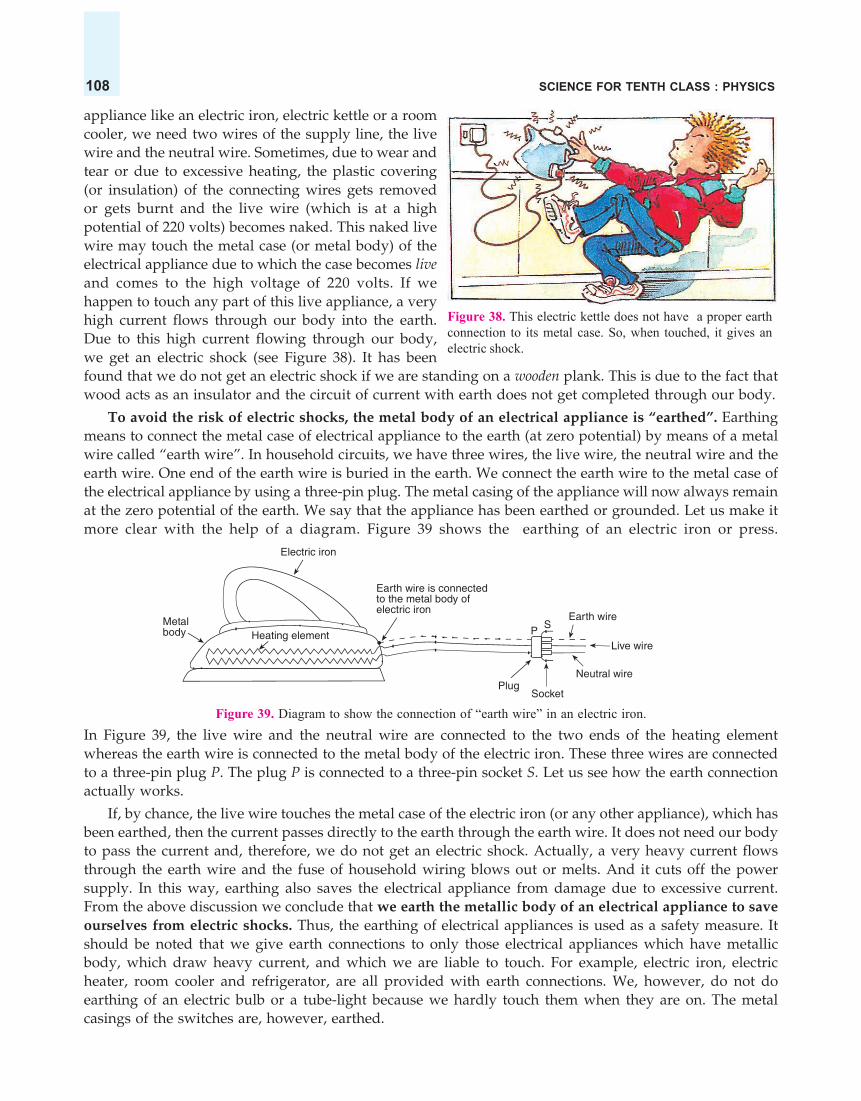
SCIENCE FOR TENTH CLASS : PHYSICS108
appliance like an electric iron, electric kettle or a roomcooler, we need two wires of the supply line, the livewire and the neutral wire. Sometimes, due to wear andtear or due to excessive heating, the plastic covering(or insulation) of the connecting wires gets removedor gets burnt and the live wire (which is at a highpotential of 220 volts) becomes naked. This naked livewire may touch the metal case (or metal body) of theelectrical appliance due to which the case becomes liveand comes to the high voltage of 220 volts. If wehappen to touch any part of this live appliance, a veryhigh current flows through our body into the earth.Due to this high current flowing through our body,we get an electric shock (see Figure 38). It has beenfound that we do not get an electric shock if we are standing on a wooden plank. This is due to the fact thatwood acts as an insulator and the circuit of current with earth does not get completed through our body.
To avoid the risk of electric shocks, the metal body of an electrical appliance is “earthed”. Earthingmeans to connect the metal case of electrical appliance to the earth (at zero potential) by means of a metalwire called “earth wire”. In household circuits, we have three wires, the live wire, the neutral wire and theearth wire. One end of the earth wire is buried in the earth. We connect the earth wire to the metal case ofthe electrical appliance by using a three-pin plug. The metal casing of the appliance will now always remainat the zero potential of the earth. We say that the appliance has been earthed or grounded. Let us make itmore clear with the help of a diagram. Figure 39 shows the earthing of an electric iron or press.
Figure 39. Diagram to show the connection of “earth wire” in an electric iron.In Figure 39, the live wire and the neutral wire are connected to the two ends of the heating elementwhereas the earth wire is connected to the metal body of the electric iron. These three wires are connectedto a three-pin plug P. The plug P is connected to a three-pin socket S. Let us see how the earth connectionactually works.
If, by chance, the live wire touches the metal case of the electric iron (or any other appliance), which hasbeen earthed, then the current passes directly to the earth through the earth wire. It does not need our bodyto pass the current and, therefore, we do not get an electric shock. Actually, a very heavy current flowsthrough the earth wire and the fuse of household wiring blows out or melts. And it cuts off the powersupply. In this way, earthing also saves the electrical appliance from damage due to excessive current.From the above discussion we conclude that we earth the metallic body of an electrical appliance to saveourselves from electric shocks. Thus, the earthing of electrical appliances is used as a safety measure. Itshould be noted that we give earth connections to only those electrical appliances which have metallicbody, which draw heavy current, and which we are liable to touch. For example, electric iron, electricheater, room cooler and refrigerator, are all provided with earth connections. We, however, do not doearthing of an electric bulb or a tube-light because we hardly touch them when they are on. The metalcasings of the switches are, however, earthed.
Figure 38. This electric kettle does not have a proper earthconnection to its metal case. So, when touched, it gives anelectric shock.
Metalbody Heating element
Electric iron
Earth wire is connectedto the metal body ofelectric iron
PS
Earth wire
Live wire
Neutral wire
SocketPlug

MAGNETIC EFFECT OF ELECTRIC CURRENT 109
Connecting cableNeutral wire
Live wire
Figure 40. A three core connecting cable has threeinsulated copper wires in it. The red coloured wireis the live wire, the black wire is the neutral wire,whereas the green wire is the earth wire.
Earth wire
Figure 41. The insulation of connecting cable ofthis electric iron is getting torn. An electric shortcircuit is waiting to happen.
Figure 42. Too many appliances connected to asingle socket. A case of overloading.
It should be noted that the connecting cable of an electricalappliance like an electric iron, electric kettle, water heater,room cooler or refrigerator contains three insulated copperwires of three different colours : red, black and green. Thered coloured wire is the live wire, the black wire is theneutral wire, whereas green wire is the earth wire(see Figure 40).
Electric Fuse
The electric wires used in domestic wiring are made ofcopper metal because copper is a good conductor of electricityhaving very low resistance. Now, the copper wires chosen forhousehold wiring are of such thickness so as to allow a certainmaximum current to pass through them. If the current passing through wires exceeds this maximum value,the copper wires get over-heated and may even cause a fire. An extremely large current can flow indomestic wiring under two circumstances : short circuiting and overloading.
(i) Short Circuiting. If the plastic insulation of the live wire and neutral wire gets torn, then the twowires touch each other (see Figure 41). This touching of the live wire and neutral wire directly is knownas short circuit. When the two wires touch each other, the resistance of the circuit so formed is very, verysmall. Since the resistance is very small, the current flowing through the wires becomes very large andheats the wires to a dangerously high temperature, and a fire may be started.
(ii) Overloading. The current flowing in domestic wiring at a particular time depends on the powerratings of the appliances being used. If too many electrical appliances of high power rating (like electriciron, water heater, air conditioner, etc.,) are switched on at the same time, they draw an extremely largecurrent from the circuit. This is known as overloading the circuit. Overloading can also occur if too manyappliances are connected to a single socket (see Figure 42). Now, due to an extremely large current flowingthrough them, the copper wires of household wiring get heated to a very high temperature and a fire maybe started.
It is obvious that we should have some device which may disconnect the electricity supply when ashort circuit or overloading occurs so that the electric fires are prevented in our homes. To avoid thisdanger of electric fires we use an electric fuse in the wiring. So, when a building is wired, the wiring isprotected by fuses. We will now describe what a fuse is and how it works.
Torn insulation

SCIENCE FOR TENTH CLASS : PHYSICS110
A fuse is a safety device having a short length of a thin, tin-plated copper wire having low meltingpoint, which melts and breaks the circuit if the current exceeds a safe value. The thickness and length ofthe fuse wire depends on the maximum current allowed through the circuit. An electric fuse works on theheating effect of current. The fuse for protecting our domestic wiring is fitted just above our main switchon the switch board. A fuse wire is connected in series in the electric circuits.
The main fuse in domestic wiring consists of a porcelain fuse holder H having two brass terminals T1
and T2 in it [see Figure 43(a)]. This is connected in the live wire. The other part of the fuse is a removablefuse grip G which is also made of porcelain. The fuse grip has a fuse wire fixed in it. When fuse grip isinserted in the fuse holder as shown in Figure 43(a), then the circuit of our domestic wiring is completed.So, under normal circumstances when the current is within limit, the fuse wire is intact and electric currentis available in our wiring.
Livewire
T1
T2
Fuseholder
Fusewire
Fusegrip
G
H
Livewire
Fuse wiremeltsand breaksthe circuit
(a) Under normal circumstances the fuse (b) When excessive current flows in thewire is intact and hence current circuit, the fuse wire gets heated tooflows in the circuit much, melts and breaks the circuit
Figure 43. Electric fuse.When a short circuit takes place, or when overloading takes place, the current becomes large and heats
the fuse wire too much. Since the melting point of fuse wire is much lower than copper wires, the fuse wiremelts and breaks the circuit as shown in Figure 43(b). When the fuse wire breaks, electricity supply isautomatically switched off before any damage can be done to the rest of the wiring (or the electricalappliances being used).
We will now give some important points about the fuse wire to be used in electrical circuits. First of allwe should know why we use a thin wire as a fuse wire and not a thick wire. We use a thin wire in a fusebecause it has a much greater resistance than the rest of connecting wires. Due to its high resistance, theheating effect of current will be much more in the fuse wire than anywhere else in the circuit. This will meltthe fuse wire whereas other wiring will remain safe. We should not use a thick wire as a fuse wire becauseit will have a low resistance and hence it will not get heated to its melting point easily. The fuse wire isusually made from tin-plated copper wire having low melting point so that it may melt easily. A purecopper wire cannot be used as a fuse wire because it has a high melting point due to which it will not melteasily when a short circuit takes place.
The fuse wire must have proper thickness which depends on the maximum current which thehousehold wiring can safely carry. The thickness of the fuse wire should be such that it is able to withstandonly a little more current than drawn by the household circuit. Fuse wires are rated as 1 A, 2 A, 3 A, 5 A,10 A, 13 A, 15 A, and so on. It is clear that a “10 ampere” fuse wire will be thicker than a “5 ampere” fusewire. The fuse in the lighting and fans circuit of a small house is of 5 amperes rating which means that the

MAGNETIC EFFECT OF ELECTRIC CURRENT 111
Figure 44. Miniature Circuit Breakers(MCBs) are now used in domestic wiringinstead of fuses.
Metalcap
Metalcap
Glass tube
Fuse wire
T
fuse wire will melt if the current exceeds 5 amperes value. Thefuse used in the power circuit of a small house for running electriciron, immersion heater, geyser and toaster, etc., having power of1000 watts or more is of 15 A capacity. A blown fuse should bereplaced only after the cause of excessive current flow has beenfound and removed. These days more and more houses are using‘Miniature Circuit Breakers’ (MCBs) to protect the household wiringfrom the excessive flow of electric current through it (see Figure44). If the current becomes too large, the miniature circuit breakerputs off a switch cutting off the electric supply. The MCB can bere-set when the fault has been corrected. Miniature circuit beaker(MCB) contains an electromagnet which, when the current exceedsthe rated value of circuit breaker, becomes strong enough to separatea pair of contacts (by putting off a switch) and breaks the circuit.So, unlike fuses, MCBs do not work on heating effect of current.MCBs work on the magnetic effect of current.
So far we have discussed the fuses which are put on the main switch-boardin our houses to protect the whole wiring of the house. Fuses are also used toprotect the individual domestic electrical appliances from damage which maybe caused due to excessive current flow through them (see Figure 45). Costlyelectrical appliances like T.V. sets and refrigerators have their own fuses whichprotect them against damage by too much current. The fuse used for eachelectrical appliance should be slightly larger than the normal current drawnby it. For example, a T.V. set which normally takes less than 1 ampere of currentshould be fused at 2 amperes, and not, for example, at 10 amperes.
The fuse used in an electrical appliance is shown in Figure 46(a). It consistsof a glass tube T having a thin fuse wire sealed inside it. The glass tube hastwo metal caps at its two ends. The two ends of the fuse wire are connected
(a) Diagram of the fuse used in (b) Symbol of an electric fuseelectrical appliances used in circuit diagrams
Figure 46.to these metal caps. The metal caps are for connecting the fuse in the circuit in a suitably made bracket. Ina circuit diagram, the electric fuse is represented by the symbol shown in Figure 46(b). We will now solvesome problems based on electric fuse.
Sample Problem 1. An electric oven of 2 kW power rating is operated in a domestic electric circuit(220 V) that has a current rating of 5 A. What result do you expect ? Explain. (NCERT Book Question)
Solution. We will first calculate the current drawn by this electric oven.Now, Power, P = 2 kW
= 2 × 1000 W= 2000 W
Potential difference or Voltage, V = 220 VAnd, Current drawn, I = ? (To be calculated)Now, Power, P = V × I
Figure 45. These are the cartridgefuses. They are used to protect theindividual electrical appliances.
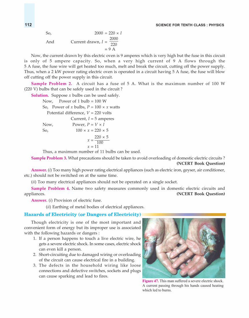
SCIENCE FOR TENTH CLASS : PHYSICS112
So, 2000 = 220 × I
And Current drawn, I = 2000220
= 9 A
Now, the current drawn by this electric oven is 9 amperes which is very high but the fuse in this circuitis only of 5 ampere capacity. So, when a very high current of 9 A flows through the5 A fuse, the fuse wire will get heated too much, melt and break the circuit, cutting off the power supply.Thus, when a 2 kW power rating electric oven is operated in a circuit having 5 A fuse, the fuse will blowoff cutting off the power supply in this circuit.
Sample Problem 2. A circuit has a fuse of 5 A. What is the maximum number of 100 W(220 V) bulbs that can be safely used in the circuit ?
Solution. Suppose x bulbs can be used safely.Now, Power of 1 bulb = 100 WSo, Power of x bulbs, P = 100 × x watts
Potential difference, V = 220 voltsCurrent, I = 5 amperes
Now, Power, P = V × ISo, 100 × x = 220 × 5
220 × 5x = ———– 100x = 11
Thus, a maximum number of 11 bulbs can be used.
Sample Problem 3. What precautions should be taken to avoid overloading of domestic electric circuits ?(NCERT Book Question)
Answer. (i) Too many high power rating electrical appliances (such as electric iron, geyser, air conditioner,etc.) should not be switched on at the same time.
(ii) Too many electrical appliances should not be operated on a single socket.
Sample Problem 4. Name two safety measures commonly used in domestic electric circuits andappliances. (NCERT Book Question)
Answer. (i) Provision of electric fuse.
(ii) Earthing of metal bodies of electrical appliances.
Hazards of Electricity (or Dangers of Electricity)
Though electricity is one of the most important andconvenient form of energy but its improper use is associatedwith the following hazards or dangers :
1. If a person happens to touch a live electric wire, hegets a severe electric shock. In some cases, electric shockcan even kill a person.
2. Short-circuiting due to damaged wiring or overloadingof the circuit can cause electrical fire in a building.
3. The defects in the household wiring like looseconnections and defective switches, sockets and plugscan cause sparking and lead to fires.
Figure 47. This man suffered a severe electric shock.A current passing through his hands caused heatingwhich led to burns.

MAGNETIC EFFECT OF ELECTRIC CURRENT 113
Figure 48. Never touch switches orsockets with wet hands.
Precautions in the Use of Electricity
To avoid the hazards like electric shocks or electric fires, we should observe the following precautionsin the use of electricity :
1. If a person accidently touches a live electric wire or if an electric fire starts in the house, the mainswitch should be turned off at once so as to cut off the electricity supply. This will prevent the fire fromspreading.
2. The person who happens to touch the live electric wire should be provided an insulated support ofwood, plastic or rubber. We should never try to pull away the person who is in contact with the live wire,otherwise we will also get a shock.
3. All the electrical appliances like electric iron, cooler, and refrigerator, etc., should be given earthconnections to save ourselves from the risk of electric shocks. Even if the earth connection is there, weshould avoid touching the metal body of an electric appliance when it is on.
4. All the switches should be put in the live wire of the A.C. circuit, so that when the switch is turnedoff, the appliance gets disconnected from the live wire and there is no risk of electric shock.
5. We should never operate switches of electrical appliances withwet hands. The plugs should also not be inserted into sockets withwet hands (see Figure 48). This is because water conducts electricity tosome extent, so touching the switches and sockets with wet hands canlead to electric shocks.
6. The fuse should always be connected in the live wire of thecircuit. The fuse wire should be of proper rating and material. Weshould never use a copper wire (connecting wire) as fuse wire becausea copper wire has a very high current rating due to which a copperwire fuse cannot protect the wiring against short circuiting oroverloading.
7. The household wiring should be done by using good qualitywires having proper thickness and insulation. All the wire connectionswith switches, sockets and plugs should be tight, and all the wire jointsshould be covered with insulated adhesive tape. Defective switches,sockets and plugs should be replaced immediately.
8. We should avoid working on a live circuit for repairs, etc. If, however, it is necessary to handle a livecircuit, then rubber gloves and rubber shoes must be put on, and we should stand on a dry wooden board.The electricians should wear rubber hand gloves and rubber shoes while working. The tools used for electricalrepairs like testers, screw drivers, pincers, etc., should have properly insulated handles made of wood orbakelite plastic.
We are now in a position to answer the following questions :
Very Short Answer Type Questions1. What name is given to the device which automatically cuts off the electricity supply during short-circuiting
in household wiring ?2. What is the usual capacity of an electric fuse used (i) in the lighting circuit, and (ii) in the power circuit, of
a small house ?3. Give the symbol of an electric fuse used in circuit diagrams.4. State whether the following statements are true or false :
(a) A wire with a green insulation is usually the live wire.(b) A miniature circuit breaker (MCB) works on the heating effect of current.
5. Alongwith live wire and neutral wire, a third wire is also used in domestic electric wiring. What name isgiven to this third wire ?

SCIENCE FOR TENTH CLASS : PHYSICS114
6. List the colours of the three wires in the cable connected to the plug of an electric iron.7. What is the electric potential of the neutral wire in a mains supply cable ?8. If fuses of 250 mA, 500 mA, 1 A, 5 A and 10 A were available, which one would be the most suitable for
protecting an amplifier rated at 240 V, 180 W ?9. When does an electric short circuit occur ?
10. In which wire in an A.C. housing circuit is the switch introduced to operate the lights ?11. In household circuits, is a fuse wire connected in series or in parallel ?12. Usually three insulated wires of different colours are used in an electrical appliance. Name the three colours.13. What is the usual colour of the insulation of : (a) live wire, (b) neutral wire, and (c) earth wire ?14. What is the main purpose of earthing an electrical appliance ?15. Give two reasons why different electrical appliances in a domestic circuit are connected in parallel.16. How should the electric lamps in a building be connected so that the switching on or off in a room has no
effect on other lamps in the same building ?17. Fill in the following blanks with suitable words :
(a) A fuse should always be placed in the .............wire of a mains circuit.(b) The earth wire should be connected to the..............of an appliance.
Short Answer Type Questions18. (a) Of what substance is the fuse wire made ? Why ?
(b) Explain why, a copper wire cannot be used as a fuse wire.19. What type of electric fuse is used in electrical appliances like car stereos ? Explain with the help of a labelled
diagram.20. Distinguish between the terms ‘overloading’ and ‘short-circuiting ’ as used in domestic circuits.21. (a) When does a fuse cut off current ? How does it do it ?
(b) What is the maximum number of 60 W bulbs that can be run from the mains supply of 220 volts if youdo not want to overload a 5 A fuse ?
22. Explain the importance of using in a household electric circuit (i) fuse, and (ii) earthing wire.23. (a) An electric iron is rated at 230 V, 750 W. Calculate (i) the maximum current, and (ii) the number of units
of electricity it would use in 30 minutes.(b) Which of the following fuse ratings would be suitable for this electric iron ?
1 A, 3 A, 5 A, 13 A24. What is the function of an earth wire ? Why is it necessary to earth the metallic bodies of electrical appliances ?25. (a) What current is taken by a 3 kW electric geyser working on 240 V mains ?
(b) What size fuse should be used in the geyser circuit ?26. (a) Why are fuses fitted in the fuse box of a domestic electricity supply ?
(b) What device could be used in place of the fuses ?
Long Answer Type Question
27. (a) Draw a labelled diagram to show the domestic electric wiring from an electric pole to a room. Give thewiring for a bulb and a three-pin socket only.
(b) State two hazards associated with the use of electricity.(c) State the important precautions which should be observed in the use of electricity.(d) What will you do if you see a person coming in contact with a live wire ?(e) Explain why, electric switches should not be operated with wet hands.
Multiple Choice Questions (MCQs)28. At the time of short circuit, the current in the circuit :
(a) reduces substantially (b) does not change(c) increases heavily (d) varies continuously
29. A 1.25 kW heater works on a 220 V mains supply. What current rating would a suitable fuse have ?(a) 2 A (b) 5 A (c) 10 A (d) 13 A

MAGNETIC EFFECT OF ELECTRIC CURRENT 115
30. The maximum number of 40 W tube-lights connected in parallel which can safely be run from a 240 Vsupply with a 5 A fuse is :(a) 5 (b) 15 (c) 20 (d) 30
31. In normal use, a current of 3.5 A flows through a hair dryer. Choose a suitable fuse from the following :(a) 3 A (b) 5 A (c) 10 A (d) 30 A
32. Which one of the following statements is not true ?(a) In a house circuit, lamps are used in parallel.(b) Switches, fuses and circuit breakers should be placed in the neutral wire(c) An electric iron has its earth wire connected to the metal case to prevent the user receiving a shock(d) When connecting a three-core cable to a 13 A three-pin plug, the red wire goes to the live pin.
33. A car headlamp of 48 W works on the car battery of 12 V. The correct fuse for the circuit of this car headlampwill be :(a) 5 A (b) 10 A (c) 3 A (d) 13 A
34. A 3-pin mains plug is fitted to the cable for a 1 kW electric kettle to be used on a 250 V a.c. supply. Which ofthe following statement is not correct ?(a) The fuse should be fitted in the live wire(b) A 13 A fuse is the most appropriate value to use(c) The neutral wire is coloured black(d) The green wire should be connected to the earth pin.
35. A TV set consumes an electric power of 230 watts and runs on 230 volts mains supply. The correct fuse forthis TV set is :(a) 5 A (b) 3 A (c) 1 A (d) 2 A
36. Circuit Breaker Device which can be used in place of fuse in domestic electric wiring is called :(a) CBD (b) DCB (c) MCD (d) MCB
37. An MCB which cuts off the electricity supply in case of short-circuiting or overloading works on the :(a) chemical effect of current(b) heating effect of current(c) magnetic effect of current(d) electroplating effect of current
Questions Based on High Order Thinking Skills (HOTS)38. An air-conditioner of 3.2 kW power rating is connected to a domestic electric circuit having a current rating
of 10 A. The voltage of power supply is 220 V. What will happen when this air-conditioner is switched on ?Explain your answer.
39. Three appliances are connected in parallel to the same source which provides a voltage of 220 V. A fuseconnected to the source will blow if the current from the source exceeds 10 A. If the three appliances arerated at 60 W, 500 W and 1200 W at 220 V, will the fuse blow ?
40. A vacuum cleaner draws a current of 2 A from the mains supply.(a) What is the appropriate value of the fuse to be fitted in its circuit ?(b) What will happen if a 13 A fuse is fitted in its circuit ?
41. Which of the following circuits will still be dangerous even if the fuse blows off and electric iron stopsworking during a short circuit ?
Fuse
Shortcircuit
L
N
L
N
Shortcircuit
Fuse
(A) (B)

SCIENCE FOR TENTH CLASS : PHYSICS116
42. An electric kettle rated as 1200 W at 220 V and a toaster rated at 1000 W at 220 V are both connected inparallel to a source of 220 V. If the fuse connected to the source blows when the current exceeds 9.0 A, canboth appliances be used at the same time ? Illustrate your answer with calculations.
43. What is the main difference in the wiring of an electric bulb and a socket for using an electric iron in adomestic electric circuit ? What is the reason for this difference ?
44. (a) Explain why, it is more dangerous to touch the live wire of a mains supply rather than the neutral wire.(b) Why is it safe for birds to sit on naked power lines fixed atop tall electric poles ?
45. A domestic lighting circuit has a fuse of 5 A. If the mains supply is at 230 V, calculate the maximum numberof 36 W tube-lights that can be safely used in this circuit.
ANSWERS
1. Electric fuse 2. (i) 5 A (ii) 15 A 4. (a) False (b) False 5. Earth wire 7. 0 volt 8. 1 A 10. Livewire 11. In series 16. In parallel 17. (a) live (b) body 19. Cartridge fuse 21. (b) 18 bulbs23. (a) (i) 3.26 A (ii) 0.375 kWh (b) 5 A 25. (a) 12.5 A (b) 13 A fuse 26. (b) MCB 28. (c) 29.(c)30. (d) 31. (b) 32. (b) 33. (a) 34. (b) 35. (d) 36. (d) 37. (c) 38. Fuse willblow cutting off the power supply 39. No 40. (a) 3 A (b) A 13 A fuse could allow very high currentto flow through the vacuum cleaner during short-circuiting or overloading which can damage the vacuumcleaner 41. Circuit A is not dangerous after fuse blows because fuse is in live wire ; Circuit B is dangerouseven if fuse blows because the fuse is in neutral wire 42. No 43. No earth connection for electric bulb ;Earth connection given to socket for electric iron 44. (a) Live wire at high potential of 220 V; Neutral wireat ground potential of 0 V (b) Bird’s body is not connected to the earth, so no current flows through bird’sbody into the earth 45. 31 tube-lights

Sources of Energy
CHAPTERCHAPTERCHAPTERCHAPTERCHAPTER
3
Figure 1. Coal is one of the most importantsources of energy. Burning of coal produces heatenergy. This heat energy can be used as such forcooking or heating purposes, or converted intoelectricity.
We use heat energy obtained by burning fuels like wood,coal, kerosene or LPG for cooking our food. The energyof fuels like petrol and diesel is used to run cars, buses,
trucks and trains. Diesel is also used to provide energy to runpump-sets for irrigation in agriculture. Coal, fuel oil and naturalgas are used to provide energy in factories and run thermal powerplants. Electrical energy (or electricity) is used for lighting bulbsand tubes, and to run radio, television, household appliances,electric trains and factory machines. In fact, all our everydayactivities use energy in one form or the other. And if there is noenergy, all our activities will come to a stop. For example, if thereis no energy, we won’t be able to cook food. If there is no energy,we won’t be able to run cars, buses, trucks, trains and aeroplanes.And if there is no energy, we won’t be able to run machines infactories, power plants or pump-sets in agriculture. So, energy isessential for our survival in this world. We will now discuss thevarious sources which can provide us energy.
A source of energy is one which can provide adequate amount of energy in a convenient form overa long period of time. All the sources of energy can be divided into two main categories : Non-renewablesources of energy and Renewable sources of energy. These are described below.
1. Non-Renewable Sources of Energy
Those sources of energy which have accumulated in nature over a very, very long time and cannotbe quickly replaced when exhausted are called non-renewable sources of energy. For example, coal is anon-renewable source of energy because coal has accumulated in the earth over a very, very long time, andif all the coal gets exhausted, it cannot be produced quickly in nature (see Figure 2). The non-renewablesources of energy are : Fossil fuels (Coal, Petroleum and Natural gas), and Nuclear fuels (such as Uranium).Non-renewable sources of energy are dug out from the earth.

SCIENCE FOR TENTH CLASS : PHYSICS118
Figure 2. Coal is a non-renewable source ofenergy.
Figure 3. Wood is a renewable sourceof energy.
The non-renewable sources of energy are also calledconventional sources of energy. The non-renewable sources ofenergy like fossil fuels (coal, petroleum and natural gas) are presentin a limited amount in the earth. Once exhausted, they will not beavailable to us again. The nuclear fuels (like uranium) have beenput in the category of non-renewable sources of energy because thenuclear materials which can be conveniently extracted from the earthare limited and hence they will get exhausted one day. Please notethat since the non-renewable sources of energy can get exhaustedone day, they are also known as exhaustible sources of energy.Another point to be noted is that though nuclear fuels are non-renewable source of energy dug out from the earth, they are notconventional source of energy.
2. Renewable Sources of Energy
Those sources of energy which are being produced continuously in nature and are inexhaustible, arecalled renewable sources of energy. For example, wood is a renewable source of energy because if treesare cut from the forests for obtaining wood, then more trees will grow inthe forest in due course of time. So, the loss of wood by cutting trees ismade good by nature (see Figure 3). The renewable sources of energyare : Hydroenergy (Energy from flowing water); Wind energy; Solarenergy; Energy from sea (Tidal energy, Sea-wave energy and Oceanthermal energy) ; Geothermal energy ; Biomass energy (Energy from bio-fuels such as Wood, Biogas and Alcohol); and Hydrogen.
The renewable sources of energy are also called non-conventionalsources of energy. These sources of energy can be used again and again,endlessly. They will never get exhausted. Since renewable sources ofenergy will never get exhausted, so they are also known as inexhaustiblesources of energy. A yet another name for renewable sources of energyis the alternative sources of energy.
According to the above classification, wood (obtained by the cuttingof trees) is a renewable source of energy. Now, a newly planted saplingusually takes more than 15 years to grow and mature into a tree. So,replenishment of cut down trees takes a very long time. Anotherdisadvantage is that the cutting down of trees on a large scale (forobtaining wood) causes depletion of the forests leading to an imbalancein nature. Due to these reasons, using wood as a source of energy is nota wise decision (even though it is a renewable source of energy).
What is a Good Source of EnergyWhenever work has to be done, energy is needed. This energy is supplied by a ‘source of energy’. Different
sources of energy are used depending on the ‘type of work’ to be done. Some sources of energy may begood whereas others may not be so good. We can find out whether a given source of energy is good or notby making use of the following ‘characteristics’ or ‘qualities’ of a good source of energy. A good source ofenergy is one :
(i) which would do a large amount of work per unit mass (or per unit volume),(ii) which is cheap and easily available,
(iii) which is easy to store and transport,

SOURCES OF ENERGY 119
Figure 4. Coal burns to produce heat,so it is a fuel.
(iv) which is safe to handle and use, and(v) which does not cause environmental pollution.
The most common sources of energy available to us are the fuels. These are discussed below.
FUELSThe materials which are burnt to produce heat energy are known as
fuels. Examples of fuels are : Wood, Coal, Cooking gas (LPG), Kerosene,Diesel and Petrol (see Figure 4). In our day to day life, the most importantsources of energy are fuels. Fuels are, in fact, the concentrated store-houseof energy. This energy is released in the form of heat when the fuels areburnt. Since a variety of fuels are available to us, we should have somemeans of deciding which fuel is the best for our purpose. Before we describesome of the characteristics (or properties) of fuels which will help us choosethe best possible fuel for a particular use, we should know the meaning oftwo terms ‘calorific value of a fuel’ and ‘ignition temperature’ of a fuel.These are discussed below.
All the fuels produce heat energy on burning. Different fuels produce different amounts of heat onburning. Some fuels produce more heat whereas others produce less heat. The usefulness of a fuel ismeasured in terms of its calorific value. Higher the calorific value, better the fuel will be. The amount ofheat produced by burning a unit mass of the fuel completely is known as its calorific value. The unit ofmass usually taken for measuring the calorific value of a fuel is “gram”. So, we can also say that “Theamount of heat produced by burning 1 gram of a fuel completely is called its calorific value”. For example,when one gram of a carbon fuel (like charcoal) is burned completely, it produces about 33000 joules of heat,so the calorific value of charcoal is 33000 joules per gram or 33000 J/g. Since joule is a very small unit ofheat energy, so the calorific value is usually expressed as kilojoules per gram (kJ/g). Thus, the calorificvalue of charcoal becomes 33 kilojoules per gram which is written in short form as 33 kJ/g. Thus, thecommon unit of measuring calorific value is kilojoules per gram (kJ/g). Please note that the ‘calorificvalue’ of a fuel represents the ‘heat value’ of the fuel. The calorific values of some common fuels are givenbelow.
Calorific Values (or Heat Values) of Some Common Fuels
Fuel Calorific value Fuel Calorific value
1. Dung cakes (Uple) : 6 to 8 kJ/g 8. Petrol : 50 kJ/g2. Wood : 17 kJ/g 9. Biogas : 35 to 40 kJ/g3. Coal : 25 to 30 kJ/g 10. Natural gas : 33 to 50 kJ/g4. Charcoal : 33 kJ/g 11. Cooking gas (LPG) : 50 kJ/g5. Alcohol (Ethanol) : 30 kJ/g 12. Methane : 55 kJ/g6. Diesel (and Fuel oil) : 45 kJ/g 13. Hydrogen gas : 150 kJ/g7. Kerosene oil : 48 kJ/g
From the above table we find that the calorific value of kerosene oil is 48 kJ/g. Now, by saying that thecalorific value of kerosene oil is 48 kilojoules per gram, we mean that if 1 gram of kerosene oil is burntcompletely, then it will produce 48 kilojoules of heat energy. Actually, the term “calorific value” comesfrom the fact that the earlier unit of measurement of heat was calorie. These days, although we mostly usejoule as the unit of heat but the term calorific value continues to be used as such. If we look up the table ofcalorific values, we will find that hydrogen gas has the highest calorific value of 150 kilojoules per gram.Thus, because of its high calorific value, hydrogen is an extremely good fuel. Most of the common fuels arethe compounds of hydrogen and carbon called ‘hydrocarbons’. Since hydrogen has the highest calorificvalue, therefore, a fuel containing higher percentage of hydrogen will have a higher calorific value than

SCIENCE FOR TENTH CLASS : PHYSICS120
Figure 5. Natural gas has highcalorific value (high heat value)and it burns without producingany smoke or harmful gases, sonatural gas is a good fuel.
another fuel which has a lower percentage of hydrogen in it. For example, LPG has a higher percentage ofhydrogen than coal, so LPG has a higher calorific value than coal. We will now describe the ignitiontemperature of a fuel.
We know that a fuel has to be burnt to obtain heat energy. Now, before a fuel can catch fire and burn,it must be heated to a certain minimum temperature. The minimum temperature to which a fuel must beheated so that it may catch fire and start burning, is known as its ignition temperature. When we applya burning matchstick (or a lighter spark) to the burner of a gas stove, we actually supply a little heat tocooking gas coming out of gas burner so that it gets heated to its ignition temperature and start burning.No fuel can burn unless it is heated to its ignition temperature.
Choice of a Good FuelThe fuel which we choose for our domestic or industrial use should have a
high calorific value. This means that the fuel chosen should be such that it givesus more heat per unit mass. The fuel should burn without giving any smoke orharmful gases. In other words, the combustion products produced by the burningof fuel should not be poisonous, and they should not pollute the environment.Carbon dioxide and water vapour are the harmless products produced by theburning of fuels. But some fuels produce poisonous gases like carbon monoxide(CO) and sulphur dioxide (SO2), etc., which pollute the air around us. The fuelshould have a proper ignition temperature which should be well above thenormal room temperature.
The fuel which we choose should be cheap and easily available. Anotherpoint which we have to keep in mind is that the fuel should be easy to handle,safe to transport and convenient to store. The fuel should have low percentageof non-combustible materials. This means that the residue left behind after theburning of a fuel should be as low as possible. For example, coal is a fuel whichleaves behind a lot of ash after burning. The removal and disposal of ash posesa big problem in factories and power plants where large quantities of coal areburnt everyday. The fuel should burn smoothly and at a steady rate. This isbecause if a fuel burns too fast, then most of the heat produced by it will bewasted. And if the fuel burns too slowly, then the heat produced may not serve our purpose. The fuelsshould have a low rate of evaporation at room temperature. We will now write down the characteristics ofan ideal fuel (or good fuel) point-wise.
Characteristics of an Ideal Fuel (or Good Fuel)While choosing the most appropriate fuel for our domestic use or for use in industry, we should keep
in mind the following characteristics of an ideal fuel or good fuel.1. It should have a high calorific value. In other words, an ideal fuel (or good fuel) is that which
gives us more heat per unit mass.2. It should burn without giving out any smoke or harmful gases. That is, an ideal fuel (or good
fuel) is that which does not pollute air on burning by giving out smoke or poisonous gases.3. It should have a proper ignition temperature, so that it can be burned easily. The ignition
temperature of an ideal fuel (or good fuel) should neither be too low nor too high. Because if theignition temperature of the fuel is very low, then the fuel will catch fire too easily and hence it willbe very unsafe to use it. On the other hand, if the ignition temperature is too high, then it will bevery difficult to light the fuel.
4. It should be cheap and easily available. That is, an ideal fuel (or good fuel) is that which is notexpensive and which is available in plenty everywhere.

SOURCES OF ENERGY 121
5. It should be easy to handle, safe to transport, and convenient to store. That is, an ideal fuel (orgood fuel) is that which does not create any safety risks during handling, during its transportationfrom one place to another or during its storage.
6. It should not leave much ash behind after burning. That is, an ideal fuel (or good fuel) shouldhave low percentage of non-volatile materials which do not burn, so that it may burn completelywithout leaving much ash.
7. It should burn smoothly. That is, an ideal fuel (or good fuel) should have a moderate rate ofcombustion, and burn at a steady rate. In other words, the fuel should not burn either too fast ortoo slow.
From the above discussion we conclude that the various factors which should be kept in mind whilechoosing a proper fuel for homes and factories are : high calorific value; absence of smoke and harmfulgases (or polluting gases) on burning ; proper ignition temperature ; low cost and easy availability ; easeof handling, transportation and storage ; low non-volatile content ; and a moderate rate of combustion. Wewill now take some examples to decide which of the two given fuels is a better fuel or a more ideal fuel.
Suppose we have two fuels A and B. The calorific value of fuel A is 55 kJ/g and its ignition temperatureis 20°C whereas the calorific value of fuel B is 50 kJ/g and its ignition temperature is 80°C. Now, we findthat fuel A has a higher calorific value of 55 kJ/g than that of fuel B. So, at first sight it would appear thatfuel A is a better fuel than fuel B. But it is not so. This is because fuel A has a very low ignition temperatureof 20°C due to which it can catch fire easily and hence it is unsafe to use. On the other hand, though thecalorific value of fuel B is little less (than that of fuel A), but it has the right ignition temperature of 80°Cwhich is neither very low nor very high. So, here fuel B will be a better fuel on the basis of its appropriateignition temperature.
Again suppose that, on burning, fuel A produces gases like CO2, H2O, CO, SO2, SO3, etc., whereas fuelB produces only CO2 and H2O. Out of these gases carbon monoxide (CO), sulphur dioxide (SO2) andsulphur trioxide (SO3) are poisonous gases or harmful gases. Now, since fuel A produces poisonous gaseslike CO, SO2 and SO3, on burning, therefore, fuel A is not a good fuel. On the other hand, burning of fuelB produces only harmless products like carbon dioxide (CO2) and water vapour (H2O), so fuel B is a betterfuel. Similarly, if a fuel burns with an explosion, it will not be a good fuel and if it leaves behind a lot ofash on burning, even then it cannot be a good fuel. Let us solve one problem now.
Sample Problem. The calorific value and ignition temperature of fuel A are 55 kJ/g and 20°C respectively.These values for another fuel B are 50 kJ/g and 80°C respectively. Which of the two will be more ideal fuelif, on burning, the fuel A produces CO2, SO2 and SO3 as by-products while the fuel B produces CO2 andH2O ? Give two reasons in support of your answer.
Solution. Fuel B will be a more ideal fuel because of the following reasons :
(i) Fuel B has a moderate ignition temperature of 80°C which is neither very high nor very low. On theother hand, the ignition temperature of fuel A is very low (20°C) and hence it is unsafe to use.
(ii) Fuel B does not produce any harmful gases on burning. On the other hand, fuel A produces poisonousgases like SO2 and SO3 on burning.
Before we go further and describe the conventional sources of energy, please answer the followingquestions :
Very Short Answer Type Questions1. Name a non-renewable source of energy other than fossil fuels.2. Define calorific value of a fuel.3. “The calorific value of cooking gas (LPG) is 50 kJ/g”. What does it mean ?4. Which of the following produces more heat (per unit mass) on burning ?
Coal or LPG

SCIENCE FOR TENTH CLASS : PHYSICS122
5. Define ignition temperature of a fuel.6. “The ignition temperature of a fuel is 80°C”. What does this mean ?7. Fill in the following blank with a suitable word :
The amount of heat produced by burning a unit mass of a fuel completely is known as its ...............value.
Short Answer Type Questions8. What is a source of energy ? What are the two main categories of the sources of energy ?9. State any four characteristics of a good source of energy.
10. What is meant by a non-renewable source of energy ? Give two examples of non-renewable sources ofenergy.
11. What is meant by a renewable source of energy ? Give two examples of renewable sources of energy.12. What is the difference between a renewable and a non-renewable source of energy ? Explain with examples.13. Why are fossil fuels classified as non-renewable sources of energy ?14. Name two sources of energy that you think are renewable. Give reason for your choice.15. Name two sources of energy which you consider to be non-renewable. Give reason for your choice.16. (a) Classify the following into renewable and non-renewable sources of energy :
Coal, Wind, Tides, Petroleum, Wood, Natural gas(b) What is the basis of above classification ?
17. Coal is said to be formed from the wood of trees. Why then is coal considered to be a non-renewable sourceof energy whereas wood is a renewable source of energy ?
Long Answer Type Question18. (a) What is a fuel ? Give five examples of fuels.
(b) What are the characteristics of an ideal fuel (or good fuel) ?(c) The calorific value and ignition temperature of fuel A are 55 kJ/g and 80°C, respectively. These values for
fuel B are 80 kJ/g and 10°C, respectively. On burning, the fuel A produces CO2 and H2O while the fuelB produces CO2, CO and SO2 . Give three points of relative advantages and disadvantages of these twofuels.
Multiple Choice Questions (MCQs)19. An example of a renewable source of energy is :
(a) petrol (b) natural gas (c) biogas (d) kerosene20. A non-renewable source of energy is :
(a) wood (b) alcohol (c) hydrogen gas (d) natural gas21. Which of the following is not a renewable source of energy ?
(a) wind (b) flowing water (c) fossil fuels (d) fuel wood22. A good fuel is one which possesses :
(a) high calorific value and low ignition temperature(b) high calorific value and high ignition temperature(c) high calorific value and moderate ignition temperature(d) low calorific value and moderate ignition tempeature
23. The fuel having a calorific value of 55 kJ/g is likely to be :(a) biogas (b) methane gas (c) hydrogen gas (d) natural gas
24. A newly planted sapling usually grows and matures into a tree in more than :(a) 50 years (b) 25 years (c) 45 years (d) 15 years
25. Which of the following fuels has the highest calorific value ?(a) natural gas (b) methane gas (c) hydrogen gas (d) biogas
26. The fuel having the lowest calorific value is :(a) coal (b) wood (c) charcoal (d) kerosene

SOURCES OF ENERGY 123
27. There are four fuels which all contain only carbon and hydrogen. The fuel having highest calorific value willbe one which has :(a) more of carbon but less of hydrgogn (b) less of carbon but more of hydrogen(c) equal proportions of carbon and hydrogen (d) less of carbon as well as less of hydrogen
28. One of the following is not a characteristic of a good fuel. This is :(a) high calorific value (b) no emission of smoke (c) smooth burning (d) high ignition temperature
29. Which of the following is not a fossil fuel ?(a) coal (b) petroleum gas (c) biogas (d) natural gas
Questions Based on High Order Thinking Skills (HOTS)30. The calorific values of three fuels A, B and C are 33 kJ/g , 48 kJ/g and 150 kJ/g, respectively. A is solid, B is
liquid and C is a gas at room temperature. On combustion, both A and B produce carbon dioxide while Cexplodes forming steam. B and C leave no residue after combustion while A leaves behind some solidresidue. Which one of the three fuels is the most ideal ? Give two reasons to support your answer.
31. Calorific value and ignition temperature of fuel X are 75 kJ/g and 20°C respectively. These values for fuel Yare 50 kJ/g and 75°C respectively. On burning, the fuel Y produces only CO2 while fuel X produces CO2and CO. Which of the two is a better fuel ? Give two reasons to support your answer.
32. The calorific values of five fuels A, B, C, D and E are given below :A 48 kJ/gB 17 kJ/gC 150 kJ/gD 50 kJ/gE 30 kJ/g
Which of the fuels could be : (i) cooking gas (ii) alcohol (iii) wood (iv) hydrogen (v) kerosene ?33. Arrange the following fuels in the order of decreasing calorific values (keeping the fuel with highest calorific
value first) :Biogas, Kerosene, Wood, Petrol, Hydrogen gas, Methane
34. Arrange the following fuels in the order of increasing calorific values (keeping the fuel with lowest calorificvalue first) :
LPG, Coal, Alcohol, Dung cakes, Diesel35. Most of the fuels contain carbon as one of the constituents. Name a fuel which has very high calorific value
but does not contain carbon.
ANSWERS1. Nuclear fuels (like uranium) 4. LPG 7. calorific 18. (c) Fuel A (i) Lower calorific value of 55 kJ/g(Disadvantage) (ii) Moderate ignition temperature of 80°C (Advantage) (iii) No harmful gases produced(Advantage); Fuel B (i) High calorific value of 80 kJ/g (Advantage) (ii) Very low ignition temperature of10°C (Disadvantage) (iii) Harmful gases like CO and SO2 produced (Disadvantage) 19. (c) 20. (d)21. (c) 22. (c) 23. (b) 24. (d) 25. (c) 26. (b) 27. (b) 28. (d) 29. (c) 30. Fuel Bis the most ideal fuel; (i) Leaves no residue on burning (ii) High calorific value of48 kJ/g (iii) Does not burn explosively 31. Fuel Y is a better fuel ; (i) Moderate ignition temperature of 75°C(ii) Produces no harmful gas (like CO) on burning. 32. (i) D (ii) E (iii) B (iv) C (v) A33. Hydrogen gas > Methane > Petrol > Kerosene > Biogas > Wood 34. Dung cakes < Coal < Alcohol< Diesel < LPG 35. Hydrogen gas
CONVENTIONAL SOURCES OF ENERGYThe traditional sources of energy which are familiar to most people are called conventional sources
of energy. The main conventional sources of energy are wood and fossil fuels (like coal, petroleum andnatural gas). The fuels derived from wood, coal and petroleum such as charcoal, coke, coal gas, petrol,diesel, kerosene, fuel oil and liquefied petroleum gas (LPG) are also known as conventional sources ofenergy (or conventional fuels). Even dung cakes (uple) is a conventional source of energy in our country.

SCIENCE FOR TENTH CLASS : PHYSICS124
In ancient times, the energy of flowing water and blowing wind were used through water-mills andwind-mills respectively, for very limited purposes like running flour mills (to grind grain to obtain flour)and water-lifting pumps. The energy of flowing water or wind is no longer used for these purposes. Theenergy of flowing water and that of wind is now used to generate electricity. So, the energy of flowingwater and of wind is now considered to be a non-conventional source of energy (or alternative source ofenergy). We will now discuss the most commonly used conventional sources of energy called fossil fuelswhich include coal, petroleum and natural gas. They are also called conventional fuels.
FOSSIL FUELSA natural fuel formed deep under the earth from the pre-historic remains of living organisms (like
plants and animals) is called a fossil fuel. Coal, petroleum and natural gas are fossil fuels. Fossil fuels aredug out from the earth. Besides being used directly in homes, transport vehicles and industry, fossil fuelsare the major source of energy for generating electricity in power plants. We will first understand howfossil fuels were formed.
How Fossil Fuels Were FormedThe plants and animals which died millions of years ago, were gradually buried deep in
the earth and got covered with sediments like mud and sand, away from the reach of oxygenof air. In the absence of oxygen, the chemical effects of pressure, heat and bacteria, convertedthe buried remains of plants and animals into fossil fuels like coal, petroleum and naturalgas. It should be noted that the buried remains of large plants were converted into coalwhereas those of small plants and animals were converted into petroleum and natural gas.
Figure 6. A piece of coal showing a fossilled leaf. Figure 7. Sun is the ultimate source of fossil fuels.
Sun is the Ultimate Source of Fossil FuelsWe have just seen that fossil fuels have been produced from the remains of plants and animals that
were buried in the earth long ago. Actually, it was the sunlight of long ago that made plants grow, whichwere then converted into fossil fuels. This can be explained as follows : The green plants need sunlightenergy to grow. They get this energy from sunlight, and store it in the form of carbon compounds. So,every leaf and every bit of wood in the plant was made with the energy of sunlight. The animals also eatplants, so the animal material is also a store-house of sun’s energy. These plants and animals which wereoriginally made by using sun’s energy have been converted into fossil fuels like coal, petroleum and naturalgas. Thus, fossil fuels are energy-rich compounds of carbon which were originally made by the plantswith the help of sun’s energy (solar energy). Without sunlight, there could have been no coal, petroleum,natural gas, wood or any other fuel in this world. Today when we burn coal, petroleum or natural gas, weare actually making use of the sunlight energy that was stored by the plants millions of years ago. We willnow discuss the three fossil fuels, coal, petroleum and natural gas, one by one. Let us start with coal.

SOURCES OF ENERGY 125
Figure 8. Coal.
COALCoal is a complex mixture of compounds of carbon, hydrogen and oxygen, and some free carbon.
Small amounts of nitrogen and sulphur compounds are also present in coal (see Figure 8). It is found indeep coal mines under the surface of earth. Coal is importantbecause it can be used as a source of energy as such, or it can beconverted into other forms of energy like coal gas, electricity andoil (synthetic petrol). The exploitation of coal as a source of energymade the industrial revolution possible.
When coal is burnt, the carbon present in coal reacts with theoxygen of air to form carbon dioxide. A lot of heat is producedduring the burning of coal which makes it a good fuel. Theburning of coal, however, produces a lot of smoke which pollutesthe air. When coal is subjected to destructive distillation (byheating strongly in the absence of air), then all the volatile materialis removed from coal and coke is formed. Coke is 98% carbon.Coke is a better fuel than coal because it produces more heat(than an equal mass of coal), and it does not produce smokewhile burning. Thus, burning of coke does not cause air pollution.Coke is, however, more valuable when used as a reducing agent in the extraction of metals from their ores.
Uses of Coal1. Coal is used as a fuel for heating purposes in homes and in industry.2. Coal is used as a fuel in thermal power plants for generating electricity.3. Coal is used to make coke. And this coke is then used as a reducing agent in the extraction of
metals.4. Coal is used in the manufacture of fuel gases like coal gas.5. Coal is used in the manufacture of petrol and synthetic natural gas.
PETROLEUMPetroleum is a dark coloured, viscous, and foul smelling crude oil
(see Figure 9). The name petroleum means rock oil (petra = rock; oleum= oil). It is called petroleum because it is found under the crust ofearth trapped in rocks. The crude oil petroleum is a complex mixtureof several solid, liquid and gaseous hydrocarbons mixed with water,salt and earth particles. It also contains small amounts of other carboncompounds containing oxygen, nitrogen and sulphur. Thus, the crudepetroleum oil is not a single chemical compound, it is a mixture ofcompounds. Petroleum is lighter than water and insoluble in it.
Petroleum occurs deep down under the earth between two layersof impervious rocks (non-porous rocks). Natural gas occurs above thepetroleum oil trapped under the rocks. Petroleum is obtained bydrilling holes (called oil wells) into the earth’s crust where the presenceof oil has been predicted by survey. When a well is drilled through the rocks, natural gas comes out firstwith a great pressure and for a time, the crude oil comes out by itself due to gas pressure. After thepressure has subsided, the crude oil is pumped out of the oil well. It should be noted that many wellsyield only natural gas but no oil. So, hundreds of wells may have to be drilled into the rocks and testedbefore getting an oil well from which oil can be produced profitably.
Figure 9. This is petroleum (which is alsocalled crude oil). It is used to obtain fuels
like petrol, diesel and kerosene, etc.

SCIENCE FOR TENTH CLASS : PHYSICS126
Figure 10. These gas cylinderscontain LPG.
Petroleum is the crude oil which is a complex mixture of alkane hydrocarbons with water, salt andearth particles. Petroleum cannot be used as a fuel as such. So, before petroleum can be used as a fuel forspecific purposes, it has to be purified or refined by the process of fractional distillation. The fractionaldistillation of petroleum gives us the following fractions which can be used as fuels : Petroleum gas,Petrol (or Gasoline), Diesel, Kerosene and Fuel oil. The fuel oil obtained from petroleum is sometimesjust called ‘oil’. The fraction of petroleum called lubricating oil is not used as a fuel.
Petroleum gas is used as a fuel for domestic heating purposes in the form of liquefiedpetroleum gas (LPG). Petrol is used as a fuel in motor cars, scooters, motor-cycles, andother light vehicles. Diesel is used as a fuel for heavy vehicles like buses, trucks, tractors,and railway engines. Diesel is also used as a fuel to run water-pumps for irrigation purposes,and in diesel generators to produce electricity on a small scale. Kerosene oil is used as ahousehold fuel. For example, kerosene is used in wick stoves or pressure stoves to cookfood. Kerosene is also used as an illuminant (for lighting purposes) in hurricane lamps. A special grade ofkerosene oil is used as ‘aviation fuel’ in jet aeroplanes. Fuel oil is used in industries to heat boilers and infurnaces. Fuel oil is also used in thermal power plants for generating electricity. Fuel oil is a better fuelthan coal because fuel oil burns completely and does not leave any residue. On the other hand, whencoal is burned, it leaves behind a lot of ash which has to be removed regularly from the coal furnace.
Petroleum GasThe main constituent of petroleum gas is butane though it also
contains smaller amounts of propane and ethane. Thus, we can say thatpetroleum gas is a mixture of three hydrocarbons : butane, propane andethane. Butane, propane and ethane, all burn readily, producing a lotof heat. This makes petroleum gas a very good fuel. Petroleum gas isobtained as a by-product in oil refineries from the fractional distillationof petroleum. It is also produced by the cracking of petrol.
Butane, propane and ethane are gases under ordinary pressure(atmospheric pressure) but they can be easily liquefied under pressure.The petroleum gas which has been liquefied under pressure is calledLiquefied Petroleum Gas (LPG) (see Figure 10). Thus, liquefiedpetroleum gas (or LPG) consists mainly of butane (alongwith smalleramounts of propane and ethane) which has been liquefied by applyingpressure. In other words, the domestic gas cylinders like Indanecontain mainly butane, with smaller amounts of propane and ethane, under pressure. Petroleum gas issupplied in liquid form so that even a small cylinder may contain a good weight of the gas. A domestic gascylinder contains about 14 kilograms of LPG (see Figure 10). A strong smelling substance called ethylmercaptan (C2H5SH) is added to LPG cylinders to help in the detection of gas leakage. Ethyl mercaptan hasa foul smell resembling that of hydrogen sulphide gas which can be easily detected. The gas used fordomestic cooking is called ‘Liquefied Petroleum Gas’ (LPG) because it is obtained from petroleum and it isliquefied by compression before filling into the cylinders.
Our domestic gas cylinders contain a mixture of liquefied butane, propane and ethane hydrocarbonsunder pressure. When we turn on the knob of the gas cylinder, the pressure is released and the highlyvolatile LPG gets converted into gas. This gas goes into the burner of our cooking stove. When a burningmatchstick is applied to the burner, the gas burns with a blue flame producing a lot of heat. This heat isused for cooking food.
Advantages of LPG1. LPG has a high calorific value. So, it is a good fuel. The calorific value of LPG is about 50 kJ/g. That
is, when 1 gram of LPG burns in a gas stove, it produces 50 kilojoules of heat energy.

SOURCES OF ENERGY 127
Figure 11. LPG burns in a kitchen stove with asmokeless blue flame and hence does not causeany air pollution.
2. LPG burns with a smokeless flame and so does not causeair pollution (see Figure 11).
3. LPG does not produce any poisonous gases on burning.4. LPG is easy to handle and convenient to store.5. LPG is a very neat and clean domestic fuel.
Dangers of LPG
Though LPG is an extremely good domestic fuel but it canbe dangerous too. LPG is a highly inflammable gas, that is, itcatches fire easily. Any leakage of LPG from the gas cylinder,stove or the rubber pipe (connecting the cylinder and stove) willform an explosive mixture with air in the kitchen. And on lightingthe matchstick, an explosion will take place, the whole kitchen will be set on fire and the person working inthe kitchen may get burnt. In fact, many such accidents occur quite often and should be avoided by observinga few precautions.
Precautions for Using LPG1. Before lighting a matchstick we should make sure that there is no foul smell of the leaking gas in
the kitchen, near the gas cylinder or gas stove. If we smell gas leakage on entering the kitchen, thenthe door and windows should be opened at once to allow the gas to escape. This is because, thoughLPG is not a poisonous gas, but when inhaled in large quantities, it is quite harmful and can evencause death. The gas cylinder, rubber tubing and gas stove should then be checked to find out thesource of gas leakage. The gas should be used only when the leakage has been set right by the gasmechanic. We should never light a matchstick or a candle during the leakage of LPG in the kitchen.
2. We should not use any hot flames like a kerosene lamp, kerosene stove or electric heater near thegas cylinder.
3. We should never use a leaking gas cylinder. The Gas Agency should be informed and the leakinggas cylinder replaced at the earliest.
4. We should handle the gas cylinder with care so that its valve does not get damaged.5. The rubber pipe connecting the gas cylinder to gas stove should be checked periodically for any
wear and tear.6. In order to light the gas stove, we should first open the valve of the cylinder and then turn on the
knob of gas stove.7. In order to put off the gas stove, we should first close the valve of the cylinder and after that the
knob of the gas stove should be turned off.8. When the gas is not being used, the valve of the gas cylinder and the knobs of the gas stove must
be kept closed.
NATURAL GASNatural gas is another important fossil fuel. Natural gas burns easily and produces a lot of heat. Natural
gas consists mainly of methane (CH4), with small quantities of ethane and propane. In fact, natural gascontains upto 95% methane, the remaining being ethane and propane. Natural gas occurs deep under thecrust of the earth either alone or alongwith oil above the petroleum deposits. Thus, some wells dug intothe earth produce only natural gas, whereas others produce natural gas as well as petroleum oil. Naturalgas is formed under the earth by the decomposition of vegetable matter lying under water. Thisdecomposition is carried out by anaerobic bacteria in the absence of oxygen. Natural gas is used as a fuelfor a number of purposes.
1. Natural gas is used as a domestic and industrial fuel. Natural gas burns readily to produce a lot ofheat. So, in many areas natural gas is used as the main fuel for domestic and industrial heating purposes.

SCIENCE FOR TENTH CLASS : PHYSICS128
2. Natural gas is used as a fuel in thermal power plantsfor generating electricity.
3. Compressed Natural Gas (CNG) is being usedincreasingly as a fuel in transport vehicles (like cars, busesand trucks) (see Figure 12). It is a good alternative to petroland diesel because it does not cause any air pollution.
Advantages of Natural Gas
1. Natural gas being a complete fuel in itself can be useddirectly for heating purposes in homes and industries.There is no need to add anything else to it.
2. Natural gas is a good fuel because it has a high calorificvalue of up to 50 kJ/g. Moreover, natural gas burnswith a smokeless flame and causes no air pollution. Italso does not produce any poisonous gases on burning.Natural gas is, therefore, an environment friendly fuel as compared to other fossil fuels.
3. A great advantage of natural gas is that it can be supplied directly from the gas wells to the homesand factories for burning through a net-work of underground pipelines, and this eliminates theneed for additional storage and transport.
Thermal Power Plant
An installation where electricity (or electrical power) is generated is called a power plant. A powerplant is also called a power house or power station. A power plant in which the heat required to makesteam to drive turbines (to make electricity) is obtained by burning fuels (coal, oil or gas) is calledthermal power plant. We will now decribe how fossil fuels are used to produce electricity.
Coal (fuel oil or natural gas) is burned in a furnace F to produce heat (see Figure 13). This heat boils thewater in a boiler B to form steam. The steam formed from the boiling water builds up a pressure. The hotsteam at high pressure is introduced into a turbine chamber C having a steam turbine T. The steam passesover the blades of the turbine as a high pressure jet making the turbine rotate (see Figure 13). The shaft S
Figure 13. The principle of working of a thermal power plant.
of turbine is connected to a generator G. When the turbine rotates, its shaft also rotates and drives thegenerator. The generator produces electricity. The spent steam coming out of turbine chamber is cooled.
Figure 12. CNG being filled in a car at aFilling Station.
Furnace
Coal, oilor gas
burned
Water
Boiler
Steam
Water formedby cooling
spent steam
Spentsteam
High pressuresteam
Turbine
Shaft
Generator
G
Electricity
B
F
STurbinechamber
CT

SOURCES OF ENERGY 129
On cooling, steam condenses to form water. This water is again sent to the boiler to form fresh steam. Thisprocess is repeated again and again.
Since it is easier to transmit electricity over long distances than to carry coal (oil or gas) over the samedistance, therefore, many thermal power plants are established near coal fields (or oil fields). We producea major part of our electricity by burning fossil fuels. Due to this, large amounts of fossil fuels (coal, oiland gas) are being burnt everyday at thermal power plants to generate electricity. Because our supplies ofcoal, oil and gas are running out at a rapid rate, and because of the pollution caused by burning fossil fuels,other ways of generating electricity must be found. Please note that electricity is not a fuel. It is a form ofenergy. At thermal power plants, it is the chemical energy of fossil fuels (coal, oil and gas) which istransformed into electrical energy.
Pollution Caused by Fossil Fuels
The main disadvantage of using fossil fuels is that the burning (or combustion) of fossils fuels causes alot of pollution in the environment. This is explained below.
1. The burning of fossil fuels produces acidic gases such as sulphur dioxide and nitrogen oxides.These acidic gases cause acid rain. The acid rain damages trees and plants (crops, etc.), reduces fertility ofsoil by making it acidic, and poses a danger to aquatic life (like fish) by making the water of lakes andrivers acidic. Acid rain damages buildings by corroding them slowly. The monuments made of marblestone and statues are also damaged by acid rain. The burning of fossil fuels also puts a poisonous gas,carbon monoxide, into air.
(a) The leaves of these forest trees (b) These fish have been killed (c) This statue has been have been damaged by the high acidity of lake damaged by acid rain
by acid rain water caused by acid rainFigure 14. Some of the harmful effects of acid rain produced by the burning of fossil fuels.
2. The burning of fossil fuels produces large amount of carbon dioxide which goes into air. Thoughcarbon dioxide gas is not harmful immediately, it damages the environment in the long run. The presenceof increasing amounts of carbon dioxide gas in the atmosphere is causing increased greenhouse effectleading to excessive heating of the earth. This is harmful for all the life on earth.
3. The burning of fossil fuels (especially coal) produces smoke which pollutes the air.
4. The burning of coal leaves behind a lot of ash. It also puts tiny particles of ash (called fly-ash) intothe air causing air pollution.
Controlling Pollution Caused by Fossil Fuels
The pollution caused by burning fossil fuels can be controlled (or reduced) to some extent by increasingthe efficiency of the combustion process, and by using various techniques to reduce the escape of harmfulgases and ash into the surrounding air. This will become clear from the following discussion.

SCIENCE FOR TENTH CLASS : PHYSICS130
Figure 15. A catalytic converter.
1. The pollution of air caused by burning petroleum fuels (likepetrol and diesel) in vehicles can be controlled by fitting the vehicleswith catalytic converters (see Figure 15). The catalytic converter is adevice which changes the harmful gases coming from the engine of acar into harmless gases before releasing them into air. For example,the catalytic converter brings about the complete combustion of thepoisonous gas carbon monoxide to form carbon dioxide which is notpoisonous at all. It also changes harmful nitrogen oxides into harmlessnitrogen gas. The catalytic converter is fitted in the exhaust system ofa vehicle (like a car).
2. The pollution of air caused by burning coal in thermal powerplants and factories can be controlled by washing down the smoke and acidic gases by water in ascrubber. Scrubbers are tanks where the smoke and waste gases produced by thermal power plants andfactories, etc., are sprayed by jets of water before they reach the chimney. Water washes away soot (carbon)present in smoke and dissolves most of the harmful acidic gases like sulphur dioxide and nitrogen oxides.
3. The pollution of air caused by burning coal in thermal power plants and factories can also becontrolled by installing electrostatic precipitators in their chimneys. When an electrostatic precipitator isinstalled in the chimney, then the unburnt carbon particles and fly-ash particles present in smoke keep ondepositing on the inner walls of the chimney and do not go into air. The ‘deposit’ of carbon and fly-ashparticles can be removed by sweeping the chimney from time to time.
Effect of Industrialisation
All the factories and companies which are engaged in the process of manufacturing goods from rawmaterials, taken together, are called an industry. The process of developing industries in a country on alarge scale is called industrialisation. Industrialisation has led to a better quality of life of the people allover the world. But the setting up of industries and running them needs energy. So, the increasingindustrialisation has caused the demand for energy to grow at a tremendous rate. At present, the growingdemand for energy is largely met through the use of fossil fuels : coal, petroleum and natural gas.
The fossil fuels have been used at such a fast pace in the past that only limited reserves of thesefuels are now left in the earth. Even today, we are mainly dependent on the fossil fuels for our energyneeds. If we continue to consume fossil fuels at such a rapid rate, they will soon get exhausted. And sincefossil fuels, which we are using today, were formed very, very slowly over the past millions of years, soonce exhausted they will not be available to us in the near future. This will create an energy crisis. In orderto avoid running out of fossil fuels and face an energy crisis, we should explore alternative sources ofenergy which do not depend on the fuels dug out from the earth. This will help us conserve fossil fuels fora much longer time to come. Thus, we are looking at the alternative sources of energy because of thefollowing reasons : (i) The fossil fuel reserves in the earth are limited which may get exhausted soon ifcontinued to be used at the current rate, (ii) The use of alternative sources of energy will reduce pressureon fossil fuels making them last for a much longer time, and (iii) By using alternative sources of energy, thepollution being caused by the burning of fossil fuels can be avoided. Before we go further and study thealternative sources of energy, please answer the following questions :
Very Short Answer Type Questions1. Name the product of petroleum that is used to drive heavy vehicles.2. Give one example of a good domestic fuel.3. Name any one hydrocarbon fraction obtained during the fractional distillation of petroleum which is used
as a domestic fuel.4. What are the various fuels which are used to generate electricity in a thermal power plant ?5. Name any four fractions obtained from petroleum which are used as fuels.

SOURCES OF ENERGY 131
6. What is the composition of liquefied petroleum gas (LPG) ?7. Which gaseous fuel is being used increasingly in transport vehicles like cars and buses these days ?8. Write the full form of : (i) LPG, and (ii) CNG.9. What is the main constituent of :
(i) petroleum gas ?(ii) natural gas ?
10. Name the component which is found in natural gas as well as in biogas.11. State two important uses of natural gas.12. State one important use of CNG these days.13. Complete the following sentence :
Domestic gas cylinders like Indane contain mainly............
Short Answer Type Questions14. Explain why, natural gas is considered to be a good fuel.15. What is meant by conventional sources of energy ? Write the names of two conventional sources of energy.16. Explain the principle of working of a thermal power plant. Draw a labelled diagram to illustrate your answer.17. What are the disadvantages of burning fossil fuels ?18. Write a short note on the pollution caused by burning fossil fuels.19. What are the various steps which can be taken to control (or reduce) pollution caused by burning fossil
fuels ?20. If you could use any source of energy for heating your food, which one would you use and why ?21. Why is LPG considered a good fuel ?22. Why is LPG considered a better fuel than coal ?23. Why is the leakage of LPG detected easily although it is odourless ? State the steps to be taken in case its
leakage is detected in the kitchen.
Long Answer Type Question24. (a) What are fossil fuels ? Give three examples of fossil fuels.
(b) Describe how fossil fuels were formed.(c) Explain how, sun is considered to be the ultimate source of fossil fuels.(d) Which fossil fuels were formed by the buried remains of small plants and animals ?(e) Which fossil fuel was formed by the buried remains of large land plants ?
Multiple Choice Questions (MCQs)25. The main constituent of petroleum gas is :
(a) methane (b) ethane (c) butane (d) propane26. The natural gas consists mainly of :
(a) methane (b) ethane (c) propane (d) butane27. Which of the following is not produced by the burning of fossil fuels ?
(a) nitrogen oxides (b) sulphur oxides (c) sodium oxides (d) carbon oxides28. The product of petroleum used to drive heavy vehicles like trucks is :
(a) petrol (b) kerosene (c) diesel (d) petroleum gas29. The aviation fuel which is used in the engines of jet aeroplanes is :
(a) diesel (b) kerosene (c) petrol (d) CNG30. The ultimate source of energy stored in fossil fuels is :
(a) moon (b) earth (c) sun (d) sea31. Which of the following is not a fossil source of energy ?
(a) kerosene oil (b) cow-dung cakes (c) CNG (d) coal32. The fuel which is not used at thermal power plants is :
(a) coal (b) uranium (c) natural gas (d) fuel oil

SCIENCE FOR TENTH CLASS : PHYSICS132
33. LPG consists mainly of :(a) butane (b) ethane (c) butanone (d) methane
34. Coke is more valuable when used :(a) as a fuel for industrial boilers (b) as an oxidising agent(c) as a reducing agent (d) as a fuel in domestic ovens
35. Coal cannot be converted into one of the following forms of energy. This is :(a) coal gas (b) electricity (c) oil (d) charcoal
36. One of the following does not contribute to acid rain. That is :(a) nitrogen monoxide (b) sulphur dioxide(c) carbon monoxide (d) carbon dioxide
Questions Based on High Order Thinking Skills (HOTS)37. Fossil fuels are energy rich compounds of an element X which were originally made by the plants with the
help of sun’s energy.(a) Name the element X.(b) Name another element which is usually found in combination with X in fossil fuels.
38. The energy in petrol originally came from the sun. Explain how it got into petrol.39. A substance X is added to LPG cylinders while filling so as to make the detection of leakage of LPG from the
cylinders easy.(a) Name the substance X.(b) How does substance X make the detection of leakage of LPG easy ?
40. The pollution of air caused by burning petroleum fuels (like petrol and diesel) in vehicles can be controlledby fitting a device X in the exhaust system of vehicles.(a) Name the device X.(b) How does this device help in controlling air pollution ?
ANSWERS
1. Diesel 2. Liquefied petroleum gas (LPG) 3. Kerosene 7. Compressed natural gas (CNG)10. Methane 13. butane 20. LPG ; High calorific value ; Burns with smokeless flame 24. (d) Petroleumand Natural gas (e) Coal 25. (c) 26. (a) 27. (c) 28. (c) 29. (b) 30. (c) 31. (b) 32. (b) 33. (a)34. (c) 35. (d) 36. (c) 37. (a) Carbon (b) Hydrogen 39. (a) Ethyl mercaptan (b) Ethyl mercaptan has a foulsmell which can be detected easily 40. (a) Catalyltic converter (b) Changes poisonous carbon monoxideinto non-poisonous carbon dioxide ; Converts harmful nitrogen oxides into harmless nitrogen gas.
ALTERNATIVE SOURCES OF ENERGY(Non-Conventional Sources of Energy)
Those sources of energy which are not based on the burning of fossil fuels or the splitting of atomsof nuclear fuels, are called alternative sources of energy (or non-conventional sources of energy). Weknow that both fossil fuels as well as nuclear fuels are dug from the earth, so we can also say that : Thosesources of energy which do not use fuels dug from the earth are called alternative sources of energy. Theexamples of alternative sources of energy are : Hydroelectric energy, Wind energy, Solar energy, Biomassenergy, Energy from the sea (Tidal energy, Sea-wave energy, Ocean thermal energy), and Geothermal energy.The scientists have started showing renewed interest in exploring and using the alternative sources ofenergy due to two reasons : (i) because the fossil fuels and nuclear fuels in the earth are limited which maynot last for long, and (ii) because of the undesirable effects of pollution both from the burning of fossil fuelsand from the radioactive nuclear wastes of nuclear power plants. We will now describe all the alternativesources of energy, one by one. Let us start with hydroelectric energy.

SOURCES OF ENERGY 133
Turbine
Turbinerotates
Shaft
S
G
Electricity
Generator
T
Reservoir
RDam
D
P
Fastflowingwater
HYDROELECTRIC ENERGYFlowing water possesses kinetic energy. The energy of flowing water has been traditionally used for
rotating the water-wheels and drive water-mills to grind wheat to make flour. The traditional use of energyof flowing water has been modified by improvements in technology and used to generate electricity.This is done by establishing hydro-power plants. At hydro-power plants, the energy of falling water (orflowing water) is tapped by using a ‘water turbine’ and then made to drive generators. We will now describea hydro-power plant in detail.
Hydro-Power Plant (or Hydroelectric Power Plant)A power plant that produces electricity by using flowing water to rotate a turbine (which drives the
generator), is called hydro-power plant (or hydroelectric power plant). The electricity produced by usingthe energy of falling water (or flowing water) is called hydroelectricity. A hydro-power plant produceselectricity as follows.
Rain falling on the high ground in hilly areas flows down as rivers. In order to produce electricity, ahigh-rise dam D is built to stop the flowing river water (see Figure 16). Due to this, a large lake or reservoirR builds up behind the dam. As more and more water collects in the reservoir, the level of water behindthe dam rises to a large height. In this way, the kinetic energy of the flowing river water is converted intothe potential energy of water stored behind the dam. Thus, the water stored behind a tall dam has a lot ofpotential energy (due to its great height).
Figure 16. The principle of working of a hydro-power plant.
The sluice gates (sliding gates) at half the height of dam are opened to allow some of the stored waterto escape. This water is taken through pipe P to the turbine T installed at the bottom of the dam (see Figure16). Since the water falls down through a large height from the dam, it flows very fast (its potential energyis changed into kinetic energy). A high pressure jet of fast flowing water pushes on the blades of turbinewith a great force and makes the turbine rotate rapidly. The turbine is connected to generator through itsshaft S. When the turbine rotates, its shaft also rotates and drives the generator. The generator produceselectricity.
When the hydroelectric generator works and produces electricity, water flows out of the damcontinuously and the level of water in the reservoir falls slowly. The reservoir is filled up again by the rainwater brought in by the rivers. Please note that since water in the dam reservoir needed for generatingelectricity is refilled each time it rains, therefore, hydroelectric power is a renewable source of energy. Itwill never get exhausted. Another point to be noted is that water to the turbine is taken from a pointmidway up the dam (see Figure 16), so that the generators continue to work even if the water level in thereservoir falls below normal.
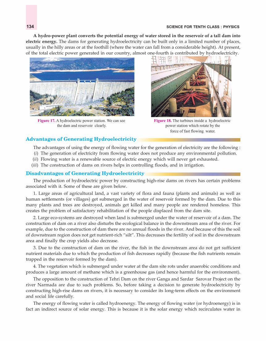
SCIENCE FOR TENTH CLASS : PHYSICS134
A hydro-power plant converts the potential energy of water stored in the reservoir of a tall dam intoelectric energy. The dams for generating hydroelectricity can be built only in a limited number of places,usually in the hilly areas or at the foothill (where the water can fall from a considerable height). At present,of the total electric power generated in our country, almost one-fourth is contributed by hydroelectricity.
Figure 17. A hydroelectric power station. We can see Figure 18. The turbines inside a hydroelectric the dam and reservoir clearly. power station which rotate by the
force of fast flowing water.
Advantages of Generating Hydroelectricity
The advantages of using the energy of flowing water for the generation of electricity are the following :(i) The generation of electricity from flowing water does not produce any environmental pollution.
(ii) Flowing water is a renewable source of electric energy which will never get exhausted.(iii) The construction of dams on rivers helps in controlling floods, and in irrigation.
Disadvantages of Generating HydroelectricityThe production of hydroelectric power by constructing high-rise dams on rivers has certain problems
associated with it. Some of these are given below.
1. Large areas of agricultural land, a vast variety of flora and fauna (plants and animals) as well ashuman settlements (or villages) get submerged in the water of reservoir formed by the dam. Due to thismany plants and trees are destroyed, animals get killed and many people are rendered homeless. Thiscreates the problem of satisfactory rehabilitation of the people displaced from the dam site.
2. Large eco-systems are destroyed when land is submerged under the water of reservoir of a dam. Theconstruction of dam on a river also disturbs the ecological balance in the downstream area of the river. Forexample, due to the construction of dam there are no annual floods in the river. And because of this the soilof downstream region does not get nutrient-rich “silt”. This decreases the fertility of soil in the downstreamarea and finally the crop yields also decrease.
3. Due to the construction of dam on the river, the fish in the downstream area do not get sufficientnutrient materials due to which the production of fish decreases rapidly (because the fish nutrients remaintrapped in the reservoir formed by the dam).
4. The vegetation which is submerged under water at the dam site rots under anaerobic conditions andproduces a large amount of methane which is a greenhouse gas (and hence harmful for the environment).
The opposition to the construction of Tehri Dam on the river Ganga and Sardar Sarovar Project on theriver Narmada are due to such problems. So, before taking a decision to generate hydroelectricity byconstructing high-rise dams on rivers, it is necessary to consider its long-term effects on the environmentand social life carefully.
The energy of flowing water is called hydroenergy. The energy of flowing water (or hydroenergy) is infact an indirect source of solar energy. This is because it is the solar energy which recirculates water in

SOURCES OF ENERGY 135
Wind energy(Kinetic energy)
WIND
ShaftSmallelectric generator
Electricity
Windturbine
Pole
Figure 19. A wind-powered electric generator.
nature in the form of water-cycle. It is this water which then flows in the rivers and makes water-energyavailable to us.
WIND ENERGYMoving air is called wind. Wind has energy. The energy possessed by wind is due to its high speed (or
motion). So, the wind possesses kinetic energy. It is this kinetic energy of wind which is utilised for doingwork. Solar energy (or sun’s energy) is responsible for the blowing of wind. Wind blows due to the unevenheating of earth by the sun in different regions. So, wind energy comes from the sun in an indirect way.
The energy of wind is harnessed by using a windmill. A windmill consists of big sized, table fan likeblades which are fixed over the top of a tall pole in such a way that they are free to rotate. When the fastmoving wind strikes on the blades of windmill, it makes them rotate continuously. The rotatory motion ofthe windmill is then used to do mechanical work through a shaft connected to the rotating blades.
In the past, wind energy was used through windmills to pump water (or lift water) from a well and togrind wheat into flour. This happened as follows : When the blades of windmill rotate by the force of wind,a shaft connected to them also rotates. This rotating shaft was made to run a water pump to lift water froma well by a suitable mechanism. It could also turn the mill-stones of a flour mill. The traditional use ofwind energy has now been modified by the improvement in technology to generate electricity throughwind-powered generators. This is explained below.
Wind Generator
The windmill used for generating electricity is called a wind turbine, and the complete set-up ofgenerating electricity by using wind energy is called ‘wind generator’. We will now describe a wind poweredelectric generator in somewhat detail.
A wind generator which is used to generate electricity byusing wind energy is shown in Figure 19. When the fast movingwind strikes the blades of wind turbine, then the wind turbinestarts rotating continuously. The shaft of wind turbine isconnected to a small generator. When the wind turbine rotates,its shaft also rotates and drives the generator. The generatorproduces electricity.
The electricity generated by a single wind turbine is quitesmall (because a single wind turbine can run only a smallgenerator). So, in order to generate a large amount of electricity,a large number of wind turbines are erected over a big area ofland. Such a set-up of having a large number of wind turbinesworking at a place to generate electrical energy on a large scaleis called a wind energy farm (see Figure 20). The smallelectricity generated by each wind generator is combinedtogether to obtain electricity on a large scale.
An important advantage of using wind energy for generating electricity is that its usedoes not cause any pollution. Another advantage is that wind energy is a renewable sourceof energy which will never get exhausted. As long as the sun keeps shining, the wind willkeep blowing and provide us energy. The increased use of wind energy for generatingelectricity will help us conserve fossil fuels (like coal, petroleum and natural gas) so thatthey may last longer. Moreover, wind energy is available free of cost !
Some of the limitations of harnessing wind energy for generating electricity are as follows :(i) Wind energy farms cannot be established everywhere. The wind energy farms can be established
only at those places where wind blows for most part of the year.
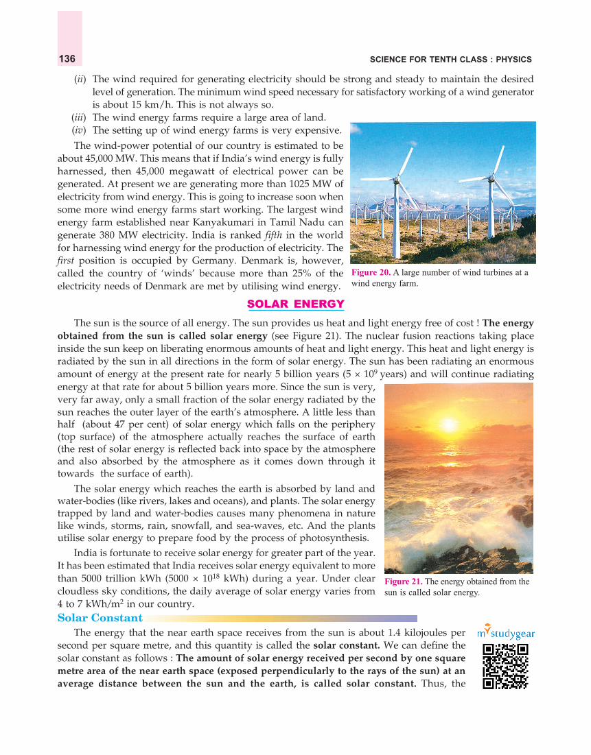
SCIENCE FOR TENTH CLASS : PHYSICS136
Figure 20. A large number of wind turbines at awind energy farm.
Figure 21. The energy obtained from thesun is called solar energy.
(ii) The wind required for generating electricity should be strong and steady to maintain the desiredlevel of generation. The minimum wind speed necessary for satisfactory working of a wind generatoris about 15 km/h. This is not always so.
(iii) The wind energy farms require a large area of land.(iv) The setting up of wind energy farms is very expensive.
The wind-power potential of our country is estimated to beabout 45,000 MW. This means that if India’s wind energy is fullyharnessed, then 45,000 megawatt of electrical power can begenerated. At present we are generating more than 1025 MW ofelectricity from wind energy. This is going to increase soon whensome more wind energy farms start working. The largest windenergy farm established near Kanyakumari in Tamil Nadu cangenerate 380 MW electricity. India is ranked fifth in the worldfor harnessing wind energy for the production of electricity. Thefirst position is occupied by Germany. Denmark is, however,called the country of ‘winds’ because more than 25% of theelectricity needs of Denmark are met by utilising wind energy.
SOLAR ENERGYThe sun is the source of all energy. The sun provides us heat and light energy free of cost ! The energy
obtained from the sun is called solar energy (see Figure 21). The nuclear fusion reactions taking placeinside the sun keep on liberating enormous amounts of heat and light energy. This heat and light energy isradiated by the sun in all directions in the form of solar energy. The sun has been radiating an enormousamount of energy at the present rate for nearly 5 billion years (5 × 10⁹ years) and will continue radiatingenergy at that rate for about 5 billion years more. Since the sun is very,very far away, only a small fraction of the solar energy radiated by thesun reaches the outer layer of the earth’s atmosphere. A little less thanhalf (about 47 per cent) of solar energy which falls on the periphery(top surface) of the atmosphere actually reaches the surface of earth(the rest of solar energy is reflected back into space by the atmosphereand also absorbed by the atmosphere as it comes down through ittowards the surface of earth).
The solar energy which reaches the earth is absorbed by land andwater-bodies (like rivers, lakes and oceans), and plants. The solar energytrapped by land and water-bodies causes many phenomena in naturelike winds, storms, rain, snowfall, and sea-waves, etc. And the plantsutilise solar energy to prepare food by the process of photosynthesis.
India is fortunate to receive solar energy for greater part of the year.It has been estimated that India receives solar energy equivalent to morethan 5000 trillion kWh (5000 × 1018 kWh) during a year. Under clearcloudless sky conditions, the daily average of solar energy varies from4 to 7 kWh/m2 in our country.Solar Constant
The energy that the near earth space receives from the sun is about 1.4 kilojoules persecond per square metre, and this quantity is called the solar constant. We can define thesolar constant as follows : The amount of solar energy received per second by one squaremetre area of the near earth space (exposed perpendicularly to the rays of the sun) at anaverage distance between the sun and the earth, is called solar constant. Thus, the

SOURCES OF ENERGY 137
solar constant tells us the amount of energy which falls in 1 second on a 1 square metre area of the nearearth space at an average distance between the sun and the earth. The value of solar constant is 1.4 kJ/s/m2
or 1.4 kW/m2 (because : 1 kJ/s = 1 kW).
Solar Energy DevicesThe sun is one of the major sources of renewable energy. Solar energy consists of heat and light. Scientists
have made a number of devices which help in utilising the solar energy directly in our everyday life. Thedevices which work by using solar energy (or sun’s energy) are : Solar cooker, Solar water heater, andSolar cell.
A device which gets heated by using sun’s heat energy is called a solar heating device. A solarcooker and solar water heater are solar heating devices. Though a large amount of sun’s heat energy fallson the earth but it is very much diffused (spread over a large area) and not concentrated. So, in order to usesun’s heat energy for heating purposes, we have to collect and concentrate it.
All the solar heating devices are designed in such a way that they help in collecting as much sun’sheat rays as possible. This is done by using a black painted surface, a glass sheet cover, and in some casesalso a plane mirror reflector. A black painted surface is used because black surface absorbs more heat raysof the sun than a white surface. A glass sheet is used as a cover in solar heating devices because a glasssheet traps more and more of sun’s heat rays by producing greenhouse effect. A plane mirror reflector isused (in solar cooker) to increase the area over which solar energy is collected so that more heat rays of thesun may enter the solar cooker box. Keeping these points in mind we will now describe the constructionand working of a solar cooker in detail.
Solar Cooker
The solar cooker is a device which is used to cook food by utilising the heat energy radiated by thesun. A solar cooker consists of an insulated metal box or wooden box which is painted all black frominside (see Figure 22). There is a thick glass sheet cover over the box and a plane mirror reflector is alsoattached to the box as shown in Figure 22. The food to be cooked is put in metal containers which arepainted black from outside. These metal containers are then placed inside the solar cooker box and coveredwith the glass sheet. We will now describe how the solar cooker works.
In order to cook food, the solar cooker is kept in sunshine,outside the house. The reflector of solar cooker is adjusted in sucha way that it faces the sun. When the sun’s rays fall on the reflector,the reflector sends them to the top of solar cooker box in the formof a strong beam of sunlight. The sun’s heat rays pass through theglass sheet cover and get absorbed by the black inside surface ofthe cooker box. Once the sun’s heat rays enter the cooker box, thenthe glass sheet cover does not allow them to go back. In this way,more and more heat rays of the sun get trapped in the box due towhich the temperature in the solar cooker box rises to about 100°Cto 140°C in two to three hours. This heat cooks the food materialskept in the black containers. For example, the food materials likerice, pulses (dal) and vegetables can be cooked in a box-typesolar cooker.
The box-type solar cooker can be used to cook only thosefood materials which require slow heating. The box-type solarcooker cannot be used to cook those foods where strong heating is required. For example, the box-typesolar cooker cannot be used for baking (chapattis, etc.) and for frying because they require stronger heating.In order to achieve higher temperatures required for baking and frying, spherical reflector-type solar cooker(having a concave reflector) is used. When a concave mirror reflector is attached to a solar cooker, it converges
Plane mirror(Reflector)
Glass sheetcover (or lid)
Cooking pots(painted blackfrom outside)
Figure 22. A box-type solar cooker.
Insulated box(painted blackfrom inside)

SCIENCE FOR TENTH CLASS : PHYSICS138
Figure 23. Solar water heater fitted on the roof of ahouse.
Solarcell Silicon-arsenic
layer
Silicon-boronlayer
Solar en
ergy
(from
sun)
(or su
nligh
t ene
rgy)
+
–
Figure 24. A solar cell.
a large amount of sun’s heat rays at its focus due to which a high temperature is produced in the focus area(which is suitable for baking and frying). Thus, a concave mirror reflector is best suited for use in a solarcooker. We will now give the advantages and limitations of a solar cooker.
The important advantages of a solar cooker for cooking food are the following :(i) The use of solar cooker for cooking food saves precious fuels like coal, kerosene and LPG.
(ii) The use of solar cooker does not produce smoke due to which it does not pollute air.(iii) When food is cooked in solar cooker, its nutrients do not get destroyed. This is because in a solar
cooker, food is cooked at a comparatively lower temperature.(iv) In a solar cooker, up to four food items can be cooked at the same time.
Some of the important limitations (or disadvantages) of a solar cooker are given below :(i) The solar cooker cannot be used to cook food during
night time (because sunshine is not available at thattime).
(ii) If the day-sky is covered with clouds, even then solarcooker cannot be used to cook food.
(iii) The direction of reflector of solar cooker has to bechanged from time to time to keep it facing the sun.
(iv) The box-type solar cooker cannot be used for baking(making chapattis, etc.) or for frying.
If a coil of copper tube painted black from outside isplaced in a box similar to that of solar cooker, it will workas a solar water heater. This is because when water is passedthrough the copper coil, it will absorb sun’s heat rays andbecome hot. Solar water heaters are used to supply hot waterin big buildings like hotels and hospitals. A solar water heatercannot be used to get hot water during the night or on a cloudyday. Let us solve one problem now.
Sample Problem. A student constructed a model of box-type solar cooker. He used a transparent plasticsheet to cover the open face of the box. He found that this cooker does not function well. What modificationshould he make to enhance its efficiency ? Give reason.
Solution. Instead of using a plastic sheet, the student should use a transparent glass sheet to cover theopen face of the box. This is because a glass sheet can trap the heatrays of the sun very effectively by producing greenhouse effect. Atransparent plastic sheet cannot do that.
Solar CellsSolar cells use the energy in sunlight to produce electricity. Thus,
solar cell is a device which converts solar energy (or sun’s energy)directly into electricity. Since solar energy is also called sunlightenergy, so we can also say that a solar cell converts sunlight energyinto electrical energy. We will now discuss the solar cell in somewhatdetail.
A solar cell is usually made from silicon. A simple solar cellconsists of sandwich of a ‘silicon-boron layer’ and a ‘silicon-arseniclayer’ (see Figure 24). The amount of boron and arsenic present inthe two silicon layers is, however, very small. A small piece of wireis soldered into the top of upper layer of cell and another piece ofwire is soldered at the bottom of the lower layer (to tap the current).

SOURCES OF ENERGY 139
The solar cell is covered with a glass cover or a transparent plastic cover for protection. When sunlight fallson the surface of solar cell, it makes the loosely held electrons in the silicon atoms move due to which acurrent begins to flow in the wires connected to the top and bottom of the solar cell. The strength of currentproduced depends on the brightness of the light and the efficiency of solar cell. A potential difference (orvoltage) of about 0.5 V is generated between the top and bottom surface of a solar cell. At present, the bestdesigned solar cells can generate 240 W/m2
in bright sunlight, with a maximum efficiency of about 25%.A single solar cell can produce only a small
amount of electricity. In those cases where moreelectrical power is needed, a large number of solarcells are joined together in series. This group ofsolar cells is called a ‘solar cell panel’. Thus, asolar cell panel consists of a large number ofsolar cells joined together in a definite pattern(see Figure 25). A solar cell panel can providemuch more electric power than a single solar cell.The various solar cells in a solar cell panel arejoined together by using connecting wires madeof silver metal. This is because silver is the bestconductor of electricity. The use of silver forconnecting solar cells makes it more expensivebut it increases the efficiency of solar cell panel.At many places, the solar cell panels are mountedon specially designed inclined roofs so that moresolar energy (or sunlight) is incident on them.Solar cell panels can provide electricity at all those places where the usual electricity is not available. Forexample, solar cell panels are used to provide electricity in remote and inaccessible rural areas. This electricityis used there for lighting purposes, to run radio and TV sets and to operate water pumps for irrigation offields. In Figure 25, a solar cell panel is being used for running a water pump for irrigation in a distantvillage. The solar cell panel S has hundreds of solar cells joined together. The electricity produced by thissolar cell panel is stored in battery B (by charging it). This battery runs an electric motor M. And finally,this motor drives a pump P which pumps out the underground water.
The solar cells cannot work at night (when sunlight is not available). So, the electricity produced by asolar cell panel during the day time can be stored by charging a battery (like a car battery) and then usedat night to power lights.
The main advantages of solar cells are that they have no moving parts, they require almost nomaintenance, and work quite satisfactorily without the use of any light focussing device. Another advantageof solar cells is that they can be set up in remote, inaccessible and very sparsely inhabited areas where thelaying of usual power transmission lines is difficult and expensive.
The main disadvantage of solar cells is that they are very expensive. This is due to the followingreasons : (i) the special grade silicon needed for making solar cells is expensive, (ii) silver wire used tointerconnect solar cells for making solar cell panels is expensive, and (iii) the entire process of making solarcells is still very expensive. So, the extensive use of solar cells for generating electric power is limited dueto their high cost. Another disadvantage of solar cells is their low efficiency. They can convert only about25 per cent of the light energy falling on them into electricity.
Uses of Solar Cells1. Solar cells are used for providing electricity in artificial satellites and space probes.2. Solar cells are used for providing electricity to remote, inaccessible and isolated places where normal
electricity transmission lines do not exist.
Undergroundwater
Waterpump
Electricmotor Battery
M
BP
Solar cell
Solar cellpanel
S
Sunl
ight
(Sol
aren
ergy
)
Figure 25. A solar cell panel is being used for running a water pumpin a remote and inaccessible village where power transmission linesdo not exist.

SCIENCE FOR TENTH CLASS : PHYSICS140
3. Solar cells are used for the transmission of radio and television programmes in remote areas.4. Solar cells are used for providing electricity to ‘light houses’ situated in the sea and to off-shore oil
drilling rig platforms.5. Solar cells are used for operating traffic signals, watches, calculators and toys.
(a) This is a solar cell panel. It has a (b) A streel light working on (c) Solar cell panels are used to powerlarge number of solar cells solar cell panel artificial satellites
joined in seriesFigure 26. Solar cells and some of their uses.
Before we end this discussion on solar energy, we would like to compare the fossil fuels and the sun assources of energy.
(i) The sun is a renewable source of energy but fossil fuels are a non-renewable source of energy.(ii) The sun’s energy does not cause any pollution but burning of fossil fuels causes a lot of pollution.
(iii) The sun’s energy is available in a diffused form (scattered form) but fossil fuels provide energy inconcentrated form.
(iv) A special device (like solar cooker or solar cell) is always needed to utilise sun’s energy but this is notso in the case of fossil fuels.
(v) The sun’s energy is available only during the day time when the sun shines but energy of fossilfuels can be used all the time.
Before we go further and discuss biomass as a source of energy, please answer the following questions :
Very Short Answer Type Questions1. A hydro-power plant converts one form of energy into another. Name the two forms of energy.2. What type of energy is possessed by flowing water ?3. Flowing water can rotate a turbine. Which type of energy is used up by the turbine ?4. Name the original source of wind energy.5. What should be the minimum wind speed for the satisfactory working of a wind-powered electric generator ?6. Write one use of wind energy (a) in the past (b) at present.7. Why is the copper tube of a solar water heater painted black from outside ?8. What type of reactions occurring inside the sun produce solar energy ?9. Name some of the solar energy devices.
10. What type of reflector is used in a box-type solar cooker ?11. What is the range of temperature which can be achieved in a box-type solar cooker in two to three hours ?12. Name the device which converts sunlight into electricity.13. How much solar energy will be received by 1 m2 area in one hour if the solar constant be 1.4 kW/m2 ?14. Fill in the following blanks with suitable words :
A solar cell converts.............energy into................energy.
Short Answer Type Questions15. (a) What is the difference between a thermal power plant and a hydro power plant ?
(b) Which of the two causes serious air pollution and how ?

SOURCES OF ENERGY 141
16. Compare the sun and the fossil fuels as the sources of energy.17. What kind of mirror, concave, convex or plane, would be best suited for use in a solar cooker ? Why ?18. (a) Name that part of a box-type solar cooker which allows the sun’s heat rays to enter the box but does not
allow inside heat to go out.(b) Explain why, a plane mirror reflector is used in a box-type solar cooker.
19. What are the advantages and disadvantages of using a solar cooker ?20. (a) What is a solar cell ? Draw the labelled diagram of a solar cell.
(b) Name the semi-conductor material which is usually used for making solar cells.(c) Write the uses of solar cells.
21. State the advantages and disadvantages of using solar cells.22. What is a solar cell panel ? For what purpose is it used ? State its two main advantages.23. (a) What is solar constant ? What is the value of solar constant ?
(b) If the energy received by 5 m2 area in 10 minutes is 4200 kJ, calculate the value of solar constant.24. How has the traditional use of energy of flowing water been modified for our convenience ?25. How has the traditional use of wind energy been modified for our convenience ?
Long Answer Type Questions26. (a) What is hydroelectricity ? Explain the basic principle of generation of hydroelectricity with the help of a
labelled diagram.(b) State two advantages of producing hydroelectricity.(c) State two disadvantages of producing hydroelectricity.
27. (a) With the help of a labelled diagram, explain the construction and working of a solar cooker.(b) Why is the solar cooker box painted black from inside ?(c) Why is the solar cooker box covered with a glass sheet ?
28. (a) What is wind ? What type of energy is possessed by wind ?(b) Explain how, wind energy can be used to generate electricity. Illustrate your answer with the help of a
labelled diagram.(c) State two advantages of using wind energy for generating electricity.(d) Mention two limitations of wind energy for generating electricity.
Multiple Choice Questions (MCQs)29. A solar water heater cannot be used to get hot water on :
(a) a sunny day (b) a cloudy day (c) a hot day (d) a windy day30. At a hydro power plant :
(a) kinetic energy possessed by stored water is converted into electrical energy(b) electricity is extracted from water(c) water is converted into steam to turn turbines and produce electricity.(d) potential energy possessed by stored water is converted into electricity.
31. The part of box-type solar cooker which is responsible for producing greenhouse effect is :(a) plane mirror reflector (b) black coating inside the box(c) glass sheet cover (d) utensils placed in the cooker box
32. Solar cells are made of :(a) conductors (b) insulators (c) semi-conductors (d) super-conductors
33. The value of solar constant is :(a) 1.4 kWh (b) 1.4 kW/m (c) 1.4 kW/m2 (d) 1.4 kW/m3
34. The radiations present in sunlight which make a solar cooker work are :(a) visible light rays (b) ultraviolet rays (c) cosmic rays (d) infrared rays
35. In order to make an efficient solar cooker, the cover of cooker box should be made of :(a) transparent plastic sheet (b) shining aluminium sheet(c) butter paper sheet (d) transparent glass sheet

SCIENCE FOR TENTH CLASS : PHYSICS142
36. The minimum speed of wind necessary for the satisfactory working of a wind generator to produce electricityis about :(a) 15 km/h (b) 25 km/h (c) 35 km/h (d) 45 km/h
37. If the solar constant is 1.4 kW/m2, then the solar energy received by 1 m2 area in one hour is :(a) 5040 J (b) 504.0 kJ (c) 5040 kJ (d) 5.04 kJ
38. A solar cooker may not cook food if :(a) the solar cooker is not placed in the shade (b) the glass sheet cover of solar cooker is not closed(c) a convex mirror reflector is not used (d) the food containers of insulating material are not used
Questions Based on High Order Thinking Skills (HOTS)39. A large coal-fired power station produces 2000 MW of electrical energy. A wind turbine with 33 m blades
can produce 300 kW.(a) How many turbines would be needed to replace the power station ?(b) Why, in actual practice, this number of turbines could not replace the coal-fired power station ?
40. In a solar water heater, why is the storage tank placed at a higher level than the solar panel containingcoils ?
41. In many applications, solar cells are connected to rechargeable batteries. Why is this so ?42. (a) Solar cells are used to provide the electric current to charge the batteries of a car driven by an electric
motor. Describe the energy changes which take place.(b) What differences would you expect in the charging of car batteries (i) in bright sunlight (ii) on a cloudy
day (iii) at night ?
ANSWERS1. Potential energy (of stored water) into Electrical energy 2. Kinetic energy 3. Kinetic energy4. Sun 8. Nuclear fusion reactions 12. Solar cell 13. 5040 kJ 14. sunlight ; electrical15. (b) Thermal power plant ; Emits harmful gases and fly-ash into the air 18. (a) Glass sheet cover23. (b) 1.4 kJ/s/m2 29. (b) 30. (d) 31. (c) 32. (c) 33. (c) 34.(d) 35. (d) 36. (a) 37. (c) 38. (b)39. (a) 6667 turbines (b) Efficiency of steam turbines used in coal-fired power station remains the samebut the efficiency of wind turbines changes due to the changes in wind speed 40. Hot water, being lighter,rises to the top 41. The electricity made by solar cells during the day time is stored in rechargeable batteriesso that it can be used later on, for example, at night 42. (a) Solar cells convert Sunlight energy intoElectrical energy ; During charging the batteries, Electrical energy is converted into Chemical energy ; Duringthe use of batteries, Chemical energy is converted into Electrical energy ; Electric motor converts Electricenergy into Kinetic energy (which drives the car) (b) (i) Batteries are charged quickly (ii) Batteries arecharged very slowly (iii) Batteries are not charged at all.
BIOMASS ENERGYThe dead parts of plants and trees, and the waste material of animals are called biomass. Biomass is the
organic matter which is used as a fuel to produce energy. Biomass includes wood, agricultural wastes(crop residues) and cow-dung. Biomass contains chemical energy in the form of carbon compounds. Driedbiomass (like wood) is the oldest source of heat energy which is still widely used as a fuel for domesticpurposes. Actually, biomass is another form in which solar energy manifests itself. This is because all theplants and trees which provide biomass (like wood) used sun’s energy to grow. Even the animal wastes(like cow-dung) are given by cattle who grew by consuming plant food made with the help of sunlightenergy. Since the fuels like wood, agricultural wastes and cow-dung are all plant and animal products, sothey are called biomass (or biofuels). Please note that biomass is a renewable source of energy because itis obtained from plants (or animals) which can be produced again and again.
The Case of Wood and Charcoal
Wood is biomass. When wood is burnt, heat is produced. So, wood has been used as a fuel for a longtime (Wood that is burnt as a fuel is called firewood). Wood is a renewable source of energy. Wood isobtained by cutting down the trees. Now, if we can ensure that enough trees are planted in place of cut

SOURCES OF ENERGY 143
down trees, then a continuous supply of firewood can be obtained. The traditional use of wood as a fuelhas many disadvantages. For example : (i) the burning of wood produces a lot of smoke which pollutes theair, and (ii) the calorific value (or heat value) of wood is low, being only 17 kJ/g. This means that woodproduces less heat per unit mass, on burning.
Figure 27. Wood is still used as a domestic fuel Figure 28. Charcoal is a better fuel than wood. Itto cook food in many parts of our country. has a higher calorific value and burns
without producing smoke.Due to improvement in the technology for using the conventional sources of energy, wood can be
converted into a much better fuel called charcoal. Charcoal can be prepared from wood as follows :When wood is burnt in a limited supply of air, then water and other volatile materials present in it getremoved and a black substance ‘charcoal’ is left behind. Thus, wood minus volatile material is charcoal.Charcoal is mainly carbon (C). Charcoal is mainly used as a fuel for domestic purposes. Charcoal is abetter fuel than wood because of the following reasons :
(i) Charcoal has a higher calorific value than wood. That is, charcoal produces moreheat on burning than an equal mass of wood. For example, the calorific value (heatproducing value) of charcoal is higher, being about 33 kilojoules per gram, whereasthat of wood is low, being only 17 kilojoules per gram.
(ii) Charcoal does not produce smoke while burning whereas wood produces a lot ofsmoke on burning and pollutes the air.
(iii) Charcoal is a compact fuel which is easy to handle and convenientto use.
The Case of Cow-Dung and BiogasCow-dung is biomass. It is also known as ‘cattle dung’ or ‘animal
dung’ or just ‘dung’. Cow-dung is the ‘excreta’ of cattle such as cows andbuffaloes, etc. Cow-dung is usually semi-solid. In our villages, dried cow-dung cakes have been traditionally used as a fuel for cooking food. Whencow-dung cakes are burnt, they produce heat. This heat is used for cookingfood, etc. It is, however, not good to burn cow-dung directly as a fuelbecause of the following disadvantages :
(i) Cow-dung contains important elements like nitrogen andphosphorus (called nutrients), which are required by the soil tosupport crops. So, burning of dung in the form of dung cakesdestroys the useful nutrients which can otherwise be used as amanure in agriculture.
(ii) Dung cakes produce a lot of smoke on burning which causes airpollution.
(iii) Dung cakes do not burn completely, they produce a lot of ash asresidue.
(iv) Dung cakes have low calorific value (low heat producing value).
Figure 29. Cow-dung (or cattle dung)has been traditionaly used as a fuel inthe form of dried dung cakes. Burningof dried dung cakes releases biomassenergy as heat.

SCIENCE FOR TENTH CLASS : PHYSICS144
Slurry of cow-dungand water
Mixingtank
Inletchamber
Slabcover
Dome
Outlet forbio-gas
Gas valve Slab cover
Overflowtank
Spent slurry(Manure)
Outletchamber
Bio-gas
F
O
S
Dung and watermixture
Undergrounddigester tank
M
Ground level
V
D
I
Since there are many disadvantages in using cow-dung as a fuel directly, it is better to preparebiogas (or gobar gas) from cow-dung. And this gas can then be used as a smokeless fuel. After extractingthe biogas, the spent cow-dung can be used as a manure because it still contains all the ‘nutrient elements’which were present in it initially. Only the organic matter of cow dung is decomposed and converted intobiogas. The other elements like nitrogen and phosphorus, etc., remain intact. In this way, the nutrients likenitrogen and phosphorus can be returned to the soil in the form of manure. When used in this way, cow-dung gives us a double advantage : (i) it gives us a clean fuel called biogas, and (ii) the spent dung can be usedas a manure.
Before we discuss biogas in detail, it will be good to know the meaning of the term “anaerobicdegradation”. The decomposition which takes place in the absence of oxygen is called anaerobicdegradation. Anaerobic degradation is carried out by the micro-organisms called anaerobic bacteria (whichdo not require oxygen to decompose complex organic compounds like those present in cow-dung). Let usdiscuss the biogas now.
Biogas is not a single gas. It is a mixture of gases. Biogas is a mixture of methane, carbon dioxide,hydrogen and hydrogen sulphide. The major constituent of biogas is methane, which is an extremelygood fuel. In fact, biogas contains up to 75 per cent of methane gas which makes it an excellent fuel.Biogas is produced by the anaerobic degradation of animal wastes like cow-dung (or plant wastes) inthe presence of water. This degradation is carried out by anaerobic micro-organisms called anaerobicbacteria in the presence of water but in the absence of oxygen. Cow-dung and plant wastes contain a lot ofcomplex carbon compounds like carbohydrates, proteins and fats. The anaerobic bacteria degrade(decompose) these carbon compounds to form methane gas, which is the main constituent of biogas. Someother gases like carbon dioxide, hydrogen and hydrogen sulphide are also formed. Cow-dung is known as‘gobar’ in Hindi. Since biogas is prepared mainly from cow-dung, so biogas is popularly known as ‘gobargas’ in our villages. We will now describe a biogas plant which is also known as gobar-gas plant.
Biogas PlantA biogas plant consists of a well-shaped, underground tank T called digester, which is made of bricks,
and has a dome-shaped roof D, also made of cement and bricks (Figure 30). The digester is a kind of sealedtank in which there is no air (or oxygen). The dome of the digester tank acts as a gas-holder or storage tankfor the biogas. There is a gas outlet S at the top of the dome having a valve V. On the left side of thedigester tank is a sloping inlet chamber I and on the right side is a rectangular outlet chamber O, both
Figure 30. A biogas plant.

SOURCES OF ENERGY 145
made of bricks. The inlet chamber is for introducing fresh dung slurry into the main digester tank whereasthe outlet chamber is for taking out the spent dung slurry after the extraction of biogas. The inlet chamberis connected to a mixing tank M while the outlet chamber is connected to the overflow tank F.
We will now describe the working of a biogas plant. Cow-dung and water are mixed in equal proportionsin the mixing tank M to prepare the slurry. This slurry of dung and water is fed into the digester tank Tthrough the inlet chamber I. The digester tank is filled with dung slurry upto the cylindrical level (asshown in Figure 30), the dome being left free for the collection of biogas. It takes about 50 to 60 days for thenew gas-plant to become operative (start functioning). During this period, the cow-dung undergoesdegradation by anaerobic bacteria in the presence of water (but absence of oxygen) with the gradual evolutionof biogas. This biogas starts collecting in the dome. As more and more biogas collects in the dome, it exertspressure on the slurry in the digester tank, and forces the spent slurry to go into overflow tank F (Figure30), through the outlet chamber O. From the overflow tank, the spent slurry is removed gradually. Thespent dung-slurry, left after the extraction of biogas, is rich in nitrogen and phosphorus compounds andhence forms a good manure.
Once the gas-plant becomes operative, more fresh dung slurry is added to the digester tank regularlyand this leads to the continuous biogas production. The biogas which has collected in the dome of thedigester tank is taken out through the outlet S and supplied to village homes through a network of pipes tobe used as a cooking gas.
Please note that though mostly we use cow-dung in biogas plants,but human excreta (human faeces) can also be added alongwith cow-dung in biogas plants. Agricultural wastes, vegetable wastes, poultrydroppings, and paper scrap can also be used for producing biogas. Insome of the cities of our country we have sewage gas plants (Sewageis the dirty drain water containing human excreta). Biogas can also beobtained by the action of anaerobic bacteria on domestic sewage inthe absence of air. The biogas obtained from the degradation ofdomestic sewage is also called sewage gas. So, at many places in ourcountry, domestic sewage is digested in large sewage gas plants toproduce biogas as well as manure. The large scale utilisation ofbiowastes and sewage materials for producing biogas can provide usa safe and efficient method of waste disposal besides supplying energyand manure. The important uses of biogas are given below :
1. Biogas is used as a fuel for cooking food. When biogas is burnedin a gas stove, it produces a lot of heat. This heat is used for cooking food and for other domesticheating purposes. Biogas is a good domestic fuel because of the following reasons :
(a) Biogas burns without smoke and hence does not cause air pollution.(b) Biogas has a high calorific value. That is, biogas produces a large amount of heat per unit mass.(c) Biogas burns completely without leaving behind any residue (unlike wood, charcoal or coal). So, it
is a clean fuel.(d) There is no storage problem for biogas as it is supplied by pipes directly from the gas plant.(e) Biogas is cheaper than most common fuels.
2. Biogas is also used for lighting.
3. Biogas is used as a fuel to run engines. At many places, the engines of water pumping sets used forirrigation are run on biogas, instead of diesel.
4. Biogas is used for generating electricity.
Biogas is a renewable source of energy. Since India has a large population of cattle and other farmanimals (called livestock) to provide animal dung, therefore, biogas can become a steady source of energy
Figure 31. Cow-dung being fed into abiogas plant in a village of India.

SCIENCE FOR TENTH CLASS : PHYSICS146
in our rural areas. Before we end this discussion on biomass as a source of energy, we would like tocompare the biomass and hydroelectricity as sources of energy.
(i) Biomass is a renewable source of energy and hydroelectricity is also a renewable source of energy.(ii) The use of biomass by burning causes air pollution but the use of hydroelectricity does not cause
any pollution.(iii) Biomass gives heat energy which can be used for cooking and heating only. On the other hand,
hydroelectricity can run all types of electrical appliances.(iv) Biomass energy can be obtained without using any special device but hydroelectricity can be
produced only by establishing hydro-power plants.
ENERGY FROM THE SEAThe energy from the sea can be obtained mainly in three forms :(i) Tidal energy,
(ii) Wave energy, and(iii) Ocean thermal energy.We will now describe these three means of obtaining energy from the sea in somewhat detail.
1. Tidal EnergyThe rise of sea water due to gravitational pull of the moon is called “high tide” whereas the fall of sea
water is called “low tide.” The tidal waves in the sea build up and recede (rise and fall) twice a day. Theenormous movement of water between the high tides and low tides provides a very large source of energyin the coastal areas of the world. The tidal energy can be harnessed by constructing a tidal barrage or tidaldam across a narrow opening to the sea (see Figure 32).
Water storedat high tide
WaterLowtide
SEA
Tidal barrage(or Tidal dam)
High tideReservoir
Turbine
SEA
Water
(a) At high tide, water flows from sea into (b) At low tide, stored water flows out fromreservoir and turns the turbine reservoir into sea and turns the turbine
Figure 32. Tidal energy.
During high tide, when the level of water in the sea is high, sea-waterflows into the reservoir of the barrage and turns the turbines [see Figure32(a)]. The turbines then turn the generators to produce electricity. Andduring the low tide, when the level of sea-water is low, the sea-waterstored in the barrage reservoir is allowed to flow out into the sea. Thisflowing water also turns the turbines and generates electricity [see Figure32(b)]. Thus, as sea-water flows in and out of the tidal barrage duringhigh and low tides, it turns the turbines to generate electricity. The tidalenergy is not likely to be a potential source of energy in future because ofthe following reasons :
(i) There are very few sites around the world which are suitable forbuilding tidal barrages (or tidal dams). Figure 33. A tidal power station. It gene-
rates electricity from the tides in the sea.

SOURCES OF ENERGY 147
(ii) The rise and fall of sea-water during high and low tides is not enough to generate electricity on alarge scale.
2. Wave Energy
Wave energy here means ‘sea-waves energy’. Energy from the sea is also available in the form of seawaves. Due to the blowing of wind on the surface of sea, very fast sea-waves (or water waves) move onits surface. Due to their high speed, sea-waves have a lot of kinetic energy in them. The energy of movingsea-waves can be used to generate electricity. A wide variety of devices have been developed to trap seawave energy to turn turbines and drive generators for the production of electricity.
(i) One idea is to set-up floating generators in the sea. These would move up and down with the sea-waves. This movement would drive the generators to produce electricity.
(ii) Another idea is to let the sea-waves move up and down inside large tubes. As the waves move up,the air in the tubes is compressed. This compressed air can then be used to turn a turbine of agenerator to produce electricity.
These ideas are only experimental in nature. Models have been made based on these ideas but it willbe many years before full-size wave-energy generators can be built to harness the sea-waves energy on alarge scale. The harnessing of sea-waves energy would be a viable proposition only at those places wheresea-waves are very strong.
3. Ocean Thermal EnergyA very large area of sea is called an ocean. The water at the surface of an ocean gets heated by the heat
of the sun and attains a higher temperature than the colder water at deeper levels in the ocean. So, there isalways a temperature difference between the water “at the surface of ocean” and “at deeper levels.” Theenergy available due to the difference in the temperature of water at the surface of the ocean and atdeeper levels is called ocean thermal energy (OTE). The ocean thermal energy can be converted into a“usable form” of energy like electricity. This can be done as follows :
The devices used to harness ocean thermal energy are called Ocean Thermal Energy Conversion powerplants (or OTEC power plants). A temperature difference of 20°C (or more) between the surface water ofocean and deeper water is needed for operating OTEC power plants. In one type of OTEC power plant, thewarm surface water of ocean is used to boil a liquid like ammonia or a chlorofluorocarbon (CFC). The highpressure vapours of the liquid (formed by boiling) are then used to turn the turbine of a generator andproduce electricity. The colder water from the deeper ocean is pumped up to cool the used up vapoursand convert them again into a liquid. This process is repeated again and again.
A great advantage of the ocean thermal energy is that it can be used continuously 24 hours a daythroughout the year. Another advantage is that ocean thermal energy is a renewable source of energy andits use does not cause any pollution. Please note that wave energy and ocean thermal energy are the twoforms in which solar energy manifests itself in oceans. Another point to be noted is that though theenergy potential from the sea (tidal energy, wave energy and ocean thermal energy) is very large but itslarge scale exploitation is difficult at the moment.
GEOTHERMAL ENERGY‘Geo’ means ‘earth’ and ‘thermal’ means ‘heat’. Thus, geothermal energy is the heat
energy from hot rocks present inside the earth. This heat can be used as a source of energyto produce electricity. Please note that geothermal energy is one of the few sources ofenergy that do not come directly or indirectly from solar energy (or sun’s energy).
At some places in the world, the rocks at some depth below the surface of the earth are very, very hot.This heat comes from the fission of radioactive materials which are naturally present in these rocks. Theplaces where very hot rocks occur at some depth below the surface of earth are called ‘hot spots’, and are

SCIENCE FOR TENTH CLASS : PHYSICS148
sources of geothermal energy. The geothermal energy isharnessed as follows :
The extremely hot rocks present below the surface of earthheat the underground water and turn it into steam (see Figure34). As more and more steam is formed between the rocks, itgets compressed to high pressures. A hole is drilled into theearth up to the hot rocks and a pipe is put into it. The steampresent around the hot rocks comes up through the pipe at highpressure. This high pressure steam turns the turbine of agenerator to produce electricity.
Sometimes two holes are drilled into the earth in the region of hot rocks and two pipes are put intothem. Cold water is pumped in through one of the pipes. This cold water is turned into steam by the hotrocks. The steam thus formed comes out through the other pipe and used to generate electricity.
Some of the advantages of using geothermal energy are as follows : It is economical to use geothermalenergy. This is because the cost of electricity produced by using geothermal energy is almost half of thatproduced from conventional energy sources. Another advantage is that the use of geothermal energy doesnot cause any pollution. So, it is a clean and environment friendly source of energy. Some of thedisadvantages of geothermal energy are as follows : Geothermal energy is not available everywhere. It isavailable only in those areas where there are hot rocks near the earth’s surface. Another disadvantage isthat deep drilling in the earth to obtain geothermal energy is technically very difficult and expensive.
In our country there are a very limited number of places where geothermal energy can be harnessed ona commercial scale. Two places where geothermal energy can be exploited on commercial scale are locatedin Madhya Pradesh and Himachal Pradesh. In USA and Newzealand, a number of geothermal energypower plants are working successfully. We are now in a position to answer the following questions :
Very Short Answer Type Questions1. What substance is obtained as a residue when wood is burned in a limited supply of air ?2. Name one source of energy which is not derived from solar energy directly or indirectly.3. What name is given to the heat energy obtained from hot rocks inside the earth ?4. Name the agent which decomposes animal dung into biogas.5. Which component of biogas is used as a fuel ?6. Name the constitutents of biogas.7. Which of the following is needed for the formation of biogas from cow-dung and which not ?
Water, Oxygen8. Name the clean fuel which can be obtained from cow-dung.9. Apart from cattle dung, what other substances can be added to a biogas plant ?
10. Name any three forms of energy which could be harnessed from the sea.11. Write two forms in which solar energy manifests itself in sea.12. Write the full form of OTE.13. What is the function of anaerobic micro-organisms such as anaerobic bacteria in a biogas plant ?14. State whether the following statement is true or false :
Tidal energy is one of the forms in which solar energy manifests itself in oceans.15. Fill in the following blanks with suitable words :
(a) Biomass is another form in which .......... energy manifests itself.(b) Tidal waves build up and recede.............. a day.
Short Answer Type Questions16. (a) What is biomass ? Give three examples of biomass.
(b) Name the biomass which is still widely used as a source of heat energy in many households of ourcountry.
17. What are the two ways in which cow-dung can be used as a fuel ? Which of them is better and why ?
Figure 34. Geothermal energy can be used toproduce electricity.

SOURCES OF ENERGY 149
18. How is charcoal prepared ? Explain why, charcoal is a better fuel than wood.19. Compare and contrast biomass and hydroelectricity as sources of energy.20. Why is biogas considered an ideal fuel for domestic use ?21. (a) Explain how tidal energy can be used to generate electricity.
(b) Why is tidal energy not likely to be a potential source of energy ?22. State two ways in which the energy of sea-waves can be harnessed.23. What is meant by ocean thermal energy ? Explain how ocean thermal energy can be used to generate
electricity.24. What are the limitations of energy that can be harnessed from the sea ?25. Suggest a safe and efficient method for the disposal of biowastes and sewage materials. How is this method
advantageous to us ?26. Which of the following sources of energy are not derived from the sun ?
Biomass, Wind, Ocean thermal energy, Geothermal energy, Nuclear fuels, Hydroelectricity, Wave energy, Coal, Petroleum, Tidal energy
Long Answer Type Questions27. (a) What is biogas ? Name the major component of biogas.
(b) What are the raw materials used for making biogas ?(c) Describe the construction and working of a biogas plant with the help of a labelled diagram.(d) Write any two uses of biogas.(e) Write any two advantages of using biogas.
28. (a) What is geothermal energy ?(b) What is the source of heat contained in geothermal energy ?(c) Explain how, geothermal energy is used to generate electricity.(d) State two advantages of geothermal energy.(e) State two disadvantages of geothermal energy.
Multiple Choice Questions (MCQs)
29. Which of the following is not an example of a biomass energy source ?(a) wood (b) biogas (c) atomic energy (d) cow-dung
30. Most of the sources of energy that we use represent stored solar energy. Which of the following is notultimately derived from the sun’s energy ?(a) wind energy (b) geothermal energy (c) fossil fuels (d) biomass
31. The constituent of biogas which makes it an excellent fuel is :(a) butane (b) methane (c) propane (d) ethane
32. The major component of biogas is :(a) hydrogen (b) butane (c) hydrogen sulphide (d) methane
33. Which of the following is more environment friendly ?(a) burning of diesel (b) burning of coal (c) burning of charcoal (d) burning of wood
34. Which one of the following is not renewable energy technology ?(a) solar cells (b) windmills (c) nuclear power (d) tidal power
35. The rise of sea-water during high tide is caused by the gravitational pull of the :(a) Sun (b) Earth (c) Moon (d) Mars
36. One of the following is not required in the formation of biogas in a biogas plant. This is :(a) cow-dung (b) water (c) oxygen (d) anaerobic bacteria
37. The fuel which is not obtained from biomass is :(a) firewood (b) cow-dung cakes (c) coke (d) charcoal
38. The non-renewable source of energy among the following is :(a) hydroelectricity (b) sewage gas (c) natural gas (d) gobar gas
39. Geothermal energy is produced by the :(a) fission of radioactive materials

SCIENCE FOR TENTH CLASS : PHYSICS150
(b) burning of coal inside the coal mines(c) combustion of natural gas deep inside the earth(d) fusion of radioactive substances
40. The harnessing of which of the following leads to the destruction of large eco-systems ?(a) thermal power (b) tidal power (c) hydro power (d) geothermal power
41. Which of the following is not a consequence of establishing hydroelectric power plants ?(a) displacement of people (b) production of methane(c) occurrence of floods (d) ecological disturbance
Questions Based on High Order Thinking Skills (HOTS)42. A certain form of energy is available due to the difference in the temperature of water at the surface of the
ocean and its deeper levels.(a) Name the form of energy.(b) Is this energy ultimately derived from the sun or not ?(c) Explain how this form of energy can be converted into electricity.(d) What is the minimum temperature difference in water at the surface of ocean and its deeper level which
is required to operate power plants based on this energy ?43. The gravitational pull of the moon causes the sea-water to rise periodically.
(a) What name is given to the condition of the sea when its water is raised ?(b) What name is given to the condition of the sea when its raised water recedes ?(c) What name is given to the energy which can be harnessed from this natural phenomenon ?(d) Draw labelled diagram to show how this energy can be harnessed to generate electricity.
44. When the material A mined from the earth is heated strongly in an insufficeint supply of air, it produces asolid fuel B which consists mainly of carbon. When another material C obtained from trees is heated in aninsufficient supply of air, it produces another solid fuel D which also consists mainly of carbon. Name A, B,C and D.
45. A certain form of energy which is not sourced directly or indirectly from the sun and does not cause anypollution is very easily converted into electricity. This form of energy is, however, not available everywhere.Moreover, it is technically very difficult and expensive to obtain it. Name the form of energy.
ANSWERS1. Charcoal 2. Geothermal energy 3. Geothermal energy 4. Anaerobic bacteria 5. Methane7. Needed : Water ; Not needed : Oxygen 8. Biogas 11. Sea-waves energy ; Ocean thermal energy14. False 15. (a) solar (b) twice 16. (b) Wood 29. (c) 30. (b) 31. (b) 32. (d) 33. (c) 34. (c)35. (c) 36. (c) 37. (c) 38. (c) 39. (a) 40. (c) 41. (c) 42. (a) Ocean thermal energy(b) No (d) 20°C 43. (a) High tide (b) Low tide (c) Tidal energy 44. A is coal ; B is coke; C is wood; D is charcoal 45. Geothermal energy
NUCLEAR ENERGYA physical reaction which involves changes in the nucleus of an atom is called a nuclear reaction. The
energy released during a nuclear reaction is called nuclear energy (because it comes from the nucleus ofan atom). Nuclear energy can be obtained by two types of nuclear reactions :
(i) Nuclear fission, and(ii) Nuclear fusion.
The source of nuclear energy is the mass of nucleus. A small amount of mass of nucleus is destroyedduring a nuclear reaction which gets converted into a tremendous amount of energy. The nuclear energyis released mainly in the form of heat (and some light). The nuclear energy is also known as atomic energybecause it can be considered to be coming from the atoms. We will now describe the nuclear reactions offission and fusion in detail, one by one. Let us start with nuclear fission.

SOURCES OF ENERGY 151
1. NUCLEAR FISSIONThe word ‘fission’ means to ‘split up’ into two or more parts. The process in which the heavy nucleus
of a radioactive atom (such as uranium, plutonium or thorium) splits up into smaller nuclei whenbombarded with low energy neutrons, is called nuclear fission. A tremendous amount of energy isproduced in the nuclear fission process. The sum of masses of the smaller nuclei formed in a fission reactionis a little less than that of the mass of the original heavy nucleus. So, there is a small loss of mass in the nuclearfission process which appears as a tremendous amount of energy. Please note that nuclear fission is carried out bybombarding the heavy nuclei with low energy neutrons which are also called slow moving neutrons. Wewill now give an example of a nuclear fission reaction. We will use the easily fissionable isotope of uraniumcalled uranium-235 in this example.
When uranium-235 atoms are bombarded with slow moving neutrons, the heavy uraniumnucleus breaks up to produce two medium-weight atoms, barium-139 and krypton-94, withthe emission of 3 neutrons. A tremendous amount of energy is produced during the fissionof uranium. This fission reaction can be represented in the form of a nuclear equation as :
235 1 139 94 192 0 56 36 0
FissionU + n Ba + Kr 3 n + Tremendous amount of energy
Heavy atom Neutron Medium weight atoms Neutrons
In the fissioning of uranium, some mass of uranium disappears (is lost), and a tremendous amount ofenergy is produced. An idea of the tremendous amount of energy produced during nuclear fission reactioncan be had from the fact that the fission of 1 atom of uranium-235 produces 10 million times more energythan the energy produced by the burning of 1 atom of carbon from coal. The energy produced duringnuclear fission reactions is used for generating electricity at nuclear power plants. Please note that theenergy produced in a fission reaction is due to the conversion of mass into energy.
If we look at the above nuclear fission reaction equation, we find that the neutrons are used up as wellas produced. For example, in the nuclear fission of uranium-235 described above, 1 neutron is consumedand 3 neutrons are produced in the fission of each nucleus. The neutrons produced in a fission processcause further fission of the heavy nuclei leading to a self-sustaining chain reaction. When all the neutronsproduced during fission of uranium-235 are allowed to cause further fission, then so much energy is producedin a very short time that it cannot be controlled and leads to an explosion called atom bomb. We can,however, control a nuclear fission reaction by using control rods made of boron. Boron has a property thatit can absorb neutrons. So, when a nuclear fission reaction is carried out in the presence of boron rods, theexcess neutrons produced during successive fissions of uranium-235 atoms are absorbed by boron rodsand hence not available to cause further fission. Due to this a controlled fission reaction of uranium-235takes place liberating heat energy at a slow, steady and manageable rate which can be used for generatingelectricity at a nuclear power plant.
Figure 35. These hands hold a piece of uranium Figure 36. Uranium is used as a fuel in the reactor that is used as a fuel in nuclear power plants of a nuclear power plant in the form of
to generate electricity. uranium rods.

SCIENCE FOR TENTH CLASS : PHYSICS152
Nuclear Power PlantA power plant in which the heat required to make steam and turn turbines (to drive generators for
making electricity) is obtained by nuclear reactions, is called a nuclear power plant. The nuclear powerplants use the nuclear fission reaction to generate electricity. Most of the nuclear power plants use uranium-235 as fuel to produce heat. But uranium-235 fuel is not burnt like coal, oil or gas to obtain energy. Itsenergy is released by the nuclear fission process. A nuclear power plant is shown in Figure 37.
Figure 37. A nuclear power plant (or atomic power plant).
In a nuclear power plant, the fission of nuclear fuel uranium-235 is carried out in a steel pressure vesselV of reactor R (Reactor is a kind of nuclear furnace) (see Figure 37). The enriched uranium-235 rods markedA (called fuel elements) are inserted in a core made of graphite blocks inside the reactor. Graphite is calleda moderator. It slows down the speed of neutrons to make them fit for causing fission. In-between theuranium rods are inserted boron rods B. Boron rods are called control rods because they absorb excessneutrons and prevent the fission reaction from going out of control. Boron rods can be raised or lowered inthe reactor from outside (The part of boron rods which is inside the reactor absorbs neutrons). The reactoris enclosed in a concrete chamber M having thick walls to absorb the nuclear radiations (so as to protect theoutside world from the dangerous nuclear radiations). Liquid sodium (or carbon dioxide gas) is used as a‘coolant’ to transfer the heat produced in the reactor by fission to heat exchanger (or boiler) for convertingwater into steam. The rest of the arrangement at a nuclear power plant is shown in Figure 37. We will nowdescribe the working of a nuclear power plant.
The controlled fission of uranium-235 in the nuclear reactor produces a lot of heat energy. Liquid sodium(or carbon dioxide gas) is pumped continuously through the pipes embedded in reactor by using a pumpP (see Figure 37). Sodium absorbs the heat produced in the reactor. This extremely hot sodium is thenpassed into the coil of the heat exchanger H containing water. Water absorbs heat from hot sodium andboils to form steam. The hot steam at high pressure is introduced into a turbine chamber C having aturbine T. The pressure of steam makes the turbine rotate. The shaft S of turbine is connected to a generatorG. When the turbine rotates, its shaft also rotates and drives the generator. The generator produces electricity.
The spent steam coming out from the turbine chamber is passed through a condenser D. The condensercools the spent steam to form water. This water is again sent to the heat exchanger for forming fresh steam.A nuclear power plant can work day and night for two to three years with the same uranium fuel. Pleasenote that the waste materials (called nuclear wastes) which are produced by the fission of uranium-235during the generation of electricity at a nuclear power plant are radioactive and hence extremely harmful toall living beings, plants as well as animals, including human beings.
Concretechamber
Nuclearreactor
Graphite core(Moderator)
Uraniumrods (Fuel)
Boroncontrol rods
Steelvessel
PumpLiquid sodium(as coolant)
WaterCondenser
D
Water in
Water out
Shaft G
GeneratorTurbineHeat
exchanger
Turbinechamber
Spentsteam
Steam
Water
Hotsodium
H
P
R
A A A
B B
MV
C
ST

SOURCES OF ENERGY 153
Figure 38. This picture shows the devastation causedby a nuclear bomb explosion in Hiroshima, Japan,in 1945.
Nuclear Power Plants in IndiaThere are a total of six nuclear power plants in India at present. These nuclear power plants are located
at : (i) Tarapur in Maharashtra, (ii) Rana Pratap Sagar near Kota in Rajasthan, (iii) Kalpakkam in TamilNadu, (iv) Narora in Uttar Pradesh, (v) Kaprapur in Gujarat, and (vi) Kaiga in Karnataka.
At present only about 3% of the total electrical power produced in India is obtained from nuclearpower plants (or nuclear reactors). Please note that in some of the industrialised countries like France,Germany and Japan, etc., more than 30% of their totalelectrical power comes from nuclear power plants.
Nuclear Bomb (or Atom Bomb)The highly destructive nuclear bomb (or atom bomb)
is based on the nuclear fission reactions of uranium–235or plutonium–239. In the nuclear bomb, the fission reactionof uranium–235 (or plutonium–239) is deliberately allowedto go out of control so as to produce an enormous amountof energy in a very short time. This energy causes destructionall around. The atom bombs based on the fission of uranium-235 and plutonium–239 were dropped on the Japanese citiesof Hiroshima and Nagasaki, respectively in 1945 during thesecond world war. Both these atom bombs caused a greatloss of human life and property. About 1.54 lakh people werekilled in these two atom bomb attacks (see Figure 38).
Einstein’s Mass-Energy Relation
Einstein said that mass and energy are equivalent, and are related by the equation :
E = mc2
where E is the amount of energy produced if mass m is destroyed, and c is the speed of light (in vacuum).
Since the speed of light is very, very large, so an extremely large amount of energy is produced even ifa small mass gets destroyed. The destruction of mass happens in nuclear reactions (like nuclear fission andfusion) with the liberation of tremendous amount of energy. Please note that in the mass-energy equation,if we put the mass in kilograms (kg), and the speed of light in metres per second (m/s), then the energy willcome in joules (J). For example, if a mass of 1 kg of any matter could be destroyed in a nuclear reaction,then the amount of energy produced would be given by Einstein’s equation as :
E = mc2
E = 1 × (3 × 108)2
E = 9 × 10¹⁶ J
Thus, 1 kg mass produces a huge amount of energy of 9 × 10¹⁶ joules.
Energy Units for Expressing Nuclear Energy
We know that the common unit of energy is joule (J). But the energy released in nuclear reactions isexpressed in the units of ‘electron Volt’ (eV) or ‘Million electron Volt’ (MeV). 1 electron volt is the amountof energy acquired by an electron (having a charge of 1.602 × 10⁻¹⁹ coulombs) when accelerated througha potential difference of 1 volt.
1 electron volt = 1.602 × 10⁻¹⁹ joules
or 1 eV = 1.602 × 10⁻¹⁹ J
The electron volt is a small unit, so the energy released in nuclear reactions is usually expressed interms of a bigger unit called million electron volts. We can obtain the value of million electron volt (MeV)

SCIENCE FOR TENTH CLASS : PHYSICS154
by multiplying the above value of electron volt (eV) by 1 million (which is 106). Thus,
1 million electron volts = 1.602 × 10–19 × 106 joules
or 1 million electron volts = 1.602 × 10⁻¹³ joules
or 1 MeV = 1.602 × 10⁻¹³ J
The Value of Atomic Mass Unit in Terms of Energy
We can calculate the value of atomic mass unit (u) in terms of energy in joules by using the Einstein’smass-energy equation : E = mc2. Now, the absolute mass of atomic mass unit is 1.66 × 10⁻²⁷ kg and the exactvalue of speed of light is 2.998 × 10⁸ m/s. So, by putting these values in the Einstein’s equation, we willfind that :
1 atomic mass unit = 1.492 × 10⁻¹⁰ joules
or 1 u = 1.492 × 10⁻¹⁰ J
Thus, 1 atomic mass unit (u) is equivalent to 1.492 × 10⁻¹⁰ joules of energy. We can convert this energyfrom joules to million electron volts (MeV) by using the relation : 1.602 × 10⁻¹³ J = 1 MeV. This will give usthe following value of atomic mass unit :
1 atomic mass unit = 931 million electron volts
or 1 u = 931 MeV
Thus, 1 atomic mass unit (u) is equivalent to 931 MeV of energy.
2. NUCLEAR FUSIONThe word ‘fusion’ means ‘to join’ or ‘to combine’. The process in which two nuclei of light elements
(like that of hydrogen) combine to form a heavy nucleus (like that of helium), is called nuclear fusion.A tremendous amount of energy is produced during the fusion process. We know that the nuclei of atomsare positively charged. So, when two nuclei are brought together, they repel each other due to their similarcharges. Due to this a lot of initial heat energy and high pressure are required to force the lighter nuclei tofuse together to form a bigger nucleus. So, the conditions needed for carrying out nuclear fusion processare ‘millions of degrees of temperature’ and ‘millions of pascals of pressure’. In other words, nuclearfusion is carried out by heating the lighter atoms to extremely high temperatures under extremely highpressure. There is some loss of mass during the fusion process which appears as a tremendous amount ofenergy. Here is an example of nuclear fusion reaction.
When deuterium atoms (heavy hydrogen atoms of mass number 2) are heated to an extremely hightemperature under extremely high pressure, then two deuterium nuclei combine together to form a heavynucleus of helium, and a neutron is emitted. A tremendous amount of energy is liberated in this fusionreaction. This fusion reaction can be written as :
2 2 3 11 1 2 0
Fusion
Two deuterium atoms One helium atom Neutron (Light atoms) (Heavy atom)
H + H He + n + Tremendous amount of energy
A fusion process is just the opposite of fission process. The energy produced in nuclearfusion reaction is, however, much more than that produced in a nuclear fission reaction.The energy produced during nuclear fusion has not been controlled so far. So, nuclearfusion energy could not be used for generating electricity so far. Please note that the nuclearreactions which occur at extremely high temperatures are called thermonuclear reactions.Before we describe a hydrogen bomb, please note that the hydrogen isotope of mass number3 is called tritium.

SOURCES OF ENERGY 155
Figure 39. This huge fireball is causedby the release of nuclear energy during atest hydrogen bomb explosion.
Hydrogen BombThermonuclear reactions (fusion reactions which occur at very high
temperatures) are used for producing a weapon of mass destructioncalled hydrogen bomb. The hydrogen bomb consists of heavy isotopesof hydrogen called deuterium (2H)and tritium (3H) alongwith anelement lithium-6 (6Li). The detonation (or explosion) of hydrogenbomb is done by using an atom bomb (based on the fission ofuranium-235 or plutonium-239). When the atom bomb is exploded, thenits fission reaction produces a lot of heat. This heat raises thetemperature of deuterium and tritium to 107°C in a few microseconds.At this temperature, fusion reactions of deuterium and tritium take placeproducing a tremendous amount of energy. This explodes the hydrogenbomb releasing an enormous amount of energy in a very short time(see Figure 39). This energy causes destruction of life and property.
The function of lithium-6 used in hydrogen bomb is to produce moretritium needed for fusion. This is because when lithium is hit byneutrous (produced during fusion reactions), it forms tritium and helium. From the above discussion weconclude that a hydrogen bomb is based on the thermonuclear fusion reactions of heavy hydrogen atoms(like deuterium and tritium) to produce helium atoms. The hydrogen bomb (based on nuclear fusion) isexploded by using an atom bomb (based on nuclear fission). A hydrogen bomb is actually an uncontrollednuclear fusion process. Thus, the source of energy of a hydrogen bomb is the same as that of the sun’senergy, the only difference being that sun’s energy supports life on earth, whereas the energy of hydrogenbomb destroys life on earth ! (because it is much more near to us than the sun). Please note that a hydrogenbomb is much more powerful than an atom bomb.
The Source of Sun’s EnergyThe sun is a huge mass of hydrogen gas and the temperature in it is extremely high. The sun may be
considered a big thermonuclear furnace where hydrogen atoms are continuously being fused into heliumatoms. Mass is being lost during these fusion reactions and energy is being produced. Thus, the sun whichgives us heat and light, derives its energy from the fusion of hydrogen nuclei into helium nuclei, whichis going on inside it, all the time.
The main nuclear fusion reaction taking place in the sun which releases a tremendous amount of energyis the fusion of 4 hydrogen atom nuclei to form a bigger nucleus of helium atom. That is :
01 41 2 1
Nuclear fusion(Inside the sun)
4 H He 2 e Tremendous amount of energy
Hydrogen nuclei Helium nucleus Positrons
The total energy produced by the fusion of hydrogen into helium is tremendous. All this energy isreleased in the form of heat and light. It is this energy which makes the sun shine and give us heat andlight. Thus, nuclear fusion reactions of hydrogen are the source of sun’s energy. Please note that just likethe sun, other stars also obtain their energy from the nuclear fusion reactions of hydrogen.
An advantage of nuclear fusion reactions over nuclear fission for producing electricity is that the amountof energy released in a fusion reaction is much more than that liberated in a fission reaction. Moreover, theproducts of a fusion reaction are not radioactive. So, they are harmless and can be disposed of easilywithout causing any contamination in the environment. The biggest disadvantage of a nuclear fusion reactionis that it has not been possible to have a controlled fusion reaction so far, and to safely use the enormousheat produced during this reaction for the production of electricity.

SCIENCE FOR TENTH CLASS : PHYSICS156
Advantages of Nuclear EnergyThe advantages of nuclear energy are that :(i) it produces a large amount of useful energy from a very small amount of a nuclear fuel (like uranium-
235).(ii) once the nuclear fuel (like uranium-235) is loaded into the reactor, the nuclear power plant can go
on producing electricity for two to three years at a stretch. There is no need for putting in nuclearfuel again and again.
(iii) it does not produce gases like carbon dioxide which contribute to greenhouse effect or sulphurdioxide which causes acid rain.
Disadvantages of Nuclear EnergyThe disadvantages of nuclear energy are that :(i) the waste products of nuclear fission reactions (produced at nuclear power plants) are radioactive
which keep on emitting harmful nuclear radiations for thousands of years. So, it is very difficult tostore or dispose of nuclear wastes safely. Improper nuclear waste storage or disposal can pollutethe environment.
(ii) there is the risk of accidents in nuclear reactors (especially the old nuclear reactors). Such accidentslead to the leakage of radioactive materials which can cause serious damage to the plants, animals(including human beings) and the environment.
(iii) the high cost of installation of nuclear power plants and the limited availability ofuranium fuel make the large scale use of nuclear energy prohibitive.
Let us solve one problem now.Sample Problem. The mass numbers of four different elements A, B, C and D are 2, 35,
135 and 239 respectively. Which of them would provide the most suitable fuel for (i) nuclearfission, and (ii) nuclear fusion ?
Solution. (i) In the process of nuclear fission, a very big atom (having a very big mass number) is usedas a fuel. Here, out of the four elements A, B, C and D, the atom of element D is the biggest, having a massnumber of 239. So, element D would provide the most suitable fuel for nuclear fission.
(ii) In the process of nuclear fusion, a very small atom (having a very small mass number) is used as afuel. Here, out of the four elements A, B, C and D, the atom of element A is the smallest, having a massnumber of 2. So, element A would provide the most suitable fuel for nuclear fusion.
Before we go further and discuss the consequences of using energy sources on the environment, pleaseanswer the following questions :
Very Short Answer Type Questions1. What type of nuclear reaction is responsible for the liberation of energy :
(a) in a nuclear reactor ?(b) in the sun ?
2. Which product of the nuclear fission of uranium-235 is utilised to cause further fission of its nuclei ?3. Which particles bring about the fission of uranium-235 ?4. State whether the fission of uranium-235 is caused by low energy neutrons or high energy neutrons.5. Name the type of nuclear reaction which is involved in the working of :
(a) a hydrogen bomb.(b) an atom bomb.
6. Name the moderator used in a nuclear reactor.7. Of what material are the control rods of a nuclear reactor made ?8. What do you think is the purpose of the thick, concrete chamber surrounding the reactor of a nuclear power
plant ?

SOURCES OF ENERGY 157
9. Where, in a nuclear power station, is uranium used up ?10. State one use of nuclear fission reactions.11. Name the unit which is commonly used for expressing the energy released in nuclear reactions.12. How many MeV are equivalent to 1 atomic mass unit (u) ?13. Fill in the following blanks with suitable words :
(a) Splitting of a heavy nucleus into two lighter nuclei is called.............(b) Uranium-235 atoms will split when hit by............ This is called....................(c) Nuclear................is used in nuclear power stations for the production of electricity.(d) In a nuclear power station, nuclear fission takes place in the .............
Short Answer Type Questions14. What is nuclear fission ? Explain with an example. Write the equation of the nuclear reaction involved.15. (a) What is nuclear fusion ? Explain with an example. Write the equation of the reaction involved.
(b) Why are very high temperatures required for fusion to occur ?16. What is the nuclear fuel in the sun ? Describe the process by which energy is released in the sun. Write the
equation of the nuclear reaction involved.17. (a) Write Einstein’s mass-energy equation. Give the meaning of each symbol which occurs in it.
(b) If 25 atomic mass units (u) of a radioactive material are destroyed in a nuclear reaction, how muchenergy is released in MeV ?
18. (a) What is the source of energy of ths sun and other stars ?(b) Describe the working of a hydrogen bomb.(c) What is common between the sun and a hydrogen bomb ?
19. (a) What will happen if slow moving neutrons are made to strike the atoms of a heavy element 23592U ? What
is the name of this process ?(b) Write a nuclear equation to represent the process which takes place.(c) Name one installation where such a process is utilised.
20. (a) What are the advantages of nuclear energy ?(b) State the disadvantages of nuclear energy.
21. The following questions are about the nuclear reactor of a power plant.(a) Which isotope of uranium produces the energy in the fuel rods ?(b) Will the fuel rods last for ever ?(c) Is the energy produced by nuclear fission or nuclear fusion ?(d) What is the purpose of using the graphite moderator ?(e) What is the function of boron rods in the nuclear reactor ?(f) Why is liquid sodium (or carbon dioxide gas) pumped through the reactor ?
22. In the reactor of a nuclear power plant, name the material which is used :(a) as a moderator (b) to absorb radiations (c) in the fuel rods(d) in the control rods (e) to carry away heat
23. In the nuclear reactor of a power plant :(a) how do control rods control the rate of fission ?(b) how is heat removed from the reactor core, and what use is made of this heat ?
24. How does inserting the control rods in the graphite core affect the fission in the reactor ? Explain youranswer.
25. What are the advantages and disadvantages of using nuclear fuel for generating electricity ?
Long Answer Type Questions
26. (a) What is a nuclear reactor ? What is the fuel used in a nuclear reactor ?(b) With the help of a labelled diagram, describe the working of a nuclear power plant.(c) How is the working nuclear reactor of a power plant shut down in an emergency ?(d) Name five places in India where nuclear power plants are located.

SCIENCE FOR TENTH CLASS : PHYSICS158
27. (a) Differentiate between nuclear fission and nuclear fusion.(b) Which of the two, nuclear fission and nuclear fusion, is made use of : (i) for the production of electricity ? (ii) for making a hydrogen bomb ?(c) Which produces more energy : nuclear fusion or nuclear fission ?(d) Calculate the energy released in joules when 5 g of a material is completely converted into energy during
a nuclear reaction.(e) How much is this energy in MeV ? (Speed of light = 3 × 10⁸ m/s)
Multiple Choice Questions (MCQs)28. Which of the following is used as a moderator in the reactor of a nuclear power station ?
(a) liquid sodium (b) boron (c) graphite (d) carbon dioxide29. The control rods used in the reactor of a nuclear power plant are made of :
(a) steel (b) graphite (c) uranium (d) boron30. The ‘coolants’ which can be used in the reactor of a nuclear power station are :
(a) liquid mercury and nitrogen dioxide (b) liquid sodium and carbon dioxide(c) liquid ammonia and carbon monoxide (d) liquid boron and uranium oxide.
31. In a nuclear power plant, coolant is a substance :(a) which cools the hot, spent steam to condense it back to water(b) which transfers heat from reactor to water in heat exchanger(c) which is boiled to make steam to turn the turbine(d) which cools the generator coils to prevent their overheating.
32. Which of the following is ultimately not derived from the sun’s energy (or solar energy) ?(a) wind energy (b) nuclear energy(c) biomass energy (d) ocean thermal energy
33. One atomic mass unit (u) is equivalent to an energy of :(a) 931 eV (b) 9.31 MeV (c) 1 MeV (d) 931 MeV
34. The energy in the reactor of a nuclear power station is produced by the process of :(a) nuclear diffusion (b) nuclear fission(c) nuclear fusion (d) nuclear fermentation
35. One eV (electron volt) of nuclear energy is equivalent to :(a) 1.6 × 10⁻¹⁴ J (b) 1.6 × 10⁻¹² J (c) 1.6 × 10⁻¹⁹ J (d) 1.6 × 10⁻¹³ J
36. Which of the following can be produced during the nuclear fission as well as nuclear fusion reactions ?(a) protons (b) deutrons (c) electrons (d) neutrons
37. Nuclear fission reactions are not a source of energy for one of the following. This is :(a) atom bomb (b) power plants (c) sun (d) pacemaker
38. The energy produced by converting 1 gram mass of a nuclear fuel into energy completely is :(a) 9 × 10¹⁶ J (b) 9 × 10¹⁴ J (c) 9 × 10¹⁵ J (d) 9 × 10¹³ J
39. The source of energy of the sun is :(a) conversion of hydrogen gas into helium(b) conversion of carbon fuel into carbon dioxide(c) burning of hydrogen gas present in the sun(d) disintegration of uranium into barium and krypton
40. An uncontrolled nuclear chain reaction forms the basis of :(a) nuclear power plant (b) hydrogen bomb (c) thermal power station (d) atom bomb
41. One MeV of nuclear energy is equivalent to :(a) 1.6 × 10⁻¹³ J (b) 1.6 × 10⁻¹⁹ J (c) 1.6 × 10⁻¹⁶ J (d) 1.6 × 10⁻¹⁵ J
42. One type of energy which has not been controlled so far is :(a) ocean thermal energy (b) nuclear fusion energy(c) geothermal energy (d) nuclear fission energy
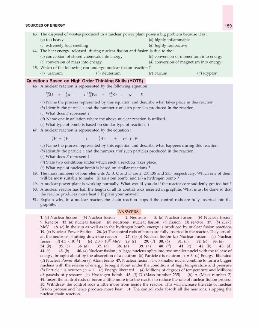
SOURCES OF ENERGY 159
43. The disposal of wastes produced in a nuclear power plant poses a big problem because it is :(a) too heavy (b) highly inflammable(c) extremely foul smelling (d) highly radioactive
44. The heat energy released during nuclear fission and fusion is due to the :(a) conversion of stored chemicals into energy (b) conversion of momentum into energy(c) conversion of mass into energy (d) conversion of magnetism into energy
45. Which of the following can undergo nuclear fusion reaction ?(a) uranium (b) deuterium (c) barium (d) krypton
Questions Based on High Order Thinking Skills (HOTS)46. A nuclear reaction is represented by the following equation :
235 1 139 9492 0 56 36U + n Ba + Kr xc E
(a) Name the process represented by this equation and describe what takes place in this reaction.(b) Identify the particle c and the number x of such particles produced in the reaction.(c) What does E represent ?(d) Name one installation where the above nuclear reaction is utilised.(e) What type of bomb is based on similar type of reactions ?
47. A nuclear reaction is represented by the equation :
2 2 31 1 2H + H He + xc E
(a) Name the process represented by this equation and describe what happens during this reaction.(b) Identify the particle c and the number x of such particles produced in the reaction.(c) What does E represent ?(d) State two conditions under which such a reaction takes place.(e) What type of nuclear bomb is based on similar reactions ?
48. The mass numbers of four elements A, B, C and D are 2, 20, 135 and 235, respectively. Which one of themwill be most suitable to make : (i) an atom bomb, and (ii) a hydrogen bomb ?
49. A nuclear power plant is working normally. What would you do if the reactor core suddenly got too hot ?50. A nuclear reactor has half the length of all its control rods inserted in graphite. What must be done so that
the reactor produces more heat ? Explain your answer.51. Explain why, in a nuclear reactor, the chain reaction stops if the control rods are fully inserted into the
graphite.
ANSWERS1. (a) Nuclear fission (b) Nuclear fusion 2. Neutrons 5. (a) Nuclear fusion (b) Nuclear fission9. Reactor 13. (a) nuclear fission (b) neutrons ; nuclear fission (c) fission (d) reactor 17. (b) 23275MeV 18. (c) In the sun as well as in the hydrogen bomb, energy is produced by nuclear fusion reactions19. (c) Nuclear Power Station 26. (c) The control rods of boron are fully inserted in the reactor. They absorball the neutrons, shutting down the reactor 27. (b) (i) Nuclear fission (ii) Nuclear fusion (c) Nuclearfusion (d) 4.5 × 10¹⁴ J (e) 2.8 × 1027 MeV 28. (c) 29. (d) 30. (b) 31. (b) 32. (b) 33. (d)34. (b) 35. (c) 36. (d) 37. (c) 38. (d) 39. (a) 40. (d) 41. (a) 42. (b) 43. (d)44. (c) 45. (b) 46. (a) Nuclear fission ; A large nucleus splits into two smaller nuclei with the release ofenergy, brought about by the absorption of a neutron (b) Particle c is neutron ; x = 3 (c) Energy liberated(d) Nuclear Power Station (e) Atom bomb 47. Nuclear fusion ; Two smaller nuclei combine to form a biggernucleus with the release of energy, brought about under the conditions of high temperature and pressure(b) Particle c is neutron ; x = 1 (c) Energy liberated (d) Millions of degrees of temperature and Millionsof pascals of pressure (e) Hydrogen bomb 48. (i) D (Mass number 235) (ii) A (Mass number 2)49. Insert the control rods of boron a little more into the reactor to reduce the rate of nuclear fission process50. Withdraw the control rods a little more from inside the reactor. This will increase the rate of nuclearfission process and hence produce more heat 51. The control rods absorb all the neutrons, stopping thenuclear chain reaction.

SCIENCE FOR TENTH CLASS : PHYSICS160
Figure 40. Hydrogen is used as afuel in rockets. Hydrogen poweredcars are also being developed now.
ENVIRONMENTAL CONSEQUENCESIn this Chapter we have studied various sources of energy. The use of
each and every source of energy disturbs the environment in one way orthe other. For example, the use of fossil fuels causes air pollution and theproduction of hydroelectricity causes ecological imbalance. In some cases,the actual operation of the device used for harnessing energy may bepollution-free but the making of the device itself must have caused someenvironmental damage. For example, the use of a wind generator, solarcooker and solar cells for obtaining energy is pollution-free but the processesinvolved in making the materials for these energy devices must havedamaged the environment in some way. From this we conclude that, inreality, no source of energy can be said to be pollution-free. So, when wetalk of a ‘clean fuel’, it actually means that it is a cleaner fuel than someother fuel. For example, when we say that CNG is a clean fuel, it meansthat CNG is a cleaner fuel than, say petrol or diesel. Similarly, we can saythat hydrogen is a cleaner fuel than CNG. This will become more clear fromthe following example.
Sample Problem. Hydrogen has been used as a rocket fuel. Would youconsider it a cleaner fuel than CNG ? Why or why not ?
(NCERT Book Question)
Answer. Hydrogen is a cleaner fuel than CNG. This is because the burning of hydrogen produces onlywater, which is totally harmless. On the other hand, burning of CNG produces carbon dioxide gas andwater. This carbon dioxide can produce greenhouse effect in the atmosphere and lead to the excessiveheating of the environment in the long run.
Some of the environmental consequences of the increasing demand for energy are the following :1. The combustion of fossil fuels is producing acid rain and damaging plants (crops), soil and aquatic
life.2. The burning of fossil fuels is increasing the amount of greenhouse gas carbon dioxide in the
atmosphere.3. The cutting down of trees from the forest (deforestation) for obtaining fire-wood is causing soil
erosion and destroying wild life.4. The construction of hydro-power plants is disturbing ecological balance.5. Nuclear power plants are increasing radioactivity in the environment.
The various factors which we should keep in mind while choosing a source of energy are : (i) the easeof extracting energy from that source, (ii) the cost of extracting energy from the source, (iii) the efficiency oftechnology available to extract energy from that source, and (iv) the damage to environment which will becaused by using that source.
How Long Will Energy Resources of Earth LastMost of the energy that we use today comes mainly from the three non-renewable energy resources of
the earth : coal, petroleum and natural gas (which are called fossil fuels). We have been using these energyresources of the earth at a very rapid rate in the past. So, the amount of coal, petroleum and natural gas leftin the earth is limited. It has been estimated that the world’s known coal reserves are expected to last foranother 200 years compared to around 40 years for the known petroleum oil reserves and around 60years for the known reserves of natural gas. So, it is high time that we start using alternative sources ofenergy to conserve the depleting reserves of coal, petroleum and natural gas so that they may last longer.We should also reduce energy consumption wherever possible. Some of the steps which can be taken to

SOURCES OF ENERGY 161
reduce energy consumption are as follows :1. Switch off lights, fans, TV and other such electrical
appliances when not needed, to save electricity.2. Use energy efficient electrical appliances to save
electricity. This can be done by using compactfluorescent lamps (CFL) and tube-lights in place ofconventional filament-type electric bulbs (see Figure 41).
3. Good quality stoves should be used to burn fuels likekerosene and LPG so as to obtain maximum heat.
4. Pressure cookers should be used for cooking food tosave fuel.
5. Solar cookers should be used to cook food wheneverpossible and solar water heaters should be used to gethot water.
6. The use of biogas as fuel should be encouraged in ruralareas.
7. Bicycles should be used for short distances to saveprecious fuel like petrol (which is used in cars, scootersand motorcycles).
We are now in a position to answer the followingquestions :
Very Short Answer Type Questions1. Which of the two is a cleaner fuel : hydrogen or CNG ? Why ?
2. Which of the two is more energy efficient : filament type electric bulb or CFL ? Why ?3. How long are the energy resources of the earth like coal, petroleum and natural gas expected to last ?4. Name two devices which can be utilised for the cooking of food so as to save fuel .
Short Answer Type Questions
5. What are the various factors which we should keep in mind while choosing a source of energy ?6. Can any source of energy be pollution free ? Explain your answer with an example.7. What are the environmental consequences of the increasing demand for energy ?8. What steps would you suggest to reduce energy consumption ?
Multiple Choice Questions (MCQs)9. The major cause of environmental pollution is the use of :
(a) hydrogen as fuel (b) biomass energy (c) ocean energy (d) fossil fuels10. The world’s known coal reserves are expected to last for about :
(a) 200 years (b) 400 years (c) 500 years (d) 100 years11. The fossil fuel whose known reserves in the earth are expected to last for the minimum period is :
(a) coal (b) uranium (c) petroleum (d) natural gas12. An energy efficient device for producing light is :
(a) DLF (b) CFL (c) FCL (d) LPG
ANSWERS
1. Hydrogen 2. CFL 4. Solar cooker ; Pressure cooker 9. (d) 10. (a) 11. (c) 12. (b)
Figure 41. The bulb shown on the left side is thetraditional, filament-type bulb. This is not energyefficient because it wastes a lot of electric energy asheat. The bulb shown on the right side is called Com-pact Fluorescent Lamp (CFL) which is energy effi-cient because it consumes much less electric energy.This is because it wastes much less electric energyas heat.

Light is a form of energy. Light is needed to see things around us. We are able to see the beautifulworld around us because of light. We can read a book, see pictures in a magazine, and watchtelevision and movies due to the existence of light. And it is light which makes us see our image in
a looking mirror. We detect light with our eyes. Though we see the various objects (or things) around uswith our eyes but eyes alone cannot see any object. We also need a source of light to make objects visible.For example, we cannot see any object in a dark room or in the darkness of night because there is no lightin a dark room or in the night to make objects visible. But as soon as an electric bulb (a tube-light or a torch,etc.) is switched on and light falls on the objects, we are able to see them clearly. It is only when light comingfrom an object enters our eyes that we are able to see that object. This light may have been emitted by the objectitself or it may have been reflected by the object.
Light enables us to see objects from which it comes or from which it is reflected. For example, thesun gives out light. We can see the sun because the lightcoming from the sun enters our eyes. The objects like thesun, other stars, electric bulb, tube-light, torch, candle andfire, etc., which emit their own light are called luminousobjects (see Figure 1). We can see the luminous objects dueto the light emitted by them. Though luminous objects arevery small in number but they help us to see a large varietyof non-luminous objects around us. The objects like a flower,a chair or a table do not have light of their own but eventhen we are able to see them. This can be explained as follows :Though the objects like a flower, a chair or a table, etc., donot emit light themselves, we can see them by the light whichthey reflect (or scatter) by taking it from a luminous objectlike the sun or an electric bulb, etc. (see Figure 2). So, whenthe sunlight or bulb light falls on a flower or chair (or anyother object), some of this light is reflected towards us. And
Reflection of Light
CHAPTERCHAPTERCHAPTERCHAPTERCHAPTER
4
Figure 1. Luminous and non-luminous objects.
(a) An electric bulb givesits own light. It is aluminous object.
(b) A flower does not giveits own light. It is anon-luminous object.

REFLECTION OF LIGHT 163
Figure 2. We see most of the objects around us by the light reflected from them.when this reflected light enters our eyes, then we are able to see the flower or chair (because to our eyes,this light appears to be coming from the flower or chair) (see Figure 2). Those objects which do not emitlight themselves but only reflect (or scatter) the light which falls on them, are called non-luminousobjects (see Figure 2). A flower, chair, table, book, trees, other plants, human beings, fan, bed, mirror,diamond, walls, floor, and road, etc., are all non-luminous objects. In fact, most of the objects around us arenon-luminous objects. We can see the non-luminous objects because they reflect light (received from aluminous object) into our eyes. Even the moon is a non-luminous object (because it does not have its ownlight). We can see the moon because it reflects the sunlight falling on its surface towards us (on the earth).
From the above discussion we conclude that light is a form of energy which causes in us the sensationof sight. Light travels in straight lines. The fact that a small source of light casts a sharp shadow of anopaque object tells us that light travels in a straight line path. This is because if light could bend easily andgo behind the opaque object, then no shadow could be formed. We will now discuss the nature of light.
Nature of Light
There are two theories about the nature of light : wave theory of light and particle theory of light.According to wave theory : Light consists of electromagnetic waves which do not require a materialmedium (like solid, liquid or gas) for their propagation. The wavelength of visible light waves is verysmall (being only about 4 × 10⁻⁷ m to 8 × 10⁻⁷ m). The speed of light waves is very high (being about3 × 108 metres per second in vacuum). According to particle theory : Light is composed of particleswhich travel in a straight line at very high speed. The elementary particle that defines light is the ‘photon’.
Some of the phenomena of light can be explained only if light is considered to be made up of waveswhereas others can be explained only if light is thought to be made up of particles. For example, thephenomena of diffraction (bending of light around the corners of tiny objects), interference and polarization oflight can only be explained if light is considered to be of wave nature. The particle theory of light cannotexplain these phenomena. On the other hand, the phenomena of reflection and refraction of light, and castingof shadows of objects by light, can be explained only if light is thought to be made of particles. Wave theoryof light cannot explain these phenomena. Thus, there is evidence for the wave nature of light as well as forparticle nature of light.
Physics experiments over the past hundred years or so have demonstrated that light has a dual nature(double nature) : light exhibits the properties of both waves and particles (depending on the situation itis in). The modern theory of light called ‘Quantum Theory of Light’ combines both the wave and particlemodels of light.
(b) We can see the chair at night because it reflects bulb light falling on it into our eyes.
Sunlight falls on the flower
The flowerreflects
sunlight inall directions
Sunlight reflected
by flower enters
our eyes
(a) We can see the flower during day time becauseit reflects sunlight falling on it into our eyes.

SCIENCE FOR TENTH CLASS : PHYSICS164
MIRROR
Light falls on mirror
Light is reflected by mirror
A
B
Figure 3. A mirror reflects the light fallingon it.
Frontside
ofplanemirror
Back side ofplane mirror(Silver coatingon glass sheetcovered byred paint)
PLANEMIRROR
Plane mirror(Front side)
Back sideofplanemirror
M′
M
(a) A plane mirror. (b) This is how a plane mirror isrepresented in diagrams.
Figure 4.
REFLECTION OF LIGHTWhen light falls on the surface of an object, some of it is sent back. The process of sending back the
light rays which fall on the surface of an object, is called reflection of light. The reflection of light isshown in Figure 3. When a beam of light AO falls on a mirror at point O, it is sent back by the mirror inanother direction OB (see Figure 3). And we say that the mirror has reflected the beam of light falling on it.We can compare the reflection of light to the bouncing back of a tennis ball on hitting a wall. For example,if we throw a tennis ball at a wall, the ball bounces back. This means that the wall sends it back. Similarly,when light falls on the surface of an object, the object sends the light back. And we say that the objectreflects the light. Most of the objects reflect light which falls onthem. Some objects reflect more light whereas other objects reflectless light. The objects having polished, shining surfaces reflectmore light than objects having unpolished, dull surfaces.
We know that an object (say, a chair) kept in a room can beseen from all the parts of the room. This is due to the fact thatusually, because of its rough surface, an object reflects light (orscatters light) in all the directions. Since the reflected light reachesall the parts of the room, the object can be seen from all the partsof the room. If, however, the surface of an object is smooth (likethat of a mirror), then the light falling on it is reflected in onlyone direction (as shown in Figure 3).
Silver metal is one of the best reflectors of light. For example, a polished block of silver metal reflectsalmost all the light falling on it and does not transmit any light through it. But the surface of silver metal iseasily scratched and soon becomes rough. So, ordinary mirrors are made by depositing a thin layer ofsilver metal on the back side of a plane glass sheet. The silver layer is then protected by a coat of redpaint. The reflection of light in a plane mirror (or any other mirror) takes place at the silver surface in it.Thus, a plane mirror is a thin, flat and smooth sheet of glass having a shining coating of silver metal on oneside. The silver coating isprotected by a red paint. Thesedays mirrors are being madeincreasingly by depositing athin coating of aluminiummetal at the back of a glasssheet (instead of silver coating).This is because aluminium ismuch cheaper than silver andit reflects light very well. Aplane mirror is shown inFigure 4(a). The mirror on ourdressing table in which we seeour face is a plane mirror.
In our everyday life, we use plane mirrors of different shapes and sizes depending on where they arebeing used. But in a science laboratory, a small rectangular strip of plane mirror is usually used forperforming experiments on the reflection of light. In our diagrams, a plane mirror is represented by astraight line having a number of short, oblique lines on one side [see Figure 4(b)]. The plane side ofstraight line is the front side of the mirror (where the reflection of light takes place). And the side havingshort, oblique lines represents the back side of the plane mirror. In Figure 4(b), the straight line MM (readas : MM-dash) represents a plane mirror.

REFLECTION OF LIGHT 165
We will also be using rays of light in constructing the ray-diagrams. A ray of light is the straight linealong which light travels. The arrow head put on the straight line tells us the direction in which the lightis travelling. A ‘bundle of light rays’ is called a ‘beam of light’. We will now study the reflection of lightfrom the plane surfaces like that of a plane mirror. This is necessary to understand the reflection of lightfrom spherical mirrors.
REFLECTION OF LIGHT FROM PLANE SURFACES : PLANE MIRROR
When a ray of light falls on a plane mirror (or any other plane surface), it is reflected according to somelaws, called the laws of reflection of light. In order to understand the laws of reflection of light, we shouldfirst know the meaning of the terms : incident ray, point of incidence, reflected ray, normal (at the point ofincidence), angle of incidence, and angle of reflection. So, we will discuss these terms first.
In Figure 5, we have a plane mirror MM . The ray of light which falls on the mirror surface is calledthe incident ray. In Figure 5, AO is the incident ray of light. The incident ray gives the direction in whichlight falls on the mirror. The point at which the incident ray falls on the mirror is called the point ofincidence. In Figure 5, point O on the surface of the mirror is the point of incidence (because the incidentray AO touches the mirror surface at this point). We know that when a ray of light falls on a mirror, themirror sends it back in another direction and we say that the mirror has reflected the ray of light. The rayof light which is sent back by the mirror is called the reflected ray. In Figure 5, OB is the reflected ray oflight. The reflected ray of light shows the direction in which the light goes after reflection from the mirror.
Another term that we will be using is the ‘normal’. The ‘normal’ is a line at right angle to the mirrorsurface at the point of incidence. In other words, ‘normal’ is a line which is perpendicular to the mirror at thepoint of incidence. In Figure 5, the mirror is MM and the point of incidence is O. So, the line ON is thenormal to the mirror surface at point O. The normal has been represented by a dotted line to distinguish itfrom the incident ray and the reflected ray. Please note that ‘normal’ is just a ‘perpendicular line’ to themirror, and it should not be called the ‘normal ray’ like the incident ray or reflected ray. The normal is aline at right angles to the mirror surface. In other words, normal makes an angle of 90° with the surface ofthe plane mirror. We will now discuss the angle of incidence and the angle of reflection.
The angle of incidence is the angle made by the incident ray with the normal at the point of incidence.In other words, the angle between the incident ray and normal is called the angle of incidence. In Figure 5,the incident ray is AO and the normal is ON, so the angle AON is the angle of incidence. The angle ofincidence is denoted by the letter i.
The angle of reflection is the angle made by the reflected ray with the normal at the point of incidence.In other words, the angle between the reflected ray and normal is calledthe angle of reflection. In Figure 5, the reflected ray is OB and the normalis ON, so the angle NOB is the angle of reflection. The angle of reflectionis denoted by the letter r. Keeping these points in mind, we will nowdescribe the laws of reflection of light.
Laws of Reflection of Light
The reflection of light from a plane surface (like that of a planemirror) or from a spherical surface (like that of a concave mirror orconvex mirror) takes place according to two laws, which are known asthe laws of reflection of light. The laws of reflection of light are givenbelow :
1. First Law of Reflection. According to the first law of reflectionof light : The incident ray, the reflected ray, and the normal (at thepoint of incidence), all lie in the same plane. For example, in Figure 5,the incident ray AO, the reflected ray OB and the normal ON, all lie in
Incident ray
Planemirror
M
ONNormal
Angle ofincidence
Angle ofreflection
Point ofincidence
Reflec
ted
ray
B M′
A
i
r
Figure 5. Reflection of light from aplane mirror.

SCIENCE FOR TENTH CLASS : PHYSICS166
the same plane, the plane of paper. They are neither coming up out of the paper; nor going down into thepaper.
2. Second Law of Reflection. According to the second law of reflection of light : The angle of reflectionis always equal to the angle of incidence. We can also state the second law of reflection of light as followsby writing the angle of incidence first : The angle of incidence is equal to the angle of reflection. If the angle ofincidence is i and the angle of reflection is r, then according to the second law of reflection :
i = rFor example, if we measure the angle of reflection NOB in Figure 5, we will find that it is exactly equal
to the angle of incidence AON.
The second law of reflection of light means that if the angle of incidence is 35°, then the angle ofreflection will also be 35° (seeFigure 6). And if the angle ofincidence is changed to 45°,then the angle of reflection willalso change and become 45°(see Figure 7). In every case, theangle of reflection remains equalto the angle of incidence.
We will now describe whathappens when a ray of lightfalls normally (orperpendicularly) on thesurface of a mirror. If a ray oflight is incident normally on a mirror, it means that it is travelling along thenormal to the mirror. So, the angle of incidence (i) for such a ray of light is zero(0). And since the angle of incidence is zero, therefore, according to the secondlaw of reflection, its angle of reflection (r) will also be zero (0). This means thata ray of light which is incident normally (or perpendicularly) on a mirror, isreflected back along the same path (because the angle of incidence as wellas the angle of reflection for such a ray of light are zero). For example, inFigure 8, a ray of light falls on the plane mirror along the normal NO, therefore,it will be reflected along the same path ON. So, in this case, the incident raywill be NO and the reflected ray will be ON. In other words, the same linerepresents incident ray, normal and reflected ray. We should, however, puttwo arrow heads on the same ‘normal’ line pointing in opposite directions –one arrow to represent incident ray and the other arrow to represent reflectedray (as shown in Figure 8).
Please note that the laws of reflection of light apply to all kinds of mirrors, plane mirrors as well asspherical mirrors (like concave mirrors and convex mirrors). By using the laws of reflection of light, wecan find out the nature and position of the images (of objects) formed by the various types of mirrors.
Regular Reflection and Diffuse Reflection of Light
In regular reflection, a parallel beam of incident light is reflected as a parallel beam in one direction.In this case, parallel incident rays remain parallel even after reflection and go only in one direction (seeFigure 9). Regular reflection of light occurs from smooth surfaces like that of a plane mirror (or highlypolished metal surfaces). For example, when a parallel beam of light falls on the smooth surface of a planemirror, it is reflected as a parallel beam in only one direction as shown in Figure 9. Thus, a plane mirrorproduces regular reflection of light. Images are formed by regular reflection of light. For example, a
Figure 6. If the angle of incidence is 35°,then the angle of reflection is also 35°.
i
PlanemirrorA
N
B
Or
35°
35°
M�
M
N
B
A
i
r
45°
45°
Planemirror
M�
M
O
Figure 7. When the angle of incidence ischanged to 45°, the angle of reflection also
becomes 45°.
M
M′
Planemirror
N (Normal)
Incidentray
Reflectedray
O
Figure 8. A ray of lightincident normally (at 90°) to themirror surface is reflected back
along the same path.

REFLECTION OF LIGHT 167
smooth surface (like that of a plane mirror) produces a clear image of an object due to regular reflection oflight. A highly polished metal surface and a still water surface also produce regular reflection of light andform images. This is why we can see our face in a polished metal object as well as in the still water surfaceof a pond or lake. A polished wooden table is very smooth and hence produces regular reflection of light.
The regular reflection of light from a smooth surface can be explained as follows : All the particles ofa smooth surface (like a plane mirror) are facing in one direction. Due to this the angle of incidence for allthe parallel rays of light falling on a smooth surface is the same and hence the angle of reflection for all therays of light is also the same. Since the angle of incidence and the angle of reflection are the same (or equal), a beamof parallel rays of light falling on a smooth surface is reflected as a beam of parallel light rays in one direction only(see Figure 9).
In diffuse reflection, a parallel beam of incident light is reflected in different directions. In this case,the parallel incident rays do not remain parallel after reflection, they are scattered in different directions(see Figure 10). The diffuse reflection is also known as irregular reflection or scattering. The diffuse reflectionof light takes place from rough surfaces like that of paper, cardboard, chalk, table, chair, walls andunpolished metal objects. For example, when a parallel beam of light rays falls on the rough surface of asheet of paper, the light is scattered by making reflected rays in different directions (see Figure 10). Thus, asheet of paper produces diffuse reflection of light. No image is formed in diffuse reflection of light. Forexample, a rough surface (like that of paper) does not produce an image of the object due to diffuse reflectionof light. Actually, the light rays falling on the rough surface of paper are scattered in all directions andhence no image is formed.
The diffuse reflection of light from a rough surface can be explained as follows : The particles of arough surface (like that of paper) are all facing in different directions. Due to this, the angles of incidence forall the parallel rays of light falling on a rough surface are different and hence the angles of reflection for allthe rays of light are also different. Since the angles of incidence and the angles of reflection are different, theparallel rays of light falling on a rough surface go in different directions (see Figure 10). Please note that thediffuse reflection of light is not due to the failure of the laws of reflection. Diffuse reflection is caused bythe roughness (or irregularities) in the reflecting surface of an object (like paper or cardboard, etc.). Thelaws of reflection are valid at each point even on the rough surface of an object.
The surfaces of most of the objects are rough (or uneven) to some extent. So, most of the objects aroundus cause diffuse reflection of light and scatter the light falling on them in all directions. In fact, we cansee these objects only because they scatter light rays falling on them in all directions. For example, a booklying on a table can be seen from all parts of the room due to diffuse reflection of light from its surface. The
Figure 10. Diffuse reflection : Incidentlight is reflected in different directions.
Figure 9. Regular reflection : Incident lightis reflected in only one direction.

SCIENCE FOR TENTH CLASS : PHYSICS168
surface of book, being rough, scatters the incident light in all parts of a room. Hence the book can be seenfrom all parts of the room. A cinema screen has a rough surface and causes diffuse reflection of light fallingon it. The cinema screen receives light from a film projector and scatters it in all directions in the cinemahall so that people sitting anywhere in the hall can see the picture focused on the screen.
Objects and ImagesIn the study of light, the term ‘object’ has a special meaning. Anything which gives out light rays
(either its own or reflected by it) is called an object. A bulb, a candle, a pin-head, an arrow, our face, or atree, are all examples of objects from the point of view of study of light. The objects can be of two types :very small objects (called point objects) or large objects (called extended objects). In drawing the ray-diagramsfor the formation of images, we will be using both type of objects according to our convenience. In ray-diagrams, the point objects (like point sources of light or a pin-head) are represented by a ‘dot’, and theextended objects are represented by drawing ‘an arrow pointing upwards’.
In physics, image is an optical appearance produced when light rays coming from an object arereflected from a mirror (or refracted through a lens). This will become clear from the following example.When we look into a mirror, we see our face. What we see in the mirror is actually a ‘reflection’ of our faceand it is called ‘image’ of our face. Thus, when we look into a mirror, we see the image of our face in it.In this case, ‘our face’ is the ‘object’ and what we see in the mirror is the ‘image’. The image of our faceappears to be situated behind the mirror. While watching a movie in the cinema hall, we see the imagesof actors and actresses on the cinema screen. Please note that an image is formed when the light rays comingfrom an object meet (or appear to meet) at a point, after reflection from a mirror (or refraction through a lens). Theimages are of two types : real images and virtual images. These are discussed below.
Real Images and Virtual ImagesThe image which can be obtained on a screen is called a real image. In a cinema hall, we see the
images of actors and actresses on the screen. So, the images formed on a cinema screen is an example ofreal images (see Figure 11). A real image is formed when light rays coming from an object actually meet ata point after reflection from a mirror (or refraction through a lens). A real image can be formed on a screenbecause light rays actually pass through a real image. Real images can be formed by a concave mirror. Aconvex lens can also form real images. We will study the formation of real images with the help of ray-diagrams after a while.
The image which cannot be obtained on a screen is called a virtual image. A virtual image can beseen only by looking into a mirror (or a lens). The image of our face formed by a plane mirror cannot beobtained on a screen, it can be seen only by looking into the mirror. So, the image of our face in a planemirror is an example of virtual image (see Figure 12). Virtual images are also called unreal images. A
Figure 12. When we look into a mirror, we see our imagein it. The image formed in a plane mirror is a virtual image.
Figure 11. The image of actors and actresses formedon a cinema screen is a real image.

REFLECTION OF LIGHT 169
virtual image is just an illusion. A virtual image is formed when light rays coming from an object onlyappear to meet at a point when produced backwards (but do not actually meet) after reflection from amirror (or refraction through a lens). A virtual image cannot be formed on a screen because light rays donot actually pass through a virtual image. A plane mirror always forms virtual images. Similarly, a convexmirror also forms only virtual images. A concave mirror can form a virtual image only when the object iskept within its focus. As we will study in the topic on lenses, a concave lens always forms virtual imagesbut a convex lens forms a virtual image only when the object is within its focus. We will study the formationof virtual images with the help of ray-diagrams after a while.
We will now describe the formation of image in a plane mirror. Before we do that please rememberthat an object gives out a large number of light rays in all the directions but we will use only two light rayscoming from the object to show the formation of image. This is done just to keep the ray-diagram simple.Another point to be noted is that the real rays of light are represented by full lines (solid lines) whereasvirtual rays of light are represented by dotted lines (broken lines). The real rays of light can exist only infront of a mirror. The virtual rays of light are those which we show behind a mirror. The virtual light raysdo not exist at all (because light cannot reach behind the mirror by passing through it). They just appear tobe coming from behind the mirror. We will now describe how the image of an object is formed in a planemirror by using the laws of reflection of light.
Formation of Image in a Plane MirrorConsider a small object O (say, a point source of light) placed in front of a plane mirror MM (see
Figure 13). The mirror will form an image I of the object O. Now, we want to know how this image hasbeen formed. This happens as follows : The object O gives outlight rays in all directions but we need only two rays of light tolocate the image. Now, a ray of light OA coming from the objectO is incident on the plane mirror at point A and it gets reflectedin the direction AX according to the laws of reflection of lightmaking the angle of reflection r1 equal to the angle of incidencei1 (see Figure 13). Another ray of light OB coming from the objectO strikes the mirror at point B and gets reflected in the directionBY, again making the angle of reflection r2 equal to the angle ofincidence i2.
The two reflected rays AX and BY are diverging (movingaway from one another), so they cannot meet on the left side.Let us produce the reflected rays AX and BY backwards (asshown by dotted lines in Figure 13). They meet at point I behindthe mirror. Now, when the reflected rays AX and BY enter theeye of a person at position E, the eye sees the rays of light inthe straight line direction in which the reflected rays enter it. So, the person looking into the mirror fromposition E sees the reflected rays as if they are coming from the point I behind the mirror (because I is thepoint of intersection of the reflected rays when produced backwards to the right side). Thus, point I is theimage of the object O formed by the plane mirror. For example, if our face is at position O in front of theplane mirror, then we will see the image of our face in the mirror at point I.
Please note that the image formed by a plane mirror can be seen only by looking into the mirror. So,if a screen is placed at position I, no image would be formed on it because the light rays do not actuallypass through the point I, they only appear to do so. An image of this type, which cannot be received on ascreen, is known as a virtual image. Another point to be noted is that the light rays shown by dotted linesbehind the mirror are only imaginary light rays. There can be no real light rays behind a mirror because ithas a silvered reflecting surface at its back (covered with a paint) which does not allow light rays to pass
Planemirror
M
I
Image
A
B
Object
M�E
Y
X
i1r1
i2
r2
O
Figure 13. Formation of image in a plane mirror.

SCIENCE FOR TENTH CLASS : PHYSICS170
Planemirror
M
A C
Object
A�
DN1
i1r1
E
B
N2
i2r2
H
G
FB�
Image
M�
Figure 14. The formation of image of an extendedobject (here an arrow AB) in a plane mirror.
Figure 15. The image of candle in the plane mirroris the same distance behind the mirror as the
candle is in front of the mirror.
through it and go behind the mirror. So, there is no light coming to the person directly from the imagepoint I. It is only the light reflected from the mirror which appears to be coming from the image point I.
Image of an Extended Object (or Finite Object)
We have just studied that a plane mirror forms a point image of a point object. But most of the actualobjects are much bigger than a mere ‘point’ and they are called ‘extended objects’ or ‘finite objects’. Anextended object (or bigger object) can be considered to be made up of a very, very large number of pointobjects. So, the image of an extended object is a collection of the image points corresponding to the variouspoints of the object. We will now describe how a plane mirror forms the image of an extended object. Inour ray-diagrams, we will use an ‘arrow pointing upwards’ to represent an extended object (or finite object).
In Figure 14, an extended object AB (an arrow pointing upwards) is placed in front of a plane mirrorMM . In order to locate the image of arrow AB in the plane mirror, we will first find out the positions ofimages of its top point A and bottom point B. This can be done as follows :
(i) From point A, we draw an incident ray AC perpendicularto the mirror (see Figure 14). This will be reflected back alongthe same path. So, CA is the first reflected ray. We now drawanother incident ray AD which strikes the mirror at point D.The ray AD is reflected along DE, making an angle of reflection(r1) equal to the angle of incidence (i1). Thus, DE is the secondreflected ray here. We produce the two reflected rays CA andDE backwards by dotted lines. They meet at point A (A–dash).So, A is the virtual image of the top point A of the object.
(ii) From point B, we draw an incident ray BF perpendicularto the mirror. This will be reflected back along the same path,giving the reflected ray FB. Another incident ray BG is reflectedalong GH making the angle of reflection (r2) equal to the angleof incidence (i2). We produce the two reflected rays FB andGH backwards by dotted lines. They meet at point B (B–dash).So, B is the virtual image of the bottom point B of the object.
In this way we have located the images of the top point A and bottom point B of the object. Now, eachpoint of the object (or arrow) between A and B will give a point image which will lie between the points Aand B. So, to get the complete image of object AB, we join the points A and B by a dotted line. Thus, AB(A–dash B–dash) is the complete image of the object AB whichhas been formed by the plane mirror (see Figure 14).
The image is virtual, erect (same side up as the object,because both the object and image have arrow-head at the top),and of the same size as the object. Please note that in Figure 14,the image AB has been drawn by dotted line just to show thatit is a virtual image. Thus, the nature of image formed by aplane mirror is virtual and erect. And the size of image formedby a plane mirror is equal to that of the object. The image isat the same distance behind the plane mirror as the object(arrow) is in front of the mirror.
The Position of Image Formed in a Plane MirrorThe image formed in a plane mirror is at the same distance
behind the mirror as the object is in front of the mirror (seeFigure 15). In other words, the image and object are at equal

REFLECTION OF LIGHT 171
distances from a plane mirror but they are on the opposite sides of the plane mirror. For example, if anobject is placed at a distance of 5 cm in front of a plane mirror, then its image will also be formed at adistance of 5 cm behind the mirror. And the total distance between the object and its image will be 5 + 5 =10 cm. That is, the object will be at a distance of 10 cm from its image.
Lateral InversionIf we stand in front of a big plane mirror, we see the image of our body in it.
Though our image appears to be just as we are, but there is a difference. This isbecause if we lift our right hand, then our image lifts its left hand. And if we liftour left hand, then the image appears to lift its right hand (see Figure 16). Thismeans that the right side of our body becomes left side in the image; whereasthe left side of our body becomes right side in the image. It appears as if ourimage has been ‘reversed sideways’ with respect to our body. This effect ofreversing the sides of an object and its image is called lateral inversion. And wesay that the image formed in a plane mirror is laterally inverted. In other words,the image formed in a plane mirror is ‘sideways reversed’ with respect to theobject. We can now define lateral inversion as follows :
When an object is placed in front of a plane mirror, then the right side ofobject appears to become the left side of image; and the left side of objectappears to become the right side of image. This change of sides of an ‘object’and its ‘mirror image’ is called lateral inversion. The phenomenon of lateralinversion will become clear from the following example. Suppose wehave a placard having the word RED written on it [see Figure 17(a)].When we hold this placard in front of a plane mirror, the image of wordRED appears to be like [see Figure 17(b)]. Please note that the object(placard) has the letter R on its left side but the image has this letter inreversed form on its right side. Similarly, the image of letter E appearsto be reversed like . And the letter D on the right side of the object(placard) is on the left side of the image in the reversed form as .Thus, all the letters written on the placard are reversed from left toright. We say that the image is laterally inverted. This is an example oflateral inversion. The phenomenon of lateral inversion is due to thereflection of light.
From the above discussion we conclude that the image formed in aplane mirror is laterally inverted (or sideways reversed) with respectto the object. It is due to lateral inversion that the image of our right hand appearsto be our left hand. So, when we sit in front of a plane mirror and write with ourright hand, it appears in the mirror that we are writing with the left hand. And itis also due to lateral inversion that the parting in our hair on the right appears tobe on the left when seen in a mirror. The word AMBULANCE on the hospitalvans is written in the form of its mirror image as (see Figure 18).This is because when we are driving our car and see the hospital van comingfrom behind in our rear-view mirror, then we will get the laterally inverted imageof and read it as AMBULANCE. Since an ambulance carriesseriously ill patients, we can make way for it to pass through and reach thehospital quickly. We are now in a position to give all the characteristics of animage formed by a plane mirror.
1. The image formed in a plane mirror is virtual. It cannot be received on ascreen.
Figure 16. Our left handappears to be right hand in themirror image.
Figure 18. An ambulance.Please note the wordAMBULANCE written inthe form of its mirror image.
(a) Object (b) Laterally invertedimage (as seen inplane mirror)
Figure 17. Diagram to show lateralinversion.
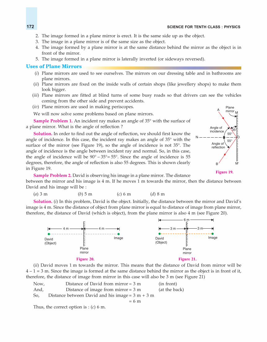
SCIENCE FOR TENTH CLASS : PHYSICS172
2. The image formed in a plane mirror is erect. It is the same side up as the object.3. The image in a plane mirror is of the same size as the object.4. The image formed by a plane mirror is at the same distance behind the mirror as the object is in
front of the mirror.5. The image formed in a plane mirror is laterally inverted (or sideways reversed).
Uses of Plane Mirrors(i) Plane mirrors are used to see ourselves. The mirrors on our dressing table and in bathrooms are
plane mirrors.(ii) Plane mirrors are fixed on the inside walls of certain shops (like jewellery shops) to make them
look bigger.(iii) Plane mirrors are fitted at blind turns of some busy roads so that drivers can see the vehicles
coming from the other side and prevent accidents.(iv) Plane mirrors are used in making periscopes.
We will now solve some problems based on plane mirrors.
Sample Problem 1. An incident ray makes an angle of 35° with the surface ofa plane mirror. What is the angle of reflection ?
Solution. In order to find out the angle of reflection, we should first know theangle of incidence. In this case, the incident ray makes an angle of 35° with thesurface of the mirror (see Figure 19), so the angle of incidence is not 35°. Theangle of incidence is the angle between incident ray and normal. So, in this case,the angle of incidence will be 90° – 35°= 55°. Since the angle of incidence is 55degrees, therefore, the angle of reflection is also 55 degrees. This is shown clearlyin Figure 19.
Sample Problem 2. David is observing his image in a plane mirror. The distancebetween the mirror and his image is 4 m. If he moves 1 m towards the mirror, then the distance betweenDavid and his image will be :
(a) 3 m (b) 5 m (c) 6 m (d) 8 m
Solution. (i) In this problem, David is the object. Initially, the distance between the mirror and David’simage is 4 m. Since the distance of object from plane mirror is equal to distance of image from plane mirror,therefore, the distance of David (which is object), from the plane mirror is also 4 m (see Figure 20).
Figure 20. Figure 21.(ii) David moves 1 m towards the mirror. This means that the distance of David from mirror will be
4 – 1 = 3 m. Since the image is formed at the same distance behind the mirror as the object is in front of it,therefore, the distance of image from mirror in this case will also be 3 m (see Figure 21)
Now, Distance of David from mirror = 3 m (in front)And, Distance of image from mirror = 3 m (at the back)So, Distance between David and his image = 3 m + 3 m
= 6 mThus, the correct option is : (c) 6 m.
M
M�
PlanemirrorA
Angle ofincidence
Angle ofreflection
55°
55°
35°
N O
B
Figure 19.
David(Object)
Planemirror
Image
4 m 4 m
David(Object)
Image
3 m 3 m
6 m
Planemirror

REFLECTION OF LIGHT 173
Sample Problem 3. The rear view mirror of a car is a plane mirror. A driver is reversing his car at aspeed of 2 m/s. The driver sees in his rear view mirror, the image of a truck parked behind his car. Thespeed at which the image of the truck appears to approach the driver will be :
(a) 1 m/s (b) 2 m/s (c) 4 m/s (d) 8 m/s
Solution. In a plane mirror, the object and its image always remain at the same distance from themirror. So, when the car reverses at a speed of 2 m/s, then the image will also appear to move towards themirror at the same speed of 2 m/s. So, the speed at which the image of truck appears to approach the cardriver will be 2 m/s + 2 m/s = 4 m/s. Thus, the correct option will be : (c) 4 m/s.
Before we go further and discuss spherical mirrors, please answer the following questions :
Very Short Answer Type Questions
1. What happens when a ray of light falls normally (or perpendicularly) on the surface of a plane mirror ?2. A ray of light is incident on a plane mirror at an angle of 30°. What is the angle of reflection ?3. A ray of light strikes a plane mirror at an angle of 40° to the mirror surface. What will be the angle of
reflection ?4. A ray of light is incident normally on a plane mirror. What will be the :
(a) angle of incidence ?(b) angle of reflection ?
5. What type of image is formed :(a) in a plane mirror ?(b) on a cinema screen ?
6. What kind of mirror is required for obtaining a virtual image of the same size as the object ?7. What is the name of the phenomenon in which the right side of an object appears to be the left side of the
image in a plane mirror ?8. Name the phenomenon responsible for the following effect :
When we sit in front of a plane mirror and write with our right hand, it appears in the mirror that we arewriting with the left hand.
9. If an object is placed at a distance of 10 cm in from of a plane mirror, how far would it be from its image ?10. Which property of light makes a pencil cast a shadow when it is held in front of a light source ?11. The image seen in a plane mirror cannot be formed on a screen. What name is given to this type of image ?12. Fill in the following blank with a suitable word :
When light is reflected, the angles of incidence and reflection are.......... .13. State whether the following statement is true or false :
A student says that we can see an object because light from our eyes is reflected back by the object.14. Where is the image when you look at something in a mirror ?15. A ray of light strikes a plane mirror such that its angle of incidence is 30°. What angle does the reflected ray
make with the mirror surface ?
Short Answer Type Questions
16. What is the difference between a real image and a virtual image ? Give one example of each type of image.17. The letter F is placed in front of a plane mirror :
(a) How would its image look like when seen in a plane mirror ?(b) What is the name of the phenomenon involved ?
18. What is lateral inversion ? Explain by giving a suitable example.19. Write the word AMBULANCE as it would appear when reflected in a plane mirror. Why is it sometimes
written in this way (as its mirror image) on the front of an ambulance ?20. What are the important differences between looking at a photograph of your face and looking at yourself in
a plane mirror ?

SCIENCE FOR TENTH CLASS : PHYSICS174
21. (a) A wall reflects light and a mirror also reflects light. What difference is there in the way they reflectlight ?
(b) Which type of reflection of light leads to the formation of images ?22. What is the difference between regular reflection of light and diffuse reflection of light ? What type of
reflection of light takes place from :(a) a cinema screen (b) a plane mirror (c) a cardboard (d) still water surface of a lake
23. What can you see in a completely dark room ? If you switch on an electric bulb in this dark room as a lightsource, explain how you could now see :(a) the electric bulb.(b) a piece of white paper.
24. (a) A boy with a mouth 5 cm wide stands 2 m away from a plane mirror. Where is his image and how wideis the image of his mouth ?
(b) The boy walks towards the mirror at a speed of 1 m/s. At what speed does his image approach him ?25. (a) An extended object in the form of an arrow pointing upward has been placed in front of a plane mirror.
Draw a labelled ray-diagram to show the formation of its image.(b) State the uses of plane mirrors.
Long Answer Type Questions
26. What is meant by ‘reflection of light’ ? Define the following terms used in the study of reflection of light bydrawing a labelled ray-diagram :(a) Incident ray (b) Point of incidence (c) Normal(d) Reflected ray (e) Angle of incidence (f) Angle of reflection
27. State and explain the laws of reflection of light at a plane surface (like a plane mirror), with the help of alabelled ray-diagram. Mark the angles of ‘incidence’ and ‘reflection’ clearly on the diagram. If the angle ofreflection is 47.5°, what will be the angle of incidence ?
28. With the help of a labelled ray-diagram, describe how a plane mirror forms an image of a point source oflight placed in front of it. State the characteristics of the image formed in a plane mirror.
29. (a) Explain why, though both a plane mirror and a sheet of paper reflect light but we can see the image ofour face in a plane mirror but not in a sheet of paper.
(b) The image in a plane mirror is virtual and laterally inverted. What does this statement mean ?(c) Write all the capital letters of the alphabet which look the same in a plane mirror.
Multiple Choice Questions (MCQs)
30. The angle of reflection is equal to the angle of incidence :(a) always (b) sometimes (c) under special conditions (d) never
31. The angle between an incident ray and the plane mirror is 30°. The total angle between the incident ray andreflected ray will be :(a) 30° (b) 60° (c) 90° (d) 120°
32. A ray of light is incident on a plane mirror making an angle of 90° with the mirror surface. The angle ofreflection for this ray of light will be :(a) 45° (b) 90° (c) 0° (d) 60°
33. The image of an object formed by a plane mirror is :(a) virtual (b) real (c) diminished (d) upside-down
34. The image formed by a plane mirror is :(a) virtual, behind the mirror and enlarged.(b) virtual, behind the mirror and of the same size as the object.(c) real, at the surface of the mirror and enlarged.(d) real, behind the mirror and of the same size as the object.
35. The figure given alongside shows the image of a clock as seen in a plane mirror. Thecorrect time is :(a) 2.25 (b) 2.35 (c) 6.45 (d) 9.25

REFLECTION OF LIGHT 175
P
Q R
30°30°
A
30°60° 60°
MB N D
C
Questions Based on High Order Thinking Skills (HOTS)
36. A man stands 10 m in front of a large plane mirror. How far must he walk before he is 5 m away from hisimage ?
37. An object is placed 20 cm in front of a plane mirror. The mirror is moved 2 cm towards the object. Thedistance between the positions of the original and final images seen in the mirror is :(a) 2 cm (b) 4 cm (c) 10 cm (d) 22 cm
38. A man sits in an optician’s chair, looking into a plane mirror which is 2 m away from him and views theimage of a chart which faces the mirror and is 50 cm behind his head. How far away from his eyes does thechart appear to be ?
39. A ray of light strikes a plane mirror PQ at an angle of incidence of 30°, is reflected from the plane mirror andthen strikes a second plane mirror QR placed at right angles to the first mirror. The angle of reflection at thesecond mirror is :(a) 30° (b) 45° (c) 60° (d) 90°Draw a ray-diagram to illustrate your answer.
40. Explain how to read the following message which was found on some blotting paper :
ANSWERS2. 30° 3. 50° 4. (a) 0° (b) 0° 6. Plane mirror 7. Lateral inversion 8. Lateral inversion9. 20 cm 10. Light travels in straight lines 11. Virtual image 12. equal 13. False 14. Behindthe mirror 15. 60° 17. (a) F (b) Lateral inversion 24. (a) 2 m behind theplane mirror ; 5 cm wide (b) 2 m/s 27. 47.5° 29. (c) A, H, I, M, O,T, U, V, W, X, Y 30. (a) 31. (d) 32. (c) 33. (a) 34. (b)35. (d) 36. 7.5 m 37. (b) 38. 4.5 m 39. (c) 60°40. The impression on blotting paper is the mirror image of the written message ; Hold the written message in front of a mirror to read it.
REFLECTION OF LIGHT FROM CURVED SURFACES :SPHERICAL MIRRORS
So far we have discussed the reflection of light from plane surfaces like that of a plane mirror. When aparallel beam of light rays falls on a plane mirror, it is reflected as a parallel beam. So, a plane mirrorchanges only the direction of incident light rays, it does not ‘converge’ or ‘diverge’ the parallel rays of light(To bring the parallel rays of light ‘closer together’ is called ‘to converge’ the light rays whereas ‘to spread out’the parallel rays of light is called ‘to diverge’ the light rays). We will now describe the spherical mirrorswhich can converge or diverge the parallel rays of light which fall on them. Please note that the sphericalmirrors have a curve-like surface, so they are also known as curved mirrors. We will first define the sphericalmirrors and then study the reflection of light from these spherical mirrors.
A spherical mirror is that mirror whose reflecting surface is the part of a hollow sphere of glass. Thespherical mirrors are of two types : Concave mirrors, and Convex mirrors.
(i) A concave mirror is that spherical mirror in which the reflection of light takes place at the concavesurface (or bent-in surface). A concave mirror is shown in Figure 22(a), in which the concave reflectingsurface has been marked A. The other surface B in Figure 22(a), having short, oblique lines is the non-reflecting surface. The inner shining surface of a steel spoon is an example of concave mirror (see Figure23). In our ray-diagrams, we use only the side-view of a concave mirror as shown in Figure 22(a). If, however,

SCIENCE FOR TENTH CLASS : PHYSICS176
we look at a concave mirror from thefront, it appears to be like a piece of thinround glass whose front surface isshining and bent inward whereas backsurface is covered with a paint andbulging outward.
(ii) A convex mirror is thatspherical mirror in which the reflectionof light takes place at the convexsurface (or bulging-out surface). A convex mirror is shown in Figure 22(b), inwhich the convex reflecting surface has been marked B. The other surface A inFigure 22(b), having short, oblique lines is the non-reflecting surface. The back-side of a shining steel spoon is an example of convex mirror (see Figure 23). Inour ray diagrams, we use only the side-view of a convex mirror as shown inFigure 22(b). If, however, we look at a convex mirror from the front, it appearslike a piece of thin, round glass whose front shining surface is bulging outwardbut the back surface covered with paint is bent inward. A spherical mirror(concave mirror or convex mirror) works on the reflection of light. We willnow understand the meaning of some new terms such as centre of curvature,radius of curvature, pole, and principal axis, which are used in the study ofspherical mirrors.
Centre of Curvature, Radius of Curvature, Pole and PrincipalAxis of a Spherical Mirror
The centre of curvature of a spherical mirror is the centre of the hollowsphere of glass of which the mirror is a part. The centre of curvature of a mirror is represented by theletter C. In Figure 24(a), C is the centre of curvature of the concave mirror and in Figure 24(b), C is thecentre of curvature of the convex mirror. The centre of curvature is not a part of the mirror. It lies outsidethe reflecting surface of the mirror. It should be noted that the centre of curvature of a concave mirror is infront of it but the centre of curvature of a convex mirror is behind it.
The radius ofcurvature of a sphericalmirror is the radius ofthe hollow sphere ofglass of which themirror is a part. InFigure 24(a), thedistance CP is the radiusof curvature of theconcave mirror and inFigure 24(b), thedistance CP is the radiusof curvature of theconvex mirror. Theradius of curvature of a mirror is represented by the letter R.
The centre of a spherical mirror is called its pole. In other words, the middle point ofa spherical mirror is called its pole. In Figure 24(a), P is the pole of the concave mirror andin Figure 24(b), P is the pole of the convex mirror. The pole of a spherical mirror lies on thesurface of the mirror.
Figure 23. The front side of ashining steel spoon is aconcave mirror whereas itsback side is a convex mirror.
Shiningsteelspoon
This sideis convexmirror
This sideis concave
mirror
X YC
M
M�
Centre ofcurvature
RRadius ofcurvature
P
Pole
ConcavemirrorPrincipal
axis
Hollow sphereof glass
X YC
M
Centre ofcurvature
RRadius ofcurvature
P
Pole
Convexmirror
Principalaxis
Hollowsphereof glass
M�
Figure 24. Diagrams to show how a concave mirror and a convex mirror can be considered tobe the part of a hollow sphere of glass.
Reflection oflight takes placeat concavesurface
A
Silvercoatingprotectedby paint
B B
Reflection oflight takes placeat convexsurface
Silvercoatingprotectedby paint
A
(a) A concave mirror (b) A convex mirrorFigure 22.
(a) (b)

REFLECTION OF LIGHT 177
The straight line passing through the centre of curvature and pole of a spherical mirror is called itsprincipal axis. In Figure 24(a), C is the centre of curvature of the concave mirror and P is the pole of theconcave mirror, so the line XY, passing through C and P is the principal axis of the concave mirror. Similarly,in Figure 24(b), XY is the principal axis of the convex mirror. The principal axis is normal (or perpendicular)to the mirror at its pole.
That portion of a mirror from which the reflection of light actually takes place is called the apertureof the mirror. The aperture of a spherical mirror is represented by the diameter of its reflecting surface. InFigure 24, the distance MMis the aperture of the mirror. In fact, the aperture of a mirror represents the size ofthe mirror.
Principal Focus and Focal Length of a Concave Mirror
The principal focus of a concave mirror is a point on its principalaxis to which all the light rays which are parallel and close to the axis,converge after reflection from the concave mirror. Look at Figure 25 inwhich a parallel beam of light rays is falling on a concave mirror MM. InFigure 25, point F is the principal focus of the concave mirror because allthe parallel rays of light converge at this point after getting reflected fromthe concave mirror. Since all the reflected light rays actually pass throughthe focus (F) of a concave mirror, therefore, a concave mirror has a realfocus. The focus of a concave mirror is in front of the mirror. Since aconcave mirror converges a parallel beam of light rays, it is also called aconverging mirror. The focal length of a concave mirror is the distancebetween its pole and principal focus. In Figure 25, P is the pole of theconcave mirror and F is the principal focus, so the distance PF is the focallength of this concave mirror. The focal length of a mirror is denoted by the letter f.
We will now describe how an image of the sun can be formed by a concave mirror. The sun is at a faroff distance from us, so the sunlight rays reaching us are parallel rays. An image of the sun can be producedby a concave mirror at its focus (see Figure 26). This can be doneby performing a simple experiment as follows. We take a concavemirror and point it towards the sun. Hold a piece of paper infront of the concave mirror in such a way that the sunlightreflected by concave mirror falls on the paper (see Figure 26). Asmall patch of bright reflected light will appear on the paper.Adjust the distance of paper from the concave mirror in such away that the sharpest point of bright light is obtained. This sharppoint of light on paper is the image of sun formed by the concavemirror (see Figure 26). This image of the sun is formed at thefocus of concave mirror (where the paper is held by us). If wekeep this piece of paper in this position for a few minutes, thepaper would start burning at the point of sun’s image and a holewill be formed in it. This is because the concave mirror converges(or concentrates) a lot of sun’s rays to a small point on paper. The heat energy of these concentrated sunrays burns the paper. Please note that the image of the sun formed by the concave mirror is real because itcan be received on screen (such as a sheet of paper).
Since the sun’s image is formed at the focus of the concave mirror, therefore, the distance of sun’simage (or paper) from the concave mirror gives us an approximate value of the focal length of the concavemirror.
Parallel rays
Principalaxis C
Concavemirror
PF
(Focus)
M�
f(Focal length)
M
Figure 25. A concave mirrorconverges (brings closer) a beam ofparallel rays of light.
Figure 26. A concave mirror forms a real imageof the sun.

SCIENCE FOR TENTH CLASS : PHYSICS178
Parallel rays
C
Convex mirrorM
P F
M´f
(Focal length)
Reflectedrays
(Focus)
Figure 27. A convex mirror diverges(spreads out) a beam of parallel rays oflight.
Principal Focus and Focal Length of a Convex MirrorThe principal focus of a convex mirror is a point on its principal axis from which a beam of light
rays, initially parallel to the axis, appears to diverge after being reflected from the convex mirror. InFigure 27, a parallel beam of light rays is incident on a convex mirrorMM. Each ray of light is reflected by the convex mirror, and the reflectedrays diverge (spread out) from the mirror surface. Let us produce allthe reflected rays backwards (as shown by dotted lines) so that theyappear to meet at a point F behind the convex mirror. Now, to a personlooking into the mirror from the left side, all the reflected rays appearto be coming (or diverging) from the same point F behind the convexmirror. This point F is the principal focus of the convex mirror. It shouldbe noted that the reflected rays do not actually pass through the focus(F) of a convex mirror, therefore, a convex mirror has virtual focus.Another point to be noted is that the focus of a convex mirror is situatedbehind the mirror. The focal length of a convex mirror is the distancefrom the pole P to its principal focus F. Thus, in Figure 27, the distance PF is the focallength of the convex mirror.
A plane mirror neither converges parallel rays of light nor diverges them. The focallength of a plane mirror can be considered to be ‘infinite’ or ‘infinity’ (which means very,very great or limitless).
Relation between Radius of Curvature and Focal Length of a Spherical MirrorFor a spherical mirror having small aperture, the principal focus (F) lies exactly mid-way between the
pole (P) and centre of curvature (C) (see Figures 26 and 27). So, the focal length of a spherical mirror (aconcave mirror or a convex mirror) is equal to half of its radius of curvature. If f is the focal length of aspherical mirror and R is its radius of curvature, then :
Rf = —2
Let us solve one problem now.
Sample Problem. If the radius of curvature of a spherical mirror is 20 cm, what is its focal length ?(NCERT Book Question)
Solution. We know that : f = 2R
Here, Focal length, f = ? (To be calculated)
And, Radius of curvature, R = 20 cm
So, f = 202
cm
= 10 cm
Thus, the focal length of this spherical mirror is 10 cm.
We are now in a position to answer the following questions :
Very Short Answer Type Questions1. Name the spherical mirror which has :
(a) virtual principal focus.(b) real principal focus.
2. Out of convex mirror and concave mirror, whose focus is situated behind the mirror ?3. Find the focal length of a concave mirror whose radius of curvature is 32 cm.4. If the focal length of a convex mirror is 25 cm, what is its radius of curvature ?

REFLECTION OF LIGHT 179
5. Fill in the following blanks with suitable words :(a) Parallel rays of light are reflected by a concave mirror to a point called the ............(b) The focal length of a concave mirror is the distance from the ..........to the mirror.(c) A concave mirror.............rays of light whereas a convex mirror..........rays of light.(d) For a convex mirror, parallel rays of light appear to diverge from a point called the.......... .
Short Answer Type Questions
6. What is a spherical mirror ? Distinguish between a concave mirror and a convex mirror.7. Name the two types of spherical mirrors. What type of mirror is represented by the :
(a) back side of a shining steel spoon ?(b) front side of a shining steel spoon ?
8. What is the relation between the focal length and radius of curvature of a spherical mirror (concave mirroror convex mirror) ? Calculate the focal length of a spherical mirror whose radius of curvature is 25 cm.
9. Explain with a suitable diagram, how a concave mirror converges a parallel beam of light rays. Mark clearlythe pole, focus and centre of curvature of concave mirror in this diagram.
10. Describe with a suitable diagram, how a convex mirror diverges a parallel beam of light rays. Mark clearlythe pole, focus and centre of curvature of convex mirror in this diagram.
Long Answer type Questions
11. Define (a) centre of curvature (b) radius of curvature (c) pole (d) principal axis, and (e) aperture, of aspherical mirror with the help of a labelled diagram.
12. (a) Define (i) principal focus of a concave mirror, and (ii) focal length of a concave mirror.(b) Draw diagram to represent the action of a concave mirror on a beam of parallel light rays. Mark on this
diagram principal axis, focus F, centre of curvature C, pole P and focal length f, of the concave mirror.13. (a) What is meant by (i) principal focus of a convex mirror, and (ii) focal length of a convex mirror ?
(b) Draw diagram to show the action of convex mirror on a beam of parallel light rays. Mark on this diagramprincipal axis, focus F, centre of curvature C, pole P and focal length f, of the convex mirror.
Multiple Choice Questions (MCQs)
14. In a convex spherical mirror, reflection of light takes place at :(a) a flat surface (b) a bent-in surface (c) a bulging-out surface (d) an uneven surface
15. A diverging mirror is :(a) a plane mirror (b) a convex mirror (c) a concave mirror (d) a shaving mirror
16. If R is the radius of curvature of a spherical mirror and f is its focal length, then :
(a) R = f (b) R = 2f (c) R = 2f
(d) R = 3f
17. The focal length of a spherical mirror of radius of curvature 30 cm is :(a) 10 cm (b) 15 cm (c) 20 cm (d) 30 cm
18. If the focal length of a spherical mirror is 12.5 less cm, its radius of curvature will be :(a) 25 cm (b) 15 cm (c) 20 cm (d) 35 cm
Questions Based on High Order Thinking Skills (HOTS)19. A communications satellite in orbit sends a parallel beam of signals down to earth. If these signals obey the
same laws of reflection as light and are to be focussed onto a small receiving aerial, what should be the bestshape of the metal ‘dish’ used to collect them ?
20. When a spherical mirror is held towards the sun and its sharp image is formed on a piece of carbon paperfor some time, a hole is burnt in the carbon paper.(a) What is the nature of spherical mirror ?(b) Why is a hole burnt in the carbon paper ?(c) At which point of the spherical mirror the carbon paper is placed ?(d) What name is given to the distance between spherical mirror and carbon paper ?(e) What is the advantage of using a carbon paper rather than a white paper ?
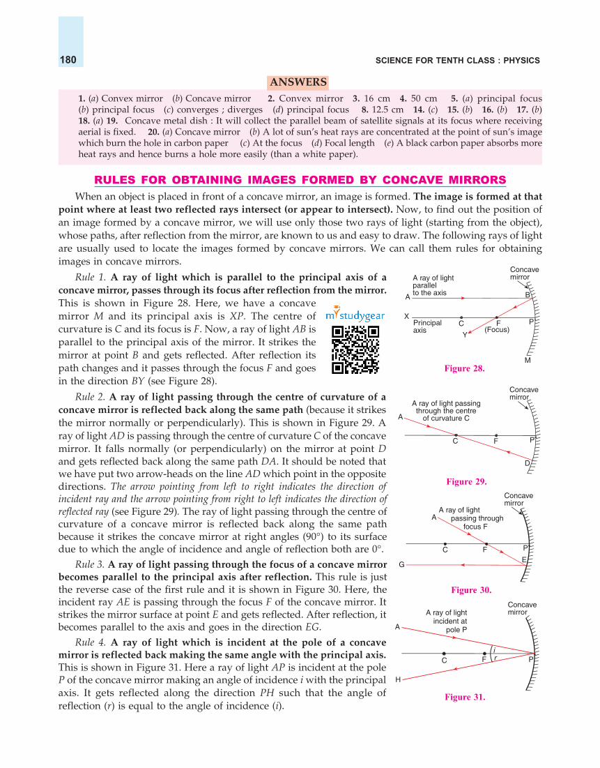
SCIENCE FOR TENTH CLASS : PHYSICS180
ANSWERS1. (a) Convex mirror (b) Concave mirror 2. Convex mirror 3. 16 cm 4. 50 cm 5. (a) principal focus(b) principal focus (c) converges ; diverges (d) principal focus 8. 12.5 cm 14. (c) 15. (b) 16. (b) 17. (b)18. (a) 19. Concave metal dish : It will collect the parallel beam of satellite signals at its focus where receivingaerial is fixed. 20. (a) Concave mirror (b) A lot of sun’s heat rays are concentrated at the point of sun’s imagewhich burn the hole in carbon paper (c) At the focus (d) Focal length (e) A black carbon paper absorbs moreheat rays and hence burns a hole more easily (than a white paper).
RULES FOR OBTAINING IMAGES FORMED BY CONCAVE MIRRORSWhen an object is placed in front of a concave mirror, an image is formed. The image is formed at that
point where at least two reflected rays intersect (or appear to intersect). Now, to find out the position ofan image formed by a concave mirror, we will use only those two rays of light (starting from the object),whose paths, after reflection from the mirror, are known to us and easy to draw. The following rays of lightare usually used to locate the images formed by concave mirrors. We can call them rules for obtainingimages in concave mirrors.
Rule 1. A ray of light which is parallel to the principal axis of aconcave mirror, passes through its focus after reflection from the mirror.This is shown in Figure 28. Here, we have a concavemirror M and its principal axis is XP. The centre ofcurvature is C and its focus is F. Now, a ray of light AB isparallel to the principal axis of the mirror. It strikes themirror at point B and gets reflected. After reflection itspath changes and it passes through the focus F and goesin the direction BY (see Figure 28).
Rule 2. A ray of light passing through the centre of curvature of aconcave mirror is reflected back along the same path (because it strikesthe mirror normally or perpendicularly). This is shown in Figure 29. Aray of light AD is passing through the centre of curvature C of the concavemirror. It falls normally (or perpendicularly) on the mirror at point Dand gets reflected back along the same path DA. It should be noted thatwe have put two arrow-heads on the line AD which point in the oppositedirections. The arrow pointing from left to right indicates the direction ofincident ray and the arrow pointing from right to left indicates the direction ofreflected ray (see Figure 29). The ray of light passing through the centre ofcurvature of a concave mirror is reflected back along the same pathbecause it strikes the concave mirror at right angles (90°) to its surfacedue to which the angle of incidence and angle of reflection both are 0°.
Rule 3. A ray of light passing through the focus of a concave mirrorbecomes parallel to the principal axis after reflection. This rule is justthe reverse case of the first rule and it is shown in Figure 30. Here, theincident ray AE is passing through the focus F of the concave mirror. Itstrikes the mirror surface at point E and gets reflected. After reflection, itbecomes parallel to the axis and goes in the direction EG.
Rule 4. A ray of light which is incident at the pole of a concavemirror is reflected back making the same angle with the principal axis.This is shown in Figure 31. Here a ray of light AP is incident at the poleP of the concave mirror making an angle of incidence i with the principalaxis. It gets reflected along the direction PH such that the angle ofreflection (r) is equal to the angle of incidence (i).
ConcavemirrorA ray of light
parallelto the axisA
XCPrincipal
axisY
B
P
M
F(Focus)
Figure 28.
A
C
D
PF
A ray of light passingthrough the centre
of curvature C
Concavemirror
�
Figure 29.Concavemirror
A ray of lightpassing through
focus FA
C PF
GE
Figure 30.
A ray of lightincident at
pole P
C
Concavemirror
P
H
A
Fir
Figure 31.

REFLECTION OF LIGHT 181
Please note that if a ray of light is incident on a concave mirror along its principal axis, then it isreflected back along the same path (because it will be normal to the mirror surface). The angle of incidenceas well as the angle of reflection for such a ray of light will be zero.
FORMATION OF DIFFERENT TYPES OF IMAGES BY A CONCAVE MIRRORThe type of image formed by a concave mirror depends on the position of object in front of the
mirror. We can place the object at different positions (or different distances) from a concave mirror to getdifferent types of images. For example, we can place the object :
(i) between the pole (P) and focus (F) (see Figure 32),(ii) at the focus (F),
(iii) between focus (F) and centre of curvature (C),(iv) at the centre of curvature (C),(v) beyond the centre of curvature (C), and
(vi) at far-off distance called infinity (This distance cannot be shownin the Figure).
Please note that in all our ray-diagrams the object, an arrow ABpointing upwards, will be placed on the principal axis. So, a ray of light coming from the bottom B of theobject always travels along the principal axis and gets reflected back along the same path. We, however, donot put arrows on the principal axis to show this ray of light.
We will now draw the ray-diagrams to show the images formed by a concave mirror for the differentpositions of an object. We will consider all the six positions of the object, one by one.
Case 1. Image formed by a concave mirror when the object is placed between pole and focus of themirror (Object between P and F)
In Figure 33, we have an object AB placed betweenthe pole (P) and focus (F) of a concave mirror, that is, theobject is within the focus of the concave mirror. To findout the position and nature of the image, starting fromA, we draw a ray AD parallel to the axis (see Figure 33).This ray gets reflected at D and then passes through thefocus F. A second ray of light AE passing through thecentre of curvature C strikes the mirror normally (orperpendicularly) at point E and gets reflected back alongthe same path.
Now, the two reflected rays DF and EC are divergingrays and, therefore, do not intersect each other on the leftside. The reflected rays DF and EC are produced backwards (as shown by dotted lines). On producingbackwards, they appear to intersect at point A behind the concave mirror. Thus, A is the virtual image ofpoint A of the object. To get the complete image of the object we draw AB perpendicular to the axis frompoint A. Thus AB is the image of the object AB formed by the concave mirror. Now, an eye at position X,sees the reflected rays as if they have come from points AB behind the mirror. Since there is no actualintersection of the reflected rays, so the image AB is a virtual image. This image can be seen only bylooking into the concave mirror, it cannot be obtained on a screen. We can see from Figure 33 that theimage is same side up as object (both of them have arrow-head at the top), so it is an erect image. And if wecompare the size of the object AB and its image AB, the image appears to be bigger in size than the object.Thus, it is an enlarged image or magnified image. From the above discussion we conclude that : When anobject is placed between the pole (P) and focus (F) of a concave mirror, the image formed is :
(i) behind the mirror,(ii) virtual and erect, and
(iii) larger than the object (or magnified).
Infinity C(Centre ofcurvature)
F(Focus)
P(Pole)
Concavemirror
Figure 32.
X
C F
A�
B�
Image
Concavemirror
A
BObject
E
D
P
M
Figure 33. Formation of image by a concave mirror whenthe object is placed between its pole (P) and focus (F).

SCIENCE FOR TENTH CLASS : PHYSICS182
It is clear from the above discussion that to obtain a magnified and erect image with a concave mirror,the object should be placed between the pole and focus of the concave mirror, that is, the object should beplaced within the focus (or focal length) of the concave mirror. For example, if the focal length of a concavemirror is 10 cm, then its focus (F) will be at a distance of 10 cm from the pole of the mirror. So, to obtain amagnified and erect image with this concave mirror, we will have to place the object at a distance of lessthan 10 cm so that it remains between the pole and focus. Thus, if we place the object at a distance of, say8 cm, from this concave mirror, the object will be within the focus and a magnified, virtual and erect imagewill be formed behind the concave mirror (which can be seen by looking into the concave mirror).
If we hold a matchstick (as object) within the focus of a concave mirror, then a magnified, virtual anderect image of the matchstick is seen on looking into the concave mirror [as shown in Figure 34(a)]. This
(a) A concave mirror can (b) A concave mirror being used as (c) Dentist’s mirror is a smallbe used to magnify objects. a make-up mirror. It is magnifying concave mirror fitted in a frameHere it is magnifying a a part of the face here. with a long handle. It gives amatchstick kept close to it magnified image of tooth.
Figure 34.
also explains the use of a concave mirror as a shaving mirror. When the face is placed close to a concavemirror (so that the face is within its focus) the concave mirror produces a magnified (large) and erect imageof the face. Since a large image of the face is seen in the concave mirror, it becomes easier to make a smoothshave. Thus, while using a concave mirror as a shaving mirror, the face should be close to the concavemirror. For the same reason, concave mirrors are also used as make-up mirrors by women for putting onmake-up (such as painting eye-lashes) [see Figure 34(b)]. In order to use a concave mirror as a make-upmirror, the face is held close to the concave mirror so that it lies within the focus of concave mirror. Dentistsuse concave mirrors to see the large image of the teeth for examining the teeth of a person (see Figure34(c)]. For this purpose, the dentist holds a small concave mirror in such a way that the tooth lies within itsfocus. A magnified image of the tooth is then seen by the dentist in the concave mirror. Since the toothlooks much bigger, it becomes easy to examine the defect in the tooth.
Case 2. When the object is placed at the focus of a concavemirror (Object at F)
In Figure 35, the object AB has been placed at the focus (F) ofthe concave mirror. Now, the parallel ray of light AD (comingfrom the top of the object) gets reflected at D and passes throughthe focus F, giving us the reflected ray DX. A second ray of lightAE passing through the centre of curvature C, is reflected backalong the same path giving us another reflected ray EY. We findthat the reflected rays DX and EY are parallel to one another.These parallel rays will intersect (or meet) at a far off distance to
Figure 35. Formation of image by a concavemirror when the object is placed at its focus (F).

REFLECTION OF LIGHT 183
form an image ‘at infinity’. And since the image is formed at infinity, it is not possible toshow it in our diagram. From this discussion we conclude that : When an object is placedat the focus of a concave mirror, the image formed is :
(i) at infinity,(ii) real and inverted, and
(iii) highly magnified (or highly enlarged).
Suppose we have a concave mirror of focal length 10 cm, then its focus (F) will be at a distance of 10 cmfrom it. So, by saying that an object is placed at the focus of this concave mirror, we will mean that theobject is placed at a distance of 10 cm from the concave mirror. In this case, the concave mirror converts thediverging rays of light coming from the object into a parallel beam of light rays (which form image atinfinity).
When a lighted bulb is placed at the focus of a concave mirror reflector, the diverging light rays ofthe bulb are collected by the concave reflector and then reflected to produce a strong, parallel-sidedbeam of light [see Figure 36(a)]. This explains the use of concave reflectors in torches, car head-lights, and
(a) When a lighted bulb is placed at the focus of a concave (b) This picture shows thereflector, a parallel beam of light is produced. concave reflector of a torch.
Figure 36.
search lights to produce a strong beam of light (which travels a considerable distance in the darkness ofnight).
Case 3. When the object is placed between focus and centre of curvature (Object between F and C)
In Figure 37, the object AB has been placed between thefocus F and centre of curvature C of a concave mirror. Now, aray of light AD parallel to the principal axis gets reflected atpoint D and then passes through the focus F. A second ray oflight AE passing through the centre of curvature C falls normallyon the mirror surface at E and returns along the same path.Thus, we have two reflected rays DF and EC which areconverging in the downward direction. If we extend these raysfurther in the downward direction, they actually intersect atpoint A. Thus A is the real image of point A of the object. Toget the complete image we draw AB perpendicular to the axisfrom point A. Thus, AB is the real image of the object AB andit can be received on a screen. For example, if we take a lightedcandle as the object then the image of its wick will be formed on a white screen placed at the imageposition. If we look at the image AB, we find that it is wrong side up having arrow-head at its bottom. So,we say that the image is inverted. The size of image is larger than the object, so the image is magnified, and
B�
Image
A�
FObject
CB
A
Concavemirror
D
P
E
Figure 37. Formation of image by a concavemirror when the object is placed between
focus (F) and centre of curvature (C).

SCIENCE FOR TENTH CLASS : PHYSICS184
it has been formed beyond the centre of curvature of the mirror. From the above discussion we concludethat : When an object is placed between the focus (F) and centre of curvature (C) of a concave mirror, theimage formed is :
(i) beyond the centre of curvature,(ii) real and inverted, and
(iii) larger than the object (or magnified).
Please remember that a real image is always inverted, and a virtual image is always erect. Supposewe have a concave mirror of focal length 10 cm. Then its focus (F) will be at a distance of 10 cm and centreof curvature (C) will be at a distance of 2 × 10 = 20 cm from it. Now, by saying that the object is placedbetween the focus and centre of curvature of this concave mirror, we mean that the object is at any distancebetween 10 cm and 20 cm from the concave mirror. For example, it may be at a distance of say, 15 cm fromthe concave mirror. And by saying that the image is formed beyond centre of curvature, we mean that it isat a distance greater than 20 cm from this concave mirror.
Case 4. When the object is placed at the centre of curvature of a concave mirror (Object at C)
In Figure 38, the object AB has been placed at the centre of curvature C of the concave mirror. A ray oflight AD which is parallel to the principal axis passes through the focusF after reflection. Now, the second ray of light that we usually use is theone passing through the centre of curvature C. But in this case the objectitself is placed at the centre of curvature, so we cannot use this ray oflight to locate the image. Here we will use rule No. 3 of image formationwhich says that “A ray of light passing through the focus of a concavemirror becomes parallel to the principal axis after reflection”. So, wenow take the ray AE passing through the focus F. It strikes the mirror atpoint E and gets reflected in the direction EA parallel to the principalaxis.
The reflected rays DA and EA meet at point A, so A is the realimage of point A of the object. To get the complete image, we draw ABperpendicular to the principal axis. Thus, AB is the real image of the object AB (Note that B and B is justthe same point). The image is of the same size as the object, it is real, inverted and formed at the centre ofcurvature, where the object itself is placed. From this discussion we conclude that : Whenan object is placed at the centre of curvature (C) of a concave mirror, the image formed is :
(i) at the centre of curvature (C),(ii) real and inverted, and
(iii) same size as the object.
Suppose we have a concave mirror of focal length 10 cm, then its focus (F) will be at a distance of 10 cmand its centre of curvature (C) will be at a distance of 2 × 10 = 20 cm. So, by saying that the object is at thecentre of curvature, we mean that the object is at a distance of 20cm from this concave mirror. And by saying that the image isformed at the centre of curvature, we mean that the image is alsoformed at a distance of 20 cm from the concave mirror.
Case 5. When the object is beyond the centre of curvature ofthe concave mirror (Object beyond C)
In Figure 39, the object AB has been placed beyond the centreof curvature C of the concave mirror. A ray of light AD which isparallel to the principal axis, passes through the focus F afterreflection. A second ray of light AE passing through the centre ofcurvature falls normally on the mirror surface at E and returns
ObjectB
B�
A�
ImageC F
E
D
P
Concavemirror
A
Figure 38. Formation of image by aconcave mirror when the object isplaced at the centre of curvature (C).
A
BObject
C
Concavemirror
D
P
E
FB�
A�
Image
Figure 39. Formation of image by a concavemirror when the object is placed beyond thecentre of curvature C.

REFLECTION OF LIGHT 185
along the same path. The two reflected rays intersect at A. Thus, A is the realimage of point A of the object. To get the complete image, we draw ABperpendicular to the axis. Thus, AB is the complete image of the object AB. It isclear from Figure 39 that the image AB is formed between the focus (F) and centreof curvature (C). The image is real and inverted. It is smaller in size than the objectAB, so we call it a diminished image. From the above discussion we conclude that :When an object is placed beyond the centre of curvature (C) of a concave mirror,the image formed is :
(i) between the focus and centre of curvature,(ii) real and inverted, and
(iii) smaller than the object (or diminished).
Suppose we have a concave mirror of focal length 10 cm, then its focus (F) willbe at a distance of 10 cm and its centre of curvature (C) will be at a distance of 2 ×10 = 20 cm from it. Now, by saying that an object is placed beyond the centre ofcurvature of this concave mirror, we mean that the object is placed at a distancegreater than 20 cm (say, 25 cm) from the concave mirror. And by saying that theimage is formed between focus and centre of curvature, we mean that the image isformed at a distance between 10 cm and 20 cm.
We know that the front side of a shining steel spoon is a kind of concave mirror.So, if we keep our face at a fairly good distance from the front side of a shiningsteel spoon (so that it is beyond its centre of curvature), we will see a real, invertedand smaller image (diminished image) of our face in the spoon (as shown in Figure 40).
Case 6. When the Object is at Infinity
When the object is at a very large distance, we say that the objectis at infinity. In Figure 41 we have a concave mirror M. Suppose anobject (an arrow pointing upwards) has been placed at infinity infront of the concave mirror (Since the object is very far off, it cannotbe shown in the diagram). Because the object AB is very far off, thetwo rays AD and AP coming from its top point A are parallel toone-another but at an angle to the principal axis as shown in Figure41. These parallel rays get reflected at points D and P and thenintersect at point A in the focal plane of the mirror. Thus, A is thereal image of the top point A of the object. To get the full image ofthe object, we draw AB perpendicular to the principal axis fromA. Thus, AB is the image of the object AB placed at infinity. Wefind that image AB is formed at the focus (F) of the concave mirror.It is real, inverted and much smaller than the object or highly diminished. From the above discussion weconclude that : When an object is at infinity from a concave mirror, the image formed is :
(i) at the focus (F),(ii) real and inverted, and
(iii) much smaller than the object (or highly diminished).
It should be noted that this case is just opposite of case No. 2 which we have alreadydiscussed. There we studied that “when the object is at focus of concave mirror, the imageis formed at infinity” and here we have seen that “when the object is at infinity, theimage is formed at the focus of concave mirror”. This means that a concave mirror can concentrate all theparallel rays of light to its focus.
Suppose we have a concave mirror of focal length 10 cm, then its focus (F) will be at a distance of 10 cm
Figure 40. The formationof a real, inverted anddiminished image of facein the front side (concavesurface) of a shining steelspoon.
Figure 41. Formation of image by a concavemirror when the object is at a considerabledistance (or infinity).

SCIENCE FOR TENTH CLASS : PHYSICS186
from it. Now, by saying that the object is at infinity, we mean that the object is at a distance which is many,many times its focal length : it may be 1000 cm, 10,000 cm or even more. And by saying that the image isformed at the focus of this concave mirror, we mean that the image is formed at a distance of 10 cm fromthe pole of this concave mirror.
Please note that when the object kept at infinity in front of a concave mirror is assumed to be a bigarrow pointing upwards, then its image is formed at focus according to the ray-diagram shown in Figure41. If, however, the object kept at infinity in front of a concave mirror is round in shape (like the sun), thenits image is formed at the focus according to the ray-diagram shown in Figure 25 on page 177.
The fact that when a parallel beam of light rays falls on a concave mirror, the concave mirror concentratesall the light at its focus, explains the use of concave mirror as a doctor’s head-mirror. A concave mirror isused as a “head-mirror” by the doctors to concentrate light coming from a lamp on to the body part of apatient (like ear, nose, throat, etc.) to be examined. This is done as follows : A concave mirror is fixed tothe front part of a doctor’s head with the help of a strap [as shown in Figure 42(a)]. When the beam of lightcoming from a lamp falls on the doctor’s concave head-mirror, the mirror focusses this light on to the bodypart of the patient. The body part gets illuminated brightly with this light due to which the doctor can lookinto the body part (like ear, nose, throat, etc.) very clearly.
(a) The doctor’s head-mirror is a (b) The metal ‘dish’ of dish antennaconcave mirror of television is concave.
Figure 42.
The concave ‘metal dishes’ are used in dish antennas (or dish aerials) of televisions to receive TVsignals from the very distant communications satellites which are high up in the sky [see Figure 42(b)].The dish is a concave reflector. The dish collects a large amount of parallel beams of TV signals comingfrom the far off satellite and converges them to its focus. The antenna (or signal detector) is fixed in front ofthe concave dish at its focus. Since the antenna is fixed at the focus of dish, it receives the strongest possibleTV signals from the satellite which make our television work. The TV signals coming from satellite can bemade even more stronger by using a bigger dish in the dish antenna. Please note that though the TVsignals coming from the satellite are not light rays, they obey the laws of reflection of light.
How to find out the Focal Length of a Concave Mirror Quickly but ApproximatelyThe fact that “when the object is at a considerable
distance (or at infinity) from a concave mirror, then its imageis formed at the focus” can be used to find out the focallength of a concave mirror quickly but approximately. Wefocus a distant object (several metres away) like a window ortree on a screen by using a concave mirror whose focal lengthis to be determined (see Figure 43). The sharp image ofwindow or tree will be formed at the focus of the concavemirror. That is, the distance of image (or screen) from the
Distantwindow
Light from
window
Screen
Image ofwindow
Scale
Concavemirror
(focal lengthf
Figure 43. Arrangement for measuring the focallength of a concave mirror quickly but approximately.

REFLECTION OF LIGHT 187
concave mirror will be equal to the focal length of concave mirror. This distance can be measured with ascale. It will give us the approximate focal length of the concave mirror. And before we conclude thisdiscussion, here is a summary of the images formed by a concave mirror.
Summary of the Images Formed by a Concave Mirror
Position of object Position of image Size of image Nature of image
1. Within focus Behind the mirror Enlarged Virtual and erect(between pole Pand focus F)
2. At focus (F) At infinity Highly enlarged Real and inverted3. Between F and C Beyond C Enlarged Real and inverted4. At C At C Equal to object Real and inverted5. Beyond C Between F and C Diminished Real and inverted6. At infinity At focus (F) Highly diminished Real and inverted
Uses of Concave Mirrors(i) Concave mirrors are used as shaving mirrors to see a large image of the face. This is because when
the face is held within the focus of a concave mirror, then an enlarged image of the face is seen in theconcave mirror. This helps in making a smooth shave. For the same reason, concave mirrors are used asmake-up mirrors.
(ii) Concave mirrors are used by dentists to see the large images of the teeth of patients. This isbecause when a tooth is within the focus of a concave mirror, then an enlarged image of the tooth is seen inthe concave mirror. Due to this, it becomes easier to locate the defect in the tooth. The concave mirrorsused by dentists are very small in size. They are fitted in a frame with a long handle.
(iii) Concave mirrors are used as reflectors in torches, vehicle head-lights and search lights to getpowerful beams of light. This is because when a lighted bulb is placed at the focus of a concave reflector,then the concave reflector produces a powerful beam of parallel light rays. This helps us see things up to aconsiderable distance in the darkness of night. Concave reflectors are also used in room heaters. Theconcave reflectors of room heaters direct heat rays into the whole room.
(iv) Concave mirrors are used as doctor’s head-mirrors to focus light coming from a lamp on to thebody parts of a patient (such as eye, ear, nose, throat, etc.) to be examined by the doctor.
(v) Concave dishes are used in TV dish antennas to receive TV signals from the distantcommunications satellites. The concave dish collects a lot of TV signals and focusses them on to an antenna(or aerial) fixed at its focus, so as to produce strong signals to run the television.
(vi) Large concave mirrors are used in the field of solar energy to focus sun’s rays for heating solarfurnaces. This can be explained as follows : The solar furnace is placed at the focus of a large concavereflector. The concave reflector focuses the sun’s heat rays on the furnace due to which the solar furnacegets very hot. Even steel can be melted in this solar furnace.
Let us solve some problems now.
Sample Problem 1. We wish to obtain an erect image of an object using a concave mirror of focal length15 cm. What should be the range of distance of the object from the mirror ? What is the nature of theimage ? Is the image larger or smaller than the object ? Draw a ray-diagram to show the image formation inthis case. (NCERT Book Question)
Solution. In order to obtain an erect image of an object with a concave mirror, the object should be at adistance less than its focal length. Here the focal length of concave mirror is 15 cm. So to obtain an erectimage of the object by using this concave mirror, the object should be placed at any distance which is lessthan 15 cm from the mirror. The nature of image will be virtual. The image will be larger than the object(For ray-diagram, see Figure 33 on page 181).

SCIENCE FOR TENTH CLASS : PHYSICS188
Sample Problem 2. The image formed by a concave mirror is seen to be virtual, erect and larger thanthe object. The position of the object must then be :
(i) between the focus and centre of curvature.(ii) at the centre of curvature.
(iii) beyond the centre of curvature.(iv) between the pole of the mirror and its focus.
Choose the correct alternative. (NCERT Book Question)
Solution. The correct alternative is (iv) : between the pole of the mirror and its focus.
Sample Problem 3. A concave mirror has a focal length of 10 cm. Where should an object be placed infront of this concave mirror so as to obtain an image which is real, inverted and same size as the object ?
Solution. When the image formed by a concave mirror is real, inverted and of the same size as theobject, then the object must be placed at its centre of curvature (C). Now, the centre of curvature of aconcave mirror is at a distance of ‘twice the focal length’ or ‘2f ’. Here,
Focal length, f = 10 cm
So, 2f = 2 × 10 cm
= 20 cm
Thus, the object should be placed at a distance of 20 cm in front of this concave mirror.
Sample Problem 4. An object is placed at the following distances from a concave mirror of focal length10 cm :
(a) 8 cm (b) 15 cm (c) 20 cm (d) 25 cm
Which position of the object will produce :(i) a diminished real image ?
(ii) a magnified real image ?(iii) a magnified virtual image ?(iv) an image of the same size as the object ?
Solution. In this case the focal length of concave mirror is 10 cm. This means that the focus (F) of thisconcave mirror is at a distance of 10 cm from the mirror and its centre of curvature (C) is at a distance of2 × 10 = 20 cm from the mirror.
(i) A diminished real image is formed by a concave mirror when the object is beyond C. Here C is at 20cm. So, the diminished real image will be formed when the object is at a distance greater than 20 cm, whichin this problem is 25 cm. So, the position of object for a diminished real image is 25 cm.
(ii) A magnified real image is formed by a concave mirror when the object is between F and C. Here Fis at 10 cm and C is at 20 cm. So, the magnified real image will be formed when the object is at a distancebetween 10 cm and 20 cm, which in this problem is 15 cm. So, the position of object for a magnified realimage is 15 cm.
(iii) A magnified virtual image is formed by a concave mirror when the object is within focus (F) at adistance less than focal length or less than 10 cm, which in this problem is 8 cm. So, the position of objectfor a magnified virtual image is 8 cm.
(iv) An image of the same size as object is formed by a concave mirror when the object is at centre ofcurvature (C). Here C is at 20 cm. So, the image of same size as the object will be formed when the object isat 20 cm from the concave mirror. Thus, the position of object for an image of same size as the object is20 cm.
Please note that we have given so many details in answering the above question just to make youunderstand clearly. There is, however, no need to give so many details in the examination. In the examination,the answer to the above question can just be written as :

REFLECTION OF LIGHT 189
(i) 25 cm (ii) 15 cm (iii) 8 cm (iv) 20 cm
Before we go further and discuss the sign convention for spherical mirrors, please answer the followingquestions :
Very Short Answer Type Questions
1. For what position of an object, a concave mirror forms a real image equal in size to the object ?2. Where should an object be placed in front of the concave mirror so as to obtain its virtual, erect and magnified
image ?3. For which positions of the object does a concave mirror produce an inverted, magnified and real image ?4. If an object is placed at the focus of a concave mirror, where is the image formed ?5. If an object is at infinity (very large distance) in front of a concave mirror, where is the image formed ?6. For what position of an object, a real and diminished image is formed by a concave mirror ?7. Copy this figure in your answer book and show the direction of the light ray after reflection :
C F
8. Draw the following diagram in your answer book and show the formation of image of the object AB withthe help of suitable rays :
C B F P
A
9. Draw the following diagram in your answer book and show the formation of image with the help of suitablerays :
C F P
10. Which type of mirror could be used as a dentist’s mirror ?
Short Answer Type Questions11. Which kind of mirror is used in the headlights of a car ? Why is it used for this purpose ?12. Explain why, a ray of light passing through the centre of curvature of a concave mirror gets reflected back
along the same path.13. What is the minimum number of rays required for locating the image formed by a concave mirror for an
object ? Draw a ray diagram to show the formation of a virtual image by a concave mirror.14. With the help of a ray diagram, determine the position, nature and size of the image formed of an object
placed at the centre of curvature of a concave mirror.15. Describe with the help of a diagram, the nature, size and position of the image formed when an object is
placed beyond the centre of curvature of a concave mirror.16. If an object is placed at a distance of 8 cm from a concave mirror of focal length 10 cm, discuss the nature of
the image formed by drawing the ray diagram.17. Draw a ray diagram showing how a concave mirror can be used to produce a real, inverted and diminished
image of an object.

SCIENCE FOR TENTH CLASS : PHYSICS190
18. Which mirror is used as a torch reflector ? Draw a labelled diagram to show how a torch reflector can beused to produce a parallel beam of light. Where is the bulb placed in relation to the torch reflector ?
19. State where an object must be placed so that the image formed by a concave mirror is :(a) erect and virtual.(b) at infinity.(c) the same size as the object.
20. With the help of a labelled ray diagram, describe how a converging mirror can be used to give an enlargedupright image of an object.
21. Make labelled ray diagrams to illustrate the formation of :(a) a real image by a converging mirror.(b) a virtual image by a converging mirror.Mark clearly the pole, focus, centre of curvature and position of object in each case.
22. Briefly describe how you would find the focal length of a concave mirror quickly but approximately.23. Which type of mirror is used in a solar furnace ? Support your answer with reason.24. Name the type of mirror used by dentists. How does it help ?25. Explain why, concave mirrors are used as shaving mirrors.26. Give two uses of concave mirrors. Explain why you would choose concave mirrors for these uses.
Long Answer Type Questions
27. (a) Draw ray-diagrams to show the formation of images when the object is placed in front of a concavemirror (converging mirror) :
(i) between its pole and focus(ii) between its centre of curvature and focus
Describe the nature, size and position of the image formed in each case.(b) State one use of concave mirror based on the formation of image as in case (i) above.
28. (a) Give two circumstances in which a concave mirror can form a magnified image of an object placed infront of it. Illustrate your answer by drawing labelled ray diagrams for both.
(b) Which one of these circumstances enables a concave mirror to be used as a shaving mirror ?
Multiple Choice Questions (MCQs)
29. The real image formed by a concave mirror is larger than the object when the object is :(a) at a distance equal to radius of curvature (b) at a distance less than the focal length(c) between focus and centre of curvature (d) at a distance greater than radius of curvature
30. The real image formed by a concave mirror is smaller than the object if the object is :(a) between centre of curvature and focus (b) at a distance greater than radius of curvature(c) at a distance equal to radius of curvature (d) at a distance equal to focal length
31. The image formed by a concave mirror is virtual, erect and magnified. The position of object is :(a) at focus (b) between focus and centre of curvature(c) at pole (d) between pole and focus
32. The image formed by a concave mirror is real, inverted and of the same size as the object. The position ofthe object must then be :(a) at the focus (b) between the centre of curvature and focus(c) at the centre of curvature (d) beyond the centre of curvature
33. The image formed by a concave mirror is real, inverted and highly diminished (much smaller than theobject). The object must be :(a) between pole and focus (b) at focus(c) at the centre of curvature (d) at infinity
34. The angle of incidence for a ray of light passing through the centre of curvature of a concave mirror is :(a) 45° (b) 90° (c) 0° (d) 180°

REFLECTION OF LIGHT 191
35. In the concave reflector of a torch, the bulb is placed :(a) between the pole and focus of reflector (b) at the focus of reflector(c) between focus and centre of curvature of reflector (d) at the centre of curvature of reflector
36. The focal length of a small concave mirror is 2.5 cm. In order to use this concave mirror as a dentist’s mirror,the distance of tooth from the mirror should be :(a) 2.5 cm (b) 1.5 cm (c) 4.5 cm (d) 3.5 cm
Questions Based on High Order Thinking Skills (HOTS)37. An object is 100 mm in front of a concave mirror which produces an upright image (erect image). The radius
of curvature of the mirror is :(a) less than 100 mm (b) between 100 mm and 200 mm(c) exactly 200 mm (d) more than 200 mm
38. A virtual, erect and magnified image of an object is to be produced with a concave mirror of focal length12 cm. Which of the following object distance should be chosen for this purpose ? (i) 10 cm (ii) 15 cm (iii) 20 cmGive reasons for your choice.
39. A concave mirror has a focal length of 25 cm. At which of the following distance should a person hold hisface from this concave mirror so that it may act as a shaving mirror ?(a) 45 cm (b) 20 cm (c) 25 cm (d) 30 cmGive reason for your choice.
40. An object is placed at the following distances from a concave mirror of focal length 15 cm, turn by turn :(a) 35 cm (b) 30 cm (c) 20 cm (d) 10 cmWhich position of the object will produce :(i) a magnified real image ?
(ii) a magnified virtual image ?(iii) a diminished real image ?(iv) an image of same size as the object ?
ANSWERS
1. At the centre of curvature 2. Between pole and focus 3. Between focus and centre of curvature4. At infinity 5. At focus 6. Beyond centre of curvature 12. It falls normally (perpendicularly) on themirror surface; The angle of incidence is 0° and the angle of reflection is also 0° 13. Two rays 16. Virtual,erect and magnified 29. (c) 30. (b) 31. (d) 32. (c) 33. (d) 34. (c) 35. (b) 36. (b) 37. (d) 38. 10 cm ;Because it is less than focal length 39. 20 cm 40. (i) 20 cm (ii) 10 cm (iii) 35 cm (iv) 30 cm.
SIGN CONVENTION FOR SPHERICAL MIRRORSThese days New Cartesian Sign Convention is used for measuring the various distances in the ray-
diagrams of spherical mirrors (concave mirrors and convex mirrors). According to the New Cartesian SignConvention :
(i) All the distances are measured from pole of the mirror as origin.(ii) Distances measured in the same direction as that of incident light are taken as positive.
(iii) Distances measured against the direction of incident light aretaken as negative.
(iv) Distances measured upward and perpendicular to the principalaxis are taken as positive.
(v) Distances measured downward and perpendicular to theprincipal axis are taken as negative.
The New Cartesian Sign Convention for mirrors is shown inFigure 44. The object is always placed on the left side of the mirror(as shown in Figure 44) so that the direction of incident light is from
Against the directionof incident light
Negative distances
In the directionof incident light
Positive distances
PObject is placed onleft side of the mirror
Direction ofincident light
(Left to right)
Mirror
Figure 44. Sign convention for mirrors.

SCIENCE FOR TENTH CLASS : PHYSICS192
left to right. Since the incident light always goes from left to right, all the distances measured from the pole(P) of mirror to the right side will be considered positive (because they will be in the same direction asthe incident light). On the other hand, all the distances measured from pole (P) of mirror to the left sidewill be negative (because they are measured against the direction of incident light).
Some Important Conclusions
According to the sign convention, the distances towards the left of the mirror are negative. Since anobject is always placed to the left side of a mirror, therefore, the object distance (u) is always negative.
The images formed by a concave mirror can be either behind the mirror (virtual) or in front of themirror (real). So, the image distance (v) for a concave mirror can be either positive or negative dependingon the position of the image. If an image is formed behind a concave mirror (to the right side), the imagedistance (v) is positive but if the image is formed in front of the mirror (on the left side), then the imagedistance will be negative.
In a convex mirror, the image is always formed on the right hand side (behind the mirror), so theimage distance (v) for a convex mirror will be always positive.
The focus of concave mirror is in front of the mirror on the left side, so the focal length of a concavemirror is considered negative (and written with a minus sign, say, –10 cm). On the other hand, the focus ofa convex mirror is behind the mirror on the right side, so the focal length of a convex mirror is positive(and written with a plus sign, say +20 cm or just 20 cm).
We will now discuss the signs for the heights of objects and images. An object is always placed abovethe principal axis in the upward direction, so the height of an object is always considered positive. On theother hand, an image can be formed above the principal axis or below the principal axis. If an image isformed above the principal axis, its height is taken as positive and if an image is formed below theprincipal axis, then its height is taken as negative. Now, we know that all the virtual images are erect andare formed above the principal axis, so the height of all the virtual and erect images is considered positive.On the other hand, all the real images are inverted and they are formed below the principal axis, so theheight of all the real and inverted images is taken as negative. We are now in a position to answer thefollowing questions :
Very Short Answer Type Questions
1. According to the “New Cartesian Sign Convention” for mirrors, what sign has been given to the focal lengthof : (i) a concave mirror ?(ii) a convex mirror ?
2. Which type of mirror has :(a) positive focal length ?(b) negative focal length ?
3. What is the nature of a mirror having a focal length of, +10 cm ?4. What kind of mirror can have a focal length of, – 20 cm ?5. Complete the following sentence :
All the distances are measured from the .......... of a spherical mirror.6. What sign (+ve or –ve) has been given to the following on the basis of Cartesian Sign Convention ?
(a) Height of a real image.(b) Height of a virtual image.
Short Answer Type Questions7. Describe the New Cartesian Sign Convention used in optics. Draw a labelled diagram to illustrate this sign
convention.

REFLECTION OF LIGHT 193
8. Giving reasons, state the ‘signs’ (positive or negative) which can be given to the following :(a) object distance (u) for a concave mirror or convex mirror(b) image distances (v) for a concave mirror(c) image distances (v) for a convex mirror
Multiple Choice Questions (MCQs)9. According to New Cartesian Sign Convention :
(a) focal length of concave mirror is positive and that of convex mirror is negative(b) focal length of both concave and convex mirrors is positive(c) focal length of both concave and convex mirrors is negative(d) focal length of concave mirror is negative and that of convex mirror is positive
10. One of the following does not apply to a concave mirror. This is :(a) focal length is negative(b) image distance can be positive or negative(c) image distance is always positive(d) height of image can be positive or negative
ANSWERS 3. Convex mirror 4. Concave mirror 5. pole 9. (d) 10. (c)
MIRROR FORMULAThe distance of an object from the pole of a mirror is known as object distance. Object distance is
denoted by the letter u. The distance of image from the pole of a mirror is known as image distance. Imagedistance is denoted by the letter v. The distance of focus from the pole of a mirror is known as focal length.Focal length is denoted by the letter f. There is a relationship between the object distance, image distanceand focal length of a spherical mirror (concave mirror or convex mirror). This relationship is given by themirror formula.
A formula which gives the relationship between image distance (v), object distance (u) and focallength (f) of a spherical mirror is known as the mirror formula. The mirror formula can be written as :
1 1 1
+ =Image distance Object distance Focal length
1 1 1or — + — = —v u fwhere v = distance of image from mirror
u = distance of object from mirrorand f = focal length of the mirror
The mirror formula has three values in it. If any two values are known, the third value can be calculated.The known values should be put in this formula with their proper signs but no sign should be given to theunknown value to be calculated. Its proper sign will come by itself by calculations. The proper signs of theknown values of u, v or f can be found by using New Cartesian Sign Convention for spherical mirrors.Another point to be noted is that the mirror formula can be applied to both type of spherical mirrors :concave mirrors as well as convex mirrors. By using this mirror formula, we can find out the position andnature of the images formed by concave mirrors and convex mirrors. Before we do that, we will discuss the‘magnification’ produced by spherical mirrors.
Linear Magnification Produced by MirrorsThe size of image formed by a spherical mirror depends on the position of the object from the mirror.
The image formed by a spherical mirror can be bigger than the object, equal to the object or smaller thanthe object. The size of the image relative to the object is given by the linear magnification. This is discussedon the next page.
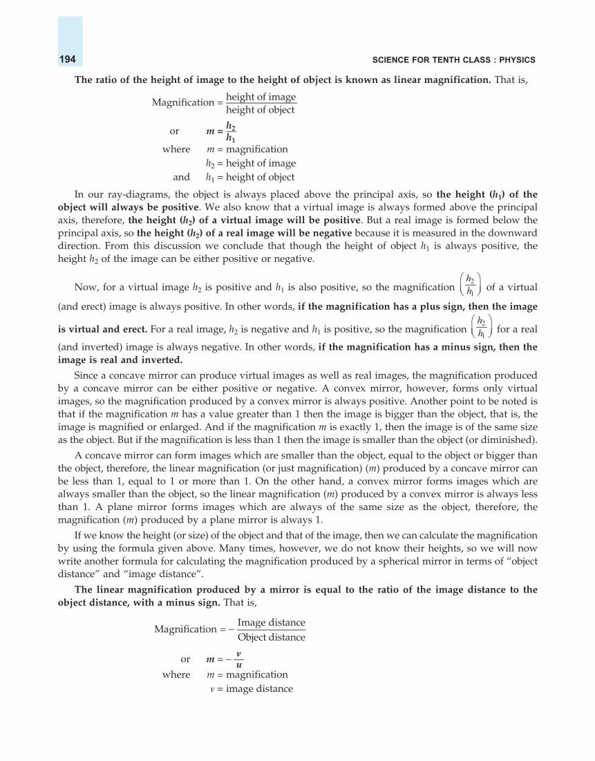
SCIENCE FOR TENTH CLASS : PHYSICS194
The ratio of the height of image to the height of object is known as linear magnification. That is,
height of imageMagnification = ———————height of object
h2or m = —h1
where m = magnificationh2 = height of image
and h1 = height of object
In our ray-diagrams, the object is always placed above the principal axis, so the height (h1) of theobject will always be positive. We also know that a virtual image is always formed above the principalaxis, therefore, the height (h2) of a virtual image will be positive. But a real image is formed below theprincipal axis, so the height (h2) of a real image will be negative because it is measured in the downwarddirection. From this discussion we conclude that though the height of object h1 is always positive, theheight h2 of the image can be either positive or negative.
Now, for a virtual image h2 is positive and h1 is also positive, so the magnification 2
1
hh
of a virtual
(and erect) image is always positive. In other words, if the magnification has a plus sign, then the image
is virtual and erect. For a real image, h2 is negative and h1 is positive, so the magnification 2
1
hh
for a real
(and inverted) image is always negative. In other words, if the magnification has a minus sign, then theimage is real and inverted.
Since a concave mirror can produce virtual images as well as real images, the magnification producedby a concave mirror can be either positive or negative. A convex mirror, however, forms only virtualimages, so the magnification produced by a convex mirror is always positive. Another point to be noted isthat if the magnification m has a value greater than 1 then the image is bigger than the object, that is, theimage is magnified or enlarged. And if the magnification m is exactly 1, then the image is of the same sizeas the object. But if the magnification is less than 1 then the image is smaller than the object (or diminished).
A concave mirror can form images which are smaller than the object, equal to the object or bigger thanthe object, therefore, the linear magnification (or just magnification) (m) produced by a concave mirror canbe less than 1, equal to 1 or more than 1. On the other hand, a convex mirror forms images which arealways smaller than the object, so the linear magnification (m) produced by a convex mirror is always lessthan 1. A plane mirror forms images which are always of the same size as the object, therefore, themagnification (m) produced by a plane mirror is always 1.
If we know the height (or size) of the object and that of the image, then we can calculate the magnificationby using the formula given above. Many times, however, we do not know their heights, so we will nowwrite another formula for calculating the magnification produced by a spherical mirror in terms of “objectdistance” and “image distance”.
The linear magnification produced by a mirror is equal to the ratio of the image distance to theobject distance, with a minus sign. That is,
Image distance
Magnification =Object distance
vor m = – —uwhere m = magnification
v = image distance

REFLECTION OF LIGHT 195
and u = object distanceThus, if we know the image distance v and the object distance u, then the magnification m can be
calculated.
So, now we have two formulae for calculating the magnification :
h2 vm = — and m = – —
h1 u
We will use these two formulae to solve numerical problems. We can also combine these two formulaeto get another formula :
h2 v— = – —h1 u
This will also be used in solving problems.
Numerical Problems Based on Concave MirrorsWe will now solve some numerical problems based on concave mirrors by using the mirror formula
and the magnification formulae. Here are some examples.
Sample Problem 1. Find the size, nature and position of image formed when an object of size 1 cm isplaced at a distance of 15 cm from a concave mirror of focal length 10 cm.
Solution. Here we have been given the object distance and focal length, so first of all we will find outthe image distance which will give us the position of image.
(i) Position of imageHere, Object distance, u = – 15 cm (To the left of mirror)
Image distance, v = ? (To be calculated)And, Focal length, f = – 10 cm (It is concave mirror)
Now, putting these values in the mirror formula :1 1 1— + — = —v u f1 1 1we get : — + —— = ——v – 15 – 101 1 1or — – — = – —v 15 10
1 1 1or — = – — + —v 10 151 – 3 + 2 — = ———v 301 1— = – —v 30
So, Image distance, v = – 30 cm
Thus, the position of image is 30 cm to the left side of mirror or 30 cm in front of mirror (Minus signshows the left side of mirror).
(ii) Nature of image. Since the image is formed in front of the concave mirror, its nature will be “Realand Inverted”.
(iii) Size of image. To find the size of image, we will have to calculate the magnification first. Themagnification produced by a mirror is given by :
vm = – —u
Here, Image distance, v = – 30 cm
Object distance, u = – 15 cm
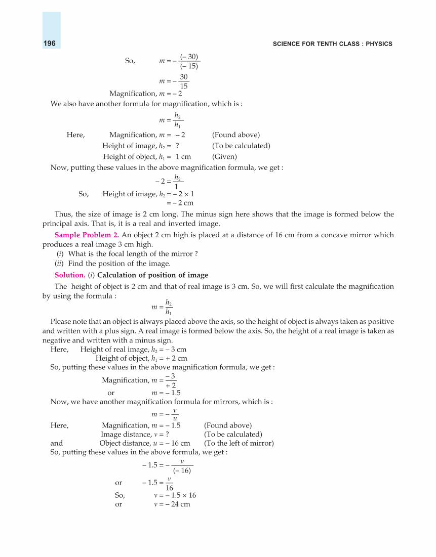
SCIENCE FOR TENTH CLASS : PHYSICS196
(– 30)So, m = – ———(– 15)30m = – —–15
Magnification, m = – 2We also have another formula for magnification, which is :
h2 m = —–h1
Here, Magnification, m = – 2 (Found above)Height of image, h2 = ? (To be calculated)Height of object, h1 = 1 cm (Given)
Now, putting these values in the above magnification formula, we get :h2– 2 = —–1
So, Height of image, h2 = – 2 × 1= – 2 cm
Thus, the size of image is 2 cm long. The minus sign here shows that the image is formed below theprincipal axis. That is, it is a real and inverted image.
Sample Problem 2. An object 2 cm high is placed at a distance of 16 cm from a concave mirror whichproduces a real image 3 cm high.
(i) What is the focal length of the mirror ?(ii) Find the position of the image.
Solution. (i) Calculation of position of image
The height of object is 2 cm and that of real image is 3 cm. So, we will first calculate the magnificationby using the formula :
h2m = —h1
Please note that an object is always placed above the axis, so the height of object is always taken as positiveand written with a plus sign. A real image is formed below the axis. So, the height of a real image is taken asnegative and written with a minus sign.
Here, Height of real image, h2 = – 3 cmHeight of object, h1 = + 2 cm
So, putting these values in the above magnification formula, we get :– 3Magnification, m = —–+ 2
or m = – 1.5Now, we have another magnification formula for mirrors, which is :
vm = – —uHere, Magnification, m = – 1.5 (Found above)
Image distance, v = ? (To be calculated)and Object distance, u = – 16 cm (To the left of mirror)So, putting these values in the above formula, we get :
v– 1.5 = – ———(– 16)
vor – 1.5 = —16
So, v = – 1.5 × 16or v = – 24 cm

REFLECTION OF LIGHT 197
Thus, the position of image is 24 cm in front of the mirror, to the left side of mirror (The minus sign showsthat the image is on the left side of the mirror).
(ii) Calculation of focal length
Here, Object distance, u = – 16 cmImage distance, v = – 24 cm
Focal length, f = ? (To be calculated)Now, putting these values in the mirror formula :
1 1 1— + — = —v u f1 1 1we get : —— + —— = —
– 24 – 16 f1 1 1or – –— – –— = —
24 16 f– 2 – 3 1——— = —
48 f5 1– —– = —
48 f48f = – —–5
So, Focal length, f = – 9.6 cm
Sample Problem 3. A concave mirror produces three times magnified (enlarged) real image of an objectplaced at 10 cm in front of it. Where is the image located ? (NCERT Book Question)
Solution. In this problem we have been given magnification (m) and object distance (u). We are to findout the image distance (v). Now,
Magnification, m = – 3 (Image is real)Object distance, u = –10 cm (To the left of mirror)
And, Image distance, v = ? (To be calculated)
Putting these values in the magnification formula for a mirror :
m =vu
we get : – 3 =v10
– 3 × –10 = – vv = – 30 cm
Thus, the image is located at a distance of 30 cm in front of the mirror (on its left side).
Sample Problem 4. The magnification produced by a plane mirror is +1. What does this mean ?(NCERT Book Question)
Answer. The plus sign (+) of the magnification shows that the image is virtual and erect. And the value1 for magnification shows that the image is exactly of the same size as the object. So, the magnification of+1 produced by a plane mirror means that the image formed in a plane mirror is virtual and erect, and ofthe same size as the object.
Sample Problem 5. What is the nature of the image formed by a concave mirror if the magnificationproduced by the mirror is +3 ?
Answer. If the magnification has a plus sign (+), then the image is virtual and erect. In this case, themagnification has a plus sign (it is +3), therefore, the nature of this image is virtual and erect.
Sample Problem 6. What is the nature of the image formed by a concave mirror if the magnificationproduced by the mirror is, – 0.75 ?

SCIENCE FOR TENTH CLASS : PHYSICS198
Answer. If the magnification has a minus sign (–), then the image is real and inverted. In this case, themagnification has a minus sign (it is, – 0.75), so the nature of image is real and inverted.
Before we go further and discuss the images formed by convex mirrors, please answer the followingquestions and problems yourself :
Very Short Answer Type Questions1. If the magnification of a body of size 1 m is 2, what is the size of the image ?2. What is the position of the image when an object is placed at a distance of 20 cm from a concave mirror of
focal length 20 cm ?3. What is the nature of image formed by a concave mirror if the magnification produced by the mirror is
(a) + 4, and (b) – 2 ?4. State the relation between object distance, image distance and focal length of a spherical mirror (concave
mirror or convex mirror).5. Write the mirror formula. Give the meaning of each symbol which occurs in it.6. What is the ratio of the height of an image to the height of an object known as ?7. Define linear magnification produced by a mirror.8. Write down a formula for the magnification produced by a concave mirror.
(a) in terms of height of object and height of image(b) in terms of object distance and image distance
9. Describe the nature of image formed when the object is placed at a distance of 20 cm from a concave mirrorof focal length 10 cm.
10. Fill in the following blanks with suitable words :(a) If the magnification has a plus sign, then image is...............and.............(b) If the magnification has a minus sign, then the image is............and.............
Short Answer Type Questions
11. An object is placed at a distance of 10 cm from a concave mirror of focal length 20 cm.(a) Draw a ray diagram for the formation of image.(b) Calculate the image distance.(c) State two characteristics of the image formed.
12. If an object of 10 cm height is placed at a distance of 36 cm from a concave mirror of focal length 12 cm, findthe position, nature and height of the image.
13. At what distance from a concave mirror of focal length 10 cm should an object 2 cm long be placed in orderto get an erect image 6 cm tall ?
14. When an object is placed at a distance of 15 cm from a concave mirror, its image is formed at 10 cm in frontof the mirror. Calculate the focal length of the mirror.
15. An object 3 cm high is placed at a distance of 8 cm from a concave mirror which produces a virtual image4.5 cm high :(i) What is the focal length of the mirror ?
(ii) What is the position of image ?(iii) Draw a ray-diagram to show the formation of image.
16. A converging mirror forms a real image of height 4 cm of an object of height 1 cm placed 20 cm away fromthe mirror : (i) Calculate the image distance.(ii) What is the focal length of the mirror ?
17. An object of size 7.0 cm is placed at 27 cm in front of a concave mirror of focal length18 cm. At what distance from the mirror should a screen be placed so that a sharp focussed image can beobtained ? Find the size and nature of image.[Hint. Find the value of image distance (v) first. The screen should be placed from the mirror at a distanceequal to image distance].

REFLECTION OF LIGHT 199
18. An object 3 cm high is placed at a distance of 10 cm in front of a converging mirror of focal length 20 cm.Find the position, nature and size of the image formed.
19. A concave mirror has a focal length of 4 cm and an object 2 cm tall is placed 9 cm away from it. Find thenature, position and size of the image formed.
20. When an object is placed 20 cm from a concave mirror, a real image magnified three times is formed. Find :(a) the focal length of the mirror.(b) Where must the object be placed to give a virtual image three times the height of the object ?
21. A dentist’s mirror has a radius of curvature of 3 cm. How far must it be placed from a small dental cavity togive a virtual image of the cavity that is magnified five times ?
22. A large concave mirror has a radius of curvature of 1.5 m. A person stands 10 m in front of the mirror.Where is the person’s image ?
23. An object of 5.0 cm size is placed at a distance of 20.0 cm from a converging mirror of focal length 15.0 cm.At what distance from the mirror should a screen be placed to get the sharp image ? Also calculate the sizeof the image.
24. A concave mirror produces three times enlarged virtual image of an object placed at 10 cm in front of it.Calculate the radius of curvature of the mirror.
25. A bright object 50 mm high stands on the axis of a concave mirror of focal length 100 mm and at a distanceof 300 mm from the concave mirror. How big will the image be ?
26. How far should an object be placed from the pole of a converging mirror of focal length 20 cm to form a real
image of the size exactly 14 th the size of the object ?
27. When an object is placed at a distance of 50 cm from a concave spherical mirror, the magnification produced
is, – 12
. Where should the object be placed to get a magnification of, 15
?
28. An object is placed (a) 20 cm, (b) 4 cm, in front of a concave mirror of focal length 12 cm. Find the nature andposition of the image formed in each case.
29. A concave mirror produces a real image 1 cm tall of an object 2.5 mm tall placed 5 cm from the mirror. Findthe position of the image and the focal length of the mirror.
30. A man holds a spherical shaving mirror of radius of curvature 60 cm, and focal length 30 cm, at a distanceof 15 cm, from his nose. Find the position of image, and calculate the magnification.
Long Answer Type Question31. (a) An object is placed just outside the principal focus of concave mirror. Draw a ray diagram to show how
the image is formed, and describe its size, position and nature.(b) If the object is moved further away from the mirror, what changes are there in the position and size of
the image ?(c) An object is 24 cm away from a concave mirror and its image is 16 cm from the mirror. Find the focal
length and radius of curvature of the mirror, and the magnification of the image.
Multiple Choice Questions (MCQs)32. Linear magnification produced by a concave mirror may be :
(a) less than 1 or equal to 1 (b) more than 1 or equal to 1(c) less than 1, more than 1 or equal to 1 (d) less than 1 or more than 1
33. Magnification produced by a convex mirror is always :(a) more than 1 (b) less than 1 (c) equal to 1 (d) more or less than 1
34. Magnification produced by a plane mirror is :(a) less than one (b) greater than one (c) zero (d) equal to one
35. In order to obtain a magnification of, –2 (minus 2) with a concave mirror, the object should be placed :(a) between pole and focus (b) between focus and centre of curvature(c) at the centre of curvature (d) beyond the centre of curvature
36. A concave mirror produces a magnification of + 4. The object is placed :(a) at the focus (b) between focus and centre of curvature(c) between focus and pole (d) beyond the centre of curvature

SCIENCE FOR TENTH CLASS : PHYSICS200
37. If a magnification of, –1 (minus one) is to be obtained by using a converging mirror, then the object has to beplaced :(a) between pole and focus (b) at the centre of curvature(c) beyond the centre of curvature (d) at infinity
38. In order to obtain a magnification of, – 0.6 (minus 0.6) with a concave mirror, the object must be placed :(a) at the focus (b) between pole and focus(c) between focus and centre of curvature (d) beyond the centre of curvature
39. An object is placed at a large distance in front of a concave mirror of radius of curvature 40 cm. The imagewill be formed in front of the mirror at a distance of :(a) 20 cm (b) 30 cm (c) 40 cm (d) 50 cm
40. In order to obtain a magnification of, –1.5 with a concave mirror of focal length 16 cm, the object will haveto be placed at a distance :(a) between 6 cm and 16 cm (b) between 32 cm and 16 cm(c) between 48 cm and 32 cm (d) beyond 64 cm
41. Linear magnification (m) produced by a rear view mirror fitted in vehicles :(a) is equal to one (b) is less than one(c) is more than one (d) can be more or less than one depending on the position of object
Questions Based on High Order Thinking Skills (HOTS)42. Between which two points of concave mirror should an object be placed to obtain a magnification of :
(a) – 3 (b) + 2.5 (c) – 0.443. At what distance from a concave mirror of focal length 10 cm should an object be placed so that :
(a) its real image is formed 20 cm from the mirror ?(b) its virtual image is formed 20 cm from the mirror ?
44. If a concave mirror has a focal length of 10 cm, find the two positions where an object can be placed to give,in each case, an image twice the height of the object.
45. A mirror forms an image which is 30 cm from an object and twice its height.(a) Where must the mirror be situated ?(b) What is the radius of curvature ?(c) Is the mirror convex or concave ?
ANSWERS1. 2 m 2. At infinity 3. (a) Virtual and erect (b) Real and inverted 6. Magnification9. Real and inverted 10. (a) virtual ; erect (b) real ; inverted 11. (b) 20 cm (c) Virtual and erect ;Magnified 12. v = –18 cm ; The position of image is 18 cm in front of concave mirror (to its left side); Realand inverted ; 5 cm 13. u = – 6.66 cm ; The object should be placed at a distance of 6.66 cm on the left sideof concave mirror 14. 6 cm 15. (i) 24 cm (ii) 12 cm behind the concave mirror (on its right side) 16. (i) 80cm in front of the mirror (ii) 16 cm 17. v = – 54 cm ; The screen should be placed at a distance of 54 cmin front of the concave mirror ; 14.0 cm; Real and inverted 18. v = +20 cm ; The image is formed at adistance of 20 cm behind the converging mirror; Virtual and erect ; 6 cm 19. Real and inverted ; v = – 7.2cm : The image is formed at a distance of 7.2 cm in front of concave mirror ; 1.6 cm 20. (a) 15 cm (b) 10 cmfrom the concave mirror ; 21. 1.2 cm 22. 0.81 m in front of the concave mirror 23. 60 cm in front of theconverging mirror ; 15.0 cm 24. 30 cm 25. 25 mm 26. 100 cm 27. 100 cm 28. (a) v = –30 cm ; Theimage is formed at a distance of 30 cm in front of mirror (on its left side); Real and inverted (b) v = + 6 cm ;The image is formed at a distance of 6 cm behind the mirror (on its right side); Virtual and erect 29. v = –20 cm ; The image is formed 20 cm in front of the mirror ; 4 cm 30. v = + 30 cm ; The image isformed at a distance of 30 cm behind the mirror ; m = + 2 31. (c) 9.6 cm ; 19.2 cm ; 0.66 32. (c) 33. (b)34. (d) 35. (b) 36. (c) 37. (b) 38. (d) 39. (a) 40. (b) 41. (b) 42. (a) Between focus and centre of curvature
(b) Between pole and focus (c) Beyond the centre of curvature 43. (a) 20 cm (b) 20 cm3 44. 15 cm ;
5 cm 45. (a) 10 cm from the object (b) 40 cm (c) Concave mirror

REFLECTION OF LIGHT 201
RULES FOR OBTAINING IMAGES FORMED BY CONVEX MIRRORSIn order to construct ray-diagrams to find out the position, nature and size of the images formed by a
convex mirror, we should remember the paths of the following rays of light. We can call them the rules forobtaining images in convex mirrors.
Rule 1. A ray of light which is parallel to the principal axisof a convex mirror, appears to be coming from its focus afterreflection from the mirror. This is shown in Figure 45. In Figure45, the ray of light AB is parallel to the principal axis XP of aconvex mirror. The ray of light AB gets reflected at point B on themirror and goes in the direction BD. To a person on the left side,the reflected ray BD appears to be coming from the focus F of theconvex mirror situated behind the mirror (as shown by dottedline).
Rule 2. A ray of light going towards the centre of curvatureof a convex mirror is reflected back along the same path. This isshown in Figure 46. In Figure 46, the ray of light AD is goingtowards the centre of curvature C of a convex mirror. It strikesthe mirror surface at point D and gets reflected back along thesame path DA. To a person on the left side, the reflected ray DAappears to be coming from the centre of curvature C (as shownby dotted line behind the mirror). Please note that the ray ADgets reflected back along the same path because it falls normally(or perpendicularly) on the mirror surface at point D.
Please note that if a ray of light is incident on a convex mirroralong its principal axis, then it is reflected back along the samepath (because it will be normal or perpendicular to the mirrorsurface). The angle of incidence as well as the angle of reflectionfor such a ray of light will be zero.
Rule 3. A ray of light going towards the focus of a convexmirror becomes parallel to the principal axis after reflection.This is just the reverse case of the first rule and it is shown inFigure 47. Here the incident ray of light AE is going towards thefocus F of the convex mirror. It strikes the mirror surface at pointE and gets reflected. After reflection, it becomes parallel to theprincipal axis and goes in the direction EG (see Figure 47).
Rule 4. A ray of light which is incident at the pole of a convexmirror is reflected back making the same angle with theprincipal axis. This is shown in Figure 48. Here a ray of light APis incident on the pole P of the convex mirror making an angle ofincidence i with the principal axis XP. It gets reflected along thedirection PH making an equal angle of reflection r with theprincipal axis (see Figure 48).
It should be noted that a convex mirror has its focus and centreof curvature behind it. Since no real rays of light can go behindthe convex mirror, all the rays shown behind the convex mirror are virtual (or unreal) and hence they havebeen represented by dotted lines. In fact, no actual rays can pass through the focus and centre of curvatureof a convex mirror.
Figure 45.
B
P
A rayof lightparallel to axis
A
XF
(Focus)
Convexmirror
Principalaxis
D Reflectedray
C
P
A ray of light goingtowards centre of
curvature CA
XF
(Focus)Convexmirror
D
C(Centre ofcurvature)
A ray of lightgoing towards
focus F
EG
X P CF(Focus)Principal
axis Convexmirror
A
Figure 46.
Figure 47.
P
A ray of lightincident at
pole PA
X
H
ir F
(Focus)
Convexmirror
C
Figure 48.

SCIENCE FOR TENTH CLASS : PHYSICS202
Please note that whatever be the position of object in front of a convex mirror, the image formed bya convex mirror is always behind the mirror, it is virtual, erect and smaller than the object (or diminished).When the distance of the object is changed from convex mirror, then only the position and size of theimage changes. There are two main positions of an object in the case of a convex mirror from the point ofview of position and size of image. The object can be :
(i) anywhere between pole (P) and infinity, and(ii) at infinity.
We will discuss both these cases one by one. Let us first describe the formation of image by a convexmirror when the object is placed between pole (P) of the mirror and infinity.
FORMATION OF IMAGE BY A CONVEX MIRRORIn Figure 49, we have an object AB placed in front of a convex
mirror M anywhere between pole P and infinity. A ray of lightAD, parallel to the principal axis of the convex mirror, strikesthe mirror at point D. Now, according to the first rule of imageformation, this parallel ray of light should appear to be comingfrom focus F after reflection. So, we join the points D and F by adotted line and produce the line FD towards the left in thedirection DX. Now, DX gives us the reflected ray which appearsto be coming from focus F of the convex mirror.
We have now to draw a second ray of light from the pointA going towards the centre of curvature C of the convex mirror.For this we join the point A with point C by a line which cutsthe mirror at point E. The line from A to E is a solid line and itrepresents a real ray of light but the line from E to C is a dottedline which represents a virtual ray of light. Now, AE represents a ray of light going towards the centre ofcurvature C of the convex mirror. According to the second rule of image formation, this ray is reflectedalong the same path EA but it appears to be coming from the centre of curvature C.
The two reflected rays DX and EA are diverging rays but they appear to intersect at point A whenproduced backwards. Thus A is the virtual image of point A of the object. To get the full image of theobject, we draw the perpendicular AB to the axis from point A. Thus AB is the virtual image of the objectAB. It is clear from Figure 49 that the image is formed behind the convex mirror between the pole and thefocus. It is virtual, erect and smaller than the object (or diminished). From the above discussion we concludethat : When an object is placed anywhere between pole (P) and infinity in front of a convex mirror, theimage formed is :
(i) behind the mirror between pole (P) and focus (F),
(ii) virtual and erect, and
(iii) diminished (smaller than the object).
If we hold a matchstick (as object) in front of a convex mirror, a virtual, erect and diminished (smaller)image of the matchstick is seen on looking into the convex mirror [see Figure 50(a)]. We know that the backside of a shining steel spoon (which is bulging outwards) is a kind of convex mirror. So, if we keep our facein front of the back side of a shining steel spoon we will see a virtual and erect image of the face which issmaller in size as compared to the face [see Figure 50 (b)].
A�
B�
ImageF C
Convexmirror
D
E
P
M
X
A
BObject
Figure 49. Formation of image by a convexmirror when the object is placed anywherebetween the pole of mirror and infinity.

REFLECTION OF LIGHT 203
If we move the object more and more away from the pole of the convex mirror, the image becomessmaller and smaller in size and moves away from the mirror towards its focus but it remains virtual anderect for all the positions of the object. And when the object is at infinity, the image is formed at the focus. Thisis discussed below.
When the Object is at InfinityWhen the object is at a far-off distance, we say that the object
is at infinity. In Figure 51, we have a convex mirror M. Supposean object (an arrow pointing upwards) has been placed at infinityin front of the convex mirror (Since the object is very far-off, itcannot be shown in the diagram). Because the object AB is veryfar-off, the two rays AD and AP coming from its top point A areparallel to one another but at an angle to the principal axis asshown in Figure 51. The ray AD gets reflected in the directionDX and the ray AP gets reflected in the direction PY. When thediverging reflected rays DX and PY are produced backwards (asshown by dotted lines in Figure 51), they intersect at point A inthe focal plane of the convex mirror. Thus, A is the virtual imageof the top point A of the object. To get the full image of the object,we draw AB perpendicular to the axis. So, AB is the image ofthe object AB placed at infinity. We find that the image is formed at the focus (F) of the convex mirrorbehind the mirror. It is virtual, erect and highly diminished (much smaller than the object). From the abovediscussion we conclude that : When an object is at infinity from a convex mirror, the image formed is :
(i) behind the mirror at focus (F),(ii) virtual and erect, and
(iii) highly diminished (much smaller than the object).Since the image of a distant object formed by a convex mirror is highly diminished, we
can see the full image of a tall building or tree even in a small convex mirror. Please notethat when the object kept at infinity in front of a convex mirror is assumed to be a bigarrow pointing upwards, then its image is formed at focus according to the ray-diagram shown inFigure 51. If, however, the object kept at infinity in front of a convex mirror is round in shape, then its
(a) The image of matchstick in (b) The image of face in the backsidethe convex mirror is virtual, erect (convex surface) of a shining steeland diminished (smaller in size). spoon is virtual, erect and diminished.
Figure 50.
A
A
B
Object atinfinity
Y
XD
Convexmirror
FImage
P
A�
B�
M
Figure 51. Formation of image by a convexmirror when the object is at infinity (largedistance).

SCIENCE FOR TENTH CLASS : PHYSICS204
image is formed at the focus according to the ray diagram shown in Figure 27 on page 178. And before weconclude this discussion, here is a summary of the images formed by a convex mirror.
Summary of the Images Formed by a Convex Mirror
Position of object Position of image Size of image Nature of image1. Anywhere between Behind the mirror Diminished Virtual and erect
pole P and infinity between P and F2. At infinity Behind the mirror Highly diminished Virtual and erect
at focus (F)
Uses of Convex Mirrors(i) Convex mirrors are used as rear-view mirrors in vehicles
(like cars, trucks and buses) to see the traffic at the rear side (orback side) (see Figure 52). A driver prefers to use a convex mirroras rear-view mirror because of two reasons :
(a) A convex mirror always produces an erect (right side up)image of the objects.
(b) The image formed in a convex mirror is highly diminishedor much smaller than the object, due to which a convexmirror gives a wide field of view (of the traffic behind)[see Figure 53(a)]. A convex mirror enables a driver to viewmuch larger area of the traffic behind him than would bepossible with a plane mirror. A plane mirror gives a narrowfield of view [see Figure 53(b)]. Due to this if a plane mirroris used as a rear-view mirror in vehicles, it will give the driver a much smaller view of the road andtraffic behind. Rear-view mirrors are also known as driving mirrors or side-view mirrors or wingmirrors.
(a) A convex mirror gives a wide field (b) A plane mirror gives a narrowof view (or large field of view). field of view (or small field of view).
Figure 53.
Please note that we cannot use a concave mirror as a rear-view mirror in motor vehicles. This is because a concave mirrorproduces inverted images (upside down images) of distantobjects. So, if we use a concave mirror as a rear view mirror ina car (bus or truck, etc.) we will see in the mirror that all thevehicles on the road (at the back side) are running upside downwith their wheels up in the air. This will be really a very funnysituation to watch.
(ii) Big convex mirrors are used as ‘shop security mirrors’(see Figure 54). By installing a big convex mirror at a strategicpoint in the shop, the shop owner can keep an eye on thecustomers to look for thieves and shoplifters among them.
Figure 52. Convex mirror is used as a rearview mirror (or side view mirror) in vehicles.
Convexmirror
Planemirror
Wide fieldof view
Figure 54. This picture shows a big convex mirrorinstalled as a security mirror in a shop. A largenumber of goods displayed in the shop can be seenin this convex mirror.
Narrow fieldof view

REFLECTION OF LIGHT 205
How to Distinguish Between a Plane Mirror, a Concave Mirror and a ConvexMirror Without Touching Them
We can distinguish between these mirrors just by looking into them, that is, by bringing our face closeto each mirror, turn by turn. All of them will produce an image of our face but of different types. A planemirror will produce an image of the same size as our face and we will look our normal self. A concavemirror will produce a magnified image and our face will look much bigger (like that of a giant !). Aconvex mirror will produce a diminished image and our face will look much smaller (like that of a smallchild !). Let us answer one question now.
Sample Problem. No matter how far you stand from a mirror, your image appears erect. The mirrormay be :
(i) plane (ii) concave (iii) convex (iv) either plane or convex
Choose the correct alternative. (NCERT Book Question)
Answer. The correct alternative is : (iv) either plane or convex.
We are now in a position to answer the following questions :
Very Short Answer Type Questions
1. What type of image/images are formed by :(a) a convex mirror ?(b) a concave mirror ?
2. Which mirror has a wider field of view ?3. If you want to see an enlarged image of your face, state whether you will use a concave mirror or a convex
mirror ?4. Which mirror always produces a virtual, erect and diminished image of an object ?5. An object is placed at a long distance in front of a convex mirror of radius of curvature 30 cm. State the
position of its image.6. Name the spherical mirror which can produce a real and diminished image of an object.7. Name the spherical mirror which can produce a virtual and diminished image of an object.8. One wants to see a magnified image of an object in a mirror. What type of mirror should one use ?9. Name the mirror which can give :
(a) an erect and enlarged image of an object.(b) an erect and diminished image of an object.
10. State whether the following statement is true or false :A diverging mirror is used as a rear-view mirror.
11. What type of mirror could be used :(a) as a shaving mirror ?(b) as a shop security mirror ?
12. Which type of mirror is usually used as a rear-view mirror in motor cars ?13. What kind of mirrors are used in big shopping centres to watch the activities of the customers ?14. A ray of light going towards the focus of a convex mirror becomes parallel to the principal axis after reflection
from the mirror. Draw a labelled diagram to represent this situation.15. Fill in the following blank with a suitable word :
A ray of light which is parallel to the principal axis of a convex mirror, appears to be coming from...........afterreflection from the mirror.
Short Answer Type Questions16. Why does a driver prefer to use a convex mirror as a rear-view mirror in a vehicle ?17. Why can you not use a concave mirror as a rear-view mirror in vehicles ?18. Where would the image be formed by a convex mirror if the object is placed :

SCIENCE FOR TENTH CLASS : PHYSICS206
(a) between infinity and pole of the mirror ?(b) at infinity ?Draw labelled ray-diagrams to show the formation of image in both the cases.
19. The shiny outer surface of a hollow sphere of aluminium of radius 50 cm is to be used as a mirror :(a) What will be the focal length of this mirror ?(b) Which type of spherical mirror will it provide ?(c) State whether this spherical mirror will diverge or converge light rays.
20. What is the advantage of using a convex mirror as a rear-view mirror in vehicles as compared to a planemirror ? Illustrate your answer with the help of labelled diagrams.
21. Give two uses of a convex mirror. Explain why you would choose convex mirror for these uses.22. What would your image look like if you stood close to a large :
(a) convex mirror ?(b) concave mirror ?Give reasons for your answer.
23. Which of the following are concave mirrors and which convex mirrors ?Shaving mirrors, Car headlight mirror, Searchlight mirror, Driving mirror, Dentist’s inspection mirror, Torchmirror, Staircase mirror in a double-decker bus, Make-up mirror, Solar furnace mirror, Satellite TV dish,Shop security mirror.
24. How will you distinguish between a plane mirror, a concave mirror and a convex mirror without touchingthem ?
25. If a driver has one convex and one plane rear-view mirror, how would the images in each mirror appeardifferent ?
Long Answer Type Questions
26. (a) Draw a labelled ray diagram to show the formation of image of an object by a convex mirror. Markclearly the pole, focus and centre of curvature on the diagram.
(b) What happens to the image when the object is moved away from the mirror gradually ?(c) State three characteristics of the image formed by a convex mirror.
27. (a) Draw a labelled ray diagram to show the formation of image in a convex mirror when the object is atinfinity. Mark clearly the pole and focus of the mirror in the diagram.
(b) State three characteristics of the image formed in this case.(c) Draw diagram to show how a convex mirror can be used to give a large field of view.
Multiple Choice Questions (MCQs)28. The image formed by a spherical mirror is virtual. The mirror will be :
(a) concave (b) convex (c) either concave or convex (d) metallic29. Whatever be the position of the object, the image formed by a mirror is virtual, erect and smaller than the
object. The mirror then must be :(a) plane (b) concave (c) convex (d) either concave or convex
30. The mirror used by a dentist to examine the teeth of a person is :(a) convex (b) concave (c) plane (d) any one of the above
31. If the image formed is always virtual, the mirror can be :(a) concave or convex (b) concave or plane(c) convex or plane (d) only convex
32. A concave mirror cannot be used as :(a) a magnifying mirror (b) a torch reflector(c) a dentist’s mirror (d) a rear view mirror
33. A boy is standing in front of and close to a special mirror. He finds the image of his head bigger thannormal, the middle part of his body of the same size, and his legs smaller than normal. The special mirror ismade up of three types of mirrors in the following order from top downwards :
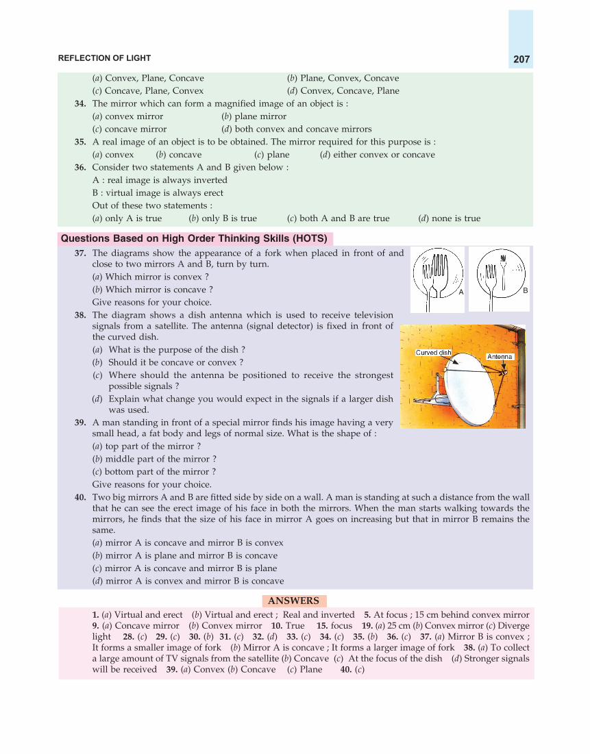
REFLECTION OF LIGHT 207
(a) Convex, Plane, Concave (b) Plane, Convex, Concave(c) Concave, Plane, Convex (d) Convex, Concave, Plane
34. The mirror which can form a magnified image of an object is :(a) convex mirror (b) plane mirror(c) concave mirror (d) both convex and concave mirrors
35. A real image of an object is to be obtained. The mirror required for this purpose is :(a) convex (b) concave (c) plane (d) either convex or concave
36. Consider two statements A and B given below :A : real image is always invertedB : virtual image is always erectOut of these two statements :(a) only A is true (b) only B is true (c) both A and B are true (d) none is true
Questions Based on High Order Thinking Skills (HOTS)37. The diagrams show the appearance of a fork when placed in front of and
close to two mirrors A and B, turn by turn.(a) Which mirror is convex ?(b) Which mirror is concave ?Give reasons for your choice.
38. The diagram shows a dish antenna which is used to receive televisionsignals from a satellite. The antenna (signal detector) is fixed in front ofthe curved dish.(a) What is the purpose of the dish ?(b) Should it be concave or convex ?(c) Where should the antenna be positioned to receive the strongest
possible signals ?(d) Explain what change you would expect in the signals if a larger dish
was used.39. A man standing in front of a special mirror finds his image having a very
small head, a fat body and legs of normal size. What is the shape of :(a) top part of the mirror ?(b) middle part of the mirror ?(c) bottom part of the mirror ?Give reasons for your choice.
40. Two big mirrors A and B are fitted side by side on a wall. A man is standing at such a distance from the wallthat he can see the erect image of his face in both the mirrors. When the man starts walking towards themirrors, he finds that the size of his face in mirror A goes on increasing but that in mirror B remains thesame.(a) mirror A is concave and mirror B is convex(b) mirror A is plane and mirror B is concave(c) mirror A is concave and mirror B is plane(d) mirror A is convex and mirror B is concave
ANSWERS1. (a) Virtual and erect (b) Virtual and erect ; Real and inverted 5. At focus ; 15 cm behind convex mirror9. (a) Concave mirror (b) Convex mirror 10. True 15. focus 19. (a) 25 cm (b) Convex mirror (c) Divergelight 28. (c) 29. (c) 30. (b) 31. (c) 32. (d) 33. (c) 34. (c) 35. (b) 36. (c) 37. (a) Mirror B is convex ;It forms a smaller image of fork (b) Mirror A is concave ; It forms a larger image of fork 38. (a) To collecta large amount of TV signals from the satellite (b) Concave (c) At the focus of the dish (d) Stronger signalswill be received 39. (a) Convex (b) Concave (c) Plane 40. (c)
A B

SCIENCE FOR TENTH CLASS : PHYSICS208
NUMERICAL PROBLEMS BASED ON CONVEX MIRRORSIn order to solve the numerical problems based on convex mirrors, we should remember that the mirror
formula for a convex mirror is the same as that for a concave mirror, which is :1 1 1— + — = —v u f
where v = image distanceu = object distance
and f = focal lengthPlease note that since a convex mirror always forms an image behind the mirror (on the right side of
the mirror), therefore, the image distance (v) in the case of convex mirrors is always positive. The objectis always placed to the left of mirror, so the object distance (u) is always taken with a negative sign. Thefocus of a convex mirror is behind the mirror on its right side, therefore, the focal length of a convexmirror is always taken as positive.
The two magnification formulae for convex mirror are also just the same as that for a concave mirror. Thatis :
h2 vm = — and m = – —
h1 uwhere the symbols have their usual meaning. Let us now solve one numerical problem based on convexmirror.
Sample Problem. An object 5 cm high is placed at a distance of 10 cm from a convex mirror of radius ofcurvature 30 cm. Find the nature, position and size of the image.
Solution. Here, Object distance, u = – 10 cm (To left of mirror)Image distance, v = ? (To be calculated)
Radius of curvatureAnd, Focal length, f = —————————2
30= — cm2
= + 15 cm (Convex mirror)Putting these values in the mirror formula :
1 1 1— + — = —v u f 1 1 1we get : — + —— = —– v – 10 +15
1 1 1or — – — = —v 10 151 1 1or — = — + —–v 15 101 2 + 3— = ——v 301 5— = —v 301 1— = —v 6
So, Image distance, v = + 6 cm
Thus, the position of image is 6 cm behind the convex mirror. Since the image is formed behind theconvex mirror, its nature will be virtual and erect.
To find the size of image, we will calculate the magnification first.vNow, Magnification, m = – —u

REFLECTION OF LIGHT 209
Here, Image distance, v = + 6 cmand Object distance, u = – 10 cm
(+ 6)So, m = – ———(– 10)
6m = —10
Magnification, m = 0.6We also have another formula for magnification, which is :
h2m = —h1
Here, Magnification, m = + 0.6Height of image, h2 = ? (To be calculated)
and Height of object, h1 = + 5 cmh2So, + 0.6 = —–
+ 5h2 = 5 × 0.6
Height of image, h2 = 3 cm (or + 3 cm)Thus, the size of image is 3 cm.
We are now in a position to answer the following questions and problems :
Short Answer Type Questions
1. An object is kept at a distance of 5 cm in front of a convex mirror of focal length 10 cm. Calculate theposition and magnification of the image and state its nature.
2. An object is placed at a distance of 10 cm from a convex mirror of focal length 5 cm.(i) Draw a ray-diagram showing the formation of image.
(ii) State two characteristics of the image formed.(iii) Calculate the distance of the image from mirror.
3. An object is placed at a distance of 6 cm from a convex mirror of focal length 12 cm. Find the position andnature of the image.
4. An object placed 20 cm in front of a mirror is found to have an image 15 cm (a) in front of it, (b) behind themirror. Find the focal length of the mirror and the kind of mirror in each case.
5. An arrow 2.5 cm high is placed at a distance of 25 cm from a diverging mirror of focal length 20 cm. Findthe nature, position and size of the image formed.
6. A convex mirror used as a rear-view mirror in a car has a radius of curvature of 3 m. If a bus is located at adistance of 5 m from this mirror, find the position of image. What is the nature of the image ?
7. A diverging mirror of radius of curvature 40 cm forms an image which is half the height of the object. Findthe object and image positions.
8. The radius of curvature of a convex mirror used as a rear view mirror in a moving car is 2.0 m. A truck iscoming from behind it at a distance of 3.5 m. Calculate (a) position, and (b) size, of the image relative to thesize of the truck. What will be the nature of the image ?
Long Answer Type Question9. (a) Draw a diagram to represent a convex mirror. On this diagram mark principal axis, principal focus F
and the centre of curvature C if the focal length of convex mirror is 3 cm.(b) An object 1 cm tall is placed 30 cm in front of a convex mirror of focal length 20 cm. Find the size and
position of the image formed by the convex mirror.
Questions Based on High Order Thinking Skills (HOTS)10. A shop security mirror 5.0 m from certain items displayed in the shop produces one-tenth magnification.
(a) What is the type of mirror ?(b) What is the radius of curvature of the mirror ?

SCIENCE FOR TENTH CLASS : PHYSICS210
11. An object is placed 15 cm from (a) a converging mirror, and (b) a diverging mirror, of radius of curvature20 cm. Calculate the image position and magnification in each case.
12. An object 20 cm from a spherical mirror gives rise to a virtual image 15 cm behind the mirror. Determinethe magnification of the image and the type of mirror used.
ANSWERS
1. 3.3 cm behind the convex mirror ; 0.66 ; Virtual and erect 2. (ii) Virtual and erect ; Diminished (Smallerthan the object) (iii) 3.3 cm behind the convex mirror 3. 4 cm behind the mirror ; Virtual and erect
4. (a) Concave mirror of focal length 607 cm (b) Convex mirror of focal length 60 cm 5. v = 11.1 cm ; The
image is formed 11.1 cm behind the convex mirror ; Virtual and erect ; 1.1 cm tall 6. 1.15 m behind themirror ; Virtual and erect 7. 20 cm ; 10 cm behind the mirror 8. (a) 0.77 m behind the mirror
(b) 1
4.5 ; Virtual and erect 9. 0.4 cm ; 12 cm behind the mirror 10. (a) Convex mirror (b) 10 m9
11. (a) v = –30 cm ; The image is formed 30 cm in front of converging mirror ; m = –2 (b) v = + 6 cm; Theimage is formed 6 cm behind the diverging mirror ; m = + 0.4 12. m = + 0.75 ; Convex mirror

We know that light travels in a straight line path. This is true as long as light rays are travelling inthe same medium (or same substance) having the same density throughout. If, however, thelight rays are made to go from one medium to another, the light
rays change their direction (or bend) at the boundary between the two media.For example, when a ray of light travelling in ‘air’ goes obliquely into anothermedium ‘glass’, it changes the direction (or bends) on entering the glass block(see Figure 1). The change in direction of ray of light (or bending of ray oflight) occurs again when it goes out from ‘glass’ into ‘air’ (see Figure 1). Thechange in direction of light when it passes from one medium to anotherobliquely, is called refraction of light. In other words, the bending of lightwhen it goes from one medium to another obliquely is called refraction oflight. The refraction of light takes place when light rays enter from air intoglass; or from glass into air. The refraction of light takes place when light entersfrom air into water ; or from water into air. And the refraction of light alsotakes place when light enters from water into glass; or from glass into water.The optical instruments like camera, microscope, and telescope work on therefraction of light through glass lenses. We will now understand the refractionof light more clearly with the help of a diagram.
Consider a rectangular glass slab PQRS shown in Figure 2. Now, here we have two different media,one is air and the other is glass (‘media’ is the plural of ‘medium’). Please note that glass is optically densermedium as compared to air (we will give the meaning of optically denser medium after a while). Now, aray of light AO travelling in air is incident (or falls) obliquely on the glass slab at point O (see Figure 2).Since the glass slab is transparent, most of the incident light passes into the glass slab. Since glass is anoptically denser medium than air, so when the ray of light AO passes from air into glass, its directionchanges, it goes along the line OB inside the glass slab and we say that the light ray has been refracted (orbent). This is because AO and OB are not in the same straight line. Please note that the refraction (orbending) of light takes place at the boundary between the two media. For example, in Figure 2, therefraction of light (or bending of light) takes place at point O at the boundary of the two media : air andglass. We will now define the angle of incidence and the angle of refraction.
Refraction of Light
CHAPTERCHAPTERCHAPTERCHAPTERCHAPTER
5
Ray oflight
AirA
Glassblock
B Air
Figure 1. The ray of light changesdirection (or refracts) at point Awhen it goes from air into glass.The ray of light changes direction(or refracts) again at point B whenit goes from glass into air.

SCIENCE FOR TENTH CLASS : PHYSICS212
In Figure 2, for the light passing from air into glass, AO isthe incident ray and OB is the refracted ray. Let us draw anormal NON at the point of incidence O. Now, the anglebetween incident ray and normal (at the point of incidence)is called the angle of incidence. In Figure 2, the angle AON isthe angle of incidence. The angle of incidence is denoted by theletter i. The angle between the refracted ray and the normal(at the point of incidence) is called the angle of refraction. InFigure 2, the angle NOB is the angle of refraction. The angle ofrefraction is denoted by the letter r.
Please note that though in the reflection of light, the angleof reflection is always equal to the angle of incidence, but inthe refraction of light, the angle of refraction is usually notequal to the angle of incidence. The angle of refraction is eithersmaller than the angle of incidence or greater than the angle ofincidence. For example, in Figure 2, the angle of refraction (r) is not equal to the angle of incidence (i). Inthis case the angle of refraction (r) is smaller than the angle of incidence (i). We will give the reasons forthis later on in this chapter. At the moment we will discuss why the refraction of light takes place on goingfrom one medium to another.
Cause of Refraction
The speed of light is different in different media (or substances). For example, the speed of light in airis 3 × 10⁸ m/s whereas that in glass is 2 × 10⁸ m/s. It is clear from these values that the speed of light ismore in air but less in glass. In other words, light travels faster in air but slower in glass. The refraction oflight is due to the change in the speed of light on going from one medium to another. Thus, when lightgoes from one medium to another, its speed changes. And this change in speed of light causes the refractionof light. The refraction of light on going from air to glass takes place because the speed of light is differentin air and glass : being more in air and lesser in glass. So, when light enters from air into glass, its speedchanges (it gets reduced). And this change in speed of light in going from air to glass causes the refractionof light (or bending of light). Please note that greater the difference in the speeds of light in the twomedia, greater will be the amount of refraction (or bending) of light.
Why a Change in Speed of Light Causes Refraction of Light (or Bending of Light)
The refraction of light or change in direction of light on going from one medium to another can beexplained by using the wave theory of light. A beam of light is made up of tiny waves. When a beam oflight consisting of light waves and travelling in a certain medium falls obliquely (at an angle) on the boundaryof another medium, then one part of the light waves enters into the other medium first and its speedchanges first but the rest of waves enter the other medium a little later and hence its speed changes a littlelater. The fact that the speed of light waves on one side of a beam of light changes a little before thechange in speed of light waves on its other side, causes a change in the direction of light. And thischange in direction of light is called refraction of light or bending of light. This will become more clearfrom the following example in which a beam of light is entering from air into a glass slab obliquely andthen emerging into air from its other side.
Light waves travel faster in air but slower in glass. Now, when a beam of light consisting of lightwaves and travelling in air falls on a glass slab obliquely then the part of light waves on the left side of thebeam of light reaches the glass slab first (at point A) and slows down first on entering the glass slab (seeFigure 3). The rest of light waves on the right side of the beam of light are still in air and have to travelmore distance in air before reaching the glass slab (at point B) and hence slow down a little later on enteringthe glass slab (see Figure 3). Since the speed of left side of the beam of light is reduced a little before its
A
Incident rayAir
Glass
Oi
r
Refracted
ray
BN�
Angle ofincidence
NNormal
Angleof
refraction
Q
R
P
S
Rectangularglass slab
Figure 2. Diagram to show the refraction of lightwhen it passes from air into glass. In this diagram,the light ray going along AO in air bends in thedirection OB on entering the glass.

REFRACTION OF LIGHT 213
right side, therefore, the direction of light changes (or bending of light occurs) on entering the glassslab (see Figure 3 ). Please note that a decrease in speed of light waves on going from air into glass causesbending of light towards left side (towards the normal) (see Figure 3).
When the beam of light travelling in glass slab comes out into air obliquely (at an angle), then the partof light waves on the left side of beam of light emerges out into air first (at point C) and speeds up first (seeFigure 3). The part of light waves on the right side of beam of light emerges out into air (at point D) a littlelater and hence its speed increases a little later. Since the speed of left side of the beam of light increasesa little before its right side, therefore, the direction of light changes (or bending of light occurs) oncoming out of glass slab into air (see Figure 3). Please note that an increase in speed oflight waves on coming out from glass into air causes bending of light towards the rightside (away from the normal) (see Figure 3).
When light waves move from air into glass, their speed decreases and their wavelengthalso decreases (they become closer). On the other hand, when light waves come out fromglass into air, their speed increases and their wavelength also increases (they becomefarther apart). Before we discuss the refraction of light in detail, we should know the meaning of the terms‘optically rarer medium’ and ‘optically denser medium’. This is described below.Optically Rarer Medium and Optically Denser Medium
A transparent substance in which light travels is known as a medium. Air, glass, certain plastics,water, kerosene, alcohol, etc., are all examples of medium. Different media are said to have different opticaldensities. A medium in which the speed of light is more is known as optically rarer medium (or lessdense medium). Air is an optically rarer medium as compared to glass and water. A medium in which thespeed of light is less, is known as optically denser medium. Glass is an optically denser medium than airand water. Now, the speed of light in water is 2.25 × 10⁸ m/s, which is less than that in air but more thanthat in glass. So, water is optically denser medium than air but it is optically rarer than glass. Please notethat the refraction of light takes place whenever it goes from an optically rarer medium to an opticallydenser medium; or from a denser medium to a rarer medium. The optically rarer medium and opticallydenser medium can also be defined on the basis of their refractive index. We will learn this after a while.Keeping the above discussion in mind, we can now write down two rules which give the direction ofbending of a ray of light when it goes from one medium to another.
It has been found that :1. When a ray of light goes from a rarer medium to a denser medium, it bends towards the normal
(at the point of incidence).
Beam oflight Light waves
A B Air Light waves on this sideof beam of light reachthe glass a little later,enter the glass a littlelater and slow down alittle later
Light waves on this sideof beam of light comeout of glass a little laterand hence speed up alittle later
Glass
Light waves on thisside of beam of lightcome out of glassfirst and hencespeed up first
Light waves on thisside of beam of lightreach the glass first,enter the glass firstand slow down first
Figure 3. Diagram to explain the refraction of light on going from air into glass; and from glass into air.
C D

SCIENCE FOR TENTH CLASS : PHYSICS214
2. When a ray of light goes from a denser medium to a rarer medium, it bends away from thenormal (at the point of incidence).
We will now understand these rules more clearly with the help of ray-diagrams.
Case 1 : Refraction of Light When it Goes From a Rarer Medium to a Denser Medium
Figure 4 shows a ray of light AO going from air (a rarermedium) into glass (which is a denser medium). In this case, theincident ray AO gets refracted at point O and bends towards thenormal ON and goes in the direction OB inside the glass slab.Thus, when a ray of light goes from air into glass, it bendstowards the normal (at the point of incidence). In this case, theangle of refraction (r) is smaller than the angle of incidence (i).
Water is also an optically denser medium than air, so when aray of light goes from air into water, it bends towards the normal.Thus, the refraction of light on going from air to water is similarto the refraction of light from air to glass (which has been shownin Figure 4). To show the path of a ray of light going from air intowater, we can use Figure 4 but we will have to write ‘water’ inplace of ‘glass’ and in place of glass slab we will have to show water by drawing some dotted lines. Pleasedraw the diagram to show the refraction of a ray of light from air to water yourself.
Case 2 : Refraction of Light When it Goes From a Denser Medium to a Rarer Medium
Figure 5 shows a ray of light AO going from glass (a densermedium) into air (which is a rarer medium). In this case, theincident ray AO gets refracted at point O and bends away fromthe normal ON in the direction OB. Thus, when a ray of lightgoes from glass into air, it bends away from the normal (at thepoint of incidence). In this case the angle of refraction (r) is greaterthan the angle of incidence (i).
Please note that water is also optically denser than air, so whena beam of light travelling in water enters into air, it bends awayfrom the normal. We can show the refraction of light on goingfrom water into air by using the ray-diagram given in Figure 5.All that we have to do is to write ‘water’ in place of ‘glass’ andshow water by drawing some dotted lines. Please draw thediagram to show the refraction of a ray of light from water to airyourself. Please note that a parallel-sided glass slab is also called rectangular glass block.
When a ray of light goes from a rarer medium to a denser medium, its speed decreases or it slowsdown. On the other hand, when a ray of light goes from a denser medium to a rarer medium, then itsspeed increases or it speeds up. So, we can now say that a ray of light travelling from a rarer medium to adenser medium slows down and bends towards the normal but when a ray of light travels from a densermedium to a rarer medium, it speeds up and bends away from the normal.
The Case of Light Going From Air into Glass and Again into AirWe have just studied the refraction of light from air into glass (Figure 4), and from glass into air
(Figure 5). We will now show these two types of refraction in the same diagram. In other words, we willnow show the complete path of a ray of light when it passes from air into glass slab and again into air. Thisis shown in Figure 6.
A
Air(Rarer medium)
Glass(Denser medium)
Oi
r
BN�
NNormal
Parallel-sidedglass slab
Refractedray
Incidentray
Figure 4.
N�
N
Refractedray
Air(Rarer medium)
Glass(Denser medium)
Normal
r
O
B
i
Incidentray
A
Parallel sidedglass slab
Figure 5.

REFRACTION OF LIGHT 215
A ray of light AO travelling in air is incident on arectangular glass slab PQRS at point O. On enteringthe glass slab, it gets refracted along OB and bendstowards the normal ON (see Figure 6). A secondchange of direction takes place when the refracted rayof light OB, travelling in glass emerges (or comes out)into air at point B. Since the ray of light OB now goesfrom a denser medium ‘glass’ into the rarer medium‘air’, it bends away from the normal BN1 and goes inthe direction BC. Please note that the incident ray AOand the emergent ray BC are parallel to each other(though the emergent ray has been displaced parallelto the incident ray). The incident ray AO and emergentray BC are parallel to each other because the extent ofbending of the ray of light at points O and B on theopposite, parallel faces (PQ and SR) of the rectangularglass slab is equal and opposite. The incident ray AObends towards the normal at point O whereas therefracted ray OB bends away from the normal at point B by an equal amount. Thus, the light emergesfrom a parallel-sided glass slab in a direction parallel with that in which it enters the glass slab. Thoughthe emergent ray BC is parallel to the incident ray AO, but the emergent ray has been sideways displaced(or laterally displaced) from the original path of the incident ray by a perpendicular distance CD (seeFigure 6). In Figure 6, the original path of incident light is AOD but the emergent light goes along BC, thelateral displacement between them being CD. The perpendicular distance between the original path ofincident ray and the emergent ray coming out of the glass slab is called lateral displacement of theemergent ray of light. Lateral displacement depends mainly on three factors : angle of incidence, thicknessof glass slab, and refractive index of glass slab. Actually, lateraldisplacement is directly proportional to (i) angle of incidence(ii) thickness of glass slab, and (iii) refractive index of glass slab.Higher the values of these factors, greater will be the lateraldisplacement. Another point to be noted is that in this case therefraction (or bending) of light takes place twice : first at pointO (when light enters from air into glass), and then at point B(when light goes out from glass into air).
The angle which the emergent ray makes with the normalis called the angle of emergence. In Figure 6, the angle N1BC isthe angle of emergence. Since the incident ray AO and theemergent ray BC are parallel to one another, so the angle ofemergence (e) is equal to the angle of incidence (i). Please notethat if a beam of light travelling in air passes into water andthen emerges into air, we will get a ray-diagram similar to thatshown in Figure 6. Draw it yourself by writing ‘water’ in placeof ‘glass’.
The Case of Light Falling Normally (or Perpendicularly) on a Glass SlabIn all our discussions so far we have assumed that the incident ray of light falls obliquely to the surface
of glass slab and bending of ray of light takes place. If the incident ray falls normally (or perpendicularly)to the surface of a glass slab, then there is no bending of the ray of light, and it goes straight. Forexample, in Figure 8, a ray of light AO travelling in air falls on a glass slab normally (or perpendicularly) at
A
i
O
Incident ray
P Q
SR
GLASS
AIR
AIR
Rectangularglass slab
Direction oforiginal ray
C
Lateraldisplacement
DEmergentray
Normal
e
B
N1N�
NormalN
Refracted
ray
N1�
Figure 6.
Figure 7. This picture shows the lateral displace-ment of a finger caused by the refraction of lightthrough a glass slab.

SCIENCE FOR TENTH CLASS : PHYSICS216
point O, so it does not bend on entering the glass slab or on coming out of the glass slab. It goes straight inthe direction AOBC. Since the incident ray goes along the normal to the surface, the angle of incidence inthis case is zero (0) and the angle of refraction is also zero (0).
We can explain the case of no refraction (or no bending) of light on going perpendicularly from air toglass as follows : When a beam of light consisting of light waves and travelling in air falls perpendicularly(at right angles) to the surface of glass slab, then all the parts of light waves reach the glass slab at the sametime, enter the glass slab at the same time and hence get slowed down at the same time (see Figure 9). Dueto this no change in direction of light takes place. In other words, no refraction of light (no bending of light)takes place. Similarly, all the parts of the light waves of the beam of light travelling in glass slab come outof the glass slab into air at the same time and hence speed up at the same time. Due to this, no bending oflight occurs when the light waves go out from glass slab into air (see Figure 9).
Please note that if a ray of light falls normally (or perpendicularly) to the surface of water, even thenthere is no bending of light ray, and it goes straight through water.
EFFECTS OF REFRACTION OF LIGHTThe refraction of light produces many effects which can be easily observed in our day to day life. We
will now describe some of the important effects of the refraction of light. It is due to the refraction of lightthat :
(i) a stick (or pencil) held obliquely and partly immersed in water appears to be bent at the watersurface.
(ii) an object placed under water appears to be raised.(iii) a pool of water appears to be less deep than it actually is.(iv) when a thick glass slab is placed over some printed matter, the letters appear raised when viewed
from the top.(v) a lemon kept in water in a glass tumbler appears to be bigger than its actual size, when viewed
from the sides.(vi) the stars appear to twinkle on a clear night.
All these effects are produced by the refraction of light (or change in direction of light) when it passesfrom one medium to another. Let us discuss some of these effects of refraction in detail.
1. A Stick Partly Immersed in Water Appears to be Bent at the Water Surface
When a straight stick is partly immersed in water and held obliquely to the surface, it appears to bebent at the point where it enters water (see Figure 10). This apparent bending of the stick is due to the
Figure 8.
Air
A
Glass
O90°
B
C
Air
Beamof light
Lightwaves
Air
Glass
Air
Figure 9.

REFRACTION OF LIGHT 217
refraction of light when it passes from water into air. Let usunderstand it more clearly with the help of a ray-diagram.
Figure 10 shows a straight stick AO whose lower portion BOis immersed in water. Though the stick is actually straight but onimmersing in water, it appears to be bent at point B, in the directionBI (see Figure 10). This can be explained as follows : A ray of lightOC coming from the lower end O of the stick passes from waterinto air at point C and gets refracted away from normal in thedirection CX (because it passes from a denser medium water intoa rarer medium air). Another ray of light OD gets refracted in thedirection DY. The two refracted rays CX and DY, when producedbackwards, appear to meet at point I, nearer to the water surfacethan point O (see Figure 10). Thus, I is the virtual image of theend O of the stick which is formed by the refraction of light ongoing from water to air. Thus, an eye at position E sees the end O of the stick at position I which is nearerto the water surface.
We can extend this reasoning to all the points which make up part BO of the stick under water. Thus,due to the refraction of light, a virtual image of the part BO of the stick is formed at BI. So, what we seeunder water is actually the virtual image BI of the part BO of the stick under water. Since the part AB of thestick which is above water and the image BI under water are not in the same straight line, the stick AOappears to be bent at point B along BI. Thus, though the actual stick is ABO, it appears to be ABI. Pleasenote that it is not the stick that is really bent. It is actually the light passing from water to air that is bent (orrefracted) (see Figure 11).
Figure 11. The stick is partly immersed Figure 12. The pencil is partly immersedin water. Due to the refraction of light in water. Because of the refraction of lightcoming from the part of the stick that coming from the part of the pencil that isis under water, the stick appears bent. under water, the pencil appears bent.
When a pencil is partly immersed in water and held obliquely to the surface, the pencil appears tobend at the water surface (when viewed from the side) (see Figure 12). This apparent bending of the pencilis due to the refraction of light when it passes from water into air. We can use Figure 10 for explaining thebending of pencil in water. Just make a pencil in place of stick.
2. An Object Placed Under Water Appears to be RaisedWe will perform an experiment to show that an object placed under water appears to be raised. This
can be done as follows : We place a coin at the bottom of an empty basin (a shallow vessel). Let us moveour head away from the basin slowly, till the coin disappears from our view and we cannot see it [see
CB D
X
Eye
Y
The stickappears to bebent here
AIR
Stick
WATER
O
I
A
Image
E
Figure 10. A straight stick AO appears bentat point B where it enters water.

SCIENCE FOR TENTH CLASS : PHYSICS218
Figure 13(a)]. Now, without moving our head, we pour water into the basin. We will find that on addingwater, the coin appears to rise and we are able to see it [see Figure 13(b)]. The coin under water appears tobe raised (and becomes visible) due to the refraction of light which takes place when it goes from waterinto air. We will now understand all this more clearly with the help of a ray-diagram.
Figure 13(a) shows a coin O placed in an empty basin (having no water). In this case the rays of lightOA and OB coming from the coin travel in straight line paths in air and do not enter our eye E (because theeye is at a lower level). Since the rays of light coming from the coin do not enter our eye, we cannot see thecoin from this position of our eye.
(a) The coin placed in empty basin is (b) On adding water in the basin, the coinnot visible to the eye from appears raised and becomes visible
this particular position. to the eye from the same position.Figure 13.
When the coin is under water, then the rays OA and OB coming from the coin travel in water in straightline paths until they reach the surface of water. When the rays of light OA and OB travelling in water, goout into air, they get refracted (they change their directions). The ray of light OA gets refracted at point A,bends away from the normal, and goes in the direction AX [see Figure 13(b)]. Similarly, the ray of light OBgets refracted at point B, bends away from the normal, and goes in the direction BY.
If we extend the refracted rays AX and BY backwards (to the left side), then a virtual image of the coinis formed at point I, nearer to the surface of water [see Figure 13(b)]. The refracted rays AX and BY, whichappear to be coming from the virtual image of the coin can enter our eye at position E due to which thecoin becomes visible to us. Thus, when the coin is under water then due to refraction of light, a virtualimage of the coin is formed nearer to the water surface. And since the virtual image of coin which wesee, is nearer to the water surface, so the coin appears to rise on adding water in the basin. Thus, it is dueto the refraction of light that a coin placed at the bottom of a container appears to rise as the container isslowly filled with water.
If instead of water, we take some other transparent liquid such as kerosene or turpentine in the abovetwo experiments, then the bending of stick or raising of coin will appear to take place by different amountsthan that in water. This is because light is refracted by different amounts in different liquids.
3. A Pool of Water Appears to be Less Deep than it Actually is
If we look into a pool of water (or tank of water), it appears to be less deep than it really is. This is dueto the refraction of light which takes place when light rays pass from the pool of water into the air. Let usunderstand it more clearly with the help of a ray-diagram.
Figure 14 shows a pool of water (or a tank of water). Let us take any point O at the bottom of this pool.This point is under the surface of water. Our eye sees this point by the light rays coming from it. Now, aray of light OA coming from the point O is travelling in water and it comes out into the air at point A. Itgets refracted away from the normal in the direction AX (see Figure 14.) Similarly, another ray of light OB,coming from the point O gets refracted at point B and goes away from the normal in the direction BY. The
Coin
Basin
E
Rays of lightgo straight
BA
O
Coinnotvisible
X
Y E
Coinvisible
A
Coin
Imageof
coinWater
BI
O
Rays of lightbend here

REFRACTION OF LIGHT 219
two refracted rays AX and BY, when produced backwards,meet at point I under water. In fact, when the rays AX andBY enter the eye E, they appear to be coming from point I.So, point I is the virtual image of point O (which is at thebottom of the pool). It is clear from Figure 14 that the imageI is nearer to the surface of water than the point O. Thus, apoint O at the bottom of a pool appears to be much nearerat position I.
This reasoning can be applied to all the points whichmake up the bottom PQ of the pool, so that due to refractionof light, the bottom PQ of the pool will appear to be muchnearer at the position PQ (see Figure 14). Due to this, thepool of water will appear less deep than it actually is. Pleasenote that when we look into a pool of water, we do notsee the actual bottom of the pool, we see a virtual image of the bottom of the pool which is formed bythe refraction of light coming from the pool water into the air. And since the image of the bottom of thepool is formed nearer to us, we feel that the pool is less deep. From this discussion we conclude that thebottom of a pool of water appears raised due to refraction oflight. And the pool of water appears to be less deep than itactually is. We should be careful while entering a swimming poolbecause the water in it will be deeper than it appears to be.
It is also due to the refraction of light that a thick glassslab appears to be less thick (when seen from above), than itactually is. Similarly, an ink mark or the writing on a piece ofpaper appears to be raised and much nearer than it actuallyis, when viewed by keeping a glass slab over it (see Figure15). This also happens due to refraction of light. As we will study in the next Chapter, the stars appear totwinkle on a clear night due to the refraction of light in the atmosphere. Before we go further and discussthe laws of refraction of light, please answer the following questions :
Very Short Answer Type Questions1. If a ray of light goes from a rarer medium to a denser medium, will it bend towards the normal or away
from it ?2. If a ray of light goes from a denser medium to a rarer medium, will it bend towards the normal or away
from the normal ?3. A beam of light travelling in a rectangular glass slab emerges into air. Draw a ray-diagram indicating the
change in its path.4. A beam of light travelling in air is incident on water. Draw a ray-diagram indicating the change in its path
in water.5. A ray of light travelling in water emerges into air. Draw a ray-diagram indicating the change in its path.6. A ray of light travelling in air is incident on a parallel-sided glass slab (or rectangular glass slab). Draw a
ray-diagram indicating the change in its path in glass.7. A ray of light travelling in glass emerges into air. State whether it will bend towards the normal or away
from the normal.8. A ray of light travelling in air enters obliquely into water. Does the ray of light bend towards the normal or
away from the normal ? Why ?9. A ray of light goes from water into air. Will it bend towards the normal or away from the normal ?
10. State two effects caused by the refraction of light.11. Name the phenomenon due to which a swimming pool appears less deep than it really is.12. When a ray of light passes from air into glass, is the angle of refraction greater than or less than the angle of
incidence ?
Figure 15. Those words of writing which arebelow the glass slab appear raised (or higher) dueto refraction of light as it comes out of glass slab.
Eye
E
YX
A BWater
Air
Realdepth
Apparentdepth
P
P�
Q
Q�I
O
Figure 14. The bottom PQ of the pool of waterappears to be raised at PQ due to refraction oflight. The pool thus appears to be less deep.
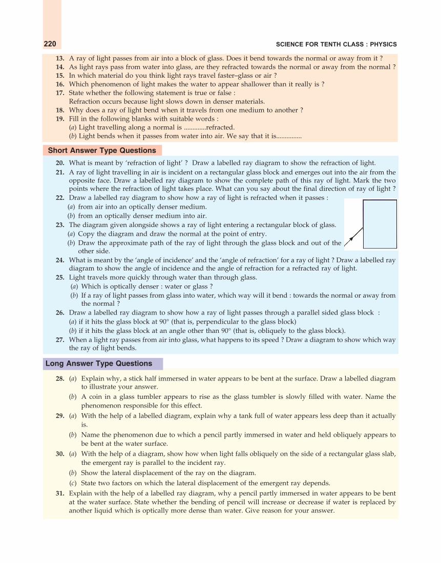
SCIENCE FOR TENTH CLASS : PHYSICS220
13. A ray of light passes from air into a block of glass. Does it bend towards the normal or away from it ?14. As light rays pass from water into glass, are they refracted towards the normal or away from the normal ?15. In which material do you think light rays travel faster–glass or air ?16. Which phenomenon of light makes the water to appear shallower than it really is ?17. State whether the following statement is true or false :
Refraction occurs because light slows down in denser materials.18. Why does a ray of light bend when it travels from one medium to another ?19. Fill in the following blanks with suitable words :
(a) Light travelling along a normal is .............refracted.(b) Light bends when it passes from water into air. We say that it is...............
Short Answer Type Questions
20. What is meant by ‘refraction of light’ ? Draw a labelled ray diagram to show the refraction of light.21. A ray of light travelling in air is incident on a rectangular glass block and emerges out into the air from the
opposite face. Draw a labelled ray diagram to show the complete path of this ray of light. Mark the twopoints where the refraction of light takes place. What can you say about the final direction of ray of light ?
22. Draw a labelled ray diagram to show how a ray of light is refracted when it passes :(a) from air into an optically denser medium.(b) from an optically denser medium into air.
23. The diagram given alongside shows a ray of light entering a rectangular block of glass.(a) Copy the diagram and draw the normal at the point of entry.(b) Draw the approximate path of the ray of light through the glass block and out of the
other side.24. What is meant by the ‘angle of incidence’ and the ‘angle of refraction’ for a ray of light ? Draw a labelled ray
diagram to show the angle of incidence and the angle of refraction for a refracted ray of light.25. Light travels more quickly through water than through glass.
(a) Which is optically denser : water or glass ?(b) If a ray of light passes from glass into water, which way will it bend : towards the normal or away from
the normal ?26. Draw a labelled ray diagram to show how a ray of light passes through a parallel sided glass block :
(a) if it hits the glass block at 90° (that is, perpendicular to the glass block)(b) if it hits the glass block at an angle other than 90° (that is, obliquely to the glass block).
27. When a light ray passes from air into glass, what happens to its speed ? Draw a diagram to show which waythe ray of light bends.
Long Answer Type Questions
28. (a) Explain why, a stick half immersed in water appears to be bent at the surface. Draw a labelled diagramto illustrate your answer.
(b) A coin in a glass tumbler appears to rise as the glass tumbler is slowly filled with water. Name thephenomenon responsible for this effect.
29. (a) With the help of a labelled diagram, explain why a tank full of water appears less deep than it actuallyis.
(b) Name the phenomenon due to which a pencil partly immersed in water and held obliquely appears tobe bent at the water surface.
30. (a) With the help of a diagram, show how when light falls obliquely on the side of a rectangular glass slab,the emergent ray is parallel to the incident ray.
(b) Show the lateral displacement of the ray on the diagram.(c) State two factors on which the lateral displacement of the emergent ray depends.
31. Explain with the help of a labelled ray diagram, why a pencil partly immersed in water appears to be bentat the water surface. State whether the bending of pencil will increase or decrease if water is replaced byanother liquid which is optically more dense than water. Give reason for your answer.

REFRACTION OF LIGHT 221
Multiple Choice Questions (MCQs)32. Light travelling from a denser medium to a rarer medium along a normal to the boundary :
(a) is refracted towards the normal (b) is refracted away from the normal(c) goes along the boundary (d) is not refracted
33. A ray of light passes from glass into air. The angle of refraction will be :(a) equal to the angle of incidence (b) greater than the angle of incidence(c) smaller than the angle of incidence (d) 45°
34. A ray of light travelling in air goes into water. The angle of refraction will be :(a) 90° (b) smaller than the angle of incidence(c) equal to the angle of incidence (d) greater than the angle of incidence
35. The speed of light in air is :(a) 3 × 108 cm/s (b) 3 × 108 mm/s(c) 3 × 10⁸ km/s (d) 3 × 10⁸ m/s
36. When a ray of light travelling in glass enters into water obliquely :(a) it is refracted towards the normal (b) it is not refracted at all(c) it goes along the normal (d) it is refracted away from the normal
37. A ray of light travelling in water falls at right angles to the boundary of a parallel-sided glass block. The rayof light :(a) is refracted towards the normal (b) is refracted away from the normal(c) does not get refracted (d) is reflected along the same path.
38. A ray of light passes from a medium X to another medium Y. No refraction of light occurs if the ray of lighthits the boundary of medium Y at an angle of :(a) 0° (b) 45° (c) 90° (d) 120°
Questions Based on High Order Thinking Skills (HOTS)39. Which of the following diagrams shows the ray of light refracted correctly ?
A B C D E
waterair
air
glass water
glass glassair
waterglass
40. A vertical ray of light strikes the horizontal surface of some water :(a) What is the angle of incidence ?(b) What is the angle of refraction ?
41. How is the reflection of light ray from a plane mirror different from the refraction of light ray as it enters ablock of glass ?
42. How does the light have to enter the glass :(a) to produce a large amount of bending ?(b) for no refraction to happen ?
43. (a) How can you bend light away from the normal ?(b) How must light travel out of a substance if it is not going to be refracted ?
44. Draw and complete the following diagrams to show what happens to the beams of light as they enter theglass block and then leave it :
Air
Glass
Air
Glass
Light
90°
Light
45. Why does a beam of light bend when it enters glass at an angle ? Why does it not bend if it enters the glassat right angles ?

SCIENCE FOR TENTH CLASS : PHYSICS222
ANSWERS12. Angle of refraction is less than the angle of incidence 17. True 19. (a) not (b) refracted 28. (b) Refractionof light (as it comes out from water into air) 31. The bending of pencil will increase; The optically densermedium will cause more refraction (or more bending) of light rays 32. (d) 33. (b) 34. (b) 35. (d)36. (d) 37. (c) 38. (c) 39. E 40. (a) 0° (b) 0° 41. The angle of reflection is equal to the angle ofincidence but the angle of refraction is not equal to the angle of incidence 42. (a) Obliquely ; Making a largeangle of incidence (b) Perpendicularly (at right angles) to the glass surface 43. (a) Make the light enter froma denser medium to a rarer medium (b) At right angles (90°) to the surface of substance.
LAWS OF REFRACTION OF LIGHTThe refraction of light on going from one medium to another takes place according to two laws which
are known as the laws of refraction of light. These are given below.
1. According to the first law of refraction of light : The incident ray, therefracted ray and the normal at the point of incidence, all lie in the sameplane. For example, in Figure 16, the incident ray AO, the refracted ray OB,and the normal ON, all lie in the same plane (which is the plane of the paperhere).
2. The second law of refraction gives a relationship between the angle ofincidence and the angle of refraction. This relationship was discovered bySnell experimentally in 1621, so the second law of refraction is called Snell’slaw of refraction. According to Snell’s law of refraction of light : The ratio ofsine of angle of incidence to the sine of angle of refraction is constant fora given pair of media (such as ‘air and glass’ or ‘air and water’). That is :
sine of angle of incidence
= constantsine of angle of refraction
or sinsin
ir = constant
This constant is called refractive index. We will now discuss the refractive index in somewhat detail.
Suppose a ray of light travelling in air enters into another medium and gets refracted. Let the angle ofincidence in air be i and the angle of refraction in that medium be r (see Figure 16). The value of the
constant sinsin
ir for a ray of light passing from air into a particular medium is called the refractive index
of that medium. The refractive index is usually denoted by the symbol n. So :
Refractive index, sin=sin
in
rwhere sin i = sine of the angle of incidence (in air)
and sin r = sine of the angle of refraction (in medium)
Suppose the angle of incidence (i) for a ray of light in air is 37° and the angle of refraction (r) in glass be24°. Then :
Refractive index of glass, sin 37°
=sin 24°
n
Now, if we look up the sine tables we will find that the value of sin 37° = 0.60 and sin 24° = 0.40.Putting these values in the above relation, we get :
0.60
=0.40
n
n = 1.50
Thus, the refractive index of this glass is 1.50.
N�
Normal
NA
Incident ray iOAir
Glassr R
efractedray
B
Figure 16.

REFRACTION OF LIGHT 223
A
iO
Medium 2
r
B
Speedv2
Speedv1
Medium 1
Figure 17.
Please note that since the refractive index is a ratio of two similar quantities (the sines of angles), ithas no units. It is a pure number. The refractive index of a substance does not depend on the angle of
incidence. When we talk of refractive index of a substance, say glass, we mean the value of sinsin
ir for light
passing from air to glass. Strictly speaking, it should mean the value of sinsin
ir for light passing from
vacuum to glass. But the difference in using air in place of vacuum is so small that it is ignored.
When light rays go from air (or vacuum) into another medium, then they bend (or refract) to someextent. Now, some media bend the light rays more than the others. The refractive index of a mediumgives an indication of the light-bending ability of that medium. For example, the refractive index of glassis greater than the refractive index of water, therefore, the light rays bend more on passing from air intoglass than from air into water. We will now solve one problem based on refractive index.
Sample Problem. A beam of light passes from air into a substance X. If the angle of incidence be 72°and the angle of refraction be 40°, calculate the refractive index of substance X. (Given : sin 72° = 0.951 andsin 40° = 0.642)
Solution. We know that :
Sine of angle of incidence
Refractive index=Sine of angle of refraction
orsin
=sin
in
r
Here, Angle of incidence, i = 72°And, Angle of refraction, r = 40°
So,sin 72°=sin 40°
n
We are given that sin 72° = 0.951 and sin 40° = 0.642. So, putting these values of sin 72° and sin 40° inthe above relation, we get :
0.951=
0.642n
or n = 1.48Thus, the refractive index of substance X is 1.48.So far we have denoted the refractive index of a substance just by the letter n. In its full form, the
refractive index n has, however, two subscripts (lower words or letters) which show the two substances ormedia between which the light travels. For example, the refractive index forlight going from air into glass is written as airnglass (or ang where a = air andg = glass). We will discuss this in more detail after a while.
Refractive Index and Speed of Light
The material (or substance) through which light travels is called medium.Light is refracted (or bent) in going from one medium to another because itsspeed changes (it slows down or speeds up). Due to this, the refractive index(n) can also be written as a ratio of speeds of light in the two media.
Look at Figure 17 in which a ray of light AO is going from medium 1 tomedium 2 as OB. The speed of light in medium 2 is different from that inmedium 1. Let the speed of light in medium 1 be v1 and that in medium 2 bev2. Now, the refractive index of medium 2 with respect to medium 1 is equalto the ratio of speed of light in medium 1 to the speed of light in medium 2.

SCIENCE FOR TENTH CLASS : PHYSICS224
This can be written as :
medium 1nmedium 2 =Speed of light in medium 1Speed of light in medium 2
or 1n2 =1
2
vv
where 1n2 = Refractive index of medium 2with respect to medium 1
v1 = Speed of light in medium 1
and v2 = Speed of light in medium 2
Please note that the symbol medium 1nmedium 2 or 1n2 means that it is the refractive index of medium 2 with
respect to medium 1 (for the light entering from medium 1 into medium 2). We have represented therefractive index of medium 2 with respect to medium 1 by the symbol 1n2. In some books, however, therefractive index of medium 2 with respect to medium 1 is represented by the symbol n21 (read as n-two-oneand not as n-twenty one). We have not used this notation because we find it a bit confusing.
When light is going from one medium (other than vacuum or air) to another medium, then the valueof refractive index is called relative refractive index. For example, when the light is going from waterinto glass, then the value of refractive index will be the relative refractive index of glass with respect towater. The relative refractive index has always ‘two subscripts’ with its symbol n which indicate the twomedia in which the light travels. For example, for the light going from water to glass, the refractive indexis written as waternglass (or wng). The symbol waternglass means that it is the refractive index of glass withrespect to water, that is, it is the refractive index of glass for light entering from water into glass.
When light is going from vacuum to another medium, then the value of refractive index is called theabsolute refractive index. The absolute refractive index has only one subscript with its symbol n on itsright side which indicates the name of the medium (the word vacuum is not written as a subscript). Forexample, for the light going from vacuum into glass, the absolute refractive index of glass is represented asnglass (and not as vacuumnglass). The symbol nglass means that it is the refractive index of glass with respect tovacuum, that is, it is the refractive index of glass for light entering from vacuum into glass. Please note thatthe symbol nglass is also written in short as ng.
The exact speed of light in vacuum is 2.9979 × 10⁸ m/s and that in air is 2.9970 × 10⁸
m/s. We can seethat the speed of light in air is almost the same as that in vacuum, so for the purpose of determiningrefractive index we can also treat air as if it were vacuum. So, the refractive index of a medium (or substance)with respect to air is also considered to be its absolute refractive index. Thus, airnglass can also be writtenas nglass. The absolute refractive index of a medium (or substance) is just called its refractive index.
We will now write some simplified formulae for calculating the refractive index from the given valuesof the speed of light in the two media. These are given below.
The ratio of speed of light in vacuum to the speed of light in a medium, is called the refractive indexof that medium. That is :
Speed of light in vacuumRefractive index =
Speed of light in medium(of a medium)
Since the speed of light in air is almost equal to the speed of light in vacuum, so for all practicalpurposes we can also say that : The ratio of speed of light in air to the speed of light in a medium, iscalled refractive index of that medium. That is :
Speed of light in airRefractive index =
Speed of light in medium(of a medium)

REFRACTION OF LIGHT 225
Let us take ‘glass’ as the medium and write a relation for its refractive index. Now, the speed of light inair is 3 × 10⁸ m/s and the speed of light in common glass is 2 × 10⁸ m/s. So :
Refractive index of glass, ng Speed of light in air or vacuum=
Speed of light in glass
or8
g 8
3 ×10=
2×10n
or g3
=2
n
or = 1.5gn
Thus, the refractive index of this glass is 1.5. By saying that the refractive index of glass is 1.5 wemean that the ratio of the speed of light in air (or vacuum) to the speed of light in glass is equal to 1.5.Let us solve one problem now.
Sample Problem. Light enters from air into a glass plate having refractive index 1.50. What is the speedof light in glass ? (The speed of light in vacuum is 3×10⁸ m s–1). (NCERT Book Question)
Solution. We know that :
Refractive index of glass Speed of light in air or vacuum
=Speed of light in glass
So, 83 × 10
1.50 =Speed of light in glass
or Speed of light in glass83 × 10
=1.50
m s–1
= 2 × 10⁸ m s–1
Thus, the speed of light in glass is 2 × 10⁸ m s–1 (or 2 × 10⁸ m/s).
The refractive index depends on the nature of the material of the medium and on the wavelength (orcolour) of the light used. The value of refractive index of a substance is a characteristic property of thatsubstance which can be used to identify it. The refractive indices of some of the common substances aregiven below (indices is the plural of index). These refractive index values have been obtained by usingyellow sodium light of wavelength 589 nm (or 5.89 × 10⁻⁷ m).
Refractive Index of Some Common Substances(with respect to air or vacuum)
Substance Refractive index Substance Refractive index(or Medium) (n) (or Medium) (n)
1. Air 1.0003 8. Benzene 1.502. Ice 1.31 9. Crown glass 1.523. Water 1.33 10. Carbon disulphide 1.634. Alcohol 1.36 11. Dense flint glass 1.655. Sulphuric acid 1.43 12. Ruby 1.716. Kerosene 1.44 13. Sapphire 1.777. Turpentine oil 1.47 14. Diamond 2.42
Please note that different types of glass have different chemical compositions due to which they havesomewhat different values of refractive indices. Because of this reason no single value can be given for therefractive index of all types of glass. The refractive index of glass usually varies from 1.5 to 1.9. Anotherpoint to be noted is that diamond has a very high refractive index of 2.42.

SCIENCE FOR TENTH CLASS : PHYSICS226
The construction of lenses of the optical instruments like cameras,microscopes and telescopes, etc., depends on an accurate knowledge of therefractive index of glass used for making lenses. Please note that if any twomedia are optically exactly the same, then no bending occurs when lightpasses from one medium to another. In other words, if the refractive indicesof two media are equal, then there will be no bending of light rays whenthey pass from one medium to another. The ability of a substance to refractlight is also expressed in terms of its optical density. The optical density ofa substance (or medium) is the degree to which it retards (or slows down)the rays of light passing through it. A substance having higher refractiveindex is optically denser than another substance having lower refractiveindex. For example, the refractive index of one type of glass is 1.52 and thatof water is 1.33. Since glass has a higher refractive index than water,therefore, glass is optically denser than water, and more bending of light rays takes place in glass than inwater. From this we conclude that higher the refractive index of a substance, more it will change thedirection of a beam of light passing through it.
Please note that the optical density of a substance is different from its mass density. A substance mayhave a higher optical density than another substance but its mass density may be less. For example, kerosenehaving a higher refractive index than water is optically denser than water though its mass density is lessthan that of water. We have been using the terms ‘rarer medium’ and ‘denser medium’ in our discussions.It actually means ‘optically rarer medium’ and ‘optically denser medium’.
We will now show that the refractive index for light going from medium 1 to medium 2 is equal tothe reciprocal of the refractive index for light going from medium 2 to medium 1. Suppose we have twomedia : medium 1 and medium 2. We can find out the refractive index in two ways : one for the lightgoing from medium 1 to medium 2 (as shown in Figure 19) and the other for light going in the reversedirection, from medium 2 to medium 1 (as shown in Figure 20).
Figure 19. A ray of light going Figure 20. A ray of light goingfrom medium 1 into medium 2 from medium 2 into medium 1
Suppose the speed of light in medium 1 is v1 and that in medium 2 is v2. Now :(i) For the light going from medium 1 to medium 2 (Figure 19), the refractive index is given by :
1n2 = 1
2
vv .......(1)
(ii) And for the light going from medium 2 to medium 1 (Figure 20), the refractive index is given by :
2n1 = 2
1
vv
Figure 18. Diamonds sparkle partlybecause of their high refractive index.The shape to which they are cut alsohelps them to sparkle.
A
Incident rayO
i
r
Refracted
ray
B
Angle ofincidence
Angleof
refraction
Medium 1v1
Medium 2v2
B
Incident ray
O
i
r
Refracted ray
A
Angleof
incidence
Angleof
refraction
Medium 1v1
Medium 2v2
REFRACTION OF LIGHT 227
Let us take the reciprocal of this equation. This will give us :
1
12 2
1 vn v .......(2)
Now, if we compare equations (1) and (2), we find that their right hand sides are equal, so their lefthand sides should also be equal. Thus,
1 22 1
1n n
This can also be written as :
medium 1 medium 2medium 2 medium 1
1=n n
This means that the refractive index for light going from medium 1 to medium 2 is equal to the reciprocalof refractive index for light going from medium 2 to medium 1.
If medium 1 is air and medium 2 is glass, then the above relation can be written as :
air glassglass air
1n n
or a gg a
1n n
Thus, the refractive index of glass for light going from air to glass is the reciprocal of the refractiveindex for light going from glass to air. Let us solve some problems now.
Sample Problem 1. If the refractive index of water for light going from air to water be 1.33, what willbe the refractive index for light going from water to air ?
Solution. Here, na w = 1.33
Now, w aa w
1=n n
1
1.33
= 0.75
Sample Problem 2. The refractive indices of kerosene, turpentine and water are 1.44, 1.47 and 1.33,respectively. In which of these materials does light travel fastest ? (NCERT Book Question)
Solution. We know that :
Speed of light in air
Refractive index = Speed of light in medium
So, Speed of light in medium Speed of light in air=
Refractive index
It is obvious from the above relation that the speed of light will be the maximum in that medium (orsubstance) which has the lowest refractive index. Now, out of kerosene, turpentine and water, water has thelowest refractive index of 1.33. So, the light will have maximum speed in water or light will travel fastest inwater.
We are now in a position to answer the following questions :
Very Short Answer Type Questions1. What name is given to the ratio of sine of angle of incidence to the sine of angle of refraction ?2. Write the relation between the angle of incidence and the angle of refraction for a medium.

SCIENCE FOR TENTH CLASS : PHYSICS228
3. What is the unit of refractive index ?4. Which has higher refractive index : water or glass ?5. Refractive indices of carbon disulphide and ethyl alcohol are 1.63 and 1.36 respectively. Which is optically
denser ?6. The refractive index of diamond is 2.42. What is the meaning of this statement in relation to the speed of
light ?7. If the refractive index for light going from air to diamond be 2.42, what will be the refractive index for light
going from diamond to air ?8. How is the refractive index of a material related to the speed of light in it ?9. Fill in the following blank with a suitable word :
When a ray of light goes from air into a clear material, you see the ray bend. How much the ray bends isdetermined by the..............of the material.
Short Answer Type Questions10. Give three examples of materials that refract light rays. What happens to the speed of light rays when they
enter these materials ?11. Define Snell’s law of refraction. A ray of light is incident on a glass slab at an angle of incidence of 60°. If the
angle of refraction be 32.7°, calculate the refractive index of glass. (Given : sin 60° = 0.866, and sin 32.7° =0.540).
12. The speed of light in vacuum and in two different glasses is given in the table below :
Medium Speed of light
Vacuum 3.00 × 10⁸ m/sFlint glass 1.86 × 10⁸ m/sCrown glass 1.97 × 10⁸ m/s
(a) Calculate the absolute refractive indexes of flint glass and crown glass.(b) Calculate the relative refractive index for light going from crown glass to flint glass.
13. The speed of light in air is 3 × 10⁸ m/s. In medium X its speed is 2 × 10⁸ m/s and in medium Y the speed oflight is 2.5 × 10⁸ m/s. Calculate:(a) air nX (b) air nY (c) xnY
14. What is the speed of light in a medium of refractive index 65 if its speed in air is 3,00,000 km/s ?
15. The refractive index of glass is 1.5. Calculate the speed of light in glass. The speed of light in air is 3.0 × 10⁸
ms–1.16. The speed of light in water is 2.25 × 10⁸ m/s. If the speed of light in vacuum be 3 × 10⁸ m/s, calculate the
refractive index of water.17. Light enters from air into diamond which has a refractive index of 2.42. Calculate the speed of light in
diamond. The speed of light in air is 3.0 × 10⁸ ms–1.
Long Answer Type Question18. (a) State and explain the laws of refraction of light with the help of a labelled diagram.
(b) What is meant by the refractive index of a substance ?(c) Light travels through air at 300 million ms–1. On entering water it slows down to 225 million ms–1.
Calculate the refractive index of water.
Multiple Choice Questions (MCQs)
19. The refractive indices of four substances P, Q, R and S are 1.50, 1.36, 1.77 and 1.31 respectively. The speed oflight is the maximum in the substance :(a) P (b) Q (c) R (d) S
20. The refractive indices of four materials A, B, C and D are 1.33, 1.43, 1.71 and 1.52 respectively. When thelight rays pass from air into these materials, they refract the maximum in :(a) material A (b) material B (c) material C (d) material D

REFRACTION OF LIGHT 229
21. The refractive index of glass for light going from air to glass is 32
. The refractive index for light going fromglass to air will be :
(a) 13 (b)
45 (c)
46 (d)
52
22. The refractive indices of four media A, B, C and D are 1.44, 1.52, 1.65 and 1.36 respectively. When lighttravelling in air is incident in these media at equal angles, the angle of refraction will be the minimum :(a) in medium A (b) in medium B (c) in medium C (d) in medium D
23. The speed of light in substance X is 1.25 × 10⁸ m/s and that in air is 3 × 10⁸ m/s. The refractive index of thissubstance will be :(a) 2.4 (b) 0.4 (c) 4.2 (d) 3.75
24. The refractive indexes of four substances P, Q, R and S are 1.77, 1.50, 2.42 and 1.31 respectively. When lighttravelling in air is incident on these substances at equal angles, the angle of refraction will be the maximumin :(a) substance P (b) substance Q (c) substance R (d) substance S
25. The refractive index of water is :(a) 1.33 (b) 1.50 (c) 2.42 (d) 1.36
26. The refractive index of water with respect to air is 43 . The refractive index of air with respect to water will
be :(a) 1.75 (b) 0.50 (c) 0.75 (d) 0.25
27. Refractive indices of water, sulphuric acid, glass and carbon disulphide are 1.33, 1.43, 1.53 and 1.63respectively. The light travels slowest in :(a) sulphuric acid (b) glass (c) water (d) carbon disulphide
28. The refractive index of glass with respect to air is 32
and the refractive index of water with respect to air is43 . The refractive index of glass with respect to water will be :
(a) 1.525 (b) 1.225 (c) 1.425 (d) 1.125
Questions Based on High Order Thinking Skills (HOTS)29. The following table gives the refractive indices of a few media :
1 2 3 4 5Medium : Water Crown glass Rock salt Ruby DiamondRefractive index : 1.33 1.52 1.54 1.71 2.42Use this table to give an example of :(i) a medium pair so that light speeds up when it goes from one of these medium to another.(ii) a medium pair so that light slows down when it goes from one of these medium to another.
30. Refractive indices of four media A, B, C and D are given below :Medium Refractive index
A 1.33 B 1.44 C 1.52 D 1.65
In which of these four media is the speed of light (i) maximum, and (ii) minimum ?
ANSWERS
7. 0.41 9. refractive index 11. 1.60 12. (a) Flint glass : 1.61 ; Crown glass : 1.52 (b) 1.059 13. (a) 1.5(b) 1.2 (c) 0.8 14. 2,50,000 km/s 15. 2.0 × 10⁸ ms–1 16. 1.33 17. 1.24 × 10⁸ ms–1 18. (c) 1.3319. (d) 20. (c) 21. (c) 22. (c) 23. (a) 24. (d) 25. (a) 26. (c) 27. (d) 28. (d) 29. (i) Crownglass to Water (ii) Water to Diamond 30. (i) A (ii) D

SCIENCE FOR TENTH CLASS : PHYSICS230
REFRACTION OF LIGHT BY SPHERICAL LENSESWe have all seen a palmist using a lens (called magnifying glass) for seeing
the details of the lines of a person’s palm. A watch maker also uses a lens to seethe extremely small parts of a watch clearly. In fact, lenses play a very importantrole in our everyday life. Lenses are used in making spectacles, cameras,microscopes, telescopes, film projectors, and many, many other opticalinstruments. We have already studied that the working of a mirror is based onthe reflection of light rays from its surface. The working of a lens is based onthe refraction of light rays when they pass through it. We will now study theformation of images by lenses in detail. Before we do that, we should know thevarious types of spherical lenses and the terms like optical centre, principal axis,principal focus (or just focus), and focal length, etc., which are used in the studyof refraction of light by lenses. These are discussed below.
A lens is a piece of transparent glass bound by two spherical surfaces.There are two types of lenses : Convex lens and Concave lens.
(i) A convex lens is thick at the centre but thinner at the edges. Figure 22(a)shows a convex lens in which the two surfaces A and B are convex or bulging out at the centre.
A B
Convexsurface
Convexsurface
C D
Concavesurface
Concavesurface
(a) Convex lens (b) Concave lens
Figure 22.(ii) A concave lens is thin in the middle but thicker at the edges. Figure 22(b) shows a concave lens in
which the two surfaces C and D are concave or bent inward.
Figure 22(a) shows the side view of a convex lens. Whenwe look at a convex lens from the front side, it looks like apiece of transparent spherical glass (round glass) having abulge in the middle [see Figure 23(a)]. We can feel the bulgein the middle of the convex lens by touching it. Similarly,Figure 22(b) shows the side view of a concave lens. Whenwe look at a concave lens from the front side, it looks like apiece of transparent spherical glass (round glass) having a‘depression’ in the middle [see Figure 23(b)]. We can feel thedepression in the middle of a concave lens by touching it.Please note that the lenses (convex lens and concave lens) work on the refraction of light through them.
Optical Centre and Principal Axis of a Lens
The centre point of a lens is known as its optical centre. The optical centre of a lens is usually denotedby the letter C. In Figure 24, C is the optical centre of the convex lens. The optical centre of a lens has aproperty that a ray of light passing through it does not suffer any deviation and goes straight. The opticalcentre of a lens is sometimes also denoted by the letter O.
The principal axis of a lens is a line passing through the optical centre of the lens and perpendicular
Figure 21. This is a micro-scope. Lenses are used inmaking microscopes.
(a) Convex lens (b) Concave lensFigure 23. Front view of spherical lenses.

REFRACTION OF LIGHT 231
to both the faces of the lens. In Figure 24, the line FF is the principal axis of the convex lens and it passesthrough the optical centre C.
Principal Focus and Focal Length of a Convex LensSuppose a parallel beam of light rays falls on a convex lens as shown in Figure 24. These light rays are
parallel to one another and also parallel to the axis of the lens. The incident rays pass through the convexlens and get refracted (or bent) according to the laws ofrefraction. All the rays, after passing through the convexlens, converge at the same point F on the other side (rightside) of the lens. The point F is called principal focus (orjust focus) of the convex lens. We can now say that : Theprincipal focus of a convex lens is a point on its principalaxis to which light rays parallel to the principal axisconverge after passing through the lens. In Figure 24, pointF is the principal focus for the light rays coming from theleft side. If the incident light rays fall on the convex lensfrom the right hand side, they will converge to a point Fon the left side of the lens. Thus, F is the second focus ofthe convex lens. From this discussion we conclude that alens has two foci. The two foci of a lens are at equaldistances from the optical centre, one on either side of the lens (The word ‘foci’ is the plural form of‘focus’). The two foci of a lens are usually denoted by the letters F and F. Since all the light rays actuallypass through the focus of a convex lens, therefore, a convex lens has real focus.
We are now in a position to define the focal length of a lens. The focal length of a lens is the distancebetween optical centre and principal focus of the lens. In Figure 24, the distance CF is the focal length ofthe convex lens. It should be noted that the distance CF is also equal to the focal length of the lens. Thefocal length of a lens is denoted by the letter f. The focal length of a lens depends on the refractive index ofthe glass from which it is made, and the curvature of its two surfaces. Higher the refractive index, shorterwill be the focal length. Similarly, more the curvature, shorter is the focal length.
Figure 25. A convex lens forms a real image Figure 26. A picture showing the formationof the sun on a piece of paper. of image of the sun by a convex lens.
A convex lens is also known as a converging lens because it converges (brings to a point), a parallelbeam of light rays passing through it (see Figure 24). The fact that a convex lens converges (or focusses)parallel rays of light to a single point can be shown as follows : Place a piece of paper on the ground inbright sunshine (see Figure 25). Hold a convex lens some distance above the piece of paper in such a waythat a sharp image of the sun is formed on the piece of paper. Here the convex lens is converging theparallel rays of sunlight due to which the sun’s rays get concentrated on a small part of the paper (whereimage is formed). The heat energy of focussed sunlight rays burns a hole in the piece of paper (where sun’s
Principalaxis
Convex lensor
Converging lensParallel raysof light
F�(Focus)
C F(Focus)
f(Focal length)
Light rays converging(coming closer)
Figure 24. A convex lens converges (brings closer) aparallel beam of light rays to a point F on its other side
(right side).

SCIENCE FOR TENTH CLASS : PHYSICS232
image is formed). Please note that we should never look at the sun through a convex lens. It can damageour eyes permanently by focussing a lot of sunlight energy into our eyes.
Principal Focus and Focal Length of a Concave Lens
We have just studied that a convex lens converges a parallel beam of light rays. A concave lens hasjust the opposite effect on such rays of light. A concave lens diverges a parallel beam of light rays. Theaction of a concave lens on a parallel beam of light rays isshown in Figure 27. When a parallel beam of light raysfalls on a concave lens, the rays will spread out (ordiverge) after passing through the lens. Since the refractedrays are diverging away from one another, they do notactually meet at a point. The diverging rays whenproduced backwards (as shown by dotted lines in Figure27) appear to meet at a point F on the left side of the lens.To a person on the right hand side, the refracted raysappear to be diverging (or coming) from a point F on theprincipal axis of the concave lens. This point is theprincipal focus of the concave lens. Thus, the principalfocus of a concave lens is a point on its principal axisfrom which light rays, originally parallel to the axis,appear to diverge after passing through the concave lens. In Figure 27, the parallel rays of light appear tobe diverging from point F after refraction. So, F is the principal focus of the concave lens for the light rayscoming from the left side. Like a convex lens, a concave lens also has two foci, one on each side of theconcave lens. For example, if the parallel rays fall on the concave lens from the right side, then they willappear to diverge from a point F. Thus, F is the second focus of the concave lens. A concave lens is alsoknown as a diverging lens because it diverges aparallel beam of light rays (see Figure 27). Since thelight rays do not actually pass through the focus of aconcave lens, a concave lens has a virtual focus. InFigure 27, the distance CF is the focal length of concavelens. The distance CF is also equal to the focal length.
A yet another term which is used in the study ofspherical lenses is ‘aperture’. The aperture of aspherical lens (convex lens or concave lens) is thesurface from which refraction of light takes placethrough the lens. The aperture of spherical lens isrepresented by its diameter. In most simple words,aperture tells us the size of the lens.
Rules for Obtaining Images Formed by Convex LensesWhen an object is placed in front of a convex lens, an image is formed. The image is formed at that
point where at least two refracted light rays meet (or appear to meet). To find out the position and natureof the image formed by a convex lens, we will use only those two rays of light (coming from the top of theobject) whose paths after refraction from the lens are known to us and easy to draw (the bottom of theobject is always assumed to be on the principal axis of the lens). Any two of the following rays of light areusually used to locate the images formed by convex lenses. We call them rules for obtaining images inconvex lenses.
Rule 1. A ray of light which is parallel to the principal axis of a convex lens, passes through its focusafter refraction through the lens. This is shown in Figure 29. Here we have a convex lens L and its principal
Parallel raysof light
Principal
axis F(Focus)
C F�
(Focus)
Concave lensor
Diverging lens
f(Focal length)
Light raysdiverging(spreadingout)
Figure 27. A concave lens diverges (spreads out)a parallel beam of light rays.
Figure 28. This picture shows that light diverges (or spreads)after passing through a concave lens.

REFRACTION OF LIGHT 233
axis is XY. Now, a ray of light AD (coming from an object)is parallel to the principal axis of the convex lens. It entersthe convex lens and gets refracted (or bends) at point D insideit. After refraction its path changes, it passes through focus Fand goes in the direction DX (see Figure 29).
Rule 2. A ray of light passing through the optical centreof a convex lens goes straight after refraction through thelens. It does not get deviated (or bent). This is shown inFigure 30. A ray of light AC is passing through the opticalcentre C of a convex lens. It goes straight in the direction CYafter passing through the lens. It does not get deviated (orbent) from its original path (see Figure 30). Please note thata ray of light going along the principal axis of a convex lensalso passes straight through the lens without any deviation.In Figure 30, the principal axis of the convex lens is XY. So,a ray of light going along the principal axis XY of thisconvex lens will also go straight (without bending). Weshould keep this point in mind because in drawing ray-diagrams, an object is always placed above the principal axisof a lens so that a ray of light coming from its bottom alwaysgoes straight through the lens (along the principal axis).
Rule 3. A ray of light passing through the focus of aconvex lens becomes parallel to its principal axis afterrefraction through the lens. This rule is just the reverse caseof the first rule and it is shown in Figure 31. Here a ray oflight AD (coming from the object) is passing through thefocus F of the convex lens. It enters the convex lens andgets refracted (or bends) at point D inside it. After passingthrough the convex lens, it becomes parallel to the principalaxis of the lens and goes in the direction DX (see Figure 31).Please note that in this case the ray of light has to pass through the second focus F of the convex lenswhich lies on its left side.
We should remember the paths of the three rays of light described above because these will be used toconstruct ray-diagrams for finding the position and nature of images formed by convex lenses. At anygiven time, we will use only two of the above three types of light rays to find the position of image formedby a convex lens. We will now discuss the various positions at which an object can be placed in front of aconvex lens to form images.
FORMATION OF DIFFERENT TYPES OF IMAGES BY A CONVEX LENSThe type of image formed by a convex lens depends on the position of the object in front of the lens.
We can place the object at different positions (or distances) from a convex lens to get different types ofimages. We can place the object :
(i) between the optical centre (C) and focus (F) (see Figure32)
(ii) at the focus (F)(iii) between F and 2F(iv) at 2F(v) beyond 2F, and
(vi) at infinity.
C
DA
X�F�
Principalaxis
A ray of lightparallel to theprincipal axis
Convexlens
L
F(Focus)
Y�
X
Passes throughfocus F
Figure 29.
C
Convexlens
LA
X�
F�
A ray of lightpassing throughoptical centre C
Opticalcentre
Goesstraight
Y�
Y
F
Figure 30.
C
A
X�
F�
(Focus)Principalaxis
A ray of lightpassing throughfocus F�
Convexlens
L
F(Focus)
Y�
XBecomes parallelto principal axis
D
Figure 31.
X2F� F�
YF 2F
A
BObject
Centre lineof the lens
C
Convexlens
Figure 32.

SCIENCE FOR TENTH CLASS : PHYSICS234
We will consider all these six positions one by one.
Case 1. Image formed by a convex lens when the object is placed between optical centre and focus(Object between C and F)
In Figure 33 we have a convex lens with optical centre C and two foci F and F. The object AB has beenplaced between the optical centre C and focus F so that it is at a distance less than the focal length f of theconvex lens. In other words, the object AB is within the focusof the convex lens. A ray of light AD starting from the top ofthe object and parallel to the axis, passes through the otherfocus F after refraction through the lens and goes in thedirection DX. Another ray of light AC passing through theoptical centre C of the lens goes straight in the direction CY.The two refracted rays DX and CY diverge away from oneanother and, therefore, they cannot meet at a point on the rightside to form a real image. We produce the refracted rays DXand CY backwards (to the left side) by dotted lines. Theyappear to meet at point A on the left side. Thus, A is thevirtual image of point A of the object. To get the completeimage of the object, we draw AB perpendicular to the axisfrom point A. Thus, AB is the complete image of object AB. When our eye looks into the lens from theright side, it appears as if the light rays are coming from A and B instead of A and B. Thus, AB is thevirtual image. It is erect, larger than the object and can be seen only by looking through the lens. It isformed on the same side of the lens as the object. From the above discussion we conclude that when theobject is placed within the focus of a convex lens, the image formed is :
(i) behind the object (on the left side of lens),(ii) virtual and erect, and
(iii) larger than the object (enlarged or magnified).
Figure 33 explains the use of a convex lens as a magnifying glass (or simple microscope). It should benoted that to use a convex lens as a magnifying glass, the object to be viewed should be placed within itsfocus, so that a magnified and erect image of the object is obtained. That is, the object should be placed at
a distance less than the focal length of the convex lens. For example, if the focal length of a convex lens is5 centimetres, then the object to be magnified with it should be kept at a distance of less than 5 centimetresfrom this convex lens. So, if we look at a comb through this convex lens (by keeping the comb within 5centimetres from it), then the part of comb seen through the convex lens appears much bigger in size thanit actually is (see Figure 34). We actually see the magnified image of the comb through the convex lens.Figure 35 shows a convex lens being used as a magnifying glass to read the small print of a book.
Please note that smaller the focal length of a convex lens, greater will be its magnifying power. So,
B�
Image(Virtual, erectand magnified)
A�
F� BObject
A
Convexlens
D
C
X
F
Y
f
Figure 33. Formation of image by a convex lenswhen the object is placed between its optical
centre (C) and focus (F ).
Figure 34. A convex lens is producing a magnifiedimage of the middle part of the comb.
Figure 35. A convex lens being used as amagnifying glass to read the small print of a book.

REFRACTION OF LIGHT 235
we should use a convex lens of short focal length as a magnifying glass. It will produce large magnificationand hence the object will appear much bigger when seen through it. For example, a convex lens of 5 cmfocal length will have a greater magnifying power than a convex lens of 50 cm focal length. So, we shoulduse the convex lens having a shorter focal length of 5 cm as the magnifying glass. Thus, if we are given twoconvex lenses of focal lengths 5 cm and 50 cm respectively, then we should prefer to use the convex lenshaving 5 cm focal length as a magnifying glass (to see small things or read small letters of a dictionary).
Case 2. When the object is placed at the focus of a convex lens (Object at F)By saying that the object is at the focus of a convex lens, we
mean that the object is at a distance equal to the focal length f ofthe lens. Figure 36 shows an object AB placed at the focus F of aconvex lens. A parallel ray of light AD passes through the focus Fafter refraction and goes along the path DX. Another ray ACpassing through the centre C of the lens goes straight in thedirection CY. The two refracted rays DX and CY are parallel toone another. These parallel rays will intersect (or meet) at a far offdistance to form an image ‘at infinity’. And since the image isformed at infinity, it is not possible to show it in our diagram. Itwill be real and inverted, and highly magnified or highly enlarged. From this discussion we conclude thatwhen an object is placed at the focus of a convex lens, the image formed is :
(i) at infinity,(ii) real and inverted, and
(iii) highly enlarged.
Suppose we have a convex lens of focal length 5 cm, then its focus (F') will be at a distance of 5 cmfrom it. So, by saying that the object is placed at the focus of this convex lens, we mean that the object isplaced at a distance of 5 cm from the convex lens on its left side. In this case the convex lens converts thediverging rays of light coming from the object into a parallel beam of light rays which form an image atinfinity (or very large distance).
Case 3. When the object is between F and 2F (Object between f and 2f )By saying that the object is between F and 2F , we mean that
the object is at a distance greater than focal length f but less thantwice the focal length 2f. So, whether we say that the object isbetween F and 2F or between f and 2f, it means the same thing.Figure 37 shows an object AB placed between F and 2F of aconvex lens. A ray of light AD which is parallel to the principalaxis passes through the focus F after refraction and goes in thedirection DF (see Figure 37). Another ray of light AC passingthrough the centre C of the lens goes straight and meets the firstrefracted ray at point A on the right side of the lens. Thus, A isthe real image of point A of the object. Draw AB perpendicularto the axis to get the complete image AB. If we place a screen atB, we can receive the image AB on the screen. It should be notedthat the image is larger than the object (or magnified) and it is formed beyond 2F on the right side of theconvex lens. From this discussion we conclude that when an object is placed between F and 2F in frontof a convex lens, the image formed is :
(i) beyond 2F,(ii) real and inverted, and
(iii) larger than the object (or magnified).
f
F�
Object
A
B
Convex lens
D
C
Raysbecomeparallel
Imageat infinity
F X
Y
Figure 36. Formation of image by a convexlens when the object is placed at its focus (F )
f2f
2F� F�
B�
A�
Image(Real, invertedand magnified)
A
BObject
Convexlens
D
C F 2F
Figure 37. Formation of image by a convex lenswhen the object is placed between F and 2F(or between f and 2f)

SCIENCE FOR TENTH CLASS : PHYSICS236
Figure 37 shows how a convex lens is used as a projection lens for the purpose of projecting a magnifiedreal image of a slide (or a film) on a screen. The slide (or film) is kept between F and 2F of a convex lensand illuminated by a source of light (such as an electric lamp). A magnified image of the picture on theslide (or film) is produced on a screen placed on the other side of the convex lens.
Suppose we have a convex lens of 5 cm focal length, then its focus (F' ) will be at a distance of 5 cmfrom it. So, by saying that the object is between F' and 2F' from this convex lens, we will mean that theobject is between 5 cm and 2 × 5 = 10 cm from the convex lens on its left side. And by saying that the imageis formed beyond 2F on the other side, we mean that the image is formed at a distance of more than 10 cmfrom convex lens on its right side.
Case 4. When the object is at 2F' (Object at 2f)
By saying that the object is placed at 2F', we mean that the objectis at a distance equal to twice the focal length of the convex lens. Inother words, the object is placed at a distance 2f from the convexlens. Figure 38 shows an object AB placed at a distance 2f (twice thefocal length), from a convex lens. A ray of light AD which is parallelto the principal axis passes through the focus F after refraction andgoes in the direction DF (see Figure 38). Another ray of light ACpassing through the optical centre C of the lens, goes straight andmeets the first refracted ray at point A', on the right side of the lens.Thus, A' is the real image of point A of the object. We draw A'B'perpendicular to the axis to get the complete image A'B'. We findthat the image A'B' is formed at 2F, at a distance 2f on the right sideof the convex lens. So, in this case, the object and its image are at equal distance (2f each)from the convex lens, but they are on opposite sides of the lens. Thus, when an object isplaced at a distance 2f in front of a convex lens, then the image formed is :
(i) at a distance 2f on the other side of the lens,(ii) real and inverted, and
(iii) of the same size as the object.
Suppose we have a convex lens of focal length 5 cm, then its focus (F' ) will be at a distance of 5 cmfrom it. So, by saying that the object is at 2F' of this convex lens, we will mean that the object is at adistance of 2 × 5 = 10 cm from this convex lens on its left side. And by saying that the image is formed at2F on the other side, we will mean that the image is formed at a distance of 2 × 5 = 10 cm from the convexlens on its right side.
Case 5. When the object is beyond 2F (Object beyond 2f)
Figure 39 shows an object AB placed beyond 2f in front of a convexlens. To construct the ray diagram, we first take a ray of light ADparallel to the principal axis. After refraction, it will pass throughfocus F and go in the direction DF. A second ray of light AC, passingthrough the optical centre C will go straight in the direction CA. Thetwo refracted rays meet at point A, so A is the real image of point Aof the object. To get the complete image, we draw AB perpendicularto the axis. Thus, AB is the complete image of the object AB. And itis formed between f and 2f on the other side of the lens. The image isreal, inverted and smaller than the object. From the above discussionwe conclude that when an object is placed beyond 2f in front of a convex lens, then the image formed is :
(i) between f and 2f on the other side of the lens,(ii) real and inverted, and
Figure 38. Formation of image by aconvex lens when the object is placed at2F (at a distance 2f from the lens).
2f
2F�
ObjectF� B�
A�
Image(Real, invertedand same sizeas the object)
A
B
Convexlens
D
C F2F
2f
2F� F�
B�
A�
Image(Real, invertedand diminished)
A
BObject
Convex lens
D
C F 2F
Figure 39. Formation of image by aconvex lens when the object is placedbeyond 2F (at a distance more than 2f ).

REFRACTION OF LIGHT 237
(iii) smaller than the object (or diminished).
Figure 39 shows the action of a simple camera lens in producing a small, real and inverted image of anobject on the film. A simple camera has a convex lens in it. The object to be photographed is at a distanceof more than twice the focal length of the convex lens. The convex lens forms a real, inverted and smallimage (diminished image) of the object on the film.
Suppose we have a convex lens of focallength 5 cm. Then its focus (F') will be at adistance of 5 cm on its left side, and its 2F'will be at a distance of 2 × 5 = 10 cm on theleft side. So, by saying that the object is beyond2F' of this convex lens, we will mean that theobject is beyond 10 cm from convex lens onthe left side. And by saying that the image isformed between F and 2F on the other side,we will mean that the image is formed at adistance between 5 cm and 10 cm from theconvex lens on the right hand side of the lens.Figure 40 shows an actual picture of theformation of a real, inverted and diminishedimage by a convex lens of the filament of alighted bulb on a screen.
Case 6. When the object is at infinity
When the object is at a considerable distance, we say that the object is at infinity. Suppose an object AB(in the form of an arrow pointing upwards) is at a considerable distance from a convex lens. Since theobject is very far off from the lens, it has not been shown in Figure 41. Now, when the object is at infinity,then all the rays from a given point of the object, which are diverging in the beginning, become parallel toone another when they reach the lens after travelling a long distance. So, in Figure 41, we have two raysAD and AC coming from the same point A of the object. Theincident rays AD and AC are parallel to one another but at anangle to the principal axis. The incident ray AD gets refractedalong DX. The second ray AC passing through the optical centreC of the lens goes straight along CY and meets the first refractedray at A. Thus, A is the real image of the top point A of theobject. We draw AB perpendicular to the axis from A. Thus,AB is the complete image of the object AB placed at infinity. Itis clear from Figure 41, that the image is formed at the focus ofthe lens. It is real, inverted and much smaller than the object.From this discussion we conclude that when an object is atinfinity from a convex lens, then the image formed is :
(i) at the focus,(ii) real and inverted, and
(iii) much smaller than the object (or highly diminished).Figure 41 represents the action of the objective lens of a telescope. Because in a telescope, the objective
lens is a convex lens which forms a real, inverted and diminished image of the distant object at its focus.Please note that when the object kept at infinity in front of a convex lens is assumed to be a big arrowpointing upwards, then its image is formed at focus according to the ray-diagram shown in Figure 41. If,however, the object kept at infinity in front of a convex lens is round in shape (like the sun), then its imageis formed at the focus according to the ray-diagram shown in Figure 24 on page 231.
Figure 40. This picture shows a convex lens forming a real, invertedand diminished image of the filament of a light bulb. The bulb is placedat a distance more than twice the focal length from the convex lens.
Objectatinfinity
F� B�
A�
Image(Real, inverted
and highly diminished)
A
B
Convex lens
D
CF
A
X
Y
Parallel rays from toppoint of distant object
Figure 41. Formation of image by a convex lenswhen the object is placed at infinity (very largedistance) from the lens.

SCIENCE FOR TENTH CLASS : PHYSICS238
To Determine the Focal Length of a Convex Lens Quickly but ApproximatelyWhen the object is at infinity, the distance of image from the lens will be equal to the focal length of
the lens. This fact is used to find out the focal length of a convex lens quickly but approximately. Let us seehow this is done.
To determine the focal length of a convex lens, we put the convex lens in a holder (or stand) and keepit in front of a distant object like a window (or a tree), so that the rays coming from the window passthrough it. A cardboard screen is put behind the lens. We change the distance of the screen from theconvex lens until a clear inverted image of the window is formed on the screen. Measure the distance of thescreen from the lens with a scale. This distance will be the focal length of convex lens. For example, if theimage of a distant window is formed at a distance of 20 cm from a convex lens, then the focal length of thisconvex lens will be 20 cm. And before we end this discussion, here is a summary of the images formed bya convex lens.
Summary of the Images Formed by a Convex Lens
Position of object Position of image Size of image Nature of image
1. Between f and lens On the same side Enlarged Virtual and erectas object
2. At f (at focus) At infinity Highly enlarged Real and inverted3. Between f and 2f Beyond 2f Enlarged Real and inverted4. At 2f At 2f Same size as object Real and inverted5. Beyond 2f Between f and 2f Diminished Real and inverted
6. At infinity At f (at focus) Highly diminished Real and inverted
Uses of Convex Lenses(i) Convex lenses are used in spectacles to correct the defect of vision called hypermetropia (or long-
sightedness).(ii) Convex lens is used for making a simple camera.
(iii) Convex lens is used as a magnifying glass (or magnifying lens) (by palmists, watchmakers, etc.).(iv) Convex lenses are used in making microscopes, telescopes and slide projectors (or film projectors).
We will now solve some problems based on the formation of images by a convex lens.
Sample Problem 1. Where should an object be placed so that a real and inverted image of the same sizeis obtained by a convex lens ?
(a) at the focus of the lens.
(b) at twice the focal length.
(c) at infinity.
(d) between the optical centre of lens and its focus. (NCERT Book Question)
Answer. (b) at twice the focal length.
Sample Problem 2. A convex lens has a focal length of 20 cm. Where should an object be placed infront of this convex lens so as to obtain an image which is real, inverted and same size as the object ? Drawthe ray diagram to show the formation of image in this case. (NCERT Book Question)
Solution. When the image formed by a convex lens is real, inverted and same size as the object, then thedistance of the object from the lens is 2f (twice the focal length). Here,
Focal length, f = 20 cmSo, 2f = 2 × 20 cm
= 40 cm

REFRACTION OF LIGHT 239
Thus, the object should be placed at a distance of 40 cm in front of the convex lens. (Please draw the raydiagram yourself).
Sample Problem 3. An object is placed at the following distances from a convex lens of focal length 10cm : (a) 8 cm (b) 15 cm (c) 20 cm (d) 25 cm
Which position of the object will produce :(i) a diminished real image ?
(ii) a magnified real image ?(iii) a magnified virtual image ?(iv) an image of the same size as the object ?
Solution. The focal length of this convex lens is 10 cm. This means that f = 10 cm.
(i) A diminished real image is formed by a convex lens when the object is beyond 2f, that is beyond2 × 10 cm or beyond 20 cm. In this problem, the distance which is beyond 20 cm (or more than 20 cm) is 25cm. Thus, 25 cm position of the object will produce a diminished real image.
(ii) A magnified real image is formed by a convex lens when the object is between f and 2f, that isbetween 10 cm and 20 cm. In this problem, the distance which is between 10 cm and 20 cm is 15 cm. So, 15cm position of the object will produce a magnified real image.
(iii) A magnified virtual image is formed by a convex lens when the object is within focus, at a distanceless than the focal length f or less than 10 cm. In this problem, the distance which is less than the focallength of 10 cm is 8 cm. Thus, 8 cm position of object will produce a magnified virtual image.
(iv) An image of the same size as the object is formed by a convex lens when the object is at 2f or twicethe focal length from lens. Here 2f = 2 × 10 = 20 cm. So, the 20 cm position of the object will produce animage of the same size as the object.
If this question is asked in the examination, then the answer can just be written as :(i) 25 cm (ii) 15 cm (iii) 8 cm (iv) 20 cmSample Problem 4. Which of the following lens would you prefer to use while reading small letters
found in a dictionary ?(a) A convex lens of focal length 50 cm.(b) A concave lens of focal length 50 cm.(c) A convex lens of focal length 5 cm.(d) A concave lens of focal length 5 cm. (NCERT Book Question)
Answer. (c) A convex lens of focal length 5 cm.
Before we go further and discuss sign convention for lenses and the lens formula, please answer thefollowing questions :
Very Short Answer Type Questions1. Name the lens which can concentrate sun’s rays to a point and burn a hole in a piece of paper.2. Give the usual name for the following :
A point inside a lens through which the light passes undeviated.3. A 1 cm high object is placed at a distance of 2f from a convex lens. What is the height of the image formed ?4. If the image formed by a convex lens is of the same size as that of the object, what is the position of the
image with respect to the lens ?5. If an object is placed at the focus of a convex lens, where is the image formed ?6. Where should an object be placed in order to use a convex lens as a magnifying glass ?7. Where should an object be placed in front of a convex lens so as to obtain its virtual, erect and magnified
image ?8. Where should an object be placed in front of a convex lens so as to obtain its real, inverted and magnified
image ?

SCIENCE FOR TENTH CLASS : PHYSICS240
9. For what position of an object a real, diminished image is formed by a convex lens ?10. If an object is at a considerable distance (or infinity) in front of a convex lens, where is the image formed ?11. Draw the given diagram in your answer book and complete it for the path of a ray of light after passing
through the lens.
2F F F 2FO
12. What type of lens would you use as a magnifying glass ? How close must the object be to the lens ?13. Name two factors on which the focal length of a lens depends.14. State any two uses of convex lenses.15. Fill in the following blanks with suitable words :
(a) Parallel rays of light are refracted by a convex lens to a point called the...........(b) The image in a convex lens depends upon the distance of the...............from the lens.
Short Answer Type Questions
16. What is a lens ? Distinguish between a convex lens and a concave lens. Which of the two is a converginglens : convex lens or concave lens ?
17. (a) Explain with the help of a diagram, why the convex lens is also called a converging lens.(b) Define principal axis, principal focus and focal length of a convex lens.
18. (a) Explain with the help of a diagram, why the concave lens is also called a diverging lens.(b) Define the principal focus of a concave lens.
19. Draw a ray diagram to show the formation of a real magnified image by a convex lens. (In your sketch theposition of object and image with respect to the principal focus of lens should be shown clearly).
20. Describe with the help of a ray-diagram, the formation of image of a finite object placed in front of a convexlens between f and 2f. Give two characteristics of the image so formed.
21. Describe with the help of a ray diagram the nature, size and position of the image formed when an object isplaced in front of a convex lens between focus and optical centre. State three characteristics of the imageformed.
22. An object is placed at a distance equal to 2f in front of a convex lens. Draw a labelled ray diagram to showthe formation of image. State two characteristics of the image formed.
23. Describe with the help of a ray-diagram, the size, nature and position of the image formed by a convex lenswhen an object is placed beyond 2f in front of the lens.
24. Describe with the help of a ray diagram the nature, size and position of the image formed when an object isplaced at infinity (considerable distance) in front of a convex lens. State three characteristics of the image soformed.
25. (a) What type of lens is shown in the diagram on the right ? What will happen to theparallel rays of light ? Show by completing the ray diagram.
(b) Your eye contains a convex lens. Why is it unwise to look at the sun ?26. Where must the object be placed for the image formed by a converging lens to be :
(a) real, inverted and smaller than the object ?(b) real, inverted and same size as the object ?(c) real, inverted and larger than the object ?(d) virtual, upright and larger than the object ?
27. Draw a diagram to show how a converging lens held close to the eye acts as a magnifying glass. Why is itusual to choose a lens of short focal length for this purpose rather than one of long focal length ?
28. How could you find the focal length of a convex lens rapidly but approximately ?
Long Answer Type Questions29. (a) With the help of a labelled diagram explain how a convex lens converges a beam of parallel light rays.
Mark the principal axis, optical centre, principal focus and focal length of the convex lens on the diagram.

REFRACTION OF LIGHT 241
(b) State whether convex lens has a real focus or a virtual focus.(c) List some things that convex lens and concave mirror have in common.
30. (a) With the help of a labelled diagram, explain how a concave lens diverges a beam of parallel light rays.Mark the principal axis, optical centre, principal focus and focal length of the concave lens on the diagram.
(b) State whether concave lens has a real focus or a virtual focus.(c) List some things that concave lens and convex mirror have in common.
31. Draw ray diagrams to represent the nature, position and relative size of the image formed by a convex lensfor the object placed :(a) at 2F1,(b) between F1 and the optical centre O of the lens.
Which of the above two cases shows the use of convex lens as a magnifying glass ? Give reasons for yourchoice.
32. (a) An object is placed well outside the principal focus of a convex lens. Draw a ray diagram to show howthe image is formed, and say whether the image is real or virtual.
(b) What is the effect on the size and position of the image of moving the object (i) towards the lens, and(ii) away from the lens ?
33. (a) Explain what is meant by a virtual, magnified image.(b) Draw a ray diagram to show the formation of a virtual magnified image of an object by a convex lens. In
your diagram, the position of object and image with respect to the principal focus should be shownclearly.
(c) Three convex lenses are available having focal lengths of 4 cm, 40 cm and 4 m respectively. Which onewould you choose as a magnifying glass and why ?
34. (a) Explain why, a real image can be projected on a screen but a virtual image cannot.(b) Draw a ray diagram to show the formation of a real diminished image of an object by a convex lens. In
your diagram, the position of object and image with respect to the principal focus should be shownclearly.
(c) Name one simple optical instrument in which the above arrangement of convex lens is used.
Multiple Choice Questions (MCQs)35. A convex lens has a focal length of 10 cm. At which of the following position should an object be placed so
that this convex lens may act as a magnifying glass ?(a) 15 cm (b) 7 cm (c) 20 cm (d) 25 cm
36. Which one of the following materials cannot be used to make a lens ?(a) Water (b) Glass (c) Plastic (d) Clay
37. A small bulb is placed at the focal point of a converging lens. When the bulb is switched on, the lensproduces :(a) a convergent beam of light (b) a divergent beam of light(c) a parallel beam of light (d) a patch of coloured light
38. An illuminated object is placed at a distance of 20 cm from a converging lens of focal length 15 cm. Theimage obtained on the screen is :(a) upright and magnified (b) inverted and magnified(c) inverted and diminished (d) upright and diminished
39. An object is placed between f and 2f of a convex lens. Which of the following statements correctly describesits image ?(a) real, larger than the object (b) erect, smaller than the object(c) inverted, same size as object (d) virtual, larger than the object
40. Which of the following can make a parallel beam of light when light from a bulb falls on it ?(a) concave mirror as well as concave lens (b) convex mirror as well as convex lens(c) concave mirror as well as convex lens (d) convex mirror as well as concave lens
41. In order to obtain a real image twice the size of the object with a convex lens of focal length 15 cm, the objectdistance should be :(a) more than 5 cm but less than 10 cm (b) more than 10 cm but less than 15 cm(c) more than 15 cm but less than 30 cm (d) more than 30 cm but less than 60 cm

SCIENCE FOR TENTH CLASS : PHYSICS242
42. A converging lens is used to produce an image of an object on a screen. What change is needed for theimage to be formed nearer to the lens ?(a) increase the focal length of the lens(b) insert a diverging lens between the lens and the screen(c) increase the distance of the object from the lens(d) move the object closer to the lens
43. A convex lens of focal length 8 cm forms a real image of the same size as the object. The distance betweenobject and its image will be :(a) 8 cm (b) 16 cm (c) 24 cm (d) 32 cm
44. A virtual, erect and magnified image of an object is to be obtained with a convex lens. For this purpose, theobject should be placed :(a) between 2F and infinity (b) between F and optical centre(c) between F and 2F (d) at F
45. A burning candle whose flame is 1.5 cm tall is placed at a certain distance in front of a convex lens. Animage of candle flame is received on a white screen kept behind the lens. The image of flame also measures1.5 cm. If f is the focal length of convex lens, the candle is placed :(a) at f (b) between f and 2f (c) at 2f (d) beyond 2f
Questions Based on High Order Thinking Skills (HOTS)46. A lens of focal length 12 cm forms an erect image three times the size of the object. The distance between the
object and image is :(a) 8 cm (b) 16 cm (c) 24 cm (d) 36 cm
47. If an object is placed 21 cm from a converging lens, the image formed is slightly smaller than the object. Ifthe object is placed 19 cm from the lens, the image formed is slightly larger than the object. The approximatefocal length of the lens is :(a) 5 cm (b) 10 cm (c) 18 cm (d) 20 cm
48. An object is placed at the following distances from a convex lens of focal length 15 cm :(a) 35 cm (b) 30 cm (c) 20 cm (d) 10 cmWhich position of the object will produce :(i) a magnified real image ?
(ii) a magnified virtual image ?(iii) a diminished real image ?(iv) an image of same size as the object ?
49. When an object is placed at a distance of 36 cm from a convex lens, an image of the same size as the objectis formed. What will be the nature of image formed when the object is placed at a distance of :(a) 10 cm from the lens ? (b) 20 cm from the lens ?
50. (a) Draw a diagram to show how a converging lens focusses parallel rays of light.(b) How would you alter the above diagram to show how a converging lens can produce a beam of parallel
rays of light.
ANSWERS2. Optical centre 3. 1 cm 4. At 2F (at twice the focal length) 5. At infinity (very large distance)6. At a distance less than focal length 7. Within focus 8. Between F and 2F (or Between f and 2f)9. Beyond 2F 10. At focus (F) 15. (a) focus (b) object 26. (a) Beyond 2F (b) At 2F (c) Between Fand 2F (d) Between F and Optical centre 33. (c) Convex lens having 4 cm focal length ; It will producegreatest magnification 34. (c) A simple camera 35. (b) 36. (d) 37. (c) 38. (b) 39. (a) 40. (c) 41. (c)42. (c) 43. (d) 44. (b) 45. (c) 46. (b) 47. (b) 48. (i) 20 cm (ii) 10 cm (iii) 35 cm (iv) 30 cm49. (a) Virtual, erect and magnified (b) Real, inverted and magnified 50. (b) Place a source of light (say,a lighted bulb) at the focus of the converging lens.

REFRACTION OF LIGHT 243
SIGN CONVENTION FOR SPHERICAL LENSESThese days New Cartesian Sign Convention is used for measuring the various distances in the ray
diagrams of spherical lenses (convex lenses and concave lenses). According to the New Cartesian SignConvention :
(i) All the distances are measured from the optical centre of the lens.(ii) The distances measured in the same direction as that of incident light are taken as positive.
(iii) The distances measured against the direction of incident light are taken as negative.(iv) The distances measured upward and perpendicular to the principal axis are taken as positive.(v) The distances measured downward and perpendicular to the principal axis are taken as negative.
The New Cartesian Sign Convention for lenses is shown in Figure42. The object is always placed on the left side of the lens (as shownin Figure 42), so that the direction of incident light is from left toright. All the distances measured from the optical centre (C) of thelens to the right side will be considered positive (because they willbe in the same direction as the incident light). On the other hand, allthe distances measured from the optical centre (C) of the lens to theleft side are considered negative (because they are measured againstthe direction of incident light). On the basis of New Cartesian SignConvention, the focal length of a convex lens is considered positive(and written with a plus sign). On the other hand, the focal length ofa concave lens is considered negative (and written with a minussign). Please note that the sign convention for spherical lenses is verysimilar to the sign convention for spherical mirrors which we havealready studied.
Lens FormulaA formula which gives the relationship between image distance (v), object distance (u), and focal length
(f ) of a lens is known as the lens formula. The lens formula can be written as :
v u f1 1 1=
where v = image distance
u = object distance
and f = focal length
This lens formula applies to both types of spherical lenses : convex lenses as well as concave lenses.
Please note that the lens formula differs from the mirror formula only in the sign between 1v and
1u . The
mirror formula is 1 1 1v u f whereas the lens formula is
1 1 1v u f . It is clear that the mirror formula has a
plus sign (+) between 1v and
1u whereas the lens formula has a minus sign (–) between
1v and
1u . The
values of v and u should be substituted in the lens formula with their proper signs.
Magnification Produced by LensesThe size of image formed by a lens depends on the position of the object from the lens. For example, the
image formed by a convex lens can be smaller than the object, equal to the object or bigger than the object.The size of the image relative to the object is given by the linear magnification. The linear magnification isthe ratio of the height of the image to the height of the object. That is :
height of image
Magnification =height of object
Figure 42. Sign convention for lenses.
A
BObject is placedon left sideof the lens
LensDirection ofincident light
(Left to right)
C
Distances measuredfrom optical centre (C)to left side are takenas negative
(Because they areagainst the directionof incident light)
Distances measuredfrom optical centre (C)to right side are takenas positive
(Because they are inthe same directionas the incident light)

SCIENCE FOR TENTH CLASS : PHYSICS244
orhmh
2
1=
where m = magnification
h2 = height of image
and h1 = height of object
We will now write another formula for the magnification produced by a lens in terms of the imagedistance and object distance.
The linear magnification produced by a lens is equal to the ratio of image distance to the objectdistance. That is :
Image distance
Magnification =Object distance
or vum
where m = magnificationv = image distance
and u = object distance
It should be noted that this second magnification formula for lenses differs only in sign from the
magnification formula for mirrors. The magnification formula for the mirrors is, vm u whereas that for
lenses is, vm u . It is clear that the magnification formula for mirrors has a minus (–) sign but the
magnification formula for lenses has no minus sign.
If the magnification m has a positive value, the image is virtual and erect. And if the magnification mhas a negative value, the image will be real and inverted. Since a convex lens can form virtual images aswell as real images, therefore, the magnification produced by a convex lens can be either positive or negative.A concave lens, however, forms only virtual images, so the magnification produced by a concave lens isalways positive. A convex lens can form images which are smaller than the object, equal to the object orbigger than the object, therefore, the magnification (m) produced by a convex lens can be less than 1, equalto 1 or more than 1. On the other hand, a concave lens forms images which are always smaller than theobject, so the magnification (m) produced by a concave lens is always less than 1.
Numerical Problems Based On Convex LensesWe will now solve some numerical problems based on convex lenses by using the lens formula and the
magnification formulae. Here are some examples.
Sample Problem 1. A convex lens of focal length 10 cm is placed at a distance of 12 cm from a wall.How far from the lens should an object be placed so as to form its real image on the wall ?
Solution. Here, the real image is formed on the wall which is at a distance of 12 cm from the convexlens. This means that the distance of image from the convex lens or image distance will be 12 cm. Since areal image is formed on the right side of the lens, so this image distance will be positive.
Now, Image distance, v =+ 12 cm (A real image)Object distance, u = ? (To be calculated)
Focal length, f = + 10 cm (It is a convex lens)Putting these values in the lens formula :
1 1 1— – — = —v u f
1 1 1we get : –— – — = —12 u 10

REFRACTION OF LIGHT 245
1 1 1—– – —– = —–12 10 u
5 – 6 1–—— = —60 u
1 1– —— = —60 u
So, Object distance, u = – 60 cm
Thus, the object should be placed at a distance of 60 cm in front of the convex lens. The minus signshows that the object is on the left side of the lens.
Sample Problem 2. If an object of 7 cm height is placed at a distance of 12 cm from a convex lens offocal length 8 cm, find the position, nature and height of the image.
Solution. First of all we will find out the position of the image. By the position of image we mean thedistance of image from the lens.
Here, Object distance, u = – 12 cm (It is to the left of lens)Image distance, v = ? (To be calculated)
Focal length, f = + 8 cm (It is a convex lens)Putting these values in the lens formula :
1 1 1— – — = —v u f1 1 1we get : — – —— = —v – 12 81 1 1or — + —– = —v 12 8
1 1 1— = — – —–v 8 121 3 – 2— = ——–v 241 1— = —–v 24
So, Image distance, v = + 24 cm
Thus, the image is formed at a distance of 24 cm from the convex lens. The plus sign for image distanceshows that the image is formed on the right side of the convex lens. Only a real and inverted image isformed on the right side of a convex lens, so the image formed is real and inverted.
Let us calculate the magnification now. We know that for a lens :vMagnification, m = —u
Here, Image distance, v = 24 cmObject distance, u = – 12 cm
24So, m = ——– 12
or m = – 2
Since the value of magnification is more than 1 (it is 2), so the image is larger than the object or magnified.The minus sign for magnification shows that the image is formed below the principal axis. Hence theimage is real and inverted. Let us calculate the size of the image by using the formula :
h2m = —h1

SCIENCE FOR TENTH CLASS : PHYSICS246
Here, Magnification, m = – 2 (Found above)Height of object, h1 = + 7 cm (Measured upwards)Height of image, h2 = ? (To be calculated)
Now, putting these values in the above formula, we get :h2– 2 = —7
or h2 = – 2 × 7Thus, Height of image, h2 = – 14 cm
Thus, the height or size of the image is 14 cm. The minus sign shows that this height is in the downwarddirection, that is, the image is formed below the axis. Thus, the image is real and inverted.
Sample Problem 3. The magnification produced by a spherical lens is +2.5. What is the :
(a) nature of image ?
(b) nature of lens ?
Answer. (a) When the magnification is positive, then the image is virtual and erect. In this case, themagnification has a positive sign, so the nature of image is virtual and erect.
(b) The value of magnification given here is 2.5 (which is more than 1). So, the image is larger than theobject or magnified. A virtual, erect and magnified image can be formed only by a convex lens, therefore,the nature of lens is convex.
We are now in a position to answer the following questions and problems :
Very Short Answer Type Questions1. Write the formula for a lens connecting image distance (v), object distance (u) and the focal length (f). How
does the lens formula differ from the mirror formula ?2. Write down the magnification formula for a lens in terms of object distance and image distance. How does
this magnification formula for a lens differ from the corresponding formula for a mirror ?3. What is the nature of the image formed by a convex lens if the magnification produced by the lens is +3 ?4. What is the nature of the image formed by a convex lens if the magnification produced by the lens is, – 0.5 ?5. What is the position of image when an object is placed at a distance of 10 cm from a convex lens of focal
length 10 cm ?6. Describe the nature of image formed when an object is placed at a distance of 30 cm from a convex lens of
focal length 15 cm.7. At what distance from a converging lens of focal length 12 cm must an object be placed in order that an
image of magnification 1 will be produced ?
Short Answer Type Questions
8. State and explain the New Cartesian Sign Convention for spherical lenses.9. An object 4 cm high is placed at a distance of 10 cm from a convex lens of focal length 20 cm. Find the
position, nature and size of the image.10. A small object is so placed in front of a convex lens of 5 cm focal length that a virtual image is formed at a
distance of 25 cm. Find the magnification.11. Find the position and nature of the image of an object 5 cm high and 10 cm in front of a convex lens of focal
length 6 cm.12. Calculate the focal length of a convex lens which produces a virtual image at a distance of 50 cm of an object
placed 20 cm in front of it.13. An object is placed at a distance of 100 cm from a converging lens of focal length 40 cm.
(i) What is the nature of image ?(ii) What is the position of image ?
14. A convex lens produces an inverted image magnified three times of an object placed at a distance of 15 cmfrom it. Calculate focal length of the lens.

REFRACTION OF LIGHT 247
15. A converging lens of focal length 5 cm is placed at a distance of 20 cm from a screen. How far from the lensshould an object be placed so as to form its real image on the screen ?
16. An object 5 cm high is held 25 cm away from a converging lens of focal length 10 cm. Find the position, sizeand nature of the image formed. Also draw the ray diagram.
17. At what distance should an object be placed from a convex lens of focal length 18 cm to obtain an image at24 cm from it on the other side ? What will be the magnification produced in this case ?
18. An object 2 cm tall is placed on the axis of a convex lens of focal length 5 cm at a distance of 10 m from theoptical centre of the lens. Find the nature, position and size of the image formed. Which case of imageformation by convex lenses is illustrated by this example ?
19. The filament of a lamp is 80 cm from a screen and a converging lens forms an image of it on a screen,magnified three times. Find the distance of the lens from the filament and the focal length of the lens.
20. An erect image 2.0 cm high is formed 12 cm from a lens, the object being 0.5 cm high. Find the focal lengthof the lens.
21. A convex lens of focal length 0.10 m is used to form a magnified image of an object of height 5 mm placedat a distance of 0.08 m from the lens. Calculate the position, nature and size of the image.
22. A convex lens of focal length 6 cm is held 4 cm from a newspaper which has print 0.5 cm high. By calculation,determine the size and nature of the image produced.
23. Determine how far an object must be placed in front of a converging lens of focal length 10 cm in order toproduce an erect (upright) image of linear magnification 4.
24. A lens of focal length 20 cm is used to produce a ten times magnified image of a film slide on a screen. Howfar must the slide be placed from the lens ?
25. An object placed 4 cm in front of a converging lens produces a real image 12 cm from the lens.(a) What is the magnification of the image ?(b) What is the focal length of the lens ?(c) Draw a ray diagram to show the formation of image. Mark clearly F and 2F in the diagram.
Long Answer Type Questions
26. (a) An object 2 cm tall stands on the principal axis of a converging lens of focal length 8 cm. Find theposition, nature and size of the image formed if the object is :
(i) 12 cm from the lens(ii) 6 cm from the lens
(b) State one practical application each of the use of such a lens with the object in position (i) and (ii).27. (a) An object 3 cm high is placed 24 cm away from a convex lens of focal length 8 cm. Find by calculations,
the position, height and nature of the image.(b) If the object is moved to a point only 3 cm away from the lens, what is the new position, height and
nature of the image ?(c) Which of the above two cases illustrates the working of a magnifying glass ?
28. (a) Find the nature, position and magnification of the images formed by a convex lens of focal length 0.20 mif the object is placed at a distance of :(i) 0.50 m (ii) 0.25 m (iii) 0.15 m
(b) Which of the above cases represents the use of convex lens in a film projector, in a camera, and as amagnifying glass ?
Multiple Choice Questions (MCQs)
29. A spherical mirror and a spherical lens each have a focal length of, –15 cm. The mirror and the lens arelikely to be :(a) both concave.(b) both convex.(c) the mirror is concave but the lens is convex.(d) the mirror is convex but the lens is concave.
30. Linear magnification produced by a convex lens can be :(a) less than 1 or more than 1

SCIENCE FOR TENTH CLASS : PHYSICS248
(b) less than 1 or equal to 1(c) more than 1 or equal to 1(d) less than 1, equal to 1 or more than 1
31. Magnification produced by a concave lens is always :(a) more than 1 (b) equal to 1 (c) less than 1 (d) more than 1 or less than 1
32. In order to obtain a magnification of, – 3 (minus 3) with a convex lens, the object should be placed :(a) between optical centre and F (b) between F and 2F(c) at 2F (d) beyond 2F
33. A convex lens produces a magnification of +5. The object is placed :(a) at focus (b) between f and 2f(c) at less than f (d) beyond 2f
34. If a magnification of, –1 (minus 1) is obtained by using a converging lens, then the object has to be placed :(a) within f (b) at 2f(c) beyond 2f (d) at infinity
35. To obtain a magnification of, – 0.5 with a convex lens, the object should be placed :(a) at F (b) between optical centre and F(c) between F and 2F (d) beyond 2F
36. An object is 0.09 m from a magnifying lens and the image is formed 36 cm from the lens. The magnificationproduced is :(a) 0.4 (b) 1.4 (c) 4.0 (d) 4.5
37. To obtain a magnification of, –2 with a convex lens of focal length 10 cm, the object should be placed :(a) between 5 cm and 10 cm (b) between 10 cm and 20 cm(c) at 20 cm (d) beyond 20 cm
38. A convex lens of focal length 15 cm produces a magnification of + 4. The object is placed :(a) at a distance of 15 cm (b) between 15 cm and 30 cm(c) at less than 15 cm (d) beyond 30 cm
39. If a magnification of, –1 is to be obtained by using a converging lens of focal length 12 cm, then the objectmust be placed :(a) within 12 cm (b) at 24 cm (c) at 6 cm (d) beyond 24 cm
40. In order to obtain a magnification of, – 0.75 with a convex lens of focal length 8 cm, the object should beplaced :(a) at less than 8 cm (b) between 8 cm and 16 cm(c) beyond 16 cm (d) at 16 cm
Questions Based on High Order Thinking Skills (HOTS)41. A student did an experiment with a convex lens. He put an object at different distances 25 cm, 30 cm, 40 cm,
60 cm and 120 cm from the lens. In each case he measured the distance of the image from the lens. Hisresults were 100 cm, 24 cm, 60 cm, 30 cm and 40 cm, respectively. Unfortunately his results are written inwrong order.(a) Rewrite the image distances in the correct order.(b) What would be the image distance if the object distance was 90 cm ?(c) Which of the object distances gives the biggest image ?(d) What is the focal length of this lens ?
42. A magnifying lens has a focal length of 100 mm. An object whose size is 16 mm is placed at some distancefrom the lens so that an image is formed at a distance of 25 cm in front of the lens.(a) What is the distance between the object and the lens ?(b) Where should the object be placed if the image is to form at infinity ?
43. A lens forms a real image 3 cm high of an object 1 cm high. If the separation of object and image is 15 cm,find the focal length of the lens.

REFRACTION OF LIGHT 249
44. An object 50 cm tall is placed on the principal axis of a convex lens. Its 20 cm tall image is formed on thescreen placed at a distance of 10 cm from the lens. Calculate the focal length of the lens.
ANSWERS
3. Virtual and erect 4. Real and inverted 5. At infinity 6. Real and inverted. 7. 24 cm 9. v = – 20cm ; The image is 20 cm in front of convex lens (on its left side) ; Virtual and erect; 8 cm 10. +611. v = + 15 cm ; The image is formed 15 cm behind the convex lens (on its right side); Real and inverted12. 33.3 cm 13. (i) Real and inverted (ii) v = + 66.6 cm ; The image is formed 66.6 cm behind the convexlens (on its right side) 14. 11.2 cm 15. 6.6 cm 16. v = + 16.6 cm ; The image is 16.6 cm behind the
convex lens ; 3.3 cm ; Real and inverted 17. 72 cm from convex lens ; 13
18. Real and inverted ;
v = + 5 cm ; The image is formed 5 cm behind the convex lens ; 0.01 cm 19. 20 cm ; + 15 cm20. + 4.0 cm 21. v = – 0.40 m ; The position of image is 0.40 m from the lens on the same side as the object(on the left of lens) ; The nature of image is virtual and erect ; The size of image is 25 mm 22. 1.5 cm high ;Virtual, erect and magnified (3 times) 23. 7.5 cm 24. 220 cm behind the lens 25. (a) 3 (b) + 3 cm26. (a) (i) v = + 24 cm ; The image is 24 cm behind the lens ; Real and inverted ; 4 cm(ii) v = – 24 cm ; The image is 24 cm in front of the lens ; Virtual and erect ; 8 cm (b) (i) Used in filmprojector (ii) Used as a magnifying glass 27. (a) v = + 12 cm ; The image is formed 12 cm behind the lens; 1.5 cm high ; Real and inverted (b) v = – 4.8 cm ; The image is formed 4.8 cm in front of the lens (on itsleft side); 4.8 cm high ; Virtual and erect (c) Case b 28. (a) (i) v = + 0.33 m ; The image is formed 0.33 mbehind the lens ; m = – 0.66 ; Real and inverted (ii) v = + 1.00 m ; The image is formed 1.00 m behind thelens ; m = – 4.0 ; Real and inverted (iii) v = – 0.60 m ; The image is formed 0.60 m in front of the lens ;m = + 4.0 ; Virtual and erect (b) Film projector : Case (ii) ; Camera : Case (i) ; Magnifying glass : case (iii)29. (a) 30. (d) 31. (c) 32. (b) 33. (c) 34. (b) 35. (d) 36. (c) 37. (b) 38. (c) 39. (b) 40. (c)41. (a) 100 cm ; 60 cm ; 40 cm ; 30 cm ; 24 cm (b) 25.7 cm (c) 25 cm (d) 20 cm 42. (a) 7.14 cm (b) 10 cm43. + 2.81 cm 44. 7.14 cm
RULES FOR OBTAINING IMAGES FORMED BY CONCAVE LENSESWe have already studied some rules for the formation of images by convex lenses. There are similar
rules for constructing ray-diagrams for obtaining images with concave lenses. These are given below.Rule 1. A ray of light which is parallel to the principal
axis of a concave lens, appears to be coming from its focusafter refraction through the lens. This is shown in Figure43. Here we have a concave lens L and its principal axis isX Y. A ray of light AD parallel to the principal axis entersthe concave lens, gets refracted at point D and goes in thedirection DX. To a person looking into the concave lens fromthe right side, the refracted ray of light DX appears to becoming from the focus F of concave lens situated on its leftside (as shown by dotted line) (see Figure 43).
Rule 2. A ray of light passing through the optical centreof a concave lens goes straight after passing through thelens. This is shown in Figure 44. The ray of light AC ispassing through the optical centre C of concave lens. Thisray of light goes straight in the direction CY after passingthrough the concave lens. It does not bend at all. Pleasenote that a ray of light along the principal axis of a conavelens also goes straight.
Rule 3. A ray of light going towards the focus of aconcave lens, becomes parallel to its principal axis afterrefraction through the lens. This rule is just the reversecase of the first rule and it is shown in Figure 45. Here a ray of light AD (coming from the object) is going
A
X� Y�F�
A ray of lightparallel to theprincipal axis
F(Focus)
Concavelens
Appears to becoming fromfocus F
X
D
C
LCentre line
of lens
Figure 43.
A
X� Y�F�
A ray of lightpassing throughoptical centre C
F
Concavelens
C
LOpticalcentre
Goesstraight
Y
Figure 44.

SCIENCE FOR TENTH CLASS : PHYSICS250
towards the focus F of the concave lens. It enters the concavelens and gets refracted (or bends) at point D. After passingthrough the concave lens, it becomes parallel to the principalaxis of the lens and goes in the direction DX (see Figure 45).
At any given time, we will use only two of the abovethree types of light rays to draw the ray-diagrams to findthe position of image formed by a concave lens.
Please note that no matter where the object is placed infront of a concave lens, the concave lens always forms avirtual, erect and diminished image of the object. Whenthe distance of an object from a concave lens is changed,then only the position and size of the image changes. There are two main positions of an object in the caseof a concave lens from the point of view of position and size of image. The object can be :
(i) anywhere between optical centre (C) and infinity, and(ii) at infinity.
We will discuss both these cases one by one. Let us first describe the formation of image by a concavelens when the object is anywhere between optical centre (C) and infinity.
Formation of Image by a Concave Lens
In Figure 46, we have a concave lens with optical centreC. And F is the focus of this lens. The arrow AB pointingupwards represents the object. Now, we want to find out theposition, nature and size of the image of this object whichwill be formed by the concave lens. The method used forobtaining the images with concave lenses is very similar tothe one we have used in the case of convex lenses. This is asfollows.
Starting from the upper point A of the object AB, we drawa line AD parallel to the principal axis. Now, according tothe first rule of image formation, this parallel ray AD shouldappear to be coming from focus F after refraction. So, we joinDF by a dotted line and produce FD upwards in the directionDX by a solid line. Now, DX is the first refracted ray which appears to be coming from focus F of theconcave lens.
We have now to draw a second ray of light starting from the samepoint A and passing through the optical centre C. For this we join thepoints A and C by a line. Thus, the line AC represents a ray of lightpassing through the optical centre C of the lens. Now, according to thesecond rule of image formation, this ray should go straight. So, weextend the line AC further in the direction CY. Thus, CY is the secondrefracted ray. The two refracted rays DX and CY are diverging raysand appear to intersect at point A on the left side of the lens, onlywhen they are produced backwards. So, to an eye placed on the rightside of the concave lens (as shown in Figure 46), the top of arrow appearsto be at A. Thus, A is the virtual image of the top point A of the object.To get the complete image of the object, we draw AB perpendicular tothe axis from point A. Thus, AB is the image of the object AB. Theimage is virtual, erect and smaller than the object. It is situated between
Becomes parallelto principal axis
X� Y�F�
(Focus)F
(Focus)
Concavelens
D
Centre lineof lens
C
A
A ray of lightgoing towards
focus F�
L
X
Figure 45.
Centre lineof the lens
Concavelens
A
BObject Eye
F
D
X
YB�
Image(Virtual, erect
and diminished)
A�
C
Figure 46. Diagram to show the formation ofimage by a concave lens.
Figure 47. A concave lens alwaysproduces a smaller image than the object.Here a concave lens is producing asmaller image of the middle part of thecomb.

REFRACTION OF LIGHT 251
the optical centre and focus (in front of the concave lens). From the above discussion weconclude that : When an object is placed anywhere between optical centre (C) and infinityin front of a concave lens, the image formed is :
(i) between optical centre (C ) and focus (F ),(ii) virtual and erect, and
(iii) diminished (smaller than the object).
If we move the object more and more away from the optical centre of the concave lens, the imagebecomes smaller and smaller in size and moves away from the lens towards its focus. And when the objectis at infinity, the image is formed at the focus (see Figure 27 on page 232). From this discussion we concludethat : When an object is at infinity from a concave lens, the image formed is :
(i) at focus (F ),(ii) virtual and erect, and
(iii) highly diminished (much smaller than the object).
And before we conclude this discussion, here is a summary of the images formed by a concave lens.Summary of the Images Formed by a Concave Lens
Position of object Position of image Size of image Nature of image
1. Anywhere between Between optical Diminished Virtual and erectoptical centre centre (C) and(C) and infinity. focus (F )
2. At infinity At focus (F ) Highly diminished Virtual and erect
How to Distinguish Between a Convex Lens and a Concave LensWithout Touching Them
We keep the lens close to the page of a book and see the image of the writing of the book through it. Ifthe letters of the book appear enlarged, then it is a convex lens; and if the letters appear diminished, thenit is a concave lens. This is due to the fact that when an object is within the focus of a convex lens, itproduces an enlarged image. But a concave lens produces a diminished image for all positions of theobject. So, in this case the object (the book) has been placed within focus of the lens.
Uses of Concave Lenses(i) Concave lenses are used in spectacles to correct the defect of vision called myopia (or short-
sightedness).(ii) Concave lens is used as eye-lens in Galilean telescope.
(iii) Concave lenses are used in combination with convex lenses to make high quality lens systems foroptical instruments.
(iv) Concave lens is used in wide-angle spyhole in doors.
Before we go further and discuss the mirror formula and magnification formulae for a concave lens,please answer the following questions :
Very Short Answer Type Questions
1. If the image formed by a lens is always diminished and erect, what is the nature of the lens ?2. Copy and complete the diagram below to show what happens to the rays of light when they pass through
the concave lens :
Principal axis
F

SCIENCE FOR TENTH CLASS : PHYSICS252
3. Which type of lenses are :(a) thinner in the middle than at the edges ?(b) thicker in the middle than at the edges ?
4. A ray of light is going towards the focus of a concave lens. Draw a ray diagram to show the path of this rayof light after refraction through the lens.
5. (a) What type of images can a convex lens make ?(b) What type of image is always made by a concave lens ?
6. Take down this figure into your answer book and complete the path of the ray.
2F F F 2FO
7. Fill in the following blanks with suitable words :(a) A convex lens...........rays of light, whereas a concave lens............rays of light.(b) Lenses refract light to form images : a.............lens can form both real and virtual images, but a diverging
lens forms only..............images.8. Things always look small on viewing through a lens. What is the nature of the lens ?
Short Answer Type Questions
9. An object lies at a distance of 2f from a concave lens of focal length f. Draw a ray-diagram to illustrate theimage formation.
10. Show by drawing a ray-diagram that the image of an object formed by a concave lens is virtual, erect anddiminished.
11. Give the position, size and nature of image formed by a concave lens when the object is placed :(a) anywhere between optical centre and infinity.(b) at infinity.
12. Which type of lens is : (a) a converging lens, and which is (b) a diverging lens ? Explain your answer withdiagrams.
13. With the help of a diagram, explain why the image of an object viewed through a concave lens appearssmaller and closer than the object.
14. How would a pencil look like if you saw it through (a) a concave lens, and (b) a convex lens ? (Assume thepencil is close to the lens). Is the image real or virtual ?
Long Answer Type Questions15. (a) An object is placed 10 cm from a lens of focal length 5 cm. Draw the ray diagrams to show the formation
of image if the lens is (i) converging, and (ii) diverging.(b) State one practical use each of convex mirror, concave mirror, convex lens and concave lens.
16. (a) Construct ray diagrams to illustrate the formation of a virtual image using (i) a converging lens, and(ii) a diverging lens.
(b) What is the difference between the two images formed above ?
Multiple Choice Questions (MCQs)17. A diverging lens is used in :
(a) a magnifying glass (b) a car to see objects on rear side(c) spectacles for the correction of short sight (d) a simple camera
18. When an object is kept at any distance in front of a concave lens, the image formed is always :(a) virtual, erect and magnified (b) virtual, inverted and diminished.(c) virtual, erect and diminished (d) virtual, erect and same size as object
19. When sunlight is concentrated on a piece of paper by a spherical mirror or lens, then a hole can be burnt init. For doing this, the paper must be placed at the focus of :

REFRACTION OF LIGHT 253
(a) either a convex mirror or convex lens (b) either a concave mirror or concave lens(c) either a concave mirror or convex lens (d) either a convex mirror or concave lens
20. A beam of parallel light rays is incident through the holes on one side of a box and emerges out through theholes on its opposite side as shown in the diagram below :
Box
Which of the following could be inside the box ?(a) a rectangular glass block (b) a concave lens(c) a convex lens (d) a glass prism
21. A beam of light is incident through the holes on one side of a box and emerges out through the holes on itsopposite side as shown in the following figure :
BoxThe box contains :(a) a glass prism (b) a concave lens(c) a convex lens (d) a parallel-sided glass slab
22. Which of the following can form a virtual image which is always smaller than the object ?(a) a plane mirror (b) a convex lens(c) a concave lens (d) a concave mirror
Questions Based on High Order Thinking Skills (HOTS)
23. When an object is placed 10 cm in front of lens A, the image is real, inverted, magnified and formed at agreat distance. When the same object is placed 10 cm in front of lens B, the image formed is real, invertedand same size as the object.(a) What is the focal length of lens A ?(b) What is the focal length of lens B ?(c) What is the nature of lens A ?(d) What is the nature of lens B ?
24. When a fork is seen through lenses A and B one byone, it appears as shown in the diagrams. What is thenature of (i) lens A, and (ii) lens B ? Give reason foryour answer.
25. What kind of lens can form :(a) an inverted magnified image ?(b) an erect magnified image ?(c) an inverted diminished image ?(d) an erect diminished image ?
ANSWERS
1. Concave lens 3. (a) Concave lenses (b) Convex lenses 5. (a) Real and Virtual (b) Virtual7. (a) converges; diverges (b) converging ; virtual 8. Concave lens 14. (a) Smaller (b) Bigger ; Virtual16. (b) The virtual image formed by a converging lens is magnified whereas that formed by a diverging lensis diminished 17. (c) 18. (c) 19. (c) 20. (c) 21. (b) 22. (c) 23. (a) 10 cm (b) 5 cm (c) Convex lens(d) Convex lens 24. (i) Concave lens (ii) Convex lens 25. (a) Convex lens (b) Convex lens (c) Convexlens (d) Concave lens.
A B

SCIENCE FOR TENTH CLASS : PHYSICS254
LENS FORMULA AND MAGNIFICATION FORMULAE FOR A CONCAVE LENSThe lens formula for a concave lens is the same as that for a convex lens, which is :
1 1 1— – — = —v u fThe magnification formulae for a concave lens are also just the same as that for convex lens, which are :
h2 vm = — and m = –h1 u
Numerical Problems Based on Concave LensesWe will now solve some numerical problems based on concave lenses by using the lens formula and
the magnification formulae. Here are some examples.
Sample Problem 1. An object is placed at a distance of 50 cm from a concave lens of focal length 20 cm.Find the nature and position of the image.
Solution. First of all we will find out the position of image which is given by the imagedistance v.
Here, Object distance, u = – 50 cm (It is to the left of lens)Image distance, v = ? (To be calculated)
Focal length, f = – 20 cm (It is a concave lens)
Putting these values in the lens formula :
1 1 1— – — = —v u f1 1 1we get : — – —— = ——v – 50 – 201 1 1or — + —– = – —–v 50 20
1 1 1or — = – —– – —–v 20 501 – 5 – 2or — = ———v 1001 – 7or — = ——v 100
100or v = – ——
7So, Image distance, v = – 14.3 cm
Thus, the image is formed at a distance of 14.3 cm from the concave lens. The minus sign for imagedistance shows that the image is formed on the left side of the concave lens. We know that a concave lensalways forms a virtual and erect image, so the nature of image is virtual and erect.
Sample Problem 2. An object placed 50 cm from a lens produces a virtual image at a distance of 10 cmin front of the lens. Draw a diagram to show the formation of image. Calculate focal length of the lens andmagnification produced.
Solution. First of all we will find out the focal length of the lens. We know that the object is alwaysplaced in front of the lens on the left side, so the object distance is always taken as negative. Here the imageis also formed in front of the lens on the left side, so the image distance will also be negative. Thus,
Object distance, u = – 50 cm (To the left of lens)Image distance, v = – 10 cm (To the left of lens)
Focal length, f = ? (To be calculated)

REFRACTION OF LIGHT 255
Putting these values in the lens formula :1 1 1— – — = —v u f
1 1 1we get : —— – —— = —– 10 – 50 f
1 1 1– —– + —– = —10 50 f
– 5 + 1 1——–— = —50 f
4 1– —– = —50 f
50f = – —–4
So, Focal length, f = – 12.5 cm
The minus sign for focal length shows that it is a concave lens. Please draw the ray diagram yourself.
We will now calculate the magnification produced by concave lens. We know that for a lens :
Magnification, m = vu
Here, Image distance, v = –10 cm
And, Object distance, u = – 50 cm
So, m = 1050
m = 15
m = + 0.2
Thus, the magnification produced by this concave lens is + 0.2. Since the value of magnification is lessthan 1 (it is 0.2), therefore, the image is smaller than the object (or diminished). The plus sign for themagnification shows that the image is virtual and erect.
Sample Problem 3. The magnification produced by a spherical lens is + 0.75. What is the :
(a) nature of image ?
(b) nature of lens ?
Answer. (a) When the magnification is positive, the nature of image is virtual and erect. In this case,the magnification is positive, so the nature of image is virtual and erect.
(b) The value of magnification given here is 0.75 (which is less than 1), so the image is smaller than theobject or diminished. A virtual, erect and diminished image can be formed only by a concave lens, so thenature of lens is concave.
We are now in position to answer the following questions and problems :
Very Short Answer Type Questions
1. The lens A produces a magnification of, – 0.6 whereas lens B produces a magnification of + 0.6.(a) What is the nature of lens A ?(b) What is the nature of lens B ?
2. A 50 cm tall object is at a very large distance from a diverging lens. A virtual, erect and diminished image ofthe object is formed at a distance of 20 cm in front of the lens. How much is the focal length of the lens ?

SCIENCE FOR TENTH CLASS : PHYSICS256
Short Answer Type Questions3. An object is placed at a distance of 4 cm from a concave lens of focal length 12 cm. Find the position and
nature of the image.4. A concave lens of focal length 15 cm forms an image 10 cm from the lens. How far is the object placed from
the lens ? Draw the ray-diagram.5. An object 60 cm from a lens gives a virtual image at a distance of 20 cm in front of the lens. What is the focal
length of the lens ? Is the lens converging or diverging ? Give reasons for your answer.6. A concave lens of 20 cm focal length forms an image 15 cm from the lens. Compute the object distance.7. A concave lens has focal length 15 cm. At what distance should the object from the lens be placed so that it
forms an image at 10 cm from the lens ? Also find the magnification produced by the lens.8. Calculate the image distance for an object of height 12 mm at a distance of 0.20 m from a concave lens of
focal length 0.30 m, and state the nature and size of the image.9. A concave lens has a focal length of 20 cm. At what distance from the lens a 5 cm tall object be placed so that
it forms an image at 15 cm from the lens ? Also calculate the size of the image formed.10. An object is placed 20 cm from (a) a converging lens, and (b) a diverging lens, of focal length 15 cm. Calculate
the image position and magnification in each case.11. A 2.0 cm tall object is placed 40 cm from a diverging lens of focal length 15 cm. Find the position and size of
the image.
Long Answer Type Questions
12. (a) Find the position and size of the virtual image formed when an object 2 cm tall is placed 20 cm from : (i) a diverging lens of focal length 40 cm.(ii) a converging lens of focal length 40 cm.
(b) Draw labelled ray diagrams to show the formation of images in cases (i) and (ii) above (The diagramsmay not be according to scale).
13. (a) A small object is placed 150 mm away from a diverging lens of focal length 100 mm. (i) Copy the figure below and draw rays to show how an image is formed by the lens.
F FObject
(ii) Calculate the distance of the image from the lens by using the lens formula.(b) The diverging lens in part (a) is replaced by a converging lens also of focal length 100 mm. The object
remains in the same position and an image is formed by the converging lens. Compare two properties ofthis image with those of the image formed by the diverging lens in part (a).
Multiple Choice Questions (MCQs)
14. A concave lens produces an image 20 cm from the lens of an object placed 30 cm from the lens. The focallength of the lens is :(a) 50 cm (b) 40 cm (c) 60 cm (d) 30 cm
15. Only one of the following applies to a concave lens. This is :(a) focal length is positive (b) image distance can be positive or negative(c) height of image can be positive or negative (d) image distance is always negative
16. The magnification produced by a spherical mirror and a spherical lens is + 0.8.(a) The mirror and lens are both convex (b) The mirror and lens are both concave(c) The mirror is concave but the lens is convex (d) The mirror is convex but the lens is concave
17. The magnification produced by a spherical lens and a spherical mirror is + 2.0.(a) The lens and mirror are both concave (b) The lens and mirror are both convex(c) The lens is convex but the mirror is concave (d) The lens is concave but the mirror is convex

REFRACTION OF LIGHT 257
Questions Based on High Order Thinking Skills (HOTS)18. A camera fitted with a lens of focal length 50 mm is being used to photograph a flower that is 5 cm in
diameter. The flower is placed 20 cm in front of the camera lens.(a) At what distance from the film should the lens be adjusted to obtain a sharp image of the flower ?(b) What would be the diameter of the image of the flower on the film ?(c) What is the nature of camera lens ?
19. An object is 2 m from a lens which forms an erect image one-fourth (exactly) the size of the object. Determinethe focal length of the lens. What type of lens is this ?
20. An image formed on a screen is three times the size of the object. The object and screen are 80 cm apartwhen the image is sharply focussed.(a) State which type of lens is used.(b) Calculate focal length of the lens.
ANSWERS1. (a) Convex lens (b) Concave lens 2. 20 cm 3. v = – 3 cm ; The image is formed at 3 cm in front ofthe concave lens (on its left side) ; Virtual and erect 4. u = –30 cm ; The object is at 30 cm from theconcave lens on its left side 5. f = –30 cm ; Diverging lens : Negative sign of focal length 6. 60 cm on leftside of lens 7. u = –30 cm ; m = + 0.33 8. v = – 0.12 m ; Virtual and erect ; 7.2 mm tall 9. u = – 60 cm ;1.25 cm 10. (a) v = + 60 cm; m = – 3 (b) v = – 8.5 cm; m = +0.42; 11. v = –10.90 cm ; 0.54 cm tall12. (a) (i) v = –13.3 cm ; 1.33 cm tall (ii) v = – 40 cm ; 4 cm tall 13. (a) (ii) v = – 60 mm (b) v = + 300 mm ;The image formed by converging lens is real, inverted and magnified (2 times). It is formed behind theconverging lens. On the other hand, the image formed by diverging lens is virtual, erect and diminished. Itis formed in front of the diverging lens. 14. (c) 15. (d) 16. (d) 17. (c) 18. (a) v = + 6.66 cm ; The filmshould be at a distance of 6.66 cm behind the camera lens (b) 1.66 cm (c) Convex lens 19. f = – 66.7 cm ;Concave lens 20. (a) Convex lens (b) + 15 cm
POWER OF A LENSA convex lens converges the light rays falling on it whereas a concave lens diverges the light rays
falling on it. The power of a lens is a measure of the degree of convergence or divergence of light raysfalling on it. If a convex lens converges a beam of parallel light rays more strongly by focussing themcloser to the optical centre, it is said to have greater power (than another convex lens which focusses thesame parallel light rays at a greater distance from the optical centre). Similarly, a concave lens which divergesa parallel beam of light rays more strongly is said to have a greater diverging power than another concavelens which diverges the light rays less strongly. The power of a lens depends on its focal length. We can definethe power of a lens as follows :
The power of a lens is defined as the reciprocal of its focal length in metres.1Thus, Power of a lens = ——————————————
focal length of the lens (in metres)1or P = —f
where P = Power of the lensand f = focal length of the lens (in metres)
Since the power of a lens is inversely proportional to its focal length, therefore, a lens of short focallength has more power whereas a lens of long focal length has less power. For example, a lens of 5 cmfocal length will have more power than a lens of 20 cm focal length. A more powerful lens is one thatbends the light rays more ; and has a shorter focal length (see Figure 48).
The unit of the power of a lens is dioptre, which is denoted by the letter D. One dioptre is the powerof a lens whose focal length is 1 metre. The power of a lens can be measured directly by using an instrumentcalled dioptremeter. It is used by opticians to measure the power of spectacle lenses (see Figure 49). Aconvex lens has a positive focal length, so the power of a convex lens is positive (and written with a

SCIENCE FOR TENTH CLASS : PHYSICS258
+ sign). A concave lens has a negative focal length, so the power of a concave lens is negative [and writtenwith a minus (–) sign]. Since a convex lens is also known as a converging lens and a concave lens is alsoknown as a diverging lens, we can also say that the power of a converging lens is positive whereas thepower of a diverging lens is negative. When an optician, after testing the eyes of a person, prescribes thecorrective lenses of say, + 2.0 D and + 1.5 D for the left eye and right eye, respectively, he actually refers tothe power of convex lenses required for making eye-glasses or spectacles to make him see clearly.
In order to calculate the power of a lens, we need its focal length in metres. In many problems, thefocal length of a lens is usually given to us in ‘centimetres’. So, to calculate the power of such a lens, weshould first convert the focal length of the lens into ‘metres’ by dividing the given ‘centimetre’ value by100. If, however, the focal length is already in metres, then there is no need to change it. We will now solvesome problems based on the calculation of power of lenses.
Sample Problem 1. A convex lens is of focal length 10 cm. What is its power ?
Solution. Here, the focal length of the lens is given in ‘centimetres’ so to calculate the power of thislens, we should first convert the focal length into ‘metres’ because our formula uses the focal length in‘metres’.
10Now, 10 cm = —– m100
= 0.1 mSo, Focal length, f = 0.1 m (A convex lens has positive focal length)
Now, putting this value of focal length in the formula for the power of a lens :1P = —————
f (in metres)1we get : P = —–
0.1
1 × 10or P = ——–1
Thus, Power, P = +10 dioptres (or +10 D)Thus, the power of this convex lens is +10 dioptres which is also written as +10 D. The plus sign with
the power indicates that it is a converging lens or convex lens.
Sample Problem 2. A person having a myopic eye uses a concave lens of focal length 50 cm. What isthe power of the lens ?
Solution. Here we have a concave lens. Now, the focal length of a concave lens is considered negative,so it is to be written with a minus sign.
Thicklens Thin
lens
Figure 48. A thick lens has short focal length but more Figure 49. An optician measuring the power of a spectaclepower. A thin lens has large focal length but less power. lens by using an instrument called dioptremeter.

REFRACTION OF LIGHT 259
Thus, Focal length, f = – 50 cm
50= – —— m100
= – 0.5 m1Now, Power, P = —————
f (in metres)
1P = ——– 0.5
1 × 10P = – ———5
P = – 2 dioptres (or – 2 D)
Thus, the power of this concave lens is, – 2 dioptres which can also be written as, – 2 D. The minussign with the power indicates that it is a diverging lens or concave lens.
Sample Problem 3. A thin lens has a focal length of, – 25 cm. What is the power of the lens and what isits nature ?
Solution. Since the focal length is negative, it is a concave lens or diverging lens. Calculate the poweryourself as shown in the above question. The power will be, – 4 D.
Sample Problem 4. The power of a lens is + 2.5 D. What kind of lens it is and what is its focal length ?
Solution. The power of this lens has positive sign, so it is a convex lens. Now,1Power, P = —————
f (in metres)1So, + 2.5 = —f1and f = —– m
2.51= —– × 100 cm
2.5
So, Focal length, f = 40 cm (or + 40 cm)
Sample Problem 5. A lens has a power of, – 2.5 D. What is the focal length and nature of the lens ?
Solution. The power of this lens has minus sign, so it is a concave lens. Calculate the focal lengthyourself as shown in the above question. The focal length will be, – 40 cm.
Sample Problem 6. Find the power of a concave lens of focal length 2 m. (NCERT Book Question)
Solution. A concave lens has negative focal length, so it is to be written with a minus sign. Thus,
Focal length, f = – 2 m (It is in metres)
Now, Power, P = 1
(in metres)f
P = 12
P = – 0.5 D
Thus, the power of this concave lens is, – 0.5 dioptre.
Sample Problem 7. A convex lens forms a real and inverted image of a needle at a distance of 50 cmfrom the lens. If the image is of the same size as the needle, where is the needle placed in front of the lens?Also, find the power of the lens. (NCERT Book Question)

SCIENCE FOR TENTH CLASS : PHYSICS260
Solution. (i) In this case needle is the object. Since the image is real, inverted and of same size as theneedle (or object), the needle must be at the same distance (50 cm) in front of lens, as the image is behindthe lens. Thus, the needle is placed at a distance of 50 cm from lens in the front.
(ii) When the image formed by a convex lens is of the same size as the needle (or object), then thedistance of needle from the lens is 2f (twice the focal length). In this case :
2 f = 50 cm
So, f = 502
cm
f = 25 cm
Thus, the focal length of this convex lens is +25 cm. This is equal to +25100 m or + 0.25 m. Now,
Power, P = 1(in metres)f
= 1
+0.25 = + 4.0 D
So, the power of this convex lens is + 4.0 dioptres.
Power of a Combination of LensesIf a number of lenses are placed in close contact, then the power of the combination of lenses is
equal to the algebraic sum of the powers of individual lenses. Thus, if two lenses of powers p1 and p2 areplaced in contact with each other, then their resultant power P is given by :
P = p1 + p2For example, if a convex lens of power, + 4 D and a concave lens of power, –10 D are placed in contact
with each other, then their resultant power will be :P = p1 + p2
= + 4 + (–10)= 4 – 10= – 6 D
This shows that a combination of convex lens of power + 4 D and a concave lens of power, – 10 D hasa resultant power of , – 6 D. So, this combination of convex lens and concave lens behaves like a concavelens (of power, – 6 dioptres). This is shown clearly in the Figure given below :
Power+ 4 D
Power– 10 D
Power– 6 D
(a) Convex lens (b) Concave lens (c) Combination of convex lensand concave lens
Figure 50. A combination of convex lens of power +4 D and a concave lens of power, –10 Dkept in close contact has a resultant power of, – 6 D.
In general, if a number of thin lenses having powers p1, p2, p3, ......etc., are placed in close contact withone another, then their resultant power P is given by :
P = p1 + p2 + p3 + ..............
Please note that the individual powers p1, p2, p3, etc., of the lenses should be put in the above formulawith their proper signs.
The use of powers of lenses (instead of their focal lengths) makes the work of opticians very simple andstraightforward. For example, when an optician places two convex lenses of powers +2.0 D and +0.25 D in

REFRACTION OF LIGHT 261
front of a person’s eye during eye-testing, he immediately knows that this convex lens combination isequivalent to a single convex lens of power +2.25 D.
The lens systems consisting of several lenses in contact are used in designing the optical instrumentslike cameras, microscopes and telescopes, etc. The use of a combination of lenses increases the sharpness ofthe image. The image produced by using a combination of lenses is also free from many defects whichotherwise occur while using a single lens. We will now solve a problem based on combination of lenses.
Sample Problem. Two thin lenses of power, + 3.5 D and, – 2.5 D are placed in contact. Find the powerand focal length of the lens combination. (NCERT Book Question)
Solution. We know that :Power of combination of lenses, P = p1 + p2
So, P = +3.5 + (–2.5)P = +3.5 – 2.5P = +1.0 D
Thus, the power of this combination of lenses is, +1.0 dioptre.We will now calculate the focal length of this combination of lenses. We know that :
Power, P =1f
or +1 = 1f
And, f = +1 mSo, the focal length of this combination of lenses is, +1 metre.We are now in a position to answer the following questions and problems :
Very Short Answer Type Questions
1. The lens A has a focal length of 25 cm whereas another lens B has a focal length of 60 cm. Giving reasonstate, which lens has more power : A or B.
2. Which causes more bending (or more refraction) of light rays passing through it : a convex lens of long focallength or a convex lens of short focal length ?
3. Name the physical quantity whose unit is dioptre.4. Define 1 dioptre power of a lens.5. Which type of lens has (a) a positive power, and (b) a negative power ?6. Which of the two has a greater power : a lens of short focal length or a lens of large focal length ?7. How is the power of a lens related to its focal length ?8. Which has more power : a thick convex lens or a thin convex lens, made of the same glass ? Give reason for
your choice.9. The focal length of a convex lens is 25 cm. What is its power ?
10. What is the power of a convex lens of focal length 0.5 m ?11. A converging lens has a focal length of 50 mm. What is the power of the lens ?12. What is the power of a convex lens whose focal length is 80 cm ?13. A diverging lens has a focal length of 3 cm. Calculate the power.14. The power of a lens is + 0.2 D. Calculate its focal length.15. The power of a lens is, – 2 D. What is its focal length ?16. What is the nature of a lens having a power of + 0.5 D ?17. What is the nature of a lens whose power is, – 4 D ?18. The optician’s prescription for a spectacle lens is marked + 0.5 D. What is the :
(a) nature of spectacle lens ?(b) focal length of spectacle lens ?
19. A doctor has prescribed a corrective lens of power, –1.5 D. Find the focal length of the lens. Is the prescribedlens diverging or converging ?
SCIENCE FOR TENTH CLASS : PHYSICS262
20. A lens has a focal length of, –10 cm. What is the power of the lens and what is its nature ?21. The focal length of a lens is +150 mm. What kind of lens is it and what is its power ?22. Fill in the following blanks with suitable words :
(a) The reciprocal of the focal length in metres gives you the ............of the lens, which is measured in.........(b) For converging lenses, the power is............while for diverging lenses, the power is..............
Short Answer Type Questions23. An object of height 4 cm is placed at a distance of 15 cm in front of a concave lens of power, –10 dioptres.
Find the size of the image.24. An object of height 4.25 mm is placed at a distance of 10 cm from a convex lens of power +5 D. Find (i) focal
length of the lens, and (ii) size of the image.25. A convex lens of power 5 D and a concave lens of power 7.5 D are placed in contact with each other. What
is the :(a) power of this combination of lenses ?(b) focal length of this combination of lenses ?
26. A convex lens of focal length 25 cm and a concave lens of focal length 10 cm are placed in close contact withone another.(a) What is the power of this combination ?(b) What is the focal length of this combination ?(c) Is this combination converging or diverging ?
27. The power of a combination of two lenses X and Y is 5 D. If the focal length of lens X be 15 cm :(a) calculate the focal length of lens Y.(b) state the nature of lens Y.
28. Two lenses A and B have focal lengths of + 20 cm and, –10 cm, respectively.(a) What is the nature of lens A and lens B ?(b) What is the power of lens A and lens B ?(c) What is the power of combination if lenses A and B are held close together ?
Long Answer Type Questions29. (a) What do you understand by the power of a lens ? Name one factor on which the power of a lens depends.
(b) What is the unit of power of a lens ? Define the unit of power of a lens.(c) A combination of lenses for a camera contains two converging lenses of focal lengths 20 cm and 40 cm
and a diverging lens of focal length 50 cm. Find the power and focal length of the combination.30. (a) Two lenses A and B have power of (i) + 2 D and (ii) – 4 D respectively. What is the nature and focal
length of each lens ?(b) An object is placed at a distance of 100 cm from each of the above lenses A and B. Calculate (i) image
distance, and (ii) magnification, in each of the two cases.
Multiple Choice Questions (MCQs)31. The focal lengths of four convex lenses P, Q, R and S are 20 cm, 15 cm, 5 cm and 10 cm, respectively. The
lens having greatest power is :(a) P (b) Q (c) R (d) S
32. A converging lens has a focal length of 50 cm. The power of this lens is :(a) + 0.2 D (b) – 2.0 D (c) + 2.0 D (d) – 0.2 D
33. A diverging lens has a focal length of 0.10 m. The power of this lens will be :(a) + 10.0 D (b) + 1.0 D (c) – 1.0 D (d) – 10.0 D
34. The power of a lens is + 2.0 D. Its focal length should be :(a) 100 cm (b) 50 cm (c) 25 cm (d) 40 cm
35. If a spherical lens has a power of, – 0.25 D, the focal length of this lens will be :(a) – 4 cm (b) – 400 mm (c) – 4 m (d) – 40 m

REFRACTION OF LIGHT 263
36. The power of a concave lens is 10 D and that of a convex lens is 6 D. When these two lenses are placed incontact with each other, the power of their combination will be :(a) + 16 D (b) + 4 D (c) –16 D (d) – 4 D
37. The power of a converging lens is 4.5 D and that of a diverging lens is 3 D. The power of this combinationof lenses placed close together is :(a) + 1.5 D (b) + 7.5 D (c) – 7.5 D (d) – 1.5 D
38. A convex lens of focal length 10 cm is placed in contact with a concave lens of focal length 20 cm. The focallength of this combination of lenses will be :(a) + 10 cm (b) + 20 cm (c) – 10 cm (d) – 20 cm
Questions Based on High Order Thinking Skills (HOTS)39. The optical prescription for a pair of spectacles is :
Right eye : – 3.50 D Left eye : – 4.00 D(a) Are these lenses thinner at the middle or at the edges ?(b) Which lens has a greater focal length ?(c) Which is the weaker eye ?
40. A person got his eyes tested by an optician. The prescription for the spectacle lenses to be made reads :Left eye : + 2.50 D Right eye : + 2.00 D(a) State whether these lenses are thicker in the middle or at the edges.(b) Which lens bends the light rays more strongly ?(c) State whether these spectacle lenses will converge light rays or diverge light rays.
ANSWERS
1. Lens A has more power ; It has shorter focal length. 2. Convex lens of short focal length 6. Lens ofshort focal length 8. Thick convex lens ; It has shorter focal length 9. + 4 D 10. + 2 D11. + 20 D 12. + 1.25 D 13. – 33.3 D 14. + 5 m 15. – 50 cm 16. Convex lens 17. Concave lens18. (a) Convex lens (b) 2 m 19. – 66.6 cm ; Diverging lens 20. –10 D ; Concave lens 21. Convexlens ; + 6.6 D 22. (a) power ; dioptres (b) positive ; negative 23. 1.6 cm 24. (i) 20 cm (ii) 8.50 mm25. (a) –2.5 D (b) – 40 cm 26. (a) – 6 D (b) –16.66 cm (c) Diverging 27. (a) – 60 cm (b) Concave lens28. (a) Lens A is convex ; Lens B is concave (b) Power of lens A = + 5 D ; Power of lens B = – 10 D (c) – 5 D29. (c) P = + 5.5 D ; f = + 18.18 cm 30. (a) Lens A is convex ; f = + 50 cm ; Lens B is concave ; f = – 25 cm(b) Lens A : v = +100 cm ; m = – 1 ; Lens B : v = –20 cm ; m = 0.2 31. (c)32. (c) 33. (d) 34. (b) 35. (c) 36. (d) 37. (a) 38. (b) 39. (a) Thinner at the middle (b) Lens of lowerpower : – 3.50 D (c) Left eye 40. (a) Thicker in the middle (b) Lens having greater power of+ 2.50 D (c) Converge light rays.

In the previous Chapter we have studied the refraction of light by lenses (convex lenses and concavelenses). The optical instruments such as cameras, microscopes, telescopes, film projectors and spectacles,etc., work on the refraction of light through various types of artificial lenses (man-made lenses) made
of transparent glass. The human eye works on the refraction of light through a natural convex lens madeof transparent living material and enables us to see things around us. Our eye is the most importantoptical instrument gifted to us by the God. Without eye, all other optical instruments would have no valueat all. In this chapter we will study the structure and working of the human eye. We will also describe thecommon defects of eye (or defects of vision) and how they are corrected by using various types of lenses(in the form of spectacles). And finally, we will discuss the refraction of light through a glass prism,atmospheric refraction and scattering of light by atmosphere. Let us start with the human eye.
THE HUMAN EYEThe main parts of the human eye are : Cornea, Iris, Pupil, Ciliary muscles, Eye lens, Retina and
Optic nerve (see Figure 1). The eye-ball is approximately spherical in shape having a diameter of about 2.5cm. We will now describe the construction and working of the eye.
Construction of the Eye
The front part of the eye is called cornea. It is made of a transparent substance and it is bulging outwards.The outer surface of cornea is convex in shape. The light coming from objects enters the eye through cornea.Just behind the cornea is the iris (or coloured diaphragm). Iris is a flat, coloured, ring-shaped membranebehind the cornea of the eye. There is a hole in the middle of the iris which is called pupil of the eye. Thus,pupil is a hole in the middle of the iris. The pupil appears black because no light is reflected from it.
The eye-lens is a convex lens made of a transparent, soft and flexible material like a jelly made ofproteins. Being flexible, the eye-lens can change its shape (it can become thin or thick) to focus light on tothe retina. The eye-lens is held in position by suspensory ligaments. One end of suspensory ligaments is
The Human Eye AndThe Colourful World
CHAPTERCHAPTERCHAPTERCHAPTERCHAPTER
6

THE HUMAN EYE AND THE COLOURFUL WORLD 265
attached to the eye-lens and their other end is attachedto ciliary muscles (see Figure 1). Ciliary muscles changethe thickness of eye-lens while focusing. In other words,the focal length of eye-lens (and hence its convergingpower) can be changed by changing its shape by theaction of ciliary muscles. In this respect an eye differsfrom a camera. The focal length of the convex lens usedin a camera is fixed and cannot be changed but the focallength of the convex lens present inside the eye can bechanged by the action of ciliary muscles.
The screen on which the image is formed in the eyeis called retina. The retina is behind the eye-lens and atthe back part of the eye. The retina of an eye is just likethe film in a camera. The retina is a delicate membranehaving a large number of light sensitive cells called ‘rods’and ‘cones’ which respond to the ‘intensity of light’ and‘colour of objects’ respectively, by generating electricalsignals. At the junction of optic nerve and retina in theeye, there are no light sensitive cells (no rods or cones) due to which no vision is possible at that spot. Thisis called blind spot. Thus, blind spot is a small area of the retina insensitive to light where the opticnerve leaves the eye (see Figure 1). When the image of an object falls on the blind spot, itcannot be seen by the eye. It should be noted that there is an eye-lid in front of the eyewhich is just like the shutter in a camera. When eye-lid is open, light can enter the eye butwhen eye-lid is closed, no light enters the eye. The space between cornea and eye-lens isfilled with a watery liquid called ‘aqueous humour’. And the space between eye-lens andretina is filled with a transparent jelly like substance called ‘vitreous humour’ whichsupports the back of the eye.
Working of the Eye
The light rays coming from the object kept in front of us enter through the cornea of the eye, passthrough the pupil of the eye and fall on the eye-lens. The eye-lens is a convex lens, so it converges the lightrays and produces a real and inverted image of the object on the retina. (Actually, the outer surface ofcornea also acts as a convex lens due to which cornea converges most of the light rays entering the eye.Only the final convergence of light rays is done by the eye-lens to focus the image of an object exactly onthe retina). The image formed on the retina is conveyed to the brain by the optic nerve and gives rise to thesensation of vision. Actually, the retina has a large number of light-sensitive cells. When the image falls onthe retina then these light-sensitive cells get activated and generate electrical signals. The retina sends theseelectrical signals to the brain through the optic nerve and gives rise to the sensation of vision. Although theimage formed on the retina is inverted, our mind interprets the image as that of an erect object. As far asphysics is concerned, the eye consists of a convex lens (called eye-lens) and a screen (called retina). Theeye-lens forms a real image of the objects on the retina of the eye and we are able to see the objects.
The human eye is like a camera. In the eye, a convex lens (called eye-lens) forms a real and invertedimage of an object on the light-sensitive screen called retina whereas in a camera, the convex lens (calledcamera-lens) forms a real and inverted image of an object on the light sensitive photographic film.
The Function of Iris and Pupil
The iris controls the amount of light entering the eyes. The iris automatically adjusts the size of thepupil according to the intensity of light received by the eye. If the amount of light received by the eye islarge (as during the day time), then the iris contracts the pupil (makes the pupil small) and reduces theamount of light entering the eye (see Figure 2). On the other hand, if the amount of light received by the
Figure 1. The structure of human eye.

SCIENCE FOR TENTH CLASS : PHYSICS266
eye is small (as in a dark room or during night), the irisexpands the pupil (makes the pupil large) so that morelight may enter the eyes (see Figure 3). Thus, the irisregulates (or controls) the amount of light entering the eyeby changing the size of the pupil. The iris makes the pupil‘expand’ or ‘contract’ according to the intensity of lightaround the eye. If the intensity of the outside light is low,then the pupil expands to allow more light to enter the eye.On the other hand, if outside intensity of light is high, thenthe pupil contracts so that less light enters the eye.
It should be noted that the adjustment of the size of thepupil takes some time. For example, when we go from abright light to a darkened cinema hall, at first we cannot seeour surroundings clearly. After a short time our visionimproves, and we can see the persons sitting around us. Thisis due to the fact that in bright sunlight the pupil of our eyeis small. So, when we enter the darkened cinema hall, verylittle light enters our eye and we cannot see properly. Aftera short time, the pupil of our eye expands and becomes large. More light then enters our eye and we cansee clearly. On the other hand, if we go from a dark room into bright sunlight or switch on a bright lamp,then we feel the glare in our eyes. This is due to the fact that in a dark room, the pupil of our eye is large.So, when we go out from a dark room into bright sunlight or switch on a bright lamp, a large amount oflight enters our eyes and we feel the glare. Gradually, the pupil of our eye contracts. Less light then entersour eye and we can see clearly. In this way, the iris also protects our eyes from the glare of bright lights.
Rods and ConesThe retina of our eye has a large number of light-sensitive cells. There are two kinds of light-sensitive
cells on the retina : rods and cones.
(i) Rods are the rod-shaped cells present in the retina of an eye which are sensitive to dim light.Rods are the most important for vision in dim light (as during the night). We can see things to some extentin a dark room or in the darkness of night due to the presence of rod cells in the retina of our eyes.Nocturnal animals (animals which sleep during the day and come out at night) like the owl have a largenumber of rod cells in their retina which help them see properly during the night when there is not muchlight (see Figure 4). In fact, our night vision is relatively poor as compared to the night vision of an owl dueto the presence of relatively smaller number of rod cells in the retinas of our eyes. Rod cells of the retina,however, do not provide information about the colour of the object.
Figure 4. An owl has very large number of ‘rod’ cells Figure 5. We can see the various colours inin the retina of its eyes. These help the owl to see this picture due to the presence of ‘cone’ cells
properly even in dim light during the night. in the retina of our eyes.
Figure 3. When outside light is dim, pupil becomeslarge, so that more light enters the eye.
Figure 2. When outside light is bright, pupilbecomes small, so that less light goes into the eye.
Iris
Smallpupil
Largepupil
Iris

THE HUMAN EYE AND THE COLOURFUL WORLD 267
(ii) Cones are the cone-shaped cells present in the retina of an eye which are sensitive to bright light(or normal light). The cone cells of our retina also respond to colours. In other words, cone cells cause thesensation of colour of objects in our eyes. The cone-shaped cells of the retina make us see colours and alsomake us distinguish between various colours (see Figure 5). Cone cells of the retina function only in brightlight. The cones do not function in dim light. This is why when it is getting dark at night, it becomesimpossible to see colours of cars on the road.
An Important Discussion
A normal eye can see the distant objects as well as the nearby objects clearly due to its power ofaccommodation. Before we discuss the power of accommodation of the eye, we should know the differencebetween the distant objects and nearby objects from the point of view of light rays received from them. Thisis described below.
(i) The rays of light coming from a distant object (at infinity) are parallel to one another when theyreach the eye [see Figure 6(a)]. Actually, the rays of light given out by the distant object are diverging inthe beginning but they become parallel when they reach the eye after travelling a large distance. The parallelrays of light coming from a distant object need a convex eye-lens of low converging power to converge themor focus them to form an image on the retina of the eye. The convex eye-lens of low converging power isthe one having a large focal length and it is quite thin.
Parallel rays froma distant object
Objectat infinity
ONearbyobject
Diverging raysfrom
nearby object
(a) The light rays coming from (b) The light rays coming froma distant object are parallel a nearby object are diverging
Figure 6.
(ii) The rays of light coming from a nearby object are diverging (or spreading out) when they reachthe eye [see Figure 6(b)]. The diverging rays coming from a nearby object need a convex eye-lens of highconverging power to converge them or focus them to form an image on the retina of the eye. The convex eye-lens of high converging power is the one having a short focal length and it is quite thick. Keeping thesepoints in mind, it will now be easy for us to understand the power of accommodation of the eye.
AccommodationA normal eye can see the distant objects as well as the nearby objects clearly. We will now discuss how
the eye is able to focus the objects lying at various distances. An eye can focus the images of the distantobjects as well as the nearby objects on its retina by changing the focal length (or converging power) ofits lens. The focal length of the eye-lens is changed by the action of ciliary muscles. The ciliary muscles canchange the thickness of the soft and flexible eye-lens and hence its focal length which, in turn, changes theconverging power of the eye-lens. Let us see how it happens.
When the eye is looking at a distant object (at infinity), then the ciliary muscles of the eye are fullyrelaxed. The relaxed ciliary muscles of the eye pull the suspensory ligaments attached to the eye-lens tightly.The suspensory ligaments, in turn, pull the eye-lens due to which the eye-lens gets stretched and becomesthin (or less convex) [see Figure 7 (a)]. The thin eye-lens has large focal length but its converging power issmall. The small converging power of thin eye-lens is sufficient to converge the parallel rays of light comingfrom a distant object to form an image on the retina of the eye [see Figure 7(a)]. When the eye is looking ata distant object, the eye is said to be unaccommodated because it is the relaxed state of the eye.

SCIENCE FOR TENTH CLASS : PHYSICS268
(b) An eye focused on a nearby object
Figure 7. Diagrams to show how an eye can focus the distant objects as well as nearby objectsby changing the thickness (or converging power) of its lens.
The thin eye-lens is not powerful enough to converge the diverging light rays coming from the nearbyobjects onto the retina. So, to look at the nearby objects, the eye-lens has to change its shape and becomethick (or more convex) to increase its converging power. This happens as follows :
When the same eye has to look at a nearby object, the ciliary muscles of the eyes contract. The contractedciliary muscles make the suspensory ligaments loose. When the suspensory ligaments become loose, theystop pulling the eye-lens. The eye-lens bulges under its own elasticity and becomes thick (or more convex)[see Figure 7(b)]. The thick eye-lens has small focal length but its converging power is large. Since theconverging power of eye-lens increases, the thick eye-lens can converge the diverging light rays comingfrom the nearby object to form an image on the retina of the eye. This is shown in Figure 7(b) in which anobject O is near to the eye. It has been focused by the thick eye-lens to form an image I on the retina. Whenthe eye-lens becomes more convex to focus the nearby objects, the eye is said to be ‘accommodated’. We can now saythat : The ability of an eye to focus the distant objects as well as the nearby objects on the retina bychanging the focal length (or converging power) of its lens is called accommodation.
The maximum “accommodation” of a normal eye is reached when the object is at a distance of about 25cm from the eye. After this the ciliary muscles cannot make the eye-lens more thick (or more convex). So,an object placed at a distance of less than 25 cm cannot be seen clearly by a normal eye because all thepower of accommodation of the eye has already been exhausted. Thus, a normal eye has a power ofaccommodation which enables objects as far as infinity and as close as 25 cm to be focused on theretina. The power of accommodation of the eye for a person having normal vision (normal eyesight) isabout 4 dioptres.
(a) An eye focused on a distant object (at infinity).

THE HUMAN EYE AND THE COLOURFUL WORLD 269
Figure 8. We can see the distant mountains, clouds andsky because the far point of our eye is at infinity.
Range of Vision of a Normal Human EyeWe will first understand the meaning of far point and
near point of an eye. The farthest point from the eye atwhich an object can be seen clearly is known as the “farpoint” of the eye. The far point of a normal human eye isat infinity (see Figure 8). This means that the far point ofa normal human eye is at a very large distance. The nearestpoint up to which the eye can see an object clearlywithout any strain, is called the “near point” of the eye.The near point of a normal human eye is at a distance of25 centimetres from the eye.
The near point of an eye is also known by another nameas the least distance of distinct vision. The minimumdistance at which an object must be placed so that anormal eye may see it clearly without any strain, is calledthe least distance of distinct vision. The least distance ofdistinct vision for a normal human eye is about 25 centimetres. For example, to read a book clearly andcomfortably without putting a strain on the eyes, it must be held at a distance of 25 centimetres from oureyes. If we try to read a book by holding it very close to our eyes, we will feel a lot of strain on the eyes andthe image of printed matter of the book will also look blurred.
From the above discussion we conclude that the range of vision of a normal humaneye is from infinity to about 25 centimetres. That is, a normal human eye can see theobjects clearly which are lying anywhere between infinity to about 25 centimetres. Let usanswer one question now.
Sample Problem. What happens to the image distance in the eye when we increase the distanceof an object from the eye ? (NCERT Book Question)
Answer. In the eye, the image distance (distance between eye-lens and retina) is fixed by the God which cannotbe changed. So, when we increase the distance of an object from the eye, there is no change in the image distanceinside the eye.
Before we go further and study the common defects of vision, please answer the following questions :
Very Short Answer Type Questions1. What kind of lens is present in the human eye ?2. Name two parts of the eye which refract light rays (or bend light rays).3. Name the part of the eye :
(a) which controls the amount of light entering the eye.(b) on which the image is formed.(c) which changes the focal length of eye-lens.
4. What is the name of :(a) the curved, transparent front surface of the eye ?(b) the light-sensitive layer in the eye ?
5. Where is the image formed in a human eye ?6. What is the function of the lens in the human eye ?7. What job does the pupil of the eye do ?8. How does the eye adjust to take account of an increase in brightness ?9. Name that part of the eye which is equivalent to the photographic film in a camera.
10. Name the part of the retina which is insensitive to light.11. Which part of the eye contains cells which are sensitive to light ?12. Name two types of cells in the retina of an eye which respond to light.

SCIENCE FOR TENTH CLASS : PHYSICS270
13. Out of rods and cones in the retina of your eye :(a) which detect colour ?(b) which work in dim light ?
14. State whether the following statement is true or false :The image formed on our retina is upside-down
15. What is the principal function of the eye-lens ?16. Where does the greatest degree of refraction of light occur in the eye ?17. What changes the shape of lens in the eye ?18. What do the ciliary muscles do when you are focusing on a nearby object ?19. What is the least distance of distinct vision for a normal human eye ?20. What is the :
(a) far point of a normal human eye ?(b) near point of a normal human eye ?
21. What is the range of vision of a normal human eye ?22. Name the part of our eyes which helps us to focus near and distant objects in quick succession.23. Define the term “power of accommodation” of human eye.24. Give the scientific names of the following parts of the eye :
(a) carries signals from an eye to the brain.(b) muscles which change the shape of the eye-lens.(c) a hole in the middle of the iris.(d) a clear window at the front of the eye.(e) changes shape to focus a picture on the retina.
25. Fill in the following blanks with suitable words :(a) Most of the refraction of light rays entering the eye occurs at the outer surface of the.............(b) The part of eye sensitive to light is...................(c) The part of eye which alters the size of the pupil is...............(d) When light is dim, the pupil becomes................(e) The iris controls the amount of...................entering the eye.(f) The ciliary muscles control the shape of the ................(g) To bring light from a distant object to a focus on the retina of the eye, the convex eye-lens needs to be
made..........(h) To bring light from a near object to a focus on the retina of the eye, the convex eye-lens needs to be
made.......
Short Answer Type Questions26. Why is a normal eye not able to see clearly the objects placed closer than 25 cm ?27. What changes take place in the shape of eye-lens :
(a) when the eye is focused on a near object ?(b) when the eye is focused on a distant object ?
28. The eyes of a person are focused (i) on a nearby object, and (ii) on a distant object, turn by turn. In whichcase :(a) the focal length of eye-lens will be the maximum ?(b) the converging power of eye-lens will be the maximum ?
29. What change is made in the eye to enable it to focus on objects situated at different distances ? Illustrateyour answer with the help of diagrams.
30. How is the amount of light entering the eye controlled ?31. What happens to the eye when you enter a darkened cinema hall from bright sunshine ? Give reason for
your answer.32. Why does it take some time to see objects in a dim room when you enter the room from bright sunshine
outside ?

THE HUMAN EYE AND THE COLOURFUL WORLD 271
33. A person walking in a dark corridor enters into a brightly lit room :(a) State the effect on the pupil of the eye.(b) How does this affect the amount of light entering the eye ?
34. Ciliary muscles of human eye can contract or relax. How does it help in the normal functioning of the eye ?35. Describe and explain, how a normal eye can see objects lying at various distances clearly.36. There are two types of light-sensitive cells in the human eye :
(a) Where are they found ?(b) What is each type called ?(c) To what is each type of cell sensitive ?
37. What are rods and cones in the retina of an eye ? Why is our night vision relatively poor compared to thenight vision of an owl ?
38. (a) How does the convex eye-lens differ from the ordinary convex lens made of glass ?(b) List, in order, the parts of the eye through which light passes to reach the retina.
39. (a) What happens to the size of pupil of our eye (i) in dim light (ii) in bright light ?(b) Name the cells on the retina of an eye which are sensitive to (i) bright light (ii) dim light (iii) sensation
of colour.
Long Answer Type Questions40. (a) Draw a simple diagram of the human eye and label clearly the cornea, iris, pupil, ciliary muscles, eye-
lens, retina, optic nerve and blind spot.(b) Describe the working of the human eye with the help of the above diagram.(c) How does the eye adjust itself to deal with light of varying intensity ?
41. (a) Explain the functions of the following parts of the eye :(a) cornea (b) iris (c) pupil (d) ciliary muscles (e) eye-lens(f) retina (g) optic nerve
(b) If you walk from a dark room into sunlight and back again into dark room, how would your pupils alterin size ? What makes this happen ?
(c) Explain why, we cannot see our seats first when we enter a darkened cinema hall from bright light butgradually they become visible.
Multiple Choice Questions (MCQs)42. The human eye forms the image of an object at its :
(a) cornea (b) iris (c) pupil (d) retina43. The change in focal length of an eye-lens is caused by the action of the :
(a) pupil (b) retina (c) ciliary muscles (d) iris44. The least distance of distinct vision for a young adult with normal vision is about :
(a) 25 m (b) 2.5 cm (c) 25 cm (d) 2.5 m45. Refraction of light in the eye occurs at :
(a) the lens only (b) the cornea only (c) both the cornea and the lens (d) the pupil46. To focus the image of a nearby object on the retina of an eye :
(a) the distance between eye-lens and retina is increased(b) the distance between eye-lens and retina is decreased(c) the thickness of eye-lens is decreased(d) the thickness of eye-lens is increased
47. The term “accommodation” as applied to the eye, refers to its ability to :(a) control the light intensity falling on the retina(b) erect the inverted image formed on the retina(c) vary the focal length of the lens(d) vary the distance between the lens and retina
48. Which of the following controls the amount of light entering the eye ?(a) ciliary muscles (b) lens (c) iris (d) cornea
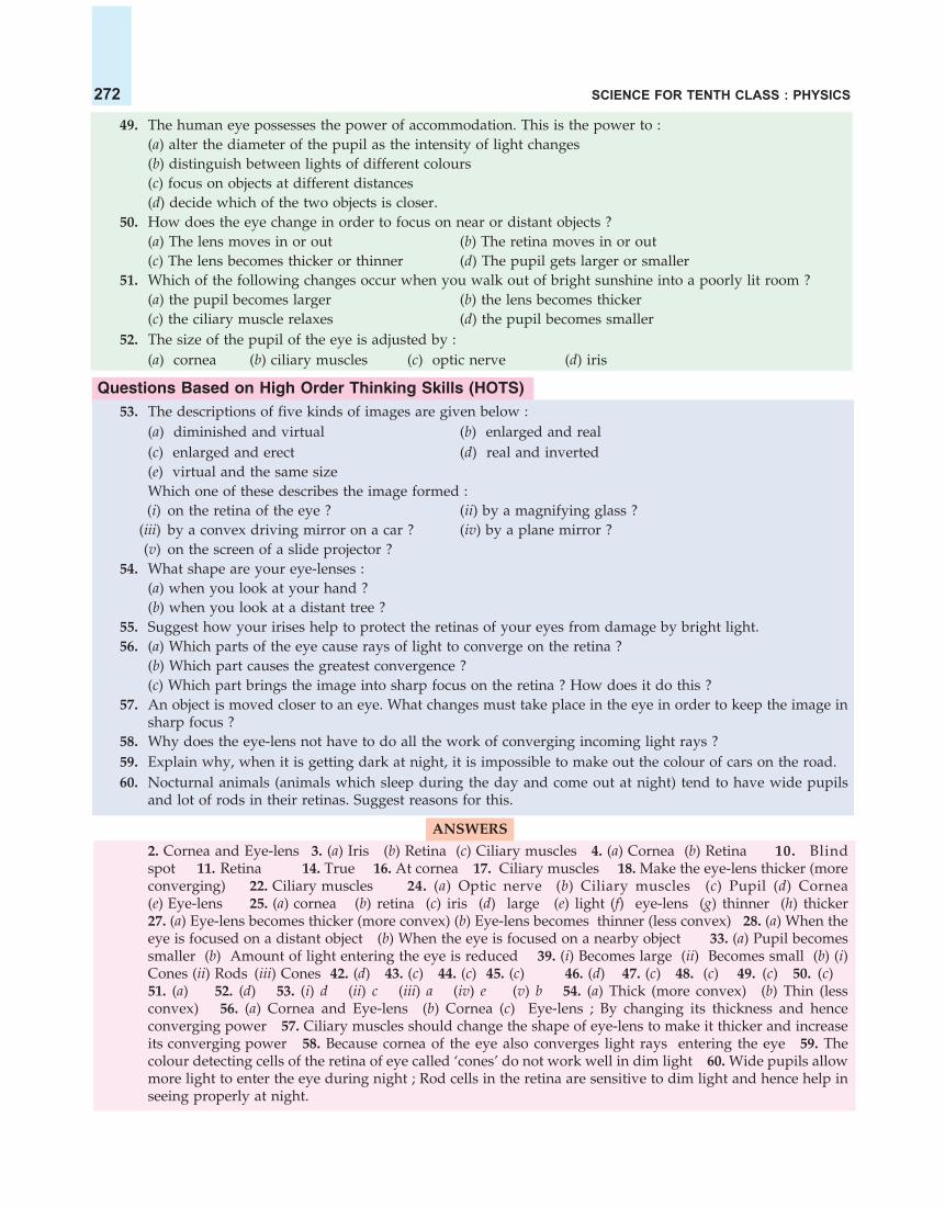
SCIENCE FOR TENTH CLASS : PHYSICS272
49. The human eye possesses the power of accommodation. This is the power to :(a) alter the diameter of the pupil as the intensity of light changes(b) distinguish between lights of different colours(c) focus on objects at different distances(d) decide which of the two objects is closer.
50. How does the eye change in order to focus on near or distant objects ?(a) The lens moves in or out (b) The retina moves in or out(c) The lens becomes thicker or thinner (d) The pupil gets larger or smaller
51. Which of the following changes occur when you walk out of bright sunshine into a poorly lit room ?(a) the pupil becomes larger (b) the lens becomes thicker(c) the ciliary muscle relaxes (d) the pupil becomes smaller
52. The size of the pupil of the eye is adjusted by :(a) cornea (b) ciliary muscles (c) optic nerve (d) iris
Questions Based on High Order Thinking Skills (HOTS)53. The descriptions of five kinds of images are given below :
(a) diminished and virtual (b) enlarged and real(c) enlarged and erect (d) real and inverted(e) virtual and the same sizeWhich one of these describes the image formed :(i) on the retina of the eye ? (ii) by a magnifying glass ?
(iii) by a convex driving mirror on a car ? (iv) by a plane mirror ?(v) on the screen of a slide projector ?
54. What shape are your eye-lenses :(a) when you look at your hand ?(b) when you look at a distant tree ?
55. Suggest how your irises help to protect the retinas of your eyes from damage by bright light.56. (a) Which parts of the eye cause rays of light to converge on the retina ?
(b) Which part causes the greatest convergence ?(c) Which part brings the image into sharp focus on the retina ? How does it do this ?
57. An object is moved closer to an eye. What changes must take place in the eye in order to keep the image insharp focus ?
58. Why does the eye-lens not have to do all the work of converging incoming light rays ?59. Explain why, when it is getting dark at night, it is impossible to make out the colour of cars on the road.60. Nocturnal animals (animals which sleep during the day and come out at night) tend to have wide pupils
and lot of rods in their retinas. Suggest reasons for this.
ANSWERS
2. Cornea and Eye-lens 3. (a) Iris (b) Retina (c) Ciliary muscles 4. (a) Cornea (b) Retina 10. Blindspot 11. Retina 14. True 16. At cornea 17. Ciliary muscles 18. Make the eye-lens thicker (moreconverging) 22. Ciliary muscles 24. (a) Optic nerve (b) Ciliary muscles (c) Pupil (d) Cornea(e) Eye-lens 25. (a) cornea (b) retina (c) iris (d) large (e) light (f) eye-lens (g) thinner (h) thicker27. (a) Eye-lens becomes thicker (more convex) (b) Eye-lens becomes thinner (less convex) 28. (a) When theeye is focused on a distant object (b) When the eye is focused on a nearby object 33. (a) Pupil becomessmaller (b) Amount of light entering the eye is reduced 39. (i) Becomes large (ii) Becomes small (b) (i)Cones (ii) Rods (iii) Cones 42. (d) 43. (c) 44. (c) 45. (c) 46. (d) 47. (c) 48. (c) 49. (c) 50. (c)51. (a) 52. (d) 53. (i) d (ii) c (iii) a (iv) e (v) b 54. (a) Thick (more convex) (b) Thin (lessconvex) 56. (a) Cornea and Eye-lens (b) Cornea (c) Eye-lens ; By changing its thickness and henceconverging power 57. Ciliary muscles should change the shape of eye-lens to make it thicker and increaseits converging power 58. Because cornea of the eye also converges light rays entering the eye 59. Thecolour detecting cells of the retina of eye called ‘cones’ do not work well in dim light 60. Wide pupils allowmore light to enter the eye during night ; Rod cells in the retina are sensitive to dim light and hence help inseeing properly at night.

THE HUMAN EYE AND THE COLOURFUL WORLD 273
Figure 9. If the lenses in our eyes don’tfocus properly, wearing spectacles withappropriate lenses helps us see clearly.
DEFECTS OF VISION AND THEIR CORRECTIONThe ability to see is called vision. It is also called eyesight. Vision is
known as ‘drishti’ in Hindi. Sometimes the eye of a person cannot focusthe image of an object on the retina properly. In such cases the vision ofa person becomes blurred and he cannot see either the distant objects ornearby objects (or both) clearly and comfortably. The person is said tohave a defect of vision. The defects of vision are also known as defects ofeye. There are three common defects of vision (or defects of eye). Theseare :
1. Myopia (Short-sightedness or Near-sightedness)2. Hypermetropia (Long-sightedness or Far-sightedness), and3. Presbyopia.
These are the refractive defects of vision because they are caused bythe incorrect refraction of light rays by the eye-lens. These defects ofvision can be corrected by using suitable spherical lenses (convex lensesor concave lenses). These lenses are usually used in the form of eye-glasses or spectacles (see Figure 9). We will now describe all these defectsof vision and their correction, one by one. Let us start with myopia.
1. Myopia (Short-sightedness or Near-sightedness)
A short-sighted person means that the short sight of theperson (to see nearby objects) is normal but his long-sight (tosee distant objects) is defective. Myopia (or short-sightedness)is that defect of vision due to which a person cannot see thedistant objects clearly (though he can see the nearby objectsclearly). For example, a child having the defect called myopia(or short-sightedness) and sitting on the back benches in theclass cannot read the writing on blackboard clearly though hecan read his book comfortably. The far point of an eyesuffering from myopia is less than infinity. Such a personcan see clearly only up to a distance of few metres (or evenless).
The defect of eye called myopia (or short-sightedness) is caused :
(i) due to high converging power of eye-lens (because of its short focal length), or
(ii) due to eye-ball being too long.
In some cases, in an eye suffering from myopia, the ciliary muscles attached to the eye-lens do not relaxsufficiently to make the eye-lens thinner to reduce its converging power. So, due to the greater convergingpower of the eye-lens in myopic eye, the image of a distant object is formed in front of the retina and hencethe eye cannot see it clearly. In other cases, in the eye suffering from myopia, the eye-ball is too long due towhich the retina is at a larger distance from the eye-lens. This condition also results in the formation of theimage of a distant object in front of the retina (even though the eye-lens may have correct convergingpower).
Figure 11(a) shows an eye having the defect called myopia (or short-sightedness). In this case, theparallel rays of light coming from the distant object O (at infinity) are converged to form an image I in frontof the retina due to which the eye cannot see the distant object clearly [see Figure 11(a)] (The object is at alarge distance called infinity from the eye, so it has not been shown in this Figure). The image is formed in
Figure 10. This girl is having the eye-defect calledmyopia (short-sightedness). She cannot see thedistant ship clearly.

SCIENCE FOR TENTH CLASS : PHYSICS274
front of the retina either due to high converging power of eye-lens or due to eye-ball being too long.
Retina
IImage isformed onthe retina
L
Rays are firstdiverged by
concave lens
Concave lens tocorrect myopiat
Parallel rays from distantobject (at infinity)
Image isformed infront ofthe retina
Parallel rays from distantobject (at infinity)
Retina
IImage
( ) In a myopic eye, image of distant object is formed in front ofthe retina (and not on the retina)
a
Retina
IImage isformed onthe retina
( ) The far point ( ) of a myopic eye is less than infinityb F
F
F
Virtualimageformed
at F
( ) . The concave lens placed in front of the eyeforms a virtual image of distant object at far point ( ) of the myopic eye
c Correction of myopiaF
Far point ofthis eye
Figure 11. Myopia and its correction by using concave lens.
The far point of eye having myopia (or short-sightedness) is at point F which is less than infinity [seeFigure 11(b)]. Please note that the rays of light coming from the person’s far point F can just be focused byhis eye on the retina as shown in Figure 11(b). This means that if the distant object can be made to appearas if it were at the far point F of this eye, then the eye can see it clearly. This is done by putting a concavelens in front of the eye (as described below).
Myopia (short-sightedness or near-sightedness) is corrected by using spectacles containing concavelenses. When a concave lens (diverging lens) L of suitable power is placed in front of the myopic eye asshown in Figure 11(c), then the parallel rays of light coming from the distant object (at infinity) are firstdiverged by the concave lens. Due to this the concave lens forms a virtual image of the distant object at thefar point F of this myopic eye [see Figure 11(c)]. Since the rays of light now appear to be coming from theeye’s far point (F), they can be easily focused by the eye-lens to form an image on the retina [see Figure11(c)]. Please note that the concave lens used for correcting myopia should be of such a focal length (orpower) that it produces a virtual image of the distant object (lying at infinity) at the far point of themyopic eye.
It should also be noted that the whole purpose of using a concave lens here is to reduce the convergingpower of the eye-lens. The concave lens used here decreases the converging power of the eye-lens andhelps in forming the image of distant object on the retina of the myopic eye.

THE HUMAN EYE AND THE COLOURFUL WORLD 275
Calculation of Power of Concave Lens to Correct Myopia. The focal length of concave lens needed to
correct myopia (or short-sightedness) in a person is calculated by using the lens formula 1 1 1 .v u f In this
formula, the object distance u is to be taken as infinity ( ) , and the image distance v will be the distance ofperson’s far point (which is different for different persons). Knowing the focal length of the concave lens,we can calculate its power. This will become more clear from the following example.
Sample Problem. The far point of a myopic person is 80 cm in front of the eye. What is the nature andpower of the lens required to correct the defect ? (NCERT Book Question)
Solution. The defect called myopia is corrected by using a concave lens. So, the person requires concavelens spectacles. We will now calculate the focal length of the concave lens required in this case. The farpoint of the myopic person is 80 cm. This means that this person can see the distant object (kept at infinity)clearly if the image of this distant object is formed at his far point (which is 80 cm here). So, in this case :
Object distance, u = (Infinity)Image distance, v = – 80 cm (Far point, in front of lens)
And, Focal length, f = ? (To be calculated)Putting these values in the lens formula :
v1 1 1=
u f
we get
1 1 1=80 f
or 1 10 =80 f (Because
10
)
1 1=80 f
f = – 80 cmThus, the focal length of the required concave lens is 80 cm. We will now calculate its power. Please
note that the focal length of, – 80 cm is equal to 80
m100
or – 0.8 m. Now,
Power, P = 1
(in metres)f
= 10.8
=108
= –1.25 DSo, the power of concave lens required is, –1.25 dioptres.
2. Hypermetropia (Long-sightedness or Far-sightedness)
A long-sighted person means that the long-sight of the person (to see distant objects) is normal but hisshort-sight (to see nearby objects) is defective. Hypermetropia (or long-sightedness) is that defect of visiondue to which a person cannot see the nearby objects clearly (though he can see the distant objectsclearly). For example, a person having the defect hypermetropia cannot read a book clearly and comfortablythough he can read the number of a distant bus clearly. The near-point of a hypermetropic eye is morethan 25 centimetres away. Such a person has to hold the reading material (like a book or newspaper) at anarm’s length, much beyond 25 cm from the eye for comfortable reading. Please note that hypermetropia isjust the opposite of myopia.

SCIENCE FOR TENTH CLASS : PHYSICS276
The defect of eye called hypermetropia (or long-sightedness) is caused :
(i) due to low converging power of eye-lens (becauseof its large focal length), or
(ii) due to eye-ball being too short.In some cases, the ciliary muscles attached to the eye-
lens become weak and cannot make the eye-lens thicker toincrease its converging power. So, due to the lowconverging power of eye-lens in an eye suffering fromhypermetropia, the image of nearby object is formed behindthe retina and hence the eye cannot see it clearly. In othercases, in an eye suffering from hypermetropia, the eye-ballis too short due to which the retina is at a smaller distancefrom the eye-lens. This condition also results in theformation of the image of a nearby object behind the retina (even though the eye-lens may have correctconverging power).
Figure 13(a) shows an eye having the defect called hypermetropia (or long-sightedness). In this case the
Figure 13. Hypermetropia and its correction by using convex lens.
Figure 12. This man is having the eye-defect calledhypermetropia (long-sightedness). He cannot read a bookclearly by holding it at the normal distance of 25 cm.He has to hold the book at a much larger distance (atarm’s length) to be able to read it.
Rays are firstconverged byconvex lens
L
O
Nearbyobject
Convex lensto correcthypermetropia
IImage is formedon the retina
O
Nearbyobject
25 cm
Retina
IImage is formedbehind the retina
Diverging raysfrom nearby object
Normalnearpoint
N
( ) In a hypermetropic eye, the image of nearby object lying at normalnear point (at 25 cm) is formed behind the retina.
aN
Near pointof thiseye
25 cm
Retina
IImage is formedon the retina
Normalnear point
NN�
( ) The near point of hypermetropic eye is farther awayfrom the normal near point
b NN
�
N�
Virtualimageformedat N �
N
( ) . The convex lens forms a virtual image of the
object (lying at normal near point ) at the near point of this eye.
c Correction of hypermetropia
N N�
More than

THE HUMAN EYE AND THE COLOURFUL WORLD 277
diverging rays of light coming from a nearby object O placed at the normal near point N (25 cm from theeye) are converged to form an image I behind the retina due to which the eye cannot see the nearby objectclearly [see Figure 13(a)]. The image is formed behind the retina either due to low converging power of eye-lens or because of eye-ball being too short.
The near-point of an eye having hypermetropia (or long-sightedness) is at point N which is more than25 centrimetres away [see Figure 13(b)]. The diverging rays of light coming from a hypermetropic person’snear point can just be focused by his eye on the retina as shown in Figure 13(b). This means that if theobject placed at the normal near point N (25 cm) can be made to appear as if it were placed at this eye’snear point N, then the eye will be able to see it clearly. This can be done by putting a convex lens in frontof the eye.
Hypermetropia (long-sightedness or far-sightedness) is corrected by using spectacles containingconvex lenses. When a convex lens (converging lens) L of suitable power is placed in front of thehypermetropic eye as shown in Figure 13(c), then the diverging rays of light coming from the nearby object(at 25 cm) are first converged by this convex lens. Due to this, the convex lens forms a virtual image of thenearby object (which is lying at the normal near point N) at the near point N of the hypermetropic eye [seeFigure 13(c)]. Since the rays of light now appear to be coming from this eye’s near point N, they can beeasily focused by the eye-lens to form an image on the retina [see Figure 13(c)]. Please note that the convexlens used for correcting hypermetropia (or long-sightedness) should be of such a focal length (or power)that it forms a virtual image of the object (placed at the normal near point N of 25 cm), at the near pointN of the hypermetropic eye.
It should also be noted that the whole purpose of using a convex lens here is to increasethe converging power of the eye-lens. The convex lens used in spectacles increases theconverging power of eye-lens and helps in forming the image of a nearby object on theretina of the eye.
Calculation of the Power of Convex Lens to Correct Hypermetropia. The focal lengthof convex lens needed to correct hypermetropia (or long-sightedness) can be calculated by using the lens
formula v 1 1 1
=u f . In this formula, the object distance u is to be taken as the normal near point of the eye
(which is 25 cm) and the image distance v will be the distance of the near point of the hypermetropic eye.Knowing the focal length of the convex lens, its power can be calculated. This will become more clear fromthe following example.
Sample Problem. The near point of a hypermetropic eye is 1 m. What is the nature and power of thelens required to correct this defect ? (Assume that the near point of the normal eye is 25 cm).
(NCERT Book Question)
Solution. The eye defect called hypermetropia is corrected by using a convex lens. So, the person requiresconvex lens spectacles. We will first calculate the focal length of the convex lens required in this case. Thishypermetropic eye can see the nearby object kept at 25 cm (at near point of normal eye) clearly if the imageof this object is formed at its own near point which is 1 metre here. So, in this case :
Object distance, u = –25 cm (Normal near point)Image distance, v = –1 m (Near point of this defective eye)
= –100 cmAnd, Focal length, f = ? (To be calculated)Putting these values in the lens formula,
v1 1 1=
u f
We get :
1 1 1=100 25 f
or 1 1 1+ =100 25 f

SCIENCE FOR TENTH CLASS : PHYSICS278
1+ 4 1=100 f
3 1100 f
100
3f
33.3 cmf
Thus, the focal length of the convex lens required is +33.3 cm. We will now calculate the power. Please
note that 33.3 cm is equal to 33.3100
m or 0.33 m. Now,
Power, P = 1
(in metres)f
= 1
+0.33
= 10033
= + 3.0 DSo, the power of convex lens required is +3.0 dioptres.
Myopia and hypermetropia are the two most common defects of vision (or defects of eye). We willnow study another defect of vision which occurs in old age. It is called presbyopia.
3. Presbyopia
In old age, due to ciliary muscles becoming weak and the eye-lens becoming inflexible (or rigid), theeye loses its power of accommodation. Because of this an old person cannot see the nearby objects clearly.This leads to the defect called presbyopia. Presbyopia is that defect of vision due to which an old personcannot see the nearby objects clearly due to loss of power of accommodation of the eye. For example, anold person having presbyopia cannot read a book or newspaper comfortably and clearly without spectacles.Presbyopia occurs in old age due to the gradual weakening of the ciliary muscles and diminishing flexibilityof the eye-lens. The near-point of the old person having presbyopia gradually recedes and becomesmuch more than 25 centimetres away. Actually, presbyopia is a special kind of hypermetropia. We can callit old age hypermetropia. Presbyopia is the hypermetropia (or long-sightedness) caused by the loss ofpower of accommodation of the eye due to old age. Presbyopia defect is corrected in the same way ashypermetropia by using spectacles having convex lenses (see Figure 13).
It is also possible that the same person has both the defectsof vision – myopia as well as hypermetropia. A person sufferingfrom myopia as well as hypermetropia uses spectacles havingbifocal lenses in which upper part consists of a concave lens (tocorrect myopia) used for distant vision and the lower partconsists of a convex lens (to correct hypermetropia) used forreading purposes (see Figure 14).
These days it is possible to correct the refractive defects ofthe eye (such as myopia and hypermetropia) by using contactlenses or by undergoing surgical procedures. Then there is no need to wear spectacles.
Cataract
A yet another defect of the eye which usually comes in old age is the cataract. The medical conditionin which the lens of the eye of a person becomes progressively cloudy resulting in blurred vision is
Concave lens(for distant
vision)
Convex lens(for reading)
Figure 14. Spectacles having bifocal lenses.

THE HUMAN EYE AND THE COLOURFUL WORLD 279
called cataract. Cataract develops when the eye-lens of a person becomes cloudy (or even opaque) due tothe formation of a membrane over it. Cataract decreases the vision of the eye gradually. It can even lead tototal loss of vision of the eye. The vision of the person can be restored after getting surgery done on the eyehaving cataract. The opaque lens is removed from the eye of the person by surgical operation and a newartificial lens is inserted in its place. Please note that the eye-defect called ‘cataract’ cannot be corrected byany type of spectacle lenses. We are now in a position to answer the following questions :
Very Short Answer Type Questions1. Name one of the common defects of vision and the type of lens used to remove it.2. Name the defect of vision in a person :
(a) whose near point is more than 25 cm away.(b) whose far point is less than infinity
3. Which defect of vision can be rectified :(a) by using a concave lens ?(b) by using a convex lens ?
4. What type of lens is used to correct (a) hypermetropia (b) myopia ?5. What is the other name for (a) myopia (b) hypermetropia ?6. What is the scientific name of (a) short-sightedness, and (b) long-sightedness ?7. What kind of lens is used to correct (a) short-sightedness (b) long-sightedness ?8. State whether the following statement is true or false :
Short-sightedness can be cured by using a concave lens.9. Name the defect of vision in which the eye-lens loses its power of accommodation due to old age.
10. Name the defect of vision which makes the eye-lens cloudy resulting in blurred vision.11. What is the other name of old age hypermetropia ?12. Name any two defects of vision which can be corrected by using spectacles.13. Name one defect of vision (or eye) which cannot be corrected by any type of spectacle lenses.14. Name the body part with which the terms myopia and hypermetropia are connected.15. What is the far point of a person suffering from myopia (or short-sightedness) ?16. Where is the near point of a person suffering from hypermetropia (or long-sightedness) ?17. Your friend can read a book perfectly well but cannot read the writing on blackboard unless she sits on the
front row in class.(a) Is she short-sighted or long-sighted ?(b) What type of lenses–converging or diverging–would an optician prescribe for her ?
18. A man can read the number of a distant bus clearly but he finds difficulty in reading a book.(a) From which defect of the eye is he suffering ?(b) What type of spectacle lens should he use to correct the defect ?
19. A student sitting in the last row of the class-room is not able to read clearly the writing on the blackboard.(a) Name the type of defect he is suffering from.(b) How can this defect by corrected ?
20. Complete the following sentences :(a) A short-sighted person cannot see .............. objects clearly. Short-sightedness can be corrected by using
...............lenses.(b) A long-sighted person cannot see .............. objects clearly. Long-sightedness can be corrected by using
.............. lenses.
Short Answer Type Questions21. What are the two most common defects of vision (or defects of eye) ? How are they corrected ?22. Differentiate between myopia and hypermetropia. What type of spectacles should be worn by a person
having the defects of myopia as well as hypermetropia ? How does it help ?23. Name the defect of vision which can be corrected by a converging lens. Show clearly by a ray diagram how
the lens corrects the defect.

SCIENCE FOR TENTH CLASS : PHYSICS280
24. Name the defect of vision which can be corrected by a diverging lens. Show clearly by a ray diagram howthe lens corrects the defect.
25. Explain with the help of labelled ray diagram, the defect of vision called myopia and how it is corrected bya lens.
26. Explain with the help of labelled ray-diagram, the defect of vision called hypermetropia, and how it iscorrected by a lens.
27. A person suffering from the eye-defect myopia (short-sightedness) can see clearly only up to a distance of 2metres. What is the nature and power of lens required to rectify this defect ?
28. The near-point of a person suffering from hypermetropia is at 50 cm from his eye. What is the nature andpower of the lens needed to correct this defect ? (Assume that the near-point of the normal eye is 25 cm).
29. A person needs a lens of power, – 5.5 dioptres for correcting his distant vision. For correcting his nearvision, he needs a lens of power, +1.5 dioptres. What is the focal length of the lens required for correcting(i) distant vision, and (ii) near vision ?
30. What is presbyopia ? Write two causes of this defect. Name the type of lens which can be used to correctpresbyopia.
31. When is a person said to have developed cataract in his eye ? How is the vision of a person having cataractrestored ?
32. Fill in the following blanks with suitable words :A person is short-sighted if his eyeball is too.................Spectacles with a ................lens are needed. A personis long-sighted if his eyeball is too.................Spectacles with a ................lens are needed. These focus lightrays exactly on to the..............
Long Answer Type Questions33. (a) What is short-sightedness ? State the two causes of short-sightedness (or myopia). With the help of ray
diagrams, show :(i) the eye-defect short-sightedness.
(ii) correction of short-sightedness by using a lens.(b) A person having short-sight cannot see objects clearly beyond a distance of 1.5 m. What would be the
nature and power of the corrective lens to restore proper vision ?34. (a) What is long-sightedness ? State the two causes of long-sightedness (or hypermetropia). With the help of
ray diagrams, show :(i) the eye-defect long-sightedness.
(ii) correction of long-sightedness by using a lens.(b) An eye has a near point distance of 0.75 m. What sort of lens in spectacles would be needed to reduce the
near point distance to 0.25 m ? Also calculate the power of lens required. Is this eye long-sighted or short-sighted ?
(c) An eye has a far point of 2 m. What type of lens in spectacles would be needed to increase the far pointto infinity ? Also calculate the power of lens required. Is this eye long-sighted or short-sighted ?
Multiple Choice Questions (MCQs)35. The human eye can focus objects at different distances by adjusting the focal length of the eye-lens. This is
due to :(a) presbyopia (b) accommodation (c) near-sightedness (d) far-sightedness
36. The defect of vision which cannot be corrected by using spectacles is :(a) myopia (b) presbyopia (c) cataract (d) hypermetropia
37. A person cannot see the distant objects clearly (though he can see the nearby objects clearly). He is sufferingfrom the defect of vision called :(a) cataract (b) hypermetropia (c) myopia (d) presbyopia
38. Though a woman can see the distant objects clearly, she cannot see the nearby objects clearly. She is sufferingfrom the defect of vision called :(a) long-sight (b) short-sight (c) hind-sight (d) mid-sight
39. A young man has to hold a book at arm’s length to be able to read it clearly. The defect of vision is :(a) astigmatism (b) myopia (c) presbyopia (d) hypermetropia

THE HUMAN EYE AND THE COLOURFUL WORLD 281
40. After testing the eyes of a child, the optician has prescribed the following lenses for his spectacles :Left eye : + 2.00 D Right eye : + 2.25 DThe child is suffering from the defect of vision called :(a) short-sightedness (b) long-sightedness(c) cataract (d) presbyopia
41. A person got his eyes tested. The optician’s prescription for the spectacles reads :Left eye : – 3.00 D Right eye : – 3.50 DThe person is having a defect of vision called :(a) presbyopia (b) myopia (c) astigmatism (d) hypermetropia
42. A student sitting on the last bench in the class cannot read the writing on the blackboard clearly but he canread the book lying on his desk clearly. Which of the following statement is correct about the student ?(a) The near point of his eyes has receded away.(b) The near point of his eyes has come closer to him.(c) The far point of his eyes has receded away.(d) The far point of his eyes has come closer to him.
43. A man driving a car can read a distant road sign clearly but finds difficulty in reading the odometer on thedashboard of the car. Which of the following statement is correct about this man ?(a) The near point of his eyes has receded away.(b) The near point of his eyes has come closer to him.(c) The far point of his eyes has receded away.(d) The far point of his eyes has come closer to him.
44. The defect of vision in which the eye-lens of a person gets progressively cloudy resulting in blurred vision iscalled :(a) myopia (b) presbyopia (c) colourblindness (d) cataract
45. A person cannot see distant objects clearly. His vision can be corrected by using the spectacles containing :(a) concave lenses (b) plane lenses (c) contact lenses (d) convex lenses
46. A person finds difficulty in seeing nearby objects clearly. His vision can be corrected by using spectaclescontaining :(a) converging lenses (b) diverging lenses (c) prismatic lenses (d) chromatic lenses
Questions Based on High Order Thinking Skills (HOTS)47. In a certain murder investigation, it was important to discover whether the victim was long-sighted or
short-sighted. How could a detective decide by examining his spectacles ?48. The picture given here shows a person wearing ‘half-moon’ spectacles. What sort
of eye-defect do you think he has ? Why are these particular spectacles useful tohim ?
49. A short-sighted person has a near point of 15 cm and a far point of 40 cm.(a) Can he see clearly an object at a distance of : (i) 5 cm ? (ii) 25 cm ? (iii) 50 cm ?(b) To see clearly an object at infinity, what kind of spectacle lenses does he need ?
50. The near point of a long-sighted person is 50 cm from the eye.(a) Can she see clearly an object at : (i) a distance of 20 cm ? (ii) at infinity ?(b) To read a book held at a distance of 25 cm, will she need converging or diverging spectacle lenses ?
51. A person can read a book clearly only if he holds it at an arm’s length from him. Name the defect of vision :(a) if the person is an old man (b) if the person is a young man
ANSWERS2. (a) Hypermetropia (b) Myopia 8. True 9. Presbyopia 11. Presbyopia 13. Cataract14. Eye 17. (a) Short-sighted (b) Diverging lenses 18. (a) Hypermetropia (Long-sightedness)(b) Convex lens 19. (a) Myopia (Short-sightedness) (b) Concave lens 20. (a) distant ; concave

SCIENCE FOR TENTH CLASS : PHYSICS282
Figure 15. The human beings have two eyes at the frontof their head.
Figure 16. Rabbits are animals of prey. Theyhave two eyes on the sides of their head.
(b) nearby ; convex 22. Spectacles having bifocal lenses in which upper part consists of concave lens andlower part consists of convex lens 27. Concave lens ; – 0.5 D 28. Convex lens; + 2 D 29. (i) –18.18 cm(ii) + 66.6 cm 32. long ; concave; short ; convex ; retina 33. (b) Concave lenses ; – 0.67 D34. (b) Convex lenses ; + 2.67 D ; Long-sighted (c) Concave lenses ; – 0.5 D ; Short-sighted 35. (b) 36. (c)37. (c) 38. (a) 39. (d) 40. (b) 41. (b) 42. (d) 43. (a) 44. (d) 45. (a) 46. (a) 47. If spectacle lenses areconvex, the person was long-sighted ; If spectacle lenses are concave, then the person was short-sighted48. Long-sightedness (Hypermetropia) ; The convex lenses of spectacles form the image of nearby object atthe near point of his eye. 49. (a) (i) No (ii) Yes (iii) No (b) Concave lenses 50. (a) (i) No (ii) Yes(b) Converging lenses 51. (a) Presbyopia (b) Hypermetropia
WHY DO WE HAVE TWO EYES FOR VISION AND NOT JUST ONEThere are many advantages of having two eyes instead of one. Some of these are given below.
1. Having Two Eyes Gives a Wider Field of View. A human being has a horizontal field of view ofabout 150° with one eye open but with two eyes open,the field of view becomes 180°. Thus, having two eyesgives a wider field of view. This means that with twoeyes open, we can see a much larger area in front of us(than can be seen with only one eye).
The human beings have two eyes at the front of theirhead, so their field of view is limited to about 180° (seeFigure 15). Some animals, however, have their two eyeslocated on the opposite sides of their head. Those animals whohave two eyes on the opposite sides of their head have the widestpossible field of view. They can see much larger area around themthan the human being can see. The animals of prey (like rabbit,deer, chicken, fish, etc.) have their two eyes on the opposite sidesof their heads so that they can see their enemies (predators) in avery large area around them and try to escape from them (seeFigure 16). A domestic animal having its two eyes on the oppositesides of the head is horse.
2. Having Two Eyes Enables Us to Judge Distances MoreAccurately. Our two eyes are a few centimetres apart from eachother (see Figure 15). Due to this, the two eyes see the same objectfrom two slightly different angles and send two slightly differentimages of the same object to the brain. The brain combines these two slightly different images to build athree-dimensional picture of the object which enables us to judge the distance of the object more accurately.
Figure 17. It is difficult to touch the tips of two pencils withone eye open (but much easier when both the eyes are open).
Figure 18. Tiger is a predator. It has twoeyes at the front of its head.

THE HUMAN EYE AND THE COLOURFUL WORLD 283
This will become clear from the following example. Let us take two sharpened pencils, one in each hand.Stretch the arms forward and try touching the tips of pencils first with one eye open and then with botheyes open. We will find that it is difficult to touch the tips of two pencils with one eye open but it is muchmore easy when both the eyes are open (see Figure 17). This is because with both the eyes open, we canjudge the distances of the pencil tips more accurately. Human beings (and all other animals having theireyes at the front of their head) are said to have stereoscopic vision (or stereopsis) which gives the perceptionof depth. All the predators (like tiger, lion, etc.) have their eyes at the front of head so that they can judgethe distance of their prey accurately and catch them easily (see Figure 18).
The Gift of Vision
There are millions of blind people in our country who cannot see at all. The eyesight of most of theseblind people can be restored if they are given the eyes donated by other persons after their death. In thisway, our eyes can live even after our death. In fact, our two eyes can give eyesight to two blind persons(each getting one eye), and make them see this beautiful world.
Some of the important points to be noted about the donation of eyes are the following :
1. Any person of any age or sex (male or female) can donate eyes. People who wear spectacles or haveundergone cataract operations can also donate eyes. Even the persons having ailments such as diabetes(sugar), hypertension (blood pressure) and asthma can donate eyes. But they should not have anycommunicable diseases. The persons who were infected with or died because of diseases such as AIDS,hepatitis B or C, rabies, leukaemia, tetanus, cholera, meningitis, or encephalitis, however, cannot donateeyes.
2. After the death of the person (who had registered for eye donation), the eye bank should be informedimmediately. This is because eyes must be removed within 4 to 6 hours of a person’s death.
3. The doctors of the eye bank team will remove the eyes at the home of the dead person or at thehospital. It takes only 10 to 15 minutes to remove the eyes. There is no disfigurement of the face in thisprocess.
4. The eye bank distributes the donated eyes to various eye hospitals where these are transplanted inthe blind people through surgical operation.
5. Those donated eyes which are not suitable for transplantation, are used for doing research and forteaching purposes in medical colleges.
We can, even today, make a pledge in writing, with the eye bank of our area that (God forbid) wheneverwe die our eyes should be removed and given to the blind persons to light up their dark world ! We shouldbe grateful to God that he has given us the gift of vision to see this wonderful world. Let us pass on thispriceless gift of vision to our less fortunate blind brothers and sisters by registering our name for eyedonation. We are now in a position to answer the following questions :
Very Short Answer Type Questions1. How much is our field of view :
(a) with one eye open ?(b) with both eyes open ?
2. Which of the following have a wider field of view ?(a) Animals having two eyes on the opposite sides of their head.(b) Animals having two eyes at the front of their head.
3. Out of animals of prey and predators, which have their eyes :(i) at the front of their head ?(ii) on the opposite sides of their head ?
4. State whether the following statement is true or false :Rabbit has eyes which look sideways.

SCIENCE FOR TENTH CLASS : PHYSICS284
5. Fill in the following blanks with suitable words :(a) Having two eyes gives a ................field of view.(b) Having two eyes enables us to judge.................more accurately.
Short Answer type Questions6. What are the advantages of having two eyes instead of just one ?7. Explain clearly why, a person who has lost the sight of one eye is at a disadvantage compared with the
normal person who has two good eyes.8. Name two animals having eyes :
(a) on the sides of the head.(b) at the front of the head.
9. Among animals, the predators (like lions) have their eyes facing forward at the front of their heads, whereasthe animals of prey (like rabbit) usually have eyes at the sides of their head. Why is this so ?
10. Five persons A, B, C, D and E have diabetes, leukaemia, asthma, meningitis and hepatitis, respectively.(a) Which of these persons can donate eyes ?(b) Which of these persons cannot donate eyes ?
Multiple Choice Questions (MCQs)11. The animal which does not have eyes that look sideways is :
(a) Horse (b) Chicken (c) Lion (d) Fish12. With both eyes open, a person’s field of view is about :
(a) 90° (b) 150° (c) 180° (d) 360°13. Having two eyes gives a person :
(a) deeper field of view (b) coloured field of view(c) rear field of view (d) wider field of view
14. The animals of prey have :(a) two eyes at the front (b) two eyes at the back(c) two eyes on the sides (d) one eye at the front and one on the side
15. The animals called predators have :(a) both the eyes on the sides (b) one eye on the side and one at the front(c) one eye on the front and one at the back (d) both the eyes at the front
ANSWERS
1. (a) About 150° (b) About 180° 2. (a) 3. (i) Predators (ii) Animals of prey 4. True 5. (a) wider(b) distances 8. (a) Rabbit ; Deer (b) Tiger ; Lion 10. (a) A and C (b) B, D and E 11. (c) 12. (c) 13. (d)14. (c) 15. (d)
GLASS PRISMWe have already studied the refraction of light through a rectangular glass slab. In a rectangular glass
slab, the emergent light rays are parallel to the incident light rays because the opposite faces of a rectangularglass slab (where refraction takes place) are parallel to one another. We will now discuss the refraction oflight through a glass object whose opposite faces (where refraction takes place) are not parallel to oneanother. A triangular glass prism is such an object. A triangular glass prism is shown in Figure 19(a). Thetriangular glass prism is a transparent object made of glass having two triangular ends and three rectangularsides (or rectangular faces). Please note that the opposite faces of a triangular glass prism are not parallelto one another. For example, in Figure 19(a), the opposite faces of the glass prism F1 and F2 (where therefraction of light takes place) are not parallel to one another. They are inclined at an angle to one another.The angle between its opposite faces is called the angle of the prism. In Figure 19(a), angle QPR is the angleof this prism. Though an actual triangular glass prism looks like that shown in Figure 19(a), but for the sakeof convenience in drawing ray-diagrams, a triangular glass prism is represented by drawing a triangle as

THE HUMAN EYE AND THE COLOURFUL WORLD 285
shown in Figure 19(b). Please note that a ‘triangular glassprism’ is usually called ‘glass prism’ and sometimes evenjust ‘prism’.
As we will study after a while the refraction of lighton passing through a glass prism is different from thatin a glass slab. This is because in refraction through aglass slab, the emergent ray is parallel to the incidentray but in refraction through a glass prism, the emergentray is not parallel to the incident ray. The emergent ray oflight in a glass prism is not parallel to the incident ray of lightbecause the opposite faces of the glass prism (where refractiontakes place) are not parallel to one another. Actually, inrefraction through a glass prism, the emergent ray isdeviated from its original direction by a certain angle. Andwe say that light rays get deviated on passing through aglass prism. We will now study the refraction of lightthrough a glass prism in somewhat detail.
REFRACTION OF LIGHT THROUGH A GLASS PRISMWhen a ray of light passes through a glass prism, refraction (or bending) of light occurs both, when it
enters the prism as well as when it leaves the prism. Since the refracting surfaces (PQ and PR) of the prismare not parallel, therefore, the emergent ray and incident ray are not parallel to one another (see Figure 20).In this case the ray of light is deviated on passing through the prism. Let us see how it happens.
In Figure 20, a glass prism PQR has been kepton its base QR. A ray of light AB is incident on theface PQ of the prism. The incident ray AB is goingfrom air (rarer medium) into glass (denser medium),so it bends towards the normal BN' and goes alongthe direction BC inside the glass prism. Thus, BC isthe refracted ray of light which bends towards thebase QR of the prism.
When the ray of light BC travelling in the glassprism comes out into air at point C, refraction takesplace again (see Figure 20). Since the ray BC is goingfrom glass (denser medium) into air (rarer medium),so it bends away from the normal MC and goes alongthe direction CD in the form of emergent ray. Herealso, the emergent ray of light CD bends towards the base QR of the prism. From this discussion weconclude that when a ray of light passes through a prism, it bends towards the base of prism. In otherwords, when a ray of light passes through a prism, it bends towards the thicker part of the prism.
If we look carefully at Figure 20, we will see that the emergent ray CD is not parallel to the incident rayAB. There has been a deviation (or change) in the path of light in passing through the prism. Let us producethe incident ray AB upwards towards the point E by a dotted line. Now, AE represents the original directionof the ray of light. Similarly, let us produce the emergent ray CD backwards by a dotted line so that it cutsthe line AE at point O (see Figure 20). We can now say that the original direction of the ray of light is AEbut after passing through the prism, it deviates from its path and goes in the direction OD. The anglebetween incident ray and emergent ray is called angle of deviation. In Figure 20, the angle EOD is theangle of deviation. Please note that it is the peculiar shape (triangular shape) of the glass prism which makes theemergent ray bend with respect to the incident ray.
F2
Q R Q R
P
F1
P
(b) This is how a triangularglass prism is representedin ray-diagrams.
(a) A triangular glass prism.
Figure 19.
N
N� M�
MC
O
P
QA
Glass prism
B
DEmergent ray
E
Angle ofdeviation
Incident ray
R
Figure 20. Refraction of light through a glass prism. Here theemergent ray CD is not parallel to the incident ray AB. It getsdeviated.

SCIENCE FOR TENTH CLASS : PHYSICS286
DISPERSION OF LIGHTIn the year 1665, Newton discovered by his experiments with glass prisms that white light (like sunlight)
consists of a mixture of seven colours. By saying that white light is a mixture of seven colours we meanthat white light is a mixture of lights of seven colours. Newton found that if a beam of white light is passedthrough a triangular glass prism, the white light splits to form a band of seven colours on a white screen(see Figure 21). The band of seven colours formed on a white screen, when a beam of white light ispassed through a glass prism, is called spectrum of white light. The seven colours of the spectrum are :Red, Orange, Yellow, Green, Blue, Indigo, and Violet. The seven colours of the spectrum can be denoted bythe word VIBGYOR where V stands for Violet, I for Indigo, B for Blue, G for Green, Y for Yellow, O forOrange and R for Red.
Figure 21. A glass prism splits the white light into lights of seven colours.In Figure 21, a beam of white light AB is passed into a glass prism PQR. This beam of white light splits
on entering the glass prism and forms a broad patch of seven colours on a white screen S placed on theother side of the prism. Please note that when the glass prism is kept on its baseas shown in Figure 21, then the red colour is at the top and violet colour is at thebottom of the spectrum. The splitting up of white light into seven colours onpassing through a transparent medium like a glass prism is called dispersion oflight. The formation of spectrum of seven colours shows that white light is madeup of lights of seven different colours mixed together. That is, white light is amixture of seven colours (or seven coloured lights). The effect of glass prism isonly to separate the seven colours of white light. A similar band of seven colours isproduced when a beam of white light from an electric bulb falls on a triangularglass prism. We can explain the dispersion of light by a glass prism as follows.
White light is a mixture of lights of seven colours : red, orange, yellow, green,blue, indigo and violet. The dispersion of white light occurs because colours ofwhite light travel at different speeds through the glass prism. The amount ofrefraction (or bending) depends on the speed of coloured light in glass. Now,since the different colours travel at different speeds, they are refracted (or bent)by different angles on passing through the glass prism (some colours are bent lesswhereas others are bent more). So, when white light consisting of seven coloursfalls on a glass prism, each colour in it is refracted (or deviated) by a differentangle, with the result that seven colours are spread out to form a spectrum. Thered colour has the maximum speed in glass prism, so the red colour is deviatedthe least. Due to this the red colour forms the upper part of the spectrum. On the
Figure 22. It is usually notpossible to distinguish all theseven colours of thespectrum easily due to theoverlapping of variouscolours. So, the spectrum isnot really seven separatecolours.

THE HUMAN EYE AND THE COLOURFUL WORLD 287
other hand, the violet colour has the minimum speed in glass prism, so the violet colour is deviated themaximum. Due to this violet colour appears at the bottom of the spectrum. Please note that the sevencolours of spectrum differ only in their frequencies. These colours in the order of increasing frequency (butdecreasing wavelengths) are : Red, Orange, Yellow, Green, Blue, Indigo and Violet. Any light that givesspectrum similar to that of sunlight is called white light.Re-Combination of Spectrum Colours to Give White Light
We have just seen that white light can be dispersed into its seven constituent colours. Newton showedthat the reverse of this is also true. That is, the seven coloured lights of the spectrum can be recombinedto give back white light. This can be done as follows.
A triangular glass prism PQR is placed on its base QR as shown in Figure 23, and another similar prismPQR is placed alongside it in the inverted position on its vertex P so that its refracting surface is in the
Figure 23. The first glass prism disperses (splits) white light into seven colours. The second glass prism(which has been placed upside down) recombines the seven colours of spectrum to give back white light.
opposite direction. When a beam of white light is allowed to fall on the first prism PQR, then a patch ofordinary white light is obtained on a screen S placed behind the second prism PQR (see Figure 23).Newton explained these observations as follows.
The first glass prism PQR disperses (splits) the white light into seven coloured rays. The second glassprism PQR receives all the seven coloured rays from the first prism and recombines them into originalwhite beam of light which falls on the screen S. The recombination ofseven colours, produced by first prism, is due to the fact that the secondprism has been placed in reversed position due to which the refractionproduced by the second prism is equal and opposite to that producedby the first prism.
The Rainbow
One of the most beautiful examples of spectrum formed by thedispersion of sunlight is provided by nature in the form of rainbow.The rainbow is an arch of seven colours visible in the sky which isproduced by the dispersion of sun’s light by raindrops in theatmosphere (see Figure 24). The rainbow is actually a natural spectrumof sunlight in the sky. The rainbow is formed in the sky when the sunis shining and it is raining at the same time. We can see the rainbow ifwe stand with our back towards the sun and rain in front of us. Arainbow is always formed in a direction opposite to that of the sun. Arainbow is produced by the dispersion of white sunlight by raindrops(or water drops) in the atmosphere. Each raindrop acts as a tiny glass Figure 24. A rainbow.

SCIENCE FOR TENTH CLASS : PHYSICS288
Figure 25. Formation of a rainbow.
prism splitting the sunlight into a spectrum. This willbecome more clear from the following discussion.
The raindrops in the atmosphere act like manysmall prisms. As white sunlight enters and leaves theseraindrops (or water drops), the various coloured rayspresent in white light are refracted by different amountsdue to which an arch of seven colours called rainbow isformed in the sky. The formation of rainbow can beexplained with the help of a diagram shown in Figure25. A ray of white sunlight AB enters the raindrop atpoint B and undergoes refraction and dispersion to forma spectrum. This spectrum undergoes total internalreflection at point C within the raindrop and finallyrefracted out of the raindrop at point D (see Figure 25).This spectrum produced by the raindrops in the atmosphere is seen from the earth. The red colour ofspectrum appears at the top of the rainbow whereas violet colour appears at its bottom.
The formation of seven-coloured rainbow in the sky shows that white sunlight consists of a mixtureof seven coloured lights. We can also see a rainbow on a sunny day if we look through a spray of waterfrom a fountain (or through a waterfall) with the sun behind us. Before we go further and discuss atmosphericrefraction, please answer the following questions :
Very Short Answer Type Questions
1. As light rays pass from air into a glass prism, are they refracted towards or away from the normal ?2. As light rays emerge from a glass prism into air, are they refracted towards or away from the normal ?3. Name a natural phenomenon which is caused by the dispersion of sunlight in the sky.4. What information do we get about sunlight from the formation of a rainbow ?5. What did Newton demonstrate by his experiments with the prism ?6. What colours make up white light ?7. Give the meaning of the term VIBGYOR. With which phenomenon is it connected ?8. In the formation of spectrum of white light by a prism :
(i) which colour is deviated least ?(ii) which colour is deviated most ?
9. What colours lie on the two sides of the ‘green colour’ in the spectrum of white light ?10. Name the scientist who discovered that sunlight consists of seven colours.11. What is the order of colours in a rainbow, from the outside to the inside ?12. Which colour of the spectrum has (a) longest wavelength, and (b) shortest wavelength ?13. Which light has the longer wavelength : red light or blue light ?14. Which colour of light has the shorter wavelength – red or violet ?15. Fill in the blanks with suitable words :
(a) When a ray of light enters a prism, it bends.................the normal ; as it leaves the prism, it bends ............the normal.
(b) White light is composed of.............colours. The colour of white light deviated through the largest angle bya prism is..............
Short Answer Type Questions
16. (i) A ray of white light breaks up into its components while passing through a glass prism.Draw a ray diagram to show the path of rays.
(ii) Mark the least deviated colour in your diagram.(iii) Why do different coloured rays deviate differently in a prism ?

THE HUMAN EYE AND THE COLOURFUL WORLD 289
17. (a) What happens when a ray of ordinary light is passed through a triangular glass prism ?(b) What will happen if another similar glass prism is placed upside down behind the first prism ?
18. When a beam of white light is passed through a prism, it splits to form lights of seven colours. Is it possibleto recombine the lights of seven colours to obtain the white light again ? Explain your answer.
19. (a) What is spectrum ? What is the name of glass shape used to produce a spectrum ?(b) How many colours are there in a full spectrum of white light ? Write the various colours of spectrum in
the order, starting with red.20. What is meant by dispersion of white light ? Describe the formation of rainbow in the sky with the help of
a diagram.21. In the figure given alongside, a narrow beam of white light is shown to pass
through a triangular glass prism. After passing through the prism, it produces aspectrum YX on the screen.(a) State the colour seen (i) at X, and (ii) at Y.(b) Why do different colours of white light bend through different angles with
respect to the incident beam of light ?22. Draw a diagram to show how white light can be dispersed into a spectrum by using a glass prism. Mark the
various colours of the spectrum.23. Make two diagrams to explain refraction and dispersion.24. Describe how you could demonstrate that white light is composed of a number of colours.25. How could you show that the colours of the spectrum combine to give white light ?26. Which is refracted most by a prism : red light or violet light ? Explain why ?
Long Answer Type Question27. (a) Draw a diagram to show the refraction of light through a glass prism. On this diagram, mark (i) incident
ray (ii) emergent ray, and (iii) angle of deviation.(b) What is a rainbow ? What are the two conditions necessary for the formation of a rainbow in the sky ?(c) What acts as tiny prisms in the formation of a rainbow ?(d) Name the process which is involved in the formation of a rainbow.(e) What are the seven colours seen in a rainbow ?
Multiple Choice Questions (MCQs)
28. A beam of white light is shone onto a glass prism. The light cannot be :(a) deviated (b) dispersed (c) focused (d) refracted
29. A beam of white light falls on a glass prism. The colour of light which undergoes the least bending onpassing through the glass prism is :(a) violet (b) red (c) green (d) blue
30. The colour of white light which suffers the maximum bending (or maximum refraction) on passing througha glass prism is :(a) yellow (b) orange (c) red (d) violet
31. Which of the following colour of white light is least deviated by the prism ?(a) green (b) violet (c) indigo (d) yellow
32. The colour of white light which is deviated the maximum on passing through the glass prism is :(a) blue (b) indigo (c) red (d) orange
33. The splitting up of white light into seven colours on passing through a glass prism is called :(a) refraction (b) deflection (c) dispersion (d) scattering
34. Which of the following coloured light has the least speed in glass prism ?(a) violet (b) yellow (c) red (d) green
35. The coloured light having the maximum speed in glass prism is :(a) blue (b) green (c) violet (d) yellow
36. Which of the following colour of white light has the least wavelength ?(a) red (b) orange (c) violet (d) blue
White
light
YX

SCIENCE FOR TENTH CLASS : PHYSICS290
37. Out of the following, the colour of light having the maximum wavelength is :(a) violet (b) indigo (c) green (d) orange
Questions Based on High Order Thinking Skills (HOTS)38. Why do you not see a spectrum of colours when light passes through a flat pane of glass ?39. Name some everyday objects :
(a) which reflect all the colours in sunlight(b) which absorb all the colours in sunlight
40. Where in nature can you find evidence that white sunlight may be made of different colours ?
ANSWERS
1. Towards the normal 2. Away from the normal 3. Rainbow 4. Sunlight consists of 7 colours8. (i) Red (ii) Violet 9. Yellow and Blue 12. (a) Red (b) Violet 13. Red light 14. Violet15. (a) towards ; away from (b) seven; violet 21. (i) Violet (ii) Red 26. Violet light 28. (c) 29. (b)30. (d) 31. (d) 32. (b) 33. (c) 34. (a) 35. (d) 36. (c) 37. (d) 38. Because a flat pane ofglass has parallel sides 39. (a) White paper (b) Blackboard 40. Formation of rainbow in the sky.
ATMOSPHERIC REFRACTIONWe know that when light goes from one medium to another medium having different optical densities,
then refraction of light rays (or bending of light rays) takes place. Now, in the atmosphere, we have aireverywhere. But all the air in the atmosphere is not at the same temperature. Some of the air layers of theatmosphere are cold whereas other air layers of the atmosphere are comparatively warm (or hotter). Now,the cooler air layers of the atmosphere behave as optically denser medium for light rays whereas the warmerair layers (or hotter air layers) of the atmosphere behave as optically rarer medium for the light rays. So, inthe same atmosphere we have air layers having different optical densities. And when light rays passthrough the atmosphere having air layers of different optical densities, then refraction of light takes place.The refraction of light caused by the earth’s atmosphere (having air layers of varying optical densities)is called atmospheric refraction.
We can see the effect of atmospheric refraction by a simple observation as follows : If we look at objectsthrough the hot air over a fire, the objects appear to be moving slightly. This can be explained as follows :The air just above the fire becomes hotter (than the air further up). This hotter air is optically rarer but thecolder air further up is optically denser. So, when we see the objects by the light coming from them throughhot and cold air layers having different optical densities, then refraction of light takes place randomly dueto which the objects appear to be moving slightly. This is an example of atmospheric refraction on a smallscale.
Please note that under normal circumstances, the air in the upper atmosphere is optically rarer and aswe come down, the air in the lower atmosphere is optically denser. This arrangement of optical densities ofair in the atmosphere can, however, change according to the local conditions such as temperature, etc., ata particular place. We will now describe some of the opticalphenomena in nature which occur due to the atmosphericrefraction of light.
1. Twinkling of StarsWe know that stars emit their own light (called star-light). Due
to this light, the stars shine in the night sky. Now, when we lookat a star in the sky on a clear night, we observe that the intensityof light coming from it changes continuously. At one moment thestar appears to be very bright, and the next moment it becomesvery dim. In fact, the stars go on becoming bright and dim, bright Figure 26. The twinkling of stars is due to the
atmospheric refraction of their light.

THE HUMAN EYE AND THE COLOURFUL WORLD 291
Starseemshigher
Actualpositionof star
B
A
Bending ofstar's light
due toatmospheric
refraction
Increasingopticaldensity
(Increasingrefractive
index)
Figure 27. A star seems to be higherin the sky (than it actually is) due toatmospheric refraction.
and dim, again and again. And we say that the stars twinkle at night. The twinkling of a star is due to theatmospheric refraction of star’s light. This can be explained as follows :
When the light coming from a star enters the earth’s atmosphere, it undergoes refraction due to thevarying optical densities of air at various altitudes. The atmosphere is continuously changing (due to whichthe optical densities of air at different levels in the atmosphere keep on changing). The continuouslychanging atmosphere refracts the light from the stars by different amounts from one moment to thenext. When the atmosphere refracts more star-light towards us, the star appears to be brightand when the atmosphere refracts less star-light, then the star appears to be dim. In thisway, the star-light reaching our eyes increases and decreases continuously due toatmospheric refraction. And the star appears to twinkle at night.
We know that though stars twinkle at night but planets do not twinkle at all. Thiscan be explained as follows : The stars appear very, very small to us (because they arevery, very far off). So, stars can be considered to be point sources of light. The continuously changingatmosphere is able to cause variations in the light coming from a point-sized star (due to refraction)because of which the star appears to be twinkling. On the other hand, the planets appear to be quite bigto us (because they are much nearer to the earth). So, a planet can be considered to be a collection of a verylarge number of point sources of light. The dimming effect produced by some of the point sources of lightin one part of the planet is nullified by the brighter effect produced by the point sources of light in its otherpart. Thus, on the whole, the brightness of a planet always remains the same and hence it does not appearto twinkle. We can now say that : The continuously changing atmosphere is unable to cause variations inthe light coming from a big-sized planet (due to refraction) because of which the planet does not twinkleat all.
2. The Stars Seem Higher Than They Actually AreDue to atmospheric refraction, the stars seem to be higher in the sky
than they actually are. This can be explained as follows : Light from a staris refracted (bent) as it leaves space (a vacuum) and enters the earth’satmosphere. Air higher up in the sky is rarer but that nearer the earth’ssurface is denser. So, as the light from a star comes down, the dense airbends the light more. Due to this refraction of star’s light, the star appearsto be at a higher position. For example, in Figure 27, though the actualposition of a star is at A, but due to atmospheric refraction, it seems higherin the sky at position B (This is because our eye will see the star at thatposition from where light enters it in the straight line direction). Our neareststar, the sun, also seems higher than it actually is, due to atmosphericrefraction.
3. Advance Sunrise and Delayed SunsetSometimes the refraction (or bending) of the light rays tend to bring
into view the objects which are actually below the horizon (and cannot be seen otherwise). This happens inthe case of the sun just before sunrise and just after sunset. Thus, we can see the sun about 2 minutesbefore the actual sunrise and 2 minutes after the actual sunset because of atmospheric refraction. Let ustake the case of sunrise.
The actual sunrise takes place when the sun is just above the horizon. But due to refraction of sunlightcaused by the atmosphere, we can see the rising sun about 2 minutes before it is actually above the horizon.This happens as follows : When the sun is slightly below the horizon, then the sun’s light coming from lessdense air to more dense air is refracted downwards as it passes through the atmosphere. Because of thisatmospheric refraction, the sun appears to be raised above the horizon when actually it is slightly belowthe horizon. For example, in Figure 28, the actual position of the sun is at A just below the horizon but it

SCIENCE FOR TENTH CLASS : PHYSICS292
The sun appearsto be abovethe horizon
Horizon B
A
Actual positionof the sun
(Just below horizon)
Atmosphericrefraction As seen
from theearth
Figure 28. Effect of atmospheric refraction at sunrise.
appears to be at position B above the horizon, due toatmospheric refraction of light rays coming from it (Thisis because our eye will see the sun at that position fromwhere light enters it in the straight line direction).
It is also due to atmospheric refraction that we canstill see the sun for about 2 minutes even after thesun has set below horizon. From the above discussionwe conclude that we can see the sun 2 minutes beforethe actual sunrise time and for 2 minutes after the actualsunset time. So, the time from sunrise to sunset islengthened by about 2 + 2 = 4 minutes because ofatmospheric refraction. Thus, the day would have beenshorter by about 4 minutes if the earth had no atmosphere. The sun appears flattened (or oval) at sunriseand sunset. The apparent flattening of the sun’s disc at sunrise and sunset is also due to atmosphericrefraction. We will study this in detail in higher classes. Before we go further and discuss scattering oflight, please answer the following questions :
Very Short Answer Type Questions1. Name the phenomenon which causes the twinkling of stars.2. Name two effects produced by the atmospheric refraction.3. Which phenomenon makes us see the sun :
(a) a few minutes before actual sunrise ?(b) a few minutes after actual sunset ?
4. Atmospheric refraction causes advance sunrise and delayed sunset. By how much time is :(a) sunrise advanced ?(b) sunset delayed ?
5. State whether the following statement is true or false :The planets twinkle at night due to atmospheric refraction of light.
6. Name the phenomenon due to which the stars seem higher in the sky than they actually are.7. Fill in the following blanks with suitable words :
We can see the sun about.............minutes before the actual sunrise and about.............minutes after the actualsunset because of atmospheric...............
Short Answer Type Questions
8. Why do stars seem higher than they actually are ? Illustrate your answer with the help of a diagram.9. Explain why, the sun can be seen about two minutes before actual sunrise. Draw a diagram to illustrate
your answer.10. Explain why, if we look at objects through the hot air over a fire, the objects appear to be moving (or
shaking) slightly.
Long Answer Type Question
11. (a) What is atmospheric refraction ? What causes atmospheric refraction ?(b) Why do stars twinkle on a clear night ?(c) Explain why, the planets do not twinkle at night.
Multiple Choice Questions (MCQs)
12. The twinkling of stars is due to atmospheric :(a) reflection of light (b) dispersion of light(c) interference of light (d) refraction of light

THE HUMAN EYE AND THE COLOURFUL WORLD 293
13. The atmospheric refraction of light causes the twinkling of :(a) planets only (b) stars only(c) planets and stars (d) stars and satellites
14. The stars appear higher in the sky than they actually are, due to :(a) diffraction of light (b) scattering of light(c) refraction of light (d) reflection of light
15. The stars twinkle but the planets do not twinkle at night because :(a) the stars are small but the planets are large(b) the stars are very large but planets are small(c) the stars are much nearer but planets are far off(d) the stars are far off but planets are nearer to earth
16. As light from a far off star comes down towards the earth :(a) it bends away from the normal(b) it bends towards the normal(c) it does not bend at all(d) it is reflected back
17. We can see the sun before the actual sunrise by about :(a) 5 minutes (b) 2 minutes (c) 2 hours (d) 20 minutes
18. Due to atmospheric refraction of sunlight, the time from sunrise to sunset is lengthened by about :(a) 6 minutes (b) 2 minutes (c) 4 minutes (d) 5 minutes
19. The day is longer on the earth by about 4 minutes because :(a) the earth is round in shape (b) the earth rotates on its axis(c) the earth revolves around the sun (d) the earth has atmosphere
Questions Based on High Order Thinking Skills (HOTS)
20. We know that light refracts (or bends) when it goes from one medium to another. Now, the atmospherecontains only air. Then how does light get refracted on passing through only air in the atmosphere ?
21. By how much time the day would have been shorter if the earth had no atmosphere ?22. A student claims that because of atmospheric refraction, the sun can be seen after it has set, and the day is,
therefore, longer than if the earth had no atmosphere.(a) What does the student mean by saying that the sun can be seen after it has set ?(b) Do you think that the students’ conclusion is correct ?
ANSWERS
1. Atmospheric refraction of light 2. Twinkling of stars ; Advance sunrise and delayed sunset 3. (a), (b)Atmospheric refraction of sunlight 4. (a), (b) About 2 minutes 5. False 6. Atmospheric refractionof light 7. two ; two ; refraction 12. (d) 13. (b) 14. (c) 15. (d) 16. (b) 17. (b) 18. (c) 19. (d)21. By about 4 minutes 22. (b) Yes
SCATTERING OF LIGHTScattering of light means to throw light in various random directions. Light is scattered when it falls
on various types of suspended particles in its path. Depending on the size of particles, the scattering can beof white sunlight as such or of the coloured lights which make up the white sunlight. As we will studyafter a while, the blue colour of the sky and the red colour of the sun at sunrise and at sunset can beexplained on the basis of scattering of light caused by the earth’s atmosphere (or air) (see Figure 29). Wewill first describe the Tyndall effect.

SCIENCE FOR TENTH CLASS : PHYSICS294
Figure 30. The scattering of sunlightpassing through the canopy of a forest.
(a) The sky is blue (b) The sunset (and sunrise) are redFigure 29. The effects produced by the scattering of sunlight by the earth’s atmosphere.
Tyndall EffectThe scattering of light by particles in its path is called Tyndall
effect. When a beam of sunlight enters a dusty room through awindow, then its path becomes visible to us. This is because the tinydust particles present in the air of room scatter the beam of light allaround the room. And when this scattered light enters our eyes, wecan see the beam of light. Thus, an example of Tyndall effect is theway a beam of sunlight becomes visible as it passes through dustparticles in the air of a room. Tyndall effect can also be observed whensunlight passes through the canopy of a dense forest. Here, tiny waterdroplets in the mist scatter sunlight (see Figure 30).
We have just studied the spectrum of sun’s white light whichconsists of seven coloured lights. If we look at the spectrum of whitesunlight, we will observe that the reds and blues are very predominentin it. Red coloured light has a longer wavelength but the blue colouredlight has a shorter wavelength. In fact, the wavelength of blue light isalmost half that of the red light. In 1859, in an attempt to explain theblue colour of the sky, Tyndall discovered that when white lightconsisting of seven colours is passed through a clear liquid having small suspendedparticles in it, then the blue colour of white light having shorter wavelength is scatteredmuch more than the red colour having longer wavelength.
Blue light has shorter wavelength, so it is scattered more easily. On the other hand, redlight has longer wavelength, so it is not scattered much. In other words, the blue colouredlight present in white sunlight is scattered much more easily than the red light. In fact,the blue light present in sunlight is scattered 10 times more than the red light.
The Colour of Scattered Light Depends on the Size of Scattering Particles
The earth’s atmosphere is a heterogeneous mixture of minute particles. These particles include suspendedparticles of dust, tiny water droplets and molecules of air (the molecules of air means the molecules ofgases like nitrogen and oxygen which make up the air). When light coming from the sun strikes the particlespresent in the atmosphere (or air), then what happens to the light depends on its wavelength and the sizeof the particles it hits. This will become clear from the following discussion.
(i) Dust particles and water droplets suspended in the atmosphere are much larger than the wavelengthrange of visible light. When white light coming from the sun hits these larger particles, it gets reflected or

THE HUMAN EYE AND THE COLOURFUL WORLD 295
scattered in different directions. The different colours of white light are reflected by the dust and waterparticles in the same way. Due to this, the scattered light appears white (because it still contains all thecolours of white light). Thus, when white sunlight falls on larger particles (like dust particles and waterdroplets) present in the atmosphere, it is scattered as such, so the scattered light also appears white.
(ii) The air molecules (nitrogen and oxygen gas molecules) present in the atmosphere are smallerthan the wavelength range of visible light. So, when light coming from the sun hits these very small airmolecules, it behaves differently. Since the different colours of white light have different wavelengths, sothey are affected differently. The lower wavelength lights (blues) are scattered much more by the airmolecules but the higher wavelength lights (reds) are scattered much less. Thus, when white sunlight fallson the extremely small particles like air molecules present in the atmosphere, it is not scattered as whitelight. The molecules of air scatter mainly the lower wavelengths of light which have blue shades.
From the above discussion we conclude that the colour of the scattered light depends on the size ofthe scattering particles in the atmosphere :
(a) The larger particles of dust and water droplets present in the atmosphere scatter the light as suchdue to which the scattered light also appears white.
(b) The extremely minute particles such as the air molecules present in the atmosphere scatter mainlythe blue light present in the white sunlight.
Why the Sky is Blue
The scattering of blue component of the white sunlightby air molecules present in the atmosphere causes the bluecolour of the sky. This can be explained as follows.
The sunlight is made up of seven coloured lights mixedtogether. When sunlight passes through the atmosphere, mostof the longer wavelength lights (such as red, orange, yellow,etc.) present in it do not get scattered much by the air moleculesand hence pass straight through. The shorter wavelength bluelight is, however, scattered all around the sky by air moleculesin the atmosphere (see Figure 31). Whichever direction welook, some of this scattered blue light enters our eyes. Sincewe see the blue light from everywhere overhead, the sky looksblue.
Thus, the sky appears blue because the molecules in theair (nitrogen and oxygen molecules) scatter blue part of thesunlight much more than they scatter red light (or othershades). Please note that only a little of the blue light presentin white sunlight is scattered by the atmosphere which makes the sky appear blue. Most of the blue lightremains behind unscattered due to which the composition of sunlight remains almost unaltered. Becauseof this the direct sunlight coming through the blue sky still appears to be white.
If the earth had no atmosphere consisting of air, there would have been no scattering ofsunlight at all. In that case no light from the sky would have entered our eyes and the skywould have looked dark and black to us.
In outer space, the sky looks dark and black instead of blue. This is because there isno atmosphere containing air in the outer space to scatter sunlight. Since there is no scatteredlight to reach our eyes in outer space, therefore, the sky looks dark and black there. This iswhy the astronauts who go to outer space find the sky to be dark and black instead of blue.
We know that the ‘danger’ signal lights are red in colour. This is because the red coloured light havinglonger wavelength is the least scattered by fog or smoke particles. Due to this the red light can be seen inthe same colour even from a distance.
Blue sky from this scattered light
Little ofblue lightscattered
Little ofblue lightscattered
Little ofblue lightscattered
SunlightSunlig
ht Sunlight
Sunlight is a mixture ofseven coloured lights
Sun
Figure 31. The scattering of a little of blue light(present in white sunlight) by air molecules in theatmosphere makes the sky appear blue.

SCIENCE FOR TENTH CLASS : PHYSICS296
Why the Sun Appears Red at Sunrise and Sunset
The sun and the surrounding sky appear red at sunrise and at sunset because at that time most ofthe blue colour present in sunlight has been scattered out and away from our line of sight, leavingbehind mainly red colour in the direct sunlight beam that reaches our eyes. This can be explained asfollows.
At the time of sunrise and sunset when the sun is near the horizon, the sunlight has to travel thegreatest distance through the atmosphere to reach us. During this long journey of sunlight, most of theshorter wavelength blue-colour present in it is scattered out and away from our line of sight. So, the lightreaching us directly from the rising sun or setting sun consists mainly of longer wavelength red colour dueto which the sun appears red (see Figure 32). Due to the same reason, the sky surrounding the rising sunand setting sun also appears red. Thus, at sunrise and sunset, the sun itself as well as the surrounding skyappear red.
At noon,sun overhead
Shorterdistance
Little ofblue lightscattered;sun appearswhite
Most of blue light scatteredaway
Most of blue light scatteredaway
Mainly red light reaches us;sun appears red
Mainly red light reaches us;sun appears redAt sunrise, sun
near horizonAt sunset, sunnear horizon
Sun Sun
Observeron earth
Sun
Much larger distance Much larger distance
Figure 32. The sun appears red at sunrise and sunset (but white at noon).We will now discuss why the sun appears white when it is overhead in the sky. When the sun is
overhead (as at noon), then the light coming from the sun has to travel a relatively shorter distance throughthe atmosphere to reach us. During this shorter journey of sunlight, only a little of the blue colour of thewhite light is scattered (most of the blue light remains in it). Since the light coming from the overhead sunhas almost all its component colours in the right proportion, therefore, the sun in the sky overhead appearswhite to us (see Figure 32).
Experiment to Study the Scattering of Light
We will now perform an experiment to understand how the scattering of light leads to the blue colourof the sky, and the red appearance of the sun at sunrise and sunset. In this experiment we will prepare acolloidal solution containing tiny particles of sulphur required for scattering the light by the action ofsulphuric acid on sodium thiosulphate solution.
Set up the apparatus as shown in Figure 33. S is a strong source of white light. We will consider thissource of light to be the sun. The source of light S is placed at the focus of a convex lens (converging lens)L1 so as to produce a parallel beam of light rays. A transparent glass tank T is filled with about 2 litres ofclear water. A cardboard disc D having a circular hole C at its centre is kept on the other side of the watertank. Another convex lens L2 is kept behind the cardboard disc to focus the light rays (coming from theglass tank and passing through the circular hole of cardboard disc) to form an image on the screen R. Wewill now describe how the experiment is actually performed.

THE HUMAN EYE AND THE COLOURFUL WORLD 297
Scattering ofblue light
Red patchon screen
Screen
R
Convexlens
Cardboarddisc havingcircular hole
D
C
L2
Water containingsuspended particles
of sulphur(Colloidal solution)
Transparentglass tank
Convexlens
T
Source ofwhite light
S
L1
Figure 33. An arrangement for observing the scattering of light in a colloidal solutionto show how the sky appears blue, and the sun appears red at sunrise and sunset.
Switch on the source of light S. We will find that a beam of light passes through water in the glass tankand forms a circular patch of white light on the screen R. We can, however, not see the path of the beam oflight inside the water of the tank (because there are no suspended particles in water to scatter the beam oflight). Let us now dissolve about 200 grams of sodium thiosulphate (called ‘hypo’) in water of the glasstank. Then add 1 to 2 mL of concentrated sulphuric acid to the water. We will see that fine microscopicparticles of sulphur begin to form in water and a colloidal solution is obtained. As the sulphur particlesbegin to form in water, we will see the blue light coming from the sides of the glass tank (see Figure 33).This is due to the scattering of short wavelength blue light (present in the beam of white light) by theminute colloidal sulphur particles. This is how the sky looks blue (when the blue light present in sunlightis scattered by the molecules of air in the atmosphere).
If we look at the screen on the front side of the glass tank containing colloidal solution of sulphur, wewill see a red patch on the screen. This is because mainly the red colour of the beam of white light reachesthe screen after passing through the colloidal sulphur solution in the glass tank (the blue colour beingscattered away and hence eliminated on the way). This is how the sun looks red at sunrise and sunsetwhen mainly the red colour of sunlight reaches our eyes after the elimination of blue colour throughscattering along the way. We are now in a position to answer the following questions :
Very Short Answer Type Questions1. What is the colour of the sunlight :
(a) scattered by the dust particles in the atmosphere ?(b) scattered by the air molecules in the atmosphere ?
2. Which of the two is scattered more easily : light of shorter wavelengths or light of longer wavelengths ?3. State whether the following statements are true or false :
(a) The scattering away of red light makes the sky appear blue during the day time.(b) The scattering away of blue light makes the sun appear red at sunset.
4. What colour does the sky appear to an astronaut ?5. Which effect is illustrated by the observation that when a beam of sunlight enters a dusty room, then its
path becomes visible to us.6. State two effects produced by the scattering of light by the atmosphere.
Short Answer Type Questions7. What is tyndall effect ? Explain with an example.8. What happens when a beam of sunlight enters a dusty room through a window ? Explain your answer.
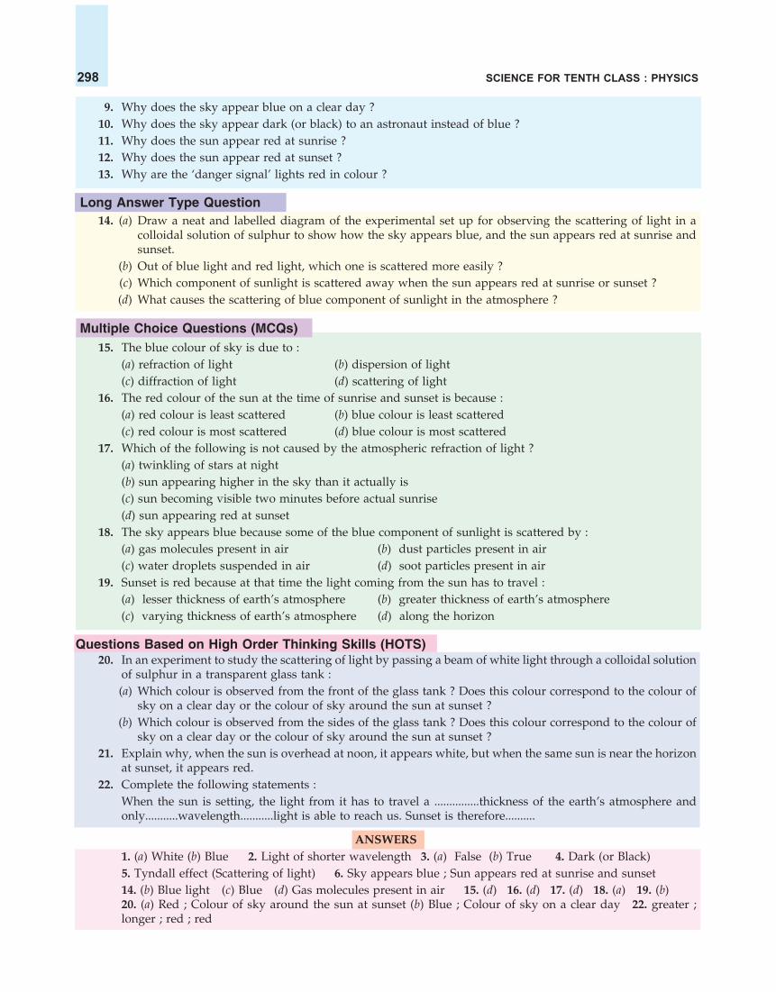
SCIENCE FOR TENTH CLASS : PHYSICS298
9. Why does the sky appear blue on a clear day ?10. Why does the sky appear dark (or black) to an astronaut instead of blue ?11. Why does the sun appear red at sunrise ?12. Why does the sun appear red at sunset ?13. Why are the ‘danger signal’ lights red in colour ?
Long Answer Type Question14. (a) Draw a neat and labelled diagram of the experimental set up for observing the scattering of light in a
colloidal solution of sulphur to show how the sky appears blue, and the sun appears red at sunrise andsunset.
(b) Out of blue light and red light, which one is scattered more easily ?(c) Which component of sunlight is scattered away when the sun appears red at sunrise or sunset ?(d) What causes the scattering of blue component of sunlight in the atmosphere ?
Multiple Choice Questions (MCQs)15. The blue colour of sky is due to :
(a) refraction of light (b) dispersion of light(c) diffraction of light (d) scattering of light
16. The red colour of the sun at the time of sunrise and sunset is because :(a) red colour is least scattered (b) blue colour is least scattered(c) red colour is most scattered (d) blue colour is most scattered
17. Which of the following is not caused by the atmospheric refraction of light ?(a) twinkling of stars at night(b) sun appearing higher in the sky than it actually is(c) sun becoming visible two minutes before actual sunrise(d) sun appearing red at sunset
18. The sky appears blue because some of the blue component of sunlight is scattered by :(a) gas molecules present in air (b) dust particles present in air(c) water droplets suspended in air (d) soot particles present in air
19. Sunset is red because at that time the light coming from the sun has to travel :(a) lesser thickness of earth’s atmosphere (b) greater thickness of earth’s atmosphere(c) varying thickness of earth’s atmosphere (d) along the horizon
Questions Based on High Order Thinking Skills (HOTS)20. In an experiment to study the scattering of light by passing a beam of white light through a colloidal solution
of sulphur in a transparent glass tank :(a) Which colour is observed from the front of the glass tank ? Does this colour correspond to the colour of
sky on a clear day or the colour of sky around the sun at sunset ?(b) Which colour is observed from the sides of the glass tank ? Does this colour correspond to the colour of
sky on a clear day or the colour of sky around the sun at sunset ?21. Explain why, when the sun is overhead at noon, it appears white, but when the same sun is near the horizon
at sunset, it appears red.22. Complete the following statements :
When the sun is setting, the light from it has to travel a ...............thickness of the earth’s atmosphere andonly...........wavelength...........light is able to reach us. Sunset is therefore..........
ANSWERS1. (a) White (b) Blue 2. Light of shorter wavelength 3. (a) False (b) True 4. Dark (or Black)5. Tyndall effect (Scattering of light) 6. Sky appears blue ; Sun appears red at sunrise and sunset14. (b) Blue light (c) Blue (d) Gas molecules present in air 15. (d) 16. (d) 17. (d) 18. (a) 19. (b)20. (a) Red ; Colour of sky around the sun at sunset (b) Blue ; Colour of sky on a clear day 22. greater ;longer ; red ; red

Multiple choice questions based on the experiment :To study the dependence of current (I) on the potential difference (V) across aresistor and determine its resistance. Also plot a graph between V and I.
1. To study the dependence of current (I) on the potential difference (V) across a resistor, the correct way ofconnecting the ammeter and voltmeter in the circuit is :(1) ammeter and voltmeter both are connected in series(2) ammeter is connected in parallel and voltmeter in series(3) ammeter is connected in series and voltmeter in parallel(4) ammeter and voltmeter both are connected in parallel
2. The following four circuitshave been made forstudying the dependence ofcurrent on the potentialdifference across a resistor.
The correct circuit is :
(1) A
(2) B
(3) C
(4) D
3. To study the dependence of current (I) on the potential difference (V) across a resistor, the followingobservations were made by four students A, B, C and D.
Student Reading No. 1 Reading No. 2 Reading No. 3
A V = 0.5 V V = 1.0 V V = 1.5 V
I = 0.1 A I = 0.2 A I = 0.3 A
B V = 0.8 V V = 1.6 V V = 2.4 V
I = 0.4 A I = 0.8 A I = 1.2 A
C V = 1.0 V V = 1.2 V V = 1.4 V
I = 0.5 A I = 1.4 A I = 1.0 A
D V = 2.4 V V = 2.7 V V = 3.0 V
I = 0.8 A I = 0.9 A I = 1.0 A
Multiple Choice Questions (MCQs)(Based on Practical Skills in Science)
+ –
+ –
(•)
A
V+ –
R
Rh
+ –
+–
(•)
A
V+ –
R
Rh
+ –
+–
(•)
A
V +–
R
Rh
+ –
+ –
(•)
A
V+–
R
Rh
(A) (B)
(C) (D)

SCIENCE FOR TENTH CLASS : PHYSICS300
The teacher found that one of the students has made wrong observations. The student who made the mistakeis :(1) A (2) B (3) C (4) D
4. Graphs plotted by four students A, B, C and D for the experiment “To study the dependence of current (I) onthe potential difference (V) across a resistor” are shown below :
I
V V V V
I I I
(A) (B) (C) (D)
The correct V–I graph is :(1) A (2) B (3) C (4) D
5. The following ‘precautions’ were listed by a student in the experiment on study of ‘Dependence of currenton potential difference’.
(A) Use copper wires as thin as possible for making connections.(B) All the connections should be kept tight.(C) The positive and negative terminals of the voltmeter and the ammeter should be correctly connected.(D) The ‘zero error’ in the ammeter and the voltmeter should be noted and taken into consideration while
recording the measurements.(E) The ‘key’ in the circuit, once plugged in, should not be taken out till all the observations have been
completed.The ‘precautions’ that need to be corrected and revised are :(1) (A), (C) and (E) (2) (C) and (E) (3) (B) and (E) (4) (A) and (E)
6. An ammeter has 20 divisions between 0 mark and 2 A mark on its scale. The least count of this ammeter is :(1) 0.01 A (2) 0.02 A (3) 0.1 A (4) 0.2 A
7. A student finds that there are 20 divisions between the 0 mark and 1 V mark of a voltmeter. What is the leastcount of this voltmeter ?(1) 0.50 V (2) 0.02 V (3) 0.2 V (4) 0.05 V
8. Which of the following instruments does not have plus (+) or minus (–) sign marked on it while representingin a circuit diagram ?(1) Rheostat (2) Voltmeter (3) Ammeter (4) Cell
9. To study the dependence of current (I) on the potential difference (V) across a resistor R, two students usedthe two set ups shown in Figures A and B respectively. They kept the contact point J in four differentpositions, marked (a), (b), (c) and (d) in the two figures.
(A) (B)For the two students, the ammeter and voltmeter readings will be maximum when the contact J is in theposition :(1) (d) in both the set ups (2) (a) in both the set ups(3) (d) in set up A and (a) in set up B (4) (a) in set up A and (d) in set up B

MULTIPLE CHOICE QUESTIONS (MCQs) 301
10. In the circuit given below, the instrument B reads 0.93 and the instrument A reads 1.80 in their respective SIunits.
Unknownresistor
A B
The value of unknown resistor will be :(1) 0.51 Ω (2) 1.63 Ω (3) 1.93 Ω (4) 19.3 Ω
11. Four identical cells of emf 1.5 V each were connected in four different ways as shown below :
X
X Y
Y
Y
YX
X
(A)
(C)
(B)
(D)
The potential difference between the points X and Y would be equal to 6.0 V in case/cases :(1) A and B (2) A and C (3) A and D (4) A only
12. The scale of an ammeter is shown below :
0
1 2
3
A
The least count of this ammeter is :(1) 0.05 A (2) 0.5 A (3) 0.1 A (4) 1 A
13. The least count of the voltmeter shown below is :
V0
1 2
3
(1) 0.1 V (2) 0.01 V (3) 0.02 V (4) 0.2 V14. Consider the following circuits :
( )
V –+
+ –
+
–A
( ) + –
–
+V
( )
+ –A
+ –
+
–V A
+
–
+ –( )
(A) (B) (C) (D)On plugging the key, the voltmeter/ammeter is likely to be damaged :(1) in circuit A (2) in circuit B (3) in circuit C (4) in circuit D
15. The rest positions of the needles in a Milliammeter and Voltmeter when not being used in a circuit are asshown in the figure. The ‘zero error’ and ‘least count’ of these two instruments are :

SCIENCE FOR TENTH CLASS : PHYSICS302
(1) (+4 mA, – 0.2 V) and (1 mA, 0.1 V) respectively (2) (+4 mA, – 0.2 V) and (2 mA, 0.2 V) respectively(3) (– 4 mA, + 0.2 V) and (2 mA, 0.2 V) respectively (4) (– 4 mA, + 0.2 V) and (2 mA, 0.1 V) respectively
16. A student has to connect 4 cells of 2 V each to form a battery of voltage 8 V. The correct way of connectingthese cells is shown in figure :(1) A (2) B (3) C (4) D
(A) (B) (C) (D)
17. To study the dependence of current (I) on the potential difference (V) across a resistor, two students used thetwo set ups shown in figs (A) and (B) respectively. They kept the contact J in four different positions, marked(a), (b), (c), (d) in the two figures.
(A) (B)For the two students, their Ammeter and Voltmeter readings will be minimum when the contact J is in theposition :(1) (a) in both the set ups (2) (d) in both the set ups(3) (d) in set up (A) and (a) in set up (B) (4) (a) in set up (A) and (d) in set up (B)
18. In the circuits A, B, C and D, with switch S open, the lamps Q and R would light up but not lamp P in :
SP Q R P
SQ R P Q
SR P Q R
S
(1) circuit A (2) circuit B (3) circuit C (4) circuit D19. The rest positions of the needles in a
milliammeter and voltmeter not inuse are as shown in Fig. A. When astudent uses these in his experiment,the readings of the needles are in thepositions shown in Fig. B. Thecorrected values of current andvoltage in the experiment are(1) 42 mA and 3.2 V(2) 42 mA and 4.0 V(3) 34 mA and 3.2 V(4) 34 mA and 4.0 V
mA
100
V
1
0
mA
30
40
4
3
V
(A) (B)
(C)(B)(A) (D)

MULTIPLE CHOICE QUESTIONS (MCQs) 303
20. The current flowing through a resistor connected in an electric circuit and the potential difference appliedacross its ends are shown in the figures below :
0
100 200
300 0
1 2
3mA V
The value of the resistance of the resistor is :(1) 10 Ω (2) 15 Ω (3) 20 Ω (4) 25 Ω
21. Consider the following circuit diagrams drawn by four students :
R
+ –V
+
–A
+ – ( )
R
+ –
V–
+
+ – ( )
A
V+–
+
–
A
+ – ( )
R
V+ –
+ –A
+ – ( )
R
(A) (B)
(C) (D)
The correct circuit diagram for studying the dependence of current on the potential difference across aresistor is :(1) A (2) B (3) C (4) D
22. The scale of an ammeter is shown below :
A0
2
6
4
The least count of this ammeter is :(1) 0.1 A (2) 0.01 A (3) 0.02 A (4) 0.2 A
23. The figure below shows the scale of a voltmeter.
V0
0.5
1.5
1.0
The least count of this voltmeter is :(1) 1 V (2) 0.5 V (3) 5 V (4) 0.05 V

SCIENCE FOR TENTH CLASS : PHYSICS304
24. A student used the set up given here to study the dependence of current(I) on the potential difference (V) across a resistor.He kept the contact C in four different positions marked as P,Q, R and S
in the figure. On calculating the values of the ratio VI
for his four
readings, he would find that the value of this ratio :
(1) for contact at point P is 1
th4
of that for contact at point S.
(2) for contact at point Q is 2
th4
of that for contact at point S.
(3) for contact at point R is 3
th4
of that for contact at point S.
(4) is the same for all the four readings25. You are given the following four voltmeters to study the dependence of current (I) on the potential difference
(V) across a resistor.
0
12
3 0
12
3 0
12
3 0
12
3
V V V V
(A) (B) (C) (D)Which one of the above voltmeters would you prefer to use in the circuit to begin your experiment ?(1) A (2) B (3) C (4) D
26. A student arranged an electric circuit as shown alongside :He would observe :(1) no reading in either the ammeter or the voltmeter(2) no reading in the voltmeter but a reading in the ammeter(3) no reading in the ammeter but a reading in the voltmeter(4) readings in both the ammeter and the voltmeter
27. Four students recorded the readings of the current by observing theposition of pointer on the ammeter scale given below :
0
1 2
3A
If there is no zero error, the correct reading of current is :(1) 2.3 A (2) 5 A (3) 2.0 A (4) 2.05 A
28. The least count of the ammeter shown below is :
0
0.5 1.0
1.5A
(1) 0.05 A (2) 0.5 A (3) 0.1 A (4) 1 A
+A
R
V
–
+ – + – + – + –
P Q R S
C
+ –
(•)
A
+
–
+ –
+ –V
R
(•)
( )

MULTIPLE CHOICE QUESTIONS (MCQs) 305
29. Four students measured the reading by observing the position of pointer on the ammeter scale as shownbelow :
0
0.5 1.0
1.5A
Assuming that the ammeter has no zero error, the correct reading is :(1) 1.25 A (2) 1.30 A (3) 1.15 A (4) 1.1 A
30. Four students recorded the readings of the potential differece by observing the position of the pointer of anideal voltmeter as shown below :
0
1 2
3V
The correct reading is :(1) 2.5 V (2) 2.0 V (3) 2.2 V (4) 2.4 V
Multiple Choice questions based on the experiments :To determine the equivalent resistance of two resistors (i) when connected in series(ii) when connected in parallel.
31. In an experiment to find the equivalent resistance of two resistors connected in series, a student uses thecircuit shown :
This circuit will give :
(1) correct reading for voltage V but incorrect readingfor current I
(2) correct reading for current I but incorrect readingfor voltage V
(3) correct readings for both voltage V and current I
(4) Incorrect readings for both current I and voltage V
32. A student sets up an electric circuit shown here for finding the equivalent resistance of two resistors in series:
+ –V
A
+
– R1
R2
+ – (•)
A
+ –
+ –
+ –
4.5 V
(•)Rh
R1 R2
V
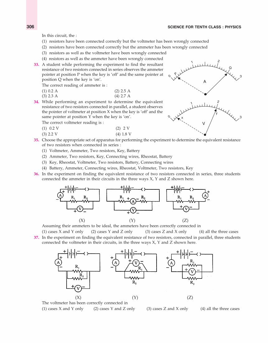
SCIENCE FOR TENTH CLASS : PHYSICS306
In this circuit, the :(1) resistors have been connected correctly but the voltmeter has been wrongly connected(2) resistors have been connected correctly but the ammeter has been wrongly connected(3) resistors as well as the voltmeter have been wrongly connected(4) resistors as well as the ammeter have been wrongly connected
33. A student while performing the experiment to find the resultantresistance of two resistors connected in series observes the ammeterpointer at position P when the key is ‘off‘ and the same pointer atposition Q when the key is ‘on’.The correct reading of ammeter is :(1) 0.2 A (2) 2.5 A(3) 2.3 A (4) 2.7 A
34. While performing an experiment to determine the equivalentresistance of two resistors connected in parallel, a student observesthe pointer of voltmeter at position X when the key is ‘off’ and thesame pointer at position Y when the key is ‘on’.The correct voltmeter reading is :(1) 0.2 V (2) 2 V(3) 2.2 V (4) 1.8 V
35. Choose the appropriate set of apparatus for performing the experiment to determine the equivalent resistanceof two resistors when connected in series :(1) Voltmeter, Ammeter, Two resistors, Key, Battery(2) Ammeter, Two resistors, Key, Connecting wires, Rheostat, Battery(3) Key, Rheostat, Voltmeter, Two resistors, Battery, Connecting wires(4) Battery, Ammeter, Connecting wires, Rheostat, Voltmeter, Two resistors, Key
36. In the experiment on finding the equivalent resistance of two resistors connected in series, three studentsconnected the ammeter in their circuits in the three ways X, Y and Z shown here.
(X) (Y) (Z)Assuming their ammeters to be ideal, the ammeters have been correctly connected in(1) cases X and Y only (2) cases Y and Z only (3) cases Z and X only (4) all the three cases
37. In the experiment on finding the equivalent resistance of two resistors, connected in parallel, three studentsconnected the voltmeter in their circuits, in the three ways X, Y and Z shown here.
(X) (Y) (Z)The voltmeter has been correctly connected in(1) cases X and Y only (2) cases Y and Z only (3) cases Z and X only (4) all the three cases
0
1 2
3P
Q
A
0
12
3
V
xy

MULTIPLE CHOICE QUESTIONS (MCQs) 307
38. The only correct statement for the following electric circuit is :
(1) The Voltmeter has been correctly connected in the circuit(2) The Ammeter has been correctly connected in the circuit(3) The Resistors R1 and R2 have been correctly connected in series(4) The Resistors R1 and R2 have been correctly connected in parallel
39. The only correct statement for the two circuits (X) and (Y) shown below is :
(1) The resistors R1 and R2 have been connected in series in both the circuits(2) The resistors R1 and R2 have been connected in parallel in both the circuits(3) In the circuit (X) the resistors have been connected in parallel whereas these are connected in series in
circuit (Y).(4) In the circuit (X) the resistors R1 and R2 are connected in series while these are connected in parallel in
circuit (Y)40. For three circuits, shown here
the same two resistors R1 and R2 have been connected in parallel in all the circuits but the voltmeter and theammeter have been connected in three different positions. The relation between the three voltmeter andammeter readings would be :(1) V1 = V2 = V3 and I1 = I2 = I3
(2) V1 ≠ V2 ≠ V3 and I1 = I2 = I3
(3) V1 = V2 = V3 and I1 ≠ I2 ≠ I3
(4) V1 ≠ V2 ≠ V3 and I1 ≠ I2 ≠ I3
41. Two students (A) and (B) connect their two given resistors R1 and R2 in the manners shown below :
+ –= V1
+
R1
= I1R2
+ –
= I2
+ – R1
+ –
= V2+ –
R2
R1
+
–
=V3
R2= I3
+
–
+
AV
A – V A
V –
(A) (B)
(X) (Y)

SCIENCE FOR TENTH CLASS : PHYSICS308
Student (A) connects the terminals marked (b1) and (c1) while student(B) connects the terminals marked (d2) and (c2) in their respectivecircuits at the points marked X and Y.Which one of the following is correct in relation to abovearrangements ?
(1) both the students will determine the equivalent resistance of theseries combination of the two resistors.
(2) both the students will determine the equivalent resistance of the parallel combination of the two resistors.(3) student (A) will determine the equivalent resistance of the series combination while student (B) will
determine the equivalent resistance of the parallel combination of the two resistors.(4) student (A) will determine the equivalent resistance of the parallel combination while student (B) will
determine the equivalent resistance of the series combination of the two resistors.
42. Three students (A), (B) and (C) connect their two given resistors R1 and R2 in the manners shown below :
(A) (B) (C)They connect the terminals marked X and Y above to the terminals marked X and Y in the circuit givenbelow :
They record the Ammeter readings (I) for different positions of the rheostat and the corresponding Voltmeterreadings (V).The average value of the ratio V/I in their observations would be minimum for :(1) students (A) and (B) only (2) students (B) and (C) only(3) students (C) and (A) only (4) student (A) only
43. Students A and B connect the two resistors R1 and R2 given to them in the manners shown below :
(A) (B)and then insert them at X and Y into the measuring circuit shown below :
We can then say that(1) both the students will determine the equivalent resistance of the series combination of R1 and R2

MULTIPLE CHOICE QUESTIONS (MCQs) 309
(2) both the students will determine the equivalent resistance of the parallel combination of R1 and R2
(3) student A will determine the equivalent resistance of the series combination while student B will determinethe equivalent resistance of the parallel combination of R1 and R2
(4) student A will determine the equivalent resistance of the parallel combination while student B willdetermine the equivalent resistance of the series combination of R1 and R2
44. A student carries out the experiment for studying the dependence of current (I) flowing through a resistorsystem of R1 and R2 on the potential difference (V) applied to it by connecting the resistor system to pointsX and Y of the measuring circuit as shown :
The average value of the ratio V/I, of his observations, would then be equal(1) only in cases A and B (2) only in cases B and C(3) only in cases C and A (4) all the three cases
45. Four students performed experiments on series and parallel combination of two given resistors R1 and R2which obey Ohm’s law and plotted the following V–I graphs :
Parallel
Series
I
V
I
Parallel
Series
V
I
Parallel
Series
I
Series
Parallel
V V
(A) (B) (C) (D)Which of the graphs is correctly labelled in terms of ‘series’ and ‘parallel’ ?(1) graph A (2) graph B (3) graph C (4) graph D
46. You are given four ammeters A, B, C and D having the least counts mentioned below :(a) Ammeter A with least count 0.25 A (b) Ammeter B with least count 0.5 A(c) Ammeter C with least count 0.05 A (d) Ammeter D with least count 0.1 AWhich of the ammeters would you prefer for doing an experiment to determine the equivalent resistance oftwo resistances most accurately, when connected in parallel ?(1) A (2) B (3) C (4) D
47. Consider the two circuits A and Bgiven alongside :In the circuits A and B shown here,the voltmeter reading would be :
(A) (B) (C)
+ –V
–
+
2 � 2 �
A
4.5 V
( )
+
–
+ –
A4 �
4 �
4.5 V
(•)
V
(A) (B)

SCIENCE FOR TENTH CLASS : PHYSICS310
(1) nearly 4.5 V in both the circuits(2) 0 V in both the circuits(3) nearly 1 V for circuit A and nearly 4.5 V for circuit B.(4) 0 V for circuit A and nearly 4.5 V for circuit B.
48. The values of resistances marked on the coils R1 and R2 are found to be correct. A student connects the givenresistors in the following manner (as shown in Figure 1).
X Y
R1 R2
3 � 6 �
X Y
–
++ –
( •)
A
V+ –
Figure 1. Figure 2.He then connects the terminals marked X and Y of the above combination of resistors R1 and R2 to theterminals marked X and Y in the circuit (shown in Figure 2).The average value of the ratio V/I in the observations recorded in the circuit would be :(1) 9 Ω (2) 6 Ω (3) 3 Ω (4) 2 Ω
49. A student using the same two resistors, ammeter, voltmeter and battery, sets up two circuits A and B connectingthe two resistors first in series and then in parallel.
V –+
V1
R1 R2I1
–
+A
+ –(•)
V
V2
+ –
R1
R2
+ –(•)
I2
+
–
A
(A) (B)If the ammeter and voltmeter readings in the two cases be I1, I2 and V1, V2 respectively, he is likely to observethat :(1) I1 = I2 but V1 ≠ V2 (2) I1 < I2 but V1 = V2
(3) I1 > I2 but V1 = V2 (4) I1 = I2 and V1 = V2
50. Two students made two circuits A and B to determine the resultant resistance of two resistors R1 and R2connected in series :
R2
–
R1
––
+
+
+A V
(•)
A V
+ –
–
++ –
R2R1
(•)
(A) (B)All the components have been connected correctly in :(1) circuit A only (2) circuit B only(3) both circuits A and B (4) neither of the two circuits

MULTIPLE CHOICE QUESTIONS (MCQs) 311
51. Four students have made the following circuit diagrams for determining the equivalent resistance of tworesistors connected in series :
AR2
+ A –
+ –V
+ –
R1
Rh( )
+ –
R1 R2
+ –
Rh
V
V– +
R1R2
Rh
+ –
A–+
( )
V
A– +
+ –
R2R1
( )+ –
Rh
+ –
( )
The correct circuit diagram is :(1) A (2) B (3) C (4) D
52. Consider the following four circuits P, Q, R and S which have been set up to find the resultant resistance oftwo resistors combined in parallel :
R2
A+
–V
+ –
R1
Rh( )
–
+
R2
A
+
–
V
+ –
R1
Rh( )
–
+
R2
–V
+ –
R1
Rh( )
+
+ –
R2
–A
+ –
R1
Rh( )
+
+ –VA
The correct way of connecting the ammeter and voltmeter in the circuit is :(1) P (2) Q (3) R (4) S
53. In order to determine the equivalent resistance of two resistors R1and R2 connected in series, a student made this circuit for hisexperiment.The only statement which is true for this circuit is that it gives :
(1) incorrect readings for current I as well as for potentialdifference V
(2) correct reading for current I but incorrect reading for potentialdifference V
(A) (B)
(C) (D)
(P) (Q )
(R) (S)
+ –
R1
+ –
V
A
R2
+ –(•)

SCIENCE FOR TENTH CLASS : PHYSICS312
(3) incorrect reading for current I but correct reading for potential difference V(4) correct readings for both current I and potential difference V.
54. To find the resultant resistance of two resistors when connectedin series, a student arranged the various components accordingto the circuit shown alongside :The student, however, did not succeed in his objective. Whichof the following mistake has been made by the student in settingup the circuit ?(1) position of voltmeter is wrong(2) position of ammeter is wrong(3) terminals of voltmeter are wrongly connected(4) terminals of ammeter are wrongly connected
55. The following apparatus is available in the school laboratory :Battery : 4.5 VRheostat : Varies battery voltage from 0 to 4.5 VResistors : 1 Ω and 2 ΩAmmeters : A1 of range 0 to 1 A ; Least count 0.05 A
: A2 of range 0 to 3 A ; Least count 0.1 AVoltmeters : V1 of range 0 to 5 V ; Least count 0.1 V
V2 of range 0 to 10 V ; Least count 0.5 VThe best combination of ammeter and voltmeter for finding the resultant resistance of the two given resistorsconnected in series would be :(1) ammeter A1 and voltmeter V1 (2) ammeter A1 and voltmeter V2
(3) ammeter A2 and voltmeter V1 (4) ammeter A2 and voltmeter V2
56. The science laboratory in a school has the following apparatus available in it :Battery : 6 VRheostat : Varies battery voltage from 0 to 6 VResistors : 3 Ω and 6 ΩAmmeters : A1 of range 0 to 5 A ; Least count 0.25 A
: A2 of range 0 to 3 A ; Least count 0.1 AVoltmeters : V1 of range 0 to 10 V ; Least count 0.5 V
: V2 of range 0 to 5 V ; Least count 0.1 VFor the experiment to determine the equivalent resistance of the two given resistors connected in parallel,the best combination would be :(1) ammeter A1 and voltmeter V2 (2) ammeter A2 and voltmeter V1
(3) ammeter A1 and voltmeter V1 (4) ammeter A2 and voltmeter V2
57. The ammeter, voltmeter and, resistors R1 and R2 connected in the circuit as shown below have been checkedand found to be correct.On plugging the key, the voltmeter reads 4.5 V but the ammeterreads 1.5 A. This is most likely because the wires joined to :
(1) resistor R1 are loose
(2) resistor R2 are loose
(3) both the resistors R1 and R2 are loose(4) ammeter terminals are loose
A+ –(•)
R1 R2
+ –V
+ –
A
V
R1 = 3 �
R2 = 6 �
+
–
+ –
4.5 V
(•)

MULTIPLE CHOICE QUESTIONS (MCQs) 313
Multiple choice questions based on the experiment :To determine the focal length of a concave mirror.
58. A student determines the focal length of a device X, by focussing the image ofa far off object on the screen positioned as shown in the figure alongside.
The device X is a :
(1) Convex lens
(2) Concave lens
(3) Convex mirror
(4) Concave mirror
59. The focal length of the concave mirror in theexperimental set up, shown alongside, equals :
(1) 10.3 cm
(2) 11.0 cm
(3) 11.7 cm
(4) 12.2 cm
60. While determining the focal length of a concave mirror, a student obtained the image of a distant object on ascreen. In order to get the focal length of the mirror, the student should measure the distance :
(1) between the object and the mirror only (2) between the screen and the mirror only(3) between the object and the screen only(4) between the screen and mirror as well as between the screen and the object
61. A student gets a blurred image of a distant object on a screen which is fixed at a place. In order to obtain asharp image on the screen, he will have to shift the mirror :(1) towards the screen (2) away from the screen(3) either towards or away from the screen (4) very far away from the screen
62. Four students A, B, C and D performed the experiment to determine the focal length of a concave mirror byobtaining the image of a distant tree on a screen. They measured the distances between the screen and themirror as shown in the diagrams given below :
(A) (B) (C) (D)The correct value for focal length will be obtained by the student :(1) A (2) B (3) C (4) D
63. A student has to do the experiment on finding the focal length of a given concave mirror by using a distantobject. Out of the following ‘set-ups’ A, B, C and D available to him :A : a screen, a mirror holder and a scaleB : a mirror holder, a screen holder and a scaleC : a screen holder and a scaleD : a mirror holder and a scaleThe ‘set-up’ which is likely to give him the best result is :(1) A (2) B (3) C (4) D

SCIENCE FOR TENTH CLASS : PHYSICS314
64. Four students A, B, C and D performed an experiment to determine the focal length of a concave mirror byusing a lighted candle kept at a considerable distance as the object. They represented the position of imageby drawing the following diagrams :
C F P C F P
C F P C F P
Which diagram describes the correct position of the image of the candle ?(1) A (2) B (3) C (4) D
65. The parallel rays from the top of a distant tree are incident on a concave mirror forming its image on ascreen.
The diagram which shows the image of the tree on the screen correctly is :(1) A (2) B (3) C (4) D
66. In order to determine the focal length of a concave mirror, a student obtained a sharp image of the grill of awindow in the laboratory wall on a screen. His teacher suggested that to get better result for focal length, heshould focus a distant tree instead of the window grill. In which direction should the mirror be moved forthis purpose so as to get a sharp image of the tree on the screen ?(1) behind the screen (2) away from the screen(3) towards the screen (4) very far away from the screen
67. In order to determine the focal length of a concave mirror, a student obtained the sharp image of a distanttree on a screen. In order to obtain a sharp image of a window grill of the laboratory on the same screen, inwhich direction should the screen be moved ?(1) very close to the mirror (2) very far away from the mirror(3) slightly nearer to the mirror (4) slightly farther away from the mirror
Multiple choice questions based on the experiment :To determine the focal length of a convex lens.
68. A student performs an experiment on finding the focal length of a convex lens by keeping a lighted candleon one end of laboratory table, a screen on its other end and the lens between them as shown in the figure.The positions of the three are adjusted to get a sharp image of the candle flame on the screen.If now the candle flame were to be replaced by a distant lamp on a far away electric pole, the student wouldbe able to get a sharp image of this distant lamp on the screen by moving :
(A) (B)
(C) (D)
(A) (B) (C) (D)

MULTIPLE CHOICE QUESTIONS (MCQs) 315
(1) the screen in the direction of the lens or the lens in the direction of the screen(2) the screen in the direction of the lens or the lens away from the screen(3) the screen away from the lens or the lens in the direction of the screen(4) neither the screen nor the lens.
69. A student obtained a sharp image of the grill of a window in the laboratory on a screen, using a convex lens.For getting better results, her teacher suggested focussing of a distant tree instead of the grill. In whichdirection should the lens be moved for this purpose to get a sharp image on the screen ?
(1) Towards the screen (2) Away from the screen(3) Behind the screen (4) Very far away from the screen
70. A sharp image of a distant object is obtained on a screen by using a convex lens. In order to determine thefocal length of the lens, you need to measure the distance between the :(1) lens and the object (2) lens and the screen(3) object and the screen (4) lens and the screen and also between object and the screen
71. While performing the experiment to determine the focal length of a convex lens by using the sun as thedistant object, a student could not find a screen with stand. In the absence of a good screen, which of thefollowing method is the most appropriate and safe to be used by the student ?
(1) He should focus the image of the sun on his hand(2) He should focus the image of the sun on his nylon shirt(3) He should focus the image of the sun on a wall of the room(4) He should focus the image of the sun on a carbon paper
72. While performing an experiment on determining the focal length of a convex lens, a student obtains a sharpinverted image of the laboratory window grill on the screen and measures the distance between the screenand the lens. She then repeats the experiment and takes a distant tree as the object in the second case. Inorder to get a sharp image of the tree on the screen, she will now have to move the screen :(1) slightly nearer to the lens (2) slightly farther away from the lens(3) very close to the lens (4) very far away from the lens
73. While performing the experiment on the determination of focal length of a convex lens, four students obtainedthe image of the same distant tree on the screen :
(A) (B) (C) (D)Which diagram shows the formation of image correctly ?(1) A (2) B (3) C (4) D
74. A student was given the following suggestions by his classmates for performing the experiment on findingthe focal length of a convex lens :
(A) Select any object very far away from the laboratory window(B) Select a well illuminated object far (but not very far) from the laboratory window(C) Keep all the lights of the laboratory on(D) Place the lens between the object and the screen
Candle (C) Lens (L)Screen (S)

SCIENCE FOR TENTH CLASS : PHYSICS316
(E) Place the screen between the object and the lens(F) Obtain the sharpest image of the object on the screenHe can perform the experiment better by following the suggestions :(1) A, D, F (2) B, C, E (3) C, F, B (4) D, F, B
75. For performing an experiment, a student was asked to choose one concave mirror and one convex lens froma lot of mirrors and lenses of different kinds. The correct procedure adopted by her will be :
(1) To choose a mirror and lens which can form an enlarged and erect image of an object.(2) To choose a mirror which can form a diminished and erect image and a lens which can form an enlarged
and erect image of the object.(3) To choose a mirror which can form an enlarged and erect image and a lens which can form a diminished
and erect image of an object.(4) To choose a mirror and a lens which can form a diminished and erect image of an object.
76. A teacher gives a convex lens and a concave mirror of focal length of about 20 cm each to his student andasks him to find their focal lengths by obtaining the image of a distant object. The student uses a distant treeas the object and obtains its sharp image, one by one, on a screen. The distances d1 and d2 between the lens/mirror and the screen in the two cases and the nature of their respective sharp images are likely to be :(1) (20 cm, 40 cm) and (erect, erect) (2) (20 cm, 40 cm) and (inverted, erect)(3) (20 cm, 20 cm) and (inverted, inverted) (4) (20 cm, 20 cm) and (erect, inverted)
77. Three students measured the focal length of a convex lens using parallel rays from a distant object. All ofthem measured the distance between the lens and the inverted image on the screen.(i) Student A saw a sharp image on the screen and labelled the distance as f1
(ii) Student B saw a slightly larger blurred image on the screen and labelled the distance as f2(iii) Student C saw slightly smaller blurred image on the screen and labelled the distance as f3
The relation between the three measurements would most likely be :(1) f1 = f2 = f3 (2) f1 < f2 < f3 (3) f3 < f1 < f2 (4) f1 < f2 and f1 = f3
78. A student has to do the experiment on finding the focal length of a given convex lens by using a distantobject. She can do her experiment if she is also made available :(1) a lamp and a screen (2) a scale and a screen(3) a lamp and a scale (4) only a screen
79. A student performs an experiment to estimate the focal length of a convex lens by obtaining the image of adistant window on a white screen. The image formed on the white screen is :(1) virtual, erect and magnified (2) real, erect and magnified(3) real, inverted and diminished (4) virtual, inverted and diminished
80. Four students A, B, C and D performed an experiment to determine the focal length of a convex lens byusing a lighted candle kept at a considerable distance as the object. They represented the position of imageby drawing the following diagrams :
F
O
F 2F F F 2F
F
O
F 2F F F 2F
O
O
Which diagram describes the correct position of image of the candle ?(1) A (2) B (3) C (4) D
(A) (B)
(D)(C)

MULTIPLE CHOICE QUESTIONS (MCQs) 317
Multiple choice questions based on the experiment :To trace the path of a ray of light through a rectangular glass slab for differentangles of incidence. Measure the angle of incidence, angle of refraction, angle ofemergence and interpret the results.
81. A student performs the experiment on tracing the path of a ray of light passing through a rectangular glassslab for different angles of incidence. He measures the angle of incidence – i, angle of refraction – r andangle of emergence – e for all his observations. He would find that in all cases :(1) – i is more than – r but (nearly) equal to – e (2) – i is less than – r but (nearly) equal to – e(3) – i is more than – e but (nearly) equal to – r (4) – i is less than – e but (nearly) equal to – r
82. A student does the experiment on tracing the path of a ray of light passing through a rectangular glass slabfor different angles of incidence. He can get a correct measure of the angle of incidence and the angle ofemergence by following the labelling indicated in figure :
(A) (B) (C) (D)
(1) A (2) B (3) C (4) D83. A student suggested the following ‘guidelines’ to his friend for doing the experiment on tracing the path of
a ray of light passing through a rectangular glass slab for three different angles of incidence :A. Draw the ‘outline’ of the glass slab at three positions on the drawing sheet.B. Draw ‘normals’ on the top side of these ‘outlines’ very near their left end.C. Draw the incident rays on the three ‘outlines’ in directions making angles of 30°, 45°, 60° with the normals
drawn.D. Fix two pins vertically on each of these incident rays at two points nearly 1 cm apart.E. Look for the images of the ‘heads’ of these pins while fixing two pins from the other side, to get the
refracted rays.When he showed these ‘guidelines’ to his teacher, the teacher corrected and modified the ‘guidelines’labelled as(1) B, C, E (2) B, D, E (3) B, C, D (4) C, D, E
84. A student traces the path of a ray of light passing through a rectangular glass slab.
For measuring the angle of incidence, he must position the protractor in the manner shown in figure :
(1) A (2) B (3) C (4) D85. A student performed the experiment of glass slab and with
different angles of incidence measured the angles ofrefraction and emergence in each case. He then recordedhis observations as given in the table.The correct observation is :(1) A (2) B(3) C (4) D
S.No. Angle of Angle of Angle ofincidence refraction emergence
A 30° 25° 30°B 40° 42° 40°C 50° 50° 50°D 60° 60° 62°

SCIENCE FOR TENTH CLASS : PHYSICS318
86. Four students A, B, C and D showed the following traces of the path of a ray of light passing through arectangular glass slab.
(A) (B) (C) (D)The trace most likely to be correct is that of student :(1) A (2) B (3) C (4) D
87. In an experiment on tracing the path of a ray of light through a rectangular glass slab, four students A, B, Cand D used the following values of the angle of incidence and the distance between the feet of the two pins(fixed on the incident rays) :(A) 30°, 45°, 60° and 1 cm (B) 30°, 45°, 60° and 6 cm(C) 20°, 50°, 80° and 10 cm (D) 20°, 50°, 80° and 15 cmOut of these, the best choice is that of the student :(1) A (2) B (3) C (4) D
88. A student while doing the experiment on tracing the path of a ray of light passing through a rectangularglass slab measured the three angles marked as θ1, θ2 and θ3 in the figure.
�1
�2
�3
His measurements could be correct if he were to find :(1) θ1< θ2 < θ3 (2) θ1 < θ2 but θ1 = θ3 (3) θ1 > θ2 > θ3 (4) θ1 > θ2 but θ2 = θ3
89. In the experiment ontracing the path of a rayof light passing througha rectangular glass slab,the correct setting of theprotractor (D), formeasuring the angle ofincidence ( i∠ ), and theangle of emergence( e∠ ) correspond, respectively, to diagrams :(1) K and M (2) K and N (3) L and M (4) L and N
90. Four students A, B, C and D selected the following items from the materials available in the science laboratoryto perform an experiment to study the refraction of light through a glass slab :(A) convex lens, glass slab, pins, drawing board, white paper, scale(B) glass slab, pins, drawing board, scale, white paper, protractor(C) glass slab, glass prism, candle, screen, pins, scale, drawing board, protractor(D) concave mirror, pins, glass slab, protractor, white paper, drawing boardCorrect choice of the items required is made by the student :(1) A (2) B (3) C (4) D
(K) (L) (M) (N)

MULTIPLE CHOICE QUESTIONS (MCQs) 319
91. In an experiment to trace the path of a ray of light passing through a rectangular glass slab, four studentsmeasured the angles of incidence (i), angles of refraction (r) and angles of emergence (e) as shown in thediagrams :
i
r
e
i
r
e
i
r
e
i
r
e
The correct measurement is given in the diagram :(1) A (2) B (3) C (4) D
92. A teacher asked four students to record the observations of the experiment on tracing the path of a ray oflight through a rectangular glass slab. The students recorded their observations under the following headings :(1) Angle of incidence, Angle of refraction, Angle of reflection(2) Angle of incidence, Angle of deviation, Angle of emergence(3) Angle of incidence, Angle of reflection, Angle of emergence(4) Angle of incidence, Angle of refraction, Angle of emergenceThe correct observations were recorded by the student :(1) A (2) B(3) C (4) D
93. An experiment for tracing the path of a ray of light through a glass slabwas set up in the laboratory and ray diagram was drawn as shown here.The teacher asked the students to identify the refracted ray. The correctanswer is :(1) SR (2) RQ(3) N1N2 (4) QP
94. A student traces the path of a ray of light passing through arectangular glass slab for three different values of angle ofincidence ( i∠ ) namely 30°, 45° and 60°. He extends the directionof incident ray by a dotted line and measures the perpendiculardistance ‘l’ between the extended incident ray and the emergentray. He will observe that :
(1) ‘l’ keeps on increasing with increase in angle of incidence(2) ‘l’ keeps on decreasing with increase in angle of incidence(3) ‘l’ remains the same for all three angles of incidence.(4) ‘l’ is the maximum for 45i∠ = ° and is less than this value
both for 30i∠ = ° and 60i∠ = °
95. A ray of light is incident on a parallel-sided glass slab as shown in thefigure. The angle of refraction for this ray of light is likely to be :(1) 60° (2) 33°(3) 57° (4) 30°
l
i
60°
30°90°
Air
Glass
33°
57°90°
P
Q
S
N1
N2
N3
N4
R
(A) (B) (C) (D)

SCIENCE FOR TENTH CLASS : PHYSICS320
96. In an experiment to study the refraction of light through a rectangular glass slab, a student measured theangle of incidence, angle of refraction and the angle of emergence. The student lost the reading of angle ofincidence but noted the readings of angle of refraction to be 35° and angle of emergence to be 65°. The angleof incidence is likely to be :(1) 45° (2) 55° (3) 35° (4) 65°
97. In the glass slab experiment, a student measures the angle of incidence ( i∠ ) in air and finds it to be 40°. Healso measured the corresponding angle of refraction as well as the angle of emergence for this ray of lightbut lost their record. The most likely record of readings for the angle of incidence and angle of emergencewill be :
(1) 40r∠ = ° and 50e∠ = ° (2) 40r∠ > ° and 50e∠ = °(3) 50r∠ = ° and 40e∠ = ° (4) 40r∠ < ° and 40e∠ = °
98. In the experiment to trace the path of a ray of light through a parallel sided glass slab, a student measuredthe angles of refraction for three different angles of incidence. He will find that :
(1) angle of refraction is always equal to the angle of incidence(2) angle of refraction is always smaller than the angle of incidence(3) angle of refraction is always greater than the angle of incidence(4) angle of refraction can be smaller or greater than the angle of incidence depending on the refractive
index of glass slab99. Which of the following is the best set-up for tracing the path of a ray of light through a rectangular glass slab
?
(A) (B) (C) (D)(1) A (2) B (3) C (4) D
100. A student performs an experiment with glass slab to trace the path of a ray of light entering from air intoglass slab and emerging into air again. On looking carefully at the trace obtained on paper, he will observethat the emergent ray and the incident ray :(1) are converging (coming closer to each other) (2) are diverging (moving away from each other)(3) are perpendicular (at right angles to each other) (4) are parallel (at equidistant from each other)
ANSWERS
01. 3 02. 1 03. 3 04. 2 05. 4 06. 3 07. 408. 1 09. 3 10. 3 11. 2 12. 3 13. 4 14. 315. 4 16. 1 17. 4 18. 2 19. 1 20. 1 21. 122. 4 23. 4 24. 4 25. 4 26. 2 27. 1 28. 129. 3 30. 3 31. 2 32. 1 33. 3 34. 4 35. 436. 1 37. 4 38. 4 39. 3 40. 3 41. 3 42. 243. 1 44. 2 45. 1 46. 3 47. 4 48. 1 49. 250. 1 51. 2 52. 2 53. 2 54. 4 55. 3 56. 257. 2 58. 4 59. 2 60. 2 61. 3 62. 3 63. 164. 4 65. 2 66. 3 67. 4 68. 1 69. 1 70. 271. 3 72. 1 73. 4 74. 4 75. 1 76. 3 77. 378. 2 79. 3 80. 3 81. 1 82. 4 83. 2 84. 285. 1 86. 2 87. 2 88. 2 89. 1 90. 2 91. 392. 4 93. 2 94. 1 95. 2 96. 4 97. 4 98. 299. 4 100. 4

NCERT BOOK QUESTIONS AND EXERCISES(with answers)
Chapter : ELECTRICITYNCERT Book, Page 200
Q. 1. What does an electric circuit mean ?Ans. A continuous conducting path consisting of wires and other resistances (like electric bulb, etc.) and a switch,
between the two terminals of a cell or battery, along which an electric current flows, is called a circuit.Q. 2. Define the unit of current.Ans. The SI unit of electric current is ampere (which is denoted by the letter A). When 1 coulomb of charge flows
through any cross-section of a conductor in 1 second, the current flowing through it is said to be1 ampere.
Q.3. Calculate the number of electrons constituting one coulomb of charge.Ans. See Sample Problem on page 2 of this book.
NCERT Book, Page 202Q. 1. Name a device that helps to maintain a potential difference across a conductor.Ans. An electric cell (or a battery).Q.2. What is meant by saying that the potential difference between two points is 1 V ?Ans. The potential difference between two points is said to be 1 volt (1 V) if 1 joule of work is done in moving 1
coulomb of electric charge from one point to the other.Q. 3. How much energy is given to each coulomb of charge passing through a 6 V battery ?Ans. See Sample Problem 2 on page 5 of this book.
NCERT Book, Page 209Q.1. On what factors does the resistance of a conductor depend ?Ans. The electrical resistance of a conductor (or a wire) depends on the following factors :
(i) length of the conductor,(ii) area of cross-section of the conductor (or thickness of the conductor),
(iii) nature of the material of the conductor, and(iv) temperature of the conductor.
Q.2. Will current flow more easily through a thick wire or a thin wire of the same material, when connectedto the same source ? Why ?
Ans. The current will flow more easily through a thick wire than through a thin wire of the same material whenconnected to the same source (like a battery). This is due to the fact that the resistance of a wire is inverselyproportional to the square of its diameter. A thick wire has greater diameter and hence lesser resistancemaking the current to flow through it more easily. On the other hand, a thin wire has smaller diameterand hence greater resistance to the flow of current through it.
Q.3. Let the resistance of an electrical component remain constant while the potential difference across thetwo ends of the component decreases to half of its former value. What change will occur in the currentthrough it ?
Ans. The current through the component will also decrease to half of its former value.Q.4. Why are coils of electric toasters and electric irons made of an alloy rather than a pure metal ?Ans. The coils (or heating elements) of toasters and electric irons are made of an alloy rather than a pure metal
because :(i) the resistivity of an alloy is much higher than that of a pure metal, and
(ii) an alloy does not undergo oxidation (or burn) easily even at high temperature, when it is red hot.
321

SCIENCE FOR TENTH CLASS : PHYSICS322
Q.5. Use the data in Table on page 23 of this book to answer the following :(a) Which among iron and mercury is a better conductor ?(b) Which material is the best conductor ?
Ans. (a) The electrical resistivity of iron is 10.0 × 10⁻⁸ Ω m whereas that of mercury is 94.0 × 10⁻⁸ Ω m. Since theresistivity of iron is less than that of mercury, therefore, iron is a better conductor than mercury.
(b) Silver metal has the lowest electrical resistivity (of 1.60 × 10⁻⁸ Ω m), therefore, silver metal is the bestconductor of electricity.
NCERT Book, Page 213Q.1. Draw a schematic diagram of a circuit consisting of a battery of three cells of 2 V each, a 5 ΩΩΩΩΩ resistor, an
8 ΩΩΩΩΩ resistor, and a 12 ΩΩΩΩΩ resistor, and a plug key, all connected in series.
Ans. See Sample Problem 3(a) on page 32 of this book.Q.2. Redraw the circuit of Question 1 putting an ammeter to measure the current through the resistors and a
voltmeter to measure the potential difference across the 12 ΩΩΩΩΩ resistor. What would be the reading in theammeter and the voltmeter ?
Ans. See Sample Problem 3(b) on page 32 of this book.
NCERT Book, Page 216Q.1. Judge the equivalent resistance when the following are connected in parallel :
(a) 1 ΩΩΩΩΩ and 106 ΩΩΩΩΩ (b) 1 ΩΩΩΩΩ, 103 Ω Ω Ω Ω Ω and 106 ΩΩΩΩΩAns. (a) The equivalent resistance of two resistances 1 Ω and 106 Ω connected in parallel will be less than 1 Ω.
This is because when a number of resistances are connected in parallel, then their equivalent resistanceis less than the smallest individual resistance (which is 1 Ω in this case).
(b) The equivalent resistance of three resistances 1 Ω , 103 Ω and 106 Ω connected in parallel will be lessthan 1 Ω.
Q.2. An electric lamp of 100 ΩΩΩΩΩ, a toaster of resistance 50 ΩΩΩΩΩ, and a water filter of resistance 500 ΩΩΩΩΩ are connectedin parallel to a 220 V source. What is the resistance of an electric iron connected to the same source thattakes as much current as all three appliances, and what is the current through it ?
Ans. The combined resistance R of three resistors (or electrical devices) R1, R2 and R3, connected in parallel isgiven by the formula :
= + +1 2 3
1 1 1 1R R R R
Here, Resistance of electric lamp, R1 = 100 ΩResistance of toaster, R2 = 50 Ω
And, Resistance of water filter, R3 = 500 ΩPutting these values of R1, R2 and R3 in the above formula, we get :
= + +1 1 1 1
100 50 500R
+ +=
5 10 11500R
=1 16
500R
=R50016
= ΩR .31 25
Thus, the resistance of electric iron will also be 31.25 Ω.Now, Potential difference, V = 220 V
Current, I = ? (To be calculated)And, Resistance, R = 31.25 Ω (Calculated above)
By Ohm’s law : =VR
I

NCERT BOOK QUESTIONS AND EXERCISES 323
= .I
22031 25
=220
31 25I
. I = 7.04 A
Thus, the current passing through the electric iron is 7.04 amperes.
Q. 3. What are the advantages of connecting electrical devices in parallel with the battery instead of connectingthem in series ?
Ans. The advantages of connecting electrical devices in parallel are the following :(i) In parallel circuits, if one electrical appliance stops working due to some defect, then all other appliances
keep working normally. On the other hand, in series circuit, if one electrical appliance stops workingdue to some defect, then all other appliances also stop working (because the whole circuit is broken).
(ii) In parallel circuits, each electrical appliance has its own switch due to which it can be turned on orturned off independently, without affecting other appliances. In series circuit, all the electrical applianceshave only one switch due to which they cannot be turned on or turned off independently.
(iii) In parallel circuits, each electrical appliance gets the same voltage as that of the battery due to which allthe appliances work properly. In series circuit, the appliances do not get the same voltage as that of thebattery because the voltage is shared by all the appliances.
(iv) In the parallel connection of electrical appliances, the overall resistance of the circuit is reduced due towhich the current from the battery is high and hence each electrical appliance can draw the requiredamount of current. In the series connection of electrical appliances, the overall resistance of the circuitincreases too much due to which the current from the battery is low and hence all the electrical appliancescannot draw sufficient current for their proper working.
Q.4. How can three resistors of resistances 2 ΩΩΩΩΩ, 3 ΩΩΩΩΩ, and 6 ΩΩΩΩΩ be connected to give a total resistance of (a) 4 ΩΩΩΩΩ,and (b) 1 ΩΩΩΩΩ ?
Ans. (a) In order to obtain a total resistance of 4 Ω from three resistors of 2 Ω, 3 Ω and 6 Ω :(i) First connect the two resistors of 3 Ω and 6 Ω in parallel to get a total resistance of 2 Ω . This is because
in parallel combination :
= +1 2
1 1 1R R R
= +1 1 1
3 6R+
=2 11
6R
=1 3
6R
=R63
R = 2 Ω(ii) Then the parallel combination of 3 Ω and 6 Ω resistors (which is equivalent to 2 Ω resistance) is connected
in series with the remaining 2 Ω resistor to get a total resistance of 4 Ω. This is because in seriescombination :
R = R1 + R2
R = 2 + 2R = 4 Ω
The arrangement of three resistors of 2 Ω , 3 Ω and 6 Ω which gives a total resistance of 4 Ω can now berepresented as follows :
3 �
6 �
2 �
3 �
6 �

SCIENCE FOR TENTH CLASS : PHYSICS324
Thus, we can obtain a total resistance of 4 Ω by connecting a parallel combination of 3 Ω and 6 Ωresistors in series with 2 Ω resistor.
(b) In order to obtain a total resistance of 1 Ω from three resistors of 2 Ω, 3 Ω and 6 Ω, all the three resistorsshould be connected in parallel. This is because in parallel combination :
= + +1 2 3
1 1 1 1R R R R
= + +1 1 1 1
2 3 6R
+ +=
3 2 116R
=1 6
6R
=66
R
R = 1 ΩQ.5. What is (a) the highest, and (b) the lowest, total resistance that can be secured by the combination of
four coils of resistances 4 ΩΩΩΩΩ, 8 ΩΩΩΩΩ, 12 ΩΩΩΩΩ and 24 ΩΩΩΩΩ ?Ans. (a) The highest resistance can be secured (or obtained) by connecting all the four coils in series. In this case :
R = R1 + R2 + R3 + R4
R = 4 + 8 + 12 + 24R = 48 Ω
Thus, the highest resistance which can be secured is 48 ohms.(b) The lowest resistance can be secured by connecting all the four coils in parallel. In this case :
= + + +1 2 3 4
1 1 1 1 1R R R R R
= + + +1 1 1 1 1
4 8 12 24R+ + +
=6 3 2 11
24R
=1 12
24R
=1 1
2R R = 2 Ω
Thus, the lowest resistance which can be secured is 2 ohms.
NCERT Book, Page 218Q. 1 Why does the cord of an electric heater not glow while the heating element does ?
Ans. The heating element of an electric heater is made of an alloy (such as nichrome) which has high resistancewhereas the cord is made of copper metal which has very, very low resistance. Now, the heating elementof an electric heater made of nichrome glows because it becomes red-hot due to the large amount of heatproduced on passing current (because of its high resistance). On the other hand, the connecting cord ofthe electric heater made of copper does not glow because negligible heat is produced in it by passing thesame current (due to its extremely low resistance).
Q.2. Compute the heat generated while transferring 96000 coulombs of charge in one hour through a potentialdifference of 50 V.
Ans. First of all we will calculate the current (I) by using the given values of charge (Q) and time (t). We knowthat :
Current, = = =×
QI
t96000 C 96000 C
1 h 60 60 sor I = 26.67 A ........(1)
We will now calculate the resistance by using Ohm’s law :
2 �
3 �
6 �

NCERT BOOK QUESTIONS AND EXERCISES 325
Resistance, = =VR
I .50 V
26 67 Aor R = 1.87 Ω ........(2)And, Time, t = 1 h = 60 × 60 s
= 3600 s ........ (3)Heat generated, H = I 2 × R × t
= (26.67)2 × 1.87 × 3600 J= 4788397 J= 4.79 × 10⁶ J or 4.8 × 10⁶ J
Thus, the heat generated is 4.8 × 10⁶ joules.Q.3. An electric iron of resistance 20 ΩΩΩΩΩ takes a current of 5 A. Calculate the heat developed in 30 s.Ans. Here, Current, I = 5 A
Resistance, R = 20 ΩAnd, Time, t = 30 sNow, Heat produced, H = I2 × R × t
H = (5)2 × 20 × 30H = 25 × 20 × 30H = 15000 J
Thus, the heat developed is 15000 joules.
NCERT Book, Page 220Q.1. What determines the rate at which energy is delivered by a current ?Ans. Electric power of the appliance.Q.2. An electric motor takes 5 A from a 220 V line. Determine the power of the motor and the energy
consumed in 2 h.Ans. Here, Voltage, V = 220 V
And, Current, I = 5 ANow, Power, P = V × ISo, P = 220 × 5 W
P = 1100 WThus, the power of the motor is 1100 watts.
Now, Power, P = 1100 W (Calculated above)Time, t = 2 h
= 2 × 60 × 60 s= 7200 s
So, Energy, E = P × tE = 1100 × 7200 JE = 7.92 × 10⁶ J
Thus, the energy consumed is 7.92 × 10⁶ joules.
NCERT Book, Pages 221-222Q.1. A piece of wire of resistance R is cut into five equal parts. These parts are then connected in parallel. If
the equivalent resistance of this combination is R′′′′′, then the ratio R/R ′′′′′ is :(a) 1/25 (b) 1/5 (c) 5 (d) 25
Ans. The resistance of wire is R. This wire is cut into five equal pieces, so the resistance of each piece of the wire
will be 5R
. Now, five pieces of wire, each piece of wire having resistance of 5R
are connected in parallel to
give the equivalent resistance R′. So,
= + + + +′ 1 2 3 4 5
1 1 1 1 1 1R R R R R R
= + + + +′
1 5 5 5 5 5R R R R R R

SCIENCE FOR TENTH CLASS : PHYSICS326
+ + + +=
′R R5 5 5 5 51
=′
1 25R R
To obtain the ratio ′
RR
we multiply both sides of the above equation by R. This will give us :
×=
′25 RR
R R
or =′
25RR
Thus, the correct answer is : (d) 25.Q.2. Which of the following terms does not represent electrical power in a circuit ?
(a) I2R (b) IR2 (c) VI (d) V2/R
Ans. (b) IR2
Q.3. An electric bulb is rated 220 V and 100 W. When it is operated on 110 V, the power consumed will be :(a) 100 W (b) 75 W (c) 50 W (d) 25 W
Ans. See Sample Problem 2 on page 53 of this book.Q.4. Two conducting wires of the same material and of equal lengths and equal diameters are first connected
in series and then in parallel in a circuit across the same potential difference. The ratio of heat producedin series and parallel combination would be :
(a) 1 : 2 (b) 2 : 1 (c) 1 : 4 (d) 4 : 1
Ans. See Sample Problem 3 on page 64 of this book.Q.5. How is a voltmeter connected in the circuit to measure the potential difference between two points ?
Ans. The voltmeter is always connected in parallel across the two points (in the circuit) where the potentialdifference is to be measured.
Q. 6. A copper wire has diameter 0.5 mm and resistivity of 1.6 × 10⁻⁸ Ω Ω Ω Ω Ω m. What will be the length of thiswire to make its resistance 10 ΩΩΩΩΩ ? How much does the resistance change if the diameter is doubled ?
Ans. See Sample Problem 2 on page 24 of this book.Q.7. The values of current I flowing in a given resistor for the corresponding values of potential difference
V across the resistor are given below :
I (amperes) : 0.5 1.0 2.0 3.0 4.0
V (volts) : 1.6 3.4 6.7 10. 2 13.2
Plot a graph between V and I and calculate the resistance of the resistor.
Ans. The graph between V and I plotted by using the given data is shown below :
3
I(a
mpe
res)
V (volts)
4
2
1
0 1 2 3 5 6 74 8 9 10 12 1311 14
2.5
8.5
If we look at the above graph, we find that when potential difference V is 8.5 volts, then the correspondingcurrent value is 2.5 amperes. Now,

NCERT BOOK QUESTIONS AND EXERCISES 327
Resistance, =V
RI
=8 52 5.
R.
R = 3.4 ΩThus, the resistance of the resistor is 3.4 ohms.
Q.8. When a 12 V battery is connected across an unknown resistor, there is a current of 2.5 mA in the circuit.Find the value of the resistance of the resistor.
Ans. In this problem, the current is given in the units of milliamperes (mA), so the current is to be converted intothe units of amperes (A) by dividing the given milliamperes value by 1000.
Here, Potential difference, V = 12 VCurrent , I = 2.5 mA
= .2 5A
1000= 0.0025 A
And, Resistance, R = ? (To be calculated)
From Ohm’s law : =V
RI
So, =12
0 0025R
.And, Resistance, R = 4800 Ω (or 4.8 kΩ)
Q.9. A battery of 9 V is connected in series with resistors of 0.2 ΩΩΩΩΩ, 0.3 ΩΩΩΩΩ, 0.4 ΩΩΩΩΩ , 0.5 ΩΩΩΩΩ and 12 ΩΩΩΩΩ respectively.How much current would flow through the 12 ΩΩΩΩΩ resistor ?
Ans. All the resistors are connected in series. So,Combined resistance, R = 0.2 + 0.3 + 0.4 + 0.5 + 12
= 13.4 ΩPotential difference, V = 9 V
And, Current, I = ? (To be calculated)Current flowing through the whole circuit can be calculated by using Ohm’s law :
Now, =V
RI
So, =9
13 4.I
And, =9
13 4I
.Current, I = 0.67 A
Since the same current flows through all the resistors connected in series in a circuit, therefore, 0.67 ampereof current would flow through the 12 Ω resistor.
Q.10. How many 176 ΩΩΩΩΩ resistors in parallel are required to carry 5 A on a 220 V line ?
Ans. Here, Potential difference (V) is 220 V and current (I) is 5 A.
So, Resistance , =V
RI
=220
5R
R = 44 ΩThus, the total resistance of the circuit is 44 ohms. Now, all that we have to do is to find out how many 176ohm resistors should be connected in parallel to obtain a resultant resistance of 44 Ω. Suppose the number of176 Ω resistors required is x.
Then : = ×1 1
44 176x (Resistances in parallel)
44 x = 176

SCIENCE FOR TENTH CLASS : PHYSICS328
x =17644
x = 4Thus, 4 resistors of 176 Ω each should be connected in parallel.
Q.11. Show how you would connect three resistors, each of resistance 6 ΩΩΩΩΩ, so that the combination has a resistanceof (i) 9 ΩΩΩΩΩ, and (ii) 4 ΩΩΩΩΩ.
Ans. (i) In order to get a resistance of 9 Ω from three resistors of 6 Ω each, we connect two 6 Ω resistors inparallel and then this parallel combination is connected in series with the third 6 Ω resistor [as shown in
Figure (i)]. This is because : +
= + = = =1 11 1 1 2 1
6 6 6 6 3R or R = 3 Ω ; And 3 Ω + 6 Ω = 9 Ω.
6 �
6 �
6 �
6 �
6 �
6 �
6 �
6 �
6 �
(i) (ii)(ii) In order to get a resistance of 4 Ω from three resistors of 6 Ω each, we connect all the three 6 Ω resistors
in parallel and then connect two such parallel combinations in series [as shown in Figure (ii)]. This isbecause :
+ += + + = = =
1 1 11 1 1 1 3 16 6 6 6 6 2R
or R = 2 Ω ; And 2 Ω + 2 Ω = 4 Ω .
Q.12. Several electric bulbs designed to be used on a 220 V electric supply line are rated 10 W each. How manybulbs can be connected in parallel with each other across the two wires of 220 V line if the maximumallowable current is 5 A ?
Ans. First we will calculate the resistance (R) of one bulb by using the given power (P) and voltage (V) values.
Now, Power, P =2V
R
So, 10 = 2220( )
R
And, R = ×220 22010
Resistance of 1 bulb, R = 4840 Ω .........(1)We will now calculate the total resistance of the circuit by using the given V (voltage) and I (current) values.Now,
=V
RI
So, =2205
R
Total resistance, R = 44 ΩThus, the total resistance of the circuit is 44 ohms. Now, all that we have to do is to find out how many4840 Ω bulbs should be connected in parallel to obtain a total resistance of 44 Ω. Suppose the number of4840 Ω bulbs required is x. Then :
= ×1 1
44 4840x (Resistances in parallel)
=4840
44x
x = 110Thus, 110 bulbs can be connected in parallel in this circuit.

NCERT BOOK QUESTIONS AND EXERCISES 329
Q.13. A hot plate of an electric oven connected to a 220 V line has two resistance coils A and B, each of 24 ΩΩΩΩΩresistance, which may be used separately, in series or in parallel. What are the currents in the three cases ?
Ans. (i) Calculation of current when each coil is used separatelyHere, Potential difference, V = 220 VAnd, Resistance, R = 24 Ω (One coil only)
Now, Current, I = VR
I = 22024
I = 9.17 A ... (1)(ii) Calculation of current when the two coils are connected in series
When the two coils of 24 Ω each are connected in series, then their combined resistance will be24 Ω + 24 Ω = 48 Ω
Here, Potential difference, V = 220 VAnd, Resistance, R = 48 Ω (Two coils in series)
Now, Current, I = VR
=22048
I
I = 4.58 A ... (2)(iii) Calculation of current when the two coils are connected in parallel
When the two coils of 24 Ω each are connected in parallel, then their combined resistance will be 12 Ω.This is because :
+= + = = =
1 11 1 1 2 124 24 24 24 12R
So, R = 12 Ω
Here, Potential difference, V = 220 VResistance, R = 12 Ω (Two coils in parallel)
Now, Current, I = VR
I = 22012
I = 18.34 A ... (3)
Q.14. Compare the power used in the 2 ΩΩΩΩΩ resistor in each of the following circuits :(i) a 6 V battery in series with 1 ΩΩΩΩΩ and 2 ΩΩΩΩΩ resistors.
(ii) a 4 V battery in parallel with 12 ΩΩΩΩΩ and 2 ΩΩΩΩΩ resistors.
Ans. (i) In the First Case :Potential difference, V = 6 V
Current, I = ? (To be calculated)And, Resistance, R = 1 Ω + 2 Ω (Resistors in series)
R = 3 Ω
Now , by Ohm’s law : =V
RI (for whole circuit)
So, =6
3I
And, Current, =I63
I = 2 AThus, the current flowing in the circuit containing 1 Ω and 2 Ω resistors in series is 2 A. In a series circuit, thesame current flows throughout the circuit. So, the current flowing through the 2 Ω resistor is also 2 A [seeFigure (i)]. Now, we know that the current (in 2 Ω resistor) is 2 A and its resistance is 2 Ω.
1 � 2 �
+ –
6 V
(i)

SCIENCE FOR TENTH CLASS : PHYSICS330
So, Power used in 2 Ω resistor, P1 = I2 × R (In first case) P1 = (2)2 × 2
P1 = 4 × 2P1 = 8 W ... (1)
Thus, the power P1 used in 2 Ω resistor in the first case is 8 watts.(ii) In the Second Case :
Here, 4 V battery is attached across the parallel combination of 12 Ω and 2 Ω resistors, so the potentialdifference across the 2 Ω resistor will also be 4 V [see Figure (ii)].Now, Potential difference, V = 4 V (Across the 2 Ω resistor)And Resistance, R = 2 Ω
So, Power used in 2 Ω resistor, P2 = VR
2
(in second case)
P2 = 2(4)
2
P2 = 162
P2 = 8 W ... (2)
Thus, the power P2 used in the 2 Ω resistor in the second case is also 8 watts.In order to compare the power used in 2 Ω resistor in the two circuits, let us divide P1 by P2.
So, =PP
1
2
8 W8 W
or =PP
1
21
or P1 = P2
The 2 Ω resistor uses equal power in both the circuits.
Q.15. Two lamps, one rated 100 W at 220 V and the other 60 W at 220 V are connected in parallel to electricmains supply. What current is drawn from the line if the supply voltage is 220 V ?
Ans. In order to solve this problem, first we have to calculate the resistances R1 and R2 of two lamps separately.
Now, Power, P = 2V
R
For first lamp : 100 = 2
1
220( )R
Resistance of first lamp, ×
= = =2
1220 220220 48400
100 100 100( )
R
= 484 Ω ... (1)
Again, Power, P = 2V
R
For second lamp : 60 = 2
2
220( )R
Resistance of second lamp, ×
= = =2
2220 220220 48400
60 60 60( )
R
= 806. 7 Ω ... (2)The two lamps of resistances 484 Ω and 806.7 Ω are connected in parallel. So, the combined resistance oftwo lamps can be calculated as follows :
= +1 2
1 1 1R R R
= +1 1 1
484 806 7R .
12 �
2 �
4 V
+ –
(ii)
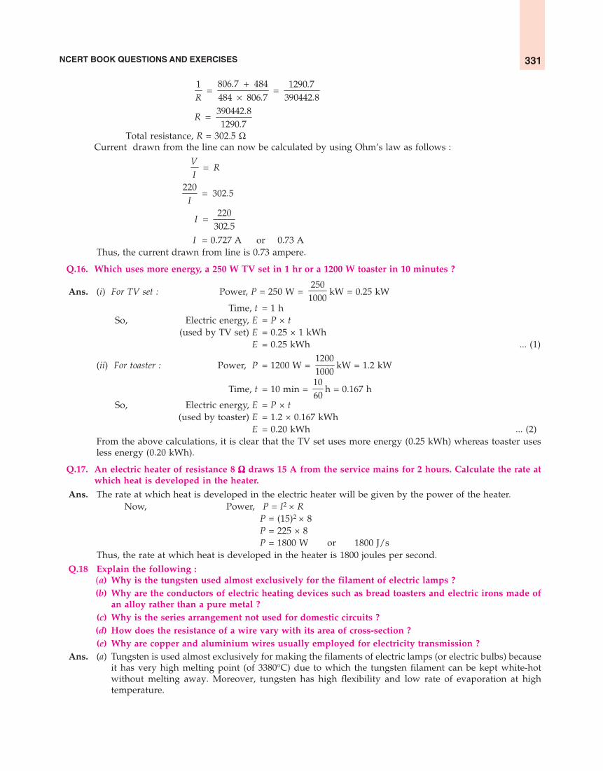
NCERT BOOK QUESTIONS AND EXERCISES 331
+= =
×806 7 4841 1290 7484 806 7 390442 8
. .R . .
=390442 81290 7
.R
.Total resistance, R = 302.5 Ω
Current drawn from the line can now be calculated by using Ohm’s law as follows :
=V
RI
=220
302 5.I
=220
302 5I
.I = 0.727 A or 0.73 A
Thus, the current drawn from line is 0.73 ampere.
Q.16. Which uses more energy, a 250 W TV set in 1 hr or a 1200 W toaster in 10 minutes ?
Ans. (i) For TV set : Power, P = 250 W = 250
1000kW = 0.25 kW
Time, t = 1 hSo, Electric energy, E = P × t
(used by TV set) E = 0.25 × 1 kWhE = 0.25 kWh ... (1)
(ii) For toaster : Power, P = 1200 W = 12001000
kW = 1.2 kW
Time, t = 10 min = 1060
h = 0.167 h
So, Electric energy, E = P × t(used by toaster) E = 1.2 × 0.167 kWh
E = 0.20 kWh ... (2)From the above calculations, it is clear that the TV set uses more energy (0.25 kWh) whereas toaster usesless energy (0.20 kWh).
Q.17. An electric heater of resistance 8 ΩΩΩΩΩ draws 15 A from the service mains for 2 hours. Calculate the rate atwhich heat is developed in the heater.
Ans. The rate at which heat is developed in the electric heater will be given by the power of the heater.Now, Power, P = I2 × R
P = (15)2 × 8P = 225 × 8P = 1800 W or 1800 J/s
Thus, the rate at which heat is developed in the heater is 1800 joules per second.Q.18 Explain the following :
(a) Why is the tungsten used almost exclusively for the filament of electric lamps ?(b) Why are the conductors of electric heating devices such as bread toasters and electric irons made of
an alloy rather than a pure metal ?(c) Why is the series arrangement not used for domestic circuits ?(d) How does the resistance of a wire vary with its area of cross-section ?(e) Why are copper and aluminium wires usually employed for electricity transmission ?
Ans. (a) Tungsten is used almost exclusively for making the filaments of electric lamps (or electric bulbs) becauseit has very high melting point (of 3380°C) due to which the tungsten filament can be kept white-hotwithout melting away. Moreover, tungsten has high flexibility and low rate of evaporation at hightemperature.

SCIENCE FOR TENTH CLASS : PHYSICS332
(b) See Q. 4 on page 321 of this book.(c) The series arrangement is not used for domestic circuits because of the following disadvantages :
(i) In series arrangement, if one electrical appliance stops working due to some defect, then all otherappliances also stop working (because the whole circuit is broken).
(ii) In series arrangement, all the electrical appliances can have only one switch due to which theycannot be turned ‘on’ or ‘off’ independently.
(iii) In series arrangement, all the appliances do not get the same voltage (220 V) as that of the powersupply line (because the line voltage is shared by all the appliances). Due to this, the appliances donot work properly.
(iv) In series arrangement of electrical appliances, the overall resistance of the circuit increases toomuch due to which the current from power supply is low. Because of this, all the appliances ofdifferent power ratings cannot draw sufficient current for their proper working.
(d) The resistance of a wire is inversely proportional to its area of cross-section. That is : ∝RA1 . So, when
the area of cross-section of wire increases (or thickness of wire increases), then its resistance decreases.And when the area of cross-section of wire decreases (or thickness of wire decreases), then its resistanceincreases.
(e) Copper and aluminium wires are usually employed for transmission of electricity because copper andaluminium have low electrical resistivity (due to which they are very good conductors of electricity).

Chapter : MAGNETIC EFFECT OF ELECTRIC CURRENT
NCERT Book, Page 224Q.1. Why does a compass needle get deflected when brought near a bar magnet ?
Ans. A compass needle gets deflected when brought near a bar magnet because the bar magnet exerts a magneticforce on the compass needle which is itself a tiny pivoted magnet (free to move in the horizontal plane).
NCERT Book, Page 228Q.1. Draw magnetic field lines around a bar magnet.Ans. See Figure 8 on page 71 of this book.
Q.2. List the properties of magnetic lines of force.Ans. (i) The magnetic lines of force originate from the north pole of a magnet and end at its south pole.
(ii) The magnetic lines of force come closer to one another near the poles of a magnet but they are widelyseparated at other places.
(iii) The magnetic lines of force do not intersect (or cross) one another.
Q.3. Why don’t two magnetic lines of force intersect with each other ?Ans. The two magnetic lines of force do not intersect each other because the resultant force on a north pole at
any point on a magnetic line of force can be only in one direction. If, however, the two magnetic lines offorce intersected (or crossed) each other, it would mean that at the point of intersection, the compass needlewould point in two directions at the same time, which is not possible.
NCERT Book, Pages 229-230Q.1. Consider a circular loop of wire lying in the
plane of the table. Let the current pass throughthe loop clockwise. Apply the right hand rule tofind out the direction of the magnetic field insideand outside the loop.
Ans. A circular loop of wire lying in the plane of thetable is shown in Figure given alongside. A batteryis passing current through the loop of wire in theclockwise direction. Now, by applying Right-handthumb rule to the left side of circular loop, we findthat the direction of magnetic field around it isanticlockwise but the magnetic field isperpendicular to the plane of table (or plane ofpaper). And by applying Right-hand thumb ruleto the right side of circular loop, we find that thedirection of magnetic field around it is clockwisebut again, the magnetic field is perpendicular tothe plane of table (or plane of paper).
Q.2. The magnetic field in a given region is uniform. Draw a diagram to represent it.Ans. See Sample Problem on page 81 of this book.
Q.3. Choose the correct option :The magnetic field inside a long, straight solenoid carrying current :(a) is zero(b) decreases as we move towards its end(c) increases as we move towards its end(d) is the same at all points
Ans. (d) is the same at all points.
Magneticfield lines
ti
–
Circular loopof wire
carrying current
+
Directionof current
Directionof current
Table
333

SCIENCE FOR TENTH CLASS : PHYSICS334
NCERT Book, Pages 231-232Q.1. Which of the following property/properties of a proton can change while it moves freely in a magnetic
field ? (There may be more than one correct answer) :(a) mass (b) speed (c) velocity (d) momentum
Ans. (c) velocity, and (d) momentum.Q.2. A small aluminium rod AB is suspended horizontally from a stand
by the ends of two connecting wires as shown in the Figure givenhere. A horseshoe magnet is placed in such a way that north poleof the magnet is vertically below and its south pole vertically abovethe aluminium rod. The aluminium rod is connected in serieswith a battery, a key and a rheostat. How do you think thedisplacement of rod AB will be affected if :(i) current in rod AB is increased ?
(ii) a stronger horseshoe magnet is used ?(iii) length of the rod AB is increased ?
Ans. In order to answer this question, we have to remember that : Whena current-carrying conductor is perpendicular to the magnetic field,the force acting on it is directly proportional to (a) magnitude ofcurrent flowing in the conductor (b) strength of magnetic fieldapplied, and (c) length of the conductor. And greater the force, greater will be the displacement of theconductor (which is an aluminium rod in this case). Now :(i) if the current in rod AB is increased, then more force will act on the rod and hence the displacement of
rod will also be more.(ii) if a stronger horseshoe magnet is used, then the strength of magnetic field will increase leading to
greater force on the rod. And due to greater force, the displacement of rod will also be more.(iii) If the length of rod AB is increased, then more force will act on the rod and hence the displacement of
rod will also be more.Q.3. A positively charged particle (alpha particle) projected towards west is deflected towards north by a
magnetic field. The direction of magnetic field is :(a) towards south (b) towards east (c) downward (d) upward
Ans. (d) upward (For details, see Sample Problem 1 on page 88 of this book).
NCERT Book, Page 233Q.1. State Flemings left-hand rule.Ans. See page 87 of this book.
Q.2. What is the principle of an electric motor ?Ans. See page 89 of this book.
Q.3. What is the role of the split ring in an electric motor ?Ans. The role of the split ring (called commutator) in an electric motor is to reverse the direction of current
flowing through the motor coil after every half rotation of the coil. Due to this reversing of current, thedirection of force remains unchanged on the two sides of the coil and hence the coil continues to rotate inthe same direction.
NCERT Book, Page 236Q.1. State different ways to induce current in a coil.Ans. (i) The current can be induced in a coil by rotating it in the magnetic field between the poles of a U-shaped
magnet.(ii) The current can be induced in the coil by keeping it stationary and rotating a magnet inside it.
(iii) The current can be induced in a coil by changing the current continuously in ‘another coil’ kept near it.
NCERT Book, Page 237Q.1. State the principle of an electric generator.
K
– +
N
SB
A

NCERT BOOK QUESTIONS AND EXERCISES 335
Ans. The electric generator works on the principle that when a straight conductor is moved in a magnetic field,then current is induced in the conductor.
Q.2. Name some sources of direct current.Ans. Dry cell, Dry cell battery, Car battery, Solar cell and D.C. generator.Q.3. Which sources produce alternating current ?Ans. A.C. generators (or Power house generators), Car alternators and Bicycle dynamos.
Q.4. Choose the correct option :A rectangular coil of copper wires is rotated in a magnetic field. The direction of the induced currentchanges once in each :(a) two revolutions (b) one revolution (c) half revolution (d) one-fourth revolution
Ans. (c) half revolution.
NCERT Book, Page 238Q.1. Name two safety measures commonly used in electric circuits and appliances.Ans. See Sample Problem 4 on page 112 of this book.
Q.2. An electric oven of 2 kW power rating is operated in a domestic electric circuit (220 V) that has a currentrating of 5 A. What result do you expect ? Explain.
Ans. See Sample Problem 1 on page 111 of this book.
Q.3. What precautions should be taken to avoid the overloading of domestic electric circuits ?Ans. See Sample Problem 3 on page 112 of this book.
NCERT Book, Pages 240-241Q.1. Which of the following correctly describes the magnetic field near a long straight wire ?
(a) The field consists of straight lines perpendicular to the wire(b) The field consists of straight lines parallel to the wire(c) The field consists of radial lines, originating from the wire(d) The field consists of concentric circles centred on the wire
Ans. (d) The field consists of concentric circles centred on the wire.
Q.2. The phenomenon of electromagnetic induction is :(a) the process of charging a body(b) the process of generating magnetic field due to a current passing through a coil(c) producing induced current in a coil due to relative motion between a magnet and the coil(d) the process of rotating a coil of an electric motor
Ans. (c) producing induced current in a coil due to relative motion between a magnet and the coil.
Q.3. The device used for producing electric current is called a :(a) generator (b) galvanometer (c) ammeter (d) motor
Ans. (a) generator
Q.4. The essential difference between an AC generator and a DC generator is that :(a) AC generator has an electromagnet while a DC generator has permanent magnet(b) DC generator will generate a higher voltage(c) AC generator will generate a higher voltage(d) AC generator has slip rings while the DC generator has a commutator
Ans. (d) AC generator has slip rings while the DC generator has a commutator.
Q.5. At the time of short circuit, the current in the circuit :(a) reduces substantially (b) does not change(c) increases heavily (d) varies continuously
Ans. (c) increases heavily.
Q.6. State whether the following statements are true or false :(a) An electric motor converts mechanical energy into electrical energy

SCIENCE FOR TENTH CLASS : PHYSICS336
(b) An electric generator works on the principle of electromagnetic induction(c) The field at the centre of a long circular coil carrying current will be parallel straight lines(d) A wire with a green insulation is usually the live wire of an electric supply
Ans. (a) False (b) True (c) True (d) False
Q.7. List three sources of magnetic fields.Ans. Magnetic fields can be produced :
(i) by using a permanent magnet(ii) by passing electric current through a straight wire or a circular coil (solenoid)
(iii) by using an electromagnet
Q.8. How does a solenoid behave like a magnet ? Can you determine the north and south poles of a currentcarrying solenoid with the help of a bar magnet ? Explain.
Ans. (a) One end of a current-carrying solenoid acts like a north pole (N-pole) and the other end a south pole(S-pole). So, if a current-carrying solenoid is suspended freely by tying a thread in the middle, it willcome to rest pointing in the north and south directions (just like a freely suspended bar magnet).
(b) We can determine the north and south poles of a current-carrying solenoid by using a bar magnet. Thiscan be done as follows : We bring the north pole of a bar magnet near both the ends of a freely suspendedcurrent-carrying solenoid. The end of solenoid which will be repelled by the north pole of bar magnetand move away from it, will be its north pole. And the end of solenoid which will be attracted by thenorth pole of the bar magnet and move towards it, will be its south pole.
Q.9. When is the force experienced by a current-carrying conductor placed in a magnetic field largest ?Ans. The force experienced by a current-carrying conductor placed in a magnetic field is the largest when the
current-carrying conductor is perpendicular to the direction of magnetic field.
Q.10. Imagine that you are sitting in a chamber with your back to one wall. An electron beam, movinghorizontally from back wall towards the front wall is deflected by a strong magnetic field to your rightside. What is the direction of magnetic field ?
Ans. See Sample Problem 2 on page 88 of this book.
Q.11. Draw a labelled diagram of an electric motor. Explain its principle and working. What is the function ofa split ring in an electric motor ?
Ans. See page 89 of this book.
Q.12. Name some devices in which electric motors are used.Ans. Electric motors are used in electric fans, coolers, refrigerators, mixer and grinders, washing machines, water
pumps and electric cars.
Q.13. A coil of insulated copper wire is connected to a galvanometer. What will happen if a bar magnet is(i) pushed into the coil (ii) held stationary inside the coil (iii) withdrawn from inside the coil ?
Ans. See Sample Problem 1 on page 102 of this book.
Q.14. Two circular coils A and B are placed close to each other. If the current in the coil A is changed, will somecurrent be induced in the coil B ? Give reason.
Ans. If the current in coil A is ‘switched on’ or ‘switched off’, then an electric current is induced in the coil B (seeFigure given here). This can be explained as follows :(i) When we switch on current in coil A, it becomes an
electromagnet and produces a magnetic field around coil B.The effect is just the same as pushing a magnet into coil B.So, an induced current flows in coil B for a moment. Whenthe current in coil A becomes steady, its magnetic field alsobecomes steady and the current in coil B stops.
(ii) When we switch off the current in coil A, then its magneticfield in coil B stops quickly. This effect is just the same aspulling a magnet quickly out of coil B. So, in this case aninduced current flows in coil B in the opposite direction.
Coil A Coil B
+ –S G
0

NCERT BOOK QUESTIONS AND EXERCISES 337
Q.15. State the rule to determine the direction of a :(i) magnetic field produced around a straight conductor carrying current.
(ii) force experienced by a current-carrying straight conductor placed in a magnetic field which isperpendicular to it.
(iii) current induced in a straight conductor moving in a magnetic field.Ans. (i) The direction of magnetic field produced around a straight current-carrying conductor is determined by
using Maxwell’s right hand thumb rule (For statement, see page 76 of this book).(ii) The direction of force experienced by a current-carrying straight conductor placed in a magnetic field is
determined by Fleming’s left-hand rule (For statement, see page 87 of this book).(iii) The direction of current induced in a straight conductor moving in a magnetic field is determined by
Fleming’s right-hand rule (For statement, see page 96 of this book).
Q.16. Explain the underlying principle and working of an electric generator by drawing a labelled diagram.What is the function of brushes ?
Ans. See page 98 of this book.
Q.17. When does an electric short circuit occur ?Ans. An electric short circuit takes place when the live wire and the neutral wire of electricity supply line touch
each other directly. This occurs when the plastic insulation of live wire and neutral wire get torn or whenthere is a fault in the electrical appliance.
Q.18. Why is it necessary to earth metallic appliances ? What is the function of an earth wire ?Ans. The metal body of an electrical appliance is ‘earthed’ or connected by means of a metal wire to the earth
(which is at zero potential) to avoid the risk of electric shocks. This is because if, by chance, the live wire atthe high potential of 220 volts touches the metal case of the electrical appliance, then the current passesfrom the electrical appliance directly to the earth through the low resistance earth wire. Since the currentdoes not pass through our body, we do not get an electric shock. Thus, the function of an earth wire is toprovide an easy passage to the leaking current from an electrical appliance to go into the earth and henceprevent electric shocks to the user of electrical appliance.

Chapter : SOURCES OF ENERGYNCERT Book, Page 243
Q.1. What is a good source of energy ?Ans. A good source of energy is one :
(i) which would give a large amount of energy per unit mass (or per unit volume)(ii) which is cheap and easily available
(iii) which is easy to store and transport(iv) which is safe to handle and use, and(v) which does not cause environmental pollution.
Q.2. What is a good fuel ?Ans. A good fuel is one :
(i) which has a high calorific value,(ii) which has a proper ignition temperature,
(iii) which burns without giving out any smoke or harmful gases,(iv) which burns smoothly and does not leave behind much ash after burning, and(v) which is cheap, easily available, easy to handle, safe to transport and convenient to store.
Q.3. If you could use any source of energy for heating your food, which one would you use and why ?Ans. I would use LPG (cooking gas) for heating food because :
(i) LPG has a high calorific value. It gives a lot of heat (per unit mass) on burning.(ii) LPG burns with a smokeless flame and hence does not cause any air pollution.
(iii) LPG does not produce any poisonous gases on burning(iv) LPG does not leave behind any ash after burning
NCERT Book, Page 248Q.1. What are the disadvantages of fossil fuels ?
Ans. Coal, petroleum and natural gas are fossil fuels. The burning of fossil fuels has the following disadvantages :(i) Fossil fuels are non-renewable sources of energy. Once exhausted, fossil fuels will not be available to us
in the near future.(ii) The burning of fossil fuels causes a lot of air pollution. This is described below :
(a) The burning of fossil fuels produces acidic gases such as sulphur dioxide and nitrogen oxides whichcause acid rain. The acid rain damages plants (crops, etc.) , reduces fertility of soil by making itacidic, poses a danger to aquatic life (like fish) by making the water of lakes and rivers acidic, anddamages buildings by corroding them slowly.
(b) The burning of fossil fuels produces large amount of carbon dioxide gas which goes into air. Thepresence of increasing amounts of carbon dioxide gas in air is causing increased greenhouse effectleading to excessive heating of the earth. This global warming is harmful for all the life on earth.
(c) The burning of fossil fuels (especially coal) produces smoke which pollutes the air. The burning ofcoal leaves behind a lot of ash. It also puts tiny particles of ash (called fly-ash) into the air causing airpollution.
Q.2. Why are we looking at alternative sources of energy ?Ans. We are looking at alternative sources of energy mainly due to two reasons :
(i) because the fossil fuels and nuclear fuels present in the earth are limited which may not last for long,and
(ii) because of the undesirable effects of pollution both from the burning of fossil fuels and from theradioactive wastes of the nuclear power plants.
338

NCERT BOOK QUESTIONS AND EXERCISES 339
Q.3. How has the traditional use of wind and water energy been modified for our convenience ?Ans. (i) The traditional use of wind energy has been modified by the improvements in technology to generate
electricity through wind-powered generators.(ii) The traditional use of energy of flowing water has been modified by improvements in technology to
generate electricity through flowing water-powered generators (by establishing hydropower plants).
NCERT Book, Page 253Q.1. What kind of mirror–concave, convex or plane–would be best suited for use in a solar cooker ? Why ?
Ans. A concave mirror reflector would be best suited for use in a solar cooker. This is because a concave reflectorconverges a large amount of sun‘s heat rays to a small area at its focus due to which a high temperature isproduced in its focus area (which is suitable for baking and frying). Such a high temperature cannot beachieved in a solar cooker by using a plane mirror reflector. Convex mirror reflector, being a divergingmirror, cannot be used at all in a solar cooker.
Q.2. What are the limitations of energy that can be obtained from the oceans ?Ans. The energy from the oceans can be obtained mainly in three forms : Tidal energy, Wave energy and Ocean
thermal energy. Some of the important limitations of these forms of energy are as follows :(i) There are very few places around the world where barrages (or dams) can be built to harness tidal
energy. Moreover, the rise and fall of water during high and low tides is not enough to generate electricityon a large scale.
(ii) The wave energy can be harnessed only at those places where the sea-waves are very strong. The efficiencyof power plants based on wave energy is very low. Moreover, the power plants built in oceans or at sea-shores have high cost of installation, corrode easily and need a lot of maintenance.
(iii) A temperature difference of 20°C (or more) between the surface water of ocean and deeper water isnecessary to harness ocean thermal energy. The efficiency of OTEC power plants which work by utilisingocean thermal energy, is very low. Moreover, it is very expensive to establish OTEC power plants.
Q.3. What is geothermal energy ?Ans. Geothermal energy is the heat energy from hot rocks present inside the earth. This heat comes from the
fission of radioactive materials which are naturally present in these rocks. Geothermal energy is availableonly at some places in the world. Geothermal energy can be used to produce electricity.
Q.4. What are the advantages of nuclear energy ?Ans. See page 156 of this book.
NCERT Book, Page 253Q.1. Can any source of energy be pollution free ? Why or why not ?
Ans. In reality, no source of energy can be said to be pollution free. The use of each and every source of energydisturbs the environment in one way or the other. For example, though the use of a wind generator, solarcooker and solar cells for obtaining energy is pollution free but the processes involved in making the materialsfor these energy devices must have caused some pollution and damaged the environment in one way orthe other.
Q.2. Hydrogen has been used as a rocket fuel. Would you consider it a cleaner fuel than CNG ? Why or whynot ?
Ans. See Sample Problem on page 160 of this book.
NCERT Book, Page 254Q.1. Name two energy sources that you would consider to be renewable. Give reasons for your choices.
Ans. Hydroenergy (Energy from flowing water) and Biomass energy (Energy from biofuels such as wood) arethe renewable sources of energy.(i) Hydroenergy is a renewable source of energy because it is supplied by the water cycle in nature (powered
by sun’s energy) and it will never get exhausted.(ii) Biomass energy contained in wood is a renewable source of energy because if trees are cut from the
forest for obtaining wood, then more trees will grow in the forest in due course of time.

SCIENCE FOR TENTH CLASS : PHYSICS340
Q.2. Give the names of two energy sources that you would consider to be exhaustible. Give reasons for yourchoices.
Ans. Exhaustible sources of energy means non-renewable sources of energy. Coal and petroleum are the twoexhaustible sources of energy (or non-renewable sources of energy). This is due to the following reasons :Coal and petroleum are fossil fuels which were formed in the earth very, very slowly. The coal and petroleumwhich are present in the earth today have taken millions of years to form and get accumulated. So, if all thecoal and petroleum present in earth get exhausted, they cannot be produced quickly in nature. We will notget any coal or petroleum in the near future.
NCERT Book, Pages 254-255
Q.1. A solar water heater cannot be used to get hot water on :(a) a sunny day (b) a cloudy day (c) a hot day (d) a windy day
Ans. (b) a cloudy day.
Q.2. Which of the following is not an example of a bio-mass energy source ?(a) wood (b) gobar gas (c) nuclear energy (d) coal
Ans. (c) nuclear energy
Q.3. Most of the sources of energy we use represent stored solar energy. Which of the following is not ultimatelyderived from the sun’s energy ?(a) geothermal energy (b) wind energy (c) fossil fuels (d) biomass
Ans. (a) geothermal energy
Q.4. Compare and contrast fossil fuels and the sun as direct sources of energy.Ans. See page 140 of this book.
Q.5. Compare and contrast bio-mass and hydroelectricity as sources of energy.Ans. See page 146 of this book.
Q.6. What are the limitations of extracting energy from :(a) wind ? (b) waves ? (c) tides ?
Ans. (a) Limitations of extracting energy from wind :(i) Wind generators to produce electricity can be established only at those places where wind blows for the
greater part of the year.(ii) The wind speed should be higher than 15 km/h to maintain the required speed of wind turbines for
generating electricity.(iii) There should be some back-up facilities like storage cells to take care of energy needs during the period
there is no wind.(iv) A large area of land is required for establishing wind energy farms(v) The initial cost of establishing wind energy farms is quite high.
(b) Limitations of extracting energy from waves (or sea-waves) :(i) The wave energy can be harnessed at only those places where the sea-waves are very strong.
(ii) The efficiency of power plants based on wave energy is very low.(iii) The power plants built in oceans or at sea-shores have high cost of installation, corrode easily and need
a lot of maintenance.(c) Limitations of extracting energy from tides :
(i) There are very few sites around the world which are suitable for building tidal barrages (or tidal dams).(ii) The rise and fall of sea-water during high and low tides is not enough to generate electricity on a large
scale.
Q.7. On what basis would you classify energy sources as :(a) renewable and non-renewable ?(b) inexhaustible and exhaustible ?Are the options given in (a) and (b) the same ?

NCERT BOOK QUESTIONS AND EXERCISES 341
Ans. The options given in (a) and (b) are the same. This is because renewable sources of energy are also knownas inexhaustible sources of energy whereas non-renewable sources of energy are also called exhaustiblesources of energy.(i) Those sources of energy which are being produced in nature continuously and can be used again and
again for ever, are called renewable sources of energy (or inexhaustible sources of energy). These sourcesof energy will never get exhausted. For example, wood is a renewable source of energy (or inexhaustiblesource of energy), because if some trees are cut down from forests for obtaining firewood, then moretrees will grow in the forest on their own or can be replanted by man. This will ensure continuoussupply of wood for obtaining heat energy.
(ii) Those sources of energy which have accumulated in the earth over very, very long time of millions ofyears and cannot be made quickly when used up completely, are called non-renewable sources of energy(or exhaustible sources of energy). These sources of energy will get exhausted sooner or later. For example,coal is a non-renewable source of energy (or exhaustible source of energy) because coal has accumulatedin the earth over a very, very long time, and if all the coal gets used up completely, it cannot be producedquickly in nature.
Q.8. What are the qualities of an ideal source of energy ?Ans. An ideal source of energy has the following qualities :
(i) It gives a large amount of energy per unit mass (or per unit volume).(ii) It does not cause any environmental pollution.
(iii) It is easy to store and safe to transport(iv) It is safe to handle and use(v) It is cheap and easily available.
Q.9. (a) What are the advantages and disadvantages of using a solar cooker ?(b) Are there any places where solar cookers would have limited utility ?
Ans. (a) See page 138 of this book.(b) The solar cookers have limited utility at those places which usually remain cloudy and have long winters.
An example of such places are hilly areas.
Q.10. (a) What are the environmental consequences of the increasing demand for energy ?(b) What steps would you suggest to reduce energy consumption ?
Ans. (a) Some of the environmental consequences of the increasing demand for energy are the following :(i) The combustion of fossil fuels is producing acid rain and damaging plants (crops), soil, aquatic life
and buildings.(ii) The burning of fossil fuels is increasing the amount of greenhouse gas carbon dioxide in the atmosphere
leading to global warming.(iii) The cutting down of forest trees (deforestation) for obtaining firewood is causing soil erosion and
destroying wildlife.(iv) The construction of hydropower plants is disturbing ecological balance.(v) Nuclear power plants are increasing radioactivity in the environment.
(b) Some of the steps which can be taken to reduce energy consumption are as follows :(i) Switch off lights, fans, TV and other such electrical appliances when not needed, to save electricity.
(ii) Use energy efficient electrical appliances such as compact fluorescent lamps (CFLs) and tube-lights tosave electricity.
(iii) Good quality stoves should be used to burn fuels like kerosene and LPG so as to obtain maximumheat.
(iv) Pressure cookers should be used for cooking food to save fuel.(v) Solar cookers should be used to cook food wherever possible and solar water heaters should be used
to get hot water.(vi) Bicycles should be used for short distances instead of scooters, motorcycles and cars so as to save
petrol.

SCIENCE FOR TENTH CLASS : PHYSICS342
Chapter : LIGHT– REFLECTION AND REFRACTIONNCERT Book, Page 168
Q.1. Define the principal focus of a concave mirror.Ans. The principal focus of a concave mirror is a point on its principal axis to which all the light rays which are
parallel and close to the axis, converge after reflection from the concave mirror.
Q.2. The radius of curvature of a spherical mirror is 20 cm. What is its focal length ?Ans. See Sample Problem on page 178 of this book.
Q.3. Name a mirror that can give an erect and enlarged image of an object.Ans. Concave mirror.
Q.4. Why do we prefer a convex mirror as a rear-view mirror in vehicles ?Ans. We prefer a convex mirror as a rear-view mirror in vehicles because of the following reasons :
(i) A convex mirror always produces an erect image (right side up image) of the objects.(ii) The image formed in a convex mirror is highly diminished or much smaller than the object, due to which
a convex mirror gives a wide field of view (of the traffic behind).
NCERT Book, Page 171Q.1. Find the focal length of a convex mirror whose radius of curvature is 32 cm.
Ans. Focal length = Radius of curvature
2
or f = R2
f = 32
cm2
f = 16 cmThus, the focal length of convex mirror is 16 centimetres.
Q.2. A concave mirror produces three times magnified (enlarged) real image of an object placed at 10 cm infront of it. Where is the image located ?
Ans. See Sample Problem 3 on page 197 of this book.
NCERT Book, Page 176Q.1. A ray of light travelling in air enters obliquely into water. Does the light ray bend towards the normal or
away from the normal ? Why ?Ans. When a ray of light travelling in air enters obliquely into water, it bends towards the normal. This is because
water is optically denser (than air) due to which the speed of light waves decreases on entering water,making the light bend towards the normal.
Q.2. Light enters from air to glass having refractive index 1.50. What is the speed of light in the glass ? Thespeed of light in vacuum is 3 × 10⁸ m s–1.
Ans. See Sample Problem on page 225 of this book.
Q. 3. Find out from Table on page 225 the medium having highest optical density. Also find the medium withlowest optical density.
Ans. (a) The medium having highest refractive index has the highest optical density. Since diamond has thehighest refractive index (2.42), therefore, diamond has the highest optical density.
(b) The medium having lowest refractive index has the lowest optical density. Since air has the lowestrefractive index (1.0003), therefore, air has the lowest optical density.
Q.4. You are given kerosene, turpentine and water. In which of these the light travels fastest ? Use theinformation given in Table on page 225.
Ans. The light travels fastest in that medium which has the lowest refractive index. Now, the refractive index of

NCERT BOOK QUESTIONS AND EXERCISES 343
kerosene is 1.44, the refractive index of turpentine is 1.47 whereas the refractive index of water is 1.33. Herewater has the lowest refractive index (of 1.33), so light travels fastest in water.
Q.5. The refractive index of diamond is 2.42. What is the meaning of this statement ?Ans. By saying that the refractive index of diamond is 2.42, we mean that the ratio of speed of light in air
(or vacuum) to the speed of light in diamond is equal to 2.42.
NCERT Book, Page 184Q.1. Define 1 dioptre of power of a lens.
Ans. 1 dioptre is the power of a lens whose focal length is 1 metre.
Q.2. A convex lens forms a real and inverted image of a needle at a distance of 50 cm from it. Where is theneedle placed in front of the convex lens if the image is equal in size to the object ? Also find the powerof the lens.
Ans. See Sample Problem 7 on page 259 of this book.
Q.3. Find the power of a concave lens of focal length 2 m.Ans. The focal length of a concave lens is considered negative and hence written with a minus sign.
So, Focal length of concave lens, f = –2 m (or –2 metres)
Now, Power, P = f ( )1
in metres
or P = −12
Thus, Power, P = – 0.5 dioptre (or, – 0.5 D)
NCERT Book, Pages 185-186Q.1. Which one of the following materials cannot be used to make a lens ?
(a) water (b) glass (c) plastic (d) clayAns. (d) clay.
Q.2. The image formed by a concave mirror is observed to be virtual, erect and larger than the object. Whereshould be the position of the object ?(a) between the principal focus and the centre of curvature(b) at the centre of curvature(c) beyond the centre of curvature(d) between the pole of the mirror and its principal focus.
Ans. (d) between the pole of the mirror and its principal focus
Q.3. Where should an object be placed in front of a convex lens to get a real image of the size of the object ?(a) at the principal focus of the lens(b) at twice the focal length(c) at infinity(d) between the optical centre of the lens and its principal focus
Ans. (b) at twice the focal length.
Q.4. A spherical mirror and a thin spherical lens each have a focal length of, –15 cm. The mirror and the lensare likely to be :(a) both concave(b) both convex(c) the mirror is concave and the lens is convex(d) the mirror is convex but the lens is concave
Ans. (a) both concave.
Q.5. No matter how far you stand from a mirror, your image appears erect. The mirror is likely to be :(a) plane (b) concave (c) convex (d) either plane or convex
Ans. (d) either plane or convex

SCIENCE FOR TENTH CLASS : PHYSICS344
Q.6. Which of the following lenses would you prefer to use while reading small letters found in a dictionary ?(a) A convex lens of focal length 50 cm(b) A concave lens of focal length 50 cm(c) A convex lens of focal length 5 cm(d) A concave lens of focal length 5 cm
Ans. (c) A convex lens of focal length 5 cm
Q.7. We wish to obtain an erect image of an object using a concave mirror of focal length 15 cm. What shouldbe the range of distance of the object from the mirror ? What is the nature of the image ? Is the imagelarger or smaller than the object ? Draw a ray diagram to show the image formation in this case.
Ans. See Sample Problem 1 on page 187 of this book.
Q.8. Name the type of mirror used in the following situations :(a) Headlights of a car(b) Side/rear view mirror of a vehicle(c) Solar furnaceSupport your answer with reason.
Ans. (a) A concave mirror is used in the headlights of a car. This is because when, a lighted bulb is placed at thefocus of the concave reflector, then the concave reflector produces a powerful beam of parallel lightrays. This beam of light helps us to see things up to a considerable distance in the darkness of night.
(b) A convex mirror is used as side-view mirror (or rear-view mirror) in a vehicle. This is because (i) aconvex mirror always produces an erect image of the objects, and (ii) the image formed in a convexmirror is highly diminished due to which a convex mirror gives a wide field of view (of the trafficbehind).
(c) A concave mirror is used in a solar furnace. This is because when the solar furnace is placed at the focusof a large concave reflector, then the concave reflector converges and focuses the sun’s heat rays on thefurnace due to which the solar furnace gets very hot.
Q.9. One half of a convex lens is covered with a black paper. Will this lens produce a complete image of theobject ? Verify your answer experimentally. Explain your observations.
Ans. The convex lens half covered with a black paper will produce acomplete image of an object (as shown in the Figure alongside).We can verify this by obtaining the image of a tree (or a window)on a screen by using this half covered convex lens. The full image ofan object is produced by this convex lens (which is half coveredwith a black paper) because light rays can still pass through its opticalcentre (as shown in Figure given here).
Q.10. An object 5 cm in length is held 25 cm away from a converging lens of focal length 10 cm. Draw the raydiagram and find the position, size and nature of the image formed.
Ans. A converging lens means a convex lens. Now, first of all we will find the position of image by calculatingthe image distance v.Here, Object distance, u = –25 cm (It is to the left of lens)
Image distance, v = ? (To be calculated)And, Focal length, f = + 10 cm (It is a converging lens or convex lens)Now, putting these values in the lens formula :
v− =
u f1 1 1
We get :v
− =−
1 1 125 10
v+ =1 1 1
25 10
v= −1 1 1
10 25
2F� F�
B�
A�
Image
A
BObject
Convex lens
D
C F 2FBlackpaper

NCERT BOOK QUESTIONS AND EXERCISES 345
v
−=
5 2150
v=1 3
50
v = +503
v = + 16.67 cmThus, the position of image is at a distance of 16.67 cm from the lens. The plus sign for image distanceshows that the image is formed on the right side of lens (or behind the lens) and that the nature of image isreal and inverted.Let us calculate the magnification now. For a lens :
Magnification,v=mu
.m =
−16 67
25m = – 0.66
We will now calculate the size of image h2
by knowing the size of object h1 and value of m.
Now, h
mh
= 2
1
So, − = h. 20 66
5 h2 = – 0.66 × 5
h2 = – 3.3 cmThus, the size of image is 3.3 cm. The negative sign of the size of image shows that the image is inverted.
Q.11. A concave lens of focal length 15 cm forms an image 10 cm from the lens. How far is the object from thelens ? Draw the ray diagram.
Ans. In this question, we have to calculate the object distance u.Here, Object distance, u = ? (To be calculated)
Image distance, v = – 10 cm (To the left of concave lens)And, Focal length, f = – 15 cm (It is a concave lens)Now, putting these values in the lens formula :
v− =
u f1 1 1
We get : u
− =− −
1 1 110 15
u
− = − +1 1 1
15 10
− +
− =u
2 3130
− =u1 1
30 Object distance, u = – 30 cmThus, the object is placed at a distance of 30 cm from the concave lens. The minus sign with object distanceshows that the object is on its left side.
Q.12. An object is placed at a distance of 10 cm from a convex mirror of focal length 15 cm. Find the positionand nature of the image.
Ans. We can find the position of image by calculating the image distance, v.
2F� F�
B�
A�
Image
A
BObject
D
C F 2F
Converging lens(Convex lens)
Concavelens
A
BObject
F C
D
X
YB�
Image
A�

SCIENCE FOR TENTH CLASS : PHYSICS346
Here, Object distance, u = – 10 cm (To the left of mirror)Image distance, v = ? (To be calculated)
And, Focal length, f = +15 cm (It is a convex mirror)Putting these values in the mirror formula :
v+ =
u f1 1 1
We get : v
+ =−
1 1 110 15
v
− =1 1 110 15
v= +1 1 1
15 10
v
+=
2 3130
v=1 5
30
v=1 1
6So, Image distance, v = + 6 cmThus, the position of image is at a distance of 6 cm from the convex mirror on its right side (behind themirror). Since the image is formed behind the convex mirror, therefore, the nature of image is virtual anderect.
Q.13. The magnification produced by a plane mirror is +1. What does this mean ?Ans. See Sample Problem 4 on page 197 of this book.
Q.14. An object 5.0 cm in length is placed at a distance of 20 cm in front of a convex mirror of radius ofcurvature 30 cm. Find the position of the image, its nature and size.
Ans. Here, Object distance, u = – 20 cm (To the left of mirror)Image distance, v = ? (To be calculated)
Radius of curvature, R = + 30 cm (It is a convex mirror)
So, Focal length, f = = = +R 3015 cm
2 2Now, putting these values of u and f in the mirror formula :
v+ =
u f1 1 1
We get : v
+ =−
1 1 120 15
v
− =1 1 120 15
v= +1 1 1
15 20
v
+=
4 3160
v=1 7
60
v = 607
or v = + 8.57 cm

NCERT BOOK QUESTIONS AND EXERCISES 347
Thus, the position of image is 8.57 cm behind the mirror (on its right side). Since the image is formedbehind the convex mirror, therefore, the nature of image is virtual and erect.
Now, For a mirror, Magnification, m = v−u
So, m = +
−−
.8 5720
m = + 0.42
Also, Magnification = height of imageheight of object
or m = 2
1
hh
So, + 0.42 = 2
5.0h
h2 = 0.42 × 5.0 Height of image, h2 = 2.1 cmThus, the size of image is 2.1 cm.
Q.15. An object of size 7.0 cm is placed at 27 cm in front of a concave mirror of focal length 18 cm. At whatdistance from the mirror should a screen be placed so that a sharp focussed image can be obtained ? Findthe size and nature of the image.
Ans. Here, Object distance, u = – 27 cm (To the left side of mirror)Image distance, v = ? (To be calculated)
Focal length, f = –18 cm (It is a concave mirror)Height of object, h1 = 7.0 cm
And, Height of image, h2 = ? (To be calculated)
Now, For a mirror : v+ =
u f1 1 1
So,v
+ =− −
1 1 127 18
v− = −1 1 1
27 18
v= − +1 1 1
18 27
v
− +=
3 2154
v= −1 1
54 Image distance, v = – 54 cmSince the image distance is minus 54 cm, therefore, the screen should be placed at a distance of 54 cm infront of the concave mirror (on its left side). The nature of image obtained on the screen is real and inverted.
Also, For a mirror, v= −h
h u2
1
So,−
= −−
h.2 54
7 0 27
= −h.2 2
7 0 h2 = –2 × 7.0
Height of image, h2 = –14.0 cmThus, the size of image is 14.0 cm.

SCIENCE FOR TENTH CLASS : PHYSICS348
Q.16. Find the focal length of a lens of power, –2.0 D. What type of lens is this ?Ans. The power of this lens has a negative sign (or minus sign), so this is a concave lens. Now,
Power, P = f ( )
1in metres
(f = focal length)
So, – 2.0 = f1
And, f = −.1
m2 0
Or f = − ×.1
100 cm2 0
So, Focal length of lens, f = –50 cm
Q.17. A doctor has prescribed a corrective lens of power + 1.5 D. Find the focal length of the lens. Is the prescribedlens diverging or converging ?
Ans. The power of this lens is positive (with a plus sign), therefore, this is a convex lens or converging lens. Now,
Power, P = f ( )1
in metres
So, +1.5 = f1
or f = + .1
m1 5
f = + ×.1
100 cm1 5
So, Focal length of lens, f = + 66.7 cm

Chapter : THE HUMAN EYE ANDTHE COLOURFUL WORLD
NCERT Book, Page 190Q.1. What is meant by the power of accommodation of the eye ?
Ans. The ability of an eye to focus the distant objects as well as the nearby objects on the retina by changing thefocal length (or converging power) of its lens is called accommodation.
Q.2. A person with a myopic eye cannot see objects beyond 1.2 m distinctly. What should be the type of thecorrective lens used to restore proper vision ?
Ans. The proper vision of a myopic eye can be restored by using concave lens of suitable power.
Q.3. What are the far point and near point of the human eye with normal vision ?Ans. The far point of human eye with normal vision is at infinity and the near point is at a distance of 25
centimetres from the eye.
Q.4. A student has difficulty in reading the blackboard while sitting in the last row. What could be the defectthe child is suffering from ? How can it be corrected ?
Ans. Since the child cannot see the distant objects (like blackboard writing) clearly, he is suffering from thedefect of vision (or defect of eye) called ‘myopia’ or ‘short-sightedness’. Myopia can be corrected by usingspectacles containing concave lenses of suitable power.
NCERT Book, Pages 197-198Q.1. The human eye can focus objects at different distances by adjusting the focal length of the eye-lens.
This is due to :(a) presbyopia (b) accommodation (c) near-sightedness (d) far-sightedness
Ans. (b) accommodation
Q.2. The human eye forms the image of an object at its :(a) cornea (b) iris (c) pupil (d) retina
Ans. (d) retina
Q.3. The least distance of distinct vision for a young adult with normal vision is about :(a) 25 m (b) 2.5 cm (c) 25 cm (d) 2.5 m
Ans. (c) 25 cm
Q.4. The change in focal length of an eye-lens is caused by the action of the :(a) pupil (b) retina (c) ciliary muscles (d) iris
Ans. (c) ciliary muscles
Q.5. A person needs a lens of power, –5.5 dioptres for correcting his distant vision. For correcting his nearvision, he needs a lens of power +1.5 dioptres. What is the focal length of the lens required for correcting(i) distant vision, and (ii) near vision ?
Ans. (i) For distant vision : Power of lens, P = –5.5 D
Now, Power, P = f ( )
1in metres
(where f = focal length)
So, –5.5 = f1
And, f = − .1
m5 5
Or, f = − ×.1
100 cm5 5
349
SCIENCE FOR TENTH CLASS : PHYSICS350
So, Focal length, f = – 18.18 cm (or –18.2 cm)Thus, the focal length of lens required for correcting distant vision is, –18.2 cm. Minus sign of focal lengthtells us that it is a concave lens.
(ii) For near vision : Power of lens, P = + 1.5 D
Now, Power, P = f ( )
1in metres
So, + 1.5 = f1
And, f = + .1
m1 5
Or, f = + ×.1
100 cm1 5
So, Focal length, f = + 66.66 cm (or + 66.7 cm)Thus, the focal length of lens required for correcting near vision is + 66.7 cm. Plus sign of focal length tellsus that it is a convex lens.
Q.6. The far point of a myopic person is 80 cm in front of the eye. What is the nature and power of the lensrequired to correct the problem ?
Ans. See Sample Problem on page 275 of this book.
Q.7. (a) Make a diagram to show how hypermetropia is corrected.(b) The near point of a hypermetropic eye is 1 m. What is the power of the lens required to correct this
defect ? Assume that the near point of the normal eye is 25 cm.Ans. (a) See Figure 13(c) on page 276 of this book.
(b) See Sample Problem on page 277 of this book.
Q.8. Why is a normal eye not able to see clearly the objects placed closer than 25 cm ?Ans. A normal eye can see nearby objects because the ciliary muscles make the eye-lens more convex (or thick)
thereby increasing its converging power. This increased converging power of eye-lens can make a normaleye see objects clearly only when placed up to 25 cm from the eye. However, when objects are placedcloser than 25 cm, then the ciliary muscles cannot make the eye-lens more convex to increase its convergingpower further so as to focus them sharply on the retina. Due to this, such objects are not seen clearly. Inother words, a normal eye is not able to see clearly the objects placed closer than 25 cm because all itspower of accommodation (or ability to increase converging power of eye-lens by making it more convex)has already been exhausted.
Q.9. What happens to the image distance in the eye when we increase the distance of an object from the eye ?Ans. See Sample Problem on page 269 of this book.
Q.10. Why do stars twinkle ?Ans. See page 290 of this book.
Q.11. Explain why the planets do not twinkle.Ans. See page 291 of this book.
Q.12. Why does the sun appear reddish in the morning ?Ans. See page 296 of this book.
Q.13. Why does the sky appear dark instead of blue to an astronaut ?Ans. This is because in outer space, there is no atmosphere to scatter sunlight. Since there is no scattering of blue
component of white sunlight which can reach the eyes of an astronaut in outer space, therefore, the skyappears dark to the astronaut, instead of blue.
Value Based Questions(with Answers)
FIRST TERMQ.1. Raman is a student of class X. Raman’s mother was making tea in an old electric kettle having metal case.
She switched on the power supply to the electric kettle. When Raman’s mother touched the metal case ofworking electric kettle unknowingly, she got a severe electric shock. Raman put off the main switchquickly. After removing the kettle plug from socket, Raman found that the connecting cord was tornwhere it touched the metal case of the kettle. He also found that though the red and black wires ofconnecting cord were firmly connected to the two lower terminals of the power plug but the green wireof cord was not connected to the upper terminal of the plug. Raman replaced the torn connecting cordand also connected the three wires of cord firmly to the power plug terminals.
(a) Why did Raman put off the main switch quickly ?(b) What name is given to (i) red wire (ii) black wire, and (iii) green wire, of the connecting cord ?(c) Which wire, red, black or green, touched the metal case of electric kettle when Raman’s mother got
electric shock ?(d) Which safety device was not working in electric kettle circuit which could have prevented the electric
shock ?(e) What values are displayed by Raman in this incident ?
Ans. (a) Raman put off the main switch to cut off the electricity supply to faulty electric kettle so as to save hismother.
(b) (i) Red wire is live wire (ii) Black wire is neutral wire, and (iii) Green wire is earth wire.(c) Red wire (or live wire) which is at a high potential of 220 volts was touching the metal case of electric
kettle.(d) Earth wire.(e) The values displayed by Raman are (i) Presence of mind (in putting off the main switch) (ii) Concern for
mother (to save her life) (iii) Knowledge of household electric wiring, and (iv) Application of knowledge(in daily life situations).
Q.2. Vikalp’s father had constructed a new room in their house. An electrician was called in to do the electricwiring. The electrician was asked to do wiring for two fans, two bulbs, a light socket and a power socket.Vikalp studies in tenth standard. Just when the electrician had completed the wiring, Vikalp returnedhome from school. Vikalp wanted to check the wiring by using all the switches and sockets. Vikalpfound that the two fans and two sockets worked properly, each having a separate switch but there was aproblem in the working of bulbs. Both the bulbs could be switched on and switched off with the sameswitch. Vikalp explained the mistake in wiring to electrician and then two separate switches were providedfor the two bulbs.
(a) In what way were the two fans and two sockets connected in the household circuit by the electrician ?(b) What mistake was made by electrician in connecting the two bulbs in the circuit ?(c) In addition to the problem of not being able to be switched on and switched off independently, what
other problem could be observed easily in the working of two electric bulbs, if the mistake had notbeen corrected ?
(d) What values were displayed by Vikalp during this incident ?Ans. (a) The two fans and two sockets were connected correctly in parallel circuits.
(b) The two electric bulbs were connected wrongly in series in the circuit.(c) The two electric bulbs would glow less brightly when connected in series because they would not get the
same voltage of 220 volts of the mains supply line.(d) Vikalp showed the values of (i) Curiosity to check whether things worked properly or not (ii) Knowledge
of household wiring, and (iii) Application of knowledge.Q.3. Rahul went to an electronics shop to get his father’s old radio set repaired. The radio mechanic required
resistances of 1.5 Ω Ω Ω Ω Ω and 10 ΩΩΩΩΩ to repair the radio set properly but he had only a large number of 3 ΩΩΩΩΩresistors. The radio mechanic made many attempts but could not get the right combinations of 3 ΩΩΩΩΩ resistorsto obtain 1.5 Ω Ω Ω Ω Ω and 10 ΩΩΩΩΩ resistances. Rahul had studied combination of resistors in class X. Rahul thoughtfor a while and then joined some 3 ΩΩΩΩΩ resistors in two different ways to obtain the required resistances.
(a) How did Rahul obtain 1.5 ΩΩΩΩΩ resistance by joining a number of 3 ΩΩΩΩΩ resistors ?(b) How many 3 ΩΩΩΩΩ resistors were combined together to obtain 1.5 ΩΩΩΩΩ resistance ?(c) How did Rahul obtain 10 ΩΩΩΩΩ resistance by joining a number of 3 ΩΩΩΩΩ resistors ?(d) How many 3 ΩΩΩΩΩ resistors were combined together by Rahul to obtain 10 ΩΩΩΩΩ resistance ?

SCIENCE FOR TENTH CLASS : PHYSICS352
(e) What values are shown by Rahul in this episode ?Ans. (a) In order to obtain 1.5 Ω resistance, Rahul first combined three 3 Ω resistors in parallel to obtain a resistance
of 1 Ω. He then connected six 3 Ω resistors in parallel to obtain a resistance of 0.5 Ω. These two parallelcombinations were then connected in series to obtain a resistance of 1 + 0.5 = 1.5 Ω (see Figure 1)
(b) Nine 3 Ω resistors.
Figure 1. Figure 2.
(c) In order to obtain 10 Ω resistance, Rahul first connected three 3 Ω resistors in parallel to obtain a resistanceof 1 Ω. He then connected three 3 Ω resistors in series to get a resultant resistance of 9 Ω. The parallelcombination and series combination were then connected in series to obtain a final resistance of 1 + 9= 10 Ω (see Figure 2).
(d) Six 3 Ω resistors.(e) Rahul showed the values of (i) Knowledge of combination of resistors (ii) Application of knowledge, and
(iii) Desire to help others.Q.4. Aslam is a welder by profession who was working at Mohan’s house. After making a ‘railing’ by using
electric welding with naked eyes, Aslam was using a grinder on it to smoothen the welding joints. Justthen some particle fell into Aslam’s eye. He started crying with pain. Mohan hired an auto and took himto an eye hospital. In the hospital, doctor used a device connected to two electric wires to remove theparticle from Aslam’s eye. Aslam asked Mohan what had fallen into his eye and what device was usedby the doctor to remove that particle from the eye. Being a science student of class X, Mohan explainedeverything to Aslam and asked him to be careful in future.
(a) What could be the particle which fell into Aslam’s eye ?(b) What device was used by the doctor to remove the particle and how it worked ?(c) What precautions should be observed by Aslam while doing electric welding and grinding work ?(d) What values are shown by Mohan during this episode ?
Ans. (a) An iron particle fell into Aslam’s eye while using the grinder on iron railing.(b) The doctor used an electromagnet to remove the tiny iron particle from Aslam’s eye. Electromagnet is a
powerful magnet and the iron particle in the eye is strongly attracted by the electromagnet, sticks to theelectromagnet and gets removed.
(c) Aslam should use some device to protect his eyes while doing electric welding or using a grinder. Suchan eye-protecting device can be welding helmet, hand held shield or welding goggles.
(d) Mohan showed the values of (i) Ability to handle a serious situation with calmness, and (ii) Desire to helpothers (by rushing Aslam to an eye hospital).
Q.5. Rajan constructed a small house. He used good quality and well insulated copper wires for wiring. Healso used good quality switches, sockets and plugs. Rajan, however, had a very old room heater. On onewinter night, Rajan was sleeping in a closed room with his family with the room heater switched on.During sleep, Rajan felt suffocated and woke up to see the room heater on fire. Rajan’s son Arvind gotup quickly and put off the main switch. Arvind also made a telephone call to Fire Brigade. The FireBrigade men reached quickly and extinguished fire in the room. Rajan and his family thanked the firemen.
(a) What was the cause of fire in Rajan’s house ?(b) Name the safety device which was missing in the electric wiring of Rajan’s house ?(c) How could the above device prevent fire in Rajan’s house ?(d) What values are displayed by Arvind in this whole incident ?
Ans. (a) The cause of fire in Rajan’s house was short-circuiting (due to the working of an old room heater havingconnecting cord with torn insulation, etc.).

VALUE BASED QUESTIONS 353
(b) Electric fuse is the safety device which was missing in the wiring of Rajan’s house.(c) During short-circuiting, when the live wire and neutral wire touch each other directly, then the resistance
of the circuit formed becomes very low due to which too much current passes through the householdcircuit (including the thin fuse wire). When too much current passes through fuse wire, the fuse wire getsheated too much, melts and breaks, cutting off the electricity supply in the household circuit. This preventsthe electric fire in the house.
(d) The values displayed by Arvind in this incident are (i) General awareness (that electric fire can be preventedfrom spreading by putting off the main switch), and (ii) Presence of mind (in calling the Fire Brigade toextinguish fire).
Q.6. Vaibhav had gone to his uncle’s home in a foreign country where the domestic electric supply is D.C.(Direct Current). An electrician was working in his uncle’s kitchen who was trying to find out the locationof electric wiring in a particular wall for further electrical work. Failing to do so, the electricianrecommended the breaking of substantial portion of the kitchen wall. Vaibhav told his uncle that hecould locate the position of current-carrying wires in the kitchen wall without breaking the kitchen wall.In order to do this, Vaibhav purchased a small device from the market and moved it slowly over thewhole kitchen wall. After about ten minutes, Vaibhav could locate the position of all the current-carryingwires in this kitchen wall. His uncle was happy that now only a small portion of the kitchen wall willhave to be dismantled.
(a) What was the small device purchased by Vaibhav ?(b) What was noticed by Vaibhav when this device was moved slowly over the current-carrying wires
embedded in the wall ?(c) What name was given to the effect which helped Vaibhav to locate the concealed current-carrying
wires in the wall ?(d) Name the Scientist who discovered the above effect.(e) What values are shown by Vaibhav in this episode ?
Ans. (a) Vaibhav purchased a plotting compass.(b) When Vaibhav moved the plotting compass over the wall slowly, the compass needle was deflected from
its usual north-south position whenever compass came over the current-carrying wires.(c) Magnetic effect of electric current.(d) Oersted.(e) The values shown by Vaibhav are (i) Knowledge of scientific facts (that even a concealed current- carrying
wire in a wall can create magnetic field around it and deflect compass needle), and (ii) Application ofknowledge in everyday situations.
Q.7. Farid was given two thin wires X and Y in the science laboratory. The teacher asked Farid to find out (byperforming suitable activities) which wire was ‘fuse wire’ and which one a ‘nichrome wire’. Farid wasgiven batteries of 3 V and 12 V, and some copper connecting wires alongwith crocodile clips. The teacherhad himself performed this activity earlier and knew that the batteries of 3 V and 12 V were appropriatefor this activity. The teacher also advised Farid to put off fan while performing the activites and takenecessary precautions to avoid burns. Farid performed the activities and concluded that wire X is nichromewire whereas wire Y is the fuse wire.
(a) Describe briefly the activity which Farid could have performed to conclude that wire X is nichromewire.
(b) Describe briefly the activity which Farid could have performed to conclude that wire Y is fuse wire.(c) Why did teacher advise Farid to switch off the fan during these activities ?(d) What values are shown by Farid in performing these activities ?
Ans. (a) Farid first connected the wire X in series circuit with 3 V battery. He found that the wire got heated andbecame dull red. Farid then connected wire X in series circuit with 12 V battery. He found that wire X gotheated too much and started glowing bright red. This showed that wire X is like the heating element of anelectric heater and hence made of nichrome.
(b) Farid now connected the wire Y in series circuit with 3 V battery. The wire got heated a little but did notglow. Farid then connected wire Y in series circuit with 12 V battery. He found that wire Y got heated toomuch, melted and broke into two pieces. Now, when a thin wire gets heated too much and breaks onpassing excessive electric current, it behaves like a fuse wire. So, wire Y is the fuse wire.
(c) The teacher advised Farid to switch off the fan while performing these activities because the fan’s aircould cool the hot wires due to which the fuse wire will not get heated to its melting point and hence notbreak.
(d) The values shown by Farid in performing these activities are (i) Knowledge of the heating effect of electriccurrent and working of fuse, and (ii) Ability to apply knowledge in real life situations.

SCIENCE FOR TENTH CLASS : PHYSICS354
Q.8. Mr. Dogra lives in a very old house. The electric wiring in this house was done more than 50 years ago.Mr. Dogra purchased an air conditioner recently. One day Mr. Dogra was sitting in a closed room with allhis family members with air conditioner switched on. A geyser was also working on the same socket asthe air conditioner. Suddenly, everyone in the room heard a little explosion and saw that the electricwires in the air conditioner socket had caught fire. Mr. Dogra was so shocked that he did not know whatto do. Mr. Dogra’s son Rajesh who is studying in Class X rushed out of the room and put off the mainswitch quickly. Before Mr. Dogra could call the Fire Brigade, Rajesh extinguished the fire with the helpof a fire extinguisher which he had made in the school. An electrician was called. When he checked themain fuse, he found that someone had put a thick copper wire in the main fuse instead of a proper fusewire. The electrician changed the whole wiring of the house by using good quality wires and fixed aproper fuse wire in the main fuse. He also made separate circuit for geyser and provided separate fusesfor all the circuits.
(a) Why did the electric wires catch fire ?(b) What is the condition of using an air conditioner and a geyser on the same socket known as ?(c) Why did the fuse not blow off ?(d) What would you recommend in place of old porcelain fuse holders in the house to protect the wiring
more efficiently ?(e) What values are displayed by Mr. Dogra’s son Rajesh in this whole episode ?
Ans. (a) The wires caught fire due to overheating caused by the excessive current passing through them when twoappliances, air conditioner and geyser, which draw heavy current were used on the same socket.
(b) This condition is called overloading.(c) The fuse did not blow off because a thick copper wire had been used as a fuse wire in the fuse box which
did not get heated too much, did not melt and hence did not break to cut off the electric supply.(d) The old porcelain fuse holders should be replaced by MCBs (Miniature Circuit Breakers). And an additional
MCB should be put in the air conditioner circuit alongwith its socket.(e) The values displayed by Mr. Dogra’s son Rajesh are (i) Presence of mind (in switching off the main switch
to cut off electricity supply and prevent fire from spreading), and (ii) Concern for the family (to protectthem by extinguishing the fire).
Q.9. Vinod went to his ancestral village alongwith his father during the summer holidays. He found that thewomen of the village still used dried cow-dung cakes (uple) as the fuel to cook food and for other heatingpurposes. One day Vinod went to Panchayat meeting in the village which is attended by all the villageelders and requested them to instal ‘Gobar gas plant’ in the village and use cow-dung in it to producegobar gas, instead of burning cow-dung cakes directly. He explained the advantages of using gobar gas asa fuel instead of cow-dung cakes. Every one liked the idea and thanked Vinod for guidance.
(a) State two disadvantages of using dried cow-dung cakes as a fuel for cooking food.(b) State two advantages of using gobar gas as a fuel for cooking food.(c) What values are displayed by Vinod in this whole episode ?
Ans. (a) (i) Burning of dried cow-dung cakes as fuel produces a lot of smoke which causes air pollution in thehouse and damages the health of all the family members, especially women and children.
(ii) The burning of dried cow-dung cakes as fuel destroys the important plant nutrients (like nitrogen andphosphorus) present in them which could otherwise be used to increase the fertility of soil in thefields.
(b) (i) Gobar gas burns without producing any smoke and hence does not cause any air pollution. This ensuresgood health for village people, especially women and children (who spend most of their time insidethe house).
(ii) The cow-dung slurry left behind after the extraction of gobar gas still contains the plant nutrients (likenitrogen and phosphorus) which can be used as a manure in fields to increase the fertility of soil.
(c) The values displayed by Vinod are (i) General awareness (or knowledge) of the alternative sources ofenergy (such as gobar gas), and (ii) Concern about the environment and health of village people (exemplifiedby his desire to reduce air pollution).
Q.10. Dinesh is a student of 10th standard. He went to a remote area of Rajasthan for trekking with his friends.Dinesh found that it was a sparsely inhabited area. He was surprised to know that there was still noelectricity in this area. The people used kerosene oil lamps to light up their homes at night and therewere no street lights. The children also had to study with kerosene lamps at night. The village farmersused diesel to run irrigation pumps. Actually, there were no power transmission lines which could bringelectricity to this remote area. Dinesh was really disturbed by the living conditions of the people in thispart of Rajasthan. One day Dinesh gathered all the people of village in the village school. He told themthat if they put pressure on their area MLAs and MP for making available the required funds, then hecould tell them about the devices to light up their homes and streets at night, play radio and television

VALUE BASED QUESTIONS 355
and also run irrigation pumps with electricity without there being power transmission lines. All thepeople agreed and Dinesh described them the devices to get electricity in their area in detail. The villagepeople were very happy to know this and soon they got electricity in their area.
(a) What was the device described by Dinesh to the village people to obtain electricity locally ?(b) What source of energy is made use of in this device to obtain electricity ?(c) Why do you think this device is more appropriate for an area like Rajasthan ?(d) What is the name of the single unit of this device ?(e) What values are shown by Dinesh in this incident ?
Ans. (a) Solar panels.(b) Solar energy (Sun’s energy or Sunlight energy).(c) Because Rajasthan gets a lot of sunshine throughout the year.(d) Solar cell.(e) The values shown by Dinesh in this incident are (i) General awareness (knowledge) about the alternative
sources of energy (here solar energy) (ii) Concern for the environment to improve it (by reducing airpollution), and (iii) Desire to help people improve their life (by providing electricity).
Q.11. Simranjit studies in tenth class in a school. There are fifty students in his class. Most of the studentscome to the school by school buses but four students (including Simranjit) live in an area where schoolbuses do not ply. These four students come to school by separate cars driven by their parents and also goback by separate cars. One day their science teacher was teaching the chapter on sources of energy. Hetold the students that the fossil fuels are limited in nature and we should make efforts to conserve themby reducing their consumption. Hearing this, an idea came to Simranjit’s mind which he shared with thethree classmates who live in the same area. All these students liked the idea. These students talked totheir parents, and even the parents liked the idea.
(a) What could be the idea mooted by Simranjit ?(b) Why was this idea mooted ?(c) How did this idea help the environment ?(d) How did this idea help the individual parents ?(e) What values are displayed by Simranjit in mooting this idea ?
Ans. (a) The idea mooted by Simranjit was that since four of them come to school from the same area, they shouldform a ‘car pool’ in which four of them come and go by one car, turn by turn.
(b) The idea of ‘car pool’ was mooted to conserve (or save) petrol fuel (which comes from a fossil fuelpetroleum) because it is non-renewable and present in limited quantity in earth.
(c) The idea of ‘car pool’ helped the environment by decreasing air pollution because less fuel (like petrol) isburned in one car daily (than four cars).
(d) The idea of ‘car pool’ helped the individual parents by providing them more spare time for doing otherwork (because only one of the parents had to do the duty of taking all the four students to school andbring them back. The other three parents are free on this day).
(e) The values displayed by Simranjit in mooting the idea of ‘car pool’ are (i) To conserve (or save) the non-renewable and fast depleting fossil fuel petroleum (so that it could last for as long as possible) (ii) Toreduce air pollution caused by the excessive burning of petroleum fuels, and (iii) Strengthening the bondsof friendship among classmates (by travelling together in one car daily).
Q.12. Mr. Firoze is a retired man who lives in a big house. He has recently replaced all the filament-type bulbsin his house by CFLs. His wife and children have a habit of keeping the lights and fans on (even whenthere is no one in the room) but Mr. Firoze keeps on going to every room periodically to switch them off.A few days back Mr. Firoze had purchased a device which can cook rice and dal without using any usualfuel. He has also installed an equipment on the roof of his house to obtain hot water. Mr. Firoze usesbicycle for short distances like going to nearby market, instead of scooter or car.
(a) What is CFL ? Why has Mr. Firoze replaced all the filament-type bulbs in his big house by CFLs ?(b) Why does Mr. Firoze keep switching off lights and fans when no one is in the rooms ?(c) Name the device which Mr. Firoze has purchased to cook rice and dal without using any usual fuel ?(d) Name the equipment which Mr. Firoze has installed on the house-roof to obtain hot water ?(e) Why does Mr. Firoze use bicycle for going through short distances ?(f) What values are displayed by Mr. Firoze by all the above actions ?
Ans. (a) CFL stands for Compact Fluorescent Lamp. Mr. Firoze has replaced all the filament-type bulbs by CFLs tosave electricity (or electrical energy) because CFLs consume much less electricity as compared to thetraditional filament-type bulbs.
(b) Mr. Firoze keeps switching off lights and fans when no one is in the rooms to save electricity by preventingits wastage.
(c) Solar cooker.

SCIENCE FOR TENTH CLASS : PHYSICS356
(d) Solar water heater.(e) Mr. Firoze uses bicycle for short distances to save petrol (which is used in scooter or car). Cycling also
keeps him physically fit.(f) The values displayed by Mr. Firoze by all his actions are (i) Conservation (or saving) of fossil fuels like
coal and natural gas (which are used to produce electricity), LPG (which is used to cook food or heatwater), petroleum (which gives petrol to run cars and scooters), and (ii) Concern for the environment tokeep it pollution free (because burning of less fossil fuels produces less air pollution).
SECOND TERMQ.13. Benny’s mother was finding it difficult to cook food in the kitchen because there was no light in the
kitchen due to a power cut. She complained about this to Benny. Benny took a big plane mirror from thehouse and made it stand in sunshine (outside the house) in such a way that sun’s rays falling on it werediverted into the kitchen. This arrangement provided sufficient light in the kitchen due to which Benny’smother could finish her work in the kitchen comfortably.
(a) Which phenomenon of light is made use of by Benny in this case ?(b) Benny’s mother could also cook rice and dal by using a device kept in sunshine outside the kitchen in
which a plane mirror is used as a reflector. Name the device.(c) State four characteristics of images formed by a plane mirror.(d) What values (or qualities) are displayed by Benny in this episode ?
Ans. (a) Benny makes use of the phenomenon of reflection of light from a plane mirror.(b) Solar cooker.(c) The image formed by a plane mirror is (i) virtual and erect (ii) same size as the object (iii) same distance
behind the mirror as the object is in front of the mirror (iv) laterally inverted (or sideways reversed).(d) The values (or qualities) displayed by Benny in this episode are (i) Awareness (or knowledge) about the
reflection of light (ii) Ability to apply knowledge in real life situations, when needed, and (iii) Desire tohelp his mother.
Q.14. Sanjay was going to his office in his car. While driving his car, Sanjay saw a man behind him on amotorcycle through his rear-view mirror. A woman was also sitting behind the man on the motorcycle.Through his rear-view mirror, Sanjay noticed that the saree of the woman was almost touching the spokesof motorcycle wheel. He signalled the motorcyclist to stop and alerted the woman. She tied her sareeproperly and thanked Sanjay for the alert.
(a) What kind of mirror is used by Sanjay as rear-view mirror ?(b) State two characteristics of the image formed by such a rear-view mirror ?(c) What could have happened if Sanjay had not alerted the woman sitting at the back of motorcycle ?(d) What values are displayed by Sanjay in this incident ?
Ans. (a) Convex mirror.(b) The characteristics of the image formed by rear-view mirror (which is a convex mirror), are (i) virtual and
erect, and (ii) diminished (smaller than the object).(c) If Sanjay had not alerted the woman sitting at the back of motorcycle, then her saree could get entangled
in the spokes of moving motorcycle wheel and cause a serious accident.(d) The values displayed by Sanjay in this incident are (i) Vigilant (because he kept careful watch for possible
danger around him) (ii) Concern about others (here he was concerned about the safety of the woman),and (iii) Responsible citizen (because he stopped the motorcycle and alerted the woman about impendingdanger to her life).
Q.15. Manoj is a twelve year old boy. He obtained a lens from one of his friends. Manoj held the lens towardsthe sun and started looking at the sun through it. On seeing this, Manoj’s elder brother ran towards himand snatched away the lens from him. The brother firmly told Manoj not to do it again.
(a) What could be the nature of the lens ?(b) Why did the brother snatch the lens from Manoj ?(c) What could have happened to Manoj if his brother had not snatched away the lens from him ? Explain.(d) What values are shown by Manoj’s brother ?
Ans. (a) It is convex lens (which is a converging lens).(b) The brother snatched away the convex lens from Manoj because looking at the sun through convex lens
could damage the eyes of Manoj.(c) Convex lens is a converging lens. It could converge (or concentrate) a lot of sun’s rays or sun’s energy into
Manoj’s eyes. This energy could damage the delicate retina of eyes and even make him blind.(d) The values shown by Manoj’s brother are (i) Awareness (having knowledge) of the properties of convex
lens, and (ii) Concern for the eyes of his brother Manoj.

VALUE BASED QUESTIONS 357
Q.16. Anahat is an eight year old girl who has just begun to learn swimming. At the moment she is in theswimming pool. Suddenly, Anahat finds that her earring has fallen into the water. It appears to her thatthe earring has not gone too deep. So, she begins to go further into swimming pool to retrieve her earring.Her trainer, who has been watching her movements, does not allow Anahat to go further and pulls herout of the swimming pool quickly.
(a) Why does it appear to Anahat that her earring has not gone too deep in water ? Name the phenomenoninvolved.
(b) Why does the trainer not allow Anahat to go further in the swimming pool ?(c) Give one example of the effect of phenomenon involved in the above episode in which a glass slab is
used.(d) What values does the trainer show in the above episode ?
Ans. (a) The phenomenon involved is refraction of light. Due to refraction of light coming out through the waterof swimming pool into air, the bottom of swimming pool appears raised. In other words, the swimmingpool appears to be less deep to Anahat than it really is. Due to this, Anahat thinks that her earring has notgone too deep in water and tries to retrieve it.
(b) The trainer does not allow Anahat to go further in the swimming pool because the water there is muchdeeper than it appears to be and there is a risk of drowning
(c) Due to refraction of light, when a glass slab is placed over some printed matter, the letters appear to beraised when viewed from top.
(d) The trainer shows the values of (i) Sense of duty (ii) Presence of mind (iii) Concern for the safety ofchildren, and (iv) Timely action.
Q.17. Seema’s father Mr. Soni runs a cosmetics and perfumes shop in a crowded market place. Mr. Soni usuallycomplains at home that there is lot of ‘shop-lifting’ in his shop which was causing loss to him. Seemaused to hear such complaints of her father. One day Seema went to the market and purchased two bigmirrors of a special kind. She then went to her father’s shop and fixed the two big mirrors at two strategicpositions inside the shop. Mr. Soni found that after the installation of these mirrors, the shop-liftingalmost stopped. He was very happy and thanked Seema for making this possible.
(a) What type of mirrors were fixed by Seema in the shop ?(b) How did these mirrors help in preventing shop-lifting ?(c) What special name is given to such mirrors which help prevent shop-lifting ?(d) Can you give one example of another use of such mirrors ?(e) What values are exhibited by Seema in this episode ?
Ans. (a) Convex mirrors.(b) Mr. Soni could see the virtual, erect and diminished images of the customers by looking at the two big
convex mirrors. In this way, Mr. Soni was able to keep a watch on most of the customers present in theshop (with the help of these two big convex mirrors) and hence the shop-lifting almost stopped.
(c) Shop security mirrors.(d) Convex mirrors are used as rear-view mirrors in vehicles such as cars, buses, trucks, motorcycles and
scooters, etc.(e) The values exhibited by Seema are (i) Knowledge about various types of mirrors (ii) Application of
knowledge in everyday situations, and (iii) Desire to solve her father’s problem.Q.18. It was a bright, sunny day in the morning when the classes started in the school. Suddenly dark clouds
appeared in the sky. Due to this the classroom became quite dark. The teacher asked a student to switchon all the lights in the classroom.
(a) Why did the teacher ask for all the lights to be switched on ?(b) What was the size of the pupil of the eyes of the students :
(i) before the clouds appeared ?(ii) when classroom became quite dark ?
(iii) when the lights were switched on ?(c) In which of the above mentioned three situations, the students will feel glare in their eyes and why ?(d) What values are exhibited by the teacher in this case ?
Ans. (a) The teacher asked all the lights in the classroom to be switched on because seeing the blackboard writingin dim light put a lot of strain on the eyes of the students.
(b) (i) Before the clouds appeared, there was sufficient light in the classroom due to which the size of pupilof eyes was small.
(ii) When classroom became quite dark, the light was dim, due to which the size of pupil of eyes was verylarge.
(iii) When the lights were switched on, the light was bright and hence the size of pupil of eyes became

SCIENCE FOR TENTH CLASS : PHYSICS358
small again.(c) The students will feel glare in their eyes when the lights are switched on in the dark classroom. This is
because the size of pupil of eye is large in the dark room. So, when lights are switched on, then suddenlytoo much light enters the eyes (due to large size of pupil) causing the glare in the eyes.
(d) The values exhibited by the teacher are (i) General awareness or Knowledge (that it is necessary to studyin sufficient light to keep the eyes healthy, and (ii) Concern for the students (that studying in dim lightcan harm the eyes of students).
Q.19. Mr. Vinay’s 65 year old mother is complaining about blurred vision in both the eyes due to which shecannot see things clearly. Mr. Vinay took his mother to an eye hospital. The doctor examined the eyes ofhis mother carefully and concluded that she has a medical condition which could not be corrected byusing any type of spectacle lenses and it required surgery. The mother’s eyes were operated upon andshe could see properly once again.
(a) What could be the defect in the eyes of Mr. Vinay’s mother ?(b) What has happened to the eye lens during this defect ?(c) What is done during surgical operation of eyes to restore the correct vision ?(d) What would happen if eye surgery of a person having this defect is not done ?(e) What values are shown by Mr. Vinay in this episode ?
Ans. (a) The defect in the eyes of Mr. Vinay’s mother is known as cataract.(b) During the development of cataract, a membrane is gradually formed over both the eye-lenses making
the eye-lenses cloudy. This makes the vision blurred.(c) During surgical operation, the cloudy eye-lenses are removed from the eyes and suitable artificial lenses
are inserted in their place.(d) If the eye surgery of a person having cataract is not done then the vision of this person will go on becoming
more and more blurred, and ultimately the person would not be able to see anything at all.(e) Mr. Vinay shows the values of (i) Awareness or knowledge (that eye-defects can be cured by eye-specialist
doctors) (ii) Desire to mitigate the sufferings of others (here mother), and (iii) Sense of responsibility(towards old mother).
Q.20. Vasantha is a domestic help (or maid) working at Mrs. Sharma’s home. One day Vasantha complained toMrs. Sharma that she had difficulty in reading the letter which she had received from her parents. Mrs.Sharma, realising that Vasantha had an eye defect, took her to an eye-specialist doctor. The doctor testedher eyes carefully and told Vasantha to wear spectacles containing certain type of lenses having specifiedpower. Mrs. Sharma bought the required spectacles for Vasantha. By wearing these spectacles, Vasanthacould read and write easily. She was very happy and thanked Mrs. Sharma.
(a) What could be the eye-defect Vasantha was suffering from ?(b) What could be the two possible reasons responsible for her eye-defect.(c) What type of lenses do you think doctor recommended for Vasantha’s spectacles ? Why ?(d) Do you think Vasantha has to wear the spectacles all the time ? Give reason for your answer.(e) What values are displayed by Mrs. Sharma in this episode ?
Ans. (a) Vasantha was suffering from an eye defect called hypermetropia (long-sightedness or far-sightedness) inwhich a person cannot see the nearby things clearly (though he or she can see the distant things clearly).
(b) (i) Low converging power of eye lens (because of eye lens being less convex or less thick).(ii) Eye-ball being too short (because of which the distance of retina from the eye lens is less than normal).
(c) The doctor recommended convex lenses for the spectacles of Vasantha. This is because convex lenses areconverging lenses which will increase the converging power of the convex eye lenses.
(d) No, Vasantha does not have to wear these spectacles all the time. She has to wear these spectacles onlywhile reading, writing, sewing, etc. (because only her near vision is defective).
(e) Mrs. Sharma displayed the values of (i) Awareness, which means having knowledge of a situation or facts(because she knew that Vasantha’s eye defect can be rectified by using spectacles) (ii) Concern for others(to mitigate their suffering), and (iii) Kindness and generosity (because Mrs. Sharma bought spectacles forVasantha by spending her own money).
Q.21. There was some construction work going on in the neighbourhood of Amar Singh. One day when AmarSingh came back from his office, he saw his ten year old son standing near the welder and looking at theelectric welding being done with great curiosity. Amar Singh grabbed his son by the arm and broughthim inside the house quickly. He firmly told his son not to look at electric welding being done againbecause it is extremely harmful. Amar Singh then went out and scolded the welder for allowing a childto stand near him and watch the electric welding being done. The welder said ‘sorry’ to Amar Singh forthe lapse on his part.
(a) Why did Amar Singh bring his son inside the house quickly ?

VALUE BASED QUESTIONS 359
(b) What harm could have been done to the child by staring at the electric welding and why ?(c) Name a natural luminous object which can do the same damage when looked at straight with naked
eyes for a considerable time.(d) What other harm could have been done to the child by standing near the welder when electric welding
was being done ?(e) What values are exhibited by Amar Singh in this episode ?
Ans. (a) Amar Singh brought his son inside the house quickly to protect his son from damage to his eyes andpossible burns.
(b) Electric welding produces enormously bright light. This extremely bright light could have damaged theretina of the eye.
(c) The sun is also an extremely bright object in the sky which can damage the retina of eyes if looked atstraight with naked eyes for a considerable time.
(d) The electric welding produces sparks which fly off in all directions. The extremely hot sparks of electricwelding could cause burns on the body of the child standing nearby.
(e) Amar Singh exhibited the values of (i) Awareness (that electric welding can damage the eyes and alsocause burns) (ii) Concern for his son (to protect his eyes and prevent burns), and (iii) Teach lesson towrong doer (by scolding the welder).
Q.22. Sunny Dayal is a car driver working for Mr. Khanna. One day Sunny Dayal complained that he haddifficulty in driving car because he could not see the distant traffic (cars, buses, scooters, motorcycles andpeople) clearly though he could see the nearby things clearly. Mr. Khanna took Sunny Dayal to an eyehospital. The eye-specialist doctor checked and tested his eyes with various machines and gave him thename and power of lenses to be worn as spectacles. Mr. Khanna paid for the required spectacles for thedriver. By wearing these spectacles, the driver could now see even the distant vehicles and people on theroad clearly. He thanked Mr. Khanna for this.
(a) Name the eye defect Sunny Dayal is suffering from.(b) What could be the two possible reasons for his eye defect ?(c) What type of lenses do you think have been recommended for Sunny Dayal’s spectacles and why ?(d) Do you think Sunny Dayal has to wear these spectacles all the time ? Give reasons for your answer.(e) What could have been the risk if Mr. Khanna had not taken Sunny Dayal to eye specialist doctor for
the correction of vision by wearing spectacles ?(f) What values (or qualities) are displayed by Mr. Khanna ?
Ans. (a) Myopia (Short-sightedenss or Near-sightedness).(b) (i) One reason for this eye defect is the high converging power of eye lens (because of eye lens being too
convex or too thick).(ii) Another reason for this eye defect is that the eyeball may be too long (because of which the distance ofretina from the eye lens is more than normal).
(c) The doctor recommended concave lenses for the spectacles of Sunny Dayal. This is because concave lensesare diverging lenses which will decrease the converging power of convex eye lenses.
(d) No, Sunny Dayal has not to wear these spectacles when reading or writing. This is because Sunny Dayal’snear vision is normal. He can see the nearby objects clearly even with naked eyes.
(e) If Sunny Dayal had not worn spectacles to correct his myopic vision, then the risk was that he could havecaused a car accident (because without spectacles he could not see distant vehicles and people clearly).
(f) Mr. Khanna displayed the values of (i) General awareness (that eye-defect can usually be corrected bywearing spectacles containing suitable lenses) (ii) Concern for others (because he wanted to mitigate orremove the suffering of driver) (iii) Concern for self and family (because he wanted to protect himself andhis family from car accidents), and (iv) Kindness or Generosity (because he spent his own money in thehospital and for buying spectacles, which the driver could not afford).
Q.23. A social worker was addressing people at an eye donation camp organised in a colony. He said that thereare millions of blind people in our country who cannot see at all. The eyesight of most of these blindpeople can be restored if we donate our eyes by making a pledge in writing to the eye bank that, afterour death, our eyes should be removed and given to the blind people. He said, in this way we can passon the priceless gift of vision to our blind brothers and sisters to light up their dark world, withoutlosing anything. By listening to the social worker, many people (including some students) filled up thepledge forms to donate their eyes, after death.
(a) Within how much time of the death of a person, his donated eyes must be removed and preserved soas to remain good for transplantation ?
(b) What happens to those donated eyes which are not good for transplantation ?(c) Can a person having AIDS disease donate eyes ?

SCIENCE FOR TENTH CLASS : PHYSICS360
(d) Can a person having diabetes disease donate eyes ?(e) How many blind people can get eyesight if ten persons donate their eyes ?(f) What values of social worker are exhibited by his address ?
Ans. (a) The eyes must be removed within 4 to 6 hours of a person’s death.(b) Those donated eyes which are not good for transplantation are used for doing research and for teaching
purposes in medical colleges.(c) No(d) Yes(e) One person donates two eyes, so ten persons donate 2 × 10 = 20 eyes. These 20 eyes can give eyesight to
20 blind persons (each blind person getting one eye).(f) The social worker exhibits values of (i) Awareness (about the donation of eyes) (ii) Concern for blind
people (that they get eyesight to see this beautiful world), and (iii) Motivational skill (to get the peoplepledge for eye donation).
Q.24. Pavni’s mother had just washed all the white clothes. She was telling her friend that the whiteness ofwhite clothes was decreasing with every wash and even new white clothes appeared to be like old onesafter a few washings. Pavni, who is a student of class 10, was listening to her mother’s complaint. Pavnithen went to the market and purchased a particular ‘dye’. She asked her mother to dissolve a little of thisdye in a bucketful of water and soak the washed white clothes in the solution of dye for some time.Pavni’s mother did the same. After sometime, the clothes were taken out of the bucket, rinsed well andspread on clothes line for drying. Pavni’s mother observed that the whiteness of washed white clotheshad increased a lot after applying a little of the dye. Pavni’s mother did not know why on applying alittle of a certain dye to washed white clothes, their whiteness had increased manifolds. Pavni explainedeverything to her mother.
(a) What could be the ‘dye’ applied by Pavni’s mother to the washed white clothes by dissolving in water ?(b) Why does the application of this dye make the washed white clothes look even more white (or shining
white) ? Explain.(c) What values are displayed by Pavni in this episode ?
Ans. (a) The dye applied by Pavni’s mother to the washed white clothes is ‘blue’ (‘blue colour’ or ‘neel’).(b) The white sunlight is a mixture of seven coloured lights; violet, indigo, blue, green, yellow, orange and
red (which is called spectrum). Now, when the white sunlight consisting of seven different colours comesdown through the atmosphere, then some of its blue colour is scattered by air molecules present in theatmosphere (causing the blue colour of the sky). In this way, the white sunlight becomes somewhat deficientin blue colour. When this sunlight (having deficiency of blue colour) falls on washed white clothes towhich ‘blue colour’ (or neel) has been applied, then the deficiency of blue colour in white sunlight is madeup. The white sunlight reflected from the washed white clothes now has all the colours of the spectrum inthe right proportions and this makes the white clothes appear extremely white.
(c) Pavni displayed the values of (i) Knowledge of scientific facts (such as composition of sunlight, spectrumand scattering of light) (ii) Application of knowledge in real life situations (such as to make washed whiteclothes look more white), and (iii) Desire to help mother by solving her problem.
Q.25. Sona was standing outside her house in the afternoon enjoying the light drizzle after the heavy rain.Suddenly she saw a rainbow in the sky. Sona called out her father and asked him what a rainbow is andhow it is formed. Sona’s father told her that rainbow is an arch of seven colours visible in the sky whichis produced by the splitting of white sunlight by tiny raindrops in the atmosphere. He also told Sona thata similar phenomenon can also be observed in a science laboratory by passing white light through atransparent object.
(a) What is the name of the phenomenon which produces rainbow ?(b) Name the seven colours of the rainbow. Which of them deviates the most ?(c) When the rainbow is formed, state whether the sun is shining in the sky or not.(d) Name the transparent object which can be used to observe the phenomenon similar to a rainbow in
the science laboratory.(e) What values are displayed by Sona’s father ?
Ans. (a) Dispersion of light.(b) Violet, Indigo, Blue, Green, Yellow, Orange and Red. The violet colour deviates the most.(c) Yes, the sun is shining in the sky.(d) Glass prism.(e) The values displayed by Sona’s father are (i) Understanding of scientific facts (such as the dispersion of
light), and (ii) Desire to impart knowledge to his daughter.