The Agile Hour in a Virtual World: Teaching Agile Methods with Open Wonderland.
Upload
khangminh22Category
view
1download
0
DISS. ETH NO. 22599
Scalable, Multi-Sensor Aided InertialNavigation for Agile Robots
A thesis submitted to attain the degree of
DOCTOR OF SCIENCES of ETH ZURICH
(Dr. sc. ETH Zurich)
presented by
KORBINIAN N. SCHMIDDipl.-Ing. (Informatik-Ingenieurwesen)
Technische Universitat Hamburg-Harburg
born on 23.04.1983
citizen of Germany
accepted on the recommendation of
Prof. Dr. Roland Yves Siegwart
Prof. Dr.-Ing. Darius Burschka
2015

ii

Abstract
In this thesis a versatile, scalable solution for autonomous navigation of mobile robots
is developed. The ability of autonomous navigation is essential to bring mobile systems
from laboratory environments to real life scenarios. The focus is set on the special class of
inherently unstable, highly dynamic Micro Aerial Vehicles (MAVs) as the systems cover
many constraints and navigation aspects of general mobile robots. These are for example
limitations in payload and computational resources, hard realtime requirements in state
estimation for control and the required ability of full 3D motion close to obstacles in
cluttered environments. In this thesis, both algorithmic and resulting system architecture
aspects are elaborated.
Considering algorithms, common state estimation approaches for MAVs use efficient filter-
ing techniques to fuse data from Inertial Measurement Units (IMUs) with further comple-
mentary, exteroceptive sensors like light-weight cameras. Measurement delays introduced
by data processing and communication pipelines are often ignored resulting in a limitation
of bandwidth of the state estimator. Furthermore, most estimation approaches are globally
metric limiting spatial and (depending on the approach) temporal scalability. Considering
system architecture, common designs either ignore inter sensor and system synchroniza-
tion issues or depend on specialized hardware. The developed navigation solution tackles
these limitations with three main contributions:
Firstly, the Local Reference (LR) Inertial Navigation System (INS) algorithm is intro-
duced. It is based on a delayed error state space Kalman Filter. Augmentation techniques
are used to process (time delayed) relative poses from multiple odometry measurements
as well as (time delayed) absolute state measurements. State augmentation, especially if
used for delay compensation, can lead to numerical instability in standard Kalman Filter
implementations. Therefore, the square root UD (Upper triangular/Diagonal matrix fac-
torization) filter algorithm is extended to integrate augmentation and marginalization in
closed, factorized covariance matrix form. Stabilizing an INS by odometry measurements
only results in unbounded position and yaw angle errors. This can lead to an increase in
unmodeled errors due to violated small error assumptions during linearization and lim-
itations in numerical precision. With the LR-INS, uncertainties of unobservable system
states can be bounded in an efficient and consistent way. Instead of state estimation in
a global frame, the system states are transformed into a local reference frame decreasing
state uncertainty. Repeated reference switching makes the hard realtime state estimation
iii

spatially and temporally scalable. All operations of LR filtering are directly integrated in
closed decomposed covariance form into a square root UD prediction step exploiting its
superior numerical properties.
The second contribution is the development of a flexible system architecture for au-
tonomous navigation of mobile robots considering hardware and software aspects. Es-
pecially on inherently unstable systems, the separation of system critical and non-critical
tasks in terms of hardware can improve overall system robustness. Furthermore, a dis-
tributed system concept enables the transparent exchange of algorithms between com-
puter boards and hardware accelerators as for example Field Programmable Gate Ar-
rays (FPGAs). In such a configuration, inter sensor and system time synchronization
is essential for consistent realtime state estimation with measurement delay compensa-
tion. The developed system architecture defines minimal requirements on the underlaying
hardware. This enables on the one hand the use of Commercial Off-The-Shelf (COTS)
components and on the other hand a flexible and fast hardware upgrade to the most recent
and powerful modules.
The third contribution is the demonstration of the entire autonomous navigation solu-
tion including stereo vision aided hard realtime state estimation, control, environment
mapping, path planning and obstacle avoidance in real life scenario quadrotor flights. Be-
sides indoor and outdoor experiments for algorithmic evaluation, autonomous flights in
challenging, cluttered environments with indoor/outdoor transitions and in a dusty and
gloomy coal mine demonstrate the usability and robustness of the developed solution for
autonomous navigation of mobile robots.
iv

Zusammenfassung
Diese Doktorarbeit behandelt die Entwicklung einer flexibel einsetzbaren, skalierbaren
Losung zur autonomen Navigation von mobilen Robotern. Die Fahigkeit autonom zu navi-
gieren ist die Grundlage um mobile Systeme von Laborumgebungen in reale Anwendungs-
gebiete zu uberfuhren. Die Klasse kleiner, inherent instabiler, hochdynamischer Flugsyste-
me, auch Micro Air Vehicles (MAVs) genannt, steht in dieser Arbeit im Fokus, da sie viele
Beschrankungen und Aspekte der Navigation genereller mobiler Robotersysteme abdeckt.
Diese beinhalten z.B. Einschrankungen bzgl. Traglast und Rechenkapazitat, harte Echt-
zeitanforderungen der Zustandsschatzung und die Fahigkeit sich in 3D nahe an Objekten,
sowie in Umgebungen mit vielen Hindernissen bewegen zu konnen. In dieser Doktorarbeit
werden sowohl algorithmische sowie daraus resultierende Aspekte der Systemarchitektur
behandelt.
Im Bereich der Algorithmik benutzen ubliche Ansatze zur Zustandsschatzung fur MAVs
effiziente Filterverfahren zur Sensordatenfusion von inertialen Messeinheiten (IMUs) mit
komplementaren, exterozeptiven Sensoren wie z.B. Miniaturkameras. Messwertverzoger-
ungen, die durch Sensordatenverarbeitung und Kommunikationswege zustande kommen,
werden hierbei oft nicht beachtet, wodurch die mogliche Bandbreite der Zustandsschazung
limitiert wird. Des Weiteren sind die meisten Ansatze zur Zustandsschatzung global me-
trisch ausgelegt und damit in ihrer raumlichen und (abhangig vom Ansatz) zeitlichen
Skalierbarkeit beschrankt. Im Bereich der Systemarchitektur wird eine explizite Synchro-
nisierung zwischen Computersystemen und Sensoren oftmals vernachlassigt oder speziali-
sierte Hardware eingesetzt. Die entwickelte Navigationslosung lost diese Einschrankungen
mit drei Hauptbeitragen:
Der erste Beitrag besteht aus dem entwickelten Lokal Referenz (LR) inertial Navigations-
algorithmus (INS) und basiert auf einem ”delayed error state space”Kalman Filter. Das
Verfahren der Zustandsaugmentierung wird eingesetzt um (zeitverzogerte) Relativposen
unterschiedlicher Odometriesysteme sowie (zeitverzogerte) absolute Zustandsmessungen
zu verarbeiten. Die Technik der Zustandsaugmentierung, besonders, wenn sie zur Kompen-
sation von Messwertverzogerungen eingesetzt wird, kann bei normalen Kalman Filter Im-
plementierungen zu numerischer Instabilitat fuhren. Aus diesem Grund wurde der “square
root UD“ (Upper triangular/Diagonal matrix factorization) Filteralgorithmus erweitert
um Zustandsaugmentierung und Marginalisierung in geschlossener, faktorisierter Form
der Kovarianzmatrix zu ermoglichen. Bei einem Inertial-Navigationssystem (INS), das nur
v

durch Odometriemessungen stabilisiert wird, sind Positions-und Gierwinkelfehler unbe-
schrankt. Dies kann zu einem Anstieg nicht modellierter Fehler durch eine Verletzung der
Annahme kleiner Fehler wahrend des Linearisierungsprozesses und zu Einschrankungen in
der numerischen Genauigkeit fuhren. Mit dem LR-INS Filter konnen Unsicherheiten nicht
beobachtbarer Systemzustande in effizienter und konsistenter Weise limitiert werden. An-
statt Systemzustande in einem globalen Referenzsystem zu schatzen werden die Zustande
in ein lokales System transformiert wodurch ihre Unsicherheit verringert wird. Raumliche
und zeitliche Skalierbarkeit der hart-echtzeitfahigen Zustandsschatzung wird durch wieder-
holte Referenztransformationen erreicht. Alle Operationen des LR-Filters werden direkt
innerhalb eines Pradiktionsschrittes des “square root UD“ Filters in geschlossener Form
der zerlegten Kovarianzmatrix durchgefuhrt, wodurch die uberlegenen numerischen Eigen-
schaften des Verfahrens ausgenutzt werden.
Der zweite Beitrag umfasst die Entwicklung einer flexiblen Systemarchitektur zur au-
tonomen Navigation mobiler Roboter, wobei sowohl Hardware- als auch Softwareaspek-
te behandelt werden. Besonders auf inherent instabilen Systemen kann die Robustheit
des Gesamtsystems durch Trennung von systemkritischen und unkritischen Prozessen auf
Hardwareebene verbessert werden. Des Weiteren ermoglicht die Auslegung als verteiltes
System den transparenten Austausch von Algorithmen zwischen Computern und Hardwa-
rebeschleunigern wie beispielsweise FPGAs (Field Programmable Gate Arrays). In einer
solchen Konfiguration ist die zeitliche Synchronisierung zwischen Sensoren und Syste-
men fur eine konsistente, echtzeitfahige Zustandsschatzung mit Verzogerungskompensation
von besonderer Bedeutung. Die entwickelte Systemarchitektur definiert minimale Anfor-
derung an die zugrundeliegende Hardware. Auf diese Weise wird der Einsatz von standard
Hardwarekomponenten (COTS) ermoglicht, die jederzeit durch die aktuellsten und leis-
tungsfahigsten Versionen ausgetauscht werden konnen.
Der dritte Beitrag beinhaltet die Anwendung der gesamten Navigationslosung in realen
Flugszenarien fur Quadrokopter und umfasst Stereokamera gestutzte, hart-echtzeitfahige
Zustandsschatzung, Regelung, Umgebungskartierung, Pfadplanung und Hindernisvermei-
dung. Die durchgefuhrten autonomen Flugexperimente in anspruchsvollen Umgebungen
mit vielen Hindernissen und Ubergangen zwischen Innen-und Außenbereich sowie die
durchgefuhrten Fluge in einem staubigen und schlecht beleuchteten Bergwerk belegen die
Verwendbarkeit und Robustheit der entwickelten autonomen Navigationslosung fur mobile
Roboter.
vi
Acknowledgement
First of all, I would like to thank Roland Siegwart, my supervisor at ETH, for his advice
and support. I am very thankful for our fruitful and strongly motivating discussions on
my research. Further, I am deeply grateful to Darius Burschka from TU Munich for his
great support over the last years. His exceptional dedication and professional advices at
any time allowed me to follow and realize the ideas written down in this thesis.
Gerd Hirzinger’s excitement about robotics, as former head of the Robotics and Mecha-
tronics Center (RMC), has always been contagious and his visions overwhelming. I have
at all times been very excited about the exceptionally creative and inspiring atmosphere
he created in his institute. I am glad that I was given the unique opportunity to be part
of it. I would like to thank Alin Albu-Schaffer, head of the RMC, and all colleagues at
the institute for the great teamwork. My deep gratitude goes to Michael Suppa who has
not only been my direct supervisor as head of the department but my mentor and friend.
I am deeply grateful for the trust he has been putting in and the opportunities he has
been providing to me. I would like to express my thanks to Heiko Hirschmuller, head of
the mobile robots group. His expertise in all vision related areas and his unlimited sup-
port was invaluable for my research. His guidance and the embedment of the multicopter
(XRotor) team into his group provided a protected and creative environment.
My research in quadrotor navigation would not have been possible without the exceptional
teamwork and friendships within the XRotor team, which I would like to thank as follows:
Felix Rueß for his great work as student during his masters’s thesis and his unlimited
dedication to the team as a colleague. Elmar Mair who became a close friend always
motivating, questioning and supporting me. Philipp Lutz for his invaluable dedication
and contributions to the team. Iris Grixa for her support at any time and her friendship.
Andreas Domel for his great contributions to the team and the questioning but always
constructive discussions. Teodor Tomic for his contributions in quadrotor control. And
last but not least, Wolfgang Sturzl for bringing in his biological inspired perspective of
robotics.
I am very grateful to my friends who encouraged me during my thesis and to my family:
to my parents, who have always been supporting me and helped me to find my way, to
my brother for aiding me with difficult decisions and to my sister for always being there
for me.
vii
Contents
Abstract ii
Zusammenfassung v
Acknowledgement vii
Preface 1
1 Introduction 3
1.1 Motivation and Objectives . . . . . . . . . . . . . . . . . . . . . . . . . . . . 4
1.2 Methodology . . . . . . . . . . . . . . . . . . . . . . . . . . . . . . . . . . . 7
1.2.1 System State Estimation Framework for Highly Dynamic Systems . 7
1.2.2 System Architecture . . . . . . . . . . . . . . . . . . . . . . . . . . . 10
2 Contributions 13
2.1 Data Acquisition for Aerial 3D Reconstruction . . . . . . . . . . . . . . . . 15
2.2 System State Estimation . . . . . . . . . . . . . . . . . . . . . . . . . . . . . 16
2.3 Autonomous, Realtime Navigation and Applications . . . . . . . . . . . . . 18
2.4 List of Publications and Awards . . . . . . . . . . . . . . . . . . . . . . . . 23
2.5 List of Students Advised . . . . . . . . . . . . . . . . . . . . . . . . . . . . . 24
3 Robotic Demonstrators 25
3.1 Developed Evaluation Platforms . . . . . . . . . . . . . . . . . . . . . . . . 25
3.2 Demonstrator Platforms . . . . . . . . . . . . . . . . . . . . . . . . . . . . . 27
4 Discussion, Conlusion and Future Work 31
4.1 Discussion and Conclusion . . . . . . . . . . . . . . . . . . . . . . . . . . . . 31
4.2 Future Work . . . . . . . . . . . . . . . . . . . . . . . . . . . . . . . . . . . 34
Acronyms 37
Bibliography 39
viii
CONTENTS
Paper 1 View planning for multi-view stereo 3D reconstruction
using an autonomous multicopter 43
1 Introduction . . . . . . . . . . . . . . . . . . . . . . . . . . . . . . . . . . . . 44
2 Related work . . . . . . . . . . . . . . . . . . . . . . . . . . . . . . . . . . . 45
3 Workflow and SGM . . . . . . . . . . . . . . . . . . . . . . . . . . . . . . . 46
3.1 Reconstruction workflow . . . . . . . . . . . . . . . . . . . . . . . . . 46
3.2 Multi-view stereo reconstruction by Semi Global Matching (SGM) . 46
4 View planning . . . . . . . . . . . . . . . . . . . . . . . . . . . . . . . . . . . 47
4.1 Viewpoint calculation . . . . . . . . . . . . . . . . . . . . . . . . . . 48
4.2 Viewpoint selection . . . . . . . . . . . . . . . . . . . . . . . . . . . . 50
5 Simulation and experiments . . . . . . . . . . . . . . . . . . . . . . . . . . . 53
5.1 Scenario specification . . . . . . . . . . . . . . . . . . . . . . . . . . 53
5.2 Simulation . . . . . . . . . . . . . . . . . . . . . . . . . . . . . . . . 53
5.3 Flying plattform . . . . . . . . . . . . . . . . . . . . . . . . . . . . . 55
5.4 Experiments . . . . . . . . . . . . . . . . . . . . . . . . . . . . . . . 56
6 Conclusion . . . . . . . . . . . . . . . . . . . . . . . . . . . . . . . . . . . . 58
7 Acknowledgment . . . . . . . . . . . . . . . . . . . . . . . . . . . . . . . . . 61
Paper 2 Toward a fully autonomous uav: Research platform
for indoor and outdoor urban search and rescue 65
1 Introduction . . . . . . . . . . . . . . . . . . . . . . . . . . . . . . . . . . . . 66
2 Software framework . . . . . . . . . . . . . . . . . . . . . . . . . . . . . . . 68
2.1 Perception . . . . . . . . . . . . . . . . . . . . . . . . . . . . . . . . . 70
2.2 Action . . . . . . . . . . . . . . . . . . . . . . . . . . . . . . . . . . . 73
2.3 Cognition . . . . . . . . . . . . . . . . . . . . . . . . . . . . . . . . . 76
3 Hardware and infrastructure . . . . . . . . . . . . . . . . . . . . . . . . . . . 76
4 Experimental results . . . . . . . . . . . . . . . . . . . . . . . . . . . . . . . 79
5 Conclusion and future work . . . . . . . . . . . . . . . . . . . . . . . . . . . 81
Paper 3 Autonomous Vision-based Micro Air Vehicle
for Indoor and Outdoor Navigation 85
1 Introduction . . . . . . . . . . . . . . . . . . . . . . . . . . . . . . . . . . . . 86
2 Related Work . . . . . . . . . . . . . . . . . . . . . . . . . . . . . . . . . . . 88
3 Navigation box setup . . . . . . . . . . . . . . . . . . . . . . . . . . . . . . . 91
3.1 Hardware . . . . . . . . . . . . . . . . . . . . . . . . . . . . . . . . . 91
3.2 Software . . . . . . . . . . . . . . . . . . . . . . . . . . . . . . . . . . 97
3.3 Spatial sensor registration . . . . . . . . . . . . . . . . . . . . . . . . 100
4 High level system design . . . . . . . . . . . . . . . . . . . . . . . . . . . . . 106
4.1 Capturing Stereo Image Pairs . . . . . . . . . . . . . . . . . . . . . . 106
4.2 Stereo Processing . . . . . . . . . . . . . . . . . . . . . . . . . . . . . 106
4.3 Visual Odometry . . . . . . . . . . . . . . . . . . . . . . . . . . . . . 107
ix

CONTENTS
4.4 Sensor data fusion . . . . . . . . . . . . . . . . . . . . . . . . . . . . 109
4.5 Position tracking control and reference generation . . . . . . . . . . 116
4.6 Mapping, planning and mission control . . . . . . . . . . . . . . . . 118
5 Experiments . . . . . . . . . . . . . . . . . . . . . . . . . . . . . . . . . . . . 120
5.1 Influence of odometry measurement frequency and delays . . . . . . 120
5.2 System validation on a handheld device . . . . . . . . . . . . . . . . 124
5.3 System validation on the quadrotor platform . . . . . . . . . . . . . 127
5.4 Autonomous indoor and outdoor flight . . . . . . . . . . . . . . . . . 128
5.5 Exploration in a coal mine . . . . . . . . . . . . . . . . . . . . . . . . 129
6 Discussion . . . . . . . . . . . . . . . . . . . . . . . . . . . . . . . . . . . . . 130
6.1 Low level system setup, lessons learned . . . . . . . . . . . . . . . . 130
6.2 Experiments . . . . . . . . . . . . . . . . . . . . . . . . . . . . . . . 132
6.3 Future work . . . . . . . . . . . . . . . . . . . . . . . . . . . . . . . . 132
7 Conclusion . . . . . . . . . . . . . . . . . . . . . . . . . . . . . . . . . . . . 133
Appendix . . . . . . . . . . . . . . . . . . . . . . . . . . . . . . . . . . . . . . . . 135
A Mathematical Notation . . . . . . . . . . . . . . . . . . . . . . . . . . . . . 135
Paper 4 Local reference filter
for life-long vision aided inertial navigation 143
1 Introduction . . . . . . . . . . . . . . . . . . . . . . . . . . . . . . . . . . . . 144
2 Local Reference Filtering . . . . . . . . . . . . . . . . . . . . . . . . . . . . 145
2.1 State Augmentation, Marginalization and Reference switching within
Prediction . . . . . . . . . . . . . . . . . . . . . . . . . . . . . . . . . 146
2.2 Square Root UD filter . . . . . . . . . . . . . . . . . . . . . . . . . . 147
2.3 Local Reference Square Root UD Filter . . . . . . . . . . . . . . . . 148
3 Local Reference Inertial Navigation System . . . . . . . . . . . . . . . . . . 148
3.1 Vision Based Keyframe Inertial Navigation . . . . . . . . . . . . . . 149
3.2 Local Reference Augmentation . . . . . . . . . . . . . . . . . . . . . 150
3.3 Navigation Frame Switching . . . . . . . . . . . . . . . . . . . . . . . 151
4 Experiments . . . . . . . . . . . . . . . . . . . . . . . . . . . . . . . . . . . . 152
4.1 Simulated UAV flight . . . . . . . . . . . . . . . . . . . . . . . . . . 152
4.2 Relative UAV navigation . . . . . . . . . . . . . . . . . . . . . . . . 154
5 Discussion . . . . . . . . . . . . . . . . . . . . . . . . . . . . . . . . . . . . . 156
6 Conclusion and Future Work . . . . . . . . . . . . . . . . . . . . . . . . . . 157
Curriculum Vitae 160
x
Preface
This thesis is structured in four introductory chapters followed by four self-contained
publications. The first part summarizes the main ideas and results of this work. Detailed
algorithmic and experimental results can be found in the second part.
Chapter 1 describes the motivation and objectives for the developed navigation system
for autonomous, mobile robots and emphasizes the economic and scientific relevance of
this work. The algorithmic state of the art of the included publications is updated and
the used methodology is introduced. Chapter 2 summarizes the contributions and results
per publication. The relevant, individual publications are put into context to each other
and to the defined objectives. The journal and international conference contributions as
well as advised students are listed. Chapter 3 gives an overview of robotic demonstrators
explicitly developed as evaluation platforms in the course of this thesis and further mobile
robotic demonstrators which use the introduced algorithms and system architecture con-
cept for autonomous navigation. Chapter 4 summarizes the most important algorithmic
and experimental results in the context of the defined objectives. Furthermore, an outlook
for future research directions is given.
The second part of this thesis includes three international journal and one international
conference contribution. All publications are peer reviewed and included in the version
finally submitted, while the formatting is adapted to fit the format of the thesis. The
journal articles are extended versions of several conference publications. Therefore, not all
conference contributions mentioned in Chapter 2 are included to prevent redundancies.
1

PREFACE
2
Chapter 1
Introduction
We are at the beginning of a “robotic revolution”. This process is initiated through the
fast development in big data processing, nano technology and ingenuity. The “robotic
revolution” will change the world we are living in by making robots to companions and
helpers in our everyday life1.
While robots have been widely used in well defined industrial environments for a long
time, we can recently observe their appearance in more general environments. There is
a wide range of commercially available toy robots reaching from complete systems as for
example the robot dog Aibo2, to construction kits as Lego Mindstorms3 or Fischertechnik
Robotics4. For a couple of years, mobile service robots have been finding their way to our
homes. To mention some of them, there are robotic vacuum cleaners, window or swimming
pool cleaning robots, mobile surveillance robots and robotic lawn mowers. Nevertheless,
these systems are still limited to navigate in a certain, constrained environment. The
ability to navigate in unconstrained, cluttered environments will open the door to a broader
field of applications.
Such applications include industrial inspection tasks, Search and Rescue (SAR), and dis-
aster management scenarios. The need for mobile robots for such tasks was emphasized
by Prof. Hajime Asama in his 2012 IEEE/RSJ International Conference on Intelligent
Robots and Systems (IROS) plenary talk. He showed how robots were used to analyze,
survey and partly clean up the area around the Fukushima Daiichi nuclear power plant
after the meltdown caused by the catastrophic earthquake and tsunami in 2011. Never-
theless, the used robots were mainly operated manually thus limiting the area of operation
to regions with a reliable radio link between the robot and its operator.
1 Prof. Mlynek, president of the Helmholtz Association (HGF), at the 2014 annual HGF meeting2 http://www.sony-aibo.co.uk3 http://www.lego.com/en-us/mindstorms4 http://www.fischertechnik.de/home/produkte/computing.aspx
3
CHAPTER 1. INTRODUCTION
1.1 Motivation and Objectives
This thesis is motivated by the current limitations in mobile robot navigation and targets
the development of a Navigation System (NavSys). Depending on the community, the
definition of “NavSys“ differs. In this work, the aspects of localization and hard realtime
state estimation are focused.
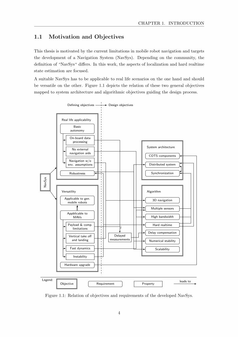
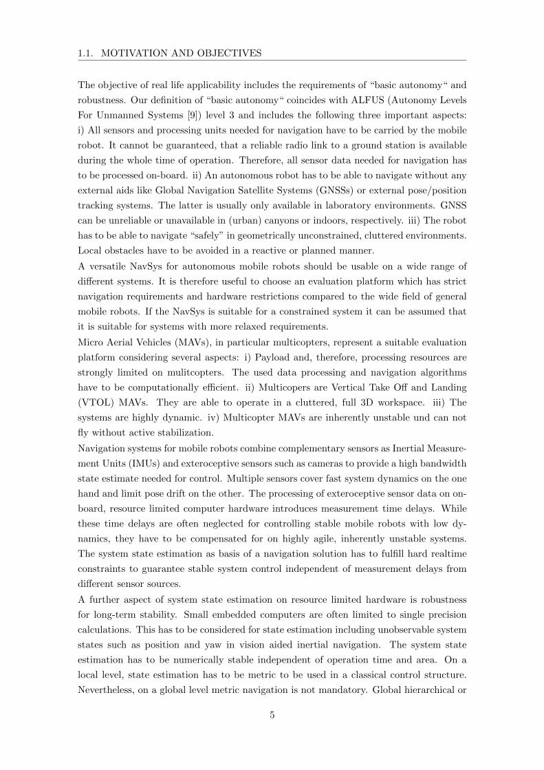
A suitable NavSys has to be applicable to real life scenarios on the one hand and should
be versatile on the other. Figure 1.1 depicts the relation of these two general objectives
mapped to system architecture and algorithmic objectives guiding the design process.
Real life applicability
Basicautonomy
On-board dataprocessing
No externalnavigation aids
Navigation w/oenv. assumptions
Robustness
Versatility
Applicable to gen.mobile robots
Appblicable toMAVs
Payload & comp.limitations
Vertical take offand landing
Fast dynamics
Instability
Hardware upgrade
Na
vSys
Algorithm
3D navigation
Multiple sensors
High bandwidth
Hard realtime
Delay compensation
Numerical stability
Scalability
Synchronization
Distributed system
COTS components
System architecture
Delayedmeasurements
Defining objectives Design objectives
Legend:Objective Requirement Property
leads to
Figure 1.1: Relation of objectives and requirements of the developed NavSys.
4
1.1. MOTIVATION AND OBJECTIVES
The objective of real life applicability includes the requirements of “basic autonomy“ and
robustness. Our definition of “basic autonomy“ coincides with ALFUS (Autonomy Levels
For Unmanned Systems [9]) level 3 and includes the following three important aspects:
i) All sensors and processing units needed for navigation have to be carried by the mobile
robot. It cannot be guaranteed, that a reliable radio link to a ground station is available
during the whole time of operation. Therefore, all sensor data needed for navigation has
to be processed on-board. ii) An autonomous robot has to be able to navigate without any
external aids like Global Navigation Satellite Systems (GNSSs) or external pose/position
tracking systems. The latter is usually only available in laboratory environments. GNSS
can be unreliable or unavailable in (urban) canyons or indoors, respectively. iii) The robot
has to be able to navigate “safely” in geometrically unconstrained, cluttered environments.
Local obstacles have to be avoided in a reactive or planned manner.
A versatile NavSys for autonomous mobile robots should be usable on a wide range of
different systems. It is therefore useful to choose an evaluation platform which has strict
navigation requirements and hardware restrictions compared to the wide field of general
mobile robots. If the NavSys is suitable for a constrained system it can be assumed that
it is suitable for systems with more relaxed requirements.
Micro Aerial Vehicles (MAVs), in particular multicopters, represent a suitable evaluation
platform considering several aspects: i) Payload and, therefore, processing resources are
strongly limited on mulitcopters. The used data processing and navigation algorithms
have to be computationally efficient. ii) Multicopers are Vertical Take Off and Landing
(VTOL) MAVs. They are able to operate in a cluttered, full 3D workspace. iii) The
systems are highly dynamic. iv) Multicopter MAVs are inherently unstable und can not
fly without active stabilization.
Navigation systems for mobile robots combine complementary sensors as Inertial Measure-
ment Units (IMUs) and exteroceptive sensors such as cameras to provide a high bandwidth
state estimate needed for control. Multiple sensors cover fast system dynamics on the one
hand and limit pose drift on the other. The processing of exteroceptive sensor data on on-
board, resource limited computer hardware introduces measurement time delays. While
these time delays are often neglected for controlling stable mobile robots with low dy-
namics, they have to be compensated for on highly agile, inherently unstable systems.
The system state estimation as basis of a navigation solution has to fulfill hard realtime
constraints to guarantee stable system control independent of measurement delays from
different sensor sources.
A further aspect of system state estimation on resource limited hardware is robustness
for long-term stability. Small embedded computers are often limited to single precision
calculations. This has to be considered for state estimation including unobservable system
states such as position and yaw in vision aided inertial navigation. The system state
estimation has to be numerically stable independent of operation time and area. On a
local level, state estimation has to be metric to be used in a classical control structure.
Nevertheless, on a global level metric navigation is not mandatory. Global hierarchical or
5
CHAPTER 1. INTRODUCTION
topological navigation schemes can make a NavSys scalable. Independent of the chosen
global navigation scheme, a decoupling of realtime, metric local navigation and (non-
realtime) global navigation brings flexibility and can improve the numerical properties of
the local navigation algorithm.
For the design of a versatile NavSys, system architecture requirements (including hardware
and software aspects) have to be considered as well: i) To improve system robustness, it
is desirable to separate system critical, Realtime (RT) tasks from less critical high level
(navigation) tasks not only at a software but at a hardware level resulting in a distributed
system architecture. In this way the robot can still be brought to a safe state in the
case of a malfunction of high level algorithms that might otherwise block the RT system.
ii) A distributed system with a multitude of different sensors poses the need for exact
time synchronization not only between the actual computers but also between sensors.
The timestamp of a sensor measurement, provided by an operating system driver, is not
necessarily the actual time the measurement was taken. Even though, assuming the time
stamp was exact, there can be a considerable delay between the actual data measurement
and the availability of the (exact) time stamp. iii) The development of computer and
sensor hardware, especially in the embedded computer sector, is very fast. It is therefore
desirable to use Commercial Off-The-Shelf (COTS) hardware components that can be
easily upgraded as soon as a more powerful version is available.
The so far mentioned aspects of navigation systems specify four classes of objectives:
Firstly, the two defining objectives: the applicability objective under real life conditions
and the versatility objective. And secondly, the two design objectives: the algorithmic
objective and the system architecture objective. The latter directly influence the design
of the NavSys and can be summarized as follows:
1. Versatile navigation algorithm allowing “basic autonomy“ including the aspects of:
(a) Robust, hard realtime, high bandwidth, metric state estimation covering fast
system dynamics despite delayed measurements from multiple sensors
(b) Algorithmic robustness in terms of numerical stability and (partial) sensor drop
outs
(c) Algorithmic scalability in terms of runtime and area of operation
2. Versatile system architecture concept including the aspects of:
(a) Distributed system design
(b) Inter system and sensor synchronization
(c) Use of COTS components
6
1.2. METHODOLOGY
1.2 Methodology
In the following, we summarize the developed methodology to tackle the introduced algo-
rithmic and system architecture objectives. The first part puts the navigation algorithm
into context with the most relevant state of the art updating the related work Section of
the publications included in the second part of this thesis. In the second part, the method-
ology of the developed system architecture considering hardware and software aspects is
introduced.
1.2.1 System State Estimation Framework for Highly Dynamic Systems
A common approach for hard realtime system state estimation needed for the control
of highly dynamic, inherently unstable systems is the combination of IMUs with further
complementary sensors such as cameras or laser scanners in an Inertial Navigation System
(INS). In this way fast system dynamics are covered by the fast proprioceptive sensors
while state drift is limited by the slower exteroceptive sensors. To consider the autonomy
objective, mobile robots have to carry on-board all sensor and computer equipment needed
for navigation.
Processing of Time Delayed (Keyframe-)Odometry Measurements
In recent years, several loosely coupled INSs suitable for MAV navigation have been pre-
sented. In mono vision systems often a visual Self Localization and Mapping (SLAM)
algorithm as PTAM [10], SVO [20] or LSD [19] is used to estimate the scale invariant sys-
tem pose. An Extended Kalman Filter based INS combines inertial measurements with
this pose and estimates scale as introduced by Weiss et al. [18, 16]. A general estimation
framework, using similar ideas as in this work, was recently published by Lynen et al.
[17]. Nevertheless, measurement delays are compensated by buffering and recalculation at
the time of measurement arrival. This approach leads to load peaks when a measurement
arrives and can violate hard realtime constraints of the filter system.
Meier et al. [15] use a stereo vision and optical flow system for pose estimation with
synchronized inertial cues. Position and attitude are estimated in separate filters without
an explicit delay compensation similar to the published work of Heng et al. [21]. In
a recent publication [22] Heng et al. use a multi-camera visual SLAM system for pose
estimation in combination with the framework of Weiss et al. [16] for the integration of
IMU measurements.
The proposed loosely coupled delayed error state space Extended Kalman Filter (EKF-
INS) uses state augmentation techniques to compensate for measurement time delays
and to enable the framework to process relative pose measurements generated by general
odometry sensors as for example a stereo vision system. The odometry measurement is
general in terms of supporting a certain number of keyframes: Saved keyframes in the
past can be re-referenced to calculate relative pose measurements realizing a local drift
7

CHAPTER 1. INTRODUCTION
free navigation.
System states needed for the processing of the delayed measurements are cloned at the
exact time of the measurement using sensor hardware trigger signals. In this way the re-
quirements on measurement timestamp precision and (inter system) communication delays
can be relaxed.
The filter framework processes (time delayed) relative or absolute measurements immedi-
ately upon arrival while (time delayed) relative measurements from different sensors can
overlap. In this way processor load is balanced over time as no measurement buffering
is conducted. Out of order measurements can be processed in the same way as regular
measurements. Furthermore, the maximum runtime of the estimation algorithm can be
limited even with variations in the odometry measurement time delays. These properties
are a prerequisite for hard-realtime operation.
Closed Form State Augmentation for Square Root UD Filters
For the implementation of a vision based EKF-INS suitable for long-term operation nu-
merical stability is essential. Parallelizing floating point units on light-weight, embedded
processors (e.g. ARM NEON) often only support hardware acceleration for single precision
floating point operations. Furthermore, employing continuous state augmentation and re-
moval within an INS filter, the covariance matrix is badly conditioned: After state cloning
the covariance matrix is rank deficient. In the next prediction step the rank is filled up by
system noise but the Eigenvalues of the Matrix are still small. Furthermore, unbounded
covariance values for unobservable states are combined with small, bounded covariance
values as for example IMU biases. Such situations are critical for regular Kalman Filter
implementations as emphasized by Maybeck [5]. In [RIEDL2011] we revealed numerical
instability up to filter divergence for a regular implementation of the delayed error state
space Extended Kalman Filter.
Square root filters have superior numerical properties. Implemented in single precision
they reach at least the quality of a regular double precision implementation [5, 3] with
a moderate increase in computational time. A numerically robust filter form, the square
root UD filter, was developed by Thornton [2]. In this form, no actual square roots have
to be computed.
The square root UD filter implementation serves as numerically stable basis concept.
In this formulation, the filter covariance matrix is expressed as P = UDUT , where
U is a strictly upper triangular matrix and D a diagonal matrix. In its original form
Thornton uses Modified Weighed Gram-Schmidt Orthogonalization (MWGS) [4] for state
propagation which is basically a modified QR factorization.
A new, numerically stable augmentation technique in closed square root UD form was
developed. The filter covariance is expressed as P = SUDUTST where S is a state
selection matrix with exactly one 1 per line used to add or remove states from the filter
in closed UD form. The resulting covariance matrix after state cloning is rank deficient
8

1.2. METHODOLOGY
but (depending on the system noise model) gets full rank again in the propagation step.
Therefore, state augmentation and removal are directly integrated into the filter propa-
gation step. Similarly to the augmentation technique in iSAM [14] by QR factorization
of the square root information matrix by regular Givens rotations, modified Givens rota-
tions (introduced by Gentleman [1]) for covariance propagation are employed. Triangular
shaped system (and noise propagation) matrices and some state cloning configurations
result in a sparse QR problem in the prediction step. This sparsity can be exploited using
Givens rotations for triangularization.
Numerically Stable Local Navigation by Reference Switching
Even though the proposed UD Filter improves numerical stability, overall numerical sta-
bility can not be guaranteed as the odometry based INS includes unobservable states [16].
These are in detail position (x,y,z) and yaw angle. For long-term numerical stability the
covariance of unobservable states has to be limited in some way.
A concept for combining local metric navigation with global topological navigation was
developed with the Local Reference Inertial Navigation System (LR-INS) [FUSION2014]
and generalized as Local Reference square root UD filter. The concept is inspired by the
sub mapping technique in hierarchical/topological SLAM [8, 11, 7]. The LR-filter has sim-
ilarities with the concept of Concurrent Filtering and Smoothing (CFS) [24]. Nevertheless,
in CFS the focus is set on the combination of non realtime smoothing over the whole robot
trajectory with parallel realtime filtering. Keeping a global trajectory of the robot with
all accumulated measurements collides with the posed scalability objective. The LR-filter
concept was designed to combine local, metric realtime navigation with global topological
navigation but can also be used with a smoothing back end in terms of CFS. The focus is
set on closed form integration of filter reference switching into square root UD filters.
Filter switching gives a solution for the problem of rising covariances for unobservable
system states. Considering INSs, the new reference system can be either the current robot
pose, a distinct landmark or only unobservable partial states as for example position
and yaw errors. The current (augmented) system state as well as the corresponding
(error) covariances are transformed within a prediction step into the new reference system.
In this way, regularly unbounded covariances of the corresponding unobservable system
states are limited and numerical stability within the EKF-INS is improved. Furthermore,
small error assumptions in the linearized system error model are better fulfilled due to
potentially smaller errors in the new reference frame. Employing keyframe odometry with
the reference frame in the keyframe pose turns a relative pose update into an absolute
pose update. The system becomes observable in the new reference frame.
Similar to state cloning, transforming filter states into an augmented state reference frame
results in a rank deficiency of the covariance matrix. By integrating transformation and
state marginalization directly into a prediction step the covariance matrix keeps its rank.
Nevertheless, the matrix is still close to singularity which encourages the use of a stable
9
CHAPTER 1. INTRODUCTION
square root filter implementation. By generalizing the algorithm described in the last
paragraph, all operations (state augmentation/marginalization/transformation) can be
directly carried out in closed square root UD form within one prediction step. Execution
time depends only on the number of system states which can be limited independently of
the system runtime or area of operation. This guarantees scalability of the algorithm and
a limited maximum execution time which is a requirement for (hard) realtime execution.
The LR-INS is designed as a scalable, locally metric, hard realtime state estimation algo-
rithm. As the new state reference can be freely chosen the system can be easily combined
with global non-realtime navigation algorithms. The LR-filter can be applied to general
unobservable systems to limit the rise of state covariances in a consistent way by local
reference transformations.
1.2.2 System Architecture
For navigation algorithm evaluation and testing on MAVs a unified, modular system archi-
tecture concept was developed. It considers hardware as well as software aspects. Designed
for highly agile systems with limitations in payload, the concept is suitable for a wide range
of mobile robots.
Hardware Concept
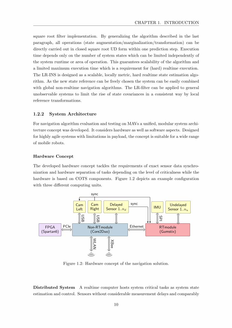
The developed hardware concept tackles the requirements of exact sensor data synchro-
nization and hardware separation of tasks depending on the level of criticalness while the
hardware is based on COTS components. Figure 1.2 depicts an example configuration
with three different computing units.
FPGA(Spartan6)
Non-RTmodule(Core2Duo)
RTmodule(Gumstix)
CamLeft
CamRight
DelayedSensor 1..nd
IMUUndelayedSensor 1..nu
sync
sync
USB
USB
SPI
PCIe Ethernet
WLAN
XBee
Figure 1.2: Hardware concept of the navigation solution.
Distributed System A realtime computer hosts system critical tasks as system state
estimation and control. Sensors without considerable measurement delays and comparably
10
1.2. METHODOLOGY
low data processing costs are connected via time deterministic buses. Further non realtime
computers host less critical but computationally intense tasks. Sensors are often connected
via buses without deterministic timing constraints. Well tested, computationally expensive
algorithms (i.e. Semi Global Matching (SGM) stereo processing at the current state of
development) can be moved to specialized acceleration hardware as Field Programmable
Gate Arrays (FPGAs). Intersystem communication is realized by standard ethernet. A
high bandwidth wireless LAN and a reliable low bandwidth radio link provide a flexible
communication infrastructure to external computers for visualization and monitoring.
Synchronization Hardware sensor trigger signals are used to register the exact mea-
surement time on the realtime system. This is the basis for immediate measurement delay
compensation without data buffering and recalculation. In this way, timing (and time
stamping) requirements on the non-realtime system can be relaxed.
COTS Components The system can be easily extended by further processing units
according to computational requirements and available payload. The architecture enables
the use of COTS hardware components simplifying a module change to the most suitable
computer boards available.
Software Concept
The software concept considers algorithmic requirements such as realtime capabilities of
the operation system, the underlying hardware infrastructure consisting of a distributed
system and practical software development aspects.
Operating system A unified operating system (OS) on all distributed computers (with
potentially different processor architectures) simplifies the transparent exchange of soft-
ware modules between systems. The OS should be available for a wide range of process-
ing units to preserve the possibility of flexible hardware exchange. Peripheral hardware
support and realtime capabilities are important factors for the selection of an operating
system. Linux with realtime kernel extensions fits most of the mentioned aspects.
Synchronization The software concept has to provide a robust time synchronization
scheme. The distributed computers need to be transparently synchronized on system level
for a common time basis. Furthermore, imprecise time stamps of sensor measurements
have to be considered. These imprecisions can be caused by non time deterministic system
buses (as for example USB) connecting COTS sensors and computers. Precise time stamps
at the time of the actual sensor measurement can be generated on the realtime system by
system level hardware interrupts registering sensor hardware triggers.
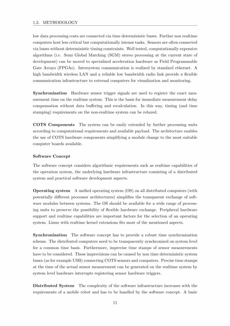
Distributed System The complexity of the software infrastructure increases with the
requirements of a mobile robot and has to be handled by the software concept. A basic
11

CHAPTER 1. INTRODUCTION
Ground Station
Navigation Box
Core2Duo
GumstixFPGA
MAV
Cam 1 Cam 2 IMU
ImageRectification
VisualOdometry
Mapping
Planning
MissionControl
StereoMatching
StrapdownAlgorithm
Data Fusion
Controller
ReferenceGenerator
LL StateMachine
Autopilot
WLAN
XBee
Operator Interface
trigg
er
sync
EthernetPCIe Ethernet
SP
I
US
B
US
B
PCIe
UART
UART
Wireless
Power
Mechanical
Hardware
Software
Physical
communication
Data
Command
channel
Time trigger
Figure 1.3: Software distribution and data flow overview of the Pelican2 MAV (see Chapter3.1) published in [JFR2014].
autonomous navigation solution includes a wide range of software modules covering state
estimation, control, odometry, mapping, path planning and mission control as depicted
in Figure 1.3. Distributing these modules over several computers requires a transparent
communication infrastructure and a clear separation of tasks depending on system crit-
icalness and computational costs. On system level, different communication channels as
on-board ethernet and partially available radio links to off board computers can be trans-
parently bridged. On module level, a suitable middleware as for example Robot Operating
System (ROS) enables transparent interprocess communication. A clear module structure
and the definition of abstract navigation tasks provide the basis for mission control.
12

Chapter 2
Contributions
In this chapter, contributions and publications are summarized and set into context. The
structure of contributions and corresponding publications is depicted in Figure 2.1.
View planning heuristicfor aerial reconstruction
Journal of Intelligent & RoboticSystems 2012 (Paper 1)
State estimation framework forfusion of IMU with multiple
time delayed (relative) measurementsIROS 2012
Scalable, numerically robustlong-term navigation
FUSION 2014(Paper 4)
Unified Hardware/Software conceptfor complex MAV missions
Robotics and AutomationMagazine 2012 (Paper 2)
Mobile Perception Device (MoPeD)for state estimation and mapping
ICRA 2013
Closed loop MAV navigationwith on-board path planning IROS 2013
Journal of FieldRobotics 2014 (Paper 3)
Application of MAVs inchallenging SAR scenarios
RSS WS 2013
Application tohumanoid robot
Humanoids 2014
Vie
wp
lan
nin
gS
tate
esti
ma
tio
nA
uto
no
mo
us
na
vig
ati
on
Ap
plica
tio
ns
Legend:
ContributionPublicationnot included
Publicationincluded
leads to
Figure 2.1: Overview of contributions and corresponding publications.
The contributions are grouped into the fields of view planning, state estimation, au-
tonomous navigation and applications. In the first contribution a view planning heuristic
13
CHAPTER 2. CONTRIBUTIONS
for aerial multi-view stereo reconstruction in a possible SAR scenario in the mountains was
developed. The algorithm and evaluation results are published as article in the Journal
of Intellegent & Robotic Systems, included as Paper 1 in the second part of this thesis.
A commercially available MAV1 based on GPS navigation was used for data acquisition.
To overcome the identified limitations (see Chapter 2.1, Paper [JIRS2012], Results and
Conclusion) in autonomous navigation a state estimation framework for highly dynamic
systems based on on-board sensors only was developed and published in a conference paper
at IROS 2012. Support for local reference navigation was added to render the framework
scalable and robust for long-term navigation. The algorithm and evaluation results were
published in an article at the FUSION 2014 conference, included as Paper 4 (chronolog-
ical order) in this thesis. Based on the functionality of autonomous localization in the
sense of state estimation, a hardware and software concept for autonomous MAV naviga-
tion in complex scenarios was developed and published in an article in the Robotics and
Automation Magazine, included in this thesis as Paper 2. The concept was extended in
the development of the Mobile Perception Device (MoPeD, see Chapter 3.1), a handheld
device for stereo vision based realtime state estimation and mapping. The system and
its evaluation was introduced by a conference article at ICRA 2013, not included in this
thesis. The MoPeD was integrated on a quadrotor platform (Pelican2, see Chapter 3.1)
and complemented by an on-board path planner allowing autonomous MAV navigation
in cluttered indoor and outdoor environments. The entire system and its evaluation was
published in a conference article at IROS 2013. Introducing a live demonstration of au-
tonomous indoor navigation, a summary of the IROS 2013 article was published at the RSS
2013 workshop on Resource-Efficient Integration of Perception, Control and Navigation
for Micro Air Vehicles. The reworked system concept of the Pelican2, a further evaluation
of the MAV navigation system in possible SAR scenarios as well as the most important
contributions of the articles of IROS 2012, ICRA 2013 and IROS 2013 were published in
an article in the Journal of Field Robotics, included in this thesis as Paper 3. A slightly
modified version of the MoPeD enables autonomous navigation for the humanoid robot,
TORO (see Chapter 3.2). An overview of the robotic system was published in an article
at HUMANOIDS 2014, not included in this thesis.
In the following Section, an overview of all peer-reviewed publications ordered by contri-
bution groups is given. If available, additional multimedia material is referenced. A list
of the publications as well as a list of supervised student research projects is provided at
the end of the chapter. The full articles which cover the main contributions are included
in chronological publication order in the second part of this thesis.
1 Asctec Falcon8: http://www.asctec.de
14
2.1. DATA ACQUISITION FOR AERIAL 3D RECONSTRUCTION
2.1 Data Acquisition for Aerial 3D Reconstruction
Paper [JIRS2012] (included as Paper 1)
K. Schmid, H. Hirschmuller, A. Domel, I. Grixa, M. Suppa, and G. Hirzinger. “View
Planning for Multi-View Stereo 3D Reconstruction Using an Autonomous Multicopter”.
In: Journal of Intelligent & Robotic Systems 65.1-4 (2012), pp. 309–323
Context and Summary In a field study the use of commercially available multicopter
platforms as aerial support systems for mountain rescue teams was evaluated. In close
cooperation with the Bavarian mountain rescue association the automated aerial mapping
of dangerous avalanche areas was identified as helpful application. With the availability
of a precise 3D model of the avalanche area a rescue mission can be precisely planned
identifying potential risk areas for the rescue team.
Multi-view stereo algorithms are an attractive technique for the digital reconstruction of
outdoor sites. A MAV with a monocular photo camera on a pan tilt unit is sufficient
for the data acquisition process. To render a precise 3D reconstruction possible a certain
overlap between the acquired images has to be guaranteed. This requirement results in
viewpoint constraints for the flying robot.
Contribution A new, fast, offline viewpoint planning algorithm was developed. It is
based on a coarse digital surface model (DSM) which is available from map providers
for most regions in the world. The planning heuristic considers coverage, maximum view
angle and image overlapping constraints. The time complexity of the algorithm is linear
with respect to the size of the area of interest.
Results and Conclusion We demonstrated the efficiency of the entire system in two
scenarios, the reconstruction of a building and a hillside in the Alps. The automatically
acquired images were post processed resulting in 2.5D models with a resolution of 5 cm.
The proposed system has limitations considering autonomous navigation: A coarse a priori
map of the area of interest is needed. Obstacles which are not part of the map can not
be considered and might result in collisions. Furthermore, the navigation of the MAV
depends on the availability of a Global Positioning System (GPS) signal which also defines
the effective precision of viewpoints. These limitations inspired further research in the area
of autonomous navigation for agile flying robots.
Related Video
http://youtu.be/xtOj8ozPWew
15

CHAPTER 2. CONTRIBUTIONS
2.2 System State Estimation
Paper [IROS2012]
K. Schmid, F. Ruess, M. Suppa, and D. Burschka. “State estimation for highly dynamic
flying systems using key frame odometry with varying time delays”. In: Intelligent Robots
and Systems (IROS), 2012 IEEE/RSJ International Conference on. Oct. 2012, pp. 2997–
3004
Context and Summary To overcome the identified limitations in autonomy a new
state estimation framework as basis of a navigation system was developed. Starting from
a standard inertial navigation approach (INS) a special focus is set on extensions for the di-
rect, simultaneous integration of different, time delayed relative measurements under hard
realtime constraints. The supervised bachelor’s thesis of Sebastian Riedl [RIEDL2011]
revealed the instability of regular Kalman Filter implementations for the proposed filter
approach and motivated the use of a square root UD filter. A system concept suitable
for a quadrotor was developed considering the introduced objectives of a flexible system
architecture. The state estimation system was evaluated in simulations and in flight ex-
periments. The simulated quadrotor trajectory is divided into three parts including a flip
as well as low and high dynamic passages. In the real quadrotor experiments the MAV
was guided by manually calculated waypoints to fly from inside a building through the
window to the outside.
Contribution A new state estimation framework on the basis of a delayed error state
space extended Kalman Filter was introduced. The use of hardware sensor triggers to
initiate state augmentation is a new application of stochastic cloning for measurement
time delay compensation. Furthermore, the concept is extended to support inertial mea-
surement fusion with multiple, time delayed general odometry sensor measurements with
keyframe support. State augmentation and marginalization are mathematically general-
ized. This formulation builds the basis to apply these operations to square root filter
implementations. The first version of a system concept suitable for UAV navigation was
introduced.
Results and Conclusion The developed state estimation framework and system con-
cept was demonstrated to be suitable for control of a highly dynamic quadrotor MAV.
Relative, delayed measurements can be processed while delays are compensated implic-
itly. The system concept relaxes the requirements on exact measurement time stamps
and allows task execution on a distributed system separating realtime from non-realtime
tasks. The influence of measurement time delays up to 1 s and frequencies from 15 Hz
to 1 Hz on the quality of the state estimate was evaluated in Monte Carlo simulations.
The simulation results emphasized the importance of measurement frequency compared
to delays. While velocity errors, important for system control, rise exponentially with
16
2.2. SYSTEM STATE ESTIMATION
lower frequency, the relation is linear with longer delays. This strongly motivates the
acceleration of sensor data processing by parallelization and pipelining techniques as in
hardware accelerated data processing algorithms on FPGAs. The entire state estimation
system as basis for closed loop control was tested on a Pelican quadrotor using only inertial
measurements combined with Iterative Closest Point (ICP) based laser and stereo vision
keyframe odometry with 80 ms and about 300 ms delay, respectively.
Related Video
http://youtu.be/r6tQu4o5PAA
Paper [FUSION2014] (included as Paper 4)
K. Schmid, F. Ruess, and D. Burschka. “Local reference filter for life-long vision aided
inertial navigation”. In: Information Fusion (FUSION), 2014 17th International Confer-
ence on. July 2014, pp. 1–8
Context and Summary The introduced NavSys is based on a state estimator including
unobservable states which are position and yaw angle errors. While the system is well
suited for short-term operation, the unbounded rise of state covariance (errors) can result
in numerical instability. To solve this issue the Local Reference Inertial Navigation System
(LR-INS) was developed. Instead of using a global reference for state estimation, the states
and corresponding covariances are transformed to local reference frames. Expressed in the
new frame the state covariances become smaller compared to the global reference.
Contribution State cloning, marginalization and reference switching operations needed
in the introduced NavSys bring the state covariance matrix close to rank deficiency. This
situation is especially critical in regular Kalman Filter implementations. The Kalman
Filter prediction step was generalized to include all LR-Filter operations. With this gen-
eralization state switching can be directly integrated into a numerically stable square root
UD filter implementation. The algorithm was evaluated in a simulated 24 h quadrotor
flight and in real quadrotor flights with repeated reference switching. The Filter concept
is general and could be applied to other state estimation problems including unobservable
states.
Results and Conclusion The conducted experiments proved the long-term stability
of the developed LR-INS. The concept allows the combination of local metric, realtime
state estimation with global topological or hierarchical navigation concepts. In this way,
the system fulfills the scalability and robustness objectives.
17

CHAPTER 2. CONTRIBUTIONS
2.3 Autonomous, Realtime Navigation and Applications
Paper [RAM2012] (included as Paper 2)
T. Tomic, K. Schmid, P. Lutz, A. Domel, M. Kassecker, E. Mair, I. Grixa, F. Ruess,
M. Suppa, and D. Burschka. “Toward a Fully Autonomous UAV: Research Platform for
Indoor and Outdoor Urban Search and Rescue”. In: Robotics Automation Magazine,
IEEE 19.3 (Sept. 2012), pp. 46–56
Context and Summary The paper details the hardware and software concepts of
the DLR Pelican1 quadrotor platform, designed for the 2011 International Micro Aerial
Vehicle competition (IMAV). It summarizes and extends publication [IROS2012] with the
focus on system architecture design. Further modules for autonomous MAV navigation
are introduced. These tackle the tasks of mission control, environment representation,
path planning, object recognition and control.
Contribution A unified hardware and software concept for a complex MAV mission
was developed. The hardware concept separates low level realtime tasks from high level
navigation tasks to improve system robustness. The software concept tackles interaction
between low-level state estimation and control with high-level tasks as object recognition,
environmental representation, path planning and mission control.
Results and Conclusion The system concept laid the groundwork for our first in-
door/outdoor transition flights using correlation based stereo visual odometry in combi-
nation with ICP based laser odometry. The system architecture of the Mobile Perception
Device introduced in publication [ICRA2013] is a further iteration of the system concept.
Paper [ICRA2013]
K. Schmid and H. Hirschmuller. “Stereo vision and IMU based real-time ego-motion and
depth image computation on a handheld device”. In: Robotics and Automation (ICRA),
2013 IEEE International Conference on. May 2013, pp. 4671–4678
Context and Summary The simulation results of publication [IROS2012] motivated
the replacement of the processor based stereo vision pipeline by a FPGA accelerated
pipeline. The employed stereo vision pipeline provides depth images of 0.5 MPixel and
keyframe odometry measurements at a frequency of 14.6 Hz with a delay of about 250 ms.
Improving the estimation quality by a higher visual odometry frequency (and higher pre-
cision due to higher resolution) we evaluated whether stereo vision aided INS is sufficient
for robust state estimation even in challenging conditions. Using stereo vision as sole ex-
teroceptive sensor, the total weight of the sensor and computer hardware could be lowered
by removing the laser scanner so far aiding. The Mobile Perception Device (MoPeD) was
developed as evaluation platform. It includes a stereo camera pair, an IMU, a Core2Duo, a
18
2.3. AUTONOMOUS, REALTIME NAVIGATION AND APPLICATIONS
FPGA and an ARM processor board. The system was tested in several indoor/outdoor ex-
periments. Using this handheld device the state estimation could be tested independently
of the quadrotor control system.
Contribution The introduced system concept was extended for FPGA vision accel-
eration preserving the hard realtime capability of the state estimator. Considering the
importance of a static camera to IMU configuration on flying systems the MoPeD was
designed as a single, stiffly constructed navigation box that could be easily mounted on
a quadrotor. Two different real life scenario experimental setups were evaluated: In the
first setup a combined indoor/outdoor run with strongly varying feature and lighting con-
ditions was examined. In the second experimental configuration the robustness of the
system against vision drop outs over several seconds was evaluated. The depth images
were combined in a probabilistic map using pose estimates of the state estimator.
Results and Conclusion The developed MoPeD combines high-latency FPGA stereo
acceleration with realtime state estimation in a light-weight navigation box composed
of COTS hardware. Extensive experiments proved the robustness of the system against
vision drop outs and made an elimination of the laser scanner from the quadrotor sensor
suite possible. The probabilistic map is the basis of an autonomous navigation system.
Related Video
http://youtu.be/FalRPdirgds
Paper [IROS2013]
K. Schmid, T. Tomic, F. Ruess, H. Hirschmuller, and M. Suppa. “Stereo vision based
indoor/outdoor navigation for flying robots”. In: Intelligent Robots and Systems (IROS),
2013 IEEE/RSJ International Conference on. Nov. 2013, pp. 3955–3962
Awarded with the 2013 IROS Robocup Best Paper Award
Context and Summary The results of [ICRA2013] proved the suitability of the MoPeD
as state estimation and mapping module in challenging environments with vision drop
outs over several seconds. A weight optimized version of the MoPeD was integrated
as navigation module for a quadrotor. By using a damped mounting, the weight of the
navigation box is exploited for passive vibration damping. The state estimates are directly
used for control. A path planner operating on the on-board map is used to calculate
collision free paths to given waypoints. The map is sent to a ground station where an
operator can set waypoints to guide the MAV. The navigation solution was evaluated in
autonomous quadrotor flights starting inside a building, leaving through a window, circling
the building, reentering through the door and returning to the starting point.
19
CHAPTER 2. CONTRIBUTIONS
Contribution The MoPeD was extended with an A* path planner. Therefore, a hori-
zontal layer at the altitude of the quadrotor and its height as thickness is cut out of the 3D
map. The occupied cells projected to the horizontal plane build a 2D collision map. All
navigation tasks from realtime state estimation, mapping and path planning are running
on-board, closing the perception action loop.
Results and Conclusion At time of publication, the first vision based flying system
that can navigate autonomously in complex, geometrically unconstrained, cluttered in-
door/outdoor environments without vertical wall or flat ground assumptions and full on-
board data processing was presented. It was demonstrated that high latency, FPGA
accelerated stereo vision odometry combined with inertial measurements is sufficient for
autonomous navigation for highly, dynamic inherently unstable flying robots in challenging
environmental conditions. The introduced NavSys integrated on a quadrotor demonstrates
the usability of MAVs for exploration of cluttered, geometrically unconstrained environ-
ments as would be needed in SAR scenarios. The navigation system is based on locally
drift free state estimation. Even though the accumulated drift in the described experi-
ments is small (less than 2 %) the global map is inconsistent. Nevertheless, the map is
locally precise allowing a collision free navigation given global guidance.
Related Video
http://youtu.be/84DiSpPhKJA
Paper [RSS2013]
K. Schmid, M. Suppa, and D. Burschka. “Towards Autonomous MAV Exploration in
Cluttered Indoor and Outdoor Environments”. In: Robotics: Science and Systems (RSS)
Workshop on Resource-Efficient Integration of Perception, Control and Navigation for
Micro Air Vehicles (MAVs). June 2013
Context and Summary At the RSS 2013 workshop on Resource-Efficient Integration
of Perception, Control and Navigation for Micro Air Vehicles, a live demonstration of
autonomous indoor navigation of a quadrotor was given. The corresponding publication
summarizes the concept of the navigation solution introduced in [IROS2013]. After take
off, the quadrotor navigated autonomously between predefined waypoints while building
an on-board map of the conference room. A pattern on a landing platform was identified
during the flight. At the end of exploration, the quadrotor positioned above the pattern
and landed on the 50 cm x 50 cm platform.
Contribution The live demonstration showed the application of the navigation solution
for general indoor navigation.
20
2.3. AUTONOMOUS, REALTIME NAVIGATION AND APPLICATIONS
Results and Conclusion The demonstration underlined the robustness and precision
of the proposed navigation solution in challenging environments. The system navigated
safely despite low texture conditions in the conference room and moving people in the
audience. The system concept for mission control made a fully autonomous flight without
interaction by an operator possible.
Related Video
http://youtu.be/MMIRPD1bO4I
Paper [JFR2014] (included as Paper 3)
K. Schmid, P. Lutz, T. Tomic, E. Mair, and H. Hirschmuller. “Autonomous Vision-based
Micro Air Vehicle for Indoor and Outdoor Navigation”. In: Journal of Field Robotics 31.4
(2014), pp. 537–570
Context and Summary The publication combines and extends the contributions of
[IROS2012, ICRA2013, IROS2013]. It consists of two parts. The first part can be un-
derstood as tutorial describing the design process of a NavSys for MAVs in form of a
navigation box module. Hardware aspects considering system architecture and mechan-
ical integration are covered. The software part of the tutorial tackles realtime system
aspects on embedded computers and extrinsic camera to IMU calibration. The second
part of the publication covers the developed algorithms for autonomous navigation. This
includes stereo visual odometry, sensor data fusion, control, mapping, path planning and
mission control. Further experiments are included.
Contribution A new iteration of the system architecture concept for autonomous nav-
igation introduced in [RAM2012] is provided. The software architecture considers task
distribution, synchronization and communication via unreliable radio links. Aspects of
hard realtime constraints of the state estimation framework are discussed. The mapping
planning and mission control pipeline is explained in detail. The NavSys was evalu-
ated in further experiments using a quadrotor for vision based mixed outdoor and indoor
multi floor mapping. Robustness in harsh environmental conditions was proved by an
autonomous quadrotor exploration flight in a dusty and gloomy coal mine.
Results and Conclusion The tutorial part of the publication can be a helpful guide
to prevent typical pitfalls when building an autonomous quadrotor platform starting from
commercially available MAVs. Robustness and precision of the introduced NavSys were
proved in simulations, on a handheld device and in several challenging real life flight
scenarios. The developed NavSys enables autonomous, short-term navigation of highly
dynamic, inherently unstable flying robots.
21

CHAPTER 2. CONTRIBUTIONS
Related Videos
http://youtu.be/iRvRU9XfNNk
http://youtu.be/RNpbxQurpd8
Paper [HUMANOIDS2014]
J. Englsberger, A. Werner, C. Ott, B. Henze, M. Roa, G. Garofalo, R. Burger, A. Beyer, O.
Eiberger, K. Schmid, and A. Albu-Schaffer. “Overview of the torque-controlled humanoid
robot TORO”. in: Humanoid Robots (HUMANOIDS), 2014 IEEE/RAS International
Conference on. Nov. 2014
Context and Summary The paper gives an overview on the torque- controlled hu-
manoid robot TORO, which has evolved from the former DLR Biped. In particular, its
mechanical design and dimensioning, its sensors, electronics and computer hardware is
described. Additionally, a short introduction to the walking and multi-contact balancing
strategies is given.
Contribution The sensor and system concept of the MoPeD was applied to autonomous
navigation of a humanoid robot. The solution was slightly adapted and integrated into
TORO’s head.
Results and Conclusion The unmodified state estimator designed for MAVs can be
directly used on a humanoid robot. The future integration of a motion model could
improve map precision to be usable for step planning in the sub centimeter range.
22
2.4. LIST OF PUBLICATIONS AND AWARDS
2.4 List of Publications and Awards
International Journals
[JIRS2012] K. Schmid, H. Hirschmuller, A. Domel, I. Grixa, M. Suppa, and G.
Hirzinger. “View Planning for Multi-View Stereo 3D Reconstruction Us-
ing an Autonomous Multicopter”. In: Journal of Intelligent & Robotic
Systems 65.1-4 (2012), pp. 309–323.
[RAM2012] T. Tomic, K. Schmid, P. Lutz, A. Domel, M. Kassecker, E. Mair, I. Grixa,
F. Ruess, M. Suppa, and D. Burschka. “Toward a Fully Autonomous
UAV: Research Platform for Indoor and Outdoor Urban Search and Res-
cue”. In: Robotics Automation Magazine, IEEE 19.3 (Sept. 2012), pp. 46–
56.
[JFR2014] K. Schmid, P. Lutz, T. Tomic, E. Mair, and H. Hirschmuller. “Au-
tonomous Vision-based Micro Air Vehicle for Indoor and Outdoor Navi-
gation”. In: Journal of Field Robotics 31.4 (2014), pp. 537–570.
International Conferences
[IROS2012] K. Schmid, F. Ruess, M. Suppa, and D. Burschka. “State estimation for
highly dynamic flying systems using key frame odometry with varying
time delays”. In: Intelligent Robots and Systems (IROS), 2012 IEEE/RSJ
International Conference on. Oct. 2012, pp. 2997–3004.
[ICRA2013] K. Schmid and H. Hirschmuller. “Stereo vision and IMU based real-time
ego-motion and depth image computation on a handheld device”. In:
Robotics and Automation (ICRA), 2013 IEEE International Conference
on. May 2013, pp. 4671–4678.
[IROS2013] K. Schmid, T. Tomic, F. Ruess, H. Hirschmuller, and M. Suppa. “Stereo
vision based indoor/outdoor navigation for flying robots”. In: Intelligent
Robots and Systems (IROS), 2013 IEEE/RSJ International Conference
on. Nov. 2013, pp. 3955–3962.
[RSS2013] K. Schmid, M. Suppa, and D. Burschka. “Towards Autonomous MAV Ex-
ploration in Cluttered Indoor and Outdoor Environments”. In: Robotics:
Science and Systems (RSS) Workshop on Resource-Efficient Integration
of Perception, Control and Navigation for Micro Air Vehicles (MAVs).
June 2013.
[FUSION2014] K. Schmid, F. Ruess, and D. Burschka. “Local reference filter for life-long
vision aided inertial navigation”. In: Information Fusion (FUSION), 2014
17th International Conference on. July 2014, pp. 1–8.
23

Student Theses
[HUMANOIDS2014] J. Englsberger, A. Werner, C. Ott, B. Henze, M. Roa, G. Garo-
falo, R. Burger, A. Beyer, O. Eiberger, K. Schmid, and A. Albu-Schaffer.
“Overview of the torque-controlled humanoid robot TORO”. In: Hu-
manoid Robots (HUMANOIDS), 2014 IEEE/RAS International Confer-
ence on. Nov. 2014.
Awards
11/2013 IROS2013 Robocup Best Paper award for “Stereo vision based indoor/out-
door navigation for flying robots“
09/2011 First place at the 2011 International Micro Aerial Vehicle competition
(IMAV) outdoor challenge
2.5 List of Students Advised
Student Assistants
Dominik Kerler Internship
10/2009 - 03/2010
Development of a quadrotor simulation in
Matlab/Simulink
Felix Rueß Student assistant
06/2010 - 12/2011
Development of a quadrotor Inertial Naviga-
tion System in Matlab/Simulink
David Augustin Internship
10/2013 - 02/2014
Integration of delayed ART tracking pose
measurements into a square root navigation
filter
Student Theses
[RIEDL2011] S. Riedl. Extended Kalman Filter: Efficient, numerically robust imple-
mentation and noise parameter optimization. Bachelor’s Thesis, Techni-
cal University Munich, Germany, 2011.
[RUESS2012] F. Rueß. Error State-Space Kalman Filter for Inertial Navigation with
Multiple Reference Frames on MAVs. Master’s Thesis, Technical Univer-
sity Munich, Germany, 2012.
24

Chapter 3
Robotic Demonstrators
The described algorithms and system architecture was mainly evaluated on multicopters.
Several other mobile robots at DLR employ the NavSys for indoor and outdoor naviga-
tion underlining the versatility of the approach. The platforms differ in their dynamic
characteristics, their sensor equipment and the resulting challenges for the NavSys.
3.1 Developed Evaluation Platforms
On the basis of the introduced system architecture concept, several robotic systems for
algorithm evaluation and autonomous navigation tests were developed. The development
cycle was driven by findings about the employed algorithms and the influencing factors
of the mechanical structure on the one hand and advancements in the field of embedded
computers on the other.
Pelican1
Figure 3.1: Pelican1 quadrotor
The Pelican1 is a quadrotor based on an Ascend-
ing Technologies1 Pelican platform. The MAV is
extended by further sensors and computing units.
The sensor suit includes a Hokuyo UTM-LX30 laser
scanner, a stereo camera rig and an additional Ana-
log Devices ADIS IMU. The sensors are directly
mounted to the quadrotor frame. An x86 Atom pro-
cessor board and three Gumstix (OMAP3530) em-
bedded computers build a small on-board computa-
tion cluster. A self designed micro ethernet switch
connects all processing units.
The sensor fusion framework combines inertial measurements with keyframe stereo and
laser odometry. Low resolution stereo images (240x480), as basis for visual odometry and
mapping, are calculated on the Atom computer board by a correlation method [6]. Laser
1 http://www.asctec.de/
25
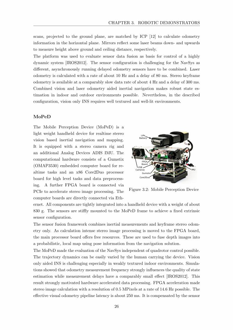
CHAPTER 3. ROBOTIC DEMONSTRATORS
scans, projected to the ground plane, are matched by ICP [12] to calculate odometry
information in the horizontal plane. Mirrors reflect some laser beams down- and upwards
to measure height above ground and ceiling distance, respectively.
The platform was used to evaluate sensor data fusion as basis for control of a highly
dynamic system [IROS2012]. The sensor configuration is challenging for the NavSys as
different, asynchronously running delayed odometry sensors have to be combined. Laser
odometry is calculated with a rate of about 10 Hz and a delay of 80 ms. Stereo keyframe
odometry is available at a comparably slow data rate of about 4 Hz and a delay of 300 ms.
Combined vision and laser odometry aided inertial navigation makes robust state es-
timation in indoor and outdoor environments possible. Nevertheless, in the described
configuration, vision only INS requires well textured and well-lit environments.
MoPeD
LiPoBattery
USBCameras
FPGABoard
Gumstix
Core2Duo
IMU
Figure 3.2: Mobile Perception Device
The Mobile Perception Device (MoPeD) is a
light weight handheld device for realtime stereo
vision based inertial navigation and mapping.
It is equipped with a stereo camera rig and
an additional Analog Devices ADIS IMU. The
computational hardware consists of a Gumstix
(OMAP3530) embedded computer board for re-
altime tasks and an x86 Core2Duo processor
board for high level tasks and data preprocess-
ing. A further FPGA board is connected via
PCIe to accelerate stereo image processing. The
computer boards are directly connected via Eth-
ernet. All components are tightly integrated into a handheld device with a weight of about
830 g. The sensors are stiffly mounted to the MoPeD frame to achieve a fixed extrinsic
sensor configuration.
The sensor fusion framework combines inertial measurements and keyframe stereo odom-
etry only. As calculation intense stereo image processing is moved to the FPGA board,
the main processor board offers free resources. These are used to fuse depth images into
a probabilistic, local map using pose information from the navigation solution.
The MoPeD made the evaluation of the NavSys independent of quadrotor control possible.
The trajectory dynamics can be easily varied by the human carrying the device. Vision
only aided INS is challenging especially in weakly textured indoor environments. Simula-
tions showed that odometry measurement frequency strongly influences the quality of state
estimation while measurement delays have a comparably small effect [IROS2012]. This
result strongly motivated hardware accelerated data processing. FPGA acceleration made
stereo image calculation with a resolution of 0.5 MPixels at a rate of 14.6 Hz possible. The
effective visual odometry pipeline latency is about 250 ms. It is compensated by the sensor
26
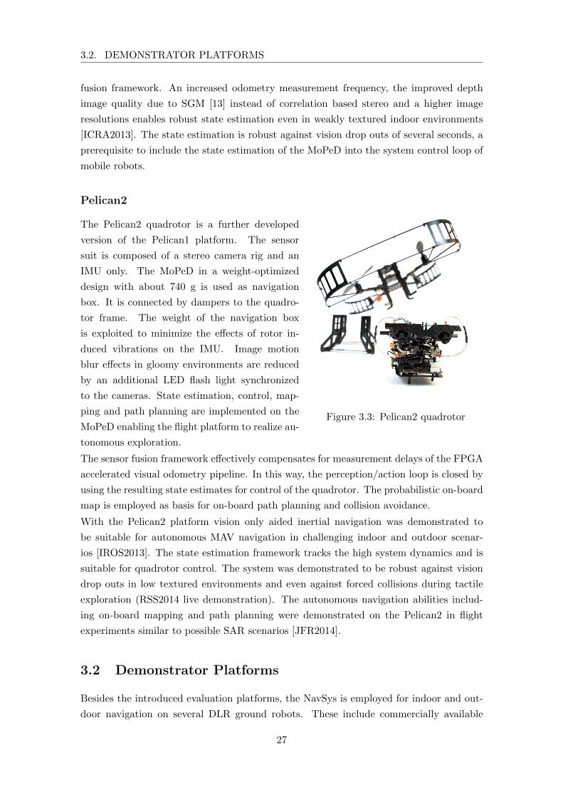
3.2. DEMONSTRATOR PLATFORMS
fusion framework. An increased odometry measurement frequency, the improved depth
image quality due to SGM [13] instead of correlation based stereo and a higher image
resolutions enables robust state estimation even in weakly textured indoor environments
[ICRA2013]. The state estimation is robust against vision drop outs of several seconds, a
prerequisite to include the state estimation of the MoPeD into the system control loop of
mobile robots.
Pelican2
Figure 3.3: Pelican2 quadrotor
The Pelican2 quadrotor is a further developed
version of the Pelican1 platform. The sensor
suit is composed of a stereo camera rig and an
IMU only. The MoPeD in a weight-optimized
design with about 740 g is used as navigation
box. It is connected by dampers to the quadro-
tor frame. The weight of the navigation box
is exploited to minimize the effects of rotor in-
duced vibrations on the IMU. Image motion
blur effects in gloomy environments are reduced
by an additional LED flash light synchronized
to the cameras. State estimation, control, map-
ping and path planning are implemented on the
MoPeD enabling the flight platform to realize au-
tonomous exploration.
The sensor fusion framework effectively compensates for measurement delays of the FPGA
accelerated visual odometry pipeline. In this way, the perception/action loop is closed by
using the resulting state estimates for control of the quadrotor. The probabilistic on-board
map is employed as basis for on-board path planning and collision avoidance.
With the Pelican2 platform vision only aided inertial navigation was demonstrated to
be suitable for autonomous MAV navigation in challenging indoor and outdoor scenar-
ios [IROS2013]. The state estimation framework tracks the high system dynamics and is
suitable for quadrotor control. The system was demonstrated to be robust against vision
drop outs in low textured environments and even against forced collisions during tactile
exploration (RSS2014 live demonstration). The autonomous navigation abilities includ-
ing on-board mapping and path planning were demonstrated on the Pelican2 in flight
experiments similar to possible SAR scenarios [JFR2014].
3.2 Demonstrator Platforms
Besides the introduced evaluation platforms, the NavSys is employed for indoor and out-
door navigation on several DLR ground robots. These include commercially available
27

CHAPTER 3. ROBOTIC DEMONSTRATORS
wheeled robots as well as specialized rover platforms, and a humanoid robot, which were
developed by DLR.
Pioneer
Figure 3.4: Modified Pioneer 3-AT
The Pioneer2 robots at DLR are test platforms for
cooperative multi robot exploration. They are ex-
tended with a 113 degree wide angle stereo cam-
era rig and an XSense IMU. The computational
hardware consists of a single Quad Core i7 proces-
sor board and a FPGA for accelerated stereo image
processing. While the cameras are synchronized to
each other, the hardware trigger is not explicitly reg-
istered.
The NavSys is used as realtime odometry. Due to
the limited system dynamics of the wheeled robots, timing and sensor synchronization
constraints are relaxed. Therefore, a purely software based synchronization scheme is
employed. Due to the used wide angle cameras, the stereo odometry measurement char-
acteristics differ from the configurations on the MoPeD and quadrotor platforms. While
delta pose measurements are less precise, keyframes can be held for a longer time. On a
similar robot of an industrial partner constant height measurements are included in the
state estimation to account for a flat floor assumption.
In ongoing work, the pose estimates and the corresponding uncertainties of the NavSys
are integrated into a pose graph submap SLAM. Submaps are exchanged between several
robots to build up a common global map. The reference switching mechanism of the
LR-INS is exploited to estimate the robot pose relative to the current submap origin.
Rovers
Figure 3.5: PTS rover carrying aPelican2 quadrotor
The Part Time Scientists (PTS) and Light-weight
Rover Unit (LRU) rovers are test platforms for cooper-
ative exploration of rough outdoor environments com-
bining ground and flying robots. The systems have a
landing platform on their backs to transport an MAV
to a possible site of operation. The MAV can be used
to get an aerial overview and find suitable exploration
paths for the ground robot by exchanging maps be-
tween the systems. The rovers are equipped with a
stereo camera rig mounted on a pan-tilt unit. An
XSense IMU is integrated into the body of the rover.
2 http://www.mobilerobots.com/ResearchRobots.aspx
28
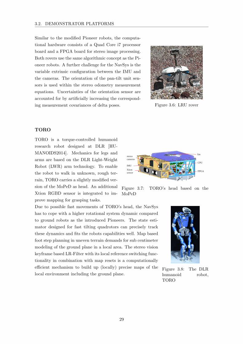
3.2. DEMONSTRATOR PLATFORMS
Similar to the modified Pioneer robots, the computa-
tional hardware consists of a Quad Core i7 processor
board and a FPGA board for stereo image processing.
Figure 3.6: LRU rover
Both rovers use the same algorithmic concept as the Pi-
oneer robots. A further challenge for the NavSys is the
variable extrinsic configuration between the IMU and
the cameras. The orientation of the pan-tilt unit sen-
sors is used within the stereo odometry measurement
equations. Uncertainties of the orientation sensor are
accounted for by artificially increasing the correspond-
ing measurement covariances of delta poses.
TORO
remaining arm. The main focus of the research with TOROis not on dexterous manipulation but rather on balancing andsimple manipulation tasks. To provide TORO with a robustsolution for picking up simple objects and establishing firmcontacts with its environment, it was equipped with electricalhand prostheses (i-limb ultra prosthesis from Touch Bionics[48]). Each finger has one active and an additional passivelycoupled DOF. The thumbs have an additional DOF, so thatthey can be opposed to the other fingers. Although the i-limbhands have no position or torque sensors available, they comewith powerful intrinsic grasping capabilities.The main part of TORO’s computer system and auxil-
iary electronics (see Sec. III) is located in the backpack(see Fig. 5). It mainly consists of a backplate (which thecomponents are screwed onto), a welded aluminum pipeframe and elastic fabric. The aluminum pipe frame is usedas a suspension point for the security rope, as mechanicalprotection of the backpack’s interior and as handle bars(see red markers in Fig. 5b), which are used to manuallysupport the robot after failed experiments. TORO’s neck hasan actuated pan tilt unit based on the commercially availableDynamixel MS106T servo motors [47]. The structural partsof TORO’s head (see Fig. 6) were designed to provide thehighest possible stiffness. The head structure contains allrequired sensors and a computer system for an onboardego-motion estimation and mapping (see Sec. III-B). Thishigh structural stiffness is not only required for mechanicalprotection (e.g. when the suspension rope hits the head aftera fall), but also to avoid low frequency vibrations of the head,which can cause problems regarding ego-motion estimation.Throughout the robot, hollow axes are used in the joints
to allow for an internal routing of all cables. This avoids thecables from getting caught or tangled.
III. MECHATRONICS AND COMPUTER HARDWARE
A. ElectronicsThe same electronics as in the LWR (see Fig. 2) is used
to supply TORO’s joint drives (except for the neck drives).It includes the motor power supply, electronics for motorcontrol, brakes, joint position and torque sensing and controland communication between joint and control computersvia Sercos-II bus (see Sec. III-C). The drive units and theelectronic components supplying them are mounted as closeto each other as possible (see Fig. 4) in order to reduceelectromagnetic crosstalk and cable routing.Two battery packs in TORO’s backpack are used to
power the robot. They consist of industrial cells based onLiFePO4 and have a nominal voltage of 48 V, a capacityof 6.6 Ah and a weight of 2.3 kg each. These batteriessupply power to the joints directly and to the computers viaswitching mode power supplies. The usual time the robotcan operate on a set of batteries is one hour (e.g. walkingor whole-body tasks). Alternatively, TORO can be suppliedwith electricity via a power cable. The power drawn insteady state is approximately 250W. The field of humanoid
fan
CPU
FPGA
stereocameras
IMUXtionsensor
Fig. 6: TORO’s head
robots is currently more focused on capabilities than onpower consumption, but endurance is also of high relevancefor real-world applications. Taking this perspective, it isinteresting to note that when TORO stands still, its powerconsumption is dominated by its electronics rather than itsmotors. Thus, in the design of a new humanoid prototype,we would pay special attention to the issue of electricalefficiency. To facilitate good heat dissipation in TORO, thejoint drives’ power electronics are either directly connectedto the structural parts (made of aluminum → good heatconduction) or cooled via forced and natural convection.
B. SensorsEach of the 25 installed LWR drive units is equipped
with an incremental motor position sensor, an output positionsensor and a torque sensor. The torque sensors are mountedon the joint output side, so that the torque measurement isalmost not affected by frictional effects in the joints. Addi-tionally, each joint has a built-in brake, which is activatedeither by software command or in case of power-down.That way, the robot’s joint positions have to be recalibratedrarely although no precise absolute joint position sensors areavailable (yet, the ILM70 and ILM85 modules have built-inpotentiometers → partially automated recalibration process).A recalibration is mainly necessary, when a power-downoccurs during robot operation and the internally trackedcurrent joint position is no longer updated while the jointskeep moving (despite engaged brakes) due to the link inertia.Each of TORO’s feet is equipped with a 6 DOF force-
torque sensor (FTS), which is mounted directly above thefoot. The FTS are used to measure the ground reactionwrenches independently of the robot’s leg configuration andcompute the zero moment point (ZMP), which is necessaryfor ZMP-based walking algorithms. The FTS are designedto measure forces and torques up to 1000 N and 100 Nm.An inertial measurement unit (IMU) is mounted to
TORO’s thorax to provide the robot with sensory informationabout its orientation and spatial acceleration. TORO’s head(see Fig. 6) contains all sensors and the computer systemrequired to estimate the robot’s ego-motion and build up amap of its environment. The sensory information of a pairof stereo cameras (15 fps) is processed and features areextracted in an onboard FPGA using Semi Global Matching(SGM) [49]. The stereo camera information and the mea-surements from an IMU mounted in the head are fused via
Figure 3.7: TORO’s head based on theMoPeD
TORO is a torque-controlled humanoid
research robot designed at DLR [HU-
MANOIDS2014]. Mechanics for legs and
arms are based on the DLR Light-Weight
Robot (LWR) arm technology. To enable
the robot to walk in unknown, rough ter-
rain, TORO carries a slightly modified ver-
sion of the MoPeD as head. An additional
Xtion RGBD sensor is integrated to im-
prove mapping for grasping tasks.
Figure 3.8: The DLRhumanoid robot,TORO
Due to possible fast movements of TORO’s head, the NavSys
has to cope with a higher rotational system dynamic compared
to ground robots as the introduced Pioneers. The state esti-
mator designed for fast tilting quadrotors can precisely track
these dynamics and fits the robots capabilities well. Map based
foot step planning in uneven terrain demands for sub centimeter
modeling of the ground plane in a local area. The stereo vision
keyframe based LR-Filter with its local reference switching func-
tionality in combination with map resets is a computationally
efficient mechanism to build up (locally) precise maps of the
local environment including the ground plane.
29

CHAPTER 3. ROBOTIC DEMONSTRATORS
30
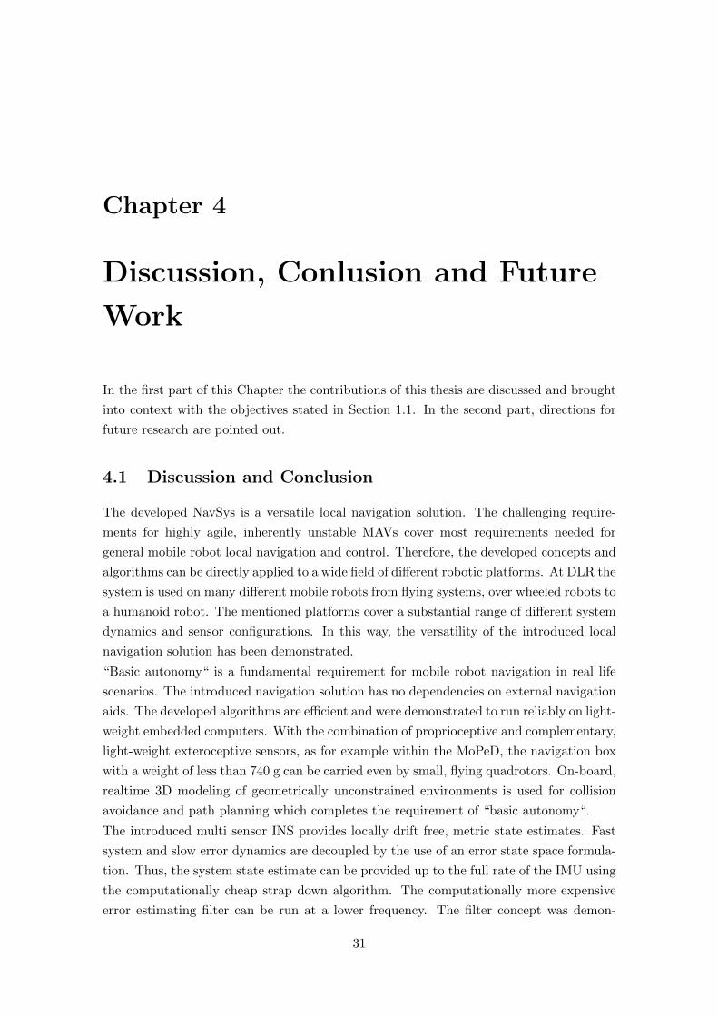
Chapter 4
Discussion, Conlusion and Future
Work
In the first part of this Chapter the contributions of this thesis are discussed and brought
into context with the objectives stated in Section 1.1. In the second part, directions for
future research are pointed out.
4.1 Discussion and Conclusion
The developed NavSys is a versatile local navigation solution. The challenging require-
ments for highly agile, inherently unstable MAVs cover most requirements needed for
general mobile robot local navigation and control. Therefore, the developed concepts and
algorithms can be directly applied to a wide field of different robotic platforms. At DLR the
system is used on many different mobile robots from flying systems, over wheeled robots to
a humanoid robot. The mentioned platforms cover a substantial range of different system
dynamics and sensor configurations. In this way, the versatility of the introduced local
navigation solution has been demonstrated.
“Basic autonomy“ is a fundamental requirement for mobile robot navigation in real life
scenarios. The introduced navigation solution has no dependencies on external navigation
aids. The developed algorithms are efficient and were demonstrated to run reliably on light-
weight embedded computers. With the combination of proprioceptive and complementary,
light-weight exteroceptive sensors, as for example within the MoPeD, the navigation box
with a weight of less than 740 g can be carried even by small, flying quadrotors. On-board,
realtime 3D modeling of geometrically unconstrained environments is used for collision
avoidance and path planning which completes the requirement of “basic autonomy“.
The introduced multi sensor INS provides locally drift free, metric state estimates. Fast
system and slow error dynamics are decoupled by the use of an error state space formula-
tion. Thus, the system state estimate can be provided up to the full rate of the IMU using
the computationally cheap strap down algorithm. The computationally more expensive
error estimating filter can be run at a lower frequency. The filter concept was demon-
31
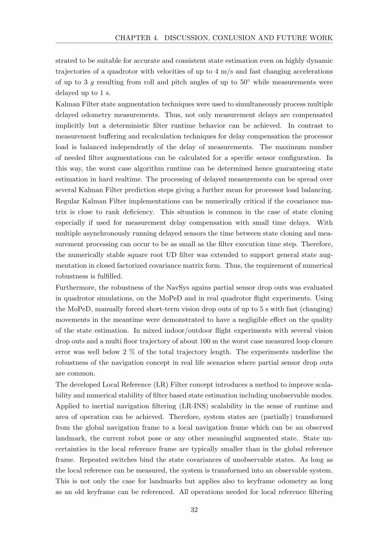
CHAPTER 4. DISCUSSION, CONLUSION AND FUTURE WORK
strated to be suitable for accurate and consistent state estimation even on highly dynamic
trajectories of a quadrotor with velocities of up to 4 m/s and fast changing accelerations
of up to 3 g resulting from roll and pitch angles of up to 50◦ while measurements were
delayed up to 1 s.
Kalman Filter state augmentation techniques were used to simultaneously process multiple
delayed odometry measurements. Thus, not only measurement delays are compensated
implicitly but a deterministic filter runtime behavior can be achieved. In contrast to
measurement buffering and recalculation techniques for delay compensation the processor
load is balanced independently of the delay of measurements. The maximum number
of needed filter augmentations can be calculated for a specific sensor configuration. In
this way, the worst case algorithm runtime can be determined hence guaranteeing state
estimation in hard realtime. The processing of delayed measurements can be spread over
several Kalman Filter prediction steps giving a further mean for processor load balancing.
Regular Kalman Filter implementations can be numerically critical if the covariance ma-
trix is close to rank deficiency. This situation is common in the case of state cloning
especially if used for measurement delay compensation with small time delays. With
multiple asynchronously running delayed sensors the time between state cloning and mea-
surement processing can occur to be as small as the filter execution time step. Therefore,
the numerically stable square root UD filter was extended to support general state aug-
mentation in closed factorized covariance matrix form. Thus, the requirement of numerical
robustness is fulfilled.
Furthermore, the robustness of the NavSys agains partial sensor drop outs was evaluated
in quadrotor simulations, on the MoPeD and in real quadrotor flight experiments. Using
the MoPeD, manually forced short-term vision drop outs of up to 5 s with fast (changing)
movements in the meantime were demonstrated to have a negligible effect on the quality
of the state estimation. In mixed indoor/outdoor flight experiments with several vision
drop outs and a multi floor trajectory of about 100 m the worst case measured loop closure
error was well below 2 % of the total trajectory length. The experiments underline the
robustness of the navigation concept in real life scenarios where partial sensor drop outs
are common.
The developed Local Reference (LR) Filter concept introduces a method to improve scala-
bility and numerical stability of filter based state estimation including unobservable modes.
Applied to inertial navigation filtering (LR-INS) scalability in the sense of runtime and
area of operation can be achieved. Therefore, system states are (partially) transformed
from the global navigation frame to a local navigation frame which can be an observed
landmark, the current robot pose or any other meaningful augmented state. State un-
certainties in the local reference frame are typically smaller than in the global reference
frame. Repeated switches bind the state covariances of unobservable states. As long as
the local reference can be measured, the system is transformed into an observable system.
This is not only the case for landmarks but applies also to keyframe odometry as long
as an old keyframe can be referenced. All operations needed for local reference filtering
32
4.1. DISCUSSION AND CONCLUSION
are integrated in closed form into a single square root UD prediction step. Therefore, the
algorithm profits directly from superior numerical properties compared to regular Kalman
Filter implementations. The LR-INS was evaluated in simulated 24 h quadrotor flights
and in real quadrotor flight experiments with the expected result of bounded state covari-
ances. By switching the navigation frame on the fly, the locally precise and consistent
navigation filter can be combined with scalable global approaches as topological or hierar-
chical navigation fulfilling the requirement of scalability in the sense of runtime and area
of operation.
Besides the actual navigation algorithms, the underlying system architecture is an impor-
tant factor for applicability of the entire NavSys. The developed architecture is flexible
and versatile. Due to the explicit design as distributed system, high-level tasks without re-
altime constraints can be separated by hardware from system critical, hard realtime tasks.
A failure of a critical task such as system state estimation or control can easily result in a
crash of the mobile robot. Such a failure can be provoked by delayed scheduling of the hard
realtime task. The applied embedded RT mini computer was proven to hold scheduling
constraints with latencies well below 400 µs. Measurement delays from non realtime tasks
are compensated by the fusion algorithm. This enables the use of hardware acceleration
pipelines for sensor data preprocessing, as demonstrated with an SGM stereo vision FPGA
implementation, and relaxes the requirements on inter system communication delays.
Nevertheless, delay compensation and the use of a distributed system architecture requires
a flexible and robust synchronization scheme between computers and sensors. In the
introduced scheme sensor hardware triggers are directly registered on the RT system.
Therefore, the precision of measurement time stamps is relaxed to half of the sensor
measurement sampling time to be still uniquely assignable. This gives the flexibility
to compensate for imprecise timestamps, transmission and processing delays and even
integrate external, delayed sensors. In a student project, not detailed in this thesis, the
infrared flash of an external tracking system was used for synchronization. The actual
pose measurement of the tracking system is transmitted via wireless LAN introducing
a considerable jitter in the delay which is implicitly accounted for by the introduced
synchronization concept.
The system architecture makes minimal demands on the underlying hardware. The only
requirements on the realtime computer platform are the availability of an interrupt trig-
gering General Purpose Input/Output (GPIO), a suitable hardware interface to connect
an IMU and a communication interface to the non realtime computer board. The latter
has to provide hardware interfaces to connect further exteroceptive sensors and a com-
munication interface. With these basic requirements, the system can be composed of
standard COTS components. In this way, computer boards can easily be upgraded to the
most recent versions available without hardware development. Several implementations
including a cluster of ARM and X86 processor boards, a combination of ARM, X86 and
FPGA acceleration boards and a minimal configuration with a single X86 computer were
presented.
33

CHAPTER 4. DISCUSSION, CONLUSION AND FUTURE WORK
The entire NavSys, based on stereo vision only and in combination with laser odometry,
was not only evaluated in simulations and laboratory environments but also in challenging
real life scenarios similar to possible SAR scenarios. Multi floor indoor flight experiments
with indoor/outdoor transitions through windows and doors demonstrated the robustness
and precision of the state estimation and its suitability as basis for mapping and path
planning. The transition phase is especially critical in stereo vision only configurations as,
due to fast changing lighting conditions, vision drop outs have to be expected in a situation
where the flying robot is only a few centimeters off the window or door frame. Flight
experiments in a coal mine demonstrated “basic autonomous“ navigation in a challenging,
dusty and gloomy environment.
The introduced NavSys covers all objective defining requirements of Chapter 1.1. It en-
ables mobile robots to navigate autonomously in 3D in geometrically unconstrained, clut-
tered environments. This is the basis to bring mobile robots from laboratory environments
into the real world and opens a wide field of new applications.
4.2 Future Work
Relaxing the objective of versatility, the estimation quality, and robustness of the NavSys
can be further improved by integrating robot specific motion models. The introduced
approach employs only general point mass kinematics within the strap down algorithm and
is, therefore, usable on any robotic platform. Nevertheless, information from control inputs
and motion constraints of the system are ignored. It was demonstrated that the navigation
solution is robust against short-term drop outs of the used stereo odometry system in the
range of seconds. Nonetheless, in situations where exteroceptive sensor measurements are
not available velocity states are not observable and a considerable position drift has to be
expected in the case of long-term sensor drop outs.
For highly dynamic, inherently unstable flying robots unobservability of velocity can be-
come critical. Even though, roll and pitch can still be stabilized, the MAV will freely
drift in space. In cluttered environments it will collide with obstacles and might crash.
The integration of a quadrotor drag model can improve this situation. By rendering ve-
locity observable drift in position will be slowed down. Nevertheless, the accuracy of the
highly nonlinear drag model and its parameters strongly influences the gain in informa-
tion. For MAVs, a suitable model must be identified. The corresponding parameters could
be integrated into the system state and estimated online.
Wheeled, mobile robots are in general stable systems. Drop outs of the exteroceptive
sensors are, therefore, less critical. Nevertheless, to improve robustness, a motion model
could be easily applied by using wheel odometry measurements. In the most basic way,
these measurements can be processed as velocity updates. Velocity will become observable
but position will still be affected by drift. Under the assumption that the system is standing
still while there is no control input, the pose at stoppage of the robot can be used within
the LR-INS as new local reference frame. A pseudo zero pose measurement will stop pose
34
4.2. FUTURE WORK
drift while standing.
Considering mobile robots with legs, as for example the DLR humanoid TORO, a motion
model can be easily integrated into the NavSys by adding foot pose states when a leg
touches the ground. In the most simple case the kinematic chain between IMU and leg
frame can be used as corresponding measurement. Even foot slippage can be considered
by adding noise to the augmented foot pose.
Besides the integration of specialized robot motion models, the combination of the LR-INS
with global navigation approaches is a promising future research direction. Especially on
resource limited mobile robots highly scalable, non-metric, insect inspired global naviga-
tion methods, as for example the Landmark-Tree Map [23], are an attractive alternative
to classical SLAM approaches. In combination with the NavSys, local consistent, metric
maps can be built and used for obstacle avoidance and object recognition. Metric state
estimates can be used for control. Using the LR-INS, the new reference frame can be
repeatedly switched into the current robot pose. The direction to follow a global path is
given by the global navigation approach which is completely decoupled from local naviga-
tion tasks.
Employing the LR-INS hierarchical, human like way descriptions could be directly mapped.
Lets assume a description in the form ”follow the path for about 20 m until you reach the
house, enter by the door, turn left into the corridor...” is given. With an object detector
which can identify the waypoint describing objects within a certain region, the reference
frame of the LR-INS can be directly switched into the coordinates of the object. The robot
can navigate relative to the last way node. Given the metric uncertainty of the LR-INS
search regions for the next way node can be defined.
With the ability of “basic autonomous“ navigation of a single mobile robot the foundation
for multi robot cooperation is laid. A heterogeneous team of robots can profit from
special abilities of the individual team members. Disadvantages of one system class can
be compensated by another type of robot. One could, for example, combine ground based
and aerial robots for autonomous exploration in SAR scenarios. In such a configuration, a
ground vehicle, with long operation time, can carry a flying system exploring the reachable
area of operation. In situations, where the way for the ground robot is blocked, the MAV
can give an aerial overview to find a possible route around obstacles and thereby, minimize
exploration time. To make the exchange of map information possible a common navigation
frame is needed. With the introduced LR-INS the reference frame of the ground robot
can be used by the flying system and local maps can be directly exchanged. Whenever
the pose of the ground robot is measurable by the MAV the navigation frame of the flying
robot can be adapted to realize relative navigation. In this way, accumulating errors in
a global navigation frame can be canceled out in a simple and efficient manner. The
ground robot can use the locally consistent maps of the flying system to build a globally
consistent environment representation by means of computationally more expensive global
optimization methods.
35

CHAPTER 4. DISCUSSION, CONLUSION AND FUTURE WORK
36

Acronyms
COTS Commercial Off-The-Shelf
FPGA Field Programmable Gate Array
GNSS Global Navigation Satellite System
GPIO General Purpose Input/Output
GPS Global Positioning System
HGF Helmholtz Association
ICP Iterative Closest Point
IMU Inertial Measurement Unit
INS Inertial Navigation System
IROS IEEE/RSJ International Conference on Intelligent Robots and Systems
MAV Micro Aerial Vehicle
NavSys Navigation System
ROS Robot Operating System
RT Realtime
SAR Search and Rescue
SGM Semi Global Matching
SLAM Self Localization and Mapping
37

ACRONYMS
38
Bibliography
[1] W. M. Gentleman. “Least Squares Computations by Givens Transformations With-
out Square Roots”. In: IMA Journal of Applied Mathematics 12.3 (1973), pp. 329–
336.
[2] C. L. Thornton. “Triangular covariance factorizations for Kalman filtering”. PhD
thesis. University of California, Los Angeles–Engineering., 1976.
[3] G. J. Bierman and C. L. Thornton. “Numerical Comparison of Kalman Filter Algo-
rithms: Orbit Determination Case Study”. In: Automatica 13.1 (Jan. 1977), pp. 23–
35.
[4] C. L. Thornton and G. J. Bierman. “Gram-Schmidt algorithms for covariance prop-
agation”. In: International Journal of Control 25.2 (1977), pp. 243–260.
[5] P. S. Maybeck. Stochastic models, estimation, and control. Vol. 141/1. Mathematics
in Science and Engineering. Elsevier, 1979, pp. 368–409.
[6] H. Hirschmuller, P. R. Innocent, and J. Garibaldi. “Real-Time Correlation-Based
Stereo Vision with Reduced Border Errors”. In: International Journal of Computer
Vision 47.1-3 (2002), pp. 229–246.
[7] J. D. Tardos, J. Neira, P. M. Newman, and J. J. Leonard. “Robust Mapping and Lo-
calization in Indoor Environments Using Sonar Data”. In: The International Journal
of Robotics Research 21.4 (2002), pp. 311–330.
[8] C. Estrada, J. Neira, and J. Tardos. “Hierarchical SLAM: Real-Time Accurate Map-
ping of Large Environments”. In: Robotics, IEEE Transactions on 21.4 (Aug. 2005),
pp. 588–596.
[9] Ad Hoc ALFUS Working Group. Autonomy Levels For Unmanned Systems (AL-
FUS) Framework. Tech. rep. NIST Special Publication 1011-II-1.0. NIST, The Na-
tional Institute of Standards and Technology of the U.S. Department of Commerce,
Dec. 2007.
[10] G. Klein and D. Murray. “Parallel Tracking and Mapping for Small AR Workspaces”.
In: Mixed and Augmented Reality, 2007. ISMAR 2007. 6th IEEE and ACM Inter-
national Symposium on. Nov. 2007, pp. 225–234.
39
BIBLIOGRAPHY
[11] J.-L. Blanco, J.-A. Fernandez-Madrigal, and J. Gonzalez. “Toward a Unified Bayesian
Approach to Hybrid Metric–Topological SLAM”. In: Robotics, IEEE Transactions
on 24.2 (Apr. 2008), pp. 259–270.
[12] A. Censi. “An ICP variant using a point-to-line metric”. In: Robotics and Automa-
tion, 2008. ICRA 2008. IEEE International Conference on. May 2008, pp. 19–25.
[13] H. Hirschmuller. “Stereo Processing by Semiglobal Matching and Mutual Informa-
tion”. In: Pattern Analysis and Machine Intelligence, IEEE Transactions on 30.2
(Feb. 2008), pp. 328–341.
[14] M. Kaess, A. Ranganathan, and F. Dellaert. “iSAM: Incremental Smoothing and
Mapping”. In: Robotics, IEEE Transactions on 24.6 (Dec. 2008), pp. 1365–1378.
[15] L. Meier, P. Tanskanen, L. Heng, G. Lee, F. Fraundorfer, and M. Pollefeys. “PIX-
HAWK: A micro aerial vehicle design for autonomous flight using onboard computer
vision”. In: Autonomous Robots 33.1-2 (2012), pp. 21–39.
[16] S. M. Weiss. “Vision based navigation for micro helicopters”. PhD thesis. Eid-
genossische Technische Hochschule ETH Zurich, Nr. 20305, 2012, 2012.
[17] S. Lynen, M. Achtelik, S. Weiss, M. Chli, and R. Siegwart. “A robust and modular
multi-sensor fusion approach applied to MAV navigation”. In: Intelligent Robots
and Systems (IROS), 2013 IEEE/RSJ International Conference on. Nov. 2013,
pp. 3923–3929.
[18] S. Weiss, M. W. Achtelik, S. Lynen, M. C. Achtelik, L. Kneip, M. Chli, and R.
Siegwart. “Monocular Vision for Long-term Micro Aerial Vehicle State Estimation:
A Compendium”. In: Journal of Field Robotics 30.5 (2013), pp. 803–831.
[19] J. Engel, T. Schops, and D. Cremers. “LSD-SLAM: Large-Scale Direct Monocu-
lar SLAM”. In: Computer Vision – ECCV 2014. Ed. by D. Fleet, T. Pajdla, B.
Schiele, and T. Tuytelaars. Vol. 8690. Lecture Notes in Computer Science. Springer
International Publishing, 2014, pp. 834–849.
[20] C. Forster, M. Pizzoli, and D. Scaramuzza. “SVO: Fast semi-direct monocular vi-
sual odometry”. In: Robotics and Automation (ICRA), 2014 IEEE International
Conference on. May 2014, pp. 15–22.
[21] L. Heng, D. Honegger, G. H. Lee, L. Meier, P. Tanskanen, F. Fraundorfer, and
M. Pollefeys. “Autonomous Visual Mapping and Exploration With a Micro Aerial
Vehicle”. In: Journal of Field Robotics 31.4 (2014), pp. 654–675.
[22] L. Heng, G. H. Lee, and M. Pollefeys. “Self-Calibration and Visual SLAM with a
Multi-Camera System on a Micro Aerial Vehicle”. In: Robotics: Science and Systems.
Berkeley, USA, July 2014.
40

BIBLIOGRAPHY
[23] E. Mair, M. Augustine, B. Jager, A. Stelzer, C. Brand, D. Burschka, and M. Suppa.
“A biologically inspired navigation concept based on the Landmark-Tree map for ef-
ficient long-distance robot navigation”. In: Advanced Robotics 28.5 (2014), pp. 289–
302.
[24] S. Williams, V. Indelman, M. Kaess, R. Roberts, J. J. Leonard, and F. Dellaert.
“Concurrent Filtering and Smoothing: A Parallel Architecture for Real-time Nav-
igation and Full Smoothing”. In: Int. J. Rob. Res. 33.12 (Oct. 2014), pp. 1544–
1568.
41

BIBLIOGRAPHY
42

Paper 1
View planning for multi-view
stereo 3D reconstruction using an
autonomous multicopter1
Korbinian Schmid, Heiko Hirschmuller, Andreas Domel, Iris Grixa, Michael Suppa, and
Gerd Hirzinger
Abstract Multi-view stereo algorithms are an attractive technique for the digital recon-
struction of outdoor sites. Concerning the data acquisition process a vertical take off and
landing UAV carrying a digital camera is a suitable platform in terms of mobility and
flexibility in viewpoint placement. We introduce an automated UAV based data acqui-
sition and outdoor site reconstruction system. A special focus is set on the problem of
model based view planning using a coarse digital surface model (DSM) with minimal data
preprocessing. The developed view planning heuristic considers a coverage, a maximum
view angle and an overlapping constraint imposed by multi-view stereo reconstruction
techniques. The time complexity of the algorithm is linear with respect to the size of the
area of interest. We demonstrate the efficiency of the entire system in two scenarios, a
building and a hillside.
1 c©2011, Springer Science+Business Media. Reprinted, with permission, from Journal of Intelligent &Robotic Systems 65.1-4 (2012), pp. 309-323, DOI: 10.1007/s10846-011-9576-2
43

VIEW PLANNING FOR MULTI-VIEW STEREO 3D RECONSTRUCTIONUSING AN AUTONOMOUS MULTICOPTER
1 Introduction
The reconstruction of three dimensional scenes has gained more attention in the last years.
Textured 3D models are used, among others, in virtual reality applications, for urban
planning, cultural heritage conservation or for the planning of search and rescue missions.
Map providers are reacting to this new field and are changing their datasets from simple
2D to 2.5D or even 3D world representations. For the 2.5D case the data acquisition is
often performed from satellites or airplanes. However, top-down images do not allow the
geometrical reconstruction of building facades or general 3D structures. Additional images
could be taken from the ground, but this is a tedious task as many objects like trees or
cars can partially occlude the object of interest.
With the use of a Vertical Take Off and Landing (VTOL) UAV, images can be taken
from better viewpoints than from ground or classical aerial images. The UAV can fly
in altitudes of several hundred meters as well as in short distances to the ground and
to objects. Thus, images can be obtained with much higher resolution than possible by
classical aerial images. The complete data acquisition process can be realized with only
one relatively cheap system and can be accelerated by automation.
An important aspect of the data acquisition process arising from the use of a VTOL UAV is
safety. Miniature helicopters, with their large turning rotor, could seriously harm persons
and damage objects. In contrast, multicopters have several small rotors and are therefore
safer to use in populated environments. While they can easily carry a digital camera, the
overall payload limits further sensor and computational hardware equipment.
By using multi-view stereo algorithms single shots from a digital camera are sufficient
for a high quality reconstruction of 3D scenes. Nevertheless, the viewpoints must be
planned carefully to gain a sufficient image overlap, which is necessary for reconstruction.
Furthermore, occlusions, full coverage of the region of interest and a constant quality
within the reconstructed scene should be considered by a viewpoint planning algorithm.
For planning, a data basis is needed. Currently, the hardware for multi-view stereo recon-
struction in realtime can not be mounted on a multicopter due to the restricted payload.
Furthermore, light-weight wireless data transceivers do not have enough bandwidth for a
realtime transmission of high resolution images to a ground station. An offline viewpoint
planning and image post processing method can solve this problem but requires a coarse
model of the region of interest.
In many outdoor situations a coarse digital surface model (DSM) is available. And, if it
is not, it can be easily created using a VTOL UAV taking top-down images of a region of
interest. In our proposed method, we use a coarse DSM for the calculation of viewpoints
fulfilling the constraints imposed by a multi-view stereo algorithm. We acquire single shot
images at the calculated viewpoints from a multicopter. Finally the scene is reconstructed
by the Semi Global Matching (SGM) algorithm.
In the next Section, we give a short overview of related work. In Section 3, we describe
the work flow of our method and give a summary of the SGM algorithm. In Section 4, we
44
2. RELATED WORK
introduce our new method for model based view planning considering constraints imposed
by multi-view stereo reconstruction. Section 5 shows simulation and experimental results
of two scenarios. The conclusion discusses pros and cons of our method and gives an
outlook on future work.
2 Related work
Several research groups are working on the automated modeling of outdoor scenes. El
Hakim et al. [8] categorize two main techniques for this application: Image based modeling
(photogrammetry) and range based modeling. The former can be realized with off-the-
shelf and lightweight hardware such as monocular camera systems while the latter needs
bulky and often expensive laser scanners.
These different approaches have a strong influence on the data acquisition process as well
as the platform for automation. Akbarzadeh et al. [10] introduced a ground based data
collection system for automatic geo-registered 3D reconstruction from video. Kim and
Nevatia [5] present an image based approach for the automated 3D reconstruction of roof
tops, whereas Frueh and Zakhor [7] show the 3D city model generation by merging DSM
data created by airborne laser scans with facade laser scans and digital images at ground
level acquired by car.
In the photogrammetry community, Eisenbeiss [13] introduced a reconstruction system
that is closely related to ours. He also employs multi-view stereo algorithms for the
reconstruction of outdoor scenes. The data acquisition process is realized by a miniature
helicopter equipped with a high-end digital camera.
The research work described so far focuses on data acquisition systems and reconstruction
algorithms. The aspect of automated view planning for data acquisition is not addressed.
Scott et al. [9] give an overview of view planning approaches. They distinguish between
model-based and non-model-based methods where the former are of interest for this work.
Non-model based approaches explore objects without a priori knowledge on the object.
The view planning problem becomes an exploration problem with next-best views. Plan-
ning views on a priori known models leads to a coverage problem, the constraints are
given by the sensor properties (opening angle), sensor principle (stereo, laser) and desired
quality of the final model.
Finding an optimal viewpoint plan is an NP-complete problem [4]. Several researchers
proposed their solutions: Cowan [1] introduced a view planning approach for single view
inspection with constraints concerning spacial resolution, focus, coverage, and occlusion.
Tarabanis et al. [2] presented results of a vision inspection system with similar constraints.
Scott et al. [6] introduced a framework to formulate the next best view planning problem as
an integer programming problem and presented an algorithm with a registration constraint
for laser scanners.
Concerning the reconstruction workflow, Blaer et al. [12] introduced a similar procedure
as described in this paper. They addressed the joint problem of data acquisition and view
45
VIEW PLANNING FOR MULTI-VIEW STEREO 3D RECONSTRUCTIONUSING AN AUTONOMOUS MULTICOPTER
planning for large scale sites and presented a mobile ground robot for an automated 3D
reconstruction by a laser scanner. Starting from a 2D map, viewpoints for the generation
of a rough 3D model are created. The resulting model is used for the viewpoint planning
of a second data acquisition process, the basis for the creation of a fine model.
3 Workflow and SGM
In contrast to ground based robots, flying robots have to consider all six degrees of freedom
within the reconstruction workflow.
3.1 Reconstruction workflow
Our method for 3D scene reconstruction can be divided in 5 steps:
1. Data acquisition for DSM calculation
2. DSM calculation
3. Viewpoint planning on the DSM
4. Data acquisition for 3D reconstruction
5. 3D reconstruction
In many situations, a low resolution DSM of the region of interest is already available
and only steps 3 to 5 are necessary. Otherwise, the data acquisition of step 1 can be
realized using a UAV. Viewpoints are chosen as a regularly spaced viewpoint grid across
the region of interest with a constant height above the ground and the camera pointing
straight downwards. Figure 1 depicts a sample viewpoint grid. It can be created either
by hand or by our view planning algorithm (Section 4) with a flat initial DSM. In step 2,
we employ the SGM algorithm (Section 3.2) for the calculation of the DSM. In step 3, the
DSM based viewpoint planning is again realized by our view planning algorithm. Next,
we use the calculated viewpoints for step 4 to acquire the data for the 3D reconstruction
by the SGM algorithm in step 5.
3.2 Multi-view stereo reconstruction by Semi Global Matching (SGM)
We employ the same workflow for each reconstruction from single shot images, as men-
tioned in the last Section.
We use a pre-calibrated camera and the bundler tool [11] for computing the relative extrin-
sic orientation of all images. The recorded GPS position is used afterwards, for scaling,
rotating and translating all camera positions so that the mean error to the correspond-
ing GPS positions is minimized. In this way, the relative orientations from bundler are
unchanged, but the whole model is transformed and geo-referenced.
46

4. VIEW PLANNING
Figure 1: Viewpoint grid for the acquisition of a coarse DSM for viewpoint planning
We perform dense image matching by the Semi-Global Matching (SGM) method [14]. It
performs pixel-wise matching supported by a global smoothness constraint. The method is
computationally efficient and can match large images. Census has been used as matching
cost, because it has been found to be the most robust matching cost for images with
radiometric differences [15]. This is important, since the camera is not radiometrically
calibrated, image orientations are rather arbitrary and the camera is using auto-exposure.
Thus, the image radiometry can vary quite a lot.
All images with more than 50% overlap and with a relative orientation of 3-25 degrees
between optical axes are pairwise matched. All pixels of one image are matched to pixels of
the other image and vice versa, in order to enable a consistency check to filter out occlusions
and mismatches. If an image overlaps with more than one other image, multiple disparity
images are created. They are used for filling occlusions and for removing outliers by
selecting the median disparity for each pixel separately. This results in one disparity (i.e.
depth) image for each input image. Using the disparity images, all pixels are reconstructed
and fused either into a 2.5 D surface model or a full 3 D model, which is automatically
textured by the original images. The result is a textured, geo-referenced high resolution
model of the covered area.
4 View planning
The success of the mentioned reconstruction workflow depends strongly on the input im-
ages, which makes viewpoint planning important. Our planning algorithm follows the
generate and test paradigm by first calculating a set of viewpoints and then selecting a
suitable subset. The goal is to cover the full scene with an optimal number of views, based
on the prior model while considering the constraints implied by the multi-view stereo
reconstruction method:
1. Coverage constraint: Any object point that should be reconstructed in 3D has to be
47
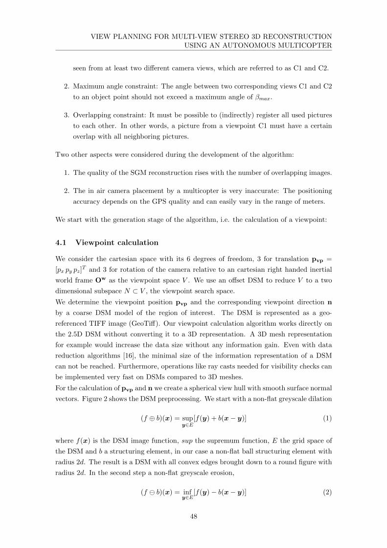
VIEW PLANNING FOR MULTI-VIEW STEREO 3D RECONSTRUCTIONUSING AN AUTONOMOUS MULTICOPTER
seen from at least two different camera views, which are referred to as C1 and C2.
2. Maximum angle constraint: The angle between two corresponding views C1 and C2
to an object point should not exceed a maximum angle of βmax.
3. Overlapping constraint: It must be possible to (indirectly) register all used pictures
to each other. In other words, a picture from a viewpoint C1 must have a certain
overlap with all neighboring pictures.
Two other aspects were considered during the development of the algorithm:
1. The quality of the SGM reconstruction rises with the number of overlapping images.
2. The in air camera placement by a multicopter is very inaccurate: The positioning
accuracy depends on the GPS quality and can easily vary in the range of meters.
We start with the generation stage of the algorithm, i.e. the calculation of a viewpoint:
4.1 Viewpoint calculation
We consider the cartesian space with its 6 degrees of freedom, 3 for translation pvp =
[px py pz]T and 3 for rotation of the camera relative to an cartesian right handed inertial
world frame Ow as the viewpoint space V . We use an offset DSM to reduce V to a two
dimensional subspace N ⊂ V , the viewpoint search space.
We determine the viewpoint position pvp and the corresponding viewpoint direction n
by a coarse DSM model of the region of interest. The DSM is represented as a geo-
referenced TIFF image (GeoTiff). Our viewpoint calculation algorithm works directly on
the 2.5D DSM without converting it to a 3D representation. A 3D mesh representation
for example would increase the data size without any information gain. Even with data
reduction algorithms [16], the minimal size of the information representation of a DSM
can not be reached. Furthermore, operations like ray casts needed for visibility checks can
be implemented very fast on DSMs compared to 3D meshes.
For the calculation of pvp and n we create a spherical view hull with smooth surface normal
vectors. Figure 2 shows the DSM preprocessing. We start with a non-flat greyscale dilation
(f ⊕ b)(x) = supy∈E
[f(y) + b(x− y)] (1)
where f(x) is the DSM image function, sup the supremum function, E the grid space of
the DSM and b a structuring element, in our case a non-flat ball structuring element with
radius 2d. The result is a DSM with all convex edges brought down to a round figure with
radius 2d. In the second step a non-flat greyscale erosion,
(f b)(x) = infy∈E
[f(y)− b(x− y)] (2)
48
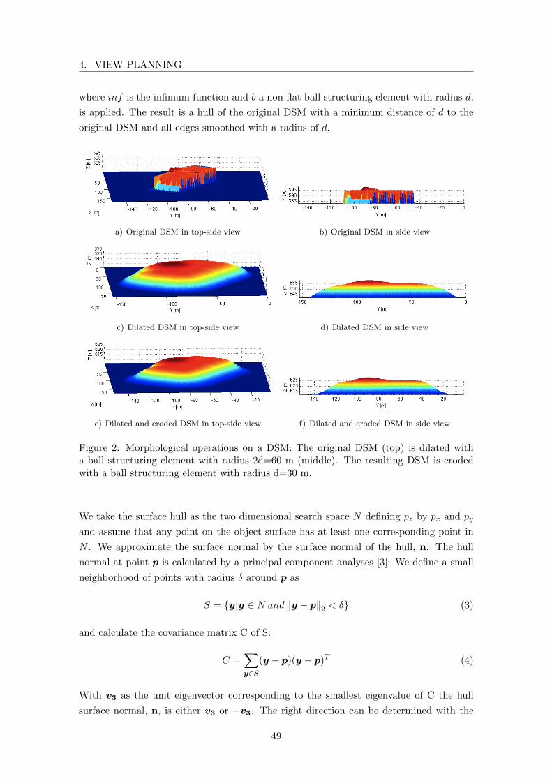
4. VIEW PLANNING
where inf is the infimum function and b a non-flat ball structuring element with radius d,
is applied. The result is a hull of the original DSM with a minimum distance of d to the
original DSM and all edges smoothed with a radius of d.
a) Original DSM in top-side view b) Original DSM in side view
c) Dilated DSM in top-side view d) Dilated DSM in side view
e) Dilated and eroded DSM in top-side view f) Dilated and eroded DSM in side view
Figure 2: Morphological operations on a DSM: The original DSM (top) is dilated witha ball structuring element with radius 2d=60 m (middle). The resulting DSM is erodedwith a ball structuring element with radius d=30 m.
We take the surface hull as the two dimensional search space N defining pz by px and py
and assume that any point on the object surface has at least one corresponding point in
N . We approximate the surface normal by the surface normal of the hull, n. The hull
normal at point p is calculated by a principal component analyses [3]: We define a small
neighborhood of points with radius δ around p as
S = {y|y ∈ N and ‖y − p‖2 < δ} (3)
and calculate the covariance matrix C of S:
C =∑
y∈S(y − p)(y − p)T (4)
With v3 as the unit eigenvector corresponding to the smallest eigenvalue of C the hull
surface normal, n, is either v3 or −v3. The right direction can be determined with the
49
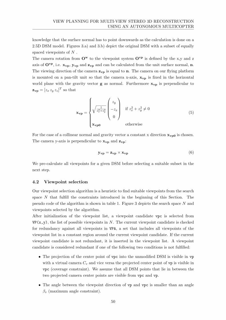
VIEW PLANNING FOR MULTI-VIEW STEREO 3D RECONSTRUCTIONUSING AN AUTONOMOUS MULTICOPTER
knowledge that the surface normal has to point downwards as the calculation is done on a
2.5D DSM model. Figures 3.a) and 3.b) depict the original DSM with a subset of equally
spaced viewpoints of N .
The camera rotation from Ow to the viewpoint system Ovp is defined by the x,y and z
axis of Ovp, i.e. xvp, yvp and zvp and can be calculated from the unit surface normal, n.
The viewing direction of the camera zvp is equal to n. The camera on our flying platform
is mounted on a pan-tilt unit so that the camera x-axis, xvp is fixed in the horizontal
world plane with the gravity vector g as normal. Furthermore xvp is perpendicular to
zvp = [zx zy zz]T so that
xvp =
√1
z2x+z2y
zy
−zx0
if z2
x + z2y 6= 0
xvp0 otherwise
(5)
For the case of a collinear normal and gravity vector a constant x direction xvp0 is chosen.
The camera y-axis is perpendicular to xvp and zvp:
yvp = zvp × xvp (6)
We pre-calculate all viewpoints for a given DSM before selecting a suitable subset in the
next step.
4.2 Viewpoint selection
Our viewpoint selection algorithm is a heuristic to find suitable viewpoints from the search
space N that fulfill the constraints introduced in the beginning of this Section. The
pseudo code of the algorithm is shown in table 1. Figure 3 depicts the search space N and
viewpoints selected by the algorithm.
After initialization of the viewpoint list, a viewpoint candidate vpc is selected from
VP(x,y), the list of possible viewpoints in N . The current viewpoint candidate is checked
for redundancy against all viewpoints in VPA, a set that includes all viewpoints of the
viewpoint list in a constant region around the current viewpoint candidate. If the current
viewpoint candidate is not redundant, it is inserted in the viewpoint list. A viewpoint
candidate is considered redundant if one of the following two conditions is not fulfilled:
• The projection of the center point of vpc into the unmodified DSM is visible in vp
with a virtual camera Cv and vice versa the projected center point of vp is visible in
vpc (coverage constraint). We assume that all DSM points that lie in between the
two projected camera center points are visible from vpc and vp.
• The angle between the viewpoint direction of vp and vpc is smaller than an angle
βv (maximum angle constraint).
50
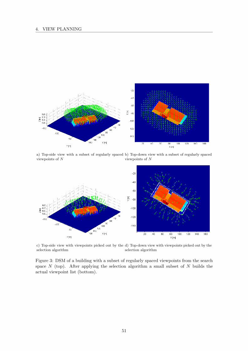
4. VIEW PLANNING
a) Top-side view with a subset of regularly spacedviewpoints of N
b) Top-down view with a subset of regularly spacedviewpoints of N
c) Top-side view with viewpoints picked out by theselection algorithm
d) Top-down view with viewpoints picked out by theselection algorithm
Figure 3: DSM of a building with a subset of regularly spaced viewpoints from the searchspace N (top). After applying the selection algorithm a small subset of N builds theactual viewpoint list (bottom).
51

VIEW PLANNING FOR MULTI-VIEW STEREO 3D RECONSTRUCTIONUSING AN AUTONOMOUS MULTICOPTER
v p l i s t = {VP( 0 , 0 ) } ;for x=1 to DSMXfor y=1 to DSMY
vpc = VP(x , y ) ;i n s e r t = 1 ;VPA = {VP(vx, vy)|VP(vx, vy) ∈ vplist, (vx, vy) ∈ R(x, y)}foreach vp ∈ VPA
i f ( redundant ( vpc , vp , camv , βv ) )i n s e r t = 0 ;break ;
endifendforeachi f ( i n s e r t )
i n s e r t vpc in v p l i s t ;endif
endforendfor
Table 1: Viewpoint selection algorithm
We introduced a virtual camera Cv. It has a smaller aperture angle α1 than the physical
camera as we have to guarantee that the redundancy check fails if the coverage criterion
could not be fulfilled for one of the viewpoints around the viewpoint candidate. Figure 4
depicts a viewpoint candidate and its neighbor. The physical aperture angle is α0 and the
modified aperture angle α1. With the assumption that the camera-object distance can be
approximated by the hull distance d we know the maximum curvature of the hull. With
the model resolution ∆x � d the virtual aperture angle α1 can be calculated from the
physical aperture angle α0 as:
α1 = atan(yd
)≈ atan
(tan(α0 −∆β)− ∆x
d
)(7)
where ∆β ≈ ∆xd . Analogously, the angle βv has to be decreased by the maximum possible
angle change ∆β between two neighboring viewpoints:
βv = βmax −∆β (8)
The region R(vx, vy) is defined as the area around the current viewpoint candidate with
viewpoints that can fulfill the coverage and the maximum angle constraint. R is a limited,
constant region so that our view planning heuristic has a complexity of O(A) where A =
DSMX ×DSMY , i.e. the DSM area of interest.
52
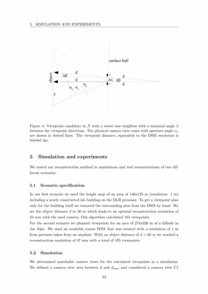
5. SIMULATION AND EXPERIMENTS
�
��
��� ��
��
��
���
�
��� �����
�
�
���� �
�
Figure 4: Viewpoint candidate in N with a worst case neighbor with a maximal angle βbetween the viewpoint directions. The physical camera view cones with aperture angle α1
are shown in dotted lines. The viewpoint distance, equivalent to the DSM resolution islabeled ∆x.
5 Simulation and experiments
We tested our reconstruction method in simulations and real reconstructions of two dif-
ferent scenarios.
5.1 Scenario specification
In our first scenario we used the height map of an area of 146x125 m (resolution: 1 m)
including a newly constructed lab building on the DLR premises. To get a viewpoint plan
only for the building itself we removed the surrounding area from the DSM by hand. We
set the object distance d to 30 m which leads to an optimal reconstruction resolution of
23 mm with the used camera. Our algorithm calculated 165 viewpoints.
For the second scenario we planned viewpoints for an area of 274x326 m of a hillside in
the Alps. We used an available coarse DSM that was created with a resolution of 1 m
from pictures taken from an airplane. With an object distance of d = 60 m we reached a
reconstruction resolution of 47 mm with a total of 435 viewpoints.
5.2 Simulation
We determined matchable camera views for the calculated viewpoints in a simulation:
We defined a camera view area between d and dmax and considered a camera view C1
53

VIEW PLANNING FOR MULTI-VIEW STEREO 3D RECONSTRUCTIONUSING AN AUTONOMOUS MULTICOPTER
Figure 5: Camera matches in scenario 1. All cameras that can be matched with each otherare connected by a green line.
Figure 6: Camera matches in scenario 2. All cameras that can be matched with each otherare connected by a green line.
54
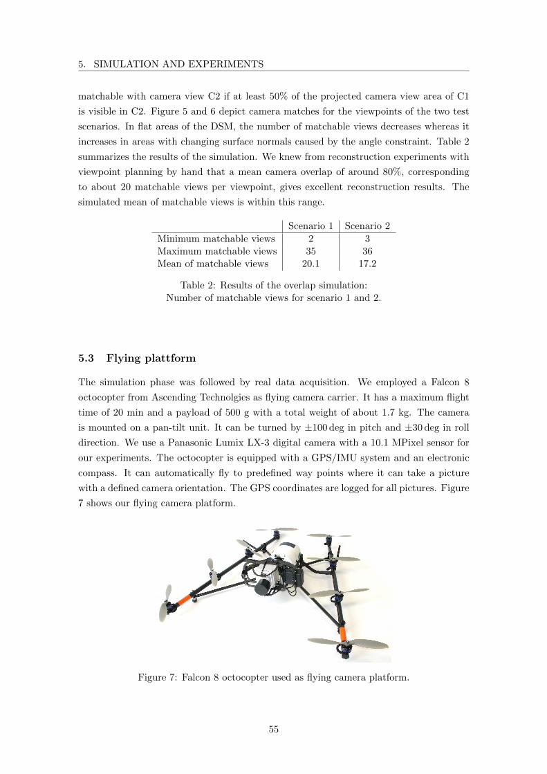
5. SIMULATION AND EXPERIMENTS
matchable with camera view C2 if at least 50% of the projected camera view area of C1
is visible in C2. Figure 5 and 6 depict camera matches for the viewpoints of the two test
scenarios. In flat areas of the DSM, the number of matchable views decreases whereas it
increases in areas with changing surface normals caused by the angle constraint. Table 2
summarizes the results of the simulation. We knew from reconstruction experiments with
viewpoint planning by hand that a mean camera overlap of around 80%, corresponding
to about 20 matchable views per viewpoint, gives excellent reconstruction results. The
simulated mean of matchable views is within this range.
Scenario 1 Scenario 2
Minimum matchable views 2 3Maximum matchable views 35 36Mean of matchable views 20.1 17.2
Table 2: Results of the overlap simulation:Number of matchable views for scenario 1 and 2.
5.3 Flying plattform
The simulation phase was followed by real data acquisition. We employed a Falcon 8
octocopter from Ascending Technolgies as flying camera carrier. It has a maximum flight
time of 20 min and a payload of 500 g with a total weight of about 1.7 kg. The camera
is mounted on a pan-tilt unit. It can be turned by ±100 deg in pitch and ±30 deg in roll
direction. We use a Panasonic Lumix LX-3 digital camera with a 10.1 MPixel sensor for
our experiments. The octocopter is equipped with a GPS/IMU system and an electronic
compass. It can automatically fly to predefined way points where it can take a picture
with a defined camera orientation. The GPS coordinates are logged for all pictures. Figure
7 shows our flying camera platform.
Figure 7: Falcon 8 octocopter used as flying camera platform.
55

VIEW PLANNING FOR MULTI-VIEW STEREO 3D RECONSTRUCTIONUSING AN AUTONOMOUS MULTICOPTER
5.4 Experiments
Since the octocopter has a maximum flight time of 20 min, it is desirable to minimize
the path length that is needed to visit the calculated viewpoints. To solve the Traveling
Salesman Problem, we sorted the viewpoints of scenario 1 and 2 by a Farthest-Insertion-
Heuristic.
The flight time of the data acquisition process for scenario 1 was about 25 min. The
reconstruction was performed with a resolution of 5 cm, instead of the optimal resolution
(23 mm) to compensate minor errors in the extrinsic orientation calculated by the bundler.
Figure 8.a) depicts the reconstructability of the DSM points in the region of interest.
The darkness of a point reflects the number of image pairs that could be used for depth
reconstruction. The results of the reconstruction are shown in Figure 8.b) and 9. Most
parts of the building could be reconstructed in high quality. In zoom view (Figure 9.d))
even foot steps on the rooftop are recognizable. In the back part of the building some
artifacts are visible. From the reconstructability map (figure 8.a)) it can be seen that in
the corresponding area (right) the building seems less densely imaged than on the left
side. However, the density of the waypoints looks equally distributed in both regions
(figure 3.d)). This means that some points of the building could not be reconstructed
properly and are interpolated by the SGM. From the building texture in figure 9.a) the
effect can be explained by missing features in continuous areas of snow in the backside of
the building.
a) Reconstructability map: The darker a pixel themore image pairs were used for depth reconstruction.
b) Resulting DSM with a resolution of 5 cm.
Figure 8: Reconstructability map and resulting high resolution DSM of scenario 1.
The data acquisition process for scenario 2 took about 81 min. The reconstruction was
also performed with a resolution of 5 cm. Figure 10.a) depicts the reconstructability of
56
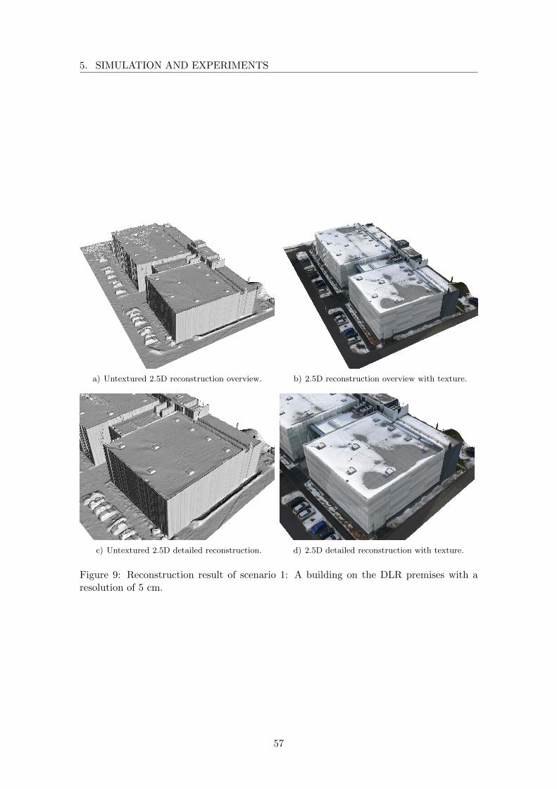
5. SIMULATION AND EXPERIMENTS
a) Untextured 2.5D reconstruction overview. b) 2.5D reconstruction overview with texture.
c) Untextured 2.5D detailed reconstruction. d) 2.5D detailed reconstruction with texture.
Figure 9: Reconstruction result of scenario 1: A building on the DLR premises with aresolution of 5 cm.
57

VIEW PLANNING FOR MULTI-VIEW STEREO 3D RECONSTRUCTIONUSING AN AUTONOMOUS MULTICOPTER
the DSM points. The results of reconstruction are shown in Figure 10.b) and 11. As in
scenario 1, several images with continuous areas of snow couldn’t be registered properly to
each other and were therefore not used for reconstruction. The corresponding areas were
interpolated by the SGM.
The effect of images that are not used for reconstruction or could not be matched to each
other is equivalent to missing or badly placed viewpoints. Therefore, areas of interpolation
as in figure 11.a) also show the effect of wrongly chosen viewpoints on the reconstruction
quality.
a) Reconstructability map: The darker a pixel themore image pairs were used for depth reconstruction.
b) Resulting DSM with a resolution of 5 cm.
Figure 10: Reconstructability map and resulting high resolution DSM of scenario 2.
After reconstruction, the models are still undetermined in 7 degrees of freedom, 6 for the
global position and orientation and 1 for the scale. We geo-referenced the models by a
least-square error optimization over the differences of the image positions calculated by
the bundler and the logged GPS coordinates. The relative camera position and orientation
within the model is not affected by this process. Table 3 summarizes the results of the
entire reconstruction process.
6 Conclusion
We presented a five step method for the reconstruction of outdoor scenes. We use a VTOL
UAV for the complete data acquisition process. Scene reconstruction is performed by a
multi-view stereo algorithm that works on single-shot images. This reconstruction method
allows using a light-weight digital consumer camera, which can be carried by a multicopter.
58

6. CONCLUSION
a) Untextured 2.5D reconstruction overview withsurface interpolation caused by missing image fea-tures in a continuous area of snow.
b) 2.5D reconstruction overview with texture.
c) Untextured 2.5D detailed reconstruction. d) 2.5D detailed reconstruction with texture.
e) Untextured 2.5D detailed reconstruction. f) 2.5D detailed reconstruction with texture.
Figure 11: Reconstruction result of scenario 2: A hillside in the alps with a resolution of5 cm.
59
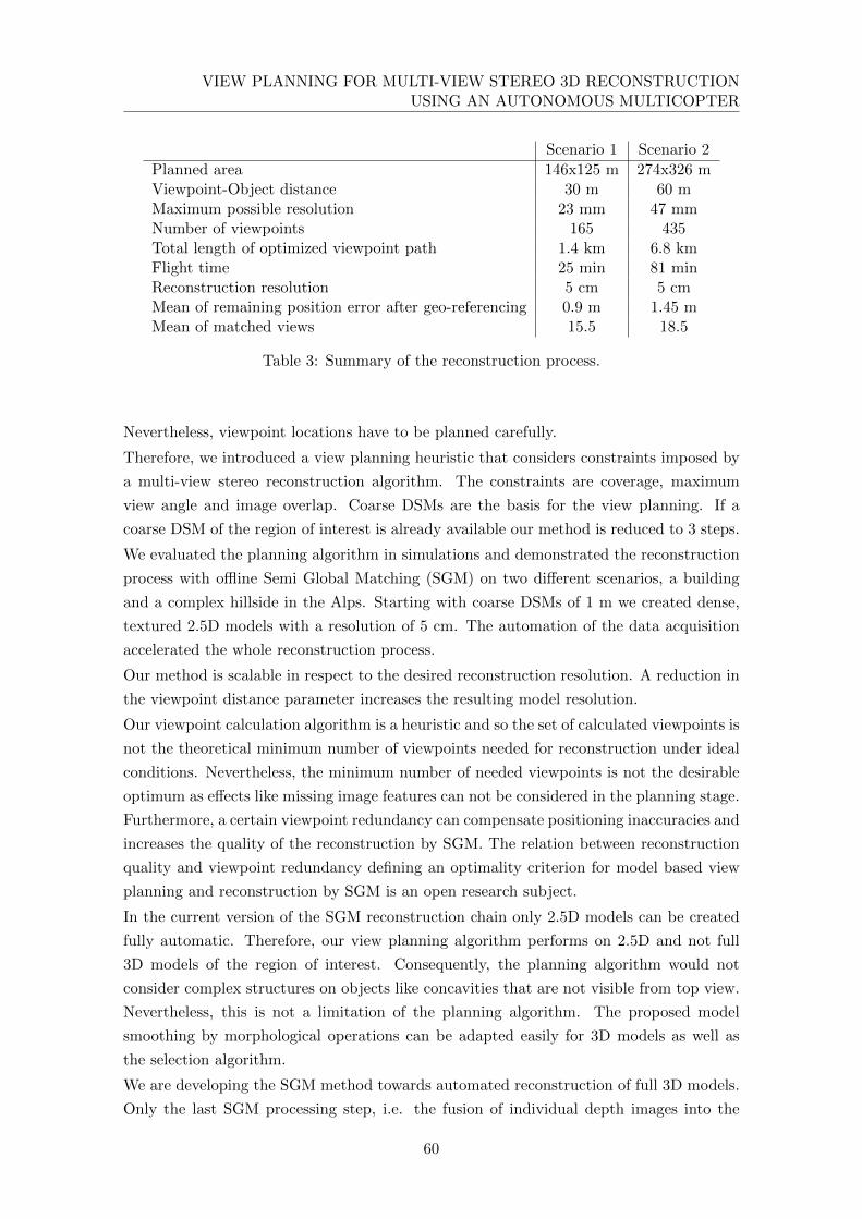
VIEW PLANNING FOR MULTI-VIEW STEREO 3D RECONSTRUCTIONUSING AN AUTONOMOUS MULTICOPTER
Scenario 1 Scenario 2
Planned area 146x125 m 274x326 mViewpoint-Object distance 30 m 60 mMaximum possible resolution 23 mm 47 mmNumber of viewpoints 165 435Total length of optimized viewpoint path 1.4 km 6.8 kmFlight time 25 min 81 minReconstruction resolution 5 cm 5 cmMean of remaining position error after geo-referencing 0.9 m 1.45 mMean of matched views 15.5 18.5
Table 3: Summary of the reconstruction process.
Nevertheless, viewpoint locations have to be planned carefully.
Therefore, we introduced a view planning heuristic that considers constraints imposed by
a multi-view stereo reconstruction algorithm. The constraints are coverage, maximum
view angle and image overlap. Coarse DSMs are the basis for the view planning. If a
coarse DSM of the region of interest is already available our method is reduced to 3 steps.
We evaluated the planning algorithm in simulations and demonstrated the reconstruction
process with offline Semi Global Matching (SGM) on two different scenarios, a building
and a complex hillside in the Alps. Starting with coarse DSMs of 1 m we created dense,
textured 2.5D models with a resolution of 5 cm. The automation of the data acquisition
accelerated the whole reconstruction process.
Our method is scalable in respect to the desired reconstruction resolution. A reduction in
the viewpoint distance parameter increases the resulting model resolution.
Our viewpoint calculation algorithm is a heuristic and so the set of calculated viewpoints is
not the theoretical minimum number of viewpoints needed for reconstruction under ideal
conditions. Nevertheless, the minimum number of needed viewpoints is not the desirable
optimum as effects like missing image features can not be considered in the planning stage.
Furthermore, a certain viewpoint redundancy can compensate positioning inaccuracies and
increases the quality of the reconstruction by SGM. The relation between reconstruction
quality and viewpoint redundancy defining an optimality criterion for model based view
planning and reconstruction by SGM is an open research subject.
In the current version of the SGM reconstruction chain only 2.5D models can be created
fully automatic. Therefore, our view planning algorithm performs on 2.5D and not full
3D models of the region of interest. Consequently, the planning algorithm would not
consider complex structures on objects like concavities that are not visible from top view.
Nevertheless, this is not a limitation of the planning algorithm. The proposed model
smoothing by morphological operations can be adapted easily for 3D models as well as
the selection algorithm.
We are developing the SGM method towards automated reconstruction of full 3D models.
Only the last SGM processing step, i.e. the fusion of individual depth images into the
60

7. ACKNOWLEDGMENT
final model, has to be changed. A further useful enhancement is the processing of high
resolution video data. By replacing the single-shot camera by a video-camera, the flight
time could be reduced drastically as the multicopter would not have to follow a stop and
go strategy for each viewpoint.
Nevertheless, model based view planning is always limited to the accuracy of the initial
model. The reconstruction process must be performed iteratively by repeating reconstruc-
tion and planning until the desired reconstruction accuracy is reached. With our method,
the model hull distance would have to be reduced in every iteration step which would also
lead to a strong increase in the number of images needed for reconstruction. The change
in image scaling prevents the reuse of images taken in a preceding reconstruction step.
Non model based online next best view planning dissolves the dependency on an initial
model and the need for iterations. The reconstruction would have to be realized in realtime
which is, at the moment, not possible onboard a multicopter due to its payload constraints.
An FPGA based realtime SGM processing board still has a weight of more than 1kg.
Online next best view planning is an exploration task. Considering the resulting need for
collision avoidance either further sensor equipment is needed or the introduced multi view
stereo camera system has to be replaced by an instant 3D sensor as for example a real
stereo system. In contrast to multi view stereo techniques, the camera base line is fixed
and therefore limits the depth range of the sensor. The multicopter would have to fly in a
low distance to the object of interest. The GPS signal that is used for positioning can be
strongly disturbed. We are therefore working on visual navigation and obstacle avoidance.
7 Acknowledgment
The authors thank Prof. Darius Burschka for his input to this paper as well as Thomas
Griesbeck from ”Bergwacht Bayern” and Rolf Frasch from ”Stiftung Sicherheit im Skisport”
for their support during the data acquisition process in the Alps.
61
VIEW PLANNING FOR MULTI-VIEW STEREO 3D RECONSTRUCTIONUSING AN AUTONOMOUS MULTICOPTER
References
[1] C. Cowan and P. Kovesi. “Automatic sensor placement from vision task require-
ments”. In: Pattern Analysis and Machine Intelligence, IEEE Transactions on 10.3
(May 1988), pp. 407–416.
[2] K. Tarabanis, R. Tsai, and S. Abrams. “Planning viewpoints that simultaneously
satisfy several feature detectability constraints for robotic vision”. In: Advanced
Robotics, 1991. ’Robots in Unstructured Environments’, 91 ICAR., Fifth Interna-
tional Conference on. June 1991, 1410–1415 vol.2.
[3] H. Hoppe, T. DeRose, T. Duchamp, J. McDonald, and W. Stuetzle. “Surface Re-
construction from Unorganized Points”. In: SIGGRAPH Comput. Graph. 26.2 (July
1992), pp. 71–78.
[4] G. Tarbox and S. Gottschlich. “IVIS: an integrated volumetric inspection system”.
In: CAD-Based Vision Workshop, 1994., Proceedings of the 1994 Second. Feb. 1994,
pp. 220–227.
[5] Z. Kim, A. Huertas, and R. Nevatia. “Automatic description of complex build-
ings with multiple images”. In: Applications of Computer Vision, 2000, Fifth IEEE
Workshop on. 2000, pp. 155–162.
[6] W. Scott, G. Roth, and J.-F. Rivest. “View planning with a registration constraint”.
In: 3-D Digital Imaging and Modeling, 2001. Proceedings. Third International Con-
ference on. 2001, pp. 127–134.
[7] C. Frueh and A. Zakhor. “Constructing 3D city models by merging ground-based
and airborne views”. In: Computer Vision and Pattern Recognition, 2003. Proceed-
ings. 2003 IEEE Computer Society Conference on. Vol. 2. June 2003.
[8] S. El-Hakim, J.-A. Beraldin, M. Picard, and A. Vettore. “Effective 3D modeling of
heritage sites”. In: 3-D Digital Imaging and Modeling, 2003. 3DIM 2003. Proceed-
ings. Fourth International Conference on. Oct. 2003, pp. 302–309.
[9] W. R. Scott, G. Roth, and J.-F. Rivest. “View Planning for Automated Three-
dimensional Object Reconstruction and Inspection”. In: ACM Comput. Surv. 35.1
(Mar. 2003), pp. 64–96.
[10] A. Akbarzadeh, J.-M. Frahm, P. Mordohai, B. Clipp, C. Engels, D. Gallup, P. Mer-
rell, M. Phelps, S. Sinha, B. Talton, L. Wang, Q. Yang, H. Stewenius, R. Yang,
G. Welch, H. Towles, D. Nister, and M. Pollefeys. “Towards Urban 3D Reconstruc-
tion from Video”. In: 3D Data Processing, Visualization, and Transmission, Third
International Symposium on. June 2006, pp. 1–8.
[11] N. Snavely, S. M. Seitz, and R. Szeliski. “Photo Tourism: Exploring Photo Collec-
tions in 3D”. In: ACM Trans. Graph. 25.3 (July 2006), pp. 835–846.
62
REFERENCES
[12] P. Blaer and P. Allen. “Data acquisition and view planning for 3-D modeling tasks”.
In: Intelligent Robots and Systems, 2007. IROS 2007. IEEE/RSJ International Con-
ference on. Oct. 2007, pp. 417–422.
[13] H. Eisenbeiss. “The Autonomous Mini Helicopter: A powerful Platform for Mobile
Mapping”. In: XXI ISPRS Congress. 2008, pp. 03–11.
[14] H. Hirschmuller. “Stereo Processing by Semiglobal Matching and Mutual Informa-
tion”. In: Pattern Analysis and Machine Intelligence, IEEE Transactions on 30.2
(Feb. 2008), pp. 328–341.
[15] H. Hirschmuller and D. Scharstein. “Evaluation of Stereo Matching Costs on Images
with Radiometric Differences”. In: Pattern Analysis and Machine Intelligence, IEEE
Transactions on 31.9 (Sept. 2009), pp. 1582–1599.
[16] F.-M. Adolf and H. Hirschmuller. “Meshing and Simplification of High Resolution
Urban Surface Data for UAV Path Planning”. English. In: Journal of Intelligent
and Robotic Systems 61.1-4 (2011), pp. 169–180.
63

VIEW PLANNING FOR MULTI-VIEW STEREO 3D RECONSTRUCTIONUSING AN AUTONOMOUS MULTICOPTER
64
Paper 2
Toward a fully autonomous uav:
Research platform for indoor and
outdoor urban search and rescue1
T. Tomic, K. Schmid, P. Lutz, A. Domel, M. Kassecker, E. Mair, I.L. Grixa, F. Ruess,
M. Suppa, and D. Burschka
Abstract Urban Search and Rescue missions raise special requirements on robotic sys-
tems. Small aerial systems provide essential support to human task forces in situation
assessment and surveillance. As external infrastructure for navigation and communication
is usually not available, robotic systems must be able to operate autonomously. Limited
payload of small aerial systems poses a great challenge to the system design. The optimal
trade-off between flight performance, sensors and computing resources has to be found.
Communication to external computers cannot be guaranteed, therefore all processing and
decision making has to be done on-board. In this paper, we present a UAS system design
fulfilling these requirements. The components of our system are structured into groups to
encapsulate their functionality and interfaces. We use both laser and stereo vision odom-
etry to enable seamless indoor and outdoor navigation. The odometry is fused with an
Inertial Measurement Unit in an Extended Kalman Filter. Navigation is supported by
a module that recognizes known objects in the environment. A distributed computation
approach is adopted to address computational requirements of the used algorithms. The
capabilities of the system are validated in flight experiments, using a quadrotor.
1 c©2012 IEEE. Reprinted, with permission, from Robotics & Automation Magazine, IEEE 19.3 (2012),pp. 46-56, DOI: 10.1109/MRA.2012.2206473
65
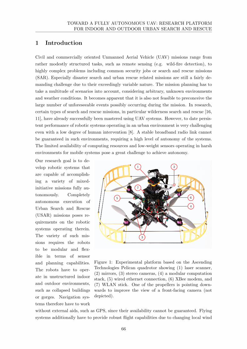
TOWARD A FULLY AUTONOMOUS UAV: RESEARCH PLATFORMFOR INDOOR AND OUTDOOR URBAN SEARCH AND RESCUE
1 Introduction
Civil and commercially oriented Unmanned Aerial Vehicle (UAV) missions range from
rather modestly structured tasks, such as remote sensing (e.g. wild-fire detection), to
highly complex problems including common security jobs or search and rescue missions
(SAR). Especially disaster search and urban rescue related missions are still a fairly de-
manding challenge due to their exceedingly variable nature. The mission planning has to
take a multitude of scenarios into account, considering arbitrary, unknown environments
and weather conditions. It becomes apparent that it is also not feasible to preconceive the
large number of unforeseeable events possibly occurring during the mission. In research,
certain types of search and rescue missions, in particular wilderness search and rescue [16,
11], have already successfully been mastered using UAV systems. However, to date persis-
tent performance of robotic systems operating in an urban environment is very challenging
even with a low degree of human intervention [8]. A stable broadband radio link cannot
be guaranteed in such environments, requiring a high level of autonomy of the systems.
The limited availability of computing resources and low-weight sensors operating in harsh
environments for mobile systems pose a great challenge to achieve autonomy.
3
1 2
5 6
4
7
Figure 1: Experimental platform based on the AscendingTechnologies Pelican quadrotor showing (1) laser scanner,(2) mirrors, (3) stereo cameras, (4) a modular computationstack, (5) wired ethernet connection, (6) XBee modem, and(7) WLAN stick. One of the propellers is pointing down-wards to improve the view of a front-facing camera (notdepicted).
Our research goal is to de-
velop robotic systems that
are capable of accomplish-
ing a variety of mixed-
initiative missions fully au-
tonomously. Completely
autonomous execution of
Urban Search and Rescue
(USAR) missions poses re-
quirements on the robotic
systems operating therein.
The variety of such mis-
sions requires the robots
to be modular and flex-
ible in terms of sensor
and planning capabilities.
The robots have to oper-
ate in unstructured indoor
and outdoor environments,
such as collapsed buildings
or gorges. Navigation sys-
tems therefore have to work
without external aids, such as GPS, since their availability cannot be guaranteed. Flying
systems additionally have to provide robust flight capabilities due to changing local wind
66
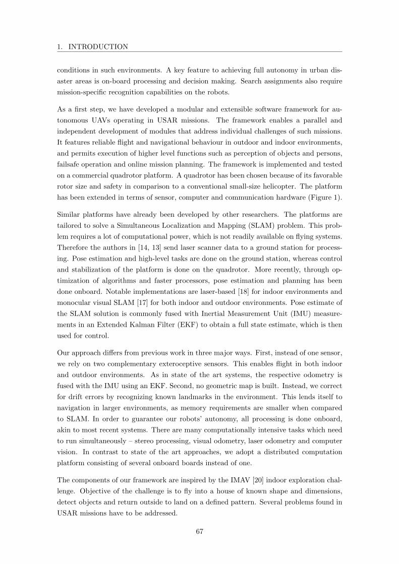
1. INTRODUCTION
conditions in such environments. A key feature to achieving full autonomy in urban dis-
aster areas is on-board processing and decision making. Search assignments also require
mission-specific recognition capabilities on the robots.
As a first step, we have developed a modular and extensible software framework for au-
tonomous UAVs operating in USAR missions. The framework enables a parallel and
independent development of modules that address individual challenges of such missions.
It features reliable flight and navigational behaviour in outdoor and indoor environments,
and permits execution of higher level functions such as perception of objects and persons,
failsafe operation and online mission planning. The framework is implemented and tested
on a commercial quadrotor platform. A quadrotor has been chosen because of its favorable
rotor size and safety in comparison to a conventional small-size helicopter. The platform
has been extended in terms of sensor, computer and communication hardware (Figure 1).
Similar platforms have already been developed by other researchers. The platforms are
tailored to solve a Simultaneous Localization and Mapping (SLAM) problem. This prob-
lem requires a lot of computational power, which is not readily available on flying systems.
Therefore the authors in [14, 13] send laser scanner data to a ground station for process-
ing. Pose estimation and high-level tasks are done on the ground station, whereas control
and stabilization of the platform is done on the quadrotor. More recently, through op-
timization of algorithms and faster processors, pose estimation and planning has been
done onboard. Notable implementations are laser-based [18] for indoor environments and
monocular visual SLAM [17] for both indoor and outdoor environments. Pose estimate of
the SLAM solution is commonly fused with Inertial Measurement Unit (IMU) measure-
ments in an Extended Kalman Filter (EKF) to obtain a full state estimate, which is then
used for control.
Our approach differs from previous work in three major ways. First, instead of one sensor,
we rely on two complementary exteroceptive sensors. This enables flight in both indoor
and outdoor environments. As in state of the art systems, the respective odometry is
fused with the IMU using an EKF. Second, no geometric map is built. Instead, we correct
for drift errors by recognizing known landmarks in the environment. This lends itself to
navigation in larger environments, as memory requirements are smaller when compared
to SLAM. In order to guarantee our robots’ autonomy, all processing is done onboard,
akin to most recent systems. There are many computationally intensive tasks which need
to run simultaneously – stereo processing, visual odometry, laser odometry and computer
vision. In contrast to state of the art approaches, we adopt a distributed computation
platform consisting of several onboard boards instead of one.
The components of our framework are inspired by the IMAV [20] indoor exploration chal-
lenge. Objective of the challenge is to fly into a house of known shape and dimensions,
detect objects and return outside to land on a defined pattern. Several problems found in
USAR missions have to be addressed.
67
TOWARD A FULLY AUTONOMOUS UAV: RESEARCH PLATFORMFOR INDOOR AND OUTDOOR URBAN SEARCH AND RESCUE
Figure 2: The house used for the experiments, located theDLR outdoor testbed for mobile robots. It corresponds inshape and dimensions to the house used for the IMAV explo-ration challenge. Provided are both an indoor environment,suitable for navigation using a laser scanner, and an outdoorenvironment, which is suitable for vision-based navigation.
The UAV system must
firstly find the house, as it
starts behind a wall with-
out direct sight of the house.
Once found, precise de-
tection of and navigation
through either the door,
window or chimney of the
house is required. Pattern
recognition is used for ob-
ject detection and landing
zone identification. Exter-
nal aids, such as GPS or a
motion tracking system, are
not available. Adding arti-
ficial features to the envi-
ronment is penalized. Al-
though not all difficulties of
an USAR mission are ad-
dressed, the navigation, autonomous decision making and object recognition challenges
are present. The size of our 70 cm wide platform in relation to the 1 m wide passages into
the house poses an additional challenge. Our system architecture is explained in terms of
the aforementioned mission.
Current approaches which try to tackle this kind of challenge are using a laser scanner
[13] or monocular vision [15]. The processing in these approaches was done offboard.
For the vision system, artificial features had to be added to the indoor environment. Our
system will use the best odometry sensor in a given situation. Systems have autonomously
flown into the house through the window and doors, however no system has yet flown the
complete mission autonomously.
In this paper, we first present the system architecture and existing software modules in
Section 2. The hardware design and infrastructure enabling the presented architecture is
described in Section 3. Functionality of the experimental system is shown through a flight
experiment in Section 4. Finally, future research directions are indicated.
2 Software framework
Our modular framework consists of intercommunicating components, enabling easy ex-
change of task related functionality and exchangeability of components. To further define
their scope, the components of our system are subdivided considering their degree of
autonomy and cognitive functionality as depicted in Figure 3.
Concerning the level of autonomy, the system is structured into low level and high level
68

2. SOFTWARE FRAMEWORK
IMU Cam Left Cam Right Laser Cam Up Cam Front
Stereoprocessing
Lasertransform
DataFusion
Odometry Recognition
EnvironmentPath
planningMissioncontrol
Controller
Autopilot
Low level High level
Sensing
Cognition
Perception
Action
sync
Atom Gumstix 1 Gumstix 2 Gumstix RT Peripheral Real-time
Figure 3: System architecture and software deployment of components. In addition tobeing organized into cognitive layers, the system components are partitioned according totheir autonomy level as well as cognitive functionality.
components. The low-level components are responsible for the data fusion and flight
control of the quadrotor. They allow for reliable autonomous flight and navigation, shared
through an abstract and unified interface between humans and high level components. As
the stability of the system depends on these components, a hard real-time system with a
high execution rate is required. The high level components provide situational awareness
and mission planning functionality with a representation of the environment. Status of
the system, the mission and the environment are monitored and commands are issued
accordingly. They take over tasks usually done by a human operator.
Furthermore, the components are grouped into perception, cognition and action layers [10,
4] as depicted in Figure 3. The perception layer includes all tasks concerning acquisition
and processing of sensor data. Therein, the data fusion component fuses the propriocep-
tive and exteroceptive sensor data. Mission-dependent recognition of world features, such
as persons or interesting objects, is done in the recognition module. World representation
as well as planning and decision making functionalities are realized in the cognition layer.
Lastly, the action layer is involved in stabilizing and moving the UAV in the desired man-
ner. Such categorization allows for a clear definition of the interfaces between components
69
TOWARD A FULLY AUTONOMOUS UAV: RESEARCH PLATFORMFOR INDOOR AND OUTDOOR URBAN SEARCH AND RESCUE
and the minimum required set of component functionalities. The realization of this struc-
ture in our experimental system can be presented more clearly when grouped by the layer
subdivision.
2.1 Perception
The UAV should be able to fly in structured indoor environments as well as outdoors.
Indoor environments mostly consist of clearly defined vertical structures (walls) that can
be detected by a laser scanner. However, poor lighting conditions and low number of
environment features make indoor environments unsuitable for a camera-based odometry
system. Conversely, outdoor environments lack clear structures. Sunlit environments con-
tain light in part of the spectrum that coincides with that used by infrared laser scanners,
disturbing the measurements. This makes low-powered light-weight laser scanners, which
are commonly employed on flying systems, unsuitable for such environments. Outdoor
environments have many natural features and good lighting contitions, which makes them
well suited for visual odometry systems. In such environments, previous camera images
can be easily recognized, so the camera can be used for loop closure.
In our approach, we use both laser and stereo odometry for pose estimation. The com-
bination of two odometry approaches allows to compensate drawbacks of a single sensor.
Moreover, the estimation of all 6DoF states can be done using only one filter. This differs
from other approaches, where either laser odometry [18] or monocular visual odometry
[17] is used for pose estimation.
The stereo camera in our system points downwards to ensure that the odometry is available
in outdoor areas, but also to enable detection of a target from above. Drift errors can be
compensated by using keyframes in the visual odometry system, as well as recognition of
known landmarks in a topological map. For the indoor exploration mission, the map is
fixed and predefined, as known landmarks include the window, door and chimney. Their
exact position is known with respect to the house, so they can be used to correct drift
errors. These are detected and tracked using front-facing and upward-facing cameras (not
shown in Figure 1), respectively. Two separate cameras provide more stable tracking than
a pan-tilt unit with one camera of the same weight.
Odometry
Laser odometry The laser odometry system is based on Censi’s Canonical Scan Matcher
[12]. The laser scan is projected to the ground plane in the Laser Transform component,
using attitude information from the Data Fusion component (Figure 3). The projected
data is only valid for scan matching if the scanned environment objects contain vertical
planes. This assumption is valid for most indoor environments. The algorithm uses an
iterative closest point (ICP) variant to compute 3D delta movement information (change
in (x, y) position and yaw angle) between two points in time and the corresponding mea-
surement covariance.
70
2. SOFTWARE FRAMEWORK
Visual odometry A correlation-based algorithm [6, 9] is used to obtain a disparity
image from two time-synchronized camera images in the stereo processing component.
Based on this 3D information, the 6D delta position and orientation between two points
in time as well as the corresponding measurement covariance are calculated [5]. The
algorithm supports a key frame buffer so that the delta measurement refers not just to
the last acquired image but to the image in the buffer that gives the delta measurement
with the smallest absolute covariance.
As shown in the experiment in Section 4, the estimated variances for laser and camera
odometry are a good indicator to classify the environment into indoor and outdoor. In
the variance calculation for each sensor it is assumed that there are no outliers in the
measurement. During experiments we have found that, under bad sensor conditions,
outliers in the measurements occured. These could not be detected by a outlier rejection
mechanism using Mahalanobis distance. Therefore, the measurement variance is invalid.
Fusing these measurements would lead to unpredictable behavior of the filter. Because of
this, we switch to the sensor that works well in a specific environment. We assume that the
sensor with the smallest measurement variance is best suited in the current environment
and is therefore used for fusion.
Data fusion
The proprioceptive sensor information from the IMU and the exteroceptive odometry
information has to be fused to get the current system state estimate. There are two main
challenges.
First, the odometry data gives only relative position and orientation information. Second,
the odometry data is time delayed due to measurement and data processing time. Precise
times of measurement are obtained through hardware synchronization triggers. The total
delay of the laser odometry in the experimental system is about 100 ms with an update
frequency of 10 Hz, and for the visual odometry the delay is more than 300 ms, with
a frequency of 3 Hz. Therefore, the measurement refers to a state in the past. As the
estimate is used to control the UAV, and the quadrotor dynamics are fast compared to the
measurement delays, the latter have to be considered in the data fusion algorithm. This
is realized using an indirect feedback Kalman Filter with state augmentation [7] using two
state vectors.
The direct state vector includes position, velocity and attitude (as quaternion) in the
world frame and the biases of the acceleration and gyro sensors in the body frame (∈R16). Quaternions are used to circumvent the gimbal lock problem that might occur when
using minimal attitude representations. The direct state is calculated by the strapdown
algorithm.
The main filter state vector includes the errors in position, velocity and orientation in
the world frame and the IMU acceleration and gyro bias errors in the system body frame
(∈ R15). Since we assume small errors in the filter, the small angle approximation is
71
TOWARD A FULLY AUTONOMOUS UAV: RESEARCH PLATFORMFOR INDOOR AND OUTDOOR URBAN SEARCH AND RESCUE
employed to efficiently represent the attitude. Hence, the scalar part of the quaternion can
be omitted, as it is implicitly defined to 1. This also simplifies modeling of the attitude
sensor noise. A hardware synchronization signal of the laser and the camera system
signaling the start of a data acquisition sequence is directly registered by the real time
system running the filter algorithm. At every sync trigger a sub-state including position
and orientation of the current direct state is saved and augmented to the main filter state.
The delayed delta measurement includes two time stamps for each measurement. These
time stamps are used to find the corresponding states within the state vector and construct
a suitable measurement matrix referencing the selected states.
The absolute position and orientation of the system is unobservable with only delta mea-
surements, which is reflected in an unbounded covariance for these states. Therefore
further absolute measurements are included:
• The height to ground is measured by laser beams reflected to the ground. Height
jumps caused by objects lying on the ground are detected and compensated.
• Measurement of the gravity vector is used as pseudo absolute measurement for roll
and pitch.
• Measurements with respect to known landmarks, if available, are used to correct
position drift errors.
If absolute position measurements arrive only in the range of minutes there might be
small jumps in the position estimate. Nevertheless, these jumps do not cause jumps in the
velocity estimate as its covariance is bounded by the regular delta position measurements.
This is an important feature for the underlying UAV controller, as jumps in the velocity
prediction can significantly degrade flight performance.
Recognition
Identifying and locating persons, animals or objects (e.g. landmarks, signs or landing
zone) is a central issue in USAR missions. The conceptual idea behind the recognition
module is to offer related object detection and recognition services. The module acts as
an interface between the mission planner, environment (cognition) and the sensors. Trig-
gered by the mission planner, it interprets sensory information and returns semantic and
location information respectively. The recognition module supports absolute localization
in a sense that it detects known objects and estimates their relative positions and heading
with respect to the UAV frame. It leverages typical object recognition techniques in com-
puter vision and 3D point-cloud processing. Three demonstrator recognizers are currently
implemented: a pattern recognizer for 2D images, a house detector based on stereo vision
and a laser object detector.
The pattern recognizer is typically used when searching a marked landing zone. The
pattern is a gray-value image or drawing of the landing zone. Together with a description
of its size, the pattern matcher checks for similar occurrences in camera images in a more
72
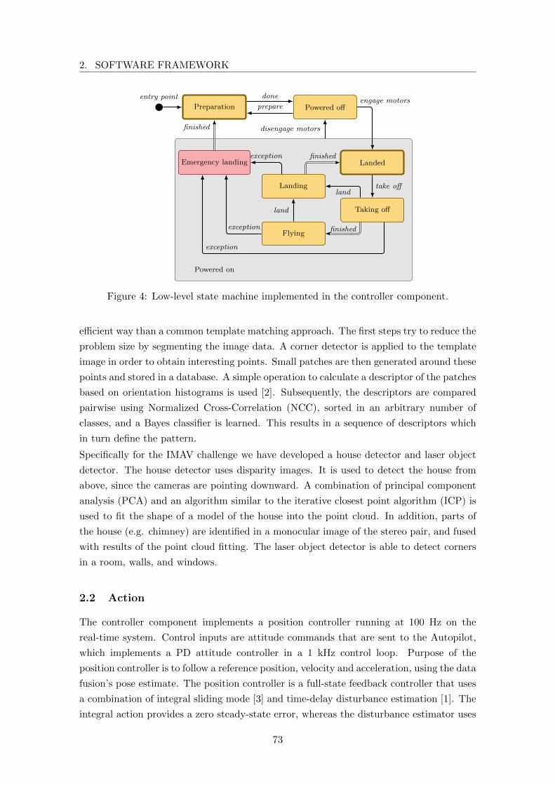
2. SOFTWARE FRAMEWORK
Preparation Powered off
Landing
LandedEmergency landing
Taking off
Flying
Powered on
entry point done
prepareengage motors
take offland
finished
land
finished
finished disengage motors
exception
exception
exception
Figure 4: Low-level state machine implemented in the controller component.
efficient way than a common template matching approach. The first steps try to reduce the
problem size by segmenting the image data. A corner detector is applied to the template
image in order to obtain interesting points. Small patches are then generated around these
points and stored in a database. A simple operation to calculate a descriptor of the patches
based on orientation histograms is used [2]. Subsequently, the descriptors are compared
pairwise using Normalized Cross-Correlation (NCC), sorted in an arbitrary number of
classes, and a Bayes classifier is learned. This results in a sequence of descriptors which
in turn define the pattern.
Specifically for the IMAV challenge we have developed a house detector and laser object
detector. The house detector uses disparity images. It is used to detect the house from
above, since the cameras are pointing downward. A combination of principal component
analysis (PCA) and an algorithm similar to the iterative closest point algorithm (ICP) is
used to fit the shape of a model of the house into the point cloud. In addition, parts of
the house (e.g. chimney) are identified in a monocular image of the stereo pair, and fused
with results of the point cloud fitting. The laser object detector is able to detect corners
in a room, walls, and windows.
2.2 Action
The controller component implements a position controller running at 100 Hz on the
real-time system. Control inputs are attitude commands that are sent to the Autopilot,
which implements a PD attitude controller in a 1 kHz control loop. Purpose of the
position controller is to follow a reference position, velocity and acceleration, using the data
fusion’s pose estimate. The position controller is a full-state feedback controller that uses
a combination of integral sliding mode [3] and time-delay disturbance estimation [1]. The
integral action provides a zero steady-state error, whereas the disturbance estimator uses
73

TOWARD A FULLY AUTONOMOUS UAV: RESEARCH PLATFORMFOR INDOOR AND OUTDOOR URBAN SEARCH AND RESCUE
Table 1: Activation of system components depending on low-level system state
System state Fusion Control Waypoints
Preparation - - -Powered off • - -Landed • - -Taking off • • -Flying • • •Landing • • -Emergency landing - • -
accelerometer measurements and previous control inputs to respond to disturbances faster.
This combination provides sufficient robustness to fly in indoor and outdoor environments
and through narrow passages.
In-flight switching and configuration of position controller implementations simplifies their
testing. The position between two waypoints is interpolated as a straight line in Cartesian
space using a constant velocity. This interpolated position is run through a linear filter
that represents the quadrotor’s translational dynamics to generate smooth reference tra-
jectories. Using this method, it is easy to configure the transient behaviour of the vehicle’s
position by setting the interpolation velocity and filter parameters. Such configurations
are stored as flight modes (e.g. fast, careful, accurate by decreasing velocity). A uni-
fied interface allows flight modes to be set for each path segment individually. High-level
components can set the flight mode according to the current mission task.
A state machine in the low-level system is implemented in the controller as depicted in
Figure 4, and defines the activation of components based on the readiness level of the
system, as summarized in Table 1. It signals availability of low-level abilities to high-level
components. The system starts in the preparation state, during which data fusion and
position control are disabled, so the quadrotor can be moved freely to a starting position.
This is useful for initialization of the system before a mission, as movement will not affect
the state estimate. It is assumed that the quadrotor is stationary in the powered off state,
so the data fusion is initialized and state estimation starts. Upon engaging the motors, the
system is in the powered on state and the sensor data fusion assumes that the quadrotor
is moving. The initial state therein is landed, which assumes that the quadrotor is still
on the ground. The take off command activates the position control feedback loop, while
commanding the quadrotor to hover at a predefined height above the starting location.
During the ascend, the system is in the transitional taking off state, which can be canceled
with the land command. Once the hover point is reached with defined accuracy, the system
is automatically transitioned into the nominal fault-free flying state. Paths can only be
flown in this state. Landing occurs through the transitional landing state analogously to
taking off. The transitional states ensure that corresponding physical changes have been
safely completed before allowing any other actions to be taken. This abstraction greatly
simplifies experiments, since components are activated and initialized as needed.
74
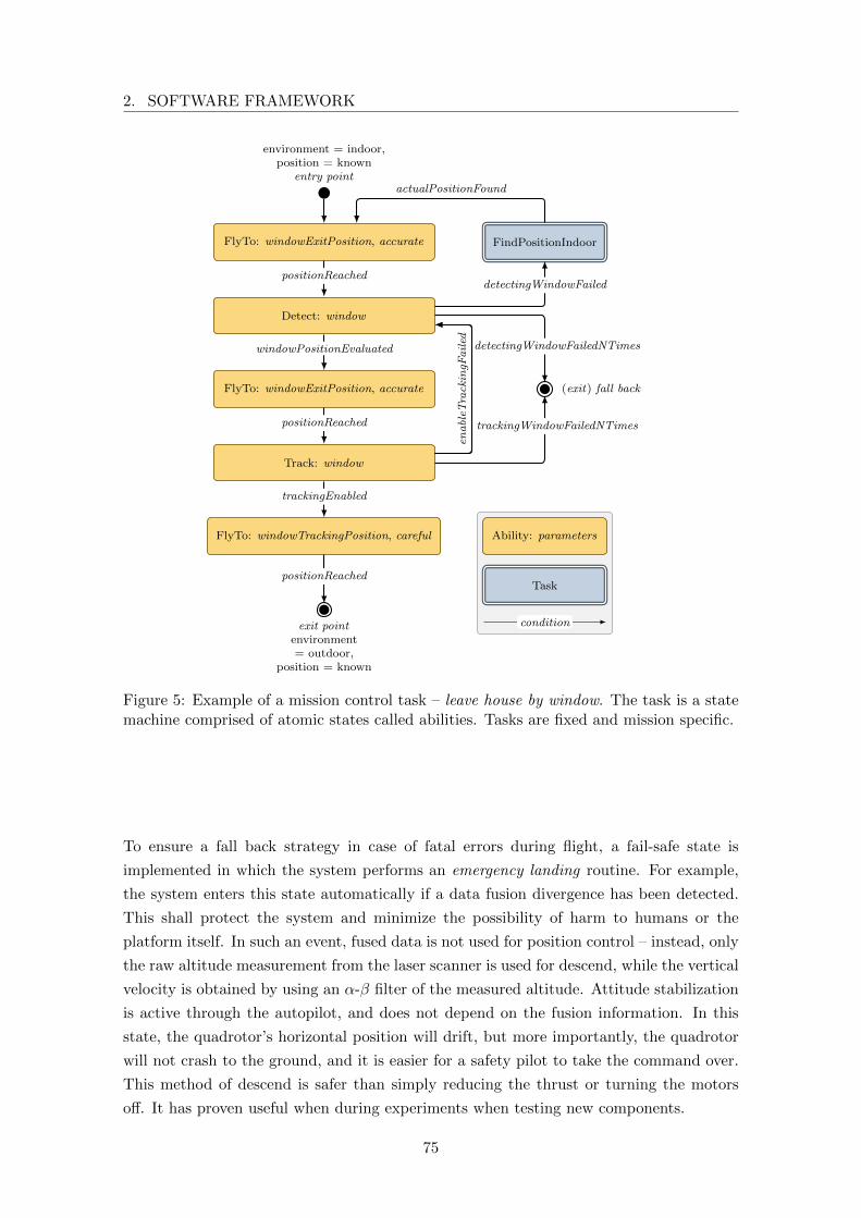
2. SOFTWARE FRAMEWORK
environment = indoor,position = known
entry point
FlyTo: windowExitPosition, accurate
Detect: window
FlyTo: windowExitPosition, accurate
Track: window
FlyTo: windowTrackingPosition, careful
FindPositionIndoor
(exit) fall back
exit pointenvironment= outdoor,
position = known
positionReached
windowPositionEvaluated detectingWindowFailedNTimes
enableT
rackingF
ailed
positionReached
trackingEnabled
trackingWindowFailedNTimes
positionReached
detectingWindowFailed
actualPositionFound
Ability: parameters
Task
condition
Figure 5: Example of a mission control task – leave house by window. The task is a statemachine comprised of atomic states called abilities. Tasks are fixed and mission specific.
To ensure a fall back strategy in case of fatal errors during flight, a fail-safe state is
implemented in which the system performs an emergency landing routine. For example,
the system enters this state automatically if a data fusion divergence has been detected.
This shall protect the system and minimize the possibility of harm to humans or the
platform itself. In such an event, fused data is not used for position control – instead, only
the raw altitude measurement from the laser scanner is used for descend, while the vertical
velocity is obtained by using an α-β filter of the measured altitude. Attitude stabilization
is active through the autopilot, and does not depend on the fusion information. In this
state, the quadrotor’s horizontal position will drift, but more importantly, the quadrotor
will not crash to the ground, and it is easier for a safety pilot to take the command over.
This method of descend is safer than simply reducing the thrust or turning the motors
off. It has proven useful when during experiments when testing new components.
75
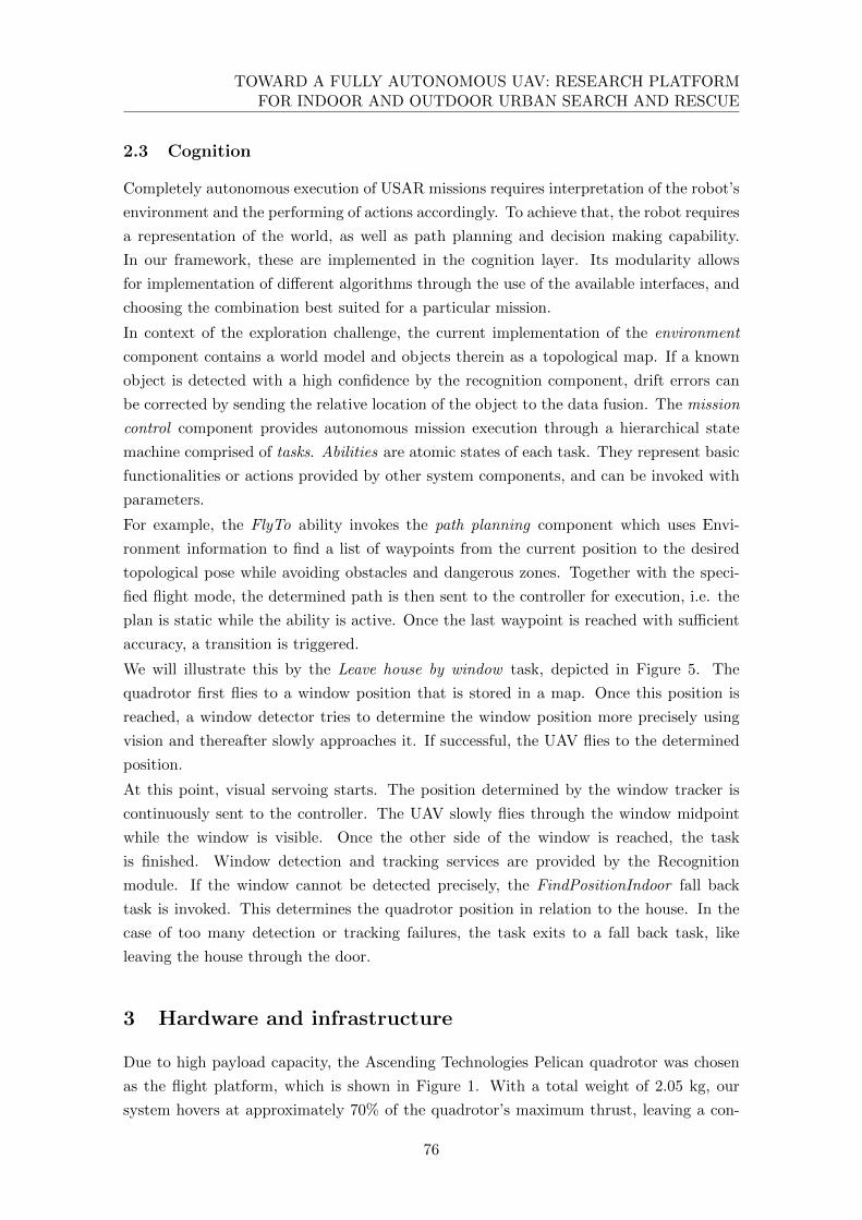
TOWARD A FULLY AUTONOMOUS UAV: RESEARCH PLATFORMFOR INDOOR AND OUTDOOR URBAN SEARCH AND RESCUE
2.3 Cognition
Completely autonomous execution of USAR missions requires interpretation of the robot’s
environment and the performing of actions accordingly. To achieve that, the robot requires
a representation of the world, as well as path planning and decision making capability.
In our framework, these are implemented in the cognition layer. Its modularity allows
for implementation of different algorithms through the use of the available interfaces, and
choosing the combination best suited for a particular mission.
In context of the exploration challenge, the current implementation of the environment
component contains a world model and objects therein as a topological map. If a known
object is detected with a high confidence by the recognition component, drift errors can
be corrected by sending the relative location of the object to the data fusion. The mission
control component provides autonomous mission execution through a hierarchical state
machine comprised of tasks. Abilities are atomic states of each task. They represent basic
functionalities or actions provided by other system components, and can be invoked with
parameters.
For example, the FlyTo ability invokes the path planning component which uses Envi-
ronment information to find a list of waypoints from the current position to the desired
topological pose while avoiding obstacles and dangerous zones. Together with the speci-
fied flight mode, the determined path is then sent to the controller for execution, i.e. the
plan is static while the ability is active. Once the last waypoint is reached with sufficient
accuracy, a transition is triggered.
We will illustrate this by the Leave house by window task, depicted in Figure 5. The
quadrotor first flies to a window position that is stored in a map. Once this position is
reached, a window detector tries to determine the window position more precisely using
vision and thereafter slowly approaches it. If successful, the UAV flies to the determined
position.
At this point, visual servoing starts. The position determined by the window tracker is
continuously sent to the controller. The UAV slowly flies through the window midpoint
while the window is visible. Once the other side of the window is reached, the task
is finished. Window detection and tracking services are provided by the Recognition
module. If the window cannot be detected precisely, the FindPositionIndoor fall back
task is invoked. This determines the quadrotor position in relation to the house. In the
case of too many detection or tracking failures, the task exits to a fall back task, like
leaving the house through the door.
3 Hardware and infrastructure
Due to high payload capacity, the Ascending Technologies Pelican quadrotor was chosen
as the flight platform, which is shown in Figure 1. With a total weight of 2.05 kg, our
system hovers at approximately 70% of the quadrotor’s maximum thrust, leaving a con-
76
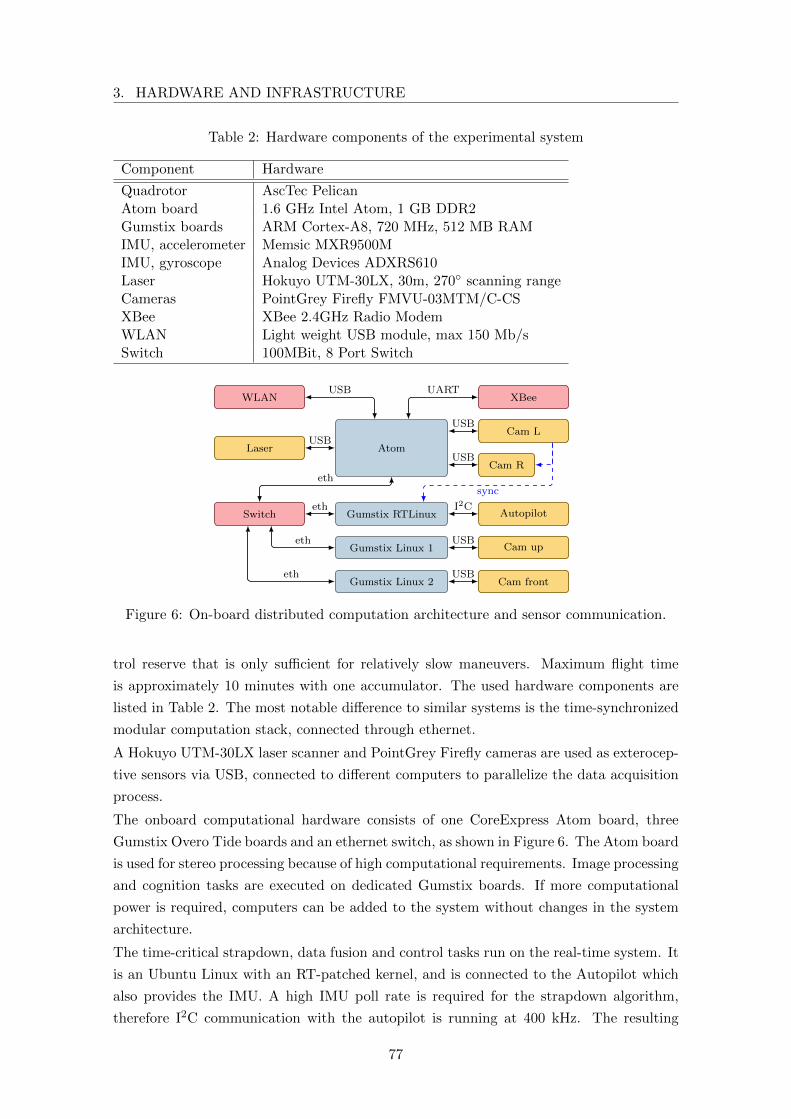
3. HARDWARE AND INFRASTRUCTURE
Table 2: Hardware components of the experimental system
Component Hardware
Quadrotor AscTec PelicanAtom board 1.6 GHz Intel Atom, 1 GB DDR2Gumstix boards ARM Cortex-A8, 720 MHz, 512 MB RAMIMU, accelerometer Memsic MXR9500MIMU, gyroscope Analog Devices ADXRS610Laser Hokuyo UTM-30LX, 30m, 270◦ scanning rangeCameras PointGrey Firefly FMVU-03MTM/C-CSXBee XBee 2.4GHz Radio ModemWLAN Light weight USB module, max 150 Mb/sSwitch 100MBit, 8 Port Switch
Atom
Gumstix RTLinux
Gumstix Linux 1
Gumstix Linux 2
Laser
Cam L
Cam R
Autopilot
Cam up
Cam front
Switch
WLAN XBee
eth
eth
eth
eth
USB UART
sync
I2C
USB
USB
USB
USB
USB
Figure 6: On-board distributed computation architecture and sensor communication.
trol reserve that is only sufficient for relatively slow maneuvers. Maximum flight time
is approximately 10 minutes with one accumulator. The used hardware components are
listed in Table 2. The most notable difference to similar systems is the time-synchronized
modular computation stack, connected through ethernet.
A Hokuyo UTM-30LX laser scanner and PointGrey Firefly cameras are used as exterocep-
tive sensors via USB, connected to different computers to parallelize the data acquisition
process.
The onboard computational hardware consists of one CoreExpress Atom board, three
Gumstix Overo Tide boards and an ethernet switch, as shown in Figure 6. The Atom board
is used for stereo processing because of high computational requirements. Image processing
and cognition tasks are executed on dedicated Gumstix boards. If more computational
power is required, computers can be added to the system without changes in the system
architecture.
The time-critical strapdown, data fusion and control tasks run on the real-time system. It
is an Ubuntu Linux with an RT-patched kernel, and is connected to the Autopilot which
also provides the IMU. A high IMU poll rate is required for the strapdown algorithm,
therefore I2C communication with the autopilot is running at 400 kHz. The resulting
77
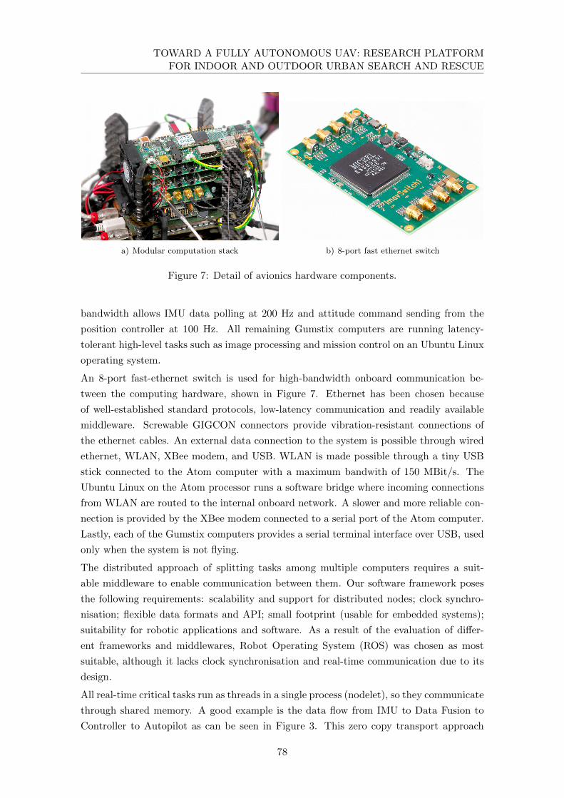
TOWARD A FULLY AUTONOMOUS UAV: RESEARCH PLATFORMFOR INDOOR AND OUTDOOR URBAN SEARCH AND RESCUE
a) Modular computation stack b) 8-port fast ethernet switch
Figure 7: Detail of avionics hardware components.
bandwidth allows IMU data polling at 200 Hz and attitude command sending from the
position controller at 100 Hz. All remaining Gumstix computers are running latency-
tolerant high-level tasks such as image processing and mission control on an Ubuntu Linux
operating system.
An 8-port fast-ethernet switch is used for high-bandwidth onboard communication be-
tween the computing hardware, shown in Figure 7. Ethernet has been chosen because
of well-established standard protocols, low-latency communication and readily available
middleware. Screwable GIGCON connectors provide vibration-resistant connections of
the ethernet cables. An external data connection to the system is possible through wired
ethernet, WLAN, XBee modem, and USB. WLAN is made possible through a tiny USB
stick connected to the Atom computer with a maximum bandwith of 150 MBit/s. The
Ubuntu Linux on the Atom processor runs a software bridge where incoming connections
from WLAN are routed to the internal onboard network. A slower and more reliable con-
nection is provided by the XBee modem connected to a serial port of the Atom computer.
Lastly, each of the Gumstix computers provides a serial terminal interface over USB, used
only when the system is not flying.
The distributed approach of splitting tasks among multiple computers requires a suit-
able middleware to enable communication between them. Our software framework poses
the following requirements: scalability and support for distributed nodes; clock synchro-
nisation; flexible data formats and API; small footprint (usable for embedded systems);
suitability for robotic applications and software. As a result of the evaluation of differ-
ent frameworks and middlewares, Robot Operating System (ROS) was chosen as most
suitable, although it lacks clock synchronisation and real-time communication due to its
design.
All real-time critical tasks run as threads in a single process (nodelet), so they communicate
through shared memory. A good example is the data flow from IMU to Data Fusion to
Controller to Autopilot as can be seen in Figure 3. This zero copy transport approach
78
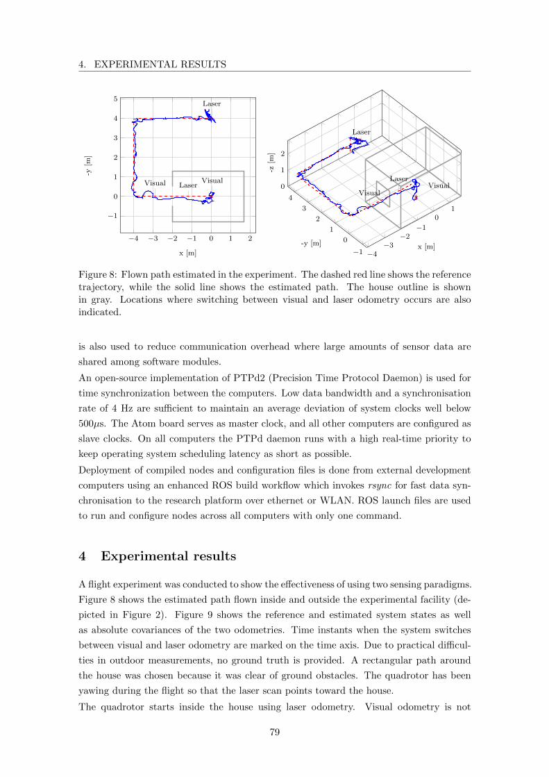
4. EXPERIMENTAL RESULTS
−4 −3 −2 −1 0 1 2
−1
0
1
2
3
4
5
VisualLaserVisual
Laser
x [m]
-y[m
]
−4−3
−2−1
01
−1
0
1
2
3
4
0
1
2
VisualLaser
Visual
Laser
x [m]-y [m]
-z[m
]Figure 8: Flown path estimated in the experiment. The dashed red line shows the referencetrajectory, while the solid line shows the estimated path. The house outline is shownin gray. Locations where switching between visual and laser odometry occurs are alsoindicated.
is also used to reduce communication overhead where large amounts of sensor data are
shared among software modules.
An open-source implementation of PTPd2 (Precision Time Protocol Daemon) is used for
time synchronization between the computers. Low data bandwidth and a synchronisation
rate of 4 Hz are sufficient to maintain an average deviation of system clocks well below
500µs. The Atom board serves as master clock, and all other computers are configured as
slave clocks. On all computers the PTPd daemon runs with a high real-time priority to
keep operating system scheduling latency as short as possible.
Deployment of compiled nodes and configuration files is done from external development
computers using an enhanced ROS build workflow which invokes rsync for fast data syn-
chronisation to the research platform over ethernet or WLAN. ROS launch files are used
to run and configure nodes across all computers with only one command.
4 Experimental results
A flight experiment was conducted to show the effectiveness of using two sensing paradigms.
Figure 8 shows the estimated path flown inside and outside the experimental facility (de-
picted in Figure 2). Figure 9 shows the reference and estimated system states as well
as absolute covariances of the two odometries. Time instants when the system switches
between visual and laser odometry are marked on the time axis. Due to practical difficul-
ties in outdoor measurements, no ground truth is provided. A rectangular path around
the house was chosen because it was clear of ground obstacles. The quadrotor has been
yawing during the flight so that the laser scan points toward the house.
The quadrotor starts inside the house using laser odometry. Visual odometry is not
79
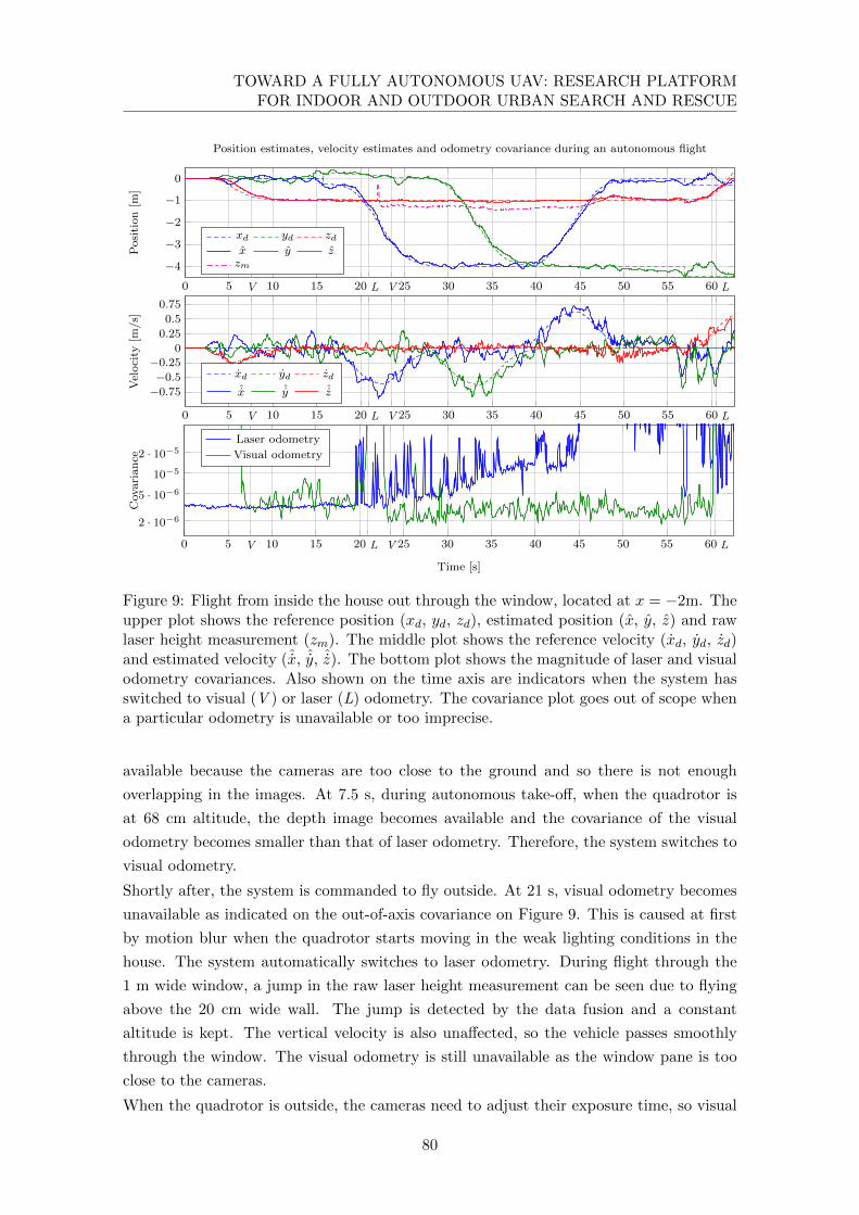
TOWARD A FULLY AUTONOMOUS UAV: RESEARCH PLATFORMFOR INDOOR AND OUTDOOR URBAN SEARCH AND RESCUE
0 5 10 15 20 25 30 35 40 45 50 55 60
−4
−3
−2
−1
0
V L V L
Posi
tion
[m]
Position estimates, velocity estimates and odometry covariance during an autonomous flight
xd yd zdx y zzm
0 5 10 15 20 25 30 35 40 45 50 55 60
−0.75
−0.5
−0.250
0.25
0.5
0.75
V L V L
Velocity
[m/s]
xd yd zdˆx ˆy ˆz
0 5 10 15 20 25 30 35 40 45 50 55 60
10−5
V L V L
2 · 10−6
5 · 10−6
2 · 10−5
Time [s]
Covariance
Laser odometry
Visual odometry
Figure 9: Flight from inside the house out through the window, located at x = −2m. Theupper plot shows the reference position (xd, yd, zd), estimated position (x, y, z) and rawlaser height measurement (zm). The middle plot shows the reference velocity (xd, yd, zd)and estimated velocity (ˆx, ˆy, ˆz). The bottom plot shows the magnitude of laser and visualodometry covariances. Also shown on the time axis are indicators when the system hasswitched to visual (V ) or laser (L) odometry. The covariance plot goes out of scope whena particular odometry is unavailable or too imprecise.
available because the cameras are too close to the ground and so there is not enough
overlapping in the images. At 7.5 s, during autonomous take-off, when the quadrotor is
at 68 cm altitude, the depth image becomes available and the covariance of the visual
odometry becomes smaller than that of laser odometry. Therefore, the system switches to
visual odometry.
Shortly after, the system is commanded to fly outside. At 21 s, visual odometry becomes
unavailable as indicated on the out-of-axis covariance on Figure 9. This is caused at first
by motion blur when the quadrotor starts moving in the weak lighting conditions in the
house. The system automatically switches to laser odometry. During flight through the
1 m wide window, a jump in the raw laser height measurement can be seen due to flying
above the 20 cm wide wall. The jump is detected by the data fusion and a constant
altitude is kept. The vertical velocity is also unaffected, so the vehicle passes smoothly
through the window. The visual odometry is still unavailable as the window pane is too
close to the cameras.
When the quadrotor is outside, the cameras need to adjust their exposure time, so visual
80
5. CONCLUSION AND FUTURE WORK
odometry is again available at approximately 1 m behind the window. It is clearly visible
that the covariance of the laser odometry outdoors is very large compared to indoors, due
to less valid laser measurements. Therefore, only visual odometry is used for the outdoor
flight.
During autonomous landing, the disparity image becomes unavailable under 60 cm of
altitude. This is indicated by the high covariance of the visual odometry. The system
switches to laser odometry.
The reference velocity and position are tracked accordingly to the estimated values. The
position control error with respect to the estimated states is under 20 cm in both indoor
and outdoor environments.
5 Conclusion and future work
We introduced a modular and extensible software and hardware framework for the au-
tonomous execution of USAR missions using aerial robots. An implementation of the
framework on an experimental quadrotor system has been presented. The implemented
computation and communication hardware enables the simultaneous execution of several
computationally demanding tasks, including navigation and computer vision. Further-
more, the hardware can be easily expanded to provide more on-board computation power
if required. Our data fusion enables the seamless use of different sensing paradigms with
delayed information on a highly dynamic quadrotor vehicle. Its effectiveness is shown
by an autonomous flight from an indoor to an outdoor environment through a 1 m wide
window, motivated by an exploration mission to enter and leave a building.
Currently, the system cannot automatically avoid obstacles. Therefore, reactive collision
avoidance schemes will be implemented on the low-level system. This requires the further
development of object recognition and scene interpretation on resource-limited systems.
As resources are limited, merely a subset of tasks can be fulfilled, therefore we will focus
on the elaboration of these tasks.
Our future work also includes miniaturization of the system, mainly through weight re-
duction of the sensing equipment. For this reason, the use of other sensors such as omnidi-
rectional cameras and sonar will be investigated. Instead of stereo cameras, the Microsoft
Kinect is also a viable sensor for obtaining depth images. However, since it uses artificial
infrared lighting, it is only suitable for indoor applications.
In USAR missions it might be necessary to fly to globally defined positions. This capa-
bility will be achieved by integrating GPS into the data fusion. We will also address the
cooperation with multiple mobile and ground robots as well as human interfaces to a team
of robots. Currently, our fusion system is based on local navigation, yet the navigation
will be improved by having higher level position information, e.g. by using a topological
map. In this way, the system is enabled to navigate through large environments on a
strongly hardware limited system.
Supplementary information about the DLR multicopters can be found online [19].
81

TOWARD A FULLY AUTONOMOUS UAV: RESEARCH PLATFORMFOR INDOOR AND OUTDOOR URBAN SEARCH AND RESCUE
References
[1] K. Youcef-Toumi and O. Ito. “A Time Delay Controller for Systems with Unknown
Dynamics”. In: American Control Conference, 1988. 1988, pp. 904–913.
[2] W. T. Freeman and M. Roth. Orientation histograms for hand gesture recognition.
Tech. rep. Mitsubishi Electric Research Labs., 201, 1995.
[3] V. Utkin and J. Shi. “Integral sliding mode in systems operating under uncertainty
conditions”. In: Decision and Control, 1996., Proceedings of the 35th IEEE. Vol. 4.
1996, 4591–4596 vol.4.
[4] M. A. Goodale and G. K. Humphrey. “The objects of action and perception”. In:
Cognition 67.1-2 (1998), pp. 181–207.
[5] H. Hirschmuller, P. R. Innocent, and J. M. Garibaldi. “Fast, Unconstrained Cam-
era Motion Estimation from Stereo without Tracking and Robust Statistics”. In:
Proceedings of the 7th International Conference on Control, Automation, Robotics
and Vision (ICARCV). 2002, pp. 1099–1104.
[6] H. Hirschmuller, P. R. Innocent, and J. M. Garibaldi. “Real-Time Correlation-Based
Stereo Vision with Reduced Border Errors”. In: International Journal of Computer
Vision (IJCV) 47.1/2/3 (2002), pp. 229–246.
[7] S. Roumeliotis and J. Burdick. “Stochastic cloning: a generalized framework for
processing relative state measurements”. In: ICRA. Vol. 2. 2002, 1788–1795 vol.2.
[8] J. Casper and R. Murphy. “Human-robot interactions during the robot-assisted
urban search and rescue response at the World Trade Center”. In: Systems, Man,
and Cybernetics, Part B: Cybernetics, IEEE Transactions on 33.3 (2003), pp. 367–
385.
[9] H. Hirschmuller. “Stereo Vision Based Mapping and Immediate Virtual Walk-
throughs”. PhD thesis. Leicester, UK: School of Computing, De Montfort University,
2003.
[10] N. L. Cassimatis, J. G. Trafton, M. D. Bugajska, and A. C. Schultz. “Integrating
cognition, perception and action through mental simulation in robots”. In: Robotics
and Autonomous Systems 49.1-2 (2004), pp. 13–23.
[11] M. Goodrich, J. Cooper, J. Adams, C. Humphrey, R. Zeeman, and B. Buss. “Using
a Mini-UAV to Support Wilderness Search and Rescue: Practices for Human-Robot
Teaming”. In: Safety, Security and Rescue Robotics (SSRR). IEEE International
Workshop on. 2007, pp. 1–6.
[12] A. Censi. “An ICP variant using a point-to-line metric”. In: Dynamical Systems
(2008), pp. 19–25.
[13] A. Bachrach, R. He, and N. Roy. “Autonomous Flight in Unstructured and Un-
known Indoor Environments”. In: Proceedings of the European Micro Aerial Vehicle
Conference (EMAV). 2009.
82

REFERENCES
[14] S. Grzonka, G. Grisetti, and W. Burgard. “Towards a Navigation System for Au-
tonomous Indoor Flying”. In: ICRA. 2009.
[15] M. Blosch, S. Weiss, D. Scaramuzza, and R. Siegwart. “Vision based MAV naviga-
tion in unknown and unstructured environments”. In: ICRA. 2010, pp. 21–28.
[16] L. Lin, M. Roscheck, M. Goodrich, and B. Morse. “Supporting Wilderness Search
and Rescue with Integrated Intelligence: Autonomy and Information at the Right
Time and the Right Place”. In: AAAI Conference on Artificial Intelligence. 2010.
[17] M. Achtelik, M. Achtelik, S. Weiss, and R. Siegwart. “Onboard IMU and monocular
vision based control for MAVs in unknown in- and outdoor environments”. In:
ICRA. 2011, pp. 3056–3063.
[18] S. Shen, N. Michael, and V. Kumar. “Autonomous multi-floor indoor navigation
with a computationally constrained MAV”. In: ICRA. 2011, pp. 20–25.
[19] German Aerospace Center (DLR) Institute of Robotics and Mechatronics. url:
http://www.dlr.de/rm/desktopdefault.aspx/tabid-7903.
[20] IMAV2011 – International Micro Aerial Vehicle Competition 2011. url: http:
//www.imav2011.org/.
83

TOWARD A FULLY AUTONOMOUS UAV: RESEARCH PLATFORMFOR INDOOR AND OUTDOOR URBAN SEARCH AND RESCUE
84
Paper 3
Autonomous Vision-based Micro
Air Vehicle for Indoor and
Outdoor Navigation1
Korbinian Schmid, Philipp Lutz, Teodor Tomic, Elmar Mair, and Heiko Hirschmuller
Abstract Micro Air Vehicles (MAVs) have become very popular in recent years. Au-
tonomous navigation of such systems plays an important role in many industrial appli-
cations as well as in search and rescue (SAR) scenarios. We present a quadrotor that
performs autonomous navigation in complex indoor and outdoor environments. An op-
erator selects target positions in the on-board map and the system autonomously plans
an obstacle free path and flies to these locations. An on-board stereo camera and Inertial
Measurement Unit (IMU) are the only sensors. The system is independent of external
navigation aids like GPS. No assumptions are made about the structure of the unknown
environment. All navigation tasks are implemented on-board the system. A wireless con-
nection is only used for sending images and a 3D map to the operator and to receive target
locations. We discuss the hardware and software setup of the system in detail. Highlights
of the implementation are the FPGA based dense stereo matching of 0.5 Mpixel images
at a rate of 14.6 Hz using Semi-Global Matching, locally drift free visual odometry with
key frames and sensor data fusion with compensation of measurement delays of 220 ms.
We show the robustness of the approach in simulations and experiments with ground
truth. We present the results of a complex, autonomous indoor/outdoor flight and the
exploration of a coal mine with obstacle avoidance and 3D mapping.
1 c©2014 Wiley Periodicals, Inc. Reprinted, with permission, from Journal of Field Robotics 31.4 (2014),pp. 537-570, DOI: 10.1002/rob.21506, View this article online at wileyonlinelibrary.com
85
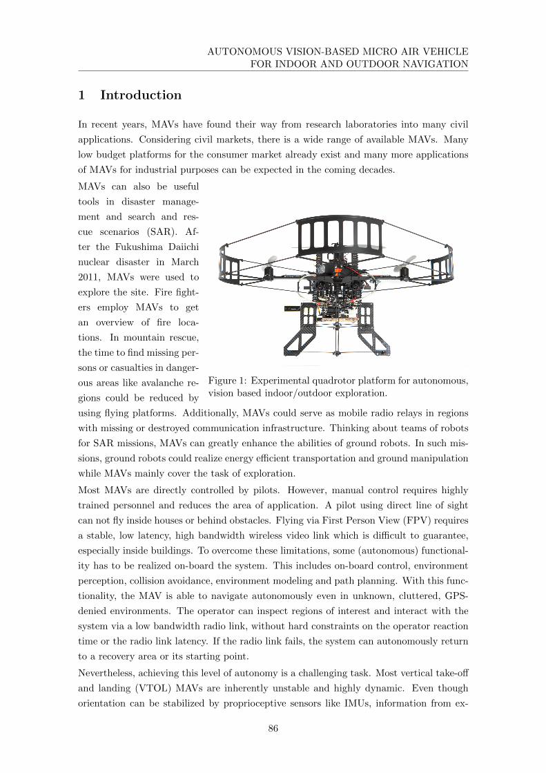
AUTONOMOUS VISION-BASED MICRO AIR VEHICLEFOR INDOOR AND OUTDOOR NAVIGATION
1 Introduction
In recent years, MAVs have found their way from research laboratories into many civil
applications. Considering civil markets, there is a wide range of available MAVs. Many
low budget platforms for the consumer market already exist and many more applications
of MAVs for industrial purposes can be expected in the coming decades.
Figure 1: Experimental quadrotor platform for autonomous,vision based indoor/outdoor exploration.
MAVs can also be useful
tools in disaster manage-
ment and search and res-
cue scenarios (SAR). Af-
ter the Fukushima Daiichi
nuclear disaster in March
2011, MAVs were used to
explore the site. Fire fight-
ers employ MAVs to get
an overview of fire loca-
tions. In mountain rescue,
the time to find missing per-
sons or casualties in danger-
ous areas like avalanche re-
gions could be reduced by
using flying platforms. Additionally, MAVs could serve as mobile radio relays in regions
with missing or destroyed communication infrastructure. Thinking about teams of robots
for SAR missions, MAVs can greatly enhance the abilities of ground robots. In such mis-
sions, ground robots could realize energy efficient transportation and ground manipulation
while MAVs mainly cover the task of exploration.
Most MAVs are directly controlled by pilots. However, manual control requires highly
trained personnel and reduces the area of application. A pilot using direct line of sight
can not fly inside houses or behind obstacles. Flying via First Person View (FPV) requires
a stable, low latency, high bandwidth wireless video link which is difficult to guarantee,
especially inside buildings. To overcome these limitations, some (autonomous) functional-
ity has to be realized on-board the system. This includes on-board control, environment
perception, collision avoidance, environment modeling and path planning. With this func-
tionality, the MAV is able to navigate autonomously even in unknown, cluttered, GPS-
denied environments. The operator can inspect regions of interest and interact with the
system via a low bandwidth radio link, without hard constraints on the operator reaction
time or the radio link latency. If the radio link fails, the system can autonomously return
to a recovery area or its starting point.
Nevertheless, achieving this level of autonomy is a challenging task. Most vertical take-off
and landing (VTOL) MAVs are inherently unstable and highly dynamic. Even though
orientation can be stabilized by proprioceptive sensors like IMUs, information from ex-
86

1. INTRODUCTION
teroceptive sensors like cameras is needed to stabilize position. This information is also
essential for all other navigation tasks. In contrast to ground robots, flying robots have to
navigate in full 3D using on-board sensor information only. Processing high amounts of
exteroceptive data using limited computational resources introduces measurement delays.
Another challenge is the compensation of these delays if used for control. Additionally,
the system has to be robust against failures of the exteroceptive sensors, for example in
case of missing environment features. For flying close to humans (i.e. in SAR scenarios)
or inside buildings, MAVs have to be safe for their environment. Freely spinning rotors
should be protected and small to limit their inertia. Such constraints result in a significant
payload limitation and hence, a strong restriction of computational resources. It is obvious
that the demands of the mentioned applications are highly conflicting with the available
system resources.
Considering these limitations and application requirements, suitable exteroceptive sensors
have to be found. Depth sensors provide ideal input for obstacle avoidance, environmental
modeling as well as ego-motion estimation. While laser scanners or Time of Flight (ToF)
cameras provide accurate depth measurements, their weight is rather high. The Kinect
has become very popular for robot navigation, but it depends on recognizing a pseudo-
random infrared pattern that is projected onto the scene. This technique does not work
outdoors in sunlight. In contrast, passive stereo vision works outdoors as well as indoors
under a large range of lighting conditions. However, sufficient processing power must be
available for stereo matching.
Even though there is a wide range of commercially available MAVs, for research purposes
the system equipment usually has to be adapted carefully to fulfil the projects’ needs.
The respective concept should therefore consider the required modularity and flexibility.
Designing such a platform, as illustrated in Fig. 1, is a time-consuming process with many
pitfalls. We address this challenge in the first part of this article. We give an overview of
existing systems and their algorithmic concepts in Section 2. We introduce our carefully
designed MAV system concept under aspects of common hardware and software issues
in Section 3. We describe the design of a modular perception and navigation device
considering MAV typical constraints and characteristics like weight, power consumption,
high system dynamics, vibrations and others. This tutorial can be helpful to everyone
setting up and equipping an autonomous MAV.
In the second part of the article, in Section 4, we introduce the algorithms running on
our quadrotor for autonomous flights in unknown, unstructured indoor/outdoor environ-
ments. We set a special focus on stereo vision based inertial navigation on resource limited
systems. Additionally, we introduce briefly the used algorithms for control, mapping and
dynamic path planning. The system is extensively tested in simulations and experiments
presented in Section 5. The influence of frame rate and time delays on the navigation
solution is analyzed in Monte Carlo simulations. The robustness of the navigation system
is demonstrated in real system experiments with forced vision dropouts. We show the
interaction of all components in an autonomous indoor/outdoor exploration flight and in
87

AUTONOMOUS VISION-BASED MICRO AIR VEHICLEFOR INDOOR AND OUTDOOR NAVIGATION
a possible SAR scenario in a coal mine. We discuss the results and highlight some lessons
learned during development and experiments in Section 6. Finally, we conclude the article
in Section 7.
2 Related Work
There is an increasing body of literature regarding MAVs with different autonomous nav-
igation solutions. In the following, we focus on work with high similarity to ours. We
will also briefly discuss the related work of the topics tackled in the following sections
which are sensor registration, depth image processing, visual odometry and system state
estimation.
Autonomous MAVs Over the last years, autonomous MAV navigation in GPS-denied
environments showed great progress. Bachrach et al. presented on-board pose estimation
of MAVs using a laser scanner [37]. The accuracy was increased off-board by a pose-
graph optimization SLAM algorithm. They demonstrated autonomous exploration and a
flight through a window, while planning was realized off-board. Shen et al. demonstrated
laser based multi-floor navigation and mapping while all algorithms including SLAM with
loop closure were running on-board the MAV [51]. Based on this work, they presented
autonomous MAV operation in a large multi-floor indoor environment with an additional
RGB-D sensor for mapping [58]. However, vertical wall constraints in the ego-motion
calculation were used which limits the operational area.
Huang et al. used visual odometry estimates from an RGB-D sensor (i.e. Kinect) with
IMU measurements for local on-board navigation [46]. Global navigation and loop closure
with SLAM was realized off-board. Due to the use of the Kinect sensor the system can
not operate in outdoor environments with direct sunlight.
Heng et al. realized on-board mapping and path planning based on stereo cameras [45].
The autonomy of the system is limited by the usage of artificial markers or an external
motion tracking system that is required for pose estimation.
Our system is most closely related to the work of Fraundorfer et al. [52]. A forward-
looking stereo camera is used as main sensor for building a global 3D occupancy map
with 0.1 m resolution on-board the MAV. A 2D slice of the 3D octomap is evaluated for
on-board planning and obstacle avoidance as well as frontier-based exploration and wall
following. In contrast to our system the MAV is limited to environments with flat ground.
This is due to the optical flow sensor which drives the system state estimation.
Sensor registration Typically, MAVs use several sensors like cameras and IMUs that
complement each other regarding error characteristics and dropouts. For getting robust
and reliable measurements by fusion, the spatial alignment between the sensors has to
be known. Microelectromechanical system (MEMS) based IMUs provide bias-prone and
noisy measurements of the rotational velocity and translational acceleration, which leads
88
2. RELATED WORK
to rather poor motion estimation after integration. In order to avoid integration, one
requires complex, error-prone setups [26] or needs to estimate the motion of the system in
an optimization framework which combines both sensor measurements.
Typical optimization approaches use Kalman filters like the Extended Kalman Filter
(EKF) [27] or Unscented Kalman Filter (UKF) [35]. Another possibility is the use of
non-linear batch-optimization [29, 47]. The maximum likelihood estimation (MLE) of
Kalman filters is highly computationally efficient and often used for real-time pose esti-
mation (Section 4.4). The drawback is that its mathematical model requires a piecewise
linear motion and white Gaussian noise. Non-linear least-squares batch-optimization has
in general significantly higher computational costs. However, it only requires the noise
to be zero-mean but neither independent nor identically distributed (i.i.d.) in order to
find the best solution in terms of the lowest variance of the estimate. Such a framework
also allows motion models of arbitrary dynamics. Some methods couple both techniques,
by estimating the trajectory within a Kalman filter and computing the spatial alignment
in an outer, non-linear optimization loop [39]. These so called gray-box approaches try
to combine the efficiency of Kalman filters with the accuracy of non-linear optimization.
However, that way the non-linear optimization can only use computationally expensive fi-
nite difference approximation for gradient computation, while maintaining the constraints
implied by the Kalman filter on the systems’ motion and noise.
Our system consists of rigidly mounted sensors, which do not require an online estimation
of the spatial alignment. In our opinion, sensor registration should be performed as an
offline step where applicable. It increases the alignment accuracy and reduces the state
space of the navigation filter, which leads to lower computational complexity and modeling
errors. Hence, in Section 3.3 we describe an approach for computing the spatial alignment
by non-linear batch-optimization of the measurements.
Depth image processing Dense depth images are an important base for detecting
obstacles, environment modeling, and ego-motion estimation. We focus on passive stereo
cameras since they are light weight and work in indoor and outdoor environments under
a wide range of lighting conditions.
The drawback of stereo matching is the required processing power, which is limited on
mobile and especially on flying systems. Correlation based stereo methods have been an
obvious choice for flying systems [53, 44], due to their simple design and rather low pro-
cessing requirements. However, correlation methods are known to blur object boundaries
and are unable to detect small or thin structures [14]. Global methods that optimize a
cost function offer much higher spatial resolution since they can perform pixel-wise match-
ing [17]. Methods that are based on this principle are known as Dynamic Programming,
Graph Cuts and Belief Propagation. However, these methods require much higher pro-
cessing resources. More recently, local methods that are based on adaptive weighting [24]
and slanted support windows [43] proved to be competitive to global methods, but again
at an increased runtime.
89

AUTONOMOUS VISION-BASED MICRO AIR VEHICLEFOR INDOOR AND OUTDOOR NAVIGATION
Semi-Global Matching (SGM) [31] is based on the principle of pixel-wise matching, sup-
ported by a global cost function. The quality is comparable to other global methods.
However, the algorithm uses simple operations, is regular and easy to parallelize. This
makes real-time implementations on the GPU [42, 30] and FPGA [38, 33] possible. Es-
pecially FPGA implementations are suitable for mobile robotics, due to their low weight
and energy consumption in comparison to CPUs and GPUs.
In the Middlebury benchmark2, SGM shows an average performance. However, the
strength of SGM is its robustness in practice without parameter tuning, which can be
achieved in real-time. Therefore, SGM and its adaptations belong to the top performing
methods in the KITTI benchmark3. Further tests confirm the advantages of SGM in real-
world applications [36]. Daimler is using SGM as part of their 6D vision system4 for driver
assistance, which is commercially available in cars since summer 2013. In our system we
are using the same FPGA implementation of SGM.
Visual odometry For flying robots, it is very important to know their current pose
accurately and at any time. For our application we cannot use any external tracking
system or infrastructure. GPS is also not always available for combined indoor/outdoor
flights. Therefore, the system has to determine its pose and movements through its own
sensors, which are the cameras.
There are many possibilities for computing the pose through visual odometry. Mono cam-
era based approaches [18] can only determine the motion with 5 Degrees of Freedom (DoF)
in an unknown environment. However, the missing scale information is very important for
control of flying systems.
Modern approaches are often based on matching dense depth images [60, 50, 49], but
require high processing power and are often implemented on the GPU. Furthermore, these
methods depend on small movements between successive frames, which make a high frame
rate necessary for highly dynamic systems. Our approach is based on [13, 20], which
utilizes the available depth images from stereo matching, but works only on features to
save processing time and make large movements or rather low frame rates possible. We
explain the algorithm in more detail in Section 4.3.
System state estimation Combining visual with inertial sensing has been extensively
demonstrated for mobile robot navigation. Kalman filters are often used for sensor data
fusion. Considering the fast dynamics of MAVs, measurement time delays can become
problematic for control, if an ill-posed estimation strategy is chosen.
Time delays are often ignored. The resulting negative effect is softened by separating
attitude and position estimation [52]. Using stereo cameras, visual odometry is computed
at 10 Hz. A reference frame is maintained as long as feasible to avoid local drift. A
2 http://vision.middlebury.edu/stereo3 http://www.cvlibs.net/datasets/kitti4 http://www.6d-vision.com
90
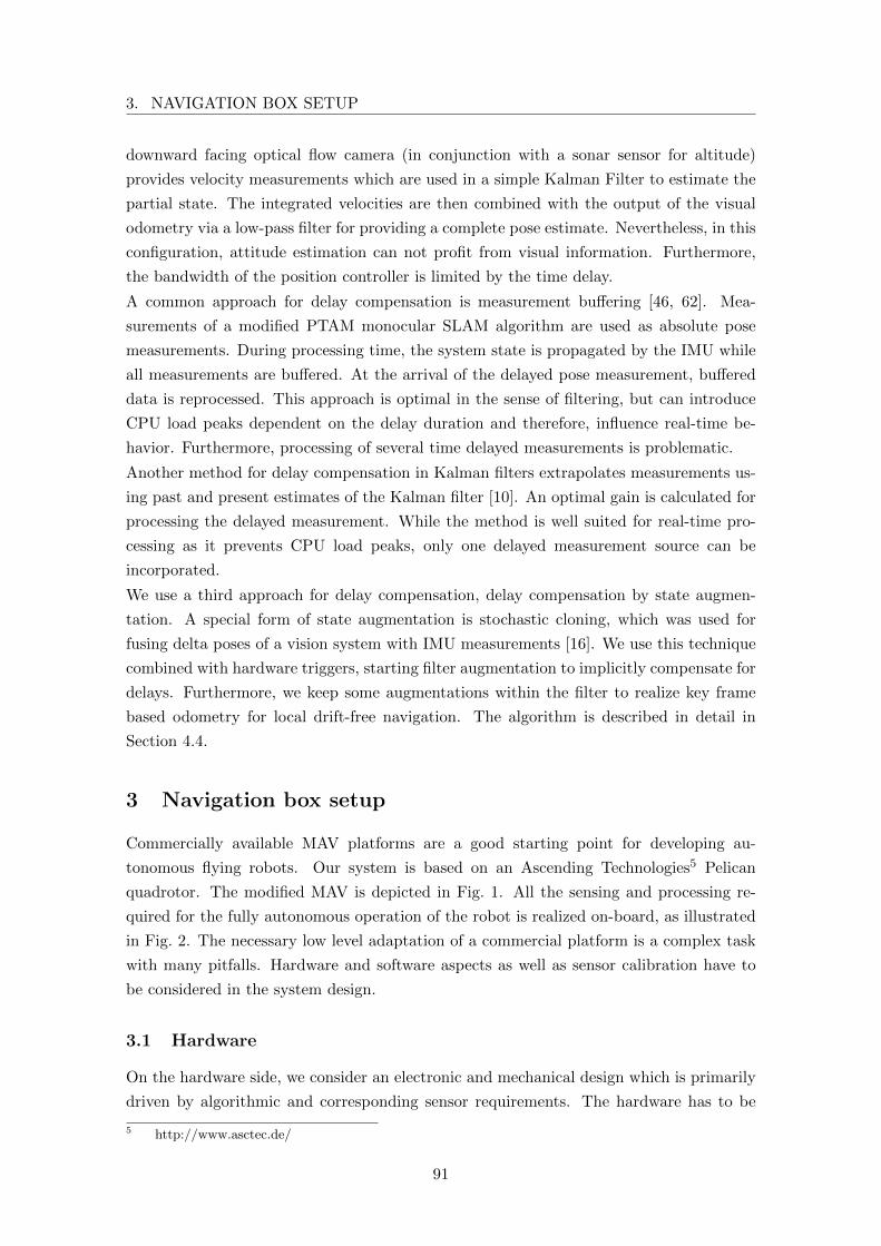
3. NAVIGATION BOX SETUP
downward facing optical flow camera (in conjunction with a sonar sensor for altitude)
provides velocity measurements which are used in a simple Kalman Filter to estimate the
partial state. The integrated velocities are then combined with the output of the visual
odometry via a low-pass filter for providing a complete pose estimate. Nevertheless, in this
configuration, attitude estimation can not profit from visual information. Furthermore,
the bandwidth of the position controller is limited by the time delay.
A common approach for delay compensation is measurement buffering [46, 62]. Mea-
surements of a modified PTAM monocular SLAM algorithm are used as absolute pose
measurements. During processing time, the system state is propagated by the IMU while
all measurements are buffered. At the arrival of the delayed pose measurement, buffered
data is reprocessed. This approach is optimal in the sense of filtering, but can introduce
CPU load peaks dependent on the delay duration and therefore, influence real-time be-
havior. Furthermore, processing of several time delayed measurements is problematic.
Another method for delay compensation in Kalman filters extrapolates measurements us-
ing past and present estimates of the Kalman filter [10]. An optimal gain is calculated for
processing the delayed measurement. While the method is well suited for real-time pro-
cessing as it prevents CPU load peaks, only one delayed measurement source can be
incorporated.
We use a third approach for delay compensation, delay compensation by state augmen-
tation. A special form of state augmentation is stochastic cloning, which was used for
fusing delta poses of a vision system with IMU measurements [16]. We use this technique
combined with hardware triggers, starting filter augmentation to implicitly compensate for
delays. Furthermore, we keep some augmentations within the filter to realize key frame
based odometry for local drift-free navigation. The algorithm is described in detail in
Section 4.4.
3 Navigation box setup
Commercially available MAV platforms are a good starting point for developing au-
tonomous flying robots. Our system is based on an Ascending Technologies5 Pelican
quadrotor. The modified MAV is depicted in Fig. 1. All the sensing and processing re-
quired for the fully autonomous operation of the robot is realized on-board, as illustrated
in Fig. 2. The necessary low level adaptation of a commercial platform is a complex task
with many pitfalls. Hardware and software aspects as well as sensor calibration have to
be considered in the system design.
3.1 Hardware
On the hardware side, we consider an electronic and mechanical design which is primarily
driven by algorithmic and corresponding sensor requirements. The hardware has to be
5 http://www.asctec.de/
91

AUTONOMOUS VISION-BASED MICRO AIR VEHICLEFOR INDOOR AND OUTDOOR NAVIGATION
Ground Station
Navigation Box
Core2Duo
GumstixFPGA
MAV
Cam 1 Cam 2 IMU
ImageRectification
VisualOdometry
Mapping
Planning
MissionControl
StereoMatching
StrapdownAlgorithm
Data Fusion
Controller
ReferenceGenerator
LL StateMachine
Autopilot
WLAN
XBee
Operator Interface
trigg
er
sync
EthernetPCIe Ethernet
SP
I
US
B
US
B
PCIe
UART
UART
Wireless
Power
Mechanical
Hardware
Software
Physical
communication
Data
Command
channel
Time trigger
Figure 2: Hardware, software and data flow overview of the presented system. The systemconsists of a ground segment (Ground Station) and a flight segment (navigation box andMAV). The navigation box consists of three computation units (Core2Duo, Gumstix andFPGA), as well as sensors and communication hardware. It is linked mechanically andelectrically (in terms of power supply) to the MAV. Furthermore, attitude commands aresent to the MAV’s Autopilot. The computers must be time-synchronized for sensor datafusion. We use hardware triggers for camera synchronization and exact image timestamp-ing. All autonomous functionality, including mapping and planning, runs on-board theflight segment.
92

3. NAVIGATION BOX SETUP
lightweight, robust and of limited size. Furthermore, the energy consumption of electron-
ics and rigid mounting of sensors have to be taken into account. The electronics include
sensors, embedded computers, and associated communication hardware. These are assem-
bled into a stack that enables simple mechanical integration with the commercial MAV.
We call the resulting stack the navigation box.
Electronics
The most limiting factor for MAV electronics is weight and power consumption, which has
an important impact on the choice of sensors and computational hardware.
We employ PointGrey Firefly FMVU-03MTM/C-CS cameras in stereo configuration as
main exteroceptive sensor. The cameras are equipped with Computar HM0320KP lenses
(f = 3 mm, horizontal FOV = 80.5◦, manual aperture). As inertial measurement unit,
we chose an Analog Devices ADIS16407 MEMS IMU which has factory-calibrated and
temperature compensated sensors. It measures all three spatial axes in the accelerometer,
gyroscope and magnetometer plus atmospheric pressure.
The autonomy functionality on the MAV is split into low-level, real-time (RT) and high-
level, computationally intensive tasks without real-time constraints (Non-RT). The system
robustness can be increased by further separating safety critical from noncritical tasks by
hardware.
The setup should be lightweight and flexible at the same time offering a wide range of
hardware interfaces. The resulting demands can be summarized as follows:
• Separation between RT and Non-RT processing.
• Availability of common embedded interfaces (I2C, UARTs, SPI, GPIOs and ADCs)
as well as high level interfaces such as Ethernet, Firewire and USB.
• Flexibility of the hardware setup to allow fast modifications and development cycles.
• High computing power at low weight and power consumption.
Building upon COTS (commercial off the shelf) hardware, which is inexpensive and readily
available, allows for fast prototype development cycles. Today most industrial embedded
computing manufacturers offer systems with separate computer modules (CPU + RAM)
and peripheral boards. By means of this scheme it is possible to update the computer
module while keeping the peripheral board. This allows keeping up with the latest improve-
ments in computing power without time consuming and error-prone customized hardware
designs. In our opinion, flexibility is more valuable for a research platform than higher
efficiency through time consuming individual designs.
Therefore, as RT embedded processing component we chose a combination of Gumstix
OVERO WaterStorm COM and Gumstix Tobi peripheral boards due to their compact
size and high computing power. The Non-RT system component builds upon the COM
93
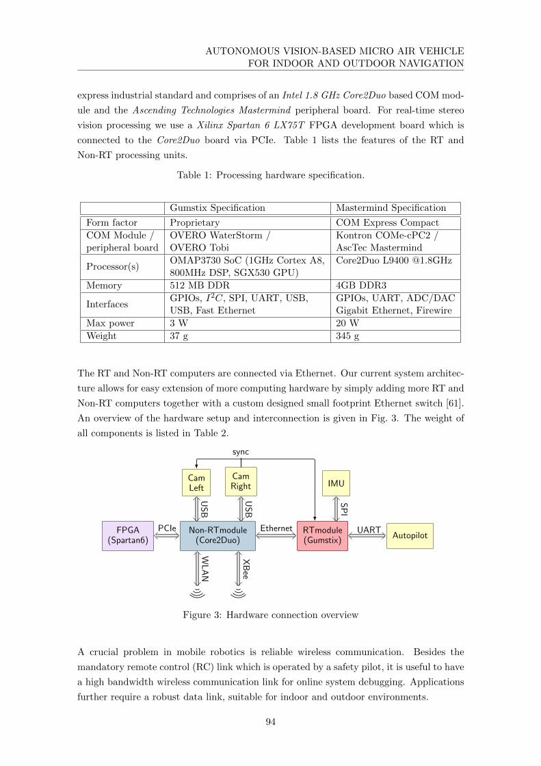
AUTONOMOUS VISION-BASED MICRO AIR VEHICLEFOR INDOOR AND OUTDOOR NAVIGATION
express industrial standard and comprises of an Intel 1.8 GHz Core2Duo based COM mod-
ule and the Ascending Technologies Mastermind peripheral board. For real-time stereo
vision processing we use a Xilinx Spartan 6 LX75T FPGA development board which is
connected to the Core2Duo board via PCIe. Table 1 lists the features of the RT and
Non-RT processing units.
Table 1: Processing hardware specification.
Gumstix Specification Mastermind Specification
Form factor Proprietary COM Express Compact
COM Module / OVERO WaterStorm / Kontron COMe-cPC2 /peripheral board OVERO Tobi AscTec Mastermind
Processor(s)OMAP3730 SoC (1GHz Cortex A8, Core2Duo L9400 @1.8GHz800MHz DSP, SGX530 GPU)
Memory 512 MB DDR 4GB DDR3
InterfacesGPIOs, I2C, SPI, UART, USB, GPIOs, UART, ADC/DACUSB, Fast Ethernet Gigabit Ethernet, Firewire
Max power 3 W 20 W
Weight 37 g 345 g
The RT and Non-RT computers are connected via Ethernet. Our current system architec-
ture allows for easy extension of more computing hardware by simply adding more RT and
Non-RT computers together with a custom designed small footprint Ethernet switch [61].
An overview of the hardware setup and interconnection is given in Fig. 3. The weight of
all components is listed in Table 2.
FPGA(Spartan6)
Non-RTmodule(Core2Duo)
RTmodule(Gumstix)
CamLeft
CamRight IMU
Autopilot
sync
USB
USB
SPI
PCIe Ethernet UART
WLAN
XBee
Figure 3: Hardware connection overview
A crucial problem in mobile robotics is reliable wireless communication. Besides the
mandatory remote control (RC) link which is operated by a safety pilot, it is useful to have
a high bandwidth wireless communication link for online system debugging. Applications
further require a robust data link, suitable for indoor and outdoor environments.
94

3. NAVIGATION BOX SETUP
Table 2: Component weights
Component Weight
Mastermind board + peripherals 345 g
FPGA board 95 g
Gumstix OVERO (COM + Tobi Board) 37 g
IMU and baseboard 22 g
Cams and Lenses 2 x 33 g
Mounts and cables 171 g
Total 739 g
In order to satisfy these requirements, we employ two different communication channels. A
WLAN module (IEEE 802.11bgn) provides high data rate communication while an XBee
module (IEEE 802.15.4) provides a robust, low bandwidth data link. Because the latter
has a lower bandwidth, it allows for a significantly higher system gain6 and, therefore,
facilitates long distance communication. Our WLAN module supports 5.8 GHz opera-
tion mode, which enables robust communication in indoor areas with a crowded 2.4 GHz
frequency band. Nevertheless, for outdoor usage we consider the 2.4 GHz band as more
appropriate because of lower signal attenuation (free space path loss). The features of
both interfaces are summarized in Table 3.
Table 3: Specification of on-board communication hardware
WLAN Module XBee Module
Model Ubiquity SR71-E Digi XBee Pro
Communication standard IEEE 802.11n (MCS15 &HT20) IEEE 802.15.4
Used frequency band ISM 2.4 / 5.8 GHz ISM 2.4 GHz
Approx. system gain 95 dBm 118 dBm
Antenna printed, 2x diversity wire antenna
Max. net data rate 4 MB/s 80 kB/s
Interface PCI-Express UART
Max power consumption 4.3W 1W
Mechanical integration
All the sensors, computers and communication hardware are integrated into the stand-
alone navigation box as illustrated in Fig. 4. The only physical connections with the MAV
are four screws, the power source and the data link with the autopilot. In that way, the
electronic and software components can be easily integrated and tested independently of
the MAV.
6 System gain = transmitter power + antenna gain + receiver sensitivity
95
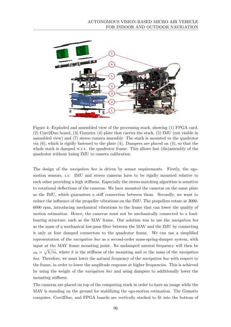
AUTONOMOUS VISION-BASED MICRO AIR VEHICLEFOR INDOOR AND OUTDOOR NAVIGATION
1
2
3
4
6
7
5
Figure 4: Exploded and assembled view of the processing stack, showing (1) FPGA card,(2) Core2Duo board, (3) Gumstix (4) plate that carries the stack, (5) IMU (not visible inassembled view) and (7) stereo camera assembly. The stack is mounted to the quadrotorvia (6), which is rigidly fastened to the plate (4). Dampers are placed on (4), so that thewhole stack is damped w.r.t. the quadrotor frame. This allows fast (dis)assembly of thequadrotor without losing IMU to camera calibration.
The design of the navigation box is driven by sensor requirements. Firstly, the ego-
motion sensors, i.e. IMU and stereo cameras have to be rigidly mounted relative to
each other providing a high stiffness. Especially the stereo-matching algorithm is sensitive
to rotational deflections of the cameras. We have mounted the cameras on the same plate
as the IMU, which guarantees a stiff connection between them. Secondly, we want to
reduce the influence of the propeller vibrations on the IMU. The propellers rotate at 3000-
6000 rpm, introducing mechanical vibrations to the frame that can lower the quality of
motion estimation. Hence, the cameras must not be mechanically connected to a load-
bearing structure, such as the MAV frame. Our solution was to use the navigation box
as the mass of a mechanical low-pass filter between the MAV and the IMU by connecting
it only at four damped connectors to the quadrotor frame. We can use a simplified
representation of the navigation box as a second-order mass-spring-damper system, with
input at the MAV frame mounting point. Its undamped natural frequency will then be
ω0 =√k/m, where k is the stiffness of the mounting and m the mass of the navigation
box. Therefore, we must lower the natural frequency of the navigation box with respect to
the frame, in order to lower the amplitude response at higher frequencies. This is achieved
by using the weight of the navigation box and using dampers to additionally lower the
mounting stiffness.
The cameras are placed on top of the computing stack in order to have an image while the
MAV is standing on the ground for stabilizing the ego-motion estimation. The Gumstix
computer, Core2Duo, and FPGA boards are vertically stacked to fit into the bottom of
96
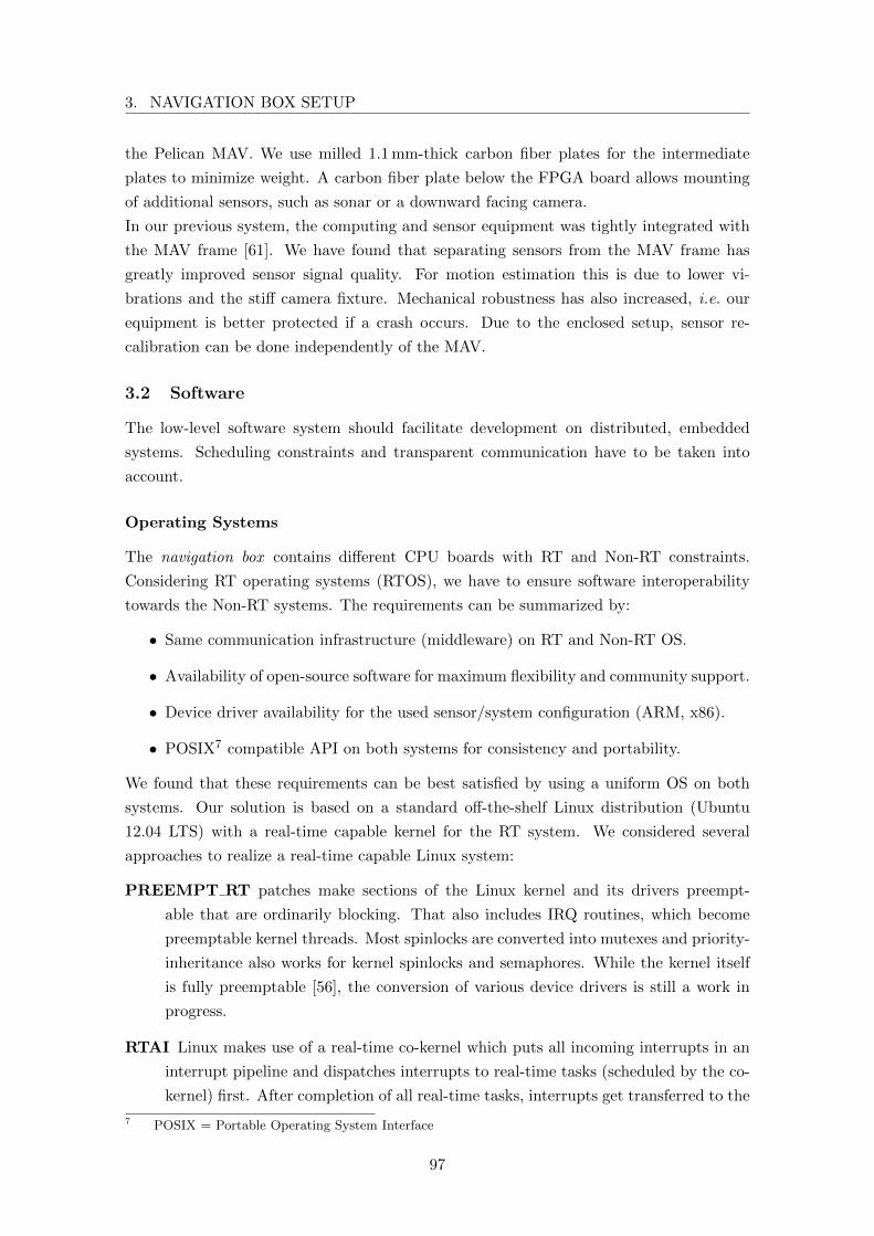
3. NAVIGATION BOX SETUP
the Pelican MAV. We use milled 1.1 mm-thick carbon fiber plates for the intermediate
plates to minimize weight. A carbon fiber plate below the FPGA board allows mounting
of additional sensors, such as sonar or a downward facing camera.
In our previous system, the computing and sensor equipment was tightly integrated with
the MAV frame [61]. We have found that separating sensors from the MAV frame has
greatly improved sensor signal quality. For motion estimation this is due to lower vi-
brations and the stiff camera fixture. Mechanical robustness has also increased, i.e. our
equipment is better protected if a crash occurs. Due to the enclosed setup, sensor re-
calibration can be done independently of the MAV.
3.2 Software
The low-level software system should facilitate development on distributed, embedded
systems. Scheduling constraints and transparent communication have to be taken into
account.
Operating Systems
The navigation box contains different CPU boards with RT and Non-RT constraints.
Considering RT operating systems (RTOS), we have to ensure software interoperability
towards the Non-RT systems. The requirements can be summarized by:
• Same communication infrastructure (middleware) on RT and Non-RT OS.
• Availability of open-source software for maximum flexibility and community support.
• Device driver availability for the used sensor/system configuration (ARM, x86).
• POSIX7 compatible API on both systems for consistency and portability.
We found that these requirements can be best satisfied by using a uniform OS on both
systems. Our solution is based on a standard off-the-shelf Linux distribution (Ubuntu
12.04 LTS) with a real-time capable kernel for the RT system. We considered several
approaches to realize a real-time capable Linux system:
PREEMPT RT patches make sections of the Linux kernel and its drivers preempt-
able that are ordinarily blocking. That also includes IRQ routines, which become
preemptable kernel threads. Most spinlocks are converted into mutexes and priority-
inheritance also works for kernel spinlocks and semaphores. While the kernel itself
is fully preemptable [56], the conversion of various device drivers is still a work in
progress.
RTAI Linux makes use of a real-time co-kernel which puts all incoming interrupts in an
interrupt pipeline and dispatches interrupts to real-time tasks (scheduled by the co-
kernel) first. After completion of all real-time tasks, interrupts get transferred to the
7 POSIX = Portable Operating System Interface
97
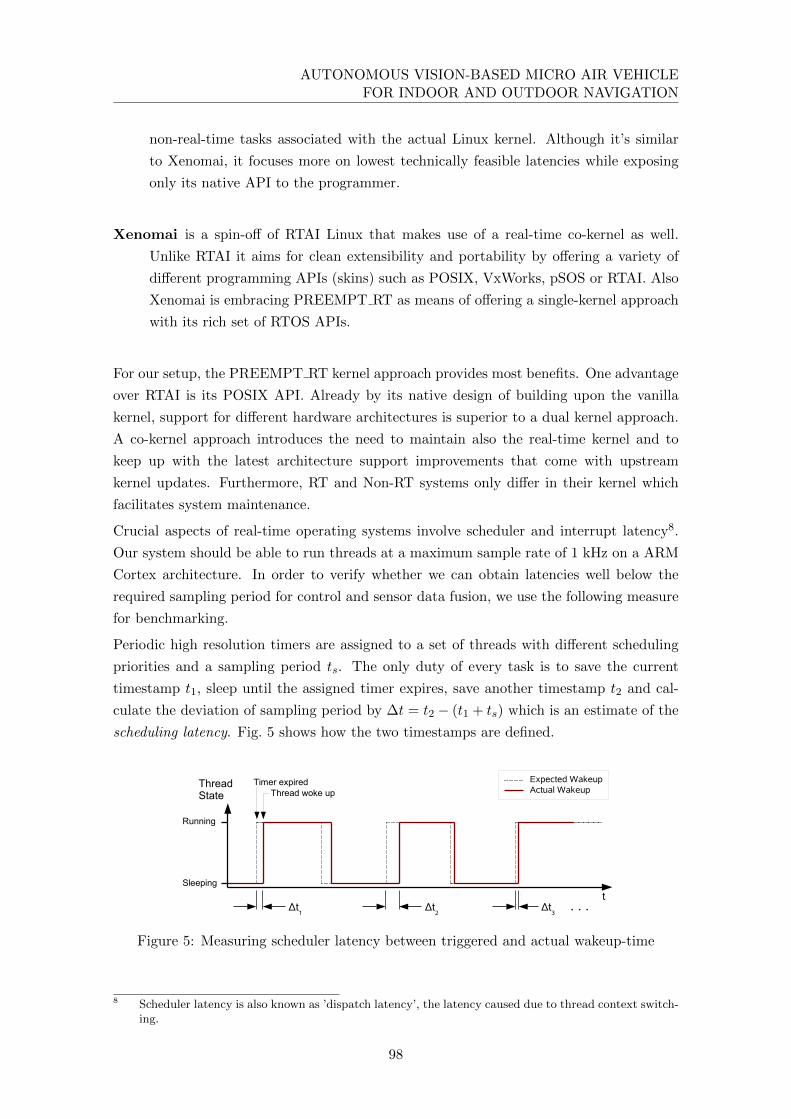
AUTONOMOUS VISION-BASED MICRO AIR VEHICLEFOR INDOOR AND OUTDOOR NAVIGATION
non-real-time tasks associated with the actual Linux kernel. Although it’s similar
to Xenomai, it focuses more on lowest technically feasible latencies while exposing
only its native API to the programmer.
Xenomai is a spin-off of RTAI Linux that makes use of a real-time co-kernel as well.
Unlike RTAI it aims for clean extensibility and portability by offering a variety of
different programming APIs (skins) such as POSIX, VxWorks, pSOS or RTAI. Also
Xenomai is embracing PREEMPT RT as means of offering a single-kernel approach
with its rich set of RTOS APIs.
For our setup, the PREEMPT RT kernel approach provides most benefits. One advantage
over RTAI is its POSIX API. Already by its native design of building upon the vanilla
kernel, support for different hardware architectures is superior to a dual kernel approach.
A co-kernel approach introduces the need to maintain also the real-time kernel and to
keep up with the latest architecture support improvements that come with upstream
kernel updates. Furthermore, RT and Non-RT systems only differ in their kernel which
facilitates system maintenance.
Crucial aspects of real-time operating systems involve scheduler and interrupt latency8.
Our system should be able to run threads at a maximum sample rate of 1 kHz on a ARM
Cortex architecture. In order to verify whether we can obtain latencies well below the
required sampling period for control and sensor data fusion, we use the following measure
for benchmarking.
Periodic high resolution timers are assigned to a set of threads with different scheduling
priorities and a sampling period ts. The only duty of every task is to save the current
timestamp t1, sleep until the assigned timer expires, save another timestamp t2 and cal-
culate the deviation of sampling period by ∆t = t2 − (t1 + ts) which is an estimate of the
scheduling latency. Fig. 5 shows how the two timestamps are defined.
t
Thread woke upTimer expired
Sleeping
Running
ThreadState
Δt1
Δt2
Δt3
Expected WakeupActual Wakeup
. . .
Figure 5: Measuring scheduler latency between triggered and actual wakeup-time
8 Scheduler latency is also known as ’dispatch latency’, the latency caused due to thread context switch-ing.
98

3. NAVIGATION BOX SETUP
For benchmarking, we use the tool cyclictest9 which resembles exactly the mentioned
behavior. We demonstrate the timing differences between a vanilla Linux kernel and one
with the PREEMPT RT patch set applied. The program was invoked10 with 4 concurrent
threads. The priority of the highest prioritized thread was set to 75, 500 histogram bins
for data output were used and the wakeup interval was chosen to be 1 ms. Every run
took around one hour, which makes a total sample count of around 3.6 × 10⁶. During
benchmarking a set of computing (FPU), file I/O and peripheral I/O intensive tasks11
were used to maintain a constant load average close to 1.0. The load scenario was carefully
chosen to reproduce the actual system load. Fig. 6 depicts two histograms showing the
results of two cyclictest runs on the same ARM-based Ubuntu Linux 12.04 system, the
first on a vanilla kernel (version 3.0.22) and the second on a patched kernel (version
3.0.22-rt37). While the unpatched kernel shows comparable results in the mean section,
the highest latency exceeds 26 ms. The highest latency occurring on the RT kernel was
334 µs.
0 100 200 300 400 500
100
101
102
103
104
latency [µs]
sample
count
Thread1
Thread2
Thread3
Thread4
a) Non-RT histogram. Kernel version: 3.0.22,Max./avg./min. latency: 26383 (out ofrange)/192/0 µs
0 100 200 300 400
100
101
102
103
104
105
latency [µs]
sample
count
Thread1
Thread2
Thread3
Thread4
b) RT histogram. Kernel version: 3.0.22-rt37,Max./avg./min. latency: 334/168/0 µs
Figure 6: Scheduler latency histograms of RT and Non-RT kernel based on ARM kernelversion 3.0.22. The scheduler tick clock was running at 1.3 MHz. System load average hasbeen close to 1.0
These tests prove the suitability of the PREEMPT RT approach: Scheduling constraints
well below 1 ms are fulfilled with high sensor IO and CPU load. Convenient system
maintenance and a clean software architecture which exhibits the same API as the Non-
RT operating system is provided.
9 ’cyclictest’ is part of the ’rt-tests’ benchmarking suite, see https://www.osadl.org/
Realtime-Preempt-Kernel.kernel-rt.0.html#externaltestingtool10 Program invocation: ./cyclictest -t 4 -p 75 -h 500 -i 100011 Generating load: Traversing the filesystem with find /, whetstone floating-point benchmark, polling
IMU at 819 Hz
99

AUTONOMOUS VISION-BASED MICRO AIR VEHICLEFOR INDOOR AND OUTDOOR NAVIGATION
Communication
In order to exchange timestamped sensor data in a distributed system, all system clocks
have to be synchronized. We employ an open-source implementation of PTPd2 (Precision
Time Protocol Daemon). Running the synchronization daemon with a rate of 4 Hz is
sufficient to maintain an average deviation of system clocks well below 500µs. The Non-
RT computer serves as master clock while the RT computer is configured as slave. The
PTPd daemon runs with a high real-time priority to minimize the influence of operating
system scheduling latency.
For communication within a distributed system, a consistent and transparent inter-process
communication infrastructure is needed. We found that the Robot Operating System
(ROS) is suitable for our purpose: it is versatile, runs on both x86 and ARM architectures
and has flexible and dynamic data messages. It is a widespread middleware in the robotics
community, which makes it very easy to exchange code with other research facilities and
groups. As ROS is not intended for real-time applications we extended inter process
communication by modified nodelets to fit our real-time communication requirements.
As shown in Fig. 3 on-board communication between the RT and Non-RT computing
units is realized by an Ethernet connection while the downlink to the ground station is
established via WLAN. These two independent network segments need to be unified to
enable the middleware to transparently communicate between all computers. Therefore,
we employ a software bridge on the Non-RT computer which connects WLAN and Ethernet
peers in the same subnet. Since forwarding is done at the MAC layer, all IP based protocols
pass the bridge transparently.
3.3 Spatial sensor registration
Especially in the context of highly dynamic systems, accurate temporal and spatial align-
ments play a crucial role for reliable data fusion. Temporal synchronization is assured by
actively triggering the cameras, while storing the respective timestamps. Hence, for the
spatial alignment, which we are discussing in the following, we assume accurately syn-
chronized measurements. In our setup we have to estimate the rigid-body transformation
between two cameras and an IMU. The extrinsic calibration between the stereo camera
pair is estimated together with the intrinsic parameters in a non-linear optimization frame-
work [22, 20].12 It remains to compute the spatial alignment between cameras and the
IMU.
A straight-forward solution is to extend the state space of the navigation filter by the
6D spatial transformation parameters and hence, estimating the spatial alignment in real-
time, together with the system pose. No offline calibration step is required. However,
estimating the spatial registration together with the actual pose may result in poor pose
estimation and spatial registration in the case of bad initialization or ill-posed motion at
12 A publicly available tool, called Callab, for intrinsic and extrinsic camera calibration can be found atwww.robotic.dlr.de/callab
100
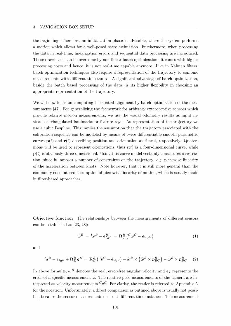
3. NAVIGATION BOX SETUP
the beginning. Therefore, an initialization phase is advisable, where the system performs
a motion which allows for a well-posed state estimation. Furthermore, when processing
the data in real-time, linearization errors and sequential data processing are introduced.
These drawbacks can be overcome by non-linear batch optimization. It comes with higher
processing costs and hence, it is not real-time capable anymore. Like in Kalman filters,
batch optimization techniques also require a representation of the trajectory to combine
measurements with different timestamps. A significant advantage of batch optimization,
beside the batch based processing of the data, is its higher flexibility in choosing an
appropriate representation of the trajectory.
We will now focus on computing the spatial alignment by batch optimization of the mea-
surements [47]. For generalizing the framework for arbitrary exteroceptive sensors which
provide relative motion measurements, we use the visual odometry results as input in-
stead of triangulated landmarks or feature rays. As representation of the trajectory we
use a cubic B-spline. This implies the assumption that the trajectory associated with the
calibration sequence can be modeled by means of twice differentiable smooth parametric
curves p(t) and r(t) describing position and orientation at time t, respectively. Quater-
nions will be used to represent orientations, thus r(t) is a four-dimensional curve, while
p(t) is obviously three-dimensional. Using this curve model certainly constitutes a restric-
tion, since it imposes a number of constraints on the trajectory, e.g. piecewise linearity
of the acceleration between knots. Note however, that it is still more general than the
commonly encountered assumption of piecewise linearity of motion, which is usually made
in filter-based approaches.
Objective function The relationships between the measurements of different sensors
can be established as [23, 28]:
ωB = IωB − eBIωB = RBC
(CωC − eCωC
)(1)
and
IaB − eIaB + RBE g
E = RBC
(CvC − eCvC
)− ωB ×
(ωB × pBBC
)− ˙ωB × pBBC (2)
In above formulæ, ωB denotes the real, error-free angular velocity and ex represents the
error of a specific measurement x. The relative pose measurements of the camera are in-
terpreted as velocity measurements CvC . For clarity, the reader is referred to Appendix A
for the notation. Unfortunately, a direct comparison as outlined above is usually not possi-
ble, because the sensor measurements occur at different time instances. The measurement
101

AUTONOMOUS VISION-BASED MICRO AIR VEHICLEFOR INDOOR AND OUTDOOR NAVIGATION
errors δx at time-instance t can be formulated by the following equations:
δIω = Iω − bIω −ω(t) (3)
δIa = Ia− bIa + r(t) •(ITvq g
E)• r(t)− p (t) (4)
δCω = RBCCωC −ω(t) (5)
δCv = RBCCvC + ω(t)× tBBC − p (t) (6)
with
ω(t) = 2 Ivq (r(t) • r (t)) , (7)
Ivq =
1 0 0 0
0 1 0 0
0 0 1 0
, (8)
r(t) = diag (−1,−1,−1, 1) r(t) , (9)
where bIω and bIa denote the IMU biases. The errors are expressed in the IMU frame
(body frame) to make the expressions simpler, whereas the frame index is neglected for the
sake of readability. The only measurement revealing information about the real orientation
of the IMU relative to the world coordinate frame is the gravity vector. However, this
becomes irrelevant if we also estimate the orientation of the gravity vector relative to the
initial pose of the IMU gB0 . That way, the trajectory starts at the origin of the IMU
coordinate frame, aligned to its axes and can be estimated independently of the world
coordinate frame.
The errors are weighted with the pseudo Huber cost function h(δ) [19], which is differen-
tiable and robust against outliers. It is defined as
h(δx) = 2b2x
√δTx δxb2x
+ 1 − 1
. (10)
A common choice for bx is 3σx, where σx denotes the standard deviation of the noise and
x the kind of measurements for Iω, Ia, Cω or Cv, respectively.
Concatenating the matrices of all the error vectors for each measurement ∆x yields the
total error matrix ∆ = (∆Iω ∆Ia ∆Cω ∆Cv). Thus, the objective function g(∆) can be
formulated as
g(∆) =∑
x∈{Iω,Ia,Cω,Cv}
1
σ2x
∑
δx∈∆
h(δx)
. (11)
B-Spline based trajectory modeling The model for our trajectory representation
needs to be twice differentiable to provide the second derivative of the position for accel-
eration estimation p(t) (see Eq. 4). Therefore, a B-spline curve of third-order is required
but also higher-order curves could be used as trajectory model. We are now going to
102
3. NAVIGATION BOX SETUP
introduce our notation used for such curves. More detailed information about B-splines
can be found in the literature [15, 12]. We define a B-spline curve as
s(t) =M∑
i=1
ci bki (t), (12)
where ci ∈ Rd are the d-dimensional control point values, bki (t) denotes the i-th basis
function of order k (for a cubic B-spline k = 4) and M is the number of knots. With
c, we denote the vector(cT1 c
T2 . . . c
TM
)T ∈ RMd of concatenated control point values.
Furthermore, we assume that an equidistant knot sequence is used.
It is well-known, that B-splines are linear in parameters, which means that the evaluation
of the above equation at several parameter locations t = (t0 t1 . . . tn) is equivalent to com-
puting the matrix-vector product B(t)c for a suitable basis matrix B(t). More formally,
this is expressed as
(s(t1)T s(t2)T . . . s(tn)T
)T= B(t)c . (13)
For d-dimensional control point values, the basis matrix has the shape
B(t) =
bk1(t1) bk2(t1) . . . bkm(t1)
bk1(t2) bk2(t2) . . . bkm(t2)...
.... . .
...
bk1(tn) bk2(tn) . . . bkm(tn)
⊗ Id, (14)
where Id is the d×d identity matrix. At this point we want to emphasize the importance of
synchronized measurements as discussed in Section 3.2. It is obvious, that if the vector of
parameter locations t remains constant, so does the matrix B=B(t). It has a significant
impact on the processing complexity of each optimization step if the matrix B has to be
computed only once. Furthermore, B-spline derivatives are again B-splines and as such
are again linear in parameters. In our optimization process, we are going to evaluate the
spline and its derivatives at the respective measurement timestamps. This means that
spline derivatives can also be computed by simply evaluating B′c for some appropriate
matrix B′ representing the basis matrix of the derived spline.
In our implementation we need a B-spline of dimension d = 7 and thus, ci ∈ R7 to model
the trajectory
s(t)=(p(t)T r(t)T
)T. (15)
Note that the quaternions are constrained to be of unit length, which yields the expected
six degrees of freedom for rigid body motion.
The control point vector of the B-spline is part of the parameter vector θ, which is subject
to optimization. Furthermore, this vector contains two IMU bias terms, which are assumed
to be constant for the short calibration sequence. The initial direction of the gravity vector,
103

AUTONOMOUS VISION-BASED MICRO AIR VEHICLEFOR INDOOR AND OUTDOOR NAVIGATION
the quaternion and the vector describing the transformation between the IMU and camera
coordinate system are also included. Hence, the parameter vector in our optimization is
defined as follows:
θ =((cT1 c
T2 . . . c
TM
)bTIω bTIa qBC
TgB0
TtBBC
T)T
. (16)
Constraints and optimization details There are some constraints on a few parame-
ters which have to be satisfied for optimization. The unit property of the control points
of the B-spline and the quaternions have to be ensured. Furthermore, the gravity vector
has to be of length 9.81 and the first control point of the spline is constrained to represent
zero rotation and zero translation to avoid dependencies in the optimization parameters.
This is because both, the direction of the gravity vector and the pose of the IMU, are
going to be optimized – at the beginning of the trajectory one of these parameters has to
be fixed to prevent redundant degrees of freedom.
We use sequential quadratic programming (SQP) as optimization algorithm, because it
is known to work well for nonlinear optimization problems and it allows implementing
equality constraints [11]. For optimization purposes it is generally necessary to compute
the gradient of the objective function, as well as an appropriate Hessian approximation.
The gradient of the objective function can be computed by applying the chain rule and for
approximating the Hessian of the system, the popular Broyden-Fletcher-Goldfarb-Shanno
(BFGS) method [11] is used.
Nonlinear optimization does not guarantee to find the global optimum. It depends on the
convexity of the problem and the initial values of the parameters to optimize whether a
local or the global optimum is found. We do not want to relax the problem to become
convex, which comes with relaxation errors, but we rather try to find good starting points
for the parameters which also speeds up the optimization process.
Parameter initialization The gravity vector gB0 can be initialized as the mean over
the first accelerometer measurements assuming that the translational acceleration at the
beginning is negligible small, so that the sensor measurements consist mainly of the gravity
force. The resulting vector has to be scaled to have a length of 9.81. The bias terms bIω
and bIa can be initialized with zero vectors or the mean over the first measurements in
case of a static period at the beginning of the calibration sequence. For accelerometer
measurements the estimated gravity vector has to be subtracted.
An initialization of the translation is rather complicated to achieve. Either one can extract
a first estimate for tBBC from a CAD drawing or a complex setup as described in [26] has
to be used. However, experiments have shown that once the angular alignment is properly
initialized, the translation converges reliably and hence, it does not have to be initialized
accurately and can be set to zero too.
Actually, the angular alignment can be estimated without ever considering the transla-
tional alignment between the sensors. This can be done by applying conventional hand-eye
104
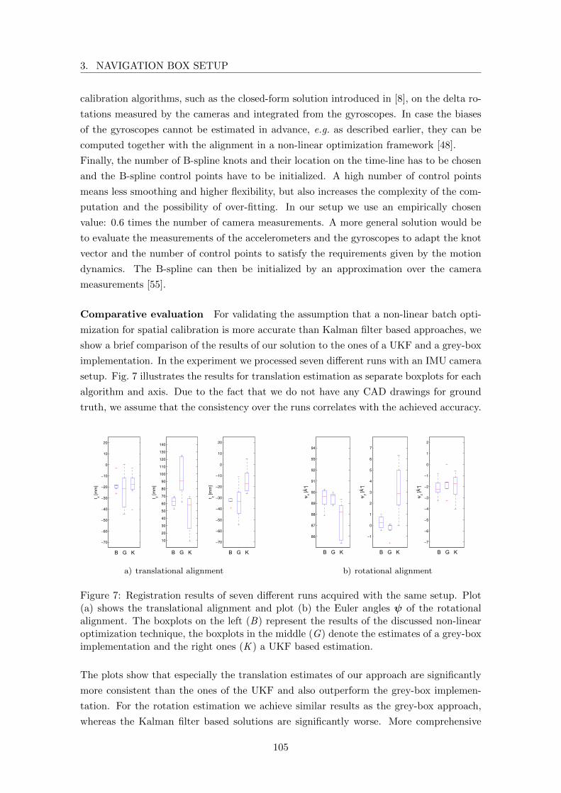
3. NAVIGATION BOX SETUP
calibration algorithms, such as the closed-form solution introduced in [8], on the delta ro-
tations measured by the cameras and integrated from the gyroscopes. In case the biases
of the gyroscopes cannot be estimated in advance, e.g. as described earlier, they can be
computed together with the alignment in a non-linear optimization framework [48].
Finally, the number of B-spline knots and their location on the time-line has to be chosen
and the B-spline control points have to be initialized. A high number of control points
means less smoothing and higher flexibility, but also increases the complexity of the com-
putation and the possibility of over-fitting. In our setup we use an empirically chosen
value: 0.6 times the number of camera measurements. A more general solution would be
to evaluate the measurements of the accelerometers and the gyroscopes to adapt the knot
vector and the number of control points to satisfy the requirements given by the motion
dynamics. The B-spline can then be initialized by an approximation over the camera
measurements [55].
Comparative evaluation For validating the assumption that a non-linear batch opti-
mization for spatial calibration is more accurate than Kalman filter based approaches, we
show a brief comparison of the results of our solution to the ones of a UKF and a grey-box
implementation. In the experiment we processed seven different runs with an IMU camera
setup. Fig. 7 illustrates the results for translation estimation as separate boxplots for each
algorithm and axis. Due to the fact that we do not have any CAD drawings for ground
truth, we assume that the consistency over the runs correlates with the achieved accuracy.
−70
−60
−50
−40
−30
−20
−10
0
10
20
1 2 3
t x[m
m]
10
20
30
40
50
60
70
80
90
100
110
120
130
140
1 2 3
t y[m
m]
−70
−60
−50
−40
−30
−20
−10
0
10
20
1 2 3
t z[m
m]
86
87
88
89
90
91
92
93
94
1 2 3
ψx
[°]
−1
0
1
2
3
4
5
6
7
1 2 3
ψy
[°]
−7
−6
−5
−4
−3
−2
−1
0
1
2
1 2 3
ψz
[°]
B G K B G K B G K B G K B G K B G K
a) translational alignment
−70
−60
−50
−40
−30
−20
−10
0
10
20
1 2 3
t x[m
m]
10
20
30
40
50
60
70
80
90
100
110
120
130
140
1 2 3
t y[m
m]
−70
−60
−50
−40
−30
−20
−10
0
10
20
1 2 3
t z[m
m]
86
87
88
89
90
91
92
93
94
1 2 3
ψx
[°]
−1
0
1
2
3
4
5
6
7
1 2 3
ψy
[°]
−7
−6
−5
−4
−3
−2
−1
0
1
2
1 2 3
ψz
[°]
B G K B G K B G K B G K B G K B G K
b) rotational alignment
Figure 7: Registration results of seven different runs acquired with the same setup. Plot(a) shows the translational alignment and plot (b) the Euler angles ψ of the rotationalalignment. The boxplots on the left (B) represent the results of the discussed non-linearoptimization technique, the boxplots in the middle (G) denote the estimates of a grey-boximplementation and the right ones (K ) a UKF based estimation.
The plots show that especially the translation estimates of our approach are significantly
more consistent than the ones of the UKF and also outperform the grey-box implemen-
tation. For the rotation estimation we achieve similar results as the grey-box approach,
whereas the Kalman filter based solutions are significantly worse. More comprehensive
105
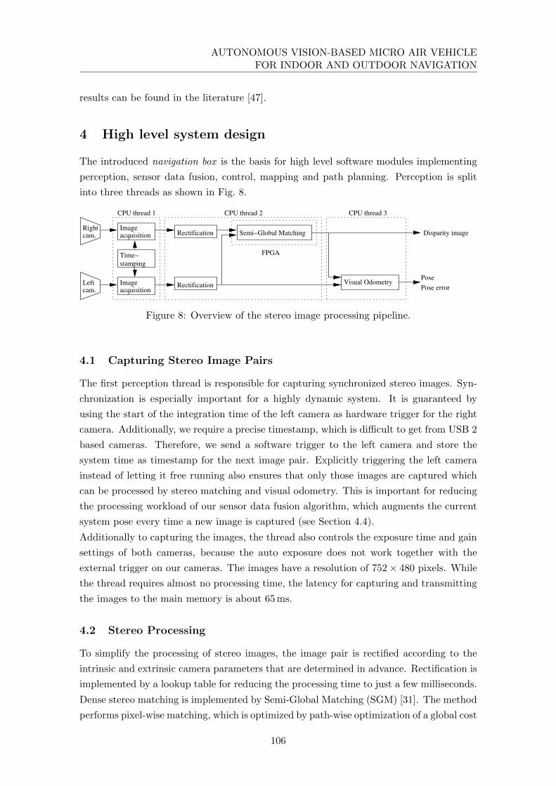
AUTONOMOUS VISION-BASED MICRO AIR VEHICLEFOR INDOOR AND OUTDOOR NAVIGATION
results can be found in the literature [47].
4 High level system design
The introduced navigation box is the basis for high level software modules implementing
perception, sensor data fusion, control, mapping and path planning. Perception is split
into three threads as shown in Fig. 8.
acquisitionImageRight
cam.
Time−
stamping
RectificationacquisitionImageLeft
cam.
Visual Odometry
Rectification
FPGA
Semi−Global Matching
CPU thread 2CPU thread 1 CPU thread 3
Disparity image
Pose
Pose error
Figure 8: Overview of the stereo image processing pipeline.
4.1 Capturing Stereo Image Pairs
The first perception thread is responsible for capturing synchronized stereo images. Syn-
chronization is especially important for a highly dynamic system. It is guaranteed by
using the start of the integration time of the left camera as hardware trigger for the right
camera. Additionally, we require a precise timestamp, which is difficult to get from USB 2
based cameras. Therefore, we send a software trigger to the left camera and store the
system time as timestamp for the next image pair. Explicitly triggering the left camera
instead of letting it free running also ensures that only those images are captured which
can be processed by stereo matching and visual odometry. This is important for reducing
the processing workload of our sensor data fusion algorithm, which augments the current
system pose every time a new image is captured (see Section 4.4).
Additionally to capturing the images, the thread also controls the exposure time and gain
settings of both cameras, because the auto exposure does not work together with the
external trigger on our cameras. The images have a resolution of 752× 480 pixels. While
the thread requires almost no processing time, the latency for capturing and transmitting
the images to the main memory is about 65 ms.
4.2 Stereo Processing
To simplify the processing of stereo images, the image pair is rectified according to the
intrinsic and extrinsic camera parameters that are determined in advance. Rectification is
implemented by a lookup table for reducing the processing time to just a few milliseconds.
Dense stereo matching is implemented by Semi-Global Matching (SGM) [31]. The method
performs pixel-wise matching, which is optimized by path-wise optimization of a global cost
106
4. HIGH LEVEL SYSTEM DESIGN
function. The cost function prefers piecewise smooth surfaces by penalizing neighboring
pixels with different disparity values. Path wise optimization is performed symmetrically
from 8 directions through the image. A left-right consistency check is used for identifying
and invalidating occlusions and mismatches. A segmentation filter on the disparity image
is used for finding and invalidating small disparity segments that are unconnected to the
surroundings. This cleans up the disparity image from possible remaining clutter.
A previous study [34] has identified Census [9] as the best and most robust matching cost
against radiometric differences. Census computes a bit vector that encodes the relative
order of intensities in the neighborhood of each pixel. We commonly work with a 9 ×7 pixel window. For each pixel in the window that is brighter than the center pixel, a
corresponding bit is set. The resulting 64 bit vector then characterizes the center pixel.
Pixel-wise matching for SGM is done by computing the Hamming distance between the
bit vectors of corresponding pixels.
In our experience, SGM behaves robustly and is not susceptible to the parameter settings
in contrast to some other stereo matching methods. Due to its regular algorithmic struc-
ture and the fact that it just adds and compares integer values in the inner loop, it can be
easily parallelized by multi-threading as well as with vector commands like with the SSE
intrinsics that are available on modern x86 CPUs. Nevertheless, SGM requires a lot of pro-
cessing resources and would not be suitable for real-time processing on a resource limited
system. Therefore, we use an FPGA implementation of SGM that has been implemented
by Supercomputing Systems13 for our former cooperation partner Daimler. An earlier pro-
totype has been described by Gehrig et al. [33]. The implementation runs on a Spartan
6 FPGA that has a very low energy consumption. It expects images of 1024× 508 pixels
with 12 bit radiometric depth and uses a disparity range of 128 pixels. Since our cameras
have a lower resolution, the remaining space is simply filled by black pixels. Currently we
also use 8 bit images only. The runtime for SGM based stereo matching is about 68 ms,
which results in a maximum frame rate of 14.6 Hz.
The stereo processing thread requests new images from the capture thread, performs recti-
fication, sends the images to the FPGA via PCI express, receives the disparity image and
performs the segmentation filter for cleaning up images. Since the FPGA has implemented
a double buffer, rectification and sending of images to the FPGA is done while the FPGA
processes the previous image pair. Similarly, post filtering is performed while matching
the next image pair on the FPGA. Therefore, with a frame rate of 14.6 Hz, the stereo
processing thread causes a CPU load of 46 %.
4.3 Visual Odometry
Our visual odometry is based on feature matching in subsequent left images. For feature
detection we used the Harris corner detector for a long time [5]. Recently we switched to
AGAST [40] for reducing the processing time from more than 20 ms to about 3 ms per
13 www.scs.ch
107
AUTONOMOUS VISION-BASED MICRO AIR VEHICLEFOR INDOOR AND OUTDOOR NAVIGATION
image. The threshold of AGAST is continuously adapted such that the detector delivers
approximately 300 features per image. However, only corners for which a disparity is
available are maintained so as to have the possibility to reconstruct all corners in 3D.
For computing feature descriptors with radiometric robustness, we apply a Rank filter
with a window size of 15 × 15 pixels to the image and then extract a region of 19 × 19
pixels around each corner. The feature descriptors are matched by the sum of absolute
differences. Computing and matching feature descriptors is implemented using SSE intrin-
sics. The resulting descriptor is very robust against radiometric differences and tolerant
to small rotations (e.g. up to 15 degrees) around the optical axis of the camera [20]. It
is not invariant to larger rotations or to scaling differences. However, even with a highly
dynamic system, there will not be large rotations or scaling differences with an antici-
pated frame rate of 10-15 Hz. Therefore, we do not need rotation and scaling invariant
feature descriptors like SIFT [21], which are computationally expensive and potentially
less discriminative, due to their invariance.
Since the rotation of the system around the vertical axis can quickly cause large image
shifts, we do not try to track features. Instead, an initial matching of all features of the
current image to all features of the previous image is performed, for finding the most
likely correspondences. Matching features vice versa from the previous to the current im-
age is used to sort out unstable matches. Outliers in the correspondences are identified by
building all possible pairs of corners and comparing the distances of their 3D reconstruc-
tions in the current view to the distances of the 3D reconstructions of the corresponding
corners in the previous view. A fast algorithm finds a large cluster of corners where
all relative distances between their 3D reconstructions match the 3D reconstructions of
their correspondences [13, 20]. In comparison to RANSAC, this method does not use any
randomization, but can still deal with much more than 50 % of outliers.
As a side effect of switching from Harris corners to AGAST, we noticed that after the
outlier detection, more correspondences are available for computing the rigid motion,
although both corner detectors have been set to deliver the same number of corners. We
cannot yet explain this positive effect.
The rigid motion is computed by singular value decomposition [7, 2] followed by mini-
mizing the ellipsoid error [3] using non-linear optimization by the Levenberg-Marquardt
algorithm.
For estimating the error of the calculated rigid motion, an image error of 0.5 pixels is
assumed in all corner positions. This error is propagated into the six parameters of the
rigid motion using the Jacobian matrix [59].
Incrementally adding the rigid motions of subsequent images for calculating the visual
odometry leads to an increasing error, even if the system is moving slowly or standing
still. To avoid this, we are using a history of a small number (e.g. 3 to 5) of key frames
[59]. The motion is not only calculated to the previous image, but also to all key frames.
This leads to n estimates of the current pose, with n corresponding error estimates. The
pose with the lowest overall error (i.e. sum of errors to the key frame and from the key
108
4. HIGH LEVEL SYSTEM DESIGN
frame to the current image) is used as the final estimate. After this determination, the
current image replaces the one in the key frame history with the largest overall error. In
this way, the algorithm seeks to minimize the overall error. If the system is standing still,
the error would not increase at all. Thus, making visual odometry drift free.
The literature contains details of the original method [13, 20] and the extensions for
estimating the error and maintaining a key frame list [59].
The calculation is implemented as further thread that gets the left stereo images and the
corresponding disparity images from the stereo processing thread. We have optimized
visual odometry for speed since earlier publications [64], without changing the algorithm.
The CPU load of the visual odometry thread with 300 features and 3 key frames is now
about 36 % at a frame rate of 14.6 Hz. This leads to a total CPU load of 82 % of one CPU
core for the capture, stereo, and visual odometry thread. The latency between capturing
the images and getting the final delta pose estimate is about 220 ms.
4.4 Sensor data fusion
We fuse the time delayed delta measurements from the visual odometry system with IMU
measurements. The on-board calculated state estimate is used for control. S ce MAVs
are inherently unstable and have fast system dynamics, they require a high controller
bandwidth for stabilization. Therefore, the time delays introduced by the vision pipeline
have to be taken into account. Furthermore, the algorithm has to run in hard real-time,
which requires a guaranteed maximum processing time. Therefore, the processor load
should be balanced, independently of measurement time delays.
We implemented the sensor data fusion algorithm as Extended Kalman Filter (EKF). It is
practical to realize the estimator as indirect filter in feedback configuration. This means
that not the system states themselves (direct states) but only the errors of the system
states (indirect states) are estimated. The indirect states are used to correct the direct
states immediately after calculation. This decoupling has several advantages [1, Chapter 6,
p. 296]:
• Fast system dynamics are tracked within the direct system state, using a computa-
tional cheap algorithm. The slower error dynamics can be accurately tracked by a
computationally more expensive filter running at a lower frequency.
• Time delays in additional sensor measurements have only to be considered within
the filter.
• The direct system state can still be calculated even in the case of a failure of the
filter.
• As the system state is corrected after each filter update we can assume small angles
in the attitude error, which can be efficiently represented by an error angle vector
of size 3 (instead of 4 for a gimbal lock free quaternion representation).
109

AUTONOMOUS VISION-BASED MICRO AIR VEHICLEFOR INDOOR AND OUTDOOR NAVIGATION
real-time
non real-time
Stereo
Odometryz−n EKF SDA
IMU
Cam 1
Cam 2
∆p,∆qδ
a, ω
a
x
sync
Augmentation trigger
Figure 9: State estimation system design. The direct system state (x) is calculated at highrate by the Strap Down Algorithm (SDA) using acceleration and gyroscope measurements(a, ω) of the IMU. An EKF uses (time delayed, relative) measurements to calculate at alower rate the state errors (δ) which are immediately used for state correction.
Our vision aided INS-filter framework, first introduced in [57], is depicted in Fig. 9. Sen-
sor data preprocessing can be easily realized on a system without real-time constraints,
whereas the actual filter runs on a real-time system. The filter framework can process any
combination of relative or absolute measurements with or without (varying) time delays.
For measurements with considerable time delays as well as for relative measurements the
exact moment of the measurement start is registered in the EKF by a hardware trigger
signal. The system state error calculated by the EKF (δ) is used for direct system state
(x) correction. For clarity, the reader is referred to Appendix A for the notation. We omit
the indices for the sensors and the reference frames where negligible. We define the direct
and indirect system states, respectively, as
x =(pE,TNxB
vE,TNxBqNx,TB bTa b
Tω
)T∈ R16 (17)
δ =(δpT δvT δσT δbTa δb
Tω
)T∈ R15 (18)
including position, velocity, orientation, and IMU acceleration and gyroscope biases. As
we assume small angle errors between filter updates, we can parameterize the orientation
error as an orientation vector. x is calculated by the Strap Down Algorithm (SDA) at a
frequency up to the full IMU sampling rate.
Strap Down Algorithm (SDA) The SDA is used to calculate the motion of the robot
from linear acceleration and angular velocity measurements. Due to limited accuracy of
the used MEMS IMU and the assumption of an approximately flat earth in the limited area
of flight, earth rotation and system transport rate can be neglected. Furthermore, it can
be assumed that the IMU measurements represent sufficiently well the specific force fBEBand angular rates ωBEB, respectively. Employing rigid body kinematics and the Bortz’
110

4. HIGH LEVEL SYSTEM DESIGN
orientation vector differential equation we find the following motion equations:
pEEB = vEEB (19)
aBEB = fBEB + gB (20)
vEEB = R(qEB)fBEB + gE (21)
qEB = q(σ) =
(cos(σ/2)σσ sin(σ/2)
)(22)
σ = ωBEB +1
2σ × ω +
1
σ2
(1− σ sin(σ)
2(1− cos(σ))
)σ × (σ × ωbnb) (23)
With the assumption of a nearly constant orientation vector σ between the discrete time
steps Tk−1 and Tk the delta orientation vector can be approximated from Eq. 23 by:
∆σ ≈ ωBEB(Tk − Tk−1) (24)
Using (22) the orientation quaternion at time Tk is calculated from the orientation at Tk−1
by:
qEBk = qEBk−1• q(∆σ) (25)
Finally, discretizing (21) under the assumption of constant acceleration between time steps
Tk−1 and Tk we get:
vEEBk ≈ R(qEBk−1)
(aBEB +
1
2σ × aBEB
)(Tk − Tk−1) (26)
Extended Kalman Filter The EKF is used to estimate the indirect system state by
processing time delayed relative (key frame) measurements coming from the stereo visual
odometry system.
For the inertial navigation system error propagation we employ the following linearized,
continuous-time error transition model for system error propagation [28]:
δ = F δ + Gn
=
O3x3 I3 O3x3 O3x3 O3x3
O3x3 O3x3 −⌊aEEB
⌋−RE
B O3x3
O3x3 O3x3 O3x3 O3x3 −REB
O3x3 O3x3 O3x3 O3x3 O3x3
O3x3 O3x3 O3x3 O3x3 O3x3
δ
+
O3x3 O3x3 O3x3 O3x3
REB O3x3 O3x3 O3x3
O3x3 REB O3x3 O3x3
O3x3 O3x3 I3 O3x3
O3x3 O3x3 O3x3 I3
n
(27)
111
AUTONOMOUS VISION-BASED MICRO AIR VEHICLEFOR INDOOR AND OUTDOOR NAVIGATION
The uncertainties in the error propagation for translation and rotation are modeled as
additive zero-mean, white Gaussian noise (AWGN). The accelerometer and gyroscope
biases are modeled as random walk processes driven by AWGN. The noise vector ns has
the spectral density Q, such that
Q = diag(Qa,Qω,Qba ,Qbω) (28)
Qs = E[nsn
Ts
]| s ∈ {a,ω, ba, bω} . (29)
We use the following (approximated) discretizations of F ,G and Q for the time interval
T at time step k which are calculated as:
Φk = eΦT (30)
GkQkGTk =
1
4(I + Φk)GQG
T (I + Φk)T T (31)
For processing relative (key frame) pose measurements in an optimal way we use state
augmentation by stochastic cloning [16]. In its original form time delays are not considered.
The arrival of a relative measurement triggers the start of the next one. Hence, the end
of the preceding relative measurement coincides with the start of the new one. The state
at the end of a relative measurement is augmented to the state vector so that it can be
referenced by the succeeding measurement.
Nevertheless, considering systems with fast dynamics, the time span between the real end
of a relative measurement and the arrival of the measurement data can be unacceptably
high due to communication and processing time delays. To compensate for these delays and
to achieve a non delayed, optimal state estimate, we trigger the filter state cloning by sensor
hardware signals, indicating the exact time of a measurement. When the delayed relative
measurement arrives, it can reference the exact start and end states of the measurements
and correct all states including the augmentations. The filter framework can directly
process all possible combinations of time delayed, overlapping and relative measurements
at the time of arrival. This results in a delay free system state estimate available at any
time, which is crucial for stable system control.
Furthermore, it is possible, depending on the available processor resources, to hold aug-
mented states in the filter instead of deleting it directly after the arrival of the measurement
data. If a relative state sensor is able to recognize a measurement start or end point that
is augmented in the filter, the proposed navigation filter is equivalent to an indirect EKF
position SLAM but can compensate for measurement time delays. We use this mechanism
to hold a fixed number of augmented poses corresponding to stereo odometry key frames.
For a general representation of filter augmentation we use in the following, the term main
state for the estimated states at the current time and augmented states for the rest of the
state vector. It is not necessary to augment the whole main state for the processing of
relative measurements but only the parts a relative measurement refers to. In general,
state augmentation and removal for the direct and indirect states at time k can be written
112

4. HIGH LEVEL SYSTEM DESIGN
as:
xk = Skxk (32)
δk = Skδk (33)
where Sk is a state selection matrix with dimension (n+ ak + a)× (n+ ak), n denotes the
size of the main state vector, ak the number of initially augmented states at time k, and
a the number of states to augment or remove from the state vector.
The augmentation of a part of the main state to the state vector in between the main
state and the already augmented states, Sk, can be written as:
Sk =
In×n 0n×akIa×n 0a×ak0ak×n Iak×ak
(34)
where Ii×i is the i × i identity matrix, Ii×j denotes an identity matrix containing only
the rows that correspond to states that should be augmented and 0ak×n is the ak × n zero
matrix.
To remove an augmentation from the state vector, Sk can be written as:
Sk = I(n+ak+a)×(n+ak) (35)
where a is negative and I is an identity matrix of size (n+ ak) × (n+ ak) with the rows
removed that correspond to a state that should be removed.
With this notation the augmented/de-augmented state covariance matrix can be written
as:
P = E[δkδTk ] = E[Skδkδ
TkS
Tk ] = SkE[δkδ
Tk ]STk = SkPS
Tk (36)
As we have a closed loop error state space filter representation, only the filter covariance
is involved in the prediction step. The augmented error propagation matrix (Φaug,k) and
the noise propagation matrix (Gaug,k) are defined as:
Φaug,k = diag(Φk, Ia+k ×a+k
) (37)
Gaug,k =
(Gk
0a+k ×n
)(38)
where a+k is the number of augmented states at the time of prediction k. The filter
covariance prediction can be realized by the standard Kalman Filter prediction step:
P−k+1 = Φaug,kP+k ΦT
aug,k +Gaug,kQkGTaug,k (39)
where P−k+1 is the a priori error state covariance at time step k+1 and P+k the a posteriori
covariance matrix at time step k.
113
AUTONOMOUS VISION-BASED MICRO AIR VEHICLEFOR INDOOR AND OUTDOOR NAVIGATION
The special form of Φaug,k and Gaug,k can be exploited in the filter implementation to
get a prediction step with a complexity rising only linearly with the number of augmented
states.
The augmented filter update is realized as standard EKF update:
Kk = P−kHTk (HkP
−kH
Tk +Rk)
−1 (40)
P+k = (I −KkHk)P
−k (41)
δ = Kkyk (42)
where Kk is the Kalman Filter gain, Hk the measurement matrix, Rk the measurement
noise covariance matrix and yk the measurement residual.
The measurement matrixHk is of dimension m×(n+a+k ) where m is the number of sensor
measurements. The first n columns of the Hk matrix correspond to the main state. For
time delayed, relative measurements the columns of Hk corresponding to the referenced
augmented states are filled with the relative measurement matrices.
We use a pseudo measurement to exploit the gravity vector for roll and pitch stabilization
[28]. The measurement equation is given by:
aBEB +R(qBE)gE = R(qEB)T
0 −g 0
g 0 0
0 0 0
δσ + na (43)
where na denotes the AWGN of the measurement with variance R = E[nanTa ]. The
pseudo measurement is valid as long as the acceleration is dominated by gravity. This
can be reflected by a measurement variance depending on the currently commanded flight
dynamics.
A general odometry sensor provides noisy position and orientation changes of the sensor
between two points in time T1 and T2.
xT2T1 =
(pC1C1,C2
qC1C2
)+ nx (44)
where nx is a AWGN random variable modeling the sensor noise (with rotational noise in
quaternion representation). Position and orientation states at time Tx are augmented to
process the measurement. The augmented sub-states can be written as:
δaug,Tx =(δpTx δσTx
)T(45)
xaug,Tx =(pE,TE,Bx
qE,TBx
)T(46)
Considering the known, static camera to IMU calibration (tBB,C , RCB), the estimated sensor
114

4. HIGH LEVEL SYSTEM DESIGN
delta pose between T1 and T2 is:
xT2T1 =
(RCBR
B1E (pEE,B2
− pEE,B1+ (RE
B2−RE
B1)tBB,C)
qCB • qB1E • qEB2
• qBC
)=
(pC1C1,C2
qC1C2
)(47)
The measurement equations can be derived as:
xT2T1 xT2T1
=(H1 H2
)(δaug,T1
δaug,T2
)+ nx (48)
with the measurement submatrices as:
H1 = RCBR
B1E
(I3×3
⌊pEE,B2
− pEE,B1+RE
B2tBB,C
⌋
03×3 I3×3
)(49)
H2 = RCBR
B1E
(−I3×3 −
⌊REB2tBB,C
⌋
03×3 −I3×3
)
and the definition of as:
xT2T1 xT2T1
=
(pC1C1,C2
− pC1C1,C2(
diag(2 2 2) 03×1
)qC1C2• qC2
C1
)T
which is a subtraction of the position part and the delta rotation for the attitude part,
computed between the two delta orientations and approximated by the error angle vector
representation.
The measurement noise nx is again characterized by its covariance matrix Rx = E[nxnTx ]
calculated by the odometry algorithm. Rotational noise is parameterized by Euler angles
corresponding to nx.
Hard real-time requirements The state estimation framework is used for system
control and therefore has to run in hard real-time. The maximum processing time has to
be determined and limited to the sampling period interval. For the introduced estimator,
the maximum execution time can be determined for a constant number of states measuring
the execution time of one filter augmentation, one filter prediction and two updates of
constant measurement vector size. Furthermore, we have to add the execution time for
one SDA calculation step, the maximum time the direct state vector might be locked by
the SDA thread. By limiting the maximum number of states, hard real-time execution
can be guaranteed independently of varying measurement time delays.
The maximum number of filter states determines the maximum number of key frames that
can be used by the visual odometry system considering real-time requirements. The key
frame buffer of the visual odometry system and the corresponding augmented states within
the EKF framework have to be synchronized to keep the number of state augmentations at
a minimum. For synchronization, the visual odometry system sends a list of timestamps
115
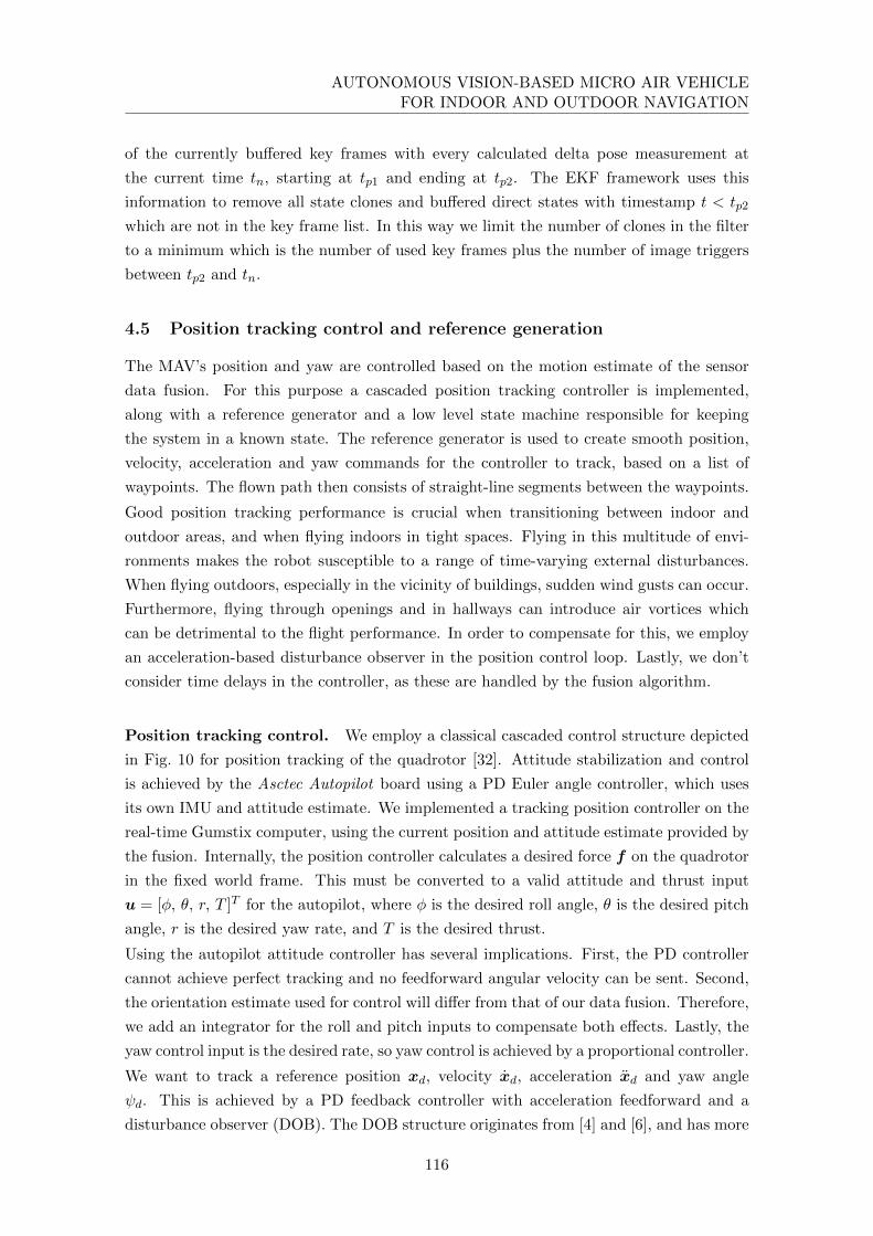
AUTONOMOUS VISION-BASED MICRO AIR VEHICLEFOR INDOOR AND OUTDOOR NAVIGATION
of the currently buffered key frames with every calculated delta pose measurement at
the current time tn, starting at tp1 and ending at tp2. The EKF framework uses this
information to remove all state clones and buffered direct states with timestamp t < tp2
which are not in the key frame list. In this way we limit the number of clones in the filter
to a minimum which is the number of used key frames plus the number of image triggers
between tp2 and tn.
4.5 Position tracking control and reference generation
The MAV’s position and yaw are controlled based on the motion estimate of the sensor
data fusion. For this purpose a cascaded position tracking controller is implemented,
along with a reference generator and a low level state machine responsible for keeping
the system in a known state. The reference generator is used to create smooth position,
velocity, acceleration and yaw commands for the controller to track, based on a list of
waypoints. The flown path then consists of straight-line segments between the waypoints.
Good position tracking performance is crucial when transitioning between indoor and
outdoor areas, and when flying indoors in tight spaces. Flying in this multitude of envi-
ronments makes the robot susceptible to a range of time-varying external disturbances.
When flying outdoors, especially in the vicinity of buildings, sudden wind gusts can occur.
Furthermore, flying through openings and in hallways can introduce air vortices which
can be detrimental to the flight performance. In order to compensate for this, we employ
an acceleration-based disturbance observer in the position control loop. Lastly, we don’t
consider time delays in the controller, as these are handled by the fusion algorithm.
Position tracking control. We employ a classical cascaded control structure depicted
in Fig. 10 for position tracking of the quadrotor [32]. Attitude stabilization and control
is achieved by the Asctec Autopilot board using a PD Euler angle controller, which uses
its own IMU and attitude estimate. We implemented a tracking position controller on the
real-time Gumstix computer, using the current position and attitude estimate provided by
the fusion. Internally, the position controller calculates a desired force f on the quadrotor
in the fixed world frame. This must be converted to a valid attitude and thrust input
u = [φ, θ, r, T ]T for the autopilot, where φ is the desired roll angle, θ is the desired pitch
angle, r is the desired yaw rate, and T is the desired thrust.
Using the autopilot attitude controller has several implications. First, the PD controller
cannot achieve perfect tracking and no feedforward angular velocity can be sent. Second,
the orientation estimate used for control will differ from that of our data fusion. Therefore,
we add an integrator for the roll and pitch inputs to compensate both effects. Lastly, the
yaw control input is the desired rate, so yaw control is achieved by a proportional controller.
We want to track a reference position xd, velocity xd, acceleration xd and yaw angle
ψd. This is achieved by a PD feedback controller with acceleration feedforward and a
disturbance observer (DOB). The DOB structure originates from [4] and [6], and has more
116
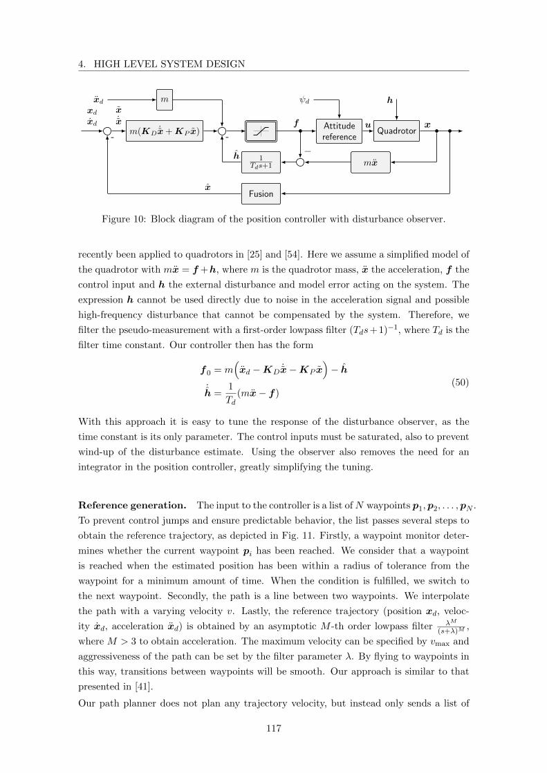
4. HIGH LEVEL SYSTEM DESIGN
QuadrotorAttitudereference
m(KD˙x+KP x)
m
mx1
Tds+1
Fusion
u x
ψd hxd
xd
xd f
−h
-
x˙x
x
-
Figure 10: Block diagram of the position controller with disturbance observer.
recently been applied to quadrotors in [25] and [54]. Here we assume a simplified model of
the quadrotor with mx = f +h, where m is the quadrotor mass, x the acceleration, f the
control input and h the external disturbance and model error acting on the system. The
expression h cannot be used directly due to noise in the acceleration signal and possible
high-frequency disturbance that cannot be compensated by the system. Therefore, we
filter the pseudo-measurement with a first-order lowpass filter (Tds+1)−1, where Td is the
filter time constant. Our controller then has the form
f0 = m(xd −KD
˙x−KP x)− h
˙h =
1
Td(mx− f)
(50)
With this approach it is easy to tune the response of the disturbance observer, as the
time constant is its only parameter. The control inputs must be saturated, also to prevent
wind-up of the disturbance estimate. Using the observer also removes the need for an
integrator in the position controller, greatly simplifying the tuning.
Reference generation. The input to the controller is a list ofN waypoints p1,p2, . . . ,pN .
To prevent control jumps and ensure predictable behavior, the list passes several steps to
obtain the reference trajectory, as depicted in Fig. 11. Firstly, a waypoint monitor deter-
mines whether the current waypoint pi has been reached. We consider that a waypoint
is reached when the estimated position has been within a radius of tolerance from the
waypoint for a minimum amount of time. When the condition is fulfilled, we switch to
the next waypoint. Secondly, the path is a line between two waypoints. We interpolate
the path with a varying velocity v. Lastly, the reference trajectory (position xd, veloc-
ity xd, acceleration xd) is obtained by an asymptotic M -th order lowpass filter λM
(s+λ)M,
where M > 3 to obtain acceleration. The maximum velocity can be specified by vmax and
aggressiveness of the path can be set by the filter parameter λ. By flying to waypoints in
this way, transitions between waypoints will be smooth. Our approach is similar to that
presented in [41].
Our path planner does not plan any trajectory velocity, but instead only sends a list of
117
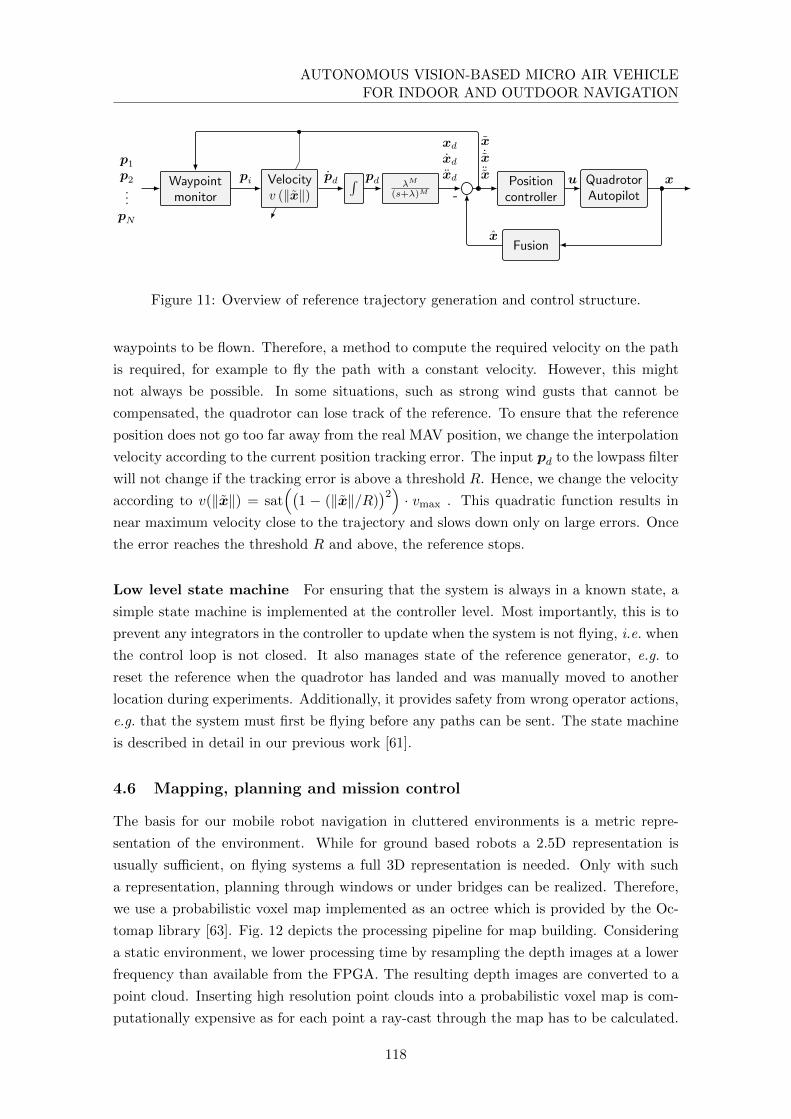
AUTONOMOUS VISION-BASED MICRO AIR VEHICLEFOR INDOOR AND OUTDOOR NAVIGATION
QuadrotorAutopilot
Positioncontroller
Fusion
λM
(s+λ)M
∫Velocityv (‖x‖)
Waypointmonitor
xu
x
x˙x¨x
xdxdxd
-
pdpdpi
p1p2...pN
Figure 11: Overview of reference trajectory generation and control structure.
waypoints to be flown. Therefore, a method to compute the required velocity on the path
is required, for example to fly the path with a constant velocity. However, this might
not always be possible. In some situations, such as strong wind gusts that cannot be
compensated, the quadrotor can lose track of the reference. To ensure that the reference
position does not go too far away from the real MAV position, we change the interpolation
velocity according to the current position tracking error. The input pd to the lowpass filter
will not change if the tracking error is above a threshold R. Hence, we change the velocity
according to v(‖x‖) = sat((
1 − (‖x‖/R))2) · vmax . This quadratic function results in
near maximum velocity close to the trajectory and slows down only on large errors. Once
the error reaches the threshold R and above, the reference stops.
Low level state machine For ensuring that the system is always in a known state, a
simple state machine is implemented at the controller level. Most importantly, this is to
prevent any integrators in the controller to update when the system is not flying, i.e. when
the control loop is not closed. It also manages state of the reference generator, e.g. to
reset the reference when the quadrotor has landed and was manually moved to another
location during experiments. Additionally, it provides safety from wrong operator actions,
e.g. that the system must first be flying before any paths can be sent. The state machine
is described in detail in our previous work [61].
4.6 Mapping, planning and mission control
The basis for our mobile robot navigation in cluttered environments is a metric repre-
sentation of the environment. While for ground based robots a 2.5D representation is
usually sufficient, on flying systems a full 3D representation is needed. Only with such
a representation, planning through windows or under bridges can be realized. Therefore,
we use a probabilistic voxel map implemented as an octree which is provided by the Oc-
tomap library [63]. Fig. 12 depicts the processing pipeline for map building. Considering
a static environment, we lower processing time by resampling the depth images at a lower
frequency than available from the FPGA. The resulting depth images are converted to a
point cloud. Inserting high resolution point clouds into a probabilistic voxel map is com-
putationally expensive as for each point a ray-cast through the map has to be calculated.
118
4. HIGH LEVEL SYSTEM DESIGN
In the near range a map voxel may be represented by several points of the point cloud.
Therefore, we use a voxel grid prefilter with the same resolution as the voxel map. The
resulting, filtered point cloud is inserted into the map by ray-casts using the robot pose
calculated by the sensor data fusion.
Depth image ResamplingPoint cloud
conversion
Point cloud
filterOctomap
Figure 12: Data processing pipeline for map generation.
The path planning module uses the map to calculate an obstacle-free path from the cur-
rent robot position to a given waypoint. We cut a horizontal plane at the current altitude
of the robot and its height as thickness out of the octomap. The voxels of this plane are
projected down into a 2D horizontal map. We employ the ROS Navfn package imple-
menting Dijkstra’s algorithm for 2D path planning at the current height of the robot. By
running the planner at the frequency of the mapping module, newly appearing obstacles
are avoided. The calculated path consists of a list of densely spaced waypoints, discretized
in the map grid.
Before commanding the plan to the controller, we first prune the plan to reduce the
number of waypoints. Pruning is based on comparing the arc length of a path segment to
its straight-line approximation. We iterate through all plan waypoints and compare the
arc lengths between the last accepted waypoint pm and the currently considered waypoint
pk to a straight line between the two. Hence, we compare the values
Larc =k∑
i=m+1
‖pi − pi−1‖, Lstraight = ‖pk − pm‖
and accept the waypoint pk−1 (thereby setting m = k−1) if the relative difference exceeds a
threshold, i.e. if Larc > (1+ε)Lstraight for small ε. By filtering the path in this way, straight
paths are approximated by a small number of waypoints, whereas path segments with high
curvature (i.e. around obstacles) are represented by a higher number of waypoints. Using
the reference generation strategy introduced in Section 4.5, the flight velocity is effectively
increased in obstacle-free areas, whereas it is decreased in cluttered environments. Lastly,
we calculate the required yaw orientation such that the MAV is always oriented toward
the next waypoint, in order to obtain a map in the flight direction.
We realize mission control by employing the ROS SMACH library. It facilitates the imple-
mentation of complex robot behaviors using the concept of hierarchical state machines.
119
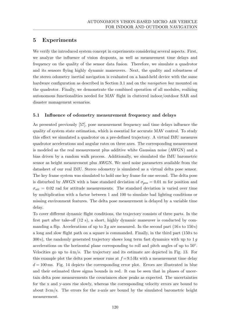
AUTONOMOUS VISION-BASED MICRO AIR VEHICLEFOR INDOOR AND OUTDOOR NAVIGATION
5 Experiments
We verify the introduced system concept in experiments considering several aspects. First,
we analyze the influence of vision dropouts, as well as measurement time delays and
frequency on the quality of the sensor data fusion. Therefore, we simulate a quadrotor
and its sensors flying highly dynamic maneuvers. Next, the quality and robustness of
the stereo odometry inertial navigation is evaluated on a hand-held device with the same
hardware configuration as described in Section 3.1 and on the navigation box mounted on
the quadrotor. Finally, we demonstrate the combined operation of all modules, realizing
autonomous functionalities needed for MAV flight in cluttered indoor/outdoor SAR and
disaster management scenarios.
5.1 Influence of odometry measurement frequency and delays
As presented previously [57], pose measurement frequency and time delays influence the
quality of system state estimation, which is essential for accurate MAV control. To study
this effect we simulated a quadrotor on a pre-defined trajectory. A virtual IMU measures
quadrotor accelerations and angular rates on three axes. The corresponding measurement
is modeled as the real measurement plus additive white Gaussian noise (AWGN) and a
bias driven by a random walk process. Additionally, we simulated the IMU barometric
sensor as height measurement plus AWGN. We used noise parameters available from the
datasheet of our real IMU. Stereo odometry is simulated as a virtual delta pose sensor.
The key frame system was simulated to hold one key frame for one second. The delta pose
is disturbed by AWGN with a base standard deviation of σpos = 0.01 m for position and
σatt = 0.02 rad for attitude measurements. The standard deviation is varied over time
by multiplication with a factor between 1 and 100 to simulate bad lighting conditions or
missing environment features. The delta pose measurement is delayed by a variable time
delay.
To cover different dynamic flight conditions, the trajectory consists of three parts. In the
first part after take-off (12 s), a short, highly dynamic maneuver is conducted by com-
manding a flip. Accelerations of up to 3 g are measured. In the second part (16 s to 150 s)
a long and slow flight path on a square is commanded. Finally, in the third part (150 s to
300 s), the randomly generated trajectory shows long term fast dynamics with up to 1 g
accelerations on the horizontal plane corresponding to roll and pitch angles of up to 50◦.
Velocities go up to 4 m/s. The trajectory and its estimate are depicted in Fig. 13. For
this example plot the delta pose sensor runs at f=9.5 Hz with a measurement time delay
d = 100 ms. Fig. 14 depicts the corresponding error plot. Errors are illustrated in blue
and their estimated three sigma bounds in red. It can be seen that in phases of uncer-
tain delta pose measurements the covariances show peaks as expected. The uncertainties
for the x and y-axes rise slowly, whereas the corresponding velocity errors are bound to
about 3 cm/s. The errors for the z-axis are bound by the simulated barometric height
measurement.
120

5. EXPERIMENTS
10−210−1100101
σ[m
]
00.20.40.6
px[m
]
0
2
−0.20
0.20.40.6
py[m
]
−2
0
2
−1
−0.5
0
pz[m
]
−1
−0.95
−0.9
−0.10
0.10.2
vx[m
/s]
−4−2024
−1
0
1
vy[m
/s]
−4−2024
0123
vz[m
/s]
−0.2
0
0.2
−100
0
100Flip
φ[◦]
−50
0
50
−2
0
2
θ[◦]
−50
0
50
0 50 100 150 200 250 300
−100
0
100
Time [s]
ψ[◦]
Figure 13: Simulated flight with delta pose sensor running at f=9.5 Hz with measurementtime delay d = 100 ms and key frame hold of 1 s. Plots from top to bottom: Standarddeviation of delta pose measurement; Reference position (px,y,z) in red, estimated positionin blue; Reference velocity (vx,y,z) in red, estimated velocity in blue; Reference angles (roll,pitch, yaw) in red, estimated angles in blue. The trajectory includes a flip (t= 12 s), aslow passage (t= 12 s to t= 150 s) and a highly dynamic passage (t= 150 s to t= 300 s)with velocities of up to 4 m/s and accelerations of up to 1 g resulting from roll and pitchangles of up to 50◦. Scale of the plots’ y-axes changes at t=150 s.
121
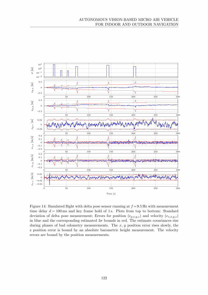
AUTONOMOUS VISION-BASED MICRO AIR VEHICLEFOR INDOOR AND OUTDOOR NAVIGATION
10−2
10−1
100
101
σ[m
]
0 50 100 150 200 250 300
−0.5
0
0.5
e p,x
[m]
0 50 100 150 200 250 300
−0.5
0
0.5
e p,y
[m]
0 50 100 150 200 250 300
−0.02
0
0.02
e p,z
[m]
0 50 100 150 200 250 300−0.2
−0.1
0
0.1
0.2
e v,x
[m/s]
0 50 100 150 200 250 300−0.2
−0.1
0
0.1
0.2
e v,y
[m/s]
0 50 100 150 200 250 300
−0.04
−0.02
0
0.02
Time [s]
e v,z
[m/s]
Figure 14: Simulated flight with delta pose sensor running at f=9.5 Hz with measurementtime delay d = 100 ms and key frame hold of 1 s. Plots from top to bottom: Standarddeviation of delta pose measurement; Errors for position (ep,x,y,z) and velocity (ev,x,y,z)in blue and the corresponding estimated 3σ bounds in red. The estimate covariances riseduring phases of bad odometry measurements. The x, y position error rises slowly, thez position error is bound by an absolute barometric height measurement. The velocityerrors are bound by the position measurements.
122

5. EXPERIMENTS
We varied the frequency of the simulated key frame odometry sensor from f = 15 Hz to
f=1 Hz as well as the delays of the measurement arrival from d= 1f − dt to d=dt with a
sampling time of dt=5 ms. For each dataset 20 Monte Carlo simulations were performed
resulting in a total of 800 runs. For control applications we are especially interested in
the velocity estimate in the body frame. In the absence of an absolute measurement of
the yaw angle, we transformed the ground truth velocities from the simulated world frame
to the estimated world frame. In this way the velocities are directly comparable. Fig. 15
depicts the dependency of the mean of the root mean square errors (RMSE) over all runs
for position and velocity.
0 0.2 0.4 0.6 0.8 1
0.15
0.2
0.25
0.3
Measurement delays [s]
RM
Sofposition
error[m
]
f=1
f=2
f=3
f=4
f=7.5
f=9.5
f=12
f=15
a) Position RMSE vs. measurement delay.
0 0.2 0.4 0.6 0.8 12
3
4
·10−2
Measurement delays [s]
RM
Sofvelocity
error[m
/s]
f=1
f=2
f=3
f=4
f=7.5
f=9.5
f=12
f=15
b) Velocity RMSE vs. measurement delay.
0
0.5
1
051015
0.1
0.2
0.3Measurem
ent
delay
s[s] Cam frequency [Hz]
RM
Sofposition
error[m
]
c) Position RMSE for varying measurement delaysand frequencies.
0
0.5
1
051015
2
3
4
·10−2
Measurem
ent
delay
s[s] Cam frequency [Hz]
RM
Sofvelocity
error[m
/s]
d) Velocity RMSE for varying measurement delaysand frequencies.
Figure 15: Root Mean Square Errors (RMSE) for varying frequencies and measurementdelays. For each frequency/delay combination the mean of 20 runs is depicted.
The position RMSE is almost constant for varying measurement delays. The direct delta
pose measurement has a strong influence on the position compared to the double integrated
acceleration. The constant key frame hold time of 1 s has the effect of an absolute position
measurement for the period of the key frame. Therefore, the effect of varying measurement
time delays with constant frequency on the position estimate is small. From Fig. 15.c) it
123

AUTONOMOUS VISION-BASED MICRO AIR VEHICLEFOR INDOOR AND OUTDOOR NAVIGATION
can be seen that the quality of the position RMSE rises exponentially with the frequency
of the measurement. The shorter the intervals during the measurement updates, the lower
the influence of the double integrated accelerations.
In contrast to the position RMSE, the RMSE of the velocity estimate depends linearly
on the delay of the measurement update. This can be explained as there are no direct
sensor measurements for velocity but the estimate is calculated by integration of accelera-
tion measurements and indirect corrections via delta poses. The noise of the acceleration
sensors has, therefore, a stronger influence. The longer the measurement time delay, the
greater the influence of integrated acceleration noise on the velocity. As seen for the posi-
tion, the accuracy of the velocity estimate also rises exponentially with the measurement
frequency (Fig. 15.d)).
5.2 System validation on a handheld device
For the second experiment, we built the navigation box (see Section 3.1) in form of a
hand-held device (see Fig. 16) to validate the system concept on real hardware. By using
a hand-held device we separate the estimation from the control problem. In the following
we will present some experimental results [64].
Figure 16: Navigation box as hand-held device.
010
20
−10
0
10
−5
0
5
x in my in m
zin
m
Ground TruthSensor Data Fusion
Visual Odometry
Figure 17: Experimental outdoor trajectorymeasured by tachymeter (ground truth), vi-sual odometry and sensor data fusion.
We conducted several outdoor experiments using a tachymeter (Leica TP1200 ) for ground
truth validation. Therefore, we mounted a 360◦ prism on top of the device. The tachymeter
can automatically track the position of the prism with an accuracy of about ±5 mm.
We carried the device on a triangular trajectory of about 70 m as illustrated in Fig. 17.
Thereby, we considered three different experimental setups:
• Setup 1 : To analyze the influence of visual odometry key frames on the estima-
tion accuracy, we disabled key frames, continuously integrating the motion between
consecutive images.
124
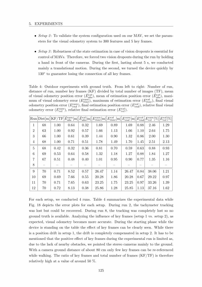
5. EXPERIMENTS
• Setup 2 : To validate the system configuration used on our MAV, we set the param-
eters for the visual odometry system to 300 features and 5 key frames.
• Setup 3 : Robustness of the state estimation in case of vision dropouts is essential for
control of MAVs. Therefore, we forced two vision dropouts during the run by holding
a hand in front of the cameras. During the first, lasting about 5 s, we conducted
mainly a translational motion. During the second, we turned the device quickly by
130◦ to guarantee losing the connection of all key frames.
Table 4: Outdoor experiments with ground truth. From left to right: Number of run,distance of run, number key frames (KF) divided by total number of images (TF), meanof visual odometry position error (Eestabs), mean of estimation position error (Eestabs), maxi-mum of visual odometry error (Ecammax), maximum of estimation error (Eestmax), final visualodometry position error (Ecamend ), final estimation position error (Eestend), relative final visualodometry error (Ecamrel ), relative final estimation error (Eestrel ).
Run Dist[m] KF/TF Ecamabs [m] Eestabs[m] Ecammax[m] Eestmax[m] Ecamend [m] Eestend Ecamrel [%] Eestrel [%]
1 68 1.00 0.64 0.32 1.69 0.89 1.69 0.88 2.46 1.29
2 63 1.00 0.92 0.57 1.66 1.13 1.66 1.10 2.64 1.75
3 66 1.00 0.61 0.39 1.44 0.90 1.32 0.86 2.00 1.30
4 68 1.00 0.71 0.51 1.78 1.49 1.70 1.45 2.51 2.13
5 68 0.42 0.32 0.36 0.81 0.70 0.59 0.63 0.88 0.93
6 69 0.53 0.64 0.58 1.32 1.18 1.27 0.88 1.84 1.27
7 67 0.51 0.48 0.40 1.01 0.95 0.90 0.77 1.35 1.16
8 – – – – – – – – – –
9 70 0.71 8.52 0.57 26.47 1.14 26.47 0.84 38.06 1.21
10 69 0.69 7.66 0.55 20.28 1.86 20.28 0.67 29.22 0.97
11 70 0.71 7.65 0.63 23.25 1.75 23.25 0.97 33.26 1.39
12 70 0.72 8.13 0.38 25.86 1.28 25.85 1.13 37.16 1.62
For each setup, we conducted 4 runs. Table 4 summarizes the experimental data while
Fig. 18 depicts the error plots for each setup. During run 2, the tachymeter tracking
was lost but could be recovered. During run 8, the tracking was completely lost so no
ground truth is available. Analyzing the influence of key frames (setup 1 vs. setup 2), as
expected, visual odometry becomes more accurate. During the starting phase while the
device is standing on the table the effect of key frames can be clearly seen. While there
is a position drift in setup 1, the drift is completely compensated in setup 2. It has to be
mentioned that the positive effect of key frames during the experimental run is limited as,
due to the lack of nearby obstacles, we pointed the stereo cameras mainly to the ground.
With a camera ground distance of about 80 cm only few key frames can be re-referenced
while walking. The ratio of key frames and total number of frames (KF/TF) is therefore
relatively high at a value of around 50 %.
125
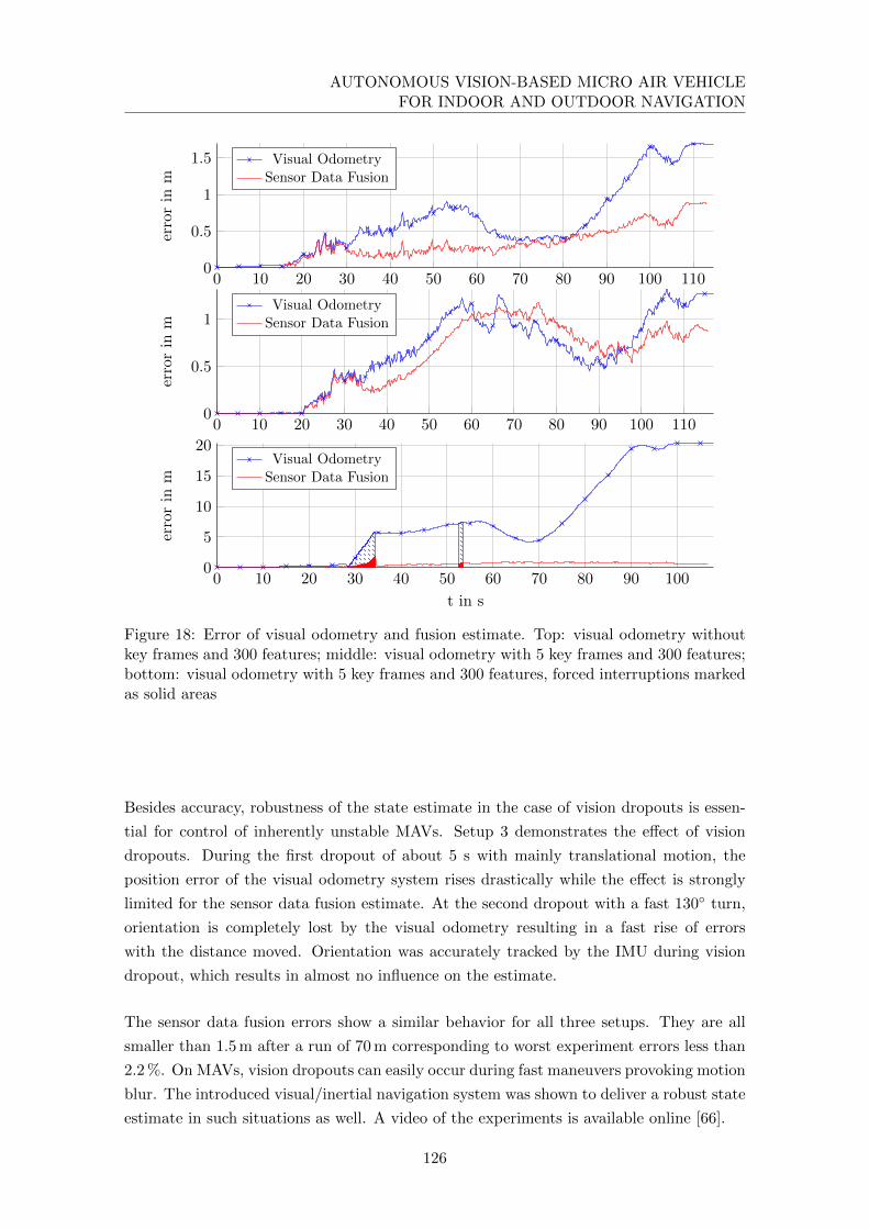
AUTONOMOUS VISION-BASED MICRO AIR VEHICLEFOR INDOOR AND OUTDOOR NAVIGATION
0 10 20 30 40 50 60 70 80 90 100 1100
0.5
1
errorin
m
Visual OdometrySensor Data Fusion
0 10 20 30 40 50 60 70 80 90 100 1100
0.5
1
1.5errorin
mVisual Odometry
Sensor Data Fusion
0 10 20 30 40 50 60 70 80 90 1000
5
10
15
20
t in s
errorin
m
Visual OdometrySensor Data Fusion
Figure 18: Error of visual odometry and fusion estimate. Top: visual odometry withoutkey frames and 300 features; middle: visual odometry with 5 key frames and 300 features;bottom: visual odometry with 5 key frames and 300 features, forced interruptions markedas solid areas
Besides accuracy, robustness of the state estimate in the case of vision dropouts is essen-
tial for control of inherently unstable MAVs. Setup 3 demonstrates the effect of vision
dropouts. During the first dropout of about 5 s with mainly translational motion, the
position error of the visual odometry system rises drastically while the effect is strongly
limited for the sensor data fusion estimate. At the second dropout with a fast 130◦ turn,
orientation is completely lost by the visual odometry resulting in a fast rise of errors
with the distance moved. Orientation was accurately tracked by the IMU during vision
dropout, which results in almost no influence on the estimate.
The sensor data fusion errors show a similar behavior for all three setups. They are all
smaller than 1.5 m after a run of 70 m corresponding to worst experiment errors less than
2.2 %. On MAVs, vision dropouts can easily occur during fast maneuvers provoking motion
blur. The introduced visual/inertial navigation system was shown to deliver a robust state
estimate in such situations as well. A video of the experiments is available online [66].
126

5. EXPERIMENTS
5.3 System validation on the quadrotor platform
We evaluated the quality of the estimation results of the navigation box and the effective-
ness of its damped mounting in quadrotor flight experiments. With the fast movements
of the MAV and the limited dynamics of the tachymeter tracking, we could not provide
a ground truth for the flown trajectory. Instead we started and landed the quadrotor at
the same position and used the position difference as quality criterion.
The manually flown trajectory (see Fig. 19) starts outside a building in the center of a
gully (radius 0.38 m) surrounded by lawn. The quadrotor is flown around the building to
the entrance door. After entering the building, the left corridor (corridor 1) is traversed
to return to the entrance hall via a laboratory on the right side. From the entrance hall,
the quadrotor is flown to the second floor via the staircase. The corridor above corridor
1 is traversed to leave the building through a window close to the starting point. The
quadrotor is landed on the center of the gully to close the trajectory loop after a path
length of 110 m. A video of the visualized on-board data is available online [66].
Start
Window
Stairway
Door
Laboratory
CorridorEntrance hall
a) Top view
Start
Window Second floor
b) Front view
Start
Window
Stairway
Door
Second floorLaboratory
Corridor 1
Entrance hall
c) Perspective view
Figure 19: Path and on-board map of a manually flown indoor (green) and outdoor (red)trajectory of 110m. Grid resolution is 1 m.
The trajectory includes several challenges for the navigation solution: Outlier rejection
for visual features has to be robust as leafs on the ground are stirred up by the quadrotor
downwash. The lighting conditions between indoor and outdoor areas vary strongly. In
poorly textured indoor areas (white walls in the corridors) visual odometry easily drops
out. The building is left through the window at a height of about 4 m above lawn with
self similar texture.
The position estimation errors of ten experimental runs are summarized in Table 5. All
ten runs resulted in an estimated position loop closure error smaller than 2.20 %. Pure
visual odometry has a mean loop closure position error of 8.15 % while the fusion with
IMU results in a mean error of 1.27 %. The resulting on-board maps are precise enough
127
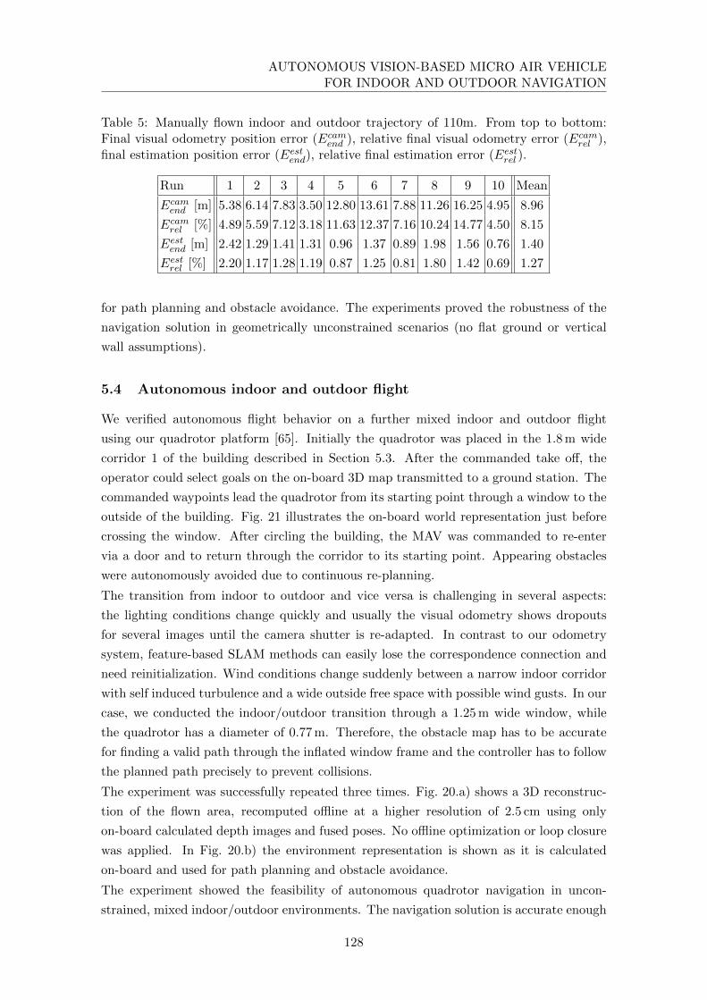
AUTONOMOUS VISION-BASED MICRO AIR VEHICLEFOR INDOOR AND OUTDOOR NAVIGATION
Table 5: Manually flown indoor and outdoor trajectory of 110m. From top to bottom:Final visual odometry position error (Ecamend ), relative final visual odometry error (Ecamrel ),final estimation position error (Eestend), relative final estimation error (Eestrel ).
Run 1 2 3 4 5 6 7 8 9 10 Mean
Ecamend [m] 5.38 6.14 7.83 3.50 12.80 13.61 7.88 11.26 16.25 4.95 8.96
Ecamrel [%] 4.89 5.59 7.12 3.18 11.63 12.37 7.16 10.24 14.77 4.50 8.15
Eestend [m] 2.42 1.29 1.41 1.31 0.96 1.37 0.89 1.98 1.56 0.76 1.40
Eestrel [%] 2.20 1.17 1.28 1.19 0.87 1.25 0.81 1.80 1.42 0.69 1.27
for path planning and obstacle avoidance. The experiments proved the robustness of the
navigation solution in geometrically unconstrained scenarios (no flat ground or vertical
wall assumptions).
5.4 Autonomous indoor and outdoor flight
We verified autonomous flight behavior on a further mixed indoor and outdoor flight
using our quadrotor platform [65]. Initially the quadrotor was placed in the 1.8 m wide
corridor 1 of the building described in Section 5.3. After the commanded take off, the
operator could select goals on the on-board 3D map transmitted to a ground station. The
commanded waypoints lead the quadrotor from its starting point through a window to the
outside of the building. Fig. 21 illustrates the on-board world representation just before
crossing the window. After circling the building, the MAV was commanded to re-enter
via a door and to return through the corridor to its starting point. Appearing obstacles
were autonomously avoided due to continuous re-planning.
The transition from indoor to outdoor and vice versa is challenging in several aspects:
the lighting conditions change quickly and usually the visual odometry shows dropouts
for several images until the camera shutter is re-adapted. In contrast to our odometry
system, feature-based SLAM methods can easily lose the correspondence connection and
need reinitialization. Wind conditions change suddenly between a narrow indoor corridor
with self induced turbulence and a wide outside free space with possible wind gusts. In our
case, we conducted the indoor/outdoor transition through a 1.25 m wide window, while
the quadrotor has a diameter of 0.77 m. Therefore, the obstacle map has to be accurate
for finding a valid path through the inflated window frame and the controller has to follow
the planned path precisely to prevent collisions.
The experiment was successfully repeated three times. Fig. 20.a) shows a 3D reconstruc-
tion of the flown area, recomputed offline at a higher resolution of 2.5 cm using only
on-board calculated depth images and fused poses. No offline optimization or loop closure
was applied. In Fig. 20.b) the environment representation is shown as it is calculated
on-board and used for path planning and obstacle avoidance.
The experiment showed the feasibility of autonomous quadrotor navigation in uncon-
strained, mixed indoor/outdoor environments. The navigation solution is accurate enough
128

5. EXPERIMENTS
for safe flight in cluttered environments. Computationally expensive SLAM algorithms
can increase global positioning accuracy especially in the case of loop closures. Neverthe-
less, they are not necessary for safe navigation. A video of the experiment is available
online [66].
Start
Window
Door
Outdoor area
Indoor area
a) Offline 3D reconstruction with 2.5 cm resolu-tion.
Start
Window
Door
Outdoor area
Indoor area
b) On-board computed octomap with 10 cm reso-lution.
Figure 20: Offline 3D reconstruction with 2.5 cm resolution using on-board calculatedego-motion estimates and depth data only. The indoor trajectory is marked in green,while the outdoor trajectory is marked in red.
Figure 21: Stereo depth image, on-board camera view, on-board computed octomap, andflown path before flying through the window.
5.5 Exploration in a coal mine
We tested the introduced MAV in a possible disaster management scenario, a coal mine
in Recklinghausen/Germany. We used the waypoint navigation system introduced in Sec-
129
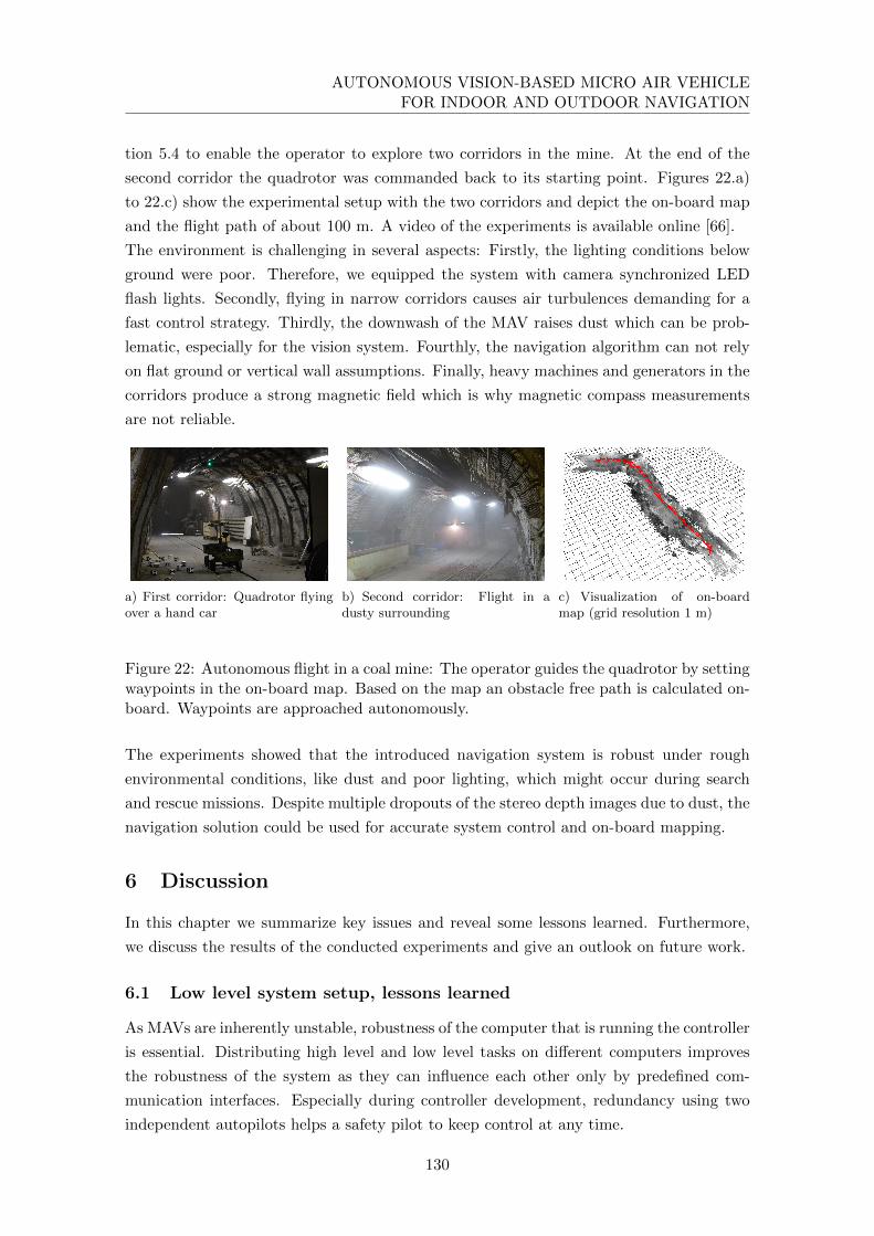
AUTONOMOUS VISION-BASED MICRO AIR VEHICLEFOR INDOOR AND OUTDOOR NAVIGATION
tion 5.4 to enable the operator to explore two corridors in the mine. At the end of the
second corridor the quadrotor was commanded back to its starting point. Figures 22.a)
to 22.c) show the experimental setup with the two corridors and depict the on-board map
and the flight path of about 100 m. A video of the experiments is available online [66].
The environment is challenging in several aspects: Firstly, the lighting conditions below
ground were poor. Therefore, we equipped the system with camera synchronized LED
flash lights. Secondly, flying in narrow corridors causes air turbulences demanding for a
fast control strategy. Thirdly, the downwash of the MAV raises dust which can be prob-
lematic, especially for the vision system. Fourthly, the navigation algorithm can not rely
on flat ground or vertical wall assumptions. Finally, heavy machines and generators in the
corridors produce a strong magnetic field which is why magnetic compass measurements
are not reliable.
a) First corridor: Quadrotor flyingover a hand car
b) Second corridor: Flight in adusty surrounding
c) Visualization of on-boardmap (grid resolution 1 m)
Figure 22: Autonomous flight in a coal mine: The operator guides the quadrotor by settingwaypoints in the on-board map. Based on the map an obstacle free path is calculated on-board. Waypoints are approached autonomously.
The experiments showed that the introduced navigation system is robust under rough
environmental conditions, like dust and poor lighting, which might occur during search
and rescue missions. Despite multiple dropouts of the stereo depth images due to dust, the
navigation solution could be used for accurate system control and on-board mapping.
6 Discussion
In this chapter we summarize key issues and reveal some lessons learned. Furthermore,
we discuss the results of the conducted experiments and give an outlook on future work.
6.1 Low level system setup, lessons learned
As MAVs are inherently unstable, robustness of the computer that is running the controller
is essential. Distributing high level and low level tasks on different computers improves
the robustness of the system as they can influence each other only by predefined com-
munication interfaces. Especially during controller development, redundancy using two
independent autopilots helps a safety pilot to keep control at any time.
130

6. DISCUSSION
While transferring algorithm tests from simulations to real hardware, we realized that the
bulk of occurring problems was caused by timing issues. Considering sensor data fusion,
the processing of delta measurements makes the algorithm strongly sensitive to small er-
rors in timing of the task scheduler. The sensitivity of the relative timing error of a system
scheduler rises with the frequency of the executed task. Considering the fast dynamics of
a flying system, the controller has to run at a high rate compared to ground based mobile
robots. The use of a real-time OS can help to lower the influence of timing errors. Further-
more, using an operating system simplifies the development of complex, multi-threaded
algorithms such as, for example, our sensor data fusion. Employing the same operating
system for RT and Non-RT tasks simplifies system maintenance and improves interop-
erability of algorithms. As shown in Section 3.2, Linux with the PREEMPT RT kernel
patch is suitable as such an operating system also on embedded ARM based computers.
A further pitfall using distributed systems is sensor data timestamping. Employing hard-
ware triggers for sensors guarantees an exact registration of measurement times on all
systems. Nevertheless, the data itself has to be timestamped and registered with the cor-
responding trigger. Therefore, all communicating systems have to use a common time
base for accurate synchronization.
Hence, the timing behavior and flexibility of the communication channel are of great im-
portance. Using standard communication interfaces such as Ethernet, even for the system
running the controller, gives great flexibility in the development phase. Communication
latencies can be reduced by applying Quality of Service (QoS). Standard software network
bridges realize a transparent communication and debugging of all systems. Changing
communication routes from wired to wireless does not affect the development process.
An FPGA extension of computers can drastically unburden CPU load if used for compu-
tationally intensive but parallelizable algorithms. Their power consumption is also lower
than that of CPUs or GPUs. Nevertheless, development of complex algorithms for FPGAs
is a time consuming task compared to CPU programming. Hence, the algorithms should
be well established and tested before implementing them on an FPGA to limit expensive
changes.
Combining all electronics and sensors in a modular unit, separate from the quadrotor
frame, has several advantages. The combined weight of all components can be used for
vibration damping. In case of crashes, most of the energy is absorbed by the quadrotor
frame, while electronics are protected by the dampers. Furthermore, the box can be easily
exchanged or used on different platforms. Mechanical stiffness of the sensor mounting can
be realized and maintained more easily as there is no direct connection to load-bearing
structures. This is especially important for the calibration of the extrinsic stereo camera
configuration but also for the camera/IMU registration.
The accurate estimation of the spatial alignment between stereo cameras and IMU has been
shown to be only partially crucial. While the rotational alignment influences the accuracy
of the motion estimation significantly, an inaccurate translational alignment only has a
small impact on it. The poor signal-to-noise ratio of the accelerometers results in small
131

AUTONOMOUS VISION-BASED MICRO AIR VEHICLEFOR INDOOR AND OUTDOOR NAVIGATION
weights for the acceleration measurements in the update step of the navigation filter.
Hence, an erroneous translation calibration can not much affect the motion estimation
result. This fact is also the reason for the poor observability of this parameter during
registration. An improved signal-to-noise ratio, e.g. applying highly dynamic motions
during registration, is beneficial for the estimation result. If a quick spatial alignment
is required, the rotation can be computed in closed form as explained in [48], while the
translation can simply be measured with a ruler. In our experience, the resulting accuracy
is sufficient for exploration flights with slow dynamics.
6.2 Experiments
Simulation results of Section 5.1 show that the proposed vision inertial navigation frame-
work delivers robust and consistent system state estimates even during failures of the
visual odometry system (VO). Using key frames, the position estimate is locally drift
free. The simulated trajectory shows fast dynamics which are accurately tracked while
measurement time delays of the VO are compensated. The introduced sensor data fusion
algorithm complies with the requirements of robustness and accuracy for navigation of
highly dynamic flying platforms.
Variation of odometry frequency and delays are shown to have an influence on the state
estimation quality. Position accuracy is hardly influenced by delays while velocity accu-
racy decreases linearly with delays. On the other hand, position and velocity accuracy
increases exponentially with frequency. Considering these results, parallelization of the
vision pipeline on an FPGA is a useful mean for accuracy improvement. Processing fre-
quency is strongly accelerated using parallelization. Delays introduced by pipelining have
a comparably small effect on the accuracy.
Our visual odometry/IMU fusion system is well suited for autonomous navigation tasks
of small mobile robots. The system is demonstrated to be robust and accurate using real
sensor data while all information is processed on-board. Even in the case of long vision
dropouts, the conducted experiments on a hand-held device show a stable and accurate
estimation behavior. The position accuracy results are comparable to runs without vision
dropouts. The position accuracy using the navigation box as hand-held device or mounted
on the quadrotor are comparable due to the damped mounting.
The introduced system realizes a robust, vision based MAV autonomy concept for SAR and
disaster management scenarios. Its proof is shown in the presented exploration missions
in an unconstrained indoor/outdoor environment and in a coal mine. The active LED
illumination enables the system to fly in badly illuminated scenarios as the coal mine.
Furthermore, it reduces the time of vision dropouts during indoor/outdoor transitions.
6.3 Future work
There are still many challenges which have to be solved before an MAV can be used in
real SAR scenarios. For our platform, one of the most limiting factors is the short flight
132

7. CONCLUSION
time of less than 10 minutes. We are working on its prolongation by lowering the weight
of the payload and developing a more efficient flying platform. Another limitation of our
current system is the limited field of view of the camera system. We are working on a new
quadrotor design that allows the mounting of cameras with a wider field of view.
Considering path planning, the current 2D planner does not exploit the possibilities of the
3D on-board map. We are working on a full 3D trajectory planner. Furthermore, dynamic
obstacles should be considered by reactive collision avoidance.
7 Conclusion
We presented an MAV for vision based autonomous operation in search and rescue and
disaster management scenarios. The presented quadrotor test platform can navigate in
cluttered indoor and outdoor environments. No radio link to a ground station is needed for
safe navigation. All algorithms including stereo image processing, visual odometry, fusion
of odometry and inertial sensor data, control, mapping, and path planning are realized
on-board. Considering SAR scenarios, complex exploration missions can be accomplished
by an operator selecting goals of interest in the on-board map.
Designing autonomous MAVs on the basis of commercially available platforms is challeng-
ing and time consuming. Aspects of computational resources, weight as well as sensor
equipment and placement have to be considered carefully. We delivered an in-depth in-
sight into the design of our MAV platform. Our system includes a Core2Duo board for
non-real-time and an OMAP3730 based processor board for real-time tasks. Depth image
calculation of the on-board stereo camera rig is implemented on an FPGA. Using kernel
scheduler benchmarks we demonstrated that Linux with applied PREEMPT RT kernel
patch is suitable as real-time operating system for low-level tasks and together with an
unpatched non-real-time Linux we achieve a unified operating system interface on all used
computer boards. Furthermore, we introduced our non-linear batch-optimization based al-
gorithms for extrinsic camera to IMU calibration, which outperform conventional Kalman
filter based approaches.
Based on the presented low-level system we introduced our high-level MAV design. Depth
images with a resolution of 0.5 MPixel are calculated at a rate of 14.6 Hz using an FPGA
implementation of Semi Global Matching (SGM). The results are used for stereo odometry
calculation with key frame support. Our sensor data fusion algorithm combines inertial
measurements with key frame odometry. Delays of about 220 ms introduced by the vision
pipeline are compensated. The used key frame system allows a local drift free navigation.
The estimated system state is used for control and mapping. Therefore, depth images are
combined in a probabilistic octree. The on-board map is the basis for path planning and
obstacle avoidance.
We demonstrated the robustness and accuracy of the odometry based fusion algorithm in
Monte Carlo simulations. A highly dynamic quadrotor trajectory including a flip is used
to evaluate the influence of odometry dropouts as well as the influence of measurement
133

AUTONOMOUS VISION-BASED MICRO AIR VEHICLEFOR INDOOR AND OUTDOOR NAVIGATION
frequency and delay variations of 1 to 15 Hz and 0 to 1 s, respectively. The simulation
accuracy results demonstrate that the fusion algorithm fits well to the timing properties
of the FPGA vision pipeline. In real system experiments, the odometry inertial fusion was
extensively tested. We demonstrated accurate results using a handheld device including
the same electronic and sensor hardware as employed on our MAV. Forced vision dropouts
in the experimental setup demonstrated the robustness of the system. In further experi-
mental scenarios, we used our quadrotor platform to prove the introduced MAV autonomy
concept in two exploration settings: a challenging mixed indoor/outdoor scenario and a
coal mine.
The next important step is to improve the endurance of the MAVs, e.g. by hardware
optimization or cooperation with ground based robots. We are confident, that this is
the last big step towards flying platforms becoming helpful and important tools for SAR
missions and disaster management scenarios.
Acknowledgments
The authors thank Michael Suppa and Darius Burschka for the fruitful discussions and
their helpful comments on our work. Furthermore, we thank the whole XRotor team and
the people in our workshops for contributions to our platform not explicitly mentioned in
this article.
134

Appendix
A Mathematical Notation
The notation and definitions described here will be used in the following paragraphs.
Vectors are written in boldface. The following coordinate frames will be used directly, as
succeeding sub- or superscript, but might be also neglected in some equations for the sake
of readability:
• E: Earth fixed frame with the z-axis aligned with the gravity vector
• B: Body frame aligned with the IMU coordinate system
• C: Frame of the left camera
• Xk: Frame X at time step k
The following preceding superscript are used to reference the sensors by which the mea-
surements are acquired:
• C: cameras
• I: IMU
Matrices/Vectors:
• RYX : Rotation matrix from frame X to frame Y
• qYX : Rotation quaternion from frame X to frame Y
• σYX : Rotation vector from frame X to frame Y in orientation vector representation
• R(qYX),R(σYX): Rotation matrix of corresponding orientation quaternion or vector,
respectively
• pXXY : Translation vector from X to Y expressed in X
• vXXY : Velocity of Y relative to X expressed in X
• bx: IMU biase of sensor x
• aXXY : Acceleration of Y relative to X expressed in X
135
AUTONOMOUS VISION-BASED MICRO AIR VEHICLEFOR INDOOR AND OUTDOOR NAVIGATION
• XωY : Rotational velocity measured by sensor X expressed in frame Y
• gE : Gravity vector
Operators:
• bac: 3× 3 skew matrix such that bac b is the cross product of a and b
• diag(X1,X2, . . . ): diagonal matrix with X1, X2, . . . as diagonal elements
• E[n]: mean of the stochastic variable n
• •: quaternion multiplication
• ⊗: Kronecker matrix product
References
[1] P. S. Maybeck. Stochastic Models, Estimation, And Control. Ed. by R. Bellman.
Vol. 1. Mathematics in Science and Engineering. Academic Press, 1979. Chap. 6,
p. 269.
[2] K. S. Arun, T. S. Hunag, and S. D. Blostein. “Least-Squares Fitting of Two 3-D
Point Sets”. In: IEEE Transactions on Pattern Analysis and Machine Intelligence
9.5 (Sept. 1987), pp. 698–700.
[3] L. Matthies and S. A. Shafer. “Error Modeling in Stereo Navigation”. In: IEEE
Journal on Robotics and Automation 3.3 (June 1987), pp. 239–248.
[4] M. Nakao, K. Ohnishi, and K. Miyachi. “A Robust Decentralized Joint Control
Based on Interference Estimation”. In: Proceedings of the IEEE International Con-
ference on Robotics and Automation. Vol. 4. 1987, pp. 326–331.
[5] C. Harris and M. Stephens. “A Combined Corner and Edge Detector”. In: Proceed-
ings of the 4th Alvey Vision Conference. 1988, pp. 147–151.
[6] K. Youcef-Toumi and O. Ito. “A Time Delay Controller for Systems with unknown
Dynamics”. In: Proceedings of the American Control Conference. Atlanta, Georgia,
USA, 1988, pp. 904–913.
[7] R. Haralick, H. Joo, C.-N. Lee, X. Zhuang, V. G. Vaidya, and M. B. Kim. “Pose
Estimation From Corresponding Point Data”. In: IEEE Transactions on Systems,
Man, and Cybernetics 19.6 (Nov. 1989), pp. 1426–1446.
[8] R. Tsai and R. Lenz. “A New Technique for Fully Autonomous and Efficient 3D
Robotics Hand/Eye Calibration”. In: Robotics and Automation, IEEE Transactions
on 5.3 (1989), pp. 345–358.
[9] R. Zabih and J. Woodfill. “Non-Parametric Local Transforms for Computing Visual
Correspondance”. In: Proceedings of the European Conference of Computer Vision.
Stockholm, Sweden, May 1994, pp. 151–158.
136
REFERENCES
[10] T. D. Larsen, N. A. Andersen, O. Ravn, and N. K. Poulsen. “Incorporation Of
Time Delayed Measurements In A Discrete-Time Kalman Filter”. In: Decision and
Control, 1998. Proceedings of the 37th IEEE Conference on. Vol. 4. IEEE. 1998,
pp. 3972–3977.
[11] J. Nocedal and S. Wright. Numerical Optimization. Springer, 2000.
[12] C. De Boor. A Practical Guide to Splines. Vol. 27. Springer Verlag, 2001.
[13] H. Hirschmuller, P. R. Innocent, and J. M. Garibaldi. “Fast, Unconstrained Cam-
era Motion Estimation From Stereo Without Tracking and Robust Statistics”. In:
Proceedings of the 7th International Conference on Control, Automation, Robotics
and Vision. Singapore, Feb. 2002, pp. 1099–1104.
[14] H. Hirschmuller, P. R. Innocent, and J. M. Garibaldi. “Real-Time Correlation-Based
Stereo Vision With Reduced Border Errors”. In: International Journal of Computer
Vision 47.1/2/3 (Apr. 2002), pp. 229–246.
[15] H. Prautzsch, W. Boehm, and M. Paluszny. Bezier and B-Spline Techniques. Springer
Verlag, 2002.
[16] S. I. Roumeliotis, A. E. Johnson, and J. F. Montgomery. “Augmenting Inertial
Navigation With Image-Based Motion Estimation”. In: Proceedings of the IEEE In-
ternational Conference on Robotics and Automation. Washington, DC, USA, 2002,
pp. 4326–4333.
[17] D. Scharstein and R. Szeliski. “A Taxonomy and Evaluation of Dense Two-Frame
Stereo Correspondence Algorithms”. In: International Journal of Computer Vision
47.1/2/3 (Apr. 2002), pp. 7–42.
[18] A. J. Davison. “Real-Time Simultaneous Localisation and Mapping With a Single
Camera”. In: International Conference on Computer Vision. 2003.
[19] R. Hartley and A. Zisserman. Multiple View Geometry in Computer Vision. Cam-
bridge university press, 2003.
[20] H. Hirschmuller. “Stereo Vision Based Mapping and Immediate Virtual Walk-
throughs”. PhD thesis. Leicester, UK: School of Computing, De Montfort University,
June 2003.
[21] D. G. Lowe. “Distinctive Image Features From Scale-Invariant Keypoints”. In: In-
ternational Journal of Computer Vision 60.2 (2004), pp. 91–110.
[22] K. Strobl, W. Sepp, S. Fuchs, C. Paredes, and K. Arbter. DLR CAlLAb and DLR
CAlDE - Http://Www.Robotic.Dlr.De/Callab/. Oberpfaffenhofen, Germany: Insti-
tute of Robotics and Mechatronics, German Aerospace Center (DLR), 2005.
[23] J. Craig. Introduction to Robotics: Mechanics and Control. 3rd ed. Addison-Wesley
New York, 2006.
137
AUTONOMOUS VISION-BASED MICRO AIR VEHICLEFOR INDOOR AND OUTDOOR NAVIGATION
[24] K.-J. Yoon and I.-S. Kweon. “Adaptive Support-Weight Approach for Correspon-
dence Search”. In: IEEE Transactions on Pattern Matching and Machine Intelli-
gence 28.4 (2006), pp. 650–656.
[25] K. Kondak, M. Bernard, N. Meyer, and G. Hommel. “Autonomously Flying VTOL-
Robots: Modeling and Control”. In: ICRA. 2007, pp. 736–741.
[26] J. Lobo and J. Dias. “Relative Pose Calibration Between Visual and Inertial Sen-
sors”. In: The International Journal of Robotics Research 26.6 (2007), p. 561.
[27] F. Mirzaei and S. Roumeliotis. “A Kalman Filter-Based Algorithm for IMU-Camera
Calibration”. In: Intelligent Robots and Systems, 2007. IROS 2007. IEEE/RSJ In-
ternational Conference On. IEEE. 2007, pp. 2427–2434.
[28] J. Wendel. Integrierte Navigationssysteme. Sensordatenfusion, GPS und Inertiale
Navigation. Oldenbourg, 2007.
[29] F. Mirzaei and S. Roumeliotis. IMU-Camera Calibration: Bundle Adjustment Im-
plementation. Tech. rep. Department of Computer Science, University of Minnesota,
2007.
[30] I. Ernst and H. Hirschmuller. “Mutual Information Based Semi-Global Stereo Match-
ing on the GPU”. In: International Symposium on Visual Computing (ISVC08).
Vol. LNCS 5358, Part 1. Las Vegas, NV, USA, Dec. 2008, pp. 228–239.
[31] H. Hirschmuller. “Stereo Processing by Semi-Global Matching and Mutual Infor-
mation”. In: IEEE Transactions on Pattern Analysis and Machine Intelligence 30.2
(Feb. 2008), pp. 328–341.
[32] G. M. Hoffmann, S. L. Wasl, and C. J. Tomlin. “Quadrotor Helicopter Trajectory
Tracking Control”. In: Proceedings of the AIAA Guidance, Navigation and Control
Conference. 2008.
[33] S. Gehrig, F. Eberli, and T. Meyer. “A Real-Time Low-Power Stereo Vision Engine
Using Semi-Global Matching”. In: International Conference on Computer Vision
Systems (ICVS). Vol. LNCS 5815. Liege, Belgium, Oct. 2009, pp. 134–143.
[34] H. Hirschmuller and D. Scharstein. “Evaluation of Stereo Matching Costs on Images
With Radiometric Differences”. In: IEEE Transactions on Pattern Analysis and
Machine Intelligence 31.9 (Sept. 2009), pp. 1582–1599.
[35] J. Kelly and G. Sukhatme. “Visual-Inertial Simultaneous Localization, Mapping
and Sensor-to-Sensor Self-Calibration”. In: Computational Intelligence in Robotics
and Automation (CIRA), 2009 IEEE International Symposium on. IEEE. 2009,
pp. 360–368.
[36] P. Steingrube, S. Gehrig, and U. Franke. “Performance Evaluation of Stereo Al-
gorithms for Automotive Applications”. In: International Conference on Computer
Vision Systems (ICVS). Vol. LNCS 5815. Liege, Belgium, Oct. 2009.
138
REFERENCES
[37] A. Bachrach, A. De Winter, R. He, G. Hemnann, S. Prentice, and N. Roy. “RANGE–
Robust Autonomous Navigation In GPS-denied Environments”. In: Proceedings
of the IEEE International Conference on Robotics and Automation. Anchorage,
Alaska, USA, 2010, pp. 1096–1097.
[38] C. Banz, S. Hesselbarth, H. Flatt, H. Blume, and P. Pirsch. “Real-Time Stereo
Vision System Using Semi-Global Matching Disparity Estimation: Architecture and
FPGA-Implementation”. In: IEEE Conference on Embedded Computer Systems:
Architectures, Modeling and Simulation. SAMOS X. July 2010.
[39] J. Hol, T. Schon, and F. Gustafsson. “Modeling and Calibration of Inertial and
Vision Sensors”. In: The International Journal of Robotics Research 29.2-3 (2010),
p. 231.
[40] E. Mair, G. Hager, D. Burschka, M. Suppa, and G. Hirzinger. “Adaptive and Generic
Corner Detection Based on the Accelerated Segment Test”. In: Computer Vision
(ECCV), 2010. European Conference on (2010), pp. 183–196.
[41] M. Achtelik, M. Achtelik, S. Weiss, and R. Siegwart. “ONboard IMU and Monocular
Vision Based Control for MAVS in Unknown In- and Outdoor Environments”. In:
Proceedings of the IEEE International Conference on Robotics and Automation.
Shanghai, China, 2011, pp. 3056–3063.
[42] C. Banz, H. Blume, and P. Pirsch. “Real-Time Semi-Global Matching Disparity
Estimation on the GPU”. In: Workshop on GPU in Computer Vision Applications
at the International Conference on Computer Vision (ICCV). Nov. 2011, pp. 514–
521.
[43] M. Bleyer, C. Rhemann, and C. Rother. “PatchMatch Stereo - Stereo Matching
With Slanted Support Windows”. In: British Machine Vision Conference. 2011.
[44] S. B. Goldberg and L. Matthies. “Stereo and IMU Assisted Visual Odometry on an
OMAP3530 for Small Robots”. In: IEEE Computer Vision and Pattern Recognition
Workshops. June 2011, pp. 169–176.
[45] L. Heng, L. Meier, P. Tanskanen, F. Fraundorfer, and M. Pollefeys. “Autonomous
Obstacle Avoidance and Maneuvering on a Vision-Guided MAV Using On-Board
Processing”. In: Proceedings of the IEEE International Conference on Robotics and
Automation. Shanghai, China: IEEE, 2011, pp. 2472–2477.
[46] A. S. Huang, A. Bachrach, P. Henry, M. Krainin, D. Fox, and N. Roy. “Visual
Odometry and Mapping for Autonomous Flight Using an RGB-D Camera”. In: In-
ternational Symposium on Robotics Research (ISRR). Shanghai, China, 2011, pp. 1–
16.
[47] E. Mair, M. Fleps, O. Ruepp, M. Suppa, and D. Burschka. “Optimization Based
IMU Camera Calibration”. In: Proceedings of the IEEE/RSJ International Confer-
ence on Intelligent Robots and Systems. IEEE. San Francisco, CA, USA, 2011.
139

AUTONOMOUS VISION-BASED MICRO AIR VEHICLEFOR INDOOR AND OUTDOOR NAVIGATION
[48] E. Mair, M. Fleps, M. Suppa, and D. Burschka. “Spatio-Temporal Initialization
for IMU to Camera Registration”. In: Robotics and Biomimetics (ROBIO), 2011.
IEEE International Conference On. IEEE. 2011.
[49] R. A. Newcombe, S. Izadi, O. Hilliges, D. Molyneaux, D. Kim, A. J. Davison, P.
Kohli, J. Shotton, S. Hodges, and A. Fitzgibbon. “KinectFusion: Real-Time Dense
Surface Mapping and Tracking”. In: ISMAR. 2011.
[50] R. A. Newcombe, S. Lovegrove, and A. J. Davison. “DTAM: Dense Tracking and
Mapping in Real-Time”. In: International Conference on Computer Vision. 2011.
[51] S. Shen, N. Michael, and V. Kumar. “Autonomous Multi-Floor Indoor Navigation
With A Computationally Constrained MAV”. In: Proceedings of the IEEE Interna-
tional Conference on Robotics and Automation. March. GRASP Laboratory, Uni-
versity of Pennsylvania, Philadelphia, 19104, USA. Shanghai, China: IEEE, 2011,
pp. 20–25.
[52] F. Fraundorfer, L. Heng, D. Honegger, G. Lee, L. Meier, P. Tanskanen, and M.
Pollefeys. “Vision-Based Autonomous Mapping and Exploration Using a Quadrotor
MAV”. In: Proceedings of the IEEE/RSJ International Conference on Intelligent
Robots and Systems. Vilamoura, Algarve, Portugal, 2012.
[53] D. Honegger, P. Greisen, L. Meier, P. Tanskanen, and M. Pollefeys. “Real-Time
Velocity Estimation Based on Optical Flow and Disparity Matching”. In: IEEE
International Conference on Intelligent Robots and Systems (IROS). 2012.
[54] S.-H. Jeong and S. Jung. “Experimental Studies of a Disturbance Observer for
Attitude Control of a Quad-Rotor System”. In: ICCAS ’12. 2012, pp. 579–583.
[55] E. Mair. “Efficient and Robust Pose Estimation Based on Inertial and Visual Sens-
ing”. PhD thesis. Technische Universitat Munchen, 2012.
[56] OSADL. Open Source Automation Development Lab EG - Realtime Linux Road
Map. Retrieved June 12, 2013, from https://www.osadl.org/Realtime-Linux.
projects-realtime-linux.0.html. July 2012.
[57] K. Schmid, F. Ruess, M. Suppa, and D. Burschka. “State Estimation For Highly
Dynamic Flying Systems Using Key Frame Odometry With Varying Time Delays”.
In: Proceedings of the IEEE/RSJ International Conference on Intelligent Robots
and Systems. Vilamoura, Algarve, Portugal, 2012, pp. 2997–3004.
[58] S. Shen, N. Michael, and V. Kumar. “Stochastic Differential Equation-Based Ex-
ploration Algorithm for Autonomous Indoor 3D Exploration With a Micro-Aerial
Vehicle”. In: The International Journal of Robotics Research 31.12 (Nov. 2012),
pp. 1431–1444.
[59] A. Stelzer, H. Hirschmuller, and M. Gorner. “Stereo-Vision-Based Navigation of a
Six-Legged Walking Robot in Unknown Rough Terrain”. In: International Journal
of Robotics Research: Special Issue on Robot Vision 31.4 (2012), pp. 381–402.
140
REFERENCES
[60] J. Sturm, W. Burgard, and D. Cremers. “Evaluating Egomotion and Structure-
From-Motion Approaches using the TIM RGB-D Benchmark”. In: Proceedings of
the Workshop on Color-Depth Camera Fusion in Robotics at the International Con-
ference on Robotic Systems (IROS). 2012.
[61] T. Tomic, K. Schmid, P. Lutz, A. Domel, M. Kassecker, E. Mair, I. Grixa, F. Ruess,
M. Suppa, and D. Burschka. “Toward a Fully Autonomous UAV: Research Plat-
form for Indoor and Outdoor Urban Search and Rescue”. In: Robotics Automation
Magazine, IEEE 19.3 (2012), pp. 46–56.
[62] S. Weiss, M. Achtelik, M. Chli, and R. Siegwart. “Versatile Distributed Pose Es-
timation and Sensor Self-Calibration for an Autonomous MAV”. In: Proceedings
of the IEEE International Conference on Robotics and Automation. St. Paul, MN,
USA, 2012.
[63] A. Hornung, K. M. Wurm, M. Bennewitz, C. Stachniss, and W. Burgard. “Oc-
toMap: An Efficient Probabilistic 3D Mapping Framework Based on Octrees”. In:
Autonomous Robots (2013), pp. 1–18.
[64] K. Schmid and H. Hirschmuller. “Stereo Vision and IMU based Real-Time Ego-
Motion and Depth Image Computation on a Handheld Device”. In: Proceedings
of the IEEE International Conference on Robotics and Automation. St. Paul, MN,
USA, May 2013.
[65] K. Schmid, T. Tomic, F. Ruess, H. Hirschmuller, and M. Suppa. “Stereo vision based
indoor/outdoor navigation for flying robots”. In: Intelligent Robots and Systems
(IROS), 2013 IEEE/RSJ International Conference on. Nov. 2013, pp. 3955–3962.
[66] K. Schmid. DLR XRotor Webpage, http://mobilerobots.dlr.de/systems/multicopters.
Nov. 2013. url: http://mobilerobots.dlr.de/systems/multicopters.
141

AUTONOMOUS VISION-BASED MICRO AIR VEHICLEFOR INDOOR AND OUTDOOR NAVIGATION
142
Paper 4
Local reference filter for life-long
vision aided inertial navigation1
K. Schmid, F. Ruess, and D. Burschka
Abstract Filter based system state estimation is widely used for hard-realtime appli-
cations. In long-term filter operation the estimation of unobservable system states can
lead to numerical instability due to unbounded state uncertainties. We introduce a filter
concept that estimates system states in respect to changing local references instead of one
global reference. In this way unbounded state covariances can be reset in a consistent
way. We show how local reference (LR) filtering can be integrated into filter prediction
to be used in square root filter implementations. The concept of LR-filtering is applied to
the problem of vision aided inertial navigation (LR-INS). The results of a simulated 24 h
quadrotor flight using the LR-INS demonstrate long-term filter stability. Real quadrotor
flight experiments show the usability of the LR-INS for a highly dynamic system with
limited computational resources.
1 c©2014, International Society of Information Fusion (ISIF). Reprinted, with permission, from Infor-mation Fusion (FUSION), 2014 17th International Conference on. IEEE. 2014
143
LOCAL REFERENCE FILTERFOR LIFE-LONG VISION AIDED INERTIAL NAVIGATION
1 Introduction
System state estimation for control requires sensor data fusion in hard realtime. For this
purpose, probabilistic filters are often used due their simplicity, low computational com-
plexity and deterministic timing behavior. To guarantee long-term stable state estimation
a numerically robust filter implementation as well as full system state observability are
fundamental. While numerically stable algorithms as for example square root filters are
well established, a state estimation formulation with full observability can not always be
guaranteed. This situation is critical in two aspects: firstly, unbounded filter covariances
can cause numerical instability. Secondly, linearization of non-linear systems often as-
sumes small state errors. If the errors rise unbounded the filter can become inconsistent.
An example of an unobservable set of states are yaw and position estimates in Vision
Aided Inertial Navigation Systems (VINS) [8]. We will explain the general concept of
local reference (LR) filtering using the example of VINS.
VINS is used on many robotic systems to estimate the current robot pose and further
states, as for example velocity. These estimated system states are the basis for autonomous
mobile robot operation including low level control, path planning and obstacle avoidance.
For inherently unstable and highly dynamic systems, as for example flying robots, state
estimation in hard-realtime is essential for system control.
In the recent years, the development of VINS showed great progress. Mourikis et al.
[5] demonstrated a hard-realtime capable mono vision/IMU fusion algorithm using an
Extended Kalman Filter (EKF). In their aproach a certain window over past poses is kept
within the filter state vector to process feature measurements taken from different locations
along the traveled trajectory. Using limited data windows makes realtime implementation
possible but turns the system into an odometry system as trajectory loop closures can not
be integrated.
In contrast to pure odometry systems, map based approaches make loop closures possible.
Kaess et al. [7] combined filtering and smoothing to realize loop closures and a realtime
capable state estimation system. A separator state on top of the smoothing problem
representing Bayes tree is used as interface between a global smoother and a local filter.
In a synchronization step, updates on the separator are exchanged between filter and
smoother. The current separator is continuously marginalized out of the filter to transfer
states from the filter to the smoother and use a new separator state. Even though, the
increase of globally referenced state uncertainty can be drastically reduced in the case of
trajectory loop closures, it is still globally unbounded.
A further map based approach, which tackles the problem of bad scalability and global
inconsistency for EKF-SLAM (Simultaneous Localization and Mapping) based systems,
is sub-mapping [4]. Local sub-maps, with arbitrary origins, are combined within a global
EKF. The demonstrated reference transformation of features can be adapted to realize
state transformation for vision aided inertial navigation and locally limit the uncertainty
increase of unobservable states. In our paper we generalize this idea and introduce a tech-
144
2. LOCAL REFERENCE FILTERING
nique to overcome the general problem of unbounded filter covariances for unobservable
filter states. Further, we consider hard-realtime constraints.
In our local reference filter a transformation function between the unobservable states and
a local reference is defined while the local reference is augmented to the filter state vector.
The filter prediction step is used to switch the filter states and its covariance to the new
local reference which is marginalized out at the same time. We demonstrate the concept
on a vision-aided inertial navigation filter. We sporadically change the filter reference
frame to a new frame with a lower relative uncertainty compared to the current system
state. All filter states and covariances are transformed to the new local reference frame
which can be a node of any (non-realtime) high-level navigation system either topological
or metric (as for example from a SLAM backend). In this way we separate local realtime
state estimation from global navigation and relax timing constraints on the latter one.
The implementation is realized as square root UD filter [1] to improve numerical stability
on embedded computers with limited floating point precision. The main contributions of
this paper are:
• a Local Reference Square Root filter concept (LR-filter) to realize long-term stable
state estimation including unobservable states
• the application of the LR-Filter concept to inertial navigation (LR-INS)
• a mechanism to combine global (topological or metric) navigation with long term
stable, local, metric state estimation with hard-realtime constraints
This paper is structured as follows: in Section 2 we explain the general concept of the
LR-filter and its implementation in square root form. In Section 3 a Local Reference
Inertial Navigation System (LR-INS) is developed. In Section 4 we prove long-term filter
stability in a simulated 24 h quadrotor flight experiment and present experimental results
of real quadrotor flights employing the LR-INS. We discuss results and limitations of the
introduced LR-Filter in Section 5 to conclude the paper in Section 6.
2 Local Reference Filtering
In the LR-filter, the global state reference is transformed to a local reference to limit the
unbounded increase of filter state covariances for unobservable system states. In terms
of filtering, this includes state augmentation, marginalization and transformation. These
operations can be included into a modified filter prediction step which we will derive in
the first part of this Section. We give a short overview of the Square Root UD Filter and
apply the modified Local Reference Filter prediction to Square Root filters. By including
all operations into the square root UD prediction step, the covariance matrix factorization
and its numerically superior properties can be kept at any time.
145

LOCAL REFERENCE FILTERFOR LIFE-LONG VISION AIDED INERTIAL NAVIGATION
2.1 State Augmentation, Marginalization and Reference switching within
Prediction
To change the reference of filter states and its corresponding covariance matrix a new local
reference has to be defined including at least states corresponding to the unobservable
system states. This local reference can be a partial clone of the current system state
optionally combined with sensor measurements. At time k, we augment the local reference
to the current state vector xk by:
xk =
(xk
xaug
)= g(xk, zk) (1)
where zk is a sensor measurement disturbed by Additive White Gaussian Noise (AWGN)
with covariance Rk. The filter covariance for the new state vector is calculated using the
Jacobian of g:
Pk =∂xk∂xk
P k∂xk∂xk
T
+∂xk∂zk
Rk∂xk∂zk
T
= AkPATk + T kRkT
Tk
(2)
where Ak is the augmentation matrix, T k is a noise transformation matrix. Using stochas-
tic cloning [3], the augmentation matrix has exactly one 1 per row and the noise transfor-
mation matrix is the zero matrix.
We can apply a regular prediction step to the augmented state which results for the
covariance prediction in:
P k+1 =ΦkAkP kATkΦT
k + (GkQkGTk + T kRkT
Tk ) (3)
where the augmented system matrix Φk is an identity matrix of corresponding size with the
original system matrix in the upper left corner. The augmented noise propagation matrix
Gk is a zero matrix of corresponding size with the original noise propagation matrix in
the top rows.
Analogously to Equation 1, we can define a transformation function f that transforms the
system states at time k + 1 (including all augmentations) into the new reference frame
defined by the augmented state and, at the same time, removes the augmented reference
state from the filter:
¯xk+1 = f(xk+1) (4)
Using the Jacobian of f(·) the transformed state covariance can be calculated as:
¯P k+1 =∂ ¯xk+1
∂xk+1P k+1
∂ ¯xk+1
∂xk+1
T
=
=SkΦkAkP kATkΦT
kSTk
+Sk(GkQkGTk + T kRkT
Tk )STk
(5)
146

2. LOCAL REFERENCE FILTERING
Equation 5 can be rewritten as:
¯P k+1 = ΦP kΦT
+ GQGT
(6)
which is exactly the form of a filter prediction step except for the (potentially) non
quadratic form of the system matrix Φ. We will exploit this similarity in Section 2.3 to
integrate state augmentation, propagation, marginalization and reference switching into
the square root UD prediction algorithm.
Even though all operations for local filtering can be carried out within one prediction step,
they do not have to be executed at the same time. For example, a reference switch can
be executed at any time after the augmentation of a potential reference. Nevertheless,
reference switching can be realized without the risk of covariance rank deficiencies due to
state cloning if the formulation from Equation 5 is used. Otherwise, state cloning may
create a problem for square root filter propagation algorithms.
2.2 Square Root UD filter
Often only single precision FPUs are available on small embedded computers. As per
Maybeck [2], the naive implementation of Kalman filters inherently involves unstable nu-
merics. Square root filters have vastly superior numerical properties. By factorization
of the covariance matrix, symmetry and positive definiteness are implicitly guaranteed.
Implemented in single precision they are at least as precise as a naive implementation
in double precision for a modest increase in computational load. State cloning, which
brings the covariance matrix close to a singular state, can be critical especially in a naive
implementation. A numerically stable implementation should be preferred. Therefore, we
shortly recap the Square Root UD filter algorithm. The square root UD-Filter (SRUD)
developed by Bierman and Thornton [1] uses a matrix factorization of the filter covariance
matrix in the form P = UDUT where U is a strictly upper triangular matrix and D a
diagonal matrix. As per Maybeck [2], in terms of numerical stability and complexity, the
SRUD filter is comparable to square root filters using Cholesky factorization but without
the need for calculating actual square roots. The introduced method can be easily applied
to both formulations. To stay consistent with the original SRUD publication, we keep the
formulation with a strictly upper triangular matrix U instead of a strictly lower triangular
matrix L as in the equivalent and more common LDLT decomposition.
Under the assumption of a diagonal noise matrix Q, without loss of generality as a Kalman
propagation noise term GQGT can always be decomposed to result in a diagonal noise
matrix Q, the filter prediction step
Uk+1Dk+1UTk+1 = ΦkUkDkU
TkΦT
k +GkQkGTk (7)
147

LOCAL REFERENCE FILTERFOR LIFE-LONG VISION AIDED INERTIAL NAVIGATION
can be reformulated as
Y DY T
Y =(ΦkUk Gk
), D = diag(Dk,Qk)
(8)
The prediction step in UDUT form is realized by triangularization of Y by the Modified
Weighted Gram-Schmidt (MWGS) algorthim or by weighted Givens rotations. The result-
ing quadratic, strictly upper diagonal part of Y corresponds to Uk+1. The corresponding
Dk+1 matrix results from the triangularization process.
Filter updates are realized in two steps: first measurements are decorrelated by diagonal-
izing the measurement noise matrix R. Then, several scalar updates are carried out via
modified Cholesky rank one downdates.
2.3 Local Reference Square Root UD Filter
State augmentation and reference switching can be implicitly realized in UD-form without
de- and refactoring of the covariance matrix. In Section 2.1, we showed that filter state
augmentation and reference switching can be seen as covariance prediction in a naive filter
implementation. We use this formulation as basis for implicit state augmentation and
reference switching for a UD factorized covariance matrix. Substituting the covariance
matrix P in Equation 6 by its UDUT factorization leads to the prediction step
Uk+1Dk+1UTk+1 = ΦUkDkU
Tk Φ
T+ GQkG (9)
which is equivalent to the regular SRUD prediction Equation 7 except for the non quadratic
form of the system matrix Φ. At this point the diagonal matrix Dk still has the size of
the old state vector before augmentation or marginalization. Applying triangularization
on Y of Equation 8 implicitly adapts the size of Dk+1 corresponding to the new state
vector size. Nevertheless, triangularization might fail if the resulting covariance matrix
is singular, depending on the used algorithm. Stochastic cloning always introduces a
covariance matrix rank deficiency directly after cloning. By combining augmentation and
prediction the matrix rank can be filled up by the system noise within one prediction step.
Therefore, special care has to be taken to choose a suitable discrete approximation of the
continuous prediction noise term G(t)Q(t)G(t)T .
3 Local Reference Inertial Navigation System
In this Section we apply the concept of LR-Filtering to vision aided inertial navigation.
We fuse odometry measurements of a stereo camera system with acceleration and angular
rate measurements of an IMU. Furthermore, we assume the sporadical availability of 6D-
landmark measurements. The pose of the landmark is included into the state vector to be
used as new local reference the filter states can be switched into.
148
3. LOCAL REFERENCE INERTIAL NAVIGATION SYSTEM
3.1 Vision Based Keyframe Inertial Navigation
Our inertial navigation system, previously introduced in [9], is based on an error state
space Extended Kalman Filter in feedback configuration. The current kinematic and dy-
namic states are calculated by the computationally cheap strap down algorithm (SDA) at
frequency fSDA. The frequency is chosen corresponding to the expected system dynamics.
The filter is running at frequency fEKF ≤ fSDA calculating the error covariances of the
system states. The result of the filter update step is used for state correction whenever a
measurement is available. We define the direct system main state and the corresponding
indirect (filter) main state as:
x =(pNx,TNxB
vNx,TNxBqNx,TB bTa b
Tω
)T∈ R16 (10)
δ =(δpT δvT δσT δbTa δb
Tω
)T∈ R15 (11)
where the direct state includes the body position, velocity and orientation quaternion rel-
ative to the navigation frame Nx and IMU accelerometer and gyroscope biases. Using
quaternions as attitude parameterization guarantees an efficient and gimbal lock free ro-
tation representation. The indirect main state includes the corresponding errors of the
direct state. As we assume small angle errors, attitude errors in the indirect system state
can be expressed as three dimensional orientation vector with minimal parameterization.
For the inertial navigation system error propagation we employ the following linearized,
continuous-time error transition model as for example derived by Wendel [6]:
δ = F δ + Gn
=
O3x3 I3 O3x3 O3x3 O3x3
O3x3 O3x3 −⌊aNxNxB
⌋−CNx
B O3x3
O3x3 O3x3 O3x3 O3x3 −CNxB
O3x3 O3x3 O3x3 O3x3 O3x3
O3x3 O3x3 O3x3 O3x3 O3x3
δ
+
O3x3 O3x3 O3x3 O3x3
CNxB O3x3 O3x3 O3x3
O3x3 CNxB O3x3 O3x3
O3x3 O3x3 I3 O3x3
O3x3 O3x3 O3x3 I3
n
(12)
where aNxNxB is the specific force (body acceleration relative to the current navigation frame
Nx expressed in Nx), b. . .c the skew symmetric matrix operator of a vector and CNxB the
rotation matrix transforming a vector expressed in the body frame to the frame Nx. The
uncertainties in the error propagation for translation and rotation are modeled as additive
zero-mean, white Gaussian noise (AWGN). The accelerometer and gyroscope biases are
modeled as random walk processes driven by AWGN. The noise vector ns has the spectral
149
LOCAL REFERENCE FILTERFOR LIFE-LONG VISION AIDED INERTIAL NAVIGATION
density Q, such that
Q = diag(Qa,Qω,Qba ,Qbω) (13)
Qs = E[nsn
Ts
]| s ∈ {a,ω, ba, bω} . (14)
The system matrix F is discretized at time step k for the filter time interval T = 1/fEKF
as Φk = eΦT .
Our visual odometry algorithm provides a transformation measurement from a keyframe
to the last captured image with the according measurement noise. The algorithm choses
the keyframe with the smallest accumulated measurement noise as reference. In this
way, drift can be avoided while moving in a small area or while standing, compared to
frame to frame odometry. To process these delta pose measurements and compensate
for measurement delays introduced by the vision pipeline, we clone the robot pose at the
time of image capturing. Whenever a new image is captured by the stereo cameras, we
register the hardware camera synchronization trigger to instantaneously initiate pose state
cloning. Analogously to Equation 1 we define the augmented state vector as:
xk =
(xk
xp,σ
)= gx(xk, zk)
δk =
(δk
δp,σ
)= gδ(δk, zk)
(15)
where xp,σ = (pNx,TNxBqNx,TB )T and δTp,σ = (δTp δ
Tσ )T are pose and pose error, respectively, at
time k. As no measurements are involved the noise transformation matrix T k of Equation 2
is the zero matrix while Ak = ∂gδ∂δk
. Further details on the keyframe based VINS, including
corresponding measurement Equations, can be found in [12].
3.2 Local Reference Augmentation
Similarly to visual odometry measurements, we employ state cloning for the processing of
6D landmark measurements of a camera. We clone the current robot pose as frame Bz
at the exact time of the camera hardware trigger measuring a potential reference frame
Nx+1 (PRF). At the time of arrival of the measurement the PRF state is augmented in
the filter using its measurement noise R for initialization. This augmentation is similar
to classical EKF-SLAM feature augmentation except for two differences: first, we use
an error state space filter formulation. Second, the robot measurement pose and PRF
augmentation can occur at different times. These measurement time delays are implicitly
compensated by state cloning at the exact hardware trigger time of image capturing and
referencing the corresponding augmented robot pose in the filter update step. The PRF
pose augmentation measurement, corresponding to Equation 1, is expressed in the current
150
3. LOCAL REFERENCE INERTIAL NAVIGATION SYSTEM
navigation frame Nx as
gx,Nx+1(x, zNx+1) =
(δNxNxNx+1
δNxNx+1)
)
(pNxNxBz +CNx
Bz(CBz
C pCCNx+1
+ pBBC)
qNxBz qBC q
CNx+1
) (16)
where pNxNxBz is the augmented estimated robot pose at time of image capturing, pCCNx+1
the PRF position in the camera frame, pBBC the known translation vector between IMU
frame and camera, CNxB the estimated rotation matrix between navigation and IMU frame,
qBC and CBC the known camera orientation between IMU and camera frame as quaternion
and rotation matrix respectively and qCNx+1the PRF orientation measurement quaternion.
From Equation 16 we can derive gδ,Nx+1and find the relevant parts of the noise augmenta-
tion and noise transformation matrices referencing the partial error state δTp,σ augmented
at the time of image capturing as:
Aδp,σ =
(I3x3 −
⌊CNxBz
(CBzC pNx+1
+ pBzC )⌋
03x3 I3x3
)
T δp,σ ,k =
(CNxc 03x3
03x3 CNxc
) (17)
After augmentation of the PRF further PRF measurements can be processed in the filter.
Therefore, we repeat state cloning at the exact camera measurement trigger time to save
the new body frame Bz and process the (delayed) arriving measurement by the linearized
PRF error measurement equation expressed in the camera frame Cz with RCzNx
= RCBR
BzNx
zδ = Ξ
(δp,σ
δNx+1
)+ nNx+1
Ξ =
(−RCz
NxRCzNx
⌊pNxNxB − p
NxNxNx+1
⌋RCzNx
03x3
03x3 −RCzNx
03x3 RCzNx
)(18)
3.3 Navigation Frame Switching
Position and yaw relative to the initial reference frame are unobservable. Therefore, we
switch the filter reference to an augmented PRF. All states relative to the navigation frame,
which are poses and velocities, have to be transformed into the new reference frame Nx+1.
We know the PRF estimate relative to the current reference frame Nx by the translation
vector pNxNxNx+1and the rotation as matrix C
Nx+1
Nxand corresponding quaternion q
Nx+1
Nx.
In analogy to Equation 4, we can formulate reference switching as function on the current
151
LOCAL REFERENCE FILTERFOR LIFE-LONG VISION AIDED INERTIAL NAVIGATION
state vectors. Direct state positions, velocities and orientations are transformed as
pNx = CNx+1
Nx(pNx − pNxNxNx+1
) = CNx+1
Nx∆pNx
vNx+1
NxB= C
Nx+1
NxvNxNxB
qNx+1 = qNx+1
NxqNx
(19)
The corresponding linearized transformations in tangent space can be derived as:
δNx+1p = C
Nx+1
Nx(δNxp − δNxNxNx+1
+⌊∆pNx
⌋δNxσ,Nx+1
)
δNx+1v = C
Nx+1
Nx(δNxv,NxB +
⌊vNxNxB
⌋δNxσ,Nx+1
)
δNx+1σ = CN1
Nx(δNxσ − δNxNx+1
)
(20)
In the same transformation, we marginalize out the PRF state. After filter switching the
PRF measurement of Equation 18 becomes an absolute pose measurement.
In some situations a full reference switch is not practical. For UAV navigation, for example,
the navigation frame x-and y-axes should be orthogonal to the gravity vector. This can be
realized by manipulating the rotation matrixCNx+1
Nxin a way that only a rotation about the
gravity vector is applied. Even the identity matrix can be used as transformation matrix
defining the current orientation as the new reference orientation. Nevertheless, using the
latter alternative yaw drift is not bound whereas using the former the yaw reference is
readapted to a local but static reference frame. We employ option one in the following
experiments.
4 Experiments
We demonstrate the concept of our LR-INS in simulations and in quadrotor flight ex-
periments. In both situations we switch off the keyframe feature of our visual odometry
system to accelerate the increase of covariances for unobservable states. The resulting
frame to frame odometry is used on many vision based UAVs and can be compared to a
configuration with velocity measurements from optical flow sensors.
4.1 Simulated UAV flight
We show the long-term stability of the LR-INS in a simulated 24 h quadrotor flight. In our
simulation environment, we defined four distinct landmarks. The quadrotor is randomly
commanded to the landmark locations. With the quadrotor closer than two meters a noisy
PRF measurement expressed in the virtual camera frame is simulated. Furthermore, IMU
measurements and delta pose measurements (also in virtual camera frame) are simulated
during the entire flight time. All sensor measurements are disturbed by zero mean AWGN.
Table 1 lists the corresponding simulation parameters. The same parameters are used
within the filter. Considering the simulated visual odometry sensor we choose rather
conservative frequency and noise parameters compared to our real implementation to
152
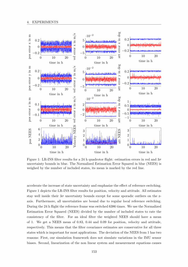
4. EXPERIMENTS
0 10 20−5
0
5·10−2
time in h
velerroryin
m/s
0 10 20
−5
0
5
·10−2
time in h
velerrorxin
m/s
0 10 20
−0.2
0
0.2
time in h
pos
errorxin
m
0 10 20−0.2
0
0.2
time in h
pos
erroryin
m
0 10 20
−0.1
0
0.1
time in h
pos
errorzin
m
0 10 20
−2
0
2
·10−2
time in h
velerrorzin
m/s
0 10 20−1
−0.50
0.51
time in h
atterrorzin
deg
0 10 20
−0.2
0
0.2
time in h
att
erroryin
deg
0 10 20
−0.2
0
0.2
time in h
att
errorxin
deg
0 10 200
1
2
3
time in h
attNEES
0 10 200
1
2
3
time in h
Velocity
NEES
0 10 200
2
4
6
time in h
pos
NEES
Figure 1: LR-INS filter results for a 24 h quadrotor flight: estimation errors in red and 3σuncertainty bounds in blue. The Normalized Estimation Error Squared in blue (NEES) isweighed by the number of included states, its mean is marked by the red line.
accelerate the increase of state uncertainty and emphasize the effect of reference switching.
Figure 1 depicts the LR-INS filter results for position, velocity and attitude. All estimates
stay well inside their 3σ uncertainty bounds except for some sporadic outliers on the z-
axis. Furthermore, all uncertainties are bound due to regular local reference switching.
During the 24 h flight the reference frame was switched 6386 times. We use the Normalized
Estimation Error Squared (NEES) divided by the number of included states to rate the
consistency of the filter. For an ideal filter the weighted NEES should have a mean
of 1. We get a NEES mean of 0.83, 0.44 and 0.09 for position, velocity and attitude,
respectively. This means that the filter covariance estimates are conservative for all three
states which is important for most applications. The deviation of the NEES from 1 has two
reasons: First, our simulation framework does not simulate variations in the IMU sensor
biases. Second, linearization of the non linear system and measurement equations causes
153
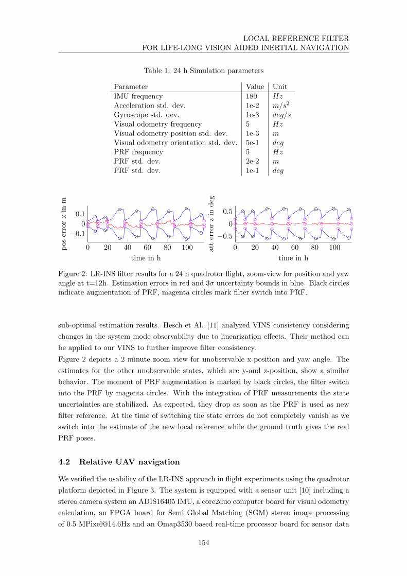
LOCAL REFERENCE FILTERFOR LIFE-LONG VISION AIDED INERTIAL NAVIGATION
Table 1: 24 h Simulation parameters
Parameter Value Unit
IMU frequency 180 HzAcceleration std. dev. 1e-2 m/s2
Gyroscope std. dev. 1e-3 deg/sVisual odometry frequency 5 HzVisual odometry position std. dev. 1e-3 mVisual odometry orientation std. dev. 5e-1 degPRF frequency 5 HzPRF std. dev. 2e-2 mPRF std. dev. 1e-1 deg
0 20 40 60 80 100
−0.1
0
0.1
time in h
pos
errorxin
m
0 20 40 60 80 100
−0.5
0
0.5
time in h
atterrorzin
deg
Figure 2: LR-INS filter results for a 24 h quadrotor flight, zoom-view for position and yawangle at t=12h. Estimation errors in red and 3σ uncertainty bounds in blue. Black circlesindicate augmentation of PRF, magenta circles mark filter switch into PRF.
sub-optimal estimation results. Hesch et Al. [11] analyzed VINS consistency considering
changes in the system mode observability due to linearization effects. Their method can
be applied to our VINS to further improve filter consistency.
Figure 2 depicts a 2 minute zoom view for unobservable x-position and yaw angle. The
estimates for the other unobservable states, which are y-and z-position, show a similar
behavior. The moment of PRF augmentation is marked by black circles, the filter switch
into the PRF by magenta circles. With the integration of PRF measurements the state
uncertainties are stabilized. As expected, they drop as soon as the PRF is used as new
filter reference. At the time of switching the state errors do not completely vanish as we
switch into the estimate of the new local reference while the ground truth gives the real
PRF poses.
4.2 Relative UAV navigation
We verified the usability of the LR-INS approach in flight experiments using the quadrotor
platform depicted in Figure 3. The system is equipped with a sensor unit [10] including a
stereo camera system an ADIS16405 IMU, a core2duo computer board for visual odometry
calculation, an FPGA board for Semi Global Matching (SGM) stereo image processing
of 0.5 [email protected] and an Omap3530 based real-time processor board for sensor data
154
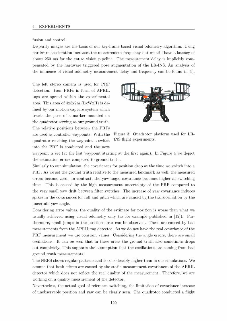
4. EXPERIMENTS
fusion and control.
Disparity images are the basis of our key-frame based visual odometry algorithm. Using
hardware acceleration increases the measurement frequency but we still have a latency of
about 250 ms for the entire vision pipeline. The measurement delay is implicitly com-
pensated by the hardware triggered pose augmentation of the LR-INS. An analysis of
the influence of visual odometry measurement delay and frequency can be found in [9].
Figure 3: Quadrotor platform used for LR-INS flight experiments.
The left stereo camera is used for PRF
detection. Four PRFs in form of APRIL
tags are spread within the experimental
area. This area of 4x5x2m (LxWxH) is de-
fined by our motion capture system which
tracks the pose of a marker mounted on
the quadrotor serving as our ground truth.
The relative positions between the PRFs
are used as controller waypoints. With the
quadrotor reaching the waypoint a switch
into the PRF is conducted and the next
waypoint is set (at the last waypoint starting at the first again). In Figure 4 we depict
the estimation errors compared to ground truth.
Similarly to our simulation, the covariances for position drop at the time we switch into a
PRF. As we set the ground truth relative to the measured landmark as well, the measured
errors become zero. In contrast, the yaw angle covariance becomes higher at switching
time. This is caused by the high measurement uncertainty of the PRF compared to
the very small yaw drift between filter switches. The increase of yaw covariance induces
spikes in the covariances for roll and pitch which are caused by the transformation by the
uncertain yaw angle.
Considering error values, the quality of the estimate for position is worse than what we
usually achieved using visual odometry only (as for example published in [12]). Fur-
thermore, small jumps in the position error can be observed. These are caused by bad
measurements from the APRIL tag detector. As we do not have the real covariance of the
PRF measurement we use constant values. Considering the angle errors, there are small
oscillations. It can be seen that in these areas the ground truth also sometimes drops
out completely. This supports the assumption that the oscillations are coming from bad
ground truth measurements.
The NEES shows regular patterns and is considerably higher than in our simulations. We
assume that both effects are caused by the static measurement covariances of the APRIL
detector which does not reflect the real quality of the measurement. Therefore, we are
working on a quality measurement of the detector.
Nevertheless, the actual goal of reference switching, the limitation of covariance increase
of unobservable position and yaw can be clearly seen. The quadrotor conducted a flight
155
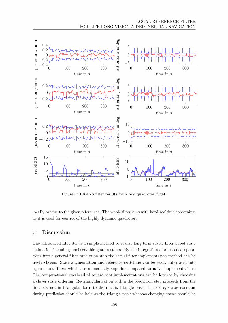
LOCAL REFERENCE FILTERFOR LIFE-LONG VISION AIDED INERTIAL NAVIGATION
0 100 200 300
−0.2
0
0.2
time in s
pos
erroryin
m
0 100 200 300−0.4−0.2
00.20.4
time in s
pos
errorxin
m
0 100 200 300−5
0
5
time in s
atterrorxin
deg
0 100 200 300−5
0
5
time in satterroryin
deg
0 100 200 300−10
0
10
time in s
atterrorzin
deg
0 100 200 300
−0.2
0
0.2
time in s
pos
errorzin
m
0 100 200 3000
5
10
15
time in s
pos
NEES
0 100 200 3000
5
10
time in s
attNEES
Figure 4: LR-INS filter results for a real quadrotor flight:
locally precise to the given references. The whole filter runs with hard-realtime constraints
as it is used for control of the highly dynamic quadrotor.
5 Discussion
The introduced LR-filter is a simple method to realize long-term stable filter based state
estimation including unobservable system states. By the integration of all needed opera-
tions into a general filter prediction step the actual filter implementation method can be
freely chosen. State augmentation and reference switching can be easily integrated into
square root filters which are numerically superior compared to naive implementations.
The computational overhead of square root implementations can be lowered by choosing
a clever state ordering. Re-triangularization within the prediction step proceeds from the
first row not in triangular form to the matrix triangle base. Therefore, states constant
during prediction should be held at the triangle peak whereas changing states should be
156
6. CONCLUSION AND FUTURE WORK
kept close to the bottom of the triangle.
Filter methods are a good choice in applications with hard-realtime constraints and lim-
ited computational resources. Nevertheless, linearization effects degrade the theoretical
optimality of the filter. Depending on the non-linearity of the state switching function
further linearization errors are induced. Nonlinear, iterative fixed lag smoothers would not
suffer from these effects but at the cost of higher computational requirements. Unbounded
covariances for unobservable states would not result in numerical problems for smoothers
as the anchor state prior can be easily changed.
Our experiments demonstrated that the application of the LR-filter to vision aided inertial
navigation results in a long-term stable navigation solution, the LR-INS. In our experi-
ments, we used exteroceptive PRFs. Nevertheless, it is also possible to use directly an
augmented robot pose as reference frame for switching. Furthermore, a filter switch could
be realized only internally. By re-transforming the estimated system states back to the
original global frame, state transformation can be made transparent to external modules
as for example a controller while the increase of state covariances is still limited. It has to
be considered that the covariances refer to the local reference and not to the global.
The LR-INS can be easily combined with other high level navigation solutions as for
example topological navigation or SLAM systems that can also be based on different
sensor domains. Human like navigation from one distinct landmark to the next can be
easily realized at low computational cost. Considering multi-robot scenarios, navigation
relative to a common (changing) reference can be easily realized with a simple navigation
filter.
6 Conclusion and Future Work
We introduced a Local Reference filter approach for stable long-term state estimation
including unobservable states. All required operations, which are state augmentation,
marginalization and transformation are included into a modified filter prediction step.
With this formulation local reference filtering can be integrated into numerically stable
square root filters. We applied the LR-filter to vision aided inertial navigation and devel-
oped the Local Reference Inertial Navigation System (LR-INS).
We conducted a 24 h simulation of the LR-INS with 6386 reference switches. We showed
that the covariances are bound for all states including position and yaw which are un-
observable. The evaluation of the Normalized Estimation Error Squared (NEES) showed
that the filter is conservative but consistent.
We demonstrated the usability of the LR-INS for control of a highly dynamic, inherently
unstable quadrotor with limited on-board processing resources. Switching continuously
its reference frame, the quadrotor can navigate robustly using time delayed relative pose
updates from an on-board stereo-odometry system. The LR-INS was demonstrated to be
suitable for navigation and control of systems with hard-realtime constraints.
As a next step, we will combine our Local Reference Inertial Navigation System with a
157

LOCAL REFERENCE FILTERFOR LIFE-LONG VISION AIDED INERTIAL NAVIGATION
high-level, scalable, topological mapping approach. In this way long-term locally metric
navigation can be realized on resource limited mobile robotic platforms.
Acknowledgments
The authors would like to thank Teodor Tomic (DLR) for the adaptation of his quadrotor
controller for the LR-INS. Furthermore, we would like to thank Michael Suppa (DLR) for
his great support of our work and the fruitful discussions.
158
REFERENCES
References
[1] G. Bierman and C. Thornton. “Numerical comparison of Kalman filter algorithms:
Orbit determination case study”. In: Automatica 13 (1977), pp. 23–35.
[2] P. S. Maybeck. Stochastic models, estimation, and control. Vol. 1. Academic press,
1982.
[3] S. Roumeliotis and J. Burdick. “Stochastic cloning: a generalized framework for pro-
cessing relative state measurements”. In: Proceedings 2002 IEEE International Con-
ference on Robotics and Automation (Cat. No.02CH37292) 2.1 (2002), pp. 1788–
1795.
[4] J. D. Tardos, J. Neira, P. M. Newman, and J. J. Leonard. “Robust mapping and
localization in indoor environments using sonar data”. In: The International Journal
of Robotics Research 21.4 (2002), pp. 311–330.
[5] A. Mourikis and S. Roumeliotis. “A Multi-State Constraint Kalman Filter for
Vision-aided Inertial Navigation”. In: Proceedings 2007 IEEE International Con-
ference on Robotics and Automation (2007).
[6] J. Wendel. Integrierte Navigationssysteme: Sensordatenfusion, GPS und Inertiale
Navigation. Oldenbourg Verlag, 2007.
[7] M. Kaess, S. Williams, V. Indelman, R. Roberts, J. J. Leonard, and F. Dellaert.
“Concurrent filtering and smoothing”. In: Information Fusion (FUSION), 2012 15th
International Conference on. IEEE. 2012, pp. 1300–1307.
[8] A. Martinelli. “Vision and IMU data fusion: Closed-form solutions for attitude,
speed, absolute scale, and bias determination”. In: Robotics, IEEE Transactions on
28.1 (2012), pp. 44–60.
[9] K. Schmid, F. Ruess, M. Suppa, and D. Burschka. “State estimation for highly
dynamic flying systems using key frame odometry with varying time delays”. In:
2012 IEEE/RSJ International Conference on Intelligent Robots and Systems (Oct.
2012), pp. 2997–3004.
[10] K. Schmid and H. Hirschmuller. “Stereo Vision and IMU based Real-Time Ego-
Motion and Depth Image Computation on a Handheld Device”. In: Robotics and
Automation (ICRA), 2013 IEEE International Conference on. 2013.
[11] J. Hesch, D. Kottas, S. Bowman, and S. Roumeliotis. “Consistency Analysis and
Improvement of Vision-aided Inertial Navigation”. In: Robotics, IEEE Transactions
on 30.1 (Feb. 2014), pp. 158–176.
[12] K. Schmid, T. Tomic, E. Mair, P. Lutz, and H. Hirschmuller. “Autonomous Vision
Based MAV for Indoor and Outdoor Navigation”. In: Accepted for Journal of Field
Robotics, Special Issue on Low-Altitude Flight of UAVs (2014).
159

Korbinian SchmidCurriculum Vitae
Born April 23rd, 1983 in Deggendorf, Germany
Research Projects/Work Experience
since 10/09 Research assistant at the Robotics and Mechatronics Center,
DLR, Oberpfaffenhofen/Wessling
Areas of research: Sensor data fusion, inertial navigation
12/07 - 08/08 Diploma thesis at the Robotics Innovation Center, DFKI, Bre-
men
“Embedded system and controller design for a micro AUV”
04/07 - 10/07 Internship at M-Audio Irvindale/USA
04/06 07/06 Student research project (“Studienarbeit”) at the Institute for
Reliable Computing (TUHH)
“Adaptation of a RISC processor architecture for optimized use in a
SoC”
Education
10/02 - 08/08 Technical University Hamburg-Harburg (TUHH)
Computer Engineering (Dipl.-Ing.)
Concentration: Algorithms und Architectures
Network Communication
09/05 - 06/06 Ecole Nationale Suprieure d’Informatique, Electronique et Ra-
diocommunications de Bordeaux (ENSEIRB)
Electrical Enginieering
Concentration: Embedded Systems
09/93 - 07/02 Maristen Gymnasium Furstenzell
Final secondary-school examinations (Abitur)

Language Skills
German Native language
English Fluent
French Fluent
Publications
Journals K. Schmid, P. Lutz, T. Tomic, E. Mair, and H. Hirschmuller. “Au-
tonomous Vision-based Micro Air Vehicle for Indoor and Outdoor Nav-
igation”. In: Journal of Field Robotics 31.4 (2014), pp. 537–570
T. Tomic, K. Schmid, P. Lutz, A. Domel, M. Kassecker, E. Mair,
I. Grixa, F. Ruess, M. Suppa, and D. Burschka. “Toward a Fully
Autonomous UAV: Research Platform for Indoor and Outdoor Urban
Search and Rescue”. In: Robotics Automation Magazine, IEEE 19.3
(Sept. 2012), pp. 46–56
K. Schmid, H. Hirschmuller, A. Domel, I. Grixa, M. Suppa, and G.
Hirzinger. “View Planning for Multi-View Stereo 3D Reconstruction Us-
ing an Autonomous Multicopter”. In: Journal of Intelligent & Robotic
Systems 65.1-4 (2012), pp. 309–323
International
Conferences
J. Englsberger, A. Werner, C. Ott, B. Henze, M. Roa, G. Garofalo,
R. Burger, A. Beyer, O. Eiberger, K. Schmid, and A. Albu-Schaffer.
“Overview of the torque-controlled humanoid robot TORO”. in: Hu-
manoid Robots (HUMANOIDS), 2014 IEEE/RAS International Con-
ference on. Nov. 2014
K. Schmid, F. Ruess, and D. Burschka. “Local reference filter for life-
long vision aided inertial navigation”. In: Information Fusion (FU-
SION), 2014 17th International Conference on. July 2014, pp. 1–8
K. Schmid, T. Tomic, F. Ruess, H. Hirschmuller, and M. Suppa. “Stereo
vision based indoor/outdoor navigation for flying robots”. In: Intelligent
Robots and Systems (IROS), 2013 IEEE/RSJ International Conference
on. Nov. 2013, pp. 3955–3962

K. Schmid, M. Suppa, and D. Burschka. “Towards Autonomous MAV
Exploration in Cluttered Indoor and Outdoor Environments”. In:
Robotics: Science and Systems (RSS) Workshop on Resource-Efficient
Integration of Perception, Control and Navigation for Micro Air Vehicles
(MAVs). June 2013
K. Schmid and H. Hirschmuller. “Stereo vision and IMU based real-time
ego-motion and depth image computation on a handheld device”. In:
Robotics and Automation (ICRA), 2013 IEEE International Conference
on. May 2013, pp. 4671–4678
K. Schmid, F. Ruess, M. Suppa, and D. Burschka. “State estimation for
highly dynamic flying systems using key frame odometry with vary-
ing time delays”. In: Intelligent Robots and Systems (IROS), 2012
IEEE/RSJ International Conference on. Oct. 2012, pp. 2997–3004
Copyright © 2022 FDOKUMEN