
Scalable Group Communication in Tightly Coupled ...
252
Scalable Group Communication in Tightly Coupled Environments Von der Fakultät für Mathematik, Informatik und Naturwissenschaften der Rheinisch Westfälischen Technischen Hochschule Aachen zur Erlangung des akademischen Grades eines Doktors der Naturwissenschaften genehmigte Dissertation Vorgelegt von Diplom-Mathematiker Dirk Trossen aus Bernkastel-Kues Berichter: Professor Dr. Otto Spaniol Professor Dr. Boudewijn Haverkort Tag der mündlichen Prüfung: 11. Juli 2000
-
Upload
khangminh22 -
Category
Documents
-
view
2 -
download
0
Transcript of Scalable Group Communication in Tightly Coupled ...

Scalable Group Communication inTightly Coupled Environments
Von der Fakultät für Mathematik, Informatik und Naturwissenschaften
der Rheinisch Westfälischen Technischen Hochschule Aachen
zur Erlangung des akademischen Grades
eines Doktors der Naturwissenschaften
genehmigte Dissertation
Vorgelegt von
Diplom-Mathematiker
Dirk Trossen
aus Bernkastel-Kues
Berichter: Professor Dr. Otto Spaniol
Professor Dr. Boudewijn Haverkort
Tag der mündlichen Prüfung: 11. Juli 2000


Acknowledgements
I wrote this dissertation during my time as a researcher and Ph.D candidate with the Chair ofComputer Science 4 at the University of Technology Aachen, Germany.
I would like to thank my advisors, Professor Otto Spaniol and Professor Boudewijn R.Haverkort. I am thankful to Professor Spaniol for offering me the opportunity and freedom tochoose my fields of interests and to carry out my ideas in this thesis. I am also grateful to Pro-fessor Haverkort who acts as the co-advisor of this thesis. His comments helped me to improveand finalize my thesis during the last months.
I would also like to thank my colleagues for giving me the opportunity to work in this specificscientific environment for more than four years. It was a pleasant time and I learned a lot. I’dlike to thank Christian Cseh for his fruitful comments to my work, but also for his contributionsto our professional and non-professional talks at ’Downunder’. Furthermore, I want to thank allpeople who were patient enough to read my thesis for correction, namely Christian Cseh,Marko Schuba, Karl-Heinz Scharer, and Andreas Ropers. Moreover, I would also like toexpress my gratitude to the student workers and diploma students. Pascal Papathemelis, ArpadKatona, Karl-Heinz Scharer, Wolf-Christian Eickhoff, Peter Kliem, and Erik Molenaar contrib-uted to my work and this thesis and I enjoyed immensely to work with them. A special thank toNils Seifert who made the protocol implementation of MTP-SO available to me.
A very personal thank you goes to my family and friends. Thank you to Martin for his patienceand understanding during our billiard evening discussions. Thank you also to Andreas andArlett for their moral support as friends and best neighbors. Thank you to my mother and Clausfor their encouragement and love. And finally thank you to my brother Axel and his family fortheir understanding. His son and my godson Kevin showed me impressively how irrelevant aPh.D thesis can be when looking into the eyes of a recently born child.


i
Table of Contents
CHAPTER 1 Introduction 1
1.1 Fields of Research and Goals of the Thesis. . . . . . . . . . . . . . . . . . . . . 21.2 Overview. . . . . . . . . . . . . . . . . . . . . . . . . . . . . . . . . . . . . . . . . . . . . . . . 5
CHAPTER 2 Group Communication Systems 7
2.1 Group Communication Applications . . . . . . . . . . . . . . . . . . . . . . . . . . . 82.1.1 Application Scenarios2.1.2 Requirements2.1.3 Summary
2.2 ITU H.32x . . . . . . . . . . . . . . . . . . . . . . . . . . . . . . . . . . . . . . . . . . . . . . 172.2.1 Service Model2.2.2 Architecture2.2.3 Data Conferencing - T.1202.2.4 Experiments and Results2.2.5 Assessment of H.3232.2.6 Summary
2.3 Group Communication in the Internet. . . . . . . . . . . . . . . . . . . . . . . . . 332.3.1 Multicast in the Internet - MBone2.3.2 Internet Multimedia Conferencing Architecture2.3.3 MBone Tools2.3.4 Assessment of the IETF Approach2.3.5 Summary
2.4 CORBA. . . . . . . . . . . . . . . . . . . . . . . . . . . . . . . . . . . . . . . . . . . . . . . . 452.4.1 Service Model2.4.2 Architecture2.4.3 CORBA 3.0 Extensions2.4.4 CORBA via T.1202.4.5 Assessment of the CORBA Functionality2.4.6 Summary
2.5 Summary . . . . . . . . . . . . . . . . . . . . . . . . . . . . . . . . . . . . . . . . . . . . . . 55

ii TABLE OF CONTENTS
CHAPTER 3 Scalable Conferencing Control Service 59
3.1 Service Model . . . . . . . . . . . . . . . . . . . . . . . . . . . . . . . . . . . . . . . . . . . 603.1.1 SCCS Service Environment3.1.2 Conference Management3.1.3 Multipoint Transfer3.1.4 Distributed Applications Support3.1.5 User Data Marshaling3.1.6 Service Data Units in SCCS
3.2 Protocol Mechanisms . . . . . . . . . . . . . . . . . . . . . . . . . . . . . . . . . . . . . 663.2.1 Protocol Stack3.2.2 SCCS Protocol Environment3.2.3 Services assumed by the Transport Layer3.2.4 Databases in SCCS3.2.5 Protocol Data Units in SCCS3.2.6 Building Topologies3.2.7 Joining Conferences3.2.8 Appending Conferences3.2.9 Inviting Conferences3.2.10 Merging Conferences3.2.11 Splitting Conferences3.2.12 Data Transfer3.2.13 Resource Management Scheme3.2.14 Fast Token Give3.2.15 Static Reconfiguration of Conferences3.2.16 Dynamic Reconfiguration of Conferences
3.3 Implementation Design . . . . . . . . . . . . . . . . . . . . . . . . . . . . . . . . . . . . 963.3.1 Object Model3.3.2 Process Model3.3.3 Activity Model3.3.4 Demo Application
3.4 Assessment of SCCS . . . . . . . . . . . . . . . . . . . . . . . . . . . . . . . . . . . . 1023.5 Performance Evaluation of SCCS. . . . . . . . . . . . . . . . . . . . . . . . . . . 105
3.5.1 Goal of the Performance Evaluation3.5.2 Performance Measures3.5.3 Evaluation Parameters
3.6 Summary. . . . . . . . . . . . . . . . . . . . . . . . . . . . . . . . . . . . . . . . . . . . . . 111
CHAPTER 4 Group Communication Modeling 115
4.1 Motivation . . . . . . . . . . . . . . . . . . . . . . . . . . . . . . . . . . . . . . . . . . . . . 1154.1.1 Requirements
4.2 Related Work . . . . . . . . . . . . . . . . . . . . . . . . . . . . . . . . . . . . . . . . . . 1174.2.1 Stochastic Models4.2.2 Workflow Approaches4.2.3 Behavior Descriptive Approaches4.2.4 Summary
4.3 Group Communication Description Language . . . . . . . . . . . . . . . . . 1264.3.1 Idea of GCDL4.3.2 Formal Description

TABLE OF CONTENTS iii
4.3.3 Examples4.3.4 Load Modeling with GCDL4.3.5 Summary
4.4 Realization with Event-based Simulation . . . . . . . . . . . . . . . . . . . . . 1364.4.1 Using SDL for Process Description4.4.2 Mapping to Event-based Simulation4.4.3 Simulation Framework4.4.4 Summary
4.5 Realization with Petri Nets . . . . . . . . . . . . . . . . . . . . . . . . . . . . . . . . 1454.5.1 Petri Net Introduction4.5.2 Performance Evaluation by SPNs4.5.3 Realization Approach with Petri Nets4.5.4 Realization of the Environment4.5.5 Drawbacks when using Petri Nets4.5.6 Summary
4.6 Summary . . . . . . . . . . . . . . . . . . . . . . . . . . . . . . . . . . . . . . . . . . . . . 154
CHAPTER 5 Resource Management Evaluation 157
5.1 Classification of the Tree Topology . . . . . . . . . . . . . . . . . . . . . . . . . 1585.1.1 Distribution Metric V(Ht)5.1.2 Statistical Considerations
5.2 Evaluation using Simple Probabilities. . . . . . . . . . . . . . . . . . . . . . . . 1595.2.1 Scenario 1 - Uniformly Distributed Floor5.2.2 Scenario 2 - Active User5.2.3 Summary
5.3 Evaluation using SPNs . . . . . . . . . . . . . . . . . . . . . . . . . . . . . . . . . . . 1635.3.1 Scenario - Uniformly Distributed Floor5.3.2 Performance Measures5.3.3 Summary
5.4 Evaluation with Simulation . . . . . . . . . . . . . . . . . . . . . . . . . . . . . . . . 1725.4.1 Scenario 1 - Lecture5.4.2 Scenario 2 - Panel Discussion5.4.3 Summary
5.5 Summary . . . . . . . . . . . . . . . . . . . . . . . . . . . . . . . . . . . . . . . . . . . . . 185
CHAPTER 6 Reconfiguration Evaluation 187
6.1 Scenario 1 - Panel Discussion . . . . . . . . . . . . . . . . . . . . . . . . . . . . . 1886.1.1 GCDL Specification6.1.2 Parameter Settings6.1.3 Results
6.2 Scenario 2 - Separated Sessions . . . . . . . . . . . . . . . . . . . . . . . . . . . 2006.2.1 GCDL Specification6.2.2 Parameter Settings6.2.3 Results
6.3 Scenario 3 - Worst Case Scenario . . . . . . . . . . . . . . . . . . . . . . . . . . 2066.3.1 GCDL Specification6.3.2 Parameter Settings6.3.3 Results

iv TABLE OF CONTENTS
6.4 Computational Effort . . . . . . . . . . . . . . . . . . . . . . . . . . . . . . . . . . . . . 2086.5 Setting Guidelines for the Reconfiguration . . . . . . . . . . . . . . . . . . . . 208
6.5.1 Case 1: Detecting High Active Users only6.5.2 Case 2: Adding Mid Active Users Sporadically
6.6 Summary. . . . . . . . . . . . . . . . . . . . . . . . . . . . . . . . . . . . . . . . . . . . . . 211
CHAPTER 7 Conclusions and Future Work 213
Appendix A SDL Template for GCDL 219
Appendix B Abbreviations 223
Appendix C List of Figures and Tables 229
Appendix D References 233

1
CHAPTER 1
Introduction
Pushed by the development of the global Internet, the need for systems to enable cooperativework among distributed users has become more and more popular in the past fifteen years.Well-known tools like e-mail, file transfer, or especially the World Wide Web have been usedfor asynchronous exchange of information, leading to an exploding usage of the Internet in thepast five years. But also more and more synchronous conferencing applications have been con-sidered in recent research. Some of them led to first products for collaborative group communi-cation between distributed sites. Additionally, the development of these tools is pushed by theincreasing costs and distribution of institutions and companies, since conferencing applicationspromise to be an efficient utility for communication and cooperation between widely spreadedsites. The notion of Computer Supported Collaborative Work (CSCW) has been used in theresearch community to describe a wide spectrum of scenarios of collaborative communicationamong distributed users. In [Lyy90], CSCW is characterized as "...computers in cooperative,coordinated, and collaborative work groups under various task, time and space".
According to the definition presented in [Lub95], synchronous, distributed cooperation takesplace at the same time between distributed sites. As a consequence, a minimal synchronizationbetween the participating users is necessary, both on control and data transfer level. Typicalscenarios are, among others, audiovisual meetings, e.g. in a virtual conference room, a paneldiscussion or lecture via the Internet, or lessons of a school. Applications used in these scenar-ios are videoconferencing tools for audiovisual exchange, shared whiteboards for distributedediting of documents, or shared applications to enable a common view of available data.Despite the variety of the scenarios, most of the required functionality in these scenarios is thesame. Hence, it is desirable to design conferencing systems suited for different situations inde-pendent from the size of the scenarios in terms of participating users, i.e. to enable the provisionof scalable group communication.
For a proper design of conferencing systems, a proper understanding is crucial of what happensin the considered scenarios. On the one hand, a posteriori approaches, like user or field tests,are not well suited for the development of new systems, because they suffer from the longdevelopment cycle to run the tests. On the other hand, a priori approaches, like simulation ofthe system, enable to shorten the development time of conferencing systems. For that, appropri-ate descriptions of the systems are crucial. Due to the complex interactivity in these scenarioscaused by the mapping of more or less complex social rules on distributed environments, sim-


INTRODUCTION 3
assuming simplified traffic characteristics, do not properly reflect the high interactive charac-teristics of typical groupware scenarios, e.g. a panel discussion. The traffic in these scenarios ishighly correlated which has to be taken into account by the used model.
Common for both modeling issues is the necessity to provide a model being suited even forlarge scaled configurations. Using this model should enable the evaluation of specific servicesand mechanisms of the system without implementing and installing the conferencing system onhundreds of machines and running expensive user tests.
In this thesis, two research issues are addressed, namely the design as well as the evaluation ofa conferencing service. On the one hand, requirements of conferencing applications are definedbefore proposing the services as well as the basic mechanisms for a Scalable ConferencingControl Service (SCCS) facilitating the implementation of conferencing applications.
On the other hand, a modeling methodology is presented which provides a framework enablingboth analytical and simulative evaluation of conferencing systems. This framework is used toevaluate two basic mechanisms of the proposed service to demonstrate the feasibility to obtainperformance evaluation results even for realistic groupware scenarios of larger scale.
In the following, both research topics are explained in detail as the main goals of the thesis.
Goal 1: Designing and Prototyping a Scalable Conferencing Control Service
Lots of conferencing systems, products, and standards have been proposed during the past fif-teen years. The scope of these platforms and systems reaches from simple client-server-basedsolutions to fairly complex tree-based provider environments. Lots of research has been per-formed for the provision of a generic conferencing system to facilitate the development of con-ferencing applications following both paradigms concerning the realized topology, namelyloosely and tightly coupled environments.
The first step towards a design and prototype of a generic conferencing service is the definitionof requirements which are necessary to be fulfilled for the implementation of conferencingapplications. In addition to the service requirements, scalability and robustness of the offeredservices and mechanisms are crucial from a technical point of view.
While most of the existing systems fulfil the service requirements, which is shown in a reviewof related work, the scalability issue is only poorly covered. As a consequence, existing plat-forms are restricted either in their applicability with respect to the conference size or in theirservice functionality to provide a higher scalability. Especially loosely coupled solutionsrestrict their synchronization and conference management functionality to improve their scala-bility in terms of supported conference members. Available tightly coupled systems arerestricted to several users only mainly due to inefficient underlying protocol mechanisms.
As a consequence, this thesis proposes the Scalable Conferencing Control Service (SCCS) as atightly coupled solution to fulfil the service requirements by the provision of sophisticated con-ference management functions, multipoint transfer capabilities, and application synchroniza-tion functionality. Beside the design of the services of SCCS, the presented work focuses on ascalable provision of the service, i.e. to use mechanisms which are suited for larger conferencesin terms of participating members. For that, efficient multicast functionality of the underlyingtransport system is extensively used in the service. Moreover, an own resource managementscheme is proposed which allows to improve the responsiveness of the system. For a furtherimprovement of the system, a dynamic reconfiguration algorithm is presented which dynami-cally rebuilds the conference environment during runtime. The services and protocol mecha-nisms are properly defined giving a detailed description of the service and protocol data unitsand the sequence of messages to provide a specific functionality.

4 INTRODUCTION
In addition to the service and protocol definition, prototyping the presented conferencing ser-vice is another big task to demonstrate the feasibility of the proposed service as a generic solu-tion for the development of conferencing applications. For that, the object and process model ofa service implementation is presented as well as core activity diagrams describing the mainfunctionality of the service. Moreover, a shared whiteboard application is presented to demon-strate the main functionality of the service.
As a starting point for the second goal of the thesis, general performance evaluation goals aredefined in terms of performance measures to be obtained and evaluation parameters to be con-sidered during the evaluation. It is the task of the second part of the thesis to provide methodsfulfilling these presented performance evaluation goals.
Goal 2: Modeling Groupware for Evaluation of the Conferencing Service
Modeling groupware scenarios is also an issue which is investigated by a large number ofresearch projects. The proposed approaches reach from simple stochastic models over work-flow management schemes to behavioral methods.
Similar to the first part of the thesis, group communication modeling requirements are definedcovering aspects like communication and user behavior description, but also the ability todefine a sophisticated access control model to distributed objects in the system. Furthermore, itis a crucial requirement for groupware scenario models to enable an analytical as well as a sim-ulative performance evaluation of the system.
The defined requirements are used to assess the related work in the area of group communica-tion models. It is shown that existing frameworks are not well suited for conferencing scenar-ios. Especially the aspect of describing user data and control traffic is only poorly supported byexisting modeling techniques. Furthermore, none of the presented methods provides a sophisti-cated access control model to describe the dynamic change of access rights to distributedobjects in a conferencing scenario. As a consequence, the related work is hardly suited to eval-uate communication and protocol mechanisms of conferencing environments for realisticgroupware scenarios.
To overcome these weaknesses of the related work, this thesis proposes a modeling methodol-ogy for groupware systems. The presented model is based on roles within a scenario interactingaccording to defined rules which are based on a social protocol. The performed actions regard-ing a defined social protocol are assumed to fully describe the communication which is carriedout between the conference members, and the dynamic change of access rights. For the descrip-tion of these actions, standard methods like stochastic Petri nets or specification languages areused. With this framework, analytical as well as simulative evaluation of the underlying confe-rencing system is enabled with an additional structural model of the groupware scenario.
In the presentation of the modeling technique, the object model is defined to statically describethe modeled system. Furthermore, the process model is outlined for the dynamic description ofthe participating entities in the conference in terms of role instances. Finally, a syntax defini-tion of the used description language is presented. A major issue in the proposal of the model-ing framework is the independence of the framework from the realization of the behaviordescription of the different roles. Two examples for this realization are presented enabling theanalytical evaluation of the system by using stochastic Petri nets and providing a simulativeevaluation by using a specification language which is mapped to an event-based simulation.For the latter, a simulation framework is presented which includes an object and process modelresulting in an extendable simulation tool for groupware scenarios.
The main purpose of proposing a modeling framework in the context of SCCS is the evaluation

INTRODUCTION 5
of basic protocol mechanisms of the service. From a quantitative point of view, the evaluationoutlines the achieved improvement when applying the proposed mechanisms even in largescaled scenarios. Hence, the evaluation should prove the applicability of SCCS for a largerscale in terms of the conference size.
From a qualitative point of view, the evaluation demonstrates the feasibility and computationaleffort of different modeling techniques in complex scenarios with respect to the size of the con-ference and the described system behavior. For that, analytical as well as simulative methodsare applied to outline the applicability of the different methods, especially of the proposed mod-eling framework.
1.2 Overview
In the following, the structure of the thesis is presented which is used to reach the describedgoals of chapter 1.1. In figure 1-1, the chapters of the thesis are presented as an overview to
illustrate the relations between the different chapters of the thesis.
The purpose of chapter 2 is twofold. On the one hand, it defines service and technical require-ments of groupware applications for the provision of a generic conferencing service. Further-more, technical definitions and paradigms for conferencing systems are introduced to clarifythe considered environments in the following. On the other hand, chapter 2 gives an overviewof related work in the area of group communication and conferencing systems. Specifically, theH.32x standards of the International Telecommunication Union (ITU) are presented as well asthe Internet Multimedia Architecture preferred by the Internet Engineering Task Force (IETF).Additionally, the Common Object Request Broker Architecture (CORBA) is introduced as amore general distributed platform, which is, as a forth platform, combined with the ITU-T.120
Figure 1-1: Structure of the Thesis
Chapter 3: SCCS
CORBA+
T.120
Chapter 2: Requirements + Related Work
Chapter 4: Modeling Groupware
. . .
Chapter 5: Resource Management Chapter 6: Dynamic Reconfiguration
IETF
H.32xCORBA
?

6 INTRODUCTION
standard as proposed by the author.
All presented group communication environments are described and assessed with respect tothe defined requirements of conferencing applications for a better comparison of the platforms.
Chapter 3 presents the Scalable Conferencing Control Service (SCCS) as a proposal for a gene-ric service to facilitate and accelerate the development of conferencing applications. For that,the considered environment, the provided services, and the used protocol mechanisms are pre-sented with respect to the defined requirements of chapter 2. Beside the definition of the ser-vices and protocol mechanisms, the chapter deals with the presentation of a prototype imple-mentation of SCCS. For this realization, an object oriented approach is chosen. Hence, the usedobject as well as a corresponding process model are outlined. Additionally, activity diagrams ofthe main control functionality of the implementation are depicted. Similar to the related work,SCCS is presented and assessed with respect to the defined service and technical requirementsof chapter 2.
As a preparation for the evaluation of SCCS, this chapter also defines the main performanceevaluation goals, outlines the performance measures which are of interest during the evalua-tion, and considers the parameters of the system and their impact on the evaluation goals.
Modeling groupware scenarios is the topic of chapter 4. Requirements are defined to be fulfil-led by modeling approaches. A review of related work in this area is presented, which leads tothe conclusion that especially communication and access control aspects are only poorly sup-ported by current approaches. Hence, an own modeling framework is proposed fulfilling thedefined requirements and enabling the analytical as well as the simulative evaluation of SCCS.Two realizations for the behavior description in this framework are depicted, namely stochasticPetri nets and protocol specification languages. For the latter, a framework is introducedenabling the event-based simulation of large scaled scenarios with a realistic system workload.
The modeling framework of chapter 4 is used to perform the performance evaluation of mainSCCS mechanisms, namely the resource management and the dynamic reconfiguration, follow-ing the presented evaluation goals of chapter 3.
Chapter 5 performs the first evaluation which compares the proposed resource managementscheme in SCCS with a standardized, centralized scheme of the ITU. The purpose of the evalu-ation is twofold. First, it is meant to demonstrate the applicability of different modelingapproaches. For that, a simple stochastic model as well as the stochastic Petri net and event-based simulation realization of the proposed modeling framework are used. Second, the evalua-tion determines the performance gain which can be achieved when applying the proposedscheme to show the improvement of the responsiveness of the conferencing system even inlarge scaled conferencing systems.
The evaluation of the dynamic reconfiguration, which is proposed in SCCS to reconfigure theconference environment during runtime for optimization, is performed in chapter 6. Conside-ring the first goal of the evaluation, it is demonstrated that the proposed algorithm is able todetect certain activity patterns in the conference and groups the corresponding members nearbyin the conference environment. Furthermore, the improvement of the responsiveness is deter-mined when applying the proposed technique. At last, the impact of the reconfiguration para-meters on the specific performance measures is investigated leading to setting guidelines forthese parameters. Due to the complexity of the dynamic reconfiguration, only the simulativemethod based on the modeling framework of chapter 4 is used for this evaluation.
Chapter 7 concludes the thesis and summarizes the main results of the presented work.

7
CHAPTER 2
Group Communication Systems
A lot of research has been performed during the past fifteen years concerning the topic of Com-puter Supported Cooperative Work (CSCW). Applications and systems ([BeKo98][BrRe98][CBV92][GuPl93][HKS93]) were developed to enable synchronous collaborative work amongdistributed users in a wide spectrum of scenarios, e.g. with different group size or different spe-cific application functionality.
As a common result from this research, several key features of conferencing applications can beoutlined as scenario-independent functionality, namely conference management facilities, sup-port of multipoint transfer of user data, distributed applications support, and provision of com-monly used functionality as standardized application protocols. Furthermore, scalability interms of group size and geographical distribution of entities and robustness of services andmechanisms are big issues in the design of such conferencing services.
As a consequence, some of the research work is focussed on the provision of a generic confe-rencing service (e.g. proposed in [AF91][ADH93][AnBa93][Ar92][BiRe94][Cr90][RBM96])to accelerate and simplify the development of group communication applications. Even stan-dardization organizations in the Telecommunication (ITU) and Internet (IETF) domain definedor are currently defining a common basis for such applications leading to several standards forconferencing environments.
In this chapter, typical group communication scenarios are introduced leading to a definition ofrequirements for the provision of a scalable conferencing service in chapter 2.1. These require-ments are used for the assessment of existing systems as well as for the proposed conferencingservice in chapter 3. As examples for group communication systems, three approaches are pre-sented. The first one is based on the ITU standards for tightly coupled conferencing environ-ments, while the second one covers the research effort in the Internet domain and is morefocussed on loosely coupled scenarios. As a third environment, the CORBA framework isintroduced as a generic platform for distributed applications. For all approaches, the service andsystem model is outlined with a brief introduction of the different system components. Further-more, their main protocol mechanisms are presented.
Additionally, it is evaluated to what extent the conferencing systems fulfil the service and tech-nical requirements. It is shown that all systems lack of certain functionality, e.g. missing scala-bility or poor conference management facilities.

8 GROUP COMMUNICATION SYSTEMS
2.1 Group Communication Applications
Many conferencing tools and applications were developed to cover either generic or specificscenarios to enable collaborative cooperation among distributed users. In this section, three typ-ical synchronous application scenarios are depicted as examples for conferencing among dis-tributed users. These scenarios are used to define requirements, on service as well as ontechnical level, for a generic provision of conferencing facilities.
2.1.1 Application Scenarios
During the past fifteen years, several group communication scenarios have been realized usingdifferent tools and systems. The scenarios cover examples from simple audio/video streamingsituations, e.g. the first audio transmitted IETF meeting in 1991 [CaDe92], over more sophisti-cated Internet lectures ([Eff95][MASH99]) to scenarios for tele-education [BGL96] and tele-working.
In this section, three application scenarios, namely tele-conferencing, tele-education, and tele-working, are presented for a non-formal description of the functionality which is needed from aconferencing system. This description is used to define requirements for the provision of ageneric service to facilitate and accelerate the application development for different scenarios.
Tele-Conferencing
The scenarios, covered by the first environments for group communication, are more or lesspure audiovisual scenarios to support different kinds of distributed meetings. The differencebetween the facets of meetings can be found in the conference size and the degree of the inter-action among the users. The first criteria might range from a few participants only up to severalhundreds or thousands, while the latter range from high interactive conferences to simplestreaming scenarios with almost no interactivity among the participants.
An example for a tele-conferencing scenario with high interaction is a project meeting whichtakes place mostly in small groups. For that, facilities like special conferencing rooms with spe-cial audio/video equipment [TrRao99] are often used. The potential group of users is normallywell-known, i.e. often the conference is announced beforehand according to a given timetable.A conference database might reflect the participating members together with additional infor-mation, e.g. site address or phone number. Functionality like authentication and authorization isneeded to provide secure and restricted access conferences. The users are exchanging videoimages and an audio stream, either mixed from the streams of all participants or selectedaccording to a given scheme. Furthermore, a participant is often defined to conduct the meetingbased on certain social rules for the interaction among the participants, e.g. to indicate a ques-tion before sending the own audiovisual data. Thus, the communication among the conferencemembers takes place according to rules which have to be implemented by the underlying sys-tem.
Especially the progress in multipoint transfer in the Internet raised another kind of tele-confe-rencing scenario, called Large Meeting, in a larger scale in terms of participants. Audiovisualdata is streamed from a central point to a number of participants which might even range up toseveral hundreds or thousands of conference members. Normally, the content of the audiovi-sual data is dedicated to a certain topic and the interactivity is rather small. Examples for thisscenario are Internet lectures ([Eff95][MASH99]) or IETF meetings [CaDe92]. The interacti-vity in these examples is mostly concentrated on the location of the central streaming point.Nevertheless, there might be situations, especially in the lecture example, where a higher

GROUP COMMUNICATION SYSTEMS 9
interactivity back to the presenter is desirable, e.g. to allow questions to the presenter.
The need for extensive interaction increases with the provision of more complex scenarios interms of social rules to be implemented. For instance, for the provision of Panel Discussions orExpert Rounds dedicated to a certain topic, higher interactivity among the participants of theconference must be supported, e.g. questions from the auditorium.
Similar to normal face-to-face meetings, an agenda and conference announcement might bedefined and distributed beforehand. Users might also be invited to join the conference.
Tele-Education
Tele-Education scenarios might be seen as a Lecture scenario with extended functionality. Inaddition to the plain audiovisual information which is sent out to the participants non-real-timedata might be used to emphasize the pedagogical goal of the lecture. For instance, accompany-ing slides might be provided or an application might be shared among the users in terms of con-trol and display content. For the first case, the content of the slides has to be distributed anddisplayed on the different sites. Annotations and saving operations have to be supported. Thus,common formats or at least format conversion functionality have to be provided by the system.
In the latter case, the state of an application has to be shared among different sites. Each localchange is displayed on each participant’s terminal. For interactive learning, the system shouldsupport to give the control of the shared application to certain users.
Depending on the scope of the participating students and the economical interests of the provid-ing institution, functionality for restricted access to the conferences, i.e. authorization, andaccounting of the received information has to be supported.
The scale of tele-education scenarios varies depending on the goal of the session. It might rangefrom several participants only for small distributed group lectures ([BGL96][Eff95]) to largeeducation scenarios with several tens or hundreds of students similar to university lectures.
Tele-Working
An extended version of the small group project meeting is the tele-working scenario. In addi-tion to the exchange of audio/video streams, project data like pictures, slides, or diagrams areexchanged among the participants. Furthermore, similar to the tele-education scenario, a sharedapplication might be used to commonly work together. Due to the sensitivity of the exchangeddata, authorization and authentication functionality is crucial to provide secure exchange. Nor-mally, the scale of the scenario is rather small similar to the size of project teams.
As a summary of the above sketched scenarios, it can be said that conferencing systems have toprovide facilities to support multipoint transfer of streaming and non-real-time data. Further-more, management facilities like invitation and announcement as well as a conference databasehave to be provided. Crucial for the mapping of well-known real-world interactivity to the dis-tributed case is the provision of functions that implement social rules. But also functionality forauthorization, authentication, accounting, and billing is important to protect intellectual pro-perty rights (IPR) in conferencing scenarios. Furthermore, it is important to provide the confe-rencing functionality independent from the size of the conference in terms of participants.
It can be seen from this non-formal functionality description that certain functions are commonin a wide spectrum of scenarios. As a consequence, this non-formal description above can beused to define requirements, both on service and technical level, for the provision of a genericconferencing service.

10 GROUP COMMUNICATION SYSTEMS
2.1.2 Requirements
In the last section, several conferencing scenarios were presented for synchronous collaborativework in distributed systems to describe needed functionality in these scenarios. This section isused to define more formal requirements, both on service and technical level, for a group com-munication system to enable collaborative work among distributed users. These requirementsare used to assess existing systems as well as the service proposed by the author in chapter 3.
2.1.2.1 Service Requirements
As presented in chapter 2.1.1, certain service functionality is requested by conferencing appli-cations even in different scenarios. Conference Management facilities are needed as well asMultipoint Transfer of streaming and non-real-time data. Furthermore, a basic DistributedApplications Support has to be provided together with a pool of Standardized Applicationswhich are commonly used in several conferencing scenarios. These four topics are outlined inmore detail in the following presenting generic functionality to be provided to conferencingsystems to facilitate the development of these applications.
Conference Management
The management of conferences covers four main topics, namely
• management of the conference environment : Functionality to announce and to initiate aconference is needed. For that, advertisement features like a lookup service for conferencesor a dedicated announcement channel are required. Furthermore, a conference setup func-tionality is crucial including features to invite other users to a (running) conference or tomerge conferences by appending or inviting entire conferences. Additionally, splitting capa-bilities can be used to form new sub-conferences out of existing ones. In general, sophisti-cated reconfiguration features have to be provided by the management services. The usedmechanisms for these features highly depend on the used environment in terms of chosentopology (see chapter 2.1.2.2), i.e. functionality for topologies like simple stars is mucheasier to provide than sophisticated tree topology management functionality. Furthermore,the conference management should enable conducted conferences in the sense that a dedica-ted user is defined having special management rights, like expelling other users from a run-ning conference or denying the access to a conference.
• provision of a common conference database : A common conference database is crucial forthe provision of membership information containing commonly used information (like nam-ing and location information) as well as extended, scenario-specific data.
• handle security aspects : For the provision of secure and restricted conferences, authoriza-tion and authentication have to be provided as well as mechanisms to support secure transferof user data.
• manage network resources : The conferencing architecture should provide facilities to con-trol the network resources, e.g. by providing a defined and guaranteed Quality of Service(QoS [Part93]).
Multipoint Transfer
Services for multipoint transfer of user data cover the aspect of secure, location-transparentexchange of user data among several conference members independent from specific networksand endsystems. The services should provide communication patterns which range from one-

GROUP COMMUNICATION SYSTEMS 11
to-one to many-to-many communication (see figure 2-1).
The management of security aspects is covered by the conference management services. How-ever, the provision of the secure transfer has to be implemented by the multipoint transfer ser-vice. For the location transparency of the transfer, a transport layer abstraction has to beprovided to address a certain user group in the conference. This transport layer abstractionshould also allow to use different kinds of transport facilities depending on the transmitted datatype, e.g. streaming protocols for real-time audiovisual data. As a consequence, multipointtransfer on the conference layer should not duplicate transport layer functionality.
The multipoint transfer services should also enable the transfer of user data among heteroge-neous endsystems. For that, marshaling capabilities [Tan96] should be supported by the ser-vice to provide a common transfer syntax of the exchanged user data.
The support of different kinds of networks is shifted to the transport layer when using the facil-ities of this layer. Thus, the internetworking aspect highly depends on the used transport layer.
Distributed Applications Support
This topic covers features to facilitate the operation of distributed applications. This means inparticular the provision of mechanisms to synchronize the state of applications. It enables acoordinated concurrent access to shared resources and data like hard-discs or printers but alsoto objects or streams. The access to resources can be abstracted by the notion of a floor whichwas introduced by turn-taking psychological studies ([KPMW94][Walk82]) and is defined as"the right to speak in a ...body, e.g. a parliament" [Coll88].
Pure audiovisual conferencing scenario often need just a loose floor control, e.g. selecting thecurrent speaker based on the audio volume, as proposed in [Scho96]. For more complex accesscontrol patterns, Dommel et al. proposed a floor control protocol in ([DoGLA95][DoGLA98])with basic operations like allocate, ask for, and pass a floor. These floors might be definedexclusively or non-exclusively. Additionally, with a member query operation, it was shown thatthese operations are sufficient to abstract access control and conventional turn-taking in confe-rencing scenarios. Thus, this functionality should be provided by a generic conferencing ser-vice for the access control in distributed applications.
Standardized Applications
Conferencing applications use the features offered by a generic conference service. Certainapplication functionality is commonly used in different conferencing scenarios. For the provi-sion of interoperability among applications within a given scenario, a standardization of theapplication functionality is crucial. This has to be provided by a generic conferencing service toaccelerate the development of scenario-specific applications. Relevant widely-used applicationfunctionality in the conference context are, among others, shared whiteboard, audio and videoconferencing, multipoint file transfer, chatting, and shared application functionality.
Figure 2-1: Communication Patterns for Multipoint Transfer
1:1 1:n m:n
.
.....
.
..

12 GROUP COMMUNICATION SYSTEMS
As a summary, the following table shows the service requirements to be covered by a genericconferencing service.
2.1.2.2 Technical Requirements
Beside the services themselves, a generic conferencing system should fulfil certain technicalrequirements which are the foundation of protocols in general, namely robustness and scalabi-lity. Furthermore, several realizations of the conferencing environment are outlined with regardto the robust and scalable provision of the services.
Robustness
A crucial issue in conferencing environments is the robustness of the system. Features of a con-ferencing service as well as the implementation of these have to be provided in a robust mannerto ensure the acceptance by the users.
On service level, the management functionality of the conferencing environment should beoffered in the sense that the existing conference status should not be affected when applyingany changes on the conference environment during the runtime, e.g. when joining or deletingusers, or merging existing conferences. Otherwise resolving mechanisms should be provided. Itis worth mentioning that it is not a solution to improve robustness of the services by removingcertain critical functionality from the service repertoire. A minimal management functionalityis crucial to provide natural operations within conferencing scenarios, e.g. join/leave mecha-nisms without affecting the rest of the conference.
Robustness on protocol level is even more difficult to provide. Communication among distrib-uted users involves a number of different endsystems, configurations, and networks. Lots ofcomponents are present in the conference, either directly, e.g. the endsystems, or indirectly, e.g.network components like routers. As a consequence, the protocol mechanisms which are usedin these multipoint end-to-end scenarios have to be designed very carefully to provide robust-ness on the protocol level. Functionality to recover from errors on lower layers, e.g. caused bynetwork components or transport layer failures, is crucial to guarantee a robust conferencingenvironment. Fault tolerance for certain parts of the conferencing system might be used toimprove the robustness of the entire system.
Aspect Features
Conference Management - management of conferencing environment- conducted conferences- conference database management- security management- network resources management
Multipoint Transfer - location-transparent addressing scheme- transport layer abstraction- provision of media-dependent transport layers- support of heterogenous networks and endsystems
Distributed Applications Support - access and floor control
Standardized Applications - audiovisual functionality- shared workspace- shared application
Table 2-1: Conferencing Service Requirements

GROUP COMMUNICATION SYSTEMS 13
Furthermore, the protocol mechanisms have to be defined and specified correctly using state-of-the-art technology. There are several methods to show the robustness on protocol level interms of correctness of the provided functionality using testing and validation methods. Thesemethods can be used to validate a protocol specification either defined as a finite-state automatadescription (using SDL [Z100a] or LOTOS [ISO8807]) or by using Message Sequence Charts(MSC [Z120]). For the first kind of specification, test cases can be defined using notations likeTTCN [X292] which define the input workload to the system to test. The results are comparedto the requirements of the system denoting the expected behavior.
Methods proposed in [AHP96] or [ObKe99] use MSCs for testing a protocol specified by thesequences of messages. Furthermore, formal verification methods like proposed in ([CrRe99][CrRo99]) might be used to check deadlock as well as lifelock freedom of the protocol mecha-nisms in a conferencing environment.
Scalability
The second crucial issue in the provision of a generic conferencing service is scalability interms of conference group size and geographical distribution. The conference managementshould be able to handle small as well as large conferences in terms of members ranging fromfew participants to several hundreds or thousands. Thus, the mechanisms for database adminis-tration and environment management have to be designed for a larger scale to provide a genericmechanism.
Another sensitive area in terms of scalability is the multipoint transfer of user data. The trans-port mechanisms for media streaming and reliable data transfer have to be designed to enableefficient and timely delivery of the data to the participating terminals even in large scaled sce-narios. Efficiency also includes optimal usage of network resources, e.g. usage of underlyingmulticast mechanisms. Furthermore, the timing constraints of certain media types, e.g. audiovi-sual data ([Part93][StNa95]), have to be taken into account for the timely delivery of the dataeven in large scaled scenarios.
The access control to distributed objects is another critical scalability issue. In general, sce-nario-dependent access control functionality is implemented using floor control. Related work,presented in ([DoGLA95][Er99][GrSt85][IKW98][KPMW84][Lyy90]), pinpoints the impor-tance of time-constrained floor control in scenarios with a need for tight control among usersand objects independent from the size of the conference. The presented results emphasize theeffect of time-constrained floor control on the acceptance by the participating users. Thus, thefloor control mechanisms have to be designed for smaller and larger scaled scenarios due thedirect impact on the responsiveness of the conferencing system.
It can be summarized that several mechanisms have to be considered when designing a confe-rencing service suited for small as well as for large scaled scenarios. These mechanisms can besupported by lower layers, e.g. network or transport layer, but have also to be considered on theconferencing layer itself.
Chosen Topology Environment
From a service point of view, the chosen topology for the realization of the services is not anissue which has to be taken into account. But from a scalability point of view, the chosen topol-ogy is crucial for the provision of certain services in a scalable manner. Depending on the givenscenario, the selection of a certain topology might be useful for a higher scalability, especiallyif some services, like management functionality, are not needed in the scenario.
In the following, a comparison of two paradigms for conferencing environments are presented,

14 GROUP COMMUNICATION SYSTEMS
namely tightly coupled and loosely coupled environments, outlining the connectivity amongconference members. The first request dedicated point-to-point connections among conferen-cing entities, while the latter do not communicate via point-to-point connection but by usingmulticast-based exchange of control and user data. It is briefly demonstrated what the advan-tages and disadvantages of both paradigms are. For the tightly coupled environments, two dif-ferent topology realizations are outlined additionally, namely tree-based and central servertopologies.
- Tightly coupled vs. Loosely coupled Environments
Conference environment topologies are usually built according to two different paradigms withrespect to the coupling of the participating users [HCBO99]. Tightly coupled environmentsbuild the topology by interconnecting the participating endsystems with point-to-point connec-tions for at least transferring control traffic via this topology. Normally tree or central servertopologies are used. For the transfer of user data, multicast capabilities might be used or thecontrol topology might be used as well.
The advantage of using tightly coupled environments is the simple provision of a membershipcontrol in terms of a conference memberlist and management functions like admitting or expel-ling members. Additionally, the restricted access to the conference is easy to implement usingcentral authorization. Furthermore, the implementation of floor control mechanisms is simpli-fied when using tightly coupled environments [DoGLA95] due to the stringent routing betweenthe point-to-point connections within this environment.
The main weakness of a tight coupling is the bad scalability in terms of conference size. This isbecause the number of point-to-point connections increases. As a consequence, the realizationof the management for large tightly coupled environments is very difficult, especially for sys-tems with several tens or hundreds of users. Moreover, error recovery mechanisms have to beprovided to ensure tolerance in the case of connection errors like node failures and to improvethe reliability of the conferencing system. The integration of these mechanisms complicates thedesign and development of a generic conferencing system with a high reliability of the pro-vided services. Another disadvantage of this environment approach is, that for the support ofmulticast transport layers, a parallel communication infrastructure has to be established by theconferencing system. Using the same topology, which means to map multipoint to point-to-point traffic, results in an inefficient usage of network resources and therefore in an even worsescalability of the approach.
Loosely coupled environments do not use point-to-point connections, but communicate mostlyusing multicast transfer. For that, the participants listen to a dedicated multicast group as shownin figure 2-2. The entire control traffic is sent to this multicast group in addition to the user data.
Figure 2-2: Tightly coupled vs. Loosely coupled Environments
Tightly coupled Loosely coupledmulticast cloud


16 GROUP COMMUNICATION SYSTEMS
top most node. Standards like the T.120 (see chapter 2.2.3 and [T120]) or the proposed confe-rencing service in chapter 3 use this approach to build tightly coupled topologies. Due to themore complex topologies which may be built with trees, more sophisticated management func-tionality has to be implemented. This complicates the design and development of services withthe support of these topologies.
But concerning the scalability of the chosen topology in terms of conference size and geograph-ical distribution of the participating endsystems, conferencing services based on tree topologiesscale much better.
In terms of conference size, the central server model emphasizes the bottleneck of the system ifthe size of the conference is increased. The number of connections which have to be adminis-trated by this server grows linearly with the number of participating endsystems. Normally, thenumber of threads in the central server implementation grows as well. Thus, the central serverwould reach a saturation point of supported endsystems, depending of course on the perfor-mance of the central entity. In addition to the bottleneck problem, the central server is also thesingle-point of failure in the system.
When using tree topologies, the central bottleneck can be avoided or at least reduced bydeveloping appropriate mechanisms for the routing of data within the topology. In fact, the pro-posed conferencing service in chapter 3 uses a newly developed routing scheme to reduce theload in the topmost node. Furthermore, error recovery from failures in the topmost node iseasier to provide for a reduction of the single-point of failure problem.
Furthermore, in terms of geographical distribution of participating endsystems, a central serverapproach might lead to problems, especially in terms of delay. In figure 2-3, a conferencingscenario is presented with a large, world-wide, geographical distribution of the endsystems. Inthis example, the central server is located in Europe as a more or less optimal solution for theplacement of this server in terms of mean delay for the control data. The right picture outlines apossible tree topology for this scenario.
But consider the case, that most of the communication would take place among "local" users,e.g. in South and North America. Despite this local communication, all requests have to be sentto the central point in Europe, instead of being served in the local area. This effect is empha-sized when considering more users in the scenario. When using tree topologies, routingschemes might be used to handle requests locally. If the tree is built according to the geograph-ical distribution (e.g. shown in figure 2-3 right), this might lead to smaller delays for controlrequests in the conference. Hence, this results in a higher responsiveness of the system.
In this thesis, conferencing systems for tightly coupled environments are presented using tree
Figure 2-3: Central Server vs. Tree Topology

GROUP COMMUNICATION SYSTEMS 17
topologies instead of following the central server approach. But it is obvious that these systemsalso support central servers as a degenerative form of a tree.
2.1.3 Summary
This section presented a brief survey of conferencing application scenarios in the area of tele-conferencing, tele-education, and tele-working. The last two scenarios can be seen as moresophisticated extensions of plain tele-conferencing scenarios by adding functionality like dis-tributed editing of documents or controlling shared applications. Many conferencing systemshave already been realized to provide more or less specific functionality for specific scenarios.
As a common result from the overview of conferencing scenarios, several key features of con-ferencing applications were outlined as scenario-independent. This led to the definition of ser-vice requirements for a generic conferencing service provision covering several key aspects,namely conference management, multipoint transfer of user data, distributed applications sup-port, and provision of standardized commonly used functionality. Beside these service require-ments, some technical points were outlined which are of interest when designing anddeveloping conferencing services. Robustness and scalability of provided services and mecha-nisms were pinpointed as crucial issues for the development of a conferencing service. Further-more, endsystem coupling and topology aspects were discussed in this section under theconstraint to fulfil the required services in a scalable manner.
The defined requirements are used as a basis for the presentation as well as the assessment ofexisting conferencing systems which are presented in the next sections. Furthermore, theapproach proposed by the author in chapter 3 is designed and assessed with respect to the defi-ned service and technical requirements.
2.2 ITU H.32x
The International Telecommunication Union (ITU) initiated the standardization for audio/video and data equipment enabling the cooperative communication among several users in thelate 1980s. This standardization effort led to the ITU-T recommendations of the H.32x series.Each of these recommendations is an umbrella standard consisting of several other protocolsfor a certain functionality. The first standard suite H.320 [H320] was finished in 1990 for theusage in narrowband ISDN systems. In 1995, this standard was adapted to broadband ISDNsystems leading to the definition of the H.321 series [H321]. The standard suites H.322 [H322]and H.323 [H323] were defined for Local Area Networks (LANs) which provide quality of ser-vice (QoS) guarantees or not respectively. Due to its IP foundations, the standardization effortsfor the H.323 standard increased in the past two years to emphasize its importance for the usagein the Internet.
In the following chapter, the H.323 is introduced in more detail, starting with the service modelof an H.323 system. After that, the architecture of the system is presented. Some of the archi-tectural views are common to the other H.32x systems, some are special for this kind of envi-ronment. Additionally, the data conferencing part of an H.32x system, standardized in the ITU-T T.120 recommendation series [T120], is presented in more detail providing data conferencingand multipoint data transfer functionality. The section will conclude with a short assessment ofthe H.323 system regarding the requirements defined in chapter 2.1.2.

18 GROUP COMMUNICATION SYSTEMS
2.2.1 Service Model
As mentioned in the introduction, H.323 is defined as an umbrella standard specifying the com-ponents to be used within an H.323-based environment. For the different components, existingstandards are used providing the functionality, i.e. the services of an H.323 system. Due to thestandardization history of the H.32x protocol series, the provided services in an H.32x systemare divided in services for audio/video and data conferencing. As a result of this separation,some functionality is implemented twice, especially for conference management and multipointtransfer of data, while other functionality is only defined for a certain part, either for data oraudio/video conferencing. In the following, the services of an H.323 system are introducedbased on the requirements defined in chapter 2.1.2.
2.2.1.1 Conference Management
The H.323 provides conference management functionality for audio/video conferences usingthe call signaling functionality of H.245 [H245]. This standard provides call set-up and calltransfer of real-time connections. Multipoint real-time conferences are also supported, but thisrequires additional equipment in the H.323 environment (see chapter 2.2.2). Users may join orleave existing conferences. The provided functionality is very similar to modern telephonyequipment, which results from the origin of the standardization as a basis for video telephony.
For the data part of a conference, the conference management of the T.120 recommendation[T120] is used (see section 2.2.3.6). This standard suite provides the establishment of data con-ferences (e.g. for shared whiteboard or shared application functionality), either as a conductedor unconducted conference. Each T.120-based end system can be a member of one or moreconferences defining the highest level of a communication relation. Each conference consists ofone or more sessions in which several application protocol entities (APEs) are grouped.
Existing conferences may be merged leading to a release of existing resource identifiers in oneof the merged conferences. More sophisticated reconfiguration functionality is not imple-mented. Queries for existing conferences on an endsystem are also supported. A domain-widelookup service for conferences is not provided. The T.120 also includes a conference databaseof all members, applications, and resources in the conference.
The set-up for a data conference is incorporated in the call set-up procedure of an H.323 confer-ence using the functionality of the H.245 signaling. Data conferences within an H.323 systemcan be set-up independently from audio/video conferences. For the provision of secure confer-ences, the H.235 standard [H235] is used. The H.323 also supports address translation betweenaliases and IP addresses and bandwidth management within a LAN for controlling the networkbandwidth e.g. by restricting the number of established conferences.
2.2.1.2 Multipoint Transfer
For multipoint conferencing for audio/video, the H.323 provides centralized conferences usingthe functionality of a central entity, called Multipoint Communication Unit (MCU, see chapter2.2.2.4). This device performs the audio mixing, video switching, and re-distribution of theresulting combined audio/video stream. Decentralized conferencing, using multicast technol-ogy of the underlying network, is supported for the transmission of the audio/video data. Thecontrol processing of the conference, e.g. selection of the video stream, is still located in thecentralized MCU using the control channel of the H.245 protocol [H245]. But processing theincoming audio/video stream has to be implemented by the terminals themselves. H.323 also

GROUP COMMUNICATION SYSTEMS 19
supports mixed conferences consisting of a centralized and decentralized part.
For the data part of an H.323 conference, the T.120 recommendation provides a channel con-cept as an abstraction for multipoint transfer. These channels offer a flexible concept foraddressing different groups of receivers within a conference. Three different kinds of channelsare supported, namely user identification channels, public channels, and private channels.
Users are identified by a user identifier which corresponds to a unique channel number. Thischannel identifier serves as an address for point-to-point communication within the domain,e.g. for notification of detaching other users.
Multipoint channels are multi-member channels. These channels can be used to send data to asubset of users within a conference. Send and receive access to individual multipoint channelsmay be controlled by a private channel mechanism. A user may convene a private channel,becoming the private channel manager of this channel. The private channel manager mayinvite other users to join the channel or force a user to leave the channel. The admitted usersmay join a dedicated channel. Public channels may be joined and created by any member of theconference. By joining a combination of channels, a user can select to receive messages sent tothese channels and ignore message sent to the other channels. An application does not needjoining to a channel to send on it, but must be member of it to receive data. Channel mem-bership is maintained in a distributed fashion.
It is not standardized how the channel concept for data conferencing is mapped to the underly-ing network. Usage of multicast technology is not mandatory. Different network profiles aredefined to provide a wide range of possible networks to be used, ranging from ISDN, B-ISDN(ATM) to IP networks.
Two different modes of multipoint data transfer are provided by the T.120 using the abovedescribed channels. When using the simple send data service, data from different senders mayarrive in a different order at each receiving site, because the data is sent via the shortest routewithin the underlying communication system. Uniform send data transfer is necessary whendata is being sent simultaneously from several senders, but must be received in the samesequence by all receivers.
Furthermore, a simple priority model for data transfer is supported. Control data is transmittedwith highest priority. Three additional priorities are possible.
2.2.1.3 Distributed Applications Support
For the audio/video part of an H.323 system, distributed conferencing is supported by synchro-nizing several audio/video streams if an MCU (see chapter 2.2.2.4) is available. For this, thepacketization functionality of the H.225.0 [H225] is used. Two video conferencing modes arestandardized, which are speaker-selection (the active speaker is selected) or conducted mode (aconference conductor selects the active video stream). Both modes are implemented in theMCU entity providing appropriate mixing, coding, and synchronization functionality.
For the data conferencing part, the notion of tokens is used to realize synchronization betweendistributed applications for the floor control [DoGLA95] (see chapter 2.1.2.1). Tokens can beallocated exclusively (grabbed tokens) or non-exclusively (inhibited tokens). It can be asked forthe status of a token. Furthermore, the token can be given to another user by the (exclusive)owner of the token, e.g. after asking for it (token please). It is not possible to ask for a list ofcurrent token holders.
It can be seen that simple floor control operations like floor-asking and floor-passing are pro-


GROUP COMMUNICATION SYSTEMS 21
2.2.2.1 Terminal
The terminals within an H.323 environment are the endpoints of the communication providinga real-time two-way communication as the minimal functionality of an H.323 system. TheH.323 recommendation defines the technical requirements in terms of supported componentswithin an H.323 terminal. The components are divided in audio, video, data, and control.
Table 2-2 shows the different media types and the corresponding ITU recommendations whichdefine the appropriate functionality. It can be seen that for the mandatory audio transmissionlots of different codecs are supported. Furthermore, the optional video transmission part allowsseveral video codecs supporting different formats. For the optional data part (like shared white-board or shared applications), the T.120 standard is used (see section 2.2.3).
During setting up a connection using an H.323 terminal, the capabilities of the connecting ter-minals are exchanged and the minimal supported capability set is chosen for the connection.For that, the second mandatory component of the terminal is used, defined in the H.245 stan-dard [H245], responsible for control functionality. As a second control component, the H.225.0[H225] is used for media stream packetization and support of the Real-time Transport Protocol(RTP [RFC1889]). Figure 2-5 shows the different components in the H.323 terminal.
2.2.2.2 Gateway
The purpose of an H.323 gateway is to reflect the capabilities of an H.323 endpoint to other
Media Required mandatory recommendation optional recommendation
Audio Yes G.711 G.722, G.723, G.728, G.729
Video No H.261 H.263
Data No T.120 -
Control Yes H.245, H.225.0 RAS
Table 2-2: Supported Media Types of an H.323 Terminal
Figure 2-5: Components of an H.323 Terminal
H.225.0H.225.0
H.245 Control
H.245 Control
Video codec
Audio codec
T.120
Receivepath delay
Data
Video
Systemcontrol
Audio
H.225.0 RAS Control
H.225.0 RAS Control
H.225.0 Call Control
H.225.0 Call Control
EthernetToken Ring
LAN

22 GROUP COMMUNICATION SYSTEMS
H.32x systems and vice versa. This is realized by translation functionality between transmis-sion formats (e.g. H.225.0 to H.221 [H221]) and communication procedures (e.g. H.245 toH.242 [H242]). In addition, the gateway also performs translation procedures between differentaudio and video codecs. Gateways are located at the edge of the LAN environment to enableconnectivity to Wide Area Networks (WANs) or ISDN-based H.32x systems. If there is noconnectivity to these systems, the gateway functionality is not needed in an H.323 system,because H.323 endpoints may communicate directly with other H.323 systems. However, it ispossible to transparently connect two LAN-based H.323 systems, bypassing some routers or alow bandwidth link. This gateway functionality is not provided by H.323 gateways.
Moreover, gateways provide multipoint control functionality, e.g. by acting as an MCU at theH.323 side or as a T.120-based data provider in the system. Gateways are normally registeredwith the H.323 gatekeeper to indicate the available functionality. Many capabilities of an H.323gateway are left to the designer and vendor of the gateway, e.g. the number of supported H.323terminals at the gateway is not standardized.
It can be seen that the gateway technology allows an H.323 system to extend the connectivity toother H.32x-based systems to provide a larger basis for collaborative working.
2.2.2.3 Gatekeeper
An H.323 gatekeeper plays a managing role within an H.323 system. The collection of H.323equipment managed by a single H.323 gatekeeper is defined as the H.323 zone (see figure 2-4).
Gatekeepers provide two important housekeeping functions which help to preserve the integrityof the network. The first one is the translation of addresses between LAN aliases for terminalsor gateways and IP addresses using a simple registration mechanism.
The second function is the management of bandwidth within the network. For instance, this canbe realized by limiting the maximum number of conferences in the network or the streamingbandwidth for each conference based on managing the bandwidth. It is outside the scope of thestandard how to determine the available bandwidth in the system.
A gatekeeper is optional for an H.323 system. However, if a gatekeeper is present, the servicesaddress translation, admission control, bandwidth control, and zone management are manda-tory. Furthermore, a gatekeeper may provide optional services, namely call control signaling,call authorization, bandwidth management, and call management. For further information ofthese services, see [H323].
2.2.2.4 Multipoint Control Unit (MCU)
The MCU within an H.323 environment consists of two functional components. The first one isthe Multipoint Controller (MC) being responsible for handling H.245 negotiations between ter-minals during set-up of the conference to define a common capability set of the participatingsystems. The MC does not deal with media streams. This is done by one or more Media Proces-sors (MPs) which are responsible for audio mixing and video switching based on the chosenpolicy (speaker selection or conducted mode). The functionalities of the MC and the MPs canbe realized in dedicated hardware or coexist in other elements like an H.323 terminal.

GROUP COMMUNICATION SYSTEMS 23
2.2.3 Data Conferencing - T.120
The data communication part within an H.323 system is provided by a parallel data conferen-cing system defined in the T.120 recommendation [T120]. Similar to the H.323, this is anumbrella standard consisting of several other standards providing the appropriate functionality.
In chapter 2.2.1, the service model of an H.323 system was presented containing also the ser-vices for data conferencing. In addition to the service model, this chapter outlines the systemmodel of a T.120-based system enabling multipoint data conferencing. For that, the differentcomponents of a T.120 system are presented. Two of the components, which provide the confe-rence management, multipoint, and distributed applications support functionality, are depictedin more detail.
2.2.3.1 System Model of T.120
The T.120 system model is comprised of the communication infrastructure and the applicationprotocols using this infrastructure. In the T.121 recommendation [T121], an application tem-
plate is defined for the design of T.120-compliant applications, which is shown in figure 2-6.The grey shaded part depicts the communication infrastructure which is composed of threecomponents: Generic Conference Control (GCC), Multipoint Communication Service (MCS)and Network Profiles. It provides multipoint connections with reliable data delivery within aconference context. It can accommodate multiple independent applications using the same mul-tipoint environment within a single conference. Multipoint connections are mapped to theunderlying communication infrastructure which can be any combination of circuit switchedtelecommunication networks and packet-based LANs.
In the following, a short overview of the different components of the system model is given.
2.2.3.2 User Applications
User applications are not within the scope of the T.120 standard series. They are assumed to bemultipoint aware and designed to use the services of the Generic Conference Control (GCC)and the Multipoint Communication Service (MCS) as the main parts of the communicationinfrastructure. Furthermore, the applications may use any combination of standardized andnon-standardized protocols to communicate with peer user applications.
Figure 2-6: ITU Protocol Suite T.120
Network Profiles
StandardAPEs
Non-StandardAPEs
Node Controller
Network Layer
User Applications
Generic ConferenceControl
Multipoint Communication Service

24 GROUP COMMUNICATION SYSTEMS
2.2.3.3 Application Protocols
Application protocol entities (APEs) comprise a set of services for commonly used applicationfunctionality and the provision of associated protocol data units for peer-to-peer(s) communica-tion. These may be proprietary (non-standard) or standard application protocols. The T.120series includes a set of application protocols designed to support facilities for data conferen-cing. These protocols define a minimum requirement in order to ensure interworking betweendifferent implementations like multipoint binary file transfer (T.127 [T127]), audiographicprotocol for still image viewing and annotation (T.126 [T126]), or application sharing (T.128[T128]). Furthermore, a simple text chat (T.134 [T134]) functionality is defined. An applica-tion protocol is divided into two functional components: the Application Resource Manager(ARM) providing functionality common to all protocols and the Application Service Element(ASE) providing the application specific functionality. The generic application template(T.121 [T121]) proposes an implementation framework for T.120-based applications using pro-vided application protocols.
2.2.3.4 Node Controller
In a T.120-based system, the Node Controller provides the T.120 management function at a ter-minal or Multipoint Control Unit (MCU). It is the role of the Node Controller to issue the prim-itives to the GCC which starts and controls the communication session. The node controller isnot within the scope of the T.120 recommendations, but the interfaces to communicate to theGCC and other standardized elements are defined by the corresponding service primitives inthe appropriate standards.
2.2.3.5 Multipoint Communication Service (T.122/T.125)
The main part of the T.120 communication infrastructure is defined in the T.122 standard[T122] as a generic service designed to support highly interactive multimedia conferencingapplications. It supports full-duplex multipoint connections with a wide variety of addressingpatterns with a provision of several networks types. A channel concept is introduced as anaddressing scheme for multipoint data transfer (see chapter 2.2.1). Additionally, services forsynchronization of distributed applications are provided to realize floor and access control ingroup communication scenarios. For that, a token concept is provided (see chapter 2.2.1). Fur-thermore, two different modes of data transfer (uniform and simple mode) are realized by mul-tipoint routing within MCS, and priorities for user data are supported. The MCS assumes atransport protocol which is conform to an OSI TP4 [X224] to enable network independence.Different network profiles are defined in the T.123 standard [T123] (see chapter 2.2.3.7) provi-ding TP4 functionality over different networks.
The mechanisms used in the MCS to realize the services as mentioned above are defined in theT.125 recommendation [T125]. This recommendation defines the MCS protocol mechanismsby introducing an informal description of the mechanisms combined with a formal definition ofthe exchanged protocol data units together with an SDL [Z100a] specification of the protocol.In the following, the system model and main mechanisms are described informally.
System Model of T.122
The MCS provides its services, namely multipoint communication and token management,within an closed administration area called MCS domain. Applications attach to a domain for

GROUP COMMUNICATION SYSTEMS 25
using the services of the MCS.
For the realization of the services, MCS providers are located within this domain offering theservices of the MCS to applications which are attached to one of these providers. Domains areidentified locally via a unique domain selector. The MCS providers in a single domain areinterconnected hierarchically as a tree topology via MCS connections. Each MCS connection isrealized via reliable transport connections. The uppermost provider of the tree topology iscalled MCS Top Provider. It is possible that a dedicated MCS provider is located in severaldomains. However, inter-domain communication is not supported due to the closed character ofan MCS domain. Figure 2-7 shows an example for the domain concept of the MCS and its rea-lization as a tree topology.
Domain Management
MCS provides simple functionality to manage the MCS domains. Domain parameters aredefined for each MCS domain. These parameters are set during creation of the domain and areexchanged among the providers when creating a new MCS connection, i.e. when adding a newprovider to the domain. For instance, the domain parameters include values for the maximumheight of the domain tree, maximum number of tokens, channels, and users. Furthermore, whenconnecting two domains between MCS providers via MCS connections, MCS performs amerging operation of these domains. Within this operation, token or channel numbering con-flicts are simply resolved by releasing conflicting resources in the lower domain. More sophis-
ticated domain management features like splitting or re-ordering of providers are not provided.
Due to the mapping of GCC conferences to a dedicated MCS domain (see chapter 2.2.3.6), thisresults in very simple conference management functionality with respect to topology adminis-tration.
Resource Management
Application resources, for instance hard discs or files, are not within the scope of MCS.Resources in the context of MCS are tokens and channels. Tokens are mostly used for applica-tion state synchronization or floor control [DoGLA95], while the latter are used for addressingof multipoint data. Channels are allocated in the topmost provider if the requested channel isnot yet in use.
Figure 2-7: Domain Concept of the MCS
MCS Domain MCS Domain
Application
MCS TopProvider
MCSProviderRealization
MCSProvider
ApplicationApplicationApplicationApplication
Application

26 GROUP COMMUNICATION SYSTEMS
Otherwise, the channel request is routed to the first provider with routing information for thischannel and confirmed by this provider. Administration requests, e.g. to admit other users, arerouted based on the user identifier given in the request.
The token resources of MCS are centrally administrated in the MCS top provider. As a conse-quence, each allocation request for a token is routed upward until it reaches the top provider toensure consistency of the identifiers. But also further requests, e.g. inquiring the token holder ortesting the status of the token, are routed to the topmost provider. This results in a high responsetime for token requests and therefore also for the floor control within the T.120. As a conse-quence, the scalability of the floor control functionality is restricted with respect to the confe-rence size.
Multipoint Data Routing
After establishing a domain and attaching users to the domain, channels can be joined and datamight be transferred in a multipoint fashion using the simple send data or uniform send dataservices for multipoint delivery of data to multiple sites.
Simple send data from different senders may arrive in different order at each site, because theyare transferred via the shortest route up and down the MCS tree of the domain. For routing userdata, the channel information in the MCS providers is used.
Uniform send data transfer is necessary when data is being sent simultaneously from severalsenders, but must be received in the same sequence by all receivers. All requests are sent to theMCS top provider. From there, the packets are dispatched in the same order to all receivers,including the sender, if it is a member of the destination channel.
It can be seen that both data transfer services use the MCS tree for routing the data. Hence, themultipoint transfer is mapped to point-to-point data transfer within the tree on the conferencinglayer instead of using transport layer functionality. In annex A of the T.125 standard [T125], amulticast adaptation layer is proposed, located between the MCS layer and the correspondingnetwork profile (see figure 2-6), for the usage of multicast on the transport layer. For that, themultipoint transfer is mapped to corresponding multicast groups. But in the protocol specifica-tion, there is no separation for channels with or without mapping to multicast groups in theMCS provider. As a consequence, the multipoint data is handled in the old way (mapping topoint-to-point, i.e. duplicating packets appropriately), and the adaptation layer has to handlemultiple data copies for the same multicast group. This is very inefficient, because the internalload of the provider remains the same. At the time of writing this thesis, there is no implemen-tation of this adaptation layer available.
MCS combines flow control on the individual connections into a global domain-wide flow con-trol to adapt the sending rate to the receiving rate. The throughput of a domain may be limitedby its slowest receiver. This throughput is negotiated during domain establishment, but themechanisms are neither standardized nor realized.
2.2.3.6 Generic Conference Control (T.124)
Within a teleconference, there are communication relations between applications of remote sys-tems. The administration of these relations is done by generic functions of the Generic Confe-rencing Control (GCC), defined in the T.124 standard [T124]. It provides functions formanagement of conferences and definition of the communication relations.
Each T.120-based endsystem (either terminal or MCU) can be a member of one or more confe-rences defining the highest level of inter-application communication relation. Each conference

GROUP COMMUNICATION SYSTEMS 27
consists of one or more sessions in which several application protocol entities (APEs) aregrouped together. Within GCC, each conference is associated with a unique MCS domain (see
chapter 2.2.3.5). The communication relations are realized by mappings to corresponding MCSchannels. In figure 2-8, the mappings between GCC and MCS concepts are illustrated.
GCC provides several functions for the conference management, e.g. asking for existing con-ferences, creating new conferences, or admitting other endsystems. Mechanisms exist to signalchanges of the conference structure, e.g. when deleting an APE. GCC supports the negotiationof capabilities of the APEs of a conference, password protected access of a conference, and ageneric administration of resources. Furthermore, GCC implements the concept of conductedconferences where a defined conference member controls the admittance and other functional-ity of the conference. The conductorship of a conference might be given to another member bythe current conductor. For this functionality, the underlying MCS token functionality is used.
The GCC does not provide conference reconfiguration mechanisms like re-ordering of endsy-stems in the logical structure, because the used MCS does not provide this functionality. Fur-thermore, GCC does not implement a global directory of conferences. Hence, the conferenceprovider must be known when looking for a specific conference.
As a second service, GCC implements a conference database as a hierarchical database withineach endsystem of the conference. With this design decision, the duration of read requests fordatabase entries is minimized, while the duration of write requests is maximized, because con-sistency of the database content has to be ensured. The GCC database consists of a the follow-ing parts:
1. conference roster, containing information of conferences and their members
2. local application roster and conference applications roster, holding information about crea-ted APEs on an endsystem, the conferences where an APE participates, and the capabilitiesof an APE
3. application registry, where the resources used by a conference are stored, i.e. tokens andchannels of MCS
The conference roster and conference applications roster exist in two versions. On the onehand, there is the full version which contains complete information of endsystems, APEs, andsessions of a conference. On the other hand, there is a subhierarchy version containing theinformation of the endsystems, APEs, and sessions in the endsystem’s subtree.
The database is distributed among all endsystems, when an entry within the database is chan-ged. In the simple version of the GCC, the entire database is refreshed if only one entry was
Figure 2-8: Communication Relations within T.120
Domain
GCC
MCS
Channel
Conference
Session
Application Protocol Entity

28 GROUP COMMUNICATION SYSTEMS
changed (full refresh). This results in a high load for conference data exchange. As an extensionof the proposed full refresh model, a more sophisticated database exchange model is proposedby defining delta refreshes (sending only the changed entries of the database). Furthermore,different types of nodes are defined which differ in the reception of conference data to reducethe network load.
It is common to both conference database exchange mechanisms that for the transfer of the con-tent the MCS data transfer functionality is used. Thus, the efficiency of the database exchangedepends on the implementation of this functionality (see chapter 2.2.3.5). If the multipoint topoint-to-point mapping is implemented in the used MCS stack, the entire database is exchangedusing the tree routing of the MCS. This results in an even less efficient exchange of the contentin terms of response time and generated load on the network (see chapter 2.2.4).
2.2.3.7 Network Specific Data Protocol Stacks (T.123)
This recommendation which defines protocol stacks for terminals and MCUs specifies net-work-dependent aspects of the T.120 protocol suite as profiles for each network. Each profiledefines a set of protocols that provides transport functionality of the OSI reference model. Net-work specific profiles are defined for ISDN, CSDN (circuit-switched digital networks), PSDN(public-switched digital networks), and PSTN (public-switched telephone network). The scopeof the recommendation also includes B-ISDN and LAN. The handling of audio and video sig-nals in a multimedia conference is not part of this recommendation, because the T.123 onlydefines protocol stack profiles for the T.120 data conferencing part.
2.2.4 Experiments and Results
Recently, several H.323-based systems have been shipped out by different vendors. Some ofthem implement the audiovisual part only, while other products offer the entire functionality ofan H.323 terminal. At the time of writing this thesis, the availability of other H.323 componentslike gatekeepers, gateways, or MCUs increases slowly. But unfortunately the price of thesecomponents rapidly reaches several thousands of dollars. As a consequence, no experimentalresults were gathered for the audiovisual part of the H.323. Instead, the mechanisms of the dataconferencing part were evaluated, standardized in the T.120 protocol suite.
As mentioned in chapter 2.2.3.5, the MCS standard was defined by a formal protocol specifica-tion using the Specification and Description Language (SDL [Z100a]). The author of this thesisevaluated this specification and the used mechanisms by translating the protocol specificationto C code with an integration of marshaling functions and a mapping to TCP/IP as the under-lying transport layer protocol (see [HeTr97]). The multicast extension was not evaluated,because during the time of the investigation, the proposal for this extension was ongoing.
Several scenarios and experiments were performed with the translated protocol stack of theMCS, published in [HeTr97]. Domain creation and merging functionality was investigatedtogether with token requests and data transfer performance. The main results of this investiga-tion can be summarized as follows:
• Domain creation and extension within MCS is a very heavy weight mechanism with lowfunctionality. Due to an error in the specification, the performed merging operation results ina complete release of resources (tokens, channels and users) within the lower of the two sub-conference. Thus, the functionality is not usable in a proper way.

GROUP COMMUNICATION SYSTEMS 29
• Token experiments were used to gather results for the service time to forward resourcerequests within an MCS provider (see [HeTr97]). The service time depends on the locationof the node within the topology (topmost node, leaf node, or intermediate node), the networkload, and the processing power of the MCS provider. The measured mean service times,shown in table 2-3, will be used as a basis for the performance evaluation of the proposedprotocol in chapter 3. The values were measured on a Sun Sparc 5 with low network load[HeTr97].
• The data transfer showed the expected results concerning the resulting bandwidth require-ments when using the multipoint to point-to-point mapping. The measurements were per-formed in a multicast-capable Ethernet-LAN. With an increasing number of participants, therequired bandwidth for the transfer increased linearly due to the mapping to single point-to-point connections [HeTr97]. This impressively shows the inefficiency of the multipoint ser-vice of the standard.
In addition to the experiments with the MCS implementation, the GCC was evaluated on afunctional basis. Beside some inconsistencies in the standard concerning non-defined resourceidentifiers and non-existing functionality requested from the underlying MCS stack, the data-base exchange mechanism was outlined as the main weakness of the GCC in terms of scalabi-lity of the proposed mechanisms [HeTr97].
As presented in chapter 2.2.3.6, the decision was made to hold information about conferencesin an internal database which is kept as a copy in each participating GCC system. Hence, theoverhead of changing the database is maximal, since every copy must be kept consistent onevery endsystem. In addition to this design decision, an inefficient replication protocol waschosen in spite of more sophisticated mechanisms with better performance. The inefficiency ofthe data administration of T.124 results from the exchange of the complete conference databasewhen adding a new endsystem, although the information is stored in all providers except thenew one. Together with the inefficient multipoint transfer of the MCS (by using point-to-pointconnections), this results in a high load for the administration of the conference database, whichleads to poor performance in higher scaled conference scenarios (a few tens of participants).
2.2.5 Assessment of H.323
The H.323 umbrella standard was defined to enable audiovisual conferencing among severalendsystems including data conferencing functionality. This section assesses the services andmechanisms with respect to the requirements given in chapter 2.1.2.
Conference Management
The conference management functionality of an H.323 system is divided into audiovisual anddata conferencing. For the first one, point-to-point and multipoint conferencing is supported.Due to the tightly coupled character of the chosen system model and the telecommunication
Location of Node Average Service Time
Top Node 2.0 ms
Intermediate Node 1.8 ms
Leaf Node 1.4 ms
Table 2-3: Service Time to forward Token Requests in the MCS Implementation

30 GROUP COMMUNICATION SYSTEMS
origins of the standard, a call-control procedure was chosen which is very similar to telephonyequipment. Several call-control features like call-setup, call-forwarding, and call-extension areimplemented. Due to the centralized design of the call control and the complex controlexchange procedures, high scalable audiovisual conferences in terms of participants are notsupported by this system. But extensions for loosely coupled environments with a more light-weight conference setup are proposed in the H.332 [H332] using IETF protocols like SIP (seechapter 2.3.2). For the provision of secure conferences, an encryption standard is used.
When using a Gatekeeper instance, a network resource management in terms of bandwidth isimplemented by H.323, e.g. by restricting the number of established conferences. But this doesnot lead to the provision of guaranteed QoS.
For the data part of the H.323, a tree-based conference management approach is chosen. Simplemanagement functionality like conference setup and local conference inquiry is standardized.Functionality to reconfigure the conference tree topology is not defined, not even a dynamicdeletion of providers from the conference tree.
A conference database is implemented by the GCC standard of the data conferencing part. Avery inefficient replication mechanism for this database restricts the applicability of theapproach. Improvements of this scheme were proposed but have not yet been realized.
Both conference management facilities, for audiovisual and data conferencing, are incorporatedin a system-wide conference setup procedure. It can be seen that this setup procedure was firstseparated for audiovisual and data part of the system and then again merged in a central confer-ence setup. This leads to a heavy-weight conference management part of the H.323 system. Forthat, some proposals for a more light-weight management of an H.323 session were defined.
Aspects like conference announcement, billing, and a directory service are currently under dis-cussion, but are not yet integrated in the standard.
It can be summarized that the complex call setup procedure for the audiovisual part and theinefficient database replication protocol of the T.124 standard are not well suited for confer-ences with a large number of endsystems. Furthermore, the separation of the conference man-agement for audiovisual and data conferences leads to different concepts for both parts. Thisresults in a heavy weight overall management structure with only basic functionality.
Multipoint Transfer
Similar to the conference management, the multipoint aspect is separated for audiovisual anddata conferencing as well. Thus, different concepts are used for both traffic types.
For the audiovisual conferencing, the notion of Multipoint Communication Units (MCUs)enables multipoint transfer of audiovisual data. But due to the high technical requirements, e.g.mixing, transcoding, and switching, the costs for this equipment are very high (several thou-sands of dollar), so normally these components are not used. Furthermore, the centralizedapproach enables audiovisual conferencing only in small scenarios, i.e. few participants. Withthe decentralized version, multicast functionality of the underlying network layer is used, butthe control of the multipoint stream is still realized by a central multipoint control entity.
For the data conferencing part, the Multipoint Communication Service (MCS) provides any pat-tern for multipoint data transfer. Furthermore, private as well as public addressing is supported.But unfortunately, the service is realized by mapping multipoint on point-to-point connectionsbuilt as a tree topology. This definition leads to several problems with regard to performanceand applicability of the standard, because multicast or broadcast capabilities of networks arenot used. Hence, transport layer functionality is duplicated on the conference layer instead of

GROUP COMMUNICATION SYSTEMS 31
using existing functionality on the transport layer. As a consequence, media- or application-dependent transport protocols are not supported by the channel concept of the standard.
A new design of the MCS implementation is required to support any kind of real multicast.Approaches like annex A of the T.125 try to replace the OSI TP4 requirement by a T.120 spe-cific multicast transport protocol for networks which provide multicast transport. But thisapproach is realized only by an extension of the existing standard instead of introducing thenotion of multicast-capable channels in MCS.
Marshaling facilities for the transfer of typed user data like objects are not supported by theT.120 protocol, so this functionality has to be implemented by the application.
Both multipoint transfer capabilities were defined to work with different types of networks. Theaudiovisual part is IP-based in the H.323, and components were defined to interoperate withother H.32x-based systems (like H.320 for N-ISDN systems). For the data conferencing part,different protocol stack profiles were defined to operate with different networks.
As a consequence, it can be summarized that the multipoint transfer capabilities of the H.323are not well suited for large-scaled conferences and offer a poor flexibility in terms of sup-ported transport protocols. Approaches were proposed to extend the applicability, but have notyet been realized.
Distributed Applications Support
The H.323 supports floor control facilities for audiovisual and data conferencing. But floorcontrol for audiovisual conferencing is restricted to simple conducted and speaker-selectedconferences. More complex floor control based on given scenarios according to social ruleshave to be implemented using the facilities of the data conferencing part, the T.120. For that, aparallel data conference has to be established to use this functionality.
The floor control in the T.120 is realized by providing a token concept. Almost all of the pro-posed functionality for floor control [DoGLA95] is integrated in this proposal, only the capabil-ity to inquire a list of the current floor holders is not provided. Unfortunately, this function isrequired to implement a shared application, so this missing feature is emulated in the corre-sponding standard (T.128 [T128]).
Standardized Applications
An important issue of the H.323 was the standardization of commonly used applications. Theaudiovisual part of the standard defines all procedures to interoperate among different H.323systems of different vendors. Furthermore, different data conferencing applications like multi-point file transfer, shared whiteboards, and shared applications were standardized as well assimple chatting functionality. As a consequence, the H.323 provides a wide range of standardapplication protocols to build group communication applications. These standardized protocolsare built on top of the service model of the underlying conferencing communication infrastruc-ture, i.e. the GCC and MCS for data conferencing. Thus, these application protocols might useother conferencing protocols if they provide an equivalent service model.
Robustness
Robustness is only poorly supported on service level. Fault tolerance and error recovery areprovided by a re-setup of a connection or a conference which leads to a complete conference re-setup instead of recovering from the error during a running conference. Furthermore, only poorconference management functionality is provided, so operations like deleting providers fromrunning conferences are not provided.

32 GROUP COMMUNICATION SYSTEMS
For the robustness on protocol level, the used protocols are defined using Message SequenceCharts (MSC [Z120]), but only the MCS protocol (T.125) is formally specified using SDL.Neither for the MCS nor for the other protocols of the H.323, test cases are defined by the ITUto ensure the conformance of products to the standards. The International Telecommunicationand Multimedia Consortium (IMTC), an industry foundation, organizes quarterly events to testthe interoperability among products of IMTC members. These tests improve the interoperabil-ity of products, but do not ensure conformance of the products to the supported standards.
More sophisticated formal methods like proposed in [CrRe99][CrRo99] were not used duringthe standardization process of the H.32x.
Scalability
The scalability aspect was mentioned as one of the most important in the requirement definitionof chapter 2.1.2. Unfortunately, the standardization effort of the H.323 was not focussed on theprovision of a high scalable system. In the audiovisual transmission part, a strictly centralizedor at least centrally controlled approach was used for the transmission of multipoint data.Hence, it does not scale well despite of the assumption of an IP-based LAN environment. Fur-thermore, the poor mechanisms which were designed for the data conferencing part, namelyconference database management and multipoint transfer, restrict the applicability of the sys-tem to a small number of users. Moreover, the centralized floor control realization leads to apoor responsiveness of T.120-based systems. Approaches to support a higher number ofparticipants are currently under development, but have not yet been realized so far. Additio-nally, in annex C of the T.120 recommendation, a light weight version of the T.120 protocolsuite is proposed with some functionality restrictions, but the used protocol mechanisms are thesame.
2.2.6 Summary
This section presented the H.32x system family which was standardized by the ITU to enableaudiovisual conferencing scenarios. As an example for one of these umbrella standards, theH.323 standard was introduced due to its IP foundations and its increasing relevance to IP tele-phony systems.
The different components of an H.323-based system were presented in this section. These com-ponents are used to extend the system functionality by adding modules to the system. Thismodular concept is one of the advantages of the system design. Capability exchange proceduresamong components in the H.323 system ensure the negotiation of a minimum level of interop-erability between the participating devices.
But this modularity is also the main weakness of the system. Most of the different componentswere designed in parallel or without taking concepts of other components into account. As aresult, some functionality was implemented twice, which led to a heavy weight system. Fur-thermore, the centralized design concept outlines many bottlenecks in an H.323-based system.Also the newer T.120 part of the system, designed for the provision of data conferencing, suf-fers from some design drawbacks for the service provision. Inefficient multipoint transfer ofuser data as well as a poor conference database replication mechanism restrict the number ofparticipants in a conference to a few members only. Furthermore, the used floor control mecha-nisms do not scale to a large number of members due to the centralized management approach.
In general, it can be said that an H.323-based system provides main parts of the requirementspresented in chapter 2.1.2. However, some of the service and mechanism design decisions

GROUP COMMUNICATION SYSTEMS 33
restrict the applicability of the standard even in moderate sized scenarios (few tens of mem-bers). As a result, the design of an H.323-based system is very static and cannot fulfil complexaudiovisual scenarios with integrated data conferencing. Proposals were defined to supportloosely coupled environments or more light weight versions of the protocols, but products andimplementations with these new protocol stacks are not widely available up to now.
2.3 Group Communication in the Internet
Group communication in the Internet has become a growing field of research during the pastten years. Pushed by technology improvements in the area of IP multicast and provided band-width of the used networks, conferencing applications and toolkits were proposed anddeveloped (e.g. [AF91][ADH93][BrRe98][Herr92][Scho93][SchoCa92]), enabling the audio-visual cooperation among researchers including data applications like shared whiteboards.
Most of these applications have been designed following the Application Level Framing (ALF)approach proposed by Floyd et al. [FJC97]. This design framework assumes that all protocolfunctionality above simple transport layers are application-specific. As a consequence, thefunctionality should be provided by the appropriate application itself instead of designing ageneric protocol for conferencing, multimedia delivery, or distributed control of applications.Service units should be framed on application level containing all semantics needed for the pur-pose of the packet being delivered by simple transport layer facilities like reliable multicast ormedia streaming protocols. Some of the first multimedia applications of the early 1990s weredesigned in this way, although Floyd et al. published this design principle first in 1997.
Following this design paradigm, the Internet Engineering Task Force (IETF) started with thestandardization of conferencing protocols for several purposes in 1996. For that, an InternetMultimedia Conferencing Architecture was proposed as a framework for the design of confe-rencing applications for the Internet. Several of the proposed protocols of this framework arestill in the standardization process or have been standardized recently. Most of these compo-nents are extracted from the monolithic tools which were designed following the ALF designapproach as a reverse engineering effort.
In this section, an overview of group communication in the Internet is given, starting with thepresentation of the underlying multicast technology, the Multicast Backbone (MBone), whichis being used in the Internet. After that, the Internet Multimedia Conferencing Architecture andits components are described in detail. A third section gives a brief overview of available toolsfor conferencing in the Internet before concluding with an assessment of the proposed architec-ture with respect to the requirements of chapter 2.1.2.
2.3.1 Multicast in the Internet - MBone
Multicast on IP level has been integrated in the development of the Internet by introducing anown class of IP addresses (class D) which is reserved for IP multicast traffic. The semanticbehind the definition of this class is to address several receivers which have joined the multicastgroup being represented by the appropriate IP multicast address. With this semantic, moresophisticated multipoint addressing schemes (one-to-many, many-to-many, one-to-all) are pro-vided on IP level.
The transfer of IP multicast packets on network level (e.g. Ethernet, Token Ring) is defined byseveral mappings of the IP multicast address to corresponding MAC (Medium Access Control)

34 GROUP COMMUNICATION SYSTEMS
addresses of the used network. For the connection of different multicast-capable networks viathe Internet backbone topology, the Multicast Backbone (MBone [Erik94]) was designed. Firstintroduced during an IETF audiocast meeting in 1991 [CaDe92], a virtual overlay networktopology was implemented to connect multicast islands via multicast tunnels. For that, an IPmulticast packet is encapsulated by special multicast routers [RFC1112] at the edge of a multi-cast-capable network and sent via the normal Internet backbone topology. If the encapsulatedpacket is received by another multicast router, the original multicast packet is restored and thedata is sent to the local multicast island if there is at least one locally registered receiver for thecorresponding multicast group. Thus, the more efficient multicast technology is used on locallevel. Figure 2-9 presents the design of the MBone topology with its different components.
To avoid the worldwide distribution of multicast packets for a specific group, the notion of thescope of a packet is introduced. For each multicast packet, the scope defines the area of the dis-tribution of the packet. This is realized by using the TTL (Time-to-live) field of the IP headerwhen transferring the packet. This field is used within multicast routers by decrementing thisvalue when leaving a defined administrative area. If the counter reaches zero, the packet is dis-carded. With this simple mechanism, the scope of the packet in terms of used routers is limited.
For the routing of the IP multicast packets, a spanning tree is built for the multicast route fromthe sender to different receivers using multicast routing protocols like Distance Vector Multi-cast Routing Protocol (DVMRP [RFC1075]) or Protocol Independent Multicast - Sparse Mode(PIM-SM [RFC2362]). Local multicast reception is announced by receivers to their local multi-cast router using the Internet Group Management Protocol (IGMP [RFC2236]) providing ajoin/leave mechanism of local users to dedicated multicast groups. An evaluation of multicastrouting protocols can be found in [Her97].
The multicast functionality of the Internet, provided by the MBone topology, is extended to thetransport layer by several protocols. Approaches for multimedia streaming like RTP
Figure 2-9: Multicast Backbone - Topology

GROUP COMMUNICATION SYSTEMS 35
[RFC1889] or RTSP [RFC2326] are built on top of UDP using the IP multicast facility. Multi-cast transport protocols like RMTP [PLSB97], MTP/SO [BOGTS94], or SRMT [Schu99] pro-vide reliable data delivery functionality to the upper layers.
This basic multicast functionality in the Internet is used in several conferencing architectures,including the presented H.323 standard (see chapter 2.2) and the following Internet approach.But also the proposed conferencing approach in chapter 3 uses the functionality of IP multicastand multicast transport protocols.
2.3.2 Internet Multimedia Conferencing Architecture
Handley et al. proposed in [HCBO99] an architecture for Internet multimedia real-time confe-rencing enabling a general and scalable framework to implement group communication appli-cations even in very large scaled scenarios. This proposal reflects the work which has beendone (and is currently ongoing) in the IETF working group MMUSIC (Multiparty MultimediaSession Control) as a standardization effort for conference management and setup.
In this section, the main components of the architecture are presented covering conferencesetup and control in addition to real-time and reliable data delivery using multicast. The presen-tation starts with the services provided by the architecture before outlining the system modelwhich is used in the architecture together with the proposed protocol stack and its components.
2.3.2.1 Service Model
The proposed architecture was designed to support a wide range of conferencing scenariostogether with a large degree of freedom when designing the applications for these scenarios.Similar to the H.323 approach, the architecture is proposed as an umbrella framework usingdifferent standardized components to provide specific functionality. This section outlines theservice model of this framework without specifying the different components. The latter areintroduced in the following sections in more detail.
Conference Management
The architecture provides management functionality for loosely as well as tightly coupled con-ferences. The provided management services are divided into services for conference setup anddiscovery and facilities for conference course control. For the first one, services for conferenceannouncement are defined as well as for active invitation of certain users to a conference. Forthe description of the conference and the used media, a meta data description is defined. For thelocation of conferences, a lookup service is provided. Existing web-based techniques are usedas well as directory services for conference announcement.
The management services for conference course control provide functionality for resource allo-cation by using existing resource reservation protocols for the Internet. For tightly coupled con-ferences, H.323-based services are used for conference management. Thus, all services of thesesystems are available in the architecture when establishing tightly coupled conferences.
For loosely coupled scenarios (or light weight sessions), the provision of a conference databasedepends on the application and is not explicitly provided. This follows the ALF design para-digm by integrating this functionality in the application semantics. A logical conference-ses-sion-application mapping similar to the conference management in the T.120 standard (seechapter 2.2.3) is not provided as a generic service for light weight sessions.
The Internet architecture also provides authentication to join a secure conference. Appropriate

36 GROUP COMMUNICATION SYSTEMS
standards like PGP (Pretty Good Privacy [RFC1991]) are used for this functionality. The corre-sponding keys are distributed for instance by e-mail in the conference announcement. Further-more, the session announcement itself might be encrypted as well as the transferred multipointdata.
For the management of network resources and the provision of a Quality of Service for a dedi-cated stream within the conference, a reservation scheme is defined as a service approach in theInternet.
Multipoint Transfer
The multipoint transfer of streaming and non-real-time data is realized by using IP multicast-based techniques and protocols. Streaming as well as reliable multicast transport protocols aredirectly used with a common notion of multicast groups to provide multipoint addressing pat-terns. Furthermore, existing unicast technologies like TCP or HTTP [RFC2616] are supported.Management services for multicast groups (like private channels or security aspects) are left tothe application according to the ALF paradigm. Thus, these services are not provided in ageneric way to simplify the design of group communication applications.
Distributed Applications Support
For the support of distributed applications, the services are divided for tightly and loosely cou-pled conferences. For the first, the ITU-based H.32x approaches are used integrating thesefunctionalities in the Internet architecture. For light weight sessions, the floor control is imple-mented as an application-specific functionality following the ALF paradigm, i.e. a generic ser-vice is not provided.
Standardized Applications
Similar to the other services, standardized ITU-based application protocols are available fortightly coupled scenarios. But in light weight sessions, standard application protocols are notdefined according to the ALF design paradigm. De-facto standards provided by certain toolsare presented in chapter 2.3.3, known as the MBone Tools.
It can be summarized that the service model of the Internet architecture provides services forconference setup and discovery. For other services, existing approaches in the area of confer-ence control and multicast delivery are used in an application-specific manner. Thus, genericservices for floor control or commonly used standard application protocols are not defined.
2.3.2.2 System Model
It can be seen from the service model that the architecture does not define a stringent model forthe provision of conferencing functionality. Most of the functionality is left to the applicationfollowing the application level approach proposed by Floyd et al. [FJC97]. Thus, the resultingsystem model of the proposed architecture is rather simple by proposing new standards for con-ference setup and discovery and using existing technology for media streaming and resourceallocation. In the following, the proposed system model and its components are presented byfirst introducing the proposed protocol stack and the division in different components. In thefollowing sections, the components and the used protocols are described in more detail.
Figure 2-10 shows the proposed protocol stack of the Internet conferencing architecture. Thegrey shaded part is defined as application-specific functionality, while the rest is provided as ageneric service to the applications. Following this proposal, a user application is divided into a

GROUP COMMUNICATION SYSTEMS 37
component dealing with conference management and into agents dealing with media handling(media agents). The latter use existing streaming technology (like the Realtime Transfer Proto-col [RFC1889]) or reliable multicast transport protocols (like RMTP [PSLB97] or MTP/SO[BOGTS94]) to implement audiovisual or shared application functionality. The conferencemanagement functionality is divided into setup and discovery of conferences as well as controlof running conferences. The latter deals with allocation of network resources (e.g. bandwidth)and floor control aspects [DoGLA95] for distributed applications support.
On the transport layer, TCP [RFC793] and UDP [RFC768] functionality is used based on IP[RFC791] and IP multicast on the network layer. In the following, the four functional blocks,conference setup and discovery, conference course control, media streaming, and shared appli-cations are described in more detail by introducing the used protocols for the correspondingfunctionality.
2.3.2.3 Conference Setup & Discovery
For the setup of conferences, two mechanisms are provided, namely announcement of sessionsand initiation of a session. For both, protocols are proposed to provide the correspondingfunctionality. Furthermore, web- and SMTP-based mechanisms may be used to announce con-ferences. For the description of conferences, a meta data language is proposed for the definitionof conference specific information. In the following, the different protocols are describedwhich provide the setup and discovery functionality.
Session Desciption Protocol - SDP
For the description of conferences, a text-based description language is proposed in[RFC2327]. Despite the chosen name, SDP does not define how to exchange the conferenceand media description. It just defines the exchange format for the conference description as ametadata language.
A typical conference description contains information about the location of the origin host,where the conference is hosted, a description of the media being transferred (used protocol,codecs, quality of service parameters), or resource requirements for the reservation of appropri-ate resources in the network.
Session Announcement Protocol - SAP
For the advertisement of conferences, the Session Announcement Protocol (SAP [HPW99]) isproposed. With this protocol, the conference description (defined using SDP) is distributed
Figure 2-10: Protocol Stack of the Internet Multimedia Architecture
UDP
IP / IP Multicast
User Applications
SAP
UDPTCP
SIP HTTP SMTPRSVP Distr. Ctrl RTP/RTCP Reliable MC
SDP
ConferenceSetup & Discovery
ConferenceCourse Control
Audio/Video
SharedApplications
Conference Management Media Agents

38 GROUP COMMUNICATION SYSTEMS
among the potential session members, that are specified in the SDP definition of the confe-rence, or by using multicast transfer capabilities to send the announcement message using adedicated multicast group. It is also intended to announce conferences for tightly coupled con-ferences. In this case, the invitation mechanism has to be specified in the session description,e.g. H.323-based. But it is expected by the authors of the proposal, that only large scaled lightweight sessions are announced with SAP to restrict the number of announced sessions byexcluding smaller, more private, tightly coupled conferences.
Session Initiation Protocol - SIP
For the initiation of a conference, the Session Initiation Protocol (SIP [HSSR98]) is proposedfor the functionality to initiate a conference regardless of the used conference model (tightly orloosely coupled). This functionality is independent from whether the conference is advertised(using SAP) or not. Furthermore, the invitation of users during a running conference is pro-vided.
As users may be mobile, SIP provides a lookup service to enable location independent invita-tion of users by introducing redirection mechanisms instead of routing invitation calls to a spe-cific terminal. Additionally, alternative responses are supported like leaving a message in thecase of temporary unreachability of the invited user.
SIP does not standardize how to initiate a conference setup. Thus, it is independent from theconference control and setup mechanism itself. Basically, it is just an invitation message deliv-ery service supporting location transparency of the message delivery. The application semantic,defined in the SDP descriptions, should allow to setup the conference using the specified appli-cation given in the SDP message. With this system, advance setup features are provided whichcould be used e.g. for advance reservation of the required resources.
HTTP/SMTP
The exchanged data units in SAP and SIP are based on the Hypertext Transfer Protocol (HTTP[RFC2616]) transferred as text messages using TCP as a reliable transfer protocol. The text-based SDP descriptions may also be advertised using HTTP for web-based exchange of confer-ence setup information or SMTP for mail exchange of the conference description.
Security
The Internet architecture uses standard encryption mechanisms like PGP [RFC1991] to encryptsession announcements as proposed in SAP. Furthermore, authentication and key distribution isused to restrict the admission to certain conferences to a defined group of members. For thesecure transmission of multipoint data, on-the-fly encryption is used, but research in this area isstill in progress due to the stringent timing requirements which make the encryption processvery difficult.
2.3.2.4 Conference Course Control
Beside features to announce and initiate conferences and to invite users for conferences, evento running ones, the proposed Internet architecture provides features for conference course con-trol covering aspects for resource reservation and distributed control of the applications.
RSVP
Due to the critical timing constraints for audio and video transmission (see chapter 2.1.2),

GROUP COMMUNICATION SYSTEMS 39
audiovisual conferencing demands a high quality of the provided services to ensure a highacceptance of the participating users. Network techniques like the Asynchronous TransferMode (ATM [Part93]) provide guarantees for certain Quality of Service (QoS) parameters likebandwidth, delay, or delay variation (jitter). But these features are not provided when using IPas the standard protocol in the Internet. As a framework to provide QoS independent from theused network infrastructure, the integrated services [RFC1633] approach is proposed. With thisframework, resource reservation and the provision of a certain level of performance is enabled.It is not within the scope of this approach how the resources are provided by the underlying sys-tem. Only the definition is given how to reserve provided resources. Additionally, a routerarchitecture is proposed to implement the resource reservation.
For the reservation of resources from a dedicated sender to a group of receivers, the ResourceReservation Protocol (RSVP [ZDE93]) is proposed. Resources can be reserved within routersin a multipath environment. It is a receiver-initiated protocol, i.e. the receiver starts the resourceallocation procedure. RSVP uses a soft-state approach, i.e. the resource allocations arerefreshed based on periodic reservation messages generating a permanent load for the RSVPflow. As mentioned above, it is neither within the scope of the protocol how the resources areprovided to the system nor how the admission control of a new connection is realized.
For the integrated services framework, two different classes of traffic are defined in [RFC2211]and [RFC2212], namely Guaranteed Load and Controlled Load Service. The first providesguaranteed bandwidth and delay to the application, while the latter only supports measurement-based QoS, i.e. the QoS is load-dependent.
The integrated services approach, and especially RSVP, is very difficult to implement. Firstimplementations of RSVP are now available, e.g. for the Microsoft Windows system. Further-more, RSVP lacks of scalability due to the complex algorithms which are hard to be imple-mented, especially in the backbone domain of the Internet.
For simplicity of the realization of a QoS-based network infrastructure, a new approach is cur-rently discussed in the Internet workings groups, called Differentiated Services ([Kilk99][RFC2475]). Instead of using the classification mechanisms for flows in the integrated servicesapproach, each transferred packet is explicitly marked using the Type of Service (TOS) field ofan IP header. Due to this flow aggregation technique, the per-hop behavior within an adminis-trative domain of an Internet Service Provider (ISP) is much better compared to the integratedservices scheme. This improves the applicability of this approach, especially in the backbonedomain and when traversing different ISPs. For more details concerning the architecture of thistype of service, see [RFC2475].
Conference Control
The services for conference control are divided into services for light weight and tightly cou-pled conferences. For the latter, approaches used in the ITU world, i.e. the H.323 (see chapter2.2), might be used for explicit membership and floor control facilities. For more scalabletightly coupled conferences, Borman et al. proposed the Simple Conference Control Protocol(SCCP [BOR96]) providing the same service as proposed for an H.323 system but with higherscalability. Unfortunately, the mechanisms for this provision of high-scalable conferences arenot proposed in the approach. So it is not clear how the authors want to provide this scalability.
For loosely coupled conferences, no explicit conference control is proposed. Hence, this type ofconferences lacks of explicit membership control and sophisticated floor control facilities.

40 GROUP COMMUNICATION SYSTEMS
2.3.2.5 Media Streaming
Streaming media data like audio and video requires only little in terms of transport protocolfunctionality. Retransmissions are normally not feasible, when the data is sent over non-trivialdistances (e.g. in MAN or WAN) due to the stringent timing constraints for real-time datatransfer [Part93]. This simplifies the implementation of a streaming protocol, because retrans-mission buffers are not necessary.
For the transfer of multimedia data, it simplifies the reception of data if different logicalstreams are carried in different logically separated units. For this separation, the notion of flowsis defined which may be realized by using different ports on transport level for the flows or bysending the flows to separate multicast groups. Furthermore, different QoS parameters mightbe associated to the different flows, e.g. a smaller packet loss for audio than for video. The flowseparation also allows to configure the reception of multimedia data more flexible, e.g. byselecting only the audio stream of a conference when connected to a slower link or to subscribeonly to the basic video layer when a smaller amount of video data can be received.
Especially the latter is realized in the framework of receiver-driven layered multicast proposedin [MJV96], where video streams are separated in different layers which are sent to differentmulticast groups. Subscribing to all layers enables the reception of the best quality video, whiledisabling more and more extended layers lowers the quality of the received video. In thisframework, the receivers control the reception by testing the available local bandwidth apply-ing a learning mechanism of local multicast group subscription and deletion. Thus, the controlalgorithm is receiver-driven. On the one hand, the subscription and deletion of multicast groupscauses an additional overhead due to the needed IGMP traffic for these operations, but on theother hand, the available (or needed) bandwidth might be adapted optimally to the user needs.Following the application level approach (ALF framework) in the Internet architecture, therealization of these separation mechanisms are within the scope of the specific scenario andtherefore of the specific application.
For the transport of the resulting media flows, the Realtime Transport Protocol (RTP[RFC1889]) is used which provides a corresponding feedback facility defined in the RealtimeTransport Control Protocol (RTCP [RFC1889]). The protocol data consists of a standardpacket header which includes, among other fields, a traffic specific timestamp, payload infor-mation, and sequence numbering. The timestamp information is normally used for media syn-chronization which is not within the scope of RTP. The payload information is a standardizedfield defining the contained media type (e.g. H.263 [H263]). These numbers are assigned by theInternet Assigned Numbers Authority (IANA) for each media type. The sequence numberinginformation of the RTP header might be used to detect losses or out-of-sequence packets toimplement adaptive applications [CSZ92]. Each RTP source is identified by a source identifiercontained in each packet. RTP allows mixing functionality in gateways, combining severalflows to combined flows. As a streaming framework (including central server elements andvideo on demand functionality like forwarding in a stream), the Realtime Streaming Protocol(RTSP [RFC2326]) might be used. Implementations of this framework are still in progress.
For control purposes (e.g. bandwidth adaptation or bandwidth management) and media syn-chronization, RTCP is used. This protocol provides the relationship between the real-time clockat a sender and the RTP timestamp of the flow packets to enable inter-flow synchronization,e.g. between video and the corresponding audio flow. Furthermore, textual information aboutthe sender is transferred using RTCP. But the protocol is also used for feedback information ofthe reception quality and partial membership information. The membership information doesnot provide an exact list of members, so it does not replace a conference database. The receiver

GROUP COMMUNICATION SYSTEMS 41
information is sent to the entire multicast group with a constant RTCP rate for each conference.Hence, if the conference grows, the RTCP rate of each member decreases.
Approaches like the receiver-driven layered multicast [MJV96] use RTCP for the learningmechanism and to indicate the reception quality of the different layers. It can be seen that theapproaches for media streaming follow the ALF approach to implement application specificsemantics.
2.3.2.6 Shared Applications
The Internet architecture does not provide a generic application to simplify commonly usedfunctionality like shared whiteboards. Following the Application Level Framing approach,many data applications have been designed during the past ten years, e.g. wb [JaCa98b] forshared whiteboard functionality or NTE (Network Text Editor [HaCr97]) for distributed textediting. An overview of commonly used MBone tools is presented in chapter 2.3.3.
It is common to all these shared applications that packet loss is not tolerable. As a consequence,some sort of multicast reliability is mandatory on transport layer level. The requirements for thereliability may differ depending on the application. Some of the applications, e.g. a shared whi-teboard, add per-participant information to a shared state. This state might be temporally incon-sistent as proposed in [HaCr97] for distributed editing. Other applications like the centraladministration of a speaker list require a proper sequence of the information to provide fairness.
The Reliable Multicast research group of the Internet Research Task Force (IRTF) is currentlydiscussing several approaches to provide reliability for these different applications. But someimportant points to be provided by reliable multicast transport protocols, e.g. congestion con-trol, are still in progress. This can impressively be seen from the high number of proposed pro-tocols ([BOGTS94][Schu98][PSLB97][WMK97]) in the past. As a consequence, it is notexpected that a standard protocol will be defined in the near future.
2.3.3 MBone Tools
At development of conferencing applications in the Internet, the approach to integrate function-ality directly into the corresponding application instead of providing generic application proto-cols was taken into account very early. This was realized in the earliest tools for the MBone,years before Floyd et al. proposed their ALF framework as a design pattern for this kind ofapplications. In the following section, some of the available tools for group communication inthe Internet are presented. Only the main functionalities are described in a short overview.
Voice Audio Tool - VAT
One of the first conferencing tools for the Internet was presented in the early 1990s for audiotransmission (vat [JaCa98a]). The tool provides several codecs and transmits the data usingRTP over IP or IP multicast. Speech control is supported selecting the current speaker depend-ing on the volume (volume-controlled floor control).
Video Conferencing - VIC
For live video transmission, the vic tool [MCa98] was developed supporting different softwarecodecs (on some platforms hardware codecs are supported as well). Due to the usage of RTPover IP multicast, multipoint conferences are provided. Different views of the current videostreams are supported (splitted, speaker-centered). Another video tool which is used in the

42 GROUP COMMUNICATION SYSTEMS
MBone is nv (network video [Fred92]). It was developed for the X11 Unix environment.
Session Directory - SD
For the provision of a conference list, the session directory tool (sd) was developed as a firstapproach to advertise conferences. Currently, the tool is adapted to the new mechanisms pro-posed in the Internet architecture using the announcement and initiation mechanisms of SAP[HPW99] and SIP [HSSR98] for the provision of the functionality.
Network Text Editor - NTE
Handley developed a network-based text editor (NTE [HaCr97]) for distributed editing of plaintext. This tool deals with the concept of temporary inconsistencies to provide reliable exchangeof the text which is marked as inconsistent while the update process is in progress. Thisapproach is motivated by the high packet losses in the MBone which were investigated in[Hand97].
Shared Whiteboard - WB
Together with the audio transmission, a shared whiteboard presented in [HaCa98b] was one ofthe first applications which was available for the Internet. It provides creation of standard draw-ing objects and integration of pictures (e.g. in postscript format) for presentation on differentsites. The reliability mechanism of the wb implementation was later extracted in the definitionof the Scalable Reliable Multicast (SRM) framework [FJC97].
Questionboard - QB
For the provision of a rather simple floor control in conferencing scenarios, the question board(qb [MaRo97]) was proposed. It establishes a central instance for the management of incomingquestions and indicates them by a question list. This approach does not provide a generic floorcontrol framework because floor control in this context is meant as asking questions to the cen-tral speaker. Distributed floor control, e.g. for synchronization of applications, is not supported.
Most of the tools described above are available for several platforms, either UNIX or Win-dows-based. In [HWC97], a control channel model is proposed to interconnect the differentcomponents among distributed systems.
2.3.4 Assessment of the IETF Approach
This section outlines to what extent the architectural approach of the IETF working group ful-fils the requirements for conferencing systems defined in chapter 2.1.2.
Conference Management
The conference management functionality of the Internet architecture is divided into servicesfor conference setup and conference control. For the first, an announcement and initiation pro-tocol is proposed, based on multicast advertisement messages in a standard text-based format.This information contains a description e.g. of the transferred media, required resources, or theused initiation mechanism. Announcements might also be advertised using web-based tech-niques (e.g. a central WWW page for announcements). Features like invitation redirections tosupport mobile users are provided as well as a directory mechanism for conference lookup. Forthe provision of secure announcements, encryption of advertisement messages is supportedusing standard encryption mechanisms like PGP.

GROUP COMMUNICATION SYSTEMS 43
For the control of conferences, mechanisms for tightly coupled conferences are used by integra-ting H.323-based systems in the architecture. An own approach for tightly controlled confe-rences was proposed, but the mechanisms to support higher scalability of this approach are notmentioned in the protocol.
According to the ALF approach, the control for loosely coupled conferences is left to the appli-cations, i.e. the functionality is assumed as application and scenario specific and therefore, ageneric service is not provided.
For the control of conference resources in terms of network quality of service, RSVP and tech-niques like Differentiated Services are proposed to provide QoS for conferencing applicationsby appropriate resources allocation mechanisms.
Due to the modular approach of the architecture, different conference control frameworks canbe integrated into this architecture by providing the appropriate functionality. It will be seenthat the proposed conferencing service SCCS, presented in chapter 3, can be embedded into thisarchitecture as well.
Multipoint Transfer
Within the Internet architecture, several multipoint transfer capabilities are provided. All ofthem are based on the notion of multicast groups as an addressing scheme which is used for thedata. With this notion, all communication patterns are supported using a common multipointaddressing scheme.
For the transfer of user data on transport layer level, RTP is proposed as a media streamingapproach using UDP via IP multicast or unicast. The protocol design is very simple in terms ofadditional header information and protocol functionality. RTP is also used in other conferen-cing frameworks, e.g. the decentralized version of H.323 (see chapter 2.2.1). The media strea-ming is supplemented by a control protocol to distribute approximate group size informationand to provide feedback facilities.
For the transfer of reliable multicast data, no generic protocol is proposed. Application func-tionality is implemented application specific according to the ALF approach. But research anddevelopment efforts are in progress to specify standard protocols for different kinds of reliab-ility requirements. Furthermore, marshaling aspects for the transfer of typed data are not provi-ded, because this functionality is covered by the application semantics which is not included inthe architecture.
On-the-fly encryption is used to support secure multipoint communication by using encryptionmechanisms like DES or PGP. But the stringent timing constraints, especially for real-timedata, restrict the applicability of these mechanisms.
Distributed Applications Support
For tightly coupled environments, control mechanisms as provided by the H.323 standard areused. As a consequence, services of these systems are available in the Internet domain as well.
For loosely coupled conferences, no generic service for floor and access control is provided. Itis assumed that this application-specific functionality is implemented in the applicationdirectly, following the ALF approach. Applications like the question board (qb [MaRo97])demonstrate how these application specific semantics have to be implemented.
Standardized Applications
There are no standardized applications defined in the Internet architecture. Commonly used


GROUP COMMUNICATION SYSTEMS 45
(Multicast Backbone) topology and some basics of this technique.
In the main part of the section, the Internet Multimedia Conferencing Architecture was introdu-ced as the framework of the session control working group of the IETF. This architecture ismainly based on the Application Level Framing (ALF) approach. As a consequence, main partsof conferencing functionalities, especially for distributed applications support, have to beimplemented by the applications. Only mechanisms for conference setup and resource reserva-tion are proposed as generic services. For tightly coupled scenarios, systems like H.323 areintegrated in the architecture for the provision of the appropriate services. Furthermore, theRTP/RTCP combination is proposed for media streaming and feedback implementation. Thefeedback mechanism itself has to be implemented by the application, i.e. no generic templatesare provided.
Regarding the requirements of chapter 2.1.2, it can be seen that the proposed Internet architec-ture covers only a few services as generic functionality. The entire distributed applications sup-port is not provided by a generic service. Thus, only basic services are available. Higherfunctionality is open to the implementation of the application. This is seen as a consequentextension of the ALF architectural paradigm to a multimedia conferencing architecture.
The main advantage of this framework is the open aspect of the architecture. It does not restrictthe functionality of applications to the services which are provided within this framework.Thus, it is possible to extend the functionality by adding application specific semantics to thesystem. But this open concept is also the main disadvantage of this approach. It complicates theinteroperability among conferencing applications, because the application semantics have to bethe same for interoperability between these applications.
As a consequence, the proposed Internet architecture can only be seen as a first step for thearchitecture of conferencing software of the future by defining a modular framework for theseapplications. Dedicated functionality for specific scenarios has to be investigated and integratedinto the framework in the future as proposed standard application protocols to ensure theinteroperability of future group communication applications.
2.4 CORBA
The Object Management Group (OMG) started with a definition for an architecture of a genericdistributed platform in the early 1990s. The platform was not specifically designed as a solutionfor conferencing scenarios, but as an architecture to simplify the development of distributedapplications in general. The resulting Common Object Request Broker Architecture (CORBA)[CORBA93] is the OMG's answer to the need for interoperability among different vendors ofsoftware products transparent in terms of used hardware platforms and locations. The maindesign goals of CORBA are
• reuse of software components,
• portability and interoperability of software, and
• forming main parts for commercial software
by allowing applications to communicate with one another no matter where they are located orwho has designed them. The architecture specifies interfaces, not the implementations withinthe system. For each proposed interface, at least one implementation of an OMG member mustexist. As already mentioned, CORBA was not defined as a special conferencing architectureproviding services for that purpose. As a consequence, no special services are standardized to

46 GROUP COMMUNICATION SYSTEMS
enable conferencing applications. However, CORBA enables the design and implementation ofthis kind of applications.
In this section, the service model of the current CORBA 2.0 standard is outlined with respect tothe conferencing requirements introduced in chapter 2.1.2. It is not meant to present a generaloverview of the CORBA framework. After that, the architecture is presented outlining specificfunctionality to enable the development of conferencing services before depicting some exten-sions of the newly proposed CORBA 3.0.
As a framework to integrate standard-based conferencing functionality in a CORBA environ-ment, the CORBA via T.120 approach is presented outlining the architecture and some resultsof this approach. At last, it is evaluated to what extent the CORBA functionality fulfils the con-ferencing requirements defined in chapter 2.1.2.
2.4.1 Service Model
Due to the general approach of CORBA, the introduction of the service model in this sectiondeals more with the means to provide the services than with the provision of the services itself.Hence, the overview is presented with respect to the requirements of chapter 2.1.2 instead ofpresenting a general overview of CORBA services. For an overview of the latter, see[CORBA93].
2.4.1.1 Conference Management
The distributed object access in CORBA follows the client-server paradigm. Hence, the com-munication in CORBA takes place as an interaction between an object interface and its imple-mentation which resides on a certain server (see chapter 2.4.2.3). In [TrSch98a], a CORBAframework was presented to realize a tightly coupled environment by using crossed client-server implementations. This approach allows to establish a communication infrastructure sim-ilar to the tree-based approach in the T.120 standard (see chapter 2.2.3). But of course, the ser-vices to manage this topology have to defined by the application, i.e. they are not provided byCORBA.
For provision of fault-tolerance in a CORBA environment, the Persistency Service [COSS97]might be used together with approaches to migrate objects for fault recovery or redundancy([Go91][Nutt96]).
Facilities to control network or endsystem resources are not provided by CORBA.
2.4.1.2 Multipoint Transfer
Object communication in CORBA is strictly point-to-point following the client-server para-digm. However, CORBA also supports multipoint transfer of data by providing the Event Ser-vice [COSS97] for the exchange of messages between consumers and suppliers of events.Furthermore, CORBA supports typing of data, i.e. marshaling the parameters of an object invo-cation to ensure interoperability among different software and hardware platforms.
Additionally, location transparency of objects is implemented in CORBA by providing theTrading Service [COSS97] as a lookup service.
But there are no generic management facilities like administrating private and public channelssimilar to the T.120 approach (see chapter 2.2.3), e.g. to manage a member list for certain trans-fer capabilities. This has to be implemented by the application. Furthermore, it is not intended

GROUP COMMUNICATION SYSTEMS 47
to use arbitrary protocols within a generalized channel concept to support different media-dependent transport protocols.
2.4.1.3 Distributed Applications Support
Due to the distributed object approach in CORBA, the support for distributed applications canbe implemented on application level. Generic concepts like tokens or floors are not defined inCORBA, because these concepts are not really necessary. The access control to objects can berealized by the object implementations directly without using explicitly allocated tokens.
2.4.1.4 Standardized Applications
Standard application protocols for conferencing are not defined in CORBA. The CommonFacilities (see chapter 2.4.2.1) of CORBA are meant as commonly used functionality providedby certain packages within CORBA. But up to now, commonly used conferencing functionalityhas not been in the scope of the CORBA standardization.
It can be seen from the description above that CORBA provides certain functionality to designand implement conferencing systems. However, it does not offer generic services to simplifythese implementations.
2.4.2 Architecture
The following section gives a brief overview of the Common Object Request Broker Architec-ture of the OMG. The description starts with the system model of the architecture which is usedto provide interactions among distributed objects. Furthermore, communication and interfacingaspects are outlined which are of interest when designing conferencing applications. For a moredetailed introduction to CORBA, its services, and applications, see [LiP98].
2.4.2.1 System Model
The system model is based on the client-server programming paradigm. Applications whichreside within clients are comprised of application objects. These objects and the correspondingservice implementations, provided by servers, communicate via a software bus, called ObjectRequest Broker (ORB), as an abstraction for the distributed communication among objects.
The OMG defines an Object Management Architecture (OMA [CORBA93]) which is depictedin figure 2-11. Application objects may use CORBA services (like Naming Service, Event Ser-vice, Concurrency Control as defined in [COSS97]) and Common Facilities (for user inter-faces, information management, system management). The communication between createdobjects and other services takes place via the ORB, abstracting from the communication infra-structure in a CORBA-based distributed system.
CORBA provides an Object Model which enables a standardized presentation of object con-cepts and terminology. An object is an identifiable, encapsulated entity that provides one ormore services. These services can be requested by a client by communicating with the objectimplementation on a server. Only the object interfaces are defined, but neither the implementa-tions nor the sequence of interface calls are specified. The standard, initially introduced asCORBA 1.1 in 1991, defines the Application Programming Interfaces (API) that enable client/

48 GROUP COMMUNICATION SYSTEMS
server object interaction within a specific implementation of an Object Request Broker (ORB).CORBA 2.0 [CORBA93], adopted in December of 1994, defines true interoperability by speci-fying how ORBs from different vendors can interoperate. For that, the General InteroperabilityProtocol (GIOP) is proposed translating requests from one ORB to another.
2.4.2.2 Interfacing in CORBA
Because the OMG only specifies interfaces and not the implementations, the interface defini-tion is a central work within the OMG. For the specification of object interfaces, an implemen-tation-independent language is proposed, the Interface Description Language (IDL[CORBA93]). It defines the interfaces for the clients and the object implementations. The lan-guage is a subset of ANSI C++, but was designed to be programming language and network-independent. No algorithms are specified. Hence, no variables and sequences exist.
The IDL separates interfaces from its implementations, as shown in figure 2-12. The IDL com-piler generates stub and skeleton functions which are used in the client and server for the com-munication (see chapter 2.4.2.3). These functions may be generated for different languages likeC++, Smalltalk, or Ada. The stub function parameters are extracted and marshaled before beingtransferred. The skeleton routine of the object implementation demarshals the parameters andinvokes the server object implementation. Thus, marshaling of user data may be done via inter-face routines of CORBA. For the encoding rules within CORBA, the CDR (Common DataRepresentation [COSS97]) notation is used.
2.4.2.3 Communication Mechanisms in CORBA
This section introduces object-to-object communication mechanisms used with the ORB con-cept of CORBA. Furthermore, multipoint communication mechanisms are introduced. For theprovision of location transparency between client and server within CORBA, the trading mech-anism is depicted.
Object-to-Object Communication
As shown in figure 2-11, the ORB is used for the communication between client objects and thecorresponding object implementation on a server. The ORB communication realizes a higherlevel Remote Procedure Call (RPC [RFC1057]) mechanism, including method invocation in acertain object and marshaling of the exchanged parameters.
Figure 2-12 shows the mechanism of requesting a service of an object implementation by aclient. Using the ORB, a client can transparently invoke a method on a server object located on
Figure 2-11: Object Management Architecture (OMA)
Application Objects
CORBA Services
Common Facilities
Object Request Broker

GROUP COMMUNICATION SYSTEMS 49
the same machine or across a network, using the IDL stub routines which are generated by theIDL compiler based on the IDL definition (see chapter 2.4.2.2). The ORB core intercepts thecall and is responsible for finding an object implementation on a server, transferring the para-meters, invoking the corresponding method, and returning the results. For this, the appropriateobject implementation is called via the generated IDL skeleton routine on the server side. Theobject is addressed at the client side with an object reference which contains information aboutthe location and implementation of the server object. A local Naming Service [COSS97] at theserver can be used to lookup a specific object reference if the reference is known to this namingservice.
In the CORBA 2.0 specification, the Internet Interoperability Protocol (IIOP) is defined forinteroperability among different ORB vendors over the Internet. A more general protocol, theGeneral Interoperability Protocol (GIOP), is also defined for the support of other network pro-tocols. This allows the invocation of object implementations among different ORB implemen-tations.
As a consequence of this communication concept, the client does not have to be aware of wherethe object is located, its programming language, the used operating system on the server side, orany other system aspects that are not part of the object interface defined in IDL.
Multipoint Communication
As mentioned above, the communication between a client object and its implementation isstrictly point-to-point via the ORB. Multipoint ORBs are neither implemented nor stan-dardized. Thus, multipoint exchange of user data is not possible. There are approaches to useother communication infrastructures like the HORUS system [BiRe94] for the provision ofobject groups [Maff95] in CORBA. But these approaches are restricted to a specific UNIXenvironment.
For the provision of an event messaging concept for multipoint communication in CORBA, theEvent Service [COSS97] was defined which provides a noticeboard-like communicationbetween objects following the consumer-supplier communication model.
In the simplest form, messages are exchanged using a FIFO-ordered model (push/pull messa-ges) between suppliers and consumers of events in a point-to-point manner. Requests may alsobe sent asynchronously. Notifications to the consumer of a message are realized either by blok-king (pull-operation) or non-blocking operations (try_pull-operation). Events may be typed(using IDL definition for user data) or generic (exchange user data as bitstreams). Thus, mar-shaling of events is supported.
Figure 2-12: ORB Communication in CORBA
IDL Stubs
DynamicInvocation
IDLSkeleton
Object Adapter
ORB Core
ORBInterface
CClient IDL IDL Object
Implementation
IDL Compiler

50 GROUP COMMUNICATION SYSTEMS
The consumer-supplier concept is extended to a multipoint communication between several
consumers and suppliers by creating Event Channels as CORBA objects which act as supplierand consumer of events (see figure 2-13). Events are exchanged via these event channels in areliable fashion. After creation of an event channel, applications may be added to this channelas a consumer and/or supplier of events (messages) to communicate with other applications viathis channel. In the CORBA standard, applications are added by the administrator of the chan-nel (the creator of the event channel object). This is similar to the private channel model of theT.120 (see chapter 2.2.3.5). It is not specified how the underlying communication is realized,because CORBA does not standardize the implementation of a service.
The CORBA implementation ORBIX from Iona, Inc. [Iona99] supports a public channel modelonly. The event channels are identified by CORBA string types and joined by the consumersand suppliers. Private channels are not supported. For the implementation of the multipointcommunication, IP multicast is used to provide multicast on network level. Building the multi-cast address groups is not standardized in the Event Service specification [COSS97]. In[Scha98], an evaluation of the Orbix Event Service V1.1 implementation was performed. It wasshown that the applicability of this implementation is restricted to the transfer of small packetsonly. Transmission of larger packets (e.g. streaming data) leads to unstable behavior of the pro-tocol stack and poor performance in terms of transmitted data (less than 20% of comparableTCP throughput). At the time of writing this thesis, a revised version of the Orbix system andthe Event Service are available which promise a more stable implementation.
Trading
The communication among objects using the ORB is realized between a client requesting a ser-vice of an object implementation and a server providing the implementation of the object. Themechanism to connect to a specific service implementation in CORBA is known as binding.Initially, the binding process was defined as static in the first CORBA specification. Thismeans that the client has to know the server address and the specific service implementation. Alocal Naming Service [COSS97] can be used to lookup a certain object implementation, but thismechanism is restricted to the server where the Naming Service is implemented.
In a distributed system, it is desirable to have a dynamic selection of required services. Thus, aprovision of a dynamic binding is crucial. The mechanism that enables a client as the serviceconsumer to choose appropriate service providers at run time without knowledge of the objectlocation is called Trading Service [COSS97]. An ODP trader is an object providing servicelocation transparency to the client object.
Figure 2-14 shows the interactions between a trader and its users. A trader receives serviceoffers from exporters of service implementations (step 1). These offers are stored in a central ordistributed database. The trader accepts service requests from importers of a service (step 2).This request is an expression of requirements. The trader searches its service database to findthe matching service offer. The most appropriate service offer which satisfies the servicerequest is returned to the importer (step 3). This may be a list of matched services if more thanone exists. Finally, the client invokes the object at the server (step 4) which, in the end, returns
Figure 2-13: Communication via Event Channels
Event Consumer SupplierPullSupplier PushConsumer
PullConsumer PushSupplierChannel

GROUP COMMUNICATION SYSTEMS 51
after service completion (step 5).
There are approaches to trade in a more user friendly way by specifying a given quality of ser-vice [LPT99]. The service requirements are expressed in terms of constraints which may beparametrized functions. Thus, service trading may lead to an optimum of service provision.
2.4.3 CORBA 3.0 Extensions
During the time of writing this thesis, the OMG is standardizing CORBA extensions incorpo-rating new functionalities for better Internet integration, messaging functionality, and real-timeextensions. This section gives a brief overview of this work as a summary of the current stan-dardization effort.
Internet Integration
For a better integration of CORBA systems in Internet-based corporate networks, firewallextensions are going to be integrated in future CORBA systems. The firewall specification pro-vides defined ports, being defined at the Internet Assigned Numbers Authority (IANA), for theIIOP and GIOP (see chapter 2.4.2.3) to enable communication among different ORBs throughfirewalls.
A second extension addresses the object reference problem in CORBA 2.0. As mentioned inchapter 2.4.2.3, the easiest way to get a remote object reference in CORBA is to use the ser-ver’s naming service for a local object instance lookup. A problem occurs if the object refe-rence for the server’s naming service is not known beforehand. The Interoperable NameService overcomes this problem by defining an URL-like object reference, iioploc, that maybe defined within a program to reach defined services at a server, including the Naming Ser-vice. A second URL format, iiopname, invokes the remote Naming Service, looks for theobject, appended at the URL, and retrieves the object reference of the remote object.
Asynchronous Messaging
CORBA 3.0 defines a messaging specification for the support of a number of asynchronous andtime-independent invocation modes to realize both static and dynamic invocations. The resultsof an asynchronous invocation may be retrieved by either polling or callback which is definedby the client in the original invocation. Invocation policies allow to control the ordering (bytime, priority, or deadline), priorities, deadlines, time-to-live of requests, and define a start andend time for time-sensitive invocations. Furthermore, the control of a routing policy and net-work routing hop count is provided.
Figure 2-14: Interactions of a Trader and its Users
Importer Exporter
Trader
Service Offers
Service Invocation
Service Return
ServiceReplies
ServiceRequests
(2)
(3)
(1)
(4)
(5)

52 GROUP COMMUNICATION SYSTEMS
CORBA for Specific Systems
For the provision of CORBA for specific systems, the OMG proposes extensions for systemswith restricted resources in terms of memory and CPU power or systems with real-time capa-bilities. Furthermore, fault-tolerance management is proposed.
Minimum CORBA systems are primarily intended for embedded systems which are static, oncethey are designed and realized in hardware. Their interactions with the outside network are pre-dictable, so they have no need for the dynamic aspects of CORBA (dynamic invocation, Nam-ing Service). As a consequence, this functionality is not included in the Minimum CORBAsystem to lower the resource requirements for these systems.
Real-time CORBA systems provide control of resources in terms of threads, protocols, and con-nections using priority models to achieve predictable behavior for both hard and statistical real-time environments. Scheduling aspects are also proposed. This proposal incorporates recentresearch results in the area of real-time extensions for CORBA ([GoS96][SGHP97]).
Fault-tolerance for CORBA is being addressed by a proposal based on entity redundancy andfault management control.
CORBA Components
As structural elements for the software design of CORBA systems, the OMG proposes CORBAcomponents to facilitate the development of large scaled distributed software and grouping ele-ment to functional units.
CORBA components consist of containers as the main part of a component. A container pack-ages transactions, security, and persistence and provides interface and event resolution of thecontainer objects. Containers keep track of event types emitted and consumed by componentsand provide event channels to carry events. The containers also keep track of interfaces pro-vided and required by the components they contain, and connect one to another at dedicatedinterfaces. Thus, a container provides its functionality to the application programmer at ahigher level of abstraction than the CORBA services do. As a consequence, the application pro-grammer does not need to take care about (secure) transactions and different interfaces of theobjects within a container.
Furthermore, the specification defines a multi-platform software distribution format, includingan installer and XML-based configuration tool to enable a CORBA component marketplace.Additionally, a separate scripting specification will map the CORBA environment and thecomponent assembly to a number of established scripting languages.
2.4.4 CORBA via T.120
As already mentioned, the CORBA environment does not support conferencing applications byproviding generic functionality for the development of such applications. An approach to inte-grate this functionality, even standard-based, in a CORBA environment is proposed by theauthor in [HTT97]. In this approach, the T.120 functionality is provided as a CORBA conferen-cing service. As a consequence, a client may access this service with well defined CORBAinterfaces by using the T.120 standard architecture for tightly coupled environments.
In [HTT97], a comparison of both environments (T.120 and CORBA) is presented leading tothe conclusion that a combination of both benefits from the advantages of both systems. In thefollowing sections, the architecture of the resulting conferencing environment is presentedbefore summarizing some experimental results of the platform.

GROUP COMMUNICATION SYSTEMS 53
2.4.4.1 Architecture
The architecture which was used to combine CORBA and T.120 is shown in figure 2-15. Each
T.120 provider is implemented as a CORBA server, bridging requests of the CORBA client,acting as a T.120 application, to requests for the T.120 environment and vice versa. Hence,bridging in this sense means to translate requests from one system to the other.
Because the T.120 protocol implements also notifications for the clients, e.g. when a databaseentry has changed, the server also implements functionality to invoke registered notifications ofthe client. For that, the notion of crossed client-server implementations is used in [HTT97]passing the CORBA object reference of the client notification object to the server, which is thenused to invoke the notification by the server.
With this architecture, the T.120 conferencing functionality is provided as a conferencing ser-vice in CORBA. Features like trading and naming services in CORBA might be used to extendthe T.120 by CORBA functionality.
2.4.4.2 Experiments and Results
The proposed architecture presented above is implemented using the Iona Orbix [Iona99] run-time environment of CORBA. For the T.120 functionality, a free available tool is used. Someof the used CORBA mechanisms are proprietary due to the missing standardization of imple-mentation details in CORBA, e.g. the multithreading of requests. However, most parts of theserver are portable to other CORBA systems.
It can be seen from the proposed architecture that the CORBA invocation of the services addsadditional overhead to the system compared to a pure T.120 system. Especially, when serverand client are located on the same host, i.e. when using the system only as a local bridgebetween two different systems, a lot of unnecessary overhead is produced:
• The communication between server and client takes place via inter-process communication.This is much more costly compared to inter-thread communication which would be used in apure T.120 environment.
• Marshaling of requests is not necessary when invoking requests at the same host, becausethe encoding of data types is the same.
• Server and client are normally two separated programs. This causes an additional schedulingoverhead when invoking a request at the client being sent to the local distribution daemonand then forwarded to the (local) server.
Figure 2-15: CORBA via T.120 - Architecture
GCCMCS
TCP/IP
Client Server
T.120 Provider
GCCMCS
TCP/IP
Server
T.120 Provider
Client
ORB ORB

54 GROUP COMMUNICATION SYSTEMS
The implemented system was evaluated by the author with regard to this overhead in [Tro99a]by adding monitoring points in the appropriate functions of the system. It was shown that thescheduling overhead, caused by the separated programs, is the worst compared to the othercosts which are more or less constant. Using the collocated mode programming model [Tro99a]of the CORBA implementation Orbix from Iona, the scheduling overhead can be eliminated bylinking the server implementation to the client. This results in one application program whichenables CORBA’s look-and-feel of a conferencing system based on a standardized conferen-cing environment. However, a CORBA-like remote invocation of the T.120 services is alsofeasible by using the server implementation only.
2.4.5 Assessment of the CORBA Functionality
The CORBA environment was designed as a generic platform to enable inter-object communi-cation in distributed systems. It was not meant as a conferencing platform. Hence, it does notprovide any conferencing specific functionality as a generic service to enable the developmentof conferencing applications. As a consequence, most of the requirements defined in chapter2.1.2 are not covered by a plain CORBA system. However, CORBA provides means to imple-ment conferencing services, e.g. shown in ([OAB99][TrSch98a]).
Conference Management
Tree-based topologies may be built from a federation of CORBA servers. Object migration andobject groups [Maff95] might be used to add fault-tolerance to a CORBA system. But this con-ference management functionality, among others like provision of a database or reconfigurationof a server tree, is not yet integrated in CORBA as a generic conference management service.Furthermore, security and network resource management are not provided by the architecture.
Multipoint Transfer
CORBA provides event and messaging services which also support multipoint communicationpatterns. CORBA extensions are proposed to realize real-time transfer of user data within aCORBA system [SGHP97] even with typed, i.e. marshaled, user data. But a homogeneous con-cept to realize multipoint transfer, e.g. using a generic channel concept, is not provided.
Distributed Systems Support
CORBA does not provide a generic floor control protocol. But the distributed implementationof an application inherently includes the access control to objects, e.g. by using semaphores inthe local implementation. However, these mechanisms can only be used for a centralized accesscontrol, not for a distributed floor control as in an H.323 environment.
Standardized Applications
The Common Facilities of CORBA were designed to provide commonly used functionality inCORBA systems, but they do not cover conferencing application functionality. Thus, com-monly used functionality like shared workspaces is not provided as generic services withinCORBA.
Robustness
CORBA provides several means to implement robust applications and therefore robust confe-rencing services. For instance, the Persistency Service [COSS97] might be used to save system

GROUP COMMUNICATION SYSTEMS 55
state information to recover from errors. Furthermore, object migration techniques might beused for redundancy of objects. In [Maff95], object groups are proposed to implement fault tol-erance in CORBA systems.
Scalability
Due to the missing conferencing service functionality, it is not possible to assess the scalabilityof CORBA-based solutions. However, multicast is supported by CORBA which enables scal-able transfer of user data. But multicast-based object invocations, implemented by a multipointORB, are not yet defined in CORBA which restricts the applicability of the entire environment.
2.4.6 Summary
This section presented an overview of the Common Object Request Broker Architecture(CORBA) proposed by the OMG as an architectural framework for the development of distrib-uted applications. The approach was not designed as a conferencing platform as such, i.e. con-ferencing specific functionality is not provided in the basic architecture. Thus, the requirementsof chapter 2.1.2 are not covered by the system. But services for this purpose might be providedin the system, for instance integrated as CORBA Common Facilities.
From the presentation of the CORBA framework and its CORBA 3.0 extensions, emphasizedby related work ([OAB99][TrSch98a]), it can be stated that CORBA might be used as a plat-form for conferencing services. But still missing functionalities like QoS support, real-timestreaming, and a homogeneous multipoint addressing restrict the development of conferencingservices. Additionally, available implementations still suffer from details like inefficient multi-point transfer [TrSch98a], missing multithreading functionality [Scha98], and missing real-time capability [SGHP97], which restrict the development of conferencing services in CORBA.
As an approach to provide conferencing services in CORBA, the integration of a T.120-basedsystem and CORBA was presented which implemented a CORBA server as a bridge betweenCORBA and T.120. The architecture of the system was presented together with a summary ofexperimental evaluation results.
2.5 Summary
This chapter dealt with the presentation of group communication scenarios, their required func-tionality, and existing examples of conferencing systems.
It started with a brief overview of conferencing scenarios like tele-conferencing, tele-education,and tele-working. The description of these scenarios presented key conferencing functionalitywhich is mostly independent from the specific scenario, namely conference management, mul-tipoint transfer of data, distributed application support, and provision of standardized applica-tions. These key features were defined as service requirements for the provision of a genericconferencing functionality covering a wide spectrum of application scenarios. Furthermore,robustness as well as scalability of provided services and mechanisms were outlined as crucialtechnical requirements for a conferencing service.
Additionally, two paradigms were compared concerning the coupling of participating endsys-tems within a conference, namely tight or loose coupling. It was concluded that for the provi-sion of a wide spectrum of service requirements, tightly coupled environments are better suitedfor scenarios with tight control of members and resources. But also a combination of both para-

56 GROUP COMMUNICATION SYSTEMS
digms is an interesting option for certain scenarios where tight control is only needed for a fewconference members.
In the second part of the chapter, existing conferencing systems were presented and assessedwith respect to the defined requirements. The first system is standardized by the InternationalTelecommunication Union (ITU) and comprises several standards for certain functionality intightly coupled environments. The umbrella standard H.323 combines all these different com-ponents to a conferencing system for audiovisual and data conferencing. Systems based on thisstandard provide most of the requirements defined for conferencing functionality. But the sys-tems suffer from some design decisions which lead to poor performance for large scaled sce-narios in terms of conference size and geographical distribution of the participants.Furthermore, the modularity of the standard causes that some functionality is duplicated in thesystem. This leads to a heavy weight system if providing a wide spectrum of scenarios. For thesupport of large scaled scenarios, several extensions of the standard components are currentlyunder discussion in the different working groups of the ITU.
The second approach reflects the ongoing work in the Internet domain concerning real-timeconferencing. For a better understanding, how multipoint transfer is realized in the Internet, theMulticast Backbone (MBone) was briefly introduced as the realization of a multicast overlaytopology. This infrastructure is commonly used for the realization of multipoint communica-tion patterns in the Internet. The main part of the IETF work presentation was covered by thediscussion of the proposed Internet Multimedia Conferencing Architecture. This proposal ismeant as a framework for realizing conferencing applications for the Internet. It defines com-ponents for conferencing functionality support. But only a few of these components are cur-rently in the standardization process, namely for conference announcement and initiation, andrealization of multipoint transfer of audiovisual data. For the control of conferences in terms ofmembership and floor control the paradigm of loosely coupled conferences is used. This leadsto the provision of conferences with no control of application resources. For scenarios withtight application resource control, the H.323 standard family is proposed. Additionally, theIETF is currently developing mechanisms to provide network Quality of Service (QoS) usingprotocols like RSVP or approaches like Differentiated Services. In contrast to the ITUapproach, the proposed architecture does not standardize commonly used functionality as appli-cation protocols. However, well known tools (MBone tools) can be seen as de-facto standardsfor certain functionality like shared whiteboard or videoconferencing. Due to some missingfunctionality which is left to the applications the proposed Internet architecture can only beseen as a first step for the architecture of conferencing software of the future. Dedicated func-tionality for specific scenarios has to be investigated and integrated in the framework in thefuture as proposed standard protocols to ensure the interoperability of future group communica-tion applications.
As a third platform, the CORBA framework of the OMG was presented for the development ofdistributed applications in general. Despite the provision of common facilities for distributedscenarios, special conferencing services are not standardized by the OMG. Multipoint transferof user data is poorly supported by a simple messaging service which was not designed tostream real-time data. Extensions for Internet support, real-time and embedded systems, andcomponents are currently in the standardization process. Other conferencing related functional-ity is neither standardized nor in discussion for standardization.
An approach to combine the T.120 standard of the ITU and CORBA was proposed by theauthor to develop a standard-based conferencing system with a CORBA look-and-feel from theuser’s point of view. The architecture to realize the system was presented, and experimentalresults were depicted.

GROUP COMMUNICATION SYSTEMS 57
As a summary, the following table outlines the different requirements of a conferencing system
and shows a comparison of the presented systems with respect to these requirements. It can beseen that the IETF approach (which includes the ITU approach for tightly coupled environ-ments) covers a wide spectrum of the requirements. But the usage of the ITU standards fortightly coupled environments leads to a poor scalability for scenarios with tight control amongusers and resources. Furthermore, both paradigms of tight and loose coupling of endsystems arehardly supported in mixed scenarios, i.e. tight control among a few participants with a largeloosely coupled auditorium.
As a result of the presentation of existing conferencing systems, the next chapter will present aconferencing service proposed by the author. This system is designed for tightly coupled envi-ronments with a service provision even in large scaled scenarios. The proposed service will bedesigned and assessed with respect to the requirements for conferencing systems defined inchapter 2.1.2.
Aspect Feature H.323 IETF CORBA
Conference Management conferencing environment management (✓ ) ✗ ✗
network resources management (✓ ) ✓ ✗
conducted conferences ✓ ✗ ✗
conference database management ✓ ✗ ✗
security management ✓ ✓ ✗
Multipoint Transfer location transparent addressing ✓ ✓ ✓
transport layer abstraction (✓ ) ✓ ✓
provision of media-dependent transport ✗ ✓ ✗
support of heterogeneous systems ✗ ✗ ✓
Distributed Applications Support access and floor control ✓ (✓ ) (✓ )
Standardized Applications audiovisual functionality ✓ (✓ ) ✗
shared workspace ✓ (✓ ) ✗
shared application ✓ ✗ ✗
Robustness Error Recovery, Fault Tolerance ✗ (✓ ) (✓ )
Specification (✓ ) ✗ (✓ )
Tests ✓ ✓ ✗
Scalability ✗ (✓ ) ✗
Table 2-4: Comparison of Presented Conferencing Systems

58 GROUP COMMUNICATION SYSTEMS

59
CHAPTER 3
Scalable Conferencing Control Service
In the previous chapter, existing group communication systems were presented in detail, someof them standard-based, some not. Regarding the requirements of a conferencing system layer,defined in chapter 2.1.2, it can be seen that the existing systems fulfil these demands diffe-rently. But even the most sophisticated T.120 standard approach, offering a rather genericfunctionality which covers a wide range of the requirements, lacks in some points like manage-ment issues and marshaling of typed data. Furthermore, the mechanisms used in the existingsystems often do not offer a high scalability of the system.
As a consequence, this chapter presents the Scalable Conferencing Control Service (SCCS) asan approach to cover a wide range of the requirements of chapter 2.1.2 together with a highscalability by using more sophisticated protocol mechanisms.
The development of the service follows the specification criterion proposed by G. Holzmann in[Holz91], which are
• specification of the service,
• assumption of the environment,
• definition of the vocabulary,
• definition of the encoding format, and
• specification of the procedure rules.
The presentation of the service starts with the service model of SCCS in chapter 3.1 presentingthe environment in which the service is provided and outlining the different services offeredfrom a user’s point of view. Chapter 3.2 presents the protocol mechanisms or procedure ruleswhich are used to provide the services of SCCS in an efficient and scalable manner. For bothparts, the vocabulary and encoding is defined by introducing the service and protocol data unitsexchanged among the different protocol entities. These data units are defined using an abstractnotation (ASN.1 [X680]). But due to the complexity of the protocol, the entire definition of theservice and data units and the message sequences are not presented in the thesis, but are speci-fied in a detailed service and protocol specification of SCCS given in [SCCS98] and [SCCS99].
In chapter 3.3, the implementation design is outlined which was chosen to realize the protocolboth on object and process model level with an additional demo application for the demonstra-tion of the SCCS functionality.

60 SCALABLE CONFERENCING CONTROL SERVICE
SCCS is assessed in chapter 3.4 regarding the requirements given in chapter 2.1.2. The scalabi-lity aspect of the requirements is evaluated for two SCCS protocol mechanisms in the chapters5 and 6 after introducing the modeling approach in chapter 4. As a starting point, the SCCS pre-sentation finishes in chapter 3.5 with outlining the general evaluation goal and the performancemeasures which are of interest, among others, when evaluating the service mechanisms. Fur-thermore, the parameters which are assumed for the different system components and theirimpact on the results are presented.
3.1 Service Model
This section presents the service model of SCCS from a user’s point of view. A first version ofthe SCCS service model was proposed in [TrSch98b], which is extended by several features inthe current version.
The classification of the services is similar to the one used for the requirements in chapter 2.1.2.After presenting the SCCS service environment, the services for managing a conference areoutlined, including database, user management, conference administration, and voting policyissues. The second class of services deals with multipoint transfer issues, while the third onesupports access and floor control in distributed applications. Finally, marshaling of typed userdata is presented. Figure 3-1 shows an overview of the services provided by SCCS.
3.1.1 SCCS Service Environment
SCCS provides the creation of conferences between several users. Within each conference, theservices of SCCS are provided by conference servers (SCCS providers) to which conferenceclients (SCCS users) are locally connected. The SCCS providers establish an SCCS controltopology which is associated to the corresponding conference.
Services of SCCS are invoked by appropriate service data units (SDUs). These SDUs are sentfrom the SCCS user to the corresponding SCCS provider and back. The services of SCCS areprovided by certain protocol mechanisms to fulfil the needed service functionality leading to anexchange of protocol data units (PDUs) among the SCCS providers. The corresponding proto-col mechanism chapters are referred to when presenting the services.
A first version of SCCS was proposed in [TrSch98a] with a realization using CORBA as theunderlying communication infrastructure. The service model is specified and described in moredetail in a service specification for SCCS [SCCS98].
Figure 3-1: Services of SCCS
Conference Management- Member Database- Inviting, Appending,
Splitting Conferences- Reconfiguration- Voting Policies
Multipoint Transfer- 1:1 Transfer- 1:n Transfer- n:m Transfer
Distributed Application Support- Floor Control
- exclusive floors- non-exclusive floors
User Data Marshaling
SCCS

SCALABLE CONFERENCING CONTROL SERVICE 61
3.1.2 Conference Management
SCCS provides main features for conference management and control. This means that it offersmeans to create conferences locally at an SCCS provider. Other conferences may also be invi-ted to join the current one (see chapter 3.2.9), or a conference might be actively appended toother conferences (see chapter 3.2.8). Conferences may also be splitted into two sub-confe-rences (see chapter 3.2.11). SCCS deals with the aspects of merging conferences (see chapter3.2.10), e.g. due to inviting another one. Resource conflicts which may occur when mergingconferences with similar resource identifiers are resolved by remapping conflicting resources.Furthermore, SCCS provides the reconfiguration of parts of the entire conference by deleting ormoving SCCS providers during a running conference without destroying or blocking (parts of)the conference during the operation (called static reconfiguration, see chapter 3.2.15). Thisenables to delete providers during runtime, e.g. when the corresponding computer is shut down.Additionally, the reconfiguration of the conference may be used to optimize the environment(called dynamic reconfiguration, see chapter 3.2.16) resulting in faster response time, e.g. forthe floor control of SCCS (see chapter 3.1.4).
Conference management functions like inviting, appending, or splitting use voting policies todecide whether the operation is valid or not. During creation of the conference, the voting pol-icy of the conference is set. Two modes are supported, conducted and democratic. In the firstmode, a defined conference conductor is asked whether a certain operation should be per-formed or not. SCCS provides passing the conductorship to other members during the confer-ence. In the conducted conference mode, the conductor is also able to expel a specific memberfrom the conference. When using the democratic voting policy, all members of the conferenceare asked about the validity of an operation which is performed only if consensus among allproviders is given.
As a major task of conference management, SCCS provides a database of conference members,which is readable for every conference member. This database contains information, amongother, like participant name and site information. Chapter 3.2.4 describes the conference data-base content in detail.
SCCS does not cover aspects like conference lookup and announcement, network resourcemanagement, group security, or accounting. For that functionality, existing approaches mightbe used, e.g. from the Internet domain (SIP [HSSR98], SAP [HPW99], or RSVP [ZDE93]).
3.1.3 Multipoint Transfer
SCCS provides simple point-to-point as well as multipoint communication in order to support
Figure 3-2: SCCS Service Environment
SCCS Control Topology
SCCS Conference
SCCSprovider
SCCSuser
SCCSprovider
SCCSprovider
SCCSprovider
SCCSuser
SCCSuser
SCCSuser
SCCSuser

62 SCALABLE CONFERENCING CONTROL SERVICE
all communication patterns from 1:1, 1:n to m:n. For point-to-point communication, a confer-ence-wide user identifier is used. For multipoint communication, a flexible channel concept isproposed similar to the T.120 standard (see chapter 2.2.3) supporting public and private chan-nels being identified by a conference-wide address.
Private channels are convened by a dedicated member of the conference who may invite othermembers to join the channel. Members can also ask for invitation. The convener may expelmembers or release the channel.
Public channels can be joined by all members in the conference and are created upon requestby any member. The channel is released if all members have left it.
SCCS does not provide data priorities or different transfer modes as proposed in the T.120 stan-dard (see chapter 2.2.3). This is because SCCS does not realize the multipoint routing of userdata by own mechanisms. Instead, it uses transfer facilities of underlying transport protocols.Thus, features like message sequencing or prioritizing data depend on the used protocol.
Note that the SCCS service multipoint transfer does not define how the transfer of data is reali-zed on lower layers. It will be outlined that SCCS supports different protocols on the transportlayer (see chapter 3.2.12). The appropriate protocol is chosen during the creation of the chan-nel. The send/receive operations within SCCS are only interfaced to the specific transport layer.As a consequence, real-time transfer can be realized as well as the transfer of reliable user databy choosing the appropriate multicast transport protocol, e.g. RTP [RFC1889] or RTSP[RFC2326] for real-time streams. Thus, SCCS provides homogeneous multipoint transfer facil-ities in contrast to the H.32x systems, where the transfer of real-time and non-real-time data isprovided by separate units (see chapter 2.2.1).
Non-SCCS Listener
As mentioned above, SCCS does not realize the user data transfer by own mechanisms to avoidduplicated functionality of the transport layer. As a consequence, it is possible to bypass theSCCS layer for the reception of user data, which dodges the channel concept introduced above.This causes some problems in the provision of real privacy for private channels. Thus, addi-tional mechanisms like authentication have to be used. But these mechanisms are not providedby SCCS. Hence, the channel concept can only be seen as a basis service for the implementa-tion of public and private transfer scenarios which have to be supplemented by other mecha-nisms.
But the possibility to bypass SCCS for the multipoint transfer of user data is also a chance toincrease the scalability of the conferencing system. With the notion of a non-SCCS listener in aconference, it is possible to transfer data in SCCS which is received by alternative endsystems.For that, an SCCS conference plus an SCCS channel is created for the users in the conferenceusing SCCS services like floor control, membership control, and so on. The multicast group isannounced beforehand, using mechanisms from the Internet domain, e.g. SAP and SIP (seechapter 2.3.2). As a consequence, the multicast data on the SCCS channel can be received byfar more users, the non-SCCS listeners who join the multicast group directly on transport level.
Thus, the entire conference consists of users who have joined the SCCS conference for usingSCCS services like floor control, and non-SCCS listeners who have joined the multicast groupdirectly on transport level to receive the multicast data only. Hence, SCCS provides a combina-tion of tightly coupled environments for tight controlled conferences together with loosely cou-pled reception of multicast data.

SCALABLE CONFERENCING CONTROL SERVICE 63
3.1.4 Distributed Applications Support
For the support of distributed applications in terms of application state synchronization andfloor control [DoGLA95], SCCS implements the floor control protocol proposed in[DoGLA98]. For that, a token concept is provided similar to the ITU-T.120 standard (see chap-ter 2.2.3.5). Tokens are used as an abstraction of states or access rights from (real) resources ina group communication environment, e.g. the right to send an audio stream in a videoconfer-ence. The mapping of resources or states to tokens is beyond the scope of SCCS.
Tokens in SCCS may be grabbed exclusively by one member or inhibited non-exclusively byseveral. The status of a token may be requested, indicating whether it is allocated exclusively ornon-exclusively or whether it is free. Furthermore, the ownership may be given to anothermember if the token is grabbed exclusively. It is also possible to ask for an exclusive token andto inquire for the owner(s) of a token. The latter functionality is not supported in the ITU stan-dard. However, it is an important feature when implementing e.g. shared applications [T128].
It can be seen that the proposed token concept provides floor-asking and floor-passing opera-tions for application synchronization together with status and owner inquiry functionality. Theservice definition does not define how tokens are managed by the system. In chapter 3.2.13, aresource management scheme is introduced to provide floor control functionality in SCCS.
3.1.5 User Data Marshaling
Another important issue demanded in the requirements of chapter 2.1.2.1 is the transfer oftyped user data among heterogeneous systems. Standard representations like the Abstract Syn-tax Notation One (ASN.1 [X680]-[X691]) or the Common Data Representation (CDR[COSS97]) are used to describe objects or data structures in a system-independent format. TheCORBA environment [CORBA93] uses the Interface Description Language (IDL [COSS97])to define objects and their signatures on an abstract level. For that, it uses the CDR notation forthe translation of the objects into an octet stream.
Common to these approaches is that the data description, either in ASN.1, CDR, or IDL, has tobe translated using appropriate tools which generate encoding/decoding functions based on theabstract notation. For instance, the ASN.1 tool SNACC [SNACC94] parses an ASN.1 descrip-tion of data structures and generates C data structures and corresponding encoding/decodingroutines. These functions are used at sender and receiver side to generate an octet stream fromthe data structure or vice versa. For this translation, the standardized Basic Encoding Rules(BER [X691]) are used to ensure that the resulting octet stream is the same even in a heteroge-neous system.
Figure 3-3 illustrates the different steps of the problem. In the first step, the user data is definedusing abstract notations like ASN.1 or CDR, while the second step generates encoding/decod-ing routines from this definition. The sender transfers typed user data by using the encodingfunctions to translate the typed data stream into an octet stream which is sent using the transfercapabilities of SCCS. At the receiver side, the octet stream is translated back to a typed datastream using the generated decoding functions.
For this purpose, SCCS proposes a user data marshaling layer (see chapter 3.2.1), containingthe generated encoding/decoding functions. It is not in the scope of SCCS what kind of repre-sentation (ASN.1, CDR) and what kind of tools could be used.

64 SCALABLE CONFERENCING CONTROL SERVICE
3.1.6 Service Data Units in SCCS
The services of SCCS are used by sending corresponding Service Data Units (SDUs) to theService Access Point (SAP) of the appropriate SCCS provider. For each functionality beingdefined, there may exist at most 4 different types of SDUs, a request, an indication, a response,and a confirm. The request SDU invokes the corresponding service at the SCCS providerand is usually confirmed by a confirm SDU. If an SCCS service notifies an entity about acertain action, an indication SDU is sent to the SCCS user. Sometimes, the SCCS user hasto respond to an indication, which is done by the corresponding response SDU.
The Message Sequence Chart (MSC [Z120]) in figure 3-4 shows the different types and theSCCS Service Access Points (SCCSSAPs) at which the PDUs are invoked. Note that an indi-
cation SDU does not necessarily need to be answered by a response SDU. It depends onthe functionality of the corresponding SCCS service. Furthermore, the SCCSSAPs are dividedin control SAPs and user SAPs [SCCS98] depending on the requested functionality.
For each SCCS functionality, the SCCSDUs, the corresponding parameter lists, and the MSCsare defined in the SCCS service specification [SCCS98]. In table 3-1, an overview of the diffe-rent SCCSSDUs is presented separated into several functional units, namely:
• conference management: creating, joining, appending, inviting conferences
• user management: conductorship and expelling users from the conference
• channel management: for any kind of administration of private and public channels
• token management: for any kind of token administration
• data transfer: for point-to-point and multipoint transfer of user data
Figure 3-3: User Data Marshaling in SCCS
Figure 3-4: Message Sequences in SCCS
Sender Receiver
SCCS
encoding func
SCCS
decoding func
e.g. SNACC
generate
typed data octet stream
(1)
(2) (2)(3)
(4)
(6)
(5)
AbstractDataNotation
requestSCCSSAP SCCSSAP
confirm
indicationresponse
SCCS ProviderSC
CS
Use
r
SC
CS
Use
r

SCALABLE CONFERENCING CONTROL SERVICE 65
• reconfiguration management: for resolving conflicting resources during reconfiguration
• database management: for member database functionality
For more detailed information about SCCSSDUs, their provided functionality and processing,see [SCCS98]. If an SCCS service is invoked by an SCCS user, certain protocol mechanismsare used to provide the requested service. These protocol mechanisms are described in the nextsection.
Functional Unit SCCSSDUs
Conference Management SCCS_Conference_Create-request/confirmSCCS_Conference_Join-request/indication/response/confirmSCCS_Conference_Invite-request/indication/response/confirmSCCS_Conference_Append-request/indication/response/confirmSCCS_Conference_Split-request/indication/response/confirmSCCS_Conference_Leave-request/indication/response/confirmSCCS_Ask_Join_Permission-indication/responseSCCS_Ask_Invite_Permission-indication/responseSCCS_Ask_Append_Permission-indication/responseSCCS_Ask_Split_Permission-indication/response
User Management SCCS_Conductorship_Give-request/indication/response/confirmSCCS_Member_Expel-request/confirm
Channel Management SCCS_Channel_Join-request/confirmSCCS_Channel_Leave-request/indication/confirmSCCS_Channel_Convene-request/confirmSCCS_Channel_Admit-request/indication/confirmSCCS_Channel_Expel-request/indication/confirmSCCS_Channel_Disband-request/indication/confirmSCCS_Channel_Members-request/confirmSCCS_Channel_Ask_Admit-request/indication/confirm
Token Management SCCS_Token_Grab-request/confirmSCCS_Token_Inhibit-request/confirmSCCS_Token_Release-request/confirmSCCS_Token_Test-request/confirmSCCS_Token_Please-request/indication/confirmSCCS_Token_Give-request/indication/response/confirmSCCS_Token_Members-request/confirmSCCS_Token_Reconf-request/confirm
Data Transfer SCCS_Data_Send_MP-request/indication/confirmSCCS_Data_Send_P2P-request/indication/confirm
Reconfiguration Management SCCS_Reconf_Remap_Members-indicationSCCS_Reconf_Remap_Channels-indicationSCCS_Reconf_Remap_Tokens-indication
Database Management SCCS_DB_Entry_Update-indicationSCCS_DB_Entry_Read-request/confirmSCCS_DB_Lock-indicationSCCS_DB_Unlock-indication
Table 3-1: Service Data Units in SCCS

66 SCALABLE CONFERENCING CONTROL SERVICE
3.2 Protocol Mechanisms
When invoking an SCCS service, certain protocol mechanisms or procedure rules [Holz91] areused to provide the requested service to the SCCS user. Problems like proposing a protocolstack, defining the used topology, outlining the database structures, building topologies, andproviding services like joining, appending, or splitting conferences as well as managingresources like token and channels have to be solved efficiently.
All these mechanisms and design issues lead to a definition of an SCCS control protocol pro-viding the SCCS service functionality. It consists of a definition of Protocol Data Units whichare exchanged among SCCS providers to provide the services, and of a functional descriptionof the used mechanisms. In this section, the description of the used mechanisms and a briefoverview of the PDU definition is presented. For further details about MSCs of the PDUs andtheir exact ASN.1 definition, see [SCCS99].
3.2.1 Protocol Stack
Figure 3-5 shows the proposed protocol stack using IP and IP multicast on the network layer.SCCS supports any multicast transport protocol for reliable multicast data-transfer as well asfor reliable multicast control traffic, e.g. RMTP [LiPa95], MTP/SO ([BOGTS94][BOS97]),SRMT [Schu98], RMP [WMK97]. Furthermore, RTP [RFC1889] is supported for media-streaming and a reliable unicast transport protocol (like TCP [RFC793]) is used for the unicastcontrol traffic. It is not shown in this figure that there might be additional point-to-point com-munication outside the scope of SCCS. The user data conversion layer is provided by usingstandard encoding/decoding routines (see chapter 3.1.5).
3.2.2 SCCS Protocol Environment
The SCCS service environment, presented in chapter 3.1.1, is implemented in the protocolenvironment of SCCS which is divided into the control and the user data part of SCCS.
For the former, a tree-based control topology is used. For that, SCCS providers establish SCCSconnections building a non-cyclic tree with an uppermost provider in the tree, called SCCS topprovider. The routing of most of the SCCSPDUs is done within this tree. The number of sup-ported SCCS connections within each SCCS provider is restricted to an upper bound whichdepends on the implementation of the SCCS protocol in the provider. This number of providedconnections is exchanged when an SCCS connection is established and is stored in the topologydatabase of the upper provider of the connection (see chapter 3.2.4.3). When creating a confe-rence and therefore building the tree topology, a multicast group is established associated to
Figure 3-5: SCCS Protocol Stack
Application
Transport Multicast
Protocol
Reliable
Reliable Transport
Unicast Protocol
Unicast/Multicast Network Layer (IP/IP Multicast)
Real-timeTransportProtocol
SCCS
Marshaling Layer

SCALABLE CONFERENCING CONTROL SERVICE 67
this conference. Each SCCS provider joins this multicast group when entering the conference.This multicast group, called multicast indication cloud, is used for some control indications andconference database refreshes (see [SCCS99]). Thus, multicast capabilities of the underlyingtransport layer is used for SCCS control traffic, which improves the scalability of SCCS com-pared to other approaches (see chapter 2.2.3). To each of the SCCS providers, an SCCS usermay be connected establishing an SCCS attachment for transferring SCCSSDUs to the appro-priate provider. Figure 3-6 shows an example for the SCCS control protocol environment.
For the user data part of SCCS, no specific transfer capabilities are established, because SCCSdoes not duplicate transport layer functionality. In contrary, the transfer of user data is realizedby a simple mapping to a multicast group of an underlying multicast protocol (see chapter3.2.12) if supported.
3.2.3 Services assumed by the Transport Layer
SCCS requests services for the establishment of unicast connections and for the control datatransfer from an underlying unicast transport layer. Additionally, a multicast-capable transportlayer (or an appropriate adaptation layer) is needed by SCCS providing services for administra-ting multicast groups and multicast user data transfer. This section defines the services to beprovided from both multicast and unicast transport layer.
3.2.3.1 Unicast Transport Service
The unicast transport service shall offer the following features to the upper SCCS layer:
• Establishment of a transport connection (TC) towards another transport service provider toexchange TSDUs.
• Transfer of TSDUs, consisting of stream of octets, on a specific TC. This transfer is trans-parent in the sense that boundaries and content of TSDUs are left unchanged by the transportservice.
• Unconditional release of TCs.
The model of the transport service is very similar to relevant parts of the ITU recommendationX.224 [X224]. Each TC is modeled by a separate pair of queues connecting two TSAPs. Eachqueue is limited in its capacity. Operations like connect, disconnect, or transfer of TSDUs result
Figure 3-6: SCCS Control Protocol Environment
SCCStop provider
SCCS connection
SCCS attachment
multicast indication cloud
SCCSprovider
SCCSuser
SCCSuser
SCCSuser
SCCSuser
SCCSuser
SCCSuser
SCCSprovider
SCCSprovider
SCCSprovider
SCCSprovider
SCCSprovider

68 SCALABLE CONFERENCING CONTROL SERVICE
in inserting or removing objects from the appropriate TC queue. These objects are removed inthe same order they were added to the queue. The only exception is that an object may be remo-ved if the following one is a disconnect object. A TC endpoint identification has to be providedlocally to distinguish between TCs at a TSAP.
The unicast transport service provides functionality to compensate any error resulting fromunderlying networks, so this functionality does not need to be duplicated on the SCCS layer. Ifthere is an unrecoverable error, this is signaled by a TP_UC_Disconnect-indicationand the SCCS connection is released with a reason code provider_initiated.
A user initiated release of an SCCS connection results in a transfer of an appropriate SCCS-PDU, containing the reason (user-requested) and the graceful release of the SCCS con-nection.
In table 3-2, the primitives for the unicast transport service are shown.
3.2.3.2 Multicast Transport Layer
The multicast transport service shall offer the following features to the upper SCCS layer:
• Creation of a multicast group (MG) for the purpose of exchanging TSDUs among the mem-bers of the multicast group.
• Joining to an existing MG with the result of receiving TSDUs exchanged via this MG.
• Transfer of TSDUs, consisting of stream of octets, on a specific MG. This transfer is trans-parent in the sense that boundaries and content of TSDUs are left unchanged by the transportservice.
• Unconditional deletion of an MG.
Each MG is modeled by an entity globally identified by a unique address. Multicast transportservices may join this MG which is modeled by a separate pair of queues connecting the TSAPof the MG endpoint with the MG. Each queue is limited in its capacity. Transferring TSDUs tothe MG results in inserting these TSDUs in all TSAPs queues which are connected to the MG.Leaving the MG by an MG endpoint means to destroy the appropriate queues of the TSAP.Deleting the MG results in destroying all queues and the MG entity itself. An MG endpointidentification has to be provided locally to distinguish between MGs at a TSAP.
The multicast transport service provides functionality to compensate any error resulting fromunderlying networks, so this functionality does not need to be duplicated on SCCS layer. Ifthere is an unrecoverable error, this is signaled by a TP_MC_Leave-indication and theSCCS channel is released with a reason provider_initiated.
A user initiated release of an SCCS channel results in a transfer of an appropriate SCCSPDU,containing the reason (user-requested), and the graceful deletion of the MG on the local
Primitive Parameters
TP_UC_Connect-request/indication/response/confirm Caller address, Callee address
TP_UC_Disconnect-request -
TP_UC_Disconnect-indication reason code
TP_UC_Data-request/indication user data
Table 3-2: Unicast Transport Service Primitives

SCALABLE CONFERENCING CONTROL SERVICE 69
endpoint. If the last endpoint has left the MG, it is deleted and the network resources are freed.
In table 3-3, the primitives for the multicast service are presented.
3.2.4 Databases in SCCS
This section gives an overview of the SCCS information base within each SCCS providerdivided in three different parts:
• Conference Database: contains information concerning each user in the conference
• Resource Database: contains information of resources allocated in the subtree below eachSCCS provider
• Topology Database: contains information of the subtree topology below each SCCS pro-vider
The next three subsections describe these three parts of the SCCS information base.
3.2.4.1 Conference Database
The conference database is the main information base of the conference containing detailsabout each user in the conference. SCCS users may query this information.
The database is replicated on each site and updated using delta refreshes which are sent via themulticast indication cloud using the DB_entry_update_indication. Thus, multicastfacilities of the underlying layers are used for the write requests. Each read request is confirmedby the local provider, so the data traffic of read operations is minimized as well. For access tothe database, a tag is defined for each field of a user entry in the database. The entries areindexed by the user identifier. When requesting an entry, the user identifier 0 may be used toget the first entry in the database. Thus, the identifier 0 is not used as a real user identifier. Thenext entries may be enumerated with the help of the NEXT_ID tag entry, which builds a linkedlist of entries. Table 3-4 shows a user entry of the conference database together with the tagsneeded to access the fields of the entry.
Primitive Parameters
TP_MC_Join-request/confirm Caller address, Group identifier
TP_MC_Leave-request/indication Caller address, Group identifier, reason
TP_MC_Data-request/indication Group identifier, user data
Table 3-3: Multicast Transport Service Primitives
Tag Parameter Content
USER_ID UserID SCCS user id of this user
NEXT_ID UserID SCCS user id of next user in the database
USER_NAME User Name name of the user
SITE_NAME Site Name name of the node
Table 3-4: Conference Database in SCCS

70 SCALABLE CONFERENCING CONTROL SERVICE
3.2.4.2 Resource Database
The resource database is a local database stored in each provider and contains informationabout the resources (users, channels, and tokens) which are allocated in the subtree below theprovider. For the users, only the identifier is stored. The user information (like address, name)is stored in the conference database. The resource database is mainly used for routing resourcerequests, e.g. for tokens, within the tree topology based on the rules of the proposed resourcemanagement scheme of SCCS (see chapter 3.2.13). This database has to be updated upon
• a new resource request
• a merge operation, i.e. by remapping identifiers
• a reconfiguration of the tree, i.e. by updating the resources due to a changed subtree
Table 3-5 shows a resource entry of the resource database, containing a pointer to the(resource) specific entry. The specific user entry is given in table 3-6, the token entry is shownin table 3-7, and the channel entry is presented in table 3-8. In contrast to the conference data-
ADDRESS Network Address network-specific address of the node
USER_DATA User Data user-(or application-)specific data
Name Parameter Content
TYPE USER, CHANNEL, TOKEN type of resource
ENTRY ChannelEntry/TokenEntry/UserEntry pointer to entry describing specific resource
Table 3-5: Resource Database Entry for a Resource
Name Parameter Content
ID UserID identifier of the user
LINK Integer link number where user is located in the subtree below
Table 3-6: Extended Resource Database Entry for a User Resource
Name Parameter Content
ID TokenID identifier of the token
EXCLUSIVE boolean flag whether exclusive token (true) or not (false)
STATUS TokenStatus current status of token
LINK Integer link number(s) where token is used in the subtree below
TIMESTAMP Integer timestamp of last received timeout
TIMEOUT Integer timeout value for fast token give operation
Table 3-7: Extended Resource Database Entry for a Token Resource
Tag Parameter Content
Table 3-4: Conference Database in SCCS

SCALABLE CONFERENCING CONTROL SERVICE 71
base, there is no entry to build a linked list. This is because the implementation of the resourcedatabase is not within the scope of SCCS.
3.2.4.3 Topology Database
The topology database is a local database stored in each provider and contains informationabout the subtree below that provider. This database is mainly used for reconfiguration of treetopologies (see chapter 3.2.15). For a network-independent representation of the providers, asite number is used which is assigned during joining a conference (see chapter 3.2.7). Each pro-vider knows the site numbers of the subtree below itself and describes the topology of the sub-tree by a context-free grammar based on the EBNF (extended Backus-Naur form) notation[ISO14977]:
Node ::= sitenrTree ::= Node [ ( Tree { ,Tree } ) ]
Additionally, the SCCS top provider stores the number of supported links of each provider.This number is given when a provider joins the conference (see chapter 3.2.7).
Figure 3-7 shows an example of the topology databases within each provider of the conference.The information stored in each provider can be determined from the overall information in theSCCS top provider, which can be seen in figure 3-7 (the topology information in the leaf nodesis not shown). Table 3-9 shows the entries of the topology database. With the NEXT_SITESentry, a linked list is build according to the grammar above. Note that the information about themaximum link number in each site is only stored in the top provider (node 12 in figure 3-7).
3.2.5 Protocol Data Units in SCCS
After invoking a specific service of SCCS, a corresponding PDU may be sent, if necessary,from the Transport Service Access Point (TSAP) of the SCCS provider to the TSAP of thesuperior or successor SCCS provider in the tree topology. Similar to the SDUs of SCCS on ser-
Name Parameter Content
ID ChannelID identifier of the channel
PRIVATE boolean flag whether private channel (true) or not (false)
CONDUCTOR UserID SCCS user id of conductor if channel is private
GROUPNAME Channel Name string representation of underlying multicast group
PROTOCOL Protocol ID identifier of underlying protocol to be used
LINK Integer link number(s) where channel is used in the subtree below
Table 3-8: Extended Resource Database Entry for a Channel Resource
Tag Parameter Content
SITE SiteNr number of current site
NEXT_SITES SiteNr list of next sites on the next level in the subtree below current site
LINK_NUMBER Integer number of provided links
Table 3-9: Topology Database Entry for a Site

72 SCALABLE CONFERENCING CONTROL SERVICE
vice level, there exist 4 different types of PDUs (see chapter 3.1.6) which are abbreviated withrq for request, cf for confirm, in for indication, and rs for response.
Table 3-10 gives an overview of the PDUs separated in functional units similar to chapter 3.1.6.For further details about the exact definition of the PDUs in ASN.1 notation and the MSCs ofthe exchanged PDUs, see [SCCS99]. It is worth mentioning that some of the PDUs are sentusing the multicast indication cloud to improve scalability.
Figure 3-7: Topology Database Entries
Functional Unit SCCSPDUs
Conference Management Connect_rq/cfConferenceJoin_rq/cfConferenceLeave_rq/cfConferenceInvite_rq/cfConferenceAppend_rq/cfConferenceSplit_rq/cfAskInivitePermission_rq/cfAskAppendPermission_rq/cfAskSplitPermission_rq/cfAskJoinPermission_rq/cf
User Management GiveConductorship_rq/cf/in/rsMemberExpel_rq/cf
Channel Management ChannelJoin_rq/cfChannelLeave_rq/cfChannelConvene_rq/cfChannelDisband_rq/cfChannelAdmit_rq/cfChannelExpel_rq/cfChannelAskAdmit_rq/cf/in/rs
Token Management TokenGrab_rq/cfTokenInhibit_rq/cfTokenGive_rq/cf/in/rsTokenPlease_rq/inTokenRelease_rq/cfTokenTest_rq/cfTokenMembers_rq/cf/in/rs
Data Transfer SendData_rq/in
Table 3-10: Protocol Data Units in SCCS
12 ( 34 ( 24 , 14 , 32 ) 2 ( 22 , 5 ) )12
34
24 14 32 22 5
2 2 ( 22 , 5 ) 34 ( 24 , 14 , 32 )

SCALABLE CONFERENCING CONTROL SERVICE 73
3.2.6 Building Topologies
For some operations within SCCS, the topology must be extended by a new provider, e.g. whenjoining, inviting, or appending a conference. Therefore, a sequence of SCCSPDUs has to beexchanged among different providers, which is shown in this section. Note that rebuilding atopology due to a reconfiguration does not fall into the category of building topologies, becauseall providers are known, and the topology is well established (no cycles) when reconfiguring.
The way SCCS builds its topology is very simple. A new provider connects to the existingtopology by establishing a connection on transport level. After that, a Connect primitive isexchanged among the connecting and connected provider. If there is already an upward connec-tion in the lower provider, the topology is not built to avoid cycles. Figure 3-8 shows an
example for an append operation of a three node subtree. The left part is a successful extension,

74 SCALABLE CONFERENCING CONTROL SERVICE
to another conference hosted on a remote host. The second join operation can be divided in twosteps:
• build the extended topology constisting of the joined conference and the new provider
• join the conference
The second step is similar for the service level shortcut and the ordinary join operation if theconference already exists on the local provider. For the first step, the topology building mecha-nism explained in chapter 3.2.6 is used. In the following, the join operation to an existing con-ference (step 2) is explained.
The ConferenceJoin request is routed upward to the SCCS top provider of the joined con-ference. If the provider of the joining user does not have an assigned site number, it sets its ownnumber to 65535 and forwards the tree entry. During propagation of the request to the SCCStop provider, each provider along the path extends the tree entry. Hence, the SCCS top providergets the entire information of the extended subtree used for its topology database. Each pro-vider along the propagation path stores the new extended subtree below itself. If the provider ofthe joining user has already an assigned site number, it sets its own number to 65534 in the treeentry. This entry is used to indicate that the tree topology is unchanged and a tree entry does notneed to be forwarded. Additionally, the number of provided links at the connecting provider isforwarded in the request, and it is stored in the topology database of the SCCS top provider.
Depending on the voting policy, the top provider asks for admission to join (for instance askingthe conductor or all members). When this operation has been realized successfully, the Con-ferenceJoin request is confirmed successfully, and the assigned user identifier and sitenumber is forwarded back to joined provider. If the temporal site number 65535 was used, it isreplaced during propagation of the confirmation by the assigned site number.
The database of the joined provider which consists only of the local participant information issent to the SCCS top provider (Merge_DB_rq). After updating the database, the top providerindicates the conference database update by sending a DB_entry_update_in to the multi-cast indication cloud. The superior provider of the joined one confirms the database mergingwith a Merge_DB_cf.
If the join operation was not successful, the request is confirmed with an error code. If a newconnection was established during the operation, the upper provider in the topology destroysthis new connection.
Figure 3-9 shows the second step of the join operation in the conducted conference case, whichmeans that the AskJoinPermission request is sent only to the conductor of the conference.
Figure 3-9: Joining Conferences in SCCS
(1,5)(4)
(1) ConferenceJoin_rq(2) AskJoinPermission_rq(3) AskJoinPermission_cf(4) ConferenceJoin_cf(5) MergeDB_rq(6) DB_entry_update_in(7) MergeDB_cf
(1,5)(4,7)
(2)
(3)

SCALABLE CONFERENCING CONTROL SERVICE 75
3.2.8 Appending Conferences
Appending conferences in SCCS is initiated by the SCCS top provider of a lower conference Awhich might be appended to another upper conference B. Only a top provider is allowed toinvoke that operation. The append operation can be divided into four steps:
1. ask for appending in conference A
2. build the new topology
3. ask for appending in conference B and confirm the operation
4. merge both conferences by remapping the identifiers
First, the SCCS top provider of conference A asks for permission to append to conference Baccording to the voting policy of conference A. If this is confirmed, the new topology is built asdescribed in chapter 3.2.6 by establishing a new connection from the SCCS top provider ofconference A to any provider of conference B. After that, the SCCS top provider of conferenceA requests for appending. The request is forwarded to the SCCS top provider of conference B.According to the voting policy of conference B, the top provider asks for appending in its con-ference. If this is confirmed positively, the append request is confirmed back. In the last stepboth conferences are merged (see chapter 3.2.10).
Figure 3-10 shows the steps 1 and 3 as described above. Both conferences are conducted for
simplicity of the picture. The steps 2 and 4 are performed according to chapter 3.2.6 and chap-ter 3.2.10.
3.2.9 Inviting Conferences
Inviting conferences in SCCS is initiated by any provider of an upper conference A whichwants to invite a lower conference B. The peer provider of conference B must be the top pro-vider of that conference. The invite operation can be divided in four steps:
1. ask for inviting in conference A
2. build the new topology
Figure 3-10: Appending Conferences in SCCS
(3)(6)
(1) AskAppendConference_rq(2) AskAppendConference_cf(3) ConferenceAppend_rq(4) AskAppendConference_rq(5) AskAppendConference_cf(6) ConferenceAppend_cf
(4)
(5)
(2)(1) Step 1
Step 3
Conference A

76 SCALABLE CONFERENCING CONTROL SERVICE
3. ask for inviting in conference B and confirm the operation
4. merge both conferences by remapping the identifiers
First, the provider of conference A, which wants to invite conference B, requests for invitation
by sending a ConferenceInvite to the SCCS top provider of conference A. The top pro-vider asks for permission to invite conference B according to the voting policy of conference Aand confirms the ConferenceInvite. After a positive result, the new topology is builtaccording to chapter 3.2.6 by establishing a new connection from the inviting provider of con-ference A to the top provider of conference B. After that, the SCCS top provider of conferenceB requests for inviting according to the voting policy of conference B. If this is confirmed pos-itively, the invite request is confirmed back. In the last step, both conferences are merged (seechapter 3.2.10).
Figure 3-11 shows the steps 1 and 3 as described above. Both conferences are conducted forsimplicity of the picture. The steps 2 and 4 are performed according to chapter 3.2.6 and chap-ter 3.2.10.
3.2.10 Merging Conferences
Merging of conferences is a feature of SCCS to append or invite conferences. The mergingmechanism provides resource resolution mechanisms by remapping conflicting resources (user,channel, and token identifiers) during the merge operation. Merging is done during two mainoperations in SCCS
• when appending a lower conference to an upper or
• when inviting a lower conference from an upper.
First, the merging operation is explained regardless of the operation which invoked the merg-ing. In the second step, the starting point of the merging operation is defined with respect to thecalling operation.
Figure 3-11: Inviting Conferences in SCCS
Conference A
(5)(8)
(1) ConferenceInvite_rq(2) AskInviteConference_rq(3) AskInviteConference_cf(4) ConferenceInvite_cf(5) ConferenceInvite_rq(6) AskInviteConference_rq(7) AskInviteConference_cf(8) ConferenceInvite_cf
(6)
(7)
(1)(4) Step 1
Step 3
(2)
(3)

SCALABLE CONFERENCING CONTROL SERVICE 77
In figure 3-12, the PDUs are presented which are exchanged during the operation. The steps for
performing the operation are as follows, using the numbering of figure 3-12:
1. The conference database of the lower one is locked using a DB_lock_in.
2. A MergeDB_rq is sent from the SCCS top provider of the lower conference to the SCCStop provider of the upper conference containing the entire conference database and all chan-nel and token identifiers of the lower conference.
3. The new merged conference database is sent via the upper multicast indication cloud with aDB_entry_update_in in the upper conference.
4. The upper SCCS top provider determines the conflict resources of the merged conferenceand maps them to other identifiers. The remapped token and channel identifiers are sentback to the SCCS top provider of the lower conference. During the propagation downward,the provider to which the lower conference is connected extends the MergeDB_cf by thenew database of the merged conference.
5. The top provider of the lower conference generates a Reconf_Remap_Channel_in andReconf_Remap_Token_in for the appropriate subtrees containing the remappedresources.
6. The remapped user identifiers and the new merged database are sent via the multicast indica-tion cloud of the lower conference using a Reconf_Remap_Member_in andDB_entry_update_in.
7. The merged conference database is unlocked.
8. The SCCS top provider of the lower conference invokes an UpdateBC_in via the multi-cast indication cloud to urge the providers of the lower conference to join the new multicastindication cloud of the merged conference.
9. Each provider of the lower conference confirms the join operation upward with anUpdateBC_cf, which is accumulated on the upward path to the SCCS top provider of thelower conference.
Note that after sending the MergeDB_rq upward in the second step, all resource requests (e.g.for tokens or channels operations) in the lower conference are sent upward to the SCCS topprovider of the merged conference to ensure consistency of the merged databases.
Figure 3-12: Merging Conferences in SCCS
(2)
(4)
(3)
(1)
lower conference
(5)(5)
(6) (7) (8)
(9) (9)
(1) DB_lock_in(2) MergeDB_rq(3) DB_entry_update_in(4) MergeDB_cf(5) Reconf_Remap_Channels,Reconf_Remap_Tokens(6)Reconf_Remap_Members,DB_entry_update_in(7) DB_unlock_in(8) UpdateBC_in(9) UpdateBC_cf

78 SCALABLE CONFERENCING CONTROL SERVICE
The starting point of the merging operation is different in the append and invite case. Wheninviting conferences, the merging operation is invoked after sending theConferenceInvite_rq back to the upper conference. When appending conferences, themerge operation is invoked after receiving the ConferenceAppend_rq from the upper con-ference.
3.2.11 Splitting Conferences
Splitting of conferences is a feature in SCCS to allow subtrees within the topology to be splittedoff from the rest of the conference. For that, the top provider of this subtree has to initiate thesplit operation by sending a ConferenceSplit_rq to the SCCS top provider. Dependingon the voting policy of the entire conference, the SCCS top provider asks for splitting the con-ference. In the next step, the split request is confirmed to the SCCS top provider of the splittedlower subconference. This provider disconnects from its upper provider. The SCCS top pro-vider of the lower conference asks all members of the lower subconference to join a new multi-cast indication cloud. It should be noticed that, in contrast to merging a conference, anUpdateBC_rq is sent via the tree topology. This is because the multicast indication cloudcannot be used because ALL providers of the old conference are still listening. Hence, it is notclear what provider should join the new multicast indication cloud. All providers of the lowersubtree confirm the update by sending back an UpdateBC_cf, which is accumulated duringpropagation back to the SCCS top provider of the lower conference.
In the last step, the SCCS top providers of both subconferences free all ’useless’ resources bydisbanding, i.e. releasing, private channels or freeing tokens. For instance, if the convener of aprivate channel is located in the lower subconference, all joined channel members in the uppersubconference are notified by a ChannelDisband_in that the channel is not longer valid inthis subconference.
Figure 3-13 shows the sequence of the PDUs when splitting a conference. In this example, onlythe conductor is asked for splitting.
Figure 3-13: Splitting Conferences in SCCS
(1)
(4)
(2)
lower subconference
(1) ConferenceSplit_rq(2) AskSplitPermission_rq(3) AskSplitPermission_cf(4) ConferenceSplit_cf(5) DISCONNECT(6) UpdateBC_rq(7) UpdateBC_cf(8) release ’useless’ resources inboth subconferences
(3)
(6)
(7) (7)
(6)
(5)

SCALABLE CONFERENCING CONTROL SERVICE 79
3.2.12 Data Transfer
The SCCS layer provides two modes of data transfer, multipoint or point-to-point. Point-to-point data to a single user is routed directly using the tree topology of SCCS. The data is trans-ferred using the shortest route within the tree. This point-to-point transfer is mainly used fornotifications within application protocols.
For the multipoint transfer, SCCS maintains a group member list for each multipoint channelproviding private channels or queries for group members. The data is transferred using theunderlying multicast transport protocol, which is determined during creation of the channel.The SCCS provider interfaces the incoming data to the different stub routines for the appropri-ate protocol. Different stub routines for several protocols may be supported by the local SCCSprovider, which is not within the scope of the service definition. If at least one local user hasjoined a specific channel, the local SCCS provider joins the corresponding multicast group andacts as a receiver for multicast data within this group. The data is transferred from the localSCCS provider to the appropriate user by local attachments.
SCCS provides error-free reception of point-to-point data, as long as the source and destinationremains attached to the conference. The reliability of the multipoint transfer depends on theused multicast transport protocol.
3.2.13 Resource Management Scheme
This section presents the resource management scheme of SCCS. Resources in the context ofconferencing environments like SCCS are tokens (as an abstraction of states or access rights toreal resources) and channels (for the multipoint transfer). While operations for channels likejoining or creating channels are not that time-critical, operations for tokens are used to realizethe floor control within SCCS. As stated in section 2.1.2, the response time of these operationsis very critical for the acceptance by the user. As a consequence, a proper design of the usedresource management scheme is crucial for the usability of the conferencing system especiallyin large scaled scenarios where large delays might occur.
Centralized resource management schemes, e.g. used in the T.120 standard [T120], are veryinefficient in hierarchical topologies, because each resource request has to be sent upwardwithin the tree topology to the top provider resulting in high response times for the request (seealso chapter 2.2.4). On the other hand, due to the temporary inconsistency and the additionalcomplexity, a distributed scheme, e.g. used in the X.500 directory [X500], is not suited either.Furthermore, the usage of tokens for inconsistency avoidance which are temporary inconsistentthemselves is not useful. [OnSch93] and [TPH98] give an overview of resource managementschemes in tightly coupled environments.
SCCS uses an improved resource management scheme developed by the author which resultsin higher performance of resource requests. In this scheme, after a successful allocation of aspecific resource in the SCCS top provider, routing information is distributed along the pathfrom the SCCS top provider to the corresponding SCCS provider where the resource was allo-cated. This routing information is used for subsequent requests concerning this resource bysending the requests upward in the tree only until a provider is reached being able to generate aconfirmation or indication. The requests are replied directly, if possible, instead of forwardingthe request up to the SCCS top provider. State changes (e.g. from allocated to free or viceversa) are only performed by the SCCS top provider, but not by any intermediate SCCS pro-vider. Thus, the routing finally leads to the SCCS top provider, so the routing scheme termi-nates.

80 SCALABLE CONFERENCING CONTROL SERVICE
The scheme can easily be demonstrated using the example in figure 3-14. In the following, it isassumed that the requested resource is an SCCS token. Operations for channels are even sim-pler, because the channel operations are less complex, but the used routing is the same.
It is assumed that a specific token is not yet allocated in the conference. When a specific SCCSuser allocates the token, the request is sent upward in the tree. Due to the fact that the token isfree, the request is sent to the SCCS top provider. The request is confirmed positively (thetoken is not yet allocated !) and sent back downwards in the tree. During the propagation of theconfirmation, a resource-branch mapping is determined within each intermediate provideralong the return path. With this mapping, the information is stored what resource is used inwhich subtree of the provider. It is not stored, what SCCS user has allocated the resource.Therefore, each provider holds an internal resource database for each resource (see chapter3.2.4.2) which is used for further requests. When the confirmation has reached the requestingprovider, a resource path has been established for this specific resource (see figure 3-14 (a)).Thus, the routing information for further requests is distributed among the tree implicitlyduring the confirmation propagation. That is why the scheme is called Implicit InformationDistribution (IID), when proposed by the author in [TPH98].
It is also possible to establish resource paths to several providers. For instance, if a non-exclu-sive token is requested, the second resource path is established using the information of thefirst. This can be seen in figure 3-14 (b). Provider B allocates the (non-exclusive) token, after itwas allocated by provider A before. The request is routed to provider C who is able to confirmthe request immediately, because the information is stored in its resource database (see chapter3.2.4.2) that this resource is non-exclusive and already allocated in the right subtree. Therefore,the request is not forwarded to the SCCS top provider anymore and the response time of thisrequest is much faster.
Figure 3-14: Resource Management Scheme in SCCS
resource path
1
2
3
4
56
A
First Resource-Branch Mapping
1 2
AB 123
4
AB
Floor-Asking Operations Floor-Passing Operations
resource path
resource path
A
Second Resource-Branch Mapping
resource path
1
2
(a) (b)
(c) (d)
B
C C
C C
B

SCALABLE CONFERENCING CONTROL SERVICE 81
Requests for floor-asking and floor-passing operations are also improved in terms of theresponse time using the proposed routing scheme. In most group communication scenarios,these floor-asking/-passing operations occur after initially allocating the floor. If provider B infigure 3-14 (c) asks for the specific (exclusive) token, the request is routed to provider C. Thisprovider is able to route the request immediately to provider A instead of routing the requestupward to the SCCS top provider as it is done in pure centralized schemes like the T.120.
Giving a token from one provider to another results in a (partial) refresh of the resource path,which can be seen in figure 3-14 (d). Provider A gives the token to provider B. The request isimmediately routed to provider B by provider C using its routing information. When respon-ding the token give request (this operation is a two-way operation), the resource path informa-tion in provider C is changed to the left subtree, i.e. the routing information in the resourcedatabase is changed.
It can be seen that the resource management scheme of SCCS consists of a central database inthe SCCS top provider to ensure consistency of the resource identifiers together with a routingscheme which uses routing information distributed implicitly during the allocation of theresource. The usage of this scheme results in higher performance for resource requests andlocation updates in terms of response time which is very important for token operations. In theexample of figure 3-14, it can be seen that the response time can be reduced especially if theresource requests occur locally in the tree topology. But also non-local resource requests areimproved. The evaluation of the resource management scheme in chapter 5 compares the per-formance of the proposed scheme with the centralized scheme used in the T.120 standard.
As a further advantage, the complexity of the proposed scheme is not much higher than usingthe pure centralized scheme. The resource-branch mapping which is used as the routing infor-mation is stored during the propagation back to the requesting user. This information can easilybe extracted from the confirmation message. When routing resource requests, an additionallookup in the resource database has to be done compared to simply forwarding the request. Thecomplexity of this operation is of linear order. The proposed scheme was implemented in thedemonstration implementation of SCCS (see chapter 3.3). It can be seen from that implementa-tion that the resulting forwarding times are only slightly higher than the observed values of theT.120 scheme (see chapter 2.2.3).
Due to the resource-branch mapping in this scheme, there exists routing information which isdistributed among the providers along the resource path (stored in the resource database). Thisinformation has to be updated during a reconfiguration of the topology as a major task of thestatic reconfiguration which is presented in chapter 3.2.15.
3.2.14 Fast Token Give
SCCS provides a fast token give operation, proposed by the author, which allows to shorten theresponse time of a complete token please/give operation. This operation sequence is very


SCALABLE CONFERENCING CONTROL SERVICE 83
In the following description of the reconfiguration, the algorithm is restricted to the move ope-ration of one subtree within the topology to simplify the description.
The reconfiguration is divided in four steps to avoid blocking the conference:
1. Initiation of the reconfiguration
2. Establishing the new topology in parallel to the old one
3. Updating the databases
4. Switching to the new topology
In the following, all four steps are explained to clarify the reconfiguration mechanism.
3.2.15.1 Initiation of the Reconfiguration
The reconfiguration operation may be initiated by any provider in the tree. The operation is for-warded to the top provider who has the complete information of the tree. The decision, whetherthe operation is valid, depends on the voting policy chosen for the conference.
After this decision, the top provider determines the new topology based on the topology infor-mation stored in each provider (which is collected when building the topology) and sendsReconf_Start_rq messages to the appropriate providers in the tree. Only providers whichhave to start reconfiguration operations are involved in the reconfiguration operation, i.e.receive a Reconf_Start_rq message. When a provider along the message path receivessuch a message, it determines the new future subtree. If there are changes in its subtree, the pro-vider generates a new Reconf_Start_rq message which is forwarded to the lower subtree.The transfer of Reconf_Start_rq messages is divided in two steps. First, theReconf_Start_rq messages for providers to which a new subtree is moved are transferred.These messages are confirmed by the appropriate providers. After that, the messages for theproviders which are moving are transferred. The confirmation is delayed until the connectionestablishment was successful (see next section). Otherwise, the message is confirmed with anegative result. In figure 3-16, an example is given. Provider B has to be moved to provider A.
Thus, the top provider sends two Reconf_Start_rq messages. The first one is send to pro-vider A consisting of the address of B and the indication to wait for a move. During the propa-gation of the Reconf_Start_rq message to A, the providers along the message pathdetermine the new subtree. Provider A confirms the message to the top provider with aReconf_Start_cf. The second message is sent to provider B consisting of the address ofthe new upper provider A and an indication to move. The subtree configuration of the new
Figure 3-16: Initiation of the Reconfiguration
A B
C
subtree topology information
(1) Reconf_Start_rq(2) Reconf_Start_cf(3) Reconf_Start_rq
(3)
(3)
(1)
(1)(2)
(2)
A
B

84 SCALABLE CONFERENCING CONTROL SERVICE
topology is updated in all providers along the reconfig message paths and B.
3.2.15.2 Establishing the New Topology
The new topology is built in parallel to the old one to avoid blocking the conference. When aprovider receives a Reconf_Start_rq message with a move indication, it establishes a con-nection to the upper provider given in the message. After the connection establishment, themoved provider sends a Reconf_Start_cf to the top provider via the new connection toindicate the completion of the connection establishment. In our example shown in figure 3-17,provider B establishes a connection to A and sends a Reconf_Start_cf to the top providerusing the new connection. These messages are collected in each provider if there are severaloutstanding Reconf_Start_cf in its subtree. When the provider has received allReconf_Start_cf, a cumulative confirmation is given to the superior provider. After thetop provider received all outstanding Reconf_Start_cf, the new topology establishment isfinished and the update of the databases begins.
During this phase, all requests are sent using the old topology. The new one is only prepared forreconfiguration, but it is not yet used.
3.2.15.3 Updating the Databases
In SCCS, there are three different databases (see chapter 3.2.4) which have to be updated due tothe reconfiguration:
• Topology database
• Conference database
• Resource database
The first one is stored in each provider containing information of the subtree below the givenprovider. This information is updated implicitly during the propagation of the reconfig mes-sages. Figure 3-16 shows the topology database of provider A and C.
The second database is updated when a delete operation is invoked. For that, the multicast indi-cation cloud is used. A move operation does not require the conference database to be updated(because the database stores only member and application information like network address oruser name which is not changed by a move operation).
The third database is the most important one, because the resource paths of the SCCS resource
Figure 3-17: Establishing the New Topology
Reconf_Start_cf
A
B
C

SCALABLE CONFERENCING CONTROL SERVICE 85
management scheme (see chapter 3.2.13) are stored in this database. The information in thisdatabase is distributed among the providers. Due to the topology reconfiguration, the resourcepaths may change and have to be updated which is shown with an example in figure 3-18.
After the establishment of the new topology, the top provider sends a Reconf_Update_rqmessage in the subtrees which are reconfigured with the indication to update the resource data-base (figure 3-18 (a)). For that, the old topology is used. The providers along the forwardingpath of that message switch the future routing of resource requests to the new subtree when themessage is passed.
In figure 3-18 (b), the providers with a new upper node register the resources in their new sub-tree without an outstanding request (e.g. an outstanding token request) by sending the resourceinformation (using Reconf_Update_in) upward. This message uses the new connectionuntil a provider is reached being able to confirm the new registration. The registration cannot bedenied because the resource path is only re-mapped but the resources are already allocated.When there is an outstanding request for a resource, the resource information update for thatresource is forwarded after the completion of the operation. After the first forwarding ofresource information, all further resource requests in the moved subtree are sent using the newtopology for consistency with the forwarded resource information. The confirmation for theregistration is sent back to the provider with a new superior node (figure 3-18 (b)).
In the third step (figure 3-18 (c)), the moved provider sends a Reconf_Delete_rq via theold topology containing the resources of the new subtree to mark the old resource paths for
Figure 3-18: Updating the Databases
A
B
C
A
B
C
Rec
onf_
Upd
ate_
rq
new resource pathresource path
resource
A
B
C
new resource path
A
B
C
new resource path
(a)
(c)
(b)
(d)
Rec
onf_
dele
te_r
q
(1)
(1)
(1)
(2)
(2)
(2)
(1) Reconf_Update_in(2) Reconf_Update_cf

86 SCALABLE CONFERENCING CONTROL SERVICE
deletion. If there are no resources to delete, a dummy message is sent upward. If there is a pro-vider along the old resource path with newer information about that resource or anotherresource-branch mapping (non-exclusive resource), the provider deletes the correspondingresource from the message. The deletion (or the dummy) message is forwarded to the top pro-vider.
Thus, a new resource-branch mapping exists (figure 3-18 (d)) in the new topology, which isdirectly used after forwarding the resource information using the new topology.
3.2.15.4 Switching to the New Topology
The last step in the reconfiguration is switching to the new topology. When all outstandingdeletion messages for resources (including the dummy message) are received at the top pro-vider, a Reconf_Delete_cf message is sent downward via the new route. This messagecarries the indication to delete the old connection at the moved provider (B in our example).The connection is disconnected when there are no outstanding messages on that link. The dis-connection message is confirmed to the top provider using the new routes. After that, the recon-figuration is completed as shown in figure 3-19. An explicit message for the end of thereconfiguration is not necessary, because the new topology is used since the forwarding of theresource information.
3.2.15.5 Correctness of the Reconfiguration
During the update of the databases, requests may proceed to avoid blocking the conferencewithout leading to failures due to inconsistent identifiers or database entries. The topologydatabase is implicitly updated during the propagation of the start messages and is enabled afterthe propagation of the Reconfig_Switch_rq. The conference database is updated similarto a normal delete or add operation in SCCS by using the multicast indication cloud.
For consistency of resource requests, the correctness of the reconfiguration scheme is shownonly for token operations which may occur during the reconfiguration to simplify the proof.The proof is shown informally based on the protocol definition given in [SCCS99]. The opera-tions to be considered are: allocation, release, pass, ask, and inquiry for owners.
Lemma 1: Token allocation, release, and pass do not lead to inconsistencies.
Only resources without pending operations are updated by the moved provider. Resource(s)
Figure 3-19: Reconfigured Topology
A
B
C
new resource path

SCALABLE CONFERENCING CONTROL SERVICE 87
with pending operations are updated in further requests, until all resources in the subtree areupdated and consistent. After the first update request, the new subtree is used. Hence,resource requests for new resources which occur after the first update request are consistent.
Lemma 2: Token ask operations do not lead to inconsistencies.
There are two cases to consider. In the first one, the token ask operation is forwardedupward and reaches a provider with a resource path marked for deletion for that resource.Instead of using the old resource path, the provider forwards the request upward until itreaches a provider with new (valid) resource information from the new resource path, whichis at least the SCCS top provider. The new resource path exists at that moment, because themark for deletion is done after the resource update. Thus, the token owner is reached.
In the second case, the token ask request is already forwarded in downward direction,because it reached a provider with still valid resource information on the old resource path.In that case, the old resource path is used until the resource owner is reached.
Lemma 3: Inquiring for owners operations do not lead to inconsistencies.
The inquiry request is routed to the (old) top provider for coordination of the operation. Thetop provider uses the old resource paths. Similar to lemma 2, the request is forwarded down-ward using the old topology regardless of the deletion mark. If the moved provider receivesa Reconf_Delete_cf message, the disconnect operation is suspended until all pendinginquiry operations in the moved subtree are confirmed and forwarded to the old upper node.Thus, valid token owner information of the moved subtree is inquired.
Lemma 1 to 3 show that the proposed scheme provides a non-blocking reconfiguration mecha-nism with ensured consistency.
3.2.15.6 Costs in Terms of Time
In this section, the costs of a move operation in terms of time to complete the operation aredetermined. For simplification, it is assumed that just one subtree is moved and that the top pro-vider remains the same. Additionally, it is assumed that the transmission time tt on all links andthe service time ts in all providers are the same. Additionally, tCo is given as the time to connecta moved provider to a new upper provider, tDis as the time for a disconnect operation, lm as thelevel of the moved, and ln as the level of the new superior provider in the old tree (lm and lnrange from 1,..,h with h the height of the tree).
The cost determination is divided into the same four steps which were used for the descriptionof the reconfiguration mechanism. For the first step, two reconfig messages are sent by theSCCS top provider to the moved and the new superior node sequentially. The new superiornode confirms the reconfig message. Thus, the initialization costs for that step are given by
(3.1)
In the second step, the moved provider establishes a new connection to the new superior nodeand confirms the establishment to the top provider using the new connection. Thus, the connec-tion establishment costs are given by
(3.2)
For the third step, it is assumed that there are no outstanding operations for any resources in themoved subtree. Furthermore, it is assumed that, in the worst case, the update has to be for-warded to the top provider. After receiving a Reconf_Update_rq with a confirmation fromthe top provider, the resource update is forwarded in one step together with the deletion of theresources along the old path. Thus, the costs are given by
tinit lm ts⋅ lm 1–( ) tt⋅ ln 2 ts ln 1–( ) 2 tt⋅ ⋅+⋅ ⋅+ +=
tconnect tCo ln 1+( ) ts ln tt⋅+⋅+=

88 SCALABLE CONFERENCING CONTROL SERVICE
(3.3)
In the last step, the moved provider is requested to disconnect from the old superior node and toconfirm the operation. The costs are given by
(3.4)
The total costs of the move operation are the sum of (3.1) to (3.4) given by
(3.5)
Typically, tCO and tDis are much larger (several hundreds of milliseconds) than ts (a few milli-seconds) and tt (depending on the link speed). When moving several subtrees, most operations(e.g. the connect and disconnect operations) are invoked in parallel or are sent in combinedmessages (e.g. the initialization of the reconfiguration). Hence, the total costs can be easily cal-culated by summation.
3.2.15.7 Costs in Terms of PDUs
The costs in terms of required PDUs can be determined similar to the costs in terms of timeusing the same steps as in chapter 3.2.15.6.
In the first step, for the initiation of the reconfiguration, a message is sent to the moved and themoving provider who confirms the message. Hence, the number of PDUs sent is given by
(3.6)
In the second step, the connection establishment which is not included in the calculation is con-firmed by the moved provider using the new connection. Thus, the number of PDUs is given by
(3.7)
In the third step, the resources are updated. Assuming the worst case that the PDUs have to berouted to the SCCS top provider, the number of PDUs is given by
(3.8)
In the last step of the reconfiguration, a switch message is sent to the moved provider which isconfirmed to the SCCS top provider, so the number of PDUs is
(3.9)
The total costs in terms of transmitted PDUs can be obtained by the sum of (3.6) to (3.9), whichresults in
(3.10)
Some of the PDUs used in the scheme are accumulated when invoking several reconfigurationoperations. Hence, the number of PDUs given in equation 3.10 multiplied with the number ofoperations results in an upper bound for the PDUs sent during a reconfiguration operation.
If considering the number of bytes transferred for the reconfiguration, the PDU size has to betaken into account. An upper bound for the number of transferred bytes is given by multiplyingequation 3.10 with the size of the PDU. When invoking several reconfiguration operations,some of the PDUs are accumulated when forwarding upward. Hence, the number of transferredbytes is smaller than given by the upper bound.
In the performance evaluation of the dynamic reconfiguration in chapter 6, only the number ofPDUs for the reconfiguration is used using equation 3.10 for the calculation.
tupdate 2 lm ts lm 1–( ) tt⋅+⋅( ) 2 ln 1+( ) ts ln tt⋅+⋅( )⋅+⋅=
tswitch 2 ln 1+( ) ts ln tt⋅+⋅( ) tDis+=
treconfig tCO tDIS ts 3 lm 7 ln 5+⋅+⋅( ) tt 3 lm 7 ln 5–⋅+⋅( )⋅+⋅+ +=
ninit lm 1– 2 ln 1–( )⋅+=
nconnect ln=
nupdate 2 lm 1–( )⋅ 2 ln⋅+=
nswitch 2 ln⋅=
nreconfig 3 lm 7 ln 5–⋅+⋅=


90 SCALABLE CONFERENCING CONTROL SERVICE
tions, defines the notion of activity with respect to certain floor control operations and a qualitymetric to evaluate tree topologies in SCCS. The proposed dynamic reconfiguration scheme willbe able to detect activity with respect to several tokens or combinations of tokens. Furthermore,the placement algorithm is outlined to group the active users locally in the tree topology. Figure3-20 clarifies the basic idea of the approach, i.e. grouping the black, active users locally in thetree topology.
3.2.16.2 Workflow
In the following, the workflow of the proposed dynamic reconfiguration [TrKl99] is presentedto depict the different parts of the algorithm. The blocks of the workflow are explained in moredetail in the following sections.
For each token which is used in SCCS the necessity to be considered in the dynamic reconfigu-ration has to be signaled by the application which allocates the token first. Because the seman-tics of a token within an application scenario is not known to SCCS, a token is not consideredin the dynamic reconfiguration by default. If there is at least one token to consider, each recon-figuration is invoked after a defined reconfiguration interval tdr. This interval may be set by theapplication which uses SCCS. By default, the reconfiguration interval is set to five minutes. Inchapter 3.2.16.12, a detailed description of all parameters of the reconfiguration is given.During the conference, measurements of the token request frequencies are performed. Based onthese measurements, the active users are determined with respect to a specific token. Link timemeasurements are used for testing the ’connectivity’ of a certain user. When invoking the firstreconfiguration, the users are divided into disjoint user groups which are active with respect to
Figure 3-21: Workflow of Dynamic Reconfiguration
Start
Measurements
Active User Determination
Connectivity Check
FirstReconf?
For all Ti, i=1,..j
Active User Groups Ti Refinement
Construction of optimized tree Ki
Quality Insertion of Ki’
Insertion of Ki
End
case1?
case2?
No
For all Ti, i=1,..j
Construction of optimized tree Ki
Insertion of Ki in K0
Yes
Check
Active User Groups Ti Determination
Construction of optimized tree K0
Insertion of K0

SCALABLE CONFERENCING CONTROL SERVICE 91
a certain combination of tokens. For each of these groups, an optimized subtree is built basedon a quality metric which takes the token request frequency into account. The optimized sub-trees are joined together in the entire conference tree.
When invoking further reconfigurations, the active user groups are refined by deleting and/oradding users to these groups based on the current measurements of the activity. For the refinedgroups, new optimized subtrees are constructed. The quality of these new subtrees is comparedto the quality of revised subtrees to avoid heavy reconfiguration operations in SCCS. Theappropriate subtree is then placed in the entire conference subtree.
3.2.16.3 Measurements
The decision of how and why to reconfigure the control tree is based on measurements of thecurrent activity in the running conference. As already mentioned, tokens are mostly used forfloor and access control. As a consequence, the measured frequency to request certain tokens isused to indicate the activity of an application in a scenario.
Token request frequencies are collected by the SCCS top provider by invoking aReconf_Frequency_rq downward the tree. The request is forwarded and duplicated oneach branch until it reaches a leaf node. The tokens for which the token request frequency infor-mation is requested are specified as parameters. The appropriate information is sent back to thetop provider. The intermediate providers accumulate the responses before forwarding the PDU.The tokens which are considered in the dynamic reconfiguration have to be set within SCCSwhich is done during allocation of the token by the requesting application.
Additionally, the link time for each SCCS connection within the control tree is measured. Thisis done by invoking a Reconf_LinkTime_rq from the SCCS top provider downward thetree. The request is forwarded and duplicated on each branch down the tree until it reaches aleaf node. During the propagation, the request arrival timestamp is stored in each provider.When the request is sent back from the leaf nodes to the top provider, the intermediate provid-ers cumulate the responses, compute the link time of the appropriate downward link by usingthe differential timing information, add their information, and forward the response upward.Thus, the link times in the control tree are determined by using a differential approach to avoidsynchronized clocks [Lamp78].
The interval which is used to issue the measurement requests corresponds to the reconfigura-tion interval (see chapter 3.2.16.12). Thus, the overhead of obtaining the measurementsdepends on the settings for the reconfiguration. Within SCCS, the measurement data is sentwith lower priority for a minimal influence on the running conference.
3.2.16.4 Active User Determination
Based on the measurements of the token request frequencies for each token, a set Ht is builtcontaining all users which have used that token t during the previous measurement period.These sets are ordered by the measured frequencies. An active user with respect to a token t isnow defined as a user belonging to the ab percent of the most active users which have used thattoken. This lower bound ab for the most active users is a parameter which can be used to adjustthe active user group determination (see chapter 3.2.16.6). Figure 3-22 outlines an example foran activity distribution of a panel discussion. There are three different groups with differentactivity areas. The group with the lowest activity is the participant group. The second one rep-resents the experts of the panel, while the activity of the chairman is the highest one. By order-

92 SCALABLE CONFERENCING CONTROL SERVICE
ing the set Ht with respect to the activity and introducing the parameter ab, the most active userscan easily be separated (in the example the experts and the chairman).
3.2.16.5 Connectivity Check
Based on the measurements of the link time within the control tree, an estimation of the con-nectivity of each provider is performed. A provider with large link times on most of its connec-tions is assumed to have a bad connectivity to its outer world (e.g. a mobile device). So thisprovider is handled separately when building the new topology by avoiding to place the provi-der centrally in the tree.
3.2.16.6 Active User Groups Determination
The conference users are partitioned by defining active user groups. The groups are builtaccording to the tokens which are used actively within these groups. Hence, token operationsare mainly invoked among users which belong to the same active user group.
For that, in a first step, the set of all users is partitioned into disjoint sets of users which areactive users (see chapter 3.2.16.4) for a combination cj of tokens. The set G0 contains all usersbeing classified as not active on any token in the system.
In a second step, the disjoint sets are grouped together by defining the relation ’ ’according to
. (3.11)
With this transitive relation, the active user groups Ti are determined according to
, (3.12)
with T0:=G0 the set of all users being not active (or marked as not active) on any token.
For instance, if there are 2 tokens in the conference and one group of users is using token num-ber 1, a second group is using token number 2 and the third group is using both tokens. Then,there are four disjoint sets G0, G1, G2, G1,2. These sets are inserted to two separated active usergroups, T0 consisting of G0 and T1 consisting of G1, G2, and G1,2.
3.2.16.7 Active User Groups Refinement
The separation of users in active user groups as shown in chapter 3.2.16.6 is done during thefirst reconfiguration. When performing further reconfigurations, new active user groups may bedetermined (according to chapter 3.2.16.6), because users became active on other resources.
Figure 3-22: Active User Determination
Act
ivity
Set Ht
ab
Gcj
GcjGcj
Gci≅
GcjGci
≅ Gckck ci ∅≠∩( ) ck cj ∅≠∩( )∧;∃⇔
Ti Gc1… Gcn
a b, c1 … cn,,{ }∈∀; Ga Gb≅⇒,,{ }=

SCALABLE CONFERENCING CONTROL SERVICE 93
Active user groups may be deleted because the activity in this group is below the activity limitor these groups of active users are refined. This refinement is done by inserting new membersto the sets (e.g. when a user became active during the last measurement period) or deletingusers from the sets. The deletion of users might occur when these users are below the activitylimit (see chapter 3.2.16.4). To avoid periodic changes of the active user groups, users remainin the group for a defined period tr after becoming non-active. For non-active user, the tokenrequest frequency is adjusted using an exponential average scheme according to
(3.13)
with ar the exponential average parameter (from 0 to 1), fact,t(u) the actual measurement value,and fold,t(u) the old (adjusted) frequency. With this scheme, the users are more and moremarked with lower frequencies when they became inactive, before they are deleted from theactive user group after tr seconds.
3.2.16.8 Quality Metric
The performance gain of the reconfiguration is determined by comparing the quality of the oldand the reconfigured, new tree. For that, a quality metric is defined for a single user. This met-ric is extended to the subtree quality by summing up the quality of all users in the subtree.
As mentioned in the motivation of the approach, the resource management scheme improvesfloor control requests which can be handled locally within the tree topology. An intuitiveapproach would be to integrate the distance in terms of link time in the quality. But the problemwith this approach is that the link times for all possible connections between the different pro-viders are not known beforehand. The link time measurements presented in chapter 3.2.16.3determine the link times only for the subset of existing connections in the tree topology.
As a consequence, the basis of the quality metric for a specific user is the distance in the SCCStree topology to a user requesting the same token. This distance is determined in terms of hopswithin the tree topology, i.e. the number of SCCS connections when routing the request. Fur-thermore, the quality metric contains the measured frequencies of token requests.
Define tok(u) as the set of tokens used by user u, uses(t) the set of users using token t, ft(u) thetoken request frequency for token t at user u, and d(u,v) the smallest number of hops between uand v. Then, the quality of the position of user u in the tree is defined by
(3.14)
Hence, the quality of a tree K is given by the sum of the quality of each user in the tree accord-ing to
(3.15)
with U(k) the set of users in tree K. The metric in (3.15) is used to determine the quality oftrees. For a given measurement set of ft(u), it holds that the smaller Q(K) the better the qualityof the tree, i.e. the smaller Q(K) the smaller the distance of active users within the tree.
3.2.16.9 Construction of Optimized Trees
After the determination (and refinement) of the active user groups, an optimized tree is con-structed in the main memory of the SCCS top provider for each active user group according to
ft u( ) ar fact t, u( )⋅ 1 ar–( ) fold t, u( )⋅+=
Q u( ) ft u( ) ft ua( ) d u ua,( )⋅ua uses t( ) ua u≠,∈
∑t tok u( )∈
∑=
Q K( ) Q u( )u U k( )∈
∑=

94 SCALABLE CONFERENCING CONTROL SERVICE
the quality metric in chapter 3.2.16.8. For that, the tree topology is built beginning with themost active user down to the user with the lowest activity in the group.
The problem in the construction of the optimized tree is the limited number of provided links ineach node. Thus, it might be better to insert a user with high activity but limited connectivity interms of supported links much lower in the tree. Therefore, the quality metric has to be appliedalso to the situation that there is a user in the set of not yet placed users with a higher connectiv-ity than the current placed user. Because the complexity of that problem is O(N!) with N thenumber of users in the active user group [Kl99], an heuristic approach is used. Instead of onlyusing the measured token request frequency, when determining the active users for a token (seechapter 3.2.16.4), the connectivity of the user is taken into account as well as the token requestfrequency. But to avoid bottlenecks in the reconfigured topology, e.g. by constructing subtreeswith a star-shaped topology, not the entire connectivity is used by the dynamic reconfiguration.As a consequence, the number of provided links which is used for the construction of the sub-tree is restricted by the algorithm to a number of at most ten connections.
Following this reasoning, the value ft(u) in equation (3.13) is adjusted to
(3.16)
with ac the construction parameter (from 0 to 1), lu the number of used links at user u, and the measured activity of user u regarding token t.
Additionally, the quality metric is not applied to the situation, that there are users not yet placedin the new tree which have a higher connectivity. This reduces the complexity to O(N3) [Kl99].The error compared to optimal trees is rather small (less than 7% [Kl99]) for ac values from 0.3to 0.7.
During the construction of the optimized subtree, problems may occur when the number ofused connections in the active user group is too small. As a solution, providers are added to theactive users which normally do not belong to this set to increase the number of supported linksin this group.
As explained in chapter 3.2.16.6, the construction of active user groups divides the user set indisjoint groups of users being active regarding a combination of tokens. Due to the constructionof the group, it is possible that there is still communication to users in other groups (especiallyto users in T0), because only the most active users are inserted in the appropriate group. Thus,the activity outside the active user group has also to be taken into account when constructingthe optimized tree. For that, a virtual provider is introduced representing the activity outside theactive user group with one supported link only. This virtual provider is inserted in the optimi-zed tree as if it would be a normal user. When the optimized tree is inserted, the provided con-nection of this virtual provider is used to connect the optimized tree to the rest of the topology.
3.2.16.10 Quality Check
To avoid heavy reconfiguration operations in SCCS, the quality of the optimized tree Ki foreach active user group Ti is compared to the quality of a non-optimized tree K’i . This non-opti-mized tree is built only by deleting users from and adding users to the active user group subtreeof the previous period according to the refinement of the active user group. Thus, this tree is notoptimal for the current measurement values. However, the number of reconfiguration opera-tions might be much smaller because the tree remains unchanged in large parts. The quality ofthis tree is compared to the quality of the optimized tree Ki based on the new measurement val-ues. If the performance gain in terms of quality difference is below a given parameter qc, thenon-optimized tree K’i is used, because its reconfiguration overhead is lower. Otherwise, the
ft u( ) ac lu⋅ 1 ac–( ) f̃ t u( )⋅+=
f̃ t u( )

SCALABLE CONFERENCING CONTROL SERVICE 95
optimized tree Ki is used.
3.2.16.11 Insertion of Trees
The optimized trees constructed for each active user group (and for T0) are joined together tothe new conference tree. For that, the virtual provider in each optimized subtree is used as theconnection point. The provider below the virtual provider is inserted in the conference treebeginning with providers on the second level of the conference tree to avoid that all subtrees areconnected directly to the top provider. The static reconfiguration service of SCCS (see chapter3.2.15) is used for this step.
3.2.16.12 Parameters for the Dynamic Reconfiguration
The proposed dynamic reconfiguration provides several parameters to adjust the approach todifferent application scenarios. First of all, the token to be considered by the dynamic reconfi-guration has to be marked by the application which allocates the token first.
In table 3-11, all parameters of the dynamic reconfiguration approach are summarized togetherwith the default settings. In a conducted conference, only the conference conductor is able toset the reconfiguration parameters. In the unconducted case, each user is able to modify theparameters.
In the performance evaluation of the dynamic reconfiguration (see chapter 6), the importance ofthe different parameters and reasonable settings for different scenarios are determined. Further-more, the impact of the different parameters on the obtained performance gain of the mecha-nism is determined.
The reconfiguration interval tdr might be used to adjust the static reconfiguration overhead ofSCCS. The smaller the interval the higher the computational overhead to perform the reconfi-guration algorithm. It can be seen that the duration of a static reconfiguration in SCCS (seechapter 3.2.15.6) is the lower bound for the reconfiguration. Additionally, the first reconfigura-tion is started after the time value twice as high as tdr, i.e. 10 minutes by default. This longertime period is required to get first confident measurements.
Adjusting parameter ab affects the size of the groups of active users regarding a specific token.In most scenarios, the adjustment of that parameter and the corresponding result exactly reflectsthe roles in the scenario. Consider for example a panel discussion. The most active user wouldbe the chairman, while the panel experts are the next active ones. At last, the participants havethe smallest activity. Increasing ab means to include more users in the appropriate group. In this
Parameter Description Default
tdr reconfiguration interval 5 min
ab relative level (in percentage) for active user determination 5 %
tr time how long inactive users remain in active user group 10 min
ar value for exponential averaging for inactive user adjustment 0.5
ac value for for tree construction 0.5
qc quality level for insertion of optimized tree 20 %
Table 3-11: Parameters of the Dynamic Reconfiguration

96 SCALABLE CONFERENCING CONTROL SERVICE
example, after ’catching’ the experts, more and more participants would be inserted in theactive user group. In some scenarios, it is intended that the active user group consists exactly ofthe most ’important’ users for which the reconfiguration should be done, e.g. the experts andthe chairman. The less important users should not be considered. Hence, the parameter abshould be set carefully to meet this requirement.
Parameter tr avoids oscillations of the algorithm due to adding and deleting users at the activeuser group limit. Periodic token usage is taken into account by considering members in activeuser groups for a prolonged time instead of removing them directly. The averaging parameterar is highly correlated with parameter tr controlling the adjustment of the active user groups.
Parameter qc is very important to adjust the construction of optimized trees in each reconfigura-tion step. If the parameter is higher, the approach uses more of the old structure of the treeinstead of rebuilding the tree completely. Thus, the static reconfiguration overhead can be con-trolled by this parameter as well.
The tree construction parameter ac is used to reduce the tree optimization problem. But theparametrization of the value does not have a large impact on the resulting tree as shown in[Kl99]. An implementation of the tree construction algorithm might test different values for acto find a proper value. This is done for instance during the simulative evaluation of the reconfi-guration algorithm in chapter 6.
It can be seen that the proposed dynamic reconfiguration scheme provides six applicationparameters to adjust the algorithm. The determination of appropriate parameter settings is oneof the tasks of the performance evaluation presented in chapter 6.
A parameter of SCCS which is not specifically mentioned as a reconfiguration parameter is thenumber of supported SCCS connections within each provider (see chapter 3.2.2). Obviously,this parameter has a strong impact on the construction of the optimized trees (see chapter3.2.16.9). The smaller the number of provided links the higher the depth of the resulting treewhen considering a given start topology. But in contrast to the reconfiguration parameters oftable 3-11 which can be set by the applications, the number of provided links mainly dependson the local implementation of SCCS. Memory restrictions might be reasons to limit the num-ber of provided links. Furthermore, a single bottleneck can be avoided by restricting the num-ber of supported connections. As explained in chapter 3.2.16.9, the reconfiguration algorithmonly uses a bounded number of links for the reconfigured tree. Hence, in the evaluation of thereconfiguration, presented in chapter 6, the number of supported links in each provider is setfairly high to avoid a negative impact of this implementation-dependent parameter.
3.3 Implementation Design
The following section outlines the design of the SCCS implementation which is realized todemonstrate the feasibility of the protocol. A first attempt to realize the main features of SCCSis proposed in [TrSch98a]. This approach used CORBA [CORBA93] as the underlying com-munication infrastructure. But the implementation suffered from several problems of the cho-sen CORBA system. Inefficient multicast communication as well as tricky multithreading ofobjects led to the decision not to use CORBA for the final implementation of SCCS.
The current design of the SCCS implementation is fully object oriented. Thus, an object modelis presented in the following as well as a process model being used for the implementation. Forthe latter, an activity model is also presented to give an impression of how the different proces-

SCALABLE CONFERENCING CONTROL SERVICE 97
ses corporate. The implementation is in conformance to the proposed protocol stack presentedin chapter 3.2.1. MTP/SO [BOS97] is used as a reliable multicast transport protocol, whileTCP/IP is used for performing the unicast transfer. The MTP/SO implementation is providedby Nils Seifert for free provision of reliable multicast in the SCCS implementation.
For demonstration of the SCCS functionality, a simple shared whiteboard is also introduced.
3.3.1 Object Model
Figure 3-23 shows the object model for a local SCCS provider in Unified Modeling Language(UML) notation [JEJ95].
The software is divided into five packages:
• Control: Functionality provided at the control service access point.
• Attachment: Functionality provided at the user service access point. Additionally, the inter-faces of notification objects which are implemented at the client side are defined.
• Connection: Functionality at the transport service access point to provide unicast and multi-cast transport services to the SCCS layer.
• UCTransport: Abstraction of unicast transport protocols providing a generic interface forthe unicast transport service (see chapter 3.2.3.1).
• MCTransport: Abstraction of multicast transport protocols providing a generic interfacefor the multicast transport service (see chapter 3.2.3.2).
The core of the implementation is located in the Control package. The central object in thispackage is the Manager object providing methods to create local conferences as well as toappend and join remote conferences. The Control object represents the internal control serviceaccess point of SCCS and is used to provide the functionality of the services being invoked atthat access point (see [SCCS98]). The Conference object is created by the Control object as thecore of a conference providing methods for the conference management and control functional-ity. A certain Conference instance is responsible for creating different interfaces at runtimedefined in several other packages. Furthermore, the UCListener object is implemented to listenon incoming connection establishment requests for the conference tree topology. The CMar-shal object is responsible for marshaling and demarshaling PDUs for the conference to ensuretransfer of control traffic among heterogeneous platforms.
In the Attachment package, the Conference object is responsible for the creation of the Mem-berInterface which is created when a new local participant enters the conference. This objectprovides methods to retrieve database entries like name and address of the endsystem, repre-sented by the object. Furthermore, a TokenInterface is created by the Conference object for theprovision of the token functionality of SCCS. When a local member of the conference joins achannel, the Conference object creates a ChannelInterface which provides methods for the datatransfer and for the channel control. This object is associated to a dedicated multicast address ofthe underlying multicast transport protocol and is used to convey further send and receive oper-ations to the underlying protocol which is chosen when creating the channel. The TokenInter-face, MemberInterface, and ChannelInterface objects represent the user service access points(User SAPs) of SCCS, while the Manager and the Control objects interface the control serviceaccess point (Control SAP) of SCCS.
Different objects in the Attachment package provide corresponding notification objects (Token-InterfaceNotify, ChannelInterfaceNotify, MemberInterfaceNotifiy) to signal information chan-ges like altering the state or adding new members to the conference. Furthermore, a central

98 SCALABLE CONFERENCING CONTROL SERVICE
notification object for the Manager object is provided for control purposes. These objects haveto be implemented by the application and registered during runtime to SCCS.
In the Connection package, the Conference object is responsible for creating different objectsto realize the provider-to-provider communication. There may be upward and downward con-nections using the same UCConnection implementation. Both objects (DownwardConnectionand UpwardConnection) are only defined as generalized interfaces to better distinguishbetween both directions of connections. For passively establishing connections, a PlainCon-nection object is initially created by the UCListener. Similar to the UpwardConnection orDownwardConnection objects, this object is only designed as a generalized interface. Afterdetermining the direction of the connection, either upward or downward, the object is casted tothe appropriate object interface (UpwardConnection or DownwardConnection) and assigned toa certain Conference object.
Furthermore, there is a broadcast channel (BCConnection) for some indications of the controlprotocol representing the multicast indication cloud (see chapter 3.2.2) of the SCCS controltopology. The UserChannel object is created as an abstraction of a multicast address when alocal conference member has joined a channel to send or receive user data. Stub routines areimplemented for each supported multicast transport protocol to interface send/receive opera-tions to the application.
The UCTransport and MCTransport packages deal with the abstraction of the transport layer,
Figure 3-23: Object Model of SCCS
Control
UCTransport
Manager
Control 11
1
*
TokenInterfaceNotify MemberInterfaceNotify ChannelInterfaceNotify
1
1
1
1
1
1
1 1 1
Attachment
Connection
Conference
UserChannel BCConnection
1
1
11
* *
1
1
MCTransportConnection
1
1
1
1
MCTransportUCTransportConnection MCTransportConnection
UCListener 1
1
Control
UCTransportConnection
UCTransportConnectionTCP UCTransportConnectionATM MCTransportConnectionRMP MCTransportConnectionMTPSO
TokenInterface MemberInterface ChannelInterface
* * *
Conference
UCListener
1
*
CMarshal
1
11
UpwardConnectionPlainConnection DownwardConnection
UCConnection
1
1
ManagerNotify11

SCALABLE CONFERENCING CONTROL SERVICE 99
for unicast or multicast respectively, by providing methods for establishing connections, send-ing, and receiving octet streams, or joining multicast groups. Different implementations of theUCTransportConnection and MCTransportConnection interfaces may exist to support differ-ent protocols as illustrated in figure 3-23.
3.3.2 Process Model
The proposed object model can be easily mapped to a process model for the conferencing appli-cation and the local service provider, the application is connected to. In the following, the termprocess is used to describe a logically independent entity being able to communicate with otherprocesses within an endsystem. In common operating systems, these logical processes aremapped to threads (or light weight processes [Tan92]) for ease of implementation. Figure 3-24shows the proposed process model for SCCS.
Each attachment is mapped to a different Member process to avoid blocking during a user ser-vice request. To each local provider, several local user entities may be connected. Each of themmay consist of several Member processes, e.g. participating in several conferences or severalapplication protocols acting as an own SCCS member.
The manager and conference object functionality is provided by the Main process of the pro-vider. The BCConnection process is responsible for listening to the multicast indication cloud.A UserChannel instance processes incoming data for a certain multicast group to which a localuser is subscribed. As a consequence, when a local user joins a specific multipoint channel inSCCS, a corresponding UserChannel instance is created if it does not yet exist locally.
The UCListener process is listening on incoming connection establishment requests from otherproviders. For that, a PlainConnection object and a corresponding temporary process for thatconnection is created. After determination of the connection direction, either upward or down-ward, the temporary process is declared as an UCUpwardConnection or UCDownwardConnec-tion process. This new process is then associated to the corresponding Conference object (seelast section) to which the connection belongs. Furthermore, UCUpwardConnection orUCDownwardConnection processes may be created actively by the Main process, when theprovider wants to actively connect to another provider. The task of the UCUpwardConnectionand UCDownwardConnection processes is to listen for incoming and to serve outgoing proto-col data units respectively.
Figure 3-24: Process Model of SCCS
User
Provider
Member
Attachment
Main UCListener
UserChannelBCConnection
UCUpwardConnection UCDownwardConnection

100 SCALABLE CONFERENCING CONTROL SERVICE
The proposed process model of SCCS can be easily implemented in a multi-threaded environ-ment like Solaris or Windows NT. The current SCCS implementation is based on WindowsNT4.0 (see chapter 3.3.4).
3.3.3 Activity Model
The following section gives an overview of the activity model used in the SCCS implementa-tion. Only two key control activities are presented as the core of the protocol, namely connec-tion establishment and dispatching of PDUs. The rest of the control structure of the protocol,e.g. receiving multicast data or member requests from an attachment, is rather simple from acontrol point of view.
Connection Establishment
The establishment of a new connection may take place in two directions within the tree topol-ogy, either in upward or downward direction. Furthermore, a connection might be establishedactively by a certain method which creates an UpwardConnection or DownwardConnectionobject and calls the connect() method to actively connect to a peer station.
For the passive establishment of connections, an entity within the provider is listening onincoming connection establishment requests. This functionality is realized by the UCListenerprocess (see chapter 3.3.2). In figure 3-25, the activity diagram for this type of connection esta-blishment is presented. The UCListener process is created during the initialization of the Con-trol object (the main object of SCCS). For that, a UCListener object is first created which inturn sets up an own thread running the listen() method of its object instance (indicated by theloop arrow in the diagram).
Within the listen() method, a loop is running which terminates when destroying the Controlobject. The functionality of this loop is very simple. First, a PlainConnection object is created,because the direction of the new connection is not known beforehand. In the second step, theconnect() method of this object is called. This method blocks by listening on incoming connec-tion establishment requests and successfully returns after establishing a valid connection. Afterthat, the loop is executed again. When the connection is established, the receive loop of thePlainConnection is started and the incoming PDUs are dispatched (see next section).
After the connection establishment, the topology is set up (see chapter 3.2.6) by exchanging theappropriate SCCS PDUs. Within the building topology functionality (see chapter 3.2.6), thedirection of the connection and the corresponding Conference object of the new connection aredetermined. As a consequence, the PlainConnection object is casted to an appropriate interface,
Figure 3-25: SCCS Activity Diagram - Connection Establishment
Control UCListenerControl() UCListener()
listen()
UCListenerPlainConnection
listen() PlainConnection()
connect()
Thread Creation

SCALABLE CONFERENCING CONTROL SERVICE 101
either DownwardConnection or UpwardConnection, and is assigned to the Conference object.
Dispatching of PDUs
When a new connection is established, the dispatching of incoming PDUs is started. The imple-mentation of the dispatching functionality is realized in the base UCConnection object.
This dispatching is solved in the SCCS implementation by using a function array (or dispatch-
ing table) containing the corresponding member functions providing the functionality of thedifferent PDUs. These functions are declared as private methods. The access to these functionsis only defined via the dispatch() method provided by the

102 SCALABLE CONFERENCING CONTROL SERVICE
3.3.4 Demo Application
The services of SCCS are partially implemented using the proposed object and process modelpresented in the previous sections. The merging functionality of SCCS is not implemented toshorten the development. Hence, appending and inviting other conferences is not possible withthe current implementation. The protocol is realized under Windows NT4.0 as a static C++library which is used to write SCCS-based applications.
For the demonstration of the SCCS functionality, a shared whiteboard application is imple-mented. This demonstration program provides simple drawing functionality in a shared work-space like placing objects (e.g. circles, rectangles), ordering objects, and assigning colors to theobjects. This program is used to demonstrate floor controlled conferencing.
In addition to this application specific functionality, the program allows to use the conferencemanagement functionality of SCCS like inquiring for users or conducting conferences. It isimplemented under Windows NT4.0 using the SCCS implementation for that environment. It ison-line available [Tro00c] for free download providing a setup program for ease of installation.
3.4 Assessment of SCCS
After proposing SCCS as a generic conferencing service, this section deals with the assessmentof SCCS with respect to the requirements defined in chapter 2.1.2. Hence, this can be seen as aqualitative evaluation of SCCS.
Conference Management
SCCS supports the main requirements for management and control of conferences. It providesa conference database of members and applications. Furthermore, sophisticated tree manage-ment features are included in SCCS like merging, splitting, and reconfiguring running confer-ences. SCCS provides unconducted or conducted conferences together with conductorshipmanagement functionality and the corresponding voting policies for management functions likeappending or inviting conferences. SCCS uses the underlying multicast transport functionalityfor conference management in form of a multicast indication cloud which is used for someindications instead of routing these via the tree topology.
Not included in SCCS are features like
• location service,
• conference announcement,
• network resource management,
• security, and
• accounting.
The first three features can be covered by approaches defined in the Internet Multimedia Confe-rencing Architecture (see chapter 2.3.2), providing a session announcement and initiation ser-vice as well as a guaranteed QoS provision framework. For the fourth issue, group keyapproaches (e.g. proposed in [WGL98]) can be applied. The first four issues can be added toSCCS as additional services without affecting the main mechanisms of SCCS. For the lastissue, accounting information has to be included in the conference database. Thus, it can beseen that the missing parts of the conference management functionality can be supplemented byappropriate techniques which are currently developed.

SCALABLE CONFERENCING CONTROL SERVICE 103
Multipoint Transfer
The multipoint transfer model of SCCS supports all communication patterns from one-to-oneto many-to-many. The multipoint transfer is abstracted by introducing a channel concept. Datasent via this channel is received by all joined members. SCCS supports public and private chan-nels. The latter are conducted by the member who created the channel.
The multipoint channels are only administrated by SCCS. The transfer of the data is realized bythe underlying transport layer, so efficient multicast functionality can be used. The used proto-col is specified during creation of the channel. Hence, different transport protocols are sup-ported. Also real-time transfer like audio and video can be realized by SCCS by using RTP[RFC1889] or RTSP [RFC2326] for the transfer. Thus, SCCS provides a common multipointtransport service for real-time and non-real-time data in contrast to the H.32x systems (seechapter 2.2) which separate real-time from non-real-time transfer by providing different ser-vices for both types of data. Furthermore, due to the notion of a non-SCCS listener, SCCS pro-vides reception of multicast data passively by bypassing the SCCS channels. As a consequence,only these users have to join a conference who want to use SCCS services within the given sce-nario, e.g. for floor control. Passive reception of multicast data is possible without joining theconference. Thus, the spectrum of conferencing scenarios is extended by combining tight con-trol for active users with loosely coupled passive entities.
Furthermore, SCCS provides the transfer of user data among heterogeneous systems by intro-ducing a user data marshaling layer on top of SCCS. In the current implementation of the ser-vice, this functionality is not integrated. However, existing tools like the ASN.1 compilerSNACC [SNACC94] might be used to integrate that functionality very easily.
Distributed Applications Support
SCCS supports the synchronization and access control of distributed applications by providinga token concept. These tokens can be used to realize floor or access control within the applica-tion context. Several management functions for the tokens are provided like allocating exclu-sive or non-exclusive tokens, passing or asking for tokens, and inquiring the list of tokenholders. Thus, SCCS covers elaborated floor control functionality similar to approaches pro-posed in ([DoGLA95][T120]).
Standardized Applications
Standard conferencing applications like shared whiteboard, file transfer, or shared applicationsare not defined specifically for SCCS. However, due to the similar service model of SCCScompared to the T.120 standard, the application protocols ([T126][T127][T128]) defined forthat protocol suite might be used to implement this functionality in an SCCS-based environ-ment.
Robustness
The robustness issue of the requirements is divided into two aspects which have to be consid-ered. The first one is the provision of mechanisms for robustness on the service level. The sec-ond one is the robustness of the mechanisms on the protocol level.
Robustness on the service level is very difficult to provide in tree-based approaches. This isbecause tightly coupled environments are inherently much less error-resilient than loosely cou-pled systems (see section 2.1.2.2). The main service to provide robustness on service level iscovered by the provision of mechanisms for managing the tree topology of SCCS. In contrast tothe T.120, SCCS provides features to reconfigure the conference tree during runtime of the

104 SCALABLE CONFERENCING CONTROL SER

SCALABLE CONFERENCING CONTROL SERVICE 105
pared to other approaches. This quantitative assessment is done in the performance evaluationof SCCS which evaluates the resource management and the usage of the dynamic reconfigura-tion to improve the responsiveness of the floor control.
3.5 Performance Evaluation of SCCS
The purpose of the following section is to define the goals of the performance evaluation ofSCCS. For that, the specific SCCS mechanisms are depicted which are evaluated. Furthermore,the performance measures are outlined which are of interest for the evaluation. These perfor-mance measures are used to assess the evaluation facilities in chapter 4 with respect to thecovered spectrum of performance measures.
Furthermore, this section deals with the system parameters which are assumed for the evalua-tion. These values concern application and system components. It is important to make clear towhat extent these parameters influence the results of the performance measures in particularand the entire performance evaluation goal in general.
It is worth mentioning that it is not the purpose of this section to perform the evaluation ofSCCS mechanisms. This is done in chapter 5 and 6 for two specific SCCS mechanisms.
3.5.1 Goal of the Performance Evaluation
In general, the goal of a performance evaluation of SCCS is to obtain performance measureswhen applying specific SCCS protocol mechanisms. For a more specific definition of the per-formance goal, the following questions have to be addressed:
1. What protocol mechanisms are evaluated?
2. What are the specific evaluation goals with respect to the considered protocol mechanism?
Concerning the first question, the protocol mechanisms have to be selected for evaluation. Withrespect to the requirements of a conferencing service, presented in chapter 2.1.2, scalability isone of the main design issues of the protocol mechanisms of SCCS. As stated in chapter 3.4,the scalability of SCCS is mainly based on two different mechanisms.
The first one is the consequent usage of multicast within SCCS both for conference manage-ment but also for the transfer of user data. However, the usage of multicast is just a design issueto improve the scalability of SCCS. It is not a new mechanism on the conferencing layer,because SCCS uses the services provided by the underlying transport layer. It is not within thescope of this thesis to evaluate the effectiveness of multicast mechanisms. This work has exten-sively been addressed in the literature (e.g. [DDC90][Erik94][HaCr97][LiPa95][MJV96][Scho96][BOS97][HCBO99]). A very good survey of multicast mechanisms and protocols isgiven in [LeGLA96].
The second mechanism improving the scalability of SCCS is the proposed resource manage-ment scheme. Together with the dynamic reconfiguration of running conferences, the floorcontrol within SCCS may be improved compared to other tree-based approaches. As a conse-quence, the performance evaluation of the SCCS mechanisms is divided into two parts. Thefirst one evaluates the proposed scheme. The second part of the evaluation is dealing with theimprovement to be achieved when dynamically reconfiguring the tree topology.
Concerning the second question above, the specific evaluation goal has to be considered sepa-rately for both mechanisms. For the proposed resource management scheme, it is of interest

106 SCALABLE CONFERENCING CONTROL SERVICE
how the conferencing system performance can be improved when applying the proposed mech-anism. For that, the obtained performance is compared to the centralized scheme of the T.120standard. For a fair comparison of the resource management schemes as such, the fast tokengive operation (see chapter 3.2.14) is not applied during the performance evaluation, becausethis mechanism is not included in the T.120 standard. It is not intended to compare the SCCSresource management to other management schemes in loosely coupled environments, likequorum-based or rotating-token-based schemes, because these schemes
• are not intended for a larger number of participants and
• often heavily rely on multicast transport layer functionality like message ordering, or reli-ability which should not be evaluated in this thesis.
For the second considered SCCS mechanism, the dynamic reconfiguration, the evaluation hasto address the following topics:
• The algorithm works correctly in the sense that active users are detected and locally groupedin a reconfigured tree topology.
• The algorithm leads to an improvement of the floor control response time at least for theactive users of the scenario compared to the old topology. Furthermore, the effect on otherusers has to be shown.
• The impact of the reconfiguration parameters (see chapter 3.2.16.12) on specific perfor-mance measures has to be evaluated to outline setting criterion for these parameters.
For reaching the specific performance goals mentioned above, the application and system per-formance measures are introduced in chapter 3.5.2 to be obtained from the system. Moreover,the parameters of the modeled system are of interest for the performance evaluation. More spe-cifically, their settings and their impact on the specific performance goal has to be outlined,which is done in chapter 3.5.3. Furthermore, means to model groupware systems are needed toobtain the performance measures analytically or statistically. This topic is addressed in chapter4 presenting a modeling approach to evaluate conferencing systems like SCCS.

SCALABLE CONFERENCING CONTROL SERVICE 107
Average response time for floor operations
The average response time for floor operations in a scenario is an important indicator for theefficiency of the floor control of the conferencing system. It can be determined for the entireconference or for specific users (by taking the location within the tree topology into account).
The response time of a floor control request is measured from the moment of invoking therequest by the application until the confirmation is received by the application. To distinguishbetween certain classes of floor operations (testing, asking for, passing), the average responsetime is handled separately for the operations.
Performance Gain for floor operations
For the comparison of two schemes (e.g. the centralized T.120 scheme and the resource man-agement scheme of SCCS), an additional performance measure is defined, called PerformanceGain G(u). This measure often depends on the location of the observed user u in the tree. For aformal definition, the following holds
Definition 3.1: Performance Gain of a Floor OperationFor a given user u located in a tree, the performance gain when applying scheme Ain relation to scheme B is defined as
% with
Ru the average response time for a floor operation when applying scheme A, andR’u the average response time for a floor operation when applying scheme B.
Thus, G(u) expresses the reduction of the response time at user u when applying scheme Ainstead of scheme B. Additionally, the overall performance gain is determined by taking theaverage overall response time into account instead of using the specific response time of a sin-gle user.
Response time history for floor operations
For demonstrating the effect of the dynamic reconfiguration, the response time history for flooroperations might be of interest. This parameter represents instant-of-time measures for a spe-cific floor control operation. With this parameter, temporal overload situations of the underly-ing system might be detected indicated by high response times. These overload points can becross-checked with appropriate system performance measures. Similar to the average responsetime parameter, this measure is separately obtained for each floor control operation.
The basic definition for the response time and performance gain assumes only one floor opera-tion. However, it is also possible to combine several floor operations to a complex user action,e.g. like a file copy operation. Following this definition, the time is measured from the begin-ning of the first floor operation to the end of the last operation needed for the entire user action.
3.5.2.2 System Performance Measures
These performance measures are obtained from the underlying conferencing system. The mea-sures represent values on protocol level gathered from the different entities on system level, e.g.provider or links. These values can be used to outline the system load with respect to a given
G u( ) 1Ru
R ′u-------–
100⋅=

108 SCALABLE CONFERENCING CONTROL SERVICE
application scenario. Therefore, the following system performance measures are considered.
Average provider PDU queue length
This measure represents the average buffer needed in the different providers to service traver-sing floor control requests. The value may be calculated as an average for all providers or foreach provider respectively. The latter is more useful to detect system bottlenecks.
In general, these values are expected to be low for most scenarios, because floor controlrequests which are stored in these buffers do not occur frequently in most scenarios. But whenconsidering specific scenarios with a higher application load, e.g. shared applications, this mea-sure reflects the robustness and the scalability of the conferencing system even in overload sit-uations.
Provider PDU queue length history
Similar to the application measures, it might be useful to obtain instant-of-time measures todetect temporal overload situations within the providers. Hence, in addition to the averagequeue length, the instant-of-time measure for the queue length is obtained for each provider.
Total number of generated PDUs
As an indicator for the total system load in terms of used bandwidth, this measure is gatheredfrom the system. When assuming, that all PDUs have the same length in bytes, the used band-width of the system can easily be determined.
Total number of serviced PDUs per provider
This measure is the sum of all PDUs traversing a specific provider. It can be used to determinepotential bottlenecks in the system. These bottlenecks might be caused by the used mecha-nisms. Furthermore, this measure can be used to determine the used bandwidth per provider inthe system by assuming a specific PDU length (see above).
Average link load
The average link load can be used to obtain the used average bandwidth separated for each linkin contrast to the average used bandwidth of the provider determined by the previous measure.The load might be expressed in terms of PDUs or bandwidth units depending on the granularityof the simulation.
Link load history
For a time-dependent evaluation of the used bandwidth on a specific link, this measure is gath-ered from the system.
For all presented system performance measures, it is worth mentioning that these values shouldbe gathered for the resource management and for the dynamic reconfiguration evaluationrespectively. Furthermore, there might be additional parameters being of interest when evalua-ting specific parts of the system. As a consequence, a performance evaluation approach shouldenable to obtain a wide range of performance measures.

SCALABLE CONFERENCING CONTROL SERVICE 109
3.5.3 Evaluation Parameters
This section identifies the system components and their parameters being used for the SCCSperformance evaluation. The purpose of this chapter is not to model the conferencing environ-ment. For that, it is referred to chapter 4 which deals with modeling conferencing systems ingeneral and presents a modeling approach for the SCCS performance evaluation in particular.
In a first step, the components are identified in the considered environment. In the second step,the parameters within these components are outlined before showing how the parameter couldbe set and to what extent the parameters influence the overall performance goal.
Starting with the first step, the following picture depicts the components of a tree-based confe-rencing environment like SCCS. Similar to the protocol environment description of SCCS (see
chapter 3.2.2), the conferencing environment consists of providers being interconnected byconnections. To these providers, users are connected by attachments. Note that only the controltopology is evaluated, because the user data transfer system is not in the scope of the evalua-tion.
In the following, each component is introduced with respect to the used model in the evalua-tion, the parameters of the components, and the used parametrization. Furthermore, the impactof the parametrization on the performance goal is shown.
User
A user in the evaluation of SCCS is defined as an entity performing specific actions to reach aspecific application-dependent goal. It will be seen in chapter 4 that the proposed modelingapproach enables to introduce the notion of user actions, e.g. asking a question within a video-conference. These user actions lead to the invocation of correlated floor control requests whichcan be interpreted as a realistic workload to the conferencing system. The notion of user actionsallows to define user-friendly parameters like mean question time in a conference which can beset for the evaluation.
For the parametrization of these user actions, measurements can be used obtained from usertests. The problem with these tests is that they are very costly in terms of time, network provi-sion, and involved users. As a consequence, most of the tests are performed only for smallgroups caused by the costs for the tests and the bad scalability of current collaborative systems.For instance, a shared collaboration scenario was evaluated in [Er99] using video tapes andsession protocols. Aspects like distribution among the different applications (like shared white-board, videoconferencing) were studied. The observations were only performed for small
Figure 3-27: Components of the Conferencing Environment
Connection
Attachment Provider

110 SCALABLE CONFERENCING CONTROL SERVICE
groups (3 sites with up to 10 users).
As a solution of this problem, results from psychological studies ([GrSt85][KPMW94][Walk92]) for real-life, even large scaled, but non-distributed scenarios can be used for theparametrization. Furthermore, results of user tests ([Er99][IKW98]) for small groups can beextrapolated to larger scenarios based on heuristic assumptions. Additionally, specific useractions can be set more or less intuitively. For instance, it is obvious that the mean time to raisea question within a videoconference is not within the range of several seconds but more withinthe range of several minutes.
The impact of the settings on the evaluation results is obvious. As mentioned above, the useractions result in a specific workload for the underlying communication system. Hence, the loadof the system can be controlled by the rate of the user actions. Since the generated workload isassumed as independent from the realization of the conferencing system, the impact of the set-tings should be independent from different realizations of the underlying mechanisms.
Provider
A provider within a tree-based conferencing environment can be simplified as a store-and-for-ward entity [Tan96] applying the routing scheme of the conferencing protocol on incomingpackets. Hence, incoming PDUs are stored in a queue and the service unit is processing the firstpacket in the queue according to the specific routing scheme. For a conferencing system, first-come first-serve (FCFS) is assumed for the request queue ordering mechanism.
A provider in the conferencing system can be modeled as a G/D/1 system. Hence, the incomingprocess is generally and the service time is uniformly distributed. There is a central service unitimplementing the routing scheme of the environment. The incoming process is a cumulativearrival process resulting from the workload generated by the attached users within the confe-rencing environment. Normally, it is very hard to determine the distribution of a specific arrivalprocess of an arbitrary provider within the tree topology. It will be seen that using the modelingapproach presented in chapter 4, it is not necessary to specify the workload at a certain node,i.e. the arrival process is not an parameter within the evaluation.
It will be shown in the simulations of chapter 5 that the queues of the providers are not highlyloaded which is equivalent to the measurements of the T.120-based system (see chapter 2.2.3).Obviously, this result depends on the rate of the user actions. However, for the evaluation ofSCCS, it is assumed that the request queue of the providers has sufficient storage space withoutany overflow to deal with.
Thus, the remaining parameter for a provider is the distribution of the service time to forwardthe packets based on the routing decision. For this parameter, a constant service time isassumed based on the measurements of the T.120 implementation presented in chapter 2.2.4.Furthermore, the service time is chosen depending on the location of the provider within thetree (leaf, intermediate, or topmost node). For the SCCS routing scheme, an additional tablelookup in the resource database is needed. First implementations of SCCS showed that there isno significant difference to the service times of the T.120 implementation. Hence, the sameparameter set is used for both schemes.
Connection
The transfer of PDUs takes place using tree connections between providers causing a certainlatency of the transmitted packets. Several methods can be used to determine the latency ofconnections on transport level. Complex methods to determine the one-way latency like propo-sed in [FaRu97] can be used as well as simple ping measurements which are the basis for the

SCALABLE CONFERENCING CONTROL SERVICE 111
Network Time Protocol (NTP [RFC1305]).
Normally, the configuration of the SCCS tree topology is more or less randomly. This isbecause the conferencing layer does not take the link capacity or link transfer time into accountwhen establishing the tree topology. Thus, the impact of the link time is randomly on the resultsof the performance evaluation independent from the realization of the routing. Furthermore, theintention of the performance evaluation is a comparison of schemes. It is not intended topresent exact figures for specific scenarios and configurations.
As a consequence, the latency of the PDU transfer on a provider-provider connection is set tothe same value for all connections. For that, results presented in [FaRu97] are used for specifictypes of networks (LAN, MAN, or WAN).
Attachment
The transfer of service primitives from the attached user to the local provider and vice versa,either as requests or notifications, depends on the realization of the local implementation. Onmost modern operating systems, an efficient thread-based communication is used. This is alsothe case for the SCCS implementation introduced in chapter 3.3. Furthermore, there is noimpact on the performance goal because the transfer via the attachments has to be realized inde-pendent from the protocol mechanisms. As a consequence, the measurements obtained from theT.120 implementation are used, which are very similar to the current SCCS implementation.
As a summary, table 3-12 presents an overview of the parameters. Note that the mean user acti-vity time parameter represents an entire class of parameters describing the user behavior mode-led with the approach presented in chapter 4.
In addition to the parameters mentioned above, there are several parameters to be set for thedynamic reconfiguration, presented in chapter 3.2.16.12. These parameters have standard set-tings shown in table 3-11.
3.6 Summary
This chapter presented the Scalable Conferencing Control Service (SCCS) as an approach toprovide a generic conferencing service to facilitate and accelerate the implementation of confe-rencing applications for tightly coupled scenarios.
In the first part of the chapter, SCCS services and protocol mechanisms were presented. It wasshown that the SCCS service model covers main aspects of the service requirements for confe-rencing environments introduced in chapter 2.1.2. The conference management services consi-
Parameter Description
mean user activity time mean time between two specific user actions
service time provider constant time to forward a PDU within a service provider
link time constant time for the transfer via a single tree topology connection
attachment time constant time for transfer from the provider to the user and vice versa
Table 3-12: Evaluation Parameters

112 SCALABLE CONFERENCING CONTROL SERVICE
der aspects like the provision of a conference database and mechanisms to merge or splitconferences during runtime. Furthermore, functionality is provided to reconfigure the confer-ence during runtime of the conference without blocking the conference while ensuring consis-tency of the conference control data. The multipoint transfer services enable all kind of transferpatterns from one-to-one to many-to-many by introducing a channel concept as a transportlayer abstraction. Public as well as private channels are provided with several administrationfacilities as a basis service. But the channels are only administrated by SCCS. The transfer ofthe user data is directly realized by underlying transport protocols. As a consequence, SCCS issuited to transfer real-time as well as non-real-time data. Hence, it offers a homogeneous trans-fer system on conference layer level for several data types in contrast to the H.323 standard.Furthermore, more efficient transport layer functionality, like multicast, might be used bySCCS. Additionally, SCCS enables the passive multicast data reception. This feature extendsthe applicability of SCCS to scenarios with only a few active entities but with a large passiveauditorium as a combination of the paradigms of tightly and loosely coupled environments forthe transfer of multipoint data. An additional layer is proposed for the SCCS environment toprovide user data marshaling for the transfer of typed user data like objects. For the support ofdistributed applications, SCCS provides a token concept to implement access and floor controlin group communication scenarios. Efficient administration functionality for the tokens is pro-vided, so sophisticated floor control functionality is available.
The services of SCCS can be integrated into the Internet Multimedia Conferencing Architec-ture (see chapter 2.3.2) as a supplement for tightly coupled conferences. With this integration,SCCS might easily be extended by commonly used announcement and initiation functionalityin the Internet. Furthermore, group key and key distribution techniques might be integrated toprovide secure conferences.
Beside the service definition, the protocol mechanisms to realize the services were introduced.The main design issue for the protocol mechanisms was to provide the SCCS service function-ality with a high scalability in terms of conference size and geographical distribution. For that,SCCS consequently uses multicast transport layer functionality, both for user data and controltraffic. Furthermore, a resource management scheme was proposed to provide low responsetimes for floor control requests even in large scaled scenarios. Furthermore, a dynamic reconfi-guration of the tree topology was proposed by detecting activity in group communication sce-narios and grouping active user locally in the tree topology by using the tree reconfigurationfunctionality of SCCS.
The services and protocol mechanisms were introduced in this chapter in detail. A more formaldefinition of the services and protocol mechanisms was not shown in this chapter due to thecomplexity of the specifications. However, the service and protocol specification are availableas technical reports ([SCCS98][SCCS99]).
Similar to the presented conferencing environments of chapter 2, SCCS was assessed withrespect to the requirements given in section 2.1.2. First, it was shown that most of the require-ments are covered by SCCS. Aspects like location service, announcement, group security, andaccounting are not provided by SCCS. However, they can be integrated in the approach asseparate components in parallel to the control structure of SCCS by using existing or currentlydeveloped approaches. Some services to provide robustness on service level are provided bySCCS, but error recovery of ungraceful destruction of (parts of) the tree is not yet provided.Robustness on protocol level in terms of testing and validating the mechanisms was enabled inSCCS by specifying the services and the protocol using message sequence charts. However, thevalidation of the mechanisms was not performed due to the complexity of the entire service andits underlying protocol. For the scalability aspect, two main protocol mechanisms were propo-

SCALABLE CONFERENCING CONTROL SERVICE 113
sed. The usage of multicast transport layer functionality shifts the scalability aspect from theconferencing to the transport layer. The second mechanism, the proposed resource managementscheme together with the dynamic reconfiguration of the tree topology allows to improveresource requests if the requesting entities are located closely within the tree topology.
In addition to the qualitative requirements assessment, a performance evaluation of the SCCSenvironment was introduced for a quantitative evaluation. It was not the intention of the chapterto perform this evaluation. Its purpose was to define the performance evaluation goal. For that,the mechanisms were outlined to be evaluated, namely the SCCS resource management schemeand the dynamic reconfiguration. For both mechanisms, the specific performance goals werepresented. Furthermore, the components of a conferencing environment were outlined whichhave to be considered for the evaluation. Moreover, application and system performance mea-sures were presented to be obtained when evaluating the SCCS mechanisms. For each compo-nent, the parameters which have to be considered for the evaluation were outlined.Furthermore, the impact of the evaluation parameter settings on the specific performance goalwas shown.
It can be concluded that the proposed conferencing service fulfils a wide range of the servicerequirements for conferencing environments. Furthermore, it provides sophisticated protocolmechanisms being designed for large scaled conferencing scenarios. For two specific protocolfunctions, a performance evaluation was proposed regarding the achieved improvement whenapplying the mechanisms.
For the provision of means to perform this evaluation, the next chapter will present techniquesto model groupware scenarios leading to an modeling approach to be used for the performanceevaluation of SCCS.

114 SCALABLE CONFERENCING CONTROL SERVICE

115
CHAPTER 4
Group Communication Modeling
After introducing existing group communication systems and presenting the Scalable Confe-rencing Control Service (SCCS), this section deals with the problem of how to model groupcommunication for performance evaluation purposes in general.
Different aspects are covered like structural object modeling as well as modeling the communi-cation, user behavior, and the access control to resources in a distributed environment. Theresulting approach enables to model and evaluate several aspects of group communicationenvironments ranging from application aspects like user behavior to the evaluation of protocolmechanisms of the underlying conferencing system.
The chapter starts with a motivation in section 4.1 for the problem of modeling group commu-nication systems. In particular, requirements for a group communication modeling approachare defined. After that, a survey of existing distributed systems modeling proposals is presentedin chapter 4.2. It is shown to what extent these approaches fulfil the requirements being definedas crucial aspects in group communication modeling.
In the second part of the chapter, a description language is proposed in section 4.3. Thisapproach is used as a modeling framework enabling the modeling of both the groupwaresystem structure and the communication between distributed entities. For the realization of thecommunication and user behavior description, two approaches are presented. The first one, des-cribed in chapter 4.4, allows the simulative evaluation of the group communication system,while the second approach in chapter 4.5 enables an analytical evaluation.
The proposed modeling technique is used in chapter 5 and 6 to evaluate main mechanisms ofSCCS, namely the resource management scheme and the dynamic reconfiguration of the treetopology.
4.1 Motivation
As mentioned in chapter 2.1.2, there are several requirements for a generic conferencing layerto facilitate the implementation of group communication applications. Approaches like SCCStry to fulfil these requirements by providing appropriate services and protocol mechanisms. Butthe provision of these services and mechanisms does not cover the realization of the specific

116 GROUP COMMUNICATION MODELING
group communication application as such. Toolkits for collaborative systems([ADH93][AnBa93][Ar92][CBV92][Cr90][HiGe98][RoUn99][SiSchu98]) might help devel-opers and users to facilitate the specification and implementation of appropriate groupwareapplications. But at the end, the structural design work remains at the developer of the applica-tion. Furthermore, if the system is realized, the performance of the resulting application mightbe of interest. Communication aspects like resulting control and data traffic are of importanceas well as user behavior aspects (e.g. mean time to invoke a specific action) and the responsetime of the system for this specific user action.
Simple performance evaluation approaches like testing real-life implementations are often toolimited to the specific scenario to get useful results. Furthermore, such tests need a largeamount of effort to run, especially in large scaled scenarios. Additionally, the system is alreadyrealized when the evaluation is done by testing. But it might be more useful to evaluate thesystem or even components beforehand without implementing them. As a consequence, theusage of a scenario-dependent model to obtain simulative or analytical results is crucial.Moreover, incorporating user profile data gathered from real-life scenarios might be useful toobtain more realistic results.
Hence, modeling group communication systems tries to provide means to enable both structu-ral design of specific groupware applications and performance evaluation of the system with-out implementing and installing it, i.e. in the design phase of the system. Most modelingapproaches which are presented in the related work section cover only some or specifically onemodeling aspect. Thus, the developer of a groupware application has to deal with severalapproaches and tools for different aspects, he/she is interested in. As a consequence, it is crucialto provide the modeling facilities in an integrated approach from a developer’s and user’s pointof view. It has to be emphasized that it is not intended to cover neither software model checkingaspects like proposed in [HoSm99] or offered by tools like SPIN [Holz97] nor protocol valida-tion and testing aspects like in ([KSCK99][ObKe99]). Thus, the modeling approach, which isoutlined in this chapter, deals with modeling and performance evaluation aspects in the designphase of a groupware system.
For that, the following sections present a model to describe group communication systems bothon structural and behavioral level. For clarification what is needed in such a modelingapproach, the next section outlines requirements which should be fulfilled by a groupwaremodel.
4.1.1 Requirements
In this section, requirements for a group communication description are presented whichshould be covered by a modeling framework for group communication systems:
• structural distributed object modeling: the involved objects of the group communicationsystem should be defined by the model. The focus is not on specifying the objects in detaillike specifying interfaces or attributes, but on modeling the structure of the distributedobjects within the collaborative environment. For that, a detailed object description is notneeded. Inheritance and grouping of objects should be supported in order to structure thegroup communication system.
• access modeling: the approach should enable the modeling of the access to objects. Thismodeling aspect is twofold. The first part covers the access rights associated with an object.Many objects are only readable for certain users in a system, while other objects might bereadable as well as writable. Thus, the modeling framework should provide positive (explicit

GROUP COMMUNICATION MODELING 117
permission to write) as well as negative access rights (explicit denial to write) to objects.This may be realized by defining write as well as read access sets of users. Secondly, theaccess model should consider the aspect of access control, which means that access rightsmay change dynamically during runtime of the system based on rules which are defined in asocial protocol.
• user behavior modeling: the model should allow to describe the behavior of an entity usingthe system in detail. For that, timed actions should be supported which can be parametrizedbased on statistical data, i.e. user profile input data should be supported.
• control traffic modeling: the access to distributed objects is realized by defined controltraffic which is exchanged between the involved entities. This traffic should be abstractedand described separately on a detailed level to allow the generation of a scenario-specificcontrol workload. For that, a standard access model to objects should be defined which isgeneral enough to cover different access realizations.
• data traffic modeling: enabling the access to distributed objects often invokes data traffic,especially when using streaming objects like audio and video. The traffic of these objectsshould be modeled in detail to allow the generation of a scenario-specific data workload.
• independence from realization: the description should be independent from the realizationof the communicating entities in the system. Only functional requirements for the controland data entities should be described independent from the realization of the entities.Nevertheless, realization approaches are presented as an extension.
• simulative and analytical evaluation: the description of the entities within the group com-munication applications should enable simulative as well as analytical evaluation of thesystem, depending on the realization of the entity description.
For the simulative and analytical evaluation of a system, it is important, what performancemeasures can be obtained by the evaluation. The goal is to provide a wide spectrum of measu-res. A set of performance measures is given in chapter 3.5 for the performance evaluation ofSCCS. Nevertheless, there might be further measures in a group communication system. Theproposed evaluation facilities are assessed according to the provision of performance measuresthey allow to obtain from the system.
It can be summarized from the requirements that a descriptive approach for group communica-tion systems should provide a structural model of the static objects, their access rights, and thecommunicating entities on control and data level in a collaborative environment with functionalrequirements for the realization of the communicating entities. Additionally, a simulative andanalytical evaluation of the system should be enabled with a wide spectrum of possible perfor-mance measures to be obtained.
4.2 Related Work
Before proposing the modeling approach used for the performance evaluation of SCCS, thissection presents a brief survey of group communication system modeling approaches. It is divi-ded into three categories. The first one considers stochastic models especially designed to allowfor an analytical evaluation of the system. The second one is dealing with workflow approachesdesigned for group communication systems or business processes. At last, the third one coversbehavior descriptive approaches which fit best with the existence of highly correlated actionswithin groupware systems.

118 GROUP COMMUNICATION MODELING
4.2.1 Stochastic Models
The first category which is presented in this section is dealing with stochastic models of group-ware systems. These models reach from simple probabilistic approaches to more complexmethods like stochastic Petri nets. Common to these approaches is that they have been designedto evaluate a system analytically. Due to this design goal, some restrictions have to be made tohandle the resulting system numerically.
4.2.1.1 Simple Probabilistic Approach
The first approach uses a simple model for a group communication system. The distribution ofa certain event is given for each user in the system. Using simple probabilistic calculationsallows to calculate certain performance measures. For the sake of simplicity, it is assumed thatthe events are independent from each other, which is a strong restriction, especially for group-ware systems. Hence, the high correlation of groupware events and messages is not taken intoaccount.
The main disadvantage of this simple approach is that scenarios using more complex rule-basedaccess models are very difficult to handle, both from the modeling as well as from the numeri-cal point of view. Furthermore, the calculations are more or less specific for a defined scenarioand even for the observed user. Thus, the parameter determination has to be changed for otherscenarios or other users. As a consequence, this approach is only useful to get an at least roughimpression of the performance of a system. For more complex scenarios, more sophisticatedmodels have to be applied.
In chapter 5.2, this simple approach is used to demonstrate the complexity of the calculation.
4.2.1.2 Queueing Networks
A more sophisticated approach to model communication systems is to use queueing networks([Klein75][Klein76][Tak91]). Each component within the system is modeled using a servercomponent, consisting of one or more service units and a queue with a given amount of storage.For the dynamic description, the notion of a flow is used. Its carried information, e.g. clients,enters a component of the system as an input flow according to given parameters. After beingqueued and serviced, it leaves the component as an output flow.
Most of the approaches to model queueing networks suffer from the restrictions being neces-sary to determine the performance measures. For instance, queueing systems like Jackson net-works [Jack63] assume input flows with exponentially distributed interarrival and servicetimes. This assumption simplifies the evaluation of the network, but is not at all a realisticassumption, especially for real-time services [PaFl95]. As an extension, Fork-Join networkswere proposed in [LPM98]. But in this approach, a stream is forked in sub-streams which mustbe joined to a stream again after servicing. This assumption is a very strong restriction, whichmight be true for the proposed application (multipoint database queries [LPM98]) but not forcollaborative environments in general. Additionally, the approach restricts input flows to Pois-son processes similar to Jackson networks.
Another approach to evaluate a system using queueing models was proposed by Kühn[Kuehn79]. His method defines the flows and service times within the system using the firsttwo moments of the distribution. This assumption enables an approximate solution of thesystem. Whitt implemented this idea in his Queueing Network Analyzer (QNA) approach[Whitt83]. This model enables the approximate evaluation of queueing networks with GI|G|m

GROUP COMMUNICATION MODELING 119
nodes, i.e. the distribution of the arrival and service process are generally defined by the firsttwo moments of the distribution. Further extensions of this approach were proposed([Haver95][Haver98a]) even for the usage in multicast environments [SSH98]. For the multi-cast extension, a pre-processing step is applied to the queueing network. In this step, input para-meters of a resulting QNA system are determined based on multicast routing probabilities.Thus, the multicast-based QNA network is transformed to an ordinary QNA network (seefigure 4-1 [Schu99]), so that the normal QNA calculations can be applied.
In contrast to the Fork-Join model, the multicast extension of QNA does not require to joinmulticast streams together after forking them. Thus, arbitrary multicast routes may be definedwith routing probabilities for each route.
Furthermore, the QNA model allows general distributions for the arrival (and the service) pro-cesses, which might be interesting when using user-profile data for generating the arrival pro-cesses. Using the techniques of QNA allows to determine the usual performance measures ofqueueing network, e.g. average queue length or response time.
As a main disadvantage, this multicast approach requires routing probabilities to be defined foreach route within the queueing network. The problem is that these probabilities are normallynot given in the scenario. Thus, the QNA model needs a further pre-processing unit (similar tothe QNA multicast extension and located on top of the multicast extension) to calculate the rou-ting probabilities from the input parameters of the system applying the routing mechanisms ofthe used resource management scheme. These routing probabilities have to be extracted fromthe considered scenario which defines the control traffic implicitly by the given protocol.
Applying the QNA method allows to reduce the computation effort and to use more genericinformation flows, compared to methods like Fork-Join networks and simple probabilisticapproaches. However, applying QNA to scenarios with complex access models and user beha-vior especially in large scaled scenarios would lead to rather complex QNA systems. Thus, itcan only be used for simple evaluations.
4.2.1.3 Stochastic Petri Nets
A more sophisticated approach to model finite-state automata systems (and therefore depen-dencies between events) and to evaluate these systems analytically are stochastic Petri nets([BaKr96][BRR87][Haver98b]). This approach models a system using a directed bipartitegraph with places P and transitions T which can be mapped (under certain circumstances) to acontinuous time Markov chain enabling the analytical evaluation of the system. For smallsystems, a simulative evaluation is provided by this approach as well.
Despite their advantages on analytical level, stochastic Petri nets are not suited for the structural
Figure 4-1: Pre-Processing by QNA-MC
multicast QNA
Input Transformation Output Transformation
standard QNA
QNA-MC Tool

120 GROUP COMMUNICATION MODELING
design of large systems. Furthermore, the effort to determine the resulting Markov chain nume-rically grows rapidly with the size of the system, since they do not provide means for hierarchi-cal structuring.
There exist a lot of extensions of the original modeling approach ([BaKr96][BRR87][Haver98b]) for the analytical part. An interesting extension, called Object Coordination Net([GGW98][WGG97]), is presented in chapter 4.2.3 introducing structural means to stochasticPetri nets for the structural design of large systems. Furthermore, behavior descriptive approa-ches like the behavior network model [Kung93] use stochastic Petri nets for the analytical eva-luation of the system and provide a mapping of the original system to stochastic Petri nets. Thisis also the case for the proposed modeling approach presented in chapter 4.3 which uses stoch-astic Petri nets for the description of communicating entities within a group communicationsystem to evaluate the resulting system analytically. As a consequence, stochastic Petri nets areintroduced in more detail in chapter 4.5.1.
4.2.2 Workflow Approaches
A large field of research in the area of collaborative systems is dealing with workflow descrip-tion and workflow management. The spectrum of applications covers collaborative computersystems as well as business and production processes and the dependencies between tasks andentities in these systems. The following section gives a short overview of this research topic.For that, the main weaknesses of these approaches are outlined in the context of modelinggroupware systems based on the requirements defined in chapter 4.1.1.
The approach presented in [FaLo96] defines group communication models in the context of theReference Model of Open Distributed Processing (RM-ODP) [X904]. The authors propose anobject-group as a collection of objects. Objects organized in object groups are accessed exter-nally by a single name. Thus, this definition allows to define a structure of the system. To eachobject group, a group context is defined describing the objectives of the group, the group policy(group management and cooperation), and the membership specification consisting of a list ofmembers. The group context is created and managed by the group administrator. Members ofan object group may join or leave the group during runtime. For the description of interactionbetween the different objects (or objects groups), the approach defines basic requirements ofgroup interaction, including distribution, collation, ordering, quorum, synchronization, concur-rence control, and atomicity. Additionally, different policies for these forms of interactionswere defined. It is not defined in the approach how to specify the interaction between theobjects formally. The approach only defines a high-level abstraction of group communicationinteraction between objects. It is very difficult to break the model down to specific scenariosfor modeling aspects mentioned in the requirements of chapter 4.1.1.
Gulla and Lindland present a model in [GuLi94] based on the Input-Process-Output (IPO)paradigm of describing workflow within a system. This basic scheme defines the productionchain within a system and is extended by aspects from the Consumer-Supplier paradigm (des-cribing the consumption of services provided by service suppliers). This means that coordina-tion facilities are integrated in the approach, defined as the Actor-Service model, to describeactor relationships in coordination activities. These extensions are incorporated in Data FlowDiagrams which, in a combination with the Actor-Service model, enable to model productionas well as coordination activities. Similar to the previous approach, this model allows the high-level definition of workflow in processes, including specifically production processes. It is notwithin the scope of this approach to evaluate these processes analytically or simulatively.
The approach presented by Tang and Veijalainen [TaVe95] introduces the concept of inter-task

GROUP COMMUNICATION MODELING 121
dependencies in transaction workflows and their enforcement. The workflow is divided intoseveral sub-tasks with dependencies among these tasks. These dependencies are describedseparately for each task, so the transaction workflow is described in a modular manner. In theirwork, the authors extend this idea in the sense that the enforcement of inter-task dependenciesmay be distributed. This is a crucial requirement for distributed workflows. For that, anenforcement protocol is proposed based on automata for each task of the workflow. Themethod does not define how to use the automata description for evaluation of the system.
In [ShDe92], a model is presented considering the access to objects in distributed environ-ments. It is not really a workflow approach in the common sense. It is more intended as anextension to existing workflow approaches to consider the access to objects. For that, theauthors propose basically a set S of subjects, a set O of objects, and a matrix R of explicit accessrights, where the rows represent the subjects and the columns the objects. The approach allowsthe notion of positive (to allow access) or negative rights (to deny access). Furthermore, theinheritance of rights is supported by defining object groups and introducing an inferencefunction for access rights. The idea of right inheritance is extended to the notion of multipleuser roles. This means that a role is mapped to one or more subjects with a defined access toobjects or object groups. The authors explicitly do not define a social protocol to change theaccess dynamically after specification. This is the major drawback of the approach, because itdoes not support to change access rights dynamically (dynamic access control) based on rulesbeing defined in a social protocol.
It can be summarized that models of workflow approaches usually cover the data flow but notthe control flow. Hence, they do not allow to model the control traffic in a distributed environ-ment. More specifically, the workflow approaches do not provide sophisticated access controlmodels, e.g. by providing the notion of roles and rules. The systems are typically defined as awhole. As an exception, the approach in [TaVe95] tries to model a workflow divided in tasksbut not provided by roles in a system. As a consequence, the workflow approaches modelaccess control, user behavior, and control traffic only insufficiently.
In the following section, approaches are presented dealing more with the entities and theirbehavior in the system instead of describing the resulting workflow.
4.2.3 Behavior Descriptive Approaches
A lot of research effort was dedicated to the topic of behavior descriptive approaches([ALL88][BeMa99][Chen76][GGW98][HZS95][JEJ95][JoSw99][Kung93][LZGS84][Ould95][QPSFV97][Sche98][She87][SSM90][VaPu99][WGG97]).
Some of these approaches simply extend workflow approaches e.g. by introducing probabilitiesassociated with transactions [VaPu99]. Others deal with introducing behavior descriptive ele-ments like finite-state descriptions associated to objects. The major drawback of these modelsis that each of them is focussed on certain aspects of the requirements of chapter 4.1.1. Thissection tries to give an overview of a selection of these behavior descriptive models.
Object Coordination Nets
As a combination of structural design means using UML (Unified Modeling Language [JEJ95])class definitions and behavior description means using an extension of Petri Nets, the ObjectCoordination Nets (OCoNs) were proposed in ([GGW98][WGG97]). In that approach, the sta-tic object description in terms of interfaces and attributes is realized using a UML class nota-tion.

122 GROUP COMMUNICATION MODELING
To each object, a resource allocation net is associated, representing the state-dependentresource allocation within the object implementation which is visible to the user. The imple-mentation of member functions (referred to as a service) in an object is described as an input-process-output diagram, called service net. The process part in the service net also representsthe visible state-dependent behavior of the object implementation. For both nets, an extensionof Petri Nets is defined. For that purpose, resource and event places are introduced to distin-guish these places from others. The event processing (using event places) is used to describethe control flow within the implementation. Resources are more fixed and normally not consu-med. For this purpose, bidirectional arcs are defined for resource places to indicate the non-consuming resource. Service nets may also be folded to enable hierarchies of implementations.Figure 4-2 shows the class structure within the OCoN approach. The shaded gray part defines
the static structure of the object using the UML class definition. The resource allocation netdescribes the resources of the object and the allocation behavior, while each member function(two in the example) has its own server net defining the visible behavior of the implementationin the input-process-output notation. The approach is based on a graphical notation, and amodeling tool for OCoNs is available.
The approach does not provide the mapping of the OCoN to commonly used stochastic Petrinets like colored Petri nets [BaKr96] for performance evaluation of the resulting system. It alsoneither offer a role-based description of the system nor an access control model.
Architectural Modeling Box for Enterprise Redesign (AMBER)
The AMBER approach, proposed in [JoSw99], is based on an actor/action/item model intendedfor business model description. However, it can also be applied to collaborative systems. Anactor in the AMBER model designates a resource carrying out a specific business process. Struc-turing actors by grouping them and building hierarchies is also supported. The interaction bet-ween actors is realized via defined interactions points with a binary or ternary relation.
The action is the main concept in the behavior domain of AMBER. There are two attributesassociated with each action, the actors which are involved and the result of the action. Causa-lity relation is provided in the form of boolean operations which can be supplied with certain
Figure 4-2: Object Coordination Nets - Class Structure
IndexSet
..
self:init test
get
DB
IndexSet
resource allocation net
...
IndexSet
Clause
DB
service nets
Signaturestest(Clause) -> ()get() -> (ItemBag)
test
AggregatesIndexSet
<< OCoN-Class QueryDB>>

GROUP COMMUNICATION MODELING 123
constraints. Additionally, triggers can be defined as immediately enabled actions. Furthermore,actions may be grouped for structuring behavior, and they may be iterative and replicated.
The item in AMBER models the objects on which the actions are performed. Items may be asso-ciated with actions and actors in the model. Structural design in terms of interfaces is not yetsupported. However, the notion of profiles is defined for specialized type definitions.
Analyzability is one of the main aspects to be covered by AMBER. It offers structure as well assemantic analysis. For performance evaluation, mappings to analytical techniques likequeueing theory or graph models are used [JoSw99]. Additionally, AMBER provides a graphicalmodeling tool to easily design models.
The modeling approach of AMBER is basically focussed on the level of processes. Thus, com-munication or access control aspects, like access rights, are not supported by this approach.Additionally, the behavior description is defined as simple as possible, which is sufficient forbusiness processes but might be a drawback when modeling groupware applications.
Manifold
The MANIFOLD approach presented in [PaAr97] defines an event-driven control-based coordi-nation framework in contrast to the data-driven Linda model [ACG86]. It defines the notion ofagents representing active entities in a collaborative environment. Two different types of agentsare distinguished, namely worker agents and manager agents. The latter are responsible for thecoordination of the former which are performing any kind of computational work, i.e. the wor-ker agents are managed by a certain manager agent. In order to define management issues likecomputational effort, hierarchies may be built by managing manager agents like worker agents.The lowest level of computational effort cannot be further subdivided. Thus, it defines thelowest level of the hierarchy. Hence, the MANIFOLD model introduces a hierarchical role-basedapproach consisting of manager and managed agents.
The communication between agents is realized by establishing streams between agents dedica-ted to defined input/output ports at the agents. The description of the agents themselves isevent-driven by reacting on certain events in the system defined as a finite-state automaton.This reaction to events may lead to new stream connections or to the disconnection of pre-viously established streams.
MANIFOLD does not provide a structural model to describe the object data on which the actionsare performed. Instead of extending the data-driven LINDA model by combining this approachwith the control-based MANIFOLD framework, it just defines a control framework for activities.Therefore, the approach lacks on data aspects like structural design, access control, and accesspatterns in the user behavior.
Behavior Network Model
Defining the notion of conceptual information modeling, several approaches were proposed([BeMa99][Chen76][Kung93][She87]) for modeling communication systems in general. Avery sophisticated approach was proposed by Kung in [Kung83] introducing the behavior net-work model (referred to as BNM in the following). A BNM provides static structural descrip-tion of the system as well as modeling the dynamic aspects in form of processes and theirinterfaces.
The static description within a BNM defines entities, their relationship, and attributes using theentity-relationship model proposed in [Chen76]. Based on these notions, complex data struc-tures are defined which can be used to describe the static structure of a system with a fine gra-nularity. Additionally, a graphical representation of these structures is presented to simplify the

124 GROUP COMMUNICATION MODELING
specification.
For the dynamic description of the system, the notions of process and interface are defined. Thebehavior is modeled by a workflow between processes using the defined interfaces under tem-poral constraints (expressing the dependence of a certain behavior on previous actions). Addi-tionally, Kung presents a mapping of the dynamic description to Petri Nets with a constructionmethod to determine the reachability set of the Petri Net (see chapter 4.5.1) from the BNM spe-cification. Thus, the BNM provides a model for structural system design as well as for behaviordescription with a mapping to Petri Nets for analytical performance evaluation.
The main drawback of the BNM approach is the lack of an access control model and the miss-sing modularity in the system design, which means that the entire system has to be defined. It isnot possible to build a system from a pool of modules by instantiating the modules to build cer-tain scenarios with a given set-up.
Unified Modeling Language (UML)
As an approach to model large scaled software systems, the Unified Modeling Language (UML[JEJ95]) was developed. The main focus of UML is on the structural description of large soft-ware systems in high detail for software engineering. Additionally to the structural design,UML allows to describe behavior within the software system.
UML provides class diagrams as means to model software system structure on a class-basedlevel. Each class contains methods and attributes which may be declared as public, private, orprotected. Classes may be inherited by other classes or implementation relationships may bedefined. Furthermore, relations between classes may be defined as well. Class diagrams can begrouped to packages to enable structural ordering of the software system into components. Itcan be seen that the class diagram mainly provides structural means of object-oriented langua-ges like C++ [Strau98] or Java in a graphical manner. Tools like Rational Rose [Rat98] imple-ment this graphical representation of classes as a case tool and also allow to generate code fromthe class diagrams to simplify the implementation steps.
In addition to the detailed structural description of the software system, UML also providesmodeling behavior in the software system by defining interaction with the outside world. Forthat, an actor/use-case model is provided. Actors in the UML notation are not part of the soft-ware system. They represent entities interacting with the system and are normally defined inthe requirement phase of the software project. Use-cases describe the interaction between anactor and the system, or more formally, a use-case is a "sequence of transactions performed bya system that yields a result for a particular actor" [JEJ95]. The use-case is described by a flowof events to perform the transactions. Additionally, use-case relations may be defined. All thesedescriptions are graphically represented within a use-case diagram. Usually, these diagrams arehierarchically ordered to enable structured modeling.
Furthermore, UML supports sequence diagrams enabling the description of message sequences(or sequence of transactions) within the software system to perform certain tasks. Thesesequence charts are very similar to Message Sequence Charts (MSCs [Z120]) which are used tospecify exchanged messages in communication protocols. These sequence diagrams are alsointegrated in the use-case diagrams to describe actions needed to implement certain use-cases.
It can be summarized that UML provides sophisticated means to model large software systems.The main focus of UML is on the graphical representation to define relationships and dynamicbehavior of distributed systems. Moreover, it provides structural modeling of groupware appli-cation in a very detailed manner following the object-oriented software design paradigm. Fur-thermore, the system behavior may be modeled based on actors and use-cases with sequence

GROUP COMMUNICATION MODELING 125
diagrams as a supplement for transaction description.
There are several drawbacks of UML regarding the requirements defined in chapter 4.1.1. Thefirst one is that the behavior description (use-cases) is a sequence of transactions only. Thus, formodeling more complex user behavior, the roles within a group communication scenario haveto be defined as a system component itself, which then invokes actions to other system com-ponents described as a sequence chart. Moreover, the access model, consisting of access rightsand access control, is only modeled insufficiently. Positive or negative rights have to be mode-led with means like public and/or private properties. A dynamic change of the access is verydifficult to model. Moreover, a differentiation between control and data traffic has to be mode-led within the resulting software system. It is not covered by the modeling approach as such.UML was meant to provide a modeling approach for large software systems. It was not inten-ded to provide performance evaluation means for checking the software performance withoutimplementing it, neither analytically nor simulatively.
As an extension of the pure UML definition of a system, a combination of SDL and UML isstandardized by the ITU in Z.109 [Z109]. With this approach, SDL is used within a UMLsystem to describe component behavior and to enable software system checking, testing, andvalidation. Nevertheless, similar to the pure UML approach, communication aspects, like con-trol and data traffic differentiation and access control model, are only insufficiently supported.
4.2.4 Summary
As it was shown in the last section, there are many approaches to model systems, software, itscomponents, and the workflow between the different actors in the system. The presented stoch-astic approaches enable an analytical evaluation of a communication system either by usingsimple probabilistic or more sophisticated queueing network techniques. The main drawback ofthese analytical methods is that the computational effort rapidly increases even in relativelysmall scenarios. This effect is aggravated when defining more complex access models andassuming complex user behavior. Additionally, the assumption of independent requests is astrong restriction for groupware applications which typically generate highly correlated traffic.
Most of the workflow approaches provide the description of the (resulting) data workflowwithin a flow and the dependence between tasks and entities. Modularity or the notion of rolesis only poorly supported by the models. Furthermore, modeling user behavior is also not provi-ded by these approaches. The approach presented in [ShDe92] defines an access right modelsupporting the notion of multiple user roles and inheritance of rights, which is meant as anextension to existing approaches. However, it lacks of a sophisticated access control model tosupport dynamic changes of the access rights.
The proposed behavior descriptive approaches allow more complex models of the communica-tion system, because they support additionally the notion of behavior in some sense. Some ofthe approaches use stochastic methods to evaluate the system analytically, e.g. Petri nets. Eachof these approaches has one or more weaknesses, because they are concentrating on specificmodeling aspects. This leads to an incomplete model of the group communication systemregarding the requirements defined in chapter 4.1.1. The main weaknesses which are commonto all approaches are:
• missing detail of the communication aspect: Only the workflow from one object to anotherin the system is modeled, but not the specific control and data information which isexchanged within this workflow. Aspects like control traffic to enable the data workflow

126 GROUP COMMUNICATION MODELING
and the data itself are not described in detail. Especially streaming objects like audio andvideo are described insufficiently with these approaches.
• poor access control model: Most of the proposed approaches do not cover the access controlrequirement sufficiently. Some of them define access rights, but none of the approachesallows a dynamic change of access rights. But this feature is crucial for groupware systemswhere most of the scenarios have a defined access control scheme specific for the given sce-nario.
• less detailed user behavior: Group communication systems are used by humans whichinteracts with distributed objects. This interaction is often based on timed actions (e.g. xmouse movements per minute in a shared application). These timed actions create typicalcontrol and data traffic, which is not covered by the related work.
Especially the first two points are of interest when modeling groupware applications for theevaluation of group communication infrastructures like SCCS. But also the last point is veryimportant when assuming a more complex user behavior.
As a consequence, the related work presentation underlines the need for a modeling approachwhich covers a wide range of requirements, especially the three mentioned above. The nextsection introduces a new modeling approach which fulfils these demands.
4.3 Group Communication Description Language
This chapter presents the Group Communication Description Language (proposed in[Tro00a]), referred to as GCDL, as a modeling approach for groupware applications. It is desig-ned to fulfil the requirements defined in chapter 4.1.1. After outlining the idea for the modelwhich is used within GCDL, the components of the approach are introduced. Furthermore, it isdescribed how to use GCDL as a load model to evaluate SCCS. Finally, two examples formodeling real applications are given.
4.3.1 Idea of GCDL
A group communication system might be described statically by distributed objects which mayalso be combined to object groups to form the scenario on the highest level of abstraction.These objects may be organized centrally, e.g. the content of a database, or they may be distri-buted (like multicast streams for audio and video). A defined set of access rights is associatedto each object. Both, negative and positive rights are provided. Due to the inheritance ofobjects, GCDL supports the inheritance of access rights as well.
The communication in collaborative environments can be interpreted as a competition to gainaccess to certain objects within this environment. This competition is realized according todefined roles (e.g. the chairman in a lecture scenario) and rules (when to grant object access toanother user) which have to be applied to gain access to objects.
The roles which are predefined at start-up of the system and associated to objects and partici-pants of the system interact according to defined rules which can be interpreted as a social pro-tocol. This is the basis for the communication on control level and for a given behavior tomodel the user actions. The social protocol defines the control model which is used to accessdifferent objects within the system. Due to the hierarchy of objects introduced by inheritance,roles may also be structured hierarchically, because roles are assigned to objects.

GROUP COMMUNICATION MODELING 127
The access control among the autonomous instances of the corresponding role itself is abstrac-ted by defining floors [DoGLA95] (or tokens) which are associated to an object. Floors areoften used in group communication infrastructure systems to realize access to distributedobjects. Instances may ask for a floor or the current floor holder may give the floor to anotherinstance. Floors may be exclusive or non-exclusive. Thus, the resulting control flow of thisaccess coordination consists of simple token-passing and token-asking transactions[DoGLA95] based on the defined rules to grant the access to the object. With the notion offloor-based access control, the change of access control and therefore the dynamic change ofaccess rights is supported, which is crucial for collaborative environments.
If the access is granted on control level, access to the object itself takes place based on certaintraffic patterns on data level which might often be described statistically (e.g. by Markovianmodels or trace-driven descriptions [Rose97]). These traffic patterns, applied on the object,result in a data flow which is sent to the underlying system.
Thus, an instance of a role within a participant of the collaborative environment is divided in acontrol and data process. The former is responsible to gain access to the associated object byapplying the rules of the social protocol, while the second one becomes active when the accessis granted and applies the data traffic patterns on the object.
The communication itself is realized by the environment of the system representing underlyingcommunication systems (e.g. a conference control protocol together with a streaming protocolfor audio and video).
As a consequence of the above, the following steps have to be applied:
1. define the scenario which is considered,
2. define the objects within the scenario and merge them to object groups,
3. define the access rights associated to the objects,
4. define the roles for each object,
5. define the access model for each object by using the floor control protocol,
6. define the behavior for each role,
7. define the data traffic pattern for each role,
8. define control and data processes for each role implementing the user behavior, the accessmodel, and the data traffic pattern.
For the provision of implementation independence, GCDL does not cover the implementationof the control and data processes. It can be seen from the outline of the modeling approach thatthe requirements defined in chapter 4.1.1 are fulfilled with GCDL, while the implementation ofthe access and data traffic modeling is not directly addressed to allow the use of differentimplementation techniques.
Example - Large Meeting
In the following, a short example is presented to clarify the modeling approach of GCDL. Thisis done on a textual basis, because a formal description has not yet been defined.
The scenario which is considered is a large meeting scenario (see figure 4-3). The objectswithin this particular scenario are the audio and video stream of the currently speaking person.Everybody in the scenario is allowed to read and write to these objects, i.e. to send audio andvideo data to other users. Although the access rights for the objects are very simple, there isnevertheless an additional access control model for this scenario which describes the dynamicchange of the current access.

128 GROUP COMMUNICATION MODELING
For that, two roles are defined in the scenario, which are the chairman and the participant.Usually, there are several instances of the latter, while the chairman role has one instance only.The access control model for the audio/video stream is as follows. The chairman acts as a con-ductor of the meeting, which means that he usually sends audio/video data continuously. Ifthere is a participant who wants to ask a question, the access to the audio/video stream is reque-sted (in reality this would be done by raising a hand - in the distributed system case a floor isrequested). It is the task of the chairman to decide, whether to grant the floor to the requestingparticipant or not. If access is granted, the participant is allowed to access the audio/videostream (i.e. send audio/video data) for a certain amount of time, representing a maximumlength for the question. The participant may ask for a prolongation of the question time, whichmight be granted by the chairman or not. After the question time is over, the access floor is pas-sed back to the chairman. It can be seen that the access model in GCDL consists of the spe-cification of the access rights and the specification of the access control, defined as a socialprotocol.
The user behavior is fairly simple. Each participant instance generates floor asking requestsbased on timed actions which might be based on user profiling statistics, representing e.g. meaninter-question intervals. The probability to ask for prolongation as well as the probability togrant the prolongation by the chairman might also be set based on previously gathered stati-stics.
The pattern for the data traffic might be generated by using appropriate traffic generators foraudio and video traffic based on e.g. Markov chains or trace files.
It can be seen from this simple example that the GCDL approach should enable modeling ofarbitrary group communication scenarios both on structural and behavioral level. In fact, thepresented example and further, more complex scenarios are feasible by GCDL and are used inthe performance evaluation of SCCS.
In the next sections, the idea of GCDL is formalized by presenting the components of themodel consisting of an object and process model as well as defining a description language todescribe these scenarios formally.
4.3.2 Formal Description
In the last section, a motivation for a modeling technique was given based on roles in a distri-buted system applying rules on objects or groups of objects. In this section, a formal descriptionof this idea is presented leading to the modeling framework GCDL. First, an overview of thedifferent components within GCDL is given, before presenting each component in detail.
Figure 4-3: Large Meeting Example
CHAIRMAN
PARTICIPANTS

GROUP COMMUNICATION MODELING 129
4.3.2.1 Components of GCDL
The GCDL model is divided into different components presented in figure 4-4 as an overview.It can be seen from this picture that GCDL provides components for structural as well as beha-
vioral modeling of a considered groupware scenario. For the structural model of the scenario,an object model is provided enabling hierarchical description of the distributed objects, theroles accessing these objects, and the access rights to these objects. In chapter 4.3.2.2, thisobject model is presented in detail. For a formal description of the structural object model, theGCDL framework uses an EBNF syntax [ISO14977] defined in chapter 4.3.2.4.
Beside the structural model of the scenario, GCDL provides a behavioral model of the scenario.For that, a process model is proposed describing the instantiation of roles and the communica-tion of these instances within the distributed environment. This process model is presented inchapter 4.3.2.3. The behavior description as such is not directly within the scope of the GCDLmodel. Only functional requirements for the behavior description are defined which are crucialto be fulfilled by the chosen description technique. As examples for such description tech-niques, SDL [Z100] and Petri nets approaches are presented in chapter 4.4.1 and chapter 4.5respectively. While the first allows a simulative evaluation of the considered scenario, the latteris used to analytically evaluate a groupware scenario.
In the following, the presented components are described in more detail, starting with the objectand process model of GCDL before introducing the EBNF syntax used in GCDL.
4.3.2.2 Object Model
The object model of GCDL is divided in the object and roles description (see figure 4-5). Theformer is built top-down from the scenario to the objects which exist in this scenario. The fine-granular description of the data is done by defining objects within the groupware environmentdescribing e.g. audiovisual streams, documents, and so on. Objects may be grouped hierarchi-
Figure 4-4: Components of GCDL Modeling Framework
Structural ModelStructural Model BehaviorialBehaviorial Model Model
GCDLGCDL
Object ModelObject Model
GCDL SyntaxGCDL Syntax
Process ModelProcess Model
SDLSDL Petri Petri netsnets
Groupware ScenarioGroupware Groupware ScenarioScenario

130 GROUP COMMUNICATION MODELING
cally to build complex object groups consisting of smaller ones to enable inheritance and struc-turing of objects. The uppermost level of that hierarchy forms the scenario in which the objectsare embedded. Access sets are associated to each object containing a set of users within the con-ference which are allowed to read and write to the object. The access to the objects is abstractedby one or more floors representing certain actions concerning the associated object. Themeaning of each floor and the realization of the read and write access to the object is not withinthe scope of GCDL. It is implicitly defined by the interactions of the appropriate roles (seebelow) representing the rules within the scenario.
The role description of the object model defines the different roles within the scenario. Eachrole is associated to one or more objects. Additionally for each role, the set of users is definedbehaving according to this role. The behavior of each role is described separately for the con-trol and data part to model the control traffic responsible for access control to the distributedobjects and to model the data traffic patterns when the access is granted to a corresponding role.Both parts are realized in parallel processes. If the control part gets access to the associatedobject, the corresponding data part applies the data traffic patterns when accessing the object.The realization of the control and data description is not within the scope of GCDL. Onlyfunctional requirements are defined which have to be fulfilled by the realization.
Thus, GCDL provides a structural model of a group communication system and its control anddata entities in the system. This structural model is described using an own description syntax,presented in chapter 4.3.2.4.
The GCDL object model does not provide a detailed description of the control and data proces-ses in form of automata or interfaced objects to be realized in a programming language. It isintended to be a structural framework which describes the objects and the corresponding com-munication entities in a collaborative environment. However, in chapter 4.4 and 4.5 a descrip-tion of the communication entities with SDL ([Z100a][Z100b]) and Petri nets automatarespectively is presented.
4.3.2.3 Process Model
The object model presented above gives a static description of the system consisting of objects(groups) and the appropriate roles operating on these objects. The process model which is pre-
Figure 4-5: Object Model of GCDL
object descriptionrole description
Scenario
ObjectGroup
Role
Control Data
**
*
*
*
11 1
1
ReadSet
11
1
Floor*1
WriteSetObject
*1

GROUP COMMUNICATION MODELING 131
sented in this section describes the dynamic behavior of the system and its interacting entities.
The dynamic description of the system is given in the different roles accessing objects. Asstated in the object model, each role is associated to one or more objects and a set of users. Foreach associated user, an independent instance of the role exists. There may be different rolesfor each user in the system. This enables the multi-access of a user to different objects based ondifferent roles. Each instance of the roles consists of two separate processes responsible forcontrol and data traffic modeling.
The rules of accessing the object are implicitly defined by the interactions between the differentinstances of the roles associated to an object. Each instance of a role acts autonomously fromother instances and coordinates the access to the object by exchanging floor control signals viathe environment which represents the underlying communication system (e.g. a conferencecontrol protocol like SCCS). The data traffic is realized by the data process in each instancesending data traffic signals to the environment. Note that neither the realization of the environ-ment nor the behavior description of the roles is within the scope of the GCDL framework.
Figure 4-6 shows the process model as described above. The static GCDL description of the
system is mapped uniquely onto instances of roles. These instances may exchange floor controlsignals via the environment to coordinate the access to the associated objects.
4.3.2.4 Syntax of GCDL
As stated in the component overview of chapter 4.3.2.1, the structural object model in GCDL isdescribed by an own GCDL syntax. For that, the EBNF notation [ISO14977] is used. The syn-tax definition is enriched with comments for further explanation of the definition.
# EBNF syntax of GCDL# simple data types:# users are identified by integers<User> ::= <integer>;
# attribute of floor<attribute> ::= "exclusive" | "non-exclusive";
# floor to coordinate the object access (given as an identifier)<Floor> ::= F_<name> = <attribute> ; <integer>; ["..." <integer>;]
Figure 4-6: Process Model of GCDL
Environment
Instance of Role
Communication
Instantiation
GCDL Specification
dynamic part
static part
. . .
Control Data
User Role User Role

132 GROUP COMMUNICATION MODELING
# instance activation time with start and end time in seconds<Time> ::= (<integer>;<integer>)
# instances are defined by the user and an activation time<Instances> ::= (<User>; [{ <User>; } | "..." <User>;] <Time>;)
# set of instances for a role<InstanceSet>::= I_<name> = { <Instances>; }
# sets of simple data types:# set of users with read rights<ReadSet> ::= RS_<name> = <User>; [{ <User>; } | "..." <User>;]
# set of users with write rights<WriteSet> ::= WS_<name> = <User>; [{ <User>; } | "..." <User>;]
# now the main parts of GCDL are specified: object and role# an object consists of floor(s) to handle the access and # sets of users being allowed to read and/or write to the object<Object> ::= O_<name> = <Floor>; { <Floor>; } <ReadSet>; <WriteSet>;
# an object may consist of other objects (object groups)<ObjectGroup>::= OG_<name> = { <Object>; | <ObjectGroup>; }
# role is associated to one or more objects and described as# an automaton, the instance set is defined<Role> ::= R_<name> = <Object>; { <Object>; } <InstanceSet>;
<Control>; <Data>;
The control and data processes for each role are only named in GCDL, the realization of theprocesses is not within the scope of GCDL.
It can be seen that a logical floor can be defined as a set of single floors by enumerating thepossible values. The appropriate floor value of this logical floor is accessed by using the floorname followed by brackets, e.g. F_AV_grant(1) means to use the first floor value of thelogical floor F_AV_grant. With this construct, floors might be grouped to logical units. Inchapter 5.4.2, a panel discussion scenario is presented using this notation for grouping floordedicated to a certain role in the scenario.
For the set of role instances, the following constraints hold. At least all writable users of theassociated object(s) are included in the set of instances to enable the access competition of thedifferent role instances. Furthermore, if the read access of associated objects is also controlledby floors, the readable users of the corresponding object(s) are also included in the instance set.
As mentioned in chapter 4.1.1, GCDL does not specify the description of the control and dataprocess defining the behavior of the specific role. It just defines functional requirements for thisrealization:
1. Each instance of a role gets the information which is needed for correct instantiation of therole including the following:
a. the activation time of this specific instance
b. for each associated object the following status information:
i. the possession status of each associated floor at start-up, e.g. the floor for the right tospeak is by default located at the chairman of the conference
ii. the access mode (read or write access)
2. To model user behavior in detail, the control and data process realization should providetimed actions to generate events based on statistical user profile data.
3. External signals which are sent to the environment are defined, but the realization is notwithin the scope of GCDL. The functional specification of the external signals is shown intable 4-1.

GROUP COMMUNICATION MODELING 133
The data traffic signals which are sent to the environment are not within the scope of GCDL. Inchapter 4.4 and 4.5, two behavior description techniques are presented to realize the control anddata processes by fulfilling the functional requirements mentioned above.
4.3.3 Examples
In this section, the applicability of the description language GCDL for structural modeling isdemonstrated by two examples. The control and data traffic is defined non-formally by descri-bing the traffic without presenting an automata specification.
4.3.3.1 Scenario 1 - Shared Application
In the first example, a scenario is presented demonstrating two shared applications in a courseunit, which might be a learning session. In this scenario, the first application shows the resultsof an experiment (controllable by all users after requesting access at the conductor), while thesecond one controls the experiment itself. Because only the conductor and experienced usersare allowed to control the experiment, the second application is restricted with respect to thewrite access but is readable for all users.
Both applications are modeled as separate objects. There are three different roles (conductor,experienced user, normal user) acting on both objects. The number of users in the scenario is10. For the sake of simplicity, the conductor has number 1, and there are 4 experienced usersnumbered 2 to 5. The duration of the lecture is one hour.
The GCDL specification of the scenario is given as:# first the floors are defined for both applicationsF_appl1_grant= exclusive; 1;F_appl1_ask = exclusive; 2;F_appl2_grant= exclusive; 3;F_appl2_ask = exclusive; 4;# then the instance sets are definedI_cond = (1; (0;3600))I_exp = (2;3;4;5; (0;3600);)I_normal = (6;7;8;9;10; (0;3600);)# read and write sets are definedRS_appl1 = 1;2;3;4;5;6;7;8;9;10;WS_appl1 = 1;2;3;4;5;6;7;8;9;10;RS_appl2 = 1;2;3;4;5;6;7;8;9;10;WS_appl2 = 1;2;3;4;5;# define the objects, one for each application
Signal Description Direction
FArq(floor) request to ask for the floor outgoing
FAin(floor) indication of a request to ask for the floor incoming
FPrq(floor, user) request to pass the floor to a user outgoing
FPin(floor, user) indication of a floor pass request incoming
FPrs(floor, user) response to a floor pass request outgoing
FPcf(floor) confirmation of a floor pass request incoming
Table 4-1: Functional Specification of Floor Requests

134 GROUP COMMUNICATION MODELING
O_appl1 = F_appl1_grant; F_appl1_ask; RS_appl; WS_appl1;O_appl2 = F_appl2_grant; F_appl2_ask; RS_appl2; WS_appl2;# the objects may be grouped to a scenarioOG_scenario = O_appl1; O_appl2;# the roles are defined, conductor, experts, and normal usersR_cond = O_appl1; O_appl2; I_cond; ctrl_cond; data_cond;R_exp = O_appl1; O_appl2; I_exp; ctrl_exp; data_exp;R_norm = O_appl1; O_appl2; I_norm; ctrl_norm; data_norm;
The processes crtl_cond, ctrl_exp, and ctrl_normal implement the rules for accessing theshared application objects while the processes data_cond, data_exp, and data_normal imple-ment the data which is transmitted when access to the shared application is granted. Themeaning of the floors is very simple. The floor F_appl1_grant (resp. F_appl2_grant) is used togrant write access to another user. The current holder of this floor is allowed to write to theobject. With F_appl1_ask (resp. F_appl2_ask), a user asks for write access. This floor is ownedby the conductor and is used to indicate the request only. The social protocol for both objects isthe same, only the access rights differ. Therefore, the same roles can be used for both objects.
4.3.3.2 Scenario 2 - Video Conference with Whiteboard
The second example is an unconducted video conference with a whiteboard for demonstrationpurposes. The access model of this scenario is much simpler than the first one. There are twoobjects (audio/video stream and whiteboard). The access to the audiovisual stream is voice-controlled, i.e. the loudest speaker gets the access to the stream. The access to the whiteboardcontent is unconducted. The participant who wants to write to the whiteboard has to ask thecurrent floor holder, who grants the floor after a certain waiting time. Again, there are 10 usersin the system, but 5 of them enter the conference after 30 minutes. The duration of the confe-rence is one hour. The GCDL description is as follows:# two floors are needed only, one for each objectF_AV_grant = exclusive; 1;F_WB_grant = exclusive; 2;# there is one instance set onlyI_all = (1;2;3;4;5;(0;3600););
(6;7;8;9;10;(1800;3600););# everybody is allowed to read and writeRS_all = 1;2;3;4;5;6;7;8;9;10;WS_all = 1;2;3;4;5;6;7;8;9;10;# there are two objects, AV stream and the shared whiteboardO_AV = F_AV_grant; RS_all; WS_all;O_WB = F_WB_grant; RS_all; WS_all;# the objects may be grouped to a scenarioOG_scenario = O_AV; O_WB;# now the roles are definedR_AV = O_AV; I_all; ctrl_AV; data_AV;R_WB = O_WB; I_all; ctrl_WB; data_WB;
The roles R_AV and R_WB are different in the process realization on control and data leveldue to the differences in accessing the objects and in generating data for these objects.
4.3.4 Load Modeling with GCDL
As explained in the previous sections, GCDL allows to model groupware application structu-rally by defining a scenario containing objects to which roles are associated. Beside the structu-ral model aspect, a main purpose for introducing GCDL is to use it for load modeling to enablethe evaluation of main mechanisms of SCCS. This section shows how GCDL can be used forworkload modeling.

GROUP COMMUNICATION MODELING 135
In the structural GCDL description of a collaborative system, a role which is associated toobjects consists of a control and data part to enable the modeling of control and data traffic inthe system. As explained in the process model, the control and data processes communicate bysending signals to the environment. The latter represents the underlying communication envi-ronment (e.g. SCCS), while the signals represent the exchanged data in the system which aresent among the processes internally, but also among the users in the system. It is the task of theenvironment to route signals from a role instance A to another role instance B in the system.
As a consequence, the control and data processes of each role instance in the system generate adefined workload to the environment representing the group communication system. Thus, theGCDL approach can be used as a workload generator for the environment according to givenrules and roles which are defined by the role instances of GCDL. Because the workload is gene-rated based on a social protocol description of the group communication system, the resultingworkload is much more realistic compared to e.g. randomly generated, independent requests.Furthermore, the workload is generated for the control and data part of the system due to thedescription of control and data entities. Thus, the evaluation of both parts of the communica-tion system, the control part (e.g. SCCS) and the data part (e.g. an arbitrary multicast transportservice), is feasible. For the workload generation of the data part, appropriate data traffic pat-terns are applied, e.g. based on Markov models or trace-driven descriptions [Rose97].
In ([TrKa98][Tro99b]), an automata-based load model was proposed by the author which app-lies the idea of GCDL to evaluate the resource management scheme of SCCS, i.e. the controlpart of a collaborative system. In this approach, the detailed structural GCDL description is notused. But in the GCDL context, this load model implements the control process as finite-stateautomata sending floor control signals to the environment which is the unknown system to beevaluated. The data process is not implemented due to the fact that SCCS is a control protocoland not a data transfer protocol. The finite-state automata implement the rules of the social pro-tocol of different scenarios generating workload for the system which is typical for the corre-sponding scenario. By adding monitoring points to the runtime system, different performancemeasures can be obtained. The runtime system may be a real environment (e.g. an SCCS imple-mentation) or an environment simulating the group communication infrastructure.
Using finite-state automata for the realization of the control and data processes is very similarto specifying a communication protocol, which enables verification and testing of the protocol.For that, specification languages like SDL ([Z100a][Z100b]), Estelle, or LOTOS [ISO8807] areused. The protocol is specified as autonomous automata communicating via an environmentrepresenting the ’known’ world.
In GCDL, the autonomous automata realize the control and data processes of the autonomousrole instances of each associated object. Compared to specifying and testing communicationprotocols, the focus in modeling group communication for workload generation is different. Inthe protocol specification area, the protocol is tested and validated by generating test cases(delivering the workload of the system) and running simulations in an environment (represen-ting the ’known’ world).
When applying the GCDL modeling approach for evaluation of group communication systems,the environment is the part of the system which is actually evaluated. Thus, the autonomousautomata generate the workload for evaluating the environment.
In chapter 4.4, the automata-based load model, presented in ([TrKa98][Tro99b]), is generalizedusing the proposed GCDL approach and realizing the behavior description (given in the controland data processes) with the specification language SDL. Additionally, a simulation frameworkis presented to map GCDL scenarios to an event-based simulation which is used to evaluate

136 GROUP COMMUNICATION MODELING
main mechanisms of SCCS in chapter 5 and chapter 6. In this way, the GCDL description fra-mework enables the workload generation and modeling of the control and data traffic in agroup communication system.
4.3.5 Summary
In this section, a framework was proposed to model groupware systems. The intention of theapproach was to structurally model the objects within a group communication environment andto enable performance evaluation of the system without implementing it. Thus, the approach isintended for the design phase of a groupware application. It does not cover software modelchecking aspects of realized, i.e. implemented, systems. The proposed Group CommunicationDescription Language (GCDL) allows to model the objects within a group communicationenvironment on a hierarchically structured level. Another goal of the development of GCDLwas to enable the communication and behavior modeling of groupware applications. By intro-ducing roles and rules, GCDL enables to model the control and data traffic as well as userbehavior within collaborative environments. A role describes the interaction among other rolesassociated to the corresponding object via the environment to realize the access model for thisobject and to apply the data traffic patterns when accessing the object. A role is divided in twoparallel processes responsible for the control and data behavior of the specific role. The realiza-tion of these processes is not within the scope of GCDL. However, functional requirementswere defined which have to be fulfilled by the chosen implementation. Two examples demon-strated how the GCDL description together with a given realization of the processes can beused as a load model for the evaluation of group communication systems. In the following twosections, approaches for the behavior description within GCDL are presented.
4.4 Realization with Event-based Simulation
The Group Communication Description Language introduced a framework to model groupcommunication applications. The realization of the role processes and the specification of thesocial protocol defining the rules is outside the scope of the GCDL framework. As it was men-tioned in chapter 4.3.2.1, the behavior of the communicating entities in the GCDL approach isdefined in the control and data process of the specific role. The behavior description of the con-trol and data processes may be realized using different approaches.
Two examples of such approaches are presented in this and the following section. Both usefinite-state automata to describe the role behavior in the system. There exist many approachesto define finite-state automata in distributed systems. Formal description techniques like SDL([Z100a][Z100b]) or LOTOS [ISO8807] might be used to describe the automata. In this section,SDL is used for a simulative evaluation of the groupware system. Other techniques might beused describing the messages in the system as sequences of transactions ([AHP96][Z120]),which are then mapped to finite-state automata. In fact, the Petri net approach, presented inchapter 4.5, is another approach to describe behavior of a communicating entity. This modelingtechnique is used for an analytical evaluation of the system.
As mentioned in chapter 4.3.4, the GCDL modeling approach might be used for simulationworkload generation to evaluate basic mechanisms of group communication environments. Theidea for realizing the GCDL modeling approach with event-based simulation is to describe thecontrol and data processes within GCDL as SDL finite-state automata in a first step. In asecond step, these automata are mapped to an event-based simulation for which a simulation

GROUP COMMUNICATION MODELING 137
framework is proposed to accelerate the development of simulation environments for the per-formance evaluation of group communication systems.
4.4.1 Using SDL for Process Description
The Specification and Description Language (SDL [Z100b]) is used to specify communicationprotocols. For that, an SDL system is defined consisting of concurrent SDL processesexchanging SDL signals with other processes using SDL channels or SDL channel routes. Dif-ferent SDL systems may communicate by exchanging signals using the SDL environmentwhich represents the known world. For further details concerning the SDL specification, see[Z100b].
In this section, the GCDL modeling approach is realized using SDL. For that, the processmodel of GCDL has to be mapped onto an SDL system, which is shown in figure 4-7. Each
role is mapped onto an autonomous SDL system which then communicates via the SDL envi-ronment. For that, the SDL channel Control.SAP, containing floor control signals, and thechannel Data.SAP for the data process specific signals are used. Each SDL system consists ofexactly one SDL block for the role definition. This block is divided in two SDL processes, onefor the control process and one for the data process, communicating by a implementation-dependent channel Data.SAP.CO between both processes. These processes are instantiatedaccording to the instance set information in GCDL (see chapter 4.3.2.1). The term <Role> infigure 4-7 represents for the name of the role defined in the GCDL specification.
In addition to the short graphical representation of the SDL system, a more detailed texturalrepresentation of the SDL system is given in appendix A of the thesis. This textural representa-tion gives a more detailed overview of the used variables and data types implementing thefunctional requirements of chapter 4.3.2.4.
As stated in chapter 4.3.1, the approach of using SDL for behavior description in group com-munication environments is very similar to the specification of communication protocols ingeneral to enable testing and verifying of the social protocol. However, the simulation of groupcommunication scenarios is also one of the goals using GCDL and its realization with finite-state automata. For the simulation of the GCDL system described with SDL, approaches like
Figure 4-7: Realizing GCDL with SDL
SYSTEM <Role>
Block <Role>
Control.SAP
Environment
Control(0,)
Data(0,)
Data.SAP
Control.SAP.CO
[(Env.to.Control)]
[(Control.to.Env)]
Data.SAP.DA
[(Env.to.Data)]
[(Data.to.Env)]
Data.SAP.CO
[(Data.to.Control)] [(Control.to.Data)] ...
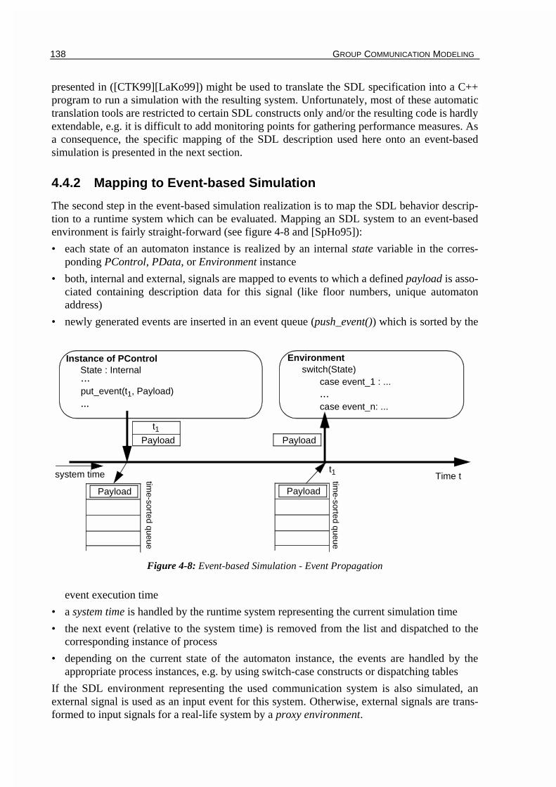
138 GROUP COMMUNICATION MODELING
presented in ([CTK99][LaKo99]) might be used to translate the SDL specification into a C++program to run a simulation with the resulting system. Unfortunately, most of these automatictranslation tools are restricted to certain SDL constructs only and/or the resulting code is hardlyextendable, e.g. it is difficult to add monitoring points for gathering performance measures. Asa consequence, the specific mapping of the SDL description used here onto an event-basedsimulation is presented in the next section.
4.4.2 Mapping to Event-based Simulation
The second step in the event-based simulation realization is to map the SDL behavior descrip-tion to a runtime system which can be evaluated. Mapping an SDL system to an event-basedenvironment is fairly straight-forward (see figure 4-8 and [SpHo95]):
• each state of an automaton instance is realized by an internal state variable in the corres-ponding PControl, PData, or Environment instance
• both, internal and external, signals are mapped to events to which a defined payload is asso-ciated containing description data for this signal (like floor numbers, unique automatonaddress)
• newly generated events are inserted in an event queue (push_event()) which is sorted by the
event execution time
• a system time is handled by the runtime system representing the current simulation time
• the next event (relative to the system time) is removed from the list and dispatched to thecorresponding instance of process
• depending on the current state of the automaton instance, the events are handled by theappropriate process instances, e.g. by using switch-case constructs or dispatching tables
If the SDL environment representing the used communication system is also simulated, anexternal signal is used as an input event for this system. Otherwise, external signals are trans-formed to input signals for a real-life system by a proxy environment.
Figure 4-8: Event-based Simulation - Event Propagation
Instance of PControl
Time t
EnvironmentState : Internal
time-sorted queue
system time time-sorted queue
t1Payload Payload
t1
...put_event(t1, Payload)...
switch(State)case event_1 : ......case event_n: ...
Payload Payload

GROUP COMMUNICATION MODELING 139
It can be seen that the mapping of the SDL description to an event-based simulation is verysimple. Only simple event handling functionality is needed which is provided e.g. by systemslike ATLAS [Da97]. In the next section, a simulation framework is presented providing simula-tive evaluation of systems which are described by GCDL.
4.4.3 Simulation Framework
The main purpose of the realization of the control and data processes with SDL is to enable thesimulative evaluation of groupware scenarios. To simplify and accelerate the implementationof this evaluation, a simulation framework is crucial. This framework should enable a scenario-based performance evaluation together with an easy plug-and-run design. As a consequence, anobject-oriented design is chosen. A previous version was published in [Tro99c], which is exten-ded by the control and data model used in GCDL. In the next two sections, the object and acti-vity model of that framework are presented.
4.4.3.1 Object Model of the Framework
The object model shown in figure 4-9 is specified using the Unified Modeling Language (UML[JEJ95]). The model is divided in a scenario-independent and scenario-dependent part.
The core of the scenario-independent part of the framework is the Main object which initializesthe different Scenario objects according to an input file (or a graphical user interface) and startsthe runtime system. For that, an object EventSim implements the event-based simulation tech-niques, providing methods for callback registration, event scheduling, and event insertion in thesystem. Additionally, an Observer object is provided to which observed values are registered.
Figure 4-9: Object Model of Simulation Framework
scenario-independent
scenario-dependent IFNotification
1
*
Notification
IFScenario
Scenario Environment
Distribution
AutomataIFAutomata
PData
PControl
IFPData
IFPControl
1
*
1
1
Main
EventSim
Observer
1
1
1
1
1
11 1
1
IFEnvironment
Registry

140 GROUP COMMUNICATION MODELING
An identifier is returned which is used to identify values pushed to that observer. For eachvalue, a small window is created showing the history of that value. At last, a Registry object isprovided for distributed simulation which is explained below.
The scenario-dependent part of the framework is defined by interfaces for notifications, envi-ronment, automata, scenarios, and processes (the interfaces are named with IF as a prefix). Theinterfaces are implemented by corresponding objects (denoted with the realize relation in theUML diagram) using the provided event-based simulation functionality.
Different Automata objects are grouped into Scenario objects implementing the different roleswithin a scenario. Thus, the instances of Automata objects represent the corresponding userinstances in the GCDL framework. Each Automata object has a one-to-one relation to certainPControl and PData objects for the realization of the automata processes which realize therules within the scenario. All these objects provide an initialization method for start-up likenotification or observation value registration. The creation of certain Scenario objects dependson the initialization by the Main object. Thus, a selection of scenarios (with given parametersfor that scenario) is feasible.
The Environment object provides an interface with a route() method for transferring externalsignals between given automata. The environment itself may be a simulation for the system tobe evaluated, thus using the event callback mechanism, or it may be a proxy implementation toan existing system. This proxy is responsible for dispatching external signals to/from the exi-sting system from/to the automata.
Due to the fact that the automata are autonomous, the framework may be extended to distribu-ted simulations. For that, the Registry object is used which registers the local automata objects.The interface provides a query() method to ask for local or remote automata objects. The Dis-tribution object is used to transfer an external signal from the local environment to a remote oneusing UDP with acknowledgements. There is no coordination needed for local events, becausethis is done implicitly by the coordination of the autonomous automata which is integrated inthe definition of the automata. Thus, the framework provides an easy extension to distributedautomata-based performance evaluation. However, the interactions between the autonomousautomata are normally highly correlated. As a consequence, it is expected that the performancegain which can be achieved by distributing the simulation is not very high. But due to the impli-cit coordination of the simulation defined by the rules of the scenario, this distribution caneasily be integrated in the framework without adding high synchronization overhead.
4.4.3.2 Activity Model of the Framework
In the following section, the activity model of the simulation framework is presented divided inthree parts, the initialization of the simulation, the event loop, and the distribution of a simula-tion. Activity diagrams [JEJ95] for each of these parts are presented together with a detaileddescription of the used objects and their functionality.
Initialization
The simulation framework is initialized by calling the init() method of the Main object. Duringthe first step, the EventSim and Observer object are created to enable the event handling and themonitoring functionality. After that, input files and graphical user input values may be parsedto set up defined simulation parameters, like the number of participants or the monitoredvalues. In the second step, the scenario-dependent objects are created, namely the Environmentand Scenario object. The Environment object registers event notification callbacks at the Event-

GROUP COMMUNICATION MODELING 141
Sim object calling its register_event() method. Furthermore, monitoring values may be registe-red at the Observer object by invoking the register_value() object. The Scenario object createsand initializes instances of Automata objects representing the role instances of the scenario. Theinitialization of these instances may be based on values read from the input file or given by auser interface during the Main object initialization.
Each Automata object creates and initializes a PControl and PData object representing the con-trol and data processes within the GCDL approach. Each instance of the process objects (PCon-trol and PData) registers event notifications and monitoring values similar to the Environmentinitialization. As a consequence, the event Notification objects are instantiated within the Envi-ronment instance as well as in the PControl and PData instances.
Event Loop
The event loop of the framework is the core of the simulation and keeps it running. It it activa-ted by calling the run() method of the Main object. In a loop (terminated after the pre-definedduration of the simulation or by a simulation error), the schedule() method of the EventSimobject is invoked to dispatch the next event in the queue. The associated notification for thisevent is called by invoking the event_callback() method of the registered object. During hand-ling the event in the Notification object (which is associated either to an Environment, PCon-trol, or PData object), new events may be generated by calling the put_event() method of theEventSim object. Furthermore, monitoring values may be pushed to the Observer object using
Figure 4-10: Simulation Framework Activity Diagram - Initialization
Main EventSim
Observer
EnvironmentEventSim
init()
register_event()
Observerregister_value()
Scenario Automatainit()
PControl
PData
Automatainit()
PControl
PData
init()
init()
init()
init()
}
...

142 GROUP COMMUNICATION MODELING
the push_value() method. At last, external signals may be sent to other automata instancesusing the route() method of the Environment object. By generating new events within the Noti-fication objects, the simulation is kept running until a special event is dispatched signaling theend of the simulation. This event is set during the initialization phase in the Main object.
Distribution
As mentioned in the object model of chapter 4.4.3.1, the simulation framework can easily beextended to distributed simulation due to the inherent independence of the different automata(the different automata acts autonomously from each other according to the defined rules).
However, a fundamental requirement for the distributed simulation is that the environment isable to be distributed. This might be the case if the environment is not simulated but a real-lifeenvironment (e.g. an existing communication protocol). In that case, a proxy environment ineach simulation host implements the route() method to send the appropriate external signals tothe real environment.
In the case of a simulated environment, the distribution of the environment might be muchmore complicated, leading e.g. to synchronization problems. Nevertheless, the distribution of asimulated SCCS environment is feasible, because each node in this protocol administrates itsown state, and only messages (PDUs) have to be exchanged. Thus, the simulated SCCS envi-ronment, which only serves as a message channel, could be distributed among different hostsbeing synchronized by the exchange of PDUs.
The open issue to realize the distribution of the different automata objects is presented in thefollowing. The initialization and the event loop have to be extended to provide that functiona-lity. When initializing the local Environment object, it registers with the local Registry objectby calling its register() method. The registration information (unique simulation-wide identifierplus location information) is sent via the network to the Global Manager. This centralizedobject is chosen at start-up of the conference and contains a mapping of the unique identifierand location information. Additionally, each local PControl object registers with the localRegistry object similar to the Environment object. When all object instances have been registe-red with the Global Manager, this host notifies the other hosts about the end of initializationand distributes the content of the global database to all other hosts to minimize future readrequests.
In the event loop, a local Environment object queries for the location information of a certainprocess instance when the route() method of the Environment object is called. The unique iden-tifier of the object is given as a parameter of the route() method and is used in the query()
Figure 4-11: Simulation Framework Activity Diagram - Event Loop
Main EventSimNotification
EventSimrun()
schedule()event_callback()
put_event()
Observerpush_value()
Environmentroute()

GROUP COMMUNICATION MODELING 143
method of the local Registry object. After resolving the location, the Environment object usesthe send() method of the Distribution object to send the external signal to the appropriate localEnvironment object which, as a result, routes the signal locally to the corresponding local pro-cess instance.
It can be seen that the simulation framework easily enables distributed simulation due to theinherent autonomy of the automata instances. However, the distribution of the environment is atask which has to be considered by the programmer and its difficulty depends on the given pro-blem.
4.4.3.3 Group Communication Simulation Tool
The proposed simulation framework for the scenario-based evaluation was realized for the pur-pose of evaluating main SCCS mechanisms, i.e. the control part of a collaborative system. Thissection describes the main features of the resulting program, called Group CommunicationSimulation Tool (GCST). The results of the simulative evaluation in the chapters 5 and 6 willbe obtained with GCST. For the realization of the program, a non-distributed version of the fra-mework is used, thus the Registry and Distribution objects of the framework are not realized.Furthermore, the data part of the communicating entities is not realized, because only the con-
Figure 4-12: Simulation Framework Activity Diagram - Distribution
Main EnvironmentRegistryinit()
register()
Scenario
Registryregister()
..
.
run()
Registryquery()
Environment
Distributionsend()
EventSimNotificationschedule()
event_callback()route()
GlobalManager
Net
wor
kAutomataPControl
Registryregister()
AutomataPControl
Net
wor
k

144 GROUP COMMUNICATION MODELING
trol part of the communication system is evaluated.
The main design goals for GCST are
• extensibility: This is provided by following the simulation framework which allows an easyextension of the program by adding new scenarios and automata objects.
• ease of use: GCST provides a graphical user interface which allows an easy operation of thesimulation.
• fast: the underlying event handling functionality is kept simple to provide high performance.
GCST provides five different scenarios:
• large meeting: consists of a chairman and many participants within a conducted conference
• panel discussion: consists of a chairman, several experts, and many participants within aconducted conference
• expert round: consists of several experts and many participants within a conference
• private channels: similar to panel discussion, but some participants open private channelsfor side communication (sub-sessions)
• generic token: worst case scenario for the dynamic reconfiguration simulating a uniformlydistributed usage of several tokens in a conference
A more detailed description of the scenarios can be found in the evaluation chapters 5 and 6.
The environment in this context represents the underlying conferencing protocol (SCCS) andits main mechanisms like resource management and dynamic reconfiguration. Hence, the envi-ronment is simulated as well. As a consequence, the Environment object of the simulation fra-mework is realized and provides the functionality of routing floor control requests based on thecentralized scheme of the T.120 standard as well as using the proposed resource managementscheme of SCCS (see chapter 3.2.13). Furthermore, the environment implementation providesthe dynamic reconfiguration functionality of SCCS.
Therefore, five Scenario and the corresponding Automata and Process objects as well as theEnvironment object were implemented using the simulation framework of chapter 4.4.3. Thisresults in a graphical user interface based simulation program (see figure 4-13), which can beeasily extended by other scenarios for evaluation of the environment.
GCST provides a context-sensitive help to explain the different scenarios, their input and out-put files, and the topology description. The topology is displayed as a tree in the main window,and several scenario-dependent statistics can be displayed when double-clicking on node oruser elements in the window. Several on-line displays (realized as Observer objects) may beshown during runtime for visualization of floor control response time for observed users in thescenario. Furthermore, at the end of the simulation, several statistics windows are displayed onthe screen. Up to now, all performance measures of chapter 3.5 for the evaluation of the mainSCCS mechanisms are provided by the current GCST implementation. Due to the simulativeapproach, it is very easy to integrate further performance measures in the program. For that, thecorresponding performance measures have to be registered with the Observer object and, at adefined monitoring point, the performance values are pushed to the Observer. Thus, the simula-tion framework covers a wide spectrum of performance measures and allows an easy extensionof this spectrum.
The software was implemented under Windows NT/9x using Visual C++5.0 and is availablefor free download under [Tro00b] with a graphical setup program.

GROUP COMMUNICATION MODELING 145
4.4.4 Summary
This section presented an approach to realize the behavior description part within the GCDLframework. For that, the specification and description language SDL was used which providesa wide range of constructs to describe finite-state automata. Therefore, it allows to sufficientlydefine the role and rules with GCDL describing the social protocol and the user behavior withina given scenario. A framework was presented to realize the GCDL system in SDL by definingan appropriate SDL system for each role within the scenario communicating with other roles(SDL systems) via the SDL environment using defined SDL signals. Furthermore, the mappingof the SDL system to an event-based simulation was shown, and a simulation framework wasdesigned which facilitates the development and implementation of event-based scenario-depen-dent simulations in the context of GCDL. The object as well as the activity model of the frame-work were described. Additionally, an example implementation which is used for theperformance evaluation of SCCS was outlined.
4.5 Realization with Petri Nets
In the proposed modeling framework of chapter 4.3, stochastic Petri nets can be used for thebehavior description of the communicating entities. Similar to the approach given in chapter4.4, the behavior of the control and data process is defined by Petri nets as a finite-state auto-mata. In contrast to the SDL description, the stochastic Petri net realization enables both theanalytical as well as the simulative evaluation of the resulting system. In the following section,
Figure 4-13: Group Communication Simulation Tool (GCST)
Main Window with Topology Visualization Debug Window
Graphical Result Display
Online Display

146 GROUP COMMUNICATION MODELING
the focus is concentrated on the analytical evaluation of groupware systems.
The section starts with a brief introduction concerning Petri nets and the measures which can beanalytically obtained. In the second part, the realization of the behavior description is presentedusing the Petri nets modeling technique.
4.5.1 Petri Net Introduction
In this section, basic definitions concerning stochastic Petri nets are presented for a betterunderstanding of the further sections.
Stochastic Petri nets (Petri nets or SPNs in the following) provide a graph-based definition of afinite-state machine. It will be seen that under certain assumptions, SPNs can be mapped to anunderlying continuous time Markov chain (CTMC) with finite state space. This resulting Mar-kov chain can be analyzed numerically to obtain specific performance measures of the system.
SPNs are directed bipartite graphs with places P and transitions T and a subset of edges calledinput arcs (from places to transitions) and a set of output arcs (from transitions to places). Pla-ces are drawn as circles, transitions as bars, while input and output arcs are depicted as arrows.Transitions may be immediate or timed. The former do not consume any time for operation,while the latter require a negative exponentially distributed time for firing. Immediate transiti-ons have higher priority than timed transitions. To distinguish between both types, immediatetransitions are typically drawn as filled bars, while timed transitions are depicted as outlinedbars. Places may contain one or more tokens drawn as small black circles within the places. Acertain distribution of tokens is called marking.
In the following, some formal definitions are presented before outlining some general proper-ties of SPNs. For further details about SPNs, see ([BaKr96][BRR87][Haver98b]).
Definition 4.1: Stochastic Petri nets(P, T, I, O, H, W, m0) is called stochastic Petri net (SPN) with P={P1, P2, ..., Pn} a set of placesT={T1, T2, ..., Tm} a set of transitionsI : a function which assigns a multiplicity to each input arcO: a function which assigns a multiplicity to each output arcH: a function which assigns a multiplicity to each inhibitor arcwith the set of numbers 1,2,3,...W: + a function which assigns to a transition t either a firing rate if the
transition is timed or a weight if the transition is immediatethe initial marking, i.e. the initial number of tokens in place P1,...,Pn
Definition 4.2: Input/Output Places
is defined as the set of input places of transition t and
is defined as the set of output places of transition t.
Based on these definitions, a brief introduction to the dynamic SPN properties can be given[Haver98b], often referred to as firing rules. A transition t is called enabled in a marking m,when all input places Ip(t) contain at least I(p,t) token. When there are immediate transitionsenabled in marking m, the following rules are applied:
• Let W be the sum of weights of all enabled immediate transitions.
P T× N→T P× N→P T× N→
ℵT R→
m0 Nn∈
Ip t( ) p P I p t( , ) 0>;∈{ }=
Op t( ) p P O p t( , ) 0>;∈{ }=

GROUP COMMUNICATION MODELING 147
• Enabled transition t fires with probability W(t)/W.
• Upon firing, transition t removes I(p,t) tokens from each input place p and adds O(t,p)tokens to each output place p. The result of the fired transition is a new marking m’.
A marking m leading to another marking m’ under transition t is written as , i.e. firingtransition t leads from marking m to m’. This fire operation is an atomic action, i.e. it eithertakes place completely or not at all.
When there are no immediate transitions enabled, the following rules hold:
• An enabled timed transition t fires with rate W(t), which is defined as an exponentially distri-buted time.
• When firing, remove and add operations are performed similar to the immediate case.
When there is more than one timed transition t enabled in a particular marking, one of thesetransitions is selected randomly based on the firing rates of the transitions (see [Haver98b]).
For simplification of the SPN specification, an enabling function E: may beused. This function specifies for each transition t in marking m whether it is enabled or not.This means that after applying the normal firing rules for a transition t, the enabling function isevaluated. If this function is 1, the transition is said to be enabled.
Definition 4.3: m’ reachable from mA marking m’ is defined as reachable from m if there is a sequence of transitionst1,...,tn such that
m m1 ... mn-1 m’ with
Definition 4.4: Reachability Set - Reachability GraphFor a given initial marking m0, the set of possible markings that are reachable fromm0 is called reachability set R(m0). The tuple (R(m0), E) is called reachability graphwith the markings of the reachability set as nodes in the graph, and there is an edgebetween markings m and m’ if m’ is reachable from m.
4.5.2 Performance Evaluation by SPNs
As already mentioned, SPNs are mainly used for analytical performance evaluation of asystem. Simulative evaluation of a system is also feasible, but is not used in this thesis. In thissection, a brief introduction is given what measures can be obtained from Petri Nets in generalbefore presenting these measures with respect to the performance measures in chapter 3.5.
It is assumed in the following that the reachability set of the SPN is finite, i.e. .This means that the number of tokens in each place is finite. This restriction easily holds consi-dering the fact, that buffer space to store token requests is finite in group communication, too.
Measures to be obtained from SPNs
There are several measures which can be obtained from Petri Nets being divided in steady-stateand transient measures [Haver98b]. The former are based on the solution of the underlyingMarkov chain and the resulting steady-state probabilities defined as pm for marking m. Usingthese results, the following conclusions can be obtained [Haver98b]:
• Let A be a subset of R(m0), then the probability for marking set A is determined by
tm m'→
T M× 0 1,{ }→
t1→
tn→ n 1≥
R m0( ) ∞<
148 GROUP COMMUNICATION MODELING
(4.1)
• The average number of tokens in a place P is obtained by
with Ak the event that k tokens are in place A. (4.2)
• The throughput Xt of a timed transition t with firing rate W(t,m) in marking m is derivedusing the following equation
. (4.3)
• Furthermore, using Little’s law, the average delay E[R] of a token traversing a subnet R iscomputed by E[R]=E[N]/X with E[N] the average number of tokens in the subnet and X thethroughput of the subnet.
It can be seen that the steady-state measures correspond directly to the underlying Markovchain steady-state probabilities. It should be mentioned that the computational effort to calcu-late the steady-state probabilities grows with the size of the reachability set (corresponding tothe size of the Markov chain). This computational effort is the strongest restriction for the usa-bility of this evaluation approach.
Additionally to the steady-state evaluation, transient measures may be obtained from thesystem. This is of interest especially when the system life-time is too short to reach the steadystate or if temporary overload occurs with no corresponding steady-state [Haver98b]. Instead ofusing the steady-state probabilities of the system, the instant-of-time vectors p(t) are usedwhich are obtained by solving the linear differential equation
with given p(0) (4.4)
and Q the generator matrix of the Markov chain. Then, similar to the steady-state case, instant-of-time measures can be obtained which correspond directly to the instant-of-time vectors p(t)of equation (4.4).
For a formal description of the different measures and further information, see [Haver98b].
SCCS Performance Measures to be obtained from SPNs
With respect to the performance measures which are defined in chapter 3.5, it can be said thatall these measures can be obtained from the Petri net. The average values like average responsetime or average queue length can be determined using the steady-state measures of the Markovchain like explained in the last section. The history values are instant-of-time measures whichare determined using the generator matrix Q and equation (4.4).
Thus, it can be summarized that the Petri Net approach enables an analytic performance evalua-tion of group communication systems. Furthermore, the performance measures defined for theevaluation of the main SCCS mechanisms may be obtained. However, it is shown in the nextsection, that the feasibility of obtaining these measures is often restricted due to the complexityof the resulting Markov chain. Especially the evaluation of system performance measuresresults in a large Petri net which is very difficult to handle numerically.
P A( ) pmm A∈
∑=
E P[ ] k P Ak( )⋅k 0=
∞
∑=
Xt W t m( , ) pm⋅m R m0( ) t E t m,( )∈,∈
∑=
p' t( ) p t( ) Q⋅=


150 GROUP COMMUNICATION MODELING
certain environment mechanisms.
In the following, both approaches are described in more detail. Furthermore, the shortcomingsas well as the advantages of both approaches are outlined.
Approach 1 - Modeling the Entire System
The first approach models the entire group communication system consisting of the underlyingenvironment (the tree of providers) and the application using the infrastructure. In the follo-wing, a binary tree is assumed for the sake of simplicity. The environment is modeled by app-lying the routing scheme to the requests which are sent from one application module entity toanother.
The environment is divided in three modules realizing the different types of nodes in the tree-based environment. The system is built of several instances of these modules which are the fol-lowing ones:
1. routing module top node : providing two downward links and one application attachment
2. routing module intermediate node : providing two downward links, one upward link, andone application attachment
3. routing module leaf node : providing one upward link and one application attachment
Depending on the given topology, a corresponding number of routing module instances exist inthe considered scenario. From this information, the entire SPN is built (including the applica-tion modules) by concatenating the different modules. Figure 4-15 shows the different
instances within a 3-level binary tree topology. Thus, the entire system consists of 14 sub-modules each of them consisting of a Petri Net as described in chapter 4.5.3.
The main advantage of modeling the entire system including the routing modules is that perfor-mance measures of the communication infrastructure can be determined.
The main shortcoming of this approach is the complexity of modeling the routing scheme pro-posed in SCCS with Petri Nets. Routing floor asking requests is very easy to model, becauseonly binary information is needed (is the token allocated in a subtree ?). In contrast to that, rou-ting floor passing requests back from the floor holder to the requesting entity is very difficult,because an explicit addressing takes place during routing the request (the floor holder sends thefloor passing request to the requesting entity). To model this routing in each routing module,the information has to be stored which application in the subtree below that module hasrecently issued a floor asking request. The amount of data to be stored depends on the size ofthe subtree and of the location of the specific instance (the higher the location in the tree thehigher the amount of information). Additionally, the size of the Petri net dramatically increasesdue to the storage of the routing information.
Figure 4-15: Approach 1 - Modeling the Entire System with Petri Nets
top node module
intermediate node module
leaf node module
application module

GROUP COMMUNICATION MODELING 151
Approach 2 - Modeling the Application only
It can be seen from approach 1 that modeling the routing in the underlying infrastructure resultsin an increasing complexity of the resulting Petri net, especially when considering large scaledscenarios. Another approach is to model the application instances only. This means that theapplication modules communicate directly via the interface places which can be seen in figure4-16. When using this approach, global places are mostly required to synchronize the applica-
tion modules appropriately, which is also the case in the application example of chapter 5.3.

152 GROUP COMMUNICATION MODELING
was introduced in the Petri net realization as well. However, this design is less structured thanthe SDL approach. This comes from the background of SDL as a specification language ofeven larger protocols. Hence, means to structure the specification are defined in SDL, whileSPNs do only offer a flat structure of the system.
Performance Measures
The analytical evaluation with stochastic Petri nets allows to determine steady-state probabili-ties of the underlying markov chain as well as instant-of-time measures using the generatormatrix of the Markov chain (see chapter 4.5.2). It can be seen from chapter 4.5.2 that usingthese values, certain performance measures for the performance evaluation of SCCS may beobtained using the Petri net approach.
However, it highly depends on the realization of the system. If the complex realization of theentire communication system is used (approach 1), the system performance measures can beobtained in addition to the application performance measures. But it was already mentioned inthe last section that determining performance measures for the communication infrastructureleads to larger Petri nets with a higher complexity of the underlying Markov chain. This effectis even worse in larger scaled scenario in terms of conference members.
If the realization approach 2 is used, the resulting Petri nets are smaller. Hence, the computatio-nal effort for obtaining performance measures is reduced. However, this approach does notallow to evaluate the underlying conferencing system which might be necessary when evalua-ting e.g. protocol mechanisms of the used system.
As a result, obtaining performance measures on application and system level is feasible ingeneral, but specifically depends on the considered scenario.
Access Control
In most group communication scenarios, concurrent access control models are allowed even insimple scenarios. For instance in a large meeting scenario, participants may ask for the floorconcurrently. The requests are normally stored in FIFO (First In-First Out) queues by the con-ductor. FIFO queues may be realized with Petri nets (see figure 4-17 [BaKr96]), but the com-plexity of the queue increases with the number of stages. Thus, the access control models whichcan be realized by Petri nets are mostly very simple on the one hand. On the other hand, thecontrol models are difficult enough to result in complex Petri nets even in simple scenarios(chapter 5.3.1).
Routing Problem
If the simple mapping approach 2 is used, which models the application only, this leads to thefollowing problem (see figure 4-18):
Assuming that application A is invoking a floor request at time t1, while the floor is held byapplication B. If there is another application C, which is closer to B, requesting the floor at the
Figure 4-17: Three-Stage FIFO Queue with SPNs

GROUP COMMUNICATION MODELING 153
time t2, this request might be served earlier in the real environment. This would be the case ifthe time difference t2-t1 were less than the latency to be needed to forward A’s request up to thenode where user C is attached to. If A’s floor request had already passed this node, its requestwould be served earlier. This situation is shown in figure 4-18.
These situations cannot be handled when using the simple mapping approach and steady-stateprobabilities, because the second realization approach does not model the routing in the confe-rence environment. In chapter 5.3, an assumption is made for the access model which excludessuch situations in the evaluation. But as a result, it does not include ALL floor control requestsin the evaluation.
4.5.6 Summary
This section presented the realization of the GCDL behavior description using stochastic Petrinets. After a brief introduction to the basic definitions of Petri Nets, a short overview was givenwhat measures may be obtained by Petri Nets when using this technique for an analytical eva-luation of a system. It was shown that in general all performance measures which were definedfor the performance evaluation of SCCS can be determined. After that, the realization of thecontrol and data process within the GCDL context was outlined. Two approaches were depic-ted, presenting two different levels of detail for the realization. The first one tried to realize theapplications as well as the environment in the case of a simulated environment. The second rea-lized the applications only without taking the underlying conferencing system into account.Both realization techniques suffer from several drawbacks. The main disadvantages are theincreasing complexity of the resulting SPN, especially in the first approach, and the missingrealization structure compared to the SDL approach. The effect of growing Petri nets is evenworse when introducing more complex access control models in the scenarios, for instanceusing queues to store requests.
It can be summarized that the Petri net realization approach enables the analytical evaluation ofgroupware systems within the GCDL context in general. But this ability highly depends on thecomplexity of the resulting Petri net.
Figure 4-18: Routing Problem
A
C
B

154 GROUP COMMUNICATION MODELING
4.6 Summary
This chapter dealt with the problem of modeling groupware applications in the design phase ofthe system to facilitate the implementation and evaluation of the system without implementingit. The focus of the work was on modeling the object structure and describing the dynamicbehavior, including aspects like communication, user behavior, and access control.
The structural design aspect is mainly used to support developers in the implementation designphase of group communication systems. The behavior modeling aspect is used to cover perfor-mance aspects allowing developers to evaluate the groupware system without implementingand installing. For a more formal discussion of the modeling problem, requirements for mode-ling approaches were defined to be fulfilled by modeling approaches for groupware systems.
The presentation of the related work in the area of groupware modeling and evaluation depictedthree main weaknesses of existing approaches, namely the missing detail of communicationaspects, insufficient user behavior modeling, and a poor access control model. Furthermore,most approaches deal only with specific modeling problems. This forces the developer to usedifferent methods for different aspects.
As a modeling approach, the Group Communication Description Language (GCDL) was pro-posed. The focus of GCDL is on both the structural design of groupware systems and modelingaspects like control/data traffic as well as user behavior with an independence from the realiza-tion of the implementation. The access control concept of GCDL is based on the definition ofroles accessing objects within a scenario according to defined rules, referred to as the socialprotocol. Several instances of a role may exist representing dedicated users in a scenario. Toeach object within the system, negative as well as positive access rights are associated. Further-more, the dynamic change of object access is abstracted using a floor control notation.
The components of the framework were presented consisting of the object and process model.For the realization of the former, the syntax definition of a description language was presentedto enable structural modeling of the considered system. For the latter, the instantiation of rolesand the communication among these instances were presented. But the GCDL framework doesnot define how to describe the behavior of the communicating entities, defined as processes, orhow to apply the rules or the data traffic patterns within the scenario and modeling the userbehavior. However, functional requirements for the description of the processes were defined.As an example, two different description approaches were presented which might be used inthe GCDL framework for analytical and simulative performance evaluation.
The first approach realized the control and data processes within GCDL as SDL systems. Forthat, a framework definition of these SDL systems was given which can easily be mapped to anevent-based simulation, which was also depicted. For an easier implementation of these event-based simulations, a simulation framework was introduced. The object and activity model wereoutlined, and a realization of this framework was presented. An implementation of this frame-work is used for the performance evaluation of SCCS, presented in chapter 5 and 6.
For an analytical evaluation of groupware systems, the description of the control/data processeswith stochastic Petri nets was presented. Two particular methods were depicted, modeling theentire system (application and environment) or the applications only. For both, a module-basedrealization was used to define a structure in the realization. However, a well-defined structureas in SDL cannot be achieved with this approach. Furthermore, the main disadvantage of bothmethods is that the resulting Petri net grows rapidly with the size of the scenario as well as withthe level of modeling details in terms of access control and user behavior.
Both behavior description approaches, using SDL or Petri Nets, enable the performance evalua-

GROUP COMMUNICATION MODELING 155
tion of a groupware system modeled with GCDL either on simulative or analytical level. Theperformance measures which were defined for the performance evaluation of SCCS can beobtained from both realization approaches.
It can be summarized that the definition of the Group Communication Description Languageoffers an easy and convenient method for groupware systems modeling. Furthermore, GCDLcovers the defined requirements and provides an integrative approach to deal with structuraldesign of groupware systems as well as with modeling aspects like control/data traffic or userbehavior. It was shown that by using SDL and stochastic Petri nets for the behavior descriptionanalytical as well as simulative evaluation is feasible.
The presented modeling framework will be used in the next two chapters for the performanceevaluation of SCCS protocol mechanisms, namely the proposed resource management and thedynamic reconfiguration of the conferencing tree topology.

156 GROUP COMMUNICATION MODELING

157
CHAPTER 5
Resource Management Evaluation
After proposing a scalable conferencing service to facilitate the development of groupwareapplications, an approach to model groupware systems was defined to enable structural model-ing as well as performance evaluation of group communication systems in general. This chapterdeals with the evaluation of a specific mechanism of SCCS, namely the resource management.This mechanism is compared to the scheme being used in the T.120 standard.
There are two goals of the performance evaluation. As a system aspect, performance measuresfor the resource management of SCCS should be obtained to outline the improvement whenapplying this mechanism. On the other hand, the applicability of different modeling methodsare compared as a methodology aspect of the evaluation. It is expected that the observedimprovement is very similar for all applied modeling methods. As a consequence, this chapteris focussed on the methodology aspect.
Due to the stringent timing constraints for floor control operations (see chapter 2.1.2.1) and forthe sake of simplicity of the result presentation, only floor requests are considered. The evalua-tion is very similar when performing channel requests.
As a starting point for the evaluation, the problem is addressed in chapter 5.1 how to considervarious topologies of the conferencing environment. This problem occurs due to the topologydependency of the proposed resource management in SCCS.
For performing the evaluation, three different methods are presented. In chapter 5.2, the simplestochastic approach, presented in chapter 4.2.1.1, is applied. This approach is used to give afirst impression of the performance gain that can be achieved and to demonstrate the computa-tional effort which is needed for the results, even in very simple scenarios. The other twoapproaches use the GCDL model, but offer different realizations for the behavior description.First, SPNs are used in chapter 5.3 to describe the communicating entities as presented in chap-ter 4.5. This approach allows to determine analytical results. But it is shown that the effort toobtain analytical performance measures grows rapidly with the complexity and the size of thegiven scenario. The third method, presented in chapter 5.4, uses the SDL realization of thebehavior description, presented in chapter 4.4. It is shown that this evaluation method allows toobtain the widest spectrum of performance measures even in more complex scenarios in termsof user behavior and access control. However, only statistical results are obtained with thismethod.

158 RESOURCE MANAGEMENT EVALUATION
5.1 Classification of the Tree Topology
The main problem in evaluating the proposed resource management scheme of SCCS is that theresults highly depend on the tree topology. The smaller the distance between the active users inthe tree, the higher the performance gain of the proposed resource management scheme. This isbecause the resource requests can be handled more locally in the tree.
As a consequence, the performance measures of the scheme should be determined for arbitrarytopologies. As an approximation, a finite number of tree topologies is generated randomly. Butthis might lead to large standard variations when averaging the results. Furthermore, the aver-age values do not properly reflect the variety of start topologies in a conference with respect tothe distribution of the active users.
5.1.1 Distribution Metric V(Ht)
To overcome these weaknesses, the generated topologies are classified according to a metricthat takes into account where the active entities reside in the tree. The evaluation results arepresented according to a tree topology spectrum defined by the minimum and maximum metricvalue.
In the following, this classification metric is defined for the distribution of active entities. Forthat, define Ht as the set of active users with respect to the token t. Moreover, Rt is the set ofvariations which can be build by pairs of users in Ht. Furthermore, let d(u,v) be the shortest pathfrom user u to v in the tree (distance metric). Then, the distribution metric V(Ht) is defined as
(5.1)
It can be seen from the definition that the metric averages the distances of all shortest path rou-tes between active users with respect to a specific token t. The smaller V(Ht), the closer are theactive users located in the conference tree.
Using this definition of V(Ht), the performance evaluation is now performed using the follo-wing topology classification approach:
A given number of topologies, defined as nr, is randomly generated. For each of these topolo-gies, the value for V(Ht) and the performance measures are determined, using any of the propo-sed modeling techniques.
After the entire evaluation is finished, the minimum and maximum for all V(Ht) values of therandom topologies are determined, and
for i=0,...,nc-1 (5.2)
is defined as the start value of class i with nc defined as the number of considered classes. Eachof the randomly generated topologies is now classified to class i if the V(Ht) value for this topo-logy is in the interval [classi, classi+1).
Within each class, the performance measure results of the topologies are now averaged. As aconsequence, the results can be presented depending on the class of the topology. It can be seenthat the proposed classification approach is very similar to a histogram approach.
V Ht( )1Rt-------- d u v,( )
u v, Rt∈∑⋅=
classi minmax min–
nc-------------------------- i⋅+=

RESOURCE MANAGEMENT EVALUATION 159
5.1.2 Statistical Considerations
There are two parameters in the proposed classification approach. The first is the number ofsimulation runs to be performed, while the second one defines the number of classes in the treetopology spectrum. In the following, a brief statistical discussion of the distribution metric ispresented to clarify how to set both parameters.
For that, define as the number of variations of the active user set and Xi=d(vi) with and i=1,...,n. Then, (Xi)i=1,...n defines a sequence of independent and identically distri-
buted random variables which satisfy the assumption for the Central Limit Theorem [Rao84].Hence, with
(5.3)
it follows that Sn is normally distributed. Hence, with and. Comparing equation (5.3) with the definition of V(Ht), it can be seen that the
metric V(Ht) is normally distributed.
Hence, the number of topologies assigned to edge classes, i.e. close to the minimum and maxi-mum V(Ht) value, is expected to be much smaller compared to the mid range classes. As a con-sequence, the number of simulation runs together with the number of considered topologyclasses must be chosen in a way that even for edge classes the confidence of the obtainedresults is assured. This means that both parameters have to be chosen so that the number oftopologies in the edge classes is large enough to ensure small confidence intervals of theresults.
It is worth mentioning that the dependence on the topology exists for all presented performanceevaluation methods. For the sake of simplicity, only binary trees are used for the first method,so the topology dependence can be solved much simpler. For the other evaluation methods, thisdependence has to be taken into account.
5.2 Evaluation using Simple Probabilities
The following section presents a performance evaluation based on a simple stochastic model todetermine the performance gain for simple floor testing operations.
For the evaluation, the following assumptions and simplifications hold:
• The observed user is located in a leaf of a binary tree.
• To each node in the binary tree exactly one user is attached.
• The transmission time on all links in the tree is the same.
In the following, two scenarios are presented concerning the distribution of the floor in the con-ference. In the first one, the floor is distributed uniformly among the users in the conference,i.e. simulating a group discussion without a conductor. For the second scenario, a dedicatedconference member is defined with a higher probability of possessing the floor, i.e. simulating aconducted conference.
For both scenarios, the performance gain is determined (see chapter 3.5.2.1), when applyingthe resource management scheme proposed by the author compared to the centralized schemeof the T.120 standard. Other performance measures (see chapter 3.5), either on application or
n Rt=vi Rt∈
Sn
1n--- Xi
i 1=
n
∑⋅=
Sn N µ σ,( )∼ µ E Xn( )=σ Var Xn( )=

160 RESOURCE MANAGEMENT EVALUATION
system level, are not determined due to the complexity of the computation.
5.2.1 Scenario 1 - Uniformly Distributed Floor
The considered scenario is very simple. There is only one object which is accessed by all usersfor reading and writing using one floor associated to the object. A uniform distribution of thefloor allocation among the users is assumed. In a first step, the performance gain is determinedindependent from the mode of the floor, namely whether it is allocated exclusively or non-exclusively. In a second step, the determination of the performance gain is applied for a exclu-sively/non-exclusively allocated floor respectively.
5.2.1.1 Determination of the Performance Gain
Given a binary tree with height h>1, and let n:=2h-1. Furthermore, define X as the random vari-able that a request originated from a leaf node provider has to be routed up to a given level inthe tree, i.e. P(X=j) is the probability that a request has to be routed up to level j.
Hence, the expectation of X is given by
(5.4)
The performance gain G(u) (in percentage) for a user u located at tree level j=h, =

RESOURCE MANAGEMENT EVALUATION 161
It can be seen that G(u) is defined in a different way than in chapter 3.5.2.1, where the perfor-mance gain is defined as the ratio of two different response time values. But the definitionabove is equivalent, because the response time directly depends on the level to which therequest is routed. It can also be seen that the performance gain G(u) for a user u only dependson the tree level j=h.
5.2.1.2 Case 1 - Exclusive Floor
The results of the last section are used to determine performance results for an exclusively allo-cated floor. For that, it is assumed that the exclusive floor is allocated by a user in a binary treewith a uniform distribution. Let pi:=n-1 be the probability that user i possesses the floor exclusi-vely. Hence, it holds
(5.6)
With the definition of the previous section, P(X=j) can be determined by
for j=1,..,h-1 (5.7)
following the reasoning that P(X=j) is given by the probability that there is a floor holder in theother subtree below the provider on level j (with 2j conference members). Hence, the expecta-tion of X is given by
(5.8)
The performance gain G(u) is determined according to equation (5.5).
5.2.1.3 Case 2 - Non-Exclusive Floor
In the second case, a non-exclusive floor is assumed for the access to the object. In contrast tothe first case, the probability to possess the floor is defined as .
P(X=j) is given by the probability that there is a floor holder in the other subtree below the pro-vider on level j (with 2j conference members) and simultaneously, there is no floor holder in thesubtree to which the requesting provider belongs (with 2j-1 conference members). Hence, itholds
for j=0,..,h-1 (5.9)
The expectation of X and the resulting performance G(u) can be determined according to equa-tions (5.4) and (5.5).
5.2.1.4 Results
Figure 5-2 shows the performance gain for both cases. For the exclusive case, it can be seenthat the performance gain decreases from nearly 33 percent to 12 percent, when the tree heightincreases. For the non-exclusive case, different values of p are considered. It can be seen thatfor a fixed value of p the performance starts to decrease when the trees becomes larger, but at acertain point the performance gain increases. For the height-dependent value of p the perfor-mance gain decreases when the tree grows, which is consistent to the results for the exclusivefloor.
pi 1=i 1=
n
∑
P X j=( ) 2jp⋅=
E X h,[ ] p h 2⋅ h 2h 1+ 2+–( )=
p 0 1( , )∈
P X j=( ) 2jp 1 p–( ) 2j 1–( )⋅ ⋅=

162 RESOURCE MANAGEMENT EVALUATION
5.2.2 Scenario 2 - Active User
In this second scenario, the same assumptions are valid concerning the object and floor given inthe system as in the first scenario using an exclusive floor. But in contrast to scenario 1, there isa dedicated active user in the system with a higher probability to request an exclusive floorcompared to the rest of the users. For the rest of the members, a uniform distribution is assumedsimilar to scenario 1.
Given a binary tree with height h, and let n:=2h-1, and .
It is assumed that the active user grabs the exclusive token with probability, while the rest of the members possess the token with probability pi:=p for all
. Hence
.
Define as the level, where the active user resides. It is assumed without anyrestriction that the active user resides in the same branch of the requesting user below the topprovider. Otherwise, scenario 1 can be used with a higher probability in the other subtree belowthe top provider, i.e. adding a to the probability in equation (5.7).
Define X as the random variable that a request has to be routed up to a given level in the tree,i.e. P(X=j) is the probability that a request has to be routed up to level j. This probability isgiven similar to scenario 1, but divided in two cases
for (5.10)
for j=lk (5.11)
For the expectation of X and the performance gain G(u), the equations (5.4) and (5.5) are used.Figure 5-3 shows the performance gain G(u) depending on h and lk for different values of a. Itcan be seen that the performance gain decreases for increasing a. This is not surprising, because1-a denotes the activity of the active user, which means that with increasing value for a the acti-vity decreases together with the performance gain. Furthermore, it can be seen that the perfor-mance gain also decreases for higher lk. This is due to the location of the observed conferencemember who resides in the leaf of the tree. Higher values for lk means that the active user residecloser to the top provider than to the observed user.
Figure 5-2: Stochastic Approach - Performance Gain G(u) Scenario 1a (left) and Scenario 1b (right)
0
20
40
60
80
100
2 3 4 5 6 7 8 9 10 11 12
h
Pe
rfo
rma
nce
Ga
in G
(u)
[%] p=0,01 p=0,05 p=0,5 p=1/n
Exclusive Floor Non-Exclusive Floor
0
5
10
15
20
25
30
35
2 3 4 5 6 7 8 9 10 11 12
h
Pe
rfo
rma
nce
Ga
in G
(u)
[%]
a 0 1 ),(∈ pa
n 1–------------=
k 1 … n, ,{ }∈pk 1 a–=i 1 … n, ,{ } k{ }–∈
pi 1=i 1=
n
∑
lk 0 … h 1–, ,{ }∈
P X j=( ) 2jp⋅= j lk≠
P X j=( ) 2j 1–( ) p 1 a–+⋅=

RESOURCE MANAGEMENT EVALUATION 163
5.2.3 Summary
This section presented a performance evaluation of the SCCS resource management schemecompared to a centralized scheme using a simple stochastic approach. Two very simple scena-rios in terms of user behavior and access control were used. Scenario 1 assumed a uniformlydistributed usage of the floor among all conference members, while in scenario 2 one activeuser was added to the system, which could be used for modeling a conductor in a conference.
Considering the system aspect of the evaluation, the determined performance gain in both sce-narios showed an improvement when applying the proposed resource management. Further-more, the performance gain depends on the location of the user in the tree. The higher the tree,the smaller the obtained gain. With respect to the methodology aspect, it can be stated that ingeneral application performance measures can be obtained analytically using the simplemethod. However, obtaining results for arbitrary tree topologies, arbitrary users, and morecomplex scenarios in terms of access control and user behavior would probably result in morecomplex equations. Hence, the method is mainly restricted to simple scenarios in terms ofaccess control, user behavior, and fixed configurations.
5.3 Evaluation using SPNs
In this section, an evaluation is performed based on the SPN behavior description within theGCDL modeling approach (see chapter 4.3) using the realization techniques outlined in chapter4.5. The main purpose of this section is to demonstrate the computational effort, which isnecessary to get analytical results even in small and simple groupware scenarios. Furthermore,the applicability of the approach should be demonstrated.
In the following, the stochastic Petri net is presented which is used for the evaluation, beforecalculating the steady-state probabilities. The latter are used for the determination of specificperformance measures. Additionally, an automatic approach and the computational effort todetermine the performance measures are presented.
Assumption
To avoid the routing problem of chapter 4.5.5, it is assumed that only one floor asking requestis issued within a specific time interval. For this assumption, the following definition is given:
Figure 5-3: Stochastic Approach - Performance Gain G(u) Scenario 2
a = 0.1 a = 0.75
0
20
40
60
80
100
0 1 2 3 4 5 6 7 8 9 10 11
lk
Pe
rfo
rma
nce
Ga
in G
(u)
[%] h=2 h=4 h=6
h=8 h=10 h=12
0
10
20
30
40
0 1 2 3 4 5 6 7 8 9 10 11
lk
Pe
rfo
rma
nce
Ga
in G
(u)
[%] h=2 h=4 h=6
h=8 h=10 h=12

164 RESOURCE MANAGEMENT EVALUATION
Definition 5.1: Successful OperationA floor asking operation which is sent to a floor holder at time t1 and received at timet2 is defined as successful if there is no other floor asking operation in the time inter-val [t1,t2].
Considering that only the successful floor operations are taken into account for the performanceimprovement of the system (because non-successful operations are not confirmed by a floorpassing operation), the assumption issuing only one request within a given time interval ismade in the following to model and evaluate a very simple conferencing scenario.
5.3.1 Scenario - Uniformly Distributed Floor
The considered scenario for the performance evaluation is very simple. There is one object inthe system to which an exclusive floor is associated. This floor is requested by each user i afteraski seconds (aski is exponentially distributed). The current floor holder passes the floor to therequesting user after passi seconds (passi is exponentially distributed). The communicationenvironment consists of a binary tree of height h>1 with n:=2h-1 nodes and one user attached toeach node.
5.3.1.1 Stochastic Petri Net
The SPN of the communication system is modeled using the second approach presented inchapter 4.5.4 by modeling the application level only. For each application instance, a separatemodule i=1,..,n is defined, as explained in chapter 4.5, with n the number of users in thesystem. Local places are indexed with i, global places do not have any indices.
Each module is divided in two functional parts. The first one is responsible for asking the floor,while the second one passes the floor to the requesting application. Figure 5-4 shows the SPNmodule for a single application which is explained in the next section.
Note that this is the Petri Net for one application entity only. The entire Petri net for the scena-rio consists of n(=2h-1) modules. Figure 5-5 shows the topology for tree height h=3. The modu-les are numbered as shown in this figure. The entire combined SPN is not shown, because it isvery complex due to its overlapping global places.
Initial Marking of the Complete SPN
After combining the SPN modules, the initial marking of the resulting SPN has to be defined.At the beginning, there is a floor holder i in the scenario, and a global request is possible. As aconsequence, there is initially a token in the global place grequest and a token in the local placetokeni indicating that this user holds the floor. In the SPN modules of the other users, there is atoken in local place startj with .
Firing the Concatenated SPN
In the functional part floor asking, each application issues a floor asking request if a globalrequest for the floor is possible (token in grequest), by firing the transition aski with exponen-tial distribution. With the grequest place, the successful operation assumption is fulfilled.
The waiting for confirmation state in the requesting module is modeled by putting a token inthe local place lrequesti. The transition marki stores the local floor holding information, firingexponentially distributed, in the local place tokeni if the floor is made globally available by the
j i≠

RESOURCE MANAGEMENT EVALUATION 165
current floor holder (signaled by global place token_free) and if there is a local request for thefloor (signaled by local place lrequesti).
In the floor passing functional part, the transition passi fires exponentially distributed if there isa pending global floor asking request (signaled by global place pending_grequest) and themodule is the current floor holder (signaled by local place tokeni). The transition passi modelsthe floor passing time (consisting of the sum of minimum token holding time and service timefor handling the request) and places a token in global place token_free indicating the success ofthe floor passing operation, so the appropriate marki transition of the requesting application isable to fire (see above). Additionally, issuing a global request is re-enabled by placing a tokenin global place grequest, and a new token is placed in starti to request for a floor locally in thefuture.
Figure 5-4: SPN Application Module
Figure 5-5: Petri nets - Topology with h=3
aski
marki
tokeni
pending_grequesttoken_freelrequesti
passi
Floor asking
Floor passing
starti
grequest
1
2
4 5 6 7
3

166 RESOURCE MANAGEMENT EVALUATION
5.3.1.2 Determination of the Steady-State Probabilities
For the determination of the steady-state probabilities, the SPN is mapped to the underlyingMarkov chain.
Due to the successful operation assumption, there can be only one active floor asking/passingoperation in the entire system. In the following, the sequence of floor asking by a user and thefollowing floor passing operation of the current floor holder is called transaction. Such a trans-action between user i and j can be described by the following sequence of markings:
1. user j possesses the floor (token in local place tokenj), and a global request is possible (tokenin global place grequest)
2. user i has requested the floor, while user j possesses the floor (token in local place lrequestiand tokenj)
3. user i has requested the floor and the token is free (token in local place lrequesti and globalplace token_free)
4. user i who has requested the floor possesses it now (token in local place tokeni)
The latter point is equivalent to the first one in the sense that the floor holder has now changedfrom user j to user i. By dividing a transaction for arbitrary users as shown above, the markingsof the SPN can be divided into three groups. The first group S1 contains all markings describingthat any user possesses the floor. The second group S2 contains the markings for the situationthat a user has requested the floor, while it is possessed by another one. And the last group S3contains the markings that a user has requested the floor which is now free. For a formaldescription of these three groups the following notation for the different markings is used:
Definition 5.2: Transaction MarkingsGiven user j as the current floor holder in the system. For a transaction between useri and j in the Petri Net of figure 5-4, the possible markings are named by S=(#grequest, #pending_grequest, #token_free, ... ,#starti, #lrequesti, #tokeni, ... ,#startj, #lrequestj, #tokenj,...). The local places of all users k not equal to i or j are set to (#startk,#requestk,#tokenk)=(1,0,0). Without restriction, user i is written first in that notation.
Using the notation of definition 5.2, the three marking groups can be defined as
with Sj1=(1,0,0,...,1,0,0,...,0,0,1,...), (5.12)
with Sij2=(0,1,0,...,0,1,0,...,0,0,1,...), (5.13)
with Si3=(0,0,1,...,0,1,0,...,1,0,0,...). (5.14)
The set S contains all states of the Markov chain as the union of S1, S2, and S3 with a size of
(5.15)
with n:=2h-1 the number of users in a tree of height h. As a consequence, the number of statesof the underlying Markov chain grows quadratically.
The rates between appropriate markings of the three marking groups are given by the firingrates of the transitions aski, passi, and marki in each module i. So define as the rate for tran-sition aski, as the rate for transition passi, and as the rate of transition marki in modulei. Then, the resulting Markov chain for one transaction between user i and j within the system isgiven in figure 5-6. Using this part of the entire Markov chain and the definition of S as theunion of separated groups S1, S2, S3, it can be seen that the generator matrix Q of the entire
S1 Sj1 j 1 … n,,{ }∈;{ }=
S2 Sij2 i 1 … n,,{ } j 1 … n,,{ }∈ i{ }–;∈;{ }=
S3 Si3 i 1 … n,,{ }∈;{ }=
S S1 S2 S3+ + n n n 1–( ) n+⋅+ n2
n+= = =
λ i1λ i2 λ i3

RESOURCE MANAGEMENT EVALUATION 167
Markov chain has the form
(5.16)
with the sub-matrices
, (5.17)
, (5.18)
, (5.19)
and the constraint
for i=1,..,n(n+1) (5.20)
Matrix A denotes the transitions from marking group S1 to S2, B from S2 to S3, and C from S3 toS1. The steady-states probabilities can now be obtained by solving the equation
with (5.21)
In the following, the steady-state probabilities are indexed using the same notation as in equati-ons (5.12) to (5.14), e.g. is the steady-state probability that user j possesses the floor.
Figure 5-6: Markov Chain for a Transaction
Sj1 Sij2 Si3 Si1λ j2λ i1 λ i3
Q qij( )i j,n n 1+( )
0 A 0
0 0 B
C 0 0
= ℜ n n 1+( ) n n 1+( )×∈=
A =λ11
λ11
0
0
λn1
λn1
0
00 0
0 0
ℜ n n n 1–( )⋅×∈
B =
λ22
λn20
0
λ12
λ n 1–( )20
0
ℜ n n 1–( )⋅ n×∈
C =
λ13
λn3
0
0ℜ n n×∈
qii qijj
∑=
π Q⋅ 0= πii
∑ 1=
πj1

168 RESOURCE MANAGEMENT EVALUATION
5.3.2 Performance Measures
System performance measures, like queue sizes, cannot be obtained from the SPN above,because the conferencing environment is not modeled. As a consequence, only the performancegain G(u) is obtained as an application performance measure. Furthermore, the average floorrequest frequency is determined as another application parameter of the system.
For the demonstration how to obtain the performance measures from the SPN, only the equa-tions of these measures are presented. In chapter 5.3.2.3, a possible automatic calculation isproposed using available tools.
5.3.2.1 Computation of the Performance Gain G(u)
In equation (5.5), the performance gain G(u) of the proposed resource management scheme fora user u was calculated for floor testing requests. This section determines G(u) for floor askingor floor passing requests.
In figure 5-7, the routing is illustrated when performing a floor asking request, indicating the
old routing scheme as an addition of the full and dotted arrows. In this example, the gray userasks for the floor which is allocated at the black provider. In contrast to the floor testing case inchapter 5.2, the performance gain for floor asking (and passing) operations also depends on thelocation of the current floor holder in the subtree. As a consequence, the simple approach ofchapter 5.2 cannot be used, i.e. determining the mean level to which the requests are routedusing the proposed routing scheme and applying equation (5.5). Instead, the exact number ofhops used for routing the request to a specific floor holder has to be taken into account.
Hence, define dm(u,v) as the minimal number of hops between user u and v and l(u) as the levelof user u in the tree starting with 0 for the top provider. Thus, the performance gain Gu(v) for afloor asking operation of user u with user v as the current floor holder can be determined by
% (5.22)
Thus, the mean performance gain G(u) for floor asking operations is calculated by multiplyingGu(v) with the probability that user v is the current floor holder at the time of issuing therequest, and determining the sum over all possible floor holders. The probabilities are given bythe steady-state probabilities of the underlying Markov chain. Hence, the mean perfor-mance gain G(u) of user u is given by
Figure 5-7: Performance Gain for Floor Asking
Performance Gain = 1-3/5 = 40%
level 0
level h-1
.
.
.
Gu v( ) 1dm u v,( )
l u( ) l v( )+-------------------------–
100⋅=
πuv2

RESOURCE MANAGEMENT EVALUATION 169
(5.23)
An advantage of the proposed SPN model compared to the simple stochastic model of chapter5.2 is, that the Petri Net approach allows to obtain results for several topologies. The determina-tion of G(u) in equation (5.22) and (5.23) is not specific for binary trees. Hence, arbitrary topo-logies might be used.
As mentioned in chapter 5.1, the location of the different entities in the tree topology has to betaken into account, because it affects the average response time and therefore the performancegain G(u). In chapter 5.1, a classification approach for this problem is proposed. Hence, thecomputation of Gu(v) has to be performed for each tree topology which was generated ran-domly. This results in a class-based presentation of the performance gain G(u). But it has to beemphasized, that the classification has to be applied only on equations (5.22) and (5.23). As aconsequence, the generator matrix Q and the steady-state probabilities does not need to be re-calculated for each considered topology.
5.3.2.2 Other Measures to be Obtained
The steady-state probabilities can be used to obtain another application parameter which mightbe interesting to characterize the given workload of a specific user for the underlying conferen-cing system.
In the used SPN of chapter 5.3.1.1, the workload produced by each user is specified by theparameters aski, marki, passi for each Petri net module i. From these parameters (by using theresulting steady-state probabilities), the average floor request frequency for each user can beobtained from the system. These values are determined by using the appropriate firing rates andthe steady-state probabilities from marking group S2, i.e. the probabilities that the observeduser has issued a floor request, while another user is holding the floor. Thus, the average floorrequest frequency F(u) of user u is given by
(5.24)
5.3.2.3 Automatic Evaluation Approach
In the previous sections, the steady-state probabilities and the performance gain G(u) wereobtained manually by determining the generator Q, solving equation (5.21), and applying equa-tion (5.22) and (5.23). But it is also possible to generate the results automatically from the SPNby using existing tools like SPNP (Stochastic Petri Net Package [CMT89]).
With this tool, the SPN is specified in a C-like language, and the generator matrix is determinedfor solving equation (5.21). But in the presented evaluation approach, the SPN was designed asa module and the entire Petri Net consists of several of these modules with overlapping globalplaces. As a consequence, a preprocessing unit is necessary to generate the concatenated Petrinet from the module description and the given topology of the conferencing environment.However, it is possible with SPNP to define arrays of places building symmetric concatenatedSPNs which is very similar to the considered scenario. However, the preprocessing unit is pro-posed to follow the module-based SPN design on the one hand and to allow different settings
G u( )Gu v( ) πuv2⋅
v u≠∑
πuv2v u≠
∑----------------------------------------------=
F u( ) λu1 πui2i u≠
∑⋅=

170 RESOURCE MANAGEMENT EVALUATION
for the module instances on the other hand.
With this preprocessing step, SPNP is able to determine the steady-state probabilities from thegenerator matrix Q. But for the determination of the performance gain G(u), a postprocessingstep is also needed to determine the number of hops between dedicated conference members forthe calculation of Gu(v) (equation (5.22)). After that, the steady-state probabilities can be usedto compute G(u). When using the classification of the tree topology (see chapter 5.1), the post-processing step has to be applied for each topology, and the results have to be presented withineach class of topology.
Both steps, preprocessor and postprocessor, can be written in C or C++ to be applied on theinput and output files of SPNP respectively. In figure 5-8, the different steps of this automatic
solutions are shown. It can be seen that for each scenario, only the SPNP description of the SPNmodules and the topology description of the underlying conferencing system is needed.
5.3.2.4 Computational Effort
Tools like SPNP enable the computation of the steady-state probabilities of the underlyingMarkov chain by determining the generator matrix Q and solving equation (5.21). This sectionoutlines the estimated computational effort to perform this computation and furthermore todetermine the performance measures G(u) and F(u) using the proposed automatic solution ofthe previous section. It begins with a first rough estimation of the memory and CPU consump-tion, before presenting some methods for decreasing the computation effort.
The time needed for the determination of the generator matrix Q from the C-like Petri net spe-cification typically ranges from several seconds to a several minutes or hours, especially for alarge number of transitions. Parallel and more efficient sequential solutions can be used toreduce the computation time to a few seconds or minutes, even for large Petri Nets with milli-ons of transitions using a Linux-based PC-Cluster.
For the numerical solution of equation (5.21), iterative linear equation solution methods like
Figure 5-8: Automatic Solution using SPNP
SPNPDescription
SPNP
G(u), F(u)
preprocessor
postprocessor
TopologyDescription

RESOURCE MANAGEMENT EVALUATION 171
Jacobi or Gauss-Seidel iterations are used. According to [Haver98b], the computational effortfor these methods depends on the number of non-zero elements in Q if the generator matrix isstored sparsely to save memory. In the current scenario, the number of non-zero elements of Qis 2n2-n (see equation (5.16)). As a consequence, the memory consumption and the number ofsummations and multiplications grows of order O(n2) [Haver98b]. The number of iterations forthe approximative methods highly depends on the used numerical approach and the requiredaccuracy of the solution. Typically, it might range between just a few and several thousands.
In addition to the solution of equation (5.21), the pre- and post-processing steps have to be app-lied to either generate the C-like notation for the Petri net or to determine G(u) and F(u) fromthe steady-state probabilities using the topology description. From equation (5.22), (5.23), and(5.24), it can be seen that the computational effort for the postprocessing step is of order O(n).The same holds for the generation of the entire Petri net description in the preprocessing step.The postprocessing step has to be applied on a given number of topologies if using the classifi-cation approach for the tree topologies.
For the computation of a chart similar to figure 5-2, i.e. the computation of the performancegain for binary tree topologies from height 1 to 12, the following maximum effort can be esti-mated assuming 64 bit floating point values for the entries in the matrices:
1. up to 4096(=212) Petri net modules have to be concatenated to the entire Petri net in the pre-processing step.
2. the size of the generator matrix grows up to (2*40962-4096)*8=256MB, and the size of thesteady-state probabilities vectors (two for the Jacobi method, one for Gauss-Seidel) growsup to (40962+4096)*8=128MB each. Hence, the entire memory consumption is 512MBwithout any other data structure overhead and variables, which means that more than512MB data are transferred from and to the main memory or to the hard disk if the mainmemory is not large enough.
3. more than 32 million multiplications and summations have to applied for the previous step.
The presented numbers give a rough impression of the computational effort for obtainingnumerical results even in a simple group communication scenario with respect to the consid-ered access control model and user behavior. Remember that only the application level is mod-eled. The effort to obtain results for a fully modeled group communication system including thesystem level would be even larger in terms of memory and processing power.
Refinement of Computation
The rough estimation presented above outlines figures for a brute force computation of the sys-tem without taking the structure of the system into account. Several methods can be applied toreduce the computational effort in terms of memory and CPU utilization.
The first is the more efficient sparse storage of the generator matrix Q. Instead of storing theexact value of each non-zero value in Q (it is assumed that the accuracy of the values is 64 bit),an index to a table is saved only. For each user, 3 parameters are necessary. Hence, 16 bit areenough for this index for conference sizes up to 16384 users. As a consequence, the memoryconsumption of the generator matrix can be reduced to 2*40962*2=64MB for the 4096 usercase, i.e. the memory is reduced to 25 percent. The memory consumption of the index table is3*4096*8=96kB, i.e. very small.
Another reduction of the computational effort might be realized when considering the symme-tric character of the presented Petri net. When assuming, that many of the application instanceparameters , , and are equal, methods for lumping [Haver98b] states on Markovλ i1 λ i2 λ i3

172 RESOURCE MANAGEMENT EVALUATION
chain level can be used. Approaches like colored Petri nets [BaKr96] can be used to modelapplication instances with equal parameter settings, which leads to simplified Markov chains.But for applying these methods, the assumption must be valid that many parameter sets of theapplications are equal. But especially when using user-profile data as input parameters for thesystem, a random shift of these values is often applied for creating more ’random’ behavior inthe system. This shift technique would reduce the applicability of lumping or colored Petri netsapproaches.
5.3.3 Summary
This section presented the application of the SPN method for the evaluation of the proposedresource management scheme in SCCS. For a simple application scenario, the SPN and the fol-lowing computations for obtaining performance measures were outlined.
Regarding the system aspect of the evaluation goals, results for the performance gain were notpresented. It was only shown how to obtain the performance gain of the proposed scheme. Forthat, the determination of the application performance measures was performed manually todemonstrate the different steps. But an automatic process was also proposed to facilitate thecomputation using available tools with additional pre- and postprocessing units. Furthermore,figures for the computational effort were estimated to obtain the numerical results for the situa-tion to gather similar results as with the stochastic approach.
With respect to the methodology aspect, it can be summarized that the used SPN method allowsto obtain analytical results for the considered group communication system. However, due tothe chosen modeling granularity only application-level performance measures were obtainedfrom the model. Modeling the system level would result in an even larger model increasing thecomplexity of the computations. Furthermore, considering more complex scenarios in terms ofaccess control and user behavior would additionally increase the complexity.
5.4 Evaluation with Simulation
As the last evaluation method, the simulation-based approach, presented in chapter 4.4, is app-lied. The scenarios considered for the evaluation are dealing with more realistic situations,which are modeled using GCDL together with the SDL behavior description approach. Theapplicability of the technique should be demonstrated even for complex scenarios with differ-ent roles and more sophisticated access control models in large scaled environments. It is alsoshown that this evaluation method provides the widest spectrum of performance measures to beobtained from the system, including measures of the application and system level.
Two different scenarios are presented, namely a lecture and panel discussion, which are morecomplex compared to the considered scenarios of the other evaluation methods. For each sce-nario, the GCDL specification and the evaluation parameters are depicted before presenting theperformance measure results.
5.4.1 Scenario 1 - Lecture
The first scenario, which is presented in this section, models a lecture in a distributed environ-ment. It consists of two roles, namely the chairman of the session and the participants, acces-sing the audio/video stream of the conference.

RESOURCE MANAGEMENT EVALUATION 173
5.4.1.1 GCDL Specification
The GCDL definition of the lecture scenario is given as follows:# one floor is needed to access the audio/video stream# the other one is needed for prolongation requestsF_AV_grant = exclusive; 1;F_AV_prolong = exclusive; 2;# there are two instance setsI_chair = (1;(0;d););I_part = (2;...;n;(0;d););# everybody is allowed to read from and write to the streamRS_all = 1;...;n;WS_all = 1;...;n;# there is an AV stream objectO_AV = F_AV_grant; F_AV_prolong; RS_all; WS_all;# the object is grouped to a lecture scenarioOG_lecture = O_AV;# now the roles are definedR_chair = O_AV; I_chair; ctrl_chair; data_chair;R_part = O_AV; I_part; ctrl_part; data_part;
The parameter n in the GCDL specification denotes the number of participants in the scenario,whereas parameter d represents the duration of the lecture.
For the performance evaluation of the resource management within a conferencing service, thedata process of the role definition does not need to be defined. Hence, only the control pro-cesses of the chairman (crtl_chair) and the participants (ctrl_part) have to be speci-fied to model the access control for the audiovisual stream. The access control for this scenariois very simple:
The chairman is the conductor of the conference. Hence, for each access to the audio/videostream, a floor asking request has to be sent to the chairman. If the chairman is willing to beinterrupted by the current requestor, the floor F_AV_grant is given to the asking participant,who is then allowed to sent audio/video data to the stream. After a certain amount of time, thefloor has to be given back to the chairman. But a participant may ask for prolongation of theaccess by asking for the floor F_AV_prolong. If the prolongation is granted by the chairman,the floor F_AV_prolong is immediately given back to the chairman. A participant may askfor several prolongations. If the prolongation is denied and the maximum asking time is over,the access floor F_AV_grant has to be given back to the chairman. The probability for gran-ting the prolongation is chosen based on a uniform distribution similar to the probability forasking for prolongation by a participant.
The chairman cannot be interrupted, when answering to a previously asked question of aparticipant. Furthermore, the chairman might directly address a participant with a question. Thedifferent parameters for maximum answering/asking time and the different probabilities can beset in the automata (see next section).
This non-formal behavior description was defined in [Ka98] as SDL specifications for bothroles. As an example, figure 5-9 shows the control process definition for the participant role inthe lecture scenario. It can be seen that the usage of timers enables to model profile-based userbehavior. The used SDL constructs are very simple, and even for the more complex chairmandescription, the SDL specification is fairly short (less than two pages).
5.4.1.2 Parameter Settings
Beside the evaluation parameters which were presented in chapter 3.5.3, a set of applicationparameters is provided by the SDL specification of the chairman and participant role, which

174 RESOURCE MANAGEMENT EVALUATION
can be separately specified for each user.
Furthermore, the number of conferencing members is given in the GCDL specification asparameter n. For the presentation of performance measures in dependence on the conferencesize, five different values are used. Otherwise, a fixed value (bold in the table) is used.
In table 5-1, the entire application parameter set for the following simulation results is presen-ted. For the parameters, which are specified with intervals, the following definition is given:
1. The corresponding timer values in the role specification are chosen based on a exponentialdistribution.
2. The expectation of the timers of each role instance is chosen randomly within the giveninterval using a uniform distribution during start-up of the simulation.
The prolongation parameters specify a dice value for the corresponding functionality. For that,a uniformly distributed random value between 0 and 1 is chosen during simulation. If the valueis smaller than the appropriate prolongation parameter, the specific action is performed, e.g. amember asks for prolongation. This selection can be seen in the participant role specification offigure 5-9 (pl:=rand()). With this interval-based parametrization, a random shift of the userparameters is introduced leading to different user profiles in the scenario.
It was mentioned in chapter 3.5.3 that it is very difficult to obtain realistic user-profiles forthese scenarios. Hence, the values for the user actions, like asking a question, are set to heuri-stic values instead of using observed values.
Figure 5-9: SDL Control Process Definition of Participant Role for Scenario 1
QUIET
SPEAK
TIMER ASK, PL;
SIGNAL TPrq(integer);
SIGNAL TVcf(integer);SIGNAL TVin(integer);SIGNAL TVrs(integer);SIGNAL TVrq(integer);
SIGNAL TPin(integer);
ASK
TPrq(TK_S)
WAITING
SPEAK SPEAK SPEAK SPEAK
PL
TPrq(TK_PL)
TVin(TK_PL)
TVrs(TK_PL)
TVrq(TK_PL)
TPin(TK_S) TVcf(TK_PL)
TIMER TIMEOUT;
QUIET
QUIET SPEAK
TIMEOUT
TVrq(TK_S)
TVcf(TK_S)TVin(TK_S)
TVrs(TK_S)
SET(NOW+tmq,TIMEOUT)
SET(NOW+t0,TIMEOUT)
SET(NOW+task,ASK)
SET(NOW+tmq-te,PL)
pl:=rand()
pl>plpTRUE
SET(NOW+tmq,TIMEOUT)RESET(TIMEOUT)
SET(NOW+task,ASK)
WAITING
speaking timetimed out ?
timeout extensionrefused ?
chairman asks forright to speak !
timeout extensionconfirmed !
randomly selectedextension request
inter-question timer runs out !
permission tospeak refused !
permission tospeak granted !
SET(NOW+tmq-te,PL)

RESOURCE MANAGEMENT EVALUATION 175
In table 5-2, the system evaluation parameters are depicted, which are also used in the secondscenario. The service times within the providers of the conferencing system are set to the valuesdetermined in chapter 2.2.4. For the link time on each provider-provider connection, a LANconnectivity is assumed [FaRu97], according to the reasoning of chapter 3.5.3. The same rea-soning was considered when setting the link time of the attachment.
The topologies of the conferencing environment are generated randomly with the same startseed for the random number generator. Hence, the sequence of tree topologies is the same forboth resource management schemes to guarantee a fair comparison. To each node, exactly oneuser is attached, except for one node (because there are 2x-1 nodes, but 2x users). But note that
the generated trees are not binary ones, the number of downlinks per node is chosen randomlyfrom 1 to dl (see table 5-2). When generating the random topology, the SCCS top provider is setto provider 0 as the only fixed point in the randomly generated tree topology.
Due to the random generation of the tree topology, the class-based classification approach (seechapter 5.1) is used to present the performance measure results. For that, a large number of
Parameter Description Value
task mean question interval of participant [5-15] min
tmq maximum question length of participant [5-15] sec
tans mean question interval of chairman [5-15] min
tmsc maximum answer and question length of chairman [5-15] sec
plp participant probability to ask for prolongation 0.1
plc chairman probability to grant prolongation 0.2
n number of conference members 32, 64, 128, 256, 512
d duration of lecture scenario 90 min
Table 5-1: Application Evaluation Parameters for Lecture Scenario
Parameter Description Value
l link time between providers 2 ms
at link time to user attachment 0.2 ms
dl maximum number of downlinks per node 8
st service time of top provider 2 ms
si service time of intermediate provider 1.8 ms
sl service time of leaf node provider 1.4 ms
nr number of simulation runs 500
nc number of classes for topology classification 1
Table 5-2: System Evaluation Parameters for Lecture Scenario
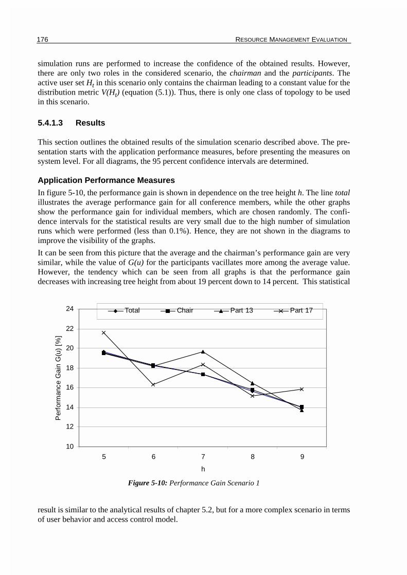
176 RESOURCE MANAGEMENT EVALUATION
simulation runs are performed to increase the confidence of the obtained results. However,there are only two roles in the considered scenario, the chairman and the participants. Theactive user set Ht in this scenario only contains the chairman leading to a constant value for thedistribution metric V(Ht) (equation (5.1)). Thus, there is only one class of topology to be usedin this scenario.
5.4.1.3 Results
This section outlines the obtained results of the simulation scenario described above. The pre-sentation starts with the application performance measures, before presenting the measures onsystem level. For all diagrams, the 95 percent confidence intervals are determined.
Application Performance Measures
In figure 5-10, the performance gain is shown in dependence on the tree height h. The line totalillustrates the average performance gain for all conference members, while the other graphsshow the performance gain for individual members, which are chosen randomly. The confi-dence intervals for the statistical results are very small due to the high number of simulationruns which were performed (less than 0.1%). Hence, they are not shown in the diagrams toimprove the visibility of the graphs.
It can be seen from this picture that the average and the chairman’s performance gain are verysimilar, while the value of G(u) for the participants vacillates more among the average value.However, the tendency which can be seen from all graphs is that the performance gaindecreases with increasing tree height from about 19 percent down to 14 percent. This statistical
result is similar to the analytical results of chapter 5.2, but for a more complex scenario in termsof user behavior and access control model.
Figure 5-10: Performance Gain Scenario 1
10
12
14
16
18
20
22
24
5 6 7 8 9
h
Per
form
ance
Gai
n G
(u)
[%]
Total Chair Part 13 Part 17

RESOURCE MANAGEMENT EVALUATION 177
In addition to the average performance measures, the simulation tool GCST allows to obtaininstant-of-time measures for the response time of floor operations at specific users by definingon-line displays for each user. In figure 5-11, an example is shown for the current (left) andmean (right) response time for floor asking operations (TPrq denotes the appropriate SCC-SPDU for that operation) at user 12 which is the chairman in this scenario. The value ts denotes
the time of observation of the corresponding measured value. Similar on-line displays for floorpassing operations might be obtained as well.
Furthermore, the scenario implementation, which is based on the simulation framework ofchapter 4.4.3, enables the integration of monitor points to measure the response time of anentire user action from the beginning of the first request to the end of the last one. However, forthe current evaluation, these instant-time measures are not used.
Moreover, the simulation-based approach allows to gather further scenario-specific applicationmeasures like number of questions in the scenario or mean speaking time of individual users,either as a timeline or average statistic. But it was not in the scope of the resource managementevaluation to gather these statistics.
System Performance Measures
Following the definition of the performance measures in chapter 3.5.2.2, the number of ser-viced PDUs in the conferencing system and the queue length of the SCCS providers are ofinterest, when evaluating the different resource management schemes.
For the former, the results presented in figure 5-12 were obtained from the simulations byadding monitoring points at each queue of the nodes in the topology. The term reduction of ser-viced PDUs per node is defined by applying the SCCS resource management scheme instead ofthe centralized version. The values are presented for the fixed SCCS top provider (node 0) andthe chairman’s node in the tree. Furthermore, the total reduction of PDUs is shown.
It can be seen from the figure that the reduction in the topmost provider is very high (more than40 percent), and it increases slightly with higher number of users in the system, i.e. for largertree height h. However, this effect might be caused by the higher confidence intervals of thisgraph. The total reduction of PDUs in the conference decreases with higher number of confe-rence participants, which is consistent to the analytical results of chapter 5.2. The confidenceintervals are very small (less than 0.2 percent).
For the chairman’s provider, it can be stated that the number of PDUs remains almost the same,
Figure 5-11: Floor Asking History in GCST
t[ms]
t[ms]
ts ts

178 RESOURCE MANAGEMENT EVALUATION
when applying the new scheme. This can be explained by the fact, that all floor asking andpassing requests are routed to the chairman anyway independent from the used routing scheme.Therefore, the number of PDUs at this node changes only slightly within the range given by theconfidence intervals.
Concerning the queue length as the second performance measure on system level, the measure-ments showed that the queues are almost empty during the conference. This is not surprisingdue to the chosen parametrization of the user actions (see table 5-1) using parameters in therange of several minutes for a user action. Considering more progressive settings in terms ofshorter interaction times would probably lead to higher queue lengths. These more progressivesettings might be used for scenarios like shared applications where mouse movements invokingfloor control requests might occur within shorter interaction times.
5.4.2 Scenario 2 - Panel Discussion
The second scenario deals with a panel discussion example adding a third role to the scenario,namely the experts of the panel. It is shown in this section that even for this more complex sce-nario in terms of user behavior and access control model, the simulation approach enables theperformance evaluation of the proposed resource management scheme together with the widespectrum of performance measures.
Similar to the first scenario, the GCDL specification is given together with a non-formaldescription of the social protocol. After that, the parameter settings for the simulations aredepicted before presenting the performance measure results.
5.4.2.1 GCDL Specification
The GCDL definition of the panel discussion scenario is given as follows:# one floor is needed to access the audio/video stream
Figure 5-12: Reduction of PDUs per Node Scenario 1
-10
0
10
20
30
40
50
60
5 6 7 8 9
h
Red
uctio
n P
DU
s [%
]
Total Chair Top Provider

RESOURCE MANAGEMENT EVALUATION 179
# there is also a prolongation floor# there is a logical floor for the experts consisting of# m floorsF_AV_grant = exclusive; 1;F_AV_prolong = exclusive; 2;F_AV_expert = exclusive; 3;...;m-1+3;# there are three instance setsI_chair = (1;(0;d););I_panel = (2;...;m+1;(0;d););I_part = (m+2;...;n;(0;d););# everybody is allowed to read from and write to the streamRS_all = 1;...;n;WS_all = 1;...;n;# there is an AV stream objectO_AV = F_AV_grant; F_AV_prolong; F_AV_expert; RS_all; WS_all;# the object is grouped to a panel scenarioOG_panel = O_AV;# now the roles are definedR_chair = O_AV; I_chair; ctrl_chair; data_chair;R_panel = O_AV; I_panel; ctrl_panel; data_panel;R_part = O_AV; I_part; ctrl_part; data_part;
The parameter n of the description above denotes the number of conference members in total, mdefines the number of experts in the panel, and the duration of the panel discussion is given asparameter d.
Similar to the first scenario, only the control processes which describe the access control anduser behavior are defined for the performance evaluation. In addition to the floors which areknown from scenario 1, to each expert a floor is assigned, used to signal a question for the cor-responding panel member. These floors are defined as a logical floor F_AV_expert (seechapter 4.3.2) to simplify the GCDL definition. The scenario is described non-formally as fol-lows:
The chairman is the conductor of the conference controlling the access to the audiovisualstream object. Each panel expert might ask for access to the stream to issue a statement con-cerning a certain topic. A participant might ask for access as well for asking a question to thechairman or to one of the panel experts. A floor asking request for the specific expert floor(F_AV_expert()) indicates a question for an expert. A question to the entire panel isdirected to the chairman. The asked expert (or the chairman) answers to the question. In themeanwhile, an interruption of the stream access is prohibited. The same prolongation mecha-nism is provided as in scenario 1. Similar to the lecture scenario, the chairman might ask one ofthe panel members or one of the participants a specific question.
In [Ka98], SDL specifications for the chairman, panel member, and participant roles are pre-sented. The definition of the floors is a bit different, but the functionality of the scenario is thesame. The specification for the participants is very similar to figure 5-9, with an additionalpanel expert handling.
5.4.2.2 Parameter Settings
A set of application parameters is provided by the SDL specifications of the different roles inthe scenario. Table 5-3 shows the entire application parameter set which is used for the follo-wing simulation results. The definition of scenario 1 is used concerning the values in brackets.It can be seen that additional parameters are available for the configuration of the panel mem-bers.

180 RESOURCE MANAGEMENT EVALUATION
The same assumptions and settings as in scenario 1 are used for the conferencing system andthe classification of the tree topology (see table 5-2). But instead of a single class for the treetopology classification, the parameter nc is set to 15 classes. This is caused by the active usersubset Ht (see equation (5.1)) which contains only a subset of all users, i.e. the chairman and thepanel members.
5.4.2.3 Results
This section outlines the evaluation results divided into the presentation of the application andsystem level measures, including the 95 percent confidence intervals for the statistical results.
As stated in the previous section, the classification approach for the tree topologies is used inthis scenario. As a starting point for the presentation of the simulation results, the classificationapproach is evaluated with respect to its influence on the confidence of the obtained results.
Influence of Classification Approach on Results
The main goal of introducing the classification of tree topologies was to better represent thedependence of the results on the location of the active users within the tree topology. In figure5-13, this dependence is demonstrated for the chairman in the panel discussion. In this picture,the response time for floor asking requests serviced by the chairman is shown depending on thetopology class. The constant line represents the case that there is only one class defined for alltopologies. The second line shows the values for the 15 classes case, which is the chosen para-meter setting in the considered scenario.
Parameter Description Value
task mean question interval of participant [5-15] min
tmq maximum question length of participant [5-15] sec
tspk mean statement interval of panel member [5-15] min
tms maximum statement length of panel member [5-15] sec
tans mean question interval of chairman [5-15] min
tmsc maximum answer and question length of chairman [5-15] sec
plp participant probability to ask for prolongation 0.1
ple panel member probability to ask for prolongation 0.1
plap participant probability to ask a question 0.1
plae panel member probability to ask a question 0.1
plc chairman probability to grant prolongation 0.2
n number of conference members 32, 64, 128, 256, 512
m number of panel members 6
d duration of panel discussion scenario 90 min
Table 5-3: Application Evaluation Parameters for Panel Discussion Scenario

RESOURCE MANAGEMENT EVALUATION 181
It can be seen from the figure that the floor control response time almost linearly increaseswhen using the classification approach. It can also be seen that the spectrum of the values forthe classification approach ranges from about 13 to 37 milliseconds. In contrary, the one classcase leads to average response time in the middle of this range. Hence, it can be stated that theproposed classification approach better represents the location dependence of the proposedresource management scheme by taking the active users into account when presenting theresults.
Another effect can be seen in figure 5-13. The confidence intervals for the 15 classes case aremuch larger at the edge of the diagram, while they are very small for the mid classes. This canalso be demonstrated by depicting the standard deviation in milliseconds for the floor askingresponse time shown in figure 5-14 for three different role instances. The average values for theresponse time range from 20 to 45 milliseconds for the different classes.
Comparing the values for the different roles, it can be seen in figure 5-14 that the chairman’sstandard deviation values are lower compared to the expert’s and participant’s ones. This iscaused by the higher number of floor asking requests which are generated by the chairman asthe central point of the scenario. As a consequence, more response time values can be used forthe determination of the mean response time in contrast to the lower active roles, expert andparticipant. However, it is shown for all roles that the standard deviation values at the edge ofthe diagram are much higher than in the mid range.
This effect can be explained by the Gaussian distribution of the metric V(Ht) (see chapter5.1.2). As a consequence from this distribution, the number of topologies in the edge classes ismuch smaller compared to the mid range, i.e. only a few topologies (less than 5) compared toseveral tens are assigned to the classes at the edge. This has a strong impact on the confidenceintervals of the statistically obtained values.
With respect to figure 5-13, it can be summarized that the classification approach allows toobtain more topology-dependent results. However, figure 5-14 demonstrates the problem ofminimizing the standard deviation and therefore the confidence intervals of the statistical
Figure 5-13: Comparison Floor Asking Response Time for 15 and 1 Classes and 256 Users
0
5
10
15
20
25
30
35
40
45
50
0 1 2 3 4 5 6 7 8 9 10 11 12 13 14
Class
Res
pons
e T
ime
[ms]
Chair 15 Classes
Chair 1 Class


RESOURCE MANAGEMENT EVALUATION 183
results, the confidence intervals are not shown in both diagrams.
In figure 5-15, the performance gain is shown for different conference sizes in terms of mem-bers. Two tendencies can be seen from the results. The first one is the dependence of the perfor-mance gain on the class number. It can be seen that the higher the class the smaller G(u). Thiscan be explained by the definition of metric V(Ht). Smaller values for V(Ht) mean that theactive users in the scenario, i.e. the chairman and the panel experts, are located more closely inthe tree topology than for higher values. Hence, the resource management scheme of SCCS canobviously achieve a higher performance gain for closer active users.
The second tendency, seen in figure 5-15, is that the performance gain slightly depends on thenumber of members in the conference. While this effect is not observable at the edges of thediagram, it can be observed in the mid range of the topology classes with a smaller confidenceinterval (less than 0.2%). However, this dependence is not that strong compared to the results ofthe first scenario.
For the comparison of the performance gain which can be achieved for different roles in theconference, figure 5-16 shows the results for G(u) for a fixed conference size consisting of 256members. The shown values are gathered from randomly selected role instances to illustrate the
tendency of the values instead of averaging the values for all instances of each role. This avoidsartificial average values with large standard deviations due to the different locations of theinstances in the tree.
It can be seen from this picture that the performance gain values decreases for all roles forhigher topology classes. This can be explained following the same reasoning as for figure 5-15with respect to V(Ht). The larger variations of the graphs for all roles at the edges of the dia-gram can also be explained by larger standard variations for these classes.
Figure 5-16: Performance Gain G(u) Scenario 2 for 256 Members
0
10
20
30
40
50
60
0 1 2 3 4 5 6 7 8 9 10 11 12 13 14
Class
Per
form
ance
Gai
n G
(u)
[%]
Total Chair Expert Part

184 RESOURCE MANAGEMENT EVALUATION
System Performance Measures
Similar to scenario 1, the reduction of serviced PDUs in each provider is used for depicting the
reduction of the load. In figure 5-17, the results for the chairman’s node, the fixed node zero,and the total reduction is shown depending on the class of the topology. Following the reason-ing concerning the influence of the classification, the large confidence intervals for the edgeclasses can be explained.
It can be seen that the total PDU reduction and the reduction at the top provider slightlydecreases for higher topology classes. Similar to the first scenario, there is no reduction at thechairman of the panel discussion. This can be explained following the reasoning of the first sce-nario. Furthermore, the range of the obtained results is almost the same as in the first scenario.
Concerning the queue length within each provider, the observed results were almost zero dur-ing the simulation. At most, two PDUs were stored in a queue simultaneously. Similar to thereasoning in scenario 1, more progressive values of the application level parameters wouldprobably lead to larger queue lengths.
5.4.2.4 Computational Effort
The computational effort for obtaining the performance measures for both scenarios is verysmall for a simulative method. The computation time for a single simulation run, i.e. for onetopology, ranges from 0.15 seconds to approximately 1.4 seconds for a 32 node topology and a512 node topology respectively. The values were obtained on a 500 MHz Pentium III PC run-ning GCST (see chapter 4.4.3.3) under Windows 98. Hence for the considered settings, i.e. 500simulation runs, the entire computation time for one conference size ranges from approxi-mately 75 seconds to 730 seconds, i.e. in the order of several minutes. The amount of memoryis less than 4 MB, which includes the graphical user interface and the topology visualization.
Figure 5-17: Reduction of PDUs per Node Scenario 2 for 256 Members
-10
0
10
20
30
40
50
60
70
80
90
100
0 1 2 3 4 5 6 7 8 9 10 11 12 13 14
Class
Red
uctio
n P
DU
s [%
]
Total Chair Top Provider

RESOURCE MANAGEMENT EVALUATION 185
5.4.3 Summary
This section presented the evaluation results using the SDL behavior description within GCDL.For that, two scenarios were realized using the simulation framework of chapter 4.4.3.
The GCDL definitions, parameter settings on application and system level, and the obtainedperformance measures were presented for both scenarios. The first scenario simulated a largemeeting based on two roles, namely the chairman and participant. In the second scenario, athird role was added leading to the most complex group communication scenario in the entirechapter in terms of user behavior and access control model.
It was demonstrated that the modeling approach provides performance measures on applicationand system level respectively with a moderate computational effort. Specifically, a high reduc-tion of the floor control response time was observed when applying the proposed resource man-agement scheme. Furthermore, the overall serviced PDUs were reduced together with asignificantly lower load in the top provider caused by traversing PDUs.
5.5 Summary
In this chapter, the resource management scheme, which is used in SCCS, was evaluated com-pared to the centralized scheme used in the ITU T.120 standard. The purpose of this evaluationchapter was twofold. Concerning the system aspect of the evaluation, application and systemperformance measures were obtained when applying the proposed method. It was shown withthe presented results, either analytically or statistically, that the SCCS resource managementscheme allows to reduce the response time for floor operations like floor asking and passing.Depending on the topology and the role of the entity, this reduction ranges from several percentup to forty percent and more. Hence, a higher responsiveness of the system can be achievedeven in larger scaled systems. Additionally, the simulative method showed that the load of theconferencing system may be reduced in terms of serviced PDUs per node in the underlyingconferencing environment. It is worth mentioning that the fast token give mechanism, as pro-posed in chapter 3.2.14, was not applied during the evaluation. However, applying this tech-nique would further decrease the response time of a floor asking/passing operation by 33percent in an SCCS environment. These floor asking/passing operations are typical in conferen-cing scenarios.
Concerning the methodology aspect of the evaluation, three different modeling techniques wereapplied to demonstrate the computational effort as well as the applicability of the differentapproaches. The first method used a simple stochastic model to enable the analytical evaluationof the system. However, the obtained equations were fixed to the specific configuration interms of topology, observed user, and access control.
The other two methods applied the GCDL modeling framework using different realizations forthe behavior description. First, SPNs were used to define the behavior and the access control ofthe roles. For that, the module-based technique of chapter 4.5 was used to structurally designthe SPN. To reduce the complexity of the concatenated SPN, only the application level wasmodeled, i.e. system performance measures were not provided. For demonstrating the compu-tational effort, the generator matrix of the underlying Markov chain was determined togetherwith the equations for the performance gain of the resource management scheme. Moreover, anautomatic evaluation was proposed using available tools. A rough estimation of the effortshowed that even for the simple scenario a high computational effort is necessary to obtain ana-

186 RESOURCE MANAGEMENT EVALUATION
lytical results. This effort would be even higher, when considering more complex scenarios interms of user behavior and access control and when modeling the system level of the conferen-cing environment.
The last modeling technique applied the SDL-based behavior description proposed in chapter4.4. Two more realistic scenarios, a large meeting and a panel discussion, were consideredusing the simulation framework of chapter 4.4.3. It was shown that the modeling techniqueenables to obtain application and system performance measures statistically. Hence, thisapproach provides the widest spectrum of provided performance measures.
It can be summarized that the proposed SCCS resource management scheme may lead to a sig-nificant improvement of the responsiveness of a conferencing system by reducing the floorcontrol response time. Furthermore, the load on system level might be reduced significantly.All presented performance evaluation methods allow to obtain specific performance measureseither analytically or statistically for evaluating a specific mechanism of the underlying confe-rencing system. But with respect to the computational effort, the difference in the applicabilityof the methods varies widely. Compared to the SPN and simple stochastic approach, the simu-lative approach enables the evaluation of very complex conferencing scenarios together with awide spectrum of obtained performance measures.
The simulative modeling technique, using the SDL-based behavior description, is also used inthe following chapter to evaluate another specific SCCS mechanism, namely the dynamicreconfiguration of the tree topology.

187
CHAPTER 6
Reconfiguration Evaluation
The last chapter presented the evaluation of the resource management scheme in SCCS, whichwas compared to the centralized version of the T.120 standard. It was shown that the achievedperformance gain depends on the distribution of the active entities in the tree topology.
This expected result was the motivation for proposing a dynamic reconfiguration of the treetopology during runtime of the conference. The mechanism presented in chapter 3.2.16 detectsan activity pattern within a scenario and groups the appropriate participants of the conferencenearby in a reconfigured tree topology using the reconfiguration service of SCCS (see chapter3.2.15). Together with the proposed resource management, an additional reduction of theresponse time for further floor control requests is expected from this procedure.
In this chapter, the dynamic reconfiguration mechanism is evaluated using the simulation-basedmodeling technique presented in chapter 4. The purpose of this presentation is twofold. On theone hand, the feasibility of the evaluation using the proposed modeling technique should bedemonstrated even for this complex protocol mechanism. On the other hand, the reconfigura-tion mechanism as such is evaluated according to three performance evaluation goals outlinedin chapter 3.5.1. The first goal aims at the applicability in the sense that the algorithm detectsactive users in the scenario and groups them together in a reconfigured tree. The second goal isto outline the improvement which can be achieved when applying this mechanism. As the thirdgoal, the impact of the reconfiguration parameters on specific performance measures is evalua-ted to derive setting guidelines for these parameters.
Due to the complex steps which have to be applied for the proposed dynamic reconfiguration, itseems not to be viable to model this scheme using analytical approaches like stochastic modelsor stochastic Petri nets. Hence, the simulation-based evaluation approach using the GCDLmodeling framework is applied for the performance evaluation of the dynamic reconfigurationto obtain simulative instead of analytical results. Compared to the performance evaluation ofthe resource management, the scenarios which are considered in the following evaluation aremore complex in terms of user behavior and access control. Furthermore, a time-dependentbehavior is integrated in one of the scenarios for testing the ability of the reconfigurationscheme to adapt dynamically to the current system workload. Additionally, a worst-case scena-rio demonstrates that the proposed dynamic reconfiguration is not able to improve the responsetime for floor control requests when there are no recognizable floor control usage patterns inthe scenario. This means that the scheme is not able to detect any dedicated activity in this sce-

188 RECONFIGURATION EVALUATION
nario, which underlines the importance of defining the considered floors carefully.
Similar to the resource management evaluation, the GCDL definition, the parameter settings,and the results of the simulations are presented for each scenario. Obviously, the results of theperformance evaluation highly depend on the distribution of the active users in the starting treetopology. Hence, the topology classification approach, which was presented in chapter 5.1, isused for a topology-dependent presentation of the results.
6.1 Scenario 1 - Panel Discussion
The first scenario is very similar to the original panel discussion scenario of chapter 5.4.2. Butfor simulating a dynamic change of activity, higher active participants are added to the sce-nario. These participants dynamically change their activity within randomly selected intervals.With this behavior, the ability of the dynamic reconfiguration is tested to adapt to thesedynamic changes.
Beside the determination of the performance gain which can be achieved with the default set-tings for the reconfiguration, this scenario is used to evaluate the impact of the reconfigurationparameters on certain performance measures, both on application and system level.
6.1.1 GCDL Specification
The GCDL specification of this scenario is very similar to the specification of the panel discus-sion in chapter 5.4.2:# one floor is needed to access the audio/video stream# there is also a prolongation floor# there is a logical floor for the experts consisting of# m floorsF_AV_grant = exclusive; 1;F_AV_prolong = exclusive; 2;F_AV_expert = exclusive; 3;...;m-1+3;# there are four instance setsI_chair = (1;(0;d););I_panel = (2;...;m+1;(0;d););I_ha_part = (m+2;...;m+2+ha;(0;d););I_part = (m+3+ha;...;n;(0;d););# everybody is allowed to read from and write to the streamRS_all = 1;...;n;WS_all = 1;...;n;# there is an AV stream objectO_AV = F_AV_grant; F_AV_prolong; F_AV_expert; RS_all; WS_all;# the object is grouped to a panel scenarioOG_panel = O_AV;# now the roles are definedR_chair = O_AV; I_chair; ctrl_chair; data_chair;R_panel = O_AV; I_panel; ctrl_panel; data_panel;R_ha_part = O_AV; I_ha_part; ctrl_ha_part; data_ha_part;R_part = O_AV; I_part; ctrl_part; data_part;
Parameter n of the description denotes the number of conference members in total, m definesthe number of experts in the panel, ha the number of higher active participants, and the durationof the panel discussion is given as parameter d.
Remember that only the control processes, describing the access control and user behavior, aredefined for the performance evaluation. As mentioned above, the scenario is very similar to thepanel scenario of chapter 5.4.2. The access control model is exactly the same. The roles of thehigher active and the "normal" participants are defined equally. The difference between both is

RECONFIGURATION EVALUATION 189
that the parametrization of the higher active participant is changed dynamically by introducinga high active interval of length tha. During this period, the participant issues more questionsthan normal, i.e. the activity of this participant is increased by a given factor fha. After thisperiod, the old parameter set is used again for the interval of length tna.
In [Kl99], the revised SDL specification of the participant role is presented. The higher activeand normal participants are realized with the same SDL automaton parametrized during initiali-zation of the automaton instance.
6.1.2 Parameter Settings
Due to the similarity of the considered scenario with the panel discussion of chapter 5.4.2, theapplication parameter set is very similar. Table 6-1 shows the entire application parameter set
which is used for the following simulation results using the definition of chapter 5.4.2 con-cerning the values in brackets. It can be seen that additional parameters are available for theconfiguration of the high active members. But in contrast to the resource management evalua-tion, the considered conference size n is set to a fixed size of 256 users for the sake of simpli-city regarding the presentation of the results.
Parameter Description Value
task mean question interval of participant [5-15] min
tmq maximum question length of participant [5-15] sec
tspk mean statement interval of panel member [5-15] min
tms maximum statement length of panel member [5-15] sec
tans mean question interval of chairman [5-15] min
tmsc maximum answer and question length of chairman [5-15] sec
plp participant probability to ask for prolongation 0.1
ple panel member probability to ask for prolongation 0.1
plap participants probability to ask a question 0.1
plae panel member probability to ask a question 0.1
plc chairman probability to grant prolongation 0.2
n number of conference members 256
m number of panel members 6
ha number of high active participants 30
tha high activity interval [5-10] min
tna normal activity interval [30-35] min
fha factor of high activity 8
d duration of panel discussion scenario 90 min
Table 6-1: Application Evaluation Parameters for Panel Discussion Scenario


RECONFIGURATION EVALUATION 191
measures which are obtained for the default settings of the reconfiguration parameters (seetable 6-3). Furthermore, reconfiguration parameters are varied to determine the impact of speci-fic parameter settings on certain performance measures. In the following graphs, the confidenceintervals are not shown to increase the visibility of the diagrams. However, the obtained resultsshow the same characteristics concerning the dependence of the results on the topology class,i.e. larger derivation values for the edge classes. Hence, the results are mainly used to outlinethe tendency and the range of the improvement which can be achieved.
6.1.3.1 Default Reconfiguration Parameter Set
Similar to the evaluation of the resource management scheme presented in chapter 5, the per-formance gain which can be achieved when applying the proposed dynamic reconfiguration isthe main performance measure on application level. According to definition 3.1 of the perfor-mance gain, the response times of floor requests are compared when applying the dynamicreconfiguration (scheme A in definition 3.1) or not (scheme B).
In the considered scenario, there is exactly one active user group accessing the audiovisualobject. The performed simulations showed that the proposed dynamic reconfiguration mecha-nism detects exactly this active user group and optimizes the tree topology appropriately.
Application Performance Measures
In figure 6-1, the statistical results for the performance gain are shown in dependence on theclass of the start topology. Beside the values for the total performance gain, the results for dif-ferent role instances are also depicted, namely for the chairman, an expert, a high active partic-ipant, and a normal participant. Similar to the results of the resource management evaluation,the graphs are only shown for specific role instances instead of averaging the values of allinstances of a role following the reasoning of chapter 5.4.2.3.
The major result which can be seen from the graphs is that the proposed dynamic reconfigura-tion drastically improves the response time of floor requests for the active users in the scenario,while the response time for the normal participants in the scenario remains almost the same.Furthermore, it can be seen from the picture that the overall performance gain as well as theperformance gain for the most active roles (chairman, expert, and high active participant)slightly increases for higher topology classes. The performance gain for the normal participantvacillates around zero percent improvement even for higher topology classes.
The increasing performance gain can be explained by the response time of the active users,when applying the dynamic reconfiguration and the results for the resource management evalu-ation. In figure 6-2, the response time values are depicted when performing the dynamic recon-figuration. It can be seen that the duration of the floor requests does not depend on the class ofthe start topology. This results from the fact that the dynamic reconfiguration rebuilds the con-ference topology to an optimized tree independent from the current start topology. Togetherwith the decreasing performance gain which was observed in the evaluation of the resourcemanagement scheme (figure 5-16), the increasing performance gain is obvious for higher topo-logy classes when applying the dynamic reconfiguration mechanism.
System Performance Measures
On system level, mainly two performance measures are of interest. The first depicts the numberof PDUs needed to perform the reconfiguration of the tree topology. For that, the calculation ofchapter 3.2.15.7 is used to determine an upper bound of required reconfiguration PDUs when

192 RECONFIGURATION EVALUATION
moving only one provider. A summation of these PDUs results in the number of required PDUsto perform the entire reconfiguration. This approach is used to avoid the implementation of theSCCS reconfiguration service in the simulation tool which would lead to an enormous over-head due to the additional PDU handling.
As the second system performance measure, the reduction of PDUs in the conferencing systemis determined, when applying the reconfiguration mechanism. The required PDUs to perform
Figure 6-1: Reconfiguration Performance Gain Scenario 1
Figure 6-2: Reconfiguration Response Time Floor Asking Scenario 1
-20
0
20
40
60
80
0 1 2 3 4 5 6 7 8 9 10 11 12 13 14
Class
Per
form
ance
Gai
n G
(u)
[%]
Total Chair Expert h.a. Part Part
0
2
4
6
8
10
12
14
16
18
0 1 2 3 4 5 6 7 8 9 10 11 12 13 14
Class
Res
pons
e T
ime
[ms]
Total Chair Expert h.a. Part

RECONFIGURATION EVALUATION 193
these reconfiguration operations are added to the ’normal’ conferencing PDUs to allow a faircomparison of the serviced PDUs in the system.
The left graph of figure 6-3 shows the reduction of the PDUs for the entire conference as wellas for the top provider. It can be seen that for increasing classes the total PDU reduction
increases. This is caused by the lower distribution of active users in the system for smallertopology classes (see definition of topology classes in chapter 5.1). However, it can be seen thatthe total amount of PDUs in the conference increases when applying the reconfiguration. Thisis caused by the enormous overhead needed to reconfigure the tree topology. Obviously, thetotal reduction of PDUs highly depends on the extent of the activity defined by the appropriateapplication evaluation parameters (table 6-1). The smaller the activity in the conference, thesmaller the reduction in terms of PDUs due to the constant overhead of reconfiguration PDUswhich are needed anyway to perform the reconfiguration of the tree topology.
For the top provider, the reduction of PDUs is very high (around 90 percent) caused by the con-struction of active user subtrees below the top provider. Hence, most of the traffic can behandled in this subtree, which drastically reduces the load at the top provider. Similar to thereasoning in chapter 5.4.2.3, the PDU reduction at this provider does not depend on the topo-logy class.
The right picture in figure 6-3 shows the number of reconfiguration PDUs required to performall reconfigurations in the entire scenario. It can be seen that this number slightly increases forhigher topology classes. This is caused by the higher distribution of active users in the topologyfollowing the definition of the topology classes (see chapter 5.1). Hence, a higher number ofreconfiguration operations is initially necessary to group the active users in a common subtree.
However, it is worth mentioning that the determination of the reconfiguration PDUs presentedin chapter 3.2.15.7 results in an upper bound for these PDUs. Especially when moving severalproviders in a common subtree as it is done in the dynamic reconfiguration, this number wouldbe far less than the presented figures resulting in a smaller number of conferencing PDUs. Butfor getting more exact figures for this measure, it would be necessary to implement the entirereconfiguration functionality in the simulation program.
Similar to the resource management evaluation, the simulation tool GCST enables to obtaininstant-of-time performance measures from the scenario, e.g. the floor control response timehistory. With these measures, the effect can be illustrated depending on the current simulationtime. Hence, the effect of the reconfiguration can be seen in these charts by a decreasedresponse time. However, any examples for these graphs are not shown.
Figure 6-3: Reduction PDUs (left) and Reconfiguration PDUs (right) Scenario 1
-100,00
-60,00
-20,00
20,00
60,00
100,00
0 1 2 3 4 5 6 7 8 9 10 11 12 13 14
Class
Re
du
ctio
n P
DU
s [%
]
Total
Top Provider
20000
22000
24000
26000
0 1 2 3 4 5 6 7 8 9 10 11 12 13 14
Class
Nu
mb
er
of P
DU
s

194 RECONFIGURATION EVALUATION
In addition to the presented performance measures, the simulation tool determines specificreconfiguration measures like number of active user groups (exactly one in the considered sce-nario) or average number of active users. These numbers are independent from the topologyclasses. This is obvious, because the detection of the activity does not depend on the location ofthe appropriate conference participants in the starting topology.
It can be summarized that the proposed reconfiguration mechanism meets the general goalsdefined in chapter 3.5.1, i.e. it detects active users in a scenario and groups them together insubtrees. Furthermore, the application of the algorithm leads to faster floor control requests byreducing the response time. Unfortunately, the used default reconfiguration parameters lead toa higher number of total PDUs in the conference due to the large amount of PDUs needed toperform the reconfiguration. It will be seen in the next section that adjusting specific reconfigu-ration parameters might reduce this overhead.
6.1.3.2 Variations of Reconfiguration Parameters
Concerning the third performance evaluation goal, the impact of the reconfiguration parameterson specific performance measures, the following section presents results for variations of speci-fic reconfiguration parameters. This evaluation is performed isolated for each parameter.However, for the configuration of the reconfiguration parameter set (see table 6-3), it is of spe-cial interest how the different parameters should be combined to reach specific application-dependent goals. From the presented results in this section, setting guidelines for the reconfigu-ration parameters are extracted, presented in chapter 6.5.
Due to the obvious relation of topology classes and performance parameters like response timeand PDU reduction (see figure 6-1 and figure 6-3), the following results are only presented forone class to simplify the presentation of the graphs. For that, a mid range class was chosen toobtain confident results according to the results in chapter 5.4.2.3. The confidence intervals forthe values are very small (less than 0.2%). Hence, they are not shown in the diagrams.
Variation of Parameter tdr
The first parameter to be varied is the interval length between two reconfigurations. Rememberthat 2*tdr also defines the moment of the first reconfiguration. In figure 6-4, the impact of tdr on
the performance gain G(u) and the reduction of serviced PDUs is presented for increasing val-ues of tdr. It can be seen that the performance gain decreases from almost 25 to 3 percent. This
Figure 6-4: Variation of tdr: Performance Gain (left) and PDU Reduction (right)
0,00
10,00
20,00
30,00
40,00
5 10 15 20 25 30 35
tdr [min]
Pe
rfo
rma
nce
Ga
in G
(u)
[%] Total Chair
-120,00
-100,00
-80,00
-60,00
-40,00
-20,00
0,00
5 10 15 20 25 30 35
tdr [min]
Re
du
ctio
n P
DU
s [%
]

RECONFIGURATION EVALUATION 195
is due to the fact that with increasing tdr the starting point of the first reconfiguration alsoincreases. As a consequence, the conference runs in a non-optimal configuration for a longertime period, i.e. for 2*tdr seconds, which directly affects the overall performance gain.
In contrast to the performance gain, the PDU reduction increases for the first three values of tdr.For tdr larger than 15 minutes, the reduction remains almost constant. This is caused by the hig-her number of normal conferencing PDUs which outweighs the lower number of reconfigura-tion PDUs which are needed due to the lower number of performed reconfigurations.
The lower number of reconfigurations also affects the size of the active user group and thenumber of providers which are moved during the reconfiguration. This can be seen in figure6-5. The presented results are obvious considering the fact that increasing tdr leads to corres-ponding reductions of the performed reconfigurations. Using the application parameters oftable 6-1, the number of performed reconfigurations is reduced from initially 16 (for tdr=5minutes) to 1 for values larger than 30 minutes.
As it can be seen from the definition of the parameter tdr, this parameter includes two functions.On the one hand, it represents the starting point of the first reconfiguration, i.e. invoked after2*tdr seconds. On the other hand, the parameter defines the time at which the i-th reconfigura-tion is performed, i.e. after 2*tdr+i*tdr seconds. Hence, increasing tdr to invoke less reconfigu-rations also shifts the starting point of the first reconfiguration. This starting point has a strongimpact on the results. Before performing the first reconfiguration, the conference is running in anon-optimal start configuration. Hence, the overall performance gain is reduced because it isdetermined averaging all response times including this non-optimal phase. As a consequence, itis proposed to decouple the reconfiguration interval from the start point for the first reconfigu-ration. This can be realized by introducing another reconfiguration parameter tstart defining thereconfiguration start point.
This solution is evaluated in the following by setting a fixed value for tstart and varying thereconfiguration interval tdr for further reconfigurations. For that, figure 6-6 shows the perfor-mance gain G(u) and the PDU reduction again, but with 10 minutes for parameter tstart.
It can be seen that the performance gain G(u) remains almost the same, while the reduction ofthe serviced PDUs increases with larger values for tdr. This can be explained with the elimina-tion of the variable non-optimal phase. With the fixed start point for the first reconfiguration,the time interval for finding a first reconfigured tree topology is the same for all tdr settings.The reconfigured topology is more or less optimal which can be seen from the results in figure6-6. Further reconfigurations are only used to adjust the first reconfiguration, i.e. by adding lessactive users (like the higher active participants) to the active user group. Obviously, this result
Figure 6-5: Variation of tdr: Size of Sub-Group (left) and moved Providers (right)
0
100
200
300
400
500
600
700
800
5 10 15 20 25 30 35
tdr [min]
# o
f pro
vid
ers
0
100
200
300
400
500
600
700
800
5 10 15 20 25 30 35
tdr [min]
ma
x #
of p
rovi
de
rs

196 RECONFIGURATION EVALUATION
highly depends on the activity in the considered scenario, especially for the obtained PDUreduction. If the members of the active user group highly fluctuate, the achieved PDU reductionis expected to be much lower than in the considered scenario. However, it can be concludedthat introducing a fixed start point allows to obtain an almost constant performance gain and tocontrol the number of serviced PDUs in the conferencing system.
Variation of Parameter ab
In the following, the parameter ab is varied. This parameter is defined to select the users with anactivity within the top ab percent of all active users (see chapter 3.2.16.4). Hence, the parametercontrols the size of the active user groups for the dynamic reconfiguration.
Following the definition of ab, it is obvious that the size of the active user subtree and the num-
ber of moved providers for the reconfiguration increase with higher values of ab, as it is illus-trated in figure 6-7. It can be seen from the presented results that the size of the active usersubtree is larger compared to the size of the subtree derived by the corresponding value for ab.For instance, a value of 5 percent for ab means that the 13 most active users are inserted in theactive user group for a conference size of 256 members. However, according to figure 6-7, forab=5, an active user group consisting of 29 users is obtained. This can be explained by the addi-tion of users who become inactive after a certain time frame. Hence, when performing the nextreconfiguration, these users are not longer within the top ab percent of active users. However,they still belong to the active user group for at most tr minutes (see chapter 3.2.16.7).
Figure 6-6: Variation of tdr: Performance Gain (left) and PDU Reduction (right) for fixed Start Point
Figure 6-7: Variation of ab: Size of Sub-Group (left) and moved Providers (right)
-120,00
-100,00
-80,00
-60,00
-40,00
-20,00
0,00
5 10 15 20 25 30 35
tdr [min]
Re
du
ctio
n P
DU
s [%
]
0,00
10,00
20,00
30,00
40,00
5 10 15 20 25 30 35
tdr [min]
Pe
rfo
rma
nce
Ga
in G
(u)
[%] Total Chair
0
300
600
900
1200
1500
1800
1 2 3 4 5 6 7 8 9 10 11 12 13 14 15
ab [%]
# o
f pro
vid
ers
0102030405060708090
1 2 3 4 5 6 7 8 9 10 11 12 13 14 15
ab [%]
ma
x #
of p
rovi
de
rs

RECONFIGURATION EVALUATION 197
Obviously, the variation of parameter ab also has an effect on the achieved performance gainG(u) and the PDU reduction. In the left part of figure 6-8, this effect is presented. It can be seen
that the performance gain G(u) first starts to increase for smaller values of ab, while it decreasesslightly for the chairman with larger values of ab. The explanation for this result is the increas-ing number of users in the active user group resulting in a larger optimized subtree for thisgroup. Due to the fact, that only the current activity measurements are used for the optimizationof the active users, sporadic peak values for higher active participants might distort the longterm activity pattern of another user, e.g. the chairman. Hence, considering these higher activeparticipants might lead to a reduction of the performance gain of other users who are moreactive with respect to their long-term behavior.
The major drawback of increasing ab is the enormous number of additional PDUs which areneeded to perform the corresponding reconfigurations. This effect can be seen in the right chartof figure 6-8.
It can be concluded that increasing this parameter leads to an improvement of the performancegain up to a certain break-even point. Beyond this value, the performance gain slightlydecreases. In parallel, the number of reconfiguration PDUs dramatically increases leading to ahigher system load. With respect to the considered scenario, the break-even point for ab repre-sents an active user group containing the most active users, namely the chairman and theexperts, and some of the highest active participants.
Variation of Parameter trThe third reconfiguration parameter to be varied is the time after which an active user isremoved from the group when becoming inactive. Similar to the first variations, the achievedperformance gain G(u) and the reduction of the serviced PDUs in the conferencing system areof interest when changing that parameter.
In figure 6-9, the results for these two performance measures are shown. It can be seen that withincreasing tr, the total performance gain G(u) only slightly increases, while the performancegain for the higher active participants increases significantly. The latter result is not surprising,because they become only sporadically active. Hence, these users are especially affected by thevariation of tr in the sense that with increasing tr, more and more higher active participantsremain in the active user group after being inserted in the group.
From the right graph in figure 6-9, it can also be seen that the number of PDUs in the systemincreases even more. This is caused by the increasing number of reconfiguration PDUs required
Figure 6-8: Variation of ab: Performance Gain (left) and PDU Reduction (right)
0,00
10,00
20,00
30,00
40,00
1 2 3 4 5 6 7 8 9 10 11 12 13 14 15
ab [%]
Pe
rfo
rma
nce
Ga
in G
(u)
[%] Total Chair
-400,00
-300,00
-200,00
-100,00
0,00
1 2 3 4 5 6 7 8 9 10 11 12 13 14 15
ab [%]
Re
du
ctio
n P
DU
[%]

198 RECONFIGURATION EVALUATION
for the dynamic reconfiguration. The reason for these additional PDUs compared to the defaultparameter setting can be seen from the graphs in figure 6-10. As explained above, more and
more higher active participants remain in the active user group, which is shown in the left graphof figure 6-10 illustrating the maximum number of providers in the active user group.Obviously, this leads to a higher number of moved, i.e. reconfigured, providers in the confe-rence shown in the right part of figure 6-10.
Hence, it can be summarized that increasing the duration of inactive members in the active usergroup leads to an improvement for less important users, i.e. the higher active participants in theconsidered scenario. However, this improvement is paid by an increasing number of reconfigu-ration PDUs due to the higher number of members in the active user group.
Variation of Parameter qc
The reconfiguration parameter qc is defined to decide whether to use the optimized subtree K ofthe active user group instead of just rebuilding the current one K’ (see chapter 3.2.16.9). If thequality difference of both subtrees is below the limit defined by qc, the revised subtree K’ isused instead of inserting the completely rebuilt tree K. Hence, this parameter can be used tocontrol the number of reconfigurations which are performed by the proposed algorithm.
In figure 6-11, the results for the performance gain G(u) (left) and the reduction of the PDUs(right) are presented. It can be seen from these figures that the achieved performance gaindecreases for increasing values of qc, because more optimized subtrees K are not used. Instead,
Figure 6-9: Variation of tr: Performance Gain (left) and PDU Reduction (right)
Figure 6-10: Variation of tr: Size of Sub-Group (left) and moved Providers (right)
0,00
10,00
20,00
30,00
40,00
5 10 15 20 25 30 35
tr [min]
Pe
rfo
rma
nce
Ga
in G
(u)
[%] Total Chair h.a. Part
-140,00
-120,00
-100,00
-80,00
-60,00
-40,00
-20,00
0,00
5 10 15 20 25 30 35
tr [min]
Re
du
ctio
n P
DU
s [%
]
0
10
20
30
40
50
5 10 15 20 25 30 35
tr [min]
ma
x #
of p
rovi
de
rs
600
650
700
750
800
5 10 15 20 25 30 35
tr [min]
# o
f pro
vid
ers

RECONFIGURATION EVALUATION 199
only the revised subtrees K’ are used, which are only suboptimal resulting in a decreased per-formance gain. In contrast to parameter tr which especially increases the performance gain ofless active user, the degradation of the performance gain affects all users in the conferencewhen changing qc.
The right graph of figure 6-11 shows that the number of conference PDUs also decreases withincreasing qc. However, for values above 40 percent, no further reduction of the serviced PDUscan be observed. This is caused by the higher number of ’normal’ conferencing PDUs beingissued due to the higher usage of revised subtrees K’ instead of the optimal ones. In parallel, thenumber of reconfiguration PDUs decreases, because a smaller share of complete subtree recon-figurations is observed for a higher value for qc. Both effects cancel out each other leading to
the obtained results.
The obtained PDU reduction can also be illustrated with the graphs in figure 6-12. It can beseen that the number of newly constructed trees (left graph) and therefore the number of movedproviders in the conference decreases with higher values for qc.
Considering the constant PDU reduction for qc above 40 percent, it is worth mentioning that thereconfiguration PDUs are calculated only as an upper bound using the equations of chapter3.2.15.7. Thus, it is expected that the number of PDUs is smaller compared to the obtainedresults. Especially when removing and adding active users to a subtree, cumulative reconfigu-ration PDUs would result in a lower number of packets to be sent.
It can be summarized that the variation of parameter qc leads to less reconfigurations in the con-
Figure 6-11: Variation of qc: Performance Gain (left) and PDU Reduction (right)
Figure 6-12: Variation of qc: Number of constructed Trees (left) and moved Providers (right)
0,00
10,00
20,00
30,00
40,00
5 10 15 20 25 30 35 40 45 50 55 60
qc [%]
Pe
rfo
rma
nce
Ga
in G
(u)
[%] Total Chair
-110,00
-105,00
-100,00
-95,00
-90,00
-85,00
-80,00
5 10 15 20 25 30 35 40 45 50 55 60
qc [%]
Re
du
ctio
n P
DU
[%]
02468
1012141618
5 10 15 20 25 30 35 40 45 50 55 60
qc [%]
# c
on
stru
ctio
ns
500
550
600
650
700
750
800
5 10 15 20 25 30 35 40 45 50 55 60
qc [%]
# o
f pro
vid
ers

200 RECONFIGURATION EVALUATION
ference. This results in smaller values for the performance gain G(u) and the number of recon-figuration PDUs. The reduction of the performance gain affects all users in the conference.Hence, this parameter can be used to control the load caused by the reconfiguration with a uni-form reduction of the responsiveness of the conferencing system.
Variation of Parameter ar
Parameter ar is defined to slightly reduce the activity of a member within an active user groupafter becoming inactive with respect to the considered activity. This parameter is highly corre-lated to the parameter tr which defines the remaining time of an inactive member of an activeuser group. Hence, with a given parameter tr, the activity values of the inactive user are gettingsmaller when remaining in the group. As a consequence, this inactive user is set more and moreat the edge of the active user subtree due to its lower activity.
In the considered scenario, the conference members who are added to an active user group andare becoming inactive after a certain time are typically higher active and normal participants.The activity of these users is normally smaller compared to users like experts or chairman.Thus, these members are set at the edge of the active user subtree, regardless whether they areactive or they became inactive for a while. As a consequence, it is obvious that the impact ofthis parameter is not very high in terms of response time improvement, which was also shownin [Kl99]. Hence, it is recommended to use the default value for this parameter, namely 0.5.
Variation of Parameter ac
The parameter ac is introduced to reduce the complexity of the optimized tree determination byweighting the activity measurements with the connectivity of the corresponding node. Theimpact of this parameter can be easily determined by constructing trees K as explained in chap-ter 3.2.16.9 with different values for ac and calculating the quality Q(K) following equation(3.15).
In [Kl99], these calculations were performed, and the results showed that the impact of thisparameter is fairly small (less than 7% difference). In the current implementation of thedynamic reconfiguration within GCST, different values for ac between 0 and 1 are used for thetree construction and the best tree with respect to Q() is chosen by the algorithm.
Because this tree construction is only performed in the memory of the top provider, it does notaffect the number of PDUs needed to perform the reconfiguration. As a consequence, thisparameter is not implemented as an application parameter in the current realization of the algo-rithm but as an internal on-line optimization parameter.
6.2 Scenario 2 - Separated Sessions
As an extension of the first scenario, the second one adds a dynamic aspect to the scenario. Thisis realized by dynamically changing the scope of some participants based on a defined timeline.This behavior is characterized with the notion of separated sessions, because some of the par-ticipants in the panel discussion join a sub-conference during runtime of the conference. Withinthese sub-sessions, a dedicated activity, e.g. a discussion or a shared application, is startedusing specific floors controlling these activities by accessing specific objects in these sub-sessi-ons. This behavior results in a changed activity pattern of the participating members of thesesub-sessions. For the sake of simplicity of the scenario description, the notion of higher activeparticipants is removed from the scenario.

RECONFIGURATION EVALUATION 201
With this scenario, the ability of the dynamic reconfiguration is tested to detect these differentactivity patterns caused by the access to separated objects. It is expected from the algorithm thatthe different members are sorted in different active user groups (see chapter 3.2.16.6), whichare handled appropriately. Moreover, the scenario is used to consider the impact of specificreconfiguration parameters on the achieved performance gain and the active user group deter-mination.
6.2.1 GCDL Specification
Due to the timed behavior for creating the separated sessions, the GCDL specification of thisscenario is more complex compared to the specification of the plain panel discussion:# one floor is needed to access the main audio/video stream# there is also a prolongation floor and several floors for# the panel members similar to the plain panel discussion# Furthermore, there are three additional floors for the sub-sessionsF_AV_grant = exclusive; 1;F_AV_prolong = exclusive; 2;F_AV_expert = exclusive; 3;...;m-1+3;F_AV_ss1 = exclusive; m+3;F_AV_ss2 = exclusive; m+3+1;F_AV_ss3 = exclusive; m+3+2;# there are several instance sets with time values for the timed behaviorI_chair = (1;(0;d););I_panel = (2;...;m+1;(0;d););I_part = (m+2;...;n;(0;d););I_part_ss1 = (s;...;s+s1;(tss1,tss2););I_part_ss2 = (s+s1+1;...;s+s2;(tss1,tss2););I_part_ss3 = (s+s2+1;...;s+s3;(tss1,tss2););I_part_ss4 = (s;...;s+s2;(tss2,tss3););I_part_ss5 = (s+s2+1;...;s+s3;(tss2,tss3););I_part_ss6 = (s;...;s+s1;(tss3,tss4););I_part_ss7 = (s+s1+1;...;s+s2;(tss3,tss4););I_part_ss8 = (s+s2+1;...;s+s3;(tss3,tss4););# there are different access sets for the different streamsRS_all = 1;...;n;WS_all = 1;...;n;RS_ss1 = s;...;s+s1;WS_ss1 = s;...;s+s1;RS_ss2 = s+s1+1;...;s+s2;WS_ss2 = s+s1+1;...;s+s2;RS_ss3 = s+s2+1;...;s+s3;WS_ss3 = s+s2+1;...;s+s3;RS_ss4 = s;...;s+s2;WS_ss4 = s;...;s+s2;RS_ss5 = s+s2+1;...;s+s3;WS_ss5 = s+s2+1;...;s+s3;# there are different AV stream objectsO_AV = F_AV_grant; F_AV_prolong; F_AV_expert; RS_all; WS_all;O_AV_ss1 = F_AV_ss1; RS_ss1; WS_ss1;O_AV_ss2 = F_AV_ss2; RS_ss2; WS_ss2;O_AV_ss3 = F_AV_ss3; RS_ss3; WS_ss3;O_AV_ss4 = F_AV_ss1; RS_ss4; WS_ss4;O_AV_ss5 = F_AV_ss3; RS_ss5; WS_ss5;# the objects are grouped to the entire panel scenarioOG_panel = O_AV; O_AV_ss1; O_AV_ss2; O_AV_ss3; O_AV_ss4; O_AV_ss5;# now the roles are definedR_chair = O_AV; I_chair; ctrl_chair; data_chair;R_panel = O_AV; I_panel; ctrl_panel; data_panel;R_part = O_AV; I_part; ctrl_part; data_part;R_part_ss1 = O_AV_ss1; I_part_ss1; ctrl_part; data_part;R_part_ss2 = O_AV_ss2; I_part_ss2; ctrl_part; data_part;R_part_ss3 = O_AV_ss3; I_part_ss3; ctrl_part; data_part;R_part_ss4 = O_AV_ss4; I_part_ss4; ctrl_part; data_part;R_part_ss5 = O_AV_ss5; I_part_ss5; ctrl_part; data_part;

202 RECONFIGURATION EVALUATION
R_part_ss6 = O_AV_ss1; I_part_ss6; ctrl_part; data_part;R_part_ss7 = O_AV_ss2; I_part_ss7; ctrl_part; data_part;R_part_ss8 = O_AV_ss3; I_part_ss8; ctrl_part; data_part;
Parameter n of the description above denotes the number of conference members in total, mdefines the number of experts in the panel, and the duration of the panel discussion is given asparameter d. Furthermore, the parameters s1, s2, s3 denote the number of participants in the dif-ferent separated sessions, and the time values tss1,...,tss4 define the different starting points ofthe corresponding actions (see explanation below).
Similar to the first scenario, only the control processes which describe the access control anduser behavior are defined for the performance evaluation. In addition to the plain panel discus-sion, a timed action behavior is added to the scenario illustrated in figure 6-13. The scenario
starts similar to the panel discussion scenario with three different instance sets, namely for thechairman, the experts, and the participants accessing the main audiovisual stream (O_AV).After tss1 minutes, three sub-sessions are created (instance sets I_part_ss1,I_part_ss2, I_part_ss3) by defined participants simulating a private channel discus-sion between these conference members. After tss2 minutes, two sub-sessions are merged intoone (instance sets I_part_ss4, I_part_ss5), while after tss3 minutes the three sub-ses-sions are restored again containing the same members as before (instance sets I_part_ss6,I_part_ss7, I_part_ss8). The sub-sessions are released after tss4 minutes, and the nor-mal panel discussion continues until it ends after d minutes.
Within each sub-session, the appropriate participants access an own audiovisual stream(O_AV_ss1 to O_AV_ss5) which is controlled using a simple floor for access control. Whenthree sub-sessions are created, the participants of each sub-session generate requests with para-meter qss1, while in the two sub-session case, requests are generated every qss2 minutes.
Despite the different instance sets for the timed behavior, the same participant role specifica-
Figure 6-13: Timed Action Behavior Scenario 2
Chair Panel
Participants
tss1 tss2
tss3
Chair Panel
Participants
Chair Panel
Participants
Chair Panel
Participants
Chair Panel
Participants
d
Endof
Scenario
t
ttss4

RECONFIGURATION EVALUATION 203
tion (ctrl_part in the GCDL specification) is used, presented in [Kl99].
It can be seen from the specification above that the GCDL modeling approach allows to specifyeven more complex scenarios in terms of time-dependent behavior.
6.2.2 Parameter Settings
In addition to the application parameters which were defined for the panel discussion in chapter5.4.2.2, several parameters have to be specified for the definition of the sub-sessions and thestarting points of the timed actions. Table 6-4 shows the entire application parameter set which
Parameter Description Value
task mean question interval of participant [5-15] min
tmq maximum question length of participant [5-15] sec
tspk mean statement interval of panel member [5-15] min
tms maximum statement length of panel member [5-15] sec
tans mean question interval of chairman [5-15] min
tmsc maximum answer and question length of chairman [5-15] sec
plp participant probability to ask for prolongation 0.1
ple panel member probability to ask for prolongation 0.1
plap participant probability to ask a question 0.1
plae panel member probability to ask a question 0.1
plc chairman probability to grant prolongation 0.2
n number of conference members 256
m number of panel members 6
s user identifier of first sub-session member 50
s1 number of participants in first sub-session 10
s2 number of participants in second sub-session 10
s3 number of participants in third sub-session 10
tss1 start of sub-session creation 30 min
tss2 start of merging two sub-sessions 60 min
tss3 time when restoring old sub-sessions 90 min
tss4 time when releasing sub-session 120 min
qss1 question interval when three sub-sessions are used [3-6] min
qss2 question interval when two sub-sessions are used [2-4] min
d duration of panel discussion scenario 150 min
Table 6-4: Application Evaluation Parameters for Panel Discussion Scenario

204 RECONFIGURATION EVALUATION
is used for performing the evaluation using the definition of chapter 5.4.2 concerning the valuesin brackets. It can be seen that additional parameters are available for the configuration of thetimed action behavior.
For the parameters on system level and for the default settings of the dynamic reconfiguration,the parameter sets of the first scenario (see chapter 6.1.2) are chosen.
6.2.3 Results
Similar to the first scenario, the settings of the last section are used to perform an evaluation ofthe dynamic reconfiguration mechanisms. The results of this evaluation are shown in the fol-lowing. According to the reasoning of scenario 1, the confidence intervals are not shown for thedefault reconfiguration set results to improve the visibility of the diagrams.
6.2.3.1 Default Reconfiguration Parameter Set
The obtained performance measures for this scenario are similar to the ones gathered for thefirst presented in chapter 6.1.3. Hence, the achieved performance gain is shown in figure 6-14
for some role instances, namely the chairman, an expert, a sub-session participant, and a normalparticipant. It can be seen that the performance gain for the active users (chairman and expert)increases for higher topology classes similar to the results of the first scenario. The perfor-mance gain for a normal participant, who is normally not a member of an active user group,vacillates around zero percent independent from the topology class. But it can also be seenfrom the picture that the performance gain for the sub-session participant is slightly higher.This can be explained by the special handling of these participants due to their dedicated acti-vity. The dynamic reconfiguration algorithm detects the (time-dependent) activity of the sub-session participants and group them temporarily in a separate subtree. Hence, all requests con-
Figure 6-14: Performance Gain G(u) Scenario 2
-20
0
20
40
60
80
1 2 3 4 5 6 7 8 9 10 11 12 13 14 15
Class
Per
form
ance
Gai
n G
(u)
[%]
Total Chair Expert Sub-Session Part Part

RECONFIGURATION EVALUATION 205
cerning the sub-session activity are improved. However, the requests for the normal conferenceactivity are not improved, because the sub-session participants are not high active concerningthis activity. As a result, the overall performance gain is only slightly higher compared to a nor-mal participant.
Figure 6-15 (left) shows the reduction of conferencing PDUs for the entire conference as well
as for the fixed top provider. It can be seen that the reduction for the top provider is higher thanin scenario 1. However, the shape of the total reduction curve is very similar to the first sce-nario. The differences to the first scenario can be explained by the higher number of activeusers taken into account for the reconfiguration.
The negative impact of this larger active user group can be illustrated by the right graph offigure 6-15. It can be seen that the shape of the curve is similar to the first scenario. However,the number of reconfiguration PDUs is higher being caused by the higher number of users to bemoved during the reconfiguration.
It can be concluded from these results that even for this more complex time-dependent sce-nario, the proposed dynamic reconfiguration scheme is able to detect users being active withrespect to certain objects. Grouping these users nearby in the tree topology leads to a reductionof the response time for floor control requests. Hence, the responsiveness for the active usergroup in the conference is increased.
Moreover, the additional reconfiguration performance measures which are gathered by the sim-ulation tool show that the number of active user groups follows the definition of the timedaction behavior of the scenario. Hence, with a specific delay, the algorithm builds active usergroups with respect to the scenario timeline. This delay obviously depends on the parameter tdr,the interval for performing reconfigurations, and the correlation between the scenario time-stamps tss1, ..., tss4.
6.2.3.2 Variations of Reconfiguration Parameters
Similar to the first scenario, variations of specific reconfiguration parameters can be applied todetermine the impact on specific application and system performance measures. Especially thetimed action behavior of the considered scenario is detected by the appropriate parameter varia-tions. For instance, the variation of parameter ab allows to include more sub-session partici-pants in the active user groups, while changing parameter tr leads to fewer changes of the activeusers after they have initially been included in the appropriate subgroup.
Figure 6-15: Reduction PDUs (left) and Reconfiguration PDUs (right) Scenario 2
56000
58000
60000
62000
64000
66000
0 1 2 3 4 5 6 7 8 9 10 11 12 13 14
Class
Nu
mb
er
of P
DU
s
-100,00
-60,00
-20,00
20,00
60,00
100,00
0 1 2 3 4 5 6 7 8 9 10 11 12 13 14
Class
Re
du
ctio
n P
DU
s [%
] TotalTop Provider

206 RECONFIGURATION EVALUATION
However, the obtained results for this scenario are generally very similar to the ones gatheredin the first scenario. Hence, the graphs of these variations are not shown.
6.3 Scenario 3 - Worst Case Scenario
In the last scenario of this chapter, a worst case for the dynamic reconfiguration mechanism isdemonstrated. As presented in chapter 3.2.16.1, the application has to specify the floors whichare considered for optimization by the dynamic reconfiguration. A wise configuration of thesefloors is crucial for the success of the mechanism. In the previous scenarios, the floors for con-trolling the access to the audiovisual streams indicated a specific activity pattern which wasdetected by the dynamic reconfiguration for grouping the active users in certain activitygroups. If this activity pattern is not recognizable, the mechanism of the dynamic reconfigura-tion should fail.
With the following scenario, this missing activity pattern is simulated by uniformly distributingthe access activity among all participants of the conference. Hence, there is no dedicated subsetof active users which can be grouped together for optimizing their response time with respect tothe floor control requests. As a consequence, this worst case scenario underlines the importanceto carefully define the floors which are considered for reconfiguration.
6.3.1 GCDL Specification
The GCDL specification for the worst-case scenario is very simple:# there are f floors indicating any kind of accessF_grant = exclusive; 1,...,f;# there is only one instance setI_part = (1;...;n;(0;d););# everybody is allowed to read from and write to the objectRS_all = 1;...;n;WS_all = 1;...;n;# there is a single object onlyO_Object = F_grant; RS_all; WS_all;# the object is grouped to a scenarioOG_generic = O_Object;# now the role is definedR_part = O_Object; I_part; ctrl_part; data_part;
Similar to the other scenarios, parameter n denotes the number of conference members, fdefines the number of used floors (specified as a logical floor as defined in chapter 4.3.2.4), andthe duration of the scenario is given as parameter d.
The control process ctrl_part is rather simple. Each conference member asks for a ran-domly selected floor after a defined interval task. This interval varies by a randomly selectedoffset tdiff for adding a random shift to the values. If a floor holder is asked for the floor, it isgiven immediately to the asking participant. It can be seen from this simple access controlmodel that the activity in terms of floor control is uniformly distributed among all participants.
The SDL specification of the participant role is presented in [Kl99] for further information.
6.3.2 Parameter Settings
Due to the fact, that there is only one role in the scenario with a very simple access control

RECONFIGURATION EVALUATION 207
model, only a few application parameters have to be specified for performing the evaluation. In
table 6-5, the application parameter set is presented using the definition of chapter 5.4.2 con-cerning the values in brackets.
Similar to the second scenario, the parameter sets of the first scenario (see chapter 6.1.2) areused for the parameters on system level and for the default settings of the dynamic reconfigura-tion. Only for the topology classification, another parameter is used. As described above, thereare no specific active users in the scenario. Hence, the active user subset Ht (see chapter 5.1) forthe topology classification consists of all members, which result in one topology class only.
6.3.3 Results
As expected, the dynamic reconfiguration does not lead to an improvement of the responsive-ness of the system with respect to the floor control response time. The results showed that thetotal response time of the conference is increased by approximately 9 percent. Moreover, thenumber of PDUs in the system is increased as well. This is not only caused by the high numberof reconfiguration PDUs. In contrast to the other scenarios, also the normal conferencing PDUsincrease. Hence, the application of the dynamic reconfiguration in this specific case leads to adegradation of the overall performance in terms of response time and PDU load.
Due to the uniform distribution of the activity among all conference members, the maximumsize of the active user groups is very high (96 users), which results in a large number of movedproviders when reconfiguring the tree topology. In table 6-6, a summary of the results for this
third scenario is given.
Parameter Description Value
task mean access interval of participant [5-30] min
tdiff random offset for task 0.1 min
n number of conference members 256
f number of floors 6
d duration of worst case scenario 180 min
Table 6-5: Application Evaluation Parameters for Panel Discussion Scenario
Parameter Value
Total Performance Gain G(u) -8.84%
Conferencing PDUs without Reconfiguration 363829
Conferencing PDUs with Reconfiguration 376489
Reconfiguration PDUs 68059
Reduction PDUs -22%
Maximum Group Size 96
Table 6-6: Summary of Results for Scenario 3

208 RECONFIGURATION EVALUATION
It can be summarized from this short overview of the obtained results that the proposeddynamic reconfiguration mechanism does not lead to an improvement of any performance mea-sure. On the contrary, important performance measures like the response time or the servicedPDUs in the system are increased after applying the reconfiguration, i.e. the system’s perfor-mance is getting worse when applying the dynamic reconfiguration in this specific case. Theseresults underline the importance of the definition of a floor which have to be considered by thereconfiguration. If there is no clear activity which is dedicated to the floor, the proposed recon-figuration cannot lead to any improvement. Hence, the application has to set the consideredfloors for reconfiguration very carefully to obtain improvements of the responsiveness insteadof deteriorating the system performance.
6.4 Computational Effort
The evaluation of the dynamic reconfiguration mechanism of SCCS is performed using thesimulation tool GCST. Similar to the resource management evaluation, a large number of simu-lation runs has to be performed to get statistical confident numbers for the results. The basiccomputational effort for obtaining these results is very similar to the resource management eva-luation. Of course, this effort also depends on specific characteristics of the considered scena-rio, e.g. the number of active users or the extent of activity in terms of generated requests.
In addition to this basic computational effort, performing the dynamic reconfiguration adds anenormous overhead to each simulation run depending on the settings for the reconfigurationparameters. While one simulation for the described panel discussion scenario for a 256 mem-bers topology without dynamically reconfiguring takes about 0.7 seconds on a 500MHz Pen-tiumIII Windows PC, the same scenario runs about 8 times longer when applying the dynamicreconfiguration with the default settings. Hence, a proposed simulation run with 500 iterationstakes about 40 minutes to finish. This effort is even higher when changing specific reconfigura-tion parameters which affect the resulting size of active user groups, e.g. parameter ab. But it isworth mentioning that this high computational effort for obtaining the evaluation results is notcaused specifically by the proposed simulation method but by the application of the proposedreconfiguration algorithm.
However, it is demonstrated with the presented results that the proposed modeling method,based on the simulation framework presented in chapter 4.4.3, enables the evaluation of fairlycomplex mechanisms in group communication environments with a reasonable effort.
6.5 Setting Guidelines for the Reconfiguration
One of the goals to evaluate the proposed dynamic reconfiguration is to find guidelines for set-ting the provided reconfiguration parameters appropriately. In chapter 6.1.3.2, variations of thedifferent reconfiguration parameters were performed, and the results of the impact on specificperformance measures, both on application and system level, were obtained. In table 6-7, abrief summary of these results is presented describing the impact on the performance measures.Furthermore, to each parameter an importance scale is assigned concerning its impact on theperformance measures.

RECONFIGURATION EVALUATION 209
One of the results of the parameter variations is that decoupling the reconfiguration intervalfrom the start point of the first reconfiguration (depicted as tdr fixed in the table) allows to con-trol the reduction of serviced PDUs without degrading the achieved performance gain. Hence,it is proposed to add another reconfiguration parameter, named as tstart, which defines the startpoint of the first reconfiguration. Furthermore, in the current realization of the reconfigurationalgorithm, parameter ac is not implemented as an application parameter. Due to its small impacton the performance measures, different values for ac are tested internally in the implementationto choose the optimal setting for each constructed tree.
In general, it can be concluded from the obtained results of the variations that the proposedreconfiguration algorithm allows to control the main performance measures, namely perfor-mance gain and PDU reduction, by providing several reconfiguration parameters.
However, for a conferencing application which uses the proposed mechanism it might be usefulto define a more user-friendly reconfiguration goal, e.g. "detect high active users only". Thisgoal has to be translated in an appropriate reconfiguration parameter set which fulfils thisreconfiguration goal satisfactory. This can be achieved by defining profiles of reconfigurationparameter sets for specific situations, which are chosen by the application.
In the following, two examples of such user-friendly reconfiguration goals are presented andappropriate settings for the reconfiguration parameters are outlined to reach these goals. As thebasic scenario, the modified panel discussion of chapter 6.1 is assumed.
6.5.1 Case 1: Detecting High Active Users only
The first case which is considered aims at the detection of high active user only, i.e. the expertsand the chairman of the panel discussion should be grouped nearby in the tree topology. In table6-8, the proposed reconfiguration parameter set is presented to reach the application specificgoal.
Parameter Importance
Impact for higher values
Performance Gain G(u)
ReductionPDU
moved Providers
Size of Group
tdr variable HIGH decrease increase decrease decrease
tdr fixed HIGH constant increase decrease decrease
ab HIGH increase firstthen decrease
decrease increase increase
qc HIGH decrease increase decrease decrease
tr MID - increase for low active users- constant for high active users
decrease increase increase
ar LOW slightly increase slightly decrease slightly increase slightly increase
ac LOW almost constant almost constant almost constant almost constant
Table 6-7: Impact of Reconfiguration Parameters

210 RECONFIGURATION EVALUATION
For the start point of the first reconfiguration, tstart, a short time is chosen to avoid a longishnon-optimal phase of the conference. Due to the assumption, which is consistent to the obtained
results in chapter 6.1.3, that the dynamic reconfiguration is able to properly detect the higheractive users, the reconfiguration interval tdr is set fairly high to reduce the reconfiguration over-head of the system. For the active user determination level ab, a value is chosen which almostrepresents the number of higher active users with respect to the scenario settings presented intable 6-1. For this setting, it is assumed that the number of higher active users is known before-hand, which is a valid assumption for the case of a panel discussion (panel members are nor-mally invited). As the last important parameter, the quality level for insertion of the optimizedtree qc is set to a fairly high value to reduce the reconfiguration overhead due to minor changesof the active user group.
For the last two parameters, tr and ar, the default settings are used due to their minor impor-tance for the considered application specific goal.
Simulation results show that the higher active users, namely the chairman and the experts of thepanel, are included in the active user group, while other conference users are only very spora-dically inserted in this group, mainly due to peaks in their activity. For the active user group, ahigh performance gain G(u) is obtained, while the PDU reduction almost reaches -10 percent,i.e. the additional reconfiguration overhead is very small. Hence, the considered reconfigura-tion goal can be reached by the proposed reconfiguration parameter set.
6.5.2 Case 2: Adding Mid Active Users Sporadically
In contrast to the first case, it might be useful to consider less active users in the reconfigura-tion. For instance in the panel discussion scenario of chapter 6.1, a sporadic insertion of higheractive participants might lead to improvements for this group of users in the conference in addi-tion to the high active user group.
In table 6-9, the proposed reconfiguration parameter set for this case is presented. It can be seenthat this set of parameters allows a more dynamic change of the active user group caused bydifferent parameters. First, the default value of 5 minutes is used for the reconfiguration inter-val tdr to allow frequent changes of the active user group. For the activity level ab, a 4 percentvalue is used. This results in a group of 10 users that are inserted in the active user group(remember, that there are 7 high active users, namely one chairman and six experts according tothe application parameters of table 6-1). As a consequence, a certain backlog of lower active
Parameter Description Value
tstart start of first reconfiguration 10 min
tdr reconfiguration interval 25 min
ab relative level (in percentage) for active user determination 3 %
tr time how long inactive users remain in active user group 10 min
ar value for exponential averaging for inactive user adjustment 0.5
qc quality level for insertion of optimized tree 50 %
Table 6-8: Dynamic Reconfiguration Parameter Set for Case 1

RECONFIGURATION EVALUATION 211
users is added to the active user group. Furthermore, more dynamic changes of the reconfigured
tree topology are enabled by defining the quality level qc with a smaller value compared to thefirst case. Extending parameter tr to 20 minutes increases the size of the active user group bylower active users that became inactive after a while.
The obtained simulation results for this case show, similar to the first case, that the consideredreconfiguration goal is reached with the proposed parameter set. However, this goal is paid by ahigher number of reconfiguration PDUs leading to a larger reconfiguration overhead in the con-ferencing system.
Hence, it can be summarized that the considered, more user-friendly, reconfiguration goals canbe reached with the proposed reconfiguration parameter sets.
6.6 Summary
The mechanism to dynamically optimize the tree topology within SCCS was evaluated in thischapter. The purpose of this chapter was twofold. On the one hand, it should have been demon-strated that the proposed modeling technique of chapter 4 enables the evaluation of rather com-plex mechanisms on system level even for complex application scenarios. On the other hand,the proposed dynamic reconfiguration mechanism was evaluated as such with respect to threeevaluation goals.
Due to the complex mechanism being necessary to perform the dynamic reconfiguration, asimulative evaluation was used instead of applying analytical models. Three different scenarioswere presented, each of them modeled using the Group Communication Description Language,proposed in chapter 4.3. For the realization of the user behavior and the access control, the SDLdescription technique and the simulation framework of chapter 4.4 were used, even for themore complex second scenario with a timed action behavior.
Considering the demonstration of the feasibility of the evaluation, it was shown that the pro-posed group communication description technique allows to obtain statistical evaluationresults. These results were gathered from the simulation tool even for complex time-dependentscenarios. Furthermore, it was shown that the approach enables to evaluate fairly complex pro-tocol mechanisms with a moderate computational effort.
With respect to the first goal of the performance evaluation, namely the applicability of the
Parameter Description Value
tstart start of first reconfiguration 10 min
tdr reconfiguration interval 5 min
ab relative level (in percentage) for active user determination 4 %
tr time how long inactive users remain in active user group 20 min
ar value for exponential averaging for inactive user adjustment 0.5
qc quality level for insertion of optimized tree 20 %
Table 6-9: Dynamic Reconfiguration Parameter Set for Case 2

212 RECONFIGURATION EVALUATION
reconfiguration mechanism, the obtained results showed that the algorithm detects active enti-ties in the scenarios even when using the default parameter set. However, the third scenario,which was defined as a worst case for the proposed mechanism, showed that the floors to beconsidered by the dynamic reconfiguration algorithm have to be defined carefully by the appli-cations. If there is no recognizable activity pattern in the conference, the algorithm does notlead to an improvement of the responsiveness of the conferencing system. In contrary, due tothe high overhead caused by the reconfiguration, the system load gets even worse when app-lying the dynamic reconfiguration.
For the second evaluation goal, simulations with the default reconfiguration parameter setshowed that the achieved performance gain is very high, especially for higher active conferencemembers. Improvements up to 90 percent were obtained. Unfortunately, invoking the reconfi-guration of the tree topology adds an overhead to the system leading to a higher number of ser-viced PDUs in the conference. However, it was shown by the evaluation that theresponsiveness of the conferencing system is significantly improved when applying the propo-sed dynamic reconfiguration.
Isolated variations of reconfiguration parameters were also performed to outline their impact onspecific performance measures. It was shown that specific performance measures like perfor-mance gain, PDU reduction, or number of active users can be influenced by appropriate set-tings for specific reconfiguration parameters. As an improvement of the mechanism presentedin chapter 3.2.16, the introduction of another reconfiguration parameter was proposed definingthe start point of the first reconfiguration. The presented results for the parameter variations ledto the presentation of setting guidelines for these parameters. To find appropriate parametersets, a profile-based approach was proposed which defines a user friendly reconfiguration goal,e.g. "detect high active users only". These goals are mapped to appropriate setting profiles forthe reconfiguration parameters. These profiles can be provided by an additional applicationprogram which allows to select different settings.
However, it can be seen from the evaluation that specific problems of the used mechanisms arenot solved. For instance, the proposed algorithm does not take the link time of a connection intoaccount when applying the reconfiguration. As a consequence, the same link time was used forall SCCS connections, which is not a realistic assumption for real-world conferences. Further-more, adaptive techniques might be used to change specific reconfiguration parameters dyna-mically to reach a defined performance gain. For that, monitoring facilities for the currentresponse time of requests have to be added to SCCS when addressing that problem.
It can be summarized from the presented results that the purpose of this chapter is fullyreached. It was shown that the proposed modeling technique allows to evaluate this complexmechanism even for the demanding timed action scenario. Furthermore, the achieved perfor-mance gain as well as the impact of certain reconfiguration parameters on specific performancemeasures were presented leading to setting profiles for specific application-dependent reconfi-guration goals.

213
CHAPTER 7
Conclusions and Future Work
The topic of this thesis was on scalable group communication systems. The presented workdealt with the design of a generic conferencing service for large scaled scenarios as well as theevaluation of basic mechanisms by providing an appropriate modeling technique.
The main goal to provide a generic and scalable conferencing service is to accelerate and faci-litate the development of conferencing solutions for synchronous, collaborative cooperationamong distributed users. Typical conferencing scenarios are, among others, distance learning,large virtual meetings, or even distributed games using audiovisual or shared workspace means.Enabling these scenarios lead to the expectation of decreasing costs and the provision of newapplications, which additionally pushed the research effort in this area from a user’s point ofview. A generic provision of conferencing services is useful due to the common needs of theseapplications independent from the specific scenario. The development of such services hasbeen pushed recently due to the increasing availability of high-speed Internet connections froma technical point of view.
Unfortunately, recently proposed and developed group communication solutions mainly suffereither from the insufficient scalability of the used protocol mechanisms or from the providedservices to some extent. As a consequence, the design and the prototype development of ageneric and scalable conferencing control service was the first goal of the research work in thisthesis. The proposed solution was designed on service as well as on protocol level providingmeans for a higher scalability of the environment. For that, mechanisms were developed lead-ing to a higher responsiveness of the conferencing system compared to other solutions even inlarge scaled scenarios. Furthermore, the object and process model of a prototype implementa-tion, including activity diagrams for the core protocol functionality, were presented to demon-strate the feasibility of the proposed service.
The second goal of the thesis was to provide a modeling technique for groupware scenarios andapplications. The proposed method was used to evaluate two protocol mechanisms of the pro-posed service, namely the resource management scheme and the dynamic reconfiguration ofthe conference tree topology. On the one hand, a quantitative evaluation of the mechanisms wasintended to show the improvement when applying the proposed mechanisms. On the otherhand, the applicability of the proposed modeling technique should be demonstrated even incomplex, realistic, and large scaled scenarios with respect to the user behavior, the access con-trol model, and the number of participating users in the conference.

214 CONCLUSIONS AND FUTURE WORK
As an introduction to the research topic and as the basis to compare different conferencing solu-tions, the thesis started with the presentation of typical group communication scenarios. Thesescenarios were used to define service as well as technical requirements for a generic provisionof conferencing functionality. From a service point of view, these requirements mainly coveraspects for conference environment management, e.g. provision of a conference database, func-tionality for multipoint transfer of user data, and means for synchronization of distributedobjects and applications, i.e. floor control services. From a technical point of view, it was out-lined that the services as well as the used protocol mechanisms have to be provided in a robustand scalable manner.
In addition to the service requirements, two paradigms were introduced with respect to therealization of the conference system, namely tightly and loosely coupled environments. On theone hand, it was outlined that the need for strong synchronization among distributed entities ismuch harder to provide in loosely coupled environments. On the other hand, the issue of scala-bility becomes much more important when following the tightly coupled paradigm for the rea-lization of the conference system.
This conclusion was underlined by a detailed review of recently proposed environments for ageneric provision of conferencing functionality. Especially the comparison of the tightly cou-pled approach of the International Telecommunication Union and the loosely coupled servicesof the Internet Multimedia Architecture proposed by the IETF showed, that scalability and fullsupport of the introduced service requirements are contradictory in these proposed solutions.Either scalability is improved by restricting certain functionality like floor and membershipcontrol or the entire spectrum of the requirements is supported with poor scalability of the pro-posed services.
This dilemma led to the proposal for a generic and Scalable Conferencing Control Service fol-lowing the paradigm for tightly coupled environments using a tree-based approach for the inter-connections between service providers. SCCS supports sophisticated conference managementfunctionality like provision of a conference database, full membership control, and reconfigura-tion functionality like merging, splitting, and completely reconfiguring the conference duringruntime. For the support of multipoint transfer capabilities, an abstraction of the underlyingtransport layer was proposed using the notion of channels for multipoint addressing. This func-tionality is directly mapped to efficient multicast functionality, if supported, of the underlyingtransport layer. Furthermore, the notion of non-SCCS listeners allows to extend the scope of theuser data reception to entities which have not joined the conference to improve the scalabilityof the considered scenario. For the provision of a scalable floor control service within SCCS, aresource management scheme was introduced by the author to improve the responsiveness ofthe conference system compared to other commonly used centralized techniques for this pur-pose. For a further improvement of the benefit of the proposed management scheme, a dynamicreconfiguration of the conference topology was introduced. This mechanism groups active con-ference members nearby in a reconfigured tree to further improve the responsiveness of the sys-tem in terms of shorter floor control response times.
The services as well as the used protocol mechanisms were defined in terms of service and pro-tocol data units. Due to the complexity of the protocol, the message sequence charts, definingthe interaction of the involved entities in the system, were excluded from this thesis beingavailable as technical reports. However, the main protocol functionality was presented in tex-tual form.
Finally, the proposed conferencing service was assessed to the defined service and technicalrequirements for conferencing environments. It can be concluded from this assessment thatSCCS provides a wide spectrum of the demanded services including membership and floor

CONCLUSIONS AND FUTURE WORK 215
control. In parallel, the scalability and robustness of the proposed service was addressed byintroducing services and mechanisms for this purpose like the proposed resource managementscheme. Moreover, it was shown that SCCS allows the integration in the Internet MultimediaArchitecture of the IETF, which additionally increases the applicability of the approach.
In addition to the proposal of SCCS, a prototype implementation of the service was presented.For that, the object and process model was introduced following the object oriented designparadigm. Furthermore, the main control activity diagrams were presented illustrating the corecontrol functionality of the implementation. As an demonstration application, a shared white-board with main conferencing functionality was introduced, which is available on-line for freedownload.
As a starting point for the second part of the thesis, the performance evaluation goals were pre-sented addressing two protocol mechanisms of SCCS, namely the resource managementscheme and the dynamic reconfiguration of the tree topology. For the first, it was intended todetermine the improvement of the floor control responsiveness when applying this schemeinstead of a centralized version. For the second mechanism, the applicability should be outlinedwith respect to the ability to recognize specific activity patterns. Furthermore, the improvementof the responsiveness was of interest when applying the reconfiguration. Additionally, theimpact of the reconfiguration parameters on specific performance measures was considered tobe of special interest. In addition to the goal of the evaluation, the measures were introduced aswell as the evaluation parameters of the system. For the latter, their impact on the performancegoal was shown and the used parametrization was presented.
Before performing the evaluation of the SCCS protocol mechanisms, the issue of modelinggroupware scenarios and applications in general was addressed. Similar to the protocol designissue of the thesis, requirements were defined which should be covered by modeling frame-works for groupware applications. Beside the structural description of the applications, model-ing the communication and user behavior within these scenarios was outlined as one of themain points to be addressed. Furthermore, describing the access to distributed objects includingthe definition of read/write access rights and the time-dependent assignment of these rights waspinpointed as a crucial issue when modeling groupware applications.
These requirements were used for a review of related work in this area which was separated instochastic, workflow management, and behavioral approaches. It was shown that especially theaspect of modeling the dynamic access control and the communication between the distributedentities is only poorly supported by recently proposed models. As a solution to overcome theseweaknesses, a modeling framework was presented, called Group Communication DescriptionLanguage. The object as well as the process model of GCDL was outlined to show the staticand dynamic description of a groupware scenario. Additionally, the syntax of the language wasdefined to describe the structure of the scenario. Finally, it was shown how to use GCDL forworkload generation to evaluate conferencing systems by means of realistic input data.
As GCDL mainly covers all defined requirements for modeling frameworks, its main advan-tage is the independence from the realization of the entity behavior description. Hence, simula-tive as well as analytical evaluation of the system should be enabled with this independence. Asexamples, two different behavior descriptions were presented in this thesis. To enable an ana-lytical evaluation, Stochastic Petri Nets were used to describe the user behavior and access con-trol respectively. For that, a module-based approach was introduced allowing to describe thedifferent entities separately and combining them in a final step to the entire system. For thiskind of realization, major drawbacks were outlined mainly caused by the increasing complexityof the described systems.

216 CONCLUSIONS AND FUTURE WORK
For performing simulative evaluations of conferencing systems, a realization of the behaviordescription was presented based on the protocol specification language SDL. It was shown howto realize the GCDL framework as SDL systems outlining a graphical as well as a textual pre-sentation for this realization. Furthermore, the mapping to an event-based simulation was pre-sented. For that, a simulation framework was introduced based on an object oriented design forwhich the object model as well as main activity diagrams were presented. This framework wasimplemented for the demonstration of the feasibility of GCDL leading to the Group Communi-cation Simulation Tool, which realizes five different group communication scenarios followinga fairly complex user behavior and access control model.
After proposing appropriate techniques to model group communication systems and scenarios,the performance evaluation of two protocol mechanisms of SCCS, namely the resource man-agement and the dynamic reconfiguration, was taken through.
For the performance evaluation of the proposed SCCS resource management scheme, three dif-ferent modeling techniques were applied. The first used a very simple stochastic model whichwas fixed to the considered binary tree topology and to the simple access control model. Thesecond implemented the proposed Petri net behavior description, while the last method appliedthe specification language approach for a simulative evaluation of the system using the simula-tion tool GCST.
Considering the first goal of the evaluation, the demonstration of the applicability, it wasimpressively shown that the complexity of the analytical approaches increases rapidly. Apply-ing the simple stochastic model but also the Petri net approach rapidly led to a certain point ofcomplexity with a huge amount of computational effort for obtaining results especially in largerscaled scenarios. But also increasing the complexity in terms of user behavior and access con-trol led to complex computations which are hard to handle numerically. Furthermore, the spec-trum of obtained performance measures is very small for both methods, namely only measureson application level were determined due to the higher complexity when considering the sys-tem level as well.
For the simulative method, it was shown that even for more complex scenarios in terms of userbehavior the computational effort for obtaining performance measures was moderate usingstate-of-the-art personal computers. Furthermore, the spectrum of obtained performance mea-sures was much wider. Application as well as system level performance measures were gath-ered from the simulation tool in contrast to the analytical methods.
The obtained results themselves showed for all applied methods that the proposed resourcemanagement scheme significantly increases the responsiveness of the conferencing systemwith respect to the response time for floor control requests compared to the centralized manage-ment approach. The latter is used for instance in the ITU conferencing solution. Furthermore,typical bottlenecks like the top node of the tree topology are avoided using the proposedmethod. It was also shown that the achieved performance gain depends on the conference sizein terms of participating users. The higher the conference tree, the smaller the overall perfor-mance gain of the new method. Additionally, the simulative method outlined that the perfor-mance gain also depends on the distribution of active entities in the conference. For obtainingthis result, a topology classification approach was proposed which classifies a randomly gener-ated topology according to the location of the active users within the tree.
The evaluation of the second considered protocol mechanism, the dynamic reconfiguration ofthe conference tree topology, demonstrated that the algorithm is able to detect active entities inthe conference and groups them locally in a reconfigured tree. This grouping of active entitiesled to a further improvement of the response time for floor control requests, which was the pur-

CONCLUSIONS AND FUTURE WORK 217
pose of proposing the dynamic reconfiguration. These general results were obtained using twofairly complex scenarios, one with changing user activity and the other one with a time-depen-dent behavior. A third scenario was performed as a worst case for the algorithm in which floorswere requested without a specific, recognizable activity pattern. This scenario showed noimprovement of the system and was used to demonstrate the importance to define the floorscarefully which are considered for reconfiguration. All scenarios were modeled using the SDLbehavior description approach within the GCDL framework due to the complexity of thedynamic reconfiguration mechanism.
Additionally, the performance evaluation of the dynamic reconfiguration outlined the impact ofthe different reconfiguration parameters on specific performance measures. As a result, settingguidelines were presented proposing profile-based parameter sets to be chosen by the applica-tion for reaching specific reconfiguration goals.
It can be concluded that this thesis provides a scalable approach for a generic conferencing ser-vice covering the main aspects of the service and technical requirements. The scalability of twobasic protocol mechanisms was evaluated using a proposed modeling methodology enablingboth simulative and analytical evaluation of the considered system. The presented results depic-ted that the developed mechanisms improve the responsiveness of the conferencing system interms of faster floor control requests to ensure the acceptance of the system by the user. Fur-thermore, it was shown that the proposed modeling technique enables the evaluation of distri-buted systems with more realistic, scenario-dependent workload.
Future Work
In this thesis, some protocol design and modeling aspects were not covered. As a consequence,some open issues remain for future research, namely:
• Integration into the Internet Multimedia Architecture: The conferencing architecture pro-posed by the IETF can be seen as a framework to integrate different conferencing solutionsfor specific applications. Despite the wide range of conferencing scenarios covered bySCCS, the integration in this framework would enable the usage of common services pro-vided in this system. Especially the missing aspects of accounting, location service,announcing, and network resource allocation can be supplemented to SCCS-based applicati-ons by simply using state-of-the-art services of the proposed Internet architecture. Hence,SCCS has to be integrated in the appropriate conference control part of the architecture toenable the usage of SCCS by applications being implemented following this architecture andvice versa.
• Extensive user tests: The need for user tests is twofold. First, the applicability of SCCS andthe robustness of the provided services and mechanisms can be evaluated additionally usinguser tests. Second, these tests can be used to extract more realistic parameters settings fromthe considered scenarios to be used in evaluations as performed in this thesis.
• Automation of modeling: Modeling specific scenarios and performing the correspondingevaluations was performed more or less manually in this thesis. For a wider applicability ofthe proposed modeling method, the need for automation arises especially from a user’s pointof view. This automation might begin with a frontend component for the more user-friendlygraphical specification using the GCDL notation. As one backend component, an SDLspecification tool might be used for the behavior description, ending in an automated codegeneration of appropriate C++ classes following the proposed simulation framework.Another backend solution might implement the proposed automation for the SPN behaviordescription enabling the analytical evaluation of the system.

218 CONCLUSIONS AND FUTURE WORK
• Investigation of other scenarios: Beside the considered scenarios in this thesis, other moresophisticated scenarios might be of interest. Especially, application scenarios like distancelearning, shared working, or even distributed games might be modeled using the proposedtechnique.
The increasing demand for conferencing solutions on scientific but especially on commerciallevel will dramatically increase the need for sophisticated conferencing systems in the nearfuture. As a consequence, it is expected by the author that the research effort in this topic willbe further extended in the next couple of years.

219
Appendix A
SDL Template for GCDL
The following appendix presents a textural template for the behavior realization in GCDL usingSDL as the specification language. This textural representation of the system gives a more pre-cise definition of the different types and variables being necessary for the description. Therealization based on the graphical definition of the system was presented in chapter 4.4.1.
In the SDL system, type and variable declarations are pre-defined for each role in the scenario.The FLOOR and USER types are defined beside some status information types. Furthermore,the first functional requirement in chapter 4.3.2 is fulfilled by defining corresponding inputparameters to the appropriate processes and defining the corresponding FLOOR variables andtheir possession status. In the control and data process, a special initialization routine is createdto set-up the automata by initializing the floors and setting the possession status correctly.Three main states are defined in the control process: ACCESS, NO_ACCESS, and WAITING.Further states for more complex control may be defined which is left to the specific implemen-tation of the scenario. Internal signals are used for coordination of the control and data process.These signals might be SDL timer signals to enable certain states (e.g. like asking a question),e.g. based on statistics (e.g. mean time to ask a question) of user profile data.
In the following, the textual SDL definition of a role within GCDL is given. Note that the reali-zation of channels for the data traffic process is not shown but it is similar to the floor controlchannel. The term <Floor> or <Role> in the specification stands for the name of the correspon-ding definition in the GCDL specification of the scenario. SYSTEM <Role>;
SYNTYPE FLOOR = Integer CONSTANTS 1:65535;SYNTYPE USER = Integer CONSTANTS 0:65535;NEWTYPE FloorStatus
LITERALSGrab,NotGrabbed,Invalid;
ENDNEWTYPE;
NEWTYPE AccessModeLITERALS
Read,Write;
ENDNEWTYPE;

220 SDL TEMPLATE FOR GCDL
NEWTYPE ObjectStatusSTRUCT
floorStatus SetOF(FloorStatus);accessMode AccessMode;
ENDNEWTYPE;
BLOCK <Role> REFERENCED;
CHANNEL Control.SAPFROM ENV to <Role> WITH
(Env.to.Control);FROM <Role> to ENV WITH
(Control.to.Env);ENDCHANNEL;CHANNEL Data.SAP
FROM ENV to <Role> WITH(Env.to.Data)
FROM <Role> to ENV WITH(Data.to.Env)
ENDCHANNEL;
SIGNALLIST Env.to.Control = FArq,FAin,FPrq,FPin,FPrs,FPcf;
SIGNALLIST Control.to.Env = FArq,FAin,FPrq,FPin,FPrs,FPcf;
SIGNALLIST Env.to.Data =# depends on implementation
SIGNALLIST Data.to.Env =# depends on implementation
SIGNALLIST Data.to.Control =# depends on implementation
SIGNALLIST Control.to.Data =# depends on implementation
SIGNAL FArq(FLOOR, USER);SIGNAL FAin(FLOOR, USER);SIGNAL FPrq(FLOOR, USER);SIGNAL FPin(FLOOR, USER);SIGNAL FPrs(FLOOR, USER);SIGNAL FPcf(FLOOR, USER);
ENDSYSTEM;
BLOCK <Role>;
CONNECT Control.SAP AND Control.SAP.CO;CONNECT Data.SAP AND DATA.SAP.DA;
SIGNALROUTE Control.SAP.COFROM ENV TO Control WITH
(Env.to.Role);FROM Control TO ENV WITH
(Role.to.Env);SIGNALROUTE Data.SAP.DA
FROM Env TO Data WITH(Env.to.Data)
FROM Data TO ENV WITH(Data.to.Env)
SIGNALROUTE Data.SAP.CO

SDL TEMPLATE FOR GCDL 221
FROM Control TO Data WITH(Control.to.Data)
FROM Data TO Control WITH(Data.to.Control)
ENDBLOCK;
# process for role. The parameters are to set the activation time# and to set the floor possession correctlyPROCESS Control;FPAR start_activation Duration,
end_activation Duration,objectStatus ObjectStatus;
# floors associated with objects are defined as variablesDCL <Floor> FLOOR;
# the possession of the floor is set at start-upDCL <Floor>_possess FloorStatus;
# variable to initialize the floor possession setDCL f Integer;
# Timer is defined for activation of automaton instanceTIMER start_activation, end_activation;
# Initialization function to be called at start-upPROCEDURE Init;
START# set automaton correctly according to object status
TASK ...# set timer for activation
SET(NOW+<start>, start_activation);SET(NOW+<end>, end_activation);
RETURN;ENDPROCEDURE;
START
CALL Init;
NEXTSTATE Starting;
STATE Starting;INPUT start_activation;DECISION <Floor>.possess = true;(true) NEXTSTATE ACCESS;(false) NEXTSTATE NO_ACCESS;ENDDECISION;
STATE ACCESS ...
STATE NO_ACCESS ...
STATE WAITING ...
ENDPROCESS;
PROCESS Data.<Role>;
ENDPROCESS;
# process for the data part. This process is controlled by the# appropriate control process. The data process is instantiated# by a control process to form a certain instance of a role.PROCESS Data;...ENDPROCESS;
It can be seen from the textual description of the role system that SDL allows to extensivelydescribe the role behavior in a group communication scenario. Timed actions are also provided

222 SDL TEMPLATE FOR GCDL
by using timer signals in SDL. The communication is realized by the SDL environment repre-senting the communication infrastructure. Defined floor control signals are used for objectaccess among the autonomous instances, while the data traffic realization depends on the actualimplementation of the data traffic process. The control processes are instantiated according to adefined setup of the scenario. Each control process creates an associated data process beingcontrolled by the control process. For that, data process-dependent signals are exchangedamong both processes using the Data.SAP.CO channel. In the control and data process, aspecific initialization routine is created to set-up the automaton instance by initializing thefloors, setting the possession of the floors correctly, and setting some of the timers to enable theinstance at a defined time.
With the approaches presented in chapter 4.4.2 and chapter 4.4.3, the presented SDL systemcan easily be mapped to an event-based simulation tool.

223
Appendix B
Abbreviations
AAMBER Architectural Modeling Box for Enterprise Redesign
API Application Programming Interface
APE Application Protocol Entity
ARM Application Resource Manager
ASE Application Service Element
ASN.1 Abstract Syntax Notation No. 1
ATM Asynchronous Transfer Mode
BBER Basic Encoding Rules
B-ISDN Broadband Integrated Service Digital Network
BNM Behavior Network Model
B-WiN German Research Network (in german Breitband-Wissenschaftsnetz)
CCDR Common Data Representation
CORBA Common Object Request Broker Architecture
CSCW Computer Supported Collaborative Work
CSDN Circuit-Switched Digital Networks
DDVMRP Distance Vector Multicast Routing Protocol

224 ABBREVIATIONS
EEBNF Extended Backus Naur Form
FFCFS First Come First Serve
FIFO First In First Out
FTP File Transfer Protocol
GGCC Generic Conference Control
GCDL Group Communication Description Language
GCST Group Communication Simulation Tool
GIOP General Interoperability Protocol
GUI Graphical User Interface
HHTML Hypertext Markup Language
HTTP Hypertext Transfer Protocol
IIANA Internet Assigned Numbers Authority
IDL Interface Description Language
IEEE Institute of Electrical and Electronic Engineers
IETF Internet Engineering Task Force
IGMP Internet Group Management Protocol
IID Implicit Information Distribution
IIOP Internet Interoperability Protocol
IMTC International Telecommunication and Multimedia Consortium
IP Internet Protocol
IPR Intellectual Property Rights
IPv4 Internet Protocol Version 4
IPv6 Internet Protocol Version 6
IRTF Internet Research Task Force
ISDN Integrated Service Digital Network
ISO International Standards Organization
ITU International Telecommunication Union

ABBREVIATIONS 225
LLAN Local Area Network
MMAC Medium Access Control
MAN Metropolitan Area Network
MBone Multicast Backbone
MC Multipoint Controller
MCS Multipoint Communication Service
MCU Multipoint Communication Unit
MMUSIC Multiparty Multimedia Session Control
MP Multipoint Processor
MPEG Motion Pictures Expert Group
MSC Message Sequence Chart
MTP/SO Multicast Transport Protocol - Self Organizing
NNTE Network Text Editor
OOCoN Object Coordination Nets
OMA Object Management Architecture
OMG Object Management Group
ORB Object Request Broker
OSF Open Software Foundation
OSI Open Systems Interconnection
PPCM Pulse Code Modulation
PDU Protocol Data Unit
PER Packed Encoding Rules
PGP Pretty Good Privacy
PIM-SM Protocol Independent Multicast - Sparse Mode
POTS Plain Old Telephone System
PSTN Public-Switched Telephone Network
PSDN Public-Switched Digital Network

226 ABBREVIATIONS
QQNA Queueing Network Analyzer
QNA-MC Queueing Network Analyzer for Multicast
QoS Quality of Service
RRAS Registration - Admission - Status
RFC Request For Comments
RMTP Reliable Multicast Transport Protocol
RMP Reliable Multicast Protocol
RPC Remote Procedure Call
RSVP Resource Reservation Protocol
RTCP Real-time Control Protocol
RTP Real-time Transport Protocol
SSAP Session Announcement Protocol
SCCP Simple Conferencing Control Protocol
SCCS Scalable Conferencing Control Service
SCCSSAP SCCS Service Access Point
SCCSSDU SCCS Service Data Unit
SCCSPDU SCCS Protocol Data Unit
SDL Specification and Description Language
SDP Session Description Protocol
SDU Service Data Unit
SIP Session Initiation Protocol
SPNP Stochastic Petri Net Package
SRM Scalable Reliable Multicast
SRMT Scalable and Reliable Multicast Transport Protocol
TTC Transport Connection
TCP Transmission Control Protocol
TOS Type of Service
TSAP Transport Service Access Point
TSDU Transport Service Data Unit
TTCN Tree and Tabular Combined Notation

ABBREVIATIONS 227
TTL Time To Live
UUDP User Datagram Protocol
UML Unified Modeling Language
URL Uniform Resource Locator
Vvat Voice Audio Tool
WWAN Wide Area Network
WWW World Wide Web
wb Whiteboard
XXTP Xpress Transfer Protocol

228 ABBREVIATIONS

229
Appendix C
List of Figures and Tables
Fig. 1-1 Structure of the Thesis . . . . . . . . . . . . . . . . . . . . . . . . . . . . . . . . . . . . . . . . . . . . . . . . . . . . . . 5Fig. 2-1 Communication Patterns for Multipoint Transfer . . . . . . . . . . . . . . . . . . . . . . . . . . . . . . . . 11Tab. 2-1 Conferencing Service Requirements . . . . . . . . . . . . . . . . . . . . . . . . . . . . . . . . . . . . . . . . . . 12Fig. 2-2 Tightly coupled vs. Loosely coupled Environments . . . . . . . . . . . . . . . . . . . . . . . . . . . . . . 14Fig. 2-3 Central Server vs. Tree Topology . . . . . . . . . . . . . . . . . . . . . . . . . . . . . . . . . . . . . . . . . . . . 16Fig. 2-4 H.323 Environment . . . . . . . . . . . . . . . . . . . . . . . . . . . . . . . . . . . . . . . . . . . . . . . . . . . . . . . 20Tab. 2-2 Supported Media Types of an H.323 Terminal . . . . . . . . . . . . . . . . . . . . . . . . . . . . . . . . . . 21Fig. 2-5 Components of an H.323 Terminal . . . . . . . . . . . . . . . . . . . . . . . . . . . . . . . . . . . . . . . . . . . 21Fig. 2-6 ITU Protocol Suite T.120 . . . . . . . . . . . . . . . . . . . . . . . . . . . . . . . . . . . . . . . . . . . . . . . . . . . 23Fig. 2-7 Domain Concept of the MCS. . . . . . . . . . . . . . . . . . . . . . . . . . . . . . . . . . . . . . . . . . . . . . . . 25Fig. 2-8 Communication Relations within T.120 . . . . . . . . . . . . . . . . . . . . . . . . . . . . . . . . . . . . . . . 27Tab. 2-3 Service Time to forward Token Requests in the MCS Implementation . . . . . . . . . . . . . . . 29Fig. 2-9 Multicast Backbone - Topology. . . . . . . . . . . . . . . . . . . . . . . . . . . . . . . . . . . . . . . . . . . . . . 34Fig. 2-10 Protocol Stack of the Internet Multimedia Architecture . . . . . . . . . . . . . . . . . . . . . . . . . . . 37Fig. 2-11 Object Management Architecture (OMA) . . . . . . . . . . . . . . . . . . . . . . . . . . . . . . . . . . . . . . 48Fig. 2-12 ORB Communication in CORBA . . . . . . . . . . . . . . . . . . . . . . . . . . . . . . . . . . . . . . . . . . . . 49Fig. 2-13 Communication via Event Channels . . . . . . . . . . . . . . . . . . . . . . . . . . . . . . . . . . . . . . . . . . 50Fig. 2-14 Interactions of a Trader and its Users. . . . . . . . . . . . . . . . . . . . . . . . . . . . . . . . . . . . . . . . . . 51Fig. 2-15 CORBA via T.120 - Architecture . . . . . . . . . . . . . . . . . . . . . . . . . . . . . . . . . . . . . . . . . . . . 53Tab. 2-4 Comparison of Presented Conferencing Systems . . . . . . . . . . . . . . . . . . . . . . . . . . . . . . . . 57Fig. 3-1 Services of SCCS . . . . . . . . . . . . . . . . . . . . . . . . . . . . . . . . . . . . . . . . . . . . . . . . . . . . . . . . . 60Fig. 3-2 SCCS Service Environment . . . . . . . . . . . . . . . . . . . . . . . . . . . . . . . . . . . . . . . . . . . . . . . . . 61Fig. 3-3 User Data Marshaling in SCCS . . . . . . . . . . . . . . . . . . . . . . . . . . . . . . . . . . . . . . . . . . . . . . 64Fig. 3-4 Message Sequences in SCCS . . . . . . . . . . . . . . . . . . . . . . . . . . . . . . . . . . . . . . . . . . . . . . . . 64Tab. 3-1 Service Data Units in SCCS. . . . . . . . . . . . . . . . . . . . . . . . . . . . . . . . . . . . . . . . . . . . . . . . . 65Fig. 3-5 SCCS Protocol Stack . . . . . . . . . . . . . . . . . . . . . . . . . . . . . . . . . . . . . . . . . . . . . . . . . . . . . . 66Fig. 3-6 SCCS Control Protocol Environment . . . . . . . . . . . . . . . . . . . . . . . . . . . . . . . . . . . . . . . . . 67Tab. 3-2 Unicast Transport Service Primitives. . . . . . . . . . . . . . . . . . . . . . . . . . . . . . . . . . . . . . . . . . 68Tab. 3-3 Multicast Transport Service Primitives . . . . . . . . . . . . . . . . . . . . . . . . . . . . . . . . . . . . . . . . 69Tab. 3-4 Conference Database in SCCS. . . . . . . . . . . . . . . . . . . . . . . . . . . . . . . . . . . . . . . . . . . . . . . 69Tab. 3-5 Resource Database Entry for a Resource . . . . . . . . . . . . . . . . . . . . . . . . . . . . . . . . . . . . . . . 70Tab. 3-6 Extended Resource Database Entry for a User Resource . . . . . . . . . . . . . . . . . . . . . . . . . . 70Tab. 3-7 Extended Resource Database Entry for a Token Resource . . . . . . . . . . . . . . . . . . . . . . . . . 70Tab. 3-8 Extended Resource Database Entry for a Channel Resource. . . . . . . . . . . . . . . . . . . . . . . . 71Tab. 3-9 Topology Database Entry for a Site . . . . . . . . . . . . . . . . . . . . . . . . . . . . . . . . . . . . . . . . . . . 71Fig. 3-7 Topology Database Entries . . . . . . . . . . . . . . . . . . . . . . . . . . . . . . . . . . . . . . . . . . . . . . . . . 72Tab. 3-10 Protocol Data Units in SCCS . . . . . . . . . . . . . . . . . . . . . . . . . . . . . . . . . . . . . . . . . . . . . . . . 72

230 LIST OF FIGURES AND TABLES
Fig. 3-8 Building SCCS Topologies . . . . . . . . . . . . . . . . . . . . . . . . . . . . . . . . . . . . . . . . . . . . . . . . . 73Fig. 3-9 Joining Conferences in SCCS . . . . . . . . . . . . . . . . . . . . . . . . . . . . . . . . . . . . . . . . . . . . . . . 74Fig. 3-10 Appending Conferences in SCCS . . . . . . . . . . . . . . . . . . . . . . . . . . . . . . . . . . . . . . . . . . . . 75Fig. 3-11 Inviting Conferences in SCCS . . . . . . . . . . . . . . . . . . . . . . . . . . . . . . . . . . . . . . . . . . . . . . . 76Fig. 3-12 Merging Conferences in SCCS . . . . . . . . . . . . . . . . . . . . . . . . . . . . . . . . . . . . . . . . . . . . . . 77Fig. 3-13 Splitting Conferences in SCCS . . . . . . . . . . . . . . . . . . . . . . . . . . . . . . . . . . . . . . . . . . . . . . 78Fig. 3-14 Resource Management Scheme in SCCS. . . . . . . . . . . . . . . . . . . . . . . . . . . . . . . . . . . . . . . 80Fig. 3-15 Fast Token Give Operation . . . . . . . . . . . . . . . . . . . . . . . . . . . . . . . . . . . . . . . . . . . . . . . . . 82Fig. 3-16 Initiation of the Reconfiguration . . . . . . . . . . . . . . . . . . . . . . . . . . . . . . . . . . . . . . . . . . . . . 83Fig. 3-17 Establishing the New Topology . . . . . . . . . . . . . . . . . . . . . . . . . . . . . . . . . . . . . . . . . . . . . . 84Fig. 3-18 Updating the Databases . . . . . . . . . . . . . . . . . . . . . . . . . . . . . . . . . . . . . . . . . . . . . . . . . . . . 85Fig. 3-19 Reconfigured Topology . . . . . . . . . . . . . . . . . . . . . . . . . . . . . . . . . . . . . . . . . . . . . . . . . . . . 86Fig. 3-20 Dynamic Reconfiguration of SCCS Topologies . . . . . . . . . . . . . . . . . . . . . . . . . . . . . . . . . 89Fig. 3-21 Workflow of Dynamic Reconfiguration. . . . . . . . . . . . . . . . . . . . . . . . . . . . . . . . . . . . . . . . 90Fig. 3-22 Active User Determination. . . . . . . . . . . . . . . . . . . . . . . . . . . . . . . . . . . . . . . . . . . . . . . . . . 92Tab. 3-11 Parameters of the Dynamic Reconfiguration . . . . . . . . . . . . . . . . . . . . . . . . . . . . . . . . . . . . 95Fig. 3-23 Object Model of SCCS. . . . . . . . . . . . . . . . . . . . . . . . . . . . . . . . . . . . . . . . . . . . . . . . . . . . . 98Fig. 3-24 Process Model of SCCS . . . . . . . . . . . . . . . . . . . . . . . . . . . . . . . . . . . . . . . . . . . . . . . . . . . . 99Fig. 3-25 SCCS Activity Diagram - Connection Establishment . . . . . . . . . . . . . . . . . . . . . . . . . . . . 100Fig. 3-26 SCCS Activity Diagram - Dispatching . . . . . . . . . . . . . . . . . . . . . . . . . . . . . . . . . . . . . . . 101Fig. 3-27 Components of the Conferencing Environment . . . . . . . . . . . . . . . . . . . . . . . . . . . . . . . . . 109Tab. 3-12 Evaluation Parameters . . . . . . . . . . . . . . . . . . . . . . . . . . . . . . . . . . . . . . . . . . . . . . . . . . . . 111Fig. 4-1 Pre-Processing by QNA-MC . . . . . . . . . . . . . . . . . . . . . . . . . . . . . . . . . . . . . . . . . . . . . . . 119Fig. 4-2 Object Coordination Nets - Class Structure . . . . . . . . . . . . . . . . . . . . . . . . . . . . . . . . . . . . 122Fig. 4-3 Large Meeting Example . . . . . . . . . . . . . . . . . . . . . . . . . . . . . . . . . . . . . . . . . . . . . . . . . . . 128Fig. 4-4 Components of GCDL Modeling Framework . . . . . . . . . . . . . . . . . . . . . . . . . . . . . . . . . . 129Fig. 4-5 Object Model of GCDL . . . . . . . . . . . . . . . . . . . . . . . . . . . . . . . . . . . . . . . . . . . . . . . . . . . 130Fig. 4-6 Process Model of GCDL . . . . . . . . . . . . . . . . . . . . . . . . . . . . . . . . . . . . . . . . . . . . . . . . . . 131Tab. 4-1 Functional Specification of Floor Requests . . . . . . . . . . . . . . . . . . . . . . . . . . . . . . . . . . . . 133Fig. 4-7 Realizing GCDL with SDL . . . . . . . . . . . . . . . . . . . . . . . . . . . . . . . . . . . . . . . . . . . . . . . . 137Fig. 4-8 Event-based Simulation - Event Propagation. . . . . . . . . . . . . . . . . . . . . . . . . . . . . . . . . . . 138Fig. 4-9 Object Model of Simulation Framework . . . . . . . . . . . . . . . . . . . . . . . . . . . . . . . . . . . . . . 139Fig. 4-10 Simulation Framework Activity Diagram - Initialization . . . . . . . . . . . . . . . . . . . . . . . . . 141Fig. 4-11 Simulation Framework Activity Diagram - Event Loop . . . . . . . . . . . . . . . . . . . . . . . . . . 142Fig. 4-12 Simulation Framework Activity Diagram - Distribution . . . . . . . . . . . . . . . . . . . . . . . . . . 143Fig. 4-13 Group Communication Simulation Tool (GCST) . . . . . . . . . . . . . . . . . . . . . . . . . . . . . . . 145Fig. 4-14 Mapping GCDL onto Petri Nets. . . . . . . . . . . . . . . . . . . . . . . . . . . . . . . . . . . . . . . . . . . . . 149Fig. 4-15 Approach 1 - Modeling the Entire System with Petri Nets . . . . . . . . . . . . . . . . . . . . . . . . 150Fig. 4-16 Approach 2 - Modeling Applications only. . . . . . . . . . . . . . . . . . . . . . . . . . . . . . . . . . . . . 151Fig. 4-17 Three-Stage FIFO Queue with SPNs . . . . . . . . . . . . . . . . . . . . . . . . . . . . . . . . . . . . . . . . . 152Fig. 4-18 Routing Problem. . . . . . . . . . . . . . . . . . . . . . . . . . . . . . . . . . . . . . . . . . . . . . . . . . . . . . . . . 153Fig. 5-1 Performance Gain for Floor Testing. . . . . . . . . . . . . . . . . . . . . . . . . . . . . . . . . . . . . . . . . . 160Fig. 5-2 Stochastic Approach - Performance Gain G(u) Scenario 1a (left) and Scenario 1b (right) 162Fig. 5-3 Stochastic Approach - Performance Gain G(u) Scenario 2 . . . . . . . . . . . . . . . . . . . . . . . . 163Fig. 5-4 SPN Application Module . . . . . . . . . . . . . . . . . . . . . . . . . . . . . . . . . . . . . . . . . . . . . . . . . . 165Fig. 5-5 Petri nets - Topology with h=3. . . . . . . . . . . . . . . . . . . . . . . . . . . . . . . . . . . . . . . . . . . . . . 165Fig. 5-6 Markov Chain for a Transaction. . . . . . . . . . . . . . . . . . . . . . . . . . . . . . . . . . . . . . . . . . . . . 167Fig. 5-7 Performance Gain for Floor Asking. . . . . . . . . . . . . . . . . . . . . . . . . . . . . . . . . . . . . . . . . . 168Fig. 5-8 Automatic Solution using SPNP . . . . . . . . . . . . . . . . . . . . . . . . . . . . . . . . . . . . . . . . . . . . 170Fig. 5-9 SDL Control Process Definition of Participant Role for Scenario 1 . . . . . . . . . . . . . . . . . 174Tab. 5-1 Application Evaluation Parameters for Lecture Scenario . . . . . . . . . . . . . . . . . . . . . . . . . 175Tab. 5-2 System Evaluation Parameters for Lecture Scenario . . . . . . . . . . . . . . . . . . . . . . . . . . . . . 175Fig. 5-10 Performance Gain Scenario 1. . . . . . . . . . . . . . . . . . . . . . . . . . . . . . . . . . . . . . . . . . . . . . . 176Fig. 5-11 Floor Asking History in GCST . . . . . . . . . . . . . . . . . . . . . . . . . . . . . . . . . . . . . . . . . . . . . 177Fig. 5-12 Reduction of PDUs per Node Scenario 1 . . . . . . . . . . . . . . . . . . . . . . . . . . . . . . . . . . . . . . 178Tab. 5-3 Application Evaluation Parameters for Panel Discussion Scenario . . . . . . . . . . . . . . . . . . 180Fig. 5-13 Comparison Floor Asking Response Time for 15 and 1 Classes and 256 Users . . . . . . . . 181

LIST OF FIGURES AND TABLES 231
Fig. 5-14 Deviation of Floor Asking Response Time for 256 Members . . . . . . . . . . . . . . . . . . . . . . 182Fig. 5-15 Performance Gain G(u) Scenario 2 . . . . . . . . . . . . . . . . . . . . . . . . . . . . . . . . . . . . . . . . . . 182Fig. 5-16 Performance Gain G(u) Scenario 2 for 256 Members . . . . . . . . . . . . . . . . . . . . . . . . . . . . 183Fig. 5-17 Reduction of PDUs per Node Scenario 2 for 256 Members . . . . . . . . . . . . . . . . . . . . . . . 184Tab. 6-1 Application Evaluation Parameters for Panel Discussion Scenario. . . . . . . . . . . . . . . . . . 189Tab. 6-2 System Evaluation Parameters for Panel Discussion Scenario . . . . . . . . . . . . . . . . . . . . . 190Tab. 6-3 Default Parameters of the Dynamic Reconfiguration . . . . . . . . . . . . . . . . . . . . . . . . . . . . 190Fig. 6-1 Reconfiguration Performance Gain Scenario 1 . . . . . . . . . . . . . . . . . . . . . . . . . . . . . . . . . 192Fig. 6-2 Reconfiguration Response Time Floor Asking Scenario 1 . . . . . . . . . . . . . . . . . . . . . . . . 192Fig. 6-3 Reduction PDUs (left) and Reconfiguration PDUs (right) Scenario 1 . . . . . . . . . . . . . . . 193Fig. 6-4 Variation of tdr: Performance Gain (left) and PDU Reduction (right) . . . . . . . . . . . . . . . . 194Fig. 6-5 Variation of tdr: Size of Sub-Group (left) and moved Providers (right) . . . . . . . . . . . . . . 195Fig. 6-6 Variation of tdr: Performance Gain (left) and PDU Reduction (right) for fixed Start Point 196Fig. 6-7 Variation of ab: Size of Sub-Group (left) and moved Providers (right). . . . . . . . . . . . . . . 196Fig. 6-8 Variation of ab: Performance Gain (left) and PDU Reduction (right) . . . . . . . . . . . . . . . . 197Fig. 6-9 Variation of tr: Performance Gain (left) and PDU Reduction (right) . . . . . . . . . . . . . . . . 198Fig. 6-10 Variation of tr: Size of Sub-Group (left) and moved Providers (right) . . . . . . . . . . . . . . . 198Fig. 6-11 Variation of qc: Performance Gain (left) and PDU Reduction (right) . . . . . . . . . . . . . . . . 199Fig. 6-12 Variation of qc: Number of constructed Trees (left) and moved Providers (right) . . . . . . 199Fig. 6-13 Timed Action Behavior Scenario 2 . . . . . . . . . . . . . . . . . . . . . . . . . . . . . . . . . . . . . . . . . . 202Tab. 6-4 Application Evaluation Parameters for Panel Discussion Scenario. . . . . . . . . . . . . . . . . . 203Fig. 6-14 Performance Gain G(u) Scenario 2 . . . . . . . . . . . . . . . . . . . . . . . . . . . . . . . . . . . . . . . . . . 204Fig. 6-15 Reduction PDUs (left) and Reconfiguration PDUs (right) Scenario 2 . . . . . . . . . . . . . . . 205Tab. 6-5 Application Evaluation Parameters for Panel Discussion Scenario. . . . . . . . . . . . . . . . . . 207Tab. 6-6 Summary of Results for Scenario 3 . . . . . . . . . . . . . . . . . . . . . . . . . . . . . . . . . . . . . . . . . . 207Tab. 6-7 Impact of Reconfiguration Parameters. . . . . . . . . . . . . . . . . . . . . . . . . . . . . . . . . . . . . . . . 209Tab. 6-8 Dynamic Reconfiguration Parameter Set for Case 1 . . . . . . . . . . . . . . . . . . . . . . . . . . . . . 210Tab. 6-9 Dynamic Reconfiguration Parameter Set for Case 2 . . . . . . . . . . . . . . . . . . . . . . . . . . . . . 211

232 LIST OF FIGURES AND TABLES

233
Appendix D
References
D.1 Books and Papers
[AF91] H. ABDEL-WAHAB, M. FEIT: XTV: A Framework for Sharing X Windows Clients in Remote Syn-chronous Collaboration, Proceedings of IEEE Tricomm, Chapel Hill, 1991
[ACG86] S. AHUJA, N. CARRIERO, D. GELERNTER: Linda and Friends, IEEE Computer, Vol.19 No.8, pp. 26-34, August 1986
[ADH93] M. ALTENHOFEN, J. DITTRICH, R. HAMMERSCHMIDT, T. KAPPER, C. KRUSCHEL, A. KUCKES, T.STEINIG: The BERKOM multimedia collaboration service, Proceedings of the 1st ACM Conferenceon Multimedia, pp. 457-463, 1993
[AHP96] R. ALUR, G. J. HOLZMANN, D. PELED: An Analyzer for Message Sequence Charts, Software Con-cepts and Tools, Vol. 17, No. 2, pp. 70--77, 1996
[AnBa93] V. ANUPAM, C. L. BAJAJI: Collaborative multimedia scientific design in SHASTRA, Proceedings ofthe 1st ACM Conference on Multimedia, pp. 447-456, 1993
[Ar92] M. ARANGO ET. AL.: Touring Machine: a software platform for distributed multimedia applications,Proceedings of IFIP Conference on Upper Layer Protocols, Architectures and Applications, pp. 3-15, June 1992
[ALL88] E. AURAMAKI, E. LEHTINEN, K. LYYTINEN: A speech-act-based office modelling approach, ACMTransactions on Office Information Systems, Vol.6 No.2, pp. 126-152, April 1988
[BaKr96] F. BAUSE, P. S. KRITZINGER: Stochastic Petri Nets: An Introduction to the Theory, Vieweg Publi-shing, 1996
[BeMa99] B.R. BEBEE, G. A. MACK: Evaluation of System Processes using an Executable Conceptual Model,Proceedings of Symposium for Performance Evaluation of Computer and TelecommunicationSystems (SPECTS’99), pp. 211- 215, July 1999
[BeKo98] I. BEIER, H. KÖNIG: GCSVA - A Multiparty Videoconferencing System with Distributed Group andQoS Management, Proceedings of 7th IEEE International Conference on Computer Communicationand Networks (IC3N’98), pp. 594-598, October 1998
[BiRe94] K.P. BIRMAN, R. VAN RENESSE: Reliable Distributed Computing with the ISIS Toolkit, IEEE Com-puter Society Press, Los Alamitos, CA, 1994
[BGL96] F. BODENDORF, R. GREBNER, C. LANGENBACH: Die Virtuelle Universität: Multimediales Tele-Teaching im B-Win, DFN-Mitteilungen 41 (in german), June 1996
[BOGTS94] C. BORMAN, J. OU, H.-C. GEHRCKE, T. KERSCHAT, N. SEIFERT: MTP-2: Towards achieving theS.E.R.O. properties for Multicast Transport, Proceedings of 3th IEEE International Conference onComputer Communication and Networks (IC3N’94), September 1994
[BRR87] W. BRAUER, W. REISIG, ROZENBERG (EDS.): Petri Nets: Central Models (Part I), Springer LectureNotes on Computer Sciences 254, 1987

234 REFERENCES
[BrRe98] T. BRAUN, A. REISENAUER: Implementation of an Audio/Video Conferencing Application overNative ATM, Proceedings of 5th International Workshop on Interactive Multimedia Systems andTelecommunication Services (IDMS'98), Lecture Notes on Computer Science 1483, pp. 342-350,September 1998
[CaDe92] S. CASNER, S, DEERING: First IETF Internet Audiocast, Computer Communication Review, pp. 92-97, July 1992
[Chen76] P.P.S. CHEN: The entity-relationship model: toward a unified view of data, ACM TODS Vol.1 No.1,pp. 9-36, 1976
[CBV92] M. CHEN, T. BARZILAI, H.M. VIN: Software architecture of DiCE: a distributed collaboration envi-ronment, Proceedings of the 4th IEEE ComSoc International Workshop on Multimedia Communi-cation , pp. 172-185, 1992
[CMT89] G. CIARDO, J. MUPPALA, K. S. TRIVEDI: SPNP: Stochastic Petri Net Package, Proceedings of Inter-national Workshop of Petri Net and Performance Modeling (PNPM), pp. 142-151, 1989
[CSZ92] D. CLARK, S. SHENKER, L. ZHANG: Supporting Real-Time Applications in an Integrated ServicesPacket Network: Architecture and Mechanism, Proceedings of ACM SIGCOMM, pp. 14-26, July1992
[Coll88] W. T. MCLEOD (ED.): The Collins Paperback English Dictionary, Collins Publishing, 1988[CTK99] C. CSEH, D. TROSSEN, R. KOGAN: Framework for Automatic SDL to C++ Translation, Proceedings
of Conference on Protocol Specification, Testing and Validation (FORTE/PSTV’99), In J. Wu, S. T.Chanson, Q. Gao (Eds.) "Formal Methods for Protocol Engineering and Distributed Systems", Klu-wer Publishing, pp. 95-115, October 1999
[CrRe99] S. J. CREESE, J. REED: Verifying End-to-End Protocols Using Induction with CSP/FDR, Procee-dings of the Workshop on Formal Methods for Parallel Programming: Theory and Applications(FMPPTA'99), April 1999
[CrRo99] S. J. CREESE, A. W. ROSCOE: Formal Verification of Arbitrary Network Topologies, Proceedings ofthe International Conference on Parallel and Distributed Processing Techniques and Applications(PDPTA'99), June 1999
[Cr90] T. CROWLEY ET. AL.: MMConf: An architecture for building shared multimedia applications, Pro-ceedings of CSCW’90, pp. 329-342, October 1990
[Da97] P. DAVIDS: Analysis Tools for Local Area Simulation (ATLAS) V6.0, Department of Computer Sci-ence 4, University of Technology Aachen, 1997
[DDC90] C. DIOT, W. DABBOUS, J. CROWCROFT: Multipoint Communication: A Survey of Protocols,Functions, and Mechanisms, Journal on Selected Areas of Communications, Vol.15 No.3, pp. 277-290, April 1990
[DoGLA95] H.-P. DOMMEL, J.J. GARCIA-LUNA-ACEVES: Floor Control for Activity Coordination in NetworkedMultimedia Applications, Proceedings of 2nd Asian-Pacific Conference on Communications(APCC’95), June 1995
[DoGLA98] H.-P. DOMMEL, J.J. GARCIA-LUNA-ACEVES: Comparison of floor control protocols for collabora-tive multimedia environments, Proceedings of SPIE International Symposium Voice, Video & DataCommunications, Conference on Multimedia and Applications I, pp. 307-318, November 1998
[Ei99] W. C. EICKHOFF: Specification and Development of Mechanisms for Reconfiguration of a Confe-rence Control Protocol, Diploma Thesis (in german), Department of Computer Science 4, Univer-sity of Technology Aachen, 1999
[Er99] R. ERAßME: Development of a Software Simulator for Testing Design Criterias for Data Connec-tions in Tele-Working Scenarios, Diploma Thesis (in german), Department of Computer Science 4,University of Technology Aachen, 1999
[Eff95] W. EFFELSBERG: Das Projekt TeleTeaching der Universitäten Heidelberg und Mannheim, Praxis inder Informationsverarbeitung und Kommunikation PIK (in german), No.18 Vol.4, pp. 205-208, SaurPublishing, 1995
[Erik94] H. ERIKSSON: MBONE: The Multicast Backbone, Communications of the ACM, Vol.37 No.8, pp.54-60, August 1994
[FR97] A. FASBENDER, I. RULANDS: On Assessing Unidirectional Latencies in Packet-Switched Networks,Proceedings of IEEE International Conference on Communication (ICC’97), June 1997
[FaLo96] K. FAROOQUI, L. LOGRIPPO: Group communication models, Computer Communcations Vol.19, pp.1276-1288, Elsevier Publishing, 1996

REFERENCES 235
[FJC97] S. FLOYD, V. JACOBSON, S. MCCANNE: A Reliable Multicast Framework for Light-weight Sessionsand Application Level Framing, IEEE/ACM Transactions on Networking Vol.5 No.6 pp. 784-703,December 1997
[Fred92] R. FREDERICK: NV - X11 video-conferencing tool, Unix Manual Page, XEROX PARC, 1992[GGW98] H. GIESE, J. GRAF, G. WIRTZ: Modeling Distributed Software Systems with Object Coordination
Nets, Proceedings of the IEEE Symposium on Software Engineering for Parallel and DistributedSystems, April 1998
[Go91] A. GOSCINSKI: Distributed operating systems: the logical design, Addison-Wesley, New York, 1991[GoS96] A. GOKHALE, D. C. SCHMIDT: Measuring the Performance of Communication Middleware on High-
Speed Networks, Proceedings of ACM SIGCOMM, 1996[GrSt85] J. G. GRUBER, L. STRAWCZYNSKI.: Subjektive Effects of Variable Delay and Speech Clipping in
Dynamically Managed Voice Systems, IEEE Transactions on Communucations, Vol.33, No.8, pp.801-808, August 1985
[GuLi94] J. A. GULLA, O. I. LINDLAND: Modeling Cooperative Work for Workflow Management, Proceedingsof 6th International Conference CAiSE’94, pp. 53-65, 1994
[GuPl93] T. GUTEKUNST, B. PLATTNER: Sharing Multimedia Applications among Heterogeneous Worksta-tions, Proceedings of 2nd European Conference on Broadband Islands, pp. 103-114, 1993
[HaCr97] M. HANDLEY, J. CROWCROFT: Network Text Editor (NTE) : A scalable shared text editor for theMBone, Proceedings of ACM SIGCOMM, 1997
[HWC95] M. HANDLEY, I. WAKEMAN, J. CROWCROFT: The Conference Control Channel Protocol (CCCP): ascalable base for building conference control applications, Proceedings of ACM SIGCOMM, 1995
[Hand97] M. HANDLEY: On Scalable Internet Multimedia Conferencing Systems, Ph.D. Thesis, University ofLondon, 1997
[HKS93] M. HANDLEY, P KIRSTEIN, A. SASSE: Multimedia Integrated Conferencing for European Resear-chers (MICE): Piloting Activities and the Conference Management and Multiplexing Center, Com-puter Networks and ISDN Systems, Vol.26, pp. 275-290, 1993
[Haver95] B. R. HAVERKORT: Approximate Analysis of Networks of PH/PH/1/K Queues: Theory and Tool Sup-port, in ’Quantitative Evaluation of Computing and Communication Systems’, Beilner H., Bauser F.(Eds.), LNCS 977, pp. 239-253, 1995
[Haver98a] B. R. HAVERKORT: Approximate analysis of networks of PH/PH/1/K queues with customer losses:Test results, Annals of Operations Research, Vol. 79, pp. 271-291, 1998
[Haver98b] B. R. HAVERKORT:

236 REFERENCES
"Formal Methods for Protocol Engineering and Distributed Systems", Kluwer Publishing, pp. 481-497, October 1999
[Holz97] G. J. HOLZMANN: The model checker SPIN, IEEE Transactions on Software Engineering, Vol.23No.5, pp. 279-295, May 1997
[IKW98] T. INGVALDSEN, E. KLOVNING, M. WILKINS: A Study of Delay Factors in CSCW Applications andTheir Importance, Proceedings of 5th International Workshop on Interactive Multimedia Systemsand Telecommunication Services (IDMS'98), Lecture Notes on Computer Science 1483, pp. 159-170, September 1998
[Iona99] IONA INC.: Iona Orbix(tm) 2000 Beta White Paper, online available on http://www.iona.com[Jack63] J. R. JACKSON: Jobshop-like Queueing Systems, Management Science, Vol.10 No.1, pp.131-142,
1963[JEJ95] I. JACOBSON, M. ERICSSON, A. JACOBSON: The Object Advantage - Business Process Reengineering
with Object Technology, ACM Books, 1995[JaCa98a] V. JACOBSON, S. MCCANNE: vat - LBNL Audio Conferencing Tool, Lawrence Berkeley Laboratory,
online available on http://www-nrg.ee.lbl.gov/vat, October 1998[JaCa98b] V. JACOBSON, S. MCCANNE: Using the LBL Network Whiteboard, Lawrence Berkeley Laboratory,
online available on http://www-nrg.ee.lbl.gov/wb, October 1998[JoSw99] H. JONKERS, M. VAN SWELM: Queueing Analysis to Support Distributed System Design, Procee-
dings of Symposium for Performance Evaluation of Computer and Telecommunication Systems(SPECTS’99), pp. 300-307, July 1999
[Ka98] A. KATONA: Modeling Multicast Data Traffic in Distributed Applications, Diploma Thesis (in ger-man), Department of Computer Science 4, University of Technology Aachen, 1998
[Kilk99] K. KILKKI: Differentiated Services for the Internet, Macmillan Publishing, June 1999[KSCK99] M. KIM, J. SHIN, S. T. CHANSON, S. KANG: An enhanced model for testing asynchronous communi-
cating systems, Proceedings of Conference on Protocol Specification, Testing and Validation(FORTE/PSTV’99), In J. Wu, S. T. Chanson, Q. Gao (Eds.) "Formal Methods for Protocol Enginee-ring and Distributed Systems", Kluwer Publishing, pp. 337-356, October 1999
[KPMW94] A. MCKINLAY, R. PROCTER, O. MASTING, R. WOODBURN: Studies of turn-taking in computer-mediated communications, Interacting with Computers, Vol.6 No.2, pp. 151-171, June 1994
[Klein75] L. KLEINROCK: Queueing System Volume 1 - Theory, Wiley-Interscience, 1975[Klein76] L. KLEINROCK: Queueing System Volume 2- Computer Applications, Wiley-Interscience, 1976[Kl99] P. KLIEM: Development and Evaluation of Mechanisms for Dynamic Reconfiguration of Tightly-
Coupled Environments, Diploma Thesis (in german), Department of Computer Science 4, Univer-sity of Technology Aachen, 1999
[Kuehn79] P. J. KÜHN: Approximate Analysis of General Queueing Network by Decomposition, IEEE Transac-tions on Communications, Vol.27 No.1, pp. 113-126. January 1979
[Kung93] D. C. KUNG: The Behavior Network Model for Conceptual Information Modeling, InformationSystems Vol.18 No. 1, pp. 1-21, 1993
[Lamp78] L. LAMPORT: Time, Clocks and the Ordering of Events in a Distributed System, Communications ofthe ACM, Vol.21 No.7, pp. 558-565, July 1978
[LaKo99] P. LANGENDÖRFER, H. KÖNIG: Deriving Activity Thread Implementations from Formal Descripti-ons using Transition Reordering, Proceedings of Conference on Protocol Specification, Testing andValidation (FORTE/PSTV’99), In J. Wu, S. T. Chanson, Q. Gao (Eds.) "Formal Methods for Proto-col Engineering and Distributed Systems", Kluwer Publishing, pp. 169-184, October 1999
[LZGS84] E.D. LAZOWSKA, J. ZAHORJAN, G. GRAHAM, K. SEVCIK: Quantitative System Performance: Com-puter System Analysis using Queueing Network Models, Prentice-Hall, 1984
[LeGLA96] B. LEVINE, J. J. GARCIA-LUNA-ARCEVES: A Comparison of Known Classes of Reliable MulticastProtocols, Proceedings of International Conference on Network Protocols, October 1996
[LiPa95] J. C. LIN, S. PAUL: RMTP: A Reliable Multicast Transport Protocol, Department of Computer Sci-ence, Purdue University, AT&T Bell Laboratories, Holmdel, NJ, 1995
[LiP98] C. LINNHOFF-POPIEN: CORBA - Kommunikation und Management (in german), Springer Publi-shing, 1998
[LPT99] C. LINNHOFF-POPIEN, D. THIßEN: Assessing Service Properties with Regard to a requested QoS:The Service Metric, Proceedings of Third International Conference on Formal Methods for OpenObject-Based Distributed Systems (FMOODS), pp.273-280, February 1999

REFERENCES 237
[LPM98] C. LINNHOFF-POPIEN, B. MEYER: Modelling Multicast Queries in Distributed Systems, Proceedings

238 REFERENCES
[Sche98] A. W. SCHEER: ARIS - Business Process Frameworks, Springer Publishing, 1998[SGHP97] D. C. SCHMIDT, A. GOKHALE, T. HARRISON, G. PARULKAR: A High-Performance Endsystem Archi-
tecture for Real-time CORBA, IEEE Communications Magazine, Vol.35, No.2, February 1997[SSH98] G. SCHNEIDER, M. SCHUBA, B. HAVERKORT: QNA-MC: A Performance Evaluation Tool for Com-
munication Networks with Multicast Data Streams, in ’Computer Performance Evaluation - Model-ling Techniques and Tools’, Puigjaner et. al. (Eds.), LNCS 1469, pp. 63-74, Springer Publishing,1998
[Scho96] E. M. SCHOOLER: Conferencing and collaborative computing, ACM Multimedia Systems Vol.4,No.5, pp. 210-225, 1996
[Scho93] E. M. SCHOOLER: Case study: multimedia conference controling packet-switched tele-conferencingsystem, Journal of Internetworking: Research and Experience, Vol.4, No.2, pp. 99-120, October1993
[SchoCa92] E. M. SCHOOLER, S.L. CASNER: An Architecture for Multimedia Connection Management, ACMSIGCOMM Computer Communication Review, Vol.22, No.3, July 1992
[Schu98] M. SCHUBA: SRMT- A Scalable and Reliable Multicast Transport Protocol, Proceedings of IEEEInternational Conference on Communication (ICC’98), June 1998
[Schu99] M. SCHUBA: Scalable and Reliable Multicast Communication in the Internet, Ph.D. Thesis (ger-man), Department of Computer Science 4, University of Technology Aachen, 1999
[ShDe92] H. SHEN, P. DEWAN: Access Control for Collaborative Environments, Proceedings of CSCW’92,pp. 51-58, November 1992
[She87] I. SHEMER: System analysis: a systematic analysis of a conceptual model, Communication of ACMVol.30 No.6, pp. 506-512, 1987
[SiSchu98] D. SISALEM. H. SCHULZRINNE: The Multimedia Internet Terminal, Journal on TelecommunicationSystems, Vol. 9, No. 3, pp. 423-444, 1998
[SpHo95] O. SPANIOL, S. HOFF: Event-based Simulation: Concepts and System Realization, Thomson Publi-shing (in german), 1995
[StNa95] R. STEINMETZ: K. NAHRSTEDT: Multimedia: Computing, Communications & Applications, PrenticeHall Innovative Technology Series, 1995
[Strau98] B. STRAUSTRUP: The C++ programming language, Addison-Wesley, 1998[SSM90] T. SUZUKI, S. M. SHATZ, T. MURATA: Protocol Modeling and Verification Approach Based on a
Specification Language and Petri Nets, IEEE Transactions on Software Engineering, Vol. 16, No. 5,pp. 523-536, May 1990
[Tak91] H. TAKAGI: Queueing Analysis - A Foundation of Performane Evaluation - Volume 1: Vacation andPriority System Part I, North-Holland, 1991
[TaVe95] J. TANG, J. VEIJALAINEN: Enforcing Inter-task Dependencies in Transactional Workflows, Procee-dings of 3rd International Conference on Cooperative Information Systems, 1995
[Tan96] A. S. TANENBAUM: Computer Networks, Third Edition, Prentice Hall, 1996[Tan92] A. S. TANENBAUM: Modern Operating Systems, Prentice Hall, 1992[TrRao99] M. M. TRIVEDI, B. D. RAO: Camera Networks and Microphone Arrays for Video Conferencing
Applications, Proceedings of SPIE International Symposium Voice, Video & Data Communicati-ons, Conference on Multimedia and Applications II, September pp. 384-390, 1999
[Tro99a] D. TROSSEN: Combining CORBA and ITU-T.120 to a Conferencing Service - Implementation andResults, Technical Report TR002-99, Department of Computer Science 4, University of TechnologyAachen, 1999
[TrSch98a] D. TROSSEN, K.-H. SCHARER: CCS: CORBA-based Conferencing Service, Proceedings of 5th Inter-national Workshop on Interactive Multimedia Systems and Telecommunication Services(IDMS'98), Lecture Notes on Computer Science 1483, pp. 71-76, September 1998
[TrSch98b] D. TROSSEN, K.-H. SCHARER: SCCS: Scalable Conferencing Control Service, Proceedings of 7thIEEE International Conference on Computer Communication and Networks (IC3N’98), pp. 698-706, October 1998
[TrPH98] D. TROSSEN, P. PAPATHEMELIS, T. HELBIG: Improved Resource Management for the ITU T.122Standard, Proceedings of the 3rd IEEE Workshop on Systems Management (SMW’98), pp. 48-56,April 1998

REFERENCES 239
[TrKa98] D. TROSSEN, A. KATONA: Conference protocol evaluation: a load model to develop conference con-trol protocols, Proceedings of SPIE International Symposium Voice, Video & Data Communicati-ons, Conference on Multimedia and Applications I, pp. 295-306, November 1998
[TrKl99] D. TROSSEN, P. KLIEM: Dynamic reconfiguration in tightly-coupled conference environments, Pro-ceedings of SPIE International Symposium Voice, Video & Data Communications, Conference onMultimedia and Applications II, pp. 391-402, September 1999
[Tro99b] D. TROSSEN: Performance Evaluation of Conference Control Protocols, Proceedings of the Com-munication Networks and Distributed Systems Modelling and Simulation Conference (CNDS’99),pp. 3-8, January 1999
[Tro99c] D. TROSSEN: Simulation Framework for Automata-based Performance Evaluation, Proceedings ofSymposium for Performance Evaluation of Computer and Telecommunication Systems(SPECTS’99), pp. 273- 276, July 1999
[Tro00a] D. TROSSEN: GCDL: Group Communication Description Language for Modeling GroupwareApplications and Scenarios, Proceedings of Communication Networks and Distributed SystemsModeling and Simulation Conference, pp. 33-38, January 2000
[Tro00b] D. TROSSEN: Group Communication Simulation Tool, online available on http://www-i4.informa-tik.rwth-aachen.de/sccs/software/gcst.zip, May 2000
[Tro00c] D. TROSSEN: Shared Whiteboard based on SCCS, online available on http://www-i4.informa-tik.rwth-aachen.de/sccs/software/wb.zip, June 2000
[VaPu99] N. N. S.VÁZQUEZ, R. PUIGJANER: Functional Specification of Scenarios for Performance Evalua-tion by Reusing Object-Oriented Simulation Performance Models, Proceedings of Symposium forPerformance Evaluation of Computer and Telecommunication Systems (SPECTS’99), pp. 223- 226,July 1999
[Walk82] M. B. WALKER: Smooth transitions in conversational turn-taking: Implications for theory, Journalof Psychology, 110(1), pp. 31-37, 1982
[WMK95] B. WHETTEN, T. MONTGOMERY, S. KAPLAN: A High Performance Totally Ordered Multicast Proto-col, in ’Theory and Practise in Distributed Systems’, Birman et. al. (Eds.), LNCS 938, pp. 33-57,1995
[WGG97] G. WIRTZ, J. GRAF, H. GIESE: Ruling the Behaviour of Distributed Software Components, Procee-dings of PDPTA’97, June 1997
[Whitt83] W. WHITT: The Queueing Network Analyzer, The Bell System Technical Journal, Vol. 62 No. 9, pp.2779-2815, November 1983
[WGL98] C. K. WONG, M. GOUDA, S. S. LAM: Secure group communication using key graphs, Proceedings ofACM SIGCOMM’98, 1998
[ZDE93] L. ZHANG, S. DEERING, D. ESTRIN, ET. AL.: RSVP - A New Resource Reservation Protocol, IEEENetwork, pp. 8-18, September 1993
D.2 Standards and Recommendations
[ASZ96] D. ATKINS, W. STALLING, P. ZIMMERMAN: PGP Message Exchange Formats, RFC 1991, August1996
[BBCD98] S. BLAKE, D. BLACK, M. CARLSON, E. DAVIES, Z. WANG, W. WEISS: An Architecture for Differen-tiated Services, RFC 2475, December 1998
[BOR96] C. BORMAN, J. OTT, C. REICHERT: Simple Conference Control Protocol, Internet Draft, ftp://ftp.ietf.org/internet-drafts/draft-borman-mmusic-sccp-00.txt, June 1996
[BOS97] C. BORMAN, J. OTT, N. SEIFERT: MTP/SO: Self-Organizing Multicast, Internet Draft, ftp://ftp.ietf.org/internet-drafts/draft-ietf-mtp-so-01.txt, November 1997
[BCS94] R. BRADEN, D. CLARK, S. SHENKER: Integrated Services in the Internet Architecture: An Overview,RFC 1633, June 1994
[X292] CCITT: OSI conformance testing methodology and framework for protocol Recommendations forCCITT applications – The tree and tabular combined notation (TTCN), CCITT Recommendation,X.292, 1992
[Z100a] CCITT: Specification and Description Language (SDL), CCITT Recommendation Z.100, 1993

240 REFERENCES
[RFC1112] S. DEERING: Host Extensions for IP Multicasting, RFC 1112, August 1989[RFC2362] D. ESTRIN, D. FARINACCI, A. HELMY, D. THALER, S. DEERING, M. HANDLEY, V. JACOBSON, C.
LIU, P. SHARMA, L. WEI: Protocol Independent Multicast-Sparse Mode (PIM-SM), RFC 2362, June1998
[RFC2236] W. FENNER: Internet Group Management Protocol Version 2, RFC 2236, November 1997[RFC2616] R. FIELDING, J. GETTYS, J. MOGUL, H. FRYSTYK, L. MASINTER, P. LEACH, T. BERNERS-LEE:
Hypertext Transfer Protocol - HTTP/1.1, RFC 2616, June 1999[HPW99] M. HANDLEY, C. PERKINS, E. WHELAN: Session Announcement Protocol V2, Internet Draft, ftp://
ftp.ietf.org/internet-drafts/draft-ietf-mmusic-sap-v2-03.txt, October 1999[HSSR98] M. HANDLEY, H. SCHULZRINNE, E. SCHOOLER, D. ROSENBERG: Session Initiation Protocol, Internet
Draft, ftp://ftp.ietf.org/internet-drafts/draft-ietf-mmusic-sip-11.txt, November 1998[HaJa98] M. HANDLEY, V. JACOBSON: SDP: Session Description Protocol, RFC 2327, April 1998[HCBO99] M. HANDLEY, J. CROWCROFT, C. BORMANN, J. OTT: The Internet Multimedia Conferencing Archi-
tecture, Internet Draft, ftp://ftp.ietf.org/internet-drafts/draft-ietf-mmusic-confarch-02.txt, October1999
[ISO14977] ISO/IEC SC 22: Information technology - Syntactic metalanguage - Extended BNF, ISO/IEC 14977,1996
[ISO8807] ISO/IEC: Information Processing Systems - Open Systems Interconnections - LOTOS - A FormalDescription Technique based on the Temporal Ordering of Observational Behavior, ISO/IEC 8807,1989
[G711] ITU-T: Pulse Code Modulation (PCM) for Voice Frequencies, ITU-T Recommendation G.711,1988
[G722] ITU-T: 7kHz Audio-Coding within 64 kBit/s, ITU-T Recommendation G.722, 1988[H221] ITU-T: Frame structure for a 64 to 1920 kBit/s channel in audiovisual teleservices, ITU-T Recom-
mendation H.221, 1997[H225] ITU-T: Media Stream Packetization and Synchronization for Visual Telephone Systems on Non-
Guaranteed Quality of Service LANs, ITU-T Recommendation H.225.0, 1995[H235] ITU-T: Security and encryption for H-Series (H.323 and other H.245-based) multimedia terminals,
ITU-T Recommendation H.235, 1998[H242] ITU-T: System for establishing communication between audiovisual terminals using digital chan-
nels up to 2 Mbit/s, ITU-T Recommendation H.242, 1997[H245] ITU-T: Control Protocol for Multimedia Communication, ITU-T Recommendation H.245, 1995[H261] ITU-T: Video Codec for Audiovisual Services at p x 64kBit/s, ITU-T Recommendation H.261, 1993[H263] ITU-T: Video Codec for Narrow Telecommunications Channels at < 64kBit/s, ITU-T Recommen-
dation H.263, 1995[H320] ITU-T: Narrowband Visual Telephone Systems and Terminal Equipment, ITU-T Recommendation
H.320, 1993[H321] ITU-T: Adaption of H.320 Visual Telephone Terminals to B-ISDN Environments, ITU-T Recom-
mendation H.321, 1995[H322] ITU-T: Visual Telephone Systems and Equipment for Local Area Networks Which Provide a Gua-
ranteed Quality of Service, ITU-T Recommendation H.322, 1995[H323] ITU-T: Visual Telephone Systems and Equipment for Local Area Networks Which Provide a Non-
Guaranteed Quality of Service, ITU-T Recommendation H.323, 1996[H332] ITU-T: H.323 extended for loosely coupled conferences, ITU-T Recommendation H.332, 1998[T120] ITU-T: Data Protocols for Multimedia Conferencing, ITU-T Recommendation T.120, 1996[T121] ITU-T: Generic Application Template, ITU-T Recommendation T.121, 1996[T122] ITU-T: Multipoint Communication Service - Service Definition, ITU-T Recommendation T.122,
1998[T123] ITU-T: Network Specific Data Protocol Stacks for Multimedia Conferencing, ITU-T Recommenda-
tion T.123, 1996[T124] ITU-T: Generic Conference Control, ITU-T Recommendation T.124, 1998[T125] ITU-T: Multipoint Communication Service Protocol Specification, ITU-T Recommendation
T.125,1998[T126] ITU-T: Multipoint Still Image and Annotation Protocol, ITU-T Recommendation T.126, 1997[T127] ITU-T: Multipoint Binary File Transfer Protocol, ITU-T Recommendation T.127, 1996

REFERENCES 241
[T128] ITU-T: Multipoint Application Sharing, ITU-T Recommendation T.128, 1998[T134] ITU-T: Text Chat Application Entity, ITU-T Recommendation T.134, 1998[T135] ITU-T: User-to-reservation system transactions within T.120 conferences, ITU-T Recommendation
T.135, 1998[X224] ITU-T: Information technology - Open Systems Interconnection - Protocol for providing the con-
nection-mode transport service, ITU-T Recommendation X.224, 1995[X680] ITU-T: Information technology - Open systems interconnection - The directory: Overview of con-
cepts, models and services, ITU-T Recommendation X.500, 1993[X680] ITU-T: Information technology - Open systems interconnection - Abstract Syntax Notation One
(ASN.1) - Specification of Basic Notation, ITU-T Recommendation X.680, 1993[X690] ITU-T: Information technology - Open systems interconnection - ASN.1 Encoding Rules - Specifica-
tion of Basic Encoding Rules (BER), ITU-T Recommendation X.690, 1994[X691] ITU-T: Information technology - Open systems interconnection - Specification of Basic Encoding
Rules for Abstract Syntax Notation One (ASN.1) - Part 2 : Packed Encoding Rules (PER), ITU-TRecommendation X.691, 1993
[X904] ITU-T: Basic Reference Model for Open Distributed Processing - Part1 - 5, ITU-T Recommenda-tion X.901 - X.904, 1997
[Z100b] ITU-T: Specification and Description Language (SDL), ITU-T Recommendation Z.100, 1993[Z109] ITU-T Study Group 10: Languages for telecommunications applications - SDL combined with
UML, ITU-T Draft Recommendation Z.109, 1999[Z120] ITU-T: Message Sequence Charts - MSC, ITU-T Recommendations Z.120, 1996[RFC1305] MILLS D.: Network Time Protocol, Version 3, RFC 1305, April 1992[CORBA93] OPEN MANAGEMENT GROUP: The Common Object Request Broker: Architecture and Specification,
1993[COSS97] OPEN MANAGEMENT GROUP: Common Object Services Specification, 1997[DCE97] OPEN GROUP: DCE 1.2.2 Documentation - Full Set, Open Group Document T151, 1997[RFC791] J. POSTEL: Internet Protocol, RFC 791, January 1981[RFC793] J. POSTEL: Transmission Control Protocol, RFC 793, January 1981[RFC768] J. POSTEL: User Datagram Protocol, RFC 768, August 1980[RFC2212] S. SHENKER, C. PARTRIDGE, R. Guerin: Specification of Guaranteed Quality of Service, RFC 2212,
September 1997[RFC1889] H. SCHULZRINNE, S. CASNER, R. FREDERICK, V. JACOBSON : RTP: A Transport Protocol for Real-
Time Applications, RFC 1889, January 1996[RFC2326] H. SCHULZRINNE, A. RAO, R. LANPHIER: Real Time Streaming Protocol (RTSP), RFC 2326, April
1998[RFC1057] SUN MICROSYSTEMS: RPC - Remote Procedure Call, RFC 1057, June 1988[SCCS98] D. TROSSEN: Scalable Conferencing Control Service - Service Specification, Technical Report
TR001-98, Department of Computer Science 4, University of Technology Aachen, 1998[SCCS99] D. TROSSEN: Scalable Conferencing Control Service - Protocol Specification, Technical Report
TR001-99, Department of Computer Science 4, University of Technology Aachen, 1999[RFC1075] D. WAITZMAN, C. PARTRIDGE, S. DEERING: Distance Vector Multicast Routing Protocol, RFC
1075, November 1988[RFC2211] J. WROCLAWSK: Specification of the Controlled-Load Network Element Service, RFC 2211, Sep-
tember 1997

242 REFERENCES

243
Appendix E
Curriculum Vitae
August, 16 1969 born in Bernkastel-Kues
1975 to 1979 Primary school in Bernkastel-Kues
1979 to 1985 Secondary school in Bernkastel-Kues
1985 to 1989 Secondary school in Wittlich
May, 31 1989 Abitur
1989 to 1990 Military service in Gerolstein
1990 to 1996 Studies in Mathematics and Computer Science at University of Technology Aachen
March, 21 1996 Diploma in Mathematics at University of Technology Aachen
1996 to 2000 Research Assistant with Department of Computer Science at Universityof Technology Aachen
since July 2000 Research Engineer with Nokia Research Center Boston, USA

244