samskruti college of engineering & technology - Kondapur(V ...
14
SAMSKRUTI COLLEGE OF ENGINEERING & TECHNOLOGY (Approved by AICTE, New Delhi & Affiliated to JNTUH.) Kondapur(V), Ghatkesar(M), Medchal(Dist) Subject Name: Microwave Engineering Prepared by (Faculty (s) Name): Mr. Ch. Mani Kumar, Assistant Professor, ECE Year and Sem, Department: IV Year- I Sem, ECE Unit-I: Microwave Transmission Lines-I Important points / Definitions: (Minimum 15 to 20 points covering complete topics in that unit) 1. Microwaves are electromagnetic waves whose frequencies range from 1GHz to 1000GHz. 2. Microwaves are defined in terms of wavelength and micro represents tininess. Microwaves are having wavelengths from cm to mm range. 3. The applications of microwaves are telecommunication, radar, commercial, military, Biomedical, industrial applications like food processing industry, chemical industry. 4. TEM waves are also called as Transverse Electro Magnetic waves, here both electric and magnetic fields are perpendicular to the direction of propagation of waves. 5. Electromagnetic waves are represented in different band designations like CCIR Band designation, IEEE/Industry standards and US/Military frequency bands. 6. Wave guides are called single line transmission lines are used to propagate TE/TM waves. The different types of waveguides are rectangular, circular, elliptical, single ridge and double ridge. 7. TE10 mode is dominant mode in rectangular waveguide if a>b and TE11 mode is dominant mode in circular waveguide. Rectangular waveguides are most commonly used to propagate microwaves. 8. Field components within a waveguide are =− ℎ 2 − ℎ 2 =− ℎ 2 + ℎ 2 =− ℎ 2 + ℎ 2 =− ℎ 2 − ℎ 2 9. Dominant mode is mode which is having longest cutoff wavelength or minimum cutoff frequency. Degenerate modes are some of the higher order modes , having same cutoff frequency.
-
Upload
khangminh22 -
Category
Documents
-
view
0 -
download
0
Transcript of samskruti college of engineering & technology - Kondapur(V ...
SAMSKRUTI COLLEGE OF ENGINEERING & TECHNOLOGY (Approved by AICTE, New Delhi & Affiliated to JNTUH.)
Kondapur(V), Ghatkesar(M), Medchal(Dist)
Subject Name: Microwave Engineering
Prepared by (Faculty (s) Name): Mr. Ch. Mani Kumar, Assistant Professor, ECE
Year and Sem, Department: IV Year- I Sem, ECE
Unit-I: Microwave Transmission Lines-I
Important points / Definitions: (Minimum 15 to 20 points covering complete topics in that unit)
1. Microwaves are electromagnetic waves whose frequencies range from 1GHz to 1000GHz.
2. Microwaves are defined in terms of wavelength and micro represents tininess. Microwaves
are having wavelengths from cm to mm range.
3. The applications of microwaves are telecommunication, radar, commercial, military,
Biomedical, industrial applications like food processing industry, chemical industry.
4. TEM waves are also called as Transverse Electro Magnetic waves, here both electric and
magnetic fields are perpendicular to the direction of propagation of waves.
5. Electromagnetic waves are represented in different band designations like CCIR Band
designation, IEEE/Industry standards and US/Military frequency bands.
6. Wave guides are called single line transmission lines are used to propagate TE/TM waves.
The different types of waveguides are rectangular, circular, elliptical, single ridge and double
ridge.
7. TE10 mode is dominant mode in rectangular waveguide if a>b and TE11 mode is dominant
mode in circular waveguide. Rectangular waveguides are most commonly used to propagate
microwaves.
8. Field components within a waveguide are
𝐸𝑥 = −𝛾
ℎ2
𝜕𝐸𝑧
𝜕𝑥−
𝑗𝜔𝜇
ℎ2
𝜕𝐻𝑧
𝜕𝑦
𝐸𝑦 = −𝛾
ℎ2
𝜕𝐸𝑧
𝜕𝑦+
𝑗𝜔𝜇
ℎ2
𝜕𝐻𝑧
𝜕𝑥
𝐻𝑥 = −𝛾
ℎ2
𝜕𝐻𝑧
𝜕𝑥+
𝑗𝜔𝜀
ℎ2
𝜕𝐸𝑧
𝜕𝑦
𝐻𝑦 = −𝛾
ℎ2
𝜕𝐻𝑧
𝜕𝑦−
𝑗𝜔𝜀
ℎ2
𝜕𝐸𝑧
𝜕𝑥
9. Dominant mode is mode which is having longest cutoff wavelength or minimum cutoff
frequency. Degenerate modes are some of the higher order modes , having same cutoff
frequency.
SAMSKRUTI COLLEGE OF ENGINEERING & TECHNOLOGY (Approved by AICTE, New Delhi & Affiliated to JNTUH.)
Kondapur(V), Ghatkesar(M), Medchal(Dist)
10. Guide wavelength is defined as the distance travelled by the wave in order to undergo a phase
shift of 2π radians. It is denoted by λg.
𝜆𝑔 =𝜆𝑜
√1−(𝜆𝑜𝜆𝑐
)2
11. The velocity of modulation envelope is called group velocity Vg.
𝑉𝑔 = 𝑐√1 − (𝜆𝑜
𝜆𝑐)2
12. The rate of change of guide wavelength λg per unit time is called phase velocity.
𝑉𝑝 =𝑐
√1 − (𝜆𝑜𝜆𝑐
)2
13. The product of Vp and Vg is 𝑉𝑝𝑉𝑔 = 𝐶2
14. The relation between guide wavelength(λg), cut off wavelength(λc) and free space
wavelength(λo).
𝜆𝑔 =𝜆𝑜
√1 − (𝜆𝜊𝜆𝑐
)2
15. The wave impedance is defined as the ratio of the strength of electric field in one transverse
direction to the strength of the magnetic field along the other transverse direction.
16. The wave impedance for TE waves is
𝑍𝑇𝐸 =𝜂
√1 − (𝜆𝑜𝜆𝑐
)2
The wave impedance for TM waves is
𝑍𝑇𝑀 = 𝜂√1 − (𝜆𝑜
𝜆𝑐)2
17. If the wave is propagating in ‘Z’ direction, for TEM wave Ez and Hz are zero and all other
remaining field components are also vanishes in waveguide i.e. Ex, Ey, Hx and Hy are also
zero. Therefore TEM waves does not exists in waveguides.
18. Microstrip line is a parallel plate transmission line having conductor strip, dielectric substrate
and ground plate. Quasi TEM mode exists for microstrip lines.
19. The different types of microstrips lines are embedded microstrip, inverted microstrip,
suspended microstrip and slotted microstrip.
20. The characteristic impedance Zo of microstrip line is given by
𝑍𝜊 =60
√𝜀𝑟ln(
4ℎ
𝑑) 𝑓𝑜𝑟 ℎ ≫ 𝑑
Where, 𝜀𝑟= dielectric constant of the dielectric medium
h = distance between the microstrip line and the ground plate.
d = diameter of the wire.
Short Questions (minimum 10 previous JNTUH Questions)
1. Explain how the excitation of modes is done in rectangular waveguide? [Dec-16, R-13]
2. Define dominant and degenerative modes of waveguide? [March-17, R-13]
SAMSKRUTI COLLEGE OF ENGINEERING & TECHNOLOGY (Approved by AICTE, New Delhi & Affiliated to JNTUH.)
Kondapur(V), Ghatkesar(M), Medchal(Dist)
3. Mention the applications of waveguides? [Dec-17, R-13]
4. Write short notes on power transmission and power losses of rectangular waveguide?
[Dec-17, R-13]
5. Draw the field pattern of TE10 mode in rectangular waveguide? [May-18, R-13]
6. Sketch microstrip line diagram and indicate important features? [May-18, R-13]
7. Define effective permittivity of microstrip line? [May-19, R-13]
8. What are the dominant modes in TE and TM waveguides? [May-19, R-13]
9. Compare TE and TM mode? [Dec-16, R-13]
10. Explain why TEM mode does not exist in a rectangular waveguide?
[March-17, May-18, R-13]
Long Questions (minimum 10 previous JNTUH Questions)
1. Explain about phase velocity and group velocity? [March-17, R-13]
2. Explain about wave impedance for TE wave? [March-17, R-13]
3. Derive wave impedance for TM wave? [March-17, R-13]
4. Derive the equation for a TE wave and obtain all the field components in a rectangular
waveguide? [March-17, R-13]
5. Derive the expressions for the field components due to TM waves in a rectangular
waveguide? [May-19, R-13]
6. Write brief note on microstrip lines? [Dec-12]
7. Explain about microwave applications, spectrum and bands? [May-19, R-13]
8. Explain the power loss in waveguides with suitable equations? [May/June-19, R-09]
9. Derive the equation for impedance of microstrip line? [May/June-19, R-09]
10. Prove the cutoff frequency the rectangular waveguide in TM and TE modes is same?
[May/June-19, R-09]
Fill in the Blanks / Choose the Best: (Minimum 10 to 15 with Answers)
1. Consider that a rectangular waveguide carrying the dominant mode is made propagate to
circular waveguide through a transition in the direction of propagation. The mode at the
circular waveguide will become TE11 mode.
2. The dominant mode of rectangular waveguide is TE10 if a>b.
3. The dominant mode in a waveguide is characterized by longest cutoff wavelength.
4. Which one of the following modes will not be propagated by a rectangular waveguide is
(a) TM10 (b) TE10 (c) TM11 (d) TE11
5. TEM mode is does not supported by rectangular waveguide.
6. Wave impedance of ZTE mode is 𝛈
√𝟏−(𝛌𝐨𝛌𝐜
)𝟐.
_______
7. The mode of propagation of microstrip lines is quasi TEM mode.
8. The relation between phase velocity and group velocity is VpVc=C2 .
9. Waveguide acts like a high pass filter.
10. Frequency range of X-band designation is 8.0-12.5.
SAMSKRUTI COLLEGE OF ENGINEERING & TECHNOLOGY (Approved by AICTE, New Delhi & Affiliated to JNTUH.)
Kondapur(V), Ghatkesar(M), Medchal(Dist)
Unit-II: Cavity Resonators, Waveguide components and applications, Waveguide multiport
junction
Important points / Definitions: (Minimum 15 to 20 points covering complete topics in that unit)
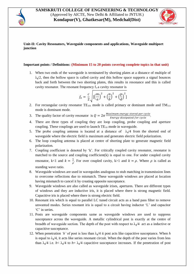
1. When two ends of the waveguide is terminated by shorting plates at a distance of multiple of
λg/2, then the hollow space is called cavity and this hollow space supports a signal bounces
back and forth between the two shorting plates, this results in resonance and this is called
cavity resonator. The resonant frequency fo a cavity resonator is
𝑓𝑜 = 𝑐
2√[(
𝑚
𝑎)
2
+ (𝑛
𝑏)
2
+ (𝑝
𝑑)
2
]
2. For rectangular cavity resonator TE101 mode is called primary or dominant mode and TM111
mode is dominant mode.
3. The quality factor of cavity resonator is 𝑄 = 2𝜋𝑀𝑎𝑥𝑖𝑚𝑢𝑚 𝑒𝑛𝑒𝑟𝑔𝑦 𝑠𝑡𝑜𝑟𝑒𝑑 𝑝𝑒𝑟 𝑐𝑦𝑐𝑙𝑒
𝐸𝑛𝑒𝑟𝑔𝑦 𝑑𝑖𝑠𝑠𝑖𝑝𝑎𝑡𝑒𝑑 𝑓𝑜𝑟 𝑐𝑦𝑐𝑙𝑒.
4. There are three types of coupling they are loop coupling, probe coupling and aperture
coupling. These couplings are used to launch TE10 mode in waveguide.
5. The probe coupling antenna is located at a distance of λg/4 from the shorted end of
waveguide where the electric field is maximum and generates electric field polarization.
6. The loop coupling antenna is placed at centre of shorting plate to generate magnetic field
polarization.
7. Coupling coefficient is denoted by ‘k’. For critically coupled cavity resonator, resonator is
matched to the source and coupling coefficient(k) is equal to one. For under coupled cavity
resonator, k<1 and 𝑘 = 1
𝜌. For over coupled cavity, k>1 and 𝑘 = 𝜌. Where 𝜌 is called as
standing wave ratio.
8. Waveguide windows are used in waveguides analogous to stub matching in transmission lines
to overcome reflections due to mismatch. These waveguide windows are placed at location
having mismatch to cancel it by creating opposite susceptance.
9. Waveguide windows are also called as waveguide irises, apertures. There are different types
of windows and they are inductive iris, it is placed where there is strong magnetic field.
Capacitive iris is placed where there is strong electric field.
10. Resonant iris which is equal to parallel LC tuned circuit acts as a band pass filter to remove
unwanted modes. Series resonant iris is equal to a circuit having inductor ‘L’ and capacitor
‘C’ in series.
11. Posts are waveguide components same as waveguide windows are used to suppress
susceptance across the waveguide. A metallic cylindrical post is exactly at the centre of
breadth of waveguide section. The depth of the post with respect to λg/4 act as a inductive or
capacitive susceptance.
12. When penetration ‘h’ of post is less than λg/4 it post acts like capacitive susceptance. When h
is equal to λg/4, it acts like series resonant circuit. When the depth of the post varies from less
than λg/4 i.e. h< λg/4 to h= λg/4 capacitive susceptance increases. If the penetration of post
SAMSKRUTI COLLEGE OF ENGINEERING & TECHNOLOGY (Approved by AICTE, New Delhi & Affiliated to JNTUH.)
Kondapur(V), Ghatkesar(M), Medchal(Dist)
further increases i.e. >λg/4 it acts like inductive susceptance and it is maximum. If the h is
further increases the inductive susceptance decreases.
13. The variable post is called as tuning screw and it is readily adjustable where as posts are
fixed. The working principle of tuning or adjustable screws is same as post. The depth of
penetration of screw with respect to λg/4 varies the susceptance from capacitive to inductance.
14. Wave guide attenuators are used for measurement of power gain or loss. There are two types
of attenuators they are fixed and variable. Further variable attenuators are classified into flap
and vane type. There are two types of vane attenuators, firstly movable vane attenuator for
rectangular wave guides and rotary vane attenuator is for circular waveguides.
15. Phase shifters are used to introduce phase shift in waveguides. There are different types of
phase shifters dielectric vane phase shifter used for rectangular waveguides and polyfoam is
used as dielectric material having 𝜀𝑟 > 1 to introduce phase shift at two different particular
positions. Rotary vane phase shifters is used for circular waveguides.
16. Waveguide multiport junctions are used to spilt all(part) microwave energy or to combine
energy into particular directions. E-plane tee, H-plane tee, magic tee and directional coupler
are components having multi ports either three or four ports.
17. H-plane tee is a three port component formed by attaching another waveguide at the width of
a main waveguide and this part is called H-arm or side arm. It is called so because the all the
three arms of this tee lie in the plane of magnetic field. This is also called as a current
junction.
18. E-plane tee is a three port component formed by attaching another waveguide section at the
breadth of a main waveguide. For E-plane tee if input power is given at port 3, the electric
field lines change their direction at the junction having 180o phase shift when come out of
port 1 and 2. E-plane tee is also called as voltage or series junction. Magic tee is combination
of E-plane and H-plane tee and is also called as E-H plane or hybrid tee. It is a four port
component.
19. Directional couplers are used for power measurements by collecting small amount of power
for measurement purposes. It is a four port device and all ports are perfectly matched. It
consists two waveguide sections primary waveguide and secondary wave guide also called
auxiliary waveguide. There are bethe hole having single hole, two hole and multi hole
directional couplers.
20. Ferrites are nonmetallic devices having magnetic, ceramic insulator and non-reciprocal
properties having general composition of MeO. Where MeO represents MnO, ZnO, CdO,
NiO or mixture of all these. Gyrator, Isolator and Circulator are components having ferrite
material which make use the principle of faraday rotation.
Short Questions (minimum 10 previous JNTUH Questions)
1. Draw E-plane Tee junction diagram? [May-18]
2. Explain any one application of Magic Tee? [Dec- 17]
3. Compare probe and loop couplings? [May-19]
4. What is post and what is application of it? [March-17]
5. Write briefly about tuning screw? [Dec-16]
6. Explain about waveguide windows? [March-17, R-13]
SAMSKRUTI COLLEGE OF ENGINEERING & TECHNOLOGY (Approved by AICTE, New Delhi & Affiliated to JNTUH.)
Kondapur(V), Ghatkesar(M), Medchal(Dist)
7. Explain about Ferrites composition and characteristics? [May-18, R-13]
8. Write about faraday rotation? [March-17, R-13]
9. Draw neat sketches of E and H-plane Tees [April/May-18, R-09]
10. Highlight the importance of attenuators? Describe their important applications?
[April/May-18, R-09]
Long Questions (minimum 10 previous JNTUH Questions)
1. What are different types of attenuators? Explain them with neat diagrams? [March-17, R-13]
2. What are waveguide phase shifters? Explain them with neat diagrams? [May-19, R-13]
3. Draw the structure diagram of E-plane Tee and explain its characteristics? [March-17, R-13]
4. Describe the working of H-plane Tee and state why it is called shunt Tee? [May-18, R-13]
5. Explain the working of two-hole directional coupler with a neat diagram and derive the
expression for the coupling and directivity of it? [Dec-16, R-13]
6. What are characteristics of directional coupler and the S-matrix of it? [Dec-16, R-13]
7. With the help of the diagram, explain principles and operation of a 3-port circulator?
[May-18, R-13]
8. Write a note on waveguide discontinuities? [April/May-18, R-09]
9. Explain how ferrites are used for isolators? Explain any one such circuit?
[May/ June-19, R-09]
10. What are waveguide windows? How these are used in microwave circuits?
[May/ June-19, R-09]
Fill in the Blanks / Choose the Best: (Minimum 10 to 15 with Answers)
1. Magic tee is a four port device.
2. H-plane Tee is also called as current junction.
3. E-plane is also called as voltage or series junction.
4. Single hole directional coupler is also called as bethe hole directional coupler.
5. Resonant frequency of cavity resonator is 𝒇𝒐 = 𝒄
𝟐√[(
𝒎
𝒂)
𝟐
+ (𝒏
𝒃)
𝟐
+ (𝒑
𝒅)
𝟐
]
___________________________
6. TE101 mode is also called primary mode or dominant mode.
7. Coupling coefficient is denoted by k.
8. The microwave cavity resonator is similar to tuned circuit.
9. Magic tee is also called as Hybrid tee or E-H plane tee.
10. A two port non-reciprocal device which have low attenuation to wave propagating in one
direction and a very high in opposite direction is isolator.
SAMSKRUTI COLLEGE OF ENGINEERING & TECHNOLOGY (Approved by AICTE, New Delhi & Affiliated to JNTUH.)
Kondapur(V), Ghatkesar(M), Medchal(Dist)
Unit-III: Microwave tubes, Helix TWTs
Important points / Definitions: (Minimum 15 to 20 points covering complete topics in that unit)
1. At microwave frequencies, conventional electronic devices cannot be used due to following
factors
a) Inter electrode capacitance effect
b) Lead inductance effect
c) Transit time effect
d) Gain bandwidth limitation
e) Radiation losses
2. Microwave tubes are classified in to, O-type tubes like two cavity klystron and reflex klystron.
M-type tubes like magnetron. These microwave tubes provide higher output power.
3. Klystron is an amplifier of power at microwave frequencies and can also be used as generator.
Klystron is vacuum tube based on velocity modulation.
4. Two cavity klystron is an amplifier consists of two cavities buncher cavity and catcher cavity
separated by small distance is called as drift space. It consists of cathode, buncher cavity,
catcher cavity and anode collector.
5. In two cavity klystron velocity of electron beam varies according to RF input voltage given as
input to buncher cavity by coaxial cable, this modulation is called velocity modulation.
6. The operation of two cavity klystron is explained by applegate diagram.
7. Applications of two cavity klystron, can be used as power output tubes, in UHF TV
transmitters, in troposphere scatter transmitters, satellite communication ground stations, radar
transmitters. The theoretical efficiency is 58%.
8. The reflex klystron is an oscillator consists of single cavity called anode cavity. It is a single
cavity variable frequency microwave generator having low power and low efficiency.
Theoretical efficiency 𝜂 is 22.78% and where as practical efficiency is 10% to 20%.
9. The applications of reflex klystron is in radar receivers, local oscillators in microwave
receivers, signal source in microwave generator of variable frequency, portable microwave
links and pump oscillator in parametric amplifier.
10. Reflex klystron consists of an electron gun consists of filament which is surrounded by cathode.
It also consist of anode cavity and repeller electrode, RF output is collected from anode cavity.
11. The frequency range of reflex klystron is 4 to 200GHz. Output power is 1.0mW to 2.5mW.
12. TWT is called as Travelling Wave Tube and it is broad band amplifier.
13. TWTs are different from klystron amplifiers and makes use of distributed interaction between
an electron beam and travelling wave.
14. Klystrons are narrow band devices and uses cavity resonators to velocity modulate the electron
beam over a narrow gap.
15. TWTs are broad band devices having no cavity resonators. The electron beam interacts with the
RF wave over the full length of tube.
16. TWTs electron beam and RF field travels in the same direction with nearly the same velocity.
17. In klystrons the electron beam travels and the RF field remains stationary.
18. The TWT consists of electron gun, used to generate electron beam having constant velocity.
This electron beam is passed trough axial helix.
SAMSKRUTI COLLEGE OF ENGINEERING & TECHNOLOGY (Approved by AICTE, New Delhi & Affiliated to JNTUH.)
Kondapur(V), Ghatkesar(M), Medchal(Dist)
19. TWT consists of helix and it is a loosely wound thin conducting helical wire and acts as a slow
wave structure.
20. In TWT, the RF signal propagates through the slow wave structure called helix. The electron
beam from electron gun of TWT passes through center of axial helix and a magnetic focusing
field is provided to guide electron beam through the centre of the helix.
Short Questions (minimum 10 previous JNTUH Questions)
1. Compare ‘O’ type and ‘M’ type tubes? [March-17]
2. What are the limitations of conventional tubes? [March-17]
3. How microwave tubes are classified? [Dec-17, May-19]
4. Draw typical applegate diagram? [May-18]
5. Explain transit time effect in conventional tubes? [May-18]
6. How is frequency tuning achieved in reflex klytron? [April/May-18, R-09]
7. How cross-field concept is used to produce oscillations in magnetron? [May/June-19, R-09]
8. List the characteristics of slow wave structures? [Nov/Dec-17, R-09]
9. Explain need for velocity modulation in microwave tubes? [April/May-18, R-09]
10. Draw the different forms of slow wave structures in TWTs? [April/May-18, R-09]
Long Questions (minimum 10 previous JNTUH Questions)
1. State the limitations of conventional tubes at high frequencies? [May-18]
2. Classify the various microwave tubes with respect to the orientation of electric and magnetic
fields? [May-18]
3. Explain the bunching process of two cavity Klystron amplifier with applegate diagram and
also derive the equations for power efficiency? [Dec-16, May-18, May-19]
4. Draw the mode curves of reflex Klystron and derive the relation between mode number and
repeller in reflex Klystron? [Dec-17]
5. Explain the principle of working of Travelling Wave Tube and write the equations for the
maximum voltage gain and efficiency? [Dec-16, Dec-17, May-18]
6. Explain how TWT is increased gain by increasing the bunching of electrons and derive the
equations of gain? [March-17]
7. Compare the performance of TWT and Klystron amplifier? [Dec-17, May-19]
8. In a helix -type TWT, explain the amplification process and extend interaction between RF
signal and electron beam? [April/May-18, R-09] 9. Describe the principle of operation of TWTA? Explain why an attenuator is sometimes placed
in mid-way along the axis of slow wave structure? [Nov/Dec-17, R-09]
10. Justify the statement: Any three port microwave network in which if all the ports exhibit
matched condition simultaneously, it must be three port circulator? [Nov/Dec-17, R-09]

SAMSKRUTI COLLEGE OF ENGINEERING & TECHNOLOGY (Approved by AICTE, New Delhi & Affiliated to JNTUH.)
Kondapur(V), Ghatkesar(M), Medchal(Dist)
Fill in the Blanks / Choose the Best: (Minimum 10 to 15 with Answers)
1. In a Klystron amplifier, the RF voltage produces velocity modulation.
2. In a vacuum tube, the transit time of electron between cathode and anode is important at high
frequencies.
3. The main advantage of TWT over klystron is higher bandwidth.
4. In a reflex klystron oscillator, repeller electrode is at negative potential.
5. The maximum theoretical output circuit efficiency of a double resonator klystron amplifier is
50%.
6. To prevent oscillations attenuator used in a TWT.
7. In reflex klystron, the adjustment of volume of the anode cavity will result in change of
a) output power b) output pulse width c) output frequency of operation d) output S/N ratio
8. In a TWT, the phase velocity of the axial component of the field on slow wave structure is
kept equal to velocity of electron.
9. The frequency of oscillations obtained from a reflex klytron depends mainly on resonant
frequency of cavity.
10. The correct sequence of subsystems of klystron amplifier as they appear in the direction of
low of the electron beam is
a) Buncher cavity, Cathode, Collector, Catcher cavity.
b) Buncher cavity, Cathode, Catcher cavity, Collector.
c) Cathode, Buncher cavity, Catcher cavity, Collector.
d) Cathode, Buncher cavity, Collector, Catcher cavity.
Unit-IV: M-Type tubes, Microwave Solid State Devices
Important points / Definitions: (Minimum 15 to 20 points covering complete topics in that unit)
1. Microwave tubes are classified in to, O-type tubes like two cavity klystron and reflex klystron.
M-type tubes like magnetron. These microwave tubes provide higher output power.
2. The tubes in which electric and magnetic field are perpendicular to each other are known as
cross field tubes. Magnetron is best example of it.
3. The magnetron was invented by Hull in 1921 and an improved magnetron was developed by
Randall and Boot around 1939. They provide microwave oscillations of very high peak power.
4. Magnetron consists of copper anode block, interaction space, cathode and anode cavity.
5. Magnetrons can be classified into three types. They are negative resistance type, cyclotron type
and travelling wave or cavity type.
6. Magnetrons are used in pulsed radar with large pulse powers, voltage tunable
magnetrons(VTMs). Magnetron having efficiency of 40% to 70%.
7. IMPATT, TRAPATT and BARITT diodes are avalanche transit time devices.
8. Applications of GaAs is front end low noise amplifier, power amplifier, drive amplifier, output
amplifier, power oscillators.

SAMSKRUTI COLLEGE OF ENGINEERING & TECHNOLOGY (Approved by AICTE, New Delhi & Affiliated to JNTUH.)
Kondapur(V), Ghatkesar(M), Medchal(Dist)
9. Gunn diode find it applications in radar transmitters, broad band linear amplifier, low and
medium power oscillators.
10. IMPATT- Impact Ionization Avalanche Transit Time device. They are used in microwave
oscillators.
11. TRAPATT- Trapped Plasma Avalanche Transit Triggered Transit device. It is derived from
IMPATT diode and it is closely related to it.
12. BARITT- Barrier Injected Transit Time device. It is less noise than IMPATT diode.
13. Solid state microwave devices are classified as on the basis of electrical behaviour like varactor
diode, tunnel diode, IMPATT diode, Gunn diode, PIN diode.
14. Solid state microwave devices are classified on the basis of construction like Schottky barrier
diode, MOS devices, metal insulation devices.
15. PIN diode consists of an Intrinsic layer sandwiched in between p and n layers.
16. PIN diodes are widely used for microwave power switching, limiting and modulation.
17. Tunnel diode works based on the negative resistance principle.
18. Tunnel diodes are used for oscillations or amplification purposes.
19. MESFETs are unipolar microwave transistors that have several advantages compare to bipolar
microwave transistors.
20. MESFETs are with silicon(Si) and gallium arsenide(GaAs) are very popular. GaAs mobility is
six times higher than Si.
Short Questions (minimum 10 previous JNTUH Questions)
1. What is strapping in magnetron? [May-19]
2. How pi-mode is separated in magnetron? [March-17]
3. What are disadvantages of strapping? [Dec-16]
4. What is mode jumping in cavity magnetron how this can be avoided? [May -19]
5. Explain RWH theory? [Dec-17]
6. Mention the application of TED’s? [Dec-17]
7. Draw the diagram of IMPATT diode and carrier concentration? [May-18]
8. How LSA mode of Gunn diode is used to produce oscillations? [March-17]
9. How cross-field concept is used to produce oscillations in magnetron? [May-19]
10. How does magnetron sustain oscillations using cross field? Assume π-mode of operation to explain the same? [April/May-18, R-09]
Long Questions (minimum 10 previous JNTUH Questions)
1. Derive equation for Hull cut-off voltage in a magnetron? [May-18]
2. Explain how 8-cavity cylindrical magnetron is used to produce oscillations? [March-17]
3. Explain the electron bunching process in cylindrical magnetron with neat diagram and derive
the Hartree condition? [May-19]
SAMSKRUTI COLLEGE OF ENGINEERING & TECHNOLOGY (Approved by AICTE, New Delhi & Affiliated to JNTUH.)
Kondapur(V), Ghatkesar(M), Medchal(Dist)
4. Explain how is bunching achieved in a cavity magnetron? [Dec-16]
5. List and explain different types of magnetrons? [Dec-17]
6. Draw the characteristics of Gunn diode and explain how negative resistance region is
obtained? [May-19]
7. Discuss in detail the principle of operation of Gunn diode considering the two valley model
theory and sketch its volt-ampere characteristics? [May-18]
8. Explain how Gunn diode is used in waveguide oscillator? [March-17]
9. Give the classification of solid state microwave devices? [Dec-16]
10. What are the different avalanche transit time devices? [March-17]
Fill in the Blanks / Choose the Best: (Minimum 10 to 15 with Answers)
1. The main feature of parametric amplifier is broad bandwidth.
2. A PIN diode can be used both as series or shunt mounted switch.
3. The semiconductor diode which can be used in switching circuit in microwave range is PIN
diode.
4. Double cavity klystron is used for amplification of microwave signals.
5. Thermal electron diode is a hot-electron diode.
6. The two valley model is used to explain the working of Gunn diode oscillator.
7. Magnetron is called M-type tube having cross field tubes.
8. In pi-mode operation of magnetron, the spokes due to phase focusing effect rotate at an angular
velocity corresponding to two poles/cycle.
9. GaAs is used in to make Gunn diode.
10. IMPATT, TRAPATT, BARITT are called avalanche transit time devices.
Unit-V: Scattering Matrix, Microwave measurements
Important points / Definitions: (Minimum 15 to 20 points covering complete topics in that unit)
1. For microwave frequencies scattering parameters are used for power calculations. This is due
to high frequency range of microwaves.
2. For low frequency circuits the network parameters are voltage and current. Here two port
networks like Z,Y, H, ABCD parameters are used.
3. S parameters are represented in S-matrix and the elements of it called as scattering
coefficients or Scattering(S) parameters.
4. Scattering matrix is denoted by [S] and is always a square matrix of order of n*n.
5. [S] matrix symmetric matrix i.e. Sij=Sji.
SAMSKRUTI COLLEGE OF ENGINEERING & TECHNOLOGY (Approved by AICTE, New Delhi & Affiliated to JNTUH.)
Kondapur(V), Ghatkesar(M), Medchal(Dist)
Sij corresponds to scattering coefficients where input is given at ith port and output is taken
from jth port.
Sji corresponds to scattering coefficients where input is given at jth port and output is taken
from ith port.
6. Scattering matrix is unitary matrix i.e. [S][S]*=[I].
Where [S]* is complex conjugate of [S]
[I] is unit matrix
7. Microwave Tee junction are three or four port devices. They are H-plane tee, E-plane tee, E-
H plane tee which is also called as hybrid junction are magic tee. These tee junctions are
formed by intersection of three or four wave guides and forms waveguide junction. These are
in the form of English alphabet ‘T’.
8. Circulator and Isolator are ferrite components having ferrite component in it. This ferrite
component is thin and circular in shape and tapered at both ends.
9. Isolator is a two port device having port 1 and port 2. When the input is given at port 1 the
output will be at port 2 with zero degree phase shift with minimum attenuation. When the
input is given at port 2 there will no output at port 1 with maximum attenuation.
10. Circulator is three or four port device. If the input is given at port 1 the output only at port 2
not for port 3 and port 4. This is due to electric field is not significantly cut at port 3 and port
4 and remains unaffected. If the input is at port 2 then the output will be at port 3 but not at
port 1 and port 4. Similarly remaining all other ports. Circulator is a device each port is
connected to the next clockwise port.
11. Microwave frequencies are range from 1GHz to 1000 GHz, because of this high frequency
range and electromagnetic in nature, it is easy to measure power at microwave frequencies
instead of measuring voltage or current.
12. Frequency, power, attenuation, VSWR, phase, impedance like parameters of microwave
frequencies are easily able to calculate.
13. Microwave signal source is a device used to generate microwave signals. Different sources
can be used they are O-type tubes like klystron and reflex klystron, Helix TWTs, Gunn diode
oscillator, M-type tubes like magnetrons.
14. Isolator is arranged after microwave source to protect it from reflection from termination side
and it is a two port device.
15. Frequency meter is used calculate precision values of microwave frequencies in terms GHz.
16. Attenuators are used to for power calculations and to save the power of microwave sources, to
protect the load from excess power input from source, it also used to isolate section of
microwave bench from remaining part of bench.
17. Slotted line is used to measure standing wave pattern inside the waveguide and is used to
measure standing wave ratio. The tunable detector is used to detect the low square wave
modulated microwave signal.
18. Detector mount is used in microwave bench setup to obtain the output microwave power to
load.
19. Matched terminations are used to terminate waveguide. These are used to avoid reflections
from the end of transmission line. Termination can be fixed or adjustable.
20. Phase shifters, bends, twists, waveguide windows, posts and tuning screws are some
microwave components used in microwave transmission line like rectangular, circular
waveguides based on their requirement. Measuring devices like VSWR meter, power meter
are used to measure standing wave values and power calculation at microwave frequencies.
SAMSKRUTI COLLEGE OF ENGINEERING & TECHNOLOGY (Approved by AICTE, New Delhi & Affiliated to JNTUH.)
Kondapur(V), Ghatkesar(M), Medchal(Dist)
Short Questions (minimum 10 previous JNTUH Questions)
1. What is the need for an isolator in microwave bench and where it is placed? [March-17]
2. What type of slot is used in microwave bench? [May-19]
3. Why the S-parameters are used in microwaves? [March-17, Dec-18]
4. Explain the significance scattering matrix? [Dec-17, May-18]
5. What are the possible errors in high frequency measurements? [May-18]
6. What are the properties of S-matrix? [May-19]
7. Draw a neat sketch of microwave measurement bench setup? [April/May-18, R09]
8. Using waveguide slotted section, explain impedance measurement techniques?
[April/May-18, R09]
9. What type of slot is used in microwave bench? [May/June -19, R09]
10. List the precautions to be taken during microwave measurement? [Nov/Dec- 17, R09]
Long Questions (minimum 10 previous JNTUH Questions)
1. Explain the S-matrix representation of a multiport microwave network and its significance?
[Dec-16]
2. Find the S-matrix of a Magic Tee? [May-18]
Or
Draw the structure of Magic tee and write its characteristics and also derive its S-matrix?
[March-17]
3. Describe the blocks of microwave bench and their features? [Dec-16]
4. Explain the procedure for measuring attenuation with neat diagram? [Dec-17]
5. Describe how the frequency of a given microwave source can be measured using two
different methods? [May-18]
Or
Explain how a slot section is used to measure the frequency of a given microwave signal?
[March-17]
6. Explain how to measure the VSWR of a given load at microwave frequencies with neat block
diagram? [May-19]
Or
What are the different possible errors that will effect VSWR measurements? [May-18]
Or
Explain the procedure for measuring VSWR<10? [Dec-17]
7. Give the measurement procedure for measuring Q factor of resonant cavity? [Dec-17]
8. Explain any one method for the measurement of microwave power? [April/May- 18, R09]
9. What are the characteristics of two hole directional coupler and derive the s-matrix of it?
[May/June-19, R09]
10. With the help of a neat sketch, explain the double minima method for measuring VSWR?
[May/June-19, R09]
SAMSKRUTI COLLEGE OF ENGINEERING & TECHNOLOGY (Approved by AICTE, New Delhi & Affiliated to JNTUH.)
Kondapur(V), Ghatkesar(M), Medchal(Dist)
Fill in the Blanks / Choose the Best: (Minimum 10 to 15 with Answers)
1. Double minimum method is used for the measurement of high VSWR.
2. The microwave source used as a local oscillator for frequency measurement is reflex
klystron.
3. Bolometers are based on the principle of variation of resistance with absorption of power.
4. The position of the probe for half power points in the slotted line of a microwave bench are
interpreted to measure high SWR.
5. In the standing wave detector method for measuring a slightly mismatched load impedance,
the distance from the load position to the nearest voltage minimum towards the generator is
one-eighth the guide wavelength. The load is a capacitive impedance.
6. As an, ideal local oscillator for microwave frequency measurements, the most suitable
microwave source would be reflex klystron.
7. S-parameters are used to measure power in dB for microwaves.
8. There is zero degree phase shift for isolator when input is given at port 1 and output is
received at port 2.
9. For a S-matrix [S][S]*= [I], where [S] is unitary matrix.
10. [S] is always a square matrix of order of (n*n).


![Semester V (Third year] Branch/Course Civil Engineering V ...](https://static.fdokumen.com/doc/165x107/6321a517ae0f5e8191058b94/semester-v-third-year-branchcourse-civil-engineering-v-.jpg)