SAFETY REQUIREMENTS for A NUCLEAR POWER PLANT ...
46
XA04N2806 NRSC/R-4.88 INIS-XA-N-233 SAFETY REQUIREMENTS for A NUCLEAR POWER PLANT ELECTRIC POWER SYSTEM Prepared byS L . F FOUAD & M.A.SHINAISHIN Nuclear Regulatory and Safety Center Atomic Energy Authority Date Published I June 198ft NRSC
-
Upload
khangminh22 -
Category
Documents
-
view
1 -
download
0
Transcript of SAFETY REQUIREMENTS for A NUCLEAR POWER PLANT ...
XA04N2806
NRSC/R-4.88INIS-XA-N-233
SAFETY REQUIREMENTSfor
A NUCLEAR POWER PLANT ELECTRICPOWER SYSTEM
Prepared byS L.F FOUAD & M.A.SHINAISHIN
Nuclear Regulatory and Safety CenterAtomic Energy Authority
Date Published I June 198ft
NRSC
Of CONTENTS
1. InTRoducTIon 1
2. SysTem DescRIpTIon 2
2. 1 ^oweR DIsTRIbuTIon sysTem ^
2.2 THe A.C. ^owER SysTem ^
2.^ The D.C. i oweR SysTem ^
2.4 NoN-lNTeRRupTabLe A.C. ^oweR SysTem ^
2.^ DIeseL GeNeRaTors ^
. INfoRmaTIoN RequIremenTs FoR SafeTy
ANaLysIs aNd Review 6
. 1 INfoRmaTIoN To be SuppLIed by The Licensee 6
^.1.1 I RefeRRed i oweR SysTem 6
^.1.2 STandby ^owER SysTem 6
^.1.^ D.C. oweR SysTems 8
^.1.4 FIRe ^RoTecTIon foR CabLe SysTems 8
^.2 Scope of review by THe reguLaToRy body 8
^.2.1 ^RefeRRed ^oweR SuppLy 9
^.2.2 STandby ^Ower SysTem 10
^.2.^ DC ^oweR SuppLIes 11
4. GeneRaL DesIgN CRITeRIa for ELecTRIc i oweR
SysTem 11
. MeaNS for ImpLemenTaTIoN/ReguLaToRy guides
aNd BRaNcH TecHNIcaL ^osITIoNS 14
. 1 INdepeNdeNce BeTween RedundanT STaNdby( ONsITe)
^oweR sources aNd THeIr DIsTRIbuTIoN SysTems. 14
^.2 SeLecTIon of DIeseL GeneRaToR SeT CapacITy foR
STandby ^ower SuppLIes 16
- i -
TabLE of CoNTEnTs
I^eriodic TesTIng of ^RoTecTioN SysTem
AcTuaTIoN FuNcTIons 17
Seismic Design CLassificaTion 18
QuaLiTy AssuRance RequiRemenTs foR The
InsTaLLaTioN, INSpecTiN and TesTiNg of
InsTRuMenTaTIon and ELecTrIc EquIpmenT. 1^
CRITeRIa for SafeTy ReLeaTed ELecTrIc ^oweR
SysTem for NucLeaR ^oweR ^LanTs 18
QuaLIficaTioN TesTs of CoNTiNuous DuTy MoToRS
INSTaLLed INSide The ConTainmeNT of WaTeR
CooLed NucLeaR ^oweR ^LaNTs . 19
^ReopeRaTioNaL TesTiNg of ReduNdaNT ONSiTe
ELecTRicaL ^oweR SysTems To VeRify ^RopeR
Load GRoup AssignmeNTs 20
Bypassed aNd InopeRabLe sTaTus INdicaTion
for NucLeaR ^oweR ^LaNT SafeTy SysTems. 21
AppLicaTioN of THe SiNgLe FaiLure CRiTeRioN
To NucLeaR ^oweR ^LaNT ^RoTecTioN SysTems. 21
MaNuaL INiTiaTioN of I^RoTecTive AcTions 22
ELecTRicaL ^eneTRaTioN AssembLies in
ConTainmenT STRucTuRes for LigHT WaTer-
CooLed NucLeaR T oweR ^LanT. 2^
IniTiaL TesT ^RogRams for WaTeR CooLed
NucLeaR i oweR ^LanTs. 24
QuaLificaTion TesTs of ELecTRic VaLve
OpeRaToRs InsTaLLed Inside THe ConTainmenT
of NucLear I ower ^LaNTs. 26
of CONTENTS
^HysIcaL IndependeNce of ELecTRIc SysTem 27
ShaRed EmeRgeNcy aNd SHuTdown ELecTrIc
SysTems for MuLTI^UnIT NucLear ^oweR ^LanTs 27
QuaLIfIcaTIoN of CLass IE EquIpmeNT foR
NucLeaR i oweR I LanT. 28
AvaILabILITy of eLecTRIc power sources 29
Seismic QuaLIfIcaTIoN of ELecTRIc
EquIpmenT foR NucLeaR T ower F LaNTs ^0
THeRmaL OveRLoad ^RoTecTIoN foR ELecTRIc
MoToRs ON MoToR OpeRaTed VaLves ^0
^eRIodIc TesTINg of DIeseL GeNeRaToR UnITs
Used as ON-sITe ELecTRIc F oweR SysTems aT
NucLeaR ^oweR ^LaNTs 1
INSTaLLaTIoN DesIgN and INSTaLLaTIoN of
LaRge Load SToRage BaTTeRIes foR NucLeaR
MaINTeNaNce, TesTINg, aNd RepLacemeNT of
LaRge Lead SToRage BaTTeRIes for NucLeaR
DIeseL-GENeRaToR ReLIabILITy QuaLIf IcaTIoN
TesTIng
RequIRemeNTs on MoToR OpeRaTed VaLves 1 ^
THe EmeRgency CoRe CooLing SysTem AccumuLaToR
Lines
Use of DieseL-GeneRaToR SeTs f o r Load
- iii -
of
^.27 STabILITy of Off-SITe ^oweR SysTem
^.28 ReacToR CooLanT ^ump BReakeR QuaLIfIcaTIon
^.29 DIeseL-GeneRaToR F roTecTIve Trip CIRcuIT by
Masses
^ ^ 0 ^ AppLIcaTIon of THe sIngLe FaILuRe CRITeRIon
To MaNuaLLy ConTRoLLed ELecTRIcaLLy-OpeRaTed
VaLves
6. ConcLusIoNS
RefeRences
AbsTRacT
woRk alms at IdentifYINg THe safety RequIRemENTs foR THE eLEctric
power systEm In a typIcal NucleAR power plant, I n views of The USNRC aNd
THe IAEA. DescriptioN of a typical sysTem is pRovided^ followed by a
pReseNtatioN of ThE scopE of THE InfoRmatioN RequIRed for safEty EvaLuatioN
of The system desigN and perfoRmance^
The acceptance and desigN cRiteria ^ ^ i musT bE mET as being SpEeified
by boTh REgulaTory sysTems, aRe compared. Means of ImpLemeNTaTion of
Such criTeria as beiNg described i n ThE USNRC ReguLATory guIdes and bRanch
TEchnical p o s I t i ^ ^ on one haNd aNd In The IAEA safety gu ta^ ON The other
haNd arE investigated. IT is concludEd that ThE IAEA REgulations address
ThE pRobLems That may be faced with In countries having vaRying grid si^es
Ranging fRom LARge stabLe To Small potENtiaLLy unstaBLE oNes; and that
ThEy put Emphasis on ThE onsitE standby power Supply. Also, i n This RespeCT
The Americans ident i fy the gr id as ThE pREfERREd power supply to The plant
auxi l iar ies, whiLE The IAEA Leaves the possibiLity ThaT The pRefeRREd
power suppty couLd bE Either ThE gr id oR The uniT mrin geneRAToR depeNring
on The Rel iabi l i tY of Each. TH^EfoRE, it is found that it ^ paRticulaRly
NEcessary In Th^s aRea of clEcTric power supplies To dEal wiTh The IAEA
and The American SEti of REgulations as i f Each compLeMents and noT
SuppLEmEntS ThE other.
1 INTRODUCTION
T h ^ paper pResEnTs a compREhEnsivE coveRagE of The REgulaTory
REQuiREmEnts coNCERNIng ThE ELEcTric ^ower Supply (E^S) To a NuclEaR ^ower
^ ^ 1 (N^) i n gENERAL, and To EnginEered SafEty FEatuRes (ESFs) and Safety
RELated EQuipmEnt i n paRticuLaR. IT also aims at making a c r i t i cAL
comparison bEtwEEn ThoSE REQuIREmENts as being described by ThE United
States NuclEaR REgulaTory Commission USNRC, and by The InTeRnationAL Atomic
ENergY IAEA REguLations.
ThE scope of This woRk ExTEnds from out l in iNg ThE infoRmation nEcessary
To ENABLE foR maKing a SouNd ETS EvaluatioN, IdEnt i f y ing ThE GENERal DesigN
^ 1 -

- 2 -
CRiteria GDC THat muST be f u l l f l l e d in order To assurE a safe desIgN and
ReLIabLe perfoRmaNce, and ENds witH a descriptioN of THE methodoLogY ThaT
shouLd bE followed IN order To achieve a good impLementatioN of Thos
However, it SEEmed NEcessary To fiRST pRovidE a brief dEScription
of a typical E S foR a N^ , and THat wHat was donE THRough ThE following
SEction. ThE comparison paRAllELs EAch of The subJEcTs (infoRmation,
criTEria, and mCThodoLogy) iNcluded i n ThE Siudy. A gEneRal coNclusioN
is madE at The end; and REferENCes aRE LisTed.
2 SYSTEM
ThE ELEctrical power sysTems at a NucleAR power plant aRE designed
To providE diveRSE ReLtabLE powER souRces To plant componEntS and EquipmEnt
i n additioN to s^pty ing power fRom ThE plant To ThE of f -s t iE trAnsmissioN
neTwork. ThE stat ion power is supplied by Either The of f -s i tE mrin
disTribution grid oR by The unIT maIN gEneR^ToR. In CASE of Loss of o f fs i tE
power supplies, Including uniT gEneRAToR^ and the gr id, the power REquIreD
foR safE shutdown of THE ReaCToR is Supplied fRom diesEL gEneRatoRS Located
on-site and known as THe standby AC power Source.
ThE station cleCTrical system ^ designed to ensuRE ELECTrical
isolation and physicaL separation of The The Redundant power supplies
foR stat ion equipment REQuiRed for safeTy; and due to liMitations Imposed
by The power whicH can bE dElivered by thE dIeseL genEratoRS thE UN T
power suppty is spl lT beTwEEn ENgiNEered Safety FEatuRe^ (ESF) buses
which can bE SupptiEd by The diesELs, and non-ESF buses.
Redundant trAIns of EngineeRed Safety FEatuRes equipmEnt aRe maintained
ELEctrIcally SEpaR TE by having each TRain powered by I t s own diesEL.
This EnsuRes t^^T a sIngLE active faILuRe (e.g., Loss of a diescl) w i l l
noT JeopaRdi^e a Safe shutdown of The REacToR.
BaTtaries aRe pRovided as a source of power for vitaL instrumEntation,
bReaker contRolleRS, emergencY llghting, eTc. In ^SE of station blackoat,
i . e . TotaL Loss of plant o f f - s i t e and on-site AC-power, baitaries are
In view of ThE USNR unit gENERaToRS ARE considered parT of The of f -
SitE power supply bEcauSE Loss of ThE griD ^ assumed to automaticaLLy
Lead To Loss of The unit gEneRAToR
ESFs include eQuipmEnt REquiREd foR SafE ReacToR shut down, ResIduAL
hEat rEmoval, and Radiation coNfinEmEnt.

ThE oNty souRCE of power LefT^ They are maIntaInEd f u l l y chaRged by baTtary
chARgers fRom so- ca l led v i taL b u s ^ which arE fed fRom ThE ESF buses vta
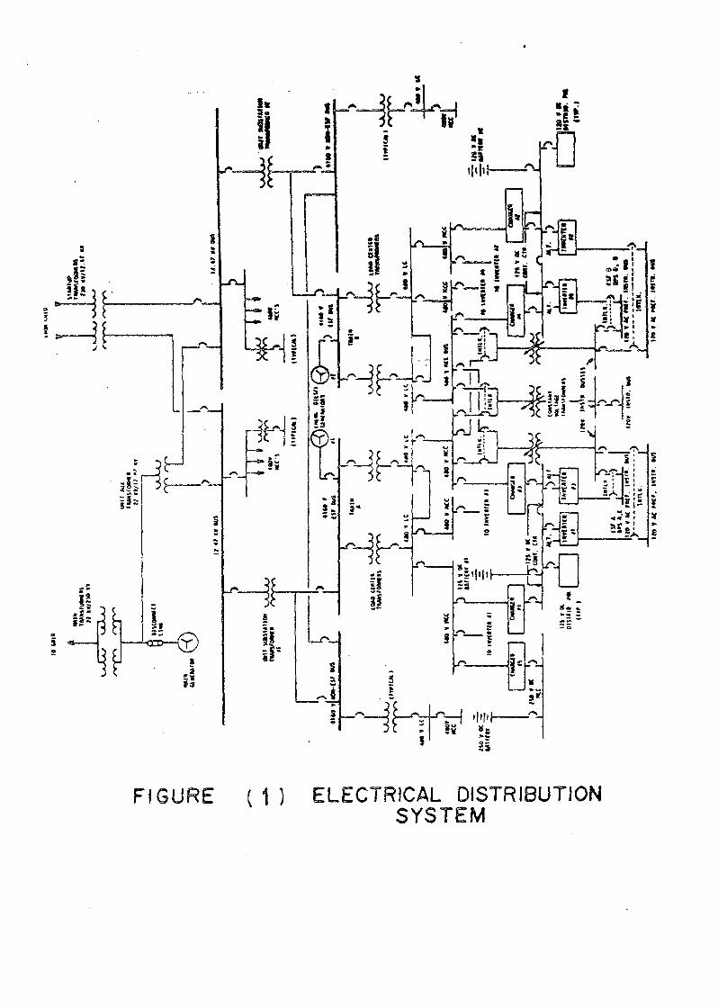
FIguRE 1, bclow, shows a typIcal ELect r Ica l power SySTem of a NucleaR
power s ta t i oN , a descr ipt ioN of which is given
2^ 1
To The g r i d ^ Supplied fRom The mriN gENeratoR ThRough ThE
maiN power TRAnsfoRmer. THE s t a t i o n d i s t r i b u t i o n buses (1^.4^ ^v b u s ^
CAN REceivE power EitHer from THE mrin gEnEratoR ThRough ThE uniT
transfoRmer OR from ThE gRid through ThE s ta r i up transfoRmer.
2^2 THe ^ C ^
ThE s t a t i o n AC power system has four 4160 v o l l buses which REceivE
power fRom ThE two 1^.4^ ^v distrIbutioN b u ^ ^ vta two u n t i substat ion
transfoRmerS and individual bREakERS. Two of thesE buses aRE EnginEerED
SafEty FEataRE (ESF) buses, The other two cARRy servicE Loads wnich ARE
noT ReL^ed to emergencY safEguards. ThE two non ESF buses arE capable
of being cRoss coNnECTed. ThE ESF b u ^ ^ havE pREfERRed power coming fRom
The s ta r i up transfoRmeRS, w t ih The power coming fRom THe uNit TRAnsfoRmer
during NoRmal p lan t opeRatioN. A l l 4160 v o l l buses suppty a 4^0 voLT
d i s t r i b u t i o n system ThRough Load cEnter step-down TransfoRmers. THE 4^0
voLT system R e c c i n g power fRom tHe two ESF buses is compLeTeLY isolaTed
fRom that REceiving power fRom THe other two 4160 v o l l non-ESF buses^
ESF LoaDs are divided beTwEEn thE mrin 4160 v ^ T buses Such tHat ThoSE
The same funct ion are suppl ied fRom differEnt souRces.
The DC power supply system, shown i n F ig. 1, consists of onE ^ 0 voLt
DC and two 12^ voLT DC sysTems desigNed To pRovide an adequate and RELtabLE
SourcE of continuous DC p o w ^
ThE 2^0 voLT DC system Supplies power fo r LARgE DC motoR-drivEn pumps
such as THE EmergEncY bEaring o l l and emergency SEaL o l l pumps. This
system is not esSEntial foR a SafE shat-down of ThE p lant . IT has I t s
owN batTEry, batiERy chaRger and diStributioN bus, and is Located in I t s
own SEpARatE vEntiLated Room in THE Turbine buiLding.
The two 12^ voLT DC systems supply power foR emergency tighting,
DC contaoL funct ions foR ciRcuIT breakeRS^ various RELays, SoLEnoid valves^
NuclEar instrumEnTatioN, AC iNveriERS and smal l DC motoR drivEn Equipment.
THis equipment ^ pa r t of The ESFs, and ^ Located i n The auxiL iary

IT ^ comprised of two baTTEries, Each having two batiERy
cHaRgeRS powered fRom RedunDANT b u s ^ aNd The NEcesSARy disTribution
This portion of ThE sysTem is designed to pRovidE reLiabLE eLEctric
power foR conTroL and instrumentatioN. IT consists of 120 voLt InsTRumEnt
AC-aNd pREfERR^ AC SySTems ThE 120 vo l l Instrument AC sysTem contains
THREE buses aNd supplies contRoL and instrumENtatioN power foR EQaipmEnt
noT ReQuiRed foR The safE shutdown of The ReactoR.
ThE pREferred instruMEnt AC sysTem supplies continuous and RELtabLE
120 voLT AC power REquiRed foR safE shut-down of ThE REacToR
THE pREfErred instrumEnt AC system, compRised of fouR ESF-RELated
buses, supplies ReLiabLE 120 voLT AC singLe-phaSE power to ThE ESF channeL
EqaipmEnt and The ReactoR pRoTection chanNELs. Each pREfERRed instrumEnt
AC bus can be supplied from one of ThREe SouRces of power as sh^^n in
Fig. 1. ThE noRmaL SouRCE of power is I t s associated s ta t i c inveRTer wnicH
Receives i t s power from an ESF 4^0 voLT motoR center. THE backup pow^^
supply foR The inveRTERS is a connection to the 12^ voLT DC stat ion
batieries. I f it is necessary to take an invEnter ouT of servicE, i t s
pREfeRRed instrument Bus may be manuallY transfeRREd to ITs associated
1 0 vo l l InstrumEnt AC bus. THE two Incoming fEeder bReakeRS foR EacH
pREfERRed Instrument AC bus aRe manuaLLY opERated and mEchanicaLLY
InterLocked to pRevent boTH bReakeRS fRo^ being closed at THe same time.
In casE of Loss of o f f -s i tE power, ThE eQuipment esseNTIal to safe
shutdown of The pLAnt wiLL bE supplied by The diescl gEnERatoRS. DieseL
genERAToRS automaticAlly staRT and tiE i ^ the 4160 voLT vitaL b u ^
on a Loss of voLtage on The bus. Each diesEL ^ designed to REach Rated
spEed and voLtagE wi tn in Ten SEconds ^f Receiving the StaRT signal, and
to automaticallY accepT ESF LoAds i n a spEeified sequence^ To pREvEnt
oveRLoading and Tripping THE diesEL, ThE maJoR Loads aRE Tripped off bEfoRE
ThE diescl bREaker closes. The LaRgE Loads wILL then be seQuenced back
one at a time. The entiRe sequEncE takes about ^0 SEconds ANd ^accompLished by an automatic SEquEnc^ The seQuencer pRevents oveRLoading
by pErioRIti^ing vitaL EquipmEnt among thE^SELves.
- 6 -
SAFETY
In THis sectioN we pResENT THE infoRmatioN wnicH sHouLd
concerning ThE eLEcTric poweR SY^Tem, by a licensEE of a nuclEAR power
p lan t as paRT of THE sa fe ty aNalysis RepoRTs. This sect ion s h a l l aLso
includE iaEntIfIcatioN of ThE scope of clEctric power systEm REview To
be perfoRmed by THE REgulaTory body^
HowEv^ bEfoRE going inTo thesE subjects we havE to cLar i f y the
dIf ferEnce beTwEEn thE American and THE IAEA ReguLAtions regaRDing THEIR
difIniti0N of ONE Of THE TERMS Wnich is COntiNUOUSly REfERRed To i n W^^T
fo l lows; nameLy ^thE pREfERRed power sysTEm^ ThE o f f - S i t e powER sysTem
is known i n ThE AmericAn INduSTry StandaRDs and NucleaR REgulaTory gaides
to be The pREferRed p o ^ ^ SysTem ^ 2 ^ IT includes two oR moRE i d E n t i f i e d
power souRces capabLE of opeRating idEpEndEnt of THE on-st iE (standby)
power sources; and Encompasses^ THE g r i d , transmission lines (overHEad
oR undergRound) , trAnsmission llnE toWERS, transfoRmeRS, switchyard
and contRoL systems, SwitcHyaRd battery systems, THE mrin
and d^sconneCT switches. In The IAEA REguLations REf. (^^, THE
pREfeRRed power system may be EitHer THE clEctric g r i d , oR The unIT mrin
gEnERatoR. ThE REiabiLi ty of Each SysTEm contRols ThE seLEction of The
pRefeRRed poweR suppty wr ich shouLd bE thE moRe RELiabLE of ThE two.
To be
In view of thE American ReguLAtions, infoRmation to be suppl ied by
licEnseE shouLd cover Those
1 ^REfERRed
ThE c t rcu i t s that suppty power fo r safCTy Loads fRom The TRansmission
network shouLd be i d e n t i f i e d and shown To meet voLtagE LEvcl and Length
of Each trAnsmission tinE from THE s i t E to ThE f i r s t major substa t ion
THat connects THe tine t o The grid^ Descr ipt ion and layout drawings of
The cIRcuITs T ^ T conneCT THE onsitE d i s t r i b u t i o n system to The pREfeRred
power suppty, incLuDing trAnsmissIoN Lines, switchyard arrangEmEnt, rights
of way CTc. shouLD also be provided^
The resuLTs of stEady s ta tE and t ransIEnt s t ab IL i t y analysis shouLD
be given. Information and discussion of g r i d ava ILabI l i t y , Inc lud ing the
frequency, Duration, and cAuses of o u t a ^ ^ must be provIded^
^^1^2 Standby ^ower
Descript ion of the on s i t e AC power systEms w i t h Emphasis placed
- 7 -
on ThoSE poRtions of THE sysTem which arE safety RelaTed muST be
THose poRtions T^T are not RElaTed to safEty NEed oNLy to bE described
IN suff IeiEnt dEtaIL To pERmit an undERStanding of TheIR IntERActions
witH THE safEty ReLated p o R t i o ^ The description of The safety RelaTed
portion shouLd iNclude^
(I) 1 ^ ^ Suppty FeedeRS.
(^) Busing ARRANgemEntS.
(^) Loads Supplied from each bus^
(4) ManuaL and automatic IntercoNnEctions between buses
and Loads, and buses and S u p p l l ^
(^) InterconnEctions beTweEN safeTy RELated and NonsafEty RELated buses.
(6) ReDuNdAnt bus SEparatioN.
(7) EQuipmEnt CApacities.
(8) Automatic LoadiNg and Tripping of
(9) SafEty-RELated EQuipmEnt
(10) Instrumentation and contRoL systems for tHE appllcabLe power systems
wtih The assigNed power suppty idEnt i f i ca t ion .
( I I ) ELEcTric ciRcuit pRoTEction System neTwoRk.
(1^) ThE schemE foR TestiNg thesE systems during power opeRation.
(1^) Any systems and equipmEnt shARed bEtwEEn uni ts.
The basis foR thE power REQuiRed foR Each safety Load shouLd bE given.
The continuous and shoRt teRm Ratings foR thE on-stiE power SouRcE shouLd
bE given.
ThE following design aspecTs of thE onsitE EmergEncY eLEctric power
souRces (e.g. d iescl gENeRatoRS) shouLd be described i n tHE Safety Analysis
(1) StaRting i n i t i a t i n g ciRcuits.
(^) Starting mechanism and system.
( ^ ) Tripping dEvices .
(4) IntERLocks and pERmissives.
(^) Load sHEdding cIRcuits
(6) TestabiLitY
(7) FueL o l l stoRAgE and transfer systEm.
(8) Coollng and hEating systems^
(9) InstRumentation and contRoL systems, incluDIng status
aLaRms and indIcations wtih power
(10) Prototype QUALIfIcation
^ 8 ^
Any fEaTu^s or componenTs NoT pRevIousty used IN simILar applicAtions
In nucLeaR gENeRating stations sHouLd bE ideNTIfIe^ SIngLe Line diagRam
of The onsite AC disTributioN sysTems, IncLuding IdENtifIcatioN of a l l
safety Loads' shouLd bE pRov id^ ThE phYSIcal aRraNgEmEnt of ThE components
of The SysTEm shouLd be dEScribed I n suf f IcIEnt deTaIL to peRmit INdEpENdEnt
vErif icatioN That singLE EvEnTs aNd accidEntS w i l l not disabLE ReduNdant
fEatuRes. ^lant tayout dRawIngS shouLd bE suff ieiEnt To peRmti evaLuatioN
of ThE phYSical sepaRation and isolatioN of RedUNdant poRtions of The
SysTem. A tabLe That ILLusTRates The aatomatIc and manual Loading and
unLoading of Each standby power supply shouLd bE provided^ ANALYSis To
demonstratE compllance wtih REguLatory REQuIREmEnts Ident i f ied I n The
following SEctioNS shouLd bE made A l l Safety ReLaTed EquipmEnt which
is expECTed to operate i n a hoStiLE EnviRonmEnt due To RAdIation,
TempERaTuRE, pResSuRE, and humidity following a poSTuLated accident shouLd
bE Ident i f ied, a l l Such conditions shouLd be tabuLated, and The completion
of appllcabLe quaLIfication Tests OR plans and scheduLes foR perfoRming
incompLeTed Tests shouLd bE DocumEnted.
ThE mEa S proposeD to Distinguish betWEEn Redundant cLass IE sysiems
and iTs associaTed cIRcuITs on onE hand and The non-cLass IE system on
THE other hanD, shouLd bE described.
^. 1 ^ D.C. ^ower SysTems.
A description of The DC power SYSiems wnich cleaRLy dEfinE THE safety
RElaTed portion^ shouLd bE pRov id^ THE description shouLD includE
REquiRemEnts for SEpaRation, capacity, charging, vEntiLAtion, Loading
Redundancy, and Testing^ ThE Safety Loads shouLd be cleaRly ident i f ied
and The LengtH of time ThEy sHouLd be opeRabLE i n ThE EVEnt of Loss of
aLL AC power (i^e^ stat ion blackouT) shouLD bE s t a t ^
Analysis to demoNSTRatE comptiancE with safety ReQuiRements shouLd
be made.
^.1.4 FIRe ^RoTection foR CabLe
The mEaSuRes EmpLoyed foR THE pRevention of and pRoTEction againsT
f i res i n eLEcTrical cabLes shouLD bE REferEnced. however, The following
shouLd be Described^
a) CabLe deRating and cabLe TRAy f i l l , and
b) FIRe baRrieRS and SEpaRation bE^Een RedundAnt
^^2 Scope of Review by
The infoRmation to bE pResEnted in This SEction compLEmEnts (and

- 9 -
does NoT itERatE) t^^T gIveN in sec^ ^ 1 In deallng witH THe safety aspects
of a NUcleaR powER pLAnT eLecTric power supplies^ IT ideNt i f ies tHose
features T^^T sHouLd be emphasi^ed i n view of The AmeRican REgulaToRy
^RefERRed
ThE pRefERRed power sysTEm aRRANgEment ^ RevIEWed To dEteRmInE THat
ThE ReQuiRed minimum of two SEpaRatE ciRcuiTs fRom THat sysTEm To
THE standby power disTributioN system ^ p r o v i d e
ThE indepEndencE of THe pRefErred power system wi th respECT to ThE
standby power systEm is Evaluated^ The scope of REview ExTEnds to
The SafEty RelaTed disTributioN sysTem buses That aRe capabLe of
being powered by standby power souRces. IT does noT includE ThE supply
bReakeRS of The safety-RelaTed distr Ibut ion sysTem b u s ^ This
evaLuation wILL IncLude a Review of The clEctrical pRoTEctivE RELaying
and bREaker controL cIRcuITs and power supplies to assuRE that Loss
of ONE pReferRed systEm cIRcuit wILL not cause OR ResuLt i n Loss
of thE RedunDant par i noR any standby power system.
Design information and anaLysis dEmonstrating ThE su I t ab i l i t y of
thE power sources, trAnsmission lines, bREakeRS, and ^ ^ ^ 0 ^ ^ ^
used foR supptying pREfERRed power fRom a distant SOURCE aRE REviEWed
to asSuRE ThaT each path has SuffieiEnt capacity, capabILity and
RELiabILity To p^oRm I t s IntEnded function.
ThE InsTRumEntation REQuIRed foR monitoring and inDIcAting ThE status
of thE pRef eRREd powER system ^ REvIEWed to assuRE that any changE
I n thE pREfERRed powER system which wouLD pREvEnt ti from perfoRming
ITS IntEnded function w i l l bE ImmEdiatEly idEnt i f ied by thE contRoL
Room opERatoR. A l l inStrumEntation foR i n i t i a t i n g safeTy actions
associated wt ih the pRef ERRed power system aRE aLso REvIewed.
^REopERatIonal and 1 ^ ^ ^ ^ staRtup tests and pRogRams anD periodic
test ing CApabilitIes aRE REviewed.
The Review shouLd aLso incLudE.^
a-EnviRonmEntaL conditions foR thE pREfERRed power system To deteRmInE
any EffEct on function^.
b-QuaLity gRoup classif icAtioN of EQuipmEnt of thE pREfeRRed power
system, and
c-ThE EQuipmEnt and fuNctions of thE pREfeRRed powER systEms
ARE used as a basis foR assumptions i n tHE accIDEnt
Standby
The following fEaTuRes of THE standby power sysTem aRE To bE
1- ConfoRmancE witH THe SingLe FaILuRe CriTerIoN^ IN This REgaRd boTh
eLectrIcal isoLAtioN and physIcaL sepaRatioN of ReduNdant power sources
and associated disTributioN sysTems aRE Examined to assess THE
INdEpendEncE beTwEEN Redundant poRtions of ThE sysTEm.
2- Standby and ^REferred (o f f -s t ie ) ^ower SysTem Independence^ ThE
scopE of REvIEW shouLd covER ThE Station disTribution Load cEntERS
wnicH aRE powerEd fRom ThE uniT transfoRmer and ThE StaRTup
transfoRmer. IT shouLd aLso IncLudE THE Supply bReakERS connecting
The (Low) side of these trAnsfoRmeRS to The d is t r Ibu t ion buses
incluDiNg TheIR contRoL ciRcuITs and power suppty.
^- Standby ^ower S u p p ^ DiesEL gEnERatoRS capacity, and RELiabiLIty
to perfoRm ThEiR intended function sHouLd be dEmonsTRatEd. THis
includes an Examination of ThE charactEristics of Each Load and ThE
Length of ^ ^ each Load is RequiRed, THe combined Load dEmand
connECT^ to eacH diesEL gEnERatoR during THe woRST opeRating
conditions, automatic and manual Loaring and unLoading of EacH dieseL
gEneRatoR, voLtagE and fREQUEncy REcovery cHaRaCTeRIsticS of The
diescl generatoRS, continuous and sHori teRm Ratings foR THe aiesEL
gEneratoR Tests and aLLowabLE faiLuRes to demonsTRatE accEptabiLity,
and s ta r i ing and Load sHeDring ciRcuits. In addit ion, wHerE THe
pRopoSed Design provides fo r The connEction of non-safeTy Loads to
THE diesEL gEneratoRS OR sHaring of dieseL gENERAtoRS bEtwEEn nuclEaR
units at THE Si tE, EmphASis is To bE gIvEn To THe poss Ib i l i t y of
^RgInaL CApacity and degRAdation of ReLiabI l i ty that may Resuit,
and THE adeguacy of such design to mEET ThE singLE faILuRE cRiterioN.
4 VItaL SuppoRting SysTEms The InstrumEnTation, contaoL cIRcuITs,
and power connEctions of vItaL SuppoRting sysTEm aRE examined To
deTERmInE that ThEy are desIgned to The same cr iTer ia as ThoSE foR
The cLass IE Loads and power systems that ThEy SuppoRT. Th^s shouLd
includE examination of The vItaL Supporting sysTem compoNEntS^
Redundancy, power feed assIgNMEnt to InstrumEntation, conTRoLs and
L o a ^ I n i t i a t i n g ciRcuITs, Load chaRACTeRistics, And Equipment
iden t i f i ca t ion SchEmE and quALification. DesIgN cr iTEria and bases
foR The InstaLlat ion of Redundant cabLes shouLd be ver i f i ed , and
The means and scHEmes pRopoSed foR IdEnt i f Ica t ion of cabLes, RAceways,
and TeRMInal eQuipment shouLd be evaluated^
TestiNg and SuRveIllaNce^ ^REopERatioNal and INIt iaL startup
TesT pRogRamS aNd periodic 0N-sitE TestiNg capabILities aRE To be
Review^ The means pRoposed foR auTomaticAlly monitoRing ThE status
of system opeRAbility shouLd be evaLuated.
^ 2 ^ DC ^wer Supplies
DC SysTem RELEVAnt REvIew items simiLaR To ThoSE foR THe standby AC
power sysTem shouLD be consiDered^
ELEcTricaL drawings including voLtagE prof l lE curves^ dischARgE raTE
curves^ TempeRaTuRE effect cuRves, aNd ELEcTrical DIsTribution diAgRAmS
IncludiNg Load IdenTIfIcaTIon^ ShouLD be provided^ TabuLatioN of a l l safEty
RELated Loads To bE conNEcTed To Each DC Suppty, tHe chaRAcTERisties of
Each Load and ThE bases us Ed to establish ThE power REQuIRed To eacH Safety
Load sHouLd bE estabLisHed^ QuaLification TesT pRogRam, and TesT ResuLTs
demonStRating THE Sui tab i l i t y of the battaries and batTery cHaRger as
DC power supplies ShouLd bE described.
The IAEA REguLations (^ addresses this subJecT of The ELEcTric power
Suppty system infoRmatioN NEcessaRY foR SysTem SafeTy EvaLuation, by
indIcatiNg That a discuSsIon of the System ShouLd bE gIvEn. Emphasis ShouLd
be put on fEatuRes wnich aSSuRE continuity of power for safety nEeds.
REliabiLity anAlysis of The power souRces, THE distrIbutioN systems, and
EqaipmEnt sHouLd aLso bE givEn.
ThE dis t r ibut ion and intercoNNEctioN of clEctrical supplies witnin
THe nuclEAR poweR plant ShouLd bE shown. ThE aRRangEment of bus bars,
ThEiR switcniNg and Loading, and ThEiR physical SEpaRation, inDepEndEncE
and isolation wheRE appRopRiaTE, ShouLd bE discussed.
The ARRAngeMEnt of conNEctions to The mrin gr id, THe geNeRal
oRgari^ation of THE neTwoRk (grid) and The IndEpEndEncE of THe exTernal
souRces of power suppties to The NucleAR plant sHouLD bE shown^ ^RotEction
fEatuRes foR THe transmission lines and tRAnsfoRmERS, THe Local
ENviRONmenTaL factoRS T^T can affEct THe gr id RELiabilIty shouLd aLso
bE discussed. AliernatE ENergy souRc^ exTernal or inteRnal, shouLd be
described i n teRmS of the i r ReLiability, ThEiR indEpendEnce and adequacy
of thEiR capacity^
4^ GENERA DESIGN CRITERIA
FOR ELECTRIC ^ E ^ SYSTEM
AccEptancE c r i t e r i a foR eLEctric power system ^2,6^ aRE pResEnted
i n THis SEction. ImpLemEntation of t h ^ E c r i t e r ia w i l l provide asSuRAncE
safeTy RElated clEctrIc power systems w i l l perfoRm design safety

- 12 -
fUNCtions as REQUIRE
Off-s i te power sysTem pRovIded descriptioN Is consIDered acceptabLE
whEN it CAN bE coNcLuded That ThE InteRRELatioNShips betweEN ThE NuclEaR
unt i , and ThE interconnEcting gr id ARE clEaRly d e ^ ^ The Ident i f ica t ion
of safety Loads is acceptabLe whEn it can be concLuded t^^T a l l systems
and dEvIces That REquIRE clEcTric power (AC OR DC) to perfoRM safety
functions are desIgNated.
Acceptance of ThE pRoposed TEchNIcal spEeifications ^ based on THE
avaIlabiLity of SuffieiEnt EQuipmEnt To mEeT ThE sIngLE faILuRE criTeria
under The Limiting coNditions for opERation, and on That ThE pRovisIons
of ThE TEchnical speeifications ARE compatibLE w^th The safCTy analyses^
THe ELecTric power sysTEm ^ acccptabLE I f it satisfIes GEnERal Design
CriTERia GDC 17 and 18 ^ wnich aRE cITed bELow duE to theiR almost
importance. HowEv^ power sysTem sHaLL aLso satisfy GDC-1 concerniNg
The QuaLity assurance, TestiNg, and sysTem opERAbility SuRvEIllance.
GDC for pRoTEction againsT NaTuRal phEnomEna, GDC- foR fIRE pRoiEction,
GDC-4 foR pRoTEctioN agaInsT missiles, GDC- In case of sharing ThE onsitE
pOWer Supplies bEtWEEN twO (OR mORE) NUclEar UNitS ON ThE SamE SitE,
GDC 1 ^ 1 , ^ , ^ , ^ , ^ , ^ a^d ^4 with REgaRd to providing adequatE, capabLe,
and ReLIabLE power supplies to ReacToR pRoiEction, ReacToR makE up, Residual
hEat REmoval, EmergENCY coRE coollng, coNtainmEnt hEat REmov^ containment
atmosphere clEan up, and cootiNg water systems, RespectivEly. IN addition
The DC power system ShouLD Satisfy GDC- 2 wrich concerns REaCToR pRoiEction
SysTEm indEpendEncE.
Cri iErion 17 ELEctric Rower SysTem
An onsitE clEctrIc power sysTem and of fs i tE eLecTric power sysTem
shal l be pRovIded to pe^^T fuNctioning of sTRucTures^ sysTems, and
componenti impoRtant to safety^ ThE safety function for Each sysTem
(assuming The other sysTem is NoT fuNctioNing) shal l be to pRovide
SuffieiEnt capacity and capabiLITy To assuRE ThaT^
( 1 ) SpEcIfIed accEpTabLE f ueL desigN 1 1 ^ 1 ^ and design condItions of
The ReacToR cooLant pRessure boundary aRE not ExcEedEd as a ResuLT
of antieipated opeRatio^aL occuRences, and 1 ^ ^
(2) ThE coRE is cooLed, and contaiNmEnt InTegrity and other v i t a l functions
are maintaIned In ThE EVEnt of poSTuLated accIdEnts.
ThE onSitE clEcTric power supplies IncludI^^g ThE baTtaries and THe
onsite eLEctric disTribution sysTem sha l l havE suffIeiEnt independEnce,

and TestabILIty To perfoRm Their Safety functions assuming
a singLe faILure^
ELectric poweR fRom THe TRAnsmissIoN nE^oRk To the 0NSite eLecTric
disTributioN SysTem sHall be supplied by two pHysIcAlly INdEpENdEnt cIRcuITs
(noT Necessarily ON SEparaTE righTs of way) designEd and Located so as
To minimi^E To The exTenT pracTIcal The llkELihood of Their sImuLtaneous
faILuRE uNder opERating and poStuLated accIDent and enviRonmental
coNditions^ A switchYaRd commoN To both ciRcuits is acceptabLe. Each
of these ciRcuiTs sha l l bE desigNEd to bE avaILabLe in suf f Ie ient time
following a Loss of a l l onsitE aLTernating cuRREnt powER supplies and
The other o f fs i te eLectric power ciRcuits, To assuRe ThaT spEcif led
accpeTabLE f ueL desIgn LImITs and desIgN condItions of The^ ReACToR coolant
pRessuRE boundary aRE noT exceeded. One of thesE cIRcuITs shaLL bE designed
To bE avaiLabLE witniN a few SEcoNds following a Loss of coolaNT accidEnt
To assuRE that coRE cooting^ coNTaiNmEnt integRity^ and oTher vitaL Safety
fuNctions are maintaiNed^
^Rovisions shaLL be iNcluded To minimise The Loss of any of The two
(of f -s t ie and 0N-sitE) power systems as a ResuLt of Loss of The o T h ^
CritERion 1^ . InSpecti^N and TestiNg of ELectricAL ^ower
SysTEm
^ower sysTemS impoRtanT to safety shal l bE desigNed to pERmit
appRopRiaTE periodic InSpEction and TestiNg of impoRta^t aREaS and fEatuRes,
Such as wiring, Insulat ion, coNnEctions, and switcH boards To assess ihE
continuitY of THE systems and ThE condition of TheIR componenTs^ The system
shal l bE desigNed with a ^ p a b I ^ ^ y To periodicaLly Testi
1 ) The opERabiLity and f unCTionaL peRf oRma ce of The compoNEnts and
systems sucH as onsitE power sources, ReLays, switcHes, and buses,
and
2) ThE opERabiLity of THE sysTEmS as a wHoLe and under conDItions as
cLoSE to ThE desIgn as pRactical, ThE f u l l operation SEQUENCE T^T
brings The sysTEms into opEration iNcluding operation of appllcabLE
portions of ThE proTEction system, and The tRanSfer of power among
The nuclEar power unt i mrin gEnERatoR, The gr id , and THE onsitE power
system.
On the other haNd The IAEA CodE of DesigN ^ 7 ^^s indicATed The various
means of supplying emeRgENcy power incLuding watER, sTEam or gas TuRbines,
diescl Engines aNd baTtaries^ The criTerioN given by T^^s code StaTes
SELEcted combiNation of The means to suppty EmergEncy power
sHall have a REl iab i l i ty and foRm which aRE consisTEnt witH a l l The
ReQuiREmeNts of THe safety sysTems To be s u p p l l ^ and shal l meCT ITS
d u t i ^ ^ assumiNg a siNgLe fallure^ IT sha l l be possibLE to TesT The
fuNctioNal capabiLity of ThE EmergENCY power suppty^^
comparing ThE StaTmEnT aNd ThE iNTEnt of T h ^ critErioN to Those
of GDC 17, and 18, ONE can dRaw THE foLLowiNg REmaRks
1- The IAEA REfRatN fRom dEfining ThE eLecTric power sysTEm configuRation
and fRom specifying ThE NatuRe of The power supplies to be installed.
2- The IAEA criTErion, aLThough sTated i n bRoad tERmS is eQuivaLEnt
To THE AmERicAN CriTEria in w^^T coNCerns EmergEncy ^ower Supply
RELiAbILity, capabILIty, and Test ib i l i ty^ HowEver, i n This REgaRd
WE wouLd likE to point ouT ThaT^ aLthough ThE IAEA code of desigN
LimiTs ThE scopE of ThE eLEcTric emeRgenc power suppty to THE standby
AC poRtion, ThE IAEA SafEty gridE of Ref. ^ ExTends this ScopE to
incLude o f f -s i te gr id and uni t gEnERatoR, i n addition To the standby
on-SitE AC and DC power Supplies.
^- The IAEA-codE o ^ ^ not REfer ^ i n any way to ThE possibiLitY of using
ThE gr id as a power suppty ( i f it is avaiLabLE) i n CASE of EmergencY,
aLthough The AmEricans consider The gr id to be the pREfeRaBLe power
supply under noRmal and EmergEncY conditions.
GUIDES AND RANC TEC^NIC^^ POSITIONS
In Tris section WE put empHASis on THE methods RecommendEd, as the
mEans foR impLemEnting ThE acceptance cRitERia, by ThE USNRC and the IAEA.
THESE meThods aRE described i n ReguLatory and safeTy guides and bRAnch
Technical pos i t ions^ (9 - ^^.^
d b T d d T T d b ^ i t ) souRces
GenERal design criTErion 17 given befoRE REQuiRes That onsitE
eLEctrical power systems havE suf f ie ient indEpEndEncE to peRfoRm thEiR
safety fuNctions assuming a singLE faiLuRE. An accEptabLE dEgRee of
indepEnDEncE BetwEEn REduNdAnt standby (onsitE) power SouRces and theIR
distr ibut ion sysTEmS ^ asSuReD pRovIded That (9^
HowEver, mEntion of ThE gr id as a powER Suppty is pRovIded
In ^ ^ D ^ ^ ^ThesE aRe USNRC documenTs wnich take ThE RoLE of a REguLatory guidE
RG but foR pRobLEmS f OR which no RG has bEEn issued.
The eLEcTricallY powERed safety Loads ( C and DC) aRE bE sepaRATed
I^To ReduNdant Load groups such that Loss of any one gRoup w i l l noT
pREvEnt ThE miNimum safety functions fRom being perfoRmed^
Each AC Load gRoup have a connEction to The pRefERRed (off-sITe)
power source and to standby (oN-site) p^wer source (usually a singLe
diesEL gEVErator)^ ThE standby power source shouLd havE no automatic
connEction To any oTher Redundant Load group^ At muLtipLe NuclEaR
unt i s i tes, ThE standbY power Source ^or onE Load gRoup may have
an automatic connection To a Load gRoup of a differEnt unti^ A
pref erred powER souRcE bus, h ^ e v ^ may ^ervE ReduNdAnt Load groups^
Each DC Load gRoup ^ ENergi^ed by a batiaRy and baTtaRy chargEr.
ThE baTtary-chaRger combination sHouLd havE no automatic connEction
to any other Redundant DC Load gRoup.
Redundant Load gRoups and THE REdunda^T standby souRces aRE independEnT
of Each oTher whEn opeRating fRom The standby souRces
A single genERatoR driven by a sIngLe primE mover ^ acceptable as
The standby power source foR each AC Load gRoup of The sI^e and
chaRaCTERisties typical of RECEnt appticAtioN. I f other aRRangEmEnTs
such as muLtipLe dieseL gEnesatoRS opERated i n paRallEL OR muLtipLE
primE movers driving a singLe gEnEr ToR arE propose it shouLd be
dEmEnsTrated That The proposed arRANgEmEnt Has an EQuivalent
RELiabILity. Common modE failuRes as w^LL as Random singLE faiLuRes
shouLD be considered i n The analysis.
In The IAEA REguLations (sec. 6.1, 6.2 and A-^2 of Ref. ^ ) ) ,
THis tiem of Redundancy and indepEndEnce is expRessed by indicatiNg
THat The Emergency ^ower SysTem E S sha l l be divIdeD InTo DIvisIons,
each consisTEnt with THe sysTEm ti SERves; and as a minimum
shal l be two iNdependent divisions^ Automatic connections
REdundAnt divisions shouLD bE avoidEd, a nd i f any connection ^ made
ti sha l l bE shown That ThE REQuiremEnTs of ThE coNnEcTed safety Loads
arE mET taking into account ThE poTEntiaL for propagation of failuRes
and for overLoading The power s o u r c e S^feTy sysTemS suppori fEatures
shal l bE assigned to ThE SamE Division o^ The E S as The safety sysTem
ti ^ supporting^ Non-safety sysTems ^Hich are supplied from THe
sha l l be connEcTed to The E S ^ i t h safCTy grade isoLation

of DIeseL geneRaT^ s^T
This SEction describes an acceptabLE basis 10 foR ThE SELection
of diescl gEneRatoR seTs of sufficiEnT capacity and margin To ImpLEmEnt
gENERal desIgN criTErion 17. A diesEL genEratoR SET seLEcTed foR USE as
a standby power suppty shouLd havE The cApabILity to^
1 StaRT and accELeratE a Number of LaRgE matoR Loads i n rapid succession^
and be abLE to sustain The Loss of any such Loads.
2 Suppty continuousty The sum of The Loads nEeded to be powered at
any onE timE^
AT a time whEn ThE charAcTERisties of LoaDs are not accuRately known,
such as during ThE stage of desigN, each DEiseL genEratoR SET on a standby
(on-SitE) power Supply ShouLd bE SELECTed to havE a continuous Rating
EQual to oR gREater thaN ThE sum of The conservativEly estimated Loads
nEeded to bE powered CT any one timE^ In The abSEnce of f u l l y substantiated
perfoRmancE chaRacTeristics foR mEchanical EQuipmEnt such as pumps, ThE
eLEctiRc motoR drive Ratings shouLd bE calcuLated using conservativE
esTmates of thesE cHaRacTEristics (I^e. pump Ran out condItions and motoR
effEeiEneiES of 90^ oR Less^
^^ IdE The above REQuiREmEnTs, EacH diEdeL gEneratoR sCT sHouLd be
capabLE of start ing and accELeratiNg to RateD spEed, i n the REQuiRed
REQuEncE, a l l The nEeDed engineered safEty feaLuRe and EmergENcy shutdown
Loads. AT no timE during The Loading SEquEncE ThE fREQUEncy and voLtagE
dECREASE shouLd bE Less ThaN 9 ^ of nominal and 7^^ of nominal RespEctivEly.
During REcovery fRom TransiEnTs cauSeD by sTEp Load inerEases oR ResuLting
from THe des connection of LARgesT singLE Load, The spEed of ThE diesEL
geneRAToR SET shouLd noT excEed 7^^ of ThE differEncE betWEEn nominal
SpEed and ThE ovERSpEed Trip seT point oR 1 1 ^ of nomiNal wnich Ever is
Lower. VoLtagE shouLD be ResToRed To witnin 10^ of nominal and fREQuency
shouLd bE RestoRed to witnin ^ of nominal i n Less Than 4^^ of Each Load
SEQUENCE time interval . The su i tab iL i ty of Each diescl generaToR set of
The standby power Suppty shouLD bE ^ ^ 1 ^ ^ by pRoTotypE quaLIfIcAtion
TesT data and pREopERationaL Tests.
According to ThE IAEA, (SEC A 4 ^ 2 REf ^ ^ ) , ThE standby eLecTric
power sySTem sha l l have suf fIcienT capabILitY under antieipated operational
and accIdEnt conDitIons To StaRT and Suppty a l l Load as spEtifiEd i n ThE
design basis. Loads noT impoRtant To safety that arE not auTomatically
disconnEcTed shal l bE assumed connEcTed and shal l bE included i n THe
calculation of TotaL Loads. Load cApabiLity REQuiRes ThaT ThE standby
- 17 -
unIT sha l l maIntaiN voLtage aNd fREqueNcy wi th in time aNd LeveL Limits
That wILL noT dEgRAdE ThE perfoRmancE of any Load beL^w ITs minimum
ReQuiREmENTs EVEN duriNg TRAnsiEnTs caused by The LARgesT Load addition
oR Load REmoval
^ Periodic Testing of ^roTecTi^N SysTem
GeneraL desIgn cr i tEr ion ^0 REQuiRes That The pRoTection sysTem bE
desIgned to I n i t i a t E ThE opeRatioN of Systems and componEnti ImpoRtant
To safEty^ WhILe genERAL desIgN critErion ^1 REQuIRes That The pRoTEction
sysiEm bE desigNed To pERm T periodic Testing of ITS functioriNg when
ThE ReacToR is i n operation. In cuRREnt designs The ab i l i t y of The
pRoTection sysTem to IniTIate operation of safety sysTems depENds on The
pRoper perfoRmaNce of acTuation dEv i c ^ ThEREfoRE thesE dEvices aRE To
bE TesTed^ This section describes accEptabLE meThods ^11) of INcLuding
The aCTuatioN dEvices i n ThE periodic tests of ThE pRoTEction sysTem during
ReactoR opERation as follows^
1. THE pRoTEctioN sysTem shouLd bE desigNed To pERmti pErioric TestiNg
To exTEnd To and include The aCTuatioN dEvices and acTuated eQuipmEnt.
a. ThE pEriodic Tests shouLd dupLIcriE, as cloSEly as pRacticabLe,
thE peRfoRmancE that is REQuIRed of ThE aCTuation DEvices i n ThE
EvEnt of an a c t i d E ^
b.ThE pRoTEction sysTEm ANd ThE sysiems ti i n i t i a tes shouLd be designed
To peRmit TestiNg of aCTuation dEvices during REactoR operatioN.
^. AccEptabLE mEthods of including THE acTuation dEvIces In The perioric
Tests of ThE pRoTection systems ARE (11^
a. TestiNg sImuLTanEousLy a l l actuation dEvices and acTuated EQuipmEnt
asSocIated with each REduNdant pRoiection sysTem output s i g n ^
b.Testing a l l aCTuation dEvices and aCTuated EquipmEnT individuAllY
oR inJudieiously SclECTed gRoups.
c. REVEnting ThE opeRation of ceRtain aCTuated eQaipment during a
TesT of TheiR actuation dEvices.
d^Roviding ThE aCTuated equipmEnt wtih moRE ThaN one acTuation device
and TestiNg each dEvicE individually.
As REQai ed by ThE IAEA REguLation (SEC A ^.4 REf ^ ^ ) , automatic
contRoL sha l l bE pRovided uNLesS SafeiY actions witnin Each division of
THE E S can bE ReL^^Y perfoRmed maNuaLLY. THE functions of The contRollERS
includE The following^
Automatic dis connection of appRopRiaTE Loads (as specif ied i n design
basis) and a l l other power supplies fRom THE disTribution systEm
- 18 -
when The standby OR aLTeRNAtive po ER suppty is
^ Automatic staRT and connEction of ThE standby eLEcTric power sysTem
and The Loads To THE disTribution sysTem in THe pRoper sequEncE^
^ SyNchRoni^ation of ThE E S To thE noRmal supply whEn THE LAtter is
being Reinstated^
IsoLation dEvices foR inStrumEntatioN and contRoL cIRcuitS sha l l
be par i of The E ^ ThesE dEvices shal l bE such ThaT^
^ The maximum erEdibLE voLtagE OR cuRREnT ^ applied To The dEvice
output, and
^ ShoRTs, gRouNds, oR open cIRcuits occuring at The output w i l l noT
dEgRadE ThE ciRcuit coNnEcted to The device input To bclow an
accepiabLE LEveL^
^.4 Seismic Design
This guide describes a mCThod accpetabLe for iaEntifying and
ThoSE feaTuRes of lignt water cooLed nucleaR power plants
that shouLd be desIgned to withstand ThE effects of The safE shatdown
EaRThQuatE. The class IE clECTric system incluDIng The sppoRting systems
foR the on-stie AC and DC eLEctric power s u p p l l ^ tHat pRovIdE thE
emergency eLEctric poweR needed foR functioniNg of plant featuRes; shouLd
be desIgned to withstand thE effecTs of the safe shutdown EArihQuake and
functional^
Quality AssuR^ce ^e^uIre^^Ts for THe iNStaLLATIoN^ ins^ectiN
of insTRu^e^TaTIoN a^d eLecTric
safety guidE describes an accEptabLE method of emptying
the USNRC REgulations wt ih REgard to thE QuaLity asSuRancE REquiREmEntS
foR the instALlation, inspEction and testing of nuclEar power plaNT
instrumEntation and eLectric eQuipment.
The ReQuiRements foR tHe instaLLation, inspEction and testing of
nuclEaR power plant instRumEntation and clEctric equipment wnich aRe
included In ANSI N4^-2-4-19^2 I n conjunction w ^ ANSI N4^ ^ - ^^^ and
IEEE Std ^^6-1971 arE gEnerally acceptable^
AccoRding to IAEA, Sec 7 Ref. ^^ avaiLabiLity assurance LeveLs sHaLL
bE i n accoRdancE with No ^0-C-QA and RELated Safety guIDes.
^^6 CriTeria for safety relaTe^ eLecTRic ^o^eR sysTems for
FoR safety RELated eLEctric power systems Recommendations in IEEE
Std ^8-197^ aRE acceptabLE subJEct to thE following^

- 19 -
AvaILAbILIty of Off-SitE ^ower^ A pREfeRRed desIgN wouLd incLudE
two ImmEdIatE access cIRcuITs from THE TRAnsmissIon nEtwoRk AccEptabLE
desigN wouLd substitute a delayed Access cIRcuit foR one of THE
immEdiaTE access cIRcuITs pRovided ThE availabILitY of ThE dElayEd
access cIRcuit conforms to cRiteriAn 17.
The capacity of The b a t i ^ y chaRger suppty shouLd be based ON ThE
laRgesT combIned Demands of The various sTeaDy-StaTe Loads and THe
chaRgIng capacity To ResToRe The baTTa^ fRom The DesIgn minimum
chaRgE staTE to The fuLLy chaRged staTe iRrespectivE of THE staTus
of ThE plant during wnich these demanDs occuR.
The IAEA REf ^ , SEC A ^ 2 ^ HAS ExacTLy ThE SamE staTemEnt.
THE baTtaRy ServicE TesT described i n IEEE STd ^ ^ ^ 1 ^ ^ ^ shouLd bE
perfoRmed I n addition to ThE baTta^ perfoRmaNCE DischARge TesT^
The baTta^ servicE TesT sHouLd bE perfoRmed during REfuElling
operatioN or aT somE other outages wt ih intervaLs bEtwEEn Tests noT
to ExcEed 18 months.
IAEA reguLAtion, Ref ^ ^ Sec A - ^ ^ 2 Ref. addResses This
SubJeCT and has an EQaivalEnt meaning.
QuaLIficAtioN TesTs of ^ ^ 1 1 ^ 0 ^ duty motors
ofSEction iaENtifIes aN accEptabLE mCThod of complying wtih THE
USNRC REguLatIons wtih REgaRd To THE QUAlificAtioN Testing of pRoTotypE
continuous duty c^ss I motoRS insta l led insidE ThE containmEnt of water
cooLed nuclEaR power plaNTs^ THE meThod ^ described i n THE IEEE STd ^^4-
1971. IT delineates sper i f Ic pRocedures for THe QualifIcatIoN Testing
of class I motoRS to dEmonsTRatE adEquacy of desIgn foR ServIce witHIn
The containmEnts of nuclEaR power plaNts^ ThesE pRoceduRes pRovide foR
Testing uNder conditions simuLating ThoSE imposed During noRmal opeRation
In addition To ThoSE ResuLtiNg fRom a design basis Loss of coolant aceidENT^
ThE StanDArd aLso spEeifIes pRocEduRes foR accomplisning acceLerated
aging of componEnto to sIMUlaTe The effects of Long-TeRm opERation,
iNcluding Radiation effecTs^ and foR subjecting a pRototypE aged moToR
to combined (sTEam) pResSuRE, TempeRaTuRE, and chEmical EnviRonmENT
appRoximating ThoSE of ThE design bases Loss of coa^^t accidEnt^
ThesE pRocEduRes aRE gENERallY accEptabLE and pRovidE an adEquaTE
basis for complying wiTh The QuaLIfication Testing ReQuIREmenTs of c r i te r ion
^ of AppENdix B to 10 CFR pari ^0, to vErify adEQuancy of desIgn foR
servIcE under The most adverSE desIgn coNdItions, sub JecT To The followIng^

^ 20 -
To The ExTEnt pRActicabLe, ^ ^ ^ 1 ^ ^ eQuIpmEnt THat w i l l bE parT
of THe InsTalLed motoR asSEmbly sHouLd aLso be QualifIed i n accoRdance
w ^ IEEE STd ^4^ 1971^
THe qual i f icat ion Tests sHouLd simuLatE as cloSE as pRacticabLe a l l
design basis evEnTs wnich affEcT opERatioN of The moToRS auxiLIary
Equipment.
THesE REQuiRemEntS haVE no EQuiValENCE in THE IAEA rEguLations^
Testing of red^da^T o^sITe eLecTricaL power
verify proper Load
dEvIces ThaT aRE RequIRed To opERatE dEpendEnt EquipmEnt
bE supplied from a RELated bus SEctioN to pREvEnt thE Loss of clecTric
power In onE Load gRoup fRom causing THe Loss of EQuipmEnt I n aNother
Load gRoup. ThE IndependEncE amoNg ReduNdAnt 0N-sitE power souRcE and
ThEiR Load gRoups shouLd be Such T^^t The successfuL opERation of any
power SouRcE and ITS Load gRoup ^ i n no way affEcTed by ThE paRtial oR
compLeTE faILuRe of any other power SouRcE and iTs Load gRoup.
SincE ThE RELIabILity of an onsitE power sysiem is pRedicatEd on
ThE ExIsTencE of Thi^ IndepEndEncy a SuItabLE pREopeRational tes i to deTecT
any lack of indEpEndEncE shouLd be performEd. As a minimum a SuitabLE
TesT shouLd aSSuRE T^^T each RedundAnt on-site power SouRcE and ITS Load
gRoup can function wtihouT any dcpEndencE upon any other REdundant Load
gRoup oR poRtion therE of
To veri fy THE ExisTEncE of indEpEndence among Redundant on-sitE power
SouRces and ThEir Load gRoup, ThE on-sitE eLEctric power sysTem shouLd
be TesTed as follows^
1 . ThE plant clEctric power disTribution sysTem, noT nEcessarily incluDINg
ThE swtichyarD and ThE StaRTup and unti^ trAnsfoRmeRS, ShouLd bE
isolaTed from ThE of f -s i tE TRAnsmissIon nEtwoRk.
^. Under The condition mEntioned abovE, THE onsitE eLectric power sysTem
sHouLd be functionally TesTed successively in iHe various possibLe
combination of power souRces and LoaD groups wtih a l l dc and on-SitE
ac power souRces foR one Load gRoup at a timE compLeiEly disconnEcTed.
Each Tesi shouLd incluDE in jec t ion of simulaTEd acr i ^^T signaLs,
s t a r i up of on-SitE power souRces and Load gRoups under TesT,
SEQUEncing of L o a ^ and ThE functional perfoRmancE of The L o a ^
Each TesT shouLd be of SufficienT duration To achieve StabLe opeRAting
conditIons and THus pErmit ThE onsET and detEction of adveRSE
conDItions which couLd ResuLt from ImpropER assignmEnt of Loads.

- 21 -
During each TesT, The DC and onsite AC buses and rELATed Loads noT
uNder TesT should be monitoRed to veri fy abSEncE of voLtagE at ThESE
buses aNd Loads^
for
safety
CuRREnt desIgns of pRoTEctioN sysTEms aNd ENginEered safety featuRes
such ^ ^ i cERTAin safety RElaTed functions of NuclEAr power pLa^T
may bE bypassed or madE InoperabLe during ThE perfoRmaNce of periodic
Tests OR maInTenaNCE^ GEnERally^ The ptanTs adminisTRAtivE pRoceduRes
RequiRE That The operatoR^S permissioN bE obTaIned pr ior to i n i t i a t i ng
aNY ac t i v i t y that wouLd oR couLd aff ECT a safety ReLatEd sysTem^
Howev^ experiEncE fEedback indIcates T^^t wHen The mEasuRes used
To indicatE inopErabLE status consists SoLeLy of adminisTRAtive pRoceduRes,
ThE opER ToR is noT aLways f u l l y aware of ThE Ramification of Each by
pasSEd oR inoperabLe co^pone^ Thus, an accEptabLe way of riring THE
opERAtoR kNowLedgE of plant status is to suppLEment adminiStrativE
pRocedu^^ wt ih automatic indicAtion of ThE inopERAbiLity oR ThE bypass
of Each ReduNdAnt portion of a safCTy sysiem^ Automatic inaication of
a bYpasS OR induced inopERAbiLity ^ nEcesSary if.^
a. The bYPasS oR iNopeRabILity affects a SysTem that is desigNed to pERfoRm
auTomaticAlly a function wnich is impoRiant to publlc safety^
b^The bypass or iNopERAbILity is noRmaty REQuiRed to bE opeRabLe
c THe bypass or iNopeRabiLity ^ expEct^ to bE moRE fReQuent
The indication of The bypass condition shouLD be at The sysTem LEveL,
whETher oR NoT ti ^ aLso at ThE componEnT oR channeL LeveL^ For exampLe,
i n a design wnich u t i l i ^es A DC poweR to contaoL C^s, or DEENeRgi ing
a DC power JusT during maIntanancE shouLD ResuLT in indiREcT inopeRAbility
foR Each safety sysiem whoSE opERation is dEpEndEnt on That power sysTem.
BY-passing a pRoTective function of a shaRed SYSTem shouLD bE iNdicated
i n Each nuclEar uriT affECTed by The bypass.
of THe singLE f aILure criTerI^N to
THis SEction describes an acccptabLE method ^ 1 ^ of comptyIng
THe USNRC ReQuiREmEnts wtiH RespeCT to satisfying THe singLe-faiLuRe
criTerion^ THE guidance IN TRiaL use THE IEEE STd ^^9-1972, foR
apptyiNg The SingLE faILuRE criTErion To THe design and analysis of
nucLEaR power plant pRoTEction sysTem is gEneRally acceptabLe and
pRovides an Adequate inteRIm basis foR comptyIng with section 4^2
of IEEE STd 279-1971, subject To THE
1-IT mAy bE nEcessary IN spEeifIc InstaNCes To deparT from oNe OR
moRe of ITS pRovisions^
^E^TIoNS ^ 2 and 6^2 of IEEE STd ^79-1972 sHouLd bE SuppLEmEnted^
ThE detEctabILity of a SingLE faILuRE is pREdIcated on ThE assumption
That THE TesT ResuLTs IN ThE pResENCE of a faILure aRe ^I f f e^^^T
fRom ThE ResuLts THat wouLd bE obtaiNed i f no faILuRE is pResent
Thus, incoNclusIvE TestiNg pRoceduRes such as ^CoNtiNuIty checks^
of RElay cIRcuit coILs IN lleu of ReLay opERAtions shouLd noT bE
consideRed as adequAtE bases To cLASSify as dETEctabLE a l l poTEntiaL
faILuRes wnich couLd NEgatE ThE fuNctioNal capabiLity of ThE TesTed
In addition, where a sIngLE modE swtich supplies sIgNaLs To REdundAnt
channeLs, it shouLd bE consIdered thai sIngLefailuRe cr i ter ion wILL
noT be satis f ied i f either^
a. INdividual switch sections Suppty sIgnaLs to REDuNdant chaNnELs, OR
b. Redundant ciRcuitS contRollEd by ThE switch aRE SEpaRated by Less
Than s ix i n c h ^ without SuitabLE baRrieRS.
^ 1 1 MaNuaL INi t iAt ioN of ^RoTective Actions^
This section describes REQuiREmEnTs 19 for includiNg means i n ThE
pRoTection sysTems, for manuaL i n i t i a t i o n of pRoTEctivE a c t i o n as follows^
1. Manual i n i t i a t i o n of each pRoTEctivE action aT ThE systEm LEveL,
shouLd bE pRovided, REgaRDLess of whether means aRE aLso pRovided
to i n i t i a t E The pRoTEctive action at ThE componEnt oR channeL Levcl.
2 No singLe faiLuRe sha l l pREvent i n i t i a t i o n of pRoTEctivE action^
^. ManuAL I n i t i a t i o n of pRoTEctive action at ThE sysTem LEveL shouLD
perfoRm a l l actions perfoRmed by automatic iNI t iat ion^
4. ThE switches foR maNual i n i t i a t i o n of pRotEctivE actions at ThE sysTEm
LeveL shouLD bE LocATed in ThE coniRoL Room and bE Easily accessibLE
to ThE opERatoR.
^ ThE amount of EQuipmEnt common To both manual aNd automatic i n i t i a t i o n
sHouLd be kepT To minimum^
6. Manual I n i t i a t i o n of pRoTective actions shouLd depEnd on The operation
of a minimum equipmEnT^
7. Manual i n i t i a t i o n of a pRoTective action aT ThE sysTEm LEveL shouLd
be designed so That once in i t i a ted , it w i l l go on to completion.
AccoRding To ThE IAEA, SEc A ^ ^ , REf ^ ^ manual conTRoLs shal l
be pRovIded To peRmit SwitcHing The various avaiLabLe power supplies and
Loads To The disTribution SYSTem as reQuired^ ThEy aLso facILItatE THE
various plant mod^ 1^ e opeRation, TestiNg, maintEnaNCE, and E S
^12 ELecTricaL ^ENeTRATIoN ^SSe^bLIes IN
This SEctioN describes a meThod accEptabLe 20 to ThE NRC Staff
foR desigN quali f icatioN, construction, insTallAtion, aNd TestiNg of
clECTric pENEtRatioN assemblies iN coNtainmEnt structuRes of lighT-water
cooLed nuclEaR power plants^ ThE IEEE STd-^17, 1976, foR clectrIc assemblies
pENEtRatioN i n coNtaiNmEnt sTRucTuRes foR Nuclear power geneRatiNg statioN
is acceptabLE pRovided That ti is SuppLEmEnted by ThE following^
1. The clecTric peneTRatioN asSEmbly shouLd bE designed To withstand,
witHout Loss of mEchanical inTEgRity, ThE maximum shoRT cIRcuIT
cuRREntS vs. timE coNDitions That couLd occur givEN SingLE Random
faiLuRes of ciRcuit ovERLoad pRoiEction d e v i c e
^. The maximum shoRT ciRcuit cuRREnt asSesSEd CT ThE peneTRAtion asSEmbly
shouLd bE consisTEnt with ThE cRiteRia used In establisniNg The
intErrupting capabiLity of ThE pRoTEctive dEvicE associated witH
THE pEneTRAtion asSEmbly conduCToRS.
DiclEctric-StrENgth TesT shouLd bE SuppLemEnted foR QuaLification
TestiNg i n The following waY Each meDium-voLtagE power conduCToR shouLd
bE gIvEn an ImpuLSE withstaNd TesT by applyIng a I.^^^O us ImpuLse voLtage
TesT series consisting of Three posit ive and ThRee negative ImpuLse voLTAges
FLashover occuRS on onLy one TesT during any gRoup of Three consecutive
tests; three moRe Tests sha l l be madE I f no fLashover occurs I n ThE SEcond
group of t ^ t i , The flasHover I n ThE f i r s t group shouLD be consIdered
as a Random ftas Hover and The EQuipmEnt shouLd be consIdered as havINg
passed The TesT. The ^^^-hr aging timE at mIniMu^ aging TemperatuRe shouLd
be corrEcted to ^0^0-hr.
AccoRDing To THE IAEA, Sec A-4^4^ Ref. (^^, a l l cleCTric peneTration
asSEmblies I n contaInMeni StrucTuRes and passages pRovIded foR THe
conductoRS fRom circui ts originating In The E S shal l be REgaRded as Safety
system equipment; They shal l thereforE be Rated aNd QualIfIed for THE
expeCTed servIce and EnvIronmEntaL conDItions THat incLuDE THE cumuLativE
RAdiation EffECTs expecTed ThrougHout Their d^^gn llfE^ ContAinmEnt
penEtrAtions shal l havE a continous servicE voLtagE rat ing grEater Than
oR EQual To ThE voLtagE of THE system of wnich The conductors are part i
^ 24 -
They sHAll aLso have an ImpuLse RatiNg gReater ThaN oR EQual To THE maximum
cREdIbLE TRAnsIent voltage^ THe peNETRAtions shal l bE s i ^ To caRRy saf eLy
THe cuRReNTs that takE Into accounT voLtagE vaRiations and shori ciRcuITs,
as WEll as dEmaNds fRom Loads withouT ExcEEding allowabLe coNductoR
TEmpERatuRes OR dEgRaDing pResSuRE bouNdAries of ThE asSEmblies^ ThE
pENETRation asSEmbly shal l bE desigNed To withstand, witHouT Loss of
mEchanical intEgRity, THe max poSsIbLE ovERcurrEnt coNditIons THat couLd
occuR given a singLE Random falluRE of ciRcuit ovERLoad pRoTection d E v i c ^
THe pENEtratIoNS shal l be installed To meeT The same SEpaRation criTEria
as wel l as THE cabLes To which ThEy aRe
TesT Programs for
The SEctioN describes ThE gENERal scope and depTh of i n i t i a l TesT
pRogRams acceptable ^21^ to The USNRC sta f f for L^R-N^s^ design f e a ^ ^ s
and perfoRmance cApabILIty TesTs that shouLd be dEmonsTRated foR planT
ELecTric sysTems (among otHERS) during ThE I n i t i a l TesT pRogRam, shouLd
( 1 ) NoRmal AC ^ower ^ ^ ^ ^ ^ ^ 1 ^ ^ EmergEncY AC
DisTributioN SysiEms.
^Roper opeRAtion of pRoTEctivE dEvices^ i n i t i a t i ng dEvIces, RelayINg
and Logic, Transfer and Trip dEvIces, peRmissive and pRonibit intERLocks,
instrumEntation and aLaRmS, and Load sHeddiNg or stripping fEaTuRes, shouLd
bE demonstrated. Testing shouLd aLso be conducTed To demonsTRatE pRopER
opeRation and LoaD-caRrying capabilIty of bREakERS, moToR controllERS,
SwitchgeAR, TRAnsfoRmERS, and cabLes^ Th^s Testing shouLd simuLatE as
as pRActicaL, acTual SERvicE coNditIons. Redundancy and clEcTrical
sHouLd be dEmonstrated wheRe appropriaTE.
Tests of noRmaL AC power sHouLd demoNStratE THAT ThE intEgRated sysTem
shal l RespoNd as designed to a sImuLated paRT^L and f u l l Loss of o f f -
SitE power SouRces. Tests ShouLd aLso dEmonstratE ThE desIgn capabILIty
to transfer fRom on-sitE to of f - s i t e poweR souRces.
Tests of The Emergency AC power sysTem shouLD dEmonstratE
EmERgEncy OR v i t a l Loads w i l l StaRt I n THE pRoper SEquEncE and
unDer sImuLated aceident conditions wtiH boTH noRmaL (pREfeRRed) AC
souRces and The EmergEncy (standby) poweR SouRc^ EmergEncy Loads shouLd
aLso bE TesTed To dEmonsTRatE THat ThEy can staRT and opERatE wt ih ThE
maximum and minimum desIgn voLtagE AvaIlabLe^ To THe ExTEnt pRActical,
THE Testing of EmergEncY oR vItaL LoaDs sHouLd bE conducTed for a suf f ic iEnt
period of TimE To provide asSuRAncE T^^T EQuilIbrium conditions ARE
attained^ Loads such as motor gENERAToR (m-g) seTs witH fLYwhEELs, wnich
aRE supplied fRom The sysTem aNd wnich aRe desIgNed To pRovIde
NON-IntERRuptibLE power To plant LoaDs shouLd be TesTed To demonsTRate
proper operation. I f appllcabLE foR ThE facILitY d ^ g ^ Testing sHouLd
includE UNder-fREquENcy and UNdervoLtage ReLaYS associated witH sucH LoaDs
(m-g SEto^ Full-Load Tests for v i t a l buses shouLd bE coNducted uSiNg
NORMal and EmergEncY souRces of power supplies to ThE bus^ Tesing shouLd
aLSo dEmonsTrate ThE adEquacY of ThE plant EmergencY and esSEntial tighting
SysTEm^ Tests shouLd bE conduCT^ to dEmonsTRatE The pRoper opeRAtion
of Indicating and aLaRm devIces used To mo^^or The avaI lab i l I ty of The
emergENCY power sysTem iN THE conTroL room^
2 EmergENcy or StaNdby AC ^ o ^ ^ SuppLIs^
AppRopRtatE Tests sHouLd be conduCTed To dEmonsTraTE RELiabiLity,
and pRoper voLtagE and frequency REguLation undeR TRAnsient AND sTeadystatE
conditions. AuxILIary systems sucH as Those foR star t ing, cooting, heating,
vEntiLating, Lubricating, and fueting shouLd aLso be appRopriatEly tesTed
To dEmonstrate That Their peRformancE ^ INaccordance wt ih design. TestiNg
shouLd bE conducTed for a SuffieiEnt time To EnsuRE 1 ^ ^ EquILibrium ^
ReacHed TestiNg shouLd aLso dEmonsTRatE THE pRoper Logic, coRReCT SETpointS
for Trip dEvIces, and pRoper operatioN of In i t ia t iNg devices and permissives
and pronibit intERLocks and shouLd aLso demonsTRatE redundancy and
eLEctrical iNDEpendEncE^ Emergency Loads Supplied shouLd be confIrmed
to be i n agREement wtih Design s i t i ng assumptions used for The poweR
^ D.C^ System
^Roper CALIbRAtion and Trip seTtingS of pRoTEctivE DEvIces, including
ReLaying, and pRoper operation of permissivE and pRonibit inTeRLocks sHouLd
bE demonsTRated^ DeMOnstration sHouLd aLso incLudE design capabiLity
of baitery cHargers^ TRAnsfer devices and invERTERS, and THE EmergEncy
ligHting sysTemS. Testing sHouLd aLso bE conduCTed to demonstratE pRoper
operation of bReakeRS, transfer dEvices, inveriErs, and c a b L ^ This Testing
shouLd simulaTE, as cloSEly as prActical, actuaL service conditions.
DEmonstrate opeRation of instrumentation and aLarmS and ground deTection
instrumEntation^ DEmonsTratE redundAncY and clEctrical IndEpendence,
and T^^T acTual totaL sysTem Loads are In agrEEment witH desIgn Loads.
A discHargE TesT of each batieRy bank sHouLd be conduCTed AT f u l l Load
^ 26 -
and foR desIgN duRation To dEmoNSTRatE THAT The baTTEry baNk voLtagE
LImit aNd 1 ^ ^ ^ ^ ^ c e l l limits are NoT ExcEeded^
to IAEA, SEcs^(ii), aNd A- ^ of REf ^ Tests Shall
cARried out to vErify That each dIvisIoN of The E S perfoRmS as intENded
uNder coNditions as sImILaR as practicabLE To ThoSE ENcountered duriNg
opERAtioNal states aNd aceidEnt coNdItions^ poweR SouRces shal l be capacity
TesTed i f such Tests havE NOT bEEN caRried out bEfoRe^ Load Tests shal l
bE perfoRmed Either by paRaLLELINg The staNdby power suppty with The NORmal
suppty oR by using a substiTutE Load^ ARRANgEmENTs sHouLd bE such THat
dEmand foR Safety action ovERrides ThE TesT SEQUENCE Load SEQUEnriNg
and Load Tests utiLI^INg The aCTual LoaDs sha l l bE pERfoRmed whEn ThE
plant ^ shut down. Onty ONE gENERator shal l bE TesTed at A
TesTs of
of
section indicates a mEtHod accEptabtabLE To THE USNRC REguLatory
Staff ^22^ foR comptyIng witH REgulations coNcerNINg QualIfIcation t o t i n g
of cLASS I eLeCTric valvE opERatoRS foR servIce witniN The c^ntaiNmEnt
of lignt waTer cooLed NUclEaR power plants To aSSuRE ThaT ThE vaLvE opeRatoR
desIgn wILL mEeT ITS peRfoRmancE RequiRemEntS.
IEEE STd ^82 - 1972 spEcifies pRoceduRes foR accomplishing accclERated
agging of compoNEnTs to siMuLatE ThE EffECTs of Long-TeRm opE^^atioN under
noRmal opERating conditIons^ ThesE effects INcLude ExposuRe to nuclEAR
, TempERatuRE, pRessuRE, humiditY ^^d chEmical spRayS.
The pRoceduRes aLso pRovide foR coNducting QualificAtion TesTs of
clEctrical valvE opERatoR under conditions simuLating ThoSE that wouLd
bE imposed during aNd afTer a desigN basis Loss of coolant a c c I ^ e ^ subject
To The following^
1- To the ex te^ pRActicabLe, a^xiLIARy eQuipmENT (E.g. 1 1 ^ ^ switches)
ThaT ^ noT INTEgRal with ThE valvE operatoR mechanism but w i l l be
par i of THE installEd valve opeRatoR assEmbly shouLd bE ^ 1 ^ i n
accoRdancE with The SubJeCT standard.
2- The t ^ T SEQUENCE described i n The standard shouLd be used unLess ThE
antieipated aCTual SERvicE opERating SEquEncE for ThE vaLvE opERatoR
is ExpEcted To cReATE a moRE SEvere opeRating coNditions^ In such CASE,
THE actuaL service sequence sHouLd bE used i n ThE TesT.
^- TesT coNdItions shouLd bE based on conservativE calculations to assuRE
T^^T ThE valve opERaToR is TesTed uNder EnviRonmEnTaL coNditions ThaT
simuLatE The condItions To wnich The valvE opERatoR is ExpEcTed To
be exposed-to during and following a design basis
of
IEEE STd ^^^-^^^^ seTs foRTh cRitERia foR ThE SEpaRation of ciRcuITs
Equipment ThaT are RedundanT^ THE staNdaRd aLso seTs foRTh
rELatiNg To TesTs and aNaLYSis foR DetErmIniNg The f
chaRAcTeristies of pRopoSed cabLe INStaLlations^ ThE criTeria arE appllcabLE
pRovided such TesTs aNd aNaLY^is are based on REaListic pREmises aNd aRE
othERWisE f u l l y AppllcabLE To ThE acTual cabLE instaLLations^ AccEptancE
^ howEver, subJecT To ThE following ^ 2 ^
1- ThE standaRd defines ^isolatioN d e v i c ^ , of The noncLaSS IE ciRcuits
fRom cLASS IE or associaTed cIRcuITs, as Those preventing maLf unctions
In ONE section of a ciRcuiT fRom causing unaccEptabLe infLuEnces i n
other SEctions of That cIRcuit oR other ciRcuits^ This staTEment sHouLd
be suppLEmEntEd as follows ^InterRupting dEvIces aCTuated o ^ ^ by fauLt
cuRrEnt arE noT consIDeRed To bE isoLatIoN dEv ic^^
^- Locating RedundAnt cIRcuitS and EQuipmEnt i n SepaRatE safety-class
StrucTuRes^ This mEThod of SEpaRation shouLd bE used whEnEver practicabLE
and wh^e i t i USE does noT conftiCT with other Safety obJEctives.
^- Associated cIRcuits InstaLLEd shouLd bE SubJEct to a l l
placed on cLASS IE ciRcuITs.
and sHuTdown eLecTric sysTemS f ^R muLti-unit
This section poinTs out a mEThod accEptabLE to ThE USNRC staf f
RespECT to ThE sharing of onsitE EmergencY anD shutdown eLEcTric
foR muLti-unIT NUclEAR power plants.
Sharing of onsite power SYSTems at muLti-unit poweR plant s i tes
genERally ResuLts I n a Reduction In The numbeR and capacity of The onsitE
power SouRces to LEVELS bclow ThoSE RequiREd foR ThE SamE number of UNITS
Located at SEpaRaTe s i tes. The Reduced capacity couLd ResuLT i n undesIRabLe
IntERActions, ThuS^
1- DC sysTemS In muLti-UNit nuLcEAR pow^^ plants shouLD noT bE shaRed
2^ ThE desIgn of sHARed onsitE EmergencY and shutdown a. c. eLEcTric SysTEms
shouLd sat is fy ThE following^
a. THE sharing of onsitE AC clECtric systems shouLd bE limited to two
A sINgLE faILuRE shouLd NoT pREcludE The capabiLity to automaticAlly
minimum ENginEered Safety fEatuRes (ESF) Loads i n aNY onE
and To safeLy sHuT down The REmaining unit, assumiNg a Loss
of of fs i tE
- 28 -
c ONSite power cApacity shouLd be pRovta^ To energI^E seismic-CatEgory-
I EquipmENT To aTtaIN a Safe and oRdERLy coLd shuTdowN of a l l UNITS,
assumINg ThE Loss of o f f s t i e poweR and The moST SEverE design basis
EvEnt aNd a singLE faILure in The onsitE ELEctric sysTem^
d THE InteRActioN beTweeN eNgINEeRed safEty fEAtuRE ELecTric eiRcuits
of Each uriT shouLd bE 1 ^ ^ ^ That any allowabLe combINAtion of
maintENAncE IN The unITs w i l l NoT pREcludE ThE capabILIty To
auTomaticAlly Supplying power To minimum ESF Loads i n aN^ unt i ,
assumiNg a Loss of o f fs i te poweR^
e CompLeTe iNfoRmation REgaRding ThE StaTus of ThE sHARed sysTems
shouLd be provided for eacn unIT operator^
^- For muLti-uNit nucLEar poweR plaNTs each un^T shouLd have SEpaRatE
and indEpENdEnT 0N-site emergencY aNd shutdown eLectric sysTemS, boTh
AC and DC, capabLE of SupplyIng minimum ESF LoaDs and The Loads REquiRed
foR attaining a Safe and oRdeRLy cold shutdown of ThE unt i , asSumIng
a sIngLe faILuRe and Loss of of f -Si tE power.
AccoRdIng to IAEA, Ref. ( ^ , Sec. 6.9. each ReaCToR i n a muLti unIT
stat ion shouLd have a SEpaR TE And indEpEndEnt E^S. Howev^ i f poRtions
of ThE E S aRE shaRed ti sha l l bE shown that safety RequiREmEnts of each
ReaCToR individual ly, and of a l l REActoRS simuLtanEously, are
of cLass IE e^uI^eNT for
This section indicates a method acceptabLE To THE USNRC REgulatory
s ta f f for complyIng wtih THE commissIons^ REguLation wtih REgard To design
vEri f icat ion of cLass IE EQuipmEnT foR SERvicE i n lighT-watercooLed nuclEar
power plants ^2^^
ThE IEEE STd ^2^-1974^ describes basic pRocEduRes foR quaLifYing
cLass IE EQuipmEnt and Interfaces T^T aRE to ^ ^ ^ 1^ nuclEaR power
plants, and qualifYing componEnti OR EQuipment of any inteRfacE whoSE
faILuRE couLd adveRSeLy affEcT any class IE EQuipmEnt. The ReQuiremenTs
ouTlined Include pRineipLes, procEdur^ and mEthods of QuaLifIcation
wnich, when satis f i ^ wiLL confirm THE adeQuacy of The eQuipment desIgn
for The perfoRmancE of cLaSS IE funCTions under norm^ abNORmal design
basis EVEnt, post design basis EVEnt, and containmEnt TesT conditions^
AccoRding To The IAEA, REf ^ ^ , Sec.8, EQuipmEnt uSed in ThE E S
shaLL be quali f ied by confirming T^^t ti w i l l mEEt OR ExcEed i t s design
basis perfoRmancE REQuiRements wHILE subJeCTed To THe envIronmEntaL
conditions E x i t i n g at ThE timE of nEed. QuaLification may bE caRried
ouT by mEans of^
^ 29 ^
(a) type TestiNg of aN acTuaL EquIpment perfoRmaNce using s I ^ u L A ^ service
(b) consIdering opERAting Experience foR simILaR EquipmEnt ^nder compaRabLe
ServicE conditIons; oR bY
( c) aNAlySis, pRovided THat Just i f icat ioN of THE assumptions aNd valldatioN
of The mode's used ^ givEn^
of eLecTric
This section outlines oprating pRocEDuRes and ResTrictions, acceptable
To The USNRC REguLatory staf f , wnich shouLd be impLEmEnted i f ThE avaiLabLE
clEcTric power souRces do NOT mEET ThE Limiting Condition foR OpeRation
(LCO) ^26^ THEy aRE appllcAbLE to siNgLE and muLti unt i pLAnTs, incLuding
muLti un i i plants ThaT shARE ThE ELEcTric power sou rce
ELEcTric Loads impoRtant To SafEty of NuclEar power pLAnts aRE served
by an clECTric power system wnicH confoRms to GDC- 17. ^LAnTs with moRE
power souRces Than aRE REQuiRed by GDC 17 can toLERatE The Loss of one
OR moRE SouRces and s t i l l mEeT ThE LCO. During ThE noRmaL couRSE of
opeRAtion, hoWEver, any nucleAR power plant may LooSE p o ^ ^ souRces to
ThE ExtEnt that ThE LCO is noT mET Th^s SEction addResses Such CAS^
GDC 17 spEcifies design REquiRements, not opeRatin^ REQuiRemEnTs,
it therEfoRE does noT stipuLatE opERational Restrictions ^n ThE Loss of
power souRces^ NEvERtheLess, opERAtional ResTrictions based ON ThE Intent
of GDC- 17, on ThE Loss of power souRces, have been included I n The TEchnical
spEeifIcAtions of REcentLy constructed nuclEar power plants. Such
spEeifIcations are basEd on ThE following consiaERations^
^ ThE LCO of nuclEar power plaNts is meT when a l l ThE eLecTric power SouRces
RequiRed by GDC- 17 are avaIlabLE^
^ UndeR ceRtain conditions, it may be Safer to continue opeRation at f u l l
oR Reduced power foR a limiteD TimE than to affEct an im^edIAte shatdown
on The Loss of somE of The RequIRed eLeCTric power souRces^ Such dEcisIons
shouLd bE basEd on an EvaluatioN THat balances ThE Risk associated with
ImmEdiatE sHuTdown agaInSi ThAT asSociated with conti^ued opeRAtion^
I f ImmEdtaTE shutdown is thE Safer couRSE, ThE unit sh^uLD bE bRoughT
to an oRdeRLy sHutdown and to a coLd sHutdown statE as s^on as
I f continued power opERation is ThE safer couRSE, The period of
opeRation shouLd be u ^ to RestoRE ThE Lost SouRce. I f The LCO has
Noi bEEN achIEved during That pEriod The unt i shouLd bE ^RompTLy bRoughT
To an oRdERLy shutdown, and to a coLd shutdown StaTe as s^on as poSSIbLE,
THese ac t iv i t ies do noT Risk fuRTheR dEgRAdation of The
eLEcTric power sysTem OR i n any way JEopaRadi E plant safety^
of ELecTric E^I^e^T for
USNRC REguLatory posit ion about This SubJEct ENdorses ThE staTemEnt
coNfoRmance with THE REQuirEmEnts aNd REcommendatioNS spEeifIed
by THE IEEE Std ^44-197^, wILL coNfIrm THE adEquacy of THE EQuipmEnt desIgN
foR The perfoRmaNCE of cLASS IE functions, subJECT to The following ^27^
(1)A s ta t ic coEfficiEnt of 1 ^ Is used for EQuipmEnt SEismic aNalysis
to take InTo accounT The EffEcts of boTh muLtifREquEncy E^cItatioN
and muLtimode Response^ The use of This coeffIcienT is acceptabLe
foR verifying integRity of fRame-type structuRes^ FoR equipmEnt having
coNfIguRatIons other ThaN a fRame-typE, Just i f icat ion shouLd be pRovta^
foR ThE USE of a s ta t i c coef f ic ient
(2) For EQuipmEnt with moRE ThaN ONE pReDomInant fReQuency, The shakE tabLE
motion shouLd pRoducE a TesT R^on^e Spectrum (TRS) wnich closely
Env^p The appllcabLe poRtion of The REQuiRed ResponSE SpECTRum (RRS)
^ ^ THeRmaL OverLoad ^R^TecTIoN fo^ ELecTric ^ t o r s on Motor OpeRated
section ouTLInes a method accEptabLe To ThE USNRC staf f
coNCerning ThE appliCAtion of ThEmaL ovERLoad pRoTection dEvices that
aRE intEgRal wtiH The moToR StaRtaR foR ELEcTric motoRS on motoR
operated valves. This meThod wouLd EnsuRE ThaT ThE thERMal ovERLoad
pRoiEction DEvices w i l l not ^E^L^Sty pREVEnt ThE moTor fRom perfoRmIng
I t s SafEty RelaTed function^
TheRmaL ovERLoad dEvices aRE designed pRimariLY To pRoTEct continuous
dutY motoRS whllE ThEy aRE RunniNg Rather Than during starting^ HowEver
USE of ThesE ovERLoad dEvices To pRoieCT intERmittEnt duty motoRS
may TheREfoRE ResuLT I n undesiRed actuation of THE dEvices i f ThE
cumuLative EffEcT of hEating caused by successivE StaRTs aT shori
intervaLs is noT takEn into account i n dETERmIning ThE overLoaD Trip
IT is gEnERally vEry d i f f i c u l t for any theRmaLLY SEnsItivE
to adeQuatELy appRoxImatE The va^^ying ThERmal chaRActERisticS of an
IntERmitTEnT-duty moTor over i t s f u l l range of StaRtiNg aNd Loading
coNditions^ This is mrinty cauSEd by ThE wide variations In moToR
hEating cuRves for ThE various sI^es and desIgns and aLso by
di f f IcuLty i n obtaiNINg moTor heating data to an acceptabLE accuracy^
The accuracy obtaInabLe with thE ThERmal oveRLoad reLay Trip
gENERally varies f rom-^ To 0^ of Trip sCT p o I ^ SIncE thE pRImary
conceRn in THE appllcation of oveRLoad devIces is To pRoTecT THe motor
wInDings againsT excessive Heating, THe above negative ToLeRance in
Trip cHaracTeriStics of THe pRoTEctioN dEvicE is considered in THE
Safe dIREctioN for motoR pRoTection^ HowEver, The conseRvativE desigN
fEataRe buILt in to these ovERLoad dEvices foR moToR pRoTectioN couLd
interfacE wiTh ThE successfuL fuNctioniNg of a safEtyRElaTed sysTem;
i . E , ThE THERmal ovERLoad device couLd opEN To RemovE power fRom
a motoR bEfoRE THE safety function has bEEn compLeTed OR even 1 ^ 1 1 ^ ^
Thus, pRovIded That The compLetion of ThE safety fuNctioN is noT
JeopaRdI^ed oR That oTheR SafEty sysTEmS are noT degraded^ onE of
THE foLLowIng two aLTERNatives sHouLd bE impLemeNTed
a) TheRmal ovERLoad pRoTection devices shouLd be continously bypassed
and TempoRArIly placed In foRcE onLy wHEn ThE valve moTors ARE
undERgoIng pEriodic Testing maintENAncE, oR
b) THeRmal ovERLoad protection dEvices that aRE noRMaLLY 1^ foRcE
during plant opeRation shouLd be bypassed under aceidEnt
Another meThod of SoLution ^ estabLished i f a l l uncer^tainties i n
The Trip seTpoint of The ThermaL oveRLoad pRoTection devices aRe
compensated i n favoR of completing safety RELated actions^
1 Periodic Test i^^ of DIeseL GeneRATor ^nITs used as On-site ELecTric
aT NucLear
This section poinTs out a meThod accEptabLE to ThE USNRC staf f foR
complying witH The commission^s REgulations ^9^ witH regard to periodic
TestiNg of dieseL geneRator unITs to EnsuRE THat ThE diescl eLeCTric
power sysTemS w i l l meeT Their ava i lab i l i t y rEquiRements^ The dieseL
genE^^toR unt i consists of The EngInE, gEnEraTor, combustion rir sy^Tem,
coollng water sysTem up To ThE suppty, fuEL supply sysTem, Lubricating
sysTEm, s tar t ing EnergY SouRc^ auToStarT contaoLs^ manual
and dIescl gEnERatoR breaker^
Testing of dIesEL gEneratoR uniTs shouLd^
( 1 ) DEmonsTRatE pRoper startup opeRation bY simuLating Loss of a l l
AC voLtage and dEmonsTraTE THat THE dieseL gEnERATor uriT can
s ta r t aatomaticAllY And attain THe RequIRed voLtage and frequency
witHin acceptable LimiTs and time^
(2) DemoNSTRate proper opeRation foR desIgN accideNTLoadiNg SEquencE
and dEmonsTRATE f u l l Load CArRying capabiLITY, verifY That voLtage
and fREquEncy ARE maiNtaINed within THE rEQuiRed Limits; aNd
That THE cooll^g SYSTEm fuNctions within desigN LImITs^
(^) DemonsTRatE proper opeRatioN during diescl gEnEratoR Load
shEdding, iNcLuding a TesT of compLETE Loss of Load, and vErifY
ThaT thE voLtagE REQuiRemENTs are met and That ThE over-spEed
Limits aRE noT Exceeded^
(4) DEmonsTRate fuNctioNal cApAbiLity aT design basis TEmpeRaTuRe
cond i t i on
(^) DEmonsTRatE ThE abiLIty to^
(a) SyNchRoni e THE dIesEL geNeRatoR witH The
of f - s t i e power whILe coNNEcTed to THe emergENCY
Load,
(b) Trans fer laod to ThE o f f -s i tE power,
(c) IsoLATe ThE diesEL gENeRatoR unit , and
(d) RestoRE it to standby status^
(6) DEmonstRatE that THE ENginE w i l l pERfoRm pRopeRLy i f switched
from one fueL o l l suppty sysTem to anoTh^
(7) DEmonstratE REadiNesS foR supptying EMergENcy power whILE THE
dieseL gENERAToR unIT is undER TesT.
(8) DemonsTRatE The REQuIRed ReLiabi l i ty by RerunniNg consEcutivE
vaLid Tests ( 1 ^ with no faiLuRes) for 69/n times per
wHere n is THE numbeR of dieseLs of THE SamE desIgn and
InsTaLLATIo^ Design a^d INSTALLATION of ^arge ^oad
for NucLear
SEction descRIbes a mCThod acceptabLe^to The USNRC staf f foR
perfoRming THe inStallatIon desIgn and InstaLlatioN of LaRgE LEad StoragE
baTterIes foR nucleAR power plaNTs ^ 0 ^ THe IEEE Sid ^4-197^ REcommENded
pRacticE for inStaLlation desIgN and InstaLlatioN of LaRgE Lead StoragE
batiEries for gENerating stations and substiTutions, ^ suppLEmented with
The followiNg infoRmatioN ThaT takes inTo considERatioN ThE REcommEndations
on f i r e pREvEntioN by ThE NRC appoInted spEctaL REview gRoup following
ThE bRowns fERRy f i r e of march 1979^
( 1 ) The vENtiLLation sysTem sha l l limit HydRogen accumuLAtion To Less
than two percent by voLume aT any Location ^ 1 ^ ^ The baTTery AREA
(2) ResTRaIning chANneL bEams and tie Rods sHouLd be eLEctricallY InsuLated
fRom THE cells
statioNary water fac iL i t ies aRE pRovIded witnin
Room, Their desigN shouLd be such as to pRecLude aN
sp i l l i ng of water fRom THese fac iL i t ies on The batieRY Instal lAt ion
(4) Any ceLL ThaT Exnibits an ELEctrolyTE LEVEL of 1/2 an Inch oR moRE
bELow ThE Top of plates shouLd bE REplaced^
(^) CEllS shouLd noT bE Exposed To ExTREmeLy Low ambIEnt TEmpERatuRes
oR Locali^ed sources of heat during storage^
(6) HYdrogEN suRvEy shouLd bE perfomed to estabLish BaSELiNE data foR
LocatiNg HydRogEn dETEctoRS^
AccoRDing To THE IAEA, SEc A - ^ 2 ^ of REf ^ , ventI lat ion shal l
bE pRovided To avoid combuStibLe gas coNCEntRations i n baTTery Rooms,
a^d To maintaiN Such coNCENtration beLow an accEptabLe maximum^
ThE vEntiLation sysTem sha l l be powered by ThE E1^
of Large Lead storage
fsection points out a meThod accEptabLE to The USNRC staf f
foR perfoRming ThE maintEnancE, TestiNg, and REpLacemEnt of LaRgE LEad
stoRagE baitaries foR a l l types of nucleAR power plants.
IEEE Std 4 ^ - 1 9 ^ , Includes maintEnancE, iesT ScheduLes, i ^ t i n g
pRoceduRes, and REplacEmEnt criTeRiA foR LaRge LEad stoRAgE battaries.
ThE standard does not incLudE surveILLance and testing of The DC sysTem
EvEn Though ThE batieRy is paRT of ThaT sysTem.
The USNRC REguLatory posit ion IdEnt i f ied i n THIS SEction indicates
THat a l l RequiRemenTs as WEll as REcommEndations of that IEEE standard
consTitutE an aDEQuatE basis foR comptying witH THe RequIRmEnTS of ThE
comm^sIon REgulations with RespECT To maintEnancE, Testing, and ReplacEmEnt
of LaRgE LEad sToRagE baTtaries SubJECT to THE following.^
- ServIcE TesT DescriptioN, shouLD bE perfoRmed In addition to The b a t i ^ y
perfoRmancE dischaRgE TesT. ThE b a t i ^ y servIcE TesT shouLD be perfoRmed
during REfuEllng opERatIons or at somE other outagE, wt ih IntervaLs
bEt^EEn Tests noT to ExcEed 18 montHs^ In addition, I f THE sysTem desIgn
is chaNged so that ThE pREvIous ServIcE TesT is no Longer a vat id TesT
of ThE capabILIty of The baitEry to meCT The changed desIgn REQuIREmEnts
of The sysTem, ThE user shouLd conducT thE servicE TesT foR ThE new
sysTem design^
^^24 DIeseL-Ge^eRatoR ReLIAbILIty ^uALIfIcAtion Testing^
A staRT and Load ReLiabIl i ty TesT progRam is ReQuiRed ^2^ foR a l l
dieseL geNERatoR sets of a typE OR si^E noT pREviousty us Ed as a standby
emeRgency power s o u R ^ IN NucleAR power pLaNTs An acceptable TesT pRogRam
shouLd incLude The followINg^
(1) AT LEAST ^ o fuLL-Load Tests shouLd be perfoRmed on each
dIesEL-gENERatoR seT To demonsTRate THE staRT ANd Load capabILITy
of THe units witH some margIN i n Excess of THe perfoRmaNCE REquiREmENTs
Such TestiNg is Evaluated on a casE bY casE b^Is^
(2) ^rioR to 1 ^ ^ ^ fueL Loao^^, aT LEasT ^00 vaLId s t a r i and Load
TesTs sHouLd bE perfoRmed^ 90^ aT THE LeasT of these Tests shal l
be madE fRom desIgN coLd ambIEnt c o n d i t i o n and 10^ fRom desIgN
hoT EQuILibRium TempERaTuRE ThE ^00 vaLue incLudes a l l vaLid Tests
perfoRmed off-s i te^
(^) A faILuRe RatE I n Excess of 1^ LeaDs to ThE RequIRemeNT foR fuRTher
Testing as wel l as Review of The sysTEm desIgn adEquEcy^ A success
is dEfined as a s t a r i fRom ThE spEeifIed TempeRatuRe coNditions with
Loading To at LeAST ^0^ of continuous Rating ^ i ^ I n The REQui^d
time in terva l , and continued opeRation untiL Equilibrium is aitained.
on ^otor OperaTed VaLves I n T^e Emergency Core Coollng
This section gIves a guiDancE In mEeting The IEEE STD- 79 REQuiREmEnt
by ThE MotoR OpERated IsoLation Valves (MOIVs) on THE lines BeTweEn
ThE REaCToR Coolant SysTem (RCS) and ThE safety inJEction Tanks
( accumuLatoRS ) , foR TheiR being opeRating bypasses^ ThE following fEataRes
shouLd bE incoRpoRated^
1 ) Aatomatic opEring of The valves when Either ThE RCS pResSuRE is Reduced
To a seT valuE, oR a safety inject ion signal is pResent^
^) Visual indicat ion i n The conTRoL Room of The open oR closed SiaTus
of The v ^ ^
^) An audibLE aNd visual aLaRm, wnicH ^ acTuated by a SEnsoR ON THE vaLvE
whEn The valvE is noT In ThE fullyopEn posit ion.
4) UtiLI^ation of Safety Inac t ion sIgnal as an automatic ovERRIDing
signal To ThE MOIVs
of DIeseL^GENERatoR SeTs for Load
ALthough n e t i ^ ^ The GDC 1^, noR ThE IEEE STd ^08 pRonibit THE USE
of EmergnECY dIesEL foR non-Safety puRpoSes, THe USNRC staf f coNcLudes
^4^ That ThE poTEnTtaL foR common modE faiLuRes shouLd pREcLude
interconnEction of on-stie standby diesELs and o f f -s i tE power souRces
foR short pEriods foR ThE puRpoSE of Load Testing^ In particuLar,
EmergEncy power dIesEL geNeRatoR seTs shouLd noT be used foR Load peAking
servIces foR THe grid^
IT ^ obvious That isolaTed power SysTEmS aRE INhERenTLY Less StabLE
ThaN EQuivalEnt SYSTems with Supporting gRid intEries ANd aRE more
vuLNERabLE to NatuRal disasTERS^ Thus, as a conservativE appRoach, ThE
USNRC staff ExaminE The avaiLabLe gENERating capacity of such sysTems
to witHstaNd ThE outage of The laRgesT u r i ^ ^ ^ FoR such isoLated grids
mEasuRes foR additioNal capabiLIty and maRgin foR ThE 0N-sitE poweR sysTEm
beyond ThoSE noRmally used may bE REQuIR^ Other mEasuRes may bE moRe
appRopRtaTe based on 1
ThE IniEnt of This SEction is To explain how To meet ThE concern
ThE rEQuiRed disENgagemEnt of ThE ReacToR Coolant ump (RC ) motoR
fRom thE gr id whEN it ExpERIENces underfREQUENCY conditioN, mignt noT
occur. Thus ^ 6 ^
(1) Tripping of The RC^ bREakeRS is considered a REquired Safety action
u ^ ^ s it ^ demonsTrated (aNaLyticAlly) ThaT pump coasTDown is noT
pREVEnted at an uNderfREquEncy RatE of 1^ H /SEc
(^) I f crEdit is to be takEN foR RC coasTdown In THE accIdEnT aNalySes,
THe pump bREakers muST bE quaLifIEd i n accoRdancE with ThE REquIremEnTs
of IEEE STd ^79 and IEEE Std ^0^^ In addition, ThESe bREakERS shouLd
bE HouSEd I n a SEismIc category-I strucTuRe.
(^) RCR sysTEm Trip SEnsoRS associated with thesE bReakers shouLd meet
The reQuiRemEnts of The IEEE STd ^79, wheTher or noT creDit is taken
foR pump coastdown^
^.^9 DIeseL-GeneRATor ^RoTecti^e Trip CIRcuit By passes
Bypasses of The diesEL-gENERator Trips sHouLd be goveRNed by THe
following ^ ^
(1) THe desIgn of standby diescl geneRator shouLd be such T^T aLL Trip
sIgnaLs, excepT THose from ovERSpEed OR THE geNerator DIf ferEnt ia l ,
arE bypassed u ^ ^ acciaEnt coNdItions. HowEver, for routinE Tests
a l l Trips sHouLd bE retain ^
(^) I f other Trips^ i n addition to THe EnginE overSpEed and gEneRator
differENtial, aRE retained for accidEnt conditions, an acccptabLE
desing wouLd bE THat which pRovides two or moRe indepEndEnt
mEaSuREmentS of each of thesE Trip paramETers^
The bypass dRcuiTry shouLd be designed To meet THe RequiRemenTs
of THe IEEE STd 279; and abNORmal values of a l l THe bypass paRametERS
shouLd bE alaRmed in The co^R^L Room
of T^e siN^Le ^ I L ^ e CriTeRio^ To
section estabLisHes THe acceptabiLITy REQuriEmENts ^8^ foR
discoNNEcting power fRom eLEcTRIcally opERated valves of a fL r id SysTEm
as one meAns of guaRding againsT a SingLE FaILuRE (SF) That mIgnt cauSE
uNDesiRAbLE valvE actioN whicH iN-TuRn ResuLTs in Loss of a safeTy sysTEm
function^ THesE REQuiRemEnTs incLudE ThE following^
( 1 ) ^LanT TEchnical speeifIcations shouLd incLudE a LisT of a l l
clEctricaLLy opERated valves, and TheIR REQui^d p o s i t i o n
(2) THesE valves shouLd havE ReDuNdant position Indication I n The main
contRoL Room and The position Indication sysTem sHouLd ITseLf meCT
The sIngLe faiLure criTerion^
In T h ^ concERn, it ShouLd bE cLARified that ELEcTricallY opeRated
^ valves wnicH aRE classified as ^ active^ and wnich are manually
contRolled wouLd bE included among Those from wrich power is To bE
Removed i n oRDer To mEet ThE singLE faILuRE criTErion pRovided ThAti
(a) ELEctrical power can bE RestoRed to ThE vaLves fRom The mrin
contRoL Room,
(b) ValvE opERation (from ThE conTroL Room) is noT nEcessary for
aT Le^sT TEN minutes following occuRREnce of ThE EvEnt REQuiring
such opERAtion, and
(c) IT is dEmonsTRated ThAt a l l NEcesSary operatoR actions w i l l be
perf oRmed witnin THE timE shown to bE adeQuatE by The analysis^
Finally, it shouLd aLso bE pointed out That^ ^eLecTricAlly operated
valves^ incLude boTh valves opeRated dIRectLy by an eLEctrical device
(e.g., a motoR-operated vaLvE OR a soLEnota opERated valvE) and valves
opERated indIRecTly by an ELEcTrical dEvIcE (E. g ^ an atr-opERatEd valvE
whoSE a i r supply is controlled by an clEctrical SoLEnoid valvE) ^
^EfoRe WE StaRt ouR comparison beTweEn ThE American REgulatory Gaides
and ^Ranch TEchnical ^ositions on onE hand and ThE IAEA SafCTy Guides
on The other hand i n this arEa of eLeCTric power sysTemS we wouLd llke
To point out T^^t thE IAEA safety guidE SG-D7, is noT coNfiNed To describing
meThodoLogy but aLso pResENts cRITEriA^
MovIg THEN to ouR comparison we found
1) In boTh REgulaTory sysTems The E S shouLd at THe LeasT sa t is fy THe
S^gLe FaILuRe CRiterioN (SFC)^ However, we dRaw THE atiENtioN To
that i n THE USNRC REguLatioNS SFC is deTERministic w^l lE i n THe IAEA
viEW SFC sHouLd bE dictaTed by Random faiLuRE pRobabILIties^
2) THE IAEA sTResSes THe need for an eLectric gr id s tab IL i ty evaLuAtion
during The 1 ^ ^ ^ s i t e seLectioN phase of InsTallINg a NucleaR
power plant^ IT made The staTEmEnts THaT ^where TheRE is pooR gr id
stabILIty, mEasuRes foR ImpRovIng grid StabiLity at The s i t e may
be considered^
On The American side, we found That aLthough The SNRC s ta f f have
made ThE concLusIoN THat g r id avaIlabILity criTEria is met wi th SomE
margIn foR mosT plaNts ON The U S maInLaNd, ThEy as a consERvativE
approach ExamInE ThE avaILabLE geneRating capacity of an isolaTed
power sySTem on Loss of i t s LaRgesT unit , and indicat ioN was madE
T^^T pRovisions for addIt ioNal, bEyond noRmaLLy used on-stiE
cApabilit ies may be Required^
^) The IAEA indIcates T^^T The numbeR of connections to The clEcTric
gr id dEpENds on The desIgN CApabilities of The whoLe gr id , and on
ThE assign of ThE NuclEAR power plant ITseLf^ A sIngLe connEction
may bE accEptabLE I n s i tuat ions wherE ThE nuclEaR power plant
REpResEnts a LaRgE pRoportion of ge^ERatioN on THE eLECTric gr id
OR wherE ThE ELECTric gr id StabILi ty is Such T^^T ThE Loss of that
NuclEaR power plant w i l l LEad dIRecTly to The collapse of ThE gr id .
In Such situations ThE pRovision of a second TRansmissioN connection
adds LI t iLe To The ReLiabI l i ty of The E^S; other oN-site meASu^^
shouLd therE by be taken^ WHere THe geneRAtioN of The NuclEaR power
plant ^ a small pRopoRtion of ThE totaL geneRation and The gr id
is consIDered stabLe followiNg The Loss of The plaNT (or a ur iT of
it) The pRefErred appRoach is To pRovidE at LeasT two transmission
coNnEctions beTWEeN ThE pLaNT s i tE and ThE eLecTric grid^ These
trAnsmissioN llNES shouLd bE aDEQuatELy SEpaRated I n o r a ^ To avoid
common cauSE faILuRE^ An Indicat ion was aLso madE That THE uSE of
moRE ThaN two conNections to The grid may noT ResuLT i n incReased
RELiabiLity^ In This RegaRd The AmErican madE ThE clEaR cut ReQuiRment
T^^t two pHysically independEnT TraNSmission circuITs sha l l supply
power fRom ThE gr id To ThE onsite power disTribution sysTEm^
(4^ FoR a muLti-ReaCToR units NUclEAR power plant ThE IAEA and ThE USNRC
agREE That it is very ImportanT to fEed power To The emergency power
sysTem of any one reacToR u^T fRom The mri^ generAtoR of other REacToR
unITs iNdepeNdent of THe state of THE TRANSmissioN liNes fRom THe
eLecTric grid^
(^) In THE AmericAN sysTem there is No ReferEnce To aLTeRnativE on-stiE
oR of f -s i tE power souRces whllE, THE IAEA rEgulations IndIcatE THat
therE may bE aLtERNativE 0N-SitE or o f f -s i tE power SouRces That can
bE used To INcREasE ThE ReLiabiLIty of The emergeNc^ power sysTems,
buT which are noT To be consIDered thEmsclves as paRT of thesE systems;
e ^ , f oss i l fuEL gEneRatoRS NORmaLLy used fo r Load peakiNg duties
oR o f fs i te spEcIal purpose Locally ed gRid neTworks^
(6) WHILE ThE American sysTEm Takes ThE posit ion T^^t THE of f -st iE grid
power souRcE is the pREfERRed power suppty, THE IAEA indicates T^^t
ThE pRefeRRed power sysTem may be eITheR thE o f f - s i t e gRid oR The
main gene^^tor DEpENdiNg on ThE RELiAbILIty of each sysTem and
CApabILitY of ThE nuclEar plant conTroL and heat dissipatioN
systems To Reduce The power gEnERATed To THe House-Load i n a spEeifIed
period of time.
WHiLe The American rEgulaTory g r i ^ describE In-detaiLs THe bases,
Limitations, and mEans of impLEmEntatioN to acHieve a^ accpetabLe
ELEcTric power sysTem wnich satis f ies safety RequiRemenTs foR a nuclEar
power plant; THE IAEA safeTy guides; nameLy ThaT of REf ^ , speaks
i n gEneraL and sometimes i n brief Terms about The techniQues for
acnieving acceptabLE desigN and perfoRmancE of eLectric power sysTem
as a whoLE and ThE standby power supplies in particuLAR.
ThE accptaNCE cRitERia wrich musT bE applied f oR eLEcTric power sysTem,
as wel l as impLEmEntatioN methodoLogies of THesE cRiteRia as being described
In reLevanT safety guIdes are RevIEWed according To boTH THe USNRC and
THe IAEA REguLAtio^
THe pREfeRRed power sysTem seLECT^ for noRmaL pL^^t opERation may
be Either ThE eLectric gr id, or The uriT main gENERAtoR. The ReLiability
of Each sysTem conTroLs The sclEction. ReLiabi l i ty depEnds essentIally
on The east ing gr id, beiNg small or Large, stabLe oR poTENtiaLly u^stabLE^
and To SomE E^TEnt on thE typE of ThE Nuclear power plant^ where WR plants
are more stabLe ThaN BWRs and among The WR plaNTs T ^ E m S ^ ^ ThoSE
rEctrcuLAtion typE sTEam gENEratoRS are more StabLe Than oNes
onceTHrougH type STeam

Long TERm utiLI^aTIon of standby power souRces can decReASe TheiR
ReLiAbILity and incReasE Their maINTEnaNCE fREquency and outage timE in
a manNer That may noT bE compatibLE with The opeRating limits and
c o n d i t i o n FoR THese Reasons, THe standby souRces sHouLd NoT bE used
To suppty powER To The clectric emergencY power sysTem EE S ON a per ior i ty
basis but RatHer THe o f f - s i t e OR aLTerNativE power supplies aRE pREfERred
( in This RespEctivE oRdeR) whEN boTh oR one of Them is avaILabLe^
However, when The REl iabi l i ty of THe of f -s i tE souRcE is ReLativELy
L ^ ThE REliAbILitY of The 0N-sitE power supply sHal l bE inerEased so
That a l l safety sysTems wouLd have The necessary power foR Them to perfoRm
Their SafCTy functions when calLed upoN to do so^
A fInaL gENERaL coNcLusIoN wnich can bE made w^th Regard to
Regulations, out of This stady is T ^ ^ w^^E ThE American REguLatIons
describe ThE bITs of dEtaILs coNCerning design, pERfoRmance, mainTEnancE,
TestiNg, and a l l other aSpEcts of ThE ELEcTric poWER sysTEm compoNEnti
and equipmEnt, and of THe sysTEm as a whoLE, ThE IAEA REgulations address
ThE gEnERal pRobLEmS That may bE faced wtih I n countrIes havIng
grid sI^es RAnging fRom LARgE StabLE To small poTeNtiALLy unstabLE
As a ResuLT we fined that ti is paRticuLaRLy nEcessaRY i n This aREA
of ELEctric powER supplies to dEal wtih these iwo seTs of REgulations
as i f Each compLemenTs noT suppLemEnts The o T h ^ This sTems fRom The
faCT ^ ^ i clEctric power is mainLy a sTRong and ReveRSibLe link beTweEn
ThE nuclEAR plant and i t s ouTsIde^
REFERENCES
1. ^WR-InfoRmation M a n u ^ ^ WestingHouSE ELEcTric coRpoRation, NuclEAR
SeRvicE D i v i s i o n , OpeRation TRAiNing, Feb. 1979.
^ USNRC-SR^ ch^8^ ^ELECTric 1 ^ ^ , NUREG-7^/087^ REv^i, Nov^ 197^^
^ SafeTy SEries No^ ^0-SG-D7, ^EmergeNCY ^ower SysTemS at NuclEar ^ower
^^NT^^ IAEA, VienNA, 19^^
4. USNRC-RG 1^70, ^StaNdaRd FoRmat and ConteNT of SafeTy Analysis REpoRTs
foR NuclEaR ^oweR ^ lan ts^ , REv^, Nov^ 197^
^. SafEty S E R ^ No^ ^0-SG-G2, ^InfoRmation to be SubmIti^d I n Support
of licensINg Appl icat ions foR NuclEaR ^ower 1 ^ ^ ^ , IAEA, VIENNA,
10 CFR ART ^0, AppEndIx A, ^GEnERal DesIgN CrITeria foR NuclEAR
^, USNRC RuLes and REgulations^ ApriL
- 40 ^
SafeTy Series No^ ^0-C-D, ^DesIgN foR Safety of NuclEAr
IAEA, VIeNNa^ 1978^
Safety Series No. ^0-SG-D11, ^GENEraL DesIgN Safety ^r ineipLes foR
NuclEaR ^ e r ^AnTs, ^IAEA, Vienna, Rev^ 8, ^une 1^^^^
USNRC-RG 1^6, ^IndependeNce BeTwEEn ReduNdant Standby (oN-SitE) 1 ^ ^
SouRces aNd beTwEEn ThEIR DisTr ibut ion SysTems^, MaR ^ ^ ^ ^
USNRC-RG 1^9, ^E^E^TIo^ DesIgN, and Qua l i f I ca t ion of Diescl-GENERatoR
UnITs Used as on-SitE ELEctric F ^ ^ SysTEms aT NucleAR Rower ^ lanTs^
REv^i, Nov^ 1978^
USNRC-RG 1^22, ^ Per iodic Testing of ^RoTection SysTem Actuat ion
USNRC-RG 1^29, ^SEiSmic DesigN ClaSSif icat ioN^,
USNRC-RG 1^0, ^QuaLity ASSURANCE REquiRmEnTs fo r ThE Ins ta l lA t i oN ,
InspEction^ and Testing of InstrumEntAtion and ELEctric
USNRC-RG 1 . ^ , ^CriTERta fo r SafEty-RElaTed ELEcTric ^ower SysTemS
f o r NuclEaR ^ower ^LanTs^, ^ e v ^ FEb^ 19^7.
USNRC-RG 1^40, ^QuaLIficaTioN Tests of Continuous DuTy MotoRS InsTalLed
In sIdE ThE ContAinmEnt of Water CooLed NuclEar ^ower ^LANTs^, MaR.
USNRC-RG ^ ^ ^ ^^ReopeRatioNaL TestiNg of RedundAnt On-stiE ELEctric
^ower SysTEms to VErify ^Roper Load GRoup AssignmEnti, ^Mar^ 1^ ^
USNRC-RG ^ 4 7 , ^Bypassed and InopERabLE Statas INdiCAtion foR NuclEaR
1 ^ ^ ^ l an t Safety SysTems^^ May 197^
USNRC-RG 1 ^ ^ , ^Appl lcat ion of ThE SIngLE-FaILuRE CRitErion to NuclEar
^ower ^ l an t ^RotEction SysTems^, ^une 197^.
USNRC-RG 1^6^, ^ManuaL I N i t i a t i o n of T^RoiEctive ActionS^^ Oct. 197^^
USNRC-RG 1.6^, ^ELecTRic ^ENETRatioN AsSEmblies I n CoNTaiNmEnt
StrucTuRes f oR LIgnt-^aTer-CooLEd NucleaR ^ower ^LANTs^ Rev. 2, TuLy
1978.
USNRC-RG 1.68, ^ I n i t i a L TesT ^RogRamS f o r WaTeR^CooLed ReactoR ^ower
^LanTs^ Rev^ 2 Aug^ 1978^
USNRC-RG 1 ^ ^ ^ ^QuaLificatioN TesTs of ELecTric ValvE OpeRatoRS
Ins ta l l ed In-s IdE The ContaiNmEnt of NuclEar
1974^
^ USNRC-RG 1 ^ , ^ h ^ s i ^ INdependence of ELecTric
Sep^ 1978^
^ USNRC-RG ^ ^ ^ ^ ^SHaREd EmERgency and Shutdown ELecTric SysTems foR
MuLti-UNit NuclEAR ^ower ^LAnTs^ R e v ^ ^an^ ^^^^
^ USNRC-RG 1^89, ^QuaLifIc^TIoN of CLaSS IE EQuipmEnt foR NuclEaR F WER
^ N T s ^ Nov^ ^^^^
^ USNRC-RG 1.9^, ^ ^ I ^ I L I T ^ of ELecTric ^ E ^ ^o^c^S^^ Dec^ 1974.
^ USNRC-RG 7 ^ ^ ^ ^ ^Seismic QuaLifIcatioN of ELectr ic EQaipmEnt foR
NuclEar oWER ^LaNTs^^ REv^ 1, Aug^ 1977^
^ USNRC-RG ^ ^ ^ ^ ^THeRmaL OvERLoad ^RoTEctioN of ELEctric MoToR-OpERatEd
V a L v ^ , REv 1, Mar ^^^^
USNRC-RG 1^10^ ^^er IodIc TestiNg of DIescl GEneraToR UnITs UseD
as On-sitE ELEcTric ^owER SysTems aT Nuclear ^ower ^ lan ts^ , Rev^
1, Aug^ 1977^
^ USNRC-RG 1^128, ^InStaLLatioN DesigN and Ins ta l la t ioN of Large Lead
SToRage Bat ier ies foR NuclEaR ^ower ^ lants^ , REv 1,
^ USNRC-RG 1^129, ^MaInTENANCE^ Testing^ and REpLacEmEnt of
StoRagE BatiEries foR NuclEAR ^ower ^ lants^ , REv 1,
. BT^ ICSB-2, ^DIeseL GENERATOR REl iAbiLi ty Quallf i c a t i o n
USNRC-SR , Appendix-^, Rev^ 1^ OcT^ ^ ^ ^
. BTI ICSB-4, ^REQuiRemenTs on MoToR-OpERatED Valves I n THE ECCS
AccumulaToR LINes^, USNRC-S^^, A p p E n ^ ^ , REv. 1, OcT 197^^
BT^ ICS^-^, ^USE of DIeseL-GENERatoR SeTs f ^ ^E^^iN^^^ USNRC—SR ,
Appendix-8, Rev. 1, Oct^ 7^^^^
^. BT^ ICSB-11, ^STabILIty of O f f - s i t e F ^ ^ SysTems^, USNRC-SR , Appendix
8 Rev^i, OcT 1978^
ICSB-1^, ^^eacToR Coolant ^ump BREaker QuaLIf Icat ion^, USNRC
, AppeNdix-8, Rev^ 1, Octi 1978^
ICSB-17, ^^IeSEL GENeRatoR ^RoTective Tr ip CIRcuIT Bypasses^,
USNRC-SR , Appcnrix-^, REv 1, OCT 1978.
BT^ ICS^-18, ^AppLIcaTion of The SingLE FaiLuRE CRitErion To ManuaLLy
ContRolled ELEcTricaLLy OpeRated Valves^^ USNRC -SR^, Appendix^,