
A step-by-step guide to writing a simple package that uses S4 methods: a \hello world" example

1
The
Saig
on C
TT
Chapter 1Chapter 1
REVIEWREVIEW
Semester 4Semester 4
Nguyen Tam TrungNguyen Tam Trung
The
Saig
on C
TT
ObjectiveObjective
The advantages of LAN switching and VLANS along with how they should be implemented. Gathering the users requirements and designing the physical topology.Selecting a routing protocol to be used in the network. Implementing a method for controlling data packet flow across the network for security. Understanding the requirements for multiple protocols such as IPX and IP.
The
Saig
on C
TT
TopicTopic
1. LAN Switching2. Virtual LANs3. LAN Design4. Routing Protocols5. Access List Overview6. IPX Routing Overview
The
Saig
on C
TT
LAN SWITCHINGLAN SWITCHING

2
The
Saig
on C
TT
Congestion and bandwidthCongestion and bandwidth
Technology advances are producing faster and more intelligent desktop computers and workstations.
Need More BANDWIDTH
The
Saig
on C
TT
Multimedia bandwidth requirementMultimedia bandwidth requirement
Increase in the transmission of large graphic files, images, full-motion video and multimedia applications
Need More BANDWIDTH
The
Saig
on C
TT
Multimedia ScalabilityMultimedia Scalability
Share large files, network congestion occurs; Slower response times; Longer file transfersRelieve network congestion
Need More BANDWIDTH
The
Saig
on C
TT
LAN SegmentationLAN Segmentation

3
The
Saig
on C
TT
Why segment LANs?Why segment LANs?
• Isolate traffic between segments.• Achieve more bandwidth per user by
creating smaller collision domains.• LANs are segmented by devices like
bridges, switches, and routers.• Extend the effective length of a LAN,
permitting the attachment of distant stations.
The
Saig
on C
TT
Segmentation with bridgesSegmentation with bridges
The
Saig
on C
TT
Segmentation with bridges (cont.)Segmentation with bridges (cont.)
The
Saig
on C
TT
LAN SwitchesLAN Switches
• Switching is a technology that decreases congestion LANs by reducing traffic and increasing bandwidth.
• LAN switches often replace shared hubs and are designed to work with existing cable infrastructures.
• Perform two basic operations:– Switching data frames: Frame arrives on an
input and is transmitted to an output media. – Maintaining switching operations: Switches
build and maintain switching tables.

4
The
Saig
on C
TT
MicroMicro--segmentationsegmentation
The
Saig
on C
TT
Content addressable memory (CAM)Content addressable memory (CAM)
The
Saig
on C
TT
Learn addressesLearn addresses
• Learn a station’s location by examining the source address.
• Sends out all ports when destination address is a broadcast, multicast or an unknown address.
• Forwards when the destination is located on a different interface.
• Filters when the destination is located on the same interface.
The
Saig
on C
TT
Benefits of switchingBenefits of switching
• Number of collisions reduced.• Simultaneous, multiple communications.• High-speed uplinks.• Improved network response.• Increased user productivity.• Maximizes the bandwidth available.• Combined with software to configure
LANs give great flexibility in managing.
5
The
Saig
on C
TT
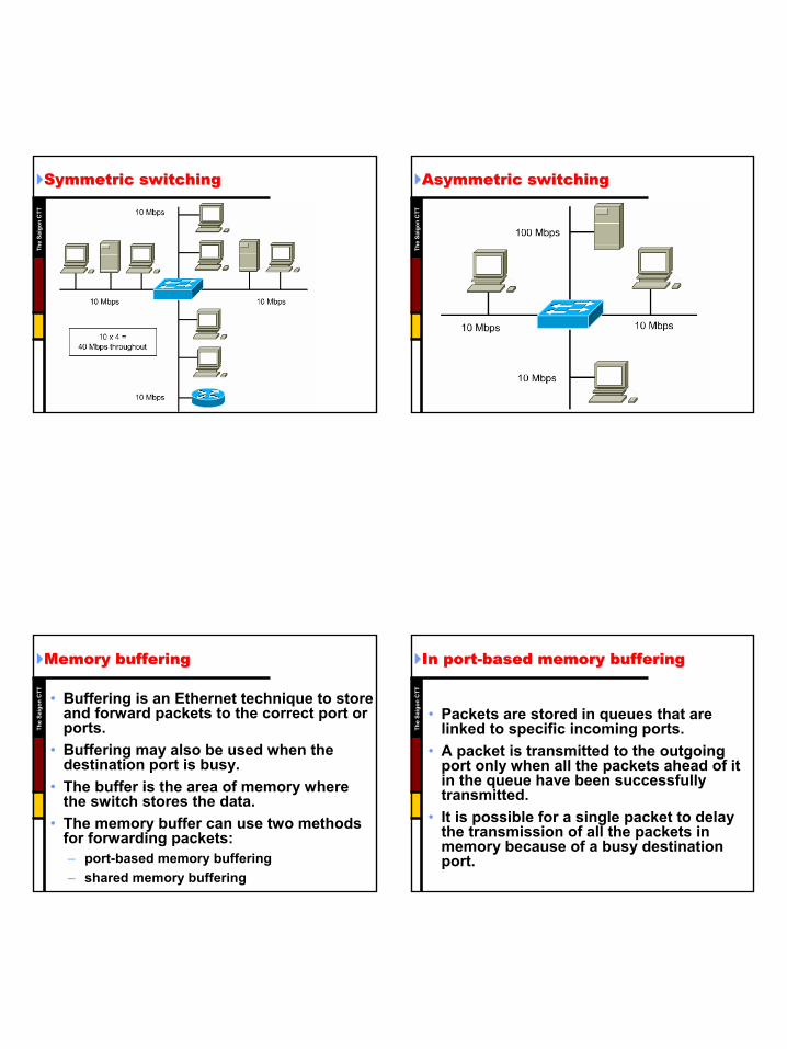
Symmetric switchingSymmetric switching
The
Saig
on C
TT
Asymmetric switchingAsymmetric switching
The
Saig
on C
TT
Memory bufferingMemory buffering
• Buffering is an Ethernet technique to store and forward packets to the correct port or ports.
• Buffering may also be used when the destination port is busy.
• The buffer is the area of memory where the switch stores the data.
• The memory buffer can use two methods for forwarding packets:– port-based memory buffering– shared memory buffering
The
Saig
on C
TT
In portIn port--based memory bufferingbased memory buffering
• Packets are stored in queues that are linked to specific incoming ports.
• A packet is transmitted to the outgoing port only when all the packets ahead of it in the queue have been successfully transmitted.
• It is possible for a single packet to delay the transmission of all the packets in memory because of a busy destination port.

6
The
Saig
on C
TT
Shared memory bufferingShared memory buffering
• All packets are stored in a common memory buffer that is shared by all the ports on the switch. This is called dynamic allocation of buffer memory.
• The packets in the buffer are then linked dynamically to the transmit port.
• This allows the packet to be received on one port and transmitted on another port, without moving it into a different queue.
• The packet is restricted by the size of the entire memory buffer, not just the allocation to one port.
The
Saig
on C
TT
Two switching methodsTwo switching methods
• Store-and-forward: – The entire frame is received before forward.– The latency is greater with larger frames. – Error detection is high.
• Cut-through: – The switch reads the destination address
before receiving the entire frame. – The frame is then forwarded before the entire
frame arrives. – Fast-forward and Fragment-free switching.
The
Saig
on C
TT
CutCut--through switching methodsthrough switching methods
• Fast-forward switching: – offers the lowest level of latency by
immediately forwarding a packet after receiving the destination address.
• Fragment-free switching: – filters out collision fragments by forwarding
a packet after receiving first 64 bytes.– Waits until the received packet has been
determined not to be a collision fragment before forwarding the packet.
The
Saig
on C
TT
ForwardingForwarding

7
The
Saig
on C
TT
VIRTUAL LANVIRTUAL LAN
The
Saig
on C
TT
Logical LAN SegmentationLogical LAN Segmentation
• Logically segment the physical LAN infrastructure into different subnets or broadcast domainsrather than physical location
The
Saig
on C
TT
VLAN IntroductionVLAN Introduction
• A VLAN is a logical grouping of devices or users.
• These devices or users can be grouped by function, department, or application, regardless of their physical segment location.
• VLAN configuration is done at the switch via software.
• VLANs are not standardized and require the use of proprietary software from the switch vendor.
The
Saig
on C
TT
VLAN ImplementationVLAN Implementation
• Each port can be assigned to a VLAN. – Ports assigned to the same VLAN share
broadcasts. – Ports that do not belong to that VLAN do
not share these broadcasts.
• Two methods that can be used to assign a switch port to a VLAN: – Static – Dynamic

8
The
Saig
on C
TT
Static VLANStatic VLAN
The
Saig
on C
TT
Dynamic VLANDynamic VLAN
The
Saig
on C
TT
Transport of VLANsTransport of VLANs
The
Saig
on C
TT
Frames TaggingFrames Tagging

9
The
Saig
on C
TT
TrunkingTrunking ProtocolProtocol
• ISL: (Cisco)– Inter-Switch Link– Fast Ethernet
• 802.1q (IEEE)– Fast Ethernet
• 802.10 (IEEE)– FDDI
• LANE (ATM Forum)– LAN Emulation– ATM
The
Saig
on C
TT
Router in the VLANsRouter in the VLANs
• Traditionally provide firewalls, broadcast management etc…
• Provide connected routes between different VLANs
• Cost effectively integrate external routers into switching architecture by using one or more high speed backbone connection
The
Saig
on C
TT
LAN DESIGNLAN DESIGN
The
Saig
on C
TT
IntroductionIntroduction
• Designing a network can be a challenging task, and involves more than just connecting computers together.
• Learning how to design networks is comprised of four basic areas: hardware, cabling, protocols and routing.
• There is no single book or manual that can teach you how to properly design computer network.
• This chapter will assist you with learning the basic foundations of network design.

10
The
Saig
on C
TT
LAN Design GoalsLAN Design Goals
• The first step in designing a LAN is to establish and document the goals of the design.
• There are requirements in most network designs: – Functionality– Scalability– Adaptability– Manageability
The
Saig
on C
TT
Design MethodologyDesign Methodology
1. Gathering the users' requirements and expectations
2. Analyzing requirements3. Designing the Layer 1, 2, and 3 LAN
structure (that is, topology)4. Documenting the logical and physical
network implementation
The
Saig
on C
TT
Develop LAN topologyDevelop LAN topology
• Decide on an overall LAN topology that will satisfy the user requirements.
• We concentrate on the star topology and extended star topology.– The reason that this curriculum focuses on a
CSMA/CD star topology is that it is by far the dominant configuration in the industry.
• The major pieces of a LAN topology design can be broken into three unique categories of the OSI reference model.
The
Saig
on C
TT
LAN topologyLAN topology

11
The
Saig
on C
TT
Layer 1 design Layer 1 design -- GoalGoal
• Choose cable type.• Identify work area and HCC.• Identify MDF, IDF, HCC, VCC and POP.• Choose Ethernet or Fast Ethernet.• Documentation and physical diagrams.
The
Saig
on C
TT
HCC and VCCHCC and VCC
The
Saig
on C
TT
Layer 2 design Layer 2 design -- GoalGoal
• The purpose of Layer 2 devices in the network is to provide flow control, error detection, error correction, and to reduce congestion in the network.
• Devices at this layer determine the size of the collision domains and broadcast domains.
The
Saig
on C
TT
Using switch in MDF and IDFUsing switch in MDF and IDF

12
The
Saig
on C
TT
Layer 3 design Layer 3 design -- Goal Goal
• Determines traffic flow between unique physical network segments based on Layer 3 addressing.
• Stops broadcasts from reaching other LAN segments.
• By using VLANs, you can limit broadcast traffic to within a VLAN and thus create smaller broadcast domains.
The
Saig
on C
TT
Diagramming a LAN that uses routers Diagramming a LAN that uses routers
The
Saig
on C
TT
ROUTING PROTOCOLSROUTING PROTOCOLS
The
Saig
on C
TT
Routing processRouting process
• Routing information can be configured by the administrator or collected dynamically
• Provides best-effort end-to-end packet delivery across interconnected networks
• The network layer uses the IP routing table to send packets from the source network to the destination network
• Takes the packet that it accepted on one interface forwards to another interface

13
The
Saig
on C
TT
Routing tableRouting table
The
Saig
on C
TT
How distances are determinedHow distances are determined
• Primary objective of routing protocol is to determine the best information to include in the routing table.
• Each routing algorithm interprets what is best in its own way.
• Routing algorithm generates a number, called the metric value, for each path through the network.
• Typically, the smaller the metric number, the better the path.
The
Saig
on C
TT
Distance in MetricsDistance in Metrics
The
Saig
on C
TT
How the metric is calculatedHow the metric is calculated
• You can calculate metrics based on a single characteristic of a path.
• You can calculate more complex metrics by combining several characteristics.
• The metrics most commonly used by routers are as bandwidth, delay, load, reliability, hop count, ticks and cost.

14
The
Saig
on C
TT
Routing protocolsRouting protocols
• Routing is the process of determining where to send data packets destined for addresses outside the local network.
• Routers gather and maintain routing information.
• Routing information takes the form of entries in a routing table, with one entry for each identified route.
• Routing protocols allow a router to create and maintain routing tables dynamically and to adjust to network changes.
The
Saig
on C
TT
The goals of routing protocols The goals of routing protocols
• The Optimal Route • Simplicity and Efficiency• Robustness• Rapid Convergence• Flexibility
The
Saig
on C
TT
Classes of routing protocolsClasses of routing protocols
• Most routing algorithms can be classified as one of two basic algorithms distance vector and link state.
• The distance-vector routing approach determines the direction and distance to any link in the internetwork.
• The link-state approach re-creates the exact topology of the entire internetwork.
• The balanced hybrid approach combines aspects of the link-state and distance-vector algorithms.
The
Saig
on C
TT
Choosing a routing protocol Choosing a routing protocol
• Network size and complexity • Network traffic levels • Security needs • Reliability needs • Network delay characteristics • Organizational policies • Organizational acceptance of change

15
The
Saig
on C
TT
Distance vector algorithm Distance vector algorithm
• Routing algorithms pass periodic copies of a routing table from router to router.
• These regular updates between routers communicate topology changes.
• Each router receives a routing table from its directly connected neighbors.
• Distance-vector algorithms do not allow a router to know the exact topology of an internetwork.
The
Saig
on C
TT
Distance vector concepts Distance vector concepts
The
Saig
on C
TT
The problem of routing loops The problem of routing loops
• Routing loops can occur if a network's slow convergence on a new configuration causes inconsistent routing entries.
• Solutions:– Defining a Maximum– Split Horizon– Split Horizon with Poison Reverse– Route Poisoning– Hold-down Timers
The
Saig
on C
TT
Problem:Problem: Routing LoopRouting Loop
Network 1 unreachable Network 1
Distance 3

16
The
Saig
on C
TT
Problem:Problem: Counting to InfinityCounting to Infinity
Network 1 Distance 3
Network 1 Distance 4
Network 1 Distance 5
The
Saig
on C
TT
Loop prevention: Loop prevention: Defining a MaximumDefining a Maximum
Maximum Metric is 16 Network 1
unreachable
Network 1 Distance 14
Network 1 Distance 15
The
Saig
on C
TT
Loop prevention: Loop prevention: Split horizonSplit horizon
Network 1 Distance 1
Network 1 unreachable
CRouter
21DistanceNetwork
ARouter
31DistanceNetwork
The
Saig
on C
TT
Loop prevention: Loop prevention: Poison reversePoison reverse
Network 1 unreachable
Network 1 Distance 16

17
The
Saig
on C
TT
Loop prevention: Loop prevention: Route poisoningRoute poisoning
Network 1 Distance 16
The
Saig
on C
TT
Loop prevention: Loop prevention: HoldHold--down timerdown timer
Network 1 unreachable
Network 1 Distance 2
The
Saig
on C
TT
ACCESS LIST OVERVIEWACCESS LIST OVERVIEW
The
Saig
on C
TT
IntroductionIntroduction
• ACLs are lists of instructions you apply to a router's interface.
• These lists tell the router what kinds of packets to accept and what kinds of packets to deny.
• Acceptance and denial can be based on certain specifications, such as source address, destination address, and port number.

18
The
Saig
on C
TT
Reasons to create Reasons to create ACLsACLs
• Limit network traffic and increase network performance.
• Provide traffic flow control. • Provide a basic level of security for
network access.• Decide which types of traffic are
forwarded or blocked at the router interfaces.
The
Saig
on C
TT
ACLsACLs check the packet and headercheck the packet and header
The
Saig
on C
TT
Testing packets with Testing packets with ACLsACLs
• The order in which you place ACL statements is important.
• IOS software tests the packet against each condition statement, in the order in which the statements were created.
• Note: After a match is found, no more condition statements are checked.
• You can create an ACL for each protocol you want to filter for each router interface.
The
Saig
on C
TT
Order of ACL statementsOrder of ACL statements

19
The
Saig
on C
TT
How the ACL work? How the ACL work?
• An ACL is a group of statements that define how packets: – Enter inbound interfaces – Relay through the router – Exit outbound interfaces of the router
• ACL statements operate in order. If a condition match is true, the rest of the ACL statements are not checked.
• If all the ACL statements are unmatched, an implicit "deny any" statement is imposed.
The
Saig
on C
TT
How the ACL work? (cont.)How the ACL work? (cont.)
The
Saig
on C
TT
ACL numbersACL numbers
The
Saig
on C
TT
Wildcard mask bitsWildcard mask bits

20
The
Saig
on C
TT
Wildcard Wildcard anyany
The
Saig
on C
TT
Wildcard Wildcard hosthost
The
Saig
on C
TT
ExampleExample
• Router(config)# access-list 1 permit 0.0.0.0 255.255.255.255
• Router(config)# access-list 1 permit any
• Router(config)# access-list 1 permit 172.30.16.29 0.0.0.0
• Router(config)# access-list 1 permit host 172.30.16.29
The
Saig
on C
TT
Placing Placing ACLsACLs
• Put the extended ACLs as close as possible to the source of the traffic denied.
• Put the standard ACL as near the destination as possible.

21
The
Saig
on C
TT
Placing Placing ACLsACLs
The
Saig
on C
TT
IPX ROUTING OVERVIEWIPX ROUTING OVERVIEW
The
Saig
on C
TT
ArchitectureArchitecture
The
Saig
on C
TT
ProtocolsProtocols
• IPX (Internetwork Packet Exchange), connectionless, layer 3 and defines the network and node addresses.
• SPX (Sequenced Packet Exchange), service for Layer 4 connection-oriented services.
• SAP (Service Advertising Protocol), to advertise network services.
• NCP (Netware Core Protocol), to provide client-to-server connections and applications.

22
The
Saig
on C
TT
Routing ProtocolsRouting Protocols
• RIP: Routing Information Protocol,– Distance Vector Protocol.– Uses ticks (network delay) and hop count as
its routing metric.– Sends routing updates every 60 seconds.– Maximum hop count is 15.
• NLSP: Novell Link State Protocol, – Link State Protocol.
The
Saig
on C
TT
IPX AddressingIPX Addressing
The
Saig
on C
TT
IPX network addressIPX network address
The
Saig
on C
TT
Encapsulation namesEncapsulation names

23
The
Saig
on C
TT
IPX RIPIPX RIP
• Distance vector routing protocol.• Uses two metrics: Tick and hop count.
– Ticks: a time measure 1/18 of a second.– If ticks are equal, hop count is used.– If both ticks a hop count are equal, the router
load shares.– By default, a Cisco router treats a link as
having a certain number of ticks. (Ethernet 1 tick and Serial 6 ticks)
• Routing table updates every 60 seconds.Th
e Sa
igon
CTT
RIPRIP
The
Saig
on C
TT
Service AdvertisementsService Advertisements
• SAP allows file and print servers, to advertise their network addresses and the services they provide.
• Each service is identified by a number, called a SAP identifier. – 4 NetWare File server– 7 Print server– 24 Remote bridge server (router)
• SAP updates are sent every 60 seconds.
The
Saig
on C
TT
SAPSAP

24
The
Saig
on C
TT
Get Nearest ServerGet Nearest Server
• The client/server interaction begins when the client powers up and runs its client startup programs.
• These programs initiate the connection sequence for the NetWare command shell to use.
• The connection sequence, a client sends a broadcast using SAP. The nearest file server responds with another SAP.
• Now, the client can log in to the target server, make a connection, set the packet size and proceed to use server resources.
The
Saig
on C
TT
GNSGNS
The
Saig
on C
TT
Get Nearest Server (cont.)Get Nearest Server (cont.)
• If a server is located on the segment, it responds to the client request. The router does not respond to the GNS request.
• If there are no servers on the local network, the router responds with a server address from its own SAP table.
• Cisco IOS software allows NetWare clients to be located on LAN segments where there are no servers.
• In responding to GNS requests, Cisco IOS software can also distribute clients evenly among the available servers.
The
Saig
on C
TT
GNS ProtocolGNS Protocol

25
The
Saig
on C
TT
Router Lab TopologyRouter Lab Topology
The
Saig
on C
TT
Copyright © 2022 FDOKUMEN


![[5]S4 Clark olmec](https://static.fdokumen.com/doc/165x107/631a7d74bb40f9952b020797/5s4-clark-olmec.jpg)


