
S38(S33) 1 5 DN 200 PN 100 1 3 5 XX
18
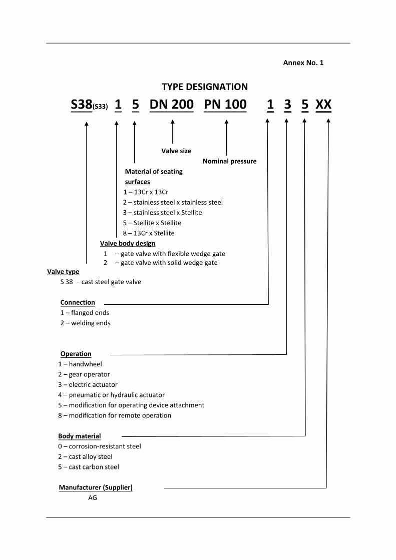
Annex No. 1 TYPE DESIGNATION S38(S33) 1 5 DN 200 PN 100 1 3 5 XX Valve size Nominal pressure Material of seating surfaces 1 – 13Cr x 13Cr 2 – stainless steel x stainless steel 3 – stainless steel x Stellite 5 – Stellite x Stellite 8 – 13Cr x Stellite Valve body design 1 – gate valve with flexible wedge gate 2 – gate valve with solid wedge gate Valve type S 38 – cast steel gate valve Connection 1 – flanged ends 2 – welding ends Operation 1 – handwheel 2 – gear operator 3 – electric actuator 4 – pneumatic or hydraulic actuator 5 – modification for operating device attachment 8 – modification for remote operation Body material 0 – corrosion-resistant steel 2 – cast alloy steel 5 – cast carbon steel Manufacturer (Supplier) AG
-
Upload
khangminh22 -
Category
Documents
-
view
1 -
download
0
Transcript of S38(S33) 1 5 DN 200 PN 100 1 3 5 XX
Annex No. 1
TYPE DESIGNATION
S38(S33) 1 5 DN 200 PN 100 1 3 5 XX
Valve size
Nominal pressure
Material of seating
surfaces
1 – 13Cr x 13Cr
2 – stainless steel x stainless steel
3 – stainless steel x Stellite
5 – Stellite x Stellite
8 – 13Cr x Stellite
Valve body design
1 – gate valve with flexible wedge gate 2 – gate valve with solid wedge gate
Valve type
S 38 – cast steel gate valve
Connection
1 – flanged ends
2 – welding ends
Operation
1 – handwheel
2 – gear operator
3 – electric actuator
4 – pneumatic or hydraulic actuator
5 – modification for operating device attachment
8 – modification for remote operation
Body material
0 – corrosion-resistant steel
2 – cast alloy steel
5 – cast carbon steel
Manufacturer (Supplier)
AG

Annex No. 2
VALVE DESIGN AND MAIN DESIGN AND CONNECTING
DIMENSIONS
CAST STEEL GATE VALVE S38.1X
Fig.3 Cast steel gate valve S33.1 with flanged ends, handwheel operated
Pojistit svarem = To be secured by weld
Design with welding ends Gate valve S38.2 with solid wedge gate

S38
PN 6
DN D D1 D2 L H(open) Dk b n d kg
40 130 100 80 140 340 160 14 4 14 14
50 140 110 90 150 405 160 14 4 14 16
65 160 130 110 170 480 160 14 4 14 18
80 190 150 128 180 510 160 16 4 18 23
100 210 170 148 190 600 200 16 4 18 36
125 240 200 178 200 640 200 18 8 18 48
150 265 225 202 210 785 200 18 8 18 60
200 320 280 258 230 980 250 20 8 18 97
250 375 335 312 250 1190 320 22 12 18 166
300 440 395 365 270 1400 400 22 12 22 210
350 490 445 415 290 1585 450 22 12 22 345
400 540 495 465 310 1720 500 22 16 22 480
500 645 600 570 350 2095 500 24 20 22 645
600 755 705 670 390 2680 600 30 20 26 895
PN 10
DN D D1 D2 L H(open) Dk b n d kg
40 150 110 88 140 340 200 18 4 16 15
50 165 125 102 150 405 200 18 4 18 17
65 185 145 122 170 480 200 18 4 18 19
80 200 160 138 180 510 250 20 8 18 25
100 220 180 158 190 600 280 20 8 18 39
125 250 210 188 200 640 300 22 8 18 52
150 285 240 212 210 785 300 22 8 22 66
200 340 295 268 230 980 350 24 8 22 82
250 395 350 320 250 1190 400 26 12 22 180
300 460 400 370 270 1400 450 26 12 22 230
350 520 460 430 290 1585 500 26 16 22 380
400 580 515 482 310 1720 600 26 16 26 505
500 670 620 585 350 2095 600 28 20 26 700
600 780 725 685 390 2680 600 34 20 30 985
PN 16
DN D D1 D2 L acc.to ČSN L =L1 H(open) Dk b n d kg
40 150 110 88 170 240 360 160 18 4 18 16
50 165 125 102 180 250 405 200 18 4 18 18
65 185 145 122 200 270 480 200 18 4 18 20
80 200 160 138 210 280 510 200 20 8 18 28
100 220 180 158 230 300 605 250 20 8 18 48
125 250 210 188 255 325 640 250 22 8 18 65
150 285 240 212 280 350 785 320 22 8 22 73
200 340 295 268 330 400 980 400 24 12 22 118
250 405 355 320 450 450 1015 450 26 12 26 240
300 460 410 378 500 500 1190 500 28 12 26 300
350 520 470 438 550 550 1350 600 30 16 26 510
400 580 525 490 600 600 1460 600 32 16 30 670
500 715 650 610 700 700 1800 700 34 20 33 930
600 840 770 725 800 800 2200 800 36 20 36 1310

PN 16
DN D D1 D2 L H (open) H (max.)* Dk b d x n kg BW ends
L1 kg
50 165 125 102 250 360 605 200 18 18x4 20 216 17
65 185 145 122 270 410 630 250 18 18x8 30 241 26
80 200 160 138 280 460 670 250 20 18x8 36 283 34
100 220 180 158 300 550 740 300 20 18x8 49 305 48
125 250 210 188 325 660 810 300 22 18x8 66 381 72
150 285 240 212 350 775 930 300 22 22x8 95 404 100
200 340 295 268 400 960 1070 350 24 22x12 154 419 160
250 405 355 320 450 1175 1245 400 26 26x12 225 457 240
300 460 410 378 500 1360 1430 500 28 26x12 334 502 355
350 520 470 438 550 1525 1550 550 30 26x16 445 762 490
400 580 525 490 600 1675 1720 600 32 30x16 610 838 690
500 715 650 610 700 2050 2080 700 44 33x20 1105 991 1070
600 840 770 725 800 2400 2480 800 54 36x20 1190 1143 1660
PN 25
DN D D1 D2 L H (open) H (max.)* Dk b d x n kg BW ends
L1 kg
50 165 125 102 250 360 605 200 20 18x4 20 216 17
65 185 145 122 270 410 630 250 22 18x8 32 241 26
80 200 160 138 280 460 670 250 24 18x8 39 283 34
100 235 190 162 300 550 740 300 24 22x8 53 305 48
125 270 220 188 325 660 810 300 26 26x8 71 381 72
150 300 250 218 350 775 930 300 28 26x8 101 404 100
200 360 310 278 400 960 1070 350 30 26x12 160 419 160
250 425 370 335 450 1175 1245 400 32 30x12 232 457 240
300 485 430 395 500 1360 1430 500 34 30x16 345 502 355
350 555 490 450 550 1525 1550 550 38 33x16 460 762 490
400 620 550 505 600 1675 1720 600 40 36x16 645 838 690
500 730 660 615 700 2050 2080 700 48 36x20 1166 991 1070
600 845 770 720 800 2450 2480 800 58 39x20 1258 1143 1660
PN 40
DN D D1 D2 L H (open) H (max.)* Dk b d x n kg BW ends
L1 kg
50 165 125 102 250 360 605 200 20 18x4 20 216 17
65 185 145 122 290 410 630 250 22 18x8 28 241 26
80 200 160 138 310 460 670 250 24 18x8 44 283 34

100 235 190 162 350 560 740 300 24 22x8 62 305 48
125 270 220 188 400 660 810 300 26 26x8 87 381 72
150 300 250 218 450 765 930 350 28 26x8 125 404 100
200 375 320 285 550 955 1070 400 34 30x12 265 419 160
250 450 385 345 650 1185 1245 450 38 33x12 405 457 240
300 515 450 410 750 1380 1430 500 42 33x16 500 502 355
350 580 510 465 850 1510 1550 500 46 36x16 725 762 490
400 660 585 535 950 1690 1720 600 50 39x16 1280 838 690
500 755 670 615 1150 2065 2080 600 52 42x20 1589 991 1070
600 890 795 735 1350 2465 2480 700 60 48x20 1903 1143 1660
PN 63
DN D D1 D2 L H (open) H (max.)* Dk b d x n kg BW ends
L1 kg
50 180 135 102 250 420 655 280 26 22x4 37 292 28
65 205 160 122 290 470 735 280 26 22x8 46 330 37
80 215 170 138 310 525 770 300 28 22x8 49 356 38
100 250 200 162 350 620 835 350 30 26x8 86 432 75
125 295 240 188 400 715 910 350 34 30x8 129 508 113
150 345 280 218 450 815 980 400 36 33x8 150 559 132
200 415 345 285 550 1115 1205 500 42 36x12 360 660 320
250 470 400 345 650 1280 1360 640 46 36x12 570 787 500
300 530 460 410 750 1550 1570 680 52 36x16 815 838 720
350 600 525 465 850 1665 1680 - 56 39x16 1080 889 950
400 670 585 535 950 1820 1840 - 60 42x16 1460 991 1290
500 800 705 615 1150 2235 2250 - 68 48x20 2315 1194 2040
600 930 820 735 1350 2570 2590 - 76 56x20 3480 1397 3060
PN 100
DN D D1 D2 L H (open) H (max.)* Dk b d x n kg BW ends
L1 kg
50 195 145 102 250 420 655 280 30 26x4 39 292 29
65 220 170 122 290 470 735 280 34 26x8 50 330 39
80 230 180 138 310 525 770 300 36 26x8 54 356 40
100 265 210 162 350 620 835 350 40 30x8 94 432 80
125 315 250 188 400 715 910 350 40 33x8 138 508 122
150 355 290 218 450 815 980 400 44 33x12 160 559 141
200 430 360 285 550 1115 1205 500 52 36x12 385 660 340
250 505 430 345 650 1280 1360 640 60 39x12 610 787 540
300 585 500 410 750 1550 1570 680 68 42x16 890 838 780
350 655 560 465 850 1665 1680 - 74 48x16 1190 889 1050
400 715 620 535 950 1820 1840 - 78 48x16 1570 991 1380
500 870 760 615 1150 2235 2250 - 90 56x20 2630 1194 2315
600 940 838 692 1350 2570 2590 - 105 52x24 3870 1397 3405

CLASS 150
NPS DN mm D D1 D2 dxn L b H (open) Dk kg BW ends
L1 kg
2" 50 150 120.7 92.1 19.1x4 178 14.3 397 200 18 216 18
2.5" 65 180 139.7 104.3 19.1x4 190 20.7 435 250 26 241 28
3" 80 190 152.4 127 19.1x4 203 17.5 497 250 34 283 30
4" 100 230 190.5 157.2 19.1x8 229 22.3 585 250 52 305 50
6" 150 280 241.3 215.9 22.4x8 267 23.9 765 350 88 403 85
8" 200 345 298.5 269.9 22.4x8 292 27 973 350 144 419 128
10" 250 405 362 323.8 25.4x12 330 28.6 1160 400 197 457 220
12" 300 485 431.8 381 25.4x12 356 30.2 1362 450 298 502 310
14" 350 535 473.6 412.8 28.6x12 381 33.4 1520 500 406 572 450
16" 400 595 539.8 469.9 28.6x16 406 35 1725 560 524 610 550
18" 450 625 577.9 533.4 31.8x16 432 38.1 1930 560 626 660 700
20" 500 700 635 584.2 31.8x20 457 41.3 2160 610 789 711 910
24" 600 815 749.3 692.2 35x20 508 46.1 2540 610 1033 813 1130
28" 700 925 863.6 800 35x28 610 69.9 2990 - 1905 914 1750
30" 750 985 914.4 857 35x28 610 73.1 3070 - 2145 914 1960
32" 800 1060 977.9 914 41.3x28 711 79.4 3460 - 3506 - -
36" 900 1170 1085.8 1022 41.3x32 711 88.9 3660 - 3575 - -
42" 1000 1345 1257.3 1194 41.3x36 813 88.9 4260 - 5123 - -
48" 1200 1510 1422.4 1356 41.3x44 884 95.3 4875 - 6668 - -
CLASS 300
NPS DN D D1 D2 dxn L b H (open) Dk kg BW ends
L1 kg
2" 50 165 127 92.1 19.1x8 216 20.7 422 200 24 216 19
2.5" 65 190 149.2 104.3 22.4x8 241 23.9 446 250 31 241 29
3" 80 210 168.3 127 22.4x8 282 27 512 250 52 282 38
4" 100 244 200 157.2 22.4x8 305 30.2 603 250 76 305 57
6" 150 320 269.9 215.9 22.4x12 403 35 804 350 146 403 118
8" 200 380 330.2 269.9 25.4x12 419 39.7 1002 400 218 419 183
10" 250 445 387.4 323.8 28.6x16 457 46.1 1229 400 352 457 278
12" 300 520 450.8 381 31.8x16 502 49.3 1479 460 460 502 406
14" 350 585 514.4 412.8 31.8x20 762 54.6 1630 560 857 762 565
16" 400 650 571.5 469.9 35x20 838 55.6 1815 460 1172 838 728
18" 450 710 628.6 533.4 35x24 914 58.8 2000 460 1281 914 806
20" 500 775 685.8 584.2 35x24 991 62 2220 560 1498 991 1231
24" 600 915 812.8 692.2 41.3x24 1143 68.3 2620 610 2282 1143 1890
30" 750 1090 997 857 47.6x28 1397 73.1 3180 700 4495 1397 3686
36" 900 1270 1168.4 1022 54x32 1727 88.9 3760 700 5833 1727 4784

CLASS 600
NPS DN D1 D2 D3 dxn L b H (open) Dk kg BW ends
L1 kg
2" 50 165 127 92.1 19.1x8 292 25.4 441 250 46 292 31
2.5" 65 190 149.2 104.3 22.4x8 330 28.6 510 300 62 330 57
3" 80 210 168.3 127 22.4x8 356 31.8 574 300 72 356 65
4" 100 275 215.9 157.2 25.4x8 432 38.1 700 350 128 432 87
6" 150 355 292.1 215.9 28.6x12 559 47.7 804 450 216 559 169
8" 200 420 349.2 269.9 31.8x12 660 55.6 1055 500 413 660 375
10" 250 510 431.8 323.8 35x16 787 63.5 1314 640 754 787 604
12" 300 460 489 381 35x20 838 66.7 1460 680 981 838 859
14" 350 605 527 412.8 38.1x20 889 69.9 1750 610 1316 889 1154
16" 400 685 603.2 469.9 41.3x20 991 76.2 1900 610 1672 991 1530
18" 450 745 654 533.4 44.5x20 1092 82.6 2020 640 2780 1092 2282
20" 500 815 723.9 584.2 44.5x24 1194 88.9 2172 700 3203 1194 2650
24" 600 940 838.2 692.2 50.8x24 1397 101.6 2650 750 4069 1397 3340
CLASS 900
NPS DN D D1 D2 dxn L b H(open) Dk kg BW ends
L1 kg
3" 80 241 191 127 25x8 381 39 660 350 115 305 95
4" 100 292 235 157 32x8 457 45 825 350 160 356 130
6" 150 381 318 216 32x12 610 56 1015 600 310 508 280
8" 200 470 394 270 38x12 737 64 1225 600 500 660 460
10" 250 546 470 324 38x16 838 70 1435 700 880 787 820
12" 300 610 533 381 38x20 965 79 1625 700 1220 914 1150
CLASS 1500
NPS DN D D1 D2 dxn L b H(open) Dk kg BW ends
L1 kg
1 1/2" 40 180 124 73 29 x 4 305 32 390 250 35 178 25
2" 50 216 165 92 25 x 8 368 39 420 300 59 216 42
3" 80 267 203 127 32 x 8 470 48 685 350 110 305 60
4" 100 311 241 157 35 x 8 546 54 745 450 180 406 110
6" 150 394 318 216 38 x 12 705 83 1015 600 370 559 230
8" 200 483 394 270 44 x 12 832 92 990 700 610 711 470
10" 250 584 483 324 51 x 12 991 108 1183 850 1300 864 800
12" 300 673 572 381 54 x 16 1130 124 1300 - 2000 991 1400
Annex No. 3
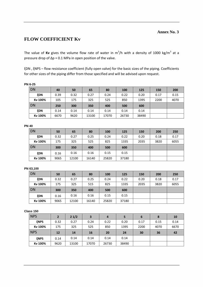
FLOW COEFFICIENT Kv
The value of Kv gives the volume flow rate of water in m3/h with a density of 1000 kg/m3 at a
pressure drop of ∆p = 0.1 MPa in open position of the valve.
ξDN , ξNPS – flow resistance coefficient (fully open valve) for the basic sizes of the piping. Coefficients
for other sizes of the piping differ from those specified and will be advised upon request.
PN 6-25
DN 40 50 65 80 100 125 150 200
ξDN 0.39 0.32 0.27 0.24 0.22 0.20 0.17 0.15
Kv 100% 105 175 325 525 850 1395 2200 4070
DN 250 300 350 400 500 600
ξDN 0.14 0.14 0.14 0.14 0.14 0.14 Kv 100% 6670 9620 13100 17070 26730 38490
PN 40
DN 50 65 80 100 125 150 200 250
ξDN 0.32 0.27 0.25 0.24 0.22 0.20 0.18 0.17
Kv 100% 175 325 525 825 1335 2035 3820 6055
DN 300 350 400 500 600
ξDN 0.16 0.16 0.16 0.15 0.15
Kv 100% 9065 12100 16140 25820 37180
PN 63,100
DN 50 65 80 100 125 150 200 250
ξDN 0.32 0.27 0.25 0.24 0.22 0.20 0.18 0.17
Kv 100% 175 325 515 825 1335 2035 3820 6055
DN 300 350 400 500 600
ξDN 0.16 0.16 0.16 0.15 0.15
Kv 100% 9065 12100 16140 25820 37180
Class 150
NPS 2 2 1/2 3 4 5 6 8 10
ξNPS 0.32 0.27 0.24 0.22 0.20 0.17 0.15 0.14
Kv 100% 175 325 525 850 1395 2200 4070 6670
NPS 12 14 16 20 24 30 36 42
ξNPS 0.14 0.14 0.14 0.14 0.14
Kv 100% 9620 13100 17070 26730 38490
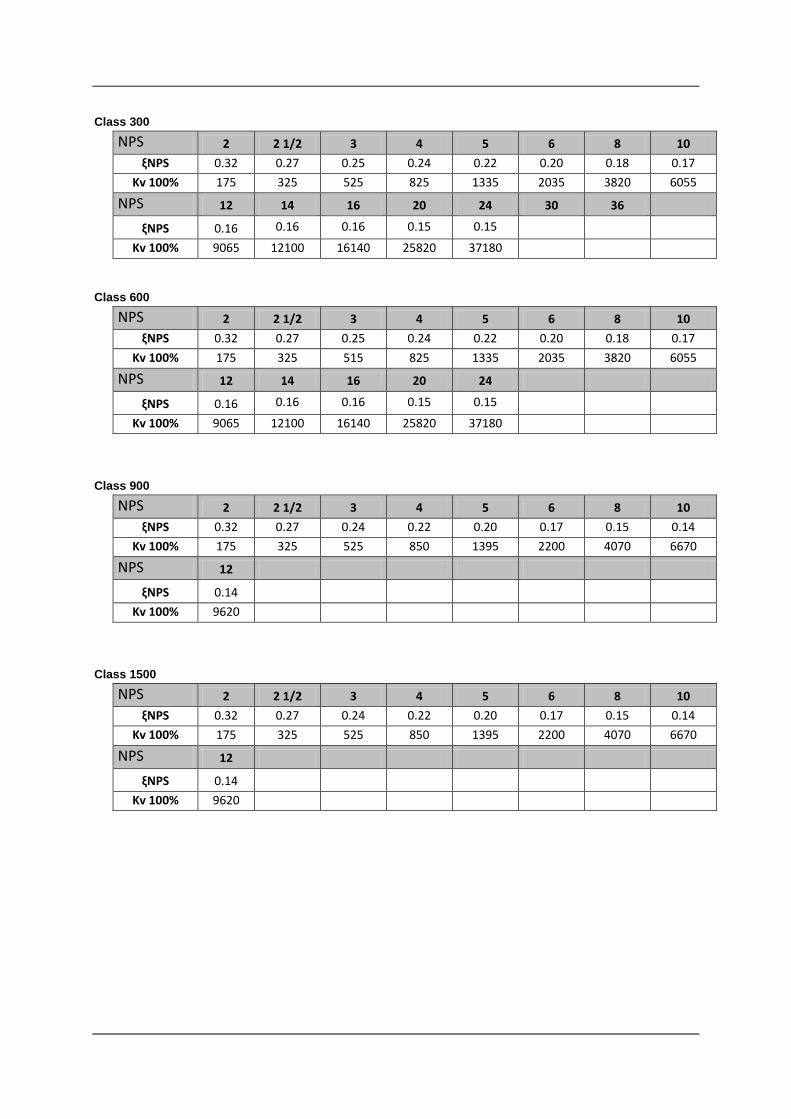
Class 300
NPS 2 2 1/2 3 4 5 6 8 10
ξNPS 0.32 0.27 0.25 0.24 0.22 0.20 0.18 0.17
Kv 100% 175 325 525 825 1335 2035 3820 6055
NPS 12 14 16 20 24 30 36
ξNPS 0.16 0.16 0.16 0.15 0.15
Kv 100% 9065 12100 16140 25820 37180
Class 600
NPS 2 2 1/2 3 4 5 6 8 10
ξNPS 0.32 0.27 0.25 0.24 0.22 0.20 0.18 0.17
Kv 100% 175 325 515 825 1335 2035 3820 6055
NPS 12 14 16 20 24
ξNPS 0.16 0.16 0.16 0.15 0.15
Kv 100% 9065 12100 16140 25820 37180
Class 900
NPS 2 2 1/2 3 4 5 6 8 10
ξNPS 0.32 0.27 0.24 0.22 0.20 0.17 0.15 0.14
Kv 100% 175 325 525 850 1395 2200 4070 6670
NPS 12
ξNPS 0.14
Kv 100% 9620
Class 1500
NPS 2 2 1/2 3 4 5 6 8 10
ξNPS 0.32 0.27 0.24 0.22 0.20 0.17 0.15 0.14
Kv 100% 175 325 525 850 1395 2200 4070 6670
NPS 12
ξNPS 0.14
Kv 100% 9620
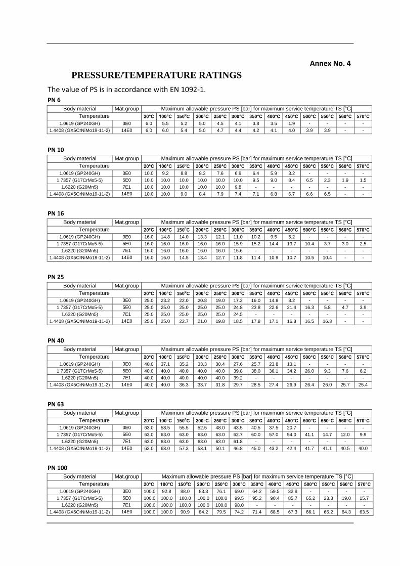
Annex No. 4
PRESSURE/TEMPERATURE RATINGS
The value of PS is in accordance with EN 1092-1. PN 6
Body material Mat.group Maximum allowable pressure PS [bar] for maximum service temperature TS [°C]
Temperature 20°C 100°C 150oC 200°C 250°C 300°C 350°C 400°C 450°C 500°C 550°C 560°C 570°C
1.0619 (GP240GH) 3E0 6.0 5.5 5.2 5.0 4.5 4.1 3.8 3.5 1.9 - - - -
1.4408 (GX5CrNiMo19-11-2) 14E0 6.0 6.0 5.4 5.0 4.7 4.4 4.2 4.1 4.0 3.9 3.9 - -
PN 10
Body material Mat.group Maximum allowable pressure PS [bar] for maximum service temperature TS [°C]
Temperature 20°C 100°C 150oC 200°C 250°C 300°C 350°C 400°C 450°C 500°C 550°C 560°C 570°C
1.0619 (GP240GH) 3E0 10.0 9.2 8.8 8.3 7.6 6.9 6.4 5.9 3.2 - - - -
1.7357 (G17CrMo5-5) 5E0 10.0 10.0 10.0 10.0 10.0 10.0 9.5 9.0 8.4 6.5 2.3 1.9 1.5
1.6220 (G20Mn5) 7E1 10.0 10.0 10.0 10.0 10.0 9.8 - - - - - - -
1.4408 (GX5CrNiMo19-11-2) 14E0 10.0 10.0 9.0 8.4 7.9 7.4 7.1 6.8 6.7 6.6 6.5 - -
PN 16
Body material Mat.group Maximum allowable pressure PS [bar] for maximum service temperature TS [°C]
Temperature 20°C 100°C 150oC 200°C 250°C 300°C 350°C 400°C 450°C 500°C 550°C 560°C 570°C
1.0619 (GP240GH) 3E0 16.0 14.8 14.0 13.3 12.1 11.0 10.2 9.5 5.2 - - - -
1.7357 (G17CrMo5-5) 5E0 16.0 16.0 16.0 16.0 16.0 15.9 15.2 14.4 13.7 10.4 3.7 3.0 2.5
1.6220 (G20Mn5) 7E1 16.0 16.0 16.0 16.0 16.0 15.6 - - - - - - -
1.4408 (GX5CrNiMo19-11-2) 14E0 16.0 16.0 14.5 13.4 12.7 11.8 11.4 10.9 10.7 10.5 10.4 - -
PN 25
Body material Mat.group Maximum allowable pressure PS [bar] for maximum service temperature TS [°C]
Temperature 20°C 100°C 150oC 200°C 250°C 300°C 350°C 400°C 450°C 500°C 550°C 560°C 570°C
1.0619 (GP240GH) 3E0 25.0 23.2 22.0 20.8 19.0 17.2 16.0 14.8 8.2 - - - -
1.7357 (G17CrMo5-5) 5E0 25.0 25.0 25.0 25.0 25.0 24.8 23.8 22.6 21.4 16.3 5.8 4.7 3.9
1.6220 (G20Mn5) 7E1 25.0 25.0 25.0 25.0 25.0 24.5 - - - - - - -
1.4408 (GX5CrNiMo19-11-2) 14E0 25.0 25.0 22.7 21.0 19.8 18.5 17.8 17.1 16.8 16.5 16.3 - -
PN 40
Body material Mat.group Maximum allowable pressure PS [bar] for maximum service temperature TS [°C]
Temperature 20°C 100°C 150oC 200°C 250°C 300°C 350°C 400°C 450°C 500°C 550°C 560°C 570°C
1.0619 (GP240GH) 3E0 40.0 37.1 35.2 33.3 30.4 27.6 25.7 23.8 13.1 - - - -
1.7357 (G17CrMo5-5) 5E0 40.0 40.0 40.0 40.0 40.0 39.8 38.0 36.1 34.2 26.0 9.3 7.6 6.2
1.6220 (G20Mn5) 7E1 40.0 40.0 40.0 40.0 40.0 39.2 - - - - - - -
1.4408 (GX5CrNiMo19-11-2) 14E0 40.0 40.0 36.3 33.7 31.8 29.7 28.5 27.4 26.9 26.4 26.0 25.7 25.4
PN 63
Body material Mat.group Maximum allowable pressure PS [bar] for maximum service temperature TS [°C]
Temperature 20°C 100°C 150oC 200°C 250°C 300°C 350°C 400°C 450°C 500°C 550°C 560°C 570°C
1.0619 (GP240GH) 3E0 63.0 58.5 55.5 52.5 48.0 43.5 40.5 37.5 20.7 - - - -
1.7357 (G17CrMo5-5) 5E0 63.0 63.0 63.0 63.0 63.0 62.7 60.0 57.0 54.0 41.1 14.7 12.0 9.9
1.6220 (G20Mn5) 7E1 63.0 63.0 63.0 63.0 63.0 61.8 - - - - - - -
1.4408 (GX5CrNiMo19-11-2) 14E0 63.0 63.0 57.3 53.1 50.1 46.8 45.0 43.2 42.4 41.7 41.1 40.5 40.0
PN 100
Body material Mat.group Maximum allowable pressure PS [bar] for maximum service temperature TS [°C]
Temperature 20°C 100°C 150oC 200°C 250°C 300°C 350°C 400°C 450°C 500°C 550°C 560°C 570°C
1.0619 (GP240GH) 3E0 100.0 92.8 88.0 83.3 76.1 69.0 64.2 59.5 32.8 - - - -
1.7357 (G17CrMo5-5) 5E0 100.0 100.0 100.0 100.0 100.0 99.5 95.2 90.4 85.7 65.2 23.3 19.0 15.7
1.6220 (G20Mn5) 7E1 100.0 100.0 100.0 100.0 100.0 98.0 - - - - - - -
1.4408 (GX5CrNiMo19-11-2) 14E0 100.0 100.0 90.9 84.2 79.5 74.2 71.4 68.5 67.3 66.1 65.2 64.3 63.5

The value of PS is in accordance with EN 1092-1.
PN 6
Body material Mat.group Maximum allowable pressure PS [bar] for maximum service temperature TS [°C]
Temperature 20°C 100°C 150oC 200°C 250°C 300°C 350°C 400°C 425°C 450°C 500°C 540°C 575°C 600°C
A 216 WCB 3E1 6.0 6.0 6.0 6.0 5.8 5.2 4.8 4.4 - - - - - -
A 352 LCC 3E1 6.0 6.0 5.7 5.4 5.0 4.6 4.2 - - - - - - -
A 217 WC6 5E0 6.0 6.0 6.0 6.0 6.0 6.0 5.7 5.4 5.2 5.0 - - - -
A 351 CF8M 14E0 6.0 6.0 5.4 5.0 4.7 4.4 4.2 4.1 4.1 4.0 3.9 3.9 3.8 -
PN 10
Body material Mat.group Maximum allowable pressure PS [bar] for maximum service temperature TS [°C]
Temperature 20°C 100°C 150oC 200°C 250°C 300°C 350°C 400°C 425°C 450°C 500°C 540°C 575°C 600°C
A 216 WCB 3E1 6.0 6.0 6.0 6.0 5.8 5.2 4.8 4.4 - - - - - -
A 352 LCC 3E1 6.0 6.0 5.7 5.4 5.0 4.6 4.2 - - - - - - -
A 217 WC6 5E0 6.0 6.0 6.0 6.0 6.0 6.0 5.7 5.4 5.2 5.0 - - - -
A 351 CF8M 14E0 6.0 6.0 5.4 5.0 4.7 4.4 4.2 4.1 4.1 4.0 3.9 3.9 3.8 -
PN 16
Body material Mat.group Maximum allowable pressure PS [bar] for maximum service temperature TS [°C]
Temperature 20°C 100°C 150oC 200°C 250°C 300°C 350°C 400°C 425°C 450°C 500°C 540°C 575°C 600°C
A 216 WCB 3E1 16 16 15.6 15.1 14.4 13.4 12.8 10.8 8.9 - - - - -
A 352 LCC 3E1 16 16 16 16 16 14.9 14.2 - - - - - - -
A 217 WC6 5E0 16 16 16 16 16 15.5 15 14.5 14.1 13.8 7.9 4.5 2.7 1.8
A 351 CF8M 14E0 14.7 12.5 11.4 10.6 9.8 9.3 9.0 8.7 8.6 8.5 8.4 8.3 - -
PN 25
Body material Mat.group Maximum allowable pressure PS [bar] for maximum service temperature TS [°C]
Temperature 20°C 100°C 150oC 200°C 250°C 300°C 350°C 400°C 425°C 450°C 500°C 540°C 575°C 600°C
A 216 WCB 3E1 25 25 24,4 23,7 22,5 20,9 20 16,9 14 - - - - -
A 352 LCC 3E1 25 25 25 25 25 23,3 22,2 - - - - - - -
A 217 WC6 5E0 25 25 25 25 25 24,3 23,5 22,7 22,1 21,5 12,5 7 4,2 2,9
A 351 CF8M 14E0 23 19,5 17,8 16,5 15,5 14,6 14,1 13,6 13,5 13,4 13,2 13 - -
PN 40
Body material Mat.group Maximum allowable pressure PS [bar] for maximum service temperature TS [°C]
Temperature 20°C 100°C 150oC 200°C 250°C 300°C 350°C 400°C 425°C 450°C 500°C 540°C 575°C 600°C
A 216 WCB 3E1 40 40 39.1 37.9 36 33.5 31.9 27 22.4 - - - - -
A 352 LCC 3E1 40 40 40 40 40 37.2 35.6 - - - - - - -
A 217 WC6 5E0 40 40 40 40 40 38.9 37.6 36.2 35.4 34.5 19.9 11.3 6.8 4.7
A 351 CF8M 14E0 36.8 31.3 28.5 26.4 24.7 23.4 22.6 21.8 21.6 21.4 21 20.8 - -
PN 63
Body material Mat.group Maximum allowable pressure PS [bar] for maximum service temperature TS [°C]
Temperature 20°C 100°C 150oC 200°C 250°C 300°C 350°C 400°C 425°C 450°C 500°C 540°C 575°C 600°C
A 216 WCB 3E1 63 63 61.5 59.6 56.8 52.7 50.3 42.5 35.2 - - - - -
A 352 LCC 3E1 63 63 63 63 63 58.7 56 - - - - - - -
A 217 WC6 5E0 63 63 63 63 63 61.2 59.2 57.1 55.7 54.3 31.4 17.8 10.8 7.4
A 351 CF8M 14E0 57.9 49.2 44.9 41.6 38.9 36.9 35.5 34.4 34 33.7 33.2 32.7 - -
PN 100
Body material Mat.group Maximum allowable pressure PS [bar] for maximum service temperature TS [°C]
Temperature 20°C 100°C 150oC 200°C 250°C 300°C 350°C 400°C 425°C 450°C 500°C 540°C 575°C 600°C
A 216 WCB 3E1 100 100 97.7 94.7 90.1 83.6 79.8 67.5 55.9 - - - - -
A 352 LCC 3E1 100 100 100 100 100 93.1 88.9 - - - - - - -
A 217 WC6 5E0 100 100 100 100 100 97.2 94 90.6 88.4 86.2 49.9 28.2 17.1 11.8
A 351 CF8M 14E0 91.9 78.1 71.3 66 61.8 58.5 56.4 54.5 54 53.4 52.6 51.9 - -

Values of maximum allowable service pressure corresponding to ASME B16.34-2004, A Standard
Class.
Class 150
Body material Mat.group Maximum allowable pressure PS [bar] for maximum service temperature TS [°C]
Temperature 20°C 100°C 150oC 200°C 250°C 300°C 350°C 400°C 425°C 450°C 500°C 538°C 575°C 600°C
A 216 WCB 1.1 19.6 17.7 15.8 13.8 12.1 10.2 8.4 6.5 5.5 - - - - -
A 352 LCC 1.2 19.8 17.7 15.8 13.8 12.1 10.2 8.4 - - - - - - -
A 217 WC6 1.9 19.8 17.7 15.8 13.8 12.1 10.2 8.4 6.5 5.5 4.6 2.8 1.4 1.4 1.4
A 351 CF8M 2.2 19.0 16.2 14.8 13.7 12.1 10.2 8.4 6.5 5.5 4.6 2.8 1.4 - -
Class 300
Body material Mat.group Maximum allowable pressure PS [bar] for maximum service temperature TS [°C]
Temperature 20°C 100°C 150oC 200°C 250°C 300°C 350°C 400°C 425°C 450°C 500°C 538°C 575°C 600°C
A 216 WCB 1.1 51.1 46.6 45.1 43.8 41.9 39.8 37.6 34.7 28.8 - - - - -
A 352 LCC 1.2 51.7 51.5 50.2 48.6 46.3 42.9 40.0 - - - - - - -
A 217 WC6 1.9 51.7 51.5 49.7 48.0 46.3 42.9 40.3 36.5 35.2 33.7 25.7 14.9 8.8 6.1
A 351 CF8M 2.2 49.6 42.2 38.5 35.7 33.4 31.6 30.3 29.4 29.1 28.8 28.2 25.2 - -
Class 600
Body material Mat.group Maximum allowable pressure PS [bar] for maximum service temperature TS [°C]
Temperature 20°C 100°C 150oC 200°C 250°C 300°C 350°C 400°C 425°C 450°C 500°C 538°C 575°C 600°C
A 216 WCB 1.1 102.1 93.2 90.2 87.6 83.9 79.6 75.1 69.4 57.5 - - - - -
A 352 LCC 1.2 103.4 103.0 100.3 97.2 92.7 85.7 80.0 - - - - - - -
A 217 WC6 1.9 103.4 103.0 99.5 95.9 92.7 85.7 80.4 73.3 70.0 67.7 51.5 29.8 17.6 12.2
A 351 CF8M 2.2 99.3 84.4 77.0 71.3 66.8 63.2 60.7 58.9 58.3 57.7 56.5 50.0 - -
Class 900
Body material Mat.group Maximum allowable pressure PS [bar] for maximum service temperature TS [°C]
Temperature 20°C 100°C 150oC 200°C 250°C 300°C 350°C 400°C 425°C 450°C 500°C 538°C 575°C 600°C
A 216 WCB 1.1 153.2 139.8 135.2 131.4 125.8 119.5 112.7 104.2 86.3 - - - - -
A 352 LCC 1.2 155.1 154.6 150.5 145.8 139.0 128.6 120.1 - - - - - - -
A 217 WC6 1.9 155.1 154.4 149.2 143.9 139.0 128.6 120.7 109.8 105.1 101.4 77.2 44.7 26.4 18.3
A 351 CF8M 2.2 148.9 126.6 115.5 107.0 100.1 94.9 91.0 88.3 87.4 86.5 84.7 75.2 - -
Class 1500
Body material Mat.group Maximum allowable pressure PS [bar] for maximum service temperature TS [°C]
Temperature 20°C 100°C 150oC 200°C 250°C 300°C 350°C 400°C 425°C 450°C 500°C 538°C 575°C 600°C
A 216 WCB 1.1 255.3 233.0 225.4 219.0 209.7 199.1 187.8 173.6 143.8 - - - - -
A 352 LCC 1.2 258.6 257.6 250.8 243.2 231.8 214.4 200.1 - - - - - - -
A 217 WC6 1.9 258.6 257.4 248.7 239.8 231.8 214.4 201.1 183.1 175.1 169.0 128.6 74.5 44.0 30.5
A 351 CF8M 2.2 248.2 211.0 192.5 178.3 166.9 158.1 151.6 147.2 145.7 144.2 140.9 125.5 - -
Annex No. 5
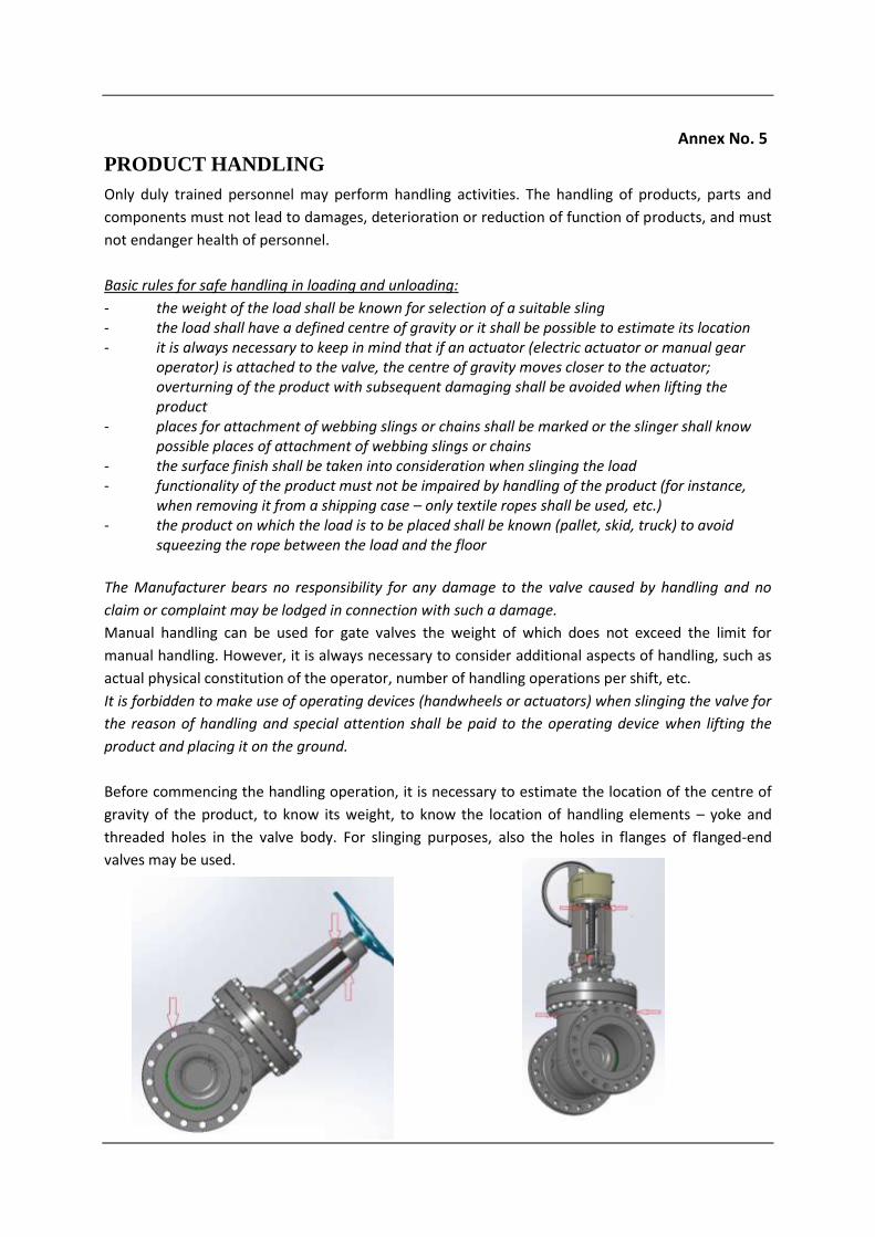
PRODUCT HANDLING
Only duly trained personnel may perform handling activities. The handling of products, parts and
components must not lead to damages, deterioration or reduction of function of products, and must
not endanger health of personnel.
Basic rules for safe handling in loading and unloading:
- the weight of the load shall be known for selection of a suitable sling- the load shall have a defined centre of gravity or it shall be possible to estimate its location- it is always necessary to keep in mind that if an actuator (electric actuator or manual gear
operator) is attached to the valve, the centre of gravity moves closer to the actuator;overturning of the product with subsequent damaging shall be avoided when lifting theproduct
- places for attachment of webbing slings or chains shall be marked or the slinger shall knowpossible places of attachment of webbing slings or chains
- the surface finish shall be taken into consideration when slinging the load- functionality of the product must not be impaired by handling of the product (for instance,
when removing it from a shipping case – only textile ropes shall be used, etc.)- the product on which the load is to be placed shall be known (pallet, skid, truck) to avoid
squeezing the rope between the load and the floor
The Manufacturer bears no responsibility for any damage to the valve caused by handling and no
claim or complaint may be lodged in connection with such a damage.
Manual handling can be used for gate valves the weight of which does not exceed the limit for
manual handling. However, it is always necessary to consider additional aspects of handling, such as
actual physical constitution of the operator, number of handling operations per shift, etc.
It is forbidden to make use of operating devices (handwheels or actuators) when slinging the valve for
the reason of handling and special attention shall be paid to the operating device when lifting the
product and placing it on the ground.
Before commencing the handling operation, it is necessary to estimate the location of the centre of
gravity of the product, to know its weight, to know the location of handling elements – yoke and
threaded holes in the valve body. For slinging purposes, also the holes in flanges of flanged-end
valves may be used.
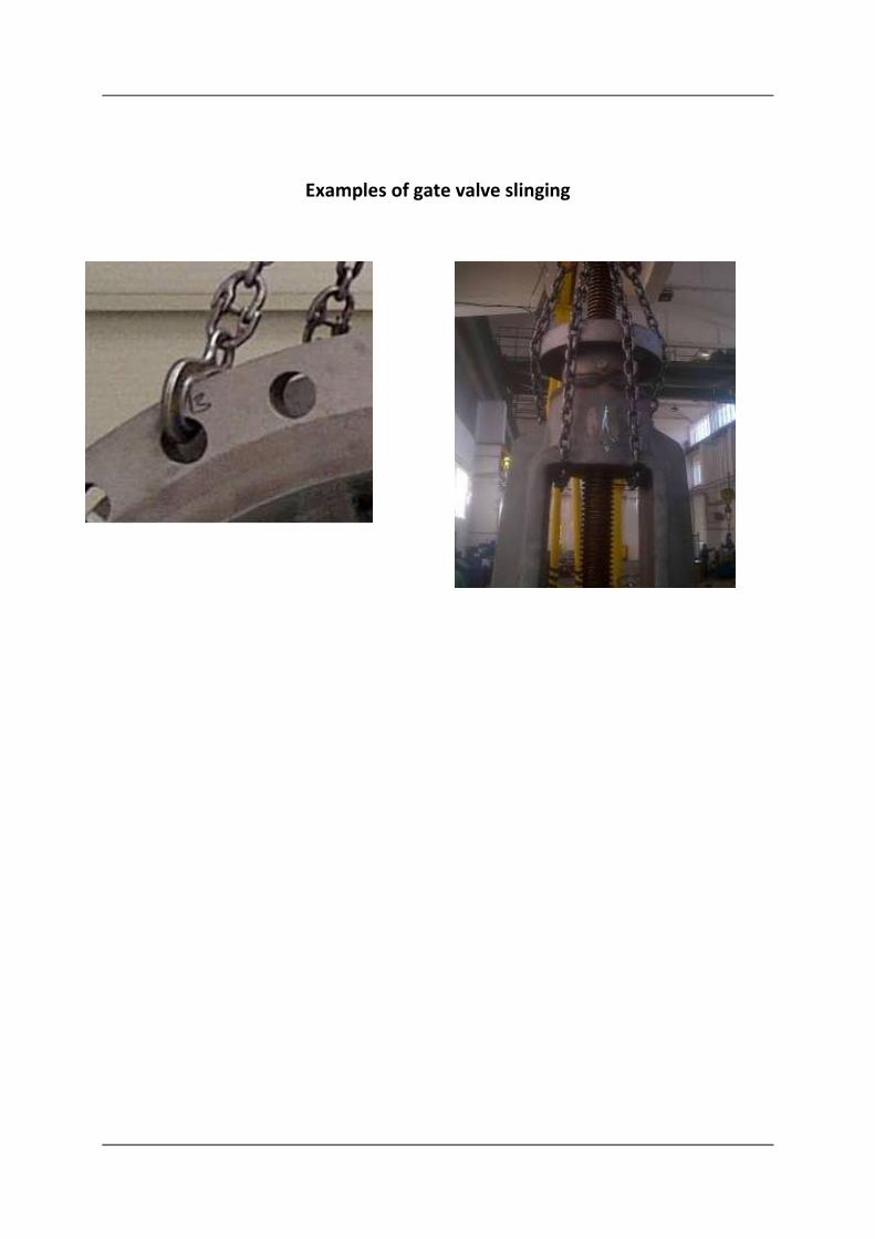
Examples of gate valve slinging
Annex No. 6
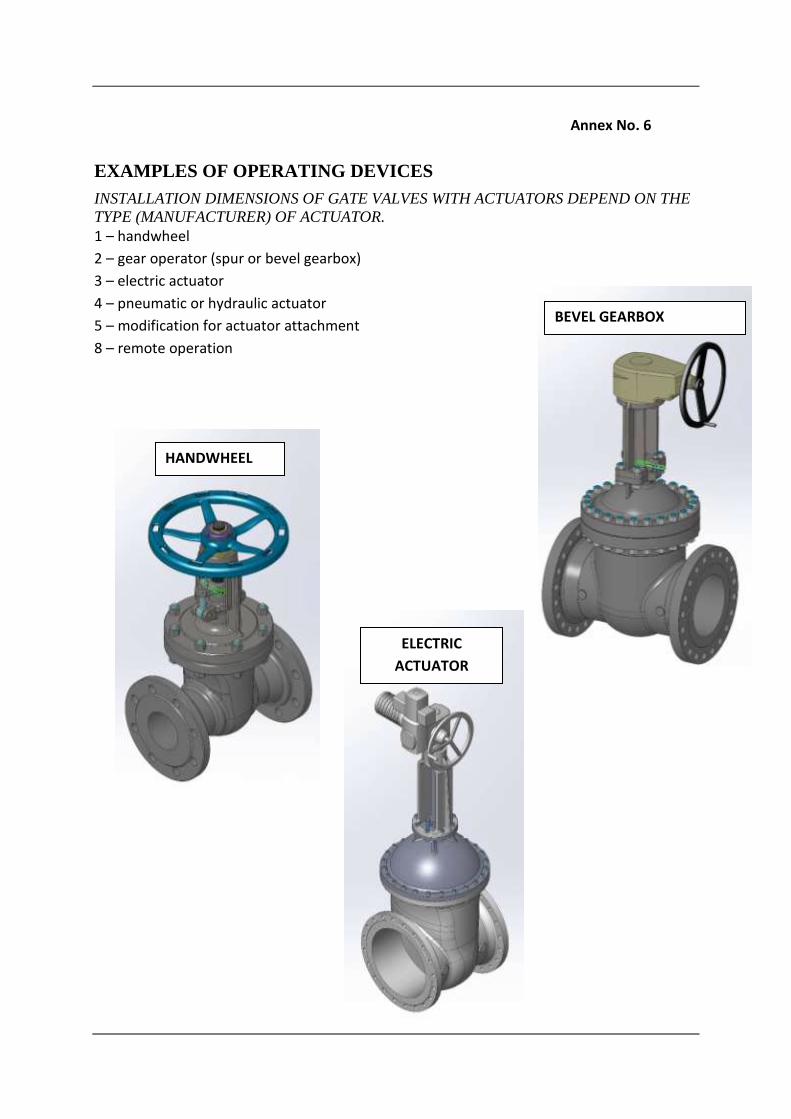
EXAMPLES OF OPERATING DEVICES
INSTALLATION DIMENSIONS OF GATE VALVES WITH ACTUATORS DEPEND ON THE
TYPE (MANUFACTURER) OF ACTUATOR.
1 – handwheel
2 – gear operator (spur or bevel gearbox)
3 – electric actuator
4 – pneumatic or hydraulic actuator
5 – modification for actuator attachment
8 – remote operation
BEVEL GEARBOX
HANDWHEEL
ELECTRIC
ACTUATOR
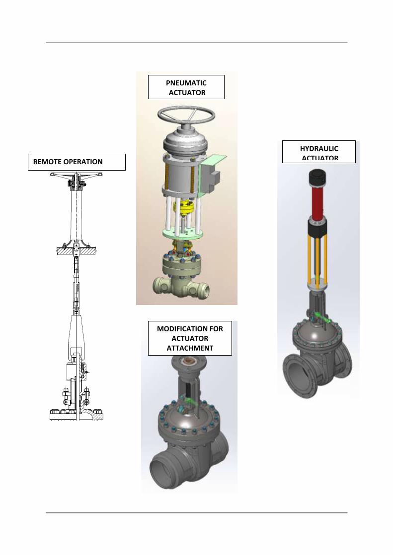
HYDRAULIC ACTUATOR
MODIFICATION FOR ACTUATOR
ATTACHMENT
REMOTE OPERATION
PNEUMATIC ACTUATOR
Annex No. 7
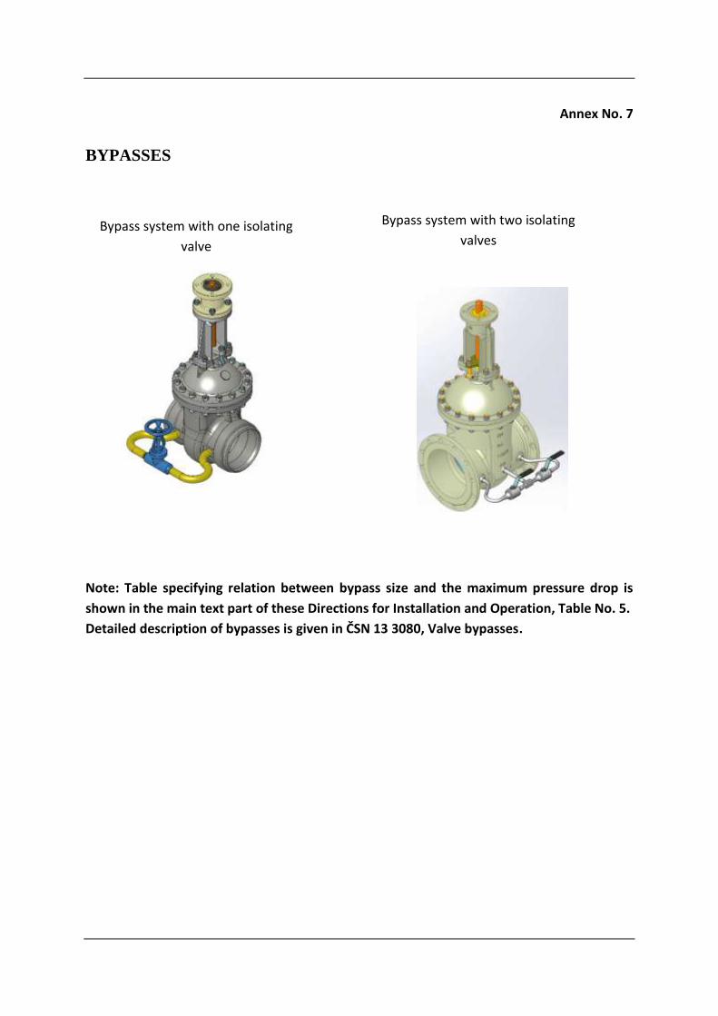
BYPASSES
Note: Table specifying relation between bypass size and the maximum pressure drop is
shown in the main text part of these Directions for Installation and Operation, Table No. 5.
Detailed description of bypasses is given in ČSN 13 3080, Valve bypasses.
Bypass system with one isolating
valve
Bypass system with two isolating
valves

Annex No. 8
LIST OF APPLICABLE STANDARDS
- EN 1984 Industrial valves – Steel gate valves
- EN 10204 Types of inspection documents
- EN 1092-1 Flanges and their joints – Circular flanges for pipes, valves, fittings and
accessories, PN designated – Part 1: Steel flanges (tables of p/t ratings)
- EN 1759-1 Flanges and their joints – Circular flanges for pipes, valves, fittings and
accessories, Class designated – Part 1: Steel flanges
- EN 1515-1 Flanges and their joints – Bolting – Part 1: Selection of bolting
- EN 12266-1 Testing of valves – Mandatory requirements
- EN 12266-2 Testing of valves – Supplementary requirements
- EN ISO 6708 Definition and selection of DN
- EN 1333 Pipework components. Definition and selection of PN
- EN 19 Industrial valves – Marking
- EN 558-1 Face-to-face and centre-to-face dimensions. PN-designated valves
- EN 1503-1 Materials for bodies, bonnets and covers. Part 1 – Steels specified in European Standards
- EN 1503-2 Materials for bodies, bonnets and covers. Part 2 – Steels other than those specified in European Standards
- ČSN 133060-2 Industrial valves. Testing of valves
- EN 736-1 Valves. Terminology – Part 1: Definitions of types of valves
- EN 736-2 Valves. Terminology – Part 2: Definitions of components of valves
- EN 736-3 Valves. Terminology – Part 3: Definition of terms
- GOST 9544-93 Pipeline isolating valves – Closure tightness standards
- GOST 12.2.063-81 Pipeline valves. General safety requirements
- GOST 5762-2000 General technical conditions for gate valves up to 25 MPa
- GOST 50460-92 Mark of conformity for mandatory certification
- GOST 9544-2005 Pipeline gate valves. Classes and rates of gates sealability
- ANSI/ASME B16.25 Buttwelding ends
- ASME B16.34 Valves – Flanged, welding and threaded end
- ASME B16.5 Pipe flanges and flanged fittings
- ASME B16.10 Face-to-face and end-to-end dimensions of valves